
A Joint Beamforming Design and Integrated CPM-LFM Signal ...
14
IEEE TRANSACTIONS ON SIGNAL PROCESSING, VOL. XX, NO. X, AUG. 2021 1 A Joint Beamforming Design and Integrated CPM-LFM Signal for Dual-functional Radar-communication Systems Yu Cao, Student Member, IEEE, Qi-Yue Yu, Senior Member, IEEE Abstract—The dual-functional radar-communication (DFRC) system is an attractive technique, since it can support both wireless communications and radar by a unified hardware platform with real-time cooperation. Considering the appealing feature of multiple beams, this paper proposes a precoding scheme that simultaneously support multiuser transmission and target detection, with an integrated continuous phase modulation (CPM) and linear frequency modulation (LFM) signal, based on the designed dual mode framework. Similarly to the conception of communication rate, this paper defines radar rate to unify the DFRC system. Then, the maximum sum-rate that includes both the communication and radar rates is set to be the objective function. Regarding as the optimal issue is non-convex, the optimal problem is divided into two sub-issues, one is the user selection issue, and the other is the joint beamforming design and power allocation issue. A successive maximum iteration (SMI) algorithm is presented for the former issue, which can balance the performances between the sum-rate and complexity; and maximum minimization Lagrange multiplier (MMLM) iteration algorithm is utilized to solve the latter optimal issue. Moreover, we deduce the spectrum characteristic, bit error rate (BER) and ambiguity function (AF) for the proposed system. Simulation results show that our proposed system can provide appreciated sum-rate than the classical schemes, validating the efficiency of the proposed system. Index Terms—Dual-functional radar-communication (DFRC), precoding, continuous phase modulation (CPM), linear frequency modulation (LFM), maximum minimization Lagrange multiplier (MMLM), user selection. I. I NTRODUCTION C URRENTLY, the joint communication and radar (JCR) system has been widely researched in both academic and industry [1], since it can simultaneously satisfy the data trans- mission and target detection, providing real-time information sharing. Therefore, the JCR system has been applied into in- door positioning [2], UAV networks [3], vehicle networks [4], and etc. Especially, the JCR system is an appealing choice for seamless connectivity to serve multiple communication users and achieve the target information. Compared to the classical single radar or communication equipment, it has advantages in terms of cost, size, power consumption, spectrum usage, and etc [5] [6]. The work presented in this paper was supported by the National Natural Science Foundation of China under Grand No. 62071148, and partly supported by the Natural Science Foundation of Heilongjiang Province of China under Grand No. YQ2019F009.(Corresponding author: Qiyue Yu). Y. Cao and Q.-Y. Yu are with the Communication Research Center, Harbin Institute of Technology, China. (email: {yucao, yuqiyue}@hit.edu.cn). The concept of JCR was first proposed by Space Shuttle program of National Aeronautics and Space Administration (NASA) in the late 1970’s [7]. The initial goal was to integrate the electronic warfare (EW) of communication and radar functions into the antenna array (AA) for resource sharing, mainly used in military scenarios. Slowly, JCR is applied into civil area, e.g., advanced driver assistance systems (ADAS) [8]. In airborne areas, [9] merges the communication system and the synthetic aperture radar (SAR) by the space time coding (STC) scheme. The prospective research directions of JCR mainly include radar-communication coexistence system (RCC) and dual- functional radar-communication (DFRC) [10]. The RCC sys- tem emphasizes on the coexistence of communication and radar system that mainly develops efficient interference man- agement techniques, including null space signal projection, transmit waveform design, power-efficient pattern design and dynamic spectrum allocation [11]-[14]. [11] proposes a null space projection method to eliminate the interferences of the RCC system, with the knowledge of the channel state information (CSI). [12] designs transmit waveforms by space- time code based on the controllable degrees of freedom to reduce the self-interferences of the RCC receiver. For the signal side-lobe interference control aspect, [13] presents a Riemann gradient conjugate power budget waveform design method to reduce the influence of side-lobe interference of a multiple input multiple output (MIMO) RCC system. In [14], the authors aim to minimize the downlink multiuser interference by using branch-and-bound dynamic spectrum allocation method. On the other hand, the DFRC focuses on the cooper- ation of communication and radar systems, and generally adopts integrated signal to improve the performances of both communication and radar [15]. There are many prospective research directions of DFRC, especially, beamforming design and integrated signal construction are two of the appealing ones [16]. There are many works on beamforming design of the DFRC system [17]- [21]. In [17], the authors present an optimal beamforming method to minimize the downlink multiuser interference, and further propose a weighted beam-pattern for a flexible trade-off between the performance of radar and communication. In [18], the authors design a beamformer that matches the radar’s beam-pattern; moreover, it satisfies the communication performance relied on the null-space criterion with the constraint of signal-to-interference-plus-noise ratio arXiv:2112.09825v1 [eess.SP] 18 Dec 2021
-
Upload
khangminh22 -
Category
Documents
-
view
0 -
download
0
Transcript of A Joint Beamforming Design and Integrated CPM-LFM Signal ...
IEEE TRANSACTIONS ON SIGNAL PROCESSING, VOL. XX, NO. X, AUG. 2021 1
A Joint Beamforming Design and IntegratedCPM-LFM Signal for Dual-functional
Radar-communication SystemsYu Cao, Student Member, IEEE, Qi-Yue Yu, Senior Member, IEEE
Abstract—The dual-functional radar-communication (DFRC)system is an attractive technique, since it can support bothwireless communications and radar by a unified hardwareplatform with real-time cooperation. Considering the appealingfeature of multiple beams, this paper proposes a precodingscheme that simultaneously support multiuser transmission andtarget detection, with an integrated continuous phase modulation(CPM) and linear frequency modulation (LFM) signal, based onthe designed dual mode framework. Similarly to the conceptionof communication rate, this paper defines radar rate to unify theDFRC system. Then, the maximum sum-rate that includes boththe communication and radar rates is set to be the objectivefunction. Regarding as the optimal issue is non-convex, theoptimal problem is divided into two sub-issues, one is the userselection issue, and the other is the joint beamforming design andpower allocation issue. A successive maximum iteration (SMI)algorithm is presented for the former issue, which can balancethe performances between the sum-rate and complexity; andmaximum minimization Lagrange multiplier (MMLM) iterationalgorithm is utilized to solve the latter optimal issue. Moreover,we deduce the spectrum characteristic, bit error rate (BER) andambiguity function (AF) for the proposed system. Simulationresults show that our proposed system can provide appreciatedsum-rate than the classical schemes, validating the efficiency ofthe proposed system.
Index Terms—Dual-functional radar-communication (DFRC),precoding, continuous phase modulation (CPM), linear frequencymodulation (LFM), maximum minimization Lagrange multiplier(MMLM), user selection.
I. INTRODUCTION
CURRENTLY, the joint communication and radar (JCR)system has been widely researched in both academic and
industry [1], since it can simultaneously satisfy the data trans-mission and target detection, providing real-time informationsharing. Therefore, the JCR system has been applied into in-door positioning [2], UAV networks [3], vehicle networks [4],and etc. Especially, the JCR system is an appealing choice forseamless connectivity to serve multiple communication usersand achieve the target information. Compared to the classicalsingle radar or communication equipment, it has advantages interms of cost, size, power consumption, spectrum usage, andetc [5] [6].
The work presented in this paper was supported by the National NaturalScience Foundation of China under Grand No. 62071148, and partly supportedby the Natural Science Foundation of Heilongjiang Province of China underGrand No. YQ2019F009.(Corresponding author: Qiyue Yu).
Y. Cao and Q.-Y. Yu are with the Communication Research Center, HarbinInstitute of Technology, China. (email: {yucao, yuqiyue}@hit.edu.cn).
The concept of JCR was first proposed by Space Shuttleprogram of National Aeronautics and Space Administration(NASA) in the late 1970’s [7]. The initial goal was to integratethe electronic warfare (EW) of communication and radarfunctions into the antenna array (AA) for resource sharing,mainly used in military scenarios. Slowly, JCR is applied intocivil area, e.g., advanced driver assistance systems (ADAS)[8]. In airborne areas, [9] merges the communication systemand the synthetic aperture radar (SAR) by the space timecoding (STC) scheme.
The prospective research directions of JCR mainly includeradar-communication coexistence system (RCC) and dual-functional radar-communication (DFRC) [10]. The RCC sys-tem emphasizes on the coexistence of communication andradar system that mainly develops efficient interference man-agement techniques, including null space signal projection,transmit waveform design, power-efficient pattern design anddynamic spectrum allocation [11]-[14]. [11] proposes a nullspace projection method to eliminate the interferences ofthe RCC system, with the knowledge of the channel stateinformation (CSI). [12] designs transmit waveforms by space-time code based on the controllable degrees of freedom toreduce the self-interferences of the RCC receiver. For thesignal side-lobe interference control aspect, [13] presents aRiemann gradient conjugate power budget waveform designmethod to reduce the influence of side-lobe interference ofa multiple input multiple output (MIMO) RCC system. In[14], the authors aim to minimize the downlink multiuserinterference by using branch-and-bound dynamic spectrumallocation method.
On the other hand, the DFRC focuses on the cooper-ation of communication and radar systems, and generallyadopts integrated signal to improve the performances of bothcommunication and radar [15]. There are many prospectiveresearch directions of DFRC, especially, beamforming designand integrated signal construction are two of the appealingones [16].
There are many works on beamforming design of the DFRCsystem [17]- [21]. In [17], the authors present an optimalbeamforming method to minimize the downlink multiuserinterference, and further propose a weighted beam-pattern fora flexible trade-off between the performance of radar andcommunication. In [18], the authors design a beamformer thatmatches the radar’s beam-pattern; moreover, it satisfies thecommunication performance relied on the null-space criterionwith the constraint of signal-to-interference-plus-noise ratio
arX
iv:2
112.
0982
5v1
[ee
ss.S
P] 1
8 D
ec 2
021
IEEE TRANSACTIONS ON SIGNAL PROCESSING, VOL. XX, NO. X, AUG. 2021 2
(SINR). [19] presents a predictive beamforming scheme toenhance angle estimation accuracy by the maximum pos-teriori probability criterion, which can acquire the locationand track the information of a vehicular system. In [20], theauthors present a hybrid beamformer based on the minimummean square error (MMSE) criterion, which can enhance theachievable sum-rate significantly. [21] presents the transmitbeamforming scheme based on the maximum SINR criterion,which optimizes both the radar transmit beam pattern andcommunication rate.
Besides the beamforming topic, signal waveforms designingis another hot topic. To combine the communication andradar waveforms, there are generally three major categories,they are orthogonal frequency division multiplexing (OFDM),frequency modulation (FM) and spread spectrum (SS) [22].In [23], the author proposes an OFDM queue schedulingmodel, taking both the network stability and radar detectionperformance into consideration. [24] proposes a novel code-division OFDM system to provide high spectrum efficiencyand robust radar sensing performances. The linear frequencymodulation (LFM) is widely considered in DFRC systems,since it provides a larger detection range and a higher rangeresolution for radar detection [25]. Phase-coded frequencymodulation can mitigate the impact of Doppler shift, thusit is suitable for high speed target detection [26]. In [27],the authors combine the low density parity check (LDPC)codes with LFM signals for a DFRC system, which canprovide a better BER than the LFM signal. The combinationof continue phase modulation (CPM) and LFM can reducethe influence of side lobes [28], thus improve the power andspectrum efficiency. As for spread spectrum signal, the directsequence (DS) can provide well-behaved auto- and cross-correlation properties to separate the radar and communicationinformation perfectly [29].
Obviously, a joint design of beamforming and signal-formfor a DFRC system is a prospective research topic, since itcan take signal processing gains to avoid interferences andimprove the spectrum efficiency. [30] considers the Hadamard-Walsh orthogonal codes with minimum variance distortion-less response (MVDR) beamforming algorithm to achieve abetter jamming and interference mitigation capability. [31]presents a zero-forcing beamforming algorithm to transmitthe independent radar waveforms and communication symbolssimultaneously.
Considering the attractive feature of the joint design, thispaper presents a joint beamforming and integrated CPM-LFMsignal for a DFRC system. The major advantages of CPM aretwo aspects: one is the continuity of signal phase that improvesthe spectrum; and the other is that the Viterbi decoding (ordemodulation) provides better BER performance. Furthermore,LFM signal is widely used in radar detection, since it haslarge time-bandwidth product, which can effectively solvethe contradiction between resolution and measuring accuracy.Thus, the integrated CPM-LFM signal is an appealing attemptfor a JCR system. To further improve the performance ofCPM-LFM, antenna array is jointly considered in this paper,and the precoder is designed based on the maximum sum-rate that includes both communication and radar rates as our
objective function. The contributions of this paper are mainlysummarized as three aspects:
1) We present a joint beamforming design and integratedCPM-LFM signal for JCR systems. The designed dualmode framework that is consisted of static and dynamicbeams can simultaneously support multiuser transmis-sion and target detection;
2) Based on the definition of radar rate, we set maximumsum-rate as our objective function that can be provedto be a non-convex optimal issue. To find the opti-mal solution, the entire problem is divided into twosub-issues, which are user selection and beamformingweights design with power allocation. A successivemaximum iteration algorithm is proposed for the userselection, and the maximum minimization Lagrangemultiplier (MMLM) is proposed to solve the latter one;and
3) Theoretical analysis are presented for the proposedsystem, including spectrum, bit error rate (BER) andambiguity function (AF) analysis. Numerical resultsverify the validity of the proposed system.
The remainder of this paper is organized as follows. SectionII presents the system model and the dual mode frameworkof the proposed system. In Section III, the transmitter andreceiver of the proposed system is described in details. Anobjective function and its solutions are deduced in SectionIV. Section V discusses the spectrum characteristic, BER andAF. Simulation results are given in Section VI, following withsome conclusion remarks in Section VII.
II. PRELIMINARY
In this paper, denote B and C by binary field and complexfield. Let x, x and X be a scalar, a vector and a matrix, respec-tively. The transposition, conjugate and conjugate transpose ofx are donated by xT, x∗ and xH respectively. Define ∗ asconvolution operation, and ‖x‖2 represents vector Euclideannorm. CN (µ, σ2) indicates the complex Gaussian distributionwith mean µ and covariance σ2. Re(x) means the real partof the complex number x. E(x) means the expectation ofa random sequence x. In is n-dimensional identity matrix,Det(X) represents the determinant of X, tr(X) means the atrace of X, Diag(X) means a diagonal matrix that is composedof the diagonal element of X, and vec(X) indicates convertinga matrix X to a vector by vectorizing columns from the leftside to the right side of X.
A. System model
Assume the base station (BS) is equipped with Nt transmitantennas and Nr received antennas, which form transmit andreceived antenna arrays for both communication and radarfunctions. There are totally U user equipments (UEs), whereU � Nt, and each UE holds a single antenna. Since the BScannot serve all the UEs simultaneously, we assume that KUEs are selected from U , where K ≤ Nt. The locations ofall the U UEs are assumed to be available at the BS. Let therange, speed, elevation and azimuth angle of the target (TA)be dT , vT and (θT , ϕT ) respectively, which will be estimated
IEEE TRANSACTIONS ON SIGNAL PROCESSING, VOL. XX, NO. X, AUG. 2021 3
Subframe 2
Target Data Frame
1Tc 2Tc TLc 1Tc 2Tc TLc 1Tc 2Tc TLc
Subframe 1 Subframe M Subframe 2
User Data Frame
Subframe 1 Subframe M
Time domain Time domain
1
1
K
k
k
c=
2
1
K
k
k
c=
1
K
kL
k
c=
...1
1
K
k
k
c=
2
1
K
k
k
c=
1
K
kL
k
c=
...1
1
K
k
k
c=
2
1
K
k
k
c=
1
K
kL
k
c=
...
Dynamic Beam Static Beam
Block 2
Frame of TA
1Tc 2Tc 1Tc 2Tc 1Tc 2Tc
Block 1 Block MS
pac
e d
om
ain
Block 2
Frame of UE
Block 1 Block M
Time domain Time domain
1
1
K
k
k
c=
2
1
K
k
k
c=
...1
1
K
k
k
c=
2
1
K
k
k
c=
...1
1
K
k
k
c=
2
1
K
k
k
c=
...
Dynamic Beam Static Beam
Time domain Time domain
Echo i
nte
nsi
ty
1 1( , ) 2 2( , ) ( , )M M
1 1( , )
2 2( , )
( , )M M
UE 1 UE 2 UE KTA
... ...
...
...
...... ......
...
...
.........TNc
TNc TNc1
K
kN
k
c=
1
K
kN
k
c=
1
K
kN
k
c=
Sig
nal
in
tensi
tyS
pac
e d
om
ain
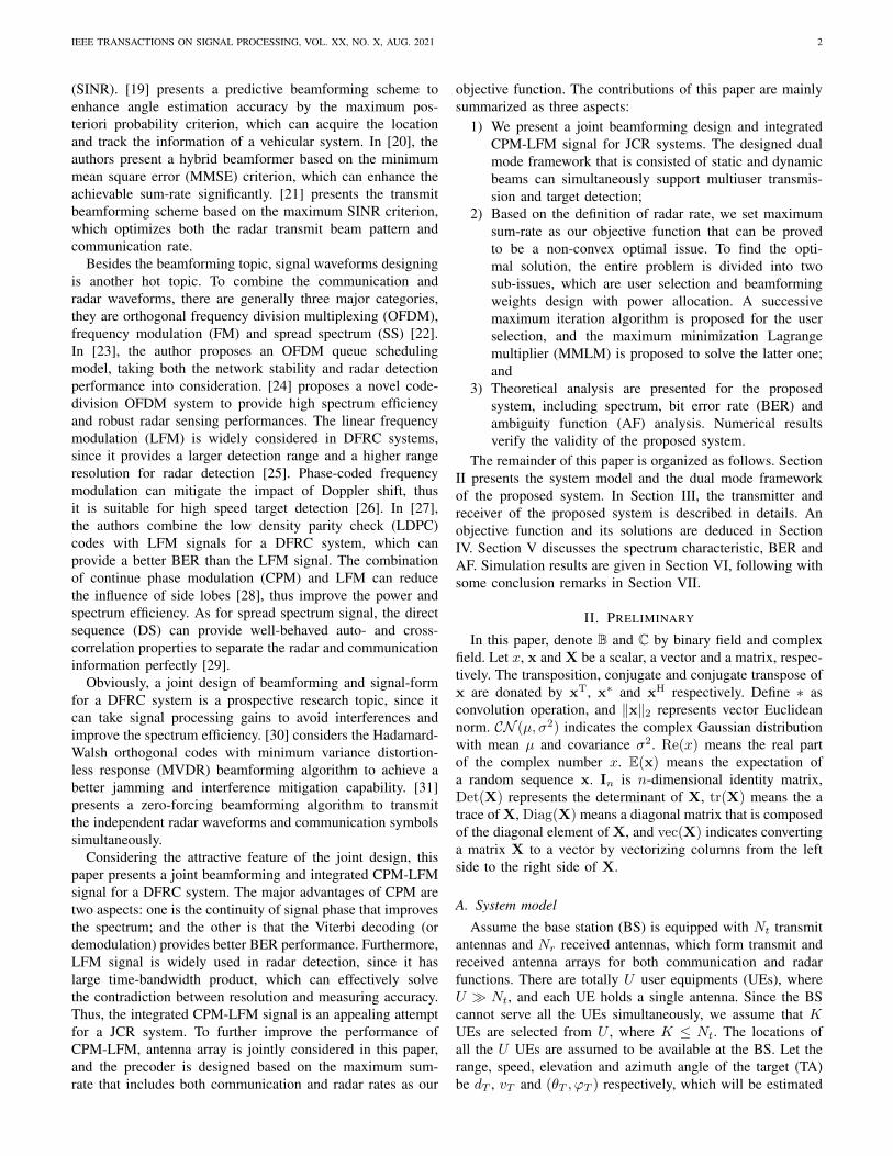
Fig. 1: A dual mode framework of a DFRC system, including time-sharing scanning mode given in (a) and fixed-directionmode given in (b).
by the radar at the BS. The ranges of elevation θT and azimuthϕT are respectively (0, π/2) and (0, 2π).
The transmit antennas of the BS is set to be a uniformrectangular array (URA) [32], whose element owns a separatephase shifter, providing a three-dimensional (3D) beamform-ing from elevation and azimuth dimensions. Suppose thenumbers of the elements of the transmit URA placed alongthe X-axis and Y-axis are respectively Ntx and Nty , indicatingNt = Ntx ×Nty . Let the distances between adjacent antennaelements of X-axis and Y-axis be dx and dy respectively. De-note the label of each transmit antenna element by (ntx, nty),where 1 ≤ ntx ≤ Ntx and 1 ≤ nty ≤ Nty . The label of thentth element can be expressed as nt = (nty − 1)Ntx + ntx,where 1 ≤ nt ≤ Nt.
Similarly, the received antenna array of the BS is also setto be a URA, and the elements of the received URA arerespectively Nrx and Nry, i.e., Nr = Nrx×Nry . The label ofthe nrth received antenna is nr = (nry − 1)Nrx+nrx, where1 ≤ nrx ≤ Nrx, 1 ≤ nry ≤ Nry and 1 ≤ nr ≤ Nr.
B. Framework
The transmit URA of the BS should simultaneously pro-vide different beams for both UEs’ communication and TA’sdetection. The UEs’ angle information are available at theBS, and the beamforming algorithms are determined by theseangle information. On contrast, the TA’s angle information isunknown, which needs to be estimated. Thus, the transmitURA of the BS is consist of two types of beams, one isdynamic beams for TA’s searching, and the other is staticbeams for UEs’ communications, as shown in Fig. 1.
Through dynamic beam scanning, both the position andspeed information of the TA are expected to be estimated.Meanwhile, UEs are served by the static beams. Because ofthe different roles of dynamic and static beams, this paperproposes a dual mode framework that is consisted of dynamictime-sharing scanning mode and static fixed-direction mode.
Assume one frame is consisted of M blocks and each blockincludes N symbols. It is noted that M is equal to the productof Me and Ma, i.e., Me = π
2δθand Ma = 2π
δϕ, where δθ
and δϕ are beamwidth in elevation and azimuth dimensions.Therefore, the TA detection precision relays on the value of M .A large M indicates a higher precision, at the cost of longerscanning time. The dynamic beam alters its direction everyblock time, thus named as “dynamic”. During one frame time,there are totally M dynamic beams. Conversely, the staticbeams keep the directions during the entire frame time, as if“static”. Dynamic beam utilize time-sharing scanning mode todetect the position and speed of a moving TA. The scanningdirection (θm, ϕm) of the mth block, where 1 ≤ m ≤ M ,keeps as a constant during the mth block. If the reflectedecho signal of the mth dynamic beam that is larger than thethreshold, the TA is estimated to be at the direction (θm, ϕm).If the reflected echo signal of the mth dynamic beam is smallerthan the threshold, there is no TA exists.
III. DESIGN OF JOINT BEAMFORMING AND CPM-LFMINTEGRATED WAVEFORM
This section presents a joint beamforming and CPM-LFMintegrated system that is designed based on the dual modeframework, as shown in Fig. 2.
A. Transmit signals of the BS
To detect whether there is a TA or not, a pilot sequenceis transmitted by the mth dynamic beam, and defined byaT = [aT,1, aT,2, ..., aT,N logM] ∈ B1×N logM, where M ismodulation order of a M -ary amplitude shift keying (MASK),and the subscript “T” indicates the sequence (or signal) forthe TA detection. Suppose K selected UEs are simultane-ously served by the static beams, where 1 ≤ K ≤ U ,define the transmit binary data sequence of the kth UE byak = [ak,1, ak,2, ..., ak,N logM] ∈ B1×N logM, where 1 ≤
IEEE TRANSACTIONS ON SIGNAL PROCESSING, VOL. XX, NO. X, AUG. 2021 4
Dynamic
Beam
Static Beam K
...
Static Beam 1
...
MASK
MASK
MASK
Tb
1b
Kb
Ta
Ka
CPM
CPM
CPM
1x
tNx
DeMod
DeMod
1y
Ky
...
1( )r t
( )Kr t
( )tNs t
Tc
1c
KcLFM
1( )s tEcho
(a) Transmitter of the BS.
,1( )Tr t
, ( )rT Nr t
(b) TA & UE.
LFM
(c) Receiver of the BS.
Matched
Filter
...1a
TA
detection
UE
detection
ˆdf
Beam-
forming
W
V
Use
r se
lect
ion
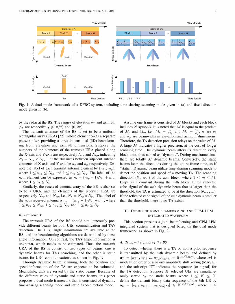
Fig. 2: A diagram of the transmitter and receiver of our proposed DFRC system, where “DeMod” indicates demodulation.There are Nt transmit antennas, and Nr received antennas at the BS. Each UE is equipped with one antenna.
k ≤ K. The binary data sequences are firstly passed tothe MASK mapper, and achieved complex signals bT =[bT,1, bT,2, ..., bT,N ] ∈ C1×N and bk = [bk,1, bk,2, ..., bk,N ] ∈C1×N .
Then bT and bk are passed to the CPM modulator. In orderto ensure the phase continuity, the phase of the baseband signalof TA and the kth UE at the nth symbol duration Ts arecalculated as
βT,n =
n∑i=1
bT,ihπ,
βk,n =
n∑i=1
bk,ihπ,
(1)
where 1 ≤ n ≤ N and the parameter h is modula-tion index [33]. The corresponding phase vectors of theTA and the kth UE are βT = [βT,1, βT,2, ..., βT,N ] andβk = [βk,1, βk,2, ..., βk,N ], respectively. Thus, the basebandsignals of CPM are obtained as cT = ejβT ∈ C1×N andck = ejβk ∈ C1×N , forming the transmit data matrixC =
[cTT , c
T1 , ...c
TK
]T ∈ C(K+1)×N .In this paper, the transmit URA adopts fully con-
nection structure. Suppose that the beamforming weightvectors of the TA and the kth UE are defined bywT = [w1,T , ..., wnt,T , ..., wNt,T ] ∈ CNt×1 and wk =[w1,k, ..., wnt,k, ..., wNt,k] ∈ CNt×1, thus the precoding matrixcan be represented as W = [wT ,w1, ...,wK ] ∈ CNt×(K+1).Assume the transmit power of the TA and kth UE are PTand Pk respectively, and the corresponding power allocationmatrix is P = Diag (PT , P1, ..., PK) ∈ C(K+1)×(K+1). Afterprecoding and power allocation, the transmit data on the ntthantenna is represented as
xnt =√PT wnt,T cT +
K∑k=1
√Pk wnt,k ck, (2)
where xnt = [xnt,1, ..., xnt,n, ..., xnt,N ] ∈ C1×N and 1 ≤nt ≤ Nt. The baseband signal xnt is passed to the filter,and modulated to the carrier frequency fc to form LFMwaveforms, then the corresponding integrated bandpass sig-
...
Carrier
Echo signal
Difference signal
...
2
w
c
Bf +
2
w
c
Bf −
upf
downf
Block 1
Time domain
...Block 2 Block 3 Block M
...
Signal frequency
Beat frequency
Time domain
(a) The relationship between signal frequency and symbol duration.
(b) The relationship between beat frequency and symbol duration.
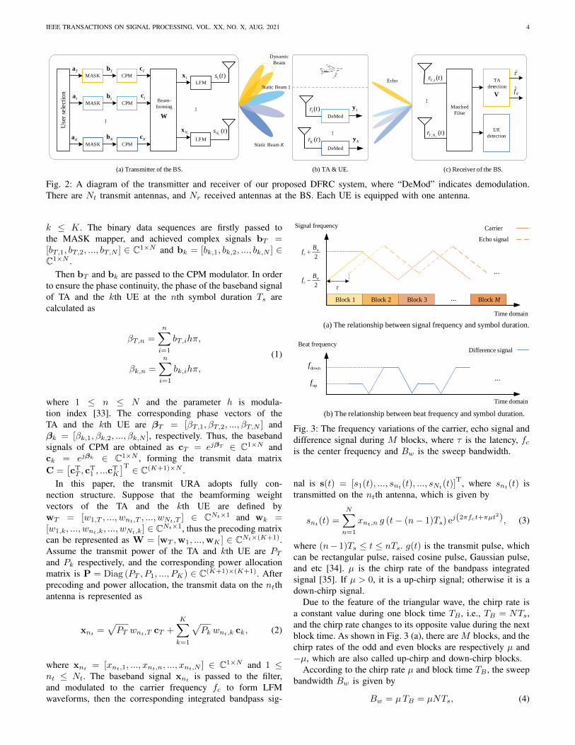
Fig. 3: The frequency variations of the carrier, echo signal anddifference signal during M blocks, where τ is the latency, fcis the center frequency and Bw is the sweep bandwidth.
nal is s(t) = [s1(t), ..., snt(t), ..., sNt(t)]T, where snt(t) is
transmitted on the ntth antenna, which is given by
snt(t) =
N∑n=1
xnt,n g (t− (n− 1)Ts) ej(2πfct+πµt2), (3)
where (n− 1)Ts ≤ t ≤ nTs. g(t) is the transmit pulse, whichcan be rectangular pulse, raised cosine pulse, Gaussian pulse,and etc [34]. µ is the chirp rate of the bandpass integratedsignal [35]. If µ > 0, it is a up-chirp signal; otherwise it is adown-chirp signal.
Due to the feature of the triangular wave, the chirp rate isa constant value during one block time TB , i.e., TB = NTs,and the chirp rate changes to its opposite value during the nextblock time. As shown in Fig. 3 (a), there are M blocks, and thechirp rates of the odd and even blocks are respectively µ and−µ, which are also called up-chirp and down-chirp blocks.
According to the chirp rate µ and block time TB , the sweepbandwidth Bw is given by
Bw = µTB = µNTs, (4)

IEEE TRANSACTIONS ON SIGNAL PROCESSING, VOL. XX, NO. X, AUG. 2021 5
atx(θk, ϕk) =1√Ntx
[1, ej2π
dxλ cos θk cosϕk , ..., ej2π(Ntx−1) dxλ cos θk cosϕk
],
aty(θk, ϕk) =1√Nty
[1, ej2π
dyλ cos θk sinϕk , ..., ej2π(Nty−1)
dyλ cos θk sinϕk
].
(6)
which indicates the highest frequency and lowest frequency ofthe transmit signals are respectively fc+Bw/2 and fc−Bw/2.
B. Received signals at each UE
The integrated signal is then transmitted to the fadingchannel. Assume that the elevation and azimuth of the kthUE θk and ϕk are perfectly known at the BS, and the rangesof elevation θk and azimuth ϕk are respectively (π/2, π) and(0, 2π). Thus, the CSI hk ∈ C1×Nt between the kth UE andBS is modeled as
hk =
√(dk/d0
)−αδk at(θk, ϕk), (5)
where dk is the distance from the BS to the kth UE, d0
is the reference distance, dk ≥ d0, α is the path lossexponent, δk indicates shadowing effect that is a zero meanand σδ variance log-normal random variable. at(θk, ϕk) =
vec(atx(θk, ϕk)
Taty(θk, ϕk)
)∈ C1×Nt is the transmit steer-
ing vector from the BS to the kth UE [36], which are givenby (6), where λ = c
fcstands for the wavelength.
At the receiver of the kth UE, the received bandpass signalrk(t) can be given as
rk(t) = hk s(t) + nk(t). (7)
The received bandpass signal rk(t) is coherent demodulatedand passed through the lowpass filter, the equivalent basebandsignal yk ∈ C1×N is
yk =√Pk hkwkck +
√PT hkwT cT
+
K∑i=1,i6=k
√Pi hkwici + nk, (8)
where nk is the complex additive white Gaussian noise(AWGN) obeying CN (0, σ2
k) with variance σ2k. The first item
is our expected signal, the second and the third items are bothinterferences, which can be eliminated by designing precodingmatrix X, and the last one is noise.
C. Received signals at the BS
If there is a TA at the location of (θm, ϕm) dur-ing the mth block time, an echo signal is feedback tothe BS. The received URA of the BS is used to ac-quire the echo signals of the TA. The steering vectorsfrom the BS to the TA is denoted by at(θm, ϕm) =vec(aTtx(θm, ϕm)aty(θm, ϕm)
)∈ C1×Nt , and from the TA
to BS is ar(θm, ϕm) = vec(aTrx(θm, ϕm)ary(θm, ϕm)
)∈
C1×Nr . Let A = aTr (θm, ϕm)at(θm, ϕm) ∈ CNr×Nt , and
AK =[aTr (θ1, ϕ1),aT
r (θ2, ϕ2), ...,aTr (θK , ϕK)
]∈ CNr×K ,
where aTr (θk, ϕk) is the steering vector from the kth UE to
the BS.
Thus the received bandpass signal at the BS is
r(t) = LA s(t− τ)ej2πfdt + AKIK(t) + nT (t), (9)
where r(t) = [r1(t), ..., rnr (t), ..., rNr (t)]T, L =
√LT ηT is
the gain of echo signal, LT is the propagation attenuationand ηT represents radar cross section (RCS). τ and fd arerespectively latency and Doppler frequency of the TA, whichare need to be estimated. Let IK = [I1(t), I2(t), ..., IK(t)],where Ik(t) is the signal of the kth UE, which is viewedas interferences for the TA detection, the power of whichsatisfy E
(|Ik(t)|2
)= 1. nT (t) is the complex AWGN obey
CN (0, σ2) with variance σ2.Define the processing vector of the BS by V ∈ C1×Nr ,
thus, we have
y(t) = V r(t),
= LVAWC · ej[2πfc(t−τ)+πµ(t−τ)2+2πfdt] (10)+ VAKIK(t) + n(t),
where n(t) = V nT (t) is the equivalent noise after signalprocessing.
Define the received difference signal dr(t) by the low-passsignal of the product of the echo signal y(t) and the coherencefrequency carrier, i.e., dr(t) = LPF
[y(t) · ej(2πfct+πµt
2)],where LPF represents low-pass filter. The frequencies of dr(t)are defined by beat frequencies, including fup and fdown,which are respectively calculated in the up-chirp and down-chip stages, as shown in Fig. 3 (b). In each up-chirp block, thefrequency of the echo signal is lower than the carrier owing tothe influence of latency and Doppler frequency, while in thedown-chirp block, the frequency of the echo signal is higherthan the carrier.
Thereby, during the up-chirp stage, the received differencesignal dr,up(t) can be expressed as
dr,up(t) = LPF[Re (y(t)) · Re(ej(2πfct+πµt
2))],
= LVAWC · ej[2π(µτ−fd)t+2π(fcτ+ 12µτ)τ)]
+ VAKIK(t) + n(t), (11)
where the beat frequency of the up-chirp stage is fup = µτ −fd. Similarly, it is able to derive the received difference signalof the down-chirp stage as
dr,down(t) = LPF[Re (y(t)) · Re(ej(2πfct−πµt2))
],
= LVAWC · ej[2π(µτ+fd)t−2π(fcτ+ 12µτ)τ)]
+ VAKIK(t) + n(t), (12)
with the beat frequency of the down-chirp stage as fdown =µτ + fd.

IEEE TRANSACTIONS ON SIGNAL PROCESSING, VOL. XX, NO. X, AUG. 2021 6
The latency and distance between the BS and TA can becalculated as τ =
fup+fdown
µ and dT = cτ2 , respectively.
The Doppler frequency is equal to fd =fdown−fup
2 , and thecorresponding radial velocity of the TA is vT = λfd
2 .Obviously, the latency and Doppler frequency can be exactly
estimated without estimation error, if the sweep bandwidthand transmit pulse bandwidth satisfy the resolutions of therequirements. However, the matrix W and vector V affect thereceived power of TA, how to design W and V is presentedin the following section.
IV. A JOINT BEAMFORMING AND RESOURCE ALLOCATIONALGORITHM
To design the precoding matrix W and processing vectorV, this section sets the maximum sum-rate as our objectivefunction. Actually, the sum-rate consists of both communica-tion rate and radar rate. It is important to denote a unifiedsum-rate of a DFRC system. As known, communication sum-rate (or channel capacity) is widely used in communicationsystems, which indicates the quality of a communicationsystem. To unify the communication and radar systems, wepresent a concept of radar rate, similarly to the conception ofcommunication rate. Thus, this paper exploits the maximumsum-rate that includes both communication and radar rates asour objective function.
A. Communication rate and radar rate
This paper only considers the downlink multiuser channelcapacities between the BS and the UEs as the communicationrate. Recalling (8), the SINR of the kth UE can be expressedas
γk =Pk |hkwk|2∣∣∣√PT hkwT +∑Ki=1,i6=k
√Pi hkwi
∣∣∣2 + σ2k
, (13)
where Pk |hkwk|2 and∣∣∣√PT hkwT +
∑Ki=1,i6=k
√Pi hkwi
∣∣∣2are respectively the power of received signal and interferenceof the kth UE. Thus, the communication rate of all the UEsis equal to
Rcom =
K∑k=1
log2 (1 + γk) , (14)
where the subscript “com” of Rcom stands for communicationsystem.
Whether a TA exists or not, it is determined by the receivedpower of TA at the BS. According to the definition of radarequation [37], if the received power of TA is greater than theminimum detection power, i.e. Pth, the TA can be detected.According to (11), the SINR of the TA is calculated as
γT =EradVZWWHZHVH
VAKAHKVH + VVH σ2
, (15)
where Z = LA ej(2πfcτ+πµτ2), Erad = E[CCH] is the powerof radar transmit pilot sequence, and the term VAKAH
KVH
indicates the interferences of other UEs.
Similarly to the concept of communication rate, we definethe radar rate by
Rrad = log2 (1 + γT ) , (16)
where the subscript “rad” stands for radar, and the radar rateis affected by V and W. Obviously, the defined radar rate canreflect the target detection performance, a large Rrad standsfor a better detection performance.
B. Objective function
In order to ensure both the communication and radar per-formances, the optimal function is to maximize the sum-rateof the system, with the constraints given by
max Rsum =
K∑k=1
log2 (1 + γk) + log2 (1 + γT )
= log2 Det (IK+1 + ΓK+1) . (17)s.t. C1 : γk ≥ 2ρk − 1,∀k,
C2 : γT ≥ 2ρT − 1,
C3 : PT +
K∑k=1
Pk ≤ Ptot,
where Ptot is the total transmit power of the BS, ρk and ρTare respectively the thresholds of the required SINR of UE andTA. ΓK+1 = Diag[γ1, γ2, ..., γK , γT ] is a diagonal matrix.
There are three constraints. C1 is to certify the communi-cation the quality of service (QoS) requirement of each UE.C2 is used to ensure the TA detection, and the radar rate Rrad
should be larger than the threshold ρT . C3 is the total powerconstraint.
Obviously, the optimization issue is non-convex. Therefore,we propose a sub-optimal joint resource allocation algorithm,including two parts: user selection, and precoding & process-ing design with power allocation. It is noted that the UE’sweight wk is constant, while the TA’s weight wT is variousduring different M blocks. The user selection part is to selectK UEs from the user set, so that to maximize Rcom. Based onthe selected UEs, the power allocation algorithm is designedto acquire W and V to obtain the sub-optimal solution of(17).
C. Sub-issue: user selection
This part is discussed based on a given W. We adopt MRTprecoding as the initial iteration value, where WMRT = HH
and the subscript “MRT” indicates maximum ratio transmis-sion (MRT) [38]. Note that the user selection result will notaffect the design of W. Actually, γk is mainly determined byeach UE’s θk and ϕk. Define Ψ = {q1, q2, ..., qu, ...qU} andψ = {qi1 , qi2 , ..., qik , ..., qiK} by the sets of all the UEs andthe selected served UEs respectively, where 1 ≤ i1 < i2 <... < iK ≤ U . Obviously, ψ is a subset of Ψ, i.e., ψ ⊆ Ψ. Theoptimal user selection algorithm is traversal algorithm, and itscomplexity is defined by the size of user set, which is O(UK)complex multiplications. If U and K are small, the traversalalgorithm is appreciated. However, when U and K are large,
IEEE TRANSACTIONS ON SIGNAL PROCESSING, VOL. XX, NO. X, AUG. 2021 7
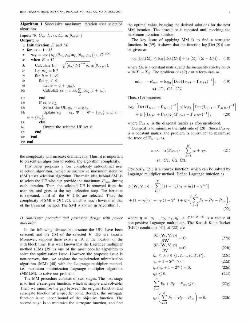
Algorithm 1 Successive maximum iteration user selectionalgorithm
Input: Ψ, Gu, du, α, δu, at(θu, ϕu)Output: ψ
1: Initialization K and M .2: for m = 1 : M3: wT = vec
(aTtx(θm, ϕm)aty(θm, ϕm)
)∈ C1×Nt
4: when K < U
5: Calculate hu =√(
du/d0
)−αδu at(θu, ϕu).
6: Let wu = hHu .
7: for k = 1 : K8: for qu ∈ Ψ9: Let ψ = ψ + {qu}.
10: Calculate ck = max∑ψ
log2 (1 + γu).
11: end12: if ck > c∆13: Select the UE qik = arg ck.14: Update c∆ = ck, Ψ = Ψ − {qik} and ψ =
ψ + {qik}.15: else16: Output the selected UE set ψ.17: end18: end19: end
the complexity will increase dramatically. Thus, it is importantto present an algorithm to reduce the algorithm complexity.
This paper proposes a low complexity sub-optimal userselection algorithm, named as successive maximum iteration(SMI) user selection algorithm. The main idea behind SMI isto select the UE who can provide the maximum Rcom duringeach iteration. Then, the selected UE is removed from theuser set, and goes to the next selection step. The iterationis repeated, until all the K UEs are selected. Thus, thecomplexity of SMI is O(UK), which is much lower than thatof the traversal method. The SMI is shown in Algorithm 1.
D. Sub-issue: precoder and processor design with powerallocation
In the following discussion, assume the UEs have beenselected, and the CSI of the selected K UEs are known.Moreover, suppose there exists a TA at the location of themth block time. It is well known that the Lagrange multipliermethod (LM) [39] is one of the most popular algorithm tosolve the optimization issue. However, the proposed issue isnon-convex, thus, we explore the majorization minimizationalgorithm (MM) [40] with the Lagrange multiplier method,i.e. maximum minimization Lagrange multiplier algorithm(MMLM), to solve our problem.
The MM procedure consists of two stages. The first stageis to find a surrogate function, which is simple and solvable.Then, we minimize the gap between the original function andsurrogate function at a specific point. Besides, the surrogatefunction is an upper bound of the objective function. Thesecond stage is to minimize the surrogate function, and find
the optimal value, bringing the derived solutions for the nextMM iteration. The procedure is repeated until reaching themaximum iteration number.
The key issue of applying MM is to find a surrogatefunction. In [39], it shows that the function log [Det(Σ)] canbe given as
log [Det(Σ)] ≤ log [Det(Σ0)] + tr(Σ−1
0 (Σ−Σ0)), (18)
where Σ0 is a constant matrix, and the inequality strictly holdswith Σ = Σ0. The problem of (17) can reformulate as
min −Rsum = log2
[Det (IK+1 + ΓK+1)
−1]. (19)
s.t. C1, C2, C3.
Thus, (19) becomes
log2
[Det (IK+1 + ΓK+1)
−1]≤ log2
[Det (IK+1 + ΓMRT )
−1]
+ tr[(IK+1 + ΓMRT )(ΓK+1 − ΓMRT )−1
], (20)
where ΓMRT is the diagonal matrix as aforementioned.Our goal is to minimize the right side of (20). Since ΓMRT
is a constant matrix, the problem is equivalent to maximizethe trace of ΓK+1, as
max tr(ΓK+1) =
K∑k=1
γk + γT . (21)
s.t. C1, C2, C3.
Obviously, (21) is a convex function, which can be solved byLagrange multiplier method. Define Lagrange function as
L (W,V,η) =
K∑k=1
[(1 + ηk) γk + ηk(1− 2ρk)
]+ (1 + ηT )γT + ηT (1− 2ρT ) + ηP
( K∑k=1
Pk + PT − Ptot),
(22)
where η = [η1, ..., ηK , ηT , ηP ] ∈ C1×(K+2) is a vector ofnon-positive Lagrange multipliers. The Karush-Kuhn-Tucker(KKT) conditions [41] of (22) are
∂L (W,V,η)
∂W= 0, (22a)
∂L (W,V,η)
∂V= 0, (22b)
ηυ ≤ 0, υ ∈ {1, 2, ...,K, T, P}, (22c)γυ + 1− 2ρυ ≥ 0, (22d)ηυ(γυ + 1− 2ρυ ) = 0, (22e)ηP ≤ 0, (22f)K∑k=1
Pk + PT − Ptot ≤ 0, (22g)
ηP
( K∑k=1
Pk + PT − Ptot)
= 0, (22h)

IEEE TRANSACTIONS ON SIGNAL PROCESSING, VOL. XX, NO. X, AUG. 2021 8
where (22a) and (22b) can be extended as
∂L (W,V,η)
∂wk=
2(1 + ηk)Pk |hkwk|hk∣∣∣√PT hkwT +∑Ki=1,i 6=k
√Pihkwi
∣∣∣2 + σ2k
−K∑i=1i6=k
2(1 + ηi)Pi |hiwi|2|hiwk|hi(∣∣∣√PT hiwT +∑Kj=1,j 6=i
√Pj hiwj
∣∣∣2+σ2i
)2
+ (1 + ηT ) ·EradVZ ∂(WWH)
∂wkZHVH
VAKAHKVH + VVHσ2
, (23)
∂L (W,V,η)
∂V=
[(2ZWWHZHVH)(VAKAH
KVH + VVH σ2)
(VAKAHKVH + VVH σ2)2
− (VZWWHZHVH)(2AKAHKVH + 2VH σ2)
(VAKAHKVH + VVH σ2)2
]· (1 + ηT ) Erad. (24)
To obtain the solutions of W and V in (22), we adoptthe alternating direction method of multipliers (ADMM). Theinitialized W by MRT is denoted by W(0), where “0”
indicates the initial step. Let∂L(W(0),V,η)
∂V = 0, then it isderived that
ZW(0)(W(0))HZHVH(VAKAH
KVH + VVH σ2)
=
VZW(0)(W(0))HZHVH(AKAH
KVH + VH σ2). (25)
By solving (25), we can obtain V(1) and then bring it to (22a).
Set∂L(W,V(1),η)
∂wk= 0, and achieve W(1). According to
the derived V(1) and W(1), do water filling power allocationalgorithm to maximum the trace
tr(Γ
(1)K+1
)=
K∑k=1
Pk
∣∣∣hkw(1)k
∣∣∣2∣∣∣√PT hkw(1)T +
∑Ki=1,i 6=k
√Pi hkw
(1)i
∣∣∣2+σ2k
+EradV(1)ZW(1)W(1)HZHV(1)H
V(1)AKAHKV(1)H + V(1)V(1)Hσ2
, (26)
and the optimal power allocation results P (1)k and P (1)
T can beobtained.
Following, take V(1) and W(1) into (20), and obtain thenext surrogate function. By optimizing the new surrogatefunction, we can solve V(2) and W(2) by KKT conditions,and then do water filling power allocation to maximizetr(Γ
(2)K+1
). Repeat this process, until the iteration number i
reaches the maximum iteration number νmax, or satisfying‖W(i)−W(i−1)‖2 < ε and ‖V(i)−V(i−1)‖2 < ε, where ε isa small position number, i.e., 10−3. Finally, we can obtain thesolutions W = W(νmax) and V = V(νmax), and the powerallocation results P (νmax)
k and P(νmax)T , where νmax is the
final iteration times. The MMLM is presented in Algorithm 2.As a summary, the joint resource allocation algorithm
includes user selection, and precoder and processor designwith power allocation. During the initialization, we firstly doSMI to find the UE set ψ, then utilize MMLM to calculateW, V, PT and Pk. Overall, the whole algorithm needs at least(UKνmax) complex multiplications.
Algorithm 2 Maximum minimization Lagrange multiplieralgorithm for designing W and VInput: ψ, γk, γT , ρk, ρT , ε, νmaxOutput: W and V
1: Initialization W(0) by MRT precoding.2: Set i = 1, ε and νmax.3: while i < Nite & ‖W(i) −W(i−1)‖2 ≥ ε & ‖V(i) −
V(i−1)‖2 ≥ ε4: Find the surrogate function according to (20) and opti-
mize the surrogate function.5: Construct Lagrange function L
(W(i),V(i),η
).
6: Calculate KKT conditions of (22).7: Calculate V(i) by
∂L(W(i−1),V(i),η)∂V(i) = 0 and bring it
back to (23).8: Calculate w
(i)k by
∂L(W(i),V(i),η)∂w
(i)k
= 0 and update KKTconditions.
9: Do water filling algorithm to maximize the tracetr(Γ
(i)K+1
), acquire the optimal power allocation results
P(νmax)k and P (νmax)
T .10: end11: W = W(νmax) and V = V(νmax)
V. THEORETICAL ANALYSIS
In this section, we derive the spectrum, BER and AF of theproposed system.
A. Spectrum
Actually, the spectrum of the integrated signal is determinedby the transmit signal snt(t). Since the spectrum of the band-pass and baseband signals are equivalent, we only consider theequivalent baseband signal snt(t) of (3), which is given by
snt(t) =
N∑n=1
xnt,n g (t− (n− 1)Ts) ejπµt2
,
=
N∑n=1
(wnt,T ej
∑ni=1 bT,ihπ +
K∑k=1
wnt,k ej∑ni=1 bk,ihπ
)· g (t− (n− 1)Ts) ejπµt
2
. (27)
Since the spectrum of different transmit antennas are thesame, we take the ntth antenna as an example for analyzing.Define the Fourier transform of snt(t) by S(f), which can beexpressed as
S(f) =∫
+∞
−∞
N∑n=1
(wnt,T ej
∑ni=1
bT,ihπ+
K∑k=1
wnt,k ej∑ni=1
bk,ihπ)
· g (t− (n− 1)Ts) ejπ(µt2−2ft) dt,
=
N∑n=1
(wnt,T ·
n∏i=1
ejbT,ihπ +
K∑k=1
wnt,k ·n∏i=1
ejbk,ihπ)
·∫ TB
0
g(t) ejπ(µt2−2ft) dt. (28)

IEEE TRANSACTIONS ON SIGNAL PROCESSING, VOL. XX, NO. X, AUG. 2021 9
∣∣∣GLFM (f)∣∣∣ =
√[C
(√µTB −
fõ
)+ C
(fõ
)]2
+
[S
(√µTB −
fõ
)+ S
(fõ
)]2
. (33)
As mentioned in Section III, bk,i and bT,i are complexsignals. Actually, the nth symbol of the ntth transmit antennaxnt,n is a random variable, thus the mean value of xnt,n is
E [|xnt,n|] = E
[|wnt,T
n∏i=1
ejbT,ihπ +
K∑k=1
wnt,k
n∏i=1
ejbk,ihπ|
],
=
∣∣∣∣∣wnt,T +
K∑k=1
wnt,k
∣∣∣∣∣ n
M
(M−1)∑ξ=−(M−1)ξ is odd
ejξMhπ, (29)
where ξ represents one of the M values of the modulatedindependent symbols bk,i and bT,i, and the prior probabilityof which is 1
M . From (29), it is found that different precodingschemes W and modulation orders M can affect the ampli-tude of the spectrum. Compared with MRT precoding, thespectrum of our scheme has a larger amplitude, and a smallerM derives a lower amplitude. Assume
G(f) =
∫ TB
0
g(t) ejπ(µt2−2ft) dt,
= Gu(f) ∗ GLFM (f), (30)
where Gu(f) is the Fourier transform of transmit pulse g(t),and Bg is the bandwidth of g(t). If we adopt rectangular pulse,i.e., Bg = 1/Ts or raised-cosine pulse i.e., Bg = (1+αg)/2Ts,where αg is the roll-off factor.
Define GLFM (f) by the Fourier transform of LFM signal,given by
GLFM (f) =
∫ TB
0
ejπ(µt2−2ft) dt,
= e−jπf2
µ
∫ √µTB− f√µ
− f√µ
[cos(πt
′2) + j sin(πt
′2)]
dt′,
(31)
where t′
=√µt − f√
µ , C(x) =∫ x
0cos(πα2) dα and
S(x) =∫ x
0sin(πα2) dα are cosine and sine Fresnel integral
respectively. Since both C(x) and S(x) are odd function, theamplitude of GLFM (f) can be expressed in (33).
According to (30), it is found that the integrated signalbandwidth is equal to B = Bw + Bg , i.e. B = µTB + 1/Tsfor rectangular pulse or B = µTB + (1 +αg)/2Ts for raised-cosine pulse. To improve the spectrum efficiency, we can adoptbandwidth-saving pulse.
B. BERActually, the BER of the proposed system is independent
of LFM. The optimum detector of a CPM signal is realizedby Viterbi algorithm [42]. Considering the proposed system,the BER of the kth UE becomes
Pe,k = 2
∫ +∞
0
Q
(√log2M
(1− sin 2πh
2πh
)γk
)p(γk) dγk,
(34)
where Q(x) =∫ +∞x
1√2π
e−t2
2 dt, p(γk) is the probabilitydensity function (PDF) of γk. For mathematic convenience, weutilize W(0) that is obtained by MRT instead of the iterationoptimal W(νmax) to calculate p(γk). The expression of γk in(13) is
γk ≤Pk(dk/d0
)−αδkNt∣∣∣√PT hkwT +
∑Ki=1,i6=k
√Pi hkwi
∣∣∣2 + σ2k
, (35)
where the path loss d−αk and shadowing effect δk obey powerlaw and log-normal distributions, the PDF of δk is p(δk) =
1δk√
2πσδke− ln(δk)2
2σδ , where σδ is the variance of δk.
Let Ik =√PT hkwT +
∑Ki=1,i6=k
√Pi hkwi be the in-
terferences, and it is the sum of several independent andidentically (i.i.d) distributed random variables. According tothe central limit theorem, Ik can be approximately viewedas complex Gaussian distribution, i.e., N (µI , σI), which issimulated by Monte Carlo. The mean value of Ik can bederived by µI =
√PT µT +
∑Kk=1
√Pi µk, where µT and µk
are respectively the mean value of hkwT and hkwi. It can beseen that a larger K leads to a larger mean value µI when thepower allocation factor is fixed. Moreover, for a given K, e.g.,K = 4, PT shows a significant influence on the µI , indicatingthat the interference increases with the increased of PT . Thevariance of Ik can be expressed as σI = PT σT +
∑Kk=1 Pi σk,
where σT and σk are respectively the variance of interferencehkwT and hkwi. Thus, the total interference plus noise obeyschi-square distribution with degree of freedom 2, given by
p(Ik) =1
2σ2I
e− Ik
2σ2I . (36)
Assume zk =d−αk δkIk
, according to the relationship ofproduct and quotient of random variables, the PDF of γk is
p(γk) =(2(σI + σk)2)−
1α e
σ4δα2
α(dk,2 − dk,1)Q(−σδ
2
)Γ
(1− 1
α
)γ− 1α−1
k ,
(37)where Γ(x) =
∫ +∞0
tx−1e−t dt, dk,1 and dk,2 are respectivelythe minimum and maximum range from the BS to the kth UE,i.e. dk,1 ≤ dk ≤ dk,2.
Taking (37) into (34), we can derive the upper bound of theBER expression. Unfortunately, the closed-form solution cannot be deducted since the integral of the Q function can beexpressed by the analytical form.
C. AF
The ambiguity function is defined as the time-frequencyresponse observed at the matched filter of the BS receiver,which is given by [43]
|χ(τ, fd)|2 =
∣∣∣∣∫ +∞
−∞snt(t) s
∗nt(t− τ) ej2πfdt dt
∣∣∣∣2 , (38)

IEEE TRANSACTIONS ON SIGNAL PROCESSING, VOL. XX, NO. X, AUG. 2021 10
|χ(τ, fd)|2 =
∣∣∣∣∣e−jπµτ2N∑n=1
N∑i=1
∫ +∞
−∞xnt,n x
∗nt,i g (t− (n− 1)Ts) g
∗ (t− (i− 1)Ts − τ) ej2π(µτ+fd)t dt
∣∣∣∣∣2
. (41)
where snt(t) is the complex envelope of baseband signalsnt(t), substituting (27) into (38) yields (41).
Let t1 = t− (n− 1)Ts, q = n− i, (41) becomes
|χ(τ, fd)|2 =
∣∣∣∣e−jπµτ2N∑n=1
ej2π(µτ+fd)(n−1)Ts
·N∑i=1
χ1(τ − qTs, fd + µτ)
∣∣∣∣2, (42)
where
χ1(τ − qTs, fd + µτ) =
∫ +∞
−∞xnt,n x
∗nt,i
g (t1) g∗ (t1 − (τ − qTs)) ej2π(µτ+fd)t1 dt1, (43)
is the single pulse auto-correlation function.Let g(t) be a rectangular pulse, regarding as the symmetry
property, i.e., |χ(τ, fd)|2 = |χ(−τ,−fd)|2, (43) becomes
|χ(τ, fd)|2 =
∣∣∣∣∣(N−1)∑
q=−(N−1)
sin [π(fd + µτ)(N − |q|)Ts]sin [π(fd + µτ)Ts]
· χ1 (τ − qTs, fd + µτ)
∣∣∣∣∣2
, (44)
Obviously, the AF is a two-dimensional function of τ andfd, whose maximum value occurs at (τ, fd) = (0, 0). Thecut along in Doppler axis is by setting τ = 0, indicating theresolution in the Doppler dimension, which is
|χ(0, fd)|2 =
∣∣∣∣∣(N−1)∑
q=−(N−1)
sin [πfd(N − |q|)Ts]sin (πfdTs)
χ1 (−qTs, fd)
∣∣∣∣∣2
.
(45)
Set |χ(0, fd)|2 = 0, the first null in Doppler domain occursat fd,w = 1
NTs. Similarly, the cut along in latency axis is
obtained by setting fd = 0, indicating the resolution in thelatency dimension, which is
|χ(τ, 0)|2 =
∣∣∣∣∣∣(N−1)∑
q=−(N−1)
sin [πµτ(N − |q|)Ts]sin (πµτTs)
χ1 (τ − qTs, µτ)
∣∣∣∣∣∣2
.
(46)Let |χ(τ, 0)|2 = 0, the first null in latency domain occurs
at τw = 1µNTs
= 1Bw
. It can be seen that τw is completelydetermined by the LFM sweep bandwidth. Define κ by thecompression ratio of the transmit and received pulse duration,which is
κ =TBτw
= TB Bw. (47)
κ is the multiplication of block time and sweep bandwidth,which is also called time-bandwidth product [44]. The mini-mum detection distance is denoted by dmin = c
2Bw, indicating
the range resolution, and c is the speed of light. Similarly,
TABLE I: Simulation parameters
Significance Parameters ValuesNumber of UEs K 4
Number of transmit antennas Nt 16Number of received antennas Nr 4
Number of blocks M 324Number of symbols per block N 20
Symbol duration Ts 5 µsCarrier Central frequency fc 2.4 GHz
Chirp rate µ 1010
Pass loss factor α 3.0Transmit power Ptot 30 dBmReference range d0 100 m
the minimum detection velocity is defined by vmin = λ2TB
,reflecting the Doppler resolution.
According to dmin and vmin, the time-bandwidth productincreases with the increased sweep bandwidth, which is dif-ferent from the single carrier radar signal. Evidently, a largeκ can meet both the requirements of the range resolution andDoppler resolution.
VI. SIMULATION RESULTS
In this section, we evaluate the performance of our proposedsystem through numerical simulations. The equipped transmitand received antennas of the BS are respectively 16 and 4,which are respectively structured by a 4×4 and 2×2 URA. Allthe UEs are uniform distribution in the cell, and the simulationparameters are listed in Table I.
A. Spectrum
Fig. 4 shows the spectrum of the proposed integrated signal,with various chirp rates and pulses. It can be seen thatthe bandwidth of integrated waveforms are determined byboth sweep bandwidth Bw and transmit pulse bandwidth Bg ,independent of the center frequency fc. For a given µ, if Bw issmall, the ripples are very evident. On contrast, the spectrumtends to be a rectangular profile with the increasing of Bw.Obviously, the bandwidth of a raised cosine pulse is smallerthan that of a rectangular pulse, for a given Ts. Moreover, thechirp rate µ affects the bandwidth significantly, a larger µ maylead to a larger bandwidth, e.g., the bandwidth of the curvein µ = 5× 10⁹ is half of the µ = 1× 10¹⁰. Furthermore, fora given g(t) and µ, the bandwidth of CPM is narrower thanthat of BPSK. From the spectrum, it is found that W has noeffect to the bandwidth of the proposed system, verifying theanalysis.
B. BER
The average BER performance is shown in Fig. 5. WhenK = 4, Nt = 16 and PT = 0.1Ptot, it can be seen that theproposed scheme achieves 10−3 when SNR is 20 dB. Thetheoretical curve is the upper bound, since γk can get the
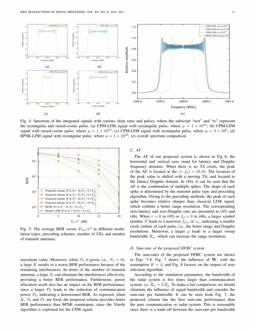
IEEE TRANSACTIONS ON SIGNAL PROCESSING, VOL. XX, NO. X, AUG. 2021 11
(a) (b)
(c) (d) (e)
2399.0 2399.5 2400.0 2400.5 2401.0
0.0
0.2
0.4
0.6
0.8
1.0
1.2
Rel
ativ
e am
pli
tud
e
Frequency (MHz)
CPM-LFM, rect, m=1010
CPM-LFM,rect, m=5×10⁹
CPM-LFM, rc, m=1010
BPSK-LFM, rect, m=1010
2399.0 2399.5 2400.0 2400.5 2401.0
0.0
0.2
0.4
0.6
0.8
1.0R
elat
ive
amp
litu
de
Frequency (MHz)
BPSK-LFM, rect, m=1×10¹⁰
2399.0 2399.5 2400.0 2400.5 2401.0
0.0
0.2
0.4
0.6
0.8
1.0
Rel
ativ
e am
pli
tud
e
Frequency (MHz)
CPM-LFM, rect, m=1×10¹⁰
2399.0 2399.5 2400.0 2400.5 2401.0
0.0
0.2
0.4
0.6
0.8
1.0
Rel
ativ
e am
pli
tude
Frequency (MHz)
CPM-LFM, rc, m=1×10¹⁰
2399.0 2399.5 2400.0 2400.5 2401.0
0.0
0.2
0.4
0.6
0.8
1.0
Rel
ativ
e am
pli
tud
e
Frequency (MHz)
CPM-LFM, rect, m=5×10⁹
Fig. 4: Spectrum of the integrated signals with various chirp rates and pulses, where the subscript “rect” and “rc” representthe rectangular and raised-cosine pulse. (a) CPM-LFM signal with rectangular pulse, where µ = 1 × 10¹⁰; (b) CPM-LFMsignal with raised-cosine pulse, where µ = 1 × 10¹⁰; (c) CPM-LFM signal with rectangular pulse, where µ = 5 × 10⁹; (d)BPSK-LFM signal with rectangular pulse, where µ = 1× 10¹⁰; (e) overall spectrum comparison.
0 5 1 0 1 5 2 0
1 0 - 4
1 0 - 3
1 0 - 2
1 0 - 1
BER
( d B )
P r o p o s e d s c h e m e , K = 4 , N t = 1 6 , P T = 0 . 1 P t o t P r o p o s e d s c h e m e , K = 4 , N t = 2 5 , P T = 0 . 1 P t o t P r o p o s e d s c h e m e , K = 8 , N t = 1 6 , P T = 0 . 1 P t o t P r o p o s e d s c h e m e , K = 4 , N t = 1 6 , P T = 0 . 5 P t o t B P S K , K = 4 , N t = 1 6 , P T = 0 . 1 P t o t B o u n d , C P M , K = 4 , N t = 1 6 , P T = 0 . 1 P t o t
2t o tP �
Fig. 5: The average BER versus Ptot/σ2 in different modu-lation types, precoding schemes, number of UEs and numberof transmit antennas.
maximum value. Moreover, when Nt is given, i.e., Nt = 16,a large K results in a worse BER performance because of theremaining interferences. In terms of the number of transmitantennas, a large Nt can eliminate the interferences effectively,providing a better BER performance. Furthermore, powerallocation result also has an impact on the BER performance,since a larger PT leads to the reduction of communicationpower Pk, indicating a deteriorated BER. As expected, whenK, Nt and PT are fixed, the proposed scheme provides betterBER performance than BPSK counterpart, since the Viterbialgorithm is exploited for the CPM signal.
C. AF
The AF of our proposed system is shown in Fig 6, thehorizontal and vertical axes stand for latency and Dopplerfrequency domains. When there is no TA exists, the peakof the AF is located at the (τ, fd) = (0, 0). The location ofthe peak value is shifted with a moving TA, and located inthe latency-Doppler domain. In (44), it can be seen that theAF is the combination of multiple spikes. The shape of eachspike is determined by the transmit pulse type and precodingalgorithm. Owing to the precoding methods, the peak of eachspike becomes relative sharper than classical LFM signal,which exhibits a better range resolution. The correspondingzero-latency and zero-Doppler cuts are presented in (45) and(46). When τ = 0 in (45) or fd = 0 in (46), a larger symbolnumber N leads to a narrower fd,w or τw, indicating a smallercircle outline of each pulse, i.e., the better range and Dopplerresolutions. Moreover, a larger µ leads to a larger sweepbandwidth Bw, which can increase the range resolution.
D. Sum-rate of the proposed DFRC system
The sum-rates of the proposed DFRC system are shownin Figs. 7-8. Fig. 7 shows the influence of W, with theassumption K = 4; and Fig. 8 focuses on the impact of userselection algorithm.
According to the simulation parameters, the bandwidth ofthe radar system is five times larger than communicationsystem, i.e. Bw = 5Bg . To make a fair comparison, we shouldeliminate the influence of signal bandwidth and consider thesum-rate per bandwidth. It can be seen from Fig. 7, theproposed scheme has the best sum-rate performance thanthe pure communication or radar system. This is reasonablesince there is a trade-off between the sum-rate per bandwidth

IEEE TRANSACTIONS ON SIGNAL PROCESSING, VOL. XX, NO. X, AUG. 2021 12
Doppl
er Freq
uency
(Hz)
L a t e n c y ( m s )0
0 . 1
0 . 2
0 . 3
0 . 4
0 . 5
0 . 6
0 . 7
0 . 8
0 . 9
1
- 0 . 2 - 0 . 1 0 0 . 1 0 . 2- 1 0 0
- 5 0
0
5 0
1 0 0
Fig. 6: The AF contour of our proposed system in latency andDoppler frequency domains, where g(t) is rectangular pulse.
with the detection ability in radar system. Moreover, for theproposed JCR system, our designed W provides the largestsum-rate than other classical beamforming algorithms, i.e.,minimum mean square error (MMSE), followed by zero-forcing (ZF) and MRT. For example, when Ptot
σ2 = 10 dB,the sum-rate of our proposed scheme is 15.3 bps/Hz, which isapproximately 2.1 bps/Hz, 2.5 bps/Hz and 2.8 bps/Hz largerthan the MMSE, ZF and MRT algorithms.
From Fig. 8, it can be seen that the traversal user selec-tion algorithm always provides the larger sum-rate than theproposed SMI algorithm, since it can achieve the optimalsolution. Evidently, the complexity of SMI is much lowerthan the traversal algorithm, especially when U and K arelarge values. For example, when U = 30 and K = 4,the complexity of SMI is 120, while traversal algorithm is8.1×105. Moreover, M shows the impact on the TA detectionprecision. Let δϕ = 10◦, we compare the case δθ = 10◦ andδθ = 15◦, the corresponding M = 324 and 216. It can bederived that a larger M represents a higher sum-rate sinceit can enhance elevation or azimuth resolution, indicating theless interferences of each UE.
E. Trade-off between communication and radar performances
The relationship between the communication rate and de-tection range is shown in Fig. 9, where K = 4, 6 and RCSηT = 0.5, 0.8, 1.0 m2. When K and ηT are constant, thecommunication rate decreases with the increased maximumdetection range, since a larger detection range needs a largerPrad, leading to a smaller Pcom. It is remarkable that theinfluence of RCS can be ignored, when the detection distanceis less than a threshold, i.e., 0.3. In the case K = 4 andηT = 0.5, when the maximum detection range is 0.6 km, thecommunication rate is approximately 8.15 bps/Hz, while themaximum detection range is 0.8 km, the communication rateis 8.02 bps/Hz. The trade-off between the maximum detectionrange and the communication rate is mainly determined bythe power allocation, since the total transmit power Ptot is a
0 2 4 6 8 1 02468
1 01 21 41 61 8
2t o tP �
Sum-
rate (b
ps/Hz
)
( d B )
P r o p o s e d M M L M a l g o r i t h m , J C R M R T a l g o r i t h m , J C R Z F a l g o r i t h m , J C R M M S E a l g o r i t h m , J C R M M L M a l g o r i t h m , C o m m u n i c a t i o n M M L M a l g o r i t h m , R a d a r
Fig. 7: An illustration of the sum-rate versus Ptot/σ2 in
proposed MMLM, ZF, MMSE, MRT algorithms in DFRC,pure communication and radar systems.
2 0 4 0 6 0 8 0 1 0 0
4
6
8
1 0
1 2
1 4Su
m-rat
e (bps/
Hz)
U
T r a v e r s a l a l g o r i t h m , M = 3 2 4 T r a v e r s a l a l g o r i t h m , M = 2 1 6 P r o p o s e d S M I a l g o r i t h m , M = 3 2 4 P r o p o s e d S M I a l g o r i t h m , M = 2 1 6
Fig. 8: An illustration of the sum-rate versus U in traversaland proposed SMI algorithm, where M = 324 and 216.
constant value, a better radar performance leads to a smallercommunication rate.
VII. CONCLUSION
In this paper, we present a joint beamforming and CPM-LFM integrated signal, based on the proposed dual modeframework. The framework includes both dynamic mode andstatic mode, and the parameter M and N affect scanningprecision and detection resolutions respectively. Following, wepropose an objective function of sum-rate with constraints.To solve the non-convex issue, we give a sub-optimal jointbeamforming and resource allocation algorithm, i.e. SMI-MMLM, which includes successive maximum iteration foruser selection; and a maximum minimization Lagrange mul-tiplier algorithm for precoding & processing design, withwater filling algorithm to achieve the optimal power allocationresults. Then, we give a detail analysis of the proposed

IEEE TRANSACTIONS ON SIGNAL PROCESSING, VOL. XX, NO. X, AUG. 2021 13
0 . 0 0 . 2 0 . 4 0 . 6 0 . 8 1 . 07 . 6
7 . 8
8 . 0
8 . 2
8 . 4
8 . 6Co
mmuni
cation
rate (b
ps/Hz
)
M a x i m u m d e t e c t i o n r a n g e ( k m )
K = 4 , � T = 0 . 5 m 2
K = 4 , � T = 0 . 8 m 2
K = 4 , � T = 1 . 0 m 2
K = 6 , � T = 0 . 5 m 2
K = 6 , � T = 0 . 8 m 2
K = 6 , � T = 1 . 0 m 2
Fig. 9: Comparison between the communication rate versusmaximum detection range in different user number K andRCS, where the chirp rate µ = 1010.
system, including the spectrum characteristic, BER and AF.Simulations results shows that our proposed CPM-LFM signalhas better spectrum efficiency and range resolution. Moreover,the proposed SMI algorithm shows lower complexity thanthe optimal traversal algorithm, and the proposed MMLMalgorithm performs larger sum-rate than the classical MRT,ZF and MMSE algorithms.
REFERENCES
[1] W. L. van Rossum, J. J. M. de Wit, M. P. G. Otten and A. G. Huizing,“SMRF architecture concepts,” IEEE Aerosp. Electron. Syst. Mag., vol.26, no. 5, pp. 12-17, May 2011.
[2] F. Liu and C. Masouros, “A Tutorial on Joint Radar and Communi-cation Transmission for Vehicular Networks—Part I: Background andFundamentals,” IEEE Commun. Lett., vol. 25, no. 2, pp. 322-326, Feb.2021.
[3] X. Wang, Z. Fei, J. A. Zhang, J. Huang and J. Yuan, “ConstrainedUtility Maximization in Dual-Functional Radar-Communication Multi-UAV Networks,” IEEE Trans. Commun., vol. 69, no. 4, pp. 2660-2672,April 2021.
[4] F. Liu and C. Masouros, “A Tutorial on Joint Radar and CommunicationTransmission for Vehicular Networks—Part II: State of the Art andChallenges Ahead,” IEEE Commun. Lett., vol. 25, no. 2, pp. 327-331,Feb. 2021.
[5] P. Kumari, S. A. Vorobyov and R. W. Heath, “Adaptive Virtual Wave-form Design for Millimeter-Wave Joint Communication–Radar,” IEEETrans. Signal Process., vol. 68, pp. 715-730, 2020.
[6] S. Quan, W. Qian, J. Guq and V. Zhang, “Radar-communication inte-gration: An overview,” in Proc. The 7th IEEE/International Conferenceon Advanced Infocomm Technology, Fuzhou, 2014, pp. 98-103.
[7] R. Cager, D. LaFlame and L. Parode, “Orbiter Ku-Band Integrated Radarand Communications Subsystem,” IEEE Trans. Commun., vol. 26, no.11, pp. 1604-1619, November 1978.
[8] S. Sun, A. P. Petropulu and H. V. Poor, “MIMO Radar for AdvancedDriver-Assistance Systems and Autonomous Driving: Advantages andChallenges,” IEEE Signal Process. Mag., vol. 37, no. 4, pp. 98-117,July 2020.
[9] J. Wang, X. Liang, L. Chen, L. Wang and S. Shi, “Joint WirelessCommunication and High Resolution SAR Imaging Using AirborneMimo Radar System,” in Proc. IGARSS 2019 - 2019 IEEE InternationalGeoscience and Remote Sensing Symposium, Yokohama, Japan, 2019,pp. 2511-2514.
[10] F. Liu, C. Masouros, A. P. Petropulu, H. Griffiths and L. Hanzo, “JointRadar and Communication Design: Applications, State-of-the-Art, andthe Road Ahead,” IEEE Trans. Commun., vol. 68, no. 6, pp. 3834-3862,June 2020.
[11] S. Sodagari, A. Khawar, T. C. Clancy and R. McGwier, “A projectionbased approach for radar and telecommunication systems coexistence,”in Proc. 2012 IEEE Global Communications Conference (GLOBECOM),Anaheim, CA, USA, 2012, pp. 5010-5014.
[12] J. Qian, M. Lops, Le Zheng, X. Wang and Z. He, “Joint System Designfor Coexistence of MIMO Radar and MIMO Communication,” IEEETrans. Signal Process., vol. 66, no. 13, pp. 3504-3519, July, 2018.
[13] F. Liu, C. Masouros, T. Ratnarajah and A. Petropulu, “On Range Side-lobe Reduction for Dual-Functional Radar-Communication Waveforms,”IEEE Wireless Commun. Lett., vol. 9, no. 9, pp. 1572-1576, Sept. 2020.
[14] F. Liu, L. Zhou, C. Masouros, A. Lit, W. Luo and A. Petropulu, “Dual-functional Cellular and Radar Transmission: Beyond Coexistence,” inProc. 2018 IEEE 19th International Workshop on Signal ProcessingAdvances in Wireless Communications (SPAWC), Kalamata, Greece,2018, pp. 1-5.
[15] B. Paul, A. R. Chiriyath and D. W. Bliss, “Survey of RF Communi-cations and Sensing Convergence Research,” IEEE Access, vol. 5, pp.252-270, 2017.
[16] A. Hassanien, M. G. Amin, Y. D. Zhang and F. Ahmad, “Dual-FunctionRadar-Communications: Information Embedding Using Sidelobe Con-trol and Waveform Diversity,” IEEE Trans. Signal Process., vol. 64, no.8, pp. 2168-2181, April15, 2016.
[17] F. Liu, L. Zhou, C. Masouros, A. Li, W. Luo and A. Petropulu, “TowardDual-functional Radar-Communication Systems: Optimal Waveform De-sign,” IEEE Trans. Signal Process., vol. 66, no. 16, pp. 4264-4279, 15Aug.15, 2018.
[18] F. Liu, C. Masouros, A. Li, H. Sun and L. Hanzo, “MU-MIMO Commu-nications With MIMO Radar: From Co-Existence to Joint Transmission,”IEEE Trans. Wirel. Commun., vol. 17, no. 4, pp. 2755-2770, April 2018.
[19] W. Yuan, F. Liu, C. Masouros, J. Yuan, D. W. K. Ng and N. Gonzalez-Prelcic, “Bayesian Predictive Beamforming for Vehicular Networks:A Low-Overhead Joint Radar-Communication Approach,” IEEE Trans.Wirel. Commun., vol. 20, no. 3, pp. 1442-1456, March 2021.
[20] Z. Cheng, B. Liao and Z. He, “Hybrid Transceiver Design for Dual-Functional Radar-Communication System,” in Proc. 2020 IEEE 11thSensor Array and Multichannel Signal Processing Workshop (SAM),Hangzhou, China, 2020, pp. 1-5.
[21] X. Liu, T. Huang, N. Shlezinger, Y. Liu, J. Zhou and Y. C. Eldar,“Joint Transmit Beamforming for Multiuser MIMO Communicationsand MIMO Radar,” IEEE Trans. Signal Process., vol. 68, pp. 3929-3944, 2020.
[22] S. Quan, W. Qian, J. Guq and V. Zhang, “Radar-communication inte-gration: An overview,” in Proc. The 7th IEEE/International Conferenceon Advanced Infocomm Technology, Fuzhou, China, 2014, pp. 98-103.
[23] H. Yang et al., “Queue-Aware Dynamic Resource Allocation for theJoint Communication-Radar System,” IEEE Trans. Veh. Technol., vol.70, no. 1, pp. 754-767, Jan. 2021.
[24] X. Chen, Z. Feng, Z. Wei, P. Zhang and X. Yuan, “Code-DivisionOFDM Joint Communication and Sensing System for 6G Machine-typeCommunication,” IEEE Internet of Things Journal.
[25] Y. Zhang, Q. Li, L. Huang, C. Pan and J. Song, “A Modified WaveformDesign for Radar-Communication Integration Based on LFM-CPM,” inProc. 2017 IEEE 85th Vehicular Technology Conference (VTC Spring),Sydney, NSW, Australia, 2017, pp. 1-5.
[26] L. Huimin and Z. Jingya, “Analysis of a combined waveform of linearfrequency modulation and phase coded modulation,” in Proc. 2016 11thInternational Symposium on Antennas, Propagation and EM Theory(ISAPE), Guilin, China, 2016, pp. 539-541.
[27] Q. Li, K. Dai, Y. Zhang and H. Zhang, “Integrated Waveform for aJoint Radar-Communication System With High-Speed Transmission,”IEEE Wireless Commun. Lett., vol. 8, no. 4, pp. 1208-1211, Aug. 2019.
[28] C. Sahin, J. Jakabosky, P. M. McCormick, J. G. Metcalf and S. D. Blunt,“A novel approach for embedding communication symbols into physicalradar waveforms,” in Proc. 2017 IEEE Radar Conference (RadarConf),Seattle, WA, 2017, pp. 1498-1503.
[29] S. Sharma, M. Melvasalo and V. Koivunen, “Multicarrier DS-CDMAWaveforms for Joint Radar-Communication System,” in Proc. 2020IEEE Radar Conference (RadarConf20), Florence, Italy, 2020, pp. 1-6.
[30] H. Chahrour, S. Rajan, R. Dansereau and B. Balaji, “Hybrid beamform-ing for interference mitigation in MIMO radar,” in Proc. 2018 IEEERadar Conference (RadarConf18), Oklahoma City, OK, USA, 2018, pp.1005-1009.
[31] X. Liu, T. Huang, N. Shlezinger, Y. Liu, J. Zhou and Y. C. Eldar,“Joint Transmit Beamforming for Multiuser MIMO Communicationsand MIMO Radar,” IEEE Trans. Signal Process., vol. 68, pp. 3929-3944, 2020.

IEEE TRANSACTIONS ON SIGNAL PROCESSING, VOL. XX, NO. X, AUG. 2021 14
[32] P. Heidenreich, A. M. Zoubir and M. Rubsamen, “Joint 2-D DOAEstimation and Phase Calibration for Uniform Rectangular Arrays,”IEEE Trans. Signal Process., vol. 60, no. 9, pp. 4683-4693, Sept. 2012.
[33] R. L. Maw and D. P. Taylor, “Space-Time Coded Systems usingContinuous Phase Modulation,” IEEE Trans. Commun., vol. 55, no. 11,pp. 2047-2051, Nov. 2007.
[34] N. J. Baas and D. P. Taylor, “Pulse shaping for wireless communicationover time- or frequency-selective channels,” IEEE Trans. Commun., vol.52, no. 9, pp. 1477-1479, Sept. 2004.
[35] J. Zheng, H. Liu and Q. H. Liu, “Parameterized Centroid Frequency-Chirp Rate Distribution for LFM Signal Analysis and Mechanisms ofConstant Delay Introduction,” IEEE Trans. Signal Process., vol. 65, no.24, pp. 6435-6447, 15 Dec.15, 2017.
[36] Y. Gu and A. Leshem, “Robust Adaptive Beamforming Based onInterference Covariance Matrix Reconstruction and Steering VectorEstimation,” IEEE Trans. Signal Process., vol. 60, no. 7, pp. 3881-3885,July 2012.
[37] H. Li, Y.-W. Kiang, The Electrical Engineering Handbook, 2005.[38] S. Atapattu, P. Dharmawansa, C. Tellambura and J. Evans, “Exact
Outage Analysis of Multiple-User Downlink With MIMO Matched-Filter Precoding,” IEEE Commun. Lett., vol. 21, no. 12, pp. 2754-2757,Dec. 2017.
[39] Z. Cao, H. Guo, J. Zhang, D. Niyato and U. Fastenrath, “Improving theEfficiency of Stochastic Vehicle Routing: A Partial Lagrange MultiplierMethod,” IEEE Trans. Veh. Technol., vol. 65, no. 6, pp. 3993-4005, June2016.
[40] Y. Sun, P. Babu and D. P. Palomar, “Majorization-Minimization Algo-rithms in Signal Processing, Communications, and Machine Learning,”IEEE Trans. Signal Process., vol. 65, no. 3, pp. 794-816, 1 Feb.1, 2017.
[41] J. Liang, C. S. Leung and H. C. So, “Lagrange Programming NeuralNetwork Approach for Target Localization in Distributed MIMO Radar,”IEEE Trans. Signal Process., vol. 64, no. 6, pp. 1574-1585, March15,2016.
[42] J. P. Fonseka, “Soft-decision phase detection with Viterbi decoding forCPM signals,” IEEE Trans. Commun., vol. 47, no. 12, pp. 1802-1810,Dec. 1999.
[43] L. Zhang, B. Yang and M. Luo, “Joint Delay and Doppler ShiftEstimation for Multiple Targets Using Exponential Ambiguity Function,”IEEE Trans. Signal Process., vol. 65, no. 8, pp. 2151-2163, 15 April15,2017.
[44] G. Chandran and J. S. Jaffe, “Signal set design with constrainedamplitude spectrum and specified time-bandwidth product,” IEEE Trans.Commun., vol. 44, no. 6, pp. 725-732, June 1996.