A higher-order unsplit-field perfectly matched layer for the reflectionless truncation of 3-D...
15
A higher-order unsplit-field perfectly matched layer for the reflectionless truncation of 3-D spherical FDTD lattices Konstantinos P. Prokopidis, Nikolaos V. Kantartzis, Theodoros D. Tsiboukis Abstract An enhanced higher-order finite-difference time- domain (FDTD) method for the systematic implementation of 3-D reflectionless perfectly matched layers (PML) in spherical coordinates is presented. By establishing a topo- logically unsplit-field formulation, the novel technique in- troduces accurate nonstandard schemes that eliminate the notably intricate lattice dispersion errors. Moreover, the wider spatial increments are treated via self-adaptive compact operators, while a mesh expansion process yields a significant reduction of the absorber’s depth. For the temporal variable, the proposed method employs a multi- stage leapfrog integration that guarantees stability and excitation universality. Hence, because of the optimal configuration of the new PML, it attains a critical annihi- lation of both propagating and spurious wave families, even for complicated domains. Numerical investigation verifies the superiority of the higher-order algorithm via several unbounded radiation and scattering spherical problems. Keywords Electromagnetic radiation/scattering, Finite-difference time-domain (FDTD) method, Perfectly matched layer (PML), Higher-order approximation schemes, Spherical coordinates 1 Introduction The accurate solution of time-dependent Maxwell’s equa- tions in spherical open-boundary electromagnetic radiation and scattering problems via the finite-difference time-domain (FDTD) method has been an issue of ongoing scientific research [1, 2, 3, 4, 5]. Considering that the technique renders a linear mapping to infinite grids with respect to the overall computer burden, any effort dedi- cated to space truncation, via the appropriate absorbing boundary conditions (ABC), is very significant. In addi- tion, a reduced lattice involves shorter execution time and consecutively higher rates of convergence. Therefore, these artificial ABC comprise a widely acknowledged approach for the termination of any unbounded value case. Among the multitude of existing schemes, the perfectly matched layer (PML) [6] exhibits remarkable wave-anni- hilating characteristics for a wide range of applications. It is based on the postulation of some nonphysical depen- dent variables in the time domain through an arbitrary splitting of the fields. Considering that numerical analysis involves plane waves propagating in the outward direc- tion, the computational lattice is artificially enlarged via a specifically designed finite lossy medium. Then, by suit- ably adjusting the set of constitutive parameters in the layer, the vacuum–PML interface becomes – at least the- oretically – completely transparent for any frequency and angle of incidence. Since the absorber’s original advent, considerable effort has been invested in its formulation as an unsplit-field medium [7, 8, 9, 10, 11, 12, 13, 14], and recently various efficient techniques have extended its competence to curvilinear coordinates. In [15, 16, 17], cylindrical and spherical PML based on complex stretch- ing are derived, while in [18, 19, 20] uniaxial absorbers for nonorthogonal and conformal meshes are developed. Fi- nally, in [21] a Maxwellian sponge layer for the three frequently used coordinate systems is thoroughly pre- sented. Apart from enhancing the PML, these studies re- vealed some important deficiencies, which are more prominent in non-Cartesian domains. These include a real frequency dependence in the reflection coefficient, the inability to absorb parasitic waves and dispersion, dissi- pation or anisotropy errors. Numerical lattice reflection errors constitute a serious inherent hindrance to the FDTD method. Generally, these artificially created lattice defects influence the accurate update of the simulated waves by enforcing a nonphysical relation of phase velocity with frequency, propagation direction and grid discretization. Therefore, for large-scale problems or long time integrations, such errors quickly accumulate and become nontrivial, particularly inside PML absorbers. Of course, such phenomena can be miti- gated by using a finer mesh resolution, until they decrease to an acceptable level. However, this leads to prohibitive computing requirements when, for example, addressing spherical applications. An alternative to cell division comes from the development of higher-order schemes, which offer increased accuracy for a given node density [1, 22, 23, 24, 25, 26, 27]. Furthermore, the crucial issues of the extended spatial stencils in higher-order boundary con- ditions (far-field, metal or absorbing) and the accurate modeling of dielectric interfaces have recently received major attention in the construction of well-posed PML [28]. However, despite the improvement, these conven- Received: 16 January 2001 / Accepted: 9 April 2002 Published online: 20 June 2002 K.P. Prokopidis, N.V. Kantartzis, T.D. Tsiboukis (&) Department of Electrical and Computer Engineering, Aristotle University of Thessaloniki, Thessaloniki GR-54006, Greece e-mail: [email protected] Electrical Engineering 84 (2002) 173–187 ȑ Springer-Verlag 2002 DOI 10.1007/s00202-002-0124-8 173
Transcript of A higher-order unsplit-field perfectly matched layer for the reflectionless truncation of 3-D...

A higher-order unsplit-field perfectly matched layer for the reflectionlesstruncation of 3-D spherical FDTD lattices
Konstantinos P. Prokopidis, Nikolaos V. Kantartzis, Theodoros D. Tsiboukis
Abstract An enhanced higher-order finite-difference time-domain (FDTD) method for the systematic implementationof 3-D reflectionless perfectly matched layers (PML) inspherical coordinates is presented. By establishing a topo-logically unsplit-field formulation, the novel technique in-troduces accurate nonstandard schemes that eliminate thenotably intricate lattice dispersion errors. Moreover, thewider spatial increments are treated via self-adaptivecompact operators, while a mesh expansion process yieldsa significant reduction of the absorber’s depth. For thetemporal variable, the proposed method employs a multi-stage leapfrog integration that guarantees stability andexcitation universality. Hence, because of the optimalconfiguration of the new PML, it attains a critical annihi-lation of both propagating and spurious wave families, evenfor complicated domains. Numerical investigation verifiesthe superiority of the higher-order algorithm via severalunbounded radiation and scattering spherical problems.
Keywords Electromagnetic radiation/scattering,Finite-difference time-domain (FDTD) method,Perfectly matched layer (PML), Higher-orderapproximation schemes, Spherical coordinates
1IntroductionThe accurate solution of time-dependent Maxwell’s equa-tions in spherical open-boundary electromagneticradiation and scattering problems via the finite-differencetime-domain (FDTD) method has been an issue of ongoingscientific research [1, 2, 3, 4, 5]. Considering that thetechnique renders a linear mapping to infinite grids withrespect to the overall computer burden, any effort dedi-cated to space truncation, via the appropriate absorbingboundary conditions (ABC), is very significant. In addi-tion, a reduced lattice involves shorter execution time andconsecutively higher rates of convergence. Therefore, theseartificial ABC comprise a widely acknowledged approachfor the termination of any unbounded value case.
Among the multitude of existing schemes, the perfectlymatched layer (PML) [6] exhibits remarkable wave-anni-hilating characteristics for a wide range of applications. Itis based on the postulation of some nonphysical depen-dent variables in the time domain through an arbitrarysplitting of the fields. Considering that numerical analysisinvolves plane waves propagating in the outward direc-tion, the computational lattice is artificially enlarged via aspecifically designed finite lossy medium. Then, by suit-ably adjusting the set of constitutive parameters in thelayer, the vacuum–PML interface becomes – at least the-oretically – completely transparent for any frequency andangle of incidence. Since the absorber’s original advent,considerable effort has been invested in its formulation asan unsplit-field medium [7, 8, 9, 10, 11, 12, 13, 14], andrecently various efficient techniques have extended itscompetence to curvilinear coordinates. In [15, 16, 17],cylindrical and spherical PML based on complex stretch-ing are derived, while in [18, 19, 20] uniaxial absorbers fornonorthogonal and conformal meshes are developed. Fi-nally, in [21] a Maxwellian sponge layer for the threefrequently used coordinate systems is thoroughly pre-sented. Apart from enhancing the PML, these studies re-vealed some important deficiencies, which are moreprominent in non-Cartesian domains. These include a realfrequency dependence in the reflection coefficient, theinability to absorb parasitic waves and dispersion, dissi-pation or anisotropy errors.
Numerical lattice reflection errors constitute a seriousinherent hindrance to the FDTD method. Generally, theseartificially created lattice defects influence the accurateupdate of the simulated waves by enforcing a nonphysicalrelation of phase velocity with frequency, propagationdirection and grid discretization. Therefore, for large-scaleproblems or long time integrations, such errors quicklyaccumulate and become nontrivial, particularly insidePML absorbers. Of course, such phenomena can be miti-gated by using a finer mesh resolution, until they decreaseto an acceptable level. However, this leads to prohibitivecomputing requirements when, for example, addressingspherical applications. An alternative to cell divisioncomes from the development of higher-order schemes,which offer increased accuracy for a given node density [1,22, 23, 24, 25, 26, 27]. Furthermore, the crucial issues of theextended spatial stencils in higher-order boundary con-ditions (far-field, metal or absorbing) and the accuratemodeling of dielectric interfaces have recently receivedmajor attention in the construction of well-posed PML[28]. However, despite the improvement, these conven-
Received: 16 January 2001 / Accepted: 9 April 2002Published online: 20 June 2002
K.P. Prokopidis, N.V. Kantartzis, T.D. Tsiboukis (&)Department of Electrical and Computer Engineering,Aristotle University of Thessaloniki,Thessaloniki GR-54006, Greecee-mail: [email protected]
Electrical Engineering 84 (2002) 173–187 � Springer-Verlag 2002
DOI 10.1007/s00202-002-0124-8
173
tional concepts are still prone to dispersion errors andinstabilities, mainly in curvilinear domains.
It is the objective of this paper to introduce a noveltopologically robust three-dimensional (3-D) FDTDmethod based on a parametric classification of higher-order nonstandard schemes for the systematic construc-tion of spherical unsplit-field PML, free from the previousdeficiencies. Delving into the general discretization pro-cess, the algorithm establishes a well-posed strategy, whichlaunches additional degrees of freedom that account forany structural peculiarities. To tackle the intricate late-time instabilities, a comprehensive higher-order leapfrogintegration – properly modified to handle lossy or di-electric media – is utilised, whereas a self-adaptive com-pact central-difference technique treats the widened spatialstencils and preserves global convergence near differentmaterial interfaces of arbitrary alignment. Hence, the newPML accomplish a critical attenuation of artificially cre-ated waves, eliminate all numerically accumulating re-flection errors and, because of their unsplit-fieldderivation, they do not increase the dimensions of thehyperbolic Maxwell’s system. The method’s profile is fur-ther enhanced by a progressive mesh expansion approach,providing larger incremental cell sizes for a specific ac-curacy level. In Sect. 2, we describe the fundamental ele-ments of the proposed higher-order FDTD concepts, andin Sect. 3 the theory of reflectionless absorbers in sphericalcoordinates is presented. Absorption verification of theadvanced PML, discussed in Sect. 4, addresses diversecomplicated two- and three-dimensional scattering prob-lems that demonstrate error norm evolution, variation ofconvergence properties and changes in the behaviour ofthe absorbers with distance from the scatterer. Finally,Sect. 5 presents our conclusions and an outlook on theapplicability of our method to arbitrary objects, along withhelpful hints for the treatment of any possible limitations.
2Higher-order nonstandard FDTD methodA serious concern in the precise investigation of con-temporary applications is the consistent modeling oftheir arbitrarily curved components. In particular, thereis a multitude of indispensable practical systems such asantennas, waveguide structures and microwave compo-nents that incorporate small-scale spherical geometriesembedded in unbounded domains [29, 30, 31, 32, 33,34]. Unfortunately, the use of the ordinary FDTD tech-nique for the analysis of such devices suffers from theclassical staircase restrictions and leads to inadequatespatial sampling or prolonged simulation times. Sincethese deficiencies are primarily related to finite meshaspects, one possible solution could be the increase ofgrid resolution. Nevertheless, in the case of electricallysmall open-boundary problems this notion leads to ex-cessive computing requirements. On the other hand, theefficacy of spherical unsplit-field PML is strongly relatedto the suppression of the undesired dispersion and an-isotropy errors. Since Yee’s algorithm does not offeracceptable treatment, its discrete profile should becarefully reformulated. Actually, this difficult task con-stitutes the key motive for the development of our
accurate higher-order FDTD regime, which will beproven a very powerful tool.
2.1PreliminariesLet us consider a source-free region of space with electriclosses r, magnetic losses r* and piecewise constant,time-invariant constitutive parameters �, l whoseelectromagnetic field vectors are continuous and single-valued functions of position and time. Then, thetime-domain Maxwell’s equations are
r� H ¼ rE þ @D
@t; r� E ¼ �r�H � @B
@t;
r � D ¼ 0; r � B ¼ 0; ð1Þ
in the absence of any impressed electric charges. Thegeneral abstraction of the ordinary higher-order (HO)FDTD forms, based on conventional finite-differencing,stems from the discretization of spatial and temporal de-rivatives encountered in Eq. (1), according to the subse-quent fourth-order nondissipative approximations
@f
@u
����t
u;v;w
9
8
f jtuþDu=2;v;w� f jtu�Du=2;v;w
Du
!
� 1
24
f jtuþ3Du=2;v;w� f jtu�3Du=2;v;w
Du
!þ O Duð Þ4� �
;
ð2Þ
@f
@t
����t
u;v;w
f jtþDt=2
u;v;w � f jt�Dt=2u;v;w
Dt� ðDtÞ2
24
@3f
@t3
����t
u;v;w
þO Dtð Þ5� �;
ð3Þ
obtained from Taylor’s series. For the purposes of nota-tion, we denote f u; v;w; tð Þ ¼ f jtu;v;w in the general coor-dinate system of (u, v, w). The above expressions wereoriginally applied to Ampere’s and Faraday’s laws by Fang[22], while an extensive review of their most importantversions and usages is conducted in [1]. Since their firstappearance, these schemes have been intensively exploredchiefly due to their inevitably enlarged spatial stencils nearperfectly conducting walls or absorbing boundary condi-tions. Hence, several competent techniques have beenproposed regarding accuracy considerations [23, 24],boundary treatment [25, 26], advanced leapfrog integra-tion [27] and termination of infinite domains [28].
In spite of the progress in conventional HO schemes,they remain vulnerable to numerical dispersion and an-isotropy errors, principally when applied to curvilinearspaces or PML. Therefore, dielectric interfaces with non-zero electric field tangential components exhibit additionaldifficulties during the imposition of the interface condi-tions on the arbitrarily curved surfaces. Notice also thatthe sampling points taken by Eqs. (2) and (3) are fairlyrestricted and do not allow for the reliable manipulation ofcomposite boundaries. Another critical remark states thatnumerical simulations are not solely affected by latticeerrors, but also from the anisotropy of the Laplacian op-erator. Hence, the attempts for a consistent discretization
Electrical Engineering 84 (2002)
174
policy should be directed towards a fully isotropic multi-frequency Laplacian, which will lead to a HO-FDTDtechnique free from any errors, even in the case of a coarsemesh. This is exactly where the flexibility of the HOnonstandard models can be incorporated and provide thenecessary solutions to the preceding disadvantages.
2.2Theory of the novel higher-order spherical schemesThe basic features of the proposed 3-D strategy are thenew HO nonstandard concepts that overwhelm all con-ventional formulae. Their superior profile is further en-hanced by the low wavelength-to-stencil ratio and thereduced number of iterations. In fact, nonstandard dif-ferencing is an extremely promising theoretical frameworkfor the accurate analysis of complicated problems inelectromagnetics. Very instructive descriptions of its maindefinitions and fundamental theorems can be found in [35,36], while [37] describes an extension to HO-Cartesiangrids. Realizing the role of reflection errors in sphericalunbounded problems and the defects of the conventionalschemes in Eqs. (2) and (3), we introduce two classes ofHO nonstandard curvilinear forms for the approximationof space and time derivatives in Maxwell’s equations. Bothclasses include three space operators corresponding to ther–h–u-axes of the spherical coordinate system (r,h,u) de-fined as LSr[.], LSh[.], LSu[.], and one temporal operatorLT[.]. In this context, the first class comprises the fol-lowing:
• Space operator:
LSr f½ ¼ a1PrDr f jtr;;uh i
þ a2Pr3Dr f jtr;;uh i
þ a3
Drf jtr�Dr=2;;u� f jtr�3Dr=2;;u
� ;
ð4Þ
• Temporal operator:
LT f½ ¼f jtþDt=2
r;;u � f jt�Dt=2r;;u
cT Dtð Þ
� 2a3
XM
m¼3 oddð Þ
1
m!
cTðDtÞ2
� �m�1@mf
@tm
����n
r;;u
ð5Þ
with LSh[.] and LSu[.] constructed in a similar manner tocompute the spatial derivatives of Eq. (1) with respect to hand u, respectively. The summation parameter m inEq. (5) runs from 3 to M, where M is a predefined upperlimit that controls the order of the time derivative ap-proximation according to the accuracy level we want toachieve. Notice that m must be odd. This constraint, alongwith the structure of the summation term and its bounds,are derived from Taylor’s series expansion, where all even-order time derivatives are mutually cancelled, thus justi-fying the odd nature of m. The nonstandard profile ofEq. (5) is substantiated by the use of the function cT(Dt)and the weighting coefficient a3. Observe that if cT(Dt)=Dt,M=3 and a3=1, operator LT[.] reduces to Eq. (3). Theo-retically, one can use an infinite number of terms for ahighly precise calculation of these derivatives. However,this is not feasible, since the burden of temporal
integration is greatly increased. Having performed a de-tailed numerical analysis, we can confirm that when M=5,the resulting operator overwhelms all other schemes, whilethe outcomes are remarkably accurate and reliable.
Let us now concentrate on the first-class HO nonstan-dard operators given by Eqs. (4) and (5) and explain theirstructure, which is answerable to their enhanced proper-ties. By setting a1=9/8, a2=–1/24, a3=0, we get the basicmember of the class, while for a1=11/12, a2=1/24, a3=1/24,the second counterpart is extracted along the r-direction ofthe spherical coordinate system, with Dr, Dh, Du and Dt itsspatial and temporal increments, respectively. In Eq. (4),Pr
h½: for h=Dr, 3Dr, is the 3-D nonstandard operator, de-fined as
Prh f jtr;;uh i
�
p1Dð1Þr;h f jtr;;uh i
þ p2D2ð Þ
r;h f jtr;;uh i
þp3D3ð Þ
r;h f jtr;;uh i�.
cs khð Þ: ð6Þ
Analogous expressions with h referring to stencils from theh- and u-axes may be easily derived. The correctionfunctions cs(kh), cT(Dt) are selected to minimise the latticeerrors and to guarantee the smooth transition from thecontinuous physical space to the discrete confined do-main. Moreover, their arguments play a significant role inthe multifrequency profile of the method and entail acareful determination. Investigating cs(kh), mathematicalanalysis reveals that kh values should be chosen in orderthat Pr
h ejkr� ��
@rejkr ! 1. For our HO-FDTD simulations,this constraint may be adequately approximated byPr
h ejkr� ��
@rejkr 2 cos k � 1ð Þ and suppress every griddiscrepancy. It is stressed that the second-order FDTDtechnique cannot fulfill this crucial requirement in curvi-linear applications, thus causing severe instabilities. Topick an acceptable kh for diverse wavenumbers k, theFourier transform of the already computed transientelectric (magnetic) components at prefixed mesh locationsis implemented. After their frequency range is acquired,we use the spectrum’s maximum or mean value for thespecification of the optimal argument. The procedure,which does not affect the total overhead, takes place atevery time step, whereas its accuracy increases as thenumber of the preset points becomes larger, regardless theproblem’s geometry, incident angles or frequencies andtime intervals. It is clear that the same holds for cT(Dt),especially from a convergence point of view. Throughthese notions, a possible (but not unique) choice for thecorrection functions [23, 35] could be
csðkhÞ ¼ 16
k2sin
kh
3
� �cos
kh
9
� �; cT Dtð Þ ¼ 5
Dtsin
Dt
4
� �
þ 10
Dtð Þ2 cos2 Dt
8
� �: ð7Þ
Conversely, operators Dið Þ
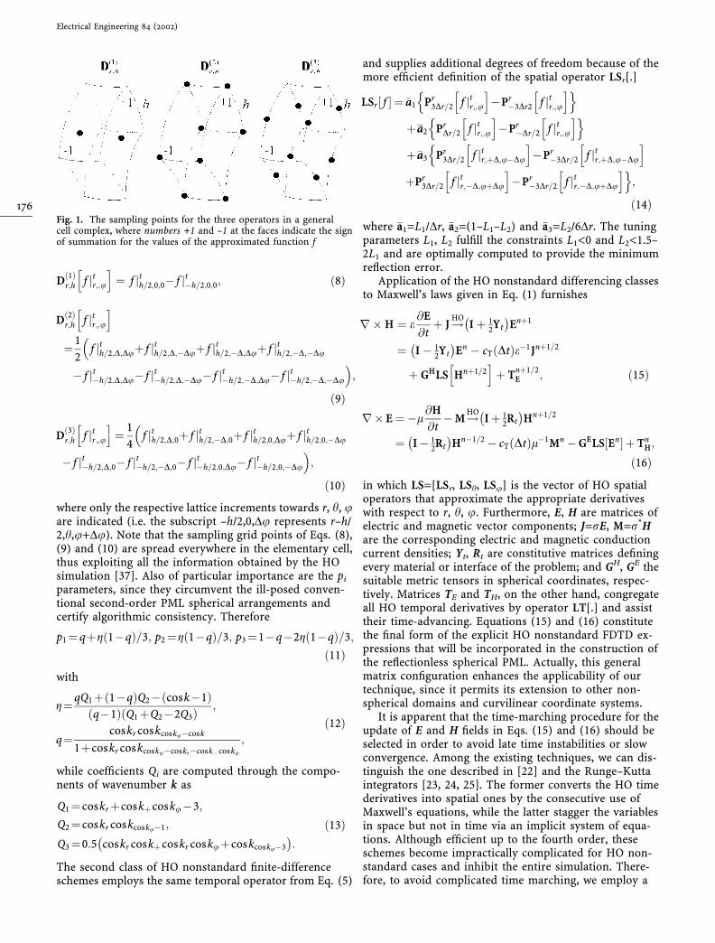
r;h :½ for i=1, 2, 3 in Eq. (6), yield aset of practical formulae that provide a systematic vecto-rial interconnection. Establishing the general curvilineargeometry of Fig. 1, where the numbers +1 and –1 at thefaces indicate the sign of summation for the approximatedfunction f, we derive
K.P. Prokopidis et al.: Higher-order unsplit-field perfectly matched layer for reflectionless truncation of 3-D spherical FDTD lattices
175
D1ð Þ
r;h f jtr;;uh i
¼ f jth=2;0;0� f jt�h=2;0;0; ð8Þ
D2ð Þ
r;h f jtr;;uh i
¼1
2f jth=2;D;Duþ f jth=2;D;�Duþ f jth=2;�D;Duþ f jth=2;�D;�Du
�� f jt�h=2;D;Du� f jt�h=2;D;�Du� f jt�h=2;�D;Du� f jt�h=2;�D;�Du
;
ð9Þ
D3ð Þ
r;h f jtr;;uh i
¼ 1
4f jth=2;D;0þ f jth=2;�D;0þ f jth=2;0;Duþ f jth=2;0;�Du
�� f jt�h=2;D;0� f jt�h=2;�D;0� f jt�h=2;0;Du� f jt�h=2;0;�Du
;
ð10Þ
where only the respective lattice increments towards r, h, uare indicated (i.e. the subscript –h/2,0,Du represents r–h/2,h,u+Du). Note that the sampling grid points of Eqs. (8),(9) and (10) are spread everywhere in the elementary cell,thus exploiting all the information obtained by the HOsimulation [37]. Also of particular importance are the pi
parameters, since they circumvent the ill-posed conven-tional second-order PML spherical arrangements andcertify algorithmic consistency. Therefore
p1¼qþg 1�qð Þ=3; p2¼g 1�qð Þ=3; p3¼1�q�2g 1�qð Þ=3;
ð11Þwith
g¼qQ1þ 1�qð ÞQ2� cosk�1ð Þq�1ð Þ Q1þQ2�2Q3ð Þ ;
q¼coskr coskcosku�cosk
1þcoskr coskcosku�coskr�cosk� cosku
;
ð12Þ
while coefficients Qi are computed through the compo-nents of wavenumber k as
Q1¼coskrþcoskþcosku�3;
Q2¼coskr coskcosku�1;
Q3¼0:5 coskr coskþcoskr coskuþcoskcosku�3
� �:
ð13Þ
The second class of HO nonstandard finite-differenceschemes employs the same temporal operator from Eq. (5)
and supplies additional degrees of freedom because of themore efficient definition of the spatial operator LSr[.]
LSr f½ ¼ �aa1 Pr3Dr=2 f jtr;;u
h i�Pr
�3Dr2 f jtr;;uh in o
þ�aa2 PrDr=2 f jtr;;uh i
�Pr�Dr=2 f jtr;;u
h in oþ�aa3 Pr
3Dr=2 f jtr;þD;u�Du
h i�Pr
�3Dr=2 f jtr;þD;u�Du
h inþPr
3Dr=2 f jtr;�D;uþDu
h i�Pr
�3Dr=2 f jtr;�D;uþDu
h io;
ð14Þwhere �aa1=L1/Dr, �aa2=(1–L1–L2) and �aa3=L2/6Dr. The tuningparameters L1, L2 fulfill the constraints L1<0 and L2<1.5–2L1 and are optimally computed to provide the minimumreflection error.
Application of the HO nonstandard differencing classesto Maxwell’s laws given in Eq. (1) furnishes
r� H ¼ e@E
@tþ J!HO
I þ 12Yt
� �Enþ1
¼ I � 12Yt
� �En � cT Dtð Þe�1Jnþ1=2
þ GHLS Hnþ1=2h i
þ Tnþ1=2E ; ð15Þ
r� E ¼�l@H
@t� M!HO
I þ 12Rt
� �Hnþ1=2
¼ I � 12Rt
� �Hn�1=2 � cT Dtð Þl�1Mn �GELS En½ þ Tn
H;
ð16Þ
in which LS=[LSr, LSh, LSu] is the vector of HO spatialoperators that approximate the appropriate derivativeswith respect to r, h, u. Furthermore, E, H are matrices ofelectric and magnetic vector components; J=rE, M=r*Hare the corresponding electric and magnetic conductioncurrent densities; Yt, Rt are constitutive matrices definingevery material or interface of the problem; and GH, GE thesuitable metric tensors in spherical coordinates, respec-tively. Matrices TE and TH, on the other hand, congregateall HO temporal derivatives by operator LT[.] and assisttheir time-advancing. Equations (15) and (16) constitutethe final form of the explicit HO nonstandard FDTD ex-pressions that will be incorporated in the construction ofthe reflectionless spherical PML. Actually, this generalmatrix configuration enhances the applicability of ourtechnique, since it permits its extension to other non-spherical domains and curvilinear coordinate systems.
It is apparent that the time-marching procedure for theupdate of E and H fields in Eqs. (15) and (16) should beselected in order to avoid late time instabilities or slowconvergence. Among the existing techniques, we can dis-tinguish the one described in [22] and the Runge–Kuttaintegrators [23, 24, 25]. The former converts the HO timederivatives into spatial ones by the consecutive use ofMaxwell’s equations, while the latter stagger the variablesin space but not in time via an implicit system of equa-tions. Although efficient up to the fourth order, theseschemes become impractically complicated for HO non-standard cases and inhibit the entire simulation. There-fore, to avoid complicated time marching, we employ a
Fig. 1. The sampling points for the three operators in a generalcell complex, where numbers +1 and –1 at the faces indicate the signof summation for the values of the approximated function f
Electrical Engineering 84 (2002)
176
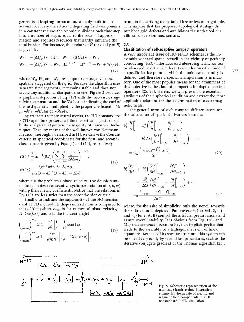
generalised leapfrog formulation, suitably built to alsoaccount for lossy dielectrics. Integrating field componentsin a constant regime, the technique divides each time stepinto a number of stages equal to the order of approxi-mation and requires resources that hardly influence thetotal burden. For instance, the update of H (or dually of E)is given by
W1 ¼ � Dt=lð Þr� En; W2 ¼ Dt=eð Þr� W1;
W3 ¼ � Dt=lð Þr� W2; Hnþ1=2 ¼ Hn�1=2 þ W1 þ W3=24;
ð17Þ
where W1, W2 and W3 are temporary storage vectors,spatially staggered on the grid. Because the algorithm usesseparate time segments, it remains stable and does notcreate any additional dissipation errors. Figure 2 providesa graphical depiction of Eq. (17) with the two circles sig-nifying summation and the �· boxes indicating the curl ofthe field quantity, multiplied by the proper coefficient: –dt/l, –dt/�, –dt/24l or –dt/24�.
Apart from their structural merits, the HO nonstandardFDTD operators preserve all the theoretical aspects of sta-bility analysis that govern the majority of numerical tech-niques. Thus, by means of the well-known von Neumannmethod, thoroughly described in [1], we derive the Courantcriteria in spherical coordinates for the first- and second-class concepts given by Eqs. (4) and (14), respectively
cDt � 3
psin�1 0:7ð Þ
Xu
l¼r
Xum¼r
glm
DlDm
!�1=2
;
cDt � 3g1=2 min Dr;D;Du½ ffiffiffiffiffiffiffiffiffiffiffiffiffiffiffiffiffiffiffiffiffiffiffiffiffiffiffiffiffiffiffiffiffiffiffiffiffiffiffiffiffiffiffiffiffiffiffiffiffiffiffiffiffi2 3 � 4L1ð Þ 3 � 4L1 � 2L2ð Þ
p ;
ð18Þ
where c is the problem’s phase velocity. The double sum-mation denotes a consecutive cyclic permutation of (r, h, u)with g their metric coefficients. Notice that the relations inEq. (18) are less strict than the second-order criteria.
Finally, to indicate the superiority of the HO nonstan-dard FDTD method, its dispersion relation is compared tothat of Yee (where cnum is the numerical phase velocity,N=2p/(kDr) and a is the incident angle)
c
cnum
� �Yee
ffi 1 � p2
N2
1
8þ 1
24cos 4að Þ
� �;
c
cnum
� �nst
ffi 1 � 5p7
670N7
1
19þ 12 cos 4að Þ
� �;
ð19Þ
to attain the striking reduction of five orders of magnitude.This implies that the proposed topological strategy di-minishes grid defects and annihilates the undesired cur-vilinear dispersion mechanisms.
2.3Classification of self-adaptive compact operatorsA very important issue of HO-FDTD schemes is the in-evitably widened spatial stencil in the vicinity of perfectlyconducting (PEC) interfaces and absorbing walls. As canbe observed, it extends at least two nodes on either side ofa specific lattice point at which the unknown quantity isdefined, and therefore a special manipulation is manda-tory. One of the most popular means for the attainment ofthis objective is the class of compact self-adaptive centraloperators [25, 26]. Herein, we will present the essentialattributes of their spherical rendition and extract the mostapplicable relations for the determination of electromag-netic fields.
The general form of such compact differentiators forthe calculation of spatial derivatives becomes
bA1
@f
@r
����t
r
þ bA2
@f
@r
����t
rþDr
þ @f
@r
����t
r�Dr
� �
þ bA3 Dr
@2f
@r2
����t
rþDr
� @2f
@r2
����t
r�Dr
!þ � � �
¼ wA
f jtrþDr=2� f jtr�Dr=2
Dr; ð20Þ
bB1
@2f
@r2
����t
r
þ bB2
@2f
@r2
����t
rþDr
þ @2f
@r2
t
r�Dr
!
þ bB3
2Dr
@f
@r
����t
rþDr
� @f
@r
����t
r�Dr
� �þ � � �
¼ wBf jtrþDr � 2 f jtrþ f jtr�Dr
ðDrÞ2 ; ð21Þ
where, for the sake of simplicity, only the stencil towardsthe r-direction is depicted. Parameters bi (for i=1, 2, ...)and wj (for j=A, B) control the artificial perturbations andassure overall stability. It is obvious from Eqs. (20) and(21) that compact operators have an implicit profile thatleads to the assembly of a tridiagonal system of linearequations. Because of its specific structure, this system canbe solved very easily by several fast procedures, such as theiterative conjugate gradient or the Thomas algorithm [23].
Fig. 2. Schematic representation of themultistage leapfrog time-integrationscheme for the update of electric andmagnetic field components in a HOnonstandard FDTD simulation
K.P. Prokopidis et al.: Higher-order unsplit-field perfectly matched layer for reflectionless truncation of 3-D spherical FDTD lattices
177
In the case of our formulation and after the appropriateFourier analysis, along with Taylor series up to the desiredorder, it is derived that b1
A=b1B=1, b2
A=7/16, b2B=–1/8,
b3A=–1/16, b3
B=9/4, wa=15/16 and wb=3. The resultingexpressions are very precise, since they lead to the verysmall truncation errors
@f
@r
����t
r
! 1:73 � 10�4 f 7ð Þ��trDr6;
@2f
@r2
����t
r
! 4:9 � 10�5 f 8ð Þ��trDr7 ;
ð22Þ
which indicate that self-adaptive compact operators retainthe accuracy of the HO-FDTD method. Additionally, byimposing meticulous handling of different material inter-faces with an arbitrary alignment, they maintain globalconvergence and ensure the fulfilment of the critical con-tinuity conditions.
Having described the complete form of the implicitcompact operators, we will also develop an alternativeexplicit approach in order to calculate the spatial deriv-atives of electric and magnetic fields associated with themodified Maxwell’s equations given by Eqs. (15) and(16). Nonetheless, particular attention must be paid tothe differentiation of these quantities at grid points sit-uated very close to the boundaries of the computationaldomain. For example, let us consider the computation ofderivative ¶Eu/¶r at r=Dr/2. Equation (16) requires theknowledge of this derivative at points r=3Dr/2, r=Dr/2and r=–Dr/2. Although the first two values are available,this is not the case for the last one. Unfortunately, thispoint lies outside the limits of the mesh, which obstructsthe completeness of the entire process. As such edgeterms, especially in 3-D problems, are not trivial, wedevelop the centrally biased sixth-order spherical formulastarting from [24]
@Eu
@r
����t
rþDr=2
¼��1581 f jtrþ976 f jtrþDrþ2126 f jtrþ2Dr
�2845f jtrþ3Dr þ1638 f jtrþ4Dr�539 f jtrþ5Dr
þ71 f jtrþ6Dr
�= 2017Dr
�;
�ð23Þ
for their manipulation. The use of this scheme enablesthe rigorous implementation of our method, since itshigher-order approximation forces the solution to bedependent upon the compact difference operator ratherthan upon the edge value. It is stressed that magneticfield derivatives are not influenced by the above problem,and hence their evaluation does not require any specialtreatment at the boundaries.
3Systematic construction of higher-order spherical PMLThe construction of the novel unsplit-field PML inspherical coordinates stems from the decomposition of a3-D space W into two regions (separated with a nonpla-nar interface G) such that W=WCS[WPML, where WCS
refers to the computational domain and WPML is the areaoccupied by the PML under investigation. The extension
of the stretched coordinate technique to the HOnonstandard models is essential in our formulation.Stretched coordinates for Cartesian PML were introducedin [7, 8], and since then they have been of greatinterest, both in rectangular [9, 10, 11, 12, 13, 14] andcurvilinear [15, 16, 17, 18, 19, 20, 21] second-orderabsorbers.
Establishing the principal framework of our algorithm,we introduce the following fundamental steps:
• Postulation of the field profile in the layer via stretchedcoordinate metrics sm ¼ vm þ rm
vmþjxj, with vm, rm,
vm<+, m=r,h,u and j the respective constitutive pa-rameter, to avoid field-splitting.
• Development of the essential equations whose solutionsexhibit the required attenuation rate. For vm>0, a highabsorption of the difficult-to-model evanescent waves isaccomplished.
• Manifestation of the resulting expressions in the formatof HO time-dependent laws.
• Deduction of the constitutive relations in WPML tocompletely identify the absorber.
Let us now study the derivation of the FDTD-PMLexpressions in a completely Maxwellian manner. It hasbeen stated that the universality of the proposed methodhas also been applied to other coordinate systems withhigh levels of accuracy and convergence. Unfortunately,such complicated curvilinear environments create highlydispersive nonphysical reflections, which form bands oftransmitted modes that grow spatially instead of beingdamped in the layer. Hence, simulations exhibit a totallyunstable and ill-posed performance, even under smallperturbations. For the objectives of our analysis, weexamine an inhomogeneous, isotropic and lossless di-electric medium that is described in the frequency do-main by
jxeE0 ¼r0 � H0; r0 � eE0ð Þ ¼ 0; �jxlH0 ¼ r0 � E0;
�r0 � lH0ð Þ ¼ 0 : ð24Þ
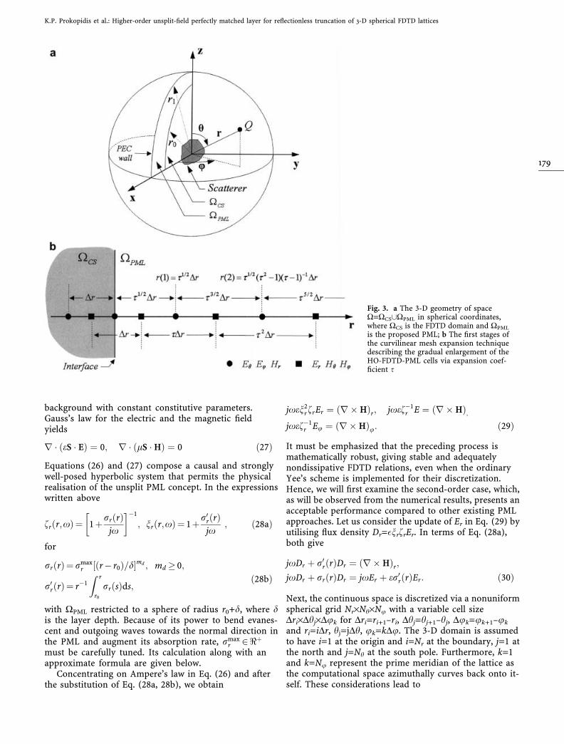
Here WCS is a sphere of radius r0, and WPML, which ex-tends from r0 to infinity (r¢‡r¢0), is the area to be backedup to a radius r1 by a PEC wall, as shown in Fig. 3a. Theoptimised PML is built through the decent scaling be-tween the independent (primed) and dependent variablesin Eq. (24), which preserve the original field variation inWCS and launch the proper coordinate stretching inWPML. This procedure may be viewed as a mapping of thehomogeneous isotropic dielectric to an inhomogeneousuniaxial one. For our medium
F0 ¼F; for r0 2 XCS;
diag fr; n�1r ; n�1
r
� �F; for r0 2 XPML;
(ð25Þ
with r¢=diag{nr,1,1}, r=(r,h,u)T and F=E, H. Applicationof Eq. (25) to the curl laws in Eq. (24) gives
jxeS � E ¼ r� H; �jxlS � H ¼ r� E ; ð26Þ
where the material tensor S is the diagonal matrixS ¼ diag n2
r fr; f�1r ; f�1
r
� �for a homogeneous dielectric
Electrical Engineering 84 (2002)
178
background with constant constitutive parameters.Gauss’s law for the electric and the magnetic fieldyields
r � eS � Eð Þ ¼ 0; r � lS � Hð Þ ¼ 0 ð27Þ
Equations (26) and (27) compose a causal and stronglywell-posed hyperbolic system that permits the physicalrealisation of the unsplit PML concept. In the expressionswritten above
fr r;xð Þ¼ 1þrr rð Þjx
� ��1
; nr r;xð Þ¼ 1þr0r rð Þjx
; ð28aÞ
for
rr rð Þ¼ rmaxr r� r0ð Þ=d½ md ; md � 0;
r0r rð Þ¼ r�1
Z r
r0
rr sð Þds;ð28bÞ
with WPML restricted to a sphere of radius r0+d, where dis the layer depth. Because of its power to bend evanes-cent and outgoing waves towards the normal direction inthe PML and augment its absorption rate, rmax
r 2<þ
must be carefully tuned. Its calculation along with anapproximate formula are given below.
Concentrating on Ampere’s law in Eq. (26) and afterthe substitution of Eq. (28a, 28b), we obtain
jxen2rfrEr ¼ r� Hð Þr; jxef�1
r E ¼ r� Hð Þ;jxef�1
r Eu ¼ r� Hð Þu: ð29Þ
It must be emphasized that the preceding process ismathematically robust, giving stable and adequatelynondissipative FDTD relations, even when the ordinaryYee’s scheme is implemented for their discretization.Hence, we will first examine the second-order case, which,as will be observed from the numerical results, presents anacceptable performance compared to other existing PMLapproaches. Let us consider the update of Er in Eq. (29) byutilising flux density Dr=�nrfrEr. In terms of Eq. (28a),both give
jxDr þ r0r rð ÞDr ¼ r� Hð Þr;
jxDr þ rr rð ÞDr ¼ jxEr þ er0r rð ÞEr: ð30Þ
Next, the continuous space is discretized via a nonuniformspherical grid Nr·Nh·Nu with a variable cell sizeDri·Dhj·Duk for Dri=ri+1–ri, Dhj=hj+1–hj, Duk=uk+1–uk
and ri=iDr, hj=jDh, uk=kDu. The 3-D domain is assumedto have i=1 at the origin and i=Nr at the boundary, j=1 atthe north and j=Nh at the south pole. Furthermore, k=1and k=Nu represent the prime meridian of the lattice asthe computational space azimuthally curves back onto it-self. These considerations lead to
Fig. 3. a The 3-D geometry of spaceW=WCS[WPML in spherical coordinates,where WCS is the FDTD domain and WPML
is the proposed PML; b The first stages ofthe curvilinear mesh expansion techniquedescribing the gradual enlargement of theHO-FDTD-PML cells via expansion coef-ficient s
K.P. Prokopidis et al.: Higher-order unsplit-field perfectly matched layer for reflectionless truncation of 3-D spherical FDTD lattices
179
Erjnþ1iþ1=2;j;k¼
1� 12r
0r;iþ1=2Dt
1þ 12r
0r;iþ1=2Dt
Erjniþ1=2;j;kþ1
e 1þ 12r
0r;iþ1=2Dt
h i� 1þ 1
2rr;iþ1=2Dt� �
Drjnþ1iþ1=2;j;k� 1� 1
2rr;iþ1=2Dt� �
Drjniþ1=2;j;k
h i;
ð31bÞ
rr;iþ1=2 ¼ rmaxr
i� 12
dPML
� �md
;
r0r;iþ1=2 ¼
rmaxr
r0 þ i� 12
� �Dr
� �dmd
�r0 þ i� 1
2
� �Dr
� �mdþ1�rmdþ10
md þ1;
ð32Þ
are the discrete counterparts of rr(r), r¢r(r), for i=1, 2,...,dPML, where dPML is the number of cells in the layer andd=dPMLDr. The update of Er at time step n+1 is conductedin two stages to circumvent the back-storing of any ad-ditional variables. Thus, the contribution from Dr at n isfirst added to the value of Er, and then Dr is advanced.Similar expressions may be derived for the remaining fieldcomponents.
However, in the case of complicated scattering appli-cations, Eq. (31a, 31b) cannot always accomplish sufficientsimulations. The fictitious dispersion mechanisms induceinstabilities and generate completely erroneous results.This is exactly where the 3-D HO nonstandard FDTD-PMLexpressions, produced through the accurate classes ofEqs. (4) and (14), should be implemented. Their enhancedtopological structure follows all geometric peculiaritiesand subdues the critical spurious deficiencies. For illus-tration, Faraday’s law becomes
LT Br½ þ r‘rðrÞBr ¼ guLSu Eh½ � ghLSh Eu� �
LT Br½ þ rrðrÞBr ¼ lLT Hr½ þlr‘rðrÞHr; ð33aÞ
LT B½ ¼ grLSr Eu� �
� guLSu Er½ ;LT B½ ¼ lLT H½ þ lrr rð ÞB; ð33bÞ
LT Bu� �
¼ gLS Er½ � grLSr E½ ;LT Bu� �
¼ lLT Hu� �
þ lrr rð ÞHu; ð33cÞ
in which Br=lnrfrHr, and gm(m=r,h,u) are the sphericalsystem metrics. Apart from the previous merits, the pro-posed strategy assigns a key characteristic to HO-PML: theability to introduce supplementary attenuation termsalong more directions in the layer, which gives a consid-erable suppression of the marked anisotropy discrepan-cies, especially in multifrequency environments with manyscattering objects.
After crossing the PML, a percentage of the outgoingwaves are reflected by the PEC conditions and return to thecomputational domain. Our aim is, naturally, to minimisethis undesired percentage. Therefore, it would be veryconvenient for the analysis to derive the theoretical reflec-tion coefficient R for normal wave incidence on a PML ofthickness d. Following the ideas of [6], we extend the pro-cedure described in [21] to cover the spherical case in anapproximate way. By this means, all strenuous mathemati-cal manipulations are avoided and the resulting expressionspresent an equivalent accuracy. Therefore, R is defined as
R ¼ exp �2ffiffiffiffiffile
p Zr0þd
r0
rr sð Þds
24
35 : ð34Þ
Enforcing Eq. (28b), which gives rr(s), in Eq. (34), we findthat
R ¼ exp �2ffiffiffiffiffile
prmax
r
Zd
0
s=dð Þmd ds
24
35 ; ð35Þ
and after some algebra, we can find rrmax in terms of the
reflection coefficient R
rmaxr ¼ �c md þ 1ð Þ ln R= 2dð Þ : ð36Þ
This implies that for a prescribed R, Eq. (36) can alwaysprovide the appropriate rr
max. Elaborate numerical studyrevealed that its optimum value can be also accurately cal-culated via rmax
r;opt 16pe0Drð Þ�1 for md=2.Finally, the number of layers can be adequately de-
creased through a spherical mesh expansion technique,which gradually enlarges the FDTD cells in the PML re-gion, as explained in Fig. 3b. Consequently, if s is theexpansion factor, the modified spatial increment �DDr growsvia the relations
�DDr 0ð Þ ¼ 1
2þ s �
ffiffiffis
p
s � 1
� �Dr; �DDr L > 0ð Þ ¼ sbDr ; ð37Þ
for b=1/2, 1, 3/2, 2,..., K. A carefully selected value of senables the highest frequencies of a broadband excitationto propagate in the HO cells as well as the association ofsteeper sine or exponential conductivity profiles to thedistinct layers of the absorber. Such choices improve theoverall convergence without affecting the grid.
4Numerical resultsThe absorption efficiency of the novel PML and theirradically improved models are validated via diverse 2- and
Drjnþ1iþ1=2;j;k ¼
1 � 12r
0r;iþ1=2Dt
1 þ 12r
0r;iþ1=2Dt
Drjniþ1=2;j;k þ 2Dt
riþ1=2 sinj½1 þ 12r
0r;iþ1=2Dt
�Hu
��nþ1=2
iþ1=2;jþ1=2;ksinjþ1=2 �Hu
��nþ1=2
iþ1=2;j�1=2;ksinj�1=2
Dj þ Dj�1�
Hjnþ1=2iþ1=2;j;kþ1=2 �Hjnþ1=2
iþ1=2;j;k�1=2
Duk þ Duk�1
24
35 ;
ð31aÞ
Electrical Engineering 84 (2002)
180
3-D spherical FDTD simulations, addressing radiation,scattering from various perfectly conducting or dielectricobjects and dissimilar-material problems. Numerical ver-ification refers to both second-order and HO nonstandardarrangements. The latter enhance algorithmic stability anddiscretization competence by taking into account a largernumber of mesh points for derivative approximation.Therefore the resulting PML are capable of supportingmore abrupt changes in rr
max and achieve a fasterdampening of all outgoing waves, including the near-grazing waves, i.e. waves whose wavevector k forms a largeangle (80� to 90�) with the normal to the vacuum–PMLinterface. Conversely, when a lossy scatterer with a notablydifferent set of constitutive parameters intersects the lat-tice in an arbitrary way, without aligning to one of theaxes, the proposed method provides the optimumweighting coefficients for the precise computation of per-mittivity or permeability values everywhere in the cell.This treatment outperforms the conventional second-or-der pointwise specification of material properties and doesnot degrade the simulation’s convergence rate.
Let us, first, focus on second-order applications and aPEC sphere of radius rs centred in a free and lossless space(c=3·108 m/s). The structure is excited by an electric di-pole source located at (0,0,z=z0>rs) and polarised alongthe z-direction. Its temporal profile is given by the smoothfunction of
P tð Þ ¼ P0 10� 15 cosx1t þ 6 cosx2t � cosx3tð Þ; t � T;0; t > T;
ð38Þ
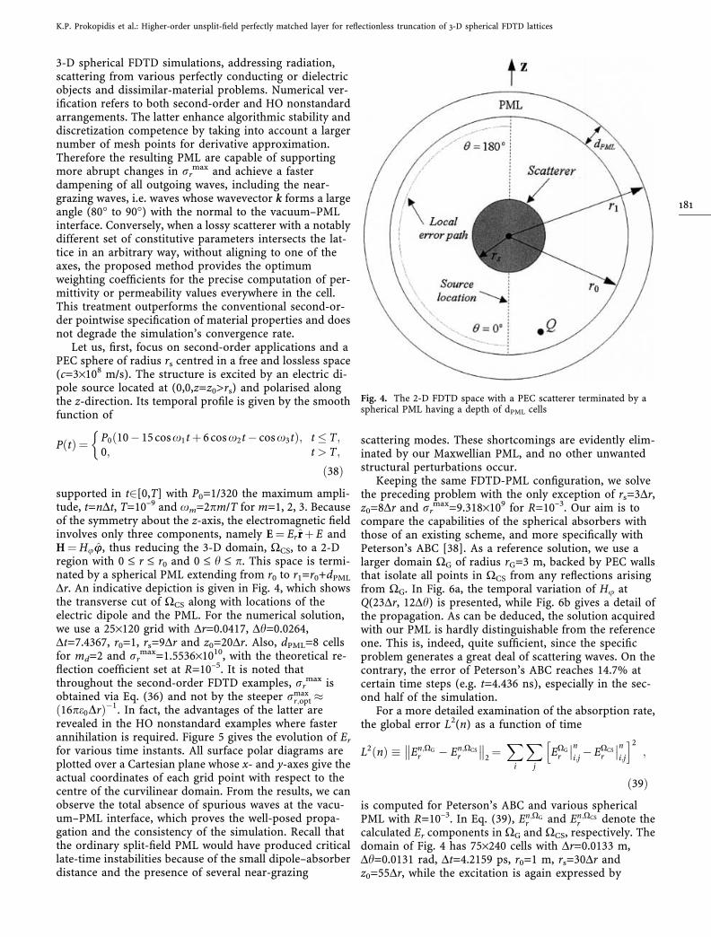
supported in t2[0,T] with P0=1/320 the maximum ampli-tude, t=nDt, T=10–9 and xm=2pm/T for m=1, 2, 3. Becauseof the symmetry about the z-axis, the electromagnetic fieldinvolves only three components, namely E ¼ Er rrþE andH ¼ Huuu, thus reducing the 3-D domain, WCS, to a 2-Dregion with 0 £ r £ r0 and 0 £ h £ p. This space is termi-nated by a spherical PML extending from r0 to r1=r0+dPML
Dr. An indicative depiction is given in Fig. 4, which showsthe transverse cut of WCS along with locations of theelectric dipole and the PML. For the numerical solution,we use a 25·120 grid with Dr=0.0417, Dh=0.0264,Dt=7.4367, r0=1, rs=9Dr and z0=20Dr. Also, dPML=8 cellsfor md=2 and rr
max=1.5536·1010, with the theoretical re-flection coefficient set at R=10–5. It is noted thatthroughout the second-order FDTD examples, rr
max isobtained via Eq. (36) and not by the steeper rmax
r;opt 16pe0Drð Þ�1. In fact, the advantages of the latter are
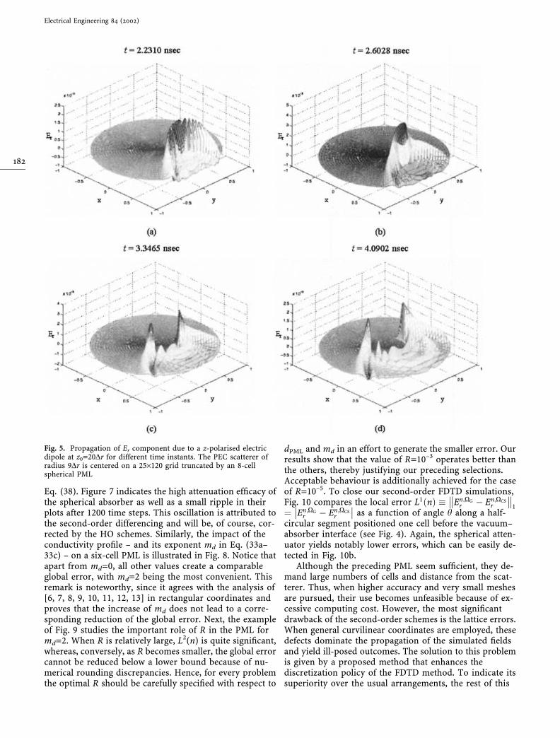
revealed in the HO nonstandard examples where fasterannihilation is required. Figure 5 gives the evolution of Er
for various time instants. All surface polar diagrams areplotted over a Cartesian plane whose x- and y-axes give theactual coordinates of each grid point with respect to thecentre of the curvilinear domain. From the results, we canobserve the total absence of spurious waves at the vacu-um–PML interface, which proves the well-posed propa-gation and the consistency of the simulation. Recall thatthe ordinary split-field PML would have produced criticallate-time instabilities because of the small dipole–absorberdistance and the presence of several near-grazing
scattering modes. These shortcomings are evidently elim-inated by our Maxwellian PML, and no other unwantedstructural perturbations occur.
Keeping the same FDTD-PML configuration, we solvethe preceding problem with the only exception of rs=3Dr,z0=8Dr and rr
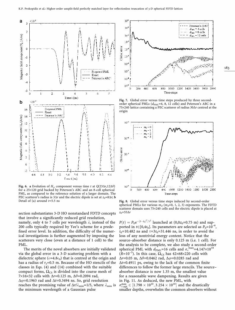
max=9.318·109 for R=10–3. Our aim is tocompare the capabilities of the spherical absorbers withthose of an existing scheme, and more specifically withPeterson’s ABC [38]. As a reference solution, we use alarger domain WG of radius rG=3 m, backed by PEC wallsthat isolate all points in WCS from any reflections arisingfrom WG. In Fig. 6a, the temporal variation of Hu atQ(23Dr, 12Dh) is presented, while Fig. 6b gives a detail ofthe propagation. As can be deduced, the solution acquiredwith our PML is hardly distinguishable from the referenceone. This is, indeed, quite sufficient, since the specificproblem generates a great deal of scattering waves. On thecontrary, the error of Peterson’s ABC reaches 14.7% atcertain time steps (e.g. t=4.436 ns), especially in the sec-ond half of the simulation.
For a more detailed examination of the absorption rate,the global error L2(n) as a function of time
L2 nð Þ � En;XGr � En;XCS
r
!! !!2¼X
i
Xj
EXGr
��ni;j� EXCS
r
��ni;j
h i2;
ð39Þ
is computed for Peterson’s ABC and various sphericalPML with R=10–3. In Eq. (39), En;XG
r and En;XCSr denote the
calculated Er components in WG and WCS, respectively. Thedomain of Fig. 4 has 75·240 cells with Dr=0.0133 m,Dh=0.0131 rad, Dt=4.2159 ps, r0=1 m, rs=30Dr andz0=55Dr, while the excitation is again expressed by
Fig. 4. The 2-D FDTD space with a PEC scatterer terminated by aspherical PML having a depth of dPML cells
K.P. Prokopidis et al.: Higher-order unsplit-field perfectly matched layer for reflectionless truncation of 3-D spherical FDTD lattices
181
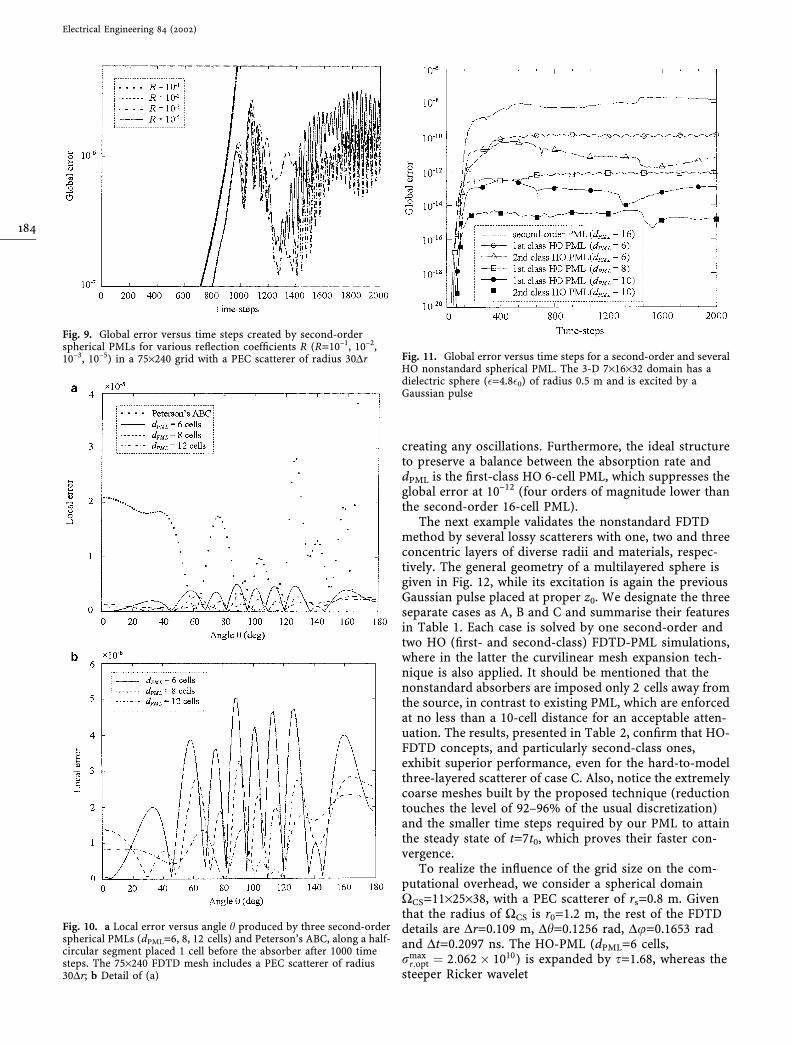
Eq. (38). Figure 7 indicates the high attenuation efficacy ofthe spherical absorber as well as a small ripple in theirplots after 1200 time steps. This oscillation is attributed tothe second-order differencing and will be, of course, cor-rected by the HO schemes. Similarly, the impact of theconductivity profile – and its exponent md in Eq. (33a–33c) – on a six-cell PML is illustrated in Fig. 8. Notice thatapart from md=0, all other values create a comparableglobal error, with md=2 being the most convenient. Thisremark is noteworthy, since it agrees with the analysis of[6, 7, 8, 9, 10, 11, 12, 13] in rectangular coordinates andproves that the increase of md does not lead to a corre-sponding reduction of the global error. Next, the exampleof Fig. 9 studies the important role of R in the PML formd=2. When R is relatively large, L2(n) is quite significant,whereas, conversely, as R becomes smaller, the global errorcannot be reduced below a lower bound because of nu-merical rounding discrepancies. Hence, for every problemthe optimal R should be carefully specified with respect to
dPML and md in an effort to generate the smaller error. Ourresults show that the value of R=10–3 operates better thanthe others, thereby justifying our preceding selections.Acceptable behaviour is additionally achieved for the caseof R=10–5. To close our second-order FDTD simulations,Fig. 10 compares the local error L1 nð Þ � En;XG
r � En;XCSr
!! !!1
¼ En;XGr � En;XCS
r
�� �� as a function of angle h along a half-circular segment positioned one cell before the vacuum–absorber interface (see Fig. 4). Again, the spherical atten-uator yields notably lower errors, which can be easily de-tected in Fig. 10b.
Although the preceding PML seem sufficient, they de-mand large numbers of cells and distance from the scat-terer. Thus, when higher accuracy and very small meshesare pursued, their use becomes unfeasible because of ex-cessive computing cost. However, the most significantdrawback of the second-order schemes is the lattice errors.When general curvilinear coordinates are employed, thesedefects dominate the propagation of the simulated fieldsand yield ill-posed outcomes. The solution to this problemis given by a proposed method that enhances thediscretization policy of the FDTD method. To indicate itssuperiority over the usual arrangements, the rest of this
Fig. 5. Propagation of Er component due to a z-polarised electricdipole at z0=20Dr for different time instants. The PEC scatterer ofradius 9Dr is centered on a 25·120 grid truncated by an 8-cellspherical PML
Electrical Engineering 84 (2002)
182
section substantiates 3-D HO nonstandard FDTD conceptsthat involve a significantly reduced grid resolution,namely, only 4 to 7 cells per wavelength k, instead of the200 cells typically required by Yee’s scheme for a prede-fined error level. In addition, the difficulty of the numer-ical investigations is further augmented by imposing thescatterers very close (even at a distance of 1 cell) to thePML.
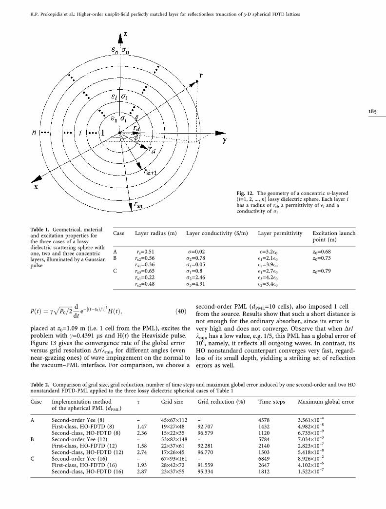
The merits of the novel absorbers are initially validatedvia the global error in a 3-D scattering problem with adielectric sphere (�=4.8�0) that is centred at the origin andhas a radius of rs=0.5 m. Because of the HO stencils of theclasses in Eqs. (4) and (14) combined with the suitablecompact forms, WCS is divided into the coarse mesh of7·16·32 cells with Dr=0.125 m, Dh=0.2094 rad,Du=0.1963 rad and Dt=0.3494 ns. So, grid resolutionreaches the promising value of Dr/kmin=1/5, where kmin isthe minimum wavelength of a Gaussian pulse
P tð Þ ¼ P0e� t�t0ð Þ2=s2launched at (0,0z0=0.75 m) and sup-
ported in t2[0,4t0]. Its parameters are selected as P0=10–6,t0=10.482 ns and s=3t0=31.446 ns, in order to avoid theloss of any nontrivial energy content. Notice that thesource–absorber distance is only 0.125 m (i.e. 1 cell). Forthe analysis to be complete, we also study a second-orderspherical PML with dPML=16 cells and rr
max=4.147·1010
(R=10–3). In this case, WCS has 42·68·220 cells withDr=0.05 m, Dh=0.0462 rad, Du=0.0285 rad andDt=0.4911 ps, owing to the lack of the common finitedifferences to follow the former large stencils. The source–absorber distance is now 1.35 m, the smallest valuefor a reasonable wave dampening. Results are givenin Fig. 11. As deduced, the new PML, withrmax
r;opt 2 1:798 � 1010; 3:254 � 1010½ and the drasticallysmaller depths, overwhelm the common absorbers without
Fig. 6. a Evolution of Hu component versus time t at Q(23Dr,12Dh)for a 25·120 grid backed by Peterson’s ABC and an 8-cell sphericalPML, as compared to the reference solution of a larger domain. ThePEC scatterer’s radius is 3Dr and the electric dipole is set at z0=8Dr; bDetail of (a) around t=5.5 ns
Fig. 7. Global error versus time steps produced by three second-order spherical PMLs (dPML=4, 8, 12 cells) and Peterson’s ABC in a75·240 lattice containing a PEC scatterer of radius 30Dr centred at theorigin
Fig. 8. Global error versus time steps induced by second-orderspherical PMLs for various md (md=0, 1, 2, 3) exponents. The FDTDscatterer domain uses 75·240 cells and the electric dipole is placed atz0=55Dr
K.P. Prokopidis et al.: Higher-order unsplit-field perfectly matched layer for reflectionless truncation of 3-D spherical FDTD lattices
183
creating any oscillations. Furthermore, the ideal structureto preserve a balance between the absorption rate anddPML is the first-class HO 6-cell PML, which suppresses theglobal error at 10–12 (four orders of magnitude lower thanthe second-order 16-cell PML).
The next example validates the nonstandard FDTDmethod by several lossy scatterers with one, two and threeconcentric layers of diverse radii and materials, respec-tively. The general geometry of a multilayered sphere isgiven in Fig. 12, while its excitation is again the previousGaussian pulse placed at proper z0. We designate the threeseparate cases as A, B and C and summarise their featuresin Table 1. Each case is solved by one second-order andtwo HO (first- and second-class) FDTD-PML simulations,where in the latter the curvilinear mesh expansion tech-nique is also applied. It should be mentioned that thenonstandard absorbers are imposed only 2 cells away fromthe source, in contrast to existing PML, which are enforcedat no less than a 10-cell distance for an acceptable atten-uation. The results, presented in Table 2, confirm that HO-FDTD concepts, and particularly second-class ones,exhibit superior performance, even for the hard-to-modelthree-layered scatterer of case C. Also, notice the extremelycoarse meshes built by the proposed technique (reductiontouches the level of 92–96% of the usual discretization)and the smaller time steps required by our PML to attainthe steady state of t=7t0, which proves their faster con-vergence.
To realize the influence of the grid size on the com-putational overhead, we consider a spherical domainWCS=11·25·38, with a PEC scatterer of rs=0.8 m. Giventhat the radius of WCS is r0=1.2 m, the rest of the FDTDdetails are Dr=0.109 m, Dh=0.1256 rad, Du=0.1653 radand Dt=0.2097 ns. The HO-PML (dPML=6 cells,rmax
r;opt ¼ 2:062 � 1010) is expanded by s=1.68, whereas thesteeper Ricker wavelet
Fig. 10. a Local error versus angle h produced by three second-orderspherical PMLs (dPML=6, 8, 12 cells) and Peterson’s ABC, along a half-circular segment placed 1 cell before the absorber after 1000 timesteps. The 75·240 FDTD mesh includes a PEC scatterer of radius30Dr; b Detail of (a)
Fig. 11. Global error versus time steps for a second-order and severalHO nonstandard spherical PML. The 3-D 7·16·32 domain has adielectric sphere (�=4.8�0) of radius 0.5 m and is excited by aGaussian pulse
Fig. 9. Global error versus time steps created by second-orderspherical PMLs for various reflection coefficients R (R=10–1, 10–2,10–3, 10–5) in a 75·240 grid with a PEC scatterer of radius 30Dr
Electrical Engineering 84 (2002)
184
P tð Þ ¼ cffiffiffiffiffiffiffiffiffiffiP0=2
p d
dte�½ðt�t0Þ=c 2 H tð Þ; ð40Þ
placed at z0=1.09 m (i.e. 1 cell from the PML), excites theproblem with c=0.4391 ls and H(t) the Heaviside pulse.Figure 13 gives the convergence rate of the global errorversus grid resolution Dr/kmin for different angles (evennear-grazing ones) of wave impingement on the normal tothe vacuum–PML interface. For comparison, we choose a
second-order PML (dPML=10 cells), also imposed 1 cellfrom the source. Results show that such a short distance isnot enough for the ordinary absorber, since its error isvery high and does not converge. Observe that when Dr/kmin has a low value, e.g. 1/5, this PML has a global error of100, namely, it reflects all outgoing waves. In contrast, itsHO nonstandard counterpart converges very fast, regard-less of its small depth, yielding a striking set of reflectionerrors as well.
Fig. 12. The geometry of a concentric n-layered(i=1, 2, ..., n) lossy dielectric sphere. Each layer ihas a radius of rsi, a permittivity of �i and aconductivity of ri
Table 1. Geometrical, materialand excitation properties forthe three cases of a lossydielectric scattering sphere withone, two and three concentriclayers, illuminated by a Gaussianpulse
Case Layer radius (m) Layer conductivity (S/m) Layer permittivity Excitation launchpoint (m)
A rs=0.51 r=0.02 �=3.2�0 z0=0.68B rs2=0.56 r2=0.78 �1=2.1�0 z0=0.73
rs1=0.36 r1=0.05 �2=3.9�0
C rs3=0.65 r1=0.8 �1=2.7�0 z0=0.79rs1=0.22 r2=2.46 �3=4.2�0
rs2=0.48 r3=4.91 �2=3.4�0
Table 2. Comparison of grid size, grid reduction, number of time steps and maximum global error induced by one second-order and two HOnonstandard FDTD-PML applied to the three lossy dielectric spherical cases of Table 1
Case Implementation methodof the spherical PML (dPML)
s Grid size Grid reduction (%) Time steps Maximum global error
A Second-order Yee (8) – 45·67·112 – 4578 3.561·10–4
First-class, HO-FDTD (8) 1.47 19·27·48 92.707 1432 4.982·10–8
Second-class, HO-FDTD (8) 2.36 15·22·35 96.579 1120 6.735·10–9
B Second-order Yee (12) – 53·82·148 – 5784 7.034·10–3
First-class, HO-FDTD (12) 1.58 22·37·61 92.281 2140 2.823·10–7
Second-class, HO-FDTD (12) 2.74 17·26·45 96.770 1503 5.418·10–8
C Second-order Yee (16) – 67·93·161 – 6849 8.926·10–2
First-class, HO-FDTD (16) 1.93 28·42·72 91.559 2647 4.102·10–6
Second-class, HO-FDTD (16) 2.87 23·37·55 95.334 1812 1.522·10–7
K.P. Prokopidis et al.: Higher-order unsplit-field perfectly matched layer for reflectionless truncation of 3-D spherical FDTD lattices
185
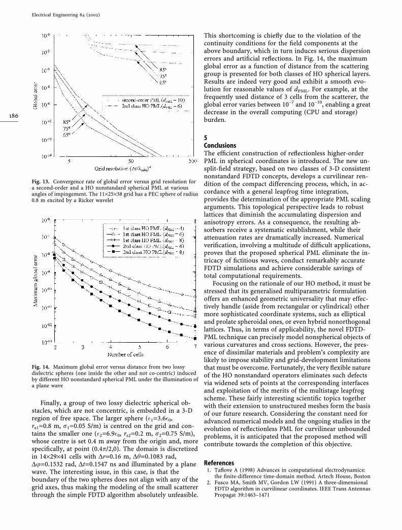
Finally, a group of two lossy dielectric spherical ob-stacles, which are not concentric, is embedded in a 3-Dregion of free space. The larger sphere (�1=3.6�0,rs1=0.8 m, r1=0.05 S/m) is centred on the grid and con-tains the smaller one (�2=6.9�0, rs2=0.2 m, r2=0.75 S/m),whose centre is set 0.4 m away from the origin and, morespecifically, at point (0.4p/2,0). The domain is discretizedin 14·29·41 cells with Dr=0.16 m, Dh=0.1083 rad,Du=0.1532 rad, Dt=0.1547 ns and illuminated by a planewave. The interesting issue, in this case, is that theboundary of the two spheres does not align with any of thegrid axes, thus making the modeling of the small scattererthrough the simple FDTD algorithm absolutely unfeasible.
This shortcoming is chiefly due to the violation of thecontinuity conditions for the field components at theabove boundary, which in turn induces serious dispersionerrors and artificial reflections. In Fig. 14, the maximumglobal error as a function of distance from the scatteringgroup is presented for both classes of HO spherical layers.Results are indeed very good and exhibit a smooth evo-lution for reasonable values of dPML. For example, at thefrequently used distance of 3 cells from the scatterer, theglobal error varies between 10–7 and 10–10, enabling a greatdecrease in the overall computing (CPU and storage)burden.
5ConclusionsThe efficient construction of reflectionless higher-orderPML in spherical coordinates is introduced. The new un-split-field strategy, based on two classes of 3-D consistentnonstandard FDTD concepts, develops a curvilinear ren-dition of the compact differencing process, which, in ac-cordance with a general leapfrog time integration,provides the determination of the appropriate PML scalingarguments. This topological perspective leads to robustlattices that diminish the accumulating dispersion andanisotropy errors. As a consequence, the resulting ab-sorbers receive a systematic establishment, while theirattenuation rates are dramatically increased. Numericalverification, involving a multitude of difficult applications,proves that the proposed spherical PML eliminate the in-tricacy of fictitious waves, conduct remarkably accurateFDTD simulations and achieve considerable savings oftotal computational requirements.
Focusing on the rationale of our HO method, it must bestressed that its generalised multiparametric formulationoffers an enhanced geometric universality that may effec-tively handle (aside from rectangular or cylindrical) othermore sophisticated coordinate systems, such as ellipticaland prolate spheroidal ones, or even hybrid nonorthogonallattices. Thus, in terms of applicability, the novel FDTD-PML technique can precisely model nonspherical objects ofvarious curvatures and cross sections. However, the pres-ence of dissimilar materials and problem’s complexity arelikely to impose stability and grid-development limitationsthat must be overcome. Fortunately, the very flexible natureof the HO nonstandard operators eliminates such defectsvia widened sets of points at the corresponding interfacesand exploitation of the merits of the multistage leapfrogscheme. These fairly interesting scientific topics togetherwith their extension to unstructured meshes form the basisof our future research. Considering the constant need foradvanced numerical models and the ongoing studies in theevolution of reflectionless PML for curvilinear unboundedproblems, it is anticipated that the proposed method willcontribute towards the completion of this objective.
References1. Taflove A (1998) Advances in computational electrodynamics:
the finite-difference time-domain method. Artech House, Boston2. Fusco MA, Smith MV, Gordon LW (1991) A three-dimensional
FDTD algorithm in curvilinear coordinates. IEEE Trans AntennasPropagat 39:1463–1471
Fig. 14. Maximum global error versus distance from two lossydielectric spheres (one inside the other and not co-centric) inducedby different HO nonstandard spherical PML under the illumination ofa plane wave
Fig. 13. Convergence rate of global error versus grid resolution fora second-order and a HO nonstandard spherical PML at variousangles of impingement. The 11·25·38 grid has a PEC sphere of radius0.8 m excited by a Ricker wavelet
Electrical Engineering 84 (2002)
186
3. Lee JF (1992) Finite difference time domain algorithm for non-orthogonal grids and its application to the solution of electro-magnetic scattering problems. Archiv fur Elektronik und Ubert-ragungstechnik 46:328–335
4. Schuhmann R, Weiland T (1998) A stable interpolation techniquefor FDTD on non-orthogonal grids. Int J Num Model 11:299–306
5. Schuhmann R, Weiland T (1999) FDTD on nonorthogonal gridswith triangular fillings. IEEE Trans Magn 35:1470–1473
6. Berenger JP (1994) A perfectly matched layer for the absorptionof electromagnetic waves. J Comp Phys 114:185–200
7. Chew WC, Weedon WH (1994) A 3D perfectly matched mediumfrom modified Maxwell’s equations with stretched coordinates.Microwave Opt Tech Lett 7:599–604
8. Rappaport CM (1996) Interpreting and improving the PML ab-sorbing boundary condition using anisotropic lossy mapping ofspace. IEEE Trans Magn 32:968–974
9. Zhao L, Cangellaris AC (1996) GT-PML: generalized theory ofperfectly matched layers and its application to the reflectionlesstruncation of finite-difference time-domain grids. IEEE TransMicrowave Theory Tech 44:2555–2563
10. Gedney SD (1996) An anisotropic perfectly matched layer-ab-sorbing medium for the truncation of FDTD lattices. IEEE TransAntennas Propagat 44:1630-1639
11. Zhao AP, Juntunen J, Raisanen AV (1997) Material independentPML absorbers for arbitrary anisotropic dielectric media. Elec-tron Lett 33:1535–1536
12. Ziolkowski RW (1998) Maxwellian material based absorbingboundary conditions. Comp Meth Appl Mech Eng 169:237–262
13. Werner DH, Mittra R (2000) Frontiers in electromagnetics. IEEEPress, New York
14. Garcia SG, Hernandez-Lopez MA, Pantoja MF, Martin RG,Olmedo BG (2001) Unsplit Berenger’s PML equation for arbitrarymedia. Electron Lett 37:1509–1510
15. Teixeira FL, Chew WC (1997) PML-FDTD in cylindrical andspherical coordinates. IEEE Microwave Guided Wave Lett7:285–287
16. Collino F, Monk P (1998) The perfectly matched layer in curvi-linear coordinates. SIAM J Sci Comp 19:2061–2090
17. He JQ, Liu QH (1999) A nonuniform cylindrical FDTD algorithmwith improved PML and quasi-PML absorbing boundary condi-tions. IEEE Trans Geosci Remote Sens 37:1066–1072
18. Navarro EA, Wu C, Chung PY, Litva J (1994) Application of PMLsuperabsorbing boundary condition to non-orthogonal FDTDmethod. Electron Lett 30:1654–1656
19. Roden JA, Gedney SD (1997) Efficient implementation of theuniaxial-based PML media in three-dimensional nonorthogonalcoordinates with the use of the FDTD technique. Microwave OptTech Lett 14:71–75
20. Teixeira FL, Hwang KP, Chew WC, Jin JM (2001) ConformalPML-FDTD schemes for electromagnetic field simulations: adynamic stability study. IEEE Trans Antennas Propagat49:902–907
21. Petropoulos PG (2000) Reflectionless sponge layers as absorbingboundary conditions for the numerical solution of Maxwell’sequations in rectangular, cylindrical and spherical coordinates.SIAM J Appl Math 60:1037–1058
22. Fang J (1989) Time-domain finite-difference computations forMaxwell’s equations. PhD dissertation, University of California,Berkeley
23. Carpenter MH, Gottlieb D, Abarbanel S (1994) Time-stableboundary conditions for finite-difference schemes solving hy-perbolic systems: methodology and application to high-ordercompact schemes. J Comp Phys 111:220–236
24. Young JL, Gaitonde DV, Shang JS (1997) Toward the constructionof a fourth-order difference scheme for transient EM wave sim-ulation: staggered grid approach. IEEE Trans Antennas Propagat45:1573–1580
25. Turkel E, Yefet A (2000) On the construction of a high orderdifference scheme for complex domains in a Cartesian grid. ApplNumer Math 33:125–136
26. Jurgens HM, Zingg DW (2000) Numerical solution of the time-domain Maxwell equations using high-accuracy finite-differencemethods. SIAM J Sci Comput 22:1675–1696
27. Young JL (2001) High-order, leapfrog methodology for the tem-porally dependent Maxwell’s equations. Radio Sci 36:9–17
28. Petropoulos PG, Zhao AP, Cangellaris AC (1998) A reflectionlesssponge layer absorbing boundary condition for the solution ofMaxwell’s equations with high-order staggered finite differences.J Comp Phys 139:184–208
29. Railton CJ, Craddock IJ (1996) Stabilized CPFDTD algorithm forthe analysis of arbitrary 3D structures. IEEE Proc MicrowaveAntennas Propagat 143:367–372
30. Ritter J, Arndt F (1996) Efficient FDTD/matrix-pencil method forthe full-wave scattering parameter analysis of waveguidingstructures. IEEE Trans Microwave Theory Tech 44:2450–2456
31. Gao Y, Lauer A, Ren Q, Wolff I (1998) Calibration of electriccoaxial near-field probes and applications. IEEE Trans Micro-wave Theory Tech 46:1694–1703
32. Fujii M, Hoefer WJR (2001) Field-singularity correction in 2-Dtime-domain Haar-wavelet modeling of waveguide components.IEEE Trans Microwave Theory Tech 49:685–691
33. Nilavalan R, Craddock IJ, Paul DL, Railton CJ (2001) Conformalantenna array modeling using a locally nonorthogonal FDTD.Microwave Opt Tech Lett 30:239–240
34. Aidam M, Russer P (1999) New high order time-steppingschemes for finite differences. In: Proceedings of 15th AnnualReview of Progress in Applied Computational Electromagnetics,Monterey, Calif, March, pp 578–585
35. Mickens RE (1994) Nonstandard finite difference models of dif-ferential equations. World Scientific, Singapore
36. Cole JB (1997) A high-accuracy realization of the Yee algorithmusing non-standard finite differences. IEEE Trans MicrowaveTheory Tech 45:991–996
37. Kantartzis NV, Tsiboukis TD (2000) A generalized methodologybased on higher-order conventional and nonstandard FDTDconcepts for the systematic development of enhanced disper-sionless wide-angle absorbing PMLs. Int J Num Model12:417–440
38. Peterson A, Scott LR, Mittra R (1998) Computational methods forelectromagnetics. IEEE Press, New York
K.P. Prokopidis et al.: Higher-order unsplit-field perfectly matched layer for reflectionless truncation of 3-D spherical FDTD lattices
187