A facility for studying laboratory plasma astrophysics
11
The Madison plasma dynamo experiment: A facility for studying laboratory plasma astrophysics C. M. Cooper, J. Wallace, M. Brookhart, M. Clark, C. Collins, W. X. Ding, K. Flanagan, I. Khalzov, Y. Li, J. Milhone, M. Nornberg, P. Nonn, D. Weisberg, D. G. Whyte, E. Zweibel, and C. B. Forest Citation: Physics of Plasmas (1994-present) 21, 013505 (2014); doi: 10.1063/1.4861609 View online: http://dx.doi.org/10.1063/1.4861609 View Table of Contents: http://scitation.aip.org/content/aip/journal/pop/21/1?ver=pdfcov Published by the AIP Publishing This article is copyrighted as indicated in the article. Reuse of AIP content is subject to the terms at: http://scitation.aip.org/termsconditions. Downloaded to IP: 128.104.165.161 On: Fri, 24 Jan 2014 18:20:31
-
Upload
khangminh22 -
Category
Documents
-
view
5 -
download
0
Transcript of A facility for studying laboratory plasma astrophysics

The Madison plasma dynamo experiment: A facility for studying laboratory plasmaastrophysicsC. M. Cooper, J. Wallace, M. Brookhart, M. Clark, C. Collins, W. X. Ding, K. Flanagan, I. Khalzov, Y. Li, J.
Milhone, M. Nornberg, P. Nonn, D. Weisberg, D. G. Whyte, E. Zweibel, and C. B. Forest Citation: Physics of Plasmas (1994-present) 21, 013505 (2014); doi: 10.1063/1.4861609 View online: http://dx.doi.org/10.1063/1.4861609 View Table of Contents: http://scitation.aip.org/content/aip/journal/pop/21/1?ver=pdfcov Published by the AIP Publishing
This article is copyrighted as indicated in the article. Reuse of AIP content is subject to the terms at: http://scitation.aip.org/termsconditions. Downloaded to IP:
128.104.165.161 On: Fri, 24 Jan 2014 18:20:31

The Madison plasma dynamo experiment: A facility for studyinglaboratory plasma astrophysics
C. M. Cooper,1,2 J. Wallace,1 M. Brookhart,1,2 M. Clark,1 C. Collins,1,2 W. X. Ding,3
K. Flanagan,1 I. Khalzov,1,2 Y. Li,1 J. Milhone,1,2 M. Nornberg,1,2 P. Nonn,1 D. Weisberg,1,2
D. G. Whyte,4 E. Zweibel,1,2,5 and C. B. Forest1,2
1Department of Physics, University of Wisconsin, Madison, Wisconsin 53706, USA2Center for Magnetic Self Organization, University of Wisconsin, Madison, Wisconsin 53706, USA3Department of Physics and Astronomy, University of California, Los Angeles, Los Angeles,California 90024, USA4Plasma Science and Fusion Center, Massachusetts Institute of Technology, Cambridge,Massachusetts 02139, USA5Department of Astronomy, University of Wisconsin, Madison, Wisconsin 53706, USA
(Received 8 October 2013; accepted 19 December 2013; published online 14 January 2014)
The Madison plasma dynamo experiment (MPDX) is a novel, versatile, basic plasma research
device designed to investigate flow driven magnetohydrodynamic instabilities and other high-bphenomena with astrophysically relevant parameters. A 3 m diameter vacuum vessel is lined with
36 rings of alternately oriented 4000 G samarium cobalt magnets, which create an axisymmetric
multicusp that contains �14 m3 of nearly magnetic field free plasma that is well confined and
highly ionized (>50%). At present, 8 lanthanum hexaboride (LaB6) cathodes and 10
molybdenum anodes are inserted into the vessel and biased up to 500 V, drawing 40 A each
cathode, ionizing a low pressure Ar or He fill gas and heating it. Up to 100 kW of electron
cyclotron heating power is planned for additional electron heating. The LaB6 cathodes are
positioned in the magnetized edge to drive toroidal rotation through J�B torques that propagate
into the unmagnetized core plasma. Dynamo studies on MPDX require a high magnetic Reynolds
number Rm> 1000, and an adjustable fluid Reynolds number 10<Re< 1000, in the regime
where the kinetic energy of the flow exceeds the magnetic energy (M2A ¼ ðv=vAÞ2 > 1). Initial
results from MPDX are presented along with a 0-dimensional power and particle balance model
to predict the viscosity and resistivity to achieve dynamo action. VC 2014 AIP Publishing LLC.
[http://dx.doi.org/10.1063/1.4861609]
I. INTRODUCTION
The Madison plasma dynamo experiment (MPDX) is
designed to create a steady-state, hot, weakly magnetized,
flowing plasma in which the kinetic energy of the flow drives
magnetohydrodynamic (MHD) instabilities. Such a device
accesses a new regime relevant to astrophysical applications
and never before achieved in a laboratory.1 This plasma is
well-suited for studying astrophysical phenomena such as
the dynamo process,2 the feasibility of which is the topic of
several recent publications3–5 and is investigated in
Sec. IV A. The magneto-rotational instability (MRI)6 could
also be investigated using the tunable boundary driven flow
or a supplemental central spinning post in conjunction with
an external Helmholtz coil. In addition, many basic plasma
physics experiments studying interactions and organization
of flows and magnetic fields can be performed.
Previous and ongoing dynamo experiments7 use flowing
liquid metals, which can be stirred mechanically and con-
fined with a simple vessel. These interesting experiments
suffer from several limitations, which can be avoided by
using plasmas. First, the magnetic Reynolds number
achieved in liquid metal experiments, which governs the
transition to a dynamo, is too low. The magnetic Reynolds
number Rm¼ vL/g (where L is the characteristic size, g is
the resistivity, and v is the flow velocity) is the ratio of mag-
netic field advection by the flow to magnetic field diffusion
from the resistivity. In liquid metal experiments, Rm is typi-
cally less than Rmcrit necessary for dynamo and MRI excita-
tion. In addition, the fluid Reynolds number, which is the ratio
of the momentum advection by the flow to the momentum dif-
fusion by the viscosity Re¼ vL/� (where � is the viscosity),
cannot be varied independently of Rm in liquid metals. The
ratio of these quantities, the magnetic Prandtl number
Pm ¼ Rm=Re ¼ �=g is a fixed, very small value �10�5 in
liquid metal; thus, the flows required to exceed Rmcrit are
always turbulent. In plasmas, by contrast, Rm can be varied in-
dependently of Re by controlling the plasma resistivity and
viscosity by changing the electron temperature, the plasma
density, and the ion species. Pm� 1 is achievable in MPDX
making these plasmas excellent candidates for dynamo action
and comparison to simulations. In addition, laminar dynamo
action (Rm>Rmcrit, Re<� 1000) can be studied in the ab-
sence of fluid turbulence, which can suppress it.8
To experimentally test theories about the dynamo mech-
anism in a plasma, the device operates in the flow-dominatedregime as opposed to the magnetically dominated regime.
Such an experiment requires not only that Rm be large but
1070-664X/2014/21(1)/013505/10/$30.00 VC 2014 AIP Publishing LLC21, 013505-1
PHYSICS OF PLASMAS 21, 013505 (2014)
This article is copyrighted as indicated in the article. Reuse of AIP content is subject to the terms at: http://scitation.aip.org/termsconditions. Downloaded to IP:
128.104.165.161 On: Fri, 24 Jan 2014 18:20:31

also that the flow energy dominates over the magnetic
energy. This is quantified by the Alfv�en Mach number
squared M2A ¼ ðv=vAÞ2, which is the ratio of the inertial force
to the magnetic force, where vA ¼ B=ffiffiffiffiffiffiffiffiffiffiffiffiffilonimip
is the Alfv�en
velocity. When MA � 1 and Rm � 1, flows can stretch and
amplify the magnetic field. The feasibility of creating such a
plasma in the lab has recently been demonstrated in a novel
multi cusp confined plasma with electrostatic stirring,9 where
unmagnetized plasmas with flows of �10 km/s have been
created.10 For MPDX class plasmas, a convenient set of for-
mulae are
Re ¼ 7:8 vkm=sLmni;1018m�3 Z4 ffiffiffilp
=T5=2i;eV; (1)
Rm ¼ 1:6 T3=2e;eVvkm=sLm=Z; (2)
MA ¼ 0:46 vkm=s
ffiffiffiffiffiffiffiffiffiffiffiffiffiffiffiffiffiffiffiffilni;1018m�3
p=Bg; (3)
where the Braginskii viscosity and the Spitzer resistivity for
unmagnetized plasma are used for � and g, respectively,
ni;1018 is the ion density in 1018/m3, l is the atomic mass in
amu, Z is the net charge of the ions, Te,eV and Ti,eV are the
electron and ion temperatures, respectively, in eV, Lm is the
characteristic size in meters, vkm=s is the plasma velocity in
units of km/s and Bg is a characteristic strength of the back-
ground magnetic field in Gauss. The plasma parameters and
relevant dimensionless parameters are adjusted by control-
ling the neutral fill pressure, input power, gas species, and
torques imposed on the plasma edge.
The MPDX uses several well-established techniques to
confine and stir a hot, unmagnetized plasma. First, an axi-
symmetric multipole magnetic ring cusp built from alternat-
ing rings of individual permanent magnets creates a strong
magnetic field localized to the edge, forming a magnetic
bucket to confine the plasma. Second, biased hot cathodes
draw current to induce an J�B rotation to stir the edge of
the plasma. The flow is driven at the boundary and momen-
tum is viscously transported throughout the unmagnetized
region. By controlling the spatial profile of these boundary-
driven flows, arbitrary large scale helical flows can be estab-
lished (Fig. 1).
The paper is organized as follows: Section II provides a
description of the device, its construction and initial opera-
tion. Section II C describes the LaB6 cathodes, which are
used for producing plasma and controlling the boundary
flow. Section II D describes the current state of diagnostics
on MPDX. Section III presents initial measurements of
plasma parameters in the MPDX operation that provides the
basis for scaling to higher power. Section IV outlines simula-
tions predicting machine confinement and operation as well
as providing a plan for achieving several types of dynamo
action in MPDX.
II. DESCRIPTION OF THE MPDX
New parameter regimes in laboratory plasmas can be
reached due to recent breakthroughs in plasma physics tech-
nologies. This section describes the design of the facility,
vacuum chamber, magnets, and plasma sources.
A. Vacuum chamber
The experimental vacuum chamber is comprised of two
3 m diameter hemispherical shells joined by equatorial
flanges to create a spherical vessel. One hemisphere is
mounted on a linear stage to provide easy opening and access
to the chamber interior. The hemispherical shells are made
of 0.03 m thick cast A356 aluminum (see Fig. 2). The wall
thickness is determined by structural integrity and the need
to provide sufficient material to machine flanges and other
features into the walls.
Each hemisphere is cast as a single piece by Portage
Casting and Molding, Inc., which provides many benefits
over a traditional welded vacuum vessel. Casting not only
eliminates the need for costly vacuum welds but also has
allowed for a more complex and precise design at a greatly
reduced cost. The design process resembled “3D Printing:”
Solidworks11 computer aided design software was used by
FIG. 1. (a) A picture of MPDX and (b) the various current and planned sub-
systems labeled.
013505-2 Cooper et al. Phys. Plasmas 21, 013505 (2014)
This article is copyrighted as indicated in the article. Reuse of AIP content is subject to the terms at: http://scitation.aip.org/termsconditions. Downloaded to IP:
128.104.165.161 On: Fri, 24 Jan 2014 18:20:31
the UW engineering team to design the machine. The design
was sent to the aluminum casting firm, where a 5 axis milling
machine was used to construct a positive (i.e., pattern) for
the mold. Sand molds were made, and molten aluminum was
cast into the molds. Stainless steel tubular cooling lines are
cast directly into the walls providing a low thermal imped-
ance to remove heat from the experiment. Fig. 2 shows the
construction.
The vessel features six identical boxports (0.2 m
� 1.0 m) on each hemisphere to provide large views for opti-
cal diagnostics. Each hemisphere has seven larger 0.35 m cir-
cular ports for probes and Radio-Frequency (RF) heating
sources. Each pole has a 0.35 m port for RF feedthroughs
and to provide axial access. An additional 182 ports of
0.075 m are located on the sphere between magnet rings for
insertion of plasma stirring electrodes, diagnostics, or electri-
cal connections. The chamber interior is plasma spray coated
with a 0.00025 m thick alumina film. The large diameter
seals (including the seals between the two hemispheres) are
differentially pumped double O-ring seals. Two 2000 l/m
turbo pumps and two 4000 l/m cryo pumps routinely achieve
5� 10�7 Torr vacuum base pressure, similar to stainless steel
vessels sealed with O-rings. The experimental operating
pressure with gas fill is <5� 10�4 Torr.
B. Magnets
Eighteen faceted rings are precisely machined into each
hemisphere interior and used for mounting the �3000
0.038 m� 0.025 m� 0.05 m samarium cobalt (SmCo) mag-
nets. Unlike neodymium (NdFeB) magnets, SmCo magnets
do not corrode in the presence of hydrogen gas. Each ring of
magnets alternates in polarity, creating a 36 pole, axisym-
metric magnetic field cusp for plasma confinement. The
magnets are in good thermal contact with the water cooled
vacuum vessel and operate at temperatures up to 40 �C, far
below their curie temperature of 350 �C. The magnets are
covered by Kapton film and thin interlocking alumina ce-
ramic tiles that protect and electrically isolate them.
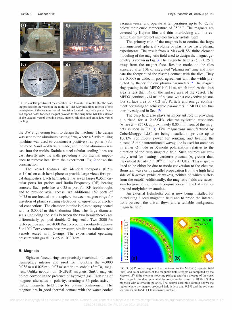
The primary role of the magnets is to confine the large
unmagnetized spherical volume of plasma for basic plasma
experiments. The result from a Maxwell SV finite element
modeling of the magnetic field used to design the magnet ge-
ometry is shown in Fig. 3. The magnetic field is <1 G 0.25 m
away from the magnet face. Residue marks on the tiles
appeared after 10 h of integrated “plasma on” time and indi-
cate the footprint of the plasma contact with the tiles. They
are 0.0008 m wide, in good agreement with the width pre-
dicted by theory for our plasma parameters.12 The magnet
ring spacing in the MPDX is 0.11 m, which implies that loss
area is less than 1% of the surface area of the vessel. The
MPDX confines �14 m3 of plasma with a convective plasma
loss surface area of �0.2 m2. Particle and energy confine-
ment pertaining to achievable parameters in MPDX are fur-
ther investigated in Sec. IV.
The cusp field also plays an important role in providing
a surface for a 2.45 GHz electron-cyclotron resonance
(where B¼ 875 G, approximately 0.05 m in front of the mag-
nets as seen in Fig. 3). Five magnetrons manufactured by
CoberMuegge, LLC, are being installed to provide up to
100 kW continuous power for ionizing and heating the
plasma. Simple unterminated waveguide is used for antennas
in either O-mode or X-mode polarization relative to the
direction of the cusp magnetic field. Such sources are rou-
tinely used for heating overdense plasmas (ne greater than
the critical density 7� 1016 m–3 for 2.45 GHz). This is specu-
lated to be either be due to mode conversion to the electron
Bernstein wave or by parallel propagation from the high field
side of R-waves (whistler waves), neither of which suffers
from the cutoff. Additionally, the magnetic fields are neces-
sary for generating flows in conjunction with the LaB6 catho-
des and molybdenum anodes.
An external Helmholtz coil is now being installed for
introducing a seed magnetic field and to probe the interac-
tions between the driven flows and a scalable background
magnetic field.
FIG. 2. (a) The positive of the chamber used to make the mold. (b) The cast-
ing process for the vessel in the mold. (c) The fully machined interior of one
hemisphere of the vacuum vessel. Precision located rings with planar facets
and tapped holes for each magnet provide for the cusp field. (d) The exterior
of the vacuum vessel showing ports, magnet bridging, and embedded vessel
cooling.
FIG. 3. (a) Poloidal magnetic flux contours for the MPDX (magnetic field
lines) and color contours of the magnetic field strength as computed by the
Maxwell SV finite element modeling package and (b) a closeup of the cusp.
The magnetic field is generated by axisymmetric rows of 4000 G SmCo
magnets with alternating polarity. The central dark blue contour shows the
region where the magnet-produced field is less than 0.2 G and the red con-
tour shows the 875 G ECH resonance surface.
013505-3 Cooper et al. Phys. Plasmas 21, 013505 (2014)
This article is copyrighted as indicated in the article. Reuse of AIP content is subject to the terms at: http://scitation.aip.org/termsconditions. Downloaded to IP:
128.104.165.161 On: Fri, 24 Jan 2014 18:20:31

C. LaB6 stirring electrodes
Lanthanum Hexaboride has long been used as a high
temperature (Te< 30 eV), high density (ne< 2� 1019 m�3)
plasma source due to its high input power density and robust
construction.13–16 The ability to stir the MPDX plasma
through LaB6 cusp biasing is possible because LaB6 can
withstand high bias voltages (Vd< 500 V).
The LaB6 stirring electrode design developed for
MPDX is shown in Fig. 4. The cylindrical LaB6 cathode
(measuring 0.056 m in length, 0.0264 m in diameter, with
0.003 m thick walls) is radiatively heated up to 1600 �C by
an internal graphite heater filament. This filament is preci-
sion machined with a five-fluted current path and threaded
ends to ensure tight electrical connections. To prevent arc-
ing, the heater filament is electrically isolated from the AC
heater power supply with an isolation transformer and does
not touch the LaB6 cathode. A stainless steel tube allows for
a sliding vacuum seal, a press-fitted plastic bushing provides
structural support for the 12 kg electrode, and a large stain-
less steel “garage” allows the cathode to be completely
retracted behind a gate-valve for periodic maintenance. The
conductors for the heater circuit as well as the cathode dis-
charge circuit are cylindrical copper tubes with a center mo-
lybdenum rod, coaxially nested inside the stainless steel tube
and isolated from each other and the surrounding plasma by
quartz tubing.
In anticipation of the large amounts of RF power pro-
vided by MPDX’s magnetrons, the three electrical feed-
throughs per electrode are each paired with a copper clamp
that fulfills three essential functions: electrical connection to
power supply cables, water cooling to the cylindrical con-
ductor bases, and transmission line choking of RF waves.
Each LaB6 stirring electrode is paired with one or more
molybdenum anodes poloidally displaced one cusp. The cur-
rent path between cathode and anode must cross a permanent
magnet ring and produces J�B torque in the toroidal direc-
tion, as shown in Fig. 5. Azimuthal particle drifts rapidly
symmetrize the potential,10 creating a virtual cathode
connected to the actual cathode, but toroidally symmetric.
This edge-applied torque couples to the bulk plasma via
ion-ion viscosity. Initial experiments using these electrodes
have injected up to 40 A of current at 500 V. Each
anode-cathode potential will eventually be independently
set, creating a customizable poloidal profile of toroidal
velocity.
D. Diagnostics
The MPDX plasma is diagnosed by physical probes ca-
pable of making in situ measurements of local plasma pa-
rameters. These probes can all be pumped down and inserted
into the machine via vacuum gate valves without interrupting
operation. The plasma temperature and density are low
enough for long probe lifetimes. The surface area of the
probes and probe shafts is much smaller than the loss area on
the cusp, and individual probes do not perturb the plasma.
A swept voltage bias is applied to the tip of planar
Langmuir probes to create an “I-V” curve. This curve is ana-
lyzed to determine Te, ne, Up, and Uf using standard
Langmuir probe techniques.17 Plasma flows inside MPDX
are measured using Mach probes. The probe tips are biased
several times Te below the plasma potential to collect ion sat-
uration current and the Mach number and absolute speed can
be measured using standard techniques.17 A triple probe is
used to provide an additional measurement of Te and Uf.
A phase locked set of 1 mm sources acquired from
Virginia Diodes, along with two mixers and an Analog
Devices phase detector provide a single channel interfero-
metric measurement of the line-integral density. The 1 mm
wavelength is optimal for normal MPDX densities of
�1017–1018 m�3 when integrated along a 6 m pathlength
twice the length of the MPDX plasma. These densities corre-
spond to phase shifts from � p2
to 4p, which are easily meas-
urable. The upper bound for a measurable density is
ne� 1021 m�3 and the minimum detectable density set by the
digitizer noise levels is �1015 m�3, a sufficient resolution for
MPDX densities. An example calibrated interferometer time
trace is found in Fig. 6.
FIG. 4. LaB6 stirring electrode design. The entire (1.1 m long) electrode is
shown in (a), with detailed views of (b) the graphite heater filament and (c)
the LaB6 tip. Not shown: the linear vacuum feedthrough and garage/gate-
valve assembly.
FIG. 5. A cartoon of the flow drive mechanism in MPDX using biased
anode-cathode pairs in the cusp field. The torque is proportional to the
anode-cathode bias voltage, current, and their location in the cusp, which
determines B.
013505-4 Cooper et al. Phys. Plasmas 21, 013505 (2014)
This article is copyrighted as indicated in the article. Reuse of AIP content is subject to the terms at: http://scitation.aip.org/termsconditions. Downloaded to IP:
128.104.165.161 On: Fri, 24 Jan 2014 18:20:31

A bolometer made from a LiTa crystal is installed on
the MPDX to measure the total radiated power. This includes
light radiated from the neutral particles and ions due to colli-
sions with electrons, as well as the incident kinetic energy of
any superthermal neutral gas created through elastic and
charge exchange collisions. The only power loss rate not
included is the ionization power losses and the losses to the
wall. The bolometer is calibrated with a laser over a scaling
of incident power.
Magnetic diagnostics consist of an array of Hall probes
mounted on the MPDX surface to measure the multipole
moment of the slowly varying magnetic fields. Rogowski
coils on probes inside the plasma will be calibrated and inte-
grated18 to measure the weak, fluctuating magnetic fields.
A two dimensional movable probe drive is mounted on
the MDPX vessel with a gate valve and a rotatable vacuum
ball valve. Two stepper motors mounted perpendicular to
each other can change the position of the probe inside the
machine, allowing the probe to trace out a plane of data as
seen in Fig. 7. The probe drive can be used with many types
of probes in MPDX and is very important for studying 2D
systems in MPDX.
The data collected by the diagnostics are digitized by a
500 kHz 96-channel ACQ-196 module from D-TACQ
Solutions Ltd, recorded by a computer and stored for analy-
sis. Information about the MPDX such as the machine condi-
tions, average plasma parameters, and probe positions are
recorded in a searchable SQL database. Probe movement
and discharge parameters are controlled by a Labview inter-
face via a Compact RIO. The machine can be run in a pulsed
operation or in a steady-state mode. The MPDX has created
over 3000 discharges and nearly 3 h of “plasma on” time
total. Plasma discharges are fully automated and create 3-5 s
plasma discharges every 45 s around the clock.
III. INITIAL MPDX RESULTS
The first major result from MPDX is exhibiting confine-
ment of an unmagnetized plasma using the edge localized
magnetic multipole cusp. Eight LaB6 cathodes (h ¼ 30�;40�; 50�; 60�; 125�; 135�; 145�; 155�; / ¼ 225�) and eight
anodes, displaced one cusp poloidally and 90� toroidally
(h ¼ 35�; 45�; 55�; 65�; 120�; 130�; 140�; 150�; / ¼ 135�),
were inserted radially into the unmagnetized region
(r¼ 1.25 m). The cathodes were biased 200–500 V with
respect to the anodes, with each cathode drawing 5–40 A for
a discharge time of 3–10 s in order to characterize the break-
down and confinement in the MPDX. Electron heating was
provided exclusively by the Ohmic heating of the
anode-cathode circuit.
The machine can create steady state plasma discharges
with a constant input power and fill pressure where plasma
parameters stay constant over the length of the shot.
However, the most interesting plasma regimes come where
the neutral gas is puffed in, over a 20 ms time, 0.5 s before
discharge, achieving a neutral fill pressure high enough to
achieve breakdown that is then pumped out to achieve high
ionization fractions and electron temperatures. An example
time trace for an 8 s discharge at 400 V drawing a total of
150 A for a helium gas puff is shown in Fig. 6. A Langmuir
FIG. 6. (a) Time trace of the gas puff, the input power, and the radiated
power from the bolometer (b) Te measured by a Langmuir probe, ne meas-
ured by an interferometer normalized to a path length measured by probes,
and the calculated ionization fraction ne/(nnþ ne).
FIG. 7. 2D plasma profiles of (a) Te and (b) ne for a 45 kW discharge in a
gas puff corresponding to when nn¼ 1� 1018 m–3 helium. Isopotentials of
the magnetic potential log(W) found from integrating the measured cusp
field are plotted over the data. A radial cut of the data along the center of the
plane is shown in (c) along with the measured value of the magnetic field. In
the unmagnetized core of MPDX, b¼ 100 for B¼ 1 G and Pm¼ 8 for
Ti¼ 1 eV. For v/ ¼ 5 km=s, Re¼ 35, Rm¼ 270 in the MPDX core.
013505-5 Cooper et al. Phys. Plasmas 21, 013505 (2014)
This article is copyrighted as indicated in the article. Reuse of AIP content is subject to the terms at: http://scitation.aip.org/termsconditions. Downloaded to IP:
128.104.165.161 On: Fri, 24 Jan 2014 18:20:31

probe was inserted radially into the unmagnetized region
(r¼ 1.12 m), h ¼ 110�;/ ¼ 45� and continuously swept
�80 V to þ20 V at 100 Hz to determine Te(t) in the core of
MPDX. The interferometer was directed through a box port,
reflected off the far wall and collected on the same side. The
interferometer was normalized to the path length through the
plasma as measured by probes to determine ne(t). The radiated
power from the plasma from the bolometer was integrated
over the surface area of the machine to yield the total radiated
power for the experiment. The shot to shot reproducibility is
comparable to the error in this measurement (dTe/Te� 5%),
which enables ensembled averaging of datasets over multiple
shots and with the probe at different locations.
The neutral gas density decreases as the gas is pumped
out over the course of the shot. With fewer neutral particles
to ionize, the plasma density drops as well. With fewer losses
to ionization, the walls, and collisions with the neutral gas
and ions, the electrons heat up with the increase in input
power. This is manifested in the ionization percentage,
which increases from 5% to 35% over the course of the shot.
However, this is the core ne compared to nn measured at the
wall. In this plasma with ne� 2.5� 1017 m�3 and Te� 15 eV,
the neutral mean free path for ionization in the reference
frame of the neutral particle (the neutral penetration depth) is
0.75 m, meaning the center of the plasma (two e-foldings in
radius) is nearly fully ionized. This will be investigated with
passive spectroscopy. In addition, the radiated power meas-
ured by the bolometer drops even as the total input power
rises. Using the below measured driven edge rotation speed
of v/ ¼ 2:3 km=s in a similar discharge yields a local
Rm¼ 320, an important benchmark for studying the dynamo.
Two dimensional profiles of Te and ne of a helium
plasma for a 45 kW discharge into a gas puff are shown in
Fig. 7. The probe was moved in 2 cm radial steps and 6� to-
roidal steps over the 54� sampled (including 0�), creating an
8 point by 11 point plane. The swept Langmuir probe meas-
ured the steady state Te at each position and the local ne is
determined from the measured ion saturation current, cali-
brated to the interferometer. A hall probe was used to mea-
sure the 3D magnetic field from the cusp on the same 2D
plane as the plasma parameters at a 0.33 cm radial spacing
and 3� toroidal spacing across the 54�. This magnetic field
was integrated to yield the magnetic potential W.
Isopotentials of log(W) are plotted over the data to elucidate
how the field lines of the cusp contribute to confinement in
MPDX by lowering the effective loss area at the wall, with
W¼ 0 on the line in the cusp perpendicular to the wall. The
isopotentials are evenly spaced along a chord perpendicular
to the wall, which indicates the predicted exponential drop-
off in magnetic field. A 1D profile of the plasma along the 0�
line is shown below with the measured magnetic field. No
plasma can be measured between the cusps by the probe until
it is 0.14 m from the wall (r¼ 1.36 m), where Bcusp drops
below 40 G. Prior measurements deeper into the plasma indi-
cate that for r< 1.32 m, Te and ne are relatively flat, indicat-
ing a homogeneous unmagnetized plasma core. In the core,
b ¼ nekBTe � 2lo=B2 � 1, and unity Prandtl number is
measured in the experiment, both important for studying the
flow driven MHD instabilities.
The values of ne and Te characteristic of the unmagne-
tized core (r¼ 1.12 m) were recorded for a scaling of input
power 200–450 V, 20–300 A (4–135 kW) with a constant fill
pressure 6.5� 10�5 Torr of helium (nn¼ 2� 1018 m�3), as
shown in Fig. 8. The ability to achieve a steady,
chamber-filling breakdown with a discharge power as a low
as 4 kW is also indicative of a well confined plasma. The
electron temperature saturates at higher input power as the
ionization cross section climbs non-linearly and incremen-
tally hotter electrons are required for large changes in den-
sity. Higher Te should be observed once the ionization
percentage becomes sufficiently high. The total radiated
power measured by the bolometer and integrated over the
surface of MPDX is shown. Using the measured values of
Te, ne, and the radiated power, a confinement model can be
used to predict the equilibrium power as described in
Sec. IV, plotted in the final panel. The experiment will even-
tually have up to 300 kW of heating power available.
The second major result is measuring the flow in
MPDX. Only four cathodes and five anodes were used. The
anodes and cathodes were retracted back into the magnetized
edge cusp (r¼ 1.40 m) at the same toroidal and poloidal
locations described above. In this setup, the only closure
path for current is across the cusp field resulting in a J�B
torque in the toroidal direction. A two-sided Mach probe was
inserted into the plasma oriented to measure the toroidal
flow v/ in the vicinity of the cathode r¼ 1.35 m,
h ¼ 55�;/ ¼ 45�. An example time trace is shown in Fig. 9.
FIG. 8. The scaling of (a) Te, (b) ne, and (c) radiated power measured while
varying the input power from 4 to 135 kW into 6.5� 10�5 Torr helium. The
data are used to predict the radiated and equilibrium power required using a
confinement a model, which is compared to the input power (d) by the LaB6
cathodes.
013505-6 Cooper et al. Phys. Plasmas 21, 013505 (2014)
This article is copyrighted as indicated in the article. Reuse of AIP content is subject to the terms at: http://scitation.aip.org/termsconditions. Downloaded to IP:
128.104.165.161 On: Fri, 24 Jan 2014 18:20:31

To elucidate the flow, the neutral argon gas was puffed into
the machine and pumped out over the course of the shot. In
this moderately ionized regime, ion-neutral collisions which
dissipate momentum can be comparable to ion-ion collisions
which propagate momentum, and the density of the station-
ary neutral gas plays a role in regulating the flow. As
the neutral density drops, the plasma-neutral gas drag
lowers and the plasma rotation velocity for a given torque
increases. In this shot, Te¼ 5.0 eV and the plasma
sound speed cs¼ 3.5 km/s, corresponding to a flow speed of
v/ ¼ 2:3 km=s. Stirring unmagnetized plasmas with electro-
des in a multicusp confinement scheme has been studied in
detail in cylindrical device.10
IV. CONFINEMENT MODELING OF RESISTIVITYAND VISCOSITY
In the central unmagnetized region of the MPDX, trans-
port rapidly eliminates any gradients in densities and temper-
atures allowing for a simple boundary model of plasma
confinement. A zero-dimensional particle and power balance
model is used to predict the plasma parameters (ne, Te) in the
MPDX given a set of laboratory parameters (fill gas density
and input power). The model includes both plasma physics
and atomic physics to predict the particle and energy con-
finement time.
Volumetric neutral gas ionization by the plasma is bal-
anced by plasma lost by convection to the wall through the
magnetic cusps. Experiments and the best available theory
suggested that cusp confinement limits plasma losses by
effectively reducing the loss area of the boundary. The pre-
dicted magnetic cusp width wc ¼ 4ffiffiffiffiffiffiffiffiffiqeqip � 0:0008 m (Refs.
12 and 19) is proportional to the hybrid gyroradius, where
qa ¼ vth;amac=eB is the gyroradius of a species a based on
its thermal velocity vth,a, mass ma. The total length of magnet
faces Lc¼ 220 m in MPDX yielding a convective loss area
Ac ¼ Lc � wc ¼ 21� ðTeTilÞ1=4B�1 m2 for the model,
which depends on the magnitude of B at the surface of the
magnet and weakly depends on Te and Ti. There are addi-
tional losses to the cathodes, anodes, as well as any probes
inserted into the plasma denoted as Al.
The volumetric ionization rate Sp ¼ hrizveinnne for an
ionization cross section riz is balanced by a boundary flux
Cc ¼ 0:5necs such thatÐ Ð Ð
Sp dV ¼Ð Ð
edge Cc dA. In the
zero-dimensional limit, the volume integral can be replaced
by the volume of the machine V and the surface integral can
be replaced with AcþAl yielding
hrizveinennV¼0:5necsðAcþAlÞ: (4)
Equation (4) is transcendental in Te and independent of ne. It
determines the neutral density nn in the presence of the
plasma in MPDX. This is related to the experimental fill den-
sity nf ¼ ne þ nn.
The power balance in MPDX is similarly modeled by
comparing the power added to the system by LaB6 cathodes
and magnetrons Qtot (in kW) to the power lost by volumetric
radiation, ionization, and surface particle convection to the
walls. In the 0D limit, this becomes
Qtot¼ ctkBTeþEizð Þ0:5necsðAcþAlÞþQradþQan: (5)
The total radiation Qrad arises from electron-neutral colli-
sions Qr;n ¼ Rr;nðTeÞnennV and electron-ion collisions
Qr;i ¼ Rr;nðTeÞneniV. The radiation coefficients associated
with these processes, Rr,n(Te) and Rr,i(Te), were calculated
from atomic rates used in the KPRAD code.20 The heat lost
to the neutral gas Qan consists of electron neutral elastic col-
lisions Qen ¼ 3ðme=miÞnekBðTe � TnÞ�enV, ion neutral
elastic collisions Qin ¼ ð3=2ÞnekBðTi � TnÞ�inV, and
charge exchange Qcx ¼ nekBðTi � TnÞ�cxV. These depend
on the elastic neutral gas collision rate for a species a,
�an ¼ nnrn
ffiffiffiffiffiffiffiffiffiffiffiffiffiffiffiffiffikBTa=ma
pwith rn � 5� 10�19 m2.
The total heat convected to a surface is modeled by the
thermal transmission coefficient,21
ct¼2
1�deþ2
Z
Ti
Te�0:5ln
2pme
mi
� �ZþTi
Te
� �1
ð1�deÞ2
" #; (6)
which depends on the secondary electron emission coeffi-
cient de and is only weakly dependent on the species via the
mass ratio. For Te< 20 eV, de¼ 0 and ct¼ 5–8.
A given Te and ne and Ti uniquely determine neutral fill
pressure and input power subject to particle and power con-
servation. Equation (4) is iteratively solved to find nn.
Equation (5) is iteratively solved using Te to calculate Qtot. A
more sophisticated model which self consistently calculates
Ti based on the ion power balance from collisions and vis-
cous heating, as well as modeling the input beam power as a
population of non-Maxwellian electrons will be presented in
a future publication. However, the current model provides a
reasonable prediction over much of the parameter ranges
sought.
The model is benchmarked against MPDX data for
Qtot< 150 kW in Fig. 8. The measured values of ne and Te
are used to calculate the radiated power flux. This rate is
compared to the measured bolometer reading to give an
FIG. 9. (a) A time trace of the input voltage, current, and power as measured
at the anode and cathode and (b) the toroidal flow v/ measured by a Mach
probe, the neutral density measured by a cold cathode gauge and the ioniza-
tion percentage. As the puffed neutral gas is pumped out, the neutral drag
decreases and the plasma spins faster.
013505-7 Cooper et al. Phys. Plasmas 21, 013505 (2014)
This article is copyrighted as indicated in the article. Reuse of AIP content is subject to the terms at: http://scitation.aip.org/termsconditions. Downloaded to IP:
128.104.165.161 On: Fri, 24 Jan 2014 18:20:31

approximation for the additional loss area Al. A value of
Al¼ 0.25 m2 fits the bolometer data best, which closely
matches the surface area of the anodes, cathodes, and several
probes in the machine. Using this additional loss area, the
corresponding values of the equilibrium input power were
calculated using Eq. (5). The result is plotted as a dashed
line in Fig. 8(d). At high power, a fraction of the discharge
electron beam is lost directly to the wall before it is thermal-
ized and accounts for the difference between the measured
input power (the total beam power) and the predicted equi-
librium input power (just the thermalized beam). This frac-
tion (as high as 25%) matches predictions based on the
thermalization rate and the loss rate for a 450 eV electron.
This loss fraction must be taken into account when designing
the machine to operate at 300 kW coupled to the plasma, and
an actual input power from LaB6 may be higher.
The individual power loss mechanisms in the transport
model are elucidated in Fig. 10. The total power Qtot is the
sum of all the power losses and represents the equilibrium
input power required to sustain a plasma with the corre-
sponding plasma parameters ne and Te. The power losses are
dominated by ion radiation Qr,i in argon due to the high num-
ber of emission lines. While the neutral radiation rate
increases with Te, the neutral density decreases from
enhanced ionization and there is a net decrease in neutral
radiation Qr,n with increasing Te. The plasma confinement
decreases with increasing Te and the plasma ionization rate
and ionization power Qiz increase with increasing Te. The
plasma power convected to the wall through the cusp Qc
increases with the higher losses and the higher thermal heat
coefficient ct. This model applies to singly ionized ions only.
When argon doubly ionizes, the radiation rate increases and
the model predicts Qtot too low at high values of Te.
However, line radiation ceases for doubly ionized helium
and Qtot should be lower than the model predicts at high val-
ues of Te.
The confinement model predictions are used to calculate
Re and Rm plotted in Fig. 11 for v/ ¼ 10 km=s and
Ti¼ 1 eV, reasonable for the high input power and high ioni-
zation fractions. These predictions address the ability to
achieve different types of dynamo action across a scaling of
Pm in MPDX. To generate this plot, the input power is
fixed at 300 kW and the plasma density is varied by changing
the neutral fill pressure. This creates a tradeoff between
Rm / T3=2e and Re / ne.
The confinement model estimates when magnetic effects
become important in MPDX by calculating the magnetic
field required for various magnetic dimensionless parameter
benchmarks (Fig. 12). The estimates assume v/ ¼ 10 km=s
for the same 300 kW discharge described above. MPDX will
be unmagnetized (i.e., a flow-dominated regime) when the
Alfv�en Mach number MA> 1 and when b> 1. This is satis-
fied for B< 10 G.
The external Helmholtz coils can be adjusted from
1 G<B< 350 G. The magnetic effects on the plasma during
the transition to magnetically dominated regime, such as the
effects on viscosity, can be studied. The MPDX can also be
configured to probe magnetized plasma regimes relevant to
laboratory plasma astrophysics. A Lundquist number
S> 5000 is estimated in MPDX for B> 100 G. The
Lundquist number is the ratio of the J�B torque to the resis-
tive magnetic diffusion force S ¼ loLvA=g ¼ Rm=MA. The
FIG. 10. The power balance calculated in the transport model in MPDX for
argon (ne¼ 2� 1017 m�3) and helium (ne ¼ 5� 1017 m�3) over a scaling of
Te. Qtot is the total power in the experiment, Qiz is the ionization power, Qc
is the convected flux to the wall through the sheath, Qr,n is the radiation
from the neutral gas from electron-neutral collisions, Qr,i is the ion radiation
from electron-ion collisions and dominates at high Te. The thermal
electron-ion and electron-neutral losses (<5 kW) are not shown. The maxi-
mum planned input power to MPDX is 300 kW.
FIG. 11. Plasma parameters calculated using the confinement code described
above for an input power of 300 kW and v/ ¼ 10 km=s over a scaling of ne
achieved by varying the fill pressure in argon (dashed) and helium (solid).
(a) The tradeoff between Te and ne. (b) The tradeoff between Re (red) and
Rm (orange). This creates a scaling of magnetic Prandtl number
0.01<Pm¼Rm/Re< 100 with the intersections of the lines corresponding
to Pm¼ 1.
013505-8 Cooper et al. Phys. Plasmas 21, 013505 (2014)
This article is copyrighted as indicated in the article. Reuse of AIP content is subject to the terms at: http://scitation.aip.org/termsconditions. Downloaded to IP:
128.104.165.161 On: Fri, 24 Jan 2014 18:20:31

Hartmann number is the ratio of the magnetic force to the
viscous force Ha ¼ BL=ffiffiffiffiffiffilgp ¼
ffiffiffiffiffiffiffiffiffiffiffiffiReRmp
=MA and is impor-
tant in determining boundary layers. A Hartmann number
Ha¼ 100 in MPDX is predicted for B� 5 G.
A. Dynamo scenarios
Kinematic dynamo simulations relevant to MPDX have
been previously reported.1,3–5 The process for experimental
design is briefly reviewed to both emphasize the connection
between the dimensionless parameters used in the modeling
but also to illustrate how the experiments are planned to op-
erate. The essence of the stirring is that the axisymmetric
multi-cusp magnetic field and cathode stirring allow the azi-
muthal velocity profile (rotation) v/ðh; tÞ to be controlled at
the plasma boundary. Boundary driven flows are modeled by
solving the incompressible Navier-Stokes equation
@v
@t¼ 1
Rer2v� ðv � rÞv�rp; r � v ¼ 0 (7)
to determine the velocity field subject to the boundary condi-
tion v/ðr ¼ a; h; tÞ ¼ f ðhÞ. Then, the solution to the Navier-
Stokes is tested for dynamo behavior by finding the eigen-
modes of the induction equation
@B
@t¼ 1
Rmr2Bþr� ðv� BÞ; r � B ¼ 0; (8)
which constitutes a kinematic dynamo problem.3,4 Note the
Lorentz force is not included in Eq. (7) when linear dynamo
stability is being addressed. An example of a resulting veloc-
ity field is shown in Fig. 13 for one of the most promising
scenarios for which the transition to a self-excited magnetic
field is Rmcrit� 300.
Table I provides a list of experimental parameters for
achieving slow dynamo action based on the simulations
described above. The values of Re and Rm are from predic-
tions of the dynamo growth rate in the simulations. These
uniquely determine ne and Te for a given gas (l), Ti¼ 1 eV
based on possible flow velocities v/. The dynamo problem is
reduced to a confinement problem in MPDX and the
power balance code is used to predict the input power and
fill density required to achieve the desired plasma para-
meters. The equipartition dynamo field that satisfies
miniv2/=2 ¼ B2
eqp=2lo is used as an approximation for the
observable saturation magnetic field for dynamo action. The
predicted magnetic fields are large enough to be measured
by Hall probes, as is done in liquid metal dynamo experi-
ments. The input power required is available, the edge rota-
tion velocities have been measured in similar devices, and
the equipartition field is large enough to be easily measured.
FIG. 12. The threshold magnetic field (G) for various astrophysically rele-
vant dimensionless magnetic scaling parameters for (a) argon and (b) he-
lium, the Alfv�en Mach numbers MA¼ 1, the Lundquist number S¼ 5000,
and the Hartmann number Ha¼ 100. These values are predicted using the
confinement code for a 300 kW discharge for v/ ¼ 10 km=s and
1 G<B< 100 G.
FIG. 13. Numerical simulations of the boundary driven flow for the flow
drive with Re¼ 300 in a Von K�arm�an geometry with counter rotating flows
in each hemisphere. The poloidal flows (right side) develop self-consistently
as a response to the centrifugal forces developing due to toroidal (left)
rotation.
TABLE I. List of experimental parameters for achieving slow dynamos in
MPDX.
Slow dynamo, Re¼ 150, Rm¼ 300
Gas Argon Helium
ne (m�3) 2� 1017 1.2� 1018
Te (eV) 7.5 12
Power (kW) 100 140
v/ ðkm=sÞ 6 3
Beqp (G) 8 3
013505-9 Cooper et al. Phys. Plasmas 21, 013505 (2014)
This article is copyrighted as indicated in the article. Reuse of AIP content is subject to the terms at: http://scitation.aip.org/termsconditions. Downloaded to IP:
128.104.165.161 On: Fri, 24 Jan 2014 18:20:31

V. CONCLUSIONS
A new experiment for rotating unmagnetized plasma
using J�B forcing in a magnetic bucket configuration has
been described. The apparatus is suitable for new astrophysi-
cally relevant experiments on flow-driven plasma instabil-
ities. As in previous magnetic buckets, the arrangement of
permanent magnets into a multicusp configuration results in
a large volume of uniform, unmagnetized plasma. A power
balance calculation has shown that there is a large range of
accessible Re, Rm, and Pm.
The MPDX continues to upgrade its power systems and
diagnostics to approach parameters necessary for exciting
dynamo action. Additional diagnostics to measure the ion
distribution function and additional two-dimensional probe
drives are planned for use.
ACKNOWLEDGMENTS
This work was funded in part by NSF Award No. PHY
0923258, ARRA MRI, NSF Award No. PHY 0821899,
Center for Magnetic Self Organization in Laboratory and
Astrophysical Plasmas, and DOE Award No. DE-
SC0008709, Experimental Studies of Plasma Dynamos. C.C.
acknowledges support by the ORISE Fusion Energy
Sciences Graduate Fellowship.
1E. Spence, K. Reuter, and C. Forest, Astrophys. J. 700, 470 (2009).2M. Ossendrijver, Astron. Astrophys. Rev. 11, 287 (2003).3I. V. Khalzov, B. P. Brown, C. M. Cooper, D. B. Weisberg, and C. B.
Forest, Phys. Plasmas 19, 112106 (2012).
4I. V. Khalzov, B. P. Brown, E. J. Kaplan, N. Katz, C. Paz-Soldan, K.
Rahbarnia, E. J. Spence, and C. B. Forest, Phys. Plasmas 19, 104501
(2012).5I. V. Khalzov, C. M. Cooper, and C. B. Forest, Phys. Rev. Let. 111,
125001 (2013).6S. A. Balbus and J. F. Hawley, Rev. Mod. Phys. 70, 1 (1998).7A. Gailitis, O. Lielausis, E. Platacis, G. Gerbeth, and F. Stefani, Rev. Mod.
Phys. 74, 973 (2002).8K. Rahbarnia, B. P. Brown, M. M. Clark, E. J. Kaplan, M. D. Nornberg, A.
M. Rasmus, N. Z. Taylor, C. B. Forest, F. Jenko, A. Limone, J.-F. Pinton,
N. Plihon, and G. Verhille, Astrophys. J. 759(2), 80 (2012).9N. Katz, C. Collins, J. Wallace, M. Clark, D. Weisberg, J. Jara-
Almonte, I. Reese, C. Wahl, and C. Forest, Rev. Sci. Instrum. 83,
063502 (2012).10C. Collins, N. Katz, J. Wallace, J. Jara-Almonte, I. Reese, E. Zweibel, and
C. Forest, Phys. Rev. Lett. 108, 115001 (2012).11See http://www.solidworks.com for Solidworks.12N. Hershkowtitz, K. Leung, and T. Romesser, Phys. Rev. Lett. 35, 277
(1975).13M. Ono, G. Greene, D. Darrow, C. B. Forest, H. Park, and T. Stix, Phys.
Rev. Lett. 59, 2165 (1987).14L. Schmitz, R. Lehmer, G. Chevalier, G. Tynan, P. Chia, R. Doerner, and
R. Conn, J. Nucl. Mater. 176–177, 522 (1990).15D. M. Goebel, R. M. Watkins, and K. K. Jameson, J. Propul. Power 23, 3
(2007).16C. M. Cooper, W. Gekelman, P. Pribyl, and Z. Lucky, Rev. Sci. Instrum.
81, 083503 (2010).17I. Hutchinson, Principles of Plasma Diagnostics (Cambridge, 2002).18E. T. Everson, P. Pribyl, C. G. Constantin, A. Zylstra, D. Schaeffer, N. L.
Kugland, and C. Niemann, Rev. Sci. Instrum. 80, 113505 (2009).19K. Leung, N. Hershkowtitz, and K. MacKenzie, Phys. Fluids 19, 1045
(1976).20D. G. Whyte, T. E. Evans, A. G. Kellman, D. A. Humphreys, A. W. Hyatt,
T. C. Jernigan, R. L. Lee, S. L. Luckhardt, P. B. Parks, M. J. Schaffer
et al., in Proceedings of the 24th European Conference on ControlledFusion and Plasma Physics, Berchtesgaden, Germany (1997), Vol. 21A,
p. 1137.21P. C. Stangeby, Phys. Fluids 27, 682 (1984).
013505-10 Cooper et al. Phys. Plasmas 21, 013505 (2014)
This article is copyrighted as indicated in the article. Reuse of AIP content is subject to the terms at: http://scitation.aip.org/termsconditions. Downloaded to IP:
128.104.165.161 On: Fri, 24 Jan 2014 18:20:31