"Advanced Medical Sys London Road Facility;Facility ... - NRC.gov
Upload
khangminh22Category
view
0download
0
PROJECT MANUAL
Facility Services – Volume III
PUBLIC SAFETY FACILITY
New Castle, Lawrence County, Pennsylvania Eckles Project No. 14005.000
LAWRENCE COUNTY DEPARTMENT OF PUBLIC SAFETY
NEW CASTLE, PA
General Construction (GC) Contract 14005.000-01 Plumbing/Fire Suppression Construction (PC) Contract 14005.000-02 HVAC Construction (HC) Contract 14005.000-03 Electrical Construction (EC) Contract 14005.000-04
11 September 2014


LAWRENCE COUNTY TABLE OF CONTENTS PUBLIC SAFETY FACILITY TOC - 1 ©2014 Eckles Architecture and Engineering, Inc.
PUBLIC SAFETY FACILITY LAWRENCE COUNTY, PENNSYLVANIA
EAE PROJECT No. 14005.000
TABLE OF CONTENTS
VOLUME 1 – General Requirements
BIDDING REQUIREMENTS Document 00 1113 ADVERTISEMENT FOR BIDS
00 2113 INSTRUCTIONS TO BIDDERS ‐ AIA Document A701, 1997 Electronic Edition
00 3100 AVAILABLE PROJECT INFORMATION
00 4116 BID FORMS .01 General Construction .02 Plumbing Construction .03 HVAC Construction .04 Electrical Construction
00 4300 SUPPLEMENTAL FORMS AND DOCUMENTS Bid Security Form (AIA Document A310, 1970) Pre-Bid Request for Information EAE Pre-Bid Substitution Request Prevailing Wages Project Rates 14-05076 Personal Information Needed for Clearances Pennsylvania Child Abuse History Clearance and Directions Pennsylvania State Police Request for Criminal Record Check Arrest/Conviction Report and Certification Form and Instructions
00 4500 – REPRESENTATIONS AND CERTIFICATIONS AIA Document A305-1986 Contractor’s Qualifications Statement (sample)
00 4519 NON-COLLUSION AFFIDAVIT
CONTRACTING REQUIREMENTS Document 00 5216 AGREEMENT FORM
AIA Document A132, 2009 00 6100 BOND FORMS
AIA Document A312, December 1984 00 6113 PERFORMANCE AND PAYMENT BOND FORMS
00 6200 CERTIFICATES AND OTHER FORMS Acord 25-S (sample) Sales Tax Statement and Certification Eckles Authorization, Release and CADPack Order Form
00 7216 CONDITIONS OF THE CONTRACT AIA Document A232-2009 Electronic Edition
DIVISION 01 – GENERAL REQUIREMENTS- SECTION 01 1000 SUMMARY OF WORK 01 1200 MULTIPLE CONTRACT SUMMARY 01 2200 UNIT PRICES 01 2300 ALTERNATES 01 2600 MODIFICATION AND PAYMENT PROCEDURES

TABLE OF CONTENTS LAWRENCE COUNTY TOC - 2 PUBLIC SAFETY FACILITY
01 3100 PROJECT MANAGEMENT AND COORDINATION 01 3200 CONSTRUCTION PROGRESS DOCUMENTATION 01 3300 SUBMITTAL PROCEDURES 01 4000 QUALITY REQUIREMENTS 01 4200 REFERENCES 01 5000 TEMPORARY FACILITIES AND CONTROLS 01 6000 PRODUCT REQUIREMENTS 01 7300 EXECUTION 01 7700 CLOSEOUT PROCEDURES 01 7823 OPERATION AND MAINTENANCE DATA 01 7839 PROJECT RECORD DOCUMENTS 01 7900 DEMONSTRATION AND TRAINING
VOLUME 2 – Facility Construction
DIVISION 03 – CONCRETE SECTION 03 3000 CAST-IN-PLACE CONCRETE
DIVISION 04 – MASONRY SECTION 04 2000 UNIT MASONRY
DIVISION 05 – METALS SECTION 05 1200 STRUCTURAL STEEL FRAMING
05 2100 STEEL JOIST FRAMING 05 3100 STEEL DECKING 05 4000 STRUCTURAL COLD-ROLLED METAL FRAMING 05 5000 METAL FABRICATIONS 05 5100 METAL STAIRS 05 5213 PIPE AND TUBE RAILINGS
DIVISION 06 – WOOD AND PLASTICS SECTION 06 1053 MISCELLANEOUS ROUGH CARPENTRY
06 4000 ARCHITECTURAL WOODWORK/ FINISH CARPENTRY
DIVISION 07 – THERMAL AND MOISTURE PROTECTION SECTION 07 1300 SHEET WATERPROOFING 07 2100 THERMAL INSULATION
07 2726 AIR BARRIERS 07 4113 METAL ROOFING 07 4214 FORMED METAL WALL PANELS 07 4641 FIBER CEMEMT SIDING 07 7125 METAL ROOF-EDGE SPECIALTIES 07 8413 PENETRATION FIRESTOPPING 07 9200 JOINT SEALANTS
LAWRENCE COUNTY TABLE OF CONTENTS PUBLIC SAFETY FACILITY TOC - 3
DIVISION 08 – OPENINGS SECTION 08 1113 HOLLOW METAL DOORS AND FRAMES
08 1416 FLUSH WOOD DOORS 08 3113 ACCESS DOORS AND FRAMES 08 3323 OVERHEAD COILING DOORS 08 4113 ALUMINUM FRAMED ENTRANCES 08 7100 DOOR HARDWARE 08 8000 GLAZING 08 8300 MIRRORS
DIVISION 09 – FINISHES SECTION 09 2116 GYPSUM BOARD ASSEMBLIES
09 3000 TILING 09 5113 ACOUSTICAL PANEL CEILINGS 09 6513 RESILIENT BASE AND ACCESSORIES 09 6516 LINOLEUM 09 6800 CARPETING 09 6900 ACCESS FLOORING IN STATIC DISSIPATIVE CARPETED AREAS 09 6901 ACCESS FLOORING IN STATIC DISSIPATIVE LAMINATE AREAS .......... 09 7215 WALL COVERINGS 09 7523 STONE STOOL 09 8400 ACOUSTIC ROOM COMPONENTS 09 9100 PAINTING
DIVISION 10 – SPECIALTIES SECTION 10 1100 VISUAL DISPLAY SURFACES
10 1400 SIGNAGE 10 2113 TOILET COMPARTMENTS 10 2600 IMPACT-RESISTANT WALL PROTECTION 10 2813 TOILET ACCESSORIES 10 4400 FIRE PROTECTION SPECIALTIES 10 5113 LOCKERS 10 7500 FLAGPOLES
DIVISION 11 – EQUIPMENT SECTION 11 3112 APPLIANCES
DIVISION 12 – FURNISHINGS SECTION 12 2413 HORIZONTAL MANUAL & MOTORIZED ROLLER SHADES 12 3200 MANUFACTURED WOOD CASEWORK
DIVISION 13 – SPECIAL CONSTRUCTION SECTION 13 1250 METAL BUILDING SYSTEMS
DIVISION 14 – CONVEYING EQUIPMENT none

TABLE OF CONTENTS LAWRENCE COUNTY TOC - 4 PUBLIC SAFETY FACILITY
VOLUME 3 – Facility Services
HVAC / PLUMBING / ELECTRICAL
DIVISION 20 – GENERAL MECHANICAL PROVISIONS SECTION 20 0000 GENERAL MECHANICAL PROVISIONS
PART 1 GENERAL PART II PRODUCTS PART III EXECUTION
DIVISION 21 – FIRE PROTECTION SECTION 21 0000 FIRE PROTECTION GENERAL PROVISIONS
21 1000 FIRE PROTECTION EXTERIOR WORK 21 2000 FIRE PROTECTION INTERIOR PIPING 21 3000 FIRE PROTECTION EQUIPMENT 21 4000 FIRE PROTECTION BIDS
DIVISION 22 – PLUMBING SECTION 22 0000 PLUMBING GENERAL PROVISIONS
22 2000 PLUMBING INTERIOR SYSTEMS 22 3000 PLUMBING INSULATION 22 4000 PLUMBING FIXTURES 22 5000 PLUMBING SYSTEM EQUIPMENT 22 7000 PLUMBING BIDS
DIVISION 23 – HEATING VENTILATING AND AIR CONDITIONING SECTION 23 0000 GENERAL PROVISIONS 23 1000 HVAC PIPING AND DISTRIBUTION SYSTEMS 23 2000 AIR DISTRIBUTION SYSTEM AND APPURTENANCES
23 3000 CENTRAL EQUIPMENT 23 4000 TERMINAL EQUIPMENT 23 5000 INSULATION 23 6000 CONTROLS 23 7000 TESTING AND BALANCING 23 8000 MISCELLANEOUS 23 9000 BIDS
DIVISION 24 – COMMISSIONING SECTION 24 0000 MECHANICAL COMMISSIONING
DIVISION 26 – ELECTRICAL SECTION 26 0100 BASIC REQUIREMENTS FOR ELECTRICAL WORK 26 0510 EQUIPMENT WIRING SYSTEMS
26 0519 WIRE AND CABLE 26 0526 GROUNDING 26 0529 SUPPORTING DEVICES 26 0533 CONDUIT 26 0534 SURFACE RACEWAYS

LAWRENCE COUNTY TABLE OF CONTENTS PUBLIC SAFETY FACILITY TOC - 5
26 0535 BOXES 26 0536 CABLE TRAYS FOR COMMUNICATION SYSTEMS 26 0553 ELECTRICAL IDENTIFICATION 26 0570 OVERCURRENT PROTECTIVE DEVICE COORDIANATION STUDY 26 0924 OCCUPANCY SENSORS 26 2200 DRY TYPE TRANSFORMERS 26 2416 PANELBOARDS 26 2726 WIRING DEVICES 26 2800 DISCONNECT SWITCHES 26 3213 PACKAGED ENGINE GENERATOR SYSTEMS 26 3353 STATIC UNINTERRUPTIBLE POWER SUPPLY 26 4113 LIGHTNING PROTECTION FOR STRUCTURES 26 4313 TRANSIENT VOLTAGE SURGE SUPPRESSION 26 5100 LIGHTING FIXTURES 26 6000 FIRE ALARM SYSTEM 26 9999 ELECTRICAL ALTERNATE BIDS
DIVISION 27 – TECHNOLOGY SECTION 27 0500 COMMON WORK RESULTS FOR COMMUNICATIONS 27 0523 CONTROL VOLTAGE COMMUNICATION CABLING 27 0526 GROUNDING 27 0529 HANGERS AND SUPPORTS FOR COMMUNICATION SYSTEMS
27 0534 BOXES AND FITTINGS 27 0553 IDENTIFICATION FOR COMMUNICATION SYSTEMS 27 0800 COMMISSIONING OF COMMUNICATIONS 27 1100 COMMUNICATION EQUIPMENT ROOM FITTINGS AND GROUNDING 27 1300 COMMUNICATIONS BACKBONE CABLING 27 1500 COPPER CABLING SYSTEMS 27 1510 STRUCTURED CABLING SYSTEM COMPONENTS
VOLUME 4 – Site and Infrastructure
DIVISION 31 – EARTHWORK SECTION 31 1100 CLEARING AND GRUBBING 31 2000 EARTH MOVING 31 2319 DEWATERING 31 2500 EROSION AND SEDIMENTATION CONTROL 31 3219 GEOSYNTHETIC SOIL STABILIZATION AND LAYER SEPARATION 31 4000 SHORING
DIVISION 32 – EXTERIOR IMPROVEMENTS
SECTION 32 0523 CEMENT AND CONCRETE FOR EXTERIOR IMPROVEMENTS 32 1216 ASPHALT PAVEMENT 32 1220 AGGREGATE PAVING
32 3101 FENCES, GATES AND SECURITY ENTRANCE 32 3113 HIGH SECURITY CHAIN LINK FENCES AND GATES

TABLE OF CONTENTS LAWRENCE COUNTY TOC - 6 PUBLIC SAFETY FACILITY
32 9000 PLANTING
DIVISION 33 – UTILITIES SECTION 33 4000 STORM DRAINAGE UTILITIES 33 4100 SANITARY SEWER AND WATERLINE UTILITIES
END OF DOCUMENT

LAWRENCE COUNTY MECHANICAL INDEX PUBLIC SAFETY FACILITY 20 0000-INDEX - 1
MECHANICAL INDEX SECTION 20 0000 – GENERAL MECHANICAL PROVISIONS 1 PART I - GENERAL ............................................................................................................................................ 1 1.01 RELATED DOCUMENTS ....................................................................................................................... 1 1.02 SUBCONTRACTOR ................................................................................................................................ 1 1.03 DEFINITIONS ......................................................................................................................................... 1 1.04 ABBREVIATIONS AND REFERENCES ................................................................................................ 2 1.05 REFERENCES ......................................................................................................................................... 2 1.06 SURVEYS AND MEASUREMENTS ...................................................................................................... 3 1.07 GENERAL ............................................................................................................................................... 3 1.08 CONTRACT DRAWINGS ....................................................................................................................... 5 1.09 APPROVALS........................................................................................................................................... 5 1.10 COST BREAKDOWN ............................................................................................................................. 5 1.11 RECORD DRAWINGS ............................................................................................................................ 5 1.12 GUARANTEE ......................................................................................................................................... 6 1.13 INSTRUCTIONS TO OPERATING PERSONNEL .................................................................................. 7 1.14 OPERATING AND MAINTENANCE MANUALS .................................................................................. 7 1.15 INSPECTIONS ........................................................................................................................................ 8 1.16 STANDARD OF QUALITY AND SUBSTITUTIONS ............................................................................. 8 1.17 REQUESTS FOR INFORMATION ........................................................................................................ 10 END OF SECTION 20 0000-I .............................................................................................................................. 10 PART II - PRODUCTS ........................................................................................................................................ 1 2.01 STEEL WORK ......................................................................................................................................... 1 2.02 FABRICATION AND INSTALLATION.................................................................................................. 1 2.03 CONCRETE ............................................................................................................................................. 1 2.04 MOTORS AND DRIVES ......................................................................................................................... 3 2.05 MOTOR STARTERS AND SWITCHES .................................................................................................. 3 2.06 BELT GUARDS ....................................................................................................................................... 5 2.07 MACHINERY ACCESSORIES ............................................................................................................... 5 2.08 V-BELTS ................................................................................................................................................. 5 2.09 COUPLINGS ........................................................................................................................................... 6 2.10 WOOD FIRE-PROOFING........................................................................................................................ 6 2.11 ACCESS PANELS ................................................................................................................................... 6 2.12 MANUFACTURER'S NAMEPLATES..................................................................................................... 6 2.13 PERFORMANCE OF EQUIPMENT ........................................................................................................ 7 END OF SECTION 20 0000-II ............................................................................................................................... 7 PART III - EXECUTION..................................................................................................................................... 1 3.01 CONDITIONS AT SITE OF BUILDING.................................................................................................. 1 3.02 PERMITS, CODES, REGULATIONS, TESTS AND FEES ...................................................................... 1 3.03 UTILITY TIE-INS.................................................................................................................................... 1 3.04 SHUTDOWNS ......................................................................................................................................... 2 3.05 COOPERATION WITH OTHER TRADES .............................................................................................. 2 3.06 PROTECTION OF SERVICES ................................................................................................................ 2 3.07 DAMAGE ................................................................................................................................................ 2 3.08 RUBBISH ................................................................................................................................................ 3 3.09 CONNECTIONS TO EXISTING STRUCTURES .................................................................................... 3 3.10 PROVISIONS FOR LATER INSTALLATIONS ...................................................................................... 3 3.11 PIPE WELDING ...................................................................................................................................... 3 3.12 SLEEVES AND PLATES ........................................................................................................................ 3 3.13 WATERPROOFING ................................................................................................................................ 4 3.14 PIPE SUPPORTS, EQUIPMENT SUPPORTS HANGERS AND INSERTS ............................................. 4 3.15 PAINTING ............................................................................................................................................... 6 3.16 SUPERVISION AND WORKMANSHIP ................................................................................................. 7

MECHANICAL INDEX LAWRENCE COUNTY 20 0000-INDEX - 2 PUBLIC SAFETY FACILITY
3.17 ACCESSIBILITY ..................................................................................................................................... 7 3.18 CLOSURES ............................................................................................................................................. 7 3.19 LUBRICATION AND PACKING ............................................................................................................ 7 3.20 VIBRATION ISOLATION ....................................................................................................................... 7 3.21 NOISE ..................................................................................................................................................... 7 3.22 WIRING................................................................................................................................................... 8 3.23 FIRE AND SMOKE PROOFING ............................................................................................................. 8 3.24 HOISTS, RIGGINGS, TRANSPORTATION AND SCAFFOLDING ....................................................... 8 3.25 EXCAVATION AND BACKFILLING .................................................................................................... 8 3.26 CONCRETE FORMING .......................................................................................................................... 9 3.27 EQUIPMENT FOUNDATIONS ............................................................................................................. 10 3.28 TAGS AND DIRECTORY ..................................................................................................................... 10 3.29 VALVE LOCATION MARKERS .......................................................................................................... 10 3.30 PIPE MARKERS .................................................................................................................................... 10 3.31 CONSTRUCTION RESPONSIBILITY .................................................................................................. 10 3.32 CLEANING ........................................................................................................................................... 10 3.33 CAULKING ........................................................................................................................................... 12 3.34 COORDINATION DRAWINGS ............................................................................................................ 12 3.35 FRESH AIR INTAKE CLEARANCES................................................................................................... 14 END OF SECTION 20 0000-III ........................................................................................................................... 15

LAWRENCE COUNTY GENERAL MECHANICAL PROVISIONS PUBLIC SAFETY FACILITY 20 0000-1
SECTION 20 0000 – GENERAL MECHANICAL PROVISIONS PART I - GENERAL
1.01 RELATED DOCUMENTS
A. The General Conditions, Instructions to Bidders, General Requirements and applicable Sections in Division 00, 01, and 02 of the General Specifications shall apply to all Division 20 0000 work.
B. These General Mechanical Provisions shall apply to all Sections in Divisions 20, 21, 22, and 23,.
C. Where items specified in the various mechanical sections conflict with requirements in this section, the former shall govern.
1.02 SUBCONTRACTOR
A. Any reference or letting of work to Subcontractors or manufacturers in these specifications does not relieve the Contractor of his responsibility for the work, materials and equipment under this Contract.
1.03 DEFINITIONS
A. The term "provide" shall mean to "furnish and install". The term "furnish" when used separately, shall mean to obtain and deliver on the job for installation.
B. "Architect" shall mean the prime professional with overall responsibility for design of the construction.
C. "Owner" shall mean Lawrence County.
D. "Contractor" shall mean that "Subcontractor" responsible for the work.
E. "Indicated" shall mean "indicated on the drawings", or as called for in these specifications.
F. "Herein" shall mean the contents of a particular section where this term appears in the Project Manual.
G. "Concealed" where used in connection with piping, ducts and accessories, shall mean that they are hidden from sight as in trenches, chases, furred spaces, pipe shafts or hung ceilings, in partly excavated or crawl spaces and in service tunnels used solely for repairs and maintenance.
H. "Exposed" where used in connection with piping, ducts and accessories shall mean that they are not "concealed" as defined herein above.
I. “Except as noted” means unless specifically directed otherwise by a note on the drawings for this contract”. If a note appears on the drawings of another discipline, that would diminish this Contractor’s responsibilities, that note shall not be considered by this Contractor unless directed to do so by the Architect. In General, the specifications or plans of another discipline do not exclude an item from this Contractor’s responsibility unless expressly covered within the documents directly covering this Contractor.
J. "Contractor" or "Mechanical Contractor" refers to both the Heating and Plumbing Prime Contractors. Whenever these terms are applied, they shall refer to the prime contractor whose work is directly affected. The scope and content of the work of both contractors are covered in their respective sections of these specifications and on their respective drawings.
K. If this project is commissioned in an alternate bid, "Commissioning Agent" the names Commissioning Agent and Balancing Contractor shall be synonymous and used interchangeable. The commissioning agent shall be responsible for all commissioning work as described in the commissioning section of this specification for all heating and plumbing equipment as detailed herein. The installing contractor and their subcontractors shall assist the commissioning

GENERAL MECHANICAL PROVISIONS LAWRENCE COUNTY 20 0000-2 PUBLIC SAFETY FACILITY
contractor as herein described. If the project is not commissioned, the balancing work shall be included in the HVAC Contract
L. "As required" shall mean as approved by and as required by the Architect.
1.04 ABBREVIATIONS AND REFERENCES
A. Abbreviations as used in these mechanical sections shall be Standard English usage. The following are the key to the less familiar abbreviations:
boiler hp- - - - - - - boiler horsepower bhp- - - - - - - - - - brake horsepower Btu- - - - - - - - - - - British thermal unit c to c- - - - - - - - - - center to center or on centers cfm- - - - - - - - - - - cubic feet per minute db- - - - - - - - - - - - decibel deg or ° - - - - - - - - degree °F - - - - - - - - - - - - degree Fahrenheit fpm- - - - - - - - - - - feet per minute f & t- - - - - - - - - - - float and thermostatic gph- - - - - - - - - - - gallons per hour gpm- - - - - - - - - - - gallons per minute Hg- - - - - - - - - - - - mercury hp- - - - - - - - - - - - horsepower ID - - - - - - - - - - - - inside diameter in. or " - - - - - - - - - inch ips- - - - - - - - - - - - iron pipe size kw- - - - - - - - - - - - kilowatt OD- - - - - - - - - - - - outside diameter O.S. & Y. - - - - - - - outside screw and yoke prv - - - - - - - - - - - pressure reducing valve psi - - - - - - - - - - - pounds per square inch rpm- - - - - - - - - - - revolutions per minute sp - - - - - - - - - - - - static pressure swp - - - - - - - - - - - steam working pressure temp- - - - - - - - - - temperature wwp - - - - - - - - - - water working pressure
1.05 REFERENCES
A. References to standards, codes, specifications, recommendations shall mean the latest edition of such publications adopted and published at date of invitation to submit Proposals.
B. Reference to technical societies, trade organizations, governmental agencies is made in mechanical sections in accordance with following abbreviations:
AFI- - - - - - - - Air Filter Institute AGA- - - - - - - American Gas Association AIEE- - - - - - - American Institute of Electrical Engineers AMCA- - - - - - Air Moving and Conditioning Association ANSI- - - - - - - American National Standards Institute ARI- - - - - - - - Air-Conditioning and Refrigeration Institute ASHRAE- - - - American Society of Heating, Refrigerating & Air Conditioning Engineers ASME- - - - - - American Society of Mechanical Engineers ASTM- - - - - - American Society for Testing Materials AWS- - - - - - - American Welding Society

LAWRENCE COUNTY GENERAL MECHANICAL PROVISIONS PUBLIC SAFETY FACILITY 20 0000-3
AWWA- - - - - American Water Works Association IBR- - - - - - - - Institute of Boiler & Radiator Manufacturers NFPA- - - - - - National Fire Protection Association NBS- - - - - - - National Bureau of Standards NEC- - - - - - - National Electrical Code (NFPA Pamphlet No. 70) NEMA- - - - - - National Electrical Manufacturers Association OSHA- - - - - - Occupational Safety and Health Act SBI- - - - - - - - Steel Boiler Institute SMACNA- - - - Sheet Metal and Air Conditioning Contractors" National Association UL- - - - - - - - Underwriters' Laboratories, Inc.
1.06 SURVEYS AND MEASUREMENTS
A. The Mechanical Contractor shall base all measurements, both horizontal and vertical from established bench marks. All work shall agree with these established lines and levels. Verify all measurements and elevations at site and check the correctness of same as related to the work.
B. Should the Mechanical Contractor discover any discrepancy between actual measurements and those indicated, which prevents following good practice or the intent of the drawings and specifications, he shall notify the Architect, and shall not proceed with his work until he has received instructions from the Architect.
1.07 GENERAL
A. All material shall be new and of good available quality. All work shall be installed in a neat and workmanlike manner. This Contractor shall be responsible for investigating all structure and finishes and install his materials in accordance therewith.
B. Mechanical work shown is diagrammatic. Follow as closely as the actual construction of the building and the work of other trades will permit. Make all changes from the plans necessary to make the work of the Contractor conform to the building as constructed and to fit the work of other trades. Contractor's attention is called to the ductwork systems which in general will have preference in case of space confliction.
C. Refer to the Architectural and structural drawings for dimensions and materials of building construction. Wherever discrepancies exist or where any questions arise in regard to the meaning of the drawings, the Architect shall be consulted and his interpretation shall be followed. Anything shown on the drawings and not mentioned in the specifications or vice versa must be furnished under this Contract. If any materials or work are required which are necessary to carry out the full meaning and intent of the drawings and specifications, the Contractor shall provide for same in his bid as if they were so noted, and shall execute same without charge or claim for extra compensation.
D. Materials, apparatus or equipment specified or otherwise provided for on Plans, addenda, or change order issued subsequent to award of Contract, shall be same brand, type, quality and character originally specified unless otherwise provided.
E. This Contractor shall secure all dimensions and location of fixtures, etc. from drawings, General Contractor or Architect. Fit and center equipment and fixtures with spaces, toilet partitions, paneling, etc. This Contractor shall furnish all dimensions of openings, wall chases, etc. to the General Contractor as work progresses.
F. See Temporary Facilities and Controls, Section 01 50 00 for additional temporary requirements. Cooperate with General, Electrical and other Prime Contractors in providing required facilities until all construction contracts are complete.
G. Protect all equipment, etc. from frost and other damage. Close openings with plugs or temporary covers to prevent entry of dirt or rubbish.

GENERAL MECHANICAL PROVISIONS LAWRENCE COUNTY 20 0000-4 PUBLIC SAFETY FACILITY
H. All ducts, heating piping, sanitary sewers, storm sewers and water piping shall be concealed in finished areas unless otherwise noted. Coordinate as required. Avoid conflict with electric fixtures, steel beams, windows, doors, etc. Final location and size of ductwork and piping subject to Architect's approval. All piping and ductwork shall run parallel or perpendicular to walls, floors and ceilings. Piping may not run directly above any electric panel. Existing piping and ductwork, which is to remain, shall be relocated as part of the Contract, where it conflicts with new equipment, piping and ductwork. The Contractor shall visit the site prior to bidding, to become familiar with the existing conditions, and shall not claim that he was unaware of the problem.
I. The Mechanical Contractor shall be entirely responsible for all apparatus, equipment, and the appurtenances furnished by him or his Subcontractors in connection with the work and special care shall be taken to protect all parts thereof in such a manner as may be necessary or as may be directed.
J. The Mechanical Contractor shall make final connections between all services furnished under this Contract and equipment furnished under other Contracts. Contractor shall make all final connections to equipment and services furnished under other Contracts that require connection by services provided in the Mechanical Contract.
K. Due to the small scale of the drawings, it is not possible to indicate all offsets, fittings, access panels, and similar parts which may be required. The drawings are generally schematic and indicative of the work to be installed. The Contractor shall carefully investigate and arrange all work accordingly furnishing such parts and equipment as may be required to meet conditions. It shall be the responsibility of the Contractor to make the installation in such a manner as to conform to the structure, avoid obstructions, preserve head room and keep openings and passageways clear without further instruction or cost.
L. All electrical materials and apparatus and equipment used in this building shall be of a type approved or labeled by the Underwriters Laboratories where such labeling applies. All equipment not so labeled shall be constructed in accordance with the latest rules of the NEMA and AIEE. Provide a disconnect means for all equipment in this Contract unless noted otherwise.
M. Certain electric heat terminal devices may be required to be installed by the electrical contractor due to trade union jurisdictional issues. It is not the intent of this specification to overrule or conflict with those requirements. It is the mechanical contractor’s responsibility to become aware of those requirements and to be prepared to pay the electrical contractor to fulfill those requirements.
N. All sizes and locations of services to equipment are approximate. The Contractor shall check with the various other Contractors furnishing equipment and obtain from them the sizes and locations of services required for each item of equipment. No roughing shall be carried out until the Mechanical Contractor has in his possession an approved shop drawing or equipment roughing layout.
O. Provide for expansion where shown or required with swing joints, expansion loops and/or expansion joints where indicated.
P. This Contractor shall be responsible for leaks and damage caused by leaks after lines are connected.
Q. Sound insulate pipe lines with mineral wool so that metal pipes will not touch steel, concrete, plaster or masonry to cause vibration noise.
R. Protect pipes passing under or through walls from breakage with suitable metal sleeves. Protect pipes passing through or under cinders or other corrosive material against corrosion with water tight PVC sleeve in a manner approved by the Architect.

LAWRENCE COUNTY GENERAL MECHANICAL PROVISIONS PUBLIC SAFETY FACILITY 20 0000-5
S. All new pressure vessels shall be manufactured, installed and equipped in strict accordance with the published, unpublished and amended to date Regulations and Rules of the ASME, the State, and OSHA. The Contractor shall check with the state and local inspectors before installing all pressure vessels to determine the minimum required clearances for each piece of equipment.
T. Coordinate pipes with existing lines when applicable.
U. Mount all exposed piping in mechanical rooms so as to maximize clearance and so as to provide best serviceability. Where piping, in the Architect’s opinion, is poorly laid out and installed, it shall be removed and properly installed at no additional cost to the Owner.
V. Mount all valves and piping in equipment piping compartments so as to maximize serviceability and so as to allow valves to function properly. Where piping, in the Architect’s opinion, is poorly laid out and installed, it shall be removed and properly installed at no additional cost to the Owner.
W. Piping and ductwork shall not be run directly over any electrical panes or electrical distribution equipment. Coordinate location of all electrical equipment and panels with the Electrical Contractor.
1.08 CONTRACT DRAWINGS
A. The HVAC or Plumbing, or Fire Protection drawings accompanying these specifications form a part of this Contract.
B. Drawings of other trades such as Architectural and Electrical are to be consulted by the bidders of this Contract. The responsibility of the bidders extends to their having full knowledge of all details affecting their work which may appear on the aforementioned drawings.
1.09 APPROVALS
A. Whenever the phrases "Architect's Approval", "Approved by the Architect", or "Approved Equal" appear in these specifications, they shall be interpreted as meaning, "As recommended and approved by the Architect".
1.10 COST BREAKDOWN
A. A complete cost breakdown for work of each section of this division shall be provided in a form acceptable to the Architect.
B. This breakdown may be in dollars or in percentages of total Contract, but must be in sufficient detail to readily show accurate cost of work completed at any given time.
C. For phased construction, the breakdown shall indicate the required information for each phase.
1.11 RECORD DRAWINGS
A. This Contractor shall maintain on a daily basis a complete set of "Record Drawings", an accurate dimensional record during the construction of all buried work and all changes and deviations in the mechanical work from that shown on the contract drawings of this Division. In addition, the "Record Drawings" shall be marked to show the precise location of concealed or buried work and equipment, including concealed, buried or embedded piping and valves. This shall not be construed as authorization for the Contractor to make changes in the layout of the work without definite instructions from the Architect in each case. The "Record Drawings" shall consist of a set of marked up prints of the contract drawings of this Division. Prior to commencing the work, this Contractor shall put aside a clean set of prints to become his "Record Drawings. "The Contractor shall maintain a second set of record drawings at the site upon which he marks all changes as they are made or encounter. The job set shall be available for review by the Architect any time during the construction period. The clean record drawings shall be marked up by the contractor at the end of the project with the location and size of all pipes, ducts, equipment, etc.

GENERAL MECHANICAL PROVISIONS LAWRENCE COUNTY 20 0000-6 PUBLIC SAFETY FACILITY
and delivered to the Architect. All pipes ductwork and equipment shall be accurately and neatly shown to dimension. The original or job site set of record drawings shall be maintained by the contractor.
B. Actual dimensions shall clearly and accurately delineate the work as installed; locations shall be suitably identified by at least two dimensions to permanent structures.
C. Equipment identification plates, valve tags, and other identifications shall be clearly marked on "Record Drawings" as to location and designation.
D. Equipment that is scheduled or identified on the drawings by manufacture's name and or model number shall be corrected on all "Record Drawings" to show the supplied equipment's Manufacturer and model number.
E. Upon completion of the work, this Contractor shall certify the "Record Drawings" for correctness by signing and dating each drawing. Prior to final acceptance of the work of this Division, and prior to a final "Punch List" for the work of this Division, the Contractor shall submit all certified "Record Drawings" to the Architect and shall make all changes, corrections, or additions as the Architect may require.
1.12 GUARANTEE
A. All equipment, materials, fabrication and workmanship shall be guaranteed to conform with the specifications, plans and approved alternates. Components and/or workmanship found to be defective or not in accordance with the specifications, plans or approved alternates shall be replaced in the system and tested without cost to the Owner. The Contractor shall furnish a guaranty covering this work, for a period of one (1) year from the date of substantial completion in accordance with the General Conditions. Final Payment or substantial completion shall constitute final acceptance for the purpose of this item.
B. If the project is commissioned, the specified warranty period in paragraph A above shall not start until Functional Performance Testing for the equipment involved has been successfully completed.
C. Manufacturer's warranties shall be augmented at the Contractor’s expense such that they cover the equipment from inception (either delivery or start-up) through the date of final acceptance to the termination date specified hereinbefore. Copies of the manufacturer's warranties, etc. shall be furnished prior to request for final payment. Manufacturer's warranties shall extend for a one year period, past the date of final acceptance, unless otherwise stipulated. The Owner's use of the equipment prior to final acceptance shall have no bearing on when the warranty period is to begin. Phased work shall similarly not affect the warranty start date. Unless otherwise stated in the Bidding Documents, the warranty start date shall be the same for the whole project which shall be the time of final acceptance of the Contractor's complete work. All warranty extensions shall be the Contractor's responsibility.
D. It shall be the Contractor’s responsibility to advise the equipment vendor, in writing, when equipment subject to extended manufacturer provided warranties are to start. Copies of this written notice shall be included with the terms of the warranties referenced in 1.14.C.7 below.
E. The Contractor shall provide equipment specific verbal and written operating instructions to the Owner prior to the Owners occupancy of a phase or area. The owner’s responsibility to perform routine maintenance (such as lubrication, filter changes, etc.) of the equipment shall not commence until such instruction is given and written confirmation of that instruction is submitted to the Architect. Until the submission of the above confirmation, routine maintenance shall be performed by the Contractor.
F. Any item or work found to be defective or improperly functioning and reported in writing within the above one year period shall be repaired and/or replaced, changed, tested, aligned and/or

LAWRENCE COUNTY GENERAL MECHANICAL PROVISIONS PUBLIC SAFETY FACILITY 20 0000-7
balanced to the satisfaction of the Architect irrespective of the time this guaranty work is actually performed. Certification that all materials and equipment installed on the project are new and manufacturers guarantees that extend beyond the one year guaranty period specified above shall be transferred to the Owner before request for final payment is made. Extended warranty, where specified, shall be provided.
G. Equipment or motor overheating or failure, condensate drips, leaks, objectionable noise, odors, and/or other abnormal or objectionable characteristics in the operation of facilities installed within the scope of this division shall be considered as Prima Facia evidence of improper functioning, of defective items, or of improper work.
H. The Contractor shall warrant, for a period of five (5) years, that all motors and equipment have been properly protected by fuses, motor overloads and other protective devices as specified hereinafter. Where it is proven that the Contractor has provided or installed improperly sized or classed fuses or thermal overloads, the Contractor shall be responsible for all costs associated with the correction of that condition.
I. All compressors and refrigerant systems in chillers and condensing units shall be warranted, for 5 years for both parts and labor, from the time of the approval of the functional performance test.
1.13 INSTRUCTIONS TO OPERATING PERSONNEL
A. Furnish printed instructions for a permanent record for the Owner in the form of an operations and Maintenance Manual as detailed herein. The Mechanical Contractor shall instruct operating personnel in all phases of the Mechanical System operations. The time of instruction shall not be the same as the time of testing, cleaning and adjusting but shall be after the respective equipment has been placed in proper operation, tested and adjusted as specified. Training for the control system is not included in the numbers below.
B. This Contractor shall instruct the personnel selected by the Owner prior to the completion of the job. As proof that this Contractor has instructed the operating personnel, the Contractor shall provide the Architect with a written notice acknowledging the instructions and signed by all of the personnel who received the instructions. Instructions shall be provided for a period not less than:
12 Hours for the HVAC or Heating Contract. 6 Hours for the Plumbing Contract. 6 Hours for the Fire Protection Contract.
1.14 OPERATING AND MAINTENANCE MANUALS
A. In addition to the verbal instructions, the Contractor shall furnish three (3) complete maintenance and operating instructions for all equipment furnished under his contract for the operation, care, maintenance and service of each piece of equipment for the owner. Provide one additional copy for the authority having jurisdiction.
B. Each manual shall be bound in a neat manner in a 3-ring binder with index tabs. Each manual shall contain, on the outside, the name of the project and the name of the contractor, along with a telephone number to call for both regular day service and night emergency service.
C. Each manual shall include, but not be limited to the following:
1. Manufacturer’s printed fixture and equipment brochures which include start-up, break-in, and routine and normal operating instructions; regulation, control, stopping, shutdown and emergency instructions; and summer/winter operating instructions.
2. Description of function, normal operating characteristics and limitations, performance curves, engineering data and tests, complete nomenclature and commercial numbers of replacement parts. All wiring and flow diagrams.

GENERAL MECHANICAL PROVISIONS LAWRENCE COUNTY 20 0000-8 PUBLIC SAFETY FACILITY
3. Lubrication instructions for each piece of equipment.
4. Maintenance procedures for routine preventative maintenance and troubleshooting; disassembly, repair, and reassembly; aligning and adjusting instructions.
5. Valve tag index, in addition to that specified in Section 23 00 00-III.
6. Balancing Reports.
7. Copies of all extended warranties.
8. Commissioning and start-up reports.
D. Additional instructions pertaining to the operation and maintenance of all equipment and systems shall be neatly typewritten on 8 ½” x 11” sheets.
E. Manuals shall be arranged to match the specification setup. Each section shall have a main tab identifying the section and each item within that section shall have an identifying sub tab for quick referencing. All section tabs shall be of different colors and all sub tabs shall match the section tab colors. All tabs shall be neatly arranged and shall have typed labels enclosed in plastic or vinyl. In the front of the manuals shall be a table of contents listing all the sections and subsections.
1.15 INSPECTIONS
A. This Contractor shall have the work ready for inspection throughout the job construction at any time by the Architect and the local Code Enforcement Department or their representatives, and applicable municipal authorities.
1.16 STANDARD OF QUALITY AND SUBSTITUTIONS
A. These specifications include two (2) classifications of equipment and material as follows:
1. Those items specified by exact manufacturers' names and/or catalog numbers.
2. Those items which have no manufacturer's name or multiple manufacturers’ names or those which manufacturers' names and/or catalog numbers are followed by "or approved equal".
B. For those items specified with an exact manufacturer's name and/or catalog number, submit the quotation based on the material of the manufacturer and specified. Substitutions are not acceptable in the Base Bid unless authorized in an addendum or in an alternate bid. Prime bidders only may apply for approval of substitute manufactures by submitting detailed descriptive and technical data to the Architect. Requests for substitute approval must be per Divisions 00 and 01. Failure to follow the prescribed procedure shall be just cause to not review or to not accept the proposed substitution.
1. When the Contractor desires to furnish equipment of another manufacturer, it shall be the responsibility of the submitting “Prime Contractor” requesting the approval of unspecified products and/or systems to prove equality. This statement of proof shall include proposed equipment listed in a schedule format which is similar to the format for the equipment on the drawings but showing the actual capacities of the proposed equipment, a line-by-line, item-by-item comparison of the specified and proposed product and a list of deviations from the specified product. Failure to adequately identify and list all deviations to the specified equipment shall make the supplier liable to supply equipment with out any deviations. Failure of the supplier to comply with submitting adequate information shall be grounds for instant rejection. The request must clearly describe each item for which the approval is requested, including three (3) originals (photo-copies not acceptable) of data sheets, manufacturer’s name, product name, product number, complete specifications, descriptive data and test reports. A “Prime Contractor” requesting the approval of unspecified

LAWRENCE COUNTY GENERAL MECHANICAL PROVISIONS PUBLIC SAFETY FACILITY 20 0000-9
“systems” shall also include the names, addresses, telephone numbers and contact person for at least five (5) installations of equal equipment and complexity of the system specified.
C. For other items and those which are specified "or approved equal":
1. All material shall be strictly in accordance with the quality, style and size as specified. Manufacturers' names and plate numbers are given for the purpose of establishing a standard of quality, style, size and type, and shall not be construed to exclude equipment or material of other manufacturers.
2. When the Contractor elects to substitute materials or equipment other than the Basis of Design, the Contractor will be held responsible for all structural, mechanical and electrical changes required for their installation of substituted materials, at no additional cost to the Owner. All changes shall be subject to Architectural, Mechanical, Electrical, and Structural Engineers' complete approvals.
3. The use of multiple names in the specification does not mean that the standard product of that manufacturer will be acceptable.
4. Prior approval is not required by the Architect for these items. However, the Contractor is not relieved of his responsibility to ultimately prove equality, and comply with Paragraphs “D” and “E” below.
D. When the Contractor desires to furnish equipment of another manufacturer, it shall be the responsibility of the submitting “Prime Contractor” to also make sure that the substituted equipment will fit in the space allotted and will be compatible with all other aspects of the design. For the purpose of “fit” and “compatibility”, the unit selected as the basis of design as listed on the drawings, shall be used for all comparisons. By the act of requesting approval, the contractor warrants that the proposed equipment will fit and be compatible. If it is subsequently determined that additional work is required by the proposing prime or other Contractor, all such work shall be the responsibility of the proposing prime contractor. If it is subsequently determined that the proposing prime contractor failed to indicate a size factor or compatibility issue in his request for approval, all approvals granted are rescinded. If, in the opinion of the Architect’s Field Representative, the installation of the proposed equipment is not in accordance with the approved information, the installation and/or the equipment shall be rejected in the field. In addition, the proposing prime contractor shall be responsible for any delays in the project resulting from the use of the proposed equipment. The proposing Prime Contractor shall not be responsible for delays caused by the Owner’s or the Design Professional’s review process; however, the proposing prime must allow for a reasonable review period when making the proposal.
E. Final approval of competitive equipment is reserved to the Architect when, in his opinion, the equipment does not correspond to that specified. It shall be this Contractor’s and Manufacturer’s responsibility to make sure that their product is equal in all aspects to the basis of design equipment. The Manufacturer’s standard product may or may not be suitable. If the Manufacturer cannot supply equipment that is equal to the specified equipment, as is determined and in the opinion of the Architect, the Contractor shall supply the base bid equipment at no additional cost.
F. Alternate Bids and Base Bids for equipment from an alternate manufacturer, does not mean that a manufacturers standard product is acceptable. All exceptions to these specifications must be made known to the Architect eight days prior to receiving bids. If a Contract is awarded based on a Base Bid or Alternate Bid and the named manufacturer cannot meet the requirements of these specifications, less his exceptions approved by the Architect by Addendum, then the Contractor will be required to supply the basis of design equipment at no additional cost to the Owner.

GENERAL MECHANICAL PROVISIONS LAWRENCE COUNTY 20 0000-10 PUBLIC SAFETY FACILITY
1.17 REQUESTS FOR INFORMATION
A. All requests for information shall be complete and shall describe in full the question. The request must describe the physical condition that gives rise to the question, giving sizes, dimensions, clearances and positions of all items involved. Where insufficient information is given, the RFI will be returned without further comment. All delays that result from inaccurate, incomplete and/or insufficient descriptive information from the Contractor will be the Contractor’s responsibility.
B. The intent of the Architect’s responses to RFI’s is to expedite the job and to get necessary information and decisions into the hands of all Contractors. When RFI’s are vague and incomplete they waste everyone’s time. Contractors must be specific when they write RFI’s so that unnecessary delays can be avoided by all.
C. If RFI’s become excessive and indicative of the fact that the Contractor has failed to adequately familiarize himself with the requirements of the contract, the Architect will invoice the Owner for the time required to respond to the RFI’s. The Owner will then withhold the invoiced amount from the Contractor’s invoices.
END OF SECTION 20 0000-I

LAWRENCE COUNTY GENERAL MECHANICAL PROVISIONS PUBLIC SAFETY FACILITY 20 0000–II-1
SECTION 20 0000 - GENERAL MECHANICAL PROVISIONS PART II - PRODUCTS
2.01 STEEL WORK
A. The Mechanical Contractors shall furnish all labor, materials, tools and whatever else shall be necessary to place all structural steel shown on the drawings or as required for proper support of all piping, and other equipment furnished and installed under this Contract.
B. All structural steel shall comply with the latest requirements of the American Institute of Steel Construction. Structural steel shall be of standard sections as given in the structural steel manufacturers' handbooks and of size as indicated on the drawings or required. Connections to building steel shall be approved by the Architect.
2.02 FABRICATION AND INSTALLATION
C. All workmanship shall be equal to the best modern structural shop practice. Shearing and punching shall be without ragged or torn edges. All holes shall be properly spaced so that when the parts are assembled there will be no distortion. Members shall be free from twists, kinks and buckles, or open joints. All steel and iron shall be of the best new material and make, and shall be complete in all details and finished in the most thorough manner to the entire satisfaction of the Architect. All structural steel joints shall be of welded or riveted construction.
D. All structural steel members required for miscellaneous metal work shall conform to ASTM Standard Specification ASTM A36 and ASTM 572 Grade 50 and shall be furnished with shop coat of Azeron Series FD88 Primer as manufactured by Tnemec Company Inc., Kansas City, Missouri. Apply field coat of primer after field welding per Section 23 00 48, “Painting”.
2.03 CONCRETE
A. All materials used for plain and reinforced concrete and the measuring, mixing, handling, placing, and curing shall conform to current specifications of the American Concrete Institute (ACI 614 and ACI 318). Cement shall be normal Portland Cement, Type I or Type II, conforming to ASTM C-150.
B. Aggregates shall be crushed stone or washed gravel conforming to ASTM Specification C-33 and shall be supplied from a source approved by the Architect. No fine or coarse aggregate containing “slag” or components of “slag” shall be acceptable. The maximum size of the aggregate shall not be larger than one-fifth (1/5) of the narrowest dimension between forms of the members for which the concrete is to be used, no larger than three-fourths ( ¾ ) of the minimum clear spacing between reinforcing bars.
C. Proportions shall be in accordance with American Concrete Institute, ACI, Standard "Recommended Practice for the Design of Concrete Mixes ACI 613". Exterior concrete mix shall be E2 A-E (Air-Entrained). The twenty-eight day minimum compressive strength shall be 3000 PSI and shall be 4500 PSI air entrained for exterior. All exposed edges shall be given a rubbed finish. Finished exterior exposed concrete shall receive two (2) coats of Penetrating Anti-Spalling sealer, “Euco-Gard 100” by The Euclid Chemical Company or approved equal.
D. Curing and Hardening Compound for interior exposed concrete slabs: Shall be "Euco Diamond Hard" as manufactured by The Euclid Chemical Company. Compound is a liquid densifier and sealer, of a siliconate polymer blend to increase abrasion resistance and reduce surface absorption of liquids on the exposed concrete surfaces. The water-based product is VOC compliant. The clear liquid dries transparent with low sheen. Compound shall be applied by low pressure spray or broom according to manufacturer’s recommendations.
1. Sonocrete Kure-N-Harden as manufactured by Sonneborn is approved for bidding.

GENERAL MECHANICAL PROVISIONS LAWRENCE COUNTY 20 0000-II-2 PUBLIC SAFETY FACILITY
E. Penetrating Anti-Spalling Sealer for exterior exposed concrete: Shall be "Euco-Guard VOX" as manufactured by The Euclid Chemical Company. Compound is a deep penetrating liquid sealer of 100% siloxane, to provide a chloride screen and water barrier to concrete surfaces. Functions as a 96% chloride-ion screen when tested by NCHRP #244 Series II and Series IV (southern exposure). Resists scaling when tested per ASTM C 672. The water-based product is VOC compliant in accordance with EPA 40 CFR Part 59 Table I Subpart D. When dry, the clear liquid will cause water to “bead” on concrete surfaces. Compound shall be job-site diluted and applied by low pressure spray or broom according to manufacturer’s recommendations. The manufacturer shall offer a three year warranty bond issued by an insurance company.
F. Metal reinforcement shall be deformed steel bars or cold-drawn steel wire, or fabricated forms of these materials, as required by the drawings or the specifications, or both. All bars shall be deformed, intermediate grade, new billet steel. These materials shall conform in quality to Standard Specifications of the American Society for Testing Materials of the following applicable titles and serial designations:
BARS Rail-Steel and Axle-Steel Deformed Bars for Concrete Reinforcement ASTM A996/A996M-01a Welded or Forged Headed Bars for Concrete Reinforcement ASTM A970/A970M-98 Deformed and Plain Stainless Steel Bars for Concrete Reinforcement ASTM A955/A955M-01 Zinc-Coated (Galvanized) Steel Bars for Concrete Reinforcement ASTM A767/A767M-00b Rail-Steel and Axle-Steel Deformed Bars for Concrete Reinforcement ASTM A996/A996M-01a WIRE Deformed and Plain Stainless Steel Wire and Welded Wire for Concrete Reinforcement ASTM A1022-01 FABRICATED MATERIALS Fabricated Steel Bar or Rod Made for Concrete Reinforcement A-184/A184M-01 Welded Steel Wire Fabric for Concrete Reinforcement A-185-01
ANCHOR BOLTS The Mechanical Contractor shall provide and set in place at the time of pouring concrete foundations, all necessary anchor bolts as required for the equipment called for under these specifications. Anchor bolts shall be set in pipe sleeves of approximately twice the bolt diameter and one-half the embedded length of the bolt.

LAWRENCE COUNTY GENERAL MECHANICAL PROVISIONS PUBLIC SAFETY FACILITY 20 0000–II-3
The Mechanical Contractor shall assume full responsibility for proper emplacement of the bolts and must have a representative present at the time foundations are poured. After the equipment is set in its proper position, the bolt sleeves and the space between the base of the equipment and the foundations shall be completely filled with a cement grout. All anchor bolts shall conform to ASTM standard F1554-99.
2.04 MOTORS AND DRIVES
A. Where required provide electric motors. Motors 3/4 horse power or larger shall be furnished for 480 volt, three phase; and motors less than 3/4 horse power shall be furnished for 120 volt, single phase. Motors shall be NEMA standard, designed for quiet operation and of ample size to operate at their proper load and full speed continuously, without causing undue noise or vibration. All motors to be drip-proof construction, high efficiency type and shall have ball bearings. All motors shall conform to UL, CSA and NEMA MG 1 and be nameplated and installed in accordance with NFPA National Electric Code requirements.
B. Unless special requirements exist, all motors should have grease lubricated ball bearings. Fractional horsepower motors 42, 48 and 56 frame may have permanently lubricated double-shielded or sealed bearings.
C. Integral horsepower open totally enclosed motors in 143T through 449T frames should have bearing systems capable of being re-lubricated without disassembly. Bearings can be open, single or double shielded, depending upon the manufacture’s re-lubrication system. In all cases, motor endplates will be either cast-iron construction or pressure-cast aluminum. Aluminum endplates must have cast in place steel inserts for bearings that are machined in place with the endplate. Bearings shall have minimum L-10 bearing life of 40,000 hours when used with minimum pitch diameter sheaves as defined by NEMA Table 14-1.
D. Provide belted motors with slide rails and adjusting screws. All "V" belt drives shall be of standard brand and shall be of the adjustable speed type. Provide guards for all exposed pulleys and couplings.
E. Motors to be used with variable speed controllers shall comply with the controller manufacturer's requirements. All motors used with variable speed drives shall be wound with Inverter Spike Resistant wire similar to Baldor ISR wire.
F. All motor name plate and equipment name plate data shall be submitted to the Electrical Contractor within 5 business days of receiving approved shop drawings. Two record copies shall be submitted to the Architect. All motor and equipment data shall be listed in spread sheet fashion and shall show the recommended fuse and thermal overload sizes. All fuses shall be class “J” which shall also be listed. When all equipment is finalized a combined list shall be assembled and redistributed to the Electrical Contractor and to the Engineer for record purposes with additional copies being put in the O. & M. Manuals.
2.05 MOTOR STARTERS AND SWITCHES
G. For each three phase motor, this Contractor shall furnish starters and switches to the Electrical Contractor for installation and wiring. Furnish a combination disconnect / across-the-line magnetic motor starter with extra interlocking contacts and control circuit transformers. "Square D", "Westinghouse", "Siemens", "Furnas", “Cerus Industrial” or approved equal, with reset button in cover. Where specified, indicated or required, furnish starters with remote start-stop pushbuttons and pilot lights. Where noted, provide special type combination starters such as "part winding" or "star delta". All multistep starters shall be closed transition type.

GENERAL MECHANICAL PROVISIONS LAWRENCE COUNTY 20 0000-II-4 PUBLIC SAFETY FACILITY
H. Acceptable disconnects include: Motor Circuit Protectors (MCP), UL 489 circuit breakers, or fused disconnects. All disconnects shall include a lock-out mechanism when in the off position. If a Motor Circuit protector is provided, it shall be a UL listed 508 current limiting manual motor starter with magnetic trip elements. The breaker shall carry a UL 508F rating (up to 100A frame size) which provides for coordinated short circuit rating for use with the motor contactor.
I. Installed accessories shall include control power transformer (CPT), minimum one set of auxiliary contacts, Hand-Off-Auto operation switch and LED pilot light indicators for Motor Run, Motor Overload, and status of Hand-Off-Auto operation switch. Incandescent pilot light indicators are not acceptable.
J. For fan applications, the starter shall provide a provision for Fireman’s Override operation. When activated, the starter will run the motor in any operation mode (Hand, Off or Auto) regardless of other inputs or lack of inputs. Starters shall include a damper control and end switch interlock circuit to provide control power to a damper motor and to prove damper open status from the actuator end switch before running motor.
K. All starters shall be the correct size for motor controlled and shall be furnished with adjustable solid state overload relays to match motor current. All three phase starters shall have overload relays for all three phases. Minimum size of all starters shall be NEMA Size 0. Nema size 00 starters are not acceptable.
L. Solid state overload relay shall provide the following:
1. True phase loss protection; trips within 3 seconds.
2. High accuracy trip curves + 2% repeat trip accuracy.
3. Ease of use to mount, wire and set FLA.
4. Overload is self protected against short circuits.
5. Self powered
6. Heatless construction minimizes energy costs.
7. Class 20 protection
M. Where required, single phase motors one horsepower or larger shall be furnished with combination disconnect / across-the-line motor starters the same as for three phase motors as specified above.
N. For all single phase motors without requirement for combination motor starters, furnish single phase motor starters with lockable toggle mechanism and thermal overload protection. "Square D", “Cerus Industrial BAS-1P” or approved equal. Switches shall be single or double pole as required. Single phase motor starters shall be furnished with LED status pilot lights for motor run and motor fault indication. Thermal overload shall be adjustable for the actual current draw of the motor. Unit shall be furnished with current sensing status relay output and motor fault output for connection to a building automation system. Motor starter shall be in a surface mount enclosure.
O. All starters mounted inside the building shall be furnished with a General Purpose Enclosure NEMA Type 1 unless otherwise noted. All starters outside of building shall be furnished with a raintight enclosure, NEMA Type 3 or better unless otherwise noted.
P. All fuses required shall be "UL" type "J", current limiting with a 200,000A RMS SYM. interrupting rating. Fuse shall be time delay carrying 500% rated current for 10 seconds. All fuses shall be rejection feature type mounted in rejection type clips. Fuses shall be sized by the Heating Contractor to protect the furnished motors in compliance with the National Electric Code and as recommended by the manufacturer.

LAWRENCE COUNTY GENERAL MECHANICAL PROVISIONS PUBLIC SAFETY FACILITY 20 0000–II-5
Q. Disconnect switches (and starters, if required) of proper current and voltage ratings shall be furnished to the Electrical Contractor for installation and wiring for all HVAC equipment. The Heating Contractor is responsible for installing all fuses and thermal overloads. The Heating Contractor is responsible for all damage to motors and equipment which might occur where it is found that the Contractor has installed improperly sized or improperly classed fuses or overloads. This warranty shall extend for five years from the date of acceptance of equipment. As proof of proper sizing, and to assist the Owner in routine replacement, the Contractor shall list all name plate motor and equipment data along with required fuse and thermal overload data in a spread sheet to be given to the Electrical Contractor, to the Architect and to be included in the O. & M. Manuals.
2.06 BELT GUARDS
A. Provide guards to enclose belts, pulleys, sheaves on belt-driven equipment. Construct of not less than 18 gauge galvanized, expanded or perforated sheet steel, or 1-inch mesh wire screen, in angle frame with steel angle or channel mounting supports; make guard easily removable for access to belt, pulley or sheave. Conform to codes or regulations of agencies having jurisdiction. Paint prime and finish coats as directed. Holes shall be provided in guards at ends of fan and motor shafts to accommodate RPM counter.
2.07 MACHINERY ACCESSORIES
A. Lubricating Devices. Provide oil level gages, grease cups, grease gun fittings for machinery bearings as recommended by machinery manufacturer; where these lubricating means are not easily accessible, extend to locations as directed. Furnish all grease gun fittings of uniform type.
B. Sleeve Bearings. Where sleeve bearings are specified for equipment, use self-aligning type.
C. Guard Railing. Where guard railings are required for machinery hazard protection, provide galvanized pipe railing with special railing fittings, galvanized malleable iron, Grinnell Co., Inc., or approved equal; fasten and brace as directed. Where required, provide suitable hinged and latched gate. Conform to codes or regulations of agencies having jurisdiction.
2.08 V-BELTS
A. V-Belt Drive shall be sized such that at the maximum possible power loading condition, the horsepower rating of the V-Belt Drive shall be one and one-half times the nameplate rating of the prime mover. In the case of reciprocating engine drives, this factor shall be applied in addition to the factor required to compensate for the intermittent power cycle of this type of prime mover.
B. All multiple belt drives shall have industrial or heavy duty type belts. Each set of belts shall be matched and marked.
C. V-Belt pulleys on drives over 1 ½ HP shall be of the type which fasten to the shaft by means of a compressed bushing having a key slot. Bushing shall be keyed to shaft and compressed around shaped inside of pulley.
D. Compressible bushings may be of the flanged or unflanged type. Bushing shall be securely positioned and fastened to pulley by not less than three (3) screws. Bushing shall have at least two locations for insertion of the fastening screws which, when tightened, will disengage the bushing from the pulley.
E. Drives which are specified or shown on drawings for exterior installation shall have pulleys constructed of a non-rusting material.
F. Drives specified with one or more adjustable pulleys shall be provided such that the design operating speed is within the center 60% of the adjustment of the adjustable pulley. When V-Belt drives require adjustment to accomplish required Contract results, the adjustable pulley shall be

GENERAL MECHANICAL PROVISIONS LAWRENCE COUNTY 20 0000-II-6 PUBLIC SAFETY FACILITY
replaced whenever the required adjustment is such that the adjustment remaining on the pulley is less than 3% of the required operating speed.
G. Drives shall be aligned so that shafts shall be parallel and each belt shall be in a plane perpendicular to the axis of the shafts. The pulleys shall be located on the shafts as close to the shaft bearing or motor as possible.
H. Contractor shall supply and use a belt tensioner on all belts after installation and following any sheave adjustments. Belt tensioner shall measure the belt tension to determine if the belt is properly tensioned. The belts shall be tensioned as recommended by the manufacturer. Hand tensioning by pushing on the belt by hand and observing the deflection is NOT acceptable. This should be checked by the commissioning agent during testing. The belt tensioner shall be given to the owner when the contractor has completed the functional testing of all equipment. Prior to that time it shall be available by the contractor, the architect or the commissioning agent. Tensioner shall be Browning V Belt Tension Checker, for 3L, 4L, 5L, A, B, C, D, 3V, 5V and 8V Sizes as sold by Granger Item no. 3HX33 or approved equal. Tensioner and tensing shall be approved for use by both the equipment manufacturer and the belt manufacturer.
2.09 COUPLINGS
A. Where couplings are specified for direct drive, use all-steel flexible type, "Falk Corp. Type F Steelflex", "Farrel-Birmingham Co., Inc.", "Gearflex", or approved equal.
2.10 WOOD FIRE-PROOFING
A. All wood lumber used as part of building construction shall be pressure impregnated at an approved plant to comply with the fire-proofing requirements of Underwriters' Laboratories, Inc. Treatment shall provide a flame spread rating not higher than equivalent of 25 with no evidence of significant progressive combustion when tested for thirty (30) minutes duration under the Standard Test Method for Fire Hazard Classification of Building Materials of Underwriters' Laboratories, Inc., U.L 723 NRPA255, ASTM E84.
B. Fire proofed wood shall be used where shown on the drawings and at all locations within 18" of the Kitchen hood exhaust ductwork.
2.11 ACCESS PANELS
A. Furnish steel access panels to all concealed controls, valves, traps, etc. Proper size for usage not less than 16" x 16". In new construction, Mechanical Contractor shall turn over access doors to the General Contractor for installation. In existing construction, doors shall be installed by the Mechanical Contractor. Set flush with finished surface with frame suitable for wall construction. Panels shall be equal to "Milcor Fire Rated", sandwich type, coated steel with prime coat of paint, cylinder lock, concealed hinges and anchor straps. All access panels shall be Underwriters' labeled, 1 ½ hour, Class "B", suitable for installation in construction type as required.
B. Certain ceilings as indicated on the Architectural drawings will be lay-in type acoustic tile and access panels will not be required. Contractor shall arrange to locate valves and equipment requiring access above lay-in ceilings wherever possible.
C. Not all access panels are indicated on the drawings. The exact location and size of all access panels shall be verified in the field. Access panels located in Toilet Rooms shall be coordinated with, but not limited to, all plumbing fixtures and accessories, toilet room accessories including grab bars, toilet partitions and mirror, and all other obstructions.
2.12 MANUFACTURER'S NAMEPLATES
A. Each unit of equipment shall be identified by permanently attached nameplate of corrosion-resistant metal. Plates shall bear the following information:

LAWRENCE COUNTY GENERAL MECHANICAL PROVISIONS PUBLIC SAFETY FACILITY 20 0000–II-7
1. Manufacturer's Name
2. Serial and Model Numbers
3. Rated Capacity
4. Temperature, Pressure or Other Limitations
2.13 PERFORMANCE OF EQUIPMENT
A. All materials, equipment and appurtenances of any kind shown on the drawings, hereinafter specified, or required for the completion of the work in accordance with the intent of these specifications, shall be completely satisfactory and acceptable as regards operation, performance and capacity. No approval, written or verbal, or any drawings, descriptive data or samples of such materials, equipment and/or appurtenances shall relieve the Mechanical Contractor of his responsibility to turn over the complete installation to the Owner in perfect working order and in complete conformance with the drawings and specifications at the completion of the work.
B. Any material, equipment or appurtenances, the operation, capacity, or performance of which does not comply with the requirements of the drawings or specifications, or which is damaged prior to acceptance by the Owner, will be held to be defective material and shall be removed and replaced with proper and acceptable material, equipment and/or appurtenances, or put in proper and acceptable working order, satisfactory to the Architect without additional cost to the Owner.
END OF SECTION 20 0000-II

LAWRENCE COUNTY GENERAL MECHANICAL PROVISIONS PUBLIC SAFETY FACILITY 20 0000-III-1
SECTION 20 0000 - GENERAL MECHANICAL PROVISIONS
PART III - EXECUTION
3.01 CONDITIONS AT SITE OF BUILDING
A. Bidders shall visit the site and shall be responsible for having ascertained pertinent local conditions such as location accessibility and general character of the building, to become familiar with any other work to be performed at this time and to fully understand the facilities, difficulty and restrictions attending the execution of the Contract. Bidder shall carefully examine all drawings and report any discrepancies or errors to the Architect immediately.
B. Contractors will be allowed no additional compensation for their failure to be so informed.
C. Where existing piping, ductwork and equipment conflicts with new work it shall be relocated as required as part of this Contract.
3.02 PERMITS, CODES, REGULATIONS, TESTS AND FEES
A. All work under this Contract shall be done in strict conformity with all applicable codes and regulations. Nothing contained in these specifications or shown on the drawings shall be construed to be in conflict with any state or local codes, ordinances or regulations governing the installation of the class of work specified herein.
B. Any errors, omissions, or conflicts between the plans and specifications or other Contract documents and any of the aforesaid laws, codes, rules, or regulations, shall be called to the attention of the Architect not later than five (5) working days prior to bid opening. It shall be of the essence of this Contract that all corrections, changes and/or said laws, codes, rules, and regulations, for which written notifications were not made within the above time limit, shall be within the scope of the applicable section of this division. Necessary corrections, changes and extra work, meeting the approval of the Architect and/or Owner, shall be made without additional compensation.
C. The Owner shall pay for the building permit for this project. Procurement of all additional required appertaining permits, inspections, tests, and payment of fees therefore, shall be part of the scope of each section in this division of the specification.
D. All tests required by lawful authorities, or necessary to establish the adequacy, quality and/or required performance of any system or item of equipment, shall be made a part of the scope of work of the applicable section of this division of the specifications. All tests shall be made in the presence of, and to the satisfaction of, the lawful authorities and/or the Architect. Decision as to grounds and necessity for testing quality and/or performance of any item shall rest solely with the Architect. If an item fails to perform as required, test and retest of replaced or modified item shall be made within the scope of work of the applicable sections of this division.
E. All work shall be done in accordance with the applicable, requirements of the Air Conditioning and Refrigerating Institute, American Society of Heating, Refrigerating and Air Conditioning Engineers Guide, Underwriters Laboratories, Pennsylvania Uniform Construction Code, National Electrical Code, American Plumbing Code ASA40.8, ASME Codes and all state, municipal or locally applicable codes having jurisdiction. Work shall also be done in accordance with the Owner's insurance carriers requirements.
3.03 UTILITY TIE-INS
A. The General Contractor shall make arrangements with State, Architect, Utilities and enforcing Governmental Authority for utility tie-ins for work in this Contract. The extent of this work is shown on the site drawings.
GENERAL MECHANICAL PROVISIONS LAWRENCE COUNTY 20 0000-III-2 PUBLIC SAFETY FACILITY
B. The Mechanical Contractor shall be responsible for the first 5 feet of utility work outside the building footprint, as well as whetever additional work that is shown on the drawings.
C. This contractor shall obtain all additional permits and pay fees connected with performing his portion of the site utility work.
D. There is no gas service for this project. The water and sanitary sewer tap-in fees will be addressed in the site contract.
E. Arrange with all parties involved for shutdown and/or tie-ins with existing systems for minimum interruption of service.
3.04 SHUTDOWNS
A. Give 5 working days notice to Architect and Owner of anticipated shutdown requirements of an operating system. Tie-ins and modifications to existing facilities and services must be done with minimum interruption of Owner's operation and during hours so effecting.
3.05 COOPERATION WITH OTHER TRADES
A. The Mechanical Contractors shall examine the drawings and specifications for the General, Electrical, and other Contracts.
B. Any piping, ductwork or equipment installed that interferes with the equipment of other trades shall be changed at the direction of the Architect and at the expense of the installing Contractor, regardless of which work was first installed.
3.06 PROTECTION OF SERVICES
A. The Contractor shall, at his own expense, repair, replace and maintain in service any utilities, facilities or services (underground, overground, exterior or interior) damaged, broken or otherwise rendered unoperative during the course of construction. The material used by this Contractor in repairing, replacing or maintaining the services shall be approved by the Architect and/or Owner.
B. The Contractor shall effectually protect at his own expense, such of his work, materials or equipment as is liable to injury during the construction period. All openings must be securely covered or otherwise protected, to prevent injury due to carelessly or maliciously dropped tools or materials, grit, dirt or any foreign matter. The Contractor shall be held responsible for all damage so done until work is fully and finally accepted.
C. It shall be the responsibility of the Contractor to protect motors, pumps, electrical equipment, heating and cooling equipment, plumbing fixtures, hot water heaters, wiring, and similar items of equipment from dirt, grime, plaster, water and other damage during all phases of construction. The Contractor shall replace all equipment, piping, insulation or materials which are damaged during construction.
D. Protection shall be provided by enclosures or by covering with transparent plastic sheeting to the satisfaction of the Architect.
3.07 DAMAGE
A. Contractor shall be held responsible for damage caused by his work or through neglect of his workmen. Repairing of damaged work shall be done by Contractor as directed by the Architect. Cost of repairs shall be paid by Contractor.
B. This Contractor shall be responsible for damages to the grounds, walks, roads, buildings, piping systems, electric systems and their equipment and contents, caused by leaks in the piping systems being installed or having been installed herein. He shall repair at his expense all damage so caused. All repair work shall be done as directed by the Architect.

LAWRENCE COUNTY GENERAL MECHANICAL PROVISIONS PUBLIC SAFETY FACILITY 20 0000-III-3
C. The Owner reserves the right to make or order emergency repairs as required to keep equipment in operation without voiding the Contractor's guarantee bond nor relieving the Contractor of his responsibilities during the bonding period.
3.08 RUBBISH
A. All rubbish resulting from the work herein specified shall be removed from the premises by the trade which produced it, as fast as it accumulates.
B. On completion of his work, each Contractor shall remove and see that each of his Subcontractors remove from the site all tools, equipment, surplus materials, and rubbish pertaining to his own operations. Each Contractor or Subcontractor shall pay all costs for such removal and disposition, and shall cooperate with General Contractor in final cleaning.
3.09 CONNECTIONS TO EXISTING STRUCTURES
A. Where the work includes alterations or additions to an existing structure, each Contractor and Subcontractor shall be responsible for removal, rerouting or replacement of all existing facilities as may be necessary to permit installation of new work or alterations to old work.
B. Where existing facilities are permanently abandoned, each outlet branch, etc., shall be removed completely and the roughing-in plugged or capped at a point well behind the proposed new finished closures or new finished surfaces as shown on the drawings.
3.10 PROVISIONS FOR LATER INSTALLATIONS
A. Where any mechanical work cannot be installed as the structure is being erected, Contractor for such work shall provide and arrange for the building-in of boxes, sleeves, inserts, fixtures or devices as necessary to permit installation of the omitted work during later phases of construction. Such Contractor shall arrange for and lay out any chases, holes, or other openings which must be provided in masonry, concrete or other work.
B. Each Contractor shall be responsible for informing himself of the nature and arrangement of the materials and construction to which his work attaches or passes through.
3.11 PIPE WELDING
A. Welding where required shall be done by a certified welder. Upon request, Contractor shall provide certification, not more than six months old, to the Architect. Certification by the National Welding Bureau or the American Welding Society will be considered as conforming to the requirements of this specification.
B. All turns, branches, reducers, etc. on welded lines shall be made with applicable factory made welding fittings. Mitered ells or notched pipe tees will not be acceptable. Use butt weld fittings on pipe 2” and larger, socket weld type on pipe 1 ½” and smaller. Welding fittings shall be of the same material and schedule as the pipe to which they are welded.
C. All welding shall conform to the current edition of the ASA Code of Pressure Piping. Gas or arc welding will be acceptable.
D. Welded branch “tees”, two pipe sizes or smaller than main shall be made with steel welding outlets. If branch is less than two pipe sizes smaller than main, a welding “tee” shall be used.
3.12 SLEEVES AND PLATES
A. The Mechanical Contractor shall provide and locate all sleeves and inserts required before the floors and walls are built, or shall be responsible for the cost of cutting and patching required for pipes where sleeves and inserts were not installed, or where incorrectly located. Each Contractor shall do all drilling required for the installation of his hangers. Sleeves must be consistent with fire rating of construction penetrated.

GENERAL MECHANICAL PROVISIONS LAWRENCE COUNTY 20 0000-III-4 PUBLIC SAFETY FACILITY
B. Sleeves shall be provided for all mechanical piping passing thru concrete floor slabs and concrete, masonry, tile and gypsum wall construction. Sleeves shall not be provided for piping running imbedded in concrete or insulating concrete slabs on grade.
C. Where sleeves are placed in exterior walls below grade, the space between the pipe or conduit and the sleeves shall be packed with oakum and lead and made completely watertight.
D. Where pipe motion due to expansion and contraction will occur, make sleeves of sufficient diameter to permit free movement of pipe. Where sleeves pass insulated pipes, the sleeves shall be large enough to pass the pipe only and the insulation shall be made to butt against the construction except for pipes requiring insulation having a vapor barrier, in which case, the sleeves shall be large enough to pass the pipe and insulation. Check floor and wall construction finishes to determine proper length of sleeves for various locations; make actual lengths to suit the following:
1. Terminate sleeves flush with walls, partitions and ceiling.
2. In areas where pipes are concealed, as in chases, terminate sleeves flush with floor.
3. In all areas where pipes are exposed, extend sleeves ¼ inch above finished floor, except in rooms having floor drains, where sleeves shall be extended ¾ inches above floor.
E. Sleeves for ferrous piping shall be constructed of 24 gage galvanized sheet steel with lock seam joints for all sleeves in interior walls, partitions, ceilings or when set in concrete floor slabs terminating flush with the floor. All sleeves through exterior walls or floors on grade shall be constructed of galvanized steel or cast iron pipe unless otherwise indicated on the drawings.
F. Sleeves for copper piping shall be schedule 40 PVC in all non-fire rated locations. In fire rated walls, use sleeves similar to those above and insulate pipe through the wall.
G. Fasten sleeves securely in floors, walls, so that they will not become displaced when concrete is poured or when other construction is built around them. Take precautions to prevent concrete, plaster, or other materials being forced into the space between pipe and sleeve during construction.
H. In all areas where ducts are exposed and ducts are passing thru floor, the hole shall be surrounded by a 4 inch high by 3 inch wide concrete curb or equal sized angle iron, welded at the corners and securely bolted and caulked to the floor.
I. Escutcheon plates shall be provided for all exposed uninsulated pipes and all exposed conduit passing thru walls, floors, and ceilings. Plates shall be nickel plated, of the split ring type, of size to match the pipe or conduit. Where plates are provided for pipes passing thru sleeves which extend above the floor surface, provide deep recessed plates to conceal the pipe sleeves.
J. Sleeves for sprinkler piping shall comply with NFPA requirements.
3.13 WATERPROOFING
A. Where any work pierces waterproofing including waterproof concrete, the method of installation shall be as approved by the Architect before work is done. Contractor shall furnish all necessary sleeves, caulking and flashing required to make openings absolutely watertight.
3.14 PIPE SUPPORTS, EQUIPMENT SUPPORTS HANGERS AND INSERTS
A. Supports shall secure pipes, in place, shall prevent pipe vibration, maintain required grading by proper adjustment, provide for expansion and contraction, and shall make neat appearance.
B. Design supports of strength and rigidity to suit loading, service, and in manner which will not stress unduly the building construction. This building emploes a roof structural system that is

LAWRENCE COUNTY GENERAL MECHANICAL PROVISIONS PUBLIC SAFETY FACILITY 20 0000-III-5
significantly high above the finished floor. All contractors shall plan and coordinate their hanging systens well in advance of actual hanging of equipment, ductwork and piping.
C. Where support is from concrete construction, take care not to weaken concrete or penetrate waterproofing.
D. Fasten supports, hangers to building steel framing wherever practicable. Do not fasten supports to metal roof deck.
E. Unless specifically authorized by the Architect, when steel joists are used for support, the load shall be suspended from the top chord of the joists. Wherever possible, load shall be supported at the joist panel point.
F. Use inserts for suspending hangers from reinforced concrete slabs wherever practicable.
G. Do not use perforated band iron, wire or chain as hangers.
H. Do not use vertical expansion shields for hanger rod support, except where there is no other choice, in which case attach hanger to 2 expansion shields of approved size and type.
I. Where inserts have been omitted, drill holes thru concrete slab from below and provide rods with nut and square steel plate on top of slab for hanger support. Where piercing of slab is not warranted use 2 expansion shields for each hanger, of size and type as approved.
J. Where inserts are not in suitable locations for proper installation of pipes, or ducts, provide approved suitable channels or angles from which to suspend hangers.
K. Hangers shall be capable of vertical adjustment after piping is erected.
L. Hanger rods shall not pierce ducts.
M. Horizontal Piping Support Schedule
1. Support horizontal steel piping as per following schedule:
Steel Maximum Pipe Size Rod Diameter Spacing Up to 1-¼ " 3/8" 8'0" 1-½" and 2" 3/8" 10'0" 2-½" and 3" 1/2" 10'0" 4" and 5" 5/8" 11'0" 6" 3/4" 8'0" 8" 7/8" 5'0" 10" and 12" 7/8" 3'0"
2. Support horizontal lines of copper tubing 1-1/2” and larger with hangers spaced not more than eight (8) feet on centers and copper pipe less than or equal to 1-1/4” at a maximum six (6) feet on centers.
3. Cast iron pipe - Support each section of pipe and not more than five (5) feet on centers. When (10) ten foot lengths of pipe are used, support spacing may be increased to (10) ten feet on center. Support each fitting.
4. CPVC greater than 1”, PVC, and ABS pipe support on four (4) foot centers and CPVC less than and equal to 1” at three (3) foot centers.
5. PEX pipe shall be supported at a maximum of thirty two (32) inches on center.
6. Sprinkler piping shall be supported as directed in NFPA No. 13.

GENERAL MECHANICAL PROVISIONS LAWRENCE COUNTY 20 0000-III-6 PUBLIC SAFETY FACILITY
7. Vertical piping shall be supported at a maximum of (10) ten foot centers except for cast iron and steel pipe which may be increased to (15) fifteen feet on centers.
3.15 PAINTING
A. All new exposed piping, hangers, equipment, etc., insulated or bare, inside the building shall be painted by the General Contractor except where otherwise noted to be painted by the Mechanical Contractor, either herein or on the drawings. All unpainted surfaces installed under this contract outside the building shall be painted by the installing contractor.
B. All painting shall be done by workmen skilled in this type of work. Equipment shall be painted in accordance with OSHA requirements and recommendations.
C. All new non-galvanized or unpainted piping, equipment, supports, and other iron and steel work, above ceilings, and in accessible pipe spaces, installed under this Contract, shall be painted with one coat of red primer and second coat shall be the black gloss. Coated cast iron sanitary piping will not require painting. Exposed piping, supports, and equipment above roof and at the exterior of the building, installed under this Contract, shall be painted similar to the above except final coats shall be of colors selected by the Architect. Insulation above ceilings shall not be painted.
D. All exposed piping, galvanized work, valves, iron and steel work, insulation, and other equipment installed in the Boiler and other Mechanical and Electrical Rooms under this Contract shall be painted one prime coat and two finish coats of satin finish paint as approved by the Architect. Paint shall be of colors selected by the Architect, except where special colors are required by OSHA requirements and recommendations.
E. All piping, equipment and other surfaces which are subject to temperatures in excess of 180°F. shall be cleaned of rust and scale and painted one prime coat and two finish coats of heat-resisting paint.
F. All piping in the Boiler Room and all Equipment Rooms installed under this Contract shall be color-coded in accordance with OSHA recommendations, complying with color coding specifications for marking pipelines as developed by the American National Standards Institute (ANSI A13.1-1956). Color coding shall appear on pipe markers attached by Contractor and specified herein. Color coding shall just be on the pipe markers or Color coding shall be on both the pipe markers and shall be as detailed above for the pipe paint color.
G. All galvanized surfaces exposed to view and installed under this Contract, shall be painted with one coat of special metal primer suitable for the type of metal, followed by two coats of satin finish paint, as approved by the Architect, of colors selected by the Architect.
H. All nameplates and dataplates that indicate the manufacturer, model, size, capacity, codes or identifying data on equipment painted, shall not be painted, but shall be carefully cut-in.
I. All painting shall be done in a careful, neat and workmanlike manner, with particular care being exercised to protect building equipment and finishes. All surfaces shall be thoroughly cleaned of rust, scale, dirt, grease, dust, and like items, and sanded so as to provide bond for new paint. The Contractor shall be entirely responsible for cleaning all surfaces and should evidence appear to the Architect that the surface was not properly prepared, the Contractor shall remove paint, prepare surface, and repaint as required at no additional cost.
J. Where the factory finish on equipment has been damaged, the equipment shall be refinished or replaced to the satisfaction of the Architect.
K. Where the inside of ducts is visible through new air distribution equipment, the inside of the ducts shall be painted by the Heating Contractor a dull black.

LAWRENCE COUNTY GENERAL MECHANICAL PROVISIONS PUBLIC SAFETY FACILITY 20 0000-III-7
3.16 SUPERVISION AND WORKMANSHIP
A. All work of each section of this division shall be performed under the immediate direction of qualified foremen and/or superintendents. Insofar as possible, there shall be no change in on-site supervisory personnel during the course of construction.
B. All workmanship shall be of the highest quality and the right to require immediate permanent removal from the project of any personnel, for inadequate quality work or other appropriate cause, shall rest with the Architect, and/or his appointed representative.
C. It is the intent and essence of these specifications that all personnel employed on work in the scope of this division cooperate with all other personnel employed on construction of this project to insure the furnishing of the highest quality throughout.
3.17 ACCESSIBILITY
A. All apparatus, controls, control motors, dampers, and any similar equipment requiring adjustment, packing or attention, shall be so located as to be easily accessible or shall be otherwise arranged for its operation and care in a manner to meet the approval of the Architect.
3.18 CLOSURES
A. At all points where pipe or ductwork passes through floors, ceilings, or partitions, the space between the duct and the opening shall be closed, packed and caulked with fiberglas material so as to be sound and vermin tight, unless such space is a plenum for air to travel through, or unless the structure has a U.L. fire or smoke rating which must be maintained with U.L. approved fire rated material as per fire and smoke proofing described herein.
3.19 LUBRICATION AND PACKING
A. All rotating and reciprocating equipment requiring lubrication shall be lubricated with the correct grade, type and quantity of lubricant before being placed in service.
B. Each shaft containing a packing gland shall be checked for condition by backing the packing gland off and examined for proper grade, amount and type of packing as recommended by the manufacturer.
C. Where lubricating points are not easily accessible, provide extensions as directed.
D. Maintain all lubrication gaskets and packing during construction and assure that at the time of acceptance by the Owner all are in first class operating condition.
3.20 VIBRATION ISOLATION
A. All equipment shall operate without objectionable noise in the occupied areas.
B. All mechanical equipment over one horsepower and unless otherwise noted, shall be isolated from the structure by means of resilient vibration and noise isolators supplied by a single manufacturer to the Mechanical Contractor. Equipment shall be isolated in accordance with the 1991-ASHRAE Applications Handbook, Chapter 42, Table 34. The isolator manufacturer's submittal shop drawings shall include the complete design for the supplementary bases; a tabulation of the design data on the isolators including O.D., free, operating, and solid heights of springs, free and operating heights of neoprene or fiberglas isolators.
C. Mounts and bases shall be "Consolidated Kinetics", "Vibration Eliminator Co.", "Mason Industries" or approved equal.
3.21 NOISE
A. Particular care shall be exercised in the selection and installation of all mechanical equipment and components to attain reasonable noise levels in occupied spaces. In general, sound levels for

GENERAL MECHANICAL PROVISIONS LAWRENCE COUNTY 20 0000-III-8 PUBLIC SAFETY FACILITY
various spaces shall be maintained in accordance with the recommendations of the ASHRAE Guide. Normally the classification of noise shall be by mutual agreement but should a dispute arise regarding sound levels after occupancy of the building, representative sound measurements shall be taken to determine the average noise level in the offending space. Measurements shall be made with a calibrated sound meter, using the flat response network in decibels (DB), and shall be taken first with doors and windows closed and mechanical equipment shut down. Upon completion of the measurements, similar readings shall be taken with the equipment in operation. If the recorded increase is in excess of the maximum noise increases indicated in the following tabulation, suitable correction shall be made by the Contractor.
Type of Space Noise increase (DB)
Offices, Class Rooms, etc. -------------------------------------3
Public Lobbies ----------------------------------------------------5
Workrooms, Storage, and Toilet Rooms ---------------------7
Mechanical Equipment Rooms -------------------------------15
3.22 WIRING
A. Electrical Contractor will do power wiring to equipment, starters and motors as shown on the drawings. Any additional wiring deemed to be necessary to fulfill the intent of this specification shall be the responsibility of the Mechanical Contractor.
3.23 FIRE AND SMOKE PROOFING
A. This Contractor shall be responsible for sealing around all new pipes and ducts through floors, smoke walls and fire walls to prevent the migration of smoke or fire, so as to maintain the U.L. rating as defined on the Architectural drawings. See 23 3000 and applicable parts of Divisions 21 0000 and 22 0000 for Specific Requirements.
3.24 HOISTS, RIGGINGS, TRANSPORTATION AND SCAFFOLDING
A. Each Mechanical Contractor shall provide all scaffolding, staging, cribbing, tackle, hoists and rigging necessary for placing all of his materials and equipment in their proper place in the project. All temporary work shall be removed from the premises when its use is no longer required on the job.
B. Each Contractor shall pay all costs for transportation of his materials and equipment to the job site and shall include such costs in his proposal.
C. Scaffolding and hoisting equipment shall comply with requirements of all pertinent Federal, State and Local Laws and Codes.
3.25 EXCAVATION AND BACKFILLING
A. This Contract includes all excavating and backfilling both inside and outside of building for all underground storm sewer, sanitary sewer, water service, heating piping and gas service as necessary to complete the project in an "unclassified" basis including rock, the cost of such excavations being included in the total payment due the Contractor as called for in this Contract.
B. Before backfilling any utility trenches, the Architect and/or his representative and the local Inspector shall be notified to inspect installed work a minimum of 24 hours prior to required inspections.
C. Utility trenches under areas inside the building to a point 5'-0" beyond the exterior wall, and under sidewalks and exterior walks shall be excavated to 4" below required line and grade. Excavate under the pipe bell so pipe will rest on solid grade its entire length. Unless otherwise noted, backfill with No. 2A stone or bankrun gravel to top of excavation. Excavated materials

LAWRENCE COUNTY GENERAL MECHANICAL PROVISIONS PUBLIC SAFETY FACILITY 20 0000-III-9
shall not be used. Tamp in layers not to exceed 6" in thickness until 12" above top of pipe. The remaining backfill shall be installed to 98% of Modified Proctor Test ASTM D1557. Dispose of excess material off site.
D. Utility trenches 5'-0" or more beyond the exterior wall shall be excavated to 4" below required line and grade. Excavate under the pipe bell so pipe will rest on solid grade its entire length. Unless otherwise noted, backfill with No. 2A stone or bankrun gravel to 12" above top of pipe. After which, excavated material may be used. Excavated material containing frozen or large clods of earth, stone, boulders, cinder fill or any other material which may cause damage, break the pipe or cause corrosive action shall not be used. Tamp in layers not to exceed 6" in thickness until 12" above top of pipe. The remaining backfill shall be installed in layers not to exceed 8" in thickness, and compacted to 90% at optimum moisture content as per ASTM D1587. Level and/or slope final grade as required. Dispose of excess material off site.
E. Where trenching exceeds the required depth to maintain proper elevations, the excavations shall be filled with No. 1 stone or bankrun gravel, thoroughly compacted to required elevation.
F. Provide coffer dams, pumping and bailing to keep excavations free of water at all times.
G. Provide sheeting shoring and breeching to protect the sides of the excavations and remove before backfilling.
H. Piping running beneath footings shall be thoroughly encased in concrete for entire area disturbed.
I. Where excavation is required under existing roadways or walks, the roadways or walks shall be replaced with new material s equivalent in thickness and material to the existing roadway or walk.
J. Where existing grass areas are disturbed, sod shall be carefully removed and replaced. All disturbed areas shall be dressed with topsoil and seeded to the satisfaction of the Architect.
K. Where existing blacktop is disturbed, trench shall be properly backfilled and tamped, provide a minimum of 8" stone base with fine limestone filler and 4" total thickness of asphaltic surface applied in 2 layers. The surface shall match existing. All patching shall be mechanically rolled and feathered to the existing surface. Completed patching shall be satisfactory to the Architect and/or municipal authorities with jurisdiction.
L. Where existing concrete curbs and walks are disturbed, they shall be replaced using 4" thick concrete reinforced with 6" x 6" #6 mesh. Surface finish shall match existing. Concrete work shall be satisfactory to the Architect and/or municipal authorities with jurisdiction.
M. For fire protection service mains excavating, bedding and backfilling shall comply with NFPA No. 24.
N. Contractor shall perform compaction tests for all areas inside the building and outside the building under walks, drives, parking areas and under equipment foundation. Contractor shall submit compaction test report to Architect, for results of tests taken every 75 lineal feet minimum of trench length and every 2 vertical feet minimum of trench depth.
3.26 CONCRETE FORMING
A. Forms shall be of steel or wood and conform to the shape, lines, grades, and dimensions of the concrete as called for on the drawings.
B. Forms shall be sufficiently tight to prevent leakage of mortar. They shall be properly braced or tied together so as to maintain the desired position and shape during and after placing concrete. All exposed corners or edges shall be chamfered. All burrs, fins, irregularities of forming or spillage shall be removed and the surface float or troweled finished to a smooth, straight surface.

GENERAL MECHANICAL PROVISIONS LAWRENCE COUNTY 20 0000-III-10 PUBLIC SAFETY FACILITY
3.27 EQUIPMENT FOUNDATIONS
A. The Mechanical Contractor shall provide all concrete foundations required for new equipment under these specifications unless specifically noted to be furnished by the General Contractor. All concrete foundations shall be accurately formed and shall be securely anchored to the floor slab. All foundation slabs shall extend 4" to 6" beyond equipment base on all sides.
3.28 TAGS AND DIRECTORY
A. Tag all new valves with 2" diameter, heavy gauge brass or aluminum tags with numbers as large as possible for identifying service. List and identify on framed directory under glass and mount on wall in Boiler Room (Mechanical Room) where directed. All tags shall be attached with brass "S" hooks. Tag numbers shall be coordinated with existing valve tagging systems where a tagging system exists.
3.29 VALVE LOCATION MARKERS
A. Where valves are located above lay-in acoustic tile ceilings, valve locations shall be marked on the exposed face of the tile with #53L thumbtacks embedded in tile with red-colored head. Thumbtacks shall have ½" diameter heads with ½" long points.
3.30 PIPE MARKERS
A. All new piping, exposed or concealed, shall be identified with semi-rigid plastic identification markers "Setmark", "Bunting" or approved equal. Direction of flow arrows shall be included on each marker unless otherwise specified. Each marker background is to be color-coded with a clearly printed legend to identify the contents of the pipe.
B. Use Bunting "Wrap-Around" or "Setmark Type SNA" markers for pipes ¾" through 5" and Type STR for pipes 6" and larger. For pipes under ¾" OD, brass identification tags 1 ½" in diameter with depressed ¼" high, black-filled letters and ½" black-filled numbers will be fastened securely in lieu of markers.
C. Locations for pipe markers shall be as follows:
1. Adjacent to each valve and fitting (except on fixtures and equipment)
2. At each branch and riser take-off
3. On each side of each pipe passage through wall, floor or ceiling construction
4. On all pipe runs, marked every 25 feet
3.31 CONSTRUCTION RESPONSIBILITY
A. These specifications do not attempt to define construction responsibility by sections.
B. Work is to be performed in accordance with the law and the General Contractor's and Subcontractor's discretion.
C. It is the intent of these specifications that any electric heat terminal units called for in the specification or shown on the drawings be installed by this Contractor and wired (power wiring) by the Electrical Contractor. If a jurisdictional dispute results in physical installation of the terminal unit by others, it shall be the responsibility of this Contractor to subcontract that work to the appropriate subcontractor at no increase in contract cost to the Owner.
3.32 CLEANING
A. Progress Cleaning
1. Retain stored items in an orderly arrangement allowing maximum access, not impeding traffic or drainage, and providing required protection of materials.

LAWRENCE COUNTY GENERAL MECHANICAL PROVISIONS PUBLIC SAFETY FACILITY 20 0000-III-11
2. Do not allow accumulation of scrap, debris, waste material, and other items not required for construction of this work.
3. At least twice each month, and more often if necessary, completely remove all scrap, debris, and waste material from the job site.
4. Provide adequate storage for all items awaiting removal from the job site, observing requirements for fire protection and protection of the ecology.
5. Daily, inspect the site and pick up all scrap, debris and waste material. Remove such items to the place designated for their storage.
6. Weekly, and more often if necessary, inspect all arrangements of materials stored on the site and restack, tidy and/or protect.
7. Maintain the site in a neat and orderly condition at all times.
8. Daily, inspect the interior structures and pick up all scrap, debris, and waste material. Remove such items to the place designated for their storage or disposal.
9. Protective coverings shall be left in place until such time that the space has received its final cleaning and is ready to be turned over to the Owner.
10. Clean up any debris created during the installation process of any Contract item in space where finished materials are installed. “Clean” for the purpose of this sub-paragraph, shall be interpreted as meaning free from foreign materials.
B. Final Cleaning
1. At the end of the project, the Contractor shall clean all equipment, to the satisfaction of the Owner and Architect. All dust, dirt, debris and foreign matter shall be removed from all equipment and all contract items shall be left in a first class manner.
2. “Clean” for the purpose of this sub-paragraph, and except as may be specifically provided otherwise, shall be interpreted as meaning the level of cleanliness generally provided by skilled cleaners using commercial quality building maintenance equipment and materials. All heat transfer surfaces shall be cleaned to the extent that equipment performance will not be diminished from rated values.
3. Prior to completion of the work, remove from the job site all tools, surplus materials, equipment, scrap, debris and waste.
4. Visually inspect exterior and interior surfaces of contract items and remove all traces of soil, smudges and other foreign matter such as inspects and debris from fresh air intakes and condenser coils.
5. Final filters shall not be installed until after final sweeping of area by General Contractor.
C. Cleaning during Owner’s occupancy, and any cleaning required after final cleaning.
1. Should the Contractor re-enter an area to work after the Owner has occupied the area, then the Contractor shall be responsible for all interim and final cleaning required from the work undertaken.
D. Cleanup and disposal of any potentially polluting substance such as refrigerant, oil, thermal transfer fluid, or other hazardous chemical shall be the responsibility of the party whose work creates such soil, stain, spill etc.
E. All remove refrigerant shall be removed by licensed technicians in a manner as approved by the authority having jurisdiction.

GENERAL MECHANICAL PROVISIONS LAWRENCE COUNTY 20 0000-III-12 PUBLIC SAFETY FACILITY
F. Any disturbance of adjacent work by the cleaning effort of this Contractor shall be the responsibility of this Contractor to clean and/or repair to the specified condition.
G. Compatibility
1. Use only the cleaning materials and equipment which are compatible with the surface being cleaned. All cleaning materials and equipment shall be used according to the manufacturer’s printed recommendations.
3.33 CAULKING
A. Exterior caulking materials shall consist of the following types: traffic bearing sealant shall be Sonolastic Paving Joint Sealant as manufactured by Sonneborn Building Products; Tremco THC-901 as manufactured by Tremco, Beechwood, Ohio; or Silkaflex-2C, two component, as manufactured by Sika Chemical Corporation. Non-traffic areas caulking sealant shall be a multi-component polyurethane sealant, Dymeric 511 as manufactured by Tremco, Beechwood, Ohio. Color shall match as nearly as possible, the adjoining surfaces.
B. Interior caulking sealant shall be a one part polyurethane sealant, Dymonic as manufactured by Tremco, Beechwood, Ohio, Vulkem 116 as manufactured by Mameco, Cleveland, Ohio; Sikaflex 1a as manufactured by Sika Chemical Corporation. Color shall match as nearly as possible, the adjoining surfaces.
C. Primers, bond breakers, solvents, cleaning agents and other accessory materials shall be used as recommended in the literature of the manufacturer of the particular sealant or caulking being used.
D. Sealant Backer Rod; Provide compressible rod stock of polyethylene foam, polyurethane foam, polyethylene jacketed polyurethane foam, butyl rubber foam, neoprene foam or other flexible, permanent, durable non-absorptive material as recommended by sealant manufacturer for back-up of and compatibility with sealant.
E. All Contract equipment in occupied spaces shall be caulked to the wall surface upon which they are mounted. Floor mounted plumbing fixtures shall be caulked to floor. If the terminal unit is constructed such that maintenance access requires the portion of the enclosure that abuts the wall be removed, the Contractor shall consult with the Architect as to whether caulking shall be required. Plumbing fixtures mounted on wall carriers shall be caulked to wall.
3.34 COORDINATION DRAWINGS
A. The HVAC Contractor shall prepare and submit to all the Prime Contractors drawings to 1/4” or 1/8” scale that indicate proposed routing of all ductwork and piping in this Contract. The drawings shall indicate size, elevation, and general location of all potential obstructions. Equipment, particularly that which is above ceilings, shall also be shown, along with its minimum required access space. All services required of other Contractors shall be shown and dimensioned.
B. The Plumbing Contractor shall also provide scaled drawings to all Prime Contractors of piping systems and equipment above the ground floor. Information required shall be similar to that described above.
C. The Fire Protection Contractor shall also provide scaled drawings to all Prime Contractors of piping systems and equipment. 21 0000 for the drawing requirements of the Fire Protection Contractor.
D. Specific information shown on the drawings shall include the following. Each item shall be dimensionally sized and located and its method of access indicated.
1. Access doors

LAWRENCE COUNTY GENERAL MECHANICAL PROVISIONS PUBLIC SAFETY FACILITY 20 0000-III-13
2. Ductwork 3. Floor penetrations 4. Roof penetrations 5. Fire dampers 6. Recessed equipment in walls, chases or above ceilings 7. Domestic water supplies 8. Floor drains, condensate drains 9. Electrical feeds 10. Piping mains and large branch piping over 2” IPS. 11. Existing piping ductwork and equipment 12. Note all critical points where conflicts might arise. 13. Ceiling heights
E. Each Contractor shall thoroughly review the coordination drawings of the other Prime Contractors and shall modify his intended routing or installation location to suit the requirements shown. The General Contractor, Electrical Contractor, and Data Contractors shall review the HVAC, PC and FPC coordination drawings regarding reflective ceiling plans, lighting fixture layout, conduit routing, cable tray routing, etc., sufficient to coordination the work of all the Prime Contractors. After all coordination is complete, two copies of the coordination drawings shall be delivered to the Architect for record purposes. The Architect will not check or verify the accuracy of these drawings. Failure of a Contractor or Subcontractor to coordinate his work shall cause the responsible party to be liable for correcting the conflicting work. The Contractor shall also pay for all field and office supervision to resolve conflicts where coordination drawings were not provided to coordinate his work. Duct drawings are a start to providing coordination drawings, but they are not complete coordination drawings.
F. The HVAC Contractor shall also coordinate all diffuser and discharge grille locations with all hanging or exposed equipment of other contractors. Where the air paths will be disrupted by equipment supplied by other contractors, it should be brought to the attention of the Architect prior to any installations. Equipment shall be relocated so as to minimize interference and to maximize performance at no additional cost to the Owner. Where the coordination drawings fail to identify all problems prior to equipment being installed, the Architect will determine what equipment must get relocated and the relocation shall be done without any addition compensation.
G. Coordination drawings shall be done sufficiently in advance of work to not cause any delays in the construction process. Work done out of phase shall require coordination drawings for that area to be done similarly out of phase. Where coordination drawings are late and cause delays to the construction process, the Contractor shall be financially responsible for those delays. Where coordination drawings are incomplete or inaccurate and fail to resolve conflicts, the Contractor shall be financially responsible for correcting the conflicts. Where the preparation of coordination drawings require that the Contactor investigate and secure information in advance of the official phase start date, the Contractor shall secure such measurements and information after the Owner’s normal occupied hours and on premium time, as required to maintain the project schedule. All required exploratory cutting and patching shall be restored so as to permit the owner to continue to use the space in a safe manner until such time as the phased work begins in the area in question.
H. The Contractor shall not assume that the Architect has employed software that automatically or manually coordinates all aspects of the design process. It remains the Contractor’s responsibility to determine the best routing and location for his work based on actual elevations, clearances and site conditions.

GENERAL MECHANICAL PROVISIONS LAWRENCE COUNTY 20 0000-III-14 PUBLIC SAFETY FACILITY
3.35 FRESH AIR INTAKE CLEARANCES
A. All fresh air intakes shall maintain the following minimum clearances. This shall include all fresh air intakes installed as part of a piece of equipment such as but not limited to RTU’s or make up air units. For descriptions or definitions of air classes see ASHRAE 62.1-2004.
Air Intake Minimum Separation Distance
Object Minimum Distance, ft (m) Significantly contaminated exhaust (Note 1) 15 (5)
Noxious or dangerous exhaust (Notes 2 and 3) 30 (10)
Plumbing vents and vents, chimneys, and flues from combustion appliances and equipment (Note 4) 15 (5)
Garage entry, automobile loading area, or drive-in queue (Note 5) 15 (5)
Truck loading area or dock, bus parking/idling area (Note 5) 25 (7.5)
Driveway, street, or parking place (Note 5) 5 (1.5)
Thoroughfare with high traffic volume 25 (7.5)
Roof, landscaped grade, or other surface directly below intake (Notes 6 and 7) 1 (0.30)
Garbage storage/pick-up area, dumpsters 15 (5)
Cooling tower intake or basin 15 (5)
Cooling tower exhaust 25 (7.5)
Note 1: Significantly contaminated exhaust is exhaust air with significant contaminant concentration,
significant sensory-irritation intensity, or offensive odor. Class three exhaust, from refrigerant machinery rooms, general chemical / biological laboratories, soiled laundry storage, janitor closets, trash rooms, day care sick rooms and commercial and residential kitchen hoods except for grease hoods.
Note 2: Laboratory fume hood exhaust air outlets shall be in compliance with NFPA 45-1991 and
ANSI/AIHA Z9.5-1992. Note 3: Noxious or dangerous exhaust is exhaust air with highly objectionable fumes or gases and/or
exhaust air with potentially dangerous particles, bioaerosols, or gases at concentrations high enough to be considered harmful. Information on separation criteria for industrial environments can be found in the ACGIH Industrial Ventilation Manual 5 and in the ASHRAE Handbook—HVAC Applications.6 Class 4 exhaust, chemical storage room, paint spray booths, diazo printing equipment grease kitchen hoods and laboratory hoods.
Note 4: Shorter separation distances are permitted when determined in accordance with (a) Chapter 7 of
ANSI Z223.1/NFPA 54-2002 for fuel gas burning appliances and equipment; (b) Chapter 6 of NFPA 31-2001 for oil burning appliances and equipment, or (c) Chapter 7 of NFPA 211-2003 for other combustion appliances and equipment.
Note 5: Distance measured to closest place that vehicle exhaust is likely to be located. Note 6: No minimum separation distance applies to surfaces that are sloped more than 45 degrees from
horizontal or that are less than 1 in. (3 cm) wide.

LAWRENCE COUNTY GENERAL MECHANICAL PROVISIONS PUBLIC SAFETY FACILITY 20 0000-III-15
Note 7: Where snow accumulation is expected, distance listed shall be increased by the expected average snow depth.
END OF SECTION 20 0000-III

LAWRENCE COUNTY FIRE PROTECTION INDEX PUBLIC SAFETY FACILITY 21 0000-INDEX
FIRE PROTECTION INDEX SECTION 21 0000 – FIRE PROTECTION GENERAL PROVISIONS 1 1.01 RELATED DOCUMENTS ............................................................................................................... 1 1.02 FIRE PROTECTION ........................................................................................................................ 1 1.03 SCOPE ............................................................................................................................................. 1 1.04 CONTRACTOR ............................................................................................................................... 2 1.05 SHOP DRAWINGS ......................................................................................................................... 2 1.06 REFERENCES ................................................................................................................................. 3 1.07 WORK NOT INCLUDED ................................................................................................................ 3 1.08 WORKING PLANS ......................................................................................................................... 3 1.09 DESIGN REQUIREMENTS ............................................................................................................ 4 1.10 INSPECTION SERVICE .................................................................................................................. 6 1.11 APPROVALS .................................................................................................................................. 6 1.12 COORDINATION ........................................................................................................................... 6 1.13 INSPECTION .................................................................................................................................. 6 1.14 GUARANTEE ................................................................................................................................. 7 1.15 CERTIFICATION ............................................................................................................................ 7 1.16 OPERATION AND MAINTENANCE MANUAL............................................................................ 7 1.17 ELECTRICAL WORK ..................................................................................................................... 8 1.18 HYDRAULIC DESIGN INFORMATION SIGN .............................................................................. 8 END OF SECTION 21 0000................................................................................................................................... 8 SECTION 21 1000 – FIRE PROTECTION EXTERIOR WORK 1 1.01 GENERAL ....................................................................................................................................... 1 END OF SECTION 21 1000................................................................................................................................... 1 SECTION 21 2000 – FIRE PROTECTION INTERIOR PIPING 1 1.01 CONCEALMENT ............................................................................................................................ 1 1.02 PIPE AND FITTINGS ...................................................................................................................... 1 1.03 VALVES.......................................................................................................................................... 3 1.04 INSTALLATION ............................................................................................................................. 3 1.05 TEST AND DRAIN CONNECTIONS .............................................................................................. 4 1.06 FIRE STOPPING ............................................................................................................................. 5 END OF SECTION 21 2000................................................................................................................................... 6 SECTION 21 3000 – FIRE PROTECTION EQUIPMENT 1 1.01 WET PIPE SYSTEMS...................................................................................................................... 1 1.02 PREACTION SYSTEM ................................................................................................................... 1 1.03 BACKFLOW PREVENTERS .......................................................................................................... 1 1.04 FIRE DEPARTMENT CONNECTIONS .......................................................................................... 2 1.05 WALL INDICATOR POSTS ........................................................................................................... 2 1.06 LOW PRESSURE ALARM.............................................................................................................. 3 1.07 WATER MOTOR ALARM .............................................................................................................. 3 1.08 WATERFLOW DETECTORS ......................................................................................................... 3 1.09 TAMPER SWITCHES ..................................................................................................................... 3 1.10 PRESSURE SWITCHES .................................................................................................................. 3 1.12 AUTOMATIC SPRINKLERS .......................................................................................................... 4 1.13 SIGHT FLOW CONNECTION ........................................................................................................ 5 1.14 SECTION CONTROL TEST/DRAIN STATIONS ........................................................................... 5 1.15 FIRE DEPARTMENT VALVES ...................................................................................................... 5 1.16 FIRE PUMP ..................................................................................................................................... 5 1.17 CLEAN AGENT FIRE SUPPRESSION SYSTEM ........................................................................... 8 END OF SECTION 21 3000................................................................................................................................. 10

FIRE PROTECTION INDEX LAWRENCE COUNTY 21 0000-INDEX PUBLIC SAFETY FACILITY
SECTION 21 4000 - FIRE PROTECTION BIDS 1 1.01 FIRE PROTECTION BASE BID ...................................................................................................... 1 1.02 FIRE PROTECTION ALTERNATE BID #FP-1 ............................................................................... 1 1.03 FIRE PROTECTION ALTERNATE BID #FP-2 ............................................................................... 1 1.04 FIRE PROTECTION ALTERNATE BID #FP-3 ............................................................................... 1 1.05 RELATED ALTERNATE BIDS ...................................................................................................... 2 END OF SECTION 21 4000................................................................................................................................... 2

LAWRENCE COUNTY FIRE PROTECTION GENERAL PROVISIONS PUBLIC SAFETY FACILITY 21 0000-1
SECTION 21 0000 – FIRE PROTECTION GENERAL PROVISIONS
1.01 RELATED DOCUMENTS
A. Documents affecting work in this Section, include but are not necessarily limited to; General Conditions, General Requirements and Sections in Division 00 and 01 of these specifications.
B. Section 20 0000, "General Mechanical Provisions" shall apply to this section.
1.02 FIRE PROTECTION
A. The fire protection system and components herein described shall comply with all laws, ordinances, rules and regulations of all local authorities having jurisdiction, and the state of Pennsylvania and shall be subject to the approval of these authorities, notwithstanding anything in these specifications to the contrary. In addition all work and materials to be provided in this section of the specification shall conform to the applicable requirements of the National Fire Protection Association requirements, BOCA Basic Fire Prevention Code, special reference is made to NFPA 13 and 20. Sprinkler systems and fire pumps .All threads shall conform to local Fire Department Standards.
B. All devices and equipment installed in the systems must be approved and listed by Underwriters Laboratories.
C. The contractor for the work under this section of the specification shall secure and pay for all permits and fees necessary to initiate and complete the work under this contract.
D. This contractor shall employ workmen of the proper labor affiliation and classification for this phase of the work.
1.03 SCOPE
A. Contractor shall provide all items, articles, materials, operations, or methods listed, mentioned, implied, intended or scheduled on the drawings, and/or herein, including all labor, materials, equipment and incidentals necessary to provide a complete, approved and workable fire protection system as shown on the plans and/or herein specified.
B. Fire Protection work shall include, but not be limited to, the following:
1. Connection to capped 6" fire service line provided by Plumbing Contractor.
2. A complete Wet-Pipe automatic sprinkler system with all required appurtenances including alarm check valve with trim, sprinklers and fire department connection.
3. A complete Preaction automatic sprinkler system with all required appurtenances including alarm check valve with trim, sprinkler, fire department connection, and compressed air supply. This system shall server rooms 124 anf 128, along with their floor plenums
4. A complete carbon dioxide and water clean agent fire suppression system (Victaulic Vortex) including smoke detectors, discharge nozzle, control panel and suppressant storage cylinders. This system shall serve room 114 along with its floor plenum.
5. Electric fire pump including jockey pump, controls, exhausts and all other required appurtenances. The fire pump system shall serve both buildings.
6. Painting of all bare iron, metal, etc. installed by this Contractor, including piping where exposed.
7. Shop drawings
8. Record drawings

FIRE PROTECTION GENERAL PROVISIONS LAWRENCE COUNTY 21 0000-2 PUBLIC SAFETY FACILITY
9. Operation and Maintenance Manuals
10. All charges made by the authorities having jurisdiction for taxes, fees, permits, etc.
11. All excavation, backfill, cutting, patching and/or firestopping required for work under this contract.
12. Performing all tests and submitting all certifications as required by the authorities having jurisdiction.
1.04 CONTRACTOR
A. The reference "Fire Protection Contractor", "Contractor", "The Contractor", or "This Contractor" when used in this specification and/or the attendant drawings refers to the Contractor responsible for all work described in this section. Any reference to a specific contractor is not used to define the Contractual arrangement but is intended to define the extent of the work.
B. Those responsible for work covered by other sections of the specifications will be indicated by trade, such as "HVAC Contractor", "Electrical Contractor", "Plumbing Contractor" or General Contractor" or will be so specified.
C. Fire protection systems shall be designed and installed by qualified Contractors, regularly engaged in the trade, with a minimum of 5 years experience in similar projects.
D. The person(s) responsible for the systems design and installation of the Fire Protection systems shall have a minimum of a NICET Level III Engineering Technician Certification in Fire Protection Engineering Technology/Automatic Sprinkler System Layout .
1.05 SHOP DRAWINGS
A. See "Shop Drawings" Supplemental and General Conditions. Submit shop drawings of the following items:
1. Piping and fittings
2. Pipe hangers and supports
3. Indicator and control valves
4. Wet pipe alarm valves and trim
5. Preaction valves and trim
6. Flow switches and pressure switches
7. Tamper switches
8. Sprinkler heads
9. Pressure gauges
10. Air compressor and accessories
11. Detectors
12. Fire department connections
13. Fire pump and accessories
14. Fire Pump Controller
15. Jockey pump and accessories
16. Jockey pump controller
17. Hose Stations and Cabinets

LAWRENCE COUNTY FIRE PROTECTION GENERAL PROVISIONS PUBLIC SAFETY FACILITY 21 0000-3
18. Clean Agent Fire Suppression System Equipment
19. Working drawings and hydraulic calculations
20. Fire Department valves and cabinets
1.06 REFERENCES
A. The work under this section of the Specifications consists of all fire protection work as hereinafter specified in accordance with regulations and the applicable portions of the National Fire Protection Association, Latest Editions, as follows:
1. Carbon Dioxide Extinguishing Systems, NFPA-12
2. Halon 1301 Fire Extinguishing Systems, NFPA-12A
3. Installation of Sprinkler Systems, NFPA-13
4. Installation of Standpipe and Hose Systems, NFPA-14
5. Installation of Dry Chemical Extinguishing Systems, NFPA-17
6. Installation of Wet Chemical Extinguishing Systems, NFPA-17A
7. Halon 1211 Fire Extinguishing Systems, NFPA-12B
8. Installation of Centrifugal Fire Pumps, NFPA-20
9. Installation of Private Fire Service Mains and Their Appurtenances, NFPA-24
10. Inspection, Testing and Maintenance of Water-Based Fire Protection Systems, NFPA-25 and the appropriate sections in NFPA-13.
11. Fire Hose, NFPA-1961
12. Care, Use, and Service Testing of Fire Hose Including Couplings and Hoses, NFPA-1962
13. Fire Hose Connections, NFPA-1963
1.07 WORK NOT INCLUDED
A. The following work shall not be included in the Fire Protection Contract. It shall be the responsibility of the Contractor to advise and direct the installation of the work in such a manner to properly serve his needs:
1. The underground fire service piping from the municipal [street] main to the point inside the building shall be the responsibility of the General and Plumbing Contractors.
2. All electrical power wiring except as defined on the drawings or as specifically noted herein.
3. Fire extinguishers and cabinets shall be the responsibility of the Appropriate Prime Contractor.
4. The fire alarm system, including all detection devices, shall be the responsibility of the Electrical Contractor.
1.08 WORKING PLANS
A. Fire Protection Contractor shall prepare working plans for submission and review by Architect and all local and state authorities with jurisdiction.
B. Working plans shall be drawn at an appropriate scale and shall include, but not limited to:
1. Most remote protected area and density requirement.

FIRE PROTECTION GENERAL PROVISIONS LAWRENCE COUNTY 21 0000-4 PUBLIC SAFETY FACILITY
2. Make, model type, and nominal orifice size of sprinkler heads for all areas. Temperature rating and location of high temperature sprinklers.
3. Total area protected by each system on each floor.
4. Indicate number of sprinkler heads per floor on each riser and total per floor, if more than one riser for large areas.
5. Plans and elevations of service entrance and alarm valve arrangement.
6. All pipe sizes and cutting lengths of pipe (or center to center dimensions). Pipe types and schedule of wall thickness. Location and size of riser nipples.
7. A reflected ceiling plan indicating locations of each sprinkler head, light fixtures, ceiling diffuser speakers and ceiling grid where applicable.
8. Hazard classification
C. Working plans shall be accompanied with complete hydraulic calculations where applicable.
D. Plot plans showing water supply mains and hydrant (public and private) shall be included with all plans submitted for review and approval. Where this work is not part of the Fire Protection Contract, it shall be clearly labeled "N.I.C." (not in contract).
1.09 DESIGN REQUIREMENTS
A. WATER TEST INFORMATION
1. The Fire Protection Contractor shall be responsible for performing flow tests on the municipal mains, in the presence of the Architect, Owner, and the local water authority. These flow tests shall be the basis of the hydraulic design calculations.
2. Final design and installation shall be based on flow and pressure tests acceptable to all approving agencies.
3. All fees and costs associated with the water flow test shall be the responsibility of the Fire Protection Contractor.
B. HAZARD CLASSIFICATION
1. Hazard classification shall be as noted on the plans or as acceptable to all agencies with jurisdiction, whichever requires the greater hazard.
C. SPRINKLER SYSTEM PIPING
1. Automatic sprinkler system piping shall be hydraulically designed [or sized using standard pipe schedule at the Contractors option]. Light hazard systems requiring ISO approval shall be hydraulically designed only.
2. Hydraulic calculations shall:
a. Be designed using the criteria specified on the Plans.
b. Be hydraulically balanced to provide a minimum density as shown on the Plans over any and including the most hydraulically remote area.
c. Include sprinkler system design requirements, with design area of water application (sq. ft.), minimum rate of water application (density, GPM/Sq. ft.) and area per sprinkler (sq. ft.).
d. Total water demand as calculated including allowance for inside hose, outside hydrants, and water curtain and exposure sprinklers.

LAWRENCE COUNTY FIRE PROTECTION GENERAL PROVISIONS PUBLIC SAFETY FACILITY 21 0000-5
3. Hydraulic calculations shall be based on the Hazen-Williams Formula with a "C" factor of 140 for underground piping, 120 for wet-pipe and deluge systems, and 100 for dry-pipe and preaction systems.
D. SPACING OF SPRINKLER HEADS
1. Sprinkler head spacing shall comply with the requirements of NFPA 13 relative to the hazard classification of the protected space.
2. The layout of the automatic sprinklers, as shown on the drawings, is diagrammatic to the extent of the types of sprinkler heads to be used in each room/area. The Fire Protection Contractor shall coordinate with all lights, diffusers, ceiling heights, obstructions, etc. to determine proper placement of sprinkler heads. The Fire Protection Contractor shall provide the quantity of sprinkler heads in each room/area to maintain minimum coverage, as required by the latest edition of NFPA-13
E. Hydraulic design areas
1. Light Hazard Occupancy hydraulic designs shall be based upon a density of 0.10 GPM/sq. ft. over 1500 sq. ft.
2. Ordinary Hazard - Group 1 occupancy hydraulic designs shall be based upon a density of 0.15 GPM/sq. ft. over 1500 sq. ft.
3. Ordinary Hazard - Group 2 occupancy hydraulic designs shall be based upon a density of 0.20 GPM/sq. ft. over 1500 sq. ft.
4. Extra Hazard - Group 1 occupancy hydraulic designs shall be based upon a density of 0.30 GPM/sq. ft. over 2500 sq. ft.
5. Extra Hazard - Group 2 occupancy hydraulic designs shall be based upon a density of 0.40 GPM/sq. ft. over 2500 sq. ft.
6. Special consideration shall be given to areas throughout the building for architectural features such as dropped soffits, lighting soffits and recessed clothing racks that necessitate additional sprinkler heads. Refer to architectural plans to determine which areas require sprinkler heads.
F. Other project requirements:
1. Sprinkler Occupancy Hazard Classifications:
a. E M A Garage Building: Ordinary Hazard, Group 1.
b. Electrical Equipment Rooms: Ordinary Hazard, Group 1.
c. General Storage Areas: Ordinary Hazard, Group 1.
d. Mechanical Equipment Rooms: Ordinary Hazard, Group 1.
e. Office and Public Areas: light Hazard.
f. Office and Public Areas: light Hazard.
2. Maximum Protection Area per Sprinkler:
a. Office Spaces: 225 sq. ft.
b. Storage Areas: 130 sq. ft.
c. Mechanical Equipment Rooms: 130 sq. ft.
d. Electrical Equipment Rooms: 130 sq. ft.
e. Other Areas: According to NFPA 13 recommendations, unless otherwise indicated.

FIRE PROTECTION GENERAL PROVISIONS LAWRENCE COUNTY 21 0000-6 PUBLIC SAFETY FACILITY
3. Total Combined Hose-Stream Demand Requirement: According to NFPA 13, unless otherwise indicated
4. Light-Hazard Occupancies: 100 GPM for 30 minutes.
5. Ordinary-Hazard Occupancies: 250 GPM for 60 to 90 minutes.
1.10 INSPECTION SERVICE
A. After completion of the fire protection installation and at the start of the guarantee year, the Fire Protection Contractor shall execute the "National Automatic Sprinkler and Fire Control Association, Inc." Standard form of "inspection agreement"; without charge to the Owner, calling for four (4) inspections of the sprinkler system during the guarantee year. Provide Owner and Architect with a copy of this document.
B. During the guarantee year, inspections shall be made as per the inspection agreement, plus the following maintenance to be performed during the course of the fourth inspection:
1. Operation of all control valves.
2. Lubrication of operating stems of all interior control valves.
3. Operation of water motor gong and/or electric alarms.
4. Cleaning of alarm valves.
5. Lubrication of fire department hose connection inlets.
6. Trip testing of dry pipe valves and quick opening devices and concentration testing of antifreeze solutions.
1.11 APPROVALS
A. Any and all required plan review fees and permits shall be obtained and paid for by the Fire Protection Contractor.
B. Approval of "Working Plans" and final installation shall be obtained by the Fire Protection [Sub-Contractor, prior to commencing any Fire Protection construction.
C. Approvals shall be required from the following:
1. Local Fire Department, Attn: [Fire Department Chief]
2. Architect.
1.12 COORDINATION
A. The Fire Protection Contractor shall be responsible for coordinating the electrical requirements for pumps, controls, and alarms with the Architect and the appropriate contractors. Any electrical accommodations required to render the sprinkler system operational not specifically noted on the final approved sprinkler working plans shall be at the sprinkler contractor's expense.
1.13 INSPECTION
A. During construction and before concealment, the complete piping system and associated controls and wiring shall be inspected and approved by Architect, applicable code officials and all local and state authorities with jurisdiction.
B. Upon completion of work, turn on water, fill and flush out all pipes, drains, etc., and leave Fire Protection work in perfect working condition.
C. At the time of final inspection, all equipment shall be operating in its normal manner. The Contractor shall verify that electric power and/or other services provided by other Contractors are fully energized and operating before the inspection. All testing shall be complete. All required

LAWRENCE COUNTY FIRE PROTECTION GENERAL PROVISIONS PUBLIC SAFETY FACILITY 21 0000-7
certificates shall be framed and mounted and all warranties and affidavits shall be available for delivery to the Owner.
D. In order for the Fire Protection Contractor to request a final inspection of the Fire Protection systems, he must complete his own substantial completion check-off sheet, included at the end of this section, and submit it to the Architect. When the entire check-off sheet is satisfactorily completed, the Contractor shall schedule the final inspection with the Architect, Owner, and all local and state authorities with jurisdiction.
E. After the Contractor has performed his own inspection, should any completed data on the check-off sheet prove not to be done, requiring reinspections or revisits by the Architect and/or his representative, subsequent reinspections or revisits shall be the responsibility of and paid for by this Contractor.
1.14 GUARANTEE
A. The Contractor shall furnish a guarantee covering this work for a period of one year from the date of final payment, in a form acceptable to the Owner and the Architect, in accordance with General construction contract. The Contractor shall further guarantee that the complete installation will meet or exceed the requirements of the International Building Code, International Plumbing Code, the N.F.P.A., the local fire department and all other authorities having jurisdiction.
1.15 CERTIFICATION
A. Fire Protection Contractor shall provide Owner with three (3) copies each of the following:
1. “Contractor’s Material and Test Certificate for Aboveground Pipe”, included at the end of this section.
2. Record drawings and hydraulic calculations
3. Sterilization certificate of facilities for piping bearing the signature of local health officials, if required.
1.16 OPERATION AND MAINTENANCE MANUAL
A. In addition to items indicated in Section 20 00 00-I, the Contractor shall include the following in the Operation and Maintenance Manual:
1. Mechanical sequence of operation
2. Any necessary diagrams
3. Recommended periodic testing procedure
4. Recommended preventative and scheduled maintenance procedures.
5. Recommended spare parts list for a one (1) year maintenance program. A stock of spare sprinklers and a storage cabinet shall be provided.
6. A complete publication titled NFPA 25, "Recommended Practice for the Inspection, Testing and Maintenance of Water Based Fire Protection Systems."
7. Manufacturer's instruction booklets on each piece of equipment, including replacement parts list.
B. Each manual shall be bound in a neat manner and shall contain on the outside the name of the project and the name of the Contractor, together with the telephone number to call for both regular day service or night emergency service.

FIRE PROTECTION GENERAL PROVISIONS LAWRENCE COUNTY 21 0000-8 PUBLIC SAFETY FACILITY
1.17 ELECTRICAL WORK
A. Provide all required electrical equipment and wiring as required for a complete and operable fire protection system.
B. All electrical devices and wiring shall conform to the "National Electric Code", latest edition.
C. Provide electrical devices, controllers and alarms as herein defined. All power and control wiring will be by this Contractor. Fire Protection Contractor shall provide wiring diagrams of all equipment and system.
1.18 HYDRAULIC DESIGN INFORMATION SIGN
A. The Fire Protection Contractor shall identify a hydraulically designed sprinkler system with a permanently marked waterproof metal or rigid plastic sign secured with corrosion resistant wire, chain, or other approved means. Such signs shall be placed at the alarm valve, dry pipe valve, preaction valve or deluge valve supplying the corresponding hydraulically designed area. the sign shall include the following information:
1. Location of the design area or areas
2. Discharge densities over the design area or areas
3. Required flow and residual pressure demand at the base of the riser.
4. Hose stream demand included in addition to the sprinkler demand.
END OF SECTION 21 0000
LAWRENCE COUNTY FIRE PROTECTION EXTERIOR WORK PUBLIC SAFETY FACILITY 21 1000-1
SECTION 21 1000 – FIRE PROTECTION EXTERIOR WORK
1.01 GENERAL
A. There is no exterior Fire Protection work in this contract. This page is included for numbering consistency only.
END OF SECTION 21 1000


LAWRENCE COUNTY FIRE PROTECTION INTERIOR PIPING PUBLIC SAFETY FACILITY 21 2000-1
SECTION 21 2000 – FIRE PROTECTION INTERIOR PIPING
1.01 CONCEALMENT
A. All piping and connections shall be concealed in finished areas, above suspended ceilings, in furred pipe spaces or chased in walls, as required. Where exposed, piping shall be installed at maximum height, parallel to and at minimum distance from walls. Pipe horizontal and vertical only with proper joints for transfer between levels. Suspended pipe sloped for drainage only. Make allowance for expansion and contraction including positive anchorage to control expansion in proper direction.
B. "Finished Area" shall mean any space except:
1. Boiler Rooms 2. Mechanical Rooms 3. Fan Rooms 4. Pipe Tunnels 5. Crawl Spaces 6. Any space or room without a finished ceiling.
1.02 PIPE AND FITTINGS
A. At the Contractor’s option, install schedule 40 steel pipe with threaded joints and fittings for piping 2" and smaller, and with welded joints for piping 2 ½" and larger, schedule 40 steel pipe with roll grooved or cut-grooved ends and rolled grooved mechanical couplings for piping 5" and smaller, schedule 10 steel pipe with roll-grooved end and grooved mechanical couplings for piping 10" and smaller or schedule 5 steel pipe with cold-drawn fittings with self-contained O-ring seals, similar to Victaulic Pressfit, for piping 2" and smaller. Threaded pipe joints utilizing pipe material with a wall thickness less than schedule 10 will not be acceptable.
B. Grooved mechanical couplings shall be zero flex rigid coupling. U-bolt type grooved mechanical couplings shall not be permitted. Grooved fittings including gaskets used on dry pipe systems shall be listed for dry pipe service.
C. All connections between dissimilar metals shall be made with dielectric or insulating unions and flanges.
D. All pipe and fittings shall comply with the following:
1. Steel pipe - ASTM -A53 and ASTM A795. 2. Steel fittings and flanges - ANSI/ASTM B16.5, ASTM B16.9 and ASTM B16.25. 3. Cast iron flanges and fittings - ANSI/ASTM B16.1 & B16.4 4. Malleable iron fittings - ANSI/ASTM B16.3 5. All couplings and fittings shall be UL listed and FM approved.
E. IPS Grooved and Plain End FIT Piping Systems
1. Fire protection piping systems, as further detailed below, shall be installed by using Victaulic mechanical pipe coupling of a bolted or mechanical locking device type, with central cavity pressure-responsive gaskets, for use on wet and dry automatic sprinklers, inspector drain lines, outside protection, low pressure carbon dioxide and Halon systems.
2. All materials and products shall be approved, for the particular service listed, by Underwriters Laboratories, Inc., Factory Mutual and installed in accordance with NFPA Standard 13, other applicable Standards and manufacturer’s published recommendations. Grooved end product manufacturer to be ISO-9001 certified.
3. To assure system integrity and performance, all mechanical couplings, fittings, flanges, grooved valves and bolted branch outlets shall be furnished by the same manufacturer

FIRE PROTECTION INTERIOR PIPING LAWRENCE COUNTY 21 2000-2 PUBLIC SAFETY FACILITY
(Victaulic Company of America). All gaskets shall be of the central cavity pressure-responsive design.
4. Pipe (Standard/Lightwall)
a. Pipe shall be prepared in accordance with the latest published Victaulic specifications. ANSI/AWWA C-606, UL, FM NFPA or other standards as applicable.
b. Grooved End Pipe – Shall be grooved utilizing Victaulic Vic-Easy roll grooving tools or prepared in accordance with Victaulic cut grooving specifications.
c. Hole Cut Pipe – Shall have a machine cut hole at a predetermined position, on the centerline of the pipe, of a size to receive the housing locating collar, in accordance with Victaulic specifications.
d. Plain End for FIT – Pipe ends shall be square cut and thoroughly cleaned on the OD, for 1” from the pipe end to remove pipe coating, mill scale, rust and raised weld beard, OD burrs and sharp edges shall be removed. Pipe shall be marked 1 ½” from the end and pipe end configuration shall be in conformance with Victaulic specifications.
5. Couplings and Gaskets
a. As manufactured by Victaulic Company of America shall be cast of ductile iron conforming to ASTM A-536, or malleable iron to ASTM A-47, with bolts/nuts conforming to ASTM A-183. Standard Grade “E” gaskets to be used for all water supply systems under operating conditions with the range - 30° through +230° F. Style 005 shall have Grade "E" (Type A) gaskets for wet fire protection sprinkler service.
b. Rigid Joints – Shall be Victaulic FireLock Style 005, 2" – 6" Zero-Flex Style 07, 1 ½" – 24" or Style HP-70, 2" – 12" (50–300 mm) couplings with gasket bolts and nuts.
c. Reducing Joints – Shall be Victaulic 750 Reducing Couplings 2" – 8" (50-200 mm) with Grade "E" standard gaskets and black bolts/nuts, for direct connection of pipe of different sizes.
d. Outlets – All joints designated Outlet Couplings, or where feasible to replace reducing outlet tees, shall be Victaulic Style 72 outlet couplings 1 ½" – 6" with Grade "E" standard gaskets and black nuts and bolts.
6. Victaulic Fire Protection Fittings
a. Fittings for Grooved End Steel Pipe – Shall be cast of ductile iron conforming to ASTM A-536 or malleable iron conforming to ASTM A-47, or forged steel conforming to ASTM A-234 (A106, Gr. B), with grooved or shouldered ends for direct connection into grooved piping systems with steel pipe – prepared as in Section 5.1.b. Fittings may be standard dimension or Firelock type.
b. Branch Outlets – Shall be made from Victaulic Style 920, 925 or 929 Mechanical – T branch connections with locating collar engaging into hole. Grade "E" standard pressure-responsive gasket (Grade "E" O-Ring in Style 925) and black bolts/nuts.
c. The use of Victaulic Style 925 Snap-Let outlet connections shall not be permitted.
d. Fittings for Plain End Steel Pipe – Shall be Victaulic FIT fittings sizes, 1, 1 ¼ 1 ½ and 2" with self-contained Grade "E" standard gaskets, internal pipe stop for uniform takeoff dimensions, plated ¼-turn positive locking lugs of heat treated carbon steel with external visible locked position indicator for easy inspection of plain end steel pie connections prepared as in Section 5.1.d. FIT products to be used in dry systems and all systems operating below 0° F shall have Grade "L" silicone gaskets.
e. Reducing Outlet Tees – Shall be Victaulic FIT Style 96 with female threaded outlets.
LAWRENCE COUNTY FIRE PROTECTION INTERIOR PIPING PUBLIC SAFETY FACILITY 21 2000-3
f. Reducing Run and Outlet Tees – Shall be Victaulic FIT Style 969 with female threaded outlet.
g. 90° Elbows – Shall be Victaulic FIT Style 961.
h. FIT Outlet/Mechanical – T- Shall be Victaulic FIT Style 929 with FIT locking lug branch outlet.
i. Straight Tee – Shall be Victaulic FIT Style 963 with FIT locking lug on all three outlets.
j. Coupling – Shall be Victualic FIT Style 960.
k. Reducing Elbows – Shall be Victaulic Style 966 with female threaded reduction outlet for direct sprinkler head, sprigs, or drop nipple.
1.03 VALVES
A. All valves shall be rated at 175 psi wwp as manufactured by "Stockham", "Clow", "Nibco", "Victaulic" or approved equal. All valves shall be UL listed and FM approved.
B. Gate valves, 2 ½" and larger, "Stockham #EG-634", "Clow #F5727", "Crane #467", "Victaulic Grooved ends" or approved equal, OS&Y, iron body, bronze mounted, flanged, "O" ring packing, solid wedge disc.
C. Gate valves, 2" and smaller, "Stockham #B133", "Nibco T-104-O", "Crane #459" or approved equal, OS&Y, all bronze and brass, threaded, solid tapered disc.
D. Butterfly valves - 4" and larger, "Stockham #LG52U-DS3-E", "Nibco #FP20E-W" or approved equal, wafer type, cast iron body, nickel plated disc, s/s stem with gear drive operator and flag indicator for disc position. Valve design shall allow attachment of tamper switch. 2 ½" and larger, Victaulic S-705W, 300 p.s.i. rated with grooved ends, outside indicator and build-in tamper switch. Tamper switch shall be wired by Electrical Contractor.
E. Check valves 2 ½" and larger, "Stockham" #G940", "Clow #F5347R", "Nibco #F-908W" "Victaulic #S-171" with grooved ends, or approved equal, swing type, cast iron body, bronze mounted with composition disc., flanged. Where used with preaction systems, provide drain tappings as required.
F. Check valves 2" and smaller, "Stockham #B-320B", "Nibco #KT-403-W" or approved equal, Y-pattern, swing type, bronze body, threaded ends and cap, regrinding type with renewable disc.
G. Wafer check valves, "Stockham #WG-970", "Nibco #W900W" or approved equal, iron body, bronze mounted with Buna-N seats, class 250.
H. Ball valves for trim and drain use where permitted, "Nibco KT-585" or approved equal, 2 piece construction with bronze threaded body, brass ball, full port, anti-blowout stem and lever handle.
1.04 INSTALLATION
A. All pipes shall be cut accurately to measurements established at the building and shall be emplaced without springing, forcing, excessive cutting or weakening of the building structure. All pipes shall be installed in a manner permitting proper drainage and free expansion and contraction. Sliding expansion joints are not permitted. Threaded pipe shall have full clean-cut threads. All burrs in pipes shall be removed by reaming. All changes in direction shall be made with fittings. Cap or plug all open ends of piping and equipment during construction to keep dirt and foreign material out of systems. Clean all piping to remove dirt and foreign material.
B. The contract drawings are generally diagrammatic due to the small scale, and it is not possible to indicate all fittings, offsets, valves or other items required for a complete operating system. However, the Fire Protection Contractor shall provide all such valves, fittings, and specialties. The Fire Protection Contractor shall carefully investigate all conditions affecting his work and so

FIRE PROTECTION INTERIOR PIPING LAWRENCE COUNTY 21 2000-4 PUBLIC SAFETY FACILITY
coordinate this work with other trades to prevent interferences between architectural, structural, electrical, and other mechanical features and shall furnish and install such offsets, fittings or other items as may be required to suit the conditions of the building. All piping shall be kept as close to walls, ceilings and columns as possible in order to take up a minimum amount of space.
C. The layout of the automatic sprinklers, as shown on the drawings, is diagrammatic to the extent of the types of sprinkler heads to be used in each room/area. This Contractor shall coordinate with all light, diffusers, ceiling heights, obstructions, etc. to determine proper placement of sprinkler heads. This Contractor shall provide the quantity of sprinkler heads in the room/area to maintain the minimum coverage, as required by the latest edition of NFPA-13.
D. System piping shall be installed to drain.
E. An approved pipe compound or tape shall be applied when threaded connections are made.
F. All sprinkler piping shall be supported in complete accordance with NFPA No. 13. All sprinkler piping must be substantially supported from building structure which must support the added load of the water-filled pipe plus a minimum of 250 lb. applied at the point of hanging and only approved type hangers shall be used. Sprinkler lines under ducts shall not be supported from ductwork but shall be supported from building structure with trapeze hangers where necessary, or from the steel angles supporting the ductwork, provided the supports are capable of handling both the load of the ductwork and the load specified. No pipe or equipment shall be supported from the steel roof deck.
G. Run piping horizontally and at right angles to walls and ceilings. Align sprinkler heads with respect to ceiling components, such as ceiling grid, light fixtures, HVAC diffusers and speakers, as directed by Architect. All rows of sprinkler heads shall align visually.
H. Where sprinkler heads are to be installed in a suspended ceiling, locate sprinkler head in the middle of the ceiling tile. If the 2' x 4' or 2' x 2' ceiling tile is scored into a "second look" effect (i.e. 6" planks, 12" x 12" tiles), the sprinkler head shall be positioned in the middle of the "second look" effect.
I. No field welding or cutting of sprinkler piping is permitted. Headers, sections of feed mains, cross mains, branch lines or risers may be shop welded in accordance with NFPA-13. Welded headers may be used if one end of the header is fitted with a flange and blind flange for future extension of the systems.
J. Drop nipples to pendent sprinklers must be 1" in size. Return bends shall be used to supply sprinkler heads in suspended ceilings.
1.05 TEST AND DRAIN CONNECTIONS
A. All piping shall be graded and drain valves with plug-type discs provided to permit complete drainage. Provide 2" drain on each sprinkler riser to permit a main drain flow test. Provide sight glass for each drain where the discharge cannot be readily observed.
B. All drain lines including riser drain, alarm drain, inspector's test drain, low points, etc. shall terminate with turned down ells and shall be so located that discharged water will not interfere with normal conduct of business in building. Concrete splash guards shall be provided at grade level beneath all outside drains to minimize soil erosion.
C. Provide a 1" inspector's test drain at furthest point of each riser system. Provide a sight glass for each drain where the discharge cannot be readily observed. Test valve shall be located at a maximum of 7 feet above the floor.
D. Sprinkler riser drains terminating in an interior storm conductor shall be equipped with an approved check valve and a fixed air gap.

LAWRENCE COUNTY FIRE PROTECTION INTERIOR PIPING PUBLIC SAFETY FACILITY 21 2000-5
E. Each "Inspection Test" shall be provided with an orifice to provide a flow equivalent of one sprinkler head.
1.06 FIRE STOPPING
A. Fire stopping as described herein, consists of furnishing and installing materials, or combinations of materials, to form an effective barrier against the spread of flame, water, smoke and hot gases, and to maintain the integrity of fire rated construction. It shall be used for fire or smoke barriers that require sealing around penetrations in accordance with NFPA 101, and NFPA 70 when applicable.
B. Furnish the following:
1. Manufacturer’s Literature and Installation Instructions. 2. Certificates: Indicating fire stopping material conforms to specified UL requirements. 3. Shop Drawings: Complete construction details showing proposed material, reinforcement,
anchorage, fastenings, and method of installation.
C. DELIVERY AND STORAGE: Deliver all materials to the building site in original unopened containers, identified with brand, type, and UL label, where applicable. Store materials in a location providing protection from damage and exposure to the elements. Damaged or deteriorated materials shall be removed from the site.
D. The publications listed below form a part of this specification to the extent referenced. The publications are referenced in the text by the basic designation only.
1. ASTM E 814: Fire Tests of Through-Penetration Firestops. 2. ASTM E 119: Fire Tests of Building Construction and Materials. 3. ASTM E 84: Surface Burning Characteristics of Building Materials. 4. UL 723: Standard Test Method for Surface Burning Characteristics of Building Materials 5. UL 1479: Fire Tests of Through-Penetration Firestops. 6. UL 263: Fire Tests of Building Construction and Materials. 7. UL Fire Resistance Directory: Through-Penetration Firestops Systems (XHEZ), and Fill, Void or Cavity Materials (XHHW) 8. NFPA 70: National Electric Code. 9. NFPA 101: Life Safety Code 10. NFPA 255: Method of Testing of Surface Burning Characteristics of Building Materials. 11. NBCC: National Building Code of Canada. 12. ULC CAN4-S115M: Standard Method of Fire Tests of Firestop Systems. 13. UL 2079 Tests for Resistance of Building Joint Structures.
E. Acceptable Manufacturers shall be Metacaulk, Biofireshield and 3M.
F. Fire Rated Fire Stopping Sealants shall be approved for the type of installation and UL rating of the application.
1. The fire stopping sealant shall not slump or sag and be thixotropic, intumescent and free of asbestos, halogens and volatile solvents.
2. Fire stop materials shall be a one part component sealant applied with a conventional caulking gun or trowel and require no special tools. For large openings and/or openings with multiple penetrating items, intumescent firestop blocks shall be used. Blocks shall be able to be cut with a typical blade, and should be flexible so as to allow for friction fitting. Temporary formwork used for trowelable or firestop blocks shall be removed after installation, and any points of fastening for the temporary formwork shall be repaired in accordance with the requirements of this specification.

FIRE PROTECTION INTERIOR PIPING LAWRENCE COUNTY 21 2000-6 PUBLIC SAFETY FACILITY
3. Fire stop materials shall be capable of maintaining an effective barrier against flames, heat and smoke in compliance with the requirements of ASTM E 814, UL 1479, ASTM E 119, UL 723, ASTM E 84 and UL 263.
4. Fire stop materials shall be paintable or capable of receiving finish materials in those areas which are exposed to view and which are scheduled to receive finishes.
G. Prepare substrate surfaces to insure proper and adequate structural support for the specified UL Rated Fire Stop System. General Contractor shall install fire-rated partitions/floors with penetration (hole) to receive fire stop system in new construction. Locate and size all openings for the General Contractor in new construction. In existing construction prepare wall and cut holes and penetrations as required. Clean all penetration (hole) and penetrating item surfaces of all foreign materials including loose debris, dirt, oil, grease, wax and/or old caulking before sealant is applied. Protect adjacent areas or surfaces from damage as a result of the work of this Section.
H. Installation of fire stopping materials shall be in exact accordance with the Manufacturers latest published instructions, requirements, specifications, details and approved shop drawings. Installation shall be in accordance with the appropriate UL Fire Resistance Directory or with the appropriate Warnock Hersey International Listing. A manufacturer’s direct representative (not a distributor or agent) shall be on-site during the initial installation of the firestop systems to train appropriate contractor personnel in proper selection and installation procedures.
1. Seal holes or voids made by penetrating items to ensure an effective fire and smoke barrier. Seal all intersections and all penetrations of floors, ceilings, walls, and columns.
2. Seal around all cutouts for cabinets, pipes and ducts, etc. 3. Where floor openings are four inches or more in width and subject to traffic or loading,
install cover plate systems capable of supporting same loading as floor. 4. Interface with Other Projects: Coordinate and cooperate with adjacent, contiguous and
related materials trades, such as concrete, drywall, plumbing, conduit, electrical wiring, communication system, etc., to ensure a proper and timely installation.
I. Contact the Manufacturer before using Fire Stop products in Computer Rooms or other areas with sensitive electronic equipment.
J. Examine finished penetrations to ensure proper installation before concealing or enclosing any areas of work. Keep areas of work accessible until inspection by applicable code authorities. Inspect to verify and confirm that systems installation is in strict conformance with Manufacturer’s and UL requirements. Correct unacceptable work and provide further inspection to verify compliance with requirements.
K. After installation and until Owner’s acceptance, protect Rated Fire Stop System from damage. Any damaged materials shall be removed and replaced with new undamaged materials prior to final acceptance.
L. Tag all penetrations with a tag showing the Manufacturer and product number of the Fire Stop material. Also list the UL system number and corresponding Manufacturers installation instruction sheet number which details the specific installation instructions.
END OF SECTION 21 2000

LAWRENCE COUNTY FIRE PROTECTION EQUIPMENT PUBLIC SAFETY FACILITY 21 3000-1
SECTION 21 3000 – FIRE PROTECTION EQUIPMENT
1.01 WET PIPE SYSTEMS
A. Each building shall be provided with a wet pipe alarm valve, rated at 175 psi, U.L. listed and FM approved. The alarm valve shall open when any sprinkler head on the riser system is activated. Water will discharge immediately from any sprinkler head opened by fire. System piping shall be normally filled with water.
B. Valve body shall be cast iron, flanged or grooved with a bolt-on cast iron handhole cover. Clapper shall be cast or ductile iron with bronze seats, EPDM clapper facing and stainless steel hinge pin and torsion spring.
C. Valve shall be installed complete with all standard NFPA trim, including but not limited to; main drain, retard chamber, inlet and system pressure gauges, water motor alarm, pressure alarm switch, and test valves.
D. Each riser shall be provided with a main control valve located before the alarm valve.
1.02 PREACTION SYSTEM
A. Each riser shall be provided with a deluge valve and a vertical swing check valve, both rated at 175 psi, U.L. listed and FM approved. Valve operation shall be double interlocked so that the deluge valve will only open on a drop in air pressure in the system piping and the simultaneous operation of a detector operated solenoid valve. System piping shall be normally dry.
B. Deluge and check valve bodies shall be cast iron, flanged or grooved with bolt-on cast iron handhole cover.
C. Each riser shall be provided with a main control valve located before the deluge valve and a system shut off valve after the check valve.
D. Preaction valve assembly shall be installed, complete with all standard NFPA trim and equipment as required for proper operation and supervision. Trim shall include, but not be limited to: deluge valve and system drain valves, inlet water pressure gauge, system air pressure gauge, air supply connection, priming and alarm valves, solenoid and dry pilot actuators, low pressure alarm switch, pressure alarm switch, manual control station and priming and alarm test valves.
E. Where preaction valve assembly serves systems with over 500 gallons of pipe capacity, provide accelerator and trim.
F. Provide a pipe mounted air pressure maintenance system. All controls, starters, disconnect switches shall be provided by this contractor. A 20 amp 120 volt power feed is included in the electrical contract. Power wiring for the compressor shall be by the EC. Any changes to the electrical feed shall be coordinated by, and paid for (if necessary) by, this contractor.
G. All required controls, smoke detectors, control panels, etc. required for proper operation of this system shall be provided installed and wired by this contractor. Connection to the main fire alarm panel shall be by the EC.
1.03 BACKFLOW PREVENTERS
A. Reduced Pressure Principle
1. Watts No. 909-SOSY-RW reduced pressure type back flow preventer, of all bronze construction, or equivalent Conbraco, Febco or Wilkins.
2. Units to be complete assembled including tight shutoff UL/FM resilient seated outside screw and yolk valves on the inlet and outlet, a strainer, four ball type test cocks and a pressure differential

FIRE PROTECTION EQUIPMENT LAWRENCE COUNTY 21 3000-2 PUBLIC SAFETY FACILITY
relief valve between two positive seating check valves. Unit to feature inline serviceability in all sizes.
3. Provide Series AG air gap and Series EL vent elbow, as required for vent outlets and pipe vent relief discharge to nearest floor drain.
B. Double Check Assembly
1. Watts No. 709-SOSY-RW double check assembly back flow precenter, epoxy coated cast iron check valve body with bronze seats or equivalent Conbraco, Febco or Wilkins.
2. Units to be complete assemblies including tight shutoff UL/FM resilient seated outside screw and yolk valves on the inlet and outlet, a strainer, and bronze body ball valve test valves.
C. Double Detector Check Assembly
1. Watts No. 709DCDA-OSY-RW double check assembly backflow preventer, epoxy preventer, epoxy coated cast iron check valve body with bronze seats. Assembly shall have the ability to meter unauthorized water usage as well as approved cross connection protection.
2. Units to be complete assemblies including tight shutoff UL/FM resilient seated outside screw and yolk valves on the inlet and outlet and bronze body ball valve test valves.
3. Units shall include a by-pass line with a No. 709 double check valve assembly, 5/8" x ¾" CFM water meter and ball type shutoff valves.
D. Units shall meet the requirements of ASSE standard No. 1015, AWWA standard C-506 and USC's FCCC & HR.
E. All units for fire service shall be UL/FM approved with UL/FM approved gate valves.
F. All installed backflow preventer to be tested at the completion of the project by a person certified to test these devices and the test results submitted.
1.04 FIRE DEPARTMENT CONNECTIONS
A. Provide “Y” type or “Storz” type fire department connection as required by the local Fire Department. This Contractor shall verify local preference prior to submitting shop drawings.
B. Device shall be as manufactured by Potter-Roemer numbers 5021, 5025, 5751, or 5752 for “Y “ type. Device shall be Croker 6360 for “storz” type/
C. Provide an automatic ball drip at low point of piping between fire department connection and check valve. Pipe discharge of ball drip to floor drain.
1.05 WALL INDICATOR POSTS
A. Where indicated or required, provide cast iron wall indicator post for main system shut-off valve. Post shall be U.L. listed and FM approved, "Gem #F751" or approved equal.
B. Indicator posts shall be complete with mounting base, hand wheel, post head, locking staple, extension rod, suitable coupling to valve nut and "open" and "shut" targets with window.
C. Mounting base shall be securely attached to wall with thru-bolts. Provide a 4" pipe sleeve thru wall for stem extension rod.
D. If required, posts shall be provided with a "Potter Electric Signal Co. #PIVS-B", SPDT monitor switch. Switch will be wired by the Fire Protection Contractor to the fire alarm panel Provide a heavy chain and padlock for exterior handwheel. Provide 2 padlock keys to Owner.

LAWRENCE COUNTY FIRE PROTECTION EQUIPMENT PUBLIC SAFETY FACILITY 21 3000-3
1.06 LOW PRESSURE ALARM
A. Each dry pipe or preaction valve shall be provided with a U.L. listed and FM approved low air pressure alarm switch, Potter Electric Signal Co." or approved equal.
B. Alarm switch shall be SPDT with pressure settings and electrical characteristics suitable for the system.
C. Switches shall be installed as recommended by the manufacturer and to comply with all approval requirements.
D. All electrical wiring of alarm switches will be by the Electrical Contractor.
1.07 WATER MOTOR ALARM
A. Each riser shall be connected to a U.L. listed and FM approved mechanically operated water motor alarm. Multiple risers may be connected to a single alarm when piped and fitted as recommended by the manufacturer. The total length of pipe to these devices should not exceed 75 feet nor should the water motor operated device be located more than 20 feet above the alarm valve.
B. Exterior cover shall be tamper proof and be labeled "FIRE ALARM - CALL FIRE DEPT. OR POLICE" or similar.
C. Alarm water motor shall be provided with an inlet and drain connection. Inlet piping from alarm valve shall be provided with a strainer. Drain piping shall be discharged to grade with a wall plate and a 45° elbow, down. Discharge shall be no more than 12" above grade. Provide splash blocks where there is potential of soil erosion due to water discharge.
1.08 WATERFLOW DETECTORS
A. Waterflow shall be provided as indicated on drawings, and shall be Potter VSR-SF for piping 1 ½" and smaller and Potter VSR-F for piping 2" and larger.
B. Detectors shall be a vane type water flow switch for use on wet-pipe sprinkler systems and shall be UL listed and FM approved.
C. Detectors shall have 2 SPDT switches sensitive to a sustained flow rate of 10 GPM or more, and an adjustable time retard mechanism. Contacts shall be rated for 10 amps @ 125 volts A.C.
D. Detectors shall be installed as recommended by the manufacturer and to comply with all approval requirements.
E. All electrical wiring of waterflow detectors will be by the Electrical Contractor.
1.09 TAMPER SWITCHES
A. Tamper switches shall be provided on all manual valves in the Fire Protection system.
B. Switch shall be similar to Potter PCVS and shall be weather proof and tamper proof. The switch shall monitor the open position of fire protection control valves. Switches shall be UL listed and FM approved.
C. Each tamper switch shall have 2 SPST switches, shall be installed as recommended by the manufacturer and to comply with all approval requirements. Contacts shall be rated for 5 amps @ 125 volts A.C.
D. All electrical wiring of tamper switches will be by the Electrical Contractor. The device shall be installed where it is accessible for service.
1.10 PRESSURE SWITCHES
A. Switches, similar to Potter PS10-2A, shall be provided where indicated on drawing, to provide detection of a waterflow condition in wet-pipe and dry-pipe systems.
B. Switches shall have all metal weather proof and tamper proof and shall be UL listed and FM approved.

FIRE PROTECTION EQUIPMENT LAWRENCE COUNTY 21 3000-4 PUBLIC SAFETY FACILITY
C. Switches shall have 2 SPDT switches and shall operate on a pressure increase between 4 and 8 psi. The contacts shall be rated for 10 amps @ 125 volts A.C.
D. Switches shall be installed as recommended by the manufacturer and to comply with all approval requirements.
E. All electrical wiring of pressure switches shall be the Electrical Contractor.
1.11 PRESSURE GAUGES
A. Pressure gauges shall be "Trerice #600" or approved equal, bottom outlet, 3-½" dial, 0# to 100# scale with 10# major divisions and 0.5# minor divisions, stainless steel case, bronze bourdon tube and brass socket. Each gauge shall be installed with a #865 "T" handle gauge cock and #872-1 bronze, ¼" N.P.T. snubber.
1. Install pressure gauges in piping tee, with pressure gauge valve, located on pipe at the most readable position.
1.12 AUTOMATIC SPRINKLERS
A. All automatic sprinkler heads shall be U.L. listed and FM approved for the specific application. All sprinklers shall be approved by the Architect Engineer.
B. Pendent sprinkler heads on dry systems shall be specifically designed for that application, and installed in accordance with NFPA-13.
C. Where indicated or required for physical protection, sprinkler heads shall be provided with approved guards finished the same as sprinkler head.
D. Automatic sprinkler heads in areas where ceiling temperature will not exceed 100°F shall be rated at 165°F. Heads in unventilated attics, equipment rooms, near skylights or unit heaters or in special occupancy rooms shall be rated as required in NFPA 13.
E. In areas subject to corrosion or with a corrosive atmosphere, sprinklers shall be finished in wax or wax over lead.
F. Where indicated or as required, provide escutcheon extension with an adjustment of 2" to 3".
G. A set of tools required to remove or replace sprinkler heads, or to make adjustment in water alarm valves, shall be furnished. Three (3) spare sprinkler heads of each type, temperature rating and orifice size shall also be furnished. Tools and heads shall be provided in a metal box capable of containing all items and provided with a brass plate riveted on and engraved "Sprinkler Tools" in block letters no less than ¾" high.
H. Types:
1. Pendent Sprinklers: Tyco Series TY-FRL, chrome pendent, with a fusible link operating mechanism, quick response, standard coverage, ½" fitting, ½" orifice, 5.5 K factor.
2. Concealed Pendent Sprinklers: Tyco RFII, concealed pendent sprinklers with a fusible link operating mechanism, quick response, standard coverage, ½" fitting, ½" orifice, 5.6 K factor. Cover plate shall be factory painted white.
3. Recessed Pendent Sprinklers: Tyco Series TY-FRL, recessed pendent with a Type 20 recessed escutcheon., with a fusible link operating mechanism, ½" fitting, ½" orifice, 5.6 K factor. Sprinkler head and recessed escutcheon to be factory painted white.
4. Upright Sprinklers: Tyco TY-FRB, bronze finished upright sprinklers with a glass bulb operating mechanism, quick response, standard coverage, ½" fitting, ½" orifice, 5.6K factor.
5. Sidewall Sprinklers: Tyco Model TY-FRB chrome plated horizontal sidewall sprinkler with Style 10 recessed escutcheon and a glass bulb operating mechanism, quick response, standard

LAWRENCE COUNTY FIRE PROTECTION EQUIPMENT PUBLIC SAFETY FACILITY 21 3000-5
coverage, ½” fitting, ½” orifice, 5.6 K factor, Sprinkler head and escutcheon shall be chrome plate.
6. Extended Coverage Recessed Pendent Sprinklers: TYCO model EC-11, extended coverage quick response recessed pendent sprinkler with a maximum coverage area of 18' x 18' based upon minimum water supply requirements, of 33 GPM at 8.7 psi, glass bulb operating mechanism, ¾” fitting, ¾” orifice, 11.2 K factor and chrome plated style 30 recessed escutcheon. It shall be the Contractor’s responsibility to submit revised working drawings and hydraulic calculations based upon the extended coverage sprinklers, and to secure all required approvals of authorities having jurisdiction. The use of extended coverage sprinklers may be limited due to obstructions, architectural features, occupancy and hazard. Sprinkler head and recessed escutcheon to be factory painted white.
7. Extended Coverage Concealed Pendent Sprinklers: TYCO model ELOC, extended coverage, quick response concealed pendent sprinkler with a maximum coverage area of 18' x 18' based upon minimum water supply requirements, of 33 GPM at 8.7 psi, fusible link operating mechanism, ¾” fitting, ¾” orifice, 11.2 K factor. Sprinkler head cover plate shall be factory painted white. It shall be the Contractor’s responsibility to submit revised working drawings and hydraulic calculations based upon the extended coverage sprinklers, and to secure all required approvals of authorities having jurisdiction. The use of extended coverage sprinklers may be limited due to obstructions, architectural features, occupancy and hazard. Cover plate to be factory painted white.
8. Extended Coverage Sidewall Sprinklers: Tyco TY-FRB, extended coverage, quick response, horizontal sidewall sprinkler with style 20 recessed escutcheon, with a maximum coverage area of 16' wide x 24' throw based upon minimum water supply requirements of 40 GPM @ 25 psi, glass bulb operating mechanism, ½" fitting, ½" orifice, 8.0 K factor.
9. Dry Sprinklers: Tyco Series DS-1, dry-type sprinkler with a glass bulb operating mechanism, quick response, standard coverage, 1" fitting, ½" orifice, 5.6 K factor.
1.13 SIGHT FLOW CONNECTION
A. Where required to monitor flow in main drain or inspector's test, provide a line size sight flow. Sight flow connection shall be U.L. listed, FM approved and rated for 175 psi.
B. Viewing windows shall be clear acrylic with Buna-N "O" ring seals.
1.14 SECTION CONTROL TEST/DRAIN STATIONS
A. Control, test/drain station shall be complete with section control valve, section drain valve, inspectors test valve, sight flow connection and water flow detector.
B. Section control valve shall be provided with a tamper switch to be wired by the Electrical Contractor.
1.15 FIRE DEPARTMENT VALVES
A. On each standpipe at each floor level provide a cast brass, angle type U.L. listed fire department valve with rough brass body, satin trim and red enamel hand wheel, female inlet, male outlet. Valves shall be provided with satin brass pin lug caps with chains and shall be suitable for use to 300 psi.
B. Where required provide valves with pressure restricting discs.
C. Each valve shall be provided with a 2 ½" x 1 ½", brass, pin lug reducer.
D. Outlet threads shall be to local fire department specifications.
1.16 FIRE PUMP
A. This specification covers the manufacturing and supplying of one (1) vertical in-line close coupled fire pump complete with controller and accessories as outlined.

FIRE PROTECTION EQUIPMENT LAWRENCE COUNTY 21 3000-6 PUBLIC SAFETY FACILITY
B. The manufacturer of the Fire Pump shall have a quality management system in place and shall be ISO 9001 Certified.
C. The vertical in-line pump shall have a rated capacity of 500 GPM @ 60 PSI TDH. The pump shall also deliver not less than 150% of rated capacity at a pressure not less than 65% of rated pressure. Maximum static suction pressure is 40 PSIG, residual suction pressure: 30 psi at 765 GPM. Motor and pump speed shall not exceed 3575 RPM. Unit provided under provision NFPA-20, 1993, paragraph #1-5. Unit pressure shut-off head shall not exceed 140% of rated pressure.
D. Design Conditions:
1. Rated Design: 500GPM at 60 PSIG
2. Shutoff condition: 0 GPM at 72 PSIG
3. 150% of Design Flow:: 750 GPM at 39 PSIG
E. The pump(s) shall be listed by Underwriters Laboratories (UL). The unit shall meet all the requirements outlined in National Fire Protection Association Pamphlet 20 and shall be a PATTERSON 5”x 3” Model VIP, or equal. The pump shall be constructed so that the rotating elements and motor can be removed without disturbing the piping fittings, and shall be of the back pull-out type and design. The suction and discharge flanges shall be on the same center line plain, 180 degrees apart.
F. Rotation shall be CW (clockwise) when viewed from the driver end. The casing shall be radially split with suitable connections supplied for gauges, priming, venting, and draining. The suction shall be 125 lbs. ASA standard; the discharge flange shall be 250 PSI.The pump shall be hydrostatically tested to 1.5 times the maximum working pressure or 250 PSI minimum. The stuffing box shall be designed for long packing life. A water seal (lantern) ring shall be located near the center of the stuffing box.
G. Sealing water injection shall be through a precision drilled passage in the volute cover to the seal ring, eliminating external lines. The stuffing box gland shall exert uniform pressure on the packing. A replaceable shaft sleeve shall be locked into position by the impeller key.
H. The impeller shall be precision cast machined and balanced for optimum pump life.
I. The pump casting shall be smooth, free of scale, lumps, cracks, sand holes and defects of any nature which may make it unfit for the use for which it is intended. The bolting of pressure-holding castings shall be such that the maximum stress on any bolt will not exceed one-fourth the elastic limit of the material as computed by using the stress area and on the basis of the water pressure equivalent to the shutoff pressure effective over the area out of the center line of the bolts.
J. The driver shall be a JP NEMA Hydraulic Institute, open drip-proof, ball bearing, squirrel cage, induction motor. The motor shall be MINIMUM 30 HP, 3-phase, 60-cycle, 460 volts operation with a 1.15 service factor. The motor shall be close coupled and is an integral part of the pump.
K. The controller shall be a Master Control Systems, Inc., Model MCSTZ80-50-46,or equal, UL/FM labeled combined manual and automatic type designed solid state soft start with built in emergency generator transfer switch. The enclosure shall be NEMA Type 2.
L. The fire pump controller and transfer switch shall be a single factory wired unit meeting the requirement of the most recently mandated edition of NFPA 20 and shall be listed by Underwriters Laboratories, Inc., and approved by Factory Mutual Research Corporation. Both shall bear the labels of UL, ULC, CSA, FM, and NYB of S and A.
M. The minimum withstand rating of the controller shall not be less than 100,000 AMPS RMS Symmetrical at 208 volts for normal power; the minimum withstand rating of the controller for the emergency generator power source shall be 100,000 AMPS RMS symmetrical at 208 volts.

LAWRENCE COUNTY FIRE PROTECTION EQUIPMENT PUBLIC SAFETY FACILITY 21 3000-7
N. The isolating disconnect switch and circuit breaker shall be mechanically interlocked so that the enclosure door cannot be opened with the handle in the "On" position except by a hidden tool operated defeater mechanism.
O. The controller shall have a minimum running period timer set for ten minutes. Terminals shall be provided to field convert the controller from automatic to manual shutdown.
P. The controller(s) shall have externally mounted individual visible indicators for "PHASE FAILURE," "PHASE REVERSAL” MOTOR RUNNING”, “FAILURE TO START” and “ISOLATING SWITCH OPEN”.
Q. The controller shall be supplied with individual "PHASE FAILURE," "PHASE REVERSAL” MOTOR RUNNING”, “FAILURE TO START” and “ISOLATING SWITCH OPEN”. Alarm contacts. Alarm contacts to be connected to the building fire alarm or security system panel as required.
R. Provide the following accessories
1. 1 Sets of suction and discharge gauges
2. 3/4" casing relief valve
3. 4" outside hose valve header
4. 2 - 2-1/ 2" hose valves with caps and chains.
S. The Jockey Pump shall be a Patterson T41J51364636-T, centrifugal close-coupled regenerative turbine type, mechanical sealed, cast iron suction and discharge chambers, or equal. Designed for 8 GPM at 70 PSI TDH, 3600 RPM complete with vertical TEFC motor rated for 1.5 HP, 3 Phase, 60 Cycle, 460 Volt operation.
T. The Jockey Pump Controller shall be a Master Control Systems, Inc. Model JPC complete with fusible disconnect, "HAND-OFF-AUTOMATIC" selector switch and a pressure switch, or equal. The controller shall be rated for 1.5 HP, 3 Phase, 60 Cycle, 460 Volt operation. The minimum enclosure rating shall be NEMA Type 2.
U. Provide the following accessories
1. 3/4" casing relief valve
2. Set of suction and discharge gauges
V. Test equipment. shall include
1. Calibrated test equipment shall be provided to determine net pump pressures, rate of flow through the pump, volts and amperes for electric motor—driven pumps, and speed.
2. Calibrated test gauges shall be used and bear a label with the latest date of calibration.
3. Gauges shall be calibrated a minimum of annually.
4. Calibration of test gauges shall be maintained at an accuracy level of ±1 percent.
W. Field Acceptance Tests.
1. The pump manufacturer, the controller manufacturer, and the transfer switch manufacturer (when supplied) or their factory-authorized representatives shall be present for the field acceptance test.
2. The date, time, and location of the field acceptance test shall be coordinated with the authority having jurisdiction.
3. The service of a factory trained representative shall be made available on the job site to check installation, field acceptance testing, start-up, and instruct operating personnel.

FIRE PROTECTION EQUIPMENT LAWRENCE COUNTY 21 3000-8 PUBLIC SAFETY FACILITY
4. In order to insure the fire pump unit is properly coordinated and will function in accordance with the intent of these specifications, all the equipment required to comprise the fire pump unit will be supplied by the fire pump manufacturer in whom shall be vested unit responsibility for the proper function of the complete fire pump unit, including the fire pump, motor, control equipment and other required accessories.
5. To verify compliance with this requirement of the fire pump, manufacturer will be required to submit a notarized Certificate of Compliance certifying that all components of the fire pump unit were in fact supplied by the fire pump manufacturer and acknowledging its responsibility for the proper function of the unit.
1.17 CLEAN AGENT FIRE SUPPRESSION SYSTEM
A. Protection shall be a hybrid high velocity low pressure Victaulic Vortex™ 1500 dual fluid system capable of making water particles less than 10 microns in size. The system shall be designed, installed and tested in accordance with performance based design intent as described in the Victaulic’s Vortex™ 1500 Design, Installation, and Maintenance Manual. The suppression system shall incorporate separate pressurized streams of nitrogen and water which are combined and discharged as a hybrid inert gas micro mist into the fire hazard.
B. The nitrogen gas and water shall be combined at the emitter outlet to atmosphere, where the nitrogen stream shall be approximately 25 psig and the water stream to the emitter trim assembly shall be at least 25 psig.
1. Water shall be introduced into the nitrogen flow downstream of the nitrogen exit orifice to atmosphere.
2. A flow cartridge that regulates flow independently of the supply pressure shall be provided for each emitter to ensure a specific water flow of less than or equal to .26gallons (1 liter) per minute per emitter.
3. A strainer shall be provided upstream of each flow cartridge.
C. The mixture of the two components (hybrid) shall be in a shock front, allowing shear forces to atomize the water, creating the hybrid inert gas micro mist of water droplets.
D. This hybrid mixture shall exit the emitter at a high velocity ranging from 1200 feet per minute within 18 inches of the emitter to 700 feet per minute eight feet from the emitter.
E. The application mode shall protect via total flooding of hazard area.
F. The fire extinguishing system’s primary mechanism shall lower the flame temperature to the point where combustion cannot continue.
G. The secondary mechanism shall be oxygen depletion due to nitrogen addition and steam displacement
H. Documented approval agency testing for machine spaces up to 3600 m3 with scalability beyond 3600 m3, shall be required from a nationally recognized testing laboratory.
I. No ozone depletion potential or Global Warming Characteristics shall be accepted.
J. The design shall include the following:
1. Engineered systems utilizing proven fire test data from a recognized international testing agency (e.g., IMO or Factory Mutual) or manufacturer to develop the proposed system design.
2. The referenced testing shall be based on the specific hazard classification, equipment packages, and the associated enclosure type.
LAWRENCE COUNTY FIRE PROTECTION EQUIPMENT PUBLIC SAFETY FACILITY 21 3000-9
K. The following design items shall be submitted by the integrator to the owner for approval as a minimum for all Victaulic Vortex™ 1500 systems:
1. Basis of design for emitter types and quantities, nitrogen discharge times, and water discharge times.
2. System plan and section drawings not limited to, but including
3. Pipe isometric drawings
4. Detail drawings identifying all fittings
5. Recommended startup and operational spare parts lists
6. Commissioning and test instructions and forms.
7. Provide documentation of detection and controls per NFPA 72 requirements
L. The Victaulic Vortex™ system Special Hazard Solutions Inquiry Check Sheet shall be provided for the hazard and reviewed by a certified Victaulic VortexTM integrator.
M. Owner's stakeholder approval is required for all fire suppression systems. These stakeholders, at a minimum, shall include the authority having jurisdiction, insurance representative, and owner.
N. Clear warning signs shall be posted inside and outside the system hazard area or adjacent to an unenclosed system. Signs and instructions shall be provided in English and the language of the country where the system will be located.
O. Emitter Requirements
1. The Victaulic Vortex™ 1500 System does not require tight enclosures similar to gaseous alternatives. Allowable openings shall not exceed 180 square inches (1.25 square feet) per emitter. A minimum effective opening of 20 square inches per emitter is necessary to protect against room over-pressurization.
2. Designs shall include emitters to ensure proper volumetric coverage of the enclosure. Designs incorporating doorway emitters shall be considered.
3. All emitters shall be located in the protected space in accordance with the fire suppression system manufacturer's recommendation.
4. Emitter covers shall be fitted to all discharge emitters to prevent blockage. The emitter covers shall not interfere with the normal discharge.
5. The testing certificate with test protocol, including arrangement of emitters and details of test results, shall be provided to Owner's stakeholders.
P. Water Supply Requirements
1. Unless approved otherwise, the fire suppression system shall provide a connected reserve of water equal in volume to the initial discharge supply per Victaulic Vortex™ 1500 performance based design intent if not capable of being refilled within 24 hours.
2. Water tank shall be provided by manufacturer.
3. Control valves for all fluid paths shall be supervised
4. A water supply is necessary for refilling the water tank. Provisions shall be made to periodically drain and refill water tanks in accordance with manufacturer’s recommendations. Filters or strainers shall be provided. A system / process to rapidly verify the water tank is full shall be provided.
5. Water shall be of potable quality.
6. Water shall not be drawn from any part of an existing sprinkler system.
7. Water vessels shall be designed to prevent corrosion.

FIRE PROTECTION EQUIPMENT LAWRENCE COUNTY 21 3000-10 PUBLIC SAFETY FACILITY
8. Systems shall be suitable for full drainage of all liquid after discharge to ensure that no piping corrosion or freezing occurs due to residual water. Water supply lines shall be pitched to ensure drainage back to the panels. Alternatively, where required, manual drains may be installed.
Q. Nitrogen Supply Requirements
1. Unless approved otherwise, the fire suppression system shall provide a connected reserve of nitrogen equal in volume to the initial discharge supply per Victaulic Vortex™ 1500 performance based design intent if not capable of being refilled within 24 hours.
2. Cylinders are to be retained in position by metal racking provided by manufacturer. (Special consideration should be given to applications and installations susceptible to additional motion induced forces, such as earthquake prone regions.)
3. Primary nitrogen cylinder pressure shall be capable of being continually monitored and displayed, with a low pressure alarm transmitted to an attended location. Secondary nitrogen cylinders shall utilize analog gauges to visually verify cylinder pressure. Monitoring devices shall be provided by manufacturer.
4. DOT or ASME approved pressure vessels with corresponding TC and UN approvals, capable of being manifolded to meet the storage requirements, shall be provided by the manufacturer. Pressure vessels shall be suitable for on-site filling.
5. Where applicable, the nitrogen supply shall be capable of being zoned using a common manifold supply.
R. General Requirements
1. A signal shall be provided to the main fire alarm control and monitoring panel confirming when the hybrid inert gas micro mist has discharged.
2. All tubing, piping, and fittings for the complete system shall be stainless steel, galvanized steel, or other corrosion resistant materials. Fittings that do not have wetted surfaces, such as the nitrogen piping lines may be black steel pipe or equivalent.
3. All system piping shall be swabbed and flushed free of debris prior to installation.
4. A pressure test of the complete system (discharge pipe, tubing, and fittings) shall be carried out in accordance with the manufacturer’s requirements for the hybrid fire extinguishing system, to ensure the system is free of leaks prior to a final discharge test. A final discharge test is required on every individual system prior to any energization or operation to ensure piping and fittings do not come loose due to system shock and that the emitters have been positioned correctly with suitable and unobstructed spray patterns.
END OF SECTION 21 3000

LAWRENCE COUNTY FIRE PROTECTION BIDS PUBLIC SAFETY FACILITY 21 4000-1
SECTION 21 4000 - FIRE PROTECTION BIDS
1.01 FIRE PROTECTION BASE BID
A. Fire Protection Base Bid shall include all of the Fire Protection work as shown on the drawings and as called for in these specifications.
B. The Base Bid shall further be described as follows:
1. The following rooms or spaces shall be served by the “Victaulic Vortex” system as previously described in this specification:
a. Systems Equipment 114 and its floor plenum.
2. The following rooms shall have a pre-action fire protection system:
a. Dispatch 124 and its floor plenum
b. EOC Command 128 and its floor plenum
A. The remainder of the project shall have a wet pipe fire protection system as called for on the drawings.
B. The HVAC system and selected systems in the Electrical, Plumbing, and Fire Protection contracts shall not be commissioned as described in division 24 0000.
C. All wiring associated with the Fire Protection Contract, with the exception of a fire alarm system interconnect by the EC, shall be included in this contract. The wiring shall comply with appropriate portions of the project electrical specification.
D. The EC shall provide smoke detectors as part of the fire alarm system, in all spaces listed above. The EC shall provide wiring to the Vortex system and to the pre-action control panels, from the fire alarm to initate the discharge process. The EC shall also provide supervisory and trouble indication wiring to the fire alarm system
1.02 FIRE PROTECTION ALTERNATE BID #FP-1
A. Fire Protection Alternate Bid FP-1 shall be the amount to be added to the Fire Protection Base Bid if Dispatch 124 and its floor plenum are served by the Victualic Vortex system as an additional zone.
1.03 FIRE PROTECTION ALTERNATE BID #FP-2
A. Fire Protection Alternate Bid FP-2 shall be the amount to be added to the Fire Protection Base Bid if AOC Command 128 and its floor plenum are served by the Victualic Vortex system as an additional zone.
1.04 FIRE PROTECTION ALTERNATE BID #FP-3
A. Fire Protection Alternate Bid FP-3 shall be the amount to be added to the Fire Protection Base Bid if the facility is commissioned as specified in division 24 0000.
B. The commissioning process will involve third party oversight and documentation of certain equipment startup, operation, and instructions. The actual work to achieve system operation and to generate data for the commissioning report wiil be the responsility of the installing contractor.
C. The commissioning agent will work for and report to the Owner. He will schedule meetings to coordinate start ups and Owner instructions. He will also ask for performance and operating parameters necessary to demonstrate proper operation. This Contractor will be expected to attend the meetings, coordinate work for a timely completion of the commissioning work, and generate data for the commissioning work.

FIRE PROTECTION BIDS LAWRENCE COUNTY 21 4000-2 PUBLIC SAFETY FACILITY
1.05 RELATED ALTERNATE BIDS
A. It shall be this Contractor’s responsibility to secure and review the related alternate bids for all of the other separate contracts for this project. The Contractor shall understand the extent of work added or deleted from all contracts and shall properly coordinate his work to provide a complete and workable system. Plans and specifications for all contracts are available for viewing or purchase as defined in “Instructions to Bidders”.
END OF SECTION 21 4000

LAWRENCE COUNTY PLUMBING INDEX PUBLIC SAFETY FACILITY 22 0000-INDEX - 1
PLUMBING INDEX SECTION 22 0000 – PLUMBING GENERAL PROVISIONS ........................................................................... 1 1.01 RELATED DOCUMENTS ....................................................................................................................... 1 1.02 SCOPE ..................................................................................................................................................... 1 1.03 CONTRACTOR ....................................................................................................................................... 2 1.04 SHOP DRAWINGS .................................................................................................................................. 2 1.05 FINAL INSPECTION .............................................................................................................................. 2 1.06 WORK NOT INCLUDED ........................................................................................................................ 3 1.07 SCHEDULE OF OPERATIONS............................................................................................................... 3 END OF SECTION 22 0000................................................................................................................................... 3 SECTION 22 2000 – PLUMBING INTERIOR SYSTEMS ................................................................................. 1 1.01 CONCEALMENT .................................................................................................................................... 1 1.02 TESTING ................................................................................................................................................. 1 1.03 SANITARY SEWERS .............................................................................................................................. 1 1.04 WATER PIPING ...................................................................................................................................... 3 1.05 WATER PIPE CLEANING AND DISINFECTION .................................................................................. 4 1.06 PIPE ANCHORS ...................................................................................................................................... 5 1.07 ALIGNMENT GUIDES ........................................................................................................................... 5 1.08 VALVES AND COCKS ........................................................................................................................... 6 1.09 PIPE SUPPORTS ..................................................................................................................................... 7 1.10 THERMOMETERS AND PRESSURE GAUGES..................................................................................... 7 1.11 WATER HAMMER ARRESTORS .......................................................................................................... 8 1.12 CROSS CONNECTION CONTROL ........................................................................................................ 8 1.13 FLOOR DRAINS ..................................................................................................................................... 8 1.14 TRENCH DRAINS ................................................................................................................................ 10 1.15 TRAP PRIMERS .................................................................................................................................... 10 1.16 CLEANOUTS ........................................................................................................................................ 10 1.17 TRAPS ................................................................................................................................................... 11 1.18 INTERIOR HOSE BIBBS ...................................................................................................................... 11 1.19 EXTERIOR HOSE BIBBS ..................................................................................................................... 11 1.20 UNIONS ................................................................................................................................................ 11 1.21 STRAINERS .......................................................................................................................................... 11 1.22 FLEXIBLE PIPE CONNECTORS .......................................................................................................... 11 1.23 HVAC EQUIPMENT CONNECTION.................................................................................................... 12 END OF SECTION 22 2000................................................................................................................................. 12 SECTION 22 3000 PLUMBING INSULATION ................................................................................................. 1 1.01 GENERAL ............................................................................................................................................... 1 1.02 PIPING INSULATION – FIBER GLASS ................................................................................................. 1 1.03 PIPE INSULATION – CLOSED CELL ELASTOMERIC......................................................................... 2 1.04 COLD WATER PIPING ........................................................................................................................... 2 1.05 HOT WATER PIPING ............................................................................................................................. 2 1.06 COLD EQUIPMENT ............................................................................................................................... 3 1.07 UNDERGROUND PIPE ........................................................................................................................... 3 1.08 HANDICAPPED ACCESSIBLE FIXTURES ........................................................................................... 3 1.09 FIRE STOPPING ..................................................................................................................................... 3 END OF SECTION 22 3000................................................................................................................................... 5 SECTION 22 4000 - PLUMBING FIXTURES .................................................................................................... 1 1.01 GENERAL ............................................................................................................................................... 1 1.02 QUALITY ASSURANCE ........................................................................................................................ 1 1.03 MANUFACTURERS ............................................................................................................................... 1 1.04 PROTECTION AND CLEANING OF FIXTURES ................................................................................... 3 1.05 LAVATORY "(L-2)" HANDICAPPED ACCESSIBLE, 4" CENTERSET, WALL HUNG ........................ 4

PLUMBING INDEX LAWRENCE COUNTY 22 0000-INDEX - 2 PUBLIC SAFETY FACILITY
1.06 WATER CLOSET "(WC-1)" WATER SAVER, WALL HUNG, FLUSH VALVE ................................... 4 1.07 WATER CLOSET "(WC-2)" HANDICAPPED ACCESSIBLE, WATER SAVER, WALL HUNG,
FLUSH VALVE ....................................................................................................................................... 5 1.08 URINAL "(UR-1)" HANDICAPPED ACCESSIBLE, WALL HUNG, FLUSH VALVE, ¾" TOP SPUD -
0.125 (PINT) GPF .................................................................................................................................... 5 1.09 MOP SERVICE BASIN "(MSB-1)" .......................................................................................................... 5 1.10 LAUNDRY TUB "(LT-1)" ....................................................................................................................... 6 1.11 WASHING MACHINE SUPPLY & DRAIN UTILITY BOX "(UB-1)" .................................................... 6 1.12 ELECTRIC WATER COOLER "(EWC-1)" HANDICAPPED ACCESSIBLE, WALL HUNG, DUAL
HEIGHT, WITH BOTTLE-FILLER ......................................................................................................... 6 1.13 ELECTRIC WATER COOLER "(EWC-2)" WALL HUNG, SINGLE UNIT, WITH BOTTLE-FILLER ... 7 1.14 EMERGENCY SHOWER/EYEWASH “(ES-1)” COMBINATION UNIT, HANDICAPPED
ACCESSIBLE .......................................................................................................................................... 7 1.15 LAVATORY SYSTEM “(L-1)” ................................................................................................................ 8 1.16 SHOWER UNIT "(SH-1)" FIBERGLASS ENCLOSURE ......................................................................... 8 1.17 SHOWER UNIT "(SH-2)" HANDICAPPED ACCESSIBLE, FIBERGLASS ENCLOSURE ..................... 8 1.18 COUNTER SINK “(S-1)” SINGLE BOWL, HANDICAPPED ACCESSIBLE .......................................... 9 1.19 COUNTER SINK “(S-2)” DOUBLE BOWL, HANDICAPPED ACCESSIBLE ...................................... 10 END OF SECTION 22 4000................................................................................................................................. 10 SECTION 22 5000 – PLUMBING SYSTEM EQUIPMENT............................................................................... 1 1.01 GENERAL ............................................................................................................................................... 1 1.02 QUALITY ASSURANCE ........................................................................................................................ 1 1.03 MANUFACTURERS ............................................................................................................................... 1 1.04 WATER HEATER ................................................................................................................................... 1 1.05 HOT WATER HEATER INSTRUCTION, SERVICE AND TEST............................................................ 2 1.06 HOT WATER RECIRCULATING PUMP ................................................................................................ 2 1.07 COLD WATER RECIRCULATING PUMP ............................................................................................. 3 1.08 MIXING VALVE ..................................................................................................................................... 3 1.09 THERMAL EXPANSION TANK ............................................................................................................ 3 1.10 TEMPERING VALVES [EMERGENCY FIXTURES] ............................................................................. 3 1.11 DUPLEX WATER BOOSTER SYSTEM WITH STORAGE TANKS ...................................................... 4 END OF SECTION 22 5000................................................................................................................................... 7 SECTION 22 7000 – PLUMBING BIDS.............................................................................................................. 1 1.01 PLUMBING BASE BID ........................................................................................................................... 1 1.02 PLUMBING ALTERNATE BID #P-1 ...................................................................................................... 1 END OF SECTION 22 7000................................................................................................................................... 1

LAWRENCE COUNTY PLUMBING GENERAL PROVISIONS PUBLIC SAFETY FACILITY 22 0000-1
SECTION 22 0000 – PLUMBING GENERAL PROVISIONS
1.01 RELATED DOCUMENTS
A. Documents affecting work in this Section, include but are not necessarily limited to; General Conditions, General Requirements and Sections in Divisions 00 and 01 of these specifications.
B. Section 20 0000, "General Mechanical Provisions" shall apply to this section.
1.02 SCOPE
A. Contractor shall provide all items, articles, materials, operations, or methods listed, mentioned, implied, intended or scheduled on the drawings, and/or herein, including all labor, materials, equipment and incidentals necessary to provide a complete and workable plumbing system as shown on the plans and/or herein specified.
1. Plumbing work shall include but not be limited to the following:
a. Sanitary sewer system including connections to all fixtures, interceptors, and drains, to a point 5’-0” from the exterior wall.
b. Domestic water service including backflow preventer, from a point 5’-0” from the exterior wall.
c. Fire water service from a point 5’-0” from the exterior.
d. Domestic water supply from the life safety building mechanical room to the garage mechanical room as indicated on drawings.
e. Fire supply from a point inside the garage building mechanical room to a point in the life safety mechanical room as indicated on drawings.
f. Interior cold water, hot water, recirculating hot water piping systems including connections to all fixtures, hot water heaters, storage tanks, and pumps.
g. Hot water heaters recirculating pump.
h. Plumbing fixtures including floor drains, all trim and fittings, carriers and supports, accessories and appurtenances, and all associated water, soil/waste and vent piping.
i. Domestic water pressure booster system including domestic water storage tanks, hydropneumatic tank, associated valves, controls and UV system.
j. Connection of water, waste, and vent to equipment being furnished by others.
k. Insulation of all water piping and wherever else indicated.
l. All excavation, backfill, cutting, patching and fireproofing required for work in this contract.
m. All sleeves, hangers, supports, inserts, anchors, access panels, appurtenances and accessories required for work in this contract.
n. Painting of all bare metal, iron, etc. including piping where exposed.
o. Refer to alternate P-1: If alternate is accepted, plumber will need to add time for meetings and means necessary for the commissioning agent to verify equipment is in working order. All equipment being commissioned shall satisfy commissioning agent.
p. Shop drawings
q. Record drawings
r. Operating and Maintenance Data Books
s. All charges made by the authorities having jurisdiction for taxes, fees and permits.
PLUMBING GENERAL PROVISIONS LAWRENCE COUNTY 22 0000-2 PUBLIC SAFETY FACILITY
t. Testing of all systems installed under work in this contract including final acceptance by all authorities having jurisdiction and furnishing all necessary water, natural gas, electric, etc. required to perform the tests.
1.03 CONTRACTOR
A. The reference "Plumbing Contractor", "Contractor", "The Contractor", or "This Contractor" when used in this specification and/or the attendant drawings refers to the Contractor responsible for all work described in this section. Any reference to a specific contractor is not used to define the Contractual arrangement but is intended to define the extent of the work.
B. Those responsible for work covered by other sections of the specifications will be indicated by trade, such as "HVAC Contractor", "Electrical Contractor", or "General Contractor" or will be so specified.
C. The plumbing systems shall be installed by a qualified Contractor, regularly engaged in the trade, with a minimum of 5 years experience in similar projects.
1.04 SHOP DRAWINGS
A. See "Shop Drawings" Supplemental and General Conditions. Shop drawings submission shall include, but not be limited to, the following items:
1. Piping and fittings 2. Pipe hangers and supports 3. Access panels 4. Solder 5. Valves and piping accessories 6. Water hammer arrestors 7. Thermometers and pressure gauges 8. Backflow preventers 9. Floor drains and floor sinks 10. Trench drains 11. Trap primers 12. Cleanouts 13. Interior hose bibbs 14. Pipe insulation 15. Equipment insulation 16. Firestopping 17. Plumbing fixtures and trim 18. Hot water heater 19. Circulating and recirculating pumps 20. Thermal expansion tank 21. Blending valve 22. Tempering valve 23. Mixing valves 24. Water pressure booster system 25. Cold water storage tanks 26. Hydropneumatic tanks
1.05 FINAL INSPECTION
A. Upon completion of work turn on water, fill and flush out all pipes, drains, etc., and leave plumbing work in perfect working condition. Submit to Owner, a final certificate of inspection, signed by Plumbing Inspector upon completion of work.

LAWRENCE COUNTY PLUMBING GENERAL PROVISIONS PUBLIC SAFETY FACILITY 22 0000-3
B. At the time of final inspection, all equipment shall be operating in its normal manner. The Contractor shall verify that electric power and/or other services provided by other Contractors are fully energized and operating before the inspection. All balancing and testing shall be complete. All required certificates shall be framed and mounted and all warranties and affidavits shall be available for delivery to the Owner.
C. In order for the Plumbing Contractor to request a final inspection of the Plumbing systems, he must complete his own substantial completion check-off sheet, included at the end of this section, and submit it to the Architect. When the entire check-off sheet is satisfactorily completed, the Architect shall schedule the final inspection.
D. After the Contractor has performed his own inspection, should any completed data on the check-off sheet prove not to be done, requiring reinspections or revisits by the Architect and/or his representative, subsequent reinspections or revisits shall be the responsibility of and paid for by this Contractor.
1.06 WORK NOT INCLUDED
A. To the extent shown or noted on the drawings, or described in these specifications, the following work shall not be included in the Plumbing Contract. It shall be the Plumbing Contractor's responsibility to advise and direct the installation of the work of other trades in such a manner as to properly coordinate with the work in this Contract.
1. All electrical power wiring for plumbing equipment as defined in "Wiring Diagrams" on the drawings or as specifically noted herein. Note: All required control wiring for plumbing equipment not shown or noted otherwise is the responsibility of this Contractor.
2. Certain sinks, counters, equipment, etc. indicated as (NIC), by others or scheduled will be furnished by others, but shall be set, roughed in and completely connected by this Contractor.
3. Fire protection system will be a separate contract to the extent indicated on the drawings.
1.07 SCHEDULE OF OPERATIONS
A. Refer to Division 1 "General Requirements", Section 01 1000 "Schedule of Work" for construction scheduling, phasing and contract procedures.
B. Building will remain in normal use during the construction.
C. All Plumbing work shall be accomplished in a manner and during the time as required to accomplish the "Schedule of Work".
D. Contractor shall cooperate with Owner to maintain plumbing systems in operation during normal and extracurricular occupied hours. Temporary shut-downs for connections, adjustments, etc. shall be with the approval of the Architect and the Owner.
E. In the situation where piping must pass through an early phase to serve a later phase, Contractor shall install piping in the early phase and provide shut-off valves to allow later extension of piping.
F. Generally the Plumbing work sequence shall be as follows:
END OF SECTION 22 0000


Substantial CompletionPlumbing Check-off Sheet
Item Inst
alle
d o
rC
omp
lete
d
Sta
rted
Up
Ch
eck
ed f
or
pro
per
op
erat
ion
Flu
shed
, Cle
aned
and
/or
Dis
infe
cted
Tes
ted
Bal
ance
d
Cer
tifi
cati
on
Ow
ner
Inst
ruct
ion
Pen
nsy
lvan
iaL
& I
In
spec
ted
Systems
Exterior Sanitary Sewer
Exterior Storm Sewer
Exterior Water
Exterior Natural Gas
Exterior Pressure Sewer
Interior Cold Water
Interior Hot Water
Interior Sanitary Sewer
Interior Storm Sewer
Interior Natural Gas
Interior Pressure Sewer
Equipment & Components
Plumbing Fixtures
Floor Drains & Floor Sinks
Roof Drains
Hot Water Heater
Hot Water Storage Tank
Hot Water Recirculating Pumps
Blending Valve
Thermal Expansion Tank
Water Softening System
Domestic Water Booster Pump
Emer. Fixtures Tempering Valves
Elevator Sump Pump
Hydro-pneumatic Tanks
Sump Pumps
Sewage Ejectors
Grease Interceptor
Solids Interceptor
Piping Insulation
Equipment Insulation
LAWRENCE COUNTYPUBLIC SAFETY FACILITY
PLUMBING CHECK-OFF SHEET22 0000

Miscellaneous
Local Authority Inspection
Valve Tags
Framed Valve Tag Chart
Pipe Identification Markers
Painting
Operation & Maintenance Manuals
Record Drawings
Note: If an item on the above list is not included in this project, insert "N/A" in the appropriate box.
Phase Signed - Contractor Date
PLUMBING CHECK-OFF SHEET22 0000
LAWRENCE COUNTYPUBLIC SAFETY FACILITY

LAWRENCE COUNTY INTERIOR SYSTEMS PUBLIC SAFETY FACILITY 22 2000-1
SECTION 22 2000 – PLUMBING INTERIOR SYSTEMS
1.01 CONCEALMENT
A. All piping and connections shall be concealed in finished areas, above suspended ceilings, in furred pipe spaces or chased in walls, as required. Where exposed, piping shall be installed at maximum height, parallel to and at minimum distance from walls. Pipe horizontal and vertical only with proper joints for transfer between levels. Suspended pipe sloped for drainage only. Make allowance for expansion and contraction including positive anchorage to control expansion in proper direction.
B. "Finished Area" shall mean any space except:
1. Boiler Rooms 2. Mechanical Rooms 3. Fan Rooms 4. Pipe Tunnels 5. Crawl Spaces 6. Any space or room without a finished ceiling.
1.02 TESTING
A. This Contractor shall test all pipe and apparatus as installed by him and shall assure that all systems are operating safely and without leaks under all service conditions. All pipe tests shall be conducted in the presence of the Architect or his authorized representative. Conduct tests of systems in manner as approved so that no pipe or fitting will be left untested. Fuel, water, electricity, etc. for test shall be furnished by the Contractor requiring same.
B. Before testing piping systems, remove or otherwise protect from damage, control devices, air vents, and other parts which are not designed to stand pressures used in testing piping.
C. Piping systems which leak under test shall be repaired or replaced as directed by the Architect and retested until all leaks have been eliminated.
D. All tests shall be limited to new piping. Connection to any existing piping system shall not leak at normal operating pressures.
1.03 SANITARY SEWERS
A. Where not otherwise specified all underground sanitary sewers within the building and to approximately 5' outside of building wall shall be schedule 40 PVC pipe conforming to ASTM D-1784 with PVC-DWV solvent weld fittings conforming to ASTM D-2665 and D-3311.
B. All soil and waste pipe above floor, 4" and larger shall be cast iron as above, or hubless cast iron soil pipe conforming to the latest revision of CISPI Standard 301, ASTM A 888 or ASTM A 74 for all pipe and fittings. Pipe and fittings shall be marked with the collective trademark of the Cast Iron Soil Pipe Institute or receive prior approval of the Engineer. . Where not otherwise specified, the options for interior waste and vent piping 3" and smaller, above ground, shall be as follows:
1. Type "DWV" hard drawn copper tube conforming to ASTM B-306-72 with wrought copper DWV soldered fittings conforming to ANSI B16.29.
2. Cast iron pipe with hub and spigot fittings or hubless fittings as specified above.
3. Schedule 40 PVC pipe conforming to ASTM D-1785 with PVC-DWV solvent weld fittings conforming to ASTM D-2665 and D-3311.
INTERIOR SYSTEMS LAWRENCE COUNTY 22 2000-2 PUBLIC SAFETY FACILITY
C. Piping materials shall be at the Contractor’s Option and as approved by all applicable codes. Check exact location and invert elevation prior to final connection. Provide adapter joint as required between dissimilar pipe materials. All sewer piping in finished areas shall be concealed.
D. PVC piping exposed in above-ceiling plenum spaces shall be covered by an insulation that has been tested to show that the insulated piping as installed meets the ASTM E 84 Flame Spread Index/Smoke Developed Index requirements of 25/50. Insulate PVC waste and vent piping in accordance with the insulation requirements for “Storm Water Piping”.
E. Joints for cast iron sewer pipe and fittings with hubs and plain end spigots shall be made with caulked lead and oakum as specified in Chapter 4, ASA A40.8, or by using positive double-seal elastomeric compression type gaskets conforming to ASTM C-564. Caulked joints for cast iron bell- and-spigot soil pipe shall be firmly packed with oakum or hemp and filled with molten lead, Federal Specification QQ-L-156, not less than one-inch deep and not to extend more than 1/8 inch below rim of hub. No paint, varnish or other coating shall be permitted on the jointing material until after the joint has been tested and approved. Positive double seal elastomeric compression type gasket joints shall be "Ty-Seal" or approved equal, and installation shall be as recommended by the joint manufacturer and shall be in accordance with the latest revision of ASTM C-564.
F. No-hub joints for plain end, hubless cast iron pipe shall be "Husky #SD-2000" or Mission Heavyweight HW. Couplings shall be made of an extra wide, heavy duty, corrugated 304 grade stainless steel shield with four (4) heavy duty clamps for sizes up to and including 4" and with six (6) heavy duty clamps for sizes larger than 4". Coupling gaskets shall be made of Neoprene, complying with ASTM C-564. All no-hub piping shall be adequately supported to structure to provide a rigid installation. Installation of no-hub piping and fittings shall be in accordance with the latest revision of CISPI Standard 310. No-hub piping and fittings shall not be permitted below ground.
G. All joints in PVC sewer pipe and fittings shall be socket type using solvent cement as recommended in PPI-TRIO-Feb.-1969. All joints shall be cleaned and primed using a purple tinted primer/cleaner for PVC and CPVC piping.
H. All joints in copper sewer pipe and fittings shall be socket type using non lead bearing solder. Lead-bearing solder shall not be available on the construction site.
I. All underground sewer piping shall be 3" minimum. All soil piping shall be 4" minimum. All waste piping aboveground shall be 1-½" minimum.
J. Run all horizontal piping above grade in practical alignment and at a uniform grade of not less than ¼" per foot for pipe 3" and smaller and not less than 1/8" per foot for pipe 4" and larger. Support or anchor at intervals not to exceed 10'. Secure all stacks at their bases. Attach pipes to building construction for support. Where so indicated, pitch sewers to inverts or grades as shown on the drawings.
K. Make all changes in direction by appropriate use of long sweep quarter, sixth, eighth, or sixteenth bends. Short quarter bends may be used in soil and waste lines where the change in direction of flow is from the horizontal to the vertical. Branch connections shall be made with "Y" and half "Y" fittings.
L. Waste connections from two lavatories may be connected to a common waste with double "Y" or double combination "Y" and eighth bend fittings. Single sanitary "T" fittings may be used on single waste connections to vertical stacks. Tees and crosses may be used in vent pipes.
M. Double hub, double "T", double sanitary "T" branches, double wye and double combination fittings on soil or waste lines shall not be permitted. Drilling or tapping soil, waste or vent pipes and the use of saddle hubs and bands are prohibited.

LAWRENCE COUNTY INTERIOR SYSTEMS PUBLIC SAFETY FACILITY 22 2000-3
N. Where different size of pipe or pipes and fittings are to be connected, use proper size increasers, reducers or combination fittings.
O. All bends up to floor or wall cleanouts shall be long sweep "ells".
P. Make connections of wall hangers, pipe supports, or fixture settings to masonry or concrete with expansion bolts in lead shields or toggle bolts.
Q. Refer to Section 20 0000-III for excavation, backfill, and compaction requirements of sanitary sewers within the building and to approximately 5'-0" outside the building wall.
R. All vent lines shall be installed as shown or required by Local Code and so graded and connected to drain all condensate back to soil or waste piping. Branch vents shall extend a minimum of 36" above vented fixtures before connecting to horizontal vent main or vertical stack.
S. Joints between cast iron waste and soil pipe and copper, steel or plastic pipe shall be made with a spigot adapter caulked into the cast iron hub or with no-hub couplings where applicable. Connections to site sewers shall be made with "FERNCO" adaptors.
T. Increase all vents to a minimum of 3" before extending through roof. Offset vents below roof to pass through roof a minimum of 72" from parapet or edge, and a minimum of 10'-0" from the fresh air inlet of any HVAC rooftop equipment. Flashing of vents at roof will be provided by the General Contractor.
U. The Contractor shall rod out and thoroughly clean all existing sanitary sewers of all clogs, debris, build-up and blockages, and shall verify that all existing sewers are free flowing. If a broken or sagging pipe is encountered, a video inspection of the sewer shall be performed. Two (2) copies of the video tape shall be given to the Architect. Repair of existing sewers shall be addressed as extra work during the construction phase.
V. A water test shall be applied to the entire above and below ground sanitary sewer system either in its entirety or in sections. If applied to the entire system, all openings in the piping shall be tightly closed, except the highest opening and the system filled with water to point of overflow. If the system is tested in sections, each opening shall be tightly plugged except the highest openings of the section under test, and each section shall be filled with water, but no section shall be tested with less than a 10 foot head of water. In testing successive sections at least the upper 10 feet of the next preceding section shall be tested, so that no joint or pipe in the building, except the uppermost 10 feet of the system, shall have been submitted to a test of less than a 10-foot head of water. The water shall be kept in the system, or in the portion under test, for at least 15 minutes before inspection starts; the system shall then be tight at all points. Any leaks shall be repaired and the system retested until proven tight.
1.04 WATER PIPING
A. Domestic water system shall be complete to all fixtures, lawn faucets, hydrants, equipment etc. as shown or required for a complete system.
B. Interior hot and cold water piping above grade, 4" and smaller shall be hard grade "L" copper tubing ASTM B-88 of standard approved brand complete with wrought copper solder fittings, complying with ANSI B16.22 except where specifically noted on the drawings or herein. All copper tubing shall be of domestic manufacture and shall have the name of the manufacturer stamped thereon.
C. All water piping buried under floor shall be type "K" soft temper copper installed in single lengths without joints insofar as possible. Joints under floor shall be made with silver solder or be compression type. Water piping below floor shall be thoroughly encased in sand.
D. Provide dielectric unions at all connections between ferrous and copper pipe.

INTERIOR SYSTEMS LAWRENCE COUNTY 22 2000-4 PUBLIC SAFETY FACILITY
E. Furnish water connections to all fixtures and equipment requiring same. Refer to schedule on drawings for branch connection size to fixtures. Connections to special equipment shall be sized as recommended by manufacturer. All exposed piping for connection to equipment or fixtures shall be chrome plated, standard weight, brass pipe.
F. All water piping shall be concealed in finished spaces. All piping shall be pitched to drain. All branches from mains valved at accessible point. Piping shall align with building walls, neatly racked or supported allowing space for insulation, future repairs and expansion. Anchor as required to distribute expansion stresses.
G. Copper piping shall be protected against contact with masonry or dissimilar metals, and hangers, supports, anchors, and clips shall be copper or copper plated.
H. Where copper piping is sleeved through masonry, sleeves shall be PVC. Where copper must be concealed in a masonry partition or against masonry, and is not insulated, contact shall be prevented by coating the copper heavily with asphaltic enamel and providing 15# asphalt saturated felt between the pipe and the masonry.
I. All bare piping shall be kept clear of structure insofar as possible and shall not run in contact with electrical conduit at any point.
J. All solder joints in water piping shall be made with solder containing no lead. The use of solder with a composition of 95.5% tin/4% copper/0.5% silver, similar to Silvabrite 100 manufactured by Engelhard Corp., or 95% tin/5% silver will be acceptable. Contractor may braze large pipe joints at his option. Lead-bearing solder shall not be available on the construction site.
K. At the Contractor's option, the ProPress copper press fitting system may be utilized. Copper press fittings shall conform to the material and sizing requirements of ASME B16.18 or ASME B16.22. O-rings for copper press fittings shall be EPDM. Copper press fittings shall be made in accordance with the manufacturer's installation instruction. The tubing shall be fully inserted into the fitting and the tubing marked at the shoulder of the fitting. The fitting alignment shall be checked against the mark on the tubing to assure the tubing is fully engaged (inserted) in the fitting. The joints shall be pressed using the tool approved by the manufacturer.
L. At the completion of all pipe work and before any covering is applied; new hot and cold water systems shall be tested and proved tight at the hydrostatic pressure of 125 PSIG pressure or 1 ½ times the normal system pressure, whichever is greater and shall maintain pressure without any loss of pressure for at least 3 hours. Tests shall be made using water as the testing medium. This contractor shall furnish all equipment and material necessary for test at his own expense.
1.05 WATER PIPE CLEANING AND DISINFECTION
A. All new interior water piping shall be thoroughly flushed and cleaned of all foreign substances. All strainers and aerators shall be cleaned at completion of flushing operation.
B. Upon the completion of all tests and necessary repairs or replacements, all water piping systems shall be subjected to a disinfection procedure as herein specified. The systems to be disinfected shall include hot and cold water piping, and any other systems that may be connected to the same supply sources. The disinfection shall be applied to all piping included in the Plumbing Contract including all tanks, pumps, and other appurtenances connected thereto. These systems shall be thoroughly flushed with water to remove sediment. Following this flushing they shall be disinfected in accordance with one of the following methods:
1. The systems shall be filled with a solution containing 50 parts per million of chlorine. The solution shall be retained in the systems for not less than 24 hours, then drained.
2. The systems shall be filled with a solution containing 200 parts per million of chlorine. The solution shall be retained in the systems for not less than 3 hours, then drained.

LAWRENCE COUNTY INTERIOR SYSTEMS PUBLIC SAFETY FACILITY 22 2000-5
C. After the systems are drained, they shall be thoroughly flushed with fresh water until the residue chlorine in the system is not greater than that in the main water system.
D. In addition to procedure previously described, if the hot water tank or hot water piping system is to be out of service for a week or longer, the water shall be raised to an operating temperature of 140° F. throughout the entire system for at least 24 hours before being brought back into service. Coordinate any temporary temperature increase with the School District, so as to reduce the potential of staff or student injury.
E. After final flushing and before the new water main is connected to the distribution system, two consecutive sets of acceptable samples, taken at least 24 hours apart, shall be collected from the new water main, plus one set from the end of the line and one set from each branch. Samples for bacteriological analysis shall be collected in sterile bottles treated with sodium thiosulfate. No hose or fire hydrant shall be used in the collection of sample.
F. The Plumbing Contractor shall engage the services of a certified testing authority or laboratory, so that all samples are tested for bacteriological quality and shall show the absence of coliform organisms. Submit test results and certification to Architect.
G. If the initial disinfection fails to produce satisfactory bacteriological results, the new main shall be reflushed and resampled. If check samples also fail to produce acceptable results, the main shall be rechlorinated until satisfactory results are obtained.
H. The foregoing is to be considered as a minimum standard. The sterilization procedure shall be in strict accordance with the local Health Department and local Water Department requirements. Under no circumstances shall the Contractor permit the use of any portion of the domestic water system until properly sterilized and certified same by the Health Department and Water Authority.
1.06 PIPE ANCHORS
A. Where indicated or required piping shall be anchored to structural frame of building. Anchors for copper pipe shall be steel pipe clamps, insulated from pipe with electrical tape, attached to steel angles which in turn shall be attached to suitable building structural members. Brace as required to resist movement.
1.07 ALIGNMENT GUIDES
A. Provide alignment guides for pipe where indicated or required.
B. Pipe alignment guides for copper pipe shall be "Adsco Type FRC" or approved equal, and shall be factory fabricated with split steel guiding cylinder with anchor base and with split semi-steel spider. Guiding cylinder shall be split on 45° for compactness and be designed to accommodate insulation thickness specified with a minimum of 1/8" clearance between I.D. of guiding cylinder and O.D. of insulation.
C. Provide steel support members as required to anchor and support guides.
D. Guides shall be spaced as follows unless otherwise noted:
1st Guide from 2nd Guide from Intermediate Pipe Size Loop Offset 1st Guide Guides
¾" 1'-0" 2'-0" 14' O.C. 1" 1'-0" 2'-0" 21' O.C. 1 ¼" 1'-0" 2'-0" 23' O.C. 1 ½" 1'-0" 2'-0" 28' O.C. 2" 1'-0" 2'-0" 32' O.C. 2 ½" 1'-0" 3'-0" 35' O.C.
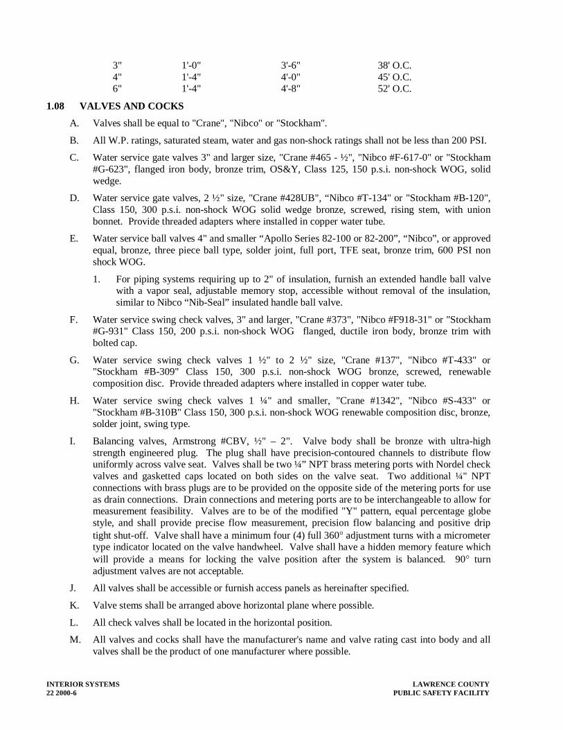
INTERIOR SYSTEMS LAWRENCE COUNTY 22 2000-6 PUBLIC SAFETY FACILITY
3" 1'-0" 3'-6" 38' O.C. 4" 1'-4" 4'-0" 45' O.C. 6" 1'-4" 4'-8" 52' O.C.
1.08 VALVES AND COCKS
A. Valves shall be equal to "Crane", "Nibco" or "Stockham".
B. All W.P. ratings, saturated steam, water and gas non-shock ratings shall not be less than 200 PSI.
C. Water service gate valves 3" and larger size, "Crane #465 - ½", "Nibco #F-617-0" or "Stockham #G-623", flanged iron body, bronze trim, OS&Y, Class 125, 150 p.s.i. non-shock WOG, solid wedge.
D. Water service gate valves, 2 ½" size, "Crane #428UB", “Nibco #T-134" or "Stockham #B-120", Class 150, 300 p.s.i. non-shock WOG solid wedge bronze, screwed, rising stem, with union bonnet. Provide threaded adapters where installed in copper water tube.
E. Water service ball valves 4" and smaller “Apollo Series 82-100 or 82-200”, “Nibco”, or approved equal, bronze, three piece ball type, solder joint, full port, TFE seat, bronze trim, 600 PSI non shock WOG.
1. For piping systems requiring up to 2" of insulation, furnish an extended handle ball valve with a vapor seal, adjustable memory stop, accessible without removal of the insulation, similar to Nibco “Nib-Seal” insulated handle ball valve.
F. Water service swing check valves, 3" and larger, "Crane #373", "Nibco #F918-31" or "Stockham #G-931" Class 150, 200 p.s.i. non-shock WOG flanged, ductile iron body, bronze trim with bolted cap.
G. Water service swing check valves 1 ½" to 2 ½" size, "Crane #137", "Nibco #T-433" or "Stockham #B-309" Class 150, 300 p.s.i. non-shock WOG bronze, screwed, renewable composition disc. Provide threaded adapters where installed in copper water tube.
H. Water service swing check valves 1 ¼" and smaller, "Crane #1342", "Nibco #S-433" or "Stockham #B-310B" Class 150, 300 p.s.i. non-shock WOG renewable composition disc, bronze, solder joint, swing type.
I. Balancing valves, Armstrong #CBV, ½" – 2". Valve body shall be bronze with ultra-high strength engineered plug. The plug shall have precision-contoured channels to distribute flow uniformly across valve seat. Valves shall be two ¼” NPT brass metering ports with Nordel check valves and gasketted caps located on both sides on the valve seat. Two additional ¼" NPT connections with brass plugs are to be provided on the opposite side of the metering ports for use as drain connections. Drain connections and metering ports are to be interchangeable to allow for measurement feasibility. Valves are to be of the modified "Y" pattern, equal percentage globe style, and shall provide precise flow measurement, precision flow balancing and positive drip tight shut-off. Valve shall have a minimum four (4) full 360° adjustment turns with a micrometer type indicator located on the valve handwheel. Valve shall have a hidden memory feature which will provide a means for locking the valve position after the system is balanced. 90° turn adjustment valves are not acceptable.
J. All valves shall be accessible or furnish access panels as hereinafter specified.
K. Valve stems shall be arranged above horizontal plane where possible.
L. All check valves shall be located in the horizontal position.
M. All valves and cocks shall have the manufacturer's name and valve rating cast into body and all valves shall be the product of one manufacturer where possible.

LAWRENCE COUNTY INTERIOR SYSTEMS PUBLIC SAFETY FACILITY 22 2000-7
1.09 PIPE SUPPORTS
A. Use clevis hangers with adjustable steel suspension rods securely fastened to construction. Hangers for bare copper pipe or tubing shall be copper plated.
B. Hangers for plastic pipe shall be clevis type with band width of 1" minimum.
C. Piping may be suspended on trapeze hangers when grouped. Trapeze spacing shall comply with the minimum for the smallest pipe on trapeze. Trapeze construction shall be neat using angle iron and rod hanger firmly attached to construction.
D. All hangers (and clamps for trapeze supported pipes) shall be sized to accommodate the outside diameter of the insulated pipe. See the insulation specification for internal insulation preparation at hangers. Provide temporary blocking within hanger, under pipe, until the insulation subcontractor installs the insulation over the installed pipe.
E. Wherever pipe lines pass through floor or wall construction, set standard weight steel pipe sleeves 1" larger than pipes where not insulated and sized to allow ½" clearance all around outside of jacket where pipes are insulated.
F. Where required or shown, provide structural beams and/or angles, welded or bolted to structure for hanger support.
G. Where pipes are exposed above ground floor, install approved chromium plated brass plates or escutcheons wherever pipes pass through walls, floors or ceilings.
H. Piping on roof shall be supported as detailed on the drawings.
I. Hang pipe with swivel ring type hangers similar to B-Line #B317ONF or clevis type similar to B-Line #B3100.
J. Rods shall be extended from these hangers and firmly attached to steel joist or from concrete inserts for concrete slab construction. Use non-ferrous seating surfaces for copper tubing. Do not use ferrous strap hangers. Provide riser clamps similar to B-Line #B3373 or #B3373CT for copper tubing at each floor to support stacks and vent piping. Grinnell Company, Fee and Mason, Michigan Hanger Co., or equal as approved hangers shall be used.
K. Hanger rods shall be suspended from building steel with "C" clamps similar to B-Line #B35L. This shall apply to all hangers used for piping and equipment. Provide locknut on "C" clamps.
L. All hangers, hanger rods, incidental support steel, etc., shall be coated or painted to resist corrosion.
1.10 THERMOMETERS AND PRESSURE GAUGES
A. Thermometers shall be "Weksler #EG5H" or approved equal, cast aluminum case, 9" long with Eco-green filled thermometer tube mounted on a V-shaped aluminum scale with bold black lines and numerals, union connection and adjustable angle stem connection. Each thermometer shall be installed in a stainless steel or brass separable socket. Temperature scale shall be 30º F to 240º F, with 2º divisions.
1. Provide thermometers at inlet and outlet of hot water heater, outlet and system return of hot water storage tank, outlet of blending valve, and wherever else indicated.
2. Install thermometers in vertical and tilted position to allow reading by observer standing on floor.
B. Pressure gauges shall be "Trerice #600" or approved equal, bottom outlet, 3-½" dial, 0# to 150# scale, with 10# major divisions and 1# minor divisions, stainless steel case, bronze bourdon tube and brass socket. Each gauge shall be installed with a #865 "T" handle gauge cock and #872-1 bronze, ¼" N.P.T. snubber.

INTERIOR SYSTEMS LAWRENCE COUNTY 22 2000-8 PUBLIC SAFETY FACILITY
1. Provide pressure gauges at suction and discharge of each pumps (except sump pumps and sewage ejectors), inlet and outlet of pressure reducing valves, inlet and outlet of backflow preventers, water service entrance, and wherever else indicated.
2. Install pressure gauges in piping tee, with pressure gauge valve, located on pipe at the most readable position.
1.11 WATER HAMMER ARRESTORS
A. Sioux Chief Series 650 "Hydra-Rester" or Wade, Josam, J. R. Smith, "Zurn" or approved equal water hammer arrestor with nesting type bellows contained within casting having sufficient displacement volume to dissipate kinetic energy generated in the piping system. Both casting and bellows shall be constructed of 18-8 stainless steel.
B. Arrestors shall be certified to comply with P.D. 1. standard WH201 and by A.S.S.E. standard 1010. P.D.1. sizing and symbols have been used on the drawings.
C. Arrestors shall be located at flush valve - operated fixtures, at automatic wash equipment, solenoid valves and any other quick closing valve, and wherever else shown on drawings. Provide access panels, as required.
1.12 CROSS CONNECTION CONTROL
A. Reduced Pressure Principle Backflow Preventer
1. Conbraco Series No. 40-200 reduced pressure type backflow preventer, or equivalent Conbraco, Febco or Wilkins, of all bronze body and covers in units 2" and smaller and FDA-approved epoxy coated ductile iron check valve body with bronze seats in units 2½" and larger.
2. Units 2" and smaller to be complete assemblies including two (2) quarter-turn, full-port, resilient-seated ball valves on the inlet and outlet; units 2 ½" and larger to be complete assemblies including tight shutoff UL/FM resilient seated outside screw and yolk valves on the inlet and outlet. Units to include a strainer, four ball type test cocks and a pressure differential relief valve between two positive seating check valves. Unit to feature inline serviceability in all sizes. Units shall be suitable for supply pressures up to 175 psi and water temperatures from 33° to 180° F.
3. Provide airgap drain AGD Model No. 40-200-X, as required, for vent outlets and pipe vent relief discharge to nearest floor drain.
B. Units shall meet the requirements of ASSE Standard No. 1015, AWWA Standard C-506 and USC's FCCC & HR.
C. All units for fire service shall be UL/FM approved with UL/FM approved gate valves.
D. All installed backflow preventers shall be tested at the completion of the project by a person certified to test these devices and the test results submitted.
E. Provide Watts Model 8A polished chrome non-removable vacuum breaker, as required, on hose threads.
F. At coffee machines, provide Watts No. LF7C backflow preventer with lead-free, bronze body, suitable for pressures up to 150 psi and temperatures up to 140° F. max.
1.13 FLOOR DRAINS
A. Floor drains (FD- 1), "Zurn #ZN-415-6B-P", “Wade”, “Josam” or approved equal with cast iron body, 6” round type “B” polished nickel bronze adjustable strainer and ½” trap-primer connection.

LAWRENCE COUNTY INTERIOR SYSTEMS PUBLIC SAFETY FACILITY 22 2000-9
B. Floor drains (FD- 2), "Zurn #Z-525-C-P", "Wade", "Josam" or approved equal with cast iron body, 9" round cast iron strainer seepage pan and clamping collar and ½” trap-primer connection.
C. Floor drains (FD- 3), "Zurn #ZN-415E-P", "Wade", "Josam" or approved equal with cast iron body and 6" round Type “E” polished nickel bronze adjustable strainer with 4" diameter funnel and ½” trap-primer connection.
D. All special floor drains shall be as noted on the drawings. The elevation of the floor drain strainer above or below finished floor is noted on the drawings.
E. All drains in floors above grade, except where prefabricated receptors have been provided, shall be provided with cast iron seepage pan, clamping collar, and shall be lined and made water tight utilizing an approved liner material. Such liners shall be turned up on all sides at least 2 inches above the finished threshold level. Liners shall be recessed and fastened to an approved backing so as not to occupy the space required for the wall covering, and shall not be nailed or perforated at any point less than one (1) inch above the finished threshold. Liners shall be pitched at 2 percent slope towards the floor drains, and shall be securely fastened to floor drain clamping collar. The liner shall be of one of the following materials:
1. PVC sheets shall be a minimum of 0.040” thick, and shall meet the requirements of ASTM D-4551. Sheets shall be joined in accordance with the manufacturer’s installation instructions.
2. Non-plastisticized chlorinated polyethelene sheets, similar to Chloraloy 240, as manufactured by the Noble Company, shall be a minimum of 0.040” thick, and shall meet the requirements of ASTM D-4068. The liner shall be joined in accordance with the manufacturer’s installation instructions.
3. Sheet lead shall weigh not less than 4 pounds per square foot, coated with an asphaltic paint or other approved coating. The lead sheet shall be insulated from conducting surfaces other than the connecting drain by 15-pound asphalt felt or its equivalent. Sheet lead shall be joined by burning.
4. Sheet copper shall conform to ASTM B-152, and shall not weight less than 12 ounces per square foot. The copper sheet shall be insulated from conducting surfaces other than the connecting drain by 15-pound asphalt felt or its equivalent. Sheet lead shall be joined by brazing or soldering.
F. Furnish and install all floor drains and floor sinks indicated on the Plumbing and Architectural drawings or specified herein. Install and connect waste piping to all floor drains and floor sinks in an approved manner, whether specifically shown or not.
G. The Plumbing Contractor shall adjust the strainer elevation of all existing floor drains in areas where the existing floor finishes are to be modified.
H. Floor drains and floor sinks in new floor slabs shall be installed at the low points of the surface areas to be drained. Set strainer elevation depressed below finished floor slab elevation so as to provide proper slope to drain.
I. The exact position of floor drains and floor sinks in existing floor slabs shall be determined in the field, so as to locate floor drain at low point of existing floor, based upon a water test performed by the Plumbing Contractor in the presence of the Architect's representative.
J. Contractor shall be responsible for the proper protection of all floor drains and floor sinks until building phase is completed and accepted by the Architect and the Owner. Care shall be taken to protect all strainers/grates from damage, and to prevent construction debris from clogging the drain and entering the sewer. When building is ready for use before final approval, Plumbing

INTERIOR SYSTEMS LAWRENCE COUNTY 22 2000-10 PUBLIC SAFETY FACILITY
Contractor shall remove all protection including paper covering and stickers and thoroughly clean all drains, and remove all coating, rubbish, etc., that has accumulated as a result of this work. Drains and sewer shall be thoroughly cleaned of all construction debris.
1.14 TRENCH DRAINS
A. Trench drains (TD-1), Zurn #Z-882, 12” wide presloped high density polyethylene trench drain system with bottom slope. Drain shall include heavy duty steel angle frame, combination leveling straps/anchor tabs and heavy duty cast iron grate.
B. Trench drain catch basins (CB-1) shall be Zurn #Z-887-24-HD, 24” x 24” x 24” deep, high density polyethylene reinforced body with heavy duty steel angle frame, heavy duty cast iron grate and sediment bucket.
C. Trench drains and catch basins shall be installed in accordance with manufacturer’s recommendations.
1.15 TRAP PRIMERS
A. Zurn Trap Primer (TP-1) Model #Z-1022 trap primer valve with the appropriate distribution unit. Primer valve shall be machined of corrosion resistant brass with no springs or diaphragms.
B. The primer valve shall operate on a pressure drop of as little as 5 psi.
C. Zurn Trap Primer (TP-2) Model #Z-1020 electronic trap primer Electronic trap primer programmed as standard to provide a six second water injection to traps every twenty-four hours, complete with galvanized steel combination surface or recessed mount box and cover, ½” solder copper inlet connection, brass ball type stop valve, slow closing 24 VAC solenoid valve with integral strainer, 120 - 24 VAC transformer, brass atmospheric vacuum breaker, PEX waterway, and anti-scaling multi-port manifold with five ½” Male PEX outlet connections.
D. Connect primer valve to cold water piping, as shown on drawings. Extend trap primer tubing to floor drains, as shown on drawings, and connect to primer connection tapping on floor drain.
1.16 CLEANOUTS
A. All cleanouts shall be full size of line up to and including 4". Lines over 4" in diameter shall be provided with 4" cleanouts.
B. Wall cleanouts (WCO), "Zurn Cleanout Tees #Z-1441-VP", "Wade", "Josam" or equal with gas and water tight tapered thread bronze plug and cast iron ferrule, smooth stainless steel wall access cover with securing screw.
C. Floor cleanouts (FCO), "Zurn #Z-1400-BP-VP", "Wade", "Josam" or approved equal. Gas and water tight tapered thread bronze plug and adjustable scoriated polished nickel-bronze round access covers. When installed in carpeted area provide –CF, provide –X when installed in tile.
D. Exterior grade cleanouts (ECO), "Zurn #Z-1474-N", "Wade", "Josam" or equal, located where shown. Gas and water tight tapered thread bronze and adjustable extension body and heavy duty cast iron adjustable housing with scoriated cover. Set cleanout in 4" thick concrete pad, 18" square, flush with grade except where cleanout occurs in concrete paving.
E. Install cleanouts at all changes of direction of all main sewer lines, at a maximum 50 feet intervals for 4" piping and less and at a maximum 100' feet intervals for piping over 4", at the base of all vertical lines including rain conductors, and soil/waste stacks, and at all other locations indicated on drawings. Extend cleanout branches to convenient accessible locations in floor or wall as directed. See "Cleanouts". All cleanout "tees" in stacks shall be cast iron, galvanized steel or copper and shall be located 24" above the finished floor. Plastic cleanout "tees" in stacks will not be acceptable.

LAWRENCE COUNTY INTERIOR SYSTEMS PUBLIC SAFETY FACILITY 22 2000-11
F. Allow a minimum clearance of 18" between cleanouts and any wall or obstruction, for rodding.
G. The Plumbing Contractor shall adjust all existing wall and floor cleanouts, as approved by the Architect, in areas where the existing wall and floor finishes have been modified.
1.17 TRAPS
A. Each fixture and piece of equipment requiring connection to the sanitary sewer system shall be equipped with a trap. Traps shall be placed as near to the fixture or equipment drain outlet as possible. Traps below floor level shall be of the same material as the pipe to which it is connected. All fixture traps shall have a minimum of 1 ½" outlet. All exposed or accessible P-traps with bottom cleanout plug.
1.18 INTERIOR HOSE BIBBS
A. Hose Bibb, (HB-1), "Chicago #387-E27", "Nibco" "Woodford" or approved equal flanged ¾" female inlet, removable tee handle and vacuum breaker. Provide chrome plate finish in finished areas. Locate as indicated.
1.19 EXTERIOR HOSE BIBBS
A. Exterior Frost-Proof Hose Bibb, (FPHB-1), "Zurn Z-1320", "Nibco" "Woodford" or approved equal "anti-siphon" automatic draining wall hydrant for flush installation. Complete with integral backflow preventer, copper casing, all bronze interior parts with 1/2 turn ceramic disc cartridge and combination ¾” female solder and ¾” male pipe thread inlet. Stainless steel box and hinged cover with operating key lock and "WATER" stamped on cover. (All solder connections are lead free.). Locate as indicated.
1.20 UNIONS
A. Provide unions where indicated and in the following locations if not indicated:
1. In long runs of piping for water piping at intervals not to exceed 100'.
2. In by-passes around equipment.
3. In connections to hot water heaters, pumps and other equipment requiring disconnections for repairs or replacement, locate between shut-off and equipment.
B. For copper pipe 2-½" and smaller, use cast bronze, sweat type unions with bronze ground joint. For copper piping 3" and larger use 150 PSI sweat flanges.
C. For steel pipe, 2-½" or smaller, use malleable iron unions, steel to brass seat, screwed, 150 PSIG W.P. For steel pipe 3" and larger use welded slip-on flanges, 150 PSIG W.P.
D. Flange gaskets shall be 1/16" thick, 150 PSIG W.P. "Cranite" or equal.
E. Between ferrous and non-ferrous metal water pipe, provide an insulating flange or coupling, "EPCO", "Malony" or approved equal.
1.21 STRAINERS
A. Strainers, "Y" type, screwed 3" and smaller with monel screens. Strainers shall be installed on inlets of all blending or tempering valves except for shower mixing valves. Strainers shall be "Mueller", "Watts", or approved equal.
1.22 FLEXIBLE PIPE CONNECTORS
A. "Flexonics Type 4016", stainless steel hose and braid with stainless steel flanged end connections. Length shall be a minimum of 6 times the ID.

INTERIOR SYSTEMS LAWRENCE COUNTY 22 2000-12 PUBLIC SAFETY FACILITY
1.23 HVAC EQUIPMENT CONNECTION
A. Condensate drain piping, for all HVAC equipment, shall be the responsibility of the HVAC Contractor.
B. Cold water piping, for all HVAC equipment and systems, shall be terminated with valved capped connections, where indicated on the drawings, by the Plumbing Contractor. HVAC Contractor shall be responsible for extending from the capped valve, and shall make final connection to all HVAC equipment and systems requiring same, including all backflow preventers installed after the capped valve.
C. Coordinate the location of all drains, piping connections and HVAC equipment with the HVAC Contractor.
END OF SECTION 22 2000
LAWRENCE COUNTY INSULATION PUBLIC SAFETY FACILITY 22 3000-1
SECTION 22 3000 PLUMBING INSULATION
1.01 GENERAL
A. Insulation shall be applied in a neat and workmanlike manner by mechanics experienced in this type of work. Insulation shall be manufactured by companies regularly engaged in the manufacture of mechanical insulation products, of the types and sizes required, whose products have been in satisfactory use in similar projects for not less than 5 years. All insulation and covering installations shall be done by skilled tradesmen normally employed in this work, with a minimum of 5 years experience in similar projects. All materials shall be installed in strict accordance with manufacturer's recommendations, all applicable building codes, and industry standards.
B. Contractor shall be required to remove and replace all insulation not applied in strict accordance with the manufacturer's specification, or not presenting a neat appearance, all as judged by the Architect. All piping shall be tested before insulation is applied at joints and all joints left uncovered until tests have been performed and approved.
C. Insulate all new water piping except exposed fixture branches.
D. All insulation material (insulation, jackets, adhesives, cements, mastics, sealers, coatings and finishes) shall have composite Fire and Smoke Hazard Ratings, as tested under procedure ASTM E-84, NFPA 255 and UL 723, with a flame spread rating of 25 or less, and smoke developed rating of 50 or less.
E. All surfaces shall be clean, dry and free of all oil and grease before insulation, adhesives or mastics are applied. All foreign matter, such as rust, scale, dirt, etc. must be removed.
F. Locate all seams in the least visible location. All joints shall be tight with insulation lengths and segments tightly butted against each other, and secured with appropriate butt-strip material. Where lengths or segments are cut, cuts must be smooth and square, and without breakage of end surfaces. All pipe insulation shall be continuous through wall, ceiling and floor openings and sleeves, except where firestopping materials are required.
G. Where vapor barrier jackets are used on cold surfaces, insulation must be applied with vapor seal integrity maintained throughout the entire system.
H. All pipe insulation shall be pre-molded, sectional, and be split ready for application.
I. Insulation where vapor barrier is required shall be continuous through pipe hangers, walls, floors and similar penetrations, except where otherwise indicated. At pipe hangers use rigid pipe insulation/covering, the same outside dimension as the adjacent insulated pipe, finished the same as the adjacent pipe covering. Provide external metal insulation shields outside the insulation jacket, but inside the pipe hanger at these locations
J. Except for handicapped accessible fixtures, omit insulation on exposed chrome plate piping, air chambers, unions, strainers, check valve, balancing valves, flow regulators, drain lines from water coolers, drainage piping located in crawl spaces or tunnels, underground service main piping, fire protection piping and pre-insulated equipment, unless otherwise noted.
1.02 PIPING INSULATION – FIBER GLASS
A. Pipe insulation and accessories shall be manufactured by Knauf Fiber Glass, Proto Corp. or approved equal.
B. For piping system, provide Kanuf 1000° rigid, molded, non-combustible glass fiber pipe insulation meeting ASTM C-547, ASTM C-585 and ASTM C-795 with a 'K' valve of 0.23 at 75°

INSULATION LAWRENCE COUNTY 22 3000-2 PUBLIC SAFETY FACILITY
F., 1000° F. maximum service temperature and an ASJ/SSL vapor retarding jacket conforming to ASTM C-1136 Type I, secured with self-sealing longitudinal laps and butt strips.
C. For piping systems operating at or below ambient conditions (35° – 70° F.) provide a continuous vapor retarder. Seal all joints, surfaces, seams and fittings to prevent condensation.
D. Metal shields shall be installed between hangers or supports and the piping insulation. Rigid insulation inserts shall be installed as required between the pipe and the insulation shields. Inserts shall be of equal thickness to the adjacent and shall be vapor sealed as required. Insulation inserts shall be no less than the following lengths:
Pipe Size Insert Length
1-1/2" to 2-1/2" 10"
3" to 6" 12"
8" to 10" 16"
12" and larger 22"
E. For piping exposed in mechanical rooms or high traffic areas, insulation shall be protected from abuse by the use of appropriate thickness of PVC jacketing.
F. Adhesive and contact surfaces must be kept free from dirt and water, and sealed immediately once adhesive is exposed. If stored below 0° F. or above 130° F., insulation cartons should stand within the recommended temperature range for 24 hours prior to application. The insulation should never be stored below –20° F. or 150° F.
G. When using a SSL (self-sealing longitudinal lap) closure system, the longitudinal and circumferential joints must be properly sealed by rubbing the closure with a squeegee. The use of staples is not recommended with the SSL closure system.
H. For fittings, valves and hangers, use Proto 25/50 rated PVC fitting covers, installed in accordance with manufacturer’s recommendations.
1.03 PIPE INSULATION – CLOSED CELL ELASTOMERIC
A. Pipe insulation, where specified, shall be flexible, pre-split, self-sealing, closed-cell elastomeric thermal insulation similar to Armstrong Armaflex SS, with a flame spread rating of 25 or less, and a smoke developed rating of 50 or less when tested in accordance with the latest version of ASTM E-84. In addition, the insulation shall not melt or drip flaming particles, and the flame shall not be progressive.
B. Piping is to be clean and dry. Wipe with a clean rag to remove any contaminants and moisture.
C. Snap the pre-split insulation over the piping in a gentle twisting motion. Longitudinal seams to be sealed by removing the protective strips from the adhesive surface and applying firm pressure along the joint. Butt end joints to be sealed with Armstrong 520 Adhesive.
1.04 COLD WATER PIPING
A. Domestic cold water piping shall be insulated with fiber glass insulation, as specified above. Insulation thickness shall be 1” for piping up to 1"; insulation thickness shall be 1-½” for piping 1-¼” and over.
B. Maintain vapor barrier on all cold water pipe insulation.
1.05 HOT WATER PIPING
A. Domestic hot water, domestic hot water return piping shall be insulated with fiber glass insulation, as specified above. Insulation thickness shall be 1" for up to 4” and 1 ½” for piping 5” and over.

LAWRENCE COUNTY INSULATION PUBLIC SAFETY FACILITY 22 3000-3
B. Insulate all circulating hot water piping between storage tanks and hot water heater.
1.06 COLD EQUIPMENT
A. Cold water storage tank, iron filter tank and water softener tank shall be insulated with Armstrong AP Armaflex flexible, closed-cell, sheet or roll elastomeric thermal insulation, with a flame spread rating of 25 or less, and a smoke developed rating of 50 or less, using Armstrong 520 Adhesive. Insulation thickness shall be 1".
B. Provide two (2) coats of high quality acrylic latex paint on all rubber insulation.
1.07 UNDERGROUND PIPE
A. Underground domestic hot and cold water piping shall be insulated with closed-cell elastomeric thermal insulation as specified above.
B. At completion of insulation work and approval by the Architect, all insulated underground pipe shall be double wrapped with a 6 mil polyethylene sheet with all longitudinal and transverse joints sealed with duct tape.
C. Insulation thickness shall be 1".
1.08 HANDICAPPED ACCESSIBLE FIXTURES
A. The waste and water piping, including P-traps, tailpieces, supply tubes and shutoff valves, to handicapped accessible lavatories and counter sinks shall be insulated with a white fully molded closed cell vinyl similar to “Truebro Handi Lav-Guard”. Insulation shall be secured with nylon fasteners, and shall comply with ASTM D 635 for burning characteristics and ASTM C 177 for thermal conductivity. Covers for shutoff valves shall have a hinged cap for access.
B. Insulation not required on fixtures installed with undersink enclosures, provided by the General Contractor.
1.09 FIRE STOPPING
A. Fire stopping as described herein, consists of furnishing and installing materials, or combinations of materials, to form an effective barrier against the spread of flame, water, smoke and hot gases, and to maintain the integrity of fire rated construction. It shall be used for fire or smoke barriers that require sealing around penetrations in accordance with NFPA 101, and NFPA 70 when applicable.
B. In accordance with Sections 22 0000-1.04 and 23 0000-1.04, SHOP DRAWINGS, furnish the following:
1. Manufacturer’s Literature and Installation Instructions.
2. Certificates: Indicating fire stopping material conforms to specified UL requirements.
3. Shop Drawings: Complete construction details showing proposed material, reinforcement, anchorage, fastenings, and method of installation.
C. DELIVERY AND STORAGE: Deliver all materials to the building site in original unopened containers, identified with brand, type, and UL label, where applicable. Store materials in a location providing protection from damage and exposure to the elements. Damaged or deteriorated materials shall be removed from the site.
D. The publications listed below form a part of this specification to the extent referenced. The publications are referenced in the text by the basic designation only.
1. ASTM E 814: Fire Tests of Through-Penetration Firestops. 2. ASTM E 119: Fire Tests of Building Construction and Materials. 3. ASTM E 84: Surface Burning Characteristics of Building Materials.

INSULATION LAWRENCE COUNTY 22 3000-4 PUBLIC SAFETY FACILITY
4. UL 723: Standard Test Method for Surface Burning Characteristics of Building Materials. 5. UL 1479: Fire Tests of Through-Penetration Firestops. 6. UL 263: Fire Tests of Building Construction and Materials. 7. UL Fire Resistance Directory: Through-Penetration Firestops Systems (XHEZ), and
Fill, Void or Cavity Materials (XHHW) 8. NFPA 70: National Electric Code. 9. NFPA 101: Life Safety Code 10. NFPA 255: Method of Testing of Surface Burning Characteristics of Building Materials. 11. NBCC: National Building Code of Canada. 12. ULC CAN4-S115M: Standard Method of Fire Tests of Firestop Systems. 13. UL 2079 Tests for Resistance of Building Joint Structures.
E. Acceptable Manufacturers shall be Metacaulk, Biofireshield and 3M.
F. Fire Rated Fire Stopping Sealants shall be approved for the type of installation and UL rating of the application.
1. The fire stopping sealant shall not slump or sag and be thixotropic, intumescent and free of asbestos, halogens and volatile solvents.
2. Fire stop materials shall be a one part component sealant applied with a conventional caulking gun or trowel and require no special tools. For large openings and/or openings with multiple penetrating items, intumescent firestop blocks shall be used. Blocks shall be able to be cut with a typical blade, and should be flexible so as to allow for friction fitting. Temporary formwork used for trowelable or firestop blocks shall be removed after installation, and any points of fastening for the temporary formwork shall be repaired in accordance with the requirements of this specification.
3. Fire stop materials shall be capable of maintaining an effective barrier against flames, heat and smoke in compliance with the requirements of ASTM E 814, UL 1479, ASTM E 119, UL 723, ASTM E 84 and UL 263.
4. Fire stop materials shall be paintable or capable of receiving finish materials in those areas which are exposed to view and which are scheduled to receive finishes.
G. Prepare substrate surfaces to insure proper and adequate structural support for the specified UL Rated Fire Stop System. General Contractor shall install fire-rated partitions/floors with penetration (hole) to receive fire stop system in new construction. Locate and size all openings for the General Contractor in new construction. In existing construction prepare wall and cut holes and penetrations as required. Clean all penetration (hole) and penetrating item surfaces of all foreign materials including loose debris, dirt, oil, grease, wax and/or old caulking before sealant is applied. Protect adjacent areas or surfaces from damage as a result of the work of this Section.
H. Installation of fire stopping materials shall be in exact accordance with the Manufacturers latest published instructions, requirements, specifications, details and approved shop drawings. Installation shall be in accordance with the appropriate UL Fire Resistance Directory or with the appropriate Warnock Hersey International Listing. A manufacturer’s direct representative (not a distributor or agent) shall be on-site during the initial installation of the firestop systems to train appropriate contractor personnel in proper selection and installation procedures.
1. Seal holes or voids made by penetrating items to ensure an effective fire and smoke barrier. Seal all intersections and all penetrations of floors, ceilings, walls, and columns.
2. Seal around all cutouts for cabinets, pipes and ducts, etc.

LAWRENCE COUNTY INSULATION PUBLIC SAFETY FACILITY 22 3000-5
3. Where floor openings are four inches or more in width and subject to traffic or loading, install cover plate systems capable of supporting same loading as floor.
4. Interface with Other Projects: Coordinate and cooperate with adjacent, contiguous and related materials trades, such as concrete, drywall, plumbing, conduit, electrical wiring, communication system, etc., to ensure a proper and timely installation.
I. Contact the Manufacturer before using Fire Stop products in Computer Rooms or other areas with sensitive electronic equipment.
J. Examine finished penetrations to ensure proper installation before concealing or enclosing any areas of work. Keep areas of work accessible until inspection by applicable code authorities. Inspect to verify and confirm that systems installation is in strict conformance with Manufacturer’s and UL requirements. Correct unacceptable work and provide further inspection to verify compliance with requirements.
K. After installation and until Owner’s acceptance, protect Rated Fire Stop System from damage. Any damaged materials shall be removed and replaced with new undamaged materials prior to final acceptance.
L. Tag all penetrations with a tag showing the Manufacturer and product number of the Fire Stop material. Also list the UL system number and corresponding Manufacturers installation instruction sheet number which details the specific installation instructions.
END OF SECTION 22 3000

LAWRENCE COUNTY PLUMBING FIXTURES PUBLIC SAFETY FACILITY 22 4000-1
SECTION 22 4000 - PLUMBING FIXTURES
1.01 GENERAL
A. Furnish and install all plumbing fixtures and drains indicated on the Plumbing and Architectural drawings or specified herein. Install and connect water, soil/waste and vent piping to all plumbing fixtures and drains requiring same, in an approved manner, whether specifically shown or not.
B. All new fixtures shall be first quality chinaware or acid resisting enamelware as specified. All exposed metal and trim shall be chromium plated brass. All equipment and fixtures shall be furnished complete with all trim, faucets, fittings, traps, piping, stops, etc. for complete installation. Provide chrome plate angle shut-off valves on all fixtures.
C. All new toilet seats and vitreous china plumbing fixtures shall be white. Color of electric water cooler cabinets and bubblers shall be as selected by Architect.
D. All flush valves shall be equipped with vacuum breakers, screwdriver stops, vandal-resistant control stop caps, non-hold open devices, sweat solder adapter and cast wall flange with set screw.
E. All supply piping, traps, etc. shall be fitted with cast brass set screw escutcheons.
F. Check setting height and location of all plumbing fixtures with General Contractor and Architect before placing. Mounting height of various fixtures may not be standard and Contractor shall be responsible for verifying mounting heights from Architect if heights are not shown on the drawings.
G. Where new plumbing fixtures are to be installed in existing construction, the Plumbing Contractor shall be responsible for all cutting, patching and restoration, as approved by the Architect.
1.02 QUALITY ASSURANCE
A. Comply with the Americans with Disabilities Act (ADA) with respect to plumbing fixtures for the physically handicapped.
B. Provide electrically operated fixtures specified in this section that are listed and labeled as defined by the National Electrical Code (NEC), Article 100.
C. Components of the electric water coolers shall be lead free as defined by the Safe Drinking Water Act Amendments of 1986 and the Lead Containment Control Act of 1988.
1.03 MANUFACTURERS
A. Manufacturer's qualifications shall be firms regularly engaged in the manufacture of plumbing fixtures and accessories of types required, whose products have been in satisfactory use in similar service for not less than 5 years.
B. Subject to compliance with the requirements, provide products in each category, by one of the following manufacturers listed for that category.
1. Vitreous china plumbing fixtures
a. American Standard
b. Kohler
c. Zurn Industries, Inc.

PLUMBING FIXTURES LAWRENCE COUNTY 22 4000-2 PUBLIC SAFETY FACILITY
2. Flush valves
a. Sloan Royal
b. Zurn Industries, Inc.
3. Toilet seats
a. Bemis
b. Beneke
c. Church
d. Olsonite
e. Zurn Industries, Inc.
4. Stainless steel sinks
a. Elkay Manufacturing Co.
b. Just
c. Moen
5. Electric water cooler
a. Elkay Manufacturing Co.
b. Haws Drinking Faucet Co.
c. Ebco
6. Fixture carriers
a. Josam
b. J. R. Smith
c. Wade Division, Tyler Pipe
d. Zurn Industries, Inc.
7. Washing machine supply and drain
a. Guy Gray Manufacturing Co.
b. Symmons Industries, Inc.
c. Oatey
8. Laundry tub
a. Fiat Products, Inc.
b. E. L. Mustee & Son
c. Florstone Products Co.
9. Mop service basins
a. Fiat Products, Inc.
b. Stern-Williams Co., Inc.
c. Florstone Products Co.
10. Fiberglass shower enclosures
a. Aqua Glass Corp.
b. Aquarius Industries
c. Universal Rundle Corp.
11. Emergency fixtures

LAWRENCE COUNTY PLUMBING FIXTURES PUBLIC SAFETY FACILITY 22 4000-3
a. Bradley Corp.
b. Guardian Equipment
c. Haws Drinking Faucet Co.
d. Speakman
12. Manual Faucets
a. Kohler
b. Chicago Faucet Co.
c. American Standard
d. Delta Faucet Company
e. Zurn Industries, Inc.
f. Speakman
13. Sensor Faucets
a. Chicago Faucet Co.
b. Sloan Royal
c. Zurn Industries, Inc.
14. Miscellaneous fittings (except faucets)
a. Chicago Faucet Co.
b. Delta Faucet Company
c. McGuire Manufacturing
d. Royal Brass Manufacturing Co.
e. Zurn Industries, Inc.
1.04 PROTECTION AND CLEANING OF FIXTURES
A. Install and anchor to structure of building, plumbing fixtures and equipment as recommended by manufacturer. In every case where fixtures or equipment are to be attached to wall or floor construction, furnish all necessary information to General Contractor and furnish approved grounds, anchors and sleeves where such are required. Do not use screws in wood plugs. Where supports are attached to masonry wall, use screws in lead shields, toggle bolts or other means of securement as approved by the Architect.
B. Make all necessary provision for proper installation of concealed fixture carriers in walls and floors.
C. Securely anchor flush valves and exposed pipes with approved heavy chromium plated brass straps.
D. Contractor shall be responsible for proper protection of all fixtures and equipment after installation until building phase is completed and accepted by the Architect and the Owner. When building is ready for use before final approval, Plumbing Contractor shall remove all protection including paper covering and stickers and thoroughly clean all fixtures and other equipment furnished under this Contract, and remove all coating, rubbish, etc., that has accumulated as a result of this work.

PLUMBING FIXTURES LAWRENCE COUNTY 22 4000-4 PUBLIC SAFETY FACILITY
1.05 LAVATORY "(L-2)" HANDICAPPED ACCESSIBLE, 4" CENTERSET, WALL HUNG
A. American Standard Lucerne Model 0356.041 20” x 18” vitreous china, wall hung lavatory with 4” center faucet holes, with front overflow. Lavatory shall be equipped for concealed arm carrier installation.
1. Chicago Faucet 116.201.AB.1 Hytronic single hole faucet DC powered, solid brass waterway, dual beam infrared sensors, cast brass spout and 0.5 gpm vandal resistant spray outlet, single supply for tempered water. 6 volt lithium CRP2 battery included.
2. McGuire #2165LK, ½" I.P.S. x 3/8" O.D. loose key angle stops with cast brass escutcheons and 3/8" O.D. x 12" long flexible risers.
3. McGuire #155WC, 1 ¼" offset wheelchair lavatory drain with perforated grid strainer, 17 gauge.
4. McGuire #8090, 1 ¼" x 1 ½" swivel P-trap with cleanout plug, 17 gauge cast brass.
5. McGuire #WE150B, 1 ½" wrought brass box flange.
6. Zurn No. Z8946-3-NT, ADA combination trap & supply protector kit with one (1) trap, two (2) supplies and one (1) offset drain, satin white PVC resin, with a 3/8" nominal wall. Shall resist thermal transfer.
7. Zurn #Z-1231, wall lavatory concealed arm system with rectangular steel uprights with welded feet cast iron adjustable headers, concealed arms steel sleeves, alignment truss and mounting fasteners. Back of lavatory shall be tight to wall. Install with rim of lavatory 31" above finished floor.
8. Provide insulation on exposed waste and water piping per Section 22 3000, except on lavatories with an under basin enclosure provided by the General Contractor.
B. Provide rough-in of handicapped accessible lavatory as detailed on architectural drawings.
C. Mixing valve: A Thermostatic Mixing Valve shall be installed on the hot water supply to the fixture. The valve shall be ASSE Standards 1070 listed and control the temperature of the hot water. It shall have a bronze body and shall include integral check valves, integral screens and an adjustment cap with locking feature. The valve shall be provided with 3/8” (10mm) male compression fittings. The valve shall be Bradley S59-4008.
1.06 WATER CLOSET "(WC-1)" WATER SAVER, WALL HUNG, FLUSH VALVE
A. American Standard Model Afwall FloWise 3351.001, 1.28 gpf wall hung, vitreous china, elongated front, siphon jet, top spud flush valve water closet with the heavy duty open front seat less cover.
1. Sloan Royal Optima Smooth 111-1.28 SMO, Quiet, battery operated, sensor operated, exposed 1 ½” top spud chrome plated flushometer with 1” I.P.S. angle stop, vandal resistant stop cap, and adjustable tailpiece. Override button, (4) four AA batteries, with ‘low battery” flashing LED.
B. Furnish applicable wall closet fitting and chair carrier for wall hung water closet. Carrier shall be "Zurn #Z-1203" (horizontal) or "Zurn #Z-1204" (vertical) and shall be horizontal or vertical "adjustable" where possible, single or double, and arranged as shown on the drawings. Where limited by available space, use "integral" type, single or double, vertical as shown on the drawings. For installations in stud construction, fixture carrier shall be furnished complete with finishing frame. Provide vent and auxiliary inlets as required. Install closet with rim 15" above floor.

LAWRENCE COUNTY PLUMBING FIXTURES PUBLIC SAFETY FACILITY 22 4000-5
1.07 WATER CLOSET "(WC-2)" HANDICAPPED ACCESSIBLE, WATER SAVER, WALL HUNG, FLUSH VALVE
A. American Standard Model Afwall FloWise 3351.001, 1.28 gpf wall hung, vitreous china, elongated front, siphon jet, top spud flush valve water closet with the heavy duty open front seat less cover. Mounted at ADA heigh requirements.
1. Sloan Royal Optima Smooth 111-1.28 SMO, Quiet, battery operated, sensor operated, exposed 1 ½” top spud chrome plated flushometer with 1” I.P.S. angle stop, vandal resistant stop cap, and adjustable tailpiece. Override button, (4) four AA batteries, with ‘low battery” flashing LED.
B. Furnish applicable wall closet fitting and chair carrier for wall hung water closet. Carrier shall be "Zurn #Z-1203" (horizontal) or "Zurn #Z-1204" (vertical) and shall be horizontal or vertical "adjustable" where possible, single or double, and arranged as shown on the drawings. Where limited by available space, use "integral" type, single or double, vertical as shown on the drawings. For installations in stud construction, fixture carrier shall be furnished complete with finishing frame. Provide vent and auxiliary inlets as required. Install closet with rim 15" above floor.
1.08 URINAL "(UR-1)" HANDICAPPED ACCESSIBLE, WALL HUNG, FLUSH VALVE, ¾" TOP SPUD - 0.125 (PINT) GPF
A. American Standard Washbrook FloWise Model 6590.001 Ultra high efficiency pint urinal system, to include wall hung flush valve urinal and flush valve as follows:
1. Vitreous china, ultra high efficiency 0.125 GPF, wall hung washout urinal with ¾” top spud and concealed hangers. 2" I.P.S. outlet flange and 14" extended rim for handicap compliance when installed at the proper height.
2. Sloan Royal Optima Smooth 186-0.125 SMO, Quiet, battery operated, sensor operated, exposed 3/4” top spud chrome plated flushometer with 3/4” I.P.S. angle stop, vandal resistant stop cap, and adjustable tailpiece. Override button, (4) four AA batteries, with ‘low battery” flashing LED.
B. Urinal supported by Zurn #Z-1222, wall urinal carrier with bearing plate. Install urinal with rim 17" above floor, for use by the physically handicapped.
1.09 MOP SERVICE BASIN "(MSB-1)"
A. Fiat #TSB-100, 24" x 24" with 12" high sides, Basin shall be one piece, precast terrazzo. Terrazzo shall be black and white marble chips in grey portland cement with a compressive strength of not less than 3000 PSI, ground smooth and filled as required for an impervious surface. Shoulders shall be not less than 2" wide.
B. Basin shall be complete with a cast-in 3", S/S drain body for lead connection and stainless steel caps around basin.
C. Provide silicon sealant, Fiat #833-AA, at all joints between wall and basin.
D. Chicago #897 wall mixing faucet with ¾" hose threaded outlet, pail hook with wall support, inlet flanges adjustable from 4" to 8", integral stops, integral vacuum breaker, polished chrome plated.
E. Provide Fiat 832AA 5/8” hose, 30” long with clamp, 889cc mop hanger with 3 clamps and MSG2424 two (2) 24” stainless steel splash panels.
\

PLUMBING FIXTURES LAWRENCE COUNTY 22 4000-6 PUBLIC SAFETY FACILITY
1.10 LAUNDRY TUB "(LT-1)"
A. Mustee 15F single compartment, 23" x 23 1/2" x 14 3/8" deep molded stone laundry tub with self-draining soap tray on back ledge. Unit shall include the following:
1. Four white baked enamel angle legs.
2. Eljer #803-0590 1 ½" laundry tray drain assembly with rubber stopper and pull ring.
3. Eljer #804-1190 1 ½" x 1 ½" adjustable P-trap with cleanout, 17 gauge tubing.
4. McGuire #2165LK, ½" I.P.S. x 3/8" O.D. loose key angle stops, with cast brass escutcheons, and 3/8” O.D. x 12” long flexible riser
5. Mustee 93.600 faucet with 4" centers, 7" swing spout.
1.11 WASHING MACHINE SUPPLY & DRAIN UTILITY BOX "(UB-1)"
A. Sioux Chief Model #696-G2313MF, recessed supply and drain box for automatic washing machine. Unit shall be roughed in with bottom inside of recessed box 42" above floor, unless otherwise noted. Recessed box and wall flange shall be high impact polystyrene.
B. Box shall be complete with single lever valve with integral water hammer arrestors, a 2" tailpiece with flange nut waste connection and copper sweat piping connections. Pipe as recommended by the manufacturer.
1.12 ELECTRIC WATER COOLER "(EWC-1)" HANDICAPPED ACCESSIBLE, WALL HUNG, DUAL HEIGHT, WITH BOTTLE-FILLER
A. Elkay Model LZSTL8WSVRK dual, vinyl-clad steel cabinet and stainless steel top with one bubbler at 34" bove floor for handicapped use and the other bubbler at 40" above the floor. Each unit shall include a 2-stream bubbler and a self-closing bubbler valve actuated by a touch pad on the front of unit only which will maintain continuous water flow as long as pressure is applied to the pads. Unit shall include a Flex-Guard Safety Bubbler utilizing an infused anti-bacterial pliable polyester elastomer and shall be keyed in location to prevent rotation. Controls shall require less than 3 pounds of force to activate. Each unit shall have a water system free of lead-containing brass parts, and shall use HFC-134a refrigerant. Unit shall have one (1) 1/5 HP compressor, 115 volt, 60 Hz, single phase. Unit will be supplied with WaterSentry Plus filtration system. Unit shall have bottle filler with electronic sensor with 20-second shut-off timer. Color of cabinet shall be as selected by Architect. Water cooler shall not be installed until potable water system has been thoroughly flushed and cleaned of all construction deposits and foreign substances.
B. The water cooler shall be certified to ANSI/NSF61. Water cooler shall be accessible to the adult physically handicapped.
C. Chiller shall be air cooled and shall have a capacity of 8.0 GPH of 50° F. drinking water based upon 80° F. inlet water temperature and 90° F. ambient air temperature.
D. Provide the following trim:
1. Sioux Chief #234-10, 1 ½" white polypropylene P-trap with 1 ½" PVC trap adapter.
2. McGuire #2165LK, ½" I.P.S. x 3/8" O.D. loose key angle stops, with cast brass escutcheons, and 3/8” O.D. x 12” long flexible riser
3. Elkay #LKAPREZL, apron assembly. Finish of apron shall match that of water cooler unit. Install apron on higher unit.

LAWRENCE COUNTY PLUMBING FIXTURES PUBLIC SAFETY FACILITY 22 4000-7
E. The water cooler must be connected to the water supply using a dielectric coupling. The cooler is to be furnished with a non-metallic strainer which meets this requirement. The drain trap is to be plastic to isolate the cooler from the building drainage system.
F. Water Cooler shall have a 5 year limited warranty on the refrigeration system of the unit, and a 2 year limited warranty on the electrical components and water system.
1.13 ELECTRIC WATER COOLER "(EWC-2)" WALL HUNG, SINGLE UNIT, WITH BOTTLE-FILLER
A. Elkay Model LZS8WSVRK vinyl-clad steel cabinet and stainless steel top. Unit shall include a 2-stream bubbler and a self-closing bubbler valve actuated by a touch pad on the front and both sides which will maintain continuous water flow as long as pressure is applied to the pads. Unit shall include a Flex-Guard Safety Bubbler utilizing an infused anti-bacterial pliable polyester elastomer and shall be keyed in location to prevent rotation. Controls shall require less than 3 pounds of force to activate. Each unit shall have a water system free of lead-containing brass parts, and shall use HFC-134a refrigerant. Unit shall have one (1) 1/5 HP compressor, 115 volt, 60 Hz, single phase. Unit will be supplied with WaterSentry Plus filtration system. Unit shall have bottle filler with electronic sensor with 20-second shut-off timer. Color of cabinet shall be as selected by Architect. Water cooler shall not be installed until potable water system has been thoroughly flushed and cleaned of all construction deposits and foreign substances. Unit shall be mounted with bubbler outlet 36" above floor for use by the physically handicapped.
B. The water cooler shall be certified to ANSI/NSF61. Water cooler shall be accessible to the adult physically handicapped.
C. Chiller shall be air cooled and shall have a capacity of 8.0 GPH of 50° F. drinking water based upon 80° F. inlet water temperature and 90° F. ambient air temperature.
D. Provide the following trim:
1. Sioux Chief #234-10, 1 ½" white polypropylene P-trap with 1 ½" PVC trap adapter.
2. McGuire #2165LK, ½" I.P.S. x 3/8" O.D. loose key angle stops, with cast brass escutcheons, and 3/8” O.D. x 12” long flexible riser
E. The water cooler must be connected to the water supply using a dielectric coupling. The cooler is to be furnished with a non-metallic strainer which meets this requirement. The drain trap is to be plastic to isolate the cooler from the building drainage system.
F. Water Cooler shall have a 5 year limited warranty on the refrigeration system of the unit, and a 2 year limited warranty on the electrical components and water system.
1.14 EMERGENCY SHOWER/EYEWASH “(ES-1)” COMBINATION UNIT, HANDICAPPED ACCESSIBLE
A. Bradley #S19-310BFSS, barrier free combination drench shower/eye wash unit with chrome plated brass shower head, chrome plated brass 1" stay-open ball valve operated by stainless steel pull rod with triangular handle, 10" diameter corrosion-resistant stainless steel bowl, chrome plated brass sprayhead assembly with protective pop-off covers, chrome plated brass ½" IPS stay-open ball valve and hand operated by a large, highly visible safety yellow PVC push flag handle. Unit shall be accessible to the physically handicapped.
B. Support standard shall be 1 ¼" stainless steel pipe, with floor flange and provisions for horizontal or vertical supply. Provide ADA installation.
C. 1 ¼" tempered water shall be supplied from emergency shower tempering valve specified herein.

PLUMBING FIXTURES LAWRENCE COUNTY 22 4000-8 PUBLIC SAFETY FACILITY
1.15 LAVATORY SYSTEM “(L-1)”
A. Bradley #FL-2H-TMA, #FL-2L-TMA, Multi-level deck with two lavatories, heavy gauge, stainless steel mounting brackets and two battery operated faucets. Trap and transition covers to enclose the following fittings: offset drain, P-trap; continuous waste with end outlet; flexible stainless steel supply connections and ASSE 1070 thermostatic mixing valve. Lavatory system shall be accessible to the physically handicapped, with a rim height of 34".
B. Lavatory stations shall be secured to a rigid base concealing all supply and waste connections. The base shall support all hand washing stations to ANSI Z124.3 load ratings.
C. Lavatory station shall be supplied with two (2) battery operated, capacitive faucets #S53-315.
D. Lavatory system shall include all waste and water supply connections to wall, and thermostatic ASSE 1070 mixing valve with stop, strainer and check valves.
E. The colors of the bowl / deck and transition covers shall be as selected by the Architect.
1.16 SHOWER UNIT "(SH-1)" FIBERGLASS ENCLOSURE
A. Clarion #3837 one piece, 3 wall, fiberglass reinforced transfer shower unit, with outside dimensions of 38" wide x 38" deep x 78 1/4" high. The finished surface of the unit shall be a sanitary-grade polyester Gelcoat, with Microban antibacterial protection. The bathing area shall have a slip resistant floor. Back of the unit shall be constructed of molded reinforced fiberglass with a cellular inner core and a reinforced polyester protective exterior coating, producing a Class B fire rating and a flame spread of less than 75 by ASTM E-84 and E-162. Unit shall have a smoke density of less than 450 to meet ASTM E-84 and NFPA 258 specifications. Color of the unit shall be as selected by Architect.
B. Stall shall be complete with 20 gauge type 304 stainless steel curtain rod with commercial grade vinyl shower curtain, self-caulking brass shower drain and mounting flange at opening.
C. The shower unit shall be warranted for a period of six years from any defeats in material or workmanship.
D. Stall shall be provided with a Bradley #1C-HD-D1-SF-ST shower valve unit consisting of a pressure balance mixing valve with single blade lever handle with adjustable stop screw, delux shower head with arm and flange.
E. Shower unit shall be set by Plumbing Contractor in cooperation with General Contractor to properly adjust mounting flange to wall.
F. Verify left hand or right hand orientation prior to ordering and installation.
1.17 SHOWER UNIT "(SH-2)" HANDICAPPED ACCESSIBLE, FIBERGLASS ENCLOSURE
A. Clarion #3837B34 one piece, 3 wall, fiberglass reinforced transfer shower unit, with outside dimensions of 38" wide x 38" deep x 78" high and ¾” threshold. The finished surface of the unit shall be a sanitary-grade polyester Gelcoat, with Microban antibacterial protection. The bathing area shall have a slip resistant floor. Back of the unit shall be constructed of molded reinforced fiberglass with a cellular inner core and a reinforced polyester protective exterior coating, producing a Class B fire rating and a flame spread of less than 75 by ASTM E-84 and E-162. Unit shall have a smoke density of less than 450 to meet ASTM E-84 and NFPA 258 specifications. Color of the unit shall be as selected by Architect.

LAWRENCE COUNTY PLUMBING FIXTURES PUBLIC SAFETY FACILITY 22 4000-9
B. Stall shall be complete with one (1) 32" x 18" "L" shaped, 1 ½" O.D., 18 gauge type 304 stainless steel grab bar, (1) 18” vertical, 1 ½” O.D., 18 gauge type 304 stainless steel grab bar, fold-down (simulated teakwood) phenolic seat, 1" O.D., 20 gauge type 304 stainless steel curtain rod with commercial grade vinyl shower curtain, self-caulking brass shower drain and mounting flange at center rear opening.
C. The shower unit shall be warranted for a period of six years from any defeats in material or workmanship.
D. Stall shall be provided with a Bradley #HN300 shower valve unit consisting of a pressure balance mixing valve with single blade lever handle with adjustable stop screw, diverter valve with integral volume control, shower head with arm and flange, wall/hand shower with flexible metal hose, in-line vacuum breaker, wall connection and flange, and 30” slide bar for hand shower mounting.
E. Grab bars and shower valve unit shall be installed per the most recent accepted ADA guidelines.
F. Shower unit shall be set by Plumbing Contractor in cooperation with General Contractor to properly adjust mounting flange to wall.
G. Verify left hand or right hand orientation prior to ordering and installation.
1.18 COUNTER SINK “(S-1)” SINGLE BOWL, HANDICAPPED ACCESSIBLE
A. Counter will be furnished and installed by the Appropriate Prime Contractor. Plumbing Contractor shall furnish the Appropriate Prime Contractor with a suitable template of sink cut-out. The Appropriate Prime Contractor will provide opening in countertop for sink.
B. Elkay #LRAD-2219-6, 22" x 19" x 6.0" deep, 18 gauge, type 316 stainless steel, self-rim, single bowl sink, with back ledge and 3-hole punching. 3 ½" drains to be centered left-to-right and are to be off-centered front to back. The sink shall be installed so that it is accessible to the physically handicapped.
C. Provide the following trim and accessories:
1. McGuire #1151, 1 ½" offset wheelchair sink drain with stainless steel basket strainer, 17 gauge.
2. McGuire #2165LK, ½" I.P.S. x 3/8" O.D. loose key angle stops with escutcheons and 3/8" x 12" long flexible risers.
3. McGuire #8089, 1 ½" x 1 ½" swivel P-trap with cleanout plug, 17 gauge cast brass.
4. McGuire #WE150B, 1 ½" wrought brass box flange.
5. Chicago Faucet #895-317GN2AE3ABCP, 4" centerset faucet modified with GN2A 5 1/4" rigid /swing gooseneck spout, #E3AB aerator with a capacity of 2.2 G.P.M. at 80 p.s.i. and #317 4" canopy wrist blade handles.
D. Provide insulation on exposed waste and water piping, per Section 22 3000, except on sinks with an undercounter enclosure provided by the General Contractor.
E. Provide rough-in of handicapped accessible lavatory as detailed on drawings.
F. Mixing valve: A Thermostatic Mixing Valve shall be installed on the hot water supply to the fixture. The valve shall be ASSE Standards 1070 listed and control the temperature of the hot water. It shall have a bronze body and shall include integral check valves, integral screens and an adjustment cap with locking feature. The valve shall be provided with 3/8” (10mm) male compression fittings. The valve shall be Bradley S59-4008.

PLUMBING FIXTURES LAWRENCE COUNTY 22 4000-10 PUBLIC SAFETY FACILITY
1.19 COUNTER SINK “(S-2)” DOUBLE BOWL, HANDICAPPED ACCESSIBLE
A. Counter will be furnished and installed by the Appropriate Prime Contractor. Plumbing Contractor shall furnish the Appropriate Prime Contractor with a suitable template of sink cut-out. The Appropriate Prime Contractor will provide opening in countertop for sink.
B. Elkay #LRAD-3319-6, 33" x 19" x 6.0" deep, 18 gauge, type 316 stainless steel, self-rim, double bowl sink, with back ledge and 3-hole punching. 3 ½" drains to be centered left-to-right and are to be off-centered front to back. The sink shall be installed so that it is accessible to the physically handicapped.
C. Provide the following trim and accessories:
1. Two Elkay #LK-35, basket strainer, 1 ½" tailpiece.
2. Elkay #53, 1 ½" twin waste.
3. McGuire #8912, 1 ½" x 1 ½" P-trap with cast body, cleanout 17 ga. tubing to wall and escutcheon.
4. McGuire #2165LK, ½" I.P.S. x 3/8" O.D. loose key angle stops with escutcheons and 3/8” x 12” long flexible risers.
5. Chicago Faucet # 895-317GN2BE4ABCP, 4" centerset faucet modified with GN2BAB 5 ¼”" rigid / swing gooseneck swing spout #E4AB, vandal resistant aerator with a capacity of 1.5 G.P.M. at 80 p.s.i. and #317 lever handles.
6. In left hand bowl, install a food waste disposer, "In-Sink-Erator Evolution Excel" or approved equal. Disposer shall be complete with stainless steel swivel impellers and shredders, batch feed, auto reversing, reset button, control/lock cover, drain elbow, dishwasher drain connection, and 1 H.P., 120 volt, 60 hertz motor.
D. Provide insulation on exposed waste and water piping, per Section 22 3000, except on sinks with an undercounter enclosure provided by the General Contractor.
E. Provide rough-in of handicapped accessible lavatory as detailed on drawings.
F. Mixing valve: A Thermostatic Mixing Valve shall be installed on the hot water supply to the fixture. The valve shall be ASSE Standards 1070 listed and control the temperature of the hot water. It shall have a bronze body and shall include integral check valves, integral screens and an adjustment cap with locking feature. The valve shall be provided with 3/8” (10mm) male compression fittings. The valve shall be Bradley S59-4008.
END OF SECTION 22 4000

LAWRENCE COUNTY PLUMBING SYSTEM EQUIPMENT PUBLIC SAFETY FACILITY 22 5000-1
SECTION 22 5000 – PLUMBING SYSTEM EQUIPMENT
1.01 GENERAL
A. This section includes the requirements for the following plumbing system equipment:
1. Hot water heaters
2. Hot water circulating/recirculating pumps
3. Tempering valves and cabinets
4. Blending valves
5. Thermal expansion tank
6. Hydro-pneumatic tanks
7. Domestic water booster systems
1.02 QUALITY ASSURANCE
A. Provide water heaters and unfired pressure vessels with safety relief valves which comply with ASME Boiler and Pressure Vessel Code and are stamped with appropriate code symbols.
B. All plumbing pumps shall be designed, manufactured and installed in accordance with “Hydraulic Institute Standards”, and shall be listed and labeled by UL and shall comply with UL Standard 778 “Motor Operated Water Pumps”.
C. Install electric water heaters in accordance with the requirements of NFPA-70, “National Electrical Code”. All electrical components shall comply with NFPA-70. All electric motors shall be listed and NEMA labeled.
D. Provide water heaters with performance efficiencies not less than that prescribed in ASHRAE Standard 90.
1.03 MANUFACTURERS
A. Manufacturers qualifications shall be companies regularly engaged in the manufacture of the specific plumbing equipment, accessories and appurtenances required, whose products have been in satisfactory use in similar service for not less than 5 years.
B. Subject to compliance with the requirements of the specification, provide products by one of the listed manufacturers.
C. In situations where multiple names of manufacturers are indicated in the specifications, it cannot be assumed that the manufacturer’s standard product will be acceptable. Optional and/or special construction may be required.
1.04 WATER HEATER
A. Water Heater “WH-1”, Bradford White Model M-II-120-30KW-3SF commercial electric water heater with a storage capacity of 119 gallons, an electric input of 30 KW per hour operating on 480 volts 3 phase 60 hz, and a recovery capacity of 124 GPH at 100 °F. temperature rise. Unit shall be operated to maintain a storage water temperature of 140° F.
B. Tank shall be Vitraglas lined and have a bolted hand hole cleanout. The tank shall have 6 magnesium anode rods installed in separate tank head couplings.
C. Heater shall have 3” Non-CFC foam insulation, and shall also be supplied with a cold water intlet Hyrdrojet Sediment Reduction System.
D. All field electrical wiring connections to the water heater shall be made to a main terminal block. All internal wiring shall be made of solderless terminal lug wiring connections. Wiring to be color coded for ease of servicing.

PLUMBING SYSTEM EQUIPMENT LAWRENCE COUNTY 22 5000-2 PUBLIC SAFETY FACILITY
E. The water heater tank shall be UL listed and of standard construction with a 150 p.s.i. working pressure and a 300 p.s.i. test pressure, and a 4' x 5' handhole. Heater shall be constructed in accordance with NSF Standards.
F. Provide an ASME rated temperature and pressure relief valve. Pipe valve discharge to nearest floor drain.
G. Water heater shall be set on a 4" high concrete housekeeping pad, furnished by the Plumbing Contractor.
H. The heater shall be covered by a 3 year limited warranty against failure due to corrosion or due to metal failure or overheating caused by the build up of sand, sediment or sludge and a 1 year limited warranty on parts.
I. Water heater location shall be essentially as shown on drawings. Eighteen (18) inch free clearance shall be provided all around water heater. If water heater of physical dimensions different from those shown are supplied, Contractor shall be responsible for providing revised Boiler Room detail drawings for the approval of Architect and the appropriate local and state agencies.
1.05 HOT WATER HEATER INSTRUCTION, SERVICE AND TEST
A. The hot water heater manufacturer, through the Contractor, shall furnish an agent or engineer to provide complete and detailed instruction for the Owner’s operating engineer in the proper operation care and maintenance of all water heater-burner equipment. All required service and maintenance of the first complete year shall be provided by this Contractor.
B. The water heater manufacturer’s representative shall provide proof of his ability to render competent service for the maintenance and repair of all equipment on a twenty-four (24) hour basis. He shall further attest that a complete inventory of parts, controls, etc. is maintained locally and that an effective service organization with these qualifications has been maintained locally for five (5) years or more.
1.06 HOT WATER RECIRCULATING PUMP
A. Hot water recirculating pump “RP- 1”, installed in Mech. Room 118 for the hot water return system, shall have a capacity of 10 GPM at 18 feet head, similar to ITT Bell & Gossett PL-30B.
B. The pump shall be constructed of lead free bronze and rated at 125 psi working pressure. The pump shall be of the horizontal, oil-lubricated type, specifically designed and guaranteed for quiet operation. The pump shall be supported by a horizontal sleeve bearing designed to circulate oil. The pump shall be equipped with a water tight seal to prevent leakage. Mechanical seals to be carbon seal face rotating against a ceramic seat.
C. The motor shall be rated at 1/12th horsepower for continuous duty operating on 120 volt/1 Ph./ 60 Hz. The pump shall be UL listed. The motor shall be non-overloading at any point on the pump curve.
D. Provide a Siemens Class SMF fractional horsepower starter for overload protection, as well as manual on-off control. The starter shall be in a NEMA Type I surface-mounted enclosure, with a green neon pilot light. Binding head screw type terminals shall be suitable for #10 or smaller copper wire, and shall be accessible from the front.
E. Provide time clock similar to Paragon Model #7003-00M, 7-day time control with double pole/single throw switch. Clock shall accommodate up to 21 trippers with three On/Off operations per day and shall be UL listed.
F. Pump shall operate continuously as determined by the time clock.

LAWRENCE COUNTY PLUMBING SYSTEM EQUIPMENT PUBLIC SAFETY FACILITY 22 5000-3
1.07 COLD WATER RECIRCULATING PUMP
A. Cold water recirculating pump” CP-1”, installed in Mech. Room 118 for the domestic cold water system between UV systm and storage tanks, shall have a capacity of 15 GPM at 5 feet head, similar to Gould # J7S.
B. The motor shall be rated at 3/4 horsepower for continuous duty operating on 120 volt/1 Ph./ 60 Hz. The pump shall be UL listed. The motor shall be non-overloading at any point on the pump curve.
C. Provide a Siemens Class SMF fractional horsepower starter for overload protection, as well as manual on-off control. The starter shall be in a NEMA Type I surface-mounted enclosure, with a green neon pilot light. Binding head screw type terminals shall be suitable for #10 or smaller copper wire, and shall be accessible from the front.
D. Pump shall run continuously.
1.08 MIXING VALVE
A. Mixing valve “MV-1”, Bradley Vernatherm S59-4008, Point-of-Use Water Tempering Valves: ASSE 1070, with piston-control mechanism, positive shutoff of hot water when cold water supply is lost, bronze body and cap with replaceable corrosion-resistant components, including stainless steel piston and liner.
B. Mixing valve “MV-2”, Bradley HL45-B-P-L, High Low Temperature Thermostatic Mixing Valves: ASSE 1017, liquid-filled thermal motor and piston control mechanism with positive shutoff of hot water when cold water supply is lost, and allowing restricted cold flow in event of loss or interruption of hot water supply. Flow is shut off in the event of thermostat failure. Equipped with integral check stops, thermometer, and removable strainers. Valve controls temperature within ±3° F from a low flow of .5 GPM to a maximum flow rate of 24 GPM with a 15 PSI system pressure drop.
1.09 THERMAL EXPANSION TANK
A. Expansion Tank “ET-1”, Wessel #TTA-5, ASME rated, fixed bladder type pre-charged expansion tank. The tank shell shall be carbon steel with a FDA approved Butyl bladder and a 3/4” system connection. The tank shall have volume of 3.5 gallons with an acceptance volume of 2.3 gallons. The tank size shall be 10" diameter x 14" high.
B. The tank shall be constructed in accordance with Section VIII of the ASME Boiler and Pressure Vessel Code. Maximum design pressure shall be 150 psi; maximum design temperature shall be 240°F.
C. The tank shall be factory pre-charged to a minimum pressure of 30 psi. The Contractor shall field adjust the pre-charge pressure to equal the cold water pressure. The final pre-charge pressure shall be reported in writing to the Architect. A pressure reducing valve must be installed if the supply pressure exceeds 80 psig.
D. The tank shall be connected to the cold water supply line of the hot water heater. This line shall be piped with a thermal trap and shall be fitted with a ball valve and a drain fitting to allow checking and adjusting of the pre-charge pressure.
E. Provide an ASME rated pressure relief valve on tank system connection. Pipe valve discharge to nearest floor drain.
1.10 TEMPERING VALVES [EMERGENCY FIXTURES]
A. Tempering Valve “MV-3“, Bradley S-19-2200-RS-W, Water Temperature Control System with thermostatic water mixing valve with built-in cold water by-pass, solid bimetal thermostat, high temperature limit stop set for 90° F., locking temperature regulator set for 85° F., integral

PLUMBING SYSTEM EQUIPMENT LAWRENCE COUNTY 22 5000-4 PUBLIC SAFETY FACILITY
combination check stops on inlets, and outlet dial thermometer (0° – 140° F.) for use Emergency Showers.
B. Field adjust outlet temperatures to 85° F. or as directed by the Owner
C. Capacities shall be as follows:
1. Combination Shower/Eye Wash: 2 GPM Min./18 GPM Max.
1.11 DUPLEX WATER BOOSTER SYSTEM WITH STORAGE TANKS
A. Furnish and install a TIGERFLOW Series ES-3000-NSF-VFD, Model # DESV-7.5PC-C-S3-CC-P-VFD-NSF, UL/C-UL Listed IAMPO N-5169 NSF/ANSI-61 Certified Engineered Variable Speed packaged water Booster System “DBP-1”. The system shall be rated for a system flow of 90 GPM at a system pressure of 60 PSIG including a suction pressure of 0 PSIG minimum, 5 PSIG maximum.
B. PUMP(S) & MOTOR(S)
Pump(s) shall be PACO, series LC, Cast Iron, Bronze Fitted, Mechanical Seal End Suction centrifugal type each close-coupled to a 3600 RPM, 460 Voltage, 3 Phase, 60 Hz, energy efficient motor (EISA Chart 12-11). (NSF-61 approved) Pump No. 1, 2 shall be Model 1070-7, 90 GPM at 104’ TDH, 7-1/2 HP
C. VALVES
Isolation Valves: 2-1/2 ”Individual pump suction and discharge valves shall be NSF 61 approved Lug Style Butterfly Valve(s) with Lever handle(s). (Provide a 2-1/2” Wafer style non-slam check valve NSF 61 approved on the discharge of each pump). (NSF-61 approved)
D. OVER-TEMPERATURE PROTECTION
Each pump shall be equipped with an individual combination type non-electric temperature probe and purge assembly with PRV on Purge line
E. UL LISTED POWER AND CONTROL PANEL
(1)UL Listed, Nema 3R, Tiger's Eye Mark V Solid State, Power and Control Panel (*)UL/C-UL 508 Label (*)Micro Controller: WITH PLC and HMI Technology -Memory Non-Volatile - no battery backup required 6” Color Scale Touch Screen Operator Interface Individual H-O-A Pump Operation Individual Pump Run indicators -Multi Level Security 7 Password protected field changeable areas Operator Adjustable settings:
Tunable Variable Speed Pressure Sequencing with read out in PSI Pump Start / Stop Pressures Pump ON and OFF delay times -Suction and Discharge Pressure Read Out in PSI -Individual Pump Run Indication -Low Level Alarm with TDR -Level control on suction tanks based on submersible transducer -Low System with TDR -High Suction Shutdown and TDR -High System Alarm with TDR -Adjustable Alternation method of Pumps

LAWRENCE COUNTY PLUMBING SYSTEM EQUIPMENT PUBLIC SAFETY FACILITY 22 5000-5
Automatic on Lead Pump shutdown Daily/ weekly/ Monthly Manual alternation Separate Alarm Silence and Reset Button Event History Records of last 10 events Pump starts / stops Alarm conditions Alarm acknowledgements Alarm reset Date and Time of each event
(2) Thru Door Disconnect(s) with Individual Motor Circuit Protection (2) Sub Micro Variable Speed Drives with PWM and thru door operator interface NEMA I enclosure (*) 24 Volt DC UL/C-UL, C.E. Approved Switching Power Supply Digital I/O maximum 256 I/O points (1) Alarm Horn and reset button (1) Common Aux Alarm Contact (1) Panel Mounted Stainless Steel Pressure Transducers [(1) Discharge] (1) Submersible transducer (2) Float switches (Mounted in suction tanks)
F. LAG PUMP SEQUENCING
Each lag pump shall be sequenced by: (Pressure sequencing with programmable minimum run timers and time delay relays) Model 220B (Insertion type paddle wheel flow sensor complete with digital flow indication in GPM through operator interface). NOTE: Pressure switches in lieu of pressure transducers will not be allowed.
G. POLY TANKS
Provide three (3) 1050 gallon poly tanks “ST-1” to be mounted on the suction side of the system. Complete with submersible transducer and back up level switches. Includes 2” make up water assembly model #113-12 complete with isolation valve. (Mounted adjacent to pump system) Provide 3” bulkhead fitting on tanks for feed line to domestic booster. Provide 1 ¼” bulkhead fitting on tanks for cold water circulation and UV system loop.
H. FACTORY PREFABRICATION
Provide each system as a complete package system on a structural steel mounting frame, piped, tubed, mounted and wired. Unit shall be factory primed and painted with machine grade finish coat. All welding shall be performed by ASME Section 9 certified welders. System shall be (Vertical) construction. Branches, Suction and discharge headers shall be: (304 Stainless Steel). Grooved ends 3” ( _ ) System manufacturer shall isolate all ferrous from all non-ferrous materials.
I. THIRD PARTY TESTING, NSF, and OSHA REQUIREMENT
The package shall be UL Listed as a system for its intended use, a IAMPO N-5169 NSF/ANSI-61Certified meetings guidelines so meeting OSHA Federal Regulations 29 CFR 1910.303 and 399 as well as NFPA Pamphlet #70 (National Electric Code) Article 90-7, City of Los Angeles Approval Code, CMR248 Massachusetts State Plumbing Code Approval P3-0910-108.
J. FACTORY TEST

PLUMBING SYSTEM EQUIPMENT LAWRENCE COUNTY 22 5000-6 PUBLIC SAFETY FACILITY
The package shall be electrically and hydrostatically tested before shipment, in addition, each system shall be factory tested from 0-100% of flow and pressure.
K. STARTUP
The factory authorized local representative shall provide (2) hours of startup and field training.
L. WARRANTY
Each TIGERFLOW system shall be warranted for a period of (18) months from date of shipment or (12) months from date of startup, whichever occurs first.
M. SUBMITTALS & INSURANCE CERTIFICATIONS
Submittals shall be in accordance with requirements of general specifications. Submit 6 copies to the engineer for approval. All submittals must include the following:
• Complete shop drawings and complete wiring diagrams. All drawings must be AUTOCADD Release 2000; complete with full mechanical Desk Top 3-D drawings in both hardcopy and disk format. Complete operating and maintenance instructions.
• Furnish written certification of the manufacturers listing with Underwriters Laboratories as an approved manufacturer of control panels.
• Furnish written certification that the manufacturer is listed by UL/C-UL as an approved manufacturer of factory assembled pumping systems.
• A complete, easily readable functional description of the proposed equipment. • Upon completion of the installation, the results of the field and acceptance tests as
specified under this section of the specification shall be submitted to the engineer. • Furnished written certification from the manufacturer’s representative of the proper
installation of the station. • Provide written certification that, a nationally recognized manufacturer of package pump
systems, manufactures the pump system. A corporate officer must sign this certification.
• Operation and maintenance manuals: Submit complete operations and maintenance information for this specific equipment. The engineer shall review these manuals for completeness. They shall include complete parts list including manufacturer’s reference and ordering number, the local representative name, address and phone number, the model and serial number of the system.
• The manufacturers shall submit a certificate of product liability insurance for no less than one million dollars ($1,000,000)
N. QUALITY ASSURANCE
• All equipment under this section shall be furnished by a single supplier and shall be products that the manufacturer regularly engages in. The supplier shall have sole responsibility for proper functioning of the system and equipment supplied.
• Equipment shall be a manufacturer’s standard product presently in commercial production.
• The manufacturer shall have in place a quality assurance program to assure the quality of the material furnished.

LAWRENCE COUNTY PLUMBING SYSTEM EQUIPMENT PUBLIC SAFETY FACILITY 22 5000-7
O. QUALIFICATIONS
• The manufacturer shall have a minimum of ten years manufacturing and application experience.
• Upon request from the engineer, the pump station manufacturer shall demonstrate proof of financial responsibility with respect to performance and delivery date.
• Upon request from the engineer, the pump station manufacturer shall provide proof or evidence of facilities, equipment and skills required to produce the equipment specified herein
END OF SECTION 22 5000


LAWRENCE COUNTY PLUMBING BIDS PUBLIC SAFETY FACILITY 22 7000-1
SECTION 22 7000 – PLUMBING BIDS
1. PLUMBING BASE BID
A. Plumbing Base Bid shall include all of the plumbing work as shown on the drawings and as called for in these specifications.
B. All bidders shall submit bids for the Plumbing Construction of this project as outlined in the following paragraphs.
C. Bids shall be entered in the proper spaces of Proposal for Contract.
D. Amount shown in bid for alternate shall include the making of all changes, and the installation of all materials and equipment necessary to the accomplishment of the alternate requirements.
2. PLUMBING ALTERNATE BID #P-1
A. Plumbing Alternate Bid #P-1 shall be the amount to be added to the Plumbing Base Bid if the facility is commissioned as specified in division 24 0000.
B. The commissioning process will involve third party oversight and documentation of certain equipment startup, operation, and instructions. The actual work to achieve system operation and to generate data for the commissioning report will be the responsility of the installing contractor.
C. The commissioning agent will work for and report to the Owner. He will schedule meetings to coordinate start ups and Owner instructions. He will also ask for performance and operating parameters necessary to demonstrate proper operation. This Contractor will be expected to attend the meetings, coordinate work for a timely completion of the commissioning work, and generate data for the commissioning work.
END OF SECTION 22 7000


LAWRENCE COUNTY HVAC INDEX PUBLIC SAFETY FACILITY 23 0000-INDEX - 1
HVAC INDEX 23 0000 - GENERAL PROVISIONS.................................................................................................................... 1 1.01 RELATED DOCUMENTS ....................................................................................................................... 1 1.02 SCOPE ..................................................................................................................................................... 1 1.03 CONTRACTOR ....................................................................................................................................... 2 1.04 SHOP DRAWINGS .................................................................................................................................. 2 1.05 FINAL INSPECTION .............................................................................................................................. 4 1.06 WORK NOT INCLUDED ........................................................................................................................ 4 1.07 SCHEDULE OF OPERATIONS............................................................................................................... 4 1.08 TEMPORARY HEAT .............................................................................................................................. 4 1.09 COMPLETION OF WORK ...................................................................................................................... 7 1.10 TEMPORARY FILTERS ......................................................................................................................... 7 1.11 START UP REPORT ............................................................................................................................... 7 1.12 REFRIGERANTS .................................................................................................................................... 8 END OF SECTION 23 0000................................................................................................................................... 9 SECTION 23 1000 – HVAC PIPING AND DISTRIBUTION SYSTEMS .......................................................... 1 1.01 CONCEALMENT .................................................................................................................................... 1 1.02 TESTING ................................................................................................................................................. 1 1.03 PIPING - GENERAL ................................................................................................................................ 1 1.04 PIPE CLEANING..................................................................................................................................... 2 1.05 VALVES AND COCKS - GENERAL ...................................................................................................... 2 1.06 HEATING HOT WATER AND CONDENSING WATER PIPING .......................................................... 3 1.07 REFRIGERATION PIPING ..................................................................................................................... 4 1.08 FUEL OIL PIPING ................................................................................................................................... 4 1.09 DRAIN PAN PIPING ............................................................................................................................... 5 1.10 WATER PIPE DISINFECTION ............................................................................................................... 5 1.11 UNIONS AND FLANGES ....................................................................................................................... 6 1.12 PIPE SUPPORTS ..................................................................................................................................... 6 1.13 REFRIGERATION SPECIALTIES .......................................................................................................... 6 1.14 BALANCING COCKS AND BALANCING VALVES ............................................................................ 7 1.15 P/T PLUGS .............................................................................................................................................. 8 1.16 BACKFLOW PREVENTERS .................................................................................................................. 9 1.17 THERMOMETERS AND PRESSURE GAUGES..................................................................................... 9 1.18 WATER SYSTEM AIR VENTS ............................................................................................................... 9 1.19 STRAINERS ............................................................................................................................................ 9 1.20 FLEXIBLE PIPE CONNECTORS .......................................................................................................... 10 1.21 WATER PRESSURE REDUCING VALVES ......................................................................................... 10 1.22 AIR SEPARATOR/ELIMINATOR ........................................................................................................ 10 1.23 FLEXIBLE HOSE .................................................................................................................................. 11 1.24 UNDERGROUND FUEL PIPING .......................................................................................................... 11 1.25 RADIANT FLOOR SYSTEM ................................................................................................................ 12 END OF SECTION 23 1000................................................................................................................................. 18 23 2000- AIR DISTRIBUTION SYSTEM AND APPURTENANCES ................................................................ 1 1.01 LOW VELOCITY, LOW PRESSURE SHEET METAL WORK ............................................................... 1 1.02 KITCHEN HOOD EXHAUST DUCTWORK ........................................................................................... 2 1.03 DRYER VENTS ....................................................................................................................................... 2 1.04 ACOUSTIC LINED RECTANGULAR AND ROUND LOW PRESSURE DUCTWORK ......................... 2 1.05 DUCTWORK SUPPORTS ....................................................................................................................... 4 1.06 FLEXIBLE COLLARS............................................................................................................................. 4 1.07 MANUAL BALANCING DAMPERS ...................................................................................................... 4 1.08 ROUND VOLUME DAMPERS ............................................................................................................... 5 1.09 SPIN-IN-CONNECTIONS ....................................................................................................................... 5 1.10 EXTRACTORS ........................................................................................................................................ 5

HVAC INDEX LAWRENCE COUNTY 23 0000-INDEX - 2 PUBLIC SAFETY FACILITY
1.11 SPLITTER DAMPERS............................................................................................................................. 5 1.12 FLEXIBLE ROUND DUCTS ................................................................................................................... 5 1.13 AUTOMATIC BACKDRAFT DAMPERS ............................................................................................... 6 1.14 ACCESS DOORS..................................................................................................................................... 7 1.15 FIRE DAMPERS ...................................................................................................................................... 7 1.16 SECONDARY FIRE DAMPERS (CEILING DAMPERS) ........................................................................ 9 1.17 BRICK VENTS ........................................................................................................................................ 9 1.18 WALL CAPS ........................................................................................................................................... 9 1.19 WALL MOUNTED FRESH AIR AND EXHAUST LOUVERS ............................................................... 9 1.20 AIR DISTRIBUTION DEVICES ............................................................................................................ 11 1.21 SOFFIT LOUVER .................................................................................................................................. 12 1.22 FABRIC DUCTWORK .......................................................................................................................... 12 END OF SECTION 23 2000................................................................................................................................. 17 23 3000 - CENTRAL EQUIPMENT .................................................................................................................... 1 1.01 IN-LINE CIRCULATING PUMPS ........................................................................................................... 1 1.02 DIAPHRAM TYPE EXPANSION TANKS .............................................................................................. 1 1.03 GLYCOL FILL SYSTEMS ...................................................................................................................... 1 1.04 ELECTRIC BOILER ................................................................................................................................ 1 1.05 EMERGENCY SHUT-DOWN SWITCHES ............................................................................................. 3 END OF SECTION 23 3000................................................................................................................................... 3 23 4000- TERMINAL EQUIPMENT ................................................................................................................... 1 1.01 COILS ...................................................................................................................................................... 1 1.02 CODE COMPLIANCE ............................................................................................................................. 1 1.03 FILTERS .................................................................................................................................................. 1 1.04 ELECTRIC RADIANT CEILING PANELS ............................................................................................. 1 1.05 ELECTRIC WALL HEATER ................................................................................................................... 2 1.06 ELECTRIC UNIT HEATER ..................................................................................................................... 2 1.07 VARIABLE REFRIGERANT FLOW (VRF) DUCTLESS A.C. SYSTEM ................................................ 3 1.08 SMALL VRF SYSTEMS WITH LESS THAN 5 TERMINAL UNITS .................................................... 22 1.09 CEILING MOUNTED PROP FANS....................................................................................................... 32 1.10 IN-LINE FANS ...................................................................................................................................... 32 1.11 DRYER EXHAUST FAN ....................................................................................................................... 33 1.12 SMALL KITCHEN RANGE HOODS .................................................................................................... 33 1.13 WALL MOUNTED PROPELLER EXHAUST FANS ............................................................................ 34 1.14 COMPUTER ROOM AC SYSTEMS ..................................................................................................... 34 1.15 SINGLE ZONE AIR HANDLING UNIT ................................................................................................ 40 1.16 SMALL HEAT RECOVERY UNIT (RENEWAIRE) ............................................................................. 41 1.17 LARGE HEAT RECOVERY UNITS...................................................................................................... 42 END OF SECTION 23 4000................................................................................................................................. 48 23 5000 - INSULATION ....................................................................................................................................... 1 1.01 GENERAL ............................................................................................................................................... 1 1.02 INSTALLATION ..................................................................................................................................... 2 1.03 HEATING HOT WATER PIPE INSULATION (ABOVE THE SLAB) ..................................................... 3 1.04 COMPUTER ROOM AC UNIT PIPE INSULATION ............................................................................... 3 1.05 REFRIGERANT PIPE INSULATION ...................................................................................................... 3 1.06 CONDENSATE DRAIN PIPE INSULATION .......................................................................................... 4 1.07 CONCEALED VAPOR BARRIER DUCT INSULATION ....................................................................... 4 1.08 EXPOSED VAPOR BARRIER DUCT INSULATION ............................................................................. 5 1.09 FIRE RATED DUCT ENCLOSURE INSULATION ................................................................................ 6 1.10 FIRE STOPPING ..................................................................................................................................... 6 END OF SECTION 23 5000................................................................................................................................... 8

LAWRENCE COUNTY HVAC INDEX PUBLIC SAFETY FACILITY 23 0000-INDEX - 3
23 6000 - CONTROLS.......................................................................................................................................... 1 1.01 GENERAL REQUIREMENTS ................................................................................................................. 1 1.02 THERMOSTATS ..................................................................................................................................... 1 1.03 CONTROL VALVES ............................................................................................................................... 2 1.04 DAMPERS ............................................................................................................................................... 3 1.05 SWITCHES AND RELAYS ..................................................................................................................... 3 1.06 PROTECTION DEVICES ........................................................................................................................ 3 1.07 WIRING................................................................................................................................................... 4 1.08 CONTROL CABINETS ........................................................................................................................... 4 1.09 EXTENDED WARRANTY ...................................................................................................................... 4 1.10 DIRECT DIGITAL CONTROL SYSTEM DESCRIPTION AND FEATURES ......................................... 4 1.11 D.D.C. CONTROL SEQUENCES AND FUNCTIONS ........................................................................... 28 END OF SECTION 23 6000................................................................................................................................. 37 23 7000 - TESTING AND BALANCING ............................................................................................................. 1 1.01 BALANCING - GENERAL...................................................................................................................... 1 1.02 AIR SYSTEM BALANCING ................................................................................................................... 2 1.03 HYDRONIC SYSTEM BALANCING...................................................................................................... 3 1.04 FINAL ADJUSTMENT ............................................................................................................................ 4 1.05 FINAL TEST ........................................................................................................................................... 4 1.06 FINAL BALANCING .............................................................................................................................. 4 END OF SECTION 23 7000................................................................................................................................... 5 23 8000– MISCELLANEOUS .............................................................................................................................. 1 1.01 CLEANING AND TREATING OF NEW WATER SYSTEMS................................................................. 1 1.02 ANTIFREEZE SOLUTION ...................................................................................................................... 1 1.03 PREFABRICATED UTILITY TRENCH .................................................................................................. 3 END OF SECTION 23 8000................................................................................................................................... 3 23 9000 - BIDS ...................................................................................................................................................... 1 1.01 HVAC BASE BID .................................................................................................................................... 1 1.02 HEATING ALTERNATE BID #H-1 ........................................................................................................ 1 1.03 RELATED ALTERNATE BIDS............................................................................................................... 2 1.04 BASE BIDS AND ALTERNATE BIDS ................................................................................................... 2 END OF SECTION 23 9000................................................................................................................................... 2


LAWRENCE COUNTY HVAC GENERAL PROVISIONS PUBLIC SAFETY FACILITY 23 0000-1
23 0000 - GENERAL PROVISIONS
1.01 RELATED DOCUMENTS
A. Documents affecting work in this Section, include but are not necessarily limited to, General Conditions, General Requirements and Sections in Divisions 00, 01, 02 and 03 of these specifications.
B. Division 20 0000, “General Mechanical Provisions” shall apply to this section.
1.02 SCOPE
A. Contractor shall provide all items, articles, materials, operations, or methods listed, mentioned, implied, intended or scheduled on the drawings, and/or herein, including all labor, materials, equipment and incidentals necessary to provide a complete and workable heating, ventilating (and air conditioning) system as shown on the plans and/or herein specified.
B. System shall include, but not be limited to, the following:
1. Boilers 2. Pumps and Expansion Tanks 3. New Piping Systems, complete with all accessories 4. Terminal heating, ventilating and/or air conditioning equipment 5. Heat Recovery equipment 6. Mechanical Refrigeration Equipment 7. Computer Room precision HVAC systems 8. Variable Refrigerant Flow system components and controls 9. Sheet Metal work 10. Radiant floor heating systems and assocairted controls. 11. Temperature Control system 12. Air Distribution devices 13. Adjusting and Balancing 14. Insulation, thermal and/or acoustic 15. Louvers 16. Air Handling equipment 17. Exhaust fans 18. Oil storage equipment, piping and controls 19. Roof ventilators, and intakes 20. Pressure reducing and safety valves 21. Air Filtration equipment 22. Disconnect switches and Starters etc. for HVAC equipment 23. Fire and smoke proofing at all HVAC rated penetrations 24. Concrete pads for or other means to support HVAC equipment 25. Control systems including all controls, all accessories, control wiring and piping. 26. Additional equipment and accessories as listed on the HVAC drawings and specifications
C. The Heating Contractor shall cooperate with the balancing contractor and with the commissioning agent (if the project is commissioned) to his part in those activities as described in Sections 23 6000 and 23 7000. The Heating Contractor shall do all sheave changes, belt changes, overload changes and miscellaneous other equipment change outs as required to balance the equipment. All dampers valves and other required balancing devices shall be by the heating contractor for use by the Balancing Contractor. The required water flow meter shall also be by the Heating Contractor.
D. Where equipment, material or services are shown in different plans and specifications of different disciplines to be done by different Contractors, all Contractors noted to be responsible for the

HVAC GENERAL PROVISIONS LAWRENCE COUNTY 23 0000-2 PUBLIC SAFETY FACILITY
work shall be required to carry the item in their bid unless it is brought to the Architect’s attention prior to bidding and an addendum is issued to correct the conflict. If brought to the Architect’s attention after the project is awarded, the Architect will ask each Contractor to quote a change order for not doing the work and will decide which change orders to accept and which Contractor must do the work. The Contractors shall not receive additional compensation for doing this work. The Architect’s decision shall be final.
E. The Contractor must be familiar with all notes, specifications and drawings covering his work. Where there are discrepancies within these plans and specifications the Contractor must assume that the more costly of the options will be required. The Contractor must carry the most costly item in his bid unless it is brought to the Architect’s attention prior to bidding and an addendum is issued to correct the conflict. If brought to the Architect’s attention after the project is awarded, the Architect will select which option must be provided for this particular project or situation. If the discrepancy is discovered after the work is installed, the Contractor may at the Architect’s option have to change the work to the more appropriate solution. The Contractor shall receive no additional compensation for doing what is required, in this regard, by the Architect. The Architect’s decision shall be final.
F. The Contractor is responsible for insuring that all equipment submitted is equal to the Basis of Design. When a manufacture’s standard product is not equal to the Basis of Design, in the opinion of the Architect, the product must be modified, altered, reconfigured or replaced with the equipment of another manufacturer, to the satisfaction of the Architect. Acceptance of any Alternate Bid or Base Bid for using an alternative manufacturer shall not relieve the Contractor from his responsibility to provide equipment that meets these specifications. Any costs to provide equipment that meets the specifications are the responsibility of the Contractor. Only those exceptions that are noted for the Alternate Bid description; in the specification; or in Addenda shall be acceptable. Manufactures of alternate equipment or Contractors interested in proposing alternative equipment, shall follow the instructions in the Project Manual to notify the Architect in writing, of any deviations from the specifications for the proposed equipment. It is the Proposer’s responsibility to point out those discrepancies, it is NOT the Architect’s responsibility to find deviations through his own review of the data contained in catalogs or transmitted by the vendor. The Architect shall, based on the data submitted, either approve the substitution by addendum, reject the manufacturer product by similar addendum or take no action where there is insufficient information to make a determination of equality. If no action is taken, it is the Contractor’s and manufacturer’s responsibilities to assure compliance. Once rejected by addendum, that product, by that particular manufacturer, may not be resubmitted for reapproval.
1.03 CONTRACTOR
A. The reference “HVAC Contractor”, “Mechanical Contractor”, “Contractor”, “The Contractor”, or “This Contractor” when used in this specification and/or the attendant drawings refers to the Contractor responsible for all work described in this section. Any reference to a specific Contractor is not used to define the Contractual arrangement but is intended to define the extent of the work.
B. Those responsible for work covered by other sections of the specifications will be indicated by trade, such as “Plumbing Contractor”, “Electrical Contractor”, or “General Contractor” or will be so specified.
1.04 SHOP DRAWINGS
A. See “Shop Drawings”, Supplemental and General Conditions. Submit shop drawings of the following items:
1. Terminal heating, and ventilating and air conditioning units. 2. VRF Systems

LAWRENCE COUNTY HVAC GENERAL PROVISIONS PUBLIC SAFETY FACILITY 23 0000-3
3. Computer room Air Conditiong Systems. 4. Radiant Floor piping and controls 5. Exhaust fans, roof vent, roof caps and curbs. 6. Air distribution devices. 7. Fresh air intake and exhaust louvers. 8. Pumps 9. Expansion tank 10. Valves and other piping accessories 11. Hot water system accessories. 12. Pipe systems 13. Boilers and trim. 14. Filters and filter housings. 15. Air handling units 16. Heat Recovery Equipment 17. Mechanical refrigeration equipment 18. Oil storage tank and accessories. 19. Access panels 20. Insulation 21. Fire and smoke proofing 22. ATC systems and equipment 23. Disconnect switches and Starters etc. for HVAC equipment
B. Shop drawings should include all applicable wiring diagrams. Wiring diagrams shall include all terminal designations, wire size, special wire type and all other information required for final field wiring. Where equipment is part of a system, a composite wiring diagram will be required to show all wiring requirements between the various parts of the system.
C. All proposed equipment shall be listed in a schedule format, which is similar to the format for the equipment on the drawings but showing the actual capacities of the proposed equipment.
D. All proposed items should have a line-by-line comparison to the corresponding sections in the specification. Comparison shall state what items are to be supplied and if items are not to be supplied then an explanation should be included of why it is not required and what is proposed to be substituted in place of the specified item.
E. Failure to follow items “C” and “D” above will be just reason for this Architect to reject the shop drawing without comment and without returning any copies of the shop drawing.
F. To avoid confusion concerning what is or is not being furnished all exceptions shall be listed on a separate cover sheet with the proposed alternative listed beside it. Failure to clearly identify, in the shop drawings, all exceptions of the proposed equipment to the plans and specifications shall be cause for the Architect to rescind his approval. Any costs or delays caused by having to correct or replace the equipment will be the Contractors responsibility.
G. It should be noted that it is the Contractors responsibility to review all shop drawings for quantities, equipment location, accessibility and fit. The Contractor is also responsible for the completeness of all shop drawings and for all purchased packages. The Contractor is responsible for all delays caused by submitting shop drawings that are not, in the opinion of the Architect, complete or approvable. The Contractor is responsible for completing the project on time and should expedite all shop drawings with the manufactures and not with the Architect. The Contractor has no basis for claim when repeated submittals get repeatedly rejected or held for additional information. Any approval given by the Architect does not alleviate the contractor of any responsibilities.
HVAC GENERAL PROVISIONS LAWRENCE COUNTY 23 0000-4 PUBLIC SAFETY FACILITY
1.05 FINAL INSPECTION
A. At the time of final inspection all HVAC equipment and or systems shall be operable in their normal manner. Contractor shall verify that electric power and/or other services provided by other Contractors are fully energized and operating before the inspection. All balancing and testing shall be complete. All required certificates shall be framed and mounted and all warranties and affidavits shall be available for delivery to the Owner.
B. In order for the Heating Contractor to request a final inspection, he must complete his own substantial completion check-off sheet, included at the end of this section. When the entire check-off sheet is satisfactorily completed, the Architect shall schedule the final inspection.
C. Should the data on the check-off sheet prove to be done without the contractor having performed his own inspection, and requiring reinspections or revisits by the Architect and/or his representative, subsequent reinspections or revisits shall be paid for by the Contractor. The costs of these visits and any other associated work shall be paid for from the money still due the contractor.
1.06 WORK NOT INCLUDED
A. The following work shall not be included in the Heating Contract, it shall be the responsibility of this Contractor to advise and direct the installation of the work in such a manner to properly serve his needs.
1. All electrical power wiring for heating equipment as defined in “Wiring Diagrams” on the drawings or as specifically noted herein.
2. Openings in new walls, floors and roofs for intakes, exhaust outlets, exhaust fans, roof ventilators, ducts, and grilles will be framed as directed by the General Contractor unless otherwise noted or specified.
3. All fresh air intake and/or exhaust louvers in new walls will be built into place and caulked by the Heating Contractor unless otherwise noted or specified.
4. Equipment foundations where noted.
5. Capped water connections for heating system will be provided where indicated by the Plumbing Contractor.
6. Gas connections will be provided by the Plumbing Contractor as detailed on the drawings.
1.07 SCHEDULE OF OPERATIONS
A. See “Schedule of Work, Division 1, Section 01 1000” of this specification.
B. Building will remain in normal use during construction.
C. All HVAC work shall be accomplished in a manner and during the time as required to accomplish the Schedule of Operations.
D. HVAC work throughout the building shall proceed in areas and phases as defined in “Schedule of Operations”. Provide all temporary connections and valves as required to maintain systems in occupied areas in operation.
E. In the situation where piping must pass through an early phase to serve a later phase, Contractor shall install piping in the early phase and provide shut-off valves to allow later extension of piping. Piping installed in an early phase shall be arranged to permit installation of work by other trades.
1.08 TEMPORARY HEAT

LAWRENCE COUNTY HVAC GENERAL PROVISIONS PUBLIC SAFETY FACILITY 23 0000-5
A. See Conditions of the Contract, Section 00 7216, for "Temporary Heat" requirements. Cooperate with General, Electrical and all other prime contractors in providing required temporary heat until all construction contracts are complete.
B. No temporary heat will be required.
C. Prior to the new construction being enclosed by walls and roof, if the outside temperature falls below 40°F. at any time during the day or night, and the work in progress requires heat for execution and protection, the respective Contractors responsible for such phases of the work shall furnish acceptable means to provide sufficient heat to maintain a temperature of 40°F. throughout the entire area of work for which the respective Contractors are responsible.
D. As soon as the new construction, or portion thereof, is generally enclosed by walls and roof, the responsibility of supplying heat shall rest with the General Contractor. When the outside temperature shall fall below 40°F at any time during the day or night. The General Contractor shall furnish sufficient heat by the use of salamanders, or other methods approved by the Architect and Owner to maintain a minimum temperature of 50° F. within the enclosed area of the new construction at all times. The General Contractor shall be held responsible and shall remove soot, smudges and other deposits from all exposed surfaces, which are the result of the use of heating equipment, including the permanent heating system during the period of its use for supplying heat. He shall not do any finish work until the areas are properly cleaned.
E. Within sixty calendar days after the new construction, or major portion thereof, is enclosed and the Owner determines that heat is required for the proper execution of the work, the Heating and Ventilating Contractor shall provide the heat. The new construction, or major portion thereof, shall be considered “enclosed” when: (a) the exterior walls have been erected, (b) the permanent roof has been installed and watertight, (c) door and window openings are closed with either permanent or temporary weather tight closures (cardboard, muslin, light canvas or flexible plastic materials are not acceptable, and (d) the concrete floor slab or wood sub-floor under unit ventilators is laid. A major unit of the new construction, as referred to herein, shall be a fully enclosed wing or section which shall have a floor area equal to at least fifty (50) percent of the total floor area of the Project. The wing of the building requiring heat must also have an enclosed connection to the permanent heat source such as the boiler plant etc.
F. When the new construction, or major portion thereof, is enclosed, as here before defined, it shall be the obligation of the General Contractor to give notice thereof at the next scheduled job conference, sending written confirmation of such notice to all Contractors with copies to the Architect and the Owner. If the Architect and the Owner's representative at the site concur with the General Contractor that the new construction, or major unit, is properly enclosed, that at the end of sixty days from the date of the job conference at which the notice was given, the supplying of heat shall become the responsibility and obligation of the Heating and Ventilating Contractor. A conformation of this responsibility and obligation shall be incorporated in the scheduled job conference, as prepared by the Architect, copies of which shall be sent to all Contractors engaged on the project who will give due attention to their obligations in this connection. The General Contractor shall continue to provide heat until the obligation of the Heating and Ventilating Contractor to supply heat shall become effective as herein stated.
G. At the termination of the sixty day interval after the notice has been given that the new construction, or major unit, is enclosed, the Heating and Ventilating Contractor may either operate the permanent heating system, if its installation has been completed to the extent necessary to make its use possible, or may provide and operate portable heaters as approved by the Architect and the Owner. The Heating and Ventilating Contractor shall provide such heat to a minimum temperature as may be directed by the Architect and/or Owner for the proper conduct and protection of the work. The Heating and Ventilating Contractor shall cause the system to be

HVAC GENERAL PROVISIONS LAWRENCE COUNTY 23 0000-6 PUBLIC SAFETY FACILITY
in operation twenty-four hours a day, seven days a week, until such time as the work is completed and is relieved of this requirement by the Owner in writing. It shall be the responsibility of the Heating and Ventilating Contractor to operate the heating system until such time as the Owner has received, in duplicate, certificates of approval of the boilers, furnaces and pressure vessels from the Boiler Inspection Division, Department of Labor and Industry, Commonwealth of Pennsylvania, Harrisburg, Pennsylvania; or until relieved by the Owner in writing. The Heating and Ventilating Contractor shall pay for and be responsible for the maintenance, operating and supervision of the heating system throughout the period that the heat is needed and until final acceptance by the Owner of the work under this contract, regardless of the completion date.
H. The Heating and Ventilating Contractor shall maintain heat in the existing building at a minimum temperature of 70°F. at all times either by means of the existing heating system, temporary heating equipment or by means of the new permanent system, whichever is appropriate.
I. The Owner will pay for all water, electricity and fuel required for the operation of the heating system. If portable heating units are used in lieu of the permanent system, the Heating and Ventilating Contractor shall supply and pay for fuel or electricity used in these units. The Heating and Ventilating Contractor shall arrange and pay for all connections to portable heaters by the Plumbing and Electrical Contractors as required for the operation of the heating system.
J. Where electricians are required to operate, service, supervise and maintain connections to electrical equipment required for the providing of heat, the payment for the services of the personnel shall be the responsibility of the Electrical Contractor. The Electrical Contractor shall provide uninterrupted electrical service to the heating, water and pumping equipment twenty-four hours a day, seven days a week.
K. If plastering or parging of any surfaces is necessary to enable the Heating and Ventilating Contractor to install the permanent heating system in a manner to permit its use for supplying temporary heat during the construction period, the plastering or parging of these surfaces shall be done by the General Contractor sufficiently in advance of the work of the Heating Contractor so as not to delay the installation of the permanent system. In the event this plastering or parging work is not completed in ample time to make possible the installation of the permanent piping and heating units in a particular area, the Heating Contractor shall install temporary piping and heating units and cost of such temporary installation shall be paid by the General Contractor.
L. The Heating Contractor shall be responsible for protecting all permanent equipment used for temporary heating, throughout the construction phase. The Heating Contractor shall install temporary filters in all units and shall be responsible for keeping the temporary filters clean throughout the construction phase. If coils, fans, ductwork, diffusers, ceilings, or other surfaces become dirty because of inadequately cared for filters during the construction phase, it will be the Heating Contractor's responsibility to clean or pay for all cleaning of the affected surfaces. After the construction phase is completed and prior to all balancing, the Heating Contractor shall clean the units and replace all temporary filters with new permanent filters. He shall then inform the Owner in writing that his work has been done and to what units. If the Architect accepts that this work has been done it shall be noted in the job minutes that it will then be the Owners responsibility to clean or replace the permanent filters as they become dirty.
M. If terminal equipment is to be used for any reason, adequate controls (either permanent or temporary) shall be installed by this contractor to insure that such operation causes no damage to the equipment, the building or any construction personnel.
N. If permanent equipment is to be used for temporary heat, the Contractor shall install all valves and temporary piping required to continue to extend new piping, required to bypass or go around unenclosed areas, required to bypass finished areas to be completed under a later phase, and in general as required to keep equipment and piping from freezing.

LAWRENCE COUNTY HVAC GENERAL PROVISIONS PUBLIC SAFETY FACILITY 23 0000-7
1.09 COMPLETION OF WORK
A. A phase of construction is not complete until all of the following requirements are met.
1. All equipment piping and ductwork shall have been installed, all equipment shall be cleaned and lubricated and all permanent filters shall be installed.
2. All air and water systems have been balanced and the corresponding balancing reports submitted for approval. If the project is commissioned, Functional Performance testing shall be complete.
3. All controls shall completely operational for all associated equipment.
4. All equipment shall have been started by the respective startup agencies and the startup reports shall have been submitted.
5. Instruction for all installed equipment shall have been given to the Owner.
6. All water treatment shall have been installed in all operational equipment.
7. All construction debris left by this contractor shall have been removed and the area left clean.
8. Contractors check off sheet, included herein, is completed and returned to the Architect.
1.10 TEMPORARY FILTERS
A. The Heating Contractor shall install temporary filters in all units and shall be responsible for keeping the temporary filters clean throughout the construction phase. If coils, fans, ductwork, diffusers, ceilings, or other surfaces become dirty because of inadequately cared for filters during the construction phase, it will be the Heating Contractor's responsibility to clean or pay for all cleaning of the affected surfaces. After the construction phase is completed and prior to all balancing, the Heating Contractor shall clean the units and replace all temporary filters with new permanent filters. He shall then inform the Owner in writing that his work has been done and to what units. If the Architect accepts that this work has been done it shall be noted in the job minutes that it will then be the Owners responsibility to clean or replace the permanent filters as they become dirty.
B. All strainers and suction diffusers shall have a fine mesh construction filter which shall remain in place until the piping system is complete and fully flushed. After the system is cleaned and flushed, all strainers and suction diffusers shall have the construction filter removed, cleaned and be left with the final filter in place. The Owner shall then be instructed on proper strainer blow down techniques.
1.11 START UP REPORT
A. Contractor shall assemble an equipment start up team consisting of representatives of at least one person from each of the following:
• Contractor
• Balancing Subcontractor
• Automatic Temperature Control Subcontractor
• Equipment Vendor
• The vendor’s representative must have at least ten years experience in servicing similar equipment and the vender or his local counter part, must maintain current catalog

HVAC GENERAL PROVISIONS LAWRENCE COUNTY 23 0000-8 PUBLIC SAFETY FACILITY
information within the office of the design professional. Vendor must also demonstrate that there are parts on stock locally to provide product support within 24 hours. The Owner shall not be expected to pay premiums for overnight delivery.
B. Start up by the Contractor or any subsidiary of the Contractor without the involvement of each of the other team members is not acceptable.
C. The Contractor shall fill out an Equipment Start Up Report for each piece of equipment. Each member of the particular start up team should also sign the Start Up Report. The Start Up Report shall be as found at the end of this section. The report shall be bound and included in the Operation and Maintenance Manuals as well as being submitted to the Architect.
D. The installation process will not be considered complete until after the Start Up Report is signed by all members of the start up team and delivered to the Architect. If the Start Up Report is inaccurate as may be found in trouble shooting of any onsite problems, the cost for all corrective measures and for any required site visits or office supervision by the Architect or his representatives shall be paid for by the Contractor.
E. Equipment start up team shall check, test and start up equipment and provide a certified report to the Architect demonstrating the following:
• That the installation is in compliance with the manufacturer’s installation instructions.
• That the unit is piped and wired properly.
• That the balancing is complete and within acceptable tolerances.
• That the unit is performing according to the information contained on the plans, in the schedule and according to the information contained within the specifications.
• That the unit is capable of operating as specified.
• That all controls are operating properly.
1.12 REFRIGERANTS
A. All refrigerants used on the project which are supplied by the Contractor either directly in servicing to charge or recharge existing equipment or which come installed in a piece of new equipment shall meet all current EPA regulations as well as all other government regulations. The Contractor being the purchasing agent is ultimately responsible for verifying that the refrigerants supplied meet all the necessary requirements. The Contractor shall be held liable for all fines and penalties that may be accessed for the installation of an improper refrigerant.
B. All approved refrigerants must meet the following three criteria:
• The refrigerant must be approved by the Environmental Protection Agency (EPA), Significant New Alternatives Policy (SNAP).
• The refrigerants must be recognized by industry standards.
• The equipment manufacturer must approve the new refrigerant for use in that particular application.
C. The use of alternative refrigerants is not approved for use through out a project, but must be submitted with all pertinent data for review by the Architect for each application. All alternative refrigerants must be submitted separately and they must be listed as an alternative indicating their compliance with the three requirements above. It is not the Architect’s responsibility to know the chemical make up of any given trade name or to research to verify the refrigerants compliance with EPA regulations.
D. Should unacceptable refrigerants get installed the Contractor shall replace them and clean up the system as required by all governing bodies.

LAWRENCE COUNTY HVAC GENERAL PROVISIONS PUBLIC SAFETY FACILITY 23 0000-9
E. When charging, servicing or recharging all refrigerant containing equipment the Contractor must follow all applicable regulations to insure that is done properly.
F. Where existing equipment is being removed by the Contractor, and is not being salvaged, by the Contractor or by the Owner, it must have the refrigerant recovered as required by the governing codes and regulations. All disposal of nonrecoverable refrigerant must be done by the Contractor in compliance with all applicable codes and regulations.
END OF SECTION 23 0000

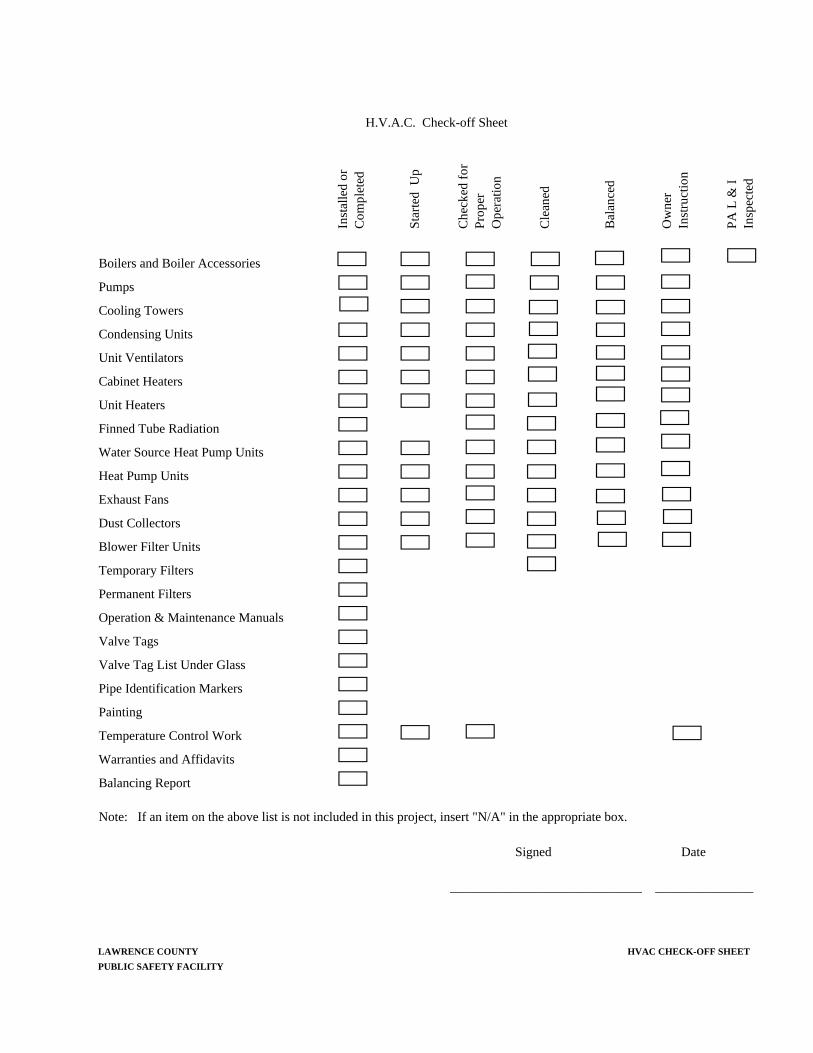
H.V.A.C. Check-off Sheet
Inst
alle
d or
C
ompl
eted
Sta
rted
Up
Che
cked
for
P
rope
r O
pera
tion
Cle
aned
Bal
ance
d
Ow
ner
Inst
ruct
ion
PA
L &
I
Insp
ecte
d
Boilers and Boiler Accessories
Pumps
Cooling Towers
Condensing Units
Unit Ventilators
Cabinet Heaters
Unit Heaters
Finned Tube Radiation
Water Source Heat Pump Units
Heat Pump Units
Exhaust Fans
Dust Collectors
Blower Filter Units
Temporary Filters
Permanent Filters
Operation & Maintenance Manuals
Valve Tags
Valve Tag List Under Glass
Pipe Identification Markers
Painting
Temperature Control Work
Warranties and Affidavits
Balancing Report
Note: If an item on the above list is not included in this project, insert "N/A" in the appropriate box.
Signed Date
______________________________ _______________
LAWRENCE COUNTY HVAC CHECK-OFF SHEET
PUBLIC SAFETY FACILITY


HVAC
EQUIPMENT START UP REPORT
Equipment Start Up Report
Job: _____________________________ Location: ____________________________
Equipment type: ____________________ Unit Designation: _____________ Room No.________
Manufacturer: ______________________ Model No.______________ Serial No.________
Unit is installed in compliance with the manufactures installation instructions? yes____ no____ Unit is properly wired? yes____ no____ Unit is properly piped? yes____ no____ Unit controls are complete and operating properly? yes____ no____ Hot water is balanced and percent deviation? yes____ no____ ___% Chilled water is balanced and percent deviation? yes____ no____ ___% Refrigerant piping is properly charged and leak free? yes____ no____ Minimum outside air quantity is set and percent deviation? yes____ no____ ___% Total air volume percent deviation? ___% Total outside air volume percent deviation at 100% outside air? ___% Unit is installed in the correct location? yes____ no____ Check and record the sound pressure level 5 feet from the unit or diffuser. _______dB All safeties are properly installed and operating properly? yes____ no____ Is the outside air louver properly installed and caulked? yes____ no____ Is the wall properly sleeved or sealed to prevent air or moisture from entering wall cavities? yes____ no____ Is the unit tight sealing to wall and floor? yes____ no____ Are vibration isolators and/or flexible connectors properly installed? yes____ no____ Are all belts tight and properly aligned? yes____ no____ Does the unit operate without excess vibration or pulsation? yes____ no____ Is the unit properly set to prevent unit racking? yes____ no____ Do the dampers and other moving parts operate freely and without binding? yes____ no____ Is the unit properly lubricated? yes____ no____ Are the filters clean? yes____ no____ Is the unit clean and free of all construction debris? yes____ no____ Are all floor wall and roof pipe penetrations properly fire sealed? yes____ no____ Are all valves installed in locations and orientations so as to be functional and serviceable? yes____ no____ Are three phase motors operating in the correct direction? yes____ no____ Are all paint scratches and nicks touched up? yes____ no____ Is the unit properly anchored? yes____ no____ Are all assembly devices such as screws and bolts etc. installed and properly tightened? yes____ no____ Is the roof top unit properly sealed to the curb? yes____ no____
SIGNATURES Contractor’s representative:___________________________________________________ Date: ____________
Vendor’s representative:______________________________________________________ Date: ____________
Balancing Subcontractor:_____________________________________________________ Date: ____________
Automatic Temperature Control Contractor:_____________________________________ Date: ____________
Representing: ______________________________________________________________ Date: ____________
Representing: ______________________________________________________________ Date: ____________
Note: Mark “NA” at items that are not appropriate for the unit in question.


LAWRENCE COUNTY PIPING AND DISTRIBUTION SYSTEMS PUBLIC SAFETY FACILITY 23 1000-1
SECTION 23 1000 – HVAC PIPING AND DISTRIBUTION SYSTEMS
1.01 CONCEALMENT
A. All piping and connections shall be concealed in finished areas, above suspended ceilings, in furred pipe spaces or chased in walls, as required. Piping shall be installed at maximum possible height, parallel to and at minimum distance from walls. Pipe shall be horizontal and vertical only with proper joints for transfer between levels. Make allowance for expansion and contraction including positive anchorage to control expansion in proper direction.
B. “Finished Area” shall mean any space except:
1. Boiler Rooms
2. Mechanical Rooms
3. Fan Rooms
4. Pipe Tunnels
5. Crawl Spaces
6. Some spaces or rooms without a finished ceiling where it is noted on the drawings that piping or ductwork is to be exposed. The Architect may choose in some areas to eliminate some part or all of a ceiling in certain rooms. In those areas horizontal piping and ductwork may be exposed unless there is a partial ceiling above which the piping and/or ductwork could be installed and could be concealed. Vertical piping in those rooms shall be concealed unless noted otherwise on the plans.
1.02 TESTING
A. All pipe tests shall be conducted in the presence of the Architect or his authorized representative. Conduct tests of systems in manner as approved so that no pipe or fitting will be left untested.
B. Before testing piping systems, remove or otherwise protect from damage, control devices, air vents, other parts which are not designed to stand pressures used in testing piping.
C. Piping systems which leak under test shall be repaired or replaced as directed by the Architect and retested until all leaks have been eliminated.
D. All tests shall be limited to new piping. Connection to any existing piping system shall not leak at normal operating pressures.
1.03 PIPING - GENERAL
A. All piping cut, reamed and fit on job. Piping shall be installed to allow for expansion. Screwed piping in branch runouts to risers shall be arranged to allow for movement of main without undue stress on risers or equipment. Furnish anchors and expansion loops or joints as shown or required. Anchors shall be provided with adequate steel bracing to withstand piping expansion stresses with pipe securely clamped or welded to pipe and building frame.
B. All piping concealed in finished areas except where specifically indicated.
C. Where appropriate, systems carrying a solution of Ethylene or Propylene glycol snf water shall be considered the same as systems conveying pure water, as addressed in this section.
D. All piping and connections to equipment shall be in accordance with details or standard applicable good practice. Exposed piping shall align with building walls, neatly racked or supported to allow space for insulation, future repairs and expansion.
E. All grooved joint couplings, fittings, valves, and specialties shall be of the same manufacturer. Grooving tools shall be of the same manufacturer as the grooved components.
PIPING AND DISTRIBUTION SYSTEMS LAWRENCE COUNTY 23 1000-2 PUBLIC SAFETY FACILITY
1. All castings used for coupling housings, fittings, valve bodies, etc., shall be date stamped for quality assurance and traceability.
F. Water piping shall not be installed at any point below top of door or to interfere with standard headroom. If such a condition is encountered due to unforeseen interference, water mains shall rise over obstruction and be vented or drop below obstruction and be drained.
G. For water circulating piping all changes in pipe size in horizontal piping shall be made with eccentric reducers or increasers, keeping the top level.
H. Pipe welding shall be as herein specified.
I. All pipes shall be cut accurately to measurement established at the site and shall be installed without springing or forcing. All changes in direction or branch connections shall be made with fittings. Copper pipe shall be cleaned bright and free of oil and grease. Finished joints shall be cleaned of all pipe compound and/or flux, ready for paint or insulation.
J. All pipe and fittings shall be reamed and free from burrs. Screw joints shall be made with compound or teflon tape on male threads only. Threads shall be full cut and seated so that not more than three threads remain exposed on a complete joint.
K. Water circulating system piping, main and branch shall pitch a minimum of 1" per 40 feet to drain and eliminate air pockets. All horizontal branch piping shall slope down toward main. Air vents shall be installed at ends of mains, at all high points and where water flow turns downward. Install drains at all low points in system. Provide air pockets of same size as main at all vents. All exposed and concealed main vents shall have outlet piped to safewaste at floor drain, service sink or janitor's basin.
L. All piping systems shall be tested as noted. Contractor shall provide all equipment and material necessary for test at his own expense. All tests shall be run in the presence of the Architect or his authorized representative. Conduct tests of systems in manner as approved so that no pipe or fittings will be left untested. Before testing piping systems, remove or otherwise protect from damage, control devices or other parts which are not designed to withstand pressures used in testing the piping. Test pressures shall be maintained for a minimum of two (2) hours or until all fittings and connections are inspected.
M. Pipe sizes shown on the drawing are for the pipe section shown through at least the next branch takeoff. All reductions in pipe size shall occur after a branch connection. If the same pipe size is shown further along the same line with intervening sections not being labeled, all the intervening piping shall be of the same size as that labeled next to it. Where piping is labeled to units it shall be that size through the valves with any reducers occurring between the union and the coil. Where control valves are approved of a smaller pipe size, reducers shall be installed on all sides of the valve to return to the labeled size. All reductions in horizontal lines shall be made with eccentric reducers so as to eliminate air pockets. All reducers in vertical piping shall be made with concentric reducers. Reducing fittings are permitted as long as they do not create an air problem. All valves except for control valves shall be the full size of the labeled line. Control valve sizing shall be indicated on the drawing or as specified in Section 23 60 00 herein.
1.04 PIPE CLEANING
A. All piping shall be thoroughly flushed and cleaned of all foreign substances. All strainers shall be cleaned at completion of flushing operation.
B. See Section 23 5000 for additional cleaning requirements.
1.05 VALVES AND COCKS - GENERAL
A. Valves shall be specification grade equal to “Victaulic” (for grooved piping systems), “Nibco”, or “Stockham”.

LAWRENCE COUNTY PIPING AND DISTRIBUTION SYSTEMS PUBLIC SAFETY FACILITY 23 1000-3
B. All W.P. ratings, saturated steam, water and gas non-shock ratings shall not be less than specified.
C. All valves located in accessible place or furnish access panels as hereinafter specified.
D. Valve stems arranged above horizontal plane where possible.
E. All check valves located in horizontal position.
F. All valves and cocks with manufacturer's name and valve rating cast into body and all valves shall be the product of one manufacturer where possible.
1.06 HEATING HOT WATER AND CONDENSING WATER PIPING
A. All pipe above grade except where otherwise noted, shall be schedule 40 black steel, ASTM A53-A, screwed 2” and smaller, welded or grooved 2 ½” and larger. Screwed fittings, cast iron, “Stockham”, “Grinell” or approved equal, suitable for 125 psi W.P. Welding fittings, seamless, standard weight, beveled end. Mechanical pipe joining system as hereinbefore specified may be used.
B. ASTM B-88 Hard copper tubing may be substituted for steel pipe for mains, branches and risers at the Contractor's option with the following provisions:
1. All copper pipe shall be type “L”, all fittings shall be wrought and all joints shall be made with 95-5 solder.
2. At each point where copper pipe is connected to steel pipe, a dielectric union or waterway fitting shall be installed.
3. All dielectric connections shall be installed in accessible locations and shall be of the same connection type as the adjoining pipe.
C. ASTM A-312 Schedule 10S stainless steel pipe with Vic-Press couplings and fittings may be used in lieu of threaded steel or soldered copper for pipe sizes 2” and smaller.
D. Gate valves 2 ½” and larger, “Nibco #F-617-0”, “Stockham G-623” or approved equal, “OS&Y”, iron body, bronze mounted, flanged or grooved, 125 psi minimum W.P.; 2” and smaller, “Nibco #T-134”, “Stockham B-120” or approved equal, union bonnet, bronze, screwed, rising stem, 150 psi minimums W.P. Gate valves used as stop valves on boiler supply and return connections shall be “OS&Y” valves as herein specified.
E. Globe valves 2 ½” and larger, “Nibco #F-718-B”, “Stockham G-512” or approved equal, iron body, flanged or grooved, bronze trim, plug disc, 125 psi minimum W.P.; 2” and smaller, “Nibco #276-A”, “Stockham B-62” or approved equal, bronze, screwed, plug disc and union bonnet, 150 psi minimums W.P.
F. Check valves 2 ½” and larger, “Nibco #F-918-B”, “Stockham G-931”, “Victaulic Series 716” and “Victaulic Series W715” or approved equal, iron body, bronze trim, flanged or grooved, spring-assisted swing type for vertical or horizontal installation, 230 psi minimum W.P.; 2” and smaller, “Nibco #T-413-B”, “Stockham B-319” or approved equal, bronze, screwed, swing type, 125 psi minimums W.P.
G. Ball valves, where shown, 1 ¼” and smaller, shall be “Stockham #S207”, “Nibco #S-585-70-66 or #T-585-70-66” or approved equal, 125 psi minimum W.P. at 220°F. with bronze body, full port, screwed ends or solder ends and two-piece, 316 stainless steel ball and stem. Each valve shall have a threaded, adjustable packing gland. Each valve in un-insulated pipe shall be furnished with a wrench handle and installed in such a manner that wrench can be operated to full open and full closed. Open and closed position of valves shall be provided with stops. In pipes requiring insulation, provide a plastic handle extension constructed so as to seal expose pipe insulation vapor barrier. Handle assembly shall ne “NIB-seal” or approved equal.

PIPING AND DISTRIBUTION SYSTEMS LAWRENCE COUNTY 23 1000-4 PUBLIC SAFETY FACILITY
H. Ball valves, 1 ½” and 2” size, shall be “Apollo”, “Nibco #T-595-Y-66” or approved equal, 125 psi minimum W.P. with bronze body, 3 piece construction, screwed ends, 316 stainless steel ball and stem and with teflon seats. Valve must have full pipe size round port to assure minimum turbulence and pressure drop. Each valve shall have a threaded, adjustable packing gland. For un-insulated pipe each valve shall be furnished with a wrench handle and installed in such a manner that wrench can be operated to full open and full closed. Open and closed position of valves shall be cast into body and stem and be provided with indicator and stops. In pipes requiring insulation, provide a plastic handle extension constructed so as to seal expose pipe insulation vapor barrier. Handle assembly shall ne “NIB-seal” or approved equal.
I. Ball valves ¾” through 2” size, “Victaulic Series P589” brass body or “Series P569” stainless steel body, with Vic-Press ends.
J. Butterfly valves, Grooved end type “Victaulic Vic300 MasterSeal” and “AGS-Vic300”; or LUG type (wafer type are not acceptable), “Nibco #LD 2000”, “Stockham LD-622-BS3-E”, “Bray” or approved equal with moulded-in pressure responsive EPDM seat or disc mounted seal, stainless steel stem, (stem shall be offset from the disc centerline to provide complete 360-degree circumferential seating), self locking gear operator with indicator and coated ductile iron or bronze/aluminum disc. Valve shall have single piece, through disc stem, attached to the disc without pins or bolts with an internal drive design. Stem shall be blow-out proof. Stem shall have upper and lower bushings. Valve shall have extended neck for insulation up to 2”.
K. All check valves at discharge of circulating pumps shall be “Victaulic Series 716” and “Victaulic Series W715”, “Metraflex 900, Nibco F910B Series”, “APCO 600 Series”, “Mueller #105” or approved equal, globe style, grooved ends or flanged, spring loaded, silent type, 125 psi S.W.P., with semi-steel body and bronze trim.
L. Hot and condensing water piping shall be hydrostatically tested at 100 psi.
1.07 REFRIGERATION PIPING
A. Field fabricated refrigeration piping shall be hard drawn copper tubing type "ACR" with wrought streamline fittings. All joints made with silver solder.
B. Piping sized and arranged essentially as shown on the drawings, but Contractor shall verify piping and arrangement with refrigeration equipment manufacturer before installation and make any or all changes required by the manufacturer to suit his particular equipment.
C. All refrigerant piping shall be done by workmen skilled in such work.
D. Precharged factory sealed tubing shall be used where indicated or required, and shall be complete with quick connect fittings. Precharged tubing shall be installed with proper support and all bends shall be made without crimping.
1.08 FUEL OIL PIPING
A. A complete set of fuel oil supply and return piping shall be provided from the fuel oil storage tank to the day tank on the emergency generator. Day tank will be provided by the Electrical Contractor, HVAC Contractor to provide final connections as recommended by the equipment manufacturer.
B. A complete set of fuel oil supply and return piping shall be provided from the fuel oil storage tank to the oil transfer pump set, which in turn shall be piped to new boilers, existing boilers and hot water heater as indicated on the drawings.
C. Fuel oil piping shall include, fuel oil supply, fuel oil return, sounding, fill and vent piping.
D. All aboveground piping shall be schedule 40, black steel pipe with threaded joints and 150 psi W.P. malleable fittings.

LAWRENCE COUNTY PIPING AND DISTRIBUTION SYSTEMS PUBLIC SAFETY FACILITY 23 1000-5
E. All piping below grade shall be schedule 40, black steel pipe with plastic coating, X-Tru Coat or equal with welded fittings and joints. All fittings, connections and damaged coating shall be primed and wrapped with “Royston Greenline” tape or approved equal.
F. All underground pipes shall be bonded together with #12 AWG type TW solid copper wire, thermit welded to the pipes and provided with cathodic protection. The bonded piping shall be provided with two (2) 17 lb. magnesium anodes ASTM A 63 Type I bonded to the pipes. Anodes shall be spaced a minimum of ten (10) feet apart. Cathodic protection shall be provided with a "Fink" five pole test station installed in new Boiler Room. Extend #12 AWG, type TW, solid copper wire from each anode and from piping to test station. Connect lead wires to test station as recommended by manufacturer. Backfill shall be carefully placed to protect pipe coating, bonding and test wiring.
G. All piping above grade shall be painted for rust resistance in an OSHA approved color.
H. Connections to the storage tank shall be made in accordance with the manufacturer’s installation instructions.
I. Ball valves shall be 125 pound, threaded, brass body. Check valves shall be 125 pound, threaded, brass body swing type. Unions, 150 PSI, W.P. malleable iron with brass seats. All valves shall be approved for use on water, oil, and gas.
J. All piping at fuel oil storage tank shall be provided with swing joints. Ream all pipe to full I.D. before joining.
K. All piping shall be installed to meet the requirements of NFPA Pamphlet #31, DER and local requirements.
1.09 DRAIN PAN PIPING
A. All condensate drain piping from drain pans of air conditioning VRF terminals, computer AC units, and other HVAC equipment, etc. shall be Type “DWV” harddrawn copper tube with wrought copper DWV drainage fittings conforming to ASTM B-306-7 and ANSI B16.29. Pitch to drain.
B. All joints in copper pipe and fittings shall be socket type using non-lead bearing solder.
C. Piping shall be pitched toward drain connections. Where there are obstructions, field interference or equipment does not permit gravity draining, the Contractor shall supply and install a condensate pump to handle the condensate. The pump shall permit the condensate to lift to a gravity system installed at a higher elevation, than could be connected to the equipment drain outlet. The Heating Contractor shall wire the condensate pump to the equipment power supply. See Section 23 40 00 for condensate pump specification.
1.10 WATER PIPE DISINFECTION
A. Upon the completion of all tests and necessary repairs or replacements, all water piping systems shall be subjected to a disinfection procedure as herein specified. The systems to be disinfected shall include hot and cold water piping, and any other systems that may be connected to the same supply sources. The disinfection shall be applied to all piping included in the Plumbing Contract including all tanks, pumps, and other appurtenances connected thereto. These systems shall be thoroughly flushed with water to remove sediment. Following this flushing the shall be disinfected in accordance with one of the following methods:
1. The systems shall be filled with a solution containing 50 parts per million of available chlorine. The solution shall be retained in the systems for not less than 4 hours, then drained.

PIPING AND DISTRIBUTION SYSTEMS LAWRENCE COUNTY 23 1000-6 PUBLIC SAFETY FACILITY
2. The systems shall be filled with a solution containing 100 parts per million of available chlorine. The solution shall be retained in the systems for not less than 2 hours, then drained.
B. After the systems are drained, they shall be thoroughly flushed water and returned to service after the drain water indicates a residual of 0.5 ppm of chlorine.
C. Provide Owner with certificate of compliance.
1.11 UNIONS AND FLANGES
A. Provide unions or flanges where indicated and in the following locations if not indicated:
1. In runs of piping at intervals not to exceed 100 ft.
2. In bypasses around equipment.
3. In connections to pumps, coils and other equipment requiring disconnection for repairs or replacement, located between shut-off and equipment.
4. If grooved piping is used, couplings shall serve as unions.
B. For hot water heating, chilled water, and low and medium pressure steam and condensate piping.
1. 2” and smaller, 150 psi, malleable iron unions, ASTM 197, black, bronze to iron seat, screwed.
2. 2 ½” and larger, 150 psi forged carbon steel flanges, ASTM A181, grade I, slip-on or weld neck bored to match schedule of connected pipe. Gaskets, 1/16” thick, flat ring type of material to suit usage.
1.12 PIPE SUPPORTS
A. Use clevis hangers with adjustable steel suspension rods securely fastened to construction. Hangers for copper pipe or tubing shall be copper plated.
B. Hangers for plastic pipe shall be clevis type with band width of 1” minimum.
C. Piping may be suspended on trapeze hangers when grouped. Trapeze spacing shall comply with the minimum for the smallest pipe on trapeze. Trapeze construction shall be neat using angle iron and rod hanger firmly attached to construction.
D. Wherever pipe lines pass through floor or wall construction, set standard weight steel pipe sleeves 1" larger than pipes where not insulated and sized to allow ½” clearance all around outside of jacket where pipes are insulated.
E. Where required or shown, provide structural beams and/or angles, welded or bolted to structure for hanger support.
F. Where pipes are exposed above ground floor, install approved chromium plated brass plates or escutcheons wherever pipes pass through walls, floors or ceilings.
G. Piping on roof shall be supported as detailed on the drawings.
1.13 REFRIGERATION SPECIALTIES
A. Furnish all dryers, strainers, moisture indicators, expansion valves, solenoid valves and piping specialties on refrigerant lines as required to be shown for a complete working piping system. All items shall be of a type special built for refrigeration service and shall be installed as recommended by the manufacturer.

LAWRENCE COUNTY PIPING AND DISTRIBUTION SYSTEMS PUBLIC SAFETY FACILITY 23 1000-7
1.14 BALANCING COCKS AND BALANCING VALVES
A. Balancing cocks and balancing valves shall be installed on by-pass pipe of all 3-way valves, on branch piping to each item of hot water heating and chilled water cooling equipment, on all coils and on mains where indicated or required. Balancing valves shall be sized based on the equipment flow rate as scheduled below. Where the branch pipe size differs from the balancing valve size, the branch size shall be extended to the balancing valve with a reducer installed at the balancing valve inlet. From the outlet of the valve to the coil the size shall be the larger of the coil connection or of the valve size. Similarly from the outlet of the coil to the control valve and from the control valve to the venturi valve, the pipe size shall be the larger of the two connections with the reducer occurring at the inlet to the smaller sized component. Balancing cocks 2” and smaller, “Tour and Anderson Series 787 STAD”, “Mepco MBV”, “Nexus”, or approved equal, water balancing, and shut-off valve with bronze or Ametak® brass copper alloy body and screwed union connection with wheel handle. Cocks shall be of suitable for use at 300 PSIG and at 250°F. Valves shall have a minimum of (4) full 360° adjustment turns of the handwheel (1440°) with a micrometer-type indicator and hidden memory feature to program the valve for a precise tamper-proof balanced setting. Each valve shall include one double seal P/T plug. Valves shall be sized based on flow rate to have a maximum pressure drop as scheduled below. Balancing valves 2 ½” and larger, shall be “Tour and Anderson Series 788 STAF or Series 789 STAG”, “Mepco MBV” or approved equal, with ductile iron body, with flanged or grooved ends, having a “Y” pattern globe and with a handwheel. Valves shall be of suitable for use at 300 PSIG and at 230°F. Valves shall have a minimum of (5) full 360° adjustment turns of the handwheel (1800°) with a micrometer-type indicator and hidden memory feature to program the valve for a precise tamper-proof balanced setting. Each valve shall include one double seal P/T plug. Valves shall be sized based on flow rate to have a maximum pressure drop as scheduled below.
B. All valves shall be capable of positive shut off with a no drip seat.
C. All valves shall be capable of supplying a minimum of 25 ft. W.G. of pressure drop at the minimum flow rate except for the “1/2” size which shall be capable of 25 ft. W.G. at a maximum of 0.88 GPM. The valves shall not be throttled below the 0.25 turn mark to produce the desired pressure drop.
D. Provide one read out kit which shall include the following:
1. 6” face
2. 270° swing dial
3. Over range and temperature compensation
PD (FT.W.G.)SIZE MIN MAX @ MAX.1/2" 0.1 1.9 113/4" 2 3.4 <1
1" 3.5 6.4 11 1/4" 6.5 11 11 1/2" 11.1 18 1.5
2" 18.1 30.5 1.52 1/2" 30.6 65 <1
3" 65.1 110 1.44" 110.1 240 2.75" 240.1 430 3.76" 430.1 700 58" 700.1 1440 6.2
GPM

PIPING AND DISTRIBUTION SYSTEMS LAWRENCE COUNTY 23 1000-8 PUBLIC SAFETY FACILITY
4. Two (2) 6 foot hoses with quick connect end connectors and with ball valve end shut offs and elbows between the quick connections and the valves to shorten up the assembly for easier insertion in tight locations.
5. Range shall be 0 – 50” W.G. and the accuracy shall be +/- 2% of full scale. If this meter is to be used by the Balancing Contractor for balancing purposes, the accuracy shall be increased to +/- ½% of full scale.
6. Bleed and equalizing manifold.
7. Instructions
8. Rugged case
E. Read out kit shall be made available for use by both the Balancing Contractor and by the Architect. The read out kit shall be turned over to the Owner and a signed receipt forwarded to the Architect at the completion of the project.
F. Each valve shall be tagged with flow rate, pressure drop at desired flow rate and venturi size in order to facilitate balancing.
G. Where valves are used to balance equipment they shall be used in conjunction with a venturi/ball valve installed on the inlet to the equipment with the balancing valve here described installed on the outlet of the equipment. The Venturi shall be used for making a more accurate measurement of the flow rate. Where balancing valves are used to balance mains or other locations, not across equipment, they shall include two double seal P/T plugs and be used for flow measurement. Where used for flow measurement follow the manufacture’s recommendations regarding the minimum amount of straight pipe before and after the valve.
H. Where p/t ports are not easily accessed from front of unit valve compartments, the taps shall be extended with copper tubing and the p/t’s shall be relocated to the front of the units for ease of making pressure readings. At each valve one p/t port shall be remounted to the valve to take temperature measurements with another p/t port being mounted at the front of the unit. The second p/t port from the same valve tap shall come off a branch tee installed between the valve and the first p/t port. Where valves are carefully mounted so as to be easily accessed, the p/t ports are not required to be extended. In all cases the Contractor must demonstrate to the satisfaction of the Architect that all ports are accessible for the types of measuring equipment that will be connected.
I. The valves shall be provided with polyurethane insulation kits by the valve manufacturer.
1.15 P/T PLUGS
A. Pressure/temperature test port ¼” brass body with dual durometer Nordel valves with retained safety cap. Plugs shall be rated at 500 PSIG @ 275°F. Safety cap shall be gasketed to seal off any minor leaks.
B. Where p/t ports are not easily accessed from front of unit valve compartments, the taps shall be extended with copper tubing and the p/t’s shall be relocated to the front of the units for ease of making pressure readings. At each valve one p/t port shall be remounted to the valve to take temperature measurements with another p/t port being mounted at the front of the unit. The second p/t port from the same valve tap shall come off a branch tee installed between the valve and the first p/t port. Where valves are carefully mounted so as to be easily accessed, the p/t ports are not required to be extended. In all cases the Contractor must demonstrate to the satisfaction of the Architect that all ports are accessible for the types of measuring equipment that will be connected.

LAWRENCE COUNTY PIPING AND DISTRIBUTION SYSTEMS PUBLIC SAFETY FACILITY 23 1000-9
1.16 BACKFLOW PREVENTERS
A. Backflow prevention devices shall be reduced pressure type. Assemblies shall be all brass, spring-loaded, double-seated type. Assembly shall have an inlet strainer and field testing cocks. Backflow preventers shall be "Watts" #909, Danfoss, or Conbraco reduced pressure type with dual vents. One vent to relieve vacuum and one vent to relieve back pressure. Provide Watts Series 600 or approved equal, spring loaded, soft seated, check valve upstream of backflow preventer.
1.17 THERMOMETERS AND PRESSURE GAUGES
A. All thermometers shall be “Miljoco #MX9”, "Trerice #BX9” or approved equal, cast aluminum case, 9” long scale with red reading mercury-in-glass tube, and universal adjustable angle stem connection. Each thermometer shall be installed in a stainless steel or brass separable socket.
B. All pressure gauges shall be “Miljoco #P4598L”, “Trerice #600C” or approved equal, 4 ½” stainless or cast aluminum case, phosphor bronze bourdon tube, and brass socket. Gauge shall meet or exceed accuracies defined by ANSI standard B40.1, Grade A. Each gauge shall be installed with a ¼” NPT ball valve for gauge isolation, and #1200-2 brass ¼” NPT snubber suitable for use on water systems.
1.18 WATER SYSTEM AIR VENTS
C. Vent all high points on new hot water circulating main piping with ¼” male NPT x female NPT bronze ball valve. Valve shall be equal to Watts B-6002, HCI, Nibco or approved equal. Valve shall be pressure rated for 400 psi minimum W.P. at 220°F. with bronze body and two-piece, chrome-plated brass ball and stem. Each valve shall be furnished with a wrench handle and installed in such a manner that wrench can be operated to full open and full closed. Provide access panels for access to vents where concealed in finished spaces. Provide flexible copper tubing on outlet of valve to space open enough to hold a bucket. Where air is being vented from an inaccessible location, the Contractor shall install a ¼” tap at the high point and then extend ¼” tubing to an accessible location where the vent valve can be located.
D. Vent all new radiation units, cabinet heaters, unit ventilators, SC units and similar equipment with similar ball valve vents. Vents shall be installed at the high points of water flow. Vents on exposed equipment shall be concealed under cabinet but accessible for repair or replacement. If units are arranged in groups, the entire group may be vented at one point if pipe pitch and arrangement will prevent air binding.
E. All vents except for the vents at the air elimination valves shall be manual air vents. Manual vents are for system start up and initial fill purposes only. All vents should be closed under normal operation. Automatic air vents that fail become a source of air into the system and will therefore not be accepted except for at the air elimination valves.
F. Contractor shall install piping and vents in such a manner to avoid air binding. If trouble does occur within one year of final acceptance, Contractor shall be obliged to install necessary and appropriate vent and access panel at no cost to the Owner.
1.19 STRAINERS
A. Strainers shall be of basket or angle type, 1 ½” strainers and smaller shall have bronze or iron bodies and screwed connections, and 2” strainers and larger shall have iron bodies and flanged connections or ductile iron bodies and grooved connections. All strainers shall be rated at 125 psi W.P.

PIPING AND DISTRIBUTION SYSTEMS LAWRENCE COUNTY 23 1000-10 PUBLIC SAFETY FACILITY
B. Screens shall be bronze, monel metal or stainless steel with perforations as follows:
Strainer Size Perforation Size Steam Liquid to 3" inclusive 20 mesh 20 mesh or 1/16” 4" and larger 1/8" 3/64 or 1/8”
1.20 FLEXIBLE PIPE CONNECTORS
A. Furnish and install flexible pipe connectors where indicated. Connectors are to be installed to eliminate vibration transmission only and all pipe and equipment shall be properly aligned so that connectors are not offset to correct misalignment. Flexible connector length shall be a minimum of 6 times the I.D, up to a maximum of 36” long.
B. Connectors shall be full line size and constructed with T321 stainless steel hose and braid with annular corrugations. End connections shall be screwed 2” and smaller, flanged 2 ½" and larger. Connectors shall be rated at 200 psi W.P. minimum, "Flexonics Type PCS", “Metraflex”, Flexicraft or equal.
C. Flexible pipe connector, expansion loops may be used in lieu of expansion compensators and in lieu of hard piped expansion loops. Dimension of loops shall be sized to handle the necessary expansion of the piping served.
D. Three or four consecutive grooved end Victaulic Style 75 or Style 77 flexible type couplings may be used in lieu of flexible connectors at equipment connections. Couplings shall provide stress relief and vibration attenuation.
1.21 WATER PRESSURE REDUCING VALVES
A. At all domestic water connections to heating water systems, provide a "Spence #D-36" pressure reducing valve. Valves shall be sized as noted on drawings. At each valve provide isolating valves, union, and full size globe valve by-pass. Valves shall be selected to suit the reduced pressure requirement as noted on the drawings.
1.22 AIR SEPARATOR/ELIMINATOR
A. Furnish and install as shown on the drawings a Spriovent coalescing type air eliminator on the hot and chilled water systems. Pipe size is not a factor and all units should be selected at the point of peak efficiency per the manufacturer’s recommendations. All eliminators shall be fabricated steel, rated for 150 psig working pressure with entering velocities not to exceed 4 feet per second at specified GPM. Units shall include an internal Spirotube® bundle filling the entire vessel to suppress turbulence and provide high efficiency. The bundle must consist of a copper core tube with continuous wound copper medium permanently affixed to the core. A separate copper medium is to be wound completely around and permanently affixed to each internal element. Each eliminator shall have a separate venting chamber to prevent system contaminants from harming the float and venting valve operation. At the top of the venting chamber shall be an integral full port float actuated brass venting mechanism. Units shall include a valved side tap to flush floating dirt or liquids and for quick bleeding of large amounts of air during system fill or refill. Eliminators shall include a bottom connection for use as a blow down connection for periodic cleaning. Air eliminators shall be Spriovent manufactured by Spirotherm, Inc. and be capable of removing 100% of the free air, 100% to the entrained air, and up to 99.6% of the dissolved air in the system fluid.
B. The automatic air separator/eliminator shall be constructed of cast iron or welded steel; constructed, tested, and stamped in accordance with Section 23 60 00 of the ASME Code for a working pressure of 150 psi, and all working parts shall be non-corrosive, “Amtrol #721” or approved equal.

LAWRENCE COUNTY PIPING AND DISTRIBUTION SYSTEMS PUBLIC SAFETY FACILITY 23 1000-11
1.23 FLEXIBLE HOSE
A. Provide “Flexonics Series 301” single braided corrugated bronze hose or approved equal for heat pump connections.
B. 1” hose shall have a 460 PSIG maximum working pressure at 70º F. Maximum temperature rating shall be 450º F. Minimum hose length shall be 24” and hose size shall be the same as branch piping size as shown on the drawings. Minimum bend radius for 1” hose shall be 3”.
C. Hose shall be finished on both ends with standard weight nipple, NPT, with hex collar. Attached to each end of hose shall be a union to facilitate ease of connection and to allow looping hose to bypass heat pump for flushing purposes.
1.24 UNDERGROUND FUEL PIPING
A. All underground piping associated with the fuel supply system shall comply with this specification. Existing piping shall be replaced with new piping meeting this specification.
B. Piping system shall consist of a primary, flexible primary fuel pipe inside a secondary pipe. The piping system shall be designed and installed in such a manner as to be retractable and reinstallable without excavation. The system shall be UL listed for use in underground installations of petroleum based products, alcohols, and gasoline-alcohol mixtures.
C. The primary pipe shall have a Kynar core layer and a Nylon reinforcing cover with braided fiber reinforcement. The containment pipe shall be of similar construction except without the Kynar layer. The containment pipe shall be capable of withstanding full line pressure, while continuing to function as a containment barrier. No part of the piping system shall be vulnerable to microbial attack.
D. The secondary access pipe shall be crush-resistant, flexible corrugated exterior and a smooth liner. Materials of construction shall be similar to the primary pipe. This pipe shall also serve as a containment barrier.
E. Fittings for the primary piping shall be zinc plated cast iron or steel, and shall be designed to mate with a female swivel pipe coupling that shall be either factory secured to the pipe or field installed using a factory furnished tool. All firings shall be provided by the pipe system manufacturer.
F. Miscellaneous requirements shall include the following:
1. All piping shall be installed as per manufacturer’s installation instructions.
2. All piping shall be a minimum of 18" below finished grade.
3. All piping to be precision tested just prior to opening of site.
4. All piping shall be backfilled with clean sand or crushed stone type material. If sand is used then a filter fabric will be required so as to prevent migration into the tank field.
a. All product piping shall be secondarily contained.
b. All product piping shall slope back into a sump so that any leaks can be detected in the sump.
c. All product piping shall be open at sump to allow product to flow into the sump.
d. All vent piping shall uniformly slope back to the tank.
e. All vent piping shall terminate at grade with galvanized steel risers, above ground vent piping shall be galvanized steel painted.
f. All vent piping shall be supported at the steel risers with support posts.

PIPING AND DISTRIBUTION SYSTEMS LAWRENCE COUNTY 23 1000-12 PUBLIC SAFETY FACILITY
g. Vent piping shall also have secondary containment as specified above.
h. All bulkhead fittings shall be specifically made to be used with the type of piping that is being used.
i. All bulkhead fittings shall be specifically made to be used with the type of piping that is being used.
1.25 RADIANT FLOOR SYSTEM
A. General
1. Summary
a. Radiant heating systems, where shown on the Drawings and Schedules, shall be hydronic, and shall include the following:
(1) Crosslinked polyethylene (PEXa) piping.
(2) Distribution manifold(s) with balancing and flow control valves, including recessed box with cover.
(3) Pipe-to manifold compression nut fittings.
(4) Cold-expansion and compression-sleeve fittings.
(5) Pipe fasteners as approved by the manufacturer of the PEXa piping.
(6) Controls.
(7) Supervision and field engineering required for the complete and proper function of the system.
2. References
a. Publications listed here are part of this specification to the extent they are referenced. Where no specific edition of the standard or publication is identified, the current edition shall apply.
b. ASTM – American Society for Testing and Materials
(1) ASTM E84, Standard Test Method for Surface Burning Characteristics of Building Materials
(2) ASTM F876, Standard Specification for Crosslinked Polyethylene (PEX) Tubing
(3) ASTM F877, Standard Specification for Crosslinked Polyethylene (PEX) Plastic Hot- and Cold-Water Distribution Systems
(4) ASTM F2014, Standard Specification for Non-Reinforced Extruded Tee Connections for Piping Applications
(5) ASTM F2080, Standard Specification for Cold-Expansion Fittings With Metal Compression-Sleeves for Cross-Linked Polyethylene (PEX) Pipe
c. PPI – Plastic Pipe Institute
(1) PPI TR-3 / 2007, Policies and Procedures for Developing Hydrostatic Design Basis (HDB), Pressure Design Basis (PDB), Strength Design Basis (SDB), and Minimum Required Strength (MRS) Ratings for Thermoplastic Piping Materials or Pipe
3. Definitions
a. Crosslinked polyethylene, commonly abbreviated PEX, is made from high density polyethylene (HDPE). Crosslinking is accomplished during manufacturing. Crosslinking enhances the physical & mechanical properties of the polymer. The
LAWRENCE COUNTY PIPING AND DISTRIBUTION SYSTEMS PUBLIC SAFETY FACILITY 23 1000-13
high-temperature properties are improved. Chemical resistance is enhanced by resisting dissolution. Low temperature properties are also improved; its impact and tensile strength, scratch resistance, and resistance to brittle fracture are enhanced. The required degree of crosslinking, according to ASTM Standard F876, is between 70-89%. This specification requires PEX to be designated as PEXa and be manufactured by the high-pressure peroxide method.
4. Submittals
a. Comply with Section 01 33 00, Submittal Procedures. Approval and/or acceptance of all submittals is required prior to fabrication.
b. Product Data: Submit manufacturer's Technical Manual, submittal forms, catalog cuts, brochures, specifications, and installation instructions. Submit data in sufficient detail to indicate compliance with the contract documents.
(1) Submit manufacturer's instructions for installation.
(2) Submit data for equipment, fittings, fasteners , manifolds,and associated items necessary for the installation of the piping and manifolds.
c. Submit computer-generated radiant heating system design indicating heat flux, pipe sizing, spacing, flow rates and temperatures. Design calculations shall be performed on pipe manufacturer’s software or equivalent.
d. Shop Drawings: Provide plans drawn to scale for all installation areas.
(1) Indicate dimensions, descriptions of materials, general construction, component connections, anchorage methods and installation procedures.
(2) Indicate design, schematic layout of system, including equipment, critical dimensions and piping/slab penetration details as well as details for protecting exposed PEX piping.
e. Certification
(1) Submit independent certification results for the piping systems from an accredited independent testing laboratory.
(2) The design shall be approved by a professional appropriately licensed in the jurisdiction where the installation will take place, as being complete and accurate.
(3) Fittings shall be third-party certified to applicable referenced standards as part of the manufacturer’s PEX piping system, with independent listings from NSF, CSA and ICC, as applicable.
(4) Fittings embedded within the thermal mass or encased behind walls or ceilings shall be certified to ASTM F2080.
f. Maintenance Instructions: Submit instructions for any maintenance required or recommended by manufacturer.
5. Quality Assurance
a. Comply with Section 01 4300, Quality Requirements.
b. Manufacturer: Must be a company specializing in the Work of this Section with a minimum of 5 years documented experience.
c. All components shall be supplied by one manufacturer.
d. Pipe shall be manufactured in a facility whose quality management system is ISO 9001 certified.
e. Cross-linked polyethylene (PEXa) pipe shall conform and be certified to ASTM F876, F877 and CSA B137.5. Fittings shall conform and be certified to ASTM F877 or

PIPING AND DISTRIBUTION SYSTEMS LAWRENCE COUNTY 23 1000-14 PUBLIC SAFETY FACILITY
F2080, and CSA B137.5. Pipes with an oxygen diffusion barrier shall conform to the requirements for oxygen permeability DIN 4726 and shall also have the PPI TR-3 listing.
6. Delivery, Storage, and Handling
a. Comply with Section 01 60 00, Product Requirements.
b. Deliver and store piping and equipment in shipping containers with labeling in place.
(1) Pipe shall be kept in original shipping boxes until required for installation.
c. Store piping and equipment in a safe place, dry, enclosed, under cover, in a well-ventilated area.
(1) Do not expose pipe to ultraviolet light beyond exposure limits recommended by manufacturer.
(2) Protect piping and manifolds from entry of contaminating materials. Install suitable plugs in open pipe ends until installation.
(3) Where possible, connect pipes to assembled manifolds to eliminate possibility of contaminants and cross-connections.
(4) Piping shall not be dragged across the ground or other surfaces, and shall be stored on a flat surface with no sharp edges.
d. Protect materials from damage by other trades.
e. Pipe shall be protected from oil, grease, paint, direct sunlight and other elements as recommended by manufacturer.
7. Warranty
a. Provide manufacturer's standard written warranty.
(1) The warranty shall include as a minimum, provisions to repair defects from faulty materials or workmanship developed during the guarantee period, or provide for replacement with new materials, at no expense to Owner.
(2) The radiant heating pipe manufacturer shall warrant the cross-linked polyethylene piping to be free from defects in material and workmanship for a period of twenty-five (25) years..
(3) Cold-expansion compression-sleeve fittings shall be warranted to be free from defects in material and workmanship for a period of twenty-five (25) years.
(4) All manifolds, distribution headers, thermostats and actuators shall be warranted to be free from defects in material and workmanship for a period of one (1) year starting at Substantial Completion.
b. Provide installer’s guarantee as appropriate.
B. Products
1. Acceptable Manufacturer
a. REHAU, 1501 Edwards Ferry Road, NE; Leesburg, VA 20176; email: [email protected]; website: www.rehau.com; upon whose products and equipment these specifications are based.
b. Other manufacturers will be considered subject to 10 day prior approval.
2. Piping
a. All radiant heating pipe shall be high-density crosslinked polyethylene manufactured using the high-pressure peroxide method of crosslinking (PEXa). Pipe shall conform to ASTM F876, ASTM F877 and CSA B137.5.

LAWRENCE COUNTY PIPING AND DISTRIBUTION SYSTEMS PUBLIC SAFETY FACILITY 23 1000-15
b. Pipe shall be rated for continuous operation of 100 psi gauge pressure at 180°F temperature (690 kPa @ 82°C), and 80 psi gauge pressure at 200°F temperature (550 kPa @ 93°C).
c. When required, pipe shall have a co-extruded oxygen diffusion barrier capable of limiting oxygen diffusion through the pipe to less than 0.32 mg/(m2/d) @ 104°F (40°C) water temperature, in accordance with DIN 4726.
d. Bend Radius
(1) The minimum bend radius for cold bending of the pipe shall be not less than five (5) times the outside diameter.
(2) Bends with a radius less than this shall require the use of a bending template as supplied by the pipe manufacturer, and/or hot air.
3. Fittings
a. Fittings shall be third-party certified to applicable standards ASTM F877, ASTM F2080 and CSA B137.5 as part of the manufacturer’s PEX piping system, with independent listings from IAPMO, NSF, CSA and ICC, as applicable.
b. Compression nut manifold fittings shall be manufactured of corrosion-resistant brass with a barbed insert and a reusable split compression ring.
c. Compression-sleeve fittings shall be manufactured of brass and shall be supplied by the piping manufacturer as part of a proven cataloged system.
d. Fittings embedded within the thermal mass or encased behind walls or ceilings shall be cold-expansion compression-sleeve fittings certified to ASTM F2080. Where required by the manufacturer, fittings shall be protected from external environmental conditions.
4. Manifolds
a. Material: Distribution manifolds shall be manufactured of brass or copper and be supplied by the piping manufacturer as a proven cataloged part of the manufacturer's system.
b. Brass manifolds shall be produced from extruded brass round pipe with tapped holes for connections, and be pre-assembled by the manufacturer. 100% of manifolds used shall have been air tested by the manufacturer with no indication of leaks.
c. Balancing Manifolds
(1) Brass balancing manifolds shall be equipped with integral visual flow gauges, circuit balancing and flow control valves, isolation valves with integral thermometer housings, and air vent/fill ports.
(2) Each circuit valve shall be supplied with a manual actuating handle for filling/purging operation.
d. Copper Manifolds
(1) Copper manifolds shall be manufactured from Type L copper.
(2) Copper and/or brass outlets shall be high-temperature brazed (lead-free) into headers.
(3) Outlets in copper headers shall be made using the T-drill process according to ASTM F2014.
5. Controls
a. Controls shall be a specified in Section 23 6000.

PIPING AND DISTRIBUTION SYSTEMS LAWRENCE COUNTY 23 1000-16 PUBLIC SAFETY FACILITY
b. Room thermostats shall be low-voltage devices with electronic temperature sensing, and shall be supplied by the pipe manufacturer as part of a proven cataloged system.
C. Execution
1. Acceptable Installers
a. As a minimum, installation shall be performed by qualified laborers trained by the manufacturer in the procedures of PEX radiant heating systems and they shall be appropriately licensed for the jurisdiction where the installation will take place.
2. Examination
a. Examine areas and conditions under which work of this Section will be performed. Correct conditions detrimental to timely and proper completion of Work. Do not proceed until unsatisfactory conditions are corrected.
b. Beginning of installation means acceptance of existing conditions.
3. Preparation
a. Coordinate with related trades and manufacturer’s recommendations with regard to installation in conjunction with:
(1) Reinforcing wire mesh or rebar.
(2) Preparation of space for manifold installation.
b. Prepare the installation site as appropriate:
(1) For Concrete Slab-on-Grade: Sub-grade should be compacted, flat and smooth to prevent damage to pipe or insulation. Approved vapor barrier material should be installed. Approved thermal insulation, according to the design, shall be installed. Reinforcing wire mesh, if required by structural design, must be flat and level, with all sharp ends pointing down. Finished grade of the thermal mass must be a minimum of 3/4 inch (19 mm) above the top of PEX heating pipes.
(2) For Wood Sub-floor: Sub-floor must be structurally sound, clean and free from all construction debris which could potentially damage the pipe. Replace any areas that appear weak. To facilitate installation of pipe, remove all unnecessary studwall baseplates in doorways and other areas. Treat the wood sub-floor with a sealant in accordance with the specifications set forth by the screed installation section, or use pressure-treated wood, as per local code requirements. Finished grade of the thermal mass overpour must be a minimum of 3/4 inch (19 mm) above the top of PEX heating pipes.
(3) For Precast Concrete Sub-floor: Sub-floor must be clean and free from all construction debris which could potentially damage the pipe. Finished grade of the thermal mass overpour must be a minimum of 3/4 inch (19 mm) above the top of PEX heating pipes.
c. Preparation of wall cavity for Manifold installation: See drawings to determine the width of the wall cabinet (if required) and required wall opening dimensions. Mount the manifold cabinet allowing space for the screed to fill up the front of the pipe opening. If a cabinet is not used, prepare a suitable cavity for the manifold, with a secure mounting plate that will secure the manifold at least 30 inches (75 cm) above floor level. Manifold must be installed in an area that will allow easy access for supply/return piping as well as future access maintenance.
4. Installation
a. Install in accordance with manufacturer's published installation manual and/or published guidelines and final shop drawings.

LAWRENCE COUNTY PIPING AND DISTRIBUTION SYSTEMS PUBLIC SAFETY FACILITY 23 1000-17
b. Mount manifolds in the locations previously prepared or in previously installed cabinets, if used. Manifolds shall be mounted as level as possible.
c. Route piping in an orderly manner, according to layout and spacing shown in final shop drawings. All installation notes shown on the drawings shall be followed.
d. At connections and fittings, use a plastic pipe cutter to ensure square and clean cuts, and join pipes immediately or cap ends of pipe to seal from contaminants. Where fittings are installed within the thermal mass, they shall be wrapped in non-adhesive waterproof silicone tape or sealed within a heat-shrink material approved by the manufacturer.
e. Pipe shall be dispensed using a suitable uncoiling device. Remove twists prior to securing pipe. Pipe shall lie flat on an even plane. Finished grade of a thermal mass shall be a minimum of 3/4 inch (19 mm) above the top of PEX heating pipes. Fasten piping at no more than 3 feet (90 cm) intervals, being careful not to twist the pipe. In thin concrete slabs, secure piping every 2 feet (60 cm). Use only fasteners supplied or approved by the manufacturer of the PEX pipe.
f. Piping that passes through expansion joints shall be covered in protective polyethylene convoluted sleeving (flexible conduit) extending 15 inches (38 cm) on each side of the joint. Sleeving shall be secured on pipe to prevent movement during installation of thermal mass.
g. Where piping exits the thermal mass, a protective conduit shall be placed around the pipe, with the conduit extending a minimum of 6 inches (15 cm) into the floor and exiting by a minimum of 6 inches (15 cm). For penetrations at manifolds, use rigid PVC bend guides secured in place to prevent movement.
h. At the time of installation of each circuit of pipe, connect the pipe to the correct manifold outlet and record pipe length for balancing. If manifold is not installed, cap the end of the pipe and label the pipe's circuit numbers along with S for supply and R for return. Connect pipes to manifold as soon as possible and record circuit lengths. All circuits shall be labeled to indicate circuit length and serviced area.
i. The following precautions shall be taken in areas intended for carpet:
(1) Notify carpet installer that radiant heating pipes have been installed.
(2) Keep pipes 6 inches (15 cm) from all wall baseplates.
(3) Install metal guards where pipe will pass through wall baseplates and where carpet tack strips will be installed.
j. The following precautions shall be taken in areas intended for hardwood flooring:
(1) Ensure that nailing areas for hardwood flooring, if nailing is required, are clearly marked and known for hardwood installers.
k. If the radiant heating system substrate material (thermal mass) requires curing and/or has other limitations which can be influenced by the radiant heating system while in operation, then the radiant heating system shall not be put into operation until such time that the substrate material has fully cured or set according to the material requirements of the substrate manufacturer.
l. The installer shall confirm minimum and maximum exposure temperatures for the substrate material (thermal mass) and shall ensure proper radiant heating operating temperatures.
5. Field Quality Control
a. Filling, Testing & Balancing: Tests of hydronic heating systems shall comply with authorities having jurisdiction, and, where required, shall be witnessed by the Construction Manager

PIPING AND DISTRIBUTION SYSTEMS LAWRENCE COUNTY 23 1000-18 PUBLIC SAFETY FACILITY
b. Pressure gauges used in testing and balancing shall show pressure increments of 1 psig and shall be located at or near the lowest points in the distribution system.
c. Air Test
(1) Charge the completed, yet unconcealed pipes with air at a minimum of 40 psig.
(2) Do not exceed 150 psig.
(3) Use liquid gas detector or soap solution to check for leakage at manifold connections.
d. Water Test
(1) Purge air from pipes.
(2) Charge the completed, yet unconcealed pipes with water.
(3) Take necessary precautions to prevent water from freezing.
(4) Check the system for leakage, especially at all pipe joints.
e. Perform a preliminary pressure test pressurizing the system to the greater of 1.5 times the maximum operating pressure or 100 psig for 30 minutes.
(1) As the piping expands, restore pressure, first at 10 minutes into the test and again at 20 minutes.
(2) At the end of the 30-minute preliminary test, pressure shall not fall by more than 8 psig from the maximum, and there shall be no leakage.
f. After successfully performing the preliminary pressure test, perform the main pressure test immediately.
(1) The test pressure shall be restored and continued as the main test for 2 hours.
(2) The main test pressure shall not fall more than 3 psig after 2 hours.
(3) No leakage shall be detected.
g. Pressure shall be maintained and monitored during installation of the thermal mass.
(1) If any leak is detected during installation of thermal mass, leak shall be found immediately and the area cleared for repair using manufacturer’s approved repair coupling.
(2) Retest before covering repair.
h. Complete inspection and furnish test reports supplied by the manufacturer of the system.
6. Cleaning
a. Clean exposed surfaces upon completion of installation using clean, damp cloth. No cleaning agents are allowed.
b. Comply with manufacturer’s recommendations.
7. Protection
a. Protect installation throughout construction process until date of final completion.
b. Replace components that cannot be repaired. Replacement shall include all required cutting and patching.
END OF SECTION 23 1000

LAWRENCE COUNTY AIR DISTRIBUTION SYSTEM AND APPURTENANCES PUBLIC SAFETY FACILITY 23 2000-1
23 2000- AIR DISTRIBUTION SYSTEM AND APPURTENANCES
1.01 LOW VELOCITY, LOW PRESSURE SHEET METAL WORK
A. All sheet metal ductwork concealed in finished areas unless otherwise noted. All supply air sheet metal work on the project shall be low velocity, low pressure ductwork suitable for +/- 2" static pressure at 2500 FPM velocity unless otherwise noted. All return, exhaust and vent ducts shall be constructed suitable for +/- 2" static pressure at 2500 FPM velocity unless otherwise noted or specified.
B. All low velocity, low pressure ductwork shall be constructed of galvanized sheet steel unless otherwise noted or specified.
C. All ductwork shall be constructed and installed in accord with "Low Velocity Duct Construction Standards" as published by the "Sheet Metal and Air Conditioning Contractor National Association, Inc.". Excluded is table 1-25 which allows for T-1 flat drives as reinforcement. T-1 flat drives are only acceptable for ducts requiring no reinforcement and all joints shall be sealed or welded.
D. All joints, longitudinal and transverse seams and connections in ductwork, shall be securely fastened and sealed with welds, gaskets, mastics (adhesives), mastic-plus-embedded-fabric systems, or tapes. Tapes and mastics used to seal ductwork shall be listed and labeled in accordance with UL 181A or UL 181B. Duct connections to flanges of air distribution system equipment shall be sealed and mechanically fastened. Unlisted duct tape is not permitted as a sealant on any metal ducts.
E. Duct transitions, etc. shall be gradual not exceeding a 15° slope on side unless specifically shown otherwise. In general, structural members, pipes, etc. shall not pass through ductwork, if such a condition arises, duct shall be increased in size to maintain original cross sectional area. Any change in shape or direction required but not shown, will be installed with gradual transitions and turning vanes as specified. All square turns supplied with turning vanes not less than 4" apart. Each turning vane shall be constructed so that the leaving air edge shall extend beyond the inside edge of the entering air duct. In lieu of square turns radius elbows may be installed without vanes if R/D is greater than or equal to 1.0 and with vanes if R/D is less than 1.0. Radius elbow vanes shall extend through the full arc of the turn. Two vanes are required for ducts up to 24" deep and 3 vanes are required for all elbows over 24" deep. See typical approved duct fittings on drawings for further requirements. All fittings not shown must be submitted for approval by the Architect before being installed.
F. Provide access panels for all dampers or equipment in ductwork and suitable openings for anemometer readings as directed by the Architect.
G. All branch connections to rectangular ductwork where indicated shall be plenum type as detailed and scheduled on the drawings.
H. All branch connections to round duct shall be made with 45° laterals and radius bends. See the drawings.
I. All supply duct shall be minimally constructed in accord with the following schedule and with SMACNA requirements:
Diameter (inches) Gauge
Through 12 26 13-30 24 31-54 22 55-84 20

AIR DISTRIBUTION SYSTEM AND APPURTENANCES LAWRENCE COUNTY 23 2000-2 PUBLIC SAFETY FACILITY
over 84 18
J. Ducts exposed in gymnasiums and multipurpose rooms shall be minimum of 18 gage sheet metal and rectangular ducts in gyms shall have a top slope of a minimum of 1 inch in 5 feet. Slope shall be made by increasing one side of the duct to increase the pitch of the top.
K. Shop fabricated ductwork shall immediately be internally cleaned of dust, dirt, oil, or other contaminants, then sealed with an airtight membrane on open ends. This membrane shall not be removed until the time that the ductwork is set in place for its final installation, and connected to another section of ductwork in its final configuration..
1.02 KITCHEN HOOD EXHAUST DUCTWORK
A. Duct where indicated shall be 16 gauge black steel with welded joints as required by NFPA.
B. Maintain clearance around duct as follows:
0" to noncombustible 3" to limited combustible 18" to combustible unless protected per NFPA 96
C. Seal around duct at all penetrations to fire rated floor ceiling enclosures as per NFPA 96.
D. A sign shall be installed on all access panels stating: “Access Panel — Do Not Obstruct”.
E. Provide cleanout openings at each change in direction. Provide one 20” x 20” clean out opening in I horizontal ductwork for personnel entry and where this is not possible provide a clean out opening every 12 feet. In vertical ducts provide an access opening at the top for personnel entry or where not possible provide a cleanout opening at each floor.
F. Adequately support all duct where personnel entry is provided for cleaning.
G. Duct system shall conform to the latest edition of “NFPA 96”.
H. Slope grease duct in accordance with the International Mechanical Code
Horizontal runs 75 feet in length or less: Slope 1/4" in 12" (2 percent slope) Horizontal runs of over 75 feet: Slope 1" in 12" (8.3 percent slope)
I. Installation. Overlapping duct connections of either the telescoping or the bell type shall be used for welded field joints as required by NFPA and the International Mechanical Code. Butt-weld connections are NOT acceptable. The inside duct section shall always be uphill of the outside duct section. The difference between inside dimensions of overlapping sections shall not exceed 1/4". The overlap shall not exceed 2".
1.03 DRYER VENTS
A. Ducts shall be stainless steel with sealed joints and connections. Construct as low velocity, low pressure sheet metal work as herein specified.
1.04 ACOUSTIC LINED RECTANGULAR AND ROUND LOW PRESSURE DUCTWORK
A. Where indicated on the drawings, ductwork shall be constructed of sheet metal with fiberglas acoustic and thermal liner. Duct liner shall be 2 PCF, 1.5" thick. Liner shall have a thermal conductivity of 0.24 at 75°F mean temperature, shall meet all requirements of NFPA 90A-90B and shall have a flame spread classification of less than 25. Liner shall be spun construction to prevent erosion and shall provide a smooth, low resistance surface to air travel. Friction loss correction factor shall be 1.08 at 1000 FPM. All duct sizes on drawings shall be net and sheet metal ducts shall be constructed larger in each dimension to allow for acoustic liner. Liner shall be Knauf Sonic XP duct liner or approved equal.

LAWRENCE COUNTY AIR DISTRIBUTION SYSTEM AND APPURTENANCES PUBLIC SAFETY FACILITY 23 2000-3
B. Liner shall have an anti-bacterial coating compliant with ASTM C 1338, G21, G22.
C. Liner shall be compliant with ASTM D 5116 and ASTM C 1071, type I.
D. Liner shall be suitable for use at up to 6000 FPM and 250˚ F, although actual application criteria on this project are subsatatially lower than those limits.
E. Material shall be attached to the interior surface of the duct with a full surface coverage of quick-taking rubber base adhesive compliant with ASTM C 916 and stud welded pins and clips as recommended by manufacturer. Mechanical fasteners shall not compress the insulation more than 1/8”. All fasteners shall comply with NAIMA standard MF-1-1975.
F. Metal nosings shall be provided at edges facing fan discharges, at access doors, at transitions to and from unlined ductwork.
G. Liner shall have an absorption of .85 at NRC specified range and shall have a flame spread classification of not more than 25, and a smoke developed rating of not more than 50 based on tests in accordance with ASTM Standard E-84-61.
H. Lined round duct shall be lined with” Johns Manville Spiracoustic Plus” , or “Owens Corning QuietR AcoustiTEX”, 1.5” duct liner or approved equal. Insulation shall be installed in accordance with the manufacturers instructions. Material shall comply with ASTM C 1071, ASTM G 21, and ASTM G 22. Insulation shall have a minimum installed “R” value of 6.3.
I. Double wall insulated duct shall be provided where specified on drawings or contract documents. Unless otherwise indicated, all insulated duct diameters shown on drawings are nominal inner liner dimensions. Lined duct shall be “United McGill K27” galvanized acoustical duct with 1.5” duct liner with perforated metal liner.
1. Insulated duct shall be constructed of a perforated inner liner, a one inch layer of fiberglas insulation and an outer pressure shell in accordance with Section "E" (round) or Section "G" (flat oval). For one inch insulation, the outer pressure shell must be 3 inches larger than the (nominal) inner liner dimension. Outer shell gauge shall always be based on actual outer shell dimensions. Insularion shall have an anti-microbial coating. Inner perforated liner shall have an anti microbial coating equal to the “AgION” process.
2. Factory test data, in accordance with UL-181, shall be available documenting internal impact and erosion at airflow velocities up to 10,000 FPM. There shall be no erosion of insulation at maximum application velocities of 4000 FPM.
3. Round liners shall be constructed according to the following table. For flat oval products, the diameter shown in this table is the basic round diameter.
Inner Liner Diameter (inches) Gauge Construction 3-8 28 Standard Spiral 9-42 28 Single Rib Spiral 44-60 26 Single Rib Spiral 62-84 22 Standard Spiral
4. When perforated liner is indicated, the acoustical performance shall equal that of United McGill's "K27" duct. Perforations in the liner walls shall be 3/32 inch in diameter with an overall open area of 23 percent.
5. All insulated duct shall have a maximum thermal conductivity (k) of 0.27 Btu/hr/sq. ft./°F/inch thickness at 75°F mean temperature.

AIR DISTRIBUTION SYSTEM AND APPURTENANCES LAWRENCE COUNTY 23 2000-4 PUBLIC SAFETY FACILITY
6. Insulation ends shall be provided at all locations where internally insulated duct connects to single wall duct or to any non-insulated component. The insulation end shall terminate the insulation and reduce the outer shell diameter to the nominal single wall size.
7. Fittings shall be similar in construction to the straight duct except that liner need not be perforated.
1.05 DUCTWORK SUPPORTS
A. Horizontal rectangular ducts generally shall be supported by hangers as follows:
Duct Size Hanger Size Max. Spacing Long Side Inches and Type of Pairs(Ft.)
60 or less 1" x .109 band 8 61 to 90 3/8" dia. rod 8 Over 90 3/8" dia. rod 4
B. Horizontal round ducts shall be supported by 1" x .109" (No. 12 U.S.S. gauge) bands around ducts spaced not over 8 feet apart. Use stainless steel hangers for stainless steel duct.
C. Bands shall be bent over 1" from the end and turned under the corners of rectangular ducts and fastened with self-tapping screws at the corners and at 6" intervals up the sides. Rod hangers shall be secured to the bottom bracing angles with nuts and locknuts. Hangers shall be as close as practicable to the transverse joints. Hanger material shall be the same as the bracing angles.
D. Upper ends of hangers shall be secured to floor or roof structure (not to the deck) above. Hangers shall not be secured to suspended ceiling. Hangers shall not be secured by through-bolts in wood construction. Provide additional structural members, secured to the building structure, as required.
E. Vertical ducts passing through floors shall be secured by extending the bracing angles to rest firmly on the floors, without loose blocking or shimming. Vertical ducts which do not pass through floors shall be supported by bands bolted to walls and columns. Size, spacing and method of attachment to ducts shall be as specified for hanger bands on horizontal ducts.
F. Access doors shall be installed in ducts where shown and wherever else required for ready access to operating parts of any kind. Material shall be as specified for ducts.
1.06 FLEXIBLE COLLARS
A. Flexible collars shall be provided in all connections between fans and ducts or casing except for roof mounted exhaust fans. Collars shall be made of neoprene coated glass fabric weighing approximately 30 ounces per square yard.
B. Collars shall be approximately 6" long and shall be installed with just sufficient slack to prevent transmission of vibration. Rectangular collars shall be secured to ducts and fans with 1" x 1/8" flat bars fastened with screws or bolts at 8" intervals or with slip joints similar to those specified for duct joints, the fabric being tightly crimped into the slip joint and the complete joint being fastened with sheet metal screws at 8" intervals. Collars shall not be painted. Metal for fastening collars shall be the same as specified for duct and bracing.
1.07 MANUAL BALANCING DAMPERS
A. Where indicated, provide galvanized steel, opposed blade balancing dampers, Greenheck VCD-15-OB, Ruskin #MD35/OB or approved equal.

LAWRENCE COUNTY AIR DISTRIBUTION SYSTEM AND APPURTENANCES PUBLIC SAFETY FACILITY 23 2000-5
1.08 ROUND VOLUME DAMPERS
A. Volume damper shall be provided where indicated on the drawings. Dampers shall be constructed according to “SMACNA Low Pressure Duct Standard 5th Edition”, published in 1976.
B. All dampers shall have continuous rods, outside end bearing, similar to vent fabrics 607, and a self-locking regulator with handle. Self locking regulator shall be “Ventfabrics 641” for lined or uninsulated ducts, Ventfabrics 644 for sound covered ducts and Ventfabrics 627, 628, 637, 638 or 639”, depending on insulation thickness, for blanket covered ducts.
C. Dampers shall be constructed so as not to vibrate or rattle under operating conditions. Dampers shall be reinstalled to minimize noise and all operators shall be readily accessible.
D. Manufactured dampers of lesser quality than specified are not acceptable.
1.09 SPIN-IN-CONNECTIONS
A. Round duct connections to rectangular ductwork shall be made with square to round plenum connections as detailed on the drawings. Spin-in connections are not acceptable as equal.
1.10 EXTRACTORS
A. Where take off from side or bottoms of supply ducts cannot or are not made with an R/D of 1.0 or greater, an extractor controller shall be installed. Extractors shall be “Anemostat #DTA, Krueger #EX-8”, “Titus #AG-45” or approved equal. Extractors shall be designed and sized for the type of takeoff furnished. The flange of the extractor must not extend into the main duct, only the vanes should be exposed in the main duct. The flange, or hinged mounting bracket on the back of the extractor, must not reduce the branch duct free area opening more than 5%.
B. Blades shall be spread 1” apart. Operators shall be a square rotation shaft with a locking regulator similar to “Ventfabric 640” mounted on the outside of the ductwork. Regulator shall be shimmed as required to extend beyond the duct insulation.
1.11 SPLITTER DAMPERS
A. Splitter dampers shall be installed where shown and wherever required to permit complete adjustment of air quantities at all outlets. Splitter dampers shall be located where they can be adjusted at anytime after completion of the work, access panels being furnished as required and specified.
B. Splitter dampers at branch duct connections shall be of the single blade type with hemmed edges. Each blade shall be hinged at one end with sheet metal straps. The free end of each blade shall be connected to a ¼" adjusting rod secured to the side of the duct in a flanged bushing with set screw.
C. Rods shall be bent to a curve so that they will operate freely between the open and closed positions. After adjustment, projecting ends of rods shall be cut off and bent over 2" from bushing and the cut ends left smooth and free from burrs.
D. Splitter and damper blades shall be made of the same metal as the ducts, except that they shall be 2 gauge numbers heavier if more than 24 inches in either height or width.
1.12 FLEXIBLE ROUND DUCTS
A. Type “FL-1”-3MR6
1. Core material shall be Trilaminate of Aluminum Foil, Fiberglass and Aluminized Polyester. The fabric shall be reinforced and supported by helically wound galvanized steel.The fabric shall be mechanically fastened to the steel helix without the use of adhesive. The core shall maintain its free area and a center line radius of 1.0 or better

AIR DISTRIBUTION SYSTEM AND APPURTENANCES LAWRENCE COUNTY 23 2000-6 PUBLIC SAFETY FACILITY
2. The internal working pressure rating shall be at least as follows with a bursting pressure of at least 2-1/2 times the working pressure.
a. Positive: 20 inches W.G.
b. Negative: 10 inches W.G. thru 12ӯ
3. The duct shall be rated for a velocity of at least 5500 feet per minute.
4. Suitable for operating temperatures of at least 250 degrees F.
5. Factory insulate the flexible duct with flexible fiberglass insulation. The R value shall be at least 6.0 (1 ½” Insulation) at a mean temperature of 75 degrees F. (R4.2 not acceptable)
6. Cover the insulation with a reinforced aluminum pigmented vapor barrier jacket having a permeance of not greater than 0.05 perms when tested in accordance with ASTM E 96, procedure A.
7. The ductwork shall be UL 181 listed, Class 1 Air Duct and comply with NFPA 90A and 90B.
8. Basis of design: FlexmasterUSA Type 3MR6.
9. Approved equals: Novaflex and Buckley. Prior approval required for other ductwork manufacturers, sample required for prior approval.
10. For proper installation refer to the Flexible Duct Installation section of this specification.
B. Flexible round duct installation.
C. Determine length of flexible duct, 6’-0” maximum. Cut outer vapor barrier and insulation. Fold back insulation and outer vapor barrier to expose inner core. Using sheet metal snips, cut the inner core.
D. Connect the inner core to the tap or collar by pulling it a minimum of 1” over the collar.
E. Where collars are less than 1” in length, i.e. diffusers, connect a separate collar to the existing collar and proceed as described in section G.
F. Wrap the core twice with UL181 tape. Secure the connection by placing a clamp over the tap or collar, Panduit Clamps for collars with beads and Stainless Steel Clamps for collars without beads.
G. Roll the insulation and vapor barrier back over the collar or tap as described in section G above and wrap twice with UL181 tape.
H. Secure the outer vapor barrier with a clamp as described in section I above if desired. Recommended if using Flexmaster 6M (Type “FL-3”) duct.
I. For Medium to High Pressure applications, use duct sealer for section I and section J in lieu of UL181 Tape.
1.13 AUTOMATIC BACKDRAFT DAMPERS
A. Furnish and install where indicated, “Greenheck ES-30”, "Ruskin CBD-2" dampers or approved equal. Dampers shall be provided with counterweight and be properly adjusted. Provide duct and structure access panels for each damper, for maintenance and adjustment. Dampers shall be full size of duct or equipment in which they are installed. Extrude aluminum blades and frames.

LAWRENCE COUNTY AIR DISTRIBUTION SYSTEM AND APPURTENANCES PUBLIC SAFETY FACILITY 23 2000-7
1.14 ACCESS DOORS
A. Access doors shall be installed at each fire damper, smoke damper and smoke detector. All exhaust and return ducts shall have access doors installed for cleaning at 20 feet intervals on all horizontal ductwork and at the bottom of each vertical riser. Access doors shall be installed according to the requirements of the latest edition of “NFPA 90-A”.
B. All access doors shall be hinged and have latch handles. Doors shall be suitable for the application. Doors shall be gasketed and have a maximum leakage of 1 CFM at the duct pressure rating.
C. Lined and insulated ducts shall have insulated access doors equal to vent fabrics stamped insulated access doors.
D. Door characteristics shall be as follows:
Maximum Frame Door Duct Dimension Door Opening Gage Gage Hinges Latches 0” - 6” 6 x 8 5 x 7 24 26 2 1 7” - 10” 10 x 12 8 x 10 22 24 2 1 11” - 18” 12 x 16 10 x 14 20 24 2 2 19” and larger 16 x 24 14 x 22 20 22 3 2
E. Maximum 16” x 24” access doors are acceptable for access to equipment where servicing the equipment can be done through that size door.
F. All horizontal return and exhaust ducts shall have cleanout openings installed every 20 feet and at the bottom of all vertical risers. Removable grilles may serve as a duct access opening where they have more than 180 square inches of area and where they offer good access to the duct.
1.15 FIRE DAMPERS
A. Fire dampers shall be provided to comply with NFPA Standard 90A. In general, most required dampers have been shown but HVAC Contractor shall be responsible for providing fire dampers to comply with the following requirements whether shown or not:
1. At each opening through a required fire partition of not less than 2-hour rating.
2. At each opening through a required enclosure of a vertical opening.
3. At duct openings in required fire resisting ceilings rated at 2 hours or better. Where a rated ceiling is pierced by an air distribution device, a secondary fire damper as specified herein shall be installed.
4. At each opening through a required fire wall, rated at 3 hours (two dampers required).
B. All fire dampers shall be U.L. inspected and labeled. Dampers shall be rated for use in dynamic and static systems. Dampers shall have both UL555 “Dynamic ratings and UL555S “Leakage ratings. Dampers must be seismic and fragility tested. Dampers shall be UL classified R6189. Vertical and horizontal dampers shall have spring operation for assured closure under air flow conditions. The dampers shall handle a maximum velocity of 2500 FPM and at a maximum of 4” static pressure. All dampers shall be approved and installed only as directed by the manufacturer for airflow direction and damper orientation with regard to airflow. The Contractor is responsible to insure that all dampers are properly installed and applied, for the field conditions encountered.
C. All fire dampers shall be multi blade, motorized fire/smoke dampers approved by the manufacturer for the size and arrangement required. The Heating Contractor shall install all wiring (including power wiring to the damper motor) and all controls to operate the damper. Power for the damper motor shall be taken from the nearest heating unit with a 120 volt supply.

AIR DISTRIBUTION SYSTEM AND APPURTENANCES LAWRENCE COUNTY 23 2000-8 PUBLIC SAFETY FACILITY
D. Where and when manufacturer offers dampers that are currently approved for dynamic service that are either nonmotorized multiblade dampers or are nonmotorized curtain type dampers, the contractor has the option to provide one of those style dampers in lieu of the powered style specified. Each manufacture has different size limitations for each style of damper, and those size restrictions are changing daily. The Contractor is responsible for ascertaining what those size limitations are, from the manufacturer’s he chooses to deal with, and shall buy ad install his dampers accordingly. Only those dampers that are approved by UL at the time of purchase and installation shall be approved. The Contractor shall assume the worst case, that all dampers require power, so that he covers his expenses. No additional monies shall be paid by the Owner or Architect for dampers that are more costly than the ones the contractor assumed he could install. It is no longer legal to parallel dampers in separate ducts as has been done in the past.
E. Where multiple section dampers are required, contractor shall provide mullions as required by the manufacturer for an approved assembly or shall provide a factory-assembled unit that is approved for the application. Only where the manufacturer has approval for field built mullions can they be used. Where and when a manufacturer only has approval for his assembled unit, it shall be bought as an assembly, so as to retain all of the UL ratings. Each section, of the multiple damper assemblies, shall be capable of closing against the full air volume of the total assembly, but not less than 2000 fpm at the system external static pressure as required by UL and the manufacturer for the UL rating.
F. The contractor is responsible to assure that all aspects of a damper installation do not exceed the rated size limitations for that product or that type of installation. All required modifications to make a damper work in an approved manner shall be by the contractor at no additional cost to the owner.
G. Provide a factory or contractor built sleeve, with angle retaining rings and breakaway connections, approved for the application. Field built sleeves shall only be used where the installation is exactly according to approved SMACNA standards. Factory sleeves that are approved for non-standard conditions such as mounting of dampers outside of the wall, and using only a single angle to retail the damper must be installed per the manufacturer’s approved installation instructions. Contractor copies of these non-standard manufacturer sleeves are not acceptable.
H. Fire dampers in low velocity, low pressure duct systems shall be “Greenheck DFD-110 Type B”, "Prefco, Model 5500, ML Type “C” or approved equal with 160°F fusible link, interlocking shutter type blades in an airtight steel frame. Damper assembly shall be 6" wide in direction of air flow and when open shall offer a minimum resistance to air flow. Dampers in horizontal ducts shall be spring operated. Dampers in vertical ducts shall be provided with a stainless steel spring closure.
I. Fire dampers in high velocity, medium pressure duct systems shall be “Greenheck DFD-150 Type C, CO or CR”, "Prefco, Model 5500, Type CR or CD", round or oval as required, or approved equal.
J. At each fire damper provide duct access panels and wall or ceiling access panels of appropriate fire resistive rating as required for servicing the fire damper. Panels shall be properly positioned, aligned and sized to provide easy access to damper linkage for replacement and damper blades for resetting.
K. At each fire damper provide an extra fusible link, wired to an eyelet attached outside the duct, near the access door.
L. Replace all fusible links in all existing fire dampers, which are to remain. Provide an extra link for all existing fire dampers as described above.

LAWRENCE COUNTY AIR DISTRIBUTION SYSTEM AND APPURTENANCES PUBLIC SAFETY FACILITY 23 2000-9
M. All dampers shall be checked by the contractor at both the start and the end of the warranty period for proper operation. The contractor shall submit reports to verify that all dampers were checked and are operating properly. Removing the retaining clip, allowing the damper to close, and then observing that there is a good seal shall verify proper operation. The damper shall then be reopened and put back into service. The owner shall be instructed to do a similar test, to every damper, on a yearly basis there after.
1.16 SECONDARY FIRE DAMPERS (CEILING DAMPERS)
A. Secondary fire dampers shall be provided to comply with NFPA Standard 90A and UL 555C. Ceiling or secondary fire damper shall function as heat barriers in air handling openings penetrating fire resistive membrane ceilings. At each duct or air distribution opening in a floor ceiling or roof ceiling assembly, a secondary fire damper shall be used to protect the opening. All dampers must be UL approved, listed and labeled for the intended purpose. Fire dampers, not meeting the temperature and performance capabilities of ceiling dampers, shall not be used as substitutes.
B. Dampers must be installed according to the manufacturer’s recommendations as required to retain the rated performance. All dampers must match the fire rating for the intended assembly. See the Architectural fire rating plans for identification of all rated assemblies and for all rating classifications.
C. Dampers must be installed and fit into the space available. Where butterfly and single blade dampers take up too much space to be mounted with good airflow above the available ceiling space, low profile curtain style dampers approved for the duty shall be used. The Contractor is responsible for the fit and shall replace any dampers that produce poor airflows that produce noise or reduced air flows. Combination balancing and secondary fire damper shall not be used.
D. Where secondary ceiling dampers make mounting volume dampers a problem above a diffuser or other air distribution device, the volume damper shall be relocated to the branch duct with an externally mounted operator. All remotely mounted volume dampers shall be opposed blade type as is specified for the air distribution device
E. All dampers shall be checked by the contractor at both the start and the end of the warranty period for proper operation. The Contractor shall submit reports to verify that all dampers were checked and are operating properly. Removing the retaining clip, allowing the damper to close, and then observing that there is a good seal shall verify proper operation. The damper shall then be reopened and put back into service. The Owner shall be instructed to do a similar test, to every damper, on a yearly basis there after.
F. Combination balancing and secondary fire dampers are not acceptable.
1.17 BRICK VENTS
A. Extruded aluminum, of modular brick size, as noted on drawings, "Penn Ventilator Model B" or equal. In new construction, provide to mason for installation in wall. Aluminum shall be anodized aluminum in color as selected by the Architect prime painted by the manufacturer.
1.18 WALL CAPS
A. Caps shall be aluminum, of the size noted on drawings, "Penn Ventilator Model WC-10" or equal. \Aluminum shall be anodized aluminum in color as selected by the Architect.
1.19 WALL MOUNTED FRESH AIR AND EXHAUST LOUVERS
A. Fresh air intake louvers shall be furnished by the HVAC Contractor. Louvers in new construction shall be set and built into masonry or framed openings by the HVAC (General Contractor) unless otherwise noted. In existing construction openings, lintels and installation shall be the responsibility of the HVAC Contractor.

AIR DISTRIBUTION SYSTEM AND APPURTENANCES LAWRENCE COUNTY 23 2000-10 PUBLIC SAFETY FACILITY
B. Louvers shall be "AMCA" rated for both air pressure drop and water penetration.
C. Louvers shall be Louvers shall be color anodized in standard anodizing color as selected by the Architect.
D. Each louver shall be furnished with a ¼" mesh aluminum screen on inside face of louver.
E. All fresh air intake and exhaust louvers shall be complete with .081" nominal thick extruded aluminum frame and blades. Frames shall be provided for anchorage to masonry or be provided with exterior flange as required by wall construction. Blades shall be set at 35° to horizontal, provided with drips to prevent migration of water and shall be spaced at less than 3 ½" O.C. Louvers shall have 6" deep drainable blades and shall have less than 0.01 ounces of water penetration at over 800 FPM across the free area. Louvers shall be “Greenheck ESD-635”, "Louvers and Dampers IEL-67", "Penn Ventilator M-6", "Arrow 265" or approved equal.
Air Intake Minimum Separation Distance Object Minimum Distance, ft (m) Significantly contaminated exhaust (Note 1) 15 (5) Noxious or dangerous exhaust (Notes 2 and 3) 30 (10) Plumbing vents and vents, chimneys, and flues from combustion appliances and equipment (Note 4) 15 (5) Garage entry, automobile loading area, or drive-in queue (Note 5) 15 (5) Truck loading area or dock, bus parking/idling area (Note 5) 25 (7.5) Driveway, street, or parking place (Note 5) 5 (1.5) Thoroughfare with high traffic volume 25 (7.5) Roof, landscaped grade, or other surface directly below intake (Notes 6 and 7) 1 (0.30) Garbage storage/pick-up area, dumpsters 15 (5) Cooling tower intake or basin 15 (5) Cooling tower exhaust 25 (7.5) Note 1: Significantly contaminated exhaust is exhaust air with significant contaminant concentration,
significant sensory-irritation intensity, or offensive odor. Class three exhaust, from refrigerant machinery rooms, general chemical / biological laboratories, soiled laundry storage, janitor closets, trash rooms, day care sick rooms and commercial and residential kitchen hoods except for grease hoods.
Note 2: Laboratory fume hood exhaust air outlets shall be in compliance with NFPA 45-1991 and
ANSI/AIHA Z9.5-1992. Note 3: Noxious or dangerous exhaust is exhaust air with highly objectionable fumes or gases and/or
exhaust air with potentially dangerous particles, bioaerosols, or gases at concentrations high enough to be considered harmful. Information on separation criteria for industrial environments can be found in the ACGIH Industrial Ventilation Manual 5 and in the ASHRAE Handbook—HVAC Applications.6 Class 4 exhaust, chemical storage room, paint spray booths, diazo printing equipment grease kitchen hoods and laboratory hoods.
Note 4: Shorter separation distances are permitted when determined in accordance with (a) Chapter 7
of ANSI Z223.1/NFPA 54-2002 for fuel gas burning appliances and equipment; (b) Chapter 6 of NFPA 31-2001 for oil burning appliances and equipment, or (c) Chapter 7 of NFPA 211-2003 for other combustion appliances and equipment.
Note 5: Distance measured to closest place that vehicle exhaust is likely to be located.

LAWRENCE COUNTY AIR DISTRIBUTION SYSTEM AND APPURTENANCES PUBLIC SAFETY FACILITY 23 2000-11
Note 6: No minimum separation distance applies to surfaces that are sloped more than 45 degrees from horizontal or that is less than 1 in. (3 cm) wide.
Note 7: Where snow accumulation is expected, distance listed shall be increased by the expected
average snow depth.
1.20 AIR DISTRIBUTION DEVICES
A. All grilles, registers and diffusers shall be "Anemostat", "Krueger", "Titus", “Price Co.”, “Tuttle & Bailey” or approved equal as herein described; sized and provided with design characteristics as scheduled on the drawings. The Heating Contractor shall coordinate selection with the General Contractor for ceiling type. Where tegular ceiling panels, or panels which drop below the "T" bars are used, all diffusers shall be furnished with the same drop so that the bottom of the diffusers are flush with the bottom of the ceiling panels. Frame and model numbers listed in this specification do not reflect tegular or plaster ceilings but should be modified as required to retain the same base model with the other specified options with the required frame style.
B. All return grilles mounted less than 7 feet above the floor shall have a 14 mesh (.007 in) screen installed behind the grille to prevent combustible solids from being drawn into the ducts.
C. All supply grilles mounted less than 7 feet above the floor shall be protected by a screen which would prevent a ½” diameter sphere from passing through.
D. Ceiling diffusers (CD), "Anemostat type DM" "Titus type TDC-AA type 6", "Krueger 5SH”, “Price #AMD6”, “Tuttle & Bailey #SQ” or approved equal, beveled frame (dropped frame) mounting type, aluminum construction with rubber ceiling seal. Diffusers shall be furnished in size and arrangements as scheduled on the drawings. Each diffuser shall be furnished with a multi-louver orificing and directional damper. Diffuser shall be finished in a white baked enamel color as approved by the Architect.
E. Ceiling diffusers (CD), "Anemostat type DP", "Titus type TDC-AA type 3", "Krueger 5SH”, “Price AMD/3P”, “Tuttle & Bailey AM” or approved equal, lay-in frame mounting type or flanged frame type as scheduled, with aluminum construction. Diffusers shall be furnished in size and arrangements as scheduled on the drawings. Each diffuser shall be furnished with a multi-louver orificing and directional damper. Diffuser shall be finished in a white baked enamel color as approved by the Architect.
F. Ceiling diffusers (CD), "Anemostat type EPL", "Titus type TMS", "Krueger 1400", "Price #SCD31”, “Tuttle & Bailey #DFF” or approved equal, lay-in frame mounting type. Diffuser shall be a stamped steel 3 or 4 cone anti-smudge design with a round neck. Diffusers shall be furnished in size and arrangements as scheduled on the drawings. Each diffuser shall be furnished with a radial opposed blade damper. Diffuser shall be finished in a white baked enamel color as approved by the Architect.
G. Ceiling exhaust registers (CER) and ceiling return grilles (CRG), "Anemostat #GC-50", "Krueger #EGC-5-OBD", "Titus #50F-5", "Price F80D”, “Tuttle & Bailey #CRE-500”, or approved equal, ½" x ½" x ½" egg crate aluminum with 1 ¼" flat extruded aluminum border, screw fastening and aluminum, opposed blade damper with concealed lever adjustment. All exposed aluminum surfaces shall be finished with a clear lacquer. Where register or grille is size 24" x 24", provide overall size as required to fit lay-in, T-bar ceiling systems.
H. Ceiling vent grille (CVG) shall be the same as ceiling exhaust register (CER) less opposed blade damper, "Anemostat #GC-5", "Krueger #EGC-5", "Titus #50F", “Price #F80”, "Tuttle & Bailey CRE-500” or approved equal. Where vent grilles are 24" x 24" and are to be installed in a "T"-bar ceiling, provide grilles with bound edge in lieu of border for lay-in installation.

AIR DISTRIBUTION SYSTEM AND APPURTENANCES LAWRENCE COUNTY 23 2000-12 PUBLIC SAFETY FACILITY
I. Side wall grilles (SWG), "Anemostat #S25VO", "Krueger #880-V-OBD" "Titus #300RS-OBD" (#300RL-OBD), Price #F520D”. "Tuttle & Bailey #T647 & T547" or approved equal, with double deflection blades which are mounted on ¾" centers. Each blade shall be individually adjustable. Provide 1 ¼" flat frame, screw mounting and a steel opposed blade damper with concealed lever adjustment. All exposed surfaces shall be finished with aluminum color enamel (prime coat for field painting by the General Contractor). Front blades shall be vertical. Grille shall be steel with a steel plaster frame.
J. Transfer grille (TG), "Anemostat type XNSB", "Krueger #600A", "Titus #CT-700", “Price ATG”, “Tuttle & Bailey #A990 VF” or approved equal, sight tight, steel construction. Blades shall be an inverted-V design mounted on ½" centers. For mounting in doors or in walls up to 2" thick use a single grille, unless noted on plan, with an auxiliary border. When mounted in walls or doors which are over 2" thick install two grilles at each opening or one on each side of the wall or door. All exposed surfaces shall be finished with baked white enamel.
K. Wall vent grilles (WVG), "Titus #33 RSHD (#33 RLHD), Anemostat #EHDD", "Price #F91”, “Tuttle & Bailey #T117G”, "Krueger #S-480H-30" or approved equal, with solid 14 gauge minimum steel bars, angled at 38°, spaced ½" on centers and 1 ¼" steel border. Bars shall be rigidly attached to frame and reinforced on 4" maximum centers. Finish in baked alumitone enamel. Blades shall be installed horizontally.
L. Wall exhaust grilles (WEG) and wall return grilles (WRG), "Anemostat #EHDOD", "Titus #33 RSHD (#33 RLHD)”, “Price #F91D”, "Tuttle & Bailey #T117DG” or approved equal with solid 14 gauge minimum steel bars, angled at 38°, spaced ½" on centers, 1 ¼" steel border, and an opposed blade damper. Bars shall be rigidly attached to frame and reinforced on 4" maximum centers. Finish in baked alumitone enamel. Blades shall be installed horizontally. A 12” x 12” grille with 528 cfm shall have a NC of 28 and a Neg. static pressure of 0.09” w.g.
1.21 SOFFIT LOUVER
A. Provide a 1 ½" deep, flanged frame, extruded aluminum louver. Louver shall consist of .125" thick blades spaced 1" on centers at 30° angle.
B. Louvers shall be painted by manufacturer in color as selected by the Architect.
C. Each louver shall be furnished with a ¼" mesh aluminum screen on inside face of louver.
D. Louver shall be "Airline ACG-150" or approved equal.
1.22 FABRIC DUCTWORK
A. RELATED DOCUMENTS
1. Drawings and general provisions of the Contract, including General and Supplementary Conditions and Division 01 Specification Sections, apply to this Section.
B. SUMMARY
1. This Section includes textile air dispersion systems and components for use in critical environments.
2. Related Sections:
a. Retain Sections in subparagraphs below that contain requirements Contractor might expect to find in this Section but are specified in other Sections.
b. Division 23 Section "Testing, Adjusting, and Balancing for HVAC" for testing, adjusting, and balancing requirements for metal ducts.
c. Division 23 Section "Nonmetal Ducts" for fibrous-glass ducts, thermoset fiber-reinforced plastic ducts, thermoplastic ducts, PVC ducts, and concrete ducts.

LAWRENCE COUNTY AIR DISTRIBUTION SYSTEM AND APPURTENANCES PUBLIC SAFETY FACILITY 23 2000-13
d. Division 23 Section “Metal Duct” for metal ductwork, duct liner, sealants and gaskets, hangers and supports and seismic-restraint devices.
e. Division 23 Section "Air Duct Accessories" for dampers, sound-control devices, duct-mounting access doors and panels, turning vanes, and flexible ducts.
C. SUBMITTALS
1. Product Data: For each type of product indicated, include the following:
a. Data Sheet: Indicate materials of construction, finish, and mounting details; and performance data including throw and drop, static-pressure drop, and noise ratings.
b. Schedules: Indicate drawing designation, room location, quantity, model number, size, and accessories furnished.
2. Coordination Drawings: Reflected ceiling plans, drawn to scale, on which the following items are shown and coordinated with each other, using input from Installers of the items involved:
a. Ceiling suspension assembly members.
b. Method of attaching suspension system and hangers to building structure.
3. Maintenance Data: For textile air dispersion systems include maintenance instructions.
D. QUALITY ASSURANCE
1. Building Codes and Standards:
a. Product must be Classified by Underwriters Laboratories in accordance with the 25/50 flame spread / smoke developed requirements of NFPA 90-A.
b. All product sections must be labeled with the logo and classification marking of Underwriter’s Laboratories.
2. Design & Quality Control
a. Manufacturer must have documented design support information including textile air dispersion system sizing, vent and orifice location, vent and orifice sizing, length, and suspension. Parameters for design shall include but not be limited to maximum air temperature, velocity, pressure drop and fabric permeability shall be provided and documented.
E. DELIVERY, STORAGE AND HANDLING
1. Protect textile air dispersion systems from damage during shipping, storage and handling.
2. Where possible, store products inside and protected from weather. Where necessary to store outside, store above grade and enclose with a vented waterproof wrapping.
F. WARRANTY
1. Provide 1 year warranty program for those products supplied for the fabric portion of this system.
2. Design and Performance Warranty: Provide manufacturer’s standard design and performance warranty stating textile air dispersion system will perform in accordance with design parameters stipulated in submittals.
G. MANUFACTURERS
1. Basis-of-Design Product: Subject to compliance with requirements, provide products indicated on Drawings or comparable product by one of the following:

AIR DISTRIBUTION SYSTEM AND APPURTENANCES LAWRENCE COUNTY 23 2000-14 PUBLIC SAFETY FACILITY
a. LabSox by DuctSox, Corporation.
b. Nanosox by Durkee America, Inc.
c. Other manufacturers subject to 10 day prior approval.
H. TEXTILE AIR DISPERSION SYSTEMS
1. TEXTILE AIR DISPERSION SYSTEM – TYPE 1
a. Sedona-Xm
(1) Textile Construction: Filament/filament twill polyester that includes 55% recycled content, treated with a machine washable anti-microbial agent by the fabric manufacturer, fire retardant in accordance with UL 2518. Non-linting filament yarn to meet the requirements of ISO Class 3 environment.
(2) Air Permeability: 2 (+2/-1) CFM/ft2 per ASTM D737, Frazier
(3) Weight: 6.8 oz. /yd2 per ASTM D3776
(4) Warranty: 10 years
b. Textile Color
(1) Standard: blue, white, tan, red, green, silver, black
(2) Custom
c. Textile system to be constructed in modular lengths (zippered) with proper radial securing clips (inlets, endcaps, and mid-sections) and top access zippers for vertical cable safety attachment.
d. Integrated air dispersion shall be specified and approved by manufacturer. (select only those that apply)
(1) Fixed Nozzles
(a) Air dispersion accomplished by using conical aerodynamic nozzles and permeable fabric. Diameter of nozzles height to be minimum ½”. Due to exact requirements of throw and maximum level of noise alternative flow models are not acceptable.
(b) Color of nozzles must match color of fabric. Unless otherwise specifically mentioned on drawings or otherwise in this specification, suppliers standard table is used for selection of color.
(c) Location and number of nozzles to be specified and approved by manufacturer.
e. Inlet connection to metal duct via fabric draw band with anchor patches as supplied by manufacturer. Anchor patches to be secured to metal duct via. zip screw fastener – supplied by contractor.
f. Inlet connection includes zipper for easy removal / maintenance.
g. Lengths to include required intermediate zippers as specified by manufacturer.
h. System to include Adjustable Flow Devices to balance turbulence, airflow and distribution as needed. Flow restriction device shall include ability to adjust the airflow resistance from 0.06 – 0.60 in w.g. static pressure.
i. End cap includes zipper for easy maintenance.
j. Each section of the textile shall include identification labels documenting order number, section diameter, section length, piece number, code certifications and other pertinent information.
2. TEXTILE AIR DISPERSION SYSTEMS FOR CRITICAL ENVIRONMENTS TYPE 2
LAWRENCE COUNTY AIR DISTRIBUTION SYSTEM AND APPURTENANCES PUBLIC SAFETY FACILITY 23 2000-15
a. Fabric shall be constructed of a pliable air porous textile media. Fabric shall be constructed of a non-linting filament textile that includes up to 55% recycled content, an active antimicrobial treatment and is UL Classified as an Air Distribution Device. Final construction shape shall include Cylindrical, D-Shape (half cylindrical) or Quarter Round (quarter cylindrical). Diameter, length and orientation of air dispersion must be included plus inlet location, diameter and
(1) Fabric Weight: Fabric weights are based on standard ASTM D3776
(a) Weight by permeability, to be >5.4 ounces / square yard
(2) Fabric Color: Standard color for LabSox fabric is white
(a) Custom colors are available upon request. Custom colors require additional lead time.
(3) Air Permeability: Air permeability ratings are based on ASTM D737, Frazier Test. Permeability shall be determined based on an inlet static pressure of 0.5” w.c. Fabrics available at 6, 13, 25, 29, 50, 100 and 165 CFM / sqft.
(4) Temperature Range: 0 degrees F to 180 degrees F
b. Performance NC values shall be provided by a third party, ETL certified laboratory. Throw for terminal velocities of 100, 75 and 50 fpm shall be published along with corresponding pressure drop and NC value. Performance tests shall have been conducted in ASHRAE Standard 70-91.
c. Component Specification:
(1) Textile air dispersion system shall be specifically designed for both constant volume and variable-air-volume flows.
3. TEXTILE AIR DISPERSION SYSTEMS TYPE 3
a. This system shall be a combination of types 1 & 2 above. See schedule for details.
I. SYSTEMS FABRICATION REQUIREMENTS:
1. Air dispersion shall be accomplished by means of air permeable fabric without linear vents.
a. Inlet connection includes zipper for easy removal / maintenance.
b. Lengths to include required zippers as specified by manufacturer.
c. System to include Adjustable Flow Devices to balance turbulence, airflow and distribution as needed. Flow control device shall include ability to adjust the airflow resistance from 0.06 – 0.60 in w.g. static pressure.
d. End cap includes zipper for easy maintenance.
e. Fabric system shall include connectors to accommodate suspension system listed below.
f. Any deviation from a straight run shall be made using a gored elbow or an efficiency tee. Normal 90 degree elbows are 5 gores and the radius of the elbow is 1.5 times the diameter of the DuctSox.
J. SUSPENSION SYSTEMS: (include applicable components only)
1. Tension Cable: System shall be installed using a tension cable system including a single (1 Row), double (2 Row), or triple (3 row) run of cable. Single (1 Row) located 1-1/2” above top-dead-center. Double (2 Row) located 1-1/2” above the 10 and 2 o’clock locations. Triple (3 Row) located 1-1/2” above 10, 12, and 2 o’clock locations. 2 Row supports are required for systems of 32” diameter and larger. Hardware to include cable, eye bolts, thimbles, cable clamps, and turnbuckle(s) as required. System attachment shall be made using Glides spaced 24 inches or less.

AIR DISTRIBUTION SYSTEM AND APPURTENANCES LAWRENCE COUNTY 23 2000-16 PUBLIC SAFETY FACILITY
a. Component options include (must specify per area if multiple on same project):
(1) Stainless Steel Cable
b. Adjustable Mid-Supports – Available lengths: 5’, 10’, 15’, and 30’
2. Suspended U-Track: System shall be installed using a tension cable system including a single (1 Row), double (2 Row), or triple (3 row) run of aluminum U-Track. Single (1 Row) located 1-1/2” above top-dead-center. Double (2 Row) located 1-1/2” above the 10 and 2 o’clock locations. Triple (3 Row) located 1-1/2” above 10, 12, and 2 o’clock locations. 2 Row supports are required for systems of 32” diameter and larger. Hardware to include 8’ sections of track, splice connectors, track endcaps and vertical cable support kits – consisting of a length of cable with cable connectors. Radius aluminum track must be included for all horizontal/flat radius sections.
a. Fabric / Track attachment
(1) Cord-In continuous supporting cord (not suggested for systems >24” Dia.)
(2) Glides are positioned every 24” or less along the length of the system (all diameters).
b. Component options include:
(1) Galvanized Steel Cable
(2) Stainless Steel Cable
(3) Plastic Impregnated Steel Cable
(4) Provide vertical plastic impregnated cable support, cable connector, and aluminum u-bolt track connector. (Required for natatorium applications)
c. Adjustable Mid-Supports – Available lengths: 5’, 10’, 15’, and 30’
3. SkeleCore Cylindrical Tensioning System with Suspended U-Track: (Available for duct diameters from 8” – 36”) System shall tension fabric in both the length and circumference of the DuctSox. Full 360 degree cylindrical rings with quick connection spacer tubes in the interior of the system. Fittings and end cap rings to be adjustable. Inlets and fittings to have tensioning anchor clips. Metal to metal safety connection device required from ring tube to track. System shall be installed using a suspended U-Track system with 1 row hanging located 1.5” above top-dead-center. Hardware to include 8’ sections of track, splice connectors, track endcaps and vertical cable support kits – consisting of a length of cable with cable connectors. System attachment shall be made using Glides spaced 24 inches apart or less.
a. Component options include:
(1) Stainless Steel Cable
(2) Provide vertical plastic impregnated cable support, cable connector, and aluminum u-bolt track connector. (Required for natatorium applications)
b. Adjustable Mid-Supports – Available lengths: 5’, 10’, 15’, and 30’
K. DESIGN PARAMETERS:
1. Textile air diffusers shall be designed from 0.25” water gage minimum to 3.0” maximum, with 0.5” as the standard.
2. Textile air dispersion system shall be limited to design temperatures between 0 degrees F and 180 degrees F (-17.8 degrees C and 82 degrees C).
3. Design CFM, static pressure and textile air dispersion length shall be designed or approved by the manufacturer.
4. Do not use textile air dispersion systems in concealed locations.

LAWRENCE COUNTY AIR DISTRIBUTION SYSTEM AND APPURTENANCES PUBLIC SAFETY FACILITY 23 2000-17
5. Use textile air dispersion system only for positive pressure air distribution components of the mechanical ventilation system.
L. EXAMINATION
1. Examine areas for compliance with requirements for installation tolerances and for structural rigidity, strength, anchors, and other conditions affecting performance of heat exchangers.
a. Proceed with installation only after unsatisfactory conditions have been corrected.
M. HANGER AND SUSPENSION SYSTEM INSTALLATION
1. Install chosen suspension system in accordance with the requirements of the manufacturer. Instructions for installation shall be provided by the manufacturer with product.
2. Install suspension system level, run suspension system parallel and perpendicular with major building structure components.
3. Install suspension system components to building structure. Attach suspension system components to building structure using conventional industry accepted means.
N. CONNECTIONS
1. Install textile air dispersion systems with fewest possible joints.
2. Unless otherwise indicated, install textile air dispersion systems horizontally, and parallel and perpendicular to building lines.
3. Where textile air dispersion systems pass through non-fire-rated interior partitions and exterior walls and are exposed to view, provide metal duct within the partition. Textile air dispersion system shall not penetrate wall assembly
4. Where textile air dispersion systems pass through fire-rated interior partitions and exterior walls, install fire dampers. Comply with requirements in Division 23 Section "Air Duct Accessories" for fire and smoke dampers. Provide sheet metal extensions from housing of fire damper to connect textile air dispersion system on either side of fire damper.
O. FIELD QUALITY CONTROL
1. Test, adjust and balance air handling equipment, main supply air ductwork and branch supply air ductwork. Replace any damaged or malfunctioning HVAC system components upstream of inlet to textile air dispersion system.
P. CLEANING
1. After completing system installation, including outlet fitting and devices, inspect exposed finish. Apply edge guard to edge of sheet metal ductwork prior to installation of textile air dispersion system.
2. Clean air handling unit and ductwork prior to the DuctSox system unit-by-unit as it is installed. Clean external surfaces of foreign substance which may cause corrosive deterioration of facing.
3. If DuctSox systems become soiled during installation, they should be removed and cleaned following the manufacturers standard terms of laundry. Refer to manufacturer’s published literature for proper laundering methods.
END OF SECTION 23 2000


LAWRENCE COUNTY CENTRAL EQUIPMENT PUBLIC SAFETY FACILITY 23 3000-1
23 3000 - CENTRAL EQUIPMENT
1.01 IN-LINE CIRCULATING PUMPS
A. "B & G", "Armstrong", or approved equal, with discharge heads and capacities as shown on the drawings. Pumps shall be oil lubricated and not system lubricated. Pumps shall be bronze fitted construction.
B. Furnish discharge pressure gauges as hereinbefore specified on each pump discharge and suction. Each gauge to be 0 to 60 PSIG with 3 ½" scale.
C. Electrical Contractor will extend feeders to pump motors and do all power and/or control wiring as shown on the "Wiring Diagrams" on the drawings.
D. Pumps shall be provided with a mechanical seal suitable for continuous operation at 250° F. Pumps shall be provided with flanged connections.
E. Pumps of horsepower and electrical characteristics as indicated on the drawings. Provide a thermal overload switch with pilot light for each single phase pump and a combination starter/disconnect switch for each 3 phase pump. Thermal elements shall be suitable for motors controlled.
1.02 DIAPHRAM TYPE EXPANSION TANKS
A. Provide expansion tanks of the pressurized diaphragm type as manufactured by "American Tube and Controls, Inc.", “Taco”, “B & G” or approved equal, size as shown on the drawings. Tank of welded construction with ASME 125 lb. W.P. stamp. Tank shall be pre-charged with air as noted on the drawings. Provide ASME relief valve and extend discharge to a floor drain.
1.03 GLYCOL FILL SYSTEMS
A. System shall include a 50 gallon polyethylene tank, a feed pump and all required associated piping.
B. Tank shall be supported in a welded steel frame with shelf for feed pump under the tank. Tank shall be provided with a polyethylene lid.
C. Fill pump shall be Armstrong “GLASHP-1” or approved equal, bronze fitted with corrosion resistant mechanical seal. All components shall be suitable for continuous use with ethylene glycol. Pump shall be, 120 volt, single phase, 1750 RPM.
D. All suction and discharge piping shall be schedule 40 black steel with 150 PSI malleable fittings. Provide suction shut-off valve and strainer.
E. Provide a low level switch to provide low solution level alarm and fill pump cut-off.
1.04 ELECTRIC BOILER
A. Furnish and install as shown on the plans electric hot water boilers, fabricated per these specifications, including all accessories and construction features as described herein. Boilers shall be completely factory assembled and pre-tested prior to shipment. Boilers shall be UL labeled and shall include an ASME Section IV pressure vessel which has been fabricated under inspection by an authorized inspector holding a National Board commission and subsequently stamped and National Board registered. Units greater than 117 KW shall also comply with CSD-1.
B. Boilers shall each be PRECISION Compact Model No. PCW-1, 2,3,4 or 5 rated at 200 KW, designed and fabricated for a balanced 3-phase,3-wire, delta load at 480 volts, 3-phase, 60 hertz. The boilers shall be designed for the scheduled capacity and characteristics.

CENTRAL EQUIPMENT LAWRENCE COUNTY 23 3000-2 PUBLIC SAFETY FACILITY
C. The pressure vessel and all trim shall be as set forth in the ASME Code, including ASME “HV” stamped safety relief valve sized as required. The vessel shall be provided with a threaded 3” inlet and a threaded 3” outlet, plus safety valve and drain nozzle as required. The pressure vessel shall be housed in a 16-gauge steel enclosure allowing 4 inches of insulation space around the vessel and filled with 4 inches of 3/4 pound-density fiberglass insulation. The electric panel and vessel shall be mounted on a common, structural steel base with over- all dimensions of the unit not to exceed those shown on the drawings.
D. The power distribution shall be through cable connection to mechanical lugs. Power shall be fed through current limiting fuses to magnetic contactors, and then to the heating element circuits. Contactors shall be 3-pole magnetic contactors tested by UL for 500,000 cycles at full load. The coil voltage shall be 120-volts. Internal wiring shall be in accordance with UL & NEC
E. Elements shall be individually mounted in steel flanges. The flange size shall not exceed 2 1/2 inches square, with a maximum of three single- bend U-shaped element blades per flange. Element sheath material shall be Incoloy.
F. The control circuit shall be 120-volt single-phase, one side grounded. Control voltage shall be pro- vided by an integral control circuit transformer, fused on both legs of the primary, with a control circuit fuse on the ungrounded leg of the secondary. The controls shall include an ON/OFF switch, a manual limit switch and, indicator lights for each stage of heating, a low water cut-off, and one auto reset and one manual reset high limit temperature switches.
G. Boilers shall be PRECISION Model PCW-1, 2, 3, 4 or 5 or approved equivalent. Alternate bids shall indicate any deviations from these specifications, and shall state price additions or deduct ions for substitution of said alternates
H. In addition to the scheduled options, provide the following:
1. Circuit Breaker for entire unit. 2. Shunt Trip Breaker connected to a separate over-temperature thermostat. Purpose is to kill
power to the boiler in the event normal element capacity control contactor contacts become welded closed. Provide a separate control transformer.
3. Ammeter (3 phase) 4. Door safety switch 5. Flow switch 6. Air Vent. 7. Probe type LWCO 8. Progressive, proportional sequencing step controller with BACnet capabilities to share
information with the ATC system. 9. Contacts/terminals to lock out the boiler from the complex ATC system (could be achieved
thru BACnet interface) 10. Terminals to receive and external setpoint reset signal from the ATC system(could be
achieved thru BACnet interface)
I. The equipment vendor shall be a part of the equipment start up team and shall participate in preparing the equipment Start Up Report. The vender’s representative must have at least ten years experience in servicing similar equipment and the vender or his local counter part, must maintain current catalog information within the office of the design professional. Vender must also demonstrate that there are parts on stock locally to provide product support within 24 hours. The Owner shall not be expected to pay premiums for overnight delivery.
J. Start up by the Contractor or any subsidiary of the Contractor without the involvement of each of the other team members is not acceptable.
K. The Contractor shall fill out an Equipment Start Up Report for each piece of equipment. Each member of the particular start up team should also sign the Start Up Report. The Start Up Report

LAWRENCE COUNTY CENTRAL EQUIPMENT PUBLIC SAFETY FACILITY 23 3000-3
shall be as found at the end of Section 23 0000 of this specifications. The report shall be bound and included in the Operation and Maintenance Manuals as well as being submitted to the Architect. See 23 0013 for additional requirements.
L. Field wiring of all loose/remote items shall be covered under the ATC subcontract. The unit manufacturer shall define the nature and extent of such wiring in his proposal to the HVAC Contractor.
1. The required control sequences shall be achieved through a combination of unit mounted controls/programming and ATC system interaction though the BACnet interface.
2. The unit manufacturer shall provide on-site assistance to the ATC subcontractor during ATC system startup and commissioning.
1.05 EMERGENCY SHUT-DOWN SWITCHES
A. Furnish and install at each door exit from the Boiler Room, a break glass push button station equal to Allen-Bradley Bulletin 800T-NX114. Station shall have bright red finish, hammer with attaching chain and name plate reading “BREAK GLASS TO STOP BOILER”.
B. The break glass stations shall be series wired to a new multi-pole relay in NEMA 1 enclosure. The relay contact shall be wired into each boiler burner limit circuit and into hot water heater boiler limit circuit.
C. An additional relay contact shall close to energize an Edwards No. 52 AdaptaBeacon with rotating light in an amber color lens. Beacon shall be mounted near the ceiling at a point relatively common to all equipment. This beacon will alert operator that multi-pole relay is de-energized.
END OF SECTION 23 3000


LAWRENCE COUNTY TERMINAL EQUIPMENT PUBLIC SAFETY FACILITY 23 4000-1
23 4000- TERMINAL EQUIPMENT
1.01 COILS
A. Coils shall be sized to minimize freezing potential, to minimize pressure drop and to minimize coil dirt clogging. Where new coils fail to perform as the scheduled, they shall be replaced at no cost or inconvenience for the Owner.
B. Where coil velocity is listed, it shall be considered the minimum allowable velocity, which shall prevent coil freezing and prevent dirt build up in the tubes. The maximum velocity shall be 3 FPS to prevent coil deterioration from erosion.
C. Where fins per inch are listed, it shall be considered the maximum fins per inch allowed.
D. The capacities listed shall be the minimum capacities allowable. Heating capacities must not be more than 10% oversized which would decrease the controllability and would increase the freeze potential.
E. Where gallons per minute (GPM), air pressure drop (APD), air velocity and water pressure drops (WPD) are listed, they shall be considered the maximums allowed.
F. It shall be the responsibility of Equipment Supplier and the Contractor to select the coils, which will meet these requirements. Where coils cannot or do not comply with the scheduled criteria, terminal equipment must be reselected or non-standard coils must be used as required to be in compliance. The Contractor shall be responsible for all changes to other contracts that related to the use of the reselected equipment. Where coil selection criteria are not listed on the schedule, it is the Equipment Supplier’s responsibility to determine the characteristics of the equipment used as the basis of design and to determine how best to match that equipment.
G. Where there is a question regarding compliance after the equipment is installed, it is the responsibility of the Contractor to retain the services of a qualified Balancing Subcontractor. The Balancing Subcontractor shall take all necessary measurements to verify that the coils are in compliance. This shall all be done at no additional cost for the Owner.
1.02 CODE COMPLIANCE
A. It is the contractor and his vender’s responsibility to determine if all equipment, where installed, meets the minimum requirements of the latest edition of the International Energy Conservation Code. Equipment found to not be in compliance with the IECC shall be removed and replace at the contractors expense.
1.03 FILTERS
A. Heating and air-conditioning systems of the central type shall be provided with approved air filters. Filters shall be installed in the return air system, upstream from any heat exchanger or coil, in an approved convenient location. Liquid adhesive coatings used on filters shall have a flash point not lower than 325ºF (163ºC).
B. Media-type and electrostatic-type air filters shall be listed and labeled. Media-type air filters shall comply with UL 900. High efficiency particulate air filters shall comply with UL 586. Electrostatic-type air filters shall comply with UL 867. Air filters utilized within dwelling units shall be designed for the intended application and shall not be required to be listed and labeled.
C. Airflow over the filter. Ducts shall be constructed to allow an even distribution of air over the entire filter.
1.04 ELECTRIC RADIANT CEILING PANELS
A. Heaters shall be composed of an electric resistant graphite element embedded between two layers of insulation. Insulation barriers shall be so designed as to limit the losses to the space above the

TERMINAL EQUIPMENT LAWRENCE COUNTY 23 4000-2 PUBLIC SAFETY FACILITY
ceiling. Outer shell shall be formed steel with finish as specified below.
B. Panel finish, when so noted in the schedule, shall be silk screened to match adjacent ceiling tiles as approved by the Architect. If no special finish notes are scheduled, manufacturer’s standard baked enamel finish will be acceptable.
C. Heater shall be U.L. listed and shall be furnished with a 36” flexible power cable, prewired to the heater.
D. Unless specified otherwise, provide a line voltage wall mounted thermostat to control each heater.
E. For use in T-bar ceilings, panels shall have nominal dimensions compatible with the ceiling system indicated on the Architectural drawings.
F. For non-T-bar ceilings, Heating Contractor shall provide all required trim at ceiling opening for neat professional appearance. Surface of panel shall be flush with the ceiling.
G. See schedule on drawings for nominal sizes, capacities, and other data.
H. Heaters shall be as manufactured by “Markel” or “Aztec-Q-Mark”.
1.05 ELECTRIC WALL HEATER
A. Wall type heater shall be recess mounted complete with 16 gauge steel mounting box, cover with down flow discharge louvers, concealed screws for locking trim to frame, satin finished anodized aluminum trim frame, enclosed steel sheath heating elements, permanently lubricated fan motor, terminal block, built-in fan delay switch and a double pole manual disconnect switch rated at 20 amps. Chromalox type AWH-4000 as scheduled on the drawings.
B. Each unit shall be provided with a built-in power relay suitable for operation with the day/night control system as herein specified.
C. Each unit shall be controlled during day operation by a line voltage, unit mounted, single stage thermostat.
1.06 ELECTRIC UNIT HEATER
A. Furnish and install electric horizontal unit heaters with heating and air delivery capacities as scheduled. The cabinet shall be made of 18 gauge die formed, furniture grade steel. Individual adjustable louvers with 30° downward stops shall be furnished to provide desired control of discharge air. All metal surfaces of the casing shall be phosphate coated to resist corrosion and finished in a decorative two toned neutral grey-bronze brown baked enamel. Mounting brackets designed for either ceiling or wall swivel mounting. Heater to be of the draw-through air flow design to eliminate element hot spots and extend design life. Unit heaters shall be type "MUH" as manufactured by chromolox or approved equal.
B. The electric heating bank shall consist of metal sheath heating elements. The elements shall have a copper clad steel sheath and aluminum fins. Automatic reset thermal over-heat protection shall be of the linear capillary type wired for instantaneous de-energizing in case of thermal overload. Heating bank to have protective air inlet louvers.
C. Motors shall be of the totally enclosed, continuous heavy-duty all-angle operation equipped with built-in thermal overload protection.
D. Fans shall be aluminum, directly connected to fan motor, designed specifically for unit heater application.
E. Provide 24 volt controls. All controls shall have pig tails and spade terminals for ease of wiring to centrally located terminal board. Unit heaters shall be provided with field installed power disconnect switches. All heaters shall be U.L. listed and meet the requirements of the National Electrical Code.

LAWRENCE COUNTY TERMINAL EQUIPMENT PUBLIC SAFETY FACILITY 23 4000-3
F. In addition to the standard features and controls, provide the following:
1. Remote wall mounted thermostat with security type guard.
2. Fan switch with fan relay.
3. Terminal block to accommodate power company shutdown.
1.07 VARIABLE REFRIGERANT FLOW (VRF) DUCTLESS A.C. SYSTEM
A. SYSTEM DESCRIPTION
1. The variable capacity, heat pump heat recovery air conditioning system shall be a Mitsubishi Electric CITY MULTI VRFZ (Variable Refrigerant Flow Zoning) System. The CITY MULTI VRFZ systems shall be the R2-Series (simultaneous cooling and heating) split system heat pump.
2. The R2-Series system shall consist of a PURY outdoor unit, BC (Branch Circuit) Controller, multiple indoor units (-E models), and M-NET DDC (Direct Digital Controls). Each indoor unit or group of indoor units shall be capable of operating in any mode independently of other indoor units or groups. System shall be capable of changing mode (cooling to heating, heating to cooling) with no interruption to system operation. Each indoor unit or group of indoor units shall be independently controlled. The sum of connected capacity of all indoor air handlers shall range from 50% to 150% of outdoor rated capacity.
3. Maximum number of field refrigerant connections shall be as specified by the manufacturer. Maximum number of connected VRF components (requiring power wiring, control wiring, and/or refrigeration connections) must not exceed specified connections.
4. VRF system must meet specified cooling, heating and CFM capacities as scheduled without upsizing/downsizing of specified fan coil(s) and outdoor unit(s).
5. All ductless split systems and VRF systems shall be provided by the same manufacturer due to operational, maintenance, and service purposes.
6. The manufacturer shall have a minimum of 25 years’ experience in the U.S. Market.
7. The Basis of Design (BOD) is the Mitsubishi City Multi system. Daikin, LG, and Samsung have demonstrated a general ability to meet the intent of this specification as a manufacturer; however, the installation practices, including both piping and wiring, differ significantly from those shown or implied for the BOD. The burden to document the required installation practices remains with the Vendor to the extent necessary for the Contractor to include all required costs in his bid. These costs must include the work of all trades—there will be no consideration given for additional compensation to any party as a result of the use of a non-BOD vendor. Furthermore, all such differences shall be shown and identified on system shop drawings. The submission of detailed piping/wiring schematics, similar in detail to those currently on the drawings, shall be included with the shop drawings, and may be requested by the Contractor, prior to that time, as he sees fit.
8. The Engineer will make the ultimate and final determination regarding equality and acceptance of a non-BOD manufacturer.
B. QUALITY ASSURANCE
1. The units shall be listed by Electrical Laboratories (ETL) and bear the ETL label.
2. All wiring shall be in accordance with the National Electrical Code (N.E.C.).
3. The units shall be manufactured in a facility registered to ISO 9001 and ISO14001 which is a set of standards applying to environmental protection set by the International Standard Organization (ISO).

TERMINAL EQUIPMENT LAWRENCE COUNTY 23 4000-4 PUBLIC SAFETY FACILITY
4. A full charge of R-410A for the condensing unit only shall be provided in the condensing unit.
5. Additional (Field Charge Adder) R-410A refrigerant must be supplied by manufacturer for quality assurance.
6. Manufacturer shall provide approved control wire for system quality assurance.
7. All field refrigerant piping shall be made with a tube joint, including an inner and an outer axially overlapping tube member, and a ring having internally an initial cone frustum zone joined at its smaller end to a cylindrical zone, and a subsequent cone frustum zone joined at its larger end to the cylindrical zone; the tube members being dimensioned to undergo corresponding radial compression in the regions of the cone frustum zones upon assembly of the ring thereon. Other embodiments of the ring being provided with additional cone frustum zones and cylindrical zones, and other embodiments of the tube members having localized ribs to provide corresponding localized constriction for increased bonding and sealing engagement between the tube members.
8. The manufacturer shall submit with the equipment shop drawings, a detailed description of the contractor start-up responsibilities, as well as copies of all pertenent startup and commissioning forms. If the project is commissioned, these forms, if approved by the Design Professional, will be used by the commissioning agent. If the project is not commissioned, these forms, completed and signed, shall still be required of the HVAC contractor as part of his closeout documentation.
C. WARRANTY
1. The units shall be covered by the manufacturer’s limited warranty for a period of one (1) year (minimum) starting at the date of installation. The warranty shall end one year after substantial completion of the project.
2. The contractor shall submit documentation to substantiate the following:
a. Designed by a certified CITY MULTI Diamond Designer, b. Installed by a certified CITY MULTI Diamond Dealer, AND c. Verified with a completed commissioning report submitted to Mitsubishi Electric
Service Department, then the units shall be covered by an extended manufacturer’s limited warranty for a period of five (5) years from date of installation.
3. In addition the compressor shall have a manufacturer’s limited warranty for a period of seven (7) years from date of installation.
4. If, during this period, any part should fail to function properly due to defects in workmanship or material, it shall be replaced or repaired at the discretion of the manufacturer.
5. This warranty shall include labor for 2 years.
6. The CITY MULTI VRFZ system shall be installed by a Mitsubishi authorized CITY MULTI Diamond Dealer with extensive CITY MULTI install and service training. The mandatory contractor service and install training should be performed by the manufacturer representative at fully operating training center located within 20 miles of project location.
7. Extensive VRF product start-up field experience required. VRF sales representative firm must have performed start-up of no fewer than 1,000 fan coils and 300 City Multi condensing units.
D. R2-SERIES OUTDOOR UNIT
1. General: The R2-Series PURY outdoor unit shall be used specifically with CITY MULTI VRFZ components. The PURY outdoor units shall be equipped with multiple circuit boards

LAWRENCE COUNTY TERMINAL EQUIPMENT PUBLIC SAFETY FACILITY 23 4000-5
that interface to the M-NET controls system and shall perform all functions necessary for operation. Each outdoor unit module shall be completely factory assembled, piped and wired and run tested at the factory.
a. The model nomenclature and unit requirements are shown below. All units requiring a factory supplied twinning kits shall be piped together in the field, without the need for equalizing line(s). If an alternate manufacturer is selected, any additional material, cost, and labor to install additional lines shall be incurred by the contractor.
b. Outdoor unit shall have a sound rating no higher than 60 dB(A) individually or 63 dB(A) twinned. Units shall have a sound rating no higher than 50 dB(A) individually or 53 dB(A) twinned while in night mode operation. If an alternate manufacturer is selected, any additional material, cost, and labor to meet published sound levels shall be incurred by the contractor.
c. Both refrigerant lines from the outdoor unit to the BC (Branch Circuit) Controller (Single or Main) shall be insulated.
d. There shall be no more than 3 branch circuit controllers connected to any one outdoor unit.
e. Outdoor unit shall be able to connect to up to 50 indoor units depending upon model.
f. The outdoor unit shall have an accumulator with refrigerant level sensors and controls.
g. The outdoor unit shall have a high pressure safety switch, over-current protection, crankcase heater and DC bus protection.
h. The outoor unit shall have the ability to operate with a maximum height difference of 164 feet and have total refrigerant tubing length of 1804-2625 feet. The greatest length is not to exceed 541 feet between outdoor unit and the indoor units without the need for line size changes or traps.
i. The outdoor unit shall be capable of operating in heating mode down to -4°F ambient temperature or cooling mode with full capacity down to -10°F (Full Capacity) ambient temperature low ambient controls shall consist of wind baffles, hood with motorized dampers, control interface and OA temperature sensor tested at factory for 0°F low ambient. If an alternate manufacturer is selected, any additional material, cost, and labor to meet low ambient operating condition and performance shall be incurred by the contractor.
j. The modular outdoor units shall be installed in a side by side configuration without the need for intermediate oil balancing piping. Alternate modular systems which require additional on site oil balancing infrastructure between modules shall not be deemed appropriate for this application.
k. The outdoor units shall not require an oil equalizing line.
l. The outdoor unit shall not cease operation in any mode based solely on outdoor ambient temperature.
m. The outdoor unit shall have a high efficiency oil separator plus additional logic controls to ensure adequate oil volume in the compressor is maintained.
n. Refrigerant tees shall be prefabricated to exact diameter required for project. Field cut refrigerant fees are not permitted.
2. Unit Cabinet:

TERMINAL EQUIPMENT LAWRENCE COUNTY 23 4000-6 PUBLIC SAFETY FACILITY
a. The casing(s) shall be fabricated of galvanized steel, bonderized and finished. Units cabinets shall be able to withstand 960 hours per ASTM B117 criteria for seacoast protected models (-BS models).
3. Fan:
a. Each outdoor unit module shall be furnished with one direct drive, variable speed propeller type fan. The fan shall be factory set for operation under 0 in. WG external static pressure, but capable of normal operation under a maximum of 0.24 in. WG external static pressure via dipswitch.
b. All fan motors shall have inherent protection, have permanently lubricated bearings, and be completely variable speed.
c. All fan motors shall be mounted for quiet operation.
d. All fans shall be provided with a raised guard to prevent contact with moving parts.
e. The outdoor unit shall have vertical discharge airflow.
4. Refrigerant
a. R410A refrigerant shall be required for PURY-P- outdoor unit systems.
5. Coil:
a. The outdoor coil shall be of nonferrous construction with lanced or corrugated plate fins on copper tubing.
b. The coil fins shall have a factory applied corrosion resistant blue-fin finish.
c. The coil shall be protected with an integral metal guard.
d. Refrigerant flow from the outdoor unit shall be controlled by means of an inverter driven compressor.
e. The outdoor coil shall include 4 circuits with two position valves for each circuit, except for the last stage.
6. Compressor:
a. Each outdoor unit module shall be equipped with one inverter driven scroll hermetic compressor. Non inverter driven compressors shall not be allowed.
b. A crankcase heater(s) shall be factory mounted on the compressor(s).
c. The compressor shall be of DC brushless configuration with Auto Tuning Inverter control to achieve optimum compressor/motor performance levels particularly during off design conditions. Non-inverter-driven compressor shall not be deemed acceptable for this application. Compressors driven by induction are not allowed in this assistance.
d. The outdoor unit compressor shall have an inverter to modulate capacity. The capacity shall be completely variable with a turndown of 19%-8% of rated capacity, depending upon unit size.
e. The compressor will be equipped with an internal thermal overload.
f. The compressor shall be mounted to avoid the transmission of vibration.
7. Electrical:
a. The outdoor unit electrical power shall be 208/230 volts or 460 volts, 3-phase, 60 hertz.

LAWRENCE COUNTY TERMINAL EQUIPMENT PUBLIC SAFETY FACILITY 23 4000-7
b. The outdoor unit shall be capable of satisfactory operation within voltage limits of 187-228 volts (208V/60Hz) or 207-253V (230V/60Hz) or 414-506V (460V/60Hz).
c. The outdoor unit shall be controlled by integral microprocessors.
d. The control circuit between the indoor units, BC Controller and the outdoor unit shall be 24VDC completed using a 2-conductor, twisted pair shielded cable to provide total integration of the system.
e. The outdoor unit shall feature an integral fused disconnect.
f. Provide phase loss—phase reversal protection.
E. BRANCH CIRCUIT (BC) CONTROLLERS FOR R2-SERIES SYSTEMS
1. General: The BC (Branch Circuit) Controllers shall be specifically used with R410A R2-Series systems. These units shall be equipped with a circuit board that interfaces to the M-NET controls system and shall perform all functions necessary for operation. The unit shall have a galvanized steel finish. The BC Controller shall be completely factory assembled, piped and wired. Each unit shall be run tested at the factory. This unit shall be mounted indoors, with access and service clearance provided for each controller. The sum of connected capacity of all indoor air handlers shall range from 50% to 150% of rated capacity.
2. BC Unit Cabinet:
a. The casing shall be fabricated of galvanized steel.
b. Each cabinet shall house a liquid-gas separator and multiple refrigeration control valves.
c. The unit shall house two tube-in-tube heat exchangers.
3. Refrigerant:
a. R410A refrigerant shall be required.
4. Refrigerant valves:
a. The unit shall be furnished with multiple branch circuits which can individually accommodate up to 54,000 BTUH and up to three indoor units. Branches may be twinned to allow more than 54,000 BTUH.
b. Each branch shall have multiple two-position valves to control refrigerant flow.
c. Service shut-off valves shall be supplied by system manufacturer for each branch to allow service to any indoor unit without field interruption to overall system operation.
d. Linear electronic expansion valves shall be used to control the variable refrigerant flow.
5. Integral Drain Pan
a. An integral condensate pan and drain shall be provided.
b. An integral condensate pump shall be provided.
6. Electrical:
a. The unit electrical power shall be 208/230 volts, 1 phase, 60 hertz.
b. The unit shall be capable of satisfactory operation within voltage limits of 187-228 volts (208V/60Hz) or 207-253V (230V/60Hz).
c. The BC Controller shall be controlled by integral microprocessors.

TERMINAL EQUIPMENT LAWRENCE COUNTY 23 4000-8 PUBLIC SAFETY FACILITY
d. The control circuit between the indoor units and the outdoor unit shall be 24VDC completed using a 2-conductor, twisted pair shielded cable to provide total integration of the system.
e. The inrush current to the outdoor unit shall not exceed the design full load amp FLA rating for the unit. Alternate systems with solid state or constant speed scroll compressors with significant inrush current characteristics will not be acceptable for this application.
f. An integral disconnect shall be provided.
E. Snow Stand
1. Condensers shall be mounted on a prefabricated condenser stand assembly which provides a professional appearance and is designed to spread the weight of the condensers evenly over the roof surface.
2. The condenser stand shall be mounted free standing on the roof surface in a convenient position to facilitate connection of the linesets to the condensers as well as access for maintenance.
3. Condenser stand shall be designed so that the feet and the supporting pads on which they rest do not penetrate the roofing membrane.
4. Condenser stand shall be of modular design to enable the cross members to be lineally adjusted during assembly to accept different configurations of condensers.
5. Condenser stand shall accommodate double decker cross members where space requirements mandate vertical stacking of condensers.
6. Condenser stand shall be fabricated from square steel tubing with a minimum wall thickness of 16 gauge.
7. For loads to a maximum of 660 lbs, cross members shall have a minimum cross section of 1.5” x 1.5”.
8. For loads from 660 lbs. to 4,000 lbs. cross members shall have a minimum cross section of 2” x 2”.
9. For loads in excess of 4,000 lbs. double cross members with a minimum cross section of 2” x 2” shall be fitted.
10. Condensers shall be secured to the cross bars with pressed steel clamps which shall be bolted to the cross members.
11. Steel clamps shall allow sufficient space for anti vibration pads to be fitted under the feet of the condenser.
12. The condenser stand shall be supported on a minimum of 6 heavy duty injection molded plastic feet which shall have a surface area of at least 144 square inches.
13. The foot upon which each leg is mounted shall be capable of supporting a maximum load of 265 lbs. for the 12” x 12” foot and 485 lbs. for the 18” x 18” foot.
14. Each foot shall be mounted on a molded neoprene rubber pad to minimize vibration and to reduce stress on the roofing membrane.
15. Each foot shall be individually height adjustable to compensate for any irregularities in the roof surface.
16. Each leg shall be individually removable for reroofing or repair purposes without removing and/or decommissioning the condensers.

LAWRENCE COUNTY TERMINAL EQUIPMENT PUBLIC SAFETY FACILITY 23 4000-9
17. All structural members shall be locked securely into place with locknuts.
18. All components shall be hot dip galvanized after fabrication.
19. Condenser stand shall be selected and installed strictly in accordance with the manufacturer’s installation instructions.
F. PLFY-P**NCMU-E (4-WAY CEILING RECESSED CASSETTE WITH GRILLE) INDOOR UNIT
1. General a. The PLFY-P**NCMU-E shall be a four-way cassette style indoor unit that recesses
into the ceiling with a ceiling grille. The indoor unit shall be factory assembled, wired and run tested. Contained within the unit shall be all factory wiring, piping, electronic modulating linear expansion device, control circuit board and fan motor. The unit shall have a self-diagnostic function, 3-minute time delay mechanism, an auto restart function, an emergency operation function and a test run switch. Indoor unit and refrigerant pipes shall be charged with dehydrated air before shipment from the factory.
2. Unit Cabinet:
a. The cabinet shall be a compact 22-7/16” wide x 22-7/16” deep so it will fit within a standard 24” square suspended ceiling grid.
b. The cabinet panel shall have provisions for a field installed filtered outside air intake.
c. Four-way grille shall be fixed to bottom of cabinet allowing two, three or four-way blow.
3. Fan:
a. The indoor fan shall be an assembly with a turbo fan direct driven by a single motor.
b. The indoor fan shall be statically and dynamically balanced to run on a motor with permanently lubricated bearings.
c. The indoor fan shall consist of three (3) speeds; Low, Mid, and High.
d. The indoor unit shall have an adjustable air outlet system offering 4-way airflow, 3-way airflow, or 2-way airflow.
e. The auto air swing vanes shall be capable of automatically swinging up and down for uniform air distribution.
4. Filter:
a. Return air shall be filtered by means of a long-life washable filter.
5. Coil:
a. The indoor coil shall be of nonferrous construction with smooth plate fins on copper tubing.
b. The tubing shall have inner grooves for high efficiency heat exchange.
c. All tube joints shall be brazed with phos-copper or silver alloy.
d. The coils shall be pressure tested at the factory.
e. A condensate pan and drain shall be provided under the coil.
f. The unit shall be provided with an integral condensate lift mechanism that will be able to raise drain water 19-3/4 inches above the condensate pan.

TERMINAL EQUIPMENT LAWRENCE COUNTY 23 4000-10 PUBLIC SAFETY FACILITY
g. Both refrigerant lines to the PLFY indoor units shall be insulated.
6. Electrical:
a. The unit electrical power shall be 208/230 volts, 1-phase, 60 hertz.
b. The system shall be capable of satisfactory operation within voltage limits of 187-228 volts (208V/60Hz) or 207-253 volts (230V/60Hz).
c. An integral non-fused disconnect shall be provided.
d. Fan coil shall feature CN24RELAYKIT-CM to tie into supplemental heat without addition of electronic boards or additional relays to control system
7. Controls:
a. This unit shall use controls provided by Mitsubishi Electric to perform functions necessary to operate the system.
I. PKFY (Wall Mounted) INDOOR UNIT
1. General:
a. The PKFY shall be a wall-mounted indoor unit section and shall have a modulating linear expansion device and a flat front. The PKFY shall be used with the R2-Series outdoor unit and BC Controller, Y-Series outdoor unit, or S-Series outdoor unit. The PKFY shall support individual control using M-NET DDC controllers.
2. Indoor Unit
a. The indoor unit shall be factory assembled, wired and run tested. Contained within the unit shall be all factory wiring, piping, electronic modulating linear expansion device, control circuit board and fan motor. The unit shall have a self-diagnostic function, 3-minute time delay mechanism, an auto restart function, and a test run switch. Indoor unit and refrigerant pipes shall be charged with dehydrated air before shipment from the factory.
3. Unit Cabinet:
a. All casings, regardless of model size, shall have the same white finish
b. Multi directional drain and refrigerant piping offering four (4) directions for refrigerant piping and two (2) directions for draining shall be standard.
c. There shall be a separate back plate which secures the unit firmly to the wall.
4. Fan:
a. The indoor fan shall be an assembly with one or two line-flow fan(s) direct driven by a single motor.
b. The indoor fan shall be statically and dynamically balanced to run on a motor with permanently lubricated bearings.
c. A manual adjustable guide vane shall be provided with the ability to change the airflow from side to side (left to right).
d. A motorized air sweep louver shall provide an automatic change in airflow by directing the air up and down to provide uniform air distribution.
5. Filter:
a. Return air shall be filtered by means of an easily removable, washable filter.
LAWRENCE COUNTY TERMINAL EQUIPMENT PUBLIC SAFETY FACILITY 23 4000-11
6. Coil:
a. The indoor coil shall be of nonferrous construction with smooth plate fins on copper tubing.
b. The tubing shall have inner grooves for high efficiency heat exchange.
c. All tube joints shall be brazed with phos-copper or silver alloy.
d. The coils shall be pressure tested at the factory.
e. A condensate pan and drain shall be provided under the coil.
f. Both refrigerant lines to the PKFY indoor units shall be insulated.
7. Electrical:
a. The unit electrical power shall be 208/230 volts, 1-phase, 60 hertz.
b. The system shall be capable of satisfactory operation within voltage limits of 187-228 volts (208V/60Hz) or 207-253 volts (230V/60Hz)
8. Controls:
a. This unit shall use controls provided by Mitsubishi Electric Cooling & Heating to perform functions necessary to operate the system. Please refer to Part 4 of this guide specification for details on controllers and other control options.
b. The unit shall be able to control external backup heat.
c. The unit shall have a factory built in receiver for wireless remote control
d. Indoor unit shall compensate for the higher temperature sensed by the return air sensor compared to the temperature at level of the occupant when in HEAT mode. Disabling of compensation shall be possible for individual units to accommodate instances when compensation is not required.
e. Control board shall include contacts for control of external heat source. External heat may be energized as second stage with 1.8°F – 9.0°F adjustable deadband from set point.
f. Indoor unit shall include no less than four (4) digital inputs capable of being used for customizable control strategies.
g. Indoor unit shall include no less than three (3) digital outputs capable of being used for customizable control strategies.
h. Manufacturer to provide drain pan level sensor powered by a 20-year life lithium battery. Sensor shall require no external power for operation and shall have an audible indication of low battery condition.
i. The drain pan sensor shall provide protection against drain pan overflow by sensing a high condensate level in the drain pan. Should this occur the control shuts down the indoor unit before an overflow can occur. A thermistor error code will be produced should the sensor activate indicating a fault which must be resolved before the unit re-starts.
J. PEFY-NMAU (CEILING-CONCEALED DUCTED) INDOOR UNIT
1. General: The PEFY shall be a ceiling-concealed ducted indoor fan coil design that mounts above the ceiling with a 2-position, field adjustable return and a fixed horizontal discharge supply and shall have a modulating linear expansion device. The PEFY shall be used with the R2-Series outdoor unit and BC Controller, Y-Series outdoor unit, or S-Series outdoor unit. The PEFY shall support individual control using M-NET DDC controllers.

TERMINAL EQUIPMENT LAWRENCE COUNTY 23 4000-12 PUBLIC SAFETY FACILITY
2. Indoor Unit: The indoor unit shall be factory assembled, wired and run tested. Contained within the unit shall be all factory wiring, piping, electronic modulating linear expansion device, control circuit board and fan motor. The unit shall have a self-diagnostic function, 3-minute time delay mechanism, and an auto restart function. Indoor unit and refrigerant pipes shall be charged with dehydrated air before shipment from the factory.
3. Unit Cabinet:
a. The unit shall be, ceiling-concealed, ducted.
b. The cabinet panel shall have provisions for a field installed filtered outside air intake.
4. Fan:
a. PEFY-NMAU models shall feature external static pressure settings from 0.14 to 0.60 in. WG.
b. The indoor unit fan shall be an assembly with one or two Sirocco fan(s) direct driven by a single motor.
c. The indoor fan shall be statically and dynamically balanced and run on a motor with permanently lubricated bearings.
d. The indoor fan shall consist of three (3) speeds, High, Mid, and Low plus the Auto-Fan function
e. The indoor unit shall have a ducted air outlet system and ducted return air system.
5. Filter:
a. Return air shall be filtered by means of a standard factory installed return air filter.
b. Optional return filter box (rear or bottom placement) with high-efficiency filter shall be available for all PEFY indoor units.
6. Coil:
a. The indoor coil shall be of nonferrous construction with smooth plate fins on copper tubing.
b. The tubing shall have inner grooves for high efficiency heat exchange.
c. All tube joints shall be brazed with phos-copper or silver alloy.
d. The coils shall be pressure tested at the factory.
e. A condensate pan and drain shall be provided under the coil.
f. The condensate shall be gravity drained from the fan coil.
g. Both refrigerant lines to the PDFY indoor units shall be insulated.
7. Electrical:
a. The unit electrical power shall be 208/230 volts, 1-phase, 60 hertz.
b. The system shall be capable of satisfactory operation within voltage limits of 187-228 volts (208V/60Hz) or 207-253 volts (230V/60Hz).
8. Controls:
a. This unit shall use controls provided by Mitsubishi Electric to perform functions necessary to operate the system. Please refer to Part 5 of this guide specification for details on controllers and other control options.

LAWRENCE COUNTY TERMINAL EQUIPMENT PUBLIC SAFETY FACILITY 23 4000-13
b. Indoor unit shall compensate for the higher temperature sensed by the return air sensor compared to the temperature at level of the occupant when in HEAT mode. Disabling of compensation shall be possible for individual units to accommodate instances when compensation is not required.
c. Control board shall include contacts for control of external heat source. External heat may be energized as second stage with 1.8°F – 9.0°F adjustable deadband from set point.
d. Indoor unit shall include no less than four (4) digital inputs capable of being used for customizable control strategies.
e. Indoor unit shall include no less than three (3) digital outputs capable of being used for customizable control strategies.
K. PVFY-P-E00A VERTICAL AIR HANDLER
1. General-The PVFY shall be a vertical ducted indoor fan coil design with a fixed bottom return, a fixed vertical discharge supply, and a modulating linear expansion device. The unit shall have the capability to be mounted in either the vertical or horizontal (left position only) and have the capability to integrate into systems with various types of indoor units connected. The PVFY shall be used with the R2-Series outdoor unit and BC Controller, Y-Series outdoor unit, or S-Series outdoor unit. The PVFY shall support individual control using M-NET DDC controllers. Units shall have the ability to control supplemental heat via connector CN24 and a 12 VDC output.
2. Indoor Unit. The indoor unit shall be factory assembled, wired and run tested. Contained within the unit shall be all factory wiring, piping, electronic modulating linear expansion device, control circuit board and fan motor. The unit shall have a self-diagnostic function, 3-minute time delay mechanism, and an auto restart function. Indoor unit and refrigerant pipes shall be charged with dehydrated air before shipment from the factory.
3. Unit Cabinet:
a. The cabinet shall be pre-painted, pre-insultated, 22 gauge galvanized steel.
4. Fan:
a. The indoor unit fan shall be an assembly with a single direct drive fan with a high efficiency DC motor.
b. The indoor fan shall be statically and dynamically balanced and run on a motor with permanently lubricated bearings.
c. The indoor unit shall have a ducted air outlet system and ducted return air system.
d. The fan shall have 3-speeds with the capability to operate between 0.3-0.5 In.W.G. selectable.
5. Filter:
a. The contractor shall provide a field fabricated filter rack.
6. Coil:
a. The indoor coil shall be of nonferrous construction with smooth plate fins on copper tubing.
b. The tubing shall have inner grooves for high efficiency heat exchange.
c. All tube joints shall be brazed with phos-copper or silver alloy.
d. The coils shall be pressure tested at the factory.
e. A condensate pan and drain shall be provided under the coil.
f. The condensate shall be gravity drained from the fan coil.

TERMINAL EQUIPMENT LAWRENCE COUNTY 23 4000-14 PUBLIC SAFETY FACILITY
g. Both refrigerant lines to the PVFY indoor units shall be insulated in accordance with the installation manual.
7. Electrical:
a. The unit electrical power shall be 208/230 volts, 1-phase, 60 hertz.
b. Indoor unit shall feature pre-mounted and wired non-fused disconnect.
c. The system shall be capable of satisfactory operation within voltage limits of 187-228 volts (208V/60Hz) or 207-253 volts (230V/60Hz).
8. Controls:
a. This unit shall use controls provided by Mitsubishi Electric to perform functions necessary to operate the system. Please refer to Part 5 of this guide specification for details on controllers and other control options.
b. Control board shall include contacts for control of external heat source. External heat may be energized as second stage with 1.8 degree F deadband from set point.
L. PCFY (CEILING-SUSPENDED) INDOOR UNIT
1. General:The PCFY shall be ceiling-suspended indoor unit section and have a modulating linear expansion device. The PCFY shall be used with the R2-Series outdoor unit and BC Controller(s), Y-Series outdoor unit, or S-Series outdoor unit. The PCFY shall support individual control using M-NET DDC controllers.
2. Indoor Unit The indoor unit shall be factory assembled, wired and run tested. Contained within the unit shall be all factory wiring, piping, electronic modulating linear expansion device, control circuit board and fan motor. The unit shall have a self-diagnostic function, 3-minute time delay mechanism, an auto restart function, and a test run switch. The unit shall have an auto-swing function for the horizontal vane. Indoor unit and refrigerant pipes shall be charged with dehydrated air before shipment from the factory.
3. Unit Cabinet:
a. The casing shall have a white finish.
4. Fan:
a. The indoor unit fan shall be an assembly with two, three, or four Sirocco fan(s) direct driven by a single motor.
b. The indoor fan shall be statically and dynamically balanced to run on a motor with permanently lubricated bearings.
c. The indoor fan shall consist of four (4) speeds, Low, Mid1, Mid2, and High, and Auto fan function.
5. Filter:
a. Return air shall be filtered by means of an easily removable, washable filter.
6. Coil:
a. The indoor coil shall be of nonferrous construction with smooth plate fins on copper tubing.
b. The tubing shall have inner grooves for high efficiency heat exchange.
c. All tube joints shall be brazed with phos-copper or silver alloy.
d. The coils shall be pressure tested at the factory.

LAWRENCE COUNTY TERMINAL EQUIPMENT PUBLIC SAFETY FACILITY 23 4000-15
e. A condensate pan and drain shall be provided under the coil.
f. Both refrigerant lines to the PCFY indoor units shall be insulated in accordance with the installation manual.
7. Electrical:
a. The unit electrical power shall be 208/230 volts, 1 phase, 60 hertz.
b. Indoor unit shall feature pre-mounted and wired non-fused disconnect.
c. The system shall be capable of satisfactory operation within voltage limits of 187-228 volts (208V/60Hz) or 207-253 volts (230V/60Hz)
8. Controls:
a. This unit shall use controls provided by Mitsubishi Electric to perform functions necessary to operate the system. Please refer to Part 5 of this guide specification for details on controllers and other control options.
b. Units shall have the ability to control supplemental heat via connector CN24 and a 12 VDC output
c. Control board shall include contacts for control of external heat source. External heat may be energized as second stage with 1.8°F – 9.0°F adjustable deadband from set point.
d. Indoor unit shall include no less than four (4) digital inputs capable of being used for customizable control strategies.
e. Indoor unit shall include no less than three (3) digital outputs capable of being used for customizable control strategies.
f. Manufacturer to provide drain pan level sensor powered by a 20-year life lithium battery. Sensor shall require no external power for operation and shall have an audible indication of low battery condition.
g. The drain pan sensor shall provide protection against drain pan overflow by sensing a high condensate level in the drain pan. Should this occur the control shuts down the indoor unit before an overflow can occur. A thermistor error code will be produced should the sensor activate indicating a fault which must be resolved before the unit re-starts.
M. CONTROLS
1. General: The CITY MULTI Controls Network (CMCN) shall be capable of supporting remove controllers, schedule timers, system controllers, centralized controllers, an integrated web based interface, remote monitoring, graphical user workstation, and system integration to Building Management Systems via BACnet® and LonWorks®.
2. Electrical Characteristics:
General: The GMCN shall operate at 24 VDC. Controller power and communications shall be via a common non-polar communications bus. Manufacturer shall provide approved control wire for system quality assurance. Wiring:
a. Control wiring shall be installed in a system daisy chain configuration from indoor unit to ME remote controller to indoor unit, to the BC controller (main and subs, if applicable) and to the outdoor unit. Control wiring to remote controllers shall be run from the indoor unit terminal block to the controller associated with that unit.
b. Control wiring for schedule timers, system controllers, and centralized controllers shall be installed in a daisy chain configuration from outdoor unit to outdoor unit, to system controllers, to the power supply.

TERMINAL EQUIPMENT LAWRENCE COUNTY 23 4000-16 PUBLIC SAFETY FACILITY
c. Control wiring for the Deluxe MA, Simple MA, and Wireless MA remote controllers shall be from the remote controller to the first associated indoor unit (TB-15) then to the remaining associated indoor units (TB-15) in a daisy chain configuration.
d. The AG-150A, G50A and GC-50A system controller shall be capable of being networked with other AG-150A, G-50A and GB-50A system controllers for web based control.
e. The central controller, power supply and BMS panels shall be pre-mounted, pre-wired and tested in an approved NEMA enclosure(s) provided by system manufacturer.
N. CITY MULTI CONTROLS NETWORK
1. The CITY MULTI Controls Network (CMCN) consists of remote controllers, schedule timers, system controllers, centralized controllers, and/or integrated web based interface communicating over a high-speed communication bus. The CITY MULTI Controls Network shall support operation monitoring, scheduling, error email distribution, personal browsers, tenant billing, online maintenance support, and integration with Building Management Systems (BMS) using either LonWorks® or BACnet® interfaces. For this project, BACnet shall be used.
2. Simple MA Remote Controller (PAC-YT51CRB) shall be capable of controlling up to 16 indoor units (as defined as 1 group). The Simple MA Remote Controller shall be compact in size, approximately 3” x 5” and have limited user functionality. The Simple MA supports temperature display selection of Fahrenheit or Celsius. The Simple MA Remote Controller shall allow the user to change on/off, mode (cool, heat, auto (R2-Series only), dry, and fan), temperature setting, and fan speed setting. The Simple MA Remote Controller shall be able to limit the set temperature rane from the Simple MA. The room temperature shall be sensed at either the Simple MA Remote Controller or the Indoor Unit dependent on the indoor unit dipswitch setting. The Simple MA Remote Controller shall display a four-digit error code in the event of system abnormality/error. The Simple MA Remote Controller shall only be used in same group with PAR-21MAA (Deluxe MA Remote Controllers), Wireless MA (PAR-FL32MA-E / PAR-FA32MA-E), or with other PAC-YT51CRB (Simple MA Remote Controllers) with up to two remote controllers per group. The Simple MA Remote Controller shall require no addressing. The Simple MA Remote Controller shall connect using two-wire, stranded, non-polar control wire to TB15 connection terminal on the indoor unit. The PAC-YT51CRB shall require cross-over wiring for grouping across indoor units.
PAC-YT51CRB (Simple MA Remote Controller)Item Description Operation DisplayON/OFF Run and stop operation for a single group Each Group Each
Group Operation Mode
Switches between Cool/Dry/Auto/Fan/Heat.Operation modes vary depending on the air conditioner unit.
Auto mode is in the R2-Series only.
Each Group Each Group
Temperature Setting
Sets the temperature for a single group.Range of temperature setting:
Cool/Dry: 67°F-87°F (57°F-87°F for PEFY/PDFY/PFFY-E) Heat: 63°F-83°F (63°F-83°F for PEFY/PDFY/PFFY-E) Auto: 67°F-83°F (63°F-83°F for PEFY/PDFY/PFFY-E)
Each Group Each Group
Fan Speed Setting
Models with 4 air flow speed settings: Hi/Mid-2/Mid-1/LowModels with 3 air flow speed settings: Hi/Mid/Low
Models with 2 air flow speed settings: Hi/Low
Each Group Each Group

LAWRENCE COUNTY TERMINAL EQUIPMENT PUBLIC SAFETY FACILITY 23 4000-17
PAC-YT51CRB (Simple MA Remote Controller)Item Description Operation DisplayAir Flow Direction Setting
Available N/A N/A
Timer Operation
Available N/A N/A
Permit / Prohibit Local Operation
Individually prohibit operation of each local remote controlfunction (Start/Stop, Change operation mode, Set temperature,
Reset filter). *1: Centrally Controlled is displayed on the remote controller for prohibited functions.
N/A *1 Each Group
Display Indoor Unit Intake Temp
Available N/A N/A
Error When an error is currently occurring on an air conditioner unit,the afflicted unit and the error code are displayed
N/A Each Unit
Test Run Operates air conditioner units in test run mode.2 The display for test run mode will be the same asfor
normal start/stop (does not display “test run”)
Each Group Each Group *2
Ventilation Equipment
Up to 16 indoor units can be connected to an interlocked system that has
one LOSSNAY unit. LOSSNAY items that can be set are “Hi”, “Low”,
and “Stop”. Ventilation mode switching is not available.
Group
Set Temperature Range Limit
e range of room temperature setting can be limited by the initial settingThe lowest limit temperature can be made higher than the usual
(67°F) in cool/dry mode, while the upper limit temperature lower than the usual(83°F) in heat mode
*Function does not work in auto mode setting. .
Each Group Each Group
3. The central controller, power supply and BMS panels shall be pre-mounted, pre-wired and tested in an approved NEMA enclosure(s) provided by system manufacturer.
4. Mr. Slim M-Series and P-Series Control
a. The CMCN shall have the capability of controlling and monitoring the Mitsubishi Electric Mr. Slim MSY and MSZ units through the use of an adaptor to allow the MSY and MSZ units to communication on the M-Net communication bus.
b. The CMCN shall have the capability of controlling and monitoring the Mitsubishi Electric Mr. Slim PUY and PUZ units through the use of an adaptor to allow the PUY and PUZ units to communication on the M-Net communication bus.
5. City MULTI 24/7 Remote Monitoring/error email
a. System manufacturer shall provide 24/7 monitoring of City Multi System.
b. Monitoring the following:
(1) Set temperature
(2) Space temperature
(3) Fan speed
(4) Vane direction
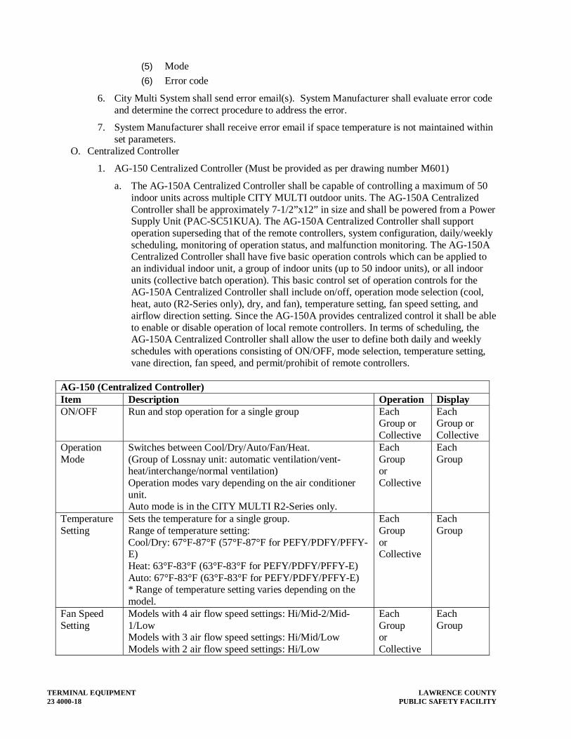
TERMINAL EQUIPMENT LAWRENCE COUNTY 23 4000-18 PUBLIC SAFETY FACILITY
(5) Mode
(6) Error code
6. City Multi System shall send error email(s). System Manufacturer shall evaluate error code and determine the correct procedure to address the error.
7. System Manufacturer shall receive error email if space temperature is not maintained within set parameters.
O. Centralized Controller
1. AG-150 Centralized Controller (Must be provided as per drawing number M601)
a. The AG-150A Centralized Controller shall be capable of controlling a maximum of 50 indoor units across multiple CITY MULTI outdoor units. The AG-150A Centralized Controller shall be approximately 7-1/2”x12” in size and shall be powered from a Power Supply Unit (PAC-SC51KUA). The AG-150A Centralized Controller shall support operation superseding that of the remote controllers, system configuration, daily/weekly scheduling, monitoring of operation status, and malfunction monitoring. The AG-150A Centralized Controller shall have five basic operation controls which can be applied to an individual indoor unit, a group of indoor units (up to 50 indoor units), or all indoor units (collective batch operation). This basic control set of operation controls for the AG-150A Centralized Controller shall include on/off, operation mode selection (cool, heat, auto (R2-Series only), dry, and fan), temperature setting, fan speed setting, and airflow direction setting. Since the AG-150A provides centralized control it shall be able to enable or disable operation of local remote controllers. In terms of scheduling, the AG-150A Centralized Controller shall allow the user to define both daily and weekly schedules with operations consisting of ON/OFF, mode selection, temperature setting, vane direction, fan speed, and permit/prohibit of remote controllers.
AG-150 (Centralized Controller) Item Description Operation DisplayON/OFF Run and stop operation for a single group Each
Group or Collective
Each Group or Collective
Operation Mode
Switches between Cool/Dry/Auto/Fan/Heat.(Group of Lossnay unit: automatic ventilation/vent-heat/interchange/normal ventilation) Operation modes vary depending on the air conditioner unit. Auto mode is in the CITY MULTI R2-Series only.
Each Group or Collective
Each Group
Temperature Setting
Sets the temperature for a single group. Range of temperature setting: Cool/Dry: 67°F-87°F (57°F-87°F for PEFY/PDFY/PFFY-E) Heat: 63°F-83°F (63°F-83°F for PEFY/PDFY/PFFY-E) Auto: 67°F-83°F (63°F-83°F for PEFY/PDFY/PFFY-E) * Range of temperature setting varies depending on the model.
Each Group or Collective
Each Group
Fan Speed Setting
Models with 4 air flow speed settings: Hi/Mid-2/Mid-1/Low Models with 3 air flow speed settings: Hi/Mid/Low Models with 2 air flow speed settings: Hi/Low
Each Group or Collective
Each Group

LAWRENCE COUNTY TERMINAL EQUIPMENT PUBLIC SAFETY FACILITY 23 4000-19
AG-150 (Centralized Controller)Item Description Operation DisplayAir Flow Direction Setting
Air flow direction angles 100%-80%-60%-40%, Swing, *1. Louver cannot be set. Air flow direction settings vary depending on the model.
*1 Each Group or Collective
Each Group
Timer Operation
Start/Stop and Enable/Disable can be set 3 times in one day. For a week’s schedule, store three start/stop patterns and one enable/disable pattern. *2 When the timer is set, “Timer Enabled” is shown on the operation setting screen of the LCD.
Each Group or Collective
*2 Each Group
Permit / Prohibit Local Operation
Individually prohibit operation of each local remote control function (Start/Stop, Change operation mode, Set temperature, Reset filter).
*3: Centrally Controlled is displayed on the remote controller for prohibited functions.
Each Group or Collective
*3 Each Group
Display Indoor Unit Intake Temp
Measures and displays the intake temperature of the indoor unit when the indoor unit is operating.
N/A Each Group
Error When an error is currently occurring on an air conditioner unit, the afflicted unit and the error code are displayed *4 When an error occurs, the LED flashes. The operation monitor screen shows the abnormal unit by flashing it. The error monitor screen shows the abnormal unit address, error code and source of detection. The error log monitor screen shows the time and date, the abnormal unit address, error code and source of detection
N/A *4 Each Unit or Collective
Test Run Operates air conditioner units in test run mode. Each Group
Each Group
Ventilation Equipment
This interlocked system settings can be performed by the master system controller. When setting the interlocked system, use the ventilation switch the free plan LOSSNAY settings between “Hi”, “Low” and “Stop”. When setting a group of only free plan LOSSNAY units, you can switch between “Normal ventilation”, “Interchange ventilation” and “Automatic ventilation”.
Each Group
Each Group
External Input / Output
By using accessory cables you can set and monitor the following. Input By level: “Batch start/stop”, “Batch emergency stop” By pulse: “batch start/stop”, “Enable/disable remote controller” Output: “start/stop”, “error/Normal” Requires the external I/O cables (PAC-YG10HA-E) :5٭sold separately.
*5 Collective
*5 Collective
b. All AG-150 Centralized Controllers shall be equipped with one RJ-45 Ethernet port to support interconnection with a network PC via a closed/direct Local Area Network (LAN).

TERMINAL EQUIPMENT LAWRENCE COUNTY 23 4000-20 PUBLIC SAFETY FACILITY
c. The AG-150 Centralized Controller shall be capable of performing initial settings via the 9” high-resolution, backlit, color touch panel on the controller or via a PC using the AG-150 Centralized Controller’s initial setting browser.
d. Optional software functions shall be available so that the building manager can securely log into each AG-150A via the PC’s web browser to support operation monitoring, scheduling, error email, personal browser for PCs and MACs, and online maintenance diagnostics. Additional optional software functions of Tenant Billing shall be available but shall require TG-2000 Integrated System software in conjunction with AG-150A Centralized Controllers. BACnet® interface shall be available through software operating on a dedicated PC and a AG-150A license. The optional software functions shall require advance purchasing and can only be activated upon receipt of a license number from Mitsubishi Electric HVAC.
2. Provide a control interface to enable The Outside Air supply RTU whenever any terminal unit is in occupied mode.
P. MANUFACTURER’S FIELD SERVICES (MFS)
1. This service shall provide full commissioning of the Variable Refrigerant Flow System. It shall be conducted by a Factory Certified and Nate Certified person(s) who shall accept both full responsibility and total accountability for this service.
2. The service shall involve:
a. “MFS” Technician will collect the Mitsubishi Electric supplied pressure test certificate on commencement of commissioning.
b. On commencement of commissioning the system must be in an evacuated state for “MFS” technician to witness the final evacuation process.
c. “MFS” Technician will inspect the integrity of the system.
d. Provide an unbiased appraisal of the installed application, based upon their experience as a manufacturer of the product.
e. Check the “as installed” drawings and make sure the pipe work runs do not exceed the operational design maximum.
f. Ensure that all grouped equipment is addressed correctly from the outset.
g. Provide a comprehensive commissioning report complete with a “true” diagnostic operating record of the functioning systems confirming that the system is operating, within its design parameters and give validation of the warranty with M-service tool.
h. Make recommendations to correct any performance related problems found during commissioning.
i. A complete asset list of equipment will be run in their database, maintaining an indefinite historical record of any calls to Mitsubishi Electric relating to this site.
j. Enhance the integrity of the 1-year Manufacturer’s Warranty by confirming the system has been commissioned correctly.
k. Maximize system operation to give optimum energy efficiency.
l. Provide Design Tool Project drawing complete with electrical engineer (P.E.) stamped drawing of piping and control wiring prior to construction, and an “as-built” copy after startup.
3. All work carried out shall be backed-up with a comprehensive commissioning log book. Provide three copies to the Owner’s Commissioning Agent.

LAWRENCE COUNTY TERMINAL EQUIPMENT PUBLIC SAFETY FACILITY 23 4000-21
4. The field start-up representative shall perform the following Start-up procedure and Commissioning. Service must be provided by the system manufacturer. A sub-contractor is not allowed. Startup shall include.
a. Start-up representative firm shall have a minimum of two diagnostic laptops with commissioning and start-up software preinstalled.
b. Start-up representative firm shall have minimum 6 years hands on VRF experience with minimum of 3 start-up employees, not subcontractors.
c. Startup representative firm shall have a minimum $500,000 inventory of VRF systems located within 20 miles of project.
d. Start-up representative shall be NATE certified in at least two categories.
e. Start-up representative shall have live experience with start-up of minimum of 420 VRF systems.
f. Start-up representative shall have over $10,000 in VRF parts available with 20 miles of project location.
5. Commissioning shall include:
a. Verify installation of all city Multi equipment must comply with the installation manual as furnished by Mitsubishi Electric.
b. The electric installation must comply with all local and Engineering Standards for Electrical installations.
c. The refrigerant pipe work is to be pressure tested to 430 psi with oxygen free nitrogen and shall be witnessed by manufacturer’s representative and documented.
d. The refrigerant pipe work must be evacuated within the aforementioned 24 hour period prior to commencement of commissioning.
e. The correct refrigerant charge must be added and service values opened.
f. All outdoor units, indoor units, remote controllers and system controllers must have the correct address settings before turning on power to outdoor unit.
g. Prior to switching on power supply to outdoor units, the power supply must be checked at the isolator for tight termination and correct voltage readings.
h. One point (g) has been checked the power can be turned on to allow the crankcase heater to energize. This must be for a period of at least 12 hours prior to the start up. The M Net terminals during this period must be disconnected.
i. On completion of point (h), the outdoor unit can be run up and commissioning can then proceed.
j. All relative operating data can be captured by use of the dipswitch settings on the main board of the inverter and then transposed onto the Mitsubishi Electric supplied commissioning sheets.
k. On completion of the commissioning sheets, a copy must be sent to the address below Mitsubishi Electric, Atlanta, GA to obtain a unique warranty number for that site. Provide a copy of the documents sent to the Owner.
l. Manufacturer’s representative will collect the Mitsubishi Electric supplied pressure test certificate on commencement of commissioning.

TERMINAL EQUIPMENT LAWRENCE COUNTY 23 4000-22 PUBLIC SAFETY FACILITY
m. On commencement of commissioning the system must be in an evacuated state for manufacturer’s representative to witness the final evacuation process.
n. Manufacturer’s representative will inspect the integrity of the system and provide an unbiased appraisal of the installed application, based upon their experience as a manufacturer of the product.
o. Check the “as installed” drawings and make sure the pope work runs do not exceed the operational design maximum.
p. Ensure that all grouped equipment is addressed correctly from the outset.
q. Provide a comprehensive commissioning report complete with a “true” diagnostic operating record of the functioning systems confirming that the system is operating within its design parameters and give validation of the warranty with M-service tool.
r. Make recommendations to correct any performance related problems found during commissioning.
s. A complete asset list of the equipment will be run in their database, maintaining an indefinite historical record of any calls to Mitsubishi Electric relating to this site.
t. Enhance the integrity of the 1-year Manufacturer’s Warranty by confirming the system has been commissioned correctly.
u. Maximize system operation to give optimum energy efficiency.
v. Provide Design Tool Project drawing complete with electrical engineer (P.E.) stamped drawing of piping and control wiring prior to construction.
w. All work carried out shall be backed-up with a comprehensive commissioning log book. Provide three copies to the Project Engineer.
1.08 SMALL VRF SYSTEMS WITH LESS THAN 5 TERMINAL UNITS
A. The heat pump air conditioning system shall be a variable capacity multi-zone series asa described hereinafter. The system shall consist of a one, two (2), three (3), or four (4) slim silhouette, compact, wall and/or floor mounted indoor fan coil sections with digital wireless remote controller, and/or ceiling suspended, ceiling recessed and/or low to mid profile ducted indoor units with a wired, wall mounted remote controller connected to a compact horizontal discharge outdoor unit which shall be of an inverter driven heat pump design.
B. The Basis of Design (BOD) manufacturer Mitsubishi. Daikin, LG, and Samsung have demonstrated a general ability to meet the intent of this specification as a manufacturer; however, the installation practices, including both piping and wiring, differ significantly from those shown or implied for the BOD. The burden to document the required installation practices remains with the Vendor to the extent necessary for the Contractor to include all required costs in his bid. These costs must include the work of all trades—there will be no consideration given for additional compensation to any party as a result of the use of a non-BOD vendor. Furthermore, all such differences shall be shown and identified on system shop drawings. The submission of detailed piping/wiring schematics, similar in detail to those currently on the drawings, shall be included with the shop drawings, and may be requested by the Contractor, prior to that time, as he sees fit.

LAWRENCE COUNTY TERMINAL EQUIPMENT PUBLIC SAFETY FACILITY 23 4000-23
C. The Professional will make the ultimate and final determination regarding equality and acceptance of a non-BOD manufacturer.
D. Indoor unit model numbers shall be:
1. Ceiling Recessed; SLZ-KA09NA
2. Ducted; SEZ-KD09NA4
E. Outdoor unit model number may be MXZ-2B20NA-1 (2:1), system.
F. Quality Assurance:
1. The system components shall be tested by a Nationally Recognized Testing Laboratory (NRTL) and shall bear the ETL label.
2. All wiring shall be in accordance with the National Electrical Code (N.E.C.).
3. The units shall be rated in accordance with Air-conditioning Refrigeration Institute’s (ARI) Standard 240 and bear the ARI Certification label.
4. The units shall be manufactured in a facility registered to ISO 9001 and ISO 14001, which is a set of standards applying to product and manufacturing quality and environmental management and protection set by the International Standard Organization (ISO).
5. A dry air holding charge shall be provided in the indoor section.
6. System efficiency shall meet or exceed 14.5 SEER when part of a multi system (2:1 / 3:1 / 4:1).
7. The manufacturer shall submit with the equipment shop drawings, a detailed description of the contractor start-up responsibilities, as well as copies of all pertenent startup and commissioning forms. If the project is commissioned, these forms, if approved by the Design Professional, will be used by the commissioning agent. If the project is not commissioned, these forms, completed and signed, shall still be required of the HVAC contractor as part of his closeout documentation.
G. Delivery, Storage and Handling
1. Unit shall be stored and carefully handled according to the manufacturer’s recommendations.
2. The wireless remote controller, for the wall mounted and floor standing indoor units, shall be shipped inside the carton and packaged with the indoor unit and shall be able to withstand 105°F storage temperatures and 95% relative humidity without adverse effect.
3. The wireless or wired remote controller, for the ceiling suspended, ceiling recessed and ducted indoor units shall be shipped separately.
H. The units shall have a manufacturer’s parts and defects warranty for a period five (5) years from date of installation. The compressor shall have an extended warranty of seven (7) years from date of installation. If, during this period, any part should fail to function properly due to defects in workmanship or material, it shall be replaced or repaired at the discretion of the manufacturer. This warranty will not include labor.
I. Manufacturer shall have over 30 years of continuous experience in the U.S. market.
TERMINAL EQUIPMENT LAWRENCE COUNTY 23 4000-24 PUBLIC SAFETY FACILITY
J. Outdoor Units:
1. The MXZ-B outdoor unit shall be specifically designed to work with the SEZ-KD and SLZ-KA family of indoor units. The outdoor unit shall be completely factory assembled, piped and wired. Each unit shall be run tested at the factory prior to shipment.
2. Unit Cabinet:
a. The casing shall be fabricated of galvanized steel, Bonderized, finished with an electrostatically applied, thermally fused acrylic or polyester powder coating for corrosion protection. Assembly hardware shall be cadmium plated for weather resistance.
b. Cabinet color shall be Munsell 3Y 7.8/1.1.
c. Two (2) mild steel mounting feet, traverse mounted across the cabinet base pan, welded mount, providing four (4) slotted mounting holes shall be furnished. Assembly shall withstand lateral wind gust up to 155 MPH to meet applicable weather codes.
3. Fan:
a. The unit shall be furnished with a direct drive, high performance propeller type fan.
b. The condenser fan motor shall be a variable speed, direct current (DC) motor and shall have permanently lubricated bearings.
c. Fan speed shall be switch automatically according to the number of operating indoor units and the compressor operating frequency.
d. The fan motor shall be mounted with vibration isolation for quiet operation.
e. The fan shall be provided with a raised guard to prevent contact with moving parts.
f. The outdoor unit shall have horizontal discharge airflow.
g. Outdoor unit sound level shall not exceed:
Model Cooling HeatingMXZ-2B20NA-1 49 dB(A) 51 dB(A)
4. Coil:
a. The outdoor unit coil shall be of nonferrous construction with lanced or corrugated plate fins on copper tubing.
b. The coil shall be protected with an integral guard.
c. Refrigerant flow from the outdoor unit to the indoor units shall be independently controlled by means of individual electronic linear expansion valves for each indoor unit.
d. Outdoor unit shall be pre-charged with sufficient R-410a refrigerant for up to one hundred and thirty-one (131) feet of refrigerant piping.
e. All refrigerant lines between outdoor and indoor units shall be of annealed, refrigeration grade copper tubing, ARC Type, meeting ASTM B280 requirements, individually insulated in twin-tube, flexible, closed-cell, CFC-free (ozone depletion potential of zero), elastomeric material for the insulation of refrigerant pipes and tubes with thermal conductivity equal to or better than 0.27 BTU-inch/hour per Sq Ft / °F, a water vapor transmission equal to or better than 0.08 Perm-inch and superior fire ratings such that insulation will not contribute significantly to fire and up to 1” thick insulation shall have a Flame-Spread Index of less than 25 and a Smoke-development Index of less than 50 as tested by ASTM E 84 and CAN / ULC S-102.

LAWRENCE COUNTY TERMINAL EQUIPMENT PUBLIC SAFETY FACILITY 23 4000-25
f. All refrigerant connections between outdoor and indoor units shall be flare type.
5. Compressor:
a. The compressor shall be a high performance, hermetic, inverter driven, variable speed, dual rotary type manufactured by Mitsubishi Electric Corporation.
b. The compressor motor shall be direct current (DC) type equipped with a factory supplied and installed inverter drive package.
c. The outdoor unit shall be equipped with a suction side refrigerant accumulator.
d. The compressor will be equipped with an internal thermal overload.
e. The compressor shall be mounted to avoid the transmission of vibration.
6. Manifold:
a. The outdoor unit shall have manifold connections providing a separate set of flared fittings for each indoor unit per the table below:
Port Connections A B C D MXZ-2B20NA-1 ¼ “ Liquid ; 3/8”
Gas ¼ “ Liquid ; 3/8” Gas
[Some indoor unit combinations may require port adapters for proper connection]
7. Piping Requirements:
a. The outdoor unit must have the ability to operate within the following refrigerant piping and height limitations without the need for line size changes, traps or additional oil.
b. Piping Lengths: Refrigerant Piping Data Length to each indoor unit Total piping lengthMXZ-2B20NA-1 82 feet (Max) 164 feet (Max)
c. Height Differential:
Model Indoor unit above outdoor unit Indoor unit below outdoor unitMXZ-2B20NA-1 49 feet (Max) 33 feet (Max)
8. Electrical:
a. The unit electrical power shall be 208/230 volts, 1-phase, 60 hertz.
b. The unit shall be capable of satisfactory operation within voltage limits of 198 volts to 253 volts.
c. The outdoor unit shall be controlled by the microprocessors located in the indoor unit and in the outdoor unit communicating system status, operation, and instructions digitally over A-Control – a system directing that the indoor unit be powered directly from the outdoor unit using a 3-wire, 14 ga. AWG connection plus ground.
d. The outdoor unit shall be equipped with Pulse Amplitude Modulation (PAM) compressor inverter drive control for maximum efficiency with minimum power consumption.
K. Indoor Units
1. Ducted SEZ-KD**NA4 Indoor Units:
a. The indoor unit shall be factory assembled, wired and run tested. Contained within the unit shall be all factory wiring, piping, control circuit board, fan and fan motor. The unit shall have a self-diagnostic function, 3-minute time delay mechanism, and an

TERMINAL EQUIPMENT LAWRENCE COUNTY 23 4000-26 PUBLIC SAFETY FACILITY
auto restart function. The indoor unit shall be charged with dry air before shipment from factory.
b. Unit Cabinet:
(1) The cabinet shall be galvanized steel construction, low profile, horizontal ducted fan coil not to exceed 7-7/8” in depth and equipped with four corner mounting brackets.
c. Fan:
(1) The indoor unit fan shall be an assembly with Sirocco blowers per the following table:
Model Number of Blowers
umber of Blower Motors
ower Motor kW
SEZ-KD09NA4 2 1 0.096 SEZ-KD12NA4 2 1 0.096 SEZ-KD15NA4 3 1 0.096 SEZ-KD18NA4 4 1 0.096
(2) The indoor fan shall be statically and dynamically balanced to run on a motor with permanently lubricated bearings.
(3) The indoor fan shall consist of three (3) speeds, High, Mid, and Low plus Auto Fan Mode
(4) The indoor unit shall have a ducted air outlet system and ducted return air system.
d. Filter:
(1) Return air shall be filtered by means of a standard factory installed return air filter.
(2) Option: An FBL1 external filter box made of galvanized steel with flange connections to the indoor unit shall be furnished and equipped with one inch thick filters having a minimum MERV rating of 8.0.
e. Coil:
(1) The indoor coil shall be of nonferrous construction with smooth plate fins on copper tubing.
(2) The tubing shall have inner grooves for high efficiency heat exchange.
(3) All tube joints shall be brazed with phos-copper or silver alloy.
(4) The coils shall be pressure tested at the factory.
(5) A condensate pan and drain shall be provided under the coil.
(6) The unit shall be provided with an integral condensate lift mechanism able to raise drain water 21 – 11/16 inches above the condensate pan.
(7) An optional drain pan level switch (DPLS1), designed to connect to the control board, shall be provided if required, and installed on the condensate pan to prevent condensate from overflowing.
(8) Both refrigerant lines to the indoor units shall be fully insulated.
f. Electrical:
(1) The unit electrical power shall be 208/230 volts, 1 phase, 60 hertz.

LAWRENCE COUNTY TERMINAL EQUIPMENT PUBLIC SAFETY FACILITY 23 4000-27
(2) The system shall be equipped with A-Control – a system directing that the indoor unit be powered directly from the outdoor unit using a 3-wire, 14 gauge AWG connection plus ground.
(3) The system shall be capable of satisfactory operation within voltage limits of 187-228 volts (208V/60Hz) or 207-253 volts (230V/60Hz).
2. Ceiling Recessed SLZ-KA**NA Indoor Units
a. The SLZ shall be a four-way cassette style indoor unit that recesses into the ceiling with a ceiling grille. The indoor unit shall be factory assembled, wired and run tested. Contained within the unit shall be all factory wiring, piping, electronic modulating linear expansion device, control circuit board and fan motor. The unit shall have a self-diagnostic function, 3-minute time delay mechanism, an auto restart function, an emergency operation function and a test run switch. Indoor unit and refrigerant pipes shall be charged with dehydrated air before shipment from the factory.
b. The SLZ shall be a four-way cassette style indoor unit that recesses into the ceiling with a ceiling grille. The indoor unit shall be factory assembled, wired and run tested. Contained within the unit shall be all factory wiring, piping, electronic modulating linear expansion device, control circuit board and fan motor. The unit shall have a self-diagnostic function, 3-minute time delay mechanism, an auto restart function, an emergency operation function and a test run switch. Indoor unit and refrigerant pipes shall be charged with dehydrated air before shipment from the factory.
c. Unit Cabinet:
(1) The cabinet shall be a compact 22-7/16” wide x 22-7/16” deep so it will fit within a standard 24” square suspended ceiling grid.
(2) The cabinet panel shall have provisions for a field installed filtered outside air intake.
(3) Four-way grille shall be fixed to bottom of cabinet allowing two, three or four-way blow.
d. Fan:
(1) The indoor fan shall be an assembly with a turbo fan direct driven by a single motor.
(2) The indoor fan shall be statically and dynamically balanced to run on a motor with permanently lubricated bearings.
(3) The indoor fan shall consist of three (3) speeds, Low, Mid, and High.
(4) The indoor unit shall have an adjustable air outlet system offering 4-way airflow, 3-way airflow, or 2-way airflow.
(5) The auto air swing vanes shall be capable of automatically swinging up and down for uniform air distribution.
e. Filter:
(1) Return air shall be filtered by means of a long-life washable filter.
f. Coil:
(1) The indoor coil shall be of nonferrous construction with smooth plate fins on copper tubing.
(2) The tubing shall have inner grooves for high efficiency heat exchange.
(3) All tube joints shall be brazed with phos-copper or silver alloy.
(4) The coils shall be pressure tested at the factory.
(5) A condensate pan and drain shall be provided under the coil.

TERMINAL EQUIPMENT LAWRENCE COUNTY 23 4000-28 PUBLIC SAFETY FACILITY
(6) The unit shall include a condensate lift mechanism that will be able to raise drain water 19-3/4” inches above the condensate pan.
(7) An optional drain pan level switch (DPLS1), designed to connect to the control board, shall be provided if required, and installed on the condensate pan to prevent condensate from overflowing.
(8) Both refrigerant lines to the SLZ indoor units shall be insulated.
g. Electrical:
(1) The unit electrical power shall be 208/230 volts, 1-phase, 60 hertz.
(2) The system shall be capable of satisfactory operation within voltage limits of 187-228 volts (208V/60Hz) or 207-253 volts (230V/60Hz).
h. Controls:
(1) The control system shall consist of a minimum of one microprocessor on each indoor unit and one on the outdoor unit, interconnected by single non-polar two-wire cables. The microprocessor located in the indoor unit shall have the capability of monitoring return air temperature and indoor coil temperature, receiving and processing commands from a wireless or wired controller, providing emergency operation and controlling the outdoor unit. The control signal between the indoor and outdoor unit shall be pulse signal 24 volts DC. Indoor units shall have the ability to control supplemental heat via connector CN24 and a 12 VDC output.
(2) For A-Control, a three (3) conductor 14 gauge AWG wire with ground shall provide power feed and bi-directional control transmission between the outdoor and indoor units. . If code requires a disconnect mounted near the indoor unit, a TAZ-MS303 3-Pole Disconnect shall be used – all three conductors must be interrupted.
(3) The system shall be capable of automatic restart when power is restored after power interruption. The system shall have self-diagnostics ability, including total hours of compressor run time. Diagnostics codes for indoor and outdoor units shall be displayed on the wired controller panel.
(4) Remote Controller
(a) Wireless, wall mounted remote controller kit (MHK1) (b) The Wireless, wall mounted remote controller kit (MHK1) shall
consist of a wireless, wall mounted controller (MRCH1), a wireless receiver (MIFH1) and a cable (MRC1) to connect the receiver to the indoor unit. The controller shall be white in color with a light-green LCD display and a backlight feature. The MRCH1 shall consist of four Function buttons below the display, and Increase/Decrease Set Temperature buttons and a Hold button to the right of the display. The controller shall have a built-in temperature sensor and a battery holder, using two AA alkaline batteries. Temperature shall be displayed in either Fahrenheit (°F) or Celsius (°C), and temperature changes shall be by increments of 1°F (0.5°C).
(c) The MHK1 uses Honeywell RedLINKTM technology, and the wireless receiver is specially designed for Mitsubishi units. Linking to the wireless network shall be done from the receiver and from the remote controller. There shall not be any interference with other wireless devices or neighboring RedLINKTM products.

LAWRENCE COUNTY TERMINAL EQUIPMENT PUBLIC SAFETY FACILITY 23 4000-29
Communication shall be automatically restored after power resumes and after batteries are replaced.
(d) The basic functions are:
Wireless, Wall Mounted Remote Controller Kit (MHK1)
Item Description
Number of Units Controllable 1 unit
ON/OFF Run and stop operation
Operation Mode Switches between Cool/Drying/Auto/Fan/Heat.
Temperature Setting (Range and modes depend on connected unit model)
Controller general setpoint temperature range: Cool/Dry: 50°F-99°F Heat: 40°F-90°F Auto: 50°F-90°F Controller temperature range when connected to the SLZ/SUZ system: Cool/Dry: 67°F-87°F Heat: 63°F-83°F Auto: 67°F-83°F
Fan Speed Setting (Range and modes depend on connected unit model)
Hi/Mid-2/Mid-1/Low/Auto
Air Flow Direction Setting (Air flow direction settings depend on the unit model)
Air flow direction angles 100%-80%-60%-40%, Swing.
Dual Setpoint Control Separate heating and cooling setpoints. Adjustable deadband from 2ºF to 8ºF. Automatically adjusts setpoints to ensure deadband. System changeover with dual setpoints.
Scheduling 5-2 and 5-1-1 schedules Separate Heat/Cool schedules Allows operation in AUTO with Scheduling setbacks and dual setpoint Simple temperature setting can be done up to 4 times one day in the week. The time can be set by the 15-minute interval. Remote controller shall be programmable as either a residential controller, which will offer residential scheduling options only; or as a commercial controller, which will offer commercial scheduling options only.
Optimal Start Set occupied time and desired set temperature Remote controller learns when to start warm up or cool down so that space is at set temperature at start of occupied time
Operating Conditions Display Setpoint and room temperature. Default sensing is at the remote controller. Installer setting to select at return air sensor. Automatically switches to return air sensor if communication to remote controller is lost Outdoor temperature and humidity (Requires optional air sensor MOS1)
Additional Functions Hold Function Temporary Schedule Override Reset to factory default
Error When an error is currently occurring on an air conditioner unit, the afflicted unit and the error code are displayed

TERMINAL EQUIPMENT LAWRENCE COUNTY 23 4000-30 PUBLIC SAFETY FACILITY
Wireless, Wall Mounted Remote Controller Kit (MHK1)
Item Description
Auto Lock Out Function Setting/releasing of simplified locking for remote control settings can be performed.
• Locking of all settings
• Locking of ON/OFF setting
• Locking of system setting (Heat, Cool, Off, Auto, etc.)
• Locking of fan setting
• Locking of temperature setting
• Locking of Clock/Day/Schedule
(e) Two optional devices can be used with the MHK1 controller kit. These are, an outdoor air sensor (MOS1), which allows the display of the outdoor temperature and humidity, and a portable central controller (MCCH1), which can control up to 16 zones with On/Off, set temperature, heat/cool mode selection and auto-off timer.
L. MANUFACTURER’S FIELD SERVICES (MFS)
1. This service shall provide full commissioning of the Variable Refrigerant Flow System. It shall be conducted by a Factory Certified and Nate Certified person(s) who shall accept both full responsibility and total accountability for this service.
2. The service shall involve:
a. “MFS” Technician will collect the Mitsubishi Electric supplied pressure test certificate on commencement of commissioning.
b. On commencement of commissioning the system must be in an evacuated state for “MFS” technician to witness the final evacuation process.
c. “MFS” Technician will inspect the integrity of the system.
d. Provide an unbiased appraisal of the installed application, based upon their experience as a manufacturer of the product.
e. Check the “as installed” drawings and make sure the pipe work runs do not exceed the operational design maximum.
f. Ensure that all grouped equipment is addressed correctly from the outset.
g. Provide a comprehensive commissioning report complete with a “true” diagnostic operating record of the functioning systems confirming that the system is operating, within its design parameters and give validation of the warranty with M-service tool.
h. Make recommendations to correct any performance related problems found during commissioning.
i. A complete asset list of equipment will be run in their database, maintaining an indefinite historical record of any calls to Mitsubishi Electric relating to this site.
j. Enhance the integrity of the 1-year Manufacturer’s Warranty by confirming the system has been commissioned correctly.
k. Maximize system operation to give optimum energy efficiency.
l. Provide Design Tool Project drawing complete with electrical engineer (P.E.) stamped drawing of piping and control wiring prior to construction, and an “as-built” copy after startup.

LAWRENCE COUNTY TERMINAL EQUIPMENT PUBLIC SAFETY FACILITY 23 4000-31
3. The field start-up representative shall perform the following Start-up procedure and Commissioning. Service must be provided by the system manufacturer. A sub-contractor is not allowed. Startup shall include.
a. Start-up representative firm shall have a minimum of two diagnostic laptops with commissioning and start-up software preinstalled.
b. Start-up representative firm shall have minimum 6 years hands on VRF experience with minimum of 3 start-up employees, not subcontractors.
c. Start-up representative shall be NATE certified in at least two categories.
d. Start-up representative shall have live experience with start-up of minimum of 420 VRF systems.
4. Commissioning shall include:
a. Verify installation of all equipment must comply with the installation manual as furnished by the manufacturer.
b. The electric installation must comply with all local and Engineering Standards for Electrical installations. The commissioning proceedures described herein pertain to the Basis of Desgin. Functionally equivalent proceedures, as dictated by other manufcatures, shall be followed as appropriate.
c. The refrigerant pipe work is to be pressure tested to 430 psi with oxygen free nitrogen and shall be witnessed by manufacturer’s representative and documented.
d. The refrigerant pipe work must be evacuated within the aforementioned 24 hour period prior to commencement of commissioning.
e. The correct refrigerant charge must be added and service values opened.
f. All outdoor units, indoor units, remote controllers and system controllers must have the correct address settings before turning on power to outdoor unit.
g. Prior to switching on power supply to outdoor units, the power supply must be checked at the isolator for tight termination and correct voltage readings.
h. One point (g) has been checked the power can be turned on to allow the crankcase heater to energize. This must be for a period of at least 12 hours prior to the start up. The M Net terminals during this period must be disconnected.
i. On completion of point (h), the outdoor unit can be run up and commissioning can then proceed.
j. All relative operating data can be captured by use of the dipswitch settings on the main board of the inverter and then transposed onto the Mitsubishi Electric supplied commissioning sheets.
k. On completion of the commissioning sheets, a copy must be sent to the address below Mitsubishi Electric, Atlanta, GA to obtain a unique warranty number for that site.
l. Manufacturer’s representative will collect the Mitsubishi Electric supplied pressure test certificate on commencement of commissioning.
m. On commencement of commissioning the system must be in an evacuated state for manufacturer’s representative to witness the final evacuation process.

TERMINAL EQUIPMENT LAWRENCE COUNTY 23 4000-32 PUBLIC SAFETY FACILITY
n. Manufacturer’s representative will inspect the integrity of the system and provide an unbiased appraisal of the installed application, based upon their experience as a manufacturer of the product.
o. Check the “as installed” drawings and make sure the pope work runs do not exceed the operational design maximum.
p. Ensure that all grouped equipment is addressed correctly from the outset.
q. Provide a comprehensive commissioning report complete with a “true” diagnostic operating record of the functioning systems confirming that the system is operating within its design parameters and give validation of the warranty with M-service tool.
r. Make recommendations to correct any performance related problems found during commissioning.
s. A complete asset list of the equipment will be run in their database, maintaining an indefinite historical record of any calls to Mitsubishi Electric relating to this site.
t. Enhance the integrity of the 1-year Manufacturer’s Warranty by confirming the system has been commissioned correctly.
u. Maximize system operation to give optimum energy efficiency.
v. Provide Design Tool Project drawing complete with electrical engineer (P.E.) stamped drawing of piping and control wiring prior to construction.
w. All work carried out shall be backed-up with a comprehensive commissioning log book. Provide three copies to the Project Engineer.
1.09 CEILING MOUNTED PROP FANS
A. Fans shall be 3 blade propeller type as manufactured by Canarm, or approved equal.
B. Motors shall be permanently sealed ball bearing type,impedence protected PSC, designed for extremely quiet operation. Motor shall have minimum 5 year limited warranty. Motors shall operate at 120V - single phase.
C. For each fan provide all required mounting and hanging hardware for safe secure installation. Provide safety chain.
D. For each fan provide an electronic variable speed switch, equal to Canarm MC series speed controller. In addition, provide a directional switch, equal to Canarm FRMC.
E. Fans shall be high performance water resistant construction, Canarm type CP-HPWP or approved equal..
1.10 IN-LINE FANS
A. Duct mounted supply, exhaust or return fans shall be of the centrifugal belt driven in-line type. The fan housing shall be of the square design constructed of heavy gauge galvanized steel and shall include rectangular duct mounting collars.
B. Provide vibration isolators suitable for hanging the fan from the roof structure in a vertical discharge arrangement. All additional support hardware shall be by the HC.
C. The side of the housing shall be equipped with a hingeable service door assembly supporting the motor, drives, wheel and inlet cone. The door assembly shall swing out for cleaning, inspection, or service without dismantling the fan in any way.
D. The fan wheel shall be of the aluminum backward inclined, centrifugal type. Wheels shall be dynamically and statically balanced and shall overlap the spun inlet venturi for maximum

LAWRENCE COUNTY TERMINAL EQUIPMENT PUBLIC SAFETY FACILITY 23 4000-33
performance.
E. The motor and drives shall be isolated from the air stream. Motors shall be of the heavy duty type with permanently lubricated, sealed ball bearings. The wheel shaft shall be ground and polished shafting mounted in heavy duty permanently sealed pillow block bearings. Drives shall be sized for a minimum of 165% of driven horsepower. Pulleys shall be of the fully machined cast iron type, keyed and securely attached to the wheel and motor shafts. The motor pulleys shall be adjustable for final system balancing.
F. Flexible wiring leads shall be provided from the fan motor to an external mounted junction box and disconnect switch permitting access for service without disconnecting the field wiring. All fans shall bear the AMCA Certified Ratings Seal for both air and sound performance.
G. Fans shall be hung from building structure with rod hangers and rubber in shear vibration isolators. Additional support steel members, as required to support fan, shall be provided by this Contractor. Provide flexible connectors on inlet and outlet ductwork.
H. Fans shall be Cook Model, DBX, Greenheck Model BSQ or approved equal .
1.11 DRYER EXHAUST FAN
A. Duct mounted supply, exhaust or return fans shall be of the centrifugal backward inclined, direct drive in-line type. The fan housing shall have a heavy gauge galvanized steel..
B. Motor shall be outside the airstream,
C. The fan housing shall be provided with a rubber vibration absorbing gasket at the mounting points.
D. The fan shall have factory installed and wired controls to automatically start the fan motor upon sensing dryer operation.
E. Fan shall be guaranteed against clogging for a minimum of 5 years.
F. Fan shall pug into a convenience outlet for power. Electrical load shall be no more than 0.8 amps at 120 volts.
G. Fan shall be Tjerlund Model Number LB-1 or approved equal.
1.12 SMALL KITCHEN RANGE HOODS
A. Range hood shall be Broan Model QDE or approved equal.
B. Unit shall exhaust 290 cfm at maxinmum speed, 130 CFM at normal speed. . All rating shall be certified by HVI.
C. Unit shall have a lifetime lubricated, dual centrifugal blower, resiliently mounted and controlled with rocker switches. RPM shall not exceed 1550. Hood shall have a separate, two position light switch.
D. Unit shall be U.L. listed.
E. Unit shall be 30” wide in standard color as selected by Architect, white, black, or stainless steel.
F. Sides shall be mitered and bottom hemmed with no sharp edges.
G. Bright polymeric light lens with (2) compact floresent lamps.
H. Unit shall be ducted with two washable aluminum filters. Blower wheel shall also be washable.
I. Fan shall be wired through a single on/off switch in the face of the cabinet to comply wirth accessibility standards.

TERMINAL EQUIPMENT LAWRENCE COUNTY 23 4000-34 PUBLIC SAFETY FACILITY
1.13 WALL MOUNTED PROPELLER EXHAUST FANS
A. Fans shall be direct drive propeller exhaust fans wityh the scheduled capacioties and characteristics.
B. Fans shall be installed in an insulated galvanized steel housing box, which shall be supported from HC installed steel framing tied to the roof structure. Support shall be independent from the building wall.
C. Housing shall contain a screened inlet, two position motorized damper wired from the load side of the fan discionnect switch, disconnect switch, speed controller (for balancing purposes).
D. Provide paintable galvanized steel weather hood on the outside of the wall opening to prevent the entry of rain and snow. Paint the hood to match the adjacent building wall.
1.14 COMPUTER ROOM AC SYSTEMS
A. These specifications describe requirements for a precision cooling system. The system shall be designed to maintain temperature and humidity conditions in the rooms containing electronic equipment. The manufacturer shall design and furnish all equipment to be fully compatible with heat dissipation requirements of the room.
B. The precision cooling system shall be a self-contained, factory-assembled unit with Downflow air delivery. The system shall have the scheduled cooling capacity at an entering air temperature of 75°F dry bulb and 61°F wet bulb. The unit is to be supplied with 460 volt 3 ph 60 Hz electrical service. 65,000 amps rms Short Circuit Current Rating.
C. Liebert is the Basis of Design. Equipment manufactured by Data Air would be considered acceptable, provided all specified and scheduled criteria are met in the opinion of the Architect.
D. Submittals shall be provided with the proposal and shall include: Single-Line Diagrams; Dimensional, Electrical and Capacity Data; Piping and Electrical Connection Drawings.
E. The frame shall be MIG welded formed sheet metal. It shall be protected against corrosion using the autophoretic coating process. The frame shall be capable of being separated into three parts in the field to accommodate rigging through small spaces.
F. The supply air shall exit from the bottom of the unit. The return air shall enter the unit from the top.
G. The exterior panels shall be insulated with a minimum 1", 1.5 lb. density fiber insulation. The main front panel shall have captive 1/4 turn fasteners. The main unit color shall be IBM Charcoal.
H. The filter chamber shall be located within the cabinet, and filters shall be removable from the top of the unit. Filters shall be arranged in a V-bank configuration to minimize air pressure drop.
I. Filters shall be deep pleated 4" filters with a MERV 8 rating.
J. Electronically Commutated (EC) Fan, Direct-Drive, Variable Speed. The fans shall be plug/plenum type, single inlet and shall be dynamically balanced, and the drive package shall be direct drive, electronically commutated and variable speed. The fans shall be located to draw air over the A-frame coil to ensure even air distribution and maximum coil performance. EC fans shall be available on Downflow models only.
K. The fan motors shall be nominal 4.15 hp each with a maximum operating speed of 1510 rpm; quantity, two.
L. A humidifier shall be factory-installed inside the unit. Bypass air slots shall be included to enable moisture to be absorbed into the air stream. The humidifier capacity shall be as scheduled. The humidifier shall be removable from the front of the cabinet.

LAWRENCE COUNTY TERMINAL EQUIPMENT PUBLIC SAFETY FACILITY 23 4000-35
M. The humidifier shall be of the infrared type consisting of high intensity quartz lamps mounted above and out of the water supply. The humidifier pan shall be stainless steel and arranged to be removable without disconnecting high voltage electrical connections. The complete humidifier section shall be pre-piped, ready for field connection to water supply. The humidifier shall be equipped with an automatic water supply system and shall have an adjustable water-overfeed to prevent mineral precipitation. A high-water detector shall shut down the humidifier to prevent overflowing.
N. The precision cooling unit shall include a factory-installed reheat to control temperature during dehumidification.
O. The electric reheat coils shall be low watt density, 304/304 stainless steel fin tubular construction, protected by thermal safety switches, shall be as scheduled, and shall be, controlled in three stages. The reheat elements shall be removable from the front of the cabinet.
P. Each unit shall include two (2) independent refrigeration circuits, liquid line filter driers, refrigerant sight glass with moisture indicator, externally equalized expansion valves and liquid line solenoid valves. Compressors shall be located outside the airstream and shall be removable and serviceable from the front of the unit.
Q. The compressor shall be digital scroll-type with a variable capacity operation capability. Compressor solenoid valve shall unload the compressor and allow for variable capacity operation. The compressor shall be suction gas cooled motor, vibration isolators, thermal overloads, automatic reset high pressure switch with control lockout after three failures, pump down low pressure transducer, suction line strainer, rotalock service valves, a maximum operating speed of 3500 RPM.
R. The evaporator coil shall be A-frame design with offset orientation, three rows deep. It shall be constructed of rifled copper tubes and aluminum fins. A stainless steel condensate drain pan shall be provided.
S. The system shall be designed for use with R-407C refrigerant, which meets the EPA clean air act for phase-out of HCFC refrigerants. Refrigerant shall be field supplied and field charged on air-cooled systems.
T. The unit control shall be factory set-up for Intelligent Control which uses "fuzzy logic" and "expert systems" methods. Proportional and Tunable PID shall also be user selectable options. Internal unit component control shall include the following:
1. Compressor Short Cycle Control - Prevents compressor short-cycling and needless compressor wear.
2. System Auto Restart - The auto restart feature will automatically restart the system after a power failure. Time delay is programmable.
3. Sequential Load Activation - On initial startup or restart after power failure, each operational load is sequenced with a minimum of one second delay to minimize total inrush current.
4. Econ-O-Coil Flush Cycles - Econ-O-Coils are periodically flushed to prevent a buildup of contaminants.
5. Predictive Humidity Control - calculates the moisture content in the room and prevents unnecessary humidification and dehumidification cycles by responding to changes in dew point temperature.
U. The control shall be compatible with all Liebert remote monitoring and control devices. Provide BMS interface to Modbus, Jbus, BACNet, Profibus and SNMP.

TERMINAL EQUIPMENT LAWRENCE COUNTY 23 4000-36 PUBLIC SAFETY FACILITY
V. The control processor shall be microprocessor based with a 320x240 dot matrix graphic front monitor display and control keys for user inputs mounted in an ergonomic, esthetically pleasing housing. The display & housing shall be viewable while the unit panels are open or closed. The controls shall be menu driven. The display shall be organized into three main sections: User Menus, Service Menus and Advanced Menus. The system shall display user menus for: active alarms, event log, graphic data, unit view/status overview (including the monitoring of room conditions, operational status in percent of each function, date and time), total run hours, various sensors, display setup and service contacts. A password shall be required to make system changes within the service menus. Service menus shall include: setpoints, standby settings (lead/lag), timers/sleep mode, alarm setup, sensor calibration, maintenance/wellness settings, options setup, system/network setup, auxiliary boards and diagnostics/service mode. A password shall be required to access the advanced menus which include the factory settings and password menus.
1. System View - Status Overview: "System View" shall display a summary of operation for the total number of operating units within a Unit-to-Unit (U2U) configuration.
2. Spare Parts List: Menu shall include a list of critical spare parts, their quantity and respective part numbers.
3. Setup Assistant: Menu shall include an online manual "assistant" for guidance during initial setup and routine maintenance.
4. Unit Diary: Menu shall include a free field area within the unit memory where unit history may be stored for reference.
5. There shall be one of these panels in the front of each terminal unit. In addition, there shall be a third panel, wall mounted in the Dispatch room. This third panel shall contain a network router/switch to facilitate communication beteen the two CRAC units.
W. The User Menus Shall be Defined as Follows
1. Active Alarms: Unit memory shall hold the 200 most recent alarms with time and date stamp for each alarm.
2. Event Log: Unit memory shall hold the 400 most recent events with id number, time and date stamp for each event.
3. Graphic Data View: Eight graphic records shall be available: return air temperature, return air humidity, supply air temperature, outdoor temperature and four custom graphs.
4. Unit View - Status Overview: Simple or Graphical "Unit View" summary displays shall include temperature and humidity values, active functions (and percent of operation) and any alarms of the host unit.
5. Total Run Hours: Menu shall display accumulative component operating hours for major components including compressors, Econ-O-Coil (FC), fan motor, humidifier and reheat.
6. Various Sensors: Menu shall allow setup and display of optional custom sensors. The control shall include four customer accessible analog inputs for sensors provided by others. The analog inputs shall accept a 4 to 20 mA signal. The user shall be able to change the input to 0 to 5VDC or 0 to 10VDC if desired. The gains for each analog input shall be programmable from the front display. The analog inputs shall be able to be monitored from the front display.
7. Display Setup: Customer shall pre-select the desired grouping of display languages at the time of the order from the following choices:
a. Group 1: English, French, Italian, Spanish, German
b. Group 2: English, Russian, Greek

LAWRENCE COUNTY TERMINAL EQUIPMENT PUBLIC SAFETY FACILITY 23 4000-37
c. Group 3: English, Japanese, Chinese, Arabic
8. Service Contacts: Menu shall allow display of local service contact name and phone number.
9. The Service Menus Shall be Defined as Follows
a. Setpoints: Menu shall allow setpoints within the following ranges:
b. Temperature Setpoint 65-85*F (18-29*C)*
c. Temperature Sensitivity +1-10*F (0.6-5.6*C)
d. Humidity Setpoint 20-80% RH*
e. Humidity Sensitivity 1-30% RH
f. High Temperature Alarm 35-90*F (2-32*C)
g. Low Temperature Alarm 35-90*F (2-32*C)
h. High Humidity Alarm 15-85% RH
i. Low Humidity Alarm 15-85% RH
10. * The microprocessor may be set within these ranges, however, the unit may not be able to control to extreme combinations of temperature and humidity.
11. Standby Settings/Lead-Lag: Menu shall allow planned rotation or emergency rotation of operating and standby units.
12. Timers/Sleep Mode: Menu shall allow various customer settings for turning on/off unit.
13. Alarm Setup: Menu shall allow customer settings for alarm notification (audible/local/ remote). The following alarms shall be available:
a. High Temperature
b. Low Temperature
c. High Humidity
d. Low Humidity
e. Short Cycle
f. Compressor Overload (Optional)
g. Main Fan Overload (Optional)
h. Humidifier Problem
i. High Head Pressure
j. Change Filter
k. Loss of Air Flow
l. Low Suction Pressure
m. Loss of Power
n. Custom Alarm (#1 to #4)
14. Custom alarms are four customer accessible alarm inputs to be indicated on the front panel. Custom alarms can be identified with prepared (programmed) alarm labels for the following frequently used inputs:
TERMINAL EQUIPMENT LAWRENCE COUNTY 23 4000-38 PUBLIC SAFETY FACILITY
a. Water Under Floor
b. Smoke Detected
c. Standby GC Pump On
d. Loss of Water Flow
e. Standby Unit On
15. User customized text can be entered for two of the four custom alarms. Each alarm (unit and custom) can be separately enabled or disabled, selected activate the common alarm and programmed for a time delay of 0 to 255 seconds.
16. Audible Alarm: The audible alarm shall annunciate any alarm that is enabled by the operator.
17. Common Alarm: A programmable common alarm shall be provided to interface user selected alarms with a remote alarm device.
18. Remote Monitoring: All alarms shall be communicated to the Liebert monitoring system with the following information: Date and time of occurrence, unit number and present temperature and humidity. Sensor Calibration: Menu shall allow unit sensors to be calibrated with external sensors.
19. Maintenance/Wellness Settings: Menu shall allow reporting of potential component problems before they occur.
20. Options Setup: Menu shall provide operation settings for the installed components.
21. System/Network Setup: Menu shall allow Unit to Unit (U2U) communication and setup for teamwork modes of operation (up to 32 units).
22. Auxiliary Boards: Menu shall allow setup of optional expansion boards.
23. Diagnostics/Service Mode: The iCOM control shall be provided with self-diagnostics to aid in troubleshooting. The microcontroller board shall be diagnosed and reported as pass/not pass. Control inputs shall be indicated as on or off at the front display. Control outputs shall be able to be turned on or off from the front display without using jumpers or a service terminal. Each control output shall be indicated by an LED on a circuit board.
24. Advanced Menus
25. Factory Settings: Configuration settings shall be factory-set based on the pre-defined component operation.
26. Change Passwords: Menu shall allow new passwords to be set or changed.
X. The unit control shall be upgraded with large graphic display shall include all of the features as the standard control with small graphic display, except that it includes a larger graphical display and shall include the additional features of: System View, Spare Parts List, Unit Diary and Online Manual.
Y. The manual disconnect switch shall be mounted in the high voltage section of the electrical panel. The switch shall be accessible with the door closed.
Z. The smoke sensor shall sample the return air, shutdown the unit upon detection, and send visual and audible alarm. Dry contacts shall also be available. This smoke sensor is not intended to function as, or replace, any room smoke detection system that may be required by local or national codes. The smoke sensor shall include a supervision contact closure.

LAWRENCE COUNTY TERMINAL EQUIPMENT PUBLIC SAFETY FACILITY 23 4000-39
AA. The condensate pump shall have a minimum capacity of 145 GPH at 20 ft. of head. It shall be complete with integral dual-float switches, pump and motor assembly and reservoir. The secondary float shall shut down the pump upon high water condition.
BB. The GLYCOOL (econ-o-coil) shall be constructed of copper tubes and aluminum fins. The coil shall be A-frame or V-frame in order to minimize air pressure drop, and shall be nested with the DX coil. The econ-o-coil shall be upstream of the DX coil to enable pre-cooling of the air.
CC. The Econ-o-coil shall have a net Sensible Cooling Capacity of 152.6 BTU/HR (44.7 kW) with 45°F entering glycol solution temperature. The system shall require 51GPM and the total unit pressure drop shall not exceed 38.9 feet of water when in the Econ-O-Coil mode of operation.
DD. The GLYCOOL coil shall be equipped with a fully proportional 3-way control valve. This motorized control valve shall control the amount of flow to the GLYCOOL (econ-o-coil) coil to control room temperature and relative humidity.
EE. The GLYCOOL system shall be designed for a pressure of 350 psi (2413 kPa).
FF. The drycooler shall be the low profile, slow speed, multiple direct drive, propeller fan type. The drycooler shall be constructed of aluminum and contain a copper tube aluminum fin coil with an integral electric control panel and disconnect switch. The drycooler shall be designed for 95°F ambient.
GG. The dual pump package shall include pumps, enclosure, field mounted flow switch and a separate factory-wired control box (including a lead/ lag switch for the pumps). The standby pump shall automatically start upon failure of the lead pump.
HH. Provide one LT460-Z25 Zone moisture/leak sensor.
II. The floor stand shall be constructed of a welded tubular steel frame. The floor stand shall have adjustable legs with vibration isolation pads. The floor stand shall be 18" inches high.
JJ. Install precision air conditioning units in accordance with manufacturer’s installation instructions. Install units plumb and level, firmly anchored in locations indicated and maintain manufacturer’s recommended clearances.
KK. Install and connect electrical devices furnished by manufacturer but not specified to be factory-mounted. Furnish copy of manufacturer’s electrical connection diagram submittal to electrical contractor.
LL. Install and connect devices furnished by manufacturer but not specified to be factory-mounted. Furnish copy of manufacturer’s piping connection diagram submittal to piping contractor.
MM. A factory trained and authorized agent shall startup cooling units in accordance with manufacturer’s startup instructions. Test controls and demonstrate compliance with requirements. These specifications describe requirements for a computer room precision cooling system. The system shall be designed to maintain temperature and humidity conditions in the rooms containing electronic equipment.
NN. The Terminal Unit control sequences shall be further defined as indicated below Field wiring of all loose/remote items shall be covered under the ATC subcontract. The unit manufacturer shall define the nature and extent of such wiring in his proposal to the HVAC Contractor.
1. During cooling mode, the unit shall use refrigeration to cool and dehumidify the space then use electric reheat, to create precise control of space temperature for the area served. The unit shall be capable of cooling with cold glycol solution when outside conditions permit.
2. The above shall be achieved through a combination of unit mounted controls/programming and ATC system interaction though the BACnet interface.

TERMINAL EQUIPMENT LAWRENCE COUNTY 23 4000-40 PUBLIC SAFETY FACILITY
3. The unit manufacturer shall provide on-site assistance to the ATC subcontractor during ATC system startup and commissioning.
4. All information shared through the BACnet interface for this system shall be considered status points only. Changing of any setpoint shall be done by individuals physically present in the room.
1.15 SINGLE ZONE AIR HANDLING UNIT
A. Furnish and install where shown on plans, air handling units, "Airtherm", "McQuay", "Trane", or approved equal. Sizes, capacities and characteristics shall be as noted on the drawings. Unit shall be installed in accordance with the manufacturer's instructions and approved installation drawings. Each unit shall be complete with factory furnished components as shown on the plans. Unit shall be ARI certified per Standard 430.
B. Cabinet shall be sectionalized, double wall galvanized steel constructed with welded channel frames. Casing panels shall be removable for easy access to the interior of the unit. Cabinets shall be constructed for 150% of the total fan static pressure as noted on the drawings.
C. Low and medium fans shall be forward curved or air foil type as scheduled, statically and dynamically balanced with galvanized steel scroll housing. Where air foil fans are scheduled, fans must be air foil design, no other fan type will be acceptable. Fan ratings shall be based on tests conducted in accordance with AMCA Code No. 210. Fan and motor shall be provided with vibration isolation from the unit casing. All medium pressure fans for use on VAV systems shall be provided with inlet vanes. Fans sound ratings shall be equal to the fan and unit sound ratings used as the basis of design. Basis of design manufactures are listed to establish a standard that all other manufactures must meet. Sound data and other data need not be scheduled to be binding. It is the substituting manufactures responsibility to be familiar with the competitive product and to determine that they meet or exceed the specified product in all details.
D. The fan shafts shall be solid steel precision turned ground and polished and shall have a protective coating to prevent excessive oxidation. Maximum operating RPM shall be 20% below first critical speed.
E. Fan cabinet shall be internally insulated with 1" thick neoprene coated glass fiber insulation.
F. Bearings shall be self-aligning, grease lubricated ball type. Lubrication fittings shall be furnished and interior bearings shall have lubrication lines extended for easy access.
G. Drive shall be adjustable to permit nominal 20% speed variation. Sheaves shall be cast iron heavy-duty type. Vee belts shall be static free and sized for 150% of BHP. Motor base shall be adjustable.
H. Motors shall be ball bearing, O.D.P.Premium efficiency type with minimum horsepower as shown on the drawings. Motors shall be located and have characteristics as shown on the drawings.
I. Upon completion of manufacture each unit shall be thoroughly inspected and all moving parts shall be electronically tested while unit is operating at the specified RPM. A copy of the certified test report shall be provided to the Engineer. Unit shall be shipped with motor and drive factory mounted.
J. Belt guard shall be provided with an accurately located tachometer hole to facilitate field adjustment of fan speeds.
K. Heating coil section shall be fabricated of continuous galvanized steel. All coil section panels shall be internally insulated with 1 inch thick neoprene coated glass fiber insulation. All coils shall be arranged within the coil section for vertical air flow. Coil headers shall be completely enclosed within the insulated casing with only connections extended through the cabinet.

LAWRENCE COUNTY TERMINAL EQUIPMENT PUBLIC SAFETY FACILITY 23 4000-41
L. All coils shall be per the schedule. Coil performance data shall be certified in accordance with Air Conditioning and Refrigeration Institute (ARI) Standard 410. Coil performance shall be substantiated by computer generated output data.
M. Coils over 60" long shall be provided with reinforcing bars. Coils shall be mounted on rails in a separate compartment and shall be removable without dismantling the unit.
N. Coils shall be tested at 320 PSIG while under warm water and shall be designed for 200 PSIG working pressure at 366° F.
O. Water coils shall be constructed with 5/8" O.D. tubes, steel pipe connections and shall be of the drainable cross flow type without turbulators.
P. Where indicated or required furnish factory built medium capacity filter sections complete with filters. The filter area shall be as specified in the unit schedule, and shall accommodate 2" thick filters which slide freely in channels. The filter section shall have a quick opening hinged access door on each side to facilitate changing filters. Filters shall be washable urethane in galvanized steel or aluminum separable frame.
Q. Where indicated or required furnish factory built mixing box sections. Mixing dampers shall be constructed of galvanized steel, parallel acting and interconnected to converge the outside and return air streams. Dampers shall be connected to shafts that rotate in permanently lubricated bearings. The drive shaft shall be extended to the outside of the section to permit connection of a damper motor. Damper blades shall be airfoil premium low leakage dampers, gasketed and end sealed to minimize leakage.
R. Where indicated on drawings, the filter section and mixing damper section shall be combined into a single section.
S. Where indicated or required furnish high capacity filter sections complete with filters as herein specified.
T. Unit shall be mounted on internal spring type vibration isolation as herein specified and as required by the installation conditions.
U. Internal static pressure shall include all pressure drops, for all internal components, including, but not limited to; fans, coils, dampers, blenders, blender boxes, access sections, inlets, outlets, clean filters and all opening changes, etc. Where filter sections, blender boxes and/or other sections are furnished by another manufacturer, their pressure drop shall be included in the internal pressure drop by this manufacturer. Internal pressure drop shall be the total pressure drop of all unit components.
1.16 SMALL HEAT RECOVERY UNIT (RENEWAIRE)
A. Shall be NewAire EV-300 as manufactured by Mitsubishi Electronics or approved equal, and shall be UL-listed. Shall include on enthalpic-energy transfer element as manufactured by Mitsubishi.
B. Unit shall provide balanced ventilation of scheduled CFM in both exhaust and supply air streams with external static pressure as indicated.
C. Exhaust and Fresh airstreams shall at all times travel in separate air passages and the airstreams shall not mix. The Exhaust Air Transfer Ratio (EATR)shall be ARI-1060 certified as 0% at balanced pressure.
D. Provide factory installed and wires motor starters for the supply and exhaust fans. Provide a unit mounted fused disconnect switch. Provide terminals for connection of a dry contact from an external, remote time clock.

TERMINAL EQUIPMENT LAWRENCE COUNTY 23 4000-42 PUBLIC SAFETY FACILITY
E. Unit shall be rated by manufacturer to provide 74% sensible energy transfer between air streams, and minimum of 50% moisture transfer between air streams, at balanced air flow rates.
F. Energy-transfer element shall be certified by data published by manufacturer to provide: less than 2% direct air transfer, less than 2.5% smoke transfer, and less than 7% carbon dioxide transfer between air streams at balanced air flow rates.
G. Unit shall be warranted by manufacturer to be capable of operating continuously without flow restriction due to frosting in air streams under cold weather conditions with outside temperature at or above -10° F and inside air at or below 40% relative humidity.
H. Energy-exchange element shall be of fixed-plate cross-flow construction, with no moving parts other than blowers.
I. Non condensate drains shall be allowed and unit shall be capable of operating in winter and summer conditions without generating condensate. Unit shall be capable of being mounted in any position.
J. Energy-exchange element shall be protected by filters.
K. Outside air and exhaust air compartments of unit shall be insulated with 1” FSK board insulation on unit sides and back; entire unit front shall be insulated with ¼” sheet rubber insulation.
L. Unit shall be UL-listed under Standard UL 1812 for Ducted Air-to-Air Heat Exchangers.
M. Unit shall be provided with manufacture’s one-year warranty on all unit components and, for residential applications, a ten-year warranty on energy-recovery element.
N. Unit shall be constructed of 20 gauge galvanized steel double wall construction and be painted with baked epoxy finish suitable for outdoor installation. Roof on unit shall be one piece with overlapping edges. Unit shall have base with counter flashing overlap. Sit unit on an insulated full perimeter curb. Fresh air and exhaust openings shall be covered by a rain hood equipped with bird screen.
O. The equipment vendor shall be a part of the equipment start up team and shall participate in preparing the equipment Start Up Report. The vender’s representative must have at least ten years’ experience in servicing similar equipment and the vender or his local counterpart, must maintain current catalog information within the office of the design professional. Vender must also demonstrate that there are parts on stock locally to provide product support within 24 hours. The Owner shall not be expected to pay premiums for overnight delivery.
P. Start up by the Contractor or any subsidiary of the Contractor without the involvement of each of the other team members is not acceptable.
Q. The Contractor shall fill out an Equipment Start Up Report for each piece of equipment. Each member of the particular start up team should also sign the Start Up Report. The Start Up Report shall be as found at the end of Section 23 0000 of this specifications. The report shall be bound and included in the Operation and Maintenance Manuals as well as being submitted to the Architect. See 23 0000 for additional requirements.
1.17 LARGE HEAT RECOVERY UNITS
A. Furnish and install Model ZQYRA hybrid heat pump unit, as manufactured by Reznor, for treatment of ventilation air per plans and specifications.
B. Unit(s) shall be completely factory assembled, tested, internally wired, fully charged with Refrigerant R410A, and shipped in one piece. Unit(s) shall consist of insulated weather-tight casing with field installed outdoor intake hood, field installed exhaust air hoods, direct digital compressor, coils, supply fan, exhaust fan, motors and drives, total enthalpy wheel and unit controls.
LAWRENCE COUNTY TERMINAL EQUIPMENT PUBLIC SAFETY FACILITY 23 4000-43
C. The unit shall be tested to ARI standard 210/240. Design certified by a nationally recognized testing lab to UL 1995 and CAN/CSA C22.2 No. 236. Thermal performance shall be certified by the manufacturer in accordance with ASHRAE Standard 84, Method of Testing Air-to-Air Heat Exchangers and ARI Standard 1060, Rating Air-to-Air Energy Recovery Ventilation Equipment. Cassettes shall be listed in the ARI Certified Products Directory and bear the ARI Certified Product Seal. The heat pump section shall be design certified by a nationally recognized testing lab. Manufacturer must have at least 20 years experience in manufacturing ventilation air equipment.
D. Outer casing shall be fabricated from G90 galvanized steel substrate with 60 gloss painted finish coat. Structural members shall be 18 gauge with access doors for the following sections: intake air filters, exhaust air filters, supply and exhaust fans, evaporator and condenser coils, drain pan, compressor, power connections, and unit controls. Roof panels shall be 20 gauge with double-wall 2â € insulation liner. The cabinet design shall prevent condensation forming on the outside of the unit casing in operation. Fully-gasketed, doors of doublewall construction shall be provided. The unit control panel section shall be laid out to provide separation of high and low voltage components per UL standards. For ease of service, all electrical components shall be clearly identified with ½” diameter self adhesive labels to match the unit specific wiring diagram.
E. The system shall utilize a total enthalpy wheel to capture waste heat energy from the building exhaust air stream for conditioning of the entering outdoor air stream. The energy recovery component shall incorporate a rotary wheel in an insulated cassette frame complete with seals, drive motor and drive belt. The wheel shall not allow more than 5% crossover between the supply and exhaust air stream. The total energy recovery wheel shall be coated with silica gel desiccant permanently bonded without the use of binders or adhesives, which may degrade desiccant performance. The substrate shall be lightweight polymer and shall not degrade nor require additional coatings for application in marine or coastal environments. Coated segments shall be washable with detergent or alkaline coil cleaner and water. Desiccant shall not dissolve nor deliquesce in the presence of water or high humidity. The wheel shall be wound continuously with one flat and one structured layer in an ideal parallel plate geometry providing laminar flow and minimum pressure drop-to-efficiency ratios. The layers shall be effectively captured in stainless steel wheel frames or aluminum and stainless steel segment frames that provide a rigid and self-supporting matrix. The wheels shall be provided with removable energy transfer matrix. Wheel frame construction shall be a welded hub, spoke and rim assembly of stainless, plated and/or coated steel and shall be self-supporting without matrix segments in place. Segments shall be removable without the use of tools to facilitate maintenance and cleaning. Wheel bearings shall be selected to provide an L-10 life in excess of 400,000 hours. Rim shall be continuous rolled stainless steel and the wheel shall be connected to the shaft by means of taper locks. All diameter and perimeter seals shall be provided as part of the cassette assembly and shall be factory set for shipping and require field setting. Drive belts of stretch urethane shall be provided for wheel rim drive without the need for external tensioners or adjustment. The energy recovery cassette shall be an Underwriters Laboratories Recognized Component for electrical and fire safety. The wheel drive motor shall be an Underwriters Laboratory recognized component and shall be mounted in the cassette frame and supplied with a service connector or junction box.
F. All electrical wiring and connections including electrical grounding should be made in accordance with the National Electric Code ANSI/NFPA No. 70 or, in Canada, the Canadian Electrical Code, Part I-CSA. Standard C22.1. Check any local ordinance or power company requirements that apply. A separate line voltage supply should be run directly from the main panel to a fused disconnect switch, at the unit, and then making connection to leads in the unit junction box. All external wiring must be made within approved conduit and have a minimum temperature rise rating of 60 degrees C. The unit must be electrically grounded in accordance

TERMINAL EQUIPMENT LAWRENCE COUNTY 23 4000-44 PUBLIC SAFETY FACILITY
with the National Electrical Code, ANSI/NFPA No. 70 or CSA Standard C22.1 when installed, if an external electrical source is utilized.
G. The unit shall have a fully integrated control system that directly controls the heat pump, enthalpy wheel and fans to condition the entering air stream. The unit shall have a factory mounted display (with an optional remote display) that indicates all unit status, parameters and alarms. The displays shall allow complete access to unit setpoints and mode. The control system shall allow normal operations, manual test mode, automatic test mode and alarm mode operation. The air balancing contractor shall have access to the control system to set the unit CFM by adjusting the fan motor RPM. The control system shall allow users to change the discharge air setpoints, allow unit time scheduling and reviewing of alarm conditions. The operation unit shall be enabled according to the building occupancy schedule stored within the ATC syste, for the area involved. The unit shall have BacNet interface to an external building automation system. Provide a detailed list of all BACnet accessible points, as well as indication of status (for alarm, observation, or user input/adjustment).
H. Factory controls shall comply with the following:
1. Units shall be supplied with factory-mounted BACnet operating controls per ASHRAE standard 135-2008 operating at a minimum of 76.8kb communication speed. All units shall be capable of operating in a standalone mode in the event the buildings DDC system experiences a communication error.
2. Unit manufacturer shall be responsible for start up, calibration, commissioning of the unit and its respective factory mounted DDC controls and safeties. Unit manufacture shall provide the required labor and support to assist with the integration requirements of the unit DDC BACnet controller and its available points into the buildings DDC system
I. Heat pump systems shall be designed to provide capacity control from 10-100% in both heating and cooling mode. Hot gas bypass or unit staging options shall not be allowed as a means for capacity control.
J. The heat pump shall not require reverse cycle system defrost of any type for outdoor air temperatures above 0°F. The heat pump shall be configured to utilize waste heat energy from the building exhaust for conditioning of the entering outdoor air stream. Hermetic compressors shall include a scroll design with internal pressure relief and motor temperature winding protection. Units shall be equipped with reversal rotation protection. The system coils shall have an SHR less than 75 insuring proper dehumidification of the outdoor air stream. All Coils shall be leak tested and charged at the factory for immediate operation upon installation and check-out of the unit. Refrigeration control shall include thermal expansion valves, external equalizers and distributors, check valves, system reversing valves and all other necessary components to insure proper operation. Refrigeration protection shall include low and high pressure switches, refrigerant circuit frost protection, liquid line filters/dryers and service guage ports. The supply air coil shall have a corrosion proof drain pan with 1/8” slope for proper draining of the condensate. The unit shall allow proper condensate trapping external of the unit. The drain pan shall be completely accessible for cleaning. The unit shall have 2” filter racks with MERV 8 filters in each air stream before the wheel and coils. See item 1.03 above. The unit shall have direct access to each filter section for inspection and changing of the filters. The unit control system shall monitor critical heat pump system parameters and shut off the system whenever an alarm occurs: The system shall indicate the following failures: high discharge temperature, excessive compressor current, locked rotor, demand signal loss, discharge thermistor fault, welded contactor, low supply voltage. The refrigerant system shall have an adjustable 5 minute minimum ON and minimum OFF timer circuit protection. The refrigerant circuit shall have an anti-cycle time in addition to the minimum ON/OFF timer that prevents the compressors from cycles on the minimum timer circuit. The unit shall be fully operational from -10°F thru 115°F ambient conditions.

LAWRENCE COUNTY TERMINAL EQUIPMENT PUBLIC SAFETY FACILITY 23 4000-45
K. Hermetic compressors shall include a scroll design with internal pressure relief and motor temperature winding protection. Units shall be equipped with reversal rotation protection. The system coils shall have an SHR less than 75 insuring proper dehumidification of the outdoor air stream. All Coils shall be leak tested and charged at the factory for immediate operation upon installation and check-out of the unit. Refrigeration control shall include thermal expansion valves, external equalizers and distributors, check valves, system reversing valves and all other necessary components to insure proper operation. Refrigeration protection shall include low and high pressure switches, refrigerant circuit frost protection, liquid line filters/dryers and service guage ports. The supply air coil shall have a corrosion proof drain pan with 1/8”slope for proper draining of the condensate. The unit shall allow proper condensate trapping external of the unit. The drain pan shall be completely accessible for cleaning. The unit shall have 2” filter racks with MERV 8 filters in each air stream before the wheel and coils. The unit shall have direct access to each filter section for inspection and changing of the filters. The unit control system shall monitor critical heat pump system parameters and shut off the system whenever an alarm occurs: The system shall indicate the following failures: high discharge temperature, excessive compressor current, locked rotor, demand signal loss, discharge thermistor fault, welded contactor, low supply voltage. The refrigerant system shall have an adjustable 5 minute minimum ON and minimum OFF timer circuit protection. The refrigerant circuit shall have an anti-cycle time in addition to the minimum ON/OFF timer that prevents the compressors from cycles on the minimum timer circuit. The unit shall be fully operational from -10°F thru 115°F ambient conditions.
L. Provide U.V. Light to irradiate cooling coil and drain pan. Provide door and fan interlocks.
M. Manufacturer shall supply scroll-type compressors. Said compressors shall have some form of internal discharge temperature protection that will reduce heat related failures. Said protection to be internal, automatic, and require no external sensors, wiring, or hardware. Protection shall reduce the possibility for failure when devices such as thermostats and low pressure cutouts are bypassed during system charging and maintenance.
N. Line voltage connections to the unit shall be made through a flush-mounted, factory-installed disconnect. Said device shall be lockable and non-fused.
O. Unit Shall be configured for 480 Volt, Three Phase, 60 cycle supply voltage.
P. Provide phase loss-phase reversal protection.
Q. The unit supply fan shall consist of centrifugal backward curve fan with either 90% efficiency alternating current control motor or 96% efficiency electronically commutated motor (ECM). The motor RPM shall be directly set by the package unit control system. The balancing contractor shall have direct access to set the motor RPM through the unit mounted control system display. The unit exhaust fan shall consist of a centrifugal backward curve fan with 96% efficiency electronic control motor. Each supply and exhaust fan shall have a differential pressure switch to indicate fan air flow status to the units control system. The unit supply and return air shall be field convertible for vertical to horizontal discharge with flanged duct connections. The unit shall allow horizontal discharge without the need for curb or other mount.
R. Provide a minimum 1 year parts and labor warranty for the entire unit. This warranty will start at owner occupancy and beneficial use, and end at substantial completion of the project. Provide a total of 5 years of parts and labor coverage for the refrigeration circuit, including the compressor, and the internal controls.
S. The equipment vendor shall be a part of the equipment start up team and shall participate in preparing the equipment Start Up Report. The vender’s representative must have at least ten years’ experience in servicing similar equipment and the vender or his local counter part, must maintain current catalog information within the office of the design professional. Vender must

TERMINAL EQUIPMENT LAWRENCE COUNTY 23 4000-46 PUBLIC SAFETY FACILITY
also demonstrate that there are parts on stock locally to provide product support within 24 hours. The Owner shall not be expected to pay premiums for overnight delivery.
T. Start up by the Contractor or any subsidiary of the Contractor without the involvement of each of the other team members is not acceptable.
U. The Contractor shall fill out an Equipment Start Up Report for each piece of equipment. Each member of the particular start up team should also sign the Start Up Report. The Start Up Report shall be as found at the end of Section 23 0000 of this specifications. The report shall be bound and included in the Operation and Maintenance Manuals as well as being submitted to the Architect. See 23 0013 for additional requirements.
V. The HRU control sequences shall be further defined as indicated below. The unit manufacturer is expected to install and configure controls within the unit to create the functionality described below. Field wiring of all loose/remote items shall be covered under the ATC subcontract. The unit manufacturer shall define the nature and extent of such wiring in his proposal to the HVAC Contractor.
1. The unit shall operate during and be off during unoccupied times
2. The internal heat wheel shall be controlled to maximize unit overall efficiency and minimize heat recovery when outside air conditions warrant.
3. During cooling mode, the unit shall use refrigeration to cool and dehumidify outside air (if cool, dry outside air is not available) then use recovered heat, refrigerant reheat, or high turndown, high efficiency gas heat to create neutral air to supply to the area served.
4. The above shall be achieved through a combination of unit mounted controls/programming and ATC system interaction though the BACnet interface.
5. The HRU manufacturer shall provide on-site assistance to the ATC subcontractor during ATC system startup and commissioning.
6. The point summaries at the end of this section of the specifications shall be considered a minimum set of data available through the BACnet interface. These points shall be made available through the graphic interface Points that can be adjusted or reset shall be dynamic on the unit graphic. Other points may be tabular..

LAWRENCE COUNTY TERMINAL EQUIPMENT PUBLIC SAFETY FACILITY 23 4000-47
Minimum BACnet Accessible Point Configuration RTU TYPE 1
Point Read Change Designation Point Description Status Status AV1 Heat wheel changeover limit Y Y AV2 Discharge temp. setpoint with high dewpoint Y Y AV3 Discharge temp. setpoint with low dewpoint Y Y AV4 Active discharge air setpoint Y N AV5 Discharge air setpoint heating-with low dewpoint Y Y AV6 Discharge air setpoint cooling-with low dewpoint Y Y AV7 OA temp Low for reset Y Y AV8 OA temp high for reset Y Y AV9 DA temp setpoint for low OAT Y Y AV10 DA temp setpoint for high OAT Y Y AV14 Heating/cooling changeover setpoint Y Y AV15 Heating/cooling changeover setpoint deadband Y Y AV16 OA Temperature Y N AV17 Heat wheel discharge air temp. Y N AV18 Not used --- --- AV19 Heat wheel discharge air dewpoint temp. Y N AV20 Unit discharge air temp. Y N
AV1001 Unit Mode Y N AV1002 Unit on/off command status Y N AV1003 Modulation compressor output percentage Y N AV1004 CO2 sensor output Y N AV1005 Fan runtime Y N AV1006 Compressor runtime Y N AV1007 Heat wheel runtime Y N AV1008 Preheat device runtime Y N AV1009 Filter runtime Y N AV1010 Temperature control scheme type Y N AV1011 Heat pump status Y N AV1012 HOA status Y N

TERMINAL EQUIPMENT LAWRENCE COUNTY 23 4000-48 PUBLIC SAFETY FACILITY
Minimum BACnet Accessible Point Configuration RTU TYPE 1
Point Read Change Designation Point Description Status Status BV1 BAS off/on command Y Y BV2 Supply fan pressure switch Y N BV3 Exhaust fan pressure switch Y N BV4 DI on/off switch status Y N BV5 Digital compressor general alarm status Y N BV6 Safety input DI status Y N BV7 Fan general alarm DI status Y N BV8 Filter DI status Y N BV9 Fan relay Y N BV10 Heat wheel relay Y N BV11 Compressor comand Y N BV12 Reversing valve command relay Y N BV13 Aux. heat stage output relay Y N BV14 Alarm output relay. Y N BV15-BV24 Miscellaneous alarm conditions Y N BV25 Digital compressor general alarm (cripple) Y N BV26 Unit in test mode Y N BV27 System is in restart mode. System will auto restart in 60 mins. Y N BV28 System is in shut down mode. Manual restart will be required. Y N BV29-39 Miscellaneous runtime hours and reset toggles Y Y and N BV40 BAS unit shutdown Y Y BV41 BAS alarm reset. Y Y
END OF SECTION 23 4000

LAWRENCE COUNTY INSULATION PUBLIC SAFETY FACILITY 23 5000-1
23 5000 - INSULATION
1.01 GENERAL
A. Insulation shall be applied in a neat and workmanlike manner by mechanics experienced and skilled in this type of work. Contractor shall be required to remove and replace all insulation not applied in strict accordance with the manufacturer's specifications, or not presenting a neat appearance, all as judged by the Architect. All piping and ductwork shall be tested before insulation is applied on joints and all joints left uncovered until tests have been performed and approved.
B. All insulation, coverings and adhesives shall have a flame spread classification of not more than 25 and smoke developed rating of not more than 50 for duct insulation, and 150 for pipe insulation, based on tests in accordance with ASTM Standard E84 and ASTM E 2231. Duct coverings and linings shall not flame , glow, smolder or smoke when tested in accordance with ASTM C 411 at the temperature to which they are exposed in service. The test temperature shall not fall below 250º F.
C. Exposed insulating material will not be acceptable. At all terminations at unions, equipment, etc., insulation will be tapered to the pipe or surface with insulating cement and covered with canvas. Apply vapor seal where required.
D. All existing insulation damaged by work in this contract shall be repaired as herein specified.
E. All insulation not otherwise specified, “Knauf Fiber Glass”, “Owens-Corning”, “Armstrong”, “CertainTeed Manson”, “Schuller” or approved equal. Mastic and sealants shall be by Foster Products or approved equal.
F. Insulation will be required on all pipe and ducts except the following:
1. Relief valve discharge piping
2. Screwed and soldered unions and flanges
3. Compressed air piping
4. Ducts which are internally lined
5. All heating only return air ducts
6. All a/c return ducts in a/c spaces
7. Exhaust ducts which are not addressed hereinafter
8. Boiler trim piping
9. Gas piping
10. Plastic condensate drain piping
G. Install all insulation according to manufacturers recommendations for installation and handling practices.
H. For all Fiber Glass insulation material, or other material that may be damaged by exposure to water or high humidity, it shall be the Contractor’s responsbility to protect the material from such exposure during delivery, storage, and installation. Furthermore, after installation, the Contractor shall exercise extreme diligernce in protecting all exposed insulationg material which is not yet fully protected, Protection shall be provided for all joints, seams , penetrations and open ends of pipes and/or ducts. If it is determined that any insulation material is or becomes wet, all such wet material, including jacket, shall be replaced to a location 18” into adjoining dry insulation, all at the Contractor’s expense.

INSULATION LAWRENCE COUNTY 23 5000-2 PUBLIC SAFETY FACILITY
I. Where appropriate, duct and pipe insulation materials shall be “Greenguard” certified with respect to emissions of respirable particles and volitaile organic compounds.
1.02 INSTALLATION
A. All materials shall be installed in a workmanlike manner by skilled workmen regularly engaged in this type of work. All materials shall be installed in strict accordance with manufacturers’ recommendations, building codes and industry standards.
B. On cold surfaces where a vapor barrier must be maintained, insulation shall be applied with a continuous, unbroken moisture and vapor seal. All hangers, supports, anchors, or other projections that are secured to cold surfaces shall be insulated and vapor sealed to prevent condensation.
C. All surface finishes shall be extended in such a manner as to protect all raw edges, ends and surfaces of insulation.
D. All pipe or duct insulation shall be continuous through walls, ceilings or floor openings, or sleeves; except where firestop or firesafing materials are required.
E. Piping Insulation
1. Locate all seams in the least visible location.
2. All piping below ambient temperatures must have a continuous vapor retarder. All joints, seams and fittings must be sealed.
3. All ends must be firmly butted and secured with appropriate butt strip material. On high temperature piping, double layer with staggered joints may be appropriate.
4. Metal shields shall be installed between hangers or supports and the piping insulation. Rigid insulation inserts shall be installed as required between the pipe and the insulation shields. Inserts shall be of equal thickness to the adjacent insulation and shall be vapor sealed as required. Insulation inserts shall be no less than the following lengths:
½” to 2 ½” IPS 10” long 3” to 6” IPS 12” long 8” to 10” IPS 16” long 12” to over IPS 22” long
5. For piping exposed in Mechanical Rooms or high traffic areas, insulation shall be protected from mechanical abuse for a height of 10 feet above the floor by the use of appropriate thickness of PVC jacketing or metal jacketing.
6. For piping exposed to the elements, jacketing shall be Outdoor Weatherable PVC; minimum 0.020 inches thick or 0.016 inches thick aluminum or stainless steel with a factory applied moisture barrier. Fitting covers shall be of similar materials. The insulation and jacketing shall be held firmly in place with a friction type Z lock or a minimum 2” overlap joint. All joints shall be sealed completely along the longitudinal seam and installed so as to shed water. All circumferential joints shall be sealed by use of performed butt strips; minimum 2” wide or a minimum 2” overlap. Butt strips shall overlap the adjacent jacketing a minimum ½ inch and be completely weather sealed. PVC jacketing shall be limited to a maximum 20 inch OD of the insulation when exposed to direct sunlight. A 6” to 10” unsealed slide joint shall be installed every 25 to 30 lineal feet for the thermal expansion of the pipe and jacketing. Where distance between fittings exceeds 8 lineal feet, an unsealed slide joint shall be installed. Insulation thickness for piping covered by PVC Jacketing shall be such that the surface temperature of the PVC does not exceed 125° F.

LAWRENCE COUNTY INSULATION PUBLIC SAFETY FACILITY 23 5000-3
1.03 HEATING HOT WATER PIPE INSULATION (ABOVE THE SLAB)
A. Piping shall be insulated with “Knauf 1000˚”, “CertainTeed Manson 850°” heavy density fiberglas snap-on pipe insulation with factory applied all service jacket with self-sealing lap (ASJ-SSL), or approved equal. The insulation shall be one-piece molded with a “K” value of 0.23 at 75° F mean temperature.
1. Maximum temperature 850° F.
2. Conforming to ASTM C 547, ASTM C 585, ASTM C 795, ASTM E 136, ASTM C 335, NFPA 90 A and 90 B, noncombustible.
3. ASJ/SSL Jacketing conforming to HH-B-100B and ASTM C1136, Type I; with a maximum vapor transmission rating of 0.02 perms.
B. Fittings, flanges and valve bodies shall be wrapped with compressed fiberglas blanket insulation to a thickness and composition equal to adjoining pipe insulation, securely wire in place and cover with one-piece pre-molded fitting and valve covers made of polyvinyl chloride (PVC).
C. For pipe greater than 1 1/2”, insulation shall be 2” thick; for pipe 1 1/2” and smaller, insulation shall be 1 1/2” thick.
D. Boiler supply and return drums and prefabricated return piping yoke and/or downcomers shall be insulated the same as hot water heating piping except covered with pre-sized glass cloth.
E. Armstrong Armaflex pipe insulation may be substituted for specified fiberglass insulation for piping to be concealed in walls and chases, where piping will be concealed prior to arrival of the insulation subcontractor. All insulation must be installed per manufacturers directions and shall be the same scheduled thickness as that listed herein for fiberglass. Where thickness’ are greater than standard Armaflex material, the Armaflex material must be layered to the desired thickness. Insulation shall be Armaflex “AP” or approved equal rated for -40° F to +220° F with K value equal to 0.27 at 75° F mean temperature. All joints and seams shall be sealed with adhesive.
F. for straight runs of pipe with no further exterior jacketing.
1.04 COMPUTER ROOM AC UNIT PIPE INSULATION
A. Piping shall be insulated with 3/4” flexible foamed plastic insulation, "Armstrong Armaflex" or approved equal. Seal all joints and install to maintain vapor barrier as recommended by the manufacturer.
1. Thermal Conductivity (K value) of 0.27 at 75° F. Mean temperature.
2. Maximum Service temperature of 220° F.
3. Maximum Flame Spread of 25; up to and including ¾” thickness; per ASTM E 84.
4. Maximum Smoke Developed of 50; up to and including ¾” thickness; per ASTM E 84.
5. Connection using waterproof, vapor retarder adhesive as needed; Armstrong Contact Adhesive or equal.
6. UV-Protection using outdoor grade protective coating; “W B Armaflex finish” or equal.
B. Insulation shall be continuous through all hangers and supports. Provide shields and sleeves where required.
1.05 REFRIGERANT PIPE INSULATION
C. Piping less than or equal to 1 ½” shall be insulated with 1” flexible foamed plastic insulation, "Armstrong Armaflex" or approved equal and over 1 ½” shall have similar 1 ½” thick insulation. Seal all joints and install to maintain vapor barrier as recommended by the manufacturer.
INSULATION LAWRENCE COUNTY 23 5000-4 PUBLIC SAFETY FACILITY
1. Thermal Conductivity (K value) of 0.27 at 75° F. Mean temperature.
2. Maximum Service temperature of 220° F.
3. Maximum Flame Spread of 25; up to and including ¾” thickness; per ASTM E 84.
4. Maximum Smoke Developed of 50; up to and including ¾” thickness; per ASTM E 84.
5. Connection using waterproof, vapor retarder adhesive as needed; Armstrong Contact Adhesive or equal.
6. UV-Protection using outdoor grade protective coating; “W B Armaflex finish” or equal.
1.06 CONDENSATE DRAIN PIPE INSULATION
A. Copper piping shall be insulated with flexible foamed plastic insulation, "Armstrong Armaflex" or approved equal. Seal all joints and install to maintain vapor barrier as recommended by the manufacturer.
1. Thermal Conductivity (K value) of 0.27 at 75° F. Mean temperature.
2. Maximum Service temperature of 220° F.
3. Maximum Flame Spread of 25; up to and including ¾” thickness; per ASTM E 84.
4. Maximum Smoke Developed of 50; up to and including ¾” thickness; per ASTM E 84.
5. Connection using waterproof, vapor retarder adhesive as needed; Armstrong Contact Adhesive or equal.
6. Thickness shall be ½ “ for pie ¾” and smaller; 1” for piping 1” and larger.
7. UV-Protection using outdoor grade protective coating; “W B Armaflex finish” or equal.
1.07 CONCEALED VAPOR BARRIER DUCT INSULATION
A. Ducts shall be insulated with 1-lb./cu.ft.”Knauf Friendly Feel” "CertainTeed Manson Standard Duct Wrap Type IV" or approved equal with factory applied heavy duty Foil-Scrim-Kraft facing as manufactured by CertainTeed Manson Corporation, or approved equal. Maximum "K" value shall be 0.29 at 75° F. mean temperature. Insulation shall conform to ASTM C553, Type I, and HH-I-558B, Form B, Class 6.
1. Foil Scrim Kraft (FSK); conforming to HH-B-100B, Type II and ASTME C 1136, Type II having a maximum vapor transmission rating of 0.02 perms. Secured in place using outward clinch staples and appropriate pressure sensitive foil tape or glass fabric and vapor barrier mastic.
2. Maximum allowable compression is 25%.
B. All insulation shall be applied with edges tightly butted with facing overlapping all joints at least 2" with the joints sealed with fire retardant adhesive. The insulation shall be secured to the duct with approximately 100% coverage of fire retardant adhesive. Where the duct width exceeds 30", the underside insulation shall be additionally held in place with mechanical fasteners on about 18" maximum centers.
C. All breaks and punctures shall be sealed with vapor barrier tape and fire retardant adhesive.
D. Vapor barrier duct insulation shall be 2 ½" thick or greater, and not less than R=6.0 (installed--not “out of package”) except in ventilated attics or unventilated attics above an insulated ceiling or below floors in a crawl space where it shall be not less than R=8.0 (installed)..
E. Vapor barrier duct insulation shall be installed on all concealed fresh air ducts, on all concealed exhaust ducts from ceiling mounted exhaust fans to brick vent or roof cap which are not internally

LAWRENCE COUNTY INSULATION PUBLIC SAFETY FACILITY 23 5000-5
lined, on all concealed supply ducts which are not lined and on all concealed air-conditioning return ducts that are not internally lined. Insulate all concealed, unlined ductwork associated with heat recovery units except for exhaust ducts leaving the unit. All return, outside air and supply ducts associated with heat recovery units shall be insulated. Insulate all other unlined, concealed, ductwork not noted “to not be insulated” as hereinbefore addressed.
1.08 EXPOSED VAPOR BARRIER DUCT INSULATION
A. Insulation shall be “Knauf Insulation Board”, "CertainTeed Manson IB 600", 6.0 lb./cu.ft. fiber glass insulation board with factory applied ASJ or Foil-Scrim-Kraft vapor barrier facing as manufactured by CertainTeed Manson Corporation, or approved equal. The board insulation shall be pre-formed, flat, rectangular, rigid material. Maximum "K" value shall be 0.23 at 75° F. mean temperature.
1. Vapor Barrier Jacket: All Service Jacket (ASJ) or Foil Scrim Kraft (FSK); conforming to HH-B-100B and ASTM C 1136, having a maximum vapor transmission rating of 0.02 perms. Secured in place using adhesive and mechanical fasteners spaced a minimum of 12” on center with a minimum of 2 rows per side of duct. Insulation shall be secured with speed washers and all joints, breaks, punctures or protuberances sealed with appropriate pressure sensitive tape or glass fabric and vapor barrier mastic.
B. All insulation shall be applied with edges tightly butted and fastened to duct with mechanical fasteners spaced on 12" to 18" centers, or as required to hold insulation firmly against the duct surface. Insulation shall be tightly secured in place with washers. Insulation may be secured to the top of the duct with adhesives.
C. Seal all joints, breaks and punctures in facing with fire retardant vapor barrier adhesive over which 3" wide tape similar to that of the facing material shall be placed. Over all insulation apply pre-sized glass cloth adhered with lagging adhesive.
D. All exposed corners shall be reinforced with minimum 2” x 2” x 24 ga. galvanized angle securely attached to the insulating board and under the glass cloth.
E. Exposed vapor barrier insulation shall be 1 ½" thick or greater and not less than R=5.0 except outside the building or in ventilated attics or unventilated attics above an insulated ceiling or below floors in a crawl space, where it shall be not less than R=8.0.
F. Exposed vapor barrier insulation shall be installed on all exposed ducts and casings, between fresh air intake and air handling units which are not internally lined. Insulate all exposed fresh air ducts which are not internally lined. Insulate all exposed exhaust ducts from ceiling mounted exhaust fans to brick vent or roof cap. Insulate exposed supply ducts which are not lined and all exposed air-conditioning return ducts that are not internally lined. Ductwork outside the building shall be insulated with exposed vapor barrier insulation and covered with a weatherproof stainless steel metal jacket, “Johns Manville Type ML” or approved equal. Insulate all other unlined, exposed, ductwork not noted “to not be insulated” as hereinbefore addressed

INSULATION LAWRENCE COUNTY 23 5000-6 PUBLIC SAFETY FACILITY
1.09 FIRE RATED DUCT ENCLOSURE INSULATION
A. Fire rated duct insulation shall be installed. Paint spray booth ductwork and ductwork for other systems as noted here in or on the drawings. Rated duct fire insulation may be installed on ducts to eliminate some fire dampers. Fire rated insulation may be used as a fire rated shaft to the exterior of the building. Fire dampers or secondary dampers are only required where ducts enter that shaft from different floors, or ducts enter or leave that shaft via rated construction. The Contractor shall comply with all applicable state and local codes in determining where and when fire dampers may be eliminated, using rated insulation. Where and when the Contractor questions applying this alternative, he should ask the Architect to provide an interpretation of the applicable codes. The determination of the Architect shall be final.
B. Insulation shall be “Nelson Flameshield Blanket”, “Thermal Ceramics Firemaster Ductwrap” or “Premier’s Proscat FP Duct Wrap” installed as directed by manufacturer or approved equal.
1. Install all insulation in strict accordance with all published applicable regulations by local, state or federal agencies that may have jurisdiction.
2. The Insulation and Fireproofing System shall be accepted by ICC, and SBCCI; Inchcape/Warnock Hersey Report No. 13343-764, UL 723 ASTM E-84, UL1978 and UL 263.4. The Insulation and Fireproofing System shall meet the NFPA UL and ASTM clearance and flame spread with (2) 1 ½” layers installed for up to a 2 hour protection.
3. Fire rated insulation shall be continuous through all fire rated construction and must be fire stopped as described herein at all fire wall and at all floor penetrations. See the architectural plans for the location of all fire walls.
4. Each layer of the duct wrap shall be fully encapsulated to prevent wicking and other forms of degredation.
5. All insulation shall be overlapped and shall be installed according to the manufacture’s approved installation instructions.
6. Duct wrap shall be approved and rated for the sizes of the duct being covered. It is the installing contractors responsibility to verify that the insulation is approved for the size duct being covered. A product approved for 24 x 24 duct can not be used on a duct that is 23 x 25. Neither dimension of the duct may exceed the duct size that the insulation is approved for.
1.10 FIRE STOPPING
A. Fire stopping as described herein, consists of furnishing and installing materials, or combinations of materials, to form an effective barrier against the spread of flame and hot gases, and to maintain the integrity of time rated construction. It shall be used for fire or smoke barriers that require sealing around penetrations in accordance with NFPA 101, and NFPA 70 when applicable.
B. In accordance with Section 23 0004, SHOP DRAWINGS, furnish the following:
1. Manufacturer’s Literature and Installation Instructions.
2. Certificates: Indicating fire stopping material conforms to specified UL requirements.
3. Shop Drawings: Complete construction details showing proposed material, reinforcement, anchorage, fastenings, and method of installation.
C. DELIVERY AND STORAGE: Deliver all materials to the building site in original unopened containers. Store materials in a location providing protection from damage and exposure to the elements. Damaged or deteriorated materials shall be removed from the site.

LAWRENCE COUNTY INSULATION PUBLIC SAFETY FACILITY 23 5000-7
D. The publications listed below form a part of this specification to the extent referenced. The publications are referenced in the text by the basic designation only.
1. ASTM E 814: Fire Tests of Through-Penetration Firestops. 2. ASTM E 119: Fire Tests of Building Construction and Materials. 3. ASTM E 84: Surface Burning Characteristics of Building Materials. 4. UL 723: Standard Test Method for Surface Burning Characteristics of Building Materials. 5. UL 1479: Fire Tests of Through-Penetration Firestops. 6. UL 263: Fire Tests of Building Construction and Materials. 7. UL Fire Resistance Directory: Through-Penetration Firestops Systems (XHEZ), and Fill, Void or Cavity Materials (XHHW) 8. NFPA 70: National Electric Code. 9. NFPA 101: Life Safety Code 10. NFPA 255: Method of Testing of Surface Burning Characteristics of Building Materials. 11. NBCC: National Building Code of Canada. 12. ULC CAN4-S115M: Standard Method of Fire Tests of Firestop Systems.
E. Acceptable Manufacturers shall be Metacaulk, Specified Technologies, Nelson, Hilti and 3M.
F. Fire Rated Fire Stopping Sealants shall be approved for the type of installation and UL rating of the application.
1. The fire stopping sealant shall not slump or sag and be thixotropic, silicone based and free of asbestos, halogens and volatile solvents.
2. Fire stop materials shall be a one part component sealant applied with a conventional caulking gun or trowel and require no special tools.
3. Fire stop materials shall be capable of maintaining an effective barrier against flames, heat and smoke in compliance with the requirements of ASTM E 814, UL 1479, ASTM E 119, UL 723, ASTM E 84 and UL 263.
4. Fire stop materials shall be paintable or capable of receiving finish materials in those areas which are exposed to view and which are scheduled to receive finishes.
G. Prepare substrate surfaces to insure proper and adequate structural support for the specified UL Rated Fire Stop System. General Contractor shall install fire-rated partitions/floors with penetration (hole) to receive fire stop system in new construction. Locate and size all openings for the General Contractor in new construction. In existing construction prepare wall and cut holes and penetrations as required. Clean all penetration (hole) and penetrating item surfaces of all foreign materials including loose debris, dirt, oil, grease, wax and/or old caulking before sealant is applied. Protect adjacent areas or surfaces from damage as a result of the work of this Section.
H. Installation of fire stopping materials shall be in exact accordance with the Manufacturers latest published instructions, requirements, specifications, details and approved shop drawings. Installation shall be in accordance with the appropriate UL Fire Resistance Directory or with the appropriate Warnock Hersey International Listing.
1. Seal holes or voids made by penetrating items to ensure an effective fire and smoke barrier. Seal all intersections and all penetrations of floors, ceilings, walls, and columns.
2. Seal around all cutouts for cabinets, pipes and ducts, etc.
3. Where floor openings are four inches or more in width and subject to traffic or loading, install cover plate systems capable of supporting same loading as floor.

INSULATION LAWRENCE COUNTY 23 5000-8 PUBLIC SAFETY FACILITY
4. Interface with Other Projects: Coordinate and cooperate with adjacent, contiguous and related materials trades, such as concrete, drywall, plumbing, conduit, electrical wiring, communication system, etc., to ensure a proper and timely installation.
I. Contact the Manufacturer before using Fire Stop products in Computer Rooms or other areas with sensitive electronic equipment.
J. Examine finished penetrations to ensure proper installation before concealing or enclosing any areas of work. Keep areas of work accessible until inspection by applicable code authorities. Inspect to verify and confirm that systems installation is in strict conformance with Manufacturer’s and UL requirements. Correct unacceptable work and provide further inspection to verify compliance with requirements.
K. After installation and until Owner’s acceptance, protect Rated Fire Stop System from damage. Any damaged materials shall be removed and replaced with new undamaged materials prior to final acceptance.
L. Tag all penetrations with a tag showing the Manufacturer and product number of the Fire Stop material. Also list the UL system number and corresponding Manufacturers installation instruction sheet number which details the specific installation instructions.
M. See the Architectural Fire Rating Plan to determine all rated walls and all rated ceiling assemblies. All floor penetrations shall be fire stopped. All openings in a rated wall or in any element of a rated assembly shall be fire stopped.
END OF SECTION 23 5000

LAWRENCE COUNTY CONTROLS PUBLIC SAFETY FACILITY 23 6000 - 1
23 6000 - CONTROLS
1.01 GENERAL REQUIREMENTS
A. Digital, electric and electronic temperature control equipment and installation shall be furnished by "Johnson Controls". Please contact Joe Genova at 330-270-4391 Systems furnished by Schnieder Electric (CS&E), Alerton (Deckman) and Siemens will be considered subject to 10 working day prior approval by the Architect
1. One of the primary issues to be evaluated in the “Prior Approval” process will be compatibility with the existing Johnson Controls DDC system installed in various County owned buildings. Maintenance staff working knowledge, parts comapibility, service availability, and a potential future maintenance relationship may all be considered, but with individual priorities established by the County.
B. This article of the specifications applies to all automatic devices for the control of the system whether the device is self-operating, electrically operated, or pneumatically operated.
C. The temperature control system and its related auxiliaries are installed to:
1. Regulate the temperature of conditioned spaces.
2. Provide for safe operation of the system.
3. Protect equipment against damage by freezing.
4. Perform the above functions while maxixmizing system operational efficiency and minimizing energy consumption.
D. Equipment furnished shall produce the results specified later herein and shall also accomplish the above purposes.
E. Furnish all thermostats, pressure sensors, transformers, relays, switches, , motor-operated valves, motor-operated dampers, and all other control auxiliaries which may be required to accomplish the control cycles specified later herein.
F. Contractor is responsible for selecting locations for instruments, relays, etc. which meet the stated requirements and which also provide for neat and workmanlike appearance and for ease of maintenance. Consult with Architect before selecting final locations. Give sufficient advance notice so progress of the work will not be delayed.
G. All control devices shall have sufficient means of adjustment to permit all necessary field adjustments which may be required to obtain the results intended by this specification.
1.02 THERMOSTATS
A. Ranges specified for thermostats refer to the range of temperature within which the thermostat may be adjusted to control temperature. With change in season, some thermostats may be subjected to temperatures outside of the specified range. Carefully examine the drawings and specifications to determine which devices may be so affected. Devices furnished for these locations shall be carefully selected so that they may be subjected to the anticipated temperature range without damage to the instrument or adverse effect on the control operation.
B. The approximate location of thermostats and sensors are indicated either in these specifications or on the contract drawings. Temperature Control Sub-Contractor is, however, responsible for the final selection of all t locations. Room thermostats shall be located as shown on the drawings, but if there are any questions concerning correctness of location, notify the Architect before installing thermostats. Locate sensors and thermostats so the control results intended and implied by these specifications are accomplished.

CONTROLS LAWRENCE COUNTY 23 6000 - 2 PUBLIC SAFETY FACILITY
C. Use remote bulb instruments when it is necessary to locate temperature sensitivity elements more than 6 feet above the floor or in other locations which are not readily accessible. Install instruments, relays, etc. on instrument panels or in other locations which are accessible for observation and adjustment to a man standing on the floor.
D. Install separable, stainless steel or brass wells for all immersion thermostats.
E. Whether a thermostat is to be positive or gradual action is indicated in the control cycle specifications which follow.
F. Install control manufacturer's standard air pressure gauge on all new duct and immersion thermostats and on all new pressure controllers. Gauges shall indicate main line and all branch line pressures.
G. Coordinate the work of various Subcontractors to the end that all thermostats will properly measure the mean temperature of the air being controlled and that thermostats are not adversely affected by baffles or flanges around heating or cooling coils.
H. Unless the indended function requires otherwise, new room thermostats shall be DDC sensors with a range of not less than 55°F to 85°F unless otherwise noted. Furnish with thermometers and with open, manual adjustment by room occupant. Set stops initially for 70°F to 76°F. Thermostats will be two temperature setback type thermostats unless control function dictates otherwise.
I. Submit covers for all new room thermostats to the Engineer for his selection and approval. Where indicated provide metal guards for thermostats. Guard shall be Shaw Perkins Series 16 or approved equal.
J. For ADA compliance the high side reach to all new thermostats shall be 48” and to all existing thermostats shall be 54”. The only exceptions are thermostats with guards not meant to be accessible to people other than service personnel and duct mounted or unit mounted thermostasts which are also not meant to be accessible to people other than the service personnel.
1.03 CONTROL VALVES
A. Automatically controlled valves shall be 150 PSI class, globe or angle pattern valves. Three-way butterfly valves are NOT acceptable. Flow shall remain constant through its full throttle range. Maximum pressure change at a constant flow rate shall be 1 PSIG. All single seated valves shall have equal percentage flow characteristics where the percentage of stem travel is roughly proportional to the amount of heat output. Valves 2" and smaller shall be bronze body, threaded end valves. Valves larger than 2" shall be flanged end, iron body, bronze trimmed. It is of extreme importance to the satisfactory operation of the system that there is no leakage when valves are closed.
B. Automatic control valves shall provide "dead-end" shut-off at a pressure difference of 50 PSI between inlet and outlet of valve. Leakage of water through valves in the closed position will be sufficient cause to reject the control system. Maximum recommended differential pressure for modulating water service shall be equal to or greater than 50 P.S.I. for all two way valves. Maximum recommended pressure for quiet service shall be 50 P.S.I. In lieu of two-way, 50 P.S.I. differential pressure valves three way valves may be used at no additional cost to the Owner.
C. Furnish new valves used for modulating control with V-ports, throttling plugs, or other approved device to accomplish modulating control.
D. Install position indicators on all new valve motors whether electric or pneumatic.
E. Unless specifically noted for a particular application in these specifications, all valve operators shall be pneumatic.

LAWRENCE COUNTY CONTROLS PUBLIC SAFETY FACILITY 23 6000 - 3
F. Determine valve sizes from the demand for water and pressure drop available. Pressure drop refers to the loss of pressure between inlet and outlet of valve and shall be within the limits stated when valve is passing the stated amount of water or steam.
G. Valves not sized elsewhere shall be sized for a maximum 3 P.S.I. pressure drop.
H. When submitting vales for approval, valves shall be listed in a schedule format in which the unit served, GPM, pressure drop, maximum recommended differential pressure, type, model number, size, Cv, and operating range are all listed. It is permissible to combine multiple unit marks with the same flow rates into the same entry as long as all of the unit marks are listed.
1.04 DAMPERS
A. New automatically controlled dampers shall be louver pattern with air foil blades made from No. 14 U.S.S. gauge, galvanized steel. Dampers shall have felted or neoprene edges. Damper frames shall be rigid steel, pivots and bearings shall be corrosion resistant material. Leakage shall not exceed 3.0 CFM Sq. Ft. for a 24" wide louver at 1.0" W. G. pressure difference.
B. All new dampers shall be throttling type with adjacent blades moving in opposite direction unless the control cycle indicates that the damper will be operated by a two-positioned motor then all blades may move in the same direction.
C. Furnish new dampers with extended shafts. Install damper motors outside of ductwork unless Architect approves alternate location. Provide suitable mounting brackets so damper motors and instruments do not interfere with duct insulation.
D. Install all new dampers in a manner to maintain free operation of blades and to permit tight closing of the entire damper.
E. Refer to drawings and specifications for new damper sizes.
F. Unless specifically noted for a particular application in these specifications, all damper operators shall be suitable for use with DDC controls.
1.05 SWITCHES AND RELAYS
A. Temperature Control Sub-Contractor shall locate all switches, relays, electronic relays and ATC relays and contacts as close as possible to their associated starters, motors or equipment as to necessitate a minimum of line voltage, power wiring to the equipment served. Coordinate all locations with the Electrical Contractor doing the power wiring. Where necessary provide remote relays exterior to controllers and panels switching the device.
B. Furnish and install relays to lock the outside air damper closed when a supply air unit fan is shut down.
1.06 PROTECTION DEVICES
A. Freezestats shall be automatic reset, electric type with capillary tube thermostat with "fade-out" fill which will permit exposure of bulb to high temperature without damage to instrument. Tube shall be not less than 20 feet long. Thermostat shall respond to the lowest temperature to which any 8-inch increment is exposed. Operating range shall be not less than 25°F to 85°F. Cut-off point shall be carefully calibrated against an accurate thermometer and shall be permanently locked at 40°F.
B. Low limit thermostats shall be automatic reset, with capillary tube thermostat with "fade-out" fill which will permit exposure of bulb to high temperature without damage to instrument. Tube shall be not less than 20 feet long. Thermostat shall respond to the lowest temperature to which any 8-inch increment is exposed. Operating range shall be not less than 25°F to 85°F. Cut-off

CONTROLS LAWRENCE COUNTY 23 6000 - 4 PUBLIC SAFETY FACILITY
point shall be carefully calibrated against an accurate thermometer and shall be permanently locked at 40°F.
C. Fire thermostats shall be manual reset, electric duct-type thermostats. Cut-off point shall be set at 165°F. Refer to "Control Diagram" on drawings. Fire thermostats will be required for all ventilating systems.
D. Duct mounted smoke detectors will be provided by the Electrical Contractor. Provide proper connection information on shop drawings.
1.07 WIRING
A. Electrical Contractor will do all power wiring to starters and motors. Any additional wiring, beyond that which is shown on the wiring diagrams, deemed to be necessary to fulfill the intent of this control specification shall be the responsibility of the Temperature Control Sub-Contractor. Electrical Contractor shall only provide power wiring to control panels shown on the plans. Any additional power wiring to control panels, interface stations, or controllers shall be by the ATC Sub-contractor.
B. All freezestats (firestats) and aquastats shall be mounted by the Temperature Control Sub-Contractor and wired by the Electrical Contractor, unless noted otherwise.
C. Duct mounted smoke detectors will be provided by the Electrical Contractor. Provide proper connection information on shop drawings.
D. All switches, relays and other electrical equipment supplied by the Heating Contractor and wired by the Electrical Contractor shall be mounted in close proximity to the equipment served so as to minimize the extent of power wiring by the Electrical Contractor.
E. Where contacts are supplied by the Electrical Contractor or by other any other contractors or by this contractor, the Heating Contractor shall determine if the holding coil or electrical load imposed on the contacts is less than 70% of the contacts rating. Where contacts are not of sufficient size to handle the load, the Heating Contractor shall wire the contact to an intermediate device, supplied by him that imposes an acceptable load on the contacts, and has sufficient capacity for the load applied by his equipment..
1.08 CONTROL CABINETS
A. Provide where indicated or required, steel temperature control cabinets. Provide all switches, pilot lights, nameplates, gauges, etc. on face of cabinets. Provide inside cabinets behind latching doors, all required timers, relays, switches, time delay relays, etc. Nameplates shall be engraved micarta. All internal wiring of control panels shall be the responsibility of the Temperature Control Sub-Contractor. Provide suitable enclosed terminals for all external electrical connections.
1.09 EXTENDED WARRANTY
A. The Temperature Control Subcontractor shall provide directly to the Owner, an additional one year warranty, covering all labor and material on the temperature control system. This additional year shall start, one year after the final acceptance of the work by the Owner. It is understood that this warranty applies to all new control devices and systems installed as part of this project. The first year warranty for control systems shall be provided by this Subcontractor as specified elsewhere.
1.10 DIRECT DIGITAL CONTROL SYSTEM DESCRIPTION AND FEATURES
A. Related Documents
1. All work of this Division shall be coordinated and provided by the single Building Management System (BMS) Contractor.

LAWRENCE COUNTY CONTROLS PUBLIC SAFETY FACILITY 23 6000 - 5
2. The work of this Division shall be scheduled, coordinated, and interfaced with the associated work of other trades. Reference the Division 15 Sections for details.
3. The work of this Division shall be as required by the Specifications, Point Schedules and Drawings.
4. If the BMS Contractor believes there are conflicts or missing information in the project documents, the Contractor shall promptly request clarification and instruction from the design team.
B. BMS Description
1. The Building Management System (BMS) shall be an extension of the existing Johnson Controls Energy Management system for use with the enterprise IT systems. This will allow for global scheduling and control from one system with our third party software integration. This functionality shall extend into the equipment rooms. Devices residing on the automation network located in equipment rooms and similar shall be fully IT compatible devices that mount and communicate directly on the IT infrastructure in the facility. Contractor shall be responsible for coordination with the owner’s IT staff to ensure that the FMS will perform in the owner’s environment without disruption to any of the other activities taking place on that LAN.
2. All points of user interface shall be on standard PCs that do not require the purchase of any special software from the BMS manufacturer for use as a building operations terminal. The primary point of interface on these PCs will be a standard Web Browser.
3. Where necessary and as dictated elsewhere in these Specifications, Servers shall be used for the purpose of providing a location for extensive archiving of system configuration data, and historical data such as trend data and operator transactions. All data stored will be through the use of a standard data base platform: Microsoft Data Engine (MSDE).
4. The work of the single BMS Contractor shall be as defined individually and collectively in all Sections of this Division specification together with the associated Point Sheets and Drawings and the associated interfacing work as referenced in the related documents.
5. The BMS work shall consist of the provision of all labor, materials, tools, equipment, software, software licenses, software configurations and database entries, interfaces, wiring, tubing, installation, labeling, engineering, calibration, documentation, samples, submittals, testing, commissioning, training services, permits and licenses, transportation, shipping, handling, administration, supervision, management, insurance, temporary protection, cleaning, cutting and patching, warranties, services, and items, even though these may not be specifically mentioned in these Division documents which are required for the complete, fully functional and commissioned BMS.
6. Provide a complete, neat and workmanlike installation. Use only manufacturer employees who are skilled, experienced, trained, and familiar with the specific equipment, software, standards and configurations to be provided for this Project.
7. Manage and coordinate the BMS work in a timely manner in consideration of the Project schedules. Coordinate with the associated work of other trades so as to not impede or delay the work of associated trades.
8. All points that are available based on the HVAC equipment Manufacturer’s factory installed controller (as identified in their PIC statemen)t shall be incorporated into the web base system for graphical representation and associated programming. These points can either be a binary state(which will need converted to a point viewable by the owner) or a numeric. Binary states will not be acceptable as a graphical representation.

CONTROLS LAWRENCE COUNTY 23 6000 - 6 PUBLIC SAFETY FACILITY
9. The BMS as provided shall incorporate, at minimum, the following integrated features, functions and services:
a. Operator information, alarm management and control functions.
b. Enterprise-level information and control access.
c. Information management including monitoring, transmission, archiving, retrieval, and reporting functions.
d. Diagnostic monitoring and reporting of BMS functions.
e. Offsite monitoring and management access.
f. Energy management
g. Standard applications for terminal HVAC systems.
h. [Indoor Air Quality monitoring and control]
C. Quality Assurance
1. General
a. The Building Management System Contractor shall be the primary manufacturer-owned branch office that is regularly engaged in the engineering, programming, installation and service of total integrated Building Management Systems.
b. The BMS Contractor shall be a recognized national manufacturer, installer and service provider of BMS.
c. If a franchised dealer is to be considered via addendum, the dealer must provide a letter written by a minimum Vice President of Operations for the specific automatic temperature control manufacturer with the following verbiage; “should the Franchise Dealer fail to provide a complete and operational system (as judged by the owner/engineer), the Manufacturer will complete the project to the Engineer’s satisfaction at no additional cost to the Owner”. This letter must be provided to the engineer along with the other supporting documentation at the time of request for equivalence.
d. The BMS Contractor shall have a branch facility within a 100-mile radius of the job site supplying complete maintenance and support services on a 24 hour, 7-day-a-week basis.
e. As evidence and assurance of the contractor’s ability to support the Owner's system with service and parts, the contractor must have been in the BMS business for at least the last ten (10) years and have successfully completed total projects of at least 10 times the value of this contract in each of the preceding five years.
f. The Building Management System architecture shall consist of the products of a manufacturer regularly engaged in the production of Building Management Systems, and shall be the manufacturer’s latest standard of design at the time of bid.
2. Workplace Safety And Hazardous Materials
a. Provide a safety program in compliance with the Contract Documents.
b. The FMS Contractor shall have a corporately certified comprehensive Safety Certification Manual and a designated Safety Supervisor for the Project.
c. The Contractor and its employees and subtrades comply with federal, state and local safety regulations.
d. The Contractor shall ensure that all subcontractors and employees have written safety programs in place that covers their scope of work, and that their employees receive the training required by the OSHA have jurisdiction for at least each topic listed in the Safety Certification Manual.

LAWRENCE COUNTY CONTROLS PUBLIC SAFETY FACILITY 23 6000 - 7
e. Hazards created by the Contractor or its subcontractors shall be eliminated before any further work proceeds.
f. Hazards observed but not created by the Contractor or its subcontractors shall be reported to either the General Contractor or the Owner within the same day. The Contractor shall be required to avoid the hazard area until the hazard has been eliminated.
g. The Contractor shall sign and date a safety certification form prior to any work being performed, stating that the Contractors’ company is in full compliance with the Project safety requirements.
h. The Contractor’s safety program shall include written policy and arrangements for the handling, storage and management of all hazardous materials to be used in the work in compliance with the requirements of the AHJ at the Project site.
i. The Contractor’s employees and subcontractor’s staff shall have received training as applicable in the use of hazardous materials and shall govern their actions accordingly.
3. Quality Management Program
a. Designate a competent and experienced employee to provide BMS Project Management. The designated Project Manger shall be empowered to make technical, scheduling and related decisions on behalf of the BMS Contractor. At minimum, the Project Manager shall:
1) Manage the scheduling of the work to ensure that adequate materials, labor and other resources are available as needed.
2) Manage the financial aspects of the BMS Contract.
3) Coordinate as necessary with other trades.
4) Be responsible for the work and actions of the BMS workforce on site.
D. References
1. All work shall conform to the following Codes and Standards, as applicable:
a. National Fire Protection Association (NFPA) Standards.
b. National Electric Code (NEC) and applicable local Electric Code.
c. Underwriters Laboratories (UL) listing and labels.
d. UL 864 UUKL Smoke Control
e. UL 268 Smoke Detectors.
f. UL 916 Energy Management
g. NFPA 70 - National Electrical Code.
h. NFPA 90A - Standard For The Installation Of Air Conditioning And Ventilating Systems.
i. American National Standards Institute (ANSI).
j. National Electric Manufacturer’s Association (NEMA).
k. American Society of Mechanical Engineers (ASME).
l. American Society of Heating, Refrigerating and Air Conditioning Engineers (ASHRAE) [user note: add ASHRAE 62 IAQ as applicable].
m. Air Movement and Control Association (AMCA).
n. Institute of Electrical and Electronic Engineers (IEEE).
o. American Standard Code for Information Interchange (ASCII).
p. Electronics Industries Association (EIA).

CONTROLS LAWRENCE COUNTY 23 6000 - 8 PUBLIC SAFETY FACILITY
q. Occupational Safety and Health Administration (OSHA).
r. American Society for Testing and Materials (ASTM).
s. Federal Communications Commission (FCC) including Part 15, Radio Frequency Devices.
t. Americans Disability Act (ADA)
u. ANSI/ASHRAE Standard 195-2004 (BACnet)
2. In the case of conflicts or discrepancies, the more stringent regulation shall apply.
3. All work shall meet the approval of the Authorities Having Jurisdiction at the project site.
E. Submittals
1. Shop Drawings, Product Data, and Samples
a. The BMS contractor shall submit a list of all shop drawings with submittals dates within 30 days of contract award.
b. Submittals shall be in defined packages. Each package shall be complete and shall only reference itself and previously submitted packages. The packages shall be as approved by the Architect and Engineer for Contract compliance.
c. Allow 15 working days for the review of each package by the Architect and Engineer in the scheduling of the total BMS work.
d. Equipment and systems requiring approval of local authorities must comply with such regulations and be approved. Filing shall be at the expense of the BMS Contractor where filing is necessary. Provide a copy of all related correspondence and permits to the Owner.
e. Prepare an index of all submittals and shop drawings for the installation. Index shall include a shop drawing identification number, Contract Documents reference and item description.
f. The BMS Contractor shall correct any errors or omissions noted in the first review.
g. At a minimum, submit the following:
1) BMS network architecture diagrams including all nodes and interconnections.
2) Systems schematics, sequences and flow diagrams.
3) Points schedule for each point in the BMS, including: Point Type, Object Name, Expanded ID, Display Units, Controller type, and Address.
4) Samples of Graphic Display screen types and associated menus.
5) Detailed Bill of Material list for each system or application, identifying quantities, part numbers, descriptions, and optional features.
6) Control Damper Schedule including a separate line for each damper provided under this section and a column for each of the damper attributes, including: Code Number, Fail Position, Damper Type, Damper Operator, Duct Size, Damper Size, Mounting, and Actuator Type.
7) Control Valve Schedules including a separate line for each valve provided under this section and a column for each of the valve attributes: Code Number, Configuration, Fail Position, Pipe Size, Valve Size, Body Configuration, Close off Pressure, Capacity, Valve CV, Design Pressure, and Actuator Type.
8) Room Schedule including a separate line for each VAV box and/or terminal unit indicating location and address
9) Details of all BMS interfaces and connections to the work of other trades.

LAWRENCE COUNTY CONTROLS PUBLIC SAFETY FACILITY 23 6000 - 9
10) Product data sheets or marked catalog pages including part number, photo and description for all products including software.
F. Record Documentation
1. Operation and Maintenance Manuals
a. Three (3) copies of the Operation and Maintenance Manuals shall be provided to the Owner's Representative upon completion of the project. The entire Operation and Maintenance Manual shall be furnished on Compact Disc media, and include the following for the BMS provided:
1) Table of contents.
2) As-built system record drawings. Computer Aided Drawings (CAD) record drawings shall represent the as-built condition of the system and incorporate all information supplied with the approved submittal.
3) Manufacturer’s product data sheets or catalog pages for all products including software.
4) System Operator’s manuals.
5) Archive copy of all site-specific databases and sequences.
6) BMS network diagrams.
7) Interfaces to all third-party products and work by other trades.
b. The Operation and Maintenance Manual CD shall be self-contained, and include all necessary software required to access the product data sheets. A logically organized table of contents shall provide dynamic links to view and print all product data sheets. Viewer software shall provide the ability to display, zoom, and search all documents.
G. Warranty
1. Standard Material and Labor Warranty:
a. Provide a one-year labor and material warranty on the BMS.
b. If within twelve (12) months from the date of acceptance of product, upon written notice from the owner, it is found to be defective in operation, workmanship or materials, it shall be replaced, repaired or adjusted at the option of the BMS Contractor at the cost of the BMS Contractor.
c. Maintain an adequate supply of materials within 100 miles of the Project site such that replacement of key parts and labor support, including programming. Warranty work shall be done during BMS Contractor’s normal business hours.
d. Provide extended warranty as described herein.
H. Large General Description
1. The Building Management System (BMS) shall use an open architecture and fully support a multi-vendor environment. To accomplish this effectively, the BMS shall support open communication protocol standards and integrate a wide variety of third-party devices and applications. The system shall be designed for use on the Internet, or intranets using off the shelf, industry standard technology compatible with other owner provided networks.
2. The Building Management System shall consist of the following:
a. Standalone Network Automation Engine(s)
b. Field Equipment Controller(s)
c. Input/Output Module(s)

CONTROLS LAWRENCE COUNTY 23 6000 - 10 PUBLIC SAFETY FACILITY
d. Local Display Device(s)
e. Portable Operator's Terminal(s)
f. Distributed User Interface(s)
g. Network processing, data storage and communications equipment
h. Other components required for a complete and working BMS
3. The system shall be modular in nature, and shall permit expansion of both capacity and functionality through the addition of sensors, actuators, controllers and operator devices, while re-using existing controls equipment.
4. System architectural design shall eliminate dependence upon any single device for alarm reporting and control execution. The failure of any single component or network connection shall not interrupt the execution of control strategies at other operational devices.
5. Acceptable Base Bid Manufacturers
a. Johnson Controls – Joe Genova @ 330-270-4391
I. BMS Architecture
1. Automation Network
a. The automation network shall be based on a PC industry standard of Ethernet TCP/IP. Where used, LAN controller cards shall be standard “off the shelf” products available through normal PC vendor channels.
b. The BMS shall network multiple user interface clients, automation engines, system controllers and application-specific controllers. Provide application and data server(s) as required for systems operation.
c. The automation network shall be capable of operating at a communication speed of 100 Mbps, with full peer-to-peer network communication.
d. Network Automation Engines (NAE) shall reside on the automation network.
e. The automation network will be compatible with other enterprise-wide networks. Where indicated, the automation network shall be connected to the enterprise network and share resources with it by way of standard networking devices and practices.
2. Control Network
a. Network Automation Engines shall provide supervisory control over the control network and shall support the following communication protocol:
1) BACnet Standard MS/TP Bus Protocol ASHRAE SSPC-135, Clause 9.
b. Control networks shall provide either “Peer-to-Peer,” Master-Slave, or Supervised Token Passing communications, and shall operate at a minimum communication speed of 9600 baud.
c. DDC Controllers shall reside on the control network.
d. Control network communication protocol shall be BACnet Standard MS/TP Bus Protocol ASHRAE SSPC-135.
e. A BACnet Protocol Implementation Conformance Statement shall be provided for each controller device (master or slave) that will communicate on the BACnet MS/TP Bus.
f. The Conformance Statements shall be submitted 10 day prior to bidding.
3. Integration
a. BACnet Protocol Integration - BACnet

LAWRENCE COUNTY CONTROLS PUBLIC SAFETY FACILITY 23 6000 - 11
1) The neutral protocol used between systems will be BACnet over Ethernet and comply with the ASHRAE BACnet standard 135-2003.
2) A complete Protocol Implementation Conformance Statement (PICS) shall be provided for all BACnet system devices.
3) The ability to command, share point object data, change of state (COS) data and schedules between the host and BACnet systems shall be provided.
J. User Interface
1. Dedicated Web Based User Interface
a. Where indicated on plans the BMS Contractor shall provide and install a personal computer for command entry, information management, network alarm management, and database management functions. All real-time control functions, including scheduling, history collection and alarming, shall be resident in the BMS Network Automation Engines to facilitate greater fault tolerance and reliability.
b. Dedicated User Interface Architecture – The architecture of the computer shall be implemented to conform to industry standards, so that it can accommodate applications provided by the BMS Contractor and by other third party applications suppliers, including but not limited to Microsoft Office Applications. Specifically it must be implemented to conform to the following interface standards.
1) Microsoft Internet Explorer for user interface functions
2) Microsoft Office Professional for creation, modification and maintenance of reports, sequences other necessary building management functions
3) Microsoft Outlook or other e-mail program for supplemental alarm functionality and communication of system events, and reports
4) Required network operating system for exchange of data and network functions such as printing of reports, trends and specific system summaries.
c. PC Hardware – The personal computer(s) shall be configured as follows:
1) Memory – 4 GB
2) CPU– Pentium I5 Quad Core processor. 2.8 Hz Clock Speed
3) Hard Drive – 500 GB free hard drive space
4) Hard drive backup system –DVD/RW or network backup software provided by IT department
5) CD ROM Drive – 32X performance
6) Ports – (2) Serial and (1) parallel, (2) USB ports
7) Keyboard – 101 Keyboard and 2 Button Mouse
8) Monitors – 1-2 CRTs as follows:
(a) Each Display – 23” LED Flat Panel Monitor 1280 x 1024 resolution minimum.
(b) 16 bit or higher color resolution
(c) Display card with multiple monitor support
9) LAN communications – Ethernet communications board 1000baseT; 3Comm or equal.
d. Operating System Software
1) Windows 7 Professional
2) Where user interface is not provided via browser, provide complete operator workstation software package, including any hardware or software keys. Include

CONTROLS LAWRENCE COUNTY 23 6000 - 12 PUBLIC SAFETY FACILITY
the original installation disks and licenses for all included software, device drivers, and peripherals.
3) Provide software registration cards to the Owner for all included software.
e. Provide a 17” Laptop computer with a configuration similar to that described above, along with all required software, to establish local communication with equipment and systems—all for use in troubleshooting.
f. Peripheral Hardware
1) Reports printer:
(a) Printer Make – Hewlett Packard DeskJet
(b) Print Speed – 600 DPI Black, 300 DPI Color
(c) Buffer – 64 K Input Print Buffer
(d) Color Printing – Include Color Kit
2. Distributed Web Based User Interface
a. All features and functions of the dedicated user interface previously defined in this document shall be available on any computer connected directly or via a wide area or virtual private network (WAN/VPN) to the automation network and conforming to the following specifications.
b. The software shall run on the Microsoft Internet Explorer (6.0 or higher) browser.
c. Minimum hardware requirements:
1) 256 MB RAM
2) 2.0 GHz Clock Speed Pentium 4 Microprocessor.
3) 40.0 GB Hard Drive.
4) 1 Keyboard with 83 keys (minimum).
5) SVGA 1024x768 resolution display with 64K colors and 16 bit color depth.
6) Mouse or other pointing device
3. User Interface Application Components
a. Operator Interface
1) An integrated browser based client application shall be used as the user operator interface program.
2) All Inputs, Outputs, Setpoints, and all other parameters as defined within Part 3, shown on the design drawings, or required as part of the system software, shall be displayed for operator viewing and modification from the operator interface software.
3) The user interface software shall provide help menus and instructions for each operation and/or application.
4) All controller software operating parameters shall be displayed for the operator to view/modify from the user interface. These include: setpoints, alarm limits, time delays, PID tuning constants, run-times, point statistics, schedules, and so forth.
5) The Operator Interface shall incorporate comprehensive support for functions including, but not necessarily limited to, the following:
(a) User access for selective information retrieval and control command execution
(b) Monitoring and reporting
(c) Alarm, non-normal, and return to normal condition annunciation
(d) Selective operator override and other control actions

LAWRENCE COUNTY CONTROLS PUBLIC SAFETY FACILITY 23 6000 - 13
(e) Information archiving, manipulation, formatting, display and reporting
(f) FMS internal performance supervision and diagnostics
(g) On-line access to user HELP menus
(h) On-line access to current FMS as-built records and documentation
(i) Means for the controlled re-programming, re-configuration of FMS operation and for the manipulation of FMS database information in compliance with the prevailing codes, approvals and regulations for individual FMS applications.
6) The operation of the control system shall be independent of the user interface, which shall be used for operator communications only. Systems that rely on an operator workstation to provide supervisory control over controller execution of the sequences of operations or system communications shall not be acceptable.
b. Navigation Trees
1) The system will have the capability to display multiple navigation trees that will aid the operator in navigating throughout all systems and points connected. At minimum provide a tree that identifies all systems on the networks.
2) Provide the ability for the operator to add custom trees. The operator will be able to define any logical grouping of systems or points and arrange them on the tree in any order. It shall be possible to nest groups within other groups. Provide at minimum 5 levels of nesting.
3) The navigation trees shall be “dockable” to other displays in the user interface such as graphics. This means that the trees will appear as part of the display, but can be detached and then minimized to the Windows task bar or closed altogether. A simple keystroke will reattach the navigation to the primary display of the user interface.
c. Alarms
1) Alarms shall be routed directly from Network Automation Engines to PCs and servers. It shall be possible for specific alarms from specific points to be routed to specific PCs and servers. The alarm management portion of the user interface shall, at the minimum, provide the following functions:
(a) Log date and time of alarm occurrence.
(b) Generate a “Pop-Up” window, with audible alarm, informing a user that an alarm has been received.
(c) Allow a user, with the appropriate security level, to acknowledge, temporarily silence, or discard an alarm.
(d) Provide an audit trail on hard drive for alarms by recording user acknowledgment, deletion, or disabling of an alarm. The audit trail shall include the name of the user, the alarm, the action taken on the alarm, and a time/date stamp.
(e) Provide the ability to direct alarms to an e-mail address or alphanumeric pager. This must be provided in addition to the pop up window described above. Systems that use e-mail and pagers as the exclusive means of annunciating alarms are not acceptable.
(f) Any attribute of any object in the system may be designated to report an alarm.
2) The FMS shall annunciate diagnostic alarms indicating system failures and non-normal operating conditions
3) The FMS shall annunciate application alarms at minimum, as required by Part 3.
d. Reports and Summaries
1) Reports and Summaries shall be generated and directed to the user interface displays, with subsequent assignment to printers, or disk. As a minimum, the system shall provide the following reports:
CONTROLS LAWRENCE COUNTY 23 6000 - 14 PUBLIC SAFETY FACILITY
(a) All points in the BMS
(b) All points in each BMS application
(c) All points in a specific controller
(d) All points in a user-defined group of points
(e) All points currently in alarm
(f) All points locked out
(g) All BMS schedules
(h) All user defined and adjustable variables, schedules, interlocks and the like.
2) Summaries and Reports shall be accessible via standard UI functions and not dependent upon custom programming or user defined HTML pages.
3) Selection of a single menu item, tool bar item, or tool bar button shall print any displayed report or summary on the system printer for use as a building management and diagnostics tool.
4) The system shall allow for the creation of custom reports and queries via a standard web services XML interface and commercial off-the-shelf software such as Microsoft Access, Microsoft Excel, or Crystal Reports.
e. Schedules
1) A graphical display for time-of-day scheduling and override scheduling of building operations shall be provided. At a minimum, the following functions shall be provided:
(a) Weekly schedules
(b) Exception Schedules
(c) Monthly calendars.
2) Weekly schedules shall be provided for each group of equipment with a specific time use schedule.
3) It shall be possible to define one or more exception schedules for each schedule including references to calendars
4) Monthly calendars shall be provided that allow for simplified scheduling of holidays and special days for a minimum of five years in advance. Holidays and special days shall be user-selected with the pointing device or keyboard, and shall automatically reschedule equipment operation as previously defined on the exception schedules.
5) Changes to schedules made from the User Interface shall directly modify the Network Automation Engine schedule database.
6) Schedules and Calendars shall comply with ASHRAE SP135/2003 BACnet Standard.
7) Selection of a single menu item or tool bar button shall print any displayed schedule on the system printer for use as a building management and diagnostics tool.
f. Password
1) Multiple-level password access protection shall be provided to allow the user/manager to user interface control, display, and database manipulation capabilities deemed appropriate for each user, based on an assigned password.
2) Each user shall have the following: a user name (24 characters minimum), a password (12 characters minimum), and access levels.
3) The system shall allow each user to change his or her password at will.

LAWRENCE COUNTY CONTROLS PUBLIC SAFETY FACILITY 23 6000 - 15
4) When entering or editing passwords, the system shall not echo the actual characters for display on the monitor.
5) A minimum of five levels of access shall be supported individually or in any combination as follows:
(a) Level 1 = View Data
(b) Level 2 = Command
(c) Level 3 = Operator Overrides
(d) Level 4 = Database Modification
(e) Level 5 = Database Configuration
(f) Level 6 = All privileges, including Password Add/Modify
6) A minimum of 100 unique passwords shall be supported.
7) Operators shall be able to perform only those commands available for their respective passwords. Display of menu selections shall be limited to only those items defined for the access level of the password used to log-on.
8) The system shall automatically generate a report of log-on/log-off and system activity for each user. Any action that results in a change in the operation or configuration of the control system shall be recorded, including: modification of point values, schedules or history collection parameters, and all changes to the alarm management system, including the acknowledgment and deletion of alarms.
g. Screen Manager - The User Interface shall be provided with screen management capabilities that allow the user to activate, close, and simultaneously manipulate a minimum of 4 active display windows plus a network or user defined navigation tree.
h. Dynamic Color Graphics
1) The graphics application program shall be supplied as an integral part of the User Interface. Browser or Workstation applications that rely only upon HTML pages shall not be acceptable.
2) The graphics applications shall include a create/edit function and a runtime function. The system architecture shall support an unlimited number of graphics documents (graphic definition files) to be generated and executed.
3) The graphics shall be able to display and provide animation based on real-time data that is acquired, derived, or entered.
4) Graphics runtime functions – A maximum of 16 graphic applications shall be able to execute at any one time on a user interface or workstation with 4 visible to the user. Each graphic application shall be capable of the following functions:
(a) All graphics shall be fully scalable
(b) The graphics shall support a maintained aspect ratio.
(c) Multiple fonts shall be supported.
(d) Unique background shall be assignable on a per graphic basis.
(e) The color of all animations and values on displays shall indicate if the status of the object attribute.
5) Operation from graphics – It shall be possible to change values (setpoints) and states in system controlled equipment by using drop-down windows accessible via the pointing device
6) Graphic editing tool – A graphic editing tool shall be provided that allows for the creation and editing of graphic files. The graphic editor shall be capable of performing/defining all animations, and defining all runtime binding.

CONTROLS LAWRENCE COUNTY 23 6000 - 16 PUBLIC SAFETY FACILITY
(a) The graphic editing tool shall in general provide for the creation and positioning of point objects by dragging from tool bars or drop-downs and positioning where required.
(b) In addition, the graphic editing tool shall be able to add additional content to any graphic by importing backgrounds in the SVG, BMP or JPG file formats.
7) Aliasing – Many graphic displays representing part of a building and various building components are exact duplicates, with the exception that the various variables are bound to different field values. Consequently, it shall be possible to bind the value of a graphic display to aliases, as opposed to the physical field tags.
i. Historical trending and data collection
1) Each Automation Engine shall store trend and point history data for all analog and digital inputs and outputs, as follows:
(a) Any point, physical or calculated, may be designated for trending. Three methods of collection shall be allowed:
(b) Defined time interval
(c) Upon a change of value
(d) Each Automation Engine shall have the capability to store multiple samples for each physical point and software variable based upon available memory, including an individual sample time/date stamp. Points may be assigned to multiple history trends with different collection parameters.
2) Trend and change of value data shall be stored within the engine and uploaded to a dedicated trend database or exported in a selectable data format via a provided data export utility. Uploads to a dedicated database shall occur based upon one of the following: user-defined interval, manual command, or when the trend buffers are full. Exports shall be as requested by the user or on a time scheduled basis.
3) The system shall provide a configurable data storage subsystem for the collection of historical data. Data can be stored in either Microsoft Access or SQL database format.
j. Trend data viewing and analysis
1) Provide a trend viewing utility that shall have access to all database points.
2) It shall be possible to retrieve any historical database point for use in displays and reports by specifying the point name and associated trend name.
3) The trend viewing utility shall have the capability to define trend study displays to include multiple trends
4) Displays shall be able to be single or stacked graphs with on-line selectable display characteristics, such as ranging, color, and plot style.
5) Display magnitude and units shall both be selectable by the operator at any time without reconfiguring the processing or collection of data. This is a zoom capability.
6) Display magnitude shall automatically be scaled to show full graphic resolution of the data being displayed.
7) Trend studies shall be capable of calculating and displaying calculated variables including highest value, lowest value and time based accumulation.
K. Network Automation Engines (NAE)
1. Network Automation Engine (NAE 55XX)

LAWRENCE COUNTY CONTROLS PUBLIC SAFETY FACILITY 23 6000 - 17
a. The Network Automation Engine (NAE) shall be a fully user-programmable, supervisory controller. The NAE shall monitor the network of distributed application-specific controllers, provide global strategy and direction, and communicate on a peer-to-peer basis with other Network Automation Engines.
b. Automation network – The NAE shall reside on the automation network and shall support a subnet of system controllers.
c. User Interface – Each NAE shall have the ability to deliver a web based User Interface (UI) as previously described. All computers connected physically or virtually to the automation network shall have access to the web based UI.
1) The web based UI software shall be imbedded in the NAE. Systems that require a local copy of the system database on the user’s personal computer are not acceptable.
2) The NAE shall support up a minimum of four (4) concurrent users.
3) The web based user shall have the capability to access all system data through one NAE.
4) Remote users connected to the network through an Internet Service Provider (ISP) or telephone dial up shall also have total system access through one NAE.
5) Systems that require the user to address more than one NAE to access all system information are not acceptable.
6) The NAE shall have the capability of generating web based UI graphics. The graphics capability shall be imbedded in the NAE.
7) Systems that support UI Graphics from a central database or require the graphics to reside on the user’s personal computer are not acceptable.
8) The web based UI shall support the following functions using a standard version of Microsoft Internet Explorer:
(a) Configuration
(b) Commissioning
(c) Data Archiving
(d) Monitoring
(e) Commanding
(f) System Diagnostics
9) Systems that require workstation software or modified web browsers are not acceptable.
10) The NAE shall allow temporary use of portable devices without interrupting the normal operation of permanently connected modems.
d. Processor – The NAE shall be microprocessor-based with a minimum word size of 32 bits. The NAE shall be a multi-tasking, multi-user, and real-time digital control processor. Standard operating systems shall be employed. NAE size and capability shall be sufficient to fully meet the requirements of this Specification.
e. Memory – Each NAE shall have sufficient memory to support its own operating system, databases, and control programs, and to provide supervisory control for all control level devices.
f. Hardware Real Time Clock – The NAE shall include an integrated, hardware-based, real-time clock.
g. The NAE shall include troubleshooting LED indicators to identify the following conditions:
1) Power - On/Off

CONTROLS LAWRENCE COUNTY 23 6000 - 18 PUBLIC SAFETY FACILITY
2) Ethernet Traffic – Ethernet Traffic/No Ethernet Traffic
3) Ethernet Connection Speed – 10 Mbps/100 Mbps
4) FC Bus A – Normal Communications/No Field Communications
5) FC Bus B – Normal Communications/No Field Communications
6) Peer Communication – Data Traffic Between NAE Devices
7) Run – NAE Running/NAE In Startup/NAE Shutting Down/Software Not Running
8) Bat Fault – Battery Defective, Data Protection Battery Not Installed
9) 24 VAC – 24 VAC Present/Loss Of 24VAC
10) Fault – General Fault
11) Modem RX – NAE Modem Receiving Data
12) Modem TX – NAE Modem Transmitting Data
h. Communications Ports – The NAE shall provide the following ports for operation of operator Input/Output (I/O) devices, such as industry-standard computers, modems, and portable operator’s terminals.
1) Two (2) USB port
2) Two (2) URS-232 serial data communication port
3) Two (2) RS-485 port
4) One (1) Ethernet port
i. Diagnostics – The NAE shall continuously perform self-diagnostics, communication diagnosis, and diagnosis of all panel components. The Network Automation Engine shall provide both local and remote annunciation of any detected component failures, low battery conditions, or repeated failures to establish communication.
j. Power Failure – In the event of the loss of normal power, The NAE shall continue to operate for a user adjustable period of up to 10 minutes after which there shall be an orderly shutdown of all programs to prevent the loss of database or operating system software.
1) During a loss of normal power, the control sequences shall go to the normal system shutdown conditions. All critical configuration data shall be saved into Flash memory.
2) Upon restoration of normal power and after a minimum off-time delay, the controller shall automatically resume full operation without manual intervention through a normal soft-start sequence.
k. Certification – The NAE shall be listed by Underwriters Laboratories (UL).
l. Controller network – The NAE shall support the following communication protocols on the controller network:
1) The NAE shall support BACnet Standard MS/TP Bus Protocol ASHRAE SSPC-135, Clause 9 on the controller network.
(a) A BACnet Protocol Implementation Conformance Statement shall be provided for each controller device (master or slave) that will communicate on the BACnet MS/TP Bus.
(b) The Conformance Statements shall be submitted 10 day prior to bidding.
(c) The NAE shall support a minimum of 100 control devices.
L. DDC System Controllers
1. Field Equipment Controller (FEC X610)

LAWRENCE COUNTY CONTROLS PUBLIC SAFETY FACILITY 23 6000 - 19
a. The Field Equipment Controller (FEC) shall be a fully user-programmable, digital controller that communicates via BACnet MS/TP protocol.
b. The FEC shall employ a finite state control engine to eliminate unnecessary conflicts between control functions at crossover points in their operational sequences. Suppliers using non-state based DDC shall provide separate control strategy diagrams for all controlled functions in their submittals.
c. Controllers shall be factory programmed with a continuous adaptive tuning algorithm that senses changes in the physical environment and continually adjusts loop tuning parameters appropriately. Controllers that require manual tuning of loops or perform automatic tuning on command only shall not be acceptable.
d. The FEC shall be assembled in a plenum-rated plastic housing with flammability rated to UL94-5VB.
e. The FEC shall include a removable base to allow pre-wiring without the controller.
f. The FEC shall include troubleshooting LED indicators to identify the following conditions:
1) Power On
2) Power Off
3) Download or Startup in progress, not ready for normal operation
4) No Faults
5) Device Fault
6) Field Controller Bus - Normal Data Transmission
7) Field Controller Bus - No Data Transmission
8) Field Controller Bus - No Communication
9) Sensor-Actuator Bus - Normal Data Transmission
10) Sensor-Actuator Bus - No Data Transmission
11) Sensor-Actuator Bus - No Communication
g. The FEC shall accommodate the direct wiring of analog and binary I/O field points.
h. The FEC shall support the following types of inputs and outputs:
1) Universal Inputs - shall be configured to monitor any of the following:
(a) Analog Input, Voltage Mode
(b) Analog Input, Current Mode
(c) Analog Input, Resistive Mode
(d) Binary Input, Dry Contact Maintained Mode
(e) Binary Input, Pulse Counter Mode
2) Binary Inputs - shall be configured to monitor either of the following:
(a) Dry Contact Maintained Mode
(b) Pulse Counter Mode
3) Analog Outputs - shall be configured to output either of the following
(a) Analog Output, Voltage Mode
(b) Analog Output, current Mode
4) Binary Outputs - shall output the following:
(a) 24 VAC Triac
5) Configurable Outputs - shall be capable of the following:
(a) Analog Output, Voltage Mode

CONTROLS LAWRENCE COUNTY 23 6000 - 20 PUBLIC SAFETY FACILITY
(b) Binary Output Mode
i. The FEC shall have the ability to reside on a Field Controller Bus (FC Bus).
1) The FC Bus shall be a Master-Slave/Token-Passing (MS/TP) Bus supporting BACnet Standard protocol SSPC-135, Clause 9.
2) The FC Bus shall support communications between the FECs and the NAE.
3) The FC Bus shall also support Input/Output Module (IOM) communications with the FEC and with the NAE.
4) The FC Bus shall support a minimum of 100 IOMs and FEC in any combination.
5) The FC Bus shall operate at a maximum distance of 15,000 Ft. between the FEC and the furthest connected device.
j. The FEC shall have the ability to monitor and control a network of sensors and actuators over a Sensor-Actuator Bus (SA Bus).
1) The SA Bus shall be a Master-Slave/Token-Passing (MS/TP) Bus supporting BACnet Standard protocol SSPC-135, Clause 9.
2) The SA Bus shall support a minimum of 10 devices per trunk.
3) The SA Bus shall operate at a maximum distance of 1,200 Ft. between the FEC and the furthest connected device.
k. The FEC shall have the capability to execute complex control sequences involving direct wired I/O points as well as input and output devices communicating over the FC Bus or the SA Bus.
l. The FEC shall support, but not be limited to, the following:
1) Hot water, chilled water/central plant applications
2) Built-up air handling units for special applications
3) Terminal units
4) Special programs as required for systems control
M. Field Devices
1. Input/Output Module (IOM X710)
a. The Input/Output Module (IOM) provides additional inputs and outputs for use in the FEC.
b. The IOM shall communicate with the FEC over either the FC Bus or the SA Bus using BACnet Standard protocol SSPC-135, Clause 9.
c. The IOM shall be assembled in a plenum-rated plastic housing with flammability rated to UL94-5VB.
d. The IOM shall have a minimum of 4 points to a maximum of 17 points.
e. The IOM shall support the following types of inputs and outputs:
1) Universal Inputs - shall be configured to monitor any of the following:
(a) Analog Input, Voltage Mode
(b) Analog Input, Current Mode
(c) Analog Input, Resistive Mode
(d) Binary Input, Dry Contact Maintained Mode
(e) Binary Input, Pulse Counter Mode
2) Binary Inputs - shall be configured to monitor either of the following:
(a) Dry Contact Maintained Mode

LAWRENCE COUNTY CONTROLS PUBLIC SAFETY FACILITY 23 6000 - 21
(b) Pulse Counter Mode
3) Analog Outputs - shall be configured to output either of the following
(a) Analog Output, Voltage Mode
(b) Analog Output, current Mode
4) Binary Outputs - shall output the following:
(a) 24 VAC Triac
5) Configurable Outputs - shall be capable of the following:
(a) Analog Output, Voltage Mode
(b) Binary Output Mode
f. The IOM shall include troubleshooting LED indicators to identify the following conditions:
1) Power On
2) Power Off
3) Download or Startup in progress, not ready for normal operation
4) No Faults
5) Device Fault
6) Normal Data Transmission
7) No Data Transmission
8) No Communication
2. Network Sensors (NS-XXX700X)
a. The Network Sensors (NS) shall have the ability to monitor the following variables as required by the systems sequence of operations:
1) Zone Temperature
2) Zone humidity
3) Zone setpoint
b. The NS shall transmit the zone information back to the controller on the Sensor-Actuator Bus (SA Bus) using BACnet Standard protocol SSPC-135, Clause 9.
c. The Network Sensors shall include the following items:
1) A backlit Liquid Crystal Display (LCD) to indicate the Temperature, Humidity and Setpoint.
2) An LED to indicate the status of the Override feature.
3) A button to toggle the temperature display between Fahrenheit and Celsius.
4) A button to initiate a timed override command
d. The NS shall be available with either screw terminals or phone jack.
e. The NS shall be available in either surface mount or wall mount styles.
N. Input Devices
1. General Requirements
a. Installation, testing, and calibration of all sensors, transmitters, and other input devices shall be provided to meet the system requirements.
2. Temperature Sensors
a. General Requirements:
1) Sensors and transmitters shall be provided, as outlined in the input/output summary and sequence of operations.

CONTROLS LAWRENCE COUNTY 23 6000 - 22 PUBLIC SAFETY FACILITY
2) The temperature sensor shall be of the resistance type, and shall be either two-wire 1000 ohm nickel RTD, or two-wire 1000 ohm platinum RTD.
3) The following point types (and the accuracy of each) are required, and their associated accuracy values include errors associated with the sensor, lead wire, and A to D conversion:
Point Type Accuracy
Room Temp + .5°F.
Duct Temperature + .5°F.
All Others + .75°F.
b. Room Temperature Sensors
1) Room sensors shall be constructed for either surface or wall box mounting.
2) Room sensors shall have the following options when specified:
(a) Setpoint reset slide switch providing a +3 degree (adjustable) range.
(b) Individual heating/cooling setpoint slide switches.
(c) A momentary override request push button for activation of after-hours operation.
(d) Analog thermometer.
c. Room Temperature Sensors with Integral Display
1) Room sensors shall be constructed for either surface or wall box mounting.
2) Room sensors shall have an integral LCD display and four button keypad with the following capabilities:
(a) Display room and outside air temperatures.
(b) Display and adjust room comfort setpoint.
(c) Display and adjust fan operation status.
(d) Timed override request push button with LED status for activation of after-hours operation.
(e) Display controller mode.
(f) Password selectable adjustment of setpoint and override modes.
d. Outside Air Sensors
1) Outside air sensors shall be designed to withstand the environmental conditions to which they will be exposed. They shall also be provided with a solar shield.
2) Sensors exposed to wind velocity pressures shall be shielded by a perforated plate that surrounds the sensor element.
3) Temperature transmitters shall be of NEMA 3R construction and rated for ambient temperatures.
e. Duct Mount Sensors
1) Duct mount sensors shall mount in an electrical box through a hole in the duct, and be positioned so as to be easily accessible for repair or replacement.
2) Duct sensors shall be insertion type and constructed as a complete assembly, including lock nut and mounting plate.
3) For outdoor air duct applications, a weatherproof mounting box with weatherproof cover and gasket shall be used.
f. Averaging Sensors

LAWRENCE COUNTY CONTROLS PUBLIC SAFETY FACILITY 23 6000 - 23
1) For ductwork greater in any dimension that 48 inches and/or where air temperature stratification exists, an averaging sensor with multiple sensing points shall be used.
2) For plenum applications, such as mixed air temperature measurements, a string of sensors mounted across the plenum shall be used to account for stratification and/or air turbulence. The averaging string shall have a minimum of 4 sensing points per 12-foot long segment.
3) Capillary supports at the sides of the duct shall be provided to support the sensing string.
g. Acceptable Manufacturers: Johnson Controls, Setra.
h. The sensor shall be a solid-state type, relative humidity sensor of the Bulk Polymer Design. The sensor element shall resist service contamination.
i. The humidity transmitter shall be equipped with non-interactive span and zero adjustments, a 2-wire isolated loop powered, 4-20 mA, 0-100% linear proportional output.
j. The humidity transmitter shall meet the following overall accuracy, including lead loss and Analog to Digital conversion. 3% between 20% and 80% RH @ 77 Deg F unless specified elsewhere.
k. Outside air relative humidity sensors shall be installed with a rain proof, perforated cover. The transmitter shall be installed in a NEMA 3R enclosure with sealtite fittings and stainless steel bushings.
l. A single point humidity calibrator shall be provided, if required, for field calibration. Transmitters shall be shipped factory pre-calibrated.
m. Duct type sensing probes shall be constructed of 304 stainless steel, and shall be equipped with a neoprene grommet, bushings, and a mounting bracket.
n. Acceptable Manufacturers: Johnson Controls, Veris Industries, and Mamac.
3. Smoke Detectors
a. Ionization type air duct detectors shall be furnished as specified elsewhere in Division 16 for installation under Division 15. All wiring for air duct detectors shall be provided under Division 16, Fire Alarm System.
4. Status and Safety Switches
a. General Requirements
1) Switches shall be provided to monitor equipment status, safety conditions, and generate alarms at the BMS when a failure or abnormal condition occurs. Safety switches shall be provided with two sets of contacts and shall be interlock wired to shut down respective equipment.
b. Current Sensing Switches
1) The current sensing switch shall be self-powered with solid-state circuitry and a dry contact output. It shall consist of a current transformer, a solid state current sensing circuit, adjustable trip point, solid state switch, SPDT relay, and an LED indicating the on or off status. A conductor of the load shall be passed through the window of the device. It shall accept over-current up to twice its trip point range.
2) Current sensing switches shall be used for run status for fans, pumps, and other miscellaneous motor loads.

CONTROLS LAWRENCE COUNTY 23 6000 - 24 PUBLIC SAFETY FACILITY
3) Current sensing switches shall be calibrated to show a positive run status only when the motor is operating under load. A motor running with a broken belt or coupling shall indicate a negative run status.
4) Acceptable manufacturers: Veris Industries
c. Low Temperature Limit Switches
1) The low temperature limit switch shall be of the manual reset type with Double Pole/Single Throw snap acting contacts rated for 16 amps at 120VAC.
2) The sensing element shall be a minimum of 15 feet in length and shall react to the coldest 18-inch section. Element shall be mounted horizontally across duct in accordance with manufacturers recommended installation procedures.
3) For large duct areas where the sensing element does not provide full coverage of the air stream, additional switches shall be provided as required to provide full protection of the air stream.
4) The low temperature limit switch shall be equal to Johnson Controls A70.
O. Output Devices
1. Actuators
a. General Requirements
1) Damper and valve actuators shall be electronic and/or pneumatic, as specified in the System Description section.
b. Electronic Damper Actuators
1) Electronic damper actuators shall be direct shaft mount.
2) Modulating and two-position actuators shall be provided as required by the sequence of operations. Damper sections shall be sized Based on actuator manufacturer’s recommendations for face velocity, differential pressure and damper type. The actuator mounting arrangement and spring return feature shall permit normally open or normally closed positions of the dampers, as required. All actuators (except terminal units) shall be furnished with mechanical spring return unless otherwise specified in the sequences of operations. All actuators shall have external adjustable stops to limit the travel in either direction, and a gear release to allow manual positioning.
3) Modulating actuators shall accept 24 VAC or VDC power supply, consume no more than 15 VA, and be UL listed. The control signal shall be 2-10 VDC or 4-20 mA, and the actuator shall provide a clamp position feedback signal of 2-10 VDC. The feedback signal shall be independent of the input signal and may be used to parallel other actuators and provide true position indication. The feedback signal of one damper actuator for each separately controlled damper shall be wired back to a terminal strip in the control panel for trouble-shooting purposes.
4) Two-position or open/closed actuators shall accept 24 or 120 VAC power supply and be UL listed. Isolation, smoke, exhaust fan, and other dampers, as specified in the sequence of operations, shall be furnished with adjustable end switches to indicate open/closed position or be hard wired to start/stop associated fan. Two-position actuators, as specified in sequences of operations as “quick acting,” shall move full stroke within 20 seconds. All smoke damper actuators shall be quick acting.
5) Acceptable manufacturers: Johnson Controls, Mamac.
LAWRENCE COUNTY CONTROLS PUBLIC SAFETY FACILITY 23 6000 - 25
2. Control Dampers
a. The BMS Contractor shall furnish all automatic dampers. All automatic dampers shall be sized for the application by the BMS Contractor or as specifically indicated on the Drawings.
b. All dampers used for throttling airflow shall be of the opposed blade type arranged for normally open or normally closed operation, as required. The damper is to be sized so that, when wide open, the pressure drop is a sufficient amount of its close-off pressure drop to shift the characteristic curve to near linear.
c. All dampers used for two-position, open/close control shall be parallel blade type arranged for normally open or closed operation, as required.
d. Damper frames and blades shall be constructed of either galvanized steel or aluminum. Maximum blade length in any section shall be 60”. Damper blades shall be 16-gauge minimum and shall not exceed eight (8) inches in width. Damper frames shall be 16-gauge minimum hat channel type with corner bracing. All damper bearings shall be made of reinforced nylon, stainless steel or oil-impregnated bronze. Dampers shall be tight closing, low leakage type, with synthetic elastomer seals on the blade edges and flexible stainless steel side seals. Dampers of 48”x48” size shall not leak in excess of 8.0 cfm per square foot when closed against 4” w.g. static pressure when tested in accordance with AMCA Std. 500.
e. Airfoil blade dampers of double skin construction with linkage out of the air stream shall be used whenever the damper face velocity exceeds 1500 FPM or system pressure exceeds 2.5” w.g., but no more than 4000 FPM or 6” w.g. Acceptable manufacturers are Johnson Controls D-7250 D-1250 or D-1300, Ruskin CD50, and Vent Products 5650.
f. One piece rolled blade dampers with exposed or concealed linkage may be used with face velocities of 1500 FPM or below. Acceptable manufacturers are: Johnson Controls D-1600, Ruskin CD36, and Vent Products 5800.
g. Multiple section dampers may be jack-shafted to allow mounting of piston pneumatic actuators and direct connect electronic actuators. Each end of the jackshaft shall receive at least one actuator to reduce jackshaft twist.
3. Control Relays
a. Control Pilot Relays
1) Control pilot relays shall be of a modular plug-in design with retaining springs or clips.
2) Mounting Bases shall be snap-mount.
3) DPDT, 3PDT, or 4PDT relays shall be provided, as appropriate for application.
4) Contacts shall be rated for 10 amps at 120VAC.
5) Relays shall have an integral indicator light and check button.
6) Acceptable manufacturers: Johnson Controls, Lectro
P. Miscellaneous Devices
1. Local Control Panels
a. All control panels shall be factory constructed, incorporating the BMS manufacturer’s standard designs and layouts. All control panels shall be UL inspected and listed as an assembly and carry a UL 508 label listing compliance. Control panels shall be fully enclosed, with perforated sub-panel, hinged door, and slotted flush latch.
b. In general, the control panels shall consist of the DDC controller(s), display module as specified and indicated on the plans, and I/O devices—such as relays, transducers, and

CONTROLS LAWRENCE COUNTY 23 6000 - 26 PUBLIC SAFETY FACILITY
so forth—that are not required to be located external to the control panel due to function. Where specified the display module shall be flush mounted in the panel face unless otherwise noted.
c. All I/O connections on the DDC controller shall be provide via removable or fixed screw terminals.
d. Low and line voltage wiring shall be segregated. All provided terminal strips and wiring shall be UL listed, 300-volt service and provide adequate clearance for field wiring.
e. All wiring shall be neatly installed in plastic trays or tie-wrapped.
f. A convenience 120 VAC duplex receptacle shall be provided in each enclosure, fused on/off power switch, and required transformers.
2. Power Supplies
a. DC power supplies shall be sized for the connected device load. Total rated load shall not exceed 75% of the rated capacity of the power supply.
b. Input: 120 VAC +10%, 60Hz.
c. Output: 24 VDC.
d. Line Regulation: +0.05% for 10% line change.
e. Load Regulation: +0.05% for 50% load change.
f. Ripple and Noise: 1 mV rms, 5 mV peak to peak.
g. An appropriately sized fuse and fuse block shall be provided and located next to the power supply.
h. A power disconnect switch shall be provided next to the power supply.
3. Thermostats
a. Electric room thermostats of the heavy-duty type shall be provided for unit heaters, cabinet unit heaters, and ventilation fans, where required. All these items shall be provided with concealed adjustment. Finish of covers for all room-type instruments shall match and, unless otherwise indicated or specified, covers shall be manufacturer’s standard finish.
Q. Carbon Monoxide and Nitrogen Dioxide sensing and control system for the EMA garage.
1. This system shall sense the presence of CO and NO2 and take appropriate action as describe hereinafter.
2. The system shall be a Macurco Gas Detection System as manufactured by Aeronics, Inc.
3. There shall be a minimum of four (4) CO sensors and four (4) NO2 sensors located so as to provide full coverage for the entire garage space.
4. All wiring for this system shall be included in this subcontract.
5. All sensors shall be wired.
6. Furnish and install where noted on the plans a Macurco DVP-120 CO/NO2 control panel. The control panel shall have the following:
a. Three 10A (240 VAC) SPDT fan/alarm relays.
b. Twelve analog (current loop) input channels.
c. LCD display (2 rows of 16 characters with backlight).
d. Audible indicator (Internal buzzer).
7. Each Fan/Alarm relay shall provide indication to the building automation system.

LAWRENCE COUNTY CONTROLS PUBLIC SAFETY FACILITY 23 6000 - 27
8. Area sensors are as follows:
a. Macuro CM-6 CO sensors with display from 0-200 PPM of Carbon Monoxide.
b. Macuro CM-6 TX-6-ND NO2 sensors with display from 0-20 PPM of Nitrogen Dioxide.
9. All Sensors will be wired to the area CO/NO2 control panel.
10. Control panel concentration level settings will be determined and set at time of commissioning. Typical alarm settings are:
a. 35 PPM for CO
b. 2.5 PPM for NO2
11. All wiring associated with CO/NO2 control panel and sensors shall be furnished and installed by this control contractor.
12. Provide all graphics associated with the systems noted.
R. BMS Specific Requirements
1. Graphic Displays
a. Provide a color graphic system flow diagram display for each system with all points as indicated on the point list. All terminal unit graphic displays shall be from a standard design library.
b. User shall access the various system schematics via a graphical penetration scheme and/or menu selection. .
2. Custom Reports:
1. Provide custom reports as required for this project:
3. Actuation / Control Type
a. Primary Equipment
1) Controls shall be provided by equipment manufacturer as specified herein.
2) All damper and valve actuation shall be electric.
b. Air Handling Equipment
1) All air handers shall be controlled with a HVAC-DDC Controller
2) All damper and valve actuation shall be electric.
S. Installation Practices
1. BMS Wiring
a. All conduit, wiring, accessories and wiring connections required for the installation of the Building Management System, as herein specified, shall be provided by the BMS Contractor unless specifically shown on the Electrical Drawings under Division 16 Electrical. All wiring shall comply with the requirements of applicable portions of Division 16 and all local and national electric codes, unless specified otherwise in this section.
b. All BMS wiring materials and installation methods shall comply with BMS manufacturer recommendations.
T. Training
1. The BMS contractor shall provide the following training services:
a. 40 Hours of on-site training broken down into 4-hour sessions by a system technician who is fully knowledgeable of the specific installation details of the project. This
CONTROLS LAWRENCE COUNTY 23 6000 - 28 PUBLIC SAFETY FACILITY
orientation shall, at a minimum, consist of a review of the project as-built drawings, the BMS software layout and naming conventions, and a walk through of the facility to identify panel and device locations.
1.11 D.D.C. CONTROL SEQUENCES AND FUNCTIONS
A. The following is an outline of the functions to be provided by the DDC system. Provide any additional devices such as relays, switches, transducers, wiring, etc., which are required.
1. Provide one spare universal input and one spare universal output at each controller.
B. All setpoints shall be adjustable.
C. Following is a preliminary outline of required control functions
1. Operator Workstation
a. The operator workstation and BacNet system controller shall be installed in the Public Safety mechanical equipment room 118 as noted on the plans. Installation shall include PC (with associated operating system software), alarm printer, and desk - chair. Furnish and install at the operator workstation, BacNet system controller digital, an un-interruptible power supply. Provide a laptop (with carrying case) to the owner’s representative for operations (local and / or remote) of the installed system. Laptop shall include all of the software and have the same operations capabilities of the main system operator workstation.
b. The system shall be programmed (in conjunction with the owners representative) to set the operating schedules for building operations. Note that some of the building is “occupied” 24/7/365 while other areas are only operational on a time scheduled basis (eg 8:00 to 5:00 Monday to Friday). Associated recovery units, condensing units etc shall be interlocked to meet the associated scheduling.
c. Site graphics shall be provided for the following:
1) Monitored utility status
2) Public Safety Building
3) Garage
d. System graphics shall be provided for the following:
1) VRF system Air Flow
2) Heat Recovery Air Flow
3) Computer Room Air Flow
4) Air Handler Air Flow @ Area Exhaust Fans
5) Electric Boiler Water Flow
6) Garage Radiant Floor Heating Flow
7) Building Domestic Water Flow
8) Sewage System Monitoring
9) Fuel Oil Level Monitoring
10) Generator Fuel Oil Flow & Monitoring
11) Fire Alarm System Monitoring
12) Security System Monitoring
e. Upon selecting an associated system, the status of the equipment will be displayed on the graphic. This shall include temperature set points, actual temperatures, fan status, limit alarm status etc.

LAWRENCE COUNTY CONTROLS PUBLIC SAFETY FACILITY 23 6000 - 29
f. Upon receipt of an alarm, the main operator workstation shall send an associated message to the owners designated representative. This message shall be in the form of an e-mail, text message or call to the representative’s cell phone.
2. Variable Flow Refrigeration Systems – 911 / LSF Building
a. All controls associated with the Variable Flow Refrigeration (VRF) Systems shall be supplied by the equipment manufacturer. This includes the BACnet interface controller that communicated between the VRF network and the building automation system network.
b. All wiring between the VRF touchpad controller, room VRF equipment, remote condensing unit and room thermostat wiring to each VRF unit shall be furnished and installed by this control contractor.
c. Interiior Heat Recovery units are provided with controls that are wired into the VRF network. Exterior Energy Recovery units are to beinterlocked thru their BACnet interface. Each energy recovery unit shall operate in unison with the associated VRF system. All interlock and BACnet communication wiring shall be furnished and installed by this control contractor.
d. Any alarms detected by the VRF equipment and /or heat recovery units shall be transmitted to the main building operator workstation via the BACnet interface.
e. Space temperature settings, terminal status, space setting limitations, and terminal operational mode shall be accessible and changeable through the BAS network interface.
f. Provide all graphics associated with the systems noted.
g. Duct detectors (furnished by the electrical-fire alarm contractor) in the supply and /or exhaust air duct from the energy recovery unit shall stop the energy recovery unit and alarm the building automation system.
h. Note that portions of the 911 building are occupied 24/7/365 while other areas operate on a day of the week time schedule. The system shall be programmed (in conjunction with the owners representative) to set the operating schedules for building operations. Note that some of the building is “occupied” 24/7/365 while other areas are only operational on a time scheduled basis (eg 8:00 to 5:00 Monday to Friday). Associated recovery units, condensing units etc shall be interlocked to meet the associated scheduling.
3. Variable Flow Refrigeration Systems – “EMA” Garage Building
a. All controls associated with the Variable Flow Refrigeration (VRF) Systems shall be supplied by the equipment manufacturer. This includes the BACnet interface controller that communicated between the VRF network and the building automation system network.
b. Rooms that have a radiant ceiling panel shall be controlled by the VRF room thermostat via a auxiliary relay connected to the VRF control circuit.
c. Space temperature settings, terminal status, space setting limitations, and terminal operational mode shall be accessible and changeable through the BAS network interface.
d. All wiring between the VRF touchpad controller, room VRF equipment, remote condensing unit and room thermostat wiring to each VRF unit shall be furnished and installed by this control contractor.
e. Heat recovery unit is an air to air exchanger that only requires a “start” command to operate when the area VRF equipment is operational. Furnish and install current

CONTROLS LAWRENCE COUNTY 23 6000 - 30 PUBLIC SAFETY FACILITY
sensing relays to monitor the status of the ERU fan’s operation. All interlock wiring shall be furnished and installed by this control contractor.
f. Any alarms detected by the VRF equipment and /or heat recovery units shall be transmitted to the main building operator workstation via the BACnet interface.
g. Provide all graphics associated with the systems noted.
h. The garage operates on a day of the week time schedule. The system shall be programmed (in conjunction with the owners representative) to set the operating schedules for building operations. Associated recovery unit, condensing units etc shall be interlocked to meet the associated scheduling.
4. Computer Room A/C Systems – 911 / LSF Building
a. All controls associated with the Computer Room A/C Systems shall be supplied by the equipment manufacturer. This equipment includes the Lead/Lag/communication panel (with an CRAC unit internal network switch), under floor moisture sensors (for equipment room only), and remote Dry Coolers. Remote dry coolers include pump packages to allow the system to operate via a free cooling water coil (winter operations) and a evaporator coil (summer operations).
b. A BACnet connection shall be made to each CRAC unit.
c. All Computer Room A/C Systems “control points, set point adjustments, alarms etc” shall be transmitted to the building automation system via the BACnet interface module factory installed within the equipment panels. All settings shall be confirmed during the commissioning of the systems.
d. All control logic shall be provided within the Lead – Lag panel and unit mounted controllers installed at the indoor Computer room A/C systems and remote dry coolers.
e. All wiring between the Computer Room A/C Systems, Dry Coolers and Lead – Lag panel shall be furnished and installed by this control contractor. This shall include the installation and wiring of the under floor sensors to each respective Computer Room A/C Systems control panel.
f. Furnish and install interlock wiring from the Fire Suppression System (furnished and installed by others) and the Computer Room A/C Systems. Upon receipt of an “alarm signal” from the Fire Suppression System, the Computer Room A/C Systems and associated Dry Coolers shall stop.
g. The Fire Suppression System “alarm signal” shall also be transmitted to the Building Automation System.
h. Provide all graphics associated with the systems noted.
5. Under Floor Leak Detection System – 911 / LSF Building
a. Furnish and install “under floor” leak detection systems for rooms 124 and 128.
b. Leak detection systems shall consist to a local monitor panel connected to 100’ of sensing cable (each room). Local monitor panel for each room will be wall mounted adjacent to a room VRF system.
c. Upon detection of moisture along any portion of the 100’ of sensing cable, a local audible alarm will be initiated at the local controller and a unit relay shall transmit a signal to the building automation system.
d. If the cable is cut or comes loose from the controller, a “fault” relay will activate and transmit a signal to the building automation system.
e. All wiring associated with the installation of the “under floor” leak detection systems shall be provided by the control contractor.

LAWRENCE COUNTY CONTROLS PUBLIC SAFETY FACILITY 23 6000 - 31
f. Moisture detection system shall be RLE Technologies model #LD310 series.
g. Control power (5vDC) shall be provided by the control contractor via a local transformer.
h. This power shall be derived from the nearest control panel power.
i. Provide all graphics associated with the systems noted.
6. Wall Mounted Electric Heaters – 911 / LSF Building and EMA Garage Building
a. All wall mounted electric wall heaters are furnished with a unit mounted, single temperature, tamper proof thermostat for control. Power wiring to each heater shall be furnished and installed by the electrical contractor.
b. Seasonal shutdown with outside air temperature shall be provided.
c. No additional control work is required under this contract.
7. Electric Boiler and Radiant Floor --EMA Garage Building
a. Heating for the Garage Radiant Floor Heating and Garage Ventilation System (AHU-A) is provided by the electric boiler and associated circulating pumps.
b. The electric boiler and associated pumps shall start when the outdoor air temperature is below 50° (adjustable).
c. Below 50° outdoor air the boiler circulating pump (P-1) shall start and the boiler indexed “On”. When the boiler is indexed “On”, the boiler temperature shall be reset to maintain 180° hot water when the outdoor air is at 0° and 110° when the outdoor air temperature is 50°.
d. Below 50° outdoor air the garage area radiant panel circulating pump (P-3) shall be placed under control of garage area space temperature sensors (4 total). If the garage temperature is below 60°, the radiant panel circulating pump shall be indexed “on”. At this time the supply water temperature to the radiant floor will be limited to 110° via a sensor on the outlet of the radiant panel circulating pump (P-3). Supply and return temperatures for the radiant panel heating shall be monitored and alarmed if temperature limits are exceeded.
e. Slab temperature sensors (located as noted on the plans) will override control of the radiant panel valve if the temperature exceeds 115°. If the slab temperature reaches 115°, an alarm will be transmitted to the building automation system.
f. When the building generator is “ON”, the boiler, circulating pumps and air handling unit shall be cycled “OFF”.
g. Refer to Air Handler (AHU-A) for control operation of the system pump (P-2) associated with the air handler coil.
8. Emergency Boiler Shutdown
a. Furnish and install an “Emergency Break glass” station at the entry-exit to the boiler room. Upon activation of the break glass station, the boiler and pumps will be shutdown and a local alarm “Horn – Strobe” within the boiler room will be indexed “On”. An alarm will also be transmitted to the building automation system.
b. All wiring associated with the boiler controls, pump controls and emergency break glass station shall be furnished and installed by this control contractor.
c. Provide all graphics associated with the systems noted.
9. Garage Ventilation
a. Garage area ventilation is provided by an Air Handler located above the office area with area exhaust provided by two exhaust fans (high and low exhaust). Area

CONTROLS LAWRENCE COUNTY 23 6000 - 32 PUBLIC SAFETY FACILITY
CO/NO2 sensors and garage building pressure sensors determine the operation of the exhaust fans and air handler ventilation system.
b. Upon an increase in CO/NO2 above preset levels, the area exhaust fans are commanded to start. When commanded to start, the exhaust damper shall open and upon proof of damper open, the exhaust fan/s shall start. As concentration levels of CO/NO2 increase, the exhaust fans will remain “ON” to reduce the CO/NO2 concentration below preset levels. When safe levels of CO/NO2 concentration levels are met, the exhaust fans will stop.
c. While the exhaust fans are “ON”, the garage area building pressure is monitored. If the building pressure does not decrease (indication that the garage doors are open), the area ventilation air handler will remain “OFF”.
d. If there is a decrease in building pressure (indication that the garage doors are closed), the air handler will be commanded to start. When commanded “ON”, the air handler will operate continuously in a “make-up” air mode. Initially the outdoor air – return air dampers will be at 100% return air. The outdoor air – return air dampers will gradually modulate to 100% outdoor air (return air damper closed) in response to the building pressure sensors. With the outdoor damper open 100% (return air damper closed) and the exhaust fans operational, the garage area will be purged of the CO/NO2 to reduce the concentrations below a preset level.
e. Discharge air temperature will be maintained 60°. See Air Handler coil valve and pump (P-2) control noted later.
f. When the CO/NO2 levels drop to a preset level, the area exhaust fans, air handler dampers and air handler fan stop process will be as follows:
1) Stop the area exhaust fan #1 (close discharge damper upon fan shutdown).
2) Stop the area exhaust fan #2 (close discharge damper upon fan shutdown) after 2 minute delay.
3) While the exhaust fans are stopped, the air handler outdoor air – return air dampers will revert to 100% return air (outdoor air damper closed) in response to the building pressure sensors.
4) When both exhaust fans are “OFF” and the air handler has operated at 100% return air for 2 minutes, the air handler will be commanded “OFF”.
g. The ventilation air handler will be started based on the building pressure sensors (exhaust fan operation as noted above). When the outdoor air is below 50°, (see electric boiler operation), the coil circulating pump P-2 will start to provide constant circulation to the air handler coil. A sensor will modulate the coil valve to maintain 60° discharge air temperature.
h. The air handler will shut down upon receipt of the following alarms:
1) Low temperature in the coil discharge air.
2) Supply air duct smoke detector (furnished and installed with the fire alarm system).
i. Each limit device will transmit an alarm the building automation system.
j. The air handler may be commanded to operate if the area temperature falls below 55° (adjustable). Garage area space temperature sensors are installed with the garage floor radiant panel controls and are networked for operation of the air handler upon low space temperature. At this time the air handler will operate at 100% return air with the discharge air temperature raised to 90°. The fan will continue to run until the space temperature is satisfied.

LAWRENCE COUNTY CONTROLS PUBLIC SAFETY FACILITY 23 6000 - 33
k. If the building pressure is “LOW” (indication that the garage doors are open), the fan will not start.
l. Provide all graphics associated with the systems noted.
10. Building Demand Control – 911 / LSF Building
a. The main electrical switchgear is provided with a building meter (demand) with a BACnet output. This meter shall be connected to the building automation system for the following monitoring and control operations:
1) Reset the discharge air temperature of Heat Recovery Units #1 & #2 in the 911/LSF building.
2) Revert areas of the 911/LSF building to unoccupied for 15 minutes (adjustable) to limit demand.
3) Reset the space temperature set point lower in the Garage/EMA building.
4) Reset the electric boiler water temperature (eg: 20° lower).
5) Log electrical historical data.
b. All wiring associated with for connection to the BACnet building meter (demand) with shall be provided by the control contractor.
c. Provide all graphics associated with the systems noted.
11. Fuel Oil Storage Tank & Emergency Generator – 911 / LSF Building
a. The generator and tank will be provided as a unit under the Electrical Contract.
b. Tank fuel level, generator operational parameters, interstitial space leak detaection shall all be monitored by factory furnished, unit mounted devices.
c. The generator manufacthurer shall provide a single network connection through which all internal data points shall be monitored. This interface shall be Modbus RTU (standard on the generator). This subcontractor shall provide a Modbus-to-Bacnet convertor, along with all required wiring and programming
d. Provide all graphics associated with the systems noted.
12. Exterior Sewage Holding Tank – 911 / LSF Building
a. The Sewage tank is provided with a sewage level probe and control panel by the plumbing contractor. The electrical contractor will furnish and install the level probe and control panel.
b. Control contractor shall monitor the associated levels within the sewage tank as provided by dry contacts within the local sewage level control panel.
c. All wiring between the sewage level control panel shall be furnished and installed by this control contractor.
d. Provide all graphics associated with the systems noted.
13. Domestic Water – 911 / LSF Building
a. The following domestic water supply equipment shall be monitored by the building automation system:
1) Incoming domestic supply water pressure.
2) Domestic water pump status.
b. All wiring associated with the above shall be furnished and installed by this control contractor.
c. Provide all graphics associated with the systems noted.

CONTROLS LAWRENCE COUNTY 23 6000 - 34 PUBLIC SAFETY FACILITY
14. Fire - Security – 911 / LSF Building
a. The following Fire and Security equipment shall be monitored by the building automation system:
1) Fire Pump status (2 pumps).
2) Fire Alarm Panel (Trouble and Alarm).
3) Security Alarm Panel (Trouble and Alarm).
b. All wiring associated with the above shall be furnished and installed by this control contractor.
c. Provide all graphics associated with the systems noted.
15. System Commissioning – 911 / LSF Building & Garage EMA
a. All points connected to the building automation system for control and/or monitoring will be defined during the commissioning process.
b. This shall include the following:
1) Temperature set points.
2) Fan status (On – Off).
3) Limit devices (Alarm or Trouble).
4) Level sensors (High – Low level @ Alarm).
5) CO/NO2 sensors (Alarm).
6) Domestic water pressure (Low – High Pressure @ Alarm).
7) Fuel Oil Tank (Level alarms).
8) Fuel Oil Tank (Fuel level status via “smart talk” software interface).
9) VRF system information (via BACnet interface).
10) Computer Room A/C information (via BACnet interface).
11) Electric boiler reset temperatures.
12) Pump status (On – Off).
13) Radiant Floor temperatures (room and slab).
14) Sewage system monitoring.
15) Generator day tank fuel level.
16) Generator alarm points
17) Transfer switch status
18) Fire and security system monitoring.
19) Building Demand Meter (via BACnet interface).
c. During the commissioning process all graphics shall be verified.
16. Primary Network Panels and Controllers – 911 / LSF Building & Garage EMA
a. All “normal/emergency” power wiring to the central operator workstation and primary network controllers shall be furnished and installed by the electrical contractor. All primary network controllers shall be furnished with UPS power supplies to retain system control operations during the switchover from “normal/emergency” power. The UPS power supplies shall be sized to handle the control equipment load (retain system operations and memory) during the switchover from “normal/emergency” power.
LAWRENCE COUNTY CONTROLS PUBLIC SAFETY FACILITY 23 6000 - 35
17. Heat Recovery Units-LSF (exterior)
a. Enable/disable from VRF controls
b. Duct detectors in supply and exhaust ductwork shut unit down
c. Monitor BACnet interface and include items in system graphics
d. Reset discharge temperature to reduce demand, if and when required.
18. Heat recovery Units EMA (interior)
a. Enable/disable thru ATC SYSTEM.
19. ATC system general -LSF & EMA
a. Coordinate with Owner’s IT department in securing required IP addresses. Comply with Owner’s security policies. The Owner may or may not permit non-county personnel to connect to the system from remote locations.
b. HVAC specific data drops from building network system:
1) ATC panel Life Safety Building (one IP address)
2) ATC panel Garage (one IP address).
c. All ATC wiring shall be included in this subcontract. Subcontractor shall assume that only the network data drops referenced hereinbefore will be provided by others. All other internal ATC network wiring shall be installed in this subcontract and shall be in accordance with the electrical specifications and shall be included in this subcontract.
d. Occupied/unoccupied switching for the administrative areas; 911 operational areas; the garage vehicle storage area; and the garage office area.
1) Initial setup shall include Owners expected occupancy schedule for the administrative part of the 911 building, the garage and the garage offices. 24/7 occupancy shall be set up for the operations portion of the 911 building
e. The HC shall review all the maintenance manuals for all HVAC equipment and, together with the ATC, develop a reminder schedule for maintenance tasks to assist the Owner in managing the building.
f. The system shall use a web based browser to access system graphics resident in the system panels. As a minimum provide graphics as follows:
1) Site with utility status
2) Public Safety Building
3) Garage
4) Clicking on a room brings up status and setpoints for that room
5) Clicking on a piece of equipment brings up status and setpoints for that equipment
6) All data shall be dynamic-real time.
g. The system shall send messages to selected individuals regarding maintenance items and alarm conditions. Messages should be emails or text messages sent to cell phones.
h. Provide a PC, desk, chair, printer, software (including OS) in the Public Safety Building Mechanical room. Provide a laptop (with carrying case) with the same characteristics as the PC.
20. Monitor the following-LSF & EMA
a. Outside air temperature
b. Utility Electric Power
1) Service Status

CONTROLS LAWRENCE COUNTY 23 6000 - 36 PUBLIC SAFETY FACILITY
2) Building Electrical load
3) Phase loss
c. Generator
1) Operational Status
2) Generator load
3) Content of fuel oil tank under generator
d. Fuel oil piping and storage system
1) Fuel oil level in the generator Base tank
2) Leak detection in the interstitial space for the generator base tank.
3) Generator operation
4) Generator run time
5) Generator fault
e. Admin area VRF System
1) Multiple points
f. Operations Area VRF System
1) Multiple points
g. Garage VRF System
1) Multiple points
h. Garage AHU
1) Multiple points
2) Freeze stat
3) Duct detectors
i. Exterior Heat Recovery Units
1) Multiple points
j. Computer AC Units
1) Multiple points for unit #1
2) Multiple points for unit #2
3) Moisture in floor space. Sensor by AC unit manufacturer.
k. Municipal Domestic Water supply pressure
l. DCW booster pump status
m. Fire pump status
n. Moisture in the floor plenums (other than main computer room). Sensors and wiring by ATC
o. High level of water in exterior sewage holding tank. Alarm by others. EC to wire output dry contacts into mechanical room. ATC –to monitor contact closure and report as an alarm.
21. BACnet connections provided by equipment manufacturers- LSF & EMA
a. The ATC shall actively coordinate the exact nature of the equipment control interface with the equipment manufacturers. The HC shall be a party to this coordination and shall facilitate all communication. BACnet interfaces have been specified for the following equipment
1) VRF systems (two)
2) Exterior HRU’s(two)

LAWRENCE COUNTY CONTROLS PUBLIC SAFETY FACILITY 23 6000 - 37
3) Main Switchgear
4) Generator
5) Generator storage tank fuel content
6) Remote storage tank fuel content.
7) Computer room AC units (two)
8) Electric Boiler
9) LSF domestic water booster pump
END OF SECTION 23 6000

LAWRENCE COUNTY TESTING AND BALANCING PUBLIC SAFETY FACILITY 23 7000-1
23 7000 - TESTING AND BALANCING
1.01 BALANCING - GENERAL
A. If the project is not commissioned, the HVAC Contractor shall obtain the services of an independent test and balance agency that specializes in and whose business is limited to the testing and balancing of air distribution systems and hydronic systems. The agency selected shall be a fully certified member of The Associated Air Balance Council.
B. If the project is commissioned, the Commissioning Agent shall obtain the services of an independent test and balance agency that specializes in and whose business is limited to the testing and balancing of air distribution systems and hydronic systems. The agency selected shall be a fully certified member of The Associated Air Balance Council. This specification is included here so that the HC will be aware of the extent of the balancing work, and will fully allow for his (the HC’s) participation in , and support of, the balancing process. Further, the HC shall schedule his work so as to permit the balncing work (as well as the commissioning work of which it is part) to be done in a timely manner.
C. All new supply, return, exhaust and ducted recirculating air systems shall be balanced.
D. All new heating water, condensing water, system water, and heat recovery water systems shall be balanced. All primary and all secondary water systems shall be balanced.
E. All pumping systems, shall be balanced to flow values as indicated on the drawings. Water flow to all new equipment shall be balanced.
F. Testing and balancing shall be performed in complete accordance with AABC Standards for Field Measurement and Instrumentation Form No. 81266 Volume One, as published by The Associated Air Balance Council.
G. Instruments used for testing and balancing of air and hydronic systems must have been calibrated within a period of six months prior to balancing. All final test analysis reports shall include a letter of certification listing instrumentation used and last date of calibration.
H. Six (6) copies of the complete test reports shall be submitted to the Architect prior to final acceptance of the project.
I. Name of Test and Balance Agency shall be submitted for approval by Architect within fifteen (15) days after receipt of construction contract by the HVAC Contractor.
J. As the various areas are completed, they shall be balanced to the extent required to maintain comfort. When all work is completed the entire heating water, new chilled water and air handling systems shall be balanced to the values as indicated on the drawings.
K. Final balance for heating system shall be done in weather below 30°F. Final balance for cooling system shall be done in weather above 75°F.
L. Final balancing shall not be started until the Heating Contractor has received an approved validation report submitted by the ATC Subcontractor and approved by the Architect.
M. When the Balancing Contractor encounters deficient or problem conditions that the Contractor fails to remedy the Balancing Contractor shall submit a report of these conditions directly to the Architect. This shall include all conditions encountered where the heating system is not complete or the heating system is not installed according to the contract plans and where such conditions are not allowing the Balancing Contractor to complete his own work. The Balancing Contractor’s failure to identify these conditions will cause his entire Balancing Report to be questioned, and will be due cause to reject the entire Balancing Report requiring the Balancing Contractor to redo the complete Balancing of the project. Failure of the Balancing Contractor to redo his work will be cause for the Architect to direct AABC or an AABC Balancer to redo the

TESTING AND BALANCING LAWRENCE COUNTY 23 7000-2 PUBLIC SAFETY FACILITY
balancing and deduct any costs or expenses from the payments due the Contractor. The Deficiency Report or reports shall be submitted within in two weeks of finding the problems. Prior to submitting a report, the condition shall be reported immediately to the involved Contractor or Contractors. The reports shall only be submitted for those items that the Heating Contractor, or other involved Contractors have failed to correct. The Deficiency Report or reports shall be submitted directly to the Engineer within two weeks of encountering the problem, assuming that the problem was not corrected before that time.
N. Any approval of any Balancing Report is for the information given. It does not excuse the Balancing Contractor from any of his contractual obligations as listed in these specifications. When additional balancing information is required, it may be requested at any time, even after the approval of the Balancing Report. All such subsequent balancing shall be done at no additional cost to the Owner or Architect.
O. The Contractor and Balancing Contractor shall protect their work by marking all final valve and damper positions with paint and securely locking all set screws, with operators in their final balanced position. Similarly all mechanical valve linkages requiring Balancing or setting of stops shall be so marked. Any unit not so marked and questioned, and found to not be in balance, as reported, will be cause to reject the Balancing Report requiring the Balancing Contractor to redo the complete balancing of the job. Failure of the Balancing Contractor to redo his work will be cause for the Architect to direct AABC or an AABC Balancer to redo the balancing and deduct any costs or expenses from the payments due the Contractor.
P. The Balancing Contractors responsibilities described herein constitute a major portion of the project Commissioning. The responsibility for helping to commission the project shall not end until the project is fully functional and working as it was designed.
1.02 AIR SYSTEM BALANCING
A. The Balance Agency shall perform the following tests and balance all new air distribution systems in accordance with the following requirements:
1. Test and adjust all fan RPM to design requirements.
2. Test and record fan motor full load amperes.
3. Make Pitot Tube traverse of main supply ducts and obtain design CFM at fans.
4. Test and record system static pressures, suction and discharge.
5. Test and adjust systems for design recirculated air, CFM.
6. Test and adjust systems for design CFM outside air. Assist in all flow station calibration required.
7. Test and record entering air temperatures. (D.B., heating and cooling)
8. Test and record entering air temperatures. (W.B. cooling)
9. Test and record leaving air temperatures. (D.B. heating and cooling)
10. Test and record leaving air temperatures. (W.B. cooling)
11. Adjust all main supply and return air ducts to proper design CFM.
12. Adjust all zones to proper design CFM, supply and return.
13. Test and adjust each diffuser, grille, and register to within 10% of design requirements.
14. Each grille, diffuser, and register shall be identified as to location and area.

LAWRENCE COUNTY TESTING AND BALANCING PUBLIC SAFETY FACILITY 23 7000-3
15. Size, type and manufacturer of diffusers, grilles, registers and all tested equipment shall be identified and listed. Manufacturer's ratings on all equipment shall be used to make required calculations.
16. Readings and tests of diffusers, grilles, and registers shall include required FPM velocity and test resultant velocity, required CFM and test resultant CFM after adjustments.
17. In cooperation with the control manufacturer's representative setting adjustments of automatically operated dampers to operate as specified, indicated, and/or noted. Testing agency shall check all controls for proper calibrations and list all controls requiring adjustment by control installer.
18. All diffusers, grilles and registers shall be adjusted to minimize drafts in all areas.
19. All outside air connections from central makeup air or heat recovery units shall be balanced by taking duct traverses at each branch takeoff.
20. All hoods shall be checked and balanced where required. CFM shall be determined by taking a duct traverse of the leaving ductwork hoods with built in fans supplied by the Heating Contractor shall be similarly checked, reporting both the CFM and the available discharge static pressure.
21. All back draft dampers shall be checked for proper operation without over pressurizing the building. Reset the counter weights as required.
22. All extractors and branch dampers shall be set to provide most balancing, to minimize noise and to produce the most uniform velocity profile across the branch duct.
23. Where units are incapable of producing the design air quantities, or systems are loud or drafty, the Balancing Contractor should check and record any ductwork problems or deviations from the plans and specifications.
24. As a part of the work of this contract, the HVAC Contractor shall make any changes in the pulleys, belts, and dampers or the addition of dampers required for correct balance as recommended by the Air Balance Agency, at no additional cost to the Owner.
25. Balance report shall list all final belt/pulley sizes.
26. Were there is any question of excess noise, the Contractor shall take and record all sound measurements and shall determine the source of the noise. The Contractor shall then take all appropriate actions to correct the noise problem to the satisfaction of the Architect.
1.03 HYDRONIC SYSTEM BALANCING
A. The Air Balance Agency shall perform the following tests, and balance the entire hot (and chilled) water system in accord with the following requirements:
1. Check each circulating pump rotation.
2. Check expansion tanks to determine they are properly pressurized and the system is completely full of water.
3. Check all air vents at high points of water systems and determine all are installed and operating freely.
4. Circulating pump operating suction and discharge pressures and final T.D.H.
5. List all mechanical specifications of pumps.
6. Rated and actual running amperage of pump motors.

TESTING AND BALANCING LAWRENCE COUNTY 23 7000-4 PUBLIC SAFETY FACILITY
7. Adjust water flow in bypass at all 3-way heating valves to match the pressure drop through the controlled coil.
8. Check water temperatures at inlet side of heating coils. Note rise or drop of temperatures from source.
9. Verify proper flow through each hot water coil and each item of radiation to flow rates as scheduled. Flows shall be measured by measuring the pressure drops across the venturis. Balance shall be made by adjusting the multi turn balancing valve and not the venturi/ball valve. Pressure differentials shall be measured with a meter with a scale of no greater than 0 – 50” W.G. and an accuracy of plus or minus ½% full scale. Meter specifications should be submitted with the Balancing Report.
10. Upon completion of flow readings and adjustments to coils, mark all settings and record data. Mark balancing valve settings in report and set all balancing valve stops.
11. Check and record proper flow through all air separators.
12. All venturi valves shall be tagged with flow rate and venturi size for identification of proper balancing scale.
1.04 FINAL ADJUSTMENT
A. All motors, bearings, etc. shall be oiled or greased before being put into service and again as required before final acceptance.
B. All motors checked for alignment of belts, noise, direction of rotation, etc.
C. Heating and cooling system temperature control equipment adjusted to maintain desired temperature conditions without undue hunting or cycling.
D. Adjust the backdraft dampers in all gravity roof vents for proper closure and maximum opening pressure of .05” inside the building.
1.05 FINAL TEST
A. All tests shall be performed in presence of Architect's representative.
B. All pipe shall be tested and be free from leaks.
C. All safety devices on system shall be tested for correct operation.
D. All water circulating and supply systems shall circulate to all equipment without undue noise or air binding, all vents opened and checked for air.
E. Air systems shall be balanced for minimum noise generation by adjustment of down stream dampers, running fans at their minimum required speeds and by not discharging more than the required air quantities.
1.06 FINAL BALANCING
A. If equipment needs to be readjusted or needs to be modified to attain the design requirements, the Balancing Contractor shall return and make further measurements and rebalance the altered systems until the tests meet the design intent. The Balancing Report should be a work in progress being submitted at each stage of the process.
B. Approval of the Balancing Report does not relieve the Balancing Contractor of any responsibility for returning and taking additional measurements to help resolve problems or to help resolve complaints. Where additional readings must be made or new readings must be made to resolve a problem, it shall be made as part of this Contract and at no additional cost to the Owner.

LAWRENCE COUNTY TESTING AND BALANCING PUBLIC SAFETY FACILITY 23 7000-5
C. The Balancing Report may also be required to be amended to contain omitted equipment or additional data which was found not to be listed in an earlier submittal.
D. The Balancing Contractor shall work with the commissioning team to insure the equipment is working and set up properly.
END OF SECTION 23 7000


LAWRENCE COUNTY MISCELLANEOUS PUBLIC SAFETY FACILITY 23 8000-1
23 8000– MISCELLANEOUS
1.01 CLEANING AND TREATING OF NEW WATER SYSTEMS
A. Prior to acceptance of any phase by the Owner all grease, dirt and metallic oxides shall be removed from each piping system. The cleaning agent shall provide for complete wetting of all metal surfaces and will disperse emulsify oil, grease, pipe dope and similar materials that contaminate new systems. The following procedure shall apply:
1. Provide one 15 gallon drum of a concentrated, heavy duty alkaline detergent and cleaner, Viking PreClean 80 or approved equal.
2. Using 1.0 - 1.5 gallons per 1000 gallons of system capacity, add the desired dose of detergent and cleaner through the shot feeder herein specified.
3. With hot water system, bring temperature to 180º F and then circulate for 24 hours. With chilled systems, simply circulate for 48 hours.
4. When cleaning is complete, drain and flush system thoroughly with fresh water.
B. Immediately following cleaning, each system shall be chemically treated to provide protection to all waterside surfaces and piping.
C. Provide and install a bypass shot feeder, "Viking" or approved equal with a capacity 2.5 gallons, for each closed heating water (and cooling)system. The feeder shall have a working pressure of 300 psi. The feeder, which shall include funnel, shall be installed between the suction and discharge sides of the circulating pumps.
D. Chemical treatment shall consist of a non-chromate corrosion inhibitor for the protection of both ferrous and non-ferrous metals, and will be compatible with ethylene and propylene glycol antifreezes.
E. Provide one 30 gallon drum of treatment solution, "Viking Chemicals HCS Series Closed System Treatment" or approved equal. Dosage rate shall be a maximum of 5.0 gallons per 1000 gallons of system water to obtain nitrite level of 1000 PPM. Provide additional treatment if required.
F. Provide one Field Test Kit to test treatment residual in the protected systems.
G. Chemical treatment supplier shall provide a service program to include technical assistance to the Contractor during installation and chemical cleaning. Chemical Supplier shall also provide the instruction of Owner's personnel in the operation, monitoring, and control of chemical treatment systems for a period of one year after final acceptance.
H. HVAC systems must be chemically treated by the Contractor if the systems are used for temporary heating or cooling during construction.
I. Chemical treatments containing phosphate, chromates, heavy metals, and other pollutants or carcinogens such as hydrazine will not be approved.
1.02 ANTIFREEZE SOLUTION
A. New radiant floor piping distribution system and computer AC Unit condensing water systems shall be filled with 60% distilled water by volume and 40% commercial ehtylenee glycol by volume, by Dow Chemicals, International Chemicals or approved equal. Do not use automotive antifreeze! Provide a chemical inhibitor and appropriate dispersants in glycol solution as recommended and the manufacturer. Inhibitor shall protect the metal piping, will neutralize any corrosive acids while maintaining fluid stability. Glycol fill solution to be used in the automatic fill system shall be factory mixed and delivered to the site where it will be pumped into the system.

MISCELLANEOUS LAWRENCE COUNTY 23 8000-2 PUBLIC SAFETY FACILITY
B. If approved by the glycol manufacturer, non-distilled water can be used at the site, provided the following criteria are met:
1. Sulfate <25 PPM 2. Chloride <25 PPM 3. Calcium <1 PPM 4. Magnesium <1 PPM 5. Silica <25 PPM 6. Conductivity@25C <1.0 µMHO/CM 7. Total Hardness <60 PPM 8. Reagent Spec. ASTM D-1193
C. Water shall be tested and shown to meet or exceed the solution manufacturer’s minimum requirements prior to use. Submit the test results along with the manufacturer’s standards to the Architect for approval. Note: if the manufacturer of the glycol solution does not acknowledge in its published literature that water that is not distilled or RO filtered can be used, then the contractor shall be responsible for securing, on site, the required volume of distilled water.
D. It shall be the contractor’s responsibility to record in detail the as-installed piping layout and dimensions, and shall accurately calculate the system volume for the determination of the amount of antifreeze concentrate to install. This requirement shall apply to each part of the system which may be filled at different times during construction. The contractor shall provide temporary pumps (and temporary power feeds) if necessary to circulate the fluid as required below.
E. All hard piping shall be cleaned and flushed with fresh water prior to filling. The glycol manufacturer shall supervise all flushing and shall then supervise all filling of the system. After the system has been filled, the fluid shall be circulated for 24 hours, after which the fluid shall be checked for proper freeze point. With 30% by volume solution the freeze point shall be +10 and a burst point of -30 degrees F..
F. The well field shall be separately filled, using temporary pump and piping. Filling shall be done in a manner that does not introduce air and /or air pockets into the well field. If necessary, each well circuit shall be filled separately to the proper concentration, while bleeding off any residual air in the circuit.
G. The Owner shall be instructed on how to take water samples and where to send them for analysis. Two years worth of testing shall be included in the contract. Analysis should normally be done every six months.

LAWRENCE COUNTY MISCELLANEOUS PUBLIC SAFETY FACILITY 23 8000-3
1.03 PREFABRICATED UTILITY TRENCH
A. The trench system shall consist of a prefabricated box made of 12 gauge stainless steel, of US origin. The cover shall be 2” thick fiber composite and shall support H-20 loads across the 30” width.. Trench shall be a nominal 12”deep and 30” wide.
B. The trench components shall be turned over to the General Contractor, along with printed factory installation instructions, for installation. Installation shall be in accordance with the manufacturer’s instructions. The HVAC contractor shall lay out and coordinate the trench with other equipment that will be installed within the exterior equipment enclosure.
C. Styrofoam fill/bracing shll not be removed until after the concrete pour.
D. Trench box shall be set with top level with concrete slab abnd shall be secured in place by rebar.
E. Provide stainless steer shrouds to cover piping rising form the thrench at the building end, and at each of the two pump packages.
F. Provide internal support hardware for the required pipes and conduit.
G. Trench shall be “Versa Trench” as manufactured by the Prefrom Trench Drain Company.
END OF SECTION 23 8000


LAWRENCE COUNTY BIDS PUBLIC SAFETY FACILITY 23 9000-1
23 9000 - BIDS
1.01 HVAC BASE BID
A. HVAC Base Bid shall include all of the heating, ventilating and air conditioning work as shown on the drawings and as called for in these specifications.
B. Base Bid shall further be described as follows:
1. The HVAC system and selected electrical, plumbing, and fire protection systems shall not be commissioned by an outside agency as part of a formal commissioning process.
a. The HVAC contractor shall subcontract the air and water balancing services as specified in 23 7000.
b. The HVAC contractor shall start up and doscument start up for all the equipment an systems required in the construction documents, using the forms provided (when appropriate) or his own forms (where required).
c. The HVAC contractor shall insure that all equipment vendors who provide BACnet control interface devices, participate with the ATC subcontractor in the adjustment, setup, and commissioning of the ATC system. The level of commitment shall increase appropriately in Alternate Bid # H-1 below.
d. Other Prime Contrators shall start-up and document their installation work as described in their appropriet specifications.
2. The generator fuel storage system shall include a unit mounted “belly tank” capable of storing the entire fuel inventory for the emergency power system. The generator, storage tank,all required piping and wiring; as well as the required diesel fuel for testing shall be the responsibility of the Electrical Contractor. The HVAC contractor shall be responsible for connecting to the generator system’s BACnet connection for status and alarm communication.
1.02 HEATING ALTERNATE BID #H-1
A. Heating Alternate Bid #H-1shall be the amount to add commissioning work (overseen and administred by an outside third party) to the Base Bid. :
1. The balancing work shall become the responsibility of the Commissioning Agent (CxA).
2. The HVAC contractor and his sheetmetal subcontractor shall cooperate with the balancing agent in the same manner as would be required in the Base Bid. All work to change drive components and make adjustments to belt drive components, to accommodate air balancing, shall remain with the HC.
3. The HC and appropriate vendors shall participate in the Functional Performance Tests (FPT), which document equipment and system operation and performance. This is particularly true for all HVAC equipment with factory furnished or installed BACnet interfaces. One of the purposes for commissioning is to make the combination of eqyupment manufacturer controls and ATC contriols work as a single unified system. All parties must cooperate as a team to insure that outcome. The CxA shall supervise this process.
4. The HC shall include appropriate time to attend periodic commission meetings. The HC shall coordinate and insure the presence of his subcontrators when appropriate.
5. The systems and equipment that are to be commissioned shall be , to the best of the HC’s abilities, completely operational, powered up, under control of the ATC system (where appropriate) before the scheduled date for balancing or the FPT’s.

BIDS LAWRENCE COUNTY 23 9000-2 PUBLIC SAFETY FACILITY
6. Systems to be commissioned shall include:
a. The entire HVAC system for both buildings, including controls.
b. The generator, fuel storage, transfer system, transfer switches, etc.
c. The domestic water supply system.
d. The sewage tank and holding system.
e. Fire pump and controls.
f. Fire Protection system interlock/interface with the fire alarm system.
B. The required work for the specified 72 hour utility shutdown simulation shall be included. This test will be overseen by the Commissioning Agent, but the test will be executed by the HC. The fuel required for this test will be the responsibility of the EC.
1.03 RELATED ALTERNATE BIDS
A. It shall be this Contractor's responsibility to secure and review the related alternate bids for all of the other separate contracts for this project. The Contractor shall understand the extent of work added or deleted from all contracts and shall properly coordinate his work to provide a complete and workable system. Plans and specifications for all contracts are available for viewing or purchase as defined in "Instructions to Bidders".
1.04 BASE BIDS AND ALTERNATE BIDS
A. The Contractor is responsible for insuring that all equipment submitted is equal to the specifications. When a manufacturer’s standard product is not equal, in the opinion of the Architect, to the equipment used as the basis of design, the product must be modified, altered or substituted for with an approved product, to the satisfaction of the Architect. Acceptance of any alternate or base bid for the use of alternate manufacturer, shall not diminish the Contractor’s responsibility to provide equipment as specified. Any costs to provide equipment as specified shall be the responsibility of the contractor. Only those exceptions that are noted for the alternate in the specification or in Addenda shall be acceptable. Manufacturers of alternate equipment should notify the Architect in writing in a timely manner, at least 8 days before bids are due, of any of any instances in the specifications that they can not meet with their product. It is the Manufacturer’s responsibility to point out those discrepancies, it is NOT the Architect responsibility to extract pertinent data to make valid comparisons. The Architect shall, based on the data submitted, approve the substitution by Addendum, reject the manufacturer’s product by similar addendum or take no action where there is insufficient information to make a determination of equality. If no action is taken, it is the Contractor’s and manufacturer’s responsibilities to assure compliance. Once rejected by addendum, that product, by that particular manufacturer, may not be resubmitted for re-approval.
END OF SECTION 23 9000

LAWRENCE COUNTY COMMISSIONING INDEX PUBLIC SAFETY FACILITY 24 0000-INDEX - 1
COMMISSIONING INDEX
SECTION 24 0000 - MECHANICAL COMMISSIONING ................................................................................ 1 PART I – GENERAL ........................................................................................................................................... 1 1.01 COMMISSIONING AGENCY ................................................................................................................. 1 1.02 COMMISSIONING AGENCY QUALIFICATIONS ................................................................................ 1 1.03 CONTRACTOR RESPONSIBILITY ........................................................................................................ 1 1.04 DESCRIPTION OF WORK ...................................................................................................................... 1 1.05 RELATED DOCUMENTS ....................................................................................................................... 2 1.06 REFERENCES ......................................................................................................................................... 2 1.07 QUALIFICATIONS ................................................................................................................................. 2 1.08 COMMISSIONING TEAM ...................................................................................................................... 2 1.09 COMMISSIONING DOCUMENTATION & SUBMITTALS ................................................................... 3 1.10 FORMS INCLUDED WITH THIS SPECIFICATION .............................................................................. 4 PART 2 – PRODUCTS (Not Used) ...................................................................................................................... 4 PART 3 – EXECUTION ...................................................................................................................................... 4 3.01 MECHANICAL SYSTEMS TO BE COMMISSIONED ........................................................................... 4 3.02 SYSTEM VERIFICATION CHECKLIST ................................................................................................ 6 3.03 EQUIPMENT PRE-START AND START-UP CHECKLIST .................................................................... 7 3.04 FUNCTIONAL PERFORMANCE TEST CHECKLISTS .......................................................................... 7 3.05 COMMISSIONING REPORTS ................................................................................................................ 8 3.06 RESOLUTION TRACKING FORMS....................................................................................................... 8 3.07 COMMISSIONING RESPONSIBILITIES – NON-CONTRACTOR TEAM MEMBERS ......................... 8 3.08 COMMISSIONING RESPONSIBILITIES – TAB AGENCY ................................................................. 10 3.09 COMMISSIONING RESPONSIBILITIES – CONSTRUCTION MANAGER—OR OWNER ................ 10 3.10 COMMISSIONING RESPONSIBILITIES – DIVISION 20/21/22/23 (PLUMBING-FIRE PROTECTION
OR HVAC CONTRACTOR ................................................................................................................... 11 3.11 COMMISSIONING RESPONSIBILITIES – ATC SUBCONTRACTOR ................................................ 13 3.12 COMMISSIONING RESPONSIBILITIES – ELECTRICAL (DIVISION 26) CONTRACTOR ............... 15 END OF SECTION 24 0000 ............................................................................................................................... 15 SAMPLE FORMS SYSTEM VERIFICATION CHECKLIST(S) EQUIPMENT PRE-START & START-UP CHECKLIST(S) FUNCTIONAL PERFORMANCE TEST CHECKLIST(S)


LAWRENCE COUNTY COMMISSIONING PUBLIC SAFETY FACILITY 24 0000-1
SECTION 24 0000 - MECHANICAL COMMISSIONING
PART I – GENERAL
1.01 COMMISSIONING AGENCY
A. In an Alternate Bid, the Owner may contract with an independent Commissioning Agent (CXA or CxA). The CxA has overall responsibility for planning and coordinating the commissioning process. However commissioning involves all parties to the design and construction process, including all mechanical (Division 20, 21, 22, 23, 26) contractors, and all specialty sub-contractors within Division 23, such as sheet metal, piping, refrigeration, water treatment, and controls, plus major equipment suppliers as required. It also involves the Owner, Construction Manager, General Contractor, Electrical Contractor and other Contractor who may directly or indirectly affect the HVAC system installation.
1.02 COMMISSIONING AGENCY QUALIFICATIONS
A. Interested firms wishing to submit proposals to be the commissioning agency, shall be certified member of AABC Commissioning Certification Program or preapproved equal. All non-AABC certified agencies wishing to seek approval and wishing to offer a proposal for this portion of the project shall submit a written request to the Architect for approval. The approval request shall describe in detail the formal commissioning certification that each employee of the firm holds along with what the minimum requirements for certification are and a list of references from past commissioning projects.
B. The owner is under no obligation to accept a proposal from any firm or individual, with whom they are not completely satisfied as to their qualifications and experience.
C. The commissioning agent shall not have any conflicting interests with any of the other members of the commissioning team. The commissioning agency shall submit to the Architect and Owner certification that they are not affiliated with any of the bidding contractors, subcontractors, professionals or with the owner. Failure of any agent to offer satisfactory written documentation in this regard shall be Cause for removal without payment and for awarding the contract to another agent. The CxA shall include the required testing, adjusting and balancing TAB, work as part of his firm’s work, without being considered a conflict of interest.
1.03 CONTRACTOR RESPONSIBILITY
A. The mechanical (Division 23) contractor's responsibilities are defined in Sections 23 0000 thru 23 9000 of the specifications as well as applicable parts of Section 20 0000. These responsibilities apply to all specialty sub-contractors and major equipment suppliers within Divisions 22 and 23. Each contractor and supplier shall review Sections 22 and 23 and their bids shall include all labor and materials required for the work described, as it applies to each section within the Division 22 and 23 specifications, individually and collectively. In addition, it shall be the responsibility of the Division 22 and 23 Contractor to insure that his suppliers and subcontractors have included all the necessary resources in their bids to fulfill the requirements of Section 24 0000.
1.04 DESCRIPTION OF WORK
A. The purpose of the commissioning process is to provide the owner/operator of the facility with assurance that the mechanical and certain other systems have been installed according to the contract documents, and operate within the performance guidelines of the contract documents and these specifications. The CxA will provide the owner with an unbiased, objective view of the system's installation, operation, and performance. The commissioning process does not take away or reduce the responsibility of the installing contractors to provide a finished product, installed and fully functional in accordance with the contract documents.

COMMISSIONING LAWRENCE COUNTY 24 0000-2 PUBLIC SAFETY FACILITY
B. Commissioning is intended to enhance the quality of system start-up and aid in the orderly completion and transfer of systems for beneficial use by the owner. The CxA will be the leader of the commissioning team, planning and coordinating all commissioning activities in conjunction with the Design Professionals, construction manager, contractors, subcontractors, manufacturers and equipment suppliers.
C. The mechanical contractors, all Division 22 and 23 sub-contractors, and the Electrical Contractor shall be responsible for cooperating, and coordinating their work, with the CxA. They shall also be responsible for Carrying out all the physical activities required for installation of components and systems, and operating them during the commissioning process as required in this Section.
1.05 RELATED DOCUMENTS
A. Drawings and general provision of the contract, including general and supplementary conditions, general mechanical provisions and applicable Division 22, 23 and 26 specification sections, apply to work of this section.
1.06 REFERENCES
A. Associated Air Balance Council Commissioning Guidelines
1.07 QUALIFICATIONS
A. Commissioning Authority Qualifications
The Commissioning Authority is an independent agent and is retained by the Owner. The CxA must maintain an unbiased approach to problem solving and conflict resolution. In addition the CxA shall:
Be certified as an independent commissioning authority (CxA) by the AABC 1.Commissioning Group (ACG)
Possess knowledge of the systems, including the design, optimization, installation, 2.operations acceptance testing, training and maintenance.
Possess experience in management, leadership, system technologies and the construction 3.process.
Have practical field construction background. 4.
Demonstrated ability to organize many specific activities into a coherent commissioning 5.plan.
Communication skills, both written and verbal. 6.
Proficiency in documentation. 7.
Experience in working with multidisciplinary teams. 8.
Experience in writing and directing functional performance tests. 9.
1.08 COMMISSIONING TEAM
A. The Commissioning Team will be comprised of representatives from each discipline involved in the commissioning process. The core members of the team will be required to attend all meetings. The core team members include the following:
Owner 1.
Design Professional 2.
CxA 3.
Construction Manager (if applicable) 4.

LAWRENCE COUNTY COMMISSIONING PUBLIC SAFETY FACILITY 24 0000-3
HVAC Contractor 5.
Plumbing Contractor 6.
Electrical Contractor 7.
Control Contractor 8.
TAB Agency 9.
Equipment Vendors 10.
B. Team Members Appointed by Owner:
Representatives of the facility user and operation and maintenance personnel. 1.
Architect and engineering design professionals. 2.
C. Team members appointed by Contractors:
Representatives of each contractor, including project superintendent and subcontractors, 1.installers, vendor, suppliers, and specialists deemed appropriate by the CxA. The individuals shall each have authority to act on behalf of the entity he or she represents, explicitly organized to implement the commissioning process through coordinated actions. Note—all vendors of equipment with BACnet interfaces are mandatory participants with respect to considerations involving their equipment.
D. The commissioning team will meet on a regular basis as defined by the CxA in the “kick-off” meetings. The frequency of the meetings will be determined by the activity for the construction and the nearness to completion of each specialty.
E. Non-core team members will be required to attend meetings as scheduled by the team in order to provide seamless continuity to the commissioning progress schedule.
1.09 COMMISSIONING DOCUMENTATION & SUBMITTALS
A. The Commissioning Plan
The CxA will develop the Commissioning Plan from the Bidding Documents. 1.
The CxA will submit the Commissioning Plan to all team members detailing checks lists, 2.procedures for testing, and other related information.
The Plan will be updated throughout the project and will consist of, at a minimum, the 3.following:
a. The scope for the commissioning
b. The commissioning team
c. Reference documents
d. Commissioning meetings
e. Schedule
f. Checklist
g. Start-up forms
h. Functional performance tests
i. O & M staff orientation and training
j. Documentation requirements
(1) Statement of Readiness – The contractor will provide the CxA a written statement of readiness, certifying that systems, sub-systems, equipment, and

COMMISSIONING LAWRENCE COUNTY 24 0000-4 PUBLIC SAFETY FACILITY
associated controls are ready for testing, manufacturer’s checklists are completed, and system verification checklists (SVCs) are completed.
(2) Statement of Completion of Installation and Start-up – The contractor will provide the CxA a written statement that installation, pre-start, and startup activities have been completed. The statement shall include completed checklists provided by the contractor, and subcontractors as indicated in the commissioning plan.
(3) Verify and Document Pipe Cleaning and Flushing Report – CxA shall verify that pipe cleaning, flushing, hydrostatic testing, and chemical treating have been completed. Verification will include test forms and reports by the contractor, subcontractors and vendors.
(4) Test and Inspection Reports – The Contractor shall compile and submit specified tests, inspection reports and certifications, and shall provide these to the CxA to include them in systems manuals and the commissioning report.
(5) Resolution Tracking Form (RTF) – CxA shall submit the resolution tracking form to the commissioning team for use in resolving commissioning deficiencies. The contractor and sub-contractors will submit responses to each RTF item to the CxA when the deficiencies are corrected.
(6) O & M Manuals – The contractor will submit one complete set of O & M manuals, including as-built drawings, to the CxA for inclusion in the commissioning report.
(7) Training – Training documentation, including video training, will be provided to the CxA for inclusion in the commissioning report.
(8) Final Commissioning Report – The CxA will prepare and submit the final commissioning report to the Owner.
1.10 FORMS INCLUDED WITH THIS SPECIFICATION
A. Forms included herewith are intended to serve as examples of the type of information that should be provided by the CxA. The responsibility to compose, format, copy and distribute the forms specifically applicable to this project remains with the CxA.
PART 2 – PRODUCTS (NOT USED) PART 3 – EXECUTION
3.01 MECHANICAL SYSTEMS TO BE COMMISSIONED
A. HVAC systems installed under this contract are to be inspected, tested, signed off as complete and operational and operated for the CxA as complete and operational, and operated for commissioning agency verification as described in Part 3 of this section. This includes, but is not necessarily limited to the work listed for each system. The foregoing includes all the following:
Boiler 1.
Heating water system 2.
Pumping systems 3.
Expansion tanks 4.
Exterior Heat recovery Units 5.
Interior Heat Recovery Units 6.
Variable refrigerant flow systems( heat recovery style) 7.
Computer Room AC Units 8.

LAWRENCE COUNTY COMMISSIONING PUBLIC SAFETY FACILITY 24 0000-5
Air Handling Units 9.
Electric heat terminal units 10.
Exhaust fans 11.
In-floor radiant hot water heating system. 12.
Automatic temperature controls 13.
Back flow preventers 14.
Domestic water booster systems 15.
Domestic Water Storage system, including chemical treatment 16.
Sewage Holding tank system, including alarms. 17.
Fire pump and controller 18.
Special Fire Suppression systems 19.
Misc. additional equipment as herein described 20.
Miscellaneous items as described below 21.
a. Computer Room AC Units (two systems in the project) – work includes installation inspections and checks; pressure tests and documentation; verification of charge pressure and bladder integrity for expansion tanks; confirmation of flow balancing completion, Confirm system operation in cooling, humidification, dehumidification modes of operation. Confirm unit operation in cool wether without refrerigeration. Confirm lead/lag unit operation. installation certification. For new and existing piping systems, the observation of flushing and cleaning of the systems shall be included.
b. Duct and air-handling systems – work includes installation inspections and checks; confirmation of flow balancing completion; leak testing as applicable; seismic restraints installation certification.
c. Exterior Heat Recovery Units – work includes installation inspection and checks; checkout and startup by manufacturer's representative, documented performance measurements including, Capacity for heating, cooling, air flow and static pressures; operation of all controls; sound level, motor amperage, heater operation and modulation, safeties and internal Capacity controls.
d. Interior Heat Recovery Units—similar to the above except there is no refrigeration associated with these units.
e. Refrigeration Compressor/condensing Unit(s) – Work includes installation inspection and checks ; checkout and startup by manufacturer's representative as specified; documented performance measurements including Capacity, evaporator and condenser pressures, motor current draw, and controls operation.
f. Boiler(s) – Work includes installation inspections and checks; boil out and chemical treatment; checkout and startup by manufacturer's representative; documented performance measurements including combustion efficiency, Capacity test, burner and controls operation.
g. Pumps – Work includes documented checks on alignment, rotation, motor current draw, flows, and pressures.
h. Supply, Return, Relief and Exhaust Fans – Work includes checks on installation (including, dampers and other accessories), rotation, sound levels, motor current draw, and airflows and pressures.

COMMISSIONING LAWRENCE COUNTY 24 0000-6 PUBLIC SAFETY FACILITY
i. Air Handling Units (both packages and built-up) – Work includes installation inspection and checks (including seismic restraints installation certification); checkout and startup by manufacturer's representative as specified; documented Capacity tests, for heating, cooling, air flow and static pressures; operation of all controls; sound level.
j. Variable Refrigerant flow system – Work includes installation inspections and checks; communication with ATC system certification; performance and controls checks. The manufacturer is required to perform a detailed startup and check out procedure. The CxA shall accompany and witness this process.
(1) The Terminal Equipment portion of the specification requires the manufacturer to submit detailed startup and commissioning forms that will be, of necessity, specific to the system manufacturerd. The CxA may choose to observe the activities described and mandated by those forms-as accept them as equivalent to the SVC, EPSC, and FPT documentation described below.. The manufacturer’s startup agent shall sign off on those forms before the commissioning process is considered complete.
k. The DDC control system shall include fully integrated automation system:
• HVAC Control and Monitoring • BACnet communication in both directions Read/write information as required for each point of each BACnet connected
item Response of equipment to setpoint adjustments
• Web Browser
The Commissioning of the above systems shall consist of verification of installation completeness and compliance with the manufacturer’s installation requirements and the observation of proper and complete system operation. Instructions of owner staff shall also be overseen.
l. Direct digital controls system – Work includes inspections and checks of installation and operation of all devices; complete operation of all controls sequences, in coordination with commissioning of all controlled systems.
m. Verify proper operation of alarm and status of the following systems:
• Sewage holding tank • Domestic water booster pump • Fire pump • Domestic water holding tank and treatment system. • Fire protection stsyem alarms • Hybrid Clean Agent/Water fire suppression system • Pre-action fire suppression system. • Generator, fuel storage, and transfer switch system
n. Verify that the various systems listed above function as intended during a hypothetical 72 hour period with no utility service to the site.
B. The responsibilities for Carrying out all work required for commissioning these systems shall be defined in Part 3 of this Section.
3.02 SYSTEM VERIFICATION CHECKLIST
A. This specification contains the System Verification Checklist (SVC's) as listed below:
SVC#1 BOILER SVC#4 PUMPS

LAWRENCE COUNTY COMMISSIONING PUBLIC SAFETY FACILITY 24 0000-7
SVC#5 SUPPLY FAN SVC#6 RETURN FAN SVC#7 EXHAUST FAN SVC#8 DUCT COILS SVC#10 ROOFTOP UNITS SVC#13 UNITARY WATER SOURCE HEAT PUMP SVC#17 SPLIT SYSTEM A/C UNIT SVC#18 CONDENSING UNITS SVC#21 ELECTRIC HEAT TERMINAL UNIT WITH FAN SVC#22 ELECTRIC HEAT TERMINAL UNIT WITH OUT FAN
B. These are examples and may at the discretion of the CXA, be amended or changed to reflect job conditions. It is expected that the CxA will develop his own forms.
C. A separate SVC shall be filled out for each piece of equipment of that type supplied on the project.
D. If the CxA finds equipment that is not approved, is not approvable, or is not as approved on the shop drawings, he shall make subsequent inspections until the installed equipment is approved or approvable. The CxA shall have authority, in addition to the Design Professional, to issue punch lists for incomplete or for incorrect work. All reasonable additional costs incurred by the C.A., the owner and the professional required to perform additional inspections shall be borne by the offending contractor.
3.03 EQUIPMENT PRE-START AND START-UP CHECKLIST
A. This specification includes Equipment Prestart and Startup Check lists, (EPSC's) as listed below:
EPSC#4 PACKAGED AIR CONDITIONING UNITS EPSC#5 PACKAGED AIR CONDITIONING UNIT – GAS HEAT EPSC#6 AIR CONDITIONING UNIT – WATER COOLED EPSC#7 HEAT PUMP UNIT-WATER COOLED EPSC#11 EXHAUST FAN EPSC#12 RETURN FAN EPSC#14 HYDRONIC HEATING SYSTEM – GENERAL EPSC#23 AIR COOLED CONDENSING UNIT
EPSC#24 COOLING SYSTEM EPSC#26 DOMESTIC WATER SYSTEM – GENERAL EPSC#28 DOMESTIC HOT WATER TANKS AND HEAT EXCHANGER EPSC#29 EQUIPMENT PRE-START & START-UP CHECKLIST SUMP PUMP EPSC#30 FIRE PROTECTION SYSTEM-GENERAL EPSC#31 FIRE PUMP/JOCKEY PUMP EPSC#32 AIR COMPRESSOR EPSC#35 ATC POINT TO POINT CHECK OUT
B. These are examples and may, at the discretion of the CxA, be amended or changed to reflect job conditions. It is expected that the CxA will develop his own forms.
C. A separate EPSC shall be filled out for each piece of equipment or system of that type supplied on the project.
3.04 FUNCTIONAL PERFORMANCE TEST CHECKLISTS
A. This specification contains Functional Performance Test checklists, (FPT's), as listed below:
FPT#1 AIR HANDLING SYSTEM FPT#2 HYDRONIC HEATING SYSTEM
FPT#4 EXHAUST FANS

COMMISSIONING LAWRENCE COUNTY 24 0000-8 PUBLIC SAFETY FACILITY
FPT#7 CONTROL VALVES FPT#8 PUMPS FPT#9 BOILERS FPT#21 ELECTRIC HEATERS
B. These are examples and may at the discretion of the CxA, be amended or changed to reflect job conditions. It is expected that the CxA will develop his own forms.
C. A separate FPT shall be filled out for each piece of equipment or system of that type supplied on the project.
3.05 COMMISSIONING REPORTS
A. The commissioning agent shall provide to each member of the commissioning team a three ring binder with tabs for each type of commission report at the start of the project. The commissioning agent shall fill out all reports and distribute copies to all members of the commissioning team on an ongoing basis. Each member of the commissioning team shall be required to place his own reports in his binder under the appropriate tabs.
B. When the job is completed, the CxA shall distribute an index to all members along with a letter stating all systems and equipment has passed the commissioning process.
C. All distributed reports shall be pre-punched ready for insertion into the three ring binder.
D. All acceptable reports shall be white.
E. All failed reports shall be pink. All failed systems on equipment must be corrected and retested until an acceptable white report Can be provided along with a blue sheet stating that the pink report is no longer valid, that the condition has been corrected.
F. The commissioning agent may limit distribution of the reports to only those members of the commissioning team that are affected. The owner, architect and engineering team shall get all reports. Basically the plumbing contractor needs only to get reports for plumbing systems and equipment including those heating systems or equipment fed by gas or oil. The electrical contractor only needs to see reports for equipment where there is a problem with the wiring he installed or has failed to install, etc. If in doubt distribute all reports to all members.
3.06 RESOLUTION TRACKING FORMS
A. A resolution tracking form shall be made for each failed item in a report. Tracking forms shall be distributed to all members of the commissioning team. The form shall identify the problem and it shall identify the member or members of the team that need to implement a solution.
B. Once a problem is resolved, the tracking form shall be filled out by the correcting member of the team, stating the date, and what was done to resolve the problem. The commissioning agent shall verify that the correction was done, sign the report and forward completed copies to all members of the team.
C. A separate sheet shall be used to track each separate issue, with each unique piece of equipment.
3.07 COMMISSIONING RESPONSIBILITIES – NON-CONTRACTOR TEAM MEMBERS
A. Introduction
1. As noted in 1.08, a multidisciplinary team carries out commissioning. The commissioning responsibilities of some non-contractor team members during the construction and acceptance phases of the project are provided here to provide some context for the overall process.
B. Commissioning Agency Responsibilities

LAWRENCE COUNTY COMMISSIONING PUBLIC SAFETY FACILITY 24 0000-9
1. The commissioning agency will:
• plan, organize and implement the commissioning process as specified herein;
• prepare the commissioning plan, and ensure its distribution for review and comment;
• revise the commissioning plan as required during construction;
• chair commissioning meetings, and prepare and distribute minutes to all commissioning team members, whether or not they attended the meeting; Consult with Architect, Owner and CM as to whwn commissioning meetings should start. From that time through the completion of the commissioning process, the CxA shll schedule and conduct on-site commissioning meetings on a bi-weekly basis. When necessary, meetings shall be held every week
• in conjunction with the General (or “Lead”) Contractor, coordinate commissioning activities among all contractors, sub-trades and suppliers;
• monitor system verification checks, and ensure the results are documented as the checks are done;
• monitor controls point-to-point checks done by the controls contractor, and ensure the results documented as the checks are done;
• observe all start-ups and initial system operations tests and checks;
• direct the contractors to operate equipment and systems as required to ensure that all required functional performance tests are Carried out for verification purposes;
• witness all functional performance tests and document the results;
• prepare and submit a Commissioning Report which documents all checks and tests done throughout the Commissioning process, and the results obtained from each; and
• Ensure all required O & M manuals, instructions and demonstrations are provided to the Owner's designated operating staff.
• In a final report, state that all commissioning is complete and all required O & M manuals, instructions and demonstrations are provided to the owner.
2. See additional requirements in Section 3.08 for testing and balancing for work as a combined TAB and CxA contract.
C. Mechanical Engineer Responsibilities
1. The Mechanical Engineer will review the Commissioning Plan, and will participate, as appropriate, in on-site commissioning meetings.
2. Will meet with the commissioning agent to go over plans and specifications and will make final decisions as to design intent.
3. During the acceptance phase of the commissioning process, the Mechanical Engineer may periodically be on site to review commissioning documentation, to witness functional performance tests, and to analyze the installation and its performance.
D. Owner's Responsibilities
1. The Owner will ensure the availability of operating staff for all scheduled instruction and demonstration sessions. This staff will possess sufficient skills and knowledge to operate and maintain the installation following attendance at these sessions.

COMMISSIONING LAWRENCE COUNTY 24 0000-10 PUBLIC SAFETY FACILITY
2. The Owner will also ensure the appropriate involvement of the Electrical Engineer, Architect, and any other consultants as required, in the commissioning process.
3. The Commissioning Agent shall advise the Owner or Construction Manager when he feels the construction process is behind schedule and is therefore impeding the execution of his work.
3.08 COMMISSIONING RESPONSIBILITIES – TAB AGENCY
A. With respect to mechanical commissioning, the TAB services as specified in 23 7000 shall be included in, and provided by the commissioning agency. In addition to the requirements of 23 7000, the TAB agency shall:
1. Include costs for mechanical commissioning requirements in the quoted price.
2. Attend commissioning meetings scheduled by the CxA prior to, and during, on-site TAB work being done.
3. Submit proposed TAB procedures to the CxA and mechanical engineer for review and acceptance.
4. Attend the TAB planning meeting, scheduled by the CxA. Be prepared to discuss the procedures that shall be followed in testing, adjusting and balancing the HVAC system.
5. At the completion of the TAB work, submit the final TAB report to the construction manager, with copies to the Owner, CxA and mechanical engineer.
6. Participate in verification of the TAB report by the CxA for verification or diagnostic purposes. When the CxA and the TAB contractor is the same contractor, the verification shall be done by an authorized representative of the construction manager or owner. This will consist of repeating a sample (normally 10% to 20%) of the measurements contained in the TAB report as directed by the CxA.
7. Even though the TAB contractor and the CxA are the same firm, the CxA shall be different staff members than the TAB staff and the CxA shall invite an independent witness for sample testing.
8. Participate in O & M personnel training sessions as scheduled by the CxA.
3.09 COMMISSIONING RESPONSIBILITIES – CONSTRUCTION MANAGER—OR OWNER
A. The Construction Manager or Owner has responsibility to ensure the overall completion of the work. In this regard he shall:
1. Participate as required in the Mechanical Commissioning process,
2. Ensure the Mechanical Contractors performs all assigned Mechanical Commissioning responsibilities as specified in 3.10.
3. Ensure the testing, adjusting and balancing agency performs Mechanical Commissioning responsibilities as listed in 3.02.
4. Ensure the Electrical Contractor performs all assigned Mechanical Commissioning responsibilities as specified in 3.06.
5. Ensure the cooperation and participation in the Mechanical Commissioning process of all other sub-contractors as applicable.
B. The Construction Manager or Owner shall assign a representative to the commissioning team, and submit the person's name to the commissioning agency, within one (1) month of the award of the contract. The representative shall have the authority to make decisions on behalf of the Construction Manager or Owner as they relate to the organization and scheduling of HVAC

LAWRENCE COUNTY COMMISSIONING PUBLIC SAFETY FACILITY 24 0000-11
commissioning. The representative shall facilitate communications among all contractors and suppliers and other commissioning team members, and shall foster the necessary cooperative action. One specific responsibility shall be to attend commissioning meetings, and ensure action items arising from them are attended to as required to allow the commissioning process to proceed on schedule.
C. In the event that any scheduled equipment or system start-ups or functional performance tests are terminated because the CxA or the mechanical engineer discover deficient or incomplete work, or due to the non-attendance of required contractor or supplier personnel, or contractor or sub-contractor responsible for the termination shall also be responsible for paying reasonable costs of time and travel expenses of any or all of the following representatives who were physically present for the purpose of witnessing the start-up or the FPT: the CxA, the mechanical engineer, the electrical engineer, and the owner. The CxA shall provide a statement to the Architect and Owner identifying the specific activity that was terminated, the scheduled date, and a list of those in attendance, along with their reasonable time and travel expense costs.
3.10 COMMISSIONING RESPONSIBILITIES – DIVISION 20/21/22/23 (PLUMBING-FIRE PROTECTION OR HVAC CONTRACTOR
A. The mechanical contractors and all the subcontractors and suppliers within Division 22/23, shall cooperate with the commissioning agency (CxA), and other commissioning team members, to facilitate the successful completion of the commissioning process.
B. The contractors shall assign a representative to the commissioning team, and submit the person's name to the commissioning agency, within one (1) month of the award of the contract. The representatives shall have the authority to make decisions on behalf of the mechanical contractors as they relate to the organization and scheduling of mechanical commissioning. The representative shall ensure communications between Division 22/23 contractors and suppliers and all other commissioning team members, and shall foster the necessary cooperative action. One specific responsibility shall be to attend commissioning meetings, and ensure action items arising from them are attended to as required to allow the commissioning process to proceed on schedule.
C. The mechanical contractors and all mechanical sub-contractors and suppliers shall cooperate with the Commissioning Agency in Carrying out the mechanical commissioning process. In this context, the Mechanical Contractors shall:
1. Each contractor and sub-contractor in this division shall include in their quotes the cost of participating in the commissioning process as specified herein.
2. Ensure the automatic temperature controls (ATC) contractor performs HVAC commissioning responsibilities as listed in 3.05.
3. Provide instruction and demonstrations for the Owner's designated operating staff, in conjunction with the commissioning agency and mechanical engineer, and with the participation of qualified technicians from major equipment suppliers and the controls contractor.
4. Include requirement for submittal data, O & M data, and training information in each purchase order or sub-contract written.
5. Ensure cooperation and participation of specialty sub-contractors such as sheet metal, piping, refrigeration, and water treatment as applicable.
6. Ensure participation of major equipment manufacturing in appropriate start-up, testing and training activities.
7. Attend HVAC commissioning meetings scheduled by the CxA.
COMMISSIONING LAWRENCE COUNTY 24 0000-12 PUBLIC SAFETY FACILITY
8. Notify the CxA a minimum of two weeks in advance of scheduled equipment and system start-ups and testing, so that the CxA may witness system verifications, and equipment and system start-ups and testing.
9. Provide sufficient personnel to assist the CxA as required during system verification and functional performance testing.
10. Prior to start-up, inspect, check and confirm the correct and complete installation of all equipment and systems for which system verification checklists are included in the commissioning plan. Document the results of all inspections and checks on the checklists and sign them. If deficient or incomplete work is discovered, ensure corrective action is taken and re-check until the results are satisfactory and the system is ready for safe start-up.
11. Notify the CxA a minimum of two weeks in advance, of the time for start of the TAB work. Attend the initial TAB meeting for review of the TAB procedures.
12. Provide equipment and systems start-up resources as specified and required. If during an attempted equipment or system start-up, deficient or incomplete work is discovered that would preclude safe operation, the start-up shall be aborted until corrective action has been taken. Ensure such action is taken and verified before re-scheduling a new start-up. Those responsible for deficient or incomplete work will be responsible for costs in accordance with 3.3 in this Section.
13. Carry out performance checks to ensure that all equipment and systems are fully functional and ready for the CxA to witness formal functional performance tests (FPTs).
14. Operate equipment and systems for FPTs in accordance with the commissioning plan and as directed by the commissioning agency. If improper functionality, incomplete work, or other deficiencies affecting system performance are discovered, the FPTs will be stopped by the CxA. Those responsible for deficient or incomplete work will be responsible for costs in accordance with 3.09.C in this Section. Ensure that all corrections necessary for full and complete system operation as specified are completed; then with the ATC contractor and other applicable sub-contractors, Carry out functional performance checks to confirm correct operation before applying to the CxA a reschedule the FPTs for the system in question.
15. Prepare preliminary schedule for mechanical system orientation and inspections. O & M manual submission, training sessions, pipe and duct system testing, flushing and cleaning, equipment start-up TAB, and task completion for use by the CxA. Update schedule as appropriate throughout the construction period.
16. Attend initial O & M staff training session.
17. Conduct mechanical system orientation and inspection at the equipment placement completion stage.
18. Update drawings to record condition and review with the CxA.
19. Gather O & M data on all equipment, and assemble in binders as required by the commissioning specification. Submit to CxA prior to the completion of construction.
20. Participate in, and schedule vendors and contractors to participate in the O & M staff training sessions as set up by the CxA.
21. Provide written notification to the Architect and CxA that the following work has been completed in accordance with the contract documents and the equipment, systems and sub-systems are operating as required.

LAWRENCE COUNTY COMMISSIONING PUBLIC SAFETY FACILITY 24 0000-13
• HVAC equipment including all fans, air handling units, dehumidification units, ductwork, dampers, terminals and all Division 20/23 equipment.
• Refrigeration equipment, pumping systems and heat rejection equipment.
• Fire stopping in the fire rated construction, including fire and smoke damper installation, Caulking, gasketting and sealing of smoke barriers.
• Fire detection and smoke detection devices furnished under other divisions of this specification as they affect the operation of the smoke control systems.
• That the building control system is functioning to control mechanical equipment and smoke control systems as specified.
22. Provide a complete set of as-record and O & M manuals to the CxA.
3.11 COMMISSIONING RESPONSIBILITIES – ATC SUBCONTRACTOR
A. With respect to mechanical commissioning, the controls contractor shall:
1. Include cost for commissioning requirements in the quoted price.
2. Review design for controllability with respect to equipment selected for the project;
• Review and confirm in writing that a proper hardware specification exists to permit functional performance testing as required by specification and sequence of operation.
• Review and confirm in writing that proper safeties and interlocks are included in design.
• Ensure the proper sizing of control valves and actuators, based on design pressure drops. Ensure that control valve authority will result in Capacity control as specified. Include valve sizing and authority information in submittal to Mechanical Engineer.
• Ensure the proper sizing of control dampers. Ensure damper authority to control air flows as specified. Review and confirm in writing proper damper positioning for mixing to prevent stratification. Ensure correct actuator vs. damper movement for smooth operation. Include damper sizing, control authority and actuator selection data in submittal to Mechanical Engineer.
• Ensure the proper selection of sensor ranges, and include date with submittal to mechanical engineer.
• Clarify all questions concerning sequences of operation with the BACnet equipment supplier and confirmed by the Mechanical Engineer.
3. Attend HVAC commissioning meetings scheduled by the CxA.
4. In addition to normal control shop drawings, provide the following submittals to the CxA for review
• Hardware and software submittals.
• Control panel construction shop drawings.
• Diagrams showing all control points, sensor locations, point names, actuators, controllers and where necessary, points of access, all superimposed on diagrams of the physical equipment.
• Narrative description of all control sequences for each piece of equipment controlled.
• Logic diagrams showing the logic flow of all control sequences.

COMMISSIONING LAWRENCE COUNTY 24 0000-14 PUBLIC SAFETY FACILITY
• A list of all control points, including analog inputs, analog outputs, digital inputs and digital outputs. This list shall include both the listed dynamic points for system graphics, and all the other points available through the various BACnet interfaces. Include the values of all parameters for each system point. Provide a separate list for each stand-alone control unit.
• A complete control language program listing including all software routines employed in operating the control system. Also provide a program write-up, organized in the same manner as the control software. This narrative shall describe the logic flow of the software and the functions of each routine and sub-routine. It should also explain individual math or logic operations that are not clear from reading the software listing.
• Hardware operation and maintenance manuals.
• Application software and project applications code manuals.
5. Inspect, check and confirm the proper installation performance of controls/BAS hardware and software provided by others.
6. Integrate installation and programming scheduling with construction and commissioning schedules.
7. Inspect, check and confirm the correct installation and operation of input and output field points and devices through documented and signed off point-to-point checkouts.
8. Provide thorough training to operating personnel on hardware operations and programming, and the application program for the system, in accordance with the O & M staff training program in the commissioning plan.
9. In conjunction with the mechanical contractor, demonstrate system performance to the CxA including all modes of system operation (e.g. occupied, unoccupied, emergency) during the functional performance tests (FPTs). If improper functionality, incomplete work, or other deficiencies affecting system performance are discovered, the FPTs will be stopped by the CxA. Those responsible for deficient or incomplete work will be responsible for costs in accordance with 3.03 in this Section.
10. Provide control system technician to assist during system verification and functional performance testing.
11. Provide support and coordination with TAB contractor on all interfaces between controls and TAB scopes of work. Provide, at no additional cost to the TAB and commissioning agencies, all devices, such as portable operator's terminals and all software for the Tab agency to use in completing TAB procedures.
LAWRENCE COUNTY COMMISSIONING PUBLIC SAFETY FACILITY 24 0000-15
3.12 COMMISSIONING RESPONSIBILITIES – ELECTRICAL (DIVISION 26) CONTRACTOR
A With respect to mechanical commissioning, the electrical contractor shall:
1. Include cost of the electrical time and materials required to comply with mechanical commissioning requirements in the quoted price.
2. Review drawings with respect to providing power to the mechanical equipment;
• Verify that power feeds exist for functional performance and sequence of operation required by specification.
• Verify that these feeds are provided with either temporary or permanent power sources, as dictated by the sequence of building construction phases.
• Verify that proper safeties and interlocks (as shown on the wiring diagrams) are included in the design of electrical connections for HVAC equipment.
3. Attend required HVAC commissioning meetings scheduled by the CxA.
4. Schedule work so that required electrical installations are completed, and systems verification checks and functional performance tests can be carried out on schedule.
5. Inspect, check and confirm in writing the proper installation and performance of all electrical services provided.
6. Provide electrical system technicians to assist during system verification and functional performance testing as required by the CxA.
7. Be prepared to demonstrate all fire alarm system notifications and interconnections.
8. Be prepared to demonstrate all aspects of emergency generator operation, fuel system operation , and staorage tank fuel transfer with proper safety and level control operation. The EC will provide the fuel for this operation.
END OF SECTION 24 0000


SVC-1
PROJECT:
DATE:
BURNER MODEL NO. -ACT BURNER MODEL NO. -ACT
BURNER MANUFACTURER
BURNER MODEL NO. -SUB BURNER MODEL NO. -SUB
BURNER MANUFACTURER
PROJECT
SERIAL NUMBER
BURNER MODEL NO. -SUB
BURNER MODEL NO. -ACT
COMMENTS COMMENTS
PROJECT
LOCATION LOCATION
UNIT NUMBER UNIT NUMBER
FIELD VERIFICATION BY:
TYPE TYPE
COMMENTS COMMENTS
MODEL NO. - SUBMITTAL MODEL NO. - SUBMITTAL
SERIAL NUMBER
MODEL NO. - ACTUAL MODEL NO. - ACTUAL
SERVICE SERVICE
MANUFACTURER MANUFACTURER
BURNER MODEL NO. -SUB
BURNER MODEL NO. -ACT
BURNER MANUFACTURER
SERIAL NUMBER
TYPE TYPE
BURNER MANUFACTURER
MODEL NO. - SUBMITTAL MODEL NO. - SUBMITTAL
SERIAL NUMBER
MODEL NO. - ACTUAL MODEL NO. - ACTUAL
SERVICE SERVICE
MANUFACTURER MANUFACTURER
UNIT NUMBER UNIT NUMBER
LOCATION LOCATION
SYSTEM VERIFICATION CHECK LIST
BOILER
PROJECT PROJECT
Commissioning Agent
HVAC SYSTEM COMMISSIONING

SVC-4
PROJECT:
DATE:
VOLTAGE/PHASE - ACTUAL VOLTAGE/PHASE - ACTUAL
VOLTAGE/PHASE - DESIGN
VOLTAGE/PHASE - ACTUAL VOLTAGE/PHASE - ACTUAL
VOLTAGE/PHASE - DESIGN VOLTAGE/PHASE - DESIGN
FIELD VERIFICATION BY:
MOTOR H.P. - ACTUAL MOTOR H.P. - ACTUAL
COMMENTS:
SYSTEM VERIFICATION CHECK LIST
MOTOR H.P. - ACTUAL
SERIAL NUMBER
MODEL NO. - ACTUAL
UNIT NUMBER
VOLTAGE/PHASE - DESIGN
MOTOR H.P. - DESIGN MOTOR H.P. - DESIGN
SERIAL NUMBER
COMMENTS:
MODEL NO. - ACTUAL
MODEL NO. - SUBMITTAL MODEL NO. - SUBMITTAL
SERVICE SERVICE
MANUFACTURER MANUFACTURER
COMMENTS: COMMENTS:
LOCATION LOCATION
UNIT NUMBER
SERIAL NUMBER SERIAL NUMBER
MOTOR H.P. - ACTUAL
MOTOR H.P. - DESIGN MOTOR H.P. - DESIGN
MODEL NO. - SUBMITTAL MODEL NO. - SUBMITTAL
MODEL NO. - ACTUAL MODEL NO. - ACTUAL
SERVICE SERVICE
MANUFACTURER MANUFACTURER
LOCATION LOCATION
PUMPS
HVAC SYSTEM COMMISSIONING
Commissioning Agent
UNIT NUMBER UNIT NUMBER

SVC-5
PROJECT:
COMMENTS:
DATE:
VOLTAGE/PHASE - ACTUAL VOLTAGE/PHASE - ACTUAL
VOLTAGE/PHASE - DESIGN
UNIT NUMBER UNIT NUMBER
VOLTAGE/PHASE - ACTUAL
MOTOR H.P. - ACTUAL
VOLTAGE/PHASE - DESIGN
MANUFACTURER
MODEL NO. - SUBMITTAL
MODEL NO. - ACTUAL
SERIAL NUMBER
MOTOR H.P. - DESIGN
MOTOR H.P. - ACTUAL
VOLTAGE/PHASE - ACTUAL
MOTOR H.P. - ACTUAL
VOLTAGE/PHASE - DESIGN
MOTOR H.P. - DESIGN
MOTOR H.P. - ACTUAL
VOLTAGE/PHASE - DESIGN
MANUFACTURER
MODEL NO. - SUBMITTAL
MODEL NO. - ACTUAL
SERIAL NUMBER
MODEL NO. - SUBMITTAL
MODEL NO. - ACTUAL
SERIAL NUMBER
MOTOR H.P. - DESIGN
UNIT NUMBER
LOCATION
SERVICE
MANUFACTURER
MODEL NO. - SUBMITTAL
MODEL NO. - ACTUAL
SERIAL NUMBER
MOTOR H.P. - DESIGN
LOCATION
SERVICE
FIELD VERIFICATION BY:
COMMENTS:
COMMISSIONING AGENT
LOCATION
SERVICE
COMMENTS:COMMENTS:
SUPPLY FAN
SYSTEM VERIFICATION CHECK LIST
HVAC SYSTEM COMMISSIONING
UNIT NUMBER
LOCATION
SERVICE
MANUFACTURER

SVC-6
PROJECT:
COMMENTS:
DATE:
COMMISSIONING AGENT
RETURN FAN
SYSTEM VERIFICATION CHECK LIST
HVAC SYSTEM COMMISSIONING
LOCATION
SERVICE
COMMENTS:
UNIT NUMBER
LOCATION
SERVICE
MANUFACTURER
FIELD VERIFICATION BY:
LOCATION
SERVICE
COMMENTS:COMMENTS:
SERVICE
MANUFACTURER
MODEL NO. - SUBMITTAL
MODEL NO. - ACTUAL
SERIAL NUMBER
MOTOR H.P. - DESIGN
VOLTAGE/PHASE - ACTUAL
MOTOR H.P. - ACTUAL
VOLTAGE/PHASE - DESIGN
MODEL NO. - SUBMITTAL
MODEL NO. - ACTUAL
SERIAL NUMBER
MOTOR H.P. - DESIGN
MANUFACTURER
MODEL NO. - SUBMITTAL
MODEL NO. - ACTUAL
SERIAL NUMBER
MOTOR H.P. - DESIGN
MOTOR H.P. - ACTUAL
MANUFACTURER
MODEL NO. - SUBMITTAL
MODEL NO. - ACTUAL
SERIAL NUMBER
MOTOR H.P. - DESIGN
MOTOR H.P. - ACTUAL
UNIT NUMBER
LOCATION
VOLTAGE/PHASE - DESIGN
UNIT NUMBER UNIT NUMBER
VOLTAGE/PHASE - ACTUAL
MOTOR H.P. - ACTUAL
VOLTAGE/PHASE - ACTUAL VOLTAGE/PHASE - ACTUAL
VOLTAGE/PHASE - DESIGNVOLTAGE/PHASE - DESIGN

SVC-7
PROJECT:
COMMENTS:
DATE:
COMMISSIONING AGENT
EXHAUST FAN
SYSTEM VERIFICATION CHECK LIST
HVAC SYSTEM COMMISSIONING
LOCATION
SERVICE
COMMENTS:COMMENTS:
LOCATION
SERVICE
FIELD VERIFICATION BY:
COMMENTS:
MODEL NO. - SUBMITTAL
MODEL NO. - ACTUAL
SERIAL NUMBER
MOTOR H.P. - DESIGN
UNIT NUMBER
LOCATION
SERVICE
MANUFACTURER
SERIAL NUMBER
MOTOR H.P. - DESIGN
UNIT NUMBER
LOCATION
SERVICE
MANUFACTURER
VOLTAGE/PHASE - DESIGN
MANUFACTURER
MODEL NO. - SUBMITTAL
MODEL NO. - ACTUAL
SERIAL NUMBER
VOLTAGE/PHASE - ACTUAL
MOTOR H.P. - ACTUAL
VOLTAGE/PHASE - DESIGN
MANUFACTURER
MODEL NO. - SUBMITTAL
MODEL NO. - ACTUAL
SERIAL NUMBER
MOTOR H.P. - DESIGN
MOTOR H.P. - ACTUAL
MOTOR H.P. - DESIGN
MOTOR H.P. - ACTUAL
VOLTAGE/PHASE - DESIGN
UNIT NUMBER UNIT NUMBER
MODEL NO. - SUBMITTAL
MODEL NO. - ACTUAL
VOLTAGE/PHASE - ACTUAL
MOTOR H.P. - ACTUAL
VOLTAGE/PHASE - ACTUAL VOLTAGE/PHASE - ACTUAL
VOLTAGE/PHASE - DESIGN

SVC-8
PROJECT:
COMMENTS:
DATE:
LOCATION
COMMISSIONING AGENT
COMMENTS:COMMENTS:
DUCT COIL
SYSTEM VERIFICATION CHECK LIST
HVAC SYSTEM COMMISSIONING
UNIT NUMBER
MANUFACTURER
MODEL NO. - SUBMITTAL
MODEL NO. - ACTUAL
FIELD VERIFICATION BY:
COMMENTS:
SERVICE
MANUFACTURER
SERIAL NUMBER
MODEL NO. - SUBMITTAL
MODEL NO. - ACTUAL
SERIAL NUMBER
SERVICE
VOLTAGE/PHASE - ACTUAL
COILS SIZE/ARANGEMENT
VOLTAGE/PHASE - DESIGN
MODEL NO. - SUBMITTAL
MODEL NO. - ACTUAL
SERIAL NUMBER
UNIT NUMBER
LOCATION
SERVICE
VOLTAGE/PHASE - DESIGN
COILS SIZE/ARANGEMENT
LOCATION
SERVICE
MANUFACTURER
MODEL NO. - SUBMITTAL
MODEL NO. - ACTUAL
SERIAL NUMBER
UNIT NUMBER
LOCATION
VOLTAGE/PHASE - ACTUAL
VOLTAGE/PHASE - DESIGN
COILS SIZE/ARANGEMENT
MANUFACTURER
UNIT NUMBER
VOLTAGE/PHASE - ACTUAL VOLTAGE/PHASE - ACTUAL
VOLTAGE/PHASE - DESIGN
COILS SIZE/ARANGEMENT

SVC-10
PROJECT:
COMMENTS:
DATE:
VOLTAGE/PHASE - DESIGN
COILS SIZE/ARANGEMENT
VOLTAGE/PHASE - ACTUAL VOLTAGE/PHASE - ACTUAL
MODEL NO. - ACTUAL
SERIAL NUMBER
MOTOR H.P. - DESIGN
MOTOR H.P. - ACTUAL
VOLTAGE/PHASE - DESIGN
COILS SIZE/ARANGEMENT
MOTOR H.P. - ACTUAL
VOLTAGE/PHASE - DESIGN
COILS SIZE/ARANGEMENT
MOTOR H.P. - ACTUAL
LOCATION
SERVICE
MANUFACTURER
MODEL NO. - SUBMITTAL
COILS SIZE/ARANGEMENT
MOTOR H.P. - ACTUAL
VOLTAGE/PHASE - DESIGN
MANUFACTURER
MODEL NO. - SUBMITTAL
VOLTAGE/PHASE - ACTUAL
UNIT NUMBER
LOCATION
SERVICE
MANUFACTURER
UNIT NUMBER UNIT NUMBER
VOLTAGE/PHASE - ACTUAL
SERIAL NUMBER
MOTOR H.P. - DESIGN
MODEL NO. - SUBMITTAL
MODEL NO. - ACTUAL
SERIAL NUMBER
MOTOR H.P. - DESIGN
UNIT NUMBER
LOCATION
SERVICE
MANUFACTURER
MODEL NO. - SUBMITTAL
MODEL NO. - ACTUAL
COMMENTS:COMMENTS:
MODEL NO. - ACTUAL
SERIAL NUMBER
MOTOR H.P. - DESIGN
COMMISSIONING AGENT
FIELD VERIFICATION BY:
COMMENTS:
LOCATION
SERVICE
ROOFTOP UNIT
SYSTEM VERIFICATION CHECK LIST
HVAC SYSTEM COMMISSIONING

SVC-13
PROJECT:
DATE:
SERVICE SERVICE
UNIT NUMBER
LOCATION LOCATION
UNIT NUMBER
MODEL NO. - ACTUAL
SERIAL NUMBER
COMMENTS
SERIAL NUMBER
COMMENTS
COMMENTS
MANUFACTURER:
MODEL NO. - SUBMITTAL
MODEL NO. - ACTUAL
MANUFACTURER:
MOTOR H.P. - DESIGN
SERIAL NUMBER
MODEL NO. - SUBMITTAL
UNIT NUMBER
LOCATION
SERVICE
MANUFACTURER:
COMMENTS
MODEL NO. - SUBMITTAL
MODEL NO. - ACTUAL
MODEL NO. - SUBMITTAL
MODEL NO. - ACTUAL
SERIAL NUMBER
FIELD VERIFICATION BY:
UNITARY WATER-SOURCE HEAT PUMP
SYSTEM VERIFICATION CHECK LIST
HVAC SYSTEM COMMISSIONING
UNIT NUMBER
LOCATION
MOTOR H.P. - DESIGN MOTOR H.P. - DESIGN
COMMISSIONING AGENT
SERVICE
MANUFACTURER:
VOLTAGE/PHASE - ACTUAL VOLTAGE/PHASE - ACTUAL
MOTOR H.P. - ACTUAL MOTOR H.P. - ACTUAL
VOLTAGE/PHASE - DESIGN VOLTAGE/PHASE - DESIGN
MOTOR H.P. - DESIGN
MOTOR H.P. - ACTUAL MOTOR H.P. - ACTUAL
VOLTAGE/PHASE - ACTUAL VOLTAGE/PHASE - ACTUAL
VOLTAGE/PHASE - DESIGN VOLTAGE/PHASE - DESIGN

SVC-17
PROJECT:
DATE:
SERVICE SERVICE
UNIT NUMBER
LOCATION LOCATION
UNIT NUMBER
MODEL NO. - ACTUAL
SERIAL NUMBER
COMMENTS
SERIAL NUMBER
COMMENTS
COMMENTS
MANUFACTURER:
MODEL NO. - SUBMITTAL
MODEL NO. - ACTUAL
MANUFACTURER:
MOTOR H.P. - DESIGN
SERIAL NUMBER
MODEL NO. - SUBMITTAL
UNIT NUMBER
LOCATION
SERVICE
MANUFACTURER:
COMMENTS
MODEL NO. - SUBMITTAL
MODEL NO. - ACTUAL
MODEL NO. - SUBMITTAL
MODEL NO. - ACTUAL
SERIAL NUMBER
FIELD VERIFICATION BY:
SPLIT SYSTEM A/C UNITS
SYSTEM VERIFICATION CHECK LIST
HVAC SYSTEM COMMISSIONING
UNIT NUMBER
LOCATION
MOTOR H.P. - DESIGN MOTOR H.P. - DESIGN
COMMISSIONING AGENT
SERVICE
MANUFACTURER:
VOLTAGE/PHASE - ACTUAL VOLTAGE/PHASE - ACTUAL
MOTOR H.P. - ACTUAL MOTOR H.P. - ACTUAL
VOLTAGE/PHASE - DESIGN VOLTAGE/PHASE - DESIGN
MOTOR H.P. - DESIGN
MOTOR H.P. - ACTUAL MOTOR H.P. - ACTUAL
VOLTAGE/PHASE - ACTUAL VOLTAGE/PHASE - ACTUAL
VOLTAGE/PHASE - DESIGN VOLTAGE/PHASE - DESIGN

SVC-18
PROJECT:
DATE:
SERVICE SERVICE
UNIT NUMBER
LOCATION LOCATION
UNIT NUMBER
MODEL NO. - ACTUAL
SERIAL NUMBER
COMMENTS
SERIAL NUMBER
COMMENTS
COMMENTS
MANUFACTURER:
MODEL NO. - SUBMITTAL
MODEL NO. - ACTUAL
MANUFACTURER:
MOTOR H.P. - DESIGN
SERIAL NUMBER
MODEL NO. - SUBMITTAL
UNIT NUMBER
LOCATION
SERVICE
MANUFACTURER:
COMMENTS
MODEL NO. - SUBMITTAL
MODEL NO. - ACTUAL
MODEL NO. - SUBMITTAL
MODEL NO. - ACTUAL
SERIAL NUMBER
FIELD VERIFICATION BY:
CONDENSING UNITS
SYSTEM VERIFICATION CHECK LIST
HVAC SYSTEM COMMISSIONING
UNIT NUMBER
LOCATION
MOTOR H.P. - DESIGN MOTOR H.P. - DESIGN
COMMISSIONING AGENT
SERVICE
MANUFACTURER:
VOLTAGE/PHASE - ACTUAL VOLTAGE/PHASE - ACTUAL
MOTOR H.P. - ACTUAL MOTOR H.P. - ACTUAL
VOLTAGE/PHASE - DESIGN VOLTAGE/PHASE - DESIGN
MOTOR H.P. - DESIGN
MOTOR H.P. - ACTUAL MOTOR H.P. - ACTUAL
VOLTAGE/PHASE - ACTUAL VOLTAGE/PHASE - ACTUAL
VOLTAGE/PHASE - DESIGN VOLTAGE/PHASE - DESIGN

SVC-20
PROJECT:
DATE:
SERVICE SERVICE
UNIT NUMBER
LOCATION LOCATION
UNIT NUMBER
MODEL NO. - ACTUAL
SERIAL NUMBER
COMMENTS
SERIAL NUMBER
COMMENTS
COMMENTS
MANUFACTURER:
MODEL NO. - SUBMITTAL
MODEL NO. - ACTUAL
MANUFACTURER:
MOTOR H.P. - DESIGN
SERIAL NUMBER
MODEL NO. - SUBMITTAL
UNIT NUMBER
LOCATION
SERVICE
MANUFACTURER:
COMMENTS
MODEL NO. - SUBMITTAL
MODEL NO. - ACTUAL
MODEL NO. - SUBMITTAL
MODEL NO. - ACTUAL
SERIAL NUMBER
FIELD VERIFICATION BY:
UNIT HEATERS
SYSTEM VERIFICATION CHECK LIST
HVAC SYSTEM COMMISSIONING
UNIT NUMBER
LOCATION
MOTOR H.P. - DESIGN MOTOR H.P. - DESIGN
COMMISSIONING AGENT
SERVICE
MANUFACTURER:
VOLTAGE/PHASE - ACTUAL VOLTAGE/PHASE - ACTUAL
MOTOR H.P. - ACTUAL MOTOR H.P. - ACTUAL
VOLTAGE/PHASE - DESIGN VOLTAGE/PHASE - DESIGN
MOTOR H.P. - DESIGN
MOTOR H.P. - ACTUAL MOTOR H.P. - ACTUAL
VOLTAGE/PHASE - ACTUAL VOLTAGE/PHASE - ACTUAL
VOLTAGE/PHASE - DESIGN VOLTAGE/PHASE - DESIGN


EPSC-4
Commissioning Agent
HVAC SYSTEM COMMISSIONINGEQUIPMENT PRE-START & START-UP CHECKLIST
PACKAGED AIR CONDITIONING UNIT
UNIT NO.:SERVICE:MODEL:SERIAL #
ITEM OK COMMENTS
Motor Amps Rated: Actual: Motor Volts Rated: Actual:
PRE-START UP BY: DATE:START-UP BY: DATE:
Electrical Interlocks Verified. . . . . . . . . . . . . . . . . . .
Construction Filters Installed . . . . . . . . . . . . . . . . .Safety Controls Verified . . . . . . . . . . . . . . . . . . . .
Damper Controls Operational . . . . . . . . . . . . . . . .Temperature Controls Operational . . . . . . . . . . . .Hot Gas Bypass Control Verified . . . . . . . . . . . . . . . Cooling Stages Verified . . . . . . . . . . . . . . . . . . . . .
Overload Heaters in Place (Sized Correctly) . . . . . . . .Cooling Coil Clean and Clear - Piping Complete . . . . .Condensate Drains Clear & Complete. . . . . . . . . .Safety Controls Operational . . . . . . . . . . . . . . . . . .Building & Fan Room Clean for Start-up . . . . . . . . . .Control System Completed (End to End Checks) . . . .
Fans Rotate Freely . . . . . . . . . . . . . . . . . . . . . . . . . Fans, Motors, & Linkages Lubricated . . . . . . . . . . Fire & Balance Dampers Positioned . . . . . . . . . . . . .Temporary Start-up Filters Installed . . . . . . . . . . . . .Electrical Connections Completed . . . . . . . . . . . . . .Disconnect Switch Installed. . . . . . . . . . . . . . . . . . . .
PROJECT:LOCATION:MANUFACTURER:
PRE-START-UP INSPECTIONMountings Checked Shipping Bolts Removed. . . . . . .Vibration Isolators Installed. . . . . . . . . . . . . . . . . . Pulleys Aligned & Belt Tension Correct . . . . . . . . . . .Plenums Clear and Free of Loose Material. . . . . . . .
START-UP INSPECTIONStart-up By Manufacturer's Representative . . . . . . . . .Fan Rotation Correct . . . . . . . . . . . . . . . . . . . . . .

EPSC-6Commissioning Agent
UNIT NO.:SERVICE:MODEL:SERIAL #
ITEM OK COMMENTS
START-UP INSPECTION
Motor Amps Rated: Actual: Motor Volts Rated: Actual:
DATE: DATE:
HVAC SYSTEM COMMISSIONINGEQUIPMENT PRE-START & START-UP CHECKLIST
AIR CONDITIONING UNIT - WATER COOLED
PRE-START-UP INSPECTIONMountings Checked Shipping Bolts Removed. . . . . . .Vibration Isolators Installed. . . . . . . . . . . . . . . . . . Equipment Guards Installed . . . . . . . . . . . . . . . . . . .
PROJECT:LOCATION:MANUFACTURER:
Fire & Balance Dampers Positioned . . . . . . . . . . . . .Temporary Start-up Filters Installed . . . . . . . . . . . . .Electrical Connections Completed . . . . . . . . . . . . . .Disconnect Switch Installed. . . . . . . . . . . . . . . . . . . .
Pulleys Aligned & Belt Tension Correct . . . . . . . . . . .Plenums Clear and Free of Loose Material. . . . . . . . Fans Rotate Freely . . . . . . . . . . . . . . . . . . . . . . . . . Fans, Motors, & Linkages Lubricated . . . . . . . . . .
Safety Controls Operational . . . . . . . . . . . . . . . . . . .Building & Fan Room Clean for Start-up . . . . . . . . . .Duct Cleaning Completed . . . . . . . . . . . . . . . . . . . .Control System Completed (End to End Checks) . . . .
Overload Heaters in Place (Sized Correctly) . . . . . . . .Piping Complete . . . . . . . . . . . . . . . . . . . .Cooling Coil Clean and Clear - Piping Complete. . . . . .Condensate Drains Clear and Complete . . . . . . . . . . .
Freeze Protection Operational . . . . . . . . . . . . . . . .Local Air Leakage Acceptable . . . . . . . . . . . . . . . . . .Vibration & Noise Level Acceptable . . . . . . . . . . . . .Combustion Efficiency Test Report Attached . . . . . . .
Start-up By Manufacturer's Representative . . . . . . . . .Fan Rotation Correct . . . . . . . . . . . . . . . . . . . . . . Electrical Interlocks Verified. . . . . . . . . . . . . . . . . . .Fan Status Indicators Verified (local/remote) . . . . . . .
PRE-START UP BY:START-UP BY:
Volume / Capacity Test Report Attached . . . . . . . . . .
Final Operating Filters Installed . . . . . . . . . . . . . . . . Water Control Valve Operational . . . . . . . . . . . . . . . .Manufacturer's Start-up Checklist Attached . . . . . . . .

EPSC-7Commissioning Agent
UNIT NO.:SERVICE:MODEL:SERIAL #
ITEM OK COMMENTS
Motor Amps Rated: Actual: Motor Volts Rated: Actual:
DATE: DATE:
HVAC SYSTEM COMMISSIONINGEQUIPMENT PRE-START & START-UP CHECKLIST
HEAT PUMP UNIT - WATER/COOLED
Manufacturer's Start-up Checklist Attached . . . . . . . .PRE-START UP BY:START-UP BY:
Plenums Clear and Free of Loose Material. . . . . . . . Fans Rotate Freely . . . . . . . . . . . . . . . . . . . . . . . . . Fans, Motors, & Linkages Lubricated . . . . . . . . . . Fire & Balance Dampers Positioned . . . . . . . . . . . . .
Mountings Checked Shipping Bolts Removed. . . . . . .Vibration Isolators Installed. . . . . . . . . . . . . . . . . . Equipment Guards Installed . . . . . . . . . . . . . . . . . . .Pulleys Aligned & Belt Tension Correct . . . . . . . . . . .
START-UP INSPECTION
Piping Complete . . . . . . . . . . . . . . . . . . . .Coil Clean and Clear - Piping Complete. . . . . .Condensate Drains Clear and Complete . . . . . . . . . . .Safety Controls Operational . . . . . . . . . . . . . . . . . . .
Temporary Start-up Filters Installed . . . . . . . . . . . . .Electrical Connections Completed . . . . . . . . . . . . . .Disconnect Switch Installed. . . . . . . . . . . . . . . . . . . .Overload Heaters in Place (Sized Correctly) . . . . . . . .
Water Control Valve Operational . . . . . . . . . . . . . . . .Final Operating Filters Installed . . . . . . . . . . . . . . . .
Fan Rotation Correct . . . . . . . . . . . . . . . . . . . . . . Electrical Interlocks Verified. . . . . . . . . . . . . . . . . . .Fan Status Indicators Verified (local/remote) . . . . . . . Freeze Protection Operational . . . . . . . . . . . . . . . .
PROJECT:LOCATION:MANUFACTURER:
PRE-START-UP INSPECTION
Local Air Leakage Acceptable . . . . . . . . . . . . . . . . . .Vibration & Noise Level Acceptable . . . . . . . . . . . . .
Building & Fan Room Clean for Start-up . . . . . . . . . .Duct Cleaning Completed . . . . . . . . . . . . . . . . . . . .Control System Completed (End to End Checks) . . . .
Start-up By Manufacturer's Representative . . . . . . . . .

EPSC-11
UNIT NO.:SERVICE:MODEL:SERIAL #
ITEM OK COMMENTS
Motor Amps Rated: Actual:
Motor Volts Rated: Actual:
DATE:
DATE:
HVAC SYSTEM COMMISSIONINGEQUIPMENT PRE-START & START-UP CHECKLIST
EXHAUST FAN
PRE-START UP BY:
START-UP BY:
PROJECT:LOCATION:MANUFACTURER:
Equipment Guards Installed . . . . . . . . . . . . . . . . . . .
Pulleys Aligned & Belt Tension Correct . . . . . . . . . . .
Plenums Clear and Free of Loose Material. . . . . . . . .
Fans Rotate Freely . . . . . . . . . . . . . . . . . . . . . . . . .
Fans, Motors, & Linkages Lubricated . . . . . . . . . . . .
Fire & Balance Dampers Positioned . . . . . . . . . . . . .
Backdraft Dampers Free to Operate . . . . . . . . . . . . .
Electrical Connections Completed . . . . . . . . . . . . . .
Disconnect Switch Installed. . . . . . . . . . . . . . . . . . . .
Commissioning Agent
PRE-START-UP INSPECTION
Mountings Checked Shipping Bolts Removed. . . . . . .
Vibration Isolators Installed. . . . . . . . . . . . . . . . . . . .
Local Air Leakage Acceptable. . . . . . . . . . . . . . . . .
Vibration & Noise Level Acceptable . . . . . . . . . . . . .
START-UP INSPECTION
Building & Fan Room Clean for Start-up . . . . . . . . . .
Fan Rotation Correct . . . . . . . . . . . . . . . . . . . . . . . .
Electrical Interlocks Verified. . . . . . . . . . . . . . . . . . .
Fan Status Indicators Verified (local/remote) . . . . . . .

EPSC-12
UNIT NO.:SERVICE:MODEL:SERIAL #
OK COMMENTS
Motor Amps Rated: Actual:
Motor Volts Rated: Actual:
DATE:
DATE:
HVAC SYSTEM COMMISSIONINGEQUIPMENT PRE-START & START-UP CHECKLIST
RETURN FAN
Commissioning Agent
PROJECT:LOCATION:MANUFACTURER:
Equipment Guards Installed . . . . . . . . . . . . . . . . . . .
Pulleys Aligned & Belt Tension Correct . . . . . . . . . . .
Plenums Clear and Free of Loose Material. . . . . . . . .
Fans Rotate Freely . . . . . . . . . . . . . . . . . . . . . . . . .
ITEM
PRE-START-UP INSPECTION
Mountings Checked Shipping Bolts Removed. . . . . . .
Vibration Isolators Installed. . . . . . . . . . . . . . . . . . . .
Disconnect Switch Installed. . . . . . . . . . . . . . . . . . . .
Overload Heaters in Place (Sized Correctly) . . . . . . . .
Building & Fan Room Clean for Start-up . . . . . . . . . .
Fan Rotation Correct . . . . . . . . . . . . . . . . . . . . . . . .
START-UP INSPECTION
Fans, Motors, & Linkages Lubricated . . . . . . . . . . . .
Fire & Balance Dampers Positioned . . . . . . . . . . . . .
Supply Fan Interlock Completed . . . . . . . . . . . . . . . .
Electrical Connections Completed . . . . . . . . . . . . . .
PRE-START UP BY:
START-UP BY:
Electrical Interlocks Verified. . . . . . . . . . . . . . . . . . .
Fan Status Indicators Verified (local/remote) . . . . . . .
Local Air Leakage Acceptable. . . . . . . . . . . . . . . . .
Vibration & Noise Level Acceptable . . . . . . . . . . . . .

EPSC-14
Commissioning Agent
HVAC SYSTEM COMMISSIONINGEQUIPMENT PRE-START & START-UP CHECKLIST
HYDRONIC HEATING SYSTEM - GENERAL
PROJECT: UNIT NO.:LOCATION: SERVICE:MANUFACTURER: MODEL:
SERIAL #
ITEM OK COMMENTSPRE-START-UP INSPECTIONSystem Pressure Tested Hours Water Make-up Station Installed . . . . . . . . . . . . . . . Fill Pressure Set PSI. . . . . . . . . . Safety Relief Valve Setting PSI . Safety Relief Valve Capacity PSI . . . Backflow Preventer Installed and Tested . . . . . . . . . . Expansion Tank On Line. . . . . . . . . . . . . . . . . . . . . .Sight Glass Installed. . . . . . . . . . . . . . . . . . . . . . . . .Air Vents Installed (High Points in System) . . . . . . . .Pressure & Temperature Gauges Installed . . . . . . . . .Chemical Pot Feeder Installed. . . . . . . . . . . . . . . . . .Pumps Ready to Start - Checklist Completed . . . . . .Boilers Ready to Start - Checklist Completed . . . . . . .Control System Completed-End to End checks . . . . . CHEMICAL CLEANING & TREATMENTCleaning Carried Out By Qualified Personnel . . . . . . . Valves Positioned For Full Circulation . . . . . . . . . . . .City Water Circulated Hours System Drained - Strainers Cleaned . . . . . . . . . . . . . Cleaning Solution Circulated Hours Cleaning Solution Drained - Strainers Cleaned . . . . .Construction Filters Removed. . . . . . . . . . . . . . . . . . 2nd City Water Circulation (Stable PH & TDH) . . . . . .Corrosion Inhibiter Added Per Manuf. Instruction . . . . .System Valves Cycled During Flushing. . . . . . . . . . .All Low Points Blown Down During Flushing . . . . . . . Chemical Cleaning Report Attached . . . . . . . . . . . . . Final PH = Final TDH = Chemical Concentration = PPM
PRE-START UP BY: DATE:START-UP BY: DATE:

EPSC-23
UNIT NO.:SERVICE:MODEL:SERIAL #
ITEM OK COMMENTS
START-UP INSPECTION
Motor Volts Rated: Actual: Motor Amps Rated: Actual: Comp. Volts Rated: Actual: Comp. Amps Rated: Actual: Thermostat Verified-Setpoint =
DATE:
DATE:
Commissioning Agent
PRE-START-UP INSPECTION
PROJECT:LOCATION:MANUFACTURER:
HVAC SYSTEM COMMISSIONINGEQUIPMENT PRE-START & START-UP CHECKLIST
AIR COOLED CONDENSING UNIT
Electrical Connections Completed . . . . . . . . . . . . . .Disconnect Switch Installed. . . . . . . . . . . . . . . . . . . .Overload Heaters in Place (Sized Correctly) . . . . . . . .Outdoor Coil Clean and Clear. . . . . . . . . . . . . . . .
Mountings Checked (Shipping Bolts Removed). . . . . Vibration Isolators Installed. . . . . . . . . . . . . . . . . . . . Piping Complete . . . . . . . . . . . . . . . . . . . . . . . . . . .Fans, Motors, & Linkages Lubricated . . . . . . . . . . . .
Start-Up By Qualified Personnel . . . . . . . . . . . . . . . Manufacturer's Start-Up Checklists Attached . . . . . . .Crankcase Heater Energized for 24 Hours . . . . . . . . .Electrical Interlocks Verified. . . . . . . . . . . . . . . . . . .
Condensate Drains Clear . . . . . . . . . . . . . . . . . . . .Safety Controls Operational . . . . . . . . . . . . . . . . . .Leak Tests Complete . . . . . . . . . . . . . . . . . . . . . . . .Oil Levels Checked . . . . . . . . . . . . . . . . . . . . . . . . .
START-UP BY:
Vibration & Noise Level Acceptable . . . . . . . . . . . . .
Mode Switches Verified (Cooling, Heating, Auto) . . . .Time Clock Set . . . . . . . . . . . . . . . . . . . . . . . . . . . .
PRE-START UP BY:
High & Low Pressure Cut-Outs Tested . . . . . . . . . . .Capacity Control Verified . . . . . . . . . . . . . . . . . . . . Low Ambient Control Verified . . . . . . . . . . . . . . . . . . Head Pressure Control Verified . . . . . . . . . . . . . . . . .

EPSC-24Commissioning Agent
HVAC SYSTEM COMMISSIONINGEQUIPMENT PRE-START & START-UP CHECKLIST
COOLING SYSTEM
PROJECT: UNIT NO.:LOCATION: SERVICE:MANUFACTURER: MODEL:
SERIAL #
ITEM OK COMMENTS
PRE-START-UP INSPECTION
Mountings Checked - Pump & Motor . . . . . . . . . . . .
Alignment by Millwright or Installer . . . . . . . . . . . . . .
Seismic Restraints Installed. . . . . . . . . . . . . . . . . .
Equipment Guards Installed . . . . . . . . . . . . . . . . . . .
Pumps, Fans Rotate Freely. . . . . . . . . . . . . . . . . .
Pumps, Fans and Motors Lubricated. . . . . . . . . . . . .
Electrical Interlocks / Starters Installed . . . . . . . . . . .
Electrical Connections Completed . . . . . . . . . . . . . .
Disconnect Switch Installed . . . . . . . . . . . . . . . . . . .
Overload Heaters Size . . . . . .
START-UP INSPECTION
Pump & Fan Rotation Correct . . . . . . . . . . . . . . . .
Electrical Interlocks Verified. . . . . . . . . . . . . . . . . . .
Status Indicators Verified (Local/Remote) . . . . . . . . .
Level Control Tested . . . . . . . . . . . . . . . . . . . . . . . . .
Tower Blowdown . . . . . . . . . . . . . . . . . . . . . . . . . . .
Vibration & Noise Level Acceptable . . . . . . . . . . . . .
Motor Amps Rated: Actual:
Motor Volts Rated: Actual:
Start-up By Manuf. Rep. (Checklists Attached) . . . . .
Controls Adjusted . . . . . . . . . . . . . . . . . . . . . . . . . .
Log Provided . . . . . . . . . . . . . . . . . . . . . . . . . . . . . .
PRE-START UP BY: DATE:
START-UP BY: DATE:

EPSC-26Commissioning Agent
PROJECT: UNIT NO.:LOCATION: SERVICE:MANUFACTURER: MODEL:
SERIAL #
ITEM OK COMMENTS
PRE-START-UP INSPECTION
Water Piping Pressure Test (Report Attached). . . . . .
System Flushed & Cleaned . . . . . . . . . . . . . . . . . . .
REPORTS & CHECKLISTS RECEIVED
Booster Pump Manufacturer's Checklists Attached . .
Booster Pump Commissioning Checklist . . . . . . . . . .
DHW Tank Manufacturer's Checklist Attached . . . . . .
DHW Tank Commissioning Checklist . . . . . . . . . . . .
Backflow Preventer Tested . . . . . . . . . . . . . . . . . . .
Fixture Checklist . . . . . . . . . . . . . . . . . . . . . . . . .
Heat Tape Verification Report Attached . . . . . . . . . . .
PRE-START UP BY: DATE:
START-UP BY: DATE:
PLUMBING SYSTEM COMMISSIONINGEQUIPMENT PRE-START & START-UP CHECKLIST
DOMESTIC WATER SYSTEM - GENERAL

EPSC-28Commissioning Agent
PROJECT: UNIT NO.:LOCATION: SERVICE:MANUFACTURER: MODEL:
SERIAL #
ITEM OK COMMENTS
PRE-START-UP INSPECTION
Installation Completed . . . . . . . . . . . . . . . . . . . . . . .
Safety Controls Complete & Operational . . . . . . . . . .
Sensor & Gage Locations Noted . . . . . . . . . . . . . . . .
Controls Complete & Operational . . . . . . . . . . . . . . .
Piping Tested . . . . . . . . . . . . . . . . . . . . . . . . . . . . .
Water Heater Temperature Setpoint =
WATER HEATER START-UP INSPECTION
Recirculation Pump Operational . . . . . . . . . . . . . . . .
Safety Valve Test . . . . . . . . . . . . . . . . . . . . . . . . . .
Control Valve Modulation Verified . . . . . . . . . . . . . . .
Water Temperature Maintained . . . . . . . . . . . . . . . .
Fixture Checklist . . . . . . . . . . . . . . . . . . . . . . . . .
Heat Tape Verification Report Attached . . . . . . . . . . .
PRE-START UP BY: DATE:
START-UP BY: DATE:
HVAC AND PLUMBING SYSTEM COMMISSIONINGEQUIPMENT PRE-START & START-UP CHECKLIST
DOMESTIC HOT WATER TANK AND HEAT EXCHANGER
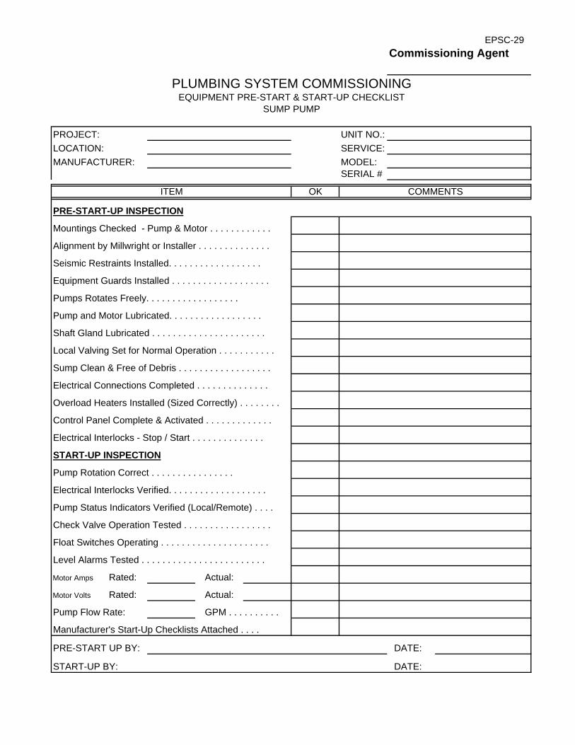
EPSC-29Commissioning Agent
PLUMBING SYSTEM COMMISSIONINGEQUIPMENT PRE-START & START-UP CHECKLIST
SUMP PUMP
PROJECT: UNIT NO.:LOCATION: SERVICE:MANUFACTURER: MODEL:
SERIAL #
ITEM OK COMMENTS
PRE-START-UP INSPECTION
Mountings Checked - Pump & Motor . . . . . . . . . . . .
Alignment by Millwright or Installer . . . . . . . . . . . . . .
Seismic Restraints Installed. . . . . . . . . . . . . . . . . .
Equipment Guards Installed . . . . . . . . . . . . . . . . . . .
Pumps Rotates Freely. . . . . . . . . . . . . . . . . .
Pump and Motor Lubricated. . . . . . . . . . . . . . . . . .
Shaft Gland Lubricated . . . . . . . . . . . . . . . . . . . . . .
Local Valving Set for Normal Operation . . . . . . . . . . .
Sump Clean & Free of Debris . . . . . . . . . . . . . . . . . .
Electrical Connections Completed . . . . . . . . . . . . . .
Overload Heaters Installed (Sized Correctly) . . . . . . . .
Control Panel Complete & Activated . . . . . . . . . . . . .
Electrical Interlocks - Stop / Start . . . . . . . . . . . . . .
START-UP INSPECTION
Pump Rotation Correct . . . . . . . . . . . . . . . .
Electrical Interlocks Verified. . . . . . . . . . . . . . . . . . .
Pump Status Indicators Verified (Local/Remote) . . . .
Check Valve Operation Tested . . . . . . . . . . . . . . . . .
Float Switches Operating . . . . . . . . . . . . . . . . . . . . .
Level Alarms Tested . . . . . . . . . . . . . . . . . . . . . . . .
Motor Amps Rated: Actual:
Motor Volts Rated: Actual:
Pump Flow Rate: GPM . . . . . . . . . .
Manufacturer's Start-Up Checklists Attached . . . .
PRE-START UP BY: DATE:
START-UP BY: DATE:

EPSC-30Commissioning Agent
PROJECT: UNIT NO.:LOCATION: SERVICE:MANUFACTURER: MODEL:
SERIAL #
ITEM OK COMMENTS
PRE-START-UP INSPECTION
Piping Pressure Test (Report Attached). . . . . . . . . . .
Contractor's Letter of Assurance (Attached) . . . . . . .
Overload Heaters Installed (Sized Correctly) . . . . . .
REPORTS & CHECKLISTS RECEIVED
Fire Pump Manufacturer's Start-up Report . . . . . . .
Fire Pump Commissioning Checklist . . . . . . . . . . . .
Fire Pump Flow Test Data Sheet . . . . . . . . . . . . . .
Standpipe Floor Test Data Sheet . . . . . . . . . . . . . . .
Sprinkler System Commissioning Checklist . . . . . . . .
Fire Protection Points Checklist. . . . . . . . . . . . . . . .
DDC Auxiliary Functions Operational Checklist. . . . .
Pressurization Fan Verification Checklist. . . . . . . . .
PRE-START UP BY: DATE:
START-UP BY: DATE:
FIRE PROTECTION SYSTEM COMMISSIONINGEQUIPMENT PRE-START & START-UP CHECKLIST
FIRE PROTECTION SYSTEM - GENERAL

EPSC-31Commissioning Agent
FIRE PROTECTION SYSTEM COMMISSIONINGEQUIPMENT PRE-START & START-UP CHECKLIST
FIRE PUMP / JOCKEY PUMP
PROJECT: UNIT NO.:LOCATION: SERVICE:MANUFACTURER: MODEL:
SERIAL #
ITEM OK COMMENTS
PRE-START-UP INSPECTION
Mountings Checked - Pump & Motor . . . . . . . . . . . .
Alignment by Millwright or Installer . . . . . . . . . . . . . .
Seismic Restraints Installed. . . . . . . . . . . . . . . . . .
Equipment Guards Installed . . . . . . . . . . . . . . . . . . .
Pump Rotates Freely. . . . . . . . . . . . . . . . . .
Pump and Motor Lubricated. . . . . . . . . . . . . . . . . .
Packing Glands Adjusted . . . . . . . . . . . . . . . . . . . . .
Accessories Installed . . . . . . . . . . . . . . . . . . .
Local Valving Set for Normal Operation. . . . . . . . . . .
Water in System . . . . . . . . . . . . . . . . . . . . . . . . . .
Electrical Connections Completed. . . . . . . . . . . . . .
Overload Heaters Installed (Sized Correctly). . . . . . . .
Electrical Disconnect . . . . . . . . . . . . . . . . . . . . . . .
Cut in Pressure . . . . . . . . . . . . . . . . . . . . . . . . . . . .
START-UP INSPECTION
Pump Rotation Correct . . . . . . . . . . . . . . . . . .
Electrical Interlocks Verified. . . . . . . . . . . . . . . . . . .
Pump Status Indicators Verified (Local/Remote) . . . .
Check Valve Operation Tested . . . . . . . . . . . . . . . . .
Jockey Pump Relief Valve Tested. . . . . . . . . . . . . .
FIRE PUMP
Motor Amps Rated: Actual:
Motor Volts Rated: Actual:
Pump Flow Rate:
Manufacturer's Test Sheets Attached . . . . . . . . . . .
PRE-START UP BY: DATE:
START-UP BY: DATE:

EPSC-32Commissioning Agent
HVAC AND PLUMBING SYSTEM COMMISSIONINGEQUIPMENT PRE-START & START-UP CHECKLIST
AIR COMPRESSORS
PROJECT: UNIT NO.:LOCATION: SERVICE:MANUFACTURER: MODEL:
SERIAL #
ITEM OK COMMENTS
PRE-START-UP INSPECTIONMountings Checked - Compressor & Motor . . . . . . .
Alignment by Millwright or Installer . . . . . . . . . . . . . .
Seismic Restraints Installed. . . . . . . . . . . . . . . . . .
Equipment Guards Installed . . . . . . . . . . . . . . . . . . .
Relief Valve Installed . . .. . . . . . . . . . . . . . . . . .
Oil Level Checked & Correct . . . . . . . . . . . . . . . . .Pressure Set: On Off
Air Driers Installed Quantity: . . . . . .
Automatic & Manual Drains Installed . . . . . . . . . . .
Electrical Connections Completed. . . . . . . . . . . . . .
Disconnect Switch Installed . . . . . . . . . . . . . . . . . .
Overload Heaters Installed (Sized Correctly). . . . . . . .
Water, Solenoid & Flow Regulating Valve in Place. . . .
Identification Complete . . . . . . . . . . . . . . . . . . . . . . .
Manufacturer's Rep. On Site for Start-Up . . . . . . . . . .
Manufacturer's Start-Up Checklists Attached . . . . . .
START-UP INSPECTIONCompressor Rotation Correct . . . . . . . . . . . .
Status Indicators Verified (Local/Remote) . . . . . . . . .
Cylinder Unloaders Verified . . . . . . . . . . . . . . . . .
Alternator Operation Verified. . . . . . . . . . . . . . . . . .
Relief Valve Tested . . . . . . . . . . . . . . . . . . . . . . . . . .
Tank Pressure Control Verified . . . . . . . . . . . . . . . . .
Voltage: Rated: Actual: Amperage: Rated: Actual:
Pump Flow Rate:
Start-Up By Qualified Personnel . . . . . . . . . . . . . . . .
PRE-START UP BY: DATE:
START-UP BY: DATE:

EPSC-35
Commissioning Agent
Name Type Description Function Address Alarms Totalize
HVAC SYSTEM COMMISSIONING
CONTROLS POINT TO POINT SUMMARY CHECKLIST
PROJECT:
LOCATION:
SYSTEM:


FPT-1
SYSTEM:SERVICE:
ITEM OK
TEST 1 BY: DATE:TEST 2 BY: DATE:VERIFIED BY: DATE:
Commissioning Agent
HVAC SYSTEM COMMISSIONINGFUNCTIONAL PERFORMANCE TEST
SYSTEM OFFCOMMENTS
Sensor Locations & Supports Checked . . . . . . . . . .
AIR HANDLING SYSTEM
PROJECT:LOCATION:
Fan Interlocks. . . . . . . . . . . . . . . . . . . . . . . . . . . . . Start-Stop Sequences . . . . . . . . . . . . . . . . . . . . . . .Mixing Damper Sequences. . . . . . . . . . . . . . . . . . . .
Installation Complete . . . . . . . . . . . . . . . . . . . . . . .Damper Positions Checked & Stroked . . . . . . . . . . .
DAY MODE START-UP SEQUENCE
Minimum Outdoor Air Control . . . . . . . . . . . . . . . . . .High & Low Limits Verified. . . . . . . . . . . . . . . . . . . .
STATIC PRESSURE CONTROL
TEMPERATURE CONTROLMixed Air Temperature Control. . . . . . . . . . . . . . . . . Supply Air Temperature Control - Cooling. . . . . . . . . .Supply Air Temperature Control - Heating . . . . . . . . . .
SAFETY & MISC. CONTROLSFreeze Protection Verified . . . . . . . . . . . . . . . . . . . .
NIGHT MODE OPERATIONStart-Stop Sequences . . . . . . . . . . . . . . . . . . . . . . .Mixing Damper Sequences . . . . . . . . . . . . . . . . . . . .Temperature Control Sequences . . . . . . . . . . . . . . . .
Static Pressure Maintained at Setpoint . . . . . . . . . . . Supply / Return Fan Tracking . . . . . . . . . . . . . . . . . .Pressure & Volume Sensors Calibrated . . . . . . . . . . .Pressure High Limit Verified . . . . . . . . . . . . . . . . . . .
Smoke Alarm Shutdown . . . . . . . . . . . . . . . . . . . . . .

FPT-2
SYSTEM:SERVICE:
ITEM OK
Integral Control Functions Verified . . . . . . . . . . . . . . .Circulation Pump Sequences Verified . . . . . . . . . . . .
TEST 1 BY: DATE:TEST 2 BY: DATE:VERIFIED BY: DATE:
Commissioning Agent
HVAC SYSTEM COMMISSIONINGFUNCTIONAL PERFORMANCE TEST
COMMENTS
Sensor Locations & Supports Checked . . . . . . . . . .
AIR HANDLING SYSTEM
PROJECT:LOCATION:
Installation Complete . . . . . . . . . . . . . . . . . . . . . . .Control Valves Checked & Stroked. . . . . . . . . . . . . .
BOILER CONTROL
SYSTEM OFF
PRIMARY PUMP CONTROLLead/Lag Pump Sequences Verified . . . . . . . . . . . . . Pump On/Off Control Sequences Verified . . . . . . . . . .
Lead/Lag Boiler Sequences Verified . . . . . . . . . . . . . Firing Sequences - Modulation Maintains Setpnt . . . . Supply Water Temperature Reset Verified . . . . . . . . .
SAFETY & MISC. CONTROLSBoiler High & Low Limits Verified . . . . . . . . . . . . . . .Boiler Low Flow Limit Verified . . . . . . . . . . . . . . . . . .
Loop Water Temperature Reset Verified . . . . . . . . . .Control Valve Modulates to Maintain Setpoint . . . . . . .Pressure Differential Sequence Verified . . . . . . . . . . .
Integral Boiler Safety Controls Verified . . . . . . . . . . . .
SECONDARY CIRCUIT CONTROLLead/Lag Pump Sequences VerifiedPump On/Off Control Sequences Verified . . . . . . . .

FPT-4
SYSTEM:
LOCATION: SERVICE:
FAN NUMBER CONTROL METHOD COMMENTS VERIFIED
TEST 1 BY: DATE:
TEST 2 BY: DATE:
VERIFIED BY: DATE:
EXHAUST FANSFUNCTIONAL TEST
HVAC SYSTEM COMMISSIONING
PROJECT:

FPT-7
PROJECT: SYSTEM:
LOCATION SERVICE:
VALVE STROKE PIPING LEAK CONTROL CHECKEDNUMBER SERVICE CHECKED CHECKED CHECK OPERATION BY
TEST 1 BY: DATE:
PRE-START BY: DATE:
START-UP BY: DATE:
HVAC SYSTEM COMMISSIONINGFUNCTIONAL TESTCONTROL VALVES

FPT-8
SYSTEM:SERVICE:
ITEM OK
COMMENTS:
TEST 1 BY: DATE:TEST 2 BY: DATE:VERIFIED BY: DATE:
Pump Shutoff Pressure in Feet . . . . . . . . . . . . . . . . .
Full Open Flow Rate in GPM . . . . . . . . . . . . . . . . .
Full Open Pressure in psig . . . . . . . . . . . . . . . . . . . .
Final Discharge Pressure in psig . . . . . . . . . . . . . . .
Final Total Pressure in feet of head . . . . . . . . . . . . . . . . .Water Flow Rate in GPM . . . . . . . . . . . . . . . . . . . . .
Voltage . . . . . . . . . . . . . .. . . . . . . . . . . . . . . . . . . .
Amperage . . . . . . . . . . . . . . . . . . . . . . . . . . . . . . . .
Full Load Amperage . . . . . . . . . . . . . . . . . . . . . . . .
Service Factor . . . . . . . . . . . . . . . . . . . . . . . . . . . . .
Seal Type . . . . . . . . . . . . . . . . . . . . . . . . . . . . . .
Static Head in Feet . . . . . . . . . . . . . . . . . . . . . . . . .
Required NPSH in feet . . . . . . . . . . . . . . . . . . . . . . .
Pump RPM . . . . . . . . . . . . . . . . . . . . . . . . . . . .
Impeller Diameter . . . . . . . . . . . . . . . . . . . . . . . . . . .
Motor Make and Frame Size . . . . . . . . . . . . . . . . . .
Motor Horsepower. . . . . . . . . . . . . . . . . . . . . . . . . . . . .
Motor RPM . . . . . . . . . . . . . . . . . . . . . . . . . . . . . . .
BOILER
Water Pressure differential in feet of head . . . . . . . . . .
Commissioning Agent
HVAC SYSTEM COMMISSIONINGFUNCTIONAL PERFORMANCE TEST
COMMENTS
PUMPS
PROJECT:LOCATION:

FPT-9
SYSTEM:SERVICE:
ITEM OK
TEST 1 BY: DATE:TEST 2 BY: DATE:VERIFIED BY: DATE:
Record temperature rise through boiler
Inspect pressure-reducing valve
Inspect water level
Record pressure drops through boiler
Attach Manufacturer's start-up report
Inspect backflow preventerCheck & record performance of boiler protection devices & firing sequencesCheck boiler fluid level, flow-switch, and high temperature interlocks
Record water flow rates through boiler
Control installations are completeOperation of pressure-reducing valve on gas train is correct, inc. ventingCheck that fluid-level, flow-switch, and high temperature interlocks are in place
Inspect expansion tank
Inspect makeup water meter
Inspect tank pressure
Flue and Chimney are installed without visible damageNo damage is visible to boiler jacket, refractory, or combustion chamber
Boiler, burner, and flue are clean and free of construction debris
Burner blower rotates in correct direction
Pressure and temperature gages are installed
Heating circuit pipes have been connected to correct ports
LOCATION:
BOILER INSPECTION:COMMENTS
Commissioning Agent
HVAC SYSTEM COMMISSIONINGFUNCTIONAL PERFORMANCE TEST
BOILERPROJECT:

LAWRENCE COUNTY ELECTRICAL INDEX PUBLIC SAFETY FACILITY 26 00 00 - 1
SECTION 26 00 00 – ELECTRICAL INDEX SECTION NO. .................................................................................................................................PAGES 26 01 00 BASIC REQUIREMENTS FOR ELECTRICAL WORK 1 – 6 26 05 10 EQUIPMENT WIRING SYSTEMS 1 – 2 26 05 19 WIRE AND CABLE 1 – 4 26 05 26 GROUNDING 1 – 8 26 05 29 SUPPORTING DEVICES 1 – 1 26 05 33 CONDUIT 1 – 4 26 05 34 SURFACE RACEWAYS 1 – 3 26 05 35 BOXES 1 – 4 26 05 36 CABLE TRAYS 1 – 6 26 05 53 ELECTRICAL IDENTIFICATION 1 – 3 26 05 70 OVERCURRENT PROTECTIVE DEVICE COORDINATION STUDY 1 – 6 26 09 24 OCCUPANCY SENSORS 1 – 3 26 22 00 DRY TYPE TRANSFORMERS 1 – 3 26 24 16 PANELBOARDS 1 – 4 26 27 26 WIRING DEVICES 1 – 8 26 28 00 DISCONNECT SWITCHES 1 – 2 26 32 13 PACKAGED GENERATOR SET 1 – 6 26 33 53 STATIC UNINTERRUPTIBLE POWER SUPPLY 1 – 11 26 41 13 LIGHTNING PROTECTION FOR STRUCTURES 1 – 5 26 43 13 TRANSIENT VOLTAGE SURGE SUPPRESSION 1 – 6 26 51 00 LIGHTING FIXTURES 1 – 7 26 60 00 FIRE ALARM SYSTEM 1 – 13 26 99 99 ELECTRICAL ALTERNATE BIDS 1 – 1 END OF INDEX 26 00 00


LAWRENCE COUNTY BASIC REQUIREMENTS FOR ELECTRICAL WORK PUBLIC SAFETY FACILITY 26 01 00 - 1
SECTION 26 01 00 - BASIC REQUIREMENTS FOR ELECTRICAL WORK
PART 1 - GENERAL
1.01 SECTION INCLUDES
A. Basic Electrical Requirements specifically applicable to Division 26 00 00 Sections, in addition to Division 01 General Requirements.
B. All documents, contracts, forms, divisions, and Sections of the Project Manual and All Drawings shall apply with equal force to all portions of the Electrical Work and shall be part of this Contract.
C. Give all requisite notices, obtain and pay for all permits, deposits, and fees necessary for the installation and operation of the work.
D. Provide all items, articles, materials, operations, or methods listed, mentioned, implied, intended, or scheduled, on the drawings, and/or herein, including all labor, materials, equipment, and incidentals necessary, and required, for completion.
E. The Electrical Contractor shall be entirely responsible for all equipment and associated appurtenances furnished by them or their subcontractors in connection with the work; and special care shall be taken to protect all parts thereof in such a manner as may be necessary or as may be directed.
F. Raceways and Cabling: Conduit and cabling for all electrical systems to be concealed in new or existing construction in finished areas.
G. Provide additional structural support for conduit and equipment, as required, to distribute the load upon the building structure without over stressing individual structural members to the satisfaction of the Architect/Engineer.
1.02 RELATED WORK
A. Division 01 - Summary of the Project.
B. Division 01 - Contract Considerations.
C. Division 01 - Alternates.
D. Division 01 - Coordination and Meetings.
E. Division 01 - Alteration Project Procedures.
F. Division 01 - Submittals
G. Division 01 - Quality Control.
H. Division 01 - Construction Facilities and Temporary Controls.
I. Division 01 - Temporary Utilities.
J. Division 01 - Material and Equipment.
K. Division 01 - Starting of System.
L. Division 01 - Contract Close-out.
M. Division 01 - Operation and Maintenance Data.
N. Division 02 - Demolition: See this Section for demolition work included in the Electrical Contract; this Contractor is responsible for all electrical demolition.
O. Division 07 - Penetration Sealants.

BASIC REQUIREMENTS FOR ELECTRICAL WORK LAWRENCE COUNTY 26 01 00 - 2 PUBLIC SAFETY FACILITY
1.03 WORK BY OWNER
A. Refer to Division 01 - Summary of the Project, for Work provided by the Owner and Work provided by separate contractors.
1.04 OWNER FURNISHED PRODUCTS
A. Refer to Division 01 - Summary of the Project, for Products furnished by Owner.
1.05 WORK SEQUENCE
A. Install Work in Phases to accommodate Owner's occupancy requirements during the construction period; all prime contractors shall coordinate their schedule and operations with work sequence as described in Division 01.
B. Summary of the Project and Division 01 - Coordination and Meetings.
1.06 ALTERNATES
A. Schedule of Alternates:
B. Refer to Division 01 - Alternates.
C. Coordinate related work and modify surrounding work as required.
1.07 REFERENCES
A. ANSI/NFPA 70 - National Electric Codes.
1.08 SUBMITTALS
A. Submit shop drawings, product data, samples, operation and maintenance manuals, and record drawings under revisions of Division 01.
B. Mark dimensions and values in units to match those specified.
C. Proposed Products List: Include products specified in all sections of Division 26 00 00.
D. Submit two (2) copies of certificates of approval and inspection by regulatory agencies, prior to final acceptance of the work by the Architect/Engineer.
1.09 REGULATORY REQUIREMENTS
A. Conform to applicable requirements of Federal, State, or local agency regulations and codes; Pennsylvania Department of Labor and Industry Regulations and Codes, Utility Company Regulations; IBC Building Code.
B. Rules and Regulations of the Board of Fire Underwriters.
C. Conform to latest edition of National Electrical Code.
D. Conform to National Fire Protection Agency.
E. Obtain permits and request inspections from Pennsylvania Department of Labor and Industry, Electrical Underwriters' Inspection Bureau, Utility Companies, Municipalities, and others requiring same.
F. Make all changes required by applicable laws, ordinances, and codes and the enforcing authorities. Such changes shall be made in a manner as recommended by the Architect/Engineer and approved by the Owner and shall be made without any additional cost to the Owner.
G. Electrical materials, apparatus, and equipment used shall be approved or labeled by the National Board of Fire Underwriters Laboratories where such labeling applies. All equipment not so

LAWRENCE COUNTY BASIC REQUIREMENTS FOR ELECTRICAL WORK PUBLIC SAFETY FACILITY 26 01 00 - 3
labeled shall be constructed in accordance with the latest rules of the National Electrical Manufacturers Association and Institute of Electrical and Electronic Engineers.
1.10 PROJECT/SITE CONDITIONS
A. Install work in locations shown on Drawings, unless prevented by project conditions.
1. All equipment shall be in locations as coordinated by the Architect/Engineer.
2. Contractor shall request such locations from the Architect/Engineer sufficiently in advance of the time when such information will be required at the site so as not to interfere with the progress of his work or that of any other Contractors.
3. Should any equipment be set without securing the approval of the Architect, this Contractor shall reset the equipment as required at no additional cost to the Owner.
B. Prepare drawings showing proposed rearrangement of Work to meet Project conditions, including changes to Work specified in other sections. Obtain permission of Owner and Architect/Engineer before proceeding.
C. Due to the small scale of the drawings, it is not possible to indicate all offsets, fittings, pullboxes, junction boxes, access panels, and similar parts which may be required. The drawings are generally schematic and indicative of the work to be installed. The Contractor shall carefully investigate and arrange all work accordingly, furnishing such parts and equipment as may be required to meet such conditions.
D. Electrical circuiting is diagrammatic. Follow as closely as the actual construction of the building and the work of other trades will permit. Make all changes from the plans necessary to make the work of the Contractor conform to the building as constructed, and to fit the work of other trades.
E. Secure all dimensions and locations, etc., from drawings and General Contractor. Verify all measurements at the building site and be responsible for the correctness of same. Any differences that may be found shall be submitted to the Architect/Engineer and the Owner for consideration before proceeding with the work. Furnish all dimensions of openings, wall chases, etc., to the General Contractor as work progresses. Verify final locations for rough-ins with field measurements and with requirements of actual equipment that is to be connected.
F. Include demolition and removal of existing electrical equipment, disconnecting and removal of all existing electrical appurtenances, including all wire, conduit, switches, outlets, light fixtures, fittings, etc., that are encountered during construction and provide a blank coverplate over boxes to remain, not indicated for reuse.
G. Workmanship shall be first class in all respects and meet the approval of the Architect/Engineer and the Owner. Any work poorly done shall be removed and replaced at once upon condemnation. All material shall be new and of specification grade quality.
H. Ceiling Replacement:
1. It shall be the responsibility of the Electrical Contractor to reinstall all acoustic ceiling panels which are removed in order to install the electrical systems in all areas where the general is not shown to be installing new ceiling.
2. In coordination with Owner's Representative, identify all panels damaged prior to removal of ceiling.
3. All panels shall be clean and undamaged when reinstalled.
4. Dirty and/or damaged panels shall be replaced with new panels identical in design, material, and size as the remainder of the ceiling.

BASIC REQUIREMENTS FOR ELECTRICAL WORK LAWRENCE COUNTY 26 01 00 - 4 PUBLIC SAFETY FACILITY
5. If the panels have hold-down clips, it shall be this Contractor's responsibility to replace the hold-down clips.
1.11 HAZARDOUS MATERIALS
A. Electrical Contractor shall be responsible for proper disposal and / or recycling of all hazardous material associated with the electrical contract. This responsibility shall include but not be limited to the following:
1. Fluorescent lamps, fluorescent ballast, HID lamps, HID ballasts, transformers, etc.
2. The recycling and / or disposal process shall conform to the Federal E.P.A., State Department of Environmental Protection, Local Authorities and R.C.R.A. Standards. The electrical contractor shall process all removed fluorescent lamps, fluorescent ballast, HID lamps, HID ballasts, etc. in accordance with these standards. The Electrical Contractor shall secure certified bills of lading, manifests or other documentation to indicate and substantiate the ultimate disposition of these items.
B. The electrical contractor shall indemnify and hold harmless the Project Design Professional and Owner from any environmental liability with respect to the removed materials
1.12 ACCESSIBILITY
A. Install equipment and materials to provide required access for servicing and maintenance. Coordinate the final location of concealed equipment and devices requiring access with final location of required access panels and doors. Allow ample space for removal of all parts that require replacement or servicing.
B. Provide access panels as required for access to service piping equipment of same rating construction as the floor, wall, bulkhead, soffits, fascia, or ceiling in which panels are installed.
1.13 PRODUCT OPTIONS AND SUBSTITUTIONS
A. Refer to the Instructions to Bidders and Division 01 - Materials and Equipment for requirements in selecting products and requesting substitutions.
1.14 DELIVERY, STORAGE, AND HANDLING
A. In accordance with the provisions of Division 01 - Materials and Equipment, deliver products to project properly identified with names, model numbers, types, grades, compliance labels, and similar information needed for distinct identifications; adequately packaged and protected to prevent damage during shipment, storage, and handling.
B. Store equipment and materials at the site, unless off-site storage is authorized. Protect stored equipment and materials from damage.
C. Coordinate deliveries of electrical materials and equipment to minimize construction site congestion. Limit each shipment of materials and equipment to the items and quantities needed for the smooth and efficient flow of installations.
1.15 CUTTING AND PATCHING
A. Perform work in accordance with the provisions of Division 01 -Coordination and Meetings.
B. All cutting and patching required for installation of all electrical systems shall be executed by the Electrical Contractor.
1.16 EXCAVATING AND BACKFILLING
A. Perform work as specified in Division 01 - Trenching.

LAWRENCE COUNTY BASIC REQUIREMENTS FOR ELECTRICAL WORK PUBLIC SAFETY FACILITY 26 01 00 - 5
B. Do all excavating and backfilling for all trenches and equipment structures required for the installation of the work. No extras will be allowed regardless of hardness or type of material encountered.
1.17 PROTECTION OF ELECTRICAL CIRCUITS
A. Protect conduits or cabling passing under or through walls from breakage with suitable metal sleeves.
B. Protect conduits or cabling passing through or under cinders or other corrosive material against corrosion in a manner approved by the Architect/Engineer and Owner.
1.18 DAMAGE AND REPAIRS TO EXISTING WORK
A. Cooperate with all other trades for the securing and anchoring of all work included within this Project.
B. Extraordinary care shall be used in the installation of all equipment and materials to avoid marring surfaces of the work of other contractors. Repair damage surfaces in accordance with Division 01 - Alteration Project Procedures.
C. This Contractor shall be held responsible for all damages caused by the lack of precaution or due to the negligence of his workmen and his subcontractors.
D. This Contractor shall at his own expense, repair, replace, and maintain in service, any new or existing utilities, facilities, or service damaged or rendered inoperative during the course of construction.
E. The method used in repairing, replacing, or maintaining the services shall be approved by the Owner and the Architect/Engineer.
1.19 FINISHES
A. All factory finished equipment shall be thoroughly cleaned at the completion of the Project.
B. Factory applied finish damaged due to execution of the Contract Work, shall be restored to its original finish to the satisfaction of the Architect/Engineer.
C. All new exposed steel, including piping, exposed equipment surfaces and bases, and like items shall be cleaned of rust and scale and painted with two (2) coats of rust-preventive primer of color selected by the Architect/Engineer.
D. All exposed rough and polished brass, copper, and aluminum surfaces shall be thoroughly cleaned and restored to their original finish at completion of Contract.
1.20 RECORD DOCUMENTS
A. Refer to Division 01 - Project Closeout for requirements.
B. Mark drawings to indicate revisions to electrical systems cabling or equipment and device locations, both exterior and interior.
C. Mark specifications to indicate approved substitutions; change orders; and actual equipment and materials used.
1.21 OPERATION AND MAINTENANCE DATA
A. Refer to Division 01 - Contract Closeout for procedures and requirements for preparation and submittal of maintenance manuals.
B. In addition to the information required by Division 01, include the following information:

BASIC REQUIREMENTS FOR ELECTRICAL WORK LAWRENCE COUNTY 26 01 00 - 6 PUBLIC SAFETY FACILITY
1. Description of function, normal operating characteristics and limitations, performance curves, engineering data and tests, and complete nomenclature and commercial numbers of all replaceable parts.
2. Manufacturer's printed operating procedures to include start-up, break-in, routine and normal operating instructions; regulation, control, stopping, shutdown, and emergency instructions; and summer and winter operating instructions.
3. Maintenance procedures for routine preventive maintenance and trouble shooting; disassembly, repair, and re-assembly; aligning and adjusting instructions.
4. Servicing instructions, and lubrication charts and schedules.
1.22 GUARANTEE/WARRANTIES
A. Contractor shall guarantee all material, equipment, and workmanship for a period of one (1) year from date of substantial completion and shall replace all defective material and workmanship and all other work damaged thereby without additional cost to the Owner.
B. Furnish any warranties, or guarantees, normally included with specific equipment exceeding the one (1) year guarantee.
1.23 CLEAN-UP AND EQUIPMENT PROTECTION
A. Progress Clean-Up: Remove waste and rubbish in accordance with Section - Construction Facilities and Temporary Controls. Premises shall be left clean and free of debris and unused construction materials at all times.
B. Refer to Division 01 - Project Closeout for general requirements for final cleaning of electrical systems prior to final acceptance.
C. Equipment Protection: Protect electrical equipment from weather elements, painting, etc., until the building is substantially completed. Damage from rust, paint, scratches, etc., shall be corrected as directed by the Architect/Engineer.
D. Equipment Clean-up: Materials, equipment, and apparatus shall be thoroughly cleaned, to be free of dust, dirt, rust, and foreign materials before acceptance.
E. Clean all panelboards, switchgear, motor controls, etc. Take special care to remove dirt, mortar, wire scraps, etc., from equipment interiors.
F. Accessible elements of disconnecting and protective devices of equipment, coils of dry type transformers and the like shall be cleaned with compressed air (less than 15 PSI) and the enclosures vacuum cleaned prior to being energized.
G. Clean light fixtures and lamps thoroughly, just prior to final inspection. Fixture enclosures, shielding, etc., shall be cleaned by an approved method.
END OF SECTION 26 01 00

LAWRENCE COUNTY EQUIPMENT WIRING SYSTEMS PUBLIC SAFETY FACILITY 26 05 10 - 1
SECTION 26 05 10 - EQUIPMENT WIRING SYSTEMS
1. PART 1 - GENERAL
1.01 WORK INCLUDED
A. Electrical connections to equipment specified under other Sections.
1.02 RELATED WORK
A. Division 10 - Display Cases.
B. Division 11 - Library Equipment.
C. Division 11 - Projection Screens.
D. Division 11 - Food Services Equipment.
E. Division 12 - General Casework.
F. Division 14 - Hydraulic Elevators - Passenger.
G. Division 23 - Motors.
H. Division 23 - Plumbing Equipment: Pumps and hot water heaters.
I. Division 23 - H.V.A.C. Pumps.
J. Division 23 - Boilers.
K. Division 23 - Packaged Rooftop or Terminal Air Conditioning Units.
L. Division 23 - Terminal Heat Transfer Units.
M. Division 23 - Air Handling Units with Coils.
N. Division 23 - Fans.
O. Division 23 - Power Ventilators.
P. Section 26 05 33 - Conduit.
Q. Section 26 05 19 - Wire and Cable.
R. Section 26 05 35 - Boxes.
1.03 REFERENCES
A. FS W-C-596 - Electrical Power Connector, Plug, Receptacle, and Cable Outlet.
B. NEMA WD 1- General Purpose Wiring Devices.
C. Nema WD 5 - Specific-Purpose Wiring Devices.
2. PART 2 - PRODUCTS
2.01 ACCEPTABLE MANUFACTURERS - CORDS AND CAPS
A. Hubbell.
B. Bryant.
C. Arrow-Hart.
D. Substitutions: Under provisions of Division 1.

EQUIPMENT WIRING SYSTEMS LAWRENCE COUNTY 26 05 10 - 2 PUBLIC SAFETY FACILITY
2.02 CORDS AND CAPS
A. Straight-blade Attachment Plug: NEMA WD 1.
B. Locking-blade Attachment Plug: NEMA WD 5.
C. Attachment Plug Configuration: Match receptacle configuration at outlet provided for equipment.
D. Cord Construction: Oil-resistant thermoset insulated Type SO multi-conductor flexible cord with identified equipment grounding conductor, suitable for extra hard usage in damp locations.
E. Cord Size: Suitable for connected load of equipment and rating of branch circuit overcurrent protection.
3. PART 3 - EXECUTION
3.01 INSPECTION
A. Verify that equipment is ready for electrical connection, wiring, and energization.
3.02 PREPARATION
A. Review equipment submittals prior to installation and electrical rough- in. Verify location, size, and type of connections. Coordinate details of equipment connections with supplier and installer.
3.03 INSTALLATION
A. Use wire and cable with insulation suitable for temperatures encountered in heat-producing equipment.
B. Make conduit connections to equipment using flexible conduit. Use Liquidtight flexible conduit in damp or wet locations.
C. Install pre-finished cord set where connection with attachment plug is indicated or specified, or use attachment plug with suitable strain- relief clamps.
D. Provide suitable strain-relief clamps for cord connections to outlet boxes and equipment connection boxes.
E. Make wiring connections in control panel or in wiring compartment of pre-wired equipment in accordance with manufacturer's instructions. Provide interconnecting wiring where indicated.
F. Install disconnect switches, controllers, control stations, and control devices such as limit switches and temperature switches as indicated. Connect with conduit and wiring as indicated.
G. Coolers and Freezers: Cut and seal conduit openings in freezer and cooler walls, floor, and ceilings.
3.04 EQUIPMENT CONNECTION SCHEDULE
A. See Contract Drawings.
END OF SECTION 26 05 10

LAWRENCE COUNTY WIRE AND CABLE PUBLIC SAFETY FACILITY 26 05 19 - 1
SECTION 26 05 19 - WIRE AND CABLE
1. PART 1 - GENERAL
1.01 WORK INCLUDED
A. Building Wire
B. Cable.
C. Wiring connections and terminations.
1.02 RELATED WORK SPECIFIED ELSEWHERE
A. Section 26 05 66 - Conduit.
B. Section 26 05 34 - Surface Raceways.
1.03 REFERENCES
A. NEMA WC 3 - Rubber-Insulated Wire and Cable for the Transmission and Distribution of Electrical Energy.
B. NEMA WC 5 - Thermoplastic-Insulated Wire and Cable for the Transmission and Distribution of Electrical Energy.
1.04 SUBMITTALS
A. Submit shop drawings and product data under the provisions of Section 01 3300, Submittal Procedures.
B. Submit manufacturer's instructions.
2. PART 2 - PRODUCTS
2.01 BUILDING WIRE
A. Thermoplastic-insulated Building Wire: NEMA WC 5.
B. Feeders and Branch Circuits Larger Than 6 AWG: Copper conductor, 600 volt insulation, THW.
C. Feeders and Branch Circuits 6 AWG and Smaller: Copper conductor, 600 volt insulation, THW 6 and 8 AWG, stranded conductor; smaller than 8 AWG, solid conductor.
D. Control Circuits: Copper, stranded conductor 600 volt insulation, THW.
E. Type THHN may be used in lieu of Type THW if conductor ampacity is determined as follows:
1. Feeders or branch circuits 100A and less - 60º Celsius temperature rating.
2. Feeders or branch circuits greater than 100A - 75º Celsius temperature rating. Note: Conductor sizes on contract documents based on above criteria.
F. Armored, Type AC, or Type "box" cables shall not be used.
2.02 REMOTE CONTROL AND SIGNAL CABLE
A. Control Cable for Class 1 Remote Control and Signal Circuits: Copper conductor, 600 volt insulation, rated 60º C, individual conductors twisted together, shielded and covered with an overall PVC jacket.

WIRE AND CABLE LAWRENCE COUNTY 26 05 19 - 2 PUBLIC SAFETY FACILITY
B. Control Cable for Class 2 or Class 3 Remote Control and Signal Circuits: Copper conductor, 300 volt insulation, rated 60º C, individual conductors twisted together, shielded and covered with a PVC jacket; UL listed.
C. Plenum Cable for Class 2 or Class 3 Remote Control and Signal Circuits: Copper conductor, 300 volt insulation, rated 60º C, individual conductors twisted together, shielded and covered with a nonmetallic jacket; UL listed for use in air handling ducts, hollow spaces used as ducts, and plenums.
2.03 SECURITY SYSTEMS CABLES
A. Plenum (8) Conductor Cable with Overall Shield: Eight (8) conductor, stranded, insulated 22 AWG (7x30) tinned copper conductors with overall shield and 24 AWG drain wire. Overall, plenum rated (CMP) jacket.
1. Manufacturers:
a. Coleman Cable # 75308
b. West Penn Wire # 253271b
B. Plenum (1) Shielded Twisted Pair Cable: One (1) pair shielded, insulated 22 AWG (7x30) tinned stranded copper conductors with common 24 AWG (7x32) drain wire. Overall, plenum rated (CMP) jacket.
1. Manufacturers:
a. Coleman Cable # 72302
b. West Penn Wire # 25291b
C. Plenum (1) Shielded Twisted Pair Cable: One (1) pair shielded, insulated 18 AWG (7x26) tinned stranded copper conductors with common 20 AWG (7x28) drain wire. Overall, plenum rated (CMP) jacket.
1. Manufacturers:
a. Coleman Cable # 71902
b. West Penn Wire # 25224b
D. Plenum (4) Conductor Cable with Overall Shield: Four (4) conductor, stranded, insulated 22 AWG (7x30) tinned copper conductors with overall shield and 24 AWG drain wire. Overall, plenum rated (CMP) jacket.
1. Manufacturers:
a. Coleman Cable # 72304
b. West Penn Wire # 25241
E. Plenum RG59/U Coaxial Cable: Single, solid 20 AWG solid copper center conductor. Foamed FEP with tap barrier. Copper braid: 95% copper foil 100% shield coverage. Overall, plenum rated (CMP) outer sheath. Electrical characteristics: Nominal Impedance: 75 ohms. Nominal Attenuation: .85 db/100’ @ 10 MHz. 84% velocity of propagation.
1. Manufacturers:
a. Coleman Cable # 99969
b. West Penn Wire # 25815
F. Plenum (2) Conductor Parallel Cable: Two (2) conductor, solid, individually insulated 18 AWG parallel copper conductors. Overall, plenum rated (FPLP) jacket.

LAWRENCE COUNTY WIRE AND CABLE PUBLIC SAFETY FACILITY 26 05 19 - 3
1. Manufacturers:
a. Coleman Cable # 75902
b. West Penn Wire # 60980
2.04 FIRE ALARM SYSTEMS CABLES
A. Plenum (Number of conductors appropriate for device served) Power Limited Cable with Overall Shield: Solid, insulated 12, 14, 16 or 18 AWG copper conductors with overall shield and 20 AWG drain wire. Overall, plenum rated, red, PVC jacket. Data Grade for Addressable System.
1. Manufacturers:
a. West Penn Wire, Fire Protective Signaling Cable (D975, D976, D977, D991, D989, D995, D999)
3. PART 3 - EXECUTION
3.01 GENERAL WIRING METHODS
A. Use no wire smaller than 12 AWG for power and lighting circuits, and no smaller than 14 AWG for control wiring.
B. Use 10 AWG conductor for 20 ampere, 120 volt branch circuits home runs longer than 75 feet.
C. Place an equal number of conductors for each phase of a circuit in same raceway or cable.
D. Splice only in junction or outlet boxes.
E. Neatly train and lace wiring inside boxes, equipment, and panelboards.
F. Make Conductor lengths for parallel circuits equal.
G. Sharing of the neutral conductor shall not be permitted.
3.02 WIRING INSTALLATION IN RACEWAYS
A. Pull all conductors into a raceway at the same time. Use UL listed wire pulling lubricate for pulling 4 AWG and larger wires.
B. Install wire in raceway after interior of building has been physically protected from the weather and all mechanical work likely to injure conductors has been completed.
C. Completely and thoroughly swab raceway system before installing conductors.
3.03 CABLE INSTALLATION
A. Provide protection for exposed cables where subject to damage.
B. Support cables above accessible ceilings; do not rest on ceiling tiles.
C. Use spring metal clips or metal cable ties to support cables from structure. Include bridle rings or drive rings.
D. Use suitable cable fittings and connectors.
3.04 WIRING CONNECTIONS AND TERMINATIONS
A. Splice only in accessible junction boxes.

WIRE AND CABLE LAWRENCE COUNTY 26 05 19 - 4 PUBLIC SAFETY FACILITY
B. Use solderless pressure connectors with insulating covers for copper wire splices and taps, 8 AWG and smaller.
C. Use split bolt connectors for copper wire splices and taps, 6 AWG and larger. Tape uninsulated conductors and connectors with electrical tape to 150 percent of the insulation value of conductor.
D. Thoroughly clean wires before installing lugs and connectors.
E. Make splices, taps and terminations to carry full ampacity of conductors without perceptible temperature rise.
F. Terminate spare conductors with electrical tape.
3.05 FIELD QUALITY CONTROL
A. Field inspection and testing will be performed.
B. Inspect wire and cable for physical damage and proper connection.
C. Torque test conductor connections and terminations to manufacturers recommended values.
D. Perform continuity test on all power and equipment branch circuit conductors. Verify proper phasing connections.
3.06 WIRE AND CABLE INSTALLATION SCHEDULE
A. Concealed Interior Locations: Building wire in raceways.
B. Exposed Interior Locations: Building wire in raceways.
C. Above Accessible Ceilings: Building wire in raceways.
D. Wet or Damp Interior Locations: Building wire in raceway.
E. Exterior Locations: Building wire in raceways.
F. Underground Locations: Building wire in raceways.
END OF SECTION 26 05 19

LAWRENCE COUNTY GROUNDING PUBLIC SAFETY FACILITY 26 05 26 - 1
SECTION 26 05 26 - GROUNDING
1. PART 1 - GENERAL
1.01 DESCRIPTION
A. This section specifies general grounding and bonding requirements of electrical and telecommunication installations for personnel safety, equipment operations and to provide a low impedance path for possible ground fault currents. Conduit and equipment supports.
B. “Grounding electrode system” refers to all electrodes required by NEC, as well as including made, supplementary, lightning protection system and telecommunications system grounding electrodes.
C. The terms “connect” and “bond” are used interchangeably in this specification and have the same meaning.
1.02 RELATED WORK
A. Section 26 05 33 CONDUIT
B. Section 26 05 34 SURFACE RACEWAY
C. Section 26 05 35 BOXES
D. Section 27 05 26 GROUNDING
1.03 SUBMITTALS
A. Submit in accordance with Section 26 01 00, BASIC METHODS AND REQUIREMENTS
B. Shop Drawings:
1. Sufficient information, clearly presented, shall be included to determine compliance with drawings and specifications.
2. Include the location of system grounding electrode connections and the routing of aboveground and underground grounding electrode conductors.
C. Test Reports: Provide certified test reports of ground resistance.
D. Certifications: Two weeks prior to final inspection, submit four copies of the following to the Resident Engineer:
1. Certification that the materials and installation is in accordance with the drawings and specifications.
2. Certification, by the Contractor, that the complete installation has been properly installed and tested.
1.04 APPLICABLE PUBLICATIONS
Publications listed below (including amendments, addenda, revisions, supplements, and errata) form a part of this specification to the extent referenced. Publications are referenced in the text by the basic designation only
A. American Society for Testing and Materials (ASTM):
B1-2001 Standard Specification for Hard-Drawn Copper Wire B8-2004 Standard Specification for Concentric-Lay-Stranded Copper
Conductors, Hard, Medium-Hard, or Soft
B. Institute of Electrical and Electronics Engineers, Inc. (IEEE):

GROUNDING LAWRENCE COUNTY 26 05 26 - 2 PUBLIC SAFETY FACILITY
81-1983 IEEE Guide for Measuring Earth Resistivity, Ground Impedance, and Earth Surface Potentials of a Ground System
C. National Fire Protection Association (NFPA):
70-2005 National Electrical Code (NEC)
99-2005 Health Care Facilities
D. Telecommunications Industry Association, (TIA)
J-STD-607-A-2002 Commercial Building Grounding (Earthing) and Bonding Requirements for Telecommunications
68P81089E50-B Motorola Standards and Guidelines for Communication Sites.
E. Underwriters Laboratories, Inc. (UL):
44-2005 Thermoset-Insulated Wires and Cables 83-2003 Thermoplastic-Insulated Wires and Cables 467-2004 Grounding and Bonding Equipment 486A-486B-2003 Wire Connectors
2. PART 2 – PRODUCTS
2.01 GROUNDING AND BONDING CONDUCTORS
A. Equipment grounding conductors shall be UL 83 insulated stranded copper, except that sizes 6 mm² (10 AWG) and smaller shall be solid copper. Insulation color shall be continuous green for all equipment grounding conductors, except that wire sizes 25 mm² (4 AWG) and larger shall be permitted to be identified per NEC.
B. Bonding conductors shall be ASTM B8 bare stranded tinned copper, except that sizes 6 mm² (10 AWG) and smaller shall be ASTM B1 solid tinned bare copper wire.
C. Isolated Power System: Type XHHW-2 insulation with a dielectric constant of 3.5 or less.
D. Telecom System Grounding Riser Conductor: Telecommunications Grounding Riser shall be in accordance with Motorola R-56 Standard. Use a minimum 50mm² (2/0 AWG) insulated stranded tinned copper grounding conductor unless indicated otherwise.
E. Electrical System Grounding: Conductor sizes shall not be less than what is shown on the drawings and not less than required by the NEC, whichever is greater.
2.02 GROUND RODS
A. Copper clad steel, 19 mm (3/4-inch) diameter by 3000 mm (10 feet) long, conforming to UL 467.
B. Quantity of rods shall be as required to obtain the specified ground resistance.
2.03 SPLICES AND TERMINATION COMPONENTS
A. Components shall meet or exceed UL 467 and be clearly marked with the manufacturer, catalog number, and permitted conductor size(s).
2.04 TELECOMMUNICATION SYSTEM GROUND BUSBARS
A. Provide solid tinned copper busbar, pre-drilled for two-hole lug connections with a minimum thickness of 6 mm (1/4 inch) for wall and backboard mounting using standard insulators sized as follows:

LAWRENCE COUNTY GROUNDING PUBLIC SAFETY FACILITY 26 05 26 - 3
1. Sub System Ground Bus: 300 mm x 100 mm (12 inches x 4 inch). 2. Master Ground Bus: 600 mm x 100 mm (24 inches x 4 inch).
2.05 GROUND CONNECTIONS
A. Below Grade: Exothermic-welded type connectors.
B. Above Grade:
1. Bonding Jumpers: Compression type connectors, using zinc-plated fasteners and external tooth lockwashers.
2. Ground Busbars: Two-hole compression type lugs using tin-plated copper or copper alloy bolts and nuts.
3. Rack and Cabinet Ground Bars: One-hole compression-type lugs using zinc-plated or copper alloy fasteners.
C. Cable Shields: Make ground connections to multipair communications cables with metallic shields using shield bonding connectors with screw stud connection.
2.06 EQUIPMENT RACK AND CABINET GROUND BARS
A. For all racks provided under this contract, provide a solid copper ground bar designed for mounting on the framework of open or cabinet-enclosed equipment racks with minimum dimensions of 4 mm thick by 19 mm wide (3/8 inch x ¾ inch).
2.07 GROUND TERMINAL BLOCKS
A. At any equipment mounting location (e.g. backboards and hinged cover enclosures) where rack-type ground bars cannot be mounted, provide screw lug-type terminal blocks.
2.08 SPLICE CASE GROUND ACCESSORIES
A. Splice case grounding and bonding accessories shall be supplied by the splice case manufacturer when available. Otherwise, use 16 mm² (6 AWG) insulated ground wire with shield bonding connectors.
2.09 EQUIPMENT ROOM GROUND BUS
A. Provide main computer room ground bar as shown on plans. Bond all racks, cable tray, mechanical equipment, and access floor pedestals to computer room ground bar.
2.10 SUB SYSTEM GROUND BUS:
A. Provide sub system ground bus in areas shown on drawings.
2.11 SUPPLEMENTAL SYSTEM GROUNDING.
A. Provide grounding and bonding hardware as required to bond raised floor pedestals and cable trays as indicated on the drawings.
3. PART 3 - EXECUTION
3.01 GENERAL
A. Ground in accordance with the NEC, as shown on drawings, and as hereinafter specified..
B. System Grounding:
1. Secondary service neutrals: Ground at the supply side of the secondary disconnecting means and at the related transformers.
2. Separately derived systems (transformers downstream from the service entrance): Ground the secondary neutral.
3. Equipment Grounding: Metallic structures (including ductwork and building steel),

GROUNDING LAWRENCE COUNTY 26 05 26 - 4 PUBLIC SAFETY FACILITY
enclosures, raceways, junction boxes, fencing, outlet boxes, cabinets, machine frames, and other conductive items in close proximity with electrical circuits shall be bonded and grounded.
3.02 INACCESSIBLE GROUNDING CONNECTIONS
A. Make grounding connections, which are buried or otherwise normally inaccessible (except connections for which periodic testing access is required) by exothermic weld.
3.03 MEDIUM-VOLTAGE EQUIPMENT AND CIRCUITS
A. Switchgear: Provide a bare grounding electrode conductor from the switchgear ground bus to the grounding electrode system.
B. Duct Banks and Manholes: Provide an insulated equipment grounding conductor in each duct containing medium or high voltage conductors, sized per NEC except that minimum size shall be 25 mm² (2 AWG). Bond the equipment grounding conductors to the switchgear ground bus, to all manhole hardware and ground rods, to the cable shielding grounding provisions of medium or high voltage cable splices and terminations, and equipment enclosures.
C. Pad Mounted Transformers:
1. Provide a driven ground rod and bond with a grounding electrode conductor to the transformer grounding pad metal steel.
2. Ground the secondary neutral.
D. Lightning Arresters: Connect lightning arresters to the equipment ground bus or ground rods as applicable.
E. Outdoor Metallic Fences around Electrical Equipment: Fences shall be grounded with a ground rod at each fixed gate post and at each corner post. Drive ground rods until the top is 300 mm (12 inches) below grade. Attach a 25 mm² (4 AWG) copper conductor, by exothermic weld to the ground rods and extend underground to the immediate vicinity of fence post. Lace the conductor vertically into 300 mm (12 inches) of fence mesh and fasten by two approved bronze compression fittings, one to bond wire to post and the other to bond wire to fence. Each gate section shall be bonded to its gatepost by a 3 by 25 mm (1/8 by one inch) flexible braided copper strap and ground post clamps. Clamps shall be of the anti-electrolysis type.
F. Metallic Conduit: Metallic conduits which terminate without mechanical connection to electrical equipment housing by means of locknut and bushings or adapters, shall be provided with grounding bushings. Connect bushings with a bare grounding conductor to the equipment ground bus.
3.04 SECONDARY EQUIPMENT AND CIRCUITS
A. Main Bonding Jumper: Bond the secondary service neutral to the ground bus in the service equipment.
B. Metallic Piping, Building Steel, and Supplemental Electrode(s):
1. Provide a grounding electrode conductor sized per NEC between the service equipment ground bus and all metallic water and gas pipe systems, building steel, and supplemental or made electrodes. Jumper insulating joints in the metallic piping. All connections to electrodes shall be made with fittings that conform to UL 467.
2. Provide a supplemental ground electrode and bond to the grounding electrode system.

LAWRENCE COUNTY GROUNDING PUBLIC SAFETY FACILITY 26 05 26 - 5
C. Service Disconnect (Separate Individual Enclosure): Provide a ground bar bolted to the enclosure with lugs for connecting the various grounding conductors.
D. Switchgear, Switchboards, Unit Substations, and Motor Control Centers:
1. Connect the various feeder equipment grounding conductors to the ground bus in the enclosure with suitable pressure connectors.
2. For service entrance equipment, connect the grounding electrode conductor to the ground bus.
3. Connect metallic conduits, which terminate without mechanical connection to the housing, by grounding bushings and grounding conductor to the equipment ground bus.
E. Transformers:
1. Exterior: Exterior transformers supplying interior service equipment shall have the neutral grounded at the transformer secondary. Provide a grounding electrode at the transformer.
2. Separately derived systems (transformers downstream from service equipment): Ground the secondary neutral at the transformer. Provide a grounding electrode conductor from the transformer to // the nearest component of the grounding electrode system // // the ground bar at the service equipment //.
F. Conduit Systems:
1. Ground all metallic conduit systems. All metallic conduit systems shall contain an equipment grounding conductor.
2. Non-metallic conduit systems shall contain an equipment grounding conductor, except that non-metallic feeder conduits which carry a grounded conductor from exterior transformers to interior or building-mounted service entrance equipment need not contain an equipment grounding conductor.
3. Conduit containing only a grounding conductor, and which is provided for mechanical protection of the conductor, shall be bonded to that conductor at the entrance and exit from the conduit.
G. Feeders and Branch Circuits: Install equipment grounding conductors with all feeders and power and lighting branch circuits.
H. Boxes, Cabinets, Enclosures, and Panelboards:
1. Bond the equipment grounding conductor to each pullbox, junction box, outlet box, device box, cabinets, and other enclosures through which the conductor passes (except for special grounding systems for intensive care units and other critical units shown).
2. Provide lugs in each box and enclosure for equipment grounding conductor termination.
3. Provide ground bars in panelboards, bolted to the housing, with sufficient lugs to terminate the equipment grounding conductors.
I. Motors and Starters: Provide lugs in motor terminal box and starter housing or motor control center compartment to terminate equipment grounding conductors.
J. Receptacles shall not be grounded through their mounting screws. Ground with a jumper from the receptacle green ground terminal to the device box ground screw and the branch circuit equipment grounding conductor.
K. Ground lighting fixtures to the equipment grounding conductor of the wiring system when the green ground is provided; otherwise, ground the fixtures through the conduit systems.

GROUNDING LAWRENCE COUNTY 26 05 26 - 6 PUBLIC SAFETY FACILITY
Fixtures connected with flexible conduit shall have a green ground wire included with the power wires from the fixture through the flexible conduit to the first outlet box.
L. Fixed electrical appliances and equipment shall be provided with a ground lug for termination of the equipment grounding conductor.
M. Panelboard Bonding: The equipment grounding terminal buses of the normal and essential branch circuit panelboards serving the same individual patient vicinity shall be bonded together with an insulated continuous copper conductor not less than 16 mm² (10 AWG). These conductors shall be installed in rigid metal conduit.
3.05 CORROSION INHIBITORS
A. When making ground and ground bonding connections, apply a corrosion inhibitor to all contact surfaces. Use corrosion inhibitor appropriate for protecting a connection between the metals used.
3.06 CONDUCTIVE PIPING
A. Bond all conductive piping systems, interior and exterior, to the building to the grounding electrode system. Bonding connections shall be made as close as practical to the equipment ground bus.
B. In operating rooms and at intensive care and coronary care type beds, bond the gases and suction piping, at the outlets, directly to the room or patient ground bus.
3.07 LIGHTNING PROTECTION SYSTEM
A. Bond the lightning protection system to the electrical grounding electrode system.
3.08 TELECOMMUNICATIONS SYSTEM
A. Bond telecommunications system grounding equipment to the electrical grounding electrode system.
B. Furnish and install all wire and hardware required to properly ground, bond and connect communications raceway, cable tray, metallic cable shields, and equipment to a ground source.
C. Ground bonding jumpers shall be continuous with no splices. Use the shortest length of bonding jumper possible.
D. Provide ground paths that are permanent and continuous with a resistance of 5 ohm or less from raceway, cable tray, and equipment connections to the building grounding electrode. The resistance across individual bonding connections shall be 10 milli ohms or less.
E. Below-Grade Grounding Connections: When making exothermic welds, wire brush or file the point of contact to a bare metal surface. Use exothermic welding cartridges and molds in accordance with the manufacturer’s recommendations. After welds have been made and cooled, brush slag from the weld area and thoroughly cleaned the joint area. Notify the Resident Engineer to arrange field inspection prior to backfilling any ground connections.
F. Above-Grade Grounding Connections: When making bolted or screwed connections to attach bonding jumpers, remove paint to expose the entire contact surface by grinding where necessary; thoroughly clean all connector, plate and other contact surfaces; and apply an appropriate corrosion inhibitor to all surfaces before joining.
G. Bonding Jumpers:
1. Use insulated ground wire of the size and type shown on the Drawings or use a minimum of 16 mm² (6 AWG) insulated copper wire.

LAWRENCE COUNTY GROUNDING PUBLIC SAFETY FACILITY 26 05 26 - 7
2. Assemble bonding jumpers using insulated ground wire terminated with irreversible compression connectors.
3. Use compression connectors of proper size for conductors specified. Use connector manufacturer’s compression tool.
H. Bonding Jumper Fasteners:
1. Conduit: Fasten bonding jumpers using screw lugs on grounding bushings or conduit strut clamps, or the clamp pads on push-type conduit fasteners. When screw lug connection to a conduit strut clamp is not possible, fasten the plain end of a bonding jumper wire by slipping the plain end under the conduit strut clamp pad; tighten the clamp screw firmly. Where appropriate, use zinc-plated external tooth lockwashers.
2. Wireway and Cable Tray: Fasten bonding jumpers using zinc-plated bolts, external tooth lockwashers, and nuts. Install protective cover, e.g., zinc-plated acorn nuts on any bolts extending into wireway or cable tray to prevent cable damage.
3. Ground Plates and Busbars: Fasten bonding jumpers using two-hole compression lugs. Use tin-plated copper or copper alloy bolts, external tooth lockwashers, and nuts.
4. Unistrut and Raised Floor Stringers: Fasten bonding jumpers using zinc-plated, self-drill screws and external tooth lockwashers.
3.09 ELECTRICAL ROOM GROUNDING
A. Building Earth Ground Busbars: Provide ground busbar hardware at each electrical room and connect to pigtail extensions of the building grounding ring.
3.10 COMMUNICATION ROOM GROUNDING
A. Telecommunications Ground Busbars:
1. Provide communications room telecommunications ground busbar hardware at at locations indicated on the Drawings.
2. Connect the telecommunications room ground busbars to other room grounding busbars as indicated on the Grounding Riser diagram.
B. Self-Supporting and Cabinet-Mounted Equipment Rack Ground Bars:
1. When ground bars are provided at the rear of lineup of bolted together equipment racks, bond the copper ground bars together using solid copper splice plates supplied by the ground bar manufacturer.
2. Bond together nonadjacent ground bars on equipment racks and cabinets with 16 mm² (6 AWG) insulated copper wire bonding jumpers attached at each end with compression-type connectors and mounting bolts.
3. Provide a 16 mm² (6 AWG) bonding jumper between the rack and/or cabinet ground busbar and the aluminum pan of an overhead cable tray or the raised floor stringer as appropriate.
C. Other Communication Room Ground Systems: Ground all metallic conduit, wireways, building elements, door frames, window frames, and other metallic equipment located away from equipment racks or cabinets to the main ground as recommended by Motorola R-56 standards.
3.11 WIREWAY GROUNDING
A. Ground and Bond Metallic Wireway Systems as follows:
1. Bond the metallic structures of wireway to provide 100 percent electrical continuity throughout the wireway system by connecting a 16 mm² (6 AWG) bonding jumper

GROUNDING LAWRENCE COUNTY 26 05 26 - 8 PUBLIC SAFETY FACILITY
at all intermediate metallic enclosures and across all section junctions. 2. Install insulated 16 mm² (6 AWG) bonding jumpers between the wireway system
bonded as required in paragraph 1 above, and the closest building ground at each end and approximately every 16 meters (50 feet).
3. Use insulated 16 mm² (6 AWG) bonding jumpers to ground or bond metallic wireway at each end at all intermediate metallic enclosures and cross all section junctions.
3.12 GROUND RESISTANCE
A. Grounding system resistance to ground shall not exceed 5 ohms. Make necessary modifications or additions to the grounding electrode system as required.
B. Services at power company interface points shall comply with the power company ground resistance requirements.
C. Below-grade connections shall be visually inspected prior to backfilling.
3.13 GROUND ROD INSTALLATION
A. Drive each rod vertically in the earth, not less than 3000 mm (10 feet) in depth.
B. Where permanently concealed ground connections are required, make the connections by the exothermic process to form solid metal joints. Make accessible ground connections with mechanical pressure type ground connectors.
C. Where rock prevents the driving of vertical ground rods, install angled ground rods or grounding electrodes in horizontal trenches to achieve the specified resistance.
3.14 GROUNDING FOR RF/EMI CONTROL
A. Install bonding jumpers to bond all conduit, cable trays, sleeves and equipment for low voltage signaling and data communications circuits. Bonding jumpers shall consist of 100 mm (4 inches) wide copper strip or two 6 mm² (10 AWG) copper conductors spaced minimum 100 mm (4 inches) apart. Use 16 mm² (6 AWG) copper where exposed and subject to damage.
B. Comply with the following when shielded cable is used for data circuits.
1. Shields shall be continuous throughout each circuit. 2. Connect shield drain wires together at each circuit connection point and insulate
from ground. Do not ground the shield. 3. Do not connect shields from different circuits together. 4. Shield shall be connected at one end only. Connect shield to signal reference at the
origin of the circuit. Consult with equipment manufacturer to determine signal reference.
END OF SECTION 26 05 26

LAWRENCE COUNTY SUPPORTING DEVICES PUBLIC SAFETY FACILITY 26 05 29 - 1
SECTION 26 05 29 - SUPPORTING DEVICES
1. PART 1 - GENERAL
1.01 WORK INCLUDED
A. Conduit and equipment supports.
B. Fastening hardware.
1.02 RELATED WORK
A. Division 03 Cast-in-Place Concrete. Concrete equipment pads.
1.03 COORDINATION
A. Coordinate size, shape and location of concrete pads with Division 03 Cast-in-Place Concrete.
1.04 QUALITY ASSURANCE
A. Support systems shall be adequate for weight of equipment and conduit, including wiring, which they carry.
2. PART 2 - PRODUCTS
2.01 MATERIAL
A. Support Channel: Galvanized or painted steel.
B. Hardware: Corrosion resistant.
3. PART 3 - EXECUTION
3.01 INSTALLATION
A. Fasten hanger rods, conduit clamps, and outlet and junction boxes to building structure using beam clamps.
B. Use toggle bolts or hollow wall fasteners in hollow masonry, plaster, or gypsum board partitions and walls; expansion anchors or preset inserts in solid masonry walls; self-drilling anchors or expansion anchor on concrete surfaces; sheet metal screws in sheet metal studs; and wood screws in wood construction.
C. Do not fasten supports to piping, ductwork, mechanical equipment, or conduit.
D. Do not use powder-actuated anchors without specific permission.
E. Do not drill structural steel members without specific permission.
F. Fabricate supports from structural steel or steel channel, rigidly welded or bolted to present a neat appearance. Use hexagon head bolts with spring lock washers under all nuts.
G. In wet locations install free-standing electrical equipment on concrete pads.
H. Install surface-mounted cabinets and panelboards with minimum of four anchors. Provide steel channel supports to stand cabinet one inch off wall.
I. Bridge studs top and bottom with channels to support flush-mounted cabinets and panelboards in stud walls.
END OF SECTION 26 05 29


LAWRENCE COUNTY CONDUIT PUBLIC SAFETY FACILITY 26 05 33 - 1
SECTION 26 05 33 - CONDUIT
1. PART 1 - GENERAL
1.01 WORK INCLUDED
A. Rigid metal conduit and fittings.
B. Intermediate metal conduit and fittings.
C. Electrical metallic tubing and fittings.
D. Flexible metal conduit and fittings.
E. Liquid-tight flexible metal conduit and fittings.
F. Non-metallic conduit and fittings.
1.02 RELATED WORK
A. Division 01 - Summary of Project.
B. Division 01 - Alteration Project Procedures.
C. Division 02 - Minor Demolition.
D. Division 02 - Trenching: Excavation and backfill for conduit and utilities on site.
E. Division 03 - Cast-In-Place Concrete: Protective envelope for underground conduit installations.
F. Division 07 - Penetration Sealants.
G. Division 07 - Elastic Sheet Roofing & Insulation.
H. Division 09 - Painting - Field painting of exposed conduits.
1.03 REFERENCES
A. ANSI C80.1 - Rigid Steel Conduit, Zinc-Coated.
B. ANSI C80.3 - Electrical Metallic Tubing, Zinc-Coated.
C. ANSI/NEMA FB 1 - Fittings and Supports for Conduit and Cable Assemblies.
D. FS WW-C-563 - Electrical Metallic Tubing.
E. FS WW-C-566 - Specification for Flexible Metal Conduit.
F. FS WW-C-581 - Specification for Galvanized Rigid Conduit.
G. NEMA RN 1 - PVC Externally-Coated Galvanized Rigid Steel Conduit and Electrical Metallic Tubing.
H. NEMA TC 2 - Electrical Plastic Tubing (EPT) and Conduit (EPC-40 and EPC-80).
I. NEMA TC 3 - PVC Fittings for Use with Rigid PVC Conduit and Tubing.

CONDUIT LAWRENCE COUNTY 26 05 33 - 2 PUBLIC SAFETY FACILITY
2. PART 2 - PRODUCTS
2.01 RIGID METAL CONDUIT AND FITTINGS
A. Rigid Steel Conduit: FS WW-C-581.
B. PVC Externally Coated Conduit: NEMA RN 1; rigid steel conduit with external 20 mil (0.05 mm) PVC coating and internal galvanized surface.
C. Fittings and Conduit Bodies: ANSI/NEMA FB 1; threaded type, material to match conduit.
2.02 INTERMEDIATE METAL CONDUIT (IMC) AND FITTINGS
A. Conduit: Galvanized steel.
B. Fittings and Conduit Bodies: ANSI/NEMA FB 1; use fittings and conduit bodies specified above for rigid steel conduit.
2.03 ELECTRICAL METALLIC TUBING (EMT) AND FITTINGS
A. EMT: FS WW-C-563 galvanized tubing.
B. Exposed Fittings and Conduit Bodies: ANSI/NEMA FB 1; steel compression type.
C. Concealed Fittings and Conduit Bodies: Set screw type.
2.04 FLEXIBLE METAL CONDUIT AND FITTINGS
A. Conduit: FS WW-C-566 steel.
B. Fittings and Conduit Bodies: ANSI/NEMA FB 1.
2.05 LIQUIDTIGHT FLEXIBLE CONDUIT AND FITTINGS
A. Conduit: Flexible metal conduit with PVC jacket.
B. Fittings and Conduit Bodies: ANSI/NEMA FB 1.
2.06 PLASTIC CONDUIT AND FITTINGS
A. Conduit: NEMA TC 2; Schedule 40 PVC.
B. Fittings and Conduit Bodies: NEMA TC 3.
2.07 ELECTRICAL PLASTIC TUBING AND FITTINGS
A. EPT: NEMA TC 2; PVC.
B. Fittings and Conduit Bodies: NEMA TC 3.
2.08 CONDUIT SUPPORTS
A. Conduit Clamps, Straps, and Supports: Steel or malleable iron.

LAWRENCE COUNTY CONDUIT PUBLIC SAFETY FACILITY 26 05 33 - 3
3. PART 3 - EXECUTION
3.01 CONDUIT SIZING, ARRANGEMENT, AND SUPPORT
A. Size conduit for conductor type installed or for Type THHN conductors, whichever is larger; 3/4 inch (19 mm) minimum size.
1. In maximum of 6'-0" length of connections within accessible ceiling or exposed to lighting fixtures.
B. Arrange conduit to maintain headroom and present a neat appearance.
C. Route exposed conduit and conduit above accessible ceilings parallel and perpendicular to walls and adjacent piping.
D. Maintain minimum 6 inch clearance between conduit and piping. Maintain 12 inch clearance between conduit and heat sources such as flues, steam pipes, and heating appliances.
E. Arrange conduit supports to prevent distortion of alignment by wire pulling operations. Fasten conduit using galvanized straps, lay-in adjustable hangers, clevis hangers, or bolted split stamped galvanized hangers.
F. Group conduit in parallel runs where practical and use conduit rack constructed of steel channel with conduit straps or clamps. Provide space for 25 percent additional conduit.
G. Do not fasten conduit with wire or perforated pipe straps. Remove all wire used for temporary conduit support during construction, before conductors are pulled.
3.02 CONDUIT INSTALLATION
A. Cut conduit square using a saw or pipecutter; de-burr cut ends.
B. Bring conduit to the shoulder of fittings and couplings and fasten securely.
C. Use conduit hubs for fastening conduit to cast boxes, and for fastening conduit to sheet metal boxes in damp or wet locations.
D. Install no more than the equivalent of three 90-degree bends between boxes for all power wiring
E. Where more than two 90-degree bends between boxes exist for communication wiring increase conduit one size.
F. Use conduit bodies to make sharp changes in direction, as around beams.
G. Use hydraulic one-shot conduit bender or factory elbows for bends in conduit larger than 2 inch size.
H. Avoid moisture traps where possible; where unavoidable, provide junction box with drain fitting at conduit low point.
I. Use suitable conduit caps to protect installed conduit against entrance of dirt and moisture.
J. Provide No. 12 AWG insulated conductor or suitable pull string in empty conduit, except sleeves and nipples.
K. Install expansion joints where conduit crosses building expansion joints.
L. Where conduit penetrates fire-rated walls and floors, seal opening around conduit with UL listed foamed silicone elastomer compound.
M. Route conduit through roof openings for piping and ductwork where possible; otherwise, route through roof jack with pitch pocket.
N. Maximum Size Conduit in Slabs Above Grade: 3/4 inch.

CONDUIT LAWRENCE COUNTY 26 05 33 - 4 PUBLIC SAFETY FACILITY
O. Use PVC-coated rigid steel factory elbows for bends in plastic conduit runs longer than 100 feet, or in plastic conduit runs which have more than two bends regardless of length.
P. Wipe plastic conduit clean and dry before joining. Apply full even coat of cement to entire area that will be inserted into fitting. Let joint cure for 20 minutes minimum.
3.03 CONDUIT INSTALLATION OF SCHEDULE
A. Underground Installations More than Five Feet from Foundation Wall: Schedule 40 plastic conduit (interior or exterior locations).
B. Installations In or Under Concrete Slab, or Underground within Five Feet of Foundation Wall: Rigid steel conduit.
C. In Slab Above Grade: Electrical metallic tubing.
D. Exposed Outdoor Locations: Rigid steel conduit.
E. Wet Interior Locations: Rigid steel conduit.
F. Concealed Dry Interior Locations: Electrical metallic tubing.
G. Exposed Dry Interior Locations: Rigid steel conduit where subject to damage; electrical metallic tubing in all other areas. Areas subject to damage considered to be areas within 4'-0" of finished floor in Mechanical Shop, Boiler, and Equipment Rooms.
H. Service Entrance: Rigid steel conduit where subject to damage/electrical metallic tubing in all other areas or as required by electrical utility company.
END OF SECTION 26 05 33

LAWRENCE COUNTY SURFACE RACEWAYS PUBLIC SAFETY FACILITY 26 05 34- 1
SECTION 26 05 34 - SURFACE RACEWAYS
1. PART 1 - GENERAL
1.01 WORK INCLUDED
A. Surface metal raceways.
B. Surface non-metallic raceways.
C. Auxiliary gutters (wireways).
1.02 RELATED WORK
A. Division 01 - Unit Masonry System.
B. Division 01 - Gypsum Wallboard Systems.
C. Division 01 - Ceramic Tile Wall Finish.
D. Division 01 - Painting: Field painting of surface metal raceway.
E. Section 26 27 26 - Wiring Devices: Receptacles.
1.03 REFERENCES
A. FS W-C-582 - Conduit, Raceway, Metal, and Fitting; Surface.
1.04 SUBMITTALS
A. Submit product data under provisions Section 01 3300, Submittal Procedures. Include product data for surface metal raceways, surface non-metallic raceways, multi- outlet assemblies, auxiliary gutters, and accessories.
2. PART 2 - PRODUCTS
2.01 ACCEPTABLE MANUFACTURERS - SURFACE METAL RACEWAYS
A. Wiremold Company
B. Mono-Systems, Inc.
2.02 SURFACE METAL RACEWAY
A. Surface Metal Raceway: FS W-C-582; sheet metal channel with fitted cover, suitable for use as surface metal raceway; Wiremold V-500 Raceway, Wiremold 2000 Series Plugmold Multi-outlet system or Wiremold G-4000 divided raceway where indicated on the Contract Documents.
B. Size: 0.75” x 17/32” for V-500, 1-9/32” x ¾” for Series 2000 Plugmold and 4-3/4" x 1-3/4", G-4000 Raceway.
C. Finish: Ivory for V-500, Ivory for Series 2000 Plugmold and Gray enamel for G-4000,
D. Fittings: Couplings, elbows, and connectors designed for use with raceway system.
E. Boxes and Extension Rings: Designed for use with raceway systems.
F. Multi-outlet wiring harnesses shall consist of 15 Amp, 125 Volt, NEMA 5-15R specification grade receptacles. The harnesses shall be available in single circuit (2 conductor plus ground), two circuit (3 conductor plus ground) or a single circuit (2 conductor plus isolated ground) versions. Type of version as indicated on plan. The wires shall be #12 AWG solid type THHN conductors, factory assemble to the receptacles. The factory installed wiring harness shall be available with receptacle spacings of 6”, 9”, 12” or 18” on centers.

SURFACE RACEWAYS LAWRENCE COUNTY 26 05 34 - 2 PUBLIC SAFETY FACILITY
2.03 ACCEPTABLE MANUFACTURERS - SURFACE NON-METALLIC RACEWAYS
A. Wiremold Company
B. Mono-Systems, Inc.
C. Hubbell Wiring Device-Kellems
2.04 SURFACE NON-METALLIC RACEWAY
A. Multi-Channel Surface Non-Metallic Raceway: The raceway shall be a three-piece design with a base, a snap-on cover and a snap-on trim cover. The base shall have two wiring channels separated by an integral barrier. Both base and cover are to be manufactured of rigid PVC compound. Raceway shall be 5500 system, manufactured by Wiremold Company.
B. Size: 5-1/4” x 1.75", Wiremold 5400 system.
C. Finish: White or Ivory.
D. Fittings: Couplings, elbows, and connectors designed for use with raceway system.
E. Boxes and Extension Rings: Designed for use with raceway systems.
2.05 SURFACE NON-METALLIC RACEWAY
A. Single Channel Surface Non-Metallic Raceway: The raceway shall be a two piece design with a base and a snap-on cover. The raceway base shall be provided with (without) adhesive tape backing. Both base and cover are to be manufactured of rigid PVC compound. Raceway shall be Series 400, Series 800, or Series 2300, manufactured by Wiremold Company.
B. Size: 0.88” x 0.44” for Series 400, 1.31” x 0.44” for Series 800, 2.25” x 0.69” for Series 2300.
C. Finish: White or Ivory.
D. Fittings: Couplings, elbows, and connectors designed for use with raceway system.
E. Boxes and Extension Rings: Designed for use with raceway systems.
2.06 ACCEPTABLE MANUFACTURERS - AUXILIARY GUTTERS
A. Hoffman Engineering Company.
B. Cooper B-Line
C. Substitutions: Under provisions of Division 1.
2.07 AUXILIARY GUTTERS
A. Auxiliary Gutters: General purpose or Raintight type wireway, without knockouts.
B. Size: Size and length as indicated on Drawings or required.
C. Cover: Screw applied cover.
D. Connector: Flanged; screw applied cover.
E. Fittings: Lay-in type with removable top, bottom, and side; captive screws.
F. Finish: Rust inhibiting primer coat with gray enamel finish.
3. PART 3 - EXECUTION
3.01 INSTALLATION - SURFACE RACEWAY AND MULTI-OUTLET ASSEMBLY
A. Use flat-head screws to fasten channel to surfaces. Mount plumb and level.
B. Use suitable insulating bushings and inserts at connections to outlets and corner fittings.

LAWRENCE COUNTY SURFACE RACEWAYS PUBLIC SAFETY FACILITY 26 05 34- 3
C. Maintain grounding continuity between raceway components to provide a continuous grounding path.
D. Fastener Option: Use clips and straps suitable for the purpose.
E. Clean and debur the raceway after installation. Raceway shall be free of defects, smudges, paint splatter, dirt and dust.
F. Unless otherwise indicated in the contract documents, horizontal raceway shall be installed at 18” above finished floor to center. Coordinate locations of raceway with the General Contractor, the Architectural drawings and with other trades.
3.02 INSTALLATION - AUXILIARY GUTTER
A. Bolt auxiliary gutter to wall using two-piece hangers. Install level.
B. Gasket each joint in oil-tight gutter.
C. Mount raintight gutter in horizontal position only.
END OF SECTION 26 05 34


LAWRENCE COUNTY BOXES PUBLIC SAFETY FACILITY 26 05 35 - 1
SECTION 26 05 35 - BOXES
1. PART 1 - GENERAL
1.01 WORK INCLUDED
A. Wall and ceiling outlet boxes.
B. Floor boxes.
C. Pull and junction boxes.
1.02 RELATED WORK
A. Division 07 - Firestopping.
B. Division 08 - Access Doors: Wall and ceiling access doors.
C. Division 09 - Metal Stud Framing System.
D. Division 10 - Display Cases.
E. Division 11 - Projection Screens.
F. Division 11 - Food Service Equipment.
G. Division 12 - General Casework.
H. Division 14 - Elevator.
I. Section 26 51 00 - Interior Luminaires.
J. Section 26 27 26 - Wiring Devices: Floor box service fittings, fire-rated poke-through fittings and mounting heights of wiring device outlets.
K. Section 26 05 10 - Equipment Wiring Systems.
L. Section 26 60 00 - Fire Alarm System: Mounting height of fire alarm outlets.
M. Section 28 16 00 - Security System: Mounting height of security alarm outlets.
1.03 REFERENCES
A. ANSI/NEMA OS 1 - Sheet-Steel Outlet Boxes, Device Boxes, Covers and Box Supports.
B. ANSI/NEMA OS 2 - Nonmetallic Outlet Boxes, Device Boxes, Covers and Box Supports.
C. NEMA 250 - Enclosures for Electrical Equipment (1,000 Volts Maximum).
D. ANSI/NFPA 70 - National Electrical Code.
E. NEMA 250 - Enclosures for Electrical Equipment (1,000 Volts Maximum).
1.04 PROJECT RECORD DOCUMENTS
A. Submit under provisions of Section 01 2900, Modifications and Payment Procedures, Section 01 3100, Project Management and Coordination, Section 01 3200, Construction Progress Documentation and Section 01 7700, Closeout Procedures.
B. Accurately record actual locations and mounting heights of outlet, pull, and junction boxes.
1.05 REGULATORY REQUIREMENTS
A. Conform to requirements of ANSI/NFPA 70.
B. Furnish products listed and classified by Underwriters Laboratories, Inc., as suitable for purpose specified and shown.

BOXES LAWRENCE COUNTY 26 05 35 - 2 PUBLIC SAFETY FACILITY
1.06 PROJECT CONDITIONS
A. Verify field measurements are as shown on Drawings.
B. Verify locations of floor boxes and outlets in all areas, prior to rough-in.
C. Electrical boxes are shown on Drawings in approximate locations unless dimensioned. Install at location required for box to serve intended purpose.
2. PART 2 - PRODUCTS
2.01 OUTLET BOXES
A. Sheet Metal Outlet Boxes: ANSI/NEMA OS 1; galvanized steel.
1. Luminaire and Equipment Supporting Boxes: Rated for weight of equipment supported; include 1/2" male fixture studs where required. Concrete Ceiling Boxes: Concrete type.
2. Cast Boxes: NEMA FB 1, Type FD, cast ferroalloy. Provide gasketed cover by box manufacturer. Provide threaded hubs.
2.02 FLOOR BOXES
A. Recessed 2 compartment high capacity Floor Box and Cover for raised floors:
B. Conform to regulatory requirements for raised floor boxes.
C. Acceptable Manufacturers:
1. Wiremold SAF21/2 series or equal. 2. Provide all plates and accessories as required.
2.03 PULL AND JUNCTION BOXES
A. Sheet Metal Boxes: ANSI/NEMA OS 1; galvanized steel.
B. Surface-Mounted Cast Metal Box: NEMA 250, Type 4 or 6 flat-flanged, surface-mounted junction box as required.
1. Material: Galvanized cast iron.
2. Cover: Furnish with ground flange, neoprene gasket, and stainless steel cover screws.
C. In-Ground Cast Metal Box: NEMA 250, Type 6, outside or inside flanged, recessed cover box for flush mounting as required.
1. Material: Galvanized cast iron.
2. Cover: Non-skid cover with neoprene gasket and stainless steel cover screws.
3. Cover Legend: ELECTRIC.
3. PART 3 - EXECUTION
3.01 INSTALLATION
A. Install electrical boxes as shown on Drawings, and as required for splices, taps, wire pulling, equipment connections and compliance with regulatory requirements.
B. Install electrical boxes to maintain headroom and to present neat mechanical appearance.
C. Install pull boxes and junction boxes above accessible ceilings and in unfinished areas only.
D. Inaccessible Ceiling Areas: Install outlet and junction boxes no more than 6" from ceiling access panel or from removable recessed luminaire.

LAWRENCE COUNTY BOXES PUBLIC SAFETY FACILITY 26 05 35 - 3
E. Install boxes to preserve fire resistance rating of partitions and other elements, using materials and methods under the provisions of Section 07 2700.
F. Align adjacent wall-mounted outlet boxes for switches, thermostats, and similar devices with each other.
G. Use flush mounting outlet boxes in finished areas.
H. Do not install flush mounting boxes back-to-back in walls; provide minimum 6" separation. Provide minimum 24" separation in acoustic rated walls.
I. Secure flush mounting box to interior wall and partition studs. Accurately position to allow for surface finish thickness.
J. Use stamped steel bridges to fasten flush mounting outlet box between studs.
K. Install flush mounting box without damaging wall insulation or reducing its effectiveness.
L. Use adjustable steel channel fasteners for hung ceiling outlet box.
M. Do not fasten boxes to ceiling support wires.
N. Support boxes independently to conduit.
O. Use gang box where more than one device is mounted together. Do not use sectional box.
P. Use gang box with plaster ring for single device outlets.
Q. Use cast outlet box in exterior locations exposed to the weather and wet locations.
R. Use cast floor boxes for installations in slab on grade; formed steel boxes are acceptable for other installations.
S. Set floor boxes level.
T. Large Pull Boxes: Boxes larger than 100 cubic inches in volume or 12 inches in any dimension.
1. Interior Dry Locations: Use hinged enclosure.
2. Other Locations: Use surface-mounted cast metal box.
3.02 INTERFACE WITH OTHER PRODUCTS
A. Coordinate installation of outlet box for products furnished under other Sections.
B. Coordinate locations and sizes of required access doors with Division 8.
C. Locate flush mounting box in masonry wall to require cutting of masonry unit corner only. Coordinate masonry cutting to achieve neat opening.
D. Coordinate mounting heights and locations of outlets mounted above counters, benches, and backsplashes.
E. Position outlet boxes to locate luminaires as shown on reflected ceiling plan.

BOXES LAWRENCE COUNTY 26 05 35 - 4 PUBLIC SAFETY FACILITY
3.03 ADJUSTING
A. Adjust floor box flush with finish flooring material.
B. Adjust flush-mounting outlets to make front flush with finished wall material.
C. Install knockout closure in unused box opening.
END OF SECTION 26 05 35

LAWRENCE COUNTY CABLE TRAYS FOR COMMUNICATION SYSTEMS PUBLIC SAFETY FACILITY 26 0536- 1
SECTION 26 0536 - CABLE TRAYS FOR COMMUNICATION SYSTEMS
PART 1 - GENERAL
1.1 RELATED DOCUMENTS
A. Drawings and general provisions of Contract, including General and Supplementary Conditions and Division 1 Specification Sections, apply to this Section.
B. Requirements of the following Division 26 Sections apply to this section:
1. Basic Electrical Requirements. 2. Common Work Results for Electrical. 3. Hangers and Supports for Electrical Systems.
1.2 SUMMARY
A. This section includes metallic cable trays. Types of cable trays in this section include the following:
1. Wire Basket Type.
2. Ladder Tray.
1.3 DEFINITIONS
A. Refer to NEMA Standard VE 1 for definitions of cable tray terminology used in this section.
1.4 SUBMITTALS
A. General: Submit the following in accordance with Conditions of Contract and Division 1 Specification Sections:
B. Product Data for wire basket and ladder tray products.
C. Shop Drawings: Layout floor plans and elevations showing wire basket tray system. Designate components and accessories including clamps, dividers, brackets, hanger rods, splice plates connectors, expansion joint assemblies, straight lengths, and fittings. Show accurately scaled components and spatial relationships to adjacent equipment. Show tray types, dimensions, and finishes.
D. Factory Test Reports: Certified copies of factory test reports performed in conformance with NEMA Standard VE 1 on wire basket trays of types and size specified for this project.

CABLE TRAYS FOR COMMUNICATION SYSTEMS LAWRENCE COUNTY 26 0536 - 2 PUBLIC SAFETY FACILITY
1.5 QUALITY ASSURANCE
A. Manufacturer: Firms regularly engaged in manufacturer of wire basket trays whose products have been in satisfactory use in similar service for not less than 5 years.
B. UL and NEMA Compliance: Wire basket trays and components shall be listed and labeled by UL and comply with NEMA Standard VE 1, "Cable Tray Systems."
C. Electrical Component Standard: Components and installation shall comply with NFPA 70 "National Electrical Code."
D. Single-Source Responsibility: All wire basket tray components shall be the product of a single manufacturer.
E. Coordination Drawings: Include wire basket tray systems in coordination drawings.
PART 2 - PRODUCTS
2.1 MANUFACTURERS
A. Manufacturers: Subject to compliance with requirements, provide products by the following:
1. T. J. Cope. 2. B-Line Systems, Inc. 3. Cablofil 4. Mono-Systems
2.2 WIRE BASKET TRAYS, GENERAL REQUIREMENTS
A. Wire basket tray systems shall be of indicated types, sizes, and NEMA classes and shall be complete with manufacturer's recommended covers, barrier strips, dropouts, fittings, conduit adapters, hold- down devices, grommets, and blind ends as required and indicated.
B. Wire basket tray products shall have rounded edges and smooth surfaces.
C. Wire basket trays shall be manufactured from high strength steel wires. Wire to be welded, formed, and coated after fabrication.
D. Straight section to be provided in 10’ sections.
E. Wire basket tray shall be Cope Cat-Tray as manufactured by T. J. Cope, or equal of B-Line.
2.3 LADDER-TYPE CABLE TRAY
A. Description: NEMA VE 1, Class 20C ladder type tray.
B. Material: Steel.

LAWRENCE COUNTY CABLE TRAYS FOR COMMUNICATION SYSTEMS PUBLIC SAFETY FACILITY 26 0536- 3
C. Finish: ASTM A 123, hot dipped galvanized after fabrication.
D. Inside Width: 24 inches or as indicated.
E. Straight Section Rung Spacing: 9 inches on center.
F. Provide manufacturer's standard clamps, hangers, brackets, splice plates, reducer plates, blind ends, barrier strips, connectors, and grounding straps.
2.4 MATERIALS AND FINISHES
A. Wire Basket Trays, Fittings, and Accessories: Carbon Steel.
B. Wire Basket Trays, Fittings, and Accessories: Hot Dip Galvanized Finish. Hot dip galvanizing to be applied to welded and formed wire mesh surfaces.
C. Minimum Tray Bending Radius: 12 inches.
2.5 SIZES AND CONFIGURATIONS
A. Wire Basket Tray Mesh Opening: 4” x 2”
B. Wire Basket Side Rail Depth: 2 inches.
C. Wire Basket Tray Width: As noted on drawings.
2.6 CABLE TRAY ACCESSORIES
A. Barrier Strips: Minimum two continuous full height dividers to separate wiring of the various systems. Same materials and finishes as wire basket trays.
2.7 SUPPORTS AND CONNECTORS
A. Wire basket tray supports and connectors, including stranded bonding jumpers shall be as recommended by wire basket tray manufacturer.
B. Supports shall be spaced a maximum of 5' on center and at all change of directions.
C. Wire basket tray support system shall be installed at manufacturer’s suggested support span of 5’ at a span load of L/300.
2.8 FASTENERS FOR SUPPORTS
A. Fasteners to connect wire basket tray supports to the building structure shall be as follows:
1. Expansion Anchors: Carbon steel wedge or sleeve type. 2. Toggle Bolts: All steel springhead type.

CABLE TRAYS FOR COMMUNICATION SYSTEMS LAWRENCE COUNTY 26 0536 - 4 PUBLIC SAFETY FACILITY
3. Powder-Driven Threaded Studs: Heat-treated steel, designed specifically for the intended service.
2.9 FIRE STOPPING
A. General: Materials shall be UL listed and labeled and FM approved for fire ratings consistent with penetrated barriers.
B. Sleeves: Schedule 40, welded, black steel pipe sleeves. Sizes as indicated or minimum NEC size for cable or cable group to be installed.
C. Sealing Fittings: Suitable for sealing cables in sleeves or core drilled holes.
D. Sealing Mortar: Suitable for sealing cable penetration slots/openings in fire barriers. Mortal must be removable for communication cable penetrations.
E. Sealant: One-part compound for sealing cables, sleeves, and openings in fire barriers.
F. Two-Part Sealant: Formed-in-place sealant as specified in Division 26 Section 26 0500 Common Work Results for Electrical.
2.10 WARNING SIGNS
A. Lettering: 1-1/2-inch high, black on yellow background with legend "WARNING! NOT TO BE USED AS WALKWAY, LADDER, OR SUPPORT FOR LADDERS OR PERSONNEL."
B. Materials and Fastening: Conform to Section "Electrical Identification."
PART 3 - EXECUTION
3.1 INSPECTION
A. Examine areas and conditions under which the wire basket trays are to be installed, coordinate locations with all other Contractors and light fixtures. The exact location will be as directed by Owner/Architect. Provide all necessary steel supports, hanger rods, and miscellaneous hardware. Provide all necessary horizontal and vertical offsets to complete the installation around obstacles, building structure, and other systems.
3.2 INSTALLATION OF CABLE TRAY SYSTEMS
A. Wire basket tray shall be installed with a minimum 18" clearance from light fixtures, electrically operated equipment and all wiring operating at 120 or more volts.
B. Install wire basket trays in accordance with equipment manufacturer's written instructions.
C. Remove burrs and sharp edges of wire basket trays.

LAWRENCE COUNTY CABLE TRAYS FOR COMMUNICATION SYSTEMS PUBLIC SAFETY FACILITY 26 0536- 5
D. Support wire basket tray independently from the building structural components.
E. Conform to manufacturer's recommendations for selection and installation of supports.
F. Support Locations: Locate supports in accordance with the recommendations of the wire basket tray manufacturer.
G. Installation of supports shall be in accordance with wire basket tray manufacturer's written instructions and the recommendations of Paragraph 6.5 of NEMA Standard VE 1.
H. Fastening Supports: Unless otherwise indicated, fasten cable tray supports securely to the building structure as specified in Division 26 Section Hangers and Supports for Electrical Systems.
I. Support at Connections to Equipment: Where wire basket trays connect to equipment, provide flanged fittings fastened to the tray and to the equipment. Support the tray separately. Do not carry the weight of the tray on the equipment enclosure.
J. Thermal Contraction and Expansion: Install expansion connectors in wire basket tray runs as recommended by the manufacturer.
K. Direction Changes: All bends, intersections, elevation changes, reducers, etc., are to be field fabricated utilizing straight sections, hardware, and instructions provided by the manufacturer.
L. Locate wire basket tray above piping except as required for tray accessibility and as otherwise indicated.
M. Firestopping: Where wire basket trays penetrate fire and smoke barriers including walls, partitions, floors, and ceilings, install fire- stopping at penetrations after cables are installed.
N. Sleeves For Future Cables: Install capped sleeves for future cables through firestopped wire basket tray penetrations of fire/smoke barriers.
O. Working Space: Install wire basket trays with sufficient space to permit access for installing cables.
P. Barriers: Where trays carry conductors of different systems, such as television, communications, and data processing, install barriers to separate the systems
3.3 GROUNDING
A. Electrically ground wire basket trays and ensure continuous electrical conductivity of wire basket tray system. Use tray as an equipment ground conductor for itself only, not for connected equipment.
3.4 WARNING SIGNS
A. After installation of wire basket trays is completed, install warning signs, on or in proximity to wire basket trays, where easily seen by occupants of space.

CABLE TRAYS FOR COMMUNICATION SYSTEMS LAWRENCE COUNTY 26 0536 - 6 PUBLIC SAFETY FACILITY
3.5 FIELD TESTING
A. Grounding: Test wire basket trays to ensure electrical continuity of bonding and grounding connections.
B. Anchorage: Test pull-out resistance of one of each type, size, and anchorage material for toggle bolts and powder-driven threaded studs.
C. Furnish equipment, including jacks, jigs, fixtures, and calibrated indicating scales required for reliable testing. Obtain the Architect's approval before transmitting loads to the structure. Test to 90 percent of rated proof-load for fastener. If fastening fails test, replace fastener and retest until satisfactory results are achieved.
D. CLEANING AND FINISH REPAIR
1. Upon completion of installation of wire basket trays, inspect trays, fittings, and accessories. Remove burrs, dirt, and construction debris and repair damaged finish including chips, scratches, and abrasions.
2. Galvanized Finish: Repair damage with a zinc-rich paint recommended by the tray manufacturer.
END OF SECTION 26 0536

LAWRENCE COUNTY ELECTRICAL IDENTIFICATION PUBLIC SAFETY FACILITY 26 05 53 - 1
SECTION 26 05 53 - ELECTRICAL IDENTIFICATION PART 1 GENERAL
1.01 GENERAL
A. Applicable provisions of Division 01 shall apply to all work under this Section.
1.02 SCOPE
A. This section describes the products and execution requirements relating to labeling of power, lighting, general wiring, signal, fire alarm, and telecommunications wire, cabling, and equipment.
1.03 RELATED WORK Section 26 01 00 – Basic Electrical Requirements Section 26 05 33 – Conduit Section 26 05 34 – Surface Raceway Section 26 05 35 – Boxes Section 26 27 26 – Wiring Devices Section 26 24 16 – Panelboards
1.04 SUBMITTALS
A. Submit shop drawings under provisions of Division 01, General Conditions of the Contract, and Section 26 01 00.
B. Include schedule for nameplates and stenciling. C. Prior to installation, the Contractor shall provide samples of all label types planned for the
project. These samples shall include examples of the lettering to be used. Samples shall be mounted on 8 1/2” x 11” sheets annotated, explaining their purposed use.
PART 2 - PRODUCTS
2.01 MATERIALS
A. Labels: All labels shall be permanent, and machine generated. NO HANDWRITTEN OR NON-PERMANENT LABELS ARE ALLOWED.
B. Label size shall be appropriate for the conductor or cable size(s), outlet faceplate layout and patch panel design. All labels shall be self-laminating, white/transparent vinyl and be wrapped around the cable or sheath. Flag type labels are not allowed. The labels shall be of adequate size to accommodate the circumference of the cable being labeled and properly self-laminate over the full extent of the printed area of the label.
C. Nameplates: Engraved three-layer laminated plastic, black letters on a white background. Emergency system shall use white letters on red background.
D. Tape (phase identification only): Scotch #35 tape in appropriate colors for system voltage and phase.
E. Adhesive type labels not permitted except for phase and wire identification.

ELECTRICAL IDENTIFICATION LAWRENCE COUNTY 26 05 53 - 2 PUBLIC SAFETY FACILITY
PART 3 EXECUTION
3.01. GENERAL A. Where mixed voltages are used in one building (e.g. 4160 volt, 480 volt, 208 volt) each
switch, switchboard, junction box, equipment, etc., on each system must be labeled for voltage in addition to other requirements listed herein.
B. All branch circuit and power panels must be identified with the same symbol used in circuit directory in main distribution center.
C. Clean all surfaces before attaching labels with the label manufacturer’s recommended cleaning agent.
D. Install all labels firmly as recommended by the label manufacturer. E. Labels shall be installed plumb and neatly on all equipment. F. Install nameplates parallel to equipment lines. G. Secure nameplates to equipment fronts using screws, or rivets. Secure nameplate to inside
of recessed panelboards in finished locations. H. Embossed tape will not be permitted for any application.
3.02. JUNCTION AND PULLBOX IDENTIFICATION A. The following junction and pullboxes shall be identified utilizing spray painted covers:
System Color(s)
Secondary Power – 480Y/277V Brown Secondary Power – 208Y/120V, 240/120V White Emergency Power – 480Y/277V Brown/Red Emergency Power – 208Y/120V White/Red Fire Alarm Red Door Control and Door Monitoring System Orange Sound and Intercom Systems Blue Video Surveillance System/MATV Yellow B. See drawings for color coding for telecommunication cabling.
3.03. COMMUNICATION CONDUIT LABELING
A. All conduits installed between Telecommunication Rooms shall be clearly labeled in accordance with ANSI/TIA/EIA-606. Both ends of the conduits shall be labeled. All labels shall be mechanical, no hand written labels. The label shall indicate the location of the far end of the conduit run and a unique conduit number. (i.e. TR-1A-01 or Room #216 – 01).
3.04. POWER AND CONTROL WIRE IDENTIFICATION
A. Provide wire markers on each conductor in panelboard gutters, pull boxes, outlet and junction boxes, and at load connection. Identify with branch circuit or feeder number for power and lighting circuits, and with control wire number as indicated on schematic and interconnection diagrams or equipment manufacturer's shop drawings for control wiring.
B. All wiring shall be labeled within 2 to 4 inches of terminations. Each end of a wire or cable shall be labeled as soon as it is terminated including wiring used for temporary purposes.
3.05. NAMEPLATE ENGRAVING
A. Provide nameplates of minimum letter height as scheduled below. B. Panelboards, Switchboards and Motor Control Centers: 1 inch (25 mm); identify equipment
designation. 1/2 inch (13 mm); identify voltage rating, source and room location of the source.

LAWRENCE COUNTY ELECTRICAL IDENTIFICATION PUBLIC SAFETY FACILITY 26 05 53 - 3
C. Equipment Enclosures: 1 inch (25 mm); identify equipment designation. D. Circuit Breakers, Switches, and Motor Starters in Panelboards or Switchboards or Motor
Control Centers: 1/2 inch (13 mm); identify circuit and load served, including location. E. Individual Circuit Breakers, Disconnect Switches, Enclosed Switches, and Motor Starters: ½
inch (13 mm); identify source and load served. F. Transformers: 1 inch (25 mm); identify equipment designation. 1/2 inch (13 mm); identify
primary and secondary voltages, primary source, and secondary load and location. G. Junction boxes: 1 inch (25 mm); identify system source(s) and load(s) served. Junction
boxes may be neatly identified using a permanent marker.
3.06. PANELBOARD DIRECTORIES A. Typed directories for panels must be covered with clear plastic, have a metal frame. Room
number on directories shall be Owner's numbers, not Plan numbers unless Owner so specifies.
END OF SECTION 26 05 53


LAWRENCE COUNTY OVERCURRENT PROTECTIVE DEVICE COORDINATION STUDY PUBLIC SAFETY FACILITY 26 0570-1
SECTION 26 0570 - OVERCURRENT PROTECTIVE DEVICE COORDINATION STUDY
PART 1- GENERAL
1.01 RELATED DOCUMENTS
A. Drawings and general provisions of the Contract, including General and Supplementary Conditions and Division 1 Specification Sections, apply to this Section.
1.02 SUMMARY
A. This Section includes computer-based, fault-current and overcurrent protective device coordination studies. Protective devices shall be set based on results of the protective device coordination study.
B. Provide a complete shock hazard and flash hazard analysis prepared by the distribution equipment Manufacturer and based on the actual equipment and conductor lengths provided by the Contractor. Provide for all warning signs and classification signage on all distribution equipment as required by NFPA 70E, 2004 Edition.
C. This contractor shall include a $2,000 dollar allowance in the electrical bid. This money shall be used to make any modifications to electrical panels suggested by the manufacturer as a result of the computer-based coordination study. All of the unused money from this allowance shall be returned to the owner by credit change order.
1.03 SUBMITTALS
A. General: Submit the following in accordance with Conditions of Contract and Division 1 Specification Sections. 1. Eight bound copies or coordination, short circuit, and shock and flash hazard studies. 2. Electronic copy of studies on CD (8 copies). 3. All flash hazard labels for use on equipment associated with the study (3 copies).
B. Product Data: For computer software program to be used for studies.
C. Product Certificates: For coordination-study and fault-current-study computer software programs, certifying compliance with IEEE 399.
D. Qualification Data: For coordination-study specialist.
E. Other Action Submittals: The following submittals shall be made after the approval process for system protective devices has been completed. Submittals shall be in digital form. 1. Coordination-study input data, including completed computer program input data sheets. 2. Study and Equipment Evaluation Reports. 3. Coordination-Study Report. 4. Shock hazard and flash hazard analysis

OVERCURRENT PROTECTIVE DEVICE COORDINATION STUDY LAWRENCE COUNTY 26 0570-2 PUBLIC SAFETY FACILITY
1.04 QUALITY ASSURANCE
A. Studies shall use computer programs that are distributed nationally and are in wide use. Software algorithms shall comply with requirements of standards and guides specified in this Section. Manual calculations are not acceptable.
B. Coordination-Study Specialist Qualifications: An entity experienced in the application of computer software used for studies, having performed successful studies of similar magnitude on electrical distribution systems using similar devices. 1. Professional engineer, licensed in the state where Project is located, shall be responsible
for the study. All elements of the study shall be performed under the direct supervision and control of engineer.
C. Comply with IEEE 242 for short-circuit currents and coordination time intervals.
D. Comply with IEEE 399 for general study procedures. 1. Qualifications: Firm engaged in performing studies of this type for at least 5 years.
1.05 SEQUENCE AND SCHEDULING
A. Contractor shall submit 3 copies of preliminary coordination and short circuit study prior to submitting distribution equipment submittals. No submittals for switchgear, switchboards, panelboards, transformers, etc., will be approved without prior submittal of coordination and short circuit study.
B. If preliminary study indicates issues with equipment that will be submitted, preliminary study shall be rerun using alternate equipment with ratings and settings appropriate for the system being installed.
C. After approval of preliminary coordination study, contractor shall submit distribution equipment submittals for approval, including any necessary revisions indicated by preliminary coordination and short circuit study.
D. Provide final bound coordination, short circuit, and shock and flash hazard study. Provide PPE labels for all equipment being provided, and for existing equipment included in study. Provide CD with each copy of study containing all study files and input files.
PART 2 - PRODUCTS
2.01 COMPUTER SOFTWARE DEVELOPERS
A. Basis-of-Design Product: Subject to compliance with requirements, provide one of the following: 1. CGI CYME. 2. EDSA Micro Corporation. 3. ESA Inc. 4. Operation Technology, Inc. 5. SKM Systems Analysis, Inc.

LAWRENCE COUNTY OVERCURRENT PROTECTIVE DEVICE COORDINATION STUDY PUBLIC SAFETY FACILITY 26 0570-3
6. Or equal.
2.02 COMPUTER SOFTWARE PROGRAM REQUIREMENTS
A. Comply with IEEE 399.
B. Analytical features of fault-current-study computer software program shall include "mandatory," "very desirable," and "desirable" features as listed in IEEE 399.
C. Computer software program shall be capable of plotting and diagramming time-current-characteristic curves as part of its output. Computer software program shall report device settings and ratings of all overcurrent protective devices and shall demonstrate selective coordination by computer-generated, time-current coordination plots. 1. Optional Features:
a. Arcing faults. b. Simultaneous faults. c. Explicit negative sequence. d. Mutual coupling in zero sequence.
PART 3 - EXECUTION
3.01 EXAMINATION
A. Examine Project overcurrent protective device submittals for compliance with electrical distribution system coordination requirements and other conditions affecting performance. Devices to be coordinated are indicated on Drawings. 1. Proceed with coordination study only after relevant equipment submittals have been
assembled. Overcurrent protective devices that have not been submitted and approved prior to coordination study may not be used in study.
3.02 POWER SYSTEM DATA
A. Gather and tabulate the following input data to support coordination study: 1. Product Data for overcurrent protective devices specified in other Division 26 Sections
and involved in overcurrent protective device coordination studies. Use equipment designation tags that are consistent with electrical distribution system diagrams, overcurrent protective device submittals, input and output data, and recommended device settings.
2. Impedance of utility service entrance. 3. Electrical Distribution System Diagram: In hard-copy and electronic-copy formats,
showing the following: a. Circuit-breaker and fuse-current ratings and types. b. Relays and associated power and current transformer ratings and ratios. c. Transformer kilovolt amperes, primary and secondary voltages, connection type,
impedance, and X/R ratios. d. Cables: Indicate conduit material, sizes of conductors, conductor material,
insulation, and length.

OVERCURRENT PROTECTIVE DEVICE COORDINATION STUDY LAWRENCE COUNTY 26 0570-4 PUBLIC SAFETY FACILITY
e. Motor horsepower and code letter designation according to NEMA MG 1. 4. Data sheets to supplement electrical distribution system diagram, cross-referenced with
tag numbers on diagram, showing the following: a. Special load considerations, including starting inrush currents and frequent starting
and stopping. b. Transformer characteristics, including primary protective device, magnetic inrush
current, and overload capability. c. Motor full-load current, locked rotor current, service factor, starting time, type of
start, and thermal-damage curve. d. Ratings, types, and settings of utility company's overcurrent protective devices. e. Special overcurrent protective device settings or types stipulated by utility
company. f. Time-current-characteristic curves of devices indicated to be coordinated. g. Manufacturer, frame size, interrupting rating in amperes rms symmetrical, ampere
or current sensor rating, long-time adjustment range, short-time adjustment range, and instantaneous adjustment range for circuit breakers.
h. Manufacturer and type, ampere-tap adjustment range, time-delay adjustment range, instantaneous attachment adjustment range, and current transformer ratio for overcurrent relays.
i. Panelboards and interrupting rating in amperes rms symmetrical.
3.03 FAULT-CURRENT STUDY
A. Calculate the maximum available short-circuit current in amperes rms symmetrical at circuit-breaker positions of the electrical power distribution system. The calculation shall be for a current immediately after initiation and for a three-phase bolted short circuit at each of the following: 1. Switchboard 2. Distribution panelboard. 3. Branch circuit panelboards.
B. Study electrical distribution system from normal and alternate power sources throughout electrical distribution system for Project. Include studies of system-switching configurations and alternate operations that could result in maximum fault conditions.
C. Calculate momentary and interrupting duties on the basis of maximum available fault current.
D. Calculations to verify interrupting ratings of overcurrent protective devices shall comply with IEEE 141 and IEEE 242. 1. Transformers:
a. ANSI C57.12.10. b. ANSI C57.12.22. c. ANSI C57.12.40. d. IEEE C57.12.00. e. IEEE C57.96.
2. Low-Voltage Circuit Breakers: IEEE 1015 and IEEE C37.20.1. 3. Low-Voltage Fuses: IEEE C37.46.
E. Study Report:

LAWRENCE COUNTY OVERCURRENT PROTECTIVE DEVICE COORDINATION STUDY PUBLIC SAFETY FACILITY 26 0570-5
1. Show calculated X/R ratios and equipment interrupting rating (1/2-cycle) fault currents on electrical distribution system diagram.
F. Equipment Evaluation Report: 1. For 600-V overcurrent protective devices, ensure that interrupting ratings are equal to or
higher than calculated 1/2-cycle symmetrical fault current. 2. For devices and equipment rated for asymmetrical fault current, apply multiplication
factors listed in the standards to 1/2-cycle symmetrical fault current. 3. Verify adequacy of phase conductors at maximum three-phase bolted fault currents;
verify adequacy of equipment grounding conductors and grounding electrode conductors at maximum ground-fault currents. Ensure that short-circuit withstand ratings are equal to or higher than calculated 1/2-cycle symmetrical fault current.
3.04 COORDINATION STUDY
A. Perform coordination study using approved computer software program. Prepare a written report using results of fault-current study. Comply with IEEE 399. 1. Calculate the maximum and minimum 1/2-cycle short-circuit currents. 2. Calculate the maximum and minimum interrupting duty (5 cycles to 2 seconds) short-
circuit currents. 3. Calculate the maximum and minimum ground-fault currents.
B. Comply with IEEE 141 recommendations for fault currents and time intervals.
C. Transformer Primary Overcurrent Protective Devices: 1. Device shall not operate in response to the following:
a. Inrush current when first energized. b. Self-cooled, full-load current or forced-air-cooled, full-load current, whichever is
specified for that transformer. c. Permissible transformer overloads according to IEEE C57.96 if required by
unusual loading or emergency conditions. 2. Device settings shall protect transformers according to IEEE C57.12.00, for fault
currents.
D. Motors served by voltages more than 600 V shall be protected according to IEEE 620.
E. Conductor Protection: Protect cables against damage from fault currents according to ICEA P-32-382, ICEA P-45-482, and conductor melting curves in IEEE 242. Demonstrate that equipment withstands the maximum short-circuit current for a time equivalent to the tripping time of the primary relay protection or total clearing time of the fuse. To determine temperatures that damage insulation, use curves from cable manufacturers or from listed standards indicating conductor size and short-circuit current.
F. Coordination-Study Report: Prepare a written report indicating the following results of coordination study: 1. Tabular Format of Settings Selected for Overcurrent Protective Devices:
a. Device tag. b. Relay-current transformer ratios; and tap, time-dial, and instantaneous-pickup
values.

OVERCURRENT PROTECTIVE DEVICE COORDINATION STUDY LAWRENCE COUNTY 26 0570-6 PUBLIC SAFETY FACILITY
c. Circuit-breaker sensor rating; and long-time, short-time, and instantaneous settings.
d. Fuse-current rating and type. e. Ground-fault relay-pickup and time-delay settings.
2. Coordination Curves: Prepared to determine settings of overcurrent protective devices to achieve selective coordination. Graphically illustrate that adequate time separation exists between devices installed in series, including power utility company's upstream devices. Prepare separate sets of curves for the switching schemes and for emergency periods where the power source is local generation. Show the following information: a. Device tag. b. Voltage and current ratio for curves. c. Three-phase and single-phase damage points for each transformer. d. No damage, melting, and clearing curves for fuses. e. Cable damage curves. f. Transformer inrush points. g. Maximum fault-current cutoff point.
G. Completed data sheets for setting of overcurrent protective devices.
END OF SECTION 26 0570

LAWRENCE COUNTY OCCUPANCY SENSORS PUBLIC SAFETY FACILITY 26 09 24-1
SECTION 26 09 24– OCCUPANCY SENSORS
1. PART 1 - GENERAL
1.1 WORK INCLUDED
A. Occupancy Sensors.
B. Power and Slave Packs.
C. Junction Boxes.
1.2 REFERENCES
A. Underwriters Laboratories.
1.3 SUBMITTALS
A. Submit product data under provisions of Section 01 3300, Submittal Procedures.
B. Include outline drawings with dimensions, and equipment ratings for voltage, capacity, horsepower, and short circuit.
2. PART 2 - PRODUCTS
2.1 ACCEPTABLE MANUFACTURERS – OCCUPANCY SENSORS
A. The Watt Stopper Series.
B. Substitutions: Under provisions of Division 01.
2.2 OCCUPANCY SENSORS
A. The Dual Technology sensor shall be capable of detecting presence in the control area by detecting doppler shifts in transmitted ultrasound and passive infrared heat changes.
B. Sensor shall utilize Dual Sensing Verification Principle for coordination between ultrasonic and PIR technologies. Detection verification of both technologies must occur in order to activate lighting systems. Upon verification, detection by either shall hold lighting on.
C. Sensor shall have a retrigger feature in which detection by either technology shall retrigger the lighting system within 5 seconds of being switched off.
D. Ultrasonic sensing shall be volumetric in coverage with a frequency of 40 kHz. It shall utilize Advanced Signal Processing which automatically adjusts the detection threshold dynamically to compensate for constantly changing levels of activity and air flow throughout controlled space.
E. Sensor shall be capable of corner mounting to a wall or ceiling. Wall mount bracket shall allow the sensor to be angled for aiming after mounting.
F. Sensor shall utilize mixed signal ASIC (application-specific integrated circuit) technology, which combines analog and digital processing into one chip package, to provide immunity to RFI and EMI.
G. The PIR technology shall utilize a temperature compensated, dual element sensor and a multi-element Fresnel lens. The lens shall be Poly IR4 material and have grooves facing in to avoid dust and residue build up.

OCCUPANCY SENSORS LAWRENCE COUNTY 26 09 24 - 2 PUBLIC SAFETY FACILITY
H. The standard lens shall be 30 element with 15 layers horizontally and 4 layers vertically and shall cover up to 2000 square feet when mounted at 10’.
I. The sensor shall have an additional single-pole, double throw isolated relay with normally open, normally closed and common outputs.
J. The sensor shall have two outputs; one based on occupancy only and one based on occupancy with a hold OFF and an internal photocell setting when a minimum light level is present (adjustable from 2 to 200 footcandles).
K. Sensor shall have a DIP switch controlled, digital time delay of 30 seconds to 30 minutes.
L. Each sensing technology shall have an independent sensitivity adjustment and LED indicator that remains active at all times in order to verify detection.
M. Sensor shall incorporate field-selectable logic configurations which allows for space utilization changes and/or other special field conditions.
2.3 ACCEPTABLE MANUFACTURERS – POWER AND SLAVE PACKS
A. The Watt Stopper, “B277E-P” Series.
B. Substitutions: Under provisions of Division 01.
2.4 POWER AND SLAVE PACKS
A. Power pack shall be a self contained transformer and relay module measuring 1.75 ”x 2.75” x 1.5”.
B. Power and Slave packs shall have 1/2” snap-in nipple for 1/2” knockouts and mounting on outside of enclosure.
C. Power and slave packs shall have dry contacts capable of switching 20 Amp ballast load at 277 Volt, 60 Hz.
D. Power packs shall provide a 24 VDC, 150 mA output.
E. Power packs shall be capable of parallel wiring without regard to AC phases on primary.
F. Slave packs shall be identical in physical size of power packs and contain no transformer power supply and shall switch 277 VAC.
G. Power and slave packs shall have low voltage teflon coated leads, rated for 300 Volts, suitable for use in plenum applications.
3. PART 3 - EXECUTION
3.1 INSTALLATION
A. It shall be the contractor’s responsibility to locate and aim sensory in the correct location required for complete and proper volumetric coverage within the range of coverage(s) of controlled areas per the manufacturer’s recommendations. Rooms shall have ninety (90) to one hundred (100) percent coverage to completely cover the controlled area to accommodate all occupancy habits of single or multiple occupants at any location within the room(s). The locations and quantities of sensors shown on the drawings are diagrammatic and indicate only the rooms which are to be provided with sensors. The contractor shall verify sensor placement with manufacturer before installation.

LAWRENCE COUNTY OCCUPANCY SENSORS PUBLIC SAFETY FACILITY 26 09 24-3
B. It is the contractors responsibility to arrange a pre-installation meeting with the manufacturer’s factory authorized representative, at the owner’s facility, to verify placement of sensors and installation criteria.
C. Proper judgment must be exercised in executing the installation so as to ensure the best possible installation in the available space and to overcome local difficulties due to space limitations or interference of structural components. The contractor shall also provide, at the owner’s facility, four hours of training to familiarize the owner’s personnel with the operation, use, adjustment, and problem solving diagnosis of the occupancy sensing devices and systems.
END OF SECTION 26 09 24


LAWRENCE COUNTY DRY TYPE TRANSFORMERS PUBLIC SAFETY FACILITY 26 22 00 - 1
SECTION 26 22 00 - DRY TYPE TRANSFORMERS
1. PART 1 - GENERAL
1.1 SECTION INCLUDES
A. Dry type two winding transformers.
B. Dry type autotransformers.
C. Dry type buck and boost transformers.
D. Dry type isolation transformers.
1.2 RELATED SECTIONS
A. Section 26 05 33 - Conduit: Flexible conduit connections.
B. Section 26 05 26 - Grounding and Bonding.
C. Section 26 05 29 - Supporting Devices.
1.3 REFERENCES
A. NEMA ST 1 - Specialty Transformers
B. NEMA ST 20 - Dry Type Transformers for General Applications.
C. NFPA 70 - National Electrical Code.
1.4 SUBMITTALS
A. Submit under provisions of Section 01330, Submittal Procedures.
B. Product Data: Provide outline and support point dimensions of enclosures and accessories, unit weight, voltage, KVA, and impedance ratings and characteristics, tap configurations, insulation system type, and rated temperature rise.
C. Test Reports: Indicate loss data, efficiency at 75 and 100 percent rated load, and sound level.
D. Manufacturer's Instructions: Indicate application conditions and limitations of use stipulated by Product testing agency specified under Regulatory Requirements. Include instructions for storage, handling, protection, examination, preparation, installation, and starting of Product.
E. Manufacturer's Certificate: Certify that Products meet or exceed specified requirements.
1.5 QUALITY ASSURANCE
A. Perform Work in accordance with NECA Standard of Installation.
1.6 QUALIFICATIONS
A. Manufacturer: Company specializing in manufacturing Products specified in this Section with minimum five years documented experience.
1.7 REGULATORY REQUIREMENTS
A. Conform to requirements of NFPA 70.
B. Furnish products listed and classified by UL as suitable for purpose specified and shown.
1.8 DELIVERY, STORAGE, AND HANDLING
A. Store, protect, and handle products to site under provisions of Division 01.
B. Deliver transformers individually wrapped for protection and mounted on shipping skids.
C. Accept transformers on site. Inspect for damage.

DRY TYPE TRANSFORMERS LAWRENCE COUNTY 26 22 00 - 2 PUBLIC SAFETY FACILITY
D. Store in a clean, dry space. Maintain factory wrapping or provide an additional heavy canvas or heavy plastic cover to protect units from dirt, water, construction debris, and traffic.
E. Handle in accordance with manufacturer's written instructions. Lift only with lugs provided for the purpose. Handle carefully to avoid damage to transformer internal components, enclosure, and finish.
2. PART 2 - PRODUCTS
2.1 TWO-WINDING TRANSFORMERS
1. Cutler-Hammer. 2. Siemens. 3. Square D.
B. Substitutions: Under provisions of Division 01.
C. Description: NEMA ST 20, factory-assembled, air cooled dry type transformers.
D. Insulation system and average winding temperature rise for rated KVA as follows:
1. KVA: Class 185 with 80º C rise. 2. KVA: Class 220 with 80º C rise.
E. Case temperature: Do not exceed 35º C rise above ambient at warmest point.
F. Winding Taps:
1. Transformers Less than 15 KVA: Two 5 percent below rated voltage, full capacity taps on primary winding.
2. Transformers 15 KVA and Larger: NEMA ST 20.
G. Sound Levels: [NEMA ST 20.] [Maximum sound levels are as follows:
1. 0 thru 9 KVA: 40 dB. 2. 10 thru 50 KVA: 45 dB. 3. 51 thru 150 KVA: 50 dB. 4. 150 thru 300 KVA: 55 dB.
H. Basic Impulse Level: 10 KV for transformers less than 300 KVA, 30 KV for transformers 300 KVA and larger.]
I. Ground core and coil assembly to enclosure by means of a visible flexible copper grounding strap.
J. Mounting: Suitable for wall, floor, or trapeze mounting, except transformers larger than 75 KVA, suitable for floor mounting.
K. Coil Conductors: Continuous windings with terminations brazed or welded.
L. Enclosure: NEMA ST 20; Type 1.ventilated. Provide lifting eyes or brackets.
M. Isolate core and coil from enclosure using vibration-absorbing mounts.
N. Nameplate: Include transformer connection data and overload capacity based on rated allowable temperature rise.
2.2 BUCK AND BOOST TRANSFORMERS
1. Manufacturers: 2. Cutler-Hammer. 3. Siemens. 4. Square D. 5. Substitutions: Under provisions of Division 01.

LAWRENCE COUNTY DRY TYPE TRANSFORMERS PUBLIC SAFETY FACILITY 26 22 00 - 3
B. Description: NEMA ST 1, factory-assembled, dry type two winding buck and boost transformers.
C. Insulation system and average winding temperature rise for rated KVA as follows:
1. KVA: Class 185 with 80º C rise. 2. KVA: Class 220 with 80º C rise.
D. Mounting: Wall.
E. Coil Conductors: Continuous windings.
F. Lugs: Suitable for terminating conductors sized for full load ampacity of transformer unit when operating in buck-and-boost configuration shown.
G. Enclosure: NEMA ST 1, Type 1.
H. Isolate core and coil from enclosure using vibration-absorbing mounts.
I. Nameplate: Include transformer connection data.
2.3 SOURCE QUALITY CONTROL
A. Provide testing of transformers under provisions of Division 01.
B. Provide production testing of each unit in accordance with NEMA ST20.
3. PART 3 - EXECUTION
3.1 EXAMINATION
A. Verify condition under provisions of Division 01.
B. Verify that surfaces are suitable for installing transformer supports.
3.2 PREPARATION
A. Provide concrete pad under provisions of Division 03.
3.3 INSTALLATION
A. Install Products in accordance with manufacturer's instructions.
B. Set transformer plumb and level.
C. Use flexible conduit, under the provisions of Section 26 05 33, 2 ft (0.6 M) minimum length, for connections to transformer case. Make conduit connections to side panel of enclosure.
D. Mount transformers on vibration isolating pads suitable for isolating the transformer noise from the building structure.
E. Provide seismic restraints.
F. Provide grounding and bonding in accordance with Section 26 05 26.
3.4 FIELD QUALITY CONTROL
A. Field inspection will be performed under provisions of Division 01.
B. Check for damage and tight connections prior to energizing transformer.
C. Measure primary and secondary voltages and make appropriate tap adjustments.
END OF SECTION 26 22 00


LAWRENCE COUNTY PANELBOARDS PUBLIC SAFETY FACILITY 26 24 16 - 1
SECTION 26 24 16 - PANELBOARDS
1. PART 1 - GENERAL
1.01 WORK INCLUDED
A. Distribution panelboards.
B. Lighting and appliance branch circuit panelboards.
C. Load centers.
1.02 RELATED WORK
A. Division 04 - Unit Masonry System.
B. Division 09 - Metal Stud Framing System.
C. Section 26 09 23 - Contactors.
1.03 REFERENCES
A. FS W-C-375 - Circuit Breakers, Molded Case, Branch Circuit and Service.
B. FS W-P-115 - Power Distribution Panel.
C. NEMA AB 1 - Molded Case Circuit Breakers.
D. NEMA KS 1 - Enclosed Switches.
E. NEMA PB 1 - Panelboards.
F. NEMA PB 1.1 - Instructions for Safe Installation, Operation and Maintenance of Panelboards Rated 600 Volts or Less.
G. NEMA PB 1.2 - Application Guide for Ground-fault Protective Devices for Equipment.
1.04 SUBMITTALS
A. Submit shop drawings for equipment and component devices under provisions of Division 01.
B. Include outline and support point dimensions, voltage, main bus ampacity, integrated short circuit ampere rating, circuit breaker and fusible switch arrangement and sizes.
1.05 SPARE PARTS
A. Keys: Furnish four (4) each to Owner.
2. PART 2 - PRODUCTS
2.01 ACCEPTABLE MANUFACTURES - PANELBOARDS AND LOAD CENTERS
A. Cutler Hammer.
B. General Electric.
C. Siemens.
D. Square D.

PANELBOARDS LAWRENCE COUNTY 26 24 16 - 2 PUBLIC SAFETY FACILITY
2.02 SWITCHGEAR
A. Switchboards shall be designed, built and tested in accordance with NEMA PB-2, UL 891 and the latest requirements of the National Electrical Code. All sections and devices shall be UL listed and labeled.
B. Class 1 Switchboards shall have all devices, mains and branches, group mounted in panelboard construction. Switchboard shall be front and capable of being installed against a wall. Maximum main device rating is 1200 Amperes.
C. Class 2 Switchboards shall have an individually mounted main device section feeding a group mounted distribution section(s). Switchboard shall be front or front/rear accessible. Maximum device rating is 4000 Amperes.
D. Switchboard shall be a completely self-supporting structure with 90” high vertical sections bolted together to form the required arrangement. All sections shall be rear aligned and may be rolled, moved or lifted into the installation position and bolted directly to the floor or housekeeping pad without the addition of floor sills. The structure frame shall be die formed 12 gauge steel with reinforcing corner gussets. Bolt-on enclosure covers shall be code gauge steel. All steel surfaces shall be chemically cleaned prior to painting; exterior paint color shall be ANSI 61 Light Gray.
E. Bus bars shall be tin plated aluminum having a cross-section that meets UL heat rise requirements. The bus bars shall be mounted on supports of high impact non-tracking insulating material, and shall be braced to withstand the mechanical forces exerted during short circuit condition; 65,000 amperes RMS Symmetrical short circuit bracing shall be standard. Where required, bracing to 100,000 amperes RMS Symmetrical shall be installed. A full length horizontal ground bus is secured to each vertical section.
F. Panel vertical bus bars shall be tin plated aluminum.
G. A-B-C type bus arrangement (left-to-right, top-to-bottom, front-to-rear) shall be used throughout to assure convenient safe testing and maintenance. Where special circuitry precludes this arrangement, bus bars shall be labeled.
H. All lugs shall be UL listed for use with copper or aluminum cable whose ampacity is based on 75 Degree C conductor temperature ratings.
I. Switchboard current ratings including devices shall be based on operation in a 25 degree C room ambient, per UL 891.
J. Group mounted branch devices must be capable of being installed or removed without loosening or removing bus bars. The switchboard symmetrical interior shall be designed and assembled so that the main and branch circuit breakers are connected to the interior bus bars with copper mounting straps. Anit-turn clips shall be used to prevent the straps from twisting during installation. If anti-turn clips are not used, at least two bolts shall be used to prevent twisting or turning of the straps during installation. The interior shall have insulation barriers installed over unused spaces for extra safety when field service is required.
K. When switchboards are series rated to meet short circuit requirements, appropriate labels shall be included in the equipment. The tested UL listed combination rating shall also be included in the UL recognized Component Directory DKSY2 (UL Yellow Book).
L. Copper and aluminum electrical joints shall be plated for compatibility.

LAWRENCE COUNTY PANELBOARDS PUBLIC SAFETY FACILITY 26 24 16 - 3
M. All switchgear shall be provided with ground fault protection; the main breaker shall be solid state trip unit with integral ground fault protection. (OR THIS METHOND - utilizing the Ground Sensor (Zero Sequence) Ground Fault Protection (GSR) system with Ground Break components for the incoming Service Entrance Feeders and for each of the protective devices indicated.) (ALTERNATE METHOD Each unit shall consist of a coordinated ground sensor (CT) with integral test winding, solid state relay to operate the shunt trip circuit on the circuit protective device and, where required, the Monitor panel. It shall trip the main breaker on an external ground fault.) The ground fault protection shall be supplied as an integral part of the trip unit.
N. Integral Power Quality Meter – Each individual switchgear assembly shall be provided with an integral Power Quality Meter. The meter shall monitor, voltage, frequency, current, kW, kVAR, kWh, demands, power factor, harmonics, K Factor, Crest Factor, and Symmetrical Components. The meter shall be provided with a minimum of 4 MB of memory for data and event recording. The meter shall be provided with an Ethernet port, allowing it to be accessed via password, through the data network or via the internet. Furnish all required software to operate and fully utilize the meter and install on two designated computers (computers by School District). Provide eight (8) hours of on sight training on the use of the meters to designated School District personnel. Provide four (4) operations manuals for the meters to the School District. Acceptable Manufacturers:
1. Siemens Model # 9600DC-1156-EZZA 2. GE Model # PL9650-0 (A or B as Voltage requires) - 0-B -1
2.03 DISTRIBUTION PANELBOARDS
A. Panelboards: NEMA PB 1; circuit breaker type. FS W-P-115; Type I, Class 1.
B. Enclosure: NEMA PB 1; Type 1.
C. Provide cabinet front with concealed trim clamps, and hinged door with flush lock. Finish in manufacturer's standard gray enamel.
D. Provide panelboards with aluminum bus, ratings as scheduled on Drawings. Provide copper ground bus in all panelboards.
E. Minimum Integrated Short Circuit Rating: For Branch circuit breakers, minimum 10,000 amperes rms symmetrical for 240 Volt panels and 14,000 amperes rms symmetrical for 277/480 Volt, unless otherwise indicated in the Contract Documents.
2.04 BRANCH CIRCUIT PANELBOARDS
A. Lighting and Appliance Branch Circuit Panelboards: NEMA PB1; circuit breaker type. FS W-P-115; Type I, Class 1.
B. Enclosure: NEMA PB 1; Type 1, Galvanized steel. Shall have minimum wire bending and gutter requirements to meet NEC and UL standards. Wire gutters shall be completely free of any part of trim clamp.
C. Interior: Shall be completely factory assembled.
D. Cabinet Size: Nominal 6 inches deep; 20 inches wire for 240 volt and less panelboards.
E. Provide flush or surface as shown on the Contract drawings cabinet front with concealed trim clamps, concealed hinge and flush lock all keyed alike. Finish in manufacturer's standard gray enamel, unless otherwise indicated in the Contract Documents.

PANELBOARDS LAWRENCE COUNTY 26 24 16 - 4 PUBLIC SAFETY FACILITY
F. Provide panelboards with aluminum bus, ratings as scheduled on Drawings. Provide copper ground bus in all panelboards.
G. Minimum Integrated Short Circuit Rating: 10,000 amperes rms symmetrical for 240 volt panelboards unless otherwise noted: See the power riser diagram on the Electrical Drawings for additional information.
H. Molded Case Circuit Breakers: NEMA AB 1 FS W-C-375; bolt-on type thermal magnetic trip circuit breakers, with common trip handle for all poles.
I. Provide circuit breakers UL listed as Type SWD for lighting circuits.
J. Provide UL Class A ground fault interrupter circuit breakers where scheduled on Drawings.
3. PART 3 - EXECUTION
3.01 INSTALLATION
A. Install panelboards plumb and flush with wall finishes, in conformance with NEMA PB 1.1.
B. Height: 6 ft. to top of panel.
C. Provide filler plates for all unused spaces in panelboards.
D. Provide typed circuit directory for each branch circuit panelboard. Revise directory to reflect circuiting changes required to balance phase loads. Provide one (1) copy of each panelboard directory to the Owner. Copies shall be on 8.5” x 11” paper.
E. Stub four (4) empty one inch conduits to accessible location above ceiling or below floor out of each recessed panelboard. These conduits shall be sufficiently separated to allow a 4 ”x 4” junction box installed at the end of each conduit stub. Install a 4” x 4” junction box at the end of each conduit stub.
F. Where panels are shown mounted adjacent, the panel cabinet and covers shall be the same size.
G. Provide on all switchboards, panelboards and load centers a sign warning of potential electric arc flash hazard, in accordance with the National Electric Code, Article 110.16 “Flash Protection”.
3.02 FIELD QUALITY CONTROL
A. Measure steady state load currents at each panelboard feeder. Should the difference at any panelboard between phases exceed 20 percent, rearrange circuits in the panelboard to balance the phase loads within 20 percent.
B. Take care to maintain proper phasing for multi-wire branch circuits.
C. Visual and Mechanical Inspection: Inspect for physical damage, proper alignment, anchorage, and grounding. Check proper installation and tightness of connections for circuit breakers, fusible switches, and fuses. Scratches to panel covers shall be repaired using touch-up paint obtained from the panel manufacturer, unless otherwise approved by the Architect.
3.03 PANELBOARD SCHEDULES
A. (see drawings)
END OF SECTION 26 24 16

LAWRENCE COUNTY WIRING DEVICES PUBLIC SAFETY FACILITY 26 27 26 - 1
SECTION 26 27 26 - WIRING DEVICES
1. PART 1 - GENERAL
1.01 SECTION INCLUDES
A. Wall switches.
B. Wall dimmers.
C. Receptacles.
D. Device plates and decorative box covers.
E. Floor box service fittings.
F. Poke-through service fittings.
G. Electronic Time Controls.
H. Photo-Initiated Controls.
I. Pushbutton Control Stations.
J. Key-Operated Control Stations.
1.02 RELATED SECTIONS
A. Section 26 05 35 - Boxes.
1.03 REFERENCES
A. NEMA WD 1 - General Purpose Wiring Devices.
B. NEMA WD 6 - Wiring Device Configurations.
C. UL 498 for Receptacles.
D. UL 943 Class A for GFCIs.
E. IEEE 587 Standards A & B.
F. Verified under Federal Specification W-S 896-E, for switches.
G. Verified under Federal Specification WC 596, for receptacles.
1.04 SUBMITTALS
A. Submit under provisions of Section 01 3300, Submittal Procedures.
B. Product Data: Provide manufacturer's catalog information showing dimensions, colors, and configurations.
C. Manufacturer's Instructions:
1. Indicate application conditions and limitations of use stipulated by product testing agency specified under regulatory requirements.
2. Include instructions for storage, handling, protection, examination, preparation, operation and installation of product.
D. Submit to the Architect/Engineer during the shop drawing review, one of EACH type of switch and receptacle being used on the project. The device shall be submitted in the original manufacturer’s box. This shall include, but is not limited to, toggle switches (including three and four way), convenience receptacle, GFI receptacle, Surge receptacle, emergency receptacle and special receptacles.

WIRING DEVICES LAWRENCE COUNTY 26 27 26 - 2 PUBLIC SAFETY FACILITY
1.05 QUALIFICATIONS
A. Manufacturer: Company specializing in manufacturing products specified in this Section with minimum 10 years documented experience.
1.06 REGULATORY REQUIREMENTS
A. Conform to requirements of ANSI/NFPA 70.
B. Furnish products listed and classified by Underwriters Laboratories, Inc., as suitable for purpose specified and shown.
1.07 EXTRA MATERIALS
A. Furnish under provisions of Division 01.
B. Provide 15 of each style, size, and finish wall plate.
C. Provide 10, 20 ampere 120V, duplex receptacles.
D. Provide 10, 20 ampere, 277V, wall switches.
2. PART 2 - PRODUCTS
2.01 WALL SWITCHES
A. Manufacturers:
1. Cooper Wiring Devices - 2221 Series.
2. Bryant - 4901 Series.
3. Hubbell - HBL1221 Series.
4. Leviton - 1221-2 Series.
a. Part numbers given above are for single pole switches. Double pole, three-way and four-way switches shall be of the same series type, but will have different part numbers.
B. Description: NEMA WD 1, heavy-duty, AC only general-use snap switch.
C. Device Body: Ivory plastic with toggle handle.
D. Ratings: Match branch circuit and load characteristics. Minimum 20 Amperes.
E. WALL DIMMERS
F. Manufacturers:
1. Lutron - Nova Series.
2. Lutron - Nova Series 3-way System
3. Leviton - Illuma Tech Series.
4. Leviton – Illuma Tech Series 3-way System
G. Description: NEMA WD 1, semiconductor dimmer for incandescent lamps, type as indicated on Drawings.
H. Device Body: Ivory plastic with linear slide.
I. Voltage: 120 volts.
J. Power Rating: Match load shown on Drawings; 600 Watts minimum.

LAWRENCE COUNTY WIRING DEVICES PUBLIC SAFETY FACILITY 26 27 26 - 3
2.02 RECEPTACLES
A. Convenience Receptacle: NEMA Type 5-20R.
B. Description: NEMA WD 1; heavy-duty, general-use receptacle.
C. Device Body: Ivory plastic.
D. Configuration: NEMA WD 6; type as specified and indicated.
E. Manufacturers:
1. Bryant - 5362 Series.
2. Cooper Wiring Devices - 5362 Series.
3. Hubbell - HBL5362 Series
4. Leviton - 5362A Series
F. GFCI Receptacle: Heavy duty, Industrial Grade convenience receptacle with integral ground fault circuit interrupter to meet regulatory requirements. 120 Volt, 20 Amp, Ivory, Sensitivity to Earth Leakage 4-6 mA. Comply with UL Standard 943.
1. Manufacturers:
a. Bryant – GFR53FT-I.
b. Hubbell - GF-5362IA.
G. Surge Suppression Receptacles: Isolated ground duplex receptacle with integral damage alert beeper and power-on indicator light. Minimum 150 Joule per mode, and protection to 13,000 Amps per mode. 120 Volt, 20 Amp, Blue.
1. Manufacturers:
a. Bryant – SP53-TIGBLA - This does not have audible alarm!
b. Cooper Wiring Devices – IG5362BLS.
c. Hubbell - IG5362SA.
d. Leviton – 8380-IG.
H. Hospital Grade Receptacles: Duplex NEMA 5-20 Amp Receptacle, Ivory:
1. Manufacturers:
a. Bryant - 8300I [Hospital Grade].
b. Cooper Wiring Devices – 8300V [Hospital Grade].
c. Hubbell - HBL8300I [Hospital Grade].
d. Leviton - 8300I [Hospital Grade].
I. Normal/Emergency Receptacle: 120 Volt, 20 Amp, Hospital Grade, Isolated Ground, Duplex with red face. Plate: 302 Stainless Steel, engraved with the word “Emergency”:
1. Manufacturers:
a. Bryant – Receptacle – 9300-IGRED, Plate – S601DEMG.
b. Cooper Wiring Devices – Receptacle – IG8300RD, Plate – EM93101.
c. Leviton – Receptacle – 8300-IGR, Plate – 84003-E40.
d. Hubbell – Receptacle – IG8300R, Plate – S8MEV.

WIRING DEVICES LAWRENCE COUNTY 26 27 26 - 4 PUBLIC SAFETY FACILITY
2.03 WALL PLATES
A. Decorative Cover Plate: Brushed or satin 302 stainless steel with smooth edges:
B. Manufacturers:
1. Bryant.
2. Cooper Wiring Devices.
3. Hubbell.
4. Leviton.
C. Weatherproof Cover Plate: Receptacles in wet locations or shown on plan to be weatherproof shall be installed with a hinged outlet cover or enclosure that will permit the cover to be in the closed position while the receptacle is in use. The device shall be gasketed between the enclosure and the mounting surface, and between the hinged cover and mounting plate. Clear plastic cover. Each enclosure must be market “suitable for wet locations while in use”, and be UL listed.
1. Bryant – RB5xxx-x Series.
2. Cooper Wiring Devices – 496x Series.
3. Hubbell – WP826 Series.
4. Leviton – 597x or 599x Series.
5. TayMac. Specification Grade
2.04 FLOOR MOUNTED SERVICE FITTINGS
A. Pedestal Convenience Receptacle:
1. Housing: Brushed aluminum, opening on both sides.
2. Device Plate: Stainless steel, for duplex receptacle.
3. Acceptable Manufacturers:
a. Hubbell - Model # SC3098 Frame Housing with SS309D Duplex receptacle plate or Communication Plate Model # SS309T.
b. Thomas & Betts Model # SFH-50 Frame Housing with SFH-50-DUPCOV Duplex receptacle plate or Communication Plate Model # SFH-50-TELECOV.
c. Wiremold Model # 505G for duplex receptacle, Model # 503E for Communication.
4. Furnish blank cover plate where required.
B. Flush Cover Convenience Receptacle:
1. Material: Steel box and cover, Brass carpet flange.
2. Must Comply with UL514A.
3. Configuration: Duplex flap opening.
4. Acceptable Manufacturers:
a. Hubbell - Model # B2436, Single gang cast iron box, with Model # S3825 brass duplex receptacle flap cover and Model # SB3083 single gang brass carpet flange.
b. Thomas & Betts Model # 641, Single gang cast iron, with Model # P-64-DS brass duplex receptacle flap cover and Model # P-64-LCP single gang brass carpet flange.

LAWRENCE COUNTY WIRING DEVICES PUBLIC SAFETY FACILITY 26 27 26 - 5
c. Wiremold Model # 880CS1, Single gang cast iron box, with Model # 828R brass duplex receptacle flap cover and Model # 817C single gang brass carpet flange.
2.05 POKE-THROUGH FITTINGS
A. Description: Assembly comprising service fitting, poke-through component, firestops and smoke barriers, and junction box for conduit termination, NEMA 5-20R duplex receptacle, brass plated cover with solid brass flange. Must comply with UL514A.
B. Fire Rating: Number of hours as required.
C. Service Fitting:
1. Type: Flush, with solid brass carpet flange when installed in carpeted areas.
2. Configuration: Slide or flip assembly for power. Minimum of two low tension communication/data openings with closures.
D. Manufacturers:
1. Hubbell, Model No. PT7FSDBRS2A.
2. Thomas & Betts Model No. RPT-2P4RJ-BRS
3. Wiremold, Incorporated, Model No. RC-700A-BR20A.
2.06 ELECTRONIC TIME CONTROLS
A. Manufacturers:
1. Grasslin Controls – Talento 894 Series
B. Description: Grasslin talento 894, four (4) channel electronic time switch. Each channel shall be independently programmable. A total of 400 events shall be provided. The time switch shall offer daily, weekly or annual programming capability with up to 99 separate holiday period of any duration and priority. Three types of switching commands shall be provided; on/off, pulse and cycle. Automatic or user selectable daylight savings time change-over shall be incorporated through the year 2095.
C. A Windows based software program (compatible with the School District’s existing operating system) shall be utilized for remote programming capability. It shall provide full graphic indication of the switching schedule. It shall also include a database of fixed and floating holidays. Floating holidays will automatically repeat each year on the correct date. An astronomical program shall be included which will automatically adjust the switch event schedule according to the changing sunrise and sunset times.
D. A LCD shall be provided to indicate the current time, date, switch contact status and program schedule. A replaceable lithium battery shall be provided to maintain the current time and date in the event of a power failure for up to six (6) years; the switch program shall be stored in non-volatile (EEPROM) memory. The SPDT switch contacts shall be rated for 16 A at 250 VAC. Time switch supply voltage shall be 24 VAC/DC or 120 VAC or 240 VAC, the time switch shall be provided in a NEMA 1, lockable enclosure.
E. Enclosure: Lockable, NEMA 1, steel.
F. Input Power Rating: 120-208-240 VAC 60 Hz, as indicated on plan or application.
G. The SPDT switch contacts shall be rated for 16 A at 250 VAC. Time switch supply voltage shall be 24 VAC/DC or 120 VAC or 240 VAC.

WIRING DEVICES LAWRENCE COUNTY 26 27 26 - 6 PUBLIC SAFETY FACILITY
2.07 PHOTO-INITIATED CONTROLS
A. Manufacturers:
1. Paragon Electric – CW Series
2. Grasslin Controls – CMM Series
B. Description: Single pole, single throw (SPST) switch with 7.0 Amp, 2000 W tungsten rating, and 6.6 Amp, 1900 VA ballast rating. Sensitivity shall be 1.5 foot-candles for sensor to turn “ON”, and 10 foot-candles for sensor to turn “OFF”. Operating temperature range from –30 degrees F to + 140 degrees F. Sensor enclosure shall be weatherproof. Sensor “Load” shall remain “ON” in case of cell failure. Sensor shall have a minimum time delay of 15 seconds.
C. Enclosure: Weatherproof.
D. Input Power Rating: 120/277 VAC, 50/60 Hz, unless otherwise noted.
E. Contact type/rating: Single pole, single throw (SPST) switch with 7.0 Amp, 2000 W tungsten rating, and 6.6 Amp, 1900 VA ballast rating.
2.08 PUSHBUTTON CONTROL STATION
A. Manufacturers:
1. Cutler-Hammer – 10250T Series
B. Description: Class I Division 02 Heavy-duty Emergency Stop Control Station. One pushbutton, with one normally open and one normally closed contact. Button type shall be aluminum type, jumbo, mushroom, red. Button shall be engraved with white letters and shall read “EMER. STOP”.
C. Enclosure: Polyester Molded, NEMA 12 enclosure.
D. Input Power Rating: 120 VAC, 50/60 Hz, unless otherwise noted.
2.09 KEY OPERATED CONTROL STATION
A. Manufacturers:
1. Cutler-Hammer – 10250T15712-1 Series
B. Description: Horizontal mount, 2 position with spring return on right side, key operated switch with cam. Key removal on left side only. Custom legend plate shall be 5/32” high black letters on white background, and shall read “CLOSE” on right side. No markings on left side.
C. Enclosure: Polyester Molded, NEMA 12 enclosure.
D. Input Power Rating: 120 VAC, 50/60 Hz, unless otherwise noted.
3. PART 3 - EXECUTION
3.01 EXAMINATION
A. Verify conditions under provisions of Division 01.
B. Verify outlet boxes are installed at proper height.
C. Verify wall openings are neatly cut and will be completely covered by wall plates.
D. Verify floor boxes are adjusted properly.
E. Verify branch circuit wiring installation is completed, tested, and ready for connection to wiring devices.
LAWRENCE COUNTY WIRING DEVICES PUBLIC SAFETY FACILITY 26 27 26 - 7
3.02 PREPARATION
A. Provide extension rings to bring outlet boxes flush with finished surface.
B. Clean debris from outlet boxes.
3.03 INSTALLATION
A. Install products in accordance with manufacturer's instructions.
B. Install devices plumb and level.
C. Install switches with OFF position down.
D. Install wall dimmers to achieve full rating specified and indicated after derating for ganging as instructed by manufacturer.
E. Do not share neutral conductor on load side of dimmers.
F. Install receptacles with grounding pole on top.
G. Connect wiring device grounding terminal to branch circuit equipment grounding conductor.
H. Install decorative plates on switch, receptacle, and blank outlets in finished areas.
I. Connect wiring devices by back wiring and wrapping conductor around terminal screw. Tighten screw and wire clamps onto conductor per manufacturers recommendations.
J. Use jumbo size plates for outlets installed in masonry walls.
K. Install galvanized steel plates on outlet boxes and junction boxes in unfinished areas, above accessible ceilings, and on surface mounted outlets.
L. Label the inside of EVERY cover plate, in black, permanent ink marker, with the panel and circuit number that feeds the device.
M. Label the outside of EVERY junction box cover, in black, permanent ink marker, with the panel and circuit numbers of the conductors contained within the junction box.
3.04 INTERFACE WITH OTHER PRODUCTS
A. Coordinate locations of outlet boxes provided under Section 26 05 35 to obtain mounting heights specified and indicated on Drawings. An approximate schematic location of ceiling switch, wall and other outlets is given on the Contract Drawings. The exact locations shall be determined at the building as the work progresses. Contractor to verify all locations and adjust locations as required.
B. Install wall switch 42" above finished floor.
C. Install convenience receptacle 18" above finished floor Unless noted otherwise.
D. Install convenience receptacle 4" above backsplash of counter.
E. Install dimmer 42" above finished floor.
F. Install telephone jack back box 18" above finished floor.
G. Install telephone jack for wall telephone 54" above finished floor.
H. Contractor to relocate inaccessible outlets at no cost to the Owner.
I. The Architect/Engineer reserves the right to change the location of any outlet before it has been installed, without additional cost to the Owner.

WIRING DEVICES LAWRENCE COUNTY 26 27 26 - 8 PUBLIC SAFETY FACILITY
3.05 FIELD QUALITY CONTROL
A. Inspect each wiring device for defects.
B. Operate each wall switch with circuit energized and verify proper operation.
C. Verify that each receptacle device is energized.
D. Test each receptacle device for proper polarity.
E. Test each GFCI receptacle device for proper operation.
F. Verify that each telephone jack is properly connected and circuit is operational.
3.06 ADJUSTING
A. Adjust devices and wall plates to be flush and level.
END OF SECTION 26 27 26

LAWRENCE COUNTY DISCONNECT SWITCHES PUBLIC SAFETY FACILITY 26 28 00 - 1
SECTION 26 28 00 - DISCONNECT SWITCHES
1. PART 1 - GENERAL
1.01 WORK INCLUDED
A. Disconnect switches.
B. Fuses.
C. Enclosures.
1.02 REFERENCES
A. ANSI/UL 198C - High-Intensity Capacity Fuses; Current Limiting Types.
B. ANSI/UL 198E - Class R Fuses.
C. FS W-F-870 - Fuseholders (For Plug and Enclosed Cartridge Fuses).
D. FS W-S-865 - Switch, Box, (Enclosed), Surface-Mounted.
E. NEMA KS 1 - Enclosed Switches.
1.03 SUBMITTALS
A. Submit product data under provisions of Division 01.
B. Include outline drawings with dimensions, and equipment ratings for voltage, capacity, horsepower, and short circuit.
2. PART 2 - PRODUCTS
2.01 ACCEPTABLE MANUFACTURERS - DISCONNECT SWITCHES
A. I-T-E.
B. General Electric.
C. Westinghouse.
D. Square D.
E. Substitutions: Under provisions of Division 01.
2.02 DISCONNECT SWITCHES
A. Fusible Switch Assemblies: NEMA KS 1; FS W-S-865; quick-make, quick-break, load interrupter enclosed knife switch with externally operable handle interlocked to prevent opening front cover with switch in ON position.
B. Handle lockable in OFF position. Fuse Clips: FS W-F- 870. Designed to accommodate Class R or J fuses as required.
C. Non-fusible Switch Assemblies: NEMA KS 1 or Type HD; FS W-S-865; quick-make, quick-break, load interrupter enclosed knife switch with externally operable handle interlocked to prevent opening front cover with switch in ON position. Handle lockable in OFF position.
D. Enclosures: NEMA KS 1; Type as required by N.E.C. or as indicated on drawings.

DISCONNECT SWITCHES LAWRENCE COUNTY 26 28 00 - 2 PUBLIC SAFETY FACILITY
2.03 ACCEPTABLE MANUFACTURERS - FUSES
A. Gould Shawmut.
B. Bussman.
C. Substitutions: Under provisions of Division 01.
2.04 FUSES
A. Fuses 600 Amperes and Less: ANSI/UL 198C, Class J; ANSI/UL 198E, Class RK5; as indicated on Drawings; dual element, current limiting, time delay, one-time fuse, 250 volt.
B. Interrupting Rating: 200,000 rms amperes.
3. PART 3 - EXECUTION
3.01 INSTALLATION
A. Install disconnect switches where indicated on Drawings.
B. Install fuses in fusible disconnect switches.
3.02 DISCONNECT SWITCH SCHEDULE
A. SEE CONTRACT DRAWINGS.
END OF SECTION 26 28 00

LAWRENCE COUNTY PACKAGED ENGINE GENERATOR SYSTEMS PUBLIC SAFETY FACILITY 26 32 13- 1
SECTION 26 32 13 - PACKAGED ENGINE GENERATOR SYSTEMS
1. PART 1 - GENERAL
1.01 SECTION INCLUDES
A. Packaged engine generator system.
B. Transfer Switches
C. Exhaust silencer, piping, fittings and insulation.
D. Remote annunciatior panels.
E. Web based status and control system with BACnet module.
F. Battery and charger.
G. Weatherproof and sound attenuation housing
H. Sub base fuel tank
1.02 REFERENCES
A. ANSI/NEMA 250 - Enclosures for Electrical Equipment (1000 Volts Maximum).
B. ANSI/NEMA MG 1 - Motors and Generators.
C. ANSI/NFPA 70 - National Electrical Code.
D. ANSI/NEMA AB 1 - Molded Case Circuit Breakers.
1.03 SYSTEM DESCRIPTION
A. Engine generator system to provide source of emergency power.
B. System Capacity: 450 kW, 563 kVA at elevation of 500 feet above sea level, and ambient temperature of 85º F continuous standby rating using engine-mounted radiator.
C. Operation: In accordance with ANSI/NFPA 99.
D. System shall comply with the latest EPA regulations and requirements for emissions for stationary units. Preform all required testing and provide all documentation to confirm compliance.
1.04 SUBMITTALS
A. Submit shop drawings and product data under provisions of Division 01.
B. Submit shop drawings showing plan and elevation views with overall and interconnection point dimensions, fuel consumption rate curves at various loads, ventilation and combustion air requirements, and electrical diagrams including schematic and interconnection diagrams.
C. Submit product data showing dimensions, weights, ratings, interconnection points, and internal wiring diagrams for engine, generator, control panel, battery, battery charger, exhaust silencer, vibration isolators, and remote annunciator.
D. Submit manufacturer's installation instructions under provisions of Division 01.
1.05 PROJECT RECORD DOCUMENTS
A. Submit record documents under provisions of Division 01.
B. Accurately record location of engine generator and mechanical and electrical connections.

PACKAGED ENGINE GENERATOR SYSTEMS LAWRENCE COUNTY 26 32 13 - 2 PUBLIC SAFETY FACILITY
1.06 OPERATION AND MAINTENANCE DATA
A. Submit operation and maintenance data under provisions of Division 01.
B. Include instructions for normal operation, routine maintenance requirements, service manuals for engine and day tank, oil sampling and analysis for engine wear, and emergency maintenance procedures.
1.07 QUALIFICATIONS
A. Manufacturer: Company specializing in packaged engine generator system with minimum five years documented experience.
B. Supplier: Authorized distributor of engine generator manufacturer with service facilities within 50 miles of project site.
1.08 DELIVERY, STORAGE, AND HANDLING
A. Deliver products to site under provisions of Division 01.
B. Store and protect products under provisions of Division 01.
C. Accept packaged engine generator set and accessories on site in crates and verify damage.
D. Protect equipment from dirt and moisture by securely wrapping in heavy plastic.
1.09 MAINTENANCE SERVICE
A. Furnish service and maintenance of packaged engine generator system for one year from Date of Substantial Completion.
1.10 EXTRA MATERIALS
A. Submit maintenance materials under provisions of Division 01.
B. Provide two additional sets of each fuel, oil, and air filter element required for the engine generator system.
2. PART 2 - PRODUCTS
2.01 MANUFACTURERS
A. Cummins: DFEJ
B. Kohler, REOZJ seroes
C. Substitutions: Under provisions of Division 01.
2.02 ENGINE
A. Type: Water-cooled inline or V-type, four stroke cycle, electric ignition internal combustion engine.
B. Rating: Sufficient to operate at 10 percent overload for one hour at specified elevation and ambient limits.
C. Fuel System: Appropriate for use of diesel.
D. Engine Speed: 1800 rpm.
E. Governor: Isochronous type to maintain engine speed within 0.5 percent, steady state, and 5 percent, no load to full load, with recovery to steady state within 2 seconds following sudden load changes.
F. Safety Devices: Engine shutdown on high water temperature, low oil pressure, overspeed, and engine overcrank. Limits as selected by manufacturer.

LAWRENCE COUNTY PACKAGED ENGINE GENERATOR SYSTEMS PUBLIC SAFETY FACILITY 26 32 13- 3
G. Engine Starting: DC starting system with positive engagement, number and voltage of starter motors in accordance with manufacturer's instructions. Include remote starting control circuit, with MANUAL-OFF-REMOTE selector switch on engine-generator control panel.
H. Engine Jacket Heater: Thermal circulation type water heater with integral thermostatic control, sized to maintain engine jacket water at 90 degrees Fahrenheit, and suitable for operation on manufacturer's standard 115 volts AC.
I. Radiator: Radiator using glycol coolant, with blower type fan, sized to maintain safe engine temperature in ambient temperature of 110º Fahrenheit. Radiator Air Flow Restriction: 0.5 inches of water, maximum.
J. Engine Accessories: Fuel filter, lube oil filter, intake air filter, lube oil cooler, fuel transfer pump, fuel priming pump, gear-driven water pump. Include fuel gage, water temperature gage, and lube oil pressure gage on engine-generator control panel.
K. Mounting: Provide unit with suitable spring-type vibration isolators and mount on structural steel base.
2.03 GENERATOR
A. Generator: ANSI/NEMA MG 1; three phase, four pole, reconnectible brushless synchronous generator with brushless exciter.
B. Rating: 450 kW, 563 kVA, at 0.8 power factor, 480Y/277 volts, 60 Hz at 1800 rpm.
C. Insulation: ANSI/NEMA MG 1, Class F.
D. Temperature Rise: 105º C continuous.
E. Enclosure: ANSI/NEMA MG 1; open drip proof.
F. Voltage Regulation: Include generator-mounted volts per Hertz exciter-regulator to match engine and generator characteristics, with voltage regulation +/- one percent from no load to full load. Include manual controls to adjust voltage drop +/- 5 percent voltage level, and voltage gain.
2.04 TRANSFER SWITCH
A. Provide and install four transfer switches as shown on the drawings: 1. Transfer TS-1: switch rated at 200 amps minimum. Unit shall be 4 pole operation
with two NO and two NC contacts. Unit shall operate upon loss of power form panel NMDP.
2. Transfer TS-2: switch rated at 600 amps minimum. Unit shall be 4 pole operation with two NO and two NC contacts. Unit shall operate upon loss of power from panel NMDP with a 30 second delay after TS-1.
3. Transfer TS-3: switch rated at 200 amps minimum. Unit shall be 4 pole operation with two NO and two NC contacts. Unit shall operate upon loss of power from panel NMDP with a 60 second delay after TS-1.
4. Transfer TS-4: switch rated at 600 amps minimum. Unit shall be 4 pole operation with two NO and two NC contacts. Unit shall be manually operated to switch between primary site generator to temporary secondary generator supplied by the owner.
B. Provide and install a transfer device TS-4 as shown on the drawing to allow the connection of a secondary generator. Upon the failure or service of the main generator a second generator set shall be trailered in and connected to the system by the owner. Transfer device shall have a compartment to allow the connection of the second generator to dead front terminals. The device shall prevent the connection of both generators being connected simultaneously.

PACKAGED ENGINE GENERATOR SYSTEMS LAWRENCE COUNTY 26 32 13 - 4 PUBLIC SAFETY FACILITY
2.05 ACCESSORIES
A. Exhaust Silencer: Critical type silencer, with muffler companion flanges and flexible stainless steel exhaust fitting, suitable for horizontal or vertical orientation, sized in accordance with engine manufacturer's instructions.
B. Batteries: Heavy duty, diesel starting type lead-acid storage batteries, capable of delivering the minimum cold cranking amps required at zero degrees Fahrenheit per SAE Standard I-537. Match battery voltage to starting system. Include necessary cables and clamps.
C. Battery Tray: Plastic coated metal or wooden tray treated for electrolyte resistance, constructed to contain spillage of electrolyte.
D. Battery Charger: Current limiting type designed to float at 2.17 volts per cell and equalize at 2.33 volts per cell. Include overload protection, full wave rectifier, DC voltmeter and ammeter, and 120 volts AC fused input. Provide wall-mounted enclosure to meet ANSI/NEMA 250, Type 1 requirements.
E. Line Circuit Breaker: One breaker shall be supplied. NEMA AB 1 molded case circuit breaker with adjustable trip, on generator output with integral thermal and instantaneous magnetic trip in each pole.
F. Weatherproof enclosure to house generator and sub base fuel tank.
G. Sub base fuel tank with the capacity to hold a minimum of 2525gallons of fuel. Tank shall be double wall construction with all fill and vent connections. This contractor shall coordinate the tank installation and obtain all DEP inspections and approvals.
H. Breaker: 600 amperes rating. Include battery-voltage operated shunt trip, connection to open circuit breaker on engine failure. Mount unit in enclosure to meet ANSI/NEMA 250, Type 1 requirements.
I. Engine-Generator Control Panel: ANSI/NEMA 250, Type 1 generator mounted control panel enclosure with engine and generator controls and indicators. Include provision for padlock and the following equipment and features: 1. Frequency Meter: 45-65 Hz range, 3-1/2 inch dial. 2. AC Output Voltmeter: 3-1/2 inch dial, 2 percent accuracy, with phase selector
switch. 3. AC Output Ammeter: 3-1/2 inch dial, 2 percent accuracy, with phase selector
switch. 4. Output voltage adjustment. 5. Push-to-test indicator lamps, one each for low oil pressure, high water temperature,
overspeed, and overcrank. 6. Engine start/stop selector switch. 7. Engine running time meter. 8. Oil pressure gage. 9. Water temperature gage. 10. Auxiliary Relay: 3PDT, operates when engine runs, with contact terminals prewired
to terminal strip. Remote Alarm Contacts: Pre-wire SPCT contacts to terminal strip for remote alarm functions required by ANSI/NFPA 99.
J. Remote Engine Control and Annunciator System: Panel shall be Power Command Control PCC3201 or equal. Recessed panel with BACnet module. System shall display all generator equipment operating data..
K. Enclosure: Furnish and install unit in a weatherproof / sound masking enclosure. Unit shall have removable lockable panels. Unit shall be sized to house generator assembly and sit atop the sub-base fuel tank

LAWRENCE COUNTY PACKAGED ENGINE GENERATOR SYSTEMS PUBLIC SAFETY FACILITY 26 32 13- 5
L. Provide and install sub base fuel tank. Tank shall be of double wall construction and hold a minimum of 2525 gallons of Diesel fuel. System shall have leak detection and remote alarm.
M. Provide connection for load bank that does not require removal of building load wiring.
3. PART 3 - EXECUTION
3.01 EXAMINATION
A. Verify that surfaces are ready to receive work and field dimensions are as shown on Drawings.
B. Verify that required utilities are available in proper location and ready for use.
C. Beginning of installation means installer accepts existing conditions.
3.02 INSTALLATION
A. Install in accordance with manufacturer's instructions.
B. Coordinate with the DEP for all required tank certifications, inspections, and permitting.
C. Provide initial fuel to fill fuel tank. Refill tank after all tests have been completed.
3.03 FIELD QUALITY CONTROL
A. Field inspection and testing will be performed.
B. Provide full load test utilizing portable test bank, if required, for four hours minimum. Simulate power failure including operation of transfer switchs, automatic starting cycle, and automatic shutdown, and return to normal.
C. During test, record the following at 20 minute intervals: 1. Kilowatts 2. Amperes. 3. Voltage. 4. Cool and temperature. 5. Frequency. 6. Oil pressure. 7. Test alarm and shutdown circuits by simulating conditions.
3.04 MANUFACTURER'S FIELD SERVICES
A. Prepare, start, test, and adjust systems under provisions of Division 01.
B. Provide all EPA certifications, inspections, and permits for the generator installation.
3.05 ADJUSTING
A. Adjust work under provisions of Division 01.
B. Adjust generator output voltage and engine speed.
3.06 CLEANING
A. Clean work under provisions of Division 01.
B. Clean engine and generator surfaces. Replace oil and fuel filters.
3.07 DEMONSTRATION
A. Provide systems demonstration under provisions of Division 01.
B. Describe loads connected to emergency system and restrictions for future load additions.

PACKAGED ENGINE GENERATOR SYSTEMS LAWRENCE COUNTY 26 32 13 - 6 PUBLIC SAFETY FACILITY
C. Simulate power outage by interrupting normal source, and demonstrate that system operates to provide emergency power.
END OF SECTION 26 32 13

LAWRENCE COUNTY STATIC UNINTERRUPTIBLE POWER SUPPLY PUBLIC SAFETY FACILITY 26 3353-1
SECTION 26 3353 – STATIC UNINTERRUPTIBLE POWER SUPPLY
PART 1 - GENERAL
1.01 SUMMARY
A. This specification describes a three-phase, on-line, double conversion, solid state Uninterruptible Power System hereafter referred to as the UPS. The UPS shall operate in conjunction with the existing building electrical system to provide high quality power conditioning, back-up power protection and distribution for electronic equipment loads. The system shall consist of a solid state IGBT rectifier/inverter, power factor corrected rectifier, a 100% rated for continuous duty static switch, battery plant, static bypass with interlocked breakers, graphical status/control panel, and synchronizing circuitry as described herein.
1.02 STANDARDS
A. The UPS shall meet the requirements of the following standards: 1. UL listed under 1778, standards for uninterruptible power supply equipment 2. UL Canada (cUL) 3. FCC rules and regulations of part 15, subpart J, class A 4. IEC 1004/ANSI C62.41 Standards for Surge Withstand Ability 5. ISO 9001 6. The UPS shall be designed in accordance with the applicable sections of the documents
published by: a. National Fire Protection Association (NFPA)/National Electric Code (NEC) b. National Electrical Manufacturer’s Association (NEMA) & (NEMA PE 1) c. Occupational Safety & Health Administration (OSHA)
1.03 SUBMITTALS
A. Submittals shall contain the following documentation: 1. Installation Package: Complete electrical characteristics and connection requirements.
Provide detailed equipment outlines with cabinet dimensions and spacing requirements; location of conduit entry/exit paths; location of floor/seismic mounting; available battery types/sizes; all cabinet weights; heat rejection and air flow requirements; single-line diagram; control and external wiring.
2. Product Data: Provide catalog sheets and technical data sheets to indicate physical data and electrical performance, electrical characteristics, and connection requirements.
3. Manufacturer’s Installation Instructions: Indicate application conditions and limitations of use stipulated by Product testing agency. Include instructions for storage, handling, protection, examination, preparation, installation, and starting of Product. Include equipment installation outline, connection diagram for external cabling, internal wiring diagram, and written instruction for installation.

STATIC UNINTERRUPTIBLE POWER SUPPLY LAWRENCE COUNTY 26 3353-2 PUBLIC SAFETY FACILITY
1.04 FINAL SUBMITTALS
A. Upon delivery of the UPS system the following submittals shall be included: 1. A complete set of installation drawings showing all the information stated in section 1.3. 2. An installation and users manual showing safe and correct operation of all UPS functions.
1.05 QUALIFICATIONS & QUALITY ASSURANCE
A. Manufacturer’s Certification: The manufacturer shall specialize in manufacturing of on-line, double conversion three phase UPS modules specified in this document with a minimum of twenty years documented experience, and with a nationwide first party service organization. The manufacturer shall be ISO 9001 certified and shall design to internationally accepted standards.
B. Factory Testing: Prior to shipment the manufacturer shall complete a documented test procedure to test all functions of the UPS module and batteries (via a discharge test), when supplied by the UPS manufacturer, and guarantee compliance with the specification. The factory test shall be performed in the presence of the customer providing the manufacturer receives adequate prior notice. The manufacturer shall provide a copy of the test report upon request.
C. Materials and Assemblies: All materials and parts comprising the UPS shall be new, of current manufacture, and shall not have been in prior service, except as required during factory testing. All active electronic devices shall be solid state and not exceed the manufacturer’s recommended tolerances for temperature or current to ensure maximum reliability. All semiconductor devices shall be sealed. All relays shall be provided with dust covers. The manufacturer shall conduct inspections on incoming parts, modular assemblies, and final products.
1.06 DELIVERY, STORAGE, AND HANDLING
A. All products shall be packaged in a manner to prevent penetration by debris and to allow safe delivery by all modes of ground transportation and air transportation where specified.
B. Prior to shipping all products shall be inspected at the factory for damage.
C. Equipment shall be protected against extreme temperature and humidity and shall be stored in a conditioned or protected environment.
D. Equipment containing batteries shall not be stored for a period exceeding three months without powering up the equipment for a period of eight hours to recharge the batteries.
1.07 ENVIRONMENTAL REQUIREMENTS
A. The UPS shall operate under the following environmental conditions: 1. Temperature:
a. UPS Module Operating: 0° to 40°C (32°F to 104°F) b. Non-Operating: -20° to +45°C (-4°F to 113°F)
2. Relative humidity (operating and storage): 0 to 95% non-condensing
LAWRENCE COUNTY STATIC UNINTERRUPTIBLE POWER SUPPLY PUBLIC SAFETY FACILITY 26 3353-3
3. Barometric Pressure: Up to 1000 meters above sea level (up to 2000 meters with ambient temperature less than 28°C) / (up to 12,000 meters above sea level non operating)
4. Audible Noise: 69 dBA at 3 feet
1.08 WARRANTY
A. UPS Module: The UPS shall be covered by a full parts and labor warranty from the manufacturer for a period of twelve (12) months from date of installation or acceptance by customer or eighteen (18) months from date of shipment from the manufacturer, whichever occurs first.
B. Battery: The battery manufacturer’s warranty shall be passed through to the final customer and shall have a minimum period of three years.
1.09 SERVICE AND SPARE PARTS
A. The manufacturer shall, upon request, provide spare parts kits for the UPS module in a timely manner as well as provide access to qualified factory trained first party service personnel to provide preventative maintenance and service on the UPS module when required.
1.010 MAINTENANCE, ACCESSIBILITY AND SELF DIAGNOSTICS
A. All UPS subassemblies, as well as the battery, shall be accessible from the front. UPS design shall provide maximum reliability and minimum MTTR (mean time to repair). To that end, the UPS shall be equipped with a self-test function to verify correct system operation. The self-test function shall identify the subassembly requiring repair in the event of a fault. The electronic UPS control and monitoring assembly shall therefore be fully microprocessor based, thus doing away with all potentiometer settings. This shall allow: 1. Auto-compensation of component drift; 2. Self-adjustment of replaced subassemblies; 3. Extensive acquisition of information vital for computer-aided diagnostics (local or
remote); 4. Socket connection to interface with computer-aided diagnostics system.
B. The UPS shall be repairable by replacing standard subassemblies requiring no adjustments. Communication via a modem with a remote maintenance system shall be possible.
PART 2 - PRODUCT DESCRIPTION
2.01 APPROVED MANUFACTURERS & PRODUCT DESCRIPTION
A. Approved Manufacturer(s): The specified equipment will be manufactured by Liebert, APC/MGE, or Toshiba that is in compliance with specifications.
B. Product Description: This specification describes a three-phase, double conversion, on-line, solid state Uninterruptible Power System, hereafter referred to as the UPS. The UPS shall

STATIC UNINTERRUPTIBLE POWER SUPPLY LAWRENCE COUNTY 26 3353-4 PUBLIC SAFETY FACILITY
operate in conjunction with the existing building electrical system to provide power conditioning, back-up power protection and distribution for electronic equipment loads. The system shall consist of a solid state IGBT PWM inverter, IGBT rectifier with a power factor corrected input, static switch, battery plant, graphical status/control panel, web interface, dry contact and communications ports, and synchronizing circuitry as described herein.
2.02 SYSTEM DESCRIPTION
A. UPS Design Requirements 1. Output Power Continuous Rating: The continuous output power rating of the UPS shall
be 75 kVA at a 0.9 lagging power factor. 2. One 15 kVA redundant power module. 3. Input Voltage: 480 VAC – 15% / +10%, 3 phase, 3 wire “grounded wye” configuration
plus ground 4. Output voltage 208 VAC 3 phase, 4 Wire plus ground 5. Battery Autonomy: The UPS shall be capable of operating at full load for a minimum of
10 minutes at 0.9 PF output at a temperature of 25°C on battery power. 6. Battery Type: Data Safe HX505-FR VRLA batteries.
B. AC Input Characteristics 1. Voltage: 480 VAC, – 15% / +10%, 3 phase, 3 wire plus ground 2. Frequency: 60 Hz ±5% 3. Power Factor: > .98 lagging 4. Total Harmonic Distortion: less than 5% at full load 5. Inrush Current: less than nominal input current for less than one cycle 6. Input Surge Protection: The UPS is equipped to withstand surges per IEC 1004/ANSI
C62.41
C. AC Output Characteristics 1. Voltage: 208 – /+ 1% steady-state variation phase to phase voltage VAC , 3 phase, 4
wire plus ground 2. Frequency: 60 Hz +1% (or selectable up to 4%); 60 Hz + 0.1% when free running 3. Voltage Regulation:
a. + 1.0% for balanced load b. + 1.75 for 50% unbalanced load c. + 2.5% for 100% unbalanced load
4. Voltage Distortion: Maximum 2% total (THD) and 1% any single harmonic on 100% linear loads.
5. Voltage Transient (Step Load) Response: a. + 3% for 50% step load change b. + 5% for 100% step load change c. + 1% for loss or return of AC input power or manual transfer at full load
6. Voltage Recovery Time: Return to within 1% of nominal value within 16.67 milliseconds (one cycle)
7. Phase Angle Displacement: 120° + 1° for balanced load; 120° + 3° for 100% unbalanced load
8. Non-Linear Load Capability: Output voltage total harmonic distortion shall be less than 3% when connected to a 100% non-linear load with a crest factor not to exceed 3.
9. Slew Rate: 1 Hz/second maximum (or selectable up to 2.0 Hz/sec) 10. Power Factor: 0.9 at the rated volt-amperes (VA)

LAWRENCE COUNTY STATIC UNINTERRUPTIBLE POWER SUPPLY PUBLIC SAFETY FACILITY 26 3353-5
11. Inverter Overload Capability: a. 125% of rated load for 10 minutes b. 150% of rated load for 1 minute
12. Bypass Overload Capability: > 212% for one cycle; > 150% for 1 minute
2.03 MODES OF OPERATION
A. The UPS module shall be designed to operate as a double conversion, on-line reverse transfer system in the following modes. 1. Normal: The inverter shall continuously supply power to the critical load. The PFC
rectifier shall derive power from the utility AC source and supply DC power to the inverter while simultaneously float charging the battery.
2. Emergency: Upon failure of the utility AC power source, the critical load shall be supplied by the inverter, which, without any interruption, shall obtain its power from the battery.
3. Recharge: Upon restoration of the utility AC power source (prior to complete battery discharge), the PFC rectifier shall power the inverter and simultaneously recharge the battery.
4. Bypass Mode: The static bypass transfer switch shall be used to transfer the load to the bypass without interruption to the critical power load. This shall be accomplished by turning the inverter off. Automatic re-transfer or forward transfer of the load shall be accomplished by turning the inverter on.
2.04 COMPONENT DESCRIPTION
A. PFC Rectifier and Battery Charger: Incoming AC power shall be converted to a regulated DC output voltage by an IGBT (insulated gate bipolar transistor) power factor corrected (PFC) rectifier. The PFC rectifier shall provide high quality DC power to charge the batteries and power the inverter and shall have the following characteristics: 1. Input Power Factor Correction (PFC): The PFC rectifier shall be power factor corrected
so as to maintain an input power factor of 0.98 lagging to unity at 75% or above load levels to ensure generator compatibility and avoid reflected harmonics from disturbing loads sharing the utility power.
2. Input Harmonic Current Suppression: The PFC rectifier shall produce a sinusoidal input AC current on each phase with low harmonic content, limiting THD on the UPS input to below 5%.
3. Battery Charger Current Limiting: The UPS shall be equipped with a system designed to limit the battery recharge current (from 0.05 C10 to 0.1 C10).
4. Charging Levels: The battery charging circuitry shall be capable of being set for automatic battery recharge operation, float service, manual battery charge service, and equalizing or commissioning operation.
5. Intermittent Charging: The battery charge level shall be maintained by an intermittent charging technique between two values Vfmin and Vfmax very close to the floating voltage. This technique shall be based on a cycle made up of a short charge period (a few seconds) from Vfmin to Vfmax followed automatically by a slow discharge period (a few minutes) from Vfmax to Vfmin. This cycle shall be repeated continuously to maintain the battery charge level. In this way the battery shall actually be charging only for a small part of the time, which considerably increases its service life.
6. Temperature Compensated Charging: The battery charger shall be equipped with a temperature probe to enable temperature compensated charging and adjust the battery

STATIC UNINTERRUPTIBLE POWER SUPPLY LAWRENCE COUNTY 26 3353-6 PUBLIC SAFETY FACILITY
float voltage to compensate for the ambient temperature using a negative temperature coefficient of 3 mV per cell per degree Celsius at a nominal temperature of 25°C.
7. Battery Capacity: The battery charger shall have sufficient capacity to support a fully loaded inverter and fully recharge the battery to 95% of its full capacity within 6-8 hours.
B. Inverter 1. The UPS output shall be derived from a Variable Frequency Pulse Width Modulated
(PWM) IGBT inverter design. The inverter shall be capable of providing the specified precise output power characteristics while operating over the battery voltage range.
C. Static Bypass – 100% Rated, Continuous Duty 1. The static bypass transfer switch shall be solid-state, rated for 100% continuous duty
without mechanical contactor device in parallel for higher reliability and consistent response time and shall operate under the following conditions: a. Uninterrupted Transfer: The static bypass transfer switch shall automatically cause
the bypass source to assume the critical load without interruption after the logic senses one of the following conditions: 1) Inverter overload exceeds unit's rating 2) Battery protection period expired and bypass current is available 3) Inverter failure
b. Interrupted Transfer: If the bypass source is beyond the conditions stated below, the UPS will make an interrupted transfer (not less than 100 mSec in duration). 1) Bypass voltage greater than + 10%, -10% from the UPS rated output
voltage. 2) Bypass frequency greater than + 2 Hz from the UPS rated output frequency.
c. Automatic Uninterrupted Forward Transfer: The static bypass transfer switch shall automatically forward transfer power, without interruption, after the UPS inverter is turned "ON" after an instantaneous overload-induced reverse transfer has occurred and the load current returns the UPS’s nominal rating or less.
d. Manual Transfer: A manual static transfer shall be initiated from the UPS Control Panel by turning the UPS inverter off.
e. Overload Ratings: The static bypass transfer switch shall have the following overload characteristics: 1) 1000% of UPS output rating for 0.016 seconds (one cycle) 2) 150% for 1 second 3) 125% of UPS for 1 minute
D. Output Static Switch – 100% Rated, Continuous Duty 1. UPS output shall be equipped with a 100% rated output static switch without mechanical
contactor device in parallel for higher reliability and consistent response time of 16.66 msec.
PART 3 - EXECUTION
3.01 SYSTEM CONTROLS AND INDICATORS
A. Microprocessor Controlled Logic 1. The full UPS operation shall be provided through the use of microprocessor controlled
logic. All operation and parameters are firmware controlled, thus eliminating the need

LAWRENCE COUNTY STATIC UNINTERRUPTIBLE POWER SUPPLY PUBLIC SAFETY FACILITY 26 3353-7
for manual adjustments or potentiometers. The logic shall include a self-test and diagnostic circuitry such that a fault can be isolated down to the printed circuit assembly or plug-in power assembly level. Every printed circuit assembly or plug-in power assembly shall be monitored. Diagnostics shall be performed via a PC through the local diagnostics port on the UPS. UPS shall be microprocessor controlled
2. The UPS will include a standard easy to use control and indicator panel. Included will be a backlit, color graphic animated LCD display and LED indicators. The UPS panel will include UPS “ON” and UPS “OFF” pushbuttons that will permit the user to safely command the UPS on or off without risk of load loss. a. Display shall facilitate operation by offering the functions listed below.
1) Operating information supplied on the screens. 2) The graphic display shall assist the user by providing step by step help in the
user's language. 3) LED mimic diagram 4) The mimic diagram shall enable display of installation parameters,
configuration, operating status and alarms and indication of operator instructions for switching operations (e.g. bypass).
5) It shall be possible to display the following measurements: a) inverter output phase-to-phase voltages; b) inverter output currents; c) inverter output frequency; d) voltage across battery bank; e) battery charge or discharge current; f) rectifier/charger input phase-to-phase voltages; g) rectifier/charger input currents; h) active and apparent power; i) power factor of the load; j) battery temperature. k) display of status conditions and events
6) It shall be possible to display the following indications: a) load on battery power; b) load on UPS; c) load on automatic bypass; d) general alarm; e) battery fault; f) remaining battery backup time; g) low battery warning; h) bypass AC source outside tolerances;
7) Additional information shall be provided in view of accelerating servicing of the system.
8) Log of time-stamped events a) This function shall store in memory and make available, for automatic
or manually initiated recall, time-stamped logs of all important status changes, faults and malfunctions, complete with an analysis and display of troubleshooting procedures. It shall be possible to time stamp and store at least 2 000 events.
B. Front Panel LCD Display: 1. The UPS control panel shall provide a back-lit, color graphic display with choice of over
15 operating languages for indication of UPS status, metering, battery status, alarm/event log, and advanced operational features. The display provides access to:
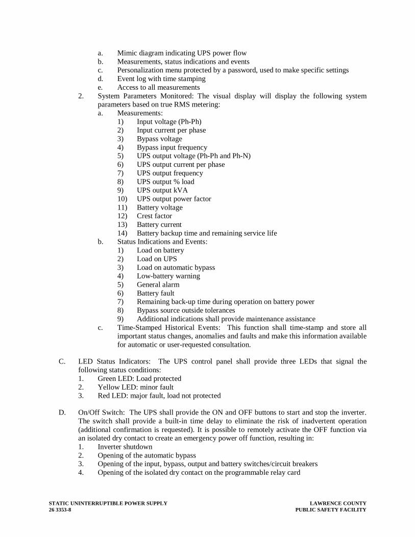
STATIC UNINTERRUPTIBLE POWER SUPPLY LAWRENCE COUNTY 26 3353-8 PUBLIC SAFETY FACILITY
a. Mimic diagram indicating UPS power flow b. Measurements, status indications and events c. Personalization menu protected by a password, used to make specific settings d. Event log with time stamping e. Access to all measurements
2. System Parameters Monitored: The visual display will display the following system parameters based on true RMS metering: a. Measurements:
1) Input voltage (Ph-Ph) 2) Input current per phase 3) Bypass voltage 4) Bypass input frequency 5) UPS output voltage (Ph-Ph and Ph-N) 6) UPS output current per phase 7) UPS output frequency 8) UPS output % load 9) UPS output kVA 10) UPS output power factor 11) Battery voltage 12) Crest factor 13) Battery current 14) Battery backup time and remaining service life
b. Status Indications and Events: 1) Load on battery 2) Load on UPS 3) Load on automatic bypass 4) Low-battery warning 5) General alarm 6) Battery fault 7) Remaining back-up time during operation on battery power 8) Bypass source outside tolerances 9) Additional indications shall provide maintenance assistance
c. Time-Stamped Historical Events: This function shall time-stamp and store all important status changes, anomalies and faults and make this information available for automatic or user-requested consultation.
C. LED Status Indicators: The UPS control panel shall provide three LEDs that signal the following status conditions: 1. Green LED: Load protected 2. Yellow LED: minor fault 3. Red LED: major fault, load not protected
D. On/Off Switch: The UPS shall provide the ON and OFF buttons to start and stop the inverter. The switch shall provide a built-in time delay to eliminate the risk of inadvertent operation (additional confirmation is requested). It is possible to remotely activate the OFF function via an isolated dry contact to create an emergency power off function, resulting in: 1. Inverter shutdown 2. Opening of the automatic bypass 3. Opening of the input, bypass, output and battery switches/circuit breakers 4. Opening of the isolated dry contact on the programmable relay card

LAWRENCE COUNTY STATIC UNINTERRUPTIBLE POWER SUPPLY PUBLIC SAFETY FACILITY 26 3353-9
E. Audible Alarm Reset: The UPS shall provide an audible alarm that can be stopped using the user interface. If a new alarm is sensed after the original alarm has been silenced, it will reactivate the audible alarm.
F. Remote Emergency Power Off (REPO): The UPS shall be equipped with provisions for remote emergency power off and dry contact input that can be used to command UPS shut down remotely. Activation of this command shall lead to the following actions: 1. inverter shutdown 2. opening of the static bypass switch and the battery circuit breaker 3. opening of an isolated dry contact on the programmable relay board
G. DB-9 Connector: One DB-9 connector with serial output will be provided for field diagnostics.
H. Dry Contacts: The UPS shall be provided standard with a programmable input/output relay board. This board shall have 8 dry contacts, i.e., 6 for input signals and 2 for output signals.Contacts shall be programmed as: 1. UPS on Line 2. Load on Bypass 3. UPS on Battery 4. UPS Battery Low 5. General alarm 6. Battery Fault 7. Remote UPS on (input) 8. Remote UPS off (input) 9. The contacts will be normally open and will change state to indicate the operating status.
The contacts will be rated at 2.0 A (250 VAC / 30 VDC).
3.02 MECHANICAL DESIGN AND VENTILATION
A. Enclosure: The UPS shall be housed in a freestanding enclosure with dead front construction. The mechanical structure of the UPS shall be sufficiently strong and rigid to withstand handling and installation operations without risk. Sheet-metal elements in the structure shall be protected against corrosion by a suitable treatment, such as zinc electroplating, bichromating, epoxy paint or an equivalent.
B. Cable Access: The standard UPS available shall accommodate bottom entry cables (top optional).
C. Ventilation and Heat Rejection: The UPS shall be designed for forced air-cooling. Air inlets shall be provided from the front bottom of the UPS enclosure. Air exhaust shall be from the top portion of the unit. Full load heat rejection is 19,750 BTU /hour.
3.03 BATTERY
A. The UPS module shall use a valve regulated sealed lead acid heavy-duty industrial battery, designed for auxiliary power service in a UPS application. The primary battery shall be furnished with impact resistant plastic cases and housed in a matching cabinet(s) next to the UPS module. 1. Protection Against Deep Discharge and Self-Discharge: The UPS shall be equipped with
a device designed to protect the battery against deep discharge, depending on discharge conditions, with isolation of the battery by a circuit breaker. In particular, a monitoring

STATIC UNINTERRUPTIBLE POWER SUPPLY LAWRENCE COUNTY 26 3353-10 PUBLIC SAFETY FACILITY
device shall adjust the battery shutdown voltage as a function of a discharge coefficient to avoid excessive discharge at less than the rated output. A second device shall avoid self-discharge of the battery into the UPS control circuits during an extended shutdown of the UPS (over two hours).
2. Battery Self-Tests: The battery monitoring system shall be able to perform the following automatic functions: a. Battery circuit checks every twelve hours b. Open-circuit battery test once a month c. Partial discharge test every three months
3. This self-test system shall signal faults via LEDs on the front panel or a message to remote supervision systems.
3.04 OPTIONAL ACCESSORIES
A. Battery Cabinet: Matching battery cabinet shall be furnished in both adjacent version. The cabinet shall match the height and depth of the UPS module and shall have a width of 32” per battery cabinet. All power wiring and control cables shall be included for adjacent models (remote cabinet cables provided by customer)
B. External Control and Communications Devices - Communications devices may be installed in the UPS module: 1. Velocity / life.net Card: This interface card offers a web interface to monitor and
configure the Life.net and Emerson Network Power protocols for use sith the Emerson Life Station, Liebert Nform and Emerson Trellis. The card delivers SNMP communications protocol for interfacing to the facility Building Management system UPS parameters: a. UPS on Line b. Load on Bypass c. UPS on Battery d. Low Battery Warning e. Battery Fault f. General Alarm g. Two (2) dry contact inputs shall also be provided to turn the UPS inverter on and
off remotely upon closure of the contacts. This feature may also be disabled if required.
2. Network Management Card : The Network Management Card (NMC) shall provide a web interface, SNMP (Simple Network Management Protocol), logging and email capabilities. The NMC shall be used for remote monitoring or graceful shutdown for most popular file servers.
3.05 FIELD SERVICE ENGINEER QUALIFICATIONS
A. The manufacturer must employ a 7 X 24 nationwide (international where applicable) field service organization with rapid access to all regions of the nation. The responding service professionals must be factory-trained engineers with an accredited and proven competence to service three phase UPS.

LAWRENCE COUNTY STATIC UNINTERRUPTIBLE POWER SUPPLY PUBLIC SAFETY FACILITY 26 3353-11
3.06 SPARE PARTS
A. Field Engineers must have immediate access to recommended spare parts with additional parts storage located in regional depots. Additional spare parts shall be accessible on a 7 x 24 basis from the national depot and must be expedited on a next available flight basis or via direct courier (whichever mode is quickest).
3.07 MAINTENANCE TRAINING
A. The manufacturer shall make available to the customer various levels of training ranging from basic UPS operation to UPS maintenance.
3.08 MAINTENANCE & SERVICE CONTRACTS
A. The manufacturer shall offer additional preventative maintenance and service contracts covering both the UPS and the battery bank. Accredited professional service engineers employed exclusively in the field of critical power systems service shall perform all maintenance and service. The manufacturer shall also offer extended warranty contracts.
END OF SECTION 26 3353


LAWRENCE COUNTY LIGHTNING PROTECTION FOR STRUCTURES PUBLIC SAFETY FACILITY 26 4113-1
SECTION 26 4113 - LIGHTNING PROTECTION FOR STRUCTURES
1. PART 1 - GENERAL
1.01 RELATED DOCUMENT
A. Drawings and general provisions of Contract, including General and Supplementary Conditions and Division-1 Specification sections, apply to work of this section.
B. Division 26 Common Work Results for Electrical sections apply to work specified in this section.
C. Motorola R-56 grounding requirements.
1.02 DESCRIPTION OF WORK
A. Provide a complete lightning protection system as described hereinafter. Provide full coverage of the new building, including, but not limited to, all roof ridges, and roof perimeters.
B. Types of lightning protection system material and components specified in this section include the following: 1. Air terminals. 2. Bonding plates. 3. Conductors. 4. Connectors. 5. Grounding rods. 6. Rod clamps. 7. Splicers. 8. Wire.
1.03 QUALITY ASSURANCE
A. Manufacturers: Firms regularly engaged in manufacture of lightning protection system components, of types, sizes and ratings required, whose products have been in satisfactory use in similar service for not less than 10 years.
B. Manufacturers: Firms regularly engaged in manufacture of lightning protection system components, of types, sizes, and ratings required, and who are Class I manufacturer-members of Lightning Protection Institute.
C. Installer's Qualifications: Firm with at least 10 years of successful installation experience with projects utilizing lightning protection systems similar to that required for this project.

LIGHTNING PROTECTION FOR STRUCTURES LAWRENCE COUNTY 26 4113- 2 PUBLIC SAFETY FACILITY
D. NEC Compliance: Comply with NEC requirements pertaining to lightning (surge) arresters, grounding, grounding electrodes, and down conductor clearances and IEEE 80.
E. NFPA Compliance: Comply with requirements of NFPA No. 780, "Lightning Protection Code", as applicable to lightning protection systems for building projects.
F. ANSI Compliance: Comply with applicable requirements of ANSI Stds C2, C62.1, C62.2, and C114.1.
G. UL Compliance: Comply with Master Label provisions of UL 96A, "Installation Requirements for Lightning Protection Components". Provide components that are UL-listed and labeled.
H. LPI Compliance: Comply with requirements of Lightning Protection Institute (LPI) Standards 175, pertaining to lightning protection system material, components, installation and testing procedures.
1.04 SUBMITTALS
A. Product Data: Submit manufacturer's data on lightning protection systems and associated components, including all down conductors and grounding materials.
B. Shop Drawings: Submit layout drawings of lightning protection system equipment and components including, but not limited to, conductor routing, connections, roof penetration details, and grounding.
2. PART 2 - PRODUCTS
2.01 ACCEPTABLE INSTALLERS
A. Subject to compliance with requirements, installers offering lightning protection components that may be incorporated in the work include, but are not limited to, the following: 1. Ace Lightning Protection Inc., 417 Plum Industrial Court, Pittsburgh, PA 15239
(Phone: 724-733-5216, Fax: 724-733-1193) 2. Maxwell Lightning Protection, Dayton, OH (937)-228-7250 3. East Coast Lightning Equipment inc. (860) 379 9072 4. Approved equal.
2.02 LIGHTNING PROTECTION SYSTEM COMPONENTS
A. General: Provide lightning protection system material and components, of types, sizes, ratings for Class 1 service, that comply with manufacturer's standard materials, design, and construction in accordance with published product information, and as required for a complete installation. Where type components or materials are not otherwise indicated, comply with NFPA 780 and LPI standards.

LAWRENCE COUNTY LIGHTNING PROTECTION FOR STRUCTURES PUBLIC SAFETY FACILITY 26 4113-3
1. All main roof conductors shall be aluminum of 28 strands, 14-gauge minimum, Thompson Catalog No. A28. Copper conductors to ground rods shall be 4/0, 19 strand copper.
2. For parapets, air terminals shall be 1/2" X 12" blunt tip, Cat. No. A55BT. Center of the roof air terminals shall be 1/2" X 24" blunt tip, spring mounted, Cat. No. A572SPBT. No sharp tipped points are permitted. Locate and space according to LPI and NFPA requirements.
3. Cable fasteners shall be substantial in construction, electrolytically compatible with the conductor and mounting surface and shall be spaced according to LPI and NFPA Code requirements. Thompson Cat. No. A174, A730, or A166, etc.
4. Bonding devices, cable splicers and miscellaneous connectors shall be of cast aluminum with bolt pressure connections to cable. Cast or stamped crimp fittings are not acceptable.
5. Ground rods shall be ¾” X 10’ copperclad steel and shall be connected to down conductors exothermically with cadweld GRC mold.
6. Equipment on stacks shall be protected from corrosion in accordance with LPI and NFPA requirements.
7. All miscellaneous bolts, nuts and screws shall be stainless steel. All sheet metal fasteners shall be ITW Buildex Scots Traxx screws. This fastener incorporates a stainless steel body with a wrap-around 18/8 stainless steel head with a neoprene washer. No substitutes will be accepted for this screw.
8. Flashings: Furnish required flashings for all flat roof penetrations. Furnish Master Flash minimum ¾” flashings for all metal roof penetrations. Roofer is to install flashings.
3. PART 3 - EXECUTION
3.01 INSTALLATION OF LIGHTNING PROTECTION SYSTEMS
A. Install lightning protection systems as indicated, in accordance with equipment manufacturer's written instructions, and in compliance with applicable requirements of NEC and NFPA 780 to ensure that lightning protection systems comply with requirements. The installation shall be accomplished by an experienced installer who is a Certified Master Installer/Designer of the LPI. This Contractor's LPI Master Installer/Designer Number shall be listed on the Contractor's bid form. The contractor must have a minimum of 10 years documented experience and submit a list of similar projects completed for the Architect's review. Failure to meet experience standards disqualifies the contractor from the project.
B. Parapet Mounting for EPDM Roofs: A complete network of lightning protection shall be installed utilizing side mount bases fastened to the inside vertical surface of the coping. Bases to be used are Cat. No. A690X with the associated cable fasteners, Cat. No. A166. The base and clips shall be attached with the ITW Buildex Scots Traxx screws. All equipment shall be installed in a neat workmanlike manner, as inconspicuously as possible. All cable runs shall be chalk line straight and plumb. All air terminals shall be plumbed.
C. EPDM Gravel Stops and Bonding: On all roofs that employ a gravel stop, utilize adhesive bases, catalog No. A688 with associated adhesive cable fasteners, No. A730.

LIGHTNING PROTECTION FOR STRUCTURES LAWRENCE COUNTY 26 4113- 4 PUBLIC SAFETY FACILITY
Attachment shall be made to the EPDM with a pourable sealer product that is approved by the roofing manufacturer. All cable runs shall be chalk-line straight. All air terminals shall be plumbed. Bond all metal bodies of inductance and conductance, in accordance with U/L and NFPA regulations. Point all metal bodies of inductance, in accordance with all recognized standards.
D. Standing Seam Metal Roofing: Provide a concealed protection system on all standing seam roofs. Provide air terminals on main ridges and dormers and make connections to structural steel with 8 square inch beam clamps. Furnish to the roofer MasterFlash flashings for all air terminals. The actual installation of the flashing will be by the roofing contractor. No exposed cables are permitted on the standing seam metal roof.
E. Building and Lightning Protection Grounding: The structural steel framework of the building shall be utilized as the down conductors. Provide grounding at a maximum of 60’ on center intervals around the entire outside perimeter. Utilize 4/0 bare, 19 strand copper cable exothermically connected to the base of the column. Utilize Cadweld Mold No. VBC-2Q. Extend the 4/0 cable out below grade and terminate to a ¾” X 10’ ground rod. The connection from the ground rod to the cable shall be by the exothermic method, utilize Cadweld Mold No. GRC-182Q. All grounds shall be bonded to the main building ground.
F. Roof-thru Electrodes: Provide roof-thru electrodes that are bonded to the structural steel at a maximum of 100’ on center intervals around the perimeter of the building. Utilize 8 square inch beam clamps and stainless steel all-threads with heavy-duty, Class II lugs and splices. Furnish to the roofing contractor Carlisle/Firestone pipe seals; it is the roofer’s responsibility to actually install the pipe seals. Coordinate the location of the penetrations with the roofing contractor and maintain a minimum of 12” separation from any cant area.
G. Coordinate with other work, including electrical wiring and roofing work, as necessary to interface installation of lightning protection system with other work.
H. Install conductors with direct paths from air terminals to ground connections avoiding sharp bends and narrow loops.
I. Bond and point all metallic bodies of inductance (fans, hoods, A/C chillers, etc.). Bond all metal bodies of conductance that fall within 6’ of the conductor (roof drains, vents, stacks, etc.
J. The limitations on areas of usage for aluminum cables and for copper and aluminum materials together as outlined in NFPA 780 and LPI 175 shall be observed.
3.02 GROUNDING AND BONDING
A. Provide equipment grounding and bonding connections, sufficiently tight to assure permanent and effective grounds and bonds, for lightning protection connection devices as indicated.
B. All grounds shall be bonded to the main building ground.

LAWRENCE COUNTY LIGHTNING PROTECTION FOR STRUCTURES PUBLIC SAFETY FACILITY 26 4113-5
3.03 TESTING
A. Upon completion of installation of lightning protection system, test resistance-to-ground (earthing connecting) with resistance tester. Where tests indicate resistance-to-ground is over 5 ohms, take appropriate action to reduce resistance to 5 ohms or less, by driving additional, properly spaced, ground rods. Then retest to demonstrate compliance.
3.04 PERSONNEL TRAINING
A. Building Maintenance Personnel Training: Train Owner's building maintenance personnel in procedures for testing and determining resistance-to-ground values of lightning protection system.
3.05 WARRANTY
A. Submit a two (2) year merchandisable warranty at completion.
B. Certify that the installed system meets the requirements of Underwriters Laboratories standard UL-96A and the Lightning Protection Institute standard LPI-175.
END OF SECTION 26 4113


LAWRENCE COUNTY TRANSIENT VOLTAGE SURGE SUPPRESSION PUBLIC SAFETY FACILITY 26 4313-1
SECTION 26 4313 – TRANSIENT VOLTAGE SURGE SUPPRESSION
PART 1 - GENERAL
1.01 RELATED DOCUMENTS
A. Drawings and general provisions of Contract, including General and Supplementary Conditions and Division-1 Specification sections, apply to work of this section.
B. Division 26 Common Work Results for Electrical sections apply to work specified in this section.
1.02 DESCRIPTION OF WORK
A. General: Transient voltage surge suppression (TVSS) or surge protection device (SPD) is the description and equipment required for the protection of all AC electrical circuits and electronic equipment from the effects of lightning induced voltages, external switching transients and internally generated switching transients.
B. TVSS units are indicated on the drawings. Units are specified by part numbers that indicate the required ratings (i.e., maximum surge current, clamping voltage), and system noise filter networks. Required accessories (i.e., status indicators, alarms, transient counters) shall be provided as specified herein.
1.03 REFERENCE STANDARDS AND PUBLICATIONS
A. General: The latest edition of the following standards and publications shall comply to the work of this section: 1. ANSI/IEEE C84.1-1989, American National Standard for Electric Power Systems and
Equipment - Voltage Ratings (60 Hertz) 2. ANSI/IEEE C62.41-1991, Recommended Practice on Surge Voltages in Low-Voltage
AC Power Circuits 3. ANSI/IEEE C62.45-1992, IEEE Guide on Surge Testing for Equipment Connected to
Low-Voltage AC Power Circuits 4. Underwriters Laboratories UL 1449 Second Edition, Standard for Safety - Transient
Voltage Surge Suppressors 5. Underwriters Laboratories, UL 1283, Standard for Safety - Electromagnetic Interference
Filters 6. National Fire Protection Association, NFPA 780 - National Electrical Code 7. IEEE Standard 142-1991, IEEE Recommended Practice for Grounding of Industrial and
Commercial Power Systems (IEEE Green Book) 8. ANSI/IEEE Standard 141-1999, IEEE Recommended Practice for Electric Power
Distribution for Industrial Plants (IEEE Red Book) 9. IEEE Standard 1100-1999, IEEE Recommended Practice for Powering and Grounding
Sensitive Electronic Equipment (IEEE Emerald Book)

TRANSIENT VOLTAGE SURGE SUPPRESSION LAWRENCE COUNTY 26 4313-2 PUBLIC SAFETY FACILITY
10. FIPS Pub 94, Federal Information Processing Standards Publication - Guideline on Electrical Power for ADP Installations
11. National Electrical Manufacturer’s Association LS-1, 1992 (NEMA LS-1) 12. MIL Standard 220A Method of Insertion-loss Measurement 13. ISO 9001:1994, Quality Systems - Model for Quality Assurance in Design, Development,
Production, Installation and Servicing
1.04 QUALITY ASSURANCE
A. Manufacturers: Firms regularly engaged in manufacture of surge protection of the types, sizes and capacities required, whose products have been in satisfactory use in similar service for not less than 5 years.
B. The manufacturer shall submit a written statement indicating that a factory authorized representative inspected the installation. The installing contractor shall submit a checkout memorandum to the manufacturer. The memorandum shall indicate the date the equipment is placed into service and the actual method of installation. Submit three copies to the specifying engineer.
C. All surge protective devices for service entrance, distribution, and branch circuit protection within a facility shall be provided by a single manufacturer.
D. Installer's Qualifications: Firm with at least (10) ten years of successful installation experience on projects utilizing surge protection similar to those required for this project.
E. TVSS Units shall be UL listed to sections 1283 and 1449 Second Edition and the rating shall be permanently affixed to the TVSS.
F. Main service units shall meet ANSI/IEEE C62.41 category C.3.
G. All units shall comply with ANSI/IEEE C62.45 withstanding a minimum of twenty-five hundred 10,000 ampere impulses.
1.05 SUBMITTALS
A. The transient voltage surge suppression submittals shall include, but shall not be limited to, the following information: 1. Data for each suppressor type indicating conductor sizes, conductor types, and
connection configuration and lead lengths. 2. Manufacturer’s certified test data indicating the ability of the product to meet or exceed
requirements of this specification. 3. Drawings, with dimensions, indicating SPD mounting arrangement and lead length
configuration, and mounting arrangement of any optional remote diagnostic equipment and assemblies.
4. List and detail all protection systems such as fuses, disconnecting means and protective materials.
5. SPD wiring, bonding, and grounding connections shall be indicated on the wiring diagrams for each system. Include installation details demonstrating mechanical and electrical connections to equipment to be protected.

LAWRENCE COUNTY TRANSIENT VOLTAGE SURGE SUPPRESSION PUBLIC SAFETY FACILITY 26 4313-3
6. If requested, a sample of each suppressor type shall be submitted for use in testing and evaluation.
1.06 WARRANTY
A. The SPD and supporting components shall be guaranteed by the manufacturer to be free of defects in material and workmanship for a period of twenty (20) years from the date of substantial completion of service and activation of the system to which the suppressor is attached. Any additional diagnostic circuits (LEDs, surge counter, etc.) must meet a warranty period of ten (10) years.
B. An SPD that shows evidence of failure or incorrect operation during the warranty period shall be replaced free of charge. Since “Acts of Nature” or similar statements typically include the threat of lightning to which the SPDs shall be exposed, any such clause limiting warranty responsibility in the general conditions of this specification shall not apply to this section. That is, the warranty is to cover the effects of lightning, single phasing, and all other electrical anomalies. The warranty shall cover the entire device, not just various components, such as modules only.
C. The installation of SPDs in or on electrical distribution equipment shall in no way compromise or violate equipment listing, labeling, or warranty of the distribution equipment.
PART 2 - PRODUCTS
2.01 PERFORMANCE
A. General: 1. Equipment in this Specification and shown on the Drawings is based on products
manufactured by Innovative Technologies and other specific manufacturers, and is intended as the standard equipment to be furnished, or as approved. Unit part numbers are shown on the drawings. These part numbers are used to establish the minimum acceptable ratings for each device and all manufacturer's published specifications pertaining to this specialization shall have the same force and effect as if shown here in full. Units provided by other manufacturers shall meet or exceed the ratings of the specified part number. Being listed as an acceptable manufacturer does not preclude the listed manufacturers from complying with this specification. a. Manufacturers: Subject to compliance with requirements, provide products by the
following: 1) United Power Corporation 2) L.E.A. Dynatech 3) Liebert Corporation 4) Current Technology
2. SPDs shall be listed in accordance with UL 1449 Second Edition, Standard for Safety, Transient Voltage Surge Suppressors and UL 1283, Standard for Safety, Electromagnetic Interference Filters.
3. The SPD shall protect all modes and there shall be seven discrete suppression circuits: 3 modes connected Line to Ground, 3 modes connected Line to Neutral, and 1 mode connected Neutral to Ground for a 3-phase, 4-wire, plus ground voltage system. Line to

TRANSIENT VOLTAGE SURGE SUPPRESSION LAWRENCE COUNTY 26 4313-4 PUBLIC SAFETY FACILITY
Neutral to Ground is not an acceptable substitute for Line to Ground. Line to Neutral to Line and Line to Ground to Line (in combination) will be acceptable for Line-to-Line protection.
4. All SPDs must have passed the UL 1449 Second Edition Fault Current Test with a Rating of 200,000 AIC. Documentation substantiating this claim must be provided.
5. SPDs shall use a separate path to building ground; the equipment safety ground is not to be used as a transient ground path.
6. All SPDs are to be MOV based and not included SAD technology as a means of suppression.
7. The maximum continuous operating voltage (MCOV) of all components shall not be less than 125% for a 120V system and 115% for 220, 240, 277, and 480V systems.
8. Standard diagnostic features are to include green LEDs (one per phase - normally on) indicating power and suppression status and a form C dry relay contact.
9. Extended diagnostics must include an audible alarm and surge counter to be displayed on an LCD display on the front of the suppressor. The surge counter must include a reset option. The audible alarm must include a mute option. Products requiring diagnostic test kits will not be acceptable.
B. Service Entrance Protection 1. The SPD for this location shall be indicated ON the project drawings. 2. The service entrance TVSS equipment shall meet or exceed the minimum performance
criteria as follows: a. The SPDs shall be Innovative Technology, Inc. model “PTE300-3Y201-D-SD”.
The single-impulse surge-current rating shall be a minimum of 300,000 Amperes per phase (150,000 Amperes per mode).
b. The UL 1449 Second Edition Suppressed Voltage Rating for the following configurations shall not exceed the following:
Voltage Configuration L-G L-N N-G
120/208V (3Y101) 400V 400V 400V
277/480V (3Y201) 800V 800V 800V
c. SPDs shall be of compact design. The mounting position of the SPD shall allow a straight and short lead-length connection between the SPD and the point of connection in the panelboard.
d. Visual indication of proper SPD connection and operation shall be easily viewed on the front panel of the enclosure. The indicator lights shall indicate suppression circuit status, phase status, phase loss, reduced protection level and suppression fault.
e. The SPD shall be equipped with an integral disconnect switch or be available as an option.
f. A set of normally open/normally closed Form “C” dry contacts shall be provided for remote monitoring.
g. The enclosure type shall have a minimum of a NEMA 4 rating. h. SPDs shall have a diagnostics LCD panel display providing information on phase
loss (specific to each phase), surge/transient event count, stored cumulative surge/transient event history, and technical support information.

LAWRENCE COUNTY TRANSIENT VOLTAGE SURGE SUPPRESSION PUBLIC SAFETY FACILITY 26 4313-5
i. SPDs shall be equipped with an audible alarm with mute, reset and acknowledge features.
j. The device must be certified (report to be submitted) to withstand a minimum of 20,000 Category C3 (Combination wave - 20,000 Volts - 1.2x50 :s OCV and 10,000 Amps - 8x20 :s SCC as defined by ANSI/IEEE C62.41-1991) impulses with less than 10% change in the baseline to final let-through voltage. This data must be submitted as an independently verified and certified test report.
k. The maximum value for the attenuation for the suppressor must exceed a minimum of 33 dB. All measurements for this requirement must be taken using the MIL STD 220A method and with only six (6) inches of lead length extending outside of the normal exit location of leads for the enclosure. Test results taken with leads extending past six (6) inches are not acceptable or compliant. Additional or excessive lead length used in the test setup is NOT acceptable.
C. System Voltage: The system voltage, a number of phases, and number of wires shall be as shown on the drawings.
PART 3 - EXECUTION
A. Installation: 1. Install the TVSS in accordance with the manufacturer's recommended installation
practices and all applicable codes.
B. System Testing and Installation: 1. The manufacturer shall own and operate a surge simulation system that creates an IEEE
C62.41 Category C3 (20 kV, 10 kA) surge event. Each unit must be tested on this test fixture and results commensurate with the IEEE and UL 1449 Second Edition standards shall be shipped with the system to the job site.
2. A representative from the consulting engineer or the end user shall be welcome to witness test the system(s) at the manufacture. It shall be the cost of the end user to attend such tests if so desired.
3. The manufacturer shall have a contracted and trained local representative to visit the site to assist the user in the proper installation of the system to ensure maximum performance.
C. Warranty and Service: 1. The TVSS system manufacturer shall warranty the entire system against defective
materials and workmanship for a period of five years following delivery from the manufacturer. The internal TVSS protection modules shall be protected by a five year warranty following delivery from the manufacturer providing the protection modules are not subjected to misuse or over-exposure. This warranty is in effect as long as the unit is installed in compliance with the manufacturer's owner's/operator's manual, UL listing requirements, and any applicable national or electrical codes.
2. The manufacturer is required to have a nationwide network of factory trained technicians dedicated to repair and service of this product. The manufacturer shall have a dedicated 1-800 telephone number for service problems and questions. This number must be manned 24 hours a day, 365 days a year by a knowledgeable factory employee to ensure prompt response to any emergency situation that may arise. The manufacturer is required to be able to service the equipment on a local basis without the requirement to return the product to the manufacturer for proper repair.

TRANSIENT VOLTAGE SURGE SUPPRESSION LAWRENCE COUNTY 26 4313-6 PUBLIC SAFETY FACILITY
D. Extended Maintenance: 1. The Surge Suppressor shall have as an optional feature extended service contract
maintenance.
END OF SECTION 26 4313

LAWRENCE COUNTY LIGHTING FIXTURES PUBLIC SAFETY FACILITY 26 51 00 - 1
SECTION 26 51 00 - LIGHTING FIXTURES
1. PART 1 - GENERAL
1.01 WORK INCLUDED
A. Interior luminaires and accessories.
B. Exterior luminaires and accessories.
C. Lamps.
D. Ballasts.
1.02 RELATED WORK
A. Division 02 - Trenching: Excavation and backfill for utilities.
B. Division 03 - Cast-In-Place Concrete: Concrete pole bases.
C. Division 09 - Suspended Acoustic Ceilings: Lay-in ceilings.
D. Division 09 - Painting.
E. Section 26 05 35 - Boxes.
1.03 REFERENCES
A. ANSI C78.379 - Electric Lamps - Incandescent and High-Intensity Discharge Reflector Lamps - Classification of Beam Patterns.
B. ANSI C82.1 - Ballasts for Fluorescent Lamps - Specifications.
C. ANSI C82.4 - Ballasts for High-Intensity Discharge and Low Pressure Sodium Lamps (Multiple Supply Type).
D. ANSI/NFPA 70 - National Electrical Code.
E. ANSI/NFPA 101 - Life Safety Code.
F. NEMA WD 6 - Wiring Devices - Dimensional Requirements.
1.04 SUBMITTALS
A. Submit product data under provisions of Section 01 3300, Submittal Procedures.
B. Submittals shall include the following for each luminaire type: Manufacturer’s product cut sheets, photometric data, catalog number clearly indicated with all options and accessories shown and defined, outline drawings, lamp and ballast data, support points, weights, and accessory information. Submittals without this information will not be accepted and shall be returned to the Contractor.
C. Only factory authorized options or luminaire modifications with supporting documentation will be accepted. Options or modifications written or typed on the submittal without supporting documentation, will not be accepted. All UL and other product listings shall be maintained for options or modifications to the fixture. Proof of UL listing for any option or modifications shall be included with the submittal.
D. Incomplete or partial submittals will not be accepted and shall be returned to the Contractor.

LIGHTING FIXTURES LAWRENCE COUNTY 26 51 00- 2 PUBLIC SAFETY FACILITY
E. Facsimiles or copies of faxes for Manufacturer’s product cut sheets will not be accepted.
F. Luminaire types that do not have prior approval as an accepted equal, must be submitted in accordance with the provisions of Section 00 2100, Supplementary Instructions to Bidders. The total amount being credited to the Owner for each luminaire type shall be included with the submittal. The Contractor shall be responsible for any delays resulting from the submission of luminaire types that do not have prior approval.
G. The Contractor shall be responsible for Additional Architectural Fees as indicated in Section 00 8000, Supplementary Conditions, Paragraph 13.10 “Contractor’s Responsibility for Additional Architectural Fees”. The Contractor shall be responsible for Additional Architectural Fees for excessive time spent reviewing poor submittals. The Contractor shall be responsible for Additional Architectural Fees for time spent evaluating submissions that include luminaire types that do not have prior approval.
H. Submit manufacturer's installation instructions under provisions of Section 01 3300, Submittal Procedures.
1.05 DELIVERY, STORAGE, AND HANDLING
A. Deliver products to site under provisions of Division 01
B. Store and protect products under provision of Division 01.
C. Ship laminated finish wood poles individually wrapped in moisture-resistant paper.
D. Handle metal poles carefully to prevent breakage and damage to finish.
1.06 EXTRA STOCK
A. Provide extra stock under provisions of Division 01.
B. Lamps: Three percent of quantity furnished, minimum of one of each size and type.
C. Lenses: Three percent of quantity furnished, minimum of one of each size and type.
1.07 PROJECT RECORD DOCUMENTS
A. Submit under provisions of Section 01 7820, Construction Progress Documentation.
B. Accurately record actual locations of each luminaire.
1.08 OPERATION AND MAINTENANCE DATA
A. Submit under provisions of Section 01 7820, Operation and Maintenance Data.
B. Maintenance Data: Include replacement parts list.
1.09 QUALIFICATIONS
A. Manufacturer: Company specializing in manufacturing products specified in this Section with minimum three years documented experience.

LAWRENCE COUNTY LIGHTING FIXTURES PUBLIC SAFETY FACILITY 26 51 00 - 3
1.10 REGULATORY REQUIREMENTS
A. Conform to requirements of ANSI/NFPA 70.
2. PART 2 - PRODUCTS
2.01 ACCEPTABLE MANUFACTURERS - LAMPS
A. General Electric
B. Osram Sylvania.
C. Philips.
2.02 LAMPS
A. All lamps shall pass the Federal TCLP test for both lead and mercury, where possible.
B. Lamps shall comply with all applicable ANSI standards.
C. Each lamp type shall be made by one manufacturer to maintain color consistency.
D. All lamps shall be free from defects in manufacture and covered by an implied warranty based on lamp mortality data as such that defective lamps or lamps failing at a higher than normal rate shall be replaced after factory inspection determining cause of failure or defect.
E. General Use Incandescent Lamps: Inside frosted type, rated 125 volts.
F. Incandescent Reflector Lamps: Shape as scheduled, rated 125 volts.
G. All line voltage halogen PAR lamps shall have infrared conserving (IR) technology for maximum efficacy where available in wattages/beam spread as specified on the lighting fixture schedule.
H. All low-volt halogen reflector lamps shall have infrared conserving technology, axial filament orientation and dichroic reflectors, for maximum efficacy and beam control, when available in wattages/beam spreads as specified on the lighting fixture schedule.
I. Fluorescent Lamps: 32 Watt rapid start, T8 lamps rated at 2950 initial lumens, 20,000+ average hours life. 3500 K and 85 CRI. All by same manufacturer.
J. Compact fluorescent (T4) lamp type: Compact fluorescent lamps shall either be single, double or triple type with 4-pin bases for operation on electronic and dimming ballasts. Where available, lamps shall contain end-of-life sensing to prevent overheating of lamp base and sockets. Lamps shall have a minimum CRI of 82 and shall have a color temperature of 2700K, 3000K, 3500K or 4100K.
K. Compact fluorescent (T5) lamp type: Lamps shall have a 2G11 base and operate on electronic ballasts. Lamps shall have a minimum CRI of 82 and shall have a color temperature of 3000K, 3500K or 4100K.
L. Linear T5 fluorescent lamp type: All linear T5 fluorescent lamp types shall have miniature bi-pin bases, 20,000 hours average rated life, a minimum CRI of 82 and shall have a color temperature of 3000K, 3500K or 4100K.

LIGHTING FIXTURES LAWRENCE COUNTY 26 51 00- 4 PUBLIC SAFETY FACILITY
M. All high intensity discharge lamps shall be operated on the appropriate ANSI designated electromagnetic ballast in accordance with ANSI C82.4. Low wattage metal halide lamps designated for use on electronic ballasts shall require written approval from the lamp manufacturer.
N. Metal Halide HID Lamps: Phosphor coated. Lamps installed in open fixtures are to be rated for open or enclosed fixtures. 1000 Watt standard Metal Halide lamps shall have an average rated life of 18,000 hours in the vertical operating position and 12,000 hours in the horizontal operating position.
2.03 ACCEPTABLE MANUFACTURERS - FLUORESCENT BALLASTS
A. Advance
B. General Electric / Magnetek
C. Osram Sylvania
2.04 FLUORESCENT BALLASTS (ELECTRONIC TYPE)
A. Fluorescent Ballasts: ANSI C82.41-1991.
B. Programmed Rapid Start for T8 OCTRON type fluorescent lamps.
C. Input current Total Harmonic Distortion shall not exceed .20
D. Ballasts shall be fully encapsulated to ensure maximum thermal and structural integrity.
E. Lamp Current Crest Factor (CCF) shall be 1.7 or less.
F. Ballasts shall have a maximum case temperature rating of 70 C.
G. Ballast output shall be protected against lamp rectification or shorted output leads.
H. Ballasts shall be
1. UL Listed, Class P, Type 1
2. CSA Certified (where applicable)
3. CBM Certified (where applicable)
4. Manufactured in accordance with ANSI C82.11 methods where applicable.
5. Meet FCC 47CFR Part 18 non-consumer for EMI and RFI
6. Comply with ANSI and IEEE standards for harmonic distortion and withstand transients as specified by ANSI C62.41 for location category A.
7. Shall contain no PCB’s.
I. Electronic ballasts for T5, T4, compact fluorescent and smaller diameter fluorescent lamps:
1. Provide dynamic end-of-life sensing to protect against overheated lamp bases and sockets.
2. Shall have 0.80 – 1.15 ballast factor, depending upon lamp type.
3. Shall be Programmed Rapid Start for linear T5 lamps.

LAWRENCE COUNTY LIGHTING FIXTURES PUBLIC SAFETY FACILITY 26 51 00 - 5
4. Shall be Instant Start or Programmed Rapid Start for T5 long (high lumen) compact fluorescent lamps.
5. Shall be Programmed Rapid Start for T4 compact fluorescent lamps.
J. Fluorescent Dimming Ballasts:
1. Dimming ballast shall be UL listed, CSA approved, NOM certified and Class P thermally protected.
2. Electronic dimming ballast shall be rated to operate in an ambient temperature range of 50 Degrees F to 140 Degrees F and 90% non-condensing relative humidity. Shall have a minimum starting temperature of 50 Degrees F, and rated for a maximum case temperature of 167 Degrees F.
3. Manufacturer shall provide a full three-year warranty on all dimming ballasts.
4. Electronic dimming ballast shall provide continuous flicker-free dimming throughout the specified dimming range.
5. Electronic dimming ballast shall have internal circuitry to limit inrush current to a maximum of seven amps at 120 volts, three amps at 277 volts.
6. Electronic dimming ballast shall be a programmed rapid start type, preheating lamp cathodes before applying full arc voltage to ensure average rated lamp life is not diminished.
7. Electronic dimming ballast operation shall not diminish average rated lamp life.
8. Electronic dimming ballast shall not interfere, at any light output level, with infrared devices operating at frequencies between 38 kHz and 42 kHz.
9. Electronic dimming ballast shall provide end-of-lamp-life protection for T5-HO linear and T4 4-pin lamps.
10. Electronic dimming ballast shall be capable of striking lamps at any light level without first flashing to full light.
11. Electronic dimming ballast shall be inaudible in a 27dBA ambient.
12. Electronic dimming ballast shall meet FCC Part 18 Non-Consumer Specifications for EMI/RFI emissions.
13. Electronic dimming ballast shall meet ANSI 82.11 maximum allowable total harmonic distortion (THD) requirements.
14. Electronic dimming ballast shall meet ANSI C62.41 Category A transient voltage line protection requirements up to and including 6kV.
2.05 HID BALLASTS
A. HID Ballast: ANSI C82.4; selected by luminaire manufacturer.
B. LS-NC Rating: NEMA LE 2; equal to or less than ratings listed in Table C-1.

LIGHTING FIXTURES LAWRENCE COUNTY 26 51 00- 6 PUBLIC SAFETY FACILITY
2.06 HAZARDOUS MATERIALS
A. Electrical Contractor shall be responsible for proper disposal and/or recycling of all hazardous material associated with the electrical contract. This responsibility shall include but not be limited to the following:
1. Fluorescent lamps
2. Fluorescent ballasts
3. HID lamps
4. HID ballasts
5. Transformers, etc.
B. The recycling and/or disposal process shall conform to the Federal E.P.A., State Department of Environmental Protection, Local Authorities and R.C.R.A. Standards. The Electrical Contractor shall process all removed fluorescent lamps, fluorescent ballasts, HID lamps, HID ballasts, etc. in accordance with these standards. The Electrical Contractor shall secure certified bills of lading, manifests or other documentation to indicate the ultimate disposition of these items.
C. The Electrical Contractor shall indemnify and hold harmless the Owner and the Project Design Professional from any environmental liability with respect to the removed materials.
3. PART 3 - EXECUTION
3.01 EXAMINATION
A. Examine substrate and supporting grids for luminaires.
B. Examine each luminaire to in accordance with manufacturers instructions.
3.02 INSTALLATION
A. Install in accordance with manufacturers instructions.
B. Install suspended luminaires using pendants supported from swivel hangers. Provide pendant length required to suspend luminaire at indicated height.
C. Support luminaires independent of ceiling framing. The Electrical Contractor shall be responsible for the supporting of all light fixtures. This includes but is not limited to providing additional ceiling, ceiling grid support for all light fixtures, supplemental steel, boxes, etc.
D. Locate recessed ceiling luminaires as indicated on reflected ceiling plan.
E. Install surface mounted luminaires and exit signs plumb and adjust to align with building lines and with each other. Secure to prohibit movement.
F. Exposed Grid Ceilings: Support surface mounted luminaires on grid ceiling directly determine suitability for lamps specified.
G. Install recessed luminaires to permit removal from below.
H. Install recessed luminaires using accessories and fire stopping materials to meet regulatory requirements for fire rating.
I. Install clips to secure recessed grid-supported luminaires in place.

LAWRENCE COUNTY LIGHTING FIXTURES PUBLIC SAFETY FACILITY 26 51 00 - 7
J. Install wall mounted luminaires at height indicated on Drawings.
K. Install accessories furnished with each luminaire.
L. Connect luminaires, emergency lighting units and exit signs to branch circuit outlets, provided under Section 16130, using flexible conduit.
M. Make wiring connections to branch circuit using building wire with insulation suitable for temperature conditions within luminaire.
N. HID Luminaires: Use power hook hangers rated 500 pounds (225 kg) minimum and provide safety chain between ballast and structure, and between reflector and ballast.
O. Bond products and metal accessories to branch circuit equipment grounding conductor.
P. Install specified lamps in each luminaire.
3.03 FIELD QUALITY CONTROL
A. Operate each luminaire after installation and connection. Inspect for proper connection and operation.
B. For electronic dimming ballast, the fluorescent lamps shall be seasoned by operation at full intensity for 100 hours prior to dimming to render lamp impurities inert.
3.04 ADJUSTING
A. Adjust Work under provisions of Division 01.
B. Aim and adjust luminaires as directed.
C. Adjust exit sign directional arrows as indicated.
D. Re-lamp luminaires that have failed lamps at Substantial Completion.
E. Touch up luminaire and pole finishes at completion of work.
3.05 CLEANING
A. Clean Work under provisions of Division 01.
B. Clean electrical parts to remove conductive and deleterious materials.
C. Remove dirt and debris from enclosure.
D. Clean photometry control surfaces as recommended by manufacturer.
E. Clean finishes and touch up damage.
3.06 DEMONSTRATION
A. Provide systems demonstration under provisions of Division 01.
B. Provide demonstration of luminaire operation.
3.07 SCHEDULE
A. See Contract Drawings.
END OF SECTION 26 51 00


LAWRENCE COUNTY FIRE ALARM SYSTEM PUBLIC SAFETY FACILITY 26 60 00 - 1
SECTION 26 60 00 – FIRE ALARM SYSTEM
1. PART 1 – GENERAL
1.01 SCOPE AND RELATED DOCUMENTS
A. The work covered by this section of the specifications includes the furnishing of all labor, equipment, materials, and performance of all operations in connection with the installation of the Fire Alarm System as shown on the drawings and as herein specified.
B. The requirements of the conditions of the Contract, Supplementary Conditions and General Requirements, apply to the work specified in this section.
C. The complete installation is to conform to the applicable sections of NFPA-72, Local Code Requirements and National Electrical Code with particular attention to Article 760.
D. Additionally, the entire installed system and all integrated system operations shall be within the guidelines of the IBC International Building Code.
E. The work covered by this section of the specifications is to be coordinated with the related work as specified elsewhere under the project specifications.
F. This Section covers fire alarm systems, including initiating devices, notification appliances, controls, and supervisory devices.
G. The Fire Alarm System shall consist of all necessary hardware equipment and software programming to perform the following functions:
1. Fire alarm and detection operations in the main facility and EMA garage. 2. Control and monitoring of fire suppression systems, emergency power systems, and
other equipment as indicated in the drawings and specifications.
H. Division 23 0000 – HVAC Systems
1.02 REFERENCES
A. NFPA 72, National Fire Alarm Code
B. NFPA 70, National Electrical Code
C. NFPA 101, Life Safety Code
D. NFPA 90A, Standard for the Installation of Air Conditioning and Ventilating Systems
E. Other applicable NFPA standards
F. Local Jurisdictional Adopted Codes and Standards
G. ADA Accessibility Guidelines
1.03 SUBMITTALS
A. General: Submit the following under the provisions of Section 01330, Submittal Procedures.
1. Product data sheets for system components highlighted to indicate the specific products, features, or functions required to meet this specification. Alternate or as-equal products submitted under this contract must provide a detailed line-by-line comparison of how the submitted product meets, exceeds, or does not comply with this specification.
2. Wiring diagrams from manufacturer. 3. Shop drawings showing system details including location of FACP, all devices, and

FIRE ALARM SYSTEM LAWRENCE COUNTY 26 60 00 - 2 PUBLIC SAFETY FACILITY
circuiting. 4. System Power and battery charts with performance graphs and voltage drop
calculations to assure that the system will operate per the prescribed backup time periods and under all voltage conditions per UL and NFPA standards.
5. System operation description including method of operation and supervision of each type of circuit and sequence of operations for all manually and automatically initiated system inputs and outputs. A list of all input and output points in the system shall be provided with a label indicating location or use of SLC, NAC, relay, Sensor and auxiliary control circuits.
6. Operating instructions for FACP. 7. Operation and maintenance data for inclusion in Operating and Maintenance
Manual. Include data for each type product, including all features and operating sequences, both automatic and manual. Provide the names, addresses, and telephone numbers of service organizations.
8. Product certification signed by the manufacturer of the fire alarm system components certifying that their products comply with indicated requirements.
9. Record of field tests of system.
B. Submission to Authority Having Jurisdiction: In addition to routine submission of the above material, make an identical submission to the authority having jurisdiction. Include copies of shop drawings as required to depict component locations to facilitate review. Upon receipt of comments from the Authority, make resubmissions if required to make clarifications or revisions to obtain approval.
1.04 PROJECT RECORD (AS-BUILT) DRAWINGS
A. The Contractor shall provide and maintain on the site an up-to-date record set of approved shop drawings.
B. Record drawings shall include location of end-of-line device locations.
C. Upon completion of the work, and final acceptance by the local authority, the Contractor shall submit record drawings to the Owner and the Engineer.
1.05 OPERATION AND MAINTENANCE DATA
A. Submit Manufacturer data sheets for all equipment installed.
B. Include operating, installation, and routine maintenance instructions.
C. Include Manufacturer letter stating the date of installation on which the system is operational.
1.06 QUALITY ASSURANCE
A. Installer Qualifications: A factory authorized installer is to perform the work of this section.
B. Each and all items of the Fire Alarm System shall be listed as a product of a single fire alarm system manufacturer under the appropriate category by Underwriters Laboratories, Inc. (UL), and shall bear the "UL" label.
1.07 MAINTENANCE SERVICE
A. Maintenance Service Contract: Provide maintenance of fire alarm systems and equipment for a period of 12 months, using factory-authorized service representatives.
B. Basic Services: Systematic, routine maintenance visits on a quarterly basis at times scheduled with the Owner. In addition, respond to service calls within 24 hours of notification of system trouble. Adjust and replace defective parts and components with

LAWRENCE COUNTY FIRE ALARM SYSTEM PUBLIC SAFETY FACILITY 26 60 00 - 3
original manufacturer's replacement parts, components, and supplies.
C. Additional Services: Perform services within the above 12-month period not classified as routine maintenance or as warranty work when authorized in writing. Compensation for additional services must be agreed upon in writing prior to performing services.
D. Renewal of Maintenance Service Contract: No later than 60 days prior to the expiration of the maintenance services contract, deliver to the Owner a proposal to provide contract maintenance and repair services for an additional one-year term. Owner will be under no obligation to accept maintenance service contract renewal proposal.
1.08 EXTRA MATERIALS
A. General: Furnish extra materials, packaged with protective covering for storage, and identified with labels clearly describing contents as follows:
1. Break Rods for Manual Stations: Furnish quantity equal to 15 percent of the number of manual stations installed; minimum of 6 rods.
2. Strobe Units: Furnish quantity equal to 10 percent of the number of units installed, but not less than one.
3. Smoke Sensors, Fire Detectors, and Flame Detectors: Furnish quantity equal to 10 percent of the number of units of each type installed but not less than one of each type.
4. Sensor Bases: Furnish quantity equal to 2 percent of the number of units of each type installed but not less than one of each type.
2. PART 2 - PRODUCTS
2.01 ACCEPTABLE MANUFACTURERS
A. Johnson Controls (Dave Pettit (724) 244 0969
B. Simplex
C. Notifier
1. Manufacturers: The equipment and service described in this specification are those supplied and supported by Johnson Controls and represent the base of design. Being listed as an acceptable Manufacturer in no way relieves obligation to provide all equipment and features in accordance with these specifications.
2. The Manufacturer shall be a nationally recognized company specializing in fire alarm and detection systems. This organization shall employ factory trained and NICET certified technicians, and shall maintain a service organization within 60 miles of this project location. The Manufacturer and service organization shall have a minimum of 10 years’ experience in the fire protective signaling systems industry.
2.02 SYSTEM DESCRIPTION
A. General: Provide a complete, non-coded, addressable, microprocessor-based fire alarm system with initiating devices, notification appliances, and monitoring and control devices as indicated on the drawings and as specified herein.
B. Software: The fire alarm system shall allow for loading and editing instructions and operating sequences as necessary. The system shall be capable of on-site programming to accommodate system expansion and facilitate changes in operation. All software operations shall be stored in a non-volatile programmable memory within the fire alarm control unit. Loss of primary and secondary power shall not erase the instructions stored in memory.
C. History Logs: The system shall provide a means to recall alarms and trouble conditions in

FIRE ALARM SYSTEM LAWRENCE COUNTY 26 60 00 - 4 PUBLIC SAFETY FACILITY
chronological order for the purpose of recreating an event history. A separate alarm and trouble log shall be provided.
D. Recording of Events: Record all alarm, supervisory, and trouble events by means of system printer. The printout shall include the type of signal (alarm, supervisory, or trouble) the device identification, date and time of the occurrence. The printout differentiates alarm signals from all other printed indications. (Printer not in contract)
E. System shall monitor and control the data room fire suppression system and the pre-action systems detailed on the fire protection plans. Coordinate with the fire protection contractor.
F. Wiring/Signal Transmission:
1. Transmission shall be addressable signal transmission, dedicated to fire alarm service only.
2. System connections for initiating (signaling) circuits and notification appliance circuits shall be (Class A – Alarm, Trouble, Supervisory), (Class B – Initiating & notification).
3. Circuit Supervision: Circuit faults shall be indicated by a trouble signal at the FACP. Provide a distinctive indicating audible tone and alphanumeric annunciation.
G. Remote Access:
1. FACP shall have the capability to provide Remote Access through a Dial-Up Service Modem using the public switched telephone system of a private switched telephone system.
2. A personal computer or technician’s laptop, configured with terminal emulation software shall have the ability to access the FACP for diagnostics, maintenance reporting and information gathering.
H. Required Functions: The following are required system functions and operating features:
1. Priority of Signals: Alarm events have highest priority. Subsequent alarm events are queued in the order received and do not affect existing alarm conditions. Supervisory and Trouble events have second-, and third-level priority respectively. Signals of a higher-level priority take precedence over signals of lower priority even though the lower-priority condition occurred first. Annunciate all events regardless of priority or order received.
2. Noninterfering: The activation of an addressable device does not prevent the receipt of signals from subsequent activations.
3. Transmission to Remote Central Station: Automatically route alarm, supervisory, and trouble signals to a remote central station service transmitter provided under another contract.
4. Annunciation: Operation of alarm and supervisory initiating devices shall be annunciated at the FACP and the remote annunciator, indicating the location and type of device.
5. General Alarm: A system general alarm shall include: a. Indication of alarm condition at the FACP and the annunciator. b. Identification of the device that is the source of the alarm at the FACP and
the annunciator. c. Operation of audible and visible notification devices throughout the building
until silenced at FACP. d. Signal the buildings automation system for HVAC control. e. Closing smoke dampers on system serving zone where alarm is initiated. f. Notifying the local fire department.
6. Supervisory Operations: Upon activation of a supervisory device such as fire pump

LAWRENCE COUNTY FIRE ALARM SYSTEM PUBLIC SAFETY FACILITY 26 60 00 - 5
power failure, low air pressure switch, and tamper switch, the system shall operate as follows: a. Activate the system supervisory service audible signal and illuminate the
LED at the control unit and the graphic annunciator. b. Pressing the Supervisory Acknowledge Key will silence the supervisory
audible signal while maintaining the Supervisory LED "on" indicating off-normal condition.
c. Record the event in the FACP historical log. d. Transmission of supervisory signal to remote central station.
7. Restoring the condition shall cause the Supervisory LED restore system to normal. 8. Alarm Silencing: If the “Alarm Silence” button is pressed, all audible alarm signals
shall cease operation. 9. System Reset 10. The “System Reset” button shall be used to return the system to its normal state.
Display messages shall provide operator assurance of the sequential steps (“IN PROGRESS”, “RESET COMPLETED”) as they occur. The system shall verify all circuits or devices are restored prior to resetting the system to avoid the potential for re-alarming the system. The display message shall indicate “ALARM PRESENT, SYSTEM RESET ABORTED.” a. Should an alarm condition continue, the system will remain in an alarmed
state. 11. Drill: A manual evacuation (drill) switch shall be provided to operate the
notification appliances without causing other control circuits to be activated. 12. WALKTEST: The system shall have the capacity of one (1) programmable passcode
protected one person testing group. The actuation of the “enable one person test” program at the control unit shall activate the “One Person Testing” mode of the system as follows: a. The city circuit connection [and suppression release circuits] shall be
bypassed for the testing group. b. Control relay functions associated to the testing group shall be bypassed. c. The control unit shall indicate a trouble condition. d. The alarm activation of any initiation device in the testing group shall cause
the audible notification appliances to sound a code to identify the device. e. The unit shall automatically reset itself after signaling is complete. f. Any momentary opening of an initiating or notification appliance circuit
wiring shall cause the audible signals to sound for 4 seconds indicating the trouble condition.
I. Analog Smoke Sensors:
a. Monitoring: FACP shall individually monitor sensors for calibration, sensitivity, and alarm condition, and shall individually adjust for sensitivity. The control unit shall determine the condition of each sensor by comparing the sensor value to the stored values.
b. Environmental Compensation: The FACP shall maintain a moving average of the sensor’s smoke chamber value to automatically compensate for dust, dirt, and other conditions that could affect detection operations.
c. Programmable Sensitivity: Photoelectric Smoke Sensors shall have [7 sensitivity levels ranging from 0.2% to 3.7%][3 sensitivity levels ranging from 2.5% to 3.7%], programmed and monitored from the FACP.
d. Sensitivity Testing Reports: The FACP shall provide sensor reports that meet NFPA 72 calibrated test method requirements. The reports shall be

FIRE ALARM SYSTEM LAWRENCE COUNTY 26 60 00 - 6 PUBLIC SAFETY FACILITY
viewed on a CRT Display or printed for annual recording and logging of the calibration maintenance schedule.
e. The FACP shall automatically indicate when an individual sensor needs cleaning. The system shall provide a means to indicate that a sensor requires cleaning. When a sensor’s average value reaches a predetermined value, (3) progressive levels of reporting are provided. The first level shall indicate that a sensor is close to a trouble reporting condition and will be indicated on the FACP as “ALMOST DIRTY.” This condition provides a means to alert maintenance staff of a dirty sensor without creating a trouble in the system. If this indicator is ignored, a second level “DIRTY SENSOR” condition shall be indicated at the FACP and subsequently a system trouble is reported [to the Central Monitoring Station]. The sensor base LED shall glow steady giving a visible indication at the sensor location. The “DIRTY SENSOR” condition shall not affect the sensitivity level required to alarm the sensor. If a “DIRTY SENSOR” is left unattended, and its average value increases to a third predetermined value, an “EXCESSIVELY DIRTY SENSOR” trouble condition shall be indicated at the control unit.
f. The FACP shall continuously perform an automatic self-test on each sensor which will check sensor electronics and ensure the accuracy of the values being transmitted. Any sensor that fails this test shall indicate a “SELF TEST ABNORMAL” trouble condition.
J. Fire Suppression Monitoring:
1. Computer room Fire Suppression: Monitor activation of Computer room Fire Suppression system and shall initiate general alarm operations.
K. Audible Alarm Notification: By horns in areas as indicated on drawings.
L. Power Requirements
1. The control unit shall receive 120 VAC power via a dedicated fused disconnect circuit.
2. The system shall be provided with sufficient battery capacity to operate the entire system upon loss of normal 120 VAC power in a normal supervisory mode for a period of 24 hours with 5 minutes of alarm operation at the end of this period. The system shall automatically transfer to battery standby upon power failure. All battery charging and recharging operations shall be automatic.
3. All circuits requiring system-operating power shall be 24 VDC and shall be individually fused at the control unit.
4. The incoming power to the system shall be supervised so that any power failure will be indicated at the control unit. A green "power on" LED shall be displayed continuously while incoming power is present.
5. The system batteries shall be supervised so that a low battery condition or disconnection of the battery shall be indicated at the control unit.
6. The system shall support 100% of addressable devices in alarm or operated at the same time, under both primary (AC) and secondary (battery) power conditions.
7. Loss of primary power shall sound a trouble signal at the FACP. FACP shall indicate when the system is operating on an alternate power supply.

LAWRENCE COUNTY FIRE ALARM SYSTEM PUBLIC SAFETY FACILITY 26 60 00 - 7
2.03 FIRE ALARM CONTROL PANEL (FACP)
A. Main FACP or network node located in the main facility shall be a JCI Model IFC2-640 and shall contain a microprocessor based Central Processing Unit (CPU) and power supply in an economical space saving single board design. The CPU shall communicate with and control the following types of equipment used to make up the system: intelligent addressable smoke and thermal (heat) detectors, addressable modules, printer, annunciators, and other system controlled devices.
B. Secondary FACP or network node located in the EMA Garage shall be a JCI Model IFC2-640 and shall contain a microprocessor based Central Processing Unit (CPU) and power supply in an economical space saving single board design. The CPU shall communicate with and control the following types of equipment used to make up the system: intelligent addressable smoke and thermal (heat) detectors, addressable modules, printer, annunciators, and other system controlled devices.
C. The following FACP hardware shall be provided:
1. Power Limited base panel with red cabinet and door, 120 VAC input power. 2. Expandable to 636 Addressable point capacity (inputs or outputs). 3. Maximum of 144 points of annunciation where one (1) point of annunciation equals:
a. 1 LED output or 1 switch input on a 24 Point I/O module. 4. Four (4) Class B or A (Style Y/Z) Notification Appliance Circuits (NAC; rated 2A
@ 24VDC, resistive); 5. Two form “C” Auxiliary Output Circuits (rated 2A @ 24VDC, resistive), operation
is programmable for trouble, alarm, supervisory of other fire response functions. 6. Dual Municipal City Circuit Connection with disconnect switches for connection to
either 24VDC Remote Station (reverse polarity) or local energy. 7. The FACP shall support two (2) RS-232-C ports. 8. Supervised serial communication channel for control and monitoring of remotely
located LCD annunciators and I/O panels. 9. Modular Network Communications Card. 10. Common Event DACT.
D. Cabinet: Lockable steel enclosure. Arrange unit so all operations required for testing or for normal care and maintenance of the system are performed from the front of the enclosure. If more than a single unit is required to form a complete control unit, provide exactly matching modular unit enclosures.
E. Alphanumeric Display and System Controls: Panel shall include an 80 character LCD display to indicate alarm, supervisory, and component status messages and shall include a keypad for use in entering and executing control commands.
2.04 ADDRESSABLE MANUAL PULL STATIONS
A. Description: Addressable Single-action type, red LEXAN or metal, and finished in red with molded, raised-letter operating instructions of contrasting color. Station will mechanically latch upon operation and remain so until manually reset by opening with a key common with the control units.
2.05 SMOKE SENSORS
A. General: Comply with UL 268, "Smoke Detectors for Fire Protective Signaling Systems." Include the following features:
1. Factory Nameplate: Serial number and type identification. 2. Operating Voltage: 24 VDC, nominal.

FIRE ALARM SYSTEM LAWRENCE COUNTY 26 60 00 - 8 PUBLIC SAFETY FACILITY
3. Self-Restoring: Sensors do not require resetting or readjustment after actuation to restore normal operation.
4. Plug-In Arrangement: Sensor and associated electronic components are mounted in a module that connects to a fixed base with a twist-locking plug connection. Removal of the sensor head shall interrupt the supervisory circuit of the fire alarm detection loop and cause a trouble signal at the control unit.
5. Each sensor head shall contain an LED that will flash each time it is scanned by the Control Unit (once every 4 seconds). In alarm condition, the sensor head LED shall be on steady.
6. Each sensor head shall contain a magnetically actuated test switch to provide for easy alarm testing at the sensor location.
7. Each sensor shall be scanned by the Control Unit for its type identification to prevent inadvertent substitution of another sensor type. Upon detection of a “wrong device”, the control unit shall operate with the installed device at the default alarm settings for that sensor; 2.5% obscuration for photoelectric sensor, 135-deg F and 15-deg F rate-of-rise for the heat sensor, but shall indicate a “Wrong Device” trouble condition.
8. The sensor's electronics shall be immune from false alarms caused by EMI and RFI. 9. Addressability: Sensors include a communication transmitter and receiver in the
sensor head having a unique identification and capability for status reporting to the FACP.
10. Removal of the sensor head for cleaning shall not require the setting of addresses.
B. Type: Smoke sensors shall be of the photoelectric type. Where acceptable per manufacturer specifications, ionization type sensors may be used.
C. Duct Smoke Sensor: Photoelectric type, with sampling tube of design and dimensions as recommended by the manufacturer for the specific duct size and installation conditions where applied. Sensor includes relay as required for fan shutdown.
1. The Duct Housing shall provide a supervised relay driver circuit for driving up to 15 relays with a single “Form C” contact rated at 7A@ 28VDC or 10A@ 120VAC. This auxiliary relay output shall be fully programmable.
2. Duct Housing shall provide a relay control trouble indicator Yellow LED. 3. Compact Duct Housing shall have a transparent cover to monitor for the presence of
smoke. Cover shall secure to housing by means of four (4) captive fastening screws. 4. Duct Housing shall provide two (2) Test Ports for measuring airflow and for testing.
These ports will allow aerosol injection in order to test the activation of the duct smoke sensor.
5. Duct Housing shall provide a magnetic test area and Red sensor status LED. 6. For maintenance purposes, it shall be possible to clean the duct housing sampling
tubes by accessing them through the duct housing front cover. 7. Each duct sensor shall have a Remote Test Station with an alarm LED and test
switch.
2.06 HEAT SENSORS
A. Thermal Sensor: Combination fixed-temperature and rate-of-rise unit with plug-in base and alarm indication lamp; 135-deg F fixed-temperature setting except as indicated.
B. Thermal sensor shall be of the epoxy encapsulated electronic design. It shall be thermistor-based, rate-compensated, self-restoring and shall not be affected by thermal lag.
C. Sensor fixed temperature sensing shall be programmable to operate at 135-deg F or 155-deg F. Sensor rate-of-rise temperature detection shall be selectable at the FACP for either 15-deg

LAWRENCE COUNTY FIRE ALARM SYSTEM PUBLIC SAFETY FACILITY 26 60 00 - 9
F or 20-deg F per minute.
D. Sensor shall have the capability to be programmed as a utility monitoring device to monitor for temperature extremes in the range from 32-deg F to 155-deg F.
2.07 DUCT SMOKE SENSORS
A. Furnish where indicated on the plans, Housings which include sensors. The sensors shall meet the requirements of UL Standard 268A and shall be documented compatible with the control equipment to which they are connected. The addressable duct smoke sensors shall digitally communicate analog information to the control panel to be analyzed. The duct housing shall contain a red LED, which shall pulse to indicate power-on and glow continuously to indicate an alarm or a sensor trouble condition. It shall also contain a relay driver output that is supervised for opens, shorts, and ground faults for control of the remote relay, described below. The duct smoke sensor shall obtain 24VDC-operating power from the fire alarm control panel. It shall utilize a cross sectional sampling principle by which a sampling tube is extended across the duct to continuously sample the air movement through the duct, after which the sampled air is returned to the duct via an exhaust tube. Sampling tubes shall be properly sized for the duct in which they are installed. The housing shall include a magnetic test location to enable the sensor to be electronically tested in place without removing the housing cover. Additionally, the housing shall include smoke test ports to enable actual smoke testing without removing the housing cover.
B. REMOTE RELAY: Furnish and install a Remote Relay (included with each duct housing) in a separate electrical box within three (3) feet of each AHU control panel or other device (damper, etc.) being controlled. The relay operation shall be software programmable and supervised by the fire alarm control panel for opens, shorts, and ground faults per NFPA 72, Section 3-9.2.1. The relay shall contain SPDT contacts rated at 10 amps @ 120VAC for unit shutdown/control.
C. REMOTE TEST STATION: Furnish and install a Remote Alarm Indicator with Test Key switch for each duct smoke sensor. The unit shall be mounted in a separate single gang electrical box in a visible/accessible location within twenty (20) feet of the duct smoke sensor or where indicated on the plans when applicable. The station shall provide a remote indication of the alarm condition of the associated smoke sensor and a key-operated switch for testing.
2.08 ALARM-NOTIFICATION APPLIANCES
A. Notification Appliances: The Contractor shall furnish and install Notification Appliances and accessories to operate on compatible signaling line circuits (SLC).
1. Notification appliance operation shall provide power and supervision of horns and strobes over a single pair of wires.
2. Class B (Style 4) notification appliances shall be wired with an end-of-line resistor.
B. Horn: horn shall be listed to UL 464. The horn shall have a minimum sound pressure level of 88 dBA @ 24VDC. The horn shall mount directly to a standard single gang, double gang or 4" square electrical box, without the use of special adapter or trim rings. Appliances shall be wired with UTP conductors, having a minimum of 3 twists per foot.
C. Visible/Only: strobe shall be listed to UL 1971. The V/O shall consist of a xenon flash tube and associated lens/reflector system. The V/O enclosure shall mount directly to standard single gang, double gang or 4” square electrical box, without the use of special adapters or trim rings. V/O appliances shall be provided with different minimum flash intensities of 15cd, 30cd, 75cd and 110cd. Provide a label inside the strobe lens to indicate the listed candela rating of the specific Visible/Only appliance.

FIRE ALARM SYSTEM LAWRENCE COUNTY 26 60 00 - 10 PUBLIC SAFETY FACILITY
D. Audible/Visible: combination Audible/Visible (A/V) Notification Appliances shall be listed to UL 1971 and UL 464. The strobe light shall consist of a xenon flash tube and associated lens/reflector system. Provide a label inside the strobe lens to indicate the listed candela rating of the specific strobe. The horn shall have a minimum sound pressure level of 85 dBA @ 24VDC. The audible/visible enclosure shall mount directly to standard single gang, double gang or 4” square electrical box, without the use of special adapters or trim rings. The appliance shall be capable of two-wire synchronization with one of the following options:
1. Synchronized Strobe with Horn on steady 2. Synchronized Strobe with Temporal Code Pattern on Horn 3. Synchronized Strobe with March Time cadence on Horn 4. Synchronized Strobe firing to NAC sync signal with Horn silenced
E. Accessories: The contractor shall furnish the necessary accessories.
2.09 ADDRESSABLE CIRCUIT INTERFACE MODULES
A. Addressable Circuit Interface Modules: Arrange to monitor one or more system components that are not otherwise equipped for addressable communication. Modules shall be used for monitoring of water flow, valve tamper, non-addressable devices, and for control of evacuation indicating appliances and AHU systems.
B. Addressable Circuit Interface Modules will be capable of mounting in a standard electric outlet box. Modules will include cover plates to allow surface or flush mounting. Modules will receive their operating power from the signaling line or a separate two wire pair running from an appropriate power supply as required.
C. There shall be three types of modules:
1. Type 1: Monitor Circuit Interface Module: a. For conventional 2-wire smoke detector and/or contact device monitoring
with Class B or Class A wiring supervision. This module shall communicate status (normal, open circuit, short circuit and current limited conditions) to the FACP.
b. For conventional 4-wire smoke detector with Class B wiring supervision. The module shall provide detector reset capability and over-current power protection for the 4-wire detector. This module shall communicate status (normal, open circuit, short circuit and current limited conditions) to the FACP.
2. Type 2: Line Powered Control Circuit Interface Module a. This type of module will provide non-supervised form C relay switching
with a single “Form C” contact rated at 2 A @ 24 VDC resistive, power limited and at 1/2 A @ 120 VAC resistive, non-power limited. Both power and communications to this module shall be supplied by the two wire multiplexing signaling line circuit. The system shall be capable of energizing 100% of the relays connected to the signaling line circuit.
3. Type 3: Line Powered Monitor Circuit Interface Module a. This type of module is an individually addressable module that has both its
power and its communications supplied by the two wire multiplexing signaling line circuit. It provides location specific addressability to an initiating device by monitoring normally open dry contacts. This module shall communicate status (normal, open circuit, short circuit and current limited conditions) to the FACP.
D. The Circuit Interface Module shall be supervised and uniquely identified by the control unit.

LAWRENCE COUNTY FIRE ALARM SYSTEM PUBLIC SAFETY FACILITY 26 60 00 - 11
Module identification shall be transmitted to the control unit for processing according to the program instructions. Modules shall have an on-board LED to provide an indication that the module is powered and communicating with the FACP. The LEDs shall provide a troubleshooting aid since the LED blinks on poll whenever the peripheral is powered and communicating.
2.10 REMOTE CRTS AND PRINTERS
A. Fire Alarm Control Unit shall be capable of operating remote CRT's and/or printers; output shall be ASCII from an RS-232-C connection with an adjustable baud rate. Printer not included under this contract.
B. Each RS-232-C port shall be capable of supporting and supervising a remote Printer; the FACP shall support as many as two (2) remote CRT displays or printers. The Fire Alarm Control Panel shall support two (2) RS-232-C ports.
2.11 REMOTE LCD ANNUNCIATOR
A. Provide one (2) Remote LCD Annunciator with the same “look and feel” as the FACP operator interface. The Remote LCD Annunciator shall use the same Primary Acknowledge, Silence, and Reset Keys, Status LEDs and LCD Display as the FACP.
B. Annunciator shall have super-twist LCD display with two lines of 40 characters each. Annunciator shall be provided with three (3) programmable LEDs (two selectable as red or yellow; one selectable as green or yellow).
C. Under normal conditions the LCD shall display a “SYSTEM IS NORMAL” message and the current time and date.
D. Should an abnormal condition be detected the appropriate LED (Alarm, Supervisory or Trouble) shall flash. The unit audible signal shall pulse for alarm conditions and sound steady for trouble and supervisory conditions.
E. The LCD shall display the following information relative to the abnormal condition of a point in the system:
1. 40 character custom location label. 2. Type of device (e.g., smoke, pull station). 3. Point status (e.g., alarm, trouble). 4. Operator keys shall be key switch enabled to prevent unauthorized use. The key
shall only be removable in the disabled position. Acknowledge, Silence and Reset operation shall be the same as the FACP.
2.12 EMERGENCY POWER SUPPLY
A. General: Components include battery, charger, and an automatic transfer switch.
B. Battery: Sealed lead-acid type. Provide sufficient capacity to operate the complete alarm system in normal or supervisory (non-alarm) mode for a period of 24 hours. Following this period of operation on battery power, the battery shall have sufficient capacity to operate all components of the system, including all alarm indicating devices in alarm or supervisory mode for a period of 5 minutes.
3. PART 3 – EXECUTION
3.01 INSTALLATION, GENERAL
A. Install system components and all associated devices in accordance with applicable NFPA Standards and manufacturer’s recommendations.

FIRE ALARM SYSTEM LAWRENCE COUNTY 26 60 00 - 12 PUBLIC SAFETY FACILITY
B. Installation personnel shall be supervised by persons who are qualified and experienced in the installation, inspection, and testing of fire alarm systems. Examples of qualified personnel shall include, but not be limited to, the following:
1. Factory trained and certified personnel. 2. National Institute of Certification in Engineering Technologies (NICET) fire alarm
level II certified personnel. 3. Personnel licensed or certified by state or local authority.
3.02 EQUIPMENT INSTALLATION
A. Furnish and install a complete Fire Alarm System as described herein and as shown on the plans. Include sufficient control unit(s), annunciator(s), manual stations, automatic fire detectors, smoke detectors, audible and visible notification appliances, wiring, terminations, electrical boxes, and all other necessary material for a complete operating system.
B. Device Location-Indicating Lights: Locate in the public space immediately adjacent to the device they monitor.
3.03 WIRING INSTALLATION
A. System Wiring: Wire and cable shall be a type listed for its intended use by an approval agency acceptable to the Authority Having Jurisdiction (AH and shall be installed in accordance with the appropriate articles from the current approved edition of NFPA 70: National Electric Code (NEC).
B. Contractor shall obtain from the Fire Alarm System Manufacturer written instruction regarding the appropriate wire/cable to be used for this installation. No deviation from the written instruction shall be made by the Contractor without the prior written approval of the Fire Alarm System Manufacturer.
C. Color Coding: Color-code fire alarm conductors differently from the normal building power wiring. Use one color code for alarm initiating device circuits wiring and a different color code for supervisory circuits. Color-code notification appliance circuits differently from alarm-initiating circuits. Paint fire alarm system junction boxes and covers red.
3.04 FIELD QUALITY CONTROL
A. Manufacturer's Field Services: Provide services of a factory-authorized service representative to supervise the field assembly and connection of components and the pretesting, testing, and adjustment of the system.
B. Service personnel shall be qualified and experienced in the inspection, testing, and maintenance of fire alarm systems. Examples of qualified personnel shall be permitted to include, but shall not be limited to, individuals with the following qualifications:
1. Factory trained and certified. 2. National Institute for Certification in Engineering Technologies (NICET) fire alarm
certified. 3. International Municipal Signal Association (IMSA) fire alarm certified. 4. Certified by a state or local authority. 5. Trained and qualified personnel employed by an organization listed by a national
testing laboratory for the servicing of fire alarm systems.
C. Pretesting: Determine, through pretesting, the conformance of the system to the requirements of the Drawings and Specifications. Correct deficiencies observed in pretesting. Replace malfunctioning or damaged items with new and retest until satisfactory performance and conditions are achieved.

LAWRENCE COUNTY FIRE ALARM SYSTEM PUBLIC SAFETY FACILITY 26 60 00 - 13
D. Final Test Notice: Provide a 10-day minimum notice in writing when the system is ready for final acceptance testing.
E. Minimum System Tests: Test the system according to the procedures outlined in NFPA 72.
F. Retesting: Correct deficiencies indicated by tests and completely retest work affected by such deficiencies. Verify by the system test that the total system meets the Specifications and complies with applicable standards.
G. Report of Tests and Inspections: Provide a written record of inspections, tests, and detailed test results in the form of a test log.
H. Final Test, Certificate of Completion, and Certificate of Occupancy:
1. Test the system as required by the Authority Having Jurisdiction in order to obtain a certificate of occupancy.
3.05 CLEANING AND ADJUSTING
A. Cleaning: Remove paint splatters and other spots, dirt, and debris. Clean unit internally using methods and materials recommended by manufacturer.
B. Occupancy Adjustments: When requested within one year of date of Substantial Completion, provide on-site assistance in adjusting sound levels and adjusting controls and sensitivities to suit actual occupied conditions. Provide up to three visits to the site for this purpose.
3.06 TRAINING
A. Provide the services of a factory-authorized service representative to demonstrate the system and train Owner's maintenance personnel as specified below.
1. Train Owner's maintenance personnel in the procedures and schedules involved in operating, troubleshooting, servicing, and preventive maintaining of the system. Provide a minimum of 8 hours' training.
2. Schedule training with the Owner at least seven days in advance. END OF SECTION 26 60 00


LAWRENCE COUNTY ELECTRICAL ALTERNATE BIDS PUBLIC SAFETY FACILITY 26 99 99 - 1
SECTION 26 99 99 - ELECTRICAL ALTERNATE BIDS
1. PART 1 - SCHEDULE OF ALTERNATES
1.01 GENERAL
A. Base Bid shall include all labor and materials to complete the project as shown on working drawings, as herein specified and as covered by complete contract documents.
B. All bidders shall submit bids for the Electrical Construction of this project as outlined in the following paragraphs.
C. Bids shall be entered in the proper spaces of Proposal for Contract.
D. See applicable sections of these specifications for labor and materials involved in Alternate Bid.
E. Amount shown in bid for alternate shall include the making of all changes, and the installation of all materials and equipment necessary to the accomplishment of the alternate requirements.
1.02 ELECTRICAL CONSTRUCTION
A. ADD ALTERNATE BID NO. E-1: (Building Commissioning)
1. Electrical Alternate Bid E-1shall be the amount to be added to the electrical Base Bid if the facility is commissioned as specified in division 24 0000.
2. The commissioning process will involve third party oversight and documentation of certain equipment startup, operation, and instructions. The actual work to achieve system operation and to generate data for the commissioning report will be the responsibility of the installing contractor.
3. The commissioning agent will work for and report to the Owner. He will schedule meetings to coordinate startups and Owner instructions. He will also ask for performance and operating parameters necessary to demonstrate proper operation. This Contractor will be expected to attend the meetings, coordinate work for a timely completion of the commissioning work, and generate data for the commissioning work.
4. Provide staff to assist in building systems review during the period of commissioning, and provide and install diesel fuel to refill the generator tank after all required commissioning tests have been completed.
2. PART 2 - PRODUCTS: Not Used
3. PART 3 - EXECUTION: Not Used
END OF SECTION 26 99 99


LAWRENCE COUNTY COMMUNICATIONS INDEX PUBLIC SAFETY FACILITY 270000 - 1
COMMUNICATIONS INDEX
SECTION DESCRIPTION PAGE NO. 270500 Common Work Results for Communications 1 - 4 270523 Control Voltage Communication Cabling 1 - 5 270526 Grounding 1 - 9 270529 Hangers and Supports for Communication Systems 1 - 6 270534 Boxes and Fittings 1 - 4 270553 Identification for Communication Systems 1 - 4 270800 Commissioning of Communications 1 - 18 271100 Communication Equipment Room Fittings and Grounding 1 - 8 271300 Communications Backbone Cabling 1 - 10 271500 Copper Cabling Systems 1 - 10 271510 Structured Cabling System Components 1 - 5


LAWRENCE COUNTY COMMON WORK RESULTS FOR COMMUNICATIONS PUBLIC SAFETY FACILITY 270500- 1
SECTION 270500 – COMMON WORK RESULTS FOR COMMUNICATIONS
PART 1 - GENERAL
1.1 RELATED DOCUMENTS
A. Drawings and general provisions of the Contract, including General and Supplementary Conditions and Division 01 Specification Sections, apply to this Section.
B. Requirements of the following Division 17 Sections apply to this section:
1. Division 27 Section 27 0100 “Basic Communication System Requirements”.
1.2 SUMMARY
A. This Section includes limited scope general construction materials and methods for application with electrical installations as follows:
1. Firestopping. 2. Locations 3. Scaffolding 4. Painting
PART 2 - PRODUCTS
2.1 FIRESTOPPING
A. Acceptable Manufacturers: Subject to compliance with UL requirements, one of the following:
1. 3M 2. Tremco 3. International Protective Coatings 4. Nelson 5. Rectorseal/Metacaulk
B. Use only that manufacturer listed in UL Fire Resistance Directory for the UL system involved.
C. All firestopping materials used on this project shall be the products of one manufacturer. Each trade shall use products of the same manufacturer.
D. Standards: The firestop systems and products shall have been tested in accordance with the procedures of U.L. 1479 (ASTM E814-81) and material shall be UL classified as Fill, Void or Cavity Materials for use in Through-Penetration Firestops. The firestop system shall comply with NEC Paragraph 300-21. All work shall comply with NFPA 101-Life Safety Code, Latest Edition.

COMMON WORK RESULTS FOR COMMUNICATIONS LAWRENCE COUNTY 270500 - 2 PUBLIC SAFETY FACILITY
2.2 FIRE-RATED WALL PENETRATIONS
A. Description: Manufactured fire rated pathways and sleeves, designed for field assembly, to restore original fire-resistance rating of floor and wall while allowing the ability to freely install or remove cabling without affecting the fire rating of device.
1. Manufacturers: Subject to compliance with requirements, provide product indicated on Drawings or comparable product by one of the following:
a. Specified Technologies Inc., E-Z Path b. Wiremold, FlameStopper c. Engineer approved equal.
2.3 NON FIRE-RATED WALL PENETRATIONS
A. Fill penetrations of non-fire rated wall penetrations with acoustical material to prevent the transmission of sound.
2.4 GROUT
A. Nonmetallic, Shrinkage-Resistant Grout: ASTM C 1107, factory-packaged, a nonmetallic aggregate grout, noncorrosive, non-staining, mixed with water to consistency suitable for application and a 30-minute working time.
PART 3 - EXECUTION
3.1 GENERAL
A. All construction under this contract shall be completed in a neat and craftsman like manner. Work that, in the judgment of the Architect, is not satisfactorily installed shall be removed and replaced to the Architect's satisfaction, at the Contractor's expense.
B. Housekeeping: Throughout construction, all work areas and storage areas shall be kept clean. The Contractor shall keep all items clean of dirt, rust, dust and finger marks.
3.2 FIRESTOPPING
A. Where communication conduits, conduit sleeves, wire ways, and other raceways or cables pass through fire partitions, fire walls, fire floors, or smoke walls, the Contractor shall provide a fire or smoke stopping that provides an effective barrier against the spread of fire, smoke or gases.
B. Installation of Fire-Stopping Materials: Install materials to fill openings around services penetrating floors and walls and provide fire-stops with fire-resistance ratings indicated for floor or wall assembly in which penetration occurs. Install materials in accordance with

LAWRENCE COUNTY COMMON WORK RESULTS FOR COMMUNICATIONS PUBLIC SAFETY FACILITY 270500- 3
printed instructions of the UL Fire Resistance Directory and per manufacturer's published instructions.
C. All cables that are installed in conduit sleeves or in wire ways through fire or smoke floors or partitions shall be provided with an equally rated re-enterable U.L. listed fire and smoke rated silicone RTV foam in the opening.
D. Examine fire/smoke-stopped areas to ensure proper installation before concealing or enclosing areas.
E. Keep areas of work accessible until inspection by applicable code authorities.
3.3 LOCATIONS
A. Obtain written approval of locations of all devices from the Owner and Architect prior to rough-in/installation. The owner reserves the right to move any or all communication devices prior to installation, at no additional cost.
B. Contractor shall obtain detailed and specific information regarding location of all equipment. Final locations may differ from those indicated on Drawings. Work improperly placed because of Contractor's failure to obtain this information shall be relocated and reinstalled as directed, without additional costs to the Contract.
C. The design shall be subject to such revisions as may be necessary to overcome building obstructions. No changes shall be made in location of equipment without prior written approval.
3.4 SCAFFOLDING
A. The Contractor shall furnish, set, erect and maintain all scaffolding, aerial equipment and ladders required in the installation of this Contract work.
B. Install temporary platforms so as to be supported only by the existing steel truss framework. Do not allow any additional loading from construction operations to transfer to suspended lath and plaster ceilings.
3.5 PAINTING
A. Except in Mechanical Rooms, Electrical Rooms, all exposed items provided or installed under this Contract shall be painted in accordance with Division 1 requirements.
B. Unless painting is provided by others, as elsewhere specified, all painting for items furnished or installed under this Contract shall be the responsibility of this Contractor.
C. Factory-painted equipment cabinets and trim shall not be field-painted except for touching up scratches or damage where necessary to achieve like-new finish. Touching up shall be done after equipment is in its final location.

COMMON WORK RESULTS FOR COMMUNICATIONS LAWRENCE COUNTY 270500 - 4 PUBLIC SAFETY FACILITY
D. Items to be painted shall be cleaned and degreased and shall be free of dirt, rust and corrosion prior to application of paint.
E. All paint shall be applied in accordance with all the manufacturer's recommendations (i.e. temperature, dew point, ventilation).
END OF SECTION 270500
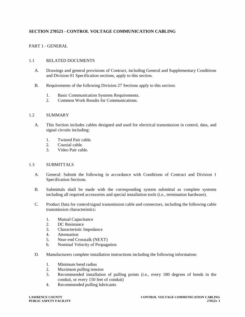
LAWRENCE COUNTY CONTROL VOLTAGE COMMUNICATION CABLING PUBLIC SAFETY FACILITY 270523- 1
SECTION 270523 - CONTROL VOLTAGE COMMUNICATION CABLING
PART 1 - GENERAL
1.1 RELATED DOCUMENTS
A. Drawings and general provisions of Contract, including General and Supplementary Conditions and Division 01 Specification sections, apply to this section.
B. Requirements of the following Division 27 Sections apply to this section:
1. Basic Communication Systems Requirements. 2. Common Work Results for Communications.
1.2 SUMMARY
A. This Section includes cables designed and used for electrical transmission in control, data, and signal circuits including:
1. Twisted Pair cable. 2. Coaxial cable. 3. Video Pair cable.
1.3 SUBMITTALS
A. General: Submit the following in accordance with Conditions of Contract and Division 1 Specification Sections.
B. Submittals shall be made with the corresponding system submittal as complete systems including all required accessories and special installation tools (i.e., termination hardware).
C. Product Data for control/signal transmission cable and connectors, including the following cable transmission characteristics:
1. Mutual Capacitance 2. DC Resistance 3. Characteristic Impedance 4. Attenuation 5. Near-end Crosstalk (NEXT) 6. Nominal Velocity of Propagation
D. Manufacturers complete installation instructions including the following information:
1. Minimum bend radius 2. Maximum pulling tension 3. Recommended installation of pulling points (i.e., every 180 degrees of bends in the
conduit, or every 150 feet of conduit) 4. Recommended pulling lubricants

CONTROL VOLTAGE COMMUNICATION CABLING LAWRENCE COUNTY 270523 - 2 PUBLIC SAFETY FACILITY
E. Product Certificates signed by the communication system manufacturers, certifying that the cables and termination hardware is suitable for the connected equipment and is certified to meet the standards described in Quality Assurance below.
F. Provide information regarding all termination, splitting and splicing connectors that will be required to complete this installation. This information shall include complete specifications and installation instructions including tightening requirements.
1.4 QUALITY ASSURANCE
A. Connected Equipment Manufacturer Approval: Where cables specified in this Section are used to provide signal paths for systems specified in other sections of these Specifications or for systems furnished under other contracts, obtain review of the cable characteristics and approval for use with the connected system equipment by the connected equipment manufacturers.
B. Electrical Component Standard: Provide work complying with applicable requirements of NFPA 70 "National Electrical Code."
C. Toxicity: Comply with applicable codes and regulations regarding toxicity of combustion products of materials used in control/signal transmission media.
D. UL Compliance: Comply with applicable requirements of UL Standard 910 "Test Method for Fire and Smoke Characteristics of Cables Used in Air Handling Spaces”. Provide products that are UL-listed and labeled for such use.
E. NEMA/ICEA Compliance: Comply with NEMA/ICEA Standard WC 41, "Coaxial Communication Cable."
F. Comply with the following Electronic Industries Association (EIA) and Telecommunications Industry Association (TIA) Standards:
1. EIA/TIA-568, "Commercial Building Telecommunications Wiring Standard" 2. EIA/TIA-569, "Commercial Building Standard for Telecommunications: Pathways and
Spaces" 3. EIA/TIA-570, "Residential and Light Commercial Telecommunications Wiring
Standard" 4. TIA/EIA-606, "The Administration Standard of the Telecommunications Infrastructure of
Commercial Building" 5. TSB-36, Technical Systems Bulletin, "Additional Cable Specifications for Unshielded
Twisted-Pair Connecting Hardware" 6. TSB-40, Technical Systems Bulletin, "Additional Transmission Specifications for
Unshielded Twisted-Pair Connecting Hardware" 7. EIA Standards EIA-230, "Color Marking of Thermoplastic Wire" and 8. EIA-258, "Semi-Flexible Air Dielectric Coaxial Cables and Connectors, 50 Ohms."
G. MIL-SPEC Compliance: Comply with MIL-C-3093, "Telephone Cable; Inside Distribution Wiring," MIL-C-55021, "Twisted-Pair and Triplet Cables; Hookups General Specifications," MIL-C-17/28, "Radio Frequency Flexible Coaxial Cables, 50 Ohms," and MIL-C-17/29, "Radio Frequency Flexible Coaxial Cables, 75 Ohms."

LAWRENCE COUNTY CONTROL VOLTAGE COMMUNICATION CABLING PUBLIC SAFETY FACILITY 270523- 3
1.5 DELIVERY, STORAGE, AND HANDLING
A. Deliver cable factory-packaged in containers or reels. Store in clean dry space and protect products from damaging fumes and traffic. Handle wire and cable carefully to avoid damage.
PART 2 - PRODUCTS
2.1 GENERAL
A. All cable installed in cable tray shall have a plenum rating.
2.2 MANUFACTURERS
A. Manufacturers: Subject to compliance with requirements, provide products of one of the following:
1. Cable:
a. AT&T Network Systems. b. The Siemon Company. c. Belden Div; Cooper Industries. d. Mohawk Wire & Cable Corp. e. West Penn Wire Corp. f. AMP
2. Connectors:
a. Thomas & Betts Corporation. b. 3M Company. c. Blounder Tongue d. Macom e. AMP
2.3 CONTROL/SIGNAL TRANSMISSION CABLE AND CONNECTORS
A. General: Provide control/signal transmission cable and connectors of manufacturer's standard materials as indicated on the drawings. All cables shall be designed and constructed as recommended by the system/equipment manufacturer, for a complete installation and for applications indicated.
2.4 APPLICATIONS
A. Install control/signal cables and connectors for the following systems:
1. Intercom networks. 2. Telephone systems. 3. Television systems.

CONTROL VOLTAGE COMMUNICATION CABLING LAWRENCE COUNTY 270523 - 4 PUBLIC SAFETY FACILITY
PART 3 - EXECUTION
3.1 INSTALLATION OF CONTROL/SIGNAL CABLE AND CONNECTORS
A. Conductors and cables for communications and signal systems shall be installed with a minimum 18" clearance from light fixtures, electrically operated equipment and all wiring operating at 120 or more volts.
B. Conductors and cables for communications and signal systems shall be type, size and insulation as recommended by manufacturer and approved. Install in accordance with manufacturer's written instructions and in compliance with NEC.
C. Coordinate installation with other Work.
D. Install without damaging conductors, shield, or jacket.
E. Do not either in handling or installation bend cable to smaller radii than minimum recommended by manufacturer.
F. Ensure that minimum manufacturer's recommended pulling tensions are not exceeded.
G. Pull conductors simultaneously where more than one is being installed in same raceway. Use pulling means, including fish tape, cable, rope, and basket weave wire/cable grips that will not damage media or raceway.
H. Use pulling compound or lubricant where necessary; compound used must be approved by the cable manufacturer.
I. Install exposed cable, parallel and perpendicular to surfaces or exposed structural members, and follow surface contours where possible.
J. No splices are allowed except at indicated splice points.
K. Use splice and tap connectors that are compatible with media material.
L. Tighten connectors and terminals, including screws and bolts in accordance with manufacturer's published instructions or torque tightening values.
3.2 COLOR CODING
A. All wiring for communications and signal systems shall be color coded, using black, red, white, yellow, blue and brown with tracers as required. There shall be no two wires of same trace color in the same cable. This color coding shall be consistent and continuous throughout the system.
3.3 TRAINING
A. Provide adequate length of conductors within electrical enclosures and at punch down blocks. Train the conductors to termination points with no excess.

LAWRENCE COUNTY CONTROL VOLTAGE COMMUNICATION CABLING PUBLIC SAFETY FACILITY 270523- 5
3.4 FIELD QUALITY CONTROL
A. Prior to usage, test wiring for electrical continuity and for short circuits. In addition, test the cable installation with a time domain reflectometer with strip chart recording capability and anomaly resolution to within one foot in runs up to 1,000 feet in length.
B. Test all cable segments for faulty connectors, splices, terminations, and the integrity of the cable and its component parts.
C. Documentation: Use the above time domain reflectometer to make a strip chart recording of transmission characteristics, wave form, and performance of all segments of the installation at the time of commissioning. Bind the recordings in a cable record book indexed for easy reference during future maintenance operations and turn book over to the Owner's authorized representative.
D. Replace malfunctioning transmission media with new materials, then retest until satisfactory performance is achieved.
3.5 COMMISSIONING
A. Subsequent to hookups of control/signal transmission media, operate control/signal systems to demonstrate proper functioning. Replace malfunctioning media with new materials, and then retest until satisfactory performance is achieved.
END OF SECTION 270523


LAWRENCE COUNTY GROUNDING PUBLIC SAFETY FACILITY 270526- 1
SECTION 270526 - GROUNDING
PART 1 - GENERAL
1.1 DESCRIPTION
A. This section specifies general grounding and bonding requirements of electrical and telecommunication installations for personnel safety, equipment operations and to provide a low impedance path for possible ground fault currents.
B. “Grounding electrode system” refers to all electrodes required by NEC, as well as including made, supplementary, lightning protection system and telecommunications system grounding electrodes in accordance with Motorola R-56 Standards.
C. The terms “connect” and “bond” are used interchangeably in this specification and have the same meaning.
1.2 RELATED WORK
A. Section 271100: Communications Equipment Room Fittings and Grounding
B. Section 270529: Hangers and Supports for Communication Systems
C. Section 270534: Boxes and Fittings
D. Section 260526: Grounding
1.3 SUBMITTALS
A. Submit in accordance with Section 01400 Submittal procedures
B. Shop Drawings:
1. Sufficient information, clearly presented, shall be included to determine compliance with drawings and specifications.
2. Include the location of system grounding electrode connections and the routing of aboveground and underground grounding electrode conductors.
C. Test Reports: Provide certified test reports of ground resistance.
D. Certifications: Two weeks prior to final inspection, submit four copies of the following to the Resident Engineer:
1. Certification that the materials and installation is in accordance with the drawings and specifications.
2. Certification, by the Contractor, that the complete installation has been properly installed and tested.
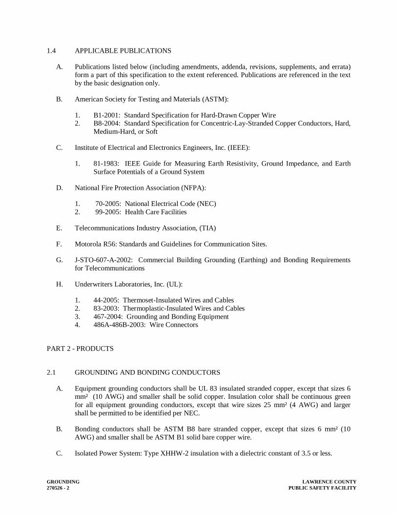
GROUNDING LAWRENCE COUNTY 270526 - 2 PUBLIC SAFETY FACILITY
1.4 APPLICABLE PUBLICATIONS
A. Publications listed below (including amendments, addenda, revisions, supplements, and errata) form a part of this specification to the extent referenced. Publications are referenced in the text by the basic designation only.
B. American Society for Testing and Materials (ASTM):
1. B1-2001: Standard Specification for Hard-Drawn Copper Wire 2. B8-2004: Standard Specification for Concentric-Lay-Stranded Copper Conductors, Hard,
Medium-Hard, or Soft
C. Institute of Electrical and Electronics Engineers, Inc. (IEEE):
1. 81-1983: IEEE Guide for Measuring Earth Resistivity, Ground Impedance, and Earth Surface Potentials of a Ground System
D. National Fire Protection Association (NFPA):
1. 70-2005: National Electrical Code (NEC) 2. 99-2005: Health Care Facilities
E. Telecommunications Industry Association, (TIA)
F. Motorola R56: Standards and Guidelines for Communication Sites.
G. J-STO-607-A-2002: Commercial Building Grounding (Earthing) and Bonding Requirements for Telecommunications
H. Underwriters Laboratories, Inc. (UL):
1. 44-2005: Thermoset-Insulated Wires and Cables 2. 83-2003: Thermoplastic-Insulated Wires and Cables 3. 467-2004: Grounding and Bonding Equipment 4. 486A-486B-2003: Wire Connectors
PART 2 - PRODUCTS
2.1 GROUNDING AND BONDING CONDUCTORS
A. Equipment grounding conductors shall be UL 83 insulated stranded copper, except that sizes 6 mm² (10 AWG) and smaller shall be solid copper. Insulation color shall be continuous green for all equipment grounding conductors, except that wire sizes 25 mm² (4 AWG) and larger shall be permitted to be identified per NEC.
B. Bonding conductors shall be ASTM B8 bare stranded copper, except that sizes 6 mm² (10 AWG) and smaller shall be ASTM B1 solid bare copper wire.
C. Isolated Power System: Type XHHW-2 insulation with a dielectric constant of 3.5 or less.

LAWRENCE COUNTY GROUNDING PUBLIC SAFETY FACILITY 270526- 3
D. Telecom System Grounding Riser Conductor: Telecommunications Grounding Riser shall be in accordance with J STO-607A. and Motorola R-56 Use a minimum 50mm² (2/0 AWG) insulated stranded copper grounding conductor unless indicated otherwise.
E. Electrical System Grounding: Conductor sizes shall not be less than what is shown on the drawings and not less than required by the NEC, whichever is greater.
2.2 SPLICES AND TERMINATION COMPONENTS
A. Components shall meet or exceed UL 467 and be clearly marked with the manufacturer, catalog number, and permitted conductor size(s).
2.3 TELECOMMUNICATION SYSTEM GROUND BUSBARS (PROVIDED BY DIVISION 26 CONTRACTOR
A. Provide solid copper bus bar, pre-drilled from two-hole lug connections with a minimum thickness of 6 mm (1/4 inch) for wall and backboard mounting using standard insulators sized as follows:
1. Room Signal Grounding: 300 mm x 100 mm (12 inches x 4 inch). 2. Master Signal Ground: 600 mm x 100 mm (24 inches x 4 inch).
2.4 GROUND CONNECTIONS
A. Below Grade: Exothermic-welded type connectors.
B. Above Grade:
1. Bonding Jumpers: irreversible compression type connectors, using zinc-plated fasteners and external tooth lock washers.
2. Ground Bus bars: Two-hole irreversible compression type lugs using tin-plated copper or copper alloy bolts and nuts.
3. Rack and Cabinet Ground Bars: one-hole irreversible compression-type lugs using zinc-plated or copper alloy fasteners.
C. Cable Shields: Make ground connections to multipair communications cables with metallic shields using shield bonding connectors with screw stud connection.
2.5 EQUIPMENT RACK AND CABINET GROUND BARS
A. Provide solid copper ground bars designed for mounting on the framework of open or cabinet-enclosed equipment racks with minimum dimensions of 4 mm thick by 19 mm wide (3/8 inch x ¾ inch).

GROUNDING LAWRENCE COUNTY 270526 - 4 PUBLIC SAFETY FACILITY
2.6 GROUND TERMINAL BLOCKS
A. See drawings.
2.7 SPLICE CASE GROUND ACCESSORIES
A. Splice case grounding and bonding accessories shall be supplied by the splice case manufacturer when available. Otherwise, use 16 mm² (6 AWG) insulated ground wire with shield bonding connectors.
2.8 LIGHTNING ARRESTORS
A. Lightning protectors shall be supplied on all OSP cables as specified by the manufacturer. At minimum, use 16 mm² (6 AWG) insulated ground wire with shield bonding connectors. Install in accordance with the best practice requirements of Motorola R-56.
PART 3 - EXECUTION
3.1 GENERAL
A. Ground in accordance with the NEC, as shown on drawings, and as hereinafter specified.
B. System Grounding:
1. Secondary service neutrals: Ground at the supply side of the secondary disconnecting means and at the related transformers.
2. Separately derived systems (transformers downstream from the service entrance): Ground the secondary neutral.
3. Isolation transformers and isolated power systems shall not be system grounded.
C. Equipment Grounding: Metallic structures (including ductwork and building steel), enclosures, raceways, junction boxes, outlet boxes, cabinets, machine frames, and other conductive items in close proximity with electrical circuits shall be bonded and grounded in accordance with the best practice requirements of Motorola R-56.
3.2 INACCESSIBLE GROUNDING CONNECTIONS
A. Make grounding connections, which are buried or otherwise normally inaccessible (except connections for which periodic testing access is required) by exothermic weld.

LAWRENCE COUNTY GROUNDING PUBLIC SAFETY FACILITY 270526- 5
3.3 CORROSION INHIBITORS
A. When making ground and ground bonding connections, apply a corrosion inhibitor to all contact surfaces. Use corrosion inhibitor appropriate for protecting a connection between the metals used.
3.4 TELECOMMUNICATIONS SYSTEM
A. Bond telecommunications system grounding equipment to the single point facility ground system.
B. Furnish and install all wire and hardware required to properly ground, bond and connect communications raceway, cable tray, metallic cable shields, and equipment to the single point facility ground system.
C. Ground bonding jumpers shall be continuous with no splices. Use the shortest length of bonding jumper possible.
D. Provide ground paths that are permanent and continuous with a resistance of 1 ohm or less from raceway, cable tray, and equipment connections to the building grounding electrode. The resistance across individual bonding connections shall be 10 milli ohms or less.
E. Below-Grade Grounding Connections: When making exothermic welds, wire brush or file the point of contact to a bare metal surface. Use exothermic welding cartridges and molds in accordance with the manufacturer’s recommendations. After welds have been made and cooled, brush slag from the weld area and thoroughly cleaned the joint area. Notify the Resident Engineer prior to backfilling any ground connections.
F. Above-Grade Grounding Connections: When making bolted or screwed connections to attach bonding jumpers, remove paint to expose the entire contact surface by grinding where necessary; thoroughly clean all connector, plate and other contact surfaces; and apply an appropriate corrosion inhibitor to all surfaces before joining.
G. Bonding Jumpers:
1. Use insulated ground wire of the size and type shown on the Drawings or use a minimum of 16 mm² (6 AWG) insulated copper wire.
2. Assemble bonding jumpers using insulated ground wire terminated with irreversible compression connectors.
3. Use irreversible compression connectors of proper size for conductors specified. Use connector manufacturer’s compression tool.
H. Bonding Jumper Fasteners:
1. Conduit: Fasten bonding jumpers using screw lugs on grounding bushings or conduit strut clamps, Where appropriate, use zinc-plated external tooth lock washers.

GROUNDING LAWRENCE COUNTY 270526 - 6 PUBLIC SAFETY FACILITY
2. Wire way and Cable Tray: Fasten bonding jumpers using zinc-plated bolts, external tooth lock washers, and nuts. Install protective cover, e.g., zinc-plated acorn nuts on any bolts extending into wire way or cable tray to prevent cable damage.
3. Ground Plates and Bus bars: Fasten bonding jumpers using two-hole compression lugs. Use tin-plated copper or copper alloy bolts, external tooth lock washers, and nuts.
4. Unistrut and Raised Floor Stringers: Fasten bonding jumpers using zinc-plated, self-drill screws and external tooth lock washers.
3.5 COMMUNICATION ROOM GROUNDING
A. Telecommunications Ground Bus bars:
1. Provide communications room telecommunications ground bus bar hardware at 950 mm (18 inches) at locations indicated on the Drawings.
2. Connect the telecommunications room ground bus bars to other room grounding bus bars as indicated on the Grounding Riser diagram.
B. Telephone-Type Cable Rack Systems: Make ground connections by installing the following bonding jumpers:
1. Each rack shall be provided with a rack grounding bar and bonded back to the main room grounding bar.
2. Install a 16 mm² (6 AWG) bonding between the telecommunications ground bus bar and the nearest access to the aluminum pan installed on the cable rack.
3. Use 16 mm² (6 AWG) bonding jumpers across aluminum pan junctions.
C. Self-Supporting and Cabinet-Mounted Equipment Rack Ground Bars:
1. When ground bars are provided at the rear of lineup of bolted together equipment racks, bond the copper ground bars together using solid copper splice plates supplied by the ground bar manufacturer.
2. Bond together nonadjacent ground bars on equipment racks and cabinets with 16 mm² (6 AWG) insulated copper wire bonding jumpers attached at each end with compression-type connectors and mounting bolts.
3. Provide a 16 mm² (6 AWG) bonding jumper between the racks, cabinets, and/raised floor pedestals to the main data room ground bus bar.
D. Other Communication Room Ground Systems: Ground all metallic conduit, wire ways, and other metallic equipment located away from equipment racks or cabinets to the main data room grounding bar.

LAWRENCE COUNTY GROUNDING PUBLIC SAFETY FACILITY 270526- 7
3.6 COMMUNICATIONS cable grounding
A. Bond all metallic cable sheaths in multipair communications cables together at each splicing and/or terminating location to provide 100 percent metallic sheath continuity throughout the communications distribution system. Bond to main grounding bar.
1. At terminal points, install a cable shield bonding connector provide a screw stud connection for ground wire. Use a bonding jumper to connect the cable shield connector to an appropriate ground source like the rack or cabinet ground bar.
2. Bond all metallic cable shields together within splice closures using cable shield bonding connectors or the splice case grounding and bonding accessories provided by the splice case manufacturer. When an external ground connection is provided as part of splice closure, connect to an approved ground source and all other metallic components and equipment at that location.
3.7 COMMUNICATIONS CABLE TRAY SYSTEMS
A. Bond the metallic structures of one cable tray in each tray run following the same path to provide 100 percent electrical continuity throughout this cable tray systems as follows:
1. Splice plates provided by the cable tray manufacturer can be used for providing a ground bonding connection between cable tray sections when the resistance across a bolted connection is 10 milliohms or less. The contractor shall verify this loss by testing across one slice plate connection in the presence of the Engineer.
2. Install a 16 mm² (6 AWG) bonding jumper across each cable tray splice or junction where splice plates cannot be used.
3.8 WIREWAY GROUNDING
A. Ground and Bond Metallic Wire way Systems as follows:
1. Bond the metallic structures of wire way to provide 100 percent electrical continuity throughout the wire way system by connecting a 16 mm² (6 AWG) bonding jumper at all intermediate metallic enclosures and across all section junctions.
2. Install insulated 16 mm² (6 AWG) bonding jumpers between the wire way system bonded as required in paragraph 1 above, and the closest building ground at each end and approximately every 16 meters (50 feet).
3. Use insulated 16 mm² (6 AWG) bonding jumpers to ground or bond metallic wire way at each end at all intermediate metallic enclosures and cross all section junctions.
4. Use insulated 16 mm² (6 AWG) bonding jumpers to ground cable tray to column-mounted building ground plates (pads) at each end and approximately every 15 meters.

GROUNDING LAWRENCE COUNTY 270526 - 8 PUBLIC SAFETY FACILITY
3.9 COMMUNCIATIONS RACEWAY GROUNDING
A. Conduit: Use insulated 16 mm² (6 AWG) bonding jumpers to ground metallic conduit at each end and to bond at all intermediate metallic enclosures.
B. Wire way: Use insulated 16 mm² (6 AWG) bonding jumpers to ground or bond metallic wire way at each end at all intermediate metallic enclosures and across all section junctions.
C. Cable Tray Systems: Use insulated 16 mm² (6 AWG) bonding jumpers to ground cable tray to bond all tray sections and to cable tray grounding conductor.
3.10 GROUND RESISTANCE
A. Grounding system resistance to ground shall not exceed 5 ohms. Make necessary modifications or additions to the grounding electrode system for compliance without additional cost to the Government. Final tests shall assure that this requirement is met.
B. Resistance of the grounding electrode system shall be measured using a four-terminal fall-of-potential method as defined in IEEE 81. Ground resistance measurements shall be made before the electrical distribution system is energized and shall be made in normally dry conditions not less than 48 hours after the last rainfall. Resistance measurements of separate grounding electrode systems shall be made before the systems are bonded together below grade. The combined resistance of separate systems may be used to meet the required resistance, but the specified number of electrodes must still be provided.
C. Services at power company interface points shall comply with the power company ground resistance requirements.
D. Below-grade connections shall be visually inspected by the Resident Engineer prior to backfilling. The Contractor shall notify the Resident Engineer 24 hours before the connections are ready for inspection.
3.11 GROUND ROD INSTALLATION (Telephone System if required)
A. Drive each rod vertically in the earth, not less than 3000 mm (10 feet) in depth.
B. Where permanently concealed ground connections are required, make the connections by the exothermic process to form solid metal joints. Make accessible ground connections with mechanical pressure type ground connectors.
C. Where rock prevents the driving of vertical ground rods, install angled ground rods or grounding electrodes in horizontal trenches to achieve the specified resistance.

LAWRENCE COUNTY GROUNDING PUBLIC SAFETY FACILITY 270526- 9
3.12 GROUNDING FOR RF/EMI CONTROL
A. Install bonding jumpers to bond all conduit, cable trays, sleeves, and equipment for low voltage signaling and data communications circuits. Bonding jumpers shall consist of 100 mm (4 inches) wide copper strip or two 6 mm² (10 AWG) copper conductors spaced minimum 100 mm (4 inches) apart. Use 16 mm² (6 AWG) copper where exposed and subject to damage.
B. Comply with the following when shielded cable is used for data circuits.
1. Shields shall be continuous throughout each circuit. 2. Connect shield drain wires together at each shielded patch panel. 3. Do not connect shields from different circuits together. 4. Shield shall be connected at one end only. Connect shield to signal reference at the
shielded patch panel. 5. Bond shielded patch panel to the rack ground.
END OF SECTION 270526


LAWRENCE COUNTY HANGERS AND SUPPORTS FOR COMMUNICATION SYSTEMS PUBLIC SAFETY FACILITY 270529- 1
SECTION 270529 - HANGERS AND SUPPORTS FOR COMMUNICATION SYSTEMS
PART 1 - GENERAL
1.1 RELATED DOCUMENTS
A. Drawings and general provisions of Contract, including General and Supplementary Conditions and Division 01 Specification Sections, apply to this Section.
B. Requirements of the following Division 27 Sections apply to this section:
1. Division 27 Section 27 0100 “Basic Communication Systems Requirements”. 2. Division 27 Section 27 0500 “Common Work Results for Communications”.
1.2 SUMMARY
A. This Section includes secure support from the building structure for communication items by means of hangers, supports, anchors, sleeves, inserts, seals, and associated fastenings.
B. All supports shall utilize threaded fasteners for all connections/attachments. The use of clips or clip-on type supports is not acceptable.
C. Types of supports, anchors, sleeves, and seals specified in this section include the following:
1. Clevis hangers 2. Riser clamps 3. C-clamps 4. I-beam clamps 5. Conduit straps 6. Round steel rods 7. Lead expansion anchors 8. Toggle bolts 9. Wall and floor seals
D. Supports, anchors, sleeves, and seals furnished as part of factory-fabricated equipment, are specified as part of that equipment assembly in other Division-27 sections.
1.3 SUBMITTALS
A. General: Submit the following in accordance with Conditions of Contract and Division 01 Specification Sections.
B. Product Data: Submit manufacturer's data on supporting devices including catalog cuts, specifications, and installation instructions, for each type of support, anchor, sleeve and seal.
C. Shop Drawings: Submit dimensioned drawings of fabricated products, indicating details of fabrication and materials.

HANGERS AND SUPPORTS FOR COMMUNICATION SYSTEMS LAWRENCE COUNTY 270529 - 2 PUBLIC SAFETY FACILITY
1.4 QUALITY ASSURANCE
A. Manufacturers: Firms regularly engaged in manufacture of supporting devices, of types, sizes, and ratings required, whose products have been in satisfactory use in similar service for not less than 3 years.
B. Installer's Qualifications: Firm with at least 3 years of successful installation experience with projects utilizing supporting device work similar to that required for this project.
C. NEC Compliance: Comply with NEC requirements as applicable to construction and installation of supporting devices.
D. MSS Compliance: Comply with applicable MSS standard requirements pertaining to fabrication and installation practices for pipe hangers and supports.
E. NECA Compliance: Comply with National Electrical Contractors Association's "Standard of Installation" pertaining to anchors, fasteners, hangers, supports, and equipment mounting.
F. UL Compliance: Provide components that are UL listed and labeled.
G. FS Compliance: Comply with Federal Specification FF-S-760 pertaining to retaining straps for conduit, pipe, and cable.
H. Components shall be listed and labeled by ETL, CSA, or other approved, nationally recognized testing and listing agency that provides third-party certification follow-up services.
PART 2 - PRODUCTS
2.1 MANUFACTURERS
A. Manufacturers: Subject to compliance with requirements, provide products by the following:
1. Slotted Metal Angle and U-Channel Systems:
a. Allied Tube & Conduit b. American Electric c. B-Line Systems, Inc. d. Cinch Clamp Co., Inc. e. Elcen Metal Products Co. f. Greenfield Mfg. Co., Inc. g. Haydon Corp. h. Kin-Line, Inc. i. Midland-Ross Corp. j. Power-Strut Div; Van Huffel Tube Corp. k. Unistrut Diversified Products
2. Anchors:
a. Abbeon Cal Inc.
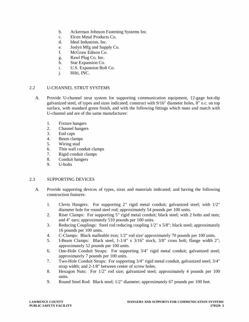
LAWRENCE COUNTY HANGERS AND SUPPORTS FOR COMMUNICATION SYSTEMS PUBLIC SAFETY FACILITY 270529- 3
b. Ackerman Johnson Fastening Systems Inc. c. Elcen Metal Products Co. d. Ideal Industries, Inc. e. Joslyn Mfg and Supply Co. f. McGraw Edison Co. g. Rawl Plug Co. Inc. h. Star Expansion Co. i. U.S. Expansion Bolt Co. j. Hilti, INC.
2.2 U-CHANNEL STRUT SYSTEMS
A. Provide U-channel strut system for supporting communication equipment, 12-gage hot-dip galvanized steel, of types and sizes indicated; construct with 9/16" diameter holes, 8" o.c. on top surface, with standard green finish, and with the following fittings which mate and match with U-channel and are of the same manufacturer:
1. Fixture hangers 2. Channel hangers 3. End caps 4. Beam clamps 5. Wiring stud 6. Thin wall conduit clamps 7. Rigid conduit clamps 8. Conduit hangers 9. U-bolts
2.3 SUPPORTING DEVICES
A. Provide supporting devices of types, sizes and materials indicated; and having the following construction features:
1. Clevis Hangers: For supporting 2" rigid metal conduit; galvanized steel; with 1/2" diameter hole for round steel rod; approximately 54 pounds per 100 units.
2. Riser Clamps: For supporting 5" rigid metal conduit; black steel; with 2 bolts and nuts; and 4" ears; approximately 510 pounds per 100 units.
3. Reducing Couplings: Steel rod reducing coupling 1/2" x 5/8"; black steel; approximately 16 pounds per 100 units.
4. C-Clamps: Black malleable iron; 1/2" rod size' approximately 70 pounds per 100 units. 5. I-Beam Clamps: Black steel, 1-1/4" x 3/16" stock, 3/8" cross bolt; flange width 2";
approximately 52 pounds per 100 units. 6. One-Hole Conduit Straps: For supporting 3/4" rigid metal conduit; galvanized steel;
approximately 7 pounds per 100 units. 7. Two-Hole Conduit Straps: For supporting 3/4" rigid metal conduit, galvanized steel; 3/4"
strap width; and 2-1/8" between center of screw holes. 8. Hexagon Nuts: For 1/2" rod size; galvanized steel; approximately 4 pounds per 100
units. 9. Round Steel Rod: Black steel; 1/2" diameter; approximately 67 pounds per 100 feet.

HANGERS AND SUPPORTS FOR COMMUNICATION SYSTEMS LAWRENCE COUNTY 270529 - 4 PUBLIC SAFETY FACILITY
10. Offset Conduit Clamps: For supporting 2" rigid metal conduit; black steel; approximately 200 pounds per 100 units.
2.4 ANCHORS
A. Provide anchors of types, sizes and materials indicated; and having the following construction features:
1. Lead Expansion Anchors: 1/2", approximately 38 pounds per 100 units. 2. Toggle Bolts: Springhead; 3/16" x 4"; approximately 5 pounds per 100 units.
2.5 SLEEVES AND SEALS
A. Provide sleeves and seals, of types, sizes and materials indicated, with the following construction features:
1. Wall and Floor Seals: Provide factory-assembled watertight wall and floor seals, of types and sizes indicated; suitable for sealing around conduit, pipe, or tubing passing through concrete floors and walls. Construct seals with steel sleeves, malleable iron body, neoprene sealing grommets and rings, metal pressure rings, pressure clamps, and cap screws.
2.6 COATINGS
A. Coating: Supports, support hardware, and fasteners shall be protected with zinc coating or with treatment of equivalent corrosion resistance using approved alternative treatment, finish, or inherent material characteristic. Products for use outdoors shall be hot-dip galvanized.
2.7 FABRICATED SUPPORTING DEVICES
A. General: Shop or field-fabricated supports or manufactured supports assembled from U-channel components.
B. Steel Brackets: Fabricated of angles, channels, and other standard structural shapes. Connect with welds and machine bolts to form rigid supports.
PART 3 - EXECUTION
3.1 GENERAL
A. Provide supporting devices that comply with manufacturer's standard materials, design and construction in accordance with published product information, and as required for complete installation; and as herein specified. Where more than one type of supporting device meets indicated requirements, selection is Contractor’s option.

LAWRENCE COUNTY HANGERS AND SUPPORTS FOR COMMUNICATION SYSTEMS PUBLIC SAFETY FACILITY 270529- 5
B. Install hangers, anchors, sleeves and seals as indicated, in accordance with manufacturer's written instructions and with recognized industry practices to insure supporting devices comply with requirements. Comply with requirements of NECA and NEC for installations of supporting devices.
C. Coordinate with the building structural system and electrical work, including raceway and wiring work, as necessary to interface installation of supporting devices with other work.
D. Do not fasten supports to pipes, ducts, mechanical equipment, and conduit.
E. Obtain approval from the Architect before drilling or cutting structural members.
F. Install surface-mounted cabinets with minimum of four anchors.
3.2 MISCELLANEOUS SUPPORTS
A. Support miscellaneous components as required to produce the same structural safety factors as specified for raceway supports. Install metal channel racks for mounting cabinets, boxes, and other devices.
3.3 FASTENING
A. Unless otherwise indicated, fasten items and their supporting hardware securely to the building structure, including but not limited to conduits, raceways, cables, cable trays, cabinets, boxes, and control components in accordance with the following:
1. Fasten by means of wood screws or screw-type nails on wood, toggle bolts on hollow masonry units, concrete inserts, or expansion bolts on concrete or solid masonry, and machine screws, welded threaded studs, or spring-tension clamps on steel. Threaded studs driven by a powder charge and provided with lock washers and nuts may be used instead of expansion bolts and machine or wood screws. Do not weld conduit, pipe straps, or items other than threaded studs to steel structures. In partitions of light steel construction, use sheet metal screws.
2. Holes cut into reinforced concrete beams or in concrete shall not cut reinforcing bars. If the Contractor cuts into any reinforcing bars, stop work and notify the Architect immediately. Fill holes that are not used.
3. Ensure that the load applied to any fastener does not exceed 25 percent of the proof test load. Use vibration- and shock-resistant fasteners for attachments to concrete slabs.
3.4 TESTS
A. Test pull-out resistance of one of each type, size, and anchorage material for the following fastener types:
1. Expansion anchors. 2. Toggle bolts. 3. Powder-driven threaded studs.

HANGERS AND SUPPORTS FOR COMMUNICATION SYSTEMS LAWRENCE COUNTY 270529 - 6 PUBLIC SAFETY FACILITY
B. Provide all jacks, jigs, fixtures, and calibrated indicating scales required for reliable testing. Obtain the structural Engineer's approval before transmitting loads to the structure. Test to 90 percent of rated proof load for fastener. If fastening fails test, revise all similar fastener installations and retest until satisfactory results are achieved.
END OF SECTION 270529

LAWRENCE COUNTY BOXES AND FITTINGS PUBLIC SAFETY FACILITY 270534- 1
SECTION 270534 - BOXES AND FITTINGS
PART 1 - GENERAL
1.1 RELATED DOCUMENTS
A. Drawings and general provisions of Contract, including General and Supplementary Conditions and Division 01 Specification Sections, apply to this Section.
B. Requirements of the following Division 27 Sections apply to this section:
1. Division 27 Section 27 0100 “Basic Communication Systems Requirements”. 2. Division 27 Section 27 0500 “Common Work Results for Communications”.
1.2 SUMMARY
A. This section includes boxes and fittings for communication installations and certain types of electrical fittings not covered in other sections. Types of products specified in this Section include:
1. Outlet and device boxes.
B. In general, all outlet boxes, conduit and raceway shall be provided by the Division 26 Electrical Contractor. The Communication Contractor shall provide any miscellaneous outlet boxes, conduit and raceway at the communication system racks only. The outlet boxes, conduit and raceway provided by the Communication Contractor shall supplement that provided by the EC in order to accomplish a neat and orderly installation.
1.3 SUBMITTALS
A. General: Submit the following in accordance with Conditions of Contract and Division 01 Specification Sections:
1.4 QUALITY ASSURANCE
A. Nationally Recognized Testing Laboratory Listing and Labeling (NRTL): Items provided under this section shall be listed and labeled by a NRTL. The term "NRTL" shall be as defined in OSHA Regulation 1910.7.
B. National Electrical Code Compliance: Components and installation shall comply with NFPA 70 "National Electrical Code."
C. UL Compliance: Comply with applicable requirements of UL 50, UL 514 Series, and UL 886 pertaining to electrical boxes and fittings. Provide electrical boxes and fittings that are UL listed and labeled.

BOXES AND FITTINGS LAWRENCE COUNTY 270534 - 2 PUBLIC SAFETY FACILITY
D. NEMA Compliance: Comply with applicable requirements of NEMA Standards/Pub No.'s 0S1, 0S2 and Pub 250 pertaining to outlet and device boxes, covers and box supports.
E. Federal Specification Compliance: Comply with applicable requirements of FS W-C-586, "Electrical Cast Metal Conduit Outlet Boxes, Bodies, and Entrance Caps".
PART 2 - PRODUCTS
2.1 BOXES AND FITTINGS, GENERAL
A. Provide electrical boxes, and fittings of indicated types, sizes, and NEMA enclosure classes. Where not indicated, provide units of types, sizes, and classes appropriate for the use and location. Provide all items complete with covers and accessories required for the intended use. Provide gaskets for units in damp or wet locations.
2.2 OUTLET AND DEVICE BOXES
A. Outlet Boxes: Provide galvanized flat rolled sheet steel outlet wiring boxes, of shapes, cubic inch capacities, and sizes, including box depths as indicated, suitable for installation at respective locations. Provide outlet boxes with mounting holes, and with cable and conduit-size knockout openings in bottom and sides. Provide boxes with threaded screw holes, with corrosion-resistant cover and grounding screws for fastening surface and device type box covers, and for equipment type grounding.
B. Outlet Box Accessories: Provide outlet box accessories as required for each installation, including box supports, mounting ears and brackets, wallboard hangers, box extension rings, fixture studs, cable clamps and metal straps for supporting outlet boxes, which are compatible with outlet boxes being used to fulfill installation requirements for individual wiring situations. Choice of accessories is Contractor's code-compliance option.
C. Manufacturers: Subject to compliance with requirements, provide interior outlet boxes of one of the following:
1. American Electric 2. Appleton Electric; Emerson Electric Co. 3. Bell Electric; Square D Company 4. Eagle Electric Mfg. Co., Inc. 5. Midland-Ross Corporation 6. OZ/Gedney; General Signal Co. 7. Thepitt 8. Hubbell, Inc. 9. Thomas & Betts Co. 10. Pass and Seymour, Inc. 11. Legrand

LAWRENCE COUNTY BOXES AND FITTINGS PUBLIC SAFETY FACILITY 270534- 3
2.3 BUSHINGS, KNOCKOUT CLOSURES, AND LOCKNUTS
A. Bushings, Knockout Closures, and Locknuts: Provide corrosion-resistant box knockout closures, conduit locknuts, malleable iron conduit bushings, offset connectors of types and sizes to suit respective installation requirements and applications.
B. Manufacturers: Subject to compliance with requirements, provide bushings, knockout closures, locknuts and connectors of one of the following:
1. Adalet-PLM Div; Scott Fetzer Co. 2. AMP, Inc. 3. Arrow-Hart Div; Crouse-Hinds Co. 4. Appleton Electric Co.; Emerson Electric Co. 5. Midland-Ross Corp. 6. Midwest Electric; Cooper Industries Inc. 7. OZ/Gedney Co.; General Signal Co. 8. RACO Div; Harvey Hubbell Inc. 9. Thomas & Betts Co., Inc.
PART 3 - EXECUTION
3.1 INSTALLATION
A. General: The Electrical Contractor shall provide all junction boxes for communication devices in walls and floors. The Communication Contractor shall provide any miscellaneous junction boxes required for a neat and complete installation.
B. Install electrical boxes and fittings as indicated, in accordance with manufacturer's written instructions, applicable requirements of NEC and NECA's "Standard of Installation" and in accordance with recognized industry practices to fulfill project requirements.
C. Locations:
1. Install items where required to suit code requirements and installation conditions. 2. Locate and install boxes to allow access. Where installation is otherwise inaccessible,
coordinate locations and sizes and provide required access doors. 3. Locate and install to maintain headroom and to present a neat appearance. 4. Position recessed outlet boxes accurately to allow for surface finish thickness.
D. Avoid using round boxes where conduit must enter box through side of box, which would result in difficult and insecure connections when fastened with locknut or busing on rounded surfaces.
1. Provide electrical connections for installed boxes. 2. Subsequent to installation of boxes, protect boxes from construction debris and damage. 3. Cap unused knockout holes where blanks have been removed and plug unused conduit
hubs. 4. Support and fasten items securely in accordance with Division 27 Section "Hangers and
Supports for Communication Systems." 5. Sizes shall be adequate to meet NEC volume requirements, but in no case smaller than
sizes indicated.

BOXES AND FITTINGS LAWRENCE COUNTY 270534 - 4 PUBLIC SAFETY FACILITY
6. Remove sharp edges where they may come in contact with wiring or personnel.
3.2 GROUNDING
A. Electrically ground metallic boxes and enclosures. Where wiring to item includes a grounding conductor, provide a grounding terminal in the interior of the box or enclosure.
3.3 CLEANING AND FINISH REPAIR
A. Upon completion of installation, inspect components. Remove burrs, dirt, and construction debris and repair damaged finish including chips, scratches, abrasions and weld marks.
B. Galvanized Finish: Repair damage using a zinc-rich paint recommended by the manufacturer.
C. Painted Finish: Repair damage using matching corrosion inhibiting touch-up coating recommended by the manufacturer.
END OF SECTION 270534

LAWRENCE COUNTY IDENTIFICATION FOR COMMUNICATION SYSTEMS PUBLIC SAFETY FACILITY 270553- 1
SECTION 270553 – IDENTIFICATION FOR COMMUNICATION SYSTEMS
PART 1 - GENERAL
1.1 RELATED DOCUMENTS
A. Drawings and general provisions of Contract, including General and Supplementary Conditions and Division 01 Specification Sections, apply to this Section.
B. Requirements of the following Division 27 Sections apply to this section:
1. Division 27 Section 27 0100 “Basic Communication System Requirements”. 2. Division 27 Section 27 0500 “Common Work Results for Communications”.
1.2 SUMMARY
A. This Section includes identification of communication cables, equipment, and installations. It includes requirements for identification components including but not limited to the following:
1. Identification labeling for cables. 2. Operational instruction signs. 3. Equipment labels and signs.
B. Refer to Division-01 General Requirements Section, "Identification Systems" for equipment and system nameplates, and performance data; not work of this section.
C. Refer to other Division 27 sections for additional specific identification requirements associated with specific items.
D. Arrange meeting with owner to determine specific labeling scheme prior t submittals.
1.3 SUBMITTALS
A. General: Submit the following in accordance with Conditions of Contract and Division 01 Specification Sections.
B. Product Data: Manufacturer's data for each type of product specified.
C. Schedule of identification nomenclature to be used for identification signs and labels.
D. Samples of each color, lettering style, and other graphic representation required for identification materials; samples of labels and signs.
IDENTIFICATION FOR COMMUNICATION SYSTEMS LAWRENCE COUNTY 270553 - 2 PUBLIC SAFETY FACILITY
1.4 QUALITY ASSURANCE
A. Manufacturers: Firms regularly engaged in manufacture of electrical or communication identification products of types required, whose products have been in satisfactory use in similar service for not less than 3 years.
B. Installer's Qualifications: Firm with at least 3 years of successful installation experience with projects utilizing identification work similar to that required for this project.
C. NEC Compliance: Comply with NEC as applicable to installation of identifying labels and markers for wiring and equipment.
D. UL Compliance: Comply with applicable requirements of UL Standard 969, "Marking and Labeling Systems", pertaining to identification systems.
E. ANSI Compliance: Comply with applicable requirements of ANSI Standard A13.1 "Scheme for the Identification of Piping Systems", with regard to type and size of lettering for cable labels.
F. NEMA Compliance: Comply with applicable requirements of NEMA Standard No's. WC-1 and WC-2 pertaining to identification of control conductors.
PART 2 - PRODUCTS
2.1 MANUFACTURERS
A. Manufacturers: Subject to compliance with requirements, provide products by the following (for each type marker):
1. Ideal Industries, Inc. 2. Panduit Corp. 3. Seton Name Plate Co.
2.2 ELECTRICAL IDENTIFICATION PRODUCTS
A. Adhesive Marking Labels for Raceway and Metal-clad Cable: Pre-printed, flexible, self-adhesive labels with legend indicating voltage and service (Communications, Control, etc.).
1. Label Size: as follows:
a. Raceways 1-Inch and Smaller: 1-1/8 inches high by 4 inches long. b. Raceways Larger than 1-Inch: 1-1/8 inches high by 8 inches long.
B. Cable Identification Bands:
1. General: Provide manufacturer's standard plastic wrap-around cable markers, of size required for proper application, and numbered to show cable identification.
C. Equipment Labels

LAWRENCE COUNTY IDENTIFICATION FOR COMMUNICATION SYSTEMS PUBLIC SAFETY FACILITY 270553- 3
1. General: Provide engraving stock melamine plastic laminate, complying with FS L-P-387, in sizes and thick nesses indicated, engraved with engraver's standard letter style of the sizes and wording indicated, black face and white core plies (letter color) except as otherwise indicated, punched for mechanical fastening.
2. Thickness: 1/16", for units up to 20 sq. in. or 8" length; 1/8" for larger units.
D. Lettering and Graphics
1. General: Coordinate names, abbreviations and other designations used in identification work, with corresponding designations shown, specified or scheduled. Provide numbers, lettering and wording as indicated or, if not otherwise indicated, as recommended by manufacturers or as required for proper identification and operation/maintenance of the systems and equipment. Comply with ANSI A13.1 pertaining to minimum sizes for letters and numbers.
E. Fasteners for Plastic-Laminated and Metal Signs
1. Self-tapping stainless steel screws or number 10/32 stainless steel machine screws with nuts and flat and lock washers. Exception: Where specifically approved contact type permanent adhesive may be used in areas where screws cannot or should not penetrate substrate.
PART 3 - EXECUTION
3.1 GENERAL
A. Except as otherwise indicated, provide manufacturer's standard products of categories and types required for each application. Where more than single type is specified for an application, selection is Installer's option, but provide single selection for each application.
B. Lettering and Graphics: Coordinate names, abbreviations, colors, and other designations used in identification work with corresponding designations specified or indicated. Install numbers, lettering, and colors as approved in submittals and as required by code.
C. Install identification devices as indicated, in accordance with manufacturer's written instructions and requirements of NEC.
D. Sequence of Work: Where identification is to be applied to surfaces that require finish, install identification after completion of finish work.
E. Regulations: Comply with governing regulations and requests of governing authorities for the identification of work.
3.2 CABLE IDENTIFICATION
A. Apply cable identification on each voice/data cable in each rack/cabinet and for all sound system cabling and cable television cabling. Match identification with marking system used on

IDENTIFICATION FOR COMMUNICATION SYSTEMS LAWRENCE COUNTY 270553 - 4 PUBLIC SAFETY FACILITY
shop drawings, contract documents, and similar previously established identification for project's work.
B. Each cable shall be marked at both ends. For local area network, each patch cable or cross connect cable shall be marked at both ends.
C. The Contractor shall review the identification scheme with the Owner prior to commencing work. The identification scheme shown on the floor plans is based on architectural room numbers and may not necessarily be the final post-construction room numbers.
3.3 OUTLET LABEL
A. For the tele/data cabling, provide labels for each data outlet, using faceplate manufacturer’s standard label holder and recommendations of owner selected labeling scheme.
END OF SECTION 270553

LAWRENCE COUNTY COMMISSIONING OF COMMUNICATIONS PUBLIC SAFETY FACILITY 270800- 1
SECTION 270800 - COMMISSIONING OF COMMUNICATIONS
PART 1 - GENERAL
1.1 SCOPE OF WORK
A. Section Includes: Testing of Telecommunications Backbone and Horizontal Cabling subsystems.
B. Related Sections
1. Consult all other Sections and Divisions, determine the extent and character of related work and properly coordinate work specified herein with that specified elsewhere to completely test a complete and operable system.
2. Section 27 0100: Basic Telecommunications Requirements 3. Section 27 1300: Communications Backbone Cabling 4. Section 27 1500: Copper Cabling Systems
C. Products Furnished and Installed Under Other Sections:
1. Telecommunications Cabling
1.2 REFERENCES
A. Additional references:
1. TIA/EIA-526-14 (“OFSTP-14”) Optical Power Loss Measurements of Installed Multimode Fiber Cable Plant.
2. TIA/EIA-526-7 (“OFSTP-7”) Measurement of Optical Power Loss of Installed Singlemode Fiber Cable Plant
3. TIA/EIA-455-171 Attenuation By Substitution Measurement – For Short-Length Multimode Graded-Index And Single-Mode Optical Fiber Cable Assemblies (a.k.a., FOTP-171).
4. TIA-568 C.2 Category rated testing equipment.
1.3 DEFINITIONS
A. Refer to Definitions of Sections 27 13 00 and 27 15 00.
B. In addition, the following list of terms as used in this specification shall be defined as follows:
1. “Adapter” (associated with fiber connectivity): Shall mean a connecting device joining 2 fiber connectors, either like or unlike.
2. “Channel”: Shall mean a testing configuration which includes the Permanent Link and the line cord (at the workstation), the equipment cord, and, if a full cross connection is implemented, a patch cord and the cross connect termination/connecting apparatus.
3. “Connect”: Shall mean install all required patch cords, equipment cords, cross-connect wire, etc. to complete an electrical or optical circuit.

COMMISSIONING OF COMMUNICATIONS LAWRENCE COUNTY 270800 - 2 PUBLIC SAFETY FACILITY
4. “Cord”: Shall mean a length of cordage having connectors at each end. The term “Cord” shall be synonymous with the term “Jumper”. The cord may be:
a. Unshielded twisted pair b. Shielded twisted pair c. Fiber (multimode or singlemode), jacketed & buffered
5. “Launch Cord”: Shall mean the cord certified for use in fiber optic characterization testing, as described in this section.
6. “OTDR”: Shall mean Optical Time Domain Reflectometer. 7. “Passive Link Segment”: Shall mean the cable, connectors, couplings, and splices
between two fiber optic termination units. 8. “Permanent Link”: Shall mean the ‘permanent’ portion of the Horizontal cabling to each
outlet with the test cords de-embedded from the measurements; this includes cable, consolidation point (if used), termination/connecting apparatus in the IDF and the connector at the outlet.
9. “System Cord”: Shall mean the cord used in the operating electrical or optical circuit. 10. “Test Cord”: Shall mean the cord certified for use in testing, as described in this section.
1.4 SYSTEM DESCRIPTION
A. Work Provided Under Other Sections
1. Refer to Section 27 13 00 for a more complete System Description. 2. Backbone Cabling
a. The Backbone Cabling includes twisted pair and fiber cabling.
3. Horizontal Cabling
a. The Horizontal Cabling, in general, consists of multiple 4-pair Category 6 UTP cables to each outlet. Refer to the Drawings for specific requirements.
B. Base Bid Work
1. Testing of a completed Telecommunications Cabling System, including:
a. Procedures Submittals. b. Equipment Submittals.
2. Testing Requirements:
a. 1-jumper reference method recommended by TIA and IEC standards b. Fiber optic passive link segment(s):

LAWRENCE COUNTY COMMISSIONING OF COMMUNICATIONS PUBLIC SAFETY FACILITY 270800- 3
Table 270800-1.1: Tests For Fiber Optic Passive Link Segments Subsystem Type Test Direc-
tion Wavelength
Backbone Multimode Characterization Both 850nm and 1300nmBackbone Single-
mode Characterization Both 1310nm and
1550nm Backbone Multimode Passive Link Ins.
Loss One 850nm and 1300nm
Backbone Single-mode
Passive Link Ins. Loss
One 1310nm and 1550nm
c. Multipair/UTP cabling:
Table 270800-1.2: Tests For Multipair/UTP Cabling Subsystem Type Test Configuration NotesBackbone Riser Wire map &
length - -
Horizontal CAT6 Category 6 Permanent Link
Per TIA/EIA-568-C.2-1
d. Record Documents, including test reports.
1.5 SUBMITTALS
A. Refer to Submittals of to Section 27 01 00 for procedural, quantity, and format requirements.
B. Preconstruction Submittal Requirements:
1. Testing Procedures Submittal, describing step-by-step procedures used by the field technicians.
2. Product Submittal, including cut sheets of testing equipment to be used (note all software/firmware versions as applicable) and certificate of last calibration.
3. Schedule Submittal, consisting of proposed schedule of work. This schedule may be combined with the schedule developed for 27 XX XX series Sections.
C. Submittal Requirements at Closeout:
1. Record Documents.
D. Submittal Description: Record Documents
1. Test Reports: Record documents submittal shall include test reports showing the following information:
a. A title page which includes: 1) Client Name 2) Project Name 3) Project Address 4) General Contractor name / Telecommunications Installer name 5) Date of Submittal

COMMISSIONING OF COMMUNICATIONS LAWRENCE COUNTY 270800 - 4 PUBLIC SAFETY FACILITY
b. Individual tabs which break down the test results by building, and then by telecommunications room.
c. All Backbone Fiber Optic “Post Installation” Passive Link Attenuation test results (utilize the forms provided in Part 4 of this specification for documentation of test results if the tester used does not have data storage capabilities) and Fiber Optic OTDR test results.
d. All Backbone UTP test results. e. All Horizontal cable test results, per cable
2. Furnish all test results on CD-ROM in their native data format and an exported Microsoft Excel compatible format.
a. Include all necessary software to allow viewing and printing of individual test results.
b. CD shall be labeled with the project name, contractor name, and date of submission.
1.6 WARRANTY
A. Warrant the validity of the test results. Under no circumstances shall any cable’s test results be substituted for another’s. If a single instance of falsification is confirmed, the Contractor shall be liable for a complete retest of the cabling system at no additional cost to the Owner. This includes the retaining the services of a neutral party to observe all retesting.
PART 2 - PRODUCTS
2.1 GENERAL
A. The manufacturer may change the product numbers listed in this Section at any time, as well as software and firmware versions. In the event this Section contains an invalid product number or conflicts with the written description, or specifies an out-of-date software and/or firmware version, notify the Engineer in writing prior to issuing submittals or field testing.
2.2 FIBER OPTIC LIGHT SOURCE
A. All connection interfaces shall be factory installed. No field-configurable adapters will be allowed at the light source.
B. Wavelengths output shall be continuous.
C. LED-based light source for multimode fiber testing shall have a:
1. Center wavelength of 850nm ± 30nm and 1300n ± 20nm. 2. Spectral width (FWHM) 30nm - 60nm at 850nm and 100nm - 140nm at 1300nm. 3. Minimum output power level of ≥14dBm.
D. VCSEL-based light source for multimode fiber testing shall have a:
LAWRENCE COUNTY COMMISSIONING OF COMMUNICATIONS PUBLIC SAFETY FACILITY 270800- 5
1. Center wavelength of 850nm ± 30nm and 1300n ± 20nm. 2. Spectral width (FWHM) 30nm - 60nm at 850nm and 100nm - 140nm at 1300nm. 3. Minimum output power level of ≥14dBm.
E. LASER-based light source for single mode fiber testing shall have a:
1. Center wavelength of 1310n ± 20nm and 1550n ± 20nm. 2. Spectral width (FWHM) of ≤5nm at 1310nm and ≤5nm at 1550nm. 3. Minimum output power level of ≥3dBm.
F. The light sources may contain internal lenses, pigtails, and modal conditioners, provided they meet the launch conditions as described in "Post-Installation" Passive Link Attenuation Testing Procedures (ref. PART 3 - EXECUTION).
G. Equipment shall be factory-calibrated within 12 months of testing date.
H. Equipment:
1. Agilent Technologies’ WireScope 350 test set
a. #450-1070 Fiber SmartProbe testing adapter, multimode 850nm. b. #450-1080 Fiber SmartProbe testing adapter, multimode 1300nm. c. #450-2020 Fiber SmartProbe testing adapter, singlemode 1300nm. d. ScopeData management software (version 5.20 or higher).
2. Corning Cable Systems
a. #OS-301 light source b. #OS-302 light source c. #OS-100D light source
3. Fluke Networks’ DSP-4300 test set
a. #DSP-4300; “CableAnalyzer” test kit, loaded with firmware version 3.0.4. b. #DSP-FTA420S; ‘Multimode’ fiber testing adapter, LED-based (850nm, 1300nm). c. #DSP-FTA430S; ‘Singlemode’ fiber testing adapter, LASER-based (1310nm,
1550nm). d. #DSP-FTA440S; ‘Gigabit’ fiber testing adapter, VCSEL-based (multimode @
850nm and singlemode @ 1310nm). e. LinkWare; “LinkWare” management software (latest version).
4. Laser Precision #5150 test set
2.3 FIBER OPTIC POWER METER
A. The power meter for both multimode and singlemode testing must be capable of measuring relative or absolute power, and must be independent of modal distributions.

COMMISSIONING OF COMMUNICATIONS LAWRENCE COUNTY 270800 - 6 PUBLIC SAFETY FACILITY
B. All power meters used must be calibrated and traceable to the National Bureau of Standards.
C. All power meters used shall have the following performance:
1. Dynamic range of 0dBm to -40dBm, minimum. 2. Accuracy of ±0.2dB.
D. Equipment shall be factory-calibrated within 12 months of testing date.
E. Equipment:
1. Agilent Technologies’ WireScope 350 test set
a. #450-1070 Fiber SmartProbe testing adapter, multimode 850nm. b. #450-1080 Fiber SmartProbe testing adapter, multimode 1300nm. c. #450-2020 Fiber SmartProbe testing adapter, singlemode 1310nm. d. ScopeData management software (version 5.20).
2. Corning Cable Systems,
a. #OTS-210 power meter, with data storage capacity. b. #OTS-310 power meter, with data storage capacity.
3. Laser Precision #5025 test set
2.4 FIBER OPTIC MANDREL
A. For jacketed (3.0 mm) fiber, mandrel diameter shall be 22 mm for 50/125 um fiber. For unjacketed buffered (0.9 mm) fiber, mandrel diameter shall be 25 mm for 50/125 um fiber.
B. Equipment: Fluke Networks
C. #NF-MANDREL-50; red mandrel for jacketed 50/125 um fiber
2.5 FIBER OPTIC OTDR
A. Multimode Source Module: Wavelength Dynamic
Range Attenuation Deadzone
Reflective Deadzone
Loss Resolu-tion
Distance Ac-curacy
850nm 24dB 6.5mt 3.0mt 0.001dB 0.1mt1300nm 27dB 7.0mt 3.0mt 0.001dB 0.1mt
B. Singlemode Source Module: Wavelength Dynamic
Range Attenuation Deadzone
Reflective Deadzone
Loss Resolu-tion
Distance Ac-curacy

LAWRENCE COUNTY COMMISSIONING OF COMMUNICATIONS PUBLIC SAFETY FACILITY 270800- 7
1310nm 40dB 6.0mt 3.5mt 0.001dB 0.1mt1550nm 28dB 12.0mt 3.5mt 0.001dB 0.1mt
C. Equipment, including main unit and source modules, shall be factory-calibrated within 12 months of testing date.
D. Equipment:
1. Agilent Technologies #8147, for multimode & singlemode systems 2. Corning Cable Systems
a. 2001HR, for multimode & singlemode systems b. 340 OTDR Plus Multitester II c. MiniOTDR+, for multimode & singlemode systems
3. Tektronix
a. TFP2A FiberMaster b. TFS3031 TekRanger2
2.6 FIBER OPTIC TEST CORDS
A. Multimode Fiber Optic Test Cord:
1. The fiber of the multimode test cord(s) shall have the core diameter and numerical aperture nominally equal to that of the multimode fiber optic passive link.
2. The length of test cords used for insertion loss testing shall be between 1m and 5m. 3. The connectors of the test cords shall be compatible with the connector types of the light
source and the power meter. a. The connector of the test cords shall be that which the light source accepts.
4. The connectors shall exhibit <= 0.5dB loss per connection @ both 850nm and 1300nm, as measured per FOTP-171 D2.
B. Singlemode Fiber Optic Test Cord:
1. The fiber of the singlemode test cord(s) shall have the mode field diameter nominally equal to that of the singlemode fiber optic passive link.
2. The length of test cords used for insertion loss testing shall be between 1m and 5m. 3. The connectors of the test cords shall be compatible with the connector types of the light
source and the power meter. a. The connector of the test cords shall be that which the light source accepts.
4. The connectors shall exhibit <= 0.5dB loss per connection @ both 1300nm and 1550nm, as measured per FOTP-171 D3.
5. All singlemode connectors shall inhibit Fresnel reflections (i.e., have a “PC” finish).
2.7 CATEGORY 6 HORIZONTAL CABLE TESTER

COMMISSIONING OF COMMUNICATIONS LAWRENCE COUNTY 270800 - 8 PUBLIC SAFETY FACILITY
A. Equipment shall meet TIA/EIA-568B.2 Addendum 1 requirements for Level III accuracy.
B. Test Standards (minimum): TIA Category 6 (per TIA/EIA-568C.2 Addendum 1); ISO/IEC 11801 Class C and D; ISO/IEC 11801-2000 Class C and D, 1000Base-T, 100Base-TX; IEEE 802.3 10Base-T; ANSI TP-PMD; IEEE 802.5
C. Areas of Test Measurement (minimum): Wire Map; Length; Insertion Loss; Near End Crosstalk (NEXT) loss, at both master unit and remote unit; Power Sum NEXT (PSNEXT) loss, at both master unit and remote unit; Equal Level Far End Crosstalk (ELFEXT), at both master unit and remote unit; Power Sum ELFEXT, at both master unit and remote unit; Return Loss (RL), at both master unit and remote unit; Propagation Delay and Delay Skew; Attenuation-to-Crosstalk Ratio (ACR), at both master unit and remote unit; Power Sum ACR (PSACR), at both master unit and remote unit; Characteristic Impedance; DC Loop Resistance.
D. Equipment: Agilent Technologies
1. #N2600A-100; “WireScope 350” test kit (main unit, remote unit, CAT6 permanent link probe, CAT6 channel probe, accessories), loaded with firmware version 3.1.1.
2. “ScopeData Pro” reporting and documentation software latest version.
E. Equipment: Fluke Networks
1. #DTX-1200 or #DTX-1800; “DTX CableAnalyzer” test kit (main unit, remote unit, CAT6 permanent link adapters, CAT6 channel adapters, accessories), loaded with latest version of firmware.
2. #DSP-4300; “CableAnalyzer” test kit (main unit, remote unit, CAT6 permanent link adapters, CAT6 channel adapters, accessories), loaded with firmware version 3.0.4.
3. “LinkWare” reporting and documentation software (version 1.1, or higher)
2.8 BACKBONE UTP CABLING TESTERS
A. Wire Map (continuity, opens, shorts, crossed pairs, split pairs) tester, or equal:
1. Siemon #MT-5000 test unit, with 25-pair adapter.
B. Length tester, or equal:
1. Harris #TS-90 test unit
PART 3 - EXECUTION
3.1 SCHEDULING
A. Schedule both the Engineer of Record and a representative of the test equipment manufacturer for a demonstration of testing methods. Execute a demonstration of testing methods with aforementioned parties prior to ‘production’ testing activities. Test reports and acceptance testing will not be accepted without proof of methods demonstration.

LAWRENCE COUNTY COMMISSIONING OF COMMUNICATIONS PUBLIC SAFETY FACILITY 270800- 9
3.2 FIELD QUALITY CONTROL
A. Complete testing as delineated below prior to system acceptance.
B. Permanently record all test results and presented in a format acceptable to the Owner or Engineer before system acceptance.
C. Remove and replace with new, at no cost to the Owner, any cables or conductors (copper or glass) failing to meet the indicated standards. The Owner will not accept the installation until testing has indicated a 100% availability of all cables and conductors or the Owner has approved any deviation from this requirement.
D. Calibrate test sets and associated equipment per the manufacturers printed instructions at the beginning of each day’s testing and after each battery charge. Fully charge the test sets prior to each day's testing to ensure proper operation.
3.3 "PRE-INSTALLATION" CONTINUITY TESTING PROCEDURES
A. Ensure fiber continuity of all fiber strands of all cables prior to installation.
B. Reports from “pre-installation” continuity testing are not required to be submitted at project close out.
3.4 BACKBONE FIBER OPTIC CHARACTERIZATION TESTING
A. Test fiber optic passive links per Part 1 of this Section.
B. Precautions:
1. Adhere to the equipment manufacturer’s instructions during testing activities. 2. Prior to any testing activity or any measurements taken, complete the following activities:
a. Ensure the test equipment is at room temperature – approximately 70 degrees F (e.g., if necessary, bring the test equipment in from outdoors and let it set for however long it takes to bring the test equipment to reach room temp).
b. Clean all launch cords and system cords (if applicable) connectors and all adapters with a lint-free wipe and 90% (or higher) isopropyl alcohol.
3. Do not power off OTDR’s light source during testing activity. 4. Do not remove launch cord from the OTDR’s light source at any time (unless the testing
is complete or the equipment is being put away for the evening, or during trouble shooting).
5. Do not bend the launch cord smaller than 20 times the cord diameter during testing activities (this may induce loss into the cord reducing the accuracy of the measurement).
6. Fully charge power source before each day’s testing activity, if applicable.
C. "Post-Installation" Characterization Testing Procedures
1. Equipment settings / measurement parameters:

COMMISSIONING OF COMMUNICATIONS LAWRENCE COUNTY 270800 - 10 PUBLIC SAFETY FACILITY
a. Index of Refraction: match cable-under-test fiber parameters; default settings as follows:
Multimode Corning 50/125 Infinicor 1.483 @ 850nm 1.483 @ 1300nm SYSTIMAX 50/125 1.483 @ 850nm 1.478 @ 1300nmSinglemode SYSTIMAX 1.466 @ 1310nm 1.467 @ 1550nm Corning SMF-28 1.4675 @
1310nm
1.4681 @ 1550nm
b. Pulse Width: multimode: 20ns; singlemode: 50 ns. Multimode 50/125 4 ns for cable lengths up to 500 meters
20 ns for cable lengths from 250 meters to 2,000 meters Singlemode 0 ns for cable lengths up to 2,000 meters
50 ns for cable lengths from 2,000 meters to 20 kilometers c. Backscatter:
1) Multimode: -67dB @ 850nm, -74dB @ 1300nm; 2) Singlemode: -74dB @ 1310nm and 1550nm
d. Event Threshold: 0.05dB for both multimode and singlemode e. Reflection Threshold:
1) Multimode: -45dB 2) Singlemode: -60dB
a) Fiber Break/End-Of-Fiber: 3dB for both multimode and singlemode
2. Waveform: The waveform shall be real-time/normal density. 3. Obtain measurements using a ‘launch’ cord connected to the test instrument and the
cable-under-test.
a. The fiber of the launch cord shall match the fiber of the cable-under-test in physical and performance parameters (such as type, core/cladding size, index of refraction, refractive profile). The fiber of the launch cord should match the fiber of the cable-under-test in manufacturer and product.
b. The length of the launch cord shall be between 25 meters and 100 meters.
4. Review the results of each test and bring to the attention of the Engineer all fibers that do not meet the manufacturer’s allowed loss for splices and connectors, or fibers that do not meet the length of the overall cable length.
D. Record Documents:
1. Test reports shall match the cable and fiber IDs as labeled in the field – i.e., the ID on the cable label/fiber port label shall be the same as what is associated with the electronic and printed test record.
2. The units for distance measurements (i.e., the “X” axis of the graph) shown on the print of the test measurements shall be feet.
3. For the traces, the x- and y-axis scales of a given cabling link shall be identical. Preferably, all reports shall be printed with identical scales on both x- and y-axis.
4. The launch cord must be shown in the trace of the printed test report. 5. Measurements shall carry a precision through one significant decimal place (minimum). 6. Each test report shall contain the following information (not necessarily in this order):
a. Project name,

LAWRENCE COUNTY COMMISSIONING OF COMMUNICATIONS PUBLIC SAFETY FACILITY 270800- 11
b. General Contractor name / Telecommunications Installer name c. Cable identifier, fiber number, and fiber type (e.g., “multimode”) d. Measurement direction, e. Date measurement was obtained, f. Operator (name an company), g. Test equipment model and serial number(s), h. Set up parameters (minimum - pulse width, refractive index, event threshold.) i. Wavelength, j. OTDR trace, k. Length of fiber, l. Overall link loss.
7. For each passive cabling link, include either a schematic graphic or narrative accurately describing the test set up as a preface to the test reports. In other words, show the launch cord with length, expected events with distances, etc. This information will eliminate many questions the Engineer will have while reviewing the reports.
3.5 Backbone fiber optic passive link Insertion Loss TESTING
A. Test fiber optic passive links per “Base Bid Requirements” in Part 1 of this Section.
B. Launch Conditions:
1. For passive link insertion loss testing for multimode fibers, the modal launch condition from the light source shall be characterized as Category 1 per OFSTP-14.
2. For passive link insertion loss testing of singlemode fibers:
a. Use the launch conditions, as described in FOTP-78. b. Employ a method to remove high-order propagating modes, as described in FOTP-
77.
C. Test Methods:
1. The passive link insertion loss testing of multimode fibers shall be performed according to “Test Method B: One Jumper Reference”, per OFSTP-14, for ‘permanent’ links, and shall be performed according to “Test Method C: Three Jumper Reference”, per OFSTP-14, for ‘channel’ links.
2. The passive link insertion loss testing of singlemode fibers shall be performed according to “Test Method A.1: One Jumper Measurement”, per OFSTP-7.
D. Precautions:
1. Adhere to the equipment manufacturer’s instructions during testing activities. 2. Prior to any testing activity or any measurements taken:
a. Ensure the test equipment is at room temperature – approximately 70 degrees F (e.g., if necessary, bring the test equipment in from outdoors and let it set for about 15 minutes or for however long it takes to bring the test equipment to reach room temp).
b. Power on the light source and power meter for at least 5 minutes.

COMMISSIONING OF COMMUNICATIONS LAWRENCE COUNTY 270800 - 12 PUBLIC SAFETY FACILITY
c. Clean all test cords & system cords (if applicable) connectors and all adapters with a lint-free wipe and 90% (or higher) isopropyl alcohol.
3. Do not power off light source or the power meter during testing activity. 4. Do not remove Test Cord #1 from the light source at any time (unless the testing is
complete or the equipment is being put away for the evening). 5. Do not bend the test cords smaller than 20 times the cord diameter (this may induce loss
into the cord reducing the accuracy of the measurement). 6. Fully charge power sources before each day’s testing activity.
E. Passive Link Insertion Loss Testing Procedures:
1. Test Equipment Set Up
a. Follow the test equipment manufacturer’s initial adjustment and set up instructions.
b. If the power meter has a Relative Power Measurement Mode, select this mode. c. If the meter can display power levels in dBm, select this unit of measurement to
simplify subsequent calculations. d. Set the light source and power meter to the same wavelength.
2. Test Cord Performance Verification
a. Connect Test Cord #1 between the light source and the power meter. b. The value displayed on the power meter is the reference power (Pref) measurement.
If the power meter has a relative power measurement mode, enter this reference power measurement (Pref) value into the meter. If it does not, hand-write Pref onto the record documents for future reference.
c. Disconnect Test Cord #1 from the power meter. Do not disconnect Test Cord #1 from the light source.
d. Connect the ‘open’ end of Test Cord #1 to an adapter (of matching connector type). Connect one end of Test Cord #2 to the adapter and the other end of Test Cord #2 to the power meter.
e. The value displayed on the power meter is the power measurement (Psum). If the power meter is in Relative Power Measurement Mode, the meter reading represents the test cord #2 connection attenuation. If the meter does not have a Relative Power Measurement Mode, perform the following calculation to determine the connection attenuation: 1) If Psum and Pref are in the same logarithmic units (dBm, dBu, etc):
Connection Attenuation (dB) = │Psum – Pref │ 2) If Psum and Pref are in watts: Connection Attenuation (dB) = │10 x log10
[Psum/Pref] │. 3) The measured connection attenuation must be less than or equal to the value
found in Table 3 (below). f. Flip the ends of Test Cord #2 so that the end connected to the power meter is now
connected to the adapter, and the end connected to the adapter is now connected to the power meter.
g. The meter reading is the reversed Power Measurement (Psum). Perform the proper calculations if not using Relative Power Measurement Mode.
h. Verify that both connection attenuation measurements are less than or equal to the value found in the following table:

LAWRENCE COUNTY COMMISSIONING OF COMMUNICATIONS PUBLIC SAFETY FACILITY 270800- 13
ST or SC Cord Mini-Connector Cord Multimode (50/125) 0.50 dB Max 0.20 dB Max
Singlemode 0.55 dB Max 0.30 dB Max i. If both measurements are found to be less than or equal to the values found in
Table 1, test cord #1 is acceptable for testing purposes. Unacceptable attenuation measurements may be attributable to test cord # or test cord #2. Examine each cord with a portable microscope and clean, polish, or replace if necessary.
j. Repeat this test procedure from the beginning reversing the test cords in order to verify the performance of test cord #2.
3. Determine the Launch Category of the Light Source
a. The launch category of a light source can be determined by measuring its Coupled Power Ratio (CPR). The CPR is a measurement of the modal power distribution launched into a multimode fiber. A light source that launches a higher percentage of its power into the higher order modes of a multimode fiber produces a more over-filled condition and is classified as a lower Category than a light source that launches more of its power into just the lower order modes producing an under-filled condition. Under-filled conditions result in lower link attenuation, while over-filled conditions produce higher attenuation. Therefore, adjusting the acceptable link attenuation to compensate for a light source’s launch characteristics increases the accuracy of the test procedure.
b. Provide two test cords, one multimode (Test Cord #1) and one singlemode (Test Cord #2). Both cords shall be directly terminated on connectors that are compatible with the light source and power meter.
1) The fiber of the multimode test cord shall have the core diameter and numerical aperture nominally equal to those of the permanent link.
2) The fiber of the singlemode test cord shall contain Class IVa singlemode fiber, with a mode field diameter of 5.0�m ±0.5�m for 850nm tests and 9.0�m ±1.0�m for 1300nm tests.
c. Connect test cord #1 between the light source and the power meter. Avoid placing bends in the cord that are less than 4 inches in diameter.
d. The meter reading is the Reference Power Measurement (Pref). If the power meter has a Relative Power Measurement Mode, enter the Reference Power Measurement (Pref) value into the meter. If it does not, hand-write Pref for future reference.
e. Disconnect test cord #1 from the power meter. Do not disconnect test cord #1 from the light source.
f. Connect test cord #2 between the power meter and test cord #1, using an appropriate adapter between the test cords. 1) Test cord #2, the singlemode cord, shall include a high order mode filter.
This can be accomplished by twice wrapping the cord around a 1.2” diameter (30-mm) mandrel.
g. The meter reading is the Power Measurement (Psum). If the power meter is in Relative Power Measurement Mode, the meter reading represents the CPR. If the meter does not have a Relative Power Measurement Mode, perform the following calculation to determine the CPR:

COMMISSIONING OF COMMUNICATIONS LAWRENCE COUNTY 270800 - 14 PUBLIC SAFETY FACILITY
1) If Psum and Pref are in the same logarithmic units (dBm, dBu, etc): CPR (dB) = │Psum – Pref │
2) If Psum and Pref are in watts: CPR (dB) = │10 x log10 [Psum/Pref] │ Coupled Power Ratio (CPR) in dB, for 50/125�m Fiber: Cat-1
Over-filled
Cat-2 Cat-3 Cat-4 Cat-5Under-filled
850nm source 20 – 24 16 – 19.9 11 – 15.9 7 – 10.9 0 – 5.91300nm source 16 – 21 12 – 15.9 8 – 11.9 4 – 7.9 0 – 3.9
4. Multimode Insertion Loss Measurement
a. After setting up the test equipment, verifying the performance of the test cords, and determining the light source’s CPR, the insertion loss of the passive link segments can be measured.
b. Connect test cord #1 between the light source and the power meter. c. The meter reading is the Reference Power Measurement (Pref). If the power meter
has a Relative Power Measurement Mode, enter the Reference Power Measurement (Pref) value into the meter. If it does not, hand-write Pref for future reference and to be included in the Record Documents.
d. Disconnect test cord #1 from the power meter. Do not disconnect test cord #1 from the light source.
e. Connect test cord #1 to the passive link segment ‘input’. f. At the opposite end of the passive link segment, connect test cord #2 to the link
segment ‘input’ and the power meter. g. The meter reading is the Power Measurement (Psum). If the power meter is in
Relative Power Measurement Mode, the meter reading represents the insertion loss. If the meter does not have a Relative Power Measurement Mode, perform the following calculation to determine the insertion loss: 1) If Psum and Pref are in the same logarithmic units (dBm, dBu, etc): Link
Segment Attenuation (dB) = │Psum – Pref │ 2) If Psum and Pref are in watts: Link Segment Attenuation (dB) = │10 x log10
[Psum/Pref] │
h. Record Psum for inclusion into the Record Documents. Refer to Records (ref. PART 3: EXECUTION) for all of the information to record.
5. Singlemode Insertion Loss Measurement
a. After setting up the test equipment and verifying the performance of the test cords, the insertion loss of the passive link segments can be measured.
b. Connect test cord #1 between the light source and the power meter. c. The meter reading is the Reference Power Measurement (Pref). If the power meter
has a Relative Power Measurement Mode, enter the Reference Power Measurement (Pref) value into the meter. If it does not, hand-write Pref for future reference and to be included in the Record Documents.
d. Disconnect test cord #1 from the power meter. Do not disconnect test cord #1 from the light source.
e. Connect test cord #1 to the passive link segment ‘input’. f. At the opposite end of the passive link segment, connect test cord #2 to the link
segment ‘input’ and the power meter.
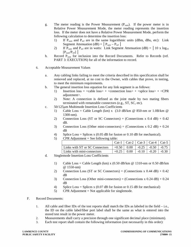
LAWRENCE COUNTY COMMISSIONING OF COMMUNICATIONS PUBLIC SAFETY FACILITY 270800- 15
g. The meter reading is the Power Measurement (Psum). If the power meter is in Relative Power Measurement Mode, the meter reading represents the insertion loss. If the meter does not have a Relative Power Measurement Mode, perform the following calculation to determine the insertion loss: 1) If Psum and Pref are in the same logarithmic units (dBm, dBu, etc): Link
Segment Attenuation (dB) = │Psum – Pref │ 2) If Psum and Pref are in watts: Link Segment Attenuation (dB) = │10 x log10
[Psum/Pref] │ h. Record Psum for inclusion into the Record Documents. Refer to Records (ref.
PART 3: EXECUTION) for all of the information to record.
6. Acceptable Measurement Values
a. Any cabling links failing to meet the criteria described in this specification shall be removed and replaced, at no cost to the Owner, with cables that prove, in testing, to meet the minimum requirements.
b. The general insertion loss equation for any link segment is as follows: 1) Insertion loss = <cable loss> + <connection loss> + <splice loss> + <CPR
adjustment>. 2) Note: A connection is defined as the joint made by two mating fibers
terminated with remateable connectors (e.g., ST, SC, etc). c. 50/125μm Multimode Insertion Loss Coefficients
1) Cable Loss = Cable Length (km) x (3.0 dB/km @ 850-nm or 1.0B/km @ 1300-nm).
2) Connection Loss (ST or SC Connectors) = (Connections x 0.4 dB) + 0.42 dB.
3) Connection Loss (Other mini-connectors) = (Connections x 0.2 dB) + 0.24 dB
4) Splice Loss = Splices x (0.05 dB for fusion or 0.10 dB for mechanical). 5) CPR Adjustment = See following table:
Cat-1 Cat-2 Cat-3 Cat-4 Cat-5
Links with ST or SC Connectors +0.50 0.00 -0.25 -0.50 -0.75Links with mini-connectors +0.25 0.00 -0.10 -0.20 -0.30
d. Singlemode Insertion Loss Coefficients
1) Cable Loss = Cable Length (km) x (0.50 dB/km @ 1310-nm or 0.50 dB/km @ 1550-nm)
2) Connection Loss (ST or SC Connectors) = (Connections x 0.44 dB) + 0.42 dB
3) Connection Loss (Other mini-connectors) = (Connections x 0.24 dB) + 0.24 dB
4) Splice Loss = Splices x (0.07 dB for fusion or 0.15 dB for mechanical) 5) CPR Adjustment = Not applicable for singlemode.
F. Record Documents:
1. All cable and fiber IDs of the test reports shall match the IDs as labeled in the field – i.e., the ID on the cable label/fiber port label shall be the same as what is entered into the stored test result in the power meter.
2. Measurements shall carry a precision through one significant decimal place (minimum). 3. Each test report shall contain the following information (not necessarily in this order):

COMMISSIONING OF COMMUNICATIONS LAWRENCE COUNTY 270800 - 16 PUBLIC SAFETY FACILITY
a. Project name and address, b. General Contractor name / Telecommunications Installer name. c. Operator’s name(s), d. Date of measurement, e. Test equipment - manufacturer, model, and serial number, f. Cable identifier, fiber and fiber type, g. Measurement direction, h. Wavelength, and i. Measured loss values.
3.6 BACKBONE TWISTED PAIR CABLING TESTING REQUIREMENTS AND PROCEDURES
A. Testing Requirements:
1. Test backbone multipair cabling per “Base Bid Requirements” in Part 1 of this Section. 2. The installation will be accepted when testing has indicated a 100% availability of all
terminated pairs or the Owner has approved any deviation from this requirement.
B. Testing Procedures
1. Test wire map and continuity for all pairs. 2. Test length for 2% of pairs of each cable. None of the pairs tested for length shall be of
the same 25-pair binder group.
C. Record Documents:
1. All cable and pair IDs of the test reports shall match the IDs as labeled in the field – i.e., the ID on the cable label/termination label shall be the same as what appears on the test reports.
2. Measurements shall carry a precision through no significant decimal place. 3. Each test report shall contain the following information (not necessarily in this order):
a. Project name and address, b. General Contractor name / Telecommunications Installer name, c. Operator’s name(s), d. Date of measurement, e. Test equipment - manufacturer, model, and serial number, f. Cable identifier and pair numbers, g. Overall test result, and h. Measured values of minimum requirements.
3.7 HORIZONTAL CATEGORY 6 TESTING PROCEDURES
A. Precautions:
1. Adhere to the equipment manufacturer’s instructions during all testing. 2. Prior to any testing activity or any measurements taken, ensure the test equipment is at
room temperature – approximately 70 degrees F (e.g., if necessary, bring the test

LAWRENCE COUNTY COMMISSIONING OF COMMUNICATIONS PUBLIC SAFETY FACILITY 270800- 17
equipment in from outdoors and let it set for about 15 minutes or for however long it takes to bring the test equipment to reach room temp).
3. Fully charge power sources before each day’s testing activity
B. Test Equipment Set Up:
1. Set up the tester to perform a full Category 6 test, as a Permanent Link configuration. 2. If the tester has the capability, set the cable type as product specific setting. If not, set as
generic Category 6. 3. Set the tester to save the full test results (all test points, graphs, etc.). 4. Save the test results with the associated cable link identifier to match that as specified in
Section 27 15 00. 5. Calibrate the test set per the manufacturers instructions.
C. Acceptable Test Result Measurements:
1. Links which report a Fail, Fail* or Pass* for any of the individual tests shall result in an overall link Fail. All individual test results must result in a Pass to achieve an overall Pass.
2. Any reconfiguration of link components required as a result of a test Fail, must be re-tested for conformance.
3. Any cabling links failing to meet the criteria described in this specification shall be removed and replaced, at no cost to the Owner, with cables that prove, in testing, to meet the minimum requirements.
4. Minimum measurement requirements: Wire Map All pairs of the cabling link shall be continuous and terminated
correctly at both ends. No exceptions shall be accepted. Length The maximum acceptable electrical length measurements for any
cabling link measured under a Permanent Link configuration shall be 94 meters, including test cords.
Insertion Loss The acceptable insertion loss measurements for any Category 6 cabling link shall be no greater than that as listed in TIA/EIA-568C.2 Addendum 1.
Worst Pair-to-Pair Near End Cross-Talk (NEXT) Loss
The acceptable worst pair-to-pair NEXT loss for any Category 6 cable shall be no greater than that as listed in TIA/EIA-568C.2 Addendum 1.
Power Sum NEXT Loss
The acceptable power sum PS-NEXT loss for any Category 6 cable shall be no greater than that as listed in TIA/EIA-568C.2 Addendum 1.
Worst Pair-to-Pair ELFEXT and FEXT Loss
The acceptable worst pair-to-pair ELFEXT and loss for any Cate-gory 6 cable shall be no greater than that as listed in TIA/EIA-568C.2 Addendum 1.
Power Sum ELFEXT and FEXT Loss
The acceptable PS-ELFEXT and loss for any Category 6 cable shall be no greater than that as listed in TIA/EIA-568C.2 Adden-dum 1.
Return Loss The acceptable return loss measurements for any Category 6 ca-ble shall be no greater than that as listed in TIA/EIA-568C.2 Ad-dendum 1.
Propagation Delay and Delay Skew
The acceptable propagation delay and delay skew measurements for any Category 6 cable shall be no greater than that as listed in TIA/EIA-568C.2 Addendum 1.

COMMISSIONING OF COMMUNICATIONS LAWRENCE COUNTY 270800 - 18 PUBLIC SAFETY FACILITY
D. Record Documents
1. For each Horizontal Category 6 test measurement, record the following information:
a. Project name and address, b. General Contractor name / Telecommunications Installer name, c. Operator’s name(s), d. Date of measurement, e. Ambient temperature, f. Test equipment - manufacturer, model, and serial number, g. Cable identifier, h. Overall test result, and i. Measured values of minimum requirements.
END OF SECTION 270800

LAWRENCE COUNTY COMMUNICATIONS EQUIPMENT ROOM FITTINGS AND GROUNDING PUBLIC SAFETY FACILITY 271100- 1
SECTION 271100 – COMMUNICATION EQUIPMENT ROOM FITTINGS AND GROUNDING
PART 1 - GENERAL
1.1 RELATED DOCUMENTS
A. Drawings and general provisions of Contract, including General and Supplementary Conditions and Division-01 Specification sections, apply to work of this section.
B. Requirements of the following Division 27 Sections apply to this section:
1. Division 27 Section 26 0526 “grounding”. 2. Division 27 Section 27 0500 “Common Work Results for Communications”.
1.2 SUMMARY
A. This section includes the following:
1. Racks 2. Cabinets
B. This Section includes solid grounding of communications systems and equipment. It includes basic requirements for grounding for protection of life, equipment, circuits, and systems. Grounding requirements specified in this Section may be supplemented in other sections of these Specifications.
C. The Electrical Contractor shall be responsible for grounding equipment provided in the Electrical Contract, HVAC Contract, Plumbing Contract, and General Contract.
D. The Communication Contractor shall be responsible for proper grounding of all racks, cabinets, and active components as shown on the Drawings and as specified herein.
1.3 SUBMITTALS
A. General: Submit the following in accordance with Conditions of Contract and Division 01 Specification Sections.
B. Product data for connectors and connection materials, and grounding fittings.
C. Field-testing organization certificate, signed by the Contractor, certifying that the organization performing field tests complies with the requirements specified in Quality Assurance below.
D. Report of field tests and observations certified by the testing organization.

COMMUNICATIONS EQUIPMENT ROOM FITTINGS AND GROUNDING LAWRENCE COUNTY 271100 - 2 PUBLIC SAFETY FACILITY
1.4 QUALITY ASSURANCE
A. Manufacturers: Firms regularly engaged in manufacture of electrical connectors, terminals and fittings of types and ratings required, and ancillary grounding materials, including stranded cable, copper braid and bus, whose products have been in satisfactory use in similar service for not less than 3 years.
B. Installer: Qualified with at least 3 years of successful installation experience on projects with communications grounding work similar to that required for project.
C. Listing and Labeling: Provide products specified in this Section that are listed and labeled. The terms "listed" and "labeled" shall be defined as they are in the National Electrical Code, Article 100.
1. Listing and Labeling Agency Qualifications: A "Nationally Recognized Testing Laboratory" (NRTL) as defined in OSHA Regulation 1910.7.
D. Field-Testing Organization Qualifications: To qualify for acceptance, the independent testing organization must demonstrate, based on evaluation of organization-submitted criteria conforming to ASTM E 699, that it has the experience and capability to conduct satisfactorily the testing indicated.
E. Electrical Component Standard: Components and installation shall comply with NFPA 70, "National Electrical Code" (NEC) and Motorola R-56 Standard.
F. UL Compliance: Comply with applicable requirements of UL Standards Nos. 467 and 869 pertaining to grounding and bonding.
G. IEEE Compliance: Comply with applicable requirements of IEEE Standard 142 and 241 pertaining to grounding.
1.5 DESCRIPTION OF WORK
A. The Communications Contractor shall furnish and supply all equipment, including but not limited to, equipment racks, cabinets, mounting hardware, and all associated equipment necessary to provide a complete and operating system.
B. All bids shall be based on equipment as specified herein. All alternate equipment must be approved ten (10) days prior to bid date. Adequate information must be made available for a evaluation and approval of alternate equipment.
C. Contractor shall furnish a manufacturer's manual of the completed system including individual specification sheets, schematics, inter-panel and intra-panel wiring diagrams. In addition, all information necessary for the proper maintenance and operation of the system must be included. Any bidder using other than the specified equipment must provide this information prior to bidding. All published specifications of the manufacturers of equipment specified shall be considered as being a part of this specification, even though they have not been included in detail.

LAWRENCE COUNTY COMMUNICATIONS EQUIPMENT ROOM FITTINGS AND GROUNDING PUBLIC SAFETY FACILITY 271100- 3
D. As-built drawings that include any changes to wiring, wiring designations, junction box labeling and any other pertinent information shall be supplied upon completion of project.
E. Wire management shall be in accordance with the recommended practices as established by BISCI.
F. All equipment installation and wiring shall meet all requirements of manufacturer.
PART 2 - PRODUCTS
2.1 GROUNDING AND BONDING PRODUCTS
A. Manufacturers: Subject to compliance with requirements, provide products by the following:
1. B-Line Systems Inc. 2. Burndy Corp. 3. Crouse-Hinds Co. 4. Electrical Components Div; Gould Inc. 5. General Electric Supply Co. 6. Ideal Industries, Inc. 7. Thomas and Betts Corp.
B. Products: Of types indicated and of sizes and ratings to comply with NEC. Where types, sizes, ratings, and quantities indicated are in excess of NEC requirements, the more stringent requirements and the greater size, rating, and quantity indications govern.
C. Conductor Materials: Copper with 98% conductivity.
2.2 WIRE AND CABLE CONDUCTORS
A. General: Comply with Division 26 Section " Low Voltage Electrical Power Cables."
B. Equipment Grounding Conductor: Green insulated.
C. Grounding Electrode Conductor: Stranded cable.
D. Bare Copper Conductors: Conform to the following:
1. Solid Conductors: ASTM B-3. 2. Assembly of Stranded Conductors: ASTM B-8.
E. Tinned Conductors: ASTM B-33.
2.3 MISCELLANEOUS CONDUCTORS
A. Ground Bus: Bare annealed copper bars of rectangular cross section.
B. Stranded Bonding Jumpers: Copper, stranded No. 6 gage bare copper wire, tinned.

COMMUNICATIONS EQUIPMENT ROOM FITTINGS AND GROUNDING LAWRENCE COUNTY 271100 - 4 PUBLIC SAFETY FACILITY
C. Bonding Strap Conductor/Connectors: Soft copper, 0.05 inch thick and 2 inches wide, except as indicated.
2.4 CONNECTOR PRODUCTS
A. General: Listed and labeled as grounding connectors for the materials used.
B. Pressure Connectors: High-conductivity-irreversible plated units.
C. Clamps: exothermic weld.
2.5 GROUNDING ELECTRODES
A. Signal and Communications: For communication systems, provide a #6 AWG minimum green insulated copper conductor in raceway from the main grounding system to each rack, cabinet or central equipment location.
B. Bonding Plates, Connectors, Terminals, and Clamps: Provide electrical bonding plates, connectors, terminals, lugs and clamps as recommended by bonding plate, connector, terminal and clamp manufacturers for indicated applications.
C. Electrical Grounding Connection Accessories: Provide electrical insulating tape, heat-shrinkable insulating tubing, welding materials, bonding straps, as recommended by accessories manufacturers for type services indicated.
2.6 COMMUNICATION ROOM EQUIPMENT
A. Provide the following equipment, including but not limited to, the purchase, delivery, unpacking, installation, connection, testing, and operation of the same.
B. The quantities of items required shall be as shown on the drawings, or as stated below. Where a conflict exists between the quantities shown on the drawings, and the quantities stated hereinafter, the greater of the two quantities shall be used.
C. Cabinet:
D. 19” Floor Rack - Item:
1. Description: 19” distribution rack 2. Manufacturer/Model No.: Cooper B-Line SB7703084UFB or approved equal. 3. Requirements:
a. Unit shall be standard 19” width by 84” high b. Unit shall be painted black
4. Accessories:
a. Hardware 1) Provide vertical cable management racks on both side of rack, full height.

LAWRENCE COUNTY COMMUNICATIONS EQUIPMENT ROOM FITTINGS AND GROUNDING PUBLIC SAFETY FACILITY 271100- 5
2) Provide one horizontal cable management for each 24-port patch panel and two horizontal cable management for each 48-port patch panel installed on the rack, Cooper B-Line SB8701952FB or approved equivalent.
3) Provide one rack ground bar. 5. Quantity: as shown on the Drawings. 6. Remarks: provide engraved label at top center of rack indicating rack number selected by
owner.
E. 19” Wall Rack :
1. Description: 19” distribution rack 2. Manufacturer/Model No.: Cooper B-Line SB706193818FB or approved equal. 3. Requirements:
a. Unit shall be standard 19” width by 38” high b. Unit shall be painted black
4. Accessories:
a. Hardware 1) Provide vertical cable management racks on both side of rack, full height. 2) Provide one horizontal cable management for each 24-port patch panel and
two horizontal cable management for each 48-port patch panel installed on the rack, Cooper B-Line SB8701952FB or approved equivalent.
3) Provide one rack mounted, 6 position power strips per wall rack, Cooper B-line No. SB3005615FB or approved equivalent.
4) Provide one rack ground bar.
5. Quantity: as shown on the Drawings. 6. Remarks: provide engraved label at top center of rack indicating rack number selected b
owner.
F. Electrostatic Discharge Kit :
1. Description: One-hole barrel lug, angled at 45-degrees, permanently marked with protective earth (ground) symbol, designated to accommodate a 4mm ESD wrist strap plug. Kit shall include an antioxidant compound, and one #12-24x ½” threaded-forming screw..
2. Manufacturer/Model No.: Panduit Corporation, part no. RGESD-1 approved equal. 3. Requirements:
a. Provide one kit for each Floor rack or wall cabinet.
4. Accessories:
a. Hardware 1) Accessories for a complete and neat installation.
5. Quantity: one (1) per rack.
G. Ladder Rack :

COMMUNICATIONS EQUIPMENT ROOM FITTINGS AND GROUNDING LAWRENCE COUNTY 271100 - 6 PUBLIC SAFETY FACILITY
1. Description: See drawings. 2. Requirements:
a. Provide ladder rack extending from cable tray to each equipment rack or wall cabinet.
b. Provide ladder rack extending from cable tray to each free standing rack. c. Ladder Rack shall have 9” rung spacing. Secure ladder rack to rack and cable tray.
3. Accessories:
a. Hardware 1) Provide mounting and wire management accessories for a complete and neat
installation. b. Software
1) None required.
4. Quantity: one (1) per rack and freestanding cabinet. 5. Remarks: none
PART 3 - EXECUTION
3.1 GENERAL
A. Except as otherwise indicated, provide electrical grounding systems indicated; with assembly of materials, including, but not limited to, cables/wires, connectors, terminals (solderless lugs), bonding jumper braid, surge arresters, and additional accessories needed for complete installation. Where more than one type unit meets indicated requirements selection is Installer's option. Where materials or components are not indicated, provide products complying with NEC, UL, IEEE, and established industry standards for applications indicated. Conform to installation guidelines as indicated in Motorola R-56.
3.2 INSPECTION
A. Installer must examine areas and conditions under which grounding connections are to be made and notify the Architect in writing of conditions detrimental to proper completion of work. Do not proceed with work until unsatisfactory conditions have been corrected in an acceptable manner.
3.3 APPLICATION
A. Provide grounding systems where shown, in accordance with applicable portions of NEC, with NECA's "Standard of Installation" and in accordance with recognized industry practices to ensure that products comply with requirements and serve intended functions.
3.4 INSTALLATION

LAWRENCE COUNTY COMMUNICATIONS EQUIPMENT ROOM FITTINGS AND GROUNDING PUBLIC SAFETY FACILITY 271100- 7
A. General: Ground communications systems and equipment in accordance with NEC requirements except where the Drawings or Specifications exceed NEC requirements.
B. Coordinate with other electrical work as necessary to interface installation of communication system grounding system with other work.
C. Route grounding conductors along building lines in the shortest and straightest paths possible without obstructing access or placing conductors where they may be subjected to strain, impact, or damage, except as indicated.
3.5 CONNECTIONS
A. General: Make connections in such a manner as to minimize possibility of galvanic action or electrolysis. Select connectors, connection hardware, conductors, and connection methods so metals in direct contact will be galvanically compatible.
1. Use electroplated or hot-tin-coated materials to assure high conductivity and make contact points closer in order of galvanic series.
2. Make connections with clean bare metal at points of contact. 3. Coat and seal connections involving dissimilar metals with inert material such as red lead
paint to prevent future penetration of moisture to contact surfaces.
B. Tighten grounding and bonding connectors and terminals, including screws and bolts, in accordance with manufacturer's published torque tightening values for connectors and bolts. Where manufacturer's torquing requirements are not indicated, tighten connections to comply with torque tightening values specified in UL 486A and UL 486B.
3.6 FIELD QUALITY CONTROL
A. Upon Completion of installation of communications grounding systems, test ground resistance with ground resistance tester. Where tests show resistance to ground is over 5 ohms, take appropriate action to reduce resistance to 5 ohms, or less, by driving additional ground rods and/or by chemically treating soil encircling ground rod; then retest to demonstrate compliance.
B. Independent Testing Organization: Arrange and pay for the services of a qualified independent electrical testing organization to perform tests described below.
C. Tests: Subject the completed grounding system to a megger test at each location where a maximum ground resistance level is specified, at service disconnect enclosure ground terminal.
D. Ground/resistance maximum values shall be as follows:
1. Equipment rated 500 kVA and less: 5 Ohms
E. Deficiencies: Where ground resistances exceed specified values, and if directed, modify the grounding system to reduce resistance values. Where measures are directed that exceed those indicated the provisions of the Contract, covering changes will apply.

COMMUNICATIONS EQUIPMENT ROOM FITTINGS AND GROUNDING LAWRENCE COUNTY 271100 - 8 PUBLIC SAFETY FACILITY
F. Report: Prepare test reports, certified by the testing organization, of the ground resistance at each test location. Include observations of weather and other phenomena that may affect test results. Describe measures taken to improve test results.
3.7 COMMUNICATION ROOM EQUIPMENT TESTING
A. Before final acceptance of the installation, the contractor shall test in the presence of the Architect/Engineer/Owner or their representative's the complete installation and show that the system is completely operational and free from unwanted grounds, shorts, breaks, etc. The Contractor shall obtain all equipment required to test the final installation. The testing of the system shall be made under the direct supervision of the equipment manufacturer's or their designated representative.
B. The Contractor shall provide a one-year guarantee of the installed system against defects in material and workmanship. All labor and materials shall be provided at no expense to the Owner. Guarantee period shall begin on the date of acceptance by the Architect/Engineer/Owner.
END OF SECTION 271100
LAWRENCE COUNTY COMMUNICATIONS BACKBONE CABLINGPUBLIC SAFETY FACILITY 271300- 1
SECTION 271300 - COMMUNICATIONS BACKBONE CABLING
PART 1 - GENERAL
1.1 SCOPE
A. This section includes the copper and fiber backbone cable and the termination requirements from a Switch Room/MDF to a BDF or ER or TR and from a BDF to a ER or TR and from a ER to TR and from a TR to another TR.
B. This section includes minimum requirements for the following:
1. Outside Plant (OSP) 2. Outdoor Rated Optical Fiber Cables 3. Heavy Wall Innerducts 4. Optical Fiber Connectors - SM/MM 5. Optical Fiber Splicing Trays for Exterior Enclosures 6. Optical Fiber Splice Enclosures 7. 24 AWG Underground Rated Copper Cables 8. (PE89) 9. Vault Closures 10. End Caps 11. Plugs 12. Bushings 13. Lubricants 14. Sealing Kits 15. Clamps 16. Bonding Harnesses 17. Dome Enclosures 18. Encapsulated Enclosures 19. Encapsulants 20. Splicing Tapes 21. Splicing Modules - Filled 22. De-Gel Stripper 23. Installation, Termination, and Splicing Methods 24. Inside Plant (ISP) 25. Plenum and Riser Rated Optical Fiber Cables 26. Riser and Plenum Rated Innerducts 27. ARMM/CMR Copper Cables 28. Splicing Modules 29. Splicing Tapes 30. Clamps 31. Split Riser Splice Cases 32. Bonding Connectors 33. Bonding jumpers sahll be stranded copper tinned

COMMUNICATIONS BACKBONE CABLING LAWRENCE COUNTY 271300 - 2 PUBLIC SAFETY FACILITY
1.2 QUALITY ASSURANCE AND REFERENCES
A. All cable shall be installed in a neat and workmanlike manner. All methods of construction that are not specifically described or indicated in the contract documents shall be subject to the control and approval of the Network & Telecommunication Department. Equipment and materials shall be of the quality and manufacture indicated. The equipment specified is based upon the acceptable manufacturers listed. Where "approved equal" is stated, equipment shall be equivalent in every way to that of the equipment specified and subject to approval.
B. Materials and work specified herein shall comply with the applicable requirements of:
1. ANSI/TIA/EIA - 568-C Commercial Building Telecommunications Cabling Standard 2. ANSI/TIA/EIA - 568-B Commercial Building Standard for Telecommunications
Pathway and Spaces 3. EIA/TIA-606-A Administration Standard for the Telecommunications Infrastructure of
Commercial Buildings 4. ANSI J-STD-607 Commercial Building Grounding and Bonding requirements for
Telecommunications. 5. Motorola R-56 Standards 6. NFPA 70 - 2008, including:
a. NEC - Article 770 b. NEC - Article 800
7. Underwriters Laboratory 8. NEMA - 250 9. Federal Communications Commission 47 CFR 68. 10. BICSI Telecommunications Distribution Design Manual (13th edition) 11. BICSI Customer Owned Outside Plant Design Manual (3rd edition) 12. BICSI Telecommunications Cabling Installation Manual (3rd edition) 13. ISO/IEC 11801 14. Bellcore GR-20
C. The fiber optic cable specified in this project may be used to support an ATM or Gigabit Ethernet network. At the time of installation all fiber optic products shall support the latest draft or formal specification released by the IEEE 802.Z (for Gigabit Ethernet).
1.3 SUBMITTALS
A. Manufacturers catalog sheets, specifications, and installation instructions for all products to be installed within the scope of work included under this contract.
B. Test Results and Documentation as per Section 27 0800.
1.4 RELATED DOCUMENTS
A. Drawings and general provisions of Contract, including General and Supplementary Conditions and Division 01 Specification sections, apply to work of this section.
B. Requirements of the following Division 27 Sections apply to this section:
1. Division 27 Section 27 01 00 “Basic Communication Systems Requirements”.

LAWRENCE COUNTY COMMUNICATIONS BACKBONE CABLINGPUBLIC SAFETY FACILITY 271300- 3
2. Division 27 Section 27 05 00 “Common Work Results for Communications”. PART 2 - PRODUCTS
2.1 PLENUM AND RISER RATED OPTICAL FIBER CABLES
A. Multimode Fiber:
1. Shall be graded-index optical fiber waveguide with nominal 50μm Multi-mode-core/cladding diameter. The primary coating diameter of 900um UV cured acrylate buffer material.
2. The fiber shall comply with ANSI/EIA/TIA-492AAAA 3. Transmission Characteristics for Multimode Fiber Optic Cable:
a. Each cabled fiber shall meet the graded performance specifications below. Attenuation shall be measured in accordance with ANSI/EIA/TIA-455-46, 53 or 61. Information transmission capacity shall be measured in accordance with ANSI/EIA/TIA-455-51 or 30. The measurements shall be performed at 23 degrees C +/- 5 degrees. 1) Maximum attenuation dB/Km @ 850/1300 nm: 3.5/1.5 2) Bandwidth 1500 Mhz-km @ 850nm 3) Bandwidth 500 Mhz-km @ 1300nm 4) Distance vs. bandwidth using a LED transmitter operating at a 1300nm
Wave length 5) 10Gig 50/125um (OM3) multimode plenum rated.
2.2 OPTICAL FIBER CONNECTORS – SM/MM
A. Physical Characteristics:
1. All fiber connectors shall meet ANSI/EIA/TIA-604-3 standards. 2. Multimode connectors shall be aqua in colored n accordance with 568 C.3. Single Mode
connectors shall be Blue colored in accordance with 568 C.3. 3. The connector shall have an optical axial pull strength of 33 N at 0 degree angle and an
optical off axial pull strength of 2.2 N at a 90 degree angle, with a maximum 0.5 dB increase in attenuation for both tests when tested in accordance with ANSI/EIA/TIA-455-6B.
B. Transmission Characteristics:
1. The maximum optical attenuation per each mated field installed fiber connector pair shall not exceed 0.5 dB.
2. The total optical attenuation through the cross-connect from any terminated optical fiber to any other terminated fiber shall not exceed 1.0 dB.
3. The connectors shall sustain a minimum of 500 mating cycles without degrading this performance.
2.3 CMP COPPER CABLES
A. Backbone UTP cables shall consist of 24 AWG, groups of 50/100 pair thermoplastic insulated copper conductors following the ANSI/ICEA S-80- 576 color code. The 50/100 pair groups shall be bound together and covered by a protective sheath consisting of an overall

COMMUNICATIONS BACKBONE CABLING LAWRENCE COUNTY 271300 - 4 PUBLIC SAFETY FACILITY
thermoplastic jacket an underlying metallic shield and one layer of dielectric material applied over the core.
B. Provide plenum rated cable.
C. Transmission Characteristics:
1. The resistance of any conductor, measured in accordance with ASTM D 4566 shall not exceed 9.38 ohms per 100m at 20 degrees C.
2. The resistance unbalance between the two conductors of any pair shall not exceed 5%. 3. The mutual capacitance of any pair shall not exceed 6.6 nF per 100m. 4. The capacitance unbalance to ground at 1 kHz of any pair shall not exceed 330 pF per
100m. 5. The characteristic impedance shall be 100 ohm +/- 15% from 1 kHz to 16 MHz. 6. The attenuation shall meet the requirements of the horizontal cable specified in section
271500. 7. The insulation between each conductor and the core shield shall be capable of
withstanding a minimum dc potential of 5 kV for 3 seconds. 8. The propagation delay of any pair at 10 MHz should not exceed 5.7 ns/m. 9. The Power Sum NEXT loss shall meet the following: 10. Frequency (MHz) NEXT loss (dB)
a. 0.150 53 b. 0.772 43 c. 1.0 41 d. 4.0 32 e. 8.0 27 f. 10.0 26 g. 16.0 23
2.4 ARMM COPPER CABLES
A. Shall be of size indicated on the drawings.
B. Shall consist of a core of 24 AWG solid annealed copper conductors, color coded in accordance with telephone industry standards.
C. Transmission Characteristics:
1. The nominal resistance of any conductor shall not exceed 27.3 ohms per 1000 feet at 20 degrees C.
2. The mutual capacitance of any pair shall not exceed 15.7 nF per 1000 feet at 1 kHz. 3. The maximum attenuation at 1.0 MHz shall not exceed 6.8 dB per 1000 feet.
D. Conductors shall be twisted to form pairs. Cable having more that 25 pairs shall be assembled in units, each individually identified by color coded unit binders.
E. The core shall be covered with a plastic tape.
F. The core and tape shall be overlaid with a corrugated shield applied longitudinally with overlap using the following materials:

LAWRENCE COUNTY COMMUNICATIONS BACKBONE CABLINGPUBLIC SAFETY FACILITY 271300- 5
1. .008 inch coated aluminum 2. .005 inch copper 3. Shall be bonded to outer jacket to form an ALVYN sheath.
G. The outer jacket shall consist of a fire retardant sheath that meets NEC low flame requirements.
H. Cable shall be suitable, listed and marked for use in a riser application. (CMR)
I. Manufacturer’s cable code, pair size, manufacturing plant location, month and year or manufacture shall be marked on cable every two feet.
2.5 BONDING CONNECTORS
A. Shall consist of a base and upper member, two securing nuts and a plastic shoe to aid connector installation and protect the conductors.
B. Base and upper members shall be made of tin plated tempered brass, slightly curved so as to exert a continuous spring form on sheath and shield after clamping.
2.6 GROUNDING CONDUCTOR
A. Shall be stranded copper, tinned..
2.7 OUTDOOR RATED OPTICAL FIBER CABLES
A. Multimode Fiber:
1. Shall be OM3 minimum, graded-index optical fiber waveguide with nominal 50/125um-core/cladding diameter. The primary coating diameter of 900um UV cured acrylate buffer material.
2. The fiber shall comply with ANSI/EIA/TIA-492AAAA 3. Transmission Characteristics for Multimode Fiber Optic Cable: 4. Each cabled fiber shall meet the graded performance specifications below. Attenuation
shall be measured in accordance with ANSI/EIA/TIA-455-46, 53 or 61. Information transmission capacity shall be measured in accordance with ANSI/EIA/TIA-455-51 or 30. The measurements shall be performed at 23 degrees C +/- 5 degrees.
a. Maximum attenuation dB/Km @ 850/1300 nm: 3.5/1.5 b. Bandwidth 1500 Mhz-km @ 850nm c. Bandwidth 500 Mhz-km @ 1300nm
2.8 HEAVY WALL INNERDUCT
A. Shall be 1” heavy wall construction.
2.9 OPTICAL FIBER CONNECTORS
A. See inside plant category for same, this section.
2.10 UNDERGROUND RATED BACKBONE COPPER CABLES
A. Shall be of size indicated on the drawings.

COMMUNICATIONS BACKBONE CABLING LAWRENCE COUNTY 271300 - 6 PUBLIC SAFETY FACILITY
B. Shall consist of a core of 24 AWG solid annealed copper conductors, color coded in accordance with telephone industry standards.
C. Transmission Characteristics:
1. The nominal resistance of any conductor shall not exceed 135.5 ohms per mile at 20 degrees C.
2. The resistance unbalance between the two conductors of any pair shall not exceed 4%. 3. The mutual capacitance of any pair shall not exceed 83 +/- 4 nF per mile at 1000 Hz. 4. The capacitance unbalance pair to ground at 1000 Hz of any pair shall not exceed 800 pF
per 1000 feet. 5. The capacitance unbalance pair to pair at 1000 Hz of any pair shall not exceed 80 pF per
1000 feet. 6. The dielectric strength of the insulation shall be capable of withstanding a conductor to
conductor minimum dc potential of:
a. 3 kV for 3 seconds for PE-89. b. 4 kV for 3 seconds for PE-39.
7. The dielectric strength of the insulation shall be capable of withstanding a conductor to shield, minimum dc potential of: 15 kV for 3 seconds (single jacket) and 20 kV for 3 seconds (double jacket).
8. The maximum attenuation at 772 kHz at 20 degrees C shall not exceed:
a. 5.6 dB per 1000 feet for PE-89 b. 4.9 dB per 1000 feet for PE-39
D. Conductors shall be twisted to form pairs. Cable having more that 25 pairs shall be assemble in units, each individually identified by color-coded unit binders.
E. The core shall be covered with a non-hygroscopic tape.
F. The cable shall be filled with a filling material that seals air spaces in the cable core, meeting of exceeding REA compound flow tests.
G. The core and tape shall be overlaid with a corrugated shield applied longitudinally with overlap using the following materials:
1. .008 inch coated aluminum 2. .005 inch copper 3. Gopher resistant types shall use 0.10 inch copper, .006 inch bimetallic alloy 194
(copper/stainless or steel/copper) or .008 inch coated aluminum/.006inch coated steel (CACSP).
4. Shall be bonded to outer jacket to form an ALVYN sheath.
H. The outer jacket shall consist of a high molecular weight polyethylene.
I. Cable shall be suitable, listed, and marked for use in a duct application.
J. Manufacturer’s cable code, pair size, manufacturing plant location, month and year or manufacture shall be marked on cable every two feet.

LAWRENCE COUNTY COMMUNICATIONS BACKBONE CABLINGPUBLIC SAFETY FACILITY 271300- 7
2.11 OUTDOOR RATED OPTICAL FIBER CABLES
A. Shall be composite fiber optic cable for all connections.
B. Install cable inside of an inner duct.
C. Adhere to all manufacturer installation guidelines.
D. A service loop of 15 feet shall be maintained at all points of termination. Service loops shall not exceed manufacturer's recommended bend radius and shall be neatly dressed and shall not interfere with other cables and termination equipment.
E. Pulling tensions shall not exceed those recommended by the fiber optic cable manufacturer.
F. Manufacturer's minimum specified bend radius shall not be exceeded.
G. In the event that cabling is totally dielectric (nonmetallic) and installed in a nonmetallic duct, a #6 copper wire shall be placed in the conduit with the cable to be used as tracer for cable locating purposes.
2.12 HEAVY WALL INNERDUCT
A. Install 1/8" polypropylene monofilament utility rope with a minimum pull tensile strength of 200 pounds. This rope shall have footage marked printed on it.
2.13 OPTICAL FIBER CONNECTORS
A. See inside plant category for same, this section.
2.14 UNDERGROUND RATED COPPER CABLES
A. All underground cable shall have been manufactured within 6 months of purchase date.
B. All open ends of the cable shall have sealing caps installed at the factory prior to shipping so that infiltration of moisture between shipment and installation is prevented.
C. Contractor shall provide notice 2 days advance notice prior to pulling any cable greater that 400 pairs in size or when a winch is planned for use.
1. Network & Telecommunications Engineer shall be present to observe all pulling activities of cable greater than 400 pair or when a winch is planned for use.
D. Cable bend radius shall be at least 10 times the diameter of the cable.
E. Contractor shall be responsible for verifying that ducts are ready for occupancy prior to cable placement.
F. Contractor shall assume responsibility for any difficulties or damage to the cable during placement.
G. Cable feeder guides shall be used between the cable reel and the face of the duct.

COMMUNICATIONS BACKBONE CABLING LAWRENCE COUNTY 271300 - 8 PUBLIC SAFETY FACILITY
H. Cable shall be watched and inspected for sheath defects, as it is played off the reel. Pulling operation shall be stopped and Network & Telecommunication Engineer shall be notified if a defect or any other irregularity is found.
I. Cable shall be payed off from the top of the reel.
J. Adhere to all manufacturers requirements regarding pulling tension allowable lubricants and bending radius.
K. Use Line Tension meter during cable pull to provide accurate measurement of the force exerted on a cable as it is installed. The meter shall have a programmable overload set point with an audible and visual indication of an overload condition. The meter shall have controls to disengage the cable puller if an overload condition occurs.
L. Secure all cables and splice cases as required with heavy duty tie-wraps to T-slot cable racking and steps. See section for 270543 for additional exterior pathway requirements.
M. Cable shield shall be continuous from end to end.
N. Ground and bond all cable at the lightning protection. Also, see section 271100.
1. All cables to be grounded at the MDF end with a minimum #6 solid soft copper ground wire as required by code.
O. All cable pairs shall be terminated.
P. Cables shall be tested and the results documented on Network & Telecommunication Department provided or approved test sheets as specified in section 270800.
Q. Cables shall be labeled as specified in section 270800.
2.15 END CAPS AND CLOSURE EXTENSION SLEEVES
A. Adhere to all manufacturer installation guidelines.
2.16 ENCAPSULANTS
A. Adhere to all manufacturer installation guidelines.
2.17 SPLICING TAPES
A. Adhere to all manufacturer usage guidelines.
2.18 DE-GEL STRIPPER
A. Adhere to all manufacturer usage guidelines.
2.19 PLENUM AND RISER RATED OPTICAL FIBER CABLES
A. Shall be MM/SM composite fiber optic cable for all ER to TR connections. (See riser diagram)

LAWRENCE COUNTY COMMUNICATIONS BACKBONE CABLINGPUBLIC SAFETY FACILITY 271300- 9
B. All fiber optic cable shall be installed in conduit, cable tray or supported from building structure at 3-foot centers.
C. Maintain polarization for entire system as described in ANSI/EIA/TIA-568- C.3.
D. Cable shall be continuous from the ER to the ER's and TR's.
E. For ER to TR fiber runs, leave a 15' service loop at the ER end and at the TR end leave a 15' service loop.
F. For ER to ER fiber runs leave a 25' service loop at each end.
G. Adhere to all manufacturers’ requirements regarding pulling tension and allowable lubricants.
H. The contractor shall be responsible for verifying the actual footage’s and distances identified on the attached prints (i.e. wall-to-wall, pullbox-to pullbox and ER to TR).
I. The contractor shall be responsible for verifying that conduits and raceways are "ready for occupancy" before cable placement.
J. The contractor shall assume the responsibility for any difficulties or damage to the cable during placement.
K. Where fiber optic cable passes through a vertical riser closet or TR secure fiber to wall vertically every 48". Review fasteners, strain relief and routing with customer.
L. Test, label, and document as per section 270800.
2.20 RISER AND PLENUM RATED INNERDUCT
A. Adhere to all manufacturer installation guidelines.
B. Support inner duct every 36" on center.
2.21 OPTICAL FIBER CONNECTORS – SM/MM
A. Adhere to all manufacturer installation guidelines.
B. Connector shall be installed with less than .50 dB of attenuation.
C. Connectors must be fusion-spliced, factory polished pigtails
PART 3 - EXECUTION
3.1 GENERAL REQUIREMENTS
A. All placements shall conform to industry standards with regard to anchoring, cable support and separation from other facilities.
B. All placements shall conform to industry standards with regard to anchoring, support, etc.

COMMUNICATIONS BACKBONE CABLING LAWRENCE COUNTY 271300 - 10 PUBLIC SAFETY FACILITY
C. Cables and Inner duct shall not sag or droop but should be installed to maintain a flat plane with smooth transitions from one level or direction to another.
D. All cables entering and leaving a splice as well as the splice itself shall be appropriately racked to eliminate stress on the cables and/or connections.
E. All cables shall be sufficiently racked and supported in order to eliminate stress on the cable or splice.
3.2 CMR/CMP COPPER CABLES
A. UTP backbone cables may be installed in conduit, cable tray, or in cat 6 cable hangers 4’ on center.
B. Cables above drywall ceilings shall be installed in conduit. Cables in exposed areas other than communications equipment rooms shall be installed in conduit or surface raceway.
C. Cables shall not be allowed to lay on ceiling or ceiling support structure. They must be anchored in such a way as to not interfere with other services or space access.
D. Unless otherwise specified, noted UTP backbone cables shall be sized based on two-pairs/connected voice jack. Round up to the next audible pair sizing when doing calculations.
E. Where UTP backbone cable incorporates a campus system (i.e., multiple buildings connected to the backbone), all cable shall be installed with gas tube or solid state protection devices at both ends.
F. Test, label, and document as per section 270800.
3.3 ARMM COPPER CABLES
A. Secure all ARMM cables to wall within 12" of all splice enclosures
B. UTP backbone cables may be installed in conduit, cable tray, or in cat 6 cable hangers 4’ on center.
C. Cables above drywall ceilings shall be installed in conduit. Cables in exposed areas other than communications equipment rooms shall be installed in conduit or surface raceway.
D. Cables shall not be allowed to lay on ceiling or ceiling support structure. They must be anchored in such a way as to not interfere with other services or space access.
E. Unless otherwise specified, noted UTP backbone cables shall be sized based on two-pairs/connected voice jack. Round up to the next audible pair sizing when doing calculations.
F. Where UTP backbone cable incorporates a campus system (i.e., multiple buildings connected to the backbone), all cable shall be installed with gas tube or solid state protection devices at both ends.
G. Test, label, and document as per section 270800.
END OF SECTION 271300

LAWRENCE COUNTY COPPER CABLING SYSTEMS PUBLIC SAFETY FACILITY 271500- 1
SECTION 271500 – COPPER CABLING SYSTEMS
PART 1 - GENERAL
1.1 SUMMARY
A. Horizontal (distribution) communications wiring and connecting hardware from the Telecommunications Room (TR) to Telecommunication Outlets (TO) throughout the site
1.2 SYSTEM DESCRIPTION
A. The horizontal distribution subsystem refers to all intra-building twisted-pair and fiber optic communications cabling connecting Telecommunication Rooms (TR’s) to telecommunication outlets (TO’s) located at individual work areas.
B. Horizontal cabling may consist of a combination of the following types of cable from the TR to the TO:
1. Enhanced Category 6 (100 Ohm, 4-pair, unshielded twisted pair) cables from the TR’s to the TO’s.) Port 1 or Port 2
C. The Horizontal System includes cables, jacks, patch panels, connecting blocks, patch cords, fiber connectors and jumpers as well as the necessary support systems, such as cable managers and faceplates.
D. Patch cables. Provide two patch cables for each data cable. One for the room side and one for the rack side. Patch cables shall match system ratings. Each patch cord shall average two meter in length. Coordinate exact quantity of each length of patch cords before obtaining material.
E. Cables may be routed through conduit, cable trays, spaces below raised floors, open ceiling areas, non-ventilated spaces above ceiling tile, and through plenum air-handling spaces above ceiling tile. Coordinate with General Contractor (GC).
F. Telecommunications contractor shall furnish and install all materials necessary for a complete and working system.
1.3 RELATED DOCUMENTS
A. This Section shall be used in conjunction with the following other specifications and related Contract Documents to establish the total general requirements for the project communications systems and equipment:
1. Contract Documents 2. Division 00 – Procurement & Contracting Requirements Group 3. Division 1 – General Requirements 4. Section 012500 – Substitution Procedures or Project’s equivalent documentation. 5. Section 270526 – Grounding and Bonding for Communications Systems 6. Section 270800 – Commissioning of Communication Systems 7. Section 271100 – Communications Equipment Room Fittings

COPPER CABLING SYSTEMS LAWRENCE COUNTY 271500 - 2 PUBLIC SAFETY FACILITY
8. Section 271300 – Communications Backbone Cabling
1.4 SUMMARY
A. Horizontal (distribution) communications wiring and connecting hardware from the Telecommunications Room (TR) to Telecommunication Outlets (TO) throughout the site.
1.5 SUBMITTALS
A. General: Submit the following in accordance with Conditions of Contract and Division 01 Specification Sections.
B. Submittals shall be made as complete systems including all required accessories and special installation tools (i.e. termination hardware).
C. Product information including the following cable transmission characteristics:
1. Insertion Loss 2. Near-end Crosstalk (NEXT) 3. Power Sum Near-end Crosstalk (PS NEXT) 4. Attention-to-Cross Talk Ratio (ACR) 5. Power Sum Attention-to-Cross Talk Ratio (PS ACR) 6. ELFEXT 7. Power Sum ELFEXT (PS ELFEXT) 8. Return Loss 9. Skew 10. LCL
D. Manufacturers complete installation instructions including, but not limited to, the following information:
1. Minimum bend radius 2. Maximum pulling tension 3. Recommended installation of pulling points (i.e. every 270 degrees of bends in the
conduit, or every 100 feet of raceway)
E. Provide information regarding all terminations that will be required to complete this installation. This information shall include complete specifications and installation instructions.
1.6 QUALITY ASSURANCE
A. Electrical Component Standard: Provide work complying with applicable requirements of NFPA 70 "National Electrical Code."
B. Toxicity: Comply with applicable codes and regulations regarding toxicity of combustion products of materials used in voice/data cables.
C. UL Compliance: Comply with applicable requirements of UL Standard 910 "Test Method for Fire and Smoke Characteristics of Cables Used in Air Handling Spaces." Provide products that are UL-listed and labeled for such use.
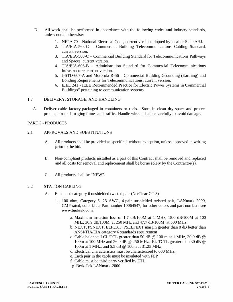
LAWRENCE COUNTY COPPER CABLING SYSTEMS PUBLIC SAFETY FACILITY 271500- 3
D. All work shall be performed in accordance with the following codes and industry standards, unless noted otherwise:
1. NFPA 70 – National Electrical Code, current version adopted by local or State AHJ. 2. TIA/EIA-568-C – Commercial Building Telecommunications Cabling Standard,
current version. 3. TIA/EIA-568-C – Commercial Building Standard for Telecommunications Pathways
and Spaces, current version. 4. TIA/EIA-606-B – Administration Standard for Commercial Telecommunications
Infrastructure, current version. 5. J-STD-607-A and Motorola R-56 – Commercial Building Grounding (Earthing) and
Bonding Requirements for Telecommunications, current version. 6. IEEE 241 - IEEE Recommended Practice for Electric Power Systems in Commercial
Buildings” pertaining to communication systems.
1.7 DELIVERY, STORAGE, AND HANDLING
A. Deliver cable factory-packaged in containers or reels. Store in clean dry space and protect products from damaging fumes and traffic. Handle wire and cable carefully to avoid damage.
PART 2 - PRODUCTS
2.1 APPROVALS AND SUBSTITUTIONS
A. All products shall be provided as specified, without exception, unless approved in writing prior to the bid.
B. Non-compliant products installed as a part of this Contract shall be removed and replaced and all costs for removal and replacement shall be borne solely by the Contractor(s).
C. All products shall be “NEW”.
2.2 STATION CABLING
A. Enhanced category 6 unshielded twisted pair (NetClear GT 3)
1. 100 ohm, Category 6, 23 AWG, 4-pair unshielded twisted pair, LANmark 2000, CMP rated, color blue. Part number 10064547, for other colors and part numbers see www.berktek.com.
a. Maximum insertion loss of 1.7 dB/100M at 1 MHz, 18.0 dB/100M at 100 MHz, 30.9 dB/100M at 250 MHz and 47.7 dB/100M at 500 MHz.
b. NEXT, PSNEXT, ELFEXT, PSELFEXT margin greater than 8 dB better than ANSI/TIA/EIA category 6 standards requirement
c. Cable balance: LCL/TCL greater than 50 dB @ 100 m at 1 MHz, 30.0 dB @ 100m at 100 MHz and 26.0 dB @ 250 MHz. EL TCTL greater than 30 dB @ 100m at 1 MHz, and 5.5 dB @ 100m at 31.25 MHz
d. Electrical characteristics must be characterized to 600 MHz. e. Each pair in the cable must be insulated with FEP f. Cable must be third party verified by ETL. g. Berk-Tek LANmark-2000

COPPER CABLING SYSTEMS LAWRENCE COUNTY 271500 - 4 PUBLIC SAFETY FACILITY
B. Enhanced category 6a shielded twisted pair
a. 100 ohm, Category 6, 23 AWG, 4-pair shielded twisted pair, , CMP rated, color blue. For colors and part numbers see www.berktek.com.
b. Maximum insertion loss of 1.7 dB/100M at 1 MHz, 18.0 dB/100M at 100 MHz, 30.9 dB/100M at 250 MHz and 47.7 dB/100M at 500 MHz.
c. NEXT, PSNEXT, ELFEXT, PSELFEXT margin greater than 8 dB better than ANSI/TIA/EIA category 6 standards requirement
d. Cable balance: LCL/TCL greater than 50 dB @ 100 m at 1 MHz, 30.0 dB @ 100m at 100 MHz and 26.0 dB @ 250 MHz. EL TCTL greater than 30 dB @ 100m at 1 MHz, and 5.5 dB @ 100m at 31.25 MHz
e. Electrical characteristics must be characterized to 600 MHz. f. Each pair in the cable must be insulated with FEP g. Cable must be third party verified by ETL. h. Berk-Tek
2.3 MODULAR JACKS
A. Category 6 modular jacks ( NetClear GT 3 & GT 2)
1. 8-position modular jack, Category 6, IDC terminals, T568A/B wiring scheme 2. Each jack must be stamped or have icons to identify it as CAT 6. 3. Color to be coordinated with building finishes.
a. Ortronics OR-TJ600
B. Category 6a shielded modular jacks
2.4 WORK AREA OUTLETS
A. Flush mounted stainless steel faceplates
1. One port TracJack stainless steel faceplate, with recessed label fields, mounts within a single gang wall box.
a. Ortronics OR-403STJ11.
2. Two port TracJack stainless steel faceplate, with recessed label fields, mounts within a single gang wall box.
a. Ortronics OR-403STJ12.
3. Three port TracJack stainless steel faceplate, with recessed label fields, mounts within a single gang wall box.
a. Ortronics OR-403STJ13.
4. Four port TracJack stainless steel faceplate, with recessed label fields, mounts within a single gang wall box.
a. Ortronics OR-403STJ14.
5. Six port TracJack stainless steel faceplate, with recessed label fields, mounts within a single gang wall box.
a. Ortronics OR-403STJ16.
B. Surface mounted outlet boxes (TracJack)

LAWRENCE COUNTY COPPER CABLING SYSTEMS PUBLIC SAFETY FACILITY 271500- 5
1. Two port TracJack surface mount box, constructed from high impact thermo-plastic, with recessed label fields.
a. Ortronics OR-404TJ4.
2. Four port TracJack surface mount box, constructed from high impact thermo-plastic, with recessed label fields.
a. Ortronics OR-40400055.
3. Four port TracJack surface mount box, constructed from high impact thermo-plastic, with recessed label fields, jacks exit from both sides.
a. Ortronics OR-40400072.
4. Six port TracJack surface mount box, constructed from high impact thermo-plastic, with recessed label fields.
a. Ortronics OR-40400056.
5. All surface box colors are to be coordinated with architect to match finish.
C. Modular furniture faceplates
1. .125-inch deep modular furniture bezel fits 1.375-inch x 2.71-inch furniture knockout.
a. Ortronics OR-40700071.
2. .625-inch deep modular furniture bezel fits 1.375-inch x 2.71-inch furniture knockout, with recessed label field.
a. Ortronics OR-40700072.
3. 1-inch deep modular furniture bezel fits 1.375-inch x 2.71-inch furniture knockout, with recessed label field.
a. Ortronics OR-40700073.
4. Three port modular furniture adapter plate
a. Ortronics OR-42100009.
5. Adjustable four port modular furniture faceplate fits 2.67-inch to 2.75-inch x 1.34-inch to 1.41-inch furniture knockout.
a. Ortronics OR-40300633
6. Four port modular furniture faceplate fits Herman Miller Beltline furniture openings 2.35-inch x 3.41-inch.
a. Ortronics OR-40300576.
7. Six port modular furniture faceplate fits Herman Miller Beltline furniture openings 2.35-inch x 3.41-inch.
a. Ortronics OR-40300577.
8. Six port modular furniture faceplate fits Herman Miller Baseline furniture openings 1.89-inch x 2.99-inch.
a. Ortronics OR-40300575.
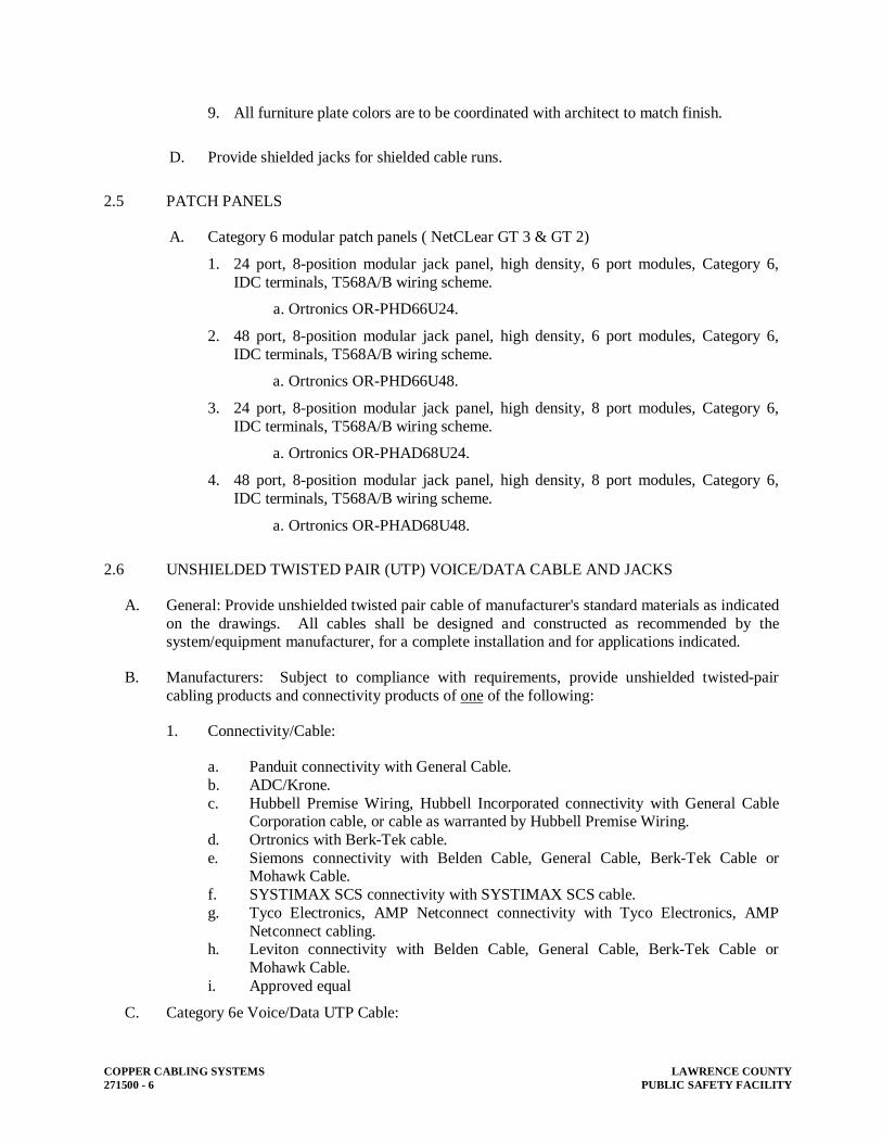
COPPER CABLING SYSTEMS LAWRENCE COUNTY 271500 - 6 PUBLIC SAFETY FACILITY
9. All furniture plate colors are to be coordinated with architect to match finish.
D. Provide shielded jacks for shielded cable runs.
2.5 PATCH PANELS
A. Category 6 modular patch panels ( NetCLear GT 3 & GT 2)
1. 24 port, 8-position modular jack panel, high density, 6 port modules, Category 6, IDC terminals, T568A/B wiring scheme.
a. Ortronics OR-PHD66U24.
2. 48 port, 8-position modular jack panel, high density, 6 port modules, Category 6, IDC terminals, T568A/B wiring scheme.
a. Ortronics OR-PHD66U48.
3. 24 port, 8-position modular jack panel, high density, 8 port modules, Category 6, IDC terminals, T568A/B wiring scheme.
a. Ortronics OR-PHAD68U24.
4. 48 port, 8-position modular jack panel, high density, 8 port modules, Category 6, IDC terminals, T568A/B wiring scheme.
a. Ortronics OR-PHAD68U48.
2.6 UNSHIELDED TWISTED PAIR (UTP) VOICE/DATA CABLE AND JACKS
A. General: Provide unshielded twisted pair cable of manufacturer's standard materials as indicated on the drawings. All cables shall be designed and constructed as recommended by the system/equipment manufacturer, for a complete installation and for applications indicated.
B. Manufacturers: Subject to compliance with requirements, provide unshielded twisted-pair cabling products and connectivity products of one of the following:
1. Connectivity/Cable:
a. Panduit connectivity with General Cable. b. ADC/Krone. c. Hubbell Premise Wiring, Hubbell Incorporated connectivity with General Cable
Corporation cable, or cable as warranted by Hubbell Premise Wiring. d. Ortronics with Berk-Tek cable. e. Siemons connectivity with Belden Cable, General Cable, Berk-Tek Cable or
Mohawk Cable. f. SYSTIMAX SCS connectivity with SYSTIMAX SCS cable. g. Tyco Electronics, AMP Netconnect connectivity with Tyco Electronics, AMP
Netconnect cabling. h. Leviton connectivity with Belden Cable, General Cable, Berk-Tek Cable or
Mohawk Cable. i. Approved equal
C. Category 6e Voice/Data UTP Cable:

LAWRENCE COUNTY COPPER CABLING SYSTEMS PUBLIC SAFETY FACILITY 271500- 7
1. Provide where indicated on the Drawings or where required by the Specifications, enhanced TIA/EIA Category 6e unshielded twisted pair cable.
2. Provide plenum rated cable in all areas having plenum rated ceiling. All areas of the building shall be considered as having plenum rated ceiling unless noted otherwise on the Drawings.
3. Cable/connectivity system shall be certified by suppler. 4. Category 6e UTP cable shall meet the following requirements:
a. Structured cabling system shall support 1GB Ethernet. b. All cables shall have 4-pairs with a pair separator built into the cable. c. All Category 6e cables shall meet the minimum requirements of the TIA/EIA-
568B.2-1 Category 6e and ISO 11801 2nd Edition Class E channel standards. d. All cables shall be tested by ETL, UL, or an equal third-party testing organization
as approved by the Engineer. All cables shall be third-party tested using a standard TIA/EIA 4-connector channel test. Provide printed test reports from the third-party testing organization with the Submittals indicating the minimum performance requirements posted by the system manufacturer:
1) TIA/EIA standard test 2) minimum means worst-case value, typical means average value 3) test frequency 4) 100 meter channel test results, plenum (CMP) cable 5) 90 meter link test results 6) submit values for Link test
5. Manufacturer/Model Number: Provide cable manufactured by one of the following companies:
Manufacturer Series Plenum (CMP)
Riser (CMR)
ADC/Krone TrueNet 6 6TP-xxyy 6TRT-xxyy
Belden Media Twist 1874A se-ries
1872A se-ries
Berk-Tek General Cable Corporation GenSpeed
TX6500 7131431 (*) 7133374
(*) SYSTIMAX SCS GigaSPEED
XL 2071 series 1071 series
Tyco Electronics/AMP NetConnect
1499033-X 1499038-X
(*) MODEL NUMBER IF FOR BLUE CABLE, USE MODEL NUMBER FOR REQUIRED COLOR CABLE.
6. Jacks and Patch Panels:
a. All jacks shall be RJ-45, 568B configuration. b. Patch Panel shall be in 24 or 48-port configuration as required by the number of
workstation cables.
c. Manufacturer/Model Number: Provide jacks and patch panels manufactured by one of the following companies:

COPPER CABLING SYSTEMS LAWRENCE COUNTY 271500 - 8 PUBLIC SAFETY FACILITY
Manufacturer Series Jacks Patch PanelsADC/Krone TrueNet 6 EC06-xx EC06-
PANELxx Hubbell HXJ6 series P6xxUE se-
ries Ortronics Siemons System 6 MX6 series HD6 seriesSYSTIMAX SCS MGS-400
series 1100GS3 se-ries
Tyco Electronics/AMP NetConnect
1375055-X 137501X-1
Pandiut DP6 PLUS Mini-Com DP6 Plus UTP
Leviton eXtreme +
PART 3 - EXECUTION
3.1 INSTALLATION OF VOICE/DATA CABLES
A. Voice/data cables shall be installed with a minimum 18" clearance from light fixtures, electrically operated equipment and all wiring operating at 120 or more volts.
B. Voice/data cables shall be installed in accordance with manufacturer's written instructions and in compliance with NEC.
C. Coordinate installation with other Work.
D. Install without damaging conductors or jacket.
E. Do not, either in handling or installation, bend cable to smaller radii than minimum recommended by manufacturer.
F. Ensure that minimum manufacturer's recommended pulling tensions are not exceeded.
G. Pull conductors simultaneously where more than one is being installed in same raceway. Use pulling means, including fish tape, cable, rope, and basket weave wire/cable grips that will not damage media or raceway.
H. Install all cable parallel and/or perpendicular to building surfaces or exposed structural members, and follow surface contours where possible. In ceiling cavities, install cables at bottom of trusses.
I. Provide “J” hooks for all cables not installed in raceways. “J” hooks shall be spaced no greater than five feet (60”) on center, with a maximum spacing of four feet (48”) for bundles of 20 or more cables. Do not exceed manufacturer’s capacity for “J” hooks.
J. No cable splices are allowed.
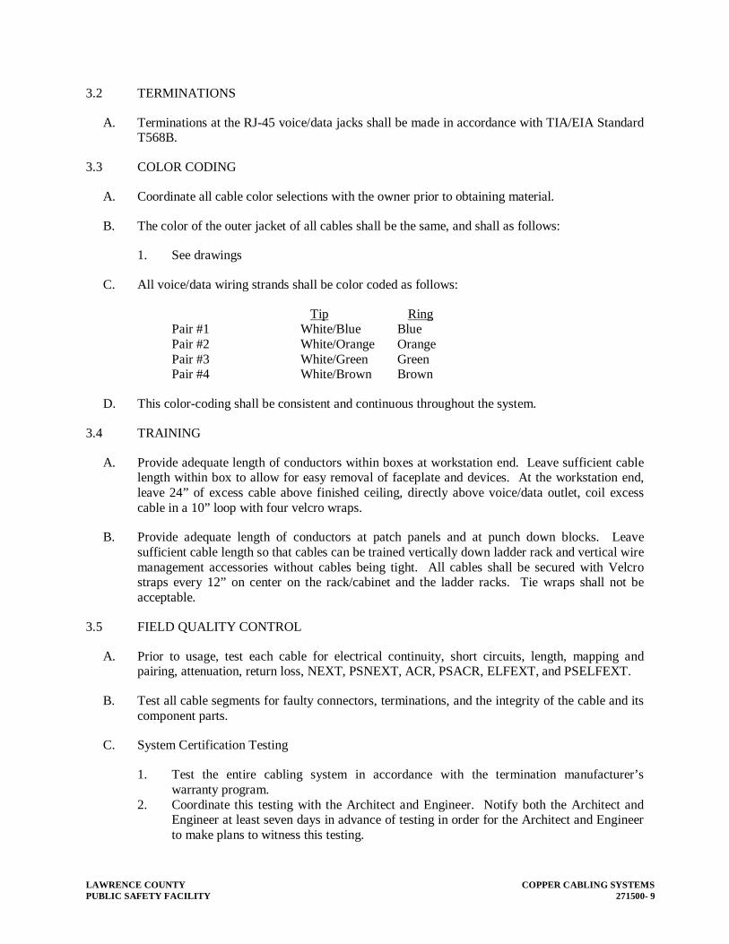
LAWRENCE COUNTY COPPER CABLING SYSTEMS PUBLIC SAFETY FACILITY 271500- 9
3.2 TERMINATIONS
A. Terminations at the RJ-45 voice/data jacks shall be made in accordance with TIA/EIA Standard T568B.
3.3 COLOR CODING
A. Coordinate all cable color selections with the owner prior to obtaining material.
B. The color of the outer jacket of all cables shall be the same, and shall as follows:
1. See drawings
C. All voice/data wiring strands shall be color coded as follows:
Tip Ring Pair #1 White/Blue Blue Pair #2 White/Orange Orange Pair #3 White/Green Green Pair #4 White/Brown Brown
D. This color-coding shall be consistent and continuous throughout the system.
3.4 TRAINING
A. Provide adequate length of conductors within boxes at workstation end. Leave sufficient cable length within box to allow for easy removal of faceplate and devices. At the workstation end, leave 24” of excess cable above finished ceiling, directly above voice/data outlet, coil excess cable in a 10” loop with four velcro wraps.
B. Provide adequate length of conductors at patch panels and at punch down blocks. Leave sufficient cable length so that cables can be trained vertically down ladder rack and vertical wire management accessories without cables being tight. All cables shall be secured with Velcro straps every 12” on center on the rack/cabinet and the ladder racks. Tie wraps shall not be acceptable.
3.5 FIELD QUALITY CONTROL
A. Prior to usage, test each cable for electrical continuity, short circuits, length, mapping and pairing, attenuation, return loss, NEXT, PSNEXT, ACR, PSACR, ELFEXT, and PSELFEXT.
B. Test all cable segments for faulty connectors, terminations, and the integrity of the cable and its component parts.
C. System Certification Testing
1. Test the entire cabling system in accordance with the termination manufacturer’s warranty program.
2. Coordinate this testing with the Architect and Engineer. Notify both the Architect and Engineer at least seven days in advance of testing in order for the Architect and Engineer to make plans to witness this testing.

COPPER CABLING SYSTEMS LAWRENCE COUNTY 271500 - 10 PUBLIC SAFETY FACILITY
3. After all punchdowns and cable terminations are complete test each cable from the workstation outlet to the patch panel. Perform both channel and link tests.
4. This testing shall be conducted with a 568 C.2 compliant tester and as approved by the cable/termination manufacturer.
5. Measure and record the following data: mapping and pairing, attenuation, return loss, NEXT, PSNEXT, ACR, PSACR, ELFEXT, and PSELFEXT.
6. Document the test results in graphic plot/text format immediately following the testing. Documentation shall be in printed form, 8½” x 11” paper printed via a laser printer. Provide two copies of the recordings bound in two separate cable record books, indexed for easy reference and transmit these books to the Architect for review by the Engineer. Bind the original recordings in a cable record book indexed for easy reference during future maintenance operations and turn book over to the Owner's authorized representative.
3.6 COMMISSIONING
A. Subsequent to installation of voice/data cable and equipment demonstrate proper functioning. Replace malfunctioning components with new materials, and then retest until satisfactory performance is achieved. At no additional cost to the owner
B. Provide manufacturer system certifications to the owner.
END OF SECTION 271500

LAWRENCE COUNTY STRUCTURED CABLING SYSTEM COMPONENTS PUBLIC SAFETY FACILITY 271510- 1
SECTION 271510 – STRUCTURED CABLING SYSTEM COMPONENTS
PART 1 - GENERAL
1.1 RELATED DOCUMENTS
A. Drawings and general provisions of Contract, including General and Supplementary Conditions and Division 01 Specification sections, apply to work of this section.
B. Related Sections include the following: 1. Division 27 Section 27 0500 “Common Work Results for Communication”. 2. Division 27 Section 27 1300 “Fiber Optic Cabling Systems”. 3. Division 27 Section 27 1500 “Copper Cabling Systems”.
1.2 GENERAL
A. This Section includes the following:
1. Individual structured cabling system components.
1.3 DESCRIPTION OF WORK
A. The Communications Contractor shall furnish and supply all equipment, including but not limited to, UTP cabling, fiber optics cable, patch panels, and other equipment necessary to provide a complete and interconnected structured cabling system.
B. Contractor shall furnish a manufacturer's manual of the completed system including individual specification sheets, schematics, inter-panel and intra-panel wiring diagrams. In addition, all information necessary for the proper maintenance and operation of the system must be included. All published specifications of the manufacturers of equipment specified shall be considered as being a part of this specification, even though they have not been included in detail. Any bidder using other than the specified equipment must provide this information prior to bidding.
C. As-built drawings that include any changes to wiring, wiring designations, junction box labeling and any other pertinent information shall be supplied upon completion of project.
D. Cabling system shall be in accordance with good engineering practices as established by the BISCI, TIA/EIA, and NEC, and any other applicable codes or regulations.
E. All equipment installation and cabling shall meet all requirements of manufacturer.
PART 2 - PRODUCTS
2.1 REQUIRED EQUIPMENT
A. Provide the following items, including but not limited to, the purchase, delivery, unpacking, installation, connection, testing, and operation of the same.

STRUCTURED CABLING SYSTEM COMPONENTS LAWRENCE COUNTY 271510 - 2 PUBLIC SAFETY FACILITY
B. The quantities of items required shall be as shown on the drawings, or as stated below. Where a conflict exists between the quantities shown on the drawings, and the quantities stated hereinafter, the greater of the two quantities shall be used. All Item Tags listed below are referenced to the Item Tags shown and listed on the Riser Diagram on the Drawings.
C. Category 6 Workstation Cable:
1. Description: TIA/EIA standard Category 6 and 6a shielded horizontal distribution cable. 2. Requirements:
a. Cable shall meet performance characteristics specified in Section 27 15 00 of the Specifications.
b. Cable shall be plenum rated for all cable routed through the ceiling.
3. Accessories:
a. None
4. Quantity: as shown and scheduled on the Drawings. 5. Remarks: None
D. Category 6 Patch Panel:
1. Description: TIA/EIA standard Category 6 RJ-45 and 6a shielded patch panel. 2. Requirements:
a. Patch panel shall meet performance characteristics specified in Section 27 15 00 of the Specifications.
b. Patch panel shall be rack mounted.
3. Accessories:
a. Rack mount hardware. b. Labeling hardware.
4. Quantity: As shown and scheduled on the drawings 5. Remarks: None
E. Category 6 and 6a shielded Cross Connect Cable:
1. Description: factory fabricated TIA/EIA standard Category 6 cross connect cable. 2. Requirements:
a. Cable shall be used to cross connect patch panel to network switch. b. Cable shall meet performance characteristics specified in Section 27 15 00 of the
Specifications. c. Coordinate actual lengths with Owner prior to ordering. d. Cables shall be colored. Coordinate color with Owner prior to ordering.
3. Accessories:
a. None

LAWRENCE COUNTY STRUCTURED CABLING SYSTEM COMPONENTS PUBLIC SAFETY FACILITY 271510- 3
F. Fiber Optic Distribution Cable:
1. Description: 12-strand 50um multi-mode fiber optic cable 2. Manufacturer/Model No.: Refer to Section 27 13 00 of the Specifications. 3. Requirements:
a. Cable shall extend from rack-mounted distribution shelf in IDF to rack mounted distribution shelf in MDF.
b. Cable shall meet performance characteristics specified in Section 27 13 00 of the Specifications.
c. Cable shall be plenum rated. d. All strands of the cable shall be terminated at both ends. e. Cable shall be suitable for 10 Gigabit Ethernet at 300 meters 50/125um (OM3)
multimode plenum rated.
4. Accessories:
a. None
5. Quantity: as shown on the Drawings. 6. Remarks: None
G. 12-Strand F.O. Distribution Shelf:
1. Description: 12-port fiber optic rack mounted distribution shelf 2. Manufacturer/Model No.: Panduit Opticom QuickNet series. 3. Requirements:
a. Cable shall meet performance characteristics specified in Section 27 13 00 of the Specifications.
b. Cable shall be plenum rated.
4. Accessories:
a. None
5. Quantity: 6. Remarks: none
H. 2-Strand Fiber Optic Patch Cable:
1. Description: 2-strand 50um multi-mode fiber optic cross connect cable 2. Manufacturer/Model No.: Refer to Section 27 13 00 of the Specifications. 3. Requirements:
a. Cable shall meet performance characteristics specified in Section 27 13 00 of the Specifications. Panduit Opti-core 10 Gig 50/125 um (OM3) fiber optic patch cords and pigtails. Part # FXE10-10M1Y.
b. Cables shall have LC (coordinate connector type with Owner prior to purchase) connectors at one end and connectors compatible with network switches at other end.

STRUCTURED CABLING SYSTEM COMPONENTS LAWRENCE COUNTY 271510 - 4 PUBLIC SAFETY FACILITY
c. Cable shall be adequate length to cross connect distribution shelf to Gigabit modules and ports.
4. Accessories:
a. None
5. Quantity: 44 EACH. 6. Remarks: None
I. Wall-Mounted Category 6 and 6a shielded Data Jack:
1. Description: wall mounted TIA/EIA standard Category 6 and 6a shielded data jack(s) 2. Requirements:
a. Number of jacks per outlet as shown on the drawings.
3. Accessories:
a. None
4. Quantity: as shown on the Drawings. 5. Remarks: Panduit Mini-Com Stainless Steel Faceplates with Labels.
J. Surface-Mounted Raceway Category 6 and 6a shielded Data Jack:
1. Description: TIA/EIA standard Category 6 and 6a shielded data jack(s) mounted in surface mounted raceway
2. Requirements:
a. Number of jacks per outlet as shown on the drawings.
3. Accessories:
a. None
4. Quantity: as shown on the Drawings. 5. Remarks: Panduit Mini-Com Stainless Steel Faceplates with Labels.
K. Floor Box Category 6 and 6a shielded Data Jack:
1. Description: TIA/EIA standard Category 6 and 6a shielded data jack(s) mounted in floor box.
2. Requirements:
a. Number of jacks per outlet as shown on the drawings. b. Install a maximum of 3 data jacks per insert plate.
3. Accessories:
a. None
4. Quantity: as shown on the Drawings.

LAWRENCE COUNTY STRUCTURED CABLING SYSTEM COMPONENTS PUBLIC SAFETY FACILITY 271510- 5
5. Remarks: None L. Wireless Access Point Category 6 Data JACK/MODULAR PLUG:
1. Description: TIA/EIA standard Category 6 above ceiling MODULAR JACK for wireless access point
2. Mount jacks in Wireless Access Point enclosure. 3. Requirements:
a. Number of jacks per outlet as shown on the drawings.
4. Accessories:
a. None
5. Quantity: as shown on the Drawings.
PART 3 - EXECUTION
A. Before final acceptance of the installation, the contractor shall test in the presence of the Architect/Engineer/Owner or their representative's the complete installation and show that the system is completely operational and tests to the performance levels of the cable specified. The Contractor shall obtain all equipment required to test the final installation. The testing of the system shall be made under the direct supervision of the equipment manufacturer's or their designated representative.
B. The Contractor shall provide a one-year guarantee of the installed system against defects in material and workmanship. All labor and materials shall be provided at no expense to the Owner. In addition, the structured cabling systems shall have a 25-year warranty. Guarantee period shall begin on the date of acceptance by the Architect/Engineer/Owner.
END OF SECTION 271510

Copyright © 2022 FDOKUMEN