
Lawrence Berkeley Laboratory
47
^-S£C ! o¥-'rO VC~ 1:5 Lawrence Berkeley Laboratory UNIVERSITY OF CALIFORNIA Accelerator & Fusion Research Division Presented at the NATO Advanced Study Institute, Maratea, Italy, June 28-JuIy 10, 1992, and to be published in the Proceedings The Properties of Undulator Radiation M R . Howells and B.M. Kincaid September 1993 Prepared for C:s V.S. Department of Energy under Contract Number DE-AC03-76SF00098
-
Upload
khangminh22 -
Category
Documents
-
view
1 -
download
0
Transcript of Lawrence Berkeley Laboratory

^-S£C ! o¥- ' rO VC~ 1:5
Lawrence Berkeley Laboratory UNIVERSITY OF CALIFORNIA
Accelerator & Fusion Research Division
Presented at the NATO Advanced Study Institute, Maratea, Italy, June 28-JuIy 10, 1992, and to be published in the Proceedings
The Properties of Undulator Radiation
MR. Howells and B.M. Kincaid
September 1993
Prepared for C:s V.S. Department of Energy under Contract Number DE-AC03-76SF00098

DISCLAIMER
This document was prepared as an account of work sponsored by the United States Government. Neither the United States Govenusent nor any agency thereof, nor The Regents of the University of California, nor any of their employees, makes any warranty, express or implied, or assumes any legal liability or responsibility for the accuracy, completeness or usefulness of any information/ apparatus, product, or proceas disclosed, or represents that its use would not Infringe privately owned rights. Reference herein to any specific commercial product, process, or service by its trade name, trademark, manufacturer, or otherwise, does not necessarily constitute or imply its endorsement, recommendation, or favoring by the United States Government or any agency thereof, or The Regents of the University of California! The views and opinions of authors expressed herein do not necessarily slate or reflect those of the United Stetes Government or any agency thereof or The Regents of the University of California and shall not be used for advertising or product endorsement purposes.
This report has been reproduced directly from the besr available copy.
Lawrence Berkeley Laboratory is an equal opportunity employer.

LBL-3475I UC-406
The Properties of Undulator Radiation
M.R. Howells and B.M. Kincaid Lawrence Berkeley Laboratory
University of California Berkeley, California 94720 USA
To be published in the Proceedings of the NATO Advanced Study Institute
New Directions in Research with Third-Generation SoftX-Ray Synchrotron Radiation Sources
held in Maratea, Italy June 28-July 10, 1992
Edited by:
A.S. Schlachter Advanced Light Source
Lawrence Berkeley Laboratory University of California
Berkeley, California 94720 USA
and
F.J. Wuilleumier Laboratoire de Spectroscopic
Atoniique et lonique Universite Paris Sud
Orsay, France
mm?, This work was supported by the Director, Office of Energy Research, Office of Basic Energy Sciences, Materials Sciences Division, of the U.S. Department of Energy under Contract No. DE-AC03-76SF00098.
^

THE PROPERTIES OF UNDULATOR RADIATION
M R . HOWELLS ANDB.M. KINCAJD Advanced Light Source Lawrence Berkeley Laboratory Berkeley CA 94720 USA
ABSTRACT. A new generation of synchrotron radiation light sources covering She VUV, soft x-ray, and hard x-ray spectral regions is under construction in several countries. These sources are designed specifically to use periodic magnetic undulators and Iow-emittance electron or positron beams to produce high-brightness near-diffraction-limited synchrotron radiation beams. Some of the novel features of the new sources are discussed, along with the characteristics of the radiation produced, with emphasis on the Advanced Light Source, a third-generation 1.5 GeV storage ring optimized for undulator use. A review of the properties of undulator radiation is presented, followed by a discussion of some of the unique challenges being faced by the builders and users of the new undulator sources. These include difficult mechanical and magnetic tolerance limits, a complex interaction with the storage ring, high x-ray beam power, partial coherence, harmonics, optics contamination, and the unusual spectral and angular properties of undulator radiation.
1. Introduction
Undulators are now established as operational sources of ultraviolet and x-ray radiation at many synchrotron radiation facilities around the world. They are providing qualitatively new and better types of radiation beams and have been involved in many of the most creative new experiments. The success of undulators can be credited to the combined efforts of the originators of the undulator concepts (Motz, 1951; Motz era/., 1953; Madey, 1971; Alferov et al., 1974; Kincaid, 1977), and to more recent activities such as the work of magnet specialists in the realization of practical undulators (Halbach 1981, 1983; Halbach et al., 1981), accelerator designers (Chasman era/., 1975; Green, 1977; Vignola, 1985), builders who incorporated wigglers and undulators into real storage rings (Bazin er al., 1980; Artamonov et al., 1980A, 1980B; Brown et al., 1983; Krinsky et al., 1983), and users applying the undulator radiation to scientific problems (Rarback et al., 1986; Johnson et al., 1992). A primary motivation for investment in undulators is that undulator beams concentrate the x-ray output into fairly narrow spectral peaks that can be arranged to cover the desired photon energy range. This greatly reduces the amount of unwanted x-ray power and the associated engineering challenges. The experimental benefits of the higher-brightness beams provided by undulators fall into two main classes: (1) the possibility for improved performance of monochromators, and (2) the ability to focus the x-ray beam to a small probe. These are essentially applications of the small optical-phase-space area of undulator beams and, in general, they use a multiplicity of wave modes. A third related benefit, which we consider to be separate, is that a useful amount of power is now available in a single mode. This is one of the qualitatively new features of undulator radiation and opens the way for a class of experiments that use coherent beams
]

In this report, we consider the physical basis and characteristics of undulator radiation and the calculation of its spectral and angular distribution. We describe the coherence properties of undulaior beams and show how to calculate the coherence functions needed for applications We examine the effect of real-world variables on the production of undulator radiation, including the beam optics of the storage ring, radiation from the upstream and downstream bending magnets, and failure of the far-field assumption that is conventionally used in calculating undulator output. We give a brief analysis of the effect of undulator magnetic field errors on the electron beam and on the radiated spectrum and discuss several examples from the Advanced Light Source (ALS) undulator propram. Finally, we make some comments on the capability of present-day undulator technology and the performance trade-offs now available.
2. Fundamentals of Radiation Emission by Fast Electrons: Time Compression
Following Kim. 1989, we consider an electron with an instantaneous velocity v = pV (c being the velocity of light) on an arbiirary trajectory r(r') relative to an origin O as shown in Fig. 1. An observer is located at x, whose position relative to the electron is specified by the unit vector n making an angle 8 with v. An electromagnetic signal emitted by the electron at time i' and traveling in a straight line will arrive at the observer at a later time r, where
, = r' + *Z*3 . ( 1 )
c
The stationary observer sees the electron's motion as a function of time r, which is different from r(; •) due to the change in time scale represented by Eq. (1). The scale-change factor is given by
± = I + £ f e z * x u , _ I I . p = 1 _ / , C 0 S f l . (2) dt di c
If we now define y for the electron as the ratio of its mass to its rest mass, then we have
Figure 1. Electron i/ajeeiory. observer and notation for time compression

1 1 Y~ j V2 yjO-PM + P)
Y'72 (3)
' - ' • £ • If we now expand the cosine in Eq. (2) and use Eq. (3), we arrive at
£-0**") • which allows us to estimate the size of the "time-compression" effect represented by di/di'. For typical storage rings, the electrons are extremely relativistic and y is of the order of a few thousand. This means that if 6 = 0, then the time is compressed by a factor of a few million. On the other hand, if 8 is greater than a few times My, then the 82 term dominates in Eq. (4) and the time compression is much less. The time compression is the factor by which the wavelength of signals radiated by the electron is shortened. We see from this argument that, in practical cases, the time compression is a very large effect, but it is mainly confined to emission angles within a cone of half angle My around the line from the observer to a "tangent point" on the electron trajectory.
Physically, the time compression is due to the fact that a highly relativistic electron follows very closely behind the signals it emitted at earlier times. Moreover, the strength of the electric field at the observer is proportional to the apparent transverse acceleration of the electron as seen by the observer, which will be large when the time compression is large. Thus, the amount of radiation will be large within the My emission cone. To see this more quantitatively, consider a tangent point P on an electron trajectory with local radius of curvature p, and define a curve segment AB centered on P and subtending an angle 2/yat the center of curvature (Fig. 2a). In terms of the emission time, the electron moves from A to P in a time At' = p/y and, during that time, suffers a transverse displacement Ac of p/y 2 (Fig. 2b). In terms of observation time, the displacement Ac happens in the much shorter time At = At'y2 - plly^ c. Thus, the motion seen by the observer has the form shown in Fig. 2c. The sharp kink at P corresponds to a very large
' transverse acceleration as seen by the observer,
d2x = Ac = 4 c 2 / 4
dt2 = ( A - A _ P ) 2 = p
which is of order y 4 times larger than the acceleration in the emission time frame. On this basis, the typical frequency of the radiation should be about MAi or 2y3c/p . This is in reasonable agreement with the so-called "critical frequency" a>c = 3y3c/2p, which is conventionally used to characterize a bending magnet spectrum.
3. Undulators
3.1. BASIC DESCRIPTION
An undulator is a device intended to drive the electron in a sinusoidal trajectory Most commonly, this is accomplished by applying an alternating magnetic field in the vertical direction

*- z
XBL938-5146
Figure 2- The effect of time compression: (al the elecuon trajecton in space, (b) radial coordinate as a function of emission time /'. (c) the apparent variation cf the radial coordinate as a function of observation timer (From Kim. 19S9 ) See text for further explanation.
4

so that the oscillations lie in the horizontal plane. We begin with the case of an exacih sinusoidal field and trajectory as shown schematically in Fig. 3. For this case.
fix
x = - a c o s ( i u r )
— = kuisai(kaz) az
= k;a = - , max r
(6)
where z is along the unduiator axis, x is horizontal, y is vertical, and ku = IJUXQ. The centripetal force at maximum curvature (radius = p) is that corresponding to the peak field B and is given by
evxB: mev~ or p = mpyc eB
(7)
where e, m £, and mo are the electronic charge, mass, and rest mass, respectively. Eliminating a and p between Eqs. (7), (8), and (9), we can determine a value for (dx/dz)m3x that we define to be equal to KJy. When defined in this way, the deflection parameter K is given by
K = eB
kumoc = 0.934;. u(cm)B(T) (8)
and is equal to the maximum angular excursion of the beam in units of \/y. From Eqs. (6) and (7), we can also obtain the following expressions fore and ft = v / c :
\ t 1 t \ \ \ t \ t \ t I t \ t
\ t 4 \ \ t \ t \ t \ t \ t \ t
K = ^ r 7 r F = 0.934 ^ [cm]BIT]
t = N/,,
Figure 3. Basic unduiator layout and noiation.

kaY
dx dx di „ . K . . . — = —— = px=—sw{kuz) dz di dz y
(9)
The value of a is normally rather small (about 10 (lm or so), which makes it much less than the horizontal width of most storage ring electron beams.
A device that deflects the beam by about \/y or less is known as an undulator (K S 1). One that deflects the beam by much more than \/y is known as a wiggier (K»l). According to our earlier discussion of time-compression, the synchrotron radiation beam can be regarded as a kind of "searchlight," of angular half width about 1/y, pointing along a tangent to the electron trajectory. The above definitions, therefore, suggest that the time variation of the electric field as seen by the observer will be roughly sinusoidal for an undulator and will consist of a series of pulses for a wiggier. It is, consequently, quite understandable that the spectrum (the Fourier transform of the field) of an undulator has a sharp peak with a few harmonics while the spectrum of a wiggier has a broad distribution of harmonics. Two representative spectra are shown in Fig. 4. It is noteworthy that the wiggier spectrum extends as far as a harmonic number approximately equal to K1.
3.2. THE FUNDAMENTAL EQUATION
The fundamental equation of undulator action sets a relationship between the wavelength of the undulator and the wavelength of the emitted radiation. The undulator output wavelength is determined essentially by the Doppler shift due to the motion of the radiating electron. The amount of the shift, or "time-compression factor," which is also the compression factor between lengths, is given by Eq. (2) as
= A u ( l - & cose (10)
1.0
0.8
£. 0.6
- 0.4
0.2 -
0.0
ft/2 Undulator
K = 1
i — 1/N
Jlk L
Wiggier
K = 3
5 0 10 20 30 40 50 60
Figure 4. Wigeler and undulaior comparative spectra
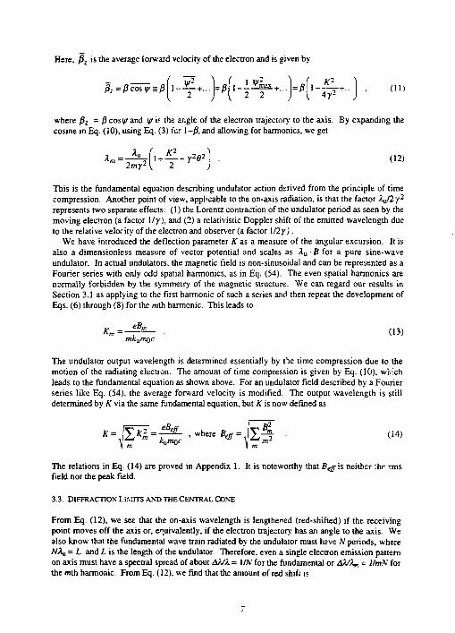
Here, /J. is the average forward velocity of the electron and is given by
ft=^co»»r = / j f i - J ^ + . . . l = p f | - I J ! | a + . . . J = ^ l - ^ i + . . j , (II)
where (3Z = /} cosy and yif the angle of the electron trajectory to the axis. By expanding the cosine in Eq. (iO), using Eq. (3) for 1-/3, and allowing for harmonics, we get
2mv2 { 2 A« = ^ r i + 4 r + r 2 « 2 | • (12)
This is the fundamental equation describing undulator action derived from the principle of time compression. Another point of view, applicable to the on-axis radiation, is that the factor X^tly"1
represents two separate effects: (1) the Lorentz contraction of the undulator period as seen by the moving electron (a factor 1/y), and (2) a relativistic Doppler shift of the emitted wavelength due to the relative velocity of the electron and observer (a factor 1/2y).
We have introduced the deflection parameter K as a measure of the angular excursion. It is also a dimensionless measure of vector potential and scales as Xu • B for a pure sine-wave undulator. In actual undulators, the magnetic field is non-sinusoidal and can be represented as a Fourier series with only odd spatial harmonics, as in Eq. (54). The even spatial harmonics are normally forbidden by the symmetry of the magnetic structure. We can regard our results in Section 3.1 as applying to the first harmonic of such a series and then repeat the development of Eqs. (6) through (8) for the mth harmonic. This leads to
K m = ~ - • (13) mkamQC
The undulator output wavelength is determined essentially by the time compression due to the motion of the radiating election. The amount of time compression is given by Eq. (10), wivich leads to the fundamental equation as shown above. For an undulator field described by a Fourier series like Eq. (54), the average forward velocity is modified. The output wavelength is still determined by K via the same fundamental equation, but K is now defined as
The relations in Eq. (14) are proved in Appendix 1. It is noteworthy that Bfffis neither :hr rms field nor the peak field.
3.3. DIFFRACTION OMITS AND THE CENTRAL CONE
From Eq. (12), we see that the on-axis wavelength is lengthened (red-shifted) if the receiving point moves off the axis or, enuivalently, if the electron trajectory has an angle to the axis. We also know that the fundamental wave train radiated by the undulator must have N periods, where NXQ = L and L is the length of the undulator. Therefore, even a single electron emission partem on axis must have a spectral spread of about &/J/. = 1/A' for the fundamental or AsSX^ = 1/mN for the mth harmonic. From Eq. (12). we find that the amount of red shift is

AX Xm(6)-Xm(0) y*f- _ , -A m A m ( 0 ) ] + J ^ 7
2
Equation (15) defines a useful quantity, y». Further, let us define an angle aT corresponding to a spectral spread AX/X„ = l!2mN as
0-;=— V P ^ = , | S . (16) 7 - \2mN U
The angle a'T turns out to be impoitant in the analysis of undulator beams. It is the rms width of the one-electron undulator beam due to diffraction. One can see this in a rough way by calculating the angle of the first minimum of the diffraction pattern of an ideal longitudinal line source. Consider a parallel beam of rays emitted co*1. ently at angle 8 from every point on the source. The diffraction minimum will occur when the path difference between the rays from the upstream and downstream ends of the source (L - LcosB) is equal to A/2. This leads directly to 6 = -JX/L.
Equations (15) and (16) show that, provided the collection half angle 9CC is less than c;, then the intrinsic spectral width 1 ImN is not much spoiled by red shifting. The radiation within 8 C C is called the central cone and is the most useful part of the undulator emission. The central cone of an undulator beam is even more highly collimated than normal synchrotron radiation. Equation (16) shows that it has a characteristic angular width I / (y V!"), which is substantially smaller than the 1/y width of a bending magnet beam. Because every harmonic is red shifted according to Eq. (12), the wavelength of each harmonic will equal that of the fundamental at a sufficiently large off-axis angle. The radiation pattern at the fundamental frequency thus consists of a bright central peak on the axis and a series of partially illuminated rings of angular radius V m - 1 / y*. A similar argument holds for higher harmonics which have rings due to the harmonics of higher number than themselves.
For the case of a real electron beam, it may happen that the electron beam angular spread a'x is greater than 6CC. In this case, the central cone width has to be defined equal to c j , and this will represent a degradation of the spectra! brightness of the undulator. Storage rings such as the ALS, which are intended to operate with undulators, are designed to have electron beam angular spreads that are small compared to 6 C C .
3.4. PRACTICAL REALIZATION OFUNDULATORS
The practical realization of undulators is now nearly always by means of permanent magnets following the methods leveloped by Halbach, 1981, 1983, and Halbach ei a t , 1981. We do not have space for a review here, but the most common design for building high-field devices (the so-called hybrid scheme) consists of blocks of permanent magnet material combined with soft iron pole pieces as shown in Fig. 5. The materials used for the recently completed ALS undulators were neodymium-iron-boron blocks and vanadium permendur poi'! pieces. The ALS devices are the largest and most demanding yet attempted, and their achieved field quality and projected performances are treated in more detail in a later section.
The technology of the undulator magnetic structure and the physics of the resulting magnetic field distributions set limits on the range of devices that can, in principle, be built. Usually, one starts with a knowledge of a photon energy operating range and a magnetic gap defined by the requirements of the storage ring injection system. As a start, we may safely assume that the output of an undulator falls to zero as K approaches zero. In fact, as we shall see in Section 4, it

Timmg Stud (Si«ij
Backing Plate (Steel;
Keeper <Alum. A"oy)
CSEM Blocks (Magnetization Orientation Shownj
Pole (Vanadium Permendur)
Vacuum Chamber (Stainless Steel)
AIT Region
Hall Gap
a.) Elevation Cross Section b.) Quarter Period Magnetic Flux Plot
CSEM-Stee; Hybrid Insertion Device
Figure 5. Construction of a hybrid undulator from current-sheet-equivalent material (CSEM) and steel.
falls to about half maximum ci K = 0.5, and fairly rapidly below that, so that we may reasonably • regard K = 0.5 as a limit. Using Eq. (12) witn K = 0.5 and 6= 0, we obtain the value for Xa that delivers the required minimum wavelength, .-.ccepting this value, we then find that the maximum wavelength obtainable will be determined, via Eq. (12), by the highest achievable value of AT, which depends on the field.
A certain amount of information about the field can be calculated from formulas that apply to magnet structures of optimum design (Halbach, 1983);
(17) Neodymium -
BQ = 3.44exp
-iron:
A u
(MB-LMX) 0.085 <-^-< 0.8 u
Samarium - cobalt:
£b = 3.33exp H ( 5 - 4 7 - L 8 t l 0.07 <-£-< 0.7 . Au
(18)
9

In these formulas. Bo ' 5 the peak field and. hence, is an overestimate cf Bfg. 'Jsaig B& to conspire A'oi/l would, therefore, be incorrect An accurate evaluation of the value of A'viaEq.(14) (and (hence K) requires a knowledge of the Fourier expansion of the field. This can be obtained using a program such as POISSON (see for example, Warren a at, 1987). In pursuing this type of design exercise, one possible variation is to reduce ?v somewhat to gain some brightness (larger A' for a given L) and reduce the total power. The trade-off would be a reduction in the spectral range. We consider this question further in Section 7.1.
Although Eqs. (17) and (18) are correctly given in the reference quoted, they have, nevertheless, often been misunderstood. Accordingly, we wish to point out several thirds that these equations do not imply.
1. They can only be used in the stated ranges of values of the gap-tc-period ratio. Outside the stated ranges they can give meaningless results.
?. They give the maximum total field obtainable by good design for a single gap-to-period ratio. They do not predict what field this same well-designed undulator will produce at other gap-to-period ratios.
3. The field given is the peak field, not the rms field or the Btjf used in Eq. (14). Consequently, one cannot obtain a correct value for K using Bo from Eqs. (17) or (18).
4. The total field may contain a strong harmonic content. For the smallest gap-to-period ratios, the field is highly non-sinusoidal. The greater the harmonic content, the greater the difference between Bo and Bcjf,
4. Characteristics of Undulator Radiation
4.1. CALCULATION OF THE SPECTRAL AND ANGULAR DISTRIBUTIONS
The general problem of calculating radiation from accelerated electrons has received extensive attention in the literature as reviewed as reviewed, for example, by Blewett, 1988. The first derivation of a synchrotron radiation spectrum was in the 1912 publication by G.A. Schott (Schoti, 1912), although not much could be done with it at the time. After the experimental discovery of synchrotron radiation, Schwinger derived expressions in terms of known functions describing bending magnet radiation and clarified the physics of the process (Schwinger, 1949). A lucid treatment of the problem, and one which has beer, widely used by other authors, is provided by Jackson, 1975. If the coordinate system is the one shown in Fig. 6, then according to Jackson, the flux per unit solid angle is given (in SI units) exactly by
dI((Q)
dasdCl'
I e 2 o 2
4;r£0 4;r2c nx[n-p]xp (n-p)c (1-n-P)2/? y 2(l-n-P) 2* 2
e ia)(r+K(r>/cy T
(19)
which reduces in the far field to
dl(co) 1 e2a>2
dojdil 4JTE0 4;r 2c Jnx(nxp)e""<T-n ir'' :><z; (20)
10
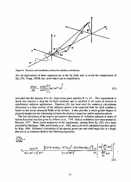
Figure 6. Notation and coordinate systems for radiation calculations.
Not all applications of these equations are in the far field, and, to avoid the complication of Eq. (19), Wang. 1993B, has :hown that it can be simplified to
dH.a) aha4
dii Alik2 Jn(f')e <dt (21)
provided that the distance R to the observation point satisfies R » yX . This requirement is much less restricth e than the far-field condition and is satisfied in all cases of interest in synchrotron radiation applications. Equation (21) has been used for numerical calculations (discussed in a later section) of the radiation pattern to be expected from the ALS undulators based on the actual measured fields of the devices. It also provides a much greater degree of physical insight into the relationship between the electron's trajectory and its radiation pattern.
The full calculation of the angular and spectral distribution of nndulator radiation in terrrs of known functions was first given by Alferov et al., ' 974. Helical undulators have been treated by Kincaid, 1977. More recent treatments of the calculations, starting from Eq. (20), have been provided by Hofmann, 1986, and Krinsky et al., 1983, and an ab initio calculation has been given by Kim, 1989. Hofmann's calculation of the spectra] power per unit solid angle due to a single electron in an undulator leads to the following expression:
diideo'
^u 3m2 y'2 [(2 ye •os<pSm] - K'Sm3f +(2y'esin <t>Sm <f »
^u *(' + K2I2)2K' ? (i + r2e2f 0)1
(Aco sinl —nN
Aco nN
(22)
11

where
Aw=w-ma>i £J
" " " ' • " " • J * 2 ' " V fc Z/r^cosQ
*-§(dryg] flu=^TFi5)- ^ = - ( ^ ^ f ' C23)
5ml = ^•';("«2u)-'m+2/('n*u) /=— V" 2 * *
and 0 and <p are the radial and azimuthal angles, respectively. In comparing Eq. (22) with the corresponding equation given by Krinsky et al., 1983, and after translation of Krinsky's notation to Hofmann's, one finds that there is still an apparent disagreement in the Smi term of Eq. (22), which Krinsky expresses in terms of different Bessel function series. However, upon application of the recurrence relation J^+iixyt-J^-jix) = 2fUf,(x)/x, the two expressions can be seen to be fully identical.
The first term in the square bracket of Eq. (22) describes the a polarization and the second term describes the n. Obviously, the n contribution is zero in the horizontal plane ($ = 0). In fact, as shown by Kitamura, 1980, the undulator radiation is plane-polarired in the a direction out to several central-cone widths so that this is the prevailing form for essentially all applications. The only frequency dependence in Eq. (22) is that of the sine function, which represents the intrinsic fractional bandwidth 1/mN due to the presence cf N undulator periods as we have noted above and can see in Fig. 4.
The shape of the light intensity distribution for the first four harmonics is depicted in Fig. 7. One can see that the strength of the even harmonics is zero on the undulator axis and that the mth partem has m lobes along the horizontal axis of the receiving plane and none along the vertical axis. The amount of each harmonic present depends, in a complicated way, on all the variables and is not represented in the diagram. An important quantity, in practice, is the on-axis flux per unit solid angle d ?r^d£l. We can obtain this under the approximation of zero electron beam emittance by setting 8= <p= 0 in Eq. (22). Considering the exact harmonic frequencies and using the Bessel function properties J JO) = 5̂ o and J-^x) - (-1 VJfrfx), we find that the 5] terms of Eq. (22) vanish and
Sm3 =Jm+i('naii)-Jm-l(.i^'\s) m odd „ , 2
= 0 m even
Using these values in Eq. (22), multiplying by the number of electrons in the undulator at any instant (IL/ec), and changing from power to photon flux, we finally get the flux per unit solid angle
*?m
da = aN^r2—-Fm(K) , (25)
where
12

2nJ harmonic
Figure 7. Intensity distribution (in arbitrary units) for the first four harmonics
13
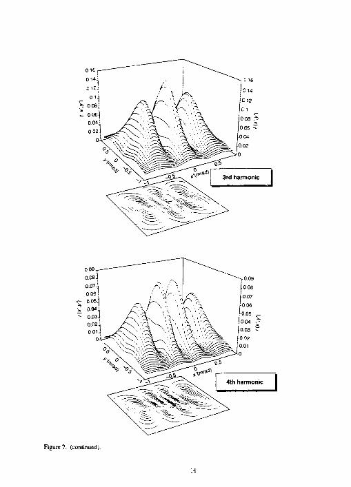
016
Figure 7. (continued).
14

FmiKi=-K-m*
= 0 m even
f f m odd (26)
This function is easier to calculate and is shown in Fig 8 for several values of m. We can recast Eq. (25) in a useful way in terms of a, as
„ \ + K2/2A(Ol _ , _ rtaN ' Fm(K) m c' e
2ncr-/ (27)
This shows that the denominator of the right hand side of Eq. (27), which we call ?„ , , is approximately equal to the flux ir. the central cone of the mth harmonic of the one-electron pattern.
4.2. THE EFFECT OF A FINITE ELECTRON BEAM EMITTANCE
Let us now consider the case when the electron beam has a non-zero emittance. Suppose that the center of the undulator is a waist of the electron beam (imply .ng a vertical phase-space ellipse) with horizontal (x) and vertical (y) rms beam widths (<TX, oy) and angular widths (cri, <T j.) given by
ax=^exi • a'x=J-F- m d eyp. (28)
where £x, ey are the storage ring emittances and ft, ft. are the electron beam amplitude functions at the waist. Suppose that an electron in the mid-plane of the undulator has phase-space coordinates (x, x', y, >•% and that we regard the coordinates as representing a ray. Let the arrival
•point of the ray in a receiving plane distance D downstream be (£ , rj). Then % = x + x'D and T] = y + y'D. If each phase-space coordinate is Gaussian-distributed, then the normalized probability that the arrival point will be (£,, rj) is
Figure 8 The function Fm(K) [Eq. (26)]
15
where
a\ = a\ + D~o? and a\ = aj + D2cf
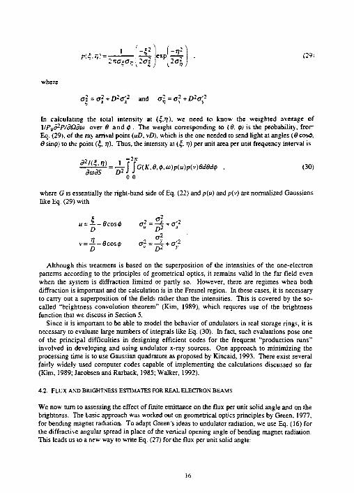
In calculating the total intensity at {c,J]). we need to know the weighted average of \IPjiP-P/d£idm over 6 and <p . The weight corresponding to (6, Q) is the probability, fror-Eq (29), of the ray arrival point (uD, vD), which is the one needed to send light at angles {6cos0, 6 sin0) to the point (|, fj). Thus, the intensity at (|, 77) per unit area per unit frequency interval is
^ r % ^ = 4 ? f f G< K<e-1>- <o)p(u)p(v)eded<p , oo) diodS Dl J J
0 0
where G is essentially the right-hand side of Eq. (22) and p(u) andp(v) are normalized Gaussians like Eq. (29) with
D -6cosi^ °2 -0cos0 °;
a 2
= ^ 2
Although this treatment is based on the superposition of the intensities of the one-electron patterns according to the principles of geometrical optics, it remains valid in the far field even when the system is diffraction limited or partly so. However, there are regimes when both diffraction is important and the calculation is in the Fresnel region. In these cases, it is necessary to carry out a superposition of the fields rather than the intensities. This is covered by the so-called "brightness convolution theorem" (Kim, 1989), which requires use of the brightness function that we discuss in Section 5.
Since it is important to be able to model the behavior of undulators in real storage rings, it is necessary to evaluate large numbers of integrals like Eq. (30). In fact, such evaluations pose one of the principal difficulties in designing efficient codes for the frequent "production runs" involved in developing and using undulator x-ray sources. One approach to minimizing the processing time is to use Gaussian quadrature as proposed by Kincaid, 1993. There exist several fairly widely used computer codes capable of implementing the calculations discussed so far (Kim, 1989; Jacobsen and Rarback, 1985; Walker, 1992).
4.2. FLUX AND BRIGHTNESS ESTIMATES FOR REAL ELECTRON BEAMS
We now turn to assessing the effect of finite emittance on the flux per unit solid angle and on the brightness. The tasic approach was worked out on geometrical optics principles by Green, 1977, for bending magnet radiation. To adapt Green's ideas to undulator radiation, we use Eq. (16) for the diffractive angular spread in place of the vertical opening angle of bending magnet radiation. This leads us to a new way to write Eq. (27) for the flux per unit solid angle:
16
where
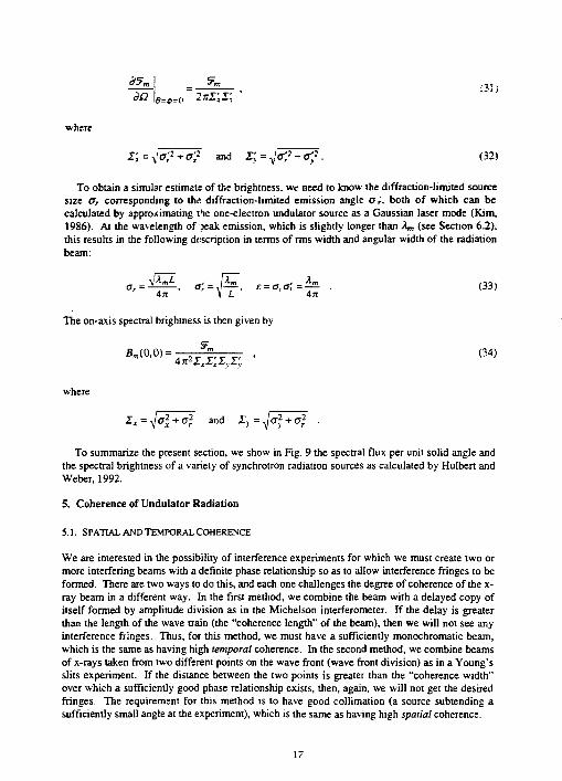
XI =Va,'2+ff/ and Z;=TJ~O?TO?. (32)
To obtain a similar estimate of the brightness, we need to know the diffraction-limited source size a, corresponding to thi: diffraction-limited emission angle ar, both of which can be calculated by approximating the one-electron undulator source as a Gaussian laser mode (Kim, 1986). At the wavelength of peak emission, which is slightly longer than X„ (see Section 6.2), this results in the following description in terms of rms width and angular width of the radiation beam:
ar = ^-^—. a; = ,p=-, e = ara'r = ^- . (33) An U An
The on-axis spectral brightness is then given by
Bm(0,0)= , J'm , (34) 4^x,x;x,r;
where
--4cl + a2r mi zy=ffi To summarize the present section, we show in Fig. 9 the spectral flux per unit solid angle and
the spectral brightness of a variety of synchrotron radiation sources as calculated by Hulbert and Weber, 1992.
5. Coherence of Undulator Radiation
5.1. SPATIAL AND TEMPORAL COHERENCE
We are interested in the possibility of interference experiments for which we must create two or more interfering beams with a definite phase relationship so as to allow interference fringes to be formed. There are two ways to do this, and each one challenges the degree of coherence of the x-ray beam in a different way. In the first method, we combine the beam with a delayed copy of itself formed by amplitude division as in the Michelson interferometer. If the delay is greater than the length of the wave train (the "coherence length" of the beam), then we will not see any interference fringes. Thus, for this method, we must have a sufficiently monochromatic beam, which is the same as having high temporal coherence. In the second method, we combine beams of x-rays taken from two different points on the wave front (wave front division) as in a Young's slits experiment. If the distance between the two points is greater than the "coherence width" over which a sufficiently good phase relationship exists, then, again, we will not get the desired fringes. The requirement for this method is to have good collimation (a source subtending a sufficiently small angle at the experiment), which is the same as having high spatial coherence.
17

ID 1 1
iu5u .y?_° _U5 0 JU3 9 w , 6 0
KSLS Ss--rc*i — ALS Scurrces
APS Soirees
Photon energy (eV)
10* — NSLS Sources — ALS Sources — APS Sources
W16.0
10 1 10' 10° 10* Photon energy (eV)
10 a 10"
Figure 9. Flux (a) and brightness (b) for various svnchrotron radiation sources from Hulbert and Weber, 1992.
IS

5.2. DEFINITION OF A MODE OF THE UN'IH.'LAIOK BEAM
The angle over which a source provides spatially coherent illumination is roughly tfie wiveteals divided by the source size. If only this angle is filled wilfc light in each of the borizoxu] axuJ vertical directions, then Ihe beam is said to comprise a single mode. Under such conditions, its size-angle product (eminance) is approximately equal to the wavelength. To make ihe concept of an undulator mode more precise, we represent Ihe undulator radiation partem in a phase space (x, x. y. y'>. which is essentially the same as the phase space used to represent the electron beam. Calculations of die paraxial ray optics of the radiation beam can be carried out using matrix techniques to manipulate the vectors (x, x') and (y. >") as one would do for the electron trajectories. However, as we have seen, there are significant diffraction effects in undulator action that are not accounted for by a geometrical optics analysis nor by the computer ray-tracing techniques that have been so valuable up to now in modeling beamline optical systems. In physical optics, we are obliged to work with the fields, so we represent the electric field at distance z from the mid-plane as E(x, y; z). We will also need the frequency-space representation of E, E(x', >•', z), where we note that, for the small angles of interest to us, the angle variables (*'. y •) are proportional to the spatial frequencies [(sinx)/A, (siny")/! ]. E and E are thus related by a Fourier transform. We now define the rms spatial and angular extent of the fields as
jx2\E(x)\2dx J *' 2|£(.r')| dx'
Vv^)=^= • •Wr)==^Z • (35) \\E(xfdx j \E(x')\ dx'
As with any signal represented in the direct ind frequency domains, the widths of the two representations are reciprocally related. In fact, the product of the widths has a minimum value that coaesponds to a signal with minimum information content Specifically, the rms widths that we have just defined are related (as shown, for example, by Bracewell, 1978) in the following way:
r-. r r. r 3 (36)
The minimum information signal, corresponding to the equals sign in Eq. (36), can be shown to be a Gaussian wave packet Physically, Eq. (36) represents the fact that, if the width is restricted, the angle (i.e., the frequency) will increase because of diffraction. The minimum allowed value of the width-angle product corresponds to the single-mode beam we are seeking to define, and this, therefore, has the emittance £c, characteristic of a spatially col-ient beam, given by
ec=ar&r=—- . (37) An
Equation (37) is the same as Eq. (33). which was derived from the Gaussian-laser-mode representation. The rectangular function of equal area to a Gaussian has a width -Jin a, so, assuming we are dealing with Gaussian-distributed beams, we find that the phase-space area of a single-mode (spatially coherent) beam is given by
19

The above results are derived from fundamental considerations and represent a physically correct measure of the size of the coherent phase space. However, in practical experiments, ore usually needs to choose the amount of phase space to accept on the basis of a resolution-flux trade-off. Insufficient spatial coherence (accepting too much phase space) leads to a loss of resolution in a hologram, for example, while accepting too little phase space is equivalent to a loss of flux. A common compromise is exemplified by the case of illumination of a zone plate lens by a pinhole of diameter d at distance z. The complex coherence factor (Bom and Wolf. 19B0) of the pinhole source (taken to be incoherently illuminated) is a circular Airy function peaked at zero separation of the two test points. This function is of the same form as the amplitude distribution of the pinhole Faunhofer diffraction pattern that has a zero at a radius 1J22?j/d. The bright region inside the zero is known as the Airy disk. To maintain a high degree of spatial coherence over the whole zone plate, it would be necessary to accept light only within a region near the central peak of the complex coherence factor. However, a compromise that causes only slight loss of resolution is to set the diameter of the zone plate equal to the radius of the Airy disk. This choice maximizes the so-called "resolution-luminosity" product of the system and is equivalent to accepting phase-space areas in x and y of (1.22A)2 instead of (.A/2)2, roughly a six-fold flux gain. As an example of the consequences of these ideas, we show in Fig. 10 a graph of the spatially coherent fraction of the light from ALS undulators for both the single-mode and the half-the-Airy-disk definitions of coherent phase space. The main point, of course, is that undulators are capable of delivering enough coherent flux to do many interesting coherence experiments.
5.3. THE DEGENERACY FACTOR
We traditionally characterize the usefulness of an undulator by quoting its time-averaged spectral brightness B, which is the number of photons per unit phase-space volume per unit fractional bandwidth per unit time. However, a more fundamental quantity would be its degeneracy parameter S^ (Goodman, 1985). This dimensionless quantity is defined as the number of emitted photons per coherent phase-space volume per coherence time or the number of photons per mode. The coherent phase-space volume is (A/2)2 and the coherence time is A2/(A/l c), so 5„, is given by
where D is the duty cycle of the storage ring. In practical units, this is
5 w = 8.33xlO-2SZ)B(ph/mm2/mr2/0.1%BW/s)A(A)3 . (40)
It is significant that the bandwidth cancels out and we are left with a measure of the probability that two wave trains will overlap in the same wave mode. Since photons are bosons, Sw is allowed to be greater than unity; however, it is only with the advent of undulators on modem storage rings that values greater than unity have been achieved in the XUV spectral region. As an example, ihe ALS undulators will achieve S„ values greater than unity for wavelengths longer than about 50 A.
20

10°
10"
c o •0 10- 2 r
c Q> a> x : o o
10- 3 -
10" 4 r
10-
K>, ; ^ x . j
: \ ^̂ >
_ — Gaussian modes I - - Half Airy disk
\ : *• _ — Gaussian modes I - - Half Airy disk \
: ': i \ '•
10° 101' 102
Photon energy (eV) 10 3 10 4
Figure 10. Coherent fraction of the central cone radiation from ALS undulators for the two definitions of coherent phase space discussed in the text.
One of the phenomena that are understandable in terms of 5„ is the bunching of photoelectron counts due to the stochastic variations of the classical electromagnetic field. This is expected to be observable with thermal light for which the intensity fluctuates in a chaotic way, but not with light from a good-quality laser for which the intensity is stable. Bunching is a separate effect from shot noise, which affects all types of light beams equally. Undulator radiation is produced as a coherent sum of the fields radiated by one electron, but an incoherent sum of the wave trains emitted by the population of electrons. The resulting intensity, therefore, has chaotic fluctuations like tliermal light, but does not have the black-body spectral distribution. Accordingly, an undulator beam should be described as pseudo thermal light with a high Sw indicating a high effective temperature. This combination of qualities is more unique than one might suppose. Based on the Planck thermal distribution function for a black body, one can show that the degeneracy parameter for thermal sources, even very hot ones like the sun, is much less than i inity (Goodman, 1985). Moreover, it can be shown that 5*. is equal to the ratio of the size of the photo count fluctuations due to the stochastic variations of the classical electric field to the size of those due to shot noise. Therefore, for sources with a very small value of 5„.p ti:e shot noise dominates and bunching is essentially not observable. Thus, even in the visible region, neither
21

lasers nor thermal sources produce easily observable pho.o coani bunching uisder ncrma] conditions. The only way to imitate a pseudo thermal source with strong lunching is to pass laser light (which also has a very high &) through a moving difuser.
In view of the above conclusions, we expect the measured instantaneous and lime-integrated intensity ir an undulaior beam to show chaotic behavior. Specifically, we expect thai the probability-density function of the instantaneous intensity will be negative-exponential, while that of the intensity integrated over a finite time will be Gaussian. The time scale of these fluctuations would be on the order of the coherence time of the wave field, which is in the femtosecond region for cases of practical interest. These physical quantities would be constants for a well-stabilized laser beam. Thus, in spite of the practical similarities between undula'cr beams and laser beams based on their low phase-space volume, the physics of their emission processes and the statistical properties of their radiations are very different.
The degeneracy parameter has importance in other mailers as well. For example, it determines the detectability of the intensity fluctuations of the classical field in an intensity-interferometer experiment (Giuskin ei al., 1992). This is a ciose parallel to its role in determining the degree of bunching. The conclusion appears to be that soft x-ray intensity-interferometer experiments will be quite feasible with undulator beams on third-generation storage rings, while only ultraviolet experiments could be considered at c._..i lauiiues.
5.4. "DEPTH-OF-FIELD BROADENING" EFFECTS
Undulators and other sources of synchrotron radiation are essentially small transversely and very extended in the emission direction. With an intuition based on geometrical optics, one, therefore, expects that it. will be impossible to make a perfect image of the source due to depth-of-field effects. This has been discussed by various authors, especially Green, 1977, and Coisson and Walker, 1985. As discussed by the latter, the effect can be described using the phase-space representation. An electron with coordinates (x, x') at z = 0 transforms to (x+x'z, JO at z = z. If, at this point, it emits a photon at an angle xe' to its trajectory, then the apparent emission point of the photon in the z = 0 plane is x - xe'z. If the trajectory was fleered by ai: angle xs' in traveling to z. then the apparent emission point would be x - (xe' + x:lz. The point to note is that this expression is independent of x'. This implies that depth-of-field broadening is not caused by the electron bea<n angular spread. Rather, it results from the emission angular spread or from steering of the beam, as in a wiggler, and is still present even for zero-emittance beam. The calculation of the form of the depth-of-field-broadened source is rather cumbersome. Even for the case of a zero-emtt<ance beam (treated by Coisson and Walker), the expression must be written in terms of the exponential integral and is infinite at its center point. The more realistic case, including a finite emittance but still within the geometrical optics approximation, is treated by Green, who represents the source by a new function ef(a, Y) (see Appendix 3). The function ef(a, Y) has a finite peak at the origin and, for long sources, has large non-Gaussian tails extending out to many sigmas of the original u.ibroadensd source.
For the case of an undulator, the amount of steering is negligible and ;he possibility for depth-of-field effects rests on the angular spread of the emission from a single electron. However, we have already noted that such spreading of the one-electron pattern is a diffraction effect and its counterpart is a broadening of the source (to *JXmL I An). Both effects are included in the representation of the source as a Gaussian laser mole. T\e diffraction picture thus includes essentially the same broadening effects that we discussed in the previous paragraph. We conclude that the "depth-of-field broadening" is simply the geometrical optics approximation of the diffraction picture of the single-electron partem and its convolution with a realistic source
7~>

with finite emitunce. Therefore, diffraction and deptii-of-iield broadening represent the same thing and should not be added in calculations.
On this basis, we can get some idea of what will happen when we try 10 image the one-electron undulator source. It will behave like any other diffraction-limited source, and we will not see evidence that the source had a great depth. As a consistency check, we compute the transverse and longitudinal resolutions (A, and Ai) to be expected from an imaging system at wavelength ?. and numerical aperture NA = \X IL. This yields
Nf (41)
' NA*
Thus, roughly speaking, the resolution of the optica] system wouid be such that it could not tell the difference between a point and an object of the size and shape of the undulator. In summary, we expect no harmful depth effects in imaging the undulator source.
53. PARTIAL COHERENCE EFFECTS IN UNDULATOR BEAMS
We have already noted that geometrical ray tracing is not adequate to represent all behaviors of an undulator source because of diffraction. Nevertheless, it is very desirable to have a way to model the performance of undulator beamlines with significant partial coherence effects, and such modeling would, naturally, start with the source. The calculation would involve a knowledge of the partial coherence properties of the source itself and of how to propagate partially coherent fields through space and through the optical components used in the beamline. We discuss the source properties further below, but it is important to recognize that, although most of the these calculaiicr? are, in principle, straightforward applications of conventional coherence theory (Born and Wolf, 1980; Goodman, 1985), there is not much current interest in this type of problem in the visible optics community. Therefore, there is not a large body of literature to help us with solutions to specific cases. For example, even for the rather simple problem of diffraction by an open aperture with partially coherent illumination, we have found published solutions only for circular and slit-shaped apertures and only for sources consisting of an incoherently illuminated aperture of similar shape to the diffracting aperture. Thus, there is no counterpart in these types of Fourier optics problems to the highly developed art of ray tracing in geometrical optics, nor is there anything as simple as a ray to which an exact system response can be calculated.
This is not to say that no progress has been made. One of the difficulties of coherence-theory calculations is that integration over a large number of variables and a high degree of complication is often encountered. A major simplification of the problem for cases where the small-angle approximation applies has been achieved by Kim, 1986, 1989. This author has developed an extension to the normal coherence theory based on the use of the frequency-space representation of the mutual intensity (see Appendix 2) rather than the usual direct-space representation. The Fourier transform of the mutual intensity (called the "brightness" by Kim) is shown to be invariant with respect to propagation through free space and simple lenses. This means that representation of such propagation is very simple and consists of linear operations on the phase-space coordinates. This allows the brightness to be calculated anywhere without multiple integrals. It would take us too far away from our main subject to give a full presentation of this, but we do consider in the next section the coherence properties of the source itself.
We first recall that the undulator source consists of an incoherent superposition of many one-electron patterns, each of which is to be represented as a Gaussian laser mode with rms width and
23

angular width 0> and a,' as given by Eq. (33). Therefore, throughout the SOTTCS area, there is an rms coherence width a, with a complex coherence factor piAx, Ay) of Gaussian form. Thus. apart from the Gaussian intensity d stribution of the source, its field correlations are spatially stationary. We. therefore, consider " undulator to be a quasi homogeneous source (Goodman. 1985). The latter is defined as one for . hich the mutual intensity can be written as
The expressions we use in this section are all separable in x and y so, starting with Eq. (42), we give only the x part. Substituting the above Gaussian forms into this equation gives
, ( Ax Ax) Jn\x+—,x- —J = «P
where
_ 1 _ = _1_ J_ fflr"4ffx+ff?
and J\2 is a function of the spatial variables (x. Ax). The propagation law for/12 is a standard result of coherence theory (Bora and Wolf, 1980; Goodman, 1985) and involves a multiple integral over four variables altogether, including y and Ay. In general, this is difficult and can be avoided by using the brightness function defined by Kim, which is valid for many practically interesting cases. The brightness function is denoted by B(x, x'-fi). It is a function of both position and angle coordinates and is defined by
+00 B(x,x';0) = C j Ji2(x + — ,x-—\-'kAxl'dAx , (44)
where it = 1WX and C is a constant Using Eq. (43) in Eq. (44), we find
B(x,x';0) = -JlnCoax exp
This forms the starting point for the simplified propagation and optical calculations that are enabled by knowledge of the brightness function. It is noteworthy that the brightness function used by Kim is not a physically measurable quantity, although several such quantities can be obtained from it. It is, therefore, necessary to pay special attention to the meaning of the brightness function as described in the published accounts (Kim, 1986, 1989) before using the results derived from it.
As an example of the use of the brightness function, we calculate the mutual intensity at a plane distance z downstream of the source. We begin by propagating the brightness a distance z using the transform (x—* x - x'z. x' —» JC"). This gives
-x* -Ax*
2«5 + 2«ij (43)
-* 2 «jr« 2<T?
(45)
24
*(x.x';.) = V 2 i C ^ e x p [ ^ ^ i , ^ ^ ] .
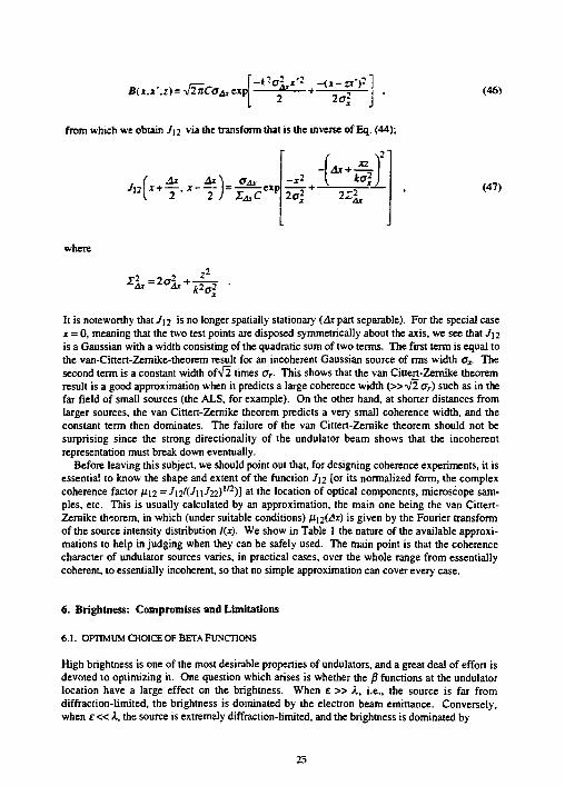
from which we obtain J12 via the transform that is the inverse of Eq. (44);
, ( Ax Ax\ 0&,
where
It is noteworthy that J] 2 is no longer spatially stationary (Ax part separable). For the special case x = 0, meaning that the two lest points are disposed symmetrically about the axis, we see that Jyi is a Gaussian with a width consisting of the quadratic sum of two terms. The first term is equal to the van-Cittert-Zemike-theorem result for an incoherent Gaussian source of rms width cx. The second term is a constant width ofV2 times aT. This shows that the van Cittert-Zemike theorem result is a good approximation when it predicts a large coherence width (»-J2 07) such as in the far field of small sources (the ALS, for example). On the other hand, at shorter distances from larger sources, the van Cittert-Zemike theorem predicts a very small coherence width, and the constant term then dominates. The failure of the van Cittert-Zemike theorem should not be surprising since the strong directionality of the undulator beam shows that the incoherent representation must break down eventually.
Before leaving this subject, we should point out that, for designing coherence experiments, it is essentia! to know the shape and extent of the function J\2 [or its normalized form, the complex coherence factor fi.12 =JnKJ\iJ22)112)] a I t n e location of optical components, microscope samples, etc. This is usually calculated by an approximation, the main one being the van Cittert-Zemike theorem, in which (under suitable conditions) /Ji2(/J*) is given by the Fourier transform of the source intensity distribution l(x). We show in Table 1 the nature of the available approximations to help in judging when they can be safely used. The main point is that the coherence character of undulator sources varies, in practical cases, over the whole range from essentially coherent, to essentially incoherent, so that no simple approximation can cover every case.
6. Brightness: Compromises and Limitations
6.1. OPTIMUM CHOICE OF BETA FUNCTIONS
High brightness is one of the most desirable properties of undulators, and a great deal of effort is devoted to optimizing it. One question which arises is whether the p functions at the undulator location have a large effect on the brightness. When e » X, i.e., the source is far from diffraction-limited, the brightness is dominated by the electron beam emittance. Conversely, when £ « K the source is extremely diffraction-limited, and the brightness is dominated by
t-*r 2ff? - 2
' 'At (47)
25

TABLE 1. Methods lo find xht complex coherence factor downstream of an unduliro; vecrce
RMS Coherence Complex Coherence
Assumed Source Width »the Factor Distance z Character Source* Downstream Method of Calculation
Coherent ~°! Constant None (diffraction-limited) Quasi homogeneous < 0 > JvJVuhi)m Brightness function
(general case) from Eq. (47) Almost incoherent «as ?[/(.*)] ^[/<!;lAr)]/Az** Generalized
van Cirtert-Zemike theorem (Goodman, 1985)
Incoherent (electron- = 0 ?[/(J)]//O** van Cittert-Zemike theorem beam-limited)
The source is taken to have an rms width oy **/o i s the integrated flux, ? represents the Fourier transform.
diffraction. In both cases, the brightness is relatively insensitive to /?, although there is a shallow minimum. On the other hand, when e - A, it is possible to suffer a major loss of brighmess by a poor choice of j9. To see the effect of the p" functions, consider the dimensions of a diffraction-limited x-ray beam. Its phase-space ellipse has semiaxes o> a'r while that of the electron beam has semiaxes (e.g.) ax, c'x, and the two would have similar area because £ - X. The optimum value of the /3 function would match the two ellipses by having ax - cj and ox - o> while the worst choice would mismatch them in the manner of a cross. In the latter case, the resulting photon phase-space area would be approximately a circle with the crossed ellipses inside it! To find the optimum p", we set the ratio of the major to minor axes equal for the two ellipses
or cx
In
(48)
leading to
04*=£ (49)
In practice, this is a rather low but possible value for /3.
6.2. INTENSITY DISTRIBUTION NEAR THE CENTRAL CONE
It comes as a slight surprise to leam that there is somewhat of a shortage of central-cone radiation at the exact frequency of a harmonic even in the one-electron pattern. The angle-integrated flux per unit fractional bandwidth is actually twice as high at a frequency G^a* = ma>i(0)(l-l/mN) as it is at the exact harmonic frequency ma>\ (0). This arises because the exact harmonic intensity on-axis can only receive contributions from the sine functions in Eq. (22) centered on directions
26
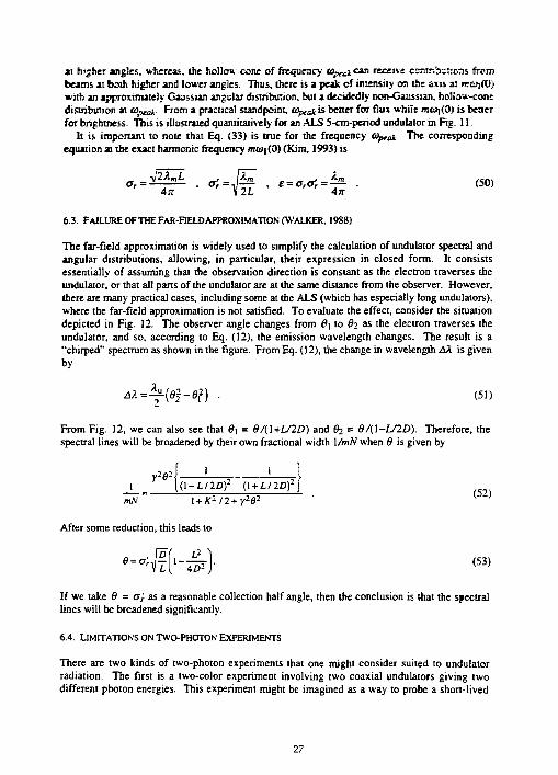
at higher angles, whereas, the hollow cone of frequency t o u c a n receive cramSaioas from beams at both higher and lower angles. Thus, (here is a peak of intensity on the axis ai moi(0) with an approximately Gaussian angular distribution, but a decidedly non-Gaussian, hollow-cone distribution at Wpcan From a practical standpoint, t ^ t i s better for flux while mojfO) is better for brightness. This is illustrated quantitatively for an ALS 5-cm-period undulator in Fig. 11.
It is important to note that Eq. (33) is true for the frequency Optai The corresponding equation at the exact harmonic frequency moi|(0) (Kim. 1993) is
a, = — , o> =•, —— , e = arOr = — . (50) 4/7 V 2 i 4n
6.3. FAILURE OF THE FAR-FIELD APPROXIMATION (WALKER, 1988)
The far-field approximation is widely used to simplify the calculation of undulator spectral and angular distributions, allowing, in particular, their expression in closed form. It consists essentially of assuming that the observation direction is constant as the electron traverses the undulator, or that all parts of the undulator are at the same distance from the observer. However, there are many practical cases, including some at the ALS (which has especially long undulators), where the far-field approximation is not satisfied. To evaluate the effect, consider the situation depicted in Fig. 12. The observer angle changes from 6\ to $2 as the electron traverses the undulator, and so, according to Eq. (12), the emission wavelength changes. The result is a "chirped" spectrum as shown in the figure. From Eq. (12), the change in wavelength AX is given by
4A=-^(f l f - f l?) . (51)
From Fig. 12, we can also see that 6\ = 0/(l+L/2£>) and 6j = B/(\-UlD). Therefore, the spectral lines will be broadened by their own fractional width 1/mN when 6 is given by
r**\ ' 1 ' [(1-L/2D) 2 (1 + L/2D)2
mN l + K2/2 + r262
After some reduction, this leads to
(52)
*£(-£) « = » | J T U - T b - • (53)
If we take 8 = cr; as a reasonable collection half angle, then the conclusion is that the spectral lines will be broadened significantly.
6.4. LIMITATIONS ON TWO-PHOTON EXPERIMENTS
There are two kinds of two-photon experiments that one might consider suited to undulator radiation. The first is a two-color experiment involving two coaxial undulators giving two different photon energies. This experiment might be imagined as a way to probe a short-lived
27

US 3rO harmonic £g = 2W eV i £ = 0
4«10' 7
0 .a* 0 ?" ^
U5 3rd harmonic. £ 0 = 284 eV. i £ = -0.8 eV
5x10
S 4x10"
3x10
2x10
1x10
5x10 1 7
Bgure 11. One-electron intensity distributions near the axis for the ALS 5-cm-period undulator in the third harmonic. Curve (a) is for the exact hannonic energy (£) and curve (b) is for an energy £(1 - 1/mAO, which is the energy of the peak of the angle-integrated spectrum. &E is the energy difference between (a) and (b). Note that the former has a peaked and the latter a hollow-cone shape.
28

F(o)
Figure 12. Illustration of the effect of the change in observer angle from one end of the undulator to the other and the resulting chirped spectrum, which becomes important when the far-field assumption is not satisfied.
intermediate state, but is not promising for the following reason. Considering that, for a single mode, we would have dCl^lno'}, Aw/to = 1/mN, and n(l +K2/2)Fm(K) is approximately unity, then Eq. (27) shows that the number of radiated photons per incident electron is about a = 1/137. Therefore, the probability of getting two photons from two undulators is proportional to (1/137)2, which would give a very low rate.
In the second type of two-photon experiment, two nominally identical photons of energy £ would do something that needed energy 2E. This experiment is much more promising because the probability of getting two photons in the same mode at the same times (from a single undulator) is equal to the degeneracy factor 5 W , which, as discussed earlier, can be much larger than unity for some conditions. This type of experiment can be considered for samples with sufficiently high interaction probability.
6.5. BENDING MAGNET BACKGROUND
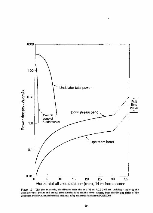
An observer near an undulator axis will see radiation from both the upstream and downstream bending magnets. The nature of this radiation will vary from a spectrum characteristic of the bending magnet fringing fields at zero and small angles to that characteristic of the bending magnet full field at sufficiently large off-axis angles. As an example, we show in Fig. 13 the power density due to an ALS 3.65-cm undulator and that due to its upstream and downstream bending magnets as calculated by the POISSON magnetic field code. It is noteworthy that the two bending magnet beams are unequal and very much weaker than the undulator beam. This has important consequences for the operation of beam position monitors, although the situation is not as good as it seems because the monitors respond to photons in proportion to their photoelectron yield, not their energy. One can also see that the full bending magnet power density is not achieved until several milliradians off axis. Another feature with implications for beam position
29
1000
0.01
Upstream bend
Full field value
0 5 10 15 20 25 30 35 Horizontal off-axis distance (mm), 14 m from source
Figure 13. The power density distribution near the axis of an ALS 3.65-cm undulator showing the undulator total-power and central-cone distributions and the power density from the fringing fields of the upstream and downstream bending magnets using magnetic fields from POISSON.
30

stabilization is thai the central cone is a narrow and relatively weak beam bcmei in a nach »-dar and stronger power-density distribution, however, u «s ihe broad power dismbinicu thai will be sensed by the beam position monitors.
6.6 IMPERFECT UNDULATORS: MEASUREMENT AND ANALYSIS OF DEFECTS
Until now, we have assumed that we were dealing with a perfect undulator. We now turn to assessing Ihe effects of the inevitable imperfections of real undulators. The consequences of departures of the undulator magnetic field from its nominal form are illustrated qualitatively in Fig. 14. This figure shows a calculated electron trajectory for a realistic imperfect undulator field. Obviously, if one wants to obtain near-theoretical performance from the undulator, one must pay careful attention to the size of the field errors and their effects. In seeking to maintain good field quality, it is worth considering the consequences of failure. Electrons traversing even the most imperfect undulator still radiate, and the power must go somewhere. In the worst case, all coherent superposition of the one-electron signals from successive periods of the undulator is lost and the coherent sum is replaced by an incoherent one. In this case, each half-period of the undulator acts like a small bending magnet, and the resulting power output is equal to 2N times the output from each half-period. The spectrum then loses the undulator peaks and becomes smooth like the spectrum of a wiggler.
Random Walk of Trajectory (uncorrected) T — i — J — l — l — i — i — | — i — l — l — l — [ — I — l — l — l — [ — I — l — I — l — | — l — l — l — I — | — I — r
.1 i I i l—l—i—I—l l l l I l l l l I l l l i I i i i i I i 71 0 10 20 30 40 50
zlku
Figure 14. Three sample orbits for a 50-period undulaior with rms field errors of 0.5%. The orbit deviation is expressed in units of the amplitude of its ideal sinusoid.
31
The consequences of field errors fall inio two mam cJassej (!) effects en the Kraare nr.r. and (2) effects on the radiated spectrum We consider the first caagon in Ssctioo 6 7 asd ilhe s-ecend in Section 6.8 However, the prerequisite for an, rational approach to these effects is an ability to measure the undulaior fields accurately enough to compare the fields of real devices with (lieu nominal values and the error tolerances derived from experience or calculation The first two ALS undulators have been extensively measured, and the analysis of the measurements has been reported by Marks et al., 1993B. We use the results of this work to illustrate the following material.
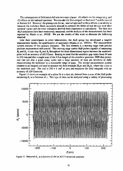
Like their counterparts in other laboratories, the ALS group has developed a magnet measurement facility for qualification of undulators (Marks « al., I993A). The measurement system consists of two primary elements. The first element is a moving stage with precise position measurement and control. This moving stage carries Hall probes capable of measuring Bz and By, it can map Bz and B} throughout the three-dimensional region between the undulator poles with an accuracy of ±0.5 Gauss. Bearing in mind that the undulator gap varies from 14 mm to 210 mm and that a single scan of the 4.5-m length of the undulator generates 2500 data points, one can see that a great many scans and a large quantity of data are involved in fully characterizing the undulator at a reasonable range of gaps. The second measurement system elemeni is an integral coil used to measure the field integrals JBydz and iB^dz, where the z axis is the undulator axis. The coil is 550 x 1 cm 2 in area and measures the field integrals with an accuracy of ±20 Gauss-cm.
Figure 15 shows an example of a spline fit to a data set, derived from a scan of the Hall probe measuring By as a function of z. This type of data can be analyzed using a variety of processing
10000 -
5000
CD
-5000 -
-10000 -
Figure 15. Measured By as a function of zfor an ALS 5-cm-period undulator.
32

tools including tools to identify field peaks, truncate the data to eJirrrsaie eid fieUds. leasa-iqniris fit the data to a set of harmonics, take the Fourier transform, balf-penod fflier the data. alcx'-nz iht optica] phase errors, and calculate the expected radiation emission- We discuss some of these tools further below
Given that the undulator structure is nominally a periodic function with a symmetry of tree formal + Ay/2) = -fiz). its field (without the non-periodic pans at the ends) should fit a cosine Fourier series with only odd harmonics:
Bh(z) = X * - C 0 S ( m * u Z + <*».) • " = 1.3.5 (54)
where ku = IW'Ka. A nonlinear least-squares fit routine is used to fit Bh to the measured data with Bm and (y as fitting parameters. The rms value o> of the residual By-B/, between the fit and the measured data is then defined as the measure of the overall size of the field errors. It includes both local errors and global effects such as taper and sag.
Another interesting technique is the half-period filter, which is applied to the spline fit to the measured Bx or By data. This is defined, for example, by
nu)=\ *KM'-*I (55)
It is implemented in the frequency domain by means of the convolution theorem. For any function that is exactly periodic with period Au and that has only odd harmonics, we can see that Fh(z) will be zero. The output of the filter provides a measure of the field errors over a half-period range (i.e., local errors). Figure 16 shows the half-period-filtered output corresponding to half of a data set similar to the one in Fig. 15. One can see the small values representing local errors in the periodic part of the undulator and the large values representing the transition to a nonperiodic field at the end. Examination of the above equation also shows that the integral of Fh(z) is equivalent to the integral over Bx or By, provided the limits of integration correspond to constant field regions. Therefore, this procedure also allows separation of the contributions to JBX dz, iBydz into portions corresponding to the periodic and nonperiodic parts, a capability which is useful in correcting the field integrals. Integrals like JBy dz are important in considering the effect of the undulator on the electron beam as discussed in the following section.
6.7. IMPERFECT UNDULATORS: EFFECT ON THE STORAGE RING
An undulator is generally short compared to a betatron wavelength, so the primary effect of the undulator magnetic fields on the electron beam is via their line integral through the device and its variation with horizontal and vertical position. We first note that in free space, B(x, y, z) satisfies the three-dimensional Laplace equation, a fact which follows from Maxwell's equations. Therefore, B(x, y) = JB(JC, >•, z)dz satisfies the two-dimensional Laplace equation as do its components, Bx and By, separately. The values of the line integrals of Bx and By can, therefore, be expressed as general solutions of Laplace's equation in polar coordinates (r, 6) as follows (Jackson, 1975):
JBydz= ^a m r"P r a (c05f l ) and JBzdz= ^fcmr™Pm(cose) , (56)
33

3DD0 p
2500 -
2000 •
1500 -
1000 -
o --500 -
-1000 -
-1500 L -3000 -2000 -1000 0 1000 2000 3000
Z(mm) Figure 16. Half-period filter output corresponding to a curve like that of Fig. 15.
where we have imposed the condition that \By dz and \BX dz are finite at the origin. These are essentially Taylor-series representations of the functions ',By dz, \BX dz and are equivalent to two-dimensional multipole expansions of the integrated magnetic fields as shown in Table 2.
The radius of convergence of the series in Eq. (56) is equal to the magnetic half-gap. The area of validity includes the central region where the electron beam core is always located, but does not include some regions that lie outside the circle of convergence b.'t still inside the dynamic aperture. The latter can contain scattered electrons that are not lost and are in the process of being returned back into the central region by radiation damping. If these particles get lost as a result of undulator magnetic field errors not represented by the multipole expansion, then the beam lifetime will be reduced. The field integral variations that are represented by multipoles are described by the coefficients am and bm, which can be determined from the integral coil measurements. The size of the unwanted multipoles, as defined by these coefficients, can then be compared to a calculated tolerance value. Table 3 shows the tolerance values calculated for the ALS ai.d the storage ring operational consequences expected for each type of unwanted muidpole.
In general, it is difficult to correct the errors listed in Table 3 by means of adjustments to the accelerator optics because the errors change in value as the undulatcr gap is tuned. Consequently, the best strategy is to make the errors negligible for each undulator. Two exceptions to this are the horizontal and vertical dipole components for which there are both fixed corrections (by means of permanent magnet rotors) and tunable corrections , y means of the horizontal and vertical bump-coil systems). These correction mechanisms are already installed at the ALS and other third-generation storage rings to achieve beam stability.
34

TABLE 2 Field integral miilupolt termi
Field Integral Term Mullipole Character
0 Bydz = oo
1 fi,.<fc = a\i
2 f&A = a( 2 j,2_,2)
3 [ V ^f(2- 3 -^) 4 ' V z = — (5x 4 -30^>
o 0 ' « X & = 4D
1 B x<fe = fc)X
2 [ f t* = ^(2*2- ,2)
3 'B^z = | ( 2 ^ - 3 ^ )
4 D j , * 4 / < , 4 -jriv2. 8
dipole
quad ru pole
5extupo!e
octupole
decapole
skew dipole
skew quadrupole
skew sextupole
skew octupole
skew decapole
As an example of the magnitudes of the errors, we show in Table 3 the tolerances used at the ALS. The as-built undulators had values of the multipole terms about two to three times larger than those in Table 2, so a correction system comprising several small, individually adjustable,
TAfiLE 3. Storage ring effects of undulator magnetic field integral errors.
Integrated Multipole Term
Tolerance Values at ALS
Operational Consequences
Horizontal (vertical) dipole Quadrupole Skew quadrupole
Sextupole
Skew sextupole
Octupole
Skew octupole
100 Gauss cm 100 Gauss 100 Gauss
50 Gauss/cm
20 Gauss/cm2
Vertical (horizontal) steering Tune shift Horizontal-to-vertical coupling, beam rotation Amplitude-dependent tune shift; loss of dynamic aperture Amplitude-dependent tune shift; loss of dynamic aperture Higher-order tune resonances; loss of lifetime Higher-order tune resonances; loss of lifetime
35

permanent magnets (Hoyer. I992> was installed ai each end of the toiKi By i* mez^i. He multiplies were brought wiiHin tolerance or within the range of aiSjnEimen en «i_ case cf the dipoles.
6.8. MreRFECT UNDULATORS EFFECT ON THE SPECTRUM
The main purpose of an undulator is to deliver a spectrum as close as possible to theoretical. Thus, there is a need for a theoretical analysis of the errors that impair its ability to dt this. Such an analysis has been provided by Kincaid. 1985. A primary conclusion of this study was the: the performance of the undulator source is degraded by random field errors and that the degradation increases like the square of the harmonic number. The peak value of the flux per unit solid angle (and hence also, via Eq. (27), the brightness) of the nth harmonic is degraded by a factor Gj or F& as follows:
FA varies like (gp)'2 g 2 1
where
g = a 2 N 3 , , = - £ , - ,
K2
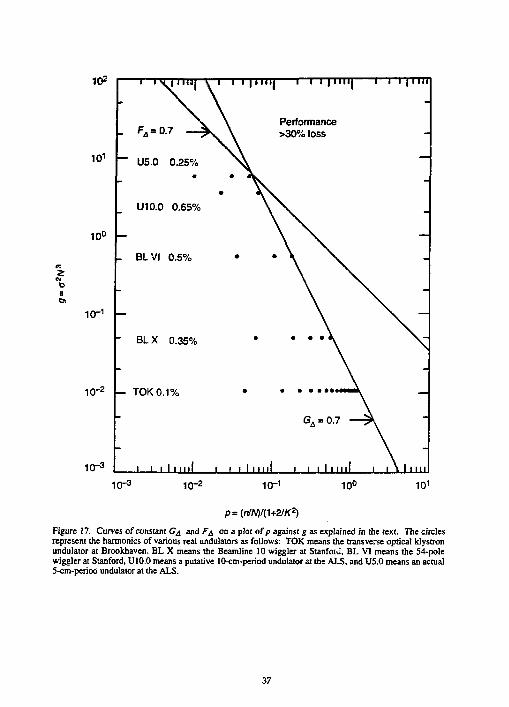
and a is the rms field en jr. The regime g S 1 corresponds to a small degree of wandering of the orbit (Fig. 14) while g S 1 corresponds to a large one. Some of the conclusions of Kincaid's paper are summarized in Fig. 17, which shows the contours Ga = 0.7 and f& = 0.7 on a log-log plot of g against p. The circular plotted points represent harmonics of actual undulators for which p and g are known. The fact that the points lie to the left of the contours shows that the predicted losses of intensity are less than 0.7. Note that all these examples are in the regime of small walking of the orbit, which implies a Gaussian dependence of the degradation factor on the size of the field errors.
The ALS group set a goal of achieving at least 70% of theoretic; flux in the 5th harmonic, which, according to the above equation fir G^ , impliss that a must be less than 0.25%. There is some difficulty in finding a rigorous procedure for determining a value for a from measured magnetic field data, but roughly speaking, »•; could identify it with oe. At the time the ALS undulators were started, the 0.25% value was about a factor of 2 beyond the state-of-the-art. Nevertheless, it was achieved, even at the minimum gap of 14 mm.
In view of the arguments following Eq. (16), it is also clear that another factor that can lead to degradation of the brightness is the electron beam angular spread resulting from its finite emittance. The emittance sets a limit to the quality of undulator fields beyond which further improvement to the undulator does not improve its performance. We show an example of the effect of emittance in the following paragraph.
Once an undulator has been built, there is no longer a need to study it by means of a general theory. One can simply calculate the radiation output using the actual measured field of the device. This can be accomplished more easily than hitherto using the simplified radiation equation derived by Wang, 1993B [Eq. (21)]. As an example of the procedure, we show in
36
10 2
10 1
10°
2 cti
10"1
' I V P ' » j \ i i i | i i ) i j 1 i i | i i i i | — r • 1 1 | l l l i \ . -
- F s = 0.7 — ^ \ Performance
V \ >30%loss -
~~ U5.0 0.25% — • * ^ v -
U10.0 0.65% -
— — _ BLVI 0.5% • * \ ^S. -
" BLX 0.35% • • • • «̂ \ -
— TOK 0.1% • * • • • I t i M I M L —
G A = °-7 — ? V
\
10- 2
10" 3 I 1 i i I m i l i i i I m i l i i i I m i l I | \ | l l l l l
10" 3 1CT2 10" 1 10° 10 1
Figure 17. Curves of constant G4 and F^ on a plot ofp against g as explained in the text. The circles represent the harmonics of various real undulators as follows: TOK means the transverse optical klystron undulator at Brookhaven, BL X means the Beamline 10 wiggler at Stanfoiu, BL VI means the 54-pole wiggler at Stanford, U10.0 means a putative 10-cm-period undulator at the ALS, and U5.0 means an actual 5-cm-period undulator at the ALS,
37

fig 18 the flux per unit solid angle of an ALS 5-cm-period undulator operated X a magnetic gap of 23 mm (Jf = 2.13) for three cases: (I) ideal field and zero eminance. (2) actual field and zero eminance, and (3) actual field and actual eminance. The spectra are taken from Wang. 1993A It is noteworthy that all the harmonics are reduced by both field error and emhunce effects and that T? .; size of the reduction increases rapidly with harmonic number as predicted by the theory. The first, third, and fifth harmonics are all still large enough to be useful, consistent with the goals of the ALS undulator design and manufacturing program.
7. TJndulalor Performance Tnde-Offis: Discussion and Conclusions
7.1. UNDULATOR DESIGN STRATEGIES
To give an overview of the material presented so far, we consider some of the scaling laws that prevail under various conditions. Equation (25) shows that the on-axis intensity scales like N2, while Eq. (27) shows that the central-cone flux scales like N. The brightness scaling, given by Eq. (33), requires a closer examination. The value and scaling of the X 's depend on whether the beam size and angle are dominated by diffraction or by the electron beam dimensions. Four cases can be distinguished (Kim, 1989):
(1) ox, ay « o> and ox, oy « o'r (size and angle are both diffraction limited)
J " ( M , ^ = ( ^ • ( 5 8 )
(2) ox, oy » or and ox, Oy«o'r (size is electron-beam limited and angle is diffraction limited)
Bm(0,Q) = A
ff" , , - / ? * * " . . (59) 4n2oxoyo2 4it2oxoyX
(3) o>, Oy « o> and ox, ay » o'r (not realistic in cases of interest to us), and
(4) ox, Oy » o> and ox, o'y » o'r (size and angle are both electron beam limited)
g„(0,0)= ^ , = f" . (60) 4x2oxoyos&y An2Exey
From these cases, we see that the brightness scales like S^ (which scales like N) when the size and angle are either both diffraction limited or both electron-beam limited. On the other hand, if the size is electron-beam limited and the angle diffraction limited, then the brightness scales like N2. The latter is a common case of which there are several examples at the ALS.
The conclusion of this discussion for the undulator designer is to use the largest possible JV for a given L (i.e., the smallest possible Xa) consistent with achieving enough field to get to the longest wavelength desired. This implies that the gap has been reduced to the minimum consistent with storage ring operation. This same philosophy of using the minimum possible Xa also maximizes the required K, which increases the total power output.
38

6*10 1
5 x 1 0 1 7
< *cr s 4 x 1 0 1 7
I 3 x 1 0 1 7
* CO
Phot
on
2 x 1 0 1 7
1 x 1 0 1 7
<a)
• ' • 200 400 600 800 1000 1200 1400 1600 1800 2000
Photon energy (eV)
4.5x10 1 7
4x10 1 7
< 3.5x10 1 7
© % 3x10 1 7
5 I 2.5x10¹⁷
Q 2x10 17
o 1.5x10¹⁷
o_ 1x10 1 7 -
0.5x10 1 7
0
(b)
. 1 1 u iii J_l 0 200 400 600 800 1000 1200 1400 1600 1800 2000
Photon energy (eV)
Figure 18. On-axis flux per unit solid angle of an ALS 5-cm undulator at K = 2.13 (a) for the ideal field and zero emittance, (b) for the actual field and zero emittance, and (c) for the actual field and actual emittance.
39

3* ID 1
2.5*10 1 7
I 2x10¹⁷
^ 1.5x10>7
o 1x10 1 7 |-
0.5x101 7
(c)
_J_ I . I n. J J J, A J A A ,A 0 200 400 600 800 1000 1200 1400 1600 1800 2000
Photon energy (eV)
Figure 18. (continued).
As a final example to illustrate these principles, we show in Table 4 three ALS undulator schemes that provide 50-eV photons. Table 4 illustrates two important points: (1) it is possible to gain flux by producing low-energy photons at high K, but there is a significant price in higher power output, and (2) such unfavorable trade-offs generally happen when trying to generate photons at an energy well below that for which the storage ring is optimized.
TABLE 4. Various designs to generate 50-eV photons using an ALS undulator.
Existing 8-cm Existing 5-cm Bending Magnet Characteristic Low-Jf Device Device Device for Comparison
Undulator period (cm) 36 8 5 Number of poles 12 55 89 K value at 50 eV 1.2 3.0 3.9 Fieldat50eV(T) 0.036 0.40 0.83 Useful flux (usual units) 4.5 x 10 1 4 3 x l 0 1 5 5 x l 0 1 5 9.2 x l O 1 3
(per 10 mr) Brightness (usual units) 5.5 x 10 1 6 S x l O 1 7 9 x l 0 1 7 2 x l 0 1 4
Unwanted power low high higher Wiggler£ c r i,(eV) not a good
measure 600 1250
40

Acknowledgements
The authors wish to acknowledge valuable conversations with K-J. Kim and S. Marks. This work was supported by the Director, Office of Energy Research, Office of Basic Energy Sciences. of the VS. Department of Energy, under contract DE-AC03-76SF00098.
Appendix I
We want to prove thai the K2 thai should be used in Eq. (12) is ^ K2,. We start with Eq. (10). m
To obiain ft, we use Eq. (3) for /» so ft = -Jy32-ft? =-\\-\l v 2 - f t ? and Eq. (9) for ft 2
We then expand sin2mkaz - (1 • (including all the harmonics) so ft; = —=- £ Km sin mk^z \ m
cos2mkuz)l2 and take the average over z. All the cosine and cross terms of the £ 2 then vanish,
and we are left with ft? =—5"^^m • Substituting this in the square root and expanding by the
binomial theorem (1/y2 « 1), we finally get ft = 1 , 2/ :
1 I+1YKI 2 +—i m
When this is inserted
in Eq. (10), we obtain Eq. (12), provided that we define K= LV^;2, • which completes the l tn
proof. The equation for /^follows from Eq. (13).
Appendix 2
The mutual intensity J] 2 is a measure of the spatial coherence of light at two transversely separated points, 1 and 2. It is assumed that the points are illuminated by quasi-monochromatic light and that the optical paths to the two points differ by an amount that is much less than the coherence length of the light. This implies that, in using /12, it is understood that there is full temporal coherence and only spatial coherence is to be considered. The mutual intensity J\2 is then equal to the correlation function of the optica] fields at the points 1 and 2.
Appendix 3
In Green, 1977, the author represents the finite-omittance, depth-broadened source as a function
ef(a, Y), where a = y/cy and tan Y = , where L is the length of the source and O" is the rms Cy
opening angle of the radiation emission. The value of ef(a, Y) is defined by Y r 2 ) J " t'co
ef(a,y)= I exp^ cos2rV . It is normalized by \ef(a,Y)da = V2lrtanY, has the J I 2 I cosr J
n ^ J
41

value ef (0, v) = - In! at a = 0. and asymptotically approaches Ycxpl-a2/!) for Y < 0.1 -2 U-sin IV
Graphs and numerical tables are provided by Green for a comprehensive range of values.
References
Alferov, D.F.. Yu. A. Bashmakov, and E.G Bessonov (1974), "Undulator Radiation," Sov. Phys. Tech. Phys. 18. 1336-1339.
Artamonov. A.S., L.M Barkov, V.B. Baryshev, N.S. Bashtovoy, N.A. Vinokurov, E.S. Gluskin. G.A. Korniukhin, V.A. Korchubei, G.N. Kulipanov, N.A. Mezentsev, V.F. Pindunn, A.N. Skrinsky, V.M. Korev (1980A), "First Results of the Work with a Superconducting "Snake" at the VEPP-3 Storage Ring," Nucl. Instrum. Methods 177, 239-246.
Artamonov, A.S., N.A. Vinokurov, P.D.Voblyi, E.S. Gluskin, G.A. Komiukhin, V.A. Korchubei, G.N. Kulipanov, V.N. Litvinenko, N.A. Mezentsev, A.N. Skrinsky (1980B), "The First Experiments with an Optical Klystron Installed on the VEPP-3 Storage Ring," Nucl. Instrum. Methods 177,247-252.
Bazin, M., Y. Farge, M. Lemonnier, J. Perot, Y. Petrov (1980), "Design of an Undulator for ACO and Its Possible Use as a Free Electron Laser," Nucl. Instrum. Methods 172,61-5.
Blewett, J.P. (1988), "Synchrotron Radiation 1873-1947," Nucl. Instrum. Methods A266,1-9. Bom, M . E. Wolf (1980), Principles of Optics, Pergamon Press, Oxford. Braceweii, R.N. (1978), The Fourier Transform and its Applications, McGraw-Hill, New York. Brown, G., K. Halbach, J. Harris, H. Winick (1983), "Wiggler and Undulator Magnets — A
Review," Nucl. Instrum. Methods 208,65-77. Chasman, R., G.K. Green, E.M. Rowe (1975), "Preliminary Design of a Dedicated Synchrotron
Radiation Facility," JEEE Trans. Nucl. Sci. NS-22,1765-7. Coisson, R., R.P. Walker (1985), "Phase-Space Distribution of Brilliance of Undulator Sources,"
Proc.SPIE 582,24-29. Gluskin, E.S., I. McNulty, P.J. Viccaro, M.R. Howells (1993), "X-Ray Intensity Interferometer
for Undulator Radiation," Nucl. Instrum. Methods A319, 213-8. Goodman, J.W. (1985), Statistical Optics, John Wiley and Sons, New York. Green, G.K. (1977), Proposal for a National Synchrotron Light Source, and Spectra and Optics
of Synchrotron Radiation, BNL-50595 Vols. I and II, Brookhaven National Laboratory. Halbach, K. (1983), "Permanent Magnet Undulators," J. Phys. (Paris), Colloque CI, 211-216. Halbach, K. (1981), "Physical and Optical Properties of Rare Earth Cobalt Magnets," Nucl.
Instrum. Methods 187,109-117. Halbach, K., J. Chin, E. Hoyer, H. Winick, R. Cronin, J. Yang, and Y. Zambre (1981), "A
Permanent Magnet Undulator for SPEAR," IEEE Trans. Nucl. Sci., NS-28,3136-3138. Hofmann, A. (1986), Theory of Synchrotron Radiation, ACD-NOTE 38, Stanford Synchrotron
Radiation Laboratory. Note that a factor 2 should be removed from Eq. (58). Hoyer, E. (1992), Multiple Trim Magnets, Engineering Note, M7354, Lawrence Berkeley
Laboratory. Hulbert, S., J.M. Weber (1992), "Flux and Brightness Calculations for Various Synchrotron
Radiation Sources," Nucl. Instrum. Methods A319,25-31. Jackson, J.D. (1975), Classical Electrodynamics, John Wiley & Sons, New York. Note that our
Eq. (19) is obtained if both terms of Jackson's equation 14.4 are retained in proceeding from equation 14.61 to equation 14.65 (both 1 st and 2nd edition).
Jacobsen, C, H. Rarback (1985), "Predictions on the Performance of the Soft X-Ray Undulator," Proc.SPIE 582,201-212.
42

Johnson, P.P.. S.L. Hulbert. R. KJaffty, N.B. Brooks. A Clark, B Sincovic. N V Sntah. R Celoria.M.H. Kelly. D.T Pierce. M.R Scheinfem. BJ Waclawsla. MR Howell* 0992t. "Spin-Polarized Phoioemission Spectroscopy of Magnetic Surfaces Using Undulatcr Radiation," Rev. Sci. Instrum. *3.1902-8.
Kim, K.-J. (1989), 'Characteristics of Synchrotron Radiation," Physics of Panicle Accelerators 184. AIP Conference Proceedings. American Institute of Physics, New York.
Kim, K.-J. (1986), "Brightness, Coherence and Propagation Characteristics of Synchrotron Radiation," Nucl. Instrum. Methods A246.71-76.
Kim. K.-J. (1993), Private communication. Kincaid, B.M. (1993), "Undulalor Radiation Calculations: Angular Integration and Convolution
with Beam Emittance," Unpublished Lawrence Berkeley Laboratory document. Kincaid, B.M. (1985), "Random Errors in Undulators and Their Effects on the Radiation
Spectrum." J. Opt. Soc. Am. B 2,1294-1306. Kincaid, B.M. (1977), "A Short-Period Helical Wiggler as an Improved Source of Synchrotron
Radiation," J. Appl. Phys. 48,2684-2691. Kitamura, H. (1980), "On the Spectral and Polarization Characteristics of an Undulator," Nucl.
Instrum. Methods 177.235-238. Krinsky, S., M.L. Perlman, R.E. Watson (1983), "Characteristics of Synchrotron Radiation and of
its Sources," Handbook on Synchrotron Radiation, E.-E. Koch, 1A, 65-172, North Holland, Amsterdam.
Madey, J. M. J. (1971), "Stimulated Emission of Bremsstrahlung in a Periodic Magnetic Field," J. Appl. Phys. 42,1906-1913.
Marks, S., C. Cork, E. Hoyer, D. Humphries, B. Kincaid, D. Plate, A. Robb, R. Schluter, C. Wang, W. Hassenzahl (1993A), "Insertion Device Magnet Measurements for the Advanced Light Source," To be published in the Proceedings of the Panicle Accelerator Conference, Washington DC, May 1993.
Marks, S., D. Humphries, B.M. Kincaid, R. Schluter, C. Wang (1993B), "Analysis of Insertion Device Magnet Measurements for the Advanced Light Source," To be published in Proc. SPIE2013.
Motz, H. (1951), "Applications of the Radiation from Fast Electron Beams," J. Appl. Phys. 22, 527-535.
Motz, H., W. Thon, R.N. Whitehurst (1953), "Experiments on Radiation by Fast Electron Beams," J. Appl. Phys. 24, 826-833.
Rarback, H.,S. Krinsky, P. Mortazavi, D. Shu, J. Kirz, C. Jacobsen, and M. Howells (1986), "An Undulator Source Beamline for Soft X-Ray Imaging," Nucl. Instrum. Methods A246, 159-162.
Schott, G.A. (1912), Electromagnetic Radiation and the Mechanical Reactions Arising from It, Cambridge University Press, Cambridge.
Schwinger, J. (1949), "On the Classical Radiation of Accelerated Electrons," Phys. Rev. 75, 1912-1925.
Vignola, G. (1985), "Preliminary Design of a Dedicated 6 GeV Storage Ring Facility," Nucl. Instrum. Methods A236,414-8.
Walker, R.P. (1992), "A Computer Program for Calculating Undulator Radiation Spectral, Angular, Polarization and Power Density Properties," Rev. Sci. Instrum. 63, 392-5.
Walker, R.P. (1988), "Near-Field Effects in Off-Axis Undulator Radiation," Nucl. Instrum. Methods A267,537-546.
Wang, C. (1993A), "Monte Carlo Calculation of Multi-Electron Effects on Synchrotron Radiation," To be published in Proc. SPIE 2013.
43
Wang. C (1993B). "Concise Expression of a Classical Radiainco Specmm." Pfciys Rev E 47. 4358-»363.
Warren, J.L.. M.T. MerceJ, G. Boiccun. H Stokes. R K. Cooper. (3967). "P01SSON\SUPERFISH Manual." L.A-UR-87-126. Los Alamos National Lat>craior> Report.
44