A distributed architecture for data mining and integration
11
A Distributed Architecture for Data Mining and Integration M.P. Atkinson National e-Science Centre School of Informatics University of Edinburgh [email protected] J.I. van Hemert National e-Science Centre School of Informatics University of Edinburgh [email protected] L. Han National e-Science Centre School of Informatics University of Edinburgh [email protected] A. Hume EPCC University of Edinburgh [email protected] C.S. Liew National e-Science Centre School of Informatics University of Edinburgh [email protected] ABSTRACT This paper presents the rationale for a new architecture to support a significant increase in the scale of data integra- tion and data mining. It proposes the composition into one framework of (1) data mining and (2) data access and integration. We name the combined activity “DMI”. It supports enactment of DMI processes across heterogeneous and distributed data resources and data mining services. It posits that a useful division can be made between the facil- ities established to support the definition of DMI processes and the computational infrastructure provided to enact DMI processes. Communication between those two divisions is restricted to requests submitted to gateway services in a canonical DMI language. Larger-scale processes are enabled by incremental refinement of DMI-process definitions often by recomposition of lower-level definitions. Autonomous evolution of data resources and services is supported by types and descriptions which will support detection of in- consistencies and semi-automatic insertion of adaptations. These architectural ideas are being evaluated in a feasibility study that involves five application scenarios and represen- tatives of the three categories of community engaged with DMI and potential DMI-service providers. General Terms Data mining; Data integration; Distributed computing; Data- aware Distributed Computing; Service-oriented architectures 1. INTRODUCTION We report the rationale for a new architecture, DMI ar- chitecture, for combined data integration and data mining under development in the ADMIRE project 1 . The principal innovations are: (1) a de-coupling of the enactment technol- ogy from the tools used to prepare DMI processes, which in turn enables (2) multiple independent DMI enactment ser- vices, some of which may be tightly coupled with curated data collections, and (3) the enactment of each DMI pro- cess by distributing it over these services, c.f. distributed queries. The DMI architecture is intended to enable society to make better use of the rapidly expanding wealth of data. The number of sources of data is increasing, while, at the same time, the diversity, complexity and scale of these data re- sources are also growing dramatically. This cornucopia of data offers much potential; a combinatorial explosion of op- portunities for knowledge discovery, improved decisions and better policies. Today, most of these opportunities are not realised because composing data from multiple sources and extracting information is too difficult. The proposed DMI architecture must make all of the stages of DMI process development and enactment as identified in [14] easier and more economic. This data-rich environment with a growing commitment to the effective exploitation of data requires an architecture that must simultaneously address a number of sources of scale and complexity. The following list is indicative: • The scale and complexity of each data source grows. The DMI architecture addresses this with data-flow technology to reduce data handling and to move data reduction and transformation operations closer to data sources. These data transformations can be updated to prevent changes in the forms of data provided by a data resource from propagating to other parts of a DMI workflow unneces- sarily. • The number and variety of independent data sources in- creases. As warehousing and virtualisation become in- feasible at the envisaged scale, the DMI architecture ad- dresses this by proposing dynamic composition of pro- cesses. • The computational complexity of extracting information grows as a result of the above and of increasingly sophis- 1 EU FP7 ICT 215024 www.admire-project.eu
Transcript of A distributed architecture for data mining and integration

A Distributed Architecture for Data Mining and Integration
M.P. AtkinsonNational e-Science Centre
School of InformaticsUniversity of [email protected]
J.I. van HemertNational e-Science Centre
School of InformaticsUniversity of Edinburgh
L. HanNational e-Science Centre
School of InformaticsUniversity of Edinburgh
[email protected]. Hume
EPCCUniversity of Edinburgh
C.S. LiewNational e-Science Centre
School of InformaticsUniversity of [email protected]
ABSTRACTThis paper presents the rationale for a new architecture tosupport a significant increase in the scale of data integra-tion and data mining. It proposes the composition intoone framework of (1) data mining and (2) data access andintegration. We name the combined activity “DMI”. Itsupports enactment of DMI processes across heterogeneousand distributed data resources and data mining services. Itposits that a useful division can be made between the facil-ities established to support the definition of DMI processesand the computational infrastructure provided to enact DMIprocesses. Communication between those two divisions isrestricted to requests submitted to gateway services in acanonical DMI language. Larger-scale processes are enabledby incremental refinement of DMI-process definitions oftenby recomposition of lower-level definitions. Autonomousevolution of data resources and services is supported bytypes and descriptions which will support detection of in-consistencies and semi-automatic insertion of adaptations.These architectural ideas are being evaluated in a feasibilitystudy that involves five application scenarios and represen-tatives of the three categories of community engaged withDMI and potential DMI-service providers.
General TermsData mining; Data integration; Distributed computing; Data-aware Distributed Computing; Service-oriented architectures
1. INTRODUCTIONWe report the rationale for a new architecture, DMI ar-chitecture, for combined data integration and data mining
under development in the ADMIRE project1. The principalinnovations are: (1) a de-coupling of the enactment technol-ogy from the tools used to prepare DMI processes, which inturn enables (2) multiple independent DMI enactment ser-vices, some of which may be tightly coupled with curateddata collections, and (3) the enactment of each DMI pro-cess by distributing it over these services, c.f. distributedqueries.
The DMI architecture is intended to enable society to makebetter use of the rapidly expanding wealth of data. Thenumber of sources of data is increasing, while, at the sametime, the diversity, complexity and scale of these data re-sources are also growing dramatically. This cornucopia ofdata offers much potential; a combinatorial explosion of op-portunities for knowledge discovery, improved decisions andbetter policies. Today, most of these opportunities are notrealised because composing data from multiple sources andextracting information is too difficult. The proposed DMIarchitecture must make all of the stages of DMI processdevelopment and enactment as identified in [14] easier andmore economic.
This data-rich environment with a growing commitment tothe effective exploitation of data requires an architecturethat must simultaneously address a number of sources ofscale and complexity. The following list is indicative:
• The scale and complexity of each data source grows. TheDMI architecture addresses this with data-flow technologyto reduce data handling and to move data reduction andtransformation operations closer to data sources. Thesedata transformations can be updated to prevent changesin the forms of data provided by a data resource frompropagating to other parts of a DMI workflow unneces-sarily.• The number and variety of independent data sources in-
creases. As warehousing and virtualisation become in-feasible at the envisaged scale, the DMI architecture ad-dresses this by proposing dynamic composition of pro-cesses.• The computational complexity of extracting information
grows as a result of the above and of increasingly sophis-
1EU FP7 ICT 215024 www.admire-project.eu

ticated application requirements. The DMI architectureaddresses this by enabling the work of data-aware dis-tributed computing (DADC) engineers and by supportingthe incremental definition and revision of libraries andpatterns.• The number of application domains using DMI grows, be-
comes more diverse and engages more users. The DMIarchitecture addresses this by recognising communities ofusers, by supporting them with their own environmentsand by delivering packaged production versions of DMIprocesses.• The number of experts involved in developing new DMI
processes and supporting their application grows. TheDMI architecture addresses this by separating support forDMI experts from that for DADC engineers and application-domain users. Support for communities with aligned DMIinterests is achieved by enabling sharing between DMI-developers’ workbenches via a common registry for theircommunity.• The number of providers of data and DMI services grows.
The DMI architecture separates the organisation of envi-ronments for DMI-process development from the complex-ities of DMI-service provision by interposing DMI gate-ways using a canonical language.• The growing sophistication of information extraction from
large bodies of data requires ever more complex and re-fined workflows. The DMI architecture addresses this bystructuring collections of components into libraries thatcorrespond to a conceptual structure captured in DMIontologies and by supporting the incremental refinementof libraries and the DMI processes that use them. Thisencourages greater contemporaneous effort by support-ing concurrent independent development by three sepa-rate categories of experts working both for providers andusers.• The providers of data and services autonomously change
their offered services and schema at a rate which defiesmanual adaptation when many data resources are in use.The DMI architecture proposes to exploit type systems,semantic description, community effort and light-weightcomposition to semi-automatically adapt to change andto pool the intelligence of human interventions.
Definitions are in Table 1. The principal elements of the ar-chitecture are presented in Section 2. Section 3 introducesthe canonical language used to send requests to DMI gate-ways. The evaluation of the DMI architecture using proto-types and test cases is described in Section 4. Related workis summarised in Section 5 and Section 6 concludes withan assessment of progress and the plans for further work.More detailed information about the architecture and thework underway in the ADMIRE project to evaluate it canbe found in [5].
2. DMI ARCHITECTUREFigure 1 shows how the complexities of matching the diver-sity of user requirements at the tools level can be separatedfrom the complexity of the enactment level, accommodatingthe diversity of data resources and services, by interposingthe single canonical domain of discourse represented by theDMI language (see Section 3). Our hypothesis is that, byenforcing this logical decoupling, both the tools development
component a computational item used in a DMI, i.e. datacollections, data resources, functions, PE, PEinstances & types.
connection a pipe streaming data between PE.CRISP-DM six phases of data mining [14].data collection a coherent collection of data, e.g. a file, a set
of files, a relational table, a set of tables, anXML document, etc.
data resource a service that provides data and may acceptdata, e.g. a file service or a DBMS.
DADC engineer a person who builds distributed systems thatdynamically adapt to the data they handle.
DMI experts specialists in developing DMI process.domain experts specialists in applying DMI in their domain.DMI gateway a service that processes DMI requests.DMI portal an interface for submitting canned DMI re-
quests.DMI process a sequence of computational steps to a DMI
goal.enactment a computation implementing a DMI process.library a collection of PE, functions and types.pattern a recurring structure within DMI processes.processing element an algorithm for a step in DMI (abbr: PE).PE instance a PE plus its processing state.registry holds descriptions of all the possible DMI
components.repository holds definitions and implementations of all
of the DMI components that are generatedwithin the DMI architecture.
session a dynamically created service providing ac-cess to parts of the state of an enactment.
streaming passing values incrementally along a connec-tion.
type a formal description of a class of values.
Table 1: Definitions used in this paper
and the platform engineering will proceed rapidly and inde-pendently. Of course, this depends on the quality of theabstract machine and the language operating at the gate-way. Developing that quality is a research goal.
We propose supporting user interaction with DMI systemsthrough two mechanisms:
• DMI workbenches that support a coherent set of tools de-signed to support a particular category of DMI-process de-velopers. DMI workbenches may take many forms to sup-port particular developer styles and application-developerrequirements.
User and application diversity
System diversity and complexity
Iterative DMIprocess
development
Mappingoptimisation
andenactment
AccommodatingMany application domainsMany tool setsMany process representationsMany working practices
DMI canonical representation and abstract machine
Composing or hidingMany autonomous resources & servicesMultiple enactment mechanismsMultiple platform implementations
Gateway interfaceone model
Tool level
Enactmentlevel
Figure 1: Separating DMI levels of diversity
Gateway
workbench workbench workbench
Gateway
A
registryregistry
B C
registry
Repository
a
b
1
2 4
N
Gateway
registry
c
3
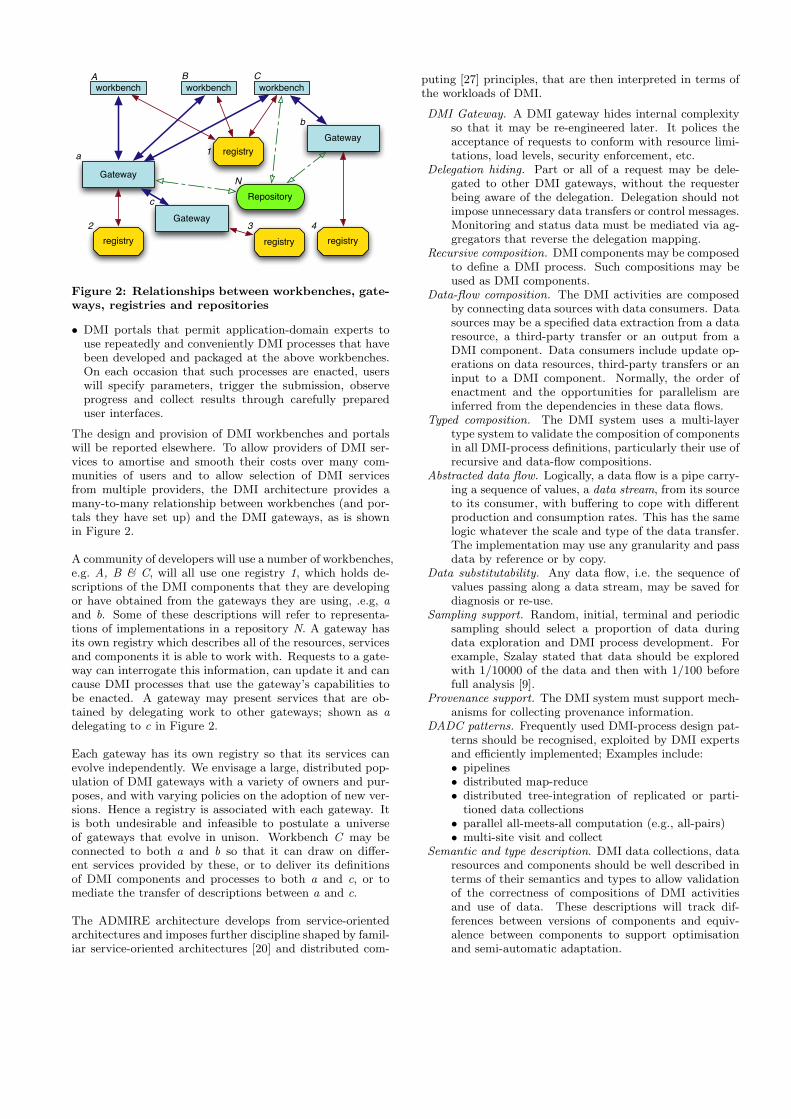
Figure 2: Relationships between workbenches, gate-ways, registries and repositories
• DMI portals that permit application-domain experts touse repeatedly and conveniently DMI processes that havebeen developed and packaged at the above workbenches.On each occasion that such processes are enacted, userswill specify parameters, trigger the submission, observeprogress and collect results through carefully prepareduser interfaces.
The design and provision of DMI workbenches and portalswill be reported elsewhere. To allow providers of DMI ser-vices to amortise and smooth their costs over many com-munities of users and to allow selection of DMI servicesfrom multiple providers, the DMI architecture provides amany-to-many relationship between workbenches (and por-tals they have set up) and the DMI gateways, as is shownin Figure 2.
A community of developers will use a number of workbenches,e.g. A, B & C, will all use one registry 1, which holds de-scriptions of the DMI components that they are developingor have obtained from the gateways they are using, .e.g, aand b. Some of these descriptions will refer to representa-tions of implementations in a repository N. A gateway hasits own registry which describes all of the resources, servicesand components it is able to work with. Requests to a gate-way can interrogate this information, can update it and cancause DMI processes that use the gateway’s capabilities tobe enacted. A gateway may present services that are ob-tained by delegating work to other gateways; shown as adelegating to c in Figure 2.
Each gateway has its own registry so that its services canevolve independently. We envisage a large, distributed pop-ulation of DMI gateways with a variety of owners and pur-poses, and with varying policies on the adoption of new ver-sions. Hence a registry is associated with each gateway. Itis both undesirable and infeasible to postulate a universeof gateways that evolve in unison. Workbench C may beconnected to both a and b so that it can draw on differ-ent services provided by these, or to deliver its definitionsof DMI components and processes to both a and c, or tomediate the transfer of descriptions between a and c.
The ADMIRE architecture develops from service-orientedarchitectures and imposes further discipline shaped by famil-iar service-oriented architectures [20] and distributed com-
puting [27] principles, that are then interpreted in terms ofthe workloads of DMI.
DMI Gateway. A DMI gateway hides internal complexityso that it may be re-engineered later. It polices theacceptance of requests to conform with resource limi-tations, load levels, security enforcement, etc.
Delegation hiding. Part or all of a request may be dele-gated to other DMI gateways, without the requesterbeing aware of the delegation. Delegation should notimpose unnecessary data transfers or control messages.Monitoring and status data must be mediated via ag-gregators that reverse the delegation mapping.
Recursive composition. DMI components may be composedto define a DMI process. Such compositions may beused as DMI components.
Data-flow composition. The DMI activities are composedby connecting data sources with data consumers. Datasources may be a specified data extraction from a dataresource, a third-party transfer or an output from aDMI component. Data consumers include update op-erations on data resources, third-party transfers or aninput to a DMI component. Normally, the order ofenactment and the opportunities for parallelism areinferred from the dependencies in these data flows.
Typed composition. The DMI system uses a multi-layertype system to validate the composition of componentsin all DMI-process definitions, particularly their use ofrecursive and data-flow compositions.
Abstracted data flow. Logically, a data flow is a pipe carry-ing a sequence of values, a data stream, from its sourceto its consumer, with buffering to cope with differentproduction and consumption rates. This has the samelogic whatever the scale and type of the data transfer.The implementation may use any granularity and passdata by reference or by copy.
Data substitutability. Any data flow, i.e. the sequence ofvalues passing along a data stream, may be saved fordiagnosis or re-use.
Sampling support. Random, initial, terminal and periodicsampling should select a proportion of data duringdata exploration and DMI process development. Forexample, Szalay stated that data should be exploredwith 1/10000 of the data and then with 1/100 beforefull analysis [9].
Provenance support. The DMI system must support mech-anisms for collecting provenance information.
DADC patterns. Frequently used DMI-process design pat-terns should be recognised, exploited by DMI expertsand efficiently implemented; Examples include:• pipelines• distributed map-reduce• distributed tree-integration of replicated or parti-
tioned data collections• parallel all-meets-all computation (e.g., all-pairs)• multi-site visit and collect
Semantic and type description. DMI data collections, dataresources and components should be well described interms of their semantics and types to allow validationof the correctness of compositions of DMI activitiesand use of data. These descriptions will track dif-ferences between versions of components and equiv-alence between components to support optimisationand semi-automatic adaptation.
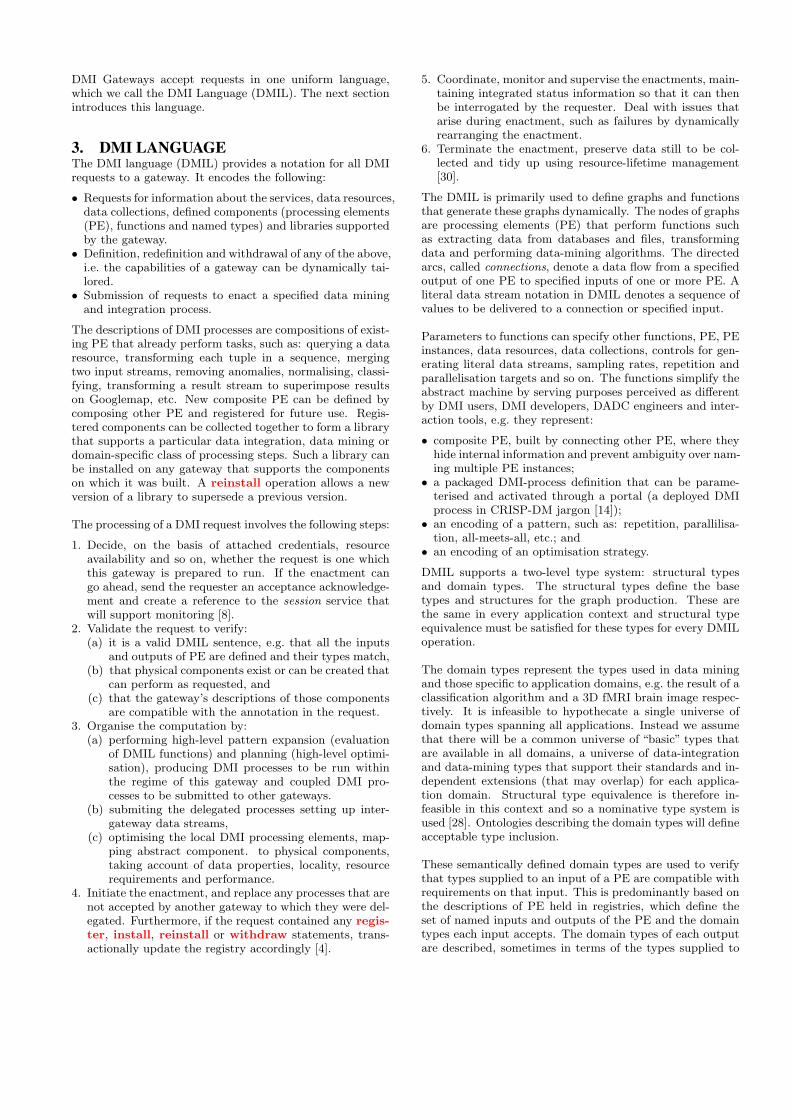
DMI Gateways accept requests in one uniform language,which we call the DMI Language (DMIL). The next sectionintroduces this language.
3. DMI LANGUAGEThe DMI language (DMIL) provides a notation for all DMIrequests to a gateway. It encodes the following:
• Requests for information about the services, data resources,data collections, defined components (processing elements(PE), functions and named types) and libraries supportedby the gateway.• Definition, redefinition and withdrawal of any of the above,
i.e. the capabilities of a gateway can be dynamically tai-lored.• Submission of requests to enact a specified data mining
and integration process.
The descriptions of DMI processes are compositions of exist-ing PE that already perform tasks, such as: querying a dataresource, transforming each tuple in a sequence, mergingtwo input streams, removing anomalies, normalising, classi-fying, transforming a result stream to superimpose resultson Googlemap, etc. New composite PE can be defined bycomposing other PE and registered for future use. Regis-tered components can be collected together to form a librarythat supports a particular data integration, data mining ordomain-specific class of processing steps. Such a library canbe installed on any gateway that supports the componentson which it was built. A reinstall operation allows a newversion of a library to supersede a previous version.
The processing of a DMI request involves the following steps:
1. Decide, on the basis of attached credentials, resourceavailability and so on, whether the request is one whichthis gateway is prepared to run. If the enactment cango ahead, send the requester an acceptance acknowledge-ment and create a reference to the session service thatwill support monitoring [8].
2. Validate the request to verify:(a) it is a valid DMIL sentence, e.g. that all the inputs
and outputs of PE are defined and their types match,(b) that physical components exist or can be created that
can perform as requested, and(c) that the gateway’s descriptions of those components
are compatible with the annotation in the request.3. Organise the computation by:
(a) performing high-level pattern expansion (evaluationof DMIL functions) and planning (high-level optimi-sation), producing DMI processes to be run withinthe regime of this gateway and coupled DMI pro-cesses to be submitted to other gateways.
(b) submiting the delegated processes setting up inter-gateway data streams,
(c) optimising the local DMI processing elements, map-ping abstract component. to physical components,taking account of data properties, locality, resourcerequirements and performance.
4. Initiate the enactment, and replace any processes that arenot accepted by another gateway to which they were del-egated. Furthermore, if the request contained any regis-ter, install, reinstall or withdraw statements, trans-actionally update the registry accordingly [4].
5. Coordinate, monitor and supervise the enactments, main-taining integrated status information so that it can thenbe interrogated by the requester. Deal with issues thatarise during enactment, such as failures by dynamicallyrearranging the enactment.
6. Terminate the enactment, preserve data still to be col-lected and tidy up using resource-lifetime management[30].
The DMIL is primarily used to define graphs and functionsthat generate these graphs dynamically. The nodes of graphsare processing elements (PE) that perform functions suchas extracting data from databases and files, transformingdata and performing data-mining algorithms. The directedarcs, called connections, denote a data flow from a specifiedoutput of one PE to specified inputs of one or more PE. Aliteral data stream notation in DMIL denotes a sequence ofvalues to be delivered to a connection or specified input.
Parameters to functions can specify other functions, PE, PEinstances, data resources, data collections, controls for gen-erating literal data streams, sampling rates, repetition andparallelisation targets and so on. The functions simplify theabstract machine by serving purposes perceived as differentby DMI users, DMI developers, DADC engineers and inter-action tools, e.g. they represent:
• composite PE, built by connecting other PE, where theyhide internal information and prevent ambiguity over nam-ing multiple PE instances;• a packaged DMI-process definition that can be parame-
terised and activated through a portal (a deployed DMIprocess in CRISP-DM jargon [14]);• an encoding of a pattern, such as: repetition, parallilisa-
tion, all-meets-all, etc.; and• an encoding of an optimisation strategy.
DMIL supports a two-level type system: structural typesand domain types. The structural types define the basetypes and structures for the graph production. These arethe same in every application context and structural typeequivalence must be satisfied for these types for every DMILoperation.
The domain types represent the types used in data miningand those specific to application domains, e.g. the result of aclassification algorithm and a 3D fMRI brain image respec-tively. It is infeasible to hypothecate a single universe ofdomain types spanning all applications. Instead we assumethat there will be a common universe of “basic” types thatare available in all domains, a universe of data-integrationand data-mining types that support their standards and in-dependent extensions (that may overlap) for each applica-tion domain. Structural type equivalence is therefore in-feasible in this context and so a nominative type system isused [28]. Ontologies describing the domain types will defineacceptable type inclusion.
These semantically defined domain types are used to verifythat types supplied to an input of a PE are compatible withrequirements on that input. This is predominantly based onthe descriptions of PE held in registries, which define theset of named inputs and outputs of the PE and the domaintypes each input accepts. The domain types of each outputare described, sometimes in terms of the types supplied to

/* import components */use dmi.rdb.SQLQuery;use dmi.samplers.ListRandomSample;use dmi.image.ImageRescale;...use dmi.classifiers.nFoldValidation;use dmi.classifiers.LDAClassifier;/* set up and identify instances of the PE */SQLQuery sqlQuery = new SQLQuery;ListRandomSample listSample = new ListRandomSample;TupleProjection tupleProj = new TupleProjection;GetFile getFile = new GetFile;ImageRescale imageRescale = new ImageRescale;MedianFilter medianFilter = new MedianFilter;WaveletDecomp wavelet = new WaveletDecomp;TupleMerge tupleMerge = new TupleMerge;ViaStatus deliver = new ViaStatus;String query = “SELECT fileName, . . .
FROM EURExpress.images, . . .WHERE . . . ”;
/* the literal “query” gets connected to sqlQuery’s input“expression”*/|- query -| => expression->sqlQuery;/* sqlQuery’s output “data” gets connected to listSample’sinput “dataIn” */sqlQuery->data => dataIn->listSample;|- 0.01 -| => fraction->listSample;Connection c1; listSample->dataOut => c1;c1 => filename->getFile;c1 => data->tupleProj;|- [“date”, “assay#”, . . . ] -| => columnIds->tupleProj;getFile->data => dataIn->imageRescale;imageRescale->dataOut => dataIn->medianFilter;|- repeat enough 〈 300, 200 〉 -| => size->medianFilter;medianFilter->dataOut => dataIn->wavelet;wavelet->dataOut => dataIn[0]->tupleMerge;tupleProj->result => dataIn[1]->tupleMerge;Validation val = nFoldValidation (10, LDAClassifier);tupleMerge->dataOut => data->val;val->results => data->deliver;
Figure 3: An example of DMIL that correspondswith the process in Figure 6
the inputs. By tracing the flow through the graph it is pos-sible to propagate the information known about types andto verify compatibility. In some cases very little can be in-ferred about an output, e.g. when reading from an arbitraryfile. In these cases, the developer has to annotate the con-nection with the type the data represents. Frequently, thePE is agnostic about components of a value, e.g. fields in atuple it doesn’t process, in which case use is made of typeany in the description.
The example of a DMIL request in Figure 3 encodes partof the workflow that expands to the OGSA-DAI shown inFigure 6, which is explained in Section 4. The mappingfrom DMIL to the diagram is straightforward and consistsof systematically importing the relevant components fromthe relevant library, instantiating them as many times as isneeded and then connecting them via their outputs. Theliterals illustrate our sequence notation. In this example
the pattern for n-fold validation has been encoded as thefunction nFoldValidation. When this is called, with thenumber of validations and a classification builder as its pa-rameters, it generates an evaluation graph equivalent to thelower part of Figure 6, except that the figure for reasons ofclarity shows only one validation, whereas the DMIL belowwould generate 10 instances of that graph if it chose maximalparallelism.
4. FEASIBILITY STUDYWe are assessing the feasibility of the DMI architecture byiterating over:
1. building prototypes of the architecture;2. mapping test DMI processes from five case study scenar-
ios into DMIL;3. submitting these as DMI requests and observing enact-
ment performance; and4. analysing the effectiveness of the architecture in separat-
ing concerns, delivering functionality, providing changemanagement and accommodating change.
OGSA-DAI [3] already implements data streaming graphsinterconnecting its PE, termed “activities”, and was an in-spiration for the DMI architecture. Therefore, the initialprototype, which is being used to explore data streamingfor DMI, maps DMI requests to sets of OGSA-DAI requests.Each OGSA-DAI request represents a subgraph of the DMIrequest that will be run on one OGSA-DAI service. Theseare coupled together, using OGSA-DAI’s inter-process datastreaming. All of the activities in one OGSA-DAI requestare started simultaneously and execute in a pipelined man-ner as data arrives at their inputs. Within an OGSA-DAI re-quest, data is passed between activities as references to Javaobjects. These are serialised for inter-process data stream-ing. This leads to efficient processing of arbitrarily largedata with a small memory footprint.
4.1 An example test DMI processThe EURExpress-II project provides one of the five use casesfrom which we draw DMI processes to evaluate our archi-tecture. It aims to build a transcriptome-wide atlas for thedeveloping mouse embryo using RNA in situ hybridisationexperiments. To date it has collected over 500,000 capturedimages (∼ 4TB) of these experiments, which are then anno-tated by human curators. The annotation consists of taggingeach image with terms from a set of 1,500 anatomical com-ponents. Tagging an image with a term means a particulargene is expressed in the corresponding anatomical compo-nent. So far, 80% of images have been manually curated.Our chosen test DMI process automatically performs anno-tation by first creating a classifier for each term and thenclassifying the remaining 20% of images in terms of anatom-ical terms, where each image may map the expression ofmultiple genes.
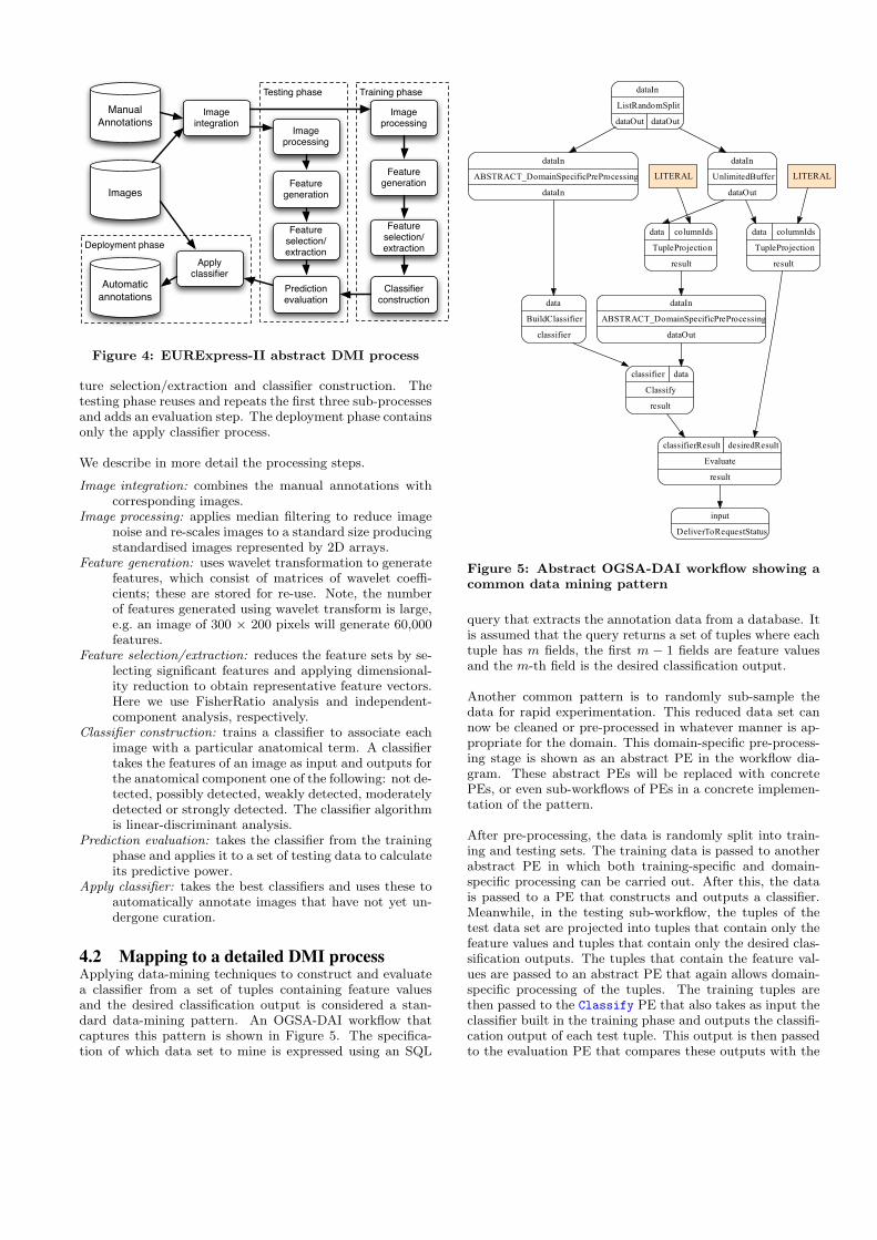
The high-level DMI process is essentially a pattern recogni-tion task. The aim is to produce multiple classifiers, whereeach classifier recognises for each image whether it showsgene expression in one anatomical component. As shownin Figure 4, it has three phases: training, testing and de-ployment. These can be further divided into sub-processes.For instance, for training the pattern recognition, the sub-processes include image processing, feature generation, fea-
Deployment phase
Training phaseTesting phase
Image integration
Manual Annotations
Image processing
Feature generation
Feature selection/extraction
Images
Automatic annotations
Apply classifier
Classifier construction
Prediction evaluation
Image processing
Feature generation
Feature selection/extraction
Figure 4: EURExpress-II abstract DMI process
ture selection/extraction and classifier construction. Thetesting phase reuses and repeats the first three sub-processesand adds an evaluation step. The deployment phase containsonly the apply classifier process.
We describe in more detail the processing steps.
Image integration: combines the manual annotations withcorresponding images.
Image processing: applies median filtering to reduce imagenoise and re-scales images to a standard size producingstandardised images represented by 2D arrays.
Feature generation: uses wavelet transformation to generatefeatures, which consist of matrices of wavelet coeffi-cients; these are stored for re-use. Note, the numberof features generated using wavelet transform is large,e.g. an image of 300 × 200 pixels will generate 60,000features.
Feature selection/extraction: reduces the feature sets by se-lecting significant features and applying dimensional-ity reduction to obtain representative feature vectors.Here we use FisherRatio analysis and independent-component analysis, respectively.
Classifier construction: trains a classifier to associate eachimage with a particular anatomical term. A classifiertakes the features of an image as input and outputs forthe anatomical component one of the following: not de-tected, possibly detected, weakly detected, moderatelydetected or strongly detected. The classifier algorithmis linear-discriminant analysis.
Prediction evaluation: takes the classifier from the trainingphase and applies it to a set of testing data to calculateits predictive power.
Apply classifier: takes the best classifiers and uses these toautomatically annotate images that have not yet un-dergone curation.
4.2 Mapping to a detailed DMI processApplying data-mining techniques to construct and evaluatea classifier from a set of tuples containing feature valuesand the desired classification output is considered a stan-dard data-mining pattern. An OGSA-DAI workflow thatcaptures this pattern is shown in Figure 5. The specifica-tion of which data set to mine is expressed using an SQL
Figure 5: Abstract OGSA-DAI workflow showing acommon data mining pattern
query that extracts the annotation data from a database. Itis assumed that the query returns a set of tuples where eachtuple has m fields, the first m − 1 fields are feature valuesand the m-th field is the desired classification output.
Another common pattern is to randomly sub-sample thedata for rapid experimentation. This reduced data set cannow be cleaned or pre-processed in whatever manner is ap-propriate for the domain. This domain-specific pre-process-ing stage is shown as an abstract PE in the workflow dia-gram. These abstract PEs will be replaced with concretePEs, or even sub-workflows of PEs in a concrete implemen-tation of the pattern.
After pre-processing, the data is randomly split into train-ing and testing sets. The training data is passed to anotherabstract PE in which both training-specific and domain-specific processing can be carried out. After this, the datais passed to a PE that constructs and outputs a classifier.Meanwhile, in the testing sub-workflow, the tuples of thetest data set are projected into tuples that contain only thefeature values and tuples that contain only the desired clas-sification outputs. The tuples that contain the feature val-ues are passed to an abstract PE that again allows domain-specific processing of the tuples. The training tuples arethen passed to the Classify PE that also takes as input theclassifier built in the training phase and outputs the classifi-cation output of each test tuple. This output is then passedto the evaluation PE that compares these outputs with the
desired classification output for these tuples and outputs theclassification score.
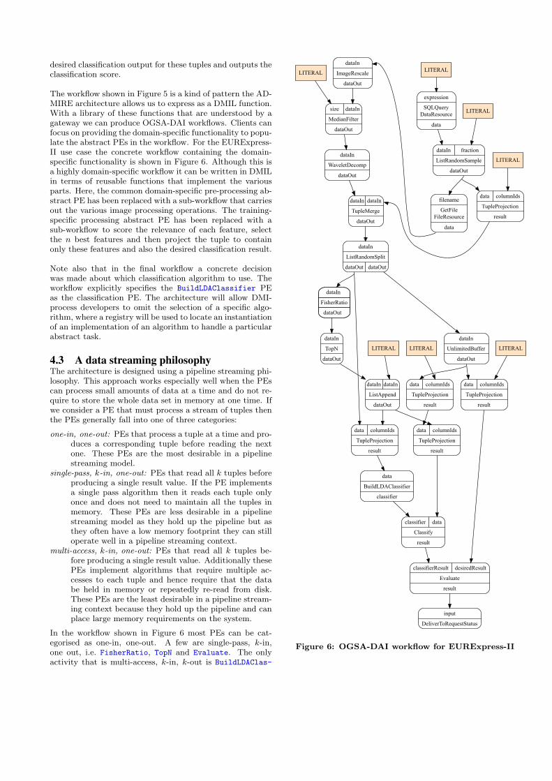
The workflow shown in Figure 5 is a kind of pattern the AD-MIRE architecture allows us to express as a DMIL function.With a library of these functions that are understood by agateway we can produce OGSA-DAI workflows. Clients canfocus on providing the domain-specific functionality to popu-late the abstract PEs in the workflow. For the EURExpress-II use case the concrete workflow containing the domain-specific functionality is shown in Figure 6. Although this isa highly domain-specific workflow it can be written in DMILin terms of reusable functions that implement the variousparts. Here, the common domain-specific pre-processing ab-stract PE has been replaced with a sub-workflow that carriesout the various image processing operations. The training-specific processing abstract PE has been replaced with asub-workflow to score the relevance of each feature, selectthe n best features and then project the tuple to containonly these features and also the desired classification result.
Note also that in the final workflow a concrete decisionwas made about which classification algorithm to use. Theworkflow explicitly specifies the BuildLDAClassifier PEas the classification PE. The architecture will allow DMI-process developers to omit the selection of a specific algo-rithm, where a registry will be used to locate an instantiationof an implementation of an algorithm to handle a particularabstract task.
4.3 A data streaming philosophyThe architecture is designed using a pipeline streaming phi-losophy. This approach works especially well when the PEscan process small amounts of data at a time and do not re-quire to store the whole data set in memory at one time. Ifwe consider a PE that must process a stream of tuples thenthe PEs generally fall into one of three categories:
one-in, one-out: PEs that process a tuple at a time and pro-duces a corresponding tuple before reading the nextone. These PEs are the most desirable in a pipelinestreaming model.
single-pass, k-in, one-out: PEs that read all k tuples beforeproducing a single result value. If the PE implementsa single pass algorithm then it reads each tuple onlyonce and does not need to maintain all the tuples inmemory. These PEs are less desirable in a pipelinestreaming model as they hold up the pipeline but asthey often have a low memory footprint they can stilloperate well in a pipeline streaming context.
multi-access, k-in, one-out: PEs that read all k tuples be-fore producing a single result value. Additionally thesePEs implement algorithms that require multiple ac-cesses to each tuple and hence require that the databe held in memory or repeatedly re-read from disk.These PEs are the least desirable in a pipeline stream-ing context because they hold up the pipeline and canplace large memory requirements on the system.
In the workflow shown in Figure 6 most PEs can be cat-egorised as one-in, one-out. A few are single-pass, k-in,one out, i.e. FisherRatio, TopN and Evaluate. The onlyactivity that is multi-access, k-in, k-out is BuildLDAClas-
Figure 6: OGSA-DAI workflow for EURExpress-II

sifier. This offers encouragement that many of the op-erations required in a data mining scenario fit well into apipeline streaming model.
The workflow shown in Figure 6 has lots of scope for parallelexecution and this scope is even greater if full n-fold crossvalidation were to be used. In n-fold validation the datawould be split into n pairs of training and testing sets andmost of the workflow would essentially be repeated n times.The ADMIRE architecture is designed to allow execution totake advantage of parallel processing where it is available butto hide most complexities from end-users. The ADMIREgateway will be able to compile a DMIL request such thatit can be executed in parallel on multiple execution enginesif these engines are available and the resulting execution ismore optimal. Planning such parallelisation will require theDMIL compiler and optimiser to have an extensive amountof performance data and descriptions for each PE.
In some places the workflow requires the use of a pipe withan unlimited buffer. These buffers have been explicitly in-serted into the workflow as PEs. Ideally users should notbe concerned about where such buffers are required. Onceagain the DMIL will allow the users to ignore such issues andthe DMIL compiler will automatically insert these bufferswhen they are required. Detecting where these unlimitedbuffers must be inserted requires details about each PE’s in-put, output and the order in which they are read from andwritten to.
5. RELATED WORKSignificant research effort has been invested in the develop-ment of distributed data mining and data access and inte-gration systems. All of the effort so far has concentratedon one aspect, either data mining or data access and in-tegration. The outcomes in terms of architecture designsfor distributed data mining can be categorised into three-tier, cluster-based, grid-based and cloud-based infrastruc-tures. We give a brief overview of these below.
Three-tier client-server: Kensington [15] is an example ofthis architecture. The client provides interactive visual pro-gramming of data-mining tasks, and three-dimensional vi-sualisation of data and analytical models. The applicationserver handles user login and authentication and providesservices for: user-object management, enactment, miningcomponent management, database access and data storage.The third-tier server provides high-performance data min-ing services located on high-end computing facilities thatinclude parallel systems. Discovery net [2] extends the Kens-ington architecture to make use of grid computing.
Cluster-based: Papyrus [7] is an architecture that enablesdata mining over distributed data sources. It aims to findoptimal mining strategies to run on meta-clusters or super-clusters. Each node of a cluster decides whether data shouldbe processed locally or sent to another node for processing.Alternatively, a hybrid approach is supported where datais processed to produce an intermediate result that is thensent to another node for further processing.
Grid-based: DataMiningGrid [31] is developed using theGlobus toolkit. It is compliant with open technology and
standards, most notable OASIS-approved standards such asWSRF and the data mining standard CRISP-DM. Its cre-ators claim the system shows high-performance, and is scal-able and flexible. Its ease of use was evaluated against awide range of representative modern data mining systems.
Knowledge grid [12] uses basic grid services such as commu-nication, authentication, information, and resource manage-ment to build parallel and distributed knowledge discoverytools and services. The architecture is composed of two lay-ers. The Core K-Grid layer implements basic services forthe definition, composition and execution of a distributedknowledge discovery applications over the Grid. Its maingoals are the management of metadata that describes thefeatures of data sources, third-party, data-mining tools andalgorithms. It also coordinates the execution of an appli-cation by trying to meet resource requirements. The highlevel K-Grid layer comprises services to compose, validate,and execute a parallel and distributed knowledge compu-tation. This layer also offers services to store and analyseresults.
GridMiner [11] is an infrastructure for distributed data min-ing and data integration in Grid environments. The archi-tecture consists of a service factory for creating and man-aging services; a service registry for registering services; adata-mining service that provides a set of data mining anddata analysis algorithms; a pre-processing service for datacleaning; a presentation service for visualisation of resultsand an orchestration service for handling the computation.
The DAME [6] has proposed a grid-enabled advanced neural-network-based model for searching distributed large datasets within the distributed aircraft maintenance environ-ment. This framework was to enhance diagonosis and prog-nosis of airoengine problems via using remote Grid services,tools and human experts. The iRODS [29] is a rule baseddata management architecture. It is a grid middleware thatprovides extensibility and customizability for the executionof workflows through user-defined and administrator-definedrules. These rules have been programmed as a set of micro-services, which can be composed together for different tasksbased on the requirements. These rules may deal with dataplacement, controlling access, data federation, data in inges-tion, etc.
Cloud-based: Grossman et al. [22] have developed a cloud-based infrastructure for data mining on large distributeddatasets. The approach moves the processing near to thedata. In contrast, most grid-based systems transfer data toprocesses prior to processing, which incurs a performancepenalty where bandwidth is limited. The architecture con-sists of the Sector storage cloud and the Sphere computecloud. It uses Sector to provide long-term persistent storageto large datasets, which are managed as distributed indexedfiles. A streaming model was developed where Sphere splitsthe input files, called Sphere Streams, into data segmentsand then Sector’s slave nodes process the segments in par-allel. The output of each process is returned to the client,written to local disks, or sent to different so-called “bucket”files. Neither Sector nor Sphere provides support for data se-mantics. It is up to the user to decide how to interpret data.In order for Sphere to split files, index files that explain the

record structure need to be provided.
A framework [16] that uses MapReduce [18]for data process-ing on several well-known machine learning algorithms hasbeen proposed, which allows these machine learning tasks torun in parallel on multicore computers. Similarly, an all-pairproduction system [26] exists for data intensive applicationssuch as data mining. The work provides users with a high-level abstraction. It runs on top of a conventional batchsubmission system and exploits the local storage connectedto each CPU.
Other cloud-based infrastructures for data-intensive applica-tions include BigTable [13], Google File System (GFS) [21],and Hadoop [10] that couple data and computing resourcesto accelerate data-intensive applications.
The most prominent commercial solution for data accessand integration to federated databases is IBM’s WebsphereInformation Integrator. In the open source space, OGSA-DAI [23] is a service-based approach that enables access toheterogeneous data resources by providing a homogeneousservice interface. Furthermore, it provides a powerful setof data transformations, data integration operations anddata delivery options. OGSA-DAI can execute data inte-gration workflows. Alternatively, it supports data federationthrough its extension OGSA-DQP [1].
A multi-tier distributed data integration architecture [33]has been developed to support enterprise data manipula-tion. The system provides a logical layer to map a unifiedlogical data model to reconstruct data from independent todependent sources, which can integrate and aggregate enter-prise data that resides in multiple relational databases. Thesystem also provide a tool set to manage and use on-line adhoc queries and decision support.
Additionally, semantic data integration has been incorpo-rated into existing distributed data integration architectures.For instance, OGSA-DAI-RDF [24] has extended OGSA-DAI access to RDF storage systems such as Jena [25]. S-OGSA [17] is a reference architecture for semantic grid,which extends OGSA defining a lightweight mechanism toallow the use of semantics and provides associated knowl-edge services to support a wide spectrum of service capabil-ities.
For the past decades, a wide range of workflow managementsystems have been established to support the constructionand management of workflow. For instance, Taverna is atool for the composition and enactment of bioinformaticworkflows and Pegasus is suitable for managing any com-plex scientific workflow. Some workflow management sys-tems e.g. Kepler provide graphical tools for workflow com-position while others require user to construct workflow fromtext editor using particular workflow languages e.g. BPELor representation e.g. directed acyclic graph used in DAG-Man Condor. Deelman et. al. [19] provides an overviewof workflow system features and capabilities with examplestaken from existing workflow systems and a taxonomy thatcharacterises and classifies various approaches for buildingand executing workflows proposes is discussed in [32].
6. CONCLUSIONS & FURTHER WORKIn this paper, we highlight the problem of the increase incomplexity, diversity and scale of data. We introduce a sep-aration of concerns between data mining and integration(DMI) process development and the mapping, optimisationand enactment of these processes. We postulate this sep-aration of concerns will allow handling separately the userand application diversity and the system diversity and com-plexity issues simultaneously. We introduce an architec-ture, which as a principal element defines gateways as thepoint where these two concerns meet. To allow uniformityand inter-gateway communication, each gateway will acceptDMI requests in DMIL, a language that allows requests forinformation about services, components and libraries; defi-nition, redefinition and withdrawal of the prior; and submis-sion of DMI requests.
To validate our hypothesis of separation of concerns, we per-form a feasibility study that comprises building prototypesof the architecture; mapping DMI processes from case stud-ies into DMIL, submitting these as DMI requests to the ar-chitecture, observing enactment performance, and analysingthe effectiveness of the architecture in separating concernsin terms of delivering functionality, providing change man-agement and accommodating change. Here we report ourfindings on the first prototype of the architecture, which isdeveloped using OGSA-DAI.
Our first use case involves a DMI scenario in the context ofdevelopmental biology where the objective is to predict inwhich anatomical components gene expression exhibits givenimages that capture the results of high-throughput in-situhybridisation experiments. We identify several propertiesof the resulting DMI processes after mapping them fromDMIL, which we argue are common in DMI requests. Weexplain how these properties can be exploited for optimisingDMI processes. Through further use cases we expect toidentify more of properties that provide opportunities foroptimisation.
AcknowledgementsThe EU Framework Programme 7 FP7-ICT-215024 fund-ing of the ADMIRE project is key to bringing the part-ners together and to undertaking the research. The UKEngineering and Physical Sciences Research Council’s sup-port of the OGSA-DAI, OMII-UK, DIALOGUE projectsand the e-Science Institute set up the meetings that led tothe ADMIRE community forming and brought the OGSA-DAI technology to the project.
7. REFERENCES[1] Alpdemir, M. N., Mukherjee, A., Paton, N.,
P.Watson, Fernandes, A. A., Gounaris, A., andSmith, J. Service-based distributed querying on thegrid. In Proceedings of the First InternationalConference on Service Oriented Computing (15-18December 2003), Springer, pp. 467–482.
[2] AlSairafi, S., Emmanouil, F.-S., Ghanem, M.,Giannadakis, N., Guo, Y., Kalaitzopoulos, D.,Osmond, M., Rowe, A., Syed, J., and Wendel, P.The Design of Discovery Net: Towards Open GridServices for Knowledge Discovery. Int. Journal of

High Performance Computing Applications 17, 3(2003), 297–315.
[3] Antonioletti, M., and Atkinson, M. The Designand Implementation of Grid Database Services inOGSA-DAI. Concurrency and Computation: Practiceand Experience 17 (February 2005).
[4] Atkinson, M., Brezany, P., Corcho, O.,Elsayed, I., van Hemert, J., Janciak, I., Pilana,S., and Wohrer, A. Advanced Data Mining andIntegration Research for Europe: Defining RegistryRequirements. Tech. rep., ADMIRE, 2009.
[5] Atkinson, M., Brezany, P., Corcho, O., Han, L.,van Hemert, J., Hluchy, L., Hume, A., Janciak,I., Krause, A., and Snelling, D. ADMIRE WhitePaper: Motivation, Strategy, Overview and Impact.Tech. Rep. version 0.9, ADMIRE, EPCC, Universityof Edinburgh, January 2009.
[6] Austin, J., Davis, R., Fletcher, M., Jackson, T.,Jessop, M., Liang, B., and Pasley, A. Dame:searching large data sets within a grid-enabledengineering application. In Proceedings of the IEEE -Special Issue on Grid Computing (2005), vol. 93(3),IEEE Computer Scociety, pp. 496–509.
[7] Bailey, S., Grossman, R., Sivakumar, H., andTurinsky, A. Papyrus: A system for data miningover local and wide area clusters and super-clusters. InProceedings of the 1999 ACM/IEEE conference onSupercomputing (CDROM) (1999), ACM New York,NY, USA.
[8] Banks, T. Web Services Resource Framework(WSRF) — Primer v1.2. Tech. rep., OASIS, May2006.
[9] Barga, R. S., Fay, D., Guo, D., Newhouse, S.,Simmhan, Y. L., and Szalay, A. S. Efficientscheduling of scientific workflows in a highperformance computing cluster. In CLADE (2008),Y. Kim and X. Li, Eds., ACM, pp. 63–68.
[10] Borthaku, D. The hadoop distributed file system:Architecture and design. retrieved fromlucene.apache.org/hadoop, 2007., 2007.
[11] Brezany, P., Hofer, J., Tjoa, A. M., andWohrer, A. Gridminer: An infrastructure for datamining on computational grids. In The APACConference and Exhibition on Advanced Computing,Grid Applications and eResearch (2003).
[12] Cannataroa, M., Taliaa, D., and Trunfioa, P.Distributed datamining on the grid. In FutureGeneration Computer Systems 18, 8 (2002),1101–1112.
[13] Chang, F., Dean, J., Ghemawat, S., Hsieh, W. C.,Burrows, D. A. W. M., Chandra, T., Fikes, A.,and Gruber, R. E. Bigtable: A distributed storagesystem for structured data. In USENIX OSDI (2004).
[14] Chapman, P., Clinton, J., Kerber, R., Khabaza,T., Reinartz, T., Shearer, C., and Wirth, R.The CRISP-DM reference model. Tech. rep., TheCRISP-DM Consortium, August 2000.
[15] Chattratichat, J., Darlington, J., Guo, Y.,Hedvall, S., Koler, M., and Syed, J. Anarchitecture for distributed enterprise data mining. InLecture Notes In Computer Science (1999), vol. 1593,7th International Conference on High-Performance
Computing and Networking.
[16] Chu, C., Kim, S. K., Lin, Y., Yu, Y., Bradski, G.,Ng, A. Y., and Olukotun, K. Mapreduce formachine learning on multicore. In In Proceedings ofNeural Information Processing Systems Conference(NIPS) (2007), B. Scholkopf, J. Platt, andT. Hofmann, Eds., pp. 281–288.
[17] Corcho, O., Alper, P., Kotsiopoulos, I.,Missier, P., Bechhofer, S., and Goble, C. Anoverview of s-ogsa: a reference semantic gridarchitecture. Journal of Web Semantics 4, 2 (2006),102–115.
[18] Dean, J., and Ghemawat, S. Mapreduce: Simplifieddata processing on large clusters. In USENIX OSDI2004 (2004).
[19] Deelman, E., Gannon, D., Shields, M., andTaylor, I. Workflows and e-science: An overview ofworkflow system features and capabilities. FutureGeneration Computer Systems 25, 5 (2009), 528 – 540.
[20] Erl, T. SOA Design Patterns. Prentice Hall,December 2008.
[21] Ghemawat, S., Gobioff, H., and Leung, S.-T. Thegoogle file system. In ACM SOSP 2003 (2003),pp. 29–43.
[22] Grossman, R., and Gu, Y. Data mining using highperformance clouds: Experimental studies using sectorand sphere. In Proceedings of The 14th ACM SIGKDDInternational Conference on Knowledge Discovery andData Mining, ACM (2008).
[23] Karasavvas, K., Atkinson, M., and Hume, A.Redesigned and new activities. specification,OGSA-DAI Project, University of Edinburgh, 2007.
[24] Kojima, I. Design and implementation of ogsa-dai-rd.In GGF 16 Semantic Grid Workshop (2006).
[25] McBride, B. Jena: a semantic web toolkit. IEEEInternet Computing 6, 6 (2002), 55–59.
[26] Moretti, C., Bulosan, J., Thain, D., and Flynn,P. All-Pairs: An Abstraction for Data-Intensive CloudComputing. In International Parallel and DistributedProcessing Symposium (April, 2008).
[27] Mullender, S. Distributed Systems, second ed.Addison-Wesley, 1993.
[28] Pierce, B. C. Types and Programming Languages.MIT Press, 2002.
[29] Rajasekar, A., Wan, M., Moore, R., andSchroeder, W. A prototype rule-based distributeddata management system. In HPDC workshop on NextGeneration Distributed Data Management (2006),IEEE Computer Scociety.
[30] Srinivasan, L., and Banks, T. Web ServicesResource Lifetime 1.2 (WS-ResourceLifetime) OASISStandard. Tech. rep., OASIS, April 2006.
[31] Stankovski, V., Swain, M., Ktavtsov, V.,Niessen, T., Wegner, D., Kindermann, J., andDubitzky, W. Grid-enabling data miningapplications with DataMiningGrid: An architecturalperspective. Future Generation Computer Systems 24,4 (2008), 259–279.
[32] Yu, J., and Buyya, R. A taxonomy of scientificworkflow systems for grid computing. SIGMOD Rec.34, 3 (2005), 44–49.

[33] Zhou, H., Duan, Q., and Liang, Z. A multiple-tierdistributed data integration architecture. InProceedings of the Seventh World Conference onIntegrated Design and Process Technology (IDPT)(2003).