From formal logic to formal ontology: The new dual paradigm ...
Upload
khangminh22Category
view
4download
0
FORMAL DEVELOPMENT OF OPEN
DISTRIBUTED SYSTEMS:
INTEGRATION OF UML AND PVS
Doctoral Dissertation
by
Demissie Bediye Aredo
Submitted to the Faculty of Mathematics and Natural Sciences,at the University of Oslo in partial fulfilment of the requirements for
the degree Dr. Scient. in Computer Science
August 2004

To my sister
Dirribee Bediye Aredo

Abstract
In this thesis, a research work conducted on formalization of the Unified ModelingLanguage (UML) notations is reported. Formal semantic definitions for UML mod-eling constructs are provided by systematically transforming them into suitable andwell-defined entities in the specification language of the Prototype Verification System(PVS). As UML is an industry standard modeling language consisting of several aspectsof object-oriented modeling techniques, it is not feasible to cover all semantic aspects ofthe UML notations. Static structural models (class diagrams), and dynamic behavioralmodels (sequence and statecharts diagrams) are the main focus of the thesis.
A strategy for deriving semantic models directly from UML graphical models, and aframework for integrating the UML modeling techniques with formal analysis techniquesof the PVS environment is proposed. Transformation of UML graphical models intoPVS specifications results in semantic models that are amenable to rigorous analysis,thereby overcoming limitations inherent in the semi-formal UML notations. This pavesa way for developing formal techniques that support rigorous development of distributedsystems through transformation and enhancement of OO modeling techniques.
Integrating semi-formal graphical modeling techniques with a mathematically baseddevelopment method(s) results in a development framework that supports rigorous modelanalysis, while useful features of the graphical modeling techniques are preserved. Au-tomation of the derivation of formal specifications from graphical UML models basedon the proposed semantics is vital as model analysis usually involves manipulation oflarge volume of information. In this regard, we have developed a prototype of a CASEtool that integrates the general-purpose PVS tool set with a UML CASE tool. The toolsupports formal development of distributed systems from requirement capture to codegeneration and allows developers to deal with the graphical models they have developedwhile the rigorous analysis is performed at the back-end.
This work contributes to the ongoing effort to provide formal semantics for the
UML notations, with the aim of clarifying and disambiguating the language as well as
supporting development of semantically-based CASE tools. Moreover, it allows exploita-
tion of the synergy between formal methods (FM) and semi-formal modeling languages,
which in turn improves the use of FMs in industrial settings.
i

ii

Acknowledgements
This work was financially supported by a grant from the Research Council of Norway
under the research program for distributed IT-systems. Additional funding was pro-
vided by the Department of Informatics, University of Oslo, Norway. The work was
carried out at the Department of Informatics, University of Oslo, and the Institute for
Energy Technology (IFE), Halden, Norway, from February 1998 – March 2001.
I would like to thank my supervisors Prof. Olaf Owe, and Dr. Wenhui Zhang for
their follow-ups, encouragements, and invaluable comments without which this work
would not have come to completion.
I am indebted to my earlier supervisor Prof. Ketil Stølen who guided me through
the early months of ’chaos’ and confusion. Colleagues who worked on the ADAPT-FT
project in general, and Drs. Issa Traore, Isabelle Ryl, and Einar Johnsen in particular
deserve special thanks for their support.
I always remember the informal and friendly atmosphere I enjoyed with the per-
sonnel and academic staff at the Department of Informatics, University of Oslo. I am
grateful to all staff members at the Department of Informatics, in particular Mr. Narve
Trædal for his courage in dealing with the administrative component of the thesis work,
most of the formal procedures were unnoticeable.
I had the pleasure of staying at IFE, in Halden, during my PhD candidacy. The
people at IFE are all wonderful, and their support made the completion of this work
possible. I am also grateful to the Research Council of Norway for the financial support
– a crucial component for the successful completion of this thesis.
I am also thankful to the Department of Computer Science, at the University of
Kent at Canterbury (UKC), for allowing me to use the facilities in their Computing
Laboratory. Dr. Stuart Kent and Prof. Keith Mander deserve special thanks for
expressing their interest in my work, and above all for making my stay at UKC so
comfortable.
Finally, my most sincere thanks go to my family for their patience, and support in
any way possible throughout the years. They had suffered my absence.
August 2004, Oslo, Norway
Demissie B. Aredo
iii

iv

Table of Contents
Abstract i
Acknowledgements iii
Table of Contents v
Executive Summary vii
1 Introduction 1
1.1 Background . . . . . . . . . . . . . . . . . . . . . . . . . . . . . . . . . 1
1.2 The Problem Statement . . . . . . . . . . . . . . . . . . . . . . . . . . 3
1.3 Formal Methods . . . . . . . . . . . . . . . . . . . . . . . . . . . . . . . 4
1.4 Involved Notations and Formalisms . . . . . . . . . . . . . . . . . . . . 6
1.4.1 The Prototype Verification System . . . . . . . . . . . . . . . . 7
1.4.2 The Unified Modeling Language . . . . . . . . . . . . . . . . . . 8
1.5 Formal Semantic Definitions . . . . . . . . . . . . . . . . . . . . . . . . 9
2 Formalization of UML Notations 13
2.1 Motivation . . . . . . . . . . . . . . . . . . . . . . . . . . . . . . . . . . 13
2.2 Formalization Approaches . . . . . . . . . . . . . . . . . . . . . . . . . 15
2.3 State-of-the-Art . . . . . . . . . . . . . . . . . . . . . . . . . . . . . . . 16
2.4 Formalization Issues . . . . . . . . . . . . . . . . . . . . . . . . . . . . 19
2.4.1 Composition of UML Models . . . . . . . . . . . . . . . . . . . 19
2.4.2 Checking Consistency of UML models . . . . . . . . . . . . . . 20
2.4.3 Refinement . . . . . . . . . . . . . . . . . . . . . . . . . . . . . 21
2.4.4 Formal Reasoning . . . . . . . . . . . . . . . . . . . . . . . . . . 22
3 Summary of Contributions 23
3.1 Formal Development of Distributed Systems . . . . . . . . . . . . . . . 24
3.2 Semantics of Structural UML Models . . . . . . . . . . . . . . . . . . . 26
3.3 Semantics of UML Sequence Diagrams . . . . . . . . . . . . . . . . . . 27
3.4 Semantics of UML Statecharts in PVS . . . . . . . . . . . . . . . . . . 28
3.5 Tracking Inconsistencies in Integrated Platforms . . . . . . . . . . . . . 29
3.6 Enhancing Structured Reviews with Model-Based Verification . . . . . 30
v

3.7 Summary of Major Achievements . . . . . . . . . . . . . . . . . . . . . 31
3.7.1 Semantic Definitions for UML Notations . . . . . . . . . . . . . 31
3.7.2 A Framework for Formal Development ODSs . . . . . . . . . . . 32
3.7.3 CASE Tool Support . . . . . . . . . . . . . . . . . . . . . . . . 34
4 Conclusions and Future Work 37
4.1 Conclusions . . . . . . . . . . . . . . . . . . . . . . . . . . . . . . . . . 37
4.2 Future Work . . . . . . . . . . . . . . . . . . . . . . . . . . . . . . . . . 38
A Formal Development of Open Distributed Systems: Towards an Inte-grated Framework 47
B Towards formalization of Structural UML Models in PVS 61
C An Integrated Framework for Formal Development of Open DistributedSystems 77
D A Framework for Semantics of UML Sequence Diagrams in PVS 95
E Semantics of UML Statecharts in PVS 119
F Tracking Inconsistencies in an Integrated Platform 135
G Enhancing Structured Review with Model-based Verification 157
H Formal System Development Using Method Integration: a Case Study193
vi

Executive Summary
The Unified Modeling Language (UML) [79, 91, 11] is an important industry stan-
dard (standardized by the Object Management Group (OMG)) for modeling software
systems that has rapidly become popular among the software communities. The popu-
larity of UML can largely be attributed to its graphical and intuitively understandable
visual notations, and its capabilities to support encapsulation, data abstraction, ex-
tensibility, and reusability. It is indisputable that the UML reflects some of the best
modeling experiences and incorporates notations that have proven useful in practice.
Using UML for effective formal analysis in industrial setting could, however, be prob-
lematic due to the lack of precise semantic definitions for its graphical notations. The
lack of firm semantic foundations for UML modeling constructs can lead to a number
of problems: understanding of the models can be more apparent than real; developers
may waste considerable time resolving disputes over usage and interpretation of no-
tations; and model analysis and communication could be difficult [42, 100]. Defining
precise semantics of a modeling language is a prerequisite for developing semantically
based CASE tools, and for model communication.
The primary objective of this thesis is to investigate semantics of UML description
techniques, to make them amenable to rigorous model analysis by transforming them
into semantic models. The specification language of the Prototype Verification System
(PVS) [81, 82, 97] is used as an underlying semantic domain. A general framework for
transforming graphical UML models into formal descriptions in the PVS specification
language is also proposed. This paves a way for formal development of systems through
a systematic transformation of UML models. The framework is used to transform
UML modeling constructs, namely, static structural modeling constructs such as class
diagrams, and dynamic behavioral modeling constructs such as sequence diagrams, and
statecharts into semantic models in the PVS specification language.
Transforming UML models into corresponding semantic models in the PVS speci-
fication language enables rigorous model analysis using the formal techniques of PVS
and its tools such as type-checker, theorem-prover, and model-checker. Analysis of the
resulting semantic models of reasonably large systems may involve processing of large
size of software artifacts, which calls for a mechanized support - a criteria for whole-scale
application of formal analysis techniques. In this regard, we have developed a platform
vii
that integrates a UML CASE tool and the PVS tool set. The platform supports formal
development of distributed systems from requirement capture to code production and
allows system designers to analyze the graphical models they have developed, while
the formal stuff is processed at the back-end.
This work is part of a long-term vision to explore how formal methods can be
used to underpin practical tools for analyzing UML models. It contributes to the
ongoing effort to meet the needs of software industry - improved quality and reliability,
and lower production cost - by providing mathematical basis for the UML modeling
techniques with the aim of clarifying the semantics of the language as well as supporting
the development of semantically-based CASE tools.
Organization of the Thesis
The thesis is organized into several chapters. In Chapter 1, the problem to be ad-
dressed is introduced. Moreover, relevant aspects of formal methods and semantics,
and modeling notations and methods involved in this work, namely the UML and the
PVS are briefly introduced. In Chapter 2, some of the central concepts of formalization
of OO modeling techniques are discussed. A literature survey of formalization of OO
modeling languages with emphasis put on the formal semantics for UML notations is
presented. In Chapter 3, a brief summary of the publications constituting the thesis
and the main achievements are presented, whereas full texts of the publications are
included as appendices. Finally, in Chapter 4, concluding remarks and future research
issues are presented.
List of Contributions
The thesis consists of a number of stand-alone publications each of which is addressing
a specific research issue. A roman-numbered list of the publications is given below. In
later sections, we refer to the publications by their respective numbers in the list. The
publications are listed in the order they have been summarized in chapter 3 to obtain a
logical flow. The versions of the publications included in the sequel may differ from the
published ones due to minor editorial fixes, reformatting necessary to give the thesis a
uniform layout, and in some cases discussions of new issues.
[I] I. Traore, D. B. Aredo and K. Stølen: Formal Development of Open Distributed
Systems: Towards an Integrated Framework, in the Proc. of the Workshop on
Object-Oriented Specification Techniques for Distributed Systems and Behaviors
(OOSDS’99), Sept. 27, 1999, Paris, France.
[II] D. B. Aredo, I. Traore and K. Stølen: Towards Formalization of Structural UML
Models in PVS, Research Report No. 272, Department of Informatics, University
viii

of Oslo, August 1999. Presented to the 11th Nordic Workshop on Programming
Theory (NWPT’99) October 1999, Uppsala, Sweden, pp. 49.
[III] I. Traore, D. B. Aredo and Hong Ye: An Integrated Framework for Formal De-
velopment of Open Distributed Systems, Journal of Information and Software
Technology (IST), Elsevier Science, a Special Issue on Software Engineering, Ap-
plications, Practices and Tools, from the ACM SAC 2003, vol. 46, no. 5, pp.
281-286, April 15, 2004. An earlier version appeared in the in the proc. of ACM
Symposium on Applied Computing (SAC 2003), March 9-12, 2003, Melbourne,
Florida, USA.
[IV] D. B. Aredo: A Framework for Semantics of UML Sequence Diagrams in PVS,
Journal of Universal Computer Science (J.UCS), Springer-Verlag Co. Pub., vol.
8, no. 7, pp. 674-697, July 2002.
[V] D. B. Aredo: Semantics of UML Statecharts in PVS, in the Proc. of the 7th Inter-
national Multi-conference on Systemics, Cybernetics and Informatics (SCI2003),
July 27-30, 2003, Orlando, FL, USA.
[VI] I. Traore, D. B. Aredo and K. Stølen: Tracking Inconsistencies in an Integrated
Platform, Research report No. 274, Department of Informatics, University of
Oslo, Norway, August 1999.
[VII] I. Traore and D. B. Aredo: Enhancing Structured Review with Model-based Ver-
ification, the IEEE Transactions on Software Engineering (to appear). An earlier
version appeared in the Proc. of CAV’01 Workshop on Inspection in Software
Engineering (WISE’01), July 2001, Paris, France.
[VIII] D. B. Aredo and O. Owe: Formal System Development Using Method Inte-
gration: a Case Study, Research Report no. 308, Department of Informatics,
University of Oslo, February 2004.
The publications coauthored with Prof. Stølen were published while he was my prin-
cipal supervisor. The cooperation with Dr. Traore started when he held a one year
post-doc position associated with the ADAPT-FT project, which also included my own
doctoral fellowship.
Other Related Publications
My contributions to the following publications are results of the work done in the
context of the thesis project, but not included in the thesis. Cooperation with the
coauthors started at the time they were working on the ADAPT-FT project1.
1http://www.ifi.uio.no/adapt/
ix

• E. B. Johnsen, W. Zhang, O. Owe and D. B. Aredo: Combining Graphical and
Formal Development of Open Distributed Systems, M. Butler, L. Petre and K.
Sere (Eds): IFM2002, LNCS 2335, pp. 319-338, Springer-Verlag, Berlin, Heidel-
berg, 2002.
• E. B. Johnsen, W. Zhang, O. Owe and D. B. Aredo: Specification of Distributed
Systems with a Combination of Graphical and Formal Languages, in the Proc.
of the 8th Asia-Pacific Software Engineering Conference (APSEC2001), IEEE
Press, December 4-7, 2001, Macau SAR, China.
• W. Zhang, E. B. Johansen, O. Owe, and D. B. Aredo: Integrating UML and
OUN for Specification of Open Distributed Systems, in the Proc. of Symposium
on Visual Languages and Formal Methods, 2001 IEEE Symposium on Human-
Centric Computing Languages and Environments, September 2001, Stresa, Italy.
x

Chapter 1
Introduction
1.1 Background
Distributed computing environments are among the most active research areas in Com-
puter Science. They have gained considerable popularity among system developers
and researchers mainly due to the distributive nature inherent in modern computing
tasks. Distributed systems provide several substantial benefits over their centralized
sequential counterparts. Reduced incremental costs, extensibility, better reliability and
response, and high performance are among the potential advantages of distributed com-
puting environments over centralized systems [110]. Their intrinsic characteristics such
as resource sharing, openness, concurrency, non-determinism, transparency, and fault
tolerance make the design and development of distributed systems exceedingly difficult
[28]. Consistency issues frequently arise, for instance, from separation of processing
resources and the concurrency in distributed systems. Hence, the benefits that they
bring are not readily available, but they can only be achieved at the cost of exceedingly
difficult design and development process. Object-oriented analysis and design (OOAD)
methods have features such as encapsulation, restructuring, reusability, and data ab-
straction, which make them effective to describe open distributed systems (ODS). The
RM-ODP [56], for instance, advocates the use of OOAD methods in the development
of ODSs.
Several object-oriented design and analysis methodologies and notations have been
proposed since the mid 1970s [89, 98]. The most recent and popular notation is the
Unified Modeling Language (UML) [79, 91, 11] that resulted from a unification of mod-
eling concepts of the OMT [90], Booch [10], and Object-Oriented Software Engineering
(OOSE) [54] methods. UML became popular among the software community mainly
because of its visual, and intuitively appealing graphical notations and useful struc-
turing mechanisms. It is based on a set of OO description techniques and modeling
notations. It is indisputable that UML reflects some of the best modeling experiences
1

and incorporates notations and techniques that have proven useful in practice. How-
ever, using UML in rigorous analysis and design of critical systems in the industrial
settings could be problematic due to the lack of precise semantics and rigorous analysis
techniques. The missing formality in OO modeling techniques hampers evaluation of
UML models for completeness, consistency, and contents of requirement and design
specifications. Without precise semantic definitions for UML modeling notations, inte-
gration of UML with other rigorous software development methods would be difficult
[12].
Formal development methods (FDM) play an important role in addressing the
problems inherent in informal (or semi-formal) OO modeling notations. Traditionally,
FDMs are involved in the software development process to support precise specification
of computerized systems. They provide a strong support for system descriptions with
precise meanings and concise strategies for decomposition, design, verification and
validation - crucial requirements in developing systems with high reliability, mainly
due to large volume of information that is involved in detailed system description and
analysis. Unfortunately, none of the existing formal methods addresses all issues related
to features that characterize contemporary distributed systems [29]. The problem can
be addressed in several different ways. A naive approach would be to build up, from
scratch, a completely novel methodology that addresses all issues central to formal
development of distributed systems. This approach is, however, very challenging and
economically inefficient as argued by Abadi et al [1].
”A new class of systems is often viewed as an opportunity to invent a new semantics.A number of years ago, the new class was distributed systems. More recently, it hasbeen real-time systems. The proliferation of new semantics may be fun for semanticists,but developing a practical method for reasoning formally about systems is a lot of work.It would be unfortunate if every new class of systems require inventing new semantics,along with proof rules, languages, and tools.”
In the spirit of Abadi et al, a manageable approach should attempt to extend, gen-
eralize, integrate, and tune existing methods to address problems specific to distributed
computing environments. This approach consists of a series of tasks that need to be
accomplished.
- Firstly, existing modeling techniques, and formal methods, and their respective
CASE tools need to be investigated in order to figure out their strengths and
weaknesses in the context of development of distributed systems. The evaluation
of several existing methods and CASE tools undertaken by Stølen et al [102, 103]
found UML techniques suitable for modeling distributed systems, and identified
the PVS specification language as a suitable underlying semantic foundation in
the formalization of UML notations;
- Secondly, a framework for integration of the chosen modeling notation(s) and
2
formalism(s) should be developed. The integrated framework can be geared to-
wards description and analysis of specific features of distributed systems. The
integration combines one or more graphical modeling notation that are suitable
for addressing development issues intrinsic to distributed systems, and a formal-
ism that enables us to deal with rigorous model analysis; and
- Thirdly, a CASE tool that supports the development of distributed systems needs
to be developed to automate the step-wise development process from requirement
capture to code production. Such a tool is crucial as a rigorous reasoning about
system models may involve a large size of software artifacts, too large to be
manipulated manually.
There are clear advantages of integrating semi-formal graphical OO modeling tech-
niques with a mathematically-based formalism into a development framework that al-
lows rigorous model analysis. Such an integration, however, may raise serious problems
such as the consistency issue that need to be carefully addressed to obtain a correct and
reliable development framework. Checking consistency across different aspects of the
system is necessary to establish that different specifications do not impose conflicting
requirements. Mechanism for consistency checking varies depending on the features
of the notations integrated and requires different approaches. Techniques for checking
consistency between different viewpoint specifications of open distributed processing
(ODP) have been addressed thoroughly in the literature [59, 68, 9, 14].
1.2 The Problem Statement
Design and development of distributed systems are difficult due to their complexity,
heterogeneity, distribution and large size. Object-oriented modeling notations such
as the Unified Modeling Language (UML) [79] provide rich structuring mechanisms
necessary to manage the complexity of descriptions of distributed systems. The UML
has become popular among software developers due to its graphical notations, which
are easy to learn and use. One of the major limitations of UML is, however, that
semantic definitions of its notations is given in a natural language.
The lack of mathematically-based semantic definitions for the UML notations con-
strains its efficiency in rigorous model analysis, which in turn hampers its application
to the development of critical systems in the industrial settings. A well-defined and
fully explored semantic definition for UML notations is crucial as the lack of such firm
semantic foundation can make understanding of models more apparent than real [99].
It is difficult to determine whether or not a design is consistent, or a design modification
is correct, or a program correctly implements a design. Evaluation of completeness,
and consistency of contents of requirements and design specifications of systems will
also be difficult. Hence, there is a strong need for precise semantic definitions for UML
3

notations. Formal development techniques can be used to achieve the level of rigor nec-
essary for the development of critical systems. However, due to the esoteric features
of formal methods, software developers will not, in the foreseeable future, be willing to
use abstract formal languages and notations to design software systems [74]. Hence,
an optimal solution should strike a balance between the ease of use and the level of
rigor.
Motivated by the need for a development framework, and a supporting CASE tool
that is easy to use and at the same time allows rigorous analysis, this thesis investi-
gates how the diagrammatic UML notations and the PVS specification language can
be integrated to support formal development of open distributed systems. The frame-
work integrates the best practice in the software development using visual modeling
languages such as the UML, and mathematically-based analysis techniques underlying
formalisms such as the PVS to support rigorous development. It allows developers to
work on the graphical models they have developed while the formal ”stuff” is processed
at the back-end.
Formally reasoning about a real-world size software system involves manipulation
of a large size of software artifacts - too large and complex to handle manually. Thus,
automation of the rigorous analysis is essential. In this regard, a prototype of a CASE
tool that supports the framework is developed by integrating the respective CASE
tools of UML and PVS into a single platform. The platform allows modeling in UML,
mechanized transformation of the UML models into PVS specifications resulting in
models amenable to rigorous analysis, and formally reasoning using the PVS tool set
to reveal any inconsistencies and/or incompleteness.
1.3 Formal Methods
A formal method (FM) refers to the use of mathematically based concepts and tech-
niques in the development of computer systems. A FM is characterized by a formal
specification language and a set of rules governing the manipulation of expressions in
the language [113]. A specification language is the specifier’s primary tool during the
initial stages of system development. Choosing appropriate notations for the descrip-
tion of a system is not as trivial as one might think, because there is a certain degree
of trade-off between the expressiveness of the specification language and the level of
abstraction it supports [13, 113]. Specification languages that have wider ’vocabular-
ies’ and constructs can support description of a particular class of systems one wants
to deal with, but they may incline towards a particular implementation. Languages
with smaller ’vocabularies’ on the other hand, offer high level of abstraction and little
implementation bias (e.g. the language of Communicating Sequential Processes (CSP)
[52] has only processes and events as a basic entities).
FMs can be used for different purposes, in many ways and styles, and with varying
4

rigor. The earliest FMs were concerned with proving programs correct, i.e. assuming
that a correct specification is available, the goal is to show that a program in some
concrete programming language satisfies the specification. Contemporary FMs provide
framework for specifying, developing, and verifying systems in a systematic way. They
also provide mechanisms for proving that a given system specification is realizable,
that the specification is implemented correctly, and for proving properties of system
without necessarily running the system to determine its behavior.
FMs aim at using sound mathematical techniques, usually provided through speci-
fication languages, in order to make software development activities precisely defined,
checked and ultimately automated. The mathematical basis allows precise definition
of notions such as consistency, and completeness, and more relevantly, specification,
implementation, and correctness [113].
The primary purpose of using FMs is to help engineers construct more reliable
systems. They can be used at all stages of software development process - from ini-
tial customer’s requirement capture through system design, implementation, testing,
debugging, maintenance, verification and evaluation. When used at earlier stages of
system development, FMs can reveal design flaws that might, otherwise, not be dis-
covered before the more costly testing and debugging phases. When used at later
stages of development, FMs can help developers in determining correctness of system
implementations and equivalence of different implementations.
Tangible results of applying FMs to system development are formal specifications
- precise and usually concise system descriptions. A specification may serve as a con-
tract and a means of communication among the stakeholders: customers, specifiers,
implementers, etc. If the syntax of the a specification language is defined explicitly,
a syntactic analysis tool can be developed. Furthermore, if the semantics of the lan-
guage is sufficiently restricted, rigorous model analysis can be performed and tools can
also be developed to automate the analysis. Hence, formal specifications have advan-
tages, over their informal counterparts, of being amenable to rigorous and mechanized
analysis and manipulation. Another advantage of using FMs in system development
is that they allow developers to concentrate on what is required at an abstract level,
i.e. developers focus directly on aspects of interest and avoid distractions entailed by
implementation details [77].
By relieving the mind of all unnecessary work, a good notation sets it free to concentrateon more advanced problems, and in effect increases the mental power of the race. –Alfred North Whitehead [13]
Formal specification and verification process involve considerable syntactic details and
require careful planning and organization to obtain modular system specifications. A
strong tool support is a prerequisite for an effective use of formal development methods
in real-world problems. With the introduction of CASE-tools, in particular theorem-
provers and model-checkers, construction of mechanically and interactively checkable
5

proofs of consistency and well-foundedness has become feasible [13]. Most of the Formal
Methods incorporate theorem-prover as a part of the method itself, e.g. PVS [81, 82],
HOL [45].
1.4 Involved Notations and Formalisms
This thesis has been undertaken within the ADAPT-FT project1. The decision to use
existing languages such as the UML [79] and the PVS [81, 82], and to create a new
language, known as the Oslo University Notation (OUN) [80], was taken at the project
level based on the result of investigation that compared several specification languages
and formalisms [102]. The main objective of the ADAPT-FT project was to adapt,
tune, develop, and extend formal methods towards the special needs of distributed
systems. To achieve this, an underlying semantic foundation was needed, preferable
a foundation already implemented with a series of powerful tools. PVS was a nat-
ural choice in this respect, especially due to its strong type systems and functional
sub-language, covering inductive data types and inductively defined functions, and its
reasoning capabilities and tools, including some model-checking and theorem-proving
facilities.
As UML was emerging as an industry standard for object-oriented modeling lan-
guages and gaining popularity among software developers, it was chosen as one com-
ponent of the ADAPT-FT integrated platform. PVS provides a vehicle for defining
formal and precise semantics of the UML and OUN languages and for defining the
associated specification formalism, including concepts for refinement and composition.
At the same time, it allows development and reuse of the semantic definitions in the
design of tools, such as forms of reasoning tools.
Even though the nature of PVS may be mathematically challenging to software
engineers, a semantic foundation from which engineering tools that are less esoteric
may be developed is needed. For instance, in the ADAPT-FT platform, integrating
UML, OUN, Java and PVS, and with translation from UML to OUN and PVS and
from OUN to java and to PVS, one may develop tools at the level of UML diagrams
or OUN programs, where the implementation of the tool is done at the PVS level
(by means of PVS translations). Tools giving yes/no answers require no insight in
PVS, and may provide useful feedback to the software engineer. It would of course be
desirable to have tools giving UML or OUN related feedback, built from PVS related
tools; however, this is beyond the scope of the ADAPT-FT project.
1http://www.ifi.uio.no/adapt/
6

1.4.1 The Prototype Verification System
The Prototype Verification System (PVS) [81, 82] is an environment for formal specifi-
cation of systems. It combines a highly expressive specification language with a power-
ful interactive theorem-prover that provides a mechanized support for verification and
validation. PVS is mainly intended for formalization of requirements and design-level
specifications, and for analysis of problems. It is being used for verification of complex
software systems, especially in the aeronautics industry.
The PVS specification language extends a strongly typed higher-order logic of total
functions. Its type system is augmented with features such as predicate subtypes, de-
pendent types, and recursive data types. These features are vital for facile mathematical
expression as well as symbolic manipulation [97]. Types impose a useful mechanism
within a specification langauge. They also allow early detection of a large class of
syntactic and semantic errors.
A distinctive feature of the PVS specification language is the predicate subtyping.
Predicate subtypes and dependent types are powerful specification concepts as a lot of
information can be encoded into the types. Predicate subtyping enables us, for instance,
to deal with partial functions in the logic of total functions by restricting the domain
of definition to an appropriate sub-domain. Type checking with predicate subtypes is,
however, undecidable and generates proof obligations, the so-called Type Correctness
Conditions (TCCs), whenever type conflicts cannot be resolved. For instance, the
arithmetic division operation can be introduced with the domain given as a subtype of
numbers consisting of nonzero numbers. If applied to a term not known to be nonzero,
a proof obligation is generated. In developing specifications using predicate subtypes
and dependent types, the TCCs may provide useful information about the consistency
and completeness of the specification. In practice, most of the TCCs are discharged
automatically by using the theorem-prover, whereas more involving ones require user
interactions.
Specifications in PVS are organized into, possibly parameterized, hierarchies of the-
ories. Parameterized theories provide a mechanism to develop generic, and reusable
templates of specifications and proofs. A theory may contain assumptions that are
used to specify constraints on the parameters of the theory, definitions, axioms and
theorems. Axiomatic specifications are effective for certain problem domains, but may
introduce inconsistencies. Definitional specifications avoid this problem and are guar-
anteed to provide conservative extensions. PVS supports both axiomatic and defini-
tional paradigms.
Modularization of large PVS specifications is achieved by structuring them into
hierarchies of theories by using the IMPORTING clause that makes previously defined
theories available. When a parameterized theory is instantiated, proof obligations are
generated in accordance with the assumptions on the parameters.
7

In this section, we presented a brief overview of the PVS environment. For a
more detailed description of PVS, interested readers should refer to the PVS language
reference [81] and the prover guide [96]. The tutorial by Rushby [93] gives a good
introduction to the PVS environment.
1.4.2 The Unified Modeling Language
The Unified Modeling Language (UML) [79, 91, 11] is a notation for specifying, visu-
alizing and documenting artifacts of object-oriented software-intensive systems. UML
is a de-facto industrial standard for OO modeling languages. By the time this thesis
work was undertaken, the accepted standard version was UML v1.3 [79].
UML was mainly intended to be a general purpose OO modeling language that
supports encapsulation, data abstraction, reusability, and adaptation and extension
mechanisms towards specific application domains. It was also intended to be a visual,
graphical and intuitively understandable notation, that is complete in the sense that
it can be used to describe and model all aspects of a system appropriately [36]. In
order to meet the intended objectives, UML combines several modeling ’sub-languages’,
each of which is suitable for describing a specific aspect of an OO system design.
That is, a system is modelled by a set of sub-models, called views each of which is
focusing on a specific system aspect. A given aspect of a system can be modelled from
different perspectives, thus leading to overlapping and even redundant or conflicting
specifications of certain system aspects. As argued by Engels et al [36], the approach
of providing overlapping, non-orthogonal sub-models eases the specification process
as it allows incremental description of an aspect by inter-relating it to other aspects.
In contrast, the use of different, even non-orthogonal, sub-languages for modeling a
system increases the danger of inconsistencies between the sub-models, and requires
additional mechanism to prevent the inconsistencies.
This calls for a common semantic foundation where semantics of modeling con-
structs of involved sub-languages are defined to allow rigorous model analysis and
check ensure consistency and completeness of the sub-models. System aspects can
be categorized into static structural aspects and dynamic behavioral aspects. UML
consists of several description mechanisms necessary to specify static structural, dy-
namic behavioral, and model management aspects. The structural modeling constructs
include, among others, class diagrams and object diagrams that are used to model struc-
tural aspects at type and instance levels, respectively. They originated from Entity-
Relationship diagrams [22] and provide a means to specify the structure of objects and
possible structural relationships among them. They are especially useful to capture sys-
tem requirements at early development phases, and to extract classes and attributes
from requirement descriptions.
8

Among the basic structural relationships are inheritance, aggregation and asso-
ciation. An aggregation is a special type of association that describes dependency
between two objects: a ’whole’ and a ’part’. In UML, two types of aggregations are
distinguished: physical and logical. In a physical aggregation, known as a composi-
tion, an object can only be a part of at most one aggregate object, i.e. there is no
sharing of parts between composite objects. There is no such restriction on the logical
aggregation.
Behavioral modeling constructs consist of among others interaction diagrams, and
statechart diagrams. A UML sequence diagram, a variant of the classical message se-
quence chart (MSC) [53, 25], is a kind of interaction diagram that is used to describe a
single flow of communication or a subset of a set of communication flows in a system.
Emphasis is put on description of communication between objects or groups of objects
described visually in time order. A collaboration diagram is another kind of interac-
tion diagram organized around object roles to explicitly show relationships among the
objects. Unlike sequence diagrams, a collaboration diagram does not show time flow,
thus the order of messages and concurrent threads are determined by numbering.
UML statechart diagrams are based on the classical statecharts invented by Harel
[47]. A statechart diagram basically consists of states and state transitions, and de-
scribes the life cycle of a model element and its reaction in response to events it receives.
A state represents a condition during the life cycle of an object in which it responds
only to certain events, or performs certain actions.
A complete system specification may involve several description techniques each
of which is efficient to describe only certain aspects of the system resulting in partial
specifications, e.g. class, sequence, and deployment diagrams. Thus, it is necessary
to define precisely how these partial specifications are combined into a complete, and
consistent system specification. Transforming UML modeling techniques into a com-
mon formal foundation, or possibly an integration of several formalisms, minimizes
the challenge of reasoning about consistency and completeness of system models. One
of the main objectives of this thesis is to contribute to the ongoing effort to provide
semantic foundation for the UML notations.
1.5 Formal Semantic Definitions
In a conventional textual notation, syntax is described as a set of characters and possi-
ble sequences of the characters. The set of all syntactically valid sequences of characters
is referred to as a language. When graphical notations are involved, the situation be-
comes more complicated since the syntax does not deal with sequence of characters,
rather with graphical constructs. Syntactic issues purely focus on the notation, disre-
garding any intention behind the notation. A syntax defines a language of well-formed
declarations and statements, whereas the semantic definitions determine the meaning
9

of every construct of the language in question.
In general, a formal semantic definition is a mapping of a given notation, usually
called syntactic domain, into a suitable and well-known formal notation, usually called
semantic domain. Given a modeling language, providing formal semantic definition for
its constructs consists of the following major steps:
- defining the syntactic notation that provides abstraction of the language. The
syntax of a language defines basic constructs that exist in the language and how
constructs are built up from the basic constructs, and often provides an algorithm
to transform or parse the language;
- identifying a semantic domain - an abstraction of reality that describes important
aspects of systems to be constructed; and
- providing definitions of semantic mappings from the syntactic domain into the
semantic domain.
If a semantic mapping M : [N → S] is explicitly defined, then it would be possible to
reason about its correctness. Defining M algorithmically enables software engineers
to translate documents in notation N into documents in the specification language of
the underlying semantic foundation S, and to use verification techniques in S [92]. For
instance, suppose that a predicate P : [S → bool] describes a consistent and correct
implementation of a specification written in S. A requirement for this property to hold
is that no contradiction is found in the specification. Then, software engineers can
apply this to documents translated from N to S. A drawback of this approach is that
the engineer must be able and willing to understand both the syntactic and semantic
domains, respectively, N and S, which is typically not the case as engineers want to work
only with notation N. A better approach would emerge if correctness and consistency
of semantic definitions for all constructs of notation N is proved. Symbolically,
∀ d ∈ N : P(M(d))
Then, software engineers using notation N could be sure that its constructs have consis-
tent semantic definitions without necessarily being explicitly exposed to the underlying
semantic domain.
The static semantics of a modeling language describes how instances of modeling
constructs of the language should be related to each other. , For example, the static
semantics of UML modeling abstractions are given as well-formedness rules that are de-
scribed using the Object Constraint Language (OCL) [79, 112] and a natural language,
English. OCL is based on first-order logic, and it is not expressive enough to capture
all aspects of UML models, and does not provide sufficient support for rigorous model
analysis [39]. Thus, a formalism with more expressive power that enables us define
10

semantics for UML modeling techniques, and that supports rigorous model analysis is
needed. The PVS specification language [83] is found to be well-suited for providing
underlying foundation for the UML models as it is based on higher-order logic, highly
expressive, and provides a general semantic foundation.
In this thesis, we investigate UML modeling techniques in order to provide semantic
definitions for a subset of the UML constructs by mapping them into entities in the
specification language of PVS. Moreover, a formal development framework for open
distributed systems, based on the method integration approach and the semantic def-
initions is proposed. Providing explicit definition of a semantic domain is important
as it allows one to understand the kinds of systems the language is intended for, and
it is a prerequisite for comparing different semantic definitions [92]. Another advan-
tage of providing formal semantic definitions for UML constructs is that it allows use of
other verification and validation techniques, such as theorem-prover and model-checker,
which were previously enjoyed only by formal specification languages.
11

12

Chapter 2
Formalization of UML Notations
2.1 Motivation
The popularity of OO software development techniques such as the UML [79], and
the Object Modeling Technique (OMT) [88] is primarily due to their intuitively ap-
pealing graphical modeling constructs, and powerful structuring mechanisms that are
crucial for the software engineering. The importance of modeling techniques in soft-
ware engineering might be comparable to that of mathematical techniques invented in
the second half of the 19th century to model physical processes, and establishing their
scientific foundations seems to have great significance [12, 16]. Despite their strengths
in expressing a wide range of concepts central to software engineering, application of
informal OO development techniques to non-trivial development projects can be prob-
lematic [39]. A major source of problems is the lack of precise semantic definitions
for the modeling constructs, which may lead to misinterpretation of models. Without
precise semantic foundation, formally checking consistency and completeness of mod-
els cannot be done correctly. Moreover, developing semantically-based CASE tools for
automation of formal verification process may not be feasible.
A requirement specification of a software system is a description of the objectives
and functionalities of the system. It provides a basis for measuring quality of the end-
product, and for guiding the design and implementation of the system. A precisely
formulated requirement specification that clearly describes functionalities of a system
is crucial for successful completion of the development project. Errors are most likely
introduced during early phases of development process, and they can severely affect
reliability, and integrity of the system in question, and fixing them during later phases
of software life-cycle is more expensive than during the earlier phases [8].
Use of formal methods and notations to describe syntax and semantics of model-
ing languages has several beneficial effects. A rigorously defined semantic foundation
serves as a complete, and precise description of the meaning and effect of every syn-
tactic construct of the language. In a development process that is based on such a
13

rigorous foundation, inconsistencies, incompleteness, and ambiguities in requirement
specifications can be detected and corrected in earlier phases of development if the
underlying formal method enforces them to behave as required.
Formal development methods also make it possible to precisely describe and rig-
orously reason about important system properties: static structural and dynamic be-
havioral. For instance, to check that a given implementation satisfies the requirements
stated in a specification of the system, i.e. to verify an implementation against a
specification, it is necessary to provide their interpretations in a common semantic
foundation. The semantic foundation provides unambiguous benchmark against which
the level of understanding of developers or the performance of CASE tools can be
measured [58].Formal semantic definitions are essential in establishing properties of syntactic lan-
guages, e.g. its consistency and well-formedness. For a given modeling language L, let’sdenote its syntactic notation by NL, and its semantic foundation by SL, and supposethat a semantic transformation M : [NL → SL] is correctly defined. Formal analysistechniques available in the underlying semantic foundation can be used to argue aboutwell-formedness, consistency, and completeness of models given in the syntactic nota-tion. For instance, suppose that p : PRED[SL] specifies a property that a given systemspecification is not implementable. Then, to prove that a given description d : NL ofthe system is realizable, we need to ensure that the following invariant holds true:
∀ (d : NL) : (d ∈ Spec ∧ Impl(d)) ↔ ¬ p(M(d))
where Spec is the set of all specifications of the system in question. Hence, once
a suitable semantic domain is identified and a transformation of syntactic constructs
into the semantic entities is correctly defined, more reliable system specifications can
be achieved, and it can be argued about the properties of the system in terms of the
elements of the underlying semantic domain. As a result, some questions about system
behaviors reduce to symbolic computations that can be checked, even mechanically.Another important benefit of using formal methods is the transferring of concepts
such as refinement, abstraction, composition, etc. and corresponding analysis tech-niques from the formal semantic foundation to the syntactic domains. For instance,suppose that ¹: [SL → SL] denotes a refinement relation in the semantic domain. If¹′ : [NL → NL] is the corresponding relation defined in the syntactic domain, then thefollowing condition must hold for the mappings ¹, ¹′ and M:
∀ (d, d′ : NL) : (d ¹ d′) ↔ (M(d) ¹′ M(d′))
Precise semantic definitions are useful not only to system developers, but also to tool
vendors, methodologists (those who create methods), and method experts (those who
use the methods and know them in detail). They allow tool vendors to develop more
reliable and semantically-based CASE tools.
The use of formal methods in software development is, however, not without draw-
back. The major concern among developers is the esoteric nature of formal methods,
14
which remained a major barrier to their whole-scale utilization in the industrial set-
tings. Despite a tremendous amount of work on making formal development techniques
acceptable to the industrial software development community, unfortunately, a little
progress has been made and there is still a lot to be done. The lack of powerful CASE
tools that support formal development process also contributes to the problem.
2.2 Formalization Approaches
Several works have attempted to provide mathematical basis for concepts underlying
the UML notations using different formalization approaches. Some tried to formalize
the UML modeling techniques directly by providing mathematical foundation for their
concepts, others use one or more formalisms as underlying foundation and establish
correspondence between elements of the informal UML notations and the formal entities
of the domain, while others extend a given formal specification technique with OO
features.
In general three approaches to formalization of OO modeling techniques are iden-
tified [43]: supplemental, OO-extension, and method integration approaches. In the
supplemental approach, informal OO modeling constructs are replaced by more formal
constructs. The work of Moreira et al [75] is based on the supplemental approach. In
the OO-extension approach, a novel or existing formal notation is extended with OO
features, thus making them more compatible with the OO modeling language. For
example, VDM++ [33], Z++ [63], and Object-Z [32] resulted from the OO-extension
approach. A major limitation of these approaches is that they are not user friendly as
developers still have to directly deal with a certain amount of formal artifacts which are
esoteric - a significant barrier for whole-scale utilization of formal methods in industrial
settings. Although a rich body of formal notation may be obtained, the OO-extension
approach often results in a more complex semantics, and suffers from the lack of sup-
porting CASE tools [37], [21].
The method integration is a more workable approach to formalization that com-
bines (informal or semi-formal) OO modeling techniques with suitable formalism(s)
making them more precise and amenable to rigorous analysis techniques [42]. It is the
most commonly used approach to formalization of OO modeling languages and allows
developers to directly manipulate graphical models they have created without having
in-depth knowledge of the underlying formal ”stuff”, which is processed at the back-
end [37]. The works of Bruel et al [21], France et al [43], Shroff et al [99] are based on
the method integration approach and advocate its use in software development pro-
cess in the industrial setting. Since the involved languages are independent and their
boundaries are preserved, checking consistency across the boundaries is necessary.
Semantics of a modeling language is usually formalized by mapping the syntac-
tic elements of the language into some well-defined and carefully selected semantic
15

foundation that enables us describe intended meanings of the modeling constructs. In
general, there are two well-established methods for formalization of distributed com-
putations: one method focuses on the events of message communication among system
components (these methods are generally based on process algebras), whereas the other
method focuses on states of the components and their transitions [93]. The PVS has
been used in both methods [34, 57].
The need for integrated development environment is becoming more frequent in
software engineering. It seems that if a tool vendor wants to propose a cutting edge tool,
it has to use an integrated approach in some way. In the sequel, the method integration
approach is adapted to propose semantic definitions for UML modeling techniques using
the specification language of PVS [81, 91, 93] as underlying semantic foundation. The
resulting semantic models allow well-formedness and consistency checks, which in turn
enable us to formally argue about behaviors of systems we are modeling.
2.3 State-of-the-Art
In this section, a survey of the literature on works related to formalization of UML mod-
eling notations, semantic definition for its notations, and on object-oriented design and
analysis is presented. A significant amount of research work has been undertaken to-
wards improving the precision of OO modeling techniques by providing a mathematical
basis to the concepts underlying the models [15]. The task of formalizing OO model-
ing techniques has been addressed using various available formalisms and approaches.
Since the inception of UML, several researchers have been working on providing formal
semantics for its constructs. In most cases, the works exclusively focus on a subset
of the UML notations. For example, on static structural modeling techniques such
as class diagrams, and object diagrams [21, 38, 39, 41]; or on the dynamic behavioral
modeling techniques such as sequence diagrams [18, 30] and the statechart diagrams
[31, 66, 65, 86, 94].
Several researchers and research groups are actively involved in the investigation
of the semantics of UML modeling techniques. The pUML (precise UML) [85] group
is one of the leading research groups in this area. It consists of several international
researchers who share the aim of developing UML as a precise modeling notation [37,
38, 17, 15, 21, 43, 92]. The pUML group members are working towards making the core
UML modeling concepts more precise and amenable to rigorous model analysis, and
are concerned with the development of new theories and practices required to construct
tools to support rigorous application of UML modeling techniques.
In [37], Evans outlined formalization of UML class diagrams using a diagrammatic
transformation approach, and developed ’sound’ rules for reasoning about the models.
The Z notation [101] is used to precisely represent the abstract syntax, and well-
formedness rules of UML class diagrams. The resulting representation, is manipulated
16

to identify some deductive transformation rules for class diagram. Because the rea-
soning is based on manipulations of diagrams, Evans argues that this approach can
be used by practitioners without recourse to complex linguistic proof techniques. In
their recent work, Evans et al [39] provided formal semantics for graphical modeling
language and developed rigorous analysis tools that allows developers to directly ma-
nipulate the graphical UML models. They argue that the method integration approach
has a limitation in the context of industrial use of formal modeling techniques as it
requires in-depth knowledge of the underlying formal notation and its proof system.
Though the authors claim that their approach is more efficient and easy-to-use, it is not
economically feasible as it requires building of a new analysis techniques and/or CASE
tools from scratch when there are hundreds of them available and can be extended,
adapted, or integrated to suit our need.
The Methods Integration Research Group (MIRG) at Florida Atlantic University
conducted a considerable amount of work [42, 41, 99] on formalization of structural
OO modeling techniques. Their work is based on the method integration approach and
combines the OO analysis techniques of the Fusion method [26] with the specification
language of Z [101] from which a mechanized environment called FuZE (Fusion/Z
Environment) [20] has resulted. Basic concepts of structural UML modeling techniques
such as classes, inheritance, aggregation, etc. are represented as Z schemas. The
schemas are combined into a hierarchy of schemas that characterizes the overall system
view. Invariants, usually expressed by annotations in structural UML models, are
specified in the predicate part of Z schemas. The type name of an attribute of a class
corresponds to the type name of the attribute of the Z class schema. An attribute
type is defined as a basic type or a schema in Z. The relationships such as association,
aggregation, and generalization are also represented as Z schemas. A binary association
is represented as a relation where role names are simply the names of the domain
and range of the relations. An aggregation structure is represented hierarchically by
including Z schemas that represent the parts in the declaration part of the schema for
the whole. In formalization of generalization, the superclass is represented in the same
way as any other class. A subclass is considered to be a subspace of the superclass
instance space, and are formally defined as Z state schemas in which a variable of the
superclass type is declared along with the variables of the attribute of the subclass,
which are not attributes of the superclass.
The works [16, 17, 15] of a research group in the SYSLAB project at the Technical
University of Munchen, on providing precise semantics for UML modeling techniques,
uses an approach called Mathematical System Model (MSM) that is based on the theory
of streams and stream processing functions [19]. Description techniques such as message
sequence charts (MSCs), and statecharts are adapted, and specialized to allow precise
semantic definitions. The authors claim that their approach provides integrated precise
semantics that allow definitions of transformations between different specifications and
17

rigorous description of consistency conditions within and across boundaries of different
description techniques. Each document, e.g. an object diagram, is regarded as a
constraint on a system model. In order to provide a common basis to define integrated
semantics for all description techniques, the mathematical framework is augmented by
a notion of system model - a model that describe overall system view.
Bourdeau et al [12] provide formal semantics of object modeling diagrams, with em-
phasis put on the Object Modeling Technique (OMT) [88] using algebraic specification
techniques. A general framework for deriving modular algebraic specifications directly
from diagrammatical object models is developed. The specification language of Larch
[46] is used as underlying semantic foundation. The notion of instance diagrams [90] is
extensively used in this work. A state space of an object model is, for instance, defined
as a set of all such instance diagrams of that object model.
UML sequence diagram, a variant of the classical Message Sequence Charts (MSCs)
[53], is one of the dynamic modeling techniques of the UML notation. Semantic defini-
tion for MSCs is provided in Annex-B [25] to the standard document of MSCs [53] in
terms of a specific process algebra for which operational semantics is provided. Other
works on semantics of MSCs are due to Mauw et al [72, 71, 70] and provide formal
semantics for basic MSCs based on process algebra. The authors justify the choice of
process algebra as underlying foundation, and argue that all features such as the state
operator and the global naming operator, incorporated into the theory of MSCs are
related to topics in process algebra. Ladkin et al [60, 62, 61], interpret a MSC as a set
of traces of accepted externally observable events, while internal process computation
is ignored. Our work that was published in [5] is based on a similar approach. It is
argued that this interpretation results in complete semantic model as MSCs focus on
communication events. Broy [18] provides semantics for MSCs based on the theory of
stream processing functions. A MSC is interpreted as a set of traces of input/output
events that may occur in the system it describes.
Some other works attempt to formalize UML notations by transforming them into
a particular specification language. For example, Lano et al [64] use Real-Time Action
Logic, a kind of real-time temporal logic to formalize semantics of UML state machines.
Mikk et al [73] build semantics of statecharts from an Extended Hierarchical Automta,
Seshia et al [94] translates statecharts into Esterel. Once the translation is ’correctly’
done, model analysis techniques available in the underlying formalisms can directly be
applied to the resulting semantic models.
This survey is by no means an exhaustive one, rather a brief overview of works that
are most relevant to our work. For a more complete list of literature on this area of
research, interested readers can refer to the UML bibliography maintained by Richters
[87] at the University of Bremen, Germany.
18
2.4 Formalization Issues
The impact of lack of precision necessary for rigorous analysis on use of modeling
techniques in industrial settings has widely been recognized [43]. Rumpe [92] and Harel
et al [48] clarify the main concepts involved in formalization of modeling languages
with emphasis put on UML and its modeling techniques. Formalization of a language
may involve the syntax that characterizes all possible expressions of the language,
a semantic domain, and a semantic mapping from the syntactic expressions to the
semantic domain. The mapping from syntax to semantics is usually intensional rather
than extensional, which means that the mapping is not explicit [58].
In formalization of OO modeling techniques, the choice of a formalization approach
and the underlying semantic domain is among the major decisions we have to make.
The semantic domain should allow us to precisely and completely describe properties
of models and rigorously reason about the models, which in turn strengthen verifica-
tion and validation of the models [42]. Moreover, the semantic domain should have
mechanisms that express relationships among models, e.g. compositions and refine-
ments, and should support model analysis, e.g. consistency checking. In the rest of
this section, we briefly discuss the notions of composition, consistency, refinement, and
formal reasoning, i.e. model checking and proof checking in the UML context.
2.4.1 Composition of UML Models
UML is a collection of several modeling techniques: state charts, message sequence
charts, etc. Describing a given system using a single UML modeling technique cap-
tures only one aspect of the system resulting in a partial specification. For instance,
UML class diagrams are effective in describing structural aspects of a system, whereas
sequence diagrams are suitable for describing temporal properties of the system. To
obtain a complete specification of a system, it would be necessary to combine several
descriptions given in different modeling techniques.
Combining several modeling techniques in a system development project results in
a more expressive framework. Such an integration requires formal semantic definitions
of the notations involved in a common semantic domain. The latter paves a way for rig-
orous analysis, and for underpinning practical CASE tools supporting the development
framework with semantic foundation.
Effective use of a multi-notation development framework requires a number of issues
to be addressed.
- How can we combine partial specifications given in different modeling techniques
and notations into one model?
- How can the results of analysis of different models be integrated in such a way
that results from one analysis can be used in the other?
19

- How can we maintain consistency of the overall system specification obtained
from composition1 of several partial specifications?
For instance, given a complete2 description of the structural aspect of a system by a set
of class diagrams CD, and description of interactions among components of the system
by a set of sequence diagrams SD, the following requirement must be fulfilled:
- For any sequence diagram and an object participating in the interaction specified
by the sequence diagram, then the class of the object must be described in CD.
Properties that need to be established between a class diagram and a statechart as-
sociated with a class specified in the class diagram can also be described in similar
way. Combining different modeling techniques, in order to obtain a more complete
description of the system, is a highly desirable phenomenon as a single UML model
provides only a partial specification that focuses on certain aspects of the system.
2.4.2 Checking Consistency of UML models
The method integration approach is a way of combining several notations and/or meth-
ods into a single development platform. Such a combination may raise the problem
of consistency within and across the boundaries of the languages involved in the in-
tegration. In general, consistency issues that may arise in this context are classified
into two: internal consistency checking, which ensures that models in the same nota-
tion do not introduce contradictory requirements; and external consistency checking,
which deals with consistency problems across boundaries of different notations [9, 14].
The two categories are not mutually exclusive as there are several notations that are
combination of other notations. In the case of UML, for instance, consistency between
statechart models and a sequence diagram models can be considered either as internal
consistency issue within the UML notation or as external across the statecharts and
the message sequence charts (MSC) notations.
In the integrated platform we proposed for the development of distributed systems
[107], checking both internal and external consistencies is necessary. A framework for
consistency check was described in [107] where system specification is given within a de-
velopment environment that integrates the UML notation and its CASE tool, the OUN
formalism, and the PVS toolkit. This approach is based on the decomposition style we
adopted in the development platform, i.e. a codification of how concerns are separated
and how the languages are built on one another, and it covers the development process
from requirement capture to code generation.
A literature survey shows that there are several articles addressing the problem of
checking consistency in general [9, 14, 50]. In [50], Heitmeyer et al proposed a technique
1Composition should not be confused with a physical containment - a variant of aggregation.2Completeness in the sense that structures of objects in the system are fully described.
20

for checking consistency of requirement specifications given in the SCR (Software Cost
Reduction) [51] method. They developed a suite of prototype tools, which includes a
specification editor, a consistency checker, and a simulator.
Other articles are specifically focusing on consistency of UML models [2, 24, 111, 84,
59]. Paige et al [84] present a formal and mechanized approach to checking consistency
constraints between UML class and collaboration diagrams. Consistency constraints
are formulated as a formal and machine-checkable specification so that the PVS the-
orem prover can be used for checking consistency and verifying the constraints. The
constraints ensure, for instance, that the messages in a collaboration diagram are legal
with respect to the pre- and post-conditions of the methods in a class diagram.
Chiorean et al [24] present a process for checking consistency of UML models against
a set of rules: methodological rules, e.g. well-formedness rules for UML models; applica-
tion profiles dependent rules, e.g. web applications; and target programming language
rules. The process is based on the OCL formalism for the specification of all categories
of the rules. It is known as the Object Constraint Language Environment (OCLE) and
is automated by the OCLE tool [23]. The rules concerning the consistency of UML
models are defined at the meta-level and hence support reuse for any UML model.
The approach by Krishnan [59] to checking consistency of UML models is similar
to ours. UML diagrams are formally represented in terms of state predicates - boolean
functions on the set of states. The approach supports translation of various UML
diagrams into state predicates defined in the PVS specification language. The PVS
theorem prover is used to verify consistency between various diagrams. It is claimed
that the approach enables consistency checks even for partially specified diagrams, e.g.
sequence diagram.
2.4.3 Refinement
In a software development process, it is practically impossible, starting from a scratch,
to achieve a deliverable product in a single step. Starting with a description of system
requirements at a higher level of abstraction, usually received from a client with little or
no knowledge about software engineering, we systematically add more details until we
achieve a full implementation of a system with the intended structural and behavioral
properties. The process by which an abstract model (containing little implementation
detail) of the system can be incrementally transformed to a model that can readily be
implemented in a specific programming language is known as refinement.
While refinement in traditional textual languages involves manipulation of textual
syntactic expressions, in languages with graphical syntax, like UML, refinement should
be thought of diagrammatically. In other words, a refinement of UML models implies
diagrammatical transformations. Moreover, because UML combines several graphical
modeling techniques to describe a complete system, a complete refinement step may
21

require several graphical transformation frameworks. In a refinement process, correct-
ness of the refined (i.e. the specialized and/or detailed) model must be verified against
its abstract counterpart(s). Formal semantic definitions of UML modeling techniques
can be used as foundation for developing refinement rules for UML.
In UML standard document v1.3 [79], the notion of refinement is used to represent a
greater level of detail. It is a kind of dependency relationship between an element that
has already been specified at a certain level of detail and its refinement that includes
more details. For instance, a class in analysis model may have a refined counterpart in a
design model, and even more refined one in implementation model. Since the distinction
between refinement and generalization is valid only in implementation models [40, 58],
at higher abstraction level, the representation of generalization as subtyping in PVS-SL
can capture refinement as well. For a detailed discussion about the current condition
of semantics of refinement and other relationships such as generalization, realization,
etc. interested reader can refer to the work by Kent et al [58]. Because refinement in
UML is defined as a relationship between modeling elements and not between complete
diagrams, an important open issue, as mentioned in [58], is to define refinements of
complete UML diagrams.
2.4.4 Formal Reasoning
Providing a formal definition for semantics of OO modeling technique is not a goal
by itself. The ultimate goal of formalization is to develop a framework that supports
rigorous analysis of models. Formal verification has been proposed for checking safety
and liveness properties in the context of critical systems. The two well established ap-
proaches to verification are model-theoretic where a certain temporal formula is applied
to the model in question, and proof-theoretic reasoning where logical deductions are
used to demonstrate that a given property of the model, usually stated as a theorem,
is a logical consequence of a set of axioms [76].
In reasoning about UML models, the model-theoretic approach is suitable for
checking temporal properties usually modelled by sequence diagrams, whereas proof-
theoretic reasoning is efficient for checking consistency of models. Our development
platform supports these model analysis techniques by relying on the PVS theorem prov-
ing and model checking. Typically, a formal reasoning can be used to verify consistency
between (possibly partial) system descriptions given in different UML modeling tech-
niques (see section 3.7), or between the UML and OUN notations (refer to paper [VI]
in appendix F).
22

Chapter 3
Summary of Contributions
A software development method is a unified process incorporating several description
techniques to characterize different aspects of a system. In a development process, a
software system goes through several phases, from requirement capture, to analysis,
to design, to testing, and to code generation, during its life-cycle. At each stage
of development, system specifications at various levels of abstraction, and focusing on
different aspects of the system should be provided using suitable description techniques.
To satisfy these requirements, UML [79] combines several modeling techniques and
graphical notations that allow descriptions of different aspects of a system, i.e. static
structural, dynamic behavioral, and administrative aspects.
However, the UML diagrammatical descriptions are essentially informal and not
suitable for precise analysis. The contemporary UML standard document (v1.3) [79]
provides semantics of UML modeling techniques in a natural language, namely, the
English language. There are now numerous attempts at giving a formal semantics to
fragments of UML using different approaches. Some replace informal object-oriented
(OO) notations with more formal ones; some extend novel or existing formal nota-
tions with OO features. These approaches are neither user friendly nor easily scalable,
mainly due to the esoteric nature of formal methods and the lack of CASE tools.
A more workable approach, adapted in this work, integrates OO modeling notations
with suitable formal specification languages (see Section 2.2). We chose the PVS
specification language [81] as underlying semantic foundation. The choice of PVS en-
vironment as semantic domain is dictated by its capacity to provide a very general
semantic foundation, a highly expressive specification language, and powerful mecha-
nisms for rigorous model analysis, and a strong tool support. The benefits of using the
PVS environment also includes facilities to describe invariant conditions that need to
be maintained, and the availability of mechanized theorem-prover, and model-checker
integrated with the specification language.
In this chapter, a brief summary of the work done towards developing precise se-
mantic definition for a subset of UML modeling techniques, namely, the class diagrams,
23

sequence diagrams, and statecharts, by transforming them into semantic models within
Prototype Verification System (PVS) [83, 81, 82] is presented.
Remark 3.1 The versions of the papers included in the sequel are revised versions ofthe published ones. The revisions consist of reformatting to fit them into the layout ofthe thesis, slight changes in contents, and corrections of typo errors.
3.1 Formal Development of Distributed Systems
The need for modeling dynamically reconfigurable and extendible distributed appli-
cations has made the dynamic features of object-oriented programming languages a
very popular area of research. We argue that there is no single specification technique
or method, at least known to us, that has the capacity to describe all aspects of the
contemporary distributed application, such as openness, dynamic reconfigurability, and
extendability.
The focus of paper [I] is integration of semi-formal modeling notations and formal
specification languages into a single framework. It presents an approach towards pro-
viding industrially applicable framework for formal development of open distributed
systems (ODS). A multi-formalism approach to formal development of ODSs is pro-
posed: existing development techniques, are adapted, extended, and integrated to cover
different aspects of software development process from requirement capture to code
production. In this regard, we decided to integrate the Unified Modeling language
(UML) [79] and the Oslo University Notation (OUN) [80] using the PVS specifica-
tion language as a common underlying semantic foundation. UML is a graphical and
object-oriented industry standard modeling language that is easy to learn and use.
UML supports modularization, structuring, reusability, dynamic and multiple classi-
fication. In UML, unlike in most OO languages, objects are typed dynamically and
there is a complete separation between specifications given as interfaces and their im-
plementations by classes. These are among the main features that make UML suitable
for description of ODSs.
Despite the above benefits, UML suffers from several limitations in the context of
formal system development. Firstly, its graphical modeling constructs are not sufficient
to achieve complete and precise system description of systems. For instance, invariants
and constraints on classes and types, abstract definition of operations and attributes
cannot be described precisely. Secondly, since semantics of UML constructs are infor-
mally provided, in a natural language, rigorous analysis is not supported. The first
deficiency can be compensated for by using UML in combination with more expressive
notation like the OUN. OUN is a formal specification language that takes into account
limitations of traditional formalisms by addressing major issues related to development
of ODSs. It supports dynamic typing by allowing addition and removal of classes and
24

interfaces from a specification. In OUN, objects are specified by means of invariants on
historic information - finite or infinite traces of parameterized events that describe in-
teractions between the objects and their environments. The second deficiency, i.e. the
lack of formal semantics definition for the UML constructs is addressed by transform-
ing semantic notions of UML modeling techniques into the PVS specification language
[4, 5, 5, 6].
Implementation of the integrated development framework proposed in [I] raises the
following research issues among others:
- formal semantics of the notations of UML and OUN need to be provided in PVS
specification language. The work published in [4, 5, 6] and summarized in section
3.2- 3.4 below deals with formalization of semantics of UML modeling constructs.
Semantics definition for the OUN notations in PVS is proposed by Johnsen [55].
- interaction between several specification languages, namely the UML and the
OUN, give rise to a number of consistency issues. This problem is the theme of
our work reported in [106] and summarized below in Section 3.5.
- refinement proof rules should be defined. This issue is among the research topics
to be addressed in the future.
A CASE tool that supports integrated development framework is crucial for the appli-
cation of the framework in industrial settings. We developed a prototype of a platform
that integrates a UML CASE tool - the Rational Rose [27], the OUN tool, and PVS
tools. The purpose is to combine the benefits of CASE tools for graphical modeling
with the benefits of the PVS analysis tools in a single platform. The platform is in-
tended to support automatic transformation of graphical models into formal semantic
models, and rigorous analysis of the models using the PVS verification tools.
In paper [II] we illustrate practical application of the development framework we
proposed and the supporting tool by presenting a case study of the IEEE 1394 tree
identify protocol. The development platform is used to specify and verify properties
of the IEEE 1394 tree identify protocol. The UML modeling techniques are used for
system specification, whereas complementary semantic properties are captured by using
the OCL expressions. The UML models and the OCL expressions are translated into
PVS specifications to verify properties using the PVS proof system.
In paper [IX] the practical usability of the formal development framework and
the supporting tool is demonstrated by presenting an example of the development
of a critical system – a banking system. We discuss how the major components of
the development framework, e.g. the semantic definitions for the UML notations, the
formal V&V strategies, the PrUDE tool can be used in formal system development.
We argue that the proposed framework contributes to improvement of the use of formal
methods in the development of highly dependable systems in the industrial settings.
25

3.2 Semantics of Structural UML Models
The focus of the work reported in paper [III] is the formalization of the UML struc-
tural description techniques. Formal semantic definitions for basic elements of UML
class diagrams are proposed, and well-formedness rules for the graphical models and
invariants that have to be maintained are formally expressed and argued about their
correctness.
In UML, static structural models of a system are described by class diagrams,
and object diagrams. UML class diagrams are the most stable and widely used part
of UML, since they translate in a straightforward way into implementation classes
[100]. A UML class diagram consists of a set of basic modeling constructs such as
classes that describe the data structure of objects that may exist in the system, and
relationships between the classes (strictly speaking, between objects of the classes). A
class specifies attributes and operations of a set of objects that share structural and
behavioral properties. Relationships that may exist among objects are associations,
aggregation, generalization, etc. that are used to classify objects, and therefore simplify
the overall structural representation of system design.
The structure of UML class diagrams implies that, we need to have reference se-
mantics for an adequate description, otherwise it would not be possible to express
relationships between classifiers properly. The objective of the work reported in [II]
was to provide formal semantic definitions for structural UML modeling techniques,
and propose a mechanism for rigorous reasoning about static structural properties of
models. This is achieved through the following steps:
- basic semantic concepts and modeling constructs such as classes, interfaces, and
relationships are encoded into the PVS specification language. Conditions that
need to be fulfilled for syntactic correctness of each modeling construct, i.e. crite-
ria for the well-formedness of diagrammatic modeling elements, are also described
in the PVS specification language.
- semantics of system models described by UML class diagrams is defined in terms
of the basic entities represented in the PVS specification language. Well-formedness
rules, required properties of the models are specified and rigorously analyzed.
The transformation also allows precise description and proof of system-specific
properties by invoking the PVS theorem-prover.
For instance, a class is encoded as a record type whose fields capture signatures of
attributes and operations of the class. A relationship is specified as a relation, i.e.
set of ordered pairs, on classifiers involved in the relationship. An association, for
example, is a relation on association ends - the ends to which a classifier, its role, and
multiplicity is attached. Then, a class diagram is defined as a PVS theory that consists
of specification of a set of classifiers, and set of relationships. Well-formedness rules
26

for class diagrams are obtained from the conjunction of well-formedness rules for its
components and some additional global requirements such as uniqueness of identifiers
across the model.
Transforming UML class diagrams into PVS specifications enables us to precisely
express and reason about static behavior of the system specified by the class diagram.
The formalization framework captures object-oriented notions such as polymorphism,
inheritance, and encapsulation, and preserves the structure of models as much as pos-
sible. The integration approach reveals ambiguities that may not have been detected
directly from the graphical UML models while preserving simplicity of OO modeling
techniques.
Transformation of a graphical UML model of a real world size system into PVS, may
involve processing of a large quantity of software artifacts. Hence, a mechanized tool
support is necessary. In this regard, a multi-formalism platform [104] that integrates a
UML CASE-tool, the Rational Rose [27], and the PVS tool set [96, 95, 82] is developed
to automate the transformation and model analysis. This supports formal development
cycle of distributed systems from requirement capture to final code production.
3.3 Semantics of UML Sequence Diagrams
The work reported in [IV] focuses on formal semantics of a behavioral UML description
technique, namely the sequence diagram. UML sequence diagram [79] is a variant of
the classical Message Sequence Charts (MSCs) [53, 25]. MSCs are graphical modeling
notations for describing interaction among system components, for example in spec-
ifications of telecommunication systems. It is a well accepted description technique
incorporated into a number of practical modeling languages, including UML.
A dynamic model of a system describes valid changes in system states and conditions
under which a change in state may occur. Interactions among system components
are captured by modeling occurrences of events such as message sending, receiving,
invocation of operation, etc. The UML sequence diagram is among the dynamic models
used to specify dynamic system behavior. A sequence diagram makes time ordering of
interactions explicit, yet hides structural relationships among the objects participating
in the interaction. A sequence diagram describes either a single execution thread or a
procedural view of all allowable decision paths available for execution. In the former
case, a sequence diagram models a scenario, whereas in the latter case it models a use
case.
A single sequence diagram describes a segment of interaction, and provides only a
partial specification of a system. To obtain a complete specification of the system, it
would be necessary to use a collection of sequence diagrams complemented with other
models such as class diagrams and statechart diagrams. When several UML modeling
techniques are used in combination, the validity and consistency of the resulting system
27

model must be taken care of since such a combination of partial specifications given in
different description techniques may introduce inconsistency. To address consistency
issues and to undertake model analysis, the development process should be augmented
with rigorous analysis technique which in turn requires formal semantic definitions
for the modeling constructs. In this regard, we provide semantic definitions for UML
sequence diagrams by expressing them in the PVS specification language.
A sequence diagram models interactions among objects that exist in a system
and/or between the system and its environment. An interaction involves message
communications which in turn involves event occurrences. A message communication
is a pair of event occurrences: a message send, and a message receive events. The
semantic of a sequence diagram is defined as a set of traces of events that may occur
on objects participating in the interaction specified by the sequence diagram. A trace
models a single possible execution thread. Trace-by-trace projection of the set of traces
representing a sequence diagram onto the alphabet of an object, i.e. events that occurs
on the object, results in a representation of the behavior of the object.
Semantic definition of sequence diagrams requires definitions of other semantic no-
tions such as events, actions, objects, operations, etc., which are also provided. General
requirements on sequence diagram models, e.g. causality - that a message must be sent
before it is received, are stated as predicates on traces. The partial ordering of events
on an object in a sequence diagrams is preserved by using sequence of events rather
than multi-sets, but the later case can be derived by considering all possible sequences
that give rise to a given multi-set [86].
Moreover, requirements that ensure well-formedness of sequence diagram models are
also specified. A case study of a telecommunication network is presented to illustrate
an integrated use of UML sequence diagrams and class diagrams in formal development
of distributed systems. The case study also shows how the PVS tools can be used to
perform rigorous analysis of models that are obtained by transforming UML constructs
into the PVS specification language.
3.4 Semantics of UML Statecharts in PVS
The work reported in [V] focuses on semantics of a behavioral UML modeling tech-
nique, namely the statecharts [79] and descriptions well-formedness properties of dy-
namic UML models. UML statecharts are object-oriented variant of the classical Harel
statecharts [47]. The classical Statecharts are visual formalism, which can be seen as
generalization of the conventional finite automata to include features such as hierarchy,
orthogonality, and broadcasting communications between system components. Being
a formalism, there is no unique semantics in the various implementations and further
statecharts specifications can be nondeterministic [94].
One of the main differences between UML statecharts and the classical statecharts
28

is that the former specifies behavior of a type, whereas the latter specifies behavior
of processes. Actually, the notion of a process is not supported by UML statecharts.
Classical statecharts assume zero-time transition, but a transition may take some time
in the UML statecharts. In UML, event broadcasting is not supported, but it can be
simulated by sending messages to a set of identified objects.
A UML statechart is associated with a specific modeling element, usually an object
or an interaction, and describes complete life cycle of the element by describing its
reaction to events. The association with a modeling element provides the context of
the statechart. An object has both static structural and dynamic behavioral aspects.
Static structural aspects of objects are described by classifiers in UML class diagrams,
whereas behavioral aspects are described using dynamic models such as statechart
diagrams and interaction diagrams. A typical application of statecharts is in modeling
the behavior of reactive objects. A UML statechart diagram is a directed graph whose
vertices are states and arcs are transitions between the states.
The focus of contribution [V] is defining semantic definitions for UML statecharts.
Using the PVS specification language as underlying foundation, semantics of the basic
entities and concepts of UML statecharts, such as states, transitions, events, actions,
and well-formedness requirements are formally defined. The semantics of UML stat-
echarts is defined in terms of the basic semantic entities in the PVS specification
language. Finally, important properties of UML statecharts are specified and proved
using PVS tool support.
The characteristic feature of the formalization is that UML statecharts can be
effectively transformed into PVS and hence, the verification tools of PVS can be used
to verify UML statecharts as well. This functionality of the transformation framework
is illustrated by a case study of a data communication platform. A data server - a
component in the platform - is modelled as a UML statechart. The statecharts is
translated into a PVS specification. Properties and requirements on the data server
are specified and can be verified using PVS tools.
3.5 Tracking Inconsistencies in Integrated Platforms
The focus of paper [VI] is issues that may arise in the context of integration of semi-
formal languages with formal methods in the development of distributed systems, e.g.
consistency within and across language boundaries.
There are numerous development techniques, and notations in software engineering.
Different methods have strengths and limitations with respect to aspects of software
development. Some methods have formal and highly expressive specification languages
that allow precise and unambiguous description of systems, yet require more effort to
use them effectively due to their esoteric nature. Others have visual and intuitively
29

appealing specification notations that are easy to learn and use, and support modu-
larization and structuring mechanisms, yet lack underlying mathematical foundation
necessary for formal system development. To tackle the increasing complexity of con-
temporary distributed software systems, and at the same time, provide the required
level of confidence in critical systems, a development method that integrates suitable
methods and notations is necessary. This approach, known as method integration (see
section 2.2), results in a development framework that exploits the strengths of well-
established formal methods and modeling techniques.
A major drawback of method integration approach is the cost of identifying and
removing conflicts and inconsistencies that may unavoidably be introduced - one of
the major sources of errors [78]. In order to improve the quality and productivity of
software development process, it is necessary to identify inconsistencies and errors at
earlier phases of development, where fixing them is by far cheaper than in later phases.
Contribution [VI] investigates consistency issues that may arise from integration of the
UML [79] and OUN [80] notations into a single development platform using the PVS
environment as underlying semantics foundation. Modeling constructs of the UML
and OUN notations are translated into semantic entities in the specification language
of PVS [83].
Representing the involved notations in a common domain, namely the PVS specifi-
cation language, reduces the problem into internal consistency. Moreover, it makes the
PVS tools available for verifying system properties, e.g. consistency, that must hold in
the integrated development framework. A general approach to inconsistencies across
language boarders, based on semantic equivalence between constructs in the languages
involved in the integrated framework is proposed.
3.6 Enhancing Structured Reviews with Model-Based
Verification
Article [VII] describes an approach to include model-based correctness arguments into
human-based review approaches. In this way, we are in a position to automate parts
of the tedious and time-consuming defect detection task. Moreover, we describe a case
study we have performed to demonstrate usability of the approach.
We argue that such an integration enhances the structured design reviews and
improves detection of errors and deficiencies in earlier phases of development, when
cost of maintenance is cheaper. We discuss a set of correctness arguments that can be
used in conjunction with formal validation and verification (V&V) in order to improve
the quality and reliability of critical systems in a cost-effective way. We demonstrate
practical usability of the proposed approach by presenting a case study of a critical
system.
30

The purpose of formalizing the semantics of object-oriented modeling techniques
is to compensate for the lacking rigor necessary for model analysis and to avoid mis-
interpretations of models. Transforming graphical models into semantic entities in a
given formalism makes the verification and validation (V&V) mechanisms of the un-
derlying formalism readily available. CASE tool supports for the modeling techniques
and formalisms can also be integrated to automate design, analysis, and V&V of the
system in question. Unfortunately, not all aspects of system design and analysis can
be mechanized. Hence, there is a need for systematic manual reviews to handle the
aspects of V&V that cannot be automated.
The level of quality obtained with conventional V&V techniques may not be suf-
ficient for critical systems where a failure may result in significant economic losses,
physical damage, or threat to human life. Achieving a high level of dependability (i.e.
availability, reliability, safety and security) is usually the most important quality crite-
ria that must be met before launching a software system. Although a better reliability
can be achieved by using formal development techniques, the esoteric nature of formal
methods, imposes a significant barrier on their large scale utilization. To overcome
these barriers, several strategies for introducing formal methods into software develop-
ment process have been proposed in the literature [44, 3, 67]. Most of the strategies
integrate the strengths of formal and semi-formal methods [49, 35, 108]. For instance,
in [67] a visual formalism based on tabular description is used in the first place to write
the specification, whereas the verification is performed by generating automatically a
PVS model based on the tables, and by invoking the PVS theorem-prover tool.
Our work draws on the same principle by highlighting the major limitations of
formal V&V and by compensating them with alternative strategies to facilitate their
large scale utilization. We proposed an integrated V&V approach based on the concept
of lightweight formal methods and structured design reviews.
3.7 Summary of Major Achievements
The objective of this work is to contribute towards formal development of open dis-
tributed system by integrating strengths of semi-formal graphical modeling notations
and formal methods. In this regard, several results are achieved: precise semantic
definitions for a subset of UML notations; a formal development framework for open
distributed systems; and a prototype of a CASE tool, which supports automation of
the development framework. The rest of this section briefly summarizes the results.
3.7.1 Semantic Definitions for UML Notations
Graphical UML models are informal system descriptions and not precise enough to
perform rigorous analysis. There have been numerous attempts to provide formal
31

semantics to UML models either by translating them into textual formal languages
[69] or by using the object constraint language (OCL) to express constraints such as
invariants and pre- and post-conditions that must be satisfied [24].
The purpose of integrating semi-formal modeling techniques with formal methods
(FMs) is to exploit the mathematical foundation underlying FMs to rigorously ana-
lyze and to reveal subtle errors that may not be discovered otherwise. This requires
transformation of graphical models into mechanically analyzable specifications in a
formal specification language, which in turn requires formal semantic definitions for
the graphical modeling constructs. In this regard, we proposed semantic definitions
for the UML notations [4, 5, 6, 105] using PVS as underlying semantic foundation.
The resulting semantics is used as a basis of a formal development framework and a
supporting CASE tool, namely, the PrUDE environment and its tool.
3.7.2 A Framework for Formal Development ODSs
The lack of precise and unambiguous semantics for UML modeling constructs severely
hampers its application to development of critical systems in industrial settings. For-
malization of semantics of the UML modeling techniques is the central theme of this
work. Ultimately, how the resulting semantic framework can be gauged towards sup-
porting formal development of open distributed systems is explored. Because UML
is a combination of several well-established modeling notations, e.g. statecharts [47],
message sequence charts (MSCs) [53], both inter and intra-language consistency issues
need to be addressed.
Static UML models such as class diagrams describe structural properties of a sys-
tem, whereas dynamic models such as statechart diagrams, and sequence diagrams
capture behavior of the system. To obtain a complete description of a system, com-
bined use of the static and dynamic models would be necessary. That is, in a software
development project, several modeling notations and techniques need to be combined in
order to provide complete system specification that captures important aspects at var-
ious level of abstraction in different phases of software development process. Although
the order of usage of the different UML modeling approaches are rather orthogonal,
it is necessary to maintain correctness and consistency across the resulting specifica-
tions. This in turn calls for a precise semantic definitions of constructs of the UML
notations to facilitate rigorous analysis of individual model, i.e. to verify if the models
are correct and consistent, the resulting system satisfies the requirement specifications.
In formalization of notations that combines several modeling techniques, a common
underlying semantic foundation is vital. Transforming the modeling notations into a
single semantic domain not only significantly simplifies internal consistencies problems,
but also improves verification and validation process. We have proposed the integrated
framework shown in Figure 3.1 for formal development of distributed systems.
32

RefinementRefinement RefinementRefinement
UML design model OUN design model
Verification
Validation
OUN partial spec.OUN partial spec.
Code generation
Code
User requirements
UML partial spec. UML partial spec.
Figure 3.1: Formal Development Framework for ODSs
- From user requirement specifications, developers provide analysis models using
suitable UML notations and OUN notations based on a given decomposition
style. The decomposition style determines which aspects of the system should
be described using which modeling notation. This may result in two partial
specifications that describe different aspects of the system.
- The specification in UML notations is translated into a design model in OUN
where analysis facilities are used to validate the models. It may also be necessary
to translate the OUN design model back to UML, and the translation between
UML and OUN models can be repeated until the developer is satisfied with the
models.
- The UML and OUN models are refined to obtain design models, which are trans-
formed into semantic models in the common underlying semantic foundation, i.e.
the PVS specification language, based on the proposed formal semantics for the
UML and OUN notations and the transformation rules (refer to papers I-IV and
33

[55]).
- The semantic models, i.e. specifications in the PVS specification language, are
verified and validated using the formal reasoning facilities provided by the PVS
environment. Although most of the V&V steps can be mechanically performed
using PVS tools such as the theorem prover and model checker, some still require
manual review (refer to paper VII).
- If the V&V of the PVS specifications are successful, the corresponding UML
models are valid. If it fails, assuming that the translation of the UML models
are correct, the UML models must be reviewed based on the feedback from the
V&V procedure.
Most of the steps in the development process are iterative. For instance, if a verification
discovers an error in a UML model, we need to fix it in the UML model and transform
it into a semantic model. These iterative steps are depicted in Figure 3.1 by two-ways
arrows.
By using the above formalization approach and the proposed framework for devel-
opment of distributed systems, contributes to the formal development process in the
following ways:
- Formally representing the graphical modeling language in the PVS specification
language enables us to clarify the language and to develop precise UML models
and prove their correctness. Representation of diagrammatical UML models in
PVS specification language results in not only specifications amenable to rigor-
ous analysis but also makes PVS theorem-proving and model checking readily
available for validation and verification of the resulting system specification.
- Model correctness properties and well-formedness rules, provided in the semi-
formal object constraint language (OCL) and a natural language are formally
expressed.
- System modeling results in descriptions of a system at higher level of abstraction
leaving out details. This allows developers to focus on analysis and design of
important aspects of the system which in turn may result in detection of errors
and/or deficiencies at earlier phases of development.
3.7.3 CASE Tool Support
Remark 3.2 The two CASE tools, namely the Integrator [104] and the PrUDE [7], aredeveloped in connection with the works included in this thesis. I was directly involved inthe development of the Integrator platform, and it is based on the semantic definitionsI proposed for the UML notations. In the case of the development of the PrUDE tool,
34

however, my contribution was rather indirectly by defining formal semantics for a subsetof the UML notation on which the implementation of the PrUDE tool is based. ThePrUDE tool was developed at the Department of Electrical and Computer Engineering,University of Victoria, Canada, by Dr. Traore and members of his research team.
Application of the strategy to a large-scale project may involves manipulation of
huge data. Thus, automation is an essential aspect of the development framework. In
this regard, we have developed a prototype of a platform, called Integrator [109], which
integrates formal methods with suitable existing graphical object-oriented notation(s).
The graphical object-oriented notations are easy to learn and use, and in most cases
they have industrial strength tool supports.
Figure 3.2: A Snapshot of the Integrator Platform
35

In our case, a commercial UML CASE tool, namely the Rational Rose, the OUN
tool and the PVS toolkits are systematically integrated. The UML tool is used to deals
with requirement capture and code generation, whereas validation and verification are
supported by the PVS toolkit such as theorem-prover, model-checker, and type-checker.
The platform allows developers to deal with graphical models they have developed in
UML while the formal ”stuff” is processed by the PVS tools at the back end. In this
way, the formal notation is hidden behind the graphical notation, and features of the
formal notations are available for rigorous reasoning.
36

Chapter 4
Conclusions and Future Work
4.1 Conclusions
Semantic definitions for UML models provided informally in the current standard docu-
ment are lacking the level of formality necessary to undertake rigorous analysis. Formal
semantic definitions for UML modeling constructs can lead to a deeper understanding
of the modeling concepts, which in turn can lead to a matured use of model analysis
techniques. As argued by Evans et al [38], such insights can be gained by exploring con-
sequences of particular interpretations, and by studying the effects of relaxing and/or
tightening constraints on the semantic models.
In this work, formal semantic definitions for a subset of UML modeling techniques
are provided by translating them into a well-defined semantic foundation. Specifically,
static structural models such as class diagrams, and the dynamic behavioral models
such as sequence and statechart diagrams are considered. Our approach to the for-
malization of UML notations is based on the method integration strategy [42], and we
integrate the UML with the specification language of PVS [81, 81, 82]. Integrating a
semi-formal graphical modeling language with a formal method results in a develop-
ment framework that combines the strengths of the modeling language and the formal
method. For instance, the framework is easy to learn and use as it allows system de-
velopers to interact with the visual modeling notation on the front end, while rigorous
analysis is carried out at the back end.
Defining formal semantics of UML modeling techniques in PVS is a good start-
ing point for developing an integrated framework for description of combined views
of static and dynamic aspects of systems. The integrated framework preserves useful
properties of the graphical UML notations, e.g. their intuitively appealing visual mod-
eling constructs, whereas the PVS environment is used to reason about correctness of
the models. The resulting framework facilitates translation of the UML models into
machine analyzable semantic models in the PVS specification language. Moreover,
it allows users to directly apply the PVS analysis techniques and tools such as the
37

type-checker, theorem-prover, and model-checker to the resulting semantic models.
Developing a platform that supports automation of the integrated framework is
crucial since analysis and design of software system may involve large quantity of
software artifacts. This facilitates rigorous reasoning about the system in question - a
support which is not available by merely using the graphical UML modeling techniques
[99]. In order to realize mechanization of the framework, we have developed a prototype
of a platform that integrates a commercial UML CASE tool, namely, the Rational Rose
[27], the OUN [80] tool, and the PVS tools. The platform supports development of
distributed systems (cf. Section 3.7) from requirement capture to code production.
This work contributes to the ongoing effort to provide formal semantics definition
for UML models, with the aim of clarifying and removing ambiguities from the language
as well as supporting the development of semantically based tools. It is also a part of
a long-term vision to explore how the PVS tool set could be used to underpin practical
CASE tools for analysis of UML models. One major advantage of our framework
is its capacity to utilize existing powerful well-established notations and formalisms
and their respective CASE tools. This enables us to address limitations inherent in
the contemporary notations, in the context of formal development of open distributed
systems, by a synergy of the strengths of graphical modeling notations and formal
reasoning techniques. The framework allows developers to deal with the graphical
system descriptions while most of the formal ’stuff’ is manipulated at the back end. We
strongly believe that masking the rigorous analysis with graphical front end improves
the use of formal development techniques in the industrial settings.
For a general purpose modeling language like the UML, that incorporates almost
all aspects of OO programming, it is difficult, if at all possible, to find a single for-
malism which can capture all its semantic aspects. Most of the research works focus
on formalization of semantics of a subset of UML notations using a suitable under-
lying semantic foundation. A major challenge facing the research community is how
the formalization frameworks can be combined in order to obtain a formalization that
captures all aspects of the UML notations.
4.2 Future Work
The task of UML formalization is not trivial and poses many problems. It is unrealistic
to try to address the whole issues of formalization of a huge modeling language like
UML in a single thesis work. Our focus is to develop a generic framework for formal
development of distributed systems, and supported with semantically-based CASE
tools. The framework can serve as a basis for further work.
Some of the main features of UML that make its formalization more difficult than
formalization of ordinary computer languages are the following: heterogeneity, multi-
view, and extendibility.
38
- Heterogeneity - UML is a collection of heterogeneous semi-formal notations that
use a variety of diagrams such as a variant of entity relationships, statecharts,
message sequence charts, etc. for different purposes.
- Multiview - A UML model of a system consists of many diagrams, each one
describing a view of the system or some of its parts. It may happen that structural
constraints on a class are specified in a class diagram, its local behavior is given
in a state diagram, and interaction of its with objects another class is specified
in a sequence diagram.
- Extendible - UML provides mechanisms to extend its modeling elements as stereo-
types, tagged values and constraints. Use of OCL to describe constraints is, for
instance, not mandatory and can be replaced by other languages.
- Notation - UML is a notation (or a modeling language) and not a method. It
does not prescribe any particular development process. Thus, it can be used in
different ways by different methods.
In the future, we extend the framework to capture the features discussed above and
other aspects such as patterns, etc. Providing formal semantic definitions for UML
notations is a prerequisite for reasoning about refinement steps, relationships between
different description techniques, and for specifying conditions that ensure the consis-
tency of a system specification [17]. We will investigate issues such as the notion of
refinement and develop refinement proof rules, and algebraic proof rules. We gauge the
framework to specific application domains, especially to the domain of critical systems
such as e-business and e-government with emphasis put on security requirements.
In connection with the CASE tools, an issue that needs further consideration is
how to communicate feedbacks from PVS toolkit back to software developer who may
not be expert in formal methods. In the current version of the PrUDE tool, results
from PVS toolkit are reported in plain text. It should be possible to implement an
’intelligent’ parser that can reinterpret the text from the PVS verification tools in
order to indicate the component, which contains the error. This will minimize the
interaction of developers with the verification tools, which improves practical usability
of the CASE tool.
39

References
References
[1] M. Abadi and L. Lamport. An Old-fashioned Recipe for Real-Time. ACM Transactions onProgramming Languages and Systems, 16(5):1543–1571, 1994.
[2] P. Andre, A. Romanczuk, J.-C. Royer, and A. Vasconcelos. Checking the Consistency of UMLClass Diagrams Using Larch Prover. In T. Clark, editor, Proc. of the third Rigorous Object-Oriented Methods Workshop (ROOM 3), January 2000.
[3] M. Archer, C. Heitmeyer, and S. Sims. TAME: A PVS Interface to Simplify Proofs for AutomataModels. In the Proc. User Interfaces for Theorem Provers, July 1998. Technical report atEindhoven Univ. of Technology, Netherlands.
[4] D. Aredo, I. Traore, and K. Stølen. An Outline of PVS Semantics for UML Class Diagrams (ex-tended abstract). In the Proc. of The 11th Nordic Workshop on Programming Theory NWPT’99,Uppsala, Sweden, October 6-8, 1999.
[5] D. B. Aredo. A Framework for Semantics of UML Sequence Diagrams in PVS. Journal of Univer-sal Computer Science (JUCS), Know-Center in cooperation with Springer Pub. Co., JoanneumResearch and the IICM, Graz University of Technology, 8(7):674–697, July 2002.
[6] D. B. Aredo. Semantics of UML Statecharts in PVS. In the Proc. of 7th World Multiconferenceon Systemics, Cybernetics and Informatics (SCI2003), Orlando, Florida, USA, July 27-30, 2003.
[7] M. Belaid and I. Traore. The Precise UML Development Environment (PrUDE) ReferenceGuide. Technical Report ECE01-2, Department of Electrical and Computer Eng., University ofVictoria, April 2001.
[8] B. Boehm. Industrial Software Metrics Top 10 List. IEEE Software, 4(5):84–85, September1987.
[9] E.A. Boiten, J. Derrick, H. Bowman, and M.W.A. Steen. Constructive consistency checking forpartial specification in Z. Science of Computer Programming, 35(1):29–75, September 1999.
[10] G. Booch. Object-Oriented Analysis and Design with Applications. Benjamin Cummings, Red-wood City, California, 1st edition, 1991.
[11] G. Booch, J. Rumbaugh, and I. Jacobson. The Unified Modeling Language User Guide. AddisonWesley Longman Inc, Reading Massachusetts 01867, 1999.
[12] R. H. Bourdeau and B. H.C. Cheng. A Formal Semantics for Object Model Diagrams. IEEETransactions on Software Engineering, 21(10):799–821, October 1995.
[13] J. P. Bowen and M. G. Hinchey. Ten Commandments of Formal Methods. Technical 350,University of Cambridge Computer Laboratory, Wolfson Building, Parks Road, Oxford, OX13QD, UK, September 1994.
[14] H. Bowman, E. A. Boiten, J. Derrick, and M. W. A. Steen. Strategies for Consistency CheckingBased on Unification. Science of Computer Programming, 33:261–298, April 1999.
[15] R. Breu, R. Grosu, C. Hofmann, F. Huber, I. Kruger, B. Rumpe, M. Schmidt, and W. Schwerin.Exemplary and Complete Object Interaction Descriptions. In Haim Kilov, Bernhard Rumpe,and Ian Simmonds, editors, the Proc. of OOPSLA’97 Workshop on Object-oriented BehavioralSemantics, Atlanta, Georgia, October 1997. TUM-I9737.
[16] Ruth Breu, Radu Grosu, Franz Huber, Bernhard Rumpe, and Wolfgang Schwerin. Towards aPrecise Semantics for Object-Oriented Modeling Techniques. In Jan Bosch and Stuart Mitchell,editors, Object-Oriented Technology, ECOOP’97 Workshop Reader. Springer Verlag, LNCS1357, 1997.
[17] Ruth Breu, Ursula Hinkel, Christoph Hofmann, Cornel Klein, Barbara Paech, Bernhard Rumpe,and Veronika Thurner. Towards a Formalization of the Unified Modeling Language. In MehmetAksit and Satoshi Matsuoka, editors, ECOOP’97 – Object-Oriented Programming, 11th Euro-pean Conference, volume 1241 of LNCS, pages 344–366. Springer, 1997.
40
References
[18] M. Broy. On the Meaning of Message Sequence Charts. In ECOOP’97, Mehmet Aksit, SatoshiMatsuoka (ed.), volume LNCS 1241, Jyvaskyla, Finland, June 1997. Springer Verlag.
[19] M. Broy, F. Dederichs, M. Fuchs, T. F. Gritzner, and R. Weber. The Design of DistributedSystems - An Introduction to FUCUS, January 1993.
[20] J. M. Bruel, B. Chintapally, R.B. France, and G. K. Raghavan. FuZE-Draft of the User’s Guide.Dep’t of Computer Science and Eng., Florida Atlantic University, FAU Technical Report TR-CSE-96-9, 1996.
[21] J.-M. Bruel and Robert B. France. Transforming UML Models to Formal Specifications. In theProc. of the OOPSLA’98 Workshop on Formalizing UML. Why? How?, Vancouver, Canada,October 1998.
[22] P. Chen. The Entity-Relationship Model - Toward a Unified View of Data. ACM Transactionson Database Systems, 1(1):9–36, 1976.
[23] D. Chiorean, M. Pasca, A. Carcu, C. Botiza, S. Moldovan M. Bortes, H. Chiorean, I. Ciupa,and D. Corutiu. The OCLE Tool, December 2003.
[24] D. Chiorean, M. Pasca, A. Carcu, C. Botiza, and S. Moldovan. Ensuring UML Models Consis-tency Using the OCL Environment. In Proc. of UML 2003 Workshop on OCL 2.0 - IndustryStandard or Scientific Playground?, San Francisco, USA, October 21, 2003.
[25] J.M.H. Cobben, A. Engels, S. Mauw, and M.A. Reniers. Annex B to Recommendation Z.120:Algebraic Semantics of Message Sequence Chart (MSC), 1995.
[26] D. Coleman, P. Arnold, S. Bodoff, C. Dollin, H. Gilchrist, and P. Jeremaes. Object-OrientedDevelopment: The Fusion Method. Prentice Hall, 1994.
[27] Rational Software Corporation. Rational Rose 98, 1998. Available atwww.rational.com/products/rose/index.jtmpl.
[28] G. Coulouris, J. Dollimore, and T. Kindberg. Distributed Systems: Concepts and Design.Addison-Wesley, Essex, CM20 2JE, England, 2nd edition, 1994.
[29] O.-J. Dahl and O. Owe. Formal Methods and the RM-ODP. Research report No. 261, March1998. Department of Informatics, University of Oslo, Norway.
[30] W. Damm and D. Harel. LSC’s: Breathing Life into Message Sequence Charts. In FormalMethods for Open Distributed Systems (FMOODS’99), Florence, Italy, February 15-18, 1999.
[31] B. P. Douglas. Uml statecharts. Embedded Systems Programing (ESP), 12(1), January 1999.[32] D. Duke. Object-Oriented Formal Specification. PhD thesis, University of Queensland, 1991.[33] E.H. Durr and N. Plat. VDM++ Language Reference Manual. Afrodite (ESPRIT-III project)
document AFRO/CG/ED/LRM/V10, cap Volmac, 1995.[34] B. Dutertre and S. Schneider. Embedding CSP in PVS: An Application to Authentication
Protocols. In Theorem Proving in Higher Order Logics: 10th International Conference, TPHOLs’97, volume 1275 of Lecture Notes in Computer Science, pages 121–136, Murray Hill, NJ, August1997. Springer-Verlag.
[35] S. Easterbrook, R. Lutz, R. Covington, J. Kelly, Y. Ampo, and D. Hamilton. Experiences UsingLightweight Formal Methods for Requirements Modeling. IEEE Trans. on Soft. Eng., 24:4–14,Jan. 1998.
[36] G. Engels, R. Heckel, and S. Sauer. UML - A Universal Modeling Language? In the Proc. ofICATPN 2000, LNCS 1825, pages 24–38, Berlin, Heidelberg, 2000. Springer-Verlag.
[37] A. Evans. Reasoning with UML Class Diagrams. In the Proc. of WIFT’98. IEEE Press, 1998.[38] A. Evans and T. Clark. Foundations of the Unified Modeling Language. In the Proc. of the 2nd
BCS-FACS Northern Formal Methods Workshop, Ilkley, UK, 23-24 September, 1997.[39] A. Evans, R. B. France, K. Lano, and B. Rumpe. Developing the UML as a Formal Modelling
Notation. In Jean Bezivin and Pierre-Alain Muller, editors, The Unified Modeling Language,UML’98 - Beyond the Notation. First International Workshop, Mulhouse, France, pages 297–307, June 1998.
41

References
[40] M. Fowler and K. Scott. UML Distilled: Applying the Standard Object Modeling Language.Addison Wesley Longman, Inc., 1997. 11th reprinting, June 1999.
[41] R. B. France, J.-M. Bruel, M. Larrondo-Petrie, and M. Shroff. Exploring the Semantics ofUML Type Structures with Z. In H. Bowman and J. Derrick, editors, the Proc. 2nd IFIP Conf.Formal Methods for Open Object-Based Distributed Systems (FMOODS’97). Chapman and Hall,London, 1997.
[42] R. B. France, J.-M. Bruel, and M. M. Larrondo-Petrie. An Integrated Object-Oriented andFormal Modeling Environment. Journal of Object-Oriented Programming (JOOP), 10(7), De-cember 1997.
[43] R. B. France, A. Evans, K. Lano, and B. Rumpe. The UML as a Formal Modeling Notation.Computer Standards & Interfaces, 19:325–334, 1998.
[44] M. D. Fraser, K. Kunar, and V. K. Vaishnavi. Strategies for Incorporating Formal Specificationin Software Development. Communications of ACM, 37(10):74–86, October 1994.
[45] M. J. C. Gordon and T. F. Melham. Introduction to HOL (A theorem-proving environment forhigher order logic). Cambridge University Press, 1993.
[46] John V. Guttag, James J. Horning, S.J. Garland, and K.D. Jones. Larch: Languages and Toolsfor Formal Specification. Springer-Verlag,, 1993.
[47] D. Harel, A. Penueli, J. P. Schmidt, and R. Sherman. On the Formal Semantics of Statecharts.In the Proc. of the 2nd IEEE Symposium on Logic in Computer Science, pages 54–64, NewYork, USA, 1987. IEEE Press.
[48] David Harel and Bernhard Rumpe. Modeling Languages: Syntax, Semantics and All That Stuff- Part I: The Basic Stuff. Technical Report MCS00-16, Faculty of Mathematics and ComputerScience, The Weizmann Institute of Science, Israel, September 2000.
[49] M. Heimdahl and N. Leveson. Completeness and Consistency Analysis of State-Based Require-ments. IEEE Trans. On Software Engineering, 22:363–377, November 1996.
[50] C. L. Heitmeyer, R.D. Jeffords, and B.G. Labaw. Automated Consistency Checking of Require-ments Specifications. ACM Trans. on Software Engineering and Methodology, 5(3):231–261,July 1996.
[51] K. L. Heninger. Specifying Software Requirements for Complex Systems: New Techniques andtheir Application. IEEE Trans. on Software Eng., 6(1), January 1980.
[52] C. A. R. Hoare. Communicating Sequential Processes. Prentice Hall, 1985.[53] ITU-TS. ITU-TS Recommendation Z.120: Message Sequence Chart (MSC), 1996.[54] I. Jacobson, M. Christerson, P. Jansson, and G. Overgaard. Object-Oriented Software Engineer-
ing: A Use Case Driven Approach. Addisn-Wesley, Wokingham, England, 1992.[55] E. B. Johnsen and O. Owe. A PVS proof environment for OUN. Research report No. 295,
Department of Informatics, University of Oslo, Norway, June 2001.[56] ISO-IEC JTC1/SC21/WG7. Reference Model of Open Distributed Processing (RM-ODP), 1995.[57] P. Kellomaki. Verification of reactive systems using DisCo and PVS. In Formal Methods Europe
FME’97, volume 1313 of Lecture Notes in Computer Science, pages 589–604, Graz, Austria,September 1997. Springer-Verlag.
[58] S. Kent, A. Evans, and B. Rumpe. UML Semantics FAQ. In ECOOP’99 Workshop Reader.Springer Verlag, LNCS, December 1999.
[59] P. Krishnan. Consistency Checks for UML. In Proc. of the Asia Pacific Software EngineeringConference (APSEC 2000), pages 162–169, December 2000.
[60] P. B. Ladkin and S. Leue. What Do Message Sequence Charts Mean? In R.L. Tenney, P.D.Amer, and M.U. Uyar, editors, Formal Description Techniques VI, IFIP Transactions C, Pro-ceedings of the 6th International Conference on Formal Description Techniques, North-Holland,Amsterdam, 1994.
42

References
[61] P.B. Ladkin and S. Leue. Comments on a Proposed Semantics for Basic Message SequenceCharts. The Computer Journal, 37(9):814–15, January 1995.
[62] P.B. Ladkin and S. Leue. Four Issues Concerning the Semantics of Message Flow Graphs. InD. Hogrefe and S. Leue, editors, Formal Description Techniques VII, Proc. of the Seventh IFIPInternational Conference on Formal Description Techniques FORTE’94. Chapman & Hall, 1995.
[63] K. Lano and H. Haughton. The Z++ Manual. Technical Report, Imperial College, London,1994.
[64] Kevin Lano and Juan Bicarregui. Formalising the UML in Structured Temporal Theories. InHaim Kilov and Bernhard Rumpe, editors, the Proc. Second ECOOP Workshop on PreciseBehavioral Semantics (with an Emphasis on OO Business Specifications), pages 105–121. Tech-nische Universitat Munchen, TUM-I9813, 1998.
[65] D. Latella, I. Majzik, and M. Massink. Automatic Verification of a Behavioural Subset of UMLStatechart Diagrams Using the SPIN Model-checker. Formal Aspects of Computing, 11(6):637–664, 1999.
[66] D. Latella, I. Majzik, and M. Massink. Towards a Formal Operational Semantics of UMLStatechart Diagrams. In the Proc. of FMOODS’99, Florence, Italy. Kluwer, February 15-18,1999.
[67] M. Lawford, P. Froebel, and G. Moum. Practical Application of Functional and RelationalMethods for the Specification and Verification of Safety Critical Software. In T. Rus, editor, theProc. of Algebraic Methodology and Software Technology, 8th International Conference, AMAST2000, Iowa City, Iowa, USA, May 2000, volume 1816 of Lecture Notes in Computer Science,pages 73–88. Springer, 2000.
[68] Xuandong Li and Johan Lilius. Checking Compositions of UML Sequence Diagrams for TimingInconsistency. In the Proc. of 7th Asia Pacific Software Engineering Conference (APSEC 2000).IEEE Computer Society, 2000.
[69] J. Lilius and I. P. Paltor. Formalizing UML State Machines for Modeling Checking. In the Proc.of UML1999 - The Unified Modeling Language Beyond the Standard, volume LNCS 1723, 1999.
[70] S. Mauw. The formalization of Message Sequence Charts. Computer Networks and ISDNSystems, 28(12):1643–1657, 1996.
[71] S. Mauw and M. A. Reniers. Formalization of Static Requirements for Message sequence Charts,1994. Joint rapporteurs meeting SG10.
[72] S. Mauw and M.A. Reniers. An algebraic semantics of Basic Message Sequence Charts. Thecomputer journal, 37(4):269–277, 1994.
[73] E. Mikk, Y. Lakhnech, and M. Siegel. Hierarchical Automata as Model for Statecharts.In K. Ueda R. K. Shyamasundar, editor, the Proc. of Asian Computing Science Conference(ASIAN’97), volume 1345 of LNCS, pages 181–196. Springer Verlag, December 9-11, 1997.
[74] A. Evans (moderator), S. Cook, S. Mellor, J. Warmer, and A. Wills. Advanced Methods andTools for a Precise UML (panel paper). In the Proc. of 2nd International Conference on theUnified Modeling Language, LNCS 1723, Colorado, USA, LNCS 1723, 1999.
[75] A. Moreira and R. Clark. Combining Object-oriented Analysis and Formal Description Tech-niques. In the Proc. of ECCOP’94, LNCS, volume 821, Bologna, Italy, 1994. Springer-Verlag.
[76] Darmalingum Muthiayen. Real-Time Reactive System Development – A Formal Approach Basedon UML and PVS. PhD thesis, Department of Computer Science at Concordia University,Montreal, Canada, January 2000.
[77] NASA. Formal Methods Specification and Analysis Guide book for the Verification of Softwareand Computer Systems: A Practitioner’s Companion. Technical report, NASA, Washington,DC 20546, May 1997. Report No. NASA-GB-001-97.
[78] B. Nuseibeh, J. Kramer, and A. Finkelstein. A Framework for Expressing The Relationshipsbetween Multiple Views in Requirement Specification. IEEE Trans. On Soft. Eng., 20(10):760–773, October 1994.
43

References
[79] OMG. OMG Unified Modeling Language Specification, version 1.3, June 1999. OMG standard.
[80] O. Owe and I. Ryl. The Oslo University Notation: A Formalism for Open, Object-Oriented,Distributed Systems. Report No. 270, August 1999. Department of Informatics, University ofOslo, Norway.
[81] S. Owre, J. Rushby, N. Shankar, and F.V. Henke. Formal Verification for Fault-tolerant Ar-chitectures: Prolegomena to the design of PVS. IEEE Transactions On Software Engineering,21(2):107–125, February 1995.
[82] S. Owre, N. Shankar, J. Rushby, and D. W. Stringer-Calvert. PVS System Guide, version 2.3.Computer Science Laboratory, SRI International, Melon Park, CA, September 1999.
[83] S. Owre, N. shankar, and J. M. Rushby. The PVS Specification Language, April 1993. ComputerScience Lab., SRI International.
[84] R. F. Paige, J. S. Ostroff, and P. J. Brooke. Checking the Consistency of Collaboration andClass Diagrams using PVS. In Proc. of Fourth Workshop on Rigorous Object-Oriented Methods(ROOM4), British Computer Society, London, U.K., March 2002.
[85] pUML. The Precise UML Group (pUML) WWW page, 2001. URL addresshttp://www.cs.york.ac.uk/puml/.
[86] G. Reggio, E. Astesiano, C. Choppy, and H. Hussmann. Analysing UML Active Classes andAssociated State Machines – A Lightweight Formal Approach. In Tom Maibaum, editor, theProc. Fundamental Approaches to Software Engineering (FASE 2000), Berlin, Germany, volume1783 of LNCS. Springer, 2000.
[87] Mark Richters. The UML Bibliography, 2001. URL address http://www.db.informatik.uni-bremen.de/umlbib/.
[88] J. Rumbaugh. OMT Insights: Perspectives on Modeling. SIGS Books, New York, October 1996.
[89] J. Rumbaugh and M. Blaha. Tutorial Notes: Object-Oriented Modeling and Design. In theProc. of OOPSLA’91 Conference, Phoenix, Arizona, October 1991.
[90] J. Rumbaugh, M. Blaha, W. Premerlani, F. Eddy, and W. Lorensen. Object-Oriented Modelingand Design. Prentice Hall, Englewood Cliffs., N.J., 1991.
[91] J. Rumbaugh, I. Jacobson, and G. Booch. The Umified Modeling Language, Reference Manual.Addison Wesley Longman Inc., 1999.
[92] Bernhard Rumpe. A Note on Semantics (with an Emphasis on UML). In Haim Kilov andBernhard Rumpe, editors, the Proc. of 2nd ECOOP Workshop on Precise Behavioral Semantics,pages 177–197. Technische Universit”at M”unchen, TUM-I9813, 1998.
[93] J. Rushby. Specification, proof checking, and model checking for protocols and distributedsystems with PVS. In FORTE X/PSTV XVII ’97: Formal Description Techniques and ProtocolSpecification, Testing and Verification, November 1997.
[94] S. A. Seshia, R. K. Shyamasundar, A. K. Bhattacharjee, and S. D. Dhodapkar. A Translationof Statecharts to Esterel. In the Proc. of FM’99 – Formal Mthods Volume II, Toulouse, France,volume 1708 of LNCS, pages 983–1007, Berlin, Germany, September 20-24, 1999. Springer-Verlag.
[95] N. Shankar, S. Owre, and J. Rushby. The PVS Prover-checker: A Reference Manual, April1993.
[96] N. Shankar, S. Owre, J. Rushby, and D. W. Stringer-Calvert. PVS Prover Guide, September1999. Available at http://pvs.csl.sri.com/manuals.html.
[97] N. Shankar and Sam Owre. Principles and pragmatics of subtyping in PVS. In Recent Trendsin Algebraic Development Techniques, WADT ’99, volume 1827 LNCS, pages 37–52, Toulouse,France, September 1999. Springer-Verlag.
[98] S. Shlaer and S. Mellor. Object-oriented Systems Analysis: Modeling the World in Data. YourdonPress Computing Series, Prentice Hall, Englewood Cliffs, NJ, 1991.
44

References
[99] M. Shroff and R. B. France. Towards a formalization of UML Class Structures in Z. In theProc. of the COMPSAC’97, 1997.
[100] A. J. H. Simons and I. Graham. 30 Things that go wrong in object modelling with UML 1.3,chapter 17, pages 237–257. Kluwer Academic Publishers, behavioral specifications of businessesand systems eds. edition, 1999.
[101] J. M. Spivey. The Z Notation: A Reference Manual. Prentice-Hall International, 2nd edition,1992.
[102] K. Stølen. A Comparison of Eleven Specification Languages. Technical Report HWR-523,OECD Halden Reactor Project, Halden, Norway, March 1998.
[103] K. Stølen, T.W. Karlsen, P. Mohn, and H. Sandmark. Using CASE Tools on Formal Methodson Real-life Software Development of Distributed Systems. Technical Report HWR-522, OECDHalden Reactor Project, IFE Halden, Norway, March 1998.
[104] I. Traore. The UML Specification of the Integrator. Research report No. 275, August 1999.Department of Informatics, University of Oslo, Norway.
[105] I. Traore. An Outline of PVS Semantics for UML Statecharts. Jounal of Universal ComputerScience, 6(11):1088–1108, 2000.
[106] I. Traore, D. B. Aredo, and K. Stølen. Tracking Inconsistencies in an Integrated Platform.Research report No. 274, August 1999. Department of Informatics, University of Oslo, Norway.
[107] I. Traore, D. B. Aredo, and H. Ye. An Integrated Framework for Formal Development of Dis-tributed Systems. Journal of Information and Software Technology, Elsevier Science, 46(5):281–286, April 2004.
[108] I. Traore, A. Jeffroy, M. Romdhani, and A.E.K. Sahraoui. An Experience with a MultiformalismSpecification of an Avionics System. In the Proc. INCOSE 98, Vancouver, Canada, July 25-31,1998.
[109] I. Traore and K. Stølen. Towards the Definition of a Platform supporting the Formal Devel-opment of Open Distributed Systems. Research report No. 271, April 1999. Department ofInformatics, University of Oslo, Norway.
[110] J. J. P. Tsai, Y. Bi, S. J. H. Yang, and R. A. W. Smith. Distributed Real-Time Systems:Monitering, Visualization, Debugging and Analysis. John Weley & Sons, 605 Third Avenue,New York, USA, 1996.
[111] A. Tsiolakis. Semantic Analysis and Consistency Checking of UML Sequence Diagrams. Tech-nical Report 2001-06, Technische Universitat Berlin, Department of Computer Science, April2001.
[112] J. B. Warmer and A. G. Kleppe. The Object Constraint Language: Precise Modeling with UML.Addison Wesley Longman Inc., 1999.
[113] J. M. Wing. A Specifier’s Introduction to Formal Methods. IEEE Computer, 23:8–24, September1990.
45

References
46

Appendix A
Formal Development of OpenDistributed Systems: Towards anIntegrated Framework
I. Traore, D. B. Aredo and K. Stølen
Publication:
I. Traore, D. B. Aredo and K. Stølen: Formal Development of Open Distributed Sys-tems: Towards an Integrated Framework, in the Proc. of Workshop on Object-OrientedSpecification Techniques for Distributed Systems and Behaviors (OOSDS’99), Septem-ber 1999, Paris, France.


Formal Development of Open DistributedSystems: Towards an Integrated
Framework
Issa Traore, Demissie Aredo and Ketil StølenDepartment of Informatics, University of OsloP. O. Box 1080 Blindern, N-0316 Oslo, Norway
Abstract
This paper contributes to the discussion on issues related to the formal devel-opment of open distributed systems. The deficiencies of traditional formal nota-tions in this setting are highlighted. We argue that there is no single formalismexhibiting all the features required. As a solution, we propose a multi-formalismplatform that involves three formalisms: UML, OUN and PVS-SL. We discussthe motivation for the choice of these formalisms and the main research issuesunderlying this kind of platform.
Keywords: Formal Methods, Open Distributed Systems, UML, PVS, OUN, Multi-
formalism, Object-orientation
1 Introduction and Problem Statement
Motivated by the need for modeling the dynamic features of object-oriented program-
ming languages and openness in distributed applications, the study of open, dynami-
cally extendable systems has become a very popular research area. In fact, since the
late 80s, much research within theoretical computer science has been directed towards
this kind of systems. The emphasis has mainly been put on semantic issues; in partic-
ular, on how such systems should be represented faithfully and fully abstracted. This
has, for example, led to the development of the Pi-calculus [14], and to new refinements
of the Actor model [1]. Most of the early proposals have a strong operational flavor.
More recent denotational approaches [10, 18] are rather technical, and in most cases
directed towards the Pi-calculus.
The above mentioned research attempts to find mathematical models suitable to
describe the semantics of systems. The emphasis in our work is not on the semantics
of systems, rather on the formal system development. Existing formal development
47

1. Introduction and Problem Statement
methods suffer from certain limitations, which constrain their application to large scale
projects, especially their esoterism is a serious obstacle. This fact is well expressed by
Kneuper as follows: ”Software development is done by people, not by machines. No
matter how ’good’ a development method is, it will only be successful if the developers
who are to use it are willing and able to do so” [13]. Most specification techniques
supporting the development of open distributed systems, such as the UML (Unified
Modeling Language) [16, 3], lack the formal semantics and the various reasoning fa-
cilities underlying formal development methods. Moreover, we are not aware of any
conventional formal development method that is able to fully handle the flexible, ex-
tendable and very dynamic features characterizing contemporary distributed systems.
In RM-ODP [12], formal description techniques such as LOTOS [9], Z, SDL and Estelle
are proposed for the specification of the various viewpoints involved. But, as pointed
out by Dahl et al in [6], these languages are only partly satisfactory. For instance, we
may use Z for the description of the static parts of the information viewpoint, but it
is not suitable to deal with the dynamic aspects. SDL and Estelle give little support
for formal reasoning. LOTOS is a flexible description technique, but in our opinion,
mainly suitable for the design phase.
Taking the above remarks into account, the challenge is to build a platform that
exhibits capabilities:
- to be grasped and used in an industrial context; this requires characteristics such
as communicability and user friendliness.
- to support the main aspects such as openness and dynamic reconfiguration ex-
hibited by open distributed systems.
- to produce formal specifications that are amenable to rigorous verification and
validation.
- existence of an efficient tool support, a prerequisite for its application to large-
scale systems.
We are not aware of any single specification technique or method that provides all
these capabilities. One obvious solution is to build-up a completely new method from
scratch. However, this is extremely costly. Instead, we propose a multi-formalism
approach where we adapt and combine already existing technologies. More explic-
itly, based on the evaluation of several existing methods and CASE-tools [20, 19], we
propose a platform based on the UML and the OUN (Oslo University Notation) [17],
for specification and refinement, and on the PVS-SL (Prototype Verification System-
Specification Language) [5] for semantic foundation.
The rest of the paper is organized as follows: In Section 2 we discuss the rational
behind the choice of the specification formalisms underlying the platform. Then, in
48

2. Choice of Notations Underlying the Platform
Sections 3 we discuss some of the main research topics involved. Finally, in Section 4
we make some concluding remarks.
2 Choice of Notations Underlying the Platform
In this section, we give an overview of the involved notations and formalisms and
discuss the rational behind the choice.
2.1 The Unified Modeling Language
The choice of UML was dictated by the fact that it is built on an object-oriented frame-
work and provides several capabilities such as extensibility mechanisms (e.g. stereo-
types), dynamic and multiple classification, which are useful for the description of open
distributed systems. In addition, UML provides an underlying methodology for speci-
fication and refinement, a graphical notation that contributes to communicability and
friendliness, and very importantly, UML is an international standard for object-oriented
modeling.
2.1.1 Support for open distribution
Being an object-oriented approach, UML provides several capabilities such as encap-
sulation, data abstraction, extensibility, reusability and flexibility, which are helpful
in modeling open distributed systems. Among the extensibility mechanisms, we can
mention stereotypes for adding new building blocks, tagged values for creating new prop-
erties for existing constructs, and constraints for extending the semantics of a UML
construct.
Concerning data abstraction, there is a complete separation between specification
and implementation objects. This allows us to design in terms of interfaces and to
enable the evolution of the system by replacing an object by an alternative implemen-
tation. An interface is a collection of operations, which are used to specify service of
a class or a component. A component is a physical and replaceable part of a system
that conforms to and provides the realization of a set of interfaces.
In most object-oriented languages, objects are statically typed, so their types are
bound at their creation time. In UML, this is expressed by class diagrams. In addition,
there are mechanisms for handling the dynamic nature of an object type, which can be
helpful in modeling dynamic reconfiguration in the context of open distribution. This
is achieved through a set of interfaces that a class may implement. An instance of such
a class will support all of those interfaces, but depending on the context, it may present
only one or more of them as relevant. Each of these interfaces represents a role that an
object can play over time. For instance, Figure 1 is extracted from the specification of a
mobile telephone system consisting of one central telephone exchange (not represented
49

2.1 The Unified Modeling Language
in the figure), two switching stations S1 and S2, and a mobile telephone T attached
to a vehicle moving around. Each station covers different (possibly overlapping) areas.
The telephone should always be in contact with at least one of the stations, which
is at that time the base station, the other station being idle. In Figure 1, we define
a class Station and its different roles by two interfaces: Base and Idlebase. In an
association between the Station and Telephone classes, the Station class plays the role
s1, whose type is Base; in another association Station may play another role, say as
IdleBase. Dynamic typing can also be rendered through an interaction diagram, by
<<interface>> Telephone
<<interface>> IdleBase
connect(c:Channel)
Station
activechs: set[Channel]
Telephone
activechs:Channel
<<interface>> Base
disconnect(c:Channel)11
t1 t2* *
s1:Base s2:IdleBase
isConnectTo mayConnect
Figure 1: Dynamic Typing through Class Diagram
o: Station <<become>> o: Station
[IdleBase][Base]
Figure 2: Dynamic Typing through Interaction Diagram
displaying the role of each instance of the corresponding class in brackets below the
object’s name or by connecting each variant with a become message. For instance, in
Figure 2 (extracted from a collaboration diagram describing the above mobile phone
system), object o of type Station changes its role from Base to IdleBase. During the
interaction, a change in an object attribute values, states, roles or relationships can also
be modelled by attaching specific constraints to it, such as new, destroyed or transient
to specify respectively creation, destruction and modification of the object.
UML also provides several facilities for modeling distributed architecture, especially
component and deployment diagrams. A deployment diagram consists of nodes, which
represent the physical deployment of components; a node can be a processor or a device.
We use nodes to model the topology of the hardware on which the system executes. We
use component diagrams in conjunction with object diagrams and interaction diagrams
50

2.1 The Unified Modeling Language
(as mentioned previously) to model mobility. For instance, Figure 3 shows a system
<<copy>>
{location = Server S1}
data.dbdata.db
{location = Server S2}
Figure 3: Modeling Migrating Components
consisting of migrating components. For load balancing purposes and failure recovery,
the system consists of databases replicated across several nodes.
2.1.2 Limitations
In spite of the benefits it provides, UML has several limitations in the context of the
formal modeling of open distributed systems. The graphical constructs provided by
UML are not enough to achieve a complete and precise specification of the system.
For instance, in [7] several incompleteness in the static semantic model of UML are
reported, especially concerning the definitions of the concepts of aggregation, inheri-
tance, constraints on inheritance hierarchies and abstract operation descriptions. In
order to fill this gap, there is a need for extending the capabilities of the UML with
respect to two main objectives:
• The description of additional constraints about the objects in the model, such as
invariants on classes and types, abstract definitions of operations and attributes,
non-functional requirements, etc.
• The definition of a formal semantics for different constructs involved, in order to
remove all ambiguities.
The first objective is generally accomplished using natural language resulting in ambi-
guities. An alternative approach is to deal with both issues in OCL (Object Constraint
Language) [16], a semi-formal constraint language easy to read and write, which is used
to specify well-formedness of modeling abstractions provided by the UML. An OCL
specification consists of a set of expressions without side-effects. OCL has modeling
constructs for types, classes, interfaces and associations, but its expressiveness is rel-
atively limited in the context of dynamic aspects of systems. For instance, non-query
operations cannot easily be handled by OCL. Moreover, OCL is not possible to invoke
processes and activate non-query operations; it is not possible to write program logic
or control flow in OCL. In fact, as pointed out in [7], the semantic of OCL is not
mathematically defined, and hence it does not provide the facilities required for rigor-
ous analysis: at most, there is a set of type conformance rules. OCL is not oriented
towards abstract observable system behaviors that are modelled by interfaces.
51

2.2 The Oslo University Notation
Hence, instead of basing our platform on OCL, we have decided to use two other
formalisms, OUN and PVS-SL, which are well-suited each for one of the two objectives
mentioned earlier.
2.2 The Oslo University Notation
One of our objectives in this platform is production of abstract descriptions of systems.
Trace-based notations are very efficient for this purpose [11]. However, most of the
existing trace-based notations don’t support object-orientation, openness and dynamic
reconfiguration; thus the choice of OUN for this platform.
OUN is a formal development method, which takes the deficiencies of traditional
formal notations into account by addressing the main aspects of open distributed sys-
tems. Used in conjunction with UML, it can describe the invariants and constraints
attached to the main constructs of UML such as types, classes and interfaces. The
main properties of objects such as attributes and operations (with or without side-
effect) can be expressed in OUN. In addition, the extensibility mechanisms of UML
that serves to define new UML notions match the specific needs of OUN. In contrary
to OCL, OUN addresses the main implementation issues at abstract level. The major
concepts considered in OUN include:
Objects with internal activity and structure.
Interfaces with syntactic and semantic specification of methods.
Classes with state variables and imperative style implementation.
Contracts used to restrict the interactions among a set of objects.
Inspired by Java and CORBA, OUN considers high level object-oriented concepts,
and is oriented towards practical specification, rather than operational semantics [6].
Objects are specified by means of invariants on historic information: finite or infinite
sequences of parameterized events that describe interactions between the object and
its environment. Consequently, only information visible outside the object, such as
its signature and operation invocation, is considered. Dynamic object creation and
addition of interfaces, and multiple inheritance of interfaces and classes are supported.
An OUN requirement specification is provided in terms of interfaces and contracts.
In contrary to UML, the concept of class appears later during design specification.
An interface contains only the syntactic definitions of operations. It contains also a
requirement specification taking the form of assumption-guarantee, which may consist
of an invariant asserting properties that each object implementing the interface should
satisfy, and an assumption stating minimal contextual requirements. In contrast to
UML, objects are typed by interface. This, in addition to the possibility for an ob-
ject to implement several interfaces, provides facilities for dynamic typing and hence
52

2.2 The Oslo University Notation
for open distribution. In the following, we give an OUN specification of a contract
that specifies an interaction among objects of interfaces Base, IdleBase and Telephone
defined previously for the mobile phone system.
interface Base
begin opr disconnect() end
interface IdleBase
begin opr connect() end
interface Telephone
begin end
contract Switch(b: Base, ib: IdleBase, t : Telephone)
begin
inv H/t prs [connect, disconnect]∗
end
The invariant states that a request for a connection (connect message) should be fol-
lowed by a disconnect message. H denotes the global communication history; the pro-
jection of the history onto an object o, denoted by H/o, corresponds to the sequence
of method-calls involving object o since its creation. Keyword prs is an abbreviation
of “prefix of regular sequence”.
A class contains definitions of attributes, implementation of operations and possibly
an invariant and assumptions. An abstract implementation of the class Station is
given below. Operations are defined using guarded commands, an unsatisfied guard
represents waiting. The with clause states that only objects of the interface mentioned
in the clause may interact with objects of the class through the listed operations.
Keywords ops, asm and inv are used respectively for operations, assumptions, and
invariants defined in a class and an interface.
class Station
implements Base, IdleBase
begin
var activechs: Set(Channel)
with Telephone
ops connect(n : Channel) == true → activechs := add(activechs, n)
53

3. Integrating UML and OUN
disconnect(m : Channel) == true → activechs := del(activechs, m)
caller
asm ...
inv ...
end
where add and del are functions that, respectively, add and remove a given channel
from the set of active channels of a telephone. In OUN, it is possible to extend a
class dynamically, by adding some operations and interfaces. This is another support
provided by OUN for open distribution.
3 Integrating UML and OUN
3.1 Main Research Issues
The implementation of an integrated platform raises a number of research issues, among
which the following can be mentioned:
• identification of the interactions among the different formalisms involved, namely
UML and OUN, which gives rise to a number of consistency proof rules. In
[22], the authors define consistency relations that should hold between partial
specifications developed using this platform.
• definition of refinement proof rules.
• definition of formal semantics for UML and OUN constructs in PVS specification
language.
Next, we discuss the last issue, namely the definition of the formal semantics of UML
in PVS-SL; a discussion on the other issues can be found in [21].
3.2 Formalising Object-oriented Models
Several works have attempted to provide a mathematical basis for the concepts underly-
ing object-oriented models. Some of these approaches consist of adapting or extending
a novel or existing formal description technique with object-oriented concepts [15].
Others derive a formal specification from the semi-formal (or informal) model built
with existing object-oriented notations such as UML or OMT [8]. The main problem
with these approaches is the fact that the user should have to deal with a certain
amount of formal artifacts, and as we have already argued, this can be a barrier to an
industrial use.
54

3.2 Formalising Object-oriented Models
A third approach, that has been adopted in this platform, consists of assigning a
formal semantics to an existing object-oriented notation [7]. In this case, the formal
“stuff” is hidden behind the graphical notation, and the user deals with the graphical
model, while the formal stuff is processed automatically at the back-end.
In [24], a formal language L is represented as a triple (SynL, SemL,R), where SynL
is a notation (the syntactic domain), SemL is a set of objects (the semantic domain),
and R is a relation between them: R ⊆ SynL × SemL. R is based on precise rules
that define which objects satisfy each specification.
Hence, since we use the notations provided by UML and OUN, and assign to them
a formal semantic in PVS-SL, we define our satisfaction relation accordingly:
R ⊆ SynUML,OUN × PV S − SL
For instance, in the case of UML class diagram components, the main semantic entities
involved are the notions of types, and relation concepts. A class and an interface are
both defined as record types that provides their specific data type definition.An interface is defined as a record type whose fields are the signatures of its opera-
tions. A class theory defines a record type whose set of fields includes the declaration ofthe attributes and signatures of the operations. If the class (or interface) is a subclassin some generalization relationships, then the record should include all the attributesand operations inherited. The record representing a class or interface is extended byone field for each of its super class or interface. These representations make the su-perclass/interface explicit. The record may also include the operations defined in theinterfaces implemented by the class. Objects are defined as instances of the record typedefined. A general scheme of a theory where a record type that represents a meta-class,(i.e. its instances are classes) is represented as follows:
Classifiers : THEORY
BEGIN
Expression: TYPE ; VisibilityKind: TYPE = {public,protected,private}Attribute : TYPE = [# name : string,
visibility : VisibilityKind,
initialValue : Expression #]
Operation : TYPE : [# name : string,
visibility : VisibilityKind,
spec : string #]
Interface : TYPE = [# name : string,
operations : setof[Operation] #]
Class : TYPE = [# name : string,
attributes : setof[Attributes],
operations : setof[Operation] #]
Classifier : TYPE = union(Interface, Class)
END Classifiers
55

3.2 Formalising Object-oriented Models
The fields attributes and operations specify, respectively, the set of attributes
and operation locally declared in the class. If a class is a specialization of another class,
e.g. SupName, then the record type contains additional field asSupName that captures
the structure and behavior inherited from the superclass. A similar approach is used
for a class that realizes an interface.An association is a relationship that involves two or more classifiers. In the sequel,
however, we consider only binary associations and represent them as a (ordered) pairsof association ends. An association end is a model element that specifies an endpointof an association, which connects the association to a classifier. It is defined as a recordtype that defines a set of properties such as the classifier, the role of the classifier, andits multiplicity. Formal representations of an Association is given as a ordered pairof AssociationEnd in the direction of navigation. Because, we consider only binaryassociations, the well-formedness requirement that constrains an association to have atleast two association ends is fulfilled. We assume that every association is navigable. Abidirectional association is modelled as two directed associations, one in each direction.
Associations : THEORY
BEGIN
IMPORTING Classifiers
Aggregation : TYPE = {none, aggregate, composite}
AssociationEnd : TYPE = [# name : string,
aggregation : Aggregation,
classifier : Classifier,
role : string,
multipilicity: setof[nat] #]
Association:TYPE = [# name : string,
connection : [AssociationEnd, AssociationEnd] #]
END Associations
In order to formally represent a class diagram, we put everything together by im-porting the respective theories of its components, instantiating elements that exist inthe class diagram, and defining necessary constraints and invariants upon them. Forinstance, in the following theory, we represent the class diagram shown in Figure 1;let’s call it MobilePhoneSystem. Assume that the classifiers Telephone, Station, etc.are defined.
MobilePhoneSystem : THEORY
BEGIN
IMPORTING Telephone, Station, Base, IdleBase
s : VAR Station; t : VAR Telephone
PhoneEnd1 : AssociationEnd = (# name := "phoneEnd",
aggregation := none,
56

3.2 Formalising Object-oriented Models
classifier := Telephone,
role := "t1",
multipilicity:= nat #)
PhoneEnd2 : AssociationEnd = (# name := "phoneEnd2",
aggregation := none,
classifier := Telephone,
role := "t2",
multipilicity:= nat #)
BaseEnd : AssociationEnd = (# name := "BaseEnd",
aggregation := none,
classifier := Station,
role := "s1",
multipilicity:= {1} #)
IdleEnd : AssociationEnd = (# name := "IdleEnd",
aggregation := none,
classifier := Station,
role := "s2",
multipilicity:= {1} #)
isConnectedTo: Association= (# name := "isconnectedTo",
connection := <PhoneEnd1, BaseEnd> #)
mayConnected : Association = (# name := "mayConnected",
connection := <PhoneEnd2, IdleEnd> #)
ae1, ae2 : VAR AssociationEnd; c1, c2 : VAR Classifier
ass : VAR Association
linked(c1,c2,ass): bool= ∃ ae1, ae2: (classifier(ae1) = c1 ∧classifier(ae2) = c2 ∧connection(ass) = (ae1,ae2))
axiom1: AXIOM (FORALL s, t :
NOT (linked(s,t,isConnectedTo) AND linked(s,t,mayConnect)))
axiom2: AXIOM (∀ t, ∃ s: linked(s,t,isConnectedTo))
...
END MobilePhoneSystem
A class diagram theory imports all theories that contain definitions of the classifiers
existing in the class diagram, and at the same time, defines associations between them
as instances of the specification given in the Association theory.
57

References
Another important part of this theory is the definition of conjectures. These conjec-
tures are defined by the user, and recorded in the main theory for validation purpose.
Hence, they are not processed in the same way as the other PVS data, which are pro-
cessed automatically and considered as the semantics. That represents the kind of facts
and properties that can be verified using our platform. For instance, conjecture1 veri-
fies that a station object and a telephone object are either connected or disconnected,
but not both at the same time. Conjecture2 ensures that a telephone is permanently
connected to a station etc. More about the formal semantics of UML into PVS-Sl can
be found in [2].
4 Concluding Remarks
One of the main objectives of our platform is to minimize the formal “stuff” the user of
the platform should have to deal with. This in turn facilitates its industrial use. The
OUN model, which is provided as a complement to the UML model, is concerned with
specific aspects with reduced complexity, and hence easy to express. In this respect,
we have decided to use PVS-SL in this platform, as semantics foundation and not
as a specification language. As a result, the user will not need to have an in-depth
knowledge of the PVS formal notation and proof system. PVS-SL offers a very general
semantic foundation and a set of powerful tools. It is highly expressive and offers
several mechanisms for formal analysis. For instance, it is possible to express and
reason about infinite traces within PVS-SL and this is important since OUN is trace-
based. Compared to OCL, PVS-SL is highly expressive and provides stronger support
for description of several kinds of operations. For instance, although operations can
be modelled by a recursive expression in OCL, it is the responsibility of the modeler
to ensure that the recursion is well-defined. In PVS-SL, however, termination of a
recursive function is handled by a built-in clause, the MEASURE construct, which
generates a proof obligation if termination, is doubtful.
Another criteria facilitating industrial use is the automation of the platform. We
are, currently, developing a supporting environment to which we refer as the Integrator.
The integrator integrates existing tool supports for UML, namely Rational Rose [4] and
the PVS toolkit and at the same time provides the functionalities they do not offer,
in order to cover the whole development cycle from requirements capture to final code
production [23].
References
[1] G. Agha, I.A. Mason, S. Smith, and C. Talcott. A Foundation for Actor Computation. Journalof Functional Programming, 7:1–71, 1997.
[2] D. Aredo, I. Traore, and K. Stølen. An Outline of PVS Semantics for UML Class Diagrams(extended abstract). In the Proc. of The 11th Nordic Workshop on Programming Theory
58

References
NWPT’99, Uppsala, Sweden, October 6-8, 1999.[3] G. Booch, J. Rumbaugh, and I. Jacobson. The Unified Modeling Language User Guide. Addison
Wesley Longman Inc, Reading Massachusetts 01867, 1999.[4] Rational Software Corporation. Rational Rose 98, 1998. Available at
www.rational.com/products/rose/index.jtmpl.[5] J. Crow, S. Owre, J. Rushby, N. Shankar, and M. Srivas. A Tutorial Introduction to PVS.
In WIFT’95: Workshop on Industrial-Strength Formal Specification Techniques, Boca Raton,Florida, USA, April 1995.
[6] O.-J. Dahl and O. Owe. Formal Methods and the RM-ODP. Research report No. 261, March1998. Department of Informatics, University of Oslo, Norway.
[7] A. Evans. UML class diagrams - Filling the Semantic Gap. Technical Report, 1998. YorkUniversity.
[8] F. Hayes and D. Coleman. Coherent Models for Object-Oriented Analysis. In the proc. ofOOPSLA conference: Communications of the ACM, Phoenix, AZ, October 1991.
[9] ISO. A Formal Description Technique Based on the Temporal Ordering of Observational Behav-ior, September 1988. ”ISO Standard 8807”.
[10] L.J. Jagadeesan and R. Jagadeesan. Causality and True Concurrency: a data-flow analysis ofthe pi-calculus. In the Proc. of AMAST’95, pages 277–291, 1995. LNCS 936.
[11] B. Jonsson. Compositional Verification of Distributed Systems. PhD thesis, Uppsala University,Sweden, 1987.
[12] ISO-IEC JTC1/SC21/WG7. Reference Model of Open Distributed Processing (RM-ODP), 1995.[13] R. Kneuper. Limits of Formal Methods. Formal Aspects of Computing, 9:379–394, 1997.[14] R. Milner, J. Parrow, and D. Walker. A Calculus of Mobile Processes part I and II. Information
and Computation, 100:1–77, 1992.[15] A. Moreira and R. Clark. Combining Object-oriented Analysis and Formal Description Tech-
niques. In the Proc. of ECCOP’94, LNCS, volume 821, Bologna, Italy, 1994. Springer-Verlag.[16] OMG. OMG Unified Modeling Language Specification, version 1.3, June 1999. OMG standard.[17] O. Owe and I. Ryl. The Oslo University Notation: A Formalism for Open, Object-Oriented,
Distributed Systems. Report No. 270, August 1999. Department of Informatics, University ofOslo, Norway.
[18] I. Stark. A Fully Abstract Domain Model for the pi-calculus. In the Proc. of LICS’96, pages36–42. IEEE computer Society Press, 1996.
[19] K. Stølen. A Comparison of Eleven Specification Languages. Technical Report HWR-523,OECD Halden Reactor Project, Halden, Norway, March 1998.
[20] K. Stølen, T.W. Karlsen, P. Mohn, and H. Sandmark. Using CASE Tools on Formal Methodson Real-life Software Development of Distributed Systems. Technical Report HWR-522, OECDHalden Reactor Project, IFE Halden, Norway, March 1998.
[21] I. Traore. The UML Specification of the Integrator. Research report No. 275, August 1999.Department of Informatics, University of Oslo, Norway.
[22] I. Traore, D. B. Aredo, and K. Stølen. Tracking Inconsistencies in an Integrated Platform.Research report No. 274, August 1999. Department of Informatics, University of Oslo, Norway.
[23] I. Traore and K. Stølen. Towards the Definition of a Platform supporting the Formal Developmentof Open Distributed Systems. Research report No. 271, April 1999. Department of Informatics,University of Oslo, Norway.
[24] J. M. Wing. A Specifier’s Introduction to Formal Methods. IEEE Computer, 23:8–24, September1990.
59

60

Appendix B
Towards formalization of StructuralUML Models in PVS
D. B. Aredo, I. Traore and K. Stølen
Publication:
D. B. Aredo, I. Traore and K. Stølen: Towards formalization of Structural UML Modelsin PVS, Research Report No. 272, Department of Informatics, University of Oslo,August 1999. An abstract appeared in the Proc. of the 11th Nordic Workshop onProgramming Theory (NWPT’99), October 6-8, 1999, Uppsala, Sweden.


Towards Formalization of Structural UMLModels in PVS
Demissie B. Aredo, Issa Traore, Ketil StølenDepartment of Informatics, University of OsloP. O. Box 1080 Blindern, N-0316 Oslo, Norway
Institute for Energy TechnologyP. O. Box 173, N-1751 Halden, Norway
{demissie,issat,ketils}@hrp.no
Abstract
The Unified Modeling Language (UML) is a language for specifying, visu-alizing and documenting object-oriented systems, and serves as a standard OOmodeling notation. As the semantics of UML constructs is given informally, ina natural language, it is difficult to formally reason about correctness of a systemdesign. Formal methods provide a rigor that is lacking in most of OO modelingnotations in general and UML notations in particular. In this paper, we present awork done on formalization of UML class diagrams. We assign formal semanticsto UML class diagrams in PVS specification language (PVS-SL) as underlyingsemantic foundation.
Keywords: Formal methods, Semantics, UML, PVS, Object-orientation
1 Introduction
Dealing with the complexity and heterogeneity of contemporary distributed systems
is absolutely among the main concerns of developers of distributed systems. Powerful
design mechanisms such as model structuring and re-usability, provided by object-
orientation, gained considerable popularity in the software community. Standards such
as RM-ODP [19], for example, advocate the use of object-oriented (OO) frameworks
in the development of open distributed systems.
Several OO design and analysis methodologies and notations have been proposed
since the mid 1970s [26, 30]. The most recent and popular notation is the Unified
Modeling Language (UML) [22], which resulted from a unification of the OMT [27],
Booch [1], and Objectory [18] methods. UML became popular among the software
61

1. Introduction
community mainly due to its visual, intuitively appealing graphical notations and useful
structuring mechanisms. It is based on standards and has a powerful tool supports
such as Rational Rose [6]. A major drawback of most object-oriented methodologies,
including UML, is their limitation in the context of formal model analysis. Because
their semantics is not precisely defined, they lack the mathematical basis to undertake
rigorous model analysis.
Several works have been undertaken to provide a mathematical basis to the con-
cepts underlying OO models. In general, three approaches to formalization of OO
modeling notations are identified: a supplemental, OO-extended formal notation, and
methods integration approach [15]. In the supplemental approach, more formal con-
structs replace parts of the model that is expressed in an informal OO notations. The
formalization work reported in [21] (using LOTOS [16], and syntropy [5]) is based on
this approach. In the OO-extended formal notation approach, an existing formal nota-
tion is extended by features that handle the notion of object-orientation, thus making
them more compatible with OO notations. VDM++ [10], Z++ [20], and Object-Z [9]
are example of formalisms based on this approach. Although a rich body of formal
systems may have resulted, such an extension often results in semantics that is more
complex, and suffers from lack of supporting CASE tools [12, 4]. The main weakness
of these approaches is that the developers still have to deal directly with a certain
amount of formal artifacts. This is a significant barrier for whole-scale utilization of
formal methods mainly because of this esoteric nature.
The methods integration is a more workable approach that makes informal OO
modeling concepts and notations more precise and amenable to rigorous analysis by
integrating them with suitable formal specification techniques [14]. This is the most
commonly used approach to formal system development and enables developers to
directly manipulate graphical models they have created and don’t need to have in-
depth knowledge about the formal “stuff”, which is processed at the back-end [12].
The works published in [4, 15, 31] are, for instance, based on this approach.
In the case of UML, an Object Constraint Language (OCL) [22] has been proposed
to make models amenable to rigorous analysis. The semantics of OCL is not math-
ematically defined either, and hence it does not provide sufficient facility for formal
reasoning [13]. We could formalize OCL and use it as a semantic basis. However,
OCL is not suitable mainly due to its limitation in expressing UML modeling con-
cepts, and the lack of strong CASE tool support. Hence, there is a strong need for
formally defined semantics for UML constructs. In the sequel, the method integration
approach is used to propose semantics of UML class diagrams in the PVS specification
language (PVS-SL) [24, 28, 29], and this contributes towards the formalization of the
UML notation.
The rest of this paper is structured as follows: In Section 2, a brief overview of the
formalisms involved, namely UML and PVS-SL, is presented. We also present a UML
62

2. Overview of the Formalisms
class diagram that will be used as a running example throughout this paper to illustrate
different concepts. In Section 3, we introduce a general framework of formalization and
define a satisfaction relation from UML syntactic domain into the corresponding PVS
semantic domain. In Section 4, we discuss formalization of UML class diagram in
detail. Finally, in Section 5, we make some concluding remarks and discuss further
research issues.
2 Overview of the Formalisms
2.1 The PVS Specification Language
PVS [24, 28, 29], is developed for design and analysis of formal specifications. It
consists of a highly expressive specification language tightly integrated with a powerful
interactive theorem-prover and exploits the synergy between them. In addition, it
contains a proof-checker, which makes it possible to construct proofs interactively and
to rerun them automatically after minor changes, and several other functionalities.
The PVS-SL is based on a classical, typed higher-order logic and supports a richer
type system than standard higher order logic and relies on an original approach to type
checking [11]. The PVS type system has been augmented by predicate subtyping and
dependent typing mechanisms. Subtyping simplifies type-checking and allows strong
checks for consistency and invariant in a uniform manner [7]. For instance, partial
functions can be accommodated in the logic of total functions by restricting their
domains of definition. Subtyping, however, renders type checking undecidable, as a
result of which proof obligations, known as Type Correctness Conditions (TCCs), are
generated during type-checking and require users to discharge them. A great deal of
TCCs can be discharged automatically, whereas more involving ones require interactive
use of the theorem-prover. A specification is considered fully type-checked only when
all TCCs have been proved.
Specifications in PVS are organized into theories. A theory may contain type,
variable, and constant declarations, definitions, axioms, and conjectures. The PVS-SL
supports modularity and reuse by means of parameterized theories that make it possible
to specify generic modeling elements and define constraint, usually called assumptions,
in terms of the parameters. PVS-SL includes a library of an extensive set of built-in
theories, called preludes, that provide several useful definitions and lemmas.
The PVS type system contains basic types - boolean, integer, real, and type con-
structors - sets, tuples, records, functions. The record and function type constructors
are extensively used in the sequel. A record is a finite list of fields of a general form R
: TYPE = [# a1 : T1, . . . , an : Tn #] where ai’s are called accessor functions and Ti’s
are type expression. Given a record r :R, function application-like terms ai(r), rather
than the conventional ’dot’ notation, are used to access the ith field of r. The structure
63

2.2 The Unified Modeling Language
of tuples are similar to that of records except that the order of the fields is significant in
tuples. Functions are of the general form [D1, D2, . . . , Dn → R] where Di’s and R are
type expressions. Given a type expression T, the type of sets of elements of T can be
specified in two different forms: pred[T] and setof[T] each of which is a shorthand
for [T → bool] and is predefined in the PVS preludes.
The capability of PVS-SL to support definition of Abstract Data Types (ADTs) from
which a theory is automatically synthesized during type-checking, and the presence of
powerful decision procedures are particularly useful mechanisms for specifications of
types.
In this section, we presented a brief overview of the PVS environment. For more
detailed description of PVS environment, the reader can refer to the system documen-
tations [7, 24, 25].
2.2 The Unified Modeling Language
The Unified Modeling Language (UML) is based on a set of OO modeling techniques
that have been standardized by the Object Management Group (OMG). It rapidly
became an important industry standard for modeling software systems. The UML
notation is rich and full bodied. It is comprised of two main subdivisions: notations
for structural modeling elements like classes, interfaces, and static relationships among
them; and notations for behavioral modeling elements like objects, messages, and state
machines. In this report, we focus on formalization of structural modeling constructs,
the UML Class Diagrams. A class diagram is important for modeling the static design
view of a system. It depicts existence and static structure of classes, interfaces, and
relationships among them. In the rest of this section we describe major elements of
a class diagram. Figure 1 shows a typical UML class diagram that consists of the
major modeling constructs. Class: A class is the most important component of UML
class diagram. It is rendered as a rectangular box with three compartments. The
top compartment contains the class name, the middle one contains a set of attributes,
and the last compartment contains a set of operations. Types and initial values of
attributes, and signature (except the name) of operations are all optional. In Figure
1, Person, Course are examples of classes.
Interface: An interface specifies a collection of operations of a class, a component, or
a subsystem without specification of the internal structure. An interface is rendered
as a rectangular box with compartments and the keyword ¿InterfaceÀ, i.e. as a
stereotyped class in order to expose its operations and other properties. It may also
be rendered as a small circle with the identifier of the interface placed close to it. The
list of operations supported by the interface is placed in the operations compartment,
whereas the attributes compartment can be omitted since it is always empty. An
interface can be realized by several classes and a class may realize several interfaces.
64

2.2 The Unified Modeling Language
PhdStud
Personname
Faculty
Student
title: Stringcredithrs: Nat
Course
open()addStud()
CourseOffering
open()
location
<<interface>> Addition
addStud() 0..4
4
3..10
1
teaches
atten
dsmajor
tenure
Figure 1: A UML Class Diagram
e.g. Addition is an interface and is realized by the CourseOffering class.
Relationships: A relationship depicts an existence of links among entities of class
diagram. The following are the most common relationships.
association is a relationship between classifier objects that specifies how the objects of
the classifiers are related. An association is graphically rendered as a solid line
connecting the classifiers involved. Though an association may, in general, involve
arbitrary number of classifiers, in this paper we consider only binary associations.
A role and multiplicity of objects can also be specified. The multiplicity of a
classifier w.r.t a given association is a subset of the set of natural numbers that
specifies the possible number of objects of the classifier that can be in association
with an object of its counterpart(s). In Figure 1, for example, attends is an
association between objects of the Student and CourseOffering classes.
generalization is an inheritance relationship between a child and a parent class. so
that objects of the child class are substitutable for objects of the parent class.
In other words, the child class inherits the structure and behavior of the parent
class. Generalization is denoted by a solid line with a hollow arrow head directed
from the child class towards the parent class. In figure 1, there is a generalization
relationship between objects of the Person and the Student classes.
aggregation is a special kind of association between a whole and a part. It is denoted
by a solid line with hollow diamond end pointing to the whole. Composition
is a kind of aggregation, which specifies that an object of a part class can be
contained in at most one object of the whole class. Composition is depicted by a
65

3. General Formalization Approach
solid line with solid-filled diamond end pointing to the composite class. In Figure
1, a Course object is a composition of objects of the CourseOffering class.
realization is a relationship between an interface and a class that implements the op-
erations specified in the interface. e.g. the class CourseOffering realizes the
interface Addition.
A minimal requirement such as no PhD student may both teach and attend the same
course cannot be expressed formally in UML. If desired these must be added as an ad-
hoc or using the OCL. In our approach, however, such a requirement can be described
precisely and specifications can be verified against them.
3 General Formalization Approach
A formal specification language is described as triple < Syn, Sem, Sat > where Syn
and Sem are, respectively, syntactic and semantic domains of the language, and Sat ⊆Syn × Sem is a satisfaction relation between them [34]. For a given specification s ∈Syn and d ∈ Sem, if Sat(s, d), we say that s is a specification of d, and d is a semantics
definition of s. The satisfaction relation associates a meaning or interpretation to the
syntactic elements. Semantics mappings are special cases of the Sat relation.In our case, the aim is to assign formal semantics to modeling elements of UML class
diagrams in PVS-SL as semantic foundation. Thus, we consider the UML notationsas syntactic domain and the corresponding set of PVS semantic entities as a semanticdomain and define a satisfaction relation R as follows:
R ⊆ SynUML × SynPV S
where SynUML denotes the set of UML syntactic constructs and SemPV S denotes PVS
semantic entities expressed by the PVS specification language. The general formaliza-
tion process in our approach can be summarized as follows:
• Every element of a UML class diagram is represented as a PVS theory.
• In a theory appropriate types whose elements represent instances of the corre-
sponding Model element in the UML class diagram are specified. Operations
that manipulate the types, and requirements on the instances of the individual
modeling element are specified in the theory as predicates, axioms, theorems, and
conjectures.
• A class diagram is represented by a theory that instantiates all elements by
importing their respective theories. Global invariants and constraints that involve
several elements are specified in the theory that represents the class diagram.
66
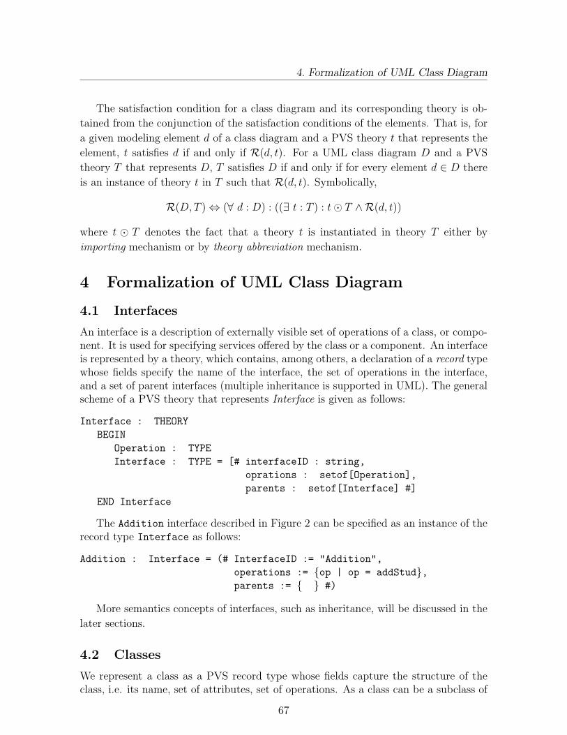
4. Formalization of UML Class Diagram
The satisfaction condition for a class diagram and its corresponding theory is ob-
tained from the conjunction of the satisfaction conditions of the elements. That is, for
a given modeling element d of a class diagram and a PVS theory t that represents the
element, t satisfies d if and only if R(d, t). For a UML class diagram D and a PVS
theory T that represents D, T satisfies D if and only if for every element d ∈ D there
is an instance of theory t in T such that R(d, t). Symbolically,
R(D, T ) ⇔ (∀ d : D) : ((∃ t : T ) : t¯ T ∧R(d, t))
where t ¯ T denotes the fact that a theory t is instantiated in theory T either by
importing mechanism or by theory abbreviation mechanism.
4 Formalization of UML Class Diagram
4.1 Interfaces
An interface is a description of externally visible set of operations of a class, or compo-nent. It is used for specifying services offered by the class or a component. An interfaceis represented by a theory, which contains, among others, a declaration of a record typewhose fields specify the name of the interface, the set of operations in the interface,and a set of parent interfaces (multiple inheritance is supported in UML). The generalscheme of a PVS theory that represents Interface is given as follows:
Interface : THEORY
BEGIN
Operation : TYPE
Interface : TYPE = [# interfaceID : string,
oprations : setof[Operation],
parents : setof[Interface] #]
END Interface
The Addition interface described in Figure 2 can be specified as an instance of therecord type Interface as follows:
Addition : Interface = (# InterfaceID := "Addition",
operations := {op | op = addStud},parents := { } #)
More semantics concepts of interfaces, such as inheritance, will be discussed in the
later sections.
4.2 Classes
We represent a class as a PVS record type whose fields capture the structure of theclass, i.e. its name, set of attributes, set of operations. As a class can be a subclass of
67

4.2 Classes
CourseOffering
open()
location
<<interface>> Addition
addStud()
Figure 2: Interface Realization
one or more classes, and can implement several interfaces, the representation of class inPVS should include fields that capture the parent classes, and set of interfaces the classimplements. Types defined in the parent classes and interface(s) can be made accessibleusing the IMPORTING the theory containing the declarations. A general scheme of atheory that represents class is as follows:
Class : THEORY
BEGIN
IMPORTING Interface
ClassID, Attribute : TYPE
Class : TYPE = [# classID : ClassID,
attributes : setof[Attribute],
operations : setof[Operation],
parents : setof[Class],
interfaces : setof[Interface]#]
END
Based on the above transformation scheme, the class CourseOffering depictedin Figure 2 can be represented as shown below. The class CourseOffering realizesthe interface Addition. Hence, the set of interfaces contains the interface Addition
declared above as an instance of type Interface.
a : VAR Attribute; location : Attribute
c : VAR Class; c : Class
o : VAR Operation; open : Operation
i : VAR Interface
CourseOffering: Class = (# classID:="CourseOffering",
attributes := {a | a = location},operations := {o | o = open},parents := {c | false},
68

4.3 Associations
interfaces := {i | i = Addition} #)
In PVS-SL, however, every identifier needs to be typed. In UML class diagrams,
however, the type of an attribute may not be specified explicitly. In such a case, a
dummy type Void is introduced as an uninterpreted type so that attributes whose
types are not explicitly specified are declared as Void.
In UML, there are notions of abstract, root, and leaf classes, parameterized elements,
e.g. template classes, visibility of attributes and operations, etc. [2]. These notions can
be specified with a slight modification to the generic class representation. For instance,
the concept of template classes directly matches the construct of parameterized theory
in the PVS specification language.
4.3 Associations
In an OO modeling techniques, there are several alternatives to interpret associations
and links in the context of classes and objects [3]: (1) as a set of data links in which
case the objects involved in the association knows about one another; (2) as a separate
association class; (3) as communication links. In our case, we represent association
as a stand-alone PVS theory. This corresponds to the representation of relations in
OUN (the Oslo University Notation) [23] and hence makes specification less compli-
cated. OUN is one of the notations involved in the development of the multi-formalism
platform, the Integrator [33], that is proposed to support formal development of open
distributed systems.
We define an association generically as a parameterized theory, which serves as a
template for all associations and aggregations that occur in the class diagram. The
list of formal parameters consists of the classes involved in the association and their
respective roles (uninterpreted types), and the corresponding multiplicities (subsets of
the set of natural numbers). This generic theory defines an instance of an association as
a relation (a set of ordered pairs) on set of objects of the involved classifiers. The order
of the entries of an ordered pair indicates the direction of navigation of the association.
This can be relaxed to the general case of bidirectional association simply by using
records instead of ordered pairs.
Next, we give a scheme of a generic association theory and represent the association
given in Figure 3 by instantiating the generic association.
StudentCourseOffering
open()location
4 3..10attends
Figure 3: Association
69

4.3 Associations
Association(C1, C2, R1, R2: TYPE, M1, M2: TYPE = setof[nat]) : THEORY
BEGIN
obj1 : VAR C1
obj2 : VAR C2
Association : TYPE = setof[[obj1 : C1, obj2 : C2]]
assoc : VAR Association
m : nat % m = max(card(M1), card(M2))
f1 : [below[m] → C1]
f2 : [below[m] → C2]
% we import the cardinality theory from PVS library
th1 : THEORY = cardinality@cardinality[C1, m, f1]
th2 : THEORY = cardinality@cardinality[C2, m, f2]
axiom12: AXIOM FORALL(obj1 : C1), (obj2 : C2) :
(member(th2.card({obj2 | member((obj1, obj2), assoc)}), M2)) AND
(member(th1.card({obj1 | member((obj1, obj2), assoc)}), M1))
END Association
In theory Association, C1 and C2 specify classes whose objects are involved in the
association, R1 and R2 denote roles of their respective object, whereas M1, and M2
are their respective multiplicities. The axiom axiom12 constrains the number of objects
of one class that can be in the association with a single object of the other class. The
fact that the instances of the involved elements play the roles R1 and R2 is not explicitly
specified. However, this can be addressed, for instance, by defining a record type whose
fields are a classifier, its multiplicity and its role. Then, the association is defined to
be a relation on the instances of such a record type.Once the generic association theory is defined, the theory that represents a class
diagram instantiates, for every association, the generic theory with actual parameters.For example, the class diagram theory may define the associations Attends and Teachesby including the following lines in the specification. A naming conflict may arise sincevariables or types with the same identifiers are declared during every instantiation.The PVS theory abbreviation mechanism discussed in Section 2.1, is used to addressthis problem.
Attends : THEORY = Association (Student, CourseOffering,
attendant, session,
{n : nat | 3 ≤ n ∧ n ≤ 10}, {4})
70

4.4 Generalization/Specialization
Teaches : THEORY = Association(Faculty, CourseOffering,
lecturer, session,
{1}, {n : nat | 0 ≤ n ∧ n ≤ 4})
To distinguish between the two relations that specify the associations, we pre-
fix them with the identifier of their corresponding theory. e.g. Attends.Association,
Teaches.Association.
4.4 Generalization/Specialization
Generalization/specialization is an inheritance relationship between a superclass anda subclass. In this kind of relationship, objects of the subclass inherit the structureand behavior of objects of the superclass’s, and in addition, can declare attributesand operations locally. Unlike the other relationships, we represent generalization aspart of the subclass involved. The superclass is represented, like any other class, bya theory. The theory that represents the subclass imports, among others, the theoryof the superclass and define a record type whose fields contain declarations of thelocal attributes and operations and concatenate this record type with the record typesdeclared in the imported superclass theories. The generalization relationship between
Person
name
Student
major
Figure 4: Generalization/Specialization of Classes
objects of class Person and class Student depicted in Figure 4 extracted from Figure 1is specified as follows:
name, major : Attribute
Person : Class = (# classID:="Person",
attributes := {a | a = name},operations := {o | false },parents := {c | false},interfaces := {i | false} #)
Student : Class = (# classID:="Student",
attributes := {a | a = major},operations := {o | false},parents := {c | c = Person},interfaces := {i | false} #)
71

4.5 Aggregation
One important requirement on the generalization that it is transitive, asymmetric
relationship. That is, for any two classes A and B, if A is a subclass of B and B is a
subclass of A, then they must be identical. Symbolically,
(A ≺ B ∧B ≺ A) ⇒ A = B
where ≺ denotes a generalization relationship. In our case, this requirement can becaptured by the axiom axgen specified below. The axiom states a sufficient conditionto avoid cyclic inheritance.
A, B, c′ : VAR Class
allparents(c): RECURSIVE setof[Class] =
IF parents(c) = ∅ THEN ∅ELSE parents(c) ∪ ⋃
c′∈parents(c) allparents(c′)ENDIF
MEASURE (LAMBDA c: parent(c) 6= ∅)
axgen : AXIOM NOT (B ∈ allparents(A) ∧ A ∈ allparents(B))
4.5 Aggregation
Aggregation is a special kind of association that depicts a conceptual whole-part re-
lationship. A simple aggregation is entirely conceptual and does nothing more than
distinguish whole from part [2]. Another variant of aggregation, a composition, adds
a semantics of strong ownership and coincidence of lifetime of a part with that of the
whole. Parts with non-fixed multiplicity can be created after the composite itself, but
once created they will die with it.
We represent a simple aggregation by instantiating the generic association GenAs-
sociation with appropriate parameters. For a composition, however, we define the
composite class as a record type with one field for a set of objects of a part class, in
addition to fields that specify its structure. For instance, the composite class Course
and a part class CourseOffering (see Figure 1) can be specified as follows:
72

4.6 Semantics for UML Class Diagram
Course : THEORY
BEGIN
Course : TYPE = [# oid : String,
title : String,
credithrs: nat,
open : [Course → bool],
addStud : [Course, StudInfo → Course],
sessions : setof[CourseOffering] #]
iscomp :THEOREM (∀ c1,c2: Course): sessions(c1) ∩ sessions(c2) = ∅END Course
Though the name of an aggregation is optional, in our formalization, we use the
name Aggreg as a place holder so that it fits to the Association template.
4.6 Semantics for UML Class Diagram
Finally, a class diagram is represented by a theory that puts all the constituents the-ories together. Constraints that involve instances of two or more entities, and globalinvariants on the behavior of the system are specified in the theory that represents theclass diagram. Assuming that every entity of the class diagram given in Figure 1 isrepresented according to the above framework, the following is a sketch of a theorythat specifies the class diagram as a whole.
ClassDiagramName : THEORY
BEGIN
[declarations]
IMPORTING Person, Student, PhdStud, Faculty
IMPORTING Course, CourseOffering, Addition
Attends: THEORY = Association (Student, CourseOffering,
attendant, session,
{n : nat | 3 ≤ n ∧ n ≤ 10}, {4})
Teaches: THEORY = Association(Faculty, CourseOffering,
lecturer, session,
{1}, {n : nat | 0 ≤ n ∧ n ≤ 4})
conj1: CONJECTURE (FORALL(co: CourseOffering) :
EXISTS (f:Faculty): (member((f,co), teaches)))
conj2: CONJECTURE (FORALL(ph: PhdStud), (c: CourseOffering):
NOT (member((ph,c), attends)) AND (member((ph,c), teaches)))
[invariants and global constraints]
END ClassDiagramName
73

5. Conclusion and Future Work
The class diagram theory imports or instantiates theories that corresponding to
all the classes and interfaces in the class diagram, and instantiates the generic theory
Association with actual parameters, for every association. Another important aspect
of this theory is the specification of global constraints and conjectures. Conjectures
are defined by the user, and recorded in the main theory for validation purpose, and
they are not processed in the same way as the other PVS data which is processed
automatically and considered as the semantics. They represent the kind of facts and
properties that can be verified using our platform. For instance, conj1 states the
requirement that a course can only be taught if there is a faculty who teaches a session.
The conjecture conj2 ensures that a PhD student either attends or teaches a course
but not both.
5 Conclusion and Future Work
Several works on formalization of UML, mainly using Z [32] as semantic foundation,
exist in the literature: [12, 13, 15, 31, 17].
Evans [12], Shroff et al. [31] developed an abstract description of UML class diagram
using the Z notation as underlying formalism. In their approach, first the fundamental
elements of a UML class diagram are formally represented as Z schemas. Then, the
system view of the class diagram is formally characterized by a schema that composes
the element schemas. The static aspect (attributes and identifier) of a class is repre-
sented as schema called Class Schema whereas attributes and identifiers of instances
are represented as state variables. Class invariants are specified in the predicate part
of a Z class schema.
Jacobs et al. [17] translate JAVA classes into higher order, classical logic of PVS
tool. A co-algebraic approach is used to give semantics to JAVA classes. PVS is used as
a back-end to the LOOP (logic of object-oriented programming) tool that automatically
provides a logical semantics for JAVA. Most of the formalization work done on UML
notations have used Z as underlying formal notation. In our case, we use PVS-SL as
underlying semantic foundation. The main reason behind this choice is the fact that
PVS-SL seems to be one of the most suitable languages in the context of an integrated
platform that we are building to support the formal development of open distributed
systems. PVS supports functional specification style, uses conventional logic and can
be mechanized easily, whereas procedural specifications such as Z involves some kind
of Hoare logic for which it is more difficult to provide mechanized deduction.
The platform integrates the UML and OUN (Oslo University Notation) [8, 23] spec-
ification formalisms. OUN is a trace-based formal notation targeted towards formal
reasoning about open distributed systems. PVS provides a general semantics founda-
tion and a set of powerful tools, among others, type checker, model checker, theorem
74

References
prover, and their synergistic integration. An instance of high expressiveness of PVS-
SL is its ability to directly support reasoning about infinite traces, and this matches
the need of OUN, which is a trace-based formal notation. As we mentioned in the
introduction, the semantic artifacts are processed at the back-end of the tool we are
currently developing, called the Integrator [33], for the automation of the platform.
The formalization framework outlined in this paper is implemented in an integrated
platform that supports formal development of open distributed systems and encourag-
ing results are obtained.
In the future, we extend the formalization work to other UML constructs. Behav-
ioral modeling entities such as interaction diagrams, and statechart diagram are among
the targets of our future work. We will also introduce various mechanisms such as re-
finement proof rules, and validation that are necessary for rigorous formal reasoning in
the context of the Integrator platform by user-defined conjectures.
References
[1] G. Booch. Object-Oriented Analysis and Design with Applications. Benjamin Cummings, Red-wood City, California, 1st edition, 1991.
[2] G. Booch, J. Rumbaugh, and I. Jacobson. The Unified Modeling Language User Guide. AddisonWesley Longman Inc, Reading Massachusetts 01867, 1999.
[3] Ruth Breu, Ursula Hinkel, Christoph Hofmann, Cornel Klein, Barbara Paech, Bernhard Rumpe,and Veronika Thurner. Towards a Formalization of the Unified Modeling Language. In MehmetAksit and Satoshi Matsuoka, editors, ECOOP’97 – Object-Oriented Programming, 11th EuropeanConference, volume 1241 of LNCS, pages 344–366. Springer, 1997.
[4] J.-M. Bruel and Robert B. France. Transforming UML Models to Formal Specifications. In theProc. of the OOPSLA’98 Workshop on Formalizing UML. Why? How?, Vancouver, Canada,October 1998.
[5] S. Cook and J. Daniels. Let’s Get Formal. Journal of Object-Oriented Programming (JOOP),pages 22–24, July 1994.
[6] Rational Software Corporation. Rational Rose 98, 1998. Available atwww.rational.com/products/rose/index.jtmpl.
[7] J. Crow, S. Owre, J. Rushby, N. Shankar, and M. Srivas. A Tutorial Introduction to PVS.In WIFT’95: Workshop on Industrial-Strength Formal Specification Techniques, Boca Raton,Florida, USA, April 1995.
[8] O.-J. Dahl and O. Owe. Formal Methods and the RM-ODP. Research report No. 261, March1998. Department of Informatics, University of Oslo, Norway.
[9] D. Duke. Object-Oriented Formal Specification. PhD thesis, University of Queensland, 1991.[10] E.H. Durr and N. Plat. VDM++ Language Reference Manual. Afrodite (ESPRIT-III project)
document AFRO/CG/ED/LRM/V10, cap Volmac, 1995.[11] B. Dutertre and S. Schneider. Embedding CSP in PVS: An Application to Authentication
Protocols. In Theorem Proving in Higher Order Logics: 10th International Conference, TPHOLs’97, volume 1275 of Lecture Notes in Computer Science, pages 121–136, Murray Hill, NJ, August1997. Springer-Verlag.
[12] A. Evans. Reasoning with UML Class Diagrams. In the Proc. of WIFT’98. IEEE Press, 1998.[13] A. Evans, J-M. Bruel, R. France, K. Lano, and B. Rumpe. Making UML Precise. In the Proc.
of OOPSLA’98, Vancouver, Canada, October 1998.
75

References
[14] R. B. France, J.-M. Bruel, and M. M. Larrondo-Petrie. An Integrated Object-Oriented and For-mal Modeling Environment. Journal of Object-Oriented Programming (JOOP), 10(7), December1997.
[15] R. B. France, A. Evans, K. Lano, and B. Rumpe. The UML as a Formal Modeling Notation.Computer Standards & Interfaces, 19:325–334, 1998.
[16] ISO. A Formal Description Technique Based on the Temporal Ordering of Observational Behav-ior, September 1988. ”ISO Standard 8807”.
[17] B. Jacobs, J. van den Berg, M. Huisman, and M. van Berkum. Reasoning about Java Classes.In the Proc. of OOPSA’98, pages 329–340. ACM Press, 1998.
[18] I. Jacobson, M. Christerson, P. Jansson, and G. Overgaard. Object-Oriented Software Engineer-ing: A Use Case Driven Approach. Addisn-Wesley, Wokingham, England, 1992.
[19] ISO-IEC JTC1/SC21/WG7. Reference Model of Open Distributed Processing (RM-ODP), 1995.[20] K. Lano and H. Haughton. The Z++ Manual. Technical Report, Imperial College, London, 1994.[21] A. Moreira and R. Clark. Combining Object-oriented Analysis and Formal Description Tech-
niques. In the Proc. of ECCOP’94, LNCS, volume 821, Bologna, Italy, 1994. Springer-Verlag.[22] OMG. OMG Unified Modeling Language Specification, version 1.3, June 1999. OMG standard.[23] O. Owe and I. Ryl. The Oslo University Notation: A Formalism for Open, Object-Oriented,
Distributed Systems. Report No. 270, August 1999. Department of Informatics, University ofOslo, Norway.
[24] S. Owre, J. Rushby, N. Shankar, and F.V. Henke. Formal Verification for Fault-tolerant Ar-chitectures: Prolegomena to the design of PVS. IEEE Transactions On Software Engineering,21(2):107–125, February 1995.
[25] S. Owre, N. Shankar, J. Rushby, and D. W. Stringer-Calvert. PVS System Guide, version 2.3.Computer Science Laboratory, SRI International, Melon Park, CA, September 1999.
[26] J. Rumbaugh and M. Blaha. Tutorial Notes: Object-Oriented Modeling and Design. In the Proc.of OOPSLA’91 Conference, Phoenix, Arizona, October 1991.
[27] J. Rumbaugh, M. Blaha, W. Premerlani, F. Eddy, and W. Lorensen. Object-Oriented Modelingand Design. Prentice Hall, Englewood Cliffs., N.J., 1991.
[28] J. Rumbaugh, I. Jacobson, and G. Booch. The Umified Modeling Language, Reference Manual.Addison Wesley Longman Inc., 1999.
[29] J. Rushby. Specification, proof checking, and model checking for protocols and distributed sys-tems with PVS. In FORTE X/PSTV XVII ’97: Formal Description Techniques and ProtocolSpecification, Testing and Verification, November 1997.
[30] S. Shlaer and S. Mellor. Object-oriented Systems Analysis: Modeling the World in Data. YourdonPress Computing Series, Prentice Hall, Englewood Cliffs, NJ, 1991.
[31] M. Shroff and R. B. France. Towards a formalization of UML Class Structures in Z. In the Proc.of the COMPSAC’97, 1997.
[32] J. M. Spivey. The Z Notation: A Reference Manual. Prentice-Hall International, 2nd edition,1992.
[33] I. Traore. The UML Specification of the Integrator. Research report No. 275, August 1999.Department of Informatics, University of Oslo, Norway.
[34] J. M. Wing. A Specifier’s Introduction to Formal Methods. IEEE Computer, 23:8–24, September1990.
76

Appendix C
An Integrated Framework forFormal Development of OpenDistributed Systems
I. Traore, D. B. Aredo and H. Ye
Publication:
I. Traore, D. B. Aredo and H. Ye: An Integrated Framework for Formal Development ofOpen Distributed Systems, the Journal of Information and Software Technology (IST),Elsevier Science, a Special Issue on Software Engineering, Applications, Practices andTools, from the ACM SAC 2003, vol. 46, no. 5, pp. 281-286, April 15, 2004. An earlierversion appeared in the Proc. of ACM Symposium on Applied Computing (SAC 2003),March 9-12, 2003, Melbourne, Florida, USA.


An Integrated Framework for FormalDevelopment of Open Distributed Systems
Issa Traore1, Demissie Aredo2 and Hong Ye1
1Department of ECE, University of Victoria,Victoria B.C. V8W 3P6, Canada
2Norwegian Computing Center,P. O. Box 114 Blindern, N-0314 Oslo, Norway
Abstract
This paper contributes to the discussion on issues related to the formal devel-opment of open distributed systems (ODS). The deficiencies of traditional formalnotations in this setting are highlighted. We argue that there is no single for-malism exhibiting all the features required to capture properties of ODSs. Asa solution, we propose an integrated development framework that involves twonotations: the Unified Modeling Language (UML) and the Prototype Verifica-tion System (PVS). We discuss the motivation for the choice of these notations,provide an overview of a CASE tool we have developed to support the proposedframework, and present a case study to demonstrate our approach.
Keywords: Formal Methods, Open Distributed Systems, UML, PVS, Multi-formalism,
Object-orientation
1 Introduction
Motivated by the need for modeling the dynamic features of object-oriented program-
ming languages and openness in distributed applications, the study of open, and dy-
namically extendable systems has become a very popular research area. In fact, since
the late 80s, much research within theoretical computer science has been directed to-
wards this kind of systems. The emphasis has mainly been put on semantic issues; in
particular, on how such systems should be represented faithfully and fully abstracted.
This has, for example, led to the development of the Pi-calculus [7], and to new refine-
ments of the Actor model [1]. Most of the early proposals have a strong operational
flavor. More recent denotational approaches are rather technical, and in most cases
directed towards the Pi-calculus.
77

1. Introduction
The above mentioned research attempts to find mathematical models suitable to
describe the semantics of systems. The emphasis in our work is not on the semantics
of systems, rather on the formal system development. Existing formal development
methods suffer from certain limitations which constrain their application to large scale
projects, especially their esoteric nature is a serious obstacle. This fact is well expressed
by Kneuper [6] as follows:
Software development is done by people, not by machines. No mat-
ter how ’good’ a development method is, it will only be successful if the
developers who are to use it are willing and able to do so.
Most specification techniques supporting the development of open distributed systems,
such as the UML (Unified Modeling Language) [8], lack formal semantics and the
various reasoning facilities provided by formal development methods. Moreover, we
are not aware of any conventional formal development method that is able to fully
handle the flexible, extendable and very dynamic features characterizing contemporary
distributed systems. In RM-ODP [5], formal description techniques such as LOTOS, Z,
SDL and Estelle are proposed for the specification of systems from various viewpoints.
But, as pointed out in [2], these languages are only partly satisfactory. For instance,
we may use Z for the description of the static parts of the information viewpoint, but
it is not suitable to deal with the dynamic aspects. SDL and Estelle give little support
for formal reasoning. LOTOS is a flexible description technique, but in our opinion,
mainly suitable for the design phase.
Taking the above remarks into account, the challenge is to build a platform that
exhibits capabilities:
- to be grasped and used in an industrial context; this requires characteristics such
as communicability and user friendliness.
- to support major aspects such as openness and dynamic reconfiguration exhibited
by open distributed systems.
- to produce formal specifications that are amenable to rigorous verification and
validation.
- existence of an efficient tool support, a prerequisite for its application to large-
scale systems.
We are not aware of any single specification technique or method which provides all
these capabilities. One obvious solution is to build-up a completely new method from
scratch. However, this is extremely costly. Instead, we propose a multi-formalism
approach where we adapt and integrate already existing technologies. More explicitly,
based on the evaluation of several existing methods and CASE-tools, we propose a
78

2. Modeling Open Distributed Systems Using the UML
platform based on the UML, for specification and refinement, and on the PVS-SL
(Prototype Verification System-Specification Language) [9] for semantic foundation.
The rest of the paper is organized as follows: In Section 2 we give an overview of the
UML and discuss the rational behind our choice. In Section 3, we give an overview of
our formalization framework. Then, in Section 4, we present a case study of a network
reconfiguration protocol. Finally, in Section 5 we make some concluding remarks.
2 Modeling Open Distributed Systems Using the
UML
The choice of UML was dictated by the fact that it is built on an object-oriented frame-
work and provides several capabilities such as extensibility mechanisms (e.g. stereo-
types), dynamic and multiple classification, which are useful for the description of open
distributed systems. In addition, UML provides an underlying methodology for spec-
ification and refinement, a graphical notation which contributes to communicability
and friendliness, and very importantly, UML is an international standard for object-
oriented modeling.
2.1 Support for Open Distribution
Being an object-oriented approach, UML provides several capabilities such as encap-
sulation, data abstraction, extensibility, reusability and flexibility, which are essential
features in modeling ODSs. Among the extensibility mechanisms, we can mention
stereotypes for adding new building blocks, tagged values for creating new properties
for existing constructs, and constraints for extending the semantics of a UML construct.
UML provides mechanisms for handling the dynamic nature of an object type, which
can be helpful in modeling dynamic reconfiguration in the context of open distribution.
This is achieved through a set of interfaces that a class may implement. An instance
of such a class will support all of those interfaces, but depending on the context, it
may present only one or more of them as relevant. Each of these interfaces represents
a role that an object can play over time.
Dynamic typing can also be rendered through an interaction diagram, by displaying
the role of each instance of the corresponding class in brackets below the object’s name
or by connecting each variant with a become message.
UML also provides several facilities for modeling distributed architecture, especially
component and deployment diagrams. We use component diagrams in conjunction with
object diagrams and interaction diagrams, as mentioned previously, to model mobility.
79

2.2 Limitations
2.2 Limitations
In spite of the benefits it provides, UML has several limitations in the context of the
formal development of open distributed systems. The graphical constructs provided
by UML are not enough to achieve a complete and precise specification of the system.
For instance, in [3] several incompleteness in the static semantic model of UML are
reported, especially concerning the definitions of the concepts of aggregation, inheri-
tance, constraints on inheritance hierarchies and abstract operation descriptions. In
order to fill this gap, there is a need for extending the UML notation with respect to
two main objectives:
• The description of additional constraints on objects in the model, such as in-
variants on classes and types, abstract definitions of operations and attributes,
non-functional requirements, etc.
• The definition of a formal semantics for different constructs involved, in order to
remove all ambiguities.
The first objective is generally accomplished using natural language resulting in am-
biguities. An alternative is the Object Constraint Language (OCL) [10], an assertion
language easy to read and write, which is used to specify well-formedness of the mod-
eling abstractions provided by UML. OCL has modeling constructs for types, classes,
interfaces and associations, but its expressiveness is relatively limited in the context
of dynamic aspects of systems, and as pointed out in [3], the semantic of OCL is not
mathematically defined. Hence, in order to achieve the objectives mentioned earlier,
we have decided to use PVS as semantic foundation for our platform.
3 Formalization of Object-oriented Models
3.1 Overview
Several works have attempted to provide a mathematical basis for the concepts un-
derlying object-oriented models [3]. Some of these approaches consist of adapting or
extending a novel or existing formal description technique with object-oriented con-
cepts. Others derive a formal specification from the semi-formal (or informal) model
built with existing object-oriented notations such as UML or OMT. The main prob-
lem with these approaches is the fact that the user should have to deal with a certain
amount of formal artifacts, and as we have already argued, this can be a barrier to
their application in industrial settings.
A third approach, that has been adopted in this platform, consists of assigning a
formal semantic to an existing object-oriented notation. In this case, the formal “stuff”
80
3.2 An Outline of Formal Semantics of UML Statechart
is hidden behind the graphical notation, and the user deals with the graphical model,
while the formal stuff is processed automatically at the back-end.
PVS specifications are organized into a collection of theories which correspond to
specification modules. A theory may consist of type, constant, axiom and theorem
definitions. PVS provides a library of built-in theories called preludes that are reusable
specifications. The PVS semantics that we define for a given UML diagram consists
of generic PVS definitions common to all UML constructs and a collection of PVS
definitions specific to the application. The generic definitions are organized into several
PVS parameterized theories that are installed in the PVS library, whereas the specific
definitions are organized into a theory which carries the actual semantic information
underlying the diagram. The generic definitions are made available to this latter theory
by importing them.
UML consists of nine standard diagrams; our formalization work has focused so far
only on three of them, namely class, sequence, and statechart diagrams. We give, in
the following subsection, a brief sketch of our formal semantic definitions for the UML
statechart.
3.2 An Outline of Formal Semantics of UML Statechart
A UML statechart diagram is a state machine that describes all possible behavior
of either a classifier (e.g. class, component etc.) or a use case. A specific behavior
corresponds to a traversal of a graph of state nodes also called state vertex. The state
nodes are related by transitions that are triggered by event instances, and may result
in the execution of series of actions.
The key components of the execution semantics of UML statecharts consist of an
event queue that holds incoming events until they are dispatched, an event dispatcher
mechanism that selects and dequeues event instances from the queue, and an event
processor that processes dispatched events.
The formalization scheme adopted in this work for UML statechart diagrams con-
sists of defining the formal semantic of a statechart diagram as a transition system
consisting of a triple (I, G, N). N is a global transition relation that describes the ex-
ecution sequence of the underlying state machine; G defines the global state in which
the machine may be at a given time. I is an initialization predicate that describes
initial global states.
3.2.1 Abstract Syntax and Well-Formedness Rules
We describe the abstract syntax of the features involved in a statechart diagram bydefining a generic theory called AbstractSyntax. We give in the following an overviewof this theory. The basic features involved in a statechart diagram are the conceptsof state vertex, state, event, action, guard condition and transition. A state vertex is
81

3.2 An Outline of Formal Semantics of UML Statechart
an abstraction of a node in a statechart diagram. The various kinds of state verticesinclude state, shallow history vertex, deep history vertex, fork, join, junction etc. Wedescribe these elements by providing suitable type definitions in PVS.
AbstractSyntax : THEORY
BEGIN
lib: LIBRARY = "~/prude/semantic/lib"
Time, Vertex, Condition, Event, Action: TYPE+
State : set[Vertex]
A transition is characterized by a source state, a target state, an activation event,a guard condition, and an associated action, which is executed when the transition isfired. Hence we define the syntax of a
Transition: TYPE+ = [# source : Vertex,
trigger : Event,
guard : Condition,
effect : Action,
target : Vertex #]
The set of states involved in a statechart diagram forms a tree structure consistingof a root state, composite states (e.g. can be further refined in substates) and simplestates (e.g. cannot be refined). Function dsubvertex defines the set of subverticesdirectly contained by a given vertex. The other kind of vertices (e.g. non-state) haveno subvertices; only states can have subvertices. As stated by the axioms, a compositestate is either a concurrent state or a sequential state; the direct subvertices of aconcurrent state are all sequential states.
x, y : VAR Vertex
dsubvertex: [Vertex − > set[Vertex]]
compositeState?(x) : bool = member(x,State)
AND dsubvertex(x) /= emptyset
simpleState?(x): bool = member(x,State) AND dsubvertex(x) = emptyset
isConcurrent: PRED[Vertex]
isSequential(x): bool = compositeState?(x) AND NOT isConcurrent(x)
ax concurrent1: AXIOM compositeState(x) <=> (isConcurrent(x) OR
isSequential(x))
ax concurrent2: AXIOM isConcurrent(x) =>(member(y,dsubvertex(x)) => isSequential(y))
...
END AbstractSyntax
We describe the well-formedness rules defining a well-formed diagram by providing
a generic theory called WellFormedness that takes a statechart instance as parameter.
82
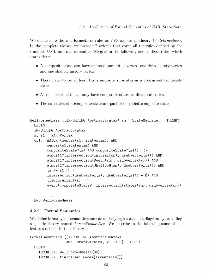
3.2 An Outline of Formal Semantics of UML Statechart
We define here the well-formedness rules as PVS axioms in theory WellFormedness.
In the complete theory, we provide 7 axioms that cover all the rules defined by the
standard UML informal semantic. We give in the following one of these rules, which
states that:
• A composite state can have at most one initial vertex, one deep history vertex
and one shallow history vertex
• There have to be at least two composite substates in a concurrent composite
state.
• A concurrent state can only have composite states as direct substates.
• The substates of a composite state are part of only that composite state
WellFormedness [(IMPORTING AbstractSyntax) sm: StateMachine]: THEORY
BEGIN
IMPORTING AbstractSyntax
s, s1: VAR Vertex
wf1: AXIOM (member(s1, states(sm)) AND
member(s1,states(sm) AND
compositeState?(s) AND compositeState?(s1)) =>atmost1?(intersection(Initial(sm), dsubvertex(s))) AND
atmost1?(intersection(DeepH(sm), dsubvertex(s))) AND
atmost1?(intersection(ShallowH(sm), dsubvertex(s))) AND
(s /= s1 <=>intersection(dsubvertex(s), dsubvertex(s1)) = ∅) AND
(isConcurrent(s) =>every(compositeState?, intersection(states(sm), dsubvertex(s)))
...
END WellFormedness
3.2.2 Formal Semantics
We define formally the semantic concepts underlying a statechart diagram by providinga generic theory named FormalSemantics. We describe in the following some of thefeatures defined in that theory.
FormalSemantics [(IMPORTING AbstractSyntax)
sm: StateMachine, V: TYPE]: THEORY
BEGIN
IMPORTING WellFormedness1[sm]
IMPORTING finite sequences[(events(sm))]
83

3.2 An Outline of Formal Semantics of UML Statechart
The bottom-line of the formalization approach adopted in our work consists of
defining a set of elementary predicates that describe relevant properties of the system
state or the system operation. The set of elementary predicates is then partitioned
into elementary states and events. A state describes a condition of the system that has
a non-null duration. A clear distinction shall be made between the concrete state of
the system and the notion of abstract state used in UML statechart. We represent the
concrete state by a record type called V whose fields corresponds to the concrete state
variables.We define three categories of predicates associated, respectively, with notions of
state vertex, guard condition and action. The predicate associated with a state cor-responds to a condition that must hold for the state to be active. The predicateassociated with an action corresponds to a condition that holds after the execution ofthe action; that can be assimilated by the action’s postcondition. Whereas the stateand the guard condition are functions of the current values of the state variables, theaction’s postcondition is a function of both the current and the future values of thestate variables. The state predicates need to be defined only for simple states. Thepredicates associated with composite states are defined as conjunction or disjunctionof the predicates of their constituents according to whether they are concurrent orsequential states.
VC: TYPE = [#current: V, next: V#]
vc: VAR VC
v: VAR V
%Predicates for states, conditions, and actions
pred: [Vertex − > PRED[V]]
pred: [Condition − >PRED[V]]
pred: [Action − > PRED[VC]]
and ax: AXIOM isSequential(x) <=>pred(x) = disjunct({q | ∃ (y:(dsubvertex(x))): q=pred(y)})
or ax: AXIOM isConcurrent(x) IMPLIES
pred(x) = conjunct({q | ∃ (y:(dsubvertex(x))): q=pred(y)})In a statechart diagram, more than one state can be active at once. If a simple
state is active, then all the composite states that contain it either directly or transi-tively are also active. The set of all the states that are active simultaneously defineswhat is called a state configuration. We define the initial configuration initConf of astatechart as a set containing all the default states involved in the diagram. All thestates containing directly or transitively a simple state are active when that state is ac-tive. Intuitively, a configuration can be uniquely defined by providing the set of simplestates involved. Therefore, we define a global predicate associated with a configurationas the conjunction of the predicates associated with the simple states involved in thatconfiguration.
Configuration: TYPE+ = finite set[Vertex]
84

3.2 An Outline of Formal Semantics of UML Statechart
c : VAR Configuration
ax configuration: AXIOM subset?(c, states(sm)) AND
FORALL (x: Vertex): (member(x,c) =>(isConcurrent(x) => subset?(dsubstate(x),c)) AND
(isSequential(x)=>singleton?(intersection(dsubstate(x),c))))
% define an initial configuration
initConf: Configuration
ax init: AXIOM subset?(initConf,states(sm)) AND
member(root(sm),initConf) AND (member(x,initConf) =>(isSequential(x) => singleton(default(x)) AND
(isConcurrent(x) => subset?(dsubstate(x),initConf))))
%predicate associated with a configuration
pred(c):PRED[V]=conjunct({p: PRED[V] | EXISTS y:
member(y,c) AND p = pred(y)
AND simpleState?(y)})%Initial state predicate
init: PRED[V] = pred(initConf)
We define, in the sequel, our transition system as a triple (init,V,next) where next is
a global transition relation, V is the global (concrete) state, and init is an initialization
predicate that is defined above.A transition is enabled if the event instance generated matches its trigger, its guard
condition is true and its source state is active. An enabled transition may be illegiblefor firing. Firing a transition will activate its target state and execute its action. Wedefine below the predicates enabled and fired that describe respectively the enablingand firing conditions of a transition. More than one transition may be enabled withina state machine, resulting in conflict. Example of conflicting transitions are transitionsoriginating from the same state, triggered by the same event, but with different guard.If the event occurs and both guards are true, only one transition chosen according toan implicit priority mechanism will be fired. In case where there are concurrent statesinvolved, several transitions may be fired at the occurrence of the same event. The setof transitions that will actually be fired in the whole state machine is a maximal set ofenabled transitions with the highest priorities, and that are non mutually conflicting.
e: VAR Event
tr, tr1, tr2: VAR Transition
a : VAR set[Transition]
v1, v2: VAR V
enabled(e, tr, v): bool = pred(source(tr))(v) AND
(trigger(tr)=e) AND pred(guard(tr))(v)
fired(tr,v,v1): bool = pred(target(tr))(v1) AND
85
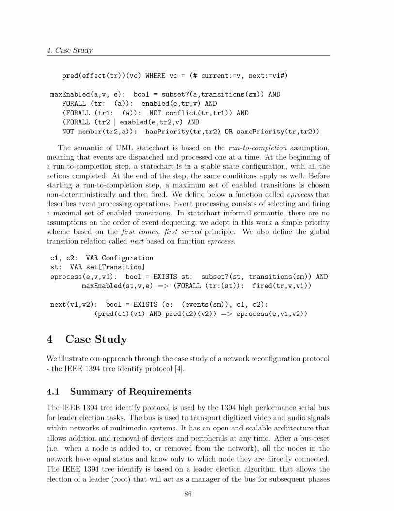
4. Case Study
pred(effect(tr))(vc) WHERE vc = (# current:=v, next:=v1#)
maxEnabled(a,v, e): bool = subset?(a,transitions(sm)) AND
FORALL (tr: (a)): enabled(e,tr,v) AND
(FORALL (tr1: (a)): NOT conflict(tr,tr1)) AND
(FORALL (tr2 | enabled(e,tr2,v) AND
NOT member(tr2,a)): hasPriority(tr,tr2) OR samePriority(tr,tr2))
The semantic of UML statechart is based on the run-to-completion assumption,meaning that events are dispatched and processed one at a time. At the beginning ofa run-to-completion step, a statechart is in a stable state configuration, with all theactions completed. At the end of the step, the same conditions apply as well. Beforestarting a run-to-completion step, a maximum set of enabled transitions is chosennon-deterministically and then fired. We define below a function called eprocess thatdescribes event processing operations. Event processing consists of selecting and firinga maximal set of enabled transitions. In statechart informal semantic, there are noassumptions on the order of event dequeuing; we adopt in this work a simple priorityscheme based on the first comes, first served principle. We also define the globaltransition relation called next based on function eprocess.
c1, c2: VAR Configuration
st: VAR set[Transition]
eprocess(e,v,v1): bool = EXISTS st: subset?(st, transitions(sm)) AND
maxEnabled(st,v,e) => (FORALL (tr:(st)): fired(tr,v,v1))
next(v1,v2): bool = EXISTS (e: (events(sm)), c1, c2):
(pred(c1)(v1) AND pred(c2)(v2)) => eprocess(e,v1,v2))
4 Case Study
We illustrate our approach through the case study of a network reconfiguration protocol
- the IEEE 1394 tree identify protocol [4].
4.1 Summary of Requirements
The IEEE 1394 tree identify protocol is used by the 1394 high performance serial bus
for leader election tasks. The bus is used to transport digitized video and audio signals
within networks of multimedia systems. It has an open and scalable architecture that
allows addition and removal of devices and peripherals at any time. After a bus-reset
(i.e. when a node is added to, or removed from the network), all the nodes in the
network have equal status and know only to which node they are directly connected.
The IEEE 1394 tree identify is based on a leader election algorithm that allows the
election of a leader (root) that will act as a manager of the bus for subsequent phases
86

4.2 UML Specification
beMyParent (Node n):booleanacknowledge (Node n)
pending: set[Node]children: set[Node]neighbors: set[Node]parent: Node
Node
confirm ( )
pending
neighbors *
root:Manager 1
nodes:Regular *
parent0..1
children*
RegularManager
Network
nodes:set[Node]root: Node
electLeader ( )
Figure 1: Class Diagram
of 1394. The protocol works properly on connected and acyclic networks. It reports an
error if a cycle is detected. At the end of a successful election, the collection of nodes
will form a tree whose root is the manager. During the election, each node waits for a
”be my parent” request from its neighbors that are not his children. When the number
of neighbors minus the number of children is exactly 1, the node can in its turn send a
”be my parent” request to the neighbor, which isn’t a child if it has not already received
a similar request from that one. Each request is followed by an acknowledgement, and
an acknowledgement of the acknowledgement.
Two nodes may send a ”be my parent” request to each other simultaneously, re-
sulting in contention. The standard resolves contention by specifying that each node
will choose nondeterministically, in that case, to wait for a certain amount of time, and
then re-sends a ”be my parent” request, if there was no such request from the other
node. We assume that all nodes start executing at the same time.
4.2 UML Specification
We describe the system by providing a UML class diagram (see Figure 1) and a UML
statechart diagram (see Figure 2).
4.2.1 Class Diagram
The class diagram consists of two classes: Node and Network. The class Node represents
individual nodes involved in the network. A name, possibly a parent node, and 3 collec-
tions of nodes corresponding respectively to the neighbors, the actual children and the
87

4.2 UML Specification
accept
vote( )[c1]
beMyParent[c1]/accept
vote( )[c1]
confirm( )[c2]/
...
Node1Status NodeNStatus
Electing
NetworkStatus
beMyParent[c1]/
updateconfirm( )/
confirm( )[c3]confirm( )[c3]
beMyParent[c1]/accept
acceptbeMyParent[c1]/
StatusNodeK
updateupdate
TimeoutTimeout
updateupdateupdateconfirm( )/ confirm( )/confirm( )/
confirm( )[c2]/
Contention
Voting
Waiting
ParentElected
Contention
Voting
electLeader( )[c4]
LeaderElected
electLeader ( )
Init
electLeader( )[c5]
ErrorDetected
Waiting
ParentElected
Figure 2: Statechart Diagram
potential children characterize an instance of Node. Potential children are represented
by the role name pending. They actually correspond to nodes that have already sent a
”be my parent” request to a node, and are waiting for the acknowledgement. The class
Network corresponds to the collection of nodes involved in the network. An instance
of Node may be either a regular child or the manager in an instance of Network; the
two associations relating both classes specify that.
4.2.2 Statechart Diagram
The statechart diagram describes the dynamic behavior of the Network class in terms
of the messages it sends and receives. Initially a Network object is in an initial state
called Init that corresponds to the state immediately after a bus reset. Then the elec-
tion starts with the occurrence of the electLeader event, bringing the Network object
in the Electing state. If a leader is elected, represented by condition c4, the object will
move to the LeaderElected state ending the statechart. If a cycle is detected, repre-
sented by condition c5, an error is reported, and the object evolves to the ErrorDetected
state. The Electing state is a concurrent state whose direct substates, also called re-
gions, describe the individual behaviour of the elements (e.g. the nodes) involved in
the collection underlying a Network object. Dividing it using dashed line specifies the
regions of a concurrent state. Each region corresponds to an independent substate,
which is executed concurrently, when the parent state (e.g. the concurrent state) is
active. Since the nodes in the collection have similar behaviour (with respect to the
88

4.3 Complementary Semantics and System Properties
protocol), state Electing consists of N identical regions labelled respectively NodeiSta-
tus, where i is a natural number such that 1 ≤ i ≤ N , and N is the number of nodes
in the network.
Given i such that 1 ≤ i ≤ N , state NodeiStatus starts in a Waiting state where the
corresponding node waits for ”be my parent” request represented by event beMyPar-
ent from its neighbours. If a request is received from a neighbour that is not a child
(condition c1), an acknowledgement is generated (action accept), followed by an ac-
knowledgement of the acknowledgement (event confirm), and an update of the number
of children of the node (action update). The update may lead to the Voting state, in
case where the number of neighbours that aren’t children is exactly 1. In that state, the
node can send a ”be my parent” request represented by event vote to the neighbour.
The node may also receive at the same time a ”be my parent” request from the same
node resulting in contention described by state Contention. After a timeout, the node
returns in the Voting state. If the request is accepted (condition c2), the node evolves
to the ParentElected state, which represents the final state of the NodeiStatus region.
When all the nodes but one have their parents elected, the election process ends, and
the single node, without any parent becomes the elected leader (condition c4).
4.3 Complementary Semantics and System Properties
The standard UML notation provides only a partial specification of the system. The
UML specification produced needs to be extended by providing complementary se-
mantics for the elementary features (e.g. state, actions, conditions etc.) and properties
involved using languages like the Object Constraint Language [10] or any other mathe-
matical or textual languages. We give in the following some examples of complementary
semantics and properties for the statechart in Figure 2 using OCL. The context of the
expressions is a Network object, and two interacting Node objects k and n involved in
the collection. Lets say that node k corresponds to one of the nodes whose behavior is
described by StatuskNode.
4.3.1 Predicates Associated with Guard Conditions
c1(n: Node,k: Node): Boolean = self.nodes→includes(n) and
self.nodes→includes(k) and
k.children→excludes(n) and
k.neighbours→includes(n)
c2(n: Node,k: Node): Boolean = self.nodes→includes(n) and
self.nodes→includes(k) and
k.pending→excludes(n)
89
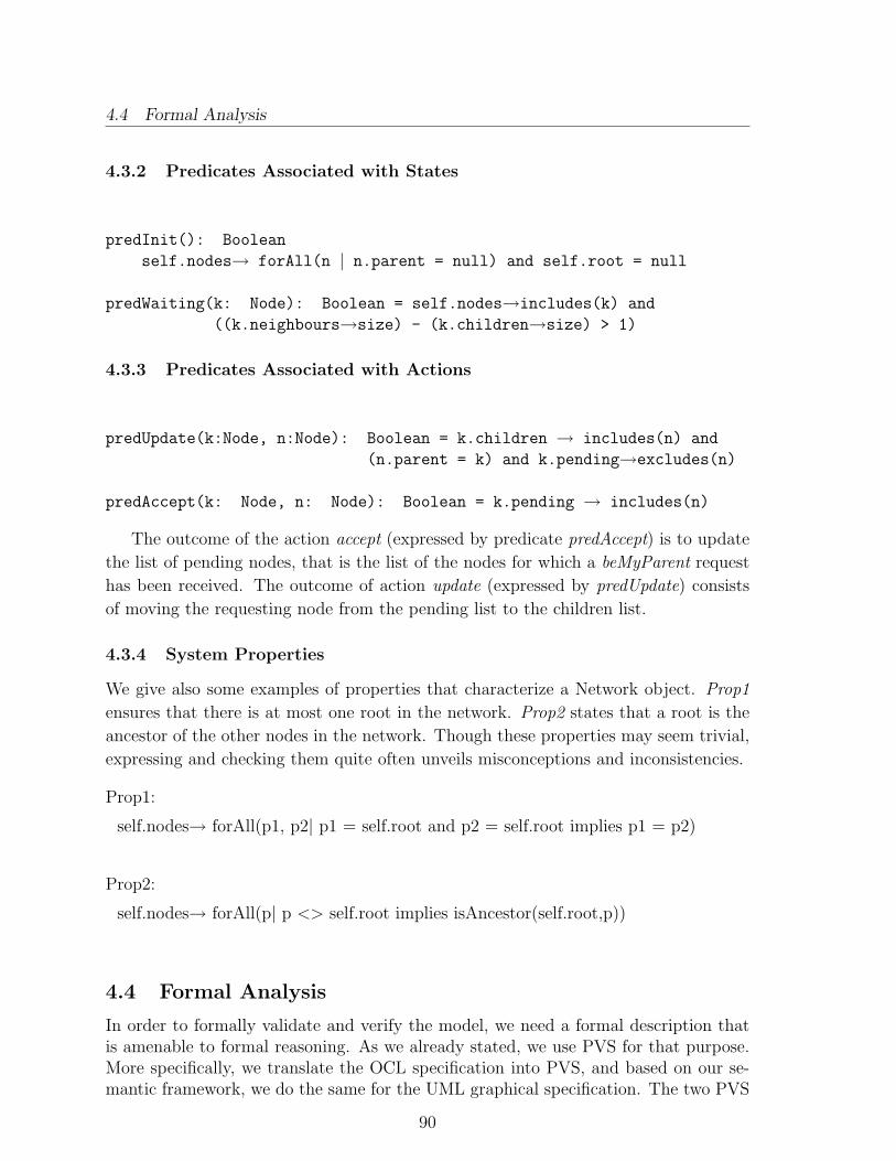
4.4 Formal Analysis
4.3.2 Predicates Associated with States
predInit(): Boolean
self.nodes→ forAll(n | n.parent = null) and self.root = null
predWaiting(k: Node): Boolean = self.nodes→includes(k) and
((k.neighbours→size) - (k.children→size) > 1)
4.3.3 Predicates Associated with Actions
predUpdate(k:Node, n:Node): Boolean = k.children → includes(n) and
(n.parent = k) and k.pending→excludes(n)
predAccept(k: Node, n: Node): Boolean = k.pending → includes(n)
The outcome of the action accept (expressed by predicate predAccept) is to update
the list of pending nodes, that is the list of the nodes for which a beMyParent request
has been received. The outcome of action update (expressed by predUpdate) consists
of moving the requesting node from the pending list to the children list.
4.3.4 System Properties
We give also some examples of properties that characterize a Network object. Prop1
ensures that there is at most one root in the network. Prop2 states that a root is the
ancestor of the other nodes in the network. Though these properties may seem trivial,
expressing and checking them quite often unveils misconceptions and inconsistencies.
Prop1:
self.nodes→ forAll(p1, p2| p1 = self.root and p2 = self.root implies p1 = p2)
Prop2:
self.nodes→ forAll(p| p <> self.root implies isAncestor(self.root,p))
4.4 Formal Analysis
In order to formally validate and verify the model, we need a formal description thatis amenable to formal reasoning. As we already stated, we use PVS for that purpose.More specifically, we translate the OCL specification into PVS, and based on our se-mantic framework, we do the same for the UML graphical specification. The two PVS
90

4.4 Formal Analysis
Figure 3: PVS Semantics Generated Using the PrUDE Tool
specification fragments (from UML and OCL) are integrated into a single and homo-geneous PVS specification that serves as a basis for the formal analysis activities likeconsistency checking, model checking, and proof checking. We have developed a sup-porting environment, to which we refer as the Precise UML Development Environment(PrUDE), which assists the specifier in generating the PVS model. The PrUDE toolalso gives the specifier the possibility to invoke PVS tools, namely the type checker,model checker, and proof checker, either in batch mode, or interactively. Figure 3presents a snapshot of the PVS semantic generated using the PrUDE tool. The lowerwindow shows the log report generated after running the PVS tool in batch mode. Theverification of the model is conducted by expressing the system properties in the formof PVS theorems, and then by checking them using mechanized support. For instance,property Prop1 (cf. Section 4.3), which states that there is at most one root in thenetwork, is expressed in PVS as follows:
p1,p2:VAR VNode
prop1: THEOREM (member(p1,nodes(v)) AND member(p2,nodes(v))
⇒ (root(v)=p1 AND root(v)=p2 ⇒p1=p2))
By invoking the PVS prover interactively from PrUDE, the proof of property Prop1is as follows.
prop1 :
91

4.4 Formal Analysis
Figure 4: Automatic Verification of Prop1 Using the PrUDE Tool
|-------{1} FORALL (p1, p2: VNode, v: V):
(member(p1, nodes(v)) AND member(p2, nodes(v))
=> (root(v) = p1 AND root(v) = p2 => p1 = p2))
Rerunning step: (SKOSIMP*)
Repeatedly Skolemizing and flattening, this simplifies to:
prop1 :
{-1} member(p1!1, nodes(v!1))
{-2} member(p2!1, nodes(v!1))
{-3} root(v!1) = p1!1
{-4} root(v!1) = p2!1
|-------{1} p1!1 = p2!1
Rerunning step: (EXPAND "member")
Expanding the definition of member,
this simplifies to:
prop1 :
92

4.4 Formal Analysis
{-1} nodes(v!1)(p1!1)
{-2} nodes(v!1)(p2!1)
[−3] root(v!1) = p1!1
[−4] root(v!1) = p2!1
|-------[1] p1!1 = p2!1
Rerunning step: (GROUND)
Applying propositional simplification and
decision procedures,
Q.E.D.
Run time = 0.17 secs.
Real time = 0.22 secs.
NIL
PVS(33):
Conducting interactive proof-checking, even from the PrUDE environment, is quiteoften tedious and time consuming. The properties expressed in our framework arebased on a common template. Using that general structure, we have succeeded indefining general PVS proof strategies based on the notion of configuration pairs. Eachstrategy consists of primitive strategies, and can be used to check automatically ourtarget properties. The proof strategy for statechart is as follows:
(defstep property-proof-strategy
(then (auto-rewrite ‘‘user defined axiom1’’
’’user defined axiom2’’
...)
(skosimp)
(expand ‘‘ConfigurationPair’’)
(grind)
)
)
The proof strategy denoted property-proof-strategy, collects the complementary se-
mantics (e.g. user-defined axioms) as auto-rewrite rules, invokes skosimp command to
replace universal quantifications in the target formulas with constants. The expand
command is then used to expand the configuration pair definition. Finally the grind
command, a catch-all strategy is invoked to apply all the necessary simplifications and
complete the proof. These proof strategies are implemented in PrUDE and can be
invoked to check automatically any proof obligation based on our framework. In case
where the proof fails, a counterexample is produced, which can be used to trace errors
in the original UML model. Figure 4 presents a snapshot of the automatic verification
of property Prop1: the property is edited using a property editor (upper-window) and
then checked automatically in less than a minute by invoking the prover.
93
5. Concluding Remarks
5 Concluding Remarks
We have presented in this paper an automated platform that supports formal devel-
opment of open distributed systems. One of the main objectives of our platform is to
minimize the formal “stuff” the user of the platform should have to deal with. This in
turn facilitates its industrial use. In this respect, we have decided to use in this plat-
form PVS-SL as semantics foundation and not as a specification language. As a result,
the user will not need to have an in-depth knowledge of the PVS formal notation and
proof system. PVS-SL offers a very general semantic foundation and a set of powerful
tools. It is highly expressive and offers several mechanisms for formal analysis. In
order to enhance the automation of the formal verification process, we have defined
suitable proof patterns and strategies for the kinds of properties that can be derived
from our semantic model. These strategies are implemented in the current version of
the PrUDE tool, and allow the automatic processing of our proof obligations.
References
[1] G. Agha, I.A. Mason, S. Smith, and C. Talcott. A Foundation for Actor Compu-
tation. Journal of Functional Programming, 7, 1997.
[2] O. J. Dahl and O. Owe. Formal Methods and the RM-ODP. Research report No.
261, March 1998. Department of Informatics, University of Oslo, Norway.
[3] A. Evans. UML class diagrams - filling the semantic gap. Technical Report, 1998.
York University.
[4] IEEE. IEEE Standard for a High Performance Serial Bus, August 1995. Standard
1394-1995.
[5] ISO-IEC JTC1/SC21/WG7. The Reference Model of Open Distributed Process-
ing, 1995.
[6] R. Kneuper. Limits of Formal Methods. Formal Aspects of Computing, 9, 1997.
[7] R. Milner, J. Parrow, and D. Walker. A Calculus of Mobile Processes part I and
II. Information and Computation, 100, 1992.
[8] The OMG. OMG Unified Modeling Language Specification, version 1.3, June
1999. OMG standard document.
[9] S. Owre, N. Shankar, J. Rushby, and D. W. Stringer-Calvert. PVS Language
Reference, version 2.3, September 1999.
[10] J. B. Warmer and A. G. Kleppe. The Object Constraint Language: Precise Mod-
eling with UML. Addison Wesley Longman Inc., Reading Massachusetts 01867,
1999.
94

Appendix D
A Framework for Semantics ofUML Sequence Diagrams in PVS
Demissie B. Aredo
Publication:
Demissie B. Aredo: A Framework for Semantics of UML Sequence Diagrams in PVS,in the Journal of Universal Computer Science (J. UCS), Springer-Verlag Co. Pub.,vol. 8, no. 7, pp. 674-697, July 2002. An earlier version appeared the Proc. of theUML2000 Workshop on Dynamic Behavior in UML Models, October 2, 2000, York,UK.

A Framework for Semantics of UMLSequence Diagrams in PVS∗
Demissie B. AredoDepartment of Informatics, University of OsloP. O. Box 1080 Blindern, N-0316 Oslo, Norway
E-mail: [email protected]
Abstract
This paper presents a framework for representing formal semantics of a subsetof the Unified Modeling Language (UML) notation in a higher-order logic, morespecifically semantics of UML sequence diagrams is encoded into the PrototypeVerification System (PVS). The primary objective of our work is to make UMLmodels amenable to rigorous analysis by providing their precise semantics. Thisapproach paves a way for formal development of systems through a systematictransformation of UML models. This work is a part of a long-term vision toexplore how the PVS tool set can be used to underpin practical tools for analyz-ing UML models. It contributes to the ongoing effort to provide mathematicalfoundation to UML notations, with the aim of clarifying the semantics of thelanguage as well as supporting the development of semantically-based tools.
Keywords: Formal Semantics, UML, PVS, Formal Methods, Object-Orientation
Category: D.3.1, D.1.5, D.2.4
1 Introduction
The Unified Modeling Language (UML) [23, 18, 4] is an object-oriented modeling lan-
guage that consists of a comprehensive set of notations. It is an industry standard
modeling language (standardized by the Object Management Group (OMG)) for spec-
ifying, visualizing, and documenting artifacts of software intensive systems. Among
the distinguishing properties of UML is its capacity to unify a collection of notations
for object-oriented modeling - a property that may raise several fundamental issues in
the context of software engineering.
∗Published in the Journal of Universal Computer Science (JUCS), Springer-Verlag Co. Pub., 8(7),pp. 674-697, July 2002, submitted: 16/1/2002, accepted: 22/7/2002, appeared: 28/7/2002 c©J.UCS
95

1. Introduction
Compared to other object-oriented modeling languages in software engineering,
UML is more precisely defined and contains a great deal of formal specification nota-
tions, for instance, the use of the Object Constraint Language (OCL) [27] for constraint
specification. However, it is not formal enough to address problems that relate to the
lack of precision [10] and suffers from the major drawbacks of object-oriented method-
ologies - their limitation in the context of formal reasoning. The semantics of UML
constructs is expressed in meta-models (descriptions of UML in UML) and natural lan-
guage. Although the meta-models capture a precise notion of the abstract syntax of the
UML modeling elements, they do little in addressing problems related to interpretation
of non-trivial UML constructs [10].
The lack of formal semantic models for graphical UML constructs renders limita-
tions in the context of rigorous model analysis and in developing semantics-based CASE
tools [28, 10]. Consistency checks provided by currently available CASE tools are, for
instance, limited to very simple syntactic checks, such as consistency of naming across
models. Great improvements would have been achieved had tools been augmented
with deeper semantic definitions for UML models [28]. Formal methods provide the
rigor that is lacking in graphical UML notations. Providing formal semantic models
to constructs of a modeling language enables us to identify and remove ambiguities,
deficiencies, and inconsistencies from the language. Defining formal semantics for mod-
eling constructs of a graphical language like UML is also a prerequisite for developing
semantically based tool support.
In the sequel, we propose semantics definition for UML sequence diagrams in the
PVS specification language (PVS-SL) [21, 19]. We describe a general framework for
formalization of UML diagrams, and an approach that involves graphical notations and
formal methods to facilitate rigorous model analysis. The approach can readily be used
to support system validation and verification. Our reference is the currently available
standard documentation for the Object Management Group UML [18]; the informal
semantics and the collection of well-formedness rules provided in the documentation.
The PVS environment is chosen as an underlying semantic foundation for the following
main reasons. Firstly, PVS provides general semantic notions necessary to model
reactive systems. For instance, it supports the notions of sequences, lists, records, etc.
that are crucial for providing trace-based semantic models for UML sequence diagrams.
Secondly, the PVS environment has a powerful tool set consisting of a type-checker, a
theorem-prover, and model-checker.
Usually, a model given in a single sequence diagram results in only a partial spec-
ification, i.e. only subsets of the set of attributes and operations can be derived from
a given sequence diagram. To provide a specification of a wide range of interactions
in a system, several sequence diagrams should be used in combination. Composition
of message sequence diagrams is dealt with in the literature, e.g. see works of Hau-
gen [14], and Gunter et al [13]. Moreover, to obtain a detailed and more complete
96

2. The PVS Environment
description of both structural and behavioural aspects of a system, it is necessary to
combine several modeling techniques such as class diagrams, statecharts, and sequence
diagrams. A class diagram provides structural description of classes and relationships
among their objects; a statechart diagram describes dynamic behavior of a component;
and a sequence diagram specifies interactions among the components. The UML nota-
tion is a combination of these modeling techniques and emphasizes their integrated use
to capture properties of systems from different viewpoints. The works of Reggio et al
[22], Blair et al [3], and Kammuller et al [17] address how different modeling techniques
can be used.
The rest of this paper is organized as follows. In Section 2, we briefly review the PVS
environment, with emphasis put on the PVS specification language and theorem-prover,
and discuss how they can be used together. In Section 3, we propose semantic models
for basic concepts of UML sequence diagrams such as actions, events, messages, and
objects. In Section 4, we describe the methodology used in our formalization framework,
which includes a bottom-up construction of semantics of UML sequence diagrams.
In Section 5, we demonstrate, by an example, the application of our formalization
framework to model analysis. Finally, in Section 6, we conclude and discuss future
research issues.
2 The PVS Environment
The Prototype Verification System (PVS) [20, 6] is a formalism for design and analysis
of system specifications. PVS consists of a highly expressive specification language,
a powerful interactive theorem-prover, a type-checker, and other tools. A particular
strength of PVS is its capacity to exploit the synergy between its tools, e.g. the type-
checker and the theorem-prover complement each other.
The PVS specification language is based on a classical typed higher-order logic.
Its type system contains basic types such as boolean, nat, integer, real, etc. and type
constructors such as set, tuple, record, and function. Record, set, and function type
constructors are extensively used in the sequel to encode abstract syntactic and seman-
tic domains of UML constructs in PVS. A record constructor is a finite list of fields of a
general form R : TYPE = [# a1 : T1, . . . , an : Tn #] where ai’s are accessor functions
and Ti’s are type expression. For a record r of type R, i.e. r:R, function application-like
terms ai(r) or r′ai, rather than the conventional ’dot’ notation, is used to access the
ith field of r. The structure of tuple type is similar to that of record type except that
the order of fields is significant in tuples.
A function constructor is of a general form F : TYPE = [D1, D2, . . . , Dn → R]
where Di’s and R are type expressions, F is the set of all functions with domain D =
D1 ×D2 × · · · ×Dn and range R. The set of elements of type T is denoted by either
pred[T] or setof[T], where each of them is a shorthand for S : [T → bool]. As a
97

2. The PVS Environment
result, given a set s:S and an element t:T, membership of t in s is by the truth value
of the expression s(t).
The PVS type system has been augmented by predicate subtyping and dependent
typing mechanisms and supports a richer type system than the standard classical
higher-order logic and relies on an original approach to type checking [8]. Given a
type T and a predicate p:[T → Bool], a predicate subtype T ′ = {t:T | p(t)} of T
can alternatively be denoted by (p). Subtyping mechanism complicates type-checking,
and yet allows a stronger checks for consistency and invariant in a uniform manner [6].
Accommodating partial functions in the logic of total functions, for instance, improves
expressive power of the specification language. Subtyping mechanism, however, ren-
ders type checking undecidable; as a result of which the type-checker generates proof
obligations called Type Correctness Conditions (TCC) that requires users to discharge
them. Though a great deal of TCCs can be discharged automatically, the more involved
ones require interactive use of the theorem-prover.
Specifications in PVS are organized into hierarchies of theories. A theory may con-
sist of specification of types, variables, constants, definitions, axioms, and conjectures.
PVS supports modularity and reuse by means of parameterized theories that make
it possible to specify generic modeling elements. The PVS-SL includes an extensive
library of built-in theories, called preludes, which provide several useful definitions and
lemmas. PVS also allows definition of Abstract Data Types (ADTs), from which a
complete PVS theory is automatically synthesized during type checking.The following ADT, for example, specifies the standard stack data structure along
with its constructors empty and push, two accessor functions top and pop, and tworecognizers empty? and nonemptystack? that characterize empty and non-emptystacks respectively.
stack[T : TYPE] : DATATYPE
BEGIN
empty : empty?
push (top: T, pop: stack) : nonemptystack?
END stack
From such an ADT, a theory called stack adt[T:TYPE] that consists of axioms,theorems, definitions, etc. is automatically synthesized during type checking and com-pletely specifies the stack data type axiomatically. For instance, the following is oneof the axioms generated during type checking, and states an invariant property ofstacks, i.e. for any stack a push operation followed by a pop operation leaves thestack unchanged. Symbolically,
pop push ax : AXIOM (FORALL (x: T, s: stack): pop(push(x,s)) = s)
Another invariant property of stacks is that application of two push operations fol-lowed by two pop operations to a given stack leave the stack unchanged. Symbolically,
98

3. Basic Concepts of UML Sequence Diagrams
pop push th : THEOREM (∀ (x, y: T, s: stack):
pop(pop(push(x, push(y, s)))) = s)
This theorem can be discharged interactively by invoking the PVS theorem prover.
While it is beyond the scope of this paper to explain details of the PVS environment,
we have only highlighted some of its key features. For a more detailed presentation of
the PVS environment, interested reader should refer to [6, 19, 20]
3 Basic Concepts of UML Sequence Diagrams
The UML sequence diagram is a variant of the classical message sequence charts (MSC)
[16]. Sequence diagrams are efficient constructs in modeling dynamic aspects of sys-
tems by building up storyboards of scenarios, involving the interacting objects and the
messages that may be communicated among them. They show sequences of message
passing as they unfold over time, and control flow throughout the interaction to effect
a desired operation or result.
A sequence diagram is especially useful to specify reactive systems with time-
dependent functions such as real-time applications, and to model complex scenarios
where time dependency plays an important role. It is particularly useful technique to
visualize dynamic behavior in the context of use case scenarios. To motivate the need
o1: o2: o3:
m1
m2
m3
m4
Figure 1: A UML Sequence Diagram
for a formal semantics for UML sequence diagrams, let us consider the UML sequence
diagram shown in Figure 1. It specifies an interaction among objects o1, o2, and
o3. It constrains messages <m1, m2, m3, m4> to occur in that order. The diagram
does not, however, state whether any of the messages must occur or may occur. The
sequence <m1, m2, m4> is also a valid instance of the interaction modelled by the
sequence diagram. In the classical message sequence charts [16], Damm et al [7] ad-
dressed this deficiency by introducing the concept of temperature - messages that must
occur have hot temperature whereas messages that may occur have cold temperature.
To model dependencies among messages one needs formal representation of sequence
diagrams. Suppose that, in Figure 1, message m4 occurs only if messages m2 and m3
99

3.1 Actions and Operations
occur in that order. This behavior cannot be specified by the graphical notations and
induces a strong need for formal semantics.
A sequence diagram specifies only a fragment of system behavior, usually an inter-
action between objects. To specify the complete behavior of an object or the system as
a whole, several sequence diagrams should be used to specify all possible interactions
during its life cycle [5].
The simplicity of sequence diagrams makes them suitable for expressing require-
ments as they can easily be understood by the customers, requirement engineers and
software developers alike [28]. The lack of formal semantics for sequence diagrams,
however, makes them ambiguous and difficult to interpret. The non-deterministic
nature of sequence diagrams also aggravates the ambiguities in their interpretation.
The sequence diagram shown in Figure 1, for example, turns to be non-deterministic
if message m2 is removed - the sending of m1 and m3 can not be ordered uniquely.
As a result, both <m1.out, m1.in, m3.out, m3.in, m4.out, m4.in> and <m3.out,
m1.out, m1.in, m3.in, m4.out, m4.in> are allowable execution traces, where m.out
and m.in denote, respectively, message sending and receiving events for message m.
Before we define semantics of sequence diagrams, we need to provide semantic mod-
els for the basic concepts, such as actions, operations, events, messages, and objects.
3.1 Actions and Operations
An action is an invocation of an executable statement that forms an abstraction of a
computational procedure that results in a change in the state of the model [18]. It can
be realized by sending a message to an object or by modifying a value of an attribute.
We represent an action as a record type with the following fields:
- the identifier of the action, normally the name of the associated message
- a list of arguments that determine parameters needed to perform the action
- a set of identifiers of the target objects. This enables us to capture the notion of
multi-casting that is used in UML to implement message broadcast.
- a boolean variable that will be used to check whether the action is synchronous
or asynchronous.
ActionID, ObjectID, ParameterID : TYPE
Action : TYPE = [# actionID : ActionID,
args : finseq[ParameterID],
targets : setof[ObjectID],
isAsynch : bool #]
100

3.1 Actions and Operations
where finseq[] and setof[] are, respectively, types of finite sequences and set of
elements of the type given as parameter predefined in PVS library. Note that the
PVS specification language is case sensitive, except for built-in identifiers, and hence
actionID : ActionID is a valid field declaration.
In UML, there are several kinds of actions, namely the create, destroy, call, return,
send, terminate, assignment, and uninterpreted actions. In the UML meta-model,
these kinds of actions are specified as subclasses (or specializations) of the generic
Action class. A CallAction, for instance, extends the general structure of Action
by an attribute, which specifies the operation to be invoked, whereas the CreateAction
specifies the class of which an object is to be created when the action ensue.
To encode classes related by generalization relationship into PVS expressions, we
use a general scheme that is described next. Consider the class diagram shown in
Figure 2(a). B is a subclass of A. First, the superclass A is represented as a PVS
record type whose fields consist of the class identifier, a set of attributes, and a set of
operations. Then, B is encoded in a similar way with one additional field of type A that
captures inherited parts of B, along with its local attributes and operations. The class
identifier field of a specialization class is the inherited identifier of the general class.
The PVS expressions shown in 2(b) is obtained from the UML class diagram shown
in 2(a). The field asA (one for every superclass in general case), in the representation
of the subclass B captures the structure and behavior inherited from the superclass
A. Detailed discussion of issues related to formal representation of structural UML
modeling elements is out of the scope of this paper. Interested readers may refer to
relevant works in the literature [1, 11, 12].Let’s begin by defining structural properties of operations, and call actions, i.e.
remote operation invocation, and requirements on their well-formedness.
OperationID, ClassID: TYPE
Operation : TYPE = [# operationID : OperationID,
isQuery : bool,
parameters : finseq[ParameterID] #]
CallAction: TYPE = [# asAction: Action, operation : Operation #]
CreateAction: TYPE = [# asAction: Action, class: ClassID #]
param(ca : CallAction) : bool =
(args(asAction(ca)) = parameters(operation(ca)))
The well-formedness rules for UML constructs are stated as predicates. For in-
stance, the predicate param() specifies a well-formedness requirement on call actions,
i.e. for any call action, the number and type of its arguments must match the pa-
rameters of the associated operation. Strictly speaking, call actions are instances of
101

3.2 Events and Messages
CallAction that fulfill all requirements, including well-formedness rules. That is, the
set of elements for which all the associated predicates holds - a predicate subtype of
CallAction.
Ax : T
B
y : D
f : [D → R]
D, R, T, Class : TYPE x : T ; y : D A : Class = (# classID := "A",
attributes := {x}, operations :={} #)
f : [D → R]
B : Class = (# asA := A, classID:="B", attributes :={y}, operations :={f} #)
(a) (b)
Figure 2: Representation of Inheritance in PVS
3.2 Events and Messages
An Event is a specification of a significant occurrence that has a location in time and
space. In a description of communication among system components, we identify three
kinds of events: a local operation call, a message send event, and a message receive
event. We are interested in externally visible behavior of objects and hence ignore local
operation calls. Occurrences of message send and message receive events usually involve
invocation of operation of one object by another (not necessarily distinct) object, the
source and the target objects respectively.Formally, we represent an event as a PVS record type whose fields consist of the
event identifier, which is identical to the identifier of the associated message, the senderand the receiver objects of the associated message, an attribute that specifies the kindof event, the action that will ensue, and a list of arguments. Symbolically, Event typeis specified as follows:
EventID : TYPE;
Time : TYPE = nat
fin set[T : TYPE] : TYPE = finite set[T]
EventKind : TYPE = {send, recv, local}
Event : TYPE = [# eventID : EventID,
sender : ObjectID,
102

3.2 Events and Messages
receivers : fin set[ObjectID],
eventKind : EventKind,
time : Time,
action : Action #]
A message is a specification of a communication among objects, or an object and
the environment of the system, and conveys information with the expectation that
activity will ensue. It also specifies roles of the sender and receiver objects, as well
as the associated action, which models the statement that causes the communication
to take place. A message can be either a signal (asynchronous) or an operation call
(synchronous).A message may be multi-casted to several target objects. UML, however, does not
directly support message broadcasting. Rather, it simulates multicasting by makingit possible to target a message to a set of objects. As a result, message receiversare represented as a finite set of objects. Making a distinction between message sendevents SendEvent and message receive events RecvEvent is necessary to specify behav-ior of objects participating in the interaction modelled by a sequence diagram. TheSendEvent, RecvEvent, and LocalEvent types are specified as predicate subtypes ofthe Event type.
e : VAR Event
send?(e) : bool = eventKind(e) = send
recv?(e) : bool = eventKind(e) = recv
local?(e) : bool = eventKind(e) = local
SendEvent : TYPE = (send?)
RecvEvent : TYPE = (recv?)
LocalEvent : TYPE = (local?)
In our framework, a message send and the corresponding message receive events are
considered to be two distinct instances of event occurrence. A message involves exactly
two (not necessarily distinct) objects - the source, and the target. In case of iterative
message passing and message broadcast, each communication is modelled separately.
Hence, we model a message as a pair of send and receive events. The correspondence
between them has to be established uniquely. The operation to be invoked and its
parameters are extracted from the associated action.
An important static constraint on a message is the causality requirement, which
is formalized as a relation between set of SendEvent and the set of RecvEvent - a
requirement that guarantees the fact that a message is sent before it is received. The
UML supports the notion of time. For a message m, m.sendTime and m.receiveTime,
(as described in OMG UML v1.3 [18] pp. 3-98) specify, respectively, the time the
message is sent and received. That is the time of occurrences of the associated send
and receive events. We capture the notion of time, by stamping every event by the time
103

3.3 Traces of Events
of its occurrence and to store this information, we adorn the event record with the time
field. The time information is useful to express temporal properties of traces of events,
such as minimum time between occurrences of events. In the sequel, however, we
consider only the order of occurrences of events. The global time stamps of events can
be used for merging traces by interleaving them in the order of the time of occurrences
of events.
3.3 Traces of Events
A trace is a sequence of events that satisfies some predicates on events and program
variables such as the causality predicate. The semantics of an object may be described
by sets of infinite and finite traces reflecting non-terminating and terminating execu-
tions. However, for safety purposes finite trace semantics suffice to specify behavior
of a system over a finite time interval, assuming that all iterations terminate, and we
consider prefix-closed sets of traces of finite lengths. The PVS library includes a pa-
rameterized list ADT, which is synthesized, during type checking, into a complete
theory that specifies the standard list data type.
We represent traces of events as a prefix-closed set of finite list of events. Todescribe essential properties of traces, and ultimately behavior of sequence diagramsthey model, we need to define some auxiliary functions on lists and events.
t, t1, t2 : VAR list[Event]
prefix(t1, t2) : bool = t1=prefix upto(length(t1),t2)
where the function prefix upto() is a defined below. Note that types and variablesthat are specified in earlier sections are considered available in later sections and ref-erenced without re-declaration.
x, e, e1: VAR Event; s: VAR setof[Trace]; n : VAR nat
prefix upto(n,t) : RECURSIVE list[T] =
CASES t OF
null : null,
cons (x, t1) :
IF n = 0 THEN null
ELSE cons(x, prefix upto(n-1,t1))
ENDIF
ENDCASES
MEASURE length(t)
In PVS, only total function calls are allowed, since the domain of function can berestricted by predicate subtyping, termination of all recursive functions must be proved.The MEASURE construct is a predefined structure in the PVS specification language andspecifies how to prove the termination of recursively defined functions.
104

3.3 Traces of Events
rank(e,t) : RECURSIVE nat = CASES t OF
null : 0,
cons(x, t1) :
IF x=e THEN 1
ELSE 1 + rank(e,t1)
ENDIF
ENDCASES
MEASURE length(t)
prefix closed(s): bool = s(null) & (∀ e, t: s(cons(e,t)) ⇒ s(t))
es : VAR SendEvent
er : VAR RecvEvent
ts, tr : VAR list[Event]
filter send(e,t) : list[Event] =
filter(prefix upto(rank(e,t), send?)
filter recv(e,t) : list[Event] =
filter(prefix upto(rank(e,t), recv?)
causal?(t): bool= ∀ er: member(er,t) ⇒length(filter send(er,t))-length(filter recv(er,t)) >= 0
Trace : TYPE = (causal?)
The prefix() and prefix upto() functions are used to determine correspondence
between send and receive events that may comprise a message. The filter() function
returns elements of the list, i.e. its first argument, that satisfy the predicate given as
the second argument. Note that in the definition of the rank function, we are interested
in the rank of events that occur in the trace given as an argument. Assigning rank
zero to all the events that are not members of the trace does not affect the definition
of the causality predicate causal?. The type Trace contains finite list of events that
satisfy the causality predicate.
Next, we define prefix-closure of a given trace t and precedence relation on the setevents w.r.t. a given trace.
n : below(length(t))
prefix closure(t): setof[Trace]= {prefix upto(n,t) | true}
precede(e1,e2,t) : bool = rank(e1,t) ≤ rank(e2,t)
The below() function is predefined in the PVS specification language and returns
the set of natural numbers less than or equal to the actual parameter provided.
105

3.4 Notions of Class and Object
3.4 Notions of Class and Object
A class describes a set of objects sharing a collection of features, including attributes,
operations, and methods. It models the data structure and behavior of its objects.
Each object of a class contains its own set of values corresponding to the structural
features described in the class. In UML graphical notation, a class is rendered as a rect-
angular box with three compartments; the topmost compartment for the class name,
the middle one for a set of attributes, and the last compartment for a set of operations.
An example shown in Figure 3(a) describes a class with name Station, attributes
phones, and operations requestCh, respond, activateCh, connect, gotoIdle,
gotoBase. Types and initial values of attributes, and signatures of operations, ex-
cept for the names, are all optional. Figure 3(b) shows a PVS specification of the class
meta-model at a higher level of abstraction (details such as the set of interfaces realized
by the class are abstracted away), and its instance, the Station class. An object is an
Attribute, ClassID : TYPE
Class: TYPE = [# classID : ClassID, attributes : setof[Attribute], operations: setof[Operation],
asClass : setof[ClassID] #]
Station: Class = (# classID:= station, attributes:= {phones},
operations:= {request, ...}, asClass := {} #)
Station
phones
requestCh()respond()activateCh()connect()gotoIdle()gotoBase()
(a) (b)
Figure 3: Representation of a Class in PVS
entity that exhibits observable properties. It specifies an instance of a class on which
operations can be invoked and which has a state that stores the effects of the opera-
tions. An object may have a set of attribute values that implement its current state,
and is connected to a set of links, where both sets conform to the specification of its
class. In UML sequence diagrams, the existence of an object is depicted by an object
box and a life-line. A life-line is a vertical line that specifies the existence of an object
over a given period of time. Object creation and/or destruction during the interaction
specified by the sequence diagram, and ordering of events that may occur on the object
are specified. It does not, however, specify the exact time elapsed between occurrences
of two events.The structure of an object is represented by a PVS record whose fields include: an
106

3.4 Notions of Class and Object
object identifier, a class, a set of attributes, a set of operations, and a set of traces ofevents that models behavior of the object. Symbolically,
AttributeLink : TYPE
ObjectRec : TYPE = [# objectID : ObjectID,
class : Class,
attributeLinks : fin set[AttributeLink],
traces : setof[Trace] #]
We define the semantics of an object as a prefix-closed set of traces of events oroperation calls that satisfy certain properties such as causality. Below, we define, aspredicates, requirements that must be fulfilled by elements of type ObjectRec to beconsidered as valid object description. Then, a predicate subtype Object of ObjectRecthat captures semantics of objects is specified.
c : VAR Class; at : VAR Attribute
op : VAR Operation; objr : VAR ObjectRec
classExists?(objr) : bool = NOT empty?(classes(objr))
all attribs(objr): bool = (∀ at: (slots(objr)(at) ⇒(∃ c: classes(objr)(c) & attributes(c)(at))))
Object: TYPE = {objr| classExists?(objr) &
(∀t: member(t, traces(objr)) ⇒causal?(t) & prefix closed(traces(objr)))}
classExistLemma : LEMMA (∀ (obj : Object) : classExists?(obj))
The functions attributes and operations return, respectively, the sets of at-
tributes and operations, local and inherited, of a class given as its argument, by recur-
sively traversing its parent classes and interfaces it realizes. The predicates all ops,
and all attribs specify that for every operations that may be invoked on an object
and for every attribute of the object, there must exist a class in the set of classes of
the object in which the operation and the attribute are specified.
In this paradigm where multiple and dynamic classification is supported, i.e. an
object can be an instance of several classes, and it may dynamically gain or lose a class
during system execution. However, there must always exist at least one class, which
specifies some structure and behavior of the object. This requirement is stated as the
predicate classExists? and the lemma classExistLemma, where the latter can be
discharged by invoking the PVS theorem prover. Other similar requirements such as
the conformance of the set of link ends of an object to the set of association ends of
one or more of its classes can similarly be stated and proven correct.
107

4. Semantics of UML Sequence Diagram
4 Semantics of UML Sequence Diagram
Once the basic semantic elements are represented formally, we put them together into
a PVS theory that contains representation of the semantic model of sequence diagrams.
This approach is in line with the specification style of PVS - an entity should be defined
before it can be referenced, and there is no forward reference. The semantic model of a
sequence diagram should capture the behaviors that system specified by the sequence
diagram should exhibit. For example, invariant properties of the system are stated
as axioms and predicates respectively. Invariants that involve only parts that were
separately defined are specified as predicates on the corresponding semantic models.
We represent sequence diagrams, as a PVS record type with fields:
- the identifier of a sequence diagram
- the set of objects participating in the interaction specified by the sequence dia-
gram
- a prefix-closed set of traces of events modeling the interaction. We use a (possibly
infinite) set of traces of events in order to capture non-determinism.
In the PVS specification language, a trace can be modelled either as a (possibly infinite)sequence or finite list of events. The sequence and list data types are predefined in thePVS library. In the sequel, we model traces as lists.
SeqDiagrams : THEORY
BEGIN
SeqDiagramID: TYPE
SeqDiagRecord : TYPE = [# seqDiagramID : SeqDiagramID,
objects : fin set[Object],
traces : setof[Trace] #]
sqr : VAR SeqDiagRecord; obj : VAR Object
causal(sqr): bool= (∀ t: traces(sqr)(t) ⇒ causal?(t))
projection : [Trace, setof[Event] → Trace] = filter
projects(sqr): bool = (∀ obj,t: (traces(sqr)(t) &
objects(sqr)(obj))⇒(∀ t1 : traces(obj)(t1) ⇒
member(projection(t, list2set(t1)), traces(obj))))
compose(sqr) : bool= (∀ e,t: (traces(sqr)(t) & member(e,t)) ⇒(∃ obj: objects(sqr)(obj) ⇒
member(operation(action(e)), operations(obj))))
108

5. Case Study: A Mobile Telephone System
prefix closed(sqr) : bool = prefix closed(traces(sqr))
seqDiag : TYPE = {sqr | causal(sqr) & prefix closed(sqr) &
projects(sqr) & compose(sqr)}END SeqDiagrams
The list2set is a predefined PVS function on lists that converts a list into a
set. A trace of events is a possible run of the system specified by the sequence diagram
if and only if it satisfies the properties specified by the predicates. The projection
function is defined as the built-in filter function and returns projection of a trace
on a given set of events. The predicate projects states that for every allowable trace
of a sequence diagram and an object participating in the interaction specified by the
sequence diagram, the projection of the trace onto a trace of the object must be a
valid trace of the object. The composition predicate compose states that for every
event in a valid trace, there must exist an object, in the set of interacting objects on
which the operation associated with the event is invoked. More behaviors, for instance
model well-formedness rules, and relationships between elements of sequence diagram
can easily be formalized similarly.
5 Case Study: A Mobile Telephone System
5.1 System Description
In this section, we present a case study to demonstrate the use of our approach in
rigorous model analysis. Consider a dynamic network of mobile telephone system shown
in Figure 4. The network consists of a central telephone exchange c : Center, two
switching stations s1, s2 : Station, and a mobile telephone p : Phone attached
to a vehicle moving around. This network configuration can be generalized to any
finite number of stations and telephones. Each switching station covers a given range
of (possibly overlapping) area and the telephone is initially connected to s1 as shown
in Figure 4. Active communication channels are represented as solid lines, whereas
inactive channels are represented as broken lines. Before the vehicle moves out of the
range of station s1, the mobile telephone relinquishes its earlier contact with s1 and
establishes contact with the station s2. This scenario is an instance of the notion of
dynamic reconfiguration. Our objective is to model the reconnection interaction using
UML sequence diagram, encode the model into PVS specification, and formally analyze
its correctness and/or consistency with respect to the requirement specification.
We assume that the switching stations s1, and s2 are permanently connected to the
central station c, and that the mobile telephone p is connected to station s1 before
the interaction begins. A crucial system requirement is that the mobile telephone
109

5.2 UML Specification of the System
c: Center
active channel inactive channel
s1 : Station s2 : Station
p :Phone
Figure 4: A Mobile Telephone Network
must remain connected to at least one station at any given time. This is equivalent
to saying that, for a mobile telephone the set of base stations within its range must
remain nonempty. This means that the mobile phone must, at any given time, remain
connected at least to one station.
5.2 UML Specification of the System
The class diagram depicted in Figure 5 shows specification of structural properties
of the telephone network system described above. The UML sequence diagram shown
Station
phones
requestCh()respond()activateCh()connect()gotoIdle()gotoBase()
1..*
Phonestation
reconnect()connected()
*
CenterchannelsstationsselectCh()confirm()
1
*
baseStation
Figure 5: A Class Diagram Specification
in Figure 6 models the reconnection interaction: when the mobile phone is leaving
the range of s1 and entering the range of s2. When the signal from s1 gets weak,
the mobile phone p sends a request for a channel to station s1 which in turn contacts
center c to get appropriate stations and channels, respectively s2 and n in this case.
We assume that c is capable, in a way we will not specify, to determine the appropriate
110

5.3 PVS Semantic Models
station(s) and channel(s). When the station and the channel are confirmed, c responds
to s1. Then, s1 informs p to reconnect to the identified station via the given channel,
and s1 may go to Idle state when there is no other telephone connected to it. Finally,
p establishes a connection to s2, and s2 goes to base state.
gotoIdle
p:Phone s1:Station s2:Station c:Center
selectChrequestCh
activateCh
confirm
respondreconnect
connect
gotoBase
reconnection
[phones=∅]
connected
Figure 6: Sequence Diagram: reconnection
5.3 PVS Semantic Models
We provide a fragment of a PVS specification of the interaction described by thesequence diagram shown in Figure 6. The classes Center, Station and Phone aredeclared as classes with their respective set of attributes and operations (only partiallylisted in the case of the Station class).
Operation : TYPE = {requestCh,activateCh,respond,connect,gotoIdle,gotoBase,reconnect,selectCh,confirm}
Attribute: TYPE = {stations: setof[Station],
channels : setof[Channel],
phones: setof[Phone]}
Center : Class = (#classID := "Center",
attributes := {},operations := {selectCh, confirm}asClass := {} #)
111

5.3 PVS Semantic Models
Station : Class = (# classID := "Station", attributes := {phones},operations := {activateCh,respond,connect,
gotoIdle,gotoBase,requestCh},asClass := {} #)
Phone : Class = (# classID := "Phone",
attributes : setof[Attribute],
operations : {reconnect, connected},traces : prefix closure((: requestCh,reconnect,
connect,connected:)),
parents : { } #)
The objects c, s1, s2 and p are declared as an instance of the Object type withappropriate values assigned to its fields. We present explicit specification of the ob-jects p,s1,s2 and c. Finally, we sketch an explicit model of the sequence diagramreconnection.
c, p, s1, s2 : VAR Object
p: Object = (# objectID := "p",
class := {Phone},attributes := {stations} #)
s1 : Object = (# objectID := "s1",
classes := {Station},traces:= prefix closure((: requestCh,selectCh,
respond,reconnect,
gotoIdle:) #)
s2 : Object = (# objectID := "s2",
classes := {Station},traces : prefix closure((:activateCh,confirm,
connect,connected,
gotoBase:)) #)
c : Object = (# objectID := "c",
classes := {Center},attributes := {channels, stations}#)
sq : SeqDiag = (# seqDiagramID := "reconnection",
objects := {c, s1, s2, p},traces := {prefix closure((:p.requestCh,
s1.requestCh,
s1.selectCh,
c.selectCh,...,
s1.gotoIdle,
s2.gotoBase:)),...
112

5.3 PVS Semantic Models
prefix closure((:p.requestCh, ...
s2.gotoBase,
s1.gotoIdle:))}#)
In description of traces, an event is denoted by the identifier of the object on which
the event occurs followed by a dot and the name of the operation to be invoked for
RecvEvent and vise versa for SendEvent. For instance, requestCh.p is a send event
where as s1.requestCh is the corresponding receive event.
As mentioned earlier, the specification given in Figure 6, assuming that there is
no mobile phone connected to s1 other than p, states that s1 enters Idle state after it
sends the reconnect message to p. Station s2 becomes a base station for p when it
receives the connect message. The UML sequence diagram shown in Figure 6 does
not guarantee that the mobile telephone is connected to the new base station s2 before
station s1 enters Idle state. In the classical message sequence charts (MSC) [16], an
approach known as a general ordering is used to guarantee deterministic order of event
occurrences. UML sequence diagram does not support such an approach and hence a
need for formal semantics that ensure this sort of behavior of systems.Once a UML sequence diagram modeling a system interaction is encoded into PVS
specification language as a prefix-closed set of traces of events, temporal propertiesof the system can be stated as predicate on the traces. For instance, the idlePred
predicate given below constrains the station object s1 from becoming Idle before themobile phone is reconnected to a new base station s2.
idlePred(t:Trace): bool =
(∀ t, sq: traces(sq)(t): precede(connected,gotoIdle))
pv : VAR Phone; sv : VAR StationID;
cv : VAR Center; chv : VAR Channel
isConnectedTo(pv,sv): bool= attributes(sv)(pv)&attributes(pv)(sv)
mayConnectTo(pv,sv): bool= (∃ cv: attributes(cv)(sv) &
NOT attributes(pv)(sv))
connectivityPred(pv): bool = attributes(pv)(stations) 6= ∅
theorem1 : THEOREM (∀ sv, pv:
NOT (isConnectedTo(pv,sv) & mayConnectTo(pv,sv)))
System requirements are stated as theorems, and we verify that a specification
meets the requirements, we need to discharged the theorems using the PVS proof
system. For instance, the theorem theorem1 captures the fact that a mobile telephone
is either connected or not connected to a station, but not both. The theorem can
113

5.3 PVS Semantic Models
be discharged automatically by a single prover command ”grind”. The following is a
snapshot of a proof of the theorem. theorem1:
{1} ∀ (pv,sv: Class): ¬ (isConnected(pv,sv) & mayConnectTo(pv,sv))
Skolemizing,
theorem1:
{-1} (isConnected(pv′, sv′) & mayConnectTo(pv′, sv′))
Trying repeated skolemization, instantiation, and if-lifting,
This completes the proof of theorem1.
Q.E.D.
Although the theorem follows straightforwardly from the definitions given above, it
clearly demonstrates how the integrated framework enables us to exploit the strengths
of the UML notations and the PVS proof system in requirement engineering. The UML
models enable us to describe systems at appropriate level of abstraction to improve
our understanding of the system in question. They can be used as contract between
the stakeholder. The corresponding semantic models that are obtained by translating
the UML models into PVS specification language, augmented with additional PVS
expressions if need be, enable us to verify important system requirements.
Two points are worth discussing in connection with the translation of UML sequence
diagrams into PVS, and the integration of UML CASE tools and the PVS toolkit.
Firstly, we discuss how the semantic models resulting from translation of graphical
UML models and the PVS proof system interact. The semantic models may not be
sufficient to capture system requirements that would be verified, and hence it may
be necessary to augment them with pure PVS expressions. Verification of the overall
system requirements by using the PVS proof system is straightforward as the whole
system specification is in PVS. A drawback of this approach is that users that may
not be experts in formal methods should directly deal with formal specifications on
PVS side. This contradicts our aim of hiding formal artifacts at the back-end so that
users interact with the graphical front-end. An alternative approach is to specify the
additional requirements in an ad hoc language such as the object constraint language
(OCL) [27] and translate the OCL expressions into PVS language, and reason about
the constraints using the PVS theorem prover.
Secondly, the integration of a UML CASE tool and the PVS toolkit into a single
platform requires a mapping of semantic models into the corresponding UML mod-
els. For instance, if the PVS theorem prover detects an error in the PVS semantic
114

6. Conclusion and Future Work
model during a verification process, how can this be communicated to users that are
not experts in PVS? This can be done by developing a browser that reverse engineer
the translation of UML into PVS. Keeping records of correspondence between UML
modeling elements and their counterparts in PVS specifications simplifies the parsing.
For instance, by using the same identifers in UML models and the corresponding PVS
semantic models will significantly simplify propagation of errors detected during veri-
fication onto the UML models. This is, however, out of the scope of this papers and
one of the potential issues for future work.
6 Conclusion and Future Work
In this paper we outline a framework for formalization of UML constructs. Express-
ing semantic models of UML constructs in a formal specification language enables
us to rigorously analyze the models. The resulting semantic models are amenable
to rigorous analysis, and facilitate the design and implementation stages as well as
use of formal techniques in software verification and validation tasks. Moreover, the
underlying formal language and its tool set is used to underpin CASE tools that are de-
veloped to automate model analysis. In our case, once the UML modeling constructs
are translated into semantic model in PVS-SL, general properties of UML models,
such as well-formedness rules, can be stated and proved correct by using PVS tools
like theorem-prover and type-checker. The PVS theorem prover discharges most of
the proof obligations with little interaction from the user if the requirements are well
formulated - and not involving complex quantifier reasoning.
This work contributes to the ongoing effort to provide formal semantics of UML,
with the aim of clarifying and disambiguating the language as well as supporting the
development of semantically based tools. It is a part of our long-term vision to explore
how the PVS tool set could be used to underpin practical tools to analyze UML models.
There are several related research works on the formalization of UML constructs
in the literature [24, 9, 10, 12, 28] mostly using Z [25] as the underlying semantic
foundation. The work on encoding of CSP [15] in PVS [8], is similar to ours. A
distinguishing feature of our work is the integration of informal graphical modeling
notations and highly expressive formal notations, and utilization of existing tools to
analyze UML models. For relevant and detailed information, the reader may refer
to our earlier works on formalization of other UML modeling techniques: structural
modeling techniques [1], and state machines [26, 2].
A UML sequence diagram describes a fragment of dynamic system behavior result-
ing in a partial specification. To achieve a more complete system description, one needs
to combine several models such as class and statechart diagrams, i.e. different view-
points in UML vocabulary. When different modeling languages are combined, their
relationship should clearly be defined, and consistency between different viewpoints
115

6. Conclusion and Future Work
must be maintained. In the future, we will investigate how different UML modeling
constructs can be used in combination and how they complement each other without
violating consistency. Model checking will also be among the research topics we will
investigate in the future. Reverse engineering of PVS semantic models to UML models
is among topics for future investigation.
Acknowledgements
I would like to thank Olaf Owe, Wenhui Zhang, and Issa Traore for fruitful discussions
and comments. This work was financed by the Research Council of Norway (NFR)
through the research program for Distributed IT-Systems. Comments by the anony-
mous reviewers were useful for the improved presentation of this paper.
References
[1] D. Aredo, I. Traore, and K. Stølen. An Outline of PVS Semantics for UML Class Diagrams(extended abstract). In the Proc. of The 11th Nordic Workshop on Programming TheoryNWPT’99, Uppsala, Sweden, October 6-8, 1999.
[2] D. B. Aredo. Semantics of UML Statecharts in PVS. In the Proc. of 7th World Multiconferenceon Systemics, Cybernetics and Informatics (SCI2003), Orlando, Florida, USA, July 27-30, 2003.
[3] L. Blair and G. S. Blair. Composition in Multi-Paradigm Specification Techniques. In the Proc.of 3rd International Workshop on Formal Methods for Open Object-based Distributed Systems(FMOODS’99), Florence, Italy, February 15-18, 1999. Kluwer.
[4] G. Booch, J. Rumbaugh, and I. Jacobson. The Unified Modeling Language User Guide. AddisonWesley Longman Inc, Reading Massachusetts 01867, 1999.
[5] R. Breu, R. Grosu, C. Hofmann, F. Huber, I. Kruger, B. Rumpe, M. Schmidt, and W. Schwerin.Exemplary and Complete Object Interaction Descriptions. In Haim Kilov, Bernhard Rumpe,and Ian Simmonds, editors, the Proc. of OOPSLA’97 Workshop on Object-oriented BehavioralSemantics, Atlanta, Georgia, October 1997. TUM-I9737.
[6] J. Crow, S. Owre, J. Rushby, N. Shankar, and M. Srivas. A Tutorial Introduction to PVS.In WIFT’95: Workshop on Industrial-Strength Formal Specification Techniques, Boca Raton,Florida, USA, April 1995.
[7] W. Damm and D. Harel. LSC’s: Breathing Life into Message Sequence Charts. In FormalMethods for Open Distributed Systems (FMOODS’99), Florence, Italy, February 15-18, 1999.
[8] B. Dutertre and S. Schneider. Embedding CSP in PVS: An Application to AuthenticationProtocols. In Theorem Proving in Higher Order Logics: 10th International Conference, TPHOLs’97, volume 1275 of Lecture Notes in Computer Science, pages 121–136, Murray Hill, NJ, August1997. Springer-Verlag.
[9] A. Evans. Reasoning with UML Class Diagrams. In the Proc. of WIFT’98. IEEE Press, 1998.[10] A. Evans, R. B. France, K. Lano, and B. Rumpe. Developing the UML as a Formal Modelling
Notation. In Jean Bezivin and Pierre-Alain Muller, editors, The Unified Modeling Language,UML’98 - Beyond the Notation. First International Workshop, Mulhouse, France, pages 297–307, June 1998.
[11] R. B. France, J.-M. Bruel, and M. M. Larrondo-Petrie. An Integrated Object-Oriented and For-mal Modeling Environment. Journal of Object-Oriented Programming (JOOP), 10(7), December1997.
116

6. Conclusion and Future Work
[12] R. B. France, A. Evans, K. Lano, and B. Rumpe. The UML as a Formal Modeling Notation.Computer Standards & Interfaces, 19:325–334, 1998.
[13] E. L. Gunter, A. Muscholl, and D. A. Peled. Compositional Message Sequence Charts. In theProc. of TACAS 2001, pages 496–511. Springer-Verlag Heidelberg, 2001. LNCS 2031.
[14] Ø. Haugen. Practitioners Verification of SDL Systems. PhD thesis, University of Oslo, April1997.
[15] C. A. R. Hoare. Communicating Sequential Processes. Prentice Hall, 1985.[16] ITU-TS. ITU-TS Recommendation Z.120: Message Sequence Chart (MSC), 1996.[17] F. Kammuller and S. Helke. Mechanical Analysis of UML State Machines and Class Diagrams.
In the Proc. of Workshop on Precise Semantics for the UML. ECOOP2000, Cannes, June 2000.[18] OMG. OMG Unified Modeling Language Specification, version 1.3, June 1999. OMG standard.[19] S. Owre, J. Rushby, N. Shankar, and F.V. Henke. Formal Verification for Fault-tolerant Ar-
chitectures: Prolegomena to the design of PVS. IEEE Transactions On Software Engineering,21(2):107–125, February 1995.
[20] S. Owre, N. Shankar, J. Rushby, and D. W. Stringer-Calvert. PVS System Guide, version 2.3.Computer Science Laboratory, SRI International, Melon Park, CA, September 1999.
[21] S. Owre, N. shankar, and J. M. Rushby. The PVS Specification Language, April 1993. ComputerScience Lab., SRI International.
[22] G. Reggio, E. Astesiano, C. Choppy, and H. Hussmann. Analysing UML Active Classes andAssociated State Machines – A Lightweight Formal Approach. In Tom Maibaum, editor, theProc. Fundamental Approaches to Software Engineering (FASE 2000), Berlin, Germany, volume1783 of LNCS. Springer, 2000.
[23] J. Rumbaugh, I. Jacobson, and G. Booch. The Umified Modeling Language, Reference Manual.Addison Wesley Longman Inc., 1999.
[24] M. Shroff and R. B. France. Towards a formalization of UML Class Structures in Z. In the Proc.of the COMPSAC’97, 1997.
[25] J. M. Spivey. The Z Notation: A Reference Manual. Prentice-Hall International, 2nd edition,1992.
[26] I. Traore. An Outline of PVS Semantics for UML Statecharts. Jounal of Universal ComputerScience, 6(11):1088–1108, 2000.
[27] J. B. Warmer and A. G. Kleppe. The Object Constraint Language: Precise Modeling with UML.Addison Wesley Longman Inc., 1999.
[28] J. Whittle. Formal Approach to Systems Analysis Using UML: An Overview. Journal ofDatabase Management, 11(4):4–13, 2000.
117

118

Appendix E
Semantics of UML Statecharts inPVS
Demissie B. Aredo
Publication:
Demissie B. Aredo: Semantics of UML Statecharts in PVS, in the Proc. of the 7th
International Multi-conference on Systemics, Cybernetics and Informatics (SCI2003),July 27-30, 2003, Orlando, FL, USA.


Semantics of UML Statecharts in PVS∗
Demissie B. AredoNorwegian Computing Center
P. O. Box 114 Blindern, N-0314 OSLO, Norway.E-mail: [email protected]
Abstract
In this paper, we present a formal semantics for the UML statecharts in thePVS specification language. Based on the semantics, we develop a general frame-work for translating UML statechart diagrams into PVS specifications, and showhow the resulting specification can be model-checked by using the PVS toolkits.This work is part of a long-term vision to explore how the PVS formalism canbe used to underpin practical tools for checking correctness of UML models, andit contributes to the ongoing effort on providing precise semantic definitions forUML notations with the aim of clarifying the language as well as supportingdevelopment of semantically based CASE tools.
Keywords: Formal Semantics, UML, PVS, Method Integration, Statecharts
1 Introduction
The Unified Modeling Language (UML) [13] is an industrial standard for object-
oriented modeling languages that was standardized by the Object Management Group
(OMG). It is a collection of several description techniques, which are suitable for model-
ing different aspects of software systems. Compared to other object-oriented modeling
languages in software engineering, UML is more precisely defined and contains a great
deal of formal specification notations, e.g. the use of Object Constraint Language
(OCL) [18] for specifying constraint. However, semantic definitions for UML notations
are not precise enough to support rigorous reasoning - a limitation that hampers its
application to rigorous system development.
In the sequel, we propose formal semantics for the UML statecharts. Our aim is
to achieve two goals. Firstly, we provide semantic model for basic modeling elements
of UML statecharts using the PVS specification language [14]. This consists of formal
∗Published in the Proc. of the 7th International Multi-conference on Systemics, Cybernetics andInformatics (SCI2003), July 27-30, 2003, Orlando, FL, USA.
119

2. The PVS Environment
representation of the abstract syntax and the well-formedness rules, and model-checking
the resulting specification. Secondly, we propose a general scheme for translating UML
statecharts into PVS specifications. This results in semantic models that are amenable
to rigorous analysis. Using PVS tools such as the theorem-prover and model-checker,
we rigorously reason about the resulting semantics models.
Several works have been undertaken to provide mathematical basis to the con-
cepts underlying object-oriented (OO) models using different approaches and semantic
foundations. In general, formalization approaches can be categorized into three: [5]:
supplemental, OO-extension and method-integration. In the supplemental approach
informal modeling notations are replaced by more formal constructs. The work of
Moreira et. al. [12] is based on this approach and involves the LOTOS and the syn-
tropy notations. The OO-extension approach extends existing formal methods by OO
features thus making them more compatible with the concepts of object-orientation.
For example, VDM++, Z++, and Object-Z are based on this approach. Even though
a rich body of formal notation results from supplemental and extension approaches,
the resulting semantic domain is more complex and suffers from lack of tool support
[1, 3]. Moreover, users have to deal directly with a certain amount of formal artifacts.
This is one of major barriers for whole-scale utilization of formal methods due to their
esoteric nature.
The method-integration [16] approaches makes OO notations more precise and
amenable to rigorous analysis by integrating them with suitable formalism(s) [4]. It is
a more workable and commonly used approach to formalization of OO modeling nota-
tions. The OO notation and a carefully chosen formalism, and their respective CASE
tools are integrated allowing developers to manipulate the graphical models they have
created without having an in-depth knowledge about the formal specifications that are
processed at the back-end [3]. Our work is based on the method-integration approach
and provides semantic definitions for UML statecharts using the specification language
of PVS as underlying semantic foundation.
The rest of the paper is organized as follows: In Section 2, a brief overview of the
PVS specification language is presented with emphasis put on concepts and notations
that will be encountered in later sections. In Section 3, main concepts of UML state-
charts are discussed. In Section 4, semantic definitions for the basic concepts of UML
statecharts are proposed. Finally, in Section 5, we draw some conclusions and discuss
future works.
2 The PVS Environment
PVS [15, 2] is a formalism for design and analysis of system specifications. It consists
of a highly expressive specification language tightly integrated with a type-checker, a
theorem-prover, and other tools. The strength of PVS is its capacity to exploit the
120

2. The PVS Environment
synergy between its specification language and tools, e.g. the type-checker uses the
theorem-prover. The theorem-prover allows construction of proofs interactively and
rerun them automatically after minor changes.
The PVS specification language (PVS-SL) provides a very general semantic foun-
dation based on the classical higher-order logic. Its type system consists of basic types
such as boolean, integer, real, and constructors for set, tuple, record, and function types.
A record type consists of a finite set of fields R:TYPE= [# a1 : T1, . . . , an : Tn #] where
ai’s are accessor functions and Ti’s are type expression. Given a record r:R, a function
application-like term ai(r), is used to access the ith field of r. Tuples have similar struc-
tures except that the order of fields is significant in tuples. A function type is specified
as F:TYPE = [D → R] where D and R are type expressions denoting domain and
range of the functions. For a given type T, the type of sets of elements of T is specified
using one of the constructs pred[T] or setof[T], each of which is a shorthand for the
predicate [T → bool]. For a given set s:setof[T] and t:T, membership of t in s is
determined by the truth value of member(t,s), or s(t).
The type system of the PVS-SL has been augmented by predicate subtyping and
dependent typing mechanisms and supports a richer type system than the classical
higher-order logic. Subtyping makes type-checking more powerful and allows stronger
checks for consistency and invariance in a uniform manner [2]. However, it renders type
checking undecidable as a result of which the type-checker generates proof obligations
called Type Correctness Conditions (TCCs). A great deal of TCCs are discharged
automatically, whereas more involving ones require interactive use of the theorem-
prover. Predicate subtypes can be specified in two different ways. Given a type T and
a predicate p on elements of T, a predicate subtype of T with respect to p, can be
specified as either S:TYPE = {t:T | p(t)} or S:TYPE = (p). When the expression of
the predicate is not explicitly given, we can specify S as uninterpreted subtype of T,
symbolically S: TYPE FROM T.
The PVS prover provides primitives to perform inductive reasoning, rewriting, and
model checking. These features simplify the proof process as mechanical aspects can
easily be automated quite easily [8]. Specifications in PVS are organized into hier-
archies of theories. A theory may contain type, variable, and constant declarations,
definitions, axioms, and theorems. Modularity and reusability are captured by param-
eterized theories that specify generic elements that are instantiated by theory abbrevi-
ation construct. Predicates, usually known as assumptions, are used to constrain the
parameters of a generic theory. PVS-SL includes a library of an extensive set of built-in
constructs known as preludes, which provides several useful definitions and lemmas.
A detailed presentation of the PVS environment is beyond the scope of this paper.
For a more complete and detailed discussion, interested reader may refer to [14].
121

3. UML Statecharts
3 UML Statecharts
UML statecharts [13] are primary modeling elements for construction of executable
models that capture complex dynamic behavior of reactive systems. A statechart
describes an abstract machine that defines a set of existence conditions, called states,
a set of behaviors or actions that can be performed in each of those states, and a set
of events that may cause state transitions according to a set of well-defined rules.
A statechart describes a model element in isolation in terms of its interaction with
the rest of the world by responding to certain events. A response of an object to an
event, and the action that may ensue as a result depend on the current state of the
object and the event that occurs. This may possibly result in performance of an action
and a transition into another state. An event may cause a firing of a transition, and
execution of a sequence of actions associated with the transition. When the object
modelled by the state machine is in a given state, it reacts only to certain events by
performing the corresponding actions, and may transform into a subset of the set of
states.
UML statecharts are object-oriented variants of the classical statecharts first con-
ceived by Harel et al [7]. The main difference between the UML statecharts and the
classical ones is that the former specifies behavior of types whereas the latter specifies
behavior of processes. In fact, the notion of process is not supported in the UML. The
classical statecharts assume zero-time transition, whereas a transition may take some
time in the UML statecharts; events are not broadcasted in UML, but they may be
sent to a set of objects. For a detailed comparison between UML statecharts and the
classical statecharts, interested readers may refer to chapter 2 page 157 in the standard
document of UML version 1.3 [13].
In the context of object-oriented modeling techniques, elements that can have dy-
namic states are objects. Objects have both structural and behavioral properties.
Static structural aspects of objects are described by UML class diagrams, whereas
behavioral aspects can be captured by statechart and interaction diagrams. A state
machine is associated with a specific modeling element, usually an object or an inter-
action, and specifies complete dynamic behavior of the modeling element by describing
its reaction to events. The associated modeling element determines the context of the
state machine. A typical instance is the use of state machines to model the behavior
of reactive objects by describing their complete life cycle.
An example of a UML statechart diagram shown in Figure 1 specifies a complete
life cycle of an account object. An account can be either in the debit or the credit
state depending on the value of its attribute balance b. The banking system allows
customers to withdraw a given amount of fund in debt, subject to fixed fee f, hence the
introduction of the debit state of the account. When an object is in the debit state,
deposit(a) is the only operation allowed. At junction p, a guard condition [a+b>0]
122

4. Semantics of UML Statecharts
[b+a>0]/b=b+a−f
deposit(a)/b=b+a
else/b=b+a−f
withdraw(a)
[b−a<0]/b=b−a else/b=b−adebit
credit
deposit(a)
p
q
Figure 1: UML statechart for an Account Class
is evaluated to check the amount against the balance b. Note that the balance b is less
than zero when the account is in the debit state, and hence the deposited amount must
be compared to -b. If the guard condition [a+b>0] is true, the account is transformed
into the credit state, otherwise it remains in the debit state. In either case, the balance
is updated by computing b:=b+a-f, where f is some constant fee charged when the
account is in debit state. When an account object is in the credit state, the deposit(a)
event increases its balance by a, and leaves its state unchanged. An occurrence of a
withdraw(a) event when the account is in credit state, may transform it into the debit
state or leave it in the same state depending on the truth value of the guard condition
[b-a<0] at junction q. In any case, the balance is updated with b:=b-a.
4 Semantics of UML Statecharts
In this section, we provide semantic definitions for UML statecharts by transforming
them into appropriate entities in the PVS specification language. We encode the ab-
stract syntax of UML statecharts, and associated well-formedness requirements. Note
that the PVS-SL is used as underlying semantic foundation and not as a description
language and hence users are not expected to have an in-depth knowledge about nei-
ther the PVS-SL nor its proof system. We define semantic models for statecharts using
bottom-up approach, i.e. starting with semantic definitions of basic model elements
such as states, transitions, events and actions we provide semantic definition for stat-
echarts as an appropriate composition of semantic definitions of its components. We
treat the informal semantic descriptions provided in UML v1.3 standard document
[13] as a requirement specification on which the formal semantic models will be based.
Some constraints on UML models may involve dynamic information, e.g. the number
of objects created could only be available during run time.
123

4.1 Abstract Syntax of UML Statecharts
We specify a parameterized theory that defines a predicate on sets of elements ofa type given as parameter of the theory. The predicate optional?() filters the emptyset and singleton sets of elements of the type.
optional[T : TYPE ] : THEORY
BEGIN
x, y : VAR T; s : VAR set[T]
singleton?(s): bool= EXISTS(x:(s)): FORALL (y:(s)): y=x
optional?(s): bool= (empty?(s) OR singleton?(s))
END optional
Given a type T and a set s of elements of T, (s) denotes a subtype of T containingexactly the elements of s. For every type (class in the UML vocabulary) involvedin optional multiplicity, a new theory is instantiated from the generic theory optionalwith the type as a parameter using the PVS construct known as theory abbreviation.For instance, for the type T, a theory optional[T] is defined as an instance of theoryoptional. The expression optionalT.optional? provides access to the predicateoptional?.
optionalS : THEORY = optional[T]
s : (optionalT.optional?)
4.1 Abstract Syntax of UML Statecharts
We begin by representation of the notions of model element, action, signal, and oper-ation as uninterpreted types in the PVS specification language. The ModelElement isa root class from which every class in UML meta-model inherits. The details of thesemodel elements are intentionally avoided since such details are irrelevant at the levelof abstraction we are working.
ModelElement : TYPE+
Action, Signal, Operation : TYPE FROM ModelElement
Next, we discuss notions of states, transitions and statecharts, and formally repre-
sent them.
States: A state is a specification of a snapshot of values of program variables or
behavior of an object that satisfies some, usually implicit, invariant conditions. Objects
of a given class that are in the same state have the same qualitative responses to an
occurrence of the same event. That is, they react to events in the same way, and
execute the same sequence of actions, and may undergo the same set of transitions,
apart from non-determinism.A state vertex is an abstraction of a node in a statechart diagram. In the UML
meta-model, state is a direct subclass of the class ModelElement and hence we representit as a subtype of the type ModelElement. In general, a state vertex can be a source and
124

4.1 Abstract Syntax of UML Statecharts
target of any number of transitions. In the record type State, the field asModelElement
captures properties inherited from the superclass ModelElement.
StateVertex : TYPE FROM ModelElement
The class StateVertex can be specialized into the following four kinds of states:
State, PseudoState, StubState, and SynchState. A synchronous state is used to
synchronize concurrent regions of a state machine. Pseudo states are vertices in the
state machine that are used to connect multiple transitions into a transition path.
A stub state appears within a submachine to refer to the actual subvertex contained
within the referenced state machine. A state may have an entry action - the first
action that takes place when the state is entered, a set of internal transitions and
associated actions, and an exit action - the last action that takes place when the state
is exited.Usually, an event that does not enable a transition is discarded. However, it is
sometimes useful to keep this event waiting until the next state. A set of events towhich a state machine does not react while it is in a given state is described as a setof ”deferable” events - the field deferable captures a set of such events. Note that wedeclare variables only once and use them in the later sections.
T: TYPE ; x, y: VAR T; s : VAR set[T]
optionalAction : THEORY = optional[Action]
State : TYPE = [# asStateVertex: StateVertex,
entry: (optionalAction.optional?)),
doActivity: (optionalAction.optional?)),
exit: (optionalAction.optional?)),
deferable: setof[Event]#]
PseudoStateKind: TYPE= { initial,deepHist,join,
shallowHist,fork,junction,choice}PseudoState: TYPE=[# asStateVertex: StateVertex,
pseudoKind: PseudoStateKind #]
StubState:TYPE= [# asStateVertex: StateVertex,
refState: String #]
SynchState:TYPE= [# asStateVertex: StateVertex,
bound: nat #]
The class State is further specialized into SimpleState, CompositeState, andFinalState which we represent as subtypes. A composite state can be concurrent orsequential.
v : VAR StateVertex
SimpleState : TYPE FROM State
125

4.1 Abstract Syntax of UML Statecharts
FinalState : TYPE = {v | outgoing(v) = ∅}
CompositeState : TYPE = [# asState : State,
isConcurrent : bool,
dsubstate : fin set[StateVertex] #]
container : [StateVertex → CompositeState]
The container function returns the smallest composite state, if any, that containsa state vertex. The field dsubstate captures the set of direct sub-states of a state.It is used to define the function subvertex(), which returns the set of all sub-statesof a given composite state. The subvertexInc() returns the set of sub-states of astate including the state itself. When applied to the top state of a state machine,subvertexInc() returns the set of all state vertices in the state machine by recursiveapplication of dsubstate() to the vertices.
contains(v,cs): bool = CompositeState(cs) ∧ member(v, dsubstate(cs))
subvertex(cs): RECURSIVE setof[StateVertex]=
union(dsubstate(cs),⋃
v∈dsubstate(cs) subvertex(v))
MEASURE (LAMBDA cs: dsubstate(cs) 6= ∅)
subvertexInc(cs): setof[StateVertex] = union({cs},subvertex(cs))
If an event is deferred in a given composite state, then it is deferred in any substateof that state. We add the axiom deferax given below to capture this notion.
v,v′: VAR StateVertex; cs: VAR CompositeState
deferax: AXIOM (v∈subvertexInc(cs)) ⇒ (deferable(cs) ⊆ deferable(v))
Transitions: A transition in UML statecharts models a change in object behavior
from one state to another state (not necessarily distinct) as a result of a response to a
reception of an event. The set of transitions specifies a reaction of an object to events,
or the action carried out by its methods in response to occurrence of the event. In
other words, an object in a given state, called the source of transition, evolves into
another state, called target state, when a specific event occurs and a guard condition is
satisfied, and perform a sequence of actions.
A transition in a statechart may be labelled by a string of the form e[c]/sa,
which means that the occurrence of event e, when the guard condition c is true,
triggers the firing of the transition, as a result of which the object performs sequence
of actions sa. The UML standard [13] also allows triggerless transitions, known as
completion transitions. They have implicit triggers, i.e. completion event, which are
generated when all transitions, entry actions and activities in the currently active state
are completed.
126

4.1 Abstract Syntax of UML Statecharts
To define semantics of a transition, we need the types Event, Action, and Guard,and instances of the theory optional instantiated with these types. Then, the notionof transition is captured by a record type with appropriate set of fields.
Event : TYPE FROM ModelElement
Guard : TYPE = [# asModelElement: ModelElement,
expression: BoolExpression #]
optionalEvent : THEORY = optional[Event]
optionalGuard : THEORY = optional[Guard]
optionalAction : THEORY = optional[Action]
Transition: TYPE = [# asModelElement: ModelElement,
source: StateVertex,
trigger: (optionalEvent.optional?),
guard: (optionalGuard.optional?),
effect: (optionalAction.optional?),
target: StateVertex #]
We define some operations that specify associations between states and transitions.The functions incoming() and outgoing() defined on StateVertex return, respec-tively, the set of transitions entering and leaving the vertex. A transition connectsexactly one source state and one target state, which are retrieved by applying theaccessor functions source and target respectively, to the transition record.
incoming : [StateVertex → setof[Transition]]
outgoing : [StateVertex → setof[Transition]]
State Machines: A state machine can be described completely by a top state, i.e. a
composite state at the root of the state containment hierarchy, and a set of transitions.
Given the top state of a state machine and the set of its transitions, all the remaining
states can be retrieved by traversing the state containment hierarchy starting at the
top state. Application of the subvertexIncl() function described above to the top
state of a state machine returns the set of all state vertices in the state machine.Semantics of a state machine is defined as a record type whose set of fields contain
the top state vertex, and the set of transitions. Symbolically,
StateMachine: TYPE = [# asaModelElement: ModelElement,
top: StateVertex,
transitions: setof[Transition]
context: ModelElement] #]
context : [StateMachine → Context]
The function context() determines the model element whose behavior is captured
by the state machine. A model element can be described by several state machines,
127

4.2 Well-formedness Requirements
but a given state machine describes at most one model element. The specification of
function context() ensures that this requirement is fulfilled.The SubmachineState defined below is a syntactical convenience that facilitates
modularity and reuse, and is semantically equivalent to a composite state. It is aplaceholder for a state machine that is referenced by another state machine. Thesubmachine() function defined below determines the state machine for which a sub-machine state stands in a given composite state. The stateMachine() function returnsthe state machine to which a transition belongs.
SubmachineState : TYPE FROM CompositeState
submachine: [SubmachineState, CompositeState → StateMachine]
stateMachine : [Transition → StateMachine]
4.2 Well-formedness Requirements
In this section we formalize well-formedness requirements (WFRs) on some of themodeling elements described above. The well-formedness rules can be defined in thesame theory as the model elements they constrain or in a separate theory and imported.We follow the latter option since this approach matches the informal descriptions givenin the standard document of UML v1.3 [13]. The WFRs are labelled with the labels inthe UML standard document [13] suffixed with the initial letter of the model elementthey constrain. For instance, ruleCS1 corresponds to the first well-formedness rule forcomposite state.
s : VAR State; c1 : VAR CompositeState
v : VAR StateVertex; m : VAR StateMachine
ps: VAR PseudoState; t : VAR Transition
WFRs of Composite States: The following WFRs apply to CompositeState. Acomposite state can contain at most one vertex of each of the pseudostates initial,deepHist, and shallowHist.
ruleCS1(cs): bool=
optional?({ps|ps ∈ subvertex(cs) ∧ pseudoKind(ps) = initial})∧ optional?({ps|ps ∈ subvertex(cs)∧(ps)=deepHist})∧ optional?({ps|ps ∈ subvertex(cs)
∧ PseudoKind(ps)=shallowHist})A concurrent composite state must have at least two direct subvertices each of whichis a composite state.
ruleCS2(cs):bool = isConcurrent(cs) ⇒((‖subvertex(cs)‖ ≥ 2) ∧ (subvertex(cs) ⊆ CompositeState))
where ‖.‖ is a function that returns the cardinality of a set. A given state vertex canbe a part of at most one composite state.
128

4.2 Well-formedness Requirements
ruleCS3(v): bool = (v∈substate(cs) ∧ v∈substate(c1)) ⇒ cs = c1
WFRs of Transitions: A fork segment should not have guards or triggers:
ruleT1(t): bool= (PseudoState(source(t))∧PseudoKind(source(t))=fork)⇒(guard(t)=∅ ∧ trigger(t)=∅)
A join segment should not have guards or triggers.
ruleT2(t): bool= (PseudoState(target(t))∧pseudoKind(target(t))=join)⇒(guard(t)=∅ ∧ trigger(t)=∅)
A fork segment should always target a state:
ruleT3(t): bool= (stateMachine(t) 6=∅ ∧ PseudoState(source(t)) ∧PseudoKind(source(t))=fork) ⇒ State(target(t))
A join segment should always originate from a state:
ruleT4(t): bool= ((stateMachine(t) 6= ∅ ∧ PseudoState(target(t)) ∧pseudoKind(target(t)) = join) ⇒ State(source(t))
Transitions outgoing from a pseudostates may not have a trigger:
ruleT5(t): bool = PseudoState(source(t))⇒ trigger(t) = ∅Join segments should originate from orthogonal states:
ruleT6(t): bool= (PseudoState(target(t)) ∧ pseudoKind(target(t))=join)
⇒ isConcurrent(container(source(t)))
Fork segments should target orthogonal states:
ruleT7(t): bool= (PseudoState(source(t)) ∧ pseudoKind(source(t))=fork)
⇒ isConcurrent(target(t))
An initial transition at the topmost level may have a trigger with the stereotype ”cre-ate”. An initial transition of a StateMachine modeling a behavioral feature has aCallEvent trigger associated with that BehavioralFeature. Apart from these cases, aninitial transition never has a trigger:
CallEvent : TYPE FROM Event
stereotype : [ModelElement → ModelElement]
ruleT8(t): bool= (PseudoState(source(t))∧ kind(source(t))=initial)
⇒(trigger(t) = ∅∨(container(source(t)) = top(stateMachine(t)) ∧
name(stereotype(trigger(t))) = "create")
∨(BehavioralFeature(context(stateMachine(t))) ∧CallEvent(trigger(t))∧
operation(trigger(t))=context(stateMachine(t))))
129

4.3 Semantic Definitions
WFRs of State Machines: A state machine is aggregated either within a classifier ora behavioral feature. The context of a state machine should be an object or a behavioras specified by the well-formedness requirement ruleSM1 given below.
ruleSM1(m): bool= Classifier(context(m)) ∨BehavioralFeature(context(m))
The following three expressions specify the facts that the top state of a state machineis always a composite state, the top state does not have a container state, and it cannotbe the source of a transition.
ruleSM2(m): bool= CompositeState(top(m))
ruleSM3(m): bool= container(top(m)) = ∅ruleSM4(m): bool= outgoing(top(m)) = ∅
If a state machine describes a behavioral feature, it contains no trigger of type Cal-lEvent, apart from the trigger on the initial transition.
ruleSM5(m): bool = BehavioralFeature(context(m))
⇒ (∀ t: t∈transitions(m) ∧NOT (PseudoState(source(t)) ∧pseudoKind(source(t)) = initial)
⇒ trigger(t) = ∅)
4.3 Semantic Definitions
Once the abstract syntax of basic elements of UML state machines, and well-formedness
requirements are precisely encoded in the PVS specification language, providing seman-
tic definitions for more complex model elements is easier. Formalizing semantic con-
cepts of UML state machines paves a way for specifying important properties exhibited
by the system and for rigorous reasoning about their correctness.
In general, for a UML model M, whose abstract syntax is encoded in the PVS-SL asSyntaxM and its weel-formedness requirements as predicates ruleM1, ..., ruleMk, itssemantics SemM is the predicate subtype of SyntaxM with respect to the conjunction ofits well-formedness predicates. For instance, semantics of the state machine is definedas follows:
SemStateMachine : TYPE = {m| ruleSM1(m) ∧ ...∧ ruleSM5(m)}
A state is said to be active when it is entered as a result of transition and becomesinactive when it is exited. A state can be thought of as a predicate on the set ofprogram variables. The state is active when this predicate returns value true. For acomposite state that is active, and non-concurrent, exactly one of its substates is active.If a composite state is active and concurrent, then all of its substates are active.
130

5. Conclusion
active: [StateVertex → bool]
activeAx1: AXIOM (active(c) ∧ NOT isConcurrent(c) ∧ v∈subvertex(c)) ⇒‖{v:(dsubstate(c))|active(v)}‖ = 1
activeAx2: AXIOM (active(c) ∧ isConcurrent(c)∧ v ∈subvertex(c)) ⇒(FORALL (v:(dsubstate(c))): active(v))
If a give simple state is active, then every composite state containing the state,directly or transitively, is also active. Since some of the composite states may beconcurrent, a current active state is represented by a tree of states, called state config-uration, starting with the top most composite state down to individual simple statesat the leaves.
configuration : [StateMachine → setof[State]]
configuration(sm) = {s| s∈subvertexInc(top(sm)) ∧ active(s)}
More advanced semantic concepts such as conflicting transitions, firing priorities,
etc. can similarly be formalized in terms of the basic concepts of UML statecharts
defined above.
5 Conclusion
We have proposed semantic definitions for UML statecharts using the PVS specification
language as underlying semantic foundation. The main objective of the work is to give
a precise and equivocal description of the UML statecharts. Such a precise description
is required as a reference model for implementing tools for code generation, simulation
and verification of UML statecharts. The framework integrates a UML CASE tool and
the PVS toolkit resulting in heterogeneous platform that combines the strengths of a
semi-formal graphical modeling notation and a formal verification environment. Other
benefits of transforming the UML statecharts into the PVS-SL include the ability to
produce precise and analyzable specifications, and the availability of PVS toolkit that
supports rigorous reasoning about the resulting semantic models.
Several semantics for statecharts have been proposed in the literature [7, 6, 9, 17].
Most of them are concerned with defining semantics of the classical Harel’s statecharts
[7]. For instance, Harel et al [7, 6] present semantics of classical statecharts in the
STATEMATE system. Mikk et al [11] propose formal semantics of UML statecharts
based on hierarchical automata. The representation in hierarchical automata is not
suitable for tool development [10]. It does not directly support transition across com-
pound states, and the hierarchical structure must be flattened before using it in a
model checker. The work presented in the sequel is similar to the work presented in
[17], yet this work is more detailed.
131

References
This work contributes to the ongoing effort to provide formal standard semantic
definitions for UML notations, with the aim of clarifying and disambiguating the lan-
guage as well as supporting the development of semantically based tools. It is a part
of our long-term vision to explore how the PVS tool set could be used to underpin
practical CASE tools to analyze UML models.
Acknowledgements
The author is grateful to Olaf Owe, Wenhui Zhang, and Issa Traore for their invaluable
comments. This work was funded by the Research Council of Norway through the
ADAPT-FT project.
References
[1] J.-M. Bruel and Robert B. France. Transforming UML Models to Formal Specifications. In theProc. of the OOPSLA’98 Workshop on Formalizing UML. Why? How?, Vancouver, Canada,October 1998.
[2] J. Crow, S. Owre, J. Rushby, N. Shankar, and M. Srivas. A Tutorial Introduction to PVS.In WIFT’95: Workshop on Industrial-Strength Formal Specification Techniques, Boca Raton,Florida, USA, April 1995.
[3] A. Evans. Reasoning with UML Class Diagrams. In the Proc. of WIFT’98. IEEE Press, 1998.
[4] R. B. France, J.-M. Bruel, and M. M. Larrondo-Petrie. An Integrated Object-Oriented and For-mal Modeling Environment. Journal of Object-Oriented Programming (JOOP), 10(7), December1997.
[5] R. B. France, A. Evans, K. Lano, and B. Rumpe. The UML as a Formal Modeling Notation.Computer Standards & Interfaces, 19:325–334, 1998.
[6] D. Harel and A. Naamad. The STATEMATE Semantics of Statecharts. ACM Transactions onSoftware Engineering and Methodology, 5(4):293–333, October 1996.
[7] D. Harel, A. Penueli, J. P. Schmidt, and R. Sherman. On the Formal Semantics of Statecharts.In the Proc. of the 2nd IEEE Symposium on Logic in Computer Science, pages 54–64, New York,USA, 1987. IEEE Press.
[8] P. Krishnan. Consistency Checks for UML. In the Proc. of the Asia Pacific Software EngineeringConference (APSEC 2000), pages 162–169, December 2000.
[9] D. Latella, I. Majzik, and M. Massink. Towards a Formal Operational Semantics of UMLStatechart Diagrams. In the Proc. of FMOODS’99, Florence, Italy. Kluwer, February 15-18,1999.
[10] J. Lilius and I. P. Paltor. The Semantics of UML State Machines. Technical Report No. 273,May 1999. Turku Centre for Computer Science, Finland.
[11] E. Mikk, Y. Lakhnech, and M. Siegel. Hierarchical Automata as Model for Statecharts. InK. Ueda R. K. Shyamasundar, editor, the Proc. of Asian Computing Science Conference (ASIAN’97),volume 1345 of LNCS, pages 181–196. Springer Verlag, December 9-11 1997.
[12] A. Moreira and R. Clark. Combining Object-oriented Analysis and Formal Description Tech-niques. In the Proc. of ECCOP’94, LNCS, volume 821, Bologna, Italy, 1994. Springer-Verlag.
[13] The OMG. OMG Unified Modeling Language Specification, version 1.3, June 1999. OMGstandard document.
132

References
[14] S. Owre, J. Rushby, N. Shankar, and F.V. Henke. Formal Verification for Fault-tolerant Ar-chitectures: Prolegomena to the design of PVS. IEEE Trans. On Soft. Eng., 21(2):107–125,February 1995.
[15] S. Owre, N. Shankar, J. Rushby, and D. W. Stringer-Calvert. PVS System Guide, version 2.3,September 1999.
[16] M. Shroff and R. B. France. Towards a formalization of UML Class Structures in Z. In the Proc.of the COMPSAC’97, 1997.
[17] I. Traore. An Outline of PVS Semantics for UML Statecharts. Jounal of Universal ComputerScience, 6(11):1088–1108, 2000.
[18] J. B. Warmer and A. G. Kleppe. The Object Constraint Language: Precise Modeling with UML.Addison Wesley Longman Inc., 1999.
133

134

Appendix F
Tracking Inconsistencies in anIntegrated Platform
I. Traore, D. B. Aredo and K. Stølen
Publication:
I. Traore, D. B. Aredo and K. Stølen: Tracking Inconsistencies in an Integrated Plat-form, Research Report 274, Department of Informatics, University of Oslo, Norway,August 1999.


Tracking Inconsistencies in IntegratedPlatforms
I. Traore, D. B. Aredo and K. StølenDepartment of Informatics, University of OsloP. O. Box 1080 Blindern, N-0316 Oslo, Norway
{issat,demissie,ketils}@ifi.uio.no
Abstract
A response to the increasing complexity of contemporary systems is the useof integrated platforms for their development. Integrated platforms may involvedifferent technologies and methodologies, that may lead unavoidably to inconsis-tencies. Tracking inconsistencies in such environments remains still an openissue, especially when we are working with different formalisms. In this paper,we introduce an approach to deal with such kinds of inconsistencies, based onsemantic equivalence between constructs in the different languages involved. Wepresent a case study involving two specification formalisms, namely UML andOUN.
Keywords: complex systems, consistency checking, requirement, specification, inte-
grated platform, UML, OUN
1 Introduction
Late decades have experienced the widespread use of software application; several
tasks, which used to be performed manually, are currently carried out using software.
For instance, in the aeronautics industry, an evidence of this fact is the increasing
amount of avionics, which represents currently, about 30% of the cost of an aircraft
[Cas94]. Another instance can be found in the telecommunication industry, where
the incremental feature-by-feature extension of systems’ functionality has led to the
problem of feature-interaction [JZ98]. The consequence of this situation is the fact
that actual software systems have reached unmanageable size and complexity [GJM91].
Hence the development process involves several participants, uses different technologies
and methodologies, unavoidably resulting in conflicts and inconsistencies, one of the
major sources of errors [NKF94]. In order to improve the quality and productivity of
software development, it is important to find a means to handle these inconsistencies,
135

1. Introduction
especially at the earlier phases, where fixing an error is by far cheaper than at later
phases.
There are various kinds and sources of inconsistencies. Development processes may
be inconsistent by involving contradictory activities; software artifacts may be incon-
sistent by containing contradictory requirements. Inconsistencies may arise during
requirement engineering, at design level and during programming [GN98]. Inconsis-
tencies may also arise between different phases of the development process: between
requirements and design, between design and implementation etc. [ECW98]. But even
if it is important to detect inconsistencies, their removal should depend on the context.
Sometimes, a removal of certain inconsistencies results in new ones; sometimes it is
better to find ways to live with inconsistencies and postpone their removal [HN97]. A
systematic removal may constrain the development process unnecessarily [FGH+93].
Considerable results have been achieved in research on consistency checking within a
single formalism [HJL96, HL96]. This is based mainly on syntax and semantic checks
and some additional checks specific to the considered modeling scheme, in order to
achieve what is broadly considered as internal consistency. The most difficult question
remains when we are dealing with inconsistencies across language boarders in a platform
that uses different languages [BDS96, GHM98]. One reason for this is the confusion
about the actual meaning of inconsistency: there are several definitions in the literature
and there is no agreement among researchers. According to [BDS96], up to three
interpretations of inconsistency can be drawn from the RM-ODP [JTC95]. Another
reason relies on the fact that there are several kinds of inconsistencies, nine different
kinds are identified in [LDL98]. This diversity of inconsistencies appeals, in fact, to the
definition of different approaches, each dealing with specific kinds of inconsistencies.
Such approaches should exhibit at least the following four characteristics:
• existence of a solid theoretical basis in order to allow rigorous reasoning.
• support for automation in order to facilitate industrial use.
• applicability to a wide range of formalisms.
• extensibility in order to ease the evolution of the platform in which they may be
involved.
In this case, the previous syntactic and semantic schemes used for internal consistency
doesn’t work since we are dealing with syntactic and semantic entities belonging to
different formalisms. The subject matter in this setting is the contradiction that may
arise from the representation of the same knowledge within different modeling schemes.
We believe that finding out why different representations of the same knowledge may
yield contradictory meanings should be possible by analyzing the interactions occur-
ring among the formalisms involved. In this paper, we propose an approach to track
136

2. Presentation of Our Approach
inconsistencies by analysing the interactions among the formalisms involved. This ap-
proach is based on the decomposition style adopted in the integrated platform, that is a
codification of how concerns are separated and how languages are built on one another.
The rest of the paper is organized as follows. In Section 2, we present our under-
standing of the concept of inconsistency, and at the same time, introduce our approach.
Then, in Section 3 we present a platform that integrates two specification formalisms:
the Unified Modeling Language (UML) [OMG99, BRJ99] and the Oslo University No-
tation (OUN) [OR99]. In Section 4, a consistency checking scheme is presented. In
Section 5, we discuss a case study based on the requirements of a mobile telephone
system. Finally, in Section 6 we make some concluding remarks.
2 Presentation of Our Approach
2.1 Context
As we mentioned in the introduction, there are different categories of inconsistencies
and different criteria can be used to identify them. From our experience in dealing
with integrated frameworks, we know that there are two criteria which cover most of
the inconsistencies: classification with respect to the stages of development and the
formalisms involved. Based on these criteria, given a pair of specification languages in-
tegrated in a system development, we consider three classes of inconsistencies. Namely,
inconsistencies:
1. between different phases of development (either in the same language or in differ-
ent languages); this should be dealt with in correlation with refinement.
2. in the same language and at the same phase of development; this is equivalent to
the case of internal consistency.
3. between different languages and at the same phase of development; this is one of
the most challenging issues.
Our work focuses on the last kind of inconsistencies between specification given in UML
and OUL notations.
2.2 Outline of our Approach
For two specification languages L1 and L2, we represent the types of consistency han-
dled in the sequel by a relation C ⊆ SynL1 × SynL2 that must hold between pairs of
specifications developed by using the languages. SynL denotes the syntactic domain
associated with a language L. Relation C is defined during the design of the integrated
platform.
137

3. A Platform Involving two Notations: UML and OUN
In this approach, we assume that internal consistency is already achieved within
each formalism. We base our work on analysis of interactions among different for-
malisms by relating constructs, which are semantically equivalent in each formalism.
Specifically, we define the relation C by providing an abstract syntax and a set of defini-
tions that describe how specific pairs of constructs are related. In some cases, semantic
equivalence between constructs in different specification languages is straightforward,
but in other cases it requires some adaptation or it can be obtained by defining specific
conditions.
The analysis of the interactions occurring in a specific platform should take into
account the decomposition style adopted. A decomposition style determines precisely
which specification languages are used, which system properties are specified in each
language, and how specifications interact across language boundaries.
2.2.1 Generalization:
So far we have presented the case of two formalisms. However, the generalization of
our approach to more than two formalisms is straightforward. To this end, given a
platform involving languages L1, ..., Ln, (n ≥ 2) , we define C as a boolean function:
C : SynL1 × ...× SynLn → Bool
which yields true if the specifications developed in this platform are pairwise consistent.
For each language Lj, 1 ≤ j ≤ n, we provide an abstract syntax. For each pair of
language (Li, Lj), i 6= j, we define a semantic equivalence relation Cij in the same way
as the relation C is provided for n = 2. Function C will be defined by combining the
small definitions provided by the relations Cij:
C(Spec1, ..., Specn) ⇔∧
1≤i,j≤n,i6=j
Cij(Speci, Specj)
2.2.2 Automation and extensibility:
The structure of our approach facilitates automation and extension. Most of the proper-
ties are algorithmically decidable, and for others that are not, theorem proving may be
required. The automation of this approach may consist of three different tools: an au-
tomatic consistency-checker, which carries out algorithmic checking, a proof-generator
augmented by a theorem-prover for undecidable cases.
3 A Platform Involving two Notations: UML and
OUN
We integrate UML and OUN in a platform dedicated to formal description of open dis-
tributed systems [TS99]. The aim of the platform is to put together various capabilities
138

3.1 UML
of the formalisms and modeling languages, like user friendliness and communicability
for an easy use in industrial settings, the ability to support major aspects of open dis-
tributed systems such as openness and dynamic reconfiguration, and the support for
formal reasoning. UML is an object-oriented language based on graphical notations.
OUN is an object-oriented formal method targeted towards formal development of
open distributed systems. The integration of UML and OUN is built on a common se-
mantic basis provided by PVS Specification Language (PVS-SL) [ORSH95, OSRSC99].
Though the proof system of PVS provides support for formal reasoning, the user will
not need to have an in-depth knowledge of the PVS formal system, since PVS is used
in this platform as a semantics foundation and not as a specification language.
3.1 UML
The UML is mainly based on a graphical notation, which consists of static structures
such as class diagrams and dynamic behaviors, such as use case, interaction diagrams,
statecharts, and implementation diagrams:
• use cases and actors define the boundary of a system and its major functionalities;
• interaction diagrams illustrate realizations of use cases;
• class diagrams describe static structure of systems;
• state transition diagrams model behavior of objects;
• component diagrams illustrate the organization of the system and dependencies
among software components;
• deployment diagrams show distribution of components across the enterprise.
A class diagram consists of a set of classes and interfaces, and relationships among them.
There are different kinds of relationships: association (a bi-directional connection be-
tween classes), aggregation (a relationship between a whole and its parts), inheritance
(generalization/specialization), realization (between class and interface) etc. A UML
interaction diagram commonly contains objects, links among objects, and messages
they communicate.
3.2 The Oslo University Notation (OUN)
A requirement specification in OUN is given in terms of interfaces and contracts. It is
a form of rely-guarantee specification, which may include assumptions and invariants
about the environment [OR99]. Classes may appear later, during design specification,
and may contain the definition of the attributes and the implementation of operations.
The following are major concepts in OUN:
139

3.3 Decomposition Style Adopted
Objects with internal activities and structure.
Interfaces with syntactic and semantic specification of methods.
Classes with state variables and imperative style implementation.
Contracts specify the interaction between two or more objects.
All these concepts are specified by historic information: finite or infinite sequences of
parameterized events that describe interactions between an object and its environment.
Consequently, only externally visible information such as its signature and operation
invocations, are considered. An object is typed by an interface in contrary to UML
where it is typed by a class. Objects can be created dynamically and can implement
several interfaces. Multiple inheritance of interfaces and classes, or dynamic addition
of interfaces and methods into classes is supported.
3.3 Decomposition Style Adopted
The philosophy behind our decomposition style is to exploit efficiently the synergy
between both formalisms. This should take into account their specific strengths and
their complementary features. In OUN, requirement specification is given in terms
of interface and contract; there is no class concept at that level in contrast to UML.
The concept of class appears in OUN later during design specification. In this re-
spect, we propose a decomposition style whose main steps are shown in Figure 1. The
process begins by providing a graphical specification of user requirements using UML
modeling techniques. This consists of capturing user needs by defining use cases and
corresponding interaction diagrams. It also includes class diagrams that define the
structure of the system, and component and deployment diagrams that describe the
system architecture.
The next step consists of refining the UML specification UML Spec1; all the compo-
nents of the original specification are preserved, except classes. Classes are modified as
follows: each class is refined as a pair of a class and an interface. The refined class will
keep the name, the attributes and non-public operations of the original class while the
interface will consist of operations, which are public. Then, from this refined version of
UML class diagrams, labelled UML Spec2, we derive a complementary OUN specifica-
tion, OUN Spec1. OUN complements UML by describing the invariants and constraints
attached to the main constructs of UML such as types, classes, and interfaces.
From a UML class diagram, we derive the OUN requirement specification, OUN
Spec1, as follows:
• each interface in the UML class diagram is redefined as an interface in the OUN
specification, with the same name and signatures of operations;
140

4. Consistency-Checking Scheme
Requ.
UML Spec1
specification
refinement 1
UML Spec2
OUN Spec1
OUN spec2
refinement 3
derivation 2
derivation 1
...
refinement 2
Figure 1: Development Process
• generalization relationships among interfaces are preserved.
The OUN requirement specification obtained at the end of this step will serve as ba-
sis for design activities, which are performed within this formalism. Our first design
product, OUN Spec2, is obtained by augmenting the OUN requirement specification,
with additional information derived from the refined UML class diagram produced
previously. This additional information is obtained as follows: each UML class, gen-
eralization and realization is redefined correspondingly in the OUN model. Hence,
the augmented specification OUN Spec2 is a refined version of OUN Spec1. From the
interaction diagrams, we may identify the objects and events involved.
4 Consistency-Checking Scheme
4.1 Decomposition Style Revisited
Analysis of the decomposition statement highlights two kinds of properties that should
be enforced: syntactic and semantic consistencies. Syntactic consistency in this setting
ensures that some specific constructs of the UML specification such as class, interface
and generalization, are uniquely and consistently redefined in terms of OUN constructs.
Semantic consistency ensures that a knowledge shared by both models yield the
same meaning. This includes, for instance, checking that the invariant and assumption
defined for an OUN interface should hold for an instance corresponding to a UML
141

4.2 Abstract Syntax Definition
object identified in an interaction diagram.
Another aspect of the decomposition style is the different steps involved (see Figure
1), which appeal to different kinds of checks. There are at least two refinement steps,
from UML Spec1 to UML Spec2, and from OUN Spec1 to OUN Spec2. Our consistency
scheme is concerned mainly with the derivation from UML Spec2 to OUN Spec1 and
from UML Spec2 to OUN Spec2, and hence takes the form of specific relations valid
for each step.
4.2 Abstract Syntax Definition
We give an abstract syntax for UML and OUN constructs using on a variant of BNF
[Nau60]. Curl brackets are used to indicate a set of items, possibly empty, whereas
square brackets denote sequences, possibly empty. We put emphasis on the definition of
constructs, which are relevant to our consistency checking scheme, and we give details
only when it is necessary. We give the following definitions:
4.2.1 UML specification
A UML specification may consist of several kinds of diagrams among which the most
relevant to this work are class diagrams, and interaction diagrams.
Specuml ::= {Class diagram|Interaction diagrams|Other diagrams}Class diagram ::= classes interfaces generalizations Others
Interaction diagram ::= objects traces
A class diagram consists of a set of classes, a set of interfaces, a set of generalization
relationships and several other kinds of constructs (not relevant in this context). An
interaction diagram can be represented by a set of objects, and a set of traces of event
describing possible sequences of interactions among the objects. We consider two kinds
of generalization: generalization among interfaces and generalization involving classes.
classes ::= {classuml}interfaces ::= {interfaceuml}generalizations ::= generalizationsintf | generalizationscl
generalizationsintf ::= {generalizationuml intf}generalizationscl ::= {generalizationuml cl}objects ::= {objectuml}traces ::= {trace}trace ::= [event]
142

4.2 Abstract Syntax Definition
We represent a class by its name, set of attributes, operations and interfaces. An
interface is represented by its name and set of operations.
classuml ::= name attributes operations interfaces
interfaceuml ::= name operations
attributes ::= {attribute}operations ::= {operation}
Class generalizations are represented by two sets of classes representing respectively
the superclass(es) and the subclasses involved.
generalizationomguml1.3 cl ::= Supcl Subcl
Supcl ::= {classuml}Subcl ::= {classuml}
We define interface generalization analogously:
generalizationuml intf ::= Supintf Subintf
Supintf ::= {interfaceuml}Subintf ::= {interfaceuml}
An object is represented by its name, its class and its set of possible traces.
objectuml ::= name class traces
4.2.2 OUN specification
An OUN specification may consist of one of two kinds of components. The first com-
ponent, labelled here as Specif, is provided at the requirement specification level and
consists of a set of contracts, a set of interfaces and a set of generalizations among
these interfaces. The second component, labelled Implem, is provided during design
specification. It consists of the same items as Specif, augmented possibly by a set of
classes and a set of class generalizations. A contract is a kind of glass-box specification,
which restricts the interactions among several objects and enable us to express more
global properties [OR99]. An example of contract is given in appendix A.2.
Specoun ::= Specif | Implem
Specif ::= interfaces generalizationsintf contracts
Implem ::= Specif classes generalizationscl
interfaces ::= {interfaceoun}contracts ::= {contract}generalizations ::= generalizationsintf | generalizationscl
generalizationsintf ::= {generalizationoun intf}generalizationscl ::= {generalizationoun cl}classes ::= {classoun}
143

4.3 Definition of a Consistency Relation
We represent an OUN class or interface by the same elements as the corresponding
constructs in UML, with two additional fields, one for the invariant and the other for
the assumption involved. An invariant asserts properties that each object that provides
the interface must satisfy, and an assumption describe minimal context requirements.
Thus, assuming that the conditions described by the assumption hold, the invariant
should always be true for any object of the corresponding interface. Each object has
an implicit local variable, which represents its history, i.e. the sequence of the method
calls involving the object since its creation. Assumptions and invariants are expressed
as predicates on the communication history.
classoun ::= name attributes operations interfaces assumption invariant
interfaceoun ::= name operations assumption invariant
A contract is represented by the set of interfaces involved, and an invariant. We
represent generalizations similarly as in the UML syntax.
contract ::= interfaces invariant
generalizationoun intf ::= Subintf Supintf
Supintf ::= {interfaceoun}Subintf ::= {interfaceoun}generalizationoun cl ::= Supcl Subcl
Supcl ::= {classoun}Subcl ::= {classoun}
Since an object is typed by an interface in OUN, we represent an object by its name
and interface.
objectoun ::= name interface
4.3 Definition of a Consistency Relation
We provide an inductive definition of a consistency relation, say C, consisting of defi-
nitions based on semantic equivalence between the various UML and OUN constructs
and the rules underlying the decomposition style adopted.
4.3.1 Mapping an Interface
An interface in UML class diagram is redefined as an OUN interface with the same
name and set of operations.
∀ i : interfaceuml, i′ : interfaceoun• C(i , i′) ⇔ (i.name = i′.name) ∧
(i.operations = i′.operations)
144

4.3 Definition of a Consistency Relation
4.3.2 Mapping a Class
A class in UML class diagram is redefined as an OUN class with the same name, and a
set of attributes and operations that include the set of attributes and operations of the
corresponding UML class (possibility of class extension in OUN is taken into account).
Additionally, each interface implemented by the UML class should be related to an
interface implemented by the OUN class.
∀ c : classuml, c′ : classoun• C(c , c′) ⇔ (c.name = c′.name)∧
(c.attributes ⊆ c′.attributes)∧(c.operations ⊆ c′.operations)∧(∀i ∈ c.interfaces, ∃!i′ : i′ ∈ c′.interfaces • C(i, i′))
In the above definition, attributes, operations, and interfaces of a class also
include those inherited from its parent classes.
4.3.3 Mapping an Object
A UML object is mapped to an OUN object having the same name, and whose interface
should be related to a UML interface implemented by the UML object.
∀ o : objectuml, o′ : objectoun• C(o , o′) ⇔ (o.name = o′.name)∧
(∃i : i ∈ o.class.interfaces • C(i, o′.interface))
4.3.4 Mapping generalization relationships:
A UML generalization is mapped to an OUN generalization if the elements of the UML
superclass (respectively subclass) can be related bijectively to the elements of the OUN
superclass (respectively subclass).
∀ G : generalizationuml, G′ : generalizationoun•
C(G , G′) ⇔ (∀c ∈ G.Sup, ∃!c′ ∈ G′.Sup • C(c, c′))∧(∀c ∈ G.Sub, ∃!c′ ∈ G′.Sub • C(c, c′))∧(#G.Sup = #G′.Sup)∧(#G.Sub = #G′.Sub)
The operator # is used to return both the length of a sequence and the cardinality of
a set.
145

4.3 Definition of a Consistency Relation
4.3.5 Mapping a class diagram
A class diagram is related to the kind of OUN specification denoted by Specif, if each
UML interface or interface generalization can be related uniquely to corresponding
items in Specif.
∀ Cd : Class diagram, Sp : Specif•C(Cd , Sp) ⇔
(∀i ∈ Cd.interfaces, ∃!i′ : i′ ∈ Sp.interfaces • C(i, i′))∧(∀g ∈ Cd.generalizationsintf , ∃!g′ : g′ ∈ Sp.generalizationsintf • C(g, g′))
A class diagram is related to the kind of OUN specification denoted by Implem, if it
is related to the Specif component of Implem, and if all the UML classes and class
generalizations are uniquely related to corresponding items in Implem.
∀ Cd : Class diagram, Im : Implem•C(Cd , Im) ⇔
C(Cd, Im.Specif)∧(∀c ∈ Cd.Class, ∃!c′ : c′ ∈ Im.classes • C(c, c′))∧(∀g ∈ Cd.generalizationscl,∃!g′ : g′ ∈ Im.generalizationscl • C(g, g′))
4.3.6 Mapping interaction diagrams:
We can relate interaction diagrams to different kinds of constructs in OUN, the ob-
jective being to capture some semantic concepts. In this work, we provide three such
definitions. The first definition is as follows:
∀ ids : P(Interaction diagram), Intf : P(interfaceoun)•C(ids , Intf) ⇔
(∀Id ∈ ids, o ∈ Id.objects, F ∈ o.class.interfaces,G ∈ Intf•C(F , G) ⇒
(∀H ∈ Id.traces/o, ∃Ho ∈ o.traces•(H in Ho)∧(∧
P→G P.assumption(Ho) ⇒ P.invariant(Ho))))
where P denotes the powerset operator. A set of interaction diagrams is consistently
related to a set of OUN interfaces if for each object involved in an interaction diagram,
we can find a corresponding OUN object for which the invariants and assumptions on
related interface hold. The “p in q ” operation on sequences of events defines that the
sequence p occurs consecutively in sequence q. We also use the projection operator
146

4.3 Definition of a Consistency Relation
denoted by “/”. H/o, also denoted by Ho, represents the projection of history Honto the set of method calls involving object o.
∧P→G denotes the conjunction of the
assumption/guarantee pairs related to any super-interface P of interface G or to G
itself.
The with clause used in the definition of an interface F, asserts that only interfaces
listed in the clause may interact with objects of F through the listed operations (see
appendix A.2 for an example). The projection H/F of the history onto interface F is
the projection of H onto the set of methods defined in F and in the interfaces appearing
in the with clause of F and of its possible super-interfaces. We denote by H/F o, the
projection of the history onto the set of methods defined in interface F and received
by object o, or defined in the interfaces appearing in the with clause of G and called
by o.
The second definition relates a set of interaction diagrams to a set of OUN classes,
if for each object involved in the interaction diagrams, a corresponding OUN object
will respect the invariant and assumption on corresponding OUN class.
∀ ids : P(Interaction diagram), Cl : P(classoun)•C(ids , Cl) ⇔
(∀Id ∈ ids, o ∈ Id.objects,G ∈ Cl•C(o.class , G) ⇒
(∀H ∈ Id.traces/o, ∃Ho ∈ o.traces•(H in Ho)∧(∧
P→G P.assumption(Ho) ⇒ P.invariant(Ho))))
.
The third definition relates a set of interaction diagrams to a contract. Given an
interaction diagram in the set, and a set of objects involved in this interaction diagram,
if the related OUN objects are involved in a contract, the invariant of the contract
should hold.
∀ ids : P(Interaction diagram), C : contract, •C(ids , C) ⇔ (∀ Id ∈ ids,H ∈ Id.traces, ∃Hc : trace•
(H/(⋃
Fi∈C.interfaces Fi) in Hc)∧C.invariant(Hc)).
Hence, we provide the following definitions, which relate interaction diagrams with the
different kinds of OUN specifications: Specif component (including OUN interfaces and
contracts) and Implem component.
∀ ids : P(interaction diagram), Sp : Specif•147
5. Case Study
C(ids , Sp) ⇔ C(ids, Sp.interfaces)∧(∀C ∈ Sp.contracts • C(ids, C))
∀ ids : P(interaction diagram), Im : Implem•C(ids , Im) ⇔ C(ids, Im.Specif)∧
C(ids, Im.Class)
4.3.7 Consistency relation:
On the basis of the previous definitions, we provide the general definition of our con-
sistency relations as follows:
∀ Spec1 : Specuml, Spec2 : Specoun•C(Spec1 , Spec2) ⇔ C(Spec1.Class diagram, Spec2)∧
C(Spec1.Interaction diagrams, Spec2)
5 Case Study
We have developed a case study dealing with a mobile phones network adapted from
[OP92]. The objective was to check the definitions provided for C (see section 4.3.7).
The definitions related to syntactic consistency were checked algorithmically. Abstract
syntax of both UML and OUN specifications were provided, and processed in order
to check incomplete or missing cases. The definitions concerning semantic consistency,
were undecidable, and required the generation of corresponding proof obligations. An
overview of the case study and some of the proof obligations generated is given in the
appendix.
6 Conclusion
The approach we have introduced meets all the requirements that are outlined in the
introduction. Some of the checks involved may seem simplistic or trivial. But we must
keep in mind that the kinds of errors to which they are targeted, that is missing cases
and misconceptions, represent undoubtedly some of the most frequent source of errors
when we are dealing with large specifications. The kinds of tools proposed are useful
in this context since they may help developers to keep track of all the details in a
consistent way.
Another characteristic of our approach is that it represents a preliminary step before
undertaking general validation activities, which may be more complex. For instance,
formulas such as the one related to assumptions and invariants, are checked in particular
148

References
cases. This is useful before undertaking the general proof covering the whole history,
since this may be time consuming and more complex.
Another important aspect of the approach is the automation. In the particular case
presented in section 3, we are developing a supporting environment, called Integrator
[TS99], which encompasses all functionalities from requirements capture to code gen-
eration. The Integrator includes specific components for verification and validation,
which consist of a parser and a type checker for each language, a consistency checker,
an animator, a proof generator and a theorem prover. Type checking and theorem
proving are based on the facilities provided by the PVS toolkit.
References
[BDS96] H. Bowman, J. Derrick, and M.W.A. Steen. Viewpoint Consistency in ODP, a generalinterpretation. In E. Najm and J.-B. Stefani, editors, the Proc. of 1st IFIP InternationalWorkshop on Formal Methods for Open Object-Based Distributed Systems, pages 189–204.Chapman & Hall, March 1996.
[BRJ99] G. Booch, J. Rumbaugh, and I. Jacobson. The Unified Modeling Language User Guide.Addison Wesley Longman Inc, Reading Massachusetts 01867, 1999.
[Cas94] V. Cassigneul. How to Control the Increase in Complexity of Civil Aircraft On-boardSystems, 1994. AEROSPATIALE Aircraft, Internal Report.
[ECW98] S. Easterbrook, J. Callahan, and V. Wiels. V&V Through Inconsistency Tracking andAnalysis. In the Proc. of International Workshop on Software Specification and Design,Ise-Shima, Japan, April 16-18 1998.
[FGH+93] A. Finkelstein, D. Gabbay, A. Hunter, J. Kramer, and B. Nuseibeh. InconsistencyHandling in Multi-Perspectives Specifications. In the Proc. of 4th European SoftwareEngineering Conference (ESEC’93): LNCS 717, pages 84–99, Garmisch-Partenkirchen,Germany, September 1993. Springer-Verlag.
[GHM98] J. Grundy, J. Hosking, and W. B. Mugridge. Inconsistency Management for Multiple-View Software Development Environments. IEEE Trans. On Soft. Eng., 24(10), October1998.
[GJM91] C. Ghezzi, M. Jazayeri, and D. Mandrioli. Fundamentals of Software Engineering.Prentice-Hall International, 1991.
[GN98] C. Ghezzi and B. Nuseibeh. Managing Inconsistency in Software Development. IEEETrans. On Soft. Eng., 24(10), November 1998. Introduction To The Special Section.
[HJL96] C. L. Heitmeyer, R.D. Jeffords, and B.G. Labaw. Automated Consistency Checking ofRequirements Specifications. ACM Trans. on Software Engineering and Methodology,5(3):231–261, July 1996.
[HL96] M. Heimdahl and N. Leveson. Completeness and Consistency Analysis of State-BasedRequirements. IEEE Trans. On Software Engineering, 22:363–377, November 1996.
[HN97] A. Hunter and B. Nuseibeh. Analyzing Inconsistent Specifications. In the Proc. RE’97,3rd Int’l Symp. Req. Eng., pages 78–86, Annapolis, Md., 1997.
[JTC95] ISO-IEC JTC1/SC21/WG7. Reference Model of Open Distributed Processing (RM-ODP), 1995.
[JZ98] M. Jackson and P. Zave. Distributed Feature Composition: A Virtual Architecture forTelecommunications Services. IEEE Trans. On Soft. Eng., 24(10), October 1998.
[LDL98] A. V. Lamsweerde, R. Darimont, and E. Letier. Managing Conflicts in Goal-DrivenRequirements Engineering. IEEE Trans. On Soft. Eng., 24(10), October 1998.
149

[Nau60] P. Naur. Revised Report on the Algorithmic Language ALGOL 60. Communications ofthe ACM, pages 299–314, May 1960.
[NKF94] B. Nuseibeh, J. Kramer, and A. Finkelstein. A Framework for Expressing The Rela-tionships between Multiple Views in Requirement Specification. IEEE Trans. On Soft.Eng., 20(10):760–773, October 1994.
[OMG99] OMG. OMG Unified Modeling Language Specification, version 1.3, June 1999. OMGstandard.
[OP92] F. Orava and J. Parrow. An Algebraic Verification of a Mobile Network. Journal ofFormal Aspects of Computing, 4:497–543, 1992.
[OR99] O. Owe and I. Ryl. The Oslo University Notation: A Formalism for Open, Object-Oriented, Distributed Systems. Report No. 270, August 1999. Department of Informat-ics, University of Oslo, Norway.
[ORSH95] S. Owre, J. Rushby, N. Shankar, and F.V. Henke. Formal Verification for Fault-tolerantArchitectures: Prolegomena to the design of PVS. IEEE Transactions On SoftwareEngineering, 21(2):107–125, February 1995.
[OSRSC99] S. Owre, N. Shankar, J. Rushby, and D. W. Stringer-Calvert. PVS System Guide, version2.3. Computer Science Laboratory, SRI International, Melon Park, CA, September 1999.
[TS99] I. Traore and K. Stølen. Towards the Definition of a Platform supporting the FormalDevelopment of Open Distributed Systems. Research report No. 271, April 1999. De-partment of Informatics, University of Oslo, Norway.
150

A. Appendix: Overview of the Case Study
A Appendix: Overview of the Case Study
Car
Centre
talk1 switch1
alert1give1 alert2
give2
Base1 Base2
Figure 2: A Mobile Phone System
We deal with a network of mobile phones (see Figure 2). A mobile phone is em-bedded in a car, which moves about the country. The telephone system consists of acenter permanently in contact with two base stations, each covering different area ofthe country and handling several mobile phones at the same time. A telephone shouldalways be in contact with a base; if it is about to go out of the area of its currentbase, it requests for reconnection. The current base transmits this information to thecenter, which is in charge of new channel allocation. As soon as the car obtain its newchannels, it relinquishes contact with its current base and assumes contact with theother. The current base becomes idle and at the same time the other base is told to be-come active on corresponding channels. We assume that before the center transmits adisconnect order to the current base, it should receive a confirmation from the selectedbase.
A.1 UML Specifications
Figure 3 depicts the UML class diagram corresponding to UML Spec1 (in Figure 1).Class Center defines an operation for channel selection. Class Station, which imple-ments two interfaces, each one corresponding to different configuration of a station:active base and idle base. There is also a class representing a car and another for pairof communication channels.
Figure 4 depicts a refined version of the class diagram in Figure 3 and correspondsto UML Spec2. Each class in the class diagram is refined as a pair of a class and aninterface.
We describe the interactions among objects by means of a collaboration diagram(see figure 5). There are three kinds of objects: C, S and V, respectively a center, a
151

A.2 OUN Specification
switching: Base
mobile
11 controller controller
1
1
ChannelPair
reconnect(p: ChannelPair)talk()
selectChannel(old:ChannelPair):ChannelPair
1 periph: Baseperiph: IdleBase1
confirm(new:ChannelPair)
Center
activechs: set of
activechs: ChannelPair
Car
ChannelPair
<<interface>>Base
<<interface>>IdleBase
goToActive(new:ChannelPair)
Station
reqNewCh(old:ChannelPair)
goToIdle(old:ChannelPair)
disconnect(old:ChannelPair,new:ChannelPair)
Figure 3: A UML Class Diagram for the Mobile Phone System
station and a vehicle. In the initial configuration, V is connected to S, which is active:V may talk repeatedly with S. When V gets rather far from S, it requests new channels.This information is retransmitted to C by S, and C selects appropriate channel andgets confirmation from the corresponding station. When V receives its new channel, itinvokes reconnection. At the same time, S becomes idle.
A.2 OUN Specification
In the following, we provide only OUN Spec1, which is derived from UML Spec2.This specification is provided in terms of interfaces and contracts; H/ → denotes theprojection of the history onto the set of all the initiation events. The signatures ofoperations implemented by an interface are preceded by keywords ops. We use belowthe notation prs to describe prefix of regular sequence.
interface IChannelPairbeginend
interface ICarbegin
152

A.2 OUN Specification
Station
<<interface>>IdleBase
switching: Base
11 controller controller
1
<<interface>>Base
activeChs: set of ChannelPair
goToActive(new:ChannelPair)
goToIdle(old:ChannelPair)
Car
activeCh: ChannelPair
<<interface>>ICar
talk()
reconnect(p: ChannelPair)
mobile1
ChannelPair <<interface>>IChannelPair
<<interface>>
selectChannel(old:ChannelPair):ChannelPair
reqNewCh(old:ChannelPair)
1 periph: Base 1
confirm(new:ChannelPair)
disconnect(old:ChannelPair,new:ChannelPair)
CenterICenter
periph: IdleBase
Figure 4: A Refined UML Class Diagram
with IdleBaseops talk()ops reconnect(n : ChannelPair)
end
interface Center-role1begin
with Base-role1ops selectChannel(o: ChannelPair)
end
interface ICenterinherits Center-role1
beginwith IdleBase
ops confirm(n : ChannelPair)asm (H/ →) prs [goToActive(n) confirm(n)]∗
inv (H/ →) prs [goToActive(n) confirm(n)]∗
153

A.2 OUN Specification
S: Station
[Base]
S: Station
[IdleBase]
V: Car *1: talk()
2: reqNewCh(o)
2.3: confirm(n)
2.2: goToActive(n)3: disconnect(o,n)
3.1: reconnect(n)
3.2: goToIdle(o)
3.3: <<become>>
C: Center
2.1: n = selectChannel(o)
Figure 5: UML Interaction Diagram
end
154

A.3 Tracking Inconsistencies
interface Base-role1begin
with Center-role1opsdisconnect(o : ChannelPair, n: ChannelPair)asm(H/ →) prs [selectChannel(o) disconnect(o,n)]∗
inv(H/ →) prs [selectChannel(o) disconnect(o,n)]∗
end
interface Baseinherits Base-role1
beginwith ICar
opsreqNewCh(o: ChannelPair)end
interface IdleBasebegin
with Icenterops goToActive(n: ChannelPair)
inv (H/ →) prs [goToActive(n) confirm(n)]∗
end
contract BaseChange (ICenter, Base, ICar)inv (H/ →) prs [reqNewCh(o)selectChannel(o)
disconnect(o,n)reconnect(n)]∗
end
contract Switch(ICenter, Base, IdleBase)inv b.id 6= ib.id ⇒ (H/ →) prs [selectChannel(o) goToActive(n)
confirm(n)disconnect(o,n)]∗
end
The invariant on interface IdleBase ensures that when the center selects a channel,it should receive a confirmation. By assuming that this requirement holds, interfaceICenter will expect that a selectChannel message from a Base is followed by a disconnectmessage to that Base.
Contracts BaseChange and Switch describe the interactions involved during stationswitching from different perspectives. The notation id is used in their invariants todescribe object identifier.
A.3 Tracking Inconsistencies
In this specific example, we need to check definitions of respective invariants, whichrelate UML interaction diagrams with OUN interfaces and contracts.
155

A.3 Tracking Inconsistencies
The definitions related to interfaces, will require to check a ′′A ⇒ I ′′ kind of formula(A being an assumption and I an invariant). This is trivial for all the interfaces listedin OUN Spec1 (since there is no invariant), except for interface IdleBase, which givesrise to one obligation as follows:
` ∃Hs : trace•([reqNewCh(o) selectChannel(o) goToActive(n) confirm(n)disconnect(o, n) reconnect(n) goToIdle(o)]in Hs) ∧((Hs/
IdleBaseIdlebase/ →) prs[goToActive(n) confirm(n)]∗)
The definition related to contracts gives rise to two obligations as follows:
` ∃Hbc : trace•([talk()∗ reqNewCh(o) selectChannel(o) diconnect(o, n) reconnect(n)goToIdle(o)] in Hbc) ∧((Hbc/(ICentre ∪Base ∪ ICar)/ →) prs[reqNewCh(o) selectChannel(o)disconnect(o, n) reconnect(n)]∗).
` ∃Hsw : trace•([selectChannel(o) goToActive(n) confirm(n) diconnect(o, n)goToIdle(o)]in Hsw)∧((Hsw/(ICentre ∪Base ∪ IdleBase)/ →) prs[selectChannel(o) goToActive(n)confirm(n) disconnect(o, n)]∗)
156

Appendix G
Enhancing Structured Review withModel-based Verification
I. Traore and D. B. Aredo
Publication:
I. Traore and D. B. Aredo: Enhancing Structured Review with Model-based Verification,IEEE Transactions on Software Engineering (to appear). This article is a revised andextended version of a paper presented at a CAV’01 Workshop on Inspection in SoftwareEngineering (WISE’01), Paris, France, July 2001.


Enhancing Structured Review withModel-based Verification∗
Issa Traore† Demissie B. Aredo‡
Abstract
In this paper, we propose a development framework that extends the scopeof structured review by supplementing the structured review with model-basedverification. The proposed approach uses the Unified Modeling Language (UML)as a modeling notation. We discuss a set of correctness arguments that can beused in conjunction with formal verification and validation (V&V) in order toimprove the quality and dependability of systems in a cost-effective way. Formalmethods can be esoteric; consequently, their large scale application is hindered.We propose a framework based on integration of lightweight formal methodsand structured reviews. Moreover, we show that structured reviews enable usto handle aspects of V&V that cannot be fully automated. To demonstratethe feasibility of our approach, we have conducted a study on a security-criticalsystem - a patient document service (PDS) system.
Keywords: Structured review, Formal Methods, UML, Prototype Verification System
(PVS), OCL, Model-based verification, Validation & Verification.
1 Introduction
The software industry is currently facing the challenge of developing systems with
a high level of quality assurance at a reasonable cost and time delay. The pressure
to be the first in the market has drastically compressed the development process.
Software products are often delivered without the minimal quality assurance criteria,
with vendors often relying on the patience and skills of customers to discover and
report bugs. Though lower costs and rapid delivery seem to be the main issues in the
∗An earlier and shorter version appeared in the Proc. of the Workshop on Inspection in SoftwareEngineering (WISE’01), Paris, France, July 2001.
†Issa Traore is with the Department of Electrical and Computer Engineering, University of Victoria,Canada. E-mail: [email protected]
‡Demissie B. Aredo is with the Norwegian Computing Center, N-314 Oslo, Norway. E-mail:[email protected]
157

1. Introduction
contemporary marketing environment, meeting some level of quality assurance is still
an important concern in the highly competitive market.
Software quality may significantly improve by integrating formal verification and
validation (V&V) into the development process. V&V is the whole range of software
analysis processes that encompass requirement, design, program code reviews, and
testing. According to studies in the literature [38, 18, 30], structured review is an
effective and cheap error detection technique.
Conventional review approaches use ad hoc or checklist-based reading (CBR) tech-
niques [14, 18]. Ad hoc techniques do not specify any explicit method for finding
defects, but rather rely solely on reviewers’ intuitions and experiences. A CBR tech-
nique provides some guidance in the form of questionnaires based on past experiences
in detecting defects and on specific rules. The number of questions in a CBR, however,
tends to be overwhelming. Moreover, there is no concrete guidance concerning how
questions should be answered. An alternative approach, in which reviewers play more
proactive roles, is the Active Design Review (ADR) technique proposed by Parnas
et al. [37]. The level of quality assurance achieved, however, with structured review
techniques may not be sufficient for critical systems, where a failure may result in
significant economic losses, physical damage, or threat to human life.
Structured reviews are effective in checking correctness arguments such as complete-
ness, robustness, and optimality of a design decision. Checking of arguments such as
optimality are usually based on intuition and experience, as they can only be partially
inspected using systematic and automated approaches, e.g. code smell detectors [46].
On the other hand, arguments such as traceability can be checked by following a re-
stricted set of guidelines and rules. When the number of guidelines, however, becomes
significantly large, manual review is not feasible: reviewers can be overwhelmed and
forget or mismatch some of the rules. Structured review is not efficient in checking
model validity, which is usually checked by analyzing semantics of the model against
requirements in order to discover inconsistencies. These issues are addressed by formal
analysis, where models are given precise semantics, and tools are used to check various
scenarios mechanically.
Although system reliability can be improved by using formal analysis techniques,
the esoteric nature of formal methods, and the need for intensive user interaction
with the verification environment, impose significant barriers on their application to
large scale systems. To address this, strategies for integrating formal methods into
the software development process have been proposed to exploit the synergy between
formal and semi-formal methods [20, 11, 45, 29, 33].
In the sequel, we propose an approach that enhances structured review with formal
V&V techniques by extending the scope of correctness arguments that can be checked
by structured review. We chose the ADR approach as a basis of the extension, since
both ADR and formal techniques require reviewers to play a proactive role during the
158

2. Concepts of Structured Reviews
review process. For the model-based verification, we use an integration of the Unified
Modeling Language (UML) [35] and the Prototype Verification System (PVS) [36]. We
propose formal semantics for UML notation using the specification language of PVS.
Based on the semantic definition we developed a CASE tool known as Precise
UML Development Environment (PrUDE) [42]. The PrUDE platform integrates the
graphical UML notation as a front-end to the PVS verification tools. To minimize the
difficulties related to interactive proof checking, we define proof strategies to automate
proof checking based on semantic definitions for UML notations. For complex proof
obligations that cannot be automated, we suggest that the designer records informal
correctness arguments to be challenged during a review process.
The rest of the paper is organized as follows. In Section 2, we discuss concepts of
structured review, such as review arguments, review process, and units of review. In
Section 3, we report on a feasibility study of our approach based on the requirements
and models of a security-critical application. In Section 4, we present a model-based
verification approach that supplements our structured review framework. In Section 5,
we discuss how the proposed framework can be used in test model review. In Section 6,
we discuss related works. Finally, in Section 7, we draw some conclusions and discuss
research issues for future work.
2 Concepts of Structured Reviews
2.1 Review Arguments
It is important to relate implementation or design elements to requirements. Gen-
erating such relationships exposes crucial errors, misconceptions, and omissions. We
advocate the use of informal correctness arguments in order to bridge the gap between
specification, design and implementation. Our approach draws on the work of Britcher
[5], where key program attributes, such as topology, algebra, invariance, and robustness
are defined for procedural programs. Correctness arguments are presented as a series
of questionnaires that should be answered by the reviewers. The formulation of the
questionnaires follows the Active Design Review (ADR) approach [37]. We consider
the following six correctness arguments to encompass and extend the criteria defined
in [5]: validity, traceability, optimality, robustness, well-formedness and consistency.
Though some of these arguments are overlapping, they provide a good coverage of the
most important concerns raised with respect to correctness of a design model.
Validity is concerned with the conformance of a specification to customer require-
ments. In order to check validity of a model, the reviewer draws some conjectures from
the requirements and checks the conjectures against the model. The questions that
should be answered for this argument include the following:
1. Do the exhibits provide complete coverage of the business rules, properties and
159

2.2 Review Process
invariants characterizing the system?
2. Are the exhibits consistent with the requirements?
Traceability relates requirement and design specifications. Questions that should be
answered by reviewers are intended to achieve structural and behavioral conformances
between corresponding abstract and refined specifications. Questions that should be
answered for this argument include the following:
1. Which aspects of the model have changed, and which ones remain unchanged by the refinement?
2. Are the relationships between abstract and concrete elements adequate and consistent?
Optimality deals with appropriateness and efficiency of design decisions. Optimality
of a design can be analyzed by answering questions such as the following:
1. Are the representations chosen during the refinement step efficient with respect
to the requirements?
2. Are there other alternatives that are better solutions?
Robustness deals with the handling of abnormal or exceptional situations. Questions
that are asked during the review should focus on detecting omissions and gaps in the
design. The following are some of the questions that could be raised for the robustness
argument:
1. What are the normal conditions under which the system operates?
2. What are the exceptional and abnormal conditions related to the system opera-
tion? Are they handled correctly?
Well-formedness is mainly concerned with a correct use of notations to describe
design models. A model is said to be well-formed if all syntactic rules underlying the
notation are enforced.
Consistency is the broadest of all correctness arguments defined so far. Some of the
above arguments may fall under the consistency category. Most inconsistencies in UML
models can be captured by UML CASE tools; however, a few of the inconsistencies
may not be caught.
2.2 Review Process
2.2.1 Development process and units of review
The UML standard document [35] defines modeling notations without any guidance
concerning their use. We use a development process that is based on the Rational
160

2.2 Review Process
Unified Process (RUP) [24], which is used in conjunction with UML in many software
development organizations. RUP is an iterative and incremental development process
aimed at mitigating risks [24]. The process begins by identifying use cases from the
customer requirements. The use cases are analyzed iteratively by focusing primarily on
the most critical use cases. A critical use case is a use case that contains a significant risk
for the system, or that covers quality requirements such as performance, availability,
and security.
In conventional review, requirements and design specifications and program code
are used as units of review. According to Laitenberger et al. [27], document-centric
approaches are appropriate for procedural systems, but they fail to meet the challenges
raised by object-oriented systems for which there is no clear cut boundary between
different artifacts involved in the software life cycle. For UML models, an architecture-
centric approach with a component as a unit of review is suggested.
In contrast to Laitenberger et al., we combine the architecture-centric and document-
centric approaches. We use key building block of software architecture, namely use
cases, as a unit of review. Within the use case, we organize the review around different
documents such as requirements, analysis, design specification and testing, as described
in the next section.
2.2.2 Major phases of the review process
The review process shown in Figure 1 consists of four major phases: user requirements
review, analysis models review, design models review, and test data review. The re-
quirements review is based on use case model and hence, all use cases are considered
at this stage. The three subsequent steps are repeated iteratively for every use case,
as use case is the unit of review. Use cases are integrated progressively after every
iteration by analyzing the possible inconsistencies that may arise from overlaps. For
instance, there is a many-to-many relationship between use cases and objects or com-
ponents that implement their functionality. This may result in inconsistencies in the
representation of the objects across relevant use cases. During the integration, the
reviewer manually checks that each object is represented consistently across the use
cases where it appears. Review of user requirements: In UML, user requirements
are described typically by use case models. Review activities in this phase consist of
checking completeness and consistency arguments. Completeness refers to checking
whether or not a useful piece of information is missing from the use case model. More
specifically, the reviewer must ensure that all functional and quality requirements of
the system are covered by at least one use case. For every use case, the reviewer must
check that every identified scenario is captured by a flow of events. The reviewer also
manually checks consistency of use case descriptions with the original requirements.
Review of analysis models: The arguments that are checked in this phase are
consistency, well-formedness and validity. The review starts by checking intra- and
161

2.2 Review Process
Model
Revised Analysis
2. Analysis Model Review
Analysis Model
(User Requirements)Revised Use Case Model
− Consistency (manual)− Well−formedness (PrUDE)− Validity (PrUDE)
− Validity (PrUDE)
Test
− Correctness (PRUDE)− Coverage (manual)
Use Case Model
Data
4. Test Data Review
Revised Test Data
Revised Design Model
Model
Design
−Consistency (manual) (manual)−Coverage
Review1. User Requirements
− Well−formedness (PrUDE)
3. Design Model Review
− Consistency (manual)− Optimatility (manual)− Robustness (manual)− Traceability (manual)
Program Testing
Figure 1: Major Steps in the Review Process
inter-model consistency of UML analysis models and consistency of business rules. Re-
viewing the models manually to identify any contradiction with the user requirements
ensures consistency of the business rules. Intra-model consistency rules for UML dia-
grams at the syntax level are checked automatically based on the set of well-formedness
rules that are given in the UML standard [35] and implemented in the PrUDE tool.
Inter-model consistency of UML diagrams are checked manually based on guidelines
provided. For instance, guidelines for checking consistency between a sequence diagram
and a class diagram associated with a use case include the following:
1. Ensure that the class of an object in the sequence diagram is represented consis-
tently in the class diagram.
2. Ensure that every message received by an object in the sequence diagram is
defined consistently as part of the class of the object in the class diagram.
After consistency of the analysis model is checked and discovered defects are fixed, the
revised model is imported into the PrUDE tool, where well-formedness and validity
arguments are automatically checked.
Review of design models: A design model is obtained from analysis model by
successive refinement steps. Design traceability is documented by describing changes
162

2.2 Review Process
made to the analysis model in order to obtain the design model. Design traceability
documentation is produced by a designer and challenged by a reviewer. Review of a
design model is performed manually and consists of checking consistency, traceability,
robustness, and optimality arguments.
Review of test data: The artifacts submitted to the reviewer consist of test
cases generated from the model and expressions used to generate them. The role
of a reviewer is to check correctness of the expressions by checking their accuracy
in representing the system specification. The reviewer must check that the coverage
criteria for specification-based testing strategies used to generate the test cases are met.
The revised test cases are then sent back to the tester, who uses them in testing the
program. Table 1 summarizes review activities that can be performed in the review
Activities AutomationConsistency, completeness of Use cases ManualWell-formedness AutomaticConsistency of business rules ManualConsistency across diagrams Semi-Automatic (*)Validity- Semantic generation Automatic- Business rules translation Manual (*)- Type checking Automatic- Model checking Automatic- Proof checking Semi-automatic (automatic
for simple proof obligations)- Error trace back Manual (*)Traceability Manual (*)Optimality ManualRobustness ManualTest case generation Semi-automaticTest data review (coverage, correctness) ManualTest execution Automatic
Table 1: Summary of Review Activities
(*) indicates activities to be automated in future work
process. Most of the steps in the process can be automated, whereas some complex
aspects, such as the refinement and correctness-checking activities, cannot be fully
automated and hence, rely on human guidance and ingenuity. We argue that these
aspects are reviewed using informal arguments. For instance, for a given correctness
argument that cannot be checked automatically, a reviewer may provide and record
informal arguments that are challenged using a carefully designed review procedure.
163

3. Feasibility Study based on a Patient Document Service (PDS)
3 Feasibility Study based on a Patient Document
Service (PDS)
In order to demonstrate feasibility of our approach, we performed a study based on a
critical system that provides a secure patient document service (PDS). In this section,
we describe the setup of the study, the results obtained, and present some examples of
review activities and defects discovered by the reviewers involved in the study.
3.1 Setup and Results Achieved
The study involved seven students participating in directed studies at the graduate
level. All of them have strong background in UML and OCL, and some of them have
several years of industrial experience either as a programmer or a tester. Three of them
were assigned the role of reviewer. The four remaining were assigned the following
roles: requirements and design specifications; implementation; test case generation;
and translation of OCL expressions into PVS (this role was assigned to the student
who has a strong background in PVS and OCL; others have little exposure to formal
methods).
The objective of the study was to evaluate feasibility of our approach by measuring
the proportion of defects detected during the review, and assess its cost effectiveness
by measuring the effort required to detect them. We did not inject any defect into
the models; instead, we reviewed every new document before every review meeting to
explore the number and kinds of errors known before the review. Before starting the
review process, the review team attended a short tutorial on PVS and the PrUDE tool
and a briefing on the review technique.
The use case model consists of eight use cases; the most critical use case was
selected for the study. The analysis model consists of business rules, six sequence
diagrams, a class diagram, and a statechart diagram. The design model consists of six
sequence diagrams, a statechart diagram, a class diagram and a collaboration diagram
describing the subsystems and their links, and a design traceability document. We
used a restricted test set consisting of fifteen expressions and twenty test cases. Table
2 summarizes the quantitative results of the study. The size of the study material and
the number of participants do not allow us to draw statistically significant conclusions
based on quantitative data. Yet, the obtained results and the kinds of defects discovered
are promising and consistent with the theoretical expectations. Hence, we discuss the
results of the study qualitatively, rather than quantitatively. We noticed that the
efficiency and cost effectiveness of defect finding vary significantly based on several
factors: the kinds of defects; whether they are detected manually or automatically;
whether the detection method follows precise rules, or is based on previous experiences
and intuition, or a combination of both; background of reviewers; and the size and
164

3.2 Summary of user requirements
Table 2: Quantitative Results of the Feasibility Study
Categories Number of Defects Average Detection Detection Ratesof Defects in Initial Document Time per Defect1 30 30s 100%2 5 5min 100%3 10 30min 50%4 15 < 1min 100%5 8 + 2 < 1min 100%
complexity of the requirements. Based on the cost and ease of detection, we identify
five categories of defects:
1. Defects discovered manually using precise and systematic guidelines, e.g. inter-
consistency between UML diagrams and test coverage analysis. All the defects
belonging to this category were easily and rapidly discovered by the reviewers.
2. Manually detected defects that require some logical thinking and for which no
clear guidelines were given, e.g. consistency of business rules. These defects were
all discovered, but they required more time than the latter.
3. Manually detected defects requiring some intuition and experience, and for which
no strict guidelines were provided. Detecting defects belonging to this category
took more time, and only half of them were detected.
4. Defects discovered automatically using the PrUDE tool, e.g. well-formedness
defects. All defects in this category were detected easily and very quickly.
5. Defects related to validity that were discovered using the PrUDE tool but required
some prior intuitive work by the reviewers to define appropriate conjectures.
Identifying conjectures, and discharging them after they are translated into PVS, was
straightforward. Narrowing the scope of the conjectures and focussing only on the
relevant ones, however, was difficult. The result was also varied depending on the
competence of the reviewers. Prior to the review, we identified eight conjectures worth
checking. One of the reviewers identified two additional interesting conjectures. Each
of these conjectures was checked using PVS proof strategies implemented in the PrUDE
tool in less than a minute.
3.2 Summary of user requirements
The main functionality of the PDS system is to provide secured access to patient med-
ical records by authorized users. Actors involved in this system are patients, relatives
165

3.3 UML Models and Business Rules
and friends of patients, doctors, and system administrators. The main information to
be secured is medical records of patients. A patient may choose a family doctor who
is automatically granted the right to read and modify medical records of the patient.
Only authorized doctors can read or modify a medical record, and every doctor is solely
accountable for the modification (s)he is making to the medical record database. The
system is expected to enforce this accountability. An authorized doctor is a registered
doctor that a patient has chosen either as his family doctor or as guest doctor, e.g. due
to unavailability of the family doctor. A patient is the only person that is allowed to
choose his own doctor. A patient may have read access to his own medical record, but
(s)he cannot modify it. He may grant read access to his friends and family members.
The site administrator is the only person who can create, delete, read and modify a
patient record. The system is required to provide security properties, i.e. integrity,
confidentiality, and availability.
3.3 UML Models and Business Rules
To illustrate feasibility of our approach, a security critical use case, namely the Login
use case, is considered. Some selected artifacts of the analysis model for the Login use
case are discussed below. The sequence diagram shown in Figure 2 describes a new
dp : DocProvider
register()
p : Person
login()
reg_Ok()
[accept]login_Ok()
[NoAccept]login_Nok()
sendRequest()
create()
recvResult()
logout()
s : Session
Figure 2: A Sequence Diagram for a New User Login Scenario
user login scenario. A new user needs to register with the document server DocProvider
before being able to login and access medical records. If the login is successful, a session
166

3.3 UML Models and Business Rules
object carrying the user data is created and will perform operations on behalf of the
user during the login session. The session object is automatically destroyed when the
user logs out.
The class diagram shown in Figure 3 describes a view of classes of objects partic-
ipating in the Login use case. Users of the system are specified by classes Patient,
Doctor, Administrator and Friend defined as subclasses of class Person that specifies
a set of common attributes. The class DocProvider manages access to medical records
described by the class MedicalRecord. The SecurityProfile of a user is defined as a set of
instances of AccessRight associated to the class Person. Figure 4 shows a statechart
Patient
Doctor
Friend
MedicalRecord
Administratorr
DocProvider − mode: boolean − connection: boolean − service: boolean − securityStatus: boolean +register() +login(uid:string,pwd:string) +sendRequest(req:Request) +recvResult(res:Result) +close() +abnormalClose() +detectViolation() +analyzeViolation() +backToNormal()
AccessRight − read: boolean − modify: boolean − delete: boolean − create: boolean − addDoc: boolean − removeDoc: boolean − addFriend: boolean − removeFriend: boolean
Person − name: string − password: string − userid: string − address: string − age: nat − ssn: nat reg_OK() recvResult() login_OK() login_Nok()
Session − owner: Person sendRequest() logout()
SecurityProfile − owner: Person
11
11
**myFriend
myDoctor
**owner
*{set}records
*{set}users
*{set}securityDirectory
*{set}sessions
*{set}right
access
Figure 3: A UML Class Diagram for the PDS System
diagram describing dynamic behavior of the DocProvider class. The state machine
starts in the initial state Idle where security parameters are initialized. Then, it moves
to a basic operating state NormalOperation, and waits for requests from users. When
a request is received, the security profile of the user is checked and the request is ei-
ther served or rejected. NormalOperation is a concurrent state in which requests for
167

3.3 UML Models and Business Rules
DocumentServerState
NormalOperation
Connected
Init
Processing
AbnormalOperation
SecurityViolation
Recovery
Idle
Waiting
logout(session)/clearSession
login(uid,pwd)[!accept]
[!recoverable]Connecting
detectViolation()
request(req)[reqOK]
[recoverable]
execute(req)
login(uid,pwd)[accept]/createSession
Servicing
request(req)[!reqOK]
backToNormal()
logout(session)/clearSession
register()
Figure 4: A UML Statechart Diagram for the DocProvider class
connection and other requests can be processed simultaneously.
Business Rules: UML diagrams are augmented by a set of business rules that are
specified using the Object Constraint Language (OCL) [47]. In the PrUDE framework,
we consider two sets of OCL expressions:
1. Set of expressions specifying the constraints that must be enforced by an object
or a group of related objects, or operations.
2. Set of expressions provided by specifiers to make UML garphical constructs more
meaningful by complementing underlying semantics. For instance, for the state-
chart diagram shown in Figure 4, the specifier should define what the state Idle
or the action createSession means.
Let us look at some examples of business rules:Rule 1: A patient cannot create, delete or modify his own medical records.
context Patient
inv self.profile.right → forAll(r |not(r.create or r.modify or r.delete))
Rule 2: A doctor cannot create or delete a medical record.
context Patient
inv self.myDoctor.profile.right → forAll(r | not (r.create or r.delete))
168

3.4 Examples of Review Activities
Complementary semantics are provided for graphical constructs in the form of pred-icates. For instance, consider the transition login() from state Idle to state Connectedin Figure 4. To describe the transition, we define predicates for the states Idle andConnected, the guard condition accept, and the action createSession. The predicatepredConnected states that the state Connected is active when DocProvider is in itsnormal operating mode, has established a connection, and has at least one active user.
context DocProvider
predIdle() : Boolean
self.mode = true and self.connection = false
predConnected() : Boolean
self.mode = true and self.connection = true and self.users→notEmpty
The predicate predAccept corresponds to the guard condition accept, and ensuresthat for a login to be successful, there must exist a security profile in the securitydatabase that matches the profile of the requesting user. Predicate predCreateSessioncorresponds to a postcondition related to the action createSession and states that aftera successful execution of the login() method, the cardinality of the set of active sessionsis increased by one.
context DocProvider::login()
predAccept(uid: string, pwd: string) : Boolean
self.securityDirectory → exists(sp | sp.owner.userid=uid ∧sp.owner.password=pwd)
predCreateSession() : Boolean
self.sessions → size = old self.sessions → size + 1
3.4 Examples of Review Activities
We illustrate some of the main steps of the review process by presenting examples of
defects discovered during the feasibility study.
3.4.1 User requirements
Review of user requirements involves checking consistency and completeness. The
Login use case is described by two flows of events: a flow of events describing login
scenario for an existing member, and a flow of events describing a login attempt by a
new member. During the review, it was discovered that an additional flow of events
must be considered to have complete coverage of all the scenarios. Four variants of the
primary flow of events must be considered: Administrator login, Doctor Login, Patient
Login, and Friend Login.
Several inconsistencies in the user requirements were discovered during the review
process. For instance, the requirement stating that “only authorized doctors can read
or modify a medical record” was found to be inconsistent with the requirement stat-
ing that “the site administrator is the only person who can create, delete, read and
169

3.4 Examples of Review Activities
modify a patient record.” This led to the following revised requirement: ”only the site
administrator and authorized doctors can read or modify a record” and ”only the site
administrator can create and delete a record.”
3.4.2 Analysis models
As previously mentioned, a review of the analysis model starts by checking consistency
of the model: intra- and inter-UML diagram consistency, and consistency of business
rules. Internal consistency of UML diagrams, at the syntactic level, is covered by the
well-formedness rules, that can be checked automatically by using the PrUDE tool.
Consistency across diagrams partly depends on the development process adopted. The
reviewer manually checks consistency by following the guidelines provided (see section
2.2.2). For example, we quote the following from reviewer’s report on consistencies
between class and sequence diagrams, and class and statechart diagrams:
1. The operations sendRequest(req:Request) and recvResult(res:Result) in
class DocProvider may not be necessary in the class diagram. They are not
called in the Login use case. Rather, the sendRequest() method of the class
Session and the recvResult() of the class Person class are used.
2. The operation logout() of the class DocProvider is missing from the class
diagram.
Consistency of business rules is checked manually by reviewers. For instance, one of
the reviewers established that the analysis model fails to consistently describe user
requirements stating that a patient must not be able to modify his own record. A
patient can be a doctor by profession, in which case, he can choose himself as a ”guest”
or family doctor. Consequently, he grants himself the right to modify his own record,
as the above system design does not prevent this. Hence, addition of the following
business rule.Rule 3: A patient can choose a registered doctor, except himself, as a family or a”guest” doctor.
context Person
inv (self.asType(Patient) ∧ self.asType(Doctor)) ⇒(self.myDoctor → excludes(self))
3.4.3 Design models
Successive refinements of an analysis model result in a design model. A design model
of the PDS system consists of six sequence diagrams, a statechart diagram, and a
class diagram. Design traceability documentation was also provided. Due to space
limitation, we discuss only the design class diagram shown in Figure 5. Review of
170

3.4 Examples of Review Activities
MedicalRecord
SecurityManager − mode: boolean − connection: boolean − service: boolean − securityStatus: boolean +register() +init() +login(uid:string,pwd:string) +service(req:Request, res:Result) + monitor() +close()
AccessRight − read: boolean − modify: boolean − delete: boolean − create: boolean − addDoc: boolean − removeDoc: boolean − addFriend: boolean − removeFriend: boolean
UserManager − name: string − password: string − userid: string − address: string − age: nat − ssn: nat − role: { Patient, Doctor, Friend,Administrator}
Session − owner: Person sendRequest() logout()
SecurityProfile − owner: Person
*{vector}records
*users
*{}securityDirectory
*{vector}sessions
*{seq}right
access
DirectoryService
directory
*{seq}right
Figure 5: Design Diagram of the Patient Document Service
the design model primarily involves checking consistency, robustness, optimality and
traceability arguments manually.
To check the traceability argument, the reviewer examines the relationships betweenthe structural and behavioral elements defined in the specification and the design doc-uments. For instance, let us consider the design class diagram shown in Figure 5. It isa refinement of the analysis class diagram shown in Figure 3. Instead of having severalclasses for different users of the system, e.g. Person, Patient, etc., there is only one userclass, namely the class UserManager. The UserManager class specifies the same set ofattributes as the Person class, in addition to the role attribute that corresponds to thespecific role played by the user. The class SecurityManager is a new class that performsnecessary security checks before processing a request. There is also a standard direc-tory service represented by the class DirectoryService. Since the configuration of themodel has changed significantly, it is necessary to ensure design traceability by showingall information mentioned in the abstract model can be found in the design model.For instance, the designer considers that there is a direct correspondence between classDocProvider in the abstract model and class SecurityManager in the design model.A similar correspondence exists between Patient, Doctor, Friend, Administrator andUser. The correspondence is documented by providing retrieve functions that relateabstract and concrete representations. We use the following notation for the retrievefunction: retr : [Rep → Abs], where Abs is the abstraction and Rep is a representation.For instance, for the class SecurityManager, the following retrieve function is defined:
171

3.4 Examples of Review Activities
retr: [SecurityManager → DocProvider]
context DocProvider
sm: SecurityManager
inv self = retr(sm) ⇒ (self.records = retr(sm.records) ∧self.securityDirectory = retr(sm.securityDirectory) ∧self.users = retr(sm.users) ∧ self.sessions = retr(sm.sessions) ∧self.mode = retr(sm.mode) ∧ self.connection = retr(sm.connection) ∧self.service = retr(sm.service) ∧self.securityStatus = retr(sm.securityStatus))
A retrieve function on a class is defined in terms of retrieve functions on its at-tributes. A retrieve function can be as simple as the identity function, or more complex,depending on data types involved. For instance, the above retrieve function establishescorrespondence between the records attributes in the classes DocProvider and Securi-tyManager. However, their data types are different (see the respective class diagrams).The abstract records attribute is defined as a set of MedicalRecord, whereas the refinedattribute is defined as a vector of MedicalRecord, e.g. an array. In this case, the retrievefunction for the attribute records is defined as follows:
retr(sm.records) = {sm.records[i]| 0 ≤ i <sm.records.size}In order to establish correctness of the representation, an adequacy proof obligation
is stated and discharged by the designer. The adequacy proof obligation is providedin the design traceability documentation. The role of the reviewer is to review thesupplied proof. The following proof obligation states that the retrieve function mustbe total:
context DocProvider
inv self→ forAll(dp|(SecurityManager →exists(sm | retr(sm.records) = dp.records)))
The proof obligation is discharged by providing the following informal constructive
argument:
Given a finite set, it is always possible to arrange the elements of the set
into an array. The set represents the collection of elements associated to
the array.
Jones [23] encourages the use of informal constructive arguments to discharge simple
proof obligations. Alternatively, the PVS prover can be used to discharge the proof
obligations. However, to make this option more attractive to reviewers, we need to
identify and rigorously define systematic mechanisms characterizing the UML refine-
ment process that can be used to define and implement efficient proof strategies. This
will be dealt with in future work.
Although the data representation chosen by the designer seems adequate, the re-
viewer may raise some concerns about its optimality. From the requirements, it appears
172

4. A Framework for Model-based Verification
that the attribute records where all medical records are stored should allow efficient
searching. The question is, would representing the records as a binary tree be more ef-
ficient than using a vector? An optimality issue raised explicitly by one of the reviewer
is quoted as follows:
Method create() is assumed missing in both SecurityProfile and Session
classes. This may not be the case if create() is meant to be interpreted
as instantiation through a constructor call. Unless the designer assumed
that it was intended as a factory method.
Some reviewers have raised a robustness issue: the patient is the only person allowed
to choose his doctor. Consider the following: a patient has travelled abroad and suffers
a serious accident. The authorized doctors listed in his record cannot reach him, and
the patient is not in a condition to choose a local ‘guest’ doctor.
4 A Framework for Model-based Verification
The verification scope of most of the conventional review techniques, with the exception
of the cleanroom approach, which involves some formal aspects, is limited to a few
arguments such as correctness, consistency, and completeness. None of them efficiently
address the validity argument. Validity can be checked by using formal reasoning. The
PrUDE platform is suitable for this purpose as it makes formal analysis more attractive
to practitioners who are reluctant to delve into the mathematical details of formal
verification. In this section, we present a framework for model-based verification and
illustrate through examples how it can be used to address arguments such as validity.
4.1 Formalization of UML Notations in PVS
We begin by giving a brief overview of the PVS environment and formal semantic def-
initions for UML notations. Because of space restriction, we present only an overview
of semantic definitions for UML statecharts. Interested readers are referred to [41, 2]
for more details.
4.1.1 The Prototype Verification System
The prototype verification system (PVS) [36] is a formalism consisting of a highly ex-
pressive specification language tightly integrated with a type-checker, a theorem-prover,
and a model-checker. The PVS specification language (PVS-SL) is based on typed clas-
sical higher-order logic. Its type system contains basic types such as boolean, integer,
real and type constructors for the set, tuple, record, and function types. A record type
is a finite set of fields of general signature R: TYPE = [# a1 : T1, . . . , an : Tn #], where
ai’s are accessor functions and Ti’s are type expressions.
173

4.1 Formalization of UML Notations in PVS
The declaration F: TYPE = [D1, D2, . . . , Dn → R] models types of functions with
domain D = D1 ×D2 × · · · ×Dn and range R where Di’s and R are type expressions.
Given a type T, the type of sets of elements of T is specified using one of the constructs
pred[T] or setof[T], each of which is a shorthand for [T→bool].
The PVS type system has been augmented by predicate subtyping and dependent
typing. Although subtyping makes type-checking more powerful by allowing stronger
checks for consistency and invariance in a uniform manner, it renders type checking
undecidable and results in generation of proof obligations, called Type Correctness
Conditions (TCCs). A great deal of TCCs can be discharged automatically using the
theorem prover, whereas the more involved ones may require user interactions.
PVS specifications are organized as a collection of theories representing specification
modules. A theory may contain specification of types, constants, axioms and theorems.
PVS supports modularity and reuse by means of parameterized theories making it
possible to describe generic modeling elements. Our formal semantics consist of a set
of theories corresponding to generic semantic definitions and theories corresponding to
application-specific definitions. The generic theories are included in the PVS library,
called preludes, and can be imported by the application-specific theories. The latter
are automatically generated for the application under design.
4.1.2 Formalization approach
A great deal of work has been done on providing the mathematical basis for the concepts
underlying OO modeling techniques using different approaches. In general, three major
approaches can be identified [17]: supplemental, OO-extension, and method integration.
In the supplemental approach, semi-formal OO modeling constructs are replaced by
more formal constructs, whereas in the OO-extension approach, a novel or an existing
formal notation is extended with OO features, thus making it more compatible with
OO modeling. These approaches have major limitations: they are not user friendly;
developers have to deal with a considerable amount of formal artifacts - a significant
barrier to large-scale application of formal methods in the industrial setting. The OO-
extension results in a rich body of formal notation, yet it introduces more complex
semantics and suffers from lack of supporting CASE tools [13]. Method integration
is a more workable approach that integrates semi-formal notations with suitable for-
malism(s), thereby making them more precise and amenable to rigorous analysis. It
allows developers to manipulate the graphical models they have created without hav-
ing in-depth knowledge about the underlying formal artifact that is processed at the
back-end.
Based on the method integration approach, we proposed semantics for a subset
of UML notations [41, 2] using the PVS specification language [36] as the underlying
semantic foundation. The informal semantic definitions provided in the UML standard
document [35] are used as the basis of the formal semantics. Our work has focused on
174

4.1 Formalization of UML Notations in PVS
semantics of UML structural and behavioral models, namely the class, statechart, and
interaction diagrams. These diagrams have been chosen because they provide a good
coverage of system properties (structural and behavioral). Our approach can easily be
extended to other UML constructs. This is among the issues to be investigated in our
future work.
4.1.3 Semantics of UML statecharts
The steps towards the formalization of semantics of UML statecharts consist of defininga set of elementary predicates that describe relevant properties of system states orsystem operations. The set of elementary predicates is then partitioned into elementarystates and events. A state describes a condition of the system that has a non-zeroduration. A clear distinction shall be made between a concrete state of the system andan abstract notion of state in statechart diagrams. We represent a concrete state bya record type V, whose fields correspond to state variables x1 . . . xn of type T1 . . . Tn,respectively, where T1 . . . Tn are type expressions. For the sake of simplicity, we defineTi’s as uninterpreted types in PVS.
T1, T2, . . . , Tn : TYPE
V : TYPE = [# x1 : T1, x2 : T2, . . . , xn : Tn#]
A transition is defined by a source state, a target state, a trigger event, a guardcondition and an action. We represent in PVS the notions of event, state vertex, guardcondition, and action as uninterpreted types. We represent transitions by defining aPVS record type Transition.
Event, Vertex, Condition, Action: TYPE+
Transition: TYPE+ = [# source: Vertex,
trigger: Event,
guard: Condition,
effect: Action,
target: Vertex #]
We define three categories of predicates associated with, respectively, the notions ofstate vertex, guard condition, and action. The predicate associated with a state vertexcorresponds to the condition that must hold for the state to be active. The predicateassociated with an action corresponds to a condition that must hold after the executionof the action, and it can be assumed to be the postcondition of the action. The stateand guard conditions are functions of the current value of the state variables, whereasthe action postcondition is a function of both the current and the future values of thestate variables. The record type VC given below, combines both the current and nextstate information.
VC : TYPE = [# current : V, next : V#];
pred : [Vertex → pred[V]];
pred : [Condition → pred[V]];
pred : [Action → pred[VC]]
175

4.1 Formalization of UML Notations in PVS
A transition is enabled if the event instance generated matches its trigger, its guardcondition is fulfilled, and its source state is active. An enabled transition is eligiblefor firing. Firing a transition activates its target state and executes its action. Thepredicates enabled and fired describe, respectively, conditions for enabling and firing ofa transition.
tr: VAR Transition; v, v1: VAR V; vc: VAR VC; e: VAR Event
enabled(e, tr, v): bool =
pred(source(tr))(v) AND (trigger(tr) = e) AND pred(guard(tr))(v)
fired(tr,v,v1): bool = pred(target(tr))(v1) AND pred(effect(tr))(vc)
WHERE vc = (# current:=v, next:=v1#)
4.1.4 PVS proof strategies
The ultimate goal of formalizing UML notations is to precisely specify and rigorouslyverify important system properties. Using primitive proof rules of the the PVS proverrequires some expertise, and it can be quite tedious. Fortunately, PVS provides amechanism for defining more powerful proof strategies, significantly improving proofautomation. This allows checking of complex proofs in a single atomic step by hidingthe tedious intermediary steps from the user. A PVS proof strategy is defined usingthe following template,
(defstep name (required-parameters & optional optional-parameters)
strategy-expression documentation-string)
where defstep is the keyword to define a strategy. The strategy itself is specified byproviding a name, a proof expression, and a documentation string. We have identifiedand implemented some powerful proof strategies that allow full automation of checkingsystem properties based on our semantic models [31]. These strategies are implementedin the PrUDE tool and executed in a batch mode. For instance, for properties basedon statechart diagrams, the following proof strategy is proposed:
(defstep statechart-proof-strategy
(then (auto-rewrite "user defined assumption1"
"user defined asumption2"...) (skosimp)
(expand "ConfigurationPair ") (grind) ) )
The predicates defined as complementary semantics of a statechart diagram repre-
sent assumptions on the system behavior defined by the specifier. These assumptions,
stated as axioms, are collected and installed in the proof system as auto-rewrite rules
using auto-rewrite command, so that the PVS theorem-prover is able to search for
these axioms automatically. The skosimp command replaces universal quantifications
in the target formula with constants. The expand command expands a generic semantic
function called ConfigurationPair that defines an abstraction of the current and next
176

4.2 The PrUDE Platform
state configurations of the system. The grind command is a catch-all strategy that
is frequently used to complete a proof branch or to apply all obvious simplifications
until they no longer apply. First, it installs the rewrite rules along with all relevant
definitions in the given sub-goal, and then carries out all the equality replacements in
addition to other things.
4.2 The PrUDE Platform
The Precise UML Development Environment (PrUDE) tool [42] has been developed to
automate the model-based verification framework presented above. In the sequel, we
discuss the main features of the PrUDE platform, namely, its foundation, automation,
and V&V strategies. Independent of the feasibility study presented in Section 3.1, the
PrUDE tool was applied to three case studies: a banking system [43], a temperature
regulator software component [31], and a network reconfiguration protocol [44].
4.2.1 Notations and tools involved in PrUDE
The core notation used in the PrUDE platform is the UML [35]. UML provides an
underlying methodology for specification and refinement, a graphical notation which
contributes to communicability and friendliness, and most importantly, UML is an
international standard for object-oriented modeling. UML, however, is severely lim-
ited by the fact that its graphical constructs are not enough to achieve a complete
and precise specification of a system. This is generally addressed by using the Ob-
ject Constraint Language (OCL) [47] to specify additional constraints on objects in
the model, such as invariants on classes and types, abstract definitions of operations
and attributes, non-functional requirements, etc. However, the semantic of OCL is
not mathematically defined, and hence, it does not provide the facilities required for
rigorous analysis; at most, there is a set of type conformance rules.
In order to achieve such objectives, we use PVS as a semantic foundation for our
platform. PVS provides a rich semantic foundation and a collection of formal verifica-
tion tools. A particular strength of PVS is its capacity to exploit the synergy between
all these tools.
The PrUDE platform is automated by a tool suite consisting of a UML CASE
tool integrated with V&V environment that supports type-checking, model-checking,
proof-checking, testing and well-formedness checking [42]. Model-checking and proof-
checking are based on the PVS toolkit. The interface of PrUDE to a UML tool is based
on XMI, as it provides an explicit model exchange format for UML based tools. Since
any UML CASE tool is expected to export models in the XMI format, the PrUDE
platform is independent of any UML tool vendor. This makes it possible to easily
adapt the PrUDE tool to an existing software development environment.
177

4.2 The PrUDE Platform
UML Spec OCL business rules
Program
PVS model
Test cases
Semantic conversion
OCL2PVS translation
− Type−checking− Well−formedness−checking
Valid UML model
− Test execution/− Test coverage analysis
Test case generation
Validation/Verification − Model−checking − Proof−checking
Code generation
Error
Figure 6: V&V Strategy Underlying the PrUDE Platform
4.2.2 V&V strategy underlying the PrUDE platform
The V&V strategy shown in Figure 6 is followed in the PrUDE platform. A designer
develops a model using a UML CASE-tool and submits the model to the PrUDE
tool, which automatically generates formal semantic models in the PVS-SL. Usually, a
UML specification is accompanied by rules, e.g. invariants, pre- and post-conditions,
and system properties specified in OCL expressions that are manually translated into
PVS and integrated with the semantic models. Business rules can be inserted directly
using a property editor. Next, well-formedness and consistency of the resulting model
is checked based on the rules defined in the abstract syntax of UML constructs [35].
In the next step, the model is checked against the business rules by invoking the PVS
toolkit. Business rules expressed as PVS conjectures, and theorems are analyzed using
model-checking or proof-checking. If an error is discovered, the reviewer goes back
to the OCL business rules or UML models and fixes the error. The above process is
iterated until a valid UML model is obtained. Using the valid UML model, the designer
refines the model through subsequent steps and implements the system. The program
code can be tested with the PrUDE tool using the UML specification. The UML model
obtained after a series of V&V steps is used to generate test cases.
178

4.3 Review Activities Supported in PrUDE
4.3 Review Activities Supported in PrUDE
A reviewer can check well-formedness and validity arguments using the PrUDE tool.
This is done by importing the XMI file generated from UML models. PVS semantic
models are then automatically generated based on the XMI file. Business rules in
OCL are manually translated into PVS and systematically integrated with the PVS
semantic models using the property editor. The model is then checked based on well-
formedness rules, whereas type-correctness is checked by invoking the PVS type-checker
in a batch mode. Finally, invoking the PVS theorem prover checks every system
property. Figure 7 shows a snapshot of a PVS specification automatically generated
Figure 7: Semantic Model generated for the UML Statechart Using the PrUDE tool
from the UML statechart diagram shown in Figure 4 using the PrUDE tool. The lower
window is a log area where reports generated from PVS tools are displayed. In order to
check validity of the specification, the reviewer states and checks conjectures based on
system requirements. The essential conjectures suggested by reviewers in the feasibility
study are security requirements for authorization, authentication, accountability, and
availability. We discuss in the following an example of a conjecture proposed by the
reviewers, which was not in the initial list of properties. It enabled us to discover a
subtle flaw that will be discussed below. The conjecture is stated as follows:
179

4.3 Review Activities Supported in PrUDE
Property 1: A user cannot perform logout operation unless (s)he is con-
nected.
The reviewer invoked the PVS prover to discharge the conjecture. The proof wasunsuccessful and resulted in a counterexample as a PVS debugging message:
{−1} dsubvertex(Connected)=emptyset
{−2} State(Connected)
{−3} dsubvertex(Connected)=emptyset
{−4} defaultState(Connected) = Connected
[−5] tr!1= (# source := Connected, trigger := logout, guard := EmptyC,
effect := clearSession, target := Connected #)
[−6] mode(v1!1)
[−7] connection(v1!1)
[−8] pred(EmptyC)(v1!1)
{−9} mode(v2!1)
[−10] logout(v1!1)
[−11] connection(v2!1)
| − − −−−−−Rule?
The debugging message is expressed in the form of unproved sequent with several
antecedents and no consequent to be proved. In such a case, either there exists a
conflict in the antecedents, or the antecedents are not sufficient to prove the sequent.
Lines {−1} to {−4} refer to the simple state Connected (see Fig. 4). Line [-5]
refers to a transition (labelled internally) tr!1 whose source and target is the state
Connected, triggering method logout, empty guard condition, and action clearSession.
This corresponds to the self-transition associated with the state Connected. Lines [-6]
to [-11] refer to the firing of transition tr!1. At this stage, the reviewer inferred that the
firing of transition tr!1 leads to an inconsistent state, and decided to closely examine
the transition and its meaning as defined in the statechart diagram.
In a normal execution, the concurrent state Connecting contains a logical inconsis-
tency. If we follow the processing of a user request to connect to the Document Server,
we can determine the following operations:
• The thread responsible for user connection starts in the Idle state.
• If the thread receives login request from unconnected user, it remains in the Idle
state.
• If the thread receives a login request with valid user ID and password from
unconnected user, it enters the Connected state.
• After a user is connected, the thread responsible for user connections returns to
Idle state.
180

5. Test Data Generation and Review
• When the thread in the Idle state receives a logout request from a connected
user, it handles the request and remains in the Idle state.
These operations seem consistent with a running server. The transition that is logically
inconsistent when compared to the implementation of the system is, as indicated by
the counterexample, the transition from the Connected state to itself triggered by a
logout request. In reality, a logout request from a user who is not connected should
not be processed. This problem could occur, if, for example, the implementation code
did not properly set the connection property of a client after it has successfully logged
in; rather, it is set before completion of the connecting code. Although the detected
error might seem trivial, it is an example of typical errors that can easily be skipped
during manual review.
Remarks: A similar irregularity arose in an application with two threads, one for
handling local requests, and the other for handling client connections. The problem
involves actions of starting, stopping and restarting a thread that handles client con-
nection. The logical inconsistency became visible when the administrator stopped the
server thread and attempted to restart it. This problem was not discovered during the
initial testing, since it was assumed that the user wants to change ports when starting
and stopping the service. However, the inconsistency was discovered when the admin-
istrator shut down the server and a client was connected successfully. After several
hours of debugging, the problem was found to be a missing statement that releases
the port the server was bound to when the server is shut down. When the server is
started, it is bound to a specific port, say port 5555, and clients request connections
to this port. When the server is stopped, all sockets are terminated properly and all
resources are freed; clients should not be able to connect. While the server thread was
down, the server socket bound to port 5555 was not released, consequently creating an
orphaned thread that the main application had no reference to. The solution: to add
a statement that closes the server socket and free the port.
To summarize, the fact that the application successfully handles login requests
when the server is stopped is a logical error. This is similar to the scenario where
the system could successfully handle logout requests from a client that had not yet
completed connection. We could make this problem more apparent by renaming the
state Connected in the statechart diagram by ConnectingClient, or something similar,
to indicate that the connection process takes some time.
5 Test Data Generation and Review
In spite of the progress that has been made in improving the level of automation of
testing, test case generation still requires significant manual input, making the process
time consuming and error prone, thereby raising the need for thorough checking of
181

5.1 Model-based testing
test data. We discuss our approach to test data generation and review based on UML
models.
5.1 Model-based testing
Our goal is to use UML models as the basis of program testing. There are a number of
publications reporting work done in the area of specification-based testing [25, 9, 39, 4].
The objective of testing a program is not only to check that it behaves properly, but also
to check that it behaves as originally required. The latter is crucial, as it is possible to
write a program without error, but which behaves differently from what was stated in
user requirements. Using a formal model as a basis of test case generation contributes
significantly towards that goal.
Our testing approach consists of validating the UML model based on its formal
semantics and system requirements. When a valid UML model is obtained, we generate
test cases from the various constraints associated to model elements, e.g. classes, states,
and operations. UML consists of nine standard diagrams, each of which may be used
for testing to various degrees and for different purposes. We describe the transition
test strategy based on statecharts and refer interested readers to [21] for test strategies
based on other UML diagrams.
5.1.1 Transition-based Testing
A transition test model consists of the set of transitions associated with a statechart
diagram. It allows the generation of test cases at the method and class levels. An
event in a UML statechart diagram corresponds to a method call. The activation
of a transition involves two predicates, enabled and fired, as defined in section 4.1.
The predicate enabled defines the enabling condition for the transition, whereas the
predicate fired specifies the resulting condition after the transition is completed. This
pair of predicates can be considered as a pair of pre- and postcondition associated
with the corresponding method, and can be used to generate suitable test cases for the
method. The characteristic formula associated with each pre-postcondition pair is as
follows: ∀v : V • ∃v1 : V • enabled(e, tr, v) ⇒ fired(tr, v, v1)
where tr is a transition, e a trigger event, and V a record type that encapsulates all
system variables. Since the same method can be called several times, a transition
provides only a partial pre-postcondition. The global pre-postcondition is obtained
from the conjunction of the partial pre-postconditions.
Test cases are generated from a partial pre-postcondition pair by decomposing the
precondition into disjunctive normal form (DNF), yielding elementary sub-expressions.
Next, the sub-expressions are refined into executable expressions from which suitable
test cases are generated using the domain test matrix technique. The PrUDE tool
automatically decomposes and generates the abstract expressions, whereas the refined
182

5.1 Model-based testing
expressions are manually generated. PrUDE also provides a spreadsheet-like table that
assists users in applying the domain test matrix technique. For Java programs, it pro-
vides a test execution component to which the generated test cases may be submitted
and executed automatically.
5.1.2 Example of Test Data Generation
we present a testing of the method login() of the class DocProvider (see Fig. 4) usingthe transition test strategy. There are two transitions that involve the method login():a transition from the state Idle to the state Connected, and the self transition on thestate Idle. Based on the predicates associated with the elements of each transition(see Section 3.3), we identify two pre-postcondition pairs associated with the methodlogin():
DocProvider::login(uid:string, pwd:string)
pre: predIdle() and predAccept()
post:predConnected() and predCreateSession()
DocProvider::login(uid:string, pwd:string)
pre: predIdle() and not predAccept()
post: predIdle()
Test cases are generated from every pre-postcondition pair using an extended formof domain analysis of object variables, exploiting decision trees and class attributestructures. The conventional domain analysis technique is only appropriate for expres-sions involving primitive variables. For instance, from the first pre-postcondition pairabove, the PrUDE tool generates the following abstract DNF expression consisting offive sub-expressions:
dp:DocProvider, sp:SecurityProfile,
uid,pwd:string
(1) dp.mode=true
(2) dp.connection=false
(3) dp.securityDirectory.includes(sp)
(4) sp.owner.userid=uid
(5) sp.owner.password=pwd
Six test cases are generated from these expressions. A test case is specified byassigning values to input variables and specifying expected output. The input variablescorrespond to the state variables and the parameters of the method under testing.Only input values that make the precondition true are considered. Expected output,corresponding to the postcondition, is always equal to true in that case. We describean example of a test case generated from a successful login of a user with ID alex andpassword camry. The test case, labelled tc1, is given as follows:
tc1 = (Input=(dp1,sp1,uid"alex",pwd="camry"); Output=True)
where dp1 and sp1 are instances of DocProvider and SecurityProfile, respectively:
183

5.2 Test data review
dp1:DocProvider, sp1:SecurityProfile, ac1: AccessRight
dp1 = (mode=True, connection=False, service=True, securityStatus=False,
securityDirectory={sp1})
sp1 = (owner=p1, right={ac1})
ac1 = (read=True, modify=False, create=False, delete=False,
addfriend=True, addDoctor=True)
p1 = (name="Alex", userid="alex", password="camry", age=20,
address="40 Bay St", ssn=1234567).
5.2 Test data review
The review of test data consists of reviewing expressions used to generate test cases,
and checking that the coverage criteria corresponding to the strategies used are met.
The coverage criteria considered at this level are specification-based testing criteria.
For instance, for the transition test strategy, we define three coverage criteria that
must be checked manually by the reviewer: transition coverage, DNF coverage, and
condition coverage.
The transition coverage criterion is defined in terms of the state machine of a class.
A tester should test every transition in the state machine at least once. Transition
coverage is analogous to statement or branch coverage at the code level.
The precondition coverage criterion requires that every DNF involved in a precon-
dition is covered by at least one test case. A DNF consists of one or more elementary
boolean conditions. A DNF criterion is based on the rationale that each condition
should be tested independently without interference from other conditions. Thus, the
test set must include at least one test case that makes all conditions true and test cases
that falsify each condition at least once.Test case expressions, e.g. pre- and post-conditions, generated using the PrUDE
tool are abstract expressions derived from the specification. In order to generate testcases, the tester needs to provide concrete implementation for these expressions in thetarget programming language. For instance, Java expressions corresponding to the fiveDNF sub-expressions for the method login() given above are as follows:
mode==true (1)
connection==false (2)
securityDirectory.contains(profile) (3)
uid.equals((profile.getOwner()).getUserid()) (4)
pwd.equals((profile.getOwner()).getPassword()) (5)
Although the expressions look very simple, they are still error prone. The role of
the reviewer is to check whether they are correct with respect to their specification,
i.e. the abstract expression.
184

6. Related Work
6 Related Work
6.1 On Using Correctness Arguments
A great deal of research work has been done on the use of correctness arguments in
structured reviews. Closely related to our approach is the work of Parnas and Weiss
on Active Design Review (ADR) [37]. The ADR approach is guided by questionnaires
provided to the reviewers by the authors of review documents. Based on the ideas of
the questionnaire, Britcher [5] later proposed an approach that combines the strength
of formal correctness arguments with informal structured review. Four correctness
arguments, namely, algebra, topology, invariance and robustness are examined using
the questionnaire based on the ADR approach. In our case, we define additional
arguments that broaden the scope of the review process, thereby increasing the number
of potential defects that may be discovered and increase the effort required.
In contrast to our approach, the cleanroom process [30], developed at IBM, puts
a strong emphasis on interactive proof-checking, which is used as an alternative to
unit testing. The software is developed and validated incrementally through successive
refinement steps. The stepwise refinement that contributes significantly towards the
efficiency of the cleanroom process is a source of its main weaknesses because of the
inherent complexity of formal verification.
Scenario-based reading (SBR) [3] is an extension of ADR that uses guided scenarios
to describe concretely how to find specific kinds of defects, and what to look for in the
exhibits. Through a controlled experiment, Laitenberger et al. [26] have established
that perspective-based reading (PBR), a particular kind of scenario-based reading,
is more efficient than checklist-based reading (CBR) for detection of defects. PBR
supports the reading of a document from the perspective of different stakeholders, e.g.
designer, implementer, tester, etc. Their experimental material is based on UML and
emphasizes the importance of defining new inspection approaches for object-oriented
models, particularly the graphical ones [27]. Our work is closely related to this approach
because the foundation of our review techniques is the ADR. However, their approach
focuses on checking solely completeness and consistency of the UML diagrams. No
information is given regarding the checking of arguments such as model validity. Our
framework allows the reviewer to express conjectures that can be translated into formal
expressions and checked against the model to evaluate its validity.
In [1, 10], Dunsmore et al. propose a systematic, abstraction-driven technique for
inspection of object-oriented code. The approach enables inspectors to read the code
systematically and create an abstract specification for each method as they read it. Our
approach can be considered as a combination of the abstraction-driven and use-case
techniques supported with formal verification.
The approach proposed by Thelin et al. [40] is similar to ours as the idea of inspec-
tions is organized around analysis models such as use cases and sequence diagrams.
185

6.2 On Using Visual Notations
They conducted an empirical study on usage-based reading using use cases as units of
review. Two groups of reviewers, one reviewing a set of use cases prioritized in terms
of their importance, and the other reviewing the same set of use cases in random order,
participated in the study. It is concluded that reviewers in the group that reviewed
the prioritized use cases are more efficient in detecting faults.
6.2 On Using Visual Notations
Integrating semi-formal visual notations and formal methods has been an important
research topic, and a significant amount of work has been performed. Heimdahl et al.
[20], defined a formal semantic for a visual language called Requirements State Machine
Language (RSML) and used it for analyzing consistency and robustness of requirement
specifications. UML statecharts that is used in our platform and the RSML are very
similar: both languages originate from Harel statecharts. Our work, however, uses
other UML notations, such as sequence and class diagrams in addition to statecharts,
thus allowing description of a wider range of system properties.
Easterbrook et al. [11] reported on three case studies consisting of a selective and
lightweight application of formal methods to system analysis. We adopt a similar prin-
ciple and use the UML design models as a basis of implementation. Formal semantics
generated at the back-end are used for rigorous analysis to improve the quality of the
baseline model.
UML has established itself as the most popular visual modeling notation since its
inception. Not surprisingly a significant amount of research work has been undertaken
towards improving the precision of UML by providing a mathematical basis to its un-
derlying concepts. Since the inception of UML, several researchers have been working
on its formalization. In most cases, the work exclusively focuses on a specific subset
of the UML notations, e.g. on static structural models such as class diagrams and ob-
ject diagrams [16, 13], or on dynamic behavioral models like sequence diagrams [6, 8]
and statechart diagrams [34, 28]. Most of the work on UML formalization focuses on
semantic definition at a general and abstract level but does not provide any concrete
guidance for practitioners. In our case, we provide more detailed and concrete semantic
definitions for UML notation, along with guidelines for their application to practical de-
velopment process. Our formalization effort is tool-centered and application-oriented.
In this respect, our work is very close to that of Betty Cheng et al. who have proposed,
and used in practical settings, a general framework for formalizing a subset of UML
diagrams based on a homomorphic mapping between corresponding meta-models and
a corresponding tool named Hydra [33].
Model-based verification is a process for identifying and correcting errors. It in-
tegrates established modeling techniques, formal methods, and model checking ap-
proaches into a systematic software engineering practice. Gluch et al. [19] present a
186

7. Conclusion and Future Work
model-based verification technique for upgrading dependable systems. Engels et al.
[12] propose a similar approach for verification and validation of dynamic properties
of concurrent systems by translating UML models into semantic models in CSP and
analyzing them using the model checker FDR [15].
A new trend of model-based verification tools, named active software tools, use
artificial intelligence techniques to assist and guide developers. WayPointer is an agent-
based environment developed by a company named Jaczone that provides context-
based support to designers in checking consistency and managing traceability among
UML models [22]. Liu and colleagues introduced a rule-based environment that can be
integrated with UML CASE tools to provide on-the-fly inconsistency management [32].
This enhances the basic consistency-checking scheme provided by existing UML CASE
tools. In [7], a constraint checker (CC) for OCL expressions is presented. Constraints
are translated into well-defined modeling rules, representing the knowledge base of an
expert system, which are used to verify UML models. In the future, we automate
several tasks in the PrUDE tool using active technology (see Table 1).
Another aspect of model-based verification that has been the focus of intensive
research is the specification-based testing. Briand et al. [4] propose a model-based
testing methodology for object-oriented systems and discuss testability and automa-
tion issues. Test requirements are derived from analysis models and the benefits of
using early artifacts are highlighted. Stocks et al. [39] developed a testing framework
based on a similar approach. Doong and Frankl [9] propose the ASTOOT approach
to test object-oriented programs by using algebraic specifications. Kung et al. [25]
present an approach in which state machines are constructed from source code by com-
bining reverse engineering and symbolic execution methods. We emphasize not only
the importance of specification-based testing, but also argue that the model used for
test case generation is subject to errors, and hence we suggest formal validation of the
model and manual review of test expressions generated from the model before using
them for test case generation.
7 Conclusion and Future Work
7.1 Conclusion
Though review can be quite effective in finding deficiencies and bugs in program codes,
it should not be considered as a replacement for other techniques such as formal veri-
fication and testing. For instance, testing is more practical than review for verification
tasks related to system integration, performance analysis, reliability assessment or user
interface validation. Formal reasoning may significantly improve the level of precision
and rigor of a software product, but both testing and formal reasoning may involve
high costs. This work builds on the strengths of techniques of developing an efficient
187

7.2 Future Work
and cost-effective integration of V&V framework with structured review. We show how
formal analysis can be used effectively to supplement and widen the scope of structured
review.
The aim of developing the PrUDE tool is to increase the level of automation of the
analysis process in order to reduce the underlying difficulties and costs. We argue that
informal structured review is a solution to the aspects of rigorous analysis that cannot
be automated. However, for highly critical aspects, the cost of performing rigorous
analysis is justifiable.
7.2 Future Work
The current version of the PrUDE tool has certain limitations. It expects the developers
and reviewers to be familiar with the OCL, and to use this notation in expressing
business rules and conjectures. In the future, the PrUDE tool will be extended with
automatic translation of OCL expressions into PVS. The format of error messages from
a failed proof checking is another major shortcoming of the current version of the tool.
These issues are mainly implementation-related that will be addressed in the future.
The resulting PVS log messages use the vocabulary of the UML modeling elements in
the system model. In the future, we will implement an intelligent parser that interprets
the PVS error messages and translates them into understandable text. This is highly
non trivial but doable for some very restricted classes of properties in specific settings,
e.g. safety properties expressed as an invariant on a particular state chart.
Another consideration: increasing the level of automation of model-based verifica-
tion. In the future, we will continue to investigate how this can be achieved for some of
the most error-prone steps of the development process. One such area that will retain
our immediate attention is the refinement process, which is one of the most complex
aspects of design process.
The formal semantics proposed in this work is based on the standard UML semantics
defined by the OMG. It may happen, however, that the semantics is understood by
the designer differently from the proposed semantics. This may lead to inconsistencies
between the requirements as understood by the designer and the formal semantics
generated by the PrUDE tool. Expressing the requirements in the form of conjectures
and checking them against the generated semantics highlight the inconsistencies. In the
future, we aim at identifying some mechanisms that will allow systematic tracking of
such kinds of inconsistencies. These mechanisms would be implemented as an extended
feature of the intelligent error reporting system that will be developed.
The proposed framework is fully integrated with various steps of the software life
cycle with a focus on model verification and review. The current framework, however,
does not support code inspection. In the future, we will also investigate how the PrUDE
tool can be extended with code inspection capabilities.
188

7.2 Future Work
References
[1] A. Dunsmore, M. Roper and M. Wood. The Development and Evaluation of Three DiverseTechniques for Object-Oriented Code Inspection. IEEE Transactions On Software Engineering,29(8), August 2003.
[2] D. B. Aredo. A Framework for Semantics of UML Sequence Diagrams in PVS. Journal ofUniversal Computer Science, 8(7):674–697, July 2002.
[3] V. Basili. Evolving and Packaging Reading Technologies. Systems and Software, 38(1):3–12,1997.
[4] L. Briand and Y. Labiche. A UML-Based Approach to System Testing. In M. Gogolla andC. Kobryn, editors, Proc. of 4th UML International Conference (UML2001), volume 2185 ofLNCS, Toronto, Canada, Oct. 2001.
[5] R. N. Britcher. Using Inspections to Investigate Program Correctness. IEEE Computer, Novem-ber 1988.
[6] M. Broy. On the Meaning of Message Sequence Charts. In ECOOP’97, Mehmet Aksit, SatoshiMatsuoka (ed.), volume LNCS 1241, Jyvaskyla, Finland, June 1997. Springer Verlag.
[7] G. Caplat and J.-L. Sourouille. Model Mapping in MDA. In Proceedings of the WorkshopWISME UML’2002, Dresden, Germany, 2002.
[8] W. Damm and D. Harel. LSC’s: Breathing Life into Message Sequence Charts. In FormalMethods for Open Distributed Systems (FMOODS’99), Florence, Italy, February 15-18, 1999.
[9] R.-K. Doong and P. G. Frankl. The astoot approach to testing object-oriented programs. ACMTransactions on Software Engineering and Methodology, 3(2), 1994.
[10] A. Dunsmore, M. Roper, and M. Wood. Systematic object-oriented inspection-an empiricalstudy. In Proc. of 23rd Int’l Conf. on Software Eng. (ICSE’01), pages 135–144. IEEEComputer Society, May 2001.
[11] S. Easterbrook, R. Lutz, R. Covington, J. Kelly, Y. Ampo, and D. Hamilton. Experiences UsingLightweight Formal Methods for Requirements Modeling. IEEE Trans. on Soft. Eng., 24:4–14,Jan. 1998.
[12] Gregor Engels, Jochen M. Kster, Reiko Heckel, and Marc Lohmann. Model-Based Verificationand Validation of Properties. In Roswitha Bardohl and Hartmut Ehrig, editors, Electronic Notesin Theoretical Computer Science, volume 82. Elsevier, 2003.
[13] A. Evans. Reasoning with UML Class Diagrams. In the Proc. of WIFT’98. IEEE Press, 1998.[14] M. Fagan. Design and Code Inspections to Reduce Errors in Program Development. IBM
Systems Journal, 15(3):182–211, 1976.[15] Formal Systems Europe (Ltd). Failures-Divergence-Refinement: FDR2 User Manual, 1997.[16] R. B. France, J.-M. Bruel, M. Larrondo-Petrie, and M. Shroff. Exploring the Semantics of
UML Type Structures with Z. In H. Bowman and J. Derrick, editors, the Proc. 2nd IFIP Conf.Formal Methods for Open Object-Based Distributed Systems (FMOODS’97). Chapman and Hall,London, 1997.
[17] R. B. France, A. Evans, K. Lano, and B. Rumpe. The UML as a Formal Modeling Notation.Computer Standards & Interfaces, 19:325–334, 1998.
[18] T. Gilb and D. Graham. Software Inspection. Workingham: Addison-Wesley, 1993.[19] D. P. Gluch and C. B. Weinstock. Model-Based Verification: A Technology for Dependable Sys-
tem Upgrade. Technical Report CMU/SEI-98-TR-009, Software Engineering Institute, CarnegieMellon University, Pittsburgh, Pa., USA, Sep. 1998.
[20] M. Heimdahl and N. Leveson. Completeness and Consistency Analysis of State-Based Require-ments. IEEE Trans. On Soft. Eng., 22:363–377, November 1996.
[21] Ye Hong. UML-based Testing of Object-Oriented Programs, July 2003. Master Thesis, Dept.of Electrical and Computer Engineering, University of Victoria.
189

7.2 Future Work
[22] I. Jacobson. A Resounding Yes to Agile Processes-but also to more. Cutter IT Journal, 15(1),January 2002.
[23] C.B. Jones. Systematic Software Development using VDM. Prentice-Hall, Englewood Cliffs,NJ,2nd edition, 1990.
[24] P. Kruchten. The Rational Unified Process. Addison Wesley, Sept. 1999.[25] D.C. Kung, N. Suchak, J. Dao, and P. Hsia. On Object State Testing. In IEEE COMPSAC’94
Conference, Feb. 26 1994.[26] O. Laitenberger, C. Atkison, M. Schlich, and K. El Emam. An Experimental Comparison of
Reading Techniques for Defect Detection in UML Design Documents. Systems and Software,pages 183–204, 2000.
[27] O. Laitenberger, C. Atkison, M. Schlich, and K. El Emam. Using Inspection Technology inObject-oriented Development Projects, June 2000. Technical Report NRC/ERB-1077.
[28] D. Latella, I. Majzik, and M. Massink. Towards a Formal Operational Semantics of UMLStatechart Diagrams. In the Proc. of FMOODS’99, Florence, Italy. Kluwer, February 15-18,1999.
[29] M. Lawford, P. Froebel, and G. Moum. Practical Application of Functional and RelationalMethods for the Specification and Verification of Safety Critical Software. Lecture Notes inComputer Science, 1816, 2000.
[30] R. C. Linger. Cleanroom Process Model. IEEE Software, 11(2):50–58, March 1994.[31] M. Y. Liu. PVS Proof Patterns for UML-based Verification, October 2002. Master Thesis, Dept.
of Electrical and Computer Engineering, University of Victoria.[32] W.Q. Liu, S. Easterbrook, and J. Mylopoulos. Rule-based Detection of Inconsistency in UML
Models. In L. Kurniaz, G. Reggio, J. Sourouille, and Z. Huzar, editors, Proceedings of theWorkshop on Consistency Problems in UML-based Software Development-UML’2002, pages 106–123, Dresden, Germany, 2002.
[33] W.E. McUmber and B. Cheng. A General Framework for Formalizing UML with Formal Lan-guages. In Proc. of IEEE International Conference on Software Engineering (ICSE01), Toronto,Canada, May 2001.
[34] E. Mikk, Y. Lakhnech, and M. Siegel. Hierarchical Automata as Model for Statecharts. InK. Ueda R. K. Shyamasundar, editor, the Proc. of Asian Computing Science Conference (ASIAN’97),volume 1345 of LNCS, pages 181–196. Springer Verlag, December 9-11, 1997.
[35] OMG. OMG Unified Modeling Language Specification, version 2.0, June 2003. OMG standarddocument.
[36] S. Owre, J. Rushby, N. Shankar, and F.V. Henke. Formal Verification for Fault-tolerant Ar-chitectures: Prolegomena to the design of PVS. IEEE Transactions on Software Engineering,21(2):107–125, February 1995.
[37] D.L. Parnas and D. M. Weiss. Active Design Reviews: Principles and Practices. Journal ofSystems and Softwares, pages 259–265, 1987.
[38] R. W. Selby and V. R. Basili. Cleanroom Software Development: an Empirical Evaluation.IEEE trans. on Sof. Eng., 13(9):1027–1037, 1987.
[39] P. Stocks and D. Carrington. A Framework for Specification-Based Testing. IEEE Trans. OnSoft. Eng, 22(11):777–793, 1996.
[40] T. Thelin, P. Runeson, and B. Regnell. Usage-based Reading - an Experiment to Guide Reviewerswith Use Cases. Journal of Information and Software Technology, 43(15):925–938, 2001.
[41] I. Traore. An Outline of PVS Semantics for UML Statecharts. Jounal of Universal ComputerScience, 6(11):1088–1108, 2000.
[42] I. Traore. An Integrated V&V Environment for Critical Systems Development. In the Proc.of 5th IEEE International Symposium on Requirements Engineering, Toronto, Canada, August2001.
190

7.2 Future Work
[43] I. Traore. A Transition-based Testing Strategy for Object-Oriented Programs. In Proc. of ACMSymposium on Applied Computing (SAC03), Melbourne, Florida, USA, March 9-12, 2003.
[44] I. Traore, D. B. Aredo, and H. Ye. An Integrated Framework for Formal Development ofDistributed Systems. In Proc. of ACM Symposium on Applied Computing (SAC03), Melbourne,Florida, USA, March 9-12, 2003.
[45] I. Traore, A. Jeffroy, M. Romdhani, and A.E.K. Sahraoui. An Experience with a MultiformalismSpecification of an Avionics System. In the Proc. INCOSE 98, Vancouver, Canada, July 25-31,1998.
[46] E. van Emden and L. Moonen. Java Quality Assurance by Detecting Code Smells. In the Proc. of9th Working Conference on Reverse Engineering (WCRE’02), pages 97–108, Richmond, Virginia,USA, October 2002. IEEE Computer Society Press.
[47] J. B. Warmer and A. G. Kleppe. The Object Constraint Language: Precise Modeling with UML.Addison Wesley Longman Inc., 1999.
191

192

Appendix H
Formal System Development UsingMethod Integration: a Case Study
D. B. Aredo and O. Owe
Publication:
D. B. Aredo and O. Owe: Formal Development Using Method Integration: a CaseStudy, Research Report no. 308, Department of Informatics, University of Oslo, August2004.


Formal System Development UsingMethod Integration: a Case Study∗
Demissie B. Aredo1 and Olaf Owe2
1Norwegian Computing CenterP. O. Box 114 Blidern, N-0314 Oslo, Norway.
2Department of Informatics, University of OsloP. O. Box 1080 Blidern, N-0316 Oslo, Norway.
Abstract
In this paper, we demonstrate feasibility of a development framework that inte-grates semi-formal graphical modeling techniques with formal methods (FMs). Inparticular, the framework integrates the Unified Modeling Language (UML) withthe PVS environment to exploit the synergy between them. System descriptionsare given in the graphical UML notations and translated into PVS specificationsbased on semantic definitions, which we have proposed for the UML notations.The resulting semantic models are rigorously analyzed using the PVS toolkit. Thetranslation of UML models into PVS specifications is automated by the PrUDEtool. This work contributes towards the improvement of the use of FMs in thedevelopment of highly dependable systems in industrial settings and narrows thegap between the theoretical foundation underlying FMs and their practical appli-cation.
Keywords: Formal Methods, UML, OCL, OUN, PVS, Method Integration
1 Introduction
Semi-formal object-oriented analysis and design (OOAD) techniques such as the UML
(Unified Modeling Language) [28] have become quite popular among software devel-
opers. The structuring mechanisms, and intuitively appealing graphical notations are
among the features that have contributed to their acceptance. Their major limitation
∗Published as Research Report No. 308, Department of Informatics, University of Oslo, August2004.
193

1. Introduction
in the context of critical systems development is, however, the lack of precise seman-
tic definitions for their notations - a significant barrier to their application to critical
system development in industrial settings. A greatly improved development process
can be obtained if tools are augmented with deeper semantic analysis of the graphical
models [45].
On the other hand, formal methods (FMs) [46] have enormous potential in the devel-
opment of highly dependable systems, and are increasingly finding practical uses due to
recent development towards automated tools. FMs are development approaches based
on a mathematical foundation allowing precise and rigorous specification of system
requirements, and ensure that the final software product meets the initial expectations
of the customer in terms of functionality as well as quality. Despite the rigor, practical
usability of formal verification approaches is limited due to their esoteric nature. A
framework that integrates a semi-formal modeling language, namely the UML, and a
formal verification environment, namely the PVS, and a supporting tool is the focus
of this paper.
The main objective of formal development methods is to specify system behavior
and desired functionalities precisely, and verify that the system meets the original
requirements. Formal specification is a basis of a meaningful and rigorous analysis
of system properties. Some verification environments provide specification languages
tailored towards a specific application domain together with a simulator, a model
checker or both, e.g. LOTOS [18], and the SPIN system [16]. Due to features inherent
in distributed systems, e.g. concurrency, dynamic reconfiguration, and complexity, a
simulation can examine only a fraction of possible system runs. Techniques related to
model checking, on the other hand, provide complete exploration of all possible runs
exhibited by a finite-state machine describing the system. Model checking has become
very popular because experiences indicate that checking all runs is more effective in
finding bugs [35] while requiring little or no insight in the formalism, and no user
interaction is required. Model checking can also be complemented with interactive
proof-checking if necessary. A major limitation of model checking is that the state
space must be finite even though advances involving symbolic execution have been
made.
The benefits of introducing FMs into a development process includes:
- Improved understanding of system requirements and reduced errors and omis-
sions;
- Possibility to check consistency and completeness of system specifications, and
prove that an implementation conforms with the specifications;
- Semantically-based CASE tools can be built to assist developers in analysis, de-
sign, implementation and program debugging. They may also support animation
and execution of formal specifications to provide a prototype of the system; and
194

1. Introduction
- Formal specifications are used as guidelines in the identification of appropriate
test cases and their evaluation.
Despite all these benefits, FMs still have difficulties in breaking through the software
industry. Very few organizations or projects are using FMs. A number of reasons have
been put forward as to why the formal development methods have not been widely
used in the software industry [36]:
- FMs are considered esoteric, due to the lack of training for software engineers in
the discrete mathematics and logic at the required level. Moreover, customers
are unlikely to be familiar with FMs, and hence they are not willing to pay for
the development activities they cannot monitor; and
- Lack of tool support: most of the effort in research on formal methods focused
on the development of languages and their mathematical underpinning and less
effort has been devoted to tool support.
As argued by Sommerville [36], the major challenge facing the software community
is not developing new techniques and methods, but transferring the existing software
engineering research results into the software industry. To address this issue, a number
of strategies for introducing FMs into software development process have been proposed
by the research community. Most of the strategies [11, 24, 42] advocate a lightweight
and selective application of FMs using visual modeling notations such as the UML [28]
as a front-end. FMs are used solely for analyzing specific aspects or properties of a
system. The baseline specification used to conduct further development activities, is
created and maintained using the graphical notations familiar to and popular among
software developers. In [41, 39], we proposed a development framework integrating the
UML specification techniques [28, 34] with the Prototype Verification System (PVS)
[30] to support formal development of distributed systems. The integrated approach
has the following major contributions to the software engineering process:
• A formal specification of syntactic well-formedness constraints for UML in the
PVS specification language, which significantly improves the acceptance of FMs
among software developers by enhancing the development process with OOAD
techniques, and supported by a CASE tool.
• Defining formal semantics of graphical modeling language addresses the limita-
tions of OOAD techniques in the context of the development of highly dependable
systems by making UML models amenable to formal analysis.
In the sequel, we demonstrate practical usability of the integrated approach by present-
ing an example of a security-critical system. Major components and concepts of the
framework and a supporting CASE tool are revisited to make this paper self contained.
195
1.1 Outline of the Report
1.1 Outline of the Report
The rest of the report is outlined as follows. In Section 2, major aspects of the de-
velopment framework and the supporting CASE tool, namely, the PrUDE tool are
briefly revisited in order to make the report self-contained. Our focus is mainly on
concepts and notations that might be encountered in later sections. In Section 3, we
demonstrate practical usability of the integrated platform and the supporting tool by
presenting an example of the development of a security-critical system. Finally, in
Section 4, we summarize, draw some conclusions and discuss future research issues.
2 The Integrated Platform Revisited
The development of critical systems such as the e-banking, and access control systems
requires high-level of rigor and reliability. Integrating formal methods (FMs) into a
software development process improves software quality and reliability by revealing
subtle errors that may not be, otherwise, discovered before it is too late and too ex-
pensive to fix. It also increases productivity by supporting development of semantically
based tools.
Usually, developers describe different aspects of a system, using several description
techniques and notations. For instance, one might want to describe the functional
behavior of a system as a composition of the functional behaviors of the modules
constituting the system. Moreover, one might want to specify structural relationships
between the modules, e.g. modules that may directly communicate. At the time of
this writing, there is no single description technique or notation that conveniently can
capture complete behavior of a system from different view points, and at the level
of rigor necessary for reasoning about reliable systems. Hence, integrating several
specification techniques, notations, and formalisms is necessary.
When several description techniques and notations are involved in a development
platform, using a common underlying semantic domain is very essential. This signifi-
cantly reduces the effort to check consistency across language boundaries, by allowing
reasoning about system properties in a uniform manner. As mentioned in the previous
section, when it comes to practical applications, both the semiformal OOAD techniques
and the FMs have inherent strengths and limitations. We argue that a development
platform that pulls together strengths of FMs and OO graphical modeling technique
significantly improves the reliability of critical systems. The main objective of method
integration approach is to obtain a development framework and a supporting tool that
enhance application of FMs in an industrial setting, and at the same time make the
OOAD techniques amenable to rigorous analysis.
196

2.1 Notations and Formalisms
2.1 Notations and Formalisms
In the rest of this section, we present a brief overview of the notations and formalisms
involved in the integrated platform. We do not present a complete tutorial on the
notations, instead we focus only on key features that will be encountered in later sec-
tions. For detailed presentations, interested readers should refer to respective relevant
literatures.
2.1.1 The Unified Modeling Language
The Unified Modeling Language (UML) [28, 34] provides a set of standard notations
and modeling techniques for specifying, visualizing, and documenting artifacts of soft-
ware systems. UML supports a highly iterative, distributed software development
process, where every stage of the software life cycle, e.g. requirement analysis, and de-
sign, can be specified by using a combination of different description techniques. Our
work is based on UML 1.3.
At the time of this writing, there is no standard formal semantics for UML notations,
and this makes development of semantically-based CASE tools a difficult task. Most
tool vendors use in-house semantic definitions for UML notations. In the UML standard
[28] a semi-formal semantic guideline is provided for developers of UML tools.
Static structural system properties can be specified by UML diagrams such as class,
and component diagram, whereas dynamic properties can be captured by diagrams
such as the interaction diagrams, statecharts, and activity diagrams. An interaction is
specified by a sequence diagram consisting of a list messages exchanged between the
interacting objects involved in the interaction.
A sequence diagram is a particular type of diagram describing a specific pattern of
interaction between objects in terms of messages exchanged as the interaction unfolds
over time to effect the desired property. A message is a specification of a communi-
cation between objects, or an object and its environment, conveying information with
the expectation that an activity will ensue. A sequence diagram specifies roles of the
objects, i.e. sender or receiver, as well as the associated action that causes the commu-
nication to take place. However, it conveys a possible behavior rather than restricting
all possible behaviors. UML sequence diagrams are efficient description technique for
describing scenarios of systems with time-dependent functionality, like real-time ap-
plications. The simplicity of sequence diagrams makes them suitable for specification
of intended behavior that can easily be understood by every stakeholder: customers,
requirements engineers, and software developers alike [45].
We are interested only in externally visible properties of objects and ignore internal
changes. We distinguish between send and receive events associated with each message
when modeling the behavior of objects participating in the interaction specified by
a sequence diagram. Hence, in a specification of a message, correspondence between
197

2.1 Notations and Formalisms
the send and receive events constituting the message has to be established. In our
framework, a message is interpreted as a pair of send and receive events. Hence, a
sequence diagram is interpreted as a set of traces of events satisfying some specific
properties, such as the causality and the general ordering requirements [3].
UML supports the notion of time (see [28, chap. 3, pp. 98]) and allows specification
of the time when a message is sent and received. The notion of time can be captured by
stamping events by the time of their occurrences. This sort of information is useful for
expressing temporal properties of traces, e.g. the minimum time interval between the
occurrences of two events. Stamping of events with global time is crucial, for example,
to obtain the global history by merging traces of events by interleaving the events in
temporal order of their occurrences. The resulting trace is a specification of the global
history of the object under consideration.
An object participating in an interaction is represented as a set of infinite and
finite traces reflecting, respectively, non-terminating and terminating executions. For
safety properties, finite trace semantics is sufficient to specify behavior of a system
over a finite time interval. Hence, we define the semantics of a sequence diagram as
a prefix-closed set of finite traces, and represented in the PVS-SL as sets of lists of
events.
2.1.2 The Object Constraint Language
The abstract syntax of UML constructs is given in terms of UML meta-models, using
UML class diagrams enhanced with textual annotations. The graphical UML models
are not expressive enough for precise and unambiguous specifications. There is a need
for description of additional constraints on objects in UML models.
In the UML standard [28], constraints on modeling elements are given as a set of
well-formedness rules expressed in the Object Constraint Language (OCL) [44] com-
plementing the English language. OCL is a specification language extension to the
UML notation provided as a part of the UML standard since UML v1.3 [28]. OCL
is an expression language that enables developers to formulate constraints and object
queries in the context of UML models. OCL expressions are used to specify invariants
attached to static structural elements such as classes and types, pre- and post-condition
of operations and guards for state transitions.
OCL is a declarative language, not a programming language, i.e. evaluation of OCL
expressions does not have side-effects on the associated UML model. Consequently, it
is not possible to write program logic or control-flow in OCL, or invoke processes or ac-
tivate non-query operations within OCL. As a modelling language, all implementation
issues, except their correctness, are out of the scope of OCL. Hence, unlike some other
formal languages such as Z [37], OCL specifications (specially invariants) are not easily
convertible into program code. However, in the development of larger systems heed to
the implementation is needed as it would not be feasible to back off in the middle of
198

2.1 Notations and Formalisms
the development and start coding from the scratch. A number of tools for parsing and
checking syntax of OCL specifications are available, e.g. OCL tool [27] developed at
the Dresden University of Technology, and Octopus [26] developed by Klasse Objecten.
To integrate constraints into UML models, invariants, and pre- and postcondition
are attached as comments to respective modeling elements. Constraints may, however,
turn out to be quite complex, with the impact that they are often specified separately.
The contextual modeling element is explicitly specified by the context clause.OCL is a typed language based on the first-order logic. Logical operators and
universal quantifiers in the first-order logic, and set operations lead to a powerfulexpressive language. Besides user-defined model types (e.g. classes, interfaces) andpredefined basic types (e.g. integer, real, boolean), OCL has the notion of objectcollection types (e.g. sets, bags, sequences). Several operations such as the arrowoperation → are predefined on the object collection types. For example, consider the
<<enumeration>>TransactionKindwithdrawdeposittransfer
Transaction
kind: TransactionKindamount : nat
Employee
name: string* 1..*
approvedBy
Figure 1: Partial Description of a UML Class Diagram
partial description of a UML class diagram shown in Figure 1. The Transaction
and Employee classes are related by an association with one association end calledapprovedBy. The following OCL expression specifies that each transaction of kindwithdraw or transfer involving an amount of funds above $10000 must be approved byat least two employees.
context Transaction inv:
(self.kind = withdraw OR self.kind = transfer) AND self.amount > 10000
implies self.approvedBy->size ≥ 2
Let us briefly explain the parts of the above OCL expression. The class name
following the keyword context specifies the class for which the invariant is defined. The
keyword inv indicates that this expression is a specification of an invariant, i.e. the
expression must always evaluate to true for each object of the context class. But, an
invariant can be violated during an execution of an operation. In other words, an
invariant must hold for an object when none of its operations is executing.
The keyword self is optional and refers to the object for which the expression is
evaluated. Attributes, operations, and associations of the object can be accessed by
dot notation, e.g. self.approvedBy results in a set of objects of class Employee
associated with the Transaction object for which the invariant is currently evaluated.
199
2.1 Notations and Formalisms
The arrow notation (→) indicates that the collection of objects proceeding the arrow
is manipulated by a predefined OCL operation following the arrow. For example, for
a given collection c, the expression c→size() returns the number of elements in the
collection.
There is a point to be made about constraints and inheritance in object-oriented
models. In object-orientation, it is a rule that classes at the lower level of an inheritance
hierarchy are always more specialized and concrete than the abstract classes at the
higher level. This principle continues to hold for constraints, in that a subclass may
strengthen constraints inherited from its superclass. In other words, a subclass inherit
constraints from its super class, and may have additional constraints. This may cause
problems where classes are freely reused.
Constraints are specification of conditions that should not be violated. But, OCL
v1.0 does not describe the measure to be taken in case a constraint is violated. As OCL
is an expression language, one may argue that action does not need to be taken, and
the model will be in an invalid state. Kleppe et al [23], however, proposed an extension
of OCL by action clauses. The action semantics and object query language definitions
are among the main feature added to OCL v2.0 that is a part of UML v2.0.
Semantics of OCL expressions are described informally in the standard document
[28]. Richters et al [33] proposed a formal semantics for the OCL constructs. Several
extensions of OCL are proposed in the literature. Flake et al [12] propose temporal ex-
tension of OCL that enables developers to specify behavioral state-oriented constraints
and present a formal semantics of state-oriented constraints [13].
We have given a brief summary of basic concepts of OCL used in later sections,
and refer interested reader to the latest proposal of OCL 2.0 language definition [43]
for more details.
2.1.3 Motivation for Creating a more Expressive Language
The main goal of the ADAPT-FT project is to develop a platform supporting pre-
cise modeling of systems that are distributed, object oriented, and open. We wished
to address high level specification of such systems, as well as high level models and
implementations, based on a semantical foundation enabling formal methods suitable
for the setting of open distributed systems. In order to integrate well with UML (for
obvious reasons) we deliberately used well known UML concepts, and developed a mod-
eling language, which may act as a textual counterpart to more graphical languages,
and with more expressiveness capturing complete behavior. The language, known as
OUN, includes executable imperatives for high-level system implementation, as well
as a non-executable sub-language for system specification purposes. A compiler from
implementation in OUN to Java was developed, allowing execution of OUN programs
as well as an executable operational semantics in Maude [8].
200

2.1 Notations and Formalisms
We wished to contribute to the research direction of developing observable specifi-
cations of components, allowing top-down design of components where a ”black box”
specification of the observable behavior of aspects of a the component comes before
the design of its inside structure. This is a development strategy recommended by
theoreticians as well as practitioners; however, according to state of the art it seems
that the questions of how to formulate behavioral specifications, and how to integrate
them into an object oriented setting, are not quite settled – at least, when considering
specification methods understandable for programmers without special mathematical
training. In contrast, the state based style of specifying components requires the defi-
nition of a state-space within the components and requirements specifications can then
be given by means of invariants expressed in, say, first order logic or by means of tempo-
ral requirements expressed in temporal logic. OCL is oriented towards specification of
invariants, pre- and post-conditions by means of a language built upon first order logic
(with some adjustments). In particular, it does not support specification of observable
behaviors of objects and components.
We therefore found it interesting to develop OUN [29], allowing observable spec-
ification of (component) interfaces, supporting aspect oriented specification, as well
as specification of assumed or required environmental behaviors; along with imple-
mentation of interfaces through (component) classes defining state space, invariants as
well as imperative implementation of methods. In the language, a component is cap-
tured by an object of such a class, equipped with a local processor, and a local ”run”
method. Distribution is enhanced by facilities for asynchronous communication, and
object orientation is maintained by staying within a generalization of remote method
invocation. High-level language constructs for programming of processor release points
and passive waiting construct, through nested guards, allow components to dynami-
cally change from active to reactive behavior, and give a reasonable efficiency control
at a high level. In order to support openness such as dynamic reconfiguration, a dy-
namic class construct is provided, allowing software components to be upgraded during
execution.
Thus OUN may be used both for specification purposes as well as (high level)
implementation purposes. The language may be seen as an extension of the basic
mechanisms of OCL, through the OUN mechanisms for class level reasoning, extended
to black box specifications of observable behavior of aspects of components. In OUN,
behavioral specifications can be related to class level (OCL-like) specifications through
notions of abstraction and refinement.
Note that the OUN notation will not be used in the examples discussed in the
sequel. The intention of the brief summary of OUN presented above is to provide an
overview over the ADAPT-FT project, which greatly influences this work, by revisiting
the integrated platform and the notation it involves. More details can be found in the
OUN specific papers listed at the ADAPT-FT project web site, including [9, 21, 20].
201

2.1 Notations and Formalisms
2.1.4 PVS as Underlying Semantic Domain
The Prototype Verification System (PVS) [30] is an environment for constructing pre-
cise specifications and for developing proofs that can be mathematically verified. PVS
is based on a strongly typed higher-order logic with powerful verification and validation
mechanisms. A salient feature of PVS is its capacity to provide a highly expressive
and strongly typed specification language (PVS-SL) [30] tightly integrated with a type-
checker, and an interactive general-purpose theorem-prover.
The PVS type system has been augmented by predicate subtyping and dependent
typing mechanisms. Subtyping makes type checking more powerful by allowing stronger
checks for consistency and invariance in a uniform manner. Subtyping renders, how-
ever, type checking undecidable and proof obligations may be generated during type-
checking. A great deal of proof obligations can be discharged automatically using the
PVS theorem-prover, whereas more involved ones require interaction from the user.
The PVS environment provides semi-automatic tools with significant automation
including decision procedures for several common theories such as equality and linear
arithmetic [30]. A particular strength of PVS is its capacity to exploit the synergy
between its tools. For instance, the theorem proving can be used in type checking, and
information obtained from type checking and model checking can be used in theorem
proving. As the main goal of the ADAPT-FT project was to adapt, tune, redevelop,
JAVAPVS
UML OUN
Figure 2: Translations in the ADAPT-FT Platform
and extend, formal methods towards the special needs of open distributed systems,
an underlying semantical foundation was needed, preferably a foundation already im-
plemented with a series of powerful tools. PVS [30, 31] was a natural choice in this
respect, especially due to its strong type systems and functional sub-language, covering
inductive data types and inductively defined functions, and its reasoning capabilities
and tools, including some model checking facilities.
PVS provides a vehicle for defining the semantics of the OUN language, in a precise
manner, and for defining the associated specification formalism, including concepts for
refinement and composition, and at the same time allowing development and reuse of
202
2.2 Semantics of UML Notations in PVS
the semantical definitions in the design of tools, such as forms of reasoning tools. Even
though the nature of PVS may be mathematically challenging to software engineers, a
semantical basis is needed, from which engineering tools that are less esoteric may be
developed. For instance, in the ADAPT-FT platform, integrating UML, OUN, Java
and PVS, and by translating UML to OUN, Java and PVS, and OUN to java and PVS
(see the arrows in Figure 2), one may develop tools at the level of UML diagrams or
OUN programs, where the implementation of the tool is done at the PVS level (by
means of PVS translations). Tools giving yes/no answers require no insight in PVS,
and may provide useful feedback to the engineer. It would of course be desirable to have
tools giving UML or OUN related feedback, built from PVS related tools; however, this
is beyond the scope of the ADPAT-FT project.
2.2 Semantics of UML Notations in PVSRigorous analysis of UML models of large applications involves manipulation of huge
software artifacts, in which case tool support is crucial. This in turn calls for formal
semantic definitions for the graphical UML notations. Consequently, a formal semantics
facilitates verification, validation and simulation of models and improves the quality
of models and software design. In our case, formal semantic definitions for the UML
notations are proposed by representing them in a well-founded formalism, namely the
PVS specification language (PVS-SL).
A semantic definition for a UML sequence diagram captures properties that a sys-
tem is expected to exhibit, i.e. system interaction described by the sequence diagram.
Assumptions and invariants on the system are expressed in the PVS specification lan-
guage as axioms and conjectures respectively. A trace of events specifies a possible run
of the application specified by the sequence diagram if and only if the trace satisfies
the requirements stated as predicates, provided that the assumption are fulfilled. For
instance, for a trace that specifies a possible scenario of the interaction specified by
the sequence diagram, and a given object participating in the interaction, the projec-
tion of the trace onto the set of events on the object must satisfy the requirements
on the traces of the object. The requirements are stated as predicates on the set of
traces of events. Static semantic constraints on modeling elements given as a set of
well-formedness rules expressed in the Object Constraint Language (OCL) [44] can be
specified similarly.
The formalization approach adopted for UML statecharts consists of definition of a
set of elementary predicates describing properties of system states or operations. The
set of elementary predicates is then partitioned into elementary states and events. A
state describes a condition of the system that has a non-zero duration. We make a clear
distinction between concrete states of the system and the abstract notion of states in
UML statecharts. We define three categories of predicates associated with the notions
of state vertex, guard condition, and action respectively. The predicate associated
203

2.3 Tool Support
with a state corresponds to a condition that must hold for the state to be activated.
Predicates associated with an action corresponds to a condition that holds after the
execution of the action; that can be understood as action’s postcondition. Whereas
the state and guard conditions are boolean functions of values of the state variables
before the execution of an operation starts, the postcondition is a boolean function of
values of the state variables both before and after the execution of the operation.
A transition is enabled if the event instance generated matches its trigger, its guard
condition is true and its source state is active. An enabled transition may be eligible
for firing. Firing a transition will activate its target state and execute its action.
2.3 Tool SupportA tool support is a crucial component for successful application of a development frame-
work in industrial settings. A CASE tool enables developers to manage large-scale
projects, which usually involve manipulation of large software artifacts, and reduces
development time by enabling them to discover subtle errors automatically. Experi-
ences show that even the most carefully crafted formal specification and proof, can still
contain inconsistencies, omissions and other errors [14].
To address this issue, we have developed a research platform, called the PrUDE
(Precise UML Development Environment) tool [5]. The PrUDE integrates the UML
[28] modeling notations and the PVS [30] formalisms, and their respective tools. Most
of the commercial UML tools support only syntactic checks and code generation. Se-
mantic checks are crucial in the development of critical systems, and hence it is nec-
essary to integrate UML tools with a verification environment. In this regard, we use
the PVS specification and verification environment and its toolkit in developing of our
CASE tool, namely the PrUDE tool, to support not only formal verification but also
testing and structured reviews.
The PrUDE tool supports automated generation of formal specifications from UML
models in PVS based on the UML semantics proposed in [1, 3, 4, 38]. UML models
along with business rules are translated into PVS so that the theorem proving technique
is exploited in checking their validity and consistency. The resulting specification will
be an input to the PVS verification toolkit running at the back-end.
The PrUDE tool suite supports checking well-formedness, consistency, model check-
ing, proof checking and testing. The design models are created using a UML tool,
whereas model analysis steps are performed using the PVS toolkit. The interface of
the PrUDE tool to UML tools is based on the XMI [22] thus providing an explicit
data exchange format. Since most of the existing UML tools support model exchange
in the XMI format, the PrUDE platform is tool vendor independent, making it easily
adaptable to existing software development environments.
A major strength of the PrUDE tool is that it allows developers to deal with
graphical UML models they have created, with minimal interaction with the formal
204

2.3 Tool Support
stuff generated from the models and processed at the back-end. The latter is achieved
by identifying and implementing proof strategies that provide automated solutions for
verification of system properties based on the formal semantic definitions. Test cases
are generated from UML models that are valid, i.e. well-formed and model checked
successfully. The PrUDE tool provides an automatic test case generator and a test
execution component.
2.3.1 V&V Strategy in the PrUDE Platform
The V&V strategy underlying the PrUDE platform is shown in Figure 3. The rectan-
gular boxes denote major activities, whereas the eclipses denote the resulting artifacts.
The main steps in formal V&V process using the PrUDE tool are summarized below.
- Start by developing design model using any UML CASE tool that supports model
exchange in the XMI format. The UML models in the sequel are developed using
the ArgoUML v0.12 [17] tool.
- Describe properties of the modeling elements more precisely by adding suitable
assertions. The assertions can be specified either in standard mathematical no-
tations or OCL expressions.
- The XMI model exported from the UML model is imported into the PrUDE tool.
- Invoke the PrUDE tool and import the XMI file generated from the UML model.
That means, a project in the PrUDE tool consists of a UML model, possibly
augmented with business rules expressed as OCL constraints [44]. By using the
PrUDE tool we can check well-formedness of the UML models, generate semantic
models in PVS specification language, and analyze the resulting semantic mod-
els. Translation of UML models into PVS results in specification templates that
include generic assertions such as well-formedness rules defining static semantics
of UML models, and serving as the basis for the verification process. To perform
a meaningful analysis, we need to complete the specification by adding some
domain-specific assertions using the PVS property editor.
- Finally, we analyze the semantic models by invoking PVS tools within the PrUDE
tool. Type-checking, model-checking, and proof-checking are among the major
analysis steps. In PrUDE, the PVS theorem prover can be invoked either in a
batch mode or in an interactive mode allowing users to guide the proof steps. If
a verification step fails, a PVS log file consisting of messages indicating errors or
omissions is output. We interpret the message and trace the discovered errors
back to the UML model, fix the errors and iterate through the above steps.
205

2.3 Tool Support
UML Spec OCL business rules
Program
PVS model
Test cases
Semantic conversion
OCL2PVS translation
− Type−checking− Well−formedness−checking
Valid UML model
− Test execution/− Test coverage analysis
Test case generation
Validation/Verification − Model−checking − Proof−checking
Code generation
Error
Figure 3: V&V Strategy Underlying the PrUDE Platform
If a verification process is successfully completed, i.e. a valid UML model is obtained,
we proceed with the development process using the UML models. We may refine them
to achieve an implementation of the system. The resulting program code can be tested
using the PrUDE tool based on the UML specification. Test cases are generated from
the valid UML model obtained after a series of V&V steps. The test cases are derived
from various constraints related to the model, e.g. invariants, pre- and post-conditions.
The current version of the PrUDE tool provides automatic test case generator and a
test execution component for Java programs.
2.3.2 Known Limitations of the PrUDE Tool
The PrUDE tool is a research prototype developed to automate some aspect of the
formal development framework we proposed. The PrUDE tool has some known limi-
tations mainly with respect to implementation-related issues.
Firstly, the translation of system properties described in OCL expressions into PVS
is done manually in the current version of PrUDE tool. Hence, developers are expected
to be familiar with the OCL notation, and to be able to use it to express business rules.
In the future, the PrUDE tool will be extended with a component that automatically
translates and integrates OCL expressions into PVS specifications, which should be
rather straightforward. Moreover, semantic definitions should be extended and more
proof strategies should be developed for the verification of domain-specific properties.
206

3. Case Study: a Banking System
Another shortcoming of the PrUDE tool is that feedback from the PVS theorem
prover, in the case of a failed proof, is rendered as an error message embedded in a
PVS message. By using the contextual vocabulary of the application domain in both
the UML models and the PVS log messages, developers can trace the cause of an error
message. But, the error message provides little support for automated tracing of the
component in the UML model that contains the error. In the future, we will implement
a parser that interprets the PVS error messages and translate them into a plain text
understandable to the developers.
3 Case Study: a Banking System
In this section, we illustrate practical usability of the integrated framework we proposed
[41] and the PrUDE tool by presenting an example of a formal development of a
critical system - an electronic banking system. A typical banking system consists of
the following main components: -
- a set of account numbers
- an account master file - a data structure for storing the current balance for each
account;
- a list of transactions performed on the accounts during a given period of time;
- a set of journals for storing transactions that are received from teller stations but
not yet entered into ledgers;
- a set of ledgers for tracking the flow of funds on their way through the system;
- a set of automatic teller machines (ATMs), usually known as cash machines;
- audit trails for recording actions of employees - essential information for verifica-
tion of security requirements such as non-repudiation;
- a set of program modules for overnight batch-processing of transactions, i.e. for
posting the transactions into appropriate ledgers, and for updating the account
master file.
- several categories of actors - customers, employees, system administrators, audi-
tors, etc.
Online processing includes a number of program modules for adding transactions to
appropriate combinations of ledgers. For instance, if a customer has successfully de-
posited a certain amount of funds into an account, then a transaction is created and
the same amount of funds is debited from the saving account ledger, and credited to
207

3.1 Summary of System Requirements
the ledger recording the cash in the drawer. That means, a successfully completed de-
posit transaction involves modifications of both the drawer and the debit ledgers. This
scenario is useful for monitoring the overall balance of the bank and activities of bank
employees.
3.1 Summary of System Requirements
Functional requirement specification is a description of services that the system is
expected to provide, how the system should react to a particular set of events, and
how the system should behave in particular situations. The banking system is expected
to provide the following list of functionalities. Note that the system requirements are
significantly simplified and details are left out.
• The system must provide an authentication mechanism.
• Customers should be able to deposit, withdraw, or transfer funds, and inquire
balances on their accounts.
• Customers should be provided with magnetic cards and PIN codes that will be
used in the authentication process to use the ATM terminals. The ATM terminals
should allow customers to choose a specific service, e.g. cash withdrawal, or
balance enquiry by pressing an appropriate key on the terminal.
• Customers should be able to change PIN codes.
• Cancellation of a transaction should be allowed, if necessary, before its comple-
tion. A successfully completed transaction is kept in a journal until it is processed
and posted to the appropriate ledgers and the account master file is updated.
Non-functional requirements are constraints put on the system, e.g. security require-
ments, and response time requirements. For an electronic banking system, a strong
security mechanism is crucial to prevent customers from cheating each other and the
bank, to prevent bank employees from cheating the customers and the bank, and to
provide sufficient information for reconstruction of transactions and evidence to trace
illegal actions. Different security models can be implemented to achieve the security
requirements. In the Clark-Wilson model [7], for instance, security critical data items
are constrained so that they can only be accessed or modified by users with appropriate
level of security clearances. Data items are tagged with values specifying the level of
access right required to access them, whereas actors are tagged with different levels of
security clearances resulting in an access control matrix.
208

3.2 UML Models for the Application Domain
3.2 UML Models for the Application Domain
3.2.1 Functional and Structural Models
Using the UML modeling techniques, major components and aspects of the banking
system and its business rules can be captured from different viewpoints. System func-
tionalities and expected behaviors can be viewed as interactions between the system
and its environment - actors such as customers, bank employees, and system adminis-
trators.
UML use case diagrams are description technique for specifying, at a high level
of abstraction, what the system is supposed to do. Use cases are often used in the
early stages of the design process to capture the intended system requirements. For
instance, the use case diagram shown in Figure 4 describes major functionalities of
the banking system. A possible realization of a use case can be modelled as an in-
teraction and can be specified by a sequence diagram. Structural system properties
Figure 4: A Use Case Diagram Modeling System Functionalities
can be captured using class diagrams in terms of classifiers and relationships between
them. This enables system developers to focus on design issues at a suitable level of
abstraction by avoiding implementation details. The class diagram shown in Fig. 5, for
example, models major components of the banking system: the classes Bank, Person,
Account, BankCard, Transaction, Ledger, Journal, ATM, CardReader, CashDispenser,
and ATMSession and relationships between them. The links connecting the classifiers
model communication, containment, and dependency relationships. For example, the
classes Account and Bank are connected by a composition relationship that specifies
the fact that an instance of the class Bank contains one or more instances of the class
Account, whereas an instance of the class Account is contained in exactly one bank.
A class specifies the data structure of its instances in terms of attributes and their
209

3.2 UML Models for the Application Domain
Figure 5: Class Diagram Describing Structure of the System
behaviors in terms of operations manipulating the data structures. The class Account,
for instance, specifies a data structure that stores account number, current balance on
an account, and a PIN code, and operations for manipulating them.
Remark 3.1 The UML diagrams presented in the sequel are generated by using theArgoUML [17] CASE tool. The stick arrowhead (→) on an association end in Figure5 specifies the direction of navigation. The default multiplicity on an association endis 1 and association ends without explicit multiplicity assume the default value.
The structural model of the banking system is shown in Figure 5 and briefly summa-
rized below.
• An instance of Bank may contain one or more instances of the class Account,
whereas an object of the class Account belongs to exactly one Bank. A bank
may own zero or more cash machines, issue zero or more bank cards, have zero
or more customers, etc.
• A cash machine contains exactly one cash dispenser, one card reader, and at most
one ATM session at a time.
• A transaction is associated with exactly one account, whereas an account may
contain several transactions that are temporally ordered based on their time of
completion.
210

3.2 UML Models for the Application Domain
• We assume that an account is owned by exactly one customer, whereas a customer
may own several accounts. This can easily be relaxed to accommodate the case
where an account is owned by a set of customers.
• There are two associations between the Transaction and the Ledger classes.
This is to capture the fact that every transaction is posted to a pair of ledgers;
one recording credit to the bank and the other recording debit from the bank.
This enables us to effectively record flow of funds and to monitor overall balance
of the bank.
3.2.2 UML Sequence Diagrams
UML sequence diagrams are used to specify dynamic behavior of a system in terms
of interactions between system components. They are useful for every stakeholder as
they enable customers to visualize the specifics of their business processing; analysts
to visualize the flow of processing; developers to visualize the objects that need to be
developed and operations on those objects. An interaction is a possible realization of a
use case described in terms of temporally ordered list of messages exchanged between
the objects involved in the interaction.
Sequence diagrams exist in two variants, namely the generic and instance forms.
The generic form of sequence diagram describes must-interactions, whereas the instance
form describes may-interactions between objects. Damm et al [10] define a variant
known as Live Sequence Charts (LSCs), the main addition being the ability to specify
a temperature (hot or cold) to specify the must and may interactions respectively. A
generic sequence diagram describes the interaction of classes, and documents all of the
messages that can be exchanged between objects of the classes. An instance form of a
sequence diagram describes a single possible scenario that may or may not occur. In
the sequel, we consider the instance forms of UML sequence diagrams.
In an implementation of a behavior specified by a sequence diagram, a message
corresponds to a method call on an object involved in the interaction. In a statechart
diagram a message maps to an event that triggers a state transition. For example,
the withdraw Fund use case shown in Figure 4 can be realized by the set of possible
traces of events that lead to a successful withdrawal of funds, or to an unsuccessful
attempt that is interrupted, for example, due to lack of sufficient funds in the account,
or a wrong PIN code. For this discussion, we can assume that the authentication is
successful. The sequence diagram shown in Figure 6 describes a scenario that leads
to a successful withdrawal of funds from an ATM terminal. The interaction begins
when a customer inserts a card into the card reader, which extracts information such
as account number, balance on the account, PIN code, etc. and opens a session that
interacts with the customer. The session prompts the user to enter a PIN code, and the
ATM validates the PIN code. If the PIN code is valid, a list of the available services
211

3.2 UML Models for the Application Domain
Figure 6: Sequence Diagram for a Successful Withdraw Funds Use Case
(deposit, withdraw, or transfer funds) is displayed. The customer selects a service,
the Withdraw in this case, by pressing an appropriate key. The ATM session prompts
the customer to enter the amount of funds to be withdrawn. When the customer
enters the amount, availability of sufficient funds on the account, and sufficient cash
in the dispenser are verified. If there is sufficient funds, the ATM deducts the amount
from the balance of the account and updates the information on the card. The cash
dispenser provides the cash and a receipt to the customer and the card reader ejects
the magnetic card and closes the session. The ATM completes the transaction and
sends it to the banking system. The system may keep the transaction in a journal for
batch processing or add it to appropriate ledgers.
The balance on the account should be updated only after the transaction is com-
pleted and cash is delivered to the customer. In cases where a transaction is interrupted,
212
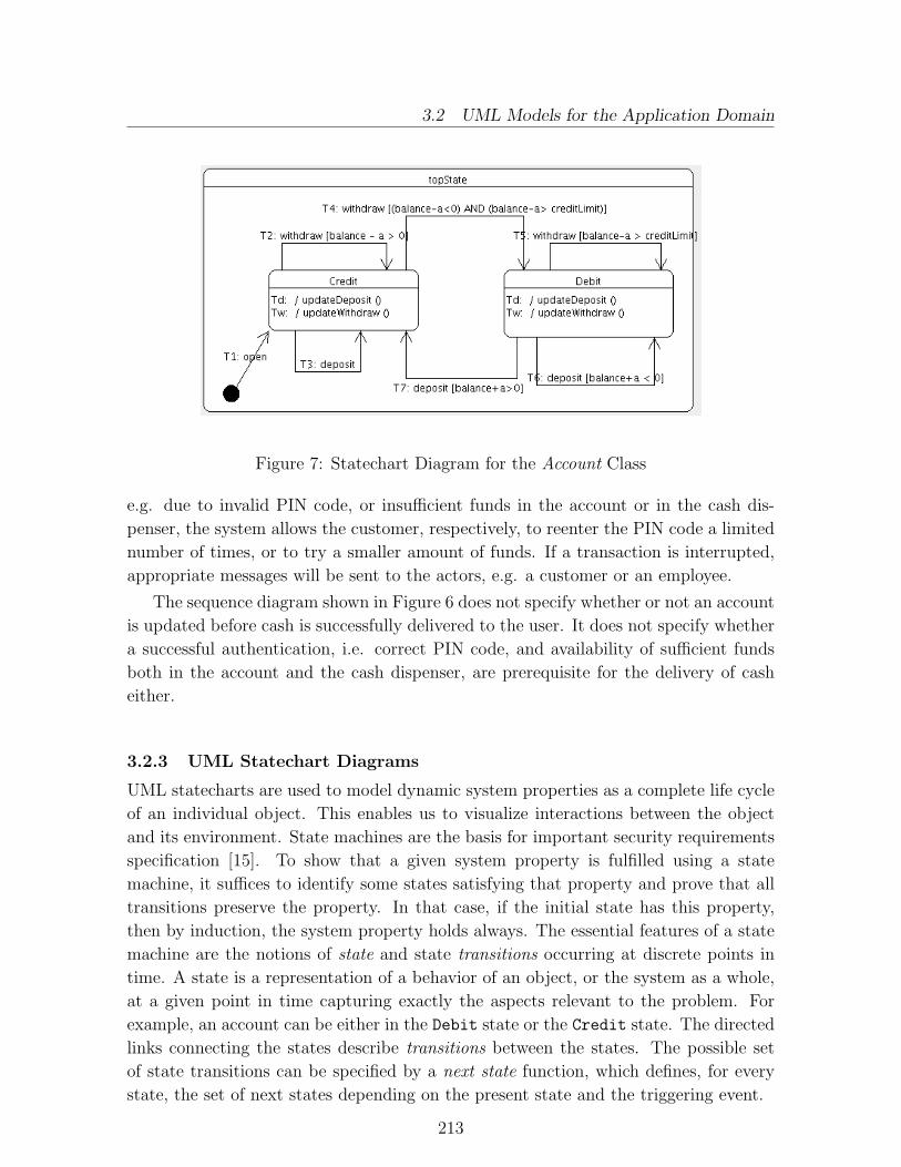
3.2 UML Models for the Application Domain
Figure 7: Statechart Diagram for the Account Class
e.g. due to invalid PIN code, or insufficient funds in the account or in the cash dis-
penser, the system allows the customer, respectively, to reenter the PIN code a limited
number of times, or to try a smaller amount of funds. If a transaction is interrupted,
appropriate messages will be sent to the actors, e.g. a customer or an employee.
The sequence diagram shown in Figure 6 does not specify whether or not an account
is updated before cash is successfully delivered to the user. It does not specify whether
a successful authentication, i.e. correct PIN code, and availability of sufficient funds
both in the account and the cash dispenser, are prerequisite for the delivery of cash
either.
3.2.3 UML Statechart Diagrams
UML statecharts are used to model dynamic system properties as a complete life cycle
of an individual object. This enables us to visualize interactions between the object
and its environment. State machines are the basis for important security requirements
specification [15]. To show that a given system property is fulfilled using a state
machine, it suffices to identify some states satisfying that property and prove that all
transitions preserve the property. In that case, if the initial state has this property,
then by induction, the system property holds always. The essential features of a state
machine are the notions of state and state transitions occurring at discrete points in
time. A state is a representation of a behavior of an object, or the system as a whole,
at a given point in time capturing exactly the aspects relevant to the problem. For
example, an account can be either in the Debit state or the Credit state. The directed
links connecting the states describe transitions between the states. The possible set
of state transitions can be specified by a next state function, which defines, for every
state, the set of next states depending on the present state and the triggering event.
213

3.2 UML Models for the Application Domain
A transition is labelled by a string of a general form n:e[c]/sa, where n is a tran-
sition name, e is a trigger event, c is a guard condition, and sa is a sequence of actions.
For instance, in the statechart diagram shown in Fig. 7, which models complete life cy-
cle of the class Account, T1,T2,...,T7 denote transition names, withdraw and deposit
are trigger events, and balance - a > 0 is a guard on the transition T2. Sequences of
actions are not explicitly shown in the statecharts diagram. For transitions triggered
by event deposit, i.e. transitions T3,T6,T7, the list of actions includes updating of the
balance with balance:=balance + a, whereas the withdraw event triggers transitions
T2,T4,T5, leads to updating of the balance with balance:=balance - a. In the se-
quence diagram shown in Fig. 6, the later corresponds to the receiving and processing
of the updateWithdraw event by an account object.Assertions on states, guard conditions and actions in statechart diagrams are trans-
lated into PVS expressions and integrated into the semantic model using the PrUDEtool. A predicate on a state specifies a condition that must hold whenever the objectto which the state machine is associated is in that state. For instance, properties of anaccount, when it is in the Credit and Debit states, can be captured by the followinglocal predicates.
State : TYPE+
acc: VAR Account
Credit, Debit : VAR State
pred(Debit) = balance(acc) < 0
pred(Credit) = balance(acc) ≥ 0
A guard condition on a transition is a predicate that specifies the condition thatmust hold for the transaction to fire. A guard condition can be viewed as a pre-condition for the operation associated with the event triggering the transition. Guardconditions on state transitions are translated into predicates in PVS specification lan-guage. For instance, the guard conditions on the transitions in Figure 7 can betranslated into the following predicates in PVS, where the guards g2,g4,g5,g6,g7
correspond to the transitions T2,T4,T5,T6,T7.
Guard : TYPE+ : [Account, nat → bool]
amount : VAR nat
g2, g4, g5, g6, g7 : VAR Guard
g2(acc,amount) = (balance(acc) - amount ≥ 0)
g4(acc,amount) = (creditLimit + amount ≤ balance(acc)) AND
(balance(acc) - amount < 0)
g5(acc,amount) = (creditLimit + amount ≤ balance(acc))
g6(acc,amount) = (balance(acc) + amount < 0)
g7(acc,amount) = (balance(acc) + amount ≥ 0)
The creditLimit is an attribute of the Account class, which specifies the maximum
amount of funds a customer can withdraw in debt, i.e. a fixed value that shows how
214

3.2 UML Models for the Application Domain
far the balance on the account can go below zero. The bank may change, through ne-
gotiation and agreement with the customer, the value of the creditLimit of an account.
3.2.4 Specification of Business Rules in OCL
UML diagrams are not detailed enough to address all the relevant aspects of system
specification. Among other things, we need to describe additional constraints on el-
ements in UML models that specify conditions and properties to be maintained, e.g.
data invariants, pre- and post-conditions on operations, and complex multiplicity in-
variants. In this subsection, we describe some examples of constraints on the UML
models given in previous sections using OCL [44, 28] expressions.
Rule 1: An instance of the class BankCard, and the Account with which it is associated
must belong to the same bank. In reference to the class diagram shown in Figure 5,
this property can be captured with the following invariant.
context BankCard inv:
self.bank = self.account.bank
Rule 2: For every instance of the class BankCard, the card holder must be the same
as the owner of the account with which the card is associated.
context BankCard inv:
self.holder = self.account.owner This rule can easily be modified to specify the
case where an account is owned by several customers, e.g. a woman and her husband, by
simply changing the type of the attribute owner to a set and the equality requirement
to membership in a set.
Rule 3: The sum of the amounts of all transactions kept in the ledgers must be zero.
This is equivalent to requiring that processing of every transaction preserves the overall
balance of the banking system. Symbolically,
n∑
l=1
amount(l) = 0 (3.1)
where l is a ledger and n denotes the number of ledgers in the bank. This is a more
complicated and important invariant that enables the banking system to prevent mali-
cious acts by monitoring activities of its employees. For instance, if an employee wants
to credit a given amount of funds to his own account, then he has to debit the same
amount from another account, rather than just modifying the account’s master file.
This requirement can be expressed as an invariant in OCL.
context Bank inv:
self.ledgers → collect(trans.amount → sum) → sum = 0
where collect is a predefined OCL operation on the collection type to return a sub-
collection of elements satisfying the predicate given as parameter. The relationships
between the collections ledgers, transactions, etc. are as shown in Figure 5. This
215

3.2 UML Models for the Application Domain
invariant is translated to a conjecture in PVS specification (see Theorem 3.1) and
checked directly using the PVS theorem prover.
This invariant is supposed to hold after completion of each transaction in an on-
line processing, or daily in a batch processing. It significantly improves the security
mechanism of the banking system by allowing monitoring of its overall balance. We
specify a number of ledgers for recording different types of transactions. To simplify
our discussion, we assume that the bank contains only three ledgers, namely:
- a drawer ledger for recording transactions affecting the amount of cash in the
drawer;
- a credit ledger for recording transactions that affect the credit of the bank; and
- a debit ledger for recording transactions that affect the debit of the bank.
Note that the sets of transactions recorded in the ledgers are not mutually disjoint.
When a transaction is successfully completed, it is processed and added to a pair of
relevant ledgers. For instance, a deposit transaction is added to the drawer ledger to
reflect the increment of cash in the drawer, and at the same time to the debit ledger to
reflect the increment in the debit from the bank, i.e. the amount the bank must owe
its customers.
Rule 4: The system must not allow withdrawal of an amount of funds that makes
the balance on the account less than the pre-agreed creditLimit - a fixed amount
of funds that the customer can withdraw in debt disregarding ongoing transactions.
For customers without such an agreement, creditLimit is equal to zero. Moreover, if
a withdrawal is successfully completed, the balance on the account must be updated.
These requirements are specified as pre- and post-conditions on the withdraw operation
as follows:
context Account :: withdraw(amount : nat) : nat
pre: self.balance− amount ≥ self.creditLimit
post: self.balance = self.balance@pre− amount
where balance@pre indicates the value of variable balance at the start of the execution
of the operation.
A pre-condition on an operation corresponds to a guard condition on a state transi-
tion that must be fulfilled for the transition to be fired. State transitions must preserve
local invariants, but a state transition may be undesirable globally. That is, when a
transition is fired, the effect of actions associated with the transition may lead to unde-
sirable behavior. For instance, transferring funds to a wrong account number is possible
as far as the pre- and post-conditions are fulfilled. That is, the pre- and postcondition
are necessary but not sufficient to enforce such requirements.
Rule 5: If a person is both a customer and an employee of a bank, then the person must
not be allowed to modify his own account. This requirement is related to the separation
216

3.2 UML Models for the Application Domain
of duties security design principle. To enforce this requirement, every employee must
be identified uniquely, for instance by a combination of social security number and a
password, and a set of accounts that the employee can update must be specified. This
requirement is expressed in OCL as follows:
contextPerson inv:
self.updates → excludes(self.owns)
where excludes is a predefined OCL operation, and the updates attribute contains the
set of accounts an employee can modify (see section 3.4 for more discussion).
Rule 6: After a successful withdrawal transaction, the effect of the withdrawal must
be reflected on the account by updating its balance before the cash is dispensed. What
if the cash dispenser fails to deliver the cash after the balance is updated? This is an
instance of the transaction integrity problem that can be handled by a new transaction
that reestablishes the correct balance.
In general, transactions can be kept in a journal until they are processed and added
to appropriate ledgers by batch processing modules during the night. In our example,
however, we assume that a transaction is put into ledgers immediately after it is suc-
cessfully completed. System properties described in OCL expressions are integrated
into the PVS specifications generated from the UML models and verified using the
PVS toolkit.
Rule 7: For any account, at most one ATM session can be associated with the account
at any given time. This requirement prevents concurrent withdrawals from the same
account by requiring uniqueness of an ATM session. This can be implemented by
updating the balance on the account before a new ATM session can be started.
context ATMSession inv:
self.allInstances → forall(s1, s2|s1 <> s2 implies s1.account <> s2.account)
where the allInstances and the → are predefined OCL operations on types and object
collections respectively.
Rule 8: The balance on an account is equal to the difference between the sum of
deposited funds and the sum of withdrawn funds. This constraint can be specified as
an invariant expressed in OCL, and translated into a conjecture in PVS and discharged.
context account inv:
self.balance =
self.trans → select(transKind = deposit)) → collect(trans.amount) → sum
- (self.trans → select(transKind = withdraw)) → collect(trans.amount) → sum
where select and collect are OCL operations and trans is the list of transactions
performed on the account object. The select operation returns a sub-list of trans
for which the boolean expression is true. The collect operation derives a collection
of objects of type different from the original collection. It returns a bag of natural
217

3.3 Formal Analysis Using the PrUDE Tool
numbers, i.e. amounts associated with the transactions selected. The sum operation
returns the total sum of the amounts in the set of transactions to which it is applied.
3.3 Formal Analysis Using the PrUDE Tool
The main purpose of integrating semi-formal modeling techniques with formal meth-
ods (FMs) is to exploit the mathematical foundation underlying FMs in reasoning
about correctness of the graphical models. This requires translation of graphical UML
models, and OCL constraints to PVS specifications to make them amenable to rigor-
ous analysis. The translation of UML models is based on the semantic definitions we
proposed for UML notations [1, 3, 4, 38] and implemented in the PrUDE [5] tool to
support automatic translation of UML models into formal specifications in PVS. The
translation of OCL expressions into PVS is rather straightforward since OCL is based
on first-order logic and PVS is based on higher-order logic.
The formal system development process using the PrUDE platform consists of the
following major steps.
• Analysis and design of a system using UML modeling techniques. In this step,
structural and behavioral properties of major system components, relationships
between the components, and possible interactions between them are described
using the UML modeling techniques and notations. Any UML CASE tool that
supports model exchange in the XMI format can be used to automate this step.
In the sequel, the ArgoUML [17] tool is used.
• PVS specifications are obtained by translating UML models and rigorously an-
alyzed using the verification mechanisms and tools provided by the PVS envi-
ronment in order to prove that the specifications satisfy the requirements. If an
error is discovered during this step, e.g. if a type-checking fails, then the above
steps are repeated until an error-free, UML model is obtained.
• When a valid, i.e. a well-formed, UML model is obtained the developer proceeds
with the implementation and code generation in a language of interest. Most of
the UML CASE tools support generation of skeletons of codes in programming
languages such as Java, C++, etc.
Specifications of generic properties of UML models, e.g. the well-formedness con-
straints, can be captured by the semantic definitions for UML notations and obtained
from the translation of UML models into PVS. The resulting PVS specifications are
analyzed using the PVS verification tools such as the type-checker, theorem-prover
and model-checker. The PVS specification shown in appendix B is, for instance, auto-
matically generated from the sequence diagram shown in Figure 6 using the PrUDE
tool.
218

3.3 Formal Analysis Using the PrUDE Tool
The following are examples of generic properties of UML models. These properties
follow from well-formedness constraints put on UML models.
• For every object involved in a given interaction that is specified by a sequence
diagram, its class should be specified at least in one class diagram.
• For a given class and a statechart diagram describing its life cycle, an operation
that triggers a state transition must be in the set of methods of the class.
As mentioned previously application-specific properties should be added directly into
the PVS specification. For instance, the invariant stated as Theorem 3.1 specifies the
requirement that the overall balance of the bank must be preserved by a processing of
a transaction, i.e. the addition of the transaction into a pair of appropriate ledgers (see
Rule 3 in Section 3.2.4). In other words, for every transaction and a bank, processing
of the transaction, i.e. its addition to a pair of appropriate ledgers, should preserve the
overall balance of the bank.
To specify and verify this requirement, we start by declarations of transaction,
ledger, bank, types. In fact these declarations are extracted from the PVS specification
resulted from the translation of UML models. Note that the excerpt from the PVS
specification contains the minimal information necessary for the following discussion.
TransactionKind : TYPE+ = {deposit, withdraw, transfer}
Transaction :TYPE+ = [# transId: int,
transKind: TransactionKind,
amount: nat #]
Ledger : TYPE+ = [# kind : LedgerKind,
trans : list[Transaction] #]
Bank : TYPE+ = [# accounts: setof[Account],
drawer : Ledger,
credit : Ledger,
debit : Ledger #]
A bank consists of a set of accounts, and three ledgers for recording cash in the drawer,
the credit, and debit of the bank. A ledger consists of a list of transactions in the order
of their occurrences. To every transaction there is an amount of funds.
The recursive function sum ledger computes the sum of the amounts of funds asso-
ciated with the list of transactions given as a parameter. When the PVS specification
was typed, a TCC was generated in order to ensure termination of the recursion. The
TCC was discharged automatically using the theorem-prover command (grind).
sum_ledger(lt:list[Transaction]) : recursive nat = CASES lt OF
null : 0,
cons(t,lt1) : amount(t) + sum_ledger(lt1)
219

3.3 Formal Analysis Using the PrUDE Tool
ENDCASES
MEASURE length(lt)
The predicate balanced?() defined on the Bank type states the condition that must
hold when a bank is in the balanced state, i.e. the sum of all ledgers is equal to zero.
b : VAR Bank
balanced?(b): bool = sum_ledger(trans(drawer(b)))
+ sum_ledger(trans(credit(b)))
+ sum_ledger(trans(debit(b))) = 0
Processing of a transaction means addition of a successfully completed transaction
into a pair of ledgers, depending on the kind of the transaction. More specifically,
the transaction is appended to the sequence of transaction in the ledgers. It may
be necessary to alter the amount associated with the transaction, for instance, when a
withdrawal transaction is added to the drawer ledger. The auxiliary function neg() was
defined for this purpose, whereas the function processTrans() specifies the processing
of transactions.
t : VAR Transaction
neg(t) : Transaction = t WITH [amount:=-amount(t)]
processTrans(t,b) : Bank = IF transKind(t)=withdraw THEN
b WITH [drawer:=drawer(b) WITH [trans:=cons(neg(t),trans(drawer(b)))],
credit:=credit(b) WITH [trans:=cons(t,trans(credit(b)))]]
ELSE IF transKind(t) = deposit THEN
b WITH [drawer:=drawer(b) WITH [trans:=cons(t,trans(drawer(b)))],
debit:=debit(b) WITH [trans:=cons(neg(t),trans(debit(b)))]]
ELSE b
ENDIF
ENDIF
where WITH is a PVS construct for overriding values of fields of a record. Since the
effect of processing a transfer transaction is the same as that of withdraw transaction,
it is not considered in the definition of the processTrans() operation. The definition of
the processTrans() operation is based on the assumption that a transaction is processed
immediately after it is completed, otherwise the operation would have been recursive.
Now let us specify the requirement as a theorem and prove it by invoking the PVS
theorem-prover.
Theorem 3.1 For any transaction t and a bank b, processing of the transaction pre-serves the overall balance of the bank. In other words, if the bank is in a balanced state,and a transaction is successfully processed, then the bank remains balanced. Symboli-cally,thm2: THEOREM FORALL t,b: balanced?(b) => balanced?(processTrans(t,b))
220

3.3 Formal Analysis Using the PrUDE Tool
The following is a slightly reformatted excerpt from a proof of the theorem generated
by the PVS toolkit.
thm2 :
{1} FORALL t, b: (balanced?(b) => balanced?(processTrans(t,b)))
Trying repeated skolemization, instantiation, and if-lifting, then Expanding the defini-
tion of sum ledger, and then Expanding the definition of processTrans, this simplifies
to:
thm2 :
{-1} (CASES trans(credit(b!1)) OFnull: 0,cons(t, lt1): amount(t) + sum ledger(lt1)
ENDCASES)+(CASES trans(debit(b!1)) OF
null: 0,cons(t, lt1): amount(t) + sum ledger(lt1)
ENDCASES)+(CASES trans(drawer(b!1)) OF
null: 0,cons(t, lt1): amount(t) + sum ledger(lt1)
ENDCASES) = 0{1} (CASES (IF transKind(t!1) = withdraw THEN
cons(t!1,trans(credit(b!1)))ELSE b!1‘credit‘trans ENDIF) OF
null: 0,cons(t,lt1): amount(t) + sum ledger(lt1)
ENDCASES)+(CASES (IF transKind(t!1)=withdraw THEN
b!1‘debit‘transELSE cons(neg(t!1), trans(debit(b!1))) ENDIF) OF
null: 0,cons(t,lt1): amount(t)+sum ledger(lt1)
ENDCASES)+ (CASES (IF transKind(t!1) = withdraw THEN
cons(neg(t!1), trans(drawer(b!1)))ELSE cons(t!1, trans(drawer(b!1))) ENDIF) OF
null: 0,cons(t,lt1): amount(t)+sum ledger(lt1)
ENDCASES) = 0
Lifting IF-conditions to the top level,
thm2 :
221

3.3 Formal Analysis Using the PrUDE Tool
{-1} IF null?(trans(credit(b!1)) THEN(0 + (CASES trans(debit(b!1)) OF
null: 0,cons(t, lt1): amount(t) + sum ledger(lt1)ENDCASES)
+ (CASES trans(drawer(b!1)) OFnull: 0,cons(t, lt1): amount(t) + sum ledger(lt1)ENDCASES)) = 0
ELSE amount(car(trans(credit(b!1))))+ sum ledger(cdr(trans(credit(b!1))))+ (CASES trans(debit(b!1)) OF
null: 0,cons(t, lt1): amount(t) + sum ledger(lt1)ENDCASES)
+ (CASES trans(drawer(b!1)) OFnull: 0,cons(t, lt1): amount(t) + sum ledger(lt1)ENDCASES) = 0
ENDIF
{1} IF transKind(t!1) = withdraw THEN(CASES cons(t!1,trans(credit(b!1))) OF
null: 0,cons(t,lt1): amount(t) + sum ledger(lt1)
ENDCASES)+ (CASES b!1‘debit‘trans OF
null: 0,cons(t,lt1): amount(t) + sum ledger(lt1)
ENDCASES)+ (CASES cons(neg(t!1), trans(drawer(b!1))) OF
null: 0,cons(t,lt1): amount(t) + sum ledger(lt1)
ENDCASES) = 0ELSE
(CASES b!1‘credit‘trans OFnull: 0,cons(t,lt1): amount(t) + sum ledger(lt1)
ENDCASES)+ (CASES cons(neg(t!1), trans(debit(b!1))) OF
null: 0,cons(t,lt1): amount(t) + sum ledger(lt1)
ENDCASES)+ (CASES cons(t!1, trans(drawer(b!1)))
null: 0,cons(t,lt1): amount(t) + sum ledger(lt1)
ENDCASES) = 0ENDIF
222

3.4 Model-based V&V in Making Design Decisions
Trying repeated skolemization, instantiation, and if-lifting,This completes the proof of thm2.
Q.E.D.
3.4 Model-based V&V in Making Design Decisions
In the UML standard document [28] it is stated that associations on base classes areinherited by its subclasses. We briefly discuss this issue, present a concrete example ofa deviation of designers’ understanding of the issue, and illustrate how the proposeddevelopment framework may assist developers in making design decisions in cases whenthe semantics of the UML notations is ambiguous and/or inconsistent with intuitiveinformal semantics.
In UML, the semantics of specialization/generalization relationship between classi-fiers satisfies Liskov’s substitutability principle [25] stated as follows:
If S is a subtype of type T , then objects of T in a program may be substitutedwith objects of type S without altering the desired properties of the program,e.g. its correctness. In other words, if p(x) is a property provable about anelement x of type T , then p(y) should be true for an element y of type S.
Let us consider the specialization/generalization hierarchy of the classes extracted fromthe class diagram shown in Figure 5, modified/refined and shown in Figures 8 and 9so that they suit the discussion in this section. When applied to the inheritancehierarchy shown in Figure 8, Liskov’s substitutability principle states that objects ofspecialized classes, namely the Employee and Customer classes, are substitutable forobjects of the base class Person. In other words, the associations between classesPerson and Account are inherited by the subclasses Customer and Employee of theclass Person. Thiat means, both subclasses are associated with the class Account bythe two associations they inherit from the base class.
In PVS semantic models, we specify the inheritance hierarchy by representingclasses and subclasses as PVS types and subtypes, respectively. Subtyping satisfiesLiskov’s substitutability principle.
Person : TYPE+
Employee : TYPE+ FROM Person
Customer : TYPE+ FROM Person
p : VAR Person
b : VAR BAnk
acc : VAR Account
Moreover, semantics of inheritance relationship requires that sets of objects of spe-cialized classes are mutually disjoint in the sense that they cannot have a common sub-class. This property does not automatically follow from the specification of subclassesas uninterpreted subtypes declared above. Hence, we need to explicitly specify thisproperty as a constraint on the metamodel (see axiom disjoint ax in the corePackage
223

3.4 Model-based V&V in Making Design Decisions
Figure 8: Associations in Inheritance Hierarchy
theory in the appendix A). There are two associations between the classes Person andAccount (see Fig. 8: the updates association that captures the relationship between anaccount and a bank employee; and the owns association that specifies a relationshipbetween an account and a bank customer. Specialized classes inherit both the structureand behavior of the base class. Note that the two associations may not be mutuallydisjoint, i.e. a single person can be associated to an account both as a customer andan employee (at least at this point) in which case additional restriction may apply tothe set of accounts such a person may update. More specifically, a person should notbe allowed to modify his own account.
According to the semantics of inheritance in UML notations, an association in-volving a base class is inherited by all its subclasses. This means, referring to Figure8, that the subclasses Employee and Customer inherit the two associations owns andupdates from the base class Person. A person is said to be associated with a bank asan employee if there exists an account in the bank, which the person may updates. Aperson is said to be associated with a bank as a customer if there exists an account inthe bank, which the person owns. We specify the associations and their properties asfollows.
owns : [Person -> set[Account]]
updates : [Person -> set[Account]]
uses : [Bank -> set[Person]]
worksfor : [Bank -> set[Person]]
worksfor ax:AXIOM (FORALL p,b: worksfor(b)(p) IFF
(EXISTS acc: accounts(b)(acc) AND updates(p)(acc)))
uses ax: AXIOM(FORALL p,b: uses(b)(p) IFF
(EXISTS acc: accounts(b)(acc) AND owns(p)(acc)))
Based on the above axioms, let us specify and verify the property stated as businessRule 5 in section 3.2.4.
224

3.4 Model-based V&V in Making Design Decisions
Theorem 3.2 If a person p is an employee and a customer of a bank b, then theperson must not be allowed to update an account acc which (s)he owns. Symbolically,
thm6: THEOREM (FORALL p,b,acc: (worksfor(b)(p) AND uses(b)(p)) IMPLIES
NOT (owns(p)(acc) IFF updates(p)(acc)))
An attempt to prove the above theorem by invoking the PVS theorem prover, turnedout to be unsuccessful by resulting in two unprovable subgoals: thm6.1 expressed asunproved sequent with several antecedents and no consequents; and thm6.2 expressedas a sequent with consequent contradicting the consequent of the original goal. Thecounter examples are given as PVS debugging messages, which indicate that either theantecedents are inconsistent, or they are insufficient to prove the sequent.
thm6 :
|--------------
{1} (FORALL p,b,acc: (worksfor(b)(p) AND uses(b)(p)) IMPLIES
NOT (owns(p)(acc) IFF updates(p)(acc)))
Rule? (grind :theories ("inheritance"))
Trying repeated skolemization, instantiation, and if-lifting, this
yields 2 subgoals:
thm6.1 :
{-1} GeneralizableElement_pred(p!1)
{-2} Classifier_pred(p!1)
{-3} Class_pred(p!1)
{-4} Person_pred(p!1)
{-5} owns(p!1)(acc!1)
{-6} updates(p!1)(acc!1)
|--------------
Rule? (postpone) Postponing thm6.1.
thm6.2 :
{-1} GeneralizableElement_pred(p!1)
{-2} Classifier_pred(p!1)
{-3} Class_pred(p!1)
{-4} Person_pred(p!1)
|--------------
{1} owns(p!1)(acc!1)
{2} updates(p!1)(acc!1)
Rule? quit
225

3.4 Model-based V&V in Making Design Decisions
Run time = 1.45 secs.
Real time = 50.58 secs.
A closer investigation of the axioms reveals that the antecedents are insufficient to provethe sequent. That means, it is inconclusive from the specified axioms, whether or nota person who can update an account is different from the one who owns it. Hence, weneed to analyze the UML class diagram since this contradicts the intended/requiredproperty of the system.
A solution is to specify the two associations owns and updates between the special-ized classes Customer and Employee, and the class Account, respectively. We capturethe desired property by specifying an {xor} (exclusive or) – a predefined constraint inUML – on the two associations (see Figure 9). The {xor} constraint specifies that forany instance of the class Account, either it is associated with an instance of the classCustomer by the association owns or with an instance of the class Employee by theassociation updates, but not both. The {xor} constraint is translated to the followingaxiom in the PVS specification.
1..*
*usesCustom er
Employee 1..*
*
updates
{x or}
Person Account
Figure 9: Associations in Inheritance Hierarchy
xor ax: AXIOM (FORALL acc: (owns(c)(acc) XOR updates(e)(acc)))
By including axiom xor ax in the PVS specification (see appendix E), theorem thm6
was discharged automatically by invoking the PVS prover, with the single command(grind :theories (”inheritance”)).
thm6 :
|-------
{1} (FORALL p,b,acc: (worksfor(b)(p) AND uses(b)(p)) IMPLIES
NOT (owns(p)(acc) IFF updates(p)(acc)))
Trying repeated skolemization, instantiation, and if-lifting,
This completes the proof of thm6.
Q.E.D.
226

3.5 Discussions
This example shows how formal V&V can reveal subtle errors (omissions, inconsis-tencies, etc) in UML models, which may not be discovered otherwise, and how logmessages can help us to reconsider our design decisions. Although the detected errormight seem trivial, it is an example of typical errors that can easily be overlookedduring design phase, until its it is too late and costly to fix them.
3.5 Discussions
Generic correctness requirements on UML models are specified and automatically ver-ified by implementing the well-formedness rules (WFRs) defining the UML static se-mantics in the PrUDE tool. Application-specific requirements should, however, bespecified during the development process and this requires certain amount of devel-opers’ interaction with the PrUDE platform, thus full automation of the verificationprocess is not realistic. System models are expressed in UML notations, whereas ad-ditional constraints on models are captured either by OCL or OUN expressions. TheADAPT-FT project integrates UML, OUN and PVS into a platform for the formaldevelopment of open distributed systems (ODS). In the PrUDE tool, however, OCLis used instead of OUN to enhance the UML notations. The UML models, and theconstraints expressed in OUN or OCL are translated to PVS to take advantage of thePVS theorem proving facilities in verifying correctness of the UML models [1, 3, 4].
The PrUDE platform relies on UML for modeling, and on OCL for specifyingconstraints on the models, and on PVS [30] for consistency checking and verification ofthe specifications. It allows developers to interactively insert assertions directly usingthe PVS editor. This seems to be in contrary to the main purpose of integrating formalmethods with graphical modeling techniques, namely, hiding the processing of formalsoftware artifacts from practitioners. However, as stated in [6], complete automation ofthe translation of semi-informal models into formal specifications is unlikely, since theinformal descriptions are inherently incomplete. Most of the generative translationsresults in only skeletons of formal specifications and require the specifiers to provideadditional details to complete the semantic models.
Hence, translation of UML models into PVS results in a skeleton of formal specifica-tion that is neither ’complete’ nor detailed enough to perform a meaningful verificationof the properties of the system in question. The level of details of the formal specifi-cations generated from the UML models directly depends on the information availablein the UML models and the detail of semantic definitions implemented in the CASEtool automating the translation.
The PrUDE tool is developed based on the formal semantic definitions we proposedfor a subset of the UML notations. Even if semantics for the whole UML notationsis defined and implemented in the platform, it is impossible to capture all applicationspecific properties although some generic properties can be implemented in the platformand instantiated in applications. Hence, allowing users to add system properties isessential for performing a meaningful verification and makes the PrUDE platform moreflexible. This feature seems to contradict with the very purpose of developing theintegrated platform and the supporting tool. This issue can be addressed in one or
227

4. Conclusion and Future Work
more of the following ways:
- Formalize generic domain-specific properties and implement them;
- Use more user friendly and intuitively understandable specification languagessuch as the tabular notation; and [32, 19] that have semantic definitions in PVS.
- Define and implement suitable proof strategies that capture domain-specific prop-erties.
The separation of generic semantic theory and model-specific definitions allows thedevelopment of a meta-theory and proof strategies for UML models, which are usefulto reduce users’ interaction with verification tools.
Another issue that needs further consideration is communication of results of formalverifications using PVS tools to developers who may not have knowledge about the PVSenvironment. In the current version of the PrUDE tool, results from PVS verificationtools are reported as plain texts. The main challenge is, to present the feedback fromthe PVS tool, e.g. an error message from type-checking or the theorem-proving, insuch a way that it enables the developers to trace the cause of errors back to the UMLmodels they have created and identifying the model elements containing the errors.Such a mechanism is very crucial for practical usability of the proposed developmentframework and its tool.
A preliminary investigation shows that it is feasible to achieve this by recordinga sufficient amount of information that is necessary to re-engineer the UML modelsfrom the PVS specifications. For instance, preserving the system vocabulary across thegraphical models and formal specifications significantly contributes to the improvementof practitioners understanding of feedbacks from the verification step. Moreover, en-coding model information in a notation that preserves the structure of UML modelscan improve understanding of the developers, and at the same time represent sufficientinformation about model elements.
An alternative approach is to implement an ’intelligent’ parser that can interpretthe log file generated by the PVS verification tools. Even though the error messagesmight indicate the cause of errors in the UML models, they are not sufficiently detailed.In the future we implement an ”intelligent” parser that will extract textual ”English-only” messages from the raw PVS log messages.
4 Conclusion and Future Work
Our framework relies on PVS [30] as a formalism for verification of specifications. Ba-sic modeling constructs and constraints on UML diagrams can be expressed formallyin the PVS specification language in terms of functions and abstract data types [2].Our approach to consistency checking was described in [40] where software specifica-tion is done in a development framework, which integrates UML and PVS toolkit. Acombined use of the different UML viewpoints improves integrity and completeness
228

of system models, which in turn provides a firm foundation for a better design andimplementation decisions.
By integrating semi-formal modeling notations with formal methods (FMs), wehave taken a step towards exploiting the mathematical foundation underlying the FMsfor rigorous analysis. This requires translation of UML models into PVS specificationsthat are amenable to rigorous analysis. The translation is based on semantic defini-tions we proposed in [1, 3, 4, 38] and provides the necessary link for reasoning aboutthe UML models. The PrUDE tool automates most of the translation of UML mod-els developed by using UML tools supporting data exchange in the XMI format intoPVS specifications. The PVS toolkit allows us to perform conformance checks of thesemantic models as illustrated in section 3.
It is not feasible to implement all application-specific properties in a CASE tool assuch properties will not be available before the development process starts. Genericproperties, however, can be implemented in CASE tools. Hence, allowing users to adddomain-specific properties is essential to perform a meaningful verification possiblyguided by users. Moreover, this feature makes the PrUDE tool flexible and useful to awider group of users. The fact that system designers are allowed to specify system prop-erties in PVS, seems to contradict with the very purpose of developing the integratedframework and the supporting tools: minimizing user’s interaction with verificationtools. This issue can be addressed by using a user friendly specification languagesuch as the tabular notation [32] and by identifying a number of proof strategies forapplication-specific properties, to minimize user’s interaction with the theorem-prover.
Another issue that needs further consideration is how to communicate feedbacksfrom PVS toolkit to developers who may not be expert in the PVS environment. Onepossible approach is to implement an ’intelligent’ parser that interprets the outputfrom the PVS verification tools, and enables the developer to navigate the model toidentify source of errors.
We presented an integrated development framework and a supporting tool andillustrated how it can be used in the development of critical applications. We stronglybelieve that integrating formal methods with a well-accepted visual modeling languagelike the UML into a development process improves system reliability and clarity of themeaning of the modeling elements.
The main contribution of our work is precise representation of UML models bytranslating them into PVS specifications and performing rigorous analysis. The in-terpretation of the feedbacks from the PVS verification tools into UML model needsto be addressed. This transformation is crucial for communicating results of formalanalysis to software practitioners that may not be familiar with the PVS environment.A significant limitation of our framework is that when a proof fails there is no realexplanation of the cause in the context of the UML models.
229

Acknowledgements
We would like to thank Dr. Issa Traore for reviewing earlier versions of this report andfor his invaluable comments.
References
[1] D. Aredo, I. Traore, and K. Stølen. An Outline of PVS Semantics for UML Class Diagrams(extended abstract). In the Proc. of The 11th Nordic Workshop on Programming TheoryNWPT’99, Uppsala, Sweden, October 6-8, 1999.
[2] D. B Aredo. Formalization of UML class Diagrams in PVS (Extended Abstract). In the Proc.of Workshop on Rigorous Modeling and Analysis with the UML: Challenges and Limitations, atOOPSLA99., Denver, Colorado, USA, November 2, 1999.
[3] D. B. Aredo. A Framework for Semantics of UML Sequence Diagrams in PVS. Journal of Univer-sal Computer Science (JUCS), Know-Center in cooperation with Springer Pub. Co., JoanneumResearch and the IICM, Graz University of Technology, 8(7):674–697, July 2002.
[4] D. B. Aredo. Semantics of UML Statecharts in PVS. In the Proc. of 7th World Multiconferenceon Systemics, Cybernetics and Informatics (SCI2003), Orlando, Florida, USA, July 27-30, 2003.
[5] M. Belaid and I. Traore. The Precise UML Development Environment (PrUDE) ReferenceGuide. Technical Report ECE01-2, Department of Electrical and Computer Eng., University ofVictoria, April 2001.
[6] J.-M. Bruel. Integrating Formal and Informal Specification Techniques. Why? How? InOverview of Panel discussion on International Workshop on Industrial Strength Formal Tech-niques, Vancouver, Canada, October 22, 1998. panalists: B. Cheng and S. Easterbrook and R.B. France and B. Rumpe.
[7] D. D. Clark and D. R. Wilson. Comparison of Commercial and Military Computer SecurityPolicies. In Proc. of the 1987 IEEE Symposium on Security and Privacy, pages 184–195,Oakland, California, USA, April 27-29, 1987.
[8] M. Clavel, F. Duran, S. Eker, P. Lincoln, N. Martı-Oliet, J. Meseguer, and J. F. Quesada. Maude:Specification and Programming in Rewriting Logic. Theoretical Computer Science, 285(2):187–243, August 2002.
[9] O.-J. Dahl and O. Owe. Formal Methods and the RM-ODP. Research report No. 261, March1998. Department of Informatics, University of Oslo, Norway.
[10] W. Damm and D. Harel. LSC’s: Breathing Life into Message Sequence Charts. In FormalMethods for Open Distributed Systems (FMOODS’99), Florence, Italy, February 15-18, 1999.
[11] S. Easterbrook, J. Callahan, and V. Wiels. V&V Through Inconsistency Tracking and Analysis.In the Proc. of International Workshop on Software Specification and Design, Ise-Shima, Japan,April 16-18 1998.
[12] S. Flake and W. Mueller. Expressing Property Specification Patterns with OCL. In The 2003International Conference on Software Engineering Research and Practice (SERP’03), pages 595–601, Las Vegas, NV, USA, June 2003. CSREA Press, Las Vegas, NV, USA.
[13] S. Flake and W. Mueller. Formal Semantics of Static and Temporal State-Oriented OCL Con-straints. Journal on Software and System Modeling (SoSyM), 2(3):164–186, October 2003.
[14] A. Gargantini and E. Riccobene. Encoding Abstract State Machines in PVS. In Y. Gurevich,P. W. Kutter, M. Odersky, and L. Thiele, editors, Proc. of Abstract State Machines, Workshop,ASM 2000, volume 1912 of Lecture Notes in Computer Science, pages 303–322, Monte Verita,Switzerland, March 19-24, 2000. Springer.
[15] D. Gollmann. Computer Security. John Wiley & Sons Ltd., Baffins Lane, Chichester, WestSussex PO19 1UD, England, 1999.
230

[16] G. J. Holzmann. Design and Validation of Computer Protocols. Prentice-Hall, 1991.
[17] CollabNet Inc. ArgoUML: A modelling tool for design using UML, 1999-2002. URL address,http://argouml.tigris.org/.
[18] ISO. A Formal Description Technique Based on the Temporal Ordering of Observational Behav-ior, September 1988. ”ISO Standard 8807”.
[19] R. Janicki, D. Parnas, and J. Zucker. Tabular representations in relational documents. InRelational Methods in Computer Science, pages 184–196. Springer-Verlag, 1996.
[20] E. B. Johnsen and O. Owe. A Compositional Formalism for Object Viewpoints. In A. Rensinkand B. Jacobs, editors, Formal Methods for Open Object-Based Distributed Systems (FMOODS),pages 45–60. Kluwer Academic Publisher, March 2002.
[21] E. B. Johnsen and O. Owe. Object-oriented specification and open distributed systems. In OlafOwe, Stein Krogdahl, and Tom Lyche, editors, From Object-Orientation to Formal Methods:Dedicated to the Memory of Ole-Johan Dahl, volume 2635 of Lecture Notes in Computer Science.Springer-Verlag, 2003.
[22] F. Keienburg and A. Rausch. Using XML/XMI for Tool Supported Evolution of UML Models. Inthe Proc. of the 34th Annual Hawaii International Conference on System Sciences (HICSS-34),Maui, Hawaii, January 3-6 2001. IEEE Computer Society.
[23] Anneke Kleppe and Jos Warmer. Extending OCL to include Actions. In Andy Evans, StuartKent, and Bran Selic, editors, UML 2000 - The Unified Modeling Language. Advancing theStandard. Third International Conference, York, UK, October 2000, Proceedings, volume 1939of LNCS, pages 440–450. Springer, 2000.
[24] M. Lawford, P. Froebel, and G. Moum. Practical Application of Functional and RelationalMethods for the Specification and Verification of Safety Critical Software. In T. Rus, editor, theProc. of Algebraic Methodology and Software Technology, 8th International Conference, AMAST2000, Iowa City, Iowa, USA, May 2000, volume 1816 of Lecture Notes in Computer Science,pages 73–88. Springer, 2000.
[25] B. Liskov and J. Wing. A Behavioral Notation of Subtyping. ACM Trans. on ProgrammingLanguages and Systems, 16(6):1811–1841, November 1994.
[26] Klasse Objecten. Octopus: OCL Tool for Precise Uml Specifications.
[27] Dresden University of Technology. Dresden ocl toolset.
[28] OMG. OMG Unified Modeling Language Specification, version 1.3, June 1999. OMG standard.
[29] O. Owe and I. Ryl. The Oslo University Notation: A Formalism for Open, Object-Oriented,Distributed Systems. Report No. 270, August 1999. Department of Informatics, University ofOslo, Norway.
[30] S. Owre, J. Rushby, N. Shankar, and F.V. Henke. Formal Verification for Fault-tolerant Ar-chitectures: Prolegomena to the design of PVS. IEEE Transactions On Software Engineering,21(2):107–125, February 1995.
[31] S. Owre, N. Shankar, J. Rushby, and D. W. Stringer-Calvert. PVS System Guide, version 2.3.Computer Science Laboratory, SRI International, Melon Park, CA, September 1999.
[32] D. L. Parnas. Tabular Representation of Relations. Technical Report 260, Department ofElectrical and Computer Engineering, Telecommunications Research Institute of Ontario, Com-munications Research Laboratory, 1992.
[33] M. Richters and M. Gogolla. On Formalizing the UML Object Constraint Language (OCL) .In Tok Wang Ling, Sudha Ram, and Mong Li Lee, editors, Proc. 17th Int. Conf. ConceptualModeling (ER’98), volume 1507 of LNCS, pages 449–464. Springer, 1998.
[34] J. Rumbaugh, I. Jacobson, and G. Booch. The Umified Modeling Language, Reference Manual.Addison Wesley Longman Inc., 1999.
231

[35] J. Rushby. Specification, proof checking, and model checking for protocols and distributedsystems with PVS. In FORTE X/PSTV XVII ’97: Formal Description Techniques and ProtocolSpecification, Testing and Verification, November 1997.
[36] I. Sommerville. Software Engineering. Addison-Wesley, 5th edition, 1996.[37] J. M. Spivey. The Z Notation: A Reference Manual. Prentice-Hall International, 2nd edition,
1992.[38] I. Traore. An Outline of PVS Semantics for UML Statecharts. Jounal of Universal Computer
Science, 6(11):1088–1108, 2000.[39] I. Traore and D. B. Aredo. Enhancing Structured Review with Model-based Verification. IEEE
Transaction on Software Engineering (to appear), April 2004.[40] I. Traore, D. B. Aredo, and K. Stølen. Tracking Inconsistencies in an Integrated Platform.
Research report No. 274, August 1999. Department of Informatics, University of Oslo, Norway.[41] I. Traore, D. B. Aredo, and H. Ye. An Integrated Framework for Formal Development of Dis-
tributed Systems. Journal of Information and Software Technology, Elsevier Science, 46(5):281–286, April 2004.
[42] I. Traore, A. Jeffroy, M. Romdhani, and A.E.K. Sahraoui. An Experience with a MultiformalismSpecification of an Avionics System. In the Proc. INCOSE 98, Vancouver, Canada, July 25-31,1998.
[43] J. B. Warmer and et al. Response to the UML2.0 OCL RfP, ver. 1.6, OMG Document ad/2003-01-07, January 2003.
[44] J. B. Warmer and A. G. Kleppe. The Object Constraint Language: Precise Modeling with UML.Addison Wesley Longman Inc., 1999.
[45] J. Whittle. Formal Approach to Systems Analysis Using UML: An Overview. Journal ofDatabase Management, 11(4):4–13, 2000.
[46] J. M. Wing. A Specifier’s Introduction to Formal Methods. IEEE Computer, 23:8–24, September1990.
232

A Representation of UML Core Package
%%%%%%%%%%%%%%%%%%%%%%%%%%%%%%%%%%%%%%%%%%%%%%%%%%%%%%%%%%%%%%%%%
%% Representation of UML Core Package-(Backbone and Relationships)
%% UML v1.3 standard pp. 2-14 and 2-15
%%%%%%%%%%%%%%%%%%%%%%%%%%%%%%%%%%%%%%%%%%%%%%%%%%%%%%%%%%%%%%%%%
corePackage : THEORY
BEGIN
%%%% TYPE DECLARATIONS %%%%%%%%%%%
ModelElement: TYPE+
Feature, GeneralizableElement, Parameter: TYPE+ FROM ModelElement
Classifier: TYPE+ FROM GeneralizableElement
Class: TYPE+ FROM Classifier
StructFeature, BehavoralFeature: TYPE+ FROM Feature
Attribute: TYPE+ FROM StructFeature
Operation: TYPE+ FROM BehavoralFeature
name: [Feature -> string]
%%%% TYPE DECLARATIONS Core Package - Relationships
Relationship, AssociationEnd: TYPE+ FROM ModelElement
Association, Aggregation: TYPE+ FROM Relationship
Generalization: TYPE+ FROM Relationship
source, target: [Relationship -> Classifier]
acyclic_ax: AXIOM (FORALL (r: Relationship): source(r) /= target(r))
parameters: [BehavoralFeature -> finite_sequence[Parameter]]
typeof: [StructFeature -> Classifier]
precondition, postcondition: [Operation -> bool]
connection: [Association -> finite_sequence[AssociationEnd]]
233

connection_ax: AXIOM
(FORALL (assoc: Association): length(connection(assoc)) >= 2)
class_attributes: [Class -> set[Attribute]]
class_features: [Class -> set[Operation]]
children: [Classifier -> set[Classifier]]
parents: [Classifier -> set[Classifier]]
%%%% TYPE DECLARATIONS: Common Behaviour - Instances and Links
Object: TYPE+ FROM ModelElement
null: ModelElement
classifier: [Object -> Class]
instance_ax: AXIOM (FORALL (o: Object): classifier(o) /= null)
class_objects: [Classifier -> set[Object]]
%%%% VARIABLE DECLARATIONS
c, c1, c2: VAR Class
f1, f2: VAR Operation
isActive: [Class -> bool]
isRoot?(c): bool = (parents(c) = emptyset)
isLeaf?(c): bool = (children(c) = emptyset)
isAbstract(c): bool = (class_objects(c) = emptyset)
%% Sets of instances of subclasses are mutually disjoint
disjoint_ax: AXIOM (FORALL c, c1, c2:
(children(c)(c1) AND children(c)(c2)) IMPLIES
empty?(intersection(class_objects(c1), class_objects(c2))))
unique_names_ax: AXIOM (FORALL c, f1, f2:
class_features(c)(f1) AND class_features(c)(f2) IMPLIES
(name(f1) = name(f2) IMPLIES f1 = f2))
no_mult_parent_ax: AXIOM (FORALL c: singleton?(parents(c)) OR
empty?(parents(c)))
END corePackage
234

B UML Sequence Diagrams in PVS
The following PVS specification is automatically generated from the UML sequencediagram shown in Figure 6 by using the PrUDE tool. The transformation is based onsemantic definitions of UML notations provided in the PVS specification language andimplemented in the PrUDE tool. In the current version of the PrUDE tool, application-specific properties are added interactively using the PVS property editor. In the future,we implement several domain specific properties, and proof strategies.
%%%%%%%%%%%%%%%%%%%%%%%%%%%%%%%%%%%%%%%%%%%%%%%%%%%%%%%
% Semantic definition for a partial UML sequence disgram,
%% generated from ArgoUML model using the PrUDE tool
%%%%%%%%%%%%%%%%%%%%%%%%%%%%%%%%%%%%%%%%%%%%%%%%%%%%%%%
sequenceDiagram[T:TYPE+]: THEORY
BEGIN
s: VAR set[T];
t1,y: VAR T
optional?(s):bool = empty?(s) OR singleton?(s)
optional: TYPE+ = (optional?)
Event : TYPE+
AccessEvent : TYPE+ FROM
Event e,x : VAR Event
Attribute, Operation, Object: TYPE+
Trace: TYPE+ = list[Event]
readCard,openSession,enterPin,readPin,verifyPin,pinOk,
enterChoice,readChoice,enterAmount,readAmount,checkBalance,
balanceOK,provideCash,cashOk,collectCash,updateWithdraw,
ejectCard,collectCard,closeSession,auth: Event
Class:TYPE = [# classID: string,
attributes:setof[Attribute],
operations:setof[Operation] #]
t1,t2, t: VAR Trace
n: VAR nat
ae: VAR AccessEvent
prefix_upto(n,t): RECURSIVE Trace =
CASES t OF
235
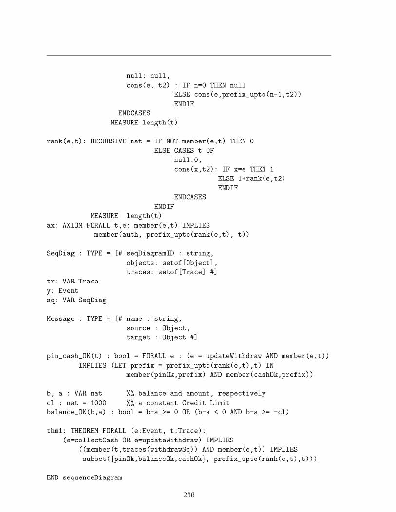
null: null,
cons(e, t2) : IF n=0 THEN null
ELSE cons(e,prefix_upto(n-1,t2))
ENDIF
ENDCASES
MEASURE length(t)
rank(e,t): RECURSIVE nat = IF NOT member(e,t) THEN 0
ELSE CASES t OF
null:0,
cons(x,t2): IF x=e THEN 1
ELSE 1+rank(e,t2)
ENDIF
ENDCASES
ENDIF
MEASURE length(t)
ax: AXIOM FORALL t,e: member(e,t) IMPLIES
member(auth, prefix_upto(rank(e,t), t))
SeqDiag : TYPE = [# seqDiagramID : string,
objects: setof[Object],
traces: setof[Trace] #]
tr: VAR Trace
y: Event
sq: VAR SeqDiag
Message : TYPE = [# name : string,
source : Object,
target : Object #]
pin_cash_OK(t) : bool = FORALL e : (e = updateWithdraw AND member(e,t))
IMPLIES (LET prefix = prefix_upto(rank(e,t),t) IN
member(pinOk,prefix) AND member(cashOk,prefix))
b, a : VAR nat %% balance and amount, respectively
cl : nat = 1000 %% a constant Credit Limit
balance_OK(b,a) : bool = b-a >= 0 OR (b-a < 0 AND b-a >= -cl)
thm1: THEOREM FORALL (e:Event, t:Trace):
(e=collectCash OR e=updateWithdraw) IMPLIES
((member(t,traces(withdrawSq)) AND member(e,t)) IMPLIES
subset({pinOk,balanceOk,cashOk}, prefix_upto(rank(e,t),t)))
END sequenceDiagram
236

C Partial Specification of the Banking System
%%%%%%%%%%%%%%%%%%%%%%%%%%%%%%%%%%%%%%%%%%%%%%%%%%%%%%%
% PVS specification for the Banking system
%% generated from ArgoUML model using the PrUDE tool
%%%%%%%%%%%%%%%%%%%%%%%%%%%%%%%%%%%%%%%%%%%%%%%%%%%%%%%
bank: THEORY
BEGIN
IMPORTING sequenceDiagram
%%%%%%% DECLARATIONS OF TYPES %%%%%%%%
ValueType: TYPE+
ClassID : TYPE+ = string
Event : TYPE+
Trace : TYPE = list[Event]
TransactionKind: TYPE+ = {deposit, withdraw}LedgerKind : TYPE+ = {drawerLedger, creditLedger, debitLedger}
%%%%%%%%% DECLARATIONS OF CLASSES as TYPES %%%%%%%
Transaction: TYPE+ = [# transId: int,
transKind: TransactionKind,
amount: int #]
Account: TYPE+ = [# accountNum : string,
balance : nat,
pin : int,
trans: list[Transaction],
trace : list[Event] #]
Ledger: TYPE+ = [# kind : LedgerKind,
trans : list[Transaction],
amount : int #]
Bank: TYPE+ = [# accounts: setof[Account],
drawer : Ledger,
credit : Ledger,
debit : Ledger #]
%%%%%%% DECLARATIONS OF VARIABLES %%%%%%%
acc, acc1: VAR Account
tr : VAR Trace
t, t2: VAR Transaction
237

b, b1, b2: VAR Bank
l, l1, l2: VAR Ledger
lt : VAR list[Transaction]
%%%%%% CONSTRUCTIVE DEFINITIONS OF OPERATIONS %%%%%
acc_bank_ax: AXIOM (FORALL acc,b1,b2:
accounts(b1)(acc) AND accounts(b2)(acc) IMPLIES b1=b2)
trans_ledger_ax: AXIOM (FORALL l1,l2:
member(t,trans(l1)) AND member(t,trans(l2)) IMPLIES l1=l2)
neg(t): Transaction = t WITH [amount:= -amount(t)]
sum_ledger(lt): recursive int = CASES lt OF
null: 0,
cons(t,lt1): amount(t)+sum_ledger(lt1)
ENDCASES
MEASURE length(lt)
balanced?(b): bool = sum_ledger(trans(drawer(b)))
+ sum_ledger(trans(credit(b)))
+ sum_ledger(trans(debit(b)))= 0
processTrans(t,b): Bank =
IF transKind(t) = withdraw THEN
b WITH [drawer:=drawer(b) WITH [trans:=cons(neg(t),trans(drawer(b)))],
credit:=credit(b) WITH [trans:=cons(t,trans(credit(b)))]]
ELSE IF transKind(t)=deposit THEN
b WITH [drawer:=drawer(b) WITH [trans:=cons(t,trans(drawer(b)))],
debit:=debit(b) WITH [trans:=cons(neg(t),trans(debit(b)))]]
ELSE b
ENDIF
ENDIF
thm1: THEOREM (FORALL t,l: (member(t,trans(l)) AND
(transKind(t)=deposit OR transKind(t)=withdraw)) IMPLIES
(EXISTS t2, l2: member(t2,trans(l2)) AND
(t2=t WITH [amount:= -amount(t)])))
thm2: THEOREM (FORALL t,b: balanced?(b)=> balanced?(processTrans(t,b)))
END bank
238

D Proof of Theorem thm2
thm2 :
|---------------------------------------------------{1} FORALL (t, b): balanced?(b) => balanced?(processTrans(t, b))
Trying repeated skolemization, instantiation, and if-lifting, thenExpanding the definition of sum ledger, and then Expanding thedefinition of processTrans(), this simplifies to: thm2 :
{-1} CASES trans(credit(b!1))OF null: 0, cons(t, lt1): amount(t) + sum ledger(lt1)ENDCASES+CASES trans(debit(b!1))OF null: 0, cons(t, lt1): amount(t) + sum ledger(lt1)ENDCASES
+CASES trans(drawer(b!1))OF null: 0, cons(t, lt1): amount(t) + sum ledger(lt1)ENDCASES
= 0|---------------------------------------------------
{1} CASES IF transKind(t!1) = withdraw THEN cons(t!1, trans(credit(b!1)))ELSE b!1‘credit‘transENDIF
OF null: 0, cons(t, lt1): amount(t) + sum ledger(lt1)ENDCASES+CASES IF transKind(t!1) = withdraw THEN b!1‘debit‘trans
ELSE cons(neg(t!1), trans(debit(b!1)))ENDIF
OF null: 0, cons(t, lt1): amount(t) + sum ledger(lt1)ENDCASES
+CASES IF transKind(t!1) = withdraw
THEN cons(neg(t!1), trans(drawer(b!1)))ELSE cons(t!1, trans(drawer(b!1)))ENDIF
OF null: 0, cons(t, lt1): amount(t) + sum ledger(lt1)ENDCASES
= 0
Lifting IF-conditions to the top level,thm2 :
239

{-1} IF null?(trans(credit(b!1)) THEN(0 + (CASES trans(debit(b!1))
OF null: 0, cons(t, lt1): amount(t) + sum ledger(lt1)ENDCASES)
+(CASES trans(drawer(b!1))OF null: 0, cons(t, lt1): amount(t) + sum ledger(lt1)ENDCASES))
= 0ELSE amount(car(trans(credit(b!1)))) +
sum ledger(cdr(trans(credit(b!1))))+CASES trans(debit(b!1))OF null: 0, cons(t, lt1): amount(t) + sum ledger(lt1)ENDCASES
+CASES trans(drawer(b!1))OF null: 0, cons(t, lt1): amount(t) + sum ledger(lt1)ENDCASES
= 0ENDIF
|---------------------------------------------------{1} IF transKind(t!1) = withdraw
THEN CASES cons(t!1, trans(credit(b!1)))OF null: 0, cons(t, lt1): amount(t) + sum ledger(lt1)ENDCASES+CASES b!1‘debit‘transOF null: 0, cons(t, lt1): amount(t) + sum ledger(lt1)ENDCASES
+CASES cons(neg(t!1), trans(drawer(b!1)))OF null: 0, cons(t, lt1): amount(t) + sum ledger(lt1)ENDCASES
= 0ELSE CASES b!1‘credit‘trans
OF null: 0, cons(t, lt1): amount(t) + sum ledger(lt1)ENDCASES+CASES cons(neg(t!1), trans(debit(b!1)))OF null: 0, cons(t, lt1): amount(t) + sum ledger(lt1)ENDCASES
+CASES cons(t!1, trans(drawer(b!1)))OF null: 0, cons(t, lt1): amount(t) + sum ledger(lt1)ENDCASES
= 0
240

ENDIF
Trying repeated skolemization, instantiation, and if-lifting,
This completes the proof of thm2.
Q.E.D.
241

E Association and Inheritance in UML
inheritance : THEORY
BEGIN%% IMPORTINGIMPORTING bankIMPORTING corepackage
%% TYPE DECLARATIONS - InheritanceInheritance : TYPE+ FROM Relationship
c1, c2 : VAR Classi: VAR Inheritance
inh_ax: AXIOM (source(i)= c1 AND target(i)= c2 IFFchildren(c2)(c1) AND parents(c1)(c2))
%%% DECLARATION CLASS Person AND ITS SUBCLASSES
Person: TYPE+ FROM ClassCustomer : TYPE+ FROM PersonEmployee : TYPE+ FROM Person
%%%%% SOME VARIABLE DECLARATIONS %%%%%%%%b : VAR Bankacc, acc1, acc2 : VAR Accountp, p1, p2 : VAR Personc : VAR Customere: VAR Employee
%%%%%% DECLARATION OF ASSOCIATIONS %%%%%%%%%%%%%owns : [Person -> set[Account]]updates : [Person -> set[Account]]
uses : [Bank -> set[Person]]worksfor : [Bank -> set[Person]]
%%%%%% AXIOMS %%%%%%%%%%%uses_ax: AXIOM (FORALL p,b: uses(b)(p) IFF
(EXISTS acc: accounts(b)(acc) AND (owns(p)(acc) IMPLIESNOT updates(p)(acc))))
worksfor_ax: AXIOM (FORALL p,b: worksfor(b)(p) IFF(EXISTS acc: accounts(b)(acc) AND (updates(p)(acc) IMPLIES
NOT owns(p)(acc))))
242

%%% An employee is not allowed to update his owns accountemp_cust_ax: AXIOM (FORALL e,b,acc: (uses(b)(e) AND worksfor(b)(e))
IMPLIES intersection(owns(e), updates(e)) = emptyset)
%%% Declaration of {xor} constraint as an axiomxor_ax: AXIOM (FORALL p,acc: NOT (owns(p)(acc) IFF updates(p)(acc)))
thm6: THEOREM (FORALL p,b,acc: (worksfor(b)(p) AND uses(b)(p))IMPLIES NOT (owns(p)(acc) IFF updates(p)(acc)))
END inheritance
243

F Proofs of Theorem thm6
thm6 :|--------------{1} (FORALL p,b,acc: (worksfor(b)(p) AND uses(b)(p)) IMPLIES
NOT (owns(p)(acc) IFF updates(p)(acc)))
Rule? (grind :theories ("inheritance"))
Trying repeated skolemization, instantiation, and if-lifting, thisyields 2 subgoals:thm6.1 :
{-1} GeneralizableElement_pred(p!1){-2} Classifier_pred(p!1){-3} Class_pred(p!1){-4} Person_pred(p!1){-5} owns(p!1)(acc!1){-6} updates(p!1)(acc!1)|--------------
Rule? (postpone) Postponing thm6.1
thm6.2 :{-1} GeneralizableElement_pred(p!1){-2} Classifier_pred(p!1){-3} Class_pred(p!1){-4} Person_pred(p!1)|--------------{1} owns(p!1)(acc!1){2} updates(p!1)(acc!1)
Rule? quit
Run time = 1.45 secs.Real time = 50.58 secs.
The two subgoals thm6.1 and thm6.2 generated are not provable. Hence, to prove thetheorem we need to add an axiom (see section 3.4 for details). The following is a successfulproof of theorem thm6.
thm6 :|-------{1} (FORALL p, b, acc:
(workers(b)(p) AND workers(b)(p)) IMPLIESNOT (owns(p)(acc) IFF updates(p)(acc)))
Trying repeated skolemization, instantiation, and if-lifting, thiscompletes the proof of thm6.
Q.E.D.
244
Copyright © 2022 FDOKUMEN