A comparative study on surface topography and ...
21
1 A comparative study on surface topography and microhardness of laser polished-hardened AISI D2 tool steel Zuofa Liu a , Jie Zhou a *, Hang Wang a , Qiuyun Wang a , Qiang Liang b , Yongliang Li b a College of Materials Science and Engineering, Chongqing University, Chongqing 400044, China b College of Mechanical Engineering, Chongqing Technology and Business University, Chongqing, 400060, China *Corresponding author: Email: [email protected] (J Zhou) Abstract: In this work, a laser polishing-hardening (LPH) method with integration and high efficiency for the treatment of AISI D2 tool steel was proposed, and the effects of laser hardening (LH), laser polishing (LP) and LPH treatments on the surface topography and microhardness were examined. The results show that LH method had a negligible effect on the surface roughness of the treated sample, while the surface roughness Ra of LP and LPH specimens was reduced by 74.6% and 80.9% respectively, indicating that the milled surface topography had been significantly improved, especially LPH was more effective in reducing the roughness. Besides, the polishing efficiency of LPH was 10 times that of LP approach. In terms of hardness improvement, the near-surface microhardness of LH and LPH samples increased by 1.5 times and 1.3 times respectively, and the effective hardened zone (EHZ) depth was 0.42 mm and 0.24 mm respectively, demonstrating that these two laser processing methods had a beneficial effect on the cross-section microhardness of D2 tool steel, while the increase of LP on the microhardness was insignificant. The comprehensive analysis of the surface morphology and microhardness of LPH specimen indicates that LPH was a feasible laser surface treatment method for D2 tool steel. On the premise of ensuring a high surface finish, the polishing efficiency can be remarkably improved, the subsurface microhardness and EHZ depth of processed specimen can be also significantly enhanced, which provided a feasible idea for the application of laser surface treatment technology in industrial mold production. Key words: AISI D2 tool steel; surface topography; microhardness; laser polishing; laser hardening; efficiency 1. Introduction As monochromatic radiation and directional non-contact heating source, the laser is extensively used in the surface engineering of metallic materials. Laser surface engineering of tool steel can be mainly divided into laser polishing (LP), laser hardening (LH) and laser cladding (LC). Laser polishing is a method of melting a small amount of material in the
-
Upload
khangminh22 -
Category
Documents
-
view
0 -
download
0
Transcript of A comparative study on surface topography and ...
1
A comparative study on surface topography and microhardness of laser polished-hardened
AISI D2 tool steel
Zuofa Liu a, Jie Zhou a*, Hang Wang a, Qiuyun Wang a, Qiang Liang b, Yongliang Li b
a College of Materials Science and Engineering, Chongqing University, Chongqing 400044, China
b College of Mechanical Engineering, Chongqing Technology and Business University, Chongqing, 400060, China
*Corresponding author:
Email: [email protected] (J Zhou)
Abstract: In this work, a laser polishing-hardening (LPH) method with integration and high efficiency for the treatment
of AISI D2 tool steel was proposed, and the effects of laser hardening (LH), laser polishing (LP) and LPH treatments on
the surface topography and microhardness were examined. The results show that LH method had a negligible effect on
the surface roughness of the treated sample, while the surface roughness Ra of LP and LPH specimens was reduced by
74.6% and 80.9% respectively, indicating that the milled surface topography had been significantly improved,
especially LPH was more effective in reducing the roughness. Besides, the polishing efficiency of LPH was 10 times
that of LP approach. In terms of hardness improvement, the near-surface microhardness of LH and LPH samples
increased by 1.5 times and 1.3 times respectively, and the effective hardened zone (EHZ) depth was 0.42 mm and 0.24
mm respectively, demonstrating that these two laser processing methods had a beneficial effect on the cross-section
microhardness of D2 tool steel, while the increase of LP on the microhardness was insignificant. The comprehensive
analysis of the surface morphology and microhardness of LPH specimen indicates that LPH was a feasible laser surface
treatment method for D2 tool steel. On the premise of ensuring a high surface finish, the polishing efficiency can be
remarkably improved, the subsurface microhardness and EHZ depth of processed specimen can be also significantly
enhanced, which provided a feasible idea for the application of laser surface treatment technology in industrial mold
production.
Key words: AISI D2 tool steel; surface topography; microhardness; laser polishing; laser hardening; efficiency
1. Introduction
As monochromatic radiation and directional non-contact heating source, the laser is extensively used in the surface
engineering of metallic materials. Laser surface engineering of tool steel can be mainly divided into laser polishing (LP),
laser hardening (LH) and laser cladding (LC). Laser polishing is a method of melting a small amount of material in the
2
near-surface zone of tool steel by laser irradiation to refine and homogenize the material structure and then improve the
comprehensive performance such as surface roughness and wear resistance. Similarly, laser hardening is also a common
surface treatment technology using laser as a heating source. The material of metal surface is heated to the austenitizing
temperature by laser energy and then self-quenched to induce martensitic transformation on the surface, resulting in
significant improvement of the surface hardness.
In recent years, considerable progress has been made in laser polishing metal surfaces. Bordatchev et al. [1]
reported that under the optimal parameters, the average surface roughness of several metal materials could be decreased
by 80%, and the processing efficiency could be also reduced by an order of magnitude compared with manual polishing.
Dai et al. [2] adopted the top-hat distribution laser beam with a diameter of 0.2 mm to reduce the initial surface
roughness Ra of SKD 11 tool steel from 3.571 to 0.332 μm. Ukar et al. [3] developed a prediction method for the surface
morphology of laser polishing and then conducted an experiment to verify its effectiveness on DIN 1.2379 tool steel.
Ukar et al. [4] examined the influence of CO2 laser and diode laser on the surface roughness and microstructure of DIN
1.2379 tool steel. Chang et al. [5] investigated the effect of laser energy on surface topography and long-term
performance of polished SKD 61 tool steel by applying a fiber laser. Guo et al. [6] optimized the LP process parameters
of DF-2 tool steel by using the orthogonal design test method. Ma et al. [7] studied the polishing performance of fiber
laser on the surface of as-received Ti-6Al-4V. They found that the surface roughness of Ti-based alloys could be
diminished to 1 μm. Pong-Ryol et al. [8] conducted laser micro-polishing experiments on two different surface forms of
316L stainless steel with a continuous wave laser beam. It was found that the surface roughness of the inclined plane
and curved surface decreased by 56.4% and 57.3%, respectively. Kang et al. [9] developed a laser polishing technology
with ultrasonic vibration, which realized the uniform heating of micro peaks and valleys on the 304 steel surface, and
the surface morphology was remarkably improved. Zhou et al. [10] investigated the influence of laser polishing on the
surface morphology of S316D tool steel by numerical simulation and experimental methods. The experimental results
indicate that the initial surface roughness could be reduced to 0.764 µm, and the error between the actual molten and
simulated pool depth was 5.3%. Lee et al. [11] polished the surface of the as-received Ti-6Al-4V sample. The fatigue
life of laser polished specimens was slightly longer than that of solid specimens due to the reduction of surface
roughness.
In the above laser experiments, the metal surfaces were both polished using laser energy with a small spot diameter
(< 1 mm). Although it can significantly reduce the metal surface roughness and improve the surface morphology, the
polishing efficiency is very low. For example, it takes about 150 minutes to polish a plane with a size of 100 mm×100
mm. In comparison with conventional manual polishing, it has insignificant advantages except for automation.
Moreover, the degree of hardness improvement is negligible due to the small laser energy, and the effective hardening
3
zone (EHZ) depth is only 20~40 μm, which can not satisfy the functional requirements of industrial dies and molds.
At present, it has been well verified that high-power laser beams can be desirably adopted to remarkably enhance
the surface hardness of metallic materials. Muthukumaran, Babu [12] applied a 4 KW high-power diode laser to
strengthen the surface of 2.5Ni-Cr-Mo steel. They found that there was strip martensite in the hardened zone, and the
hardness enlarged to 700 HV, which was 3.5 times that of the base metal. Bande et al. [13] studied the effects of laser
transformation hardening on the microhardness and structure of AISI 01 die steel. Akao et al. [14] found that the
hardness of SKD 11 die steel treated by laser beam increased from 200 HV to 430 HV due to grain refinement and
austenite dissolution. Amine et al. [15] employed a 9 kW CW CO2 laser to study the effect on the microstructure and
hardness of AISI D2 cold working tool steel. The investigation on the microhardness and gradient of laser hardened
AISI 1045 carbon steel using response surface methodology was carried out by Chen et al. [16]. Lesyk et al. [17]
developed a compound surface treatment approach of laser surface hardening and ultrasonic impact treatment and
examined the influences of D2 die steel on surface morphology, hardness and microstructure. Li et al. [18] compared
the effects of laser hardening of AISI 1045 steel applying CO2 laser and high-power diode laser. Dinesh Babu et al. [19]
conducted laser transformation hardening on EN 25 carbon steel using a 2 KW CW laser system and investigated the
effect of process parameters on hardening degree. Lee et al. [20] used a fiber laser as a heating source to enlarge the
surface microhardness and wear resistance of H13 tool steel. Tobar et al. [21] established a three-dimensional numerical
model of laser hardening of H13 die steel, which was conformed by experiments. The results of experiment show that
the measured hardness and depth distribution were well consistent with the numerical prediction.
The ultimate aim of this work is to propose a laser polishing-hardening (LPH) technology with integration and
high efficiency for the treatment of D2 tool steel. On the premise of ensuring a high surface finish, the polishing
efficiency can be remarkably improved, the subsurface microhardness and EHZ depth of the processed specimen can be
also significantly enhanced. Therefore, the surface of AISI D2 tool steel was treated using the laser energy with a large
spot (Φ2.8 mm), and the comparison and analysis of LH, LP and LPH on surface topography and microhardness were
carried out to verify the feasibility of the proposed LPH method.
2. Materials and methods
2.1. Experimental materials
AISI D2 is a cold working tool steel with high wear resistance, hardenability and thermal stability formed by adding Cr,
Mo, V and other elements into carbon steel. It is extensively used in the manufacture of various automobile stamping
dies with large sections, complex structure and heavy working conditions, such as punching die, trimming die, edging
die, stretching die. In this work, D2 tool steel was supplied under annealed conditions and heated to 850 °С, then slowly
4
cooled to 650 °C in the furnace at a rate of 10 °C/h, then taken out and cooled in air. The surface microhardness of tool
steel is 250 HV, and the main chemical composition is given in Table 1.
Table 1 Chemical composition of AISI D2 (wt%)
Elements Cr Mo Mn V Si C Fe
AISI D2 (%) 11.8 0.8 0.35 0.95 0.25 1.55 Bal.
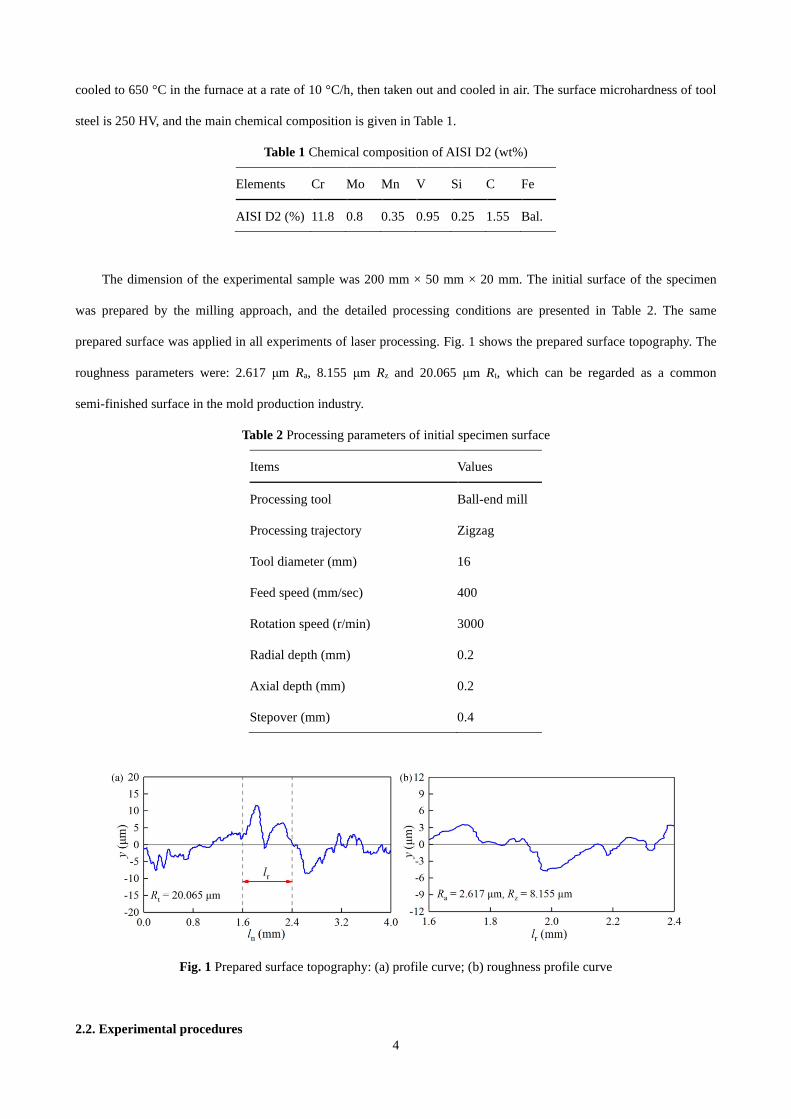
The dimension of the experimental sample was 200 mm × 50 mm × 20 mm. The initial surface of the specimen
was prepared by the milling approach, and the detailed processing conditions are presented in Table 2. The same
prepared surface was applied in all experiments of laser processing. Fig. 1 shows the prepared surface topography. The
roughness parameters were: 2.617 μm Ra, 8.155 μm Rz and 20.065 μm Rt, which can be regarded as a common
semi-finished surface in the mold production industry.
Table 2 Processing parameters of initial specimen surface
Items Values
Processing tool Ball-end mill
Processing trajectory Zigzag
Tool diameter (mm) 16
Feed speed (mm/sec) 400
Rotation speed (r/min) 3000
Radial depth (mm) 0.2
Axial depth (mm) 0.2
Stepover (mm) 0.4
Fig. 1 Prepared surface topography: (a) profile curve; (b) roughness profile curve
2.2. Experimental procedures
5
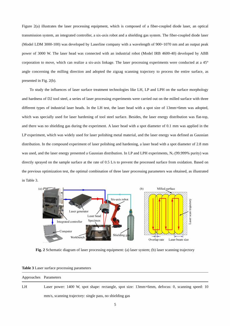
Figure 2(a) illustrates the laser processing equipment, which is composed of a fiber-coupled diode laser, an optical
transmission system, an integrated controller, a six-axis robot and a shielding gas system. The fiber-coupled diode laser
(Model LDM 3000-100) was developed by Laserline company with a wavelength of 900~1070 nm and an output peak
power of 3000 W. The laser head was connected with an industrial robot (Model IRB 4600-40) developed by ABB
corporation to move, which can realize a six-axis linkage. The laser processing experiments were conducted at a 45°
angle concerning the milling direction and adopted the zigzag scanning trajectory to process the entire surface, as
presented in Fig. 2(b).
To study the influences of laser surface treatment technologies like LH, LP and LPH on the surface morphology
and hardness of D2 tool steel, a series of laser processing experiments were carried out on the milled surface with three
different types of industrial laser heads. In the LH test, the laser head with a spot size of 13mm×6mm was adopted,
which was specially used for laser hardening of tool steel surface. Besides, the laser energy distribution was flat-top,
and there was no shielding gas during the experiment. A laser head with a spot diameter of 0.1 mm was applied in the
LP experiment, which was widely used for laser polishing metal material, and the laser energy was defined as Gaussian
distribution. In the compound experiment of laser polishing and hardening, a laser head with a spot diameter of 2.8 mm
was used, and the laser energy presented a Gaussian distribution. In LP and LPH experiments, N2 (99.999% purity) was
directly sprayed on the sample surface at the rate of 0.5 L/s to prevent the processed surface from oxidation. Based on
the previous optimization test, the optimal combination of three laser processing parameters was obtained, as illustrated
in Table 3.
Fig. 2 Schematic diagram of laser processing equipment: (a) laser system; (b) laser scanning trajectory
Table 3 Laser surface processing parameters
Approaches Parameters
LH Laser power: 1400 W, spot shape: rectangle, spot size: 13mm×6mm, defocus: 0, scanning speed: 10
mm/s, scanning trajectory: single pass, no shielding gas
6
LP Laser power: 100 W, spot shape: circular, spot size: Φ0.1 mm, defocus: 3 mm, scanning speed: 30 mm/s,
scanning overlap rate: 50%, scanning trajectory: multi-pass and zigzag, shielding gas: N2 (99.999%
purity), shielding gas flow rate: 0.5 L/s
LPH Laser power: 1000 W, spot shape: circular, spot size: Φ2.8 mm, defocus: 0, scanning speed: 20 mm/s,
scanning overlap rate: 60%, scanning trajectory: multi-pass and zigzag, shielding gas: N2 (99.999%
purity), shielding gas flow rate: 0.5 L/s
2.3. Surface topography
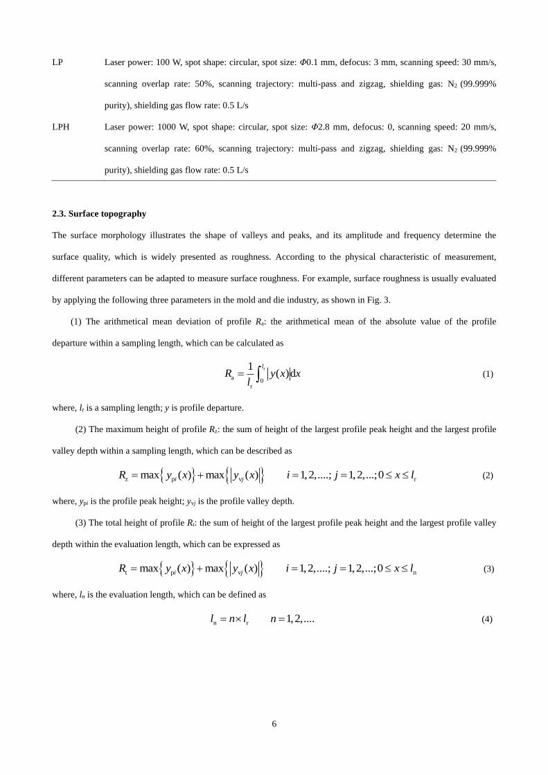
The surface morphology illustrates the shape of valleys and peaks, and its amplitude and frequency determine the
surface quality, which is widely presented as roughness. According to the physical characteristic of measurement,
different parameters can be adapted to measure surface roughness. For example, surface roughness is usually evaluated
by applying the following three parameters in the mold and die industry, as shown in Fig. 3.
(1) The arithmetical mean deviation of profile Ra: the arithmetical mean of the absolute value of the profile
departure within a sampling length, which can be calculated as
r
a0
r
1( )d
l
R y x xl
= (1)
where, lr is a sampling length; y is profile departure.
(2) The maximum height of profile Rz: the sum of height of the largest profile peak height and the largest profile
valley depth within a sampling length, which can be described as
z p vmax ( ) max ( )i jR y x y x= + r1,2,....; 1,2,...;0i j x l= = (2)
where, ypi is the profile peak height; yvj is the profile valley depth.
(3) The total height of profile Rt: the sum of height of the largest profile peak height and the largest profile valley
depth within the evaluation length, which can be expressed as
t p vmax ( ) max ( )i jR y x y x= + n1,2,....; 1,2,...;0i j x l= = (3)
where, ln is the evaluation length, which can be defined as
n rl n l= 1,2,....n = (4)
7
Fig. 3 Parameters for evaluating surface roughness
The surface topography of the processed samples was analyzed by a Leica DVM6S hyperfocal optical
microscope (HOM), the surface roughness was measured with a TIME-3221 profilometer, and the 2D profile
curve and roughness profile curve were extracted using the TIME-3R-2.0 software. The profile curve refers to the
profile of the processed surface within the evaluation length, and the roughness profile curve indicates the micro
profile curve in a certain sampling length. Based on the international standard of geometric terms, definitions and
surface texture parameters (ISO 4287), when the surface roughness Ra is between 0.1 and 2.0 μm, the sampling
length is defined as 0.8 mm and the evaluation length is 4.0 mm. Besides, five different surface roughness
measurements were made for each experiment to obtain an accurate value.
2.4. Cross-section microhardness
The metallographic specimens with the dimensions of 10mm×10mm×5mm were cut by the wire electrical discharge
machine (WEDM) in the direction perpendicular to the laser scanning on the treated D2 tool steel. And, the
cross-sections of the processed specimens were mechanically polished and chemically corroded with a 4% nitric acid +
96% alcohol solution. The analysis and observation of the microstructure in the cross-section were conducted by
adopting a Leica DMILM optical microscope.
Microhardness measurements of the cross-section were carried out using an HV-1000 Vickers microhardness tester
with a 500 g applied load for 15 s and were taken at an increment of 0.1 mm in the vertical direction. The hardness
values were the average of three readings taken along a centerline from the surface of the sample towards the center at
the same depth from the surface.
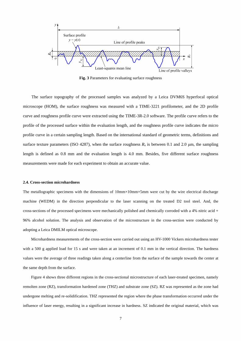
Figure 4 shows three different regions in the cross-sectional microstructure of each laser-treated specimen, namely
remolten zone (RZ), transformation hardened zone (THZ) and substrate zone (SZ). RZ was represented as the zone had
undergone melting and re-solidification. THZ represented the region where the phase transformation occurred under the
influence of laser energy, resulting in a significant increase in hardness. SZ indicated the original material, which was
8
not affected by the laser application. The hardened zone (HZ) depth of the cross-section was defined as the vertical
distance from the sample surface to the bottom of the semi-circular THZ, which was composed of the EHZ depth and
the heat-affected zone (HAZ) depth. According to the international standard on the determination of the effective depth
of hardening (ISO 3754), the EHZ depth is the vertical distance from the test surface to the limiting hardness, and the
limiting hardness of D2 tool steel is 458 HV. The width of the hardened region was the width of the hardness increase of
the material on the treated specimen surface. As the multi-pass strategy is extensively used for laser processing of parts
and tools in actual industrial production, the transversal hardening zone width is not considered in this work.
Fig. 4 Schematic diagram of processed cross-section structure
3. Experimental results
3.1. Effects of LH on specimen characteristics
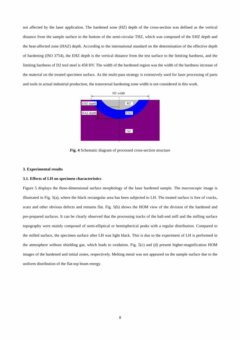
Figure 5 displays the three-dimensional surface morphology of the laser hardened sample. The macroscopic image is
illustrated in Fig. 5(a), where the black rectangular area has been subjected to LH. The treated surface is free of cracks,
scars and other obvious defects and remains flat. Fig. 5(b) shows the HOM view of the division of the hardened and
pre-prepared surfaces. It can be clearly observed that the processing tracks of the ball-end mill and the milling surface
topography were mainly composed of semi-elliptical or hemispherical peaks with a regular distribution. Compared to
the milled surface, the specimen surface after LH was light black. This is due to the experiment of LH is performed in
the atmosphere without shielding gas, which leads to oxidation. Fig. 5(c) and (d) present higher-magnification HOM
images of the hardened and initial zones, respectively. Melting metal was not appeared on the sample surface due to the
uniform distribution of the flat-top beam energy.
9
Fig. 5 3D surface morphologies of LH specimen: (a) macroscopic image; (b) HOM image; (c), (d) higher-magnification
HOM images of hardened and initial surface
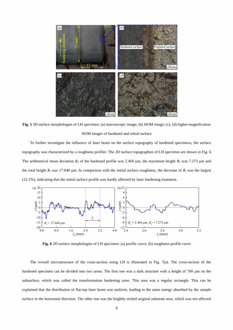
To further investigate the influence of laser beam on the surface topography of hardened specimens, the surface
topography was characterized by a roughness profiler. The 2D surface topographies of LH specimen are shown in Fig. 6.
The arithmetical mean deviation Ra of the hardened profile was 2.468 μm, the maximum height Rz was 7.273 μm and
the total height Rt was 17.640 μm. In comparison with the initial surface roughness, the decrease of Rt was the largest
(12.1%), indicating that the initial surface profile was hardly affected by laser hardening treatment.
Fig. 6 2D surface morphologies of LH specimen: (a) profile curve; (b) roughness profile curve
The overall microstructure of the cross-section using LH is illustrated in Fig. 7(a). The cross-section of the
hardened specimen can be divided into two areas. The first one was a dark structure with a height of 700 μm on the
subsurface, which was called the transformation hardening zone. This area was a regular rectangle. This can be
explained that the distribution of flat-top laser beam was uniform, leading to the same energy absorbed by the sample
surface in the horizontal direction. The other one was the brightly etched original substrate area, which was not affected
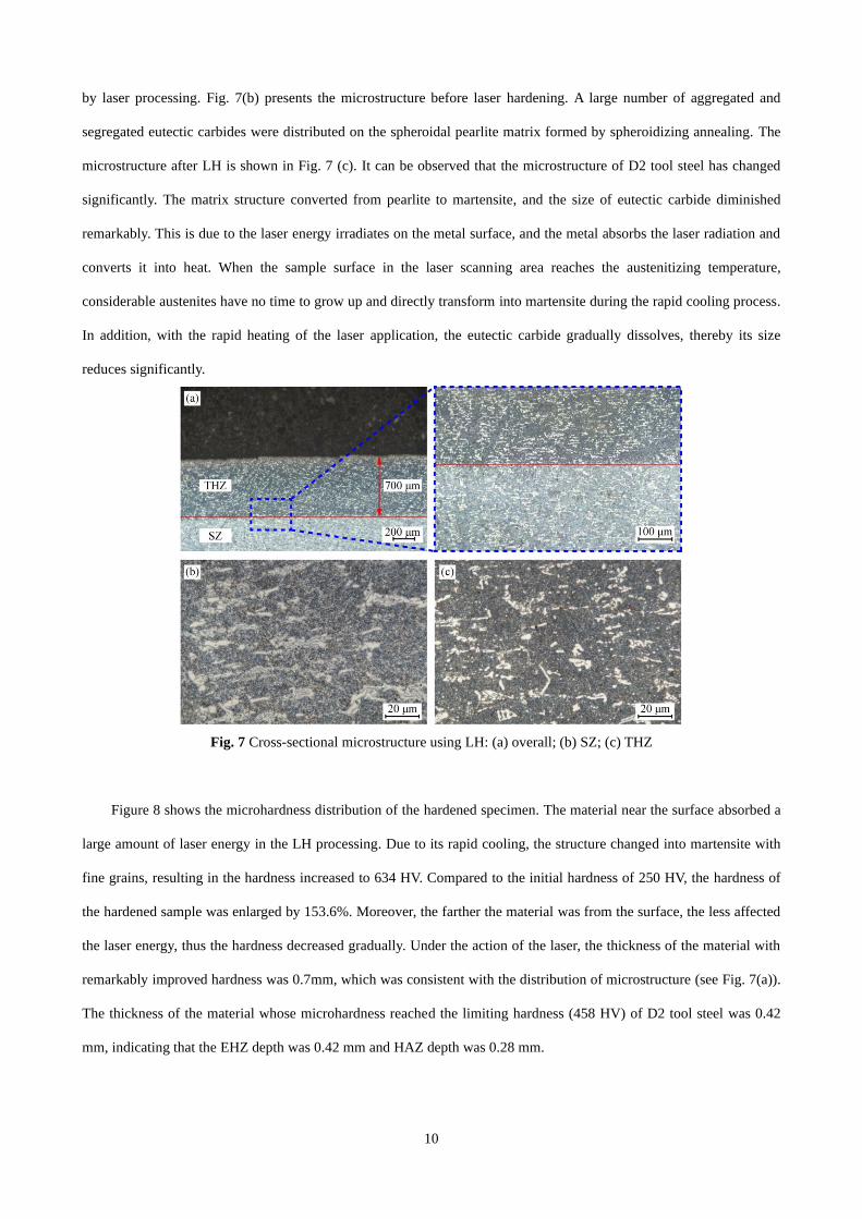
10
by laser processing. Fig. 7(b) presents the microstructure before laser hardening. A large number of aggregated and
segregated eutectic carbides were distributed on the spheroidal pearlite matrix formed by spheroidizing annealing. The
microstructure after LH is shown in Fig. 7 (c). It can be observed that the microstructure of D2 tool steel has changed
significantly. The matrix structure converted from pearlite to martensite, and the size of eutectic carbide diminished
remarkably. This is due to the laser energy irradiates on the metal surface, and the metal absorbs the laser radiation and
converts it into heat. When the sample surface in the laser scanning area reaches the austenitizing temperature,
considerable austenites have no time to grow up and directly transform into martensite during the rapid cooling process.
In addition, with the rapid heating of the laser application, the eutectic carbide gradually dissolves, thereby its size
reduces significantly.
Fig. 7 Cross-sectional microstructure using LH: (a) overall; (b) SZ; (c) THZ
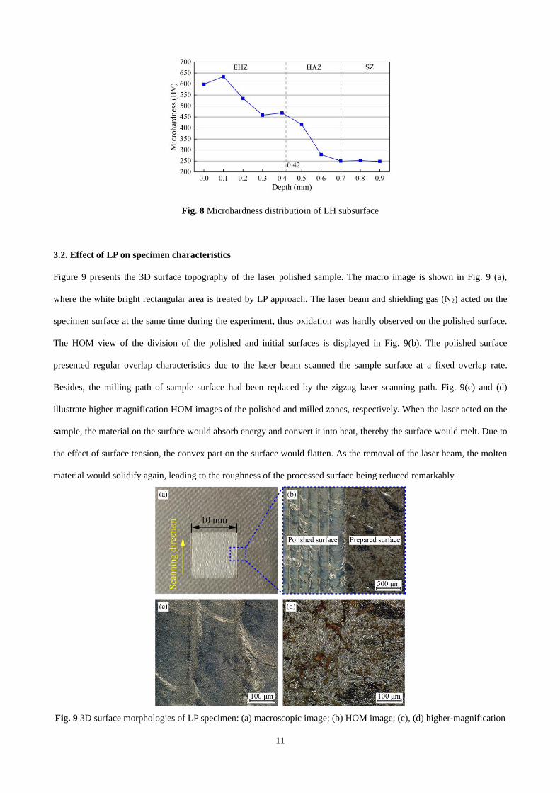
Figure 8 shows the microhardness distribution of the hardened specimen. The material near the surface absorbed a
large amount of laser energy in the LH processing. Due to its rapid cooling, the structure changed into martensite with
fine grains, resulting in the hardness increased to 634 HV. Compared to the initial hardness of 250 HV, the hardness of
the hardened sample was enlarged by 153.6%. Moreover, the farther the material was from the surface, the less affected
the laser energy, thus the hardness decreased gradually. Under the action of the laser, the thickness of the material with
remarkably improved hardness was 0.7mm, which was consistent with the distribution of microstructure (see Fig. 7(a)).
The thickness of the material whose microhardness reached the limiting hardness (458 HV) of D2 tool steel was 0.42
mm, indicating that the EHZ depth was 0.42 mm and HAZ depth was 0.28 mm.
11
Fig. 8 Microhardness distributioin of LH subsurface
3.2. Effect of LP on specimen characteristics
Figure 9 presents the 3D surface topography of the laser polished sample. The macro image is shown in Fig. 9 (a),
where the white bright rectangular area is treated by LP approach. The laser beam and shielding gas (N2) acted on the
specimen surface at the same time during the experiment, thus oxidation was hardly observed on the polished surface.
The HOM view of the division of the polished and initial surfaces is displayed in Fig. 9(b). The polished surface
presented regular overlap characteristics due to the laser beam scanned the sample surface at a fixed overlap rate.
Besides, the milling path of sample surface had been replaced by the zigzag laser scanning path. Fig. 9(c) and (d)
illustrate higher-magnification HOM images of the polished and milled zones, respectively. When the laser acted on the
sample, the material on the surface would absorb energy and convert it into heat, thereby the surface would melt. Due to
the effect of surface tension, the convex part on the surface would flatten. As the removal of the laser beam, the molten
material would solidify again, leading to the roughness of the processed surface being reduced remarkably.
Fig. 9 3D surface morphologies of LP specimen: (a) macroscopic image; (b) HOM image; (c), (d) higher-magnification
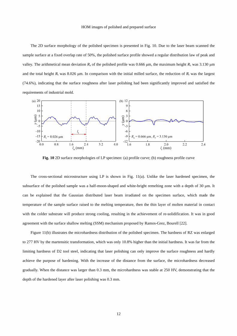
12
HOM images of polished and prepared surface
The 2D surface morphology of the polished specimen is presented in Fig. 10. Due to the laser beam scanned the
sample surface at a fixed overlap rate of 50%, the polished surface profile showed a regular distribution law of peak and
valley. The arithmetical mean deviation Ra of the polished profile was 0.666 μm, the maximum height Rz was 3.130 μm
and the total height Rt was 8.026 μm. In comparison with the initial milled surface, the reduction of Rt was the largest
(74.6%), indicating that the surface roughness after laser polishing had been significantly improved and satisfied the
requirements of industrial mold.
Fig. 10 2D surface morphologies of LP specimen: (a) profile curve; (b) roughness profile curve
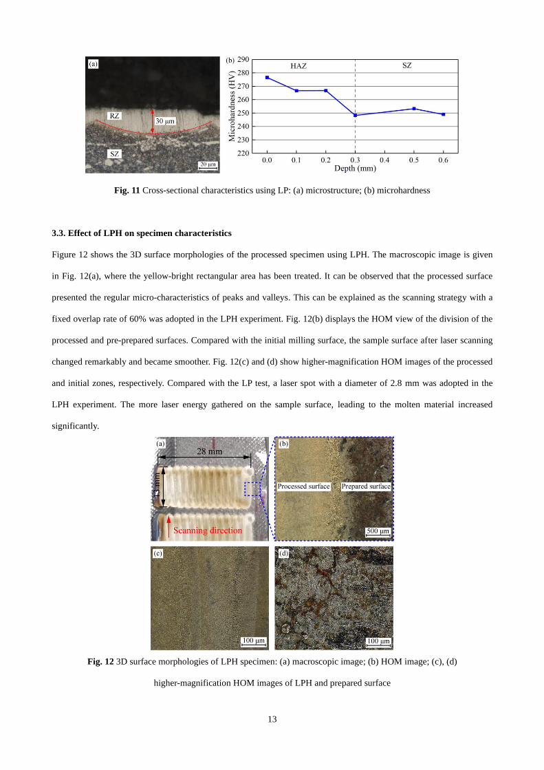
The cross-sectional microstructure using LP is shown in Fig. 11(a). Unlike the laser hardened specimen, the
subsurface of the polished sample was a half-moon-shaped and white-bright remelting zone with a depth of 30 μm. It
can be explained that the Gaussian distributed laser beam irradiated on the specimen surface, which made the
temperature of the sample surface raised to the melting temperature, then the thin layer of molten material in contact
with the colder substrate will produce strong cooling, resulting in the achievement of re-solidification. It was in good
agreement with the surface shallow melting (SSM) mechanism proposed by Ramos-Grez, Bourell [22].
Figure 11(b) illustrates the microhardness distribution of the polished specimen. The hardness of RZ was enlarged
to 277 HV by the martensitic transformation, which was only 10.8% higher than the initial hardness. It was far from the
limiting hardness of D2 tool steel, indicating that laser polishing can only improve the surface roughness and hardly
achieve the purpose of hardening. With the increase of the distance from the surface, the microhardness decreased
gradually. When the distance was larger than 0.3 mm, the microhardness was stable at 250 HV, demonstrating that the
depth of the hardened layer after laser polishing was 0.3 mm.
13
Fig. 11 Cross-sectional characteristics using LP: (a) microstructure; (b) microhardness
3.3. Effect of LPH on specimen characteristics
Figure 12 shows the 3D surface morphologies of the processed specimen using LPH. The macroscopic image is given
in Fig. 12(a), where the yellow-bright rectangular area has been treated. It can be observed that the processed surface
presented the regular micro-characteristics of peaks and valleys. This can be explained as the scanning strategy with a
fixed overlap rate of 60% was adopted in the LPH experiment. Fig. 12(b) displays the HOM view of the division of the
processed and pre-prepared surfaces. Compared with the initial milling surface, the sample surface after laser scanning
changed remarkably and became smoother. Fig. 12(c) and (d) show higher-magnification HOM images of the processed
and initial zones, respectively. Compared with the LP test, a laser spot with a diameter of 2.8 mm was adopted in the
LPH experiment. The more laser energy gathered on the sample surface, leading to the molten material increased
significantly.
Fig. 12 3D surface morphologies of LPH specimen: (a) macroscopic image; (b) HOM image; (c), (d)
higher-magnification HOM images of LPH and prepared surface
14
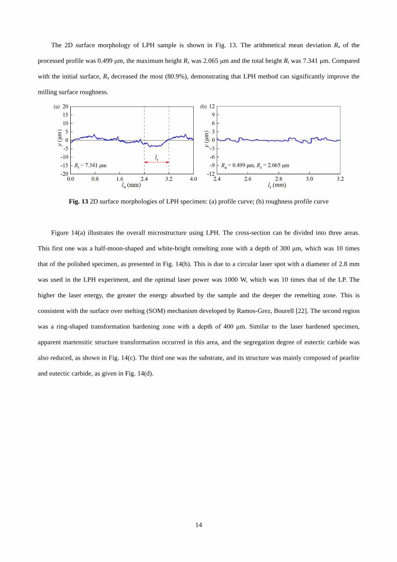
The 2D surface morphology of LPH sample is shown in Fig. 13. The arithmetical mean deviation Ra of the
processed profile was 0.499 μm, the maximum height Rz was 2.065 μm and the total height Rt was 7.341 μm. Compared
with the initial surface, Ra decreased the most (80.9%), demonstrating that LPH method can significantly improve the
milling surface roughness.
Fig. 13 2D surface morphologies of LPH specimen: (a) profile curve; (b) roughness profile curve
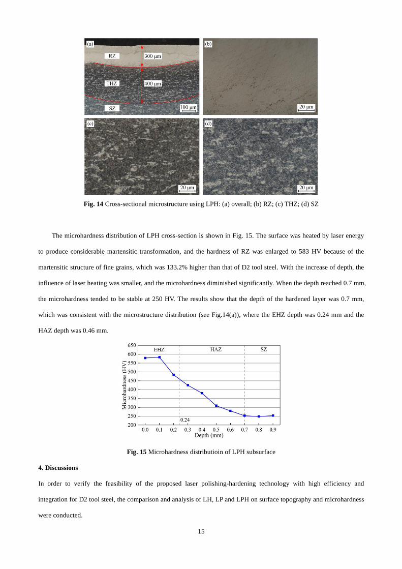
Figure 14(a) illustrates the overall microstructure using LPH. The cross-section can be divided into three areas.
This first one was a half-moon-shaped and white-bright remelting zone with a depth of 300 μm, which was 10 times
that of the polished specimen, as presented in Fig. 14(b). This is due to a circular laser spot with a diameter of 2.8 mm
was used in the LPH experiment, and the optimal laser power was 1000 W, which was 10 times that of the LP. The
higher the laser energy, the greater the energy absorbed by the sample and the deeper the remelting zone. This is
consistent with the surface over melting (SOM) mechanism developed by Ramos-Grez, Bourell [22]. The second region
was a ring-shaped transformation hardening zone with a depth of 400 μm. Similar to the laser hardened specimen,
apparent martensitic structure transformation occurred in this area, and the segregation degree of eutectic carbide was
also reduced, as shown in Fig. 14(c). The third one was the substrate, and its structure was mainly composed of pearlite
and eutectic carbide, as given in Fig. 14(d).
15
Fig. 14 Cross-sectional microstructure using LPH: (a) overall; (b) RZ; (c) THZ; (d) SZ
The microhardness distribution of LPH cross-section is shown in Fig. 15. The surface was heated by laser energy
to produce considerable martensitic transformation, and the hardness of RZ was enlarged to 583 HV because of the
martensitic structure of fine grains, which was 133.2% higher than that of D2 tool steel. With the increase of depth, the
influence of laser heating was smaller, and the microhardness diminished significantly. When the depth reached 0.7 mm,
the microhardness tended to be stable at 250 HV. The results show that the depth of the hardened layer was 0.7 mm,
which was consistent with the microstructure distribution (see Fig.14(a)), where the EHZ depth was 0.24 mm and the
HAZ depth was 0.46 mm.
Fig. 15 Microhardness distributioin of LPH subsurface
4. Discussions
In order to verify the feasibility of the proposed laser polishing-hardening technology with high efficiency and
integration for D2 tool steel, the comparison and analysis of LH, LP and LPH on surface topography and microhardness
were conducted.
16
4.1. Surface morphology
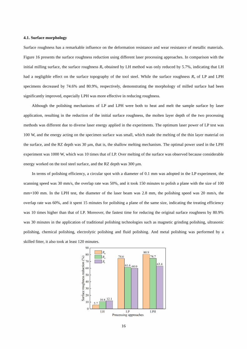
Surface roughness has a remarkable influence on the deformation resistance and wear resistance of metallic materials.
Figure 16 presents the surface roughness reduction using different laser processing approaches. In comparison with the
initial milling surface, the surface roughness Ra obtained by LH method was only reduced by 5.7%, indicating that LH
had a negligible effect on the surface topography of the tool steel. While the surface roughness Ra of LP and LPH
specimens decreased by 74.6% and 80.9%, respectively, demonstrating the morphology of milled surface had been
significantly improved, especially LPH was more effective in reducing roughness.
Although the polishing mechanisms of LP and LPH were both to heat and melt the sample surface by laser
application, resulting in the reduction of the initial surface roughness, the molten layer depth of the two processing
methods was different due to diverse laser energy applied in the experiments. The optimum laser power of LP test was
100 W, and the energy acting on the specimen surface was small, which made the melting of the thin layer material on
the surface, and the RZ depth was 30 μm, that is, the shallow melting mechanism. The optimal power used in the LPH
experiment was 1000 W, which was 10 times that of LP. Over melting of the surface was observed because considerable
energy worked on the tool steel surface, and the RZ depth was 300 μm.
In terms of polishing efficiency, a circular spot with a diameter of 0.1 mm was adopted in the LP experiment, the
scanning speed was 30 mm/s, the overlap rate was 50%, and it took 150 minutes to polish a plane with the size of 100
mm×100 mm. In the LPH test, the diameter of the laser beam was 2.8 mm, the polishing speed was 20 mm/s, the
overlap rate was 60%, and it spent 15 minutes for polishing a plane of the same size, indicating the treating efficiency
was 10 times higher than that of LP. Moreover, the fastest time for reducing the original surface roughness by 80.9%
was 30 minutes in the application of traditional polishing technologies such as magnetic grinding polishing, ultrasonic
polishing, chemical polishing, electrolytic polishing and fluid polishing. And metal polishing was performed by a
skilled fitter, it also took at least 120 minutes.
17
Fig. 16 Surface roughness reduction using different approaches
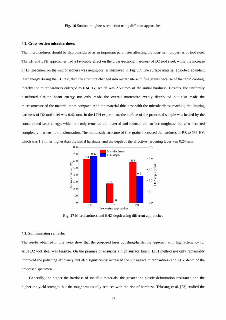
4.2. Cross-section microhardness
The microhardness should be also considered as an important parameter affecting the long-term properties of tool steel.
The LH and LPH approaches had a favorable effect on the cross-sectional hardness of D2 tool steel, while the increase
of LP specimen on the microhardness was negligible, as displayed in Fig. 17. The surface material absorbed abundant
laser energy during the LH test, then the structure changed into martensite with fine grains because of the rapid cooling,
thereby the microhardness enlarged to 634 HV, which was 2.5 times of the initial hardness. Besides, the uniformly
distributed flat-top beam energy not only made the overall martensite evenly distributed but also made the
microstructure of the material more compact. And the material thickness with the microhardness reaching the limiting
hardness of D2 tool steel was 0.42 mm. In the LPH experiment, the surface of the processed sample was heated by the
concentrated laser energy, which not only remelted the material and reduced the surface roughness but also occurred
completely martensitic transformation. The martensitic structure of fine grains increased the hardness of RZ to 583 HV,
which was 1.3 times higher than the initial hardness, and the depth of the effective hardening layer was 0.24 mm.
Fig. 17 Microhardness and EHZ depth using different approaches
4.3. Summarizing remarks
The results obtained in this work show that the proposed laser polishing-hardening approach with high efficiency for
AISI D2 tool steel was feasible. On the premise of ensuring a high surface finish, LPH method not only remarkably
improved the polishing efficiency, but also significantly increased the subsurface microhardness and EHZ depth of the
processed specimen.
Generally, the higher the hardness of metallic materials, the greater the plastic deformation resistance and the
higher the yield strength, but the toughness usually reduces with the rise of hardness. Telasang et al. [23] studied the
18
laser surface hardening of AISI H13 hot working tool steel by adopting a diode laser. They found that the yield strength
of the remelted material on the treated sample surface was significantly improved, but the fatigue strength was
remarkably lower than that of the initial material due to the brittle structure of carbide precipitation at the grain
boundary. It is well-known that automobile stamping dies not only need high hardness to improve the ability to resist
plastic deformation, but also need good toughness to increase the ability to resist fracture. Therefore, to satisfy the
functional requirements of stamping die, potential mechanical behavior changes must also be considered. In the
follow-up investigation, the mechanical properties (such as yield strength, fatigue strength, wear resistance) and
strengthening mechanism of the remelted materials of LPH samples will be studied to further verify the feasibility and
effectiveness of the developed laser polishing-hardening approach.
5. Conclusions
This work proposed a high-efficient laser polishing-hardening technology for the treatment of AISI D2 tool steel surface
and studied the influences of LH, LP and LPH approaches on surface topography and cross-sectional microhardness.
The following conclusions can be drawn.
(1) LH method had a negligible effect on the surface roughness of the treated sample, while the surface roughness Ra
of LP and LPH specimens was reduced by 74.6% and 80.9% respectively, indicating that the milled surface
topography had been significantly improved, especially LPH was more effective in reducing the roughness.
Moreover, the polishing efficiency of LPH was 10 times that of LP approach.
(2) The near-surface microhardness of LH and LPH samples increased by 1.5 times and 1.3 times respectively, and the
effective hardened layer depth was 0.42 mm and 0.24 mm respectively, demonstrating that these two laser
processing methods had a beneficial effect on the cross-section microhardness of D2 tool steel, while the increase
of LP on the microhardness was insignificant.
(3) LPH was a feasible laser surface treatment method for D2 tool steel. On the premise of ensuring a high surface
finish, LPH method not only remarkably improved the polishing efficiency, but also significantly increased the
subsurface microhardness and EHZ depth of processed specimen, which provided an effective idea for the
application of laser surface treatment technology in industrial mold production.
Declarations
Consent to Publish
All authors agree to publication in The International Journal of Advanced Manufacturing Technology.
Authors Contributions
19
Zuofa Liu, Hang Wang and Jie Zhou conceived and designed the study. Zuofa Liu, Hang Wang, Qiuyun Wang and
Yongliang Li performed the experiments. Jie Zhou provided funding. Zuofa Liu and Qiang Liang wrote the paper. Hang
Wang, Qiuyun Wang, Yongliang Li and Jie Zhou reviewed and edited the manuscript. All authors read and approved the
manuscript.
Funding
This research was supported by the National Natural Science Foundation of China (No. 52075058), Chongqing
Graduate Scientific Research and Innovation Foundation (No. CYS21003) and the whole process green
manufacturing process innovation and application project of large and complex aviation die forgings (No.
2018272106).
Competing Interests
The authors declare no declarations of interest.
Availability of data and materials
All data, models, and code generated or used during the study appear in the submitted article.
References
1. Bordatchev E, Cvijanovic S, Tutunea-Fatan OR (2019) Effect of initial surface topography during laser polishing
process: Statistical analysis. Procedia Manufacturing 34:269-274.
doi:https://doi.org/10.1016/j.promfg.2019.06.150
2. Dai W, Li J, Zhang W, Zheng Z (2019) Evaluation of fluences and surface characteristics in laser polishing SKD
11 tool steel. Journal of Materials Processing Technology 273. doi:10.1016/j.jmatprotec.2019.05.022
3. Ukar E, Lamikiz A, Martínez S, Tabernero I, Lacalle L (2012) Roughness prediction on laser polished surfaces.
Journal of Materials Processing Technology 212 (6):1305-1313
4. Ukar E, Lamikiz A, López de Lacalle LN, del Pozo D, Arana JL (2010) Laser polishing of tool steel with CO2
laser and high-power diode laser. International Journal of Machine Tools and Manufacture 50 (1):115-125.
doi:10.1016/j.ijmachtools.2009.09.003
5. Chang C-S, Chen T-H, Li T-C, Lin S-L, Liu S-H, Lin J-F (2016) Influence of laser beam fluence on surface quality,
microstructure, mechanical properties, and tribological results for laser polishing of SKD61 tool steel. Journal of
Materials Processing Technology 229:22-35. doi:10.1016/j.jmatprotec.2015.09.009
6. Guo W, Hua M, Tse PW-T, Mok ACK (2012) Process parameters selection for laser polishing DF2 (AISI O1) by
Nd:YAG pulsed laser using orthogonal design. The International Journal of Advanced Manufacturing Technology
59 (9-12):1009-1023. doi:10.1007/s00170-011-3558-1
20
7. Ma CP, Guan YC, Zhou W (2017) Laser polishing of additive manufactured Ti alloys. Optics and Lasers in
Engineering 93:171-177. doi:10.1016/j.optlaseng.2017.02.005
8. Pong-Ryol J, Tae-Sok J, Nam-Chol K, Xing F, kum-Hyok J (2015) Laser micro-polishing for metallic surface
using UV nano-second pulse laser and CW laser. The International Journal of Advanced Manufacturing
Technology 85 (9-12):2367-2375. doi:10.1007/s00170-015-7992-3
9. Kang D, Zou P, Wu H, Wang W, Xu J (2021) Research on ultrasonic vibration-assisted laser polishing of the 304
stainless steel. Journal of Manufacturing Processes 62:403-417. doi:10.1016/j.jmapro.2020.12.009
10. Zhou H, Zhou H, Zhao Z, Li K, Yin J (2021) Numerical Simulation and Verification of Laser-Polishing Free
Surface of S136D Die Steel. Metals 11 (3). doi:10.3390/met11030400
11. Lee S, Ahmadi Z, Pegues JW, Mahjouri-Samani M, Shamsaei N (2021) Laser polishing for improving fatigue
performance of additive manufactured Ti-6Al-4V parts. Optics & Laser Technology 134.
doi:10.1016/j.optlastec.2020.106639
12. Muthukumaran G, Babu PD (2021) Metallurgical characterization of laser hardened, mechanically textured 2.5
Ni-Cr-Mo low alloy steel and optimization using RSM. Optics & Laser Technology 141.
doi:10.1016/j.optlastec.2021.107126
13. Bande H, L'Espérance G, Islam MU, Koul AK (2013) Laser surface hardening of AISI 01 tool steel and its
microstructure. Materials Science and Technology 7 (5):452-457. doi:10.1179/mst.1991.7.5.452
14. Akao T, Sakurai Y, Onda T, Uehara K, Chen Z-c (2014) Surface Modification of Cold-working Die Steel by
Electron Beam Irradiation – Formation of Cemented Carbide Composite Layer. Procedia Engineering
81:1939-1944. doi:10.1016/j.proeng.2014.10.261
15. Amine T, Newkirk JW, El-Sheikh HE-DF, Liou F (2014) Microstructural and hardness investigation of tool steel
D2 processed by laser surface melting and alloying. The International Journal of Advanced Manufacturing
Technology 73 (9-12):1427-1435. doi:10.1007/s00170-014-5882-8
16. Chen C, Zeng X, Wang Q, Lian G, Huang X, Wang Y (2020) Statistical modelling and optimization of
microhardness transition through depth of laser surface hardened AISI 1045 carbon steel. Optics & Laser
Technology 124. doi:10.1016/j.optlastec.2019.105976
17. Lesyk DA, Martinez S, Dzhemelinskyy VV, Lamikiz А, Mordyuk BN, Prokopenko GI (2015) Surface microrelief
and hardness of laser hardened and ultrasonically peened AISI D2 tool steel. Surface and Coatings Technology
278:108-120. doi:10.1016/j.surfcoat.2015.07.049
18. Li R, Jin Y, Li Z, Qi K (2014) A Comparative Study of High-Power Diode Laser and CO2 Laser Surface
Hardening of AISI 1045 Steel. Journal of Materials Engineering and Performance 23 (9):3085-3091.
21
doi:10.1007/s11665-014-1146-x
19. Dinesh Babu P, Buvanashekaran G, Balasubramanian KR (2012) Experimental investigation of laser
transformation hardening of low alloy steel using response surface methodology. The International Journal of
Advanced Manufacturing Technology 67 (5-8):1883-1897. doi:10.1007/s00170-012-4616-z
20. Lee J-H, Jang J-H, Joo B-D, Son Y-M, Moon Y-H (2009) Laser surface hardening of AISI H13 tool steel.
Transactions of Nonferrous Metals Society of China 19 (4):917-920. doi:10.1016/s1003-6326(08)60377-5
21. Tobar MJ, Álvarez C, Amado JM, Ramil A, Saavedra E, Yáñez A (2006) Laser transformation hardening of a tool
steel: Simulation-based parameter optimization and experimental results. Surface and Coatings Technology 200
(22-23):6362-6367. doi:10.1016/j.surfcoat.2005.11.067
22. Ramos-Grez JA, Bourell DL (2004) Reducing surface roughness of metallic freeform-fabricated parts using
non-tactile finishing methods. Int J Mater Prod Technol 21 (4):297-316. doi:10.1504/ijmpt.2004.004944
23. Telasang G, Dutta Majumdar J, Padmanabham G, Manna I (2014) Structure–property correlation in laser surface
treated AISI H13 tool steel for improved mechanical properties. Materials Science and Engineering: A
599:255-267. doi:10.1016/j.msea.2014.01.083