A comparative study of arbitration algorithms for the Alpha 21364 pipelined router
13
Document downloaded from: This paper must be cited as: The final publication is available at Copyright http://dx.doi.org/10.1145/605432.605421 http://hdl.handle.net/10251/43338 ACM Mukherjee, S.; Silla Jiménez, F.; Bannon, P.; Emer, J.; Lang, S.; Webb, D. (2002). A comparative study of arbitration algorithms for the Alpha 21364 pipelined router. ACM SIGPLAN Notices. 37(10):223-234. doi:10.1145/605432.605421.
-
Upload
independent -
Category
Documents
-
view
1 -
download
0
Transcript of A comparative study of arbitration algorithms for the Alpha 21364 pipelined router

Document downloaded from:
This paper must be cited as:
The final publication is available at
Copyright
http://dx.doi.org/10.1145/605432.605421
http://hdl.handle.net/10251/43338
ACM
Mukherjee, S.; Silla Jiménez, F.; Bannon, P.; Emer, J.; Lang, S.; Webb, D. (2002). Acomparative study of arbitration algorithms for the Alpha 21364 pipelined router. ACMSIGPLAN Notices. 37(10):223-234. doi:10.1145/605432.605421.

Tenth International Conference on Architectural Support for Programming Languages and Operating Systems (ASPLOS), 2002
1
A Comparative Study of Arbitration Algorithms for the Alpha 21364 Pipelined Router
Shubhendu S. Mukherjee*, Federico Silla$, Peter Bannon
!, Joel Emer*, Steve Lang*, and David Webb
!
ABSTRACT Interconnection networks usually consist of a fabric of
interconnected routers, which receive packets arriving at their
input ports and forward them to appropriate output ports.
Unfortunately, network packets moving through these routers
are often delayed due to conflicting demand for resources, such
as output ports or buffer space. Hence, routers typically
employ arbiters that resolve conflicting resource demands to
maximize the number of matches between packets waiting at
input ports and free output ports. Efficient design and imple-
mentation of the algorithm running on these arbiters is critical
to maximize network performance.
This paper proposes a new arbitration algorithm called
SPAA (Simple Pipelined Arbitration Algorithm), which is
implemented in the Alpha 21364 processor’s on-chip router
pipeline. Simulation results show that SPAA significantly
outperforms two earlier well-known arbitration algorithms:
PIM (Parallel Iterative Matching) and WFA (Wave-Front
Arbiter) implemented in the SGI Spider switch. SPAA outper-
forms PIM and WFA because SPAA exhibits matching
capabilities similar to PIM and WFA under realistic conditions
when many output ports are busy, incurs fewer clock cycles to
perform the arbitration, and can be pipelined effectively.
Additionally, we propose a new prioritization policy called the
Rotary Rule, which prevents the network’s adverse perfor-
mance degradation from saturation at high network loads by
prioritizing packets already in the network over new packets
generated by caches or memory.
1. INTRODUCTION
Cache-coherent, shared-memory multiprocessors with 16 or
more processors have become common server machines. In
2001 such machines generated a total revenue of $9 billion,
which is roughly 16% of the world-wide server revenue [6].
This market segment’s revenue tripled in the last four years
making it the fastest growing segment of the entire server
market. Major vendors, such as IBM [8][37], Hewlett-Packard
[19][17][26], SGI [33], and Sun Microsystems [6] offer such
shared-memory multiprocessors, which scale up to anywhere
between 24 and 512 processors.
High performance interconnection networks are critical to
the success of large-scale shared-memory multiprocessors. Such
networks allow a large number of processors and memory
modules to communicate with one another using a cache
coherence protocol. In such systems, a processor’s cache miss
to a remote memory module (or another processor’s cache) and
consequent miss response are encapsulated in network packets
and delivered to the appropriate processors or memories. The
performance of many parallel applications, such as database
servers [29], depends on how rapidly and how many of these
miss requests and responses can be processed by the system.
Consequently, it is extremely critical for networks to deliver
packets with low latency and high bandwidth.
An interconnection network usually consists of a fabric of
small interconnected routers, which receive packets arriving at
their input ports and forward them to appropriate output ports.
Unfortunately, packets moving through such routers are often
delayed due to conflicting demand for resources, such as output
ports or buffer space. Hence, routers include arbiters to resolve
conflicting resource demands (Figure 1). The presence of input
buffers in a router usually divides up the arbitration process into
two steps: first an input port picks one or more packets from
those waiting in its buffers, and then an output port picks a
packet among the packets nominated to it by one or more input
ports. By definition only one packet can be delivered through
an output port.
This paper examines several arbitration algorithm choices
for the on-chip router in the Alpha 21364 processor [3], which
runs at 1.2 GHz and uses 152 million transistors to integrate on
the same chip an aggressive dynamically-scheduled processor,
1.75 megabytes of second-level cache, two Rambus Direct
RDRam™ memory controllers, and an interconnection network
router. Efficient design and implementation of these arbiters is
critical to maximize network throughput, as illustrated by
Figure 2. Typically, arbitration algorithms try to maximize the
number of matches between input and output ports to provide
high local routing throughput. A locally maximal match in a
router does not necessarily guarantee globally optimal network
Figure 1. A router with 8 input ports and 7 output ports, like the Alpha 21364 router. The arbiter controls how and which packets are forwarded from the input to the output ports.
C R
O
S S
B
A
R
Input
Ports
Output
Ports
Arbiter
Router
*Intel Corporation
334 South Street
Shrewsbury, MA 01545
{shubu.mukherjee,joel.emer,steve.lang}@intel.com
!Hewlett-Packard
334 South Street
Shrewsbury, MA 01545
{peter.bannon,david.webb}@hp.com
$Department of Computer Engineering
Universidad Politecnica de Valencia
Camino de Vera s/n, 46022 Valencia, Spain

2
performance. Nevertheless, in our experience, a locally
maximal match has the first order impact on overall network
performance.
The high-frequency implementation of the Alpha 21364
router made the already difficult task of arbitration even harder.
The entire 21364 chip, including the router, runs at 1.2 GHz. In
contrast, earlier generations of such routers ran at much slower
speeds. For example, the Cray T3E router runs at 75 MHz [31],
the SGI Spider runs at 100 MHz [16], while IBM’s third
generation Vulcan switch runs at 125 MHz [35].
For efficient implementation at 1.2 GHz, we had to pipeline
the 21364 router. Unfortunately, in the 0.18 micron CMOS
process that the 21364 was designed for, only up to 12-13 logic
levels could be incorporated in the 0.83 nanoseconds cycle
time. This forced us to pipeline the arbitration algorithm itself,
unlike the SGI switch in which the algorithm was implemented
within one 10-nanosecond clock cycle. Unfortunately, each
additional cycle added to the 21364 router’s arbitration pipeline
degraded the network throughput by roughly 5% under heavy
load1. Hence, any additional cycles incurred by a more
complex arbitration algorithm must gain back the performance
degradation from the added cycles in the pipeline.
This paper shows that SPAA (Simple Pipelined Arbitration
Algorithm)—implemented in the 21364 router—significantly
outperforms two well-known arbitration algorithms—Parallel
Iterative Matching (PIM) [2] and Wavefront Arbitration (WFA)
[36], which is implemented in the SGI Spider switch. For
completeness, we also examine a maximal cardinality matching
algorithm (MCM), which maximizes the number of matches
between packets waiting at the input ports and free output ports.
The number of matches found by PIM and WFA between
packets waiting at input ports and free output ports is close to
that of MCM’s, which makes both PIM and WFA very
powerful arbitration algorithms. PIM iterates between the input
and output ports to find a suitable match of packets, whereas
WFA makes a pass through a matrix of input and output ports
to find a suitable match.
The key to PIM and WFA’s high matching capabilities lies
in their high level of interaction between input and output ports.
1 This measurement was done using SPAA, which is explained later.
When multiple input ports nominate packets to the same output
port, naïve algorithms, such as OPF in Figure 2, can result in
arbitration “collisions” and consequent poor performance. In
contrast, both PIM and WFA’s input and output port arbiters
will interact to choose the appropriate match for the specific
arbitration cycle. Unfortunately, such high level of interaction
requires a higher number of cycles to implement them com-
pared to what a simpler algorithm, such as SPAA, would need.
Additionally, such interaction also makes it hard to pipeline
these algorithms.
SPAA is a much simpler algorithm compared to PIM and
WFA and is more like the OPF algorithm in Figure 2. In
SPAA, each input port chooses a packet in every cycle to
nominate to an output port. However, an input port arbiter’s
choice is independent of most of the other input port arbiters.
Similarly, an output port arbiter chooses a packet from the
packets nominated to it by the input port arbiters. But, an
output port arbiter’s decision is independent of the other output
port arbiters’ decisions. Thus, SPAA minimizes interactions
between the input and output ports.
Clearly, because of its reduced interaction between input
and output port arbiters, SPAA can result in arbitration
collisions at the output port and, hence, fewer matches than
what PIM or WFA would offer. Nevertheless, SPAA signifi-
cantly outperforms both algorithms because of three reasons.
First, with medium to heavy loads many output ports are busy
and, hence, an arbitration algorithm need only find matches for
a few free output ports. Thus, when our seven output ports are
busy 50% of the time, SPAA’s matching capabilities are similar
to PIM and WFA’s. The difference between PIM, WFA, and
SPAA’s matching capabilities is negligible when the output
ports are busy 75% of the time.
Second, SPAA minimizes its interaction between input and
output ports, which lowers its matching capabilities, but makes
it simpler, so that it can be implemented in three cycles in the
21364 router. WFA would have incurred four cycles to
implement. Similarly, one iteration of PIM takes four cycles to
implement. Multiple iterations of PIM would have incurred
significantly more cycles and would have obviously performed
poorly in our environment. Hence, we use only one iteration of
PIM—which we call PIM1—in all our timing evaluations.
Third, SPAA can be pipelined effectively because it mini-
mizes interactions between the input and output ports. PIM1
requires an extra step of interaction between the output and
input ports, whereas WFA requires interaction between the
output ports themselves. These features prevent both PIM1 and
WFA from being pipelined effectively. In our implementation
both PIM1 and WFA take four cycles, but can start input port
arbitration every three cycles, whereas SPAA takes three cycles
and can initiate input port arbitration every cycle.
Additionally, SPAA nominates a packet to only one output
port, unlike PIM or WFA, which can nominate the same packet
to multiple output ports. This has the added benefit that a
packet can be speculatively read out from an input buffer as
soon as it is scheduled for delivery by an input port arbiter (but
before the output port arbitration is complete), much like the
way direct-mapped caches allow processors to speculatively
read out data before the address comparison completes [20].
Our simulation results show that SPAA significantly outper-
forms both PIM1 and WFA. We also demonstrate that SPAA
will continue to deliver higher throughput compared to PIM1
Input Port 0 3 2 1
Input Port 1 3 2 1
Input Port 2 3 2 1
Input Port 3 3 2 1
Input Port 4 3 6 1
Input Port 5 3 2 0
Input Port 6 3 2 4
Input Port 7 3 2 5
Figure 2. An illustration of the challenges of an arbitration algorithm for the router in Figure 1. The first column lists the input ports. Column 2 – 4 list the output port destinations of the packets waiting at that input port. Column 2 contains the oldest packets to arrive at the specific input port, while column 4 lists the corresponding youngest packets. An arbitration algorithm (lets call it OPF) that picks the oldest packet from each input port will be sub-optimal because output port 3 can deliver only one packet. Thus, OPF will result in arbitration collisions at output port 3. In contrast, an arbitration algorithm that chooses the shaded packets will have the maximum throughput at this router in the current arbitration cycle.

3
and WFA, if the router were scaled to have twice the pipeline
length, greater input load, or support bigger networks than the
21364 was designed for.
In addition to SPAA, we propose a new prioritization policy
called the Rotary Rule, which provides a significant boost in
network performance by preventing the network’s adverse
performance degradation from saturation at high network loads.
The Rotary Rule prioritizes the movement of network packets
already in the network over packets recently generated from the
processor ports. We demonstrate the effectiveness of the
Rotary Rule with WFA and SPAA. The Alpha 21364 router
provides the Rotary Rule as an optional mode programmable at
boot-time. We do not, however, expect most real applications
running on a system composed of 21364 processors to create
such heavy network load that would require us to turn on the
Rotary Rule.
The rest of the paper is organized as follows. We first de-
scribe the 21364’s base router architecture in Section 2. Section
3 discusses PIM, WFA, SPAA, and the Rotary Rule, as well as
related work. Section 4 discusses our evaluation methodology
and Section 5 describes our results. Section 6 summarizes the
paper and presents our conclusions.
2. THE ALPHA 21364 ON-CHIP ROUTER
Mukherjee, et al. [26] discusses details of the 21364 net-
work and router architectures. Here we summarize the salient
features of the network (Section 2.1) and the router pipeline
(Section 2.2) relevant to this paper.
2.1 21364 Network Architecture
The Alpha 21364’s on-chip router uses two million transis-
tors to connect up to 128 processors in a two-dimensional torus
network (Figure 3). Salient features of the network are:
Packets. The network supports seven classes of coherence
packets for the directory-based cache-coherence protocol.
These are requests (three flits), forwards (three flits), block
response (18 or 19 flits), non-block response (two or three
flits), write I/O (19 flits), read I/O (three flits), and special
(one flit, excluding no-ops). Each flit is 39 bits—32 bits for
data and 7 bits for ECC. A 19 flit packet, such as a block
response, can carry a 64-byte cache block (3 flits for header
and 16 flits for the cache block). Thus, when an input or an
output port is scheduled to deliver a packet, the port can be
busy for two, three, 18, or 19 cycles. An output port is ready
for re-arbitration once all flits of a packet are delivered via the
port.
Virtual Cut-Through Routing. The 21364 uses virtual cut-
through routing in which flits of a packet proceed through
multiple routers until the header flit gets blocked at a router.
Then, all flits of the packet are buffered at the blocking router
until the congestion clears. Subsequently, the packet is
scheduled for delivery through the router to the next router
and the same pattern repeats. To support virtual cut-through
routing, the 21364’s router provides buffer space for 316
packets per input port [26]. Note that a packet is never
dropped from the network in the absence of errors.
Adaptive Routing in the Minimal Rectangle. In the 21364,
packets adaptively route within the minimum rectangle.
Given two points in a torus (in this case, the current router
and the destination processor), one can draw four rectangles
that contain these two points as their diagonally opposite
vertices. The minimum rectangle is the one with the minimum
diagonal distance between the current router and the destina-
tion. Thus, the adaptive routing algorithm has to pick one
output port among a maximum of two output ports that a
packet can route in. Packets that follow adaptive routing may
not be delivered in order, but the coherence protocol in 21364
is designed to handle out of order traffic.
Virtual Channels. The 21364 router uses virtual channels [9]
to break deadlocks in the coherence protocol and the routing
algorithms. It assigns a virtual channel group to each coher-
ence packet class. By design, these virtual channel groups are
ordered, such that a request packet can never block a block
response packet. Each group (except the special class)
contains three virtual channels: adaptive, VC0, and VC1.
Packets adaptively route within the adaptive channel until
they get blocked.2 Blocked packets are then routed in the
2 This is only true for non-I/O packets. Read and Write I/O packets only
route in the deadlock-free channels to adhere to the Alpha 21364’s I/O
ordering rules.
Figure 3. A 12-processor Alpha 21364 2D torus network.
Figure 4. Two of the nine logical router pipelines in the 21364. (a) shows the router pipeline for a local input port (cache or memory controller) to an interprocessor output port (b) shows the router pipeline from an interprocessor (north, south, east, or west) input port to an interprocessor output port. The first flit goes through two pipelines: the scheduling pipeline (upper pipeline) and data pipeline (lower pipeline). Second and subsequent flits follow the data pipeline. RT = Router Table Lookup, Nop = No operation, T = Transport (wire delay), DW = Decode and Write Entry Table, LA = Input Port Arbitration, RE = Read Entry Table and Transport, GA = Output Port Arbitration, W = Wait, WrQ = Write Input Queue, RQ = Read Input Queue, X = Crossbar, and ECC = Error Correction Code. This paper focuses on the LA, RE, and GA stages of the pipeline.
(a)
Nop Nop Nop WrQ W RQ X ECC
First Flit
Second Flit
DW LA RE GA
Nop WrQ W RQ X ECC
(b)
ECC Nop WrQ W RQ X ECC
First Flit
Second Flit
DW LA RE GA
Nop WrQ W RQ ECC X ECC
T
Nop Nop
RT
21364
Chip
Rambus
Memory I/O
M
IO
M
IO
M
IO
M
IO
M
I
O
M
I
O
M
I
O
M
I
O M
I
O
M
I
O
M
I
O
M
I
O

4
deadlock-free channels, VC0 and VC1, which follow strict
dimension-order routing. Duato [13] has shown that such a
scheme breaks routing deadlocks in such networks. Because
of virtual cut-through routing, however, packets can return
from the deadlock-free channels to the adaptive channel. For
performance reasons, the adaptive channels have the bulk of
the packet buffers, whereas the VC0 and VC1 typically have
one or two buffers. In the 21364 there is a total of 19 virtual
channels (three for each of the six non-special coherence
classes and one for the special class).
Ports. Each port is 39 bits wide to match the network’s flit
size. Each router has eight input ports and seven output ports.
The input ports include four 2D torus ports (north, south, east,
and west), one cache port (that sends cache miss requests,
etc.), two memory controller ports (that sends responses to
cache miss requests), and one I/O port. The buffers at each
input port have two read ports to allow the arbitration algo-
rithm greater choice in matching inputs to outputs. Like the
input ports, the output ports are divided into four 2D torus
ports (north, south, east, and west), two memory controller
ports, and one I/O port. Inside the processor, the two memory
controller ports are also tied to the internal cache and, hence,
there is no separate explicit cache output port.
2.2 21364 Router Pipeline
The 21364’s router has nine pipeline types based on the
input and output ports. There are three types of input and
output ports: local (cache and memory controllers), interproces-
sor (off-chip network), and I/O. Any type of input port can
route packets to any type of output port, leading to nine types of
pipeline. Figure 4 shows two such pipeline types.
As Figure 4 shows, the router pipeline in the 21364 consists
of several stages that perform router table lookup, decoding,
arbitration, forwarding via the crossbar, and ECC calculations.
A packet originating from the local port looks up its routing
information from the router table and loads it up in its header.
The decode stage decodes a packet’s header information and
writes the relevant information into an entry table, which
contains the arbitration status of packets and is used in the
subsequent arbitration pipeline stages.
The 21364’s arbitration pipeline, which is the focus of this
paper, consists of three stages: LA (input port arbitration), RE
(Read Entry Table and Transport), and GA (output port
arbitration).3 The input port arbitration stage finds packets
from the input buffers and nominates one of them for output
port arbitration. Each input buffer has two read ports and each
read port has an input port arbiter associated with it. Thus, the
21364 has a total of 16 input port arbiters. The input port
arbiters perform several readiness tests, such as determining if
the targeted output port is free, using the information in the
entry table.
The output port arbiters accept packet nominations from the
input port arbiters and decide which packets to dispatch. Each
output port has one arbiter, so the 21364 has a total of seven
output port arbiters. Once an output port arbiter selects a
packet for dispatch, it informs the input port arbiters of its
decision, so that the input port arbiters can re-nominate the
unselected packets in subsequent cycles.
Figure 5 shows the crossbar connection between the input
and output port arbiters. Although the connections form a
crossbar between input and output ports, the individual read
ports are not connected to all the output ports. The same
crossbar connection is followed by the datapath in the X stage
of the pipeline (Figure 4).
In addition to the basic pipeline latency, there are six addi-
tional delay cycles along the path of a packet, including
synchronization delay, pad receiver and driver delay, and
transport delay from the pins to the router and from the router
back to the pins. Thus, the on-chip pin-to-pin latency from a
network input to a network output is 13 cycles. At 1.2 GHz,
this leads to a pin-to-pin latency of 10.8 nanoseconds.
Also, the network links that connect the different 21364
chips run at 0.8 GHz, which is 33% slower than the internal
router clock. The input port arbitration internally nominates
packets at the appropriate cycles so that packets leaving the
router are synchronized with the off-chip network clock.
3. ARBITRATION ALGORITHMS
In the 21364 router, the 16 input port arbiters and 7 output
port arbiters work together to implement the arbitration
algorithm. The 21364 router’s arbitration problem can be
modeled in two ways. First, it can be modeled as a matching
problem in a bipartite graph with 16 input port arbiters and 7
output port arbiters. Each connection between the input and
output port arbiters will carry a certain “weight.” Then, a
Maximum Weight Matching (MWM) algorithm, will try to find
a match that maximizes the total weight of the connections
selected by the match. Examples of such MWM algorithms are
LQF (longest queue first), which uses the number of waiting
packets at an input port as the weight for a connection, and OCF
(oldest cell first), which uses the waiting time for the oldest
packet at an input buffer as the weight for a connection [24].
Unfortunately, the MWM algorithms require O(N3) iterations in
the worst case [25], which makes it very difficult to implement
them in hardware in a few cycles. Also, approximations of the
MWM algorithm, such as RPA [1], MUCS [12], Laura and
Serena [25], and Apsara [18], are also not implementable in
hardware within a few cycles.
3 The 21364 router’s input and output port arbiters are also referred to as
local arbiters (LA) and global arbiters (GA), respectively [26].
G-N G-S G-E G-W G-L0 G-L1 G-I/O
L-N rp0
L-N rp1
L-S rp0
L-S rp1
L-E rp0
L-E rp1
L-W rp0
L-W rp1
L-Cache rp0
L-Cache rp1
L-MC0 rp0
L-MC0 rp1
L-MC1 rp0
L-MC1 rp1
L-I/O rp0
L-I/O rp1
Figure 5. The 21364 router’s connection matrix. This figure represents the router’s crossbar connections in a matrix format. “G-X” denotes output port arbiter for output port X. “L-X rpY” denotes input port arbiter for input port X and read port Y. The shaded boxes represent no connection.

5
In this paper, as an upper bound we use an algorithm called
the Maximal Cardinality Matching Algorithm (MCM), which is
basically MWM with all connections having equal weights.
MCM exhaustively searches the space for the maximum
number of matches between input and output port arbiters. We
use MCM only in our non-timing simulations because we do
not know how to implement MCM in hardware within a few
cycles.
Another way to model the arbitration problem is to use a
two-dimensional “connection” matrix with input ports forming
the rows and output ports forming the columns. Such a
representation makes it easier for us to explain the arbitration
algorithms we study in this paper. In this representation, an
input port nominates packets to output ports by filling up the
corresponding row in the matrix. An output port chooses
packets from input ports by scanning the corresponding column
in the matrix.
Figure 5 shows the connection matrix for the 21364 router.
Given this representation, an arbitration algorithm for the 21364
router then needs to answer the following questions:
Which packets should an input port arbiter nominate to an
output port arbiter? An input port arbiter can pick packets
out of all the buffers in each of the 19 virtual channels. For
correctness and improved performance, each input port arbiter
(independent of the arbitration algorithm) obeys some basic
constraints, such as whether the corresponding output port is
free to dispatch a packet. Each input port arbiter then selects
the oldest packet, which satisfies the basic constraints, from
the least-recently selected virtual channel. An input port
arbiter fills up the corresponding row in the connection matrix
with the packets it selects.
Can the same packet be nominated multiple times? Any
packet can proceed along a maximum of two directions
because 21364 adaptively routes packets within the minimal
rectangle (Section 2.1). Thus, a packet can be nominated to at
most two output port arbiters. Multiple nominations have the
advantage that a packet would have a greater probability of
being dispatched in the same cycle. However, multiple
nominations of the same packet also imply extra interaction
between input and output ports to ensure that the same packet
is not dispatched through two different output ports.
Which packets should an output port arbiter pick from the
packets nominated to it by the input port arbiters? An output
port arbiter examines its corresponding column for packets
nominated to it by all the input port arbiters. Then, to select a
packet from a column it can use a variety of policies, such as
random [11], round-robin [31], least-recently selected [35],
some kind of a priority chain [10], or the “Rotary Rule.”
Such prioritization policies are easily implemented in hard-
ware via a priority matrix. We describe the implications of
some of these policies later in this section. Section 3.4
describes the Rotary Rule in detail.
Can there be multiple iterations (or passes) through the
matrix? Multiple iterations through the nomination and
selection procedure allow the arbitration algorithm to find
more matches compared to a single iteration. However,
multiple iterations would also incur higher number of cycles
to perform the arbitration.
Answers to the above questions have important implications on
the hardware implementation of an arbitration algorithm. For
example, these choices determine how much synchronization is
required among all the 23 arbiters (16 for input, 7 for output) in
the router and whether the arbitration algorithm can be
effectively pipelined.
The rest of this section discusses how PIM, WFA, and
SPAA answer the above questions (Sections 3.1, 3.2, and 3.3).
Section 3.4 describes the Rotary Rule and how it can be
incorporated into WFA and SPAA.
3.1 Parallel Iterative Matching
The Parallel Iterative Matching (PIM) algorithm, proposed
by Anderson, et al. [2], was designed to quickly identify a set of
conflict-free packets for transmission through an ATM switch.
PIM works extremely well in such ATM switches where the
matching algorithm may be implemented in software. The key
to PIM’s success lies in its interaction between input and output
port arbiters, which avoids arbitration collisions incurred by
naïve algorithms, such as OPF (Figure 2).
Below we describe the algorithm’s three key steps for the
21364 router:
1. Nominate. Each unmatched input port arbiter nominates a
packet for each output port arbiter for which it has a pack-
et. The same packet can be nominated to multiple output
port arbiters.
2. Grant. If an unmatched output port arbiter receives any
requests, it accepts one randomly and informs the corre-
sponding input port arbiter of its decision.
3. Accept. If an input port arbiter receives grants for multiple
output port arbiters, it selects one randomly. PIM iterates over the above three steps until the algorithm
converges. According to Anderson, et al. [2], PIM usually
converges within log2N iterations, so the 21364 router would
need four iterations (N = 16 input port arbiters) of the above
three steps. Researchers have proposed variations of PIM,
such as iSLIP [23] that can be implemented in hardware, but
their matching capabilities are similar to PIM’s. PIM has two properties that make it difficult to implement
in hardware in a few cycles. First, it can nominate the same
packet to multiple output port arbiters, even though multiple
output port arbiters cannot dispatch the same packet. PIM
avoids multiple dispatches using an additional synchronization
step (Step 3) between the input and output port arbiters.
Unfortunately, this synchronization makes it difficult for input
port arbiters to nominate other packets until they receive their
grants from the output port arbiters. In other words, it is hard to
do input port arbitrations in consecutive cycles, which makes it
difficult to pipeline PIM.
Second, PIM requires multiple iterations of its three steps.
This would further increase the delay of the algorithm. Hence,
we use a variant of PIM called PIM1, which is PIM with one
iteration of its three steps. McKeown has shown, however, that
PIM1’s matching capabilities are significantly worse than
PIM’s [24].
In our evaluation, we assume that PIM1 takes four cycles
for arbitration. We would implement PIM1 using a centralized
16x7 connection matrix, which receives inputs from the input
port arbiters and lets output port arbiters iterate over its
columns. The first three cycles of the four cycles consist of
matrix operations and wire delays: 1.5 cycles to select packets
from the input ports and load up the matrix (i.e., nominate) and
1.5 cycles to grant and accept (via passes over the matrix). The
speed at which the matrix can be evaluated is limited because of

6
dependences between the input and output ports and the limited
number of logic levels (12-13) per cycle in our process
technology. Further, PIM1 requires a random number genera-
tor, which will require a few additional logic levels.
In this implementation of PIM1, a new arbitration can be
started every three cycles because nominate, grant, and accept
take a total of three cycles. Starting a grant or accept before the
prior nominate step is difficult because of two reasons. First,
the total nominations for the matrix could be up to 54 (unshaded
boxes in Figure 5). Keeping track of these large number of in-
flight packets (i.e., nominated, but not delivered) would require
additional state and could increase the number of cycles
incurred by PIM1. Second, we would have to maintain multiple
copies of the matrix to act as buffers for the pipeline stages for
the arbiters. These matrices must be consistent with one
another and should not be loaded with stale packets. Again,
this may further increase the number of cycles incurred by
PIM1.
The fourth cycle of PIM1’s four-cycle arbitration accounts
for wire delays from the matrix to the output ports and can be
pipelined.
3.2 Wave-Front Arbiter
Tamir and Chi [36] proposed the Wave-Front Arbiter
(WFA) for routers in interconnection networks. WFA has been
implemented in the SGI Spider interconnect [16]. WFA is a
much lighter-weight algorithm than PIM1 and could be used
effectively in routers that operate at a much lower frequency
than that of the 21364 router. For example, WFA in the Spider
switch operates at 100 MHz and is implemented within a single
10 nanosecond clock cycle. Also, the key to WFA’s success
lies in its interaction among the input port arbiters and among
the output port arbiters, which allows it to avoid arbitration
collisions that may be incurred by naïve algorithms, such as
OPF (Figure 2).
WFA operates on the entire connection matrix as a whole.
First, the input port arbiters load up the matrix with their
nominations. Then, evaluation of the matrix starts from a
specific cell in the matrix. The evaluation proceeds in a wave
front as follows (Figure 6):
Granti,j = Request i,j and Ni,j and Wi,j
Si,j = Ni,j and NOT(Granti,j)
Ei,j = Wi,j and NOT(Granti,j)
The connection matrix is represented in hardware as a two-
dimensional array of arbitration cells. The position of each cell
in the connection matrix is denoted by i,j. Request denotes that
an input port arbiter has nominated a packet for that arbitration
cell. Grant denotes that the specific arbitration cell has been
chosen for packet delivery. Then, following the above equa-
tions, no other cell in the same row (i.e., same input port
arbiter) and no other cell in the same column (i.e., same output
port arbiter) as the granted cell, would select any other packet
for dispatch. Also, note that Ni,j = Si-1,j and Wi,j = Ei,j-1.
Thus, as Figure 6 shows, if the evaluation starts with wave-
front 1, then the cell (0,0) will be evaluated first, followed by
the cells (0,1) and (1,0), which make up wavefront 2.
Subsequent wavefronts will be evaluated in this fashion.
To ensure fairness, the first cell from where the wave fronts
begin must be chosen carefully. Tamir and Chi suggested using
a robin-robin scheme to choose the first cell. We will refer to
this scheme as WFA-base. Section 3.4 will show how to use the
Rotary Rule to choose the first cell, which we will refer to as
WFA-rotary.
Although the WFA is very appealing, it is not amenable to
efficient pipelining. This is because input port arbiters in
WFA, like in PIM, can nominate the same packet to multiple
output port arbiters. PIM uses synchronization between input
and output port arbiters (Step 3 in PIM) to avoid multiple
dispatches of the same packet. In contrast, WFA requires
communication between the output port arbiters—via the
propagation of the N and S signals along the columns—to avoid
dispatching the same packet through multiple output port
arbiters. Note that WFA uses the same mechanism—i.e.,
interaction among output port arbiters—to avoid arbitration
collisions and, thereby, provide good matching performance.
Thus, interaction between output port arbiters is fundamental to
the WFA algorithm. Additionally, micropipelining the matrix
operations themselves—by pipelining the “waves” of the
WaveFront Arbiter—is difficult because the starting cell (as
indicated in the last paragraph) changes every cycle.
We assume a four-cycle arbitration delay for the WFA. Our
timing is optimistically based on the Wrapped Wave-Front
Arbiter, proposed by Tamir and Chi. The Wrapped WFA
provides matching performance similar to that of WFA’s, but
executes faster in hardware by starting multiple wavefronts in
parallel. As in PIM1, the first three cycles of WFA’s four-cycle
arbitration are spent on matrix operations and wire delays: 1.5
cycles to nominate packets and load up the matrix and 1.5
cycles to evaluate the matrix. WFA suffers from the same
problems as PIM1 (Section 3.1) and hence a new arbitration can
only be restarted every three cycles. Again, as in PIM1, the
fourth cycle accounts for wire delays from the matrix to the
output ports and can be pipelined.
3.3 Simple Pipelined Arbitration Algorithm
The Simple Pipelined Arbitration Algorithm (SPAA) im-
plemented in the 21364 carefully minimizes the impact of
features, such as interaction between input and output ports,
which would be hard to pipeline. However, this also makes its
matching performance much worse than PIM1 and WFA
because it may not be able to avoid arbitration collisions
(Figure 2), particularly in the presence of a large number of free
output ports. Thus, in terms of its matching capability, SPAA
is more like OPF from Figure 2.
Figure 6. Operations of the Wave-Front Arbiter (WFA) for a 4x4 connection matrix. (a) The dotted lines (with circled numbers) show the wave fronts. Each square represents an arbitration cell with coordinates i,j. (b) This figure shows an arbitration cell (i,j) of the WFA matrix.
(b)
(b)
E
N
S
W
Grant
Request
(a)
i,j
1 2 3 4
5
6
7
0,0 0,1 0,2 0,3
1,0 1,1 1,2 1,3
2,0 2,1 2,2 2,3
3,0 3,1 3,2 3,3

7
Like PIM, SPAA has three steps:
1. Nominate. Each input port arbiter nominates a packet for
only one output port arbiter, if there is one. A nominated
packet cannot be nominated again in subsequent cycles
until Step 3 of this algorithm completes.
2. Grant. If an output port arbiter receives multiple requests,
it selects the packet from the least-recently selected input
port arbiter. Then, it informs all input port arbiters con-
nected to it of its decision.
3. Reset. An input port arbiter resets the state of all nominat-
ed packets that are not selected by the output port arbiter,
so that they can be nominated again.
SPAA has three important properties that make it amenable to
easy hardware implementation and pipelining. First, unlike
PIM1 or WFA, an input port arbiter nominates a packet to only
one output port arbiter. This avoids the extra interaction
required between the input and output port arbiters (as in PIM1)
or between the output port arbiters (as in WFA). Nevertheless,
because a pair of input port arbiters shares the same set of input
buffers via different read ports, the input port arbiters in a pair
must synchronize to ensure that they do not choose the same
packet. However, because the synchronization is between pairs
of input port arbiters located in close proximity, this is not hard
to implement.
Nominating a packet to only one output port also has the
added benefit that a packet can be speculatively read out from
an input buffer as soon as it is nominated by an input port
arbiter (but before the output port arbitration is complete), much
like the way direct-mapped caches allow processors to
speculatively read out data before the address comparison
completes [20]. Of course, the read is wasted if the output port
does not select the specific packet that was speculatively read
out.
Second, SPAA can be implemented as a distributed router
with the input and output port arbiters sitting right next to their
corresponding ports. In contrast, because of PIM1 and WFA’s
high level of interaction between input and output ports, it is
easier to implement PIM1 and WFA using a centralized
connection matrix. The distributed implementation of SPAA
allows it to directly send input port nominations from the input
to the output ports without an intervening connection matrix.
This helps reduce the number of cycles incurred by SPAA.
Third, SPAA need only maintain a small list of in-flight
packets—that is, only 16—because each input port can only
nominate a maximum of one packet. In contrast, aggressive
and more complicated implementations of PIM1 and WFA
would have required us to maintain state for 54 in-flight
packets, which would complicate their implementation.
SPAA’s small number of in-flight packets (i.e., nominated from
the input port, but not yet accepted by the output port) facili-
tates effective pipelining of SPAA. Thus, unlike PIM1 and
WFA, new input port arbitrations in SPAA can be restarted
every cycle.
Thus in summary, SPAA incurs only three cycles (Figure 4)
for its arbitration compared to the four cycles required by PIM1
or WFA and SPAA can be pipelined effectively, so that an
input port arbitration can be started every cycle. SPAA’s three
cycles consist of input port arbitration (i.e., nominate), transport
from input to output port, and output port arbitration (Figure 4).
SPAA’s Step 2 (Grant) selects packets based on the least-
recently selected policy. We call this SPAA-base. In the next
subsection, we discuss how SPAA can use the rotary rule to
select an input port arbiter. We call this SPAA-rotary.
3.4 Rotary Rule
Under extremely heavy loads most multiprocessor networks
suffer from tree saturation [28][30], which can dramatically
degrade a network’s performance beyond the saturation point
(Figure 7). Such tree saturation occurs when multiple packets
contend for a single resource (e.g., a link between nodes)
creating a hot spot. Since only one packet can use the resource,
other packets must wait. These waiting packets occupy buffers
and thus delay other packets, even though they may be destined
for a completely different node and share only one link on their
paths to their respective destinations. This process continues
and waiting packets delay other packets producing a tree of
waiting packets that fans out from the original hot spot.
Eventually, this clogs the network bringing down the delivered
throughput of the entire network.
The 21364 network is no exception and can get saturated at
extremely high load levels. Interestingly, the network produces
a cyclic pattern of network link utilization with extremely high
levels of uniform random input traffic. This is because as the
network gets saturated, it puts backpressure on the links in the
tree. Eventually, this backpressure throttles the routers in the
tree and forces them to avoid injecting new traffic, which
causes the network congestion to clear up slowly. The period
of this cycle increases with the diameter of the network because
it takes longer to fill up the buffers on the path and propagate
the backpressure.
Ideally, we would like network throughput to remain at the
same level as exhibited at the saturation point, instead of
degrading dramatically beyond the saturation point. Most
proposed solutions rely on throttling the input network load
based on some estimate of congestion, so that the network never
goes beyond the saturation point. Lopez, et al. [21][22] use the
number of busy virtual channels in a router to estimate
congestion. Baydal, et al. [4] proposes an approach that counts
a subset (free and useful) of virtual channel buffers to decide
whether to throttle or not. Other researchers (e.g., [34], [30],
[38]) have proposed the use of a variety of global heuristics to
determine congestion.
Fortunately, the 21364 network has two properties that limit
the network load. First, a 21364 processor can have only 16
outstanding cache miss requests to remote memory or caches.
This limits the load the 21364 network can observe.
Second, the 21364 is a “direct” network in which the same
router is responsible for both new traffic (originating from the
Figure 7. Possible network behavior with increasing network load. Network performance degrades rapidly beyond the saturation point.
Increasing Network Load
Delivered
Throughput
saturation
point
degradation
beyond
saturation
point

8
local ports, such as the cache port or memory controller ports)
and cross-traffic between routers. Thus, prioritizing the cross-
traffic over new traffic generated from the local ports has the
beneficial effect of both clearing the network congestion as well
as throttling the input load into the network. We call this
prioritization policy the “Rotary Rule.” The name is derived
from the Massachusetts rotaries in which vehicles in the rotary
has higher priority to exit than vehicles trying to enter the
rotary.
It is easy to implement the Rotary Rule for PIM1, WFA,
and SPAA. In PIM1 and SPAA, the output port arbiters would
select packets nominated by the input port arbiters for the
network ports before they select packets from the local ports.
Within the network ports, we use least-recently used selection
policy. In WFA, the selection of the first cell to start the
arbitration process would follow the Rotary Rule. Thus, cells
connected to the input port arbiters for the network ports would
get the highest priority to be the first cell from where the
wavefronts will start. In this paper, we only evaluate the Rotary
Rule for WFA and SPAA. We call these variants WFA-rotary
and SPAA-rotary, respectively.
The Rotary Rule’s prioritization of cross-traffic packets can
create starvation in the network. The 21364 router implements
an anti-starvation algorithm for certain corner cases. The
Rotary Rule simply relies on this anti-starvation algorithm to
clear any starvation caused by its prioritization policy. The
anti-starvation algorithm assigns two different colors to packets
waiting at a router: an old color and a new color. If the number
of old colored packets exceed a threshold, the 21364 ensures
that all the old colored packets are drained before any new
colored packets are routed. Further discussion of the anti-
starvation algorithm is beyond the scope of this paper.
The 21364 network provides the Rotary Rule as an optional
mode programmable at boot time. It is an optional mode
because we believe most applications will not stress the
network to the extent of pushing it into saturation. Neverthe-
less, we provide it both as a “safety net” for the 21364 proces-
sor and as a mechanism that may have allowed its use in future
processors with many more outstanding misses (e.g., the next
generation Alpha 21464 processor would have had 64 outstand-
ing misses).
4. METHODOLOGY
This section describes our performance model, traffic pat-
terns, and performance metric.
4.1 Performance Model
Our evaluation of the 21364’s arbitration algorithm choices
is based on two kinds of performance models written in the
Asim framework [15], unlike Bhuyan [5] or Peh and Dally [27],
who had used analytical modeling to understand the behavior of
arbiters and routers4. Our first model—what we call the
standalone model—allows us to evaluate the matching
capabilities of MCM, PIM, PIM1, WFA, and SPAA in a single
21364 router (just like a cache simulator would allow one to
evaluate the cache miss ratio without any timing information).
Our second model—what we call the timing model—is an
extremely detailed performance model of the 21364 router. We
4 Bhuyan’s paper pre-dates PIM1 and WFA. Peh and Dally focused on
developing analytical models for router pipelines, but did not compare the
performance of different arbitration algorithms.
have validated this model against a production-level perfor-
mance model of the 21364 network architecture. We have
modeled the detailed timing characteristics of PIM1, WFA-
base, WFA-rotary, SPAA-base, and SPAA-rotary using this
timing model.
We described most of the parameters of the timing runs in
Section 2.2 and Section 3. In addition, we assume 73 nanosec-
onds for the memory system’s response time, 25 cycles for the
on-chip L2 cache’s response time, and 3 network clocks
(running at 0.8 GHz) for latency on each network link. Most of
the results we present in this paper are for a 16-processor (4x4)
network and a 64-processor (8x8) network. Although the
21364 network only scales up to 128 processors, Section 5.3
examines results for a 144-processor (12x12) network to
understand how the arbitration algorithms may scale for larger
network configurations.
4.2 Traffic Patterns
We evaluate our timing models using a mix of synthetic
traffic patterns as opposed to real workloads. Simulations of
real workloads, such as database servers, would have helped us
make more accurate predictions about the performance impact
of the different arbitration algorithms. Such simulation,
however, would have required complex full-system simulation
(including the operating system), which our modeling infra-
structure is unable to handle today. Trace-driven simulation
would have been an alternative, but that also has its limitations
[7].
Nevertheless, synthetic workloads have two advantages.
First, they often tend to increase the contention for resources for
sub-optimal/worst case performance scenarios [39]. Second,
they represent communication patterns in many real-world
applications [14].
Recently, Towles and Dally [39] demonstrated a technique
to construct synthetic traffic patterns that result in worst-case
performance for oblivious routers. Unfortunately, there is no
known similar technique for adaptive routers, such as the
21364.
Our synthetic patterns can be defined along two dimensions.
The first dimension selects the mix of coherence packets. We
use 70% two coherence hop transactions (3-flit request and a
19-flit block response) and 30% three coherence hop transac-
tions (3-flit request, 3-flit forward, and a 19-flit block response)
to model a mix of coherence traffic. We, however, ignore
traffic generated from cache replacements or invalidations to
make our analysis simpler.5 Note that a coherence hop only
specifies a single packet, which can take multiple router hops
via the network.
The second dimension selects the destination of the requests
and forwards. We use three patterns for such selection:
uniform, bit-reversal, and perfect-shuffle. If the bit-coordinate
of the source processor can be represented as (an-1, an-2, ...a1,a0),
then the destination bit-coordinates for bit-reversal and perfect-
shuffle are (a0,a1,...,an-2,an-1) and (an-2,an-3,...,a0,an-1) respectively.
4.3 Performance Metric
We use the Burton Normal Form (BNF) [14] to express the
performance of our different arbitration algorithms. A BNF
graph uses observed latency as its vertical axis and delivered
5 The 21364 processor can have 16 outstanding cache replacement requests.
9
throughput as its horizontal axis. For our BNF graphs, we use
the average latency of a packet through the network as the
vertical axis. The minimum per-packet latency with a 4x4
network, uniform random distribution of destinations, and a
70/30 mix of 2-hop and 3-hop coherence transactions is about
45 ns (nanoseconds). The 45 ns can be broken into 2.5 ns of
local port latency, 34 ns of network transit latency for the first
flit, and 8.5 nanoseconds of latency for the rest of a packet.
The last number is averaged across the different packet sizes for
our coherence transaction mixes.
We represent the delivered throughput as flits/router/ns
(where ns = nanoseconds). The maximum throughput is two
flits/router/cycle because the 21364 router has two local ports to
sink packets and only one flit can be delivered to a local port
per cycle. Thus, the maximum delivered throughput can be 2.4
flits/router/nanosecond (= 2 / 0.83). In reality, however, the
actual delivered throughput will be significantly lower because
the network links are 33% slower than the processor and the
network links often carry cross-traffic, whose residence time in
the network increases with the size of the network.
We ran each timing simulation for 75,000 cycles. We have
validated that simulation for this number of cycles is sufficient
to predict the steady-state behavior of the network.
5. RESULTS
This section presents our standalone, timing, and scaling
results. Although we present our results only for a subset of the
network sizes and traffic patterns, our results are qualitatively
similar across a wide spectrum of the design space.
5.1 Standalone Results
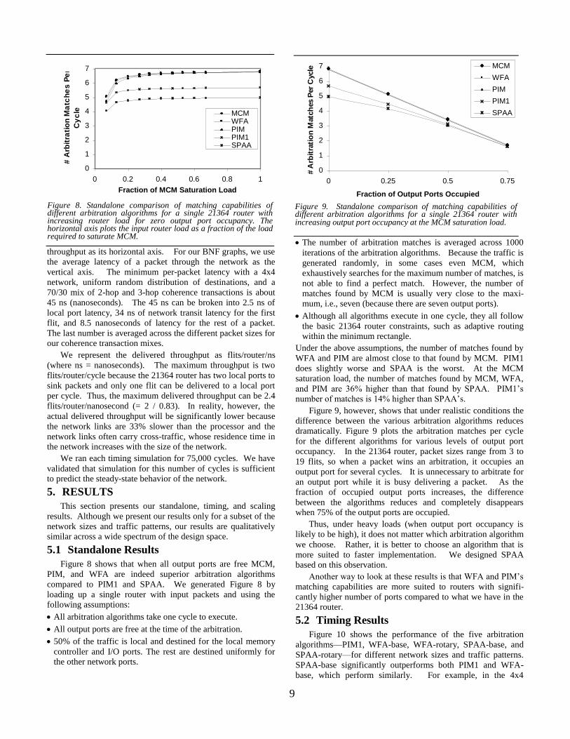
Figure 8 shows that when all output ports are free MCM,
PIM, and WFA are indeed superior arbitration algorithms
compared to PIM1 and SPAA. We generated Figure 8 by
loading up a single router with input packets and using the
following assumptions:
All arbitration algorithms take one cycle to execute.
All output ports are free at the time of the arbitration.
50% of the traffic is local and destined for the local memory
controller and I/O ports. The rest are destined uniformly for
the other network ports.
The number of arbitration matches is averaged across 1000
iterations of the arbitration algorithms. Because the traffic is
generated randomly, in some cases even MCM, which
exhaustively searches for the maximum number of matches, is
not able to find a perfect match. However, the number of
matches found by MCM is usually very close to the maxi-
mum, i.e., seven (because there are seven output ports).
Although all algorithms execute in one cycle, they all follow
the basic 21364 router constraints, such as adaptive routing
within the minimum rectangle.
Under the above assumptions, the number of matches found by
WFA and PIM are almost close to that found by MCM. PIM1
does slightly worse and SPAA is the worst. At the MCM
saturation load, the number of matches found by MCM, WFA,
and PIM are 36% higher than that found by SPAA. PIM1’s
number of matches is 14% higher than SPAA’s.
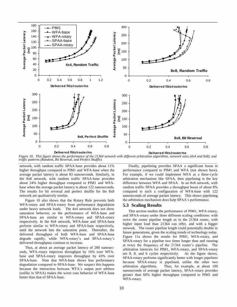
Figure 9, however, shows that under realistic conditions the
difference between the various arbitration algorithms reduces
dramatically. Figure 9 plots the arbitration matches per cycle
for the different algorithms for various levels of output port
occupancy. In the 21364 router, packet sizes range from 3 to
19 flits, so when a packet wins an arbitration, it occupies an
output port for several cycles. It is unnecessary to arbitrate for
an output port while it is busy delivering a packet. As the
fraction of occupied output ports increases, the difference
between the algorithms reduces and completely disappears
when 75% of the output ports are occupied.
Thus, under heavy loads (when output port occupancy is
likely to be high), it does not matter which arbitration algorithm
we choose. Rather, it is better to choose an algorithm that is
more suited to faster implementation. We designed SPAA
based on this observation.
Another way to look at these results is that WFA and PIM’s
matching capabilities are more suited to routers with signifi-
cantly higher number of ports compared to what we have in the
21364 router.
5.2 Timing Results
Figure 10 shows the performance of the five arbitration
algorithms—PIM1, WFA-base, WFA-rotary, SPAA-base, and
SPAA-rotary—for different network sizes and traffic patterns.
SPAA-base significantly outperforms both PIM1 and WFA-
base, which perform similarly. For example, in the 4x4
0
1
2
3
4
5
6
7
0 0.2 0.4 0.6 0.8 1
Fraction of MCM Saturation Load
# A
rbit
rati
on
Ma
tch
es
Pe
r
Cy
cle MCM
WFAPIMPIM1SPAA
Figure 8. Standalone comparison of matching capabilities of different arbitration algorithms for a single 21364 router with increasing router load for zero output port occupancy. The horizontal axis plots the input router load as a fraction of the load required to saturate MCM.
Figure 9. Standalone comparison of matching capabilities of different arbitration algorithms for a single 21364 router with increasing output port occupancy at the MCM saturation load.
0
1
2
3
4
5
6
7
0 0.25 0.5 0.75
Fraction of Output Ports Occupied
# A
rbit
rati
on
Matc
hes P
er
Cycle MCM
WFA
PIM
PIM1
SPAA
10
network, with random traffic SPAA-base provides about 11%
higher throughput compared to PIM1 and WFA-base when the
average packet latency is about 83 nanoseconds. Similarly, in
the 8x8 network, with random traffic SPAA-base provides
about 24% higher throughput compared to PIM1 and WFA-
base when the average packet latency is about 122 nanoseconds.
The results for bit reversal and perfect shuffle for the 8x8
network are qualitatively similar.
Figure 10 also shows that the Rotary Rule prevents both
WFA-rotary and SPAA-rotary from performance degradation
under heavy network loads. The 4x4 network does not show
saturation behavior, so the performance of WFA-base and
SPAA-base are similar to WFA-rotary and SPAA-rotary
respectively. In the 8x8 network, WFA-base and SPAA-base
perform similar to WFA-rotary and SPAA-base respectively,
until the network hits the saturation point. Thereafter, the
delivered throughput of both WFA-base and SPAA-base
degrade rapidly, while WFA-rotary’s and SPAA-rotary’s
delivered throughputs continue to increase.
Thus, at about an average packet latency of 280 nanosec-
onds, WFA-rotary improves throughput by 16% over WFA-
base and SPAA-rotary improves throughput by 43% over
SPAA-base. Note that WFA-base shows less performance
degradation compared to SPAA-base. We suspect this happens
because the interaction between WFA’s output port arbiters
(unlike in SPAA) makes the worst case behavior of WFA-base
better than that of SPAA-base.
Finally, pipelining provides SPAA a significant boost in
performance compared to PIM1 and WFA (not shown here).
For example, if we could implement WFA as a three-cycle
arbitration mechanism like SPAA, then pipelining is the key
difference between WFA and SPAA. In an 8x8 network, with
random traffic SPAA provides a throughput boost of about 8%
compared to such a configuration of WFA-base with 122
nanoseconds of average packet latency. This shows pipelining
the arbitration mechanism does help SPAA’s performance.
5.3 Scaling Results
This section studies the performance of PIM1, WFA-rotary,
and SPAA-rotary under three different scaling conditions: with
twice the router pipeline length as in the 21364 router, with
higher input load than 21364 can offer, and with a bigger
network. The router pipeline length could potentially double in
future generations, given the scaling trends of technology today.
Figure 11a shows the results for PIM1, WFA-rotary, and
SPAA-rotary for a pipeline two times longer than and running
at twice the frequency of the 21364 router’s pipeline. The
arbitration latencies for PIM1, WFA-rotary, and SPAA-rotary
are 8, 8, and 6 cycles respectively. As the figure shows,
SPAA-rotary performs significantly better with longer pipelines
because SPAA-rotary is pipelined, unlike the other two
arbitration algorithms. Thus, for example, at about 100
nanoseconds of average packet latency, SPAA-rotary provides
greater than 60% higher throughput compared to PIM1 and
WFA-rotary.
Figure 10. This figure shows the performance of the 21364 network with different arbitration algorithms, network sizes (4x4 and 8x8), and traffic patterns (Random, Bit Reversal, and Perfect Shuffle).
8x8, Random Traffic
0
50
100
150
200
250
300
0 0.2 0.4 0.6 0.8
Delivered flits/router/ns
Av
era
ge P
ac
ke
t La
tenc
y
(ns)
4x4, Random Traffic
0
20
40
60
80
100
120
140
160
180
0 0.2 0.4 0.6 0.8 1 1.2
Delivered flits/router/ns
Av
era
ge
Pa
cke
t La
tenc
y
(ns)
PIM1WFA-baseWFA-rotarySPAA-baseSPAA-rotary
8x8, Bit Reversal0
50
100
150
200
250
300
0 0.2 0.4 0.6 0.8
Delivered flits/router/ns
Av
era
ge P
ack
et L
ate
nc
y
(ns)
8x8, Perfect Shuffle
0
50
100
150
200
250
300
0 0.2 0.4 0.6 0.8
Delivered flits/router/ns
Av
era
ge P
ack
et L
ate
nc
y
(ns)
11
Figure 11b shows the results for the three arbitration algo-
rithms for an 8x8 network with higher network load. Higher
network load, in the form of greater number of outstanding
misses, can be expected from future processors with deeper
pipelines. Hence, this figure assumes 64 outstanding misses,
four times higher than that of the 21364 processor. As the
figure shows, even under such high network loads, SPAA-
rotary outperforms both PIM1 and WFA-rotary. Thus, for
example, at about roughly 200 nanoseconds of average packet
latency, SPAA-rotary provides roughly 13% higher throughput
compared to WFA-rotary.
Figure 11c shows the scaling results for the 21364 router for
a 144-processor (12x12) network (Note: the 21364 network can
only scale up to 128 processors). Like the first two scaling
results, SPAA-rotary outperforms both PIM1 and WFA-rotary
significantly. Thus, for a 200 nanoseconds average packet
latency, SPAA-rotary provides an 18% higher throughput
compared to WFA-rotary. Interestingly, however, at extremely
high loads, SPAA-rotary is unable to prevent throughput
degradation under saturation, whereas WFA-rotary’s through-
put continues to increase, possibly because of its synchroniza-
tion between output port arbiters.
6. CONCLUSIONS
Large-scale cache-coherent shared-memory machines have
become common server machines. Such machines often
employ interconnection networks to allow communication
between processors and memory modules. These interconnec-
tion networks must deliver low latency and high bandwidth to
effectively run demanding parallel applications.
Interconnection networks usually consist of a fabric of
interconnected routers, which receive packets arriving at their
input ports and forward them to appropriate output ports.
Unfortunately, network packets moving through these routers
are often delayed due to conflicting demand for resources, such
as output ports or buffer space. Hence, routers typically employ
arbiters to resolve conflicting resource demands. These
arbiters try to maximize the number of matches between
packets waiting at input ports and free output ports.
Efficient design and implementation of these arbiters is
critical to maximize network performance. The 1.2 GHz
implementation of the Alpha 21364 microprocessor’s on-chip
router, which can connect up to 128 processors in a 2D torus,
made the already difficult task of designing arbitration
algorithms even more challenging. Because the 21364’s
implementation allowed very few logic levels—between 12 and
13 per clock cycle—we had to carefully weigh the complexity
of an arbitration algorithm against its benefit.
This paper proposed a new arbitration algorithm called
SPAA (Simple Pipelined Arbitration Algorithm), which is
implemented in the 21364 router’s pipeline. Simulation results
showed that SPAA significantly outperforms two earlier well-
known arbitration algorithms: PIM (Parallel Iterative Matching)
and WFA (Wave-Front Arbiter), which is implemented in the
SGI Spider switch. Instead of PIM, which is iterative and
would have obviously performed poorly in the 21364 router, we
considered PIM1, which runs only one iteration of the PIM
algorithm.
SPAA outperformed PIM1 and WFA, even though both
PIM1 and WFA have better matching capabilities than SPAA.
This is because SPAA exhibits matching capabilities similar to
PIM1 and WFA under realistic conditions when many output
ports are busy, incurs fewer clock cycles to perform the
arbitration, and can be pipelined effectively. We also demon-
strated that SPAA will continue to deliver higher throughput
compared to PIM1 and WFA, if the router were scaled to have
twice the pipeline length, incur greater input load, or support
bigger networks than the 21364 was designed for.
Additionally, we proposed a new prioritization policy called
the Rotary Rule, which provided significant boost in network
performance by preventing the network’s adverse performance
degradation from saturation at high network loads. The Rotary
Rule prioritizes the movement of network packets already in the
network over packets recently generated from the processor
ports. We demonstrated the effectiveness of the Rotary Rule
with WFA and SPAA. The Alpha 21364 router provides the
Rotary Rule as an optional mode programmable at boot-time.
The arbitration algorithm choice for the Alpha 21364 router
depends largely on its architectural constraints. The arbitration
Figure 11. Scaling Results for the 21364 router.
(a) (b) (c)
12x12, Random Traffic
0
50
100
150
200
250
300
350
400
0 0.2 0.4 0.6
Delivered flits/router/ns
Av
era
ge P
ack
et L
ate
nc
y (
ns)
64 requests, 8x8,Random Traffic
0
50
100
150
200
250
300
350
400
0 0.2 0.4 0.6 0.8
Delivered flits/router/ns
Av
era
ge P
ack
et L
ate
nc
y (
ns
)
2x Pipeline, 8x8, Random Traffic0
50
100
150
200
0.0 0.2 0.4 0.6 0.8 1.0 1.2 1.4
Delivered flits/router/ns
Av
era
ge P
ack
et L
ate
nc
y (
ns
)
PIM1WFA-rotarySPAA-rotary

12
algorithm did not need to be as aggressive because of a
maximum of two output port choices for each packet, per-
packet arbitration, and virtual cut-through routing. Greater
routing freedom, flit-level arbitration, and wormhole routing
(with shallow buffering) may reduce the advantage of SPAA
over PIM1 and WFA.
Acknowledgements We thank Richard Kessler, who was one of the most important
contributors to the design of the Alpha 21364 network. We also
thank Geoff Lowney and the anonymous referees for their
comments on earlier drafts of this paper. Finally, we thank the entire Asim team for their help with the Asim infrastructure.
References [1] M.G.Ajmone Marshan, A. Bianco, and E. Leonardi, “RPA: A Flexible
Scheduling Algorithm for Input Buffered Switches,” IEEE Transac-tion on Communications, vol. 47, no. 12, pp. 1921-1933, Dec. 1999.
[2] Thomas E. Anderson, Susan S. Owicki, James B. Saxe, and Charles P.
Thacker, “High Speed Switching for Local Area Networks,” Fifth
International Conference on Architectural Support for Programming
Languages and Operating Systems, pp. 98 – 110, Boston, Massachu-
setts, October 12-15, 1992. [3] Peter Bannon, “Alpha 21364: A Scalable Single-Chip SMP,” 11th
Annual Microprocessor Forum, Microdesign Resources, Sebastopol,
California, 1998. [4] E.Baydal, P.Lopez, and J.Duato, “A Simple and Efficient Mechanism
to Prevent Saturation in Wormhole Networks,” 14th International
Parallel and Distributed Processing Symposium, pp. 617-622, 2000. [5] Laxmi N. Bhuyan, “Analysis of Interconnection Networks with
different arbiter designs,” Journal of Parallel and Distributed Compu-
ting, vol. 4, no. 4, pp 384-403, August 1987. [6] Alan Charlesworth, “The Sun Fireplane Interconnect,” IEEE Micro,
pp 36-45, Volume 22, Number 1, January/February 2002.
[7] Andrew Chien and Magda Konstantinidou, “Workloads and Performance Metrics for Evaluating Parallel Interconnects,” IEEE
TCCA Newsletter, Fall 1994.
[8] R.Cutler and S.Atkins, “IBM e-Server pSeries 680 Handbook,” IBM, Armonk, N.Y., 2000; http://www.redbooks.ibm.com/pubs/pdfs/red-
books/sg246023.pdf.
[9] William J. Dally, “Virtual Channel Flow Control,” 17th Annual International Symposium on Computer Architecture (ISCA), pp. 60-
68, 1990.
[10] William J. Dally and Charles L. Seitz, “The Torus Routing Chip,” Distributed Computing, vol. 1, no. 4, pp. 187-196, Oct. 1986.
[11] A.DeHon, F. Chong, M. Becker, E. Egozy, H. Minsky, S. Peretz, and
T.F.Knight Jr., “METRO: A Router Architecture for High-Performance, Short-Haul Routing Networks,” pp. 266-277, 21st Annu-
al International Symposium on Computer Architecture (ISCA), Chica-go, Illinois, April 1994.
[12] H. Duan, J.W.Lockwood, S.M.Kang, and J.D.Will, “A High
Performance OC12/OC48 Queue Design Prototype for Input Buffered ATM Switches,” INFOCOM 97: 16th Annual Joint Conference of the
IEEE Computer and Communication Societies (Infocom 97), IEEE CS
Press, pp. 20-28, Los Alamos, California, 1997. [13] Jose Duato, “A New Theory of Deadlock-free Adaptive Routing in
Wormhole Networks,” IEEE Transaction on Parallel and Distributed
Systems, vol. 4, no. 12, pp. 1320-1331, December 1993.
[14] Jose Duato, Sudhakar Yalamanchilli, and Lionel Ni, “Interconnection
Networks: An Engineering Approach,” IEEE Computer Society, 1997.
[15] Joel Emer, Pritpal Ahuja, Nathan Binkert, Eric Borch, Roger Espasa, Toni Juan, Artur Klauser, Chi-Keung Luk, Srilatha Manne, Shubhen-
du S. Mukherjee, Harish Patil, and Steven Wallace, “Asim: A Per-
formance Model Framework,” IEEE Computer, pp. 68-76, February 2002.
[16] M. Galles, “Spider: A High-Speed Network Interconnect,” IEEE
Micro, vol. 17, no. 1, pp. 34-39, Jan.-Feb. 1997. [17] K. Gharachorloo, et al., “Architecture and Design of the Alphaserver
GS320,” Architectural Support for Programming Languages and
Operating Systems (ASPLOS), pp. 13-24, 2000.
[18] Paolo Giaccone, Devavrat Shah, and Balaji Prabhakar, “An
Implementable Parallel Scheduler for Input-Queued Switches,” IEEE Micro, pp 19-25, Volume 22, Number 1, January/February 2002.
[19] Hewlett-Packard, “Meet the HP Superdome Servers,” September,
2001; http://www.hp.com/products1/servers/scalableservers/super-dome/infolibrary/whitepapers/technical_wp.pdf.
[20] M.D.Hill, “A Case for Direct-Mapped Caches,” IEEE Computer, vol.
21, no. 12, pp. 25-40, December 1988. [21] P.Lopez, J.M.Martinez, J.Duato, “DRIL: Dynamically Reduced
Message Injection Limitation Mechanism for Wormhole Networks,”
International Conference on Parallel Processing, pp. 535-542, August 1998.
[22] P.Lopez, J.M.Martinez, J.Duato, and F.Petrini, “On the Reduction of
Deadlock Frequency by Limiting Message Injection in Wormhole Networks,” Parallel Computer Routing and Communication Work-
shop, June 1997.
[23] N. McKeown, “iSLIP: A Scheduling Algorithm for Input-Queued Switches,” IEEE Transaction on Networking, vol. 7, no. 2, pp. 188-
201, April 1999.
[24] N. McKeown, “Scheduling Algorithms for Input-Queued Cell Switches,” doctoral dissertation, Dept. of EECS, University of Cali-
fornia, Berkeley, 1995.
[25] Devavrat Shah, Paolo Giaccone, and Balaji Prabhakar, “Efficient Randomized Algorithms for Input-Queued Switch Scheduling,” IEEE
Micro, pp 10-18, Volume 22, Number 1, January/February 2002. [26] Shubhendu S. Mukherjee, Peter Bannon, Steven Lang, Aaron Spink,
and David Webb, “The 21364 Network Architecture,” IEEE Micro, pp
26-35, Volume 22, Number 1, January/February 2002. [27] Li-Shiuan Peh and William J. Dally, “A Delay Model for Speculative
Architecture for Pipelined Routers,” 7th Annual International Sympo-
sium on High-Performance Computer Architecture (HPCA), pp. 255-266, Neuvo Leon, Mexico, January 2001.
[28] G.E.Pfister and V.A.Norton, “Hot-Spot Contention and Combining in
Multistage Interconnection Networks,” IEEE Transaction on Comput-ers, C-34(10):943-948, October 1985.
[29] Parthasarathy Ranganathan, Kourosh Gharachorloo, Sarita V. Adve,
and Luiz Andre Barroso, “Performance of Database Workloads on Shared-Memory Systems with Out-of-Order Processors,” Eighth
International Conference on Architectural Support for Programming
Language (ASPLOS), pp. 307-318, San Jose, California, October
1998.
[30] S.L.Scott and G. Sohi, “The Use of Feedback in Multiprocessors and
its Application to Tree Saturation Control,” IEEE Transactions on Parallel and Distributed Systems, vol. 1, no. 4, pp. 385-398, October
1990.
[31] S.L.Scott and G.M.Thorson, “The Cray T3E Network,” Hot Interconnects IV, pp. 147-156, 1996.
[32] Simon Steely, Compaq Computer Corporation, Personal Communica-
tion. [33] Silicon Graphics, “SGI 3000 Family Reference Guide,” 2001;
http://www.sgi.com/origin/3000/3000_ref.pdf.
[34] A. Smai and L.Thorelli, “Global Reactive Congestion Control in Multicomputer Networks,” 5th International Conference on High
Performance Computing, pp. 179-186, 1998.
[35] C. B. Stunkel, J. Herring, B. Abali, and R. Sivaram, ``A new switch chip for IBM RS/6000 SP systems,'' Supercomputing '99, Portland,
Oregon, November 1999.
[36] Yuval Tamir and Hsin-Chou Chi, “Symmetric Crossbar Arbiters for VLSI Communication Switches,” IEEE Trans. on Parallel and Dis-
tributed Systems, vol. 4, no. 1, pp. 13-27, January 1993.
[37] J.M.Tendler, et al., “IBM e-server POWER4 System Microarchitec-ture,” IBM, Armonk, N.Y., 2001; http://www-
1.ibm.com/servers/eserver/pseries/hardware/whitepapers/power4.pdf.
[38] Mithuna Thottethodi, Alvin Lebeck, and Shubhendu S. Mukherjee, “Self-Tuned Congestion Control for Multiprocessor Networks,” Sev-
enth Annual International Symposium on High-Performance Comput-
er Architecture (HPCA), pp. 107-118, Monterrey, Mexico, January 2001.
[39] Brian Towles and William J. Dally, “Worst-case Traffic for Oblivious
Routing,” Computer Architecture Letters, (http://www.cs.vir-ginia.edu/~tcca/2002paps.html), 2002.