UCO.MIPSIM: PIPELINED COMPUTER SIMULATOR FOR TEACHING PURPOSES
10
UCO.MIPSIM: PIPELINED COMPUTER SIMULATOR FOR TEACHING PURPOSES J. GÓMEZ-LUNA, A. PALACIOS, E. HERRUZO AND J.I. BENAVIDES. Dept. Computer Architecture and Electronics. University of Córdoba. Spain. [email protected] Since pipelining is a very important implementation technique for processors, students in Computer Science need to achieve a good understanding of it. UCO.MIPSIM simulator has been developed to support teaching such concepts. This paper introduces the basics of pipelining and describes UCO.MIPSIM, its main components and its functions. The learning effectiveness of the simulator has been tested by means of the comparison with two learning tools, the traditional paper and pencil and another pipelined computer simulator. In this way, a tool evaluation methodology is also introduced. 1. Introduction Pipelining has been a fundamental technique in computer architecture for a few decades. It permits several instructions to execute simultaneously, each of them in a different stage of the datapath. Thus, a good understanding of pipelining dynamics is very important for the students in Computer Science. However, teaching these concepts on a paper and pencil basis is rather difficult. Moreover, simulators have proved to be effective teaching tools for distance learning, such as Internet courses, or while having limited resources [1, 2, 3]. UCO.MIPSIM pipeline simulator has been developed at the University of Córdoba (Spain), in order to support teaching and give the students an environment to experiment. It implements the complete MIPS pipeline, including the forwarding unit and the hazard detection unit, explained in [4]. The MIPS processor is one of the best examples of the RISC philosophy of fixed instruction lengths, load-store instruction sets, limited addressing modes and limited operations. Other tools with similar purposes can be found. Although it is a clear and easy-to-handle simulator, MIPSim [5] does not implement as detailed and complete pipeline as UCO.MIPSIM. WinDLX [5] models a DLX processor with very little processor-internal information. Another tool is VLIW-DLX [6], which is a graphical simulator of a simple VLIW processor. HDLDLX [7] is a VHDL model of a DLX processor, which can be used as a complement to software simulators. This paper is organized as follows. Section 2 introduces the pipelined datapath implemented by UCO.MIPSIM. Section 3 describes UCO.MIPSIM simulator, its main components and two performance examples. Experimental results related to the UCO.MIPSIM assessment are explained in Section 4. Section 5 and 6 conclude the paper. 2. A pipelined datapath Pipelining is an implementation technique in which multiple instructions are overlapped in execution. Nowadays, pipelining is a key to make processors faster. A pipelined datapath is implemented by adding some hardware components to the processor resources, in order to execute several instructions
Transcript of UCO.MIPSIM: PIPELINED COMPUTER SIMULATOR FOR TEACHING PURPOSES
UCO.MIPSIM: PIPELINED COMPUTER SIMULATOR FOR TEACHING PURPOSES
J. GÓMEZ-LUNA, A. PALACIOS, E. HERRUZO AND J.I. BENAVIDES.
Dept. Computer Architecture and Electronics. University of Córdoba. Spain. [email protected]
Since pipelining is a very important implementation technique for processors, students in Computer Science need to achieve a good understanding of it. UCO.MIPSIM simulator has been developed to support teaching such concepts. This paper introduces the basics of pipelining and describes UCO.MIPSIM, its main components and its functions. The learning effectiveness of the simulator has been tested by means of the comparison with two learning tools, the traditional paper and pencil and another pipelined computer simulator. In this way, a tool evaluation methodology is also introduced.
1. Introduction Pipelining has been a fundamental technique in computer architecture for a few decades. It permits
several instructions to execute simultaneously, each of them in a different stage of the datapath. Thus, a good understanding of pipelining dynamics is very important for the students in Computer Science. However, teaching these concepts on a paper and pencil basis is rather difficult. Moreover, simulators have proved to be effective teaching tools for distance learning, such as Internet courses, or while having limited resources [1, 2, 3].
UCO.MIPSIM pipeline simulator has been developed at the University of Córdoba (Spain), in order
to support teaching and give the students an environment to experiment. It implements the complete MIPS pipeline, including the forwarding unit and the hazard detection unit, explained in [4]. The MIPS processor is one of the best examples of the RISC philosophy of fixed instruction lengths, load-store instruction sets, limited addressing modes and limited operations.
Other tools with similar purposes can be found. Although it is a clear and easy-to-handle simulator,
MIPSim [5] does not implement as detailed and complete pipeline as UCO.MIPSIM. WinDLX [5] models a DLX processor with very little processor-internal information. Another tool is VLIW-DLX [6], which is a graphical simulator of a simple VLIW processor. HDLDLX [7] is a VHDL model of a DLX processor, which can be used as a complement to software simulators.
This paper is organized as follows. Section 2 introduces the pipelined datapath implemented by
UCO.MIPSIM. Section 3 describes UCO.MIPSIM simulator, its main components and two performance examples. Experimental results related to the UCO.MIPSIM assessment are explained in Section 4. Section 5 and 6 conclude the paper.
2. A pipelined datapath Pipelining is an implementation technique in which multiple instructions are overlapped in
execution. Nowadays, pipelining is a key to make processors faster. A pipelined datapath is implemented by adding some hardware components to the processor resources, in order to execute several instructions

simultaneously. The pipeline will have as many stages as the steps in the instruction execution. MIPS instructions classically take five steps [4]:
1. IF: Instruction fetch. 2. ID: Instruction decode and register file read.
3. EX: Execution or address calculation. 4. MEM: Data memory access. 5. WB: Write back into a register. Hence the MIPS pipeline has five stages. Each stage takes one instruction in each clock cycle. In
this way, assuming ideal conditions, a five-stage pipelined datapath is five times faster than a non-pipelined datapath.
Figure 1 shows the MIPS pipelined datapath. The pipeline stages are separated by pipeline registers.
These are labeled by the stages that they separate. The registers must be wide enough to store all the data corresponding to the lines that go through them.
There are situations in pipelining when the next instruction cannot execute in the following clock
cycle. These events, called hazards, limit the performance improvement provided by the pipeline. Two types of hazards affect the pipelined datapath in Figure 1:
- Control Hazards: Conditional branches involve a decision which is not taken until the mentioned
branch instruction is executed. The easiest solution is to stall the pipeline until the branch is complete. An improved solution is to assume that the branch will not be taken and thus continue the execution down the sequential instruction stream. If the branch is taken, the instructions that are being fetched and decoded must be discarded.
- Data Hazards: When an instruction depends on the result of a previous instruction still in the
pipeline, a stall must happen until this item is written in the register file. The primary solution, called forwarding or bypassing, consists of getting the missing item early from the internal resources.
Some hardware must be added to the datapath in Figure 1 in order to forward previous results. The
forwarding unit controls whether an instruction in the EX stage requires a result which is still in the EX/MEM or MEM/WB registers.
Forwarding can help with many data hazards. However, there is one case where forwarding cannot
save the day. This is when an instruction tries to read a register following a load instruction that writes the same register. The data is still being read from memory in the MEM stage, while the arithmetic logic unit (ALU) is performing the operation for the following instruction in the EX stage. In this case, the pipeline must be stalled. Hence, in addition to a forwarding unit, a hazard detection unit is needed. This unit operates during the ID stage so that it can insert the stall between the load and its use. It checks if the target register of a load instruction is the source operand of the next instruction.

Figure 1. Pipelined version of the MIPS datapath.
3. UCO.MIPSIM simulator UCO.MIPSIM is a Windows based software system which implements the pipelined datapath
described in the previous section. The five-stage MIPS pipeline is simulated, including the forwarding unit and the hazard detection unit. UCO.MIPSIM is a useful and effective tool to understand the principles of pipelining. Moreover, it has a friendly and clear interface, as can be seen in Figure 2.
A subset of the MIPS instruction set is implemented. Table 1 shows the instruction subset. This
allows writing small programs, which can be executed within the simulator. Thus the user can watch the instruction flow through the pipeline, understand control and data hazards and the solutions for them.
The simulator has a task bar which permits easy user interaction. All the functions of the simulator
can be accessed through this bar: create new code, open or save programs; run the simulation or execute step by step; access the internal configuration of several pipeline components; and consult a complete user manual.
3.1. UCO.MIPSIM main components
The simulator has a code editor which permits the user to create new programs or modify the existing ones. When the mnemonic of an instruction is written, this is detected by the editor which displays a small box with the syntax of the corresponding instruction. Moreover, at the bottom of the interface an explanation about the instruction can be read. Instructions are highlighted in red. Comments and labels can also be used in any line of the code. Comments are highlighted in green, and labels are in blue.
Once the user has finished the program, it can be compiled and loaded into the instruction memory.
Then the program can be run in the simulator mode. This mode shows a graphical representation which contains all the hardware components of the pipeline. The simulator mode is shown in Figure 2.

Operation group MIPS instructions Control beq, bne, j, jr, jal
ALU add, sub, addi, mul, and, or, nor, andi, ori
Memory lw, sw No operation nop
Table 1. UCO.MIPSIM instruction subset.
Figure 2. Interface of UCO.MIPSIM simulator.
The interface has an information panel under the datapath which notifies some especial events, e.g.
a stall or a forwarding action. The simulator mode also has an online help which informs about the state of any pipeline stage during each execution cycle. It explains which instruction is in each stage and which actions are taken.
Control lines are red and data buses are black. The instruction memory, the 32-register file, the
ALU, the 4 Gb data memory, the sign extend unit, the control units, the forwarding and the hazard detection units, the pipeline registers and the multiplexers are implemented. When the mouse pointer is placed on any of these hardware components, an information box is displayed. This shows the input and output signals of the component.
Moreover, many of the hardware components can be left-clicked in order to obtain more
information. The instruction memory, the register file and the data memory show their content. The content of the register file and the data memory can also be modified. The hazard detection unit and the forwarding unit show the logic circuit that they have inside.

Figure 3. Combinational circuits within the hazard detection unit (left) and the forwarding unit (right). Figure 3 (left) shows the combinational circuit of the hazard detection unit. Further explanations are
given under the schematic. The inputs of this circuit are the destination register of the instruction in the EX stage, the source registers of the instruction in the ID stage and the control signal which is going to steer the data memory in the MEM stage, in order to check whether the instruction in the EX stage is a load. If the hazard detection unit detects the conditions explained in section 2, a bubble is inserted by disabling the program counter writing and changing the control of the ID/EX register to 0.
The details inside the forwarding unit are shown in Figure 3 (right). The inputs are the source
registers of the instruction in the EX stage, the destination registers of the instructions in the MEM and the WB stages and the signals that are going to control whether the register file is going to be written. If the forwarding unit detects that a result in the MEM or the WB stage is needed as an operand in the EX stage, this is forwarded by the proper values of the output. These output signals steer the multiplexers at the input of the ALU.
3.2. Performance examples
Small programs can be created by using the code editor. For instance, the following code represents one hazard condition that will be resolved by the forwarding unit:
sub $2,$1,$3 or $4,$5,$5 add $6,$2,$3
During the fifth clock cycle, the forwarding unit detects that the destination register of the sub
instruction in the WB stage, i.e. $2, is a source operand of the add instruction. Then, this result will be forwarded by controlling the multiplexer at the upper input of the ALU. The information panel within the simulator mode will notify this event.
The hazard detection unit performs a stall when a load instruction and the following one are
dependent, as in the following code:
lw $2,0($1) add $6,$2,$3 sub $7,$2,$3

During the third clock cycle, the hazard detection unit detects the dependence. This event is notified
by the information panel. One cycle later, a bubble will have been inserted in the EX stage, while the add instruction will have been stalled in the ID stage.
4. UCO.MIPSIM assessment The earlier experimental results were obtained with a beta version of the simulator in the 2006
academic year. A laboratory practice was proposed to a group of 11 volunteer students. They worked with UCO.MIPSIM during three hours. A couple of weeks later, a 90.1% of these students passed the exam with good grades. However, only a 42.9% of the remaining 36 students achieved a proper understanding of the pipelining. These results encouraged the instructors to prepare a more rigorous evaluation test, in order to weigh up the learning effectiveness of UCO.MIPSIM.
Selecting teaching tools raises an indispensable question, which is how to evaluate their validity for
learning purposes. Some authors perform an analysis of the students’ grades [8], comparing them with the ones of the previous academic years. However, the final version of UCO.MIPSIM has been evaluated using a different methodology, in order to achieve a thorough assessment.
The followed evaluation methodology consists of two parts: a learning effectiveness evaluation and
a survey for the self-assessment of the tool, which was performed using the Web Evaluation Teaching Tool (WETT), a web-based platform also developed at the University of Córdoba. Both strategies are explained next.
4.1. Learning effectiveness evaluation
During the 2007 academic year, 59 students attended the Computer Architecture and Engineering course at the University of Córdoba. They were divided in three groups, one of 19 and two of 20 people, respectively. First of all, the pipelining fundamentals were explained during two 2 hour lectures. All the students attended these lectures.
After that, a 2 hour laboratory session was prepared by the instructors for each group. The first
group worked on several exercises, using paper and pencil. These exercises covered the most important topics about pipelining, such as MIPS instruction formats, instructions through the pipeline, reordering and insertion of nop instructions for the avoidance of data hazards, the forwarding unit, the hazard detection unit and branch hazards. The second group worked with the MIPSim simulator. Several codes were provided by the instructors or developed by the students, in order to learn the same topics. Since MIPSim does not include a forwarding unit or a hazard detection unit, the students were encouraged to analyze the data hazards and how they could be solved by both units. Finally, the third group worked with the UCO.MIPSIM simulator.
After the laboratory sessions the instructors recommended to study one or two hours, in order to
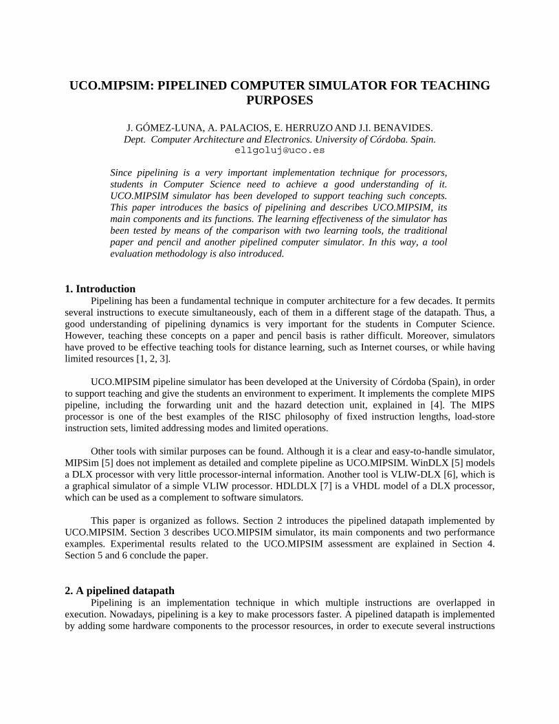
assimilate the new concepts about pipelining. Finally, a test was appointed. During one hour and a half, the students had to answer ten questions and exercises about the pipelined datapath. Figure 4 shows the test.
As can be inferred, the aim of this experiment was to evaluate three different learning tools. Thus,
their learning effectiveness can be identified with the corresponding students’ grades. Moreover, this
strategy permits to keep these results, in order to compare them with the ones of future versions of the simulators or new simulators designed for the same purposes.
Figure 4. Test about pipelining used for the evaluation.
0,01,02,03,04,05,06,07,08,09,0
Paper and pencil
MIPSim
UCO.MIPSIM
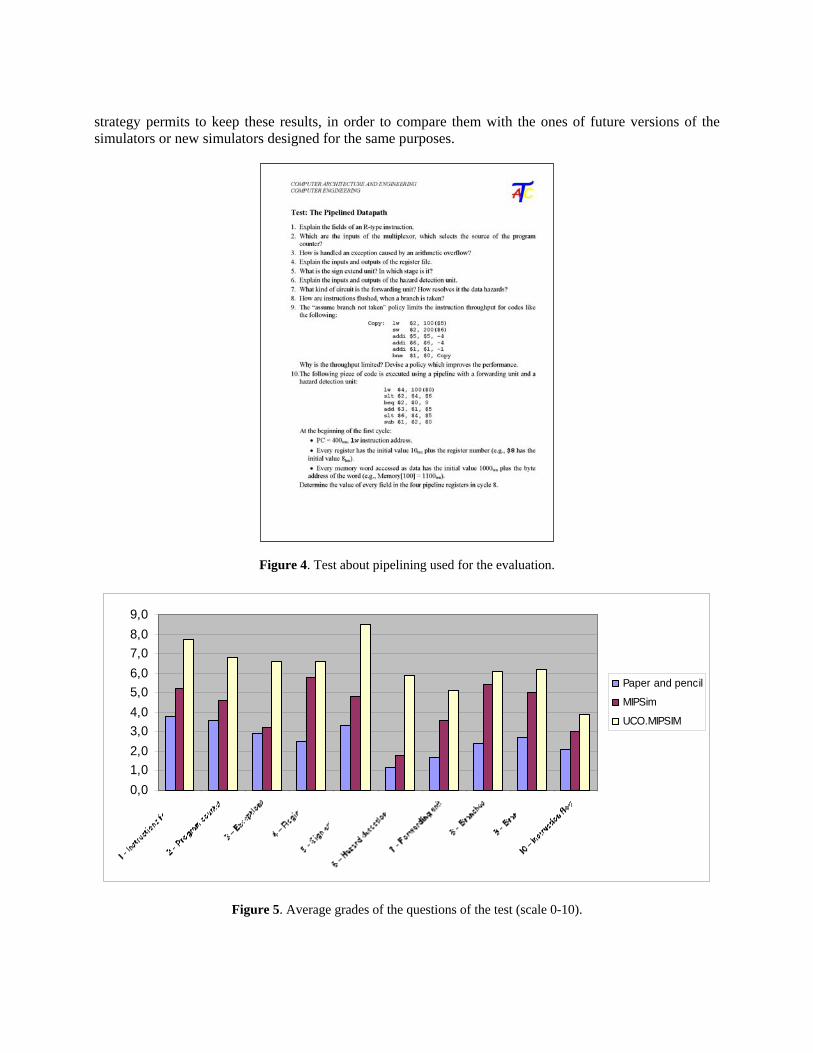
Figure 5. Average grades of the questions of the test (scale 0-10).
Grades Paper and pencil MIPSim UCO.MIPSIM F 73.7 % 40.0 % 25.0 %
C D 21.0 % 40.0 % 45.0 % A B 5.3 % 20.0 % 30.0 %
Table 2. Students’ grades for the evaluated learning tools.
The students’ grades show that the simulation tools greatly improve the performance of the
traditional paper and pencil. Furthermore, UCO.MIPSIM performs better than MIPSim, especially on those questions about the forwarding unit and the hazard detection unit. Figure 5 compares the average grades of each question of the test on a scale of 0 to 10. Table 2 shows the students’ grades obtained in the test. These results prove the positive effects of using these simulators in a computer architecture course. Moreover, UCO.MIPSIM can be declared the best learning tool about pipelining, which has been evaluated.
4.2. Survey using the WETT
At the end of the laboratory sessions, the students, which worked with the simulators, were requested to complete a questionnaire, in order to know their subjective perceptions about the tools. These students answered the questions related to the simulator they had worked with. The paper and pencil group did not complete any questionnaire. However, the instructors observed that the students, which worked with simulators, were pretty much motivated than the others.
The questionnaire was filled out through the WETT. This is a web-based platform, which permits
the instructors to prepare specific questionnaires about learning tools, laboratory sessions, methodologies, etc. The students should log in, select a course and a tool, and answer the corresponding questions. Their responses are on a 5 point scale, where 5 and 0 indicate strong acceptance or rejection, respectively. Later, the instructors can extract the results in order to analyze them. The WETT reports the average score and the standard deviation of each question, a group of questions related to the same topic, and the global score of the tool.
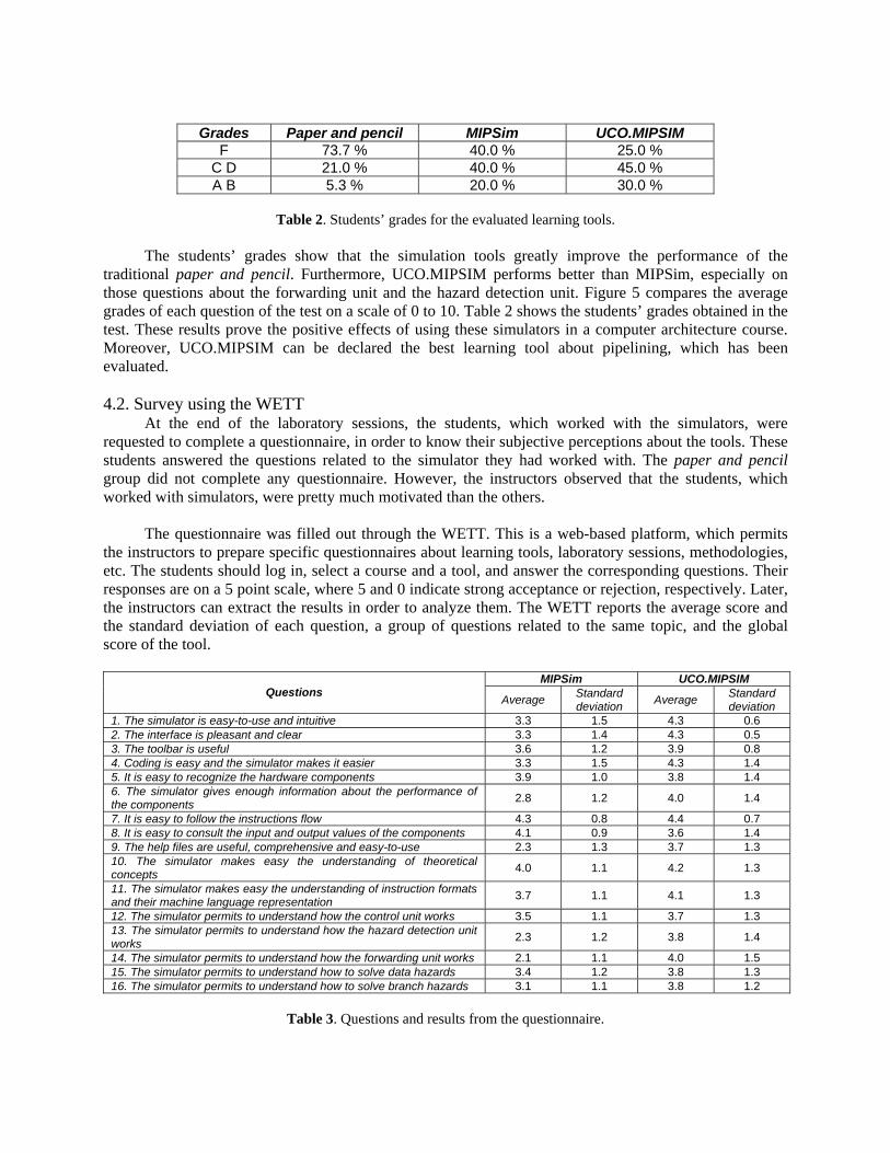
MIPSim UCO.MIPSIM
Questions Average Standard deviation Average Standard
deviation 1. The simulator is easy-to-use and intuitive 3.3 1.5 4.3 0.6 2. The interface is pleasant and clear 3.3 1.4 4.3 0.5 3. The toolbar is useful 3.6 1.2 3.9 0.8 4. Coding is easy and the simulator makes it easier 3.3 1.5 4.3 1.4 5. It is easy to recognize the hardware components 3.9 1.0 3.8 1.4 6. The simulator gives enough information about the performance of the components 2.8 1.2 4.0 1.4
7. It is easy to follow the instructions flow 4.3 0.8 4.4 0.7 8. It is easy to consult the input and output values of the components 4.1 0.9 3.6 1.4 9. The help files are useful, comprehensive and easy-to-use 2.3 1.3 3.7 1.3 10. The simulator makes easy the understanding of theoretical concepts 4.0 1.1 4.2 1.3
11. The simulator makes easy the understanding of instruction formats and their machine language representation 3.7 1.1 4.1 1.3
12. The simulator permits to understand how the control unit works 3.5 1.1 3.7 1.3 13. The simulator permits to understand how the hazard detection unit works 2.3 1.2 3.8 1.4
14. The simulator permits to understand how the forwarding unit works 2.1 1.1 4.0 1.5 15. The simulator permits to understand how to solve data hazards 3.4 1.2 3.8 1.3 16. The simulator permits to understand how to solve branch hazards 3.1 1.1 3.8 1.2
Table 3. Questions and results from the questionnaire.

The survey contained sixteen questions, which are shown in Table 3. The first three questions evaluated the goodness of the user interface. Questions 4 to 9 provided information on several features of the simulator. Questions 10 to 16 dealt with the correspondence between the simulator and the theoretical concepts, and how the tool can be used for self-training.
The results are encouraging, since UCO.MIPSIM scored at least 3.6 in every question. Moreover,
UCO.MIPSIM had a global score of 4, while MIPSim had 3.3.
5. Future work Although the former experimental results are acceptable, the evaluation will be repeated during the
next academic years, in order to involve a higher amount of students. Moreover, future versions or new simulators will also be tested, using the same evaluation methodology.
6. Conclusion UCO.MIPSIM simulator presented in this paper is a very useful tool for teaching purposes. The
performance of a MIPS pipelined datapath can be easily explained. Its editor permits a user to code simple programs. The students can use these programs to understand how the instructions go through the pipeline.
A forwarding unit and a hazard detection unit are included in the pipeline. Both permit the students
to understand how data hazards are solved. Moreover, the simulator includes a detailed user manual and an online help, which informs extensively about the state of each pipeline stage during each clock cycle.
This tool improves significantly the features of other simulators [5]. Furthermore, a thorough
evaluation methodology has been applied in order to compare UCO.MIPSIM with other learning tools. Nowadays, UCO.MIPSIM simulator is widely used in the courses of Computer Architecture and
Engineering and Computer Organization and Architecture at the University of Córdoba (Spain) with successful results.
References [1] G. Wolffe, W. Yurcik, H. Osborne and M. Holliday. Teaching Computer Organization/Architecture with
Limited Resources using Simulators. Proceedings of the 33rd SIGCSE Technical Symposium on Computer Science Education. 176-180. 2002.
[2] J. Gómez, A.J. Mesones, F.J. Jiménez, E. Herruzo, F.J. Sánchez and J.I. Benavides. Teaching the Cache Memory Coherence with the MESI Protocol Simulator. Proceedings of the 7th TAEE Congress on Technologies Applied to Electronics Teaching. 2006.
[3] J. Gómez-Luna, E. Herruzo and J.I. Benavides. MESI Cache Coherence Simulator for Teaching Purposes. Proceeding of the 15th CIESC Congress on Computer Education. 2007.
[4] J.L. Hennessy and D.A. Patterson. Computer Organization & Design: The Hardware/Software Interface. Morgan Kaufman Publishers, San Francisco, California. 1998.
[5] H. Gruenbacher and M. Khospavipour. WinDLX and MIPSim Pipeline Simulators for Teaching Computer Architecture. Proceedings of the IEEE Symposium and Workshop on Engineering of Computer Based Systems (ECBS). 412-419. 1996.
[6] M. Becvar and S. Kahanek. VLIW-DLX Simulator for Educational Purposes. Proceedings of the Workshop on Computer Architecture Education. 8-13. 2007.
[7] M. Becvar. Teaching Basics of Instruction Pipelining with HDLDLX. Proceedings of the Workshop on Computer Architecture Education. 74-78. 2004.

[8] J. Sahuquillo, N. Tomás, S. Petit and A. Pont. Spim-Cache: A Pedagogical Tool for Teaching Cache Memories through Code-Based Exercises. IEEE Transactions on Education, Vol. 50, No. 3, August 2007.