PROCESS SIMULATOR USING PLC TECHNOLOGY - UPB ...
10
U.P.B. Sci. Bull., Series C, Vol. 72, Iss. 2, 2010 ISSN 1454-234x PROCESS SIMULATOR USING PLC TECHNOLOGY Ioana FĂGĂRĂŞAN 1 , Sergiu St. ILIESCU 2 , Iulia DUMITRU 3 Proiectarea şi realizarea unui simulatorul de procese poate înlocui un număr amplu de sisteme costisitoare. Simularea proceselor fizice și a automatizării lor reduce costul și timpul de punere în funcțiune a sistemelor de automatizare. Simulatorul realizat permite învățarea, simularea și proiectarea sistemelor cu logică programabilă atât la nivel grafic cât și pratic. Numărul mare de procese modelate, de diferite complexităti, permite utilizarea sistemului atât pentru training cât și pentru dezvoltarea aplicațiilor practice din domeniul energetic, transportului, chimic, contrucțiilor etc. Simulatorul proiectat utilizează un singur bloc de simulare pentru toate aplicațiile, dispunând de măști ce se pot înlocui în funcție de aplicația dorită. Simulatorul utilizează logică programabilă implementată pe automate programabile de serie industrială. The implementation and the achievement of a Process Simulator can replace a vast number of expensive system or function models. The simulation and automation of physical processes reduce the costs and the amount of time needed for deployment. The designed system can be used to simulate, project and train the programming of programmable logical control (PLC) systems graphically and practically. A vast number of masks (an applied mask corresponds to an assignment), showing model systems for different types of application and with different complexity factors, allow us to use the system for training and for practical work in different areas as: energy, transport, chemistry, construction etc. The designed simulator uses only a simulation block for all the application, having different replaceable masks according to the desired application. The Process Simulator uses an industrial programmable logical control. Keywords: industrial processes automation, PLC, process-simulator 1. Introduction Modular systems for the simulation of the automatic supervision of some industrial processes represent a modern and efficient direction for multifunctional educational platforms. The modular system can be used for student’s training as well as for developement, improvement and conception of some technologic 1 Prof., Dept.of Automatic Control and Industrial Informatics, University POLITEHNICA of Bucharest, Romania 2 Prof., Dept.of Automatic Control and Industrial Informatics, University POLITEHNICA of Bucharest, Romania, [email protected] 3 PhD student, Faculty of Automatic Control and Computers, University POLITEHNICA of Bucharest, Romania
-
Upload
khangminh22 -
Category
Documents
-
view
6 -
download
0
Transcript of PROCESS SIMULATOR USING PLC TECHNOLOGY - UPB ...

U.P.B. Sci. Bull., Series C, Vol. 72, Iss. 2, 2010 ISSN 1454-234x
PROCESS SIMULATOR USING PLC TECHNOLOGY
Ioana FĂGĂRĂŞAN1, Sergiu St. ILIESCU2, Iulia DUMITRU3
Proiectarea şi realizarea unui simulatorul de procese poate înlocui un număr amplu de sisteme costisitoare. Simularea proceselor fizice și a automatizării lor reduce costul și timpul de punere în funcțiune a sistemelor de automatizare. Simulatorul realizat permite învățarea, simularea și proiectarea sistemelor cu logică programabilă atât la nivel grafic cât și pratic. Numărul mare de procese modelate, de diferite complexităti, permite utilizarea sistemului atât pentru training cât și pentru dezvoltarea aplicațiilor practice din domeniul energetic, transportului, chimic, contrucțiilor etc. Simulatorul proiectat utilizează un singur bloc de simulare pentru toate aplicațiile, dispunând de măști ce se pot înlocui în funcție de aplicația dorită. Simulatorul utilizează logică programabilă implementată pe automate programabile de serie industrială.
The implementation and the achievement of a Process Simulator can replace a vast number of expensive system or function models. The simulation and automation of physical processes reduce the costs and the amount of time needed for deployment. The designed system can be used to simulate, project and train the programming of programmable logical control (PLC) systems graphically and practically. A vast number of masks (an applied mask corresponds to an assignment), showing model systems for different types of application and with different complexity factors, allow us to use the system for training and for practical work in different areas as: energy, transport, chemistry, construction etc. The designed simulator uses only a simulation block for all the application, having different replaceable masks according to the desired application. The Process Simulator uses an industrial programmable logical control.
Keywords: industrial processes automation, PLC, process-simulator
1. Introduction
Modular systems for the simulation of the automatic supervision of some industrial processes represent a modern and efficient direction for multifunctional educational platforms. The modular system can be used for student’s training as well as for developement, improvement and conception of some technologic
1 Prof., Dept.of Automatic Control and Industrial Informatics, University POLITEHNICA of Bucharest, Romania 2 Prof., Dept.of Automatic Control and Industrial Informatics, University POLITEHNICA of Bucharest, Romania, [email protected] 3 PhD student, Faculty of Automatic Control and Computers, University POLITEHNICA of Bucharest, Romania

18 Ioana Făgărăşan, Sergiu Iliescu, Iulia Dumitru
scenario for control scheme in modern technologies. The majority of simulators are composed of the command segment – the
PC with an interface or a PLC – and the process simulator that can be a micro-plant or an electrical circuit.
The process simulator that is presented in this paper is hardware and software intergraded system for multifunctional educational platforms that enables training and practical work.
The first thing most papers about programmable logic controller do is to define the programmable logic controller. To keep the tradition we will give a definition:”A programmable logic controller (PLC) or programmable controller is a digital computer used for automation of electromechanical processes”, [6].
Process control system has a hardware structure that assures stability, accuracy and good transitions. These performances are realized by interconnection of PLCs and a PC. The PLC is used for automation of industrial processes and replaces the circuits of sequential command in cable logic, [1].
2. Description of the Process Simulator
The Process Simulator is divided into three parallel panels: the PLC, a demonstration panel which holds a mask (an applied mask corresponds to an assignment) with a large image of the process that is being simulated and the connection panel between the PLC connection and the demonstration panel.
The connected PLC with the corresponding program allows the user to study automatic functions while controlling the actuators. These automatic functions depend on the respective assignment.
The large number of assignments allows the study of an automation field without previous knowledge, starting with small control circuits, up to market solution strategies which use the full functions scale offered by the programmable logical control systems. The individual examples are obtained with masks that contain a current or process flow chart and is applied to the demonstration panel of the process simulator.
Thus we dispose of three categories of exercises: • Projection and testing of the simple assignments using classical
contactor circuits (switching a three phase motor on and off, reversing contactor circuit, automatic star-delta connection, automatic reversing star-delta connection, motor with two separate windings and others), [2].
• Projection and testing of the medium difficulty assignments using industrial system models (conveyor belt system with positive sequential circuit, reactive current compensation, heating control, automatic filling system, coal grinder, collecting belt conveyor,

Process simulator using PLC technology 19
conveyor charging system and others), [2]. • Projection and testing of the complex assignments using industrial
system models with the incorporation of the analog function (silo control, reactor, pump control, monitoring of 3 pumps and others), [2].
In the following are described all the components of the Process Simulator. In Fig. 1 is depicted the process simulator.
Fig. 1. The Process Simulator, [4]
3. The PLC
All the inputs and outputs on the Process Simulator have been designed to meet industrial standards for control engineering. As a result, the simulator can be operated with the programmable logical control systems of all major manufacturers. The system simulator can be connected to a PLC either with individual connection cables, to every input, or with a flat-ribbon cable. The connection with individual cables is much more practical and allows you, for example, to test a fail-safe circuit for a stop button. On the other hand, the connection of all the inputs and outputs with a flat-ribbon cable requires much less time, particularly when the basics of control engineering have already been practiced intensively and the user is interested only in the programming of the PLC.
The PLC used in this case is a SIMATIC S7-300 module. The S7-300

20 Ioana Făgărăşan, Sergiu Iliescu, Iulia Dumitru
module was chose to familiarize the students with an industrial PLC, with a system which is able to offer that feeling of "real life" conditions during the entire educational and vocational training as well.
The standard software used for configuring and programming the S7-300 controller is Step 7.
The programming languages for S7-300 are Ladder Logic, Statement List, and Function Block Diagram:
• Ladder Logic (or LAD) is a graphic representation of the STEP 7 programming language. Its syntax for the instructions is similar to a relay ladder logic diagram: Ladder allows you to track the power flow between power rails as it passes through various contacts, complex elements, and output coils.
• Statement List (or STL) is a textual representation of the STEP 7 programming language, similar to machine code. If a program is written in Statement List, the individual instructions correspond to the steps by which the CPU executes the program. To make programming easier, Statement List has been extended to include some high-level language constructions (such as structured data access and block parameters).
• Function Block Diagram (FBD) is a graphic representation of the STEP 7 programming language and uses the logic boxes familiar from boolean algebra to represent the logic. Complex functions (for example, math functions) can be represented directly in conjunction with the logic boxes.
The S7-300 is a modular control system for system solutions with a main emphasis on production engineering. The wide ranges of assemblies are ideally suited to cope with all required demands and a flexible application. The S7-300 contains the following types of modules:
• Central processing units (CPU) • Power supply modules (PS) • Interface modules (IM) • Communications processors (CP); (for connecting to PROFIBUS) • Digital and analog modules are now called “signal modules” (SM) As in real application, the S7-300 modules are plugged into the profiled
rail on the basic plate, fastened and connected to each other via the rear panel bus to be system compatible. The system is quickly and safely connected electrically to the inputs and outputs on the modules with the respective connector adapter.
Due to its construction, the system is open to future development. The PLC is build of the following modules: a power supply PS 307 2A, a
CPU 313C (Fig. 2 and Fig. 3), digital input module SM 321, digital output module SM 322 and analog input/output module SM 334.

Process simulator using PLC technology 21
Fig. 2. Elements and assembly Fig. 3. Basic Circuit Diagram of the of a CPU 31Xc, [11] Integrated Digital I/O or the
CPUs 313C, [11]
The figure below (Fig. 4) represents a module view and block diagram of
the digital input module and Fig. 5 represents a module view and block diagram of the digital output module.
Fig. 4. Module View and Block Diagram of Fig. 5. Module View and Block Diagram of the Digital Input Module SM 321; the Digital Output Module SM 322; DI 16 x 24VDC, [10] DO 16 x 24 VDC, [10]
The figure below (Fig. 6) represents a module view and block diagram of
the analog input/output module.
Fig. 6. Module View and Block Diagram of the Analog Input/output Module AI 4/AO 2 x 8/8 bits,
[10]

22 Ioana Făgărăşan, Sergiu Iliescu, Iulia Dumitru
4. The connection panel
On the connection panel it can be observed the connection for the supply voltage. Also, the panel presents 4 variable analog input voltage of 0 to 10 V DC, external analog inputs used to supply analog signals, e.g. from the sensors to the PLC system, two analog outputs, 20 switches to simulate digital input signals and 16 outputs to access the digital output signals. The connection panel contains also an input to supply the external power voltage supply of 24 V to the outputs. When the selector is set to “int” position, the digital output signals are supplied with the voltage from the PS. When the selector is on “ext” position, it is possible to reach the max. switching capacity for the output stages via an externally supplied DC voltage of 24 V.
5. The demonstration panel
The demonstration panel is operated with a stabilized DC voltage of 24 V, e.g. supplied with the power supply unit of the PLC system. The sockets are used to connect the sensors and switches on the system simulator to the PLC system.
The push buttons on the system simulator marked from S0 to S12 are connected to the sensors and switches according to the assignment. Each of these switches and sensors can physically act as make or break contact depending on the setting of the respective selector with the same marking.
The operating state of an actuator is indicated with an LED assigned to the symbol. The pilot lamps from H1 to H4 are directly connected to the signal lamps on the control panel.
All the switches signal lamps and potentiometers required for operating the control circuit illustrated on the applied mask are clearly arranged on the control panel. Only the control elements labeled on the control panel are visible, corresponding to the applied mask. We have also a “Manual/Automatic” selector. When selector is set to position “man.”, the voltage of 0 ÷ 10 V DC adjusted on the potentiometer directly runs to an analog input on the microcontroller in the system simulator. Depending on the applied, it can be used to set, for example, an inflow or outflow rate. at “auto.” Position, the analog input U1 in is connected to an analog input on the microcontroller in the system simulator.
The voltage of 0 ÷ 10 V DC set on this potentiometer directly runs to an analog input on the microcontroller in the system simulator. Its effect depends on the assignment.
The demonstration panel contains numerous LEDs to indicate the operating states of the actuators, such as relay and contactor coils. The LED strip, for example, clearly indicates filling levels and dynamic behavior. The PLC can only control the LEDs or the segments of the LED strip, which are assigned to the actuators on the applied mask.

Process simulator using PLC technology 23
6. Case study - Collecting Belt Conveyor
From the specified category of exercises in selection 2, a case study regarding the conveyor belt system is presented in this selection.
In order to build the command proceed for the process, some steps need to be followed: the drawing of the pushbuttons and the sensor into the PLC terminal diagram, the completion of the truth table and the Karnaugh-Veitch map, the drawing of the current flow chart according to the Karnaugh-Veitch map, the PLC program designed according to the current flow. The final step is the downloading of the program into the PLC and then his simulation.
The characteristic and the operative of the process is presented and depicted in a mask as in picture 7.
Fig. 7: The mask for the assignment collecting belt conveyor
6.1 The assignment
The collecting belt conveyor can be loaded via four feeding conveyors. The feeding conveyors must only be connected or switched on when the conveyor monitor indicates a correct closed circuit condition for the collecting belt conveyor.
The motor 2 s automatically generates the B1 sensor signal “high” after the motor has started running and stays until the motor is switched off. The overload protection for the motors has not been taken into account in the following exercise.
To prevent the collecting belt conveyor from being overloaded, only two feeding conveyors must be switched on simultaneously. If two conveyors load the collecting belt conveyor simultaneously, the connection of the other two conveyors must be prevented with an appropriate lock. The closed circuit condition of the four feeding conveyors must be indicated with the pilot lamps H1 to H4.
24 Ioana Făgărăşan, Sergiu Iliescu, Iulia Dumitru
6.2 The solving procedure
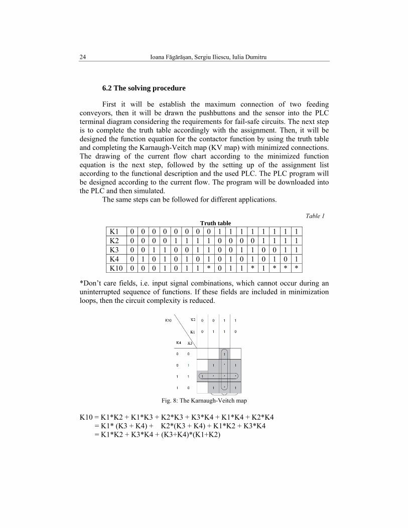
First it will be establish the maximum connection of two feeding conveyors, then it will be drawn the pushbuttons and the sensor into the PLC terminal diagram considering the requirements for fail-safe circuits. The next step is to complete the truth table accordingly with the assignment. Then, it will be designed the function equation for the contactor function by using the truth table and completing the Karnaugh-Veitch map (KV map) with minimized connections. The drawing of the current flow chart according to the minimized function equation is the next step, followed by the setting up of the assignment list according to the functional description and the used PLC. The PLC program will be designed according to the current flow. The program will be downloaded into the PLC and then simulated.
The same steps can be followed for different applications. Table 1
Truth table *Don’t care fields, i.e. input signal combinations, which cannot occur during an uninterrupted sequence of functions. If these fields are included in minimization loops, then the circuit complexity is reduced.
Fig. 8: The Karnaugh-Veitch map
K10 = K1*K2 + K1*K3 + K2*K3 + K3*K4 + K1*K4 + K2*K4 = K1* (K3 + K4) + K2*(K3 + K4) + K1*K2 + K3*K4 = K1*K2 + K3*K4 + (K3+K4)*(K1+K2)
K1 0 0 0 0 0 0 0 0 1 1 1 1 1 1 1 1 K2 0 0 0 0 1 1 1 1 0 0 0 0 1 1 1 1 K3 0 0 1 1 0 0 1 1 0 0 1 1 0 0 1 1 K4 0 1 0 1 0 1 0 1 0 1 0 1 0 1 0 1 K10 0 0 0 1 0 1 1 * 0 1 1 * 1 * * *
Process simulator using PLC technology 25
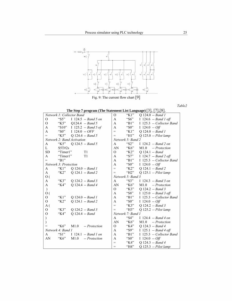
Fig. 9: The current flow chart [9]
Table2
The Step 7 program (The Statement List Language) [3], [7],[8]. Network 1: Collector Band O “S5” I 124.5 -- Band 5 on O “K5” Q124.4 -- Band 5 A “S10” I 125.2 -- Band 5 of A “S0” I 124.0 -- OFF = “K5” Q 124.4 -- Band 5 Network 2: Band Activation A “K5” Q 124.5 -- Band 5 L S5T#2s SD “Timer1” T1 A “Timer1” T1 = “B1” Network 3: Protection A “K1” Q 124.0 -- Band 1 A “K2” Q 124.1 -- Band 2 O ( A “K3” Q 124.2 -- Band 3 A “K4” Q 124.4 -- Band 4 ) O ( O “K1” Q 124.0 -- Band 1 O “K2” Q 124.1 -- Band 2 A ( O “K3” Q 124.2 -- Band 3 O “K4” Q 124.4 -- Band ) ) = “K6” M1.0 -- Protection Network 4: Band 1 A “S1” I 124.1 -- Band 1 on AN “K6” M1.0 -- Protection
O “K1” Q 124.0 -- Band 1 A “S6” I 124.6 -- Band 1 off A “B1” I 125.3 -- Collector Band A “S0” I 124.0 -- Off = “K1” Q 124.0 -- Band 1 = “H1” Q 125.0 -- Pilot lamp Network 5: Band 2 A “S2” I 124.2 -- Band 2 on AN “K6” M1.0 -- Protection O “K2” Q 124.1 -- Band A “S7” I 124.7 -- Band 2 off A “B1” I 125.3 -- Collector Band A “S0” I 124.0 -- Off = “K2” Q 124.1 -- Band 2 = “H2” Q 125.1 -- Pilot lamp Network 5: Band 3 A “S3” I 124.3 -- Band 3 on AN “K6” M1.0 -- Protection O “K3” Q 124.2 -- Band 3 A “S8” I 125.0 -- Band 3 off A “B1” I 125.3 -- Collector Band A “S0” I 124.0 -- Off = “K3” Q 124.2 -- Band 3 = “H3” Q 125.2 -- Pilot lamp Network 7: Band 1 A “S4” I 124.4 -- Band 4 on AN “K6” M1.0 -- Protection O “K4” Q 124.3 -- Band 4 A “S9” I 125.1 -- Band 4 off A “B1” I 125.3 -- Collector Band A “S0” I 124.0 -- Off = “K4” Q 124.3 -- Band 4 = “H4” Q 125.3 -- Pilot lamp

26 Ioana Făgărăşan, Sergiu Iliescu, Iulia Dumitru
7. Conclusions
The Process Control Simulator can be used for vocational training in order to practice programming of PLCs. It can be used for testing and analyzing command diagrams before the actual deployment. The PLC systems can simulate the real processes with several masks, as shown in the case study. PLCs have the great advantage that the same basic controller can be used with a wide range of control systems. To modify a control system and the rules that are to be used, all that is necessary is for an operator to set a different set of instructions. There is no need to rewire. PLCs are optimized for control and command tasks and the industrial environment.
An advantage of the system is the modulation. This characteristic allows an easy development of the system and can be use in future development by adding FPGA (Field-Programmable Gate Array) components. In this case the commands procedure or process simulator could be implemented using FPGA technology and the system will be used for training and testing using both technologies PLC and FPGA [5].
R E F E R E N C E S
[1]. S. St. Iliescu, C. Soare, P, Arsene, I. Fagarasan - The pursuit problem of control systems with relay action, Scientific Bulletin, University POLITEHNICA Bucharest, Series C: Electrical Engineering, vol. 61, nr. 3-4, 1999, pag. 319-327
[2]. S. St. Iliescu, I. Fagarasan, I. Dumitru, N. Arghira, G. Stamatescu, Sisteme modulare de simulare a conducerii automate a unor procese industrial pentru dotarea platformelor educationale multifunctionale, Automatizari si Instrumentatie, ISSN 1582-3334, vol. 1, martie 2010, pag 11-13
[3]. Daniel Popescu Automate programabile, Editura Matrix Rom, 2005 [4]. I, Fagarasan, S. St. Iliescu, I. Dumitru, N. Arghira, I. Bucur, Modular System for Process
Control Testing, Wseas Transactions on System and Control, ISSN 1991-8763, no 7, 2009 [5]. Bucur,I., Ioana Făgărăşan, C. Popescu, C.A. Boiangiu, G. Culea – On K-LUT Based FPGA
Optimum Delay and Optimal Area Mapping, Proceedings of de 10th WSEAS International Conference on Mathematic and Computational Methods in Science and Engineering (MACMESE’08), ISBN 978-960-474-019-2, ISSN 1790-2769, noiembrie 2008, Bucuresti.
[6]. H. Jack, Automating Manufacturing Systems with PLCs, march 2008, http://www.eod.gvsu.edu/~jackh/books/plcs/pdf/plcbook5_1.pdf. [7]. FJ.Molina, J. Barbancho, C. Leon, A. Molina, A. Gomez, Using industrial standards on PLC
programming learning, Proceedings on Mediterranean Conference on Control & Automation, Vols. 1-4, Pages 390-395, 2007
[8]. Frank D. Petruzella, Programmable Logic Controllers, 3rd edition, McGraw-Hill Ed. US 2005, ISBN 0078298520 / 9780078298523, 482 pages
[9]. *** Elwe – Automation, Electrical machines, Power electronics, User Guide, 2007 [10]. *** Siemens – Programmable Logic Controllers S7-300 Module Data, User Guide, 2004 [11]. *** Siemens – Central processing units, User Guide, 1999