Vaccination of dogs in an African city interrupts rabies ...
Upload
khangminh22Category
view
2download
0
1
8086 INTERRUPTS
Interrupts
(1) External Signal (2) Internally by software (3) Exceptional conditions (Divide by
zero).
(1)Type 0: INT0 Divide by zero
(2)Type 1: INT1 Single step
(3)Type 2: INT2 Non-mask-able interrupt (NMI pin)
(4)Type 3: INT3 Breakpoint
(5)Type 4: INT4 Interrupt over flow
Explanation
Intel
ed interrupt is not used in a system, the user may assign some other function to the associated
type.
Intel as part of the execution of divide instruction
-step mode.

2
PUSHF ;save flags
MOV BP, SP ; Move [SP] [BP]
AND 0[BP], 0FEFFH ; Clear TF1
POPF ; Pop flags
Once TF is set (=1), 8086 automatically generates a Type 1 interrupt after execution of each instruction.
The user can write an ISR at the interrupt address vector to display memory locations/or register to debug
a program.
-mask-able and cannot be enabled (STI) or disable (CLI) instructions.

3
NON-MASK-ABLE INTERRUPTS

4
Type 3 & Type 4 -mask-able.
- byte instruction INT3 into a program by replacing instruction.
executed.
L.
executed.
Internal interrupts -byte interrupt instruction INT nn
truction is not maskable by the interrupt enable flag (IF).
-255 can be used.
lized with the INT nn
instruction to generate software (internal) interrupts.

5
External Maskable Interrupts
current instruction), generates INTA LOW twice, each time for about 2 cycles.
f each instruction.
following instruction. i.e.: 32 bit to be loaded to SS and SP without the danger of interrupt occurring between
the two loads.
Interrupt Procedure
IPLSB : IPMSB CSLSB: CSMSB
)
6
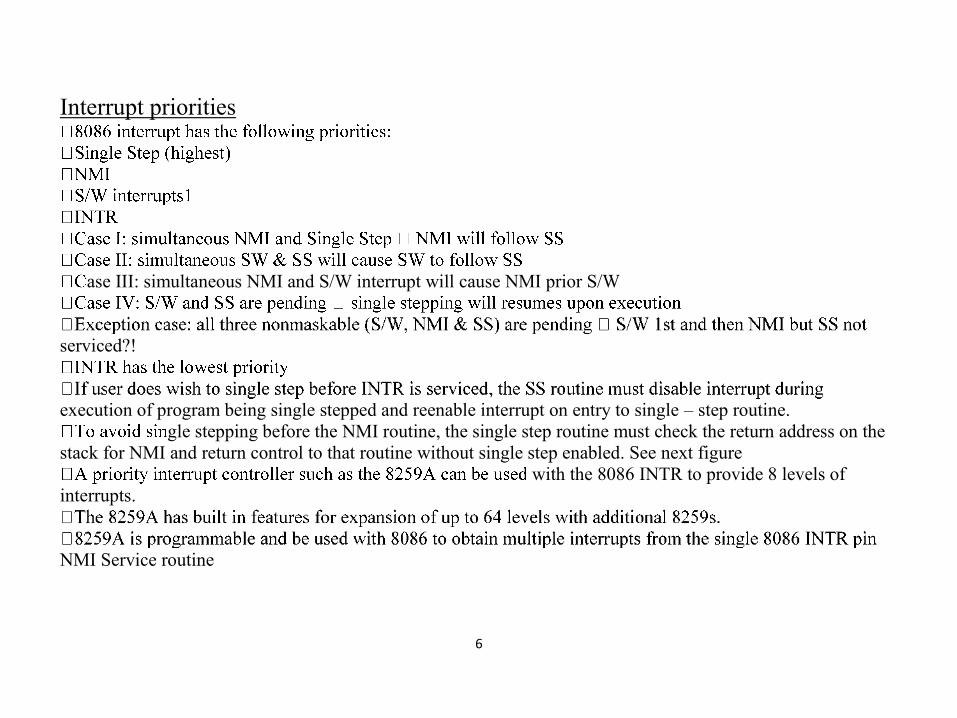
Interrupt priorities
ase III: simultaneous NMI and S/W interrupt will cause NMI prior S/W
serviced?!
execution of program being single stepped and reenable interrupt on entry to single – step routine.
gle stepping before the NMI routine, the single step routine must check the return address on the
stack for NMI and return control to that routine without single step enabled. See next figure
with the 8086 INTR to provide 8 levels of
interrupts.
NMI Service routine

7
Interrupt Pointer Table
the other for CS)1
addresses in the pointer table where IP and CS and
stored for a type:
IP address= 4 * 2=00008
00008 H & 0000A H in the pointer table
see table below
ined as follows:
-4 for predefined interrupts
-31 For Intel’s future use
-255 For user interrupt

8
Interrupt I/O waiting for ready bit to be active.
What happen on interrupt?
current instruction is a HLT or WAIT1.
recognized between the prefix and the instruction.
e primitive operation following the REP is completed,
and the return address is the location of the REP prefix.
until after the instruction following the MOV or POP instruction is executed.

9
Interrupt Sequence

10
Putting the contents of the memory locations 4 *N into IP and the contents of 4*N+2 into CS
Interrupt I/O

11

12
interrupt occurs, the CPU will return an acknowledgment signal to the device
interface through INTA pin and initiate interrupt sequence
re the type range 5-255
Sequence of maskable interrupt Microprocessors Interrupt I/O Example
How to resolve more than one interrupt?
priority scheme should be applied (S/W, H/W or combination).
several means:

13
Daisy chain use a logic circuit with each interface and passing the ACK signal through these cct.
the interface, and INTA is blocked from passing to the next interface.
and INTA signal will proceed to the requesting interface.
cognize more requests and so on.
Microprocessors Wisam I Hasan 23 Daisy Chain Arrangement Microprocessors Wisam I Hasan 24 Full Daisy
Chain Arrangement

14

15
HW/SW priority management INTA pins would not be connected to the interfaces, but to the management
circuit.
ic.
H/W&S/W management cct

16
LSBs of the type register are set to the number of request line, a bit is set in the in-service register, and an
interrupt is sent to CPU.
the in-service register is cleared1
but lower priority requests will be blocked by the priority logic until the bit that was set in the in-service register
is cleared2.
-service register, this register must be programmable3
Final points -byte mask register is included to allow masking of the individual
requests. Bit n in this register would be for masking IRn (it assumed this register is programmable)
priority logic.
ter is programmable, the most 5 significant bits could be initialized when the system is turned on.
8259A is one type.

17
HWs 1.If devices 0, 1, 2, 3, 4, and 5 are connected along a daisy chain in that order, and interrupts arrive as listed
below, give the order in which ISR will be completed. (All interrupt routines are to begin with STI instruction)
t same time
other request.
2.Repeat above but this time assume that there are no STI instructions in ISR & that IRET instruction enabled
IF flag by popping the PSW
3.Compare between the overall events occurrence at CALL & RET for procedures and INT & IRET.
Copyright © 2022 FDOKUMEN