8 Hydrates in Production, - Processing, and Transportation
41
“9078_C008” — 2007/8/1 — 15:53 — page 643 — #1 8 Hydrates in Production, Processing, and Transportation INTRODUCTION The objective of this chapter is provide an overview of how solid masses of hydrates (plugs) form, means of preventing and encouraging plug formation, and means of dissociating plugs once they have formed. Unlike the other portions of the book, for example, the thermodynamic calcula- tion methods in Chapters 4 and 5, in this chapter, conceptual pictures indicate how phenomena occur, based upon hydrate research and industrial practice. Particularly emphasized are those that have evolved during the last decade. For those who wish to do prevention calculations, several practical engineering guides are available. The engineering books by Kidnay and Parrish (2006), Carroll (2003), Makogon (1997), and Sloan (2000) prescribe hydrate calculations for the practicing engineer. Because most of the industrial hydrate concerns have been in flow assur- ance, that application is emphasized. However, the concepts apply to other uses, such as gas processing and hydrated gas transport. In Section 8.1 beginning with several typical case studies of hydrate plug formation, we conclude with a con- ceptual overview of hydrate formation in both oil- and gas-dominated systems. Section 8.2 considers hydrate plug prevention, before considering plug remedi- ation in Section 8.3. Then, and perhaps most important, hydrate safety is considered in Section 8.4, together with a computer program CSMPlug (on the book’s CD) that provides the sole chapter exception, to enable calculations of plug remediation and safety considerations. Finally, Section 8.5 discusses concepts of gas storage and transportation. Below are six important points to realize in this chapter: 1. Hydrate plugs and their dissociation can have major economic and safety impacts on flowline operation. 2. While the past methods of preventing hydrate plugs have been to use avoidance with thermodynamic inhibitors such as methanol or glycols, our new understanding of how plugs form, allows us to propose eco- nomic risk management (kinetics) to avoid hydrate formation. These concepts differ in type for oil-dominated and gas-dominated systems. 3. New, low dosage hydrate inhibitors (LDHIs) are being commonly used in the industry, based upon the kinetics of hydrate formation. 643 © 2008 by Taylor & Francis Group, LLC
-
Upload
khangminh22 -
Category
Documents
-
view
3 -
download
0
Transcript of 8 Hydrates in Production, - Processing, and Transportation

“9078_C008” — 2007/8/1 — 15:53 — page 643 — #1
8 Hydrates in Production,Processing, andTransportation
INTRODUCTION
The objective of this chapter is provide an overview of how solid masses of hydrates(plugs) form, means of preventing and encouraging plug formation, and means ofdissociating plugs once they have formed.
Unlike the other portions of the book, for example, the thermodynamic calcula-tion methods in Chapters 4 and 5, in this chapter, conceptual pictures indicate howphenomena occur, based upon hydrate research and industrial practice. Particularlyemphasized are those that have evolved during the last decade. For those who wishto do prevention calculations, several practical engineering guides are available.The engineering books by Kidnay and Parrish (2006), Carroll (2003), Makogon(1997), and Sloan (2000) prescribe hydrate calculations for the practicing engineer.
Because most of the industrial hydrate concerns have been in flow assur-ance, that application is emphasized. However, the concepts apply to other uses,such as gas processing and hydrated gas transport. In Section 8.1 beginning withseveral typical case studies of hydrate plug formation, we conclude with a con-ceptual overview of hydrate formation in both oil- and gas-dominated systems.Section 8.2 considers hydrate plug prevention, before considering plug remedi-ation in Section 8.3. Then, and perhaps most important, hydrate safety is consideredin Section 8.4, together with a computer program CSMPlug (on the book’s CD)that provides the sole chapter exception, to enable calculations of plug remediationand safety considerations. Finally, Section 8.5 discusses concepts of gas storageand transportation.
Below are six important points to realize in this chapter:
1. Hydrate plugs and their dissociation can have major economic and safetyimpacts on flowline operation.
2. While the past methods of preventing hydrate plugs have been to useavoidance with thermodynamic inhibitors such as methanol or glycols,our new understanding of how plugs form, allows us to propose eco-nomic risk management (kinetics) to avoid hydrate formation. Theseconcepts differ in type for oil-dominated and gas-dominated systems.
3. New, low dosage hydrate inhibitors (LDHIs) are being commonly usedin the industry, based upon the kinetics of hydrate formation.
643
© 2008 by Taylor & Francis Group, LLC
“9078_C008” — 2007/8/1 — 15:53 — page 644 — #2
644 Clathrate Hydrates of Natural Gases
4. We can predict plug dissociation using two-sided dissociation.5. The safety implications of plug dissociation are sometimes life-
threatening, and should be an important concern.6. It is possible to store and transport gas in hydrated form.
8.1 HOW DO HYDRATE PLUGS FORM IN INDUSTRIAL EQUIPMENT?
Considering hydrate formation and prevention, the physical conditions necessaryfor hydrates are
1. A hydrate guest molecule2. Water3. The correct conditions of temperature and pressure—usually low tem-
perature and high pressure
Without any one of the above conditions, hydrates will not form. However,removing some of the above conditions may be impractical:
1. To remove the guest molecule (e.g., methane) may be to remove thereason for the process.
2. To use an insufficient gas pressure (typically less than 225 psia or1.5 MPa) may decrease the energy density to a point that it is noteconomical.
However, it is practical to use the other thermodynamic preventionconditions:
1. Frequently the system is heated to keep it above the hydrate formationtemperature at the system pressure.
2. Frequently the system has both the free water and vaporized waterremoved, by separation and drying the remaining gas with triethyleneglycol or molecular sieves.
A second, indirect way of removing the free water is by injecting an inhibitor(typically alcohol or glycol) so that much of the free water is hydrogen bondedto the inhibitor. This reduces the water activity so that lower temperatures andhigher pressures are required to form hydrates with the lower concentration ofnonhydrogen bonded water, as shown in the first case study below.
In a 1999 survey of 110 energy companies, flow assurance was listed as themajor technical problem in offshore development (Welling and Associates, 1999).On September 24, 2003, in a Flow Assurance Forum, Professor James Brill (2003)discussed the need for a new academic discipline called “Flow Assurance.” Sucha question, presented to an audience of 289 flow assurance engineers, would nothave been considered in 1993, when the flow assurance community totaled a fewdozen people.
© 2008 by Taylor & Francis Group, LLC

“9078_C008” — 2007/8/1 — 15:53 — page 645 — #3
Hydrates in Production, Processing, and Transportation 645
Yet the statement of Professor Brill’s question indicates the importance offlow assurance, particularly related to hydrates, waxes, scale, corrosion, andasphaltenes, in decreasing order of importance. In the Gulf of Mexico, for example,hydrates are considered to be the largest problem by an order of magnitude relativeto the others.
Hydrate plugs do not occur in normal flowline operation due to design, butplugs are the result of three types of abnormal flowline operation:
1. When the water phase is uninhibited, as when excess water is produced,dehydrator failure, or when inhibitor injection is lost, for example, dueto inhibitor umbilical failure or inhibitor pump failure.
2. Upon start-ups following emergency shut-ins, due to system componentfailure and recovery, such as compressor failure, without the opportunityto take inhibition steps.
3. When cooling occurs with flow across a restriction, such as in the flowof a wet gas through a choke or valve in a fuel gas line.
8.1.1 Case Study 1: Hydrate Prevention in a DeepwaterGas Pipeline
Notz (1994) noted that almost all of Texaco’s efforts concerning natural gashydrates dealt with the prevention of hydrate formation in production and trans-portation systems. He presented Figure 8.1 from Texaco’s hydrate preventionprogram in a 50 mile deepwater gas pipeline, using a phase diagram similar tothose discussed with Figure 4.2.
Figure 8.1 shows the pressure and temperature of fluids in a flowline at variouspoints along the ocean floor, predicted by a multiphase flow prediction program.As a unit mass of fluid traverses the pipeline, the pressure drops normally due tofriction losses associated with fluid flow. However, the temperature decrease ismore interesting.
At water depths greater than 4000 ft, the ocean floor temperature is amazinglyuniform at temperatures of 36–40◦F. The ocean thus provides an infinite coolingmedium for the warm fluids from the reservoir. In the case shown in Figure 8.1 atlow pipeline distance (e.g., 7 miles) the flowing unit mass retains some residualenergy (high T and high P) from the hot reservoir.
The ocean cools the fluids as they flow, including both produced water (hereassumed to be salt-free) and condensed water that is always salt-free. At about9 miles the flowing hydrocarbons and water enter the hydrate region (to the left ofthe line marked “hydrate formation curve”), remaining in the uninhibited hydrateenvelope until mile 45. Such a distance may represent several days of residencetime for the water phase (which flows slower than the hydrocarbon phases) so thathydrates would undoubtedly form, were no inhibition steps taken.
In Figure 8.1, by mile 30 the gas in the pipeline has cooled to within a fewdegrees of the ocean floor temperature, so that approximately 23 wt% methanolin the free water phase is required to prevent hydrate formation and subsequent
© 2008 by Taylor & Francis Group, LLC

“9078_C008” — 2007/8/1 — 15:53 — page 646 — #4
646 Clathrate Hydrates of Natural Gases
2500
2000
1500
1000
500
030 40 50 60 70 80
Temperature (°F)
Pre
ssur
e (p
isa)
Pipeline10
1520
25
30
35
40
45
50
7 Miles
0%10%20%30%MeOH
Hydrateformingregion
Hydrateform
atio
ncu
rve
FIGURE 8.1 Typical offshore flowline system with intrusion into hydrate region. (FromNotz, P.K., in (First) International Conference on Natural Gas Hydrates, Ann. N.Y. Acad.Sci., 715, 425, 1994. With permission.)
pipeline blockage. Methanol injection facilities are not available at the neededpoints (9–45 miles) along the pipeline. Instead methanol is vaporized into thepipeline at some convenient upstream point, such as a subsea well-head so that inexcess of 23 wt% methanol will be present in the free water phase over the entirepipeline length.
As vaporized methanol flows along the pipeline shown in Figure 8.1, it parti-tions into any produced water, along with water condensed from the gas. Hydrateinhibition occurs in the free water, usually at water accumulations with somechange in geometry (e.g., a riser, bend, or pipeline dip along an ocean floordepression) or some nucleation site (e.g., sand, weld slag, etc.).
Hydrate inhibition occurs in the aqueous liquid, rather than in the vapor orhydrocarbon liquid phases. While a significant portion of the methanol partitionsinto the water phase, a significant amount of methanol either remains with thevapor or partitions into any liquid hydrocarbon phase. Although the methanolmole fraction in the vapor or liquid hydrocarbon may be low relative to the waterphase, the large amounts (phase fractions) of vapor and liquid phases will cause asubstantial amount of inhibitor loss.
In Figure 8.1 Notz notes that the gas begins to warm (from mile 30 to mile 45)with shallower, warmer water conditions. From mile 45 to mile 50, however,a second cooling trend is observed due to Joule–Thomson expansion. The methanolexiting the pipeline in the vapor, aqueous, and condensate phases is usually notrecovered, due to the expense of separation.
© 2008 by Taylor & Francis Group, LLC

“9078_C008” — 2007/8/1 — 15:53 — page 647 — #5
Hydrates in Production, Processing, and Transportation 647
Note that regular methanol (or monoethylene glycol) injection is used only withgas-dominated systems. In oil-dominated systems the higher liquid heat capacityallows the system to retain reservoir heat, so that insulation maintains sufficienttemperatures to prevent hydrate formation. Thermodynamic inhibitor is normallyonly injected for planned shutdowns in oil-dominated systems.
8.1.2 Case Study 2: Hydrates Prevention viaCombination of Methods
As a summary of the thermodynamic hydrate prevention methods, consider thesteps taken to prohibit hydrates in the Dog Lake Field export pipeline in Louisiana,by Todd et al. (1996) of Texaco. During the winter months hydrates formed in theline, which traverses land and shallow water (a marsh).
Hydrate formation conditions, shown in Figure 8.2 are calculated via the meth-ods of Chapters 4 and 5 with 0, 10 and 20 wt% methanol in the water phase. TheDog Lake gas composition is: 92.1 mol% methane, 3.68% ethane, 1.732% pro-pane, 0.452% i-butane, 0.452% n-butane, 0.177% i-pentane, 0.114% n-pentane,0.112% hexane, 0.051% heptane, 0.029% octane, 0.517% nitrogen, 0.574% carbondioxide.
The pipeline pressure and temperature, calculated using PIPEPHASE®, weresuperimposed on the hydrate formation curve shown in Figure 8.3. Gas leaves
Temperature (°F)
4000
3500
3000
2500
2000
1500
1000
500
0
Pre
ssur
e (p
sia)
30 35 40 45 50 55 60 65 70
Hydrate forming region
Hydrate free region
20 wt% MeOH 10 wt% MeOH
0 wt% MeOH
FIGURE 8.2 Dog Lake gas hydrate formation curves with methanol in free water phase.(From Todd, J.L., et al., Reliabilty Engineering—Gas Freezing and Hydrates, TexacoCompany Hydrate Handbook (1996). With permission.)
© 2008 by Taylor & Francis Group, LLC

“9078_C008” — 2007/8/1 — 15:53 — page 648 — #6
648 Clathrate Hydrates of Natural Gases
Temperature (°F)
2000
1800
1600
1400
1200
1000
800
600
400
200
030 40 50 60 70 80 90
Pre
ssur
e (p
sia)
SeparatorWellheadPipeline
20 wt%MeOH
10 wt%MeOH
0 wt%MeOH
25 wt%MeOH
FIGURE 8.3 Normal Dog Lake flowline conditions indicating the need for methanol.(From Todd, J.L., et al., Reliabilty Engineering—Gas Freezing and Hydrates, TexacoCompany Hydrate Handbook (1996). With permission.)
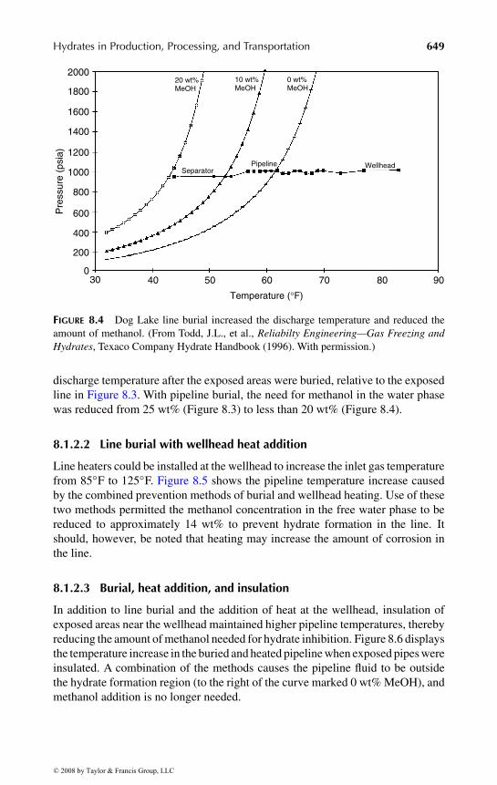
the wellhead at 1000 psia and 85◦F, far from hydrate forming conditions. As thegas moves down the pipeline, it is cooled toward ambient temperatures. Once thetemperature reaches approximately 62◦F, hydrates will form, so methanol mustbe added to avoid blockage. The figure shows pipeline conditions and the hydrateformation curves for various concentrations of methanol, indicating that 25 wt%methanol in the free water phase is needed to inhibit hydrates.
Despite large quantities of methanol injection for hydrate prevention, 110hydrate incidents occurred in the Dog Lake line during the winter of 1995–1996 ata remediation cost of $323,732, not counting lost production. Combinations of fouralternative hydrate prevention methods were considered: (1) burying the pipeline,(2) heating the gas at the wellhead, (3) insulating the pipeline, and (4) methanoladdition. The first three methods were intended to maintain sufficiently high tem-peratures to prevent hydrate formation, while the last method effectively inhibitedfree water, via hydrogen bonding with methanol. The details of each preventionmeasure are considered below.
8.1.2.1 Burying the pipeline
Portions of the Dog Lake pipeline were built over a stretch of marsh. The exposureto winter ambient temperatures caused rapid reductions in the gas temperature.Burying the pipeline would protect it from low environmental temperatures dueto the higher earth temperatures. Figure 8.4 shows the increase in the pipeline
© 2008 by Taylor & Francis Group, LLC
“9078_C008” — 2007/8/1 — 15:53 — page 649 — #7
Hydrates in Production, Processing, and Transportation 649
Temperature (°F)
2000
1800
1600
1400
1200
1000
800
600
400
200
030 40 50 60 70 80 90
Pre
ssur
e (p
sia)
SeparatorWellheadPipeline
20 wt% MeOH
10 wt%MeOH
0 wt% MeOH
FIGURE 8.4 Dog Lake line burial increased the discharge temperature and reduced theamount of methanol. (From Todd, J.L., et al., Reliabilty Engineering—Gas Freezing andHydrates, Texaco Company Hydrate Handbook (1996). With permission.)
discharge temperature after the exposed areas were buried, relative to the exposedline in Figure 8.3. With pipeline burial, the need for methanol in the water phasewas reduced from 25 wt% (Figure 8.3) to less than 20 wt% (Figure 8.4).
8.1.2.2 Line burial with wellhead heat addition
Line heaters could be installed at the wellhead to increase the inlet gas temperaturefrom 85◦F to 125◦F. Figure 8.5 shows the pipeline temperature increase causedby the combined prevention methods of burial and wellhead heating. Use of thesetwo methods permitted the methanol concentration in the free water phase to bereduced to approximately 14 wt% to prevent hydrate formation in the line. Itshould, however, be noted that heating may increase the amount of corrosion inthe line.
8.1.2.3 Burial, heat addition, and insulation
In addition to line burial and the addition of heat at the wellhead, insulation ofexposed areas near the wellhead maintained higher pipeline temperatures, therebyreducing the amount of methanol needed for hydrate inhibition. Figure 8.6 displaysthe temperature increase in the buried and heated pipeline when exposed pipes wereinsulated. A combination of the methods causes the pipeline fluid to be outsidethe hydrate formation region (to the right of the curve marked 0 wt% MeOH), andmethanol addition is no longer needed.
© 2008 by Taylor & Francis Group, LLC

“9078_C008” — 2007/8/1 — 15:53 — page 650 — #8
650 Clathrate Hydrates of Natural Gases
2000
1800
1600
1400
1200
1000
800
600
400
200
030 40 50 60 70 80 90 100 110 120 130
Temperature (°F)
Pre
ssur
e (p
sia)
WellheadPipeline
20 wt%MeOH
10 wt%MeOH
0 wt%MeOH
SeparatorSeparatorSeparator
FIGURE 8.5 Dog Lake line burial and inlet heating reduces the need for methanol. (FromTodd, J.L., et al., Reliabilty Engineering—Gas Freezing and Hydrates, Texaco CompanyHydrate Handbook (1996). With permission.)
Temperature (°F)
2000
1800
1600
1400
1200
1000
800
600
400
200
030 40 50 60 70 80 90 100 110 120 130
Pre
ssur
e (p
sia)
Separator WellheadPipeline
20 wt%MeOH
10 wt%MeOH
0 wt%MeOH
FIGURE 8.6 Dog Lake line burial, inlet heating, and insulation removes system fromhydrate region. (From Todd, J.L., et al., Reliabilty Engineering—Gas Freezing andHydrates, Texaco Company Hydrate Handbook (1996). With permission.)
8.1.2.4 Methanol addition alternative
Continued methanol injection could be done at a cost of approximately $1.50–2.00per gallon during the 1996–1997 winter. Since methanol recovery is problematic,
© 2008 by Taylor & Francis Group, LLC
“9078_C008” — 2007/8/1 — 15:53 — page 651 — #9
Hydrates in Production, Processing, and Transportation 651
methanol is normally considered an operating cost. In addition, refineries have putrestrictions on methanol concentrations in condensate and this further decreasesthe economics of methanol injection.
This case study illustrates how combinations of pipeline burial, insulation,heating, and methanol injection can be used to prevent hydrates. The selectionof the hydrate prevention scheme(s) is then a matter of balancing capital againstoperating costs.
8.1.3 Case Study 3: Hydrate Formation via Expansionthrough Valves or Restrictions
When water-wet gas expands rapidly through a valve, orifice or other restriction,hydrates form due to rapid gas cooling caused by adiabatic (Joule–Thomson)expansion. Hydrate formation with rapid expansion from a wet line commonlyoccurs in fuel gas or instrument gas lines. Hydrate formation with high pressuredrops can occur in well testing, start-up, and gas lift operations, even when theinitial temperature is high, if the pressure drop is very large.
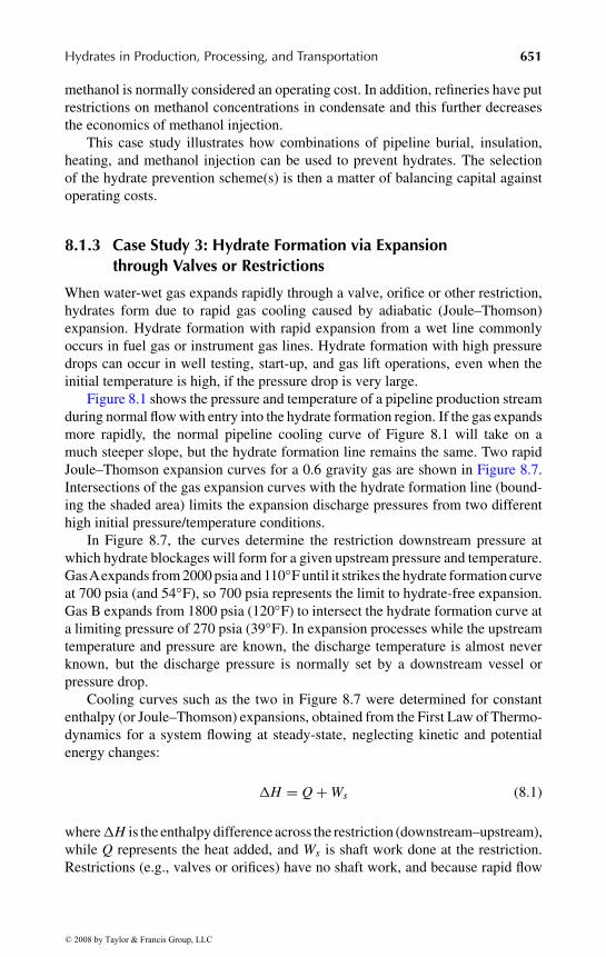
Figure 8.1 shows the pressure and temperature of a pipeline production streamduring normal flow with entry into the hydrate formation region. If the gas expandsmore rapidly, the normal pipeline cooling curve of Figure 8.1 will take on amuch steeper slope, but the hydrate formation line remains the same. Two rapidJoule–Thomson expansion curves for a 0.6 gravity gas are shown in Figure 8.7.Intersections of the gas expansion curves with the hydrate formation line (bound-ing the shaded area) limits the expansion discharge pressures from two differenthigh initial pressure/temperature conditions.
In Figure 8.7, the curves determine the restriction downstream pressure atwhich hydrate blockages will form for a given upstream pressure and temperature.GasAexpands from 2000 psia and 110◦F until it strikes the hydrate formation curveat 700 psia (and 54◦F), so 700 psia represents the limit to hydrate-free expansion.Gas B expands from 1800 psia (120◦F) to intersect the hydrate formation curve ata limiting pressure of 270 psia (39◦F). In expansion processes while the upstreamtemperature and pressure are known, the discharge temperature is almost neverknown, but the discharge pressure is normally set by a downstream vessel orpressure drop.
Cooling curves such as the two in Figure 8.7 were determined for constantenthalpy (or Joule–Thomson) expansions, obtained from the First Law of Thermo-dynamics for a system flowing at steady-state, neglecting kinetic and potentialenergy changes:
�H = Q+Ws (8.1)
where�H is the enthalpy difference across the restriction (downstream–upstream),while Q represents the heat added, and Ws is shaft work done at the restriction.Restrictions (e.g., valves or orifices) have no shaft work, and because rapid flow
© 2008 by Taylor & Francis Group, LLC

“9078_C008” — 2007/8/1 — 15:53 — page 652 — #10
652 Clathrate Hydrates of Natural Gases
30 40 50 60 70 80 90 100 110 120 130
200
100
300
400
500
600700800900
1000
2000
3000
4000
Pre
ssur
e (p
sia)
Temperature (°F)
Gas B
Gas A
Hydrate region when water is present
FIGURE 8.7 Expansion of two gases into the hydrate formation region. (From Katz, D.L.,Trans AIME, 160, 140 (1945). With permission.)
approximates adiabatic operation (limited heat transfer); both Ws and Q are zero,resulting in constant enthalpy (�H = 0) operation on expansion.
Due to the constant enthalpy requirement, rapid gas expansion with pressurelowering normally results in cooling. Because of the constraint that the enthalpy(roughly a flow-corrected energy) must be equal on both sides of the valve, a lowerpressure gas (higher enthalpy) downstream of the valve, must be compensated bya lower temperature (lower enthalpy). So Figure 8.7 for fluid expansion througha valve has a steeper slope than normal flow along a pipeline (Figure 8.1) that hasheat transfer (Q) with the surroundings, which are typically around 40◦F.
To prevent hydrate formation in expansion on the downstream side of a valve,the most common method is to inject methanol or glycol before the value, removingthe hydrate formation (shaded) region to the left of Figure 8.7 from the expansionconditions. Alternatives include heating the inlet gas or limiting the downstreampressure.
In concluding this case study, it should be recalled that Section 4.2.1.1 providesthe hand calculation limits to Joule–Thomson expansion, through Figures 4.7through 4.9. The computer program CSMGem on the CD supplied with this bookalso provides a method for calculation of expansion limits, as shown in the User’sExamples in Appendix A, and in the User’s Guide found on the CD accompanyingthis volume.
© 2008 by Taylor & Francis Group, LLC
“9078_C008” — 2007/8/1 — 15:53 — page 653 — #11
Hydrates in Production, Processing, and Transportation 653
Water
Oil
Time Hydrate shells
Water entrainment
Hydrate shell growth Agglomeration Plug
Gas
Capillary attraction
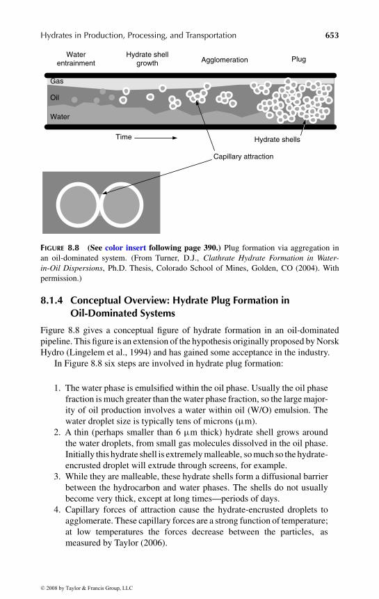
FIGURE 8.8 (See color insert following page 390.) Plug formation via aggregation inan oil-dominated system. (From Turner, D.J., Clathrate Hydrate Formation in Water-in-Oil Dispersions, Ph.D. Thesis, Colorado School of Mines, Golden, CO (2004). Withpermission.)
8.1.4 Conceptual Overview: Hydrate Plug Formation inOil-Dominated Systems
Figure 8.8 gives a conceptual figure of hydrate formation in an oil-dominatedpipeline. This figure is an extension of the hypothesis originally proposed by NorskHydro (Lingelem et al., 1994) and has gained some acceptance in the industry.
In Figure 8.8 six steps are involved in hydrate plug formation:
1. The water phase is emulsified within the oil phase. Usually the oil phasefraction is much greater than the water phase fraction, so the large major-ity of oil production involves a water within oil (W/O) emulsion. Thewater droplet size is typically tens of microns (µm).
2. A thin (perhaps smaller than 6 µm thick) hydrate shell grows aroundthe water droplets, from small gas molecules dissolved in the oil phase.Initially this hydrate shell is extremely malleable, so much so the hydrate-encrusted droplet will extrude through screens, for example.
3. While they are malleable, these hydrate shells form a diffusional barrierbetween the hydrocarbon and water phases. The shells do not usuallybecome very thick, except at long times—periods of days.
4. Capillary forces of attraction cause the hydrate-encrusted droplets toagglomerate. These capillary forces are a strong function of temperature;at low temperatures the forces decrease between the particles, asmeasured by Taylor (2006).
© 2008 by Taylor & Francis Group, LLC
“9078_C008” — 2007/8/1 — 15:53 — page 654 — #12
654 Clathrate Hydrates of Natural Gases
5. As the hydrated particles agglomerate, the effective viscosity increasesdramatically, and spikes in the flowline pressure drop occur with time,indicating agglomeration and breakage of hydrate masses. Finally theagglomerate becomes sufficiently large to increase the pressure drop sothat flow is stopped. This point is normally taken as a hydrate plug,causing flow to be shut in.
6. As the plug sits for a longer period of time, the masses anneal and theplug becomes more solid-like, with less flexibility. That is, both intra-and interparticle growth occurs. This annealing process is not shown inFigure 8.8.
The simplified conceptual picture in Figure 8.8 has important implications forflow assurance. For example, the model’s implication is that hydrate agglomeration(not the kinetics of shell growth) is the limiting factor in plug formation. If onecould determine a means of preventing agglomeration, such as antiagglomerants(AAs) (Mehta, et al., 2003) or cold flow (Wolden, et al., 2005), one could allowthe hydrates to form and flow without obstructing the pipeline. There is significantevidence that such situations normally occur in flowlines in Brazil (Palermo et al.,2004), where natural AAs exist in oils.
8.1.5 Conceptual Overview: Hydrate Formation inGas-Dominated Systems
Hydrate formation in a gas-dominated system is thought to differ significantlyfrom formation in oil-dominated systems. In gas systems, there is much less liquid(both hydrocarbon and water), so that the W/O emulsion concept may not apply.Instead a concept may apply as shown in Figure 8.9.
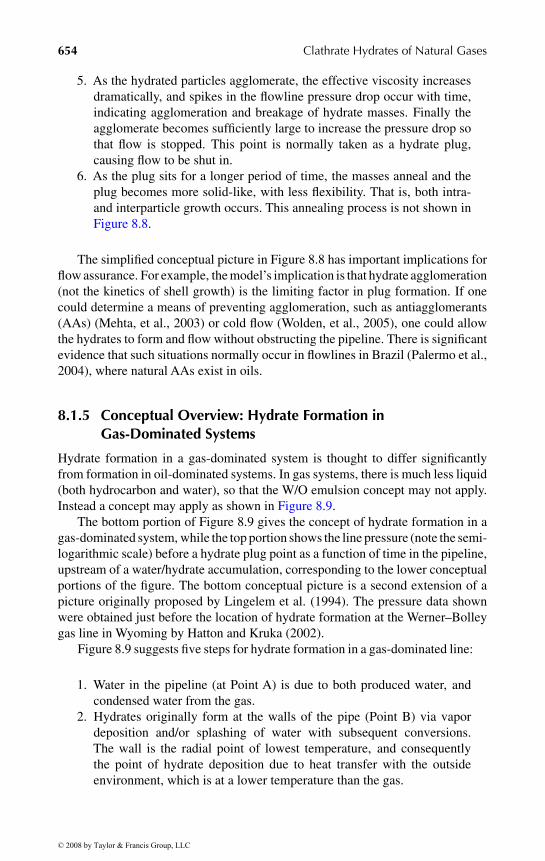
The bottom portion of Figure 8.9 gives the concept of hydrate formation in agas-dominated system, while the top portion shows the line pressure (note the semi-logarithmic scale) before a hydrate plug point as a function of time in the pipeline,upstream of a water/hydrate accumulation, corresponding to the lower conceptualportions of the figure. The bottom conceptual picture is a second extension of apicture originally proposed by Lingelem et al. (1994). The pressure data shownwere obtained just before the location of hydrate formation at the Werner–Bolleygas line in Wyoming by Hatton and Kruka (2002).
Figure 8.9 suggests five steps for hydrate formation in a gas-dominated line:
1. Water in the pipeline (at Point A) is due to both produced water, andcondensed water from the gas.
2. Hydrates originally form at the walls of the pipe (Point B) via vapordeposition and/or splashing of water with subsequent conversions.The wall is the radial point of lowest temperature, and consequentlythe point of hydrate deposition due to heat transfer with the outsideenvironment, which is at a lower temperature than the gas.
© 2008 by Taylor & Francis Group, LLC

“9078_C008”
—2007/8/1
—15:53
—page
655—
#13
Hydrates
inProduction,Processing,and
Transportation655
Flow
A B C D E F
Date and timeDate and timeDate and timeDate and timeDate and time
0:00 6:00 12:00 18:00 0:00 6:00 12:00 18:00 0:00 6:00 12:00 18:00 0:00 6:00 12:00 18:00 0:00 6:00 12:00 18:00 0:00
1000
100
10
1
1/27 1/27 1/27 1/27 1/28 1/28 1/28 1/28 1/29 1/29 1/29 1/29 1/30 1/20 1/30 1/30 1/31 1/31 1/31 1/31 2/1
Pre
ssur
e (p
si)
Early middleFinal
FIGURE 8.9 Hydrate blockage formation (bottom) and corresponding pressure buildup (top) in a gas-dominated pipeline (upper figure From Hat-ton, G.J., Kruka, V.R., Hydrate Blockage Formation—Analysis of Werner Bolley Field Test Data, DeepStar CTR 5209-1, 2002; lower figure modifiedfrom Lingelem, M.N., et al., in (First) International Conference on Natural Gas Hydrates, Ann. N.Y. Acad. Sci., 715, 75 (1994). With permission.)
© 2008 by Taylor & Francis Group, LLC

“9078_C008” — 2007/8/1 — 15:53 — page 656 — #14
656 Clathrate Hydrates of Natural Gases
3. As the hydrate deposition on the wall becomes thicker (Point C), narrow-ing of the flow channel occurs. The deposition forms irregularly (PointD) so that a nonconcentric annulus increases the pipeline pressure drop.Steps 1–3 are in the stages of hydrate plug formation marked “early” inthe top of Figure 8.9, with a gradual upstream pressure increase.
4. At Point E in the bottom of Figure 8.9, the hydrate wall deposit can nolonger bear the stress imposed by a combination of the fluid passing bytogether with the hydrate deposit weight, and hydrate sloughs from thewall. These sloughs are marked by a decrease in the upstream pressure, ateach of the arrows in the top of Figure 8.9 in the portion marked “middle.”
5. As the sloughed particles travel downstream, they bridge across theflow channel (Point F) to form a plug, with the corresponding upstreampressure spikes as shown in the “final” period of the top of Figure 8.9.
The above simplified picture has important implications for flow assurance ingas lines, as shown by the gas line operation in the case studies of Section 8.2.
8.2 HOW ARE HYDRATE PLUG FORMATIONS PREVENTED?
The five studies of hydrate formation given in Section 8.1 are of two types. The firstthree case studies show thermodynamic (time-independent) methods to preventplug formation. However, the second type provides a closer, mechanistic lookat the physical kinetics (time-dependent) hydrate formation and agglomeration.A goal of this section is to show how these two methods provide two differentmethods of plug prevention.
Avoidance of the hydrate formation thermodynamic conditions of temperature,pressure, or inhibitor concentration, makes it impossible for plugs to form. Thecalculations of thermodynamic conditions can be made with acceptable accuracy.Using the methods presented in Chapters 4 and 5 along with the CD programCSMGem provided with this book, the temperature, pressure, and inhibitor con-centrations can be calculated respectively, to within 2◦F, 10% in pressure and 3%of inhibitor concentration. Since the discovery of hydrate flowline plugs in 1934,such thermodynamic methods have served to provide the major method of flowassurance.
However, as mankind has exhausted the most accessible hydrocarbon supplies,more severe conditions (e.g., higher pressures, lower temperatures, and higher acidgas contents) caused thermodynamic prevention means to be less acceptable eco-nomically. The following two case studies illustrate the fact that thermodynamicinhibition is becoming very expensive.
8.2.1 Case Study 4: Thermodynamic Inhibition CanyonExpress and Ormen Lange Flowlines
1. At start-up in September 2002, the Canyon Express development in theGulf of Mexico was the world’s deepest, with the three field locations in
© 2008 by Taylor & Francis Group, LLC

“9078_C008” — 2007/8/1 — 15:53 — page 657 — #15
Hydrates in Production, Processing, and Transportation 657
6500–7200 ft of sea water (Hare and Case, 2003). Due to the extremedepth, large amounts of methanol injection necessitated an unusual dis-tillation methanol recovery. Without methanol recovery, the CanyonExpress maximum design of 1000 BPD of water production requires1 million dollars of methanol injection (at U.S.$1/gal methanol) every16 days.
2. The Ormen Lange gas field (Wilson et al., 2004), offshore of northern-Norway, when it commences production in 2016, will have two unusualfeatures: (1) flow of fluids uphill against a seabed gradient of 26% and(2) an unusual ocean bottom temperature of 30◦F due to subsea currents.Typical deepwater temperatures are around 40◦F (well above 32◦F, thefreezing point of water), and such a low temperature at Ormen Langemeans that any water produced could form ice, as well as hydrates.Extra precautions, must be taken because an ice plug is much moreproblematic to remove than a hydrate plug (which can be removed bydepressurization). The estimated maximum monoethylene glycol injec-tion needed is 26,500 ft3/d, with a capacity of 53,000 ft3/d. As a result,when the Ormen Lange inhibition system is first charged, the amount ofmonoethylene glycol will require 67% of the world’s annual productioncapacity (Wilson, Personal Communication, March 15, 2004).
The above two examples serve to illustrate that more severe conditions of gasrecovery require large expense in thermodynamic inhibitors. The high pressureand high water production at Canyon Express and the steeply upward slopinglines and subfreezing temperatures of Ormen Lange are harbingers of more severeconditions in the future. There are some cases in which the cost of hydrate inhibitorsdetermine the project viability.
A fair question is, “If industry always recovers from infrequent blockages,what is the economic incentive to justify the risk of very infrequent blockages?”The answer is complex, including technical disciplines, statistics, economics, andrisk management.
Forty-six case studies of hydrate plug formation and remediation are recordedin Hydrate Engineering (Sloan, 2000). In every case, hydrate plugs were remedi-ated. In addition, a rule of thumb is that most of the offshore flowline shut-ins areless than the 10 h “no touch” time, which requires no antihydrate operation beforerestart (J.E. Chitwood, Personal Communication, August 1, 2003). However,hydrate prevention methods are very expensive, as shown in the above CanyonExpress and Ormen Lange examples, or in the fact that deepwater insulation costsare typically U.S.$1 million per kilometer of flowline.
In the future, economic risk evaluation will guide the hydrate-plugging pre-vention philosophy. It is important to note that phase equilibria thermodynamicsprovide the current paradigm of hydrate avoidance, but risk management is in thedomain of time-dependent phenomena or physical hydrate kinetics. The experi-ence base with hydrate plugs and their remediation impacts the economic need forlarge amounts of insulation and/or thermodynamic inhibitors.
© 2008 by Taylor & Francis Group, LLC
“9078_C008” — 2007/8/1 — 15:53 — page 658 — #16
658 Clathrate Hydrates of Natural Gases
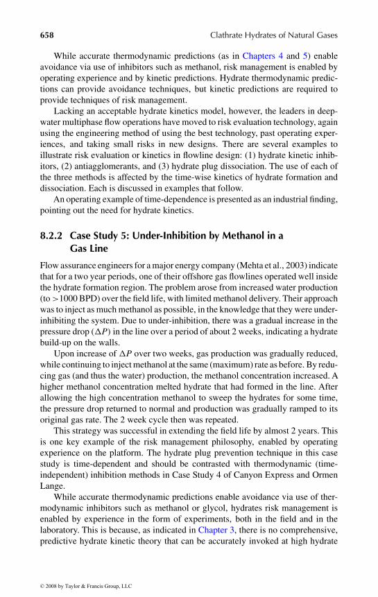
While accurate thermodynamic predictions (as in Chapters 4 and 5) enableavoidance via use of inhibitors such as methanol, risk management is enabled byoperating experience and by kinetic predictions. Hydrate thermodynamic predic-tions can provide avoidance techniques, but kinetic predictions are required toprovide techniques of risk management.
Lacking an acceptable hydrate kinetics model, however, the leaders in deep-water multiphase flow operations have moved to risk evaluation technology, againusing the engineering method of using the best technology, past operating exper-iences, and taking small risks in new designs. There are several examples toillustrate risk evaluation or kinetics in flowline design: (1) hydrate kinetic inhib-itors, (2) antiagglomerants, and (3) hydrate plug dissociation. The use of each ofthe three methods is affected by the time-wise kinetics of hydrate formation anddissociation. Each is discussed in examples that follow.
An operating example of time-dependence is presented as an industrial finding,pointing out the need for hydrate kinetics.
8.2.2 Case Study 5: Under-Inhibition by Methanol in aGas Line
Flow assurance engineers for a major energy company (Mehta et al., 2003) indicatethat for a two year periods, one of their offshore gas flowlines operated well insidethe hydrate formation region. The problem arose from increased water production(to>1000 BPD) over the field life, with limited methanol delivery. Their approachwas to inject as much methanol as possible, in the knowledge that they were under-inhibiting the system. Due to under-inhibition, there was a gradual increase in thepressure drop (�P) in the line over a period of about 2 weeks, indicating a hydratebuild-up on the walls.
Upon increase of �P over two weeks, gas production was gradually reduced,while continuing to inject methanol at the same (maximum) rate as before. By redu-cing gas (and thus the water) production, the methanol concentration increased. Ahigher methanol concentration melted hydrate that had formed in the line. Afterallowing the high concentration methanol to sweep the hydrates for some time,the pressure drop returned to normal and production was gradually ramped to itsoriginal gas rate. The 2 week cycle then was repeated.
This strategy was successful in extending the field life by almost 2 years. Thisis one key example of the risk management philosophy, enabled by operatingexperience on the platform. The hydrate plug prevention technique in this casestudy is time-dependent and should be contrasted with thermodynamic (time-independent) inhibition methods in Case Study 4 of Canyon Express and OrmenLange.
While accurate thermodynamic predictions enable avoidance via use of ther-modynamic inhibitors such as methanol or glycol, hydrates risk management isenabled by experience in the form of experiments, both in the field and in thelaboratory. This is because, as indicated in Chapter 3, there is no comprehensive,predictive hydrate kinetic theory that can be accurately invoked at high hydrate
© 2008 by Taylor & Francis Group, LLC
“9078_C008” — 2007/8/1 — 15:53 — page 659 — #17
Hydrates in Production, Processing, and Transportation 659
concentrations. The very best work in hydrate kinetics comes from the laboratoryof Bishnoi over the last three decades. However, that work was confined to lowhydrate concentrations, due to the need to eliminate confounding heat and masstransfer phenomena. In pipelines and other processes, heat and mass transportphenomena can commonly limit hydrate formation more than kinetics.
The following sections present three examples of kinetic phenomena: (1) kin-etic inhibitors, (2) antiagglomerants (AAs), and (3) hydrate plug remediation.These kinetic phenomena were determined by field and laboratory observations.They also point to the need for a comprehensive kinetics theory, from whichhydrate nucleation and growth can be predicted for industrial utility.
As shown in Chapter 3 and in Figure 8.8, the three steps to hydrate plugformation are (1) nucleation of hydrate films, (2) growth of hydrate films aroundwater droplets or along the wall, and (3) agglomeration of hydrated particles to formplugs. Kinetic hydrate inhibitors (KHIs, also known as KIs) and AAs, both fallingunder the general nomenclature of low dosage hydrate inhibitors (LDHIs), whichare typically lower in concentration than 1 wt%, provide chemical approaches toall three of the plug formation mechanisms. While kinetic inhibitors focus on thefirst two means of prevention, AAs deal with the third means. It should be notedthat in addition to the chemical means of hydrate plug prevention, there are flowmeans of doing so, but this evolving technology is not discussed here.
A major thrust of the research on LDHIs is driven by concern for theenvironment—for chemicals with high biodegradability. The Norwegian PollutionAuthority requires that all new chemicals used offshore must have a biodegrad-ability of higher than 60%, while British environmental authorities require abiodegradability of greater than 20% for new offshore chemicals. For example,although kinetic inhibitors such as those based on PVCap (see description below)and water-soluble polymers have low toxicity, neither kinetic inhibitors nor AAscan be used in the Norwegian sector of the North Sea, while normal PVCap hasa biodegradability below the British requirements. Grafted polymers have beendeveloped to help increase the biodegradability of the kinetic inhibitor polymer(Maximilian et al., 2005). In other places in the world where restrictions are notso stringent, kinetic inhibitors and AAs have wider use.
8.2.3 Kinetic Hydrate Inhibition
Kinetic inhibitors are low molecular weight polymers dissolved in a carrier solventand injected into the water phase in pipelines. These inhibitors bond to the hydratesurface and prevent plug formation for a period longer than the free water resid-ence time in a pipeline. Liquid hydrocarbons may or may not be present for thisprevention method to be effective. Water and small hydrate crystals are removedat a platform or onshore. Kinetic inhibitors are limited at long times, low tem-peratures, and high pressures because with sufficient time, the crystal growth issignificant enough to cause line plugs.
However, there is a limit to the effectiveness of the inhibitors, commonlytaken to be a subcooling (�T = temperature below the equilibrium temperature)
© 2008 by Taylor & Francis Group, LLC
“9078_C008” — 2007/8/1 — 15:53 — page 660 — #18
660 Clathrate Hydrates of Natural Gases
NNO
C O
NH C3 CH3
H C3
CH
CH
2
2
57520
VC-713
ON
n
NN
yx
N
n
Poly(N-Vinylcaprolactam)
Poly(N-Vinylpyrrolidone/N-Vinylcaprolactam) copolymer Poly(N-Vinylpyrrolidone)
O
O
OO
O
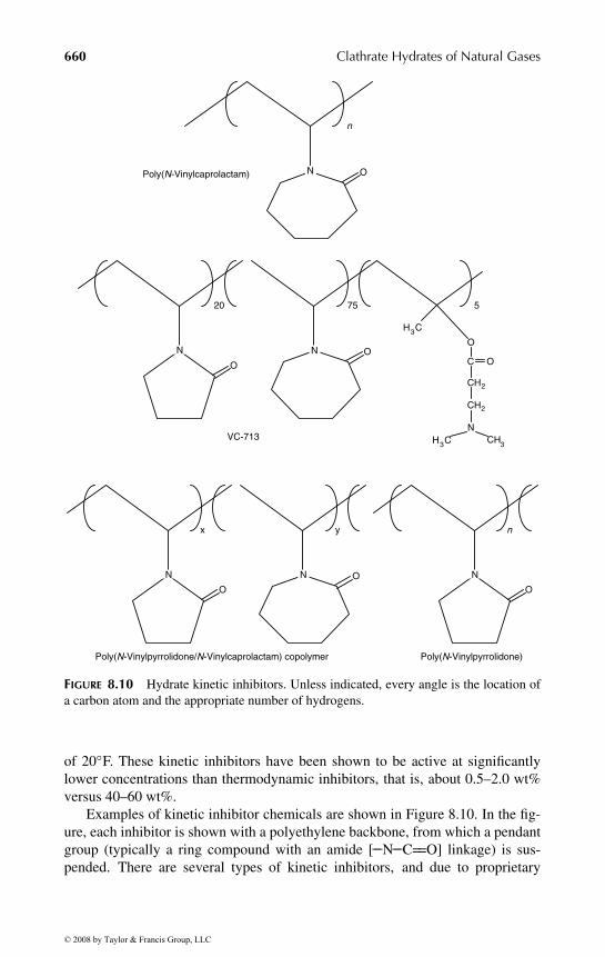
FIGURE 8.10 Hydrate kinetic inhibitors. Unless indicated, every angle is the location ofa carbon atom and the appropriate number of hydrogens.
of 20◦F. These kinetic inhibitors have been shown to be active at significantlylower concentrations than thermodynamic inhibitors, that is, about 0.5–2.0 wt%versus 40–60 wt%.
Examples of kinetic inhibitor chemicals are shown in Figure 8.10. In the fig-ure, each inhibitor is shown with a polyethylene backbone, from which a pendantgroup (typically a ring compound with an amide [−−N−−C==O] linkage) is sus-pended. There are several types of kinetic inhibitors, and due to proprietary
© 2008 by Taylor & Francis Group, LLC

“9078_C008” — 2007/8/1 — 15:53 — page 661 — #19
Hydrates in Production, Processing, and Transportation 661
∆T <4σ
C ·L
L L Cry
stal
sur
face
Poly
mer
cha
in
FIGURE 8.11 One mechanism for kinetic inhibition �T ≤ 4σ/C·L.
concerns, only a few in the literature are discussed to show the principles involved.The reader is referred to the review by Kelland (2006) for a more detailedoverview.
The definitive hydrate kinetic inhibition mechanism is not yet available. Somework suggests that the mechanism is to prevent hydrate nucleation (Kelland, 2006).However, a significant amount of evidence suggests that hydrate kinetic inhibitorsinhibit the growth (Larsen et al., 1996). However, this apparent conflict is due tothe definition of the size at which crystal nucleation stops and growth begins. Toresolve this confusion, one may consider growth to occur after the critical nucleussize is achieved.
As indicated in Figure 8.11, the subcooling �T is directly proportional tothe liquid-crystal surface tension (σ ), but inversely proportional to the length(L) between polymer strands; C is a constant. If the amount of polymer adsorp-tion increases, the distance L between the polymer strands decrease, resultingin an increased subcooling �T performance. Conversely, if the amount ofinhibitor adsorption decreases (due to depletion by multiple small hydrate crys-tals) the distance L between polymer strands increases, resulting in a smallersubcooling �T .
Initial field tests of kinetic inhibitors were reported by ARCO (Bloys et al.,1995) and Texaco (Notz et al., 1995). Bloys reported the effectiveness of0.3–0.4 wt% VC-713 in a 17-day test in a North Sea pipeline. Other large fieldapplications, include BP’s West Sole/Hyde 69 km wet gas pipeline where themaximum subcooling was 8◦C (Argo et al., 1997; Philips 1997), the BP oper-ated Eastern Trough Area Project (ETAP) in the British Sector of the North Sea(Philips 1997; Palermo et al., 2000) where the subcooling was 6–8◦C. In the lat-ter ETAP application, kinetic inhibitors replacing methanol were used. A similarmethod was used by Elf (now Total) to replace methanol in an onshore multiphasetransportation line (Leporcher 1998; Kelland 2006). More recently, PVCap kineticinhibitors have been applied in Qatar involving about 100–120 tn of PVCap peryear, representing the largest applications of kinetic inhibitors in the world.
It should be noted here that, while PVP was one of the first kineticinhibitors discovered, it is one of the weakest kinetic inhibitors available.
© 2008 by Taylor & Francis Group, LLC

“9078_C008” — 2007/8/1 — 15:53 — page 662 — #20
662 Clathrate Hydrates of Natural Gases
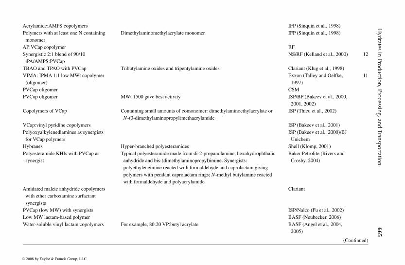
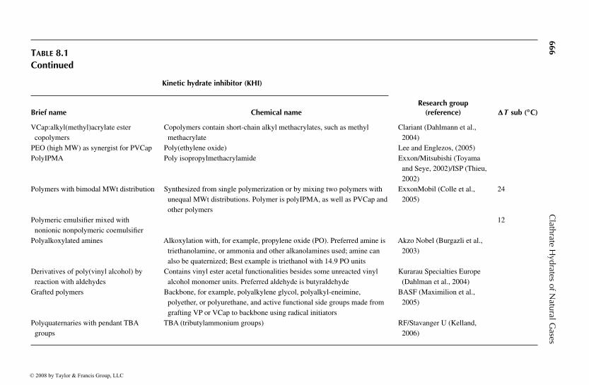
Examples of the use of modern kinetic inhibitors are given by Fu (2002) andKelland (2006). Perhaps the best kinetic inhibitor copolymer was developedby ExxonMobil (Talley, Personal Communication, February 20, 2006) as theN-methyl-N-vinylacetamide: polyisopropyl-methacrylamide 1:1 low molecularweight copolymer (VIMA:IPMA 1:1) that can provide a subcooling of up to 22–23◦C. However, the use of VIMA:IPMA is determined by availability and cost.Table 8.1 summarizes the development of kinetic inhibitors in chronological order,a qualitative ranking of these inhibitors is also given. Much of this historical devel-opment of kinetic inhibitors has been excerpted from the recent review of LDHIsby Kelland (2006).
In his review of LDHIs, Kelland shows that kinetic inhibitors are well-established tools for hydrate prevention, with the following three points:
1. Low molecular weight PVCap-based products with added synergistswere the best kinetic inhibitors for structure II hydrates on the market in2005, and these inhibitors can provide 48 h of inhibition at a subcoolingof 13◦C.
2. In 2005, 40–50 applications of kinetic inhibitors operated worldwide,with the largest applications in the North Sea and Qatar Applications.
3. In 2000 the sales of PVCap-based polymers were 300–500 tn per year.
8.2.3.1 Antiagglomerant means of preventing hydrate plugs
As shown in Figure 8.8, in oil-dominated systems there are three ways to preventhydrate plug formation: (1) prevent particle nucleation, (2) prevent particle growth,and (3) prevent agglomeration of particles so that plugs will not form. AAs preventthe latter aggregation stages that lead to plugging.
AAs are surface active agents that reduce particle adhesion. The AA methodwas begun by Behar, Sugier, and coworkers at l’Institut Francais du Petrole in1987 (Behar et al., 1988). Chemicals effective as AAs are surfactants that typicallyprovide a relatively stable water-in-oil emulsion. The developments by l’InstitutFrancais du Petrole were followed by Shell with surfactants of alkylarylsulfonicacid and its salts (Muijs et al., 1991) and alkyl glycocides (Reynhout et al., 1993).In Bishnoi’s laboratory, Kalogerakis et al. (1993) showed that some surfactantsincreased the agglomeration tendency, counter to the desired effect. Many of thesefirst chemicals, as well as surfactants and polymers were shown to be ineffectivethrough testing by Urdahl et al. (1995).
Figure 8.12 shows the macroscopic method of AAs. In the top portion of thefigure, hydrates are agglomerated into a plug, analogous to that in the far right ofFigure 8.8. In the lower portion of the figure, the hydrate particles are dispersedin the hydrocarbon liquid, so that they will continue to flow.
There are two types of AAs: (1) the French Petroleum Institute (IFP) type thatprovides a special kind of water-in-oil emulsion so that on hydrate formation, theemulsion will not agglomerate and (2) the Shell type that have hydrate-philic headgroup(s) and long hydrophobic tail(s). Because the IFP-type of AA still awaits a
© 2008 by Taylor & Francis Group, LLC

“9078_C008”
—2007/8/1
—15:53
—page
663—
#21
Hydrates
inProduction,Processing,and
Transportation663
TABLE 8.1Chronology of Kinetic Inhibitor Developments
Kinetic hydrate inhibitor (KHI)
Brief name Chemical nameResearch group
(reference) �T sub (◦C)
PVP Poly-N-vinylpyrrolidone CSM (Long et al., 1994) 5HEC Hydroxyethylcellulose CSM (Long et al., 1994)PVCap Poly-N-vinylcaprolactam CSM (Long et al., 1994) 8–9Graffix VC-713 Terpolymer of vinycaprolactam (VCap), vinylpyrollidone (VP), and
dimethlyaminoethyl methacrylateCSM (Sloan, 1995a,b) 8–9
Polyelectrolytes CSM (Sloan, 1995a,b)Polyether block copolymers CSM (Sloan, 1995a,b)Polyvinylamides For example, poly(N-methyl-N-vinyl acetamide) CSM (Sloan, 1995a,b)Polyalkylacrylamides For example, polyethylacrylamide CSM (Sloan, 1995a,b)Polyalkyloxazolines For example, polyethyloxazoline CSM (Sloan, 1995a,b)AFPs Antifreeze proteins (from winter flounder) BP/Shell (Edwards, 1994)AGGPs Antifreeze glycoproteins (from winter flounder) BP/Shell (Edwards, 1994)Butylated PVP Butylated poly-N-vinylpyrrolidone Shell (Anselme et al., 1993)Amino acids Tyrosines and related chemicals BP (Duncan et al., 1993)Threshold inhibitor blends For example, polyvinylcaprolactam+ tetrabutylammonium bromide,
or+ tetrapentylammonium bromideBP (Duncan et al., 1996) <10
Polyamino acids Poly-l-proline (related to fish antifreeze protein) RF (Rogaland Research)VIMA:VCap 1:1 N-methyl-N-vinylacetamide:vinylcaprolactam 1:1 copolymer RF/Exxon (Colle et al., 1996,
1999)10–11
VCap:vinyl imidazole RF
(Continued)
© 2008 by Taylor & Francis Group, LLC
“9078_C008”
—2007/8/1
—15:53
—page
664—
#22
664C
lathrateH
ydratesofN
aturalGases
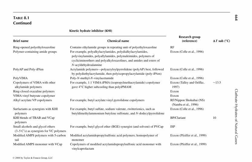
TABLE 8.1Continued
Kinetic hydrate inhibitor (KHI)
Brief name Chemical nameResearch group
(reference) �T sub (◦C)
Ring-opened polyethyloxazoline Contains ethylamide groups in repeating unit of polyethyloxazoline RFPolymer-containing amide groups For example, polyalkylacrylamides, polydialkylacrylamides,
polyvinylamides, polyallylamides, polymaleimides, polymers ofcycliciminoethers and polyalkyloxazolines, and amides and esters ofN-acyldehydroalannine
Exxon (Colle et al., 1996)
PolyAP and Poly-iPAm Acrylamide polymers—polyacryloylpyrrolidene (polyAP) best, followedby polydiethylacrylamide, then polyisopropylacrylamide (poly-iPAm)
Exxon (Colle et al., 1996)
PolyVIMA Poly-N-methyl-N-vinylacetamide Exxon (Colle et al., 1996)Copolymers of VIMA with other
alkylamide polymersFor example, 1:1 VIMA:iPMA (isopropylmethacrylamide) copolymer
gave 4◦C higher subcooling than polyiPMAMExxon (Talley and Oelfke,
1997)∼13.5
Ring-closed oxazaline polymers ExxonVIMA:vinyl butyrate copolymer ExxonAlkyl acrylate:VP copolymers For example, butyl acrylate:vinyl pyrrolidone copolymers RF/Nippon Shokubai (NS)
(Namba et al., 1996)Surfactants as synergists with KHI
polymersFor example, butyl sulfate, sodium valerate, zwitterionics, such as
butyldimethylammonium butylene sulfonate, and N-dodecylpyrrolidoneExxon (Colle et al., 1996)
KHI blends of TBAB and VCappolymers
BP/Clariant 10
Small alcohols and glycol ethers(3–5 C’s) as synergists for VC polymers
For example, butyl glycol ether (BGE) synergist (and solvent) of PVCap ISP
Modified AMPS polymers with 5-carbontail
Modified acrylamidopropylsulfonic acid polymers; homopolymer ofmonomer
Exxon (Pfeiffer et al., 1999)
Modified AMPS monomer with VCap Copolymers of modified acrylamidopropylsulfonic acid monomer withvinylcaprolactam
Exxon (Pfeiffer et al., 1999)
© 2008 by Taylor & Francis Group, LLC
“9078_C008”
—2007/8/1
—15:53
—page
665—
#23
Hydrates
inProduction,Processing,and
Transportation665
Acrylamide:AMPS copolymers IFP (Sinquin et al., 1998)Polymers with at least one N containing
monomerDimethylaminomethylacrylate monomer IFP (Sinquin et al., 1998)
AP:VCap copolymer RFSynergistic 2:1 blend of 90/10
iPA/AMPS:PVCapNS/RF (Kelland et al., 2000) 12
TBAO and TPAO with PVCap Tributylamine oxides and tripentylamine oxides Clariant (Klug et al., 1998)VIMA: IPMA 1:1 low MWt copolymer
(oligomer)Exxon (Talley and Oelfke,
1997)11
PVCap oligomer CSMPVCap oligomer MWt 1500 gave best activity ISP/BP (Bakeev et al., 2000,
2001, 2002)Copolymers of VCap Containing small amounts of comonomer: dimethylaminoethylacrylate or
N-(3-dimethylaminopropyl)methacrylamideISP (Thieu et al., 2002)
VCap:vinyl pyridine copolymers ISP (Bakeev et al., 2001)Polyoxyalkylenediamines as synergists
for VCap polymersISP (Bakeev et al., 2000)/BJ
UnichemHybranes Hyper-branched polyesteramides Shell (Klomp, 2001)Polyesteramide KHIs with PVCap as
synergistTypical polyesteramide made from di-2-propanolamine, hexahydrophthalic
anhydride and bis-(dimethylaminopropyl)imine. Synergists:polyethyleneimine reacted with formaldehyde and caprolactam givingpolymers with pendant caprolactam rings; N-methyl butylamine reactedwith formaldehyde and polyacrylamide
Baker Petrolite (Rivers andCrosby, 2004)
Amidated maleic anhydride copolymerswith ether carboxamine surfactantsynergists
Clariant
PVCap (low MW) with synergists ISP/Nalco (Fu et al., 2002)Low MW lactam-based polymer BASF (Neubecker, 2006)Water-soluble vinyl lactam copolymers For example, 80:20 VP:butyl acrylate BASF (Angel et al., 2004,
2005)
(Continued)
© 2008 by Taylor & Francis Group, LLC
“9078_C008”
—2007/8/1
—15:53
—page
666—
#24
666C
lathrateH
ydratesofN
aturalGases
TABLE 8.1Continued
Kinetic hydrate inhibitor (KHI)
Brief name Chemical nameResearch group
(reference) �T sub (◦C)
VCap:alkyl(methyl)acrylate estercopolymers
Copolymers contain short-chain alkyl methacrylates, such as methylmethacrylate
Clariant (Dahlmann et al.,2004)
PEO (high MW) as synergist for PVCap Poly(ethylene oxide) Lee and Englezos, (2005)PolyIPMA Poly isopropylmethacrylamide Exxon/Mitsubishi (Toyama
and Seye, 2002)/ISP (Thieu,2002)
Polymers with bimodal MWt distribution Synthesized from single polymerization or by mixing two polymers withunequal MWt distributions. Polymer is polyIPMA, as well as PVCap andother polymers
ExxonMobil (Colle et al.,2005)
24
Polymeric emulsifier mixed withnonionic nonpolymeric coemulsifier
12
Polyalkoxylated amines Alkoxylation with, for example, propylene oxide (PO). Preferred amine istriethanolamine, or ammonia and other alkanolamines used; amine canalso be quaternized; Best example is triethanol with 14.9 PO units
Akzo Nobel (Burgazli et al.,2003)
Derivatives of poly(vinyl alcohol) byreaction with aldehydes
Contains vinyl ester acetal functionalities besides some unreacted vinylalcohol monomer units. Preferred aldehyde is butyraldehyde
Kurarau Specialties Europe(Dahlman et al., 2004)
Grafted polymers Backbone, for example, polyalkylene glycol, polyalkyl-eneimine,polyether, or polyurethane, and active functional side groups made fromgrafting VP or VCap to backbone using radical initiators
BASF (Maximilion et al.,2005)
Polyquaternaries with pendant TBAgroups
TBA (tributylammonium groups) RF/Stavanger U (Kelland,2006)
© 2008 by Taylor & Francis Group, LLC

“9078_C008” — 2007/8/1 — 15:53 — page 667 — #25
Hydrates in Production, Processing, and Transportation 667
Oil Oil
OilHydrates in suspension
With antiagglomerant
Without antiagglomerant
FIGURE 8.12 The macroscopic mechanism of hydrate antiagglomerant slurries.
R2
R2
R2
R2
R2
MX +
MX +
X
R1
R1
R1
FIGURE 8.13 The two Shell-types of antiagglomerant. On the left is the water-solubletype, with one branch (R1) containing 8–18 carbons. On the right is the oil-soluble typewith two branches (R1) with 8–18 carbons. The central atom is nitrogen or phosphorus,and the shorter branches (R2) are butyl- or pentyl-groups.
field trial (Kelland, 2006) we will concentrate here on the Shell-type AA, whichcan be further categorized as (1) water soluble, with one long hydrocarbon tail or(2) oil soluble, with two long hydrocarbon tails. Both of these types are shown inFigure 8.13.
A typical water soluble Shell-type AA is a quaternary ammonium salt (QAS),in which two or three of the four ammonium branches are short (e.g., a butylcompound that might be a candidate for inclusion within hydrate cavities ) andone or two branch(es) are much longer (e.g., C8 to C18) so that it might be solublewithin the oil phase. The mechanism of AAs is uncertain at this time, but someeducated guesses can be given, which evolve from the chemical structure of AAs.
The butyl-ammonium end of the AA is very attractive to water and to hydrates,so that it remains firmly attached either to the water droplet, or to the hydrate phaseafter the water droplet conversion. The other, long carbon end of the AA has the
© 2008 by Taylor & Francis Group, LLC

“9078_C008” — 2007/8/1 — 15:53 — page 668 — #26
668 Clathrate Hydrates of Natural Gases
function of stabilizing the QAS in the liquid hydrocarbon, using the physicalchemistry principle of “like dissolves like.” So the attachment of one end of theAA to the hydrate with the other end dissolved in the hydrocarbon liquid turnsthe spherical hydrate shells in Figure 8.8 to spheres with protruding strands ofchemicals.
These long protruding chemical strands provide separation of the hydrateparticles, so that agglomeration does not occur for the suspension in the oil phase.As measured by Yang et al. (2004) and by Taylor (2006), without such preventionthe capillary forces between the hydrate particles are very strong, and can lead tolarge hydrate masses.
In antiagglomeration, since the prevention method relies on emulsifiedwater/hydrates, a condensed hydrocarbon is required (Mehta et al., 2003). Thesolid phase loading cannot exceed 50 volume% of the liquid hydrocarbon phaseto prevent high viscosity associated with compacted slurry flow. The emulsion isbroken and water is removed onshore or at a platform.
The oil-soluble Shell-type AA may behave similarly, but with two long-chainhydrocarbon tails to maintain solubility in the oil phase. However, of the twocategories of Shell-type AAs, the water-soluble type has had the widest use. Withthe above broad-brush, conceptual picture of AAs, it is clear that further definitionshould be done for refinement of the AA mechanism.
8.2.4 Case Study 6: AAs are a Major Hydrate PlugPrevention Tool
Mehta et al. (2003) review the shortcomings of traditional thermodynamic inhib-itors, and the use of the new LDHIs, which are based upon kinetic principles, andare typically applied in concentrations less than 1 wt%. They note that the newKHIs have an upper subcooling limitation of approximately 20◦F, while deepwaterdevelopments often have subcooling requirements of 35–40◦F.
In addition, Mehta et al. present a case study of Shell’s Popeye field use of anew AA inhibitor in a gas condensate line, with the following points:
1. The AA works by emulsifying hydrates in the hydrocarbon liquid.Hydrates are carried as a nonagglomerated slurry, without viscosityincrease for up to 50% water cuts.
2. The AA limit to water cut (volume of water per volume of oil) isapproximately 60%.
3. In the field case study, the AA effectively inhibited hydrate formation,with no significant downstream problems.
4. Flowlines are continuously treated with AA before shut-in, elim-inating the need for instantaneous corrective actions (e.g., flowlinedepressurization) on shut-in.
5. The volume reduction of injected inhibitor can be reduced by a factorof 25 relative to methanol, allowing less topside storage space, easiertransportation, and smaller umbilicals.
© 2008 by Taylor & Francis Group, LLC
“9078_C008” — 2007/8/1 — 15:53 — page 669 — #27
Hydrates in Production, Processing, and Transportation 669
6. The AA eliminates methanol discharge in overboard water and exportlines.
7. CAPEX savings are particularly appealing with the use of AAs for newprojects, but OPEX savings may justify retrofits of existing projects.
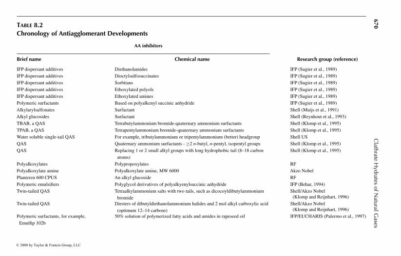
Table 8.2 summarizes the chronological development of AAs. As of April 1,2004, AAs were used in 17 gas and oil fields in the Gulf of Mexico, with pro-spects for rapid expansion. However, as of this writing, kinetic inhibitors arepredominantly used in LDHI work.
8.3 HOW IS A HYDRATE PLUG DISSOCIATED?
This section provides a qualitative understanding of CSMPlug, the plug disso-ciation program which accompanies this book and is illustrated in Appendix B.Sometimes a hydrate plug does form, with the consequences of blocking fluidflow. When a flowline plugs, the usual responses are
1. Locate the plug to determine its position and length2. Carefully evaluate the safety concerns of plug removal (please read the
following section to determine the major safety implications imposed byhydrate plugs)
3. Evaluate the methods of plug removal, of which there are four types:a. Hydraulic methods such as depressurizationb. Chemical methods such as injection of inhibitors or reactive
chemicals that generate heat (Freitas et al., 2002)c. Thermal methods that involve direct electrical heating (Davies
et al., 2006)d. Mechanical methods with coiled tubing, drilling, etc.
The below concepts are an extension of those in Chapter 3 of Hydrate Engineering(Sloan, 2000). Details of the model can be found in the work by Davies et al.(2006). Here, only the first, most-common method of depressurization is treatedconceptually.
From both a safety and technical standpoint, the preferred method to dissociatehydrate plugs is to depressurize from both sides. Depressurization is particularlydifficult when the liquid head on the hydrate plug is greater than the dissociationpressure, as in mountainous terrain or in very deepwater, in which case electricalheating may be used (Davies et al., 2006), a method not considered here.
When a hydrate plug occurs in a pipeline at temperatures above the ice point,the pressure–temperature conditions are illustrated in Figure 8.14. To the left of thethree phase (LW –H–V) line hydrates can form, while to the right only fluids canexist. Because the lowest ground burial temperatures or ocean temperatures (39◦F)are usually above 32◦F, ice formation (which will also block flows) is not a normal
© 2008 by Taylor & Francis Group, LLC
“9078_C008”
—2007/8/1
—15:53
—page
670—
#28
670C
lathrateH
ydratesofN
aturalGases
TABLE 8.2Chronology of Antiagglomerant Developments
AA inhibitors
Brief name Chemical name Research group (reference)
IFP dispersant additives Diethanolamides IFP (Sugier et al., 1989)
IFP dispersant additives Dioctylsulfosuccinates IFP (Sugier et al., 1989)
IFP dispersant additives Sorbitans IFP (Sugier et al., 1989)
IFP dispersant additives Ethoxylated polyols IFP (Sugier et al., 1989)
IFP dispersant additives Ethoxylated amines IFP (Sugier et al., 1989)
Polymeric surfactants Based on polyalkenyl succinic anhydride IFP (Sugier et al., 1989)
Alkylarylsulfonates Surfactant Shell (Muijs et al., 1991)
Alkyl glucosides Surfactant Shell (Reynhout et al., 1993)
TBAB, a QAS Tetrabutylammonium bromide-quaternary ammonium surfactants Shell (Klomp et al., 1995)
TPAB, a QAS Tetrapentylammonium bromide-quaternary ammonium surfactants Shell (Klomp et al., 1995)
Water soluble single-tail QAS For example, tributylammonium or tripentylammonium (better) headgroup Shell US
QAS Quaternary ammonium surfactants - ≥2 n-butyl, n-pentyl, isopentyl groups Shell (Klomp et al., 1995)
QAS Replacing 1 or 2 small alkyl groups with long hydrophobic tail (8–18 carbon
atoms)
Shell (Klomp et al., 1995)
Polyalkoxylates Polypropoxylates RF
Polyalkoxylate amine Polyalkoxylate amine, MW 6000 Akzo Nobel
Planteren 600 CPUS An alkyl glucoside RF
Polymeric emulsifiers Polyglycol derivatives of polyalkyenylsuccinic anhydride IFP (Behar, 1994)
Twin-tailed QAS Tetraalkylammonium salts with two tails, such as dicocoyldibutylammonium
bromide
Shell/Akzo Nobel(Klomp and Reijnhart, 1996)
Twin-tailed QAS Diesters of dibutyldiethanolammonium halides and 2 mol alkyl carboxylic acid
(optimum 12–14 carbons)
Shell/Akzo Nobel(Klomp and Reijnhart, 1996)
Polymeric surfactants, for example,
Emulfip 102b
50% solution of polymerized fatty acids and amides in rapeseed oil IFP/EUCHARIS (Palermo et al., 1997)
© 2008 by Taylor & Francis Group, LLC
“9078_C008”
—2007/8/1
—15:53
—page
671—
#29
Hydrates
inProduction,Processing,and
Transportation671
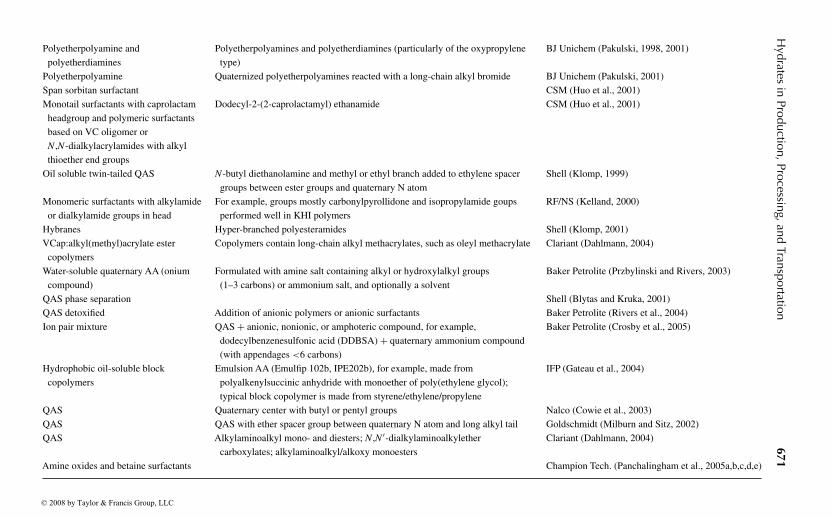
Polyetherpolyamine and
polyetherdiamines
Polyetherpolyamines and polyetherdiamines (particularly of the oxypropylene
type)
BJ Unichem (Pakulski, 1998, 2001)
Polyetherpolyamine Quaternized polyetherpolyamines reacted with a long-chain alkyl bromide BJ Unichem (Pakulski, 2001)
Span sorbitan surfactant CSM (Huo et al., 2001)
Monotail surfactants with caprolactam
headgroup and polymeric surfactants
based on VC oligomer or
N ,N-dialkylacrylamides with alkyl
thioether end groups
Dodecyl-2-(2-caprolactamyl) ethanamide CSM (Huo et al., 2001)
Oil soluble twin-tailed QAS N-butyl diethanolamine and methyl or ethyl branch added to ethylene spacer
groups between ester groups and quaternary N atom
Shell (Klomp, 1999)
Monomeric surfactants with alkylamide
or dialkylamide groups in head
For example, groups mostly carbonylpyrollidone and isopropylamide goups
performed well in KHI polymers
RF/NS (Kelland, 2000)
Hybranes Hyper-branched polyesteramides Shell (Klomp, 2001)
VCap:alkyl(methyl)acrylate ester
copolymers
Copolymers contain long-chain alkyl methacrylates, such as oleyl methacrylate Clariant (Dahlmann, 2004)
Water-soluble quaternary AA (onium
compound)
Formulated with amine salt containing alkyl or hydroxylalkyl groups
(1–3 carbons) or ammonium salt, and optionally a solvent
Baker Petrolite (Przbylinski and Rivers, 2003)
QAS phase separation Shell (Blytas and Kruka, 2001)
QAS detoxified Addition of anionic polymers or anionic surfactants Baker Petrolite (Rivers et al., 2004)
Ion pair mixture QAS+ anionic, nonionic, or amphoteric compound, for example,
dodecylbenzenesulfonic acid (DDBSA)+ quaternary ammonium compound
(with appendages <6 carbons)
Baker Petrolite (Crosby et al., 2005)
Hydrophobic oil-soluble block
copolymers
Emulsion AA (Emulfip 102b, IPE202b), for example, made from
polyalkenylsuccinic anhydride with monoether of poly(ethylene glycol);
typical block copolymer is made from styrene/ethylene/propylene
IFP (Gateau et al., 2004)
QAS Quaternary center with butyl or pentyl groups Nalco (Cowie et al., 2003)
QAS QAS with ether spacer group between quaternary N atom and long alkyl tail Goldschmidt (Milburn and Sitz, 2002)
QAS Alkylaminoalkyl mono- and diesters; N ,N ′-dialkylaminoalkylether
carboxylates; alkylaminoalkyl/alkoxy monoesters
Clariant (Dahlmann, 2004)
Amine oxides and betaine surfactants Champion Tech. (Panchalingham et al., 2005a,b,c,d,e)
© 2008 by Taylor & Francis Group, LLC
“9078_C008” — 2007/8/1 — 15:53 — page 672 — #30
672 Clathrate Hydrates of Natural Gases
3000
2500
2000
0
500
1000
1500
30 35 40 45 50 55 60 65 70 75 80
Temperature (°F)
Pre
ssur
e (p
sia)
Isenthalpic expansion from 68°F, 2180 psia
1
2
Isenthalpic expansion from 77°F, 2180 psia
Isenthalpic expansion from 68°F, 2180 psia
AB
C
∆H = 0
∆T = 0
∆H = 0
Hydrate formation curve
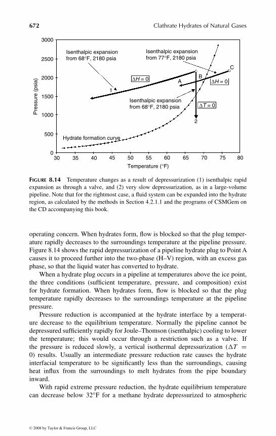
FIGURE 8.14 Temperature changes as a result of depressurization (1) isenthalpic rapidexpansion as through a valve, and (2) very slow depressurization, as in a large-volumepipeline. Note that for the rightmost case, a fluid system can be expanded into the hydrateregion, as calculated by the methods in Section 4.2.1.1 and the programs of CSMGem onthe CD accompanying this book.
operating concern. When hydrates form, flow is blocked so that the plug temper-ature rapidly decreases to the surroundings temperature at the pipeline pressure.Figure 8.14 shows the rapid depressurization of a pipeline hydrate plug to Point Acauses it to proceed further into the two-phase (H–V) region, with an excess gasphase, so that the liquid water has converted to hydrate.
When a hydrate plug occurs in a pipeline at temperatures above the ice point,the three conditions (sufficient temperature, pressure, and composition) existfor hydrate formation. When hydrates form, flow is blocked so that the plugtemperature rapidly decreases to the surroundings temperature at the pipelinepressure.
Pressure reduction is accompanied at the hydrate interface by a temperat-ure decrease to the equilibrium temperature. Normally the pipeline cannot bedepressured sufficiently rapidly for Joule–Thomson (isenthalpic) cooling to lowerthe temperature; this would occur through a restriction such as a valve. Ifthe pressure is reduced slowly, a vertical isothermal depressurization (�T =0) results. Usually an intermediate pressure reduction rate causes the hydrateinterfacial temperature to be significantly less than the surroundings, causingheat influx from the surroundings to melt hydrates from the pipe boundaryinward.
With rapid extreme pressure reduction, the hydrate equilibrium temperaturecan decrease below 32◦F for a methane hydrate depressurized to atmospheric
© 2008 by Taylor & Francis Group, LLC

“9078_C008” — 2007/8/1 — 15:53 — page 673 — #31
Hydrates in Production, Processing, and Transportation 673
pressure. In this case the water from the dissociated hydrate buffers the temperaturereduction to around 0◦C, by converting to ice below the solid–liquid line. If iceformation occurs with hydrate dissociation, then the question arises, “How willthe ice plug dissociation rate compare to the hydrate dissociation rate in an oceanpipeline?”
Recent experiments and modeling suggests that blockages are most efficientlyremoved when the line is depressurized to the fullest extent, as rapidly as possible.When ice forms, it normally has a lower temperature and higher thermal diffusivitythan hydrates, resulting in a rate increase of heat transfer into the pipe.
During 1994–1997 field studies, over 20 hydrate plugs were systematicallyformed and removed from a 6 in. North Sea line in the Tommeliten Gamma field.In both laboratory and field studies these plugs were found to be very porous(>50%) and permeable. Porous, permeable hydrates easily transmit gas pressurewhile still acting to prevent liquid flow in the pipeline. When the pressure wasdecreased at both ends of a highly porous hydrate plug, the pressure decreasedthroughout the entire plug to a constant value. The dissociation temperature at thehydrate front is determined by the pipeline pressure and by the buffering capacityof the water fusion to ice.
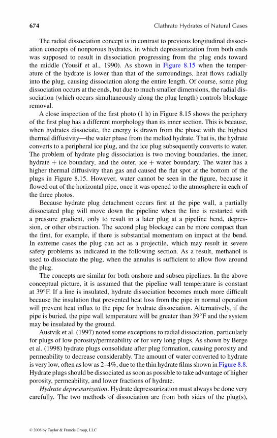
Pipeline depressurization reduces the hydrate temperature below the temper-ature of the surroundings. Heat flows radially into the pipe, causing dissociationfirst at the pipe wall as shown in Figure 8.15. In the figure three laboratory hydrateplugs are shown after three separate experiments—after 1, 2, and 3 h of dissoci-ation (Peters, 1999). Radial hydrate dissociation controls plug removal, becausethe pipe diameter (typically less than 2 ft) is at least an order of magnitude lessthan the length of a hydrate plug (frequently more than 50 ft) in a pipeline.
Pictures of dissociating hydrate plugs
After 1 h
After 3 h
After 2 h
FIGURE 8.15 Hydrate plug radial dissociation in three experiments.
© 2008 by Taylor & Francis Group, LLC
“9078_C008” — 2007/8/1 — 15:53 — page 674 — #32
674 Clathrate Hydrates of Natural Gases
The radial dissociation concept is in contrast to previous longitudinal dissoci-ation concepts of nonporous hydrates, in which depressurization from both endswas supposed to result in dissociation progressing from the plug ends towardthe middle (Yousif et al., 1990). As shown in Figure 8.15 when the temper-ature of the hydrate is lower than that of the surroundings, heat flows radiallyinto the plug, causing dissociation along the entire length. Of course, some plugdissociation occurs at the ends, but due to much smaller dimensions, the radial dis-sociation (which occurs simultaneously along the plug length) controls blockageremoval.
A close inspection of the first photo (1 h) in Figure 8.15 shows the peripheryof the first plug has a different morphology than its inner section. This is because,when hydrates dissociate, the energy is drawn from the phase with the highestthermal diffusivity—the water phase from the melted hydrate. That is, the hydrateconverts to a peripheral ice plug, and the ice plug subsequently converts to water.The problem of hydrate plug dissociation is two moving boundaries, the inner,hydrate + ice boundary, and the outer, ice + water boundary. The water has ahigher thermal diffusivity than gas and caused the flat spot at the bottom of theplugs in Figure 8.15. However, water cannot be seen in the figure, because itflowed out of the horizontal pipe, once it was opened to the atmosphere in each ofthe three photos.
Because hydrate plug detachment occurs first at the pipe wall, a partiallydissociated plug will move down the pipeline when the line is restarted witha pressure gradient, only to result in a later plug at a pipeline bend, depres-sion, or other obstruction. The second plug blockage can be more compact thanthe first, for example, if there is substantial momentum on impact at the bend.In extreme cases the plug can act as a projectile, which may result in severesafety problems as indicated in the following section. As a result, methanol isused to dissociate the plug, when the annulus is sufficient to allow flow aroundthe plug.
The concepts are similar for both onshore and subsea pipelines. In the aboveconceptual picture, it is assumed that the pipeline wall temperature is constantat 39◦F. If a line is insulated, hydrate dissociation becomes much more difficultbecause the insulation that prevented heat loss from the pipe in normal operationwill prevent heat influx to the pipe for hydrate dissociation. Alternatively, if thepipe is buried, the pipe wall temperature will be greater than 39◦F and the systemmay be insulated by the ground.
Austvik et al. (1997) noted some exceptions to radial dissociation, particularlyfor plugs of low porosity/permeability or for very long plugs. As shown by Bergeet al. (1998) hydrate plugs consolidate after plug formation, causing porosity andpermeability to decrease considerably. The amount of water converted to hydrateis very low, often as low as 2–4%, due to the thin hydrate films shown in Figure 8.8.Hydrate plugs should be dissociated as soon as possible to take advantage of higherporosity, permeability, and lower fractions of hydrate.
Hydrate depressurization. Hydrate depressurization must always be done verycarefully. The two methods of dissociation are from both sides of the plug(s),
© 2008 by Taylor & Francis Group, LLC
“9078_C008” — 2007/8/1 — 15:53 — page 675 — #33
Hydrates in Production, Processing, and Transportation 675
or from one side of a plug(s). There are two reasons for the preferred method oftwo-sided hydrate plug dissociation:
1. For a single plug, dissociation from both sides eliminates the safetyconcern of having a projectile in the pipeline. As indicated in the nextsection this is a major safety concern. Sometimes plug dissociation cancause projectiles that damage equipment and in the extreme, can causea loss of life. It should be noted, however, that sometimes gas trappedbetween two plugs can cause risks, even for two-sided dissociation, asindicated in Section 8.4 on Safety.
2. Two-sided dissociation eliminates the Joule–Thomson cooling that maystabilize the downstream end of the plug. With radial dissociation alongthe plug, two-sided dissociation is more than twice as fast as single-sideddissociation.
For the above reasons, the upstream portion of a hydrate plug should bedissociated through a second production line, if available. If this is impossible,depressurization through an umbilical for injecting inhibitors at the wellhead maybe possible; in this case provision should be made for removing or bypassing anycheck valve that may be in the service line at the wellhead. In extreme cases, wherethe line cannot be depressurized due to a high liquid head on the plug, it may bepossible to use electrical heating to dissociate the plug, as indicated by Davieset al. (2006) and as practiced on the Nakika gas field operated by BP, but designedby Shell.
Two-sided dissociation is almost always the method of choice for the flowassurance engineer. Many of the concerns with single-sided plug dissociation arediscussed by Davies et al. (2006). The program CSMPlug and a User’s Manualare provided on the CD in the endpapers of this book. Appendix B contains aset of User’s examples to enable the engineer: (1) to estimate the time for two-sided dissociation, (2) to estimate the time required for (very careful) single-sideddissociation, and (3) to estimate the safety concerns of the hydrate, such as velocityand plug displacement.
8.3.1 Case Study 7: Gulf of Mexico Plug Removal in GasExport Line
Ahydrate blockage in the export line from Shell’s Bullwinkle platform in the GreenCanyon Block 65 to the Boxe platform was reported in DeepStar Report A208-1(Mentor Subsea, 1996, p. 52). The 12 in., 39,000 ft line was not insulated. Theseawater temperature was 50◦F at the base of the platform in 1,400 ft of water. Gasgravity was 0.7 and the flow rate was 140 MMscf/d at an inlet pressure of 800 psi.
Gas hydrates formed during a restart after the platform was shut down dueto a hurricane. During the shut-in period the gas dehydrator partially filled withwater. After production restarted, since the dehydrator was not cleaned properly, itwas not dehydrating gas as designed and wet gas entered the export line, causing
© 2008 by Taylor & Francis Group, LLC

“9078_C008” — 2007/8/1 — 15:53 — page 676 — #34
676 Clathrate Hydrates of Natural Gases
water condensation and hydrate formation. A complete hydrate blockage formedin less than 1 h, just past the base of the export riser at a low spot.
To remove the blockage, the line was depressured on both sides of the plug.Then methanol was circulated into the line to accelerate the hydrate dissociationrate. After complete removal of the hydrates, the dehydrator was cleaned, inspectedand restarted properly. The entire remedial operation required 36 h to complete.The major cost was the lost production time.
8.4 SAFETY AND HYDRATE PLUG REMOVAL
There are many examples of line rupture, sometimes accompanied by loss of life,attributed to the formation of hydrate plugs. Hydrate safety problems are causedby three characteristics:
1. Hydrate density is similar to ice, and upstream pressure can propel adislodged hydrate plug at high velocity. In 1997 DeepStar Wyomingfield tests, plugs ranged from 25 to 200 ft with velocities between 60 and270 ft/s. Such velocities and masses provide sufficient momentum tocause two types of failure at a pipeline restriction (orifice), obstruction(flange or valve), or sharp change in direction (bend, elbow, or tee) asshown in Figure 8.16. First, hydrate impact can fracture the pipe, andsecond, extreme plug momentum and gas compression can cause piperupture downstream of the hydrate path.
2. Hydrates can form either single or multiple plugs, with no method topredict that will occur. High differential pressures can be trapped betweenplugs, even when the discharge end of plugs are depressurized.
3. Hydrates contain 164 volumes (STP) of gas per volume of hydrate. Whenhydrate plugs are dissociated by heating, any confinement causes rapid
A hydrate plug moves down a flowline at very high velocites.
Where the pipe bends, the hydrate plug can rupture the flowline through projectile impact.
A hydrate plug moves down a flowline at very high velocites.
(a) (b)
Closed valve
Closed valve
If the velocity is high enough, the momentum of the plug can cause pressures large enough to rupture the flowline
FIGURE 8.16 Two ways a plug can rupture a pipe: (at left) via momentum impact of highvelocity projectile at a pipeline bend, and (at right) via a combination of plug momentumand gas compression at a pipeline obstruction.
© 2008 by Taylor & Francis Group, LLC
“9078_C008” — 2007/8/1 — 15:53 — page 677 — #35
Hydrates in Production, Processing, and Transportation 677
gas pressure increases. However, heating is not an option within buriedpipe due to the difficulty of plug location and economics of heating aninaccessible pipeline.
When a plug is depressured using a high differential pressure, the dislodgedplug can be a very dangerous projectile, as the below case study indicates (fromMobil’s Kent and Coolen, 1992).
The first chapter of Sloan (2000) is devoted to hydrate safety principles, show-ing several types of safety problems associated with a hydrate plug. Here only oneprecautionary example is given.
8.4.1 Case Study 8: Hydrate Plug Incident Resulting inLoss of Life
At a major energy company in Alberta, a foreman and operator were attemptingto clear a hydrate plug in an outlying sour gas flowline. They had bled downthe pressure in the distant end from the wellhead. They were standing near theline when the line failed, probably from the impact of a moving hydrate mass.A large piece of pipe struck the foreman and the operator summoned help. An airambulance was deployed; however, the foreman was declared dead on arrival atthe hospital. No preexisting pipe defects were found.
The Canadian Association of Petroleum Producers Hydrate Guidelines (Kinget al., 1994) suggest three safety concerns in dealing with hydrate blockages:
• Always assume multiple hydrate plugs; there may be pressure betweenthe plugs.
• Attempting to move ice (hydrate) plugs can rupture pipes and vessels.• While heating a plug is not normally an option for a buried pipeline,
any heating should always be done from the end of a plug to release thegas, rather than heating the plug middle.
The above case study warns that hydrates can be hazardous to personnel and toequipment. Yet hydrate plugs can be safely dissociated with the use of CSMPlugand User’s Manual on the CD in the endpapers of this book, with the User’s GuideExamples in Appendix B. The safety option of this program and process shouldbe considered first, so that the potential for overpressurization and eruption can beconsidered.
In ocean drilling, hydrated sediment cores are often obtained. Because thecores frequently traverse warm waters for periods of about 1 h, hydrated coresdissociate and release gas, to yield higher pressures. When core liners are retrievedon the deck of a drilling vessel, frequently the warm weather can cause additionalhydrate dissolution, resulting in further pressure increases. The modeling of thisdissociation has been done by Wright et al. (2005) and by Davies et al. (2006).
To counteract these shipboard safety problems, several steps are taken such asdrilling through core liners to relieve the pressure, or placing wooden barriers at
© 2008 by Taylor & Francis Group, LLC

“9078_C008” — 2007/8/1 — 15:53 — page 678 — #36
678 Clathrate Hydrates of Natural Gases
Core liner failure at APC/XCB transition
FIGURE 8.17 Core liner failures due to hydrate gas release on ship board.
the open end of cores. Nevertheless, with these cautions, exploding core liners canoccur, as shown by Figure 8.17. These examples point to the need for a hydratecore safety manual, whose basis is in experiment.
8.5 APPLICATIONS TO GAS TRANSPORT AND STORAGE
It is estimated that about 70% of the total gas reserve is either too far from anexisting pipeline or too small to justify a liquefaction facility. Gudmundsson andBorrehaug (1996, 2000) suggested that it is economically feasible to transportstranded gas in hydrated form. In the fourth international hydrate conference MitsuiShipbuilding (Nakajima et al., 2002) show that work in conjunction with the JapanMaritime Research Institute (Shirota et al., 2002) provides a basis for extendingthe basic concept by Gudmundsson and Borrehaug to ship stranded gas.
For storage and transportation the self-preservation phenomenon ofSection 3.3.3 could be an important phenomenon due to its requirements ofdecreased amounts of refrigeration. Recall that the self-preservation phenomenonwas described as: “Self-preservation” consists of a short rapid dissociation phasewith a release of 5–20 vol% of the total methane in the hydrate sample. Duringthis gas release, adiabatic cooling of methane as well as general heat absorptionoccur, resulting in a drop in temperature of between 3 and 7 K relative to thetemperature of the external cooling bath. After this rapid dissociation phase, themethane hydrate remains “metastably preserved for up to 24 h.” It is thought that
© 2008 by Taylor & Francis Group, LLC
“9078_C008” — 2007/8/1 — 15:53 — page 679 — #37
Hydrates in Production, Processing, and Transportation 679
this phenomena is associated with an ice coating that prevents rapid dissociation,aided by ice defect propagation (Kuhs et al, 2004).
Frequently, hydrates become important in natural gas storage in salt cavernsfor peak shaving, or seasonal or diurnal volume averaging delivery of gases. Thework by deRoo et al. (1983) discusses this process, regarding hydrate formation inhigh salt concentration, with their data provided in Chapter 6 on methane hydrateinhibited by sodium chloride.
8.6 SUMMARY OF HYDRATES IN FLOW ASSURANCE AND
TRANSPORTATION
As the energy industry produces from more hostile environments, such as theultra-deepwater and the arctic, flow assurance problems will increase. Associatedhigher pressures, colder temperatures, and higher concentrations of acid gases willcause hydrates to be a larger concern, frequently impacted economically by thehigh cost of thermodynamic inhibitors at high concentration, so that LDHIs willbe more commonly used.
The industrial flow assurance paradigm is shifting from avoidance, enabled bythermodynamic inhibition, to risk management, enabled by application of kinetics.Examples of time-dependent flow assurance phenomena are kinetic inhibitors,AAs, plug dissociation, and electrical heating of pipelines for plug dissociation.Research support will move from thermodynamics, which is currently acceptablyaccurate for engineering applications, to time-dependent kinetics.
The current chapter shows the application of mainly thermodynamic calcu-lations, which have their basis in Chapters 4 and 5. However, as indicated inChapter 3, a fundamental kinetic model, separated from heat and mass transferphenomena, has yet to be established, particularly at high concentrations to extendthe measurements pioneered in the laboratory of Bishnoi during the last three dec-ades. The generation of such a time-dependent growth model and its applicationis one of the major remaining hydrate challenges.
REFERENCES
Angel, M., Neubecker, K., Stein, S., WO Patent Application 04/042190 (2004).Angel, M., Stein, S., Neubecker, K., US Patent 6878788 (2005).Anselme, M.J., Reijnhout, M.J., Klomp, U.C., WO Patent Application 93/25798 (1993).Argo, C.B., Blaine, R.A., Osborne, C.G., Priestly, I.C., in Proc. SPE International
Symposium on Oilfield Chemistry, SPE 37255 Houston, TX, February (2007).Austvik, T., Hustvedt, E., Gjertsen, L.H., Urdahl, O., in Proc. 75th GPA Annual Convention,
p. 205 (1997).Bakeev, K., Chuang, J.-C., Drzewinski, M.A., Graham, D.E., US Patent 6117929 (2000).Bakeev, K., Harris, K., Argo, C.B., Drzewinski, M.A., Graham, D.E., US Patent 6451892
(2002).Bakeev, K., Myers, R., Chuang, J.-C., Winkler, T., Krauss, A., US Patent 6242518 (2001).Behar, E., in Gas Hydrate Seminar, Trondheim, Norway, June (1994).
© 2008 by Taylor & Francis Group, LLC

“9078_C008” — 2007/8/1 — 15:53 — page 680 — #38
680 Clathrate Hydrates of Natural Gases
Behar, E., Sugier, A., Rojey A., “Hydrate Formation and Inhibition in Multiphase Flow,”presented at BHRA Conference Operation consequences of Hydrate Formation andInhibition Offshore, Cranfield, UK, November 3 (1988).
Berge, L.I., Gjertsen, L.H., Lysne, D., Chem. Eng. Sci., 53(9), 1631 (1998).Bloys, B., Lacey, C., Lynch, P., in Proc. 27th Annual OTC, OTC 7772, Houston, TX,
May 1–4 (1995).Blytas, G.C., Kruka, V.R., International Patent Application WO 01/36895 (2001).BP/Clariant, Internal unpublished reports, cited in Kelland, pp. 831, 834 (2006).Brill, J.E., in Flow Assurance as a Discipline, Flow Assurance 2003, Galveston, Texas,
September 23–25 (2003).Burgazli, C.R., Navarrete, R.C., Mead, S.L., in Proc. Canadian International Petroleum
Conference, Paper 2003-070, Calgary, Alberta, Canada, June 10–12 (2003).Carroll, J.J., Natural Gas Hydrates: A Guide for Engineers, Gulf Professional Publishing,
Houston, TX (2003).Colle, K.S., Costello, C.A., Talley, L.D., Longo, J.M., Oelfke, R.H., Berluche, E., WO
Patent Applications, 96/08672, 96/41784 and 96/41834 (1996).Colle, K.S., Oelfke, R.H., Kelland, M.A., U.S. Patent Applications 58746560 (1999).Colle, K.S., Talley, L.D., Longo, J.M., World Patent Application WO 2005/005567 (2005).Cowie, L., Shero, W., Singleton, N., Byrne, N., Kauffman, L., Deepwater Technology, Gulf
Publishing Co, p. 39 (2003).Crosby, D.L., Rivers, G.T., Frostman, L.M., US Patent Application 2005/0261529 (2005).Dahlmann, U., Feustel, M., Kayser, C., Morschchaeuser, R., US Patent Application
2004/00030206 (2004).Davies, S.R., Selim, M.S., Sloan, E.D., Bollavaram, P., Peters, D.J., Hydrate Plug
Dissociation, AIChE J., 52(12), 4016–4027 (2006).de Roo, J.L., Peters, C.J., Lichtenthaler, R.N., Diepen, G.A.M., AIChE J., 29, 651 (1983).Duncan, S., Edwards, A.R., Osborne, C.G., European Patent Application 0536950 A1
(1993).Duncan, S., Edwards, A.R., Osborne, C.G., WO Patent Applications 96/04462, 96/29501,
96/29502 (1996).Edwards, A.R., in (First) International Conference on Natural Gas Hydrates, Ann. NY
Acad. Sci. (Sloan, E.D., Happel, J., et al., eds.), 715, 543 (1994).Freitas, A.M., Lobao, D., Anselmo C., Cardoso, C.B., in Offshore Technology Conference
Proceedings, OTC 14257 Houston, TX, May (2002).Fu, B., Special Publication—Royal Society of Chemistry, Chemistry in the Oil Industry VII,
p. 264 (2002).Gateau, P., Sinquin, A., Beunat, V., Vilagines, R., US Patent Application 2004/0162456
(2004).Gudmundsson, J., Borrehaug, A., in Proc. Second International Conference on Natural
Gas Hydrates (Monfort, J.P., ed.), Toulouse, France, June 2–6, p. 415 (1996).Gudmundsson, J., Borrehaug, A., in Proc. Third International Conference on Natural Gas
Hydrates, Salt Lake City, Utah, U.S.A., July 18–22, 1999; Ann. NY Acad. Sci.(Holder, G.D., Bishnoi, P.R., eds.), 912, 403 (2000).
Hare, S., Case, R., Canyon Express Commissioning and Start-up Experience, in OffshoreTechnology Conference Proceedings, OTC15097, Houston, TX, May 6 (2003).
Hatton, G.J., Kruka, V.R., Hydrate Blockage Formation—Analysis of Werner Bolley FieldTest Data, DeepStar CTR 5209-1 (2002).
Huo, Z., Freer, E., Lamar, M., Sannigrahi, B., Knauss, D.M., Sloan, E.D., Chem. Eng. Sci.,56, 4979 (2001).
© 2008 by Taylor & Francis Group, LLC
“9078_C008” — 2007/8/1 — 15:53 — page 681 — #39
Hydrates in Production, Processing, and Transportation 681
ISP, Internal unpublished reports, cited in Kelland, 834 (2006).Kalogerakis, N., Jamaluddin, A.K.M., Dhloabhai, P.D., Bishnoi, P.R., in Proc. SPE Inter-
national Symposium on Oilfield Chemistry, SPE25188, New Orleans, LA, March2–5, 375 (1993).
Katz, D.L., Trans. AIME, 160, 140 (1945).Kelland, M.A., Energy Fuels, 20(3), 825 (2006).Kelland, M.A., Svartaas, T.M., Ovsthus, T.M., in Proc. Third International Conference on
Natural Gas Hydrates, Salt Lake City, Utah, U.S.A., July 18–22, 1999; Ann. NYAcad. Sci. (Holder, G.D., Bishnoi, P.R. eds.), 912, 281 (2000).
Kent, R.P., Coolen, M.E., Hydrates in Natural Gas Lines, Mobil Internal Report(1992).
Kidnay, A.J., Parrish, W.R., Fundamentals of Natural Gas Processing, Taylor and Francis,Boca Raton, FL (2006).
King, R., et al., Canadian Association of Petroleum Producers Hydrate Guidelines,Canadian Association of Petroleum Producers, Calgary, Alberta, Canada (1994).
Klomp, U.C., WO Patent Application 99/13197 (1999).Klomp, U.C., WO Patent Application 01/77270 (2001).Klomp, U.C., Kruka, V.C., Reijnhart, R., WO Patent Application 95/17579 (1995).Klomp, U.C., Reijnhart, R., WO Patent Application 96/34177 (1996).Klug, P., Feustel, M., Frenz, V., WO Patent Application 98/22557 and 98/03615 (1998).Kuhs, W.F., Genov, G., Stalkova, D.K., Hansen, T., Phys. Chem. Chem. Phys., 6, 4917
(2004).Larsen, R., Makogon, T., Knight, C., Sloan, E.D., in Proc. Second International Conference
on Natural Gas Hydrates (Monfort, J.P., ed.), Toulouse, France, June 2–6, p. 163(1996).
Lee, D.J., Englezos, P., in Proc Fifth International Conference on Gas Hydrates (Austvik,T., ed.), Trondheim, Norway, June 13–16, p. 44 (2005).
Leporcher, E.M., Fourest, J.M., Labes Carrier, C., Lompre, M., in Proc. 1998 SPE EuropeanPetroleum Conference, SPE 50-683, The Hague, The Netherlands, October 20–22(1998).
Lingelem, M.N., Majeed, A.I., Stange, E., in (First) International Conference on NaturalGas Hydrates, Ann. NY Acad. Sci. (Sloan, E.D., Happel, J., et al., eds.), 715, 75(1994).
Long, J., Lederhos, J., Sum, A., Christiansen, R., Sloan, E.D., “Kinetic Inhibitors of NaturalGas Hydrates,” in Proc. 73rd Annual Convention of Gas Processors Association,New Orleans, LA, March 7–9, p. 85 (1994).
Makogon, Y.F., Hydrates of Hydrocarbons, PennWell Books, Tulsa, OK (1997).Maximilian, A., Neubecker, K., Sanner, A., US Patent 6867262 (2005).Mehta, A.P., Hebert, P.B., Cadena, E.R., Weatherman, J.P., SPE Prod. Facil., 73 (2003).Mentor Subsea, Methods to Clear Blocked Flowlines, DeepStar CTR A208-1 (1996).Milburn, C.R., Sitz, G.M., US Patent 644852 B1 (2002).Muijs, H.M., Anselme, M. J., Beers, N.C.M., Van Os, N.M., Kind, C.E., PatentApplication,
Nr. 91.0619 (1991).Nakajima, Y., Takaoki, T., Ohgaki, K., Ota, S., in Proc. Fourth International Conference
on Gas Hydrates (Mori, Y.H., ed.), Yokohama, Japan, May 19–23, 987 (2002).Namba, T., Fujii, Y., Saeki, R., Kobayashi, H., WO Patent Application 96/38492 and
96/37584 (1996).Neubecker, K., Personal communication in 2005 to M.Kelland, cited in Kelland, p. 828
(2006).
© 2008 by Taylor & Francis Group, LLC
“9078_C008” — 2007/8/1 — 15:53 — page 682 — #40
682 Clathrate Hydrates of Natural Gases
Notz, P.K., in (First) International Conference on Natural Gas Hydrates, Annals ofNew York Academy of Sciences (Sloan, E.D., Happel, J., et al., eds.), 715, 425(1994).
Notz, P.K., Bumbgartner, S.B., Schaneman, B.D., Todd, J.L., in Proc. 27th Ann OTC, OTC7777, Houston, TX, May 1–4 (1995).
Pakulski, M. European Patent Application 57458 (1998).Pakulski, M. US Patent Application 6331508 (2001).Palermo, T., Argo, C.B., Goodwin, S.P., Henderson, A., in Proc. Third International
Conference on Natural Gas Hydrates, Salt Lake City, Utah, July 18–22, 1999;Ann. NY Acad. Sci. (Holder, G.D., Bishnoi, P.R., eds.), 912, 355 (2000).
Palermo, T., Mussumeci, A., Leporcher, E., in Proc. Offshore Technology Conference, OTC16681, Houston, TX, May 3–8 (2004).
Palermo, T., Sinquin, A., Dhulesia, H., Fourest, J.M., in Proc. of Multiphase 1997, BHRGroup, p. 133 (1997).
Panchalingham, V., Rudel, M.G., Bodnar, S.H., US Patent Application 20050081714(2005a).
Panchalingham, V., Rudel, M.G., Bodnar, S.H., US Patent Application 20050081432(2005b).
Panchalingham, V., Rudel, M.G., Bodnar, S.H., US Patent Application 20050085396(2005c).
Panchalingham, V., Rudel, M.G., Bodnar, S.H., US Patent Application 20050085675(2005d).
Panchalingham, V., Rudel, M.G., Bodnar, S.H., US Patent Application 20050085676(2005e).
Peters, D.J., A Study of Hydrate Dissociation in Flowlines by the Method of Two-SidedDepressurization: Experiment and Model, M.S. Thesis, Colorado School of Mines,Golden, CO (1999).
Pfeiffer, D.G., Costello, C.A, Talley, L.D., Wright, P.J., WO Patent Application 99/64718(1999).
Philips, N.J., in Proc. 8th International Oilfield Chemical Symposium Geilo, Norway,March (1997).
Przbylinski, J.L., Rivers, G.T., US Patent 6596911 B2 (2003).Reijnhout, M.J., Kind, C.E., Klomp, U.C., European Patent Application, 0 526 929 AL
(1993).Reynhout, M.J., Anselme, M.J., Beers, N.C.M., Van Os, N.M., Kind, C.E., Patent
Application Nr. 91.0619 (1993).Rivers, G.T., Crosby, D.L., US Patent Application 2004/0110998 (2004) WO Patent
Application 2004/22909 (2004).Rivers, G.T., Downs, H.H., US Patent Application 20040144732 (2004).Rivers, G.T., Frostman, L.M., Pryzbyliski, J.L., McMahon, J.A., US Patent Application
2003146173 (2003).Rogalands Research Unpublished Report of Early 1990s, cited in Kelland, p. 825 (2006).Rogalands Research Unpublished Reports of 1995, cited in Kelland, p. 832 (2006).Shirota, H., Aya, I., Namie, S., Bollavaram, P., Turner, D., Sloan, E.D., in Proc. Fourth
International Conference on Gas Hydrates (Mori, Y.H., ed.), Yokohama, Japan,May 19–23, p. 972 (2002).
Sinquin, A., Vellyh, M., Durand, J.P., European Patent Application 789132 (1998).Sloan, E.D., U.S. Patent 5,420,370, May 30 (1995a).Sloan, E.D., U.S. Patent 5,432,292, July 11 (1995b).
© 2008 by Taylor & Francis Group, LLC
“9078_C008” — 2007/8/1 — 15:53 — page 683 — #41
Hydrates in Production, Processing, and Transportation 683
Sloan, E.D., Hydrate Engineering, Monograph 21, Society of Petroleum Engineers,Richardson, TX (2000).
Sugier, A., Bourgmayer, P., Behar, E., Freund, E., European Patent Applications 323307,323774 (1989).
Talley, L.D., Oelfke, R.H., WO Patent Application 97/07320 (1997).Taylor, C.J., Adhesion Force between Hydrate Particles and Macroscopic Investigation of
Hydrate Film Growth at the Hydrocarbon/Water Interface, M.Sc. Thesis, ColoradoSchool of Mines, Golden, CO (2006).
Thieu, V., Bakeev, K., Shih, J.S., US Patent 6359047 (2002).Todd, J.L., et al., Reliabilty Engineering—Gas Freezing and Hydrates, Texaco Company
Hydrate Handbook, New Orleans, LA (1996).Toyama, M., Seye, M., World Patent Application WO 02/10318 (2002).Turner, D.J., Clathrate Hydrate Formation in Water-in-Oil Dispersions, Ph.D. Thesis,
Colorado School of Mines, Golden, CO (2004).Urdahl, O., Lund, A., Mork, P., Nilsen, T.-N., Chem. Eng. Sci., 50, 863 (1995).Welling andAssociates 1999 Survey, cited by Macintosh, N., “FlowAssurance Still Leading
Concern Among Producers,” Offshore, October (2000).Wilson, A., Overaa, S.J., Holm, H., Offshore Technology Conference, OTC 1655, Houston,
TX, May 3–6 (2004).Wolden, M., Lund, A., Oza, N., Makogon, T., Argo, C.B., Larsen, R., in Proc. Fifth
International Conf. on Gas Hydrates (Austvik, T., ed.), paper 4002 (5 volumes andCD), Trondheim, Norway, June 13–16, p. 1101 (2005).
Wright, J.F., Dallimore, S.D., Nixon, F.M., Dchesne, C., in Scientific Results from theMallik 2002 Gas Hydrate Production Research Well Program, Mackenzie Delta,Northwest Territories, Canada (Dallimore, S.R., Collett, T.S., eds.), GeologicalSurvey of Canada Bulletin 585, including CD, p. 92 (2005).
Yang, S.O., Kleehammer, D.M., Huo, Z., Sloan, E.D., Miller, K.T., J. Colloid Interf. Sci.,277, 335 (2004).
Yousif, M.H., Li, P.M., Selim, M.S., Sloan, E.D., J. Inclus. Phenom. Mol., 8, 71 (1990).
© 2008 by Taylor & Francis Group, LLC