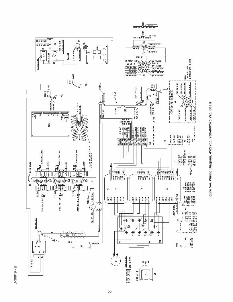
452CVCC & 582CVCC DC WELDING POWER SOURCES
28
INSTRUCTION MANUAL F-15-364-A March, 2001 Be sure this information reaches the operator. You can get extra copies through your supplier. 452CVCC & 582CVCC DC WELDING POWER SOURCES This manual provides complete instructions for the following power sources starting with Serial No. M0RI708101, January 1997: ESAB ITEM NO. 36385 - 452CVCC - 230/460 vac, 3 ph., 60 Hz * ESAB ITEM NO. 36387 - 582CVCC - 230/460 vac, 3ph., 60 Hz ESAB ITEM NO. 36386 - 452CVCC - 230/460/575 vac, 3 ph., 60 Hz ESAB ITEM NO. 36388 - 582CVCC - 220/400 vac, 3 ph., 50 Hz ESAB ITEM NO. 36389 - 582CVCC - 220/400 vac, 3 ph., 50 Hz CE Label ESAB ITEM NO. 36855 - 582CVCC - 220/400 vac, 3 ph., 60 Hz * Manufactured for export service only. These INSTRUCTIONS are for experienced operators. If you are not fully familiar with the principles of operation and safe practices for arc welding equipment, we urge you to read our booklet, "Precautions and Safe Practices for Arc Welding, Cutting, and Gouging," Form 52-529. Do NOT permit untrained persons to install, operate, or maintain this equipment. Do NOT attempt to install or operate this equipment until you have read and fully understand these instructions. If you do not fully understand these instructions, contact your supplier for further information. Be sure to read the Safety Precautions before installing or operating this equipment.
-
Upload
khangminh22 -
Category
Documents
-
view
1 -
download
0
Transcript of 452CVCC & 582CVCC DC WELDING POWER SOURCES

INSTRUCTION MANUAL
F-15-364-AMarch, 2001
Be sure this information reaches the operator.You can get extra copies through your supplier.
452CVCC & 582CVCC
DC WELDING POWER SOURCES
This manual provides complete instructions for the following power sources starting with Serial No. M0RI708101, January 1997:
ESAB ITEM NO. 36385 - 452CVCC - 230/460 vac, 3 ph., 60 Hz* ESAB ITEM NO. 36387 - 582CVCC - 230/460 vac, 3ph., 60 HzESAB ITEM NO. 36386 - 452CVCC - 230/460/575 vac, 3 ph., 60 HzESAB ITEM NO. 36388 - 582CVCC - 220/400 vac, 3 ph., 50 HzESAB ITEM NO. 36389 - 582CVCC - 220/400 vac, 3 ph., 50 Hz CE Label
ESAB ITEM NO. 36855 - 582CVCC - 220/400 vac, 3 ph., 60 Hz
* Manufactured for export service only.
These INSTRUCTIONS are for experienced operators. If you are not fully familiar with the principles of operationand safe practices for arc welding equipment, we urge you to read our booklet, "Precautions and Safe Practicesfor Arc Welding, Cutting, and Gouging," Form 52-529. Do NOT permit untrained persons to install, operate, ormaintain this equipment. Do NOT attempt to install or operate this equipment until you have read and fullyunderstand these instructions. If you do not fully understand these instructions, contact your supplier forfurther information. Be sure to read the Safety Precautions before installing or operating this equipment.
2
USER RESPONSIBILITYThis equipment will perform in conformity with the description thereof contained in this manual and accompanying labels and/or inserts wheninstalled, operated, maintained and repaired in accordance with the instructions provided. This equipment must be checked periodically. Defectiveequipment should not be used. Parts that are broken, missing, worn, distorted or contaminated should be replaced immediately. Should suchrepair or replacement become necessary, the manufacturer recommends that a telephone or written request for service advice be made to theAuthorized Distributor from whom it was purchased.
This equipment or any of its parts should not be altered without the prior written approval of the manufacturer. The user of this equipment shallhave the sole responsibility for any malfunction which results from improper use, faulty maintenance, damage, improper repair or alteration byanyone other than the manufacturer or a service facility designated by the manufacturer.
TABLE OF CONTENTSSECTION TITLE PAGE
PARAGRAPH
SECTION 1 DESCRIPTION ................................................................................................................................... 71.1 General ............................................................................................................................................... 71.2 Receiving-Handling ............................................................................................................................ 71.3 Description ......................................................................................................................................... 71.3.1 Power Source ..................................................................................................................................... 71.3.2 Volt-Ampere Characteristics .............................................................................................................. 71.4 Optional Accessories ......................................................................................................................... 81.4.1 Remote Control Kit ............................................................................................................................. 81.4.2 HC-3B Remote Hand Control ............................................................................................................ 81.4.3 TR-23A Truck Kit ................................................................................................................................ 81.4.4 Swivel Mount Kit ................................................................................................................................. 81.4.5 External Grounding Control Protection Kit ......................................................................................... 81.5 Safety ................................................................................................................................................. 8
SECTION 2 INSTALLATION ................................................................................................................................. 92.1 Location .............................................................................................................................................. 92.2 Receiving, Unpacking and Placement ............................................................................................... 92.3 Primary (Input) Electrical Connection ................................................................................................ 92.4 Secondary (Output) Welding Connections ........................................................................................ 112.5 Power Source/Wire Feeder/Control Interconnections ....................................................................... 112.5.1 Wire Feeder Control ........................................................................................................................... 112.5.2 Remote Control .................................................................................................................................. 112.5.3 Auxiliary 115 V ac Receptacle ........................................................................................................... 112.5.4 42 V Circuit Breaker ........................................................................................................................... 112.5.5 115 V Circuit Breaker ......................................................................................................................... 11
SECTION 3 OPERATION ...................................................................................................................................... 133.1 Controls .............................................................................................................................................. 133.1.1 Power Switch (ON-OFF) .................................................................................................................... 133.1.2 Contactor On/Remote Switch ............................................................................................................ 133.1.3 Output Panel/Remote Switch ............................................................................................................. 133.1.4 Output Voltage/Current Control ......................................................................................................... 133.1.5 Process Switch ................................................................................................................................... 133.1.6 Over Temperature Indicator ............................................................................................................... 133.1.7 Voltmeter and Ammeter ..................................................................................................................... 133.1.8 Fault Indicator ..................................................................................................................................... 143.1.9 Over Current Protection ..................................................................................................................... 143.1.10 High & Low Inductance Receptacles ................................................................................................. 143.2 Sequence of Operation ...................................................................................................................... 143.2.1 General Procedures for CV-Mig, Sub Arc and CC-Stick, Sub Arc .................................................... 143.2.2 Specific Procedures for CV-Mig and Sub Arc ................................................................................... 143.2.3 Specific Procedures for CC-Stick and Arc Gouging .......................................................................... 15
SECTION 4 MAINTENANCE ................................................................................................................................. 164.1 General ............................................................................................................................................... 164.2 Cleaning ............................................................................................................................................. 164.3 Inspection and Service ....................................................................................................................... 164.3.1 Fan Motor ........................................................................................................................................... 164.3.2 Transformer ........................................................................................................................................ 164.3.3 Wire Feeder and Control Circuits ...................................................................................................... 164.3.4 Over Temperature Protection ............................................................................................................ 164.3.5 Digital Voltmeter/Ammeter Calibration .............................................................................................. 16
SECTION 5 TROUBLESHOOTING ....................................................................................................................... 175.1 General ............................................................................................................................................... 175.2 Testing and Replacing Bridge Assembly Components ..................................................................... 17
SECTION 6 PARTS ................................................................................................................................................ 236.1 General ............................................................................................................................................... 236.2 Ordering .............................................................................................................................................. 23
3
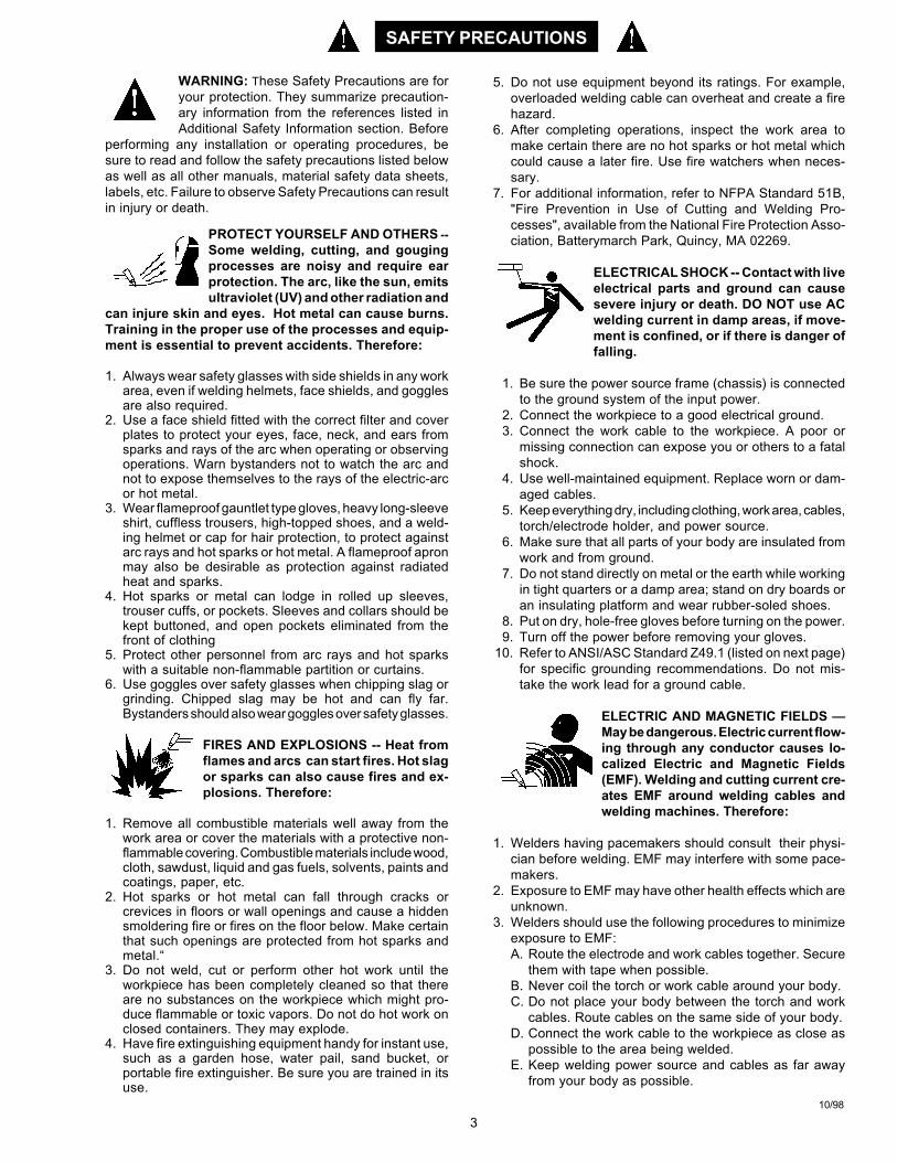
WARNING: These Safety Precautions are foryour protection. They summarize precaution-ary information from the references listed inAdditional Safety Information section. Before
performing any installation or operating procedures, besure to read and follow the safety precautions listed belowas well as all other manuals, material safety data sheets,labels, etc. Failure to observe Safety Precautions can resultin injury or death.
PROTECT YOURSELF AND OTHERS --Some welding, cutting, and gougingprocesses are noisy and require earprotection. The arc, like the sun, emitsultraviolet (UV) and other radiation and
can injure skin and eyes. Hot metal can cause burns.Training in the proper use of the processes and equip-ment is essential to prevent accidents. Therefore:
1. Always wear safety glasses with side shields in any workarea, even if welding helmets, face shields, and gogglesare also required.
2. Use a face shield fitted with the correct filter and coverplates to protect your eyes, face, neck, and ears fromsparks and rays of the arc when operating or observingoperations. Warn bystanders not to watch the arc andnot to expose themselves to the rays of the electric-arcor hot metal.
3. Wear flameproof gauntlet type gloves, heavy long-sleeveshirt, cuffless trousers, high-topped shoes, and a weld-ing helmet or cap for hair protection, to protect againstarc rays and hot sparks or hot metal. A flameproof apronmay also be desirable as protection against radiatedheat and sparks.
4. Hot sparks or metal can lodge in rolled up sleeves,trouser cuffs, or pockets. Sleeves and collars should bekept buttoned, and open pockets eliminated from thefront of clothing
5. Protect other personnel from arc rays and hot sparkswith a suitable non-flammable partition or curtains.
6. Use goggles over safety glasses when chipping slag orgrinding. Chipped slag may be hot and can fly far.Bystanders should also wear goggles over safety glasses.
FIRES AND EXPLOSIONS -- Heat fromflames and arcs can start fires. Hot slagor sparks can also cause fires and ex-plosions. Therefore:
1. Remove all combustible materials well away from thework area or cover the materials with a protective non-flammable covering. Combustible materials include wood,cloth, sawdust, liquid and gas fuels, solvents, paints andcoatings, paper, etc.
2. Hot sparks or hot metal can fall through cracks orcrevices in floors or wall openings and cause a hiddensmoldering fire or fires on the floor below. Make certainthat such openings are protected from hot sparks andmetal.“
3. Do not weld, cut or perform other hot work until theworkpiece has been completely cleaned so that thereare no substances on the workpiece which might pro-duce flammable or toxic vapors. Do not do hot work onclosed containers. They may explode.
4. Have fire extinguishing equipment handy for instant use,such as a garden hose, water pail, sand bucket, orportable fire extinguisher. Be sure you are trained in itsuse.
SAFETY PRECAUTIONS
10/98
5. Do not use equipment beyond its ratings. For example,overloaded welding cable can overheat and create a firehazard.
6. After completing operations, inspect the work area tomake certain there are no hot sparks or hot metal whichcould cause a later fire. Use fire watchers when neces-sary.
7. For additional information, refer to NFPA Standard 51B,"Fire Prevention in Use of Cutting and Welding Pro-cesses", available from the National Fire Protection Asso-ciation, Batterymarch Park, Quincy, MA 02269.
ELECTRICAL SHOCK -- Contact with liveelectrical parts and ground can causesevere injury or death. DO NOT use ACwelding current in damp areas, if move-ment is confined, or if there is danger offalling.
1. Be sure the power source frame (chassis) is connectedto the ground system of the input power.
2. Connect the workpiece to a good electrical ground.3. Connect the work cable to the workpiece. A poor or
missing connection can expose you or others to a fatalshock.
4. Use well-maintained equipment. Replace worn or dam-aged cables.
5. Keep everything dry, including clothing, work area, cables,torch/electrode holder, and power source.
6. Make sure that all parts of your body are insulated fromwork and from ground.
7. Do not stand directly on metal or the earth while workingin tight quarters or a damp area; stand on dry boards oran insulating platform and wear rubber-soled shoes.
8. Put on dry, hole-free gloves before turning on the power.9. Turn off the power before removing your gloves.
10. Refer to ANSI/ASC Standard Z49.1 (listed on next page)for specific grounding recommendations. Do not mis-take the work lead for a ground cable.
ELECTRIC AND MAGNETIC FIELDS —May be dangerous. Electric current flow-ing through any conductor causes lo-calized Electric and Magnetic Fields(EMF). Welding and cutting current cre-ates EMF around welding cables andwelding machines. Therefore:
1. Welders having pacemakers should consult their physi-cian before welding. EMF may interfere with some pace-makers.
2. Exposure to EMF may have other health effects which areunknown.
3. Welders should use the following procedures to minimizeexposure to EMF:A. Route the electrode and work cables together. Secure
them with tape when possible.B. Never coil the torch or work cable around your body.C. Do not place your body between the torch and work
cables. Route cables on the same side of your body.D. Connect the work cable to the workpiece as close as
possible to the area being welded.E. Keep welding power source and cables as far away
from your body as possible.

4
FUMES AND GASES -- Fumes andgases, can cause discomfort or harm,particularly in confined spaces. Donot breathe fumes and gases. Shield-ing gases can cause asphyxiation.Therefore:
1. Always provide adequate ventilation in the work area bynatural or mechanical means. Do not weld, cut, or gougeon materials such as galvanized steel, stainless steel,copper, zinc, lead, beryllium, or cadmium unless posi-tive mechanical ventilation is provided. Do not breathefumes from these materials.
2. Do not operate near degreasing and spraying opera-tions. The heat or arc rays can react with chlorinatedhydrocarbon vapors to form phosgene, a highly toxicgas, and other irritant gases.
3. If you develop momentary eye, nose, or throat irritationwhile operating, this is an indication that ventilation is notadequate. Stop work and take necessary steps to im-prove ventilation in the work area. Do not continue tooperate if physical discomfort persists.
4. Refer to ANSI/ASC Standard Z49.1 (see listing below)for specific ventilation recommendations.
5. WARNING: This product, when used for welding orcutting, produces fumes or gases whichcontain chemicals known to the State ofCalifornia to cause birth defects and, insome cases, cancer. (California Health &Safety Code §25249.5 et seq.)
CYLINDER HANDLING -- Cylinders, ifmishandled, can rupture and violentlyrelease gas. Sudden rupture of cylin-der, valve, or relief device can injure orkill. Therefore:
1. Use the proper gas for the process and use the properpressure reducing regulator designed to operate fromthe compressed gas cylinder. Do not use adaptors.Maintain hoses and fittings in good condition. Followmanufacturer's operating instructions for mounting regu-lator to a compressed gas cylinder.
2. Always secure cylinders in an upright position by chainor strap to suitable hand trucks, undercarriages, benches,walls, post, or racks. Never secure cylinders to worktables or fixtures where they may become part of anelectrical circuit.
3. When not in use, keep cylinder valves closed. Havevalve protection cap in place if regulator is not con-nected. Secure and move cylinders by using suitablehand trucks. Avoid rough handling of cylinders.
4. Locate cylinders away from heat, sparks, and flames.Never strike an arc on a cylinder.
5. For additional information, refer to CGA Standard P-1,"Precautions for Safe Handling of Compressed Gases inCylinders", which is available from Compressed GasAssociation, 1235 Jefferson Davis Highway, Arlington,VA 22202.
EQUIPMENT MAINTENANCE -- Faulty orimproperly maintained equipment cancause injury or death. Therefore:
1. Always have qualified personnel perform the installa-tion, troubleshooting, and maintenance work. Do notperform any electrical work unless you are qualified toperform such work.
2. Before performing any maintenance work inside a powersource, disconnect the power source from the incomingelectrical power.
3. Maintain cables, grounding wire, connections, powercord, and power supply in safe working order. Do notoperate any equipment in faulty condition.
4. Do not abuse any equipment or accessories. Keepequipment away from heat sources such as furnaces,wet conditions such as water puddles, oil or grease,corrosive atmospheres and inclement weather.
5. Keep all safety devices and cabinet covers in positionand in good repair.
6. Use equipment only for its intended purpose. Do notmodify it in any manner.
ADDITIONAL SAFETY INFORMATION -- Formore information on safe practices for elec-tric arc welding and cutting equipment, askyour supplier for a copy of "Precautions andSafe Practices for Arc Welding, Cutting andGouging", Form 52-529.
The following publications, which are available from theAmerican Welding Society, 550 N.W. LeJuene Road, Mi-ami, FL 33126, are recommended to you:1. ANSI/ASC Z49.1 - "Safety in Welding and Cutting"2. AWS C5.1 - "Recommended Practices for Plasma Arc
Welding"3. AWS C5.2 - "Recommended Practices for Plasma Arc
Cutting"4. AWS C5.3 - "Recommended Practices for Air Carbon
Arc Gouging and Cutting"5. AWS C5.5 - "Recommended Practices for Gas Tung-
sten Arc Welding“6. AWS C5.6 - "Recommended Practices for Gas Metal Arc
Welding"“7. AWS SP - "Safe Practices" - Reprint, Welding Hand-
book.8. ANSI/AWS F4.1, "Recommended Safe Practices for
Welding and Cutting of Containers That Have HeldHazardous Substances."
MEANING OF SYMBOLS - As used through-out this manual: Means Attention! Be Alert!Your safety is involved.
Means immediate hazards which, ifnot avoided, will result in immediate,serious personal injury or loss of life.
Means potential hazards which couldresult in personal injury or loss of life.
Means hazards which could result inminor personal injury.
SP98-10
SAFETY PRECAUTIONS
5
coupes à l’arc, à moins de les recouvrir complètementd’une bâche non-inflammable. Ce type de matériauxcomprend notamment le bois, les vêtements, la sciure,l’essence, le kérosène, les peintures, les solvants, legaz naturel, l’acétylène, le propane et autres sub-stances combustibles semblables.
b. Les étincelles ou les projections de métal incandes-cent peuvent tomber dans des fissures du plancher oudans des ouvertures des murs et y déclencher uneignition lente cachée. Veiller à protéger ces ouverturesdes étincelles et des projections de métal.
c. N’exécutez pas de soudures, de coupes, d’opérationsde gougeage ou autres travaux à chaud à la surfacede barils, bidons, réservoirs ou autres contenantsusagés, avant de les avoir nettoyés de toute trace desubstance susceptible de produire des vapeursinflammables ou toxiques.
d. En vue d’assurer la prévention des incendies, ilconvient de disposer d’un matériel d’extinction prêt àservir immédiatement, tel qu’un tuyau d’arrosage, unseau à eau, un seau de sable ou un extincteur portatif.
e. Une fois le travail à l’arc terminé, inspectez le secteurde façon à vous assurer qu’aucune étincelle ou projec-tion de métal incandescent ne risque de provoquerultérieurement un feu.
3. CHOC ÉLECTRIQUE-- Le gougeage à l’arc et à l’arcau plasma exige l’emploi de tensions à viderelativement importantes; or, celles-ci risquent decauser des dommages corporels graves et mêmemortels en cas d’utilisation inadéquate. La gravité duchoc électrique reçu dépend du chemin suivi par lecourant à travers le corps humain et de son intensité.
a. Ne laissez jamais de surfaces métalliques sous ten-sion venir au contact direct de la peau ou devêtements humides. Veillez à porter des gants biensecs.
b. Si vous devez effectuer un travail sur une surfacemétallique ou dans un secteur humide, veillez à assu-rer votre isolation corporelle en portant des gants secset des chaussures à semelles de caoutchouc et envous tenant sur une planche ou une plate-formesèche.
c. Mettez toujours à la terre le poste de soudage/coupageen le reliant par un câble à une bonne prise de terre.
d. N’utilisez jamais de câbles usés ou endommagés. Nesurchargez jamais le câble. Utilisez toujours unéquipement correctement entretenu.
e. Mettez l’équipement hors tension lorsqu’il n’est pas enservice. une mise à la masse accidentelle peut en effetprovoquer une surchauffe de l’équipement et un dan-ger d’incendie. Ne pas enrouler ou passer le câbleautour d’une partie quelconque du corps.
f. Vérifiez si le câble de masse est bien relié à la pièce enun point aussi proche que possible de la zone detravail. Le branchement des câbles de masse àl’ossature du bâtiment ou en un point éloigné de lazone de travail augmente en effet le risque de pas-sage d’un courant de sortie par des chaînes de
PRÉCAUTIONS DE SÉCURITÉ
AVERTISSEMENT: Ces règles de sécurité ont pour objetd’ assurer votre protection. Veillez à lire et à observer lesprécautions énoncées ci-dessous avant de monter l’équipement ou de commercer à l’utiliser. Tout défautd’observation de ces précautions risque d’entraîner desblessures graves ou mortelles.1. PROTECTION INDIVIDUELLE-- Les brûlures de la
peau et des yeux dues au rayonnement de l’arcélectrique ou du métal incandescent, lors du soudageau plasma ou à l’électrode ou lors du gougeage àl’arc, peuvent s’avérer plus graves que cellesrésultant d’une exposition prolongée au soleil. Aussiconvient-il d’observer les précautions suivantes:
a. Portez un écran facial adéquat muni des plaquesprotectrices et des verres filtrants appropriés afin devous protéger les yeux, le visage, le cou et les oreillesdes étincelles et du rayonnement de l’arc électriquelorsque vous effectuez des soudures ou des coupesou lorsque vous en observez l’exécution.
AVERTISSEZ les personnes se trouvant à proximitéde façon à ce qu’elles ne regardent pas l’arc et à cequ’elles ne s’exposent pas à son rayonnement, ni àcelui du métal incandescent.
b. Portez des gants ignifugés à crispins, une tuniqueépaisse à manches longues, des pantalons sansrebord, des chaussures à embout d’acier et uncasque de soudage ou une calotte de protection, afind’éviter d’exposer la peau au rayonnement de l’arcélectrique ou du métal incandescent. ll est égalementsouhaitable d’utiliser un tablier ininflammable defaçon à se protéger des étincelles et du rayonnementthermique.
c. Les étincelles ou les projections de métal incandes-cent risquent de se loger dans des manchesretroussées, des bords relevés de pantalons ou dansdes poches. Aussi convient-il de garder boutonnés lecol et les manches et de porter des vêtements sanspoches à l’avant.
d. Protégez des étincelles et du rayonnement de l’arcélectrique les autres personnes travaillant à proximitéà l’aide d’un écran ininflammable adéquat.
e. Ne jamais omettre de porter des lunettes de sécuritélorsque vous vous trouvez dans un secteur où l’oneffectue des opérations de soudage ou de coupage àl’arc. Utilisez des lunettes de sécurité à écrans ouverres latéraux pour piquer ou meûler le laitier. Lespiquetures incandescentes de laitier peuvent êtreprojetées à des distances considérables. Lespersonnes se trouvant à proximité doivent égalementporter des lunettes de protection.
f. Le gougeage à l’arc et le soudage à l’arc au plasmaproduisent un niveau de bruit extrêmement élevé (de100 à 114 dB) et exigent par conséquent l’emploi dedispositifs appropriés de protection auditive.
2. PRÉVENTION DES INCENDES-- Les projections delaitier incandescent ou d’étincelles peuventprovoquer de graves incendies au contact dematériaux combustibles solides, liquides ou gazeux.Aussi faut-il observer les précautions suivantes:
a. Éloigner suffisamment tous les matériaux combus-tibles du secteur où l’on exécute des soudures ou des
9/97
6
levage, des câbles de grue ou divers cheminsélectriques.
g. Empêchez l’apparition de toute humidité, notammentsur vos vêtements, à la surface de l’emplacement detravail, des câbles, du porte-électrode et du poste desoudage/coupage. Réparez immédiatement toutefuite d’eau.
4. VENTILATION-- La respiration prolongée des fuméesrésultant des opérations de soudage/coupage, àl’intérieur, d’un local clos, peut provoquer des mal-aises et des dommages corporels. Aussi convient-ild’observer les précautions suivantes:
a. Assurez en permanence une aération adéquate del’emplacement de travail en maintenant une ventila-tion naturelle ou à l’aide de moyens mécaniques.N’effectuez jamais de travaux de soudage ou decoupage sur des matériaux de zinc, de plomb, deberyllium ou de cadmium en l’absence de moyensmécaniques de ventilation capables d’empêcherl’inhalation des fumées dégagées par ces matériaux.
b. N’effectuez jamais de travaux de soudage ou decoupage à proximité de vapeurs d’hydrocarburechloré résultant d’opérations voisines de dégraissageou de pulvérisation. La chaleur dégagée ou lerayonnement de l’arc peut déclencher la formation dephosgène -- gaz particulièrement toxique -- et d’autresgaz irritants, à partir des vapeurs de solvant.
c. Une irritation momentanée des yeux, du nez ou de lagorge constatée au cours de l’utilisation del’équipement dénote un défaut de ventilation. Arrêtez-vous de travailler afin de prendre les mesures néces-saires à l’amélioration de la ventilation. Ne poursuivezpas l’opération entreprise si le malaise persiste.
d. Certaines commandes comportent des canalisationsoù circule de l’hydrogène. L’armoire de commande estmunie d’un ventilateur destiné à empêcher la forma-tion de poches d’hydrogène, lesquelles présentent undanger d’explosion; ce ventilateur ne fonctionne quesi l’interrupteur correspondant du panneau avant setrouve placé en position ON (Marche). Veillez àmanœuvrer cette commande en vérifiant si lecouvercle est bien en place, de façon à assurerl’efficacité de la ventilation ainsi réalisée. Ne jamaisdébrancher le ventilateur.
e. Les fumées produites par l’opération de soudage oude coupage peuvent s’avérer toxiques. Aussi est-ilnécessaire de disposer en permanence d’un dispositifadéquat de ventilation de type aspirant, afin d’élimi-ner du voisinage de l’opérateur tout dégagement defumée visible.
f. Consultez les recommandations particulières enmatière de ventilation indiquées à l’alinéa 6 de lanorme Z49.1 de l’AWS.
5. ENTRETIEN DE L’ÉQUIPEMENT-- Un équipemententretenu de façon défectueuse ou inadéquate risquenon seulement de réaliser un travail de mauvaisequalité mais, chose plus grave encore, d’entraîner desdommages corporels graves, voire mortels en
déclenchant des incendies ou des chocs électriques.Observez par conséquent les précautions suivantes:
a. Efforcez-vous de toujours confier à un personnel qua-lifié l’installation, le dépannage et l’entretien du postede soudage et de coupage. N’effectuez aucuneréparation électrique sur l’équipement à moins d’êtrequa-lifié à cet effet.
b. Ne procédez jamais à une tâche d’entretienquelconque à l’intérieur du poste de soudage/coupage, avant d’avoir débranché l’alimentationélectrique.
c. Maintenez en bon état de fonctionnement les câbles,le câble de masse, les branchements, le cordond’alimentation et le poste de soudage/coupage.N’utilisez jamais le poste ou l’équipement s’il présenteune défectuosité quelconque.
d. Prenez soin du poste de soudage et de coupage et deséquipements accessoires. Gardez-les à l’écart dessources de charleur, notamment des fours, del’humidité, des flaques d’eau maintenez-les à l’abri destraces d’huile ou de graisse, des atmosphères corro-sives et des intempéries.
e. Laissez en place tous les dispositifs de sécurité et tousles panneaux de l’armoire de commande en veillant àles garder en bon état.
f. Utilisez le poste de soudage/coupage conformément àson usage prévu et n’effectuez aucune modification.
6. INFORMATIONS COMPLÉMENTAIRES RELATIVESÀ LA SÉCURITÉ--
Pour obtenir des informations complémentaires sur lesrègles de sécurité à observer pour le montage etl’utilisation d’équipements de soudage et de coupageélectriques et sur les méthodes de travailrecommandées, demandez un exemplaire du livret N°52529 “Precautions and Safe Practices for Arc Weld-ing, Cutting and Gouging” publié par ESAB. Nousconseillons également de consulter les publicationssui-vantes, tenues à votre disposition par l’AmericanWelding Society, 550 N.W. LeJuene Road, Miami, FL32126:
a. “Safety in Welding and Cutting” AWS Z49.1b. “Recommended Safe Practices for Gas-Shielded Arc
Welding “AWS A6. 1.c. “Safe Practices for Welding and Cutting Containers
That Have Held Combustibles” AWS-A6.0.d. “Recommended Safe Practices for Plasma Arc Cutting”
AWS-A6. 3.e. “Recommended Safe Practices for Plasma Arc Weld-
ing” AWS-C5. 1.f. “Recommended Safe Practices for Air Carbon Arc
Gouging and Cutting” AWS-C5. 3.g. “Code For Safety in Welding and Cutting”
CSA-Standard W117. 2.
9/97
PRÉCAUTIONS DE SÉCURITÉ
7
SECTION 1 DESCRIPTION
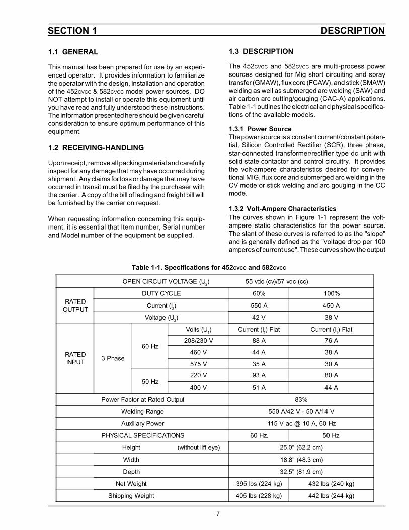
Table 1-1. Specifications for 452CVCC and 582CVCC
1.3 DESCRIPTION
The 452CVCC and 582CVCC are multi-process powersources designed for Mig short circuiting and spraytransfer (GMAW), flux core (FCAW), and stick (SMAW)welding as well as submerged arc welding (SAW) andair carbon arc cutting/gouging (CAC-A) applications.Table 1-1 outlines the electrical and physical specifica-tions of the available models.
1.3.1 Power SourceThe power source is a constant current/constant poten-tial, Silicon Controlled Rectifier (SCR), three phase,star-connected transformer/rectifier type dc unit withsolid state contactor and control circuitry. It providesthe volt-ampere characteristics desired for conven-tional MIG, flux core and submerged arc welding in theCV mode or stick welding and arc gouging in the CCmode.
1.3.2 Volt-Ampere CharacteristicsThe curves shown in Figure 1-1 represent the volt-ampere static characteristics for the power source.The slant of these curves is referred to as the "slope"and is generally defined as the "voltage drop per 100amperes of current use". These curves show the output
1.1 GENERAL
This manual has been prepared for use by an experi-enced operator. It provides information to familiarizethe operator with the design, installation and operationof the 452CVCC & 582CVCC model power sources. DONOT attempt to install or operate this equipment untilyou have read and fully understood these instructions.The information presented here should be given carefulconsideration to ensure optimum performance of thisequipment.
1.2 RECEIVING-HANDLING
Upon receipt, remove all packing material and carefullyinspect for any damage that may have occurred duringshipment. Any claims for loss or damage that may haveoccurred in transit must be filed by the purchaser withthe carrier. A copy of the bill of lading and freight bill willbe furnished by the carrier on request.
When requesting information concerning this equip-ment, it is essential that Item number, Serial numberand Model number of the equipment be supplied.
OPEN CIRCUIT VOLTAGE (U2) 55 vdc (cv)/57 vdc (cc)
RATEDOUTPUT
DUTY CYCLE 60% 100%
Current (I2) 550 A 450 A
Voltage (U2) 42 V 38 V
RATEDINPUT 3 Phase
60 Hz
Volts (U1) Current (I1) Flat Current (I1) Flat
208/230 V 88 A 76 A
460 V 44 A 38 A
575 V 35 A 30 A
50 Hz220 V 93 A 80 A
400 V 51 A 44 A
Power Factor at Rated Output 83%
Welding Range 550 A/42 V - 50 A/14 V
Auxiliary Power 115 V ac @ 10 A, 60 Hz
PHYSICAL SPECIFICATIONS 60 Hz. 50 Hz.
Height (without lift eye) 25.0" (62.2 cm)
Width 18.8" (48.3 cm)
Depth 32.5" (81.9 cm)
Net Weight 395 lbs (224 kg) 432 lbs (240 kg)
Shipping Weight 405 lbs (228 kg) 442 lbs (244 kg)

DESCRIPTIONSECTION 1
8
voltage available at any given output current from theminimum to the maximum setting of the voltage control.Because the volt-ampere slope is fixed, it is possible toselect welding conditions by estimating the open-circuitvoltage required for the load current when operating inthe CV mode.
1.4.3 TR-23A Truck Kit (Item No. 36224)This truck kit provides complete mobility of the powersource. The kit consists of front castors, rear cylinderrack and wheels, gas cylinder bracket, cylinder chain,and pull handle.
1.4.4 Swivel Mount Kit (Item No. 36172)This kit allows the MIG 2E and MIG 4HD wire feedersto be mounted to the top of the power source on aninsulated swivel mount. This allows the feeder to freelyrotate, relieving potential wire feed problems whileincreasing the working area of the torch.
1.4.5 External Grounding Conductor Protection Kit(Item No. 36098)
This kit, when installed, will de-energize the powersource output if current flow is detected in the externalground conductor. When this happens, the Fault lighton the front control panel will light. It will remain lit untilthe fault is corrected or the power source power switch(S1) is turned off.
1.4.6 Automatic Fan Kit (Item No. 36707)With this kit installed, the fan will start to operate whenthe welding arc is initiated and will continue to run for 5minutes after the arc has been extinguished.
1.5 SAFETY
Before the equipment is put into operation, the safetysection at the front of this manual should be readcompletely. This will help avoid possible injury due tomisuse or improper installation.
The definitions relating to the:
safety notations are described at the end of the SafetySection in the front of this manual — read them andtheir specific text references carefully.
AMPS
Volts
Figure 1-1. Volt-Ampere Curves
1.4 OPTIONAL ACCESSORIES
1.4.1 Remote Control Kit (Item No. 36010)This Remote Control Kit consists of a 14 pin receptacleand assembly that permits the use of the HC-3B Re-mote Control (Item No. 33838) as described below.
1.4.2 HC-3B Remote Hand Control (Item No. 33838)This control provides remote output control and pro-vides a contactor closure switch to close the contactormaking the output terminals “hot”. The panel/remoteswitch on the front panel must be placed in the remoteposition when using this accessory.
9
SECTION 2 INSTALLATION
2.1 LOCATION
A proper installation site is necessary for the powersource to provide dependable service. A proper instal-lation site permits freedom of air movement through theunit while minimizing exposure to dust, dirt, moisture,and corrosive vapors. A minimum of 18 inches (46 cm)is required between the side and rear panels of thepower source and the nearest obstruction.
The selected site should also allow easy removal of thepower source outer enclosure for maintenance. SeeTable 1-1 for overall dimensions of the unit.
2.2 RECEIVING, UNPACKING AND PLACEMENT
A. Immediately upon receipt of the power source,inspect for damage which may have occurredin transit. Notify the carrier of any defects ordamage.
B. Remove the power source from the container.Remove all packing materials. Check thecontainer for any loose parts.
C. Check air passages at front and rear of cabi-net, making sure that no packing materials thatmay obstruct air flow through the power source.
D. Install the lifting ring furnished with the powersources into the top of the unit.
For lifting purposes and for keeping dust, mois-ture, and other foreign material from enteringthe power source, the lifting eyebolt must befully tightened with a tool.
E. After selecting an installation site (see para-graph 2.1), place the power source in thedesired location. The unit may be lifted eitherby using the lifting ring or by forklift truck. If aforklift is used for lifting the unit, be sure that thelift forks are long enough to extend completelyunder the base.
Do not use filters on this unit as they would restrictthe volume of intake air required for proper cooling.Output ratings on this unit are based on an unob-structed supply of cooling air drawn over its inter-nal components. Warranty is void if any type offiltering device is used.
2.3 PRIMARY (INPUT) ELECTRICALCONNECTION
This power source is a three-phase unit and must beconnected to a three-phase power supply. It is recom-mended that the unit be operated on a dedicated circuitto prevent impairment of performance due to an over-loaded circuit.
ELECTRIC SHOCK CAN KILL! Before making elec-trical input connections to the power source, "Ma-chinery Lockout Procedures" should be employed.If the connections are to be made from a linedisconnect switch, place the switch in the off posi-tion and padlock it to prevent inadvertent tripping.If the connection is made from a fusebox, removethe corresponding fuses and padlock the box cover.If it is not possible to use padlocks, attach a red tagto the line disconnect switch (or fuse box) warningothers that the circuit is being worked on.
A. The primary power leads must be insulatedcopper conductors. Three power leads andone ground wire are required. Either rubbercovered cable or conduit (flexible or solid) maybe used. Table 2-1 provides recommendedinput conductors and line fuse sizes.
B. Remove the top cover. Identify primary powerinput connections on the power switch, chassisground lug on the "A" frame, and primary inputterminal board. Refer to Figures 2-1 and 2-2.
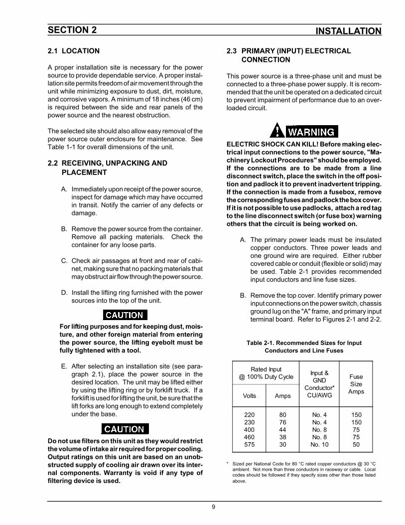
Table 2-1. Recommended Sizes for InputConductors and Line Fuses
* Sized per National Code for 80 °C rated copper conductors @ 30 °Cambient. Not more than three conductors in raceway or cable. Localcodes should be followed if they specify sizes other than those listedabove.
Rated Input@ 100% Duty Cycle Input &
GNDConductor*CU/AWG
FuseSize
AmpsVolts Amps
220230400460575
8076443830
No. 4No. 4No. 8No. 8
No. 10
150150757550
10
INSTALLATIONSECTION 2
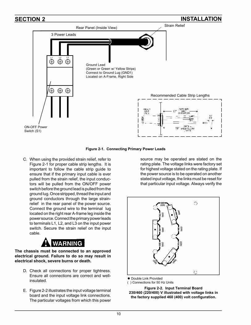
Figure 2-1. Connecting Primary Power Leads
� Double Link Provided( ) Connections for 50 Hz Units
Figure 2-2. Input Terminal Board230/460 (220/400) V illustrated with voltage links inthe factory supplied 460 (400) volt configuration.
Strain ReliefRear Panel (Inside View)
3 Power Leads
L1 L2 L3
Ground Lead(Green or Green w/ Yellow Stripe)Connect to Ground Lug (GND1)Located on A-Frame, Right Side
ON-OFF PowerSwitch (S1)
Recommended Cable Strip Lengths
(220)
(220)(220)
(220)(220)
(220)
(400)
(400)
(400)
C. When using the provided strain relief, refer toFigure 2-1 for proper cable strip lengths. It isimportant to follow the cable strip guide toensure that if the primary input cable is everpulled from the strain relief, the input conduc-tors will be pulled from the ON/OFF powerswitch before the ground lead is pulled from theground lug. Once stripped, thread the input andground conductors through the large strain-relief in the rear panel of the power source.Connect the ground wire to the terminal luglocated on the right rear A-frame leg inside thepower source. Connect the primary power leadsto terminals L1, L2, and L3 on the input powerswitch. Secure the strain relief on the inputcable.
The chassis must be connected to an approvedelectrical ground. Failure to do so may result inelectrical shock, severe burns or death.
D. Check all connections for proper tightness.Ensure all connections are correct and well-insulated.
E. Figure 2-2 illustrates the input voltage terminalboard and the input voltage link connections.The particular voltages from which this power
source may be operated are stated on therating plate. The voltage links were factory setfor highest voltage stated on the rating plate. Ifthe power source is to be operated on anotherstated input voltage, the links must be reset forthat particular input voltage. Always verify the
11
SECTION 2 INSTALLATIONinput voltage and check the link arrangementregardless of factory setting. The voltage linksare set up by reconfiguring the copper link barsto the silk-screened voltage designations forthe desired voltage.
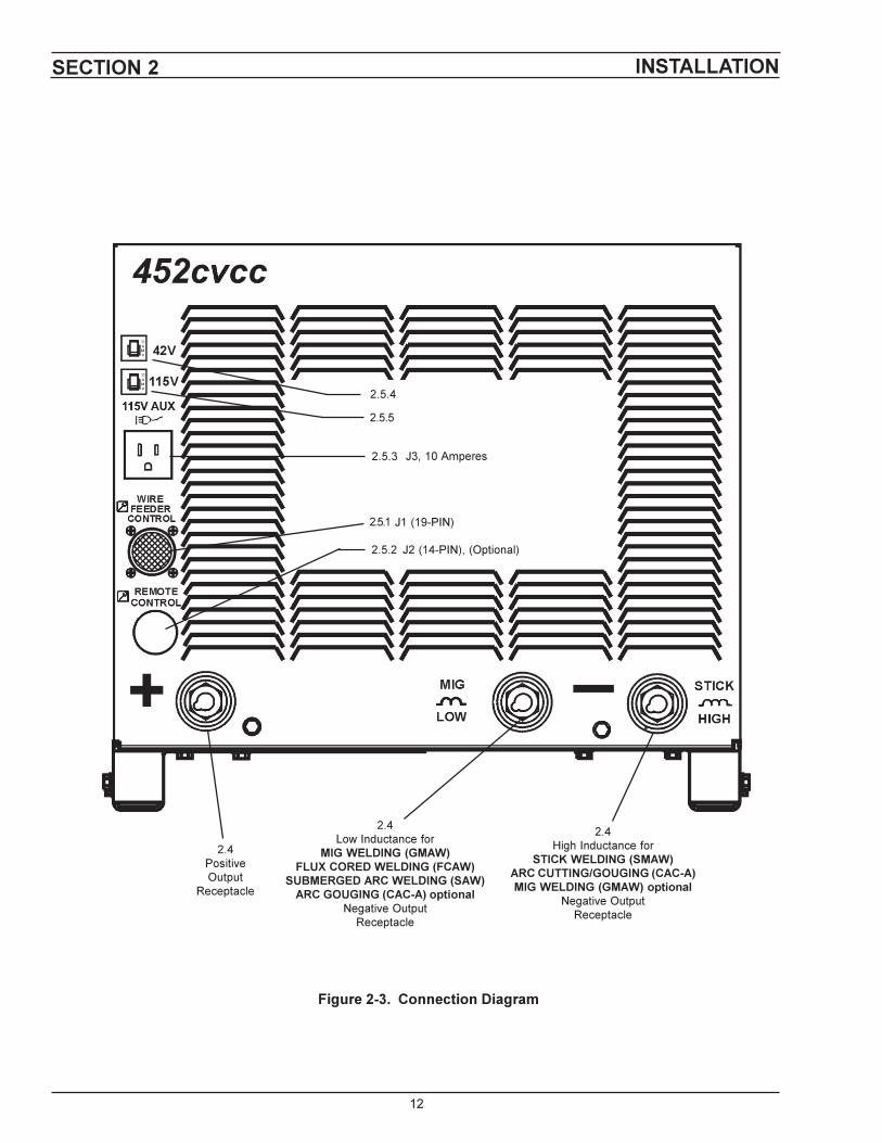
2.4 OUTPUT WELDING CONNECTIONS(SECONDARY)
Before making any connections to the power sourceoutput terminals, make sure that all primary inputpower to the machine is off.
The output connections are located on the front panel(Figure 2-3). The positive connection is located at thebottom left corner and the negative (high inductanceand low inductance) connections are located at thebottom right corner. Table 2-2 provides the recom-mended cable output sizes.
2.5 CONTROL CONNECTIONS
Refer to Figure 2-3.
2.5.1 Wire Feeder ControlThe Wire feeder control cable connection is providedby a 19-pin receptacle (J1) located on the left-handside of the power source front panel. This receptaclewill operate all ESAB wire feeders with 19 pin controlcables including the Mig 2E, Mig 4HD, Mig 28A, Mig35, Digimig, Digimig Dual as well as the UEC-8,Digimatic II and Analog Interface mechanized con-trols.
2.5.2 Remote Control (Optional)This function is provided by an optional 14-pin recep-tacle (J2) located on the front panel directly belowconnector J1. It receives a mating plug from a HandControl Assembly (optional). This receptacle is opera-tive only if the panel remote switch on the power sourcefront panel is in the "Remote" position.
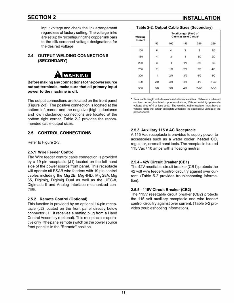
Table 2-2. Output Cable Sizes (Secondary)
* Total cable length includes work and electrode cables. Cable size is basedon direct current, insulated copper conductors, 100-percent duty cycle and avoltage drop of 4 or less volts. The welding cable insulator must have avoltage rating that is high enough to withstand the open circuit voltage of thepower source.
2.5.3 Auxiliary 115 V AC ReceptacleA 115 Vac receptacle is provided to supply power toaccessories such as a water cooler, heated CO2regulator, or small hand tools. The receptacle is rated115 Vac / 10 amps with a floating neutral.
2.5.4 - 42V Circuit Breaker (CB1)The 42V resettable circuit breaker (CB1) protects the42 volt wire feeder/control circuitry against over cur-rent. (Table 5-2 provides troubleshooting informa-tion).
2.5.5 - 115V Circuit Breaker (CB2)The 115V resettable circuit breaker (CB2) protectsthe 115 volt auxiliary receptacle and wire feeder/control circuitry against over current. (Table 5-2 pro-vides troubleshooting information).
WeldingCurrent
Total Length (Feet) ofCable in Weld Circuit*
50 100 150 200 250
100
150
200
250
300
400
500
6
4
3
2
1
2/0
3/0
4
3
1
1/0
2/0
3/0
3/0
3
1
1/0
2/0
3/0
4/0
4/0
2
1/0
2/0
3/0
4/0
4/0
2-2/0
1/0
2/0
3/0
4/0
4/0
2-2/0
2-3/0
��
�������������������
�����
�����
�����
�������� �����������
����� ��������
����� ��������������
������������ ������ ���������
����� !���"#$���$��%��
������������ ������������������������� ���������������� ��������������
�� ���&���#��#�'�$����$��
���(�)���"#$���$��%��
���������� �������������������� �����
������������������� ���������������� ���������������
�� ���&���#��#�'�$����$��
��������&��#��#�
'�$����$��
SECTION 3
13
OPERATION
Never operate the power source with the coversremoved. In addition to the safety hazards, im-proper cooling may cause damage to the compo-nents. Keep side panels and top closed when unitis energized. Welding helmet, gloves, and otherpersonal protection should always be worn whenwelding.
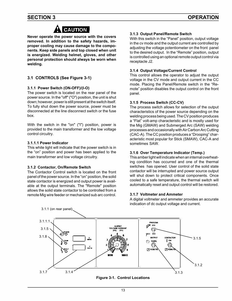
3.1 CONTROLS (See Figure 3-1)
3.1.1 Power Switch (ON-OFF)/(I-O)The power switch is located on the rear panel of thepower source. In the "off" ("O") position, the unit is shutdown; however, power is still present at the switch itself.To fully shut down the power source, power must bedisconnected at the line disconnect switch or the fusebox.
With the switch in the "on" ("I") position, power isprovided to the main transformer and the low voltagecontrol circuitry.
3.1.1.1 Power IndicatorThis white light will indicate that the power switch is inthe “on” position and power has been applied to themain transformer and low voltage circuitry.
3.1.2 Contactor, On/Remote SwitchThe Contactor Control switch is located on the frontpanel of the power source. In the “on” position, the solidstate contactor is energized and output power is avail-able at the output terminals. The "Remote" positionallows the solid state contactor to be controlled from aremote Mig wire feeder or mechanized sub arc control.
3.1.1 (on rear panel)
3.1.7 3.1.4
3.1.5
3.1.3
3.1.2
Figure 3-1. Control Locations
3.1.8
3.1.5
3.1.1.1
3.1.3 Output Panel/Remote SwitchWith this switch in the “Panel” position, output voltagein the cv mode and the output current are controlled byadjusting the voltage potentiometer on the front panelto the desired output. In the “Remote” position, outputis controlled using an optional remote output control viareceptacle J2.
3.1.4 Output Voltage/Current ControlThis control allows the operator to adjust the outputvoltage in the CV mode and output current in the CCmode. Placing the Panel/Remote switch in the “Re-mote” position disables the output control on the frontpanel.
3.1.5 Process Switch (CC-CV)The process switch allows for selection of the outputcharacteristics of the power source depending on thewelding process being used. The CV position producesa “Flat” volt-amp characteristic and is mostly used forthe Mig (GMAW) and Submerged Arc (SAW) weldingprocesses and occasionally with Air Carbon Arc Cutting(CAC-A). The CC position produces a “Drooping” char-acteristic most popular for Stick (SMAW), CAC-A andsometimes SAW.
3.1.6 Over Temperature Indicator (Temp.)This amber light will indicate when an internal overheat-ing condition has occurred and one of the thermalswitches has opened. User control of the solid statecontactor will be interrupted and power source outputwill shut down to protect critical components. Oncecooled to a safe temperature, the thermal switch willautomatically reset and output control will be restored.
3.1.7 Voltmeter and AmmeterA digital voltmeter and ammeter provides an accurateindication of dc output voltage and current.

OPERATIONSECTION 3
14
3.2.1 General Procedures for the CV-MIG (GMAW),SUB ARC (SAW) and CC-STICK (SMAW),SUB ARC (SAW) Processes
A. Make the secondary output connections to thepositive and negative output receptacles. Seeparagraph 3.1.10 and figure 2-3.
B. Make the control connections. Refer to theappropriate wire feeder, mechanized control,and/or torch instruction booklets for additionalprocess requirements or control connections.
C. If primary input connections have been madeto the power switch, and on the input terminalboard to match the incoming voltage, close themain wall disconnect switch or reinstall fuses inthe fuse box.
3.2.2 Specific Procedures for the CV-MIG (GMAW)and SUB ARC (SAW) Processes
A. Set the Output Panel/Remote switch to thedesired setting.
B. Set the Process switch to the CV position.
C. Set the contactor switch to "Remote".
ELECTRIC SHOCK CAN KILL! When the contactorswitch is in the "ON" position, output power will bepresent throughout the welding circuit; ie. cables,wire feeder, wire spool, drive stand, gun, and elec-trode. Be sure all are clear of the workpiece orarcing will result.
D. Set the power switch on the rear panel to the"on" ("I") position.
E. To preset the approximate welding voltage,place the Contactor switch to the "on" position.This will energize the power source output,allowing the voltage to be preset using theOutput Voltage/Current Control dial and ob-serving the voltmeter.
F. After setting the desired voltage condition, turnthe contactor switch back to the “remote” posi-tion. This position requires a remote start con-trol in order to start the welding sequence.
3.1.8 Fault IndicatorIf an optional External Ground Conductor Protection Kitwas installed, this red light, when lit, will signal thatcurrent was flowing through the external ground con-ductor. It will also light if a short occurs (momentaryor permanent) between the +12 volt J1-E; the +10volt (J2-E) and either the chassis ground or the nega-tive terminal of the power source. The power sourceoutput terminals are de-energized and the fault must becorrected before resuming operation.
3.1.9 Over Current ProtectionIn the CV mode the 452CVCC and 582CVCC incorporatean automatic over current protection. If an over currentcondition occurs, the automatic circuitry will “fold back”the output current to a level that will prevent damage tothe power source. The power source will remain in thislow current “fold back” mode until the arc is broken, thetorch trigger is released or the contactor switch is reset.
3.1.10 High & Low Inductance ReceptaclesThe 452CVCC and 582CVCC provides high and low induc-tance output connections (see figure 2-3). Both arepositive output terminals. The high inductance terminalslows the power source dynamic response. This meansthe output current will build at a slower rate comparedto the low inductance terminals. The welding processand application will determine which terminal should beused. The chart below provides suggested terminalconnections.
Process Switch CC CVInductance High Low High LowMig Solid Wire (GMAW) X X 1 XFlux Cored (FCAW) X XSub Arc (SAW) X X 2 XArc Gouging (CAC-A) X X 3 X
1. Small diameter wires (<1/16-inch) with argon mixtures.2. <3/32-inch diameter wires.3. Fast dynamic response (optional setting only).
3.2 SEQUENCE OF OPERATION
Prior to performing the steps below, open the walldisconnect switch or remove the fuse from the fuse boxto electrically isolate the power source.
ELECTRIC SHOCK CAN KILL! "Machinery LockoutProcedures" should be employed. If it is not pos-sible to use padlocks, attach a red tag to the linedisconnect switch (or fuse box) warning othersthat the circuit is being worked on.
SECTION 3
15
OPERATION
G. Begin welding. Observe the voltmeter, amme-ter, and the weld. Readjust the voltage and wirefeed speed settings as necessary to obtain asatisfactory weld.
H. When welding is completed, release torchswitch. (This action will deenergize the powersource solid state contactor and remove dcpower from the output terminals.)
3.2.3 Specific Procedures for the CC-Stick Welding(SMAW) and Arc Gouging (CAC-A) Processes
A. Place the Output Panel/Remote switch intoPANEL position if output current is regulatedfrom the Output Voltage/Current dial on thepanel, or in REMOTE position if output currentis regulated from the optional Hand Control.
B. Set the Output Voltage/Current Control to pro-vide the approximate desired welding currentusing 0 (zero) to 550 amps as the power sourcecurrent range and 0 to 10 on the control knobas the reference. Example - set knob to “8” forapproximately 450 amps output.
C. Set the Contactor switch to the ON position --this will energize the solid-state contactor andall associated circuitry up to the output termi-nals.
D. Place the Process Control switch in the CCposition.
E. Begin welding by touch or scratch starting theelectrode.
16
SECTION 4 MAINTENANCE
4.1 GENERAL
If this power source does not operate properly,stop work immediately and investigate the cause ofthe malfunction. Maintenance work must be per-formed by an experienced person, and electricalwork by a trained electrician. Do not permit un-trained persons to inspect, clean, or repair thispower source. Use only recommended replace-ment parts.
Be sure that the branch circuit or main disconnectswitch is off, or electrical input fuses are removed,before attempting any inspection or work insidethe power source. Placing the power switch in theoff position does not remove all power from insidethe power source.
4.2 CLEANING
Periodically, remove the cover from the power sourceand blow accumulated dust and dirt from the air pas-sages and interior components by using clean lowpressure air. The frequency of cleaning required de-pends upon the environment in which the power sourceis used.
It is imperative that all air passages be kept as clean aspossible in order to allow adequate air flow to provideproper cooling.
After cleaning with low pressure air, check for andtighten any loose hardware, including all electricalconnections. Check for frayed and/or cracked insula-tion on all power cables and replace if necessary.
Failure to replace worn or damaged cables mayresult in a bare cable touching a grounded object.The resulting electrical arc may injure unprotectedeyes and will present a serious fire hazard. Bodycontact with a bare cable, connector, or conductormay result in severe electrical shock, causing seri-ous burns or death.
4.3 INSPECTION AND SERVICE
Keep the power source dry, free of oil and grease, andprotected at all times from damage by hot metal andsparks.
4.3.1 Fan MotorKeep the fan motor free of accumulated dust and lint.
4.3.2 TransformerOther than periodically cleaning the dust and dirt fromthe transformer, no maintenance is required. Ensurethat only clean, dry, low pressure air is used.
4.3.3 Wire Feeder and Control CircuitsThese circuits are protected by two 10 amp circuitbreakers mounted in the front panel. If these open, thecontactor and wire feeder will not operate.
4.3.4 Over Temperature ProtectionIf the power source reaches an abnormally high internaltemperature, the thermal protection will deenergize thecontactor circuit, shutting down the power source butleaving the cooling fan on. After the power source hascooled to a safe level, the thermal protection will auto-matically reset. While deenerigized, the contactor andwire feeder cannot be operated.
4.3.5 Digital Voltmeter/Ammeter CalibrationTo verify the accuracy of the digital volt/ammeter com-bination, the following calibration procedure can beperformed periodically:1. Place the Panel/Remote switch in Panel position.2. Disconnect cables from the output terminals and
then connect an accurate DC voltmeter to theoutput terminals.
3. Place the Contactor switch in the On position.4. With the primary input power on, turn the Voltage
control knob until you get 25V on the DC voltmeter.Compare the reading with the reading on the digitalvoltmeter on the front panel.
5. If there is a difference in the voltage readings, openfront control panel by removing the two mountingscrews from the upper corners, remove meterboard from its four mounting posts, and adjust thetrimpot (R13) on the meter board with a smallscrewdriver until the digital meter reading matchesthe DC voltmeter reading. When satisfied, reas-semble meter board and front control panel.
17
TROUBLESHOOTINGSECTION 5
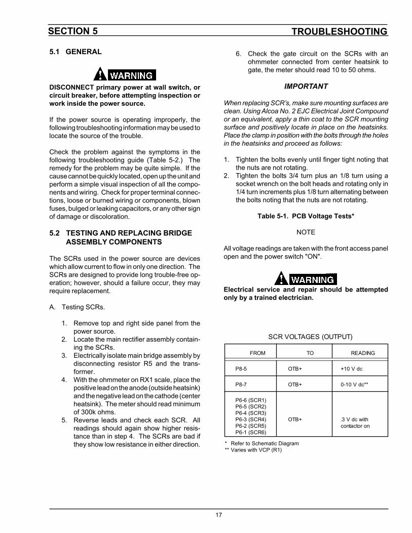
5.1 GENERAL
DISCONNECT primary power at wall switch, orcircuit breaker, before attempting inspection orwork inside the power source.
If the power source is operating improperly, thefollowing troubleshooting information may be used tolocate the source of the trouble.
Check the problem against the symptoms in thefollowing troubleshooting guide (Table 5-2.) Theremedy for the problem may be quite simple. If thecause cannot be quickly located, open up the unit andperform a simple visual inspection of all the compo-nents and wiring. Check for proper terminal connec-tions, loose or burned wiring or components, blownfuses, bulged or leaking capacitors, or any other signof damage or discoloration.
5.2 TESTING AND REPLACING BRIDGEASSEMBLY COMPONENTS
The SCRs used in the power source are deviceswhich allow current to flow in only one direction. TheSCRs are designed to provide long trouble-free op-eration; however, should a failure occur, they mayrequire replacement.
A. Testing SCRs.
1. Remove top and right side panel from thepower source.
2. Locate the main rectifier assembly contain-ing the SCRs.
3. Electrically isolate main bridge assembly bydisconnecting resistor R5 and the trans-former.
4. With the ohmmeter on RX1 scale, place thepositive lead on the anode (outside heatsink)and the negative lead on the cathode (centerheatsink). The meter should read minimumof 300k ohms.
5. Reverse leads and check each SCR. Allreadings should again show higher resis-tance than in step 4. The SCRs are bad ifthey show low resistance in either direction.
6. Check the gate circuit on the SCRs with anohmmeter connected from center heatsink togate, the meter should read 10 to 50 ohms.
IMPORTANT
When replacing SCR’s, make sure mounting surfaces areclean. Using Alcoa No. 2 EJC Electrical Joint Compoundor an equivalent, apply a thin coat to the SCR mountingsurface and positively locate in place on the heatsinks.Place the clamp in position with the bolts through the holesin the heatsinks and proceed as follows:
1. Tighten the bolts evenly until finger tight noting thatthe nuts are not rotating.
2. Tighten the bolts 3/4 turn plus an 1/8 turn using asocket wrench on the bolt heads and rotating only in1/4 turn increments plus 1/8 turn alternating betweenthe bolts noting that the nuts are not rotating.
Table 5-1. PCB Voltage Tests*
NOTE
All voltage readings are taken with the front access panelopen and the power switch "ON".
Electrical service and repair should be attemptedonly by a trained electrician.
* Refer to Schematic Diagram** Varies with VCP (R1)
SCR VOLTAGES (OUTPUT)
FROM TO READING
P8-5 OTB+ +10 V dc
P8-7 OTB+ 0-10 V dc**
P6-6 (SCR1)P6-5 (SCR2)P6-4 (SCR3)P6-3 (SCR4)P6-2 (SCR5)P6-1 (SCR6)
OTB+ .3 V dc withcontactor on
18
TROUBLESHOOTINGSECTION 5
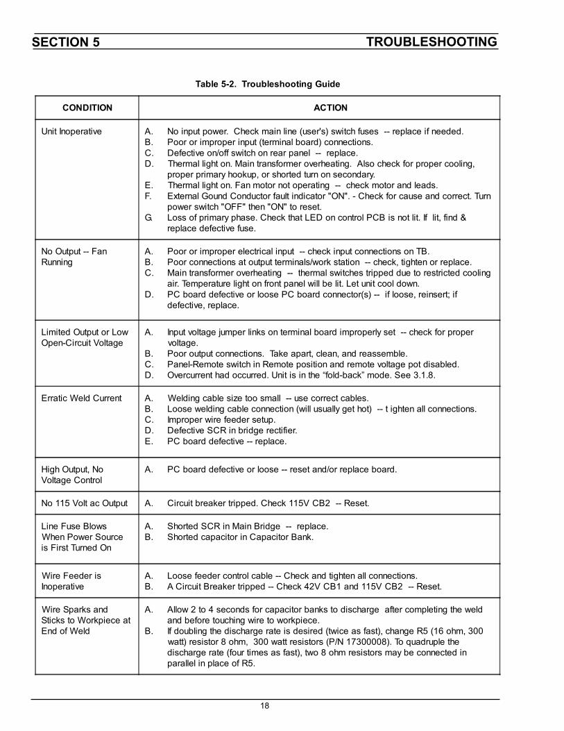
Table 5-2. Troubleshooting Guide
CONDITION ACTION
Unit Inoperative A.B.C.D.
E.F.
G.
No input power. Check main line (user's) switch fuses -- replace if needed.Poor or improper input (terminal board) connections.Defective on/off switch on rear panel -- replace.Thermal light on. Main transformer overheating. Also check for proper cooling,proper primary hookup, or shorted turn on secondary.Thermal light on. Fan motor not operating -- check motor and leads.External Gound Conductor fault indicator "ON". - Check for cause and correct. Turnpower switch "OFF" then "ON" to reset.Loss of primary phase. Check that LED on control PCB is not lit. If lit, find &replace defective fuse.
No Output -- FanRunning
A.B.C.
D.
Poor or improper electrical input -- check input connections on TB.Poor connections at output terminals/work station -- check, tighten or replace.Main transformer overheating -- thermal switches tripped due to restricted coolingair. Temperature light on front panel will be lit. Let unit cool down.PC board defective or loose PC board connector(s) -- if loose, reinsert; ifdefective, replace.
Limited Output or LowOpen-Circuit Voltage
A.
B.C.D.
Input voltage jumper links on terminal board improperly set -- check for propervoltage.Poor output connections. Take apart, clean, and reassemble.Panel-Remote switch in Remote position and remote voltage pot disabled.Overcurrent had occurred. Unit is in the “fold-back” mode. See 3.1.8.
Erratic Weld Current A.B.C.D.E.
Welding cable size too small -- use correct cables.Loose welding cable connection (will usually get hot) -- t ighten all connections.Improper wire feeder setup.Defective SCR in bridge rectifier.PC board defective -- replace.
High Output, NoVoltage Control
A. PC board defective or loose -- reset and/or replace board.
No 115 Volt ac Output A. Circuit breaker tripped. Check 115V CB2 -- Reset.
Line Fuse BlowsWhen Power Sourceis First Turned On
A.B.
Shorted SCR in Main Bridge -- replace.Shorted capacitor in Capacitor Bank.
Wire Feeder isInoperative
A.B.
Loose feeder control cable -- Check and tighten all connections.A Circuit Breaker tripped -- Check 42V CB1 and 115V CB2 -- Reset.
Wire Sparks andSticks to Workpiece atEnd of Weld
A.
B.
Allow 2 to 4 seconds for capacitor banks to discharge after completing the weldand before touching wire to workpiece.If doubling the discharge rate is desired (twice as fast), change R5 (16 ohm, 300watt) resistor 8 ohm, 300 watt resistors (P/N 17300008). To quadruple thedischarge rate (four times as fast), two 8 ohm resistors may be connected inparallel in place of R5.
��
����������
�� �
����
�����������
���������������������
������
� �����!�����"�
����������������
������
#$����������������
����
����
����� ��������"%������������
�����
������
������
����
�������&�
����������������
����������
���������������� #
�����������
���
��� ����������������� � ������������ ���������� ����������� �������

'(
�����������!
���������������������� � ������������ ���������� ����������� �������
������)��*
'�
������������
���
��� ������������� � �����������"���� �������
����������
�� �
����
�����������
���������������������
������
� �����!�����"�
����������������
������
#$����������������
����
����
����� ��������"%������������
�����
������
������
����
�������&�
����������������
����������
���������������� #
''
����������*
�����������!
������������������ � �����������"���� �������

������������������ ��
��
6.1 GENERAL
���������� ��������������������������������������������������������������� ��������������������������� ����������������������
6.2 ORDERING
�������������������������������� � ����������������������������� �� ����������� �������������������������������������������������� ����������
������������������������������������������������ �����������������������������
����������������������� �� ����������� ���������!���������������"� �#����������������������������������$�%&&������$'(�
!�����������������������)�����������*�� ���������� �������� ������� ����� ������� ���� ��������� ����������������������+�
��������������
� �����,�,� ��� �-����$...������� ��� ���������������������������������!�����/�(��������� ������� ��������0���1��������0���2��34��)������������ � �������������� ��� ����� �������!����������#���������������� ����+����������������������� ��� ����������� ������������,�,� ��������������5������������������
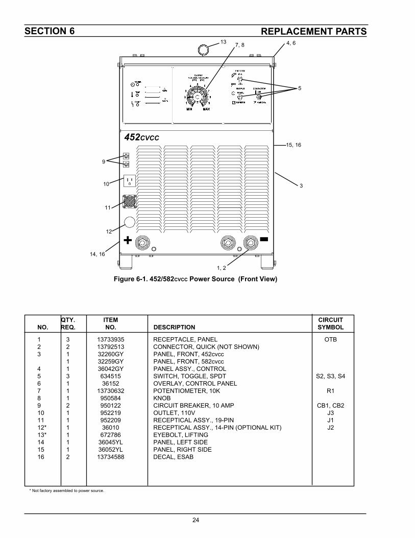
SECTION 6 REPLACEMENT PARTS
24
+ -
3
15, 16452CVCC
* Not factory assembled to power source.
QTY. ITEM CIRCUITNO. REQ. NO. DESCRIPTION SYMBOL
1 3 13733935 RECEPTACLE, PANEL OTB2 2 13792513 CONNECTOR, QUICK (NOT SHOWN)3 1 32260GY PANEL, FRONT, 452cvcc
1 32259GY PANEL, FRONT, 582cvcc4 1 36042GY PANEL ASSY., CONTROL5 3 634515 SWITCH, TOGGLE, SPDT S2, S3, S46 1 36152 OVERLAY, CONTROL PANEL7 1 13730632 POTENTIOMETER, 10K R18 1 950584 KNOB9 2 950122 CIRCUIT BREAKER, 10 AMP CB1, CB210 1 952219 OUTLET, 110V J311 1 952209 RECEPTICAL ASSY., 19-PIN J112* 1 36010 RECEPTICAL ASSY., 14-PIN (OPTIONAL KIT) J213* 1 672786 EYEBOLT, LIFTING14 1 36045YL PANEL, LEFT SIDE15 1 36052YL PANEL, RIGHT SIDE16 2 13734588 DECAL, ESAB
7, 813 4, 6
5
1, 2
Figure 6-1. 452/582CVCC Power Source (Front View)
9
10
11
12
14, 16
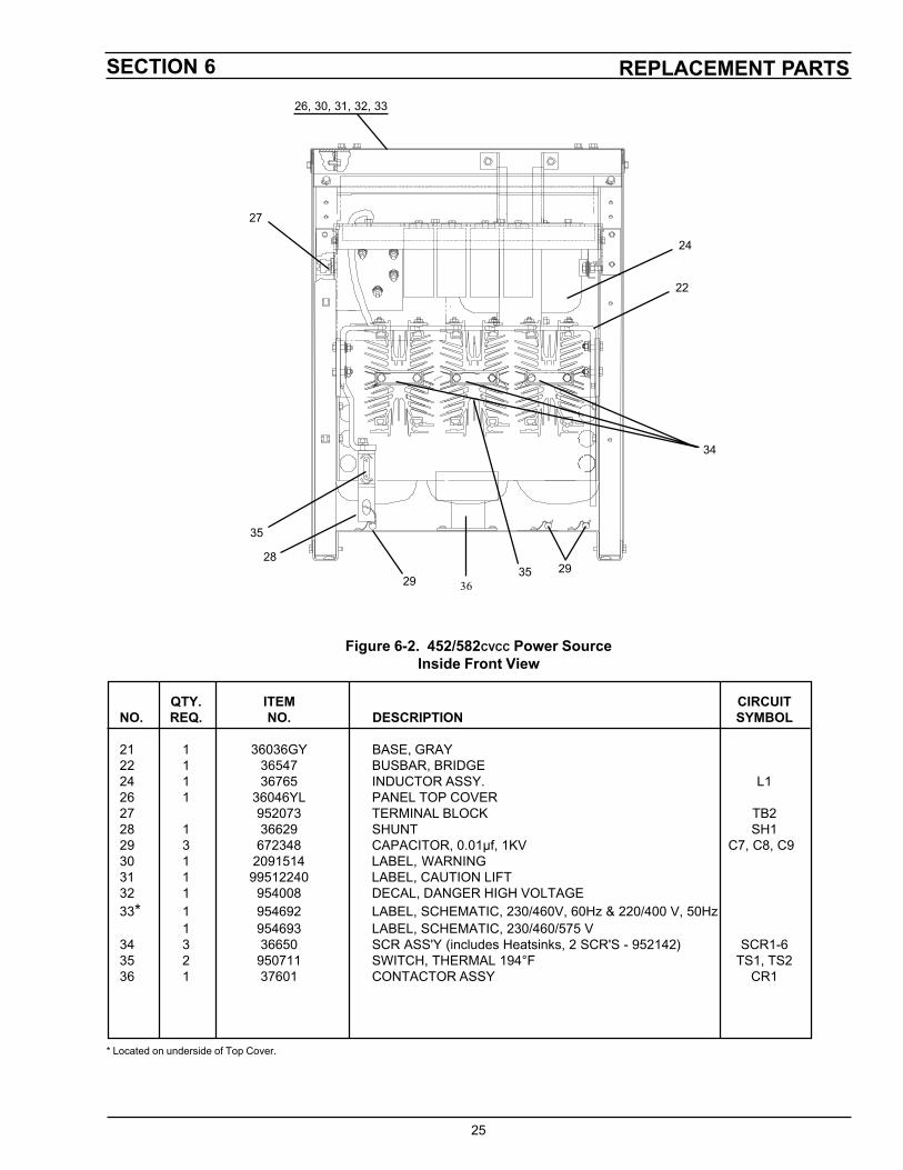
REPLACEMENT PARTSSECTION 6
25
QTY. ITEM CIRCUITNO. REQ. NO. DESCRIPTION SYMBOL
21 1 36036GY BASE, GRAY22 1 36547 BUSBAR, BRIDGE24 1 36765 INDUCTOR ASSY. L126 1 36046YL PANEL TOP COVER27 952073 TERMINAL BLOCK TB228 1 36629 SHUNT SH129 3 672348 CAPACITOR, 0.01µf, 1KV C7, C8, C930 1 2091514 LABEL, WARNING31 1 99512240 LABEL, CAUTION LIFT32 1 954008 DECAL, DANGER HIGH VOLTAGE33* 1 954692 LABEL, SCHEMATIC, 230/460V, 60Hz & 220/400 V, 50Hz
1 954693 LABEL, SCHEMATIC, 230/460/575 V34 3 36650 SCR ASS'Y (includes Heatsinks, 2 SCR'S - 952142) SCR1-635 2 950711 SWITCH, THERMAL 194°F TS1, TS236 1 37601 CONTACTOR ASSY CR1
* Located on underside of Top Cover.
26, 30, 31, 32, 33
27
29
28
34
22
35
Figure 6-2. 452/582CVCC Power SourceInside Front View
35 29
24
36
�������� ��� �������� ��
��
���� ���� �������� ��� ��� ��������� ������
�� � ������ ��� ��������� � ������� ������ ��� ���� � ����� ������ ����� ������ ������� � ���
� ����� ������ ����� ������ ������� � ���� ����� ������ ����� ������ ��������� � � ���
�� � � ���� !����� �������� ������� � " ������� �� � ���� !����� �������� ��������� � �
� � ������ #���#����� ������$ �� %� #������� � ����� �#� ��%���#����� �#���� � ����� �#��� ������ ����� �#���� � ����� #���� ������� ��& ����� � ��� �� ����� !������� #��#��� �#'����� � ��� � ���#'��� (���!��'�� � ����� ����!������ �!!)�� ����� ������� � ��
� ���� ����!������ �!!)�� ����� ������� �� ��(* ��� ����� ����!����� �!!)�� ����� � � � ��
�� � ������� �(����!��� ���+# ,-./01232 4-56 700 �� �87.9$:8;389< �!��� � � ������ ��!�!��� ���%� �� �(� ���� � �������� ���#'�� ��!�!���� � � ���� #����#��� #��
����������� �� �������������������������������������
��
��������
�
�����
��
�����
��
��
��������
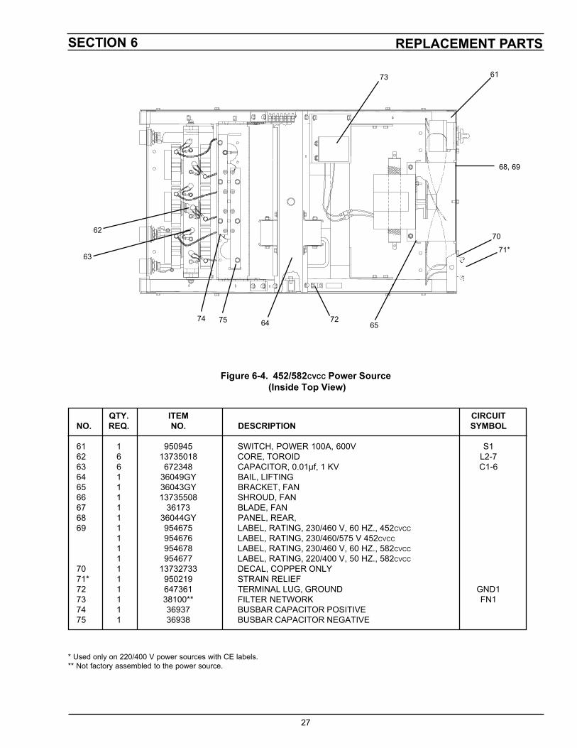
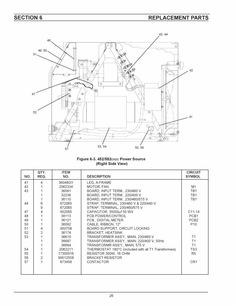
REPLACEMENT PARTSSECTION 6
27
62
73 61
70
71*
6564 72
63
QTY. ITEM CIRCUITNO. REQ. NO. DESCRIPTION SYMBOL
61 1 950945 SWITCH, POWER 100A, 600V S162 6 13735018 CORE, TOROID L2-763 6 672348 CAPACITOR, 0.01µf, 1 KV C1-664 1 36049GY BAIL, LIFTING65 1 36043GY BRACKET, FAN66 1 13735508 SHROUD, FAN67 1 36173 BLADE, FAN68 1 36044GY PANEL, REAR,69 1 954675 LABEL, RATING, 230/460 V, 60 HZ., 452CVCC
1 954676 LABEL, RATING, 230/460/575 V 452CVCC
1 954678 LABEL, RATING, 230/460 V, 60 HZ., 582CVCC
1 954677 LABEL, RATING, 220/400 V, 50 HZ., 582CVCC
70 1 13732733 DECAL, COPPER ONLY71* 1 950219 STRAIN RELIEF72 1 647361 TERMINAL LUG, GROUND GND173 1 38100** FILTER NETWORK FN174 1 36937 BUSBAR CAPACITOR POSITIVE75 1 36938 BUSBAR CAPACITOR NEGATIVE
* Used only on 220/400 V power sources with CE labels.** Not factory assembled to the power source.
Figure 6-4. 452/582CVCC Power Source (Inside Top View)
68, 69
7574
���������� ���� � ������������������
IF YOU DO NOT KNOW WHOM TO CALL
Telephone: (800) ESAB-123/ Fax: (843) 664-4452/ Web:http://www.esab.com
Hours: 7:30 AM to 5:00 PM EST
A. CUSTOMER SERVICE QUESTIONS:Order Entry Product Availability Pricing DeliveryOrder Changes Saleable Goods Returns Shipping Information
Eastern Distribution Center Telephone: (800)362-7080 / Fax: (800) 634-7548
Central Distribution Center Telephone: (800)783-5360 / Fax: (800) 783-5362
Western Distribution Center Telephone: (800) 235-4012/ Fax: (888) 586-4670
B. ENGINEERING SERVICE: Telephone: (843) 664-4416 / Fax : (800) 446-5693Welding Equipment Troubleshooting Hours: 7:30 AM to 5:00 PM ESTWarranty Returns Authorized Repair Stations
C. TECHNICAL SERVICE: Telephone: (800) ESAB-123/ Fax: (843) 664-4452Part Numbers Technical Applications Hours: 8:00 AM to 5:00 PM ESTPerformance Features Technical Specifications Equipment Recommendations
D. LITERATURE REQUESTS: Telephone: (843) 664-5562 / Fax: (843) 664-5548Hours: 7:30 AM to 4:00 PM EST
E. WELDING EQUIPMENT REPAIRS: Telephone: (843) 664-4487 / Fax: (843) 664-5557Repair Estimates Repair Status Hours: 7:30 AM to 3:30 PM EST
F. WELDING EQUIPMENT TRAINING:Telephone: (843)664-4428 / Fax: (843) 679-5864Training School Information and Registrations Hours: 7:30 AM to 4:00 PM EST
G. WELDING PROCESS ASSISTANCE:Telephone: (800) ESAB-123 / Fax: (843) 664-4454 Hours: 7:30 AM to 4:00 PM EST
H. TECHNICAL ASST. CONSUMABLES:Telephone : (800) 933-7070 Hours: 7:30 AM to 5:00 PM EST
ESAB Welding & Cutting Products, Florence, SC Welding EquipmentCOMMUNICATION GUIDE - CUSTOMER SERVICES
ESAB Welding & Cutting ProductsPO Box 100545 Florence SC 29501-0545