3T - Through The Trapdoor Method - PASMA
20
ALTO MEDIUM DUTY SINGLE WIDTH LADDERSPAN TOWER Mobile Aluminium Access Tower ISSUE 6 Instruction Manual EN 1298-IM-EN The ALTO MD Ladderspan Tower is certified to BS EN 1004:2004 3T - Through The Trapdoor Method Lakeside Industries Ltd www.altoaccess.com [email protected]
-
Upload
khangminh22 -
Category
Documents
-
view
4 -
download
0
Transcript of 3T - Through The Trapdoor Method - PASMA

ALTO MEDIUM DUTYSINGLE WIDTH LADDERSPAN TOWER
Mobile Aluminium Access Tower
ISSUE 6
Instruction Manual EN 1298-IM-ENThe ALTO MD Ladderspan Tower is certified to BS EN 1004:2004
3T - Through The Trapdoor Method
Lakeside Industries [email protected]
Page 2 ALTO MD Single Width Ladderspan Tower | Assembly Guide
IntroductionPlease read these instructions carefully and ensure that you fully understand all of the information
contained herein. All of the information in this document is vital for the safe utilisation of your Alto
Medium Duty Tower.
All Alto Access products are professional quality engineered equipment designed primarily with safety
in mind and meet or exceed all standards, recommendations and guidelines. Used properly, Alto access
equipment will keep you safe when working at height.
This manual contains all of the information necessary to correctly assemble your Alto Medium Duty
mobile access tower and incorporates all of the requirements of the PASMA 3T method of assembly as
endorsed by the HSE.
This manual should be used in conjunction with your Risk Assessment and Method Statement and in
line with the Work at Height Regulations 2005 which place an obligation on employers to eliminate or
minimise risks. This manual must be made available to the user/assembler at all pertinent times.
Only competent and qualified personnel should undertake erection, dismantling or alteration, organisation,
planning or supervision of mobile access towers. In the case of any doubt, sufficient relevant additional
training must be given beforehand to ensure safe use. For further information on the use of mobile
access towers consult PASMA (www.pasma.co.uk; Tel +44 (0) 845 230 4041). For any additional technical
information or specific advice please contact the manufacturer Lakeside Industries Limited Tel: +44 1527
500577 or Email: [email protected].
CertificationsThe Alto Medium Duty Tower is a mobile access tower certified to EN 1004 Class 3. If the application is
outside the scope of EN 1004, reference should be made to EN 1139 to ensure that the configuration of
the equipment meets the relevant requirements. This tower is manufactured in our ISO 9001 accredited
facility. This manual complies with EN 1298-IM-EN.
Maximum Safe Working LoadsThe safe working load of the tower is 2,000kg including its own weight. The maximum safe working load
of any individual platform is 282 kg evenly distributed.If the tower is to be used in an application outside
the scope of EN1004, contact your supplier or the manufacturer, Lakeside Industries Limited, for advice
on loadings. Tel: +44 1527 500577 or Email: [email protected].

Page 3ALTO Access Products | Lakeside Industries Ltd
Inspection Care & MaintenanceAlto Access equipment is designed and manufactured to the highest standards in the industry and is
stronger, more robust and safer than any comparable competitor product. Properly cared for, it will give
a long and productive service life.
· The equipment should be inspected and maintained as outlined in the “ALTO MD Tower Inspection
Procedures”. A free downloadable copy is available at www.altoaccess.com/downloads.
· Equipment should always be inspected before and after each use.
· Whilst Alto Access equipment is extremely robust, care should be exercised in loading, transporting
and handling components to avoid damage or injury to either the equipment or persons.
· Repairs should only be carried out by Lakeside Industries Limited or their authorised repairers.
· In case of any doubt as to the integrity of any items of Alto Access equipment, the part should be
withdrawn from use, quarantined and subject to detailed examination to determine whether repair
or replacement is required. If returned to the factory, Lakeside Industries Limited will provide a free
of charge evaluation of any damaged components.
SafetyCheck that all of the necessary components and equipment for the particular tower configuration to be
built are on site, undamaged and functioning correctly. Damaged or incorrect components must not be
used.
· Check that the surface on which the tower is to be located is capable of supporting the tower and its
payload.
· The safe working load of the tower is 2,000kg including its own weight. The maximum safe working
load of any individual platform is 282 kg evenly distributed.
· If the tower is to be used in an application outside the scope of EN1004, contact your supplier or the
manufacturer, Lakeside Industries Limited, for advice on loadings. Tel: +44 1527 500577 or Email:
· Towers must always be climbed from the inside using the built in ladders only. If the work carried
out from the tower requires frequent carrying of equipment and materials up or down the tower, an
Alto stair tower should be used in preference to a ladderspan tower.
· The tower must be levelled when erected using the adjustable jack or castor legs.
· Two or more persons are required for the safe erection and dismantling of a tower.
· It is recommended that the tower be tied in when left unattended.

Page 4 ALTO MD Single Width Ladderspan Tower | Assembly Guide
· Always comply with the Work at Height Regulations 2005 when erecting, dismantling & using the
tower.
· When lifting components, always use reliable lifting equipment and fastening methods and always lift
from within the footprint of the tower structure to prevent risk of the tower overturning.
· See “Moving the Tower” below for safety guidelines affecting the relocation of the tower.
· Beware live electrical installations, cables, moving machinery or other obstructions when erecting,
dismantling or using the tower. The tower is a conductive metallic structure.
· The maximum safe lateral force for a freestanding Alto Medium Duty tower is 30kg.
· Do not use boxes, ladders or other items to gain additional height.
· Do not stand on guard rails for any reason.
· If the tower is to be used in connection with hoisting arrangements, this is outside the scope of
EN1004 and requires specific advice from the manufacturer to ensure safety.
· Contact the manufacturer Lakeside Industries Limited for advice on loadings Tel: +44 1527 500577 or
Email: [email protected].
· Fit guard rails to all Platforms.
· Fit toe boards to all working platforms.
· Intermediate (rest) platforms are installed every 2m.
· The tower is not designed to be sheeted. Sheeting massively increases wind loads on the structure.
If sheeting is to be attached, contact the manufacturer Lakeside Industries Limited for advice on
loadings Tel: +44 1527 500577 or Email: [email protected].
· The tower is not designed to be lifted or suspended.
· Every erected tower must be inspected at least every seven days and any tower which has been left
unattended should be inspected before use to ensure that:
1 no components have been removed or relocated incorrectly;
2 the tower is still vertical; and
3 no environmental or other factors have arisen which will influence safe use of the tower.
· Unattended towers should be tied in to a rigid structure.
· Stabilisers or outriggers and ballast shall always be fitted when specified.
· Where there is insufficient clearance to fit the specified stabilisers, contact your supplier or the
manufacturer for specific advice. Where ballast or kentledge is used, it must be of solid material,
placed on a platform on the lowest rung of the tower and secured against unauthorised removal.

Page 5ALTO Access Products | Lakeside Industries Ltd
Wind SpeedsPersons using or responsible for towers must beware of the effect of wind on the structure. Wherever
possible, as a precaution, it is advisable to tie the tower in to a rigid structure if it is to be used where it is
exposed to potential windy conditions. Users should beware the potential tunnelling effect of open ended
or unclad buildings and narrow openings between buildings. We recommend that the use of the tower is
discontinued in conditions where the wind speed is above 17mph (force 4).
WINDDESCRIPTION
BEAUFORT SCALE
AVERAGE SPEED INFORMATION
Medium Breeze 4 13-17 mph Safe to work on tower.
Strong Breeze 6 25-31 mph Tie the tower to a solid structure. Do not work on tower.
Gale Force 8 39-46 mph Towers must be dismantled. Towers must not be assembled.
Erecting & Dismantling the TowerAll Alto towers must be built and dismantled in accordance with the step by step instructions in the
following pages corresponding to the particular tower configuration involved and having regard to the
working at height regulations and Health & Safety legislation.
Moving the TowerBefore moving the tower, its overall height should be reduced to 4m working platform height or less. No
persons, tools, equipment or materials shall be permitted to remain on the tower when it is being moved.
The tower should only be moved by pushing it by the lowest frames.
When moving the tower, users are to be particularly careful of the following:
· Obstructions, moving machinery or electrical cables and equipment
· not to move the tower in wind speeds of 18mph (force 5) or above
· the effect of rough, uneven or sloping ground on the stability of the tower
· locking and unlocking the castors to allow and prevent the tower moving at appropriate times
· after completing the movement, use a spirit level to ensure that the tower is vertical and safely
supported on an appropriate surface
· after completing the movement check that the tower is correct and complete.

Page 6 ALTO MD Single Width Ladderspan Tower | Assembly Guide
Frames
Braces
Stabilisers
1.6m SW
3100
mm
(upt
o 7.
5m)
4100
mm
(7.5
m &
abo
ve)
3100mm (upto 7.5m)
4100mm (7.5m & above)
2.4m SW
3350
mm
(upt
o 7.
5m)
4350
mm
(7.5
m &
abo
ve)
3350mm (upto 7.5m)
4350mm (7.5m & above)
Diagonal braces must always be located
with the claw opening facing down.
Horizontal braces must be located with
the claw facing either down (on the rung)
or outwards (if on the upright).
All braces are fitted with spring loaded
pins that automatically lock the brace
into position when attached to a tower.
Brace hooks must be located either over
the rung screw heads, between 2 screw
heads or between the frame upright and a
screw head to prevent lateral movement.
Frames must always be assembled with
the offset conical head fitting pointing
inwards towards the centre of the tower.
Stabilisers should always be attached to
the tower so as to maximise the base area
of the tower structure. Set the stabilisers
so they form a square around the tower
as per the diagram below. The correct
size stabilisers must always be used - see
component schedule for details.

Page 7ALTO Access Products | Lakeside Industries Ltd
3T Method ExplainedThe “3T” or “through the trapdoor” method is one of the two permitted ways of assembling a tower
without the assembler being at risk of falling. This tower is a 3T tower.
Tying InTowers must be tied into a suitable rigid structure once they go beyond the freestanding working heights
specified in EN 1004 2004 - 8m working platform height outdoors and 12m working platform height
indoors - or if the tower is unstable or is in danger of being unstable.
Standard scaffold tubes and fittings can be used with the Alto Access products. Ties should be spaced at
no more than 4m intervals. Ties must be rigid and be secured to both frame uprights. For further details
regarding tying in, please contact your supplier or the manufacturer: Lakeside Industries Limited.
Step 1:
As each new level of platform is installed, the operative
takes up a working position in the trap door of the
platform, standing on the ladder and leaning back
against the edge of the trapdoor aperture.
Step 2:
From this position the operative fits the horizontal
braces 500mm and 1000 mm above the platform level
(i.e. on the first and second available rungs). If the far
end of the guardrail braces don’t fully engage when they
are put in place, the operative fully engages it when first
climbing up onto the platform. This process ensures
that operatives never have to stand on an unguarded
platform.

Page 8 ALTO MD Single Width Ladderspan Tower | Assembly Guide
COMPONENT SCHEDULE1.6m Long x 0.8m Wide (Single Width) MD Ladderspan Tower
SIN
GLE
WID
TH M
EDIU
M D
UTY
SPA
N T
OW
ER T
O B
S EN
100
4:20
04
Usi
ng th
e 3T
(Thr
ough
The
Tra
pdoo
r) a
ssem
bly
met
hod
PLAT
FORM
WO
RKIN
G H
EIG
HT
(m)
INTE
RNAL
& E
XTER
NAL
USE
INTE
RNAL
USE
ON
LY
COD
EPA
RT D
ESCR
IPTI
ON
2.2
2.7
3.2
3.7
4.2
4.7
5.2
5.7
6.2
6.7
7.2
7.7
8.2
8.7
9.2
9.7
10.2
10.7
11.2
11.7
12.2
2239
125m
m D
ia. C
asto
r Whe
el4
44
44
44
44
44
44
44
44
44
44
3076
MD
Adj
. Alu
m L
eg (b
lack
col
lar)
44
44
44
44
44
44
44
44
44
44
4
3036
MD
1.6
m S
/W T
oebo
ard
11
11
11
11
11
11
11
11
11
11
1
3008
MD
S/W
4 R
ung
Fram
e1
12
12
23
23
34
34
45
45
56
56
3012
MD
S/W
4 R
ung
Ladd
er F
ram
e1
12
12
23
23
34
34
45
45
56
56
3010
MD
S/W
3 R
ung
Fram
e1
11
11
11
11
1
3013
MD
S/W
3 R
ung
Ladd
er F
ram
e1
11
11
11
11
1
3011
MD
S/W
2 R
ung
Fram
e1
11
11
11
11
11
3014
MD
S/W
2 R
ung
Ladd
er F
ram
e1
11
11
11
11
11
3015
MD
1.6
m H
orizo
ntal
Bra
ce (b
lue)
68
1010
1012
1414
1416
1818
1820
2222
2224
2626
26
3016
MD
1.6
m D
iago
nal B
race
(gre
en)
33
34
44
45
55
56
66
67
77
78
8
3021
MD
1.6
m T
rap
Plat
form
12
22
22
33
33
44
44
55
55
66
6
3023
MD
Sm
all S
tabi
liser
44
44
44
44
44
4
3024
MD
Lar
ge S
tabi
liser
44
44
44
44
44
TOTA
L SE
LF W
EIG
HT
OF
TOW
ER (k
g)97
117
124
131
135
142
163
170
174
181
201
213
217
224
245
252
256
263
283
290
294
MAX
No.
WO
RKIN
G L
EVEL
S1
22
22
23
33
34
44
45
55
55
55
BUIL
D M
ETH
OD
AB
CD
AB
CD
AB
CD
AB
CD
AB
CD
A

Page 9ALTO Access Products | Lakeside Industries Ltd
COMPONENT SCHEDULE2.4m Long x 0.8m Wide (Single Width) MD Ladderspan Tower
SIN
GLE
WID
TH M
EDIU
M D
UTY
SPA
N T
OW
ER T
O B
S EN
100
4:20
04
Usi
ng th
e 3T
(Thr
ough
The
Tra
pdoo
r) a
ssem
bly
met
hod
PLAT
FORM
WO
RKIN
G H
EIG
HT
(m)
INTE
RNAL
& E
XTER
NAL
USE
INTE
RNAL
USE
ON
LY
COD
EPA
RT D
ESCR
IPTI
ON
2.2
2.7
3.2
3.7
4.2
4.7
5.2
5.7
6.2
6.7
7.2
7.7
8.2
8.7
9.2
9.7
10.2
10.7
11.2
11.7
12.2
2239
125m
m D
ia. C
asto
r Whe
el4
44
44
44
44
44
44
44
44
44
44
3076
MD
Adj
. Alu
m L
eg (b
lack
col
lar)
44
44
44
44
44
44
44
44
44
44
4
3037
MD
2.4
m S
/W T
oebo
ard
11
11
11
11
11
11
11
11
11
11
1
3008
MD
S/W
4 R
ung
Fram
e1
12
12
23
23
34
34
45
45
56
56
3012
MD
S/W
4 R
ung
Ladd
er F
ram
e1
12
12
23
23
34
34
45
45
56
56
3010
MD
S/W
3 R
ung
Fram
e1
11
11
11
11
1
3013
MD
S/W
3 R
ung
Ladd
er F
ram
e1
11
11
11
11
1
3011
MD
S/W
2 R
ung
Fram
e1
11
11
11
11
11
3014
MD
S/W
2 R
ung
Ladd
er F
ram
e1
11
11
11
11
11
3017
MD
2.4
m H
orizo
ntal
Bra
ce (y
ello
w)
68
1010
1012
1414
1416
1818
1820
2222
2224
2626
26
3018
MD
2.4
m D
iago
nal B
race
(bro
wn)
33
34
44
45
55
56
66
67
77
78
8
3022
MD
2.4
m T
rap
Plat
form
12
22
22
33
33
44
44
55
55
66
6
3023
MD
Sm
all S
tabi
liser
44
44
44
44
44
4
3024
MD
Lar
ge S
tabi
liser
44
44
44
44
44
TOTA
L SE
LF W
EIG
HT
OF
TOW
ER (k
g)11
113
714
615
415
816
619
320
120
521
324
025
325
726
529
230
030
431
233
934
735
1
MAX
No.
WO
RKIN
G L
EVEL
S1
22
22
23
33
34
44
45
55
55
55
BUIL
D M
ETH
OD
AB
CD
AB
CD
AB
CD
AB
CD
AB
CD
A
Page 10 ALTO MD Single Width Ladderspan Tower | Assembly Guide
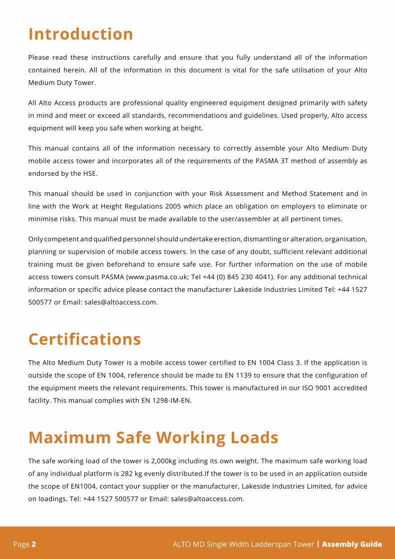
Step 1
Insert the leg & castor assembly into the base of the first main frame and ladder frame. When fully inserted, ensure the spring loaded pin is engaged into the hole in the side of the frames. Ensure all 4 wheels have the brakes applied.
Step 2
Connect 2 horizontal braces to the uprights of the first frame in the area below the bottom rung. Make sure that the braces are connected from the inside of the tower facing outwards. Make sure that the frame head fittings are pointing inwards into the tower.
Step 3
Connect the 2nd frame to the horizontal braces in the same position that they are located on the first frames. Make sure that the frame head fittings are pointing inwards into the tower.
ASSEMBLY INSTRUCTIONS - All Platform Working Heights

Page 11ALTO Access Products | Lakeside Industries Ltd
Step 4
Connect 2 diagonal braces to the frames as shown. Keep the diagonal braces as close to the frame uprights as possible. Ensure that they run in opposite directions to each other.
Step 5
Install a trap platform on the 2nd rung up and 4 horizontal braces as guard rails. Using a spirit level, ensure that the framework is completely level by adjusting the legs. Twist the serrated collar above the wheel to adjust up & down.
Step 6
Once the framework is in position and level, connect 4 stabilisers to the corners. Fix the shorter arm to the lowest part of the frame, then connect the longer arm to the upper part, ensuring the foot is firmly placed on the ground. Small vertical adjustments can be made to either arm to guarantee a sturdy placement.

Page 12 ALTO MD Single Width Ladderspan Tower | Assembly Guide
Step 7.1
Working from the temporary platform, install a 2 rung main frame & a 2 rung ladder frame onto the 4 rung frames. Then, clip onto the top rung a diagonal brace. Diagonal braces always run parallel to the braces below.
Install another 4 guard rails above the 4 already in place for when the platform is relocated.
Step 7.2
Remove the lower 4 guardrails by using the 3T method or uninstalling them from the ground. Relocate the platform to the top rung of the first frames. If a 2.2m tower is being assembled, go straight to Step 10. From this new platform position, install a 4 rung frame and a 4 rung ladder frame. Clip on one standard diagonal brace on the same side of the tower as the one form step 7.1. The start position of the brace should be on the same rung height as the finishing position from the brace below - running in the same parallel direction.
Proceed to Step 9
Build Method A 2.2m, 4.2m, 6.2m, 8.2m, 10.2m

Page 13ALTO Access Products | Lakeside Industries Ltd
Step 7.1
Working from the temporary platform, install a 3 rung main frame & a 3 rung ladder frame onto the 4 rung frames. Then, clip onto the top rung a diagonal brace. Diagonal braces always run parallel to the braces below.
Step 7.2
Relocate the platform down one rung to the bottom rung of the first frames and add 2 additional guardrails. Working off this, install a 2nd platform 4 rungs above.
Step 7.3
Using the 3T method install 4 guardrails to the upper platform. If a 2.7m tower is being assembled, go straight to step 10. The platform on the bottom rung of the tower and the 4 guardrails can now be removed. Make sure that there are still 2 horizontal braces on the bottom rung and the 4th rung up on the tower.
Proceed to Step 8
Build Method B 2.7m, 4.7m, 6.7m, 8.7m, 10.7m

Page 14 ALTO MD Single Width Ladderspan Tower | Assembly Guide
Step 7.1
Working from the temporary platform, install a 4 rung main frame & a 4 rung ladder frame onto the first set of 4 rung frames. Then, clip 1 diagonal brace on. The start position of the brace should be on the same rung height as the finishing position from the brace below - running in the same parallel direction.
Step 7.2
Install a 2nd platform 4 rungs above the first platform. Using the 3T method install 4 guardrails to the upper platform. If a 3.2m tower is being assembled, go to step 10.
Proceed to Step 8
Build Method C 3.2m, 5.2m, 7.2m, 9.2m

Page 15ALTO Access Products | Lakeside Industries Ltd
Step 7.1
Working from the temporary platform, install a 2 rung main frame & a 2 rung ladder frame onto the 4 rung frames. Then, clip onto the top rung of one frame a diagonal brace. The other end connects to the rung 3 below on the opposite face.
Install another 4 guard rails above the 4 already in place for when the platform is relocated.
Step 7.2
Remove the lower 4 guardrails by either using the 3T method or uninstalling them from the ground. Then relocate the platform to the top rung of the first frames. Working off this new platform position, install a 3 rung main frame and a 3 rung ladder frame. Then clip 1 more diagonal brace.
Step 7.3
Lower the platform down 1 rung and relocate the guardrails into the correct positions using the 3T method. Install another platform 4 rungs above and install 4 guardrails using the 3T method. If a 3.7m tower is being assembled, go to step 10.
Proceed to Step 8
Build Method D 3.7m, 5.7m, 7.7m, 9.7m

Page 16 ALTO MD Single Width Ladderspan Tower | Assembly Guide
Step 8
Working from the top platform, install a 4 rung main frame & a 4 rung ladder frame. Then clip 1 more diagonal brace onto the same side as the previously installed diagonal brace. The start position of the brace should be on the same rung height as the finishing position from the brace below - running in the same parallel direction.
Step 9
Install a trap platform 4 rungs above the previous platform. Using the 3T method install 4 guardrails to the upper platform.
Now, repeat steps 8 and 9 until the required platform working height is achieved. Once the final step 9 is complete, move to step 10.
Step 10
Finally, working from the guard railed platform, install a toeboard, ensuring that the sides are hooked securely over the outside edge of both platforms.
All Platform Working Heights
Page 17ALTO Access Products | Lakeside Industries Ltd
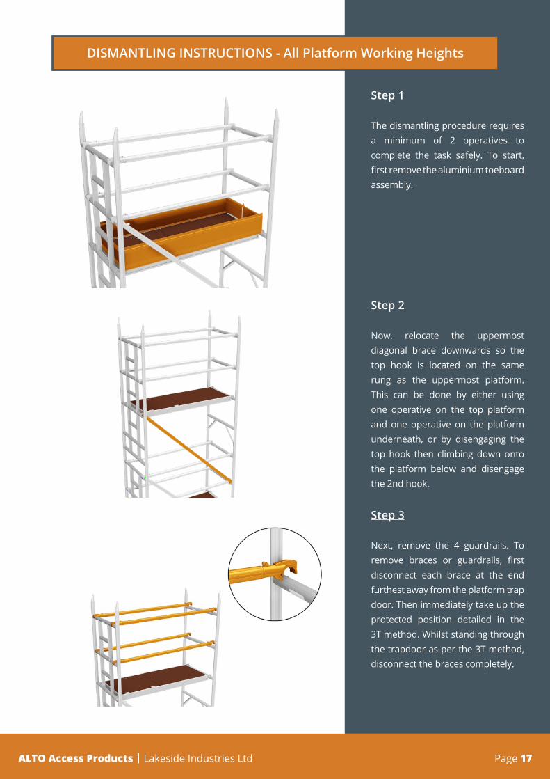
Step 1
The dismantling procedure requires a minimum of 2 operatives to complete the task safely. To start, first remove the aluminium toeboard assembly.
Step 2
Now, relocate the uppermost diagonal brace downwards so the top hook is located on the same rung as the uppermost platform. This can be done by either using one operative on the top platform and one operative on the platform underneath, or by disengaging the top hook then climbing down onto the platform below and disengage the 2nd hook.
Step 3
Next, remove the 4 guardrails. To remove braces or guardrails, first disconnect each brace at the end furthest away from the platform trap door. Then immediately take up the protected position detailed in the 3T method. Whilst standing through the trapdoor as per the 3T method, disconnect the braces completely.
DISMANTLING INSTRUCTIONS - All Platform Working Heights

Page 18 ALTO MD Single Width Ladderspan Tower | Assembly Guide
Step 4
Now, working from the platform below, the upper platform can be removed. Once this is fully removed, the recently relocated diagonal brace(s) can now be taken off. This can be done by one operative from the platform.
Step 5
Now remove the final 2 frames off the top of the tower.
Now repeat steps 2 to 5 until the tower is dismantled or the new platform height is achieved.
DISMANTLING INSTRUCTIONS - All Platform Working Heights

Page 19ALTO Access Products | Lakeside Industries Ltd
2239 - 125mm castor wheel3076 - MD Adj. Leg
3008 - MD S/W 4 Rung Frame 3012 - MD S/W 4 Rung Ladder Frame
3010 - MD S/W 3 Rung Frame 3013 - MD S/W 3 Rung Ladder Frame
3011 - MD S/W 2 Rung Frame
3014 - MD S/W 2 Rung Ladder Frame
3015 - 1.6m Horiz. Brace (blue)3017 - 2.4m Horiz. Brace (yellow)
3016 - 1.6m Diag. Brace (green)3018 - 2.4m Diag. Brace (brown)
3023 - MD Small Stabiliser3024 - MD Large Stabiliser
Components
3021 - 1.6m Trap Platform3022 - 2.4m Trap Platform
3036 - 1.6m S/W Toeboard3037 - 2.4m S/W Toeboard

Lakeside Industries LtdUnit 19 Howard Road, Park Farm Industrial Estate, Redditch, Worcestershire. B98 7SE+44(0)1527 500577 | [email protected] | www.altoaccess.com
For further information regarding our range of access products and services, please get in touch with us:
Lakeside Industries LtdUnit 19 Howard Road, Park Farm Industrial EstateRedditch, Worcestershire. B98 7SE. UK
t: +44(0)1527 500 577e: [email protected]: www.altoaccess.com
@lakesideindust
lakeside-industries-ltd
@altotowers
Manufacturing Member