3JH2 Series 2000. 3. 10 MARINE DIESEL ENGINE - Varen4U
308
3JH2 Series 2000. 3. 10 MARINE DIESEL ENGINE SERVICE MANUAL 0000A0A1015-9112
-
Upload
khangminh22 -
Category
Documents
-
view
0 -
download
0
Transcript of 3JH2 Series 2000. 3. 10 MARINE DIESEL ENGINE - Varen4U

3JH2 Series
2000. 3. 10
MARINE DIESEL ENGINE
SERVICE MANUAL
0000A0A1015-9112

series

Publication No. A0A1015
Page No 1
Manual Name Service Manual for Marine Diesel Engine
History of Revision
Engine Model : 3JH2 series
Number ofrevision
Reason for correction Corrected byOutline of correctionDate of
revisionCorrection item
No. (page)
1st Apr. 2001
2nd Feb. 2003
●Crank shaftV-pulley bolttighteningtorque
●Clutch levercontrol cableconnectlion.
●Addthe model3JH25A &3JH30A
10-32
8-3
1-3, 10-31
QualityAssuranceDept.
●Added the standard V-pulley(material: casting iron) tighteningtorque and general use nuts & boltstightening torque.
●Added the tightening torque of nutfor the remote control cable connec-tion of clutch shifting lever.
● Injection timing changed.
● Added the Exterior Views ● Added the Specifieations ● Added the Engine Outiine ● Added the Pertomance Curves ● Added the Piping Diagrams ● Added the Fuel Injection Pump
Sewice Data ● Added the Intake and
Exhaust System figure ● Added the Lubrieation System
figure ● Added the Lube Oil Filter figure ● Added theSea water line flgure ● Added the Marine Gear Models
KM3P1,KM3P3,KM35P1 ● Added the Wiring diagrams
1-2-1, 1-2-21-3-1, 1-4-11-8-11-11-1, 1-11-21-14-13-1-1
4-1-1
5-2-15-6-16-3-17-29~7-56
9-4-1
QualityAssuranceDept.
Printed in JapanA0A1015-0302
Printed in JapanA0A1015-0302


CONTENTSCHAPTER 1 GENERAL
1.Exterior Views . . . . . . . . . . . . . . . . . . . . . . . . . . . . . 1-12.Specifications . . . . . . . . . . . . . . . . . . . . . . . . . . . . . . 1-33.Engine Outline . . . . . . . . . . . . . . . . . . . . . . . . . . . . . 1-54.Performance Curves . . . . . . . . . . . . . . . . . . . . . . . 1-105.Piping Diagrams. . . . . . . . . . . . . . . . . . . . . . . . . . . 1-12
CHAPTER 2 BASIC ENGINE PARTS1.CylinderBlock . . . . . . . . . . . . . . . . . . . . . . . . . . . . . 2-12.Cylinder Head . . . . . . . . . . . . . . . . . . . . . . . . . . . . . 2-43.Piston and Piston Pins . . . . . . . . . . . . . . . . . . . . . . 2-114.Connecting Rod . . . . . . . . . . . . . . . . . . . . . . . . . . 2-155.Crankshaft and Main Bearing . . . . . . . . . . . . . . . . 2-186.Camshaft and Tappets. . . . . . . . . . . . . . . . . . . . . . 2-217.Timing Gear . . . . . . . . . . . . . . . . . . . . . . . . . . . . . 2-248.Flywheel and Housing . . . . . . . . . . . . . . . . . . . . . . 2-26
CHAPTER 3 FUEL INJECTION EQUIPMENT1.Fuel Injection Pump Service Data . . . . . . . . . . . . . . 3-12.Governor . . . . . . . . . . . . . . . . . . . . . . . . . . . . . . . . . 3-23.Disassembly Reassembly and Inspection of Fuel
Injection Pump . . . . . . . . . . . . . . . . . . . . . . . . . . . . 3-114.Adjustment of Fuel Injection Pump and Governor . . 3-215.Fuel Feed Pump. . . . . . . . . . . . . . . . . . . . . . . . . . . 3-276.FuelInjection Nozzle . . . . . . . . . . . . . . . . . . . . . . . 3-297.Troubleshooting . . . . . . . . . . . . . . . . . . . . . . . . . . . 3-338.Tools . . . . . . . . . . . . . . . . . . . . . . . . . . . . . . . . . . . 3-359.Fuel Filter . . . . . . . . . . . . . . . . . . . . . . . . . . . . . . . 3-37
10.Fuel Tank (Optional). . . . . . . . . . . . . . . . . . . . . . . . 3-38
CHAPTER 4 INTAKE AND EXHAUST SYSTEM1.Intake and Exhaust System . . . . . . . . . . . . . . . . . . 4-12.Turbocharger . . . . . . . . . . . . . . . . . . . . . . . . . . . . . . 4-33.Mixing Elbow . . . . . . . . . . . . . . . . . . . . . . . . . . . . . 4-17
CHAPTER 5 LUBRICATION SYSTEM1. Lubrication System . . . . . . . . . . . . . . . . . . . . . . . . . 5-12.Lube Oil Pump . . . . . . . . . . . . . . . . . . . . . . . . . . . . 5-33.Lube Oil Filter . . . . . . . . . . . . . . . . . . . . . . . . . . . . . 5-64.Oil Pressure Control Valve . . . . . . . . . . . . . . . . . . . 5-85.Lube Oil Cooler . . . . . . . . . . . . . . . . . . . . . . . . . . . . 5-96.Piston Cooling Nozzle . . . . . . . . . . . . . . . . . . . . . . 5-107.Rotary Waste Oil Pump (Optional) . . . . . . . . . . . . . 5-11
CHAPTER 6 COOLING WATER SYSTEM1.Cooling Water System . . . . . . . . . . . . . . . . . . . . . . 6-12.Sea Water Pump . . . . . . . . . . . . . . . . . . . . . . . . . . . 6-43.Fresh Water Pump . . . . . . . . . . . . . . . . . . . . . . . . . 6-74.Heat Exchanger . . . . . . . . . . . . . . . . . . . . . . . . . . 6-105.Pressure Cap and Sub Tank . . . . . . . . . . . . . . . . . 6-126.Thermostat . . . . . . . . . . . . . . . . . . . . . . . . . . . . . . . 6-147.Kingston Cock (Optional) . . . . . . . . . . . . . . . . . . . 6-168.Sea Water Filter (Optional) . . . . . . . . . . . . . . . . . . 6-179.Bilge Pump and Bilge Strainer (Optional) . . . . . . . 6-18
CHAPTER 7 REDUCTION AND REVERSING GEARKM3A
1.Construction . . . . . . . . . . . . . . . . . . . . . . . . . . . . . . . 7-12.Shifting Device . . . . . . . . . . . . . . . . . . . . . . . . . . . . 7-73.Inspection And Servicing . . . . . . . . . . . . . . . . . . . . 7-124.Disassembly . . . . . . . . . . . . . . . . . . . . . . . . . . . . . 7-225.Reassembly . . . . . . . . . . . . . . . . . . . . . . . . . . . . . . 7-25
KM3P1,KM3P3,KM35P11.Construction . . . . . . . . . . . . . . . . . . . . . . . . . . . . . . 7-292.Shifting Device . . . . . . . . . . . . . . . . . . . . . . . . . . . 7-353.Inspection And Servicing . . . . . . . . . . . . . . . . . . . . 7-404.Disassembly . . . . . . . . . . . . . . . . . . . . . . . . . . . . . 7-485.Reassembly . . . . . . . . . . . . . . . . . . . . . . . . . . . . . . 7-53
CHAPTER 8 REMOTE CONTROL1.Remote Control System . . . . . . . . . . . . . . . . . . . . . . 8-12.Remote Control Installation . . . . . . . . . . . . . . . . . . . 8-23.Remote Control Inspection . . . . . . . . . . . . . . . . . . . 8-54.Remote Control ADJUSTMENT. . . . . . . . . . . . . . . . 8-65.Disassembly . . . . . . . . . . . . . . . . . . . . . . . . . . . . . 8-13
CHAPTER 9 ELECTRICAL SYSTEM1.Electrical System . . . . . . . . . . . . . . . . . . . . . . . . . . . 9-12.Battery . . . . . . . . . . . . . . . . . . . . . . . . . . . . . . . . . . . 9-53.Starter Motor . . . . . . . . . . . . . . . . . . . . . . . . . . . . . . 9-84.Alternator . . . . . . . . . . . . . . . . . . . . . . . . . . . . . . . . 9-245.Instrument Panel . . . . . . . . . . . . . . . . . . . . . . . . . . 9-346.Warning Devices . . . . . . . . . . . . . . . . . . . . . . . . . . 9-367.Air Heater (Optional) . . . . . . . . . . . . . . . . . . . . . . . 9-398.Electric Type Engine Stop Device (Optional) . . . . . 9-409.Tachometer . . . . . . . . . . . . . . . . . . . . . . . . . . . . . . 9-42
10.AIternator 12V/80A(Optional) . . . . . . . . . . . . . . . . . 9-45
CHAPTER 10 DISASSEMBLY AND REASSEMBLY1.Disassembly and Reassembly Precautions . . . . . . 10-12.Disassembly and Reassembly Tools . . . . . . . . . . . 10-23.Disassembly and Reassembly . . . . . . . . . . . . . . . . 10-94.Bolt/nut Tightening Torque. . . . . . . . . . . . . . . . . . 10-325.Test Running . . . . . . . . . . . . . . . . . . . . . . . . . . . 10-33
Printed in JapanA0A1015-0302
Printed in JapanA0A1015-0302


1-2-1
3JH2 Series
Chapter 1 General1. Exterior Views
1-3 3JH25A/30A
With KM3P3
Operating side
Operating side
Fuel injection pump
Air intake manifoldMist separator
KM3P3
Torque limiterDipstic (clutch side)
Dipstic (engine side)Lube filter
Fuel priming pump
Fuel filter
Fresh water pump
Alternator
Pressure cap
Fresh water tankExhaust manifold
Mixing elbow
Clutch handleStarting motorSeawater pump
Printed in JapanA0A1015-0302
Printed in JapanA0A1015-0302

1-2-2
3JH2 Series
Chapter 1 General1. Exterior Views
With KM3P1/ KM35P1
Operating side
Operating side
Fuel injection pump
Air intake manifoldMist separator
KM3P1KM35P1
Dipstic (clutch side)
Dipstic (engine side)Lube filter
Fuel priming pump
Fuel filter
Fresh water pumpAlternator
Pressure cap
Fresh water tankExhaust manifold
Mixing elbow
Clutch handleStarting motorSeawater pump
Printed in JapanA0A1015-0302
Printed in JapanA0A1015-0302


3JH2 Series
Chapter 1 General2. Specifications
1-3-1
Model Unit 3JH25A
Vertical 4-cycle water cooled diesel engine
Direct injection
Normal aspiration
3
82× 86
1.303
3JH30A
___
___
___
___
mm
m/sec. 9.5 8.6
kW(PS)/rpm20.2/3300
(27.5/3300)
24.3/3000
(33.0/3000)
0.539 (5.50) 0.713 (7.27)
9.2
18.1
1 — 3 — 2 — 1
YPES-CL
19±1
19.6±0.5(200±5)
Hole type
At Flywheel side
Forced lubrication with trochoid pump
DC 12V-1.8kW
12V-35A
730
185
770
190
545
680
0.9 / 7.0
4.4
0.8
Constant high temperature fresh water cooling
Fresh water : Centrifugal pump
See water : Rubber impeller pump
Counter-clock wise
viewed from stern
8.3
18.4/3200
(25/3200)
22.1/2900
(30/2900)
0.506 (5.016) 0.670 (6.83)
MPa(kgf/cm2)
Type
Combustion system
Aspiration
Number of cylinders
Bore × stroke
Displ acement
Compression ratio
Fire order
Fuel injection pump
Fuel injection timing (b.T.D.C.)
Fuel injection pressure
Fuel injection nozzle
Power taka off
Lubrication system
Engine weight without marine gear (dry)
Lubricating oi l capacity Effect/max.
Starting system
Dimensions
(with KM35P1)
Cooling watercapacity
(Fresh water)
Starting motor
AC generator
Overall length
Overall width
Overall height
Fresh water tank
Sub tank
Cooling system
Direction of rotaion (Crankshaft)
One hour rating
output
(DIN6270B)
flywheel output
Continuous rating
output
(DIN6270A)
flywheel output
Output/crankshaft speed
Brake mean effectivepressure
Piston speed
m/sec.
___
___
___
degree.
MPa(kgf/cm2)
___
___
___
V-kW
V-A
mm
mm
mm
kg
___
___
kW(PS)/rpm
MPa(kgf/cm2)
Output/crankshaft speed
Brake mean effectivepressure
Piston speed
Printed in JapanA0A1015-0302
Printed in JapanA0A1015-0302


3JH2 Series
1-4-1
Chapter 1 General2. Specifications
marine gearsystem
Model KM3P1
12kg
Not Eqipped
Cone clutch
2.36 / 3.1 6
Clock wise
0.3 / 0.35 0.45 / 0.5
SAE #30
API CC or CD
KM3P3
15
Eqipped
KM35P1
12
Eqipped
Clutch Type
mas
Torque limiter
Reduction ratio
(Forward/Reverse)
Direction of rotation(Forward)
viewed from stern
Lubricating oil capacity
min/max
Lubricating oil
Printed in JapanA0A1015-0302
Printed in JapanA0A1015-0302


442.
5
JOINT φ8 FOR FO RETURN
JOINT φ8 FOR FO INLET
28.8
701.3
730.1
180.6
183.8
AHEAD
ASTERN
309.
1
MIXING ELBOW PT 11/4
237.
568
0
33.5
31.5
6.5
4.5
SO
LE P
LAT
E
543278 265
190.5
93 95480
119.
5
SEA WATER INLET φ26
7
φ50+0.025
0
φ22
7.54-φ10.54-φ117311 3
φ52
φ40
φ10
0
φ5
0 0
-0.019 pc
φ78pcφ78
φ10
0
35
(PROPELLER SHAFT COUPLING) (OUTPUT SHAFT COUPLING)
4
4-M8 TAPPEDHOLES(DEPTH 12)
pcφ
82.5
DIRECTION OF ROTATION
DETAIL OF PULLY (VIEW FROM ARROW A)
530
240
240
247.
5
22
5
φ63
.5+0.048
0
φ13
4
445
70 4-φ16.5
50
305 159237.3
(VIEW FROM ARROW B)
1-8-1
3JH2 Series
Chapter 1 G
eneral3. Engine O
utline
3JH25A/30A
Printed in Japan
A0A
1015-0302P
rinted in JapanA
0A1015-0302


1-11-1
3JH2 series
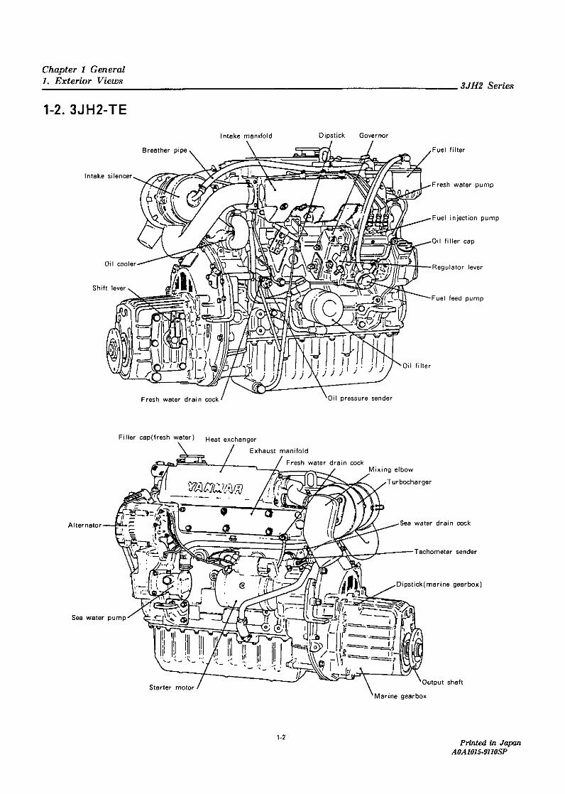
Chapter 1 General4. Performance Curves
3JH25A Performance Curve
Crankshaft speed (min-1)
Specific fuel consumption
Spe
cific
fuel
con
sum
ptio
n (g
/kW
-h)
Exhaust Gas Temp.
Propeller curve curveP
rope
ller p
ower
cur
ve (k
W)
350
300
250
200
150
400
20
15
10
5
01500 1700 1900 2100 2300 2500 2700 2900 3100 3300
Crankshaft speed (min-1)
1500 1700 1900 2100 2300 2500 2700 2900 3100 3300
Crankshaft speed (min-1)
1500 1700 1900 2100 2300 2500 2700 2900 3100 3300
350
300
250
200
150
100
400
Exh
aust
Gas
Tem
p. (°C
)
Printed in JapanA0A1015-0302
Printed in JapanA0A1015-0302

1-11-2
3JH2 series
Chapter 1 General4. Performance Curves
3JH30A Performance Curve
Crankshaft speed (min-1)
Specific fuel consumption
Exhaust Gas Temp.
Propeller curve curve
Pro
pelle
r pow
er c
urve
(kW
)S
peci
fic fu
el c
onsu
mpt
ion
(g/k
W-h
)
300
250
200
150
350
20
15
10
5
01500 1700 1900 2100 2300 2500 2700 2900 3100
350
300
250
200
150
100
400
Exh
aust
Gas
Tem
p. (°C
)
25
Crankshaft speed (min-1)
1500 1700 1900 2100 2300 2500 2700 2900 3100
Crankshaft speed (min-1)1500 1700 1900 2100 2300 2500 2700 2900 3100
Printed in JapanA0A1015-0302
Printed in JapanA0A1015-0302


PT1 1/4
4520
φ53EXH.
GAS
DETAIL OF PART B
A WATER
1-14-1
3JH2 series
Chapter 1 G
eneral5. Piping D
iagrams
3JH25A
/30A
Marks of PIPING NAME
RUBBER HOSE
STEEL PIPE
COPPER PIPE
UNION SCREW JOINT
FLANGE JOINT
EYE JOINT
INSERTION JOINT
DRILL HOLE
COOLING FRESH WATFR PIPING
COOLING SEA WATFR PIPING
LUB.OIL PIPING
FUEL OIL PIPING
MIST PIPE
R H
SGP
STS
C1201T
FUEL OVERFLOW
FUEL FEED PUMP
FUEL OIL INLET
φ7X t3 RH
φ7X t3 RHφ7X t3 RH φ7X t3 RH
φ7X t3 RH
φ4X t2 RH
φ28X t1.2 C1201T
φ27X t4 RH
φ28X t4 RH
φ28X t4 RH
φ25.4X t1.8 C1201Tφ25.4X t4.3 RH
φ25.4X t4.3 RH
φ25.4X t4.3 RH
φ4X t2 RH
φ4.76X t0.7 STS
φ6.35X t2.275 ST9
FUEL HIGH PRESSURE PIPE
FUEL INJECTION NOZZLE
OIL PRESSURE SWITCH
LUB. OIL FILTER (CARTRIDGE TYPE)
PRESSURE CONTROL VALVE
FUEL INJECTION PUMP
MIXING ELBOW
B
FRESH WATER COOLER
LUB. OIL INLET FILTER
MAIN BEARING
TO CAM SHAFT
SER WATER INLET
TO OIL PAN
FUEL OIL FILTER (CARTRIDGE TYPE)
HOT WATER CONNECTION INLET
COOLING WATER PUMP (FRESH WATER)
HOT WATER CONNECTION OUTLET
LUB. OIL PUMP
THERMOSTAT
FROM CYLINDER HEAD
(SEA WATER)COOLING WATER PUMP
Printed in Japan
A0A
1015-0302P
rinted in JapanA
0A1015-0302


Printed in JapanA0A1015-0302
3-1-1 Printed in JapanA0A1015-0302
3JH2 series
Chapter 3 Fuel Injection Equipment1. Fuel Injection Pump Service Data
Item Engine
Assemble codePart No 729198-51300
3JH25A
B450
0.95~1.05/2.5
1650
6
1000
Engine spec. Cal. Spec. Engine spec. Cal. Spec.
150P244HCO DN-12SD12 150P244HCO DN-12SD12
200~210 165~175 200~210 165~175
φ6×φ1.8×360 φ6×φ2.0×600 φ6×φ1.8×360 φ6×φ2.0×600
21.5 28.2 27 ——
6~7 7~8 6~7 7~8
729198-51320
3JH30A
B451
0.95~1.05/2.5
1500
6
1000
±3 ±3
±20 ±20
200 200
11.5~1.25 11.5~1.25
1000 1000
60~70 56~66 60~70 56~66
——— ———
——— ———
325 325
1000 1000
I.D. mark
Adjustment specs
Nozzle type I.D. mark
Injection starting pressure (kg/cm2)
Fuel injection pipe (ODφ×IDφ×L)
Top clearance/Pre stroke (mm)
Rated load
Idling
Starting
No load
Pump rpm:N1 (rpm)
Rack position:R1 (mm)
Measuring stroke (St)
Injection volume (cm3)
Non unifomity (%)
Pump rpm:N2 (rpm)
Rack position:R2
Pump rpm:N3 (rpm)
Measuring stroke (St)
Injection volume (cm3)
Non uniformity (%)
Pump rpm:N4 (rpm)
Rack position (mm)
Measuring stroke (St)
Injection volume (cm3)


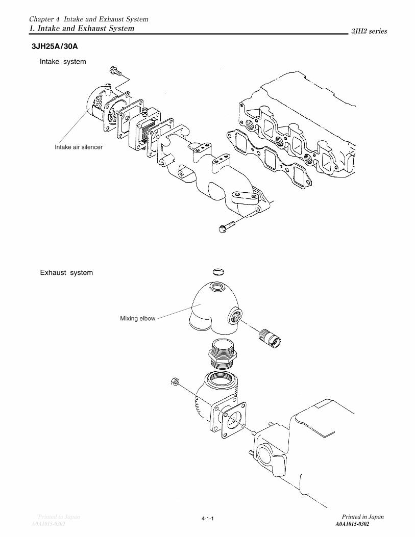
Mixing elbow
Intake air silencer
4-1-1
3JH2 series
Chapter 4 Intake and Exhaust System1. Intake and Exhaust System
3JH25A/30A
Intake system
Printed in JapanA0A1015-0302
Printed in JapanA0A1015-0302
Exhaust system


5-2-1
3JH2 series
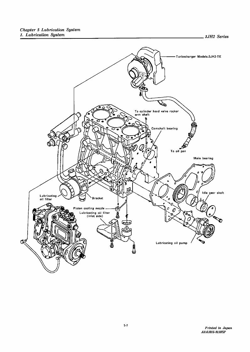
Chapter 5 Lubrication System1. Lubrication System
Printed in JapanA0A1015-0302
Printed in JapanA0A1015-0302
3JH25A/30A
Lubricating oil filter
Oil return piper
Oil pan
Fuel injection pumplubricating pipe
A
B
A
B
Fuel injection pump


5-6-1
3JH2 series
Chapter 5 Lubrication System3. Lube Oil Filter
Printed in JapanA0A1015-0302
Printed in JapanA0A1015-0302
3JH25A/30A
Lubricating oil filter
Oil return pipe
Oil pan
Oil pressure regulator valve
Filter bracket
Cylinder block


6-3-1
3JH2 series
Chapter 6 Cooling Water System1. Cooling Water System
Printed in JapanA0A1015-0302
Printed in JapanA0A1015-0302
3JH25A/30A
Mixing elbow
Heat exchanger
Sea water pump
Kingston cock
A
A


7-29
3JH2 series
Chapter 7 Reduction and Reversing Gear1. Construction
Printed in JapanA0A1015-0302
Printed in JapanA0A1015-0302
Marine Gear Models
KM3P1, KM3P3, KM35P1for Engine Models 3JH25A /3JH30A
1. Construction1-1. Construction
These clutches are a cone-type, mechanically operated
clutch.
When the drive cone (which is connected to the output
shaft by the lead spline) is moved forward or backward, its
taper contacts with the large gear and transfers power to
the output shaft.
The construction is simple when compared with other-
types of clutch and if serves to reduce the number of com-
ponents, making for a lighter, more compact unit which
can be operated smoothly. Although it is small, the power
transmission efficiency is high even under a heavy load.
Its durability is high and it is also reliable because high
grade materials are used for the shaft and gear, and. a
taper roller bearing is incorporated.
Power transmission is smooth because connection
with the engine is made through the damper disc
● The drive cone is made from special aluminum bronze, which has both higher wear-resistance and durability. The drive cone is connected with the output shaftthrough the thread spline. The taper angle, diameter ofthe drive cone, twist angle, and diameter of the threadspline, are designed to give the greatest efficiency, thus ensuring that the drive cone can be readily engaged ordisengaged.
● Helical gears are used for greater strength.The intermediate shaft is supported at 2 points toreduce deflection and gear noise.
● The clutch ease and mounting flange are made from an aluminum alloy of special composition to reduce weight.
It is also anticorrosive against seawater.● As the damper disc is fitted to the input shaft, power can
be transmitted smoothly. ● There is small clearance between the dipstick and the
inside of the dipstick tube. A small hole in the dipstick
works as a breather. ● when the load on the propeller is removed, the engage-
ment of the drive cone and the large gear is maintained
by the shifter and V-groove of the drive cone.
Even when the drive cone's tapered area and V-groove
are worn, this engagement is maintained by the shift
lever device and accordingly no adjustment of the
remote control cable is required. ● The cup spring on the rear of the larger gear absorbs
rotational fluctuations and stabilizes the engagement of
the drive cone and the larger gear.
Thus, the durability of the cone against wear is enhanced.
NOTE:
KM3P3 marine gear differs from KM3P1 as follows. ● Torque !imiter applied to KM3P3.
KM35P1 marlne gear differs from KM3P1 as follows. ● Output shaft dia. 28mm. (KM3P1 : 25mm). ● Drive corn the same as the one for KM4A marine gear.● Marine gear oil reserve capacity up.
0.5L (0.35L KM3P1 )

Reduction ratio No. of blade Diameter of the propeller Moment of inertia N-m2 Material
3 450 1.49(0.15)2.36
4 425
3 470 Bronze
2.61 4 440 1.86(0.19)
4 460
7-30
3JH2 series
Chapter 7 Reduction and Reversing Gear1. Construction
For engine models 3JH25A
KM3P1 KM3P3 KM35P1
12 15 12
Constant mesh gear with servo cone clutch (wet type)
2.36 2.61 2.36 2.61
3.16 3.16 3.16 3.16
1356 1226 1229 1111
Counter-clockwise, viewed from stern
Clockwise, viewed from stern
Counter-clockwise, viewed from stern
Single lever control
Morse. 33-C (cable travel 76.2mm)
YANMAR made. standard accessory
YANMAR made, standard accessory
100
78
4-1 0.5
Right side, viewed from stern
API CC SAE 20/30
0.35 0.5
3JH30A
Clutch
Forward
Mode
Reverse
Propeller shaft mirr1 (Forward) (min-1)
Input shaft
Forward
Output shaft Reverse
Control head
Cable
Clamp
Cable connector
Outer diameter (mm)
Pitch circle diameter (mm)
Connecting bolt holes (mm)
Remote control
Reduction ratio
Position of shift lever
Output shaft coupling
Direction of rotation
Lubricating oil
Lubricating oil capscity ( )
Dry mass (kg)
Printed in JapanA0A1015-0302
Printed in JapanA0A1015-0302
1.2 Specifications
Note:
Torque limiter should be installed on KM3P3No torque limiter installed on KM3P1 & KM35P1
(mm) (kg-m2=GD2 )

7-31
3JH2 series
Chapter 7 Reduction and Reversing Gear1. Construction
Printed in JapanA0A1015-0302
Printed in JapanA0A1015-0302
1-3 Power transmission system
1-3.1 Arrangement of shafts and gears
Idle gear
Forward small gear with input shaft
Forward small gear of input shaft
Reverse small gear of input shaft
input shaft
Large gear of output shaft
Reverse small gear with input shaft
Output shaft
Reverse large gear
Idle gear
Drive cone
Forward large gear
Shaft arrangementviewed from the stern
Intermediate shaft
Intermediate shaft
Output shaft
Model No. of teeth No. of teeth Reduction retio Zof /Zifof forward small gear Zif of forward 18rge gear Zof
KM3P1, KM3P3, KM35P125 59 59/25 = 2.36
23 60 60/23 = 2.61
1-3.2 Reduction ratio
Forward
Model No. of teeth No. of teeth No. of teeth Reduction ratio Zi/Zir・Zdr/Ziof reverse small gesr Zif of intemediate shaft gear Zi of reverse large gear Zdr
KM3P1KM3P3 19 26 60 60/19 = 3.16KM35P1
Reverse


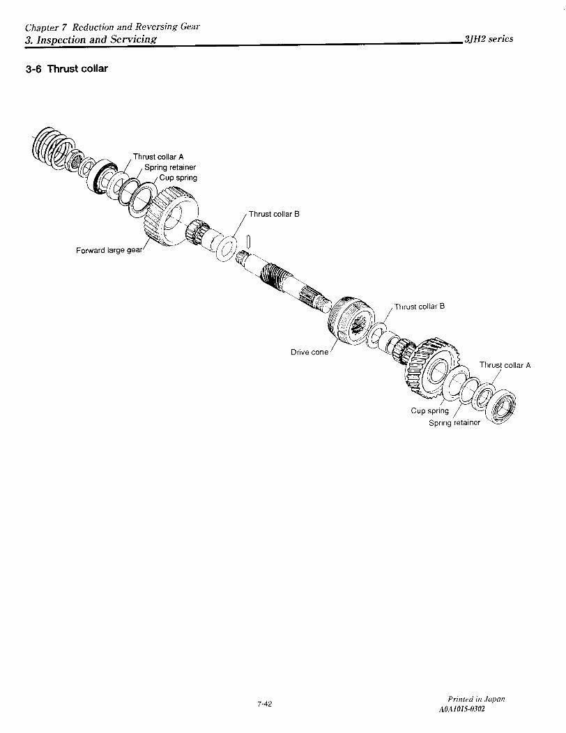
7-41
3JH2 series
Chapter 7 Reduction and Reversing Gear3. Inspection and Servicing
Printed in JapanA0A1015-0302
Printed in JapanA0A1015-0302
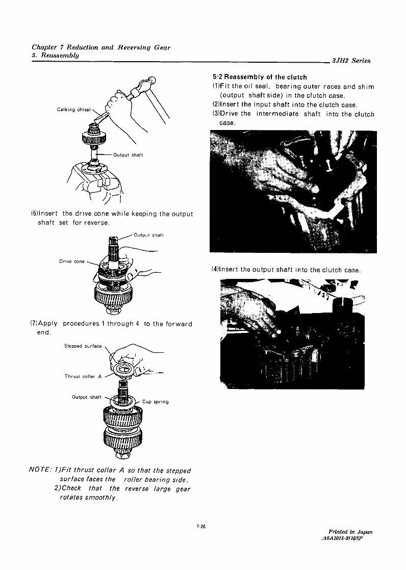
NOTE : When dismantled, the forward of reverse direc-tion of the drive cone must be clearly identified.
(4) lf the wear of the V-groove of the drive cone is exces-sive, replace the part.
NOTE : When replacing the drive cone, the new cone and forward large gear and reverse large gear must be lapped prior to assembly.The lapping procedure is described below.
3-5-1 Lapping Procedure for Drive Cone
(1) Coat the lapping powder onto the cave of the clutch gear (Lapping powder :67 micron silicon carbide #280)
(2) Set the large gear on the output shaft with a needle bearing and then set the drive cone on the outputshaft.
(3) Lap the large gear's cave and drive cone, pushing them together by hand.
(4) Push and turn the large gear about 5 times both clockwise and counter-clockwise.
(5) After lapping them, wash them with washing oil. The lapped parts should be cleaned completely.
NOTE:● Do not mix the combination of the lapped parts. The washing oil should be changed frequently inorder to prevent residual powder being left on theparts.When assembling the drive cone, be sure to check its alignment. The larger chamfering face should be on the forward large gear side.
mm
Standarddimensions
Dimensions KM3P1KM3P3
KM35P1
Limiteddimensions
32.7-33.3 32.4
29.25-29.75 28.1


9-4-1
3JH2 series
Chapter 9 E
lectrical System1. Electrical System
Printed in Japan
A0A
1015-0302P
rinted in JapanA
0A1015-0302
3JH25A
/30A
Tacho with Hour meter
Buzzer stop
Buzzer
Illumination switch
Starte switch
Fuse 3A
B
B
A
A
Wire harness
Instument panel
ChargeEng. Oil P.C.W. Temp.
Fuel Empty
Glow
Air heater
Battery Switch
Battery
S or C
Starter
Battery
Battery Switch
12V
12V
Earth bolt
Alternator
Tacho sensor
Eng. Oil Pressure switch
C.W.Temp switch
WR
WL
YW
3R
5L
BR3B
21
3
F
RL
LB
BYG
YB
O
GW
O
RRGG r B
R RB
3R3L
3WRC
LB
YW
WL
WG
GY
RWY
G
G
Y
W
B
+ - P
+ -
+ -
ACP1
P2 AR
30
G1G2
17
LWLYL
R RedB BlackW WhiteY YellowL BlueG GreenO OrangeLg Light greenLb Light blueBr BrownP PinkGr GrayPu Purple
Color coding