
Leyland Thornycroft - Varen4U
44
',.. -iffii; i r- - -:r-a. ' =:ii.: l: ' +t:.! - -,.,:i
-
Upload
khangminh22 -
Category
Documents
-
view
4 -
download
0
Transcript of Leyland Thornycroft - Varen4U

' , . .
-iffii;i r - -
- : r - a .' = : i i . : l :
' + t : . !
- -,.,:i

b
*
^
I ïrf0RtïfYcR0FT
pub l ished by
TECHNICAL PUBLTCATIONS
DEPT.
Leyland ThornycroftBRITISH LEYLAND UK L IMITEDPO 8ox 2 . Hurs l Lane, Í ip ron . S ta Í ís Oy4 9ADTelephone 021 -557 2881 Tetex 338026 Cabtes Bean T ip ron Teter

. -* *-
INTRODUCTION
The instruct ions contained within the fol}owing
pages are res t r i c ted to those necessary fo r the e f f i c ien :
operation and maintenance of the engi: le; operators
are urged to read them careful ly, to observe the
lubri-cation reconmendati-ons ald. to note careful ly the
aclvlce given in Section D about fuel cleal l iness.
Certajn overhaul operations are inpracticabl-e
without the use of speci-al tools, and. those operators
who are not equípped to undertake najor repairs, areurged to consuft their Thornycroft or Bri t ish-Leyiand
Dealer or Distr ibutor.
Besides befug kept l l forned of the latest develop-
nents, Dealers and Distr ibutors have ski l led' personnel and
fu11y equippecl r*orkshops thus enabling thera to naintairteff icient after-sales service.
RUNNING IN
All diesel engines nanufactured by the Comparry are
checked for perfornance on a test-bed but the duration of
this test is ilsufficient to conplete the ttrunnjlg-inrl
process. After instal l i lg the engile' the ruming-i lprocess nust be continued by coromenciag with a l lght load
and gradually lncreasi lg to normql load duri lg the j l i t ial
50 hours nrani-ng. This r i1l result i -a greater eff iclencyancl d.epeniiability throughout the life of the engine-
ILIST OF PARAGRAPHS
SECTION A - DATA & OPERATIOIL
G e r : r a l l e s c r i p t i o na - n - - - t : ^ + -
i: le]l le lal]-ngs
i= ' ' - l -e t and b i lge punp suc t ion s t ra iners--; frrr s;arr i-ng the engif ie for the f irst t ime
i - i - c - r ' i ' . n i s t o n i h o o n o i n o-
z:í ' - a :p the engile:-c:;-. : nr i-ntenance d.r lr ing lay up,:. = -: : -- i s s i oni-.:: g
and periods
SECTICE{ C - d{GE{E LTBRICÀ:iO]{
P a r a ,I t
I
t l
I t
l l
I t
t l
t l
P a r a . C 1t ' c 2t , a ?v )
t t 1 1 ^
r ? n E
, t c 6
SECIION D *FUEL SYSTN{
Genera l descr ip t ionGrade of lubricating oi-1To check engine oi_1 leveLTo change engl-ne oilTo change the engine oi l f i l ter elementEng ine o i l coo le r
Para.t r
t l
t l
t l
t l
t l
$ECTIoN E - C0oLING SYSTH4
C leanl inessFuel handling and storageFueI lift purnpFue l in jec to rsFue l f i l te rB leed ing the sys temAi.r cleaner
l ' l e n e r r ' l d o c n r i n l - i ^ "! u q È u a r } J u r U t l ,
Frost precaut ionsT ) r a - i n i n a e n d n l o o n is d r r r n g
Routine mplntenance ofThe sea water pumpHeat exchalgerBil-ge punp
D1D2D1D4D5, o
D7
Para.I
l l
t t
t l
I t
t l
E 1E2E3E4n5-LO
E7
the water systemsthe sea water system

SECTIO{ F - H,ECTRICÁI, SYSTM{
Para . F li l F 2
il Ir3
l l I1 / t
Para G]V L
AlternatorBat te r iesStarter motorIleater plugs
Sorg Warner GearTMP Gearbox
SECTIOIi G - REVIfiSE//REDIETION GEIRS
LIST OF ITTUSTRATTONS
I ig . i . Genera l v iew o f eng i le .
F ig . 2 . Va lve rockers"
F ig . l . cy l inder head nu ts .
F ig . 4 . O i l cooLer , f i l te r , sump dra ïn p runp.
F ig . 5 . 0 i -1 f i l l e r cap and d ips t i ck .
F ig . 6 . 0 i1 f i l te r e lenent .
F ig . 7 . Fue l l i f t purap .
F i g . 8 . F u e l f i l t e r .
F ig . 9 . A i r c l -eaner .
F ig . 10 , Water coo l in6 sys tern .
Fig. 11. Heat exchanger.
Fig. l-2. htiriag diagran.
F ie . 15 . Be l t ad jus tnent "
FÍg. 1{. Heater p1u6s.
F ig . 15 . Geexbox o i l coo le r .
SECTION A - DATA & OPERATIO]TI
.! ,', g!}{ERAI, DESCRÏPTION, \ _'
I ! i s f n ê
The Thornycroft 154 marine diesel engirre isbased upon the Bri t ish Leyland 2.52 Lítre,4 cyl inder diesel engine.
(2 ) Lubr ica t ion Sys ten
}e lubr icat ion systen is a fuJ-L pïessrtre systen'* i tn exrernal- ful- l - f low oi l - f i l ter and oi l cool_er.
- \ ^j I ; O C . - ' E S ' r ' S t e = ,
lhe sta::oar l coo.t-rng system is a fresh waters J r s : e r , : i e r r o s t a t i c a i l y c o n t r o l l e d , p w pa s s i s t e d . I t i s c o o i e d b y s e a w a t e r p a s s i n gthrough a heat exchange:.
The External Keel Cooli-:cg i_s a fresh natersJrstem, thermostat ical ly control l_ed and punpass is ted . Pressure is ma in ta ined by a headertank. Cool ing is achieved by passi lg the freshr'rateï through a series of pipes mounted. onthe outside skin of the boat, below the water1íne where i t is cooied by the cont i_nualimmersion of these pipes jn sea water,
A water jacketted exhaust manifold is f i_t tedas stand.ard.
/ r r - t -( 4/ t(everqe7'Re(Lqqing Gears
FulI detaiLs are given in the service nanualsfor the Borg Warner, fMp and p.R. Motorsgearboïes.
4 . 1
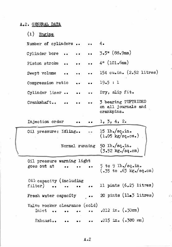
Á'2. ÊES,EE4!-!48/ - \( L $nsule
Nunber of cylilders
CyJ.ind.er bore ..
Piston stroke . .
Swept volume ..
Conpression ratio
Cylilder li:ner ..
Crankshaft . . . r
Inject ion order .o
0i1 pressure: Idlirrg..
4 .
5.5u (88.9En)
4, ' (101.6nn)
154 cu. jn . (2"52 l i t res)
L9.5 : I
Dry, sl ip f i t .
J bearing TUFTRIDEDon afl j ournals andcrarkpjsso
I t 7 , 4 , 2 .
15 Ib. /sq. i -n.( r ,05 kg /sq .cm. )
? a
o a
t a
a t
a a
a a
e c
c a
o a
o a
o 9
a c
a a
o o
Normal running 50 lb'/sq.in"(3 .52 kg ' /sq 'en)
0i1 pressure lÍarnirlg lightgOeS OUt a t r r . . . e g lb./sq.r4,
to ,65 kg,/sq,cn)
pints \6,21 l: . tres )
pirits (tla| litres)
íJ:. ( "Jonm)
i.n. (.5so sun)
0i1- capaeity ( iacfuaiagf i l t e r ) o c . . r .
Fresh weter capacÍty
Valse rocker clesrsneeI n l e t o e 6 o
f i rh ; :us too 'n e {
5 t o( z e
t 1
20
€ a
. t '
\ cord ,a 9
* o
cu* '1
.015
l { e ë

i:alve tining (with .021 irr.\ , - \.>i rr l 'm) rocKer cleaSance/
ppens. Closes
5 0 B . T . D . c . 4 o o À . 8 . D . c .
6 0 0 r . B . D . c . i o A . T . D . 0 .
(with Direct
Direct. . . . 45.7/a" (rrr05 mro)
. . . . 25 , t (A lS ̂ )
. . . . 5L (787 mn)
D r i v e ) . . . o . . . . . . . B l 2 l b s . ( j } g t s . )
:':l-ei valve
:-iaust valve
t{ei-ght of engile
f
fve:ar I length (wi th' ! L ' Í ? , 1 o o r . . .
-; : Ia - i r ' r At l) . .
. . ^ : - . . :- , = - - - - - = - À 1 l r a a
- - : - - - - : : - - - : ^ -. _ , ' _ - = - - i - ! Ë :
l i : : ' l i r i a n i i n n n r- - - - - * f r I ? l P
! q E I I 4 U P L U l l p . .
Fuel i : r jectors . .
N o z z l g . , . . . .
NozzLe hol-der . .
Mairt fuel f i l ter . .
fnjector nut . tightness
/ - \ - .t r l $feclTr_cal. svsten
e+--.r-^-u u 4 u g l a a a a a a
Alternator .. . .
R q * * o r r rJ a a a t
I leater plugs.. , .
. . C .4 .V .?ype D.P.A. 324ABB0A
.. A.C. nechanical type U
. . C .A.V.P in taux
. . BDN.0 .SPC .6209
o o B I G . 5 5 . S D . 5 2 8 5
. . C .A.V. type FS5B36L30
. . 1 2 I b . f t . ( f . ? k g . n . )
l,ucas M45G
Lucas, IIAC
c.A.v. 6MTr7
Cha"npion AG12
a a
a o
a a
a c
a a
l a
a a
o a
a a
4 . 5
a o
a a
c o
a t
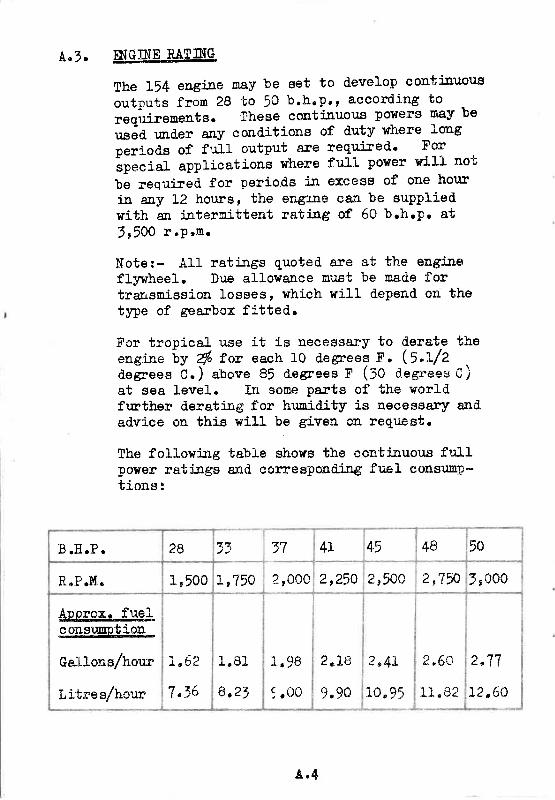
A , n 7 . M.IJ ruÏr{G.
She 154 engjJle nay be 6et to d'evelop conti$uou's
outputs fron 28 to 50 b.b.p.r according to
reqiuirenents. These contiÍIuol:.s polÍers ney be
usàd. r.nd.er any cond'itions of duty where 3'oag
period.s of fuJ.l output are req-ujÍed'" For'special
eppiications where fu1l power wiLL not
be requi-red for period's in excees of one hor:r
in eny 12 hor.Es, the engrlle ean be suppliedwith an jaternittent ratjng of 60 b.hnp. at
3r50O r.Pel l r
Note:- All rati.:ngs quoted are et the engineflywheel, Dr:e allowsrrce must be rnade f,ortrarrsmission losses, which will depend on thetype of gBarbox fitted".
Fcr tropical use it is neeessery to d.erate theengire uv & for each 10 degreeq F, (5"I/2degrees C.) above 85 d.egroe" F (30 degrees C)at sea Ievel. In some perts of the lrorLdfrrther d.eratiag for hunidi-ty is necessary ancladvise on thig will be given oa reguesto
The followi:*g table shows the continuous fulIpolÍer ratiags ênd eorrespoiltèilÈg fuel consunp*t ions :
B .E.P . 2B 3:" 77 +.L +5 48 50
D D Mr r a r a u c 1 '500 1,75Q ?,00c2 t 2 5 A 2'50c 2u7 f r5,000
Áporox. fuelconsunptioa
Gallonsfhorrr
Litresfhor"rr
r , 6 2't zA
1 . 8 1
8 . 2 3
1 0 Ê
9 .oo
2 " 1 9
9.90
I n 4 í
10,95
2 , 6 0
"r 1 0.jÁ À . U Á ,
2 " V 7
12,60
À . 4

!.4 SEA ÏlfIET Á]'TD BTIGE PWP JJUCTION STRÁINM.S.
Èani-ne and clean the sea inlet and bilge putrp suctionstrai:rers at regrrlar i:rtervals. No definile iaspectionperiod.s can be set d're fo varyi:rg local conditioi.s,
Before starting up the engine for the first time, dealwith the following points -
(f) Clean off with paraffin the rus,t preventativeapplied to alr brieht parts. particur-ar attentionshouLd be paid. to the reverse €iear and tailshaftcoupl-i-ng faces which nufrt be cleaned before theengi.:re is li-aed up"
(Z) Renove the vaJve gear coverroekers and val_ve stems pJr
and give al.li:ritial feed of oi.l.
(=) Go over both engiae and aceessories with an oilgrJlrro Put a little oiI i.:a morriag parts si:ch asjoiats of control gearsz etcnl and fill up a1llubrieators and g€êsêTso
(4) Put into the engine sump and reverse gear, thecomect quantity of lubricating oi l as indieatedby the dipsticks and levell ing p1ugs. Use onlyhigh grade lubri_eants.
(:) By neans of a barr5r.g lever give the engineat least two eonplete turs.s to enswe tËateverSrbhi-ng ie free and. that all novi:rg partsare elear of obstruction,
(6) Drai' ered fh:,sh out the fresh water coolixgsJrsten - See ,Cooling Systen Section, para]g"] (f)Close the drain eock aná refíll tfrrolieh-ihe-fj-Iler sap oa the top of the heat erei.snser/head.er tqnk" Use c1ásn freeh ""tu*-o"6ï--'pref,erably soft Fater. Where freezingiisanticipated', anti-frêeze shouJ-d be adaód. to thes1rsten * See Cooting SSrsten, para E.Z
4 " 5
( l \ T ' i l t the fuel tank with the coreet fueL a.nd.\ r /
vent the pipe l ine, f i l ters and. fuel in ject ionpump e
(e) Examine the batteriesn Make srire they are ingood cond.iti-on, topped up, fully charged andeorrect lY wired. uPo
(g) Cheek all terninals and nake srlre they a.re tight'
À.6. Í0 Sl_Ant:ëíD S-!Q_l- TïiE- 4qI,{8"
. To start the engine: proceei. as f ol lo l ls t -
r / - \I ( ] ) Open r+ iCe the sea in le t cockotl !
(2) Check that the engine eontrol lever is i -n theidl-ing position and that the gearbox is in neutral.
3) Operate the prÍnri-ng iever on the Íuel feeo p'.rmp toprine the systenn fhis is particularly importaniif the engine has been iÈle for soice time.
(+) Set the thrott le ful1y opêïro.__**___
/ - \(5) Turn the staïter switch key to. the heat posi t ionfor J0 secondse
( (,'t Trrrn the starber. switeh to the heat and stsrt\ - /nos' i t i on .- ' :o ê.err*.. i . l re s*":r.geI. nrot0f o! v v : v 4 v . r \ v e i / v 4 * r ' .
/ - \(7) When the englne stuts, release the starterswitch and retu:Tj the throttle control to itsnormal idling posr'-tion "
(g) Check the e:rg;i.::e L'rbr:lcating oil preseureó ,
{g) Cheek the sea uater fl-on and. the dis*hargeover-boafd"
/ - - \ *(tOj F-enove the valve gpsr eover anC eheek t1:elubrieatio& of the rockex gea.re
À . 6
t . a _ L . /
3)
t '*enty :oi.leutes nrnning, stop
: : :a : :e : : - : : -e c : l_ :oo_er a : :d f l l te r " ):- -e;e- r : í :esi rater i : : the heat
p:,.:-ÊT:: ::e el6::" ;r.subseguently started froro cold,--s:-- ic: :c:s i : -) to (9) atove should be observed..
ï:;i a uar= eng-jae, horever, it will not be necessaryto eiop ihe starter switch m the "heat,r position sndthe tbrottle does not have to be fully opËrr.
?9 slof the engine, pu1l the stop lever on the sid"eof the governor body.
.1..f . !AÏ]ÏG UP THE nfG]NE%
( r ) Run the engine until hot, drai-n the oil fron theengine.sump, Teverse gear and red.ucing gear (iff i t ted) r and re-f i l I r i th clean new oi l .
Turn off the mairl fuel coek on the fuel tank andd.isconnect the fuel srrction pipe fron the suctionconnection on the fuel feeder pump. Rig up asna11 ternporary fuel tank corurected. to the suctionside of the feeder puncp and. fil l it with a highquality low viscosity eorrosion inhibitjag oi1 suchas She1l Fusw A. (ft is essential_ to pipe up thetemporary li:re as described., so as to includ,e thefeeder pump €r.tl fi lter in the circuit )
R+n the engine at about half speed for a firrther15-20 mi:rutes to circulate the new oi1 thror:ghthe beerings, and the co:=osion inhibitor thioughthe injection equipnento
Drain the cooling systen thoroughly, includ.ingthe exhaust nanrfold jacket and any jackettetiexhaust bend.s or silencer, and. the eng:ine aÍrdreverse gpar oil cooler jackets. ït isdesiJable to flush out rrith fresh water anyjackets in the sea rater cireu:it.
( z )
:Ê3 .1e : i F . { .
\ ,+)
4 . 7
Turn off the sea cock, d. isconnect ' the watersuctron connection on the sea inlet and d.rain thesuct ion prpe to the engine.
(l) Remove the valve geaï covers and wetl lubricatethe valve gear axd valve springs wi-th clean oil.
(6) Cl-ean oï renew the fuel fitter and lubricati:rgoi t f i l ter elements.
Check and cfean the sea i:rlet strainer (if frtteO).
(Z) Remove the electrical equipnent components fromthe engine and store them ashore in a warra dryplace. Wrap the conponents securely if they arelrable to get dirty or dusty while ashore"
(B) Rernove the engi-ne sea water pump and the bilgepunp ( i f f i t ted). These pumps are of the rubberinpeller type and these should be stored., preferably
. wrth the uapellers removed and tied up to theexterior of the pump and kept in the dark" 0n noaccount must the inpellers be oiled as this willcause swelling and consequent failute.
(g) Blank off the engine arr i:rtake and. also the exhaustoutlet and any cooliag water d.ischarge pipes at theskin of the boat.
(fO) Wefr grease any parts of the engine liable to rusto r cor tode.
If the boat is to be hauled. out of the water for storase
(ff ) lisconnect the tailsiraft couphng before haulÍag
,the boat out of the water.
ïf the sterngear is equipped. with external sar.dexclud.erse ca.rê nust be ta.leen to prevent theshaft frorn slid3ng af t noore than I/2 i:." (fZ nnn)when the couplings are d.iscorurected,o
(re) Cneck the propeller and external sterngeax fordamage"
(r3) Open the sea coek ( i f f i t ted) to ara:n the seainlet"
A . 3
3 )
i À )
{ : )
{ 6 )
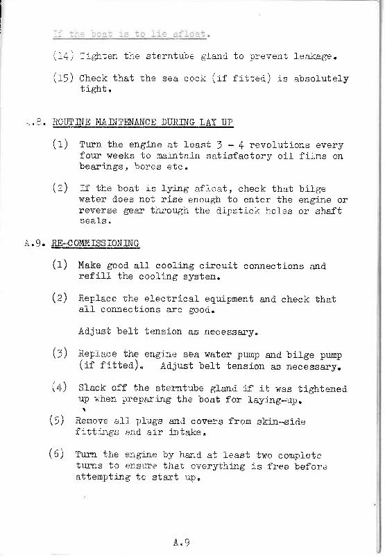
. - 1 : : r - À i r r + ' r , - ^ I - * * + - . ' - ^ - f - - t i : n n r e r r a n i I o q j r :. - + . / - , g t l E e I I D J r e S t r e r n l u r r e g l 8 f l r - l - - r - * - * - J g e .
/ - - \ ^ . - / - - \i i 5 ) Check tha t the sea cock ( i f f i t teCJ rs abso lu te ly
+ i ^L.l-U IH, lr U .
, " 3. R0UTINE_S4II{TtrIIA]SW
(t) Turn the e4g:i:re at least 1 - 4 revolutions everyfour weeks to maintain satisfactoly oíl fi lms onbear i : rgs , bores e tc .
/ ^ \(2) I f the boat ís ly lng af ioat, check that bi lgewater d"oes not rise enough to enter the engíne orïeveïse gear thrcugh the dipstick holcs or shaftsea ls "
A. 9. RE-CW}lIFS IQN.INÊ
/ - \(11 Make good. al1 cooljng circui-t connections andref i l l the coel ing system.
/ ̂ \\2) Replace the electrical eqr.r_ipnent and check that
all conrreetions are Eood..
Àdjust belt tension as necessa"ryc
Replaee the engi:te sèa water pump and. bilge prmp(i f f i t teC)" Adju.st bel t tension as necessarye
Slack off the sterntube gland jf it was tightenedup uhen preparing the boat f,o:: layi-ng*up,
Remove ali nli:.gs and coveïs from skin*sidefitt::ige; *nd air jntake,
Tu:n the engi:re by ha:rd at ieast two conpletetuars to e:isure thal every-chitg is free befareattempting tc start upo
A , 9
SECTIOH B -ROUTINE MAINTENANCE
. . : - = : - icr the rout i : re maintenarrce i : rs t ruct ions f or the- .= - , - : l se lReduc t i - on Gear see sepa r .a te pub l r ca l r ons .
-:-e fol-fowing is a sunmat:i i of the rout-rne mai:]tre'ance,=- : : i the per iods at which i t shoulo be carr ied out , to- ' : r ta i : r the ef f íc ient and economic nmning of t re engi : re; : rc ier normal operat ing and c l i rnat ic condi t ions. Under
: inormal cond. l t ions i t may be necessary to adjust the:ecommended serv ic ing in tervals .
. .1 . _DAII,Y 0E_ ix@I__1Q__II0UEg
Check the engi le o i l level ernd top uD asnecessa ry ( see Sec t i on C ) .Check water level in heat exchanger tank and, i frequi rec l , replenish r^r i th sof t water .
ÁFT-ry F]RST 25 ITOLNS
C h a n g e e n g i l e o i l ( S e e S e c t j o n C ) .Check and* i f necessa ry , t i gh ten the cy l i nCerh e a d n u t s ( S e e p a g e B " 3 . ) .Check and ad jus t ( i f necessa ry ) va l ve rocke rc l e a r a n c e s ( S e e F a g e 8 . 2 ) .
EVmI*5Q EqrJBs
check e lect rory te le 'e-L in bat tery (see sect ion F) .
EYERÏ 2OO HOURS
Change engíne oi1.Check ai-r cleaner elementCrlean the fuel 1i-ft pur:pChange engi:re oil fi lterC l ieck s ta te o f charsp o f
( S e e S e c t i o n D ) "f i l t e r ( S e e S e c t i o n D ) .e i e r n e n t ( S e e S e c t i o n C ) .b a t r e r y ( S e e S e c t i o n I ) .
Eymy sqQ__]IQ1lrg
check and adjust ( i f necessaïy) valve rocker crearancr. :s-Reneu fue l f i . l te r e iement (See Sect ion D) .Rener t r o i l f i t l e ï cap (See Sect ion C ) .? e s t i n j e c t o r s f o r s p r a y ( S e e S e c t i o n D ) .Renove heater p lugs and c lean or i f i ce (See Sect ion I ] .

8.2. VÁ1,1/E BoCKERS (FIG 2)
The correct clearance between the valve roekers
and. the valve sten is given in I'DATA & OPmATIONrr '
Unscrew the rocker cov;r retaining nuts (1) and'
Iift off the cover' Cheek the clearances at the
posit ion i l lustrat"d " ld in the ord'er as fol lowss-
Check No. 1. valve with No. 8' ful ly open'
. r t n S r t l t t t 6 l l l ll t S t r l t n 4 t t r l
' t l ' t t 2 t t t t n 7 l l l l
t r t t B l t r t t l l t l l l
t t f t 6 t t t l l t T u l t
t r í t 4 l t t l t S l l l l
t r t t T u l l l l 2 t r l t
Ad.just, if necessary' by slackeni":ag the locking nut (a)
aná t*rning the adjusting screw (5) unt:"f the clearance
is correct. Hold. the screw against rotation anci tighten
the locking nut. Refit the rocker cover, checki:rg
that its gasket (+) iu serviceable.
2 Velve roekers
8 " 2
Fig.

?ighien thei :r Fig J.
cylilder headforoue wrench
)
nuts i:tsett i r lg
thè order shown75 rb. f t ( I0.57 ks.m.
1 5 t 9 2 5
24 t8 t4 t2
22 20 16 r0
l7 2a 23
Fie. 5 Cylinder head nuts.
8 . 5
SECTIOiI C .ENGINE LUBRICATIOTU
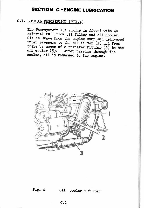
C.1. GEfER,AT, DESCR]PTÏCN (Ï'IC .4)
cooler, oil is retu::ned to the engÍ.ne.
the elrgiae sump and deliveredthe oil filter (I) ana frona transfer fittiag (e) to tUe.Af,ter passirng througb the
r"1'
The Thorayeroft I54exte:ma1 frrlI flowOil is drawa fronurd.er pressure tothere by neans ofo i l cooLer (3) .
eagiae is fitted. with anoiI f i l ter and oi l coolero
0i1 cooler & filter
c . 1
Fig. 4

C . 2 .
RmouuB{pEp H{G]NE rïtsRIo4NTS
!
I
Clinatic Conditione
Lbo,Ie 32oc.ïeob . )
-rro. ̂ ( ï05, )to rz"c.(90"r'.;
-rr%l(0o". )^to -r2"c.(ro"F)
Selow - I8oc.(0" r ' . )
FÏ],1RaTE
STERNOI,
D{TIcl.AI{S
CASTROL
ESSO
IiíOBIL
3P
SHELT,
FiltrêteDlesel 3O
Panther ,0
DucHlansFleetolEDX 'O
CastrolcRr to
EÊsolubeEDX 'O
Delvecrlto
BP Vatrelluss.Á.E. r0
Shell RotelLas oil t0
ï i l t l .ateDi.esel 20
Panther 20
DUCLfiqhÁFlee to Imx 20
CastrolCRI 20
EgsolubeEDI 20
Delvac1120
BP Ve,aelluss.Á.8. 20.
Stp11 RotelLas or-t nY/n
FiltrateDiesel l0
Pantber 10
DuckhansSleetoIElx 10
CastlolCRÏ 10
EseolubetrDX 108
Delvai1It0
BP Vanelluss.a.D.r0r
Sbell Rotellas 0i1 10u
Filtrate,r/20
Sternol S,U.Iilultielade 5H/20
DuckhansQ.5-r0
CastrolcR 5v/zo
Esso EtraUotor 0 i15Y/2a
BP Supel Visco-Statj.c 5C/20
SheLI fi-rlterSpêcial I'lotorOil or ShellSuper l{otcou 5ríl20
The appropriate nr:ltigradeconpanies, j"s approved forprevaili:rg,
0r th-e cument praetice of
oi1, suppi-ied by approvedthe particular cond.itious
the eor.utry coneem"ed *
th-
L . 2

Fis . 5)
I
Check the oil level by reuoving thelhe level shoutd shorÍ at the rS[.AJ(udipstick.
Turn the oil fi lter/fi:rterthe sr:mp wiih new oil u::tilthe correct 1evel.
The oiI fi l l.er capc4nnot be cleaned..i:rtervals.
(f) Cfean the exterior of the f,ilterthe ceatral bott (f) *a detach
C.4. TO CHA].IGE ETGI{E O]T (FrG"5)
Using the hand pump, drcin a1l oi1 fron the eagiaesump. The sump is best drained. r+hen the engine Íswarmo
OiI fil ler cap & itipstick
aipstick (1)position on the
eap (e) to renove" FiIl_the dipstick registers
iacorporates an air filter nhichFit a nerr eap at the recourcaded
This operation is ca:ried. out at thé sane tj.:ne as anengine oi-l ehange.
IÍhen the sr.up is enpty, proceed as folloTrs:_
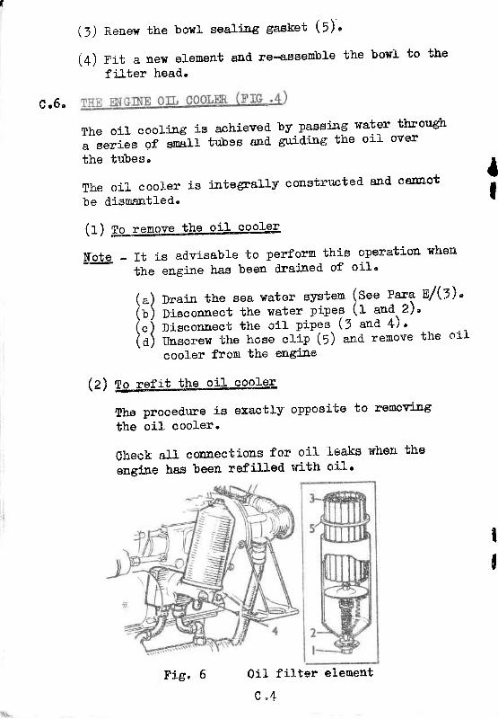
(2) lis""*d. the elenent (f) "na thoror.rghly clean thebowl antl the erposed. face of the fiftór castj!;-(4).
assembly, remolr€the f i l ter towl (2).
e . 3
T-
3 )(+t
Reoen the borl seali:ag sa^eket (5)''
Fit a aew element snti re-acsemble the
filter head.
bowl to tbe
C . 6 '
The oil cooling is achievetla seríes of snaIl tubes and'
the tubes'
The oil cooler is i-ntegrally eonstructed- and cennot
be d.isrÍantled.
by passi-ng nater throwltguiding'the oil over
is advisable to perform this operation when
engÍle has been clrajned' of oil'
Drai-a the sea water system (See Para nl$) '
Disconnect the water pipeg (1 and' .2) '
Disconnect the oil pipeá (5 ana 4)"
uo""""rn the hose clip-(f) ""a ïemove the oí1
eooler fron the engi-ne
II
tI
Thethe
(1) ro-rssqve-the oil cooler
lfote * ïtthe
/ \\ a /( r )( " )(a )
(Z) no rgfat- tite- oil cooleg
proeedr:re is exactly oppooite to renov:i-ng
oi l oooler"
0heck aÏL connections for oi"} leeks when the
engiue ha.g been refilled with oi-I'
0i1 f i l ter
c " 4Fig. 6 element

SECTIOil D:FUEL SYSTEM
-r.tn cLqArylILStS.
The fuel Í:ajeetion equipnent is nade to
veïy aceuïate Umits and even the sna-llestparticl-e of d.irt enteri:rg the systen will
d.estroy its efficiency by causi:ag scori-n'g orpremati;re lÍear oI1 the highly filished' paris'
Considerable care haso therefore, been takenin the d,esigp and layout of the fuel system to
ensure that fuel oil of normal cleanhness is
ad.equately filtered before it reaches the punp
and. i:r;ectors. The use of dirty fuel willquickly fcul the frlters and have a:t ad-verseeffect uPou the equiProent.
A clean fuet system is absotutely essential and
this can only be accomplrshed by always ensurilg
that scrupuLous cleanlj-ness is observed when
handl-Íng the fuel systern compoaents and also j:r
hand.ti:rg the fuel.
At alt ti.roes, talce care that water or rnoisture is
not allowed to conta.ninate the fuel oil" lihere-
ever the fuel system ls d.isconnected' at anynnin* r;+ sui-f,slte blankj-ng plugs to the pipesI J V s l v t f ! e
and rmioas'
If the fuel pipes are d-isconnected' or i:r the
event of the engi-ue ru::ni:rg out of fuel, bleed'
the systen (See ParagraPh D"6.)
NE\m. CTEAN fHE INSIDES 0F CONTAINERS' 0R ÀIIT
C O M P O N I N T 0 F T I { E F U I Í ' S Y S T E I { ' W I T H A F L U Ï ' F Y C L o T H
D.2. FUtr-ruI'IDtI{q Àl-{D SIOEÀJE
(r) storaee of fuel- lir
NEVM. USE A GALVANISED TANK.
0 . 1
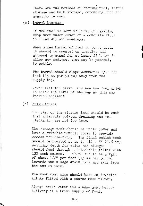
There are two methods of stori-ng f uel, barrelstorage ard bulk storage, dependilg upon thequantity jÍI use.
/ \\ ai !arrer Jtor,€_
If the fuel is kept in drrms or barrels,keep them und"er cover on a concrete floorin clean dry surroundi:rgs"
When a, new bar:rel- of fuel is to be used,i t should be mounted on irest les anda-llowed to sta.rd for at least 24 hours toalf ow any secliment that rnay be present,to se t t le .
The barrel shoul-d slope dounwarCs L/Zn perfoct ( f7 mni peï 1O cn) away from thesupply iap.
Never tirt the barref ald use the fuel whichis beiow the level- of the tap as this mayinclude sediment
/ , \\D / 51 |_K Stora f re
The size of the storage tanl< should be such';hat intervals between drai:rriae and re-plenishing are not too long,
The storage tank shoul-d be und.er cover andhave a suitable nanhole coveï to provideaccess for cleani_:rg. The fila-! outl-et cockshould be l-oeated so as to al lor.r 1" (7"6 cn)settlÍ:rg depth for water a-nd sludge: itshould feed thror:gh a detachable filter with120 nesh scleen. There shoul_d be a fal_1
, - I ^of about L/2tt per foot (IJ nm per JO crn)toward.s the sludge drain plug and away fronthe out let cock.
Tl:e irink vent pi-pei:rtg"l;e fitted with
Alwa3ng drai:r. waterdeJ-ivery of a fresh
shou-ld have aR invertecia coarse mesh f i l tero
and sludge ;rust 'bci'olr,,
^ r ' - * 1 - - ^ . Ê 3 - , ^ lÈ u l / } / r J u l I U e I s
D . 2
{
I
È\

3
45
té..\
f
FIS 7 Fuel lift punp
D . 1
/ \(c) Refue,LI:LLg the boat fuel tank
Ensure that only cl-ean fuel- oi1 is poured.ilto the fuel tank, preferabJ-y through a cleanfur:rieI fitted with a fi.lter,
ft is advisable to fill- the fuel tankafter use to mrlrmiss overnight condensation.
Always wipe the fuel tarrk aror:nd the filler icap before and after filfi.ag and inrnediatelyreplace the eap.
D ' 7 .
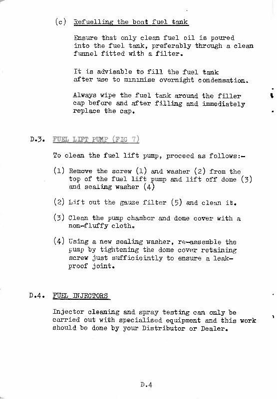
To clean the fuel lift punp, proceed as follor*s:-
(t) nenove the serew (r) ana washer (z) from thetop of the fuel lift pump and tift off done (l)and seali-ns rdasher (4)
(Z) l : r t out the gauze f i l ter ( f ) "na clean i t .
(:) Cfeari the pr:mp chamber and d.ome cover with anon-fLr:ffy cloth.
(+) Using a nerÍ seati.n.g washer, re-assenble thepump by tightenj:rg the d.ome cover retaiailgscrew just sufficieintly to ensure a leak-proof joi:at.
D"4. FUEL II\ïJECTORS
Injector cleani.r'g and spray testing can only becanied out with specialised. equ:ipnent and this work
'
should be d.one by your Distributoï or Dealer.
D . 4
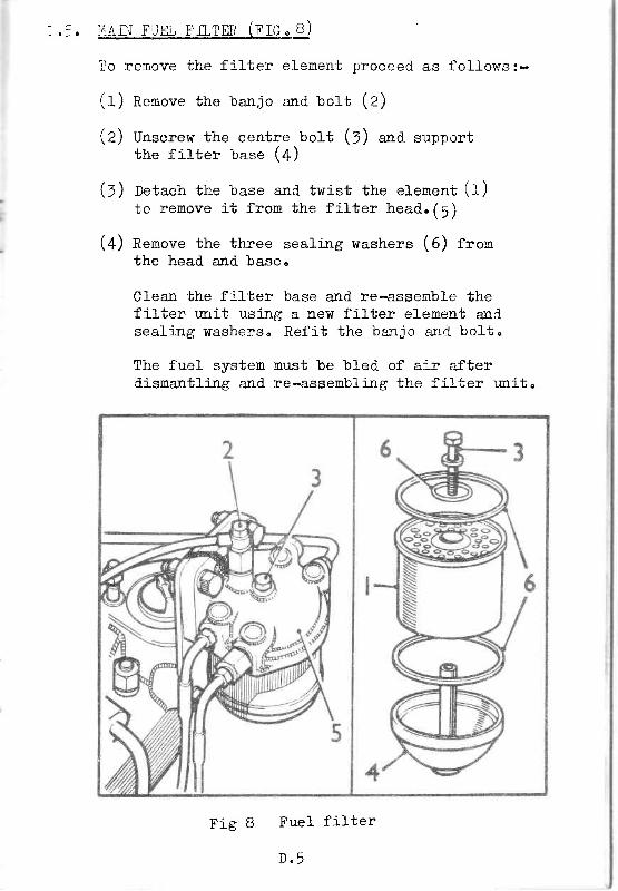
:,1AI].I FUfl, FILTM1 (FIG9JII
To remove the f i l ter eLement proceed. as fol lows:-
( t) nenove the banjo and boft (z)
(Z) Unscrew the centre bolt (7) utrd supportthe f i l ter uase (4)
(:) rcta"h the base and twist the elenent (1)to remove i t f rom the f i l ter head.(5)
(4) nenove the three sealilg washers (6) frornthe head and base"
Clean the filter base and re-assenble thefilter unit usilg a new fil-ter elenent andsealing washerso Refit the baljo a:rd bolt"
The fuel- system must be bled of air afterdismantling and re-assembling the filter unit.
Fue
n q
l r ó v I f i l te r

rD.6" BI,EED4ÏG TIP SÏSTM{
(f) nUsure that there is an adeqr.rate supply offuel in the tank"
. (2) Slacken the -anion at the fj-1ter end of thei-njection p'.mp feed pipe. Operate the lÍ-ftpump and, when the fuel eonilg fron theurion is free of air bubbles, tighten theunion"
(l) Sfacten the plug jn the r.inused connectr-on onthe filter head. Operate the lift pump and,when the fuel conilg from the corurection isfree of air bubbles tighten the p1ug.
(4) Sfacten the two bleed screÏÍs on the inject ionpunp. Operate the lift pr.uip and, when thefuel coni-ng from both screws is free of airbubbles, t ighten the screws.
(l) Sfacten the unions at the i:rjector entl of anytwo high-pïessllre pipes, Ersure that thestop control is il the nn posÍtion and thethrottle in the ful1y open position. Crankthe engiae m.til the fuel_ seming fron bothpipes is free of ai-r bubbles, then tightenboth pipe unt-ou,s.
(6) Start the engiae and. a1lor.r it to run untilit is firing on all cyliaders. o
D.7 . À IR CLEANM (F IG. q . )
(f) fire ai.r cleaner is integerally constructed andcannot be dismantled. To elean the elenent,remove froro breather pipe by loosening the pipeclip beneath the filter and pulling .i;he filter1n aïL upward d.ireetion"
(a) aft*" removal the complete f i l ter should beinrnersed j:r an oi:- solvent (not celulosettrinners) and agitated until the mesh filteris free from forelgn natter.
D " 6

(1) Sirate off aII remaining cleanilg solvent or
preferably blow dry with an ai-r line ' Bef ore-replacÍng,
jntroauce a small quentity of medium'
gtàa* oit i-nto the nesh filter through each of
ih" holeu on the irnd'erside. Replace the aj_r
cleaner on to the breather pipe and' tighten the
c I iP .
Fig 9 Air cleaner
D " 7
SECTIOhJ Ë .COOLING SYSTËNfr
.,]M. NO CTRCUMSTÁT{CES }ïUST THE n{Gn{E BE STÁRTE} WITTïOUT,.:-M N.I T}IE COOII}TG SYSTE{.
- r ] . u )
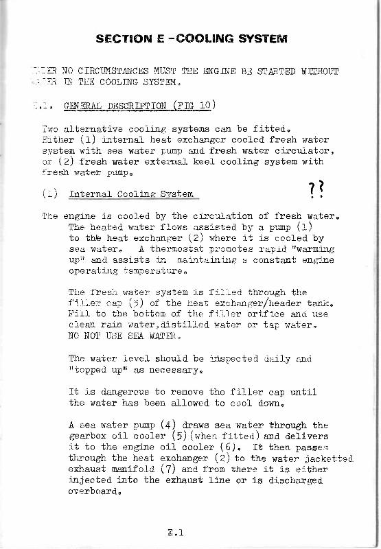
iwo alternative cooli:rg systems can be fitted."Erther {f) :nternal heat exehanger eooled fresh waiersysten with sea water punp and fresh water ei-rculatcr,cr (Z) fresh wa'ter external keel eooling system withf:resh rsrater purtrpo
( . r ) Internal Cool-ine Svstem
'Ilre engine is cooled by the cj-rculation of fresh wateroThe heated water flows assisied by a pr.rmp (:-)to thb heat exchaïrger (Z) where i t is coolet l bysea water" Á ther"nostat pï ' : 'Éotes raprd I 'warm:íg
rt}".'Í anel assists in ma:ntai:ri:rg a eonstant eag::reoï.er"*t-i:rg tem.r'Èrat:"tïe n
The fres;h wa, ieï systen is fr l " 'L--ct through thefilter eap (5) of the heat exchanger/header tanlr"Fi l t to the bottem of the f i i ler or i f ice ancl useclea:r rairi wateruóistil led wate:: or tap water,I{O NTJT USE SEA WATFfi""
The water level slrcuïd. be irlspected daily andtrtopped. upsr as fiÊeessal'$e
It Ís d.angerous to remove the f rl.ler cap untilthe water has been allowed" to eool downo
A sea water FuïGp (4) draws sea wa*er through thegearbox oí1 eooler (5) (when f i t ted) ana del iversi t to the engiae oí1 eooler (6), I t then passestÏ:-rough tire heat exchange:. (Zj to the wate:" jackettsdexhaust maBifold (l) and from ihere it is eítherinjected i:rto the exhaust line or is d"isehargedovsrboard"n
? l
El 'l

!r i
/ ' l it ' ' ' /"/' -1 ' n2
<c*"-*r
\-<=z-
' * ; l ler rcol i .ng systc".
1 1 : " 1
F r.6; - ii"1
I
a , l External- Cooli:rE Systern (or keel cooljng)
The systen is basically the same as the internalcooli:rg systemo It d.i.ffersr fu that the heatexchanger is replaeed. by a head.er tank and. ertrapipes are fitted alongsid.e the keel. Thesepipes are connected to the i:rlet (A) una exhaust (9).These extra pipes are constantly irnmssssfl in watero
:,2O FROST PRMAUTIONS
ïn colci weather it is advisable to use an antidreezi:rgmi-:rture i:r the cooling sYstem.
The following are the recommended. percentages
I'(a) lerperatures down to Zor' (-14oc ), W% sorution
(t) tenperatures d.own to oor (-reoc), zo% sofution
Use only a good. quality anti-freeze solution andcarefully f,ollow the nakerts reconmend.atronso
Do not use anti-fTeeze compound.s contaj-nilg oil basedrust i-nhibitors, as this will cause early failure ofthe water pump inpell-erso
The engíne fresh water capacity, inctuding the heat
exehanger, is 20 pi.:rts approxlnately"
As anti-freezing mixtr:re is only add.ed. towater system, it is essential that the seasysten be drai.rred when the englne is not j:r- * - / , \-H€r.?8.o E) \) ) .
="3o DRAïNïNG AlïD CLEANING TIm WAIIR SïSTB,I
(I) Drainjne the fresh water svsten
the freshwater
use (see
lhe fresh r'rater syeten is pressurised. and before thesysten can be drajaed it i-s aecessary to remorrethe filler cap on the heat exchsngêro
E r ?
ft is dangerous to remove the fil ler cap (l) r:nti: Ithe water has been allowed to cool d.own. If i
the cap is removed when the water is hot, it isnecessary to turn the cap slowly and" releasepïessure before removi-ng the cap.
lÍhen the fil ler cap has been removed, the systemcan be drajned by opening the drajn coct (t0).
(2) fleanrng the fresh ï.rater system
') Occasionally the entire system shoul_d be flushed.
/ out thoroughly. All that is necessary is tot dlain the cooling system and keep pouri:rg clean, fresh r.rater irrto the fil ler (7) r,rntif the water.
runnilg out of the d.raia coct (fO) is clear.
(l) lraili:rE the sea water svstem
The sea water s;rstem is drailed at the fotlowi-ngpoints -
(a) mairr' prug (rr) in the heat exchangerc
(l) sea water pu-np (4). Loosen the end. cover (tZ) .Áfter draÍniag ensure that the joint is irater-tight.
(c) lrairr pfus (L7) tn the engine oil cooler.
(a) lrain prus (14) i:a the gearbox oil cooler.
(e) lrain pfug (f5) in the exhaust man:_fold.
E.4. ROUTINE MAINTB{ANCE 0F THE SEA I,IATffi. SySTmil,
ll (r) iieeularly examjne and clean the sea ialet strajlernll If the strajner has to be removed", D0 NOT d"o thisll whÍlst the engine is runnilg, as foreign nattert .' can be drawn i:rto the system.
l2j &rsure that the sea cock is fulJ.y open when theengine is nnnilg; to nn the engjrre with the coekpart"ly ciosed may result in the sea nater pumpsucici:rg air with consequent failixe of wa,ter flowand. over-heati:rg.
E . 4

,l) ïruoediately the engiae has been started'' check the
sea water d.ischarge from the exhaust outlet pipe
to ensure that thó pr;mp has pickeci up properly" If
the engi-ne is run with no sea lrater flowt it can
suff er seveïe da:lage.
:..5. THX SEA WA!_ffi. PWP
The sea water prrurp is a Jabsco Self Pri-rni:rg wrth a
Neoprene impeller'
The pump depends on the liquid. pumped for h.rbrication'D0 NOT RIIN !R.Ï for more than 30 sêcoodsc Lack of
Iiqurlwrll burn the imPeller.
!íhen replaci:rg the gasket' it is essentral to use the
correet part. A thicker gasket wil1 reduce prÍmilg
abili y and a thirener gasket wrll cause the impelJ.er
to bincl and. subsequentlY fail"
: . c e
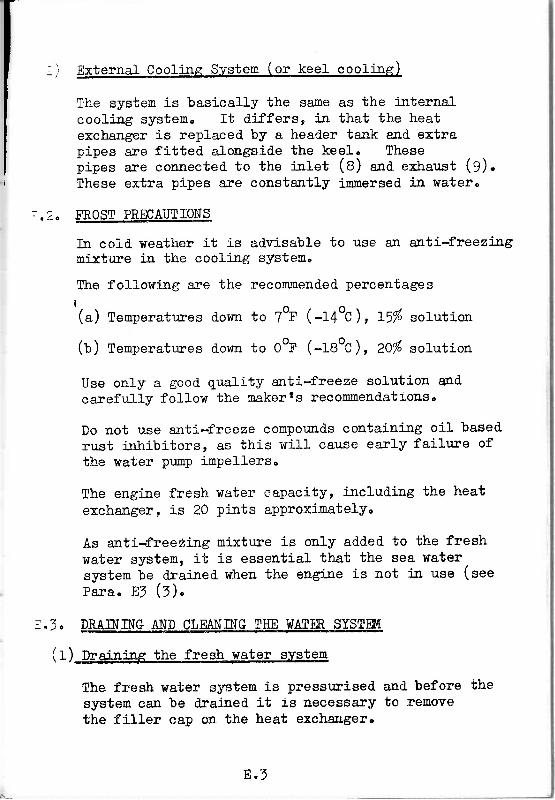
i i) fi ie purpose of the heat exchanger is to provide -
(a) Eead.er tank to allow for erpansion and' evap-oration of the fresh water.
(l) n nethorl of coolj-ng the fresh water by neans
of sea uater. This is acconplished. by passi-ng sea
water through a serieg of sna11 bore tubes (1)
and. guid.ing the fresh water over the outsicie ofthese tubes"
(Z) fire heat exeharlg€r comprises the followi.:eg -
(a) Casi-ng (2) provid.i:tg the head.er tank and. rnachined'conpartnent irrto which the tube stack is located.
(t) a tube staci . ( : )
(c) ma covers (+ *ra l )
(a) e t ie roi i (6) which passes through cover (4)
and screns into cover (5)
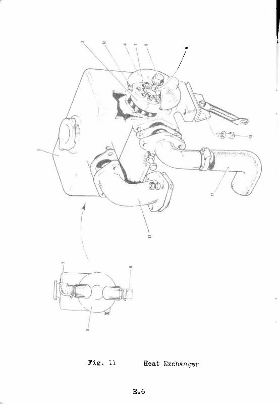
Eeat iixchár,ger
8 " 6
F ig . 11

=IL@!,te the heat exchanger
(a) lrain the sea water system and' drai:r fron the
íresh water system eriougli water to enpty the heat
exciranger "
(b) Renove the sea water pipe hoses (7 ana
fron the end cov€r e
(:) Remove nut (g) "na washer*
(a) ne*over end cover (4).
(e) aenove end, cover (5) compfete with t ie
(t) nenove the ' rOrt seals ( fO) anA withdraw
s-Lae kn
r o d ( 6 ) "
the tube
ls ) l i sconnect the f resh water p ipes ( f r ana fZ) '
( t r) Renove the setbolts and washers (r3).
The main casing carr noï'Í be li-fted" from the engine"
lo clea:r thq Ï'94t Bxcha:rger
t f the tube stack appears to be badly choked' ' i t
should. le praced in-à aegreasing plant' This will
loosen al-l foreiglr rnatter ad'hering to rt'
fhe inside of the tu.bes whj-eh have sea water passing
thr'ough then, are more iikel-y io require cleani":ag'
If these are bad-Iy choked, they can be cleaned' by
push:-ng. r**eth ï t t /a" dia ' steel roó d' l l in the tube
!o uu io aisróoge all fo::eign matter' It is
SIP0RTÁJ{T, rctren"clollg this, to push the rod' throltgh
th,e i,lbes rn the oppàsite direction to that i:r r*hich
tl,e water flolrs"
T h e o t h e r e o m p o n e n t s s h o u " ] . d . b e c l e a r r e d b e f o r e a s s e r n b } y 'and. as these
'contaj':n no hid'd'en surfaces' no speeial
instruciions sre required"
To reassemble, the procedrire is exactly the
opposite to disrnantling the un'Ít" If the rr0'l
seals appear,badly d.eformed., it is advisable to
replace them.
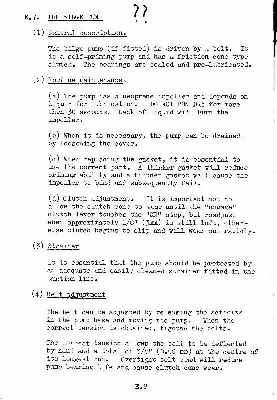
E"?. TI{E BILGE PUMP
( I ) Gene{al_ deÊpï.Ub:Lg4:
/ - ^ ̂ . , , . \The bi lge punp (Í f f i t ted.) is dr iven by a belt . I tis a self-prining punp and has a friction cone tSrpecluteh. The bearings are seaJed and pre-lubricated"
/ ^ \ ^( 2) Routlqe n_Ajnteqê4gs.
(a) fne pr.rmp has a neoprene inpeller and depend.s ontiquid" for fubrication" D0 NOT RUN DRY for morethen 50 secondso Lack of liquid. will burn thermpeLler.
(U) Wren it is necessary, the pump can be drainedby loosening the cover.
(c) Wfren reptacilg the gasket, it is essential toi:se the correct part. A thicker gasket will red.ircepri-mrng ability and a thimer gasket wiII cause theimFeller to birrd and" subsequently fail-.
(a) Cfutch ad.justment. It is irnportant not toa1low thê clutch cone to wear until the Itengagettclutch l-ever touches tl '!e ttONr! stop o but read.justwhen approxinatety /8r' (:r*1 is stil l left, other*wise clutch begi-ns to slip arrd wrll sear out rapidly.
1 ' 4 \ s + - o i - o -\ / I v
It is essential that the pr;mp should be protecied byan adeqriate and easil;r cleaned. strainer fitted in thesuction lj:ne.
(4) sert adJustnent
The belt ca:r be adjusted by'r 'e leasing the setboltsin the pump base and moving the p'rrnp" When thecorrect tension is obtained, t ighten t l re bol is,
The coruect tension allows the belt to be d.eflected.by hand and a total ot 3/8" (9,50 mu) at the centre ofits longest run. Overtight belt load. ic-il l red.ucepump bearing life and ;ause eluteh c:one weare
7 7
E . B
: . 1 .
SECTIOru F -ELECTRICAL SVSTETfr
ATTER}I4TOR
alternator requires no attention except tc see th,atcable eonnectrons are clean anC tight.
General precautions
Reversed battery conneetj-ons will danage the d.ioderectifi.ers" Battery polarity should be checked.before the connections are made to ensrire that theycorrespond to the boat battery earth polarity.
The alternator should never be run on open-circuit(with main output lead disconnected) with the f i -el t iwinding energised, or the rect i f ier diodes arelikely to be d.anaged.
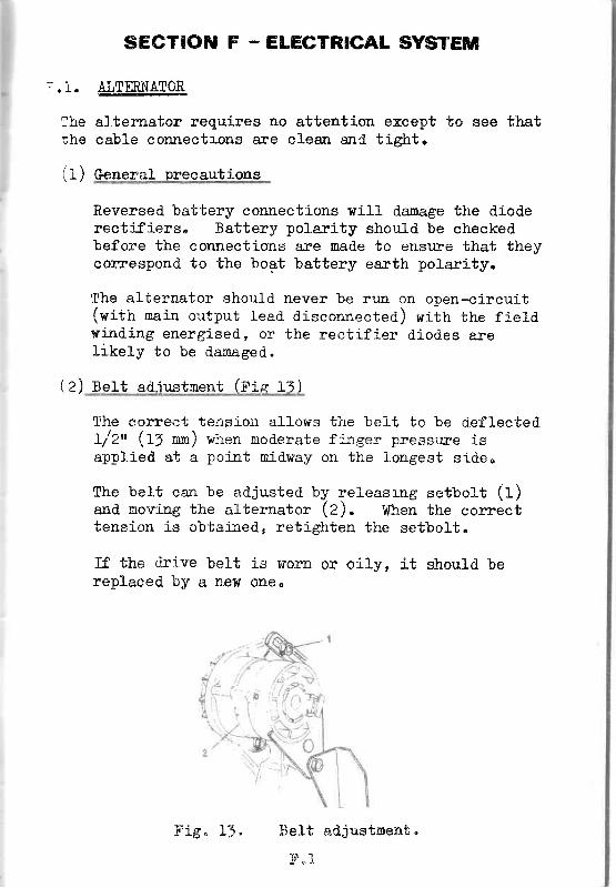
Belt ad.ir:.stment (i'ie f l )
ïhe comect terrsion allows the belt to be deflectedl-12" (f: r*) when moderate finger pressure isapplied at a poi:et nid.way on the longest sj-deu
The belt can be adjusted by releasrng setbolt (1)arrd novi:rg the alternator (2)" When the correcttension is obtaiaed, retighten the setbolt.
ïf the d.r'ive bett is worn or oiIy, it should berepiaeed by a new one.
Belt adjustnent,
F " 1
Thel - h a
\ . 1 /
r . 4 . )
F is , 15 .

Fig L2, Wlring Dlagran
@ ffrornycroft)4
4144!_
pêD---
tAbw -
V/óLET
F " 2
ii
, w' .. ti.
, ? 7 " t j ' L: ,2. SATTffi.IES
--ead acrd. batter ies are- U i t U È c
-t- typical speciÍication
l i ' p e - 6 M T I 7l{o. of batter ies - 2
supphed. to customers t require-
is as follows -
Voltage - 6 V.Capacity - 108 amp" hortr.
t
I 'c it'íï,-'
,!u.
The lengf,h of li-fe which you obtarn frora your batteryiepend.s largely on the najltenance canied out. Toensure that you receive the meximrn life fron your batterythe followilg points shoul-d be observed. :-
(f) f::spect the electrolybe level- once each week andensujre that it is nairtained level with the perfor-ated splash guard; overtopping is the most frequentcause of external corrosion.
(Z) to ïemove corutectors never use force. I f acorrnector cannot be removed. easilyr wash itusirrg a rag soaked. j-n hot water. líhen thecorrosion between the connector and" the term-i:nal has dissolved. it will be removed easily.To replace the connector, tap it gently ontothe terninal post, using the hand"le of aserewdriver, ensu.ri-ng that it fits fi.rnly andcorrectly, then insert and tighten the re-taining scïew. This retajnjns screlr shouldnever be used to pu1l the connector down ontothe ternirral post,
Should the screw be iladvertently stripped artoversize screw is available. Note only oneoversize is availabl-e so that extra care mustbe taken not to strip the second thread..
/ - \ . - -(1) Keep the termilal posts cleal and srnear therowith vaseljle or petroleum 3e11y. The top ofthe battery should also be kept clean and dryat all ti-mes.
(4) Cirect vent plugs to see that the vent holes arenot blocked.n Vrlhere the battery has a manifoldthis does not apply"
(f ) Oo not over-tighten the fixtr.ire which holds thebattery as this may erack the batteïy case.líhere the battery is seci.lred by means of a metalstrap along the top ed,ge of the battery, thestrap shoul-d be insulated lri-th p.V.Cc ol sinilaracid, proof naterial. Alternatively, the strapshould be given two coats of anti-sulphuric paiat*
(6) Take hydroneter read.ilgs, at nonthly iatervals, tocheck the state of charge of the battery. Areading of I.270-L"290 on each cell i ldicates thatthe battery is fully charged., 1"190-l.2IO jxdicatesthat the battery is hatf d.ischa:rged.. In thel-atter case the battery should be rechargBd atthe eorrect reeharge rateo A triekle charger maybe r:sed for this DllrÊosêo
F.3. STÁRTIR MOTOE_
The starter motor requires no attention beyond see-ing that the cable eorrnections are clea.rr arrd tight,commutator is kept clean and the brushes are renewedwhen necessary.
r.4. EEÀfm PLUGS (r'rc ra)
(1) To renove heater plue and clean orifice
(a) nenove the electrical lead.s (f) anO unscre$each plug (Z) fron the cyli-nd.er head.
(t) tnsert a twi-st drilr (3) af LL/64 tu (4"ï? nn)d.ia.neter into the screwed holes (+) i:r ttrehead and turn the dril1 by hald to remove thecarbon buiJ.d. up"
(c) W:.tirOrar the dri1l and remove any pa;nticles ofearbon fron the eonical seatjLgs j:r the eylinderhead"
(a) nefit the heater plugs and etectri-cal le&ds,
F . 4

Kr{"H^.)CIy
Fig. 14 Heater PIug

sEcTroN G -REVERSEjREDUCTION GEARS
,.I. BORG WARNEN. GEAR
(t) Ëeneral descr- iPt ion
Full d"etail-s of the general description androutile mailtenance are given in the Borg
Coo ler (1 ) wh ich
the gearbox to theit returns to the
supplied. by the sea
Warner Service Manual-.
(e) oi r coot" ins (F'rc r l )
The oi l - is cooled bY an Oi lis f i t ted to the gearbox.
The oit is transferred fronoi1 cooler via hose (2) andgearbox v ia hose (5 ) .
Water for the oi l - cooler isr+ater cool ing sYstem.
The oi1 cooler is integrally constructed. andcannot be disnantted.
FiS. 15 Gearbox oi l cooler
G " 1
G"2. TMP GEARBOX
/ . \ ^(1i General desctl.plion
Full details of the general d.escription androutine maintenance are given irr the rrWorkingfnstructionstf for the tT{p gearbox.
( 2 ) 0 n c o o r i n e
Full detail-s are given in the "llorking Instructions"for the TMp gearbox.