"Catawba Nuclear Station Diesel Engine 1A Component ...
180
. .- _ _ . . _ _ . . _ _ _ _ _ _ _ _ _- _ _ - - . . . . a . . - CATAWBA NUCLEAR STATION DIESEL ENGINE 1A C(EtPONENT REVALIDATION INSPECTION REPORT 1. _ | PREPARED NY - DUEE POWER CGIPANY June 1, 1984 8406050373 840601 PDR ADOCK 0S000413 PDR . g ' l U
-
Upload
khangminh22 -
Category
Documents
-
view
0 -
download
0
Transcript of "Catawba Nuclear Station Diesel Engine 1A Component ...

. .- _ _ . . _ _ . . _ _ _ _ _ _ _ _ _- _ _ - - . . .
.
a
.
. -
CATAWBA NUCLEAR STATIONDIESEL ENGINE 1A C(EtPONENT REVALIDATION INSPECTION
REPORT
1.
_
|
PREPARED NY-
DUEE POWER CGIPANY
June 1, 1984
8406050373 840601PDR ADOCK 0S000413PDR
.
g'
l
U

.. . _ .. _
.
Table of Contents
1.0 Introduction
2.0 Summary and Conclusions
2.1 Overview of Inspection Results
2.2 Piston Skirt Cracking
2.3 Subcovers
2.4 Cylinder Head Leaks
2.5 Conclusions
3.0 Discussion of Inspection Results
3.1 Inspections Related to TDI Generic Problems
3.2 Inspections Related to Catawba Specific Problems
3.3 General Inspections
4.0 References
5.0 Appendic es
A. Inspection Reports
B. Engineering Validation Report.
Figures
2-1 Cracked Type AN Piston Skirt
2-2 Cracked Subcover Castings
2-3 Crack in cylinder Head
Table
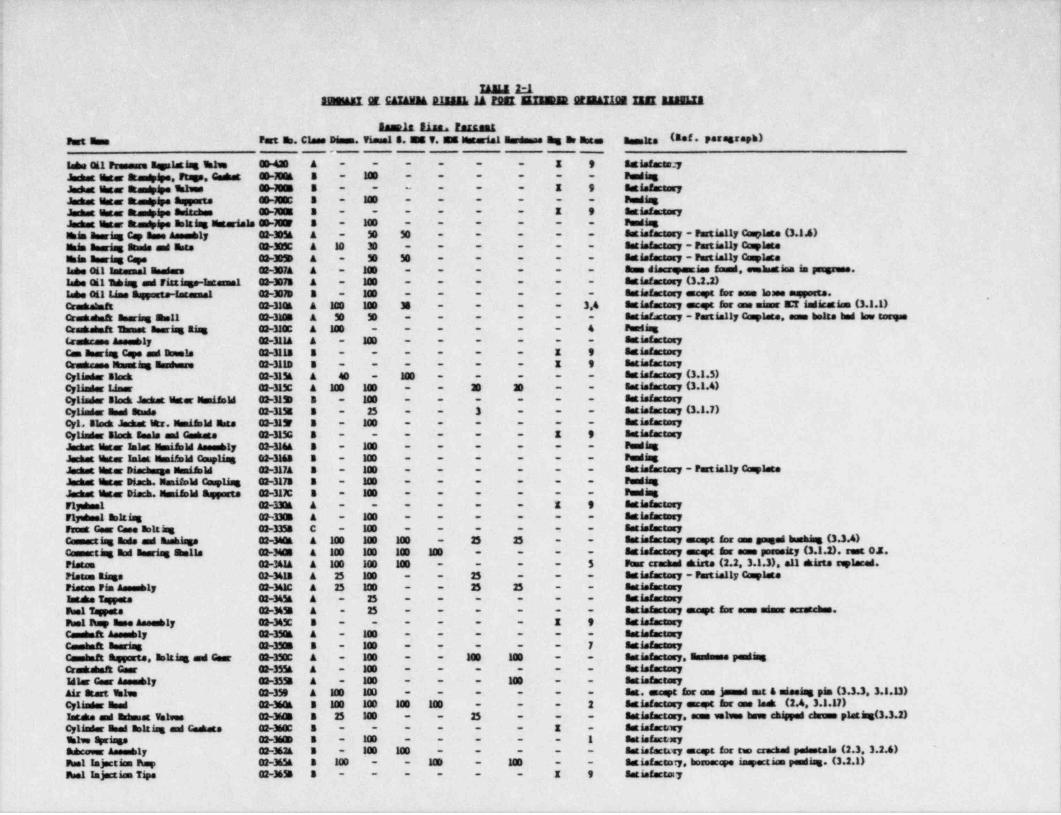
2-1 Summary of Catawba Diesel IA Post Extended Operation Test Results
|,
.-e...___,~--_ .,-_ -
. . - . -
.
<
l
1.0 Introduction
1
I This report describes the results of inspections and evaluationsperformed on the Catawba 1A diesel engine. These inspections were
| performed as part of an overall program to verify the reliability ofTransamerica Delaval, Incorporated (TDI) diesel engines used for safety-grade power supplies at Catsuba. The overall program is described inan April 5, 1984 letter to the NRC, reference 1. The scope of the
1| - inspections meets or escoeds the TDI Owners Group inspection progra's.
The inspections of the 1A diesel engine discussed herein were performed, in April and May, 1984. The inspections involved extensive disassembly1 of the 41esel and 1002 inspection of parts for which there was a history
of problems or other reasons for special concern. Substantial (e.g.*
25%) sampling inspections were performed of other importsat parts wherethere was no history of problems. The scope of the inspections is*
essentially as described in reference 1, with the exception that all 16pistons, connecting rods, and related parts were inspected on a 100%basis rather taan on a sample basis. Also, one additional main bearingand two additional cylinder liners were added to the inspection plan.
; The diesel disassembly, reassembly, and inspections are being performedi in accordance with the Duke Power Quality Assurance Program. The' assembly, disassembly and inspection work was largely performed by Duke
Power personnel, with selected inspections performed by Failure AnalysisAssociates (FaAA) and Stone and Webster (S&W) personnel in conjunctionwith the TDI Owners Group program. '
Detailed results of the inspections are contained in section 5.0,,
Appendia A and are discussed in Section 3.0. Some parts which are,
important to diesel operability were not inspected since inspection is! not called for by the TDI Owners Group program and there has been no'
history of problems. For such items an engineering evaluation of the,
operating and usintenance history of each of these parts was performed<
' and is documented in Appendix B of Section 5.0.|| This report is the initial report of the Catawba 1A diesel inspections.
This report covers over 76% of the inspection plan which includes about4200 separate inspections. Inspection results not covered in thisreport are as follows:
e Walkdowns of the jacket water, s. tart ing air, fuel oil, engineshutdown, engine conduit and exhaust manifold systems. Thesewalkdowns can only be accomplished following reas sembly of theeng ine.
e Visual inspections of turbocharger exhaust gas inlet bolts.
Visual enamination of some components within the overspeed trip andehardness and liquid penetrant (FT) tests of components of theaccessory drive.

- . . . . . - __ . -_ . _ _ - . - - - --__ . - - - . _ -_ ..- . -. .._.
I
e FT test of components of the governor drive.
Material comparitor tests on valves, jacket water pump drive shaft,ecylir. der liners, and piston pins.
e Inspections of bearings and journals on #6 and #8 main bearing s.Inspections of #4 and #5 male bearings have been completed.
Eddy-current (ECT) test of fuel line tubing.e
e X-ray acceptance of connecting rod shells.
e Review of c/linser heads to see if they have been repaired at thebase of the fuel injector hole.
e Boroscope inspection of bore of injection pump valve holder.
e Visual and magnetic particle inspection (MT) of fuel injectornossle holder stude.
A updated report incorporating the above inspection results, additionalengineering evaluat ions , as well as the results of ongoing failureanalysis work (reported in the body of this report) will be issued byJune 29, 1984.
.
e
t.
,, c ew ,--e--m-er--en-,--w w ee e,v--ee-o~-x,--------eew,----*'erw----------

_ _ - , _ __. _ . _ . _ . . _ _ _ _ . _ . . _ _ _ _ _ _ _ . _
i
I
2.0 Summary ad, Conclusions
!
2.1 Overview gL Insnection Results
In March 1984, the Catawba 1A diesel engine success fully completed(reference 1) its extended operation test which results in more than 800total accumulated hours on the engine. This test confirmed the ability
of the diesel to operate reliably for long periods of time at highpower. Subsequent to the extended operation test, extensive disassemblyand inspection of this diesel engine has been performed to confirm the |
s atis factory condition of varicas parts and to identify any parts,
requiring repair, replacement, and/or redesign to eneure highly reliablestandby electric generator service.
,
The post extended operation test inspections are now nearly completed,with the only exceptions being as outlined in Section 1.0. The results t
'
of the inspections are suussarized in Table 2-1. Initial engineeringand quality assurance evaluation of the inspection results has been;
performed with final evaluation expected to be completed by June 29,1984. Work performed to date is considered to have identified allsignificant conditions. These conditions are discussed below.'
The most ' significant results of the Catawba 1A diesel engine postextended operation test inspections are as follows:
e Many of the major problems experienced with other TDI dieselengines did not occur in the Catawba IA diesel engine. Theseproblems include failed crank shaf t s ', cracked connecting rod-
crankpin bearing shells, connecting rod box cracks,and erschedcylinder blocks,
e One major problem was noted on the 1A diesel. Four of the type ANpiston skirts used in the 1A diesel were found to have one or morecracks in the region where an internal circumferential reinforcing
| rib intersects the piston pin boss (Figure 2-1). This problem isdiscussed further in Section 2.2.
e The turbocharger - thrust bearings were found to be severely worn,though they had continued to function satis factorily duringeven
the test. This condition was anticipated since similar problems;, have been experienced at other stations. As a result of this'
history, a redesigned lube oil system is being developed which isexpected to prevent recurrence of the problem. It will beinstalled by September 1,1984. In the meantime, the bearings are
<
~ being replaced as necessary to ensure operability.|
"
o Several other problems of potential significance to diesel|, operability were detected and are being further investigated as:
| part of the TDI Owners Group program. These are:
|\
~
__ _ . _ _.__ ._ _ _ _ _ _ ._ _ - _ _ . . _ _ . . _ _ . . . . . _ _ _ _ __ __

. . .. . - _ _ - - - . . - - _ _ _ - - . -
E
Two subcover castings were found to have cracks in an incake-
rocker are pedestal (Figure 2-2). These cracks are
discussed in Section 2.3.
on IB)Two Catawba cylinder heads (one on diesel LA and one--
experienced small jacket water leaks into the fuel injectorcavity. Recent metallographic examinations of the headremoved from the la diesel indicates that the leak was due to'
fatigue crack (Figure 2-3). This problem is discussed in' aSection 2.4.
e A small eddy-current test (ECT) indication was detected incrankpin . to web fillet #7 (generator end) on the crankshaft.Metallurgical examination using replicas indicates that indicationwas due to two small (about .030 inch long) axial linear defects.ECT indicates that the defects are less than .020 inches deep.Preliminary evaluation is that these are not due to service butrather due to initial fabrication. Duke Power Co. is continuing to i
examine these indications metallographically by replication. Theseindications will be removed by polishing.
A variety of routine minor conditions were noted, and are discussedein Section 3.0 and 5.0. None of these conditions impact the
operability or structural integrity of the diesel. Typical''
conditions of this type include:
Chipped and cracked edges of rocker are sockets. (Section--
3.3.1)
Chipped and removed valve stem chrome plate. (Section 3.3.2)--
Jammed air start valve adjusting nut. (Section 3.3.3)--
Heads of small bolts . broken off, due to under or over--
torquing. (Section 3.3.5)i
| 2.2 Piston jhigt Crackinz
l
Four type AN skirts were found to have cracks adjacent to piston pinbosses. (Figure 2-1) These cracks run approximately vertically, andappear to initiate on the inside of the skirt where a circumferentialreinforcing rib intersects the piston pin boss. The largest crack, on
through well and was about 3 to 4 inches long on theskirt 3L, wasouts ide .
It is understood from TDI that this type of crack has never before been| reported to TDI for stress relieved piston skirts . However, similar
cracks have occurred on non-stress relieved type AN skirts and, as al
result, TDI recalled non-stress relieved skirts for stress relief.Those Catawba la skirts which had not been originally stress relievedwere returned to TDI and stress relieved in 1983, prior to the extendedoperation test and other tests. Thus, the cracking of the Catawba 1Askirts indicates that this type of cracking is possible even with stressrelieved type AN piston skirts.
.
,. _,. __ _ _ . _ _ _ . _ . _ _ _ _ _ _ _ _ _ _ . _ _ _ _ _ _ _ _ _ _ _ _ _ _ _ __

. . _ . _ _ . _ . _ _ . _ . _ __.__. _ ._. .__
An extensive failure analysis of the cracked Catawba type AN pistonskirts is now being performed by Failure Analysis Associates (FaAA) aspart of the TDI Owners Group program. This program includesdetermination of residual and applied stresses, fractography, andmetallurgical evaluations . Operational tests of cracked piston skirtsare also being considered to evaluate crack growth rates.
.
The cracked AN type piston skirts in the Catawba 1A diesel did not causeany operational problems, and 12 of the 16 skirts were free of cracks.Nevertheless, all the pisten skirts will be replaced with improveddesign AE skirts. The AE skirts have been stress relieved and includeimproved design features such as a thicker reinforcing rib and betterrib-piston boss intersection details. These improvements are expected
4 to adeoustely reduce the stresses and propensity for cracking in thearea which experienced cracking at Catawba. The FaAA/0wners Groupprogram will quantify the benefits achieved by use of AE piston skirts.It is anticipated that this will show that no cracking is expectedduring the life of the Catawba diesels. The AE piston skirts alsoincorporate the latest improvements in the stud boss region, which hasbeen a problem area in earlier piston designs at the skirt to headtransit ion.
1
2.3 Subcovers
Two cast iron subcovers were found to have cracks in a pedestal wherethe intake rocker arm shaft is bolted to the subcover (Figure 2-2B).Prior to the extended operation test, another subcover was found to havea piece of this pedestal missing (Figure 2-2C). None of these crackshave affected diesel operability. However. . since similar problems havebeen reported with other diesels, FaAA has initiated a failure analysisof a Catawba subcover. Preliminary thinking is that the cracks are dueto installation tolerances between dowels, bushings, and the pedestalleading to excessive interference. Whether such excessive interferencefits will be confirmed as the problem by the failure analysis beingperformed by FaAA is not yet known.
i
2.4 Cylinder Eggi Lagkgii
Two cylinder heads at Catawba, one on engine 1A and one on engine IB,developed small jacket water leaks into the fuel injection cavity. The1A leak developed during the extended operation test and the engine wasshut down due to other problems three days after detection of the leak.The 1A leak did not affect engine operability. The leak on the IB
| engine was of similar magnitude to that of 1A. The 1A cylinder head| has recently been examined by FaAA. This investigation revealed thatI the leak was caused by a crack initiating from the corner of a welded-in
plug where it was seated in the cylinder head (Figure 2-3). Thisvelded-in plug is reported by TDI to have been used to repair thecasting around the fuel injector hole.
. . - , _ _ . _ _ . _ . . . ___ ____ __._ _. __ _ _ _ _ , _ . . - . . - - ._.
-. _ - _ . . . _ . _ _ _ - . . . _ . . __ .
r
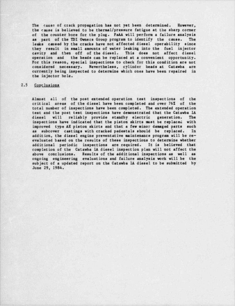
The cause of crack propagation has not yet been determined. However,the esuse is believed to be thermal / pressure fatigue at the sharp cornerof the counter bore for the plug. FaAA will perform a failure analysisas part of the TDI Owners Group program to identify the c aus e. Theleaks caused by the cracks have not affected diesel operability sincethey result in small amounts of water leaking into the fuel injectorcavity and then off of the diesel. This does not affect dieseloperation and the heads can be replaced at a convenient opportunity.For this reason, special inspections to check for this condition are notconsidered necessary. Nevertheless, cylinder heads at Catawba are4
currently being inspected to determine which ones have been repaired inthe injector hole.
2.5 Sanclusions<
Almost all of the post extended operation test inspections of thecritical areas of the diesel have been completed and over 76% of thetotal number of inspections have been completed. The extended operationtest and the post test inspections have demonstrated that the Catawba 1Adiesel will reliably provide standby electric generation. Theinspections have indicated that the piston skirts must be replaced withimproved type AE piston skirts and that a few minor damaged parts such
.as subcover castings with cracked pedestals should be replaced. In
! addition, the diesel engine preventative maintenance program will be re-evaluated based on the results of these inspections to determine whetheradditional periodic inspections are required. It is believed thatcompletion of the Catawba 1A diesel inspection plan will not affect theabove conclusions. Results of the additional inspections as well asongoing engineering evaluations and failure analysis work will be the-
subject of a updated report on the Catawba 1A diesel to be submitted byJune 29, 1984.
;
.-
e
!
I
I|
,
, , - . . - - - - - - -. m . _ _... ,. ...._- . , _ . . . , , _ , . _ . . _ _ , - . _ _ . _ . - _ _ _ _ _ _ _ _ _ . . . _ _ _ _ . _ _ _ _ _ . - _ .-
_ - _ - _ _______- ______________ - __ - ____-_ - _ __ _ __________- ____ .-_ - - -__ _ _ ___ _ --. . _ _ . _
|
1ABLK 1-LSasI&sf g. CATAlfaA gj333k M M aETREaB We&f1M Igg 3335,11
Assa1A t h rarsmathet Emma Part Es. Class Dimmm. Tiamal S. Ms T. Es maarist madamse Be Br antes ammalts IE*I. Paragraph)
les ol17:emmene Egslatlag him OHN A - - - - - - x 9 assisfaceraMe - - - - - - hadwJ a r meer manipe, rises, enest eHeen s -
' x s assisenceeryJamat maar madripe thus - eHess s - - - - - -
had%James w m. spi,e asemite e-nec s - MS - - - - - -
Jesse maar mespipe Adtches SS-NEE s - - - - - - x 9 assiefactoryhedheJeemt maar ==spiy a lth unarists as-ner s MO - - - - - --
,
autisfactory - hetially caplsta 0.1.6)30 50mh anerk cs, aume Asnesty aMOR A - - - - --.,
ashfactory - partisu cm,letemain amm% sends ad Este as-3Mc A le 30 r- - - - - -,
- - - - - satisfactusy - hscially cm,1stai min ausr% cs,. as-som A - 50 seamme diessey-cies ismed. histies in ymmesmas.i has oil set el ammense es-30m A - ies - - - - - -
Ide ci11h6he and ristisee-ha-i on-sers A - lag - - - - - - amisfactory 0.2.2)14. oil l.ine agemets-Intammet m-30m a - MS - - - - - - authfactory esca,t hc kne esposts.
*
3,4 antisfactory ancgt See ame nimer 52 indicatism U.1.1)Orasahnit 03-3146 A MO 100 30 - - - -
antisfactasy - Partially ceplats, amma bolts had leur tasyecreseem ausrise hell 03-34 5 A 30 50 - - - - - -
; cr=*a-* w amer % aw es-31ec A lab - - - - - - 4 pues%! Lem6came amamsbty 01-311A A - 100 - - - - - - autisfactory' cm an=% csys ad ameh as-311s - - - - - - x s assisenceery
cramesmo mm tw ammmene on-mis - - - - - - a s antist ctory
| cylinder almsk 01-3RR A 40 - MO - - - - - autisfactory 0.I.5)- - satisimetary 0.1.4)' cylinder IJamr 03-MSc A 100 180 - - 3 20
cytisser sloe Jeest h melhu es-313 a - la0 - - - - - - autisfaceerysatisimetery 0.1.7)3 - - -cylinder asse amids at-u5s s - 25 - -
Cyl. Bise Judat Mr. in-de=W Ents 03-31 2 s - 100 - - - - - - satisfactoryCyll=d r stad anels amt Gesats 05-MSC a - - - - - - x 9 antisemeteryJammt Mitar Inlet ItanihM Asamsty 03-3Ma a - 100 - - - - - - hedhasset meer 1 16 inmimu cumplias es-sus - 3o0 - - - - - - pensins
Jammt maar siachemen meu u ot-317A 3 - 100 - - - - - - sothimetery - Petially cuy1stsJamme meer slach. ammifou cm,11ss e-stys : - los - - - - - - smusks
Fundhs100Jetst maar Disch. MaisoM Agymsts 03-31E a - - - - - - -
x 9 authasctoryFlyshmal m-33h A - - - - - -
300 - - - - - - autisfaceeryFlyisselmolth 01'-33m A -
antisfactesyFemmt Gear Case notths 03-335s C - 100 - - - - - -
satisemetary aucupt for ame geged bushk D.3.4)commact% ands and haelata 03-3401 A 100 100 MO 25 25 - --
satisfactory emcast sur emme ymmesity 0.1.2). runt 02.commmeth and ausrias hells 08-34 5 A 100 100 im Me - - - -
- - - - 5 her creemd Airts (2.2, 3.1.3), all diets nipiscad.Pisten OS-ula A 100 100 Meamisfactesy - hetis11y campistsPiste akse Oa-mas A 25 300 - - 25 - - -
ristem rim samasty on-3ec A 25 100 - - 25 25 - - smtssemeterySethf-*=yinada Tagents Ot-wh A - 25 - - - - - -
- - - - - - antisfactory easyt sur mimer scratches.met Tgests on-Ms A 25-
het may n=e Ass =hly ea-msc a - - - - - - x e satisfaceeryantiseactorycashna Ass =61r es-35e6 & - le0 - - - - - -
- - - - - y sucht-a-ycan amerius as-35es s - le0amisfacessy, amemmes petiuscamhah Agymrts, asking ad Game 08-350c A Me 100 - -10 0 - --
cr-ma-ar Gear e-335a & - 100 - - - - - - autisfactory- - antisemetssyM1er Gear Asem617 M-35m A - 100 - - - 100
- - - - - - amt. encsyt for one Jamed mit & adesias pim 0.33,3.1.13)Air start the 03-350 A 100 100- - - 2 amisfactosy meet ser een Ise 0.4,3.1.17)cylinder amad as-3 sat a loe too log 1e0
antisfactory, same vehus haue chipped cisame platissu.3.2)Intde ad ashasst thus 03-36m a 25 180 - - 25 - - -
x - amisfactnrycylinder assa seichs and c-a-e- as-3 soc - - - - - -
100 - - - - - 1 antisfact mywho sprinse on-seco s -
w- A- -Air on-mm a - 100 Ic0 - - - - - satisfactasy = cape for :== creams pase cals (2.3. 3.2.6)het isjactima her on-Mn a 100 - - 100 - 100 - - antisfaceary, nosoec,e inspeccias ped %. O.2.1)asal tajectism tips o -m5s a - - - - - - x s antisfactay

_ _ _ _ _ _ _ _ _ _ _ _ _ _ _ _ - _ _ _ _ _ _ _ - _ _ _ _ _ _ _ _ _ _ _ _ _ _ - _ _ _ _ _ _ - _ - _ - _ _ _ _ _ - _ - _ _ - _ _ - - _ _ - _ _ _ _ _ _ . _ - _ _ _ _ _ _ _ _ _ _ _ _ _ _ _ - _ _ _ _ _ _ _ _ _ _ - - - _ _ _ _ _ _ _ _
TAaLa 1-1 (Centimmad)
Sammte h rarcaatpast amme part b. Class Dimmm. Tianal 5. as T. Es hitarial numemane aus r antes a tr. (set. parasra,b)e
a husk 0.1.11)het 1.jsstiam mans ca-use s - 30o 10o - - - -
n .: rejstian u w a ,,orte ea-mm - 100 - - - - - - had%' mi am,i.ne ans costs.1 a.h Os-371A A - - - - 100 300 - - asteractory
sao - - - - - -m.1 me,, s.imm.o., amer %. .a n.k m-sits A ami e. -y-
nashe amis.u. On-375 s 300 - - - - - - amisfacesry-
leo - - - - - -Samme M =IE.M m-3BAL s ani gactory - rustially campiste-
mia===e lemnisoW a.kW al-MB a 9 9 - - - - - - Snisfactary, ammiAsM to auske bekje pamdius. O.2.8)
cr-scam comer smeate as n uk On-asse c - leo - - - - - -
ani.amesory ,im.1 1-,.ctima er . s...x 9cytisser an sh comme, c m . -s a.k. On-seM c - - - - - - . .
a-.i brn head snui u.2.5)1
l# 15 - 35 l#Imade & i.e. -.diate ausbar Ass Aambly. SF31RL s asti.fmetary magt tuo sechste had chi,yed lies. OJ.1)- --~,
im IN - -memet anskar Asm Aameubly 88-30 5 a - MD 100: Imad e and h * mastmode 03-390c 3 - 100 le - - - - -
amtsagnetary 0.2.9)-
- - - - -
amtiefnetary 0.1.14)No istc - .y n,mem.d on-sem anot - - - - - -
amieracensy-
j anser Ass minh%. en-3seslet 300 - -
ames.g co ry-
300 MORusher Asma nokies GadgeG s ant.a.,e.,y 0,1J)- -
omsa , a ws,as otales A - - - - - - x 9 anchencessy300 300 - 300 300 - -omnes, a ws, & - 1, art. aMie A suchenciary - Perth11y cglace-
omsa,.ma wi, ca, times ca4anc A - MS - - - - - - asiafactory1 9 gal. factoryoeure,and wl,het him. 5 430D A - - - - - -
spass aus asthe ommsmer arin Os411A A - MO 180 - let 100 - -c anbraceeryiso - - acecommmmer artie cau,1%. eMata A sati. emes sy- - --
,
Gommsmer 1.imbase GN13 A - Mo - - - - - - sal f.cearypset mm, Listags Asto assedsma Cy11mder GMim - 300 antar cr ,y- - - - - -
,
a 1 9 angt.8.re. yw agulaths -.- e GMIS& A - - - - - -,
.j Gamesmer amenar Serienstar 0341m s - - - - - - I 9 autisgaciesy1 9 Salefactory]
c.-- a- ammt mustamger Assembly 03415c A - - - - - -
I 9< Inte oil am, OMM A - - - - - -
1 .hchst Mner mm, OM2R A - 10e - - 10e leo - -
anglegactorygegi.gartery, maarial ca,aritor of shak pedias.
j Immancaster riphs-cm,1%, soit, ces. oH36s A 10 0 sai.e.e -y- - - - - --
see - - - - - -i ambe ca tk hter ripe -d ruths. assia a
Me - - - - - -
pumshs-
i msh cuoth user ripe as,, esse eM37 Amet Air thalioW ripe. Miss & yttug. 03441A A - 300 - - - - - -
p-she-
panths1 9 sal a. e. ym et Air m it= u vii., kamers,ritre. e M 41s A - - - - - -
st=c Air ammirou ripe a,,.sts ca4uc A - neo - - - - - - p-das6 salsemesary - restiany complatemath Air sistrihasar w ay oHom A 18 0 100 - - - aco -
met Air merihmeer a ., ris., sets. anus A ISS - - - - - - pueshe-sX 9 amtiesmecarymi ait asestar mm, e H 45 A - - - - - -
m :oilri,% .a miss eM5es A - see - - - - - - huske 0.1.15)100 - - - - - -mt att ripios ,merte 03459 Aa has% 0.3.5)-
E 9 autissectoryunetoilrika. OM5h a - - - - - -
mi att se inere ea45m a - ' - - - - - 3 9 antinenceary,
m1 ost riker unmahs -ense e M 55c A 100 - - - - - -a Swisfacessy-
mans.116. o611.1 oH6m A - leo - - - - - - amassectoryantamat i.e. att s.ine a ,pute erem A - 100 - - - - - - wi,k henser cism, helt human, otherwise entist ctory,
I 9 satisfactory'
iht.smal w Gil win. o H 65c A - - - - - -
100S,s .,m ,., m oil ripiss Ce 4 7A a passins 0 .2.7)m - - - - - --
ms rm u-r1 6. oil rip % a ,, oste o H 67s s - 300n - - - - - - pues%- -- ar.ch.t osais a - 300 - - - - - - sachemetarySsshochasser Air Astterfly have 03475s A - leo - - Mo Me - - Asti factory- * - - arsha nokhs azars a - s - - s - - - amtieracturcasson real cabinet 02-5006 A - - - - - - I 9 Satisfactosycenson Air Acamstator o2-50s A - - - - - - X 9 Autisfactory
X 9 satisfactorycostson Air Syntam htves o2-500G A - - - - - -
__ __ _ _ - _ _

. _ _ _ _ - - - _ _ _ _ _ _ - _ _ - _ _ _ _ - . . - - __
.
TABLs 2-1 (Contimmad)
lam ig Sina. Farcanty'
Sant Emm Part me. Class Mmm. Timal s. Es T. as material andmune tu r Estas amentte (sef. paragraph)a
d omes.1 Air sys -rr.m no annadas eMost s - - - - - - x 9 ami. factorye--I symem a.i.,. oMear A - - - - - - x 9 sets face rycantal syssam animais unties eMeat A - - - - - - I 9 satisfaccary
los - - - - - - sadisscantal Air syntes rip %, miss, rises eMose : -
e-e-t em.1 mise eMem A - - - - - - 1 9 autisfactoryseeai1 % sah eMeet : - nao - - - - - - asti. face ry,
san ott am, w askiss aMess : loo - - - - - - nase -a-e-y-
14. oil any Tak meeths =~ eMesc s - los - - - - - - asti.faciary,
seedscism aska ad Anchus OH50 3 I 9 Sutisfactory- - - - -
x 9 astifactory(3.2.4), w.e inam - m ies es43ss - - - - - -
a sem a wiuary metsia utrhs aesit aHeat A - - - - - - x 9 nati.fmes sy; s a v rwin. still s ,mme e.s c'
a k ad a-ait-y sese l. vir% eHam A - - - - - - x 9 asts.faccary 0.1.1o); s- anime sad amiliary meeste miss mas awes: A - - - - - - x 9 amts. factorya
m w As. m sumere aa4eo A I 9 Saisfaceery; - - - - - -sarf m ins sasety An== ammer -emitems eHe:A a - - - - - -a r 9 ames. factory'
a ime amadas miss ad ritt%s ee49m n - Ice hedh- - - - - -na ime asseemse talves, Bass. & Grifice OH92 A - - - - - - 1 9 antisfactory; air syste clasmii-ma ausde to be -i=*at==d.nm w asseems hip Me,a gM93: A - - - - - - 1 9 autisfactorysanel all a,1= strainer as-erse A - - - - - - x 9 antisfactoryw+ ns.mt ameries se e syssam e H ra c - aco - - - - - - rediss
x 9 antisfactorym--- eicuntie c 13 H o s - - - - - -
=em Air riker e le6 s - - - - - - x 9 isit -r-re-y ,
Istem Air silmser on-le7 s E 9 ans tar-e-y- - - - - -,
- - - - - - I 9 SatisfactoryI seemre ard After Ide oil IW M AI 9 satisfactorymall Flas late til Tilter W lle A - - - - - -'
*< Imbe Oil anst anchegar Mll - - - - - - 1 9 aitinfaciary
| Guarator haft ad Ramrhe @ !!96 A - - - - - - I 9 antisfactoryI 9 Satisfactoryj Justat Mutar anst huteser E!B s - - - - - -
I 9 Satisfactoryj G1 Prehte Fiker 05-122 A - - - - - -
Ide Oilsespense ser=I==r N 131 & - - - - - - I 9 Satisfactory'
} Istausealer F-468 A - 100 100 - - - - - SatisfactoryW te-022/3 A ace Ice - - - - - - autisimetary mesyt timmat hamrisse damese (3.1.16)
,Inte cit anti rremane strainer 54Xt3 A - - - - - - 1 9 assiefactory
!
|h Ig Tabla
| 1. Istake and esamet valve seriase have proper color code.I 2. Oltrasonic well thickness measurement of fire dock area sad fuel aossle
eres.i
j 3. A torsiograph was developed of the crankshaft.4. Craukshaft web deflections and thrust clearance was measured with thei
| diesel hot med will he usessured cete.I S. Measure torque on helleville spring loaded bolte.
6. Bardsees of the spools was est measured since escessive wear had not'
| occurred., 7. Isopec t ions of the camshaft hearisse wee not performed eiace se
inspection of the csashaft lohee showed so aheermal wear.8. sCT inspections were limited to both ende of all high pressure injecties
times.| 9. sosiseerias validation of part is to determine that the part is per hill
of meteriste sad a review of unscheduled meistessace reports associatedwith part.

.
.
>'
' f(;. ;.
!!' ,, / " ',
. n, '
| |/,,' '
.,. ,
'Aree of Crack
.
* , -,' .
t
. g
kl ii
. ,_ _. + _ _ . _ _ 1_. _ _ . _ _.
- ,
Ng 's s. _
. ~..
f/[ ' ~
.- -
,
P' lil
Elevation view of skirt
>
Cylinder Rib g
k'
1
!
Crack4V
Skirt Shell ,
's
'.-
'
View A-ADetail of crack initiation
FIGURE 2-1CRACKED TYPE AN PISTON SKIRT
. . _ . . _ , _ _ _ _ . . . _ . _ - . _ _ _ _ . _ . . . _ _ . _ _ . . _ __. _ - _ _

.
Cracked Pedestal __~ [ F -( _i . ~~ ,
i!D @' M (9|N3 ,
.if - f'
| - % -.5 -- %,l'
9 ). .
y~ '
, ,
0 % O ' W @,/)-.
% SW % &,
N -- g _ ~ ts-
I
A. Plan view of subcover
* "Dowel Hole
\o3
\B. Crack in web between bolt hole and surface
:
-,
-.
J~- ).
C. Cracked off Edge of Pedestal
FIGURE 2-2CRACKED SUBCOVER CASTINGS
|
. _ . . . . _ _ _ . _ _ . . _ . _ . . . _ _ _ _ _ . _ _ . . - _ _ , _ _ _ _ _ _ _ _ _ _ _ _ _

Non-Weided SentingSurface for Mug Surface of Water Passageg
Fuel injectorWater leek Peth Seeting Surface
h '
% +,I,
9f a
crack Cylinder Head Casting
N N-
- A \* 4
Weid
Fire Deck
\|
t
FIGURE 2 3
; CRACK IN CYLINDER HEAD
,
!
.
m*
-, . . . . _ _ _ . - _ - - , - - - . - - . . , , _ , - _ . , , . , . ,....-.,,,-__%__ - , y.,y. . _

- _
3.0 Discussion g.L Inspection Results
This discussion of inspection results is contained in three parts. The ,
Ifirst- part (Section 3.1) covers inspections related to the 17 ge.nericproblems being addressed by the TDI owners Group. The second part(Section 3.2) covers inspections performed to address concerns raised byspecific problems which have been experienced with Catawba diesels. Thethird part (Section 3.3) covers significant inspection results not
,
covered by the first two parts. All of these inspection results aredocumented in the Appendices, Section 5.0.
.
f
3.1 Insoections Related 19,,IR1 Generic ProblemsIl The inspections related to TDI generic problems which were performed,
and the results of these inspections, are described below.
3.1.1 Crankshaft (Part No. 02-310A)
PROBLEM:
A crackshaft failuts occurred at Shoreham. The cause of thefailure being high cycle fatique cracks initiating fromfillets in the crankshaft at the junction of a crankpin and
L web (reference 2). Similar cracks were found to exist onother crank-web fillets in all three diesels at Shoreham.'
The Catawba crankshaft design differs from that originallyused at Shoreham. The Catawba crankshaft has substantially
| lower stresses, which meet industry standards and are notexpected to cause problems (references 3 and 12).Nevertheless, it was considered prudent to inspect a sample ofcrankpin-web and main bearing jottrnal-web fillets.
SCOPE OF INSPECTIONS:
The cranks' aft inspections consisted of:|
e Web owflection measurements.'
e Visual inspections of the crankpin journals and thefillets at either end of all eight crankpins.
:. e Eddy-current inspection of crankpin-web fillets for allcrankpins except #2.
Visual inspection of main bearing journals and journal toeweb. fillets for main bearings #4, #5, #6, and #8.'
Flourescent dye penetrant inspection of oil holes in mainebearing journals #4, #6, and #8.
e Torsiograph tests.
.
, - - - - . - - . - . - , . .,_-,.e.r,-.---,--.,,,_,v,.,-,---,--.,,.--------+--2-.. .-.w,-.-~._,..----____--m___ __-__ _ _ - - - -

- - . ..
|
|.
RESULTS OF INSPECTIONS: (Through May 29, 1984; Main bearings6 and 8 not yet inspected.)
|
( No unusual or reportable conditions were noted, with oneexception. A small * indication was detected by ECT on thegenerator end crankpin-veb fillet for crankpin #7. Detailed
,
[examination by polishing and taking of replicas indicates thatthe ECT indication was caused by two small axial lineardefsets, each about .030 inches long. These indications arecurrently being metal 1 graphically examined by replicationtechniques while being removed.
Torsiographic test results are still being reviewed by FaAA.. Preliminary results, reference 16, indicate that torsionalvibration frequencies and stresses were almost identical tothe Grand Gulf tests and also,that calculated- by TDI. Thesestresses meet industry standards.
( SUMMARY:
In summary, the inspections of the crankshaft to date indicate'
that it is free of significant defects and is not
experiencing the type of problem experienced with the Shorehamcrankshaft. One small indication was detected by BCT in acrankpin fillet. It is believed that this indication, owingto its orientation, was non service induced. The indication isdue to axial defects whereas the service stresses would inducenonaxial cracks. The metallographic examination, still beingconducted, will determine whether the defects are service .induced.
3.1.2 Connectina End. Bearinas (Part No. 02-3405)
PROBLEM:
Several connecting rod bearing shells in the Shoreham dieselengine cracked . Analysis performed by Failure AnalysisAssociates (reference 4) indicates that stresses in theCatawba diesel engine bearing shells are about one half or
' -less of those that were present in the original Shorehamengines . Thus, cracking of Catawba bearing shells was
I considered unlikely. Nevertheless, thorough inspections ofthe shells were performed to confirm freedom from problems.
SCOPE OF INSPECTIONS:i
The bearing shell inspections consisted of:
e Visual inspection of bearing and back surfaces of allbearing shells.
e Measurement of the thickness of all bearing shells.
7
0
-.-.n, -- -.. - .,. . , _ , . , , . - . _ . - , , - - - . . - - . - , , - , , , - , , , . - , - , . . , _ , - - - - , - . - , , . , . , - , - . - - - . . - . - - ....n, - - - . , - - . - - - - _ . ~ - , . - - . - , , , . ..

_ - -
e PT examination of the bearing shells.
e X-ray examination of all bearing shells.
RESULTS OF INSPECTIONS:
No cracks were detected by visual, liquid penetrant or x-rayinspection. Visual and liquid penetrant inspections indicatedbabbit fatigue in the area of link rod maximum bearingpressures. This has been evaluated and found to exist on allTDI vee block engines and not to affect bearing operat ion.Duke Power Co. is continuing to evaluate x-ray acceptancestandards in order to determine realistically conservativeacceptance criteria for the bearing shells. This work will becompleted prior to engine reassembly.
SUMMARY:
Inspection results to date indicated that connecting rodbearing shells are acceptable for continued operat ion.Prior to reassembling the shells, a satisfactory
|
acceptance standard for porosity will be determined and theshells evaluated to tnese acceptance standards.
| 3.1.3 Pistons (Part No. 02-341A)!
PROBLEM:
Cracks were experienced at stud attachment bosses in " ModifiedAF" piston skirts at Shoreham (references 5 and 6). 23 out of23 " Modified AF" skirts experienced such cracks, while one ANskirt did not (reference 6). TDI indicated that type ANskirts have been widely used and, if properly heat - treated,
would perform satisfactorily.
Durir; the extended operation test, Catawba diesel 1A had typeAN skirts which had been heat treated at the factory.Because of the freedom from reported problems with AN skirts,no problems were expected with the Catawba piston skirts, andinspections were originally planned on a sampling basis.
SCOPE OF INSPECTIONS:
The inspections of piston skirts listed below were directedat assessing their structural bat egrity. Some of theseinspections were planned on a sample basis, however, as aresult of cr acks- found near the piston pin bosses, 100%inspections were performed.
Visual inspection of 100% of the pistons skirts.e
e PT examination of stud bosses of 100% of the pis ton'
skirts.
_._ _ _ . - ,_. _ _. . _ _ _ _ _ . _ _ _ _ . _ _ _ - .__ _ _ _ _ _ ___ _ ___ _ _ _ _ _ _

. - .
'
e PT examination of piston pin bosses of 100% of thepiston skirts.
,- e PT or NT examination of areas adjacent to piston pin
bosses (these are the areas where several cracks werenoted).
e Ultrasonic (UT) and radiography (RT) examinations were,
' performed if PT or NT indications were observed.
RESULTS OF INSPECTIONS:
The most significant condition noted was the presence ofcracks in four piston skirts adjacent to piston pin bosses.,
The largest crack was 3 or 4 inches long and was through thewall. The cracks appear to originate at the skirt ID, on thefillets where a reinforcing rib intersects the piston. pinbosses, and to run in an approximately axial direction. Thecause of the cracking is unknown at this time but is believedto be due to cyclic fatigue. Skirts have been sent to FaAAfor failure analysis.
One small (1/2" long) linear indication was also noted in thebore of a piston pin boss. No indications were found at studbosses.
SUMMARY:
Cracks were found to be present in piston skirts near piston,
pin bosses. As a result, all of the piston skirts will be'
replaced with type AE pistons. In addition, a detailedfailure analysis has been initiated, as part of the TDI Owners
,
Group program.
3.1.4 cylinder LinaEE. (Part No. 02-315C),
| PROBLEN:l
i Severe grooving has been noted in at least one TDI nucleardiesel engine (reference 7). This grooving was attributed todebris that entered the diesel during assembly or initialstartup.
SCOPE OF INSPECTIONS:
All of the cylinder liners were 100% inspected to check for thepresence of grooves or other damage.
_ . _ ___ _ _ _ _ _ _ - _ _ _ _ _ _ _ _ _ . _ _ _ _ _ _ _ _ _- _ _ _ _ _ . _ _ . _ _ . _ _ . _ _ .

i:
4
RESULTS OF INSPECTIONS:
No significant grooves approaching the 1/16" deep grooves seenin the Grand Gulf diesel were observed in the Catawba cylinderliners. Minor pitting and scratching were observed which is<
normal for a diesel which has seen substantial servie.e. Thesepits and scratches'are considered to have no ef fect on diesel
- operability.
SUMMARY:
The inspections indicate that 'the cylinder liners are insatisfactory condition.
3.1.5 Cylinder M (Part No. 02-315A)
PROBLEM:
Cracks have been reported on cylinder blocks in the area ofthe cylinder liner landing and at cylinder head stud holes(reference 7).
SCOPE OF INSPECTIONS:1
The cylinder block inspections included the following:'
e The area between the cylinder stude and the liner and thearea around the studs were PT examined for 'all cylinders.
The cylinder liners were removed from seven cylinders (3,e4, 5 and 6 left; 3, 4 and 5 right) and the cylinder linerlanding area within the block was PT examined.
| e The stud holes were examined by ECT for the seven! cylinders identified above.!
RESULTS OF INSPECTIONS:
No significant indications were noted.
SUMMARY:
Cylinder block cracks were not detected on diesel engine 1A.
,
3.1.6 Enaine AAAA (Part No. 02-305A)l
PROBLEM:
Linear indications have been reported as emanating from mainbearing stud holes in the engine base. These problems havebeen attributed to inadequate bearing cap s tud preload(references 7 and 13).
|
_. _ _ - . _ . _ _ _ _ , _ , . _ _ __ _ _ _ _ _ ._. _ _ _ _. _ _ ._ ..._ _ _ ._. . . . _ _ - . _ - _ . _ _ _ - _ . .

._.
.
SCOPE OF INSPECTIONS:
The main bearing saddle area around and between the stud holesis being FT examined for bearings 4, 5, 6, and 6. In
addition, the stud tension required to permit removal of thenuts is being measured. This has been completed for bearings4 and 5.
RESULTS OF INSPECTIONS:
No linear indications have been found, and stud tensions werein the normal range.
SUMMARY:
Inspections, to date, of one half of the planned sampleindicates that this problem has not occurred in the Catawba 1Adiesel.
3.1.7 - Cylinder gaat jaudi (Part No. 02-315E)
PROBLEM:
Isolated failures of cylinder head studs have been reported asoccurring in non-nuclear TDI diesels (reference 8). Also ,improper torquing of these studs has been reported ascontributing to the cylinder block cracking problem discussedin paragraph 3.1.5.
SCOPE OF INSPECTIONS:,
|
Inspections of the cylinder head studs included the following:
e The breakaway torque was measured for the head studs ofthree cylinders (4L, SL, and 6L).
e The removed studs from the three cylinders identifiedabove were visually inspected.
t
e One stud from each of four cylinders was checked bymaterial comparitor and hardness measurement.
RESULTS OF INSPECTIONS:
Measured breakaway torques all were above 1100 f t-lb s . Thesetorques indicate that required torque (1500 ft-lbs) wasoriginally applied and that the torque has remained at
acceptable values after extended operation.
No significant visual indications were noted.
Material comparitor and hardness test results indicated thatstude are made of acceptable material.
.
- - - > - , , .y.w - , - - ---,-m- , . - - , , %,. 7 ,%.,,.,,ya,.-w,ww-,-,_.%--+w,y.w.-y 9-,,.-,-w ,.-----,.--r-, y--,-,.---.- --

. _ . .
,
.
SUMMARY:
A sampling inspection of cylinder head studs indicates thatthey are acceptable and that they had been correctly torqued.
3.1.8 Rocker &g3L Canscrews (Part No. 02-390G)
PROBLEN:
A fatigue failure is reported to have occurred with a rockerare capocrew at Shoreham (reference 7). This failure wasattributed to undertorquing. Reference 8 indicates thatproperly torqued capscrews have satisfactory fatigueresistance.
SCOPE OF INSPECTIONS:~
!
Inspections of the rocker arm capscrews included thefollowing:
The breakaway torque of all the capscrews was measured.e
All capscrews were visually and MT examined.e
e All the capscrews were checked by superficial hardnesstest methods and material comparitor tests.
| RESULTS OF INSPECTIONS:
The breakaway torques of the intake / intermediate capscrewsi varied be tween 276 and 336 f t.-lbs., and the torques of the
exhaust capscrews ranged between 324 and 498 ft.-lbs. Thesevalues indicate that the required torque of 365 ft.-lbs. hadbeen originally applied and that acceptable torque values werestill present after extended service.
No indications were noted in the visual or NT examination.|| The material comparitor and hardness tests indicate that the
capscrews material is satisfactory.
SUMMARY:
The diesel engine 1A capscrews were found to be satisfactory| and to have been properly torqued.
3.1.9 Connecti== ]3 ult (Part No. 02-340A)
PROBLEK:
Cracking of connecting rods is reported to- have occurred ,apparently due to relative motion between the two halves ofthe connecting rod at the " rack-teeth" joint (reference 7).
- - - . . - . - . . - - _ . - - - . - _ . _ - _ . - _ - _ . . - - _ . _ - - . _ . . . _ - . - _ _ - - - - _ _ _ - . - _ ,
- -. . _ ._
.
SCOPE OF INSPECTIONS:
The inspections of the connecting rods included the following:.
e Breakaway torque was measured on the connecting rod boltsfor all eight master / link rod / rod box assemblies.
! e The threaded holes on the rod boxes of all connecting rodassemblies were ECT inspected.
e The areas of the rod box which have been reported asbeing subject to cracking were LP saamined.
e Material comparitor and hardness tests were performed onmaster rod, rod box, and link rod for four connecting rod
;
assemblies.
e Areas of the connecting rod which would be subject tofretting or wear if looseness developed were visually
;- inspected (rack-teeth, washers, seating surfaces) on allconnecting rod assemblies.
RESULTS OF INSPECTIONS:
Normal torque values were found, and no significant
indications were detected. Material properties wereacceptable, and no signs of joint looseness or fretting wereseen.
4
SUMMARY:
The Catawba 1A connecting rods are considered to be
: satisfactory.
3.1.10 Electrical Cables (Part No. 02-6885)
PROBLEM:
A number of electrical cables used by TDI have been identifiedi as either - failing insulation flame test requirements or not
having sufficiently high temperature ratings (references 7 and14).
SCOPE OF INSPECTION:'
3
Stone and Webster, as part of TDI Owners Group activit ies ,reviewed the Catawba electrical cable installation.
RESULTS OF INSPECTION:
The results of Stone & Webster inspections are not yetavailable and are expected aoout June 15, 1984.
4
,,,.s__...mme.__. _ . _ _ . ,,,_,.,,,,,._,,...__.,,,_m._,,,..,.,,_,_,__,,,_,,__,-,_,__,,_...__,_,,_y,.,_ , . . . , , , , . . . .,,__,.,,-,-,,_,..,,.m, .,,,__r

. - .
.
SUMMARY:
The electrical cables have been inspected but the results ofthe inspections are not yet available.
3.1.11 lus.L Iniection Magg, (Part No. 02-363C)
PROBLEN:
Several cases of failure of high pressure fuel injection lineshave occurred. These failures have been attributed to afatigue crack initiating at pre-existing .006" draw sean atthe tubing ID. (reference 10).
SCOPE OF INSPECTIONS:
All of the high pressure fuel injection lines will beinspected using ECT methods in early June.
RESULTS OF INSPECTIONS:
The ins'pections have not yet been performed. ,
SUMMARY:
The fuel lines have operated for over 10 million cycleswithout problem and are thus considered to be satisfactory.In addit ion, ECT inspections will be performed to confirmtheit satisfactory condition.
3.1.12 Jacket ]!algt Pumps (Part No. 02-425A)
PROBLEN:
Several jacket water pump shaft failures occurred at Shoreham(reference 11). The Catawba jacket water pumps are of adifferent design than the Shoreham pumps. However, even thoughthe problems experienced at Shoreham are not expected to applyto the Catawba diesels, detailed inspections were performed ofthe Catawba jacket water pumps.
| SCOPE OF INSPECTIONS:
The engine driven jacket water pump inspections included the: following:l,
| e Visual and PT examination of coupling.
Visual inspection of clearance ring.e
e Verification of shaft material by material comparitor andhardness checks.
e PT and RT of pump impeller.
_ _ . _ - . _ . . _ _ . . . _ , . _ _ _ _ - _ _ _ _ _ _ _ _ . _ _ _ _ . _ _ _ _ _ _ _ _ _ _ _ _ _ _ _ _ _ _ . _ _ _ _ _ _

_. _
RESULTS OF ~ INSPECTIONS:i
All planned testing with the exception of a materialcomparitor test of the shaft has been completed. The only,
!
significant condition noted was some porosity in the impellerc ast ing . . Based on RT examination, the porosity was evaluated
,
' as acceptable.
SUMMARY:
To date, the jacket water pump was inspected and found to besatisfactory. Material comparitor tests of the shaft arestill to be performed.
'3.1.13 Air.11ari Yaly.g Capscrews (Part No. 02-359)
PROBLEN:
f
|Capscrew bottoming out due to insufficient hole depth for the
! capscrew length can lead to insuf ficient clamping force(reference 7). TDI recommended reducing capscrew length toprevent this problem. Catawba diesel capscrews weremodified prior to the extended operation test.
SCOPE OF INSPECTION:
The inspections for the capscrews included the following:
e Measure breakaway torque on all capscrews.
Measure length of capscrews for 4 valves.e
1
RESULTS OF INSPECTIONS:
Breakaway torques and capscrew lengths were accep table , andthe valves showed no signs of insufficient clamping force.
SUMMARY:
|
| There appear to be no problems with airstart valve 'capscrewbottoming out in the Catawks IA diesel.'
3.1.14 Egg]Lggda (Part No. 02-390C)
PROBLEM:7
Originally supplied pushrods experienced cracking of the weldsjoining the rod to their rod ends. New design push rods withfriction welds were installed in the. Catawba diesels during
|- the extended operation test and accumulated about 400 hours ofoperation.
!
.__ .,. . . _ _ _ . . _ _ - . . _ _ _ , _ _ _ _ . _ . _ _ . _ _ _ _ _ _ _ _ _ - . _ . _ _ _ _ _ _ _ _ _ _ _ _ _ _ _ _

-. - _. _ - _. .
.
SCOPE OF INSPECTIONS:
The' inspections of the new design push rods included thefollowing:
'
e Visual inspection of the shaft end welds to verify thatthe desired new type of friction welds were used.
e PT examination of all the welds..
*
RESULTS OF INSPECTIONS:
All the push rods were confirmed as having the correct type ofweld and were found to be free of defects.
SUMMART:
The Catawba diesel engine push rods are considered to besatisfactory.
3.1.15 Ensl. Lins. Fitt n=s (Part No. 02-4505)i
PROBLEM:
Failures have been reported as occurring at Swagelockfittings , apparently as a result of vibration induced fatiguedue to the absence of the supports required by the TDI drawing(reference 7). One fuel line had to be replaced on the Catawba1A diesel due to leakage. However, inspection of the fuelline indicated that it was improperly awaged rather thanfailing from fatigue. A flat spot in the cone portion of thetube had been eroded away cassing the leakage.
SCOPE OF INSPECTIONS:*
The inspections of the fuel lines will include a walk down| inspection to verify that the piping is installed per the! applicable design drawing.
RESULTS OF INSPECTIONS:
|j' This inspection will be performed after the engine is
| reassembled.,
.
. - - - - . , _ . _ _+.-.,v.--.,.w--_ -.-,y -.y., . ,_v_, n_--,c.- .,.-,_.,---,.o,..--,,. _ , . _ , . - - , , , ,m,..-_,,,...,..-..-..r-,y - _ - , , _ ___.%_ _-__-

- . _ . . . - - . _
.
4
SUlelARY:
This inspection has not yet been performed; it will beperformed when the engine is reassembled. Reassemblyprocedures will use Duke Power Co. special fittinginstallation instructions to guard against improper swaging.,
3.1.16 Turbocharmer Bearines (Part No. MP-022/23; 02-CFR)
PROBLEN:.
t
Severe wear of the bearings has been reported, apparently dueto inadequate lubrication during diesel starts (reference 7).An improved lube oil supply system is being developed forCatawba, with installation by September 1,1984.
SCOPE OF INSPECTION:
The bearings were visually and dimensionally inspected.. . e
RESULTS OF INSPECTIONS:
The t> rust faces of the turbocharger bearings were found to beseverely worn.
It should be noted that this wear had notaffected turbocharger operation during the extended operationtest.
SUlel&RY:J
The turbocharger bearings are being replaced with new parts,andare expected to operate as well as the original bearings,- which caused no operational problems for several hundred
hours. Until the new lube oil system is installed, thebearings will be inspected as necessary to ensure thatremain in operable condition. they
,
S
4
a
4
w y -- , , - - , me- , . -,w- ,--.,---w,-,.,,wm--,v.w,-,--,--,--en-, --.-..~.-,,.-r,-~,., .----en- - - - - - - - _ _ _ . _ _ _ - . - - . _ _ _ _ - --

. .~ . . _ _ ._ . . . - ..-
-..
3.1.17 Cylinder Handi (Part No. 02-360A)
PROBLEM:
Two small jacket water leaks have been experienced at Catawbaresulting in water leaking into the fuel injector nozzle cavity.Failure analysis of one of the leaking heads has been partially
- completed. The leak was due to cracks propagating' from a cornerwhere a welded ping was installed in the fuel injector nossleseating area. This welded plug was used to repair the injectorbore during manufacture. (Figure 2-3)
SCOPE OF INSPECTION:
The inspections performed of the cylinder head included:
o PT examination of valve seats in cylinder heads.
e UT examination of fire deck thickness at selected locations.
e UT examinations of wall thickness at selected locations of thefa41 injector well.
I
i RESULTS OF INSPECTIONS:
|
|No cracks were detected and all thicknesses were acceptable.
SUMMARY:
The currently installed heads in the 1A diesel engine areconsidered to be satisfactory since they were not leaking when lastused and exhibit no cracks in inspectable areas. While theinspections performed were not directed at detecting cracks of the ,type which caused the earlier leak at Catawba, the type of leakscaused by these cracks do not affect diesel operation and are notsignificant. Heads will be inspected to determine if they havebeen repaired in the area where leaks have been encountered.
.
l
.- -- - - . - _ - __ _ _ _ _ ._ _ __ _ _ - - - _ - _ . - , __ - _. _

. . . -
.
3.2 Catawba Snecific Problems
3.2.1 Engl Iniection Puum (Part No. 02-365A)
PROBLEN:
A fuel injection pump nozzle valve holder at Catawba cracked as ai result of a material defect (reference 1).
'
SCOPE OF INSPECTIONS:
The inspections performed to date related to the problem included:
! e Measuring the hardness of each valve holder.I
e Performing a UT examination of each fuel pump valve holder.
RESULTS OF INSPECTIONS:|'
All the fuel pump valve holders were found to be acc eptable.However, the UT inspection procedure used may not have completelychecked all possible defect locations. Hence, additional borescopeinspections are planned.
! SUMMARY:
The valve holder failure is believed to have been due to anisolated material defect. All of the currently installed valveholders have been checked to above scope of inspections and foundto be free of such defects. However to provide additional
,
boroscope inspection of the bore of the valve holder; assurance, awill be accomplished to assure that there are no voids.
3.2.2 Turbocharmer Prelube 911 LinRL (Part No. 02-3075)'
PROBLEM:
Two failures of the prelube oil lines occurred during the LAextended operation test, due to fatigue cracking at compressionfitt ings. The lines have been replaced using an improvedproc edure , using additional clamps, vibration dampening devices,improved compression fittings and heavier wall stainless steel
jtubing. A further improved prelube system will be installed toi
correct turbocharger bearing lubrication problems.
SCOPE OF INSPECTIONS:|
The piping will be visually inspected to verify that it has beeninstalled in accordance with the latest approved drawings, and toverify that there is no evidence of vibration induced damage(fretting, etc.).
- , , - ----..,---,.n_, . . , , - _ _ , - _ _ ,_ , . . . . _ . . . .n.. - , _ , , , . . , . , , . - , - . _ . . . , - ,,_

.._ _ - _ _ _ _ -
.
RESULTS OF INSPECTIONS:
Inspection of this piping has not yet been performed.
SUMMARY:
After the diesel is reassembled, the system will be inspected toverify that it is properly installed so as to prevent vibrationproblems .
3.2.3 Turbocharmer Adantor (Part No. 00-495A)
PROBLEM:
A turbocharger to intercooler adaptor cracked at a flange veld.This is assumed to have been caused by poor flange alignment withmismatched bolt holes. Catawba now uses improved alignmentpractices when torquing turbocharger flange bolts (reference 1).
SCOPE OF INSPECTIONS:
The adaptor veld joints were visually and MT examined.
RESULTS OF INSPECTIONS:
No defects were noted.
SUMMARY:
These welds are considered to be satisfactory.
3.2.4 Luki 91L and, Jacket Maint Iharmacouplet (Part No. 02-630D)"
PROBLEM:
Several failures have occurred with these thermocouples as a resultof intermittent shorts (reference 1).
SCOPE OF INSPECTIONS:
Inspections of thermocouples are not considered useful.
RESULTS OF INSPECTIONS:
Not applicable.
SUMMARY:
Occassional thermocouple failures are a normal occurrence and donot affect diesel operability under emergency run condit ions .Failed thermocouples are repaired or replaced at the firstopportunity.
_ . . _ . . _ . . . ,

- - ~ . _ _ - .. - .
3.2.5 Crankcase And.Canshaft 9,gy.gr Canscrews (Part No. 02-386B)1
PROBLEM:
Occasional failures of these capscrews has occurred, apparentlydue to overtorquing (reference 1).
.
SCOPE OF INSPECTIONS:
.All of these capscrews are being replaced with capscrews of knownchemical and physical properties. Accordingly, inspection is not
' ''
applicable.
j SUMMARY:
This . problem has been resolved by replacement of the capscrewsusing capocrews of appropriate quality and by revising installationprocedures to control torques to appropriate values.
3.2.6 Rocker }25. (Subcover) Subassembiv (Part No. 02-362A)
PROBLEM:
Two types of problems have been experienced with these bosses. Thefirst type was reported in reference 1 and involves fracturing offof a piece of the boss (also called a pedestal), apparently due toinstallation with a misaligned dowel pin. The second type ofproblem was detected in the post extended operation test
| inspections, and involves tight cracks running down the boss in the! web between the bolt hole and the boss surface. The cause of the
second type of problem has not been firmly established but may be! due to installation tolerances between bushings or dowels and the! pedestal leading to excessive interference fits..
SCOPE OF INSPECTION:
e All of the bosses on all of subcover assemblies were PTexamined.
RESULTS OF INSPECTIONS:
Two subcovers were found to have cracked bosses following theextended operation test. All of the others were free of defects.
SUMMARY:
Several cracked bosses were found and the affected subcoverassemblies have been replaced. These cracks have not caused a lossof operability of the engines . A failure analysis will beperformed by FaAA under TDI Owners Group direct ion. Until thecause of failure and the fre mency of cracking are betterestablished , the Catawba subcovers will be inspected as necessaryto verify that additional cracking has not occurred.
|I
. _ ~ .--_ _ _- _ ._.__.__ _. _ ._ . . _ _ _ - - . _ _ _ . . - _ . _ _ _ _ . . _ __

._ .. - . . _ _ _ _ _
,
-
3.2.7 Turbocharmer Iddli 9.11 Exain Lia.g (Part No. 02-467A)
PROBLEM:
A temporary drain line on diesel 1A leaked during the extendedoperation test due to fatigue. It is being replaced with an
|improved design as part of the diesel reassembly.
I SCOPE OF INSPECTION:!' Not applicable.,
!-- SUMMARY:|I
'
This problem is being resolved by incorporation of an improved-
design. -
L
3.2.8 Turbocharter Exhaust 9.33. I.nigi Bolts (Part No. 02-3805),
PROBLEM:
Four 1/2 inch stainless mounting bolts were found broken (reference1). The cause of the failure has not yet been firmly established,
.,
t but failure analysis indicates that one bolt to have failed fromcreep rupture while the others failed from torsional overload.
SCOPE OF INSPECTION:
All of the intact bolts and those replaced are being inspected byvisual methods at a magnification of 5x to assure that no new
j cracks have initiated.
RESULTS OF INSPECTION:
The bolt inspections have not yet been performed.
SUMMARY:
Preliminary failure analysis indicated that one bolt failed due tocreep rupture with others failing due to overload. Use of a more
creep resistant alloy will be evaluated. In addit ion, bolt, installation procedures have been revised to insure that proper
preloads are applied.
3.2.9 Exhaust J.alY.s. Tannet (Rocker Arm Adinstina iszag Swivel Z.ad) (PartNo. 02-3905)
PROBLEM:
One of the swivel pads was found cracked on diesel IB. Failureanalysis indicates that the cracking occurred due to a one timeoverload. It is believed that the swivel pad cracked due toimproper swaging at the factory during manufacture.
. -- . - . - . . , . . . . . . _ - . . . - _ . - . - . . _. - - -_. - - .- - - - - .. -

.- _ . _ _ _ _ . _ , _ _ . _ _ . _ .
t
. SCOPE OF INSPECTIONS:
All swivel pads were visually and liquid penetrant inspected ondiesel 1A.;
RESULTS OF INSr. "')RS :
No defects were found and the sockets were found to be correctly.i
swaged.
SUMMARY:
The swivel pads are considered to be in satisfactory condition.
3.3 General Insoection' ~
In sddition to inspections related to TDI generic problems and toCatawba specific problems, inspections have been performed of numerousother parts in order to verify the operability of the Catawba lAdiesel engine. The results of these inspections showed that the 1A*
,
diesel engine was in excellent condition, with a few relatively minorproblems in addition to the problems discussed in sections 3.1 and 3.2above. The only additional problems noted were as follows:
e Two intermediate rocker arm sockets had chipped or cracked edges.
e Nine valve stems had chipped or removed chrome plate.i
<. One air start valve had a jammed spring retaining nuc and another~
had a missing roll pin.
One rod box bushing was found to have a heavy circumferential gougee,
in it.
e Several bolts and capscrews were found to have missing heads orcracks.
These problems are discussed below.*
3.3.1 Cracked Intermediate Em;. hag &gg Sockets (Part No. 02-390A)
PROBLEM:
Two sockets were found to have chipped and/or cracked lips. Thesechips and cracks did not affect functioning of the sockets sincethe push rods seat further in- the socket, well inside the area withchips or cracks . The chips and cracks show no evidence ofpropagating into the functioning part of the socket. The problemis believed to be due to improper installation of the rocker armprior to valve adjustment, such that excessive clearance exis ted ,
' allowing pushrods to move sideways and contact the lips.
i'
i
- . _ , . _ . _ . _ , - . . , . _ . _ , _ , . _ _ . . . , . _ , . , . _ _ _ . , . _ . , , , . _ . . . . _ _ _ _ _ _ _ , _ . _ _ _ . . . . _ _ , . . _ . . . _ _

.
.
SCOPE OF INSPETION:
All of the sockets were visually examined.
RESULTS OF INSPETIONS:
The two sockets mentioned above were found to be chipped and/orcracked. No other problems were voted.
SUMMARY:
The chipped and cracked sockets are considered to b'e a cosmeticproblem and to not affect diesel operability. The affected socket
! lips will be ground smooth. In additon, procedure changes arebeing made to ensure that excessive clearance does not exist in the
,
rocker arm at assambly; this is expected to preclude recurrence ofthis problem.'
3.3.2 Igly.g. J.g.gg (Part No. 02-360B)
PROBLEM:'
Nine ' exhaust valve stems bad areas with chipped or removedchrome plate. This occurred at about 6 to 8 inches above the valve
- seat, at a location corresponding to where the stem entert thevalve gu ide . The chrome plate chipping had no affect on sieseloperability, and caused no observable damage to the valve guides.
SCOPE OF INSPETIONS:
All valve stems were visually inspected.-
'RESULTS OF INSP ETIONS:
As discussed above, 9 exhaust valve stems had chipped or removedchrome plating in areas about 6 to 8 inches above the valve seat.
j No structural damage was observed.,
('
SUMMARY:
Valve stem chrome plate chipping of a cosmetic nature occurred.'
The - affected valve stems are being replaced. This condition willbe monitored in the future during routine maintenance inspections.
3.3.3 = Sorta= Retainina Eus. ansL Roll Zia na Air. As.ar.s. Valves(Part No.-02-359)
PROBLEM:
'.The spring retaining nut on an air start valve was found to bejaansed due to galled threads. A spring retaining nut roll pin was,
found to be missing on another valve. The galled threads andmissing roll pin had not affected diesel operability.
;
_ . . _ _ _ , _ _ _ _ . _ _ ___ _ _ _ __ _ _ __ _ _. __ . - - _ _ _ . . _ . . . . . _ _ _ _ _ _ _

SCOPE OF INSPECTIONS:
All of the air start valves were disassembled and visuallyinspected.
RESULTS OF INSPECTIONS:
The one jammed nut and one missing roll pin were the only'
inspection deficiencies found.
SUMMARY:,
The jammed nut and missing roll pin are believed to be due toinstallation errors. These items have been replaced. Currentinstallation procedures provide assurance that these problems will, ,
i- not recur.
3.3.4 Red. .hm, Bushina (Part No. 02-340A)
PROBLEM:
A rod box bushing (IL) was found to have a circumferential gougeover about 1/3 of the circumference, with a depth of 1/16 inch.
SCOPE OF INSPECTIONS:
All of the rod box bushings were visually and PT examined.
RESULTS OF INSPECTIONS:
The only problem noted was the one gouge described above.
SUMMARY:
. The gouged rod box bushing is.being replaced, even though the gouge'
did not affect operability. This problem is considered to havebeen an isolated case of damage by a piece of debris.
|
3.3.5 9. lamp. Bolt s (Part No. 02-450D)I
PROBLEM:
|Several bolts on the fuel / lube oil tripple clamp were found to have
| heads broken off or cracks.
,,SCOPE OF INSPECTIONS:
These bolts are being replaced. and inspection is therefore notapplicable.
t
RESULTS OF INSPECTIONS:
Not applicable.
. . -- -- - .-.- - . . . . - - - - - - - - . . - . _ - . . . . . . - . _ - _ _

.
.
SUMMARY:
Failure analysis of these bolts indicates that they failed due to- fatigue as a result of under or overtorquing. The bolts are beingreplaced using new bolts of incre sed fatigue resistance.a
Reinstallation procedures include the provision to assure thatunder and overtorquing do not occur.
3.3.6 lugl. Iniector Enmals. solder Studi (Item 3, TnI dvs. 03-360-08).
PROBLEM:.
While removing a cylinder head (7L) with the pulling fixture, thenozzle holder studs sheared off. During disassembly these studshold the pulling fixture to the head. The pulling fixture is usedboth for reacting cylinder head send torquing /untorquing loads andto lift the head. Investigation indicates that these capscrews were
i bent during untorquing of the heads leading to failure when theI head weight was put on them during head removal. The reason the
( studs were bent is that the head was not cleaned properly prior to
|. seating the handling fixtures so that the handling fixture rockedon the head.
; SCOPE OF INSPECTIONS:!\.
! e Visual inspection of studs to determine if they are bent.
! Magnetic particle of studs to determine if they are cracked.e
RESULTS OF INSPECTIONS:
I'cepections have not been completed.
SUMMARY:
Inspections have not been completed. .No summary is available atthis time.j
|
3.3.7 Turbocharmer Baltine (Item 7. TDI dwg. 02-475-22)
: PROBLEM:
One turbocharger to bracket, 5/8 x 11 NC x 2 long capscrew failedon diesel 15. Preliminary failure analysis of the capscrew indicated fatiguefailure.
SCOPE OF INSPECTIONS:
These bolts are being replaced on diesel 1A and inspections aretherefore not applicable.
.
- g-- - =* -- e 9 -e*ar e er--&ew M -*r*rae'' mw-wsi-r-ee+ wee ir e 4e -e r- N- -e -= v*-- -- -- - - - * - -'

.-
,
RESULTS OF INSPECTIONS:
Not applicable.
SUlGIARY:
|| Failure analysis of the capscrew indicated that it failed due to; fat igue . All capocrews are being replaced with new material of
| increased fatigue resistance. Reassembly procedures have been
|revised to assure that proper preloads are applied. |
l
|
|
.
l
. - - _ ._ - - . _ _ _ _ . _ , . . . . - - . _ . . _ _ _ . _ . _ _ _ _ _ _ _ - . . _ _ _ _ . _ . . _ _ _ _ _ _ _ _ _ _ _ . _

. .--
.
4.0 References.
1._ Duke Power Co. letter dated April 5, 1984 to H.R. Denton, NRC , withattached document entitled " Catawba Nuclear Station Extended OperationTests and Inspections of Diesel Generators".
2. IE Information Notice No. 83-58, "Transamerica Delaval Diesel GeneratorCrankshaft Failure", NRC, August 30, 1983.
3. Bechtel Power Corporation, " Evaluation of Crankshaft Stresses for DukePower Corporation, Catawba Nuclear Station", March 19, 1984.
>
4. Failure Analysis Associates, " Design Review of Connecting Rod BearingShells for Transamerica Delaval Enterprise Engines", March 12, 1984.
5. Delaval minutes of November 30, 1983 meeting with TDI owners Group.
6. Failure Analysis Associates, " Investigation of Types AF and AE Pis tonSkirts", May 27, 1984.
,
7. Mississippi Power & Light Co., " Comprehensive report on Standby DieselGenerators -Significant Activities to Enhance and Verify Reliability",February 1984 transmittal to NRC by letter dated February 20, 1984.
8. Stone and Webster Engineering Corporation, " Emergency Diesel GeneratorCylinder Head cap stud Stress Analysie", March 1984.
9. Stone and Webster Engineering Corporation, " Emergency Diesel Gene.rator,Rocker Arm Capscrew, Stress Analysis", dated March 1984, and Supplementdated April 1984.
10. Stone and Webster Engineering Corporation, " Emergency Diesel Generator,i Fuel Oil Injection Tubing, Qualification Analysis", April 1984.
11. Stone and Webster Engineering Corporation, " Emergency Diesel Generator,Engine Driven Jacket Water Pump, Design Review", April 1984.
' 12. Failure Analysis Associates, " Evaluation of Emergency Diesel GeneratorCrankshafts at Shoreham and Grand Gulf Nuclear Stations", April 19, 1984.
13. - Failure Analysis Associates, " Design Review of Engine Base and BearingCaps for Transamerica Delaval Diesel Engine", April 1984.
14. Stone and Webster Engineering Corporation, " Emergency Diesel Generator.Auxiliary Module Control Wiring and Termination, Qualification Review",April 1984.
15. . Stone and Webster Engineering Corporation, " Emergency Diesel GeneratorAir Start Valve Capscrew, Dimension and Stress Analysis", March 1984 andSupplement, April 1984.
16. Failure Analysis Associates letter of April 12, 1984 to G.W. Hallman(Duke Power Co.) from T.M. Thomas.
,
i
., ., . . - - - . - - . - - - . - - - . , - - - . . - . . . - _ _ - - _ _ - . - . _ _- -- ~__.--__----__ _ __-_ _ _ _

tr<b
$
- 5.0 Anoendic es'
t
h
>
2
7,
p
.
I
!
?
,
S
9
|
fa
.
i
9
-
+
* .
3
y
a
g , .-.

I
1
i
|
|
|
1
11
|
|
APPFJIDIX &_
INSPECTION RFEORTS
,
,
- . .

.. - _ - _
$
Table of Contents
Procedure & Pagl & Parl NABR. Class
01 02-385B Cylinder Block Cover Gaskets and Bolts C
04 02-390D Connector Pushrods B
| 01/04 02-390G Rocker Arm Bolting B' 04 02-390C Pushrods B
04 02-390A Rocker Arm Assembly B
04 02-3.905 Exhaust Rocker Arm Assembly B,
! 04 02-390E Rocker Arm Bushings B
04 02-3605 Intake and Exhaust Va'1ves B
04 02-360A Cylinder Head B
04 02-360D Valve Springs B
04/01 02-362A Subcover Assembly B
04/01 02-359 Air Start 7.1ve A05/02 02-340A Connecting Rods and Bushings A05 02-340B Connecting Rod Bearing Shells A05 02-341A Piston A05 02-341C Piston Pin Assembly A05 02-341B Piston Rings Aj06 02-310C Crankshaft Thrust Bearing Ring Ai
06 02-305D Main Bearing Caps A06 02-305A Main Bearing Cap and Base Assembly A06/03 02-3105 Crankshaft Bearing Shells A06 02-311A Crankcase Assembly A06/03 02-386B Crankcase Covers Gaskets and Bolting C -06/03 02-305C Main Bearing Caps and Studs A06 02-310A Crankshaft and Turning Gear A07 02-355A Crankshaft Gear A07 02-3555 Idler Gear Assembly A08 02-3955 Gear case Covers Gaskets and Bolting C
08 02-325B Front Gear Case Bolting C -
09 02-365A Fuel Injection Pump B
09/27 02-455C Fuel Oil Filter Mounting Hardware A,
09 02-371A Fuel Pump Control Shaft A''
09 02-371B . Fuel Pump Linkage Bearings and Shaft A10 02-307B Lube Oil Tubing and Fittings A10 02-4655 External Lube oil Supports A10 02-465A External Lube Oil Lines A
i 10 02-307D Lube Oil Line Supports B
10 02-307A Lube Oil Internal Headers A10 02-540A Lube Oil Sump Tank B
10 02-540C Lube Oil Sump Tank Mounting Hardware B
10 02-5405 Lube Oil Sump Tank Bolting B
11/01 02-315E Cylinder Head Studs B
| 11 02-315D Cylinder Block Jacket Water Manifold A'
11/25 02-317A Jacket Water Discharge Manifold B
11 02-315F Cyl. Block Jacket Water Manifold Nuts 5.
11 02-315A Cylinder Block A11 02-315C Cylinder Liner A12 02-442A Starting Air Distributor Assembly A13 02-425A Jacket Water Pump A14 02-350B Camshaft Bearing A
| 14 02-350A Camshaft Assembly A
.- . . - - . - - . - _ . . . . - - - . . _ - . . . - - - - . . - . - _ - . - . - --- -. .__--- -

.
Table of Contents
Procedure A Eszt b Zart Esas. Class'
14 02-350C Camshaft Supports, Bolting and Gear A14 02-3458 Fuel Tappets A14 02-345A Intake Tappets A15/28 02-380A Exhaust Manifolds B
15 02-375 Intake Manifolds B
15 02-3805 Exhaust Manifold Bolting B
16 02-4105~ Overspeed Trip and Accessory Drives A16 02-411A Speed Regulating Governor Drive A16 02-4138 Fuel Pump Linkage and Shutdown Cylinder B16 02-411B Speed Reg. Gov. Drive Coupling A!
| 16 02-410C Overspeed Trip Drive Couplings A16 02-415C Governor Heat Exchanger Assembly A16 02-413A Speed Regulating Gov. Linkage A17 02-3305 Flywheel Bolting A18 02-4365 Intercooler Piping Coup., Bolts, Oskts. A18 MP/022/3 Turbocharger A18 02-4755 Turbocharger Air Butterfly Valve A18 02-475A Turbocharger Bracket B
18 02-475D Turbocharger Bracket Bolting B
18 F-086 Intercooler B
Additional Inspections To Be Performed After Diesel Reassembly
|
|t
(
|f
, , . - - -,y,,,-v,,., -- - - , +w,, ,.n-m ,e,,.,.n. , , , , , . , - . ,-w---, , - - _ , , , , , n,. , -, , , - ,,, .n, , , .,-v., --,,_ --

Catawba Diesel _11 Inspection Report
Part Name: Cylinder Block Cover. Gekts. Agi Bolts Class: C.
Part No.: 02-3855 Work Request No.: QJ_Z) E
No. of Separate Inspections: 16
Attributes Verified And Sample li&R.
1. Visual inspect gaskets per 11.2.2, ref. 1, 16 insp.
References
1. MP/0/A/1000/01 Diesel Engine Cylinder Head Removal and Disassembly
Insoection Results
1. Gaskets were inspected and found to be in satisfa: tory condition.
Disposition g[ Inspection Findings
There were no significant findingsi
11
|
. _ _ . __ - .-. - -. __ _.. . . _ _ - . - _ _ _ _ - .___.!

. __ ._
C.ataba Diesel R Insnection Report
Part Name: Connector Pushrod Class: B
Part No.: 02-390D Work Request No.: 9]]2 ]gI,
No. of Separate Inspections: ja,"
Attributes Verified and, jaEllt.1138.
i,
1. Visual inspect connector pushrods per 11.10.2, ref.1,16 insp.2. Liquid penetrant exam friction velds per 11.10.3, ref.1, 32 insp.3. Visual inspect special surfaces per 11.10.4, ref.1, 32 insp.
References
'' 1. MP/0/A/1000/04 Diesel Engine Cylinder Head and Associated PartsSpecial Inspection
Insnection Resultsi
! 1. Visual inspection of pushrods - No significant conditions noted.2. PT of friction welds - No indications were noted.r
l 3. Visual inspection of spherical surfaces - No significant conditions werenoted (3 pushrod spherical surfaces had light scratches or grooves,which are considered normal and not deleterious).
|
|
Disnosition 9,1 Inspection Findinas
There were no significant findings.
i,
!
I
r--,,,e,,,,, -----n-~ ,---r., - ---,-,,,~ m , ,,,-,,--,-,- n---.,.,,-,m,-.,,,,..._..,-,-----_-.n.-n--, . , - . . , - - . - - . . - - - - - . . . - , - -

Catawba Diesel M Insoection Resort
Part Name: Egghar, AEs, Boltina class: J.
Part No.: 02-390G Work Request No.: 9]]], HE,
No. of Separate Inspections: JJ9,
! Attributes Verified ud, jaggh jigg,
i 1. Measure breakaway torque per 11.2.7, ref.1, 64 insp.2. Perform material comparitor test per 11.11.2, ref. 2, 64 insp.
:
| 3. Measure superficial hardness per 11.11.3, ref. 2, 64 insp.4. Magnetic particle test per 11.11.4, ref.2, 64 insp.'
: 5. Visual inspect capocrews per11.11.5 ref.2, 64 insp.
References
1. MP/0/A/1000/01 Diesel Engine Cylinder Head Removal and Disassembly2. MP/0/A/1000/04 Diesel Engine Cylinder Head and Associated Parts
|i
|
| Insoection Resultsi
| 1. Bolt torques - Intermediate / intake assembly - bolt torque ranged between| 276 and 336 ft-lbs. Exhaust assembly - bolt torque ranged between 324
and 336 ft-lbs. These values are considered acceptable.
2. Material comparitor - All results were acceptable.3. Hardness ranged from Rockwell C 20 to 284. Magnetic Particle - No indications were noted.5. Visual Inspection - No indications were noted.
Disposition 91 Insoection Findinas
3. The specified hardness for the rocker arm bolts is Rockwell C 25 to 30.The results are considered acceptable within the limits of accuracy of -
the measuring device. This is further evidenced by the satisfactoryoperation of the bolting for extended periods.
I
:
. . - .- _ - . - - - - _ - - . - . ~ . . . . , - - . . . . . - . . . . - . . . . _ - . - . _ . , _ . , - . _ - - _ _ .

- . . _ _
,
Catauba Dignal R Insoection Resort
Part Name: Pushrods class: 1
Part No.: 02-390C Work Request No.: 9]ll E
No. of Separate Inspections: . 121|
|' Attributes Verified sad, M jigg,
1. Visual inspect intake and exhaust pushrods per 11.9.2, ref.1, 64 insp.j. 2. Liquid penetrant exam friction welds per 11.9.3, ref.1, 64 insp.' 3. Visual inspect special surfaces per 11.9.4, ref.1, 64 insp.
.
References -
'1. MP/0/A/1000/04 Diesel Engine Cylinder Read and Associated PartsSpecial Inspection
L Inanection Results
1. Visual inspection of pushrods - No significant conditions noted.2. PT of friction welds - No indications were noted.3. Visual inspection of spherical surfaces - No significant conditions were
noted (some light scratches were noted on 3L intake pushrod; these areconsidered normal).
Dianosition 21 Insoection Findinas
There were no significant findings.
|
|
|
. - - _ , .. - _ _ ..,_ _ ___.___ _ _.__ ,, _ - _ . _ , _ _ , . _ _ _ _ _ _ _ _ _ . _ _ . . _ _ _ _ - _

- - - - . .-
J
.
Catauba Diesel li Insoection Ranort
Part Name: Rocker &gg Assembiv Class: ),
Part No.: 02-390& Work Request No.: p]]1 ME,
No. of S¶te Inspections: 22,{;
Attributes Verified And. Sample lias.'
1. Visual inspect intake and int. rocker shaft assembly per 11.7.2, ref.116 insp.'
| 2. - Visual inspect intake and int. rocker arm lips per 11.7.3, ref. 1,
; 48 insp.* - 3. Measure distance lip to push rod socket per 11.7.4, ref.1, 48 insp.
4. Visual inspect push rod sockets per 11.7.5, ref.1, 48 insp.5. PT exam adjusting screw swivel pads per 11.7.6, ref.1, 32 insp.6. Perform material comparitor test per 11.7.8, ref.1,16 insp.7. Measure superficial hardness per 11.7.9, ref.1,16 insp.
References
1. MP/0/A/1000/04' Diesel Engine Cylinder Read and Associated PartaSpecial Inspection
Inanection Results-
1. Visual inspection of shaf t assembly - No significant conditions werenoted (some minor pitting was noted on 7R, which was judged to be of noconsequence) .
2. Visual inspection of rocker arm lips - No significant conditions we.te
noted.3. Measurement of distance from lip to socket, if ground - None were
seasured since none were ground.4. Visual inspection of intermediate rocker arm sockets -Edges of sockets'
on 4R and 6L were chipped and cracked.5. PT of swivel pads - No indications were noted.6. Material comparitor check of shafts - All shafts were acceptable.7. Hardness check of shaf ts - Shaf t hardness ranged from BEN 253 to 299.
*,
Disonsition 31 Insnection Findinas
4. Chipped and cracked socket lips have no affect on diesel operation, butwill be ground smooth for cosmetic reasons.
)' 7. The specified hardness for the rocker arm shafts is BER 260-331. Thetest results are considered acceptable within the limits of accuracy ofthe testing device.
.. _ _ - . , _ . ~ _ . . . . _ _ _ _ . , _ _ . _ . _ _ _ . _ . _ , _ _ _ . - _ . . _ _ _ _ _ _ . _ _ _ _ _ _ _ - _ _ _ _ _ _ - -

_ _ . __ _ . _ _ __ _ . __ __.. . _ _ _ _ - . _ . . . _. _
.(-
Catevha Diesel M. Insnaction Renort1t
Part Name: Enhanas.Eashar. 6 Assembly class: J.'
. ork Request No.: 21Z2. HEI.WPart No.: 02-3903
No. of Separate Inspections: M2,
Attributes Verified sad,18Et18.1138.,
| 1. Visual inspect exhaust rocker are shaft per 11.8.2, ref. 1| 16 insp.; 2. Visual inspect exhaust rocker arm lips per 11.8.3, ref. 1,
i 16 insp.3. Measure distance lip to push rod socket per 11.8.4, ref.1,16 insp.4. Visual inspect push rod sockets per 11.8.5, ref.1,16 insp.5. PT exam adjusting screw swivel pads per 11.8.6, ref.1, 32 insp.
,
6. Perform material comparitor test per 11.8.7 ref.1,16 insp. i
References |
1. MP/0/A/1000/04 Diesel Engine Cylinder Head and Associated Parts- i
Special Inspection :,
!|
Insnaction Results
! 1. Visus 1 inspection of shaft assembly - No significant conditions wereI noted (some machine marks sere noted around the socket of 11; these wereI judged to be of no consequence).
2. Visual inspection of rocker are lips - No significant conditions were,
noted.'
| -3. Measurement of distsace from lip to socket, if ground - None were i
measured since none were ground. |
4. Visual inspection of sockets - No significant conditions were noted.5. PT of swivel pads - No indications were noted.6. Material comparitor check of shaf ts - All shaf ts were acceptable.7. Hardness of shafts - Shaft hardness ranged from BEN 241 to 311.
1
Disnosition 31 Inanection Findinas
7. Although no hardness testing was required by the procedure, the hardness,
I results are considered acceptable. (See Rocker Arm Assembly Part M2-'
390&)
i
Ii
i
|'

- .
.
Catawba Diesel R Inspection Report
Part Name: Regksg Aga Bushinas Clasa: 1
Part No.: 02-390E Work Request No.: 9]]1 ME,
No. of Separate Inspections:
Attributes Yarified and, Sample 1133,
1. Visual inspect Rocker Arm bushings per 11.7.7 and 11.8.7, ref. 1, 48j insp.
.
References
1. MP/0/A/1000/04 Diesel Engine Cylinder Head and Associated PartsSpecial Inspection'
Inspection Rasults
1. Visual inspection of rocker arm bushings showed no significantindications .
Discosition gf Insoection Findinns*
There were no significant findings
_ _ . _ _ . _ . _ _ _ . _. . _ . _. _ _ _ _ . .._ __ _.._ _ . _ _. _ _ _ _. _ _ _._ .. _ . . _ _ _ . .

.
a
.
concern. However, valves with peeling chrone plate are beingreplaced.
d. Top of Yalve Stem - The scratches, grooves, etc., in the top of thevalve stem are considered normal and have not had any effect ondiesel operation. The valve stems will be used as-is.
i
,
!
,
- - - -, -, , - - . . . - - - - , .,--,-n.,,,.-----.-.,,,.,.,__..._,.,.,_-,_,,,,.,-___,.__.,--,,...,.,,,-.,,_,...n.__,_ , - , _ - - _ , . - - . . .

._. _ _.-._ _
.
Catawba Diesel R Insoection Renort
Part Name: Intaks. anst Exhaust Valves Class: 1.
Part Number: 02-3605 Work Request No. 9212,M E,
No. of Separate Inspections: ),ja,1
Attributes Verified Anst jaER12. 3.131,
1. Visual inspections on seat area, valve guides,valve stem surface and top per 11.4.2,3,4,6 ref.1, 256 insp.
2. Measure valve stem length per 11.4.5 ref.1*, 16 insp.'
3. Visual exam of valve head weld per 1_1.4.7 ref.1*, 8 insp.4. PT exam of valve head radius per 11.4.7.1 ref.1, 64 insp.5. Perform material comparator test per 11.4.10, ref.1*,16 insp..
* 25% sample - valves from 4 cylinders"
References ,
5
1. MP/0/A/1000/04 Diesel Ragine Cylinder Head and Associated Parts' Special Inspection
Inspection Results'
1. a. Seat Areas - Minor pitting was present in many seats; -there was onelarge pit in the right intake of 7R.
i b. Yalve Guides - No significant conditions were observed.c. Valve stems - The chrome plate had peeled off at spots located 6"
to 8" above the valve seat for 9 exhaust valves. The chromeplate also exhibited a dull color in this area. Miscellaneous '
. scratches were observed in the chrome plate.d. Top of Stem - A variety of scratches, p its , grooves, etc., were
observed.These results were obtained for information2. Valve eten length -
purpos es .3. Visual exam of valve head weld - No significant condit ions were
observed.! 4. PT exam of valve head radius - No rejectable indicscions observed.
5. Material comparitor tests - (later)"
Discosition gi Inspection Findinas
1. a. Valve seat pitting - The minor pitting of the valves seat areas isnormal and the valves will be reused as-is. The 71 intake valve
j with' a large pit was still functional (the pit spanned less thanj 50% of the land width), but is being replaced because of chromei plate peeling (see 1. c. below).
c. Valve Stems - The peeling chrome plate has not caused anyoperational problems, and is not considered to be a cause for
i
,
*--vvt-ret - * - - ep -- a m<=ew-,-+-.ry--v-- * -4 ve eye-------ww w -we-m-----=-le-------=-wm-,--,-r,--. w iw a- e.ai--mg-sw-- ----r- ---=--*--*==----*-ed-* -i

.
~i
concern. However, valves with peeling chrome plate are beingreplaced.
d. Top of Yalve Stes - The scratches, grooves, etc., in the top of thevalve stem are considered normal and have not had any effect ondiesel operation. The valve stems will be used as-is.
|
|
|
.
I
I:
|
|
|
. - _ . . . - - _ . . . - . - . . _ - - . _ - _ . - . - . _ - _ . - ,_._ , - __. - _ - _ _ _ _ _ . _ _ _ _ _ _ .

. . _ . . . _ . _ . . . ..
.
Catawba Diesel M Inspection Report
Part Name: Cylinder Esad. C1.as: 1
Part Number: 02-360A Work Request No. QJ12, M' No. of Separate Inspections: 169,
Attributes Yerified And. Sample life.
1. Visual inspect intake and exhaust valve seatsper 11.5.2, ref.1, 64 insp.
2. Perform PT exam of intake & exhaust valve seats and;
fire deck area per 11.5.4, ref. 1, 80 insp'
3. Perform ultrasonic thickness measurement of! fire deck per 11.5.5, ref.1, 96 insp.i 4. Perform ultrasonic thickness measurement of
fuel nossle cavity per 11.5.6, ref.1, 32 insp.,
Referenc es
1. MP/0/A/1000/04 Diesel Engine Cylinder Head and Associated PartsSpecial Inspection
Inanection Results
162 Valve seats - minor pitting observed in many seats. One large pit4
observed in the intake valve seat for 7R. No rejectable PT indicationswere observed.c
| 3. Fire deck thickness - thickness ranged from 0.460" to 0.939".|; 4. Fuel nossle cavity thickness - thickness ranged from 0.440" to 0.560".' Discositinn 21 Inspection Findinas
: 1. Yalve seats - The minor pitting observed in many seats is considerednormal and the seats can be used as-is. The large pit in 71 spans lessthan 50% of the land width and can be used as-is; it should be observedat the next routine maintenance period.
364. Wall thickness - No unusually thin wall thicknesses were observed andall of the wall thicknesses are therefore considered to be acceptable.
.
!
||
, - - - , . , , , ,.,nn- - - . , . . . - - . - . . . . - . , . < _ , . - - - - . - - - . - - . . . , , - . . , - - - , . . . , - , - - _ - . - - - - - . . - , . - _ -

. -
Catawba Diesel R Inspection Renort
Part Name: J, gly,3, Sorians Class: B
Part Number: 02-360D Work Request No. 0772 MIrr
No. of Separate Inspections: 118,
Attributes Yerified and, J,333,13.1133.
1. Check spring color code per 11.4.8, ref.1, 64 insp.2. Visual check intake and exhaust valve spring
per 11.4.9, ref. 1, 64 insp.
References
1. MP/0/A/1000/04 Diesel gngine Cylinder Head and Associated PartsSpecial Inspection
Insnection Results
1. Spring color code - Springs for seven right cylinders have a yellowrather than white stripe.
2. Visual check - No cracks or other defects were detected.
Discosition g,[ Insnection Results
1. TDI indicates that only springs painted grey with a brown stripe areunacc ept able. Springs with a yellow stripe were supplied by analternate acceptable vendor.
!
|
i
l
!
||
l
- - . . _ - - _ . _ . - _ _ - . -- . _ . - . _ - _ _ . . - - _ - . - - . .

. - - _ -_ . --. . . .
1
|
Catawba Diesel .14 Inspection lan.9n, )
!
!
Part Name: Subcover Assembiv Class: 1
Part Number: 02-362A Work Request No. QZJ71 g.
No. of Separate Inspections: 12).
Attributes Yerified and,133313,1133,
1. Visual inspect subcover per 11.6.2, ref.1,16 insp.2. PT exam on each subcover per 11.6.3, ref.1, 64 insp.3. Record as found torques per 11.2.8, ref. 2,176 insp.
References
1. MP/0/A/1000/04 Diesel Engine Cylinder Head and Associated Parts'
Special Inspection2. MP/0/A/1000/01 Diesel Engine Cylinder Head Removal, Disassembly
', Inspection and Reassembly
Inspection Results
1. Visual inspection - No visual defects were observed.2.- PT of pedestals - Subcovers 3L and 6L had 1" and 1 1/4" long cracks
in the thin web between the bolt hole in the pedestal and the sidesurface.
- 3. Subcover bolt torques ranged from 30 to 194 ft-lbs.
Disoosit ion af. Insnection Findl==a
2. PT of pedestals - The two cracked subcovers will be replaced. Thesecracks are also discussed in Section 3.
| .3. The bolt torques are considered acceptable. These bolts have beenremoved and reinstalled numerous times, using torque wrenches duringreinstallation. There have been no problems as a result of low torquevalues. The bolts will be reinstalled, again using torque wrenches inorder to assure that proper torques are used.
i
i
!
I
I.
w -*- e.- +c--g--- -=-,,we - w +W-qy8,--pag., pww...---y- w. p y-m-.m._ g-,-..p,--,a,,aa-ai'Nm'"'=4-e-n--mM***-'==-em *We*Pe- + - - * - - - - - ' ' - - * " - - - * ~ - ' "-- --
- ''

__ _ ._
l
.-
Catawba Diesel R Inspection Renort
Part Name: &ig. Start J.gigg, Class: A:|
Part Number: 02-359 Work Request No. 9122.M E,
No. of Separate Inspections: 22,.
Attributes Yerified Aad. Sample 1133.
1. Measure as found torque of air start cap screws!
l per 11.3.11, ref. 2, 32 insp. .
2. Measure length air start valve cap screwsper 11.3.2, ref.1, 8 insp.
3. Visual inspect valve seat area each valveper 11.3.3, ref.1,16 insp.
4. Visual inspect valve internal surfacesper 11.3.4, ref.1,16 insp.
References
1. MP/0/A/1000/04 Diesel gngine cylinder Head and Associated PartsSpecial Inspection
2. MP/0/A/1000/01 Diesel Engine Cylinder Head Removal, Disassembly.! Inspection and Reassembly
Inspection Results
1. Capocrew as found torques - values ranged between 45-134 ft.-lbs.2. Capscrew length - all capscrews met tolerance limits.3. Yalve seat area - several nicks and grooves were observed.4. Valve internals - several valve stems were discolored or had slight
carbon buildup on them. The spring retaining nut on one valvewas galled.
Disoosition 21. Inanection Findinas
i 1. Capocrew as found torques - the observed values are acceptable3. Valve seats - The observed seat conditions are considered normal
considering the number of starts. The worst seat will be reground.4. Valve internals - The amount of carbon buildup is normal considering the
amount of operation. The galled spring retaining nut was replaced.2
|
.
_ . _ . - . - . . _ - - - . _ . _ _ . _ _ . _ . . _ . _ . - _ _- _ _ . _ . - _ _ _ - _ . _ _ . _

-. - .-. . . . .- -. - .- . .-
.
4
Catawba Diesel _1A Insnection Report,
.
Part Name: Connectina hd.g And. Bushinas Class: A
Part Number: 02-340& Work Request No. p]]1 ] E,
No. of Separate Inspections: 1(j,
Attributes Yerified Aad. Sample 1138. 100% inspection except where noted'
1. Visual inspect per 11.3.2, ref.1, 24 insp.2. Measure rod dimensions per 11.3.3, ref.1+,168 insp.3. Perform material comparator test per 11.3.5, ref.1*,16 insp.4. Perform hardness test per 11.3.6, ref.1*,12 insp.
,
5. Perform PT test per 11.3.7, ref.1, 8 insp.6. Eddy current test per 11.3.4, ref.1,16 insp.7. Measure breakaway torques per 11.3.5 and 11.5.1, ref 2, 80 insp.8 Inspect connecting rod oil passages per 11.3.13, and
11.4.7, ref. 2, 16 insp.;
* 251 sample basis inspection251 sample basis for piston pin bushing+
'Referenc es
1. MP/0/A/1000/05 Diesel Engine Piston, Rod, Bushing and ShellsSpecial Inspection
.
j 2. MP/0/A/1000/02 Diesel Engine Piston Rod and Liner Disassembly!'
T==nection Resulta
1. Visual inspection of connecting rod boxes, master rods and link rods.
| show several instances of scratching and pitting.2. Measurement of piston pin bushings shows three bushings out of tolersace
,
| by .001".| 3. Results of the material comparitor test of the connecting rod componentsj were acceptable| 4. Hardness test results ranged from BRE 241 to 291.l 5. All PT tests results were satisfactory.
6. Eddy current tests of the rod box bolt holes showed no indications7. Master rod breakaway torques ranged from 1260 to 2150 ft-lbs. One lock
wire was found loose on cylinder #3. Link rod torques ranged from 880to 1470 ft-lbs.
8. All connecting rod oil passages were found to be satisfactory..
Dianosition gf. Insnection Findinas
1. Visual inspection of connecting rod boxes, master rods, and link rods-p these small pits and scratches :re normal and have no adverse effects.
.
!I
_ . - _ _ - _ _ _ . . - - _ . _ _ _ _ _ - - _ _ _ _ _ . . . . . . _ ._. _ . _ . _ . . . _ , ,_. _.- _ _

, -..
2. Piston pin bushings - The tolerance limits used for the inspection wereThe cuali der .ations noted are normal for parts that2for new parts.
have been in service and have no effect on diesel operation.- 7. -Ine lockwire found on disassembly inspection had been loosened before
final inspection and is not considered significant.
.
. k
ii
1
--.~.-.-,,,,-..-.._,-,,_.,,,.n.,_n.--,, _ . , - , _ , , , . , - , - _ - - , . . _ , - _ , , . . . - ...a. -- -- . - . -

. . . -. . - _ _ , ._ . - _ - _ __ ._ _ - . - .
Catamha Diesel R Insoection Eggar.t.
Part Name: Connectina Red, Bearina jhella, Class: &'
Part Number: 02-3405 Work Request No. 91].1 ]g[,
No. of Separate Inspections: 32),
Attributes Yerified and, jaMdt,1.15A, 100% inspection except where noted
1. Visual inspect crankpin shells per 11.5.2, ref.1, 20 insp.2. Measure crankpin shells per 11.5.3, ref.1,160 insp.
' 3. Liquid penetrant inspect per 11.5.4, ref.1 *, 32 insp.4. X-ray inspection per 11.5.5, ref.1, 8 insp.5. Eddy current inspection per 11.5.6, ref.1, 8 insp.6. Inspect connecting rod bolt contact surfaces per 11.4, ref.1, 40 insp.7. Mag. partical inspect connecting rod bolts
per 11.4.2, ref. 1, 40 insp.
25% sample basis inspection for link rod end*
References
1. MF/0/A/1000/05 Diesel Engine Fiston, Rod, Bushing and ShellSpecial Inspection
Inanection Results
-1. Results of the visual inspection shows one scratch in bearing shell IL;otherwise, the inspection was within normal limits.
| 2. Measurensat of crankpin shell - All measurements of crankpin shells meetacceptance standards.
3. FT exam of shells - The exam revealed one 1 1/4" long scratch on link| rod bushing IL. This is thought to have been caused during manufacture! and is not considered a probles.| 4. Radiography of the bearing shells showed no linear indications. Several
shells had porosity that exceeded acceptance standards; however, RTstandards are still being evaluated.
5. Eddy current inspection was not required as no crack-like indicationsappeared on radiography.
6. Visu'al inspection of the connecting rod contact surfaces demonstratedgalling under the bolt heads.
7. Magnetic particle esaminations of connector rod bolts found norejectable indications.
Dianositinn 21 Insnection FindinasI
4. The bearing shells with rejectable conditions will be replaced.'
6. The extent of the observed bolt contact surface galling is believed to;
have been caused by torquing the bolts and is considered normal and,
acceptable.i
1
_----- _ . _ _ _ - . - .- _ _ __ _ - - _ _ ._

. - - .- . - - _ - -
,
I.
Cat _avhs Diesel .la Inspection Report
Part Name: Fiston Class: A
Fart Number: 02-341A Work Request No. 9]J1 jg[,
No. of Separate Inspections: jig,
'
Attributes Yerifind Aad. lamis. Risa.;
1. Visual inspect fitup of crown to skirt per 11.6.2, ref.1,16 insp.2. Inspect rings in grooves and measure axial clearance per 11.6.3, ref. 1,
288 insp.3. Visually inspect pistons and piston rings for normal wear per 11.6.4, ref.
1,16 insp.4. Liquid penetrant inspect stud bosses in crown and skirt area and piston
pin bosses on skirt per 11.6.5, ref.1,160 insp.5. UT piston skirts per 11.9.2 if unsat. results from 11.9.16. FT/MT exam piston skirt per 11.9.3, ref.1,16 insp.7. Measure crow 2 to skirt bolt breakaway torque per 11.7.3, ref. 2, 64 insp.
References
1. MF/0/A/1000/05 Diesel Engine Piston, Rod, Bushing and ShellsSpecial Inspection
2. MF/0/A/1000/02 Diesel Engine Fiston, Rod and Cylinder LinerDisassembly
Inanection Results
1. All visual inspections of crown to skirt fitups were satisfactory.2. Axial clearance of piston rings in grooves were measured. Twenty rings
out of 96 were out of tolerance by as much as .006".3. Eight of sixteen piston assemblies demonstrated pitting or scratching on
visual inspection.4. FT exam of piston crown showed no indications One 1/2" linear.
indication was found on piston skirt pin boss #1L.5. UT not necessary as skirts will be replaced.;
,
6. FT/MT exam demonstrated cracks in four of the piston skirts.
|7. Torques of piston crown to skirt bolts ranged from 80 to 200 foot-pounds
Dianosition 31 Inanection Findinas
2. Axist clearance of piston rings in grooves - The tolerance used for this'
inspection were for new parts. The ses11 deviations noted are normalfor parts which have seen service and are considered acceptable.i
3. Visual inspection of pistons and rings - The small scratches and piteobserved are normal for parts which have seen service, have no effect ondiesel operability, and are considered acceptable.
4.5,6. The piston skirts are to be replaced.
,
h
4
~ ~ -,-w---=w,-----vwr,--,- m , v -s,e n, me. -----+wew-m,,--e--ws-wrw-ee-me,~,me--o-mewwwe---, e,w--e- ee--~~,m_w wa.--e- ---w-

. - _ - . . - _ - - . .. . .
.
Catsuba 11:1s1 JA Insnection Resort
Part Name: 114123 lig Assembly Class: &
Part Number: 02-341C Work Request No. AZ21 MEJ
Ko. of Separate Inspections: 28,
Attributes Yarified and,185t113133. 251 sample size except where noted
1. Visual inspect per 11.7.2, ref.1*,16 insp.2. Dimensional inspect per 11.7.3, ref.1, 4 insp.3. Materials verification test per 11.7 4, ref.1, 4 insp.4. Hardness test per 11.7.4, ref. 1, 4 insp.
* 100% inspection
' Raferences
1. MF/0/A/1000/05 Diesel Engine Fiston, Rod, Bushings and ShelleSpecial Inspection
Inanection Results.
1. Results of the visual inspection of .the piston pins were satisfactory.2. Dimensional inspection shows all dimensions satisfactory.3. (later)4. Hardness test results for the piston pins were within the range of
Rockwell C 54 to 58.
.
Disnositinn af, Inanectinn Findinns.
4. The specified hardness is Rockwell C 57 to 60. The measured hardness is,
I considered acceptable within the limits of accuracy of the testing-device
l
I
'
!_ . _ _ _ _ . _ . . _ _ _ _ _ . _ _ . _ _ _

_ _ _ _ _ _ - _ _ _
l
'
Catawba Diesel 14. Insoection Renort,
Part Name: Fiston 11333. Class: &,
Part Number: 02-3415 Work Request No. 9.1Z1 E
No. of Separate Inspections: 19.2, 251 sample basis inspection
Ateributes Verified Aad. I.REElt. I.138.
1. Install rings in cylinders & measure butt gay per 11.8.2, ref.1,% insp.
2. Perform material comparator test per 11.8.3, ref.1, 6 insp.
References
1. MF/0/A/1000/05 Diesel Engine Piston, Rod, Bushing and ShellsSpecial Inspection
Inspection Results
1. 56 piston rings were found to have a butt gap out of tolerance.2. (later)
Dianosition g.[ Insnection Findinas
1. The tolerances used for the inspection were for new rings and pis tons.The small deviations from these will not adversely affect the engine.However, the piston rings will be replaced before reassembly for otherreasons .
2. (later)
_ _. _ _ -.. -- -

.
Catawba Diesel R Insoection Reoort
Part Name: Crankshaft Thrust Beari"* Bing. Class: A
Part Number: 02-310C Work Request No. 0774 g
No. of Separate Inspections: 1 ,
~
Attributes Verified and, Sample jin
1. Measure thrust clearance per 11.3.1, ref.1,1 insp.2. Measure web clearance per 11.3.2, ref.1, 8 insp.
References
1. MP/0/A/1000/06 Diesel Engine Crankshaft and Turning Gear,Gear, Crankshaft Bearings, Crankcase Assemblyand Crankcase Covers Special Inspection
Insoection Results
162 Hot inspections have been performed, with satisfactory results. Thecold inspections will be done later. ,
Discosition 21 Insoection Findinas
1&2 There have been no significant findings to date, the cold inspectionswill follow.
I
_ . . _ .

_. _ _ _ _ _ _ _
i
Catawba Diesel M Insnaction Report
Part Name: Haig,Bearine $331 Class: A
Part Number: 02-305D Work Request No. AZ14 HIE.
No. of Separate Inspections: j, ,
*
Attributes Yerified 331 Sample 1.133.
1.- Visual inspect main bearing cap #4,5,6,8 per 11.4.1, ref.1, 4 insp.2. Liquid penetrant main bearing cap #4,5,6,8 per 11.4.2, ref.1, 4 insp.
Referenc es
1. MP/0/A/1000/06 Diesel Engine Crankshaft and Turning Gear,Gear, Crackshaf t Bearings, Crankcase Assemblyand Crankcase Covers Special Inspection
Inspection Results
1&2 Inspections of main bearing cap 4&5 are satisfactory. Inspections of f6&8 are not yet complete.
Discosition 21 Inspection Findines
1&2 (later)
-
64,i i-.,n ii, i i

- _ _ _ _ _ _ _ _ _ _ _ _ .
.
Catawba Diesel JA Insnection Renort
Part Name: Haig Bearinz Emp.1. Jags. Assemb17 Class: A.
Part Number: 02-305A Work Request No. 0774 MNT.
No. of Separate Inspections: J..
Attributes Verified agi jgplg.113.,
1. Visual inspect main bearing base around main bearings 4.5,6,8per 11.4.1, ref.1, 4 insp.
2. Liquid penetrant examine base material around main bearings 4.5,6,8per 11.4.4, ref.1, 4 insp.
References
1. MP/0/A/1000/06 Diesel Engine Cranksbaft and Turning Gear,Gear, Cranksbaft Bearings, Crankcase Assembly _
and Crankcase Covers Special Inspection
Insnection Results
1&2 Inspections of main bearing bases 4&5 were satisfactory. Inspections onbearing bases 6&8 are not yet complete.
Disnosition 2f. Insnection Findines
1&2 (later)
.. .

- _ _ _ _ _
_
t
Catawba Diesel 1A Inspection Reoort
Part Name: Crankshaft Bearing Sit 1 Class: A1
Part Number: 02-310B Work Request No.0774 Mirr
No. of Separate Inspections: 1Q*
Attributes Verified and. Saanle litt.
1. Measure breakaway torque of upper bearing shell capscrews per 11.3.1,ref.2,48 insp.
2. Visual inspect bearings 4.5,6,8 per 11.5.1, ref.1,Upper main bearing shell, 4 insp.s.
b. I,over main bearing shell, 4 insp.c. Crankshaft journal, 4 insp.
3. Measure thickness of lower main bearing shell f4,5,6,8 per 11.5.2,ref. 1, 30 insp.
References
1. MP/0/A/1000/06 Diesel Engine Crankshaft and Turning Gear,Gear Crankshaf t Bearings, Crankcase Assemblyand Crankcase Covers Special Inspection
2. MP/0/A/1000/03 Diesel Engine Main Bearing Disassembly for SpecialInspection and Reassembly
Inspection Rysults
1. Breakaway torque for bearing 5 shell capscrews was zero.
2&3 Inspections of main bearing shell f 5 are satisfactory. Inspections of ,
the o her 3 main bearing shells are not yet complete.
Discosition d Inspection Findines
1. Cause of low breakaway torque is not known. Capscrews only serve tohold shell in place during assembly, and low torque does not affectdiesel operability. The reassembly procedure assures that the propertorque is applied.
s
.

_
Y
Catawba Diesel JA Insoection Reoort
Part Name: Crankcase Assembiv Class: A
Part Number: 02-311A Work Request No. 92]4 M
, No. of Separate Inspections: 18,
Attributes Verified M Samnie 1133,
1. Visual inspect area between machined bolt hole surfaces and castsurfaces for smooth radii per 11.7.1, ref.1,18 insp.
,,
References
1. MP/0/A/1000/06 Diesel Engine Crankshaft and Turning Gear,Gear, Crankshaft Bearings, Crankcase Assemblyand Crankcase Covers Special Inspection
Insoection Results
1. Results of the visual inspection of the crankcase assemblysurface were satisfactory.
:
! 'Dipoosition 2f Insnection Findinns.
i
! There were no significant findings.
Ii
||
, - . , .- , . . - . - . . , . , , , , , , - - . - - - . , - - . . , ~ - - . - . . - - . - - - - , - - - - - - - - - - - - - - - - - -

_ _ _ _
~ .
Catawba Diesel JA Insoection Resort
Part Name: Crankcase Covers Gaskets and, Bolthe Class: g,
222,4,, E4Part No.: 02-386B Work Request No.:
No. of Separate Inspections: 228,
Attributes Verified and, Sample j,1,n"
1. Measure breakaway torque per 11.2.2, ref. 2,192 insp.2 Visual inspect crankcase covers per 11.7.2, ref 1,16 insp.
References1. MP/0/A/1000/06 Diesel Engine Crankcase and Turning Gear, Gear
Crankshaft Bearings, Crankcase Assembly andCrankcase Covers Special Inspection
2. MP/0/A/1000/03 Diesel Engine Piston Rod and Cylinder LinerRemoval, Disassembly, Reassembly and Replacement
Inspection Results
1. The torque measurements were not done as the hot alignment testing tookprecedence
2. The results of the visual inspection of the crankcase cover bolt holeswere satisfactory
Discosition g,[ Insoection Findinas ,
There were no significant findings

_ _ _ _ _ _ _ _
Catawba Diesel R Inspection Report
Part Name Hain. Bearina 9.Ag Studs sad. Enla. Class: A.
Part Number: 02-305C Work Request No. 0774 HE.
No. of Separate Inspections: }].,
Attributes Verified gad.133g13.1133.1. Measure breakaway hydraulic pressure per 11.2.7, ref 2, 42 insp.2. Visual inspect main bearing nuts for forging laps per 11.8.1,
ref. 1, 12 insp.3. Measure length one stud M.B. 5 per 11.8.2, ref.1,1 insp.4. Measure height of cap where stud passes through per 11.8.2,
ref. 1, 2 insp.
'
References
1. MP/0/A/1000/06 Diesel Engine Crankshaft and Turning Gear,Gear, Crankshaft Bearings, Crankshaft Assemblyand Crankcase Covers Special Inapection
2. MP/0/A/1000/03 Diesel Engine Main Bearing Disassembly for SpecialInspection and Reassembly
Insnection Results
1&2 Results for M.B. 4 & 5 are as follows (M.B. 6 & 8 are not yetcompleted):1. Breakaway hydraulic pressure was within normal limits2. Visual inspection of the nuts was acceptable
*
364 Stud length a d cap height measurements are satisfactory
Disnosition g1. Inanection Findinas
There have been no significant findings to date
_ __ _ _ _ _ __ _ _ _ _ _ . __ O

p--
|
i- Catawba Diesel R Inspection Resort
|
Part Name: Crankshaft And IEInias,9.s.ar Class: A,
Part Number: 02-310A Work Request No. 0774 E|
|
[No. of Separate Inspections: 12,
Attributes Verified And,lasutla.J. ins.
-1. Visual inspect crankpins 1-8 bearing surfaces and crankpin filletsper 11.6.1, ref.1, 8 insp.
2. Eddy current test crankpins fillets between crankpin journals andwebbing per 11.6.2, ref.1,12 insp.
3. Sensitive PT test oil holes on main bearing journals #4,6,8 withsupplemental eddy current and visual exams as necessary per 11.6.3and 11.6.4, ref.1, 3 insp.
Re ferenc es
1. MP/0/A/1000/06 Diesel Engine Crankshaft and Turning Gear,Cear, Crankshaft Bearings, Crankcase Assembly,and Crankcase Covers Special Inspection
Inspection Results
1. Visual inspection of the crankpin fillets was satisfactory!
| 2. One indication was found on the generator end of rod journal #7 by eddy| current- testing; otherwise, no relevant indications were found.;
3. Flourescent PT inspection of oil hole on f4 bearing showed no-
indications . . Bearings 6 and 8 have not yet been inspected.
Discosition 9.L Inspection Findinas
| .
2. The indication demonstrated by eddy current testing will be ground outin~ .005 inch increments with metallographic replicas taken at each
| . stage. The replicas will be used to confirm that the indiaction was not| service induced.|
|
|
|
|
-- - . , , - . . - - - . . . - - - ,,n, , , , _ , ,, , - , . _ _ _ .

i
'
i|
Catawba Diesel R Inspection Renort
Part Name: Crankshaft fast Class: A
Part Number: 02-355& Work Request No. 0778mrf.
No. of Separate Inspections: 2.
Attributes Verified Angl Sample lies.
1. Visual inspect crankshaft gear per 11.2.2, ref.1,1 insp.2. Visual inspect pump drive gear per 1.1.2.4, ref.1,1 insp.
Referenc es
| 1. MP/0/A/1000/07 Diesel Engine Idler Gears and Pump Drive GearsInspections and Adjustments
Inspection Results
1. The crankshaft gear was visually inspected and found to be insatisfactory condition.
~
2. The pump drive gear was visually inspected and found to be insatisfactory condition.
l1
Discosition 9.1 Inspection Findinas
There were no significant findings.
il
.
!
- . - . ._ _ ._ , __ _ _ . , . . _ - . - - . . , . . . _ . . , _ - _ - . , , . . _ _ _ - - . _ _ _ . - . . _ , , - _ . _ . . . _ . _ . _ . . _ . . _ . . _ _ . , .-

- -. .
|
|
| Catawba Diesel JA Inspection Report|
|,
Part Name: h Eggr. Assembly Class: &
| -. Part Number: 02-3555 Work Request No. 0778Mirr
| No. of Separate Inspections: 21
Attributes Yerified and Sample fing,
~1. Visual inspect idler gears per 11.2.3, ref.1, 2 insp.2. Measure superficial hardness of idler gears per 11.2.5, ref.1, 6 insp.
| 3. Perform material comparitor test on idler gears per 11.2.6, ref.1,l _2 insp.
4. Measure backlash of assembly per 11.3, ref.1, 7 insp.
References
1. MP/0/A/1000/07 Diesel Engine Idler Gears and Pump Drive Gears'
Inspections and Adjustmentsi
Inspection Results
1. The left and right idler gears were found to be in satisfactorycondition.
2. The hardness of the gears was found to be BER 320 - 3603. Material comparitor exam results were satisfactory.4. The backlash was found to range from .004" to .014".
| Disnosition 91 Inspection Resultsii 2. The specified hardness for the idler gears is BEN 380 - 405.
The test result is considered acceptable within the limitsof accuracy of the testing device.
All other results showed ~ no significant findings
i
I
|
|t
I
!I
l
|
i.. _..-,.m.-_. _ . . _ . - _ . . _ . . . - - - . . . . - - _ . . _ _ _ . _ _ _ _ - - - - _ _ _ __- .____ __-__ --- -__

_ _ _ _ _ _ _ _ _
Catawba Diesel }A Inspection Report
Part Name: gagg, Eggi Covers / Gaskets gd,, Bolt ne Class: G,i
Part No.: 02-3955 Work Request No.:0778HNT
No.. of Separate Inspections: 2.
Attributes Verified ed. Sample jing.
1. Visual inspect for oil leakage per 11.1, ref.1,1 insp.2. Visual inspect capocrews per 11.2, ref.1,1 insp.
References
1. MP/0/A/1000/08 Diesel Engine Gear Case Gaskets and BoltingSpecial Inspection
Inspection Results
1. No significant leakage around the gear case covers was found on visualinspection.
2. All gear case cover capscrews were found to be satisfactory.
Disoosition af. Inspection Findinas
There were no significant findings
_

,= R '-Yi % 4 7 .'a -; . '. ~ w ' ': -: / . ' - 'Tc: . : y;'+-9:~
c.. ,) . : ; .r t .c :s , < , :.;. ;; ,>- . s v < . . q: c . - m -' '
.. .
Catawba Diesel 1A Inspection Resort
Part Name: Front 9.sar,Cagg Bolt ne Class: 9.i
Part Number: 02-3255 Work Request No. 0778MNT
No. of Separate Inspections: 2
Attribut33, Verified AD.d.Saanle Sing,
1. Examine periphery for oil leakage per 11.1, ref.1,1 insp.2. Visual inspect gear case capscrews per 11.2, ref.1,1 insp.
References
1. MP/0/A/1000/8 Diesel Engine Gear CaJe Gaskets and BoltingSpecial Inspection
Inspection Results
1. No significant gear case cover leaksge was found on visual inspection.2. All gear case cover capscrews were found to be satisfactory.
Disnosition gf_ Insoection Findines
There were no significant findings
<
I

._. _ _ . . _ _
|
Catawba Diesel JA Inspection Resort
Part Name:. Eggi Iniection IEEE. Class: B
Part No.: 02-365& Work Request No.: 0842 MNT
No. of Separate Inspections: J2,,
Attributes Verified and. Sample jing.
1. Measure superficial hardness of each fuel pump valve holder per 11.4.2,ref.1,16 insp.
2. Perform UT inspection each fuel pump valve holder per 11.4.3, ref.1, |16 insp.
References
1. MP/0/A/1000/09 Diesel Engine Fuel Pump and LinkageSpecial Inspection
Insoection Results
1. Hardness test results ranged from Rockwell C 31 - 34.5.2. Ultrasonic testing of the fuel pump valve holders was
;
,s atisfactory
i
I
Disposition 21. Inspection Findinas
There were no significant findings. The hardness results agree with thoseincluded in the B&W failure analysis report for the cracked valve holderdated March 1,1984; therefore, they are considered acceptable.
|
|
$
- _ - . - .-.

_ _ . _
,.
Catawba Diesel R Inspection Report
Part Name: [g31911 Filter Mountina Hardware Class: &
Part No.: 02-455C Work Request No.: 9331 E
No. of Separate Inspections: 1
Attributes verified amL Samnia liga.
1. Visual inspect mounting hardware per 11.4, ref.1,1 insp.
2. Measure or verify torque of bolt holding filter to side of engine per11.5.1. ref. 2. 1 insp.
References
1. MP/0/A/1000/27 Diesel Engine Fuel Piping System SpecialInspection
2 MP/0/A/1000/09 Diesel Engine Fuel Pump and LinkageSpecial Inspection
Inspection Results
1. (later)
2. The fuel oil filter mounting bolt torque was verified as correct.
Diseosition gi Inspection Findinas
There are no significant findings to date
_ . . .

- _ _ _ _ _ _ _ _ _ _ _ _
Catawba Diesel R Insoection Report
Part Name: [ggi h Control lhgig, Class: A
Part No.: 02-371A Work Reqsest No.: 9142 E
No. of Separate Inspections: 1.
Attributes Verified Agi jaERit. EiER.
1. Measure superficial hardness both shafts per 11.2.2, ref.1, 2 insp.2. Perform material comparitor test per 11.2.3, ref.1, 2 insp.
References
1. MP/0/A/1000/09 Diesel Engine Fuel Pump and Linkage - SpecialInspection
Inspection Results
1. Hardness test results ranged from BRN 216 to 229.2. Material comparitor examination results were satisfactory.
Disoosition 21 Inspection Findinas
1. The measured hardness corresponds to a tensile strength of about 105no specific acceptance standards available,ksi. There were
however this strength is considered acceptable for the 4140 steel used.
..

_ _ _ _ - _
Catawba Diesel JA Insnection Resort
Part Name: Inf1 195L Linkane. Bearinas and. Ihaf.L Class: A
Part No.: 02-3715 Work Request No.: 9),M, ME,
No. of Separate Inspections: 1
Attributes Verified AgL Saanle ling.
1. Visual inspect fuel pump linkage per 11.3.2, ref.1, 2 insp.2. Check site documentation to ensure adequate lubrication per 11.3.3,
ref 1, 1 insp.
.
References
1. MP/0/A/1000/09 Diesel Engine Fuel Pump and Linkage - SpecialInspection
Insoection Results
1. Visual inspection of fuel pump linkage was satisfactory.2. An adequate lubrication schedule was found to be established.
.
Disposition gi Inspection Findinas
There were no significant findings.
_ . . . . . . . . . . . . .

- _ _ _ _ _ _ _ _ _ _ _ _ _ _ _ _
;.
.
Catawba Diesel & Inspection Renort
Part Name:Ighg,9,LL Tubinn agi Fitt nes Class:Li
Part No.: 02-3075 Work Request No.: ME
No. of Separate Inspectiona:2.
Attributes Verified Aad ISEEls.liEA.
1. . Visual inspect internal lube oil system piping, tubing and fittings per11.3, ref.1,1 insp.
2. Visual inspect external lube oil system piping, tubing and fittings per11.4.1, ref.1, 1 insp .
References
1.' MP/0/A/1000/10 Diesel Engine Lube Oil System Piping and SupportsSpecial Inspection
Inspection Results
1&2 The visual examination of the internal and external lube oil tubing andfittings was satisfactory
Dinnosition 21. Insoection I,indinns
There were no significant findings
.

_ _ _ _ _ _ _ _ _ _ _ _ _
f
Catawba Diesel & Insnection Renort
Part Name: External ]ddt.g, pil, Sunnorts Class: &
Part No.: 02-4655 Work Request No.: 9{}1 M
No. of Separate Inspections: 1
Attributes verified ed. Sample h
1. Visual inspect supports per 11.4, ref. 1, 1 insp.
References
1. MP/0/A/1000/10 Diesel Engine Lube Oil System Piping and SuspSpecial Inspection
Insnection Results
1. Visual examination of the external lube oil supports was satisfactorywith the exception of the triple header clamp bolts on cylinders 8R and11. Some of these bolts were found broken off.
Disnosition 91 Insnection Findinas
1. All triple header clamp bolts were replaced with higher quality boltsand retorqued to specifications. Also, the associated pipe lines willbe reinspected to verify proper support to prevent excessive vibration.

_ _ _ _ _ _ _ _ _ _ _ _
catawba Diesel & Insnection Resort
Part Name: External IddLt. 911 L,13,33. Class: &
Part No.: J2-465A Work Request No.: 9]]1 M
No. of Separate Inspections: 1
Attributes Yerified Aad.Samnia 1138.
1. Visual inspect lube oil lines per 11.4, ref.1,1 insp.
.
References
1. MP/0/A/1000/10 Diesel Engine Lube Oil System Piping and SumpSpecial Inspection
Insnection Results
1. Visual examination of the external lube oil lines was satisfactory.
Disposition g.1 Inanection Findinas
There were no significant findings.
... i.. ..I

- _ _ _ _ _ _ _ _ _ _ _ _ _ _ _ _ _ .
,
Catawba Diesel M Insnection Resort
Part Name: Iddt1 91L Liga Sunnorts Class: 1'
Part No.: 02-307D Work Request No.: 9)H ME
No. of Separate Inspections: 1
Attributes Verified mL sample 11as.
1. Visual inspect supports per 11.3, ref. 1, 1 insp.
References
1. MP/0/A/1000/10 Diesel Engine Lube Oil System Piping and SumpSpecial Inspection
Insoection Results
1. Visual inspection of the lube oil line supports demonstrated twosupports that were ' loose. Otherwise, the examination was within normallimits.
Discosition 21 Insoection Findinas.
1. The loose supports will be retorqued using torque wrenches to preventreoccurrance .
._ . . . .. . . . .. . .

. - _ _ - _ _ _ _ _ _ _ _
.
.
Catawba Diesel 1A Insnection Esport
Part Name: ]ddtg 911 Internal Headers Class: A
Part No.: 02-307A Work Request No.: 9)]2, E
No. of Separate Inspections: 1
Attributes Yerified mi Saanle ling.
1. Visual inspect headers per 11.3, ref.1,1 insp.
References
1. MP/0/A/1000/10 Diesel Engine - Lube Oil System Piping and SumpSpecial Inspection
Insoection Results
1. Viwual examination of the lube oil internal headers showed some minordisagreement with the Owners Group isometric drawings.
Disnosition 91 Insoection Findinns
1. Plant-specific isometric drawings are being obtained to determine if thediscrepancies with the general isometrics are specific to the Catawabastat ion. Any nonconformances with these drawings will be subject toengineering evaluation.

- _ _ _ _ _ _ _ _
.
Catawba Diesel R Insnaction Resort
Part Name: W 91118E2. Iaak Class: ),
Part No.: 02-540A Work Request No.: 98]], HE,
No. of Separate Inspections: 1
Attributes Verified and Sample 1.ias,
1. Visual inspect lobe oil sump per 11.4.2, ref.1,1 insp.
.
References
1. NP/0/A/1000/10 Diesel Engine Lube Oil System Piping and Sump -
Special Inspection
Inanection Results
1. Visual inspection of the lube oil sump tank was satisfactory.
. Discosition gf. Insnection Findians
There were no significant findings.
_ . _ . . . ,

.
Catawba Diesel R Insoection Report
Part Name: Is)3,9111gn,Ingh. Mountina Hardware Class: ).
-Part No.: 02-540C Work Request No.: ME
No. of Separate Inspections: 1
Attributes Verified gd. Saanle J. igg.
1. Visual inspect sump tank supports per 11.4.1, ref. 1, 1 insp.
References
1. MP/0/A/1000/10 Diesel Engine Lube Oil System Piping and Sump -
Special Inspection
Inspection Results
1. Visual inspection of the lube oil sump tank mounting hardware wasj satisfactory.!l
l
ii
|
Discosition .9.1 Insoection Findinas
|There were no significant findings
il
i
I
f!
!- . . . . . _ . .-. - , - _ _ _ , _ _ -- . . . - . - - - . - - _ . - . . _ -- _ _ .~. . .
.

- - - - - -.
.
Catawba Diesel R Inanection Resort
4Part Name: Iddt.9. 211 IEEt, IARA. Bolt ne Class: ),
Part No.: 02-5405 Work Request No.: 98)1 ]gg,
No. of Separate Inspections: 1,
Attributes Verified and. Sample 1133,;'! 1. Verify mountius bolt torque per 11.4.2, ref.2,1 insp.!
1
References
1. MP/0/A/1000/10 Diesel Engine Lube Oil System Piping and Sump -
Special Inspection
||
!
- Inanection Results
1. The lube oil sump tank mounting bolts were verified from existingdoc 4aentation as having the correct applied torque.
Disnosition 21 Insnection Findinas
There were no significant findings
_
:
--m -7 , -- -,9y--- w+ yw-g gy e( - -ws g- ww--m g?--ww--qn---w---*-e--egyw-- - . ww-- --- m * .-* -- --------

- - . . ._. _. ._. .- .
Catauba Diesel .M Inspection Renort
Part Name: Cylinder Ed84.1GRdA. Class: B
Part Number: 02-315E Work Request No. 0773Mirr
No. of Separate Inspections: M
Attributes Verified Aad. itaullt.1138.
1. Record breakaway torque cylinder head nuts per 11.2.12, ref. 1,
128.insp.2. Record breakaway torque cylinder head studs per 11.2.14, ref.1,
32 insp.3. Inspect head studs for ID marks per 11.4.1, ref. 2, 32 insp.4. Visual inspect head studs per 11.4.2, ref. 2, 32 insp.5. Perform material test coup. per 11.4.3, ref. 2, 4 insp.6. Perform superficial hardness test per 11.4.3, ref. 2, 4 insp.'
Referenc es
1. 'MP/0/A/1000/01~ Diesel Engine Cylinder Head Removal and Disassembly2.. MP/0/A/1000/11 Diesel Engine Cylinder Block, Cylinder Liner and
Jacket Water Manifold and Piping Special Inspection
Inspection Results
, 1. The breakaway torque of the cylinder head nuts was measured and found toj. range from 2780 to 4190 ft-lbs.| 2. The breakaway torque of the cylinder head studs was measured and found
to range from 1100 to 1930 ft-lbs.3. The head stud ID numbers were inspected and found satisfactory.4. Nine studs showed pitted areas, One stud had a nick in the threads.5. The material comparitor test results were satisfactory.
| 6. Hardness test results ranged from Rockwell C 29 to 30
Discosition RI. Inspection Findinas
4. The indications described above were determined to have resulted fromnormal service and to not affect stud integrity; the s tuds will bereused.,
6. The hardness results are within normal limits.
-
|
|'
-. _ . - . . . _ . . _ _ _ _ _ _ _ . _ . . . . . _ _ _ _ _ _ . _ _ _ _ _ _ _ _ _ _ _ _ _ _ _ _ _ _ _ . . . _ _ _ _ . . _

Catawba Diesel JA Inspection Reoort
Part Name: Cylinder Block Jacket Wag.gr Manifold Class: A
Part Number: 02-315D Work Request No. 9]]Q MNT
No. of Separate Inspections: j,
Attributes Verified gul jaEPli1133.
! 1. Visual inspect water manifold and piping per 11.5.4, ref.1,1 insp.
Referenc es
1. MP/0/A/1000/11 Diesel Engine Cylinder Block, Cylinder Liner andJacket Water Manifold and Piping Special Inspection
Insnection Results
1. The jacket water manifold and piping were inspected and found to besatisfactory.
t
|
Disposition 21. Inspection Findinas
There were no significant findings.
|
|. 9.
|,
1-
|\
. . - - - _ . . _ _ _ . . . - . _ _ _ _ - _ . . -_

=_. . . . - . - .=. . . . . .- .
Catawba Diesel M Inspection Resort >
Part Name: Jaskgg. E31gr Discharme Manifold Class: 1
Part Number: 02-317A Work Request No. 0773HIrr
No. of Separate Inspections: 1
[ Attributes Verified Aad.Saanle lias.
! ~1. _ Visual inspect jacket water manifold per 11.5.4 ref.1,1 insp
2. Visual inspect manifold per 11.5, ref. 2,1 insp.
References
1. MP/0/A/1000/11 Diesel Engine Cylinder Block, Cylinder Liner andJacket Water Manifold and Piping Speial Inspection
2. MP/0/A/1000/25 Diesel Engine Jacket Water System Piping Standpipeand Manifold Special Inspection
Inspection Results
i 1 Visual inspection of the jschet water manifold was satisfactory..
2. (later)i
I(
i
Disnosition 91 Inspection Findinns
There are no significant findings to date.
I
l
l
l1
1
!
|
|,
1
- . _ _ _. _ . _ _ _ . _ .. _ __. _ _ _ _ . _ _ _ _ _ _ _ _ _ _ __ _ _ _ , _

,, . .
-_ _ - - - - - - . - - - - - - - -
Catawba Diesel M Insoection Reoort
Part Name: Cylinder 11231 Jacket Entgr. Manifold Ensi Class: 1
Part Number: 02-315F Work Request No. g]]l M
No. of Separate Inspections: lj.
Attributes Verified mad. Sample lias.
1. Visual inspect all 5/8" nuts per 11.5.1, ref.1, 22 insp.2. Visual inspect 25% water manifold nuts per 11.5.2, ref.1, 4 insp.
References
1. MP/0/A/1000/11 Diesel Engine Cylinder Block, Cylinder Liner andJacket Water Manifold and Piping Special Inspection
Inspection Results
1&2. Visual inspections of the jacket water manifold nuts were satisfactory.
Discosition g.1 Insoection Findinas
There were no significant findings.
_.

.. .. . . . . . - . . . . . . . ._ . . . ._ _ . . _ _.
Catawba Diesel 1A Inspection Reoort
.
Part Name: Cylinder Block Class: A
Part Number: 02-315A Work Request No. 0773 MNT
No. of Separate Inspections: 12]L
Attributes Verified .g.d. Samole Sigg.
1. Liquid penetrant inspect cylinder block top per 11.2.1, ref.1,16 insp.
2. Eddy current inspect cylinder block holes per 11.2.2, ref.1, 32 insp.3. UT inspect cylinders per 11.2.3, ref.1,16 insp.4. Dimensional inspect cyliader liner landing area per 11.6.1, ref.1,
56 insp.
5. PT inspect cylinder liner landing area per 11.6.2, ref.1, 7 insp.
E,?12.EABS.RL
1. MP/0/A/1000/ll Diesel Engine Cylinder Block, Cylinder Liner andJacket Water Manifold and Piping Special Inspections
Inspection Results
1. The PT examination of cylinder block top was satisfactory.2. Eddy current exam of the cylinder head stud holes showed no indications.3. Ultrasonic er.au was not required due to satisfactory ECT and PT exams.4. Dimensions of the liner landing areas were taken and will be forwarded
to the Owners' Group.5. The PT examination of the liner landing area were satisfactory.
Disposition gf Inspection Findines
There were no significant findings.
:

- ______
Catawba Diesel 1A, Inspection Reoort
Part Name: Cylinder Liner Class: A.
Part Number: 02-315C Work Request No. 0773 MEE
No. of Separate Inspections: 221
Attributes Verified gl_ Sample Sing,
1. Visual inspect cylinder liner per 11.3.1, ref.1,16 insp.2. Measure bore per 11.3.2, ref.1,120 insp.3. Perform Materials Comparator Test per 11.3.3, ref.1, 6 insp.4. Perform hardness test per 11.3.3, ref.1, 6 insp.5. Measure dist. cylinders protrude above block per 11.3.4, ref.1,
64 insp.6. Supplement visual inspect liner per 11.6.3, ref.1, 7 insp.7. Dimensional insp. cylinder liner per 11.6.4, ref.1, 7 insp.
Referencet
1. MP/0/A/1000/11 Diesel Engine Cylinder Block, Cylinder Liner andJacket Water Manifold and Piping Special Inspection
Insoection Results
1. All cylinders have ring scuffing and scratching. Seven cylindersshowed polish lines.
2. Twenty eight of 120 measurements of cylinder liner bore were not tospecification. The dimensions ranged from 16.994" to 17.009".
3. (later)4. Hardness test results ranged from BEN 241 to 275.5. Twenty one of 64 measurements of liner protrusion were not to
specifications . The protrusions ranged from .003" to .009".6. The supplemental visual inspection of cylinder liners were satisfactory.7. The dimensional inspections yielded the following results: 0.D. Lip -
19.494"-19.498", 0.D. Seat Surf. - 18.991"-18.998", Height 1.505"-1.5 06 ".
Disoosition g[ Insoection Findines
1. The various scratches and marks are the results of normal wear and arenot a problem.
2&5. The specifications were for new parts. The small discrepancies areconsidered normal for parts that has seen service and are acceptable.
3. (later)4. The hardness is considered acceptable within the limits of accuracy of
the measuring device.
-- --- -___ _____-____-_ __ _ _ - _ _ _ _ _ _ _ _ _ _ _ _ _ _ _ _ _ _ _ _ _ _ _ _ _ _ _ _ _ _ _ _ _ _ _ _ _ _

_ _ _ _ _ _ _ _
.
Catawba Diesel 1& Insnectiou Renort
Start == & Distributor Assembiv Class: 4.fPart Name:
Part No.: 02-442A Work Request No.: 9]]1 E
No. of Separate Inspections: f),
Attributes Verifind gad,183R18. E138.
1. Visual inspect each spool per 11.7, ref.1,16 insp.2. Measure smallest diameter of each spool per 11.10, ref.1,16 insp.3. Measure superficial hardness of each spool per 11.11, ref. 1, if
diameter ratios are not within specifications
References,
1. MP/0/A/1000/12 Diesel Engine Starting Air Distributor Disassemblyand Special Inspection
Insoection Results
1. Visual inspection of the spools was satisfactory.2. All spool diameter ratios are within specified limits.3. Hardness not required since diameter ratios were satisfactory.
'Dianosition gg, Inspection Find f=*s1. There were no significant findings.
_ . . . . , . . . . .
,. . . . . ..- - - - - _ _ _ _ _ _ _ _ _ _ _ _ _ _ _ _
'
.
Catsuba Diesel ik Insoection Report
Part Name: Jacket MalSK.F.HEt. Class: &,
Part No.: 02-425A Work Request No.:9]]JL M
No. of Separate Inspections: 19.
Attributes Verified mad.185R18. EiER.
1. Visual inspect gear carrier assembly per 11.2, ref.1,1 insp.2. Visual inspect driven gear, coupling and spline per 11.3.1, ref.1, 1
insp.-3. PT coupling and external spline per 11.-3.2, ref.1,1 insp.4. Visual inspect volute wear ring per 11.4.1 ref.1,1 insp.,
5. ' Visual inspect and PT inspect shaft per 11.4.2, ref.1, 2 insp.6. Perform material comparitor test per 11.4.3, ref.1, 2 insp.7. Perform superficial hardness test per 11.4.3, ref.1, 2 insp.
Jteferences
1. MP/0/A/1000/13 Diesel Engine Jacket Water Pump - Special Inspection
Insnection Results
1. (later)2. Visual inspection of the driven gear, coupling and external spline was
eatisfactory.3. (later)4. - Visual inspection of the volute wear ring was satisfactory.5. Visual inspection of the impeller shaft was satisfactory.6. (later)7. (later)
Disoosition gf. Inspection Findinasa
There are no significant findings to date.
I

.
Catawba Diesel M Inspection Renort
Part Name: Camshaft Bearing class: A
Part Number: 02-3505 Work Request No j]]l M
No. of Separate Inspections: 4
Attributes Verified and, Sample liar!.
| 1. Visual inspect left and right outboard support bushings per 11.4.2,
| ref.1, 4 insp.
References
1. MP/0/A/1000/14 Diesel Engine Camshaft, Camshaft Gear andIappet Assembly Special Inspection
Insoection Results
1. Visual inspection of the outboard support bushings was satisfactory.
Discosition 21 Insoection Findinas
There were no significant findings.
. . _ . - . . . . , . . . . , . .- -. - . . - - . - - . , - - - ---.-
- _ _ _ _ _ _ _ _ _ _
!l.
.
Catawba Diesel g Inspection Renort
Part Naas: Camshaft Assembly Class: A.
Part Number: 02-350A Work Request No. 077) M
No. of Separate Inspections: 1Q .
Attributes Verified Aad. Sample 113.
1. Visual inspect camshaft lobes per 11.3, ref.1, 48 insp.2. Inspect locking clips both camshafts per 11.4.3, ref.1, 2 insp.
Referenc es
1. - MP/0/A/1000/14 Diesel gagine Camshaft Camshaf t Gear andTappet Assembly Special Inspection
Insoection Results
1. The visual inspection of the camshaft was satisfactory with theexception of two small pits in one lobe, which are not significant.
2. Visual inspection of the locking clips showed the locking clips to be inplace.
Disnosition gi Inspection Findinas
There were no significant findings
- - ___ _ _ _ _
..- _ _ _ _
Catawba Diesel R Inspection Resort
Part Name: Canshaft Suonerts. Boltina Anst Esar Class: A
Part Number: 02-350C Work Request No. j]]]. M
No. of Separate Inspections: j,1,
Attributes Verified agl13m13. 3,13g,
1. Record breakaway torque per 11.2.2, ref. 1, 42 insp.2. Inspect gasket for damage per 11.2.4, ref.1,1 insp.3. Visual inspect left and right camshaft gears
per 11.5.4, ref.1, 2 insp.4. Perform Material Comparator Test camshaft gear
per 11.5.5, ref.1, 2 insp.5. -Perform hardness test camshaft gear
per 11.3.5, ref.1, 2 insp.6.- Reassemble supports and torque per 11.5.1, ref.1, 2 insp.
Referenc es
1. MP/0/A/1000/14 Diesel Engine Camshaft, Camshaft Gear and' Tappet Assembly Special Inspection
Insoection Results
1. Can cover bolt breakaway torques ranged from 0 to 86 ft-lbs. Can gear
cover torque ranged from 9 to 42 ft-lbs.2. Visual inspection of all eight can cover gaskets showed no signs of
leaks or damage.
3. Visual inspection of camshaft gears show only a slight amount of pittingin the gear contact surface.
4. The results of the material comparitor test are acceptable.5. Hardness (later)6. The can gear support was reassembled according to procedure.
Dianosition 21 Nonconformances
gear cover bolting is being replaced with higher1. The can and canstrength bolts and will be reinstalled to specified torques.
5. (later)_
k
..

Catawba Diesel 14. Inspection Report
Part Name: Zugl Tannets Class: &,
Part Number: 02-3455 -Work Request No. p]]l ]gI,'
No. of Separate Inspections: 12,,
Attributes Verified Aad.Sammle lias,
| 1. Visual inspect tappet rollers per 11.4.1, ref. 1, 12 insp.
Referenc es
1. MP/0/A/1000/14 Diesel Engine Camshaft, Camshaft Gear andTappet Assembly Special Inspection
4
Inanection Results
1. _ Visual- inspection of the fuel tappet rollers showed one scratch in the8L roller, otherwise they were satisfactory.
4
i
Discosition ,gf, Insoection Findinas|
1. The scratch was evaluated as being the result of normal service and thei.I tappet roller was evaluated as being acceptable.:
_ - _ - . _ . _ . . . , _ . _ . . . _ . _ _ _ . _ . _ _ _ _ _ . . _ , _ _ _ _ _ _ _ _ _ _ . _ . . _ _ _ _ , _ _ _ . _ _ _ . _ _ _ _ _ _ .

.
Catawba Diesel & Insoection Reoort
Part Name: IBlakS.Tannets Class: A
Part Number: 02-345A Work Request No.p]]l M
No. of Separate Inspections: ',Q,
Attributes Verifind mL lamals. jina.
1. Visual inspect tappet rollers per 11.6.1, ref.1,12 insp..
Re ferenc es
1. MP/0/A/1000/14 Diesel Engine Camshaft, Camshaft gear andTappet Assembly Special Inspection
Insoection Results
1. Visual inspection of the intake and exhaust tappet rollers wassat is factory.
Discosit ion 21 Insoection Findinas
There were no significant indications
.- . - - , . _ _ _ . _ _ - _ _ _ _ - . _ _ . . . - . . - _ . - . . _ - - - _ . . - - _ _ _ - _ - . - - - - - _ . _ . _ . - _ _ _ _

.
.
Catawba Diesel R Inspection Renort
Part Name: Exhaust Manifold Class: B
Part No.: 02-380& Work Request No.: 9]J1 E
No. of, Separate Inspections: JJ.
Attributes Verified mut Samol's jing.
1. Visual inspect exhaust manifold to flange veld per 11.3.4, ref.1, 1
! insp.i 2. Visual . inspect exhaust manifold per 11.3, ref. 2,1 insp.
References
1. MP/0/A/1000/15 Diesel Engine Intake and Exhaust Manifolds - SpecialInspection
2. MP/0/A/1000/28 Diesel Engine Exhaust Manifold - Special Inspection''
Insnection Results
1. Visual inspection of the exaust manifold to flange welds was,
| sat is factory..
2. (later)| .
.
|!l
!
Discosition 31 Inspection Findinns|
| There are no significant findings to date.|,
:
|
|- _ _ . -_ ._ . _ _ _ _ _ _ . . . _ _ . _ . _ _ _ _ _ _ _ - . _ _ _ . - , , _ . _ _ _ _ , - - . . _ _ . _ . - _ _ _ _ _ _ _ - _ . _ . -

-_ _ _ - _ _ _ _ _ _ _ _ _ _ . _ _ _ _
.
Catawba Diesel IA Insoection Renort
Part Name:Iggaks. Manifolds Class:B
Part No.: 02-375 Work Request No.: ER E
No. of Separate Inspections:R
Attributes Verified mut Sample 1.133.
1. Visual inspect surfaces and bolt holes per 11.2.2, ref. 1, 32 insp.
Re ferenc es
1. MP/0/A/1000/15 Diesel gagine Intake and Exaust ManifoldsSpecial Inspection
Inspection Results
1. Visual inspection of the manifold surfaces and bolt holes was
satisfactory.
Discosal g1 Insnection Findinzs*
There were no significant findings.
_ . . . . . . .

. .. ...
.
Catawba Diesel & Inspection Report
Part Name: Exhanst Manifold. Boltina Class: }.
Part No.: 02-3805 Work Request No.:91]]. E
No. of Separate Inspections:j,
Attributes Verified agt Samnia jing.
1. Visual inspect capscrews per 11.3.2, ref.1, 3 insp.2. Measure depth of capocrew hole and flange thickness per 11.3.3, ref.1,
3 insp.
References
1. MF/0/A/1000/15 Diesel Engine Intake and Exsust Manifolds SpecialInspection
Inspection Results
1. Visual inspection of the capocrews was satisfactory.2. The depth of the flanges plus the capscrew holes in the exaust
manifolds were satisfactory.
Discosal 21 Inspection Findinas
There were no significant finpings.
.
- - - , , , a

__ _ .
L
Catsuba Diesel JA Inspection Resort
Part Name: Oversneed Igig and. Accessorv Eriy.ga. Class: A
Part No.: 02-4105 Work Request No.:9,).4,J. ]gI,
No. of Separate Inspections: 14,;.
Attributes Verified and, Sample jigg.
| 1. Remove drive assembly per 11.2, ref.1,13 insp.' 2. Disassemble overspeed trip drive per 11.3, ref.1, 3 insp.
3. Visual inspect 0.S. trip drive drive shaft for deterioration per11.3.10.1 ref.1,1 insp.
4. Perform material comparitor on 0.S. trip drive drive shaft per11.3.10.2,1 insp.
5. PT inspect 0.8. trip drive drive shaft per 11.3.10.3, ref.1, 1 insp.6. Visual inspect 0.8. trip drive drive shaft per 11.3.10.4, ref.1, 1 insp.7. Perform asterial comparitor test on 0.8. trip drive driven shaft per
i 11.3.10.5, ref.1, 1 insp.8. PT inspect 0.8. trip drive driven shaft per 11.3.10.6, ref.1, 1 insp.9. Visual inspect 0.8. trip drive drive gear per 11.3.10.7, ref.1,1 insp.10. Perform material comparitor test on 0.S. trip drive drive gear per
|11.3.10.8, ref.1,1 insp.
I 11. Perform hardness test on 0.S. trip drive drive gear per 11.3.10.9, ref.1, 1 insp.
12. Visual inspect 0.S. trip drive driven gear per 11.3 10.10, ref.1, 1
insp.13. Perform material comparitor . on 0.S. trip drive driven gear peri
| 11.3.10.11, ref.1,1 insp.
| 14. terform hardness test on 0.S. trip drive driven gear per 11.3.10.12,ref.1,1 insp.
15. Visual inspect 0.8. drive antifriction bearings per 11.3.10.13, ref.1, 1insp.
16. Measure end play of accessory drive drive shaft per 11.4.2, ref. 1, 1
insp .17. Visual inspect accessory drive shaft per 11.4.5.1, ref.1,1 insp.18. Perform material comparitor test on accessory drive shaft per 11.4.5.2,
. ref. 1, 1 insp.19. PT inspect accessory drive shaft per 11.4.5.3, ref.1,1 insp.20. Visual inspect accessory drive gear per 11.4.5.4, ref.1,1 insp.21. Perform material comparitor on accessory drive gear per 11.4.5.5, ref.
1,1 insp.22. Perform hardness test on accessory drive gear per 11.4.5.6, ref. 1, 1
insp.
References
1. MP/0/A/1000/16 Diesel Engine Governor and Overspeed Trip AccessoryDrives - Disassembly, Inspection, and Reassembly
, . . - .- _ - _- _ - - - .. - . _ .. - .-
_ _ _ _ - . - - . _ _ - _

- - _ _ _ _ _
Insnection Results
1. The drive assembly was removed according to procedure.2. The overspeed trip drive was disassembled according to procedure.3. The visual inspection of the OS trip drive shaft was satisfactory.4. The material comparitor results on the 08 trip drive were satisfactory.5. The PT inspection of the 08 trip drive was satisfactory.6. Visual inspection OS trip driven shaft (later)7. The material comp. results of the OS trip driven shaft were
satisfactory.
8. The PT inspections of the OS trip driven shaft were satisfactory.9. Visual inspections of the 08 trip drive gear were satisfactory.10. Material comp. results of the OS trip drive gear were satisfactory.11. The hardness of the OS trip drive gear was BRN 252 (UTS about 124 kei.)12. Visual inspection of the 08 trip driven grar was satisfactory.13. Material coup. results for the OS trip driven gear were satisfactory.14 The hardness test result for the 08 trip driven gear was BEN 218 (UTS
about 106 ksi.)15. Visual inspection of the 08 trip drive antifriction bearings showed a
rough spot in the bearina.16. Visual inspection accessory drive shaft (latsr)17. The end play of the accessory drive shaft was satisfactory.18. Material comp. results for the accessory drive shaft were satisfactory.19. The PT inspection of the accessory drive shaft was satisfactory.20. Visual inspection accessory drive gear (later)21. Material comp. inspection results of the accessory drive gear were
satisfactory.
22. Bardness of the accessory drive gear (later)
Disnosition 31. Insnection Findinas
6.16,20,22 - (later)
11614 Espected hardness values for these gears are not yet available; thisinformation will be requested from the Owners Group and/or TDI.
15. The damage to the bearing occurred during disassembly. The bearing hasbeen replaced.
- . _ _ . . . ...
. . _- . __ _ - - - .____ .
4
9.ag.AIha Diesel 14. Insnestion Resort
Part Name: 133gd. Eastulatina Governor DIly.3. Gear / Shaft Class: A
Part No.: 02-411A Work Request No.:9.jM. MT
No. of Separate Inspections: l},
Attributes Verified and.13sals.113a.
1. Measure end play of horizontal shaft per 11.6.4, ref.1,1 insp.2. Visual inspect larger horisontal shaft drive gear per 11.6.7.1, ref. 1,
1 insp.3. Perform asterial comparitor test on larger horizontal shaft drive gear
per 11.6.7.2, ref.1,1 insp.t
4. Perform hardness test on larger horizontal shaft drive gear per11.6.7.3, 1 insp .
5. Visual inspect small horizontal shaft drive gear per 11.6.7.4, ref.1,1 insp.
6. Perform material comparitor test on small horisontal shaft drive gearper 11.6.7.5, ref.1,1 insp.
7. Perform hardness test on small horisontal shaft drive gear per 11.6.7.6,ref.1,1 insp.
8. Visual inspect horizontal shaft per 11.6.7.7, ref.1,1 insp.9. Perform material comparitor test on horizontal shaft per 11.6.7.8, ref.
1, 1 insp.
! 10. PT exam horizontal shaft per 11.6.7.7, ref.1,1 insp.*
11. Visual inspect vertical shaft per 11.6.7.10, ref.1,1 insp. |
12. Perform materisi comparitor test on vertical shaft per 11.6.7.11, ref.
1, 1 insp.13. PT exam vertical shaft per 11.7.7.12, ref. 1, 1 insp.
|
| References
1. MP/0/A/1000/16 Diesel Engine Governor and Overspeed Trip AccessoryDrive-Disassembly, Inspection, and Reassembly
i
!
j Insoection Results
1. The end play of the horizontal shaft was satisfactory.2. The visual inspection of the large horizontal shaft drive gear was
satis factory.3. Material comparitor results for the Isrge horisontal shaft drive gear
were satisfactory.i
I 4. The hardness of the large horizontal shaft drive gear was BBN 468-472(UTS of about 240 kai) vs. an expected hardness of Rockwell A 76-79 (UTSof about 250 to 300 ksi)
5. Visual inspection of the small, horizontal shaft drive gear wasi sat is factory.!
't
i
- - .. - --.._. .-.- ..- - - - - - . - . - _ . - . -

6. Material comp. test results for the small horizontal shaft drive gearwere acceptable.
7. The hardness of the small horisontal shaft drive gear was BEN 457 to 460(trr8 of about 235 kei) vs. an expected Rockwell A hardness of 76-79(trr5 of about 250 - 300 kei.)
8. The visual inspection of the horizontal shaft was satisfactory.9. Material comp. test results for the shaft were satisfactory.10. PT exam results of the horizontal shaft were satisfactory.11. Visual inspection of the vertical shaft was satisfactory.12. Material comp. test results for the vertical shaft were satisfactory.
! 13. The PT inspection of the vertical shaft was satisfactory.:
Disnosition g Inanection Findinas
4&7 The measured hardness is considered acceptable within the limits ofaccuracy of the measuring device.
i
1
|
l
!
l
l,
,. . . - - . , - - _ , - - - . - - , . , _ . , , , , , , , , , , - . , , _ _ _ , . , _ _ _ .,,__,~,-,.,_..,,._.n_ , , , . - . _ _ _ . . - - _ . , , _ , _ , . , . - , ,_ , , , , , , , n .n-,,._,,_._,,___

. . . . .. -. - - - . ------.
, .
|
Catawba Diesel R Inspection Reoort
Part Name: InniInm. Linkane And. Shutdown Cylinder Class: 1
Part No.: 02-413B Work Request No.: 914J. H]J.
No. of Separate Inspections: 1
Attributes Verified Aad.Samnia j.133.
1. Check linkage action per 11.7.1 ref.1,1 insp.2. Visual inspect cross shaft assembly per 11.7.2, ref.1,1 insp.
References
1. MP/0/A/1000/16 Diesel Engine Governor and Overspeed Trip AccessoryDrives - Disassembly, Inspection, and Reassembly
Inanection Results
1. The linkage action was inspected and found to be satisfactory.2. The visual inspection of the cross shaft assembly was satisfactory.
Dianosition gf. Inanection Findings.
There were no significant findings.
,
t
.,
. ...
_ - _ _ _ _ _ _ _ _ _ _ _ _ _ _ _ _
Catauba Diesel M Insoection Resort
Part Nams:InsgL tenniatinn fear Dzize. canonne class:t
Part No.: 02-4113 Work Request No.:0841MNT
No. of Separate Inspections:1
Attributes Yarified and, Sample 11EA.
1. Visual inspect coupling halves, shaft ends and spacersper 11.6.7.13, ref.1, 2 insp.
2. Visual inspect female drive coupling per 11.6.7.14. ref.1, 1 insp.
References
1. MF/0/A/1000/16 Diesel gngine Governor and Overspeed TripAccessory Drives Disassembly Inspection andReassembly.
Inspection Resulta
1&2 Visual inspections of the governor drive couplings and related hardwarewere satisfactory.
Disposal 21. Inanection Findians
There were no significant findings.
_

_ _ _ _ _ _ _ _ _ _ _ _ _ _ _.
Catawba Diesel 1A Insnection Report
Part Name:Oversneed TI.is. Dr.ir.s. counit= s class: A
Part No.: 02-410C Work Request No.:M ME.
No. of Separate Inspections: h,
Attributes Verified ad, Sample liga,
1. Verify coupling halves are snug against spider per 11.2.7, ref.1,
1 insp.2. Check both couplings to ensure tapered pin is tight per 11.3.1.1,
ref 1, 2 insp.3. Note condition of elastomer piece per 11.3.1.4, ref.1,1 insp.
References
1. MP/0/A/1000/16 Diesel Engine Governor and Overspeed TripAccessory Drives Disassembly Inspection andReassembly
Inanection Results
1. The coupling snugness was checked and found to be satisfactory.2. The tapered pin was found to be satisfactory.3. The elastomer piece was found to have small indentations.
Dianosal gf, Insnection Findinas
3. The indentations in the elastomer piece do not affect the operability ofthe engine. However, it will be replaced as part of routine annualmaintenance.

___
Catavba Diesel .lA Inspection Reoort
Part Name: Governor 1333. Exchanner Assembiv class:A
Part No.: 02-415C Work Request No.:0841MNT
No. of Separate Inspections:,1,
Attributes Verified d Sample 1133,
1. Verify oil cooler is mounted below oil level per 11.5.1, ref.1, 1 insp.
Referenc es
1. MP/0/A/1000/16 Diesel Engine Governor and Overspeed TripAccessory Drives Disassembly Inspection andReassembly
Inspection Results
1. The location of the oil cooler was inspected and found to besatisfactory.
P
Dinnosition 21 Insnection Findinns
There were no significant findings.
- , -- __ _ - __ . .. .. _ - - _ _ _ - _ _ . . _ - - _ .--_---- - _ - _-

- . _ _ _ _ _
Catawba Diesel R Insnaction Resort
,
Part Name:AnamL teaulatinz Sty,_ Linkame Class:4.
Part No.: 02-413A Work Request No.:0841MNT
No. of Separate Inspections:2,
Attributes Yerified and. Sample lias.
1. Check Linkage Action per 11.7.1., ref.1,1 insp.2. Visual inspect cross shaft per 11.7.2., ref.1,1 insp.
References
1. MP/0/A/1000/16 Diesel Engine Governor and Overspeed TripAccessory Drives Disassembly Inspection andReassembly
Insnection Results
1. The linkage was inspected and found to be acceptable.2. The visual inspection of the cross shaft assembly was satisfactory.
Dianosition gi Insnection Findinas
There were no significant findings
- .

,Q.gg.AIk.a. Diesel .11 Insnection Renort
Part Name: Fifwheel Baltine Class: 4.
Part Number: 02-3305 Work Request No. 0841)qrr
No. of Separace Inspections: 24
Attributes Verified And. Sample 3.13s.
1. Visual inspect for loose roll pins per 11.2.1, ref.1, 12 insp.'
Torque test per 11.2.3, ref. 1 if correct torque was not previously2.,
documented, 12 insp.
References
1. MP/0/A/1000/17 Diesel Engine Flywheel Bolting Special Inspection
Inspection Results
1. Visual inspections of the roll pins were satisfactory.'
2. Documented torque values were located in documentation of previous workwith the minimum torque being 4500 foot pounds.
|
Dianosition gi Nonconformances
There were no specific findings
i
:
!
:
. . - . . - . . . . - - . - -.-.-. -. --- - - . .. ~- . .- . - . - . _ - . - - . - . , - . . . - . . - . - . . . - - . , --

. . . . . _ . .
,
|1
.
Catauba Diesel R Insoection Report j
!
Part Name: Intercooler h Counlina . Bolt 4=-/c--bet Class: L
Part No.: 02-4365 Work Request No.: 9].21 NE
No. of Separate Inspections: 1'
Attributes Yarified and Samole 1.133,
1. Check dresser coupling on piping per 11.6.4, ref.1,1 insp.
References
1. MP/0/A/1000/18 Diesel Engine Turbocharger and Intercooler - SpecialInspection
f
Insoection Results
1. Dresser coupling found on inspection was a 90 degree elbow straightcoupling . This information will be forwarded to the Owners Group.
:
Discosition 21 Insnaction Findinas1. There were no significant findings.
-- - . . - . - __ _ -. , . - - .-_- . . - . - - - . - _ ... - - _ - _ _. - - _ . - - .

. , . - __ -
<.
Gagamba Diesel M Insnaction Resort
Part Waas: Tarbocharger Class: &
Part No.: MF/022/3 Work Request No.:9Jll M
No. of Separate Inspections: n
Attributes Yarifind and, janth lias.
1. Visual inspect assembly per 11.2.2, ref.1, 6 insp.2. Visual inspect journal bearings per 11.2.3, ref.1, 4 insp.3. Measure ID of journal bearings per 11.2.4, ref.1, 4 insp.4. Visual inspect turbo examat gas inlet bolts per 11.7.1, ref.1,16 insp.
!
References.
1. MF/0/A/1000/18 Diesel Engine Turbocharger and Intercooler - SpecialInspection
|
Insnaction Results
1. -The right nossle of the right bank turbocharger has a chipped spot,otherwise the visual exam is satisfactory.
2. The right journal bearing has a chip in it and the left journal bearingis satisfactory. The thrust bearings are severely worn and damaged.
. 3. The I.D. of the journals was measured with satisfactory results.' 4. (later)
Dianosition 31 Insnection Findinas
1. The chip on the nossle was evaluated as not being significant.
2. New bearings will be installed. In addition, a new lubrication systeswill be installed to prevent recurrence of this probles.
,
,
|r
|
i
1
- ~ - - ~ - - , - - . - - - - ~ . _ _ , . , _ _ _ , _ , , _ _ , _

._ - ., -. .. . . . _ _ _ _- _.
i
. .
Catauba Diesel JA Insnection Renort<
Fart Naam: Turbocharmer & Butterfiv J.31gg Class: &I Part No.: 02-4755 Work Request No.: 9]].1 Hg.
i No. of Separate Inspections: 11
i Attributes Verifind Aad. Sansle lias.
1. Perfora disassembly inspection per 11.3, ref. 2, 2 insp.
2. Visual inspect roll pins per 11.3.2, ref.1, 8 insp.3. Visual inspect valve shaf t per 11.3.3, ref.1, 2 insp.4. Check to ensure no cold springing required on reassembly per 11.3.4,
ref. 1, 2 insp.
References'
' 1. MF/0/A/1000/18 Diesel Engine Turbocharger and Intercooler - SpecialInspection
2. MF/0/A/1000/22 Diesel Engine Air Butterfly Valve RemovalDisassembly, Reassembly and Inspection
Insoection Results
1. Disassembly of the butterfly valve was done according to procedure, and| revealed no problems| 2. Visual inspections of roll pins were satisfactory.I 3. Visual inspections of the shaf ts indicated they were satisfactory.
4. Checks of cold spring indicated that the piping was satisfactory. -
>
Diancaition 21 Insoection Findinas
There were no significant findings.
,
d
., , . _ _ _ . _ m __ --..___,-._-m..,. . _ , - _ , , . . . . . , , , . _ _ _ . _ _ . _ , - , , . . , _ _ . . _ __ _ . _ , _ _ _ _ . . _ _ _ _ . _ , . _ . _ . . - . . - . - -

.
a
.
Galmtb1 Diesel R Inspection Resort
Part Name: Turhasharzer Bracket Class: 1
Part-No.: 02-475& Work Request No.: 9]]1 M
No. of Separate Inspections: j,
Attributes Verified and. Saanle list. ,
1. Visually inspect support bracket per 11.4.2, ref.1,1 insp.
References
1. MP/0/A/1000/18 Diesel Engine Turbocharger and Intercooler - SpecialInspection
!
Insoection Results -
1. Visual inspection of turbocharger bracket shows no signs of distress or,
' dis tortion.
i
!
|l Disnosition 21 Insnection Findinas
There were no significant findings
ii
r
- . . . _ _ . . _ . . . - _ . - . _ . . , . . . _ _ _ , _ . ~ - , _ _ _ _ _ . . _ _ _ , _ . . . _ . . . - . _ _ . , _ _ . . _ _ , _ . . _ . . . _ , . , . . , . _ _ . , . _ _ _ , _ _ _ . _ _ ._

. . . . - . . _ _ _ - . _ - - _ . .. _ _ _ _ . .-
.
i
'Catavbs Diesel la Insnection laRSIL
Part Nass: Turbocharmer Bracket Baltina Class: ),
Part No.: 02-475D Work Request No.: 9,ZZ 1 M I,
No. of Separate Inspections: 29,
Attributes Verifind And. Eastia. lisa.
; 1. Measure breakaway torque per 11.5.2, ref.1, 6 insp.2. Material comparitor test per 11.5.3, ref.1, 6 insp.3. Visual inspect bolted joint per 11.5.4, ref.1, 2 insp.4. Check torque on reassembly per 11.5.5, ref. 1, 6 insp.
.
References
1. MF/0/A/1000/18 Diesel Engine Turbocharger and Intercooler - SpecialInspection
f
Insoectinn Resulta
1. Breakaway torque of turbocharger bracket bolts ranged from 0 to 250 ft-lbs.
2. Material comparitor test of turbocharger bracket bolts were acceptable.! 3. Visual inspection of the bolt joint was satisfactory.
4. The turbo bracket bolts were reinstalled according to procedure.j
Dianosition gi Insnection Findinas
1. Several of the bracket bolts were found to have low torques. All of thebolts will be checked and bolts with low torques will be retorquedusing a torque wrench and loctice.
!
!
,
I-. - _ . - _ . . ._, _ - , . _ . _ _ . _ _ _ . _ _ _ _ - _ . _ _ . . _ _ _ _ _ _ _ _ _ . _ _ . _ _ _ _ , - _ _ . _ . . . _ _ _ . _ _ .

.
t
Catawba Diesel R Inanection Renort j
li
Part Name Intercooler Class: 1Part No.: L-911 Work Request No.: 9121 E
No. of Separate Inspections: j,
Attributes Verifind And. IAERis. h
1. Visual inspection of intercooler and inlet and outlet adaptors per11.6.2, ref.1, 6 insp.
2. - Perform PT or MT exam of each intercooler inlet adaptor flange weldper 11.6.3, ref.1, 2 insp.
References
1. MF/0/A/1000/18 Diesel Engine Turbocharger and Intercooler - SpecialInspection
Inanection Results
1. Visual inspection of the intercooler was satisfactory.2. MT examination of the weld was satisfactory
|
Disposition af. Insnection Findinas
There were no significant findings
.
- y - - - , , , - - , -.-.w. ,- - , , _ , - - . - - - - - - - - - - - =

. __ ___ . _ _
Catavaba listal M. Inspection Resort
Additional Insnections 1g hs. Performed After Diesel Reassembiv
Part No. Part N-- Proc.No. Inanection to be nerf. dinsn.00-700A Jacket votar stdpipe 25 Visual inspect system 1
fittings and gasket00-700C Jacket veter stdpipe 25 Visual inspect supports I
supports02-316A Jacket water manifold 25 Visual inspect system 1,
i assembly00-700F Jacket water stdpipe 25 Visual inspect bolting 1
bolting materials -,
02-3165 Jacket water inlet 25 Visual inspect coupling 1'
manifolds02-317C Jacket water discharge 25 Visual inspect supports 1
manifolds|
02-317B Jacket water manifold 25 Visual inspect coupling 1i
coupling02-437A Turbo cooling water 25 Visual inspect system 1
pipe and fittings02-4375 Turbo cooling water 25 Visual inspect supports 1
supports02-441A Start air mainifold 26 Visual inspect system 1
tubing and fittings02-441C Start air manifold 26 Visual inspect supports 1
pipe supportst 02-4425 Start air distributor 26 Visual inspect tubing 1
tubing,fitags & sskts02-4505 Fuel oil piping and 27 Visual inspect system 1
tubing ECT inspect HP lines 1602-4503 Fuel oil piping supp 27 Visual inspect supports 1
| 02-455C Fuel oil filter 27 Visual insp. unts hardwarelj. mounting brdwre| 02-688A Engine and aux mod 29 Visual insp conduit I
l wiring conduit02-695A Engine shutdown tbag 29 Visual insp engine mounted 1
and fittings tubing02-467A Turbo L.O. piping 10 Visual inspect piping 1
'
02-467B Turbo L.O. supports 10 Visual inspect supports 1
02-CFR Turbo thrust bearing 10 Visual inspect system 1
L.O. system
* Nos. shown are the last two digits of procedure MP/0/A/1000/II
;
1
|
.
,
. - . . . _ . _ _ _ - , , , . . . . , . ._ . _ _ _ _ _ _ _ , . . . , . _ ..m_._. . _ _ _ _ _ . - . _ . ,__ ,__ ,_,. .___.. . ,__ ,._,___ _ __. _ _ _ _ _ . . _ . _ _ . _ _ _ _ _ , _ . _ , _ _ , ,_

i
- - - - - _ _ ___
APPENDIX B
ENGIllEERING VALIDATION REPORT
SELECTED CATAWBA 1A DIESEL PARTS
_

_
TABLE OF C0lrIElrfS
Section I.it.lB.
Bl.0 Introduction
'B2.0 Identification of Parts
B3.0 Detailed Review of Part Validation
54.0 References
Tables
32-1 List of Parts Covered by EngineeringValidation Review
. . . _________-______-___

_ _ _ _ _ _ _ _ _ _ _ _ .
31.0 Introduction
The purpose of this report is to document the results of theengineering validation performed for selected parts of the Catawba1A Diesel. The parts were selected for this review if theirquality was not being verified by detailed insp ect ions . Thisvalidation was performed for the parts listed in Table 32-1;Information for the validation was obtained by visual observationof the parts, review of test results, review of maintenancerecords , and discussions with operating and maintenance personnelregarding performance of the parts. An engineering evaluation wasthen performed of this information to assess the condition andquality of the parts.
The detailed results of this review are presented in Section B3.0.
/
-
. . . . . . .;

B2.0 Identification d 1gx13,
The parts covered by this review are listed in Table B2-1. Partswere listed in Table B2-1 if they met the following criteria:
* The parts are identified as category A or 5 per reference 1(or approved modifications); and
* The quality of the parts is not being verified as part ofdetailed inspections (e.g., per Catawba Special InspectionProcedures MP/0/A/1000/01 through 18); and
* The quality of the parts is not being verified as part ofpiping installation checks covered by Catawba SpecialInspection Procedures MP/0/A/1000/25 through 29).
In essence, the parts listed in Table B2-1 are intended to coveritems important to operability of the diesels but which have notbeen covered by detailed inspections because no specific need forinspection was developed owing to failure history or general
diesel experience.
!t
(
!
i,
|
|
I
|
!
, . - . . - - . ~ . . -, ..... ., . - ,--....--,_,.- ..- - . ... --.-_--- .. . -- - --. -.,_. - --- -

. ..
- _ _ - _ - . _ _ _ _ _
TABLE B2-1
LiEL 21. lHLE. Covered h.y. Enainserina Validation Review
- EREL E9.a. Int Ram. .C.J.aat
00-420 LUBE OIL PRESSURE REGUALTING VALVE A
00-7005 JACKET WATH STANDPIPE VALVES B
00-700E JACKET WATER STANDPIPE SWITCHES B
02-311D CRA N CASE MOUNTING NARDWARE B
02-3158 CAM BEARING CAPS AND DOWELS B
02-315E CYLINDER BLOCK STRUCTURAL BOLTS B
02-315G CYLINDER BLOCK SEALS AND CASKETS B
02-330A- FLTWEEEL A02-345C FUEL PUMP BASE B
02-360C CYLINDER HEAD BOLTING AND GASKETS B
02-365A FUEL INJECTION PUMP B
02-365B FUEL INJECTION TIPS B
02-410A GOVERNOR - OVERSPEED TRIP A02-410D OVERSPEED TRIP VENT VALVES A02-41SA SPEED REGUIATING GORENOR A02-4155 GOVERNOR BOOSTER SERV 0MOIOR 502-420 LUBE OIL PUMP A02-441B START AIR MANIFORLD VALVES, STRAINERS, FILTERS A02-445 FUEL OIL BOOSTER PUMP A02-455A FUEL OIL FILTERS B
02-455B FUEL OIL STRAIMERS B
02-465C EKTERNAL LUBE OIL VALVES A02-500A CONIROL PANEL CABINET A
'02-500F COMROL AIR ACCUMUMTOR A02-500G CO MROL AIR SYSTEM VALVES A02-5005 COMROL AIR SYSTEM PRESSURE SWITCHES B
02-500J COMROL SYSTEM RELAYS A02-500K COMROL SYSTEM SOLENOID VALVES A02-500N COMROL PANEL WIRING A02-550 FOUNDATION BOLTS AND ANCHORS B
02-430D INST 10ME NATION TREEM0 COUPLES B
02-688B ENGIR AND AUX MODULE WIRING A02-688C ENGINE AND AUX MODULE WIRING BOKES A02-689 0FF ENGINE SAFETY AIABM SENSORS-WIRING B
02-690 ENGINE AIARM SENS0r.S B
02-691A 0FF ENGIR SAFETY ALARM SENSORS-SWITCHES B
02-695B ENGIR SHUTDOWN VALVES, REGUIATORS, ORIFICES A02-695C ENGIR SHUTDOWN TRIP SWIICES A02-825D FUEL OIL DUPLE 1 STRAINER B
.
.- .- -

_ _ _ _ _ _ _
Table 32-1 cont.
C 136/40 THERN0 STATIC VALVE B
CN-106 INTAKE AIR FILTER B
CN-107 INTAKE AIR SILENCER B
CN-109 BEFORE AND AFTER LUBE DIL PUMP A
CN-110 FUEL FLOW LUBE OIL FILTER A
CN-lli LUBE OIL HEAT EKCHANGER B
CN-119A GENERATOR SHAFT AND BEARINGS A
CN-120 JACKET WATER HEAT EECHANGER B
CN-122 OIL PRELUBE FILTER A
CN-131 LUBE OIL KEEFWARM STRAINER A
F-068 IlffERC00LER B
SE-025 LUBE OIL FULL PRES 3URE STRAINER A
t

.
33.0 Detailet Review 21. EEEL Validation
This section contains the results, detailed review and engineeringvalidation of the quality of parts indentified as requiring qualityvalidation per Section 1.0.
It should be noted that the " visual observation" listed in thissection was not done using detailed checklists and quantifiedacceptance crit eria. Rather, it was a brief qualitative
engineering scan directed at detecting obvious abnormalities.

_. _ _ _ _ _
;
-
i
-33.1 latt 313: 00-420
Part h : Lube Oil Pressure Regulating Valvej-i
Func tion: This valve controls lube oil pressure.'
|Drawings:- TDI Drawing 00-420-01, Valve Assembly-Pressure Regulator
Onerat4== Bistory: This valve has performed satisfactorily with no; ' reported problems.;:
! Maintenance History: Yalve was disassembled and adjusted prior toinitial diesel operation at Catawba per recommendations of TDIrepresentative. No unscheduled maintenance has been required.'
Visual Observation: The valve was visually observed by J. Gorman onMay 10, 1984 and found to be of the type shown on TDI drawing 00-420-01.. No abnormal conditions were noted.
Conclusions: Pressure regulating valve 00-420 is considered to besatisfactory as demonstrated by satisfactory performance for
extended periods of operation.
.
7'
- _

.
33.2 13I3, h: 00-7005
3Le, Ngag,: Jacket Water Standpipe ValvesP t
Function: These valves serve to isolate the jacket water standpipewhen needed.
Drawinas: TDI drawing 100546, Jacket Water Piping Schematic
Operatina History: These valves have performed satisfactorily withno reported problems.
Maintenance History: No maintenance has been performed on thesevalves.
Visual Observation: The valve installations were observed on May10, 1984 by J. Gorman and appeared to be normal.
Conclusions: The valves are considered to be satisfactory as4
demonstrated by the absence of any reported problems and thesatis factory operating history of the jacket water system forextended periods of operation.
4
l
||
. , , . ..-- . _ . - - _ - , - . . . . , , . . . . . , . - _ _ - . , - - _ - . _ . . , _ . . . . . _ . - _ . , . - _ . _ . - . _ . . . _ . . _ . - - . - . _ _ - _ . . -

. . _ _ _ _ _ .
A.
B3.3 Zari Ng : 00-700E
EgIl h : Jacket Water Standpipe Switchest
Func tion: The Jacket water standpipe is a pressure switch whichindicates a low level of water in the jacket water standpipe.,
.
(
.
Drawinas: TDI drawing No. 09-691-75017
!l.
Operatina History: Tubing to the switch has clogged several times.
due to precipitation of chromates. The tubing is not consideredpart of the jacket water standpipe switch, and was supplied by Duke
? Power Company. Periodic inspection and maintenance has correctedthis situation.
Visual Observations: Since no problems with the switch itself havebeen- reported, observation of this device is not consideredappropriate.
|
,
Conc lusions : The jacket water standpipe switch, Part No. 00-700E,jis considered to be satisfactory for its intended service by thej
| absence of any reported problems with the switch and its satisfactory| . performance for extended periods of operation.|
.
I'
\.
|
f
|,
|
!
_ ..._ _ - . _ . . . _ _ _ . , , . , , _ . _ _ , . _ _ . . . - _ , . _ . _ _ _ . . _ . . . . . _ _ - . _ . - - , _ . _ _ _ _ . . _ . - . _ . _ . . . _ . _ . . _ ._

-
B3.4 IgEL 19 ,: 02-311D
Pagt 133,: Crankcase Mounting Hardware
Function: This hardware consists of the main crankcase studs, nutsand washers (parts 19, 20, 21, 22, 23, and 29 on TDI drawing 02-311-03) and capocrews (part 18 on TDI drawing 02-311-03). The mainstuds serve to hold the crankcase to the base, while the capocrewsserve to clamp the crankcase seal.
Drawinas: TDI drawing 02-0311-03 , Crankcase Assembly
Operat ina History: This hardware has performed satisfactorilywithout adjustment since initial delivery from TDI.
Maintenanc e History: No maintenance has been performed on thishardware. No adjustment has been required since initial deliveryfrom TDI.
Visual Observation: The hardware was visually observed on May 2,1984 by J. Gorman, and was found to all be properly in place and ofthe type shown on the drawing.
Conclusion: The crankcase mounting hardware is considered to besatis factory as demonstrated by satisfactory performance forextended periods of operation.
i
|
I
i
i
||
e-e rm-.---.---e-=. -- --e-y-e .----~----n,-w---e-o-es+.-----*m g--%,.,- ,- .ym,w - -w., .-,--,ye- - - - - - ww--t - m v9--ee ->'e- ---"

_ . _ . . .
|1
i
Easi E9 : 02-3155
Pag,g. h: Can Bearing Caps and Dowels
Function: This hardware consists of the bearing assemblies used to-
position the camshafts in the crankcase assembly.
Drawinas: TDI Drawing 02-311-03, Crankcase Assembly*
Omarat == History: This hardware has performed satisfactorily4
since initial delivery as evidenced by inspection of the camshafts .
after 810 hours of operation. Camshafts showed no wear of camlobes, hence can bearings are fu11 filling their function.
Maintenance History: No maintenance has been performed or requiredon this hardware.
Visual Observation: Due to camshaft inspection results, no visual.
observation of the can bearings is required.
Conclusions: The can bearing caps and dowels are considered to bes atisfactory as demonstrated by satisfactory performance for,
extended periods of operation.
:
C
|1
L
|
|
' .- - .- __ _ _ __ _ . _ . _ _ _ _ _ _ _ _ _ _ _ _ _ _ _ _ _ _ , _ _ _ _ . _ _ _ _ , . _ _ . _ _ _ _ _ . _ _ _ . _ . _ _ _ _ _ _ . _ _ _ _ _ ._ __.

.
53.6 Ean. En.s.: 02-315s, 02-315c
lan, lag: Cylinder Block Seals, Gaskets and Structural Bolts
Function: The cylinder block seals and gaskets provide:1. An oil seal between the' cylinder block and crankcase
-(part 8 of TDI drawing 02-315-04)2. A water seal between the cylinder block and cylinder
liner (part 6 of TDI drawing 02-315-5001); and3. A seal between the cylinder block and water manifold
(part 14 of TDI drawing 02-315-5001).4. The bolts serve as structural bolting holding the
cylinder block to the crankcase. (Part 10 of TDI dwaving02-315-04)
Drawinas: TDI drawings 02-315-04, cylinder Block Assembly, and 02-315-5001, cylinder Block and Liner Assembly.
Operatina History: The cylinder block to crankcase bolts and oilseal have performed satisfactorily without any evidence of oilleakage. The water seals are hydrostatically tested after eachreassembly to ensure that there is no water leakage. All o-rings
and gaskets are replaced each time the joint is disassembled.
Maintenance Historv: No corrective maintenance has been performedon any of the joints. The cylinder block to crankcase oil seal and
;
|bolts hava not been disturbed since shipment in the assembledcondition from TDI. As stated above the o-rings and gaskets are'
replaced each time a water joint is disassembled.
Visual Observation: These parts are inaccessable for visualobservation.
Conclusions: The cylinder block bolts, seals and gaskets areconsidered to be satisfactory as demonstrated by satisfactory
f performance for extended periods of operation..
.
|t
il
I
!
! - -- - - - - , .. .. ... _ , _._., , _ , ___, _ ,,__ _ __ , _ _ _ . . _ _

_ _ _ _ _ _ _ _ _ _
.
B3.7 Pggi, E5b.: 02-330A_
Pat,g, N333,: Flywheel
Function: The flywheel provides rotating somentum for smoothoperation of the diesel engine.
Drawinas: TDI drawing 101505, Flywheel Assembly
Onoratina History: The flywheel has performed satisfactorily duringengine operation.
,
Maintenanc e History: No maintenance has been performed on thispart.
Visual Observation: The flywheel was visually observed on May 10,1984 by J. Gorman and appeared to be normal.
Conclusion: The flywheel is considered to be satisfactory asdemonstrated by satisfactory performance for extended periods ofoperatien.
.
' - - _ _
_ -- - _
.
B3.8 Zar3.Ig : 02-345C
Pg.rt. Nggg.: Fuel Pump Base Assemblyrt
function: This assembly provides a base to which the fuel injectionpump is attached.
Drawinas: TDI drawings 02-345-05, Tappets and Guides; and 02-345-3443, Base Assembly-Fuel Pump.
Operatina History: The fuel pump base assemblies have performed' satisfactorily as evidenced by the satisfactory operatior. of the
| fuel injection pumps during engine operation. No problems have| been reported for this part,.|
| Maintenance History: No maintenance has been performed on the fuelpump base assemblies. The assemblies have not been disturbed sinceinitial delivery from TDI.
Visual Observation: A sample of bases was visually observed on May10, 1984 by J. Corman and appeared to be normal.
Conc lus ions : The fuel pump base assemblies are considered to besatisfactory as demonstrated by satisfactory performance of thefuel injection pumps for extended periods of operation.
,
e
i
|
t
- - - - - , , , . . - + ar w -.-y --e----,e-* ------w =-=,-.-m.-t .-- , . - . . - - ---e , + - , - - , , w- =-e.w.-,- -----.-----r e- - - - - -+ - - - ------,

- _ _ _ _ -
->
33.9 Pag,L Ig : 02-360C
P,,gg,L NAER.: Cylinder Head Bolting
Function: This bolting attaches the subcover assemblies to thecylinder heads.
Drawinas: TDI drawing 02-362-04, Covers Assembly Cylinder Head
Operatina History: The cylinder head bolting has performedsatisfactorily as evidencut by the satisfactory functioning of theintake valves, exhaust valves, and rocker arms that attach to thesubcover assemblies.
Maintenance History: No maintenance has been performed on thecylinder head bolting. No cylinder head bolting has been replaced.
Visual Observation: A sample of this bolting was visually observedon May 11, 1984, by J. Gorman and appeared normal.
Conclusion: The cylinder head bolting is considered to besatisfactory as demonstrated by satisfactory performance forextended periods of operation.
.
rduim imi ii i mii ir

- - _ _ _ _ _
!
B3.10 lags, h: 02-365A
M h: Fuel Injection PumpFunction: The fuel injection pump increases fuel oil pressure toinject it into the cylinder. It is operated by tappet motioninduced by camshaft rotation.
Drawints: TDI drawing 02-365-01, Fuel Injection Equipment
Oneratina HiptorY: The valve holder of one fuel injection pumpcracked. Consequently, the valve holder of each pung wasultrasonically inspected and tested for hardness as part of theinspection program. Otherwise,- the fuel injection pumps haveoperated satisfactorily with no other problems reported.
Maintenance HistoIY: The only maintenance performed on the fuelinjection pumps has consisted of:
1. Replacement of the pump with the cracked valve holder asidentified above, and
2. disassembly of all 16 pumps prior to engine operation toensure that the pumps were free from summy fuel oilresidues after long periods (well over one year) ofinoperat ion.
Visual Observations: Several pumps were visually observed on May10, 1984 by J. Gorman and appeared to be normal.
Conclusions: The fuel injection pumps are considered to besatisfactory as demonstrated by satisfactory performance forextended periods of operation.
.
9
-

,
B3.11 laKI. h: 02-3655
Zag 1. !aER.: Fuel Injection Tips
Function: The fuel injection tips spray high pressure fuel oil intothe cylinders.
Drawinas: TDI drawins 02-365-01, Fuel Injection Equipment
Oneratina History: These tips have performed satisfactorily with noproblems.
Maintenance History: The tips have been periodically removed forroutine cleaning.
Visual Observation: One tip was visually observed on May 10, 1984by J. Gorman and appeared normal.
Conclusion: The tips are considered to be satisfactory asdemonstrated by satisfactory performance for extended periods ofoperation.
_ . - . . . _ _ . . - . . - . . . . . - . , - . . . _ _ . - . - _ - . - . - - , _ . , . . - .- .-- . - . - . . . - , ._

_ _ _ _ _ _ _ _ _ _ _ _ _
il
33.12 lagt Ig.,,: 02-410A
laEL !am: Governor - Overspeed Trip
Function: The overspeed trip governor senses engine speed(revolutions) by direct mechanical coupling to the drive train ofthe engine. When the engine speed exceeds the setting on thedevice, the centrifugal force of the internal flyweights actuate alever which causes a vent valve to open in the control air system,and shutdown the engine via the auto shutdown cylinder.
Drawinas: Woodward Bulletin No. 04026A
Oneratina History: The overspeed trip governor has demonstratedsatisfactory performance since initial adjustments were made duringstartup. No further adjustments have been required.
Maintenance History: No maintenance has been performed or beenrequired on the overspeed trip governor since initial adjustmentswere made during startup.
,Yignal Observations: The overspeed trip governor has beencompletely removed from the engine for the inspection of the drivemechanism as required by Special Inspection Procedure No.MP/0/A/1000/16. No abnormal conditions have been reported.
Conclusions: The overspeed trip governor is considered to besatisfactory as demonstrated by its satisfactory performance duringextended periods of operation.
I
.
i-W

B3.13 1 81 1. h : 02-410D
Eggg, h: Overspeed Trip Vent Yalves
Function: Upon actuation by the governor overspeed trip mechanism(Woodward Governor), the overspeed trip vent valves vent thecontrol air thus causing actuation of the fuel shutdown cylinder,tripping the engine.
Drawinas: Amot Controls Corp. Form 675, Rev. 1, Model 40955 Ventvalve.
Operatina History: This vent valve has performed satisfactorilywith no reported problems.
Maintenance History: No maintenance has been performed on these
vent valves.
| Visual Observation: No visual observation of these valves have beenI. made.|
| Conclusion: The overspeed trip vent valves are considered to besatisfactory for intended service as demonstrated by satisfactoryperformance for extended periods of operation.
1l-
t~
|
|
|
. . . _ . - - - . - - - _ - , _ _ , _ . _ - . - . . - - . . . . - . . . . . . . _ - . , _ . . - . - - . . - - - - . - - . - . - - . . . - . . . - . . - . ..

. . . - - . .
B3.14 Zar.t.19 : 02-415A
P.,3gg, h: Speed Regulating Governor
Function: The speed regulating governor controls the engine speedby regulating the fuel supply based on load demand on the generator(via. an electrohydraulic actuator) and current engine speed (viadirect mechanical coupling to the drive train and internal
,
flyweights) .'
Drawinas Woodward Bulletin No. 25004R|
Oneratina History: Over all, the speed regulating governor hasperformed satisfactorily. An adjustment to set droop at 5 % was madeby the Woodward factory service representative during the extended runtest (2-21-84). No other adjustments have been required since;-
startup.
Maintenance History: No maintenance has been performed on the speedregulating governor other than the factory representative adjustmentdescribed above.
,
!
| Visual Observation: The speed regulating governor has been
| disassembled to the extent necessary to perform the inspection onl the drives as required by Special Inspection Procedure
MF/0/A/1000/16. No abnormalitles have been reported.
Conclusions: The speed regulating governor is considered to be. satisfactory as demonstrated by its satisfactory performance for
extended operating periods.
1
- , . . - - . - , . . , - . , , , . - - - , . , - . . - - - - , , , . - - , . - - - . ~ - - . . _ . . - - . . - . _ , - - - . . - - - . , - - -

- _ _ _ _ _ _
B3.15 f.arl h : 02-415B
J,ggg, hs Governor Booster Servosotor
Function: The governor booster servosotor aids in starting theengine by using starting air to increase governor oil pressurewhich in turn results in the govenor engine going to the full fuelon position.
DK,p,y,ings.: Woodward Service Bulletin 36684 5 and TDI dyg. 101414
Operatina History: This servosotor has performed satisfactorilywith no reported problems.
Maintenance History: No maintenance has been performed on thispart.
Visual Observation: No visual observations have been accomplished.
Conclusion: The governor booster servosotor is considered to besatisfactory for its intended service as demonstrated bysatisfactory performance for extended periods of operation.
... __ _

_.
33.16 Zagt h : 02-420
zag 1 Nagg.: Lube Oil Pump
Function: This pump is a diesel engine attached pump that suppliesengine lobe oil during engine operatior..
Drawinas: TDI drawings 02-420-2674, Pump Assembly-Lube Oil, andFigure titled "Model 35K-437 IMO Lube Oil Pump" in Volume III ofthe TDI diesel manual.
,
Operat ina History: The lube oil pump has performed satisfactorilyas evidenced by the satisfactory operation of the lube oil system.No engine bearings show degradation resulting from a lack of lubeoil during diesel operation.
Maintenance History: No maintenance has been performed on the lube'
oil pump.,
J.isu.al Observation: The lube oil pump was observed on May 10, 1984by J. Gorman and appeared normal.
Conclusion: The lube oil pump is considered to be satisfactory asdemonstrated by satisfactory performance for extended periods ofoperation.
!
i
i
s
!
|
-. - - - . - , . . , , , . , , - . . . - . - , , - - _ . , , . _ _ . . . , _ - - . - - , - . - - - - . - . - - _ , - - . . . . . ._. ---... .--.

_
33.17 Intl 19 : 02-441B
ZaIL Isas.: Starting Air Manifold Yalves, Strainers and Filters
Function: Starting air is used to turn the engine during startup .The starting air system is comprised of the starting air manifolds,manifold valves, strainers and filters, starting air distributors,piping from the distributors to the air start valves and the airstarting valves. Inspections for various parts of the starting airsystem are as follows: Starting Air Manifold and DistributorPiping (Procedure MP 0/A/1000/26); Air Starting Valves (ProcedureMF 0/A/1000/04); and Starting Air Distributor (Procedure MF0/A/1000/12). Hence, this engineering validation is limited to themanifold valves, strainer, and fillets.
Drawinas: TDI drawing 101815, Starting Air Manifold (Valves andStrainers), and TDI drawing 51825 Tubing Arrangement Starting Air
,
; Distributor (Filter).i
Operatina History: The starting air manifold valves, strainers andfilters have performed satisfactorily with no problems.
Maintenance History: No maintenance other than periodic cleaning aspart of routine maintenance procedures have been performed on theseitems .
|
-
Visual Observation: The components listed on the attachment wereobserved by R. Reyns on May 23, 1984 with the results indicated onthe attachment.
|
|,
Conclusion: The starting air manifold valves, strainers, andfilters are considered to be satisfactory as demonstrated byextended periods of satisfactory operation.
i
l
|.
|
|
_ _ _ . . _ . - . - _- -~ __ _ . _ _ _ _ . _ . . _ _ . . _ _ . . . _ . _ _ _ _ _ _ _ _ _ - _ . _ _ . _ . . _ . - _ _ _ . - _ .

. _ . _
Attachment to B3.17
ManufacturerPart No. Description Qty. Visual Observations
!
KE-800-000 Check Valve-3" 4 Valves were observed to be ofthe type shown on the referenceDrawing. No abnormal conditionswere noted other than theabsence of factory " Blue" paint.
SE-007-001 Strainer 4 Strainers were observed to be ofthe type shown on the referencedrawing. No abnormal conditionswere noted.
KR-002-000 Valve, Air Start 4 Valves were observed to be ofthe type shown on the referencedrawing. No abnormal conditionswere noted.
SA-406-000 Filter (Air Supply 2 Filters were observed to be ofLine to Distributor) the type shown on the reference
drawing. No abnormal conditionswere noted. It was noted thatsome pipe fittings had beenr eplaced.
F-573-413 Valve, Shuttle 1 The shuttle valve to the
( governor oil boost was observed; to be the type designated on
iparts list 02-441 for 75017. No
l abnormal conditions were noted.|
F-573-348 Valve, Check 2 The check valve on the line to'
the starting air distributorswere observed to be the type
| designated on Parts List 02-441for 75017. No abnormal
, conditions were noted.
|
|
|
I
|~
l
l
- . - . . . - . _ - - . . _ . . ..__ - - . _ .~-._-..._ - - .-.__ . _ - . - . . .

11
B3.18 F.AI.E. E2.:.: 02-445:
Pagt h: Fuel Oil Booster Pump
Function: The fuel oil booster pump transfers fuel oil from the daytank to the diesel.
Drawinas: 02-445-06, Fuel Oil Booster Pump
Oneratina History: The fuel oil booster pump has performedsatisfactorily. as evidenced by the satisfactory diesel engineoperation for extended periods.
Maintenance History: No major maintenance has been performed on- this pung , other than tightening s fitting to correct a leakage
problem. (Ref. W.R. No. 8058 OPS, .2-2-84) .
Visual' Observations: The fuel oil booster pump was observed on May10, 1984 by J. Gorman and appeared normal.
Conclusions: The fuel oil pump is considered to be satisfactory asdemonstrated by satisfactory performance for extended periods ofoperation.
i!
,
i
,
.
I
|
I
|
|;
I
l
-. . . _ . _ . . . _._.._ .. . _ , _ _ _ _ _ _ . - . . _ , _ . . . . _ _ . _ , _ _ . . _ _ _ . - _. -. _ . . _ .

-
,
|
B3.19 Z.agt h : 02-455A
Z3x1 h : Fuel Oil FilterFunction: This filter is a duplex cartridge filter which removesparticles from the fuel oil prior to its introduction to thefuel oil headers.
Eggy.ingg.: The Hilliard Corp. Drawing DD-297-46, and TDI drawing 09-825-75017-H, Fuel Oil Piping Schematic
Oneratina History: The fuel oil filter has performed satisfactorily,
( as evidenced by the satisfactory performance of the fuel oil system| and the diesel engine.
| Maintenangs. History: No corrective maintenance has been required.I Filters are periodically replaced as needed based on increasing
pressure drop.
Visual Observations: The installation of the filter was observed onMay 10, 1984 by J. Gorman and appeared normal.
Conclusions: The fuel oil filter is considered to be satisfactoryas demonstrated by satisfactory performance for extended periods ofoperation.
i
!
l'.
1
_- . _ _ _ _ _ __ - _ - . __ __ _ _ _ _ _ . -

.
B3.20 Fgr.g. Eg.2,: 02-4555
f.gy,1, !agg.: Fuel Oil Strainers
Function: These strainers filter the fuel oil to the fuel oilbooster pump.
Drawinas: Air Maze Drawing It9W1752 and TDI drawing 09-825-75017-H,Fuel Oil Piping Schematic
Operatina History: The fuel oil strainer has performedsatisfactorily as evidenced by the satisfactory performance of thefuel oil system and the diesel engine.
( Maintenance History: The only maintenance required has been toperiodically clean the filter elements.
Visual Observat ion: The installation of the strainer was observedt on May 10, 1984 by J. Gorman and appeared normal.!~; Conclusions: The fuel oil strainer is considered to be satisfactory
| as demonstrated by satisfactory performance for extended periods ofoperation.
i,
| .
1
i
-- , - . _ _ _ , . -. . . - . . . . _ - . . . . - . . _ _ . . _ _ _ _ _ _ . . _ . _ _ _ _ - _ _ _

_ _ _ _ _ _ _ _
53.21 Z, art h : 02-465C
Zart N.agg.: External Lube Oil Valves
11uns.lioA: These valves are used to direct lube oil flow, isolate
components, etc.
Drawinas: TDI drawing 09-820-75017-E, Lube Oil Piping Schematic
Operat ne History: These valves have operated satisfactorily withi
no problems.
Maintenance History: No maintenance has been required.
Visual Observation: These valves were observed by J. Gorman on May10, 1984 and appeared normal.
Conclusions: These valves are considered to be satisfactory asdemonstrated by satisfactory performance during extended operation.
. . . ,

- _ _ _ _ _ _ _ _ _
.'
B3.22 IAEL E9.a.: 02-500Am
lAE1 h : Control Panel Cabinet
Func tion: The control panel cabinet houses essential controlcomponents for both off-engine electrical and off-engine pneumaticsystems and provides barriers between Class 1E circuits andcomponents within the cabinet and non IE circuits and components.
Drawinst: TDI drawing 52213
Operatina History: No problems have been encountered with thepanel.
Maintenance History: No maintenance has been (one on the panel.
Visual Observation: Since the panel has had no maintenance oroperating problems, no visual observations were deemed necessary.
Conclusign: The control panel cabinet, Part No. 02-500A, is
considered to be satisfactory for its intended service as
denonstrated by satisfactory performance.
- . . . . . . . . . . . . . . . . . . . .. . . . . .

. .._ _ _ _ _ - _ _
L .
33.23 Z ag i P.g : 02-500F
Pagi !33.: Control Air Accumlator
Function: The Control Air Accunnalator acts as a timing device forsome engine pneumatic control functions. Control air is admittedto these devices allowing a time delay for prewsure to build whichwill then actuate other pressure activated devices in the pneumaticcontrol system.
Drawinas: There are no drawings available describing theaccuunalators. The capacity and circuit locations are described onTDI Drawing 52216. Panel Pneumatic Schematic.
Operatina History: The three control air accumulators haveperformed satisfactorily with no reported problems.
Maintenance History: No maintenance has been performed on thecontrol air accumulators.
Visual Observations: No visual observations have been accomplishedas a part of this engineering validation.
Conclusions: The control air accumulators, part no. 02-500F, areconsidered to be satisfactory for their intended service asdemonstrated by their satisfactory performance for extended periodsof operation.
.
+
. . _ _ . . _ .

..
.
33.24 Pm Rg.a.: 02-500G
Pggg, h: Control Air System Valves
Punction: The control air system valves open and close upon asignal (pneumatic) from the pneumatic shutdown logic board, eitherpermitting the engine to start and run or trip the engine' byactuating the auto shutdown cylinder.,
Drawinas: TDI Drawings 52216, Panel Pneumatic Schematic, and 52215,Engine Pneumatic Schematic.
Operatina History: Most of the control air system valves haveperformed satisfactorily with no maintenance required. One shuttle |
valve in the low low lube oil pressure circuit periodically stuck,preventing the engine from starting. This was corrected by
| replacing the valve.
Maintenanc e History: Other than the valve replacement describedabove, no maintenance has been required on the control air system
j valves.
Visual Observation: Visual observations have not been conducted as|. a part of the engineering validation.
Conclusions: These valves are considered to be satisfactory for
| their indended service as demonstrated by satisfactory performance'
for extended periods of operation..
|,
l Note-This review and discussion applies only to control air valvesessential for engine operation and engine trip.
l|1
|
!
l!
L ii l
I
l
ll 1
l
: !
|,

_ _ _ _
'
.
33.25 F. AIL h: 02-5005
P, ggt h: Control Air System Pressure Switches
Function: The control air system pressure switches open and closedepending on control air pressure in the pneumatic control system.These devices are also actuated by control air and serve bothcontrol system functions and supervisory functions.
Drawinas: TDI drawing 52216, Panel Pneumatic Schematic
Operating History: All pressure switches have demonstratedsatisfactory performance with no problems.
Maintenance History: No maintenance has been performed on thecontrol air system pressure switches.
Visual Observation: As the pressure switches have operatedsatisfactorily, no visual observation was deemed necessary for thisengineering evaluation.
Conclusion: The control air system pressure switches are consideredto be satisfactory for their intended service as demonstrated bytheir satisfactory performance during extended operation.
1
--
- - J

. .._ _ - _ - _ _ _ _
B3.26 Earl E9.s.: 02-500J
lay 3., Ram: Control System Relays
function: The Control System Relays provide electrical signals tovarious elements of the engine control system.
Drawinas: TDI Drawing 52218, Panel Electrical Schematic.
Operatina Historv: The control system relays have demonstratedsatisfactory performance with no problems since modifications weremade to the control panel wiring. (See Part No. 02-500N)
Maintenance History: There has been no required maintenance onthese relays since the viring modification.
Visual Obs'ervation: No visual observations were conducted as partof this engineering validation.
Conclusion: The control system relays are considered to besatisfactory for their intended service as demonstrated by theirsatisfactory performance during' extended operation since the wiringmodification.
.
- , .

-- - - - - _ _ _ _ _ . _ _ _
B3.27- Ear.t.Es : 02-50er
Pagg h: Control System Solenoid Yalves
The control system solenoid valves open or close whenFunction:energized by the pneumatic or electrical control system, permittingthe flow of control air in the system.
Darwinas: TDI Drawing 52216, Panel Pneumatic Schematic, and 52218,Panel Electrical Schematic.
Doerat == History: The control system solenoid vcives havei
performed satisfactorily with no problems.
Naiptenance Bistory: No maintenance has been required or performedon the control system solenoid valves.
Visual observation: No visual observations were conducted as partof this engineering validation.
Conclusion: The control system solenoid valves are considered to
be satisfactory for their intended service as demonstrated by theirsatisfactory performance during extended operation.
. .
_

B3.28 lagt Ng.,,: 02-5005
Iggi h : Control Panel Wiring
Imag.tigg: The control panel wiring interconnects the electricalcomponents in the control panel system.
Drawinas: TDI Drawing 52218, Panel Electrical Schematic and theattached listing of Duke Power Co. drawings.
Operatina History: The control pa .1 wiring was extensivelymodified by Duke Power Company at installation, startup and checkout. Panel wiring changes installed by Duke Power Co. under theirquality assurance system are documented in Duke Power Co. drawingslisted in the attachment. Since these modifications, the viringhas performed satisfactorily and required no maintenance. ,
,
Maintenance History: No maintenance has been required or beenperformed since the modifications to the control panel wiring.
Visual Observations: No visual observations of the control panel' wiring were made during this engineering validation as Duke PowerCo. Quality Assurance has inspected all wiring modifications.
Conclusion: The control panel wiring is considered to be'
satisfactory as demonstrated by the absence of problems for anextended period of operation.
i
i'
_ . . _ _ _ _ . _ _ _ _ _ _ _ _ _ _ _ . . _ _ - - - - _ _ _ _ _ _ _ . . ~ - - , ~ - - - - - - - - - - - - - - - - - - - - - -

ATTACEMENT TO B3.28
Duke Power Company Eleneatary Diagrams updated for Control Panel Wiringchanges: .
C HE-0120-01.01-01CHE-0120-01.01-02CNEE-0120-01.01-03CNEE-0120-01.01-04C HE-0120-01.01-05 ,
CNH-0120-01.01-06CEH-0120-02.01C HE-0120-02.01-01CNEE-0120-03.01CRE-0120-04.01CNEE-0120-04.01-01CNEE-0120-04.01-02CHE-0120-05.01CHE-0120-05.01-02C RE-0120-05.01-03CHE-0120-05.01-04CHE-0120-05.01-05CNEE-0120-05.01-06CNEE-4120-05.02-01CNEE-0120-06.01C HE-0120-07.01CHE-0120-07.01-01CNEE-0120-07.01-03
.
1
- . - . , , ,- - ,-, - - - - - - , , - . , , , _ . , - - - , - - - - , , .. , - - . - - - - , .. - -,- -,, -,

33.29 Eggs, h: 02-550
Egg 3, N_ gag,: Foundation Bolts and Anchors
function: The foundation bolt and anchor assemblies serve to fastenthe diesel base to the diesel room floor structure.
Drawinas: TDI drawings 02-550-03, Engine Mounting; and 00-550-6005,Anchor, Foundation Bolt, Front and Rear
Onerat == History: These bolts and anchors have perforned4
satisfactorily with no problems.,
Maintenance History: No maintenance has been required.
Visual Observations: All of the bolts were observed on May 10, 1984by J. Gorman and appeared normal.
Conclusions: The foundation bolts and anchors are considered to besatisfactory as demonstrated by the absence of problems for anextended period of operation.
|;
,
.
l
|
.
|
|
|
|,
i
l- - .- -- _ . . _ _ . _ _ _ _ _ _ _ _ , - , . _ _ _ , . . _ . , , _ _ , _ _ _ _ _ _ . . . _ , _ _ _ _ _ _ _ _ . , _ _ _ _ __ _ _ _ _ _ _ _ . ,__ __

_ _ - -
B3.30 lagt h : 02-630D
Zag.L Nam: Instrumentation Thermocouples
Function: The instrumentation thermocouples sense the temperaturesin the lobe oil system, jacket water system and exhaast system andprovide signals to the control panel, giving indications andactivating annunciators where appropriate. The thermocouples'
cannot cause the engine to trip or to fail to start on an emergencysignal.
Drawinas: TDI Drawing 09-688-75017, Engine Electrical Diagram and| Schematic, and 09-691-75017, Off-Engine Electrical.
Oneratina History: Instrumentation thermocouples have indicated; erroneous readings when the engine heated up at full load (jacket
water and lube oil), and read accurately at slightly below fullload. This situation was corrected by replacing the thermocouples.The replacement thermocouples have performed satisfactorily.
Maintenan:e History: Other than the replacements described above,no other maintenance has been performed of the instrumentationthermocouples.
.113g31 Observat ion: No visual observations have been made.;
i
Conclusion: The instrumentation thermocouples are consideredsatisfactory for their intended service as demonstrated by theirsatisfactory performance (since replacement) for extended periodsof op.eration.
i
5
>
e
e - - - - -- - - - - .--,---,--,-..,,-...e,.--- - - - , - - . ~ , - . . - - - - - - - . n-.-.. -n-_,,,,,--n.---- .-----,,,-.---.-,.,----m- - ~ . - - - ,

. .~
.
-33.31 gagt h : 02-688B
Engt Rams.: Engine and Auxiliary Module wiring
Function:. The engine and auxiliary module wiring connects theengine electrical sensors to the termination boxes. Also, power isprovided .to the engine electrical controls (solenoids, etc.) via
j this wiring.
IDrawinas: IDI drawing 09-688-75017, Engine Electrical Diagram andSchematic
!
|
Operatina History: The engine and auxiliary module wiring haveperformed satisfactorily and required no maintenance.
i
|
Maintenance History: No maintenance has been required or performedon the engine and auxiliary module wiring.
i
Visual Observation: The engine and auxiliary module wiring was, inspected by representatives of the diesel generator Owners Group( during the week of May 7, 1984. Their report is expected to be
available on June 15, 1984.i
Conclusion: Preliminary conclusions indicate that the engine and4
i auxiliary wiring is satisfactory for its intended service asdemonstrated by its satisfactory performance during extended
; periods of operation.
!
_ _ _ . . _ . _ . . . - _ _ _ . . _ _ _ _ . _ . . _ . _ - _. _._,._. ___ _ _ _ _ _ . . , _ _ _ . _ _ _ _ _ _ . _ _ _ __. _

-. - -. . . . . .
.
B3.32 Zatt.E9 : 02-6sec.
ZaEE. Jam: Engine and Auxiliary Module Wiring Boxes
Function: These boxes serve as termination points for the engineand auxiliary module wiring , via the engine mounted conduit.These boxes are connected to the control panel via Duke Powersupplied conduit.
t
Drawinas: TDI Drawing 09-688-75017, Engine Electrical Diagram and.Schenstic
l|
Onerati== History: The engine and auxiliary module wiring boxeshave performed satisfactorily and required no maintenance.
Maintenance History: No maintenance has been required or performedon the engine and auxiliary module wiring boxes.
i
! Visual Observations: The engine and auxiliary module wiring boxesare to be inspected as part of the walkdown of engine conduit ,
|Special Inspection Procedure No. MP/0/A/1000/29.
[ conclusions: Preliminary conclusions indicate that the engine andauxiliary module wiring boxes are satisfactory for their intendedservices as demonstrated by satisfactory performance for extendedperiods of operation.
|
i|
|
;
_ _ .-. _ _ _ . _ . .. _ _____ _ ,..-_ _ ._ _.- _ .. _ - .. _ .__. _ __ _ _ ...- - _ .._ ______ _ _ .. _ . _ _ __ _ -..___ _ _ __ _

..
_ _ _ _ _ _ _
.
53.33 Iggi Eg.,: 02-689
lagt Egg: Off Engine Safety Alarm Sensors-Wiring
Function: The off engine safety alarm sensor wiring connects thesensors which are located off the engine to the local enginecontrol panel. This wiring was supplied by Duke Power Company andis not part c,f the engineering validation.
.

__
.
33.34 M h: 02-690
Pggg,1333,: Engine Alarm Sensors
Punction: The engine alarn sensors provide signals to thesupervisory alarms on the engine control panel during an emergencystartup and run. These alarms do not shut the engine down during anemergency run. The sensors for these alarms are mounted on theeng ine. These alarms are tabulated in the attachment to thissection. Refer to Part No. 02-360D for thermocouples derived fromthis section.
Drawinas: TDI drawings 52218, Panel Electrical Schematic, 52216,Panel Pneumatic Schematic, and 52215, Engine Pneumatic Schematic.
Operatina History: The engine alarm sensors have performedsatisfactorily and required no maintenance.
Maintenance History: No maintenance has been performed on theengine alarm sensors other than thermocouples. (See Part No. 02-360D)
Visual Observation: No visual observation has been made,
conclusion: The engine alarm sensors are considered satisfactoryfor their intended service as demonstrated by their satisfactoryperformance for extended periods of operation.
i
I
, - . - - _ _ _ _ _ , _ . - _ . . . , . _ _ . _ _ . . _ _ _ . _ _ . . . , _ _ _ . _ _ _ _ . . . . . _ _ _ _ _ _ _ . _ . _ , _ _ . _ _ _ _ . - _ _ _ _ _ _ _ _ _ _ _ _ . _ .

..
_ _ _ _ - _ _ _ _ _ _ _ _ _ _
.
ATTACEMENT TO B3.34
ENGINE ALARMS*
Righ Differential Pressure Lube Oil FilterHigh Differential Pressure Lube Oil StrainerLow Pressure Lube OilLow Temperature Oil InletLow Temperature Oil OutletHigh Temperature Oil InletHigh Temperature Oil OutletLow Pressure Turbo Oil RFLow Pressure Turbo Oil LFFuel Pump Overspeed Drive FailureHigh Differential Pressure Fuel Oil Filterdigh Differential Pressure Fuel Oil Pump StrainerLow Pressure Fuel OilLow Pressure Jacket WaterHigh Temperature After Cooler Water InLow Temperature Jacket Water InRigh Temperature Jacket Water InExhaust Temperature High/ LowBarring Device Engaged
'._ - _ _

- _ _ _ _ _ - _ _ _ _ _ _ _ _ _ - _ _ _ _ _
B3.35 Inss. Enz: 02-691A
Pag 3, Em: Off Engine Safety Alarm Sensors-Switches
Fnaction: The off engine safety alarm sensors provide signals tothe supervisory alarm annunciators on the engine control panel.
run. TheThese alarms do not trip the engine during an emergencysensors are located off the engine and are tabulated in theattachment to this section. Thermocouple sensors in the attachmentare under Part No. 02-630D.
.
Drawinas: TDI drawing.. 52218, Fanel Electsical Schematic, 52216,Panel Pneumatic Schematic, 52215, Engine Pneumatic Schematic, and09-691-75017, Off Engine Electrical.
Oneratina History: The off engine safety alarm sensors haveperformed satisfactorily.
Maintenanna History: No maintenance has been performed on the offengine safety alarm sensors.
Visual Observation: Because of their satisfactory past performanceand the non-critical nature of these items, visual observation is
not required.
Conc lusion: The off engine safety alarm sensors and switches areconsidered to be satisfactory for their intended service, asdemonstrated by their satisfactory performance for extended periodsof operation.
.. .... .. _. . . . . .

ATTACEMENT TO B3.35
0FF ENGINE SAFETT M SENSORS
Low Level Lube Oil TankHigh Level Main Fuel TankLow Level Main Fuel TankMain Fuel Oil Tank Tech. Spec. WARNHigh Level Day TankIow Level Day TankLow Level Jacket WaterLow Temperature Jacket Water Out -
High Tangerature Jacket Water OutPanel IntrusionAux Equip Not In AutoRefer To Operational Mode
"
Building Ventillation Malfunction,
High Level Deisel Generator Susp -
|
High High Level Diesel Generator Susp,' Unit Failed To Start
Low Pressure Starting AirLow Pressure Control Air
1
l
|[
I
|
|
!
l'
!
|;
i
|
i
!_ - _ - - _ . - . . . . - -_ .-. - _ _ _ _ _ _ . _ _ _ _ . _. _ _ , _ _. _ _ _ _ _ _ _ .. __.

- . ..
.
33.36 gagt h : 02-6958
Zagt h : Engine Shutdown Valves, Regulators, Orifices
Function: The engine shutdown valves, regulators and orificescontrol the flow of air in the pneumatic shutdown control system onthe diesel engine.
Drawina's: TDI drawing 52215, Engine Pneumatic Schematic, and 52216,*
Fanel Fneumatic Schematic.
Oneratina History: During the extended run test, an orificesupplying air to the lov low lube oil pressure sensor clogged,causing the pressure sensor to trip the engine. The orifices werecleaned and the angine performed satisfactorily. All otherorifices , valves and regulators have demonstrated satisfactoryyerforuance requiting no naintenance.
Maintenance Ristetry: Other than cleaning the orifices describedabove, no maintenance has been performed or required on the engineshutdown valves, regulators and orifices.
Visual Observation: No visual observations were made.
Conc lusions : The engine shutdown valves, regulators and orifices ,
are considered satisfactory for their intended service asdemonstrated by their satisfactory performance for extended periodsof operation, with the one exception described above. Preventivemaintenance schedules will be reviewed to assure that procsduresare being followed to keep the air adequately filtered.

_. . _ _
.
.
33.37 .P.,gg i Eg.,,: 02-695C
P,ggi Eggs.: Engine Shutdown Trip Switches
h Funct, iga: The engine shutdown trip switches siste the engine down andannunciate the cause of the trip. During emergency run only threetrips shut down the engine , low low lubricating oil pressure,overspeed, and generator to switchgear differential (fault). Duringmanual or remote run, six other trips in addition to the threementioned above shut the engine down, two low pressure lube oils, high, .
temperature lube oil out, high pressure crankcase, high tageraturebearings, high temperature- jacket water out, low pressure turbo oiland high vibration. The six manual run trips cannot shut down the,
i engine during an emergency run.i|
Drawinas: TDI drawings 52218, Panel Electrical Schematic, 52216,Panel Pneumatic Schematic and 52215, Engine Pneumatic Schematic.*
.
Oneratina History: The engine shutdown trip switches have performedsatisfactorily requiring no maintenance.
Maintenance History: No maintenance has been performed on theengine shutdown trip switches.
Visual Observation: Because of their satisfactory performance oftheir func tion, visual observation of the engine shutdown tripswitches is not required. .
'
Conclusion: The engine shutdown trip switches are consideredsatisfactory for their intended service as demonstrated by theirsatisfactory performance for extended periods of operation.
;
4
*
-- . - - _ . - _ . . . - _ _ _ _ _ _ _ _ _ _ . _ _ _ _ _ _ _ _ _ _ _ . _ . . _ _ - . - _ , _ _ . _ _ . _ . . _ _ _ . _-

.
B3.38 P.AI.E.12.s.: 02-825D
P,ggi, NAEk.: Fuel Oil Duplex Strainer.
Function: This strainer filters fuel oil which is supplied to theauxiliary (engine mounted) fuel oil pump.
Drawinas: TDI drawing 09-825-75017-R, Fuel Oil Piping
Operatina History: The duplex strainer has performed satisfactorilyas evidenced by the satisfactory performance of the fuel oil
*system.
,
Maintenance History: The only maintenance required has been toperiodically clean the strainer elements.'
Visual Observation: The installation of the strainer was observedon May 10, 1984 by J. Gorman and appeared normal.
Conclusion: The fuel oil duplex strainer is considered to besatisfactory as demonstrated by satisfactory performance.
|
.
!
!
|
t
|
|
._ _ . - - - . _ . _ . - _ , . . _ , . _ _ _ _ . _ _ . - . . ._ . _ _ _ _ _ _ _ . _ _ _ _ _ . . . _ _ . - _ . _ . . _ . _ _ _ _ _ _ _

_ _ _ _ _ _ _ _ _ _ _ _
|
B3.39 F.arl EL.: C 136/40
P,331 ]agg: Thermostatic Valve
Function: This valve automatically controls the flow of jacket water through thejacket water heat exchanger in order to control jacket watertemperature.
Drawinas: TDI drawing 100546, Jacket Water Piping Schematic
Onerat == History: This valve has worked satisfactorily after an4
initially incorrect installation direction was corrected.
Maintenance History: No maintenance has been required other than tocorrect the valve's initially incorrect flow direction.
Visual Observation: The valve was observed by J. German on May 10,1984 and appeared normal.
Conc lusion: The valve is considered to be satisfactory asdemonstrated by its satisfactory performance for extended periodsof operation.
.
w
_ . . . . . . . . . . . . . . _ - - - _ . -

._.
53.40 Zggi, Eh,: CN-106 and CN-107
Z3II, h: Intake Air Filter
Func tion: This component serves to filter the intake air.
Drawinas: American Air Filter Co. Drawing A-92553
Oneratina His tory.: The intake air filter has performedsatisfactorily as evidenced by the satisfactory operation of thediesel engine.
Maintenance History: Filters have been replaced periodically asrequired based on pressure drop increases.
Visual Observation: No visual observation was made.
Conclusions: The intake air filter is considered to besatisfactory as demonstrated by satisfactory performance forextended periods of operation.
!
:
i
t
.
|
|
|||
f
o
I
6
4
< - - - -_,,..--, .- ,,,y._,,r-, , - - - , - - , - - , . - . - . . _ - . . . - . . - - , - . __,...,.-.-,-._.-,cy,,,- ,,----.-y-,.-- - . - - - - - . . - - - - - , , - .--
- -- --

_ _ _ _ _ _ ._.
,
:
B3.41 ZEEL h : CN-107
P,gri NAER.: Intake Air Silencers
Function: The silencers minimize noise generated by intake air.
Drawinas: None available.
Operatina History: There have been no problems with thesesilencers.
Maintenance History: No maintenance has been required.
Visual Observation: The silencers were observed on May 10, 1984 byJ. Gorman and appeared normal.
Conclusion: The silencers are considered to be satisfactory asdemonstrated by satisfactory performance for an extended period ofoperation.
e
9
4
, . _ . , , ,. . . - _ . ..__.y. , __..y..._ y.. ,,y,. ,_,_ , , , , , , , _ _ __ ,,.,,m___.,,,,, ._,__,,_-___,.,__,.m...._,__ __,,.__r

- .
,
n
53.42 Zagg, Eg.,,: CN-109
-lag 1, h: Before and After Lube Oil Pump
Function: This pump provides heated lube oil to the viesel engineparts prior to engine operation and after the engine has ehu* down.:
This lobe oil pump is also known as the keep wara lube oil pump.
Drawinas: TDI drawing 09-820-75017-E, Lube oil Piping Schematic,
i
Oneratina Bis. tory: The before and after lube oil pump has performedsatisfactorily as evidenced by the satisfactory condition of thei
I diesel engine bearing surfaces. The diesel has experienced a largei number of start /stop operations during startup testing.
Maintenance Bistory: The pump motor was replaced due to suspectedj. water damage (W.R. No. 6000078, 9-6-83).
Visual Observation: The punp installation was observed on May 10,. 1984 by J. Gorman and appeared normal.!
Conclusion: The before and after (keepwarm) lube oil pump is| considered to be satisfactory as demonstrated by satisfactory
performance during the startup testing start /stop engine
| operations.l
.
|
|,
.
|.,
0
!
_ _ _ . _ , . . _ . _ _ . , _ _ . . _ _ , , . _ _ . _ _ _ . _ _ _ _ _ _ _ _ _ _ _ _ . . _ . . . _ _ . . .._ . . , _ . . . _ _ __ _ _ _, _ .

._ _
B3.43 f. sit.E9 : cN-110
P,gr,t, Ngug : Full Flow Lube Oil Filters
Function: These components filter the lube oil at the discharge ofthe labe oil pump.
Drawinas: TDI drawing 09-820-75017-E, Lube Oil Piping Schematic
Oneratina History: The full fow lube oil filters have performedsatisfactorily as evidenced by the satisfactory operation of thelube oil system. No engine bearings showed degradation attesting tothe lack of particulate matter in the lube oil.
! Maintenance History: No corrective maintenance has been required.Filter elements have been periodically replaced.
Visual Observation: The filter installation was observed on May 10,1984 by J. Gorman and appeared normal.
Conc lusions : The full flow lube oil filters are considered to besatisfactory as demonstrated by satisfactory performance for
extended periods of operation.
|
|!
1|
|
!
!
i
||
e r*---,-- e----, - - = --, ,- - ,,.,,..m_.-... . . , , , , , . . , _ - _ . - - , , , , , , , .,_,,_,_,-----ry------w--,-----m--- ------w -- - w-- - , - - - -- r-

_ _ _ _ _ _ _ _ _ _ _ _ _ _
33.44 EAEL IR.s.: CN-111
Zarl Eam: Labe 011 Heat Exchanger (Cooler)
Panction: The lube oil heat exchanger serves to cool lube oil tokeep it in the desired temperature range.
Drawinas: TDI drawings 09-820-75017-E, Lube Oil Piping Schematic;and 100546, Jacket Water Piping Schematic
Operatina Bistory: This heat exchanger has performed satisfactorilyevidenced by the satisfactory condition of the diesel bearings,as
and satisfactory lube oil temperature.
Maintenance History: No maintenance has been required.
Visual Observation: The heat exchanger installation was observed onMay 10, 1984 by J. German and appeared to be normal.
Conclusions: The lube oil heat exchanger is considered to besatisfactory as demonstrated by satisfactory operation for extendedperiods of operation.
.
4
, , - , . n., ..

_ _ _ _
|
B3.45 lug. En : CN-119 A
Igl. h: Generator Shaf t and Bearing
Fur.c t ion: The generator shaft and bearing serve to support the*
generator.
Drawings: None available.
Oneratina Bistory: No problems have been experienced with thegenerator shaft and bearing.
Maintenance History: No maintenance has been required except forperiodic oil changes. Alignment of the generator shaft is checkedduring routine web deflection measurements made on the diesel.
Visual Observation: The generator shaft and bearing were observed,J
to the extent accessible without disassembly, on May 10, 1984 by J.! Corman and appeared normal.
Conclusions: The generator shaft and bearings are considered to besatisfactory as demonstrated by satisfactory operation of thegenerator for an extended period of operation.
,
!
|
|
||
|
|
.
- - - - - _ _ . - - - * - --*__*_-.--r .e- -----s-- --y.---eww- -- wwwv., -m, - % y wy- y w, - - - - - , -e wy.-- - - - yww. pm - w--wt-**g- -yw--w-- .c-+'

. . _ __ __ _ _ . _ _ _ _._
33.46 P, AIL 19 .: CN-120 (75017-120)
Zagt h : Jacket Water Heat Exchanger (Jacket Water Cooler)
Func tion: This is a shell and tube heat exchanger which serves tocool jacket water during engine operat ion. Service water issupplied to the tube side to remove heat. A thermostatic 3-wayvalve directs as such of the jacket water flow as required throughthe cooler to keep the jacket water at the desired temperature.
Drawinas: TDI drawing 100546-F, Jacket Water Piping Schematic (nopart drawing is available)
Operatina History: This heat exchanger has performed satisfactorily(except for one minor head to shell gasket leak - see below) asevidenced by satisfactory jacket water temperatures during dieselop eration.
Maintenance History: The head to gasket bolts were retorqued to'
correct a minor head-shell gasket leak. (The bolts had initiallynot been torqued to specific values).
Visual Observation: The jacket water heat exchanger installationwas observed on May 10, 1984 by J. Gorman and appeared to benormal.
| Conclusion: The jacket water heat exchanger is considered to besatisfactory as demonstrated by satisfactory operation for extendedperiods of operation.
;
!
||t
[
_ . --. - _ , _ . _ _ . .. . - _ - .__. - . . _ _ . . - -.____ __ . _ _ - . . _ - - _ _ _ _ _ - _ _ _ _ - _ _
_ _ _
B3.47 Pagt Ega: CN-122 (75017-131)
I.AEl lant.: 011 Prelube Filter
Function: This filter is located downstream of the keepwarm pumpand upstream of the keepvara strainer (CN-131). It servts tofilter the keepwarm lube oil (prelube system).
Drawinas: TDI drawing 09-820-75017-E, Lube Oil Piping Schematic (nopart drawing is available)
Operatina History: This filter has performed satisfactorily with noproblems.
Maintenance History: No corrective maintenance has been required.The filter element and 0-ring seal have been replaced periodically.
Visual Observation: The filter installation was observed on May 10,
1984 by J. Gorman and appeared to be normel.
Conclusions: The prelube oil filter is considered to besatisfactory as demonstrated by satisfactcry operation for extendedperiods of operation.
6
- - - ~ ~. -e a , - ,w,< w ,,- --.----.,,n-,--,--w-- -,, - , - - -

B3.48 Pagt Eg.a.: CN-131 (75017-131)
P_ ggt h : Lube Oil Keepwara Strainer
Function: This strainer is located downstream of the filter on thekeepwarm prelube labe oil line. It serves to filter the lube oilprior to its introduction to the main lube oil header.
Drawings: TDI drawing 09-820-75017, Lube Oil Piping Schematic; andAir Mase Drawing "Model 07W231735 Simplex Lube oli Strainer".
Dnerallar Bistory: This strainer has performed satisfactorilywith no problems.
Maintenanc e History: No corrective maintenance has been required.,
j Periodic strainer cleaning and occasional filter elementreplacement have been performed.r
Visual Observation: The keepvarm strainer installation was observedon May 10, 1984 by J. Gorman and appeared to be normal.
Conclusion: The keepwara strainer is considered to be satisfactoryas demonstrated by extended periods of satisfactory operation.
|.
1
|.
I
i
||
|
|
I
i
|'
_ - _ .

.
53.49 Pgg,t, Eg. ,: F-068
PAI.I EAER.: Intetcoolers
Function: These are air-water heat exchangers located between theturbochargers and the engine intake air manifolds which cool theturbocharged air to the desired temperature.
Drawines: Young Radiator Co. drawing D 264836 Intercooler Assembly
Onerat inn History: The intercoolers have performed satisfactorilywith no problems.
j Maintenance History: No maintenance has been required.|
Visual Observation: The intercoolera were observed on May 10, 1984by J. Gorman and appeared normal.
Conclu sions: The intercoolers are considered to be satisfactory as
demonstrated by satisfactory performance for an extended period ofoperation.
|
*
|!
|

.
B3.50 !.gra, No . : SE-025
Part Name: Lube Oil Full Pressure Strainers
Function: These two strainers filter the lube oil downstream of themain lobe oil filters prior to the lube oil being introduced intothe main lube oil headers.
Drawinas: TDI drawing 09-820-75017-E, Lube Oil Piping Schematic;and Air Maze drawing E-00736-19W1752, Strainer, Lube Oil-Simplex
; Operat ina History: These strainers have performed satisfactorilywith no problems, as evidenced by the satisfactory condition of the
| diesel bearings.,
Maintenance History: No corrective maintenance has been required .Periodic strainer cleaning and occasional filter elementreplacement have been performed.
Visual Observation: The lube oil full pressure strainers were| observed on May 10, 1984 and appeared to be installed normally.l
| Conc lusion: The lube oil full pressure strainers are considered tobe satisfactory as demonstrated by satisfactory performance for anextended period of operation.
i
i
I| .
|
|
|
|
|

4--
.
54.0 References
|
1. Duke Power Company letter to NRC dated April 5, 1984, Re:Catawba Nuclear Stat ion, Docket Nos. 50-413 and 50-414, iforwarding report entitled " Catawba Nuclear Station, Extended I
.
Operation Tests and Inspection of Diesel Generators".
>
l'
:
||
|
, . . . . _ _ . . . . _ _ _ _ . _ _ ._. _ _ _ _ _ - - . . _ . _ - _ _ . _ _ - _ _ . - _