Market Design and Motivated Human Trading Behavior in Electricity Markets

3D Wayfinding Choremes: A Cognitively
Motivated Representation of Route Junctions in
Virtual Environments
Tassilo Glander1, Denise Peters
2, Matthias Trapp
1, Jürgen Döllner
1
1) Hasso-Plattner-Institute, University of Potsdam,
Prof.-Dr.-Helmert-Strasse 2-3, 14482 Potsdam, Germany
[tassilo.glander, matthias.trapp, juergen.doellner]@hpi.uni-potsdam.de
2) Transregional Collaborative Research Center SFB/TR 8 Spatial Cogni-
tion, University of Bremen
P.O. Box 330 440, 28334 Bremen, Germany
Abstract
Research in cognitive sciences suggests that orientation and navigation
along routes can be improved if the graphical representation is aligned
with the user’s mental concepts of a route. In this paper, we analyze an ex-
isting 2D schematization approach called wayfinding choremes and
present an implementation for virtual 3D urban models, transferring the
approach to 3D. To create the virtual environment, we transform the junc-
tions of a route defined for a given road network to comply with the eight
sector model, that is, outgoing legs of a junction are slightly rotated to
align with prototypical directions in 45° increments. Then, the adapted
road network is decomposed into polygonal block cells, the individual po-
lygons are extruded to blocks and their façades are textured. For the evalu-
ation of our 3D wayfinding choreme implementation, we present an

experiment framework that allows to train and test subjects by route learn-
ing tasks. The experiment framework can be parameterized flexibly, ex-
posing parameters to the conductor. We finally give a sketch of a user
study by identifying hypotheses, indicators, and, hence, experiments to be
done.
1 Introduction
The spreading applications of 3D geovirtual environments show that they
are evolving from expert tools for selected applications to platforms ad-
dressing everyday needs of average users. For example, virtual 3D city
models are used as integration platforms for real estate search, vacation
planning, and traffic information. Thus, they serve as a spatial index struc-
ture for users to access data from different domains, revealing underlying
spatial relations in the data.
However, in order to compete with 2D maps for navigation and orienta-
tion tasks, applications using 3D geovirtual environments need to provide
additional benefits that legitimate the higher effort of creating and main-
taining the used models, providing the infrastructure, such as a PC or a
mobile device, and actually interacting with them. Given the higher com-
plexity as one reason, many people have problems with navigation and
orientation in virtual environments. For example, the acquisition of survey
knowledge is difficult, as the impression from egocentric perspective has
to be transferred to an allocentric model of the situation (Nash et al. 2000).
1.1 Virtual Environments
Viewed from a cognition science point of view, a virtual environment
(VE) “[...] offers the user a more naturalistic medium in which to acquire
spatial information, and potentially allows to devote less cognitive effort to
learning spatial information than by maps.“ (Montello et al. 2004, pp:275).
Encouraged by this argument, lots of research has been done regarding
navigation in virtual VEs. As interactive, real-time, 3D graphical render-
ings of spatial data, VEs are controlled by the users, thus directly changing
and responding to users’ behavior, e.g., through joystick or mouse interac-
tion. In a VE, users typically have a dynamic first-person perspective on
the scene. They acquire information sequentially and have to integrate
them over time to build up a mental representation of the environment.
Many studies show that people are able to learn spatial information from a
VE (Montello et al. 2004).

There is a long tradition to present spatial information in a static pictori-
al way, e.g., in maps, and using verbal descriptions. Several approaches
aim at easing the use of navigation assistance systems to increase user’s
performance in navigation through an environment. Most of these ap-
proaches apply principles of information reduction or abstraction to the
spatial data to emphasize the necessary information elements while hiding
unnecessary or disturbing parts.
One of these approaches are the wayfinding choremes introduced by
(Klippel et al. 2005). Choreme is coined from the greek word for space,
chor, and the suffix -eme, and means elementary primitives of space in
analogy to phonemes for speech, or graphemes for written language. These
wayfinding choremes represent prototypes of turning actions, which can
also be used to emphasize turning actions in wayfinding maps (Klippel et
al. 2005).
In this paper, we transfer the schematization principles of wayfinding
choremes, i.e., the concept of cognitively adequate route representations
developed for maps, to 3D VEs (Figure 1). We want to investigate, if as-
sumptions made for 2D plans work in 3D visualization in spite of the fact,
that space reception is fundamentally different. After the introduction of
the theoretical basis of 3D wayfinding choremes and a sketch of the expe-
riment to be done, we will present an implementation of wayfinding cho-
remes in a 3D VE, followed by our experiment application. Then, we will
discuss the concept as well as relate our solution to other approaches. We
will conclude this paper with an outlook.
This paper focuses on the concept of 3D wayfinding choremes, their
technical realization and the implementation of an experiment application.
We expect to get first results of our ongoing empirical studies in the next
months.
Fig. 1. Transformation of a junction into a prototypic configuration: The original
roads (left) are analyzed, sorted and processed according to their angle to create a
cognitively adequate representation of the junction (right).

2 3D Wayfinding Choremes
When VEs are used for tourist information, the most important purpose is
communication of knowledge of the environment to users, i.e., tourists, to
enable them to navigate in the VE and/or to learn a route. Unfortunately,
navigation is often difficult in VEs even for trained users, especially if they
have to navigate in large environments. The difficulties arise from users’
problems to orientate themselves in VEs; also the acquisition of survey
knowledge of the environment is poorer compared to navigation in the real
world. These problems to some extent originate from the absence of vesti-
bular and proprioceptive stimuli; though, many difficulties and spatial be-
havior issues within virtual environment are only fragmentary understood
(Nash et al. 2000).
There are different approaches aiming at improving users’ navigation
performance in VEs, for example, providing a map or positioning addi-
tional landmarks within the VE, e.g., (Darken and Sibert 1993, 1996), or
redesigning structural elements of VEs founded by the theory of Lynch
(1960), e.g., (Omer et al. 2006). So far, these studies present a large range
of different setting in terms of subjects’ exposure time, their level of exper-
tise and also in the details of the represented VE, such as size and natural-
ism of representation, e.g., (Goerger et al. 1998; Richardson 1999). Hence,
existing approaches have largely contradicting navigation performance re-
sults.
2.1 Schematization
In our approach, we decide to apply the principle of schematization for en-
hancing the structural information of our urban VE. Definitions of the term
schematization strongly vary between science disciplines. In cognitive
sciences, especially linguistics, schematization is interpreted in the context
of information processing. Herskovit (1998) postulates that three distin-
guishable processes are involved in schematization: abstraction, idealiza-
tion, and selection. In computer science and artificial intelligence, sche-
matic representation focuses on the identification and extraction of
information that is relevant for a task (Berendt et al. 1998). Hereby three
types of knowledge are defined: Knowledge that is essential and therefore
needs to be represented unaltered; knowledge that can be altered, but has
to

Fig. 2. Sketches of intersections with turning descriptions and their prototypes in
the bottom right. (adapted from Klippel et al.( 2005))
be presented; and knowledge that should be omitted (Goerger et al. 1998;
Palmer 1978). We understand schematization beyond the named definition
as a process of intentionally simplifying a representation beyond technical
needs to achieve cognitive adequacy, as defined in (Klippel et al. 2005).
Cognitive adequacy, defined by Strube (1992), means on the one hand the
representation of cognitive processes or on the other hand representations
that have the quality to support cognitive processes. Compared to generali-
zation, as understood in cartography, schematization is more than a simpli-
fied representation – it is a cognitively motivated representation.
2.2 2D Wayfinding Choremes
Representing spatial information in a two-dimensional way as maps has a
long tradition. Usually, cartographic maps depict selected aspects of the
environment on a spatial scale much smaller than 1:1. Schematization is
one way of selecting the represented aspects beyond the technical need to-
wards a cognitively motivated representation. Schematization principles
are applied to improve the legibility of maps depending on the specific
tasks.

Fig. 3. A sketch of 3D wayfinding choreme. The original intersection (left) is
compared with the prototype of this intersection (right). On the lower part, the re-
spective 2D representation is shown. (from Peters and Richter (2008))
One example for cognitively adequate schematization principles for way-
finding maps are wayfinding choremes introduced by (Klippel et al. 2005).
They define wayfinding choremes as mental conceptualization of func-
tional wayfinding primitives. This schematization principle is aimed at
easing the decision process at a junction by replacing the original curve by
prototypes. Klippel et al. empirically identified mental conceptualizations
of turning situations. Figure 2 shows sketches of resulting prototypical
turning directions and the correlated wayfinding choremes. Participants
tend to represent a turning action in a prototypical way.
Wayfinding choremes are prototypes of turning actions. Externalized
graphically, they are useful to emphasize a turning action in a wayfinding
situation. This method can be applied to route-following maps. Empirical
data (Meilinger et al. 2007) show that schematic maps with prototypical
junctions improve navigation performance for wayfinding compared to
normal, that is, unchanged floor plans.
2.3 Transferring wayfinding choremes to 3D
In our approach, we apply the schematization principle of wayfinding cho-
remes to VEs. As explained in the beginning, navigation in VEs is a diffi-
cult navigation task. For enhancing navigation performance, 3D wayfind-
ing choremes have been suggested (Peters and Richter 2008), applying the
principle of wayfinding choremes to 3D representations by locally chang-
ing the angular configuration of road junctions. Furthermore, not only an-
gles of the intersecting roads but also angles of buildings have to be
changed locally at the intersection, as sketched in Figure 3. For the imple-
mentation of 3D wayfinding choremes, it is not necessary to change the
global configuration of the street network. We will explain our implemen-
tation in detail in Section 3.
“Much of the knowledge about time and space is qualitative in nature.
Specifically, this is true for visual knowledge about space.” (Freksa 1991,
pp:365). In our approach, we aim to emphasize the qualitative nature of
VEs by applying the schematization principle of wayfinding choremes. By
replacing junctions with prototypes, this schematization approach eases the
decision for actions to be performed at these intersections, as a displayed
prototypical direction instead of the real angle (e.g., 90° instead of 79.3°)
can be understood easily. This can be argued, as the estimation of angles is
a difficult task in VEs (Riecke 2003). It can be expected that orientation is
more accurate using prototypical angles.
2.4 Experiment
To define requirements for software that creates a VE and supports con-
ducting experiments to evaluate the wayfinding choreme concept in 3D,
we give a sketch of an experiment setup. We hypothesize that 3D wayfind-
ing choremes in VEs improve navigation performance. Therefore, we will
compare route learning performance in an unchanged VE with the trans-
formed VE. The subjects will learn the route by actively navigating
through the VE, following the indicated route that is highlighted by ar-
rows. Then, the participants have to navigate along the route without addi-
tional route indicators being presented. We will analyze the number of er-
rors of the participants when reproducing the route as a measure for their
performance. An error is defined as a wrong turning decision that is not
recognized within a predefined distance to the route. The subjects will be
divided in two groups: One group will learn the route in an unchanged
world and the other one in a choremized world.

Additionally, we will perform some pre-testing of the perceptual and al-
so qualitative nature of intersections in VEs. We will analyze the quality of
estimation of angles in the VE by the subjects and let them draw sketch
maps.
3 Creation of a Choremized World
Targeting the evaluation of the application of the wayfinding choreme
concept in a user study, we design an experiment framework as follows
(Figure 4): We need two main components, the world creation component
to derive the VE using a given set of input data under certain parameters,
and the interactive viewer application that helps conducting the experi-
ment.
In the following, we will firstly describe the creation of the VE, and
then present the application (Section 4).
3.1 Design Decisions
The VE has to look sufficiently similar to a real urban situation to be suffi-
ciently convincing to the subjects. For the evaluation, three requirements
exist to allow studying the impact of choreme transformation of junctions
in the context of route navigation:
The use of landmarks for orientation needs to be controlled and limited.
The junctions and the course of the roads have to be emphasized.
The terrain is planar as the concept does not cover implications for 3D
terrain.
Fig. 4. Overview of the experiment framework.

Fig. 5. Façades can be visualized naturalistic, hand-drawn, or white.
Therefore, the complexity of the VE’s visualization has to be reduced to
limit the number of potential landmarks. To emphasize the course of roads
and junction configurations, building façades are aligned with the roads.
Additionally, explicit street polygons are embedded in the scene.
The creation of the choremized world can be sketched as follows. First,
the input road network is processed using the input route to transform the
route junctions to follow the choreme concept. The resulting transformed
road network is then used to create polygonal partitions, i.e., cells. These
cells are then extruded to yield 3D blocks.
3.2 Input Data
A virtual 3D city model typically integrates data from various sources and
of different types, such as building models, infrastructure networks, digital
terrain models, terrain textures, city furniture positions and models, and
vegetation models (Kolbe et al. 2005). For our exemplary urban environ-
ment, we use just a subset of those to create an urban environment suffi-
cient to visualize the choreme aspect along a route.
First of all we need a road network, which is in our case a part of a real
world city. Data providers are TeleAtlas or OpenStreetMap, but also a ma-
nually created set of roads can be used. Our application reads them as line
features from a Shapefile. The route also needs to be given as a Shapefile
with a single line feature that is approximately aligned with the road net-
work.
By creating urban VEs, we need for the building façades a set of façade
images that are sufficiently generic, that is, they do not contain overly dis-
tinctive features. Using individual, remarkable façades would allow the
subjects to use them as landmarks, which we want to control. In our scena-
rio, we use a selected set of 38 different façade photos. Alternatively,
completely synthetically façade images can be used, or no façade images
at all (Figure 5).

Since we want to enable the controllable integration of landmark ob-
jects, we allow specifying landmark positions in a Shapefile along with a
set of 3D models from typical city furniture objects. On each point in the
Shapefile, one of the 3D models is placed as a remarkable landmark object
on the streets.
3.3 Route Processing
3.3.1 Deriving Topology
Once the road network and the route are read in, the road network is con-
verted into an arrangement (Wein et al. 2007; de Berg et al. 2008), which
basically intersects all line features L = {li} to create a half-edge data struc-
ture G = (V,E,P) with vertices V, edges E, and polygons P with the usual
operations (de Berg et al. 2008).
PEVGlL tarrangemen
i ,,
The half-edge data structure is necessary to do further processing that
also regards the topology, e.g., does consider neighbor relations of junc-
tions. In addition, it allows querying the polygonal decomposition P of the
plane that is implicated by the set of linear features.
As the topological graph structure on the road network does not exist at
the time of the route specification, the geometric route feature r = {r1,...,rn}
with ri = (x, y), x, yR has to be aligned with and mapped to the topologi-
cal road network representation. This is done by searching for geometrical-
ly near and connected vertices of the computed half-edge structure.
VvvvrrG r
j
r
m
r
G
alignment ,,, 1
At the end, a topological representation of the route has been derived,
e.g., an ordered list of connected nodes in the graph structure.
3.3.2 Applying Choreme Transformation
The graph together with the route information is then used to apply the
geometric transformation to junctions along the route, i.e., nodes of degree
greater than two. It is therefore a transformation of the half-edge structure
depending on the route, ', GrG ationchorematiz
G .Note that the direction
of the route is important, as, considering a single junction, the incoming
road has to be kept unchanged, while all other outgoing roads have to be

Fig. 6. Pseudo-code for creating a choreme representation.
changed to conform to the direction model (Klippel 2005). Hence, the al-
gorithm iterates through all nodes along the route, starting with the first
node and transforming all junctions to the destination node (Figure 6).
For one junction, the existing outgoing road segments are at first eva-
luated to compute the angles relative to the incoming road segment. Using
the graph structure, neighboring edges can easily be queried for a certain
vertex, hence we get positions of the neighboring vertices for the computa-
tion. The result is a numerical representation of the junction, containing the
angles of each outgoing leg. These are sorted into bins with a defined size,
first, into 90°-sized bins, i.e., a four-sector model, and then, in case of mul-
tiple legs within one bin, into 45°-sized bins. If there are still multiple
items in one bin after the second iteration, the junction is not changed, as it
can be argued that the junction is too specific for a generalization.
In the next step, the outgoing road segments are rotated slightly to fol-
low the prototypic directions (Figure 7). This has a number of implica-
tions: As the transformation effect should be sufficiently local, i.e., within
a radius r, and other junctions’ positions are to be kept fix, new vertices
have to be inserted along the changed edge. The prototypical direction
should be remarkable, though it is not clear what this means in terms of
meters. Therefore, our algorithm exposes the desired length of the proto-
typical direction as a parameter, being r/2. In case this length cannot be
guaranteed, as another junction is within the desired length as shown in
Figure 7, we insert the point half-way to the next junction. The connection
applyChoremes(G, rG){
for each vir in rG, i>1 do {
if (degree(vir)>2){
Bins[4] bins4
bool isOverlap
bins4, isOverlapp sortAngles(vir)
if (isOverlap = true){
Bins[8] bins8
Bins8, isOverlap sortAngles(vir)
if (isOverlap = false){
transformJunction(vir, bins8) // use 8 sector model
}else {} // leave unchanged
}else{
transformJunction(vir, bins4) // use 4 sector model
}
}
}
}

Fig. 7. The transformation applied to a junction. The prototypic directions are su-
perimposed, the gray circle showing the local limitation of the effect. The shifted
roads are smoothed using Beziér curves (right) when connected with the subse-
quent original edge.
of the inserted and shifted vertex with the original road network is then, as
in the original paper, smoothed by applying a Bézier curve (Klippel et al.
2005). The algorithm stops, when all junctions along the route have been
processed.
3.4 Creation of the 3D Geometry
After the 2D processing, 3D geometry has to be created for an explorable
VE. Therefore, the half-edge data structure is queried for the polygons,
which need to be further processed to be the footprints for block cells. At
first, using 2D Boolean operations, the road network is subtracted from the
polygons, cutting away space for the roads.
Then, the footprints are extruded to typical urban building heights,
which can be given as an interval specifying minimum and maximum
height. For an individual block, the height is then randomly varied within
the interval, and for again randomly sized façade sections, textures from
the façade textures pool are assigned (Figure 8). The texture parameteriza-
tion is stored, so that we can apply approximately the same parameteriza-
tion to both the choremized and the unchanged version of the world.
The resulting urban-like building blocks are finally pre-shaded and
stored together with collision geometry necessary for collision free naviga-
tion, later.

Fig. 8. A cell block’s façade parameterization. A block, which is defined by its
surrounding streets, is randomly textured from a pool of given façade textures.
3.5 Computational Complexity
The computation of the choreme representation starting from the road net-
work and the route depends linearly on the size of those two data compo-
nents. As the algorithm to change route junctions iteratively goes through
all junctions along the route, and for each junction only the topological
neighborhood is processed, the complexity is O(n). The most expensive
operations are done after the choreme transformation for the creation of
the virtual environment, i.e., the Boolean operations and the lighting.
For an overview of the processing timings, we look at two data sets of
differently sized road network and two routes drawn above them.
Small World The small data set covers an area of 1500x2000 m² and con-
tains 722 line features with 2330 points.
Large World The larger data set of the two covers 3000x2700 m² and
contains 1730 line features with 5450 points.
Short Route The short route has 8 junctions on a length of 1660 m.
Long Route The long route has 51 junctions on a length of 4300 m.
The Small World data set is a subset of the Large World data set. Com-
paring the times (Table 1) to compute these different data sets reveals, that
most of the time is spent with geometry creation. During the geometry cre-
ation phase, the polygons are trimmed through the surrounding streets by
performing buffering and Boolean difference operations. Then, the result-
ing polygons are extruded and textured and collision geometry is created.
However, the Boolean operations take the most time.

Table 1. Timings for the computation of differently sized worlds.
Small World
short route [s]
Large World
short route [s]
Large World
long route [s]
Choreme Transformation 0.05 0.11 0.13
Geometry Creation 10.73 25.83 29.94
Pre-Lighting 6.03 9.61s 10.05
4 An Interactive Application for Experiments
For evaluating the concept of applying wayfinding choremes on a route in
a VE, we have created an interactive application. It allows the user to ex-
plore the VE with and without choreme transformation, thus allowing to
compare both navigation performances. Furthermore a number of parame-
ters of the visualization for the subject can be controlled. The application
works as a tool to conduct and trace experiments with different subjects
and different settings. In an experiment, the subjects’ behavior, i.e.,
movement trajectories and heading information are stored in a log file to-
gether with name, date and the current visual parameter settings. Therefore
it is suitable for arbitrary user studies targeting VEs that compare subjects’
performance along a route in two different configurations of a scene.
The application is written in C++ and uses the Virtual Rendering Sys-
tem (VRS)1 for 3D scene visualization and interaction, and Qt for the user
interface.
4.1 Exploration Mode
After loading a data set, the application is in exploration mode, allowing
free navigation in the VE. It is targeted at the experiment conductor to in-
spect the chosen route and the choreme effect. Therefore, the two represen-
tations of the world, that is, with and without the choreme transformation
along the route, can be switched instantly. The user can also jump directly
to junctions along the route for quick inspection.
A separate properties panel allows the configuration of the VE and ex-
periment parameters independently from the main window showing the 3D
scene. In addition to switching between the two world representations and
loading another data set, the landmark objects and guiding arrows along
the route can be disabled to compare the subjects’ behavior (Figure 9). Es-
pecially, the field of view of the virtual camera can be configured to permit
1 The Virtual Rendering System, www.vrs3d.org
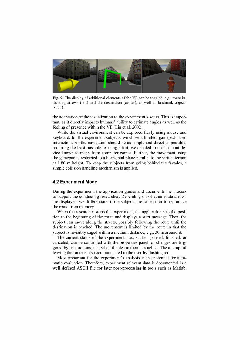
Fig. 9. The display of additional elements of the VE can be toggled, e.g., route in-
dicating arrows (left) and the destination (center), as well as landmark objects
(right).
the adaptation of the visualization to the experiment’s setup. This is impor-
tant, as it directly impacts humans’ ability to estimate angles as well as the
feeling of presence within the VE (Lin et al. 2002).
While the virtual environment can be explored freely using mouse and
keyboard, for the experiment subjects, we chose a limited, gamepad-based
interaction. As the navigation should be as simple and direct as possible,
requiring the least possible learning effort, we decided to use an input de-
vice known to many from computer games. Further, the movement using
the gamepad is restricted to a horizontal plane parallel to the virtual terrain
at 1.80 m height. To keep the subjects from going behind the façades, a
simple collision handling mechanism is applied.
4.2 Experiment Mode
During the experiment, the application guides and documents the process
to support the conducting researcher. Depending on whether route arrows
are displayed, we differentiate, if the subjects are to learn or to reproduce
the route from memory.
When the researcher starts the experiment, the application sets the posi-
tion to the beginning of the route and displays a start message. Then, the
subject can move along the streets, possibly following the route until the
destination is reached. The movement is limited by the route in that the
subject is invisibly caged within a medium distance, e.g., 30 m around it.
The current status of the experiment, i.e., started, paused, finished, or
canceled, can be controlled with the properties panel, or changes are trig-
gered by user actions, i.e., when the destination is reached. The attempt of
leaving the route is also communicated to the user by flashing red.
Most important for the experiment’s analysis is the potential for auto-
matic evaluation. Therefore, experiment relevant data is documented in a
well defined ASCII file for later post-processing in tools such as Matlab.

Each experiment is documented with a header containing a given subject
identifier and the environment’s configuration. The progress of the subject
is tracked with respect to position and heading in regular, configurable
time intervals, such as 1/10 s. It is supplemented by status change events
and collision events when the route is left. Thus, errors of the subjects
while reproducing the route can be counted as an indicator for the adequa-
cy of the representation.
4.3 Experiment Questions
Using our experiment application, a number of hypotheses can be eva-
luated both quantitatively and qualitatively.
Estimating Angles The estimation of angles of outgoing legs of a junction
is the basis for a determination of the feasibility of the choreme ap-
proach in 3D. The situation is fundamentally different compared to 2D
maps, as the subjects have to transfer the egocentric impression from the
3D visualization to a mental allocentric concept of the junction. In our
application, the subjects can be told to explore a junction and then asked
to sketch a top-down view of it. We are interested, to which degree the
estimation of the angles is correct.
Choreme Impact on 3D Route Comprehension While cognitively ade-
quate representationof spatial data was shown to be effective for 2D
floor plans (Meilinger et al. 2007), our application addresses the 3D
case. It is possible to assess the choreme transformation of a 3D city en-
vironment along a route. The application automatically tracks attempts
to leave the route, e.g., when a subject has forgotten the correct way. By
counting these attempts, we have a quantitative measure for the confi-
dence of the learned route, and, hence, can compare a subject’s perfor-
mance in the unchanged and the changed world.
Landmarks along the Route Landmarks undoubtedly play an essential
role in the wayfinding process. Our application allows for the definition
of landmark objects’ positions and models to control their integration in
the VE. Therefore, the subjects’ wayfinding performance in different
configurations can be measured and compared.
As the application only uses a small set of sufficiently generic, photo-
realistic or synthetic façades or even no façades at all, we can exclude as
far as possible the effect of façades used as landmarks. In addition, the flat
terrain and the simple scene structure with low detail ground complexity
limit memorization of the route to the sequence of junctions and their con-
figuration.

5 Discussion
The presented framework for the creation of a virtual city environment ex-
ternalizes the mental concept of a route and can be used in different set-
tings. As our focus is on experiments evaluating the usefulness of 3D way-
finding choremes, the presented implementation creates a geometrically
simple urban environment that still provides first insights into this ques-
tion. In addition to using the experiment application in our own experi-
ments, it is possible to export the created VEs for use in other applications
in standard formats, e.g., CityGML (Kolbe et al. 2005) or VRML. Thus,
the 3D environments can be evaluated by the community, or other experi-
ments can be done. Another interesting opportunity is to use the trans-
formed road network as input data for a procedural city model creation
(Müller et al. 2006) as it would lead to much higher detailed buildings and
ground level geometry to increase the photo-realistic impression. Still, the
environment could be created in a controlled way.
5.1 Concept
Regarding the potential to transfer the wayfinding choreme concept to 3D,
we are not sure, what the results of the experiments will be. The applicabil-
ity of the concept in 3D is contradicted by our subjective impression that
the changes of a junction’s configuration are quite small. In addition, it is
questionable, if the simplification of the route junctions in the sense of the
choreme concept leads to a better comprehension and memorization of the
route, or if it removes unique properties necessary for memorization. Fi-
nally, in our world 3D junctions are especially perceived through the
closed façades. In a more photo-realistic 3D world, apart from very dense
central city areas, buildings have free spaces between them, making per-
ception and judgment of a junction more difficult. This effect does not oc-
cur on 2D maps, as roads are typically printed as lines and a possible trans-
formation directly gets visible.
However, previous experiments have shown that route junctions are not
remembered with exact angles regarding their configuration (Tversky and
Lee 1999). Therefore, a simplification according to the wayfinding cho-
remes reduces the presented information to the necessary aspects, thus eas-
ing the process of picking up the path. Therefore we are interested in con-
ducting the experiment for 3D environments to create a more sound base
for further discussion.

5.2 Comparison with Existing Work
If we compare our work with existing approaches, routes are usually visua-
lized using additional scene elements that give directional hints. Typically,
line features aligned with the course of the route or arrows at decision
points are integrated in the visualization to guide the user. These elements
can be integrated, for example, within live video imagery as an overlay
showing route indicators in a perspectively correct way (Narzt et al. 2004).
In (Coors et al. 2005), multi-modal representations of routes are analyzed,
including verbal instructions, 2D and 3D route hints. Our solution uses in-
tegrated elements during learn phase.
Current commercial solutions for navigation systems typically do rely
on these explicit route indicators and integrate them in 2D views as well
as, increasingly, 3D views. However, 3D visualization in navigation sys-
tems is in its infancy. Today’s solutions just show annotated 3D models of
the environment and use only few techniques to support perception and
comprehension of the route.
In addition to explicit route indicators, a route and its environment can
be visualized in a deformed way to ease its communication. The classical
example for 2D route visualization, (Agrawala and Stolte 2001), simplifies
the route by shrinking distances of straight route segments while preserv-
ing angles. In (Böttger et al. 2008), a metro plan, i.e., a schematic, topolog-
ical route representation, is used to transform a topographic map accor-
dingly with image warping techniques, revealing the spatial relations
between the metro stations. For short routes within a 3D VE, (Degener et
al. 2008) present an image warping technique to create a single image de-
scribing the way. Focus + context visualization as in (Trapp et al. 2008) is
another way to support wayfinding along routes in 3D VEs. Our approach
focuses on the geometric transformation of junctions to conform to the
cognitive concept of a route.
The automatic creation of artificial virtual 3D city models is typically
done using procedural techniques. Based on a grammar, that is, a set of
rules, whole city models including a road network can be created (Parish
and Müller 2001). This technique can also be extended to create different,
complex building types (Müller et al. 2006). A similar approach with the
focus on interactive road network creation is presented in (Kelly and
McCabe 2007). As we create a VE aiming at the conduction of an experi-
ment, we currently do not need a very high degree of realism.

6 Conclusion & Outlook
We present a framework to create a cognitively adequate representation of
a route in a 3D virtual environment following the concept of wayfinding
choremes, transferring the concept from 2D maps. The framework includes
an application to conduct experiments for the evaluation of this transferred
concept and support the conducting researcher with the automatic logging
of relevant events during one experiment.
Our next steps will be the accomplishment of experiments, testing the
memorization of a route in the unchanged and the transformed environ-
ment. In addition to monitor and flat-screen projector based tests, we plan
to do the experiment in a half cylinder. We presume, that the results will
be different compared to the flat screen experiment, as the immersion is
enhanced, and, standing on a junction the subjects actually can look into
the outgoing roads without further interaction. This will probably influence
the ability to estimate angles, and, hence, the impact of the choreme trans-
formation.
Technically, we plan to change our implementation in some aspects. An
enhancement for the choreme concept refines the eight-sector-model and
suggests a nonuniform size of the different sectors (Klippel et al. 2004).
Especially aiming at verbal communication of directions, for example, the
sector straight ahead is smaller compared to the directions “veer left” or
“veer right”. Another interesting idea is the dynamic adaptation of junc-
tions as the user gets near, possibly using image warping techniques
(Böttger et al. 2008). This would be needed for dynamic rerouting in case
of a lost way and thus is relevant for car navigation systems.
Finally, the results of the experiments will eventually be integrated into
the experiment application and/or be used in a refined concept.
Acknowledgement
We want to thank Sebastian Pasewaldt for supporting us with the imple-
mentation. We also thank the reviewers for their comments.
This work has been funded by the German Federal Ministry of Education
and Research (BMBF) as part of the InnoProfile research group “3D
Geoinformation” (www.3dgi.de).
This work is also supported by the Transregional Collaborative Re-
search Center SFB/TR 8 Spatial Cognition, which is funded by the
Deutsche Forschungsgemeinschaft (DFG).

References
Agrawala, M. and Stolte, C. (2001) Rendering Effective Route Maps: Improving
Usability Through Generalization, in: Proceedings of ACM SIGGRAPH,
ACM press.
Berendt, B., Barkowsky, T., Freksa, C., and Kelter, S. (1998) Spatial Representa-
tion with Aspect Maps, in: LNCS: Spatial Cognition - An Interdisciplinary
Approach to Representing and Processing Spatial Knowledge, Springer, pp.
313–336.
Böttger, J., Brandes, U., Deussen, O. and Ziezold, H. (2008) Map Warping for the
Annotation of Metro Maps, in: IEEE Computer Graphics and Applications,
28(5), IEEE Computer Society Press, pp. 56–65.
Coors, V., Elting, C., Kray, C. and Laakso, K. (2005) Presenting Route Instruc-
tions on Mobile Devices: From Textual Directions to 3D Visualization, in
Dykes, J., MacEachren, A.M. and Kraak, M.-J (eds.): Exploring Geovisualiza-
tion, Elsevier, pp. 529–550.
Darken, R. P and Sibert, J. L. (1993) A Toolset for Navigation in Virtual Envi-
ronments, in: UIST: Proceedings of the 6th
annual ACM Symposium on User
Interface Software and Technology, ACM press, pp. 158–165
Darken, R. P. and Sibert, J. L (1996) Wayfinding Strategies and Behaviors in
Large Virtual Worlds, in: Proceedings of the SIGCHI conference, pp. 142–
149.
De Berg, M., Cheong, O., and van Kreveld, M. (2008) Computational Geometry:
Algorithms and Applications, Springer.
Degener, P., Schnabel, R., Schwartz, C. and Klein, R. (2008) Effective Visualiza-
tion of Short Routes, in: IEEE Transactions on Visualization and Computer
Graphics 14(6), IEEE Computer Society Press, pp. 1452–1458.
Freksa, F., (1991) Qualitative Spatial Reasoning, in Mark, D.M and Frank, A.U.
(eds.): Cognitive and Linguistic Aspects of Geographic Space, Springer, pp.
361–372.
Freksa, F. (1999) Spatial Aspects of Task-Specific Wayfinding Maps, in: Gero,
J.S. and Tversky, B. (eds.): Visual and Spatial Reasoning in Design, Universi-
ty of Sidney, Key Centre of Design Computing and Cognition, pp. 15–32
Goerger, S.R., Darken, R.P.,. Boyd, M.A, Gagnon, T.A., Liles, S.W., Sullivan,
J.A., and Lawson, J.P (1998) Spatial Knowledge Acquisition from Maps and
Virtual Environments in Complex Architectural Spaces, in: Colorado Springs
US AirForce Academy (ed.): 16th Applied Behavioral Sciences Symposium,
pp. 6–10.
Herskovits, A. (1998) Schematization, in Olivier, P. and Gapp, K.P (eds.): Repre-
sentation and Processing of Spatial Expressions, Lawrence Erlbaum Assi-
ociates, pp 149–162.
Kelly, G. and McCabe, H. (2007) Citygen: An Interactive System for Procedural
City Generation, in: Proceedings of Fifth International Conference on Game
Design and Technology, ACM press, pp. 8–16.

Klippel, A., Dewey, C., Knauff, M., Richter, K.-F., Montello, D.R., C. Freksa, and
Loeliger, E.-A. (2004) Direction Concepts in Wayfinding Assistance Systems,
in Workshop on Artificial Intelligence in Mobile Systems (AIMS’04).
Klippel A., Richter, K.-F., Barkowsky, T. and Freksa, C. (2005) The Cognitive
Reality of Schematic Maps, in: Meng, L., Zipf, A. and Reichenbacher T.
(eds): Mapbased Mobile Services - Theories, Methods and Implementations,
Springer, pp 57–74.
Kolbe, T. H., Gröger, G. and Plümer, L. (2005) CityGML Interoperable Access to
3D City Models, in van Oosterom, P., Zlatanova, S. and Fendel, E.M. (eds.)
Proc. of the 1st International Symposium on Geoinformation for Disaster
Management, Springer.
Lin, J.J.W., Duh, H.B.L., Parker, D.E., Abi-Rached, H. and Furness, T.A. (2002)
Effects of Field of View on Presence, Enjoyment, Memory, and Simulator
Sickness in a Virtual Environment, in: Proceedings of the IEEE Virtual Reali-
ty Conference , IEEE Computer Society press.
Lynch K. (1960) The Image of the City, MIT Press.
Meilinger, T., Hölscher, C., Büchner, S.J. and Brösamle, M. (2007) How Much
Information Do You Need? Schematic Maps in Wayfinding and Self Locali-
sation, in: LNCS: Spatial Cognition, Springer.
Montello, D. R., Hegarty, M. and Richardson, A. E (2004) Human Spatial Memo-
ry: Remembering Where, Chapter Spatial Memory of Real Environments,
Virtual Environments, and Maps, Lawrence Erlbaum Associates, pp. 251–
285.
Müller, P., Wonka, P., Haegler, S., Ulmer, A. and van Gool, L. (2006) Procedural
Modeling of Buildings, in: Proceedings of ACM SIGGRAPH 2006 / ACM
Transactions on Graphics, 25(3), ACM press, pp. 614–623.
Narzt, W., Pomberger, G., Ferscha, A., Kolb, D., Müller, R., Wieghardt, J., Hört-
ner, H. and Lindinger, C. (2004) A New Visualization Concept for Navigation
Systems, in LNCS: User-Centered Interaction Paradigms for Universal Access
in the Information Society, Springer.
Nash, E. B., Edwards, G. W., Thompson, J. A. and Barfield, W. (2000) A Review
of Presence and Performance in Virtual Environments, in: International Jour-
nal of Human Computer Interaction, 12(1), Taylor & Francis, pp. 1–41.
Omer, I., Golblatt, R., Talmor, K. and Roz, A. (2006) Enhancing the Legibility of
Virtual Cities by Means of Residents’ Urban Image: A Wayfinding Support
System, in: Complex Artificial Environments Simulation, Cognition and VR
in the Study and Planning of Cities, Springer.
Palmer, S.E. (1978) Fundamental Aspects of Cognitive Representation, in Rosch,
E. and Lloyd, B.B.(eds.): Cognition and Categorization, Lawrence Erlbaum
Assiociates, pp. 259–303.
Parish, Y.I.H. and Müller, P. (2001) Procedural Modeling of Cities, in:
SIGGRAPH’01: Proceedings of the 28th Annual Conference on Computer
Graphics and Interactive Techniques, ACM press, pp. 301–308.
Peters, D. and Richter, K.-F. (2008) Taking off to the Third Dimension - Schema-
tization of Virtual Environments in: International Journal of Spatial Data In-

frastructures Research, Vol 3, Joint Research Centre of the European Com-
mission.
Richardson, A. R., Montello, D. R. and Hegarty, M. (1999) Spatial Knowledge
Acquisition from Maps and From Navigation in Real and Virtual Environ-
ments, in: Memory and Cognition, 27, Psychonomic Society, pp. 741–750.
Riecke, B. E. (2003) How Far Can We Get With Just Visual Information? Path In-
tegration and Spatial Updating Studies in Virtual Reality, PhD thesis, Univer-
sität Tübingen, Fakultät für Mathematik und Physik.
Strube, G. (1992) Contemporay Knowledge Engineering and Cognition, in:
Schmalhofer, F., Strube, G., and Wetter, T.(eds): The Role of Cognitive
Science in Knowledge Engineering, Springer, pp. 161–174.
Trapp, M., Glander, T., Buchholz, H. and Döllner, J. (2008) 3D Generalization
Lenses for Interactive Focus + Context Visualization of Virtual City Models,
in Proceedings of the 12th International Conference on IEEE Information Vi-
sualization, IEEE Computer Society Press, pp. 356–361.
Tversky, B., and Lee, P. U. (1999) Pictorial and Verbal Tools for Conveying
Routes, in Freksa, C. and Mark, D.M. (eds.): LNCS: Spatial Information
Theory. Cognitive and computational foundations of geographic information
science.pp. 51-64.
Wein, R., Fogel, E., Zukerman, B. and Halperin, D. (2007) 2D Arrangements, in
CGAL Editorial Board (ed.): CGAL User and Reference Manual. 3.3 edition.
Copyright © 2022 FDOKUMEN