3D Printed Microfluidic Devices - Open Research Library
214
3D Printed Microfluidic Devices Savas Tasoglu and Albert Folch www.mdpi.com/journal/micromachines Edited by Printed Edition of the Special Issue Published in Micromachines
-
Upload
khangminh22 -
Category
Documents
-
view
0 -
download
0
Transcript of 3D Printed Microfluidic Devices - Open Research Library

3D Printed
Microfluidic
Devices
Savas Tasoglu and Albert Folch
www.mdpi.com/journal/micromachines
Edited by
Printed Edition of the Special Issue Published in Micromachines

3D Printed Microfluidic Devices


3D Printed Microfluidic Devices
Special Issue Editors
Savas Tasoglu
Albert Folch
MDPI • Basel • Beijing • Wuhan • Barcelona • Belgrade

Special Issue Editors
Savas Tasoglu
University of Connecticut
USA
Albert Folch
University of Washington USA
Editorial Office
MDPI
St. Alban-Anlage 66
4052 Basel, Switzerland
This is a reprint of articles from the Special Issue published online in the open access
journal Micromachines (ISSN 2072-666X) in 2018 (available at: https://www.mdpi.com/journal/
micromachines/special issues/3d printed microfluidic devices)
For citation purposes, cite each article independently as indicated on the article page online and as
indicated below:
LastName, A.A.; LastName, B.B.; LastName, C.C. Article Title. Journal Name Year, Article Number,
Page Range.
ISBN 978-3-03897-467-3 (Pbk)
ISBN 978-3-03897-468-0 (PDF)
Cover image courtesy of Nirveek Bhattacharjee and Albert Folch.
c© 2018 by the authors. Articles in this book are Open Access and distributed under the Creative
Commons Attribution (CC BY) license, which allows users to download, copy and build upon
published articles, as long as the author and publisher are properly credited, which ensures maximum
dissemination and a wider impact of our publications.
The book as a whole is distributed by MDPI under the terms and conditions of the Creative Commons
license CC BY-NC-ND.

Contents
About the Special Issue Editors . . . . . . . . . . . . . . . . . . . . . . . . . . . . . . . . . . . . . vii
Preface to ”3D Printed Microfluidic Devices” . . . . . . . . . . . . . . . . . . . . . . . . . . . . . ix
Savas Tasoglu and Albert Folch
Editorial for the Special Issue on 3D Printed Microfluidic DevicesReprinted from: Micromachines 2018, 9, 609, doi:10.3390/mi9110609 . . . . . . . . . . . . . . . . . 1
Sander van den Driesche, Frieder Lucklum, Frank Bunge and Michael J. Vellekoop
3D Printing Solutions for Microfluidic Chip-To-World ConnectionsReprinted from: Micromachines 2018, 9, 71, doi:10.3390/mi9020071 . . . . . . . . . . . . . . . . . . 4
Ludovic Serex, Arnaud Bertsch and Philippe Renaud
Microfluidics: A New Layer of Control for Extrusion-Based 3D PrintingReprinted from: Micromachines 2018, 9, 86, doi:10.3390/mi9020086 . . . . . . . . . . . . . . . . . . 16
Megan Carve and Donald Wlodkowic
3D-Printed Chips: Compatibility of Additive Manufacturing Photopolymeric Substrata withBiological ApplicationsReprinted from: Micromachines 2018, 9, 91, doi:10.3390/mi9020091 . . . . . . . . . . . . . . . . . . 27
.Frederik Kotz, Patrick Risch, Dorothea Helmer and Bastian E. Rapp
Highly Fluorinated Methacrylates for Optical 3D Printing of Microfluidic DevicesReprinted from: Micromachines 2018, 9, 115, doi:10.3390/mi9030115 . . . . . . . . . . . . . . . . . 48
Nurul Mohd Fuad, Megan Carve, Jan Kaslin and Donald Wlodkowic
Characterization of 3D-Printed Moulds for Soft Lithography of Millifluidic DevicesReprinted from: Micromachines 2018, 9, 116, doi:10.3390/mi9030116 . . . . . . . . . . . . . . . . . 59
Yong Tae Kim, Kurt Castro, Nirveek Bhattacharjee and Albert Folch
Digital Manufacturing of Selective Porous Barriers in Microchannels Using Multi-Material StereolithographyReprinted from: Micromachines 2018, 9, 125, doi:10.3390/mi9030125 . . . . . . . . . . . . . . . . . 70
Martin D. Brennan, Fahad F. Bokhari and David T. Eddington
Open Design 3D-Printable Adjustable Micropipette that Meets the ISO Standard for AccuracyReprinted from: Micromachines 2018, 9, 191, doi:10.3390/mi9040191 . . . . . . . . . . . . . . . . . 81
Eric Lepowsky and Savas Tasoglu
Emerging Anti-Fouling Methods: Towards Reusability of 3D-Printed Devices for Biomedical ApplicationsReprinted from: Micromachines 2018, 9, 196, doi:10.3390/mi9040196 . . . . . . . . . . . . . . . . . 93
Sein Oh and Sungyoung Choi
3D-Printed Capillary Circuits for Calibration-Free Viscosity Measurement of Newtonian andNon-Newtonian FluidsReprinted from: Micromachines 2018, 9, 314, doi:10.3390/mi9070314 . . . . . . . . . . . . . . . . . 112
Michael J. Beauchamp, Hua Gong, Adam T. Woolley and Gregory P. Nordin
3D Printed Microfluidic Features Using Dose Control in X, Y, and Z DimensionsReprinted from: Micromachines 2018, 9, 326, doi:10.3390/mi9070326 . . . . . . . . . . . . . . . . . 123
v

Mohamed Sharafeldin, Abby Jones and James F. Rusling
3D-Printed Biosensor Arrays for Medical DiagnosticsReprinted from: Micromachines 2018, 9, 394, doi:10.3390/mi9080394 . . . . . . . . . . . . . . . . . 135
Yonghee Kim, Jinyeop Lee and Sungsu Park
A 3D-Printed Millifluidic Platform Enabling Bacterial Preconcentration and DNA Purificationfor Molecular Detection of Pathogens in BloodReprinted from: Micromachines 2018, 9, 472, doi:10.3390/mi9090472 . . . . . . . . . . . . . . . . . 157
Christopher Lim, Yangchung Lee and Lawrence Kulinsky
Fabrication of a Malaria-Ab ELISA Bioassay Platform with Utilization of Syringe-Based and 3DPrinted Assay AutomationReprinted from: Micromachines 2018, 9, 502, doi:10.3390/mi9100502 . . . . . . . . . . . . . . . . . 169
Eric Lepowsky, Reza Amin and Savas Tasoglu
Assessing the Reusability of 3D-Printed Photopolymer Microfluidic Chips for Urine ProcessingReprinted from: Micromachines 2018, 9, 520, doi:10.3390/mi9100520 . . . . . . . . . . . . . . . . . 185
vi
About the Special Issue Editors
Savas Tasoglu joined the University of Connecticut (UCONN) in 2014 as an Assistant Professor in
the Department of Mechanical Engineering. He received his Ph.D. in 2011 from UC Berkeley, with
a research focus on transport phenomena and the pharmacokinetics of anti-HIV microbicide drug
delivery. Dr. Tasoglu held a postdoctoral appointment at Harvard Medical School and Harvard-MIT
Division of Health Sciences and Technology until he joined UConn in 2014. His current research
interests are point-of-care diagnostic devices, bioprinting, magnetic focusing, microfluidics, and
regenerative medicine. He serves on the editorial board of several journals including Bioprinting
(Elsevier), Scientific Reports (Nature), Journal of 3D Printing in Medicine (FSG), and International
Journal of Bioprinting. Dr. Tasoglu’s achievements in research and teaching have been recognized
by fellowships and awards including Chang-Lin Tien Fellowship in Mechanical Engineering,
Allen D. Wilson Memorial Scholarship, and UC Berkeley Institute Fellowship for Preparing Future
Faculty. Dr. Tasoglu has published 50+ co-author articles in journals such as Nature Communications,
Nature Materials, Advanced Materials, PNAS, Small, ACS Nano, Chemical Society Reviews, Trends in
Biotechnology, and Physics of Fluids. His work has been featured on the cover of Advanced Materials,
Small, Trends in Biotechnology, and Physics of Fluids and highlighted in Nature, Nature Physics, Nature
Medicine, Boston Globe, Reuters Health, and Boston Magazine.
Albert Folch received his BSc in physics from the University of Barcelona (UB), Spain, in 1989.
In 1994, he received his PhD in surface science and nanotechnology from the UB’s Physics Dept.
During his PhD, he was a visiting scientist from 1990–91 at the Lawrence Berkeley Lab working on
AFM. From 1994–1996, he was a postdoc at MIT developing MEMS. In 1997, he joined Mehmet
Toner’s laboratory at Harvard. He has been at UW BioE since June 2000, where he is now a
full Professor, accumulating over 7,600 citations (averaging >82 citations/paper). His lab works at
the interface between microfluidics, 3D-printing, and cancer. In 2001 he received a NSF Career
Award, and in 2014 he was elected to the AIMBE College of Fellows. Albert Folch is the author
of four books, including “Introduction to BioMEMS”, a textbook now adopted by more than 78
departments in 18 countries. Since 2007, the lab has run a celebrated outreach art program called
BAIT (Bringing Art Into Technology), which has produced 7 exhibits, a popular resource gallery
(>2,000 free BioMEMS-related images), and a YouTube channel (>133,000 visits since 2009).
vii


Preface to ”3D Printed Microfluidic Devices”
Three-dimensional (3D) printing has revolutionized the microfabrication prototyping workflow
over the past few years. With recent advances in 3D printing and 3D computer-aided design
(CAD) technologies, highly complex microfluidic devices can be fabricated via single-step,
rapid, and cost-effective protocols as a promising alternative to the time-consuming, costly, and
sophisticated poly(dimethylsiloxane) (PDMS) molding and traditional cleanroom-based fabrication.
Microfluidic devices have enabled a wide range of biochemical and clinical applications, such
as cancer screening, micro-physiological system engineering, high-throughput drug testing, and
point-of-care diagnostics. Using 3D printing fabrication techniques, the alteration of design features
is significantly faster and easier than with traditional fabrication, enabling agile iterative and modular
design, 3D printing services and marketplaces, and rapid prototyping. Biocompatible resins for 3D
printing are now available that, contrary to PDMS, feature very low drug absorption and are thus
very good material candidates for building complex 3D organ-on-a-chip systems in the future. These
advances will make microfluidic technology more accessible to researchers in various fields and
will accelerate innovation in the field of microfluidics. Accordingly, this Special Issue showcases
14 research papers, communications, and review articles that focus on novel methodological
developments in 3D printing and its use for various biochemical and biomedical applications. The
papers of this special issue explore the following aspects of 3D printing and how it pertains to
microfluidic devices: (1) fabrication methods and materials, (2) applications for equipment and tools,
(3) biological applications, and (4) biological compatibility.
Savas Tasoglu, Albert Folch
Special Issue Editors
ix


micromachines
Editorial
Editorial for the Special Issue on 3D PrintedMicrofluidic Devices
Savas Tasoglu 1,2,3,4,5,* and Albert Folch 6,*
1 Department of Mechanical Engineering, University of Connecticut, Storrs, CT 06269, USA2 The Connecticut Institute for the Brain and Cognitive Sciences, University of Connecticut,
Storrs, CT 06269, USA3 Department of Biomedical Engineering, University of Connecticut, Storrs, CT 06269, USA4 Institute of Materials Science (IMS), University of Connecticut, Storrs, CT 06269, USA5 Institute for Collaboration on Health, Intervention, and Policy (InCHIP), University of Connecticut,
Storrs, CT 06269, USA6 Department of Bioengineering, University of Washington, Seattle, WA 98195, USA* Correspondence: [email protected] (S.T.); [email protected] (A.F.)
Received: 19 November 2018; Accepted: 19 November 2018; Published: 21 November 2018
Three-dimensional (3D) printing has revolutionized the microfabrication prototyping workflowover the past few years. With recent advances in 3D printing and 3D computer-aided design(CAD) technologies, highly complex microfluidic devices can be fabricated via single-step, rapid,and cost-effective protocols as a promising alternative to the time-consuming, costly, and sophisticatedpoly(dimethylsiloxane) (PDMS) molding and traditional cleanroom-based fabrication. Microfluidicdevices have enabled a wide range of biochemical and clinical applications, such as cancer screening,micro-physiological system engineering, high-throughput drug testing, and point-of-care diagnostics.Using 3D printing fabrication techniques, the alteration of design features is significantly faster andeasier than with traditional fabrication, enabling agile iterative and modular design, 3D printingservices and marketplaces, and rapid prototyping. Biocompatible resins for 3D printing are nowavailable that, contrary to PDMS, feature very low drug absorption and are thus very good materialcandidates for building complex 3D organ-on-a-chip systems in the future. These advances willmake microfluidic technology more accessible to researchers in various fields and will accelerateinnovation in the field of microfluidics. Accordingly, this Special Issue showcases 14 researchpapers, communications, and review articles that focus on novel methodological developmentsin 3D printing and its use for various biochemical and biomedical applications. The papers ofthis special issue explore the following aspects of 3D printing and how it pertains to microfluidicdevices: (1) fabrication methods and materials, (2) applications for equipment and tools, (3) biologicalapplications, and (4) biological compatibility.
1. Fabrication methods and materials: Fuad et al. [1] characterized additively manufacturedmolds fabricated via stereolithography and material jetting, as well as the positive replicas producedby soft lithography and PDMS molding. They showed that stereolithography provides finer partresolution with no toxicity observed in the corresponding positive replicas. Beauchamp et al. [2]demonstrated a custom 3D printer which, via optical dosage control, provides very high-resolutionprinting capabilities down to ~ 30 µm and ~ 20 µm scales for positive and negative surface features,respectively. The custom printer was used to fabricate and optimize various microfluidic particle traps.Kim et al. [3] also developed a novel printing scheme: specifically, a sequential stereolithographicco-printing process which utilizes two different molecular weight poly(ethylene glycol) diacrylate(PEG-DA) resins to produce microchannels with embedded porous barriers. The semi-autonomousfabrication process reduced the processing time, manufacturing costs, and eliminated complicationswith assembly. In addition to fabrication methods, Kotz et al. [4] presented work on materials
Micromachines 2018, 9, 609; doi:10.3390/mi9110609 www.mdpi.com/journal/micromachines1

Micromachines 2018, 9, 609
formulated for 3D printing, namely highly fluorinated perfluoropolyether (PFPE) methacrylates,for which 3D printing has seldom been demonstrated. The developed formulations, printed andcured using stereolithography, exhibited high light transmittance and high chemical resistance toorganic solvents.
2. Applications for equipment and tools: Brennan et al. [5] utilized the capabilities of 3Dprinting technology to create an open source design for micropipettes which can be assembledfrom 3D-printed parts and a disposable syringe. The open source design exemplifies scientifictools that can be produced via 3D printing as inexpensive alternatives to commercial products.Oh et al. [6] also developed 3D-printed laboratory equipment to measure the viscosity of fluids,which is applicable, for example, to the quality assurance of liquid products and for monitoringthe viscosity of clinical fluids. They designed 3D-printed capillary circuits, with graduations toserve as a flow meter for easy readability and a syringe modified with an air chamber to generatepressure-driven flow, to provide equipment and calibration-free viscosity measurement of Newtonianand non-Newtonian fluids. Van den Driesche et al. [7] presented methods for a wide variety ofapplications to design and fabricate microfluidic chip holders with integrated fluidic and electricconnections, such as fluidic sealing by O-rings and electric connections by spring-probes without glueor wire bonding. Microfluidics can also be applied to 3D printing technologies, as demonstrated bySerex et al. [8]. For application to bioprinting, Serex et al. demonstrated the integration of micromixers,micro-concentrators, and microfluidic switches into the tip of the print heads for extrusion-based 3Dprinting, thereby enabling new prospects in 3D bioprinting.
3. Biological applications: There are countless biological applications for 3D-printed microfluidicdevices, a few of which are included in this Special Issue. Lim et al. [9] reported an automatedplatform for a colorimetric malaria-Ab assay, assembled from stereolithographic-printed elastomericreservoirs, fused deposition modeling-printed framework, plastic tubing, servomotors, and an Arduinomicrocontroller chip. Kim et al. [10] demonstrated a 3D-printed millifluidic platform for bacterialpreconcentration and genomic DNA (gDNA) purification, by immunomagnetic separation andmagnetic silica-bead-based DNA extraction, to improve the molecular detection of pathogens inblood samples. The platform was verified for preconcentrating E. coli in blood, suggesting that theplatform is a useful tool for lowering limitations on molecular detection. In addition to these researcharticles, Sharafeldin et al. [11] wrote a review on the applications of 3D-printed microfluidic devices inbiomedical diagnostics and on how 3D printing enables low-cost, sensitive, and geometrically complexdevices. Three-dimensional printing can be used for the fabrication of microfluidics, supportingequipment, optical and electrical components, in addition to 3D bioprinting which can incorporateliving cells or biomaterials into diagnostic systems.
4. Biological compatibility: In their work on connections and holders for microfluidic devices,for bioanalysis applications, van den Driesche et al. [7] addressed the possible cytotoxicity of cured3D-printed resin by introducing a surface coating of parylene-C. Carve et al. [12] reviewed commonlyused vat polymerization and material jetting materials with respect to the materials’ biocompatibility,in addition to discussing methods to mitigate material toxicity to promote the application of 3D-printeddevices in biomedical and biological research, such as for monolithic lab-on-chip devices. In additionto biocompatibility with cells, interactions with biomolecules such as protein have been studied byLepowsky et al. [13]. They demonstrated a simple cleaning chip design with an integrated cleaningprocedure to study the long-term cyclic biofouling burden on 3D-printed microfluidic devices, andverified the cleaning chip for urine sampling handling for a protein assay. Lepowsky et al. [14] alsoprovided a perspective on traditional and emerging anti-fouling methods as applicable to enabling thegreater reusability of 3D-printed microfluidic devices for biomedical applications.
We wish to thank all authors who submitted their papers to this Special Issue. We would also liketo acknowledge all the reviewers for dedicating their time to provide careful and timely reviews toensure the quality of this Special Issue.
2

Micromachines 2018, 9, 609
Conflicts of Interest: A.F. declares no conflict of interest. S.T. is a founder of, and has an equity interest in mBiotics,LLC, a company that is developing microfluidic technologies for point-of-care diagnostic solutions and QRfertile,LLC, a company that is developing technologies for fertility testing. S.T.’s interests were viewed and managedin accordance with the conflict of interest policies. The authors have no other relevant affiliations or financialinvolvement with any organization or entity with a financial interest in or financial conflict with the subject matteror materials discussed in the manuscript apart from those disclosed.
References
1. Fuad, N.M.; Carve, M.; Kaslin, J.; Wlodkowic, D. Characterization of 3D-printed moulds for soft lithographyof millifluidic devices. Micromachines 2018, 9, 116. [CrossRef] [PubMed]
2. Beauchamp, M.J.; Gong, H.; Woolley, A.T.; Nordin, G.P. 3D printed microfluidic features using dose controlin X, Y, and Z dimensions. Micromachines 2018, 9, 326. [CrossRef] [PubMed]
3. Kim, Y.T.; Castro, K.; Bhattacharjee, N.; Folch, A. Digital manufacturing of selective porous barriers inmicrochannels using multi-material stereolithography. Micromachines 2018, 9, 125. [CrossRef] [PubMed]
4. Kotz, F.; Risch, P.; Helmer, D.; Rapp, B.E. Highly fluorinated methacrylates for optical 3D printing ofmicrofluidic devices. Micromachines 2018, 9, 115. [CrossRef] [PubMed]
5. Brennan, M.D.; Bokhari, F.F.; Eddington, D.T. Open design 3D-printable adjustable micropipette that meetsthe ISO standard for accuracy. Micromachines 2018, 9, 191. [CrossRef] [PubMed]
6. Oh, S.; Choi, S. 3D-printed capillary circuits for calibration-free viscosity measurement of Newtonian andnon-Newtonian fluids. Micromachines 2018, 9, 314. [CrossRef] [PubMed]
7. van den Driesche, S.; Lucklum, F.; Bunge, F.; Vellekoop, M.J. 3D printing solutions for microfluidicchip-to-world connections. Micromachines 2018, 9, 71. [CrossRef] [PubMed]
8. Serex, L.; Bertsch, A.; Renaud, P. Microfluidics: A new layer of control for extrusion-based 3D printing.Micromachines 2018, 9, 86. [CrossRef] [PubMed]
9. Lim, C.; Lee, Y.; Kulinsky, L. Fabrication of a Malaria-Ab ELISA Bioassay Platform with Utilization ofSyringe-Based and 3D Printed Assay Automation. Micromachines 2018, 9, 502. [CrossRef] [PubMed]
10. Kim, Y.; Lee, J.; Park, S. 3D-Printed Microfluidic Platform Enabling Bacterial Preconcentration and DNAPurification for Molecular Detection of Pathogens in Blood. Micromachines 2018, 9, 472. [CrossRef] [PubMed]
11. Sharafeldin, M.; Jones, A.; Rusling, J. 3D-Printed Biosensor Arrays for Medical Diagnostics. Micromachines
2018, 9, 394. [CrossRef] [PubMed]12. Carve, M.; Wlodkowic, D. 3D-printed chips: Compatibility of additive manufacturing photopolymeric
substrata with biological applications. Micromachines 2018, 9, 91. [CrossRef] [PubMed]13. Lepowsky, E.; Amin, R.; Tasoglu, S. Assessing the Reusability of 3D-Printed Photopolymer Microfluidic
Chips for Urine Processing. Micromachines 2018, 9, 520. [CrossRef] [PubMed]14. Lepowsky, E.; Tasoglu, S. Emerging Anti-Fouling Methods: Towards Reusability of 3D-Printed Devices for
Biomedical Applications. Micromachines 2018, 9, 196. [CrossRef] [PubMed]
© 2018 by the authors. Licensee MDPI, Basel, Switzerland. This article is an open accessarticle distributed under the terms and conditions of the Creative Commons Attribution(CC BY) license (http://creativecommons.org/licenses/by/4.0/).
3

micromachines
Article
3D Printing Solutions for MicrofluidicChip-To-World Connections
Sander van den Driesche 1,2,∗, Frieder Lucklum 1,2, Frank Bunge 1,2 and Michael J. Vellekoop 1,2
1 Institute for Microsensors, -actuators and -systems (IMSAS), University of Bremen, 28359 Bremen, Germany;[email protected] (F.L.); [email protected] (F.B.);[email protected] (M.J.V.)
2 Microsystems Center Bremen (MCB), University of Bremen, 28359 Bremen, Germany* Correspondence: [email protected]; Tel.: +49-421-218-62652
Received: 2 January 2018; Accepted: 3 February 2018; Published: 6 February 2018
Abstract: The connection of microfluidic devices to the outer world by tubes and wires isan underestimated issue. We present methods based on 3D printing to realize microfluidicchip holders with reliable fluidic and electric connections. The chip holders are constructedby microstereolithography, an additive manufacturing technique with sub-millimeter resolution.The fluidic sealing between the chip and holder is achieved by placing O-rings, partly integratedinto the 3D-printed structure. The electric connection of bonding pads located on microfluidic chipsis realized by spring-probes fitted within the printed holder. Because there is no gluing or wirebonding necessary, it is easy to change the chip in the measurement setup. The spring probes andO-rings are aligned automatically because of their fixed position within the holder. In the case ofbioanalysis applications such as cells, a limitation of 3D-printed objects is the leakage of cytotoxicresidues from the printing material, cured resin. This was solved by coating the 3D-printed structureswith parylene-C. The combination of silicon/glass microfluidic chips fabricated with highly-reliableclean-room technology and 3D-printed chip holders for the chip-to-world connection is a promisingsolution for applications where biocompatibility, optical transparency and accurate sample handlingmust be assured. 3D printing technology for such applications will eventually arise, enabling thefabrication of complete microfluidic devices.
Keywords: 3D printing; stereolithography; microfluidics; chip-holder; fluidic and electric connections
1. Introduction
3D printing technology has evolved remarkably the last couple of years. Instead of a plasticmelting machine that creates low-resolution structures with a high surface roughness, now, liquidresin-based 3D printers with a resolution of tens of micrometers and a surface roughness of a fewmicrometers have become affordable [1–7]. With two-photon polymerization-based 3D printers,it is even possible to attain a resolution down to 100 nanometers [8,9]. 3D printing has becomean attractive tool to fabricate measurement setup components. It enables the fabrication of sampleholders for various applications such as electron paramagnetic resonance measurements [10], surfaceplasmon resonance spectroscopic measurements to align various illumination angles [11] and forsingle-plane illumination microscopy [12]. It allows the construction of cartridge components to alignthe optical setup containing a smart-phone, battery, cuvette and electrical circuitry for fluorescencemeasurements [13], a smart-phone adapter including fluidic reservoirs [14], a connector to realizethe electrical connection to a digital microfluidic chip to conduct droplet size analysis by colormeasurements [15] and lab ware [16]. In microfluidics, 3D printing is also becoming an acceptedtechnology. There is a series of 3D-printed microfluidic devices described in the literature, includingmicromixers [17–19], flow channels [20] and valves [21,22]. Besides the printing of such structures,
Micromachines 2018, 9, 71; doi:10.3390/mi9020071 www.mdpi.com/journal/micromachines4

Micromachines 2018, 9, 71
also the integration of fluidic and electric connections can be realized [23]. A 3D-printed holder waspresented that compartmentalizes a glass microscope slide [24]. In this holder, recesses were made tofit an electrochemical sensor and PEEK tubings to make fluidic connections. 3D-printed microfluidiccircuits that handle multiple fluid streams were presented that consist of integrated chip-to-worldinterconnects [25]. A fluidic interconnect based on a 3D-printed clamping structure yielded a maximumsealing pressure up to 416 kPa [26].
Apart from the many advantages, there are several limitations in 3D printing for direct fabricationof microfluidic devices [2,4]. The removal of support material, structures that are required totemporarily reinforce the design to prevent its collapse during the printing process, of small fluidicgeometries requires careful handling. Furthermore, it is hard to print microfluidic channels witha diameter of less than several hundred micrometers. The surface roughness of constructed designs,material selection and biocompatibility to biological samples are also not optimal to realize devicesthat from a functional point of view can compete with silicon and glass chips [2,27,28].
Microfluidic devices constructed from hard non-cytotoxic materials, like silicon and glass, havemany advantages for the analysis or actuation of biological samples. The chips can be fabricatedby standard clean-room processes. The channel geometry ensures a closed and thus controlledenvironment that can be optimized for the sample [29]. However, the connection of microfluidicdevices to the outer world by tubes and wires is an underestimated issue. The diversity in microfluidicchip dimensions, the fluidic inlet and outlet amount, geometry of the channel, bonding pad sizes andnumber to connect the electrodes, as well as optical measurement window geometry make it infeasibleto design a universal chip holder. This means that almost every designed chip requires a specializedholder. The gluing of bonded-port connectors directly on the chip is a possible solution [30]. However,these connectors have a relatively large footprint that might not fit on the chip. In addition, theyincur considerable expenses, and gluing is a process with limited reliability for fluidic interconnects.A method is needed to quickly construct and easily redesign holders for different microfluidic chips.The following design criteria should be taken into account: (i) the holder should have integrated fluidicand electric connections; (ii) easy exchange of the chip; no gluing; (iii) the dimension of the holdershould be as small as possible. A useful overview of fluidic connections and electrical interconnects inmicrofluidics is given in the Design Guideline for Microfluidic Side Connect [31] and the Guidelines forPackaging of Microfluidics: Electrical Interconnections [32]. Both documents are part of an initiative tostandardize microfluidic devices and component interfaces [33,34].
Injection molding and micro-milling are existing techniques to construct customized microfluidicchip holders [35]. However, these techniques require specialized expensive equipment or molds.A separate mold is needed for every design. Furthermore, these techniques do not give many degreesof freedom for the design of geometric channel structures within the holder. This makes themimpractical when multiple fluidic and electric interconnects have to be accommodated. 3D printinghas several advantages compared to injection molding and micro-milling. It allows the integrationof complex geometric structures such as curved and closed sub-millimeter channels and specializedfluidic and electric connector ports printed directly within the holder. Injection molding for massproduction of simple chip holder geometries has certain advantages compared to standard 3D printingtechnology. However, when the fluidic chip-to-world connections consist of an inner channel structurewith curves, 3D printing shows enormous advantages. In this work, we combine the best of two worlds:clean-room technology for the fabrication of silicon and glass microfluidic chips with submicrometerresolution and 3D printing to make chip holders with integrated electric connections and fluidicconnections that do not require a very high resolution. Several designed and assembled microfluidicchip holders are presented, including fluidic and electric connections, to show 3D printing as thesolution for chip-to-world connections.
5

Micromachines 2018, 9, 71
2. Materials and Methods
2.1. Stereolithography
Stereolithography, a form of additive manufacturing that is based on layer-by-layerphotopolymerization of liquid resins, is a technology to create high resolution complex 3D-printedmicrofluidic geometries. The design of 3D-printed devices can easily be created and adapted in CADsoftware such as Inventor (Autodesk, San Rafael, CA, USA) or SolidWorks (Dassault Systèmes SolidWorksCorp., Waltham, MA, USA). The completed design is exported in the STL (Standard Tessellation Language)format at high resolution for pre-processing with the 3D printer software. Pre-processing the designsincludes checking for and fixing any errors to create a completely valid STL file, orienting the part onthe build platform and adding support structures for overhangs as necessary. Finally, the 3D printersoftware slices the STL file and supports into individual layers. In most cases, these pre-processing stepsare automated and just takes a few mouse clicks to confirm the proposed changes.
There are many different additive fabrication technologies, each with its strengths andweaknesses [1,36]. Stereolithography technology is recommended to construct parts with a featuresize on the sub-millimeter scale. It features a high lateral resolution and high surface smoothness.Microstereolithography with DLP (Digital Light Processing) micromirror array projection reliablyyields feature sizes (such as channels, holes and walls) down to 100µm [37].
In this work, a high-resolution microstereolithography DLP printer (Perfactory Micro HiRes,EnvisionTEC Inc., Dearborn, MI, USA) was used to fabricate the chip holders. A high-resolution,high-temperature, low viscosity acrylic polymer resin (HTM140 M, EnvisionTEC Inc., [38]) is usedas the printing material. E-Shell 300 [39], a Class IIa biocompatible resin used for hearing aid shellmanufacturing, was tested for cytotoxic effects on the growth of mammalian cells. Prior to printing,the stirred resin is filtrated into the carefully-cleaned printer bath for optimal printing conditions.The process is set to a lateral (x/y) resolution of 31µm and a slicing thickness (z) of 25µm. The exposuretime is typically set to 3000 ms per slice. The maximum build size is 40 mm× 30 mm× 100 mm.
After printing, all constructed parts are removed from the build platform and rinsed withisopropanol in an ultrasonic bath. Then, the realized part is dried with nitrogen or air, and thesupport structures are removed. Finally, all parts are cured in a UV flood chamber for at leastfive minutes. The total processing time is primarily dependent on the height of the printed structure,typically ranging from one to a few hours, which highlights the rapid prototyping characteristics ofthis approach.
2.2. Cell Line for Biocompatibility Test
The influence on the viability of Madin-Darby Canine Kidney cells (MDCK, ATCC CCL-34,a gift from Dr. Manfred Radmacher, Institute for Biophysics, University of Bremen, Bremen,Germany) and HaCaT cells (a gift from Dr. Ursula Mirastschijski, Centre for Biomolecular InteractionsBremen, University of Bremen, Bremen, Germany) exposed to UV-cured 3D-printed structures hasbeen investigated. The epithelial kidney cell line MDCK and keratinocyte skin cell HaCaT arewell-established models used in many biological studies [40,41].
2.3. Cell Line Preparation
The MDCK and HaCaT cells were cultivated in Glasgow Minimum Essential Medium (GMEM)and 10% fetal calf serum, supplemented with 100 units/mL penicillin and 100µg/mL streptomycin(all obtained from Sigma-Aldrich, Darmstadt, Germany). The cell culture was kept in a humidifiedatmosphere containing 5% CO2 and 95% ambient air at 37 °C.
2.4. Coating of 3D-Printed Structures with Parylene-C
Parylene-C is a USP Class VI and ISO-10993-6 certified biocompatible material [42–44]. We havecoated 3D-printed structures with parylene-C with a Labcoater series 300 (Plasma Parylene Systems
6

Micromachines 2018, 9, 71
GmbH, Rosenheim, Germany) to investigate the inhibition of cytotoxic effects on mammalian cells.The deposition process of parylene-C is depicted in Figure 1.
Figure 1. The deposition process of parylene-C. First, parylene-C dimer powder or granulate isvaporized at 150 °C, followed by a pyrolysis step at 730 °C to obtain parylene-C diradical monomers.At a temperature of 50 °C and a pressure of approximately 10 Pa, the monomer vapor condensates andforms a conformal coating on the substrate.
3. Results and Discussion
The cytotoxicity of printing material is discussed in Section 3.1; followed by Sections 3.2 and 3.3,where methods are described about how to realize reliable fluidic and electric chip-to-worldconnections, all based on 3D printing. Several chip holder concepts for on-chip cell growth and/oranalysis are presented in Section 3.4.
3.1. Cytotoxicity Tests of MDCK and HaCaT Cells Exposed to 3D-Printed Structures
In the case of bioanalysis applications, a strong influence on cellular behavior of mammaliancells and bacteria exposed to 3D-printed structures realized from liquid resins was observed [29].The resins commonly used for stereolithography 3D printing contain UV-sensitive photo-initiators,which exhibit a pronounced cytotoxic effect [45]. Biocompatible classified resins such as E-Shell 300from Envisiontec [39] or Med610 from Stratasys [46] need a thorough post-processing, includingUV-flood exposure to cross-link residual monomers. However, the 3D-printed microfluidic chipholders contain inner channel structures with regions inaccessible to UV light. When measurementsare conducted with sensitive biological cells, an efficient and attractive method to prevent suchcytotoxic effects is by coating the 3D-printed structures with parylene [47]. During the depositionprocess of parylene-C, reactive monomer diffuses into the 3D-printed channel, coating the innerstructure. This assures that liquid sample, pumped from syringes into the chip, does not becomecontaminated with resin residues that are toxic for the biological sample.
In Figure 2, measurement results are depicted of MDCK cells grown in a multi-well plate for 24 hexposed to 3D-printed parts with and without a 10 μm-thick parylene-C coating. Two samples wereprepared for each test.
The printed structures from the resins E-Shell 300 and HTM140 both show a strong cytotoxic effecton MDCK cells (Figure 2b,c). The cells did not attach to the bottom of the culture well within the 24 h ofincubation. The parylene-C coating strongly inhibits the cytotoxic effect of the resin. The MDCK cellsbehavior in Figure 2d is similar compared to the negative control sample shown in Figure 2a (viability ofrespectively 84% and 85%), while the cells exposed to uncoated parts die. HaCaT cells yielded thesame coated versus uncoated viability results as the MDCK cell measurements. For each HaCaT test,four samples were prepared, and the exposure time to 3D printed structures was 72 h. The controlgroup and the parylene-C coated samples both yielded a HaCaT cell viability of >95%. The viable testswere conducted by trypan blue staining (Thermo Fischer Scientific, Darmstadt, Germany).
The measurements show that the coating of 3D-printed HTM140 structures with parylene-Cis an easy and effective method preventing toxic resin components from diffusing into thebiological sample.
7

Micromachines 2018, 9, 71
Figure 2. Cytotoxicity tests of MDCK cells exposed to 3D-printed structures built from E-Shell 300 andHTM140 resin and a 10-μm parylene-C-coated structure. The MDCK cells were grown in a multi-wellplate for 24 h in Glasgow Minimum Essential Medium (GMEM) supplemented with 10% fetal bovineserum and antibiotics. (a) Negative control. MDCK cells attached to the bottom of a well plate shownormal cell proliferation. (b,c) MDCK cells exposed to a 3D-printed part made from E-Shell 300 orHTM140 resin, respectively. The cells did not attach to the well-plate. (d) MDCK cells exposed toa 3D-printed part coated with a 10-µm parylene-C layer. The cell attached to the bottom of the well,showing similar behavior as the negative control sample.
3.2. Fluidic Chip Holder Connections
In microfluidic applications where a continuous flow of sample and/or carrier liquids is required,the chip needs to be connected to syringe pumps. In Figure 3, a method for fluidic connections isdepicted where the holder acts as an interface between the chip and the syringe pumps.
Figure 3. Methods to realize the fluidic connection between microfluidic chips and syringe pumps.(a) A schematic of an O-ring positioned in a recess and a tube fitted in a conically-shaped channelgeometry; (b) a 3D rendered image visualizing the inner channel geometry; (c) a Labsmith one-piecefitting connection integrated in a chip holder.
The fluidic connections between the microfluidic chip and 3D-printed holder are sealed by O-rings.By creating half doughnut-shaped recesses in the 3D-printed holder, the O-ring positions are secured,which simplifies the assembly of chip and holder. These recesses are designed in such a way that 80%(height) of the O-rings are located within the holder. The width of the recesses are 110% of the O-ring
8

Micromachines 2018, 9, 71
diameter, allowing the rubber material to be pressed by the chip, yielding an air- and liquid-tightchip-to-holder connection (Figure 3).
The fluid connections from the holder to syringes are realized by fixing PEEK tubing with an innerand outer diameter of 250µm and 800µm, respectively, directly into the holder (Figure 3a,b). A channelstructure with a diameter of 0.7 mm starting at the O-ring recess is directed within the holder to thetube connection, fitting the PEEK tubing. This connection is achieved by mechanically clamping thetubing in a conically-shaped geometry integrated in the channel. A fluid-tight connection is obtainedby gluing the tubing with two-component epoxy resin adhesive to the chip holder. An alternativemethod that does not require the gluing of the tubing to the holder is depicted in Figure 3c. Here,the tubing is placed in a Labsmith one-piece fitting (T132-100 [30]), which clamps the tube whenmounted in a metal 2-56 UNC nut, integrated in the holder. The other end of the tube is connected toa syringe by a Luer-lock connector.
A series of leakage tests was conducted to investigate the O-ring-based chip-to-world sealing.More than ten 3D-printed chip holders, each containing four to six fluidic connections, were eachassembled up to fifty times. Fluidic tests were performed up to 100 kPa. In none of the O-rings didleakage occur. For three measurements, a pressure of 700 kPa was applied to a holder assembly bya Hamilton Gastight 1 mL syringe (Sigma-Aldrich), placed in a KD Scientific Legato 180 dual syringepump (KD Scientific, Holliston, MA, USA). A fitting glass slide was placed to seal off the O-rings.To allow slow pressure increase, a gas plug was used in the syringe; the rest was filled with water.The applied pressure was measured by a LabSmith uPS0800-C360 pressure sensor set (LabSmith,Livermore, CA, USA) containing fluidic connection adapters and PEEK tubing. Within approximatelyfour minutes at a flow rate of 0.1 mL/min, a pressure of 700 kPa was reached. Also in these tests,no leakage was detected. This demonstrates the reliability of the presented O-ring method.
3.3. Electric Chip Holder Connections
The electric connection between the bonding pads of the chip and 3D-printed holder can berealized by integrating spring probes within the holder. Because the probes are positioned atfixed, predefined locations, they are automatically aligned to the bonding pads during chip andholder assembly. In Figure 4, a 3D render of a chip holder with two electric connections is depicted.The recesses printed into the holder have a 100-µm wider diameter than the spring probes. They arefixed into the holder by soldering a wire at the end of the pin. The reliability of spring probe connections,a well-known solution in microelectronics, remains high, even after multiple re-assemblies of the chipand holder [32].
Figure 4. A method to electrically connect a microfluidic chip to the outer world by applying springprobes fitted into a 3D-printed holder.
3.4. 3D-Printed Microfluidic Chip Holders for Cell-Growth and Cell-Analysis Experiments
In this section, four dedicated 3D-printed chip holder designs for different cell growth and cellanalysis experiments are presented. The holder aspects illustrated by these designs are the method offluid supply connection (O-ring (#1), screwed (#2) or glued(#3,4)), the realization of fluid reservoirs ontop of the chip (#1) and an assembly with multiple electric connections (#2,3). In addition, a holderthat furthermore allows optics is presented (#4). All printed holder parts that are in contact with
9

Micromachines 2018, 9, 71
biological samples were coated with parylene-C. The first design, a 3D-printed chip holder fora mammalian cell growth chip, is depicted in Figure 5 [29]. The 18 mm× 13 mm× 1.4 mm chip issandwiched between a top and a bottom holder fitted by M3-screws and nuts. The total system,chip and holder, has a dimension of 22 mm× 29 mm× 8 mm. Each top holder contains three fluidreservoirs of 20–40µL, which are sealed on the microfluidic chip inlets by O-rings. Because of theopen reservoirs, liquids can be supplied much more easily and more reliably with a pipette comparedto pipetting directly into the chip. Furthermore, these reservoirs can be designed with a depth andspacing allowing a pipetting robot to handle the liquids. The optical window, the area located inthe center of the chip, is easily accessible with a microscope objective, allowing optical investigationof biological samples. When measurements are conducted with mammalian cells or bacteria, it isrecommended to use medical-grade O-rings. Standard O-rings are oiled and therefore might betoxic for the biological sample. We used O-rings made from E3609-70, which is a special EthylenePropylene Diene Monomer rubber (EPDM), purchased from Parker Hannifin GmbH, Kaarst, Germany.According to the manufacturer, this material passed ISO 10993-5 and -10 testing, and it is compliantwith USP Class VI and USP <87> , proving its biocompatibility and non-cytotoxicity.
Figure 5. The assembly of a microfluidic chip and holder (22 mm× 29 mm× 8 mm). The chip issandwiched between two top holder parts and a bottom holder. The three printed parts are fixed byM3 screws and nuts. Liquid reservoirs, integrated in the top holder, have a volume of 20–40µL and areconnected with O-rings to the chip inlets. (a) The schematic; (b) cut-out visualizing the fluid reservoirsand O-rings; and (c) a photo of the assembly.
The second design, a microfluidic device utilized for bacterial growth experiments, is depictedin Figure 6. The chip has integrated heating and temperature measurement elements. These requireelectrical connections from the chip to an external control circuitry. Four spring probes with a diameterof 1.6 mm and a length of 6.2 mm (Harwin Part Number P70-2300045R) were used to accomplish theseelectric connections. The fluidic chip-to-world connection consist of an O-ring placed between thechip and holder, an inner holder channel construction with a geometry fitting a 2-56 UNC nut anda conically-shaped structure allowing a Labsmith one-piece fitting tube connection.
The third design, depicted in Figure 7, is a microfluidic device used to position and analyzebiological samples at predefined regions in the chip [48]. The chip holder has an optical windowaccessible with an inverted microscope, three fluidic and nine electric connections. The spring probeshave a diameter of 0.68 mm, a length of 16.55 mm, and a travel distance of 2.65 mm (Multicomp PartNumber P50-B-120-G).
In the fourth design, a measurement assembly fitting the microfluidic chip and external opticalcomponents are 3D-printed (Figure 8). This measurement setup is used for monitoring the oxygenconsumption of mammalian cell cultures [49]. The setup is constructed from a 3D-printed chipholder (Figure 8b) and a 3D-printed optical alignment structure, fitting the chip holder and additionalcomponents, such as LEDs, a Raspberry Pi camera module and an optical filter at any desired position.The optical alignment structure was printed by a Form 1 3D printer (Formlabs, Somerville, MA, USA).
10
Micromachines 2018, 9, 71
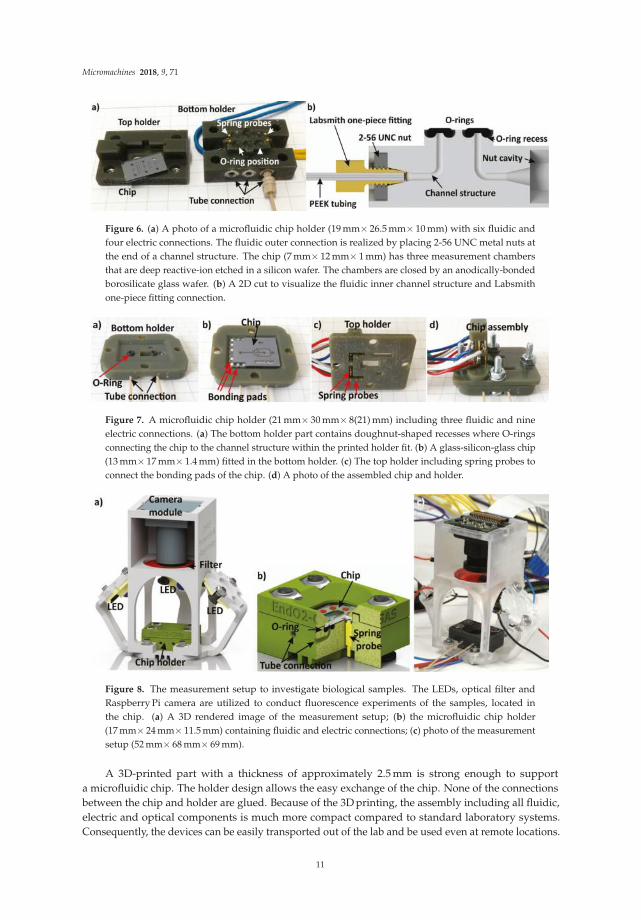
Figure 6. (a) A photo of a microfluidic chip holder (19 mm× 26.5 mm× 10 mm) with six fluidic andfour electric connections. The fluidic outer connection is realized by placing 2-56 UNC metal nuts atthe end of a channel structure. The chip (7 mm× 12 mm× 1 mm) has three measurement chambersthat are deep reactive-ion etched in a silicon wafer. The chambers are closed by an anodically-bondedborosilicate glass wafer. (b) A 2D cut to visualize the fluidic inner channel structure and Labsmithone-piece fitting connection.
Figure 7. A microfluidic chip holder (21 mm× 30 mm× 8(21) mm) including three fluidic and nineelectric connections. (a) The bottom holder part contains doughnut-shaped recesses where O-ringsconnecting the chip to the channel structure within the printed holder fit. (b) A glass-silicon-glass chip(13 mm× 17 mm× 1.4 mm) fitted in the bottom holder. (c) The top holder including spring probes toconnect the bonding pads of the chip. (d) A photo of the assembled chip and holder.
Figure 8. The measurement setup to investigate biological samples. The LEDs, optical filter andRaspberry Pi camera are utilized to conduct fluorescence experiments of the samples, located inthe chip. (a) A 3D rendered image of the measurement setup; (b) the microfluidic chip holder(17 mm× 24 mm× 11.5 mm) containing fluidic and electric connections; (c) photo of the measurementsetup (52 mm× 68 mm× 69 mm).
A 3D-printed part with a thickness of approximately 2.5 mm is strong enough to supporta microfluidic chip. The holder design allows the easy exchange of the chip. None of the connectionsbetween the chip and holder are glued. Because of the 3D printing, the assembly including all fluidic,electric and optical components is much more compact compared to standard laboratory systems.Consequently, the devices can be easily transported out of the lab and be used even at remote locations.
11

Micromachines 2018, 9, 71
The 3D printing of microfluidic chip holders brings high flexibility to research laboratories.When multiple parts are required, the fabrication can easily be up-scaled for small series production. One ofthe current drawbacks of 3D printing for mass production is the speed to fabricate devices. However,3D printing technology is evolving quite fast, and the printing speed is a parameter that is increasingrapidly. Two interesting 3D printing technologies have recently been presented. TNO (The Hague,The Netherlands) has developed a microstereolithography device (Lepus) that constructs up to 1200 layersper hour (30 mm/h at a resolution of 25 μm per layer). The light synthesis technology (CLIP) from Carbon(USA) yields printing speeds of 100–1000 mm/h [50,51]. This reduces the printing time by a factor ofa hundred. In the hearing aid industry [52], dentistry [53] and footwear industry [54], 3D printing hasalready evolved from a rapid prototyping technology into a manufacturing tool for mass production.
Other advantages of 3D printing that could revolutionize the manufacturing industry areon-demand direct fabrication of production parts stored in a digital library, customized productdesigns without additional cost, reduction of assembly work because structures of higher complexitycan be constructed from a single printed part and the reduction of logistic hassle because the storageof production parts can be reduced [55].
4. Conclusions
The given examples show that 3D printing is a versatile tool to realize microfluidic chip holders.The flexibility of 3D printing allows the quick redesign of chip holders and adaptation for other chipgeometries. Reliable chip and holder assembling is achieved by applying O-rings and spring probes toattach the fluid and electric connections. This solves the challenge of connecting fluidic and electricalparts of microfluidics to the outer world. When the 3D-printed structures are used in combination withbiological samples, cytotoxic effects due to resin components can be prevented by coating 3D-printedstructures with parylene-C.
The combination of silicon/glass microfluidic chips fabricated with highly-reliable clean-roomtechnology and 3D-printed chip holders for the chip-to-world connection is a promising solution forapplications where biocompatibility, optical transparency and accurate sample handling must be assured.
Acknowledgments: The authors would like to thank André Bödecker and Lukas Immoor for depositingparylene-C on the 3D-printed structures.
Author Contributions: The work presented in this paper was a collaboration of all authors. S.v.d.D., F.L. and F.B.designed and fabricated the devices. The biocompatibility tests, conducted by F.B., were designed by S.v.d.D., F.B.and M.J.V. The results were interpreted by S.v.d.D., F.L., F.B. and M.J.V. The manuscript was written by S.v.d.D.and discussed by all authors.
Conflicts of Interest: The authors declare no conflict of interest.
Abbreviations
The following abbreviations are used in this manuscript:
CLIP Continuous Liquid Interface ProductionDLP Digital Light ProcessingEPDM Ethylene Propylene Diene MonomerGMEM Glasgow Minimum Essential MediumMDCK Madin-Darby Canine KidneyPEEK Polyether Ether KetoneSTL Standard Tessellation Language
References
1. Vaezi, M.; Seitz, H.; Yang, S. A review on 3D micro-additive manufacturing technologies. Int. J. Adv.
Manuf. Technol. 2013, 67, 1721–1754.2. Waheed, S.; Cabot, J.M.; Macdonald, N.P.; Lewis, T.; Guijt, R.M.; Paull, B.; Breadmore, M.C. 3D printed
microfluidic devices: Enablers and barriers. Lab Chip 2016, 16, 1993–2013.
12

Micromachines 2018, 9, 71
3. He, Y.; Wu, Y.; Fu, J.Z.; Gao, Q.; Qiu, J.J. Developments of 3D printing microfluidics and applications inchemistry and biology: A review. Electroanalysis 2016, 28, 1658–1678.
4. Chen, C.; Mehl, B.T.; Munshi, A.S.; Townsend, A.D.; Spence, D.M.; Martin, R.S. 3D-printed microfluidicdevices: Fabrication, advantages and limitations—A mini review. Anal. Methods 2016, 8, 6005–6012.
5. Mao, M.; He, J.; Li, X.; Zhang, B.; Lei, Q.; Liu, Y.; Li, D. The emerging frontiers and applications ofhigh-resolution 3D printing. Micromachines 2017, 8, 113.
6. Xu, Y.; Wu, X.; Guo, X.; Kong, B.; Zhang, M.; Qian, X.; Mi, S.; Sun, W. The boom in 3D-printed sensortechnology. Sensors 2017, 17, 1166.
7. Krujatz, F.; Lode, A.; Seidel, J.; Bley, T.; Gelinsky, M.; Steingroewer, J. Additive Biotech—Chances, challenges,and recent applications of additive manufacturing technologies in biotechnology. New Biotechnol. 2017,39, 222–231.
8. Cumpston, B.H.; Ananthavel, S.P.; Barlow, S.; Dyer, D.L.; Ehrlich, J.E.; Erskine, L.L.; Heikal, A.A.;Kuebler, S.M.; Lee, I.Y.; McCord-Maughon, D.; et al. Two-photon polymerization initiators for three-dimensional optical data storage and microfabrication. Nature 1999, 398, 51–54.
9. Xing, J.F.; Zheng, M.L.; Duan, X.M. Two-photon polymerization microfabrication of hydrogels: An advanced3D printing technology for tissue engineering and drug delivery. Chem. Soc. Rev. 2015, 44, 5031–5039.
10. Niemöller, A.; Jakes, P.; Kayser, S.; Lin, Y.; Lehnert, W.; Granwehr, J. 3D printed sample holder for in-operandoEPR spectroscopy on high temperature polymer electrolyte fuel cells. J. Magn. Reson. 2016, 269, 157–161.
11. Hill, R.T.; Kozek, K.M.; Hucknall, A.; Smith, D.R.; Chilkoti, A. Nanoparticle–film plasmon ruler interrogatedwith transmission visible spectroscopy. ACS Photonics 2014, 1, 974–984.
12. Desmaison, A.; Lorenzo, C.; Rouquette, J.; Ducommun, B.; Lobjois, V. A versatile sample holder for singleplane illumination microscopy. J. Microsc. 2013, 251, 128–132.
13. Friedrichs, A.; Busch, J.; van der Woerd, H.; Zielinski, O. SmartFluo: A method and affordable adapter tomeasure chlorophyll a fluorescence with smartphones. Sensors 2017, 17, 678.
14. Cevenini, L.; Calabretta, M.M.; Tarantino, G.; Michelini, E.; Roda, A. Smartphone-interfaced 3D printedtoxicity biosensor integrating bioluminescent “sentinel cells”. Sens. Actuators B Chem. 2016, 225, 249–257.
15. Yafia, M.; Ahmadi, A.; Hoorfar, M.; Najjaran, H. Ultra-portable smartphone controlled integrated digitalmicrofluidic system in a 3D-printed modular assembly. Micromachines 2015, 6, 1289–1305.
16. Lücking, T.H.; Sambale, F.; Beutel, S.; Scheper, T. 3D-printed individual labware in biosciences by rapidprototyping: A proof of principle. Eng. Life Sci. 2015, 15, 51–56.
17. Shemelya, C.; Cedillos, F.; Aguilera, E.; Espalin, D.; Muse, D.; Wicker, R.; MacDonald, E. Encapsulated copperwire and copper mesh capacitive sensing for 3-D printing applications. IEEE Sens. J. 2015, 15, 1280–1286.
18. Plevniak, K.; Campbell, M.; Myers, T.; Hodges, A.; He, M. 3D printed auto-mixing chip enables rapidsmartphone diagnosis of anemia. Biomicrofluidics 2016, 10, 054113.
19. Bhargava, K.; Ermagan, R.; Thompson, B.; Friedman, A.; Malmstadt, N. Modular, discrete micromixerelements fabricated by 3D printing. Micromachines 2017, 8, 137.
20. Gong, H.; Bickham, B.P.; Woolley, A.T.; Nordin, G.P. Custom 3D printer and resin for 18 µm × 20 µmmicrofluidic flow channels. Lab Chip 2017, 17, 2899–2909.
21. Au, A.K.; Bhattacharjee, N.; Horowitz, L.F.; Chang, T.C.; Folch, A. 3D-printed microfluidic automation.Lab Chip 2015, 15, 1934–41.
22. Gong, H.; Woolley, A.T.; Nordin, G.P. High density 3D printed microfluidic valves, pumps, and multiplexers.Lab Chip 2016, 16, 2450–8.
23. Van den Driesche, S.; Bunge, F.; Lucklum, F.; Vellekoop, M.J. 3D-Printing: An attractive tool to realizemicrofluidic chip holders. In Proceedings of the 3rd International Conference on MicroFluidic HandlingSystems, Enschede, The Netherlands, 4–6 October 2017; pp. 94–97.
24. Oomen, P.; Mulder, J.; Verpoorte, E.; Oleschuk, R. Controlled, synchronized actuation of microdroplets bygravity in a superhydrophobic, 3D-printed device. Anal. Chim. Acta 2017, 988, 50–57.
25. Bhargava, K.C.; Thompson, B.; Malmstadt, N. Discrete elements for 3D microfluidics. Proc. Natl. Acad.
Sci. USA 2014, 111, 15013–15018.26. Paydar, O.; Paredes, C.; Hwang, Y.; Paz, J.; Shah, N.; Candler, R. Characterization of 3D-printed microfluidic
chip interconnects with integrated O-rings. Sens. Actuators A Phys. 2014, 205, 199–203.27. Alharbi, N.; Wismeijer, D.; Osman, R. Additive manufacturing techniques in prosthodontics: Where do we
currently stand? A critical review. Int. J. Prosthodont. 2017, 30, 474–484.
13
Micromachines 2018, 9, 71
28. Osman, R.B.; van der Veen, A.J.; Huiberts, D.; Wismeijer, D.; Alharbi, N. 3D-printing zirconia implants;a dream or a reality? An in-vitro study evaluating the dimensional accuracy, surface topography andmechanical properties of printed zirconia implant and discs. J. Mech. Behav. Biomed. Mater. 2017, 75, 521–528.
29. Bunge, F.; van den Driesche, S.; Vellekoop, M. Microfluidic platform for the long-term on-chip cultivation ofmammalian cells for lab-on-a-chip applications. Sensors 2017, 17, 1603.
30. Labsmith One-Piece Fitting. Available online: http://products.labsmith.com/one-piece-fitting (accessed on25 October 2017).
31. Buesink, W.; Heeren, H. Design Guideline for Microfluidic Side Connect. Available online: http://www.enablingmnt.co.uk/wp-content/uploads/2017/06/Design-Guidelines-for-Microfluidic-Side-Connect-version-1.0.pdf (accessed on 5 Februar 2018).
32. Bullema, J.E.; Heeren, H.; Buesink, W. Guidelines for Packaging of Microfluidics: ElectricalInterconnections. Available online: http://mf-manufacturing.eu/wp-content/uploads/Guidelines-for-Electrical-Interconnections-to-microfluidic-devices-version-1.0.pdf (accessed on 5 Februar 2018).
33. Heeren, H.; Atkins, T.; Verplanck, N.; Peponnet, C.; Hewkin, P.; Blom, M.; Buesink, W.;Bullema, J.E.; Dekker, S. Design Guideline for Microfluidic Device and Component Interfaces(Part 1). Available online: http://www.enablingmnt.co.uk/wp-content/uploads/2016/05/Design-for-Microfluidic-Interfacing-White-Paper-part-1-version-2.pdf (accessed on 5 Februar 2018).
34. Heeren, H.; Atkins, T.; Verplanck, N.; Peponnet, C.; Hewkin, P.; Blom, M.; Buesink, W.;Bullema, J.E.; Dekker, S. Design Guideline for Microfluidic Device and Component Interfaces (Part 2).Available online: http://www.enablingmnt.co.uk/wp-content/uploads/2017/06/Design-for-Microfluidic-Interfacing-White-Paper-part-2-version-3.0.pdf (accessed on 5 Februar 2018).
35. Guckenberger, D.J.; de Groot, T.E.; Wan, A.M.D.; Beebe, D.J.; Young, E.W.K. Micromilling: A method forultra-rapid prototyping of plastic microfluidic devices. Lab Chip 2015, 15, 2364–2378.
36. Bhattacharjee, N.; Urrios, A.; Kang, S.; Folch, A. The upcoming 3D-printing revolution in microfluidics.Lab Chip 2016, 16, 1720–1742.
37. Sun, C.; Fang, N.; Wu, D.; Zhang, X. Projection micro-stereolithography using digital micro-mirror dynamicmask. Sens. Actuators A Phys. 2005, 121, 113–120.
38. EnvisionTec HTM140 Resin. Available online: https://envisiontec.com/wp-content/uploads/2016/09/2018-HTM-140-V2-1.pdf (accessed on 25 October 2017).
39. EnvisionTec E-Shell 300 Resin. Available online: https://envisiontec.com/wp-content/uploads/2016/09/2018-E-Shell-300-Series.pdf (accessed on 26 January 2018).
40. Kip, S.N.; Strehler, E.E. Characterization of PMCA isoforms and their contribution to transcellular Ca2+ fluxin MDCK cells. Am. J. Physiol. Ren. Physiol. 2003, 284, F122–F132.
41. Rehders, M.; Grosshäuser, B.B.; Smarandache, A.; Sadhukhan, A.; Mirastschijski, U.; Kempf, J.; Dünne, M.;Slenzka, K.; Brix, K. Effects of lunar and mars dust simulants on HaCaT keratinocytes and CHO-K1fibroblasts. Adv. Space Res. 2011, 47, 1200–1213.
42. Parylene Coating . Available online: https://www.plasmaparylene.de/en/parylene-coating/parylene-rosenheim.php (accessed on 5 February 2018).
43. ISO 10993-6:2016, Biological Evaluation of Medical Devices—Part 6: Tests for Local Effects after Implantation.Available online: https://www.iso.org/standard/61089.html (accessed on 5 February 2018).
44. Chang, T.Y.; Yadav, V.G.; De Leo, S.; Mohedas, A.; Rajalingam, B.; Chen, C.L.; Selvarasah, S.; Dokmeci, M.R.;Khademhosseini, A. Cell and protein compatibility of parylene-C surfaces. Langmuir 2007, 23, 11718–11725.
45. Schmelzer, E.; Over, P.; Gridelli, B.; Gerlach, J.C. Response of primary human bone marrow mesenchymalstromal cells and dermal keratinocytes to thermal printer materials in vitro. J. Med. Biol. Eng. 2016,36, 153–167.
46. Stratasys MED610 Resin. Available online: http://www.stratasys.com/de/materials/search/biocompatible(accessed on 29 January 2018).
47. Akhtar, M.; van den Driesche, S.; Bödecker, A.; Vellekoop, M.J. Long-term storage of droplets on a chip byParylene AF4 coating of channels. Sens. Actuators B Chem. 2018, 255, 3576–3584.
48. Van den Driesche, S.; Bunge, F.; Tepner, S.; Kotitschke, M.; Vellekoop, M.J. Travelling-wave dielectrophoresisallowing flexible microchannel design for suspended cell handling. Proc. SPIE 2017, 10247, 102470H.
14

Micromachines 2018, 9, 71
49. Bunge, F.; van den Driesche, S.; Waite, A.; Mirastschijski, U.; Vellekoop, M.J. μRespirometer to determinethe oxygen consumption rate of mammalian cells in a microfluidic cell culture. In Proceedings of the 2017IEEE 30th International Conference onMicro Electro Mechanical Systems (MEMS), Las Vegas, NV, USA,22–26 January 2017; pp. 414–417.
50. TNO–Improved Stereolithography. Available online: https://www.tno.nl/en/focus-areas/industry/roadmaps/flexible-free-form-products/additive-manufacturing/improved-micro-stereolithography/(accessed on 5 February 2018).
51. Tumbleston, J.R.; Shirvanyants, D.; Ermoshkin, N.; Janusziewicz, R.; Johnson, A.R.; Kelly, D.; Chen, K.;Pinschmidt, R.; Rolland, J.P.; Ermoshkin, A.; et al. Continuous liquid interface production of 3D objects.Science 2015, 347, 1349–1352.
52. Sandström, C.G. The non-disruptive emergence of an ecosystem for 3D Printing—Insights from the hearingaid industry’s transition 1989–2008. Technol. Forecast. Soc. Chang. 2016, 102, 160–168.
53. Dawood, A.; Marti, B.M.; Sauret-Jackson, V.; Darwood, A. 3D printing in dentistry. Br. Dent. J. 2015,219, 521–529.
54. Jones, D.; Larson, R. Footwear Assembly Method with 3D Printing. U.S. Patent 9,005,710, 14 April 2015.55. Weller, C.; Kleer, R.; Piller, F.T. Economic implications of 3D printing: Market structure models in light of
additive manufacturing revisited. Int. J. Prod. Econ. 2015, 164, 43–56.
© 2018 by the authors. Licensee MDPI, Basel, Switzerland. This article is an open accessarticle distributed under the terms and conditions of the Creative Commons Attribution(CC BY) license (http://creativecommons.org/licenses/by/4.0/).
15

micromachines
Article
Microfluidics: A New Layer of Control forExtrusion-Based 3D Printing
Ludovic Serex *, Arnaud Bertsch and Philippe Renaud
EPFL STI IMT LMIS4, Station 17, CH-1015 Lausanne, Switzerland; [email protected] (A.B.);[email protected] (P.R.)* Correspondence: [email protected]; Tel.: +41-21-69-36728
Received: 1 February 2018; Accepted: 15 February 2018; Published: 16 February 2018
Abstract: Advances in 3D printing have enabled the use of this technology in a growing numberof fields, and have started to spark the interest of biologists. Having the particularity of being cellfriendly and allowing multimaterial deposition, extrusion-based 3D printing has been shown to bethe method of choice for bioprinting. However as biologically relevant constructs often need to beof high resolution and high complexity, new methods are needed, to provide an improved level ofcontrol on the deposited biomaterials. In this paper, we demonstrate how microfluidics can be usedto add functions to extrusion 3D printers, which widens their field of application. Micromixers canbe added to print heads to perform the last-second mixing of multiple components just before resindispensing, which can be used for the deposition of new polymeric or composite materials, as well asfor bioprinting new materials with tailored properties. The integration of micro-concentrators in theprint heads allows a significant increase in cell concentration in bioprinting. The addition of rapidmicrofluidic switching as well as resolution increase through flow focusing are also demonstrated.Those elementary implementations of microfluidic functions for 3D printing pave the way for morecomplex applications enabling new prospects in 3D printing.
Keywords: micro-fluidic; additive manufacturing; 3D printing; bio-printing; lab on a tip
1. Introduction
Three-dimensional (3D) printing, also commonly referred to as additive manufacturing or rapidprototyping, is a set of techniques that consist in building 3D parts layer by layer. This fabricationprinciple dates from the early 1980s [1] and has seen a number of different implementations basedon the use of multiple deposition techniques [2]. While photopolymers and thermoplastic polymerswere initially used in 3D printing techniques, the choice of materials that can be used has beensignificantly widened, and includes metals [3,4], ceramics [5] and biomaterials [6–11]. Current researchin this field includes the development of “smart materials” [12,13] that can evolve with time andbring additional functions to the fabricated objects. If 3D printing was first used for automotive andaerospace applications [14,15], many other application fields currently use these techniques, includingmedical application [16–19], tissue enginering [20–24], biosensors [25], microfabrication [26,27] or evenconstruction [28] and the food industry [29]. With hobbyists now having access to 3D printing, it islikely that its field of applications will expand even more.
Among these 3D printing methods, stereolithography (SLA) and extrusion based system dominatethe market. SLA is known for its very high resolution [30], but is subject to limitations directly relatedto the process itself, such as the limited biocompatibility of the materials that can be used (often linkedto the use of photoinitiators) and the very challenging implementation of multi-material printingmachines. On the other hand, extrusion-based processes are increasingly popular [31] as they arerelatively cheap and easy to use. However, this printing technique suffers from its limited number
Micromachines 2018, 9, 86; doi:10.3390/mi9020086 www.mdpi.com/journal/micromachines16

Micromachines 2018, 9, 86
of printable materials: only low melting temperature materials such as ABS for fused depositionmodeling or fast crosslinking materials for bio-printing can be used. Additionally, in recent years,the need for smarter dispensing tools has emerged, in particular in the field of bioprinting to answerthe need to print complex materials for cells [32–34]. As the field increasingly aims toward regenerativemedicine [9,35–37]. A few implementations of such smart dispensing tools have been already presentedin the literature, such as print heads made from needles used for manufacturing perfusable vascularconstructs [38]. To further overcome this limitation, extrusion-based 3D printing can benefit from morecomplex microfluidic systems, which can implement a number of fluidic manipulation functions at themicro-scale. Microfluidics has seen major developments in recent years, and has contributed to theemergence of the concept of “Lab on a chip” by allowing the implementation of many fluidic functionssuch as micro-mixers [39–41], switching valve [42–44], flow focusing [45], particles focusing [46–48],in-channel detection [49] or particles and cell sorting [49–52] in compact, microfabricated devices.
Up until now, these functionalities have mainly been used on chip to perform various analysis.In this paper, we propose to exploit the potential of microfluidics to develop a “lab on a tip” that couldperform various operations on the dispensing solution directly in the print head of the 3D printer.Using this principle, we demonstrate multiple smart printing heads that allow the use of new materials,enhance the print resolution, or allow the printing of composite parts or multi-material parts that wereonly possible using expensive 3D printing techniques.
2. Materials and Methods
2.1. Probe Fabrication
All the print head dispensing tips that are presented in this paper were manufacture in a similar wayusing specific microchannel designs depending on the targeted application. A 500 nm SiO2 layer is firstgrown by wet oxidation on a single-side polished silicon wafer. Standard photolithography is performedto pattern the fluidic channels and the silicon oxide is etched to create a hard mask. In the case of theherringbone mixer presented in Section 3.3, which requires a two-level microchannel to be manufactured,an additional photoresist mask, silicon etching and resist striping is performed as described in the previousliterature [39]. Then, the channels are etched to 300 µm in depth using deep reactive ion etching, and thetop-layer oxide is etched away as well to expose the silicon for anodic bonding. Next, a borofloat® 33 glasswafer is mechanically drilled to create the probes inlets. The two wafers are cleaned with a piranha solutionand bonded by anodic bonding. The wafer stack is then diced, revealing the dispensing outlet in a similarfashion as described in the previous literature [53].
2.2. 3D Printer Setup
The printer setup is similar to the one presented in previous work [53]. A DLT-180, Double Delta 3Dprinter has been purchased from He3D and adapted to fit the fabricated probes. The printing path andspeed was either hard-coded in G-code or automatically generated using a slicer as is usually done forstandard 3D printing.
3. Results
In this section we present four different probes that can perform specific tasks. Those probesdemonstrate how microfluidics can be implemented to improve extrusion-based 3D printing in termsof printed materials, resolution or material switching.
3.1. Multi-Material
One limitation of extrusion-based 3D printers is that each print head can only print a single material.Printing an object made of multiple materials is usually achieved by using a 3D printing machine withmultiple extrusion heads placed next to each other. By switching between print heads, different materialscan then be printed [54]. In addition to requiring specific equipment, printing multi-material components
17

Micromachines 2018, 9, 86
with extrusion-based 3D printers is generally a very slow process, and a smooth transition between printedmaterials is not always guaranteed. A number of microfluidic systems allowing switching between differentliquids have already been presented in the literature, including some that could be implemented in 3Dprinters [44]. Here, we will show a very simple system that is easy to implement and allows a fast switchingbetween materials.
The print head we designed is composed of three micro-channels merging into one right beforethe ejection point, as presented in Figure 1A. Each of these three channels can be connected to a syringecontaining a different material and actuated by a syringe pump. By choosing the sequence of actuationof the syringe pumps and synchronizing it with the geometry of the part being built, a seamlesstransition between multiple materials can be achieved during the object manufacturing process.Furthermore, as microfluidic benefits from very small dead volumes, it is possible to rapidly switchbetween materials. In our case, a complete transition between two materials can be performed in500 ms, as presented in Figure 1B, where the transition between different colored liquids was recordedusing a camera connected to a microscope focused at the tip of the print head we used.
The print head was then mounted on a 3D printer, and colored alginate solutions were printed onan agarose 4% and CaCl2 1% bed, inducing the alginate gelation by diffusion of the calcium ions intothe alginate deposit. Figure 1C shows the smooth transition between colors obtained as the printingprocess goes.
By combining extrusion 3D printing with ultraviolet (UV) light irradiation of the printed layers,it is possible to print and crosslink photosensitive inks using the same print head based on mergingmicrochannels. Thus, multimaterial components can be made by the extrusion method by selectingphotosensitive resins having the desired properties, chosen from the large catalogue of materials developedfor the stereolithography process. As an example, we used Formlabs resins RS-F2-GPCL-04 (whichresults in a transparent and rigid material once cured), RS-F2-GPWH-04 (which is a white resin) andRS-F2-GPBK-04 (which is a black resin). By switching between these resins, we were able to print multicolorparts, as shown in Figure 1D. Formlabs also developed a flexible resin (RS-F2-GPGR-02). By alternatingrigid and flexible areas, we can create parts with varying Young’s moduli. In this example, a two-hingepart was printed (Figure 1E).
Figure 1. Multi-channel print head. (A) Schematic of the microfluidic channel design. (B,C) Switchingof three colored liquids as recorded at the tip of the print head. (D) Clear, white and black part.(E) Two-hinges part printed with two different inks (one rigid and one flexible). All scale barscorrespond to 1 cm.
18

Micromachines 2018, 9, 86
Switching between two different materials can be performed in a cleaner and faster way that theone used in the very simple multi-channel print head presented in Figure 1, for example by usingactuated virtual valves similar to the ones presented by Braschler et al. [42]; however, this methodinduces the waste of larger amounts of printing material, which can be a problem.
In the examples we presented, the materials were deposited alternately one after the other,using microfluidic switching, but multiplexing can also be implemented directly in the print head,allowing the alternation of materials both laterally and during printing. Microfluidic devicescapable of performing such types of multiplexing have been demonstrated in Lab on Chips,using polydimethylsiloxane (PDMS) as structural material, as it allows a simple fabrication andactuation of valves, but its use in print heads for 3D printing may be limited, as the flexibility of PDMSwould limit the extrusion pressure [55].
3.2. Enhanced Resolution
Microfluidic flows present a laminar behavior [45]. This property can be exploited to changethe resolution of the printed material by focusing it while it is dispensed using sheath flows [25].Hydrodynamic focusing only requires a very rudimentary microfluidic setup, the most commonconfiguration being a 3-channel device, where the center flow stream is pinched between two side flowstreams, resulting in a shrinking of the width of the center flow. Implementing hydrodynamic focusingin the print head of an extrusion-based 3D printer, its resolution can be not only be significantlyincreased, but it can be adjusted while printing by simply varying the ratio between the core andlateral flows. Figure 2A demonstrates the principle of sheath flow. Alginate filaments (in blue) arefocused using de-ionized (DI) water with 4% CaCl2. Depending on the ratio of the alginate core flowto the CaCl2 solution sheath flow (Figure 2B), the obtained filaments can vary in diameter from 800 µmto below 200 µm, providing a fivefold resolution increase. Figure 2C shows the evolution of the size ofthe deposited filaments as a function of the ratio between sheath and core flows.
One issue of the use of sheath flows for increasing the printing resolution is the fact that the liquidused in the sheath flow for focusing is also “printed” alongside the actual material of interest. In ourexample, using a water-based solution, large quantities of water are ejected from the probe and maydisrupt the printing. On Figure 2D, a printed filament with changing diameter is presented. The firstsection of the filament is small and soaked in the sheath flow that will ultimately dry. The filamentthen widens and the surplus of liquid produced by the sheath flow becomes almost nonexistent as it isreduced to a minimum. To solve the problem of residual fluid, Perfluoro(methyldecalin) (PFD) wasused as sheath flow. Given that it is a highly volatile material, it will quickly evaporate, leaving onlythe desired focused filament. One limitation of this technique is that when the sheath flow becomesmuch larger than the core flow, flow instabilities occur, limiting the use of hydrodynamic focusingfor enhancing the resolution of the dispensed material. In this case, there is always the possibility ofreducing the dimensions of the microfabricated channels provided on the print head for improvingthe resolution. However, this implies the use of larger values of pressure to drive the various liquids inthe microchannels. Furthermore, it is important to note that as liquids are being printed, the tuning ofthe printed filament through flux control of the core flow only without flow focusing can be achieved.With a constant printing speed, an increase of the flux will result in a larger printed filament (Figure 2E).This presents the advantage of not having residual liquid from the sheath flow, but the crosslinkingmust be performed from the probe either by UV light or, in this case, by printing alginate on a CaCl2bed, which is not suitable for high structures.
Adjusting the printer resolution on the fly opens new ways of controlling the printed part.It would thus be possible to choose the resolution depending on the importance of the part beingprinted while printing. This methods allows the printing of coarse filament for the filling of the printedpart, while at the same time, for the wall, the filament can be refined to obtain fast and precise printing.
19

Micromachines 2018, 9, 86
Figure 2. Print head based on flow focusing. (A) Principle of hydrodynamic flow focusing with thecore flow in blue and the sheath flow in white. (B) Flow focusing at different sheath flow/core flowratios (R). (C) Printed fiber diameter as a function of the flow ratio. (D) Printed filament going fromsmall filament (1) to large filament (2) whilst the ratio R is changed. (E) First layer of a printed partwith fine edge (1) and coarse filling (2). Scale bars = 5 mm.
3.3. New Materials
Laminar flows have the particularity that they do not mix easily, as turbulence does not occurin this flow regime. Mixing relies solely on the diffusion phenomenon, which can be enhanced bysplitting and rearranging the flow using a mixer. Many micro-mixers [41] have been devised formicrofluidic applications; of these static micro-mixers have the advantage of being passive structuresthat provide efficient mixing in laminar conditions and that can be integrated directly in the print headnozzles used for 3D printing.
In a previous work, we demonstrated the use of a meander-based static micro-mixer forperforming the mixing of slow reacting materials used to 3D print carboxymethylcellulose-basedcryogels [53]. A micro-fabricated dispensing print head allowing both the last-second mixing ofcryogel precursors and the temperature control of the extruded material during printing was used.This allowed the 3D printing of multi-layer cryogels with on-demand local pore size change throughthe control in temperature of the dispensed solution. The seeding and culture of cells in specific areasof the obtained 3D cryogel structure was also demonstrated after its functionalization.
There are, however, static mixers much more efficient than meander-based micro-mixers.Herrigbone mixers [39] still remain to this day among the most efficient static micro-mixers,but their manufacturing using microfabrication technologies is slightly more complicated than thatof meander-based mixers, as they are two-level structures and require a larger number of fabricationsteps. By implementing herringbone micro-mixers at the tip of a dispensing print head, even viscousmaterials can be mixed in structures of only a few millimeters in length. This principle is demonstratedin Figure 3A, where colored glycerol streams (in blue and white) are pushed through two three-inlet
20
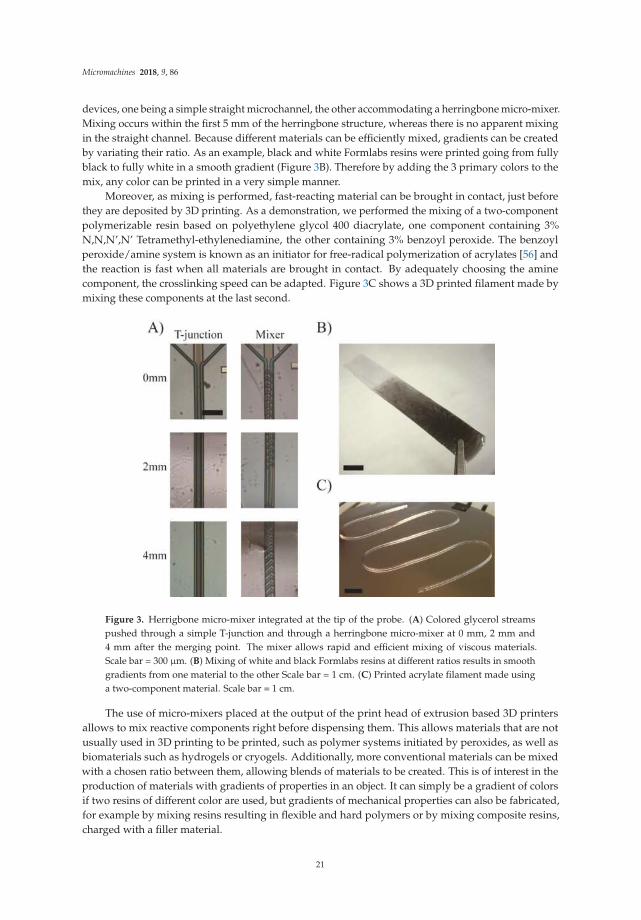
Micromachines 2018, 9, 86
devices, one being a simple straight microchannel, the other accommodating a herringbone micro-mixer.Mixing occurs within the first 5 mm of the herringbone structure, whereas there is no apparent mixingin the straight channel. Because different materials can be efficiently mixed, gradients can be createdby variating their ratio. As an example, black and white Formlabs resins were printed going from fullyblack to fully white in a smooth gradient (Figure 3B). Therefore by adding the 3 primary colors to themix, any color can be printed in a very simple manner.
Moreover, as mixing is performed, fast-reacting material can be brought in contact, just beforethey are deposited by 3D printing. As a demonstration, we performed the mixing of a two-componentpolymerizable resin based on polyethylene glycol 400 diacrylate, one component containing 3%N,N,N’,N’ Tetramethyl-ethylenediamine, the other containing 3% benzoyl peroxide. The benzoylperoxide/amine system is known as an initiator for free-radical polymerization of acrylates [56] andthe reaction is fast when all materials are brought in contact. By adequately choosing the aminecomponent, the crosslinking speed can be adapted. Figure 3C shows a 3D printed filament made bymixing these components at the last second.
Figure 3. Herrigbone micro-mixer integrated at the tip of the probe. (A) Colored glycerol streamspushed through a simple T-junction and through a herringbone micro-mixer at 0 mm, 2 mm and4 mm after the merging point. The mixer allows rapid and efficient mixing of viscous materials.Scale bar = 300 µm. (B) Mixing of white and black Formlabs resins at different ratios results in smoothgradients from one material to the other Scale bar = 1 cm. (C) Printed acrylate filament made usinga two-component material. Scale bar = 1 cm.
The use of micro-mixers placed at the output of the print head of extrusion based 3D printersallows to mix reactive components right before dispensing them. This allows materials that are notusually used in 3D printing to be printed, such as polymer systems initiated by peroxides, as well asbiomaterials such as hydrogels or cryogels. Additionally, more conventional materials can be mixedwith a chosen ratio between them, allowing blends of materials to be created. This is of interest in theproduction of materials with gradients of properties in an object. It can simply be a gradient of colorsif two resins of different color are used, but gradients of mechanical properties can also be fabricated,for example by mixing resins resulting in flexible and hard polymers or by mixing composite resins,charged with a filler material.
21

Micromachines 2018, 9, 86
3.4. Concentration
In the previous paragraphs, print heads based on very simple microfluidic components werepresented; however, microfabrication techniques can be used to manufacture much more complexstructures. In this paragraph, we demonstrate a print head allowing the concentration of particlesin solution, which can be used to increase the filler concentration of a composite resin just beforeit is printed or to concentrate cells in bioprinting. Figure 4A shows a schematic of the print head.A solution containing particles or cells enters the device by the inlet and flows in a straight channelequipped with a crossflow filter towards the outlet. This crossflow filter allows some of the liquidto be withdrawn between inlet and outlet simply by adequately imposing the flows both at the inletand the waste outlet, thus concentrating the particles in solution. The extracted liquid is removedfrom the device through the waste outlet, while the concentrated solution is 3D printed. To separatemicrometric-sized particles, the crossflow filter must feature small openings. This is made by a seriesof 50 µm tall, 2 µm wide pillars with a 4 µm pitch, as shown in Figure 4B. This structure is fabricated ina single etching step. Figure 4C–E demonstrates the concentration of a solution containing 8 µm beads.
Figure 4. Crossflow filter for particle concentration. (A) Schematic of the print head. (B) Scanningelectron micrograph of the crossflow filter. (C–E) Concentration of 8µm beads by adjusting thewithdrawing factor. Scale bar = 250 µm.
Concentrating particles in solution before their being dispensed by 3D printing can findapplications in various fields. It is known that the concentration of particles in composite materials isa major factor in their physical properties [57]. With the device we presented, the physical propertiesof the printed composites could be changed during printing. This is of particular interest when highconcentrations of filler material need to be present in the printed material, making it very viscous.Concentrating the particles in a composite material at the last second when printing makes it possible towork with diluted (thus of low viscosity) solutions for the whole process and still produce compositesof the desired composition, removing the excess liquid just before dispensation.
22

Micromachines 2018, 9, 86
Concentrating cells in solution is of even bigger interest in the field of bio-printing, as intercellularcommunications rely heavily on intercellular distance [58], and thus on the cell concentration. However,working with high concentrations of cells in bioprinting is often inappropriate, as a large quantity ofcells would be lost in pipes and other dead volumes, and the cells would be subjected to large shearforces because of the high viscosity of the solution. In general bioprinting techniques use solutionscontaining roughly 1 million cells per milliliter of solution, which results in cell-laden gels containinga cell concentration orders of magnitude lower than in native tissue [56].
By concentrating the cell right at the tip of the printer, it is possible to print tissue with biologicallyrelevant cell concentration, without wasting large numbers of cells in dead volumes or subjecting themto high shear stress.
4. Discussion
Stereolithography and extrusion-based 3D printing are the most commonly used additivemanufacturing techniques. Extrusion-based techniques are easy to use and are cost effective, but haveseen almost no improvement in terms of process development since their creation. On the contrary,microfluidic techniques have seen major developments in terms of device design and fabrication,and these developments can now be applied to significantly improve the print heads of extrusion-based3D printers.
In this paper, we explored the integration of four relatively simple microfluidic systems at thetip of the print head of extrusion-based 3D printers to create smart dispensing tools that can performdifferent functions right before printing. The integration of additional functions to print heads is ofparticular importance for bioprinting applications. We demonstrated fast switching between two ormore materials to create multimaterial parts, but when applied to bioprinting, it can be used to switchbetween the different cell types needed in a cell co-culture. Enhancing the printing resolution usingsheath flows can also be used for centering cells inside hydrogel filaments. Micro-mixers can be usedto prepare hydrogels or cryogels from their components, to insert cells into the printing medium or tocreate gradients of composition or of cell types while printing. Concentration using crossflow filtersmakes it possible to reach cell concentrations close to native tissue without adverse effects duringtheir manipulation.
Thanks to microfabrication, more complex functions can also be integrated in the print heads,taking advantage of all the knowledge available in the field of Lab on Chip devices, but suchdevelopments would probably have precise needs in terms of specific applications. For example,combining fluidic functions with in-channel spectroscopy could provide continuous feedback on theprinted material quality, implementing dielectrophoresis electrodes could be used for filtering particlesand cells and could make it possible to print only the viable cells, and detecting the passage of cells ofinterest while they flow through the microchannels and filtering out the excess of liquid medium couldmake it possible to print each cell at a precisely chosen location. Many other microfluidic functionscan be integrated, such as fast switching valves, digital microfluidic, microfluidic gradient generators,cell concentrator or micro-heaters, each bringing the potential of using new materials and developingnew applications for extrusion-based 3D printing.
The integration of customized microfluidic functions into the print heads of 3D printers has thepotential to be a game changer in fields where additive manufacturing is used, and in particular forbioprinting. Compared to more conventional 3D printing, there is an additional level of complexityinvolved when making biological constructs out of different types of cells and scaffold materials,and the use of cells in bioprinting applications requires more care than the usual materials used inadditive manufacturing techniques. Bioprinting is often described as the key development to gotowards artificial organs and engineered biological tissues, but to obtain the level of complexity neededto form such complex cell constructs, major improvements in 3D printing techniques are needed,and one of the keys to achieving this is clearly the integration of microfluidic functions into print heads.
23

Micromachines 2018, 9, 86
5. Conclusions
New opportunities generally arise when merging different technologies, and the present paperattempts to show the value of bringing microfluidics closer to extrusion-based 3D printing techniques.By applying some concepts developed over the years for Lab on Chip applications to create smart printheads, we tried to open the way and demonstrate improved dispensing functionalities. Four differentmicrofluidic functions were implemented at the tip of print heads: Micro-mixers were used to mixreactive components before dispensing and to blend materials with varying ratios. Sheath flowswere implemented to improve the print resolution. Fast switching was demonstrated to createmultimaterial components and crossflow filtration was shown to concentrate particles or cells inthe deposited material. By using microfluidic functions in the world of 3D printing, an additional layerof control can be added, enabling the fabrication of components that were impossible to print before.This methodology can be scaled, and has the potential to revolutionize the way we print, in particularin the field of bioprinting, where new challenges need to be faced in going towards the fabrication ofengineered 3D biological tissues.
Acknowledgments: The authors of the paper would like to acknowledge the staff of the EPFL center ofmicronanotechnology for their support in the cleanrooms as well as Matthieu Rüegg for his help.
Author Contributions: Ludovic Serex conceived, designed and performed the experiments. Arnaud Bertschdesigned the chemistry of the printed media. Ludovic Serex and Arnaud Bertsch wrote the paper. Researchdiscussions were executed by all authors.
Conflicts of Interest: The authors confirm that there are no known conflict of interest associated with thispublication and there has been no significant financial support for this work that could have influenced its outcome.
References
1. Kodama, H. Automatic method for fabricating a threedimensional plastic model with photo hardeningpolymer. Rev. Sci. Instrum. 1981, 52, 1770–1773. [CrossRef]
2. Gibson, I.; Rosen, D.; Stucker, B. Additive Manufacturing Technologies. In Additive Manufacturing Technologies,2nd ed.; 3D Printing, Rapid Prototyping, and Direct Digital Manufacturing; Springer: Berlin, Germay, 2015.[CrossRef]
3. Todd, I. Metallurgy: Printing steels. Nat. Mater. 2017, 17, 13–14. [CrossRef] [PubMed]4. Sames, W.J.; List, F.A.; Pannala, S.; Dehoff, R.R.; Babu, S.S. The metallurgy and processing science of metal
additive manufacturing. Int. Mater. Rev. 2016, 61, 315–360. [CrossRef]5. Eckel, Z.C.; Zhou, C.; Martin, J.H.; Jacobsen, A.J.; Carter, W.B.; Schaedler, T.A. Additive manufacturing of
polymer-derived ceramics. Science 2016, 351, 58–62. [CrossRef] [PubMed]6. Hockaday, L.A.; Kang, K.H.; Colangelo, N.W.; Cheung, P.Y.C.; Duan, B.; Malone, E.; Wu, J.; Girardi, L.N.;
Bonassar, L.J.; Lipson, H.; et al. Rapid 3D printing of anatomically accurate and mechanically heterogeneousaortic valve hydrogel scaffolds. Biofabrication 2012, 4, 035005. [CrossRef] [PubMed]
7. Jang, J.; Park, J.Y.; Gao, G.; Cho, D.W. Biomaterials-based 3D cell printing for next-generation therapeuticsand diagnostics. Biomaterials 2018, 156, 88–106. [CrossRef] [PubMed]
8. Murphy, S.V.; Atala, A. 3D bioprinting of tissues and organs. Nat. Biotechnol. 2014, 32, 773–785. [CrossRef][PubMed]
9. Hospodiuk, M.; Dey, M.; Sosnoski, D.; Ozbolat, I.T. The bioink: A comprehensive review on bioprintablematerials. Biotechnol. Adv. 2017, 35, 217–239. [CrossRef] [PubMed]
10. Kolesky, D.B.; Homan, K.A.; Skylar-Scott, M.A.; Lewis, J.A. Three-dimensional bioprinting of thickvascularized tissues. Proc. Natl. Acad. Sci. USA 2016, 113, 3179–3184. [CrossRef] [PubMed]
11. Pataky, K.; Braschler, T.; Negro, A.; Renaud, P.; Lutolf, M.P.; Brugger, J. Microdrop Printing of HydrogelBioinks into 3D Tissue-Like Geometries. Adv. Mater. 2012, 24, 391–396. [CrossRef] [PubMed]
12. Sydney Gladman, A.; Matsumoto, E.A.; Nuzzo, R.G.; Mahadevan, L.; Lewis, J.A. Biomimetic 4D printing.Nat. Mater. 2016, 15, 413–418. [CrossRef] [PubMed]
13. Khoo, Z.X.; Teoh, J.E.M.; Liu, Y.; Chua, C.K.; Yang, S.; An, J.; Leong, K.F.; Yeong, W.Y. 3D printing of smartmaterials: A review on recent progresses in 4D printing. Virtual Phys. Prototyp. 2015, 10, 103–122. [CrossRef]
24

Micromachines 2018, 9, 86
14. Guo, N.; Leu, M.C. Additive manufacturing: Technology, applications and research needs. Front. Mech. Eng.
2013, 8, 215–243. [CrossRef]15. Chu, M.Q.; Wang, L.; Ding, H.Y.; Sun, Z.G. Additive Manufacturing for Aerospace Application.
Appl. Mech. Mater. 2015, 798, 457–461. [CrossRef]16. Prasad, L.K.; Smyth, H. 3D Printing technologies for drug delivery: A review. Drug Dev. Ind. Pharm. 2016,
42, 1019–1031. [CrossRef] [PubMed]17. Bose, S.; Ke, D.; Sahasrabudhe, H.; Bandyopadhyay, A. Additive Manufacturing of Biomaterials.
Prog. Mater. Sci. 2017, 93, 45–111. [CrossRef]18. Davia-Aracil, M.; Hinojo-Pérez, J.J.; Jimeno-Morenilla, A.; Mora-Mora, H. 3D printing of functional
anatomical insoles. Comput. Ind. 2018, 95, 38–53. [CrossRef]19. Rengier, F.; Mehndiratta, A.; Von Tengg-Kobligk, H.; Zechmann, C.M.; Unterhinninghofen, R.; Kauczor, H.U.;
Giesel, F.L. 3D printing based on imaging data: Review of medical applications. Int. J. Comput. Assist.
Radiol. Surg. 2010, 5, 335–341. [CrossRef] [PubMed]20. Zhang, Y.S.; Yue, K.; Aleman, J.; Mollazadeh-Moghaddam, K.; Bakht, S.M.; Yang, J.; Jia, W.; Dell’Erba, V.;
Assawes, P.; Shin, S.R.; et al. 3D Bioprinting for Tissue and Organ Fabrication. Ann. Biomed. Eng. 2017,45, 148–163. [CrossRef] [PubMed]
21. Wu, Z.; Su, X.; Xu, Y.; Kong, B.; Sun, W.; Mi, S. Bioprinting three-dimensional cell-laden tissue constructswith controllable degradation. Sci. Rep. 2016, 6, 24474. [CrossRef] [PubMed]
22. Dvir-Ginzberg, M.; Gamlieli-Bonshtein, I.; Agbaria, R.; Cohen, S. Liver tissue engineering within alginatescaffolds: Effects of cell-seeding density on hepatocyte viability, morphology, and function. Tissue Eng. 2003,9, 757–766. [CrossRef] [PubMed]
23. Zadpoor, A.A.; Malda, J. Additive Manufacturing of Biomaterials, Tissues, and Organs. Ann. Biomed. Eng.
2017, 45, 1–11. [CrossRef] [PubMed]24. Roth, E.A.; Xu, T.; Das, M.; Gregory, C.; Hickman, J.J.; Boland, T. Inkjet printing for high-throughput cell
patterning. Biomaterials 2004, 25, 3707–3715. [CrossRef] [PubMed]25. Lind, J.U.; Busbee, T.A.; Valentine, A.D.; Pasqualini, F.S.; Yuan, H.; Yadid, M.; Park, S.J.; Kotikian, A.;
Nesmith, A.P.; Campbell, P.H.; et al. Instrumented cardiac microphysiological devices via multimaterialthree-dimensional printing. Nat. Mater. 2017, 16, 303–308. [CrossRef] [PubMed]
26. Vaezi, M.; Seitz, H.; Yang, S. A review on 3D micro-additive manufacturing technologies. Int. J. Adv.
Manuf. Technol. 2013, 67, 1721–1754. [CrossRef]27. Au, A.K.; Huynh, W.; Horowitz, L.F.; Folch, A. 3D-Printed Microfluidics. Angew. Chem. Int. Ed. 2016,
55, 3862–3881. [CrossRef] [PubMed]28. Salet, T.A.M.; Bos, F.P.; Wolfs, R.J.M.; Ahmed, Z.Y. 3D concrete printing—A structural engineering perspective.
In Proceedings of the 2017 fib Symposium—High Tech Concrete: Where Technology and Engineering Meet,Maastricht, The Netherlands, 12–14 June 2017.
29. Kouzani, A.Z.; Adams, S.; Oliver, R.; Nguwi, Y.Y.; Hemsley, B.; Balandin, S. 3D printing of a pavlova.In Proceedings of the Region 10 Conference (TENCON), Singapore, 22–25 November 2016; pp. 2281–2285.[CrossRef]
30. Bertsch, A.; Bernhard, P.; Vogt, C.; Renaud, P. Rapid prototyping of small size objects. Rapid Prototyp. J. 2000,6, 259–266. [CrossRef]
31. Turner, B.N.; Strong, R.; Gold, S.A. A review of melt extrusion additive manufacturing processes: I. Processdesign and modeling. Rapid Prototyp. J. 2014, 20, 192–204. [CrossRef]
32. Liu, W.; Zhang, Y.S.; Heinrich, M.A.; De Ferrari, F.; Jang, H.L.; Bakht, S.M.; Alvarez, M.M.; Yang, J.; Li, Y.C.;Trujillo-de Santiago, G.; et al. Rapid Continuous Multimaterial Extrusion Bioprinting. Adv. Mater. 2017,29, 1–8. [CrossRef] [PubMed]
33. Hardin, J.O.; Ober, T.J.; Valentine, A.D.; Lewis, J.A. Microfluidic printheads for multimaterial 3D printing ofviscoelastic inks. Adv. Mater. 2015, 27, 3279–3284. [CrossRef] [PubMed]
34. Nie, M.; Mistry, P.; Yang, J.; Takeuchi, S. Microfluidic enabled rapid bioprinting of hydrogel µfiber basedporous constructs. In Proceedings of the 2017 IEEE 30th International Conference on Micro ElectroMechanical Systems (MEMS), Las Vegas, NV, USA, 22–26 January 2017; pp. 589–591. [CrossRef]
35. Tan, X.P.; Tan, Y.J.; Chow, C.S.L.; Tor, S.B.; Yeong, W.Y. Metallic powder-bed based 3D printing ofcellular scaffolds for orthopaedic implants: A state-of-the-art review on manufacturing, topological design,mechanical properties and biocompatibility. Mater. Sci. Eng. C 2017, 76, 1328–1343. [CrossRef] [PubMed]
25
Micromachines 2018, 9, 86
36. Yu, Y.; Moncal, K.K.; Li, J.; Peng, W.; Rivero, I.; Martin, J.A.; Ozbolat, I.T. Three-dimensional bioprinting usingself-Assembling scalable scaffold-free ‘tissue strands’ as a new bioink. Sci. Rep. 2016, 6, 1–11. [CrossRef][PubMed]
37. Duan, B. State-of-the-Art Review of 3D Bioprinting for Cardiovascular Tissue Engineering. Ann. Biomed. Eng.
2017, 45, 195–209. [CrossRef] [PubMed]38. Jia, W.; Gungor-Ozkerim, P.S.; Zhang, Y.S.; Yue, K.; Zhu, K.; Liu, W.; Pi, Q.; Byambaa, B.; Dokmeci, M.R.;
Shin, S.R.; et al. Direct 3D bioprinting of perfusable vascular constructs using a blend bioink. Biomaterials
2016, 106, 58–68. [CrossRef] [PubMed]39. Stroock, A.D.; Dertinger, S.K.; Ajdari, A.; Mezic, I.; Stone, H.A.; Whitesides, G.M. Chaotic mixer for
microchannels. Science 2002, 295, 647–651. [CrossRef] [PubMed]40. Liu, Y.Z.; Kim, B.J.; Sung, H.J. Two-fluid mixing in a microchannel. Int. J. Heat Fluid Flow 2004, 25, 986–995.
[CrossRef]41. Lee, C.Y.; Chang, C.L.; Wang, Y.N.; Fu, L.M. Microfluidic Mixing: A Review. Int. J. Mol. Sci. 2011,
12, 3263–3287. [CrossRef] [PubMed]42. Braschler, T.; Theytaz, J.; Zvitov-Marabi, R.; Van Lintel, H.; Loche, G.; Kunze, A.; Demierre, N.; Tornay, R.;
Schlund, M.; Renaud, P. A virtual valve for smooth contamination-free flow switching. Lab Chip 2007,7, 1111–1113. [CrossRef] [PubMed]
43. Liepsch, D.; Versorgungstechnik, F.; Germany, W.; Karlsruhe, U.; Vlachos, N.S. Measurement and calculationsof laminar in A ninety degree bifurcation. J. Biomech. 1982, 15, 473–485. [CrossRef]
44. Devaraju, N.S.G.K.; Unger, M.A. Pressure driven digital logic in PDMS based microfluidic devices fabricatedby multilayer soft lithography. Lab Chip 2012, 12, 4809–4815. [CrossRef] [PubMed]
45. Knight, J.B.; Vishwanath, A.; Brody, J.P.; Austin, R.H. Hydrodynamic focusing on a silicon chip: Mixingnanoliters in microseconds. Phys. Rev. Lett. 1998, 80, 3863–3866. [CrossRef]
46. Martel, J.M.; Toner, M. Inertial focusing in microfluidics. Annu. Rev. Biomed. Eng. 2014, 16, 371–396.[CrossRef] [PubMed]
47. Xuan, X.; Zhu, J.; Church, C. Particle focusing in microfluidic devices. Microfluid. Nanofluid. 2010, 9, 1–16.[CrossRef]
48. Aoki, R.; Yamada, M.; Yasuda, M.; Seki, M. In-channel focusing of flowing microparticles utilizinghydrodynamic filtration_Supplementary material. Microfluid. Nanofluid. 2009, 6, 571–576. [CrossRef]
49. Gascoyne, P.R.C.; Vykoukal, J. Review Particle separation by dielectrophoresis. Electrophoresis 2002,23, 1973–1983. [CrossRef]
50. Huang, L.R.; Cox, E.C.; Austin, R.H.; Sturm, J.C. Lateral Displacement. 2004; 304, 987–991.51. Valero, A.; Braschler, T.; Demierre, N.; Renaud, P. A miniaturized continuous dielectrophoretic cell sorter
and its applications. Biomicrofluidics 2010, 4, 022807. [CrossRef] [PubMed]52. Yamada, M.; Seki, M. Hydrodynamic filtration for on-chip particle concentration and classification utilizing
microfluidics. Lab Chip 2005, 5, 1233–1239. [CrossRef] [PubMed]53. Serex, L.; Braschler, T.; Filippova, A.; Rochat, A.; Béduer, A.; Bertsch, A.; Renaud, P. Pore Size Manipulation
in 3D Printed Cryogels Enables Selective Cell Seeding. Adv. Mater. Technol. 2018, 1700340. [CrossRef]54. Colosi, C.; Costantini, M.; Barbetta, A.; Dentini, M. Microfluidic bioprinting of heterogeneous 3d tissue
constructs. Methods Mol. Biol. 2017, 1612, 369–380. [PubMed]55. Constantinescu, V.N. Laminar Viscous Flow; Springer: New York, NY, USA, 1995. [CrossRef]56. Sideridou, I.D.; Achilias, D.S.; Karava, O. Reactivity of benzoyl peroxide/amine system as an initiator for
the free radical polymerization of dental and orthopaedic dimethacrylate monomers: Effect of the amineand monomer chemical structure. Macromolecules 2006, 39, 2072–2080. [CrossRef]
57. Alsson, B.E.O.P. Effective intercellular communication distances are determined by the relative time constantsfor cyto/chemokine secretion and diffusion. Engineering 1997, 94, 12258–12262.
58. Bianconi, E.; Piovesan, A.; Facchin, F.; Beraudi, A.; Casadei, R.; Frabetti, F.; Vitale, L.; Pelleri, M.C.; Tassani, S.;Piva, F.; et al. An estimation of the number of cells in the human body. Ann. Hum. Biol. 2013, 4460, 463–471.[CrossRef] [PubMed]
© 2018 by the authors. Licensee MDPI, Basel, Switzerland. This article is an open accessarticle distributed under the terms and conditions of the Creative Commons Attribution(CC BY) license (http://creativecommons.org/licenses/by/4.0/).
26

micromachines
Review
3D-Printed Chips: Compatibility of AdditiveManufacturing Photopolymeric Substrata withBiological Applications
Megan Carve 1,† and Donald Wlodkowic 1,2,*,†
1 School of Science, RMIT University, Melbourne, VIC 3083, Australia; [email protected] Centre for Additive Manufacturing, School of Engineering, RMIT University,
Melbourne, VIC 3083, Australia* Correspondence: [email protected]; Tel.: +61-3-9925-7157† These authors contributed equally to this work.
Received: 27 January 2018; Accepted: 19 February 2018; Published: 23 February 2018
Abstract: Additive manufacturing (AM) is ideal for building adaptable, structurally complex,three-dimensional, monolithic lab-on-chip (LOC) devices from only a computer design file.Consequently, it has potential to advance micro- to milllifluidic LOC design, prototyping,and production and further its application in areas of biomedical and biological research. However,its application in these areas has been hampered due to material biocompatibility concerns. In thisreview, we summarise commonly used AM techniques: vat polymerisation and material jetting.We discuss factors influencing material biocompatibility as well as methods to mitigate materialtoxicity and thus promote its application in these research fields.
Keywords: lab-on-a-chip; bioassay; toxicity; additive manufacturing; polymers; 3D printing
1. Introduction
Additive manufacturing (AM), colloquially known as three-dimensional (3D) printing, is anautomated computer-assisted design (CAD) and fabrication method developed in the 1980’s [1].Via AM, structurally complex monolithic devices can be built from a range of materials, such asliquid-polymer or powder grains, with various material, mechanical, and physical properties. AMis a versatile and agile technology platform suited to the rapid development of prototypes andthe fabrication of adaptable high-value products. Expansion of innovative desktop AM systems,exhibiting fast build-speeds and improved printing resolutions, coupled with decreasing prices ofAM technologies, is enabling their rapid adoption in small-scale industries and laboratories. By 2020,the global AM industry revenue is predicted to exceed $21 billion [2]. It’s growing popularity is due tothe advantages it has over traditional ’subtractive’ or ’formative’ manufacturing techniques, whichrely on economies of scale and are comparatively wasteful [3].
Demand for inexpensive prototyping and fabrication of lab-on-a-chip (LOC) devices hasstimulated substantial interest in alternative fabrication methods. In this regard, AM has attractedinterest within the LOC community, which aims to reduce the cost and complexity of prototypingand developing bespoken devices [4]. AM circumvents cumbersome processes inherent to traditionalmanufacturing methods (e.g., photolithography), such as complex multi-step fabrication techniquesand the use of expensive clean room facilities. Specifically, the vat polymerisation AM methods,stereolithography (SLA), multi-photon polymerisation, and digital light processing (DLP), provideelegant fabrication alternatives.
Vat polymerization AM can produce optically transparent structurally complex monolithic deviceswith functional elements such as integrated fluidic interconnects, valves, pumps, and lenses [5]. In this
Micromachines 2018, 9, 91; doi:10.3390/mi9020091 www.mdpi.com/journal/micromachines27
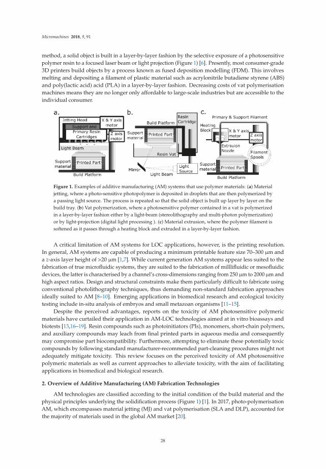
Micromachines 2018, 9, 91
method, a solid object is built in a layer-by-layer fashion by the selective exposure of a photosensitivepolymer resin to a focused laser beam or light projection (Figure 1) [6]. Presently, most consumer-grade3D printers build objects by a process known as fused deposition modelling (FDM). This involvesmelting and depositing a filament of plastic material such as acrylonitrile butadiene styrene (ABS)and poly(lactic acid) acid (PLA) in a layer-by-layer fashion. Decreasing costs of vat polymerisationmachines means they are no longer only affordable to large-scale industries but are accessible to theindividual consumer.
Figure 1. Examples of additive manufacturing (AM) systems that use polymer materials: (a) Materialjetting, where a photo-sensitive photopolymer is deposited in droplets that are then polymerized bya passing light source. The process is repeated so that the solid object is built up layer by layer on thebuild tray. (b) Vat polymerization, where a photosensitive polymer contained in a vat is polymerizedin a layer-by-layer fashion either by a light-beam (stereolithography and multi-photon polymerization)or by light-projection (digital light processing ). (c) Material extrusion, where the polymer filament issoftened as it passes through a heating block and extruded in a layer-by-layer fashion.
A critical limitation of AM systems for LOC applications, however, is the printing resolution.In general, AM systems are capable of producing a minimum printable feature size 70–300 µm anda z-axis layer height of >20 µm [1,7]. While current generation AM systems appear less suited to thefabrication of true microfluidic systems, they are suited to the fabrication of milllifluidic or mesofluidicdevices, the latter is characterised by a channel’s cross-dimensions ranging from 250 µm to 2000 µm andhigh aspect ratios. Design and structural constraints make them particularly difficult to fabricate usingconventional photolithography techniques, thus demanding non-standard fabrication approachesideally suited to AM [8–10]. Emerging applications in biomedical research and ecological toxicitytesting include in-situ analysis of embryos and small metazoan organisms [11–15].
Despite the perceived advantages, reports on the toxicity of AM photosensitive polymericmaterials have curtailed their application in AM-LOC technologies aimed at in vitro bioassays andbiotests [13,16–19]. Resin compounds such as photoinitiators (PIs), monomers, short-chain polymers,and auxiliary compounds may leach from final printed parts in aqueous media and consequentlymay compromise part biocompatibility. Furthermore, attempting to eliminate these potentially toxiccompounds by following standard manufacturer-recommended part-cleaning procedures might notadequately mitigate toxicity. This review focuses on the perceived toxicity of AM photosensitivepolymeric materials as well as current approaches to alleviate toxicity, with the aim of facilitatingapplications in biomedical and biological research.
2. Overview of Additive Manufacturing (AM) Fabrication Technologies
AM technologies are classified according to the initial condition of the build material and thephysical principles underlying the solidification process (Figure 1) [1]. In 2017, photo-polymerisationAM, which encompasses material jetting (MJ) and vat polymerisation (SLA and DLP), accounted forthe majority of materials used in the global AM market [20].
28

Micromachines 2018, 9, 91
The vat polymerization process produces a solidified 3D object by localised irradiation andpolymerisation of a light sensitive resin (contained in a vat) by a spatially controlled light source [1].The light source used in SLA is a spot laser that irradiates the resin as it scans in an x–y direction ofeach plane, whereas the light source used in DLP is a projector and the whole x–y plane is irradiated ina single flash. For both, the final object is built in a layer-by-layer fashion as the build platform movesthrough the resin along the z-axis, whereas multi-photon, also known as two-photon, polymerisation(MPP), produces a solid object by focusing a femtosecond laser beam into the resin vat. The lasermoves in any direction within the resin, so it is not a layer-by-layer technique [21,22].
In contrast, MJ is a process similar to inkjet printing and involves jetting droplets of photosensitivepolymer resin onto the build platform (Figure 1). Resin is solidified by a passing light source,and the process is repeated in a layer-by-layer fashion, as the object is built from the bottom up.Vat polymerization technology, more than MJ, can accelerate micro/milllifluidic device developmentsince it is capable of achieving finer resolutions. It has been used to build LOC and micro-devices fromoptically transparent materials [5,23–25].
SLA and DLP has been used in LOC design and manufacture. The authors of Au et al. [26]built a peristaltic pump and cell perfusion chamber with integrated fluidic valves, and the authorsof Comina et al. [27] built a monolithic LOC with integrated check-valves. In addition, LOC deviceshave been fabricated via replica moulding in poly(dimethylsiloxane) PDMS from moulds [28,29].SLA and DLP are applied in dental implant design and production, surgical planning, the building ofanatomical prosthetic devices, and tissue engineering [5,30,31].
MPP is suited to the design of microfluidic devices, as it can build structures down to 200 nm frommaterials classified as biocompatible [32]. It has been used to build micro-needle arrays for vaccine anddrug delivery [33] and develop complex suspended micro-channel resonators for LOC biomechanicalsensing applications [34] as well as integrative optofluidic refractometers with microtubes of variousdiameters and wall thicknesses [35].
3. Photopolymerization and Stereolithographic Resins
Polymerization, by chemical reactions, connects unsaturated monomer molecules to propagatea polymer-chain network [36,37]. To create a 3D solid object, a photo-sensitive stereolithographicpolymer resin is solidified by the successive vitrification of the photopolymer by a light-initiatedchemical reaction that leads to the cross-linking of polymers by produced reactive species(free radicals, cations or anions) [38]. The photo-polymerisation process is consistent with ‘chain-growth’polymerization in that it requires initiation, propagation, chain transfer, and termination [36,37,39].
Resin components include a photo-sensitive polymer and a photoinitiator system along withother additives and fillers, such as inhibitors, plasticizers, light stabilizers, and pigments (e.g., shownin Tables 1–3). Auxiliary compounds may improve polymerisation (in the industry termed ‘curing’)efficiency and enhance mechanical, physical, and aesthetic properties of the final printed part.Ultimately, final material properties depend on the post-cleaning and post-curing process.
In radical polymerization, photolytic energy is absorbed by the PI and the produced reactivespecies is a free radical, a molecular fragment having one unpaired electrons (Figure 2) [36].The propagating site of reactivity is a carbon radical [40]. Free radicals are transferred from monomerto monomer during chain growth. Radical polymerization terminates when two radicals, either theforming polymer chains or PI fragments, combine.
In cationic polymerization, photolytic energy is absorbed by the PI to release free radicals anda Lewis or a Brönsted acid [40,41]. The propagating site of reactivity is a carbocation. Charge istransferred from monomer to monomer during chain growth. Termination occurs via unimolecularrearrangement within the counterion, i.e., where an anionic fragment of the counterion combines withthe propagating chain end, inactivating the growing chain, and reducing the concentration of theinitiator complex [42].
29

Micromachines 2018, 9, 91
Two polymerisation steps are required to produce the final object built using vat polymerisationAM [31]. The first-step occurs in the vat of the machine and is by the light emitted by the machine.This step produces a partially cured object, referred to as ‘green’. While the object at this stage has itsfinal shape and form, a second curing step is need to optimise its mechanical properties. Typically,the ‘green’ object is first rinsed in a solvent to remove polymerised resin. The second curing step occursin a purpose-built ‘post-curing’ oven that emits a (stroboscopic) light at a wavelength that should bematched to the resin type. The object typically must be systematically re-orientated during this step,so that exposure of each surface of the geometry to the light source is maximised.
Figure 2. The two photoinitiator (PI) mechanisms are radical (a,b) and cationic (c,d). In theradical system, absorption of light (hv) produces a free radical by homolytic cleavage, propagatingpolymerization, for example, as in (a) hydroxyacetophenone and (b) phosphine-oxide, where Rrepresents a methyl group in (a) and a phenyl ring in (b). In the cationic PI system, in PIssuch as (c) triarylsulfonium hexafluoroantimonate salts and (d) bis(4-tert-butylphenyl)iodoniumperfluoro-1-butanesulfonate, light is absorbed causing heterolytic and homolytic cleavage that formsa cationic portion (labeled in green) and anionic portion (labeled in pink). The generated molecules arereactive with monomers, forming an acid and free radicals, propagating polymerization (open sourceimage adapted from [36]).
3.1. Photoinitiator Systems
A PI compound (examples are shown in Table 1) acts as catalyst for photopolymerisation byconverting absorbed light energy into chemical energy, free radicals, and/or cations [43]. To enhancethe efficiency and depth of polymerization, stereolithographic resins will typically contain multiple‘PIs’ and a thermal initiator compound. A thermal initiator, such as benzoyl peroxide or Lauroylperoxide, ideally does not affect the resin during printing, but operates during ‘post-curing’ to aid ininterior part polymerization. Radical PI systems are classified by their mode of operation as eithera Norrish Type I or Norrish Type II. The Norrish Type I PI molecule undergoes homolytic cleavage toproduce free radicals upon the absorption of light [38], whereas the Norrish Type II PI is a bimolecularsystem, where absorption of light, typically ultra-violet (UV)-C, causes a light absorbing molecule(or sensitizer) to interact with a second molecule (a co-initiator) to generate free radicals [44].
A cationic PI system consists of a cationic and anionic pair, and each component has an explicitrole in the polymerization mechanism [37]. The cationic portion of the PI molecule absorbs light toproduce an excited electron state, whereas the anionic portion of the PI molecule absorbs light toproduce an acid [41]. The excited electron state causes the PI molecule to undergo homolytic cleavageto yield several free radicals and heterolytic cleavage to produce another cationic species and an acid.Typically, cationic PIs are either sulfonium or iodonium salts (e.g., 4-octyloxy-phenyl-phenyl iodoniumhexafluoroantimonate). Cationic photopolymerization is used for monomers, such as epoxides andvinyl ethers, which cannot be polymerized by free radical mechanisms [45].
For photopolymerization to proceed efficiently, the absorption wavelength of the PI must overlapwith the emission spectrum of the light source and there must be minimal competing absorptionby the other resin components [46]. Optimal absorption of each PI occurs at a specific wavelength
30

Micromachines 2018, 9, 91
range, for example, phosphine-oxide compounds will typically have an absorption maximum between360 nm and 400 nm, and camphorquinone has an absorption maximum at a wavelength of 468 nm [30].Catatonic PIs absorb in the wavelength range between 220 nm and 280 nm, with the different molecularconfigurations around the sulphur or iodine atom determining the specific absorption maximum foreach PI [39].
Table 1. Summary of toxicity data available for photoinitiators used in stereolithography resins.
Compound w/w Available Toxicological Information
Phosphine oxidecompounds 1
(Type II)0.1–5%
FORMlabs e.g.,Dental andE-Shell series
Fertility impairing effect [47], acute and chronic toxic for aquaticorganisms [48], toxic effect on mouse NIH 3T3 cells [38]. Not readilybiodegradable by OECD criteria [48,49].LD50 Oral rat > 5000 mg/kg (OECD) [48]LC50 (48 h) Oryzias latipes—6.53 mg/L (JIS K 0102-71) [49,50]EC50 (48 h) Daphnia magna—3.53 mg/L (OECD 202) [48,50]EC50 (72 h) Pseudokirchneriella subcapitata—1.56 mg/L (OECD 201) [49]
Hydroxy-acetophenone(Type II)
Readily biodegradable (OECD 301B) [51]LD50 Oral Rat—2.240 mg/kg [51]LC50 (96 h) Salmo gairdneri—25 mg/L [51]EC50 (48 h) Daphnia magna—50 mg/L [51]
Benzophenonecompounds 2
(Type II)<10% UV-cured inks
Causes liver hypertrophy and kidney adenoma in rats [52]EC50 (24 h) Daphnia magna—0.28 mg/L [53]LC50 (96 h) Pimephales promelas—14.2 mg/L [53]BP-3 and BP-4:LC50 (48 h) Daphnia magna—1.09 and 47.47 mg/LLC50 (96 h) Brachydanio rerio—3.89 and 633.00 mg/L
Camphorquinone Dental resins EC50 mouse fibroblasts—235 µM [30]
1-hydroxy cyclohexyl phenylketone
FORMlabsIrgacure 184
LC50 (96 h) Danio rerio—24 mg/L [54]EC50 (48 h) Daphnia magna—59.3 mg/L (OECD 202) [54]EC50 (72 h) Desmodesmus subspicatus—14.4 mg/L (OECD 201) [54]
Triarylsulfoniumsalt (Cationic)3 1–10% 3D Systems
EC50 (24 h) Daphnia magna—4.4 mg/L [55]EC50 (48 h) Daphnia magna—0.68 mg/L [55]
1 Including diphenyl(2,4,6-trimethylbenzoyl)phosphine oxide (TPO) and bis acyl phosphine oxide (BAPO).2 Including benzophenone-3 (BP-3), benzophenone-4 (BP-4) [56]. 3 50% propylene carbonate and 50% mixedtriarylsulfonium salts, i.e., an antimonate mixture.
3.2. Photopolymer Matrix/Systems
Photopolymers are mono-, di- and trifunctional monomers, acting as cross linkers, andhyper-branched oligomers that are multifunctional, acting as both cross linkers and diluents [57].Classical photopolymer systems contain a single type of photopolymer (e.g., acrylic, epoxide,vinyl-ether, or a thiol-ene), whereas commercially available resins have combinations of photopolymersto enhance mechanical properties of the final fabricated object and to overcome the limitations of singlepolymer systems (e.g., low strength and high anisotropy). Examples of photopolymers are shownin Table 2.
Most free-radical curing resins employ the unsaturated functionality of acrylate and methacrylates;however, allyl- and vinyl-based formulations are also available [1]. An acrylate oligomer backbonecan be modified to be of a different polymer class to achieve the material properties desired inthe final object. For example, material properties are customized when an acrylate oligomer iscombined with highly flexible polybutadienes, rigid and chemically resistant bisphenol A epoxies,and flexible yet tough polyurethanes [58]. Polyester- and acrylic-based acrylate oligomers are alsocommercially available.
The biocompatibility of candidate photopolymeric materials for the AM of biomedical devices hasbeen carefully scrutinised. Organically modified ceramic (ORMOCER) composite resins, for example,have been used with MPP and SLA to build devices including scaffolds for tissue engineering,microneedles for drug delivery, and dental implants [33,59,60]. ORMOCER-based photopolymerresins contain silicon alkoxides, organically modified silicon alkoxides, several metal alkoxides
31

Micromachines 2018, 9, 91
and in/organic monomers [61]. Typically, they operate either as methacrylate alkoxysilane systems,initiated via radical polymerization, or epoxysilane systems initiated via cationic polymerization. Thebiocompatibility of ORMOCER copolymer resins increases as the content of inorganic co-polymersdecreases, such that leaching of toxic residues is minimised [62]. For example, a polymerized objectmade from an ORMOCER-based resin may contain up to 50% unreacted methacrylate monomer. Theseare liable to leach in an aqueous medium and cause toxicity.
Polyethylene glycols (PEGs) are polymers of ethylene oxide [63]. PEGs are non-toxic, exceptwhen they are administered at exceedingly high doses (for humans, >10 mg/(kg·day−1)). Materialproperties of PEGs can be fine-tuned by modifying the molecular weight (MW) of the PEG backboneand by cross-linking them with acrylate groups. Polyethylene glycol diacrylate (PEG-DA) containsdouble-bond acrylate groups at each end of the PEG chain.
PEG-DA is a relatively biocompatible material [64,65]. While PEG-DA is used in biomedicalapplications, toxicity of PEG-DA can arise from unreacted monomers and PIs. Consequently,assessment on biocompatibility precedes each application [64]. The authors of Urrios et al. [66],for example, built transparent microfluidic devices in PEG-DA (MW 250) using SLA. To mitigatethe toxicity of unreacted PEG-DA monomers and PI, the surfaces were subjected to an additionalcuring step in a UV bath to allow residual compounds to leach. The authors of Traore and Behkam[67] combined PEG-DA hydrogels with photolithography to produce LOC devices for use in cellularassays. To mitigate toxicity, gels were soaked in PBS overnight to remove excess PI and unreactedmonomers.
Direct AM of PDMS is still in its early stages of development. The authors of Femmer et al. [68]used AM to create the first membrane made from PDMS using DLP. They fabricated features inthe range of 150 and 300 µm from a custom PDMS-based resin. However, the optical clarity of thematerial was reduced because PI concentration and biocompatibility assays were not undertaken.PDMS materials have been applied, to a degree, in the development of microfluidic LOC using AM.The authors of He et al. [69] produced an LOC using FDM, sugar, and PDMS. Micro-channels werecreated by extruding melted sugar on a PDMS-based layer. PDMS was cast over the sugar layer andthe sugar was removed with water. The authors of Comina et al. [29] used AM master moulds to castPDMS into LOC. In addition, PDMS has been used to coat AM LOC to improve biocompatibility.
32

Micromachines 2018, 9, 91
Table 2. Summary of toxicity data available for photopolymers used in stereolithography resins.
Compound w/w Available Toxicological Information
Acrylate monomers,Acrylate andUrethane acrylateoligomers
5–60%
FORMlabsAutodeskEnvisiontec3D Systems
Toxic or harmful to various species of fish, algae and watermicroorganisms [49]. Potential mutagens and a reproductive anddevelopmental toxicant.LD50 Oral rat >5000 mg/kg [49]LC50 (96 h) Brachydanio rerio—10.1 mg/L (OECD 203) [70]LC50 (96 h) Cyprinus carpio—1.2 mg/L (OECD 203) [71]LC50 (96 h) Pimephales promelas—34.7 mg/L (OECD 203) [70]
Methyl methacrylatemonomers 1,and oligomers
5–90%FORMlabsEnvisiontecDental resin
Assessment of repeated dose toxicity indicates potential to affect theliver and kidneys as indicated in animal studies [72]. Potentialmutagen, and a reproductive and developmental toxicant, aquatictoxicant, and genotoxic in mammalian cell culture [73].LC50 (96 h) Salmo gairdneri—3.4 mg/L (OECD 203) [73]LC50 (96 h) Cyprinodon variegatus—1.1 mg/L (OECD 203) [73]EC50 (48 h) Daphnia magna—2.6 mg/L (OECD 202) [73]EC50 (72 h) Selenastrum capricornutum—3.55 mg/L (OECD 201) [73]EC50 (96 h) Mysidopsis bahia—1.6 mg/L (OPP 72-3) [73]LC50 (96 h) Lepomis macrochirus—283 mg/L * [74]LC50 (96 h) Oncorhynchus mykiss—5.2 mg/L * [75]EC50 (48 h) Daphnia magna—8.74 mg/L * [75]EC50 (72 h) Pseudokirchneriella subcapitata—5.2 mg/L * [75]LD50 Oral rat—7900 mg/kg * [74]
Tripropylene Glycoldiacrylate
3D Systems
LD50 Oral rat—6800 mg/kg (OECD 401) [76]LC50 (96 h) Leuciscus idus >4.6–10 mg/L [76]EC50 (48 h) Daphnia magna—89 mg/L [76]EC50 (72 h) Scenedesmus subspicatus—65.9 mg/L [76]
Table 2. Cont.
Compound w/w Available Toxicological Information
HydroxyethylMethacrylate
Dental resinsEC50 (48 h) Daphnia magna—380 mg/L (OECD 202) [77]EC50 (72 h) Selenastrum capricornutum—836 mg/L (OECD 201) [77]
3,4-Epoxycyclohexylmethyl3,4-epoxy-cyclohexanecarboxylate
25–60% 3D SystemsEC50 (48 h) Daphnia magna—40 mg/L [78]LC50 (96 h) Oncorhynchus mykiss—24 mg/L [78]LC50 Oral rats—5000 mg/kg [78]
1,6-bis(2,3-epoxypropoxy) hexane
15–30% 3D Systems
Not easily biodegradable (according to OECD-criteria) [79]EC50 (48 h) Daphnia magna—47 mg/L [79]LC50 (96 h) Leuciscus idus—30 mg/L [79]LD50 Oral rats—2190 mg/Kg [79]
BisphenolA-diglycidyldimethacrylate(Bis-GMA)
Dental resins EC50 mouse fibroblasts—9.35 µM [30]
Tetraacrylate 2,3 30–60%AutodeskEvisiontecFORMlabs
LC50 (96 h) Cyprinus carp—1.2 mg/L 2 [80]LC50 (96 h) Danio rerio—7.9 mg/L 3 [80]
1 Degrades to methacrylic acid: LD50 Oral rat—1320 mg/kg, LC50 (96 h) Oncorhynchus mykiss—85 mg/L [81].2Alkox. pentaerythritol tetraacrylate. 3 Di(trimethylolpropane)tetra-acrylate.
Additives and fillers are auxiliary compounds included for the purpose of enhancing andcustomizing qualities of the printed part. For example, vertical print resolution and transparencyis improved, and solubility is reduced, by inclusion of ‘light-blocker’ compounds, such as carbonblack and Naphthol-based pigments, and UV blockers, such as 2,2’-(2,5-thiophene diyl) bis(5-tert-butylbenzoxazol) Liu and He [82]. All acrylate-based resins require auxiliary compounds to extendresin shelf life. Inhibitors, which are usually a quinone-based compound such as butylatedhydroxytoluene, hydroquinone, hydroquinone monomethyl ether, and benzoquinone, preventspontaneous polymerization during storage [83].
33
Micromachines 2018, 9, 91
In general, commercially available resins utilize a wide range of auxiliary compounds that servevarious purposes such as tuning material, mechanical, physical, and aesthetic propertis. Severalexamples of auxillary compounds are shown in Table 3. Further example compounds include silica,titanium dioxide, zinc, iron oxides, silver, silicon nitrides, calcium, lead, cerium, tin, zirconium,strontium, barium, borosilicate glasses, kaolin, quartz, talc, rubber impact modifiers, thermoplastic andcross-linked polyurethanes, polyethylene, polypropylene, polycarbonates, and poly-epoxides [83–89].
4. Compatibility of AM Substrata with Biological Applications
Biocompatibility of polymeric substrata used to fabricate LOC technologies is critical for anybiological and biomedical applications. Bioassays on living cells and tissues are conducted in aqueousmedia and leaching of any chemicals from 3D printed plastics after contact with water can directly affecttest specimens. Until recently, critical biocompatibility issues and potential hazard risk implicationsof widespread usage of 3D printed polymers have received only marginal attention [13,17–19,56,90].Data on toxicity, bioaccumulative potential, persistence, and degradability of photopolymer materialsis largely lacking [4]. This is in part due to a lack of available information on resin composition,which constrains independent evaluation of environmental and human health risk.
Typically, commercial resin formulas are proprietary. Only known hazardous materials aredeclared in material product safety data sheets (SDS). Compounds considered by the manufacturer asposing no significant risk are omitted. Open source and patent documents showed limited insight on thepotential formulas and compounds used in resins. This indicates that formulas are complex, potentiallycontaining greater than 20 compounds [82–88]. Consequently, it is difficult to predict which compoundsmay leach and to estimate and measure the toxicity of individual and mixtures of compounds.Comprehensive biological and chemical testing is a consequence necessary to evaluate biocompatibility.
Generally, substrata used for MJ and vat photopolymerization AM can have greater toxicitythan those used in material extrusion AM [17,91]. Typically, photopolymerization AM is reliant onacrylate- and methacrylate-based compounds, which have up to a 90% weight-to-weight ratio (w/w),and phosphine-oxide-based PI systems, which are less than 5% w/w (Tables 1 and 2). These compoundsare known to be acutely and chronically toxic to aquatic test organisms, including fish, algae, and watermicroorganisms. In mammals, chronic exposure to these compounds has sublethal effects that includeimpaired reproductive, liver, and kidney function and abnormal growth and development. Despitethis, studies investigating AM polymer toxicity have primarily focused on the emission hazards offumes resulting from material extrusion techniques, and photopolymerization materials have beenlargely ignored [12,13,18,92,93].
The two principal mechanisms by which compounds can be released from a polymerizedobject are (1) degradation or erosion and (2) extraction by solvent or aqueous medium, the latteroften referred to as a leaching of toxic residues [91]. Erosion, which may be caused byphoto, thermal, mechanical, or chemical factors, and the solubility of the resin-matrix alsoinfluence the release of compounds. For example, UDMA-based resins (urethane dimethacrylate,1,6-bis(methacryloyloxy-2-methoxycarbonyl amino)-trimethylhexane) are less water-soluble thanmaterials containing bisphenol-A-glycidyl methacrylates and are thus more susceptible to erosion [91].Salivary esterases can erode the surfaces of resin-based dental materials, releasing methacrylicsubstances that subsequently enter the intestine via swallowing, diffuse into the circulatory system,and remain in the body until metabolized [94]. Unpolymerized co-monomers, triethylene glycoldimethacrylate (TEGDMA) and 2-hydroxyethyl methacrylate (HEMA), released from polymerizedparts used as dental implants, have been detected in the human circulatory system [95].
34

Micromachines 2018, 9, 91
Table 3. Summary of toxicity data available for auxiliary compounds used in stereolithography resins.
Compound w/w% Available Toxicological Information
Butylatedhydroxytoluene
Dental resins
Toxic or harmful to various species of fish, algae, and watermicroorganisms [96]LD50 Oral rat >6000 mg/kg (OECD 401) [96]LC50 (48 h) Oryzias latipes—5.3 mg/L [96]EC50 (48 h) Daphnia magna—0.48 mg/L (OECD 202) [96]EC50 (24 h) Protozoa—1.7 mg/L [96]
Sebacatecompounds 1 <5%
FORMlabse.g., DentalEnvisiontec
Toxic to aquatic life with long lasting effects [49], not readilybiodegradable (OECD 301B) [49,97]LD50 Oral rat—3230 mg/kg (OECD 423) [49,97]LC50 (96 h) Lepomis macrochirus—0.97 mg/L (OECD 203) [49,97]LC50 (96 h) Oncorhynchus mykiss—7.9 mg/L (OECD 203) [49]LC50 (96 h) Brachydanio rerio—0.9 mg/L (OECD 203) [49]LC50 (48 h) Daphnia magna—8.58 mg/L (OECD 202) [97]EC50 (72 h) Pseudokirchneriella subcapitata—1.1 mg/L (OECD 201) [97]EC50 (72 h) Desmodesmus subspicatus—1.68 mg/L (OECD 201) [49]
Methylthiophenolcompounds 2
AutodeskLC50 (96 h) Danio rerio—9 mg/L [80]EC50 (72 h) Pediastrum boryanum—1.7 mg/L [80]EC50 (24 h) Daphnia magna—15 mg/L [80]
Hydroquinone Dental resins
Evidence of mutagenicity in mammal studies, toxic to aquatic life;absorption, in sufficient concentrations, leads to cyanosis [98]LC50 (96 h) Oncorhynchus mykiss—0.04 mg/L [98]EC50 (48 h) Daphnia magna 0.13 mg/L [98]EC50 (72 h) Pseudokirchneriella subcapitata—0.34 mg/L [98]LD50 Oral rat—367.3 mg/kg [98]
1 Bis(2,2,6,6-tetramethyl-4-piperidyl) sebacate, Pentamethyl-piperidyl sebacate.2 2-methyl-1-(4-methylthiophenol)-2-Morpholinopropan-1-one.
Leaching of toxic residues to aqueous media is significantly more important for implementationsof AM in bioanalytical LOC technologies. Recent reports have shown that leaching of compounds fromplastic parts is relatively high in the first 24 h [30]. The rate of compound leaching is influenced partlyby geometry, characteristics of resin components, and polymerization extent [36,99]. Several studieshave isolated compounds such as residual monomers, additives, and photoinitiators by means ofextraction with aqueous media including distilled water, natural or artificial saliva, Ringer’s solution,and organic diluents such as methanol, ethanol, and acetone. We have recently tested a random sampleof photopolymer leachate from several SLA systems using gas chromatography–mass spectrometry(GC-MS) analysis. Our qualitative data based on different retention times in GC confirmed the presenceof a photoinitiator 1-hydroxycyclohexyl phenyl ketone (1-HCHPK) and a substance closely related butnot identical to methacrylate monomer (Figure 3).
Interestingly, 1-HCHPK has recently been reported as toxicant leaching from polyethyleneampoules used for intravenous injections [100]. Such pilot GC-MS analysis highlighted its limiteddetection capability for substances that are polar and non-volatile. Indeed, subsequent toxicity profilingof identified pure compounds suggested that they were responsible for only half of the cumulativetoxicity effect. This warrants additional analysis to enable quantitative and conclusive identificationof compounds that leach out of the 3D-printed plastic parts. Combined, these data signify possiblebiological risks associated with photoinitiators use in different plastic materials.
35

Micromachines 2018, 9, 91
Figure 3. Qualitative analysis of Form Labs photopolymer leachate using gas chromatography-massspectrometer (GC-MS) indicating the presence of photoinitiator 1-hydroxycyclohexyl phenyl ketone(1-HCHPK) and a substance closely related but not identical to methacrylate monomer.
Incomplete polymerization of photo-reactive resins amid MJ, SLA, and DLP processes can leadto greater levels of uncured and highly toxic substratum in the manufactured object, which canpotentially increase the leaching rate [31]. Even under optimal conditions, the conversion of monomersto polymers is usually incomplete, and even the most efficient systems achieve approximately 55–60%of complete polymerization [101]. Early termination of polymerization may further result froma higher-than-optimal PI concentration in the resin, which over-produces reactive species, or thepresence of oxygen [102]. The above issues can be further intensified by part geometry. The latteraffects polymerization since initiation is due to ‘line of sight’, making shadowed areas more difficultto cure, particularly at the ‘post-curing’ stage. Since the PI, compounds are not typically indicatedby the resin manufacturer, mismatch of the absorption characteristics of the resin to the emissioncharacteristics of the chosen curing method, is a potential problem that may result in incompletepolymerization. For example, most UV photoinitiators, in particular those for cationic polymerization,exhibit very weak or no absorption at 365 nm, 400 nm, and 465 nm, which makes the MPM lamps andLEDs inefficient light sources for curing [45].
When considering AM systems such as SLA, MJ and DLP for any biological applications itis important to consider that PIs, auxiliary compounds, monomers, and short chain polymers,as well as their metabolites, may not be exhausted during or after polymerization. Furthermore,
36

Micromachines 2018, 9, 91
they are not entirely bound to or within the printed object [103,104]. For example, smallphotoinitiators of 200–250 Da used in food packaging, such as 4-methyl benzophenone (4-MBP)and isopropylthioxanthone, were found to migrate from the packaging into the food, raising significantfood safety concerns [105]. The authors of Short et al. [90] found that the PI antimony, a toxic heavymetal, leached from AM objects over a 24 h period. In addition, several studies on human tissues haveshown that PI metabolites were implicated in material toxicity [106].
Key metabolites of PIs are free radicals, also known as reactive oxygen species (ROS), such asperoxides and peroxy radicals [40,44]. These are implicated in the damage of DNA and proteins byoxidative stress mechanisms [107]. The pathophysiology of ageing and various age-related diseases,including chronic inflammatory of the gastrointestinal tract, diseases associated with cartilage,and other neurology disorders, have been linked to oxidative damage [108].
Recent clinical investigations of biocompatibility of AM-fabricated polymeric dental implantshave shown a correlation between leachate and irritation of the oral mucosa [30]. Compounds such asMMA, formaldehyde (a degradation of a copolymer formed from oxygen and methacrylate duringpolymerization), and dibutyl phthalate (a plasticizer) have been detected in saliva. The authors ofSchweikl et al. [109] demonstrated that methacrylate monomers, such as HEMA, leach from dentalmaterials and induce cell apoptosis as a response to the associated DNA damage. Epoxides arehighly reactive molecules that are also implicated in DNA damage, apoptosis, and carcinogenic andmutagenic effects [94]. The leached PI camphorquinone has moderate cytotoxic effects as shown inhuman submandibular-duct cells [110]. It has been associated with cytotoxicity and correlated witha significant increase in intracellular ROS in human pulp fibroblasts [111].
A commonly used endpoint for the determination of adverse systemic effects is acute oraltoxicity in rats (Tables 1–3). This quantifies the single-dose required to kill 50% of test animals (LD50).Since photopolymerised resin-based materials release compounds in relatively small amounts, acuteoral toxicity in rats is less relevant to the assessment of the biocompatibility of these materialscompared with tests documenting sublethal endpoints [91]. The latter determines the effectiveconcentrations, which induce a response in 50% of the test animals (EC50), sometimes determinedalong with the concentration required to kill 50% of the test organisms (LC50). These valuesallow comparisons between relative biocompatibility of materials. For example, the authors ofGeurtsen [111] investigated cytotoxic effects of 35 single compounds used in stereolithographic resins,in permanent 3T3 cells, and in three primary human oral fibroblast cultures. They showed thatEC50 values varied significantly among compounds, and that the PI 2,6-di-t-butyl-4-methylphenol,the auxiliary compound 2-hydroxy-4-methoxy benzophenone, and the PI diphenyliodonium chloridehad relatively elevated cytotoxic effects.
Several recent studies have investigated the biocompatibility of parts made by vat polymerizationand MJ (Table 4). These studies utilized the fish embryo toxicity (FET) test, which is an established andsensitive, phenotype-based physiological analysis of developing zebrafish (Danio rerio) embryos. It isa relatively non-biased approach and is used extensively in the process of elucidating organ-specifictoxicity and environmental adaptations at the organ, tissue, and systems level [112]. The embryonicdevelopmental stage is considered one of the most sensitive to environmental perturbations and canbe readily applied to assess the impacts of any potential toxic effects of chemicals or solid phases.
Despite SLA and MJ parts being post-processed according to manufacturer specifications,they appear to leach compounds. The authors of Macdonald et al. [13] investigated the biocompatibilityof commercial resins—VisiJet Crystal EX200, VisiJet S300, Watershed 11122 XC, ABSplus P-430,and Fototec SLA-7150-Clear—using FET and found that these resins may leach toxic compounds(Table 4). Leachate from several caused malformations during embryonic development (teratogenicity)of zebrafish embryos. The authors of Oskui et al. [17] tested the biocompatibility of a Form Clear(Form Labs, Inc., Somerville, MA, USA) resin and found that exposure to leachate lowered survivalrates of zebrafish embryos and elevated rates of malformations (yolk sac edema, heart edema,embryo length deformation, spine flexures, a lack of melanophore development, and a lack of swim
37

Micromachines 2018, 9, 91
bladders). In a similar study, the authors of Alifui-Segbaya et al. [16] showed that 48 h of exposureto a VisiJet (3D Systems Inc., Rock Hill, SC, USA) crystal-printed part leachate had lethal, sublethal,and teratogenic effects on zebrafish embryos.
Table 4. Summary of recent assessments on biocompatibility of parts printed with commerciallyavailable SLA and MJ printing polymers.
Resin Organism Toxicological Information
VisiJet Crystal Algae 1 At 24 h ∼70% growth inhibition [18].Flea 2 At 24 h 100% mortality [18]Rotifer 3 At 24 h 100% mortality [18]
Zebrafish 4Stunted growth, missing eyes, reduced pigmentation and yolk sac, abnormalshapes and also appear darker [13]. Greater than 90% mortality observed at48 h [16] and 100% mortality observed at at 72 h [13].
Watershed 11122XC Algae 1 At 24 h >90% growth inhibition [18]Rotifer 3 At 24 h ∼ 100% mortality [18]Flea 2,5 At 24 h ∼ 100% mortality [18]
Fototec 7150 Clear Algae 1 At 24 h >90% growth inhibition [18]Rotifer 3 At 24 h ∼ 100% mortality [18]Flea 2,5 At 24 h ∼ 100% mortality [18]
Form Clear Algae 1 At 24 h ∼60% growth inhibition [18]Rotifer 3 At 24 h ∼100% mortality [18]Flea 2,5 At 24 h ∼ 100% mortality [18]
Zebrafish 4At 72 h higher rate of mortality, malformations (yolk sac edema, heartedema, embryo length deformation, spine flexures, lack of melanophoredevelopment, and a lack of swim bladders) [17].
VisiJet Clear Zebrafish 4 At 48 h >90% mortality of embryos [16].Algae 1 At 24 h >90% growth inhibition [18]Rotifer 3 At 24 h ∼ 100% mortality [18]Flea 2,5 At 24 h ∼ 100% mortality [18]
MED610/620 Zebrafish 4 >50% lethality [16].1 Freshwater algae (Pseudokirchneriella subcapitata)—OECD 201 Growth Inhibition Test. 2 Freshwater waterflea Daphnia sp.—OECD 202 Acute Immobilization Test. 3 Freshwater rotifer Brachionus calycifloru—ASTME1440-91 Acute Toxicity Test. 4 Zebrafish Danio rerio embryo—OECD 236 Fish Embryo Acute Toxicity (FET)Assay. 5 Freshwater water flea Ceriodaphnia dubia—USEPA Acute Toxicity Test.
38

Micromachines 2018, 9, 91
Zhu et al. [18] expanded upon the above studies and performed a battery of cell-based and wholeorganism bioassays to assess the biocompatibility of several polymers including Watershed 11122XC, Dreve Fototec 7150 Clear, VisiJet Crystal, Form Clear, and VisiJet SL Clear (Table 4). This workfor the first time provided an in-depth and multispecies view of potential biological implications offabricating devices using AM technologies. The published results demonstrated that leachate frompolymerized parts were toxic to vertebrates and several invertebrate model organisms. All of the zebrafish larvae exposed to MJ and SLA leachates developed complete paralysis within 5 min of exposure,indicating the effect leachates may have on the central nervous system of zebrafish larvae.
These results identified VisiJet Crystal polymer as toxic despite its being classified as a substancewith favourable biocompatibility, as evidenced by United States Pharmacopeia (USP) Class VIcertification [13,18,113]. However, its USP Class VI certification is dependent on specific post-curingand cleaning steps [113]. These recent studies, though, have demonstrated that compounds, which arepotentially toxic, remain and can leach. Furthermore, standard and specialised post-processing stepsmay not be adequate for removing toxicity, which still may occur in ranges affecting LOC bioassays.
While advances in AM of microfluidic and biomedical devices empower a rapidly growingnumber of applications, the above studies suggest that considerable caution must be exercised tomitigate biocompatibility concerns. The AM of biomicrofluidic LOC devices may not be suitable for invitro bioassays applications. Ongoing research is aimed at solving these biocompatibility concerns by,for example, the development of AM systems capable of using biologically compatible substrata suchas PDMS and PEG-DA [114].
5. Methods for Mitigating Toxicity of Polymeric Resins
AM is undoubtedly an elegant approach to the fabrication of monolithic functional LOC devices.Its ability to produced LOC with integrated fluidic interconnects and functional elements such asvalves has been proven. In addition, several different approaches aimed at ensuring biocompatibilityof photopolymer resins have been explored. Beyond customizing resin formulas to select for less toxiccompounds, carefully managed post-cleaning and post-curing processes, or coating of surfaces withvarious biocompatible compounds, can increase biocompatibility.
While cross-linked polymer matrix may not leach, unreacted monomers, short-chain polymers,additives and PI residues are prone to leaching when the part is in aqueous media (Tables 1–3). For thisreason, dentures and orthodontic devices, made using proprietary resins, are routinely stored inwater for up to 24 h (depending on the type of resin) to allow uncured compounds to be released,thus reducing unwanted side effects [30]. For microfluidic LOC and biomedical devices made usingproprietary photopolymer resins, coating with PDMS, a nontoxic and transparent elastomer, has alsobeen used to overcome the limitation of unknown surface chemistry and toxicity [114,115].
Biocompatibility increases when polymerizing and post-curing light sources, and emissionregimes, are matched to meet the absorption requirements of the resin compounds [46]. To optimizepolymerization, the absorption maximum of PIs present in the photopolymer resin should overlapwith the wavelength emitted by the polymerizing light source [45,116]. Commonly used light sourcesfor polymerization are light-emitting diodes (LEDs), medium pressure mercury (MPM) lamps, and theUV-light-emitting diodes (UV LEDs). LED curing units emit at two wavelength peaks (400 nm and465 nm), MPM lamps emit at one wavelength peak (365 nm) and UV LED can emit at four wavelengthpeaks (320 nm, 345 nm, 365 nm, and 390 nm). The total energy (light intensity times exposure time)irradiating the surface is also essential to polymerization [117]. Thus, it is necessary that the chosenpolymerizing light source emits a sufficient intensity, and at wavelengths matching the absorptionrange of the PIs present in the SL resin.
Differences in the structure of printed parts will influence the effectiveness of post-curingtreatments. To maximize exposure of the printed parts surface to the polymerizing light source,commercial curing ovens often have a rotating inner table and several floodlights that project fromthe inner walls and ceiling. However, LOCs have enclosed inner channels that are likely to be shaded
39

Micromachines 2018, 9, 91
from polymerizing light. The degree of which will depend on the penetration depth of the light sourcethrough the part, the thickness of the part, and part geometry. Shading will result in incomplete curingand less than optimal mechanical properties. For this reason, post-curing alone may not effectivelyremove toxicity.
Photopolymer resins classed as biocompatible require thorough post-cleaning [113]. For example,a standard cleaning procedure for a part printed in VisiJet clear consists of soaking the part in isopropylalcohol (IPA), brushing lightly if needed, rinsing in IPA, and air-drying, followed by 10–30 min ofpost-curing. Cleaning procedures required for a USP Class VI certification involve soaking the part for20 min in IPA, followed by scrubbing, and afterward four repeat cycles of soaking the part for 5 minin IPA, again followed by scrubbing. Each repeat soak is to be conducted in fresh IPA. Subsequentlyexcess solvent is removed from the surface of the part using clean compressed air, and the part isair-dried for a minimum of 6 h, during which the part must be flipped periodically to facilitate equaldrying. After this, the part must be cured for 1 h per side in a ProJet Curing Unit.
To reduce leaching, Macdonald et al. [13] experimented with coating SLA printed parts with waxand found that the coating was only effective at delaying the onset of toxicity (by ∼40 h). The authorsof van den Driesche et al. [118] removed the toxicity of parts printed by DLP in resins, E-Shell 300and HTM140, by coating them in parylene-C, which is an ultra-thin biocompatible polymer coating.Coating parts with biocompatible hydrogels (e.g., PEG-DA) or PDMS may also be an effective strategyto remove toxicity of easily accessible photopolymeric resins.
In another attempt to mitigate toxicity of photopolymeric resins by minimizing leaching in situ,the authors of Popov and Evseev [119] experimented with post-processing SLA-printed anatomicalimplants with supercritical carbon dioxide and found that, without treatment, the implant causedsevere inflammation, whereas, with treatment, the implant was biocompatible [119].
Commercially available resins vary in how effective post-curing and cleaning techniques are atreducing toxicity. The authors of Macdonald et al. [13] treated parts by washing them in 99% ethanoland found that this increased biocompatibility of some printed parts, such as Fototec 7150 polymers.However, VisiJet Crystal still showed toxicity after treatment and 100% mortality of zebrafish embryosat 72 h was observed. The authors of Oskui et al. [17] reduced toxicity of the Form Clear SLA polymerby post-curing each side for 30 min. However, while survival and hatching rates of embryos increasedcompared to those exposed to non-treated parts, the majority of larvae still had elevated rates ofmalformations (e.g., yolk sac and heart edema and slower swim bladder development).
To improve the safety of photosensitive polymers, alternative compounds can replace thosethat exhibit higher toxicity. PIs that are less toxic and less likely to leach are being developed.For example, PIs derived from grafting or condensing low-molecular-weight PIs to linear,dendritic, or hyper-branched polymers exhibit reduced leaching compared to their correspondinglow-molecular-weight analogues [120]. The authors of Nguyen et al. [106] used riboflavin (VitaminB2) as an alternative PI, and this had the effect of significantly increasing the biocompatibilityof 3D-printed objects, compared to those made with other commercial PIs such as Irgacure 2959and Irgacure 369. Acrylates, which are cytotoxic, can be replaced by less toxic methacrylates andthiol-ene systems (Table 2). In general, cationic photopolymerizable systems are characterized bydecreased toxicity and are, to a degree, a viable alternative to acrylate-radical photopolymerizationsystems Sangermano [40]. Compounds such as methacryloxypropyl trimethoxysilane-zirconiumpropoxide copolymer have demonstrated biocompatibility and have been used to buildmicroneedles [121]. As previously discussed, materials such as PDMS, ORMOCER, and PEG-DA areconsidered relatively non-toxic.
6. Outlook
The AM industry is projected to grow by 17.8% by 2025 due to the expansion of AM applications,the adoption of industry standards, the improvements in material quality, and its technologicalcapabilities [2]. Currently, SLA and DLP AM occupy ∼32% of the market share, and FDM and SLS,
40

Micromachines 2018, 9, 91
∼36% and ∼33%, respectively [20]. Photopolymerization AM (namely, SLA, MJ, and DLP) systemsrepresent by far the largest and most attractive market segment. SLA, DLP, and MPP are AM methodsthat are highly relevant to LOC design and manufacture as they offer higher resolution than alternativesand can utilize optically transparent materials.
While advances in AM of micro-milllifluidic devices is enabling a rapidly growing number ofapplications, the studies discussed in this work suggest that caution is required when devices arefabricated for biological applications. Further improvement in resin compositions by, for example,improving the depth of curing and selecting environmentally benign compounds will mitigate toxicityand simultaneously improve print resolution. The treatment of parts with organic solvents anddedicated surface modifications has been shown to minimize toxicity in some cases. These methods canbe considered as a practical, albeit limited, stopgap solution to improve biocompatibility. However, dueto limited knowledge about proprietary polymers and their interactions with biological specimens, suchmethods lack in-depth studies evaluating their effectiveness. Moreover, solvent extraction methodsduring post-processing steps are inherently variable and may not remove the potential for long-termeffects resulting in chronic toxicity.
To solve biocompatibility issues, ongoing research efforts aim to develop AM systems proficientat using biologically compatible substrata such as ORMOCER PDMS and PEG-DA [114,122–124].Despite some recent progress, these techniques are still at early stages of development and not readilyavailable on the market.
This review highlights that, despite the obvious advantages of AM, the leaching and toxicitymechanisms of AM photopolymers need to be clarified so that innovative AM technologies can beused to advance the LOC field. In this context, we also have to become aware of the larger pictureassociated with AM technologies. We expect that, with their increasingly use, many relevant questionsabout waste disposal and about environmental and human health effects will soon emerge. Relativelylittle is known about long-term impacts of AM materials on human health as well as wellbeing of theenvironment. New research efforts exploring the above and related issues are necessary [125].
Acknowledgments: All sources of funding of the study should be disclosed. Please clearly indicate grants thatyou have received in support of your research work. Clearly state if you received funds for covering the costs topublish in open access.
Conflicts of Interest: The authors declare no conflict of interest.
Abbreviations
The following abbreviations are used in this manuscript:
MDPI Multidisciplinary Digital Publishing InstituteAM Additive manufacturing3D Three-dimensionalCAD Computer-assisted designLOC Lab-on-a-ChipABS Acrylonitrile butadiene styrenePLA Polylactic acidSLA StereolithographyMJ Material jettingDLP Digital light processing2PP Multiphoton polymerizationPI PhotoinitiatorUV Ultra-violetTEGDMA Triethylene glycol dimethacrylateHEMA 2-hydroxyethyl methacrylatew/w weight-to-weightGC-MS Gas Chromatography-Mass Spectrometry1-HCHPK 1-hydroxycyclohexyl phenyl ketone
41

Micromachines 2018, 9, 91
LED Light-emitting diodesMPM Medium pressure mercuryUSP United States PharmacopeiaPDMS Poly(dimethylsiloxane)PEG-DA Poly(ethylene glycol) diacrylateOECD Organisation for Economic Co-operation and DevelopmentFET Fish embryo toxicityEC Effective concentrationLC Lethal concentrationLD Lethal doseTPO Diphenyl(2,4,6-trimethylbenzoyl)phosphine oxideBP-3 Benzophenone-3BP-4 Benzophenone-4BAPO Bis Acyl Phosphine oxideMMA Methyl methacrylateUDMA Urethane dimethacrylateROS Reactive oxygen speciesMW Molecular weightIPA Isopropyl alcohol
References
1. Ligon, S.C.; Liska, R.; Stampfl, J.; Gurr, M.; Mulhaupt, R. Polymers for 3D Printing and Customized AdditiveManufacturing. Chem. Rev. 2017, 117, 10212–10290.
2. Transparency Market Research (TMR). 3D Printing Market (Use—Commercial and Personal;Technology—PolyJet, Fused Deposition Modeling (FDM), Selective Laser Sintering (SLS), andStereolithography (SLA); By Application—Consumer Products and Electronics, Automotive, Medical,Industrial, Aerospace, Military & Defense, Architecture, and Education)—Global Industry Analysis, Size,Share, Growth, Trends and Forecast 2017–2025. Available online: https://www.transparencymarketresearch.com/3d-printing-industry.html (accessed on 23 Feburary 2018).
3. Petrick, I.J.; Simpson, T.W. 3D Printing Disrupts Manufacturing: How Economies of One Create New Rulesof Competition. Res. Technol. Manag. 2013, 56, 12–16.
4. Waheed, S.; Cabot, J.M.; Macdonald, N.P.; Lewis, T.; Guijt, R.M.; Paull, B.; Breadmore, M.C. 3D printedmicrofluidic devices: Enablers and barriers. Lab Chip 2016, 16, 1993–2013.
5. Campana, O.; Wlodkowic, D. The undiscovered country: Ecotoxicology meets microfluidics. Sens. Actuators
B Chem. 2018, 257, 692–704.6. Lee, J.Y.; An, J.; Chua, C.K. Fundamentals and applications of 3D printing for novel materials.
Appl. Mater. Today 2017, 7, 120–133.7. Bhushan, B.; Caspers, M. An overview of additive manufacturing (3D printing) for microfabrication.
Microsyst. Technol. 2017, 23, 1117–1124.8. Akagi, J.; Khoshmanesh, K.; Evans, B.; Hall, C.J.; Crosier, K.E.; Cooper, J.M.; Crosier, P.S.; Wlodkowic,
D. Miniaturized embryo array for automated trapping, immobilization and microperfusion of zebrafishembryos. PLoS ONE 2012, 7, e36630.
9. Huang, Y.; Reyes Aldasoro, C.C.; Persoone, G.; Wlodkowic, D. Integrated microfluidic technology forsub-lethal and behavioral marine ecotoxicity biotests. In Proceedings of the SPIE—The International Societyfor Optical Engineering, Barcelona, Spain, 5–6 May 2015.
10. Huang, Y.; Persoone, G.; Nugegoda, D.; Wlodkowic, D. Enabling sub-lethal behavioral ecotoxicity biotestsusing microfluidic Lab-on-a-Chip technology. Sens. Actuators B Chem. 2016, 226, 289–298.
11. Lee, W.; Kwon, D.; Choi, W.; Jung, G.Y.; Au, A.K.; Folch, A.; Jeon, S. 3D-Printed Microfluidic Devicefor the Detection of Pathogenic Bacteria Using Size-based Separation in Helical Channel with TrapezoidCross-Section. Sci. Rep. 2015, 5, 1–7.
12. Zhu, F.; Skommer, J.; Macdonald, N.P.; Friedrich, T.; Kaslin, J.; Wlodkowic, D. Three-dimensional printedmillifluidic devices for zebrafish embryo tests. Biomicrofluidics 2015, 9, doi:10.1063/1.4927379.
42

Micromachines 2018, 9, 91
13. Macdonald, N.P.; Zhu, F.; Hall, C.J.; Reboud, J.; Crosier, P.S.; Patton, E.E.; Wlodkowic, D.; Cooper, J.M. Labon a Chip Assessment of biocompatibility of 3D printed photopolymers using zebrafish embryo toxicity.Lab Chip 2016, 16, 291–297.
14. Fuad, N.M.; Kaslin, J.; Wlodkowic, D. Lab-on-a-Chip imaging micro-echocardiography (iµEC) for rapidassessment of cardiovascular activity in zebrafish larvae. Sens. Actuators B Chem. 2018, 256, 1131–1141.
15. Wlodkowic, D.; Khoshmanesh, K.; Akagi, J.; Williams, D.E.; Cooper, J.M. Wormometry-on-a-chip: Innovativetechnologies for in situ analysis of small multicellular organisms. Cytom. Part A 2011, 79A, 799–813.
16. Alifui-Segbaya, F.; Varma, S.; Lieschke, G.J.; George, R. Biocompatibility of Photopolymers in 3D Printing.3D Print. Addit. Manuf. 2017, 4, 185–191.
17. Oskui, S.M.; Diamante, G.; Liao, C.; Shi, W.; Gan, J.; Schlenk, D.; Grover, W.H. Assessing and Reducing theToxicity of 3D-Printed Parts. Environ. Sci. Technol. Lett. 2016, 3, 1–6.
18. Zhu, F.; Friedrich, T.; Nugegoda, D.; Kaslin, J. Assessment of the biocompatibility of three-dimensional-printed polymers using multispecies toxicity tests. Biomicrofluidics 2015, 9, doi:10.1063/1.4939031.
19. Zhu, F.; Skommer, J.; Friedrich, T.; Kaslin, J.; Wlodkowic, D. 3D printed polymers toxicity profiling: A cautionfor biodevice applications. Proc. SPIE 2015, 9668, doi:10.1117/12.2202392.
20. Columbus, L. The State of 3D Printing, 2017.21. Fourkas, J.T. Fundamentals of Two-Photon Fabrication. In Three-Dimensional Microfabrication Using
Two-Photon Polymerization; William Andrew: Norwich, NY, USA, 2016; Chapter 1.3, pp. 45–61.22. Obata, K.; El-Tamer, A.; Koch, L.; Hinze, U.; Chichkov, B.N. High-aspect 3D two-photon polymerization
structuring with widened objective working range (WOW-2PP). Light Sci. Appl. 2013, 2, 8–11.23. Horváth, B.; Ormos, P. Nearly Aberration-Free Multiphoton Polymerization into Thick Photoresist Layers.
Micromachines 2017, 8, 219.24. Sochol, R.D.; Sweet, E.; Glick, C.C.; Venkatesh, S.; Avetisyan, A.; Ekman, K.F.; Raulinaitis, A.; Tsai, A.;
Wienkers, A.; Korner, K.; et al. 3D printed microfluidic circuitry via multijet-based additive manufacturing.Lab Chip 2016, 16, 668–678.
25. Yazdi, A.A.; Popma, A.; Wong, W.; Nguyen, T.; Pan, Y.; Xu, J. 3D printing: An emerging tool for novelmicrofluidics and lab-on-a-chip applications. Microfluid. Nanofluid. 2016, 20, 1–18.
26. Au, A.K.; Lee, W.; Folch, A. Mail-Order Microfluidics: Evaluation of Stereolithography for the Production ofMicrofluidic Devices. Lab Chip 2014, 14, 1294–1301.
27. Comina, G.; Suska, A.; Filippini, D. 3D printed unibody lab-on-a-chip: Features survey and check-valvesintegration. Micromachines 2015, 6, 437–451.
28. Suzuki, H.; Mitsuno, K.; Shiroguchi, K.; Tsugane, M.; Okano, T.; Dohi, T.; Tsuji, T. One-step micromolding ofcomplex 3D microchambers for single-cell analysis. Lab Chip 2017, 17, 647–652.
29. Comina, G.; Suska, A.; Filippini, D. PDMS lab-on-a-chip fabrication using 3D printed templates. Lab Chip
2014, 14, 424–430. [arXiv:cs/9605103].30. Schmalz, G.; Arenholt-Bindslev, D. Biocompatibility of Dental Materials; Springer: Berlin/Heidelberg, Germany,
2009; pp. 1–379.31. Melchels, F.P.W.; Feijen, J.; Grijpma, D.W. Biomaterials A review on stereolithography and its applications in
biomedical engineering. Biomaterials 2010, 31, 6121–6130.32. Nanoscribe GmbH. Nanoscribe; Nanoscribe GmbH.: Eggenstein-Leopoldshafen, Germany.33. Gittard, S.D.; Ovsianikov, A.; Chichkov, B.N.; Doraiswamy, A.; Narayan, R.J. Two Photon Polymerization of
Microneedles for Transdermal Drug Delivery. Expert Opin. Drug Deliv. 2010, 7, 513–533.34. Accoto, C.; Qualtieri, A.; Pisanello, F.; Ricciardi, C.; Pirri, C.F.; Vittorio, M.D.; Rizzi, F. Two-Photon
Polymerization Lithography and Laser Doppler Vibrometry of a SU-8-Based Suspended MicrochannelResonator. J. Microelectromech. Syst. 2015, 24, 1038–1042.
35. Li, Y.; Fang, Y.; Wang, J.; Wang, L.; Tang, S.; Jiang, C.; Zheng, L.; Mei, Y. Integrative optofluidic microcavitywith tubular channels and coupled waveguides via two-photon polymerization. Lab Chip 2016, 16, 4406–4414.
36. Fouassier, J.P.; Lalevée, J. Photochemical Production of Interpenetrating Polymer Networks; SimultaneousInitiation of Radical and Cationic Polymerization Reactions. Polymers 2014, 6, 2588–2610.
37. Ophardt, C.; Reusch, W. Organic Chemistry; 2015, Available online: https://chem.libretexts.org/Core/Organic_Chemistry (accessed on 23 Feburary 2018).
43

Micromachines 2018, 9, 91
38. Bail, R.; Patel, A.; Yang, H.; Rogers, C.M.; Rose, F.R.A.J.; Segal, J.I.; Ratchev, S.M. The effect of a type Iphotoinitiator on cure kinetics and cell toxicity in projection-microstereolithography. Procedia-Soc. Behav. Sci.
2013, 5, 222–225.39. Gotro, J. Cationic Photopolymerization; 2016, Available online: https://polymerinnovationblog.com/uv-
curing-part-five-cationic-photopolymerization/ (accessed on 23 Feburary 2018).40. Sangermano, M. Advances in cationic photopolymerization. Pure Appl. Chem. 2012, 84, 2065–2133.41. Crivello, J.V. The discovery and development of onium salt cationic photoinitiators. J. Polym. Sci. Part A
Polym. Chem. 1999, 37, 4241–4254.42. Subramanian, M.N. Basics of Polymer Chemistry; River Publishers: London, UK, 2017.43. Wang, X.; Jiang, M.; Zhou, Z.; Gou, J.; Hui, D. 3D printing of polymer matrix composites: A review and
prospective. Compos. Part B Eng. 2017, 110, 442–458.44. Lago, M.A.; de Quirós, A.R.-B.; Sendón, R.; Nieto, M.T.; Paseiro, P.; Lago, M.A. Food Additives &
Contaminants: Part A Photoinitiators: A food safety review. Food Addit. Contam. Part A 2015, 32, 779–798.45. Nowak, D.; Ortyl, J.; Kaminska-Borek, I.; Kukuła, K.; Topa, M.; Popielarz, R. Photopolymerization of hybrid
monomers: Part I: Comparison of the performance of selected photoinitiators in cationic and free-radicalpolymerization of hybrid monomers. Polym. Test. 2017, 64, 313–320.
46. Czech, Z.; Klementowska, P.; Drzycimska, A. Choosing the right initiator. Eur. Coat. J. 2007, 2, 26.47. Clear Photoreactive Resin for Formlabs 3D Printers. Available online: https://formlabs.com/media/upload/
Clear__Resin_SDS_EU.pdf (accessed on 21 February 2018).48. Sigma-Aldrich. SAFETY DATA SHEET: Diphenyl(2,4,6-trimethylbenzoyl)phosphine Oxide, version 5.4;
Sigma-Aldrich: St. Louis, MO, USA, 2016.49. Dental LT Clear. Available online: https://formlabs.com/media/upload/DentalLTClear-SDS-EN.pdf
(accessed on 21 February 2018).50. SAFETY DATA SHEET: NextDent Ortho IBT, ID:M-NOIBT-2015-01-UK. Available online: https://nextdent.com/
wp-content/uploads/2016/02/UK_SDS-NextDent-Ortho-IBT-V01-2015.pdf (accessed on 21 February 2018).51. SIGMA-ALDRICH. SAFETY DATA SHEET: 4-Hydroxyacetophenone, version 3.5; Sigma-Aldrich: St. Louis,
MO, USA, 2016.52. Anadón, A.; Bell, D.; Binderup, M.L.; Bursch, W.; Castle, L.; Crebelli, R.; Engel, K.H.; Franz, R.; Gontard, N.;
Haertlé, T.; et al. Toxicological Evalatuion of Benzophenone. Eur. Food Saf. Auth. 2009, 2009,doi:10.2903/j.efsa.2009.1104.
53. SIGMA-ALDRICH. SAFETY DATA SHEET: Benzophenone, version 3.12; Sigma-Aldrich: St. Louis, MO,USA, 2017.
54. SIGMA-ALDRICH. SAFETY DATA SHEET: 1-Hydroxycyclohexyl Phenyl Ketone, version 5.2; Sigma-Aldrich:St. Louis, MO, USA, 2014.
55. 3D Systems Inc. Safety Data Sheet: VisiJet SL Clear, ID: 24672-S12-04-A; 3D Systems Inc.: Rock Hill, SC,USA, 2016.
56. Du, Y.; Wang, W.Q.; Pei, Z.T.; Ahmad, F.; Xu, R.R. Acute Toxicity and Ecological Risk Assessment of inUltraviolet (UV)-Filters. Int. J. Environ. Res. Public Health 2017, 14, 414.
57. Zhang, J.; Xiao, P.; Dietlin, C.; Campolo, D.; Dumur, F.; Gigmes, D.; Morlet-savary, F.; Fouassier, J.P.; Lalevée, J.Cationic Photoinitiators for Near UV and Visible LEDs: A Particular Insight into One-Component Systems.Macromol. Chem. Phys. 2016, 217, 1214–1227.
58. Maurya, S.D.; Kurmvanshi, S.K.; Mohanty, S.; Nayak, S.K. A Review on Acrylate-Terminated UrethaneOligomers and Polymers: Synthesis and Applications. Polym.-Plast. Technol. Eng. 2017, 57, 625–656.
59. Gittard, S.D.; Narayan, R.J. Laser direct writing of micro- and nano-scale medical devices. Expert Rev.
Med. Dev. 2010, 7, 343–356.60. Ovsianikov, A.; Chichkov, B.; Mente, P.; Monteiro-Riviere, N.A.; Doraiswamy, A.; Narayan, R.J. Two
photon polymerization of polymer-ceramic hybrid materials for transdermal drug delivery. Int. J. Appl.
Ceram. Technol. 2007, 4, 22–29.61. Haas, K.H.; Wolter, H. Synthesis, properties and applications of inorganic-organic copolymers
(ORMOCER R©s). Curr. Opin. Solid State Mater. Sci. 1999, 4, 571–580.62. Comparative evaluation of residual monomer content and polymerization shrinkage of a packable composite
and an ormocer. J. Conserv. Dent. 2012, 15, 161, doi:10.4103/0972-0707.94592
44

Micromachines 2018, 9, 91
63. Webster, R.; Elliott, V.; Park, B.K.; Walker, D.; Hankin, M.; Taupin, P. PEG and PEG conjugates toxicity:Towards an understanding of the toxicity of PEG and its relevance to PEGylated biologicals. In PEGylated
Protein Drugs: Basic Science and Clinical Applications; Veronese, F.M., Ed.; Birkhäuser: Basel, Switzerland, 2009;pp. 127–146.
64. McAvoy, K.; Jones, D.; Thakur, R. Synthesis and Characterisation of Photocrosslinked poly(ethylene glycol)diacrylate Implants for Sustained Ocular Drug Delivery. Pharm. Res. 2018, 35, doi:10.1007/s11095-017-2298-9.
65. Hahn, M.S.; Taite, L.J.; Moon, J.J.; Rowland, M.C.; Ruffino, K.A.; West, J.L. Photolithographic patterning ofpolyethylene glycol hydrogels. Biomaterials 2006, 27, 2519–2524.
66. Urrios, A.; Parra-Cabrera, C.; Bhattacharjee, N.; Gonzalez-Suarez, A.M.; Rigat-Brugarolas, L.G.; Nallapatti, U.;Samitier, J.; DeForest, C.A.; Posas, F.; Garcia-Cordero, J.L.; et al. 3D-printing of transparent bio-microfluidicdevices in PEG-DA. Lab Chip 2016, 16, 2287–2294.
67. Traore, M.A.; Behkam, B. A PEG-DA microfluidic device for chemotaxis studies. J. Micromech. Microeng.
2013, 23, doi:10.1088/0960-1317/23/8/085014.68. Femmer, T.; Kuehne, A.J.C.; Wessling, M. Print your own membrane: Direct rapid prototyping of
polydimethylsiloxane. Lab Chip 2014, 14, 2610.69. He, Y.; Qiu, J.; Fu, J.; Zhang, J.; Ren, Y.; Liu, A. Printing 3D microfluidic chips with a 3D sugar printer.
Microfluid. Nanofluid. 2015, 19, 447–456.70. Safety Data Sheet: E-shell 600 Clear. Available online: https://envisiontec.com/wp-content/uploads/2016/
09/MSDS-EShell-600.pdf (accessed on 21 February 2018).71. Autodesk-Inc. SAFETY DATA SHEET: Autodesk Resin: PR57-K-v.2 Black; Autodesk-Inc.: San Rafael, CA,
USA, 2016.72. Dormer, W.; Gomes, R.; Meek, M. Concise International Chemical Assessment Document: Methyl methacrylate;
Technical Report; World Health Organization: Geneva, Switzerland, 1998.73. BASF CORPORATION. Safety Data Sheet: METHYL ACRYLATE, version: 3; BASF CORPORATION:
Ludwigshafen, Germany, 2016.74. SIGMA-ALDRICH. SAFETY DATA SHEET: Methyl Methacrylate, version 5.4; Sigma-Aldrich: St. Louis, MO,
USA, 2015.75. SIGMA-ALDRICH. SAFETY DATA SHEET: Methyl Acrylate, version 3.9; Sigma-Aldrich: St. Louis, MO,
USA, 2015.76. Allnex-USA. SAFETY DATA SHEET: Tripropyleneglycol Diacrylate, version 0021157; Allnex-USA: Alpharetta,
GA, USA, 2016.77. SIGMA-ALDRICH. Safety Data Sheet: 2-Hydroxyethyl Methacrylate, version 4.9; Sigma-Aldrich: St. Louis, MO,
USA, 2015.78. Safety Data Sheet: Accura 40. Available online: http://infocenter.3dsystems.com/materials/sites/
default/files/sds-files/production/sla/Accura_40/24022-s12-02-asds_ghsenglishaccura_40.pdf (accessedon 21 February 2018).
79. PAGEL Spezial-Beton GmbH & Co. KG. Safety Data Sheet: EH130 A, version 2.21; PAGEL Spezial-BetonGmbH & Co. KG: Essen, Germany, 2016.
80. Autodesk-Inc. SAFETY DATA SHEET: Autodesk PR57 CMYKW Resins; Autodesk-Inc.: San Rafael, CA,USA, 2016.
81. SIGMA-ALDRICH. SAFETY DATA SHEET: Methacrylic Acid, version 4.7; Sigma-Aldrich: St. Louis, MO,USA, 2014.
82. Liu, H.; He, C. Additive use in Photopolymer Resin for 3D Printing to Enhance the Appearance of PrintedParts. U.S. Patent US9574039B1, 21 February 2017.
83. Sun, B.J.; Kennedy, C.R.; Sundar, V.; Lichkus, A.M. Three-Dimensional Fabricating Material Systems forProducing Dental Products. U.S. Patent US20140131908A1, 15 May 2014.
84. Murphy, E.J.; Ansel, R.E.; Krajewski, J.J. Method of forming a three-dimensional object by stereolithographyand composition therefore, U.S. Patent US4942001A, 17 July 1990.
85. Ramos, M.J.; Harrison, J.P.; Coats, A.L.; Hay, J.S.; Harrison, J.P.; Hay, J.S.; Ramos, M.J. StereolithographyResins and Methods. U.S. Patent US7211368B2, 1 May 2007.
86. Steinkraus, W.J.; Woods, J.; Rooney, J.M.; Jacobine, A.F.; Glaser, D.M. Thiolene Compositions on BasedBicyclic ’Ene Compounds. U.S. Patent US4808638A, 28 February 1989.
45

Micromachines 2018, 9, 91
87. Sun, F. Methods for Making Dental Restorations Using Two-Phase Light Curing Materials. U.S. PatentUS7939575B2, 10 May 2011.
88. Vanmaele, L.; Daems, E.; De Voeght, F.; Van Thillo, E. 3D-Inkjet Printing Methods. U.S. Patent US8142860B2,27 March 2012.
89. EnvisionTEC. Safety Data Sheet: Photopolymer ABS Tough Series (Includes ABS Tough, ABS Tough M, ABS 3SP
Tough); EnvisionTEC: Gladbeck, Germany, 2015.90. Short, D.B.; Volk, D.; Badger, P.D.; Melzer, J.; Salerno, P.; Sirinterlikci, A. 3D Printing (Rapid Prototyping)
Photopolymers: An Emerging Source of Antimony to the Environment. 3D Print. Addit. Manuf. 2014,1, 24–33.
91. Geurtsen, W. Biocompatibility of resin-modified filling materials. Crit. Rev. Oral Biol. Med. 2000, 11, 333–355.92. Azimi, P.; Zhao, D.; Pouzet, C.; Crain, N.E.; Stephens, B. Emissions of Ultrafine Particles and Volatile Organic
Compounds from Commercially Available Desktop Three-Dimensional Printers with Multiple Filaments.Environ. Sci. Technol. 2016, 50, 1260–1268.
93. Zhu, F.; Macdonald, N.P.; Cooper, J.M.; Wlodkowic, D. Additive manufacturing of lab-on-a-chip devices:Promises and challenges. SPIE—Int. Soc. Opt. Eng. 2013, 8923, doi:10.1117/12.2033400.
94. Yang, Y.; He, X.; Shi, J.; Hickel, R.; Reichl, F.X.; Högg, C. Effects of antioxidants on DNA double-strandbreaks in human gingival fibroblasts exposed to dental resin co-monomer epoxy metabolites. Dent. Mater.
2017, 33, 418–426.95. De Souza Costa, C.A.; Do Nascimento, A.B.L.; Teixeira, H.M. Response of human pulps following acid
conditioning and application of a bonding agent in deep cavities. Dent. Mater. 2002, 18, 543–551.96. SIGMA-ALDRICH. SAFETY DATA SHEET: Butylated Hydroxytoluene, version 5.2.; Sigma-Aldrich: St. Louis,
MO, USA, 2014.97. SIGMA-ALDRICH. SAFETY DATA SHEET: 1-Bis(2,2,6,6-tetramethyl-4-piperidyl) Sebacate, version 4.4;
Sigma-Aldrich: St. Louis, MO, USA, 2015.98. SIGMA-ALDRICH. SAFETY DATA SHEET: Hydroquinone, version 4.2; Sigma-Aldrich: St. Louis, MO,
USA, 2017.99. Cebe, M.A.; Cebe, F.; Cengiz, M.F.; Cetin, A.R.; Arpag, O.F.; Ozturk, B. Elution of monomer from different
bulk fill dental composite resins. Dent. Mater. 2015, 31, e141–e149.100. Yamaji, K.; Kawasaki, Y.; Yoshitome, K.; Matsunaga, H.; Sendo, T. Quantitation and Human Monocyte
Cytotoxicity of the Polymerization Agent 1-Hydroxycyclohexyl Phenyl Ketone (Irgacure 184) from ThreeBrands of Aqueous Injection Solution. Biol. Pharm. Bull. 2012, 35, 1821–1825.
101. Ferracane, J.L.; Condon, J.R. Post-cure heat treatments for composites: Properties and fractography.Dent. Mater. 1992, 8, 290–295.
102. Ogunyinka, A.; Palin, W.M.; Shortall, A.C.; Marquis, P.M. Photoinitiation chemistry affects light transmissionand degree of conversion of curing experimental dental resin composites. Dent. Mater. 2007, 23, 807–813.
103. Aparicio, J.L.; Elizalde, M. Migration of photoinitiators in food packaging: A review. Packag. Technol. Sci.
2015, 28, 181–203.104. Schmalz, G.; Galler, K.M. Biocompatibility of biomaterials – Lessons learned and considerations for the
design of novel materials. Dent. Mater. 2017, 33, 382–393.105. Anderson, W.A.; Castle, L. Benzophenone in cartonboard packaging materials and the factors that influence
its migration into food. Food Addit. Contam. 2003, 20, 607–618.106. Nguyen, A.K.; Gittard, S.D.; Koroleva, A.; Schlie, S.; Gaidukeviciute, A.; Chichkov, B.N.; Narayan, R.J.
Two-photon polymerization of polyethylene glycol diacrylate scaffolds with riboflavin and triethanolamineused as a water-soluble photoinitiator. Regen. Med. 2013, 8, 725–738.
107. Stohs, S.J. The role of free radicals in toxicity and disease. J. Basic Clin. Physiol. Pharmacol. 1995, 6, 205–228.108. Finkel, T.; Holbrook, N.J. Oxidants, oxidative stress and the biology of ageing. Nature 2000, 408, 239–247.109. Schweikl, H.; Petzel, C.; Bolay, C.; Hiller, K.A.; Buchalla, W.; Krifka, S. 2-Hydroxyethyl methacrylate-induced
apoptosis through the ATM- and p53-dependent intrinsic mitochondrial pathway. Biomaterials 2014,35, 2890–2904.
110. Atsumi, T.; Murata, J.; Kamiyanagi, I.; Fujisawa, S.; Ueha, T. Cytotoxicity of photosensitizers camphorquinoneand 9-fluorenone with visible light irradiation on a human submandibular-duct cell line in vitro.Arch. Oral Biol. 1998, 43, 73–81.
46
Micromachines 2018, 9, 91
111. Geurtsen, W. Substances released from dental resin composites and glass ionomer cements. Eur. J. Oral Sci.
1998, 106, 687–695.112. Scholz, S.; Fischer, S.; Gündel, U.; Küster, E.; Luckenbach, T.; Voelker, D. The zebrafish embryo model in
environmental risk assessment—Applications beyond acute toxicity testing. Environ. Sci. Pollut. Res. 2008,15, 394–404.
113. 3D Systems Inc. VisiJet SL Clear cleaning procedure for USP Class VI; Library Technology Reports; 3D SystemsInc.: Rock Hill, SC, USA, 2013; pp. 1–2.
114. Hinton, T.J.; Hudson, A.; Pusch, K.; Lee, A.; Feinberg, A.W. 3D Printing PDMS Elastomer in a HydrophilicSupport Bath via Freeform Reversible Embedding. ACS Biomater. Sci. Eng. 2016, 2, 1781–1786.
115. Gross, B.C.; Anderson, K.B.; Meisel, J.E.; McNitt, M.I.; Spence, D.M. Polymer Coatings in 3D-Printed FluidicDevice Channels for Improved Cellular Adherence Prior to Electrical Lysis Bethany. Anal. Chem. 2015,87, 6335–6341.
116. Abedin, F.; Ye, Q.; Camarda, K.; Spencer, P. Impact of light intensity on the polymerization kinetics andnetwork structure of model hydrophobic and hydrophilic methacrylate based dental adhesive resin. J. Biomed.
Mater. Res. B Appl. Biomater. 2016, 104, 139–148.117. Emami, N.; Söderholm, K.J.M.; Berglund, L.A. Effect of light power density variations on bulk curing
properties of dental composites. J. Dent. 2003, 31, 189–196.118. van den Driesche, S.; Lucklum, F.; Bunge, F.; Vellekoop, M. 3D Printing Solutions for Microfluidic
Chip-To-World Connections. Micromachines 2018, 9, 71.119. Popov, V.K.; Evseev, A.V. Laser stereolithography and supercritical fluid processing for custom-designed
implant fabrication. J. Mater. Sci. Mater. Med. 2004, 15, 123–128.120. Han, Y.; Wang, F.; Lim, C.; Chi, H.; Chen, D.; Wan, F. High-Performance Nano-Photoinitiators with Improved
Safety for 3D Printing. Appl. Mater. Interfaces 2017, 9, 32418–32423.121. Versace, D.L.; Soppera, O.; Lalevée, J.; Croutxé-Barghorn, C. Influence of zirconium propoxide on the radical
induced photopolymerisation of hybrid sol–gel materials. New J. Chem. 2008, 32, 2270–2278.122. Lee, D.S.; Kim, S.J.; Sohn, J.H.; Kim, I.G.; Kim, S.W.; Sohn, D.W.; Kim, J.H.; Choi, B. Biocompatibility of
a PDMS-coated micro-device: Bladder volume monitoring sensor. Chin. J. Polym. Sci. (Engl. Ed.) 2012,30, 242–249.
123. Peterson, S.L.; McDonald, A.; Gourley, P.L.; Sasaki, D.Y. Poly(dimethylsiloxane) thin films as biocompatiblecoatings for microfluidic devices: Cell culture and flow studies with glial cells. J. Biomed. Mater. Res—Part A
2005, 72, 10–18.124. xia Zheng, G.; jie Li, Y.; lin Qi, L.; ming Liu, X.; Wang, H.; ping Yu, S.; hua Wang, Y. Marine phytoplankton
motility sensor integrated into a microfluidic chip for high-throughput pollutant toxicity assessment.Mar. Pollut. Bull. 2014, 84, 147–154.
125. Kellens, K.; Baumers, M.; Gutowski, T.G.; Flanagan, W.; Lifset, R.; Duflou, J.R. Environmental Dimensions ofAdditive Manufacturing: Mapping Application Domains and Their Environmental Implications. J. Ind. Ecol.
2017, 21, S49–S68.
c© 2018 by the authors. Licensee MDPI, Basel, Switzerland. This article is an open accessarticle distributed under the terms and conditions of the Creative Commons Attribution(CC BY) license (http://creativecommons.org/licenses/by/4.0/).
47

micromachines
Article
Highly Fluorinated Methacrylates for Optical 3DPrinting of Microfluidic Devices
Frederik Kotz †, Patrick Risch †, Dorothea Helmer and Bastian E. Rapp *
Institute of Microstructure Technology, Karlsruhe Institute of Technology, Hermann-von-Helmholtz-Platz 1,76344 Eggenstein-Leopoldshafen, Germany; [email protected] (F.K.); [email protected] (P.R.);[email protected] (D.H.)* Correspondence: [email protected]; Tel.: +49-721-608-28981† Contributed equally to this work.
Received: 31 January 2018; Accepted: 7 March 2018; Published: 8 March 2018
Abstract: Highly fluorinated perfluoropolyether (PFPE) methacrylates are of great interest fortransparent and chemically resistant microfluidic chips. However, so far only a few examples ofmaterial formulations for three-dimensional (3D) printing of these polymers have been demonstrated.In this paper we show that microfluidic chips can be printed using these highly fluorinated polymersby 3D stereolithography printing. We developed photocurable resin formulations that can be printedin commercial benchtop stereolithography printers. We demonstrate that the developed formulationscan be printed with minimal cross-sectional area of 600 µm for monolithic embedded microfluidicchannels and 200 µm for open structures. The printed and polymerized PFPE methacrylates show agood transmittance above 70% at wavelengths between 520–900 nm and a high chemical resistancewhen being exposed to organic solvents. Microfluidic mixers were printed to demonstrate the greatvariability of different designs that can be printed using stereolithography.
Keywords: 3D printing; perfluoropolyether; additive manufacturing; microfluidics; stereolithography
1. Introduction
Three-dimensional (3D) printing is of high interest for microfluidics due to the multitude ofchannel systems that need to be tested in the course of lab-on-a-chip device development. With 3Dprinting, prototypes and devices can be produced in a fast and effective manner. While many differenttechniques exist for 3D printing of microfluidic devices [1–3], for example, fused deposition modeling(FDM) [4], inkjet printing [5], two-photon printing [6], or stereolithography. While two-photonprinting has been used to fabricate optical submicron structures [7,8], stereolithography remainsthe method of choice for most laboratories to fabricate microfluidic chips as it combines affordablemachinery with high resolution [9]. Microfluidics started out with chips made from silicon andglass, but today polymers (thermosets, elastomers) are the preferred material class because polymerprocessing and structuring is considerably easier when compared to glass and silicon. One ofthe main perspectives of microfluidics is automation and miniaturization in biological as well asin chemical devices. While alternative materials, such as glass [10,11], are extremely chemicallyresistant, polymers are still the preferred choice for rapid fabrication as they do not requirespecialized fabrication equipment [12,13]. However, most polymers that are used for printingand fabrication of microfluidic chips are not stable when exposed to even low concentrations ofchemicals, especially organic solvents. This is why there has been increasing interest in recent yearsin developing resistant materials, which could pave the way to simple fabrication techniques ofsolvent-resistant microfluidic chips. Concerning durability and chemical resistance, fluoropolymersstand out specifically. Fluorination affords the lowest known surface energies: the difluoromethylene(-CF2-) group, the difluoromethyl group (-CF2H), and the trifluoromethyl group (-CF3) possess surface
Micromachines 2018, 9, 115; doi:10.3390/mi9030115 www.mdpi.com/journal/micromachines48

Micromachines 2018, 9, 115
energies of ~18 mN/m, ~15 mN/m, and ~6 mN/m, respectively [14]. For comparison, methyl groups(-CH3) have surface energies of ~23 mN/m [14]. In addition, the carbon/fluorine bond is the shortestbond in organic chemistry which makes fluorinated polymers outstandingly stable also in direct contactwith organic solvents. There is a high interest in using fluoropolymers for microfluidic chips, and manyapplications have been reported. Commercial fluorinated thermoplasts such as Viton and Dyneoncan be structured by hot embossing [15,16], or selectively bonded to parts of the chip that requirechemical stability [17]. Commercially available perfluoropolyether (PFPE) polymers, like SIFEL, havebeen used for chip fabrication via, e.g., casting [18] or spin-coating [19]. Another strategy is to employchemical vapor deposition techniques to deposit fluoropolymer films on microfluidic devices [20].Photolithographic direct structuring of highly fluorinated polymers has been first reported usingPFPE acrylates [21], which are now widely used for the fabrication of microfluidic devices [22,23].Despite the interesting features of fluoropolymers, few attempts have been reported to structurefluoropolymers via 3D printing or for the fabrication of microfluidic devices. Recently, a method tofabricate pillar arrays (100 µm diameter, 400 µm height, 50 µm layer thickness, 150–200 µm spacing)by printing a custom-synthesized PFPE tetraacrylate was reported [24]. Here, we present a simplemethod for 3D printing of PFPE dimethacrylates for the fabrication of microfluidic devices. To thebest of our knowledge, this is the first technique for 3D printing of microfluidic chips in highlyfluorinated polymers.
2. Materials and Methods
Materials: All of the chemicals were used as received and were not purified any further. PFPEFluorolink MD700 was purchased from Acota, Shrewsbury, UK. Acetone, 2-propanol, methanol(MeOH), dichloromethane (DCM), dimethylformamide (DMF), tetrahydrofuran (THF), toluene,and n-heptane were purchased from Merck, Darmstadt, Germany. Diphenyl(2,4,6-trimethylbenzoyl)phosphine oxide (TPO), phenylbis(2,4,6-trimethylbenzoyl)phosphine oxide (PPO) was purchasedfrom Sigma Aldrich, Taufkirchen, Germany. Tinuvin 384-2 (T384-2) and Tinuvin 326 (T326) werekindly provided by BASF, Ludwigshafen, Germany. Sudan Orange G (SOG) was purchased fromSigma Aldrich. Elastosil RT 601 A/B was purchased from Wacker, Munich, Germany. Formlabs Toughwas purchased from Formlabs, Somerville, MA, USA. The microfluidic channels were filled with ablack, blue, and yellow printing ink that was purchased from ESM online, Hirschberg, Germany.
Stereolithography: The benchtop stereolithography printer Asiga Pico 2 was used for printing,postcuring of the printed parts was done with the ultraviolet radiation lamp Asiga Flash DR-301C(both Asiga, Alexandria, Australia). Single layer thickness was 50 µm and an overcuring of 125 µm wasadjusted to avoid delamination of the individual layers during the printing process. Single layerthickness of 50 µm was chosen for giving good printing results at adequate printing speeds.The overcure of 125 µm was necessary to prevent the parts from delaminating during printing.Overcuring does not cause the channel structures to be blocked because the Asiga Slicing Softwarecompensates for the overcuring when void or free hanging structures are printed. Compensationis achieved by the so-called z-compensation, which adds the overcure thickness to the size of thechannel void (see Supplementary Figure S1 for details). The spectrum of the blue LED was measuredusing a BTC112E Fibre Coupled TE Cooled Linear CCD array spectrometer (B&W Tek, Newark,DE, USA). UV-Vis measurements were performed on an Evolution 201 UV-Vis spectrophotometer(Thermo Fisher, Waltham, MA, USA). Quartz Suprasil high precision cells were purchased from Hellma,Müllheim, Germany. HybriWell chambers were purchased from Grace Bio-Labs, Bend, OR, USA. Layerthicknesses were measured using a MT 60 M length gauge (Heidenhain, Traunreut, Germany). A Stemi508 microscope (Zeiss, Oberkochen, Germany) with an AxioCam ERc 5s was used for microscopy.
LED spectrum measurements: The spectrum of the blue LED of the Asiga Pico 2 was measured usinga BTC112E spectrometer. A background spectrum of the surrounding area was recorded, then theprinter LED light was switched on and the spectrometer was held above the optical setup, whichwas close to the printing focus of the (removed) build tray. Spectra were recorded with the BWSpec
49

Micromachines 2018, 9, 115
software (version 4.03_23_C, B&W Tek, Newark, DE, USA). Spectra have been normalized to themaximum value.
UV-Vis measurements: Initiators were weighed into microcentrifuge tubes, dissolved in acetoneand diluted to a concentration of 12.5 mg/mL. The solutions were transferred to a quartz glass Suprasilhigh precision cell and measured in an UV-Vis spectrophotometer against a blank measurement of pureacetone. Absorbers were weighed in microcentrifuge tubes, dissolved in acetone, and were diluted to aconcentration of 3.76 mg/mL. The SOG solution was further diluted to a concentration of 0.12 mg/mL.
Preparation of printing mixtures: Stock solutions of the initiator TPO or PPO and acetone wereprepared in a vortex mixer of type Reax Top (Heidolph, Schwabach, Germany). The required amountof absorber SOG, T326, or T384-2 was added in a glass vial and the initiator/acetone stock solution wasadded up to their respective concentrations. After mixing with the vortex mixer, the PFPE FluorolinkMD700 was added to this solution up to the final concentrations listed in Table 1. After agitating theglass vial, entrapped air bubbles in the solution where removed by using an ultrasonic bath SonorexDa 300 (Bandelin electronic, Berlin, Germany) for 2 min at 25 ◦C.
Table 1. Composition of printing formulations mix 1–5.
Mix 1 Mix 2 Mix 3 Mix 4 Mix 5
Initiator (mg/mL) 1 6.25 TPO 9 PPO 6.25 TPO 6.25 TPO 9 PPOAbsorber (mg/mL) 1 1.88 T326 10 T384-2 0.235 SOG - 0.5 T326
1 Final concentration in MD700.
Preparation of poly(dimethylsiloxane) (PDMS): Elastosil RT 601 A and B were mixed in a ratio of9:1 wt %. Entrapped air bubbles were removed using a desiccator and a vacuum pump. The materialwas polymerized at a temperature of 70 ◦C for 30 min.
Determination of optimal printing parameters: To determine the layer thicknesses in dependence ofthe exposure time under the LED of the printer, the printing mixtures were pipetted into a rectangularcutout of a PDMS form to a height of 2 mm and were placed above a circular light spot of the printerwith a diameter of approximately 3 mm and were exposed to the light for time periods between 4 sand 20 s. The polymer layer thicknesses were measured at three different spots using a length gauge.The results were plotted and analyzed for the slope of the resulting plots. The light intensity was set to8.8 mW·cm−2.
Solvent compatibility: Solvent compatibility of the printed PFPE material was determined using8 mm × 8 mm × 3 mm printed blocks of mix 3 and 5. The blocks were weighted three timesand consecutively immersed in eight solvents (water, MeOH, DCM, DMF, THF, toluene, acetone,and n-heptane—approximately 5 mL each) for 24 h. The blocks were retrieved from the solvents,the solvent on the outside was quickly dabbed away and the blocks were immediately placed onthe balance and the initial weight was recorded. The block was then re-immersed in the solvent andafter weighting of the next eight blocks, the block was measured again. In this way, the weight wasdetermined a total of three times.
Contact angle measurement: Contact angles were measured with an OCA15 Pro (Data Physics,San Jose, CA, USA). Static contact angles were measured using 5 µL water droplets. The surface energywas calculated using the Owens, Wendt, Rabel, and Kaelble (OWRK) method. 5 µL of diiodomethanand water were used as the nonpolar and polar testing liquid, respectively.
3. Results and Discussion
Several printing mixtures were used to produce PFPE microfluidic devices. To determine theoptimum mixture, spectra of initiators and absorbers were recorded, mixtures were prepared andthe optimum printing parameters were tested. Microfluidic devices were printed and tested for theirperformance. The solvent compatibility and the spectra of the printed materials were characterized.
50

Micromachines 2018, 9, 115
3.1. UV-Vis Spectra of Initiators and Absorbers
In order to obtain embedded microchannels with a height of less than 1 mm, a printing formulationrequires an effective initiator and a significant amount of absorber, thus ensuring that the light doesnot penetrate too deep into the material which would lead to undesired polymerization in layersbelow the lowermost layer facing the light source. The absorber must cover the whole spectralrange of the light source. The UV LED of the Asiga Pico 2 emits light at 370–430 nm (see Figure 1).Two phosphine based initiators, PPO and TPO were tested for their absorption properties. At therelevant concentrations for 3D printing, PPO effectively absorbs light between 325–465 nm, while TPOshows a less broad absorption spectrum between 325 nm–415 nm (see Figure 1a). Both initiators absorbwithin the spectrum of the UV LED of the Asiga Pico 2 printer and were suitable for the printingprocess. Three absorbers, T326, T384-2, and SOG were tested for their absorption properties (Figure 1b).The absorption spectrum of T326 is well suited for printing with the UV light source, but the powdercould only be mixed at a significant amount with MD700 if dissolved in acetone first (mix 1). However,this renders the printing formulation unstable for storage due to the volatility of acetone. T384-2 couldalso only be mixed with MD700 if being dissolved in acetone first and additionally didn’t cover thewhole range of the UV LED. SOG is a very effective absorber at wavelengths between 325 nm and560 nm. In addition, it was readily dissolvable in MD700 and the formulation was stable for storage.
Figure 1. Absorption spectra of initiators and absorbers tested in comparison to the spectrumemitted by the UV LED of the Asiga Pico 2 printer (three-dimensional (3D) printer LED):(a) Absorption spectrum of the initiators phenylbis(2,4,6-trimethylbenzoyl)phosphine oxide (PPO)and Diphenyl(2,4,6-trimethylbenzoyl)phosphine oxide (TPO). TPO (325–415 nm) shows a less broadabsorption spectrum than PPO (325–465 nm); (b) Absorption spectra of the absorbers tested: Tinuvin326 (T326), Tinuvin 384-2 (T384-2), and Sudan Orange G (SOG).
3.2. Optimum Printing Parameters
The aim of this work was to print microfluidic channels with a layer thickness of 50 µm. To preventthe layers from delaminating during the printing process, an additional overcuring of 125 µm wasrequired. The printing parameters for the different mixtures were optimized by analyzing themeasured polymerization thickness in dependence of the exposure time (see Figure 2). The optimumprinting curve should have a small slope (when plotted on a lin-log semi-logarithmic graph) toachieve most accurate printing results, but should allow for the printing of layers with a thicknessof 175 µm (50 + 125 µm) within reasonable time [25]. The SOG absorber shows an optimum slope fora concentration of 0.235 mg SOG per mL of MD700, which affords a total layer thickness of 175 µmafter an exposure time of 11.250 s (see Figure 2a). The T326 formulations (Figure 2b) show thisoptimum slope for 1.88 mg T326 per mL of MD700 (9.5 s for 175 µm layer thickness) and the T384-2formulations at 10 mg T384-2 per mL of MD700 (6.5 s for 175 µm thickness, Figure 2c). As discussed
51

Micromachines 2018, 9, 115
above, these high amounts of absorbers (both T326 and T384-2) were not readily soluble in the finalformulations and thus required acetone as a solvent, thereby impairing storage stability due to thevolatility of acetone. Additionally, these mixtures led to a decrease of the optical transparency of theprinted parts (see characterization in Section 3.5). Therefore, SOG was chosen as suitable absorberdue to the fact that low concentrations are sufficient to obtain adequate light absorption and hightransparency of the final parts. In the course of this work, mix 3 with an SOG concentration of 0.235 mgper mL of MD700 was used for printing the embedded microfluidic channels.
Figure 2. Layer thickness of printing formulations as a function of the exposure time.The polymerization curve flattens with increasing absorber concentration (final absorber concentrationin MD700). Layer thickness as a function of the exposure time for different SOG (a), T326 (b), and T384-2(c) concentrations.
3.3. Printing Embedded Microfluidic Chips
Two exemplary microfluidic gradient generators were printed with the formulation using SOGas absorber (mix 3, see Table 1). The chips were printed with a channel width and height of 800 µmand 600 µm, respectively, with a single layer thickness of 50 µm (Figure 3a–d). After printing,the microfluidic chips were washed out with 2-propanol in an ultrasonic bath for 15 min at atemperature of 45 ◦C. Afterwards, the printed parts were postcured for 15 min. The microfluidic chipswere filled with black ink to highlight the 3D channel networks.
Figure 3. 3D printed perfluoropolyether (PFPE) microfluidic chips: (a) Front view of a gradientgenerator with a channel width and height of 800 µm, filled with black printing ink (scale bar: 2 mm);(b) Photomicrograph of the 800 µm gradient generator (scale bar: 500 µm); (c) Isometric view of the600 µm gradient generator, filled with black printing ink (scale bar: 2 mm); and, (d) Photomicrographof the 600 µm gradient generator (scale bar: 500 µm).
In Figure 4, the microfluidic gradient generator with a channel width and height of 800 µm wasfilled with a blue printing ink at the upper entrance and a yellow printing ink at the lower entrance
52
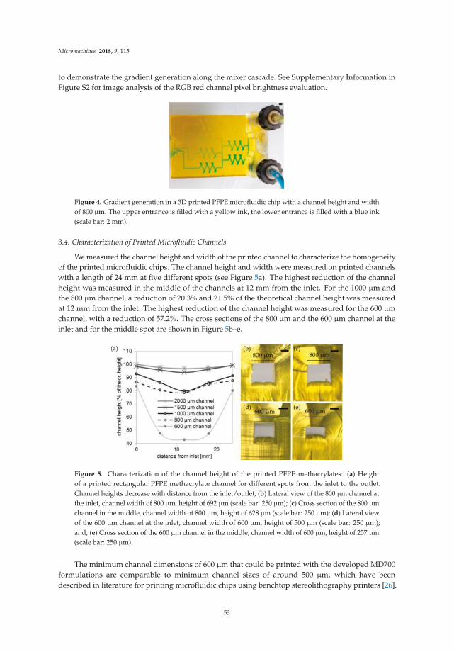
Micromachines 2018, 9, 115
to demonstrate the gradient generation along the mixer cascade. See Supplementary Information inFigure S2 for image analysis of the RGB red channel pixel brightness evaluation.
Figure 4. Gradient generation in a 3D printed PFPE microfluidic chip with a channel height and widthof 800 µm. The upper entrance is filled with a yellow ink, the lower entrance is filled with a blue ink(scale bar: 2 mm).
3.4. Characterization of Printed Microfluidic Channels
We measured the channel height and width of the printed channel to characterize the homogeneityof the printed microfluidic chips. The channel height and width were measured on printed channelswith a length of 24 mm at five different spots (see Figure 5a). The highest reduction of the channelheight was measured in the middle of the channels at 12 mm from the inlet. For the 1000 µm andthe 800 µm channel, a reduction of 20.3% and 21.5% of the theoretical channel height was measuredat 12 mm from the inlet. The highest reduction of the channel height was measured for the 600 µmchannel, with a reduction of 57.2%. The cross sections of the 800 µm and the 600 µm channel at theinlet and for the middle spot are shown in Figure 5b–e.
Figure 5. Characterization of the channel height of the printed PFPE methacrylates: (a) Heightof a printed rectangular PFPE methacrylate channel for different spots from the inlet to the outlet.Channel heights decrease with distance from the inlet/outlet; (b) Lateral view of the 800 µm channel atthe inlet, channel width of 800 µm, height of 692 µm (scale bar: 250 µm); (c) Cross section of the 800 µmchannel in the middle, channel width of 800 µm, height of 628 µm (scale bar: 250 µm); (d) Lateral viewof the 600 µm channel at the inlet, channel width of 600 µm, height of 500 µm (scale bar: 250 µm);and, (e) Cross section of the 600 µm channel in the middle, channel width of 600 µm, height of 257 µm(scale bar: 250 µm).
The minimum channel dimensions of 600 µm that could be printed with the developed MD700formulations are comparable to minimum channel sizes of around 500 µm, which have beendescribed in literature for printing microfluidic chips using benchtop stereolithography printers [26].
53

Micromachines 2018, 9, 115
The minimum channel dimensions in this work were mainly limited by the high viscosity (850 mPas,according to the manufacturer’s information) of the commercially available PFPE methacrylate MD700.These highly viscous resins are difficult to fully wash out of the printed microfluidic chips especiallyfor long channels. Developing resin formulations with lower viscosities by using fluorinated acrylateswith lower molecular weight and lower viscosity could help in solving this problem. Adding anappropriate solvent, like 1-butanol, to the resin formulation [27] could be another strategy to reducethe viscosity of the resin formulation with the additional advantage that the shrinkage of the materialduring solvent evaporation could further reduce the minimum channel dimensions.
The formulation for printing open-channel structures or replication masters (mix 4) was identicalto mix 3 for printing embedded microfluidic chips with the sole exception that no absorber wasrequired. Rectangular open channels with a height and width from 500 µm to 200 µm were printed.As can be seen in Figure 6a, the channels show a high uniformity of the width along the channellength. The width was measured at three different spots: The 500 µm channel possesses a width of499 ± 14 µm, the 400 µm channel a width of 413 ± 14 µm, the 300 µm channel a width of 300 ± 13 µm,and the 200 µm channel a width of 205 ± 22 µm. Figure 6b shows the cross section of the printedopen channels and demonstrates the high accuracy of the printed channel height. The 500 µm channelpossess a height of 491 ± 6 µm, the 400 µm channel a height of 403 ± 8 µm, the 300 µm channel aheight of 307 ± 6 µm, and the 200 µm channel a height of 209 ± 7 µm. Figure 6c,d shows an exemplaryprinted PFPE methacrylate structure with a 500 µm chess board structure.
Figure 6. PFPE-printed open channels with a height and width of 500 µm, 400 µm, 300 µm, 200 µmand an exemplary printed PFPE chessboard structure: (a) The top view of the open channels shows ahigh conformity of the channel width (scale bar: 500 µm); (b) The lateral view shows the accordance ofthe channel heights with the set values. The inset shows the cross section of the 500 µm channel with achannel height of approximately 491 µm (scale bars: 500 µm); (c) Exemplary printed PFPE methacrylatechessboard structure (scale bar: 2 mm); and, (d) Microscope image of the chessboard from (c) (scale bar:500 µm).
3.5. Characterization of Printed PFPE Methacrylates
Solvent compatibility of printed PFPE methacrylates of mix 3 and 5 were tested and compared toreplicated PDMS components and the printed commercial stereolithography resin Formlabs Tough.Therefore, blocks (8 × 8 × 3 mm3) were immersed in the following solvents: water, MeOH, DCM,DMF, THF, toluene, acetone, and n-heptane. As can be seen in Figure 7, the printed PFPE methacrylates
54

Micromachines 2018, 9, 115
show a higher solvent compatibility than the printed commercial resin and the replicated PDMS blocks.The printed PFPE methacryates show a maximum swelling of around 14% in THF and 11% in DCM.In comparison, PDMS showed a swelling of 146% in THF and 175% in DCM. The printed FormlabsTough parts showed the highest swelling of around 78% in DCM and 76% in DMF. However, theprinted Formlabs Tough parts that were immersed in DCM, DMF, THF, and acetone were stronglydamaged by the solvents (see Figure 7b,c). We further tested if the used absorbers and initiators affectthe chemical resistance of the printed PFPE methacrylates. For this we compared blocks made frommix 5 (initiator: PPO, absorber: T326) and from mix 3 (initiator: TPO, absorber: SOG). As can be seenfrom Figure 7, the printed polymers from both mixtures show a similar swelling, suggesting thatthe absorbers and initiators do not have major impacts on the swelling of the printed PFPE parts.We also determined the surface energies of the printed PFPE methacrylates, which were measured at19.5 ± 0.5 mN/m. Given this relatively low value, the printed PFPE methacrylates showed a high watercontact angle of 107 ± 0.8◦, which is comparable to the values described in literature [21]. Althoughthe contact angle for water on MD700 is relatively high, at 107◦ the capillary pressure (calculated usingLaplace-Young equation [28]) is around −1.4 mbar for a printed channel with a circular cross-sectionof 600 µm. Therefore, the channels do not oppose microfluidic flow in a significant manner.
Figure 7. Solvent compatibility of printed PFPE methacrylates compared to poly(dimethylsiloxane)(PDMS) and the printed commercial stereolithography resin Formlabs Tough: (a) Rectangular8 × 8 × 3 mm3 blocks were immersed in eight different solvents and the weight increase was measuredafter 24 h. The PFPE blocks show a lower weight increase than the PDMS blocks and the FormlabsTough resin, which were immersed in the solvents dichloromethane (DCM), tetrahydrofuran (THF),toluene, acetone, and n-heptane. Mix 5 (initiator: PPO, absorber: T326) and mix 3 (initiator: TPO,absorber: SOG) show a similar swelling, which demonstrates that the absorbers and initiators haveno major impact on the swelling of the printed PFPE parts; (b) Polymerized Formlabs Tough resinafter immersion in the respective solvents for 24 h. The parts were strongly damaged by DCM,dimethylformamide (DMF), THF, and acetone; (c) Photograph of a Formlabs Tough block (left) and aPFPE methacrylate block (mix 3, middle) and PDMS (right) after 24 h immersion in THF.
We further characterized the transmittance of the printed PFPE methacrylates using UV-Visspectroscopy. The transmittance of the printed PFPE methacrylates was further compared topolymerized PDMS parts. The transmission spectra of polymerized PFPE sheets with a thicknessof 250 µm are shown in Figure 8a. Mix 1 with the absorber T326 shows a transparency above 30%between 400–900 nm, mix 2 (T384-2) a transparency above 35% between 400–900 nm. Mix 3 (SOG)shows a transmittance of over 70% between 520–900 nm. Mix 4 without any absorber shows the highesttransparency above 75% between 350–900 nm. Mix 1 and mix 3 show a peak at about 330 nm and280 nm in the UV-range, which is most likely an artefact from the photoinitiator TPO. Figure 8b showstwo blocks printed from mix 1 and 2 and a microfluidic mixer that is printed from mix 3 (from left to
55

Micromachines 2018, 9, 115
right, thickness: 3.5 mm) placed on top of the logo of our lab (NeptunLab, Eggenstein-Leopoldshafen,Germany) showing the varying transparencies of the printed PFPE parts. As mentioned above, the highconcentration of T326 and T384-2 required for printing microfluidic channels below 1 mm is not readilysoluble in the formulation and required a prior dissolving in acetone. Consequently, a decrease of thetransparency of the printed PFPE methacrylates was observed. SOG, which possesses a high lightabsorption at low concentrations, is readily soluble in the mixture and the printed parts have a higheroptical clarity.
Figure 8. UV-Vis spectroscopy of PDMS and the printed PFPE methacrylates from mix 1, 2, 3 and4 show different transparencies between 190–900 nm: (a) Transmission spectra of polymerized PDMSand PFPE methacrylates from mixtures 1, 2, 3 and 4 (thickness: 250 µm). Mix 1 shows a transparencyof about 30% between 400–900 nm, mix 2 a transparency above 35% between 400–900 nm and mix 3has a transmission above 70% between 520–900 nm. Mix 4 has a transparency of over 75% between350–900 nm. Peaks at 330 and 280 nm are measured for the formulations prepared with TPO asphotoinitiator. For comparison the UV-Vis spectrum of PDMS is shown; (b) Three microfluidic chipsprinted from mixtures 1, 2, and 3 (from left to right) show different transparencies as a function of theused absorber (scale bar: 4 mm).
4. Conclusions
In this work, we have demonstrated a new method to fabricate microfluidic chips in highlyfluorinated PFPE methacrylates using stereolithography 3D printing. We have developed materialformulations that can be printed in commercial stereolithography printers. We have shown thatby adjusting the amount of initiator and absorber transparent microfluidic chips can be printed.The printed chips show high chemical resistance in the tested organic solvents. We believe thatprinting highly fluorinated PFPE methacrylates will find numerous applications from chemical resistantmicrofluidic valves to chemistry-on-chip applications.
Supplementary Materials: The following materials are available online at http://www.mdpi.com/2072-666X/9/3/115/s1, Figure S1: Overcuring and z-compensation of the Asiga Pico 2 printer: (a) Initial CAD file; (b) Slicing ofthe CAD file without the overcuring effect. The sliced CAD file has the same dimension like the initial CAD file;(c) Overcuring (l+o) is needed to prevent the slices from delamination during the printing process; (d) During theslicing process the overcuring is taken into account by the so called z-compensation. The shown sliced channelstructure is higher than the initial CAD file; (e) The difference is polymerized by the overcuring during theprinting process. The printed channel has the height of the initial CAD file. Figure S2: Determination of the colorintensity in a PFPE-printed microfluidic channel (800 µm channel height and width) at different mixing positions:(a) The color intensity ((red+green+blue)/3) at different measurement spots shows the gradient generation in themicrofluidic chip; (b) Greyscale image of the microfluidic chip showing the position of the measurement spots.
Acknowledgments: This work was funded by the German Ministry of Education and Research (BMBF), fundingcode 03X5527 “Fluoropor”.
56

Micromachines 2018, 9, 115
Author Contributions: F.K. printing experiments and formulations, P.R. printing experiments and formulations,D.H. UV-Vis measurements and writing of the paper, B.E.R. concept idea and writing of the paper.
Conflicts of Interest: The authors declare no conflict of interest.
References
1. Waheed, S.; Cabot, J.M.; Macdonald, N.P.; Lewis, T.; Guijt, R.M.; Paull, B.; Breadmore, M.C. 3D printedmicrofluidic devices: Enablers and barriers. Lab Chip 2016, 16, 1993–2013. [CrossRef] [PubMed]
2. Bhattacharjee, N.; Urrios, A.; Kanga, S.; Folch, A. The upcoming 3D-printing revolution in microfluidics.Lab Chip 2016, 16, 1720–1742. [CrossRef] [PubMed]
3. Au, A.K.; Huynh, W.; Horowitz, L.F.; Folch, A. 3D-printed microfluidics. Angew. Chem. Int. Ed. 2016, 55,3862–3881. [CrossRef] [PubMed]
4. Tsuda, S.; Jaffery, H.; Doran, D.; Hezwani, M.; Robbins, P.J.; Yoshida, M.; Cronin, L. Customizable 3D printed‘plug and play’ millifluidic devices for programmable fluidics. PLoS ONE 2015, 10, e0141640. [CrossRef][PubMed]
5. Su, W.J.; Cook, B.S.; Fang, Y.N.; Tentzeris, M.M. Fully inkjet-printed microfluidics: A solution to low-costrapid three-dimensional microfluidics fabrication with numerous electrical and sensing applications. Sci. Rep.
2016, 6. [CrossRef] [PubMed]6. Ho, C.M.B.; Ng, S.H.; Li, K.H.H.; Yoon, Y.-J. 3D printed microfluidics for biological applications. Lab Chip
2015, 15, 3627–3637. [CrossRef] [PubMed]7. Malinauskas, M.; Žukauskas, A.; Hasegawa, S.; Hayasaki, Y.; Mizeikis, V.; Buividas, R.; Juodkazis, S. Ultrafast
laser processing of materials: From science to industry. Light Sci. Appl. 2016, 5, e16133. [CrossRef]8. Jonušauskas, L.; Gailevicius, D.; Mikoliunaite, L.; Sakalauskas, D.; Šakirzanovas, S.; Juodkazis, S.;
Malinauskas, M. Optically clear and resilient free-form µ-optics 3D-printed via ultrafast laser lithography.Materials 2017, 10, 12. [CrossRef] [PubMed]
9. Gong, H.; Bickham, B.P.; Woolley, A.T.; Nordin, G.P. Custom 3D printer and resin for 18 µm × 20 µmmicrofluidic flow channels. Lab Chip 2017, 17, 2899–2909. [CrossRef] [PubMed]
10. Kotz, F.; Plewa, K.; Bauer, W.; Schneider, N.; Keller, N.; Nargang, T.; Helmer, D.; Sachsenheimer, K.;Schafer, M.; Worgull, M.; et al. Liquid glass: A facile soft replication method for structuring glass. Adv. Mater.
2016, 28, 4646–4650. [CrossRef] [PubMed]11. Kotz, F.; Arnold, K.; Bauer, W.; Schild, D.; Keller, N.; Sachsenheimer, K.; Nargang, T.M.; Richter, C.; Helmer, D.;
Rapp, B.E. Three-dimensional printing of transparent fused silica glass. Nature 2017, 544, 337–339. [CrossRef][PubMed]
12. De Mello, A. Focus: Plastic fantastic? Lab Chip 2002, 2, 31N–36N. [CrossRef] [PubMed]13. Kotz, F.; Arnold, K.; Wagner, S.; Bauer, W.; Keller, N.; Nargang, T.M.; Helmer, D.; Rapp, B.E. Liquid PMMA:
A high resolution polymethylmethacrylate negative photoresist as enabling material for direct printing ofmicrofluidic chips. Adv. Eng. Mater. 2017. [CrossRef]
14. Jarvis, N.L.; Zisman, W.A. Surface Chemistry of Fluorochemicals; Report of NRL Progress; U.S. Naval ResearchLaboratory (NRL): Washington, DC, USA, 1965.
15. Begolo, S.; Colas, G.; Viovy, J.L.; Malaquin, L. New family of fluorinated polymer chips for droplet andorganic solvent microfluidics. Lab Chip 2011, 11, 508–512. [CrossRef] [PubMed]
16. Sharma, G.; Klintberg, L.; Hjort, K. Viton-based fluoroelastomer microfluidics. J. Micromech. Microeng. 2011,21. [CrossRef]
17. Ogilvie, I.R.G.; Sieben, V.J.; Cortese, B.; Mowlem, M.C.; Morgan, H. Chemically resistant microfluidic valvesfrom viton® membranes bonded to COC and PMMA. Lab Chip 2011, 11, 2455–2459. [CrossRef] [PubMed]
18. Goyal, S.; Desai, A.V.; Lewis, R.W.; Ranganathan, D.R.; Li, H.R.; Zeng, D.X.; Reichert, D.E.; Kenis, P.J.A.Thiolene and SIFEL-based microfluidic platforms for liquid-liquid extraction. Sen. Actuators B Chem. 2014,190, 634–644. [CrossRef] [PubMed]
19. Renckens, T.J.A.; Janeliunas, D.; van Vliet, H.; van Esch, J.H.; Mul, G.; Kreutzer, M.T. Micromolding ofsolvent resistant microfluidic devices. Lab Chip 2011, 11, 2035–2038. [CrossRef] [PubMed]
20. Riche, C.T.; Zhang, C.C.; Gupta, M.; Malmstadt, N. Fluoropolymer surface coatings to control droplets inmicrofluidic devices. Lab Chip 2014, 14, 1834–1841. [CrossRef] [PubMed]
57

Micromachines 2018, 9, 115
21. Rolland, J.P.; Van Dam, R.M.; Schorzman, D.A.; Quake, S.R.; DeSimone, J.M. Solvent-resistant photocurable“liquid teflon” for microfluidic device fabrication. J. Am. Chem. Soc. 2004, 126, 2322–2323. [CrossRef][PubMed]
22. Vitale, A.; Quaglio, M.; Marasso, S.L.; Chiodoni, A.; Cocuzza, M.; Bongiovanni, R. Direct photolithographyof perfluoropolyethers for solvent-resistant microfluidics. Langmuir 2013, 29, 15711–15718. [CrossRef][PubMed]
23. De Marco, C.; Gaidukeviciute, A.; Kiyan, R.; Eaton, S.M.; Levi, M.; Osellame, R.; Chichkov, B.N.; Turri, S. Anew perfluoropolyether-based hydrophobic and chemically resistant photoresist structured by two-photonpolymerization. Langmuir 2013, 29, 426–431. [CrossRef] [PubMed]
24. Credi, C.; Levi, M.; Turri, S.; Simeone, G. Stereolithography of perfluoropolyethers for the microfabricationof robust omniphobic surfaces. Appl. Surf. Sci. 2017, 404, 268–275. [CrossRef]
25. Melchels, F.P.W.; Feijen, J.; Grijpma, D.W. A review on stereolithography and its applications in biomedicalengineering. Biomaterials 2010, 31, 6121–6130. [CrossRef] [PubMed]
26. Urrios, A.; Parra-Cabrera, C.; Bhattacharjee, N.; Gonzalez-Suarez, A.M.; Rigat-Brugarolas, L.G.; Nallapatti, U.;Samitier, J.; DeForest, C.A.; Posas, F.; Garcia-Cordero, J.L. 3D-printing of transparent bio-microfluidic devicesin peg-da. Lab Chip 2016, 16, 2287–2294. [CrossRef] [PubMed]
27. Ligon, S.C.; Liska, R.; Stampfl, J.; Gurr, M.; Mülhaupt, R. Polymers for 3D printing and customized additivemanufacturing. Chem. Rev. 2017, 117, 10212–10290. [CrossRef] [PubMed]
28. Rapp, B.E. Microfluidics: Modeling, Mechanics and Mathematics; William Andrew: Norwich, NY, USA, 2016.
© 2018 by the authors. Licensee MDPI, Basel, Switzerland. This article is an open accessarticle distributed under the terms and conditions of the Creative Commons Attribution(CC BY) license (http://creativecommons.org/licenses/by/4.0/).
58

micromachines
Technical Note
Characterization of 3D-Printed Moulds for SoftLithography of Millifluidic Devices
Nurul Mohd Fuad 1, Megan Carve 1, Jan Kaslin 2 and Donald Wlodkowic 1,3,*
1 School of Science, RMIT University, Melbourne, VIC 3083, Australia; [email protected] (N.M.F.);[email protected] (M.C.)
2 Australian Regenerative Medicine Institute, Monash University, Clayton, VIC 3800, Australia;[email protected]
3 Centre for Additive Manufacturing, School of Engineering, RMIT University, Melbourne, VIC 3083, Australia* Correspondence: [email protected]; Tel.: +61-3-9925-7157
Received: 2 February 2018; Accepted: 7 March 2018; Published: 8 March 2018
Abstract: Increased demand for inexpensive and rapid prototyping methods for micro- andmillifluidic lab-on-a-chip (LOC) devices has stimulated considerable interest in alternativecost-effective fabrication techniques. Additive manufacturing (AM)—also called three-dimensional(3D) printing—provides an attractive alternative to conventional fabrication techniques. AM has beenused to produce LOC master moulds from which positive replicas are made using soft-lithographyand a biocompatible elastomer, poly(dimethylsiloxane) (PDMS). Here we characterize moulds madeusing two AM methods—stereolithography (SLA) and material-jetting (MJ)—and the positive replicasproduced by soft lithography and PDMS moulding. The results showed that SLA, more than MJ,produced finer part resolution and finer tuning of feature geometry. Furthermore, as assessed byzebrafish (Danio rerio) biotoxicity tests, there was no toxicity observed in SLA and MJ moulded PDMSreplicas. We conclude that SLA, utilizing commercially available printers and resins, combined withPDMS soft-lithography, is a simple and easily accessible technique that lends its self particularly wellto the fabrication of biocompatible millifluidic devices, highly suited to the in-situ analysis of smallmodel organisms.
Keywords: stereolithography; material jetting; soft lithography; Lab-on-a-Chip; millifluidic; biodevices;biotests; polydimethylsiloxane
1. Introduction
Lab-on-a-chip (LOC) devices permit the manipulation of extremely small volumes of fluids andregents within networks of miniaturized channels, and are being readily adopted in the fields ofbiomedical and ecological testing [1–7]. Consequently, interest in the development of superior rapidand inexpensive prototyping and fabrication techniques has increased.
Traditionally, LOC devices have been prototyped and produced by methods such as laser cutting,micro milling, or soft lithography [5,8,9]. However, these techniques often require multiple stages ofassembly, a high degree of technical expertise, and the use of clean room facilities. In the case of lasercutting, low resolution and heat-related substratum deformations may occur.
Additive manufacturing (AM) techniques such as stereolithography (SLA) and material jetting(MJ) provide an elegant and practical alternative LOC fabrication method [2–4,10]. By usingcomputer-assisted design (CAD), SLA and MJ produce a solid monolithic three-dimensional (3D)object by the successive polymerization of a light-sensitive resin. The produced part requires minimalpost-processing. The multiple stages of assembly and the high degree of technical proficiency requiredby conventional LOC manufacturing techniques is thus avoided. AM has been used to produce
Micromachines 2018, 9, 116; doi:10.3390/mi9030116 www.mdpi.com/journal/micromachines59

Micromachines 2018, 9, 116
optically transparent LOC devices with integrated fluidic interconnects and functional elements suchas pumps and valves [11–14].
The sub-millimeter resolution achieved by the market-dominant SLA and MJ machines makesthem highly suited to application in millifluidic LOC device prototyping and production. SLAmachines such as the FORM 2 and ProJet 7000 HD, are capable of printing layers as thin as ≥25 µm,and MJ machines such as the Objet J750 can print layers as thin as ≥14 µm. The minimum featuresize achievable by SLA and MJ is dependent on accuracy, z-axis layer thickness, and laser-spot (SLA)or droplet (MJ) size. For SLA machines, features may be produced as small as ∼70 µm, and for MJ,∼100 µm [3,14,15].
Millifluidic LOC devices typically require designs customized to the selected model metazoanorganism which are typically ≤50 mm in size [10]. Consequently, LOC geometric features whichare often required include channel cross-section dimensions ranging from 250–2000 µm and featureswith high aspect ratios (width-to-height). In general, millifluidic LOC devices are difficult to rapidlyprototype, customize, and fabricate using traditional techniques and materials.
Biocompatibility of the LOC material is critical [10,16,17]. The material used in SLA and MJ is aliquid light-sensitive resin composed of a polymer–photoinitiator system, and auxiliary compoundsfor tuning material mechanical and aesthetic properties [18]. Companies recommend using theirproprietary resins in their AM machines to optimize final print resolution and mechanical properties.However, studies have identified that quantities of toxic compounds may leach from proprietary AMmaterials, reviewed in [19]. For example, Zhu et al. [9] showed that leachate from several commonlyavailable AM materials were toxic to a variety of model organisms, with exposure having both sublethaland lethal affects. Tsuda et al. [20] found that the leaching of unknown compounds from materials canunpredictably affect test organisms, and may compromise the outcomes of biological tests.
In some respects, the results found by Zhu et al. [9], and similar studies conducted byOskui et al. [21], Alifui-Segbaya [22], and Macdonald et al. [17], were unexpected because someof the materials tested (e.g., VisiJet SL Clear) have been awarded a United States Pharmacopoeia (USP)Class VI certification [23]. However, it is important to note that this certification is highly dependenton strict adherence to post-processing cleaning procedures.
Nonetheless, these studies highlight a potential obstacle in the use of proprietary AM resinsfor fabricating LOC devices intended for biological applications. Since advances in AM LOCdevices can enable a growing number of applications [6], ongoing research aims to develop thecapability of AM systems capable of using biologically compatible substrata. Several proprietaryresins are reported to be biocompatible, including the E-Shell series (Envision Tec. Inc., Dearborn, MI,USA). E-shell has been successfully applied in micro-needle fabrication with SLA-based two-photonpolymerization systems [24,25].
Custom-designed open-source resins, primarily consisting of poly(ethylene glycol) diacrylate(PEG-DA), are also reported to be biocompatible [10,26–28]. Bhattacharjee et al. [10] used PEG-DAto fabricate biocompatible petri dishes. After printing, the petri dishes were rendered biocompatibleby post-curing under ultraviolet light, followed by 24 h extraction in water to remove potential toxiccompounds (i.e., uncreated monomers and photoinitiators). Rogers et al. [13] used a B9 Creator SLAprinter and a PEG-DA custom resin to manufacture microfluidic valves and channels designed to beas narrow as 350 µm in diameter. Using the the AM technique of material extrusion, Tsuda et al. [20]created biocompatible LOC devices printed in thermoplastic materials, rendered biocompatible bypost-treatment with oxygen plasma bonding of a silicone-based polymer.
Those involved in the design and application of AM for LOC in vitro bioassays should exercisecaution in their approach, and aim to avoid the use of potentially toxic materials which may leach fromAM-printed parts in aqueous media. Compared to the direct AM of LOC devices, transfer mouldinghas been explored as a more rapid and economic manufacturing method [29]. Transfer mouldinginvolves the AM of moulds which are used to cast a relief in a material which has the desired properties,such as biocompatible poly(dimethylsiloxane) (PDMS). For example, Glick et al. [29] used transfer
60

Micromachines 2018, 9, 116
moulding to produce a biocompatible LOC with geometrically complex components and roundedchannels as narrow as 100 µm. In this example, the ProJet 3000 SLA printer was used to produce themoulds, and PDMS was used for casting.
The main motivation of our work was to demonstrate an easily and widely accessible user-friendlyand inexpensive fabrication method using “off-the-shelf” resins and commercially available AMprinters to produce biocompatible millifluidic systems for application in bioengineering, biomedicaland toxicological fields, and for use in laboratories that may or may not have direct access toAM facilities. This method utilizes standard technology and materials and requires minimuminfrastructure investments, thus reducing the entry barrier to this technology when compared toconventional techniques.
In this work, we use two different AM methods—SLA (ProJet 7000 HD) and MJ (Objet350)—toproduce moulds for casting PDMS, and compare these AM methods for application in PDMS transfermoulding for the production of biocompatible millifluidic LOC devices. We characterize both themoulds and PDMS replicas, and assess the toxicity of PDMS replicas by using zebrafish (Danio rerio)toxicity tests.
2. Materials and Methods
2.1. Metrology
Scanning electron micrographs were taken using a Quanta 200 SEM (FEI Inc., Hillsboro, OR, USA)operating at 20.0 kV and 5.0 Spot size in high vacuum. Samples were coated with Au/Pd using anin-house sputter coater operating at 15 mA for 2 min [9]. Optical profilometry was performed using aContourGT-I 3D Optical Microscope (Bruker Daltonics Inc., Billerica, MA, USA) with stitching enabled,as described by Zhu et al. [9]. Images were analysed with Image J.
2.2. Additive Manufacturing
AM prototypes were designed using SolidWorks 2011 (Dassault Systems SolidWorks Corp.,Waltham, MA, USA). The CAD was exported as a .stl file and processed by the AM machine softwarepackages. SLA was performed with ProJet 7000 HD in VisiJet SL Clear resin (3D Systems Inc., Rock Hill,SC, USA), and MJ performed with Objet350 Connex, in VeroClear resin (Stratasys Inc., Eden Prairie,MN, USA) and as described earlier [9,30].
2.3. Soft-Lithography
Replica moulding was performed in PDMS (Sylgard 184; DowCorning Corp, Midland, MI, USA)according to a standard protocol as described earlier [31]. Briefly, the PDMS was mixed at a 10:1weight-to-weight (w/w) ratio of elastomer base to curing agent, then degassed at 40 Torr to removeany residual air bubbles. PDMS was then poured on master moulds to achieve approximately 5 mmthickness and cured thermally at 75 ◦C for up to 1 h.
2.4. Non-Contact Laser Machining
Controls were fabricated using infra-red computer numerical control (CNC) laser machining ofpoly(methyl methacrylate) (PMMA) substrate by the methods described by Khoshmanesh et al. [32]and Akagi et al. [31]. The laser cutting system achieved x–y accuracy of up to 5 µm.
2.5. Toxicological Profiling
The OECD 236 Fish Embryo Acute Toxicity (FET) Assay [33] and fish behavioural toxicitytest [9,30] were employed to assess toxicity as described previously [9,30]. Five days post-fertilisation(DPF) zebrafish (Danio rerio) embryos were used in all tests. Animals were treated according to MonashUniversity Ethics Committee regulations and protocols.
61

Micromachines 2018, 9, 116
3. Results and Discussion
A combination of AM negative relief moulds and soft lithography were used to produce abiocompatible millifluidic LOC. Preliminary validation experiments showed that this approach ishighly suited to the design, prototyping, and production of LOC with cages designed to mirror theshape of the biological specimen.
The reproduction quality of geometric features of the printed moulds made by two differentAM techniques was compared, and PDMS replicas were assessed using SEM and quantitative 3Dtopographic surface mapping using optical profilometry. The x–y and z resolution of the printedmoulds were also evaluated and compared. Of the two techniques, SLA was found most suitable forthis application.
The two AM machines used in this study were the Objet350 Connex (MJ) and ProJet 7000 HD(SLA), and both are claimed to have ”ultra-high definition” capabilities. Positive relief test structures(moulds) were fabricated using the ProJet 7000 HD in VisiJet SL Clear resin, and the Objet350 Connexin VeroClear resin. Accuracy of the moulds was evaluated by comparing the fabricated dimensionsto the dimensions in the CAD. There was variability between SLA and MJ in terms of accuracy(Figures 1 and 2).
Figure 1. Physical characteristics of moulds fabricated using additive manufacturing processes:(A) SEM image of the cross-section of millifluidic positive relief pattern made with infrared lasercutting (and subsequent thermal bonding to obtain a complete mould), ProJet 7000 HD (in VisiJet SLClear resin), and Objet350 Connex (in VeroClear resin). (B) Deviation from designed feature geometryof high aspect ratio poly(dimethylsiloxane) (PDMS) replicas. Dotted boxes represent the designedgeometry superimposed on SEM images of PDMS channel cross-sections. (C) Quantitative analysis ofAM moulds. Angle parameter denotes an average deviation from the designed geometry measuredtop plane edges of positive relief moulds. Measurements were performed on cross-sectional viewsobtained using SEM. Measurements were made with ImageJ software (n = 20).
In general, we found that the smallest feature reliably produced by both machines was ∼300 µmin width and height. Features such as rectangular channel geometries with straight sidewalls fabricatedby the ProJet 7000 HD more closely matched the theoretical CAD design than the features fabricatedby the Objet350 Connex.
62

Micromachines 2018, 9, 116
Figure 2. Physical characteristics of millifluidic channel replicas obtained from stereolithography (SLA;ProJet) or material jetting (MJ; Objet350 Connex) printed moulds: (A) SEM image of the channel withrectangular cross-section formed by moulding PDMS on a positive relief pattern made with ProJet 7000HD (in VisiJet SL Clear resin). The channel was obtained from two identical and sandwiched PDMSreplicas; (B) Relationship between the designed and actual width parameter of rectangular channelsfabricated using SLA or MJ; (C) The relationship between the designed and actual height parameter ofrectangular channels fabricated using SLA or MJ; (D) SEM micrographs of the channel with circularcross-section formed by moulding PDMS on a positive relief pattern made with ProJet 7000 HD inVisiJet SL Clear resin; (E) Relationship between the designed and actual feature width (defined here asa diameter in the centre plane) of circular channels fabricated using SLA or MJ; and (F) The relationshipbetween the designed and actual height parameter (defined here as a diameter in the vertical plane) ofcircular channels fabricated using SLA or MJ. Measurements using ImageJ software were performedon cross-sectional views obtained using SEM (n = 20).
For positive relief test structures fabricated by the ProJet 7000 HD, deviation from the designedgeometry was typically <10%, irrespective of feature dimension, and vertical walls exhibited an angularskew in the vertical plane of 6–9◦ compared to the design parameters (Figure 1). In contrast, thosefabricated by the Objet350 Connex failed to reproduce straight edges and corners. Considerable edgerounding—up to 60◦—occurred at the bottom and top planes of the channels. Rounding was morepronounced when fabricating features ≤600 µm in height, which resulted in deviations from the designedgeometry >40%.
The Objet350 Connex tended to exceed the designed channel width; for example, when printingfeatures designed to be smaller than 400 µm, the printed object feature was ∼650 µm (±25µm)(Figure 2). Accuracy improved when fabricating channels designed to be larger than 900 µm inwidth. While the printer achieved excellent results in terms of height deposition, significant edgerounding artefacts prevented the printed channels having a rectangular shape as specified by design.Furthermore, the Objet350 Connex could not reproduce semicircular geometries reliably, and deviationsfrom the designed geometry exceeded 40%.
We explored the fabrication of millifluidic channels with both rectangular and circularcross-sections (Figure 2, and Figure S1). When fabricating channels with both rectangular and circularcross-sections from two sandwiched PDMS replicas, the ProJet 7000 HD achieved the most consistencywith theoretical design parameters. For instance, a channel with a designed geometry of 500 × 500 µm,width and height, was reproduced with dimensions of 520 ± 6 µm × 484 ± 5 µm (Figure 2). Thiscorresponded to average deviations from a desired CAD geometry in x and y-axis of ∼5%. Overall, theProJet 7000 HD tended to exceed channel width by 5–7%. The ProJet 7000 HD also failed to match the
63

Micromachines 2018, 9, 116
CAD file with respect to height. The degree of inaccuracy varied depending on the designed height.Precision decreased for designed rectangular channel heights of 1000 µm and for circular cross-sectionheights of 400 µm (Figure 2).
The control method—infra-red laser cutting—was unable to fabricate an optically transparentpositive relief pattern with a channel width <300 µm. Achievable laser x–y accuracy was up to 5 µm.The vertical walls exhibited an angular skew in the vertical plane of ∼8◦ compared to the specifieddesign parameters (Figure 1). This is likely due to significant thermal deformation and melting damageof PMMA sheets (data not shown). These results show that these geometries are not easily fabricatedby laser micromachining or photolithography methods.
A considerable advantage of using SLA to fabricate LOC moulds is that it permits fine controlover complex topologies without any additional cost or complex protocols. Accordingly, we exploredthe capability of fabricating miniaturized 3D-cages that mirrored the shape of the selected biologicalspecimen, larval zebrafish (D. rerio) (Figure 3). Such 3D geometries are typically difficult to achieveusing conventional methods such as laser micromachining or photolithography. In addition, thesemethods require multiple stages of assembly, multiple masks, repeated coatings, photoresist re-flow,development, and alignment procedures.
Figure 3. Fabrication of miniaturized 3D cages that mirror the shape of the biological specimens suchas the larval stages of zebrafish (Danio rerio) using SLA moulds: (A) Microphotograph of a positiverelief pattern fabricated using a ProJet 7000 HD in VisiJet SL Clear resin. The mould is the size of astandard microscope slide 25 mm × 75 mm. The dashed box denotes a single 3D cage; (B) Topographicsurface analysis of a single 3D cage (marked as dashed box in (A) using scanning electron microscopy(SEM); (C) D. rerio larvae immobilized inside a PDMS cage, made from an SLA mould and that mirrorsthe organisms shape; and (D) High-resolution fluorescence imaging of a transgenic Fli1a:EGFP D. rerio
larva showing green fluorescent protein (GFP)-expressing vasculature. Larger and smaller vessels areclearly distinguishable in the trunk region (boxed area, red outline).
Soft-lithography moulds the size of a standard microscope slide (25 mm × 75 mm; Figure 3) werefabricated using SLA process in under 40 min, and cost ∼US$2 per template. In comparison, lasermachining soft-lithography moulds took ∼5 min, and cost ∼US$0.2 per mould. However, the controlmethod was more labour intensive than SLA. It required the cutting of independent PMMA layers,
64

Micromachines 2018, 9, 116
subsequent alignment for assembly in 3D structures, and then thermal bonding for >60 min. WhereasAM required transferring the CAD to the AM software.
PDMS cured well on the VisiJet SL Clear moulds and VisiJet SL Clear moulds were geometricallystable during the PDMS curing process at 70 ◦C for 1 h. In addition, the releasing of PDMS replicasdid not require any application of releasing agents. However, the curing of PDMS on VeroClear resinexperienced several polymerization issues, and were more difficult to release.
Importantly, the SLA mould could be used multiple times without any degradation or deformationof pattern geometries observed during the repeated PDMS curing cycles.
Quantitative 3D topographic surface mapping using optical profilometery revealed that PDMSreplicas had low surface roughness (Figure 4). Median surface roughness of PDMS replicas made fromVisiJet SL Clear resin moulds was higher than the control PMMA moulds (Ra = 850 nm vs. 200 nm,respectively). The SLA moulds had had an average surface roughness of 1.7 ± 0.4 µm (taking intoaccount both the tops of channels and bases of troughs). Consequently, following plasma treatment,PDMS replicas achieved proper hydraulic sealing to both glass and PDMS surfaces.
The PDMS millifluidic LOC produced from the SLA mould was optically transparent, thusenabling high-resolution fluorescence imaging (Figure 3).
Several studies have shown that photoinitiator and short-chain polymer residues that may leachfrom SLA devices exhibit a level of toxicity to test organisms [17,21,22,30,34]. This indicates thatcompounds remaining in the SLA-printed parts are not irreversibly trapped or adequately removedin standard manufacturer recommended post-processing protocols (e.g., solvent extraction andpost-curing) [23]. This has cast doubt on the appropriateness of using SLA to produce biomicrofluidicLOC devices intended for in vitro bioassays [9,16,17,35]. However, using AM to create moulds, andthe final LOC being produced by soft-lithography in PDMS side-steps these concerns.
Biocompatibility of PDMS replicas fabricated from SLA moulds was evaluated by using thewell-established and very sensitive standard OECD FET test on developing D. rerio embryos [9,17].The embryonic developmental stage is considered to be the most sensitive to environmentalperturbations, and can be readily applied to assess impacts of any potential toxic effects of chemicalsand solid phases [9,33].
The FET bioassay showed no observable toxicity of PDMS replicas fabricated using SLA moulds(Figure 4). At 24 h, all D. rerio embryos exposed to PDMS replicas survived without any developmentalabnormalities. In contrast, at 24 h, the survival rate of embryos exposed to test parts fabricated bySLA and post-processed using standard cleaning procedures was ∼0% (data not shown). Behaviouraltoxicity bioassay revealed a lack of any behavioural abnormalities in zebrafish larvae exposed to PDMSreplicas. In contrast, D. rerio larvae exposed to parts made with SLA exhibited sudden and completeparalysis. This suggests that toxic compounds did not transfer from SLA moulds to PDMS during thecasting and curing process.
One of the main limitations of conventional soft lithography for millifluidic devices is the lowavailability of inexpensive master-mould fabrication techniques, and AM presents an attractive solutionto overcoming this obstacle. Current-generation SLA technologies are generally able to print withresolutions >100 µm in the x–y dimension and >25 µm in the z dimension. Consequently, thistechnology is particularly suitable for fabricating millifluidic devices such as those designed withchannel minimum cross-section dimensions ranging from 500 to 1500 µm for use with metazoan modelorganisms. While AM cannot match the performance and resolution of photolithography, it doespermit the design and manufacture of complex geometries. SLA, rather than MJ, was shown to be abetter choice for the fabrication of the millifluidic devices used in our study.
Despite some practical limitations, the significance and convenience of PDMS replica mouldingand PDMS-on-glass-LOC is still high. Due to high metabolic rate, gas diffusion through PDMS layer isparticularly advantageous for devices aimed at bioassays on model metazoan organisms. Moreover,the elastic properties of PDMS can alleviate mechanical damage during the loading and immobilizationprocess of fragile embryonic stages. The replicas achieved a suitable level of pattern fidelity, with
65

Micromachines 2018, 9, 116
only a relatively insignificant deviation from the desired geometry of the fluidic channels. PDMSreplicas also permitted bright field and fluorescent imaging at relatively high resolution. In addition,we showed that there was no transfer of toxic compounds from AM moulds to PDMS replicas.
Figure 4. Characterization of PDMS replicas obtained from both control (CTRL) laser-cutting methodsand SLA-AM (ProJet 7000 HD) positive relief moulds: (A) Quantitative topographic surface analysis ofa representative 500 µm × 500 µm section of a millifluidic channel fabricated in PDMS from mouldsmade with laser cut and thermally bonded PMMA moulds; PMMA surface topography such asvalleys (peak-to-peak value of 200 ± 20 nm) are thermal deformations formed during laser cuttingand subsequent oven bonding. (B) Surface roughness renders of PDMS replicas obtained from ProJet7000 HD printed moulds. Surface topography characteristic of SLA was peak-to-peak = 850 ± 70 nm.Measurements consisting of at least three independent samples were taken using ContourGT-I 3Doptical profilometery. (C,D) Toxicity profiling of PDMS test wells casted on a mould fabricated usingProJet 7000 HD in VisiJet SL Clear resin. PDMS replicas were tested using OECD 236 Fish EmbryoAcute Toxicity (FET) Assay with zebrafish (Danio rerio). Comparative analysis between negative controlpolystyrene wells (CTRL), SLA moulds printed in VisiJet Clear SL (PROJET), and wells made frommoulding PDMS with Visijet Clear SL moulds (PROJET-PDMS): (C) survival of D. rerio larvae, and(D) behavioural responses of D. rerio larvae, measured as the change in total distance travelled (±S.E)after 5 min in wells. Results represent data from at least three independent experiments performedin triplicate.
Here we present a combinatorial fabrication approach utilizing SLA and soft lithography in PDMSas a viable method for the inexpensive production of high-definition biocompatible millifluidic LOCdevices. These devices are easily adaptable for use in a range of studies using small to large metazoanmodel organisms. The presented technique offers the possibility of prototyping millifluidic devices
66

Micromachines 2018, 9, 116
and iterating multiple designs per day to support fast optimization cycles and achieve significantadvancement in the definition of manufactured structures. Due to the growing availability of AMfacilities, which enables the outsourced fabrication of small batches of prototypes at a very low cost,our described manufacturing method is readily accessible to any biological laboratory. In addition,issues previously observed with polymer toxicity were avoided.
Supplementary Materials: The following are available online at www.mdpi.com/2072-666X/9/3/116/s1,Figure S1: Physical characteristics of semi-circular positive relief patterns fabricated using additive manufacturingprocesses. (A) Pattern fabricated in VisJet Clear material using the ProJet 7000 HD system; (B) PDMS replicaobtained from the master depicted in (A); (C) Pattern fabricated in Vero Clear using the Objet350 Connex system;(D) PDMS replica obtained from the master depicted in (C). Dotted lines represent the designed CAD geometrysuperimposed on SEM images of representative cross-sections.
Acknowledgments: This work was supported by: the Australian Research Council DECRA [DE130101046] (D.W.);Vice-Chancellor’s Senior Research Fellowship, RMIT University, Australia (D.W.), National Health and MedicalResearch Council [GNT1068411] (J.K.), Eva and Les Erdi foundation (J.K.). We acknowledge the assistance of:RMIT Micro Nano Research Facility (MNRF) during optical profilometry; RMIT Microscopy and MicroanalysisFacility (RMMF) during SEM imaging experiments; Monash University FishCore in zebrafish breeding andembryo culture. Zebrafish husbandry and biotests were performed according to the regulations of MonashUniversity Animal Ethics Committee.
Author Contributions: D.W. and N.M.F. conceived and designed the experiments; N.M.F. performed theexperiments; N.M.F. analyzed the data; J.K. contributed materials; D.W. and M.C. wrote the paper.
Conflicts of Interest: The authors declare no conflict of interest. The funding sponsors had no role in the designof the study; in the collection, analyses, or interpretation of data; in the writing of the manuscript, and in thedecision to publish the results.
Abbreviations
The following abbreviations are used in this manuscript:
LOC Lab-on-a-ChipAM A dditive manufacturingMJ Material jetting3D Three-dimensionalPDMS Poly(dimethylsiloxane)SLA StereolithographyPEG-DA poly(ethylene glycol) diacrylateUSP United States PharmacopeiaPMMA Poly(methyl methacrylate)CNC Computer numerical controlOECDv Organisation for Economic Co-operation and DevelopmentCAD Computer-assisted designDPF Days post-fertilisationSEM Scanning electron microscopeGFP Green fluorescent protein
References
1. Waheed, S.; Cabot, J.M.; Macdonald, N.P.; Lewis, T.; Guijt, R.M.; Paull, B.; Breadmore, M.C. 3D printedmicrofluidic devices: Enablers and barriers. Lab Chip 2016, 16, 1993–2013.
2. Au, A.K.; Huynh, W.; Horowitz, L.F.; Folch, A. 3D-Printed Microfluidics. Angew. Chem. Int. Ed. 2016,55, 3862–3881.
3. Ho, C.M.B.; Ng, S.H.; Li, K.H.H.; Yoon, Y.J. 3D printed microfluidics for biological applications. Lab Chip
2015, 15, 3627–3637.4. Chen, C.; Mehl, B.T.; Munshi, A.S.; Townsend, A.D.; Spence, D.M.; Martin, R.S. 3D-printed microfluidic
devices: Fabrication, advantages and limitations—A mini review. Anal. Methods 2016, 8, 6005–6012.5. Cartlidge, R.; Nugegoda, D.; Wlodkowic, D. Millifluidic Lab-on-a-Chip technology for automated toxicity
tests using the marine amphipod Allorchestes compressa. Sens. Actuators B Chem. 2017, 239, 660–670.
67

Micromachines 2018, 9, 116
6. Campana, O.; Wlodkowic, D. The undiscovered country: Ecotoxicology meets microfluidics. Sens. Actuators
B Chem. 2018, 257, 692–704.7. Wlodkowic, D.; Khoshmanesh, K.; Akagi, J.; Williams, D.E.; Cooper, J.M. Wormometry-on-a-chip: Innovative
technologies for in situ analysis of small multicellular organisms. Cytom. Part A 2011, 79, 799–813.8. Zhu, F.; Wigh, A.; Friedrich, T.; Devaux, A.; Bony, S.; Nugegoda, D.; Kaslin, J.; Wlodkowic, D. Automated
Lab-on-a-Chip Technology for Fish Embryo Toxicity Tests Performed under Continuous Microperfusion(µFET). Environ. Sci. Technol. 2015, 49, 14570–14578.
9. Zhu, F.; Skommer, J.; MacDonald, N.P.; Friedrich, T.; Kaslin, J.; Wlodkowic, D. Three-dimensional printedmillifluidic devices for zebrafish embryo tests. Biomicrofluidics 2015, 9, doi:10.1063/1.4927379.
10. Bhattacharjee, N.; Urrios, A.; Kang, S.; Folch, A. The upcoming 3D-printing revolution in microfluidics.Lab Chip 2016, 16, 1720–1742.
11. Gong, H.; Woolley, A.T.; Nordin, G.P. High density 3D printed microfluidic valves, pumps, and multiplexers.Lab Chip 2016, 16, 2450–2458.
12. Au, A.K.; Bhattacharjee, N.; Horowitz, L.F.; Chang, T.C.; Folch, A. 3D-printed microfluidic automation.Lab Chip 2015, 15, 1934–1941.
13. Rogers, C.I.; Qaderi, K.; Woolley, A.T.; Nordin, G.P. 3D printed microfluidic devices with integrated valves.Biomicrofluidics 2015, 9, doi:10.1063/1.4905840.
14. Macdonald, N.P.; Cabot, J.M.; Smejkal, P.; Guijt, R.M.; Paull, B.; Breadmore, M.C. Comparing MicrofluidicPerformance of Three-Dimensional (3D) Printing Platforms. Anal. Chem. 2017, 89, 3858–3866.
15. Bhushan, B.; Caspers, M. An overview of additive manufacturing (3D printing) for microfabrication.Microsyst. Technol. 2017, 23, 1117–1124.
16. Zhu, F.; Skommer, J.; Friedrich, T.; Kaslin, J.; Wlodkowic, D. 3D printed polymers toxicity profiling: A cautionfor biodevice applications. Proc. SPIE 2015, 9668, doi:10.1117/12.2202392.
17. Macdonald, N.P.; Zhu, F.; Hall, C.J.; Reboud, J.; Crosier, P.S.; Patton, E.E.; Wlodkowic, D.; Cooper, J.M.Assessment of biocompatibility of 3D printed photopolymers using zebrafish embryo toxicity assays.Lab Chip 2016, 16, 291–297.
18. Ligon, S.C.; Liska, R.; Stampfl, J.; Gurr, M.; Mulhaupt, R. Polymers for 3D Printing and Customized AdditiveManufacturing. Chem. Rev. 2017, 117, 10212–10290.
19. Carve, M.; Wlodkowic, D. 3D-Printed Chips: Compatibility of Additive Manufacturing PhotopolymericSubstrata with Biological Applications. Micromachines 2018, 9, 91.
20. Tsuda, S.; Jaffery, H.; Doran, D.; Hezwani, M.; Robbins, P.J.; Yoshida, M.; Cronin, L. Customizable 3D printed‘Plug and Play’ millifluidic devices for programmable fluidics. PLoS ONE 2015, 10, e0141640.
21. Oskui, S.M.; Diamante, G.; Liao, C.; Shi, W.; Gan, J.; Schlenk, D.; Grover, W.H. Assessing and Reducing theToxicity of 3D-Printed Parts. Environ. Sci. Technol. Lett. 2016, 3, 1–6.
22. Alifui-Segbaya, F.; Varma, S.; Lieschke, G.J.; George, R. Biocompatibility of Photopolymers in 3D Printing.3D Print. Addit. Manuf. 2017, 4, 185–191.
23. 3D Systems Inc. VisiJet SL Clear Cleaning Procedure for USP Class VI; Library Technology Reports; 3D Systems Inc.:Valencia, CA, USA, 2013; pp. 1–2.
24. Miller, P.R.; Skoog, S.A.; Edwards, T.L.; Lopez, D.M.; Wheeler, D.R.; Arango, D.C.; Xiao, X.; Brozik, S.M.;Wang, J.; Polsky, R.; et al. Multiplexed microneedle-based biosensor array for characterization of metabolicacidosis. Talanta 2012, 88, 739–742,
25. Gittard, S.D.; Ovsianikov, A.; Monteiro-Riviere, N.A.; Lusk, J.; Morel, P.; Minghetti, P.; Lenardi, C.;Chichkov, B.N.; Narayan, R.J. Fabrication of polymer microneedles using a two-photon polymerization andmicromolding process. J. Diabetes Sci. Technol. 2009, 3, 304–311.
26. Rogers, C.I.; Pagaduan, J.V.; Nordin, G.P.; Woolley, A.T. Single-monomer formulation of polymerizedpolyethylene glycol diacrylate as a nonadsorptive material for microfluidics. Anal. Chem. 2011, 83, 6418–6425,
27. Urrios, A.; Parra-Cabrera, C.; Bhattacharjee, N.; Gonzalez-Suarez, A.M.; Rigat-Brugarolas, L.G.; Nallapatti, U.;Samitier, J.; DeForest, C.A.; Posas, F.; Garcia-Cordero, J.L.; et al. 3D-printing of transparent bio-microfluidicdevices in PEG-DA. Lab Chip 2016, 16, 2287–2294.
28. Hinton, T.J.; Hudson, A.; Pusch, K.; Lee, A.; Feinberg, A.W. 3D Printing PDMS Elastomer in a HydrophilicSupport Bath via Freeform Reversible Embedding. ACS Biomater. Sci. Eng. 2016, 2, 1781–1786.
68

Micromachines 2018, 9, 116
29. Glick, C.C.; Srimongkol, M.T.; Schwartz, A.J.; Zhuang, W.S.; Lin, J.C.; Warren, R.H.; Tekell, D.R.; Satamalee,P.A.; Lin, L. Rapid assembly of multilayer micro fl uidic structures via 3D-printed transfer molding andbonding. Microsyst. Nanoeng. 2016, 2, 16063.
30. Zhu, F.; Friedrich, T.; Nugegoda, D.; Kaslin, J.; Wlodkowic, D. Assessment of the biocompatibility of three-dimensional-printed polymers using multispecies toxicity tests. Biomicrofluidics 2015, 9, doi:10.1063/1.4939031.
31. Akagi, J.; Khoshmanesh, K.; Evans, B.; Hall, C.J.; Crosier, K.E.; Cooper, J.M.; Crosier, P.S.; Wlodkowic, D.Miniaturized embryo array for automated trapping, immobilization and microperfusion of zebrafishembryos. PLoS ONE 2012, 7, e36630.
32. Khoshmanesh, K.; Akagi, J.; Hall, C.J.; Crosier, K.E.; Crosier, P.S.; Cooper, J.M.; Wlodkowic, D. New rationale forlarge metazoan embryo manipulations on chip-based devices. Biomicrofluidics 2012, 6, doi:10.1063/1.3699971.
33. OECD. Test No. 236: Fish Embryo Acute Toxicity (FET) Test Section 2: Effects on Biotic Systems. In OECD
Guidelines for the Testing of Chemicals; OECD: Paris, France, 2013; Chapter 2.34. Cebe, M.A.; Cebe, F.; Cengiz, M.F.; Cetin, A.R.; Arpag, O.F.; Ozturk, B. Elution of monomer from different
bulk fill dental composite resins. Dent. Mater. 2015, 31, e141–e149.35. Zhu, F.; Macdonald, N.; Skommer, J.; Wlodkowic, D. Biological implications of lab-on-a-chip devices fabricated
using multi-jet modelling and stereolithography processes. SPIE Microtechnol. 2015, 9518, doi:10.1117/12.2180743.
c© 2018 by the authors. Licensee MDPI, Basel, Switzerland. This article is an open accessarticle distributed under the terms and conditions of the Creative Commons Attribution(CC BY) license (http://creativecommons.org/licenses/by/4.0/).
69

micromachines
Communication
Digital Manufacturing of Selective Porous Barriers inMicrochannels UsingMulti-Material Stereolithography
Yong Tae Kim *,†, Kurt Castro †, Nirveek Bhattacharjee and Albert Folch
Department of Bioengineering, University of Washington, Seattle, WA 98195, USA; [email protected] (K.C.);[email protected] (N.B.); [email protected] (A.F.)* Correspondence: [email protected]; Tel.: +1-206-685-2257† These authors contributed equally to this work.
Received: 1 February 2018; Accepted: 13 March 2018; Published: 14 March 2018
Abstract: We have developed a sequential stereolithographic co-printing process using two differentresins for fabricating porous barriers in microfluidic devices. We 3D-printed microfluidic channelswith a resin made of poly(ethylene glycol) diacrylate (MW = 258) (PEG-DA-258), a UV photoinitiator,and a UV sensitizer. The porous barriers were created within the microchannels in a different resinmade of either PEG-DA (MW = 575) (PEG-DA-575) or 40% (w/w in water) PEG-DA (MW = 700)(40% PEG-DA-700). We showed selective hydrogen ion diffusion across a 3D-printed PEG-DA-575porous barrier in a cross-channel diffusion chip by observing color changes in phenol red, a pHindicator. We also demonstrated the diffusion of fluorescein across a 3D-printed 40% PEG-DA-700porous barrier in a symmetric-channel diffusion chip by measuring fluorescence intensity changesacross the porous barrier. Creating microfluidic chips with integrated porous barriers usinga semi-automated 3D printing process shortens the design and processing time, avoids assemblyand bonding complications, and reduces manufacturing costs compared to micromolding processes.We believe that our digital manufacturing method for fabricating selective porous barriers providesan inexpensive, simple, convenient and reproducible route to molecule delivery in the fields ofmolecular filtration and cell-based microdevices.
Keywords: multi-material stereolithography; porous barrier; diffusion; microfluidics
1. Introduction
Precise control of small molecule diffusion through porous materials and its application to analyzecell behavior is an important technology in fundamental biology, biomedicine, and pharmaceutics [1–5].Lab-on-a-chip research has progressed over the last decades by adapting microfabrication technology fromsemiconductor fabrication processes that bring advantages such as miniaturization, uniformity, accuracy,reproducibility, and fluid/cell/tissue manipulations [6–12]. Hydrogels, which are three-dimensional (3D)polymer networks with high porosity, have been employed in the field of tissue engineering, drug deliverysystems, biomaterials, and size-selective separation, among others [13–18]. The pore size of hydrogels canbe easily tuned by manipulating their crosslinking density.
Researchers have used microfluidic architectures in combination with hydrogel materials fordelivery of chemicals in cell and tissue engineering applications [19–22]. For example, Lee et al.developed a macroporous polyacrylamide and poly(ethylene glycol) diacrylate (PEG-DA) hydrogelarray within a microchannel to monitor solute transport into the hydrogel; they fabricatedmacroporous hydrogels composed of polyacrylamide and analyzed the diffusion of both glutathioneS-transferase-green fluorescent protein and dextran-fluorescein isothiocyanate into the hydrogel;they also produced PEG-DA (MW = 700) (PEG-DA-700) hydrogels and tested the penetration of
Micromachines 2018, 9, 125; doi:10.3390/mi9030125 www.mdpi.com/journal/micromachines70
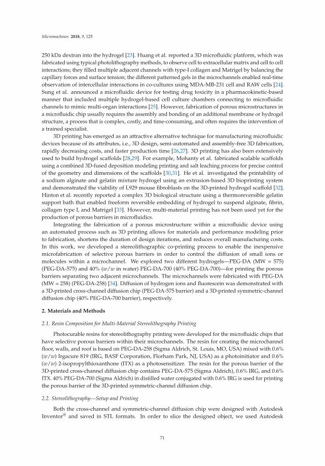
Micromachines 2018, 9, 125
250 kDa dextran into the hydrogel [23]. Huang et al. reported a 3D microfluidic platform, which wasfabricated using typical photolithography methods, to observe cell to extracellular matrix and cell to cellinteractions; they filled multiple adjacent channels with type-I collagen and Matrigel by balancing thecapillary forces and surface tension; the different patterned gels in the microchannels enabled real-timeobservation of intercellular interactions in co-cultures using MDA-MB-231 cell and RAW cells [24].Sung et al. announced a microfluidic device for testing drug toxicity in a pharmacokinetic-basedmanner that included multiple hydrogel-based cell culture chambers connecting to microfluidicchannels to mimic multi-organ interactions [25]. However, fabrication of porous microstructures ina microfluidic chip usually requires the assembly and bonding of an additional membrane or hydrogelstructure, a process that is complex, costly, and time-consuming, and often requires the intervention ofa trained specialist.
3D printing has emerged as an attractive alternative technique for manufacturing microfluidicdevices because of its attributes, i.e., 3D design, semi-automated and assembly-free 3D fabrication,rapidly decreasing costs, and faster production time [26,27]. 3D printing has also been extensivelyused to build hydrogel scaffolds [28,29]. For example, Mohanty et al. fabricated scalable scaffoldsusing a combined 3D-fused deposition modeling printing and salt leaching process for precise controlof the geometry and dimensions of the scaffolds [30,31]. He et al. investigated the printability ofa sodium alginate and gelatin mixture hydrogel using an extrusion-based 3D bioprinting systemand demonstrated the viability of L929 mouse fibroblasts on the 3D-printed hydrogel scaffold [32].Hinton et al. recently reported a complex 3D biological structure using a thermoreversible gelatinsupport bath that enabled freeform reversible embedding of hydrogel to suspend alginate, fibrin,collagen type I, and Matrigel [33]. However, multi-material printing has not been used yet for theproduction of porous barriers in microfluidics.
Integrating the fabrication of a porous microstructure within a microfluidic device usingan automated process such as 3D printing allows for materials and performance modeling priorto fabrication, shortens the duration of design iterations, and reduces overall manufacturing costs.In this work, we developed a stereolithographic co-printing process to enable the inexpensivemicrofabrication of selective porous barriers in order to control the diffusion of small ions ormolecules within a microchannel. We explored two different hydrogels—PEG-DA (MW = 575)(PEG-DA-575) and 40% (w/w in water) PEG-DA-700 (40% PEG-DA-700)—for printing the porousbarriers separating two adjacent microchannels. The microchannels were fabricated with PEG-DA(MW = 258) (PEG-DA-258) [34]. Diffusion of hydrogen ions and fluorescein was demonstrated witha 3D-printed cross-channel diffusion chip (PEG-DA-575 barrier) and a 3D-printed symmetric-channeldiffusion chip (40% PEG-DA-700 barrier), respectively.
2. Materials and Methods
2.1. Resin Composition for Multi-Material Stereolithography Printing
Photocurable resins for stereolithography printing were developed for the microfluidic chips thathave selective porous barriers within their microchannels. The resin for creating the microchannelfloor, walls, and roof is based on PEG-DA-258 (Sigma Aldrich, St. Louis, MO, USA) mixed with 0.6%(w/w) Irgacure 819 (IRG, BASF Corporation, Florham Park, NJ, USA) as a photoinitiator and 0.6%(w/w) 2-isopropylthioxanthone (ITX) as a photosensitizer. The resin for the porous barrier of the3D-printed cross-channel diffusion chip contains PEG-DA-575 (Sigma Aldrich), 0.6% IRG, and 0.6%ITX. 40% PEG-DA-700 (Sigma Aldrich) in distilled water conjugated with 0.6% IRG is used for printingthe porous barrier of the 3D-printed symmetric-channel diffusion chip.
2.2. Stereolithography—Setup and Printing
Both the cross-channel and symmetric-channel diffusion chip were designed with AutodeskInventor® and saved in STL formats. In order to slice the designed object, we used Autodesk
71

Micromachines 2018, 9, 125
Print Studio (Autodesk, Inc., San Rafael, CA, USA), which has a function for automatic meshanalysis and healing. After slicing the designed object into 25 µm-thick layers, the sliced imagesand the UV exposure settings for each layer outlined in a CSV file named layersettings.csv werecompressed into a zipped folder. The folder was then sent to the 3D printer to fabricate the object.The fabrication of the multi-material diffusion microfluidic chip was carried out in bat configurationwith an Ember DLP® 3D Printer (Autodesk, Inc.), which has a 405 nm wavelength LED, 50 µmin-plane resolution, and 10~100 µm out-of-plane resolution controlled by a digital light projector(DLP). To make transparent prints, we used a glass slide (75 mm (L) × 50 mm (W) × 1.0 mm (T)) as thesubstrate on which the designed object was built [34]. Prior to using the glass slide, the glass surfacewas thoroughly cleaned with acetone, isopropyl alcohol, and deionized (D.I.) water and dried at 70 ◦Covernight. The surface of the glass slide was plasma-activated with oxygen plasma for 180 s andtreated with 3-(trimethoxysilyl) propyl methacrylate (TMSPMA) (Sigma-Aldrich) in an 85 ◦C chamberfor 8 h. The silanized glass slide was attached to the aluminum build plate by coating one side of itwith uncured PEG-DA-258 resin and exposing it to UV light using a broadband UV lamp (B-100 A,UVP). For the microchannel fabrication, the PEG-DA-258 resin was poured into a resin tray and thenthe build plate was lowered until it reached the resin tray for calibration. After calibration, the objectwas printed with repeated cycles of UV curing, resin tray separation from the current print position,Z-Axis overlift, and resin tray approach to the new print position. This process was repeated until thewhole object was fabricated. For multi-material printing, the printer was paused at the desired layerand the PEG-DA-258 resin tray was changed to the other material (PEG-DA-575 or 40% PEG-DA-700),or vice versa. The glass slide with the printed object was removed from the build plate and cleanedusing D.I. water and pressurized air.
2.3. Molecule Diffusion Analysis
To test the hydrogen ion diffusion through the porous barrier printed using PEG-DA-575 in the3D-printed cross-channel diffusion chip, phenol red (Sigma) was employed to observe color changescorresponding to changes in acidity. Then 0.1 M HCl was injected into the bottom channel of thecross-channel diffusion chip and phenol red was loaded into the top channel of the diffusion chip.The color change of the phenol red was recorded using a Nikon SMZ1500 stereomicroscope (Nikon,Tokyo, Japan) fitted with a Canon Rebel EOS 5D Mark II DSLR camera (Canon, Tokyo, Japan).
The 3D-printed symmetric-channel diffusion microchip was utilized to transport fluoresceinmolecules through its porous barrier made of 40% PEG-DA-700 resin. The 0.1 M fluorescein wasinserted into Channel 1 of the symmetric-channel diffusion chip while PBS buffer was loaded intoChannel 2. The diffusion of fluorescein across the porous barrier from one channel to the other wasmeasured for 1 hour using an inverted epifluorescence microscope (Nikon Eclipse Ti, Plan Apo λ
2× objective).
3. Results and Discussion
3.1. Selection of Resin Components
We have fabricated selective porous barriers in microchannels using multi-materialstereolithography. We chose PEG-DA-258 to print microfluidic channels due to its characteristicssuch as photo-curability, water impermeability, transparency, and low cost [34]. We added 0.6% IRG tothe PEG-DA-258 resin because of its ability to absorb energy and initiate free radical polymerization atlonger UV wavelengths (405 nm), corresponding to that of the printer DLP projector. We also addedITX at 0.6% to increase the Z-resolution of 3D-printed microchannels. ITX, which is a sulfur-typephotosensitizer, is widely used in UV curing to promote the polymerization of photopolymers becauseof its UV absorption characteristics. PEG-DA with higher molecular weights were chosen as porousbarrier materials since it had been shown before that PEG-DA hydrogel networks (MW = 575 to 20,000)have a mesh size of 0.1 to 10 nm [35–37]. A porous barrier in the cross-channel diffusion chip was
72

Micromachines 2018, 9, 125
printed using PEG-DA-575 mixed with 0.6% IRG and 0.6% ITX for small ion diffusion such as hydrogenions. We also used 40% PEG-DA-700 in D.I. water containing 0.6% IRG to make a porous barrier forthe transport of larger molecules since adding 60% water to PEG-DA-700 resin increases the pore sizein a hydrogel polymer matrix [16].
3.2. Fabrication of a 3D-Printed Cross-Channel Diffusion Chip
Figure 1A shows the fabrication process of a cross-channel diffusion chip. We developed twodifferent resins to print the 3D-printed cross-channel diffusion chip: a resin to build the porous barrier(PEG-DA-575) and a microfluidic channel resin (PEG-DA-258). Prior to the printing of the 3D-printedcross-channel diffusion chip, the designed object was sliced into 25 µm-thick layers. A PEG-DA-258resin tray and a PEG-DA-575 resin tray were prepared to build the microchannel part and the porousbarrier part, respectively. First, the PEG-DA-258 resin tray was inserted into the Ember DLP® 3DPrinter and the first layer was created with 6 s UV exposure to aid the adhesion of the device to theglass slide. After printing a 100 µm-thick bottom layer, a 1 mm high bottom channel was fabricatedusing the PEG-DA-258 resin with a 0.3 s exposure setting for each layer. Prior to build the porousbarrier, PEG-DA-258 residue was washed using D.I. water. The PEG-DA-575 resin tray was insertedinto the printer for fabricating the porous barrier. The 100 µm-thick porous barrier was printed byirradiating each layer for 0.8 s. Compared to PEG-DA-258, PEG-DA-575 needs longer exposure timesto fabricate polymer structures because, for the same polymer mass, PEG-DA-575 has less activesites (diacrylate groups) for photopolymerization than PEG-DA-258; the smaller number of activesites results in a slower reaction speed in PEG-DA-575. The lower molecular weight monomers inPEG-DA-258 have a higher mobility in the resin, which increases the probability of radical initiation onthe carbon-carbon double bond (this radical initiation is the first step of the polymerization process).Moreover, due to its higher mobility compared to PEG-DA-575, the PEG-DA-258 molecule has a greaterchance of encountering other molecules, which also results in a faster reaction speed. To fabricatea 1 mm-high top channel, the resin tray was switched back to the PEG-DA-258 resin tray after rinsingthe PEG-DA-575 residue and the top channel was fabricated with the same conditions as the bottomchannel. In order to prevent the microchannel from clogging with PEG-DA-258 residue due tooverexposure, the resin in the microchannels was removed after printing a 100 µm-thick top channelroof and the fabrication continued until the diffusion chip was completed. At the end of the printprocess, the microchannels were flushed in a dark room with distilled water to remove any PEG-DAresin from the channel.
73

Micromachines 2018, 9, 125
Figure 1. (A) Fabrication process in cross-section schematics (top row) and 3D view (bottom row) ofa 3D-printed cross-channel diffusion microchip containing a PEG-DA-575 porous barrier. The processdepicts the fabrication of (i) the bottom layer; (ii) the bottom channel; (iii) the porous barrier; (iv) the topchannel; and (v) the roof and inlets; (B) CAD representation of the finished 3D-printed cross-channeldiffusion chip (left) and its cross-sectional schematic (right); (C) photograph (top view) of the 3D-printedcross-channel diffusion chip; the top channel is filled with red dye and the bottom channel is filled withblue dye for visualization purposes.
Figure 1B illustrates a CAD design of the 3D-printed cross-channel diffusion chip and itscross-sectional view. A photo image of the 3D-printed cross-channel diffusion chip is displayedin Figure 1C. The bottom channel is filled with blue dye while the top channel is filled with red dye.
3.3. Hydrogen Ion Diffusion Test
We confirmed the selective diffusion of hydrogen ions through a PEG-DA-575 barrier by observingpH shifts as color changes with the pH-sensitive phenol red dye. The phenol red color was shownto gradually shift from yellow to red over the pH range 6.8 to 8.2 [38]. 0.1 M HCl solution wasinjected into the bottom channel of the cross-channel diffusion chip and then 0.5% phenol red in PBSwas loaded into the top channel. Hydrogen ion diffusion was recognized by observing the colorchange of phenol red as shown in Figure 2. The phenol red solution at 0 s gradually took on a yellowcolor at 10 s at the porous barrier area, corresponding to the overlap between the two microchannels.The phenol red turned completely yellow after 70 s. The color change happened only in the topchannel, which means hydrogen ions can pass through the porous barrier from the bottom channel tothe top channel, while phenol red remains in the top channel, as illustrated in the cross-section viewof Figure 2.
Figure 2. Hydrogen ion diffusion experiment (top row) and cross-section schematic (bottom row)using the 3D-printed cross-channel diffusion chip. The phenol red in the channel (t = 0 s) graduallychanged to yellow at the channel intersection (t = 10 s) until it turned completely yellow (t = 70 s),while the bottom channel did not change color.
74

Micromachines 2018, 9, 125
3.4. Fabrication of a 3D-Printed Symmetric-Channel Diffusion Chip
Small-ion diffusion was successfully carried out with the 3D-printed cross-channel diffusion chip(see Section 3.3). However, some biomedical applications may require the delivery of larger moleculessuch as dyes and drugs. To make a hydrogel barrier with larger pores, we used 40% PEG-DA-700 mixedwith 60% water. The higher molecular weight of PEG-DA can produce larger pores in the hydrogelbecause of its longer chain length, which increases the mesh size of the polymer network. To polymerizea dilute PEG-DA-700 resin, a longer exposure time is required, which increases the risk of cloggingchannels under the porous barrier. We changed the diffusion chip design to a symmetric-channelchip having a porous barrier in between two channels, which ensured that the longer exposure timerequired to polymerize 40% PEG-DA-700 did not occlude the channels.
The fabrication process of a 3D-printed symmetric-channel diffusion chip is described in Figure 3A.PEG-DA-258 resin and 40% PEG-DA-700 resin in D.I. water were used to print the symmetric-channeland porous barrier, respectively. Prior to printing, the 3D designed symmetric-channel diffusion chipwas sliced into 25 µm thick layers similar to the cross-channel chip. As explained before, a 100 µm-thickbottom layer was printed with 6 s exposure and then eight layers of the channel (200 µm) werefabricated with 0.3 s UV irradiation for each layer. Next, the PEG-DA-258 residue was washed usingD.I. water and the 40% PEG-DA-700 resin tray was inserted. The porous barrier was created by a single6.5 s exposure of the resin, which allowed the PEG-DA-700 hydrogel structure to grow down and attachto the glass slide. The porous barrier is designed as the shape of an extruded rectangle between twomicrochannels and is, by design, 200 µm tall, 300 µm wide and 2 mm long. The PEG-DA-258 resin traywas re-installed in the 3D printer to build the last of the channel layers after cleaning the PEG-DA-700residue. To avoid clogging of the microchannels, they were cleaned after printing a 100 µm-thick rooflayer and then the diffusion chip fabrication was completed. The microchannels were washed usingdistilled water to remove uncured PEG-DA resin. Figure 3B,C show a schematic cross section anda photograph, respectively, of the device.
Figure 3. (A) Fabrication process in cross-section schematics (top row) and 3D view (bottom row) ofa 3D-printed symmetric-channel diffusion microchip with a 40% w/w PEG-DA-700 porous barrier.The process depicts the fabrication of (i) the bottom layer; (ii) the channel part 1; (iii) the porousbarrier; (iv) the channel part 2; and (v) the roof and inlets; (B) CAD representation of the 3D-printedsymmetric-channel diffusion chip (left) and its cross-sectional schematic (right); (C) photograph of the3D-printed symmetric-channel diffusion chip; Channel 1 is filled with blue dye and Channel 2 is filledwith red dye for visualization purposes.
75

Micromachines 2018, 9, 125
3.5. Fluorescein Diffusion Test
Molecular diffusion across the 40% PEG-DA-700 barrier in the 3D-printed symmetric-channelchip was tested by observing the transport of fluorescein (as a model of a small drug) using aninverted epifluorescence microscope. 0.1 mM fluorescein was loaded into Channel 1 while PBSbuffer was loaded into Channel 2. The change in fluorescence intensity as fluorescein diffused fromChannel 1 to Channel 2 was measured for 1 h. The results of the fluorescein diffusion are shownin Figure 4. The green signal was observed only in Channel 1 when fluorescein was loaded intoit (Figure 4A). Then, fluorescein molecules transferred to Channel 2 through the 40% PEG-DA-700hydrogel barrier (Figure 4B). After 60 min, the green color was clearly observed in Channel 2 as seenwith the fluorescence image in Figure 4C. The fluorescence intensity was quantitatively analyzed andplotted in Figure 4D. The fluorescence intensity gradually increased with time from 0 to 60 min in boththe 40% PEG-DA-700 hydrogel barrier and Channel 2.
Fick’s second law of diffusion was employed to calculate the diffusivity of fluorescein moleculesinto the 40% PEG-DA-700 barrier [39]:
∂C
∂t= D
∂2C
∂x2 , (1)
where D represents the diffusivity of fluorescein in 40% PEG-DA-700 and C indicates the concentrationof fluorescein.
The solution to Equation (1) can be expressed as
C(x, t) =Cx − C0
Cs − C0= 1 − er f
(
x
2√
Dt
)
= er f c
(
x
2√
Dt
)
, (2)
where C(x = 0) = Cs is the concentration of fluorescein at the junction of the porous barrier andthe channel containing fluorescein (“Channel 1”), and C(x = ∞) = C0 = 0 corresponds to the initialconcentration of fluorescein in PEG-DA [39]. We assume that Cs and C0 remain constant over time.
The characteristic diffusion length (L) at a given time (t) is defined as the distance at whichthe concentration of the diffusing species reaches 50% of the source concentration (Cs), and can beapproximated as [39]:
L ≈ (Dt)1/2. (3)
To determine the diffusivity of fluorescein in the 40% PEG-DA-700 barrier, we acquired time-lapseimages of fluorescein diffusion through the hydrogel from 0 min to 10 min using an invertedepifluorescence microscope. The fluorescent time-lapse images were analyzed using ImageJ to obtainthe diffusion profiles, which show that the fluorescein molecules diffuse into the porous barrier(Figure 4E). For the duration of the experiment (t = 10 min), since C(x = 200 µm) = 0, we canassume that there is negligible mass loss from the porous barrier into Channel 2. We plotted theexperimentally observed characteristic diffusion length (L) as a function of the square root of time(t1/2) and performed a linear regression analysis to determine the diffusivity (D). The diffusivity offluorescein in 40% PEG-DA-700 was estimated to be ~4.6 × 10⁻⁷ cm2/s from the slope (D1/2) of thefitted curve (L = 6.77951t1/2, adjusted R2 = 0.99343) (Figure 4E inset).
76

Micromachines 2018, 9, 125
Figure 4. Fluorescein diffusion test using the 3D-printed symmetric-channel diffusion microchip.(A–C) Fluorescein diffused through the 40% PEG-DA-700 hydrogel barrier from 0 min to 60 min;(D) graph of the fluorescein intensity profiles obtained across the microchannel in the three imagesabove, showing that the fluorescein intensity gradually increased in Channel 2; (E) concentrationprofile of fluorescein in the 40% PEG-DA-700 hydrogel barrier from 1 min to 10 min. (Inset) Plot of thecharacteristic diffusion length as a function of the square root of time (dots); the red line is a linear fit ofthe dots, L = 6.77951t1/2 (adjusted R2 = 0.99343).
4. Conclusions
Our simple 3D-printed microfluidic channel with an integrated porous barrier is thefirst step toward 3D-printed devices capable of more advanced functionalities. We developeda stereolithographic co-printing process to demonstrate the selective diffusion of small ions orfluorescein molecules through a 3D-printed porous barrier. The 3D-printed cross-channel chipand the 3D-printed symmetric-channel chip were successfully printed using PEG-DA-575 and 40%PEG-DA-700, respectively, for the porous barrier and PEG-DA-258 for the microchannels. We wereable to confirm the selective hydrogen ion diffusion through the PEG-DA-575 hydrogel barrier byobserving the color change of phenol red. Fluorescein diffusion was demonstrated using the 3D-printedsymmetric-channel chip, which has a 40% PEG-DA-700 hydrogel barrier in the microchannel.The proposed stereolithographic co-printing process for fabricating selective porous barriers willprovide an inexpensive, simple, convenient, and reproducible molecule delivery platform that canbe applied in the fields of tissue engineering, drug delivery systems, and biomaterials. 3D-printedhydrogels with larger porosities could potentially be used for filtering particles from bodily fluids suchas circulating tumor DNA, exosomes, bacteria, and circulating tumor cells, and in general 3D-printedhydrogels could be used for immobilizing biomolecules within microfluidic devices for biosensingapplications. Moreover, the biocompatibility of 3D-printed PEG-DA-258 microdevices as well as
77

Micromachines 2018, 9, 125
PEG-DA-700 structures makes our strategy of printing porous barriers inside a microchannel amenableto the development of cell-based assays and organ-on-chip platforms [40,41].
Acknowledgments: This research was partially supported by the National Cancer Institute (Grant No.5R01CA181445) and the BioNano Health-Guard Research Center funded by the Ministry of Science, ICT (MSIT) ofKorea as Global Frontier Project (Grant No. H-GUARD_2014M3A6B2060302).
Author Contributions: Yong Tae Kim fabricated the diffusion chips, tested the ion and molecule diffusion usingthe diffusion chips, and wrote the paper. Kurt Castro developed the stereolithographic co-printing methodsand PEG-DA-575 hydrogel printing conditions. Nirveek Bhattacharjee discussed the details of experiments andadvanced 3D printing using PEG-DA-258 resin. Albert Folch advised on and enabled funding for the project.
Conflicts of Interest: The authors declare no conflict of interest.
References
1. Novikov, D.S.; Fieremans, E.; Jensen, J.H.; Helpern, J.A. Random walks with barriers. Nat. Phys. 2011, 7,508–514. [CrossRef] [PubMed]
2. Nance, E.A.; Woodworth, G.F.; Sailor, K.A.; Shih, T.-Y.; Xu, Q.; Swaminathan, G.; Xiang, D.; Eberhart, C.;Hanes, J. A dense poly(ethylene glycol) coating improves penetration of large polymeric nanoparticles eithinbrain tissue. Sci. Transl. Med. 2012, 4, 149ra119. [CrossRef] [PubMed]
3. Verhulsel, M.; Vignes, M.; Descroix, S.; Malaquin, L.; Vignjevic, D.M.; Viovy, J.L. A review of microfabricationand hydrogel engineering for micro-organs on chips. Biomaterials 2014, 35, 1816–1832. [CrossRef] [PubMed]
4. Gizzatov, A.; Key, J.; Aryal, S.; Ananta, J.; Cervadoro, A.; Palange, A.L.; Fasano, M.; Stigliano, C.; Zhong, M.;Di Mascolo, D.; et al. Hierarchically structured magnetic nanoconstructs with enhanced relaxivity andcooperative tumor accumulation. Adv. Funct. Mater. 2014, 24, 4584–4594. [CrossRef] [PubMed]
5. Park, H.B.; Jung, C.H.; Lee, Y.M.; Hill, A.J.; Pas, S.J.; Mudie, S.T.; Wagner, E.V.; Freeman, B.D.; Cookson, D.J.Polymers with cavities tuned for fast selective transport of small molecules and ions. Science 2007, 318,254–258. [CrossRef] [PubMed]
6. El-Ali, J.; Sorger, P.K.; Jensen, K.F. Cells on chips. Nature 2006, 442, 403–411. [CrossRef] [PubMed]7. Unger, M.A. Monolithic microfabricated valves and pumps by multilayer soft lithography. Science 2000, 288,
113–116. [CrossRef] [PubMed]8. Sackmann, E.K.; Fulton, A.L.; Beebe, D.J. The present and future role of microfluidics in biomedical research.
Nature 2014, 507, 181–189. [CrossRef] [PubMed]9. Ren, K.; Zhou, J.; Wu, H. Materials for microfluidic chip fabrication. Acc. Chem. Res. 2013, 46, 2396–2406.
[CrossRef] [PubMed]10. Hsu, C.H.; Folch, A. Spatio-temporally-complex concentration profiles using a tunable chaotic micromixer.
Appl. Phys. Lett. 2006, 89, 144102. [CrossRef]11. Scott, A.; Weir, K.; Easton, C.; Huynh, W.; Moody, W.J.; Folch, A. A microfluidic microelectrode array for
simultaneous electrophysiology, chemical stimulation, and imaging of brain slices. Lab Chip 2013, 13, 527–535.[CrossRef] [PubMed]
12. Lai, H.; Folch, A. Design and dynamic characterization of “single-stroke” peristaltic PDMS micropumps.Lab Chip 2011, 11, 336–342. [CrossRef] [PubMed]
13. Seliktar, D. Designing cell-compatible hydrogels. Science 2012, 336, 1124–1128. [CrossRef] [PubMed]14. Vagias, A.; Košovan, P.; Koynov, K.; Holm, C.; Butt, H.J.; Fytas, G. Dynamics in stimuli-responsive
poly(N-isopropylacrylamide) hydrogel layers as revealed by fluorescence correlation spectroscopy.Macromolecules 2014, 47, 5303–5312. [CrossRef]
15. Nguyen, K.T.; West, J.L. Photopolymerizable hydrogels for tissue engineering applications. Biomaterials 2002,23, 4307–4314. [CrossRef]
16. Zustiak, S.P.; Boukari, H.; Leach, J.B. Solute diffusion and interactions in cross-linked poly(ethylene glycol)hydrogels studied by fluorescence correlation spectroscopy. Soft Matter 2010, 6, 3609–3618. [CrossRef][PubMed]
17. Hubbell, J.A. Hydrogel systems for barriers and local drug delivery in the control of wound healing.J. Control. Release 1996, 39, 305–313. [CrossRef]
18. Tourovskaia, A.; Figueroa-Masot, X.; Folch, A. Long-term microfluidic cultures of myotube microarrays forhigh-throughput focal stimulation. Nat. Protoc. 2006, 1, 1092–1104. [CrossRef] [PubMed]
78

Micromachines 2018, 9, 125
19. Hou, X.; Zhang, Y.S.; De Santiago, G.T.; Alvarez, M.M.; Ribas, J.; Jonas, S.J.; Weiss, P.S.; Andrews, A.M.; Aizenberg, J.;Khademhosseini, A. Interplay between materials and microfluidics. Nat. Rev. Mater. 2017, 2, 17016. [CrossRef]
20. Khademhosseini, A.; Langer, R. Microengineered hydrogels for tissue engineering. Biomaterials 2007, 28,5087–5092. [CrossRef] [PubMed]
21. Peppas, N.A.; Hilt, J.Z.; Khademhosseini, A.; Langer, R. Hydrogels in biology and medicine: From molecularprinciples to bionanotechnology. Adv. Mater. 2006, 18, 1345–1360. [CrossRef]
22. Cosson, S.; Lutolf, M.P. Hydrogel microfluidics for the patterning of pluripotent stem cells. Sci. Rep. 2014, 4, 4462.[CrossRef] [PubMed]
23. Lee, A.G.; Arena, C.P.; Beebe, D.J.; Palecek, S.P. Development of macroporous poly(ethylene glycol) hydrogelarrays within microfluidic channels. Biomacromolecules 2010, 11, 3316–3324. [CrossRef] [PubMed]
24. Huang, C.P.; Lu, J.; Seon, H.; Lee, A.P.; Flanagan, L.A.; Kim, H.-Y.; Putnam, A.J.; Jeon, N.L. Engineeringmicroscale cellular niches for three-dimensional multicellular co-cultures. Lab Chip 2009, 9, 1740–1748.[CrossRef] [PubMed]
25. Sung, J.H.; Kam, C.; Shuler, M.L. A microfluidic device for a pharmacokinetic–pharmacodynamic (PK–PD)model on a chip. Lab Chip 2010, 10, 446–455. [CrossRef] [PubMed]
26. Au, A.K.; Huynh, W.; Horowitz, L.F.; Folch, A. 3D-Printed Microfluidics. Angew. Chem. Int. Ed. 2016, 55,3862–3881. [CrossRef] [PubMed]
27. Bhattacharjee, N.; Urrios, A.; Kang, S.; Folch, A. The upcoming 3D-printing revolution in microfluidics.Lab Chip 2016, 16, 1720–1742. [CrossRef] [PubMed]
28. Kirchmajer, D.M.; Gorkin, R., III; in het Panhuis, M. An overview of the suitability of hydrogel-formingpolymers for extrusion-based 3D-printing. J. Mater. Chem. B 2015, 3, 4105–4117. [CrossRef]
29. Pantani, R.; Turng, L.S. Manufacturing of advanced biodegradable polymeric components. J. Appl. Polym. Sci.
2015, 132. [CrossRef]30. Mohanty, S.; Larsen, L.B.; Trifol, J.; Szabo, P.; Burri, H.V.R.; Canali, C.; Dufva, M.; Emnéus, J.; Wolff, A.
Fabrication of scalable and structured tissue engineering scaffolds using water dissolvable sacrificial 3Dprinted moulds. Mater. Sci. Eng. C 2015, 55, 569–578. [CrossRef] [PubMed]
31. Mohanty, S.; Sanger, K.; Heiskanen, A.; Trifol, J.; Szabo, P.; Dufva, M.; Emnéus, J.; Wolff, A. Fabrication ofscalable tissue engineering scaffolds with dual-pore microarchitecture by combining 3D printing and particleleaching. Mater. Sci. Eng. C 2016, 61, 180–189. [CrossRef] [PubMed]
32. He, Y.; Yang, F.; Zhao, H.; Gao, Q.; Xia, B.; Fu, J. Research on the printability of hydrogels in 3D bioprinting.Sci. Rep. 2016, 6, 29977. [CrossRef] [PubMed]
33. Hinton, T.J.; Jallerat, Q.; Palchesko, R.N.; Park, J.H.; Grodzicki, M.S.; Shue, H.-J.; Ramadan, M.H.;Hudson, A.R.; Feinberg, A.W. Three-dimensional printing of complex biological structures by freeformreversible embedding of suspended hydrogels. Sci. Adv. 2015, 1, e1500758. [CrossRef] [PubMed]
34. Urrios, A.; Parra-Cabrera, C.; Bhattacharjee, N.; Gonzalez-Suarez, A.M.; Rigat-Brugarolas, L.G.; Nallapatti, U.;Samitier, J.; DeForest, C.A.; Posas, F.; Garcia-Cordero, J.L.; et al. 3D-printing of transparent bio-microfluidicdevices in PEG-DA. Lab Chip 2016, 16, 2287–2294. [CrossRef] [PubMed]
35. Cruise, G.M.; Scharp, D.S.; Hubbell, J.A. Characterization of permeability and network structure ofinterfacially photopolymerized poly(ethylene glycol) diacrylate hydrogels. Biomaterials 1998, 19, 1287–1294.[CrossRef]
36. Mellott, M.B.; Searcy, K.; Pishko, M.V. Release of protein from highly cross-linked hydrogels of poly(ethyleneglycol) diacrylate fabricated by UV polymerization. Biomaterials 2001, 22, 929–941. [CrossRef]
37. Russell, R.J.; Axel, A.C.; Shields, K.L.; Pishko, M.V. Mass transfer in rapidly photopolymerized poly(ethyleneglycol) hydrogels used for chemical sensing. Macromolecules 2001, 42, 4893–4901. [CrossRef]
38. Pick, E.; Keisari, Y. A simple colorimetric method for the measurement of hydrogen peroxide produced bycells in culture. J. Immunol. Methods 1980, 38, 161–170. [CrossRef]
39. Kirby, B.J. Micro- and Nanoscale Fluid Mechanics: Transport in Microfluidic Devices; Cambridge University Press:Cambridge, UK, 2010; ISBN 978-0-521-11903-0.
79

Micromachines 2018, 9, 125
40. Cvetkonic, C.; Raman, R.; Chan, V.; Williams, B.J.; Tolish, M.; Bajaj, P.; Sakar, M.S.; Asada, H.H.; Saif, M.T.;Bashir, R. Three-dimensionally printed biological machines powered by skeletal muscle. Proc. Natl. Acad.
Sci. USA 2014, 111, 10123–10130.41. Khademhosseini, A.; Yeh, J.; Jon, S.; Eng, G.; Suh, K.Y.; Burdick, J.A.; Langer, R. Molded polyethylene glycol
microstructures for capturing cells within microfluidic channels. Lab Chip 2014, 4, 425–430. [CrossRef][PubMed]
© 2018 by the authors. Licensee MDPI, Basel, Switzerland. This article is an open accessarticle distributed under the terms and conditions of the Creative Commons Attribution(CC BY) license (http://creativecommons.org/licenses/by/4.0/).
80

micromachines
Article
Open Design 3D-Printable Adjustable Micropipettethat Meets the ISO Standard for Accuracy
Martin D. Brennan, Fahad F. Bokhari and David T. Eddington *
Department of Bioengineering, University of Illinois at Chicago, Chicago, IL 60607, USA;[email protected] (M.D.B.); [email protected] (F.F.B.)* Correspondence: [email protected]; Tel.: +1-312-355-3278
Received: 30 March 2018; Accepted: 17 April 2018; Published: 18 April 2018
Abstract: Scientific communities are drawn to the open source model as an increasingly utilitarianmethod to produce and share work. Initially used as a means to develop freely-available software,open source projects have been applied to hardware including scientific tools. Increasing convenienceof 3D printing has fueled the proliferation of open labware projects aiming to develop and sharedesigns for scientific tools that can be produced in-house as inexpensive alternatives to commercialproducts. We present our design of a micropipette that is assembled from 3D-printable parts and somehardware that works by actuating a disposable syringe to a user-adjustable limit. Graduations on thesyringe are used to accurately adjust the set point to the desired volume. Our open design printedmicropipette is assessed in comparison with a commercial pipette and meets the ISO 8655 standards.
Keywords: open source labware; 3D printing; functional prototyping
1. Introduction
The open source development model, initially applied to software, is thriving in the developmentof open source scientific equipment due in part to increasing access of 3D printing [1,2]. Additivemanufacturing methods have existed for decades although the recent availability of inexpensivedesktop printers [3,4] has made it feasible for consumers to design and print prototypes and evenfunctional parts, as well as consumer goods [5,6]. The proliferation of free CAD software [7–10]and design sharing sites [11–14] has also supported the growth and popularity of open designedparts and projects. Open design 3D-printable lab equipment is an attractive idea because, likeopen source software, it allows free access to technology that is otherwise inaccessible due toproprietary and/or financial barriers. Open design tools create the opportunity for scientists andeducational programs in remote or resource-limited areas to participate with inexpensive and easyto make tools [15–20]. Open source development also enables the development of custom solutionsto meet unique applications not met by commercial products that are shared freely and are usermodifiable [5,21–26]. Some advanced, noteworthy, open source scientific equipment include a PCRdevice [27], a tissue scaffold printer [28] and a two-photon microscope [29], although simple tools havethe potential to be impactful as they can serve a wider community.
Some simple and clever printable parts that have emerged are ones that give a new function toa ubiquitous existing device, such as a drill bit attachment designed to hold centrifuge tubes, allowinga dremel to be used as a centrifuge [30]. Although this may make a rather crude centrifuge, it may be anadequate solution for a fraction of the cost of a commercial centrifuge. Other examples of open sourceresearch tools that utilize 3D-printed parts include optics equipment [31], microscopes [32,33], syringepumps [34,35], reactionware [36–39] and microfluidics [40,41], and the list continues to grow [42].
One example of an everyday scientific tool that provides the opportunity for an open designsolution is the micropipette. An open design micropipette that can be made inexpensively affords
Micromachines 2018, 9, 191; doi:10.3390/mi9040191 www.mdpi.com/journal/micromachines81
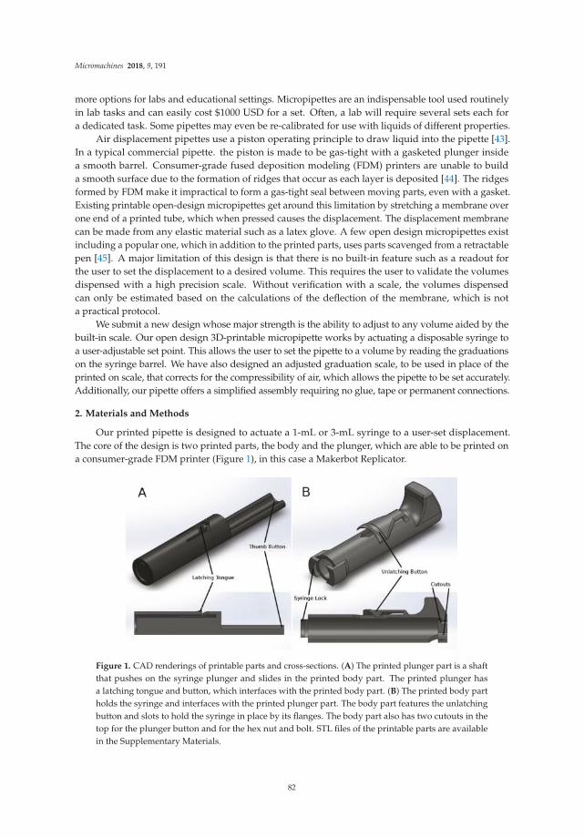
Micromachines 2018, 9, 191
more options for labs and educational settings. Micropipettes are an indispensable tool used routinelyin lab tasks and can easily cost $1000 USD for a set. Often, a lab will require several sets each fora dedicated task. Some pipettes may even be re-calibrated for use with liquids of different properties.
Air displacement pipettes use a piston operating principle to draw liquid into the pipette [43].In a typical commercial pipette. the piston is made to be gas-tight with a gasketed plunger insidea smooth barrel. Consumer-grade fused deposition modeling (FDM) printers are unable to builda smooth surface due to the formation of ridges that occur as each layer is deposited [44]. The ridgesformed by FDM make it impractical to form a gas-tight seal between moving parts, even with a gasket.Existing printable open-design micropipettes get around this limitation by stretching a membrane overone end of a printed tube, which when pressed causes the displacement. The displacement membranecan be made from any elastic material such as a latex glove. A few open design micropipettes existincluding a popular one, which in addition to the printed parts, uses parts scavenged from a retractablepen [45]. A major limitation of this design is that there is no built-in feature such as a readout forthe user to set the displacement to a desired volume. This requires the user to validate the volumesdispensed with a high precision scale. Without verification with a scale, the volumes dispensedcan only be estimated based on the calculations of the deflection of the membrane, which is nota practical protocol.
We submit a new design whose major strength is the ability to adjust to any volume aided by thebuilt-in scale. Our open design 3D-printable micropipette works by actuating a disposable syringe toa user-adjustable set point. This allows the user to set the pipette to a volume by reading the graduationson the syringe barrel. We have also designed an adjusted graduation scale, to be used in place of theprinted on scale, that corrects for the compressibility of air, which allows the pipette to be set accurately.Additionally, our pipette offers a simplified assembly requiring no glue, tape or permanent connections.
2. Materials and Methods
Our printed pipette is designed to actuate a 1-mL or 3-mL syringe to a user-set displacement.The core of the design is two printed parts, the body and the plunger, which are able to be printed ona consumer-grade FDM printer (Figure 1), in this case a Makerbot Replicator.
Figure 1. CAD renderings of printable parts and cross-sections. (A) The printed plunger part is a shaftthat pushes on the syringe plunger and slides in the printed body part. The printed plunger hasa latching tongue and button, which interfaces with the printed body part. (B) The printed body partholds the syringe and interfaces with the printed plunger part. The body part features the unlatchingbutton and slots to hold the syringe in place by its flanges. The body part also has two cutouts in thetop for the plunger button and for the hex nut and bolt. STL files of the printable parts are availablein the Supplementary Materials.
82

Micromachines 2018, 9, 191
A 1-mL or 3-mL syringe twists to lock in the body part and is held into place by the syringeflanges. The 30–300-µL configuration uses a 1-mL pipette, and the 100–1000-µL configuration usesa 3-mL pipette. The plunger part slides freely in the body part and actuates the syringe by pushingthe thumb button (Figure 2). The pipette is spring loaded towards a set point, which is adjustable bya set-screw. When the thumb button is pressed, the system locks when it reaches the latched position,where it is ready to draw in fluid. The plunger is held in place with a latching mechanism, whichwhen released, draws in fluid. The displacement is equal to the distance between the set positionand the latched position. The pipette can also be pressed past the latched position to ‘blow-out’ thetransferred fluid completely from the pipette tip. For a demonstration of the assembly and operation,see the videos in the Supplementary Materials. Additional materials required for assembly includetwo springs, a nut and a bolt (Tables A1 and A2). Attempts to make a printable luer lock adapter fortips was abandoned as the surface of printed parts is too rough to make an air-tight seal with the lueror pipette tip. Instead, a combination of a barbed luer adapter and elastic tubing is used to attach thepipette tips. Our printed pipette mimics commercial pipettes in design, function and user operation,making it intuitive to use.
Figure 2. CAD renderings of assembled pipette and function. The pipette actuates the syringe to threepositions. (A) The latched position. When the plunger is pressed, the pipette locks at this position.The tip is then placed in a liquid, and the unlatching button is pressed to release the pipette back tothe set position (B), drawing in liquid. (B) The set position. The position of the screw determinesthe total displacement that the plunger moves. The pipette is spring loaded to return to this position.(C) The blow-out position. The fluid is transferred by pressing the plunger past the latched position toblow-out all the liquid. (D) Return to the latched position. The pipette returns to the latched positionready to perform another transfer.
83

Micromachines 2018, 9, 191
Our pipette uses the air-displacement method, where a vacuum is applied to a pocket of airto draw liquid into the pipette. As air is a compressible fluid, this pocket of air expands due to theweight of the liquid pulling on it. Due to this effect, the graduations on the syringe are not accurate,as they are designed for measuring liquid within the syringe. At larger volumes, this effect is morepronounced, resulting in the volume measured being greater than the amount of liquid pulled into thesyringe. We remedied this by creating a new scale to account for the expansion. The scale is printed ona transparency sheet and is taped onto the syringe for accurate measurements (the scales appear inAppendix A: Figures A1 and A2).
2.1. Fabrication and Assembly
Two parts are printed at normal resolution with rafts on a Makerbot Replicator (STL files areavailable in the Supplementary Materials). A disposable syringe and a few extra parts are used toassemble the pipette (Figure 3). A small amount of paraffin wax is applied to the screw to prevent slopfrom causing the set point to drift after each actuation. The nut is sunk into the hex inset in the printedbody part. The bolt is threaded in from the top of the body into the nut. Two springs are threadedonto the plunger of a 1-mL syringe for the 30–300-µL configuration. Springs are placed inside a 3-mLsyringe for the 100–1000-µL configuration. The plunger part is inserted in the body, and the syringeassembly is pushed in and locked from the syringe flanges to the body part to complete assembly(Figure 4). Parts and cost are listed in Tables A1 and A2 in Appendix A.
Figure 3. Photo of the parts to make the pipette. (A) Printed body part. (B) Printed plunger part.(C) Springs. (D) M3 hex nut and M3 bolt. (E) Disposable syringes. (F) Two sizes of tubing to adaptpipette tips to luer barbs. (G) Luer lock syringe-to-barb adapters. (H) Pipette tips. A list of parts isin Appendix A: Tables A1 and A2.
84

Micromachines 2018, 9, 191
Figure 4. Photos of assembled pipettes. (A) Two assemblies of the pipette: the 100–1000-µL configuration(top) and the 30–300-µL configuration (bottom). (B) Close-up photo of the taped on scale for each ofthe syringes. Scales are available in the Appendix A: Figures A1 and A2.
2.2. Validation
The printed pipette’s accuracy and precision were characterized and compared to a commercialpipette, as well as ISO 8655. The printed pipette was adjusted to the target volume by eye from thesyringe graduations. Deionized water was transferred and measured with a high precision scale.Five transfers were recorded and averaged to account for random variability. Data were taken forprinted pipettes with existing syringe graduations, as well as with our adjusted scale. Data were takenwith commercial pipettes of 30–300 µL and 100–1000 µL to compare to the printed pipette. Accuracyand precision are expressed as systematic error and random error, respectively, and are calculatedaccording to ISO 8655 [43] (Tables 1 and 2). The systematic error, or accuracy, is calculated according tothe following equations where accuracy (A) is the difference of the mean volume (V) and the nominalvolume (Vo):
A = V − Vo, A% = 100% × A/Vo (1)
The precision or random error is the standard deviation (s) of the measurements, and (cv) is thecoefficient of variation:
s =
√
∑ni=1(Vi − V)2
n − 1, cv = 100% × s/V (2)
3. Results
Using the adjusted syringe graduation scale, our printed pipette meets ISO 8655 standards,but using the existing syringe graduation scale does not meet the ISO standard for accuracy. Accordingto ISO 8655 for a pipette with the maximum nominal volume of 1000 µL, the systematic errorcannot exceed 8 µL, and the random error cannot exceed 3 µL [43]. For the maximum nominal
85
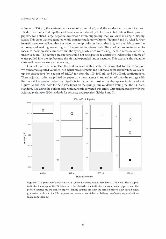
Micromachines 2018, 9, 191
volume of 300 µL, the systemic error cannot exceed 4 µL, and the random error cannot exceed1.5 µL. The commercial pipettes met these standards handily, but in our initial tests with our printedpipette, we noticed large negative systematic error, suggesting that we were missing a biasingfactor. This error was exaggerated while transferring larger volumes (Figures 5 and 6). After furtherinvestigation, we realized that the water in the tip pulls on the air due to gravity, which causes theair to expand, making measuring with the graduations inaccurate. The graduations are intended tomeasure incompressible fluids within the syringe, while we were using them to measure air whileunder vacuum. The syringe graduations could not be expected to accurately indicate the volume ofwater pulled into the tip, because the air had expanded under vacuum. This explains the negativesystematic error we were experiencing.
Our solution was to replace the built-in scale with a scale that accounted for the expansion.We compared expected volumes with actual measurements and noticed a linear relationship. We scaledup the graduations by a factor of 1:1.027 for both the 100–1000-µL, and 30–300-µL configurations.These adjusted scales are printed on paper or a transparency sheet and taped onto the syringe withthe zero at the plunger when the pipette is in the latched position (scales appear in Appendix A:Figures A1 and A2). With the new scale taped on the syringe, our validation testing met the ISO 8655standard. Replacing the built-in scale with our scale corrected this effect. Our printed pipette with theadjusted scale meets ISO standards for accuracy and precision (Tables 1 and 2).
Figure 5. Comparison of the accuracy, or systematic error, among 100–1000-µL pipettes. The box plotindicates the range of the ISO standard; the plotted circle indicates the commercial pipette; and theplotted squares are the printed pipette. Empty squares are with the printed pipette with our adjustedgraduation scale, and the filled squares are measurements taken with the syringe’s existing graduations(data from Table 1.)
86

Micromachines 2018, 9, 191
Figure 6. Comparison of the accuracy, or systematic error, among 30–300-µL pipettes. The box plotindicates the range of the ISO standard; the plotted circle indicates the commercial pipette; and theplotted squares are the printed pipette. Empty squares are with the printed pipette with our adjustedgraduation scale, and the filled squares are measurements taken with the syringe’s existing graduations(data from Table 2.)
Table 1. ISO 8655 for 100–1000-µL comparing a commercial pipette with our printed pipette used withthe existing 3-mL syringe scale and an adjusted scale.
Mean Systematic Error % Sys. Err. Random Error % Rand. Err.
1000 µL
ISO 8655, 100–1000 µL 1000 8.00 0.80 3.00 0.30Commercial Pipette 1002.98 2.98 0.30 1.72 0.17Printed Pipette 949.29 −50.71 −5.07 0.60 0.06Printed Pipette Scale 1003.57 3.57 0.36 0.89 0.09
500 µL
ISO 8655, 100–1000 µL 500 8.00 1.60 3.00 0.60Commercial Pipette 503.67 3.67 0.73 0.49 0.10Printed Pipette 475.99 −24.01 −4.80 4.75 1.00Printed Pipette Scale 503.62 3.62 0.72 1.64 0.33
200 µL
ISO 8655, 100–1000 µL 200 8.00 4.00 3.00 1.50Commercial Pipette 204.61 4.61 2.30 0.15 0.07Printed Pipette 186.55 −13.45 −6.72 1.31 0.70Printed Pipette Scale 201.87 1.87 0.94 1.47 0.73
100 µL
ISO 8655, 100–1000 µL 100 8.00 8.00 3.00 3.00Commercial Pipette 104.29 4.29 4.29 1.65 1.58Printed Pipette 94.02 −5.98 −5.98 4.81 5.12Printed Pipette Scale 101.00 1.00 1.00 1.05 1.04
87

Micromachines 2018, 9, 191
Table 2. ISO 8655 for 30–300-µL comparing a commercial pipette with our printed pipette used withthe existing 3-mL syringe scale and an adjusted scale.
Mean Systematic Error % Sys. Err. Random Error % Rand. Err.
300 µL
ISO 8655, 30–300 µL 300 4.00 1.33 1.50 0.50Commercial Pipette 301.19 1.19 0.40 0.53 0.18Printed Pipette 286.91 −13.09 −4.36 0.42 0.15Printed Pipette Scale 299.11 −0.89 −0.30 0.48 0.16
200 µL
ISO 8655, 30–300 µL 200 4 2 1.5 0.75Commercial Pipette 200.06 0.06 0.03 0.46 0.23Printed Pipette 193.40 −6.60 −3.30 2.86 1.48Printed Pipette Scale 200.57 0.57 0.28 0.86 0.43
50 µL
ISO 8655, 30–300 µL 50 4 8 1.5 3Commercial Pipette 49.02 −0.98 −1.96 0.10 0.20Printed Pipette 49.62 −0.38 −0.76 1.26 2.53Printed Pipette Scale 48.73 −1.27 −2.54 1.11 2.27
30 µL
ISO 8655, 30–300 µL 30 4 13.3 1.5 5Commercial Pipette 29.08 −0.92 −3.06 0.09 0.31Printed Pipette 29.22 −0.78 −2.59 0.31 1.07Printed Pipette Scale 27.78 −2.22 −7.41 1.37 4.93
4. Discussion and Conclusions
Our printed pipette improves on existing open design pipettes in several ways. Most significantly,the user is able to adjust the syringe accurately without verifying the volume with a scale. The pipettecan be adjusted to any discrete volume within range. In addition, the assembly requires no permanentconnections using tape or glue, which allows for re-configuration and easy replacement of parts.Conveniently, our design can also reach to the bottom of a 15-mL conical tube allowing tasks suchas aspirating supernatant fluid from a cell pellet. Unlike existing designs, our design does not usea membrane that may wear out and require replacement. The only major limitation of this designcompared to the biropipette [45] is the option for a pipette tip ejector. The biropipette also uses arguablyeasier to source parts (a pen vs. a syringe) relative to what is required for our design. The biropipettealso was developed in OpenSCAD, which is free and open source CAD software, whereas our designwas created in Solidworks, a proprietary software. This creates a limitation for users who may nothave access to the proprietary software used to make the design. Fortunately, the produced STL filesare universal and can be imported and modified by any CAD software.
The luer to pipette tip connection is a good candidate for a 3D-printed solution. Unfortunately,the current state of FDM cannot make this adapter with high enough resolution or, critically, surfacesmoothness [44]. Other printing techniques, such as stereolithography (SLA) and multijet printing(MJP), provide higher resolution and smoother finishing, yet FDM is the the most widely availableand affordable of the printing technologies. SLA printers are coming down in price, but are stillsignificantly more expensive, especially considering the higher cost of the consumable resin vs. FDMfilament. Ultimately, the goal of this project is to make this pipette inexpensive and easy to make.
Our design relies heavily on the syringe, a specialized part, for the core function, as well asaccuracy. Fortunately, as disposable syringes are a regulated medical device, they must meet highstandards, making them a reliable part for this design. As good as the performance of our printedpipette is, a commercial pipette should be expected to be more reliable and preferred for criticalprocedures. Adjusting our printed pipette to the desired volume requires more time and attention,which would be tedious for procedures requiring many adjustments. On the other hand, due to the $6cost to make it, many printed pipettes could be assembled and pre-set, each for a planned transfer,rather then re-adjusting one commercial pipette for each step. The printable pipette can also be usedas a disposable, sparing the commercial micropipette when damage from volatile reagents is a concern
88

Micromachines 2018, 9, 191
or in situations were cross-contamination and resterilization is required. This pipette would also beideal for high school and teaching labs or any resource-limited program.
The open design nature of this project encourages anyone to use and submit changes to improveand add features to this design. All of the working files and documentation are kept in a publicrepository [46]. Future directions for this project include developing a tip ejection system and additionalconfigurations for transferring volumes below 30 µL, as well as increasing overall user friendliness,such as making the adjusting bolt easier to grip and improving ergonomics. It is our hope that thisproject will be under continuous development where improvements and compatibility with differentsyringes and printers can be crowd-sourced from community contributors.
Supplementary Materials: The following are available online at https://zenodo.org/record/1220094#.WtcQ2FKSCJ1: File S1: body-clip.STL, File S2: plunger.STL, Video S1: Assembly of the pipette, Video S2:Operation of the pipette.
Acknowledgments: We would like to acknowledge the UIC Bioengineering Senior Design team of 2014 for initialwork on this project: Oluwafemi Aboloye, Pedro Hurtado, Rafael Romero and Vivian Sandoval.
Author Contributions: M.D.B. wrote the manuscript. M.D.B. and F.F.B. designed the device, collected andanalyzed data and made the figures. D.T.E. advised and reviewed the manuscript.
Conflicts of Interest: Martin Brennan and David Eddington are founders of Go Go Micro LLC and have equityinterest in the company.
Appendix A. Additional Materials
Table A1. Parts and cost for the 30–300-µL pipette.
30–300 mL Configuration: Source Unit Price Part Number
Filament Makerbot $1.63 NA1-mL Syringe BD Biosciences $0.15 309628M3 Bolt, 35 mm McMaster-Carr $0.12 91287A026M3 Nut McMaster-Carr $0.01 90591A121Music Wire Compression Springs * (2) Jones Spring Co $1.23 C10-022-048Female Luer to 1/8" Hose Barb Adapter Cole-Parmer $0.40 EW-30800-08Tygon Tubing, 1/16” ID × 3/16” OD Cole-Parmer $0.03 EW-06407-72300-µL Tips (10) Fisher Scientific $0.34 02-707-447
Total $3.91
* Spring specifications: Overall length 38 mm, OD 7.62 mm, wire diameter 0.56 mm, Max load 0.86 kg, withclosed and flat ends. Also available from McMaster-Carr P/N: 9657K347.
Table A2. Parts and cost for the 100–1000-µL pipette.
100–1000 mL Configuration: Source Unit Price Part Number
Filament Makerbot $1.63 NA3-mL Syringe BD Biosciences $0.73 309657M3 Bolt, 35 mm McMaster-Carr $0.12 91287A026M3 Nut McMaster-Carr $0.01 90591A121Music Wire Compression Springs * (2) Jones Spring Co $1.23 C10-022-048Female luer to 5/32" Hose Barb Adapter Cole-Parmer $0.66 EW-45508-06Tygon Tubing, 1/8" ID × 1/4" OD Cole-Parmer $0.05 EW-06407-761000-µL Tips (10) Fisher Scientific $0.41 02-707-400
Total $4.84
* Spring specifications: Overall length 38 mm, OD 7.62 mm, wire diameter 0.56 mm, Max load 0.86 kg, withclosed and flat ends. Also available from McMaster-Carr P/N: 9657K347.
89

Micromachines 2018, 9, 191
Figure A1. Adjusted scale graduations for the 30–300-µL pipette. Adjusted scale graduations that canbe printed on paper or a transparency sheet and taped onto a 1-mL syringe. Using these graduationswill correct for expansion of air and allow ISO standards to be met. One-inch and 1-cm marks to checkthe scale are included, as well as a reproduction of the existing 1-mL syringe graduation marks.
Figure A2. Adjusted scale graduations for the 100–1000-µL pipette. Adjusted scale graduations that canbe printed on paper or a transparency sheet and taped onto a 3-mL syringe. Using these graduationswill correct for expansion of air and allow ISO standards to be met. One-inch and 1-cm marks to checkthe scale are included, as well as a reproduction of the existing 3-mL syringe graduation marks. Printthis image to 100% scale.
References
1. Baden, T.; Chagas, A.M.; Gage, G.; Marzullo, T.; Prieto-Godino, L.L.; Euler, T. Open Labware: 3-D PrintingYour Own Lab Equipment. PLoS Biol. 2015, 13, e1002086. [CrossRef]
2. Pearce, J. M. Open-Source Lab: How to Build Your Own Hardware and Reduce Research Costs; Newnes:New South Wales, Australia, 2013.
3. Makerbot Industries. Makerbot. 2018. Available online: https://www.makerbot.com/ (accessed on 18 April 2018).4. RepRap Project. RepRap. 2018. Available online: reprap.org (accessed on 18 April 2018).
90

Micromachines 2018, 9, 191
5. Fullerton, J.N.; Frodsham, G.C.M.; Day, R.M. 3D printing for the many, not the few. Nat. Biotechnol. 2014, 32,1086–1087. [CrossRef]
6. Wittbrodt, B.; Glover, A.G.; Laureto, J.; Anzalone, G.C.; Oppliger, D.; Irwin, J.L.; Pearce, J.M. Life-cycleeconomic analysis of distributed manufacturing with open-source 3-D printers. Mechatronics 2013, 23,713–726. [CrossRef]
7. Kintel, M. OpenSCAD. 2018. Available online: http://www.openscad.org/ (accessed on 18 April 2018).8. Blender Foudation. Blender. 2018. Available online: www.blender.org (accessed on 18 April 2018).9. Trimble Inc. SketchUp. 2016. Available online: www.sketchup.com (accessed on 18 April 2018).10. Autodesk Inc. Autodesk 123D. 2018. Available online: www.123dapp.com (accessed on 18 April 2018).11. Makerbot Industries. Thingiverse. 2018. Available online: https://www.thingiverse.com/ (accessed on
18 April 2018).12. National Institutes of Health. NIH 3D Print Exchange. 2018. Available online: http://3dprint.nih.gov/
(accessed on 18 April 2018).13. Stratasys. GrabCAD. Available online: https://grabcad.com/ (accessed on 18 April 2018).14. GitHub Inc. GitHub. 2018. Available online: https://github.com/ (accessed on 18 April 2018).15. Marzullo, T.C.; Gage, G.J. The SpikerBox: A Low Cost, Open-Source BioAmplifier for Increasing Public
Participation In Neuroscience Inquiry. PLoS ONE 2012, 7, e30837. [CrossRef]16. Lang, T. Advancing global health research through digital technology and sharing data. Science 2011, 331,
714–717. [CrossRef]17. Fobel, R.; Fobel, C.; Wheeler, A.R. DropBot: An open-source digital microfluidic control system with precise
control of electrostatic driving force and instantaneous drop velocity measurement. Appl. Phys. Lett. 2013,102, 1–5. [CrossRef]
18. Baker, E. Open source data logger for low-cost environmental monitoring. Biodivers. Data J. 2014, e1059.[CrossRef]
19. Cybulski, J.S.; Clements, J.; Prakash, M. Foldscope: origami-based paper microscope. PLoS ONE 2014, 9, e98781.[CrossRef]
20. Bhamla, M.S.; Benson, B.; Chai, C.; Katsikis, G.; Johri, A.; Prakash, M. Hand-powered ultralow-cost papercentrifuge. Nat. Biomed. Eng. 2017, 1, 0009. [CrossRef]
21. Pearce, J.M. Building Research Equipment with Free, Open-Source Hardware. Science 2012, 337, 1303–1304.[CrossRef]
22. Rankin, T.M.; Giovinco, N.A.; Cucher, D.J.; Watts, G.; Hurwitz, B.; Armstrong, D.G. Three-dimensionalprinting surgical instruments: are we there yet? J. Surg. Res. 2014, 189, 193–197. [CrossRef]
23. Sulkin, M.S.; Widder, E.; Shao, C.; Holzem, K.M.; Gloschat, C.; Gutbrod, S.R.; Efimov, I.R. Three-dimensionalprinting physiology laboratory technology. Am. J. Physiol.-Heart Circ. Physiol. 2013, 305, H1569–H1573.[CrossRef]
24. Dryden, M.D.M.; Wheeler, A.R. DStat: A versatile, open-source potentiostat for electroanalysis andintegration. PLoS ONE 2015, 10, 1–17. [CrossRef]
25. Costa, E.T.; Mora, M.F.; Willis, P.A.; Lago, C.L.; Jiao, H.; Garcia, C.D. Getting started with open-hardware:Development and control of microfluidic devices. Electrophoresis 2014, 35, 2370–2377. [CrossRef]
26. Tek, P.; Chiganos, T.C.; Mohammed, J.S.; Eddington, D.T.; Fall, C.P.; Ifft, P.; Rousche, P.J. Rapid prototypingfor neuroscience and neural engineering. J. Neurosci. Methods 2008, 172, 263–269. [CrossRef]
27. Chai Biotechnologies Inc. Open PCR. 2017. Available online: http://openpcr.org/ (accessed on 18 April 2018).28. Trachtenberg, J.E.; Mountziaris, P.M.; Miller, J.S.; Wettergreen, M.; Kasper, F.K.; Mikos, A.G. Open-source
three-dimensional printing of biodegradable polymer scaffolds for tissue engineering. J. Biomed. Mater. Res.
Part A 2014, 102, 4326–4335. [CrossRef]29. Rosenegger, D.G.; Tran, C.H.T.; LeDue, J.; Zhou, N.; Gordon, G.R. A High Performance, Cost-Effective,
Open-Source Microscope for Scanning Two-Photon Microscopy that Is Modular and Readily Adaptable.PLoS ONE 2014, 9, e110475. [CrossRef]
30. Garvey, C. DremelFuge. 2009. Available online: https://www.thingiverse.com/thing:1483 (accessed on18 April 2018).
31. Zhang, C.; Anzalone, N.C.; Faria, R.P.; Pearce, J.M. Open-Source 3D-Printable Optics Equipment. PLoS ONE
2013, 8, e59840. [CrossRef]
91

Micromachines 2018, 9, 191
32. Baden, T. Raspberry Pi Scope. 2014. Available online: http://3dprint.nih.gov/discover/3dpx-000609(accessed on 18 April 2018).
33. Walus, K. A Fully Printable Microscope. 2014. Available online: http://3dprint.nih.gov/discover/3dpx-000304(accessed on 18 April 2018).
34. Wijnen, B.; Hunt, E.J.; Anzalone, G.C.; Pearce, J.M. Open-Source Syringe Pump Library. PLoS ONE 2014, 9, e107216.[CrossRef]
35. Patrick, W.G.; Nielsen, A.A.; Keating, S.J.; Levy, T.J.; Wang, C.W.; Rivera, J.J.; Mondragón-Palomino, O.;Carr, P.A.; Voigt, C.A.; Oxman, N.; et al. DNA assembly In 3D printed fluidics. PLoS ONE 2015, 10, 1–18.[CrossRef]
36. Symes, M.D.; Kitson, P.J.; Yan, J.; Richmond, C.J.; Cooper, G.J.; Bowman, R.W.; Vilbrandt, T.; Cronin, L.Integrated 3D-printed reactionware for chemical synthesis and analysis. Nat. Chem. 2012, 4, 349–354.[CrossRef]
37. Kitson, P.J.; Rosnes, M.H.; Sans, V.; Dragone, V.; Cronin, L. Configurable 3D-Printed millifluidic andmicrofluidic ‘lab on a chip’ reactionware devices. Lab Chip 2012, 12, 3267–3271. [CrossRef]
38. Mathieson, J.S.; Rosnes, M.H.; Sans, V.; Kitson, P.J.; Cronin, L. Continuous parallel ESI-MS analysis ofreactions carried out In a bespoke 3D printed device. Beilstein J. Nanotechnol. 2013, 4, 285–291. [CrossRef]
39. Kitson, P.J.; Marshall, R.J.; Long, D.; Forgan, R.S.; Cronin, L. 3D Printed high-throughput hydrothermalreactionware for discovery, optimization, and scale-up. Angew. Chem. Int. Ed. 2014, 53, 12723–12728.[CrossRef]
40. Brennan, M.D.; Rexius-Hall, M.L.; Eddington, D.T. A 3D-Printed Oxygen Control Insert for a 24-Well Plate.PLos ONE 2015, 10, e0137631. [CrossRef]
41. Dragone, V.; Sans, V.; Rosnes, M.H.; Kitson, P.J.; Cronin, L. 3D-printed devices for continuous-flow organicchemistry. BeilsteIn J. Org. Chem. 2013, 9, 951–959. [CrossRef]
42. Plos Collections. Open Source Toolkit Hardware. 2017. Available online: http://collections.plos.org/open-source-toolkit-hardware (accessed on 18 April 2018).
43. International Organization for Standardization. Piston-Operated Volumetric Apparatus—Part 1: Terminology,
General Requirements and User Recommendations; ISO 8655-1:2002(en); ISO: Geneva, Switzerland, 2002.44. Takagishi, K.; Umezu, S. Development of the Improving Process for the 3D Printed Structure. Sci. Rep. 2017,
7, 39852. [CrossRef]45. Baden, T. Biropette: Customisable, High Precision Pipette. 2014. Available online: http://www.thingiverse.
com/thing:255519 (accessed on 18 April 2018).46. Eddington Lab. 3D Printable Micropipette. 2017. Available online: https://github.com/Biological-
Microsystems-Laboratory/micropipette (accessed on 18 April 2018).
c© 2018 by the authors. Licensee MDPI, Basel, Switzerland. This article is an open accessarticle distributed under the terms and conditions of the Creative Commons Attribution(CC BY) license (http://creativecommons.org/licenses/by/4.0/).
92

micromachines
Perspective
Emerging Anti-Fouling Methods: TowardsReusability of 3D-Printed Devices forBiomedical Applications
Eric Lepowsky 1 and Savas Tasoglu 1,2,3,4,5,*
1 Department of Mechanical Engineering, University of Connecticut, Storrs, CT 06269, USA;[email protected]
2 Department of Biomedical Engineering, University of Connecticut, Storrs, CT 06269, USA3 Institute of Materials Science, University of Connecticut, Storrs, CT 06269, USA4 Institute for Collaboration on Health, Intervention, and Policy, University of Connecticut,
Storrs, CT 06269, USA5 The Connecticut Institute for the Brain and Cognitive Sciences, University of Connecticut,
Storrs, CT 06269, USA* Correspondence: [email protected]; Tel.: +1-860-486-5919
Received: 21 March 2018; Accepted: 19 April 2018; Published: 20 April 2018
Abstract: Microfluidic devices are used in a myriad of biomedical applications such as cancerscreening, drug testing, and point-of-care diagnostics. Three-dimensional (3D) printing offers alow-cost, rapid prototyping, efficient fabrication method, as compared to the costly—in terms of time,labor, and resources—traditional fabrication method of soft lithography of poly(dimethylsiloxane)(PDMS). Various 3D printing methods are applicable, including fused deposition modeling,stereolithography, and photopolymer inkjet printing. Additionally, several materials are availablethat have low-viscosity in their raw form and, after printing and curing, exhibit high material strength,optical transparency, and biocompatibility. These features make 3D-printed microfluidic chips idealfor biomedical applications. However, for developing devices capable of long-term use, fouling—bynonspecific protein absorption and bacterial adhesion due to the intrinsic hydrophobicity of most3D-printed materials—presents a barrier to reusability. For this reason, there is a growing interestin anti-fouling methods and materials. Traditional and emerging approaches to anti-fouling arepresented in regard to their applicability to microfluidic chips, with a particular interest in approachescompatible with 3D-printed chips.
Keywords: 3D printing; microfluidic chips; anti-fouling; surface coatings
1. Introduction
Microfluidic devices are widely used in numerous fields. Pertaining specifically to biotechnology,microfluidic devices have been used for cancer screening [1–3], microphysiological systemengineering [4,5], high-throughput drug testing [6,7], and point-of-care diagnostics [8–10]. Withinthe broad field of microfluidics, novel technologies have been reported, such as paper-basedmicrofluidics and three-dimensional (3D) printed devices. Each of these alternative methods addressesdifferent drawbacks of the conventional soft lithography fabrication of poly(dimethylsiloxane) (PDMS)microfluidic devices. Using paper as a substrate alleviates the need for external pumps, in addition tothe added benefits of low-cost fabrication and disposability [11–16]. Three-dimensional (3D) printingis a relatively new technique in microfluidics that offers rapid prototyping of a variety of materials,enabling fabrication of high resolution molds, as well as direct fabrication of 3D-printed chips [17–24].The latter is of particular interest, as microfluidic chips can be designed using computer aided design(CAD) software and printed with high resolution. Compared to the laborious fabrication involved
Micromachines 2018, 9, 196; doi:10.3390/mi9040196 www.mdpi.com/journal/micromachines93

Micromachines 2018, 9, 196
with PDMS chips, 3D-printed chips are low-cost, efficient, and highly customizable. Microfluidicdevices, of all forms and methods, are indispensable tools in biomedical engineering. Accordingly,there is a need for reusable, long-term use of microfluidic chips for applications such as long-termhealth monitoring. Efforts towards designing long-term use microfluidic chips can be aided by thelow-cost, high-throughput capabilities offered by 3D-printing.
Fostered by biomedical research, a transformation of the healthcare industry is imminent.There is an unmet need for transformative technologies that are essential for enabling the shift fromhospital-centered, reactive care to proactive, person-centered care which focuses on individuals’well-being [25]. Next-generation technologies are the vital factor in developing affordable andaccessible care, while also lowering the costs of healthcare. A promising solution to this challengeis low-cost continuous health monitoring; this approach allows for effective screening, analysis, anddiagnosis and facilitates proactive medical intervention. In a study reported by Health Affairs, it wasshown that a 90% increase in specific preventative screenings back in 2006 would have saved more than2 million lives without a significant increase in healthcare costs—in fact, a 0.2% decrease in costs wasestimated [26]. Not only does public health benefit, but savings in healthcare costs could be drasticallyincreased by further research focused on the development and implementation of preventative caremethods and tools. To support this much-needed approach, there is an impending demand for low-cost,compact, and innovational technologies to perform routine health measurements across the population.Microfluidic devices have a proven record for being effective analytical devices, capable of controllingthe flow of fluid samples, containing reaction and detection zones, and displaying results, all within acompact footprint [27–30]. The next crucial step within microfluidic technologies is to address the needfor microfluidic chips capable of long-term use, with a particular interest in designing microfluidicchips that can be embedded within sophisticated medical devices without the need for replacement bythe user [31,32].
A primary challenge in producing microfluidic devices for long-term use is the biofouling that oftenoccurs on the surface of integrated channels and features [33,34]. This phenomenon occurs due to surfaceinteractions between the walls of the channels and the biological sample flowing through the channels.As a result, there is an accumulation of unwanted substances on the surface of the microfluidic channels,thereby adversely affecting the performance of the device. Specifically, protein fouling, or nonspecificprotein absorption, is the cause of failure for many microfluidic devices [31]. Furthermore, once a proteinlayer is formed, bacterial attachment and growth of biofilms is facilitated. To address the long-termuse of microfluidic devices, there has been a growing research interest in developing new anti-foulingmethods and materials [31,32,35–39]. If fouling can be reduced to miniscule levels, a device may beconsidered reusable for the purpose of point-of-care, long-term health monitoring performed ex vivo.Possible solutions for reducing or preventing biofouling have been explored, including dynamic coatingand chemical modification. Additionally, with the advent of 3D-printed microfluidic devices, there is anewfound interest in studying the protein absorption of 3D-printed materials [40–42]. Directly associatedwith protein absorption are possible anti-fouling techniques which may be implemented to improve thesurface properties of 3D-printed devices. With continued research, these anti-fouling methods appliedto 3D-printed microfluidic devices will work towards the future of reusable, long-term use, low-cost,point-of-care biomedical devices. Herein, we assess the reusability of 3D-printed chips for biomedicalapplications through a review of 3D-printed microfluidic fabrication techniques, 3D-printable materials,and traditional and emerging anti-fouling methods and materials.
2. 3D-Printed Microfluidics
2.1. Fabrication Methods for 3D-Printed Microfluidics
There are several 3D printing techniques, including the following: fused deposition modeling(FDM), stereolithography (SLA), photopolymer inkjet printing, selection laser sintering (SLS),binder deposition, laminated object manufacturing [19], two-photon polymerization (2PP), and
94

Micromachines 2018, 9, 196
micromirror-controlled projection printing [20]. In FDM, depicted in Figure 1a, a thermoplastic filamentis fed through a nozzle [17,19,20,43]. Within the nozzle, rollers force the solid filament through heaterswhich melt the filament prior to extrusion. The melted filament is then deposited onto the print-bedwhere it solidifies post-extrusion. SLA 3D printers use light to cure layers of photosensitive resin,as seen in Figure 1b [17,19,20,43]. The resin is cured by photopolymerization caused by a laser ordigital projector that is directed towards the surface of the resin by motorized mirrors. SLA offershigh resolution, as defined by the size of the laser spot and the type of resin. Photopolymer inkjetprinting, modeled in Figure 1c, also prints with a photosensitive polymer, but functions on the conceptbehind inkjet printing: the liquid photopolymer is deposited onto the print-bed by an inkjet printinghead [17,19,20,43,44]. By printing layer-by-layer, each layer is deposited and subsequently curedby UV light. Two powder-based 3D printing methods are SLS and binder jetting. In SLS, a laseris used to thermally bind precursor polymer powders in a layer-by-layer fashion [19,45]. In binderjetting, a liquid adhesive, or binder, is deposited by a print head onto a bed of powder [19,43].For both SLS and binder deposition, a roller is used to form layers of powder. Another 3D printingmethod used for microfabrication is 2PP, which uses a near-IR light with high peak power within aUV-photopolymerizable resin. The photo-initiator within the resin absorbs one UV photon and twonear-IR photons, causing it to radicalize, thereby breaking its current monomer bonds and formingpolymer bonds [19,46,47]. In terms of application in microfluidic device fabrication, FDM, SLA, andphotopolymer inkjet printing are the most commonly implemented [18].
Figure 1. Schematic representation of 3D printing methods commonly applied in the fabrication ofmicrofluidic devices. (a) Fused deposition modeling (FDM) [48]: a solid filament is fed from an externalspool through the extrusion head, in which the filament is heated and extruded; (b) Stereolithography(SLA) [49]: a laser is directed at a scanning mirror which focuses the laser on a pool of photo-sensitiveresin; (c) Photopolymer inkjet printing [50]: photopolymer material and support material are fed intoan inkjet printing head which deposits the material in layers while an attached UV lamp cures theprinted material. Illustrations courtesy of [48–50].
95

Micromachines 2018, 9, 196
2.2. Materials for 3D-Printed Microfluidics
Beyond the fabrication methods, another important aspect of 3D-printed microfluidic devices isthe material itself. Certain mechanical properties are very relevant to 3D printability, including theelastic modulus and tensile strength of the post-printed material, and the viscosity of the pre-printedmaterial (Table 1) [17]. The elastic modulus is representative of the mechanical relationship betweenstress and strain. The 3D-printed materials must withstand high internal pressures from the fluidflow; due to the high fluid-induced stress, the resulting degree of strain is an important factor inchoosing a material [51]. Likewise, tensile strength also helps to characterize the mechanical propertiesof the material in terms of the forces it can withstand. Additionally, the viscosity of the material beforeprinting (for resins) is an important factor in determining the printability and resolution of the print.The material must be thin enough (low viscosity) to be precisely deposited in minute quantities butmust also be sufficiently thick (high viscosity) such that it does not spread, migrate, or deform duringthe printing process. Viscosity also plays a role in the ease of cleaning the microfluidic channelspost-printing—a lower viscosity is preferred for easier and quicker emptying and rinsing of channelsand semi-enclosed geometries.
Additional material properties that are necessary for microfluidics include high opticaltransparency, hydrophobicity or hydrophilicity, and biocompatibility (Table 1). Optical transparencyis extremely useful for microfluidic applications since visual observation and imaging are oftennecessary. In particular, a transparent microfluidic chip allows for qualitative observations—a visualcheck on proper fluid flow and reagent interactions—as well as quantitative, through-chip imagingusing either visible transmitted light or fluorescence detection. PDMS is widely used for microfluidicdevice fabrication and has excellent transparency [52]. Several 3D-printable resins have comparabletransparency. However, these resins may suffer from fogginess or discoloration over time due toexcessive UV-light exposure after fabrication. In some cases, such as for Formlabs clear resin, a thinlayer of isopropyl alcohol, oil, or PDMS can be applied to the exterior surfaces of the printed chip tofacilitate transparency. Additionally, some commonly used materials in 3D printing exhibit naturalfluorescence due to the photo-initiators used for curing, contributing to fluorescent background noise,which could be problematic in fluorescent imaging systems—a challenge which can be mitigatedby proper calibration of the imaging process [43,53,54]. Another important property of materials inmicrofluidics is their intrinsic hydrophobicity or hydrophilicity. Hydrophobic surfaces are more proneto suffering from fouling due to surface interactions, whereas hydrophilic surfaces can facilitate aprotective hydration layer [31,55]. Since practically all 3D-printable resins are hydrophobic, eithercopolymerization, material grafting, or a surface treatment is necessary for anti-fouling purposes.While it should not absorb or react with biological agents in the fluid sample, such as proteins orbacteria, the material should be biocompatible. In biomedical applications, it is likely that living cellsmay come into contact with the 3D-printed material. Fortunately, the majority of 3D-printable resinsare reportedly biocompatible or can be UV-treated to reduce cytotoxicity [20,40,56].
Table 1. Materials for 3D printing.
3D Printing Properties Important Properties for Microfluidics
Material/ExampleElastic
Modulus (GPa)Tensile
Strength (MPa)Viscosity
(cps)Optical Transparency Hydro-Phobicity/Philicity Bio-Compatibility
Poly(dimethylsiloxane)(PDMS) (for
comparison) [52,57]0.00132–0.00297 3.51–7.65 N/A
High transparency(standard)
Hydrophobic Biocompatible
MakerBot polylacticacid (PLA) [40,58,59]
3.368 56.6 N/A Semi-transparentHydrophobic, easily
modifiedBiocompatible,biodegradable
MakerBot acrylonitrilebutadiene styrene
(ABS) [40,58]1.807 28.5 N/A Opaque Hydrophobic Biocompatible
Formlabs proprietarymethacrylate[40,43,60–62]
2.7 61.5 850–900 Transparent, discolors Hydrophobic N/A
Asiga PlasCLEARpolypropylene/ABS
[43,63,64]N/A 52.6 342 Semi-transparent N/A N/A
96

Micromachines 2018, 9, 196
Table 1. Cont.
3D Printing Properties Important Properties for Microfluidics
Material/ExampleElastic
Modulus (GPa)Tensile
Strength (MPa)Viscosity
(cps)Optical Transparency Hydro-Phobicity/Philicity Bio-Compatibility
Stratasys Objectacrylates and acrylics
[19,43,65]2–3 50–65 N/R Transparent, discolors Hydrophobic Biocompatible
3DSystems VisiJetClear Class [40,66–69]
0.866–2.168 20.5–49 150–260 Semi-transparent N/A Biocompatible
Somos WaterShedXC [19,40,43,70–72]
2.77 50.4 260 Transparent, discolors Hydrophobic Biocompatible
MiiCraft acrylates(BV-007 ClearResin) [43,73]
N/A N/A N/A Semi-transparent N/A Biocompatible available
DWS Lab Vitra 429 &DS3000 [74]
1.38 32–35 600–850 Transparent N/A Short-term biocompatible
2.3. Benefits and Applications of 3D-Printed Microfluidics
Given the variety of fabrication methods and materials available for 3D printing, it is alsoimportant to consider the benefits and applications of 3D-printed microfluidics. The conventionalmethod for fabricating microfluidic devices is soft lithography, which involves casting PDMS based ona semi-3D mold [20]. A channel pattern, designed using CAD software, is used to fabricate a masternegative-mold. The mold is fabricated, most often by a photoresist process, consisting of spin coatingSU-8 on a wafer and exposing it to an ultraviolet source filtered by a photomask. The master mold isthen filled with PDMS, which is then allowed to cure. After curing, the PDMS is peeled away fromthe master, cut into the shape of the desired device, and inlet ports are punched. The cast PDMS isthen oxygen plasma treated to improve adhesion to a glass substrate, resulting in the final microfluidicdevice, in which one of the four channel walls is provided by the glass. This conventional fabricationprocess is extremely time consuming, involves extensive manual operation, and requires new molds fordifferent designs [75–77]. Additionally, the channel height of traditional PDMS microfluidic chips castusing soft lithography, determined by the material properties of the photoresist, is extremely limited.Although photoresist-based molds can have a very high resolution, fabricating complex designs isa tedious and exacting process, requiring photomasks to be perfectly aligned, to expose sequentiallayers of photoresist [78]. Even with multiple layers of photoresist, three-dimensional PDMS chips arenot feasible, as 3D PDMS designs are produced by layering and thus cannot be arbitrarily complex.Three-dimensional (3D) printing offers a solution to these challenges, yet it comes with its own uniqueset of limitations [19]. The resolution achievable by 3D printing cannot match that of soft lithography.Similarly, the smooth surface of PDMS cannot be recreated by 3D-printed materials. 3D printing canbe implemented in two ways: (1) to fabricate a mold, and (2) to directly print the device.
While conventional photoresist-based molds yield smoother surface topology and smaller featuresizes, this method is often economically unfeasible, inaccessible, and involves a lengthy prototypingprocess [79]. On the other hand, molds can be fabricated by 3D printing, which enables low-costproduction of more complex designs. Fabrication of PDMS microfluidic chips using 3D-printed mastermolds provides many of the advantages of 3D printing fabrication while maintaining the desirablematerial properties of PDMS, such as biocompatibility and gas permeability [17]. The mold benefitsfrom rapid prototyping techniques, reducing the overall cost and time required for fabrication andenabling a simple method for printing new mold designs. Additionally, 3D-printed molds enableconsiderably more complex channel geometries: circular cross-section channels [80], non-planarchannels such as helices and pillars [81], and even complex intermingling internal patterns supportedby sacrificial scaffolds which can be dissolved or melted away post-production [82–84].
Three-dimensional (3D) printing can also be implemented to directly fabricate microfluidicdevices. Rather than designing a negative-mold for the chip, the chip is printed using the 3D-printedmaterial. This method reduces fabrication costs, increases the speed of production, and is ideal for rapidprototyping and low-cost microfluidic devices. Since the whole device is directly printed, 3D printingeliminates the assembly steps required by conventional molding processes and allows for quick
97

Micromachines 2018, 9, 196
changes to the design, simply requiring a few hours for the new design to print. Another advantage ofprogressing beyond mold-based fabrication is the ability to produce arbitrarily defined structures in afully 3D space, with no significant increase in fabrication complexity and time [78,85]. Furthermore, awide variety of microfluidic components can be fabricated by 3D printing, including passive, whichrely on external actuation or capillary forces, and active, which apply energy to manipulate fluid flowcomponents. Examples of passive 3D-printed components include a micromixer, gradient generator,droplet generator, reaction zones, and check valves [17,86–89]. Active 3D-printed components whichhave been demonstrated include active valves, flow switches, and pumps [17,54,70].
Fully-functional 3D-printed microfluidic chips have also been designed for biomedical applications(Figure 2), such as a chip for inertial focusing and separation of bacteria [90], high-throughput drugtransport and cell viability testing [91], electrochemical detection [92], pathogen detection of bacteriaand viruses [93,94], biological assays and cell observations [95,96], and cancer assays and studieson cell migration [97]. Figure 2a demonstrates a mixing scheme which has broad applicability tohigh-throughput combinatorial testing applications, such as drug screening, biochemical assays,lab-on-chip devices, and biosensors [98]. Figure 2b shows an bacteria detection device which separatescaptured bacteria using inertial focusing [90]. The fabrication of this device’s complex helical geometryand trapezoidal cross-section channels was only made possible by the capabilities of 3D printing.Figure 2c depicts a single-valve 3D-printed microfluidic device which allows for the controlledopening and closing of channels [70]. While soft-lithographic automation generally involves PDMSlayering, alignment, and bonding, the pictured device offers a rapid, prototyped alternative, whichis completely fabricated by stereolithography. Additionally, two-valve and four-valve switches havealso been demonstrated. Such actuated switches can be pivotal in microfluidic sample handlingfor various assays. Figure 2d shows a three-dimensional microfluidic device built from identical,individual elements [99]. As another example of enhanced control of fluid flow, these modular3D-printed elements allow for a wide variety of fluidic circuits to be constructed. Figure 2e offersan example of a 3D-printed mini-bioreactor (MBRA) for cultivating fecal microbial communitiesto study epidemic Clostridium difficile strains [100]. The MBRAs used in this study benefitted fromthe simple, high-throughput fabrication process offered by 3D printing. Figure 2f demonstratesanother 3D-printed microfluidic mixing device; however, instead of solely relying on two-dimensionalserpentines and splitters, the pictured device utilizes three-dimensional channel patterns to improvethe gradient generation [86]. Finally, Figure 2g,h detail a multi-material 3D-printed device for themicrophysiological study of cardiac tissues [101]. The functionality of the device relies on contractionsof cardiac tissue to deflect a cantilever substrate, thereby stretching an embedded strain gaugewhich generates a resistance chance proportional to the stress of the tissue (Figure 2g). The deviceitself was printed with multiple materials to form the cantilever base, strain gauge wire, wire cover,tissue-guiding microfilaments, electrical leads, and surrounding wells. The inset images of Figure 2hshow (1) a confocal microscopy image of the immunostained cardiac tissues tested using this device,(2) an image of an active cantilevered device, and (3) an example of the resistance signal from thecantilever deflection. These examples demonstrate the wide applicability of 3D-printed microfluidicsto biomedical applications.
98

Micromachines 2018, 9, 196
Figure 2. Biomedical applications of 3D-printed microfluidic devices; (a) A combinatorial mixerwhich generates four titrations of two dye solutions and produces combinatorial mixes of the dyetitrations to deliver sixteen mixture combinations into separate outlet microchannels (reproduced,with permission, from [98]); (b) a helical-shaped 3D microfluidic device with trapezoidal-shapedchannels for the detection of pathogenic bacteria by inertial focusing (reproduced, with permission,from [90]); (c) automated 3D-printed microfluidic single-valve device. Below are micrographs of thevalve unit in its open and closed states (reproduced, with permission, from [70]); (d) single-outletsub-circuit elements are connected to form a four-outlet mixer. Each sub-circuit element is identical,constituted by a single inlet splitter (reproduced, with permission, from [99]); (e) example of a simple,high-throughput mini-bioreactor array (MBRA) used for the cultivation of microbial communities(reproduced, with permission, from [19,100]); (f) Three-dimensional gradient generator for the mixingof two dyes, consisting of three levels of combining, mixing, and splitting (reprinted, with permission,from [86], Copyright 2014 American Chemical Society); (g,h) instrumented cardiac microphysiologicaldevice fabricated by multi-material 3D printing; (g) illustration of the working principles of themicrophysiological device; (h) images of the fully-printed device (reproduced, with permission,from [101]).
3. Anti-Fouling Methods and Materials
3.1. Traditional Anti-Fouling Methods and Materials
Attributed to the hydrophobicity of PDMS, microfluidic devices fabricated using this traditionalmaterial exhibit low wettability and are prone to biofouling from nonspecific protein and analyteabsorption and cell and bacterial adhesion [102]. To counteract the fouling, coatings aim to minimizeintermolecular forces and interactions between the surface and samples. Pertaining to protein fouling,absorption into the substrate can be due to hydrogen bonding, electrostatic forces, charge-transfers,or hydrophobic interactions [55].
99

Micromachines 2018, 9, 196
Considerable work has been done to create a hydrophilic PDMS surface with anti-foulingproperties [31,36]. Physical methods to accomplish this adaptation rely on changing the state ofthe PDMS surface via physical processes. For instance, a coating material may be absorbed by thePDMS by hydrophobic or electrostatic interaction. Alternatively, the surface can be treatment-activatedby plasma, ozone, or ultraviolet exposure. There are also chemical modification methods that havebeen studied, such as covalent bonding between a coating material and the PDMS. Both physical andchemical methods have their respective drawbacks—physical modification results in only temporaryanti-fouling, with the effectiveness decreasing over time, while chemical modification requires complexprocesses with several reagents and procedural steps. Consequently, these methods may not be idealfor commercialization, particularly for fabricating long-term use or low-cost devices, since theyare often ephemeral and laborious. Polymer chain length is an important factor when consideringanti-fouling mechanisms [31]. Protein resistance can be achieved by a hydration layer of short chainlength polymers, which forms due to the hydrophilicity of the short chains. In addition to forming ahydrophilic hydration layer, long chain length materials have the added benefit of steric repulsionfrom the flexible polymer chains. When tuning the protein resistance of a material, longer chainlengths are therefore preferred since they exhibit both a hydration layer and steric repulsion. Beyondhydrophilicity, anti-fouling mechanisms should be electrically neutral and should only have hydrogenbond acceptors—no hydrogen bond donors [103].
A widely used anti-fouling surface treatment is a poly(ethylene oxide) (PEO) or poly(ethyleneglycol) (PEG) coating. PEO and PEG are hydrophilic and nontoxic [104,105]. They can be addedas a coating on PDMS by physical or chemical absorption, direct covalent attachment, or graftcopolymerization. The addition of PEG chains to the surface of the microfluidic channels offersanti-fouling capabilities due to a hydration layer and steric repulsion, the strength of which is dependenton factors such as surface density and the length of the PEG chains [106–110]. Another class of materialsthat has been demonstrated for anti-fouling purpose is zwitterions. Polyzwitterion-based coatingshave an equal amount of positively and negatively charged groups and thus exhibit electrical neutrality,which is a desirable characteristic [31]. Zwitterionic materials are able to form thick hydrationlayers by bonding with water molecules, forming a shield across the surface to prevent proteinabsorption [111–116]. Other types of anti-fouling coatings to prevent the absorption of nonspecificproteins include saccharide-based coatings [117–120], polyhydroxy-polymer-based coatings [121,122],amide-containing-hydrophilic-polymer-based coatings [36,123,124], and fluorinated-polymer-basedcoatings [125–128].
3.2. Emerging Anti-Fouling Methods and Materials
The numerous methods proposed for anti-fouling of PDMS suggest that reusable microfluidicdevices are plausible. However, other materials and methods are needed for anti-fouling coatings of3D-printed microfluidic devices. Novel advancements from the Wyss Institute at Harvard Universityhave yielded SLIPS (Slippery Liquid-Infused Porous Surfaces). SLIPS is an ultra-repellent, self-healing,transparent surface coating for industrial and medical materials [129]. While most repellent surfacematerials can repel aqueous substances, they often fail to repel other liquids, fail or degrade underphysical stress, cannot self-heal after repeated use, and may be very costly to implement [129–131].The SLIPS technology relies on nano- and micro-structured porous material infused with lubricatingfluid [129]. The commonality between the traditional methods and materials described above and SLIPSis the implementation of a lubrication or hydration layer. High optical transparency and compatibilitywith a myriad of substrates are what differentiate SLIPS from other coatings. These features also makeSLIPS an ideal anti-fouling material for 3D-printed microfluidic chips for biomedical applications,in addition to a variety of previously reported applications [130–133].
As a transparent, anti-fouling material, SLIPS was demonstrated for implementation on anendoscope lens to prevent vision loss after repeated submersions in blood and mucus [37]. The coatingexhibited conformability, mechanical adhesion, high transparency, biocompatibility, and high resistance
100

Micromachines 2018, 9, 196
to fogging and fouling by bodily fluids (Figure 3a,b) [134,135]. These material characteristics wereattributed to the liquid-infused structure of the coating, which consisted of a porous silica particlenetwork infiltrated with various oils, such as silicone oil which is already used in a variety ofmedical applications due to its biocompatibility and proven clinical performance [37,130,136–138].By applying the coating to the lens, cleaning procedures in between uses of the endoscope wereunnecessary or, in the worst cases, reduced to ten-to-fifteen times shorter than for an untreated lens.Additionally, the surface coating maintained a clear view through the lens, which is also extremelyimportant for 3D-printed microfluidic chips for diagnostic applications, as diagnostics often rely onthrough-chip imaging.
As opposed to the stationary lens of an endoscope, in an environment with interfaces under flow,such as the channels of a microfluidic chip, it is also important to consider the stability and longevity ofimmobilized hydration layers as surface coatings. The surface hydration layer provides a low-adhesioninterface that deters the attachment of fouling materials. However, as fouling material-laden fluidflows over the hydration layer, there is an increase in the instability of the interface [139]. Experimentalresults and mathematical modeling by Howell et al. provided several important findings: (1) initialconditioning to flush out excess lubricant from the surface reduces further losses; (2) surface structureand lubricant viscosity do not cause significant differences in performance; and (3) the formation of anair–water interface within the channel causes disruptions in the lubricant layer.
SLIPS technology has also been applied as a coating for medical materials that can effectivelysuppress thrombosis, even under high-pressure and high-shear flow [35]. An anti-thrombogenicsurface coating was formed by covalently binding a flexible tethered perfluorocarbon (TP) layer onthe material surface, which was then coated by a layer of a liquid perfluorocarbon (LP). The resultingbilayer is referred to as a tethered-liquid perfluorocarbon (TLP) surface. The TLP is capable of repellingblood and preventing the adhesion of blood components and bacteria, thereby reducing thrombosiswithout the need for anti-coagulants (Figure 3c). Even when subjected to a flowing fluid, the TPmaintains the LP hydration layer. The TLP is also simple to fabricate—virtually any substrate can bemodified by low-plasma surface modification, a procedure which is commonly used for the commercialmodification of materials and is independent of surface geometry and properties [140]. The TLP coatingis ideal for treating the surfaces of 3D-printed microfluidic channels as it is compatible with a largevariety of materials and exhibits anti-thrombogenic, anti-bacterial, and anti-fouling properties.
Another lubricant-infused coating that has been applied to polymeric biomedical devices isa new, advanced type of the traditional fluorinated-polymer-based coatings. Badv et al. recentlydemonstrated an omniphobic, lubricant-infused coating which was applied to catheters to preventthrombosis [141]. The proposed omniphobic coating functioned on a similar liquid lubricant conceptas SLIPS—a biocompatible liquid lubricant is held to the surface of the catheter to form an anti-foulingcoating. However, instead of forming a hydrophilic hydration layer as SLIPS aims to accomplish,the coating developed by Badv et al. was based on a self-assembled monolayer (SAM) of hydrophobicorganosilanes which attenuates clotting. Recently, omniphobic, lubricant-infused coatings havebeen developed as a new class of coatings created by tethering biocompatible, perfluorocarbonlubricants onto SAMs of hydrophobic organosilanes [35,130]. In greater detail, fluorous moleculescan be physically adsorbed onto fluorous-containing surfaces, facilitated by the strong intermolecularinteraction between the fluorinated lubricant and the fluorosilane layer. Such omniphobic coatings areexcellent for resisting blood clot formation and are more effective than traditional anti-fouling methods,such as PEG grafting, for blocking non-specific adhesion of cells and bacteria [142,143]. In additionto the great effectiveness of omniphobic coatings, they are stable and durable when exposed to shearstress [35,139].
A feature that sets the work of Badv et al. apart from other traditional omniphobic, fluorinated-polymer-based coatings is the method of application. The most common technique for applying SAMsof fluorine-based silanes is liquid phase deposition (LPD). LPD has a few notable drawbacks andlimitations. LPD is not commercially feasible due to the high volume of solvent waste that it produces
101

Micromachines 2018, 9, 196
which is harmful to the environment [144]. Another limitation is that the self-polymerization of silanesin the liquid may prevent homogenous silane layer formation [145]. Additionally, LPD-treated surfacesare likely to be exposed to impurities and reaction side products which may have detrimental effectson the surface itself [144]. Conversely, the proposed surface coating was applied via chemical vapordeposition (CVD), which has the following benefits: a simplified application process, a lesser effecton the topography of the receiving substrate, and greater effectiveness. CVD was performed byoxygen plasma treatment of the catheters, followed by silanization, and completed by the addition of abiocompatible liquid lubricant.
Figure 3. Emerging anti-fouling methods and materials: SLIPS (Slippery Liquid-Infused PorousSurfaces). (a,b) Evolution of the reduction in the visible area of an endoscope surface coated by SLIPSas a function of the number of dips. Silicone oil of low viscosity (10 cSt) was used as the lubricatingliquid. Red corresponds to an uncoated endoscope, which fails immediately after a single dip. Green,blue, and black correspond to three replicates of SLIPS coated endoscopes; (a) endoscope dipped inwhole porcine blood. Inset images show the visibility of the field of view at 70, 08, and 100 dips forthe poorest performing sample; (b) endoscope dipped in mucus. Insets show the visibility of a coatedendoscope after repeated dips compared to an untreated endoscope (reproduced, with permission,from [37]). (c) Comparison of the repellency of a tethered-liquid perfluorocarbon (TLP) treated surfaceto an untreated surface (reproduced, with permission, from [35]).
3.3. Anti-Fouling Methods Applied to 3D-Printed Materials
Biofouling from nonspecific protein and analyte absorption and cell and bacterial adhesion is not adetriment of only PDMS; biofouling can occur on the surfaces of all microfluidic chips, of all materials.While extensive work has been conducted to address the anti-fouling of PDMS, disproportionatelyless work has been reported for 3D printing. Nonetheless, recent studies and reviews have consideredthe biofouling of 3D-printed materials, demonstrating its significance and importance in the field.The objective of a study done by Siddiqui et al. was to propose a strategy for developing, characterizing,and testing 3D-printed feed spacers, both numerically by membrane fouling simulator (MFS) studiesand experimentally [42]. Although the biofouling of the 3D-printed device was not directly assessed,
102

Micromachines 2018, 9, 196
the results showed that a 3D-printed feed spacer was similar. Feed spacers are commonly used devicesin spiral-wound reverse osmosis and nanofiltration membrane systems to enhance water mixing andto reduce biofouling. As reported by Baker et al., the surface of feed spacers is prone to the initialdeposition of fouling which can accumulate and spread [146]. Van Paassen et al. then showed thatbiofouling accumulated on feed spacers causes an exponential increase in the pressure drop acrossthe membrane module containing the feed spacer [147]. To remedy the biofouling of feed spacers,various solutions have been proposed [148,149]. More recently, researchers have focused on the surfacechemistry of the feed spacers. Multiple studies have considered anti-fouling coatings; however, theseare more likely to wear out over time [150–154]. The solution proposed by Siddiqui et al. consideredthe native anti-fouling properties of 3D-printed materials. Their findings demonstrated the benefits of3D-printing—feed spacers can be designed and printed with complex geometries to reduce the effectsof biofouling. This studied demonstrates an example of the importance and application of studyingthe fouling of 3D-printed materials.
In reporting on the 3D printing of biopolymers for tissue engineering applications, Li et al.discussed the biocompatibility of common 3D-printed materials, such as polycaprolactone (PCL),poly-lactic acid (PLA), and acrylonitrile butadiene styrene (ABS) [41]. While PCL and PLA are nativelybiocompatible, ABS is not as ideally suited for biomedical applications. For this reason, there isconsiderable interest in possible methods for modifying the surface of printed ABS to render ithydrophilic and biocompatible. A traditional anti-fouling method which is compatible with a widevariety of materials, including ABS and other 3D-printed materials, is surface modification by thegrafting of PEG [41,110]. As an alternative, McCullough and Yadavlli utilized an acetone solution totransform a porous ABS device fabricated by fused deposition modeling into a water-tight microfluidicdevice [155]. The acetone-treated microfluidic device retained the structural fidelity of microstructuresas small as 250 µm, while benefiting from improved water impermeability, hydrophilicity, andbiocompatibility. In addition to the acetone soaking, a traditional process of photo-induced PEGgrafting was performed to further facilitate the formation of a stable, biocompatible surface by reducingbiofouling behavior [155].
Anti-fouling methods have also been applied to 3D-printed molds for microfluidic devicefabrication. Villegas et al. utilized omniphobic, lubricant-infused coatings, similar to the previouslycoating implemented by Badv et al., to fabricate 3D-printed molds for fabricating smooth PDMSmicrofluidic channels [79,141]. While the use of 3D-printed molds for casting PDMS microfluidicdevices has been previously reported and described above, methods to improve the surface topologyof the mold have not been previously studied [81,82]. The surface topology of a 3D-printed mold islikely to exhibit high variability and roughness, thereby increasing the difficulty of creating smooth,defined microfluidic channels from the mold [80]. In the recent study by Villegas et al., they addressedthis challenge by investigating the use of lubricant-infused surfaces as a method for decreasingsurface roughness—in addition to the more common use of lubricant-infusion for creating omniphobicslippery surfaces, which can be used in a multitude of applications including anti-biofouling.In this particular study, the mold was 3D-printed using a multi-jet modeling printer equipped withhigh-resolution nozzles [156]. The mold was then sonicated in ethanol and oxygen plasma treatedbefore a self-assembled monolayer of fluorosilane was applied by chemical vapor deposition. Finally,a fluorocarbon lubricant was applied to form the smooth, lubricant-infused interface. This study,therefore, demonstrated the compatibility of 3D-printed material with omniphobic lubricant-infusedcoatings applied via chemical vapor deposition.
4. Conclusions
Microfluidic devices are invaluable tools in biomedical engineering. Microfluidics have aproven record of being effective analytical and diagnostic devices. Presently, there is an ongoingevolution in the field of microfluidics as researchers explore 3D printing as a viable fabrication method.3D printing is revolutionizing the fabrication workflow of microfluidics. As opposed to the time-
103

Micromachines 2018, 9, 196
and resource-intensive process of soft lithography for PDMS chip fabrication, 3D printing offers alow-cost, customizable platform for the direct fabrication of microfluidic chips. There are several 3Dprinting methods, of which fused deposition modeling, stereolithography, and photopolymer inkjetprinting are applicable to 3D-printed microfluidic chips. Additionally, many materials are offered thatmay be compatible, boasting features such as high mechanical strength post-printing, low viscositypre-printing, optical transparency, and biocompatibility.
The diagnostic capabilities of microfluidic chips and the benefits of 3D printing can be leveragedto address the unmet need for the long-term use of microfluidic chips for biomedical applications, suchas for long-term health monitoring. Long-term, routine health monitoring has the capacity to improvepublic health while also reducing healthcare costs. A noteworthy obstacle in developing long-termdiagnostic microfluidic chips is the fouling that is common on the surfaces of integrated microchannelsand features. Similar to traditional PDMS, 3D-printed resins are most often hydrophobic, which meansthey are prone to surface interactions between the walls of the channels and the biological sampleflowing through the channels. The resulting accumulation of unwanted substances on the surface ofthe microfluidic channels adversely affects the performance of the device. To combat fouling, there hasbeen a growing research interest in developing new anti-fouling methods and materials. Traditionalanti-fouling relies on chemical and/or physical surface modification. As an emerging solution, SLIPS(Slippery Liquid-Infused Porous Surfaces) offers a transparent, durable and robust surface treatmentthat can be applied to practically any surface, including the channels of a 3D-printed microfluidic chip.Continued research and characterization will result in reusable 3D-printed microfluidic chips that arelow-cost, robust, transparent, and biocompatible.
Acknowledgments: S.T. acknowledges the American Heart Association Scientist Development Grant(15SDG25080056), Connecticut Innovations Biopipeline Award, and the University of Connecticut ResearchExcellence Program award for financial support of this research.
Conflicts of Interest: S.T. is founder of, and have an equity interest in mBiotics, LLC, a company that is developingmicrofluidic technologies for point-of-care diagnostic solutions. S.T.’s interests were viewed and managed inaccordance with the conflict of interest policies of the University of Connecticut. The authors have no otherrelevant affiliations or financial involvement with any organization or entity with a financial interest in or financialconflict with the subject matter or materials discussed in the manuscript apart from those disclosed.
References
1. Wankhede, S.P.; Du, Z.; Berg, J.M.; Vaughn, M.W.; Dallas, T.; Cheng, K.H.; Gollahon, L. Cell detachmentmodel for an antibody-based microfluidic cancer screening system. Biotechnol. Prog. 2006, 22, 1426–1433.[CrossRef] [PubMed]
2. Leoncini, E.; Ricciardi, W.; Cadoni, G.; Arzani, D.; Petrelli, L.; Paludetti, G.; Brennan, P.; Luce, D.; Stucker, I.;Matsuo, K.; et al. Lab-on-a-chip for oral cancer screening and diagnosis. Head Neck 2014, 36, 1391. [CrossRef]
3. Kim, L. Overview of the Microfluidic Diagnostics Commercial Landscape; Humana Press: Totowa, NJ, USA, 2013;Volume 949, ISBN 978-1-62703-133-2.
4. Srinivasan, V.; Pamula, V.K.; Fair, R.B. An integrated digital microfluidic lab-on-a-chip for clinical diagnosticson human physiological fluids. Lab Chip 2004, 4, 310–315. [CrossRef] [PubMed]
5. Hsu, Y.-H.; Moya, M.L.; Hughes, C.C.W.; George, S.C.; Lee, A.P. A microfluidic platform for generatinglarge-scale nearly identical human microphysiological vascularized tissue arrays. Lab Chip 2013, 13, 2990.[CrossRef] [PubMed]
6. Toh, Y.-C.; Lim, T.C.; Tai, D.; Xiao, G.; van Noort, D.; Yu, H. A microfluidic 3D hepatocyte chip for drugtoxicity testing. Lab Chip 2009, 9, 2026. [CrossRef] [PubMed]
7. Yu, L.; Chen, M.C.W.; Cheung, K.C. Droplet-based microfluidic system for multicellular tumor spheroidformation and anticancer drug testing. Lab Chip 2010, 10, 2424. [CrossRef] [PubMed]
8. Chin, C.D.; Linder, V.; Sia, S.K. Commercialization of microfluidic point-of-care diagnostic devices. Lab Chip
2012, 12, 2118. [CrossRef] [PubMed]9. Sia, S.K.; Kricka, L.J. Microfluidics and point-of-care testing. Lab Chip 2008, 8, 1982. [CrossRef] [PubMed]
104

Micromachines 2018, 9, 196
10. Foudeh, A.M.; Fatanat Didar, T.; Veres, T.; Tabrizian, M. Microfluidic designs and techniques usinglab-on-a-chip devices for pathogen detection for point-of-care diagnostics. Lab Chip 2012, 12, 3249. [CrossRef][PubMed]
11. Amin, R.; Ghaderinezhad, F.; Li, L.; Lepowsky, E.; Yenilmez, B.; Knowlton, S.; Tasoglu, S. Continuous-Ink,Multiplexed Pen-Plotter Approach for Low-Cost, High-Throughput Fabrication of Paper-Based Microfluidics.Anal. Chem. 2017, 89. [CrossRef] [PubMed]
12. Cate, D.M.; Adkins, J.A.; Mettakoonpitak, J.; Henry, C.S. Recent developments in paper-based microfluidicdevices. Anal. Chem. 2015, 87, 19–41. [CrossRef] [PubMed]
13. Martinez, A.W.; Phillips, S.T.; Whitesides, G.M.; Carrilho, E. Diagnostics for the developing world:Microfluidic paper-based analytical devices. Anal. Chem. 2010, 82, 3–10. [CrossRef] [PubMed]
14. Yetisen, A.K.; Akram, M.S.; Lowe, C.R. Paper-based microfluidic point-of-care diagnostic devices. Lab Chip
2013, 13, 2210. [CrossRef] [PubMed]15. Lepowsky, E.; Ghaderinezhad, F.; Knowlton, S.; Tasoglu, S. Paper-based assays for urine analysis.
Biomicrofluidics 2017, 11. [CrossRef] [PubMed]16. Ghaderinezhad, F.; Amin, R.; Temirel, M.; Yenilmez, B.; Wentworth, A.; Tasoglu, S. High-throughput
rapid-prototyping of low-cost paper-based microfluidics. Sci. Rep. 2017, 7, 1–9. [CrossRef] [PubMed]17. Amin, R.; Knowlton, S.; Hart, A.; Yenilmez, B.; Ghaderinezhad, F.; Katebifar, S.; Messina, M.;
Khademhosseini, A.; Tasoglu, S. 3D-printed microfluidic devices. Biofabrication 2016, 8, 022001. [CrossRef][PubMed]
18. Amin, R.; Joshi, A.; Tasoglu, S. Commercialization of 3D-printed microfluidic devices. J. 3D Print. Med. 2017,1, 85–89. [CrossRef]
19. Au, A.K.; Huynh, W.; Horowitz, L.F.; Folch, A. 3D-Printed Microfluidics. Angew. Chemie Int. Ed. 2016, 55,3862–3881. [CrossRef] [PubMed]
20. Ho, C.M.B.; Ng, S.H.; Li, K.H.H.; Yoon, Y.-J. 3D printed microfluidics for biological applications. Lab Chip
2015, 15, 3627–3637. [CrossRef] [PubMed]21. Sochol, R.D.; Sweet, E.; Glick, C.C.; Wu, S.; Yang, C.; Restaino, M.; Lin, L. Microelectronic engineering 3D
printed microfluidics and microelectronics. Microelectron. Eng. 2018, 189, 52–68. [CrossRef]22. Knowlton, S.; Yu, C.H.; Ersoy, F.; Emadi, S.; Khademhosseini, A.; Tasoglu, S. 3D-printed microfluidic chips
with patterned, cell-laden hydrogel constructs. Biofabrication 2016, 8, 25019. [CrossRef] [PubMed]23. Knowlton, S.; Yenilmez, B.; Tasoglu, S. Towards Single-Step Biofabrication of Organs on a Chip via 3D
Printing. Trends Biotechnol. 2016, 34, 685–688. [CrossRef] [PubMed]24. Knowlton, S.; Joshi, A.; Syrrist, P.; Coskun, A.F.; Tasoglu, S. 3D-Printed Smartphone-Based Point of Care
Tool for Fluorescence- and Magnetophoresis-Based Cytometry. Lab Chip 2017, 17, 2839–2851. [CrossRef][PubMed]
25. National Science Foundation. Smart and Connected Health (SCH). Available online: https://www.nsf.gov/pubs/2016/nsf16601/nsf16601.htm (accessed on 27 November 2017).
26. Ward, B.W.; Clarke, T.C.; Nugent, C.N.; Schiller, J.S. Early Release of Selected Estimates Based on Data Fromthe 2015 National Health Interview Survey (05/2016). National Health Interview Survey Early ReleaseProgram. Available online: https://www.cdc.gov/nchs/data/nhis/earlyrelease/earlyrelease201605.pdf(accessed on 27 November 2017).
27. Ashraf, M.W.; Tayyaba, S.; Afzulpurkar, N. Micro Electromechanical Systems (MEMS) based microfluidicdevices for biomedical applications. Int. J. Mol. Sci. 2011, 12, 3648–3704. [CrossRef] [PubMed]
28. Jivani, R.R.; Lakhtaria, G.J.; Patadiya, D.D.; Patel, L.D.; Jivani, N.P.; Jhala, B.P. Biomedicalmicroelectromechanical systems (BioMEMS): Revolution in drug delivery and analytical techniques.Saudi Pharm. J. 2016, 24, 1–20. [CrossRef] [PubMed]
29. Fujii, T. PDMS-based microfluidic devices for biomedical applications. Microelectron. Eng. 2002, 61–62,907–914. [CrossRef]
30. Dario, P.; Carrozza, M.C.; Benvenuto, A.; Menciassi, A. Micro-systems in biomedical applications. J. Micromech.
Microeng. 2000, 10, 235–244. [CrossRef]31. Zhang, H.; Chiao, M. Anti-fouling coatings of poly(dimethylsiloxane) devices for biological and biomedical
applications. J. Med. Biol. Eng. 2015, 35, 143–155. [CrossRef] [PubMed]
105

Micromachines 2018, 9, 196
32. Picher, M.M.; Küpcü, S.; Huang, C.-J.; Dostalek, J.; Pum, D.; Sleytr, U.B.; Ertl, P. Nanobiotechnology advancedantifouling surfaces for the continuous electrochemical monitoring of glucose in whole blood using alab-on-a-chip. Lab Chip 2013, 13, 1780. [CrossRef] [PubMed]
33. Wong, I.; Ho, C.M. Surface molecular property modifications for poly(dimethylsiloxane) (PDMS) basedmicrofluidic devices. Microfluid. Nanofluid. 2009, 7, 291–306. [CrossRef] [PubMed]
34. Goyanes, A.; Buanz, A.B.M.; Hatton, G.B.; Gaisford, S.; Basit, A.W. 3D printing of modified-releaseaminosalicylate (4-ASA and 5-ASA) tablets. Eur. J. Pharm. Biopharm. 2015, 89, 157–162. [CrossRef] [PubMed]
35. Leslie, D.C.; Waterhouse, A.; Berthet, J.B.; Valentin, T.M.; Watters, A.L.; Jain, A.; Kim, P.; Hatton, B.D.;Nedder, A.; Donovan, K.; et al. A bioinspired omniphobic surface coating on medical devices preventsthrombosis and biofouling. Nat. Biotechnol. 2014, 32, 1134–1140. [CrossRef] [PubMed]
36. Tu, Q.; Wang, J.C.; Liu, R.; He, J.; Zhang, Y.; Shen, S.; Xu, J.; Liu, J.; Yuan, M.S.; Wang, J. Antifouling propertiesof poly(dimethylsiloxane) surfaces modified with quaternized poly(dimethylaminoethyl methacrylate).Colloids Surf. B Biointerfaces 2013, 102, 361–370. [CrossRef] [PubMed]
37. Sunny, S.; Cheng, G.; Daniel, D.; Lo, P.; Ochoa, S.; Howell, C.; Vogel, N.; Majid, A.; Aizenberg, J. Transparentantifouling material for improved operative field visibility in endoscopy. Proc. Natl. Acad. Sci. USA 2016,113, 201605272. [CrossRef] [PubMed]
38. Defense Sciences Office. DARPA DARPA-RA-17-01: Young Faculty Award. Available online: https://www.darpa.mil/attachments/DARPA-RA-17-01FAQ11-17-17.pdf (accessed on 27 November 2017).
39. Wan, A.M.D.; Devadas, D.; Young, E.W.K. Recycled polymethylmethacrylate (PMMA) microfluidic devices.Sens. Actuators B Chem. 2017, 253, 738–744. [CrossRef]
40. Bhattacharjee, N.; Urrios, A.; Kang, S.; Folch, A. The upcoming 3D-printing revolution in microfluidics.Lab Chip 2016, 16, 1720–1742. [CrossRef] [PubMed]
41. Li, X.; Cui, R.; Sun, L.; Aifantis, K.E.; Fan, Y.; Feng, Q.; Cui, F.; Watari, F. 3D-printed biopolymers for tissueengineering application. Int. J. Polym. Sci. 2014, 2014. [CrossRef]
42. Siddiqui, A.; Farhat, N.; Bucs, S.S.; Linares, R.V.; Picioreanu, C.; Kruithof, J.C.; Van Loosdrecht, M.C.M.;Kidwell, J.; Vrouwenvelder, J.S. Development and characterization of 3D-printed feed spacers for spiralwound membrane systems. Water Res. 2016, 91, 55–67. [CrossRef] [PubMed]
43. Waheed, S.; Cabot, J.M.; Macdonald, N.P.; Lewis, T.; Guijt, R.M.; Paull, B.; Breadmore, M.C. 3D printedmicrofluidic devices: Enablers and barriers. Lab Chip 2016, 16, 1993–2013. [CrossRef] [PubMed]
44. Singh, M.; Haverinen, H.M.; Dhagat, P.; Jabbour, G.E. Inkjet printing-process and its applications. Adv. Mater.
2010, 22, 673–685. [CrossRef] [PubMed]45. Mazzoli, A. Selective laser sintering in biomedical engineering. Med. Biol. Eng. Comput. 2013, 51, 245–256.
[CrossRef] [PubMed]46. Xing, J.-F.; Zheng, M.-L.; Duan, X.-M. Two-photon polymerization microfabrication of hydrogels: an
advanced 3D printing technology for tissue engineering and drug delivery. Chem. Soc. Rev. 2015, 44,5031–5039. [CrossRef] [PubMed]
47. Maruo, S.; Nakamura, O.; Kawata, S. Three-dimensional microfabrication with two-photon-absorbedphotopolymerization. Opt. Lett. 1997, 22, 132–134. [CrossRef] [PubMed]
48. Additively. Fused Deposition Modeling (FDM). Available online: https://www.additively.com/en/learn-about/fused-deposition-modeling (accessed on 27 November 2017).
49. Additively. Stereolithography (SL). Available online: https://www.additively.com/en/learn-about/stereolithography (accessed on 27 November 2017).
50. Additively. Photopolymer Jetting (PJ). Available online: https://www.additively.com/en/learn-about/photopolymer-jetting (accessed on 27 November 2017).
51. Stone, H.A.; Stroock, A.D.; Ajdari, A. Engineering Flows in Small Devices: Microfluidics Toward aLab-on-a-Chip. Annu. Rev. Fluid Mech. 2004, 36, 381–411. [CrossRef]
52. Mata, A.; Fleischman, A.J.; Roy, S. Characterization of polydimethylsiloxane (PDMS) properties forbiomedical micro/nanosystems. Biomed. Microdevices 2005, 7, 281–293. [CrossRef] [PubMed]
53. Qaderi, K. Polyethylene Glycol Diacrylate (PEGDA) Resin Development for 3D-Printed Microfluidic Devices.Master’s Thesis, Brigham Young University, Provo, UT, USA, May 2015.
54. Rogers, C.I.; Qaderi, K.; Woolley, A.T.; Nordin, G.P. 3D printed microfluidic devices with integrated valves.Biomicrofluidics 2015, 9, 016501. [CrossRef] [PubMed]
106
Micromachines 2018, 9, 196
55. Liu, J.; Lee, M.L. Permanent surface modification of polymeric capillary electrophoresis microchips forprotein and peptide analysis. Electrophoresis 2006, 27, 3533–3546. [CrossRef] [PubMed]
56. Oskui, S.M.; Diamante, G.; Liao, C.; Shi, W.; Gan, J.; Schlenk, D.; Grover, W.H. Assessing and Reducing theToxicity of 3D-Printed Parts. Environ. Sci. Technol. Lett. 2016, 3, 1–6. [CrossRef]
57. Johnston, I.D.; McCluskey, D.K.; Tan, C.K.L.; Tracey, M.C. Mechanical characterization of bulk Sylgard 184for microfluidics and microengineering. J. Micromech. Microeng. 2014, 24, 35017. [CrossRef]
58. Tymrak, B.M.; Kreiger, M.; Pearce, J.M. Mechanical properties of components fabricated with open-source3-D printers under realistic environmental conditions. Mater. Des. 2014, 58, 242–246. [CrossRef]
59. Ramot, Y.; Haim-Zada, M.; Domb, A.J.; Nyska, A. Biocompatibility and safety of PLA and its copolymers.Adv. Drug Deliv. Rev. 2016, 107, 153–162. [CrossRef] [PubMed]
60. Ma, Y.; Cao, X.; Feng, X.; Ma, Y.; Zou, H. Fabrication of super-hydrophobic film from PMMA with intrinsicwater contact angle below 90◦. Polymer (Guildf.) 2007, 48, 7455–7460. [CrossRef]
61. Brandhoff, L.; van den Driesche, S.; Lucklum, F.; Vellekoop, M.J. Creation of hydrophilic microfluidic devicesfor biomedical application through stereolithography. SPIE Microtechnol. 2015, 9518, 95180D. [CrossRef]
62. Formlabs Formlabs Clear Safety Data Sheet. Available online: https://formlabs.com/media/upload/Clear-SDS_u324bsC.pdf (accessed on 27 November 2017).
63. Takenaga, S.; Schneider, B.; Erbay, E.; Biselli, M.; Schnitzler, T.; Schöning, M.J.; Wagner, T. Fabrication ofbiocompatible lab-on-chip devices for biomedical applications by means of a 3D-printing process. Phys. Status
Solidi Appl. Mater. Sci. 2015, 212, 1347–1352. [CrossRef]64. Asiga PlasCLEAR Technical Datasheet. Available online: https://www.asiga.com/media/main/files/
materials/PlasCLEAR_us_en.pdf (accessed on 27 November 2017).65. Stratasys Stratasys PolyJet Materials Material Safety Data Sheets. Available online: http://www.stratasys.
com/materials/material-safety-data-sheets/polyjet/transparent-materials (accessed on 27 November 2017).66. Martino, C.; Berger, S.; Wootton, R.C.R.; deMello, A.J. A 3D-printed microcapillary assembly for facile double
emulsion generation. Lab Chip 2014, 14, 4178–4182. [CrossRef] [PubMed]67. 3D System Material Selection Guide for Stereolithography—SLA. Available online: https://www.3dsystems.
com/sites/default/files/2017-06/3D-Systems_SLS_MaterialSelectionGuide_USEN_2017.06.28_WEB.pdf(accessed on 27 November 2017).
68. 3D Systems VisiJet S300 Specification Sheet. Available online: http://infocenter.3dsystems.com/projetmjp3600/user-guide/introduction/important-safety-information/visijet%C2%AE-s300-specification-sheet (accessed on27 November 2017).
69. 3D Systems VisiJet MP200, VisiJet M3 StonePlast Safety Data Sheet. Available online: http://infocenter.3dsystems.com/materials/sites/default/files/sds-files/professional/24156-s12-02-asds_ghsenglishvisijet_mp200_and_m3_stoneplast.pdf (accessed on 27 November 2017).
70. Au, A.K.; Bhattacharjee, N.; Horowitz, L.F.; Chang, T.C.; Folch, A. 3D-Printed Microfluidic Automation.Lab Chip 2015, 15, 1934–1941. [CrossRef] [PubMed]
71. Wood, S.; Krishnamurthy, N.; Santini, T.; Raval, S.; Farhat, N.; Holmes, J.A.; Ibrahim, T.S. Design andfabrication of a realistic anthropomorphic heterogeneous head phantom for MR purposes. PLoS ONE 2017,12, e0183168. [CrossRef] [PubMed]
72. Proto Labs Product Data: Somos WaterShed XC 11122. Available online: https://www.protolabs.com/media/1010884/somos-watershed-xc-11122.pdf (accessed on 27 November 2017).
73. MiiCraft. MiiCraft-Technical Data Sheet: BV-007 Clear Resin. Available online: http://www.miicraft.com/support/ (accessed on 27 November 2017).
74. DWS Lab Materials Range. Available online: http://www.dwslab.com/materials-range/?v=7516fd43adaa(accessed on 27 November 2017).
75. Choudhury, D.; Mo, X.; Iliescu, C.; Tan, L.L.; Tong, W.H.; Yu, H. Exploitation of physical and chemicalconstraints for three-dimensional microtissue construction in microfluidics. Biomicrofluidics 2011, 5.[CrossRef] [PubMed]
76. Waldbaur, A.; Rapp, H.; Länge, K.; Rapp, B.E. Let there be chip—Towards rapid prototyping of microfluidicdevices: One-step manufacturing processes. Anal. Methods 2011, 3, 2681. [CrossRef]
77. O’Neill, P.F.; Ben Azouz, A.; Vázquez, M.; Liu, J.; Marczak, S.; Slouka, Z.; Chang, H.C.; Diamond, D.;Brabazon, D. Advances in three-dimensional rapid prototyping of microfluidic devices for biologicalapplications. Biomicrofluidics 2014, 8, 52112. [CrossRef] [PubMed]
107

Micromachines 2018, 9, 196
78. Spivey, E.C.; Xhemalce, B.; Shear, J.B.; Finkelstein, I.J. 3D-printed microfluidic microdissector forhigh-throughput studies of cellular aging. Anal. Chem. 2014, 86, 7406–7412. [CrossRef] [PubMed]
79. Villegas, M.; Cetinic, Z.; Shakeri, A.; Didar, T.F. Fabricating smooth PDMS microfluidic channels fromlow-resolution 3D printed molds using an omniphobic lubricant-infused coating. Anal. Chim. Acta 2018,1000, 248–255. [CrossRef] [PubMed]
80. Hwang, Y.; Seo, D.; Roy, M.; Han, E.; Candler, R.N.; Seo, S. Capillary Flow in PDMS Cylindrical MicrofluidicChannel Using 3-D Printed Mold. J. Microelectromech. Syst. 2016, 25, 238–240. [CrossRef]
81. Hwang, Y.; Paydar, O.H.; Candler, R.N. 3D printed molds for non-planar PDMS microfluidic channels.Sensors Actuators, A Phys. 2015, 226, 137–142. [CrossRef]
82. Saggiomo, V.; Velders, A.H. Simple 3D Printed Scaffold-Removal Method for the Fabrication of IntricateMicrofluidic Devices. Adv. Sci. 2015, 2, 1–5. [CrossRef] [PubMed]
83. Gelber, M.K.; Bhargava, R. Monolithic multilayer microfluidics via sacrificial molding of 3D-printed isomalt.Lab Chip 2015, 15, 1736–1741. [CrossRef] [PubMed]
84. He, Y.; Qiu, J.; Fu, J.; Zhang, J.; Ren, Y.; Liu, A. Printing 3D microfluidic chips with a 3D sugar printer.Microfluid. Nanofluid. 2015, 19, 447–456. [CrossRef]
85. Bonyár, A.; Sántha, H.; Ring, B.; Varga, M.; Kovács, J.G.; Harsányi, G. 3D Rapid Prototyping Technology(RPT) as a powerful tool in microfluidic development. Procedia Eng. 2010, 5, 291–294. [CrossRef]
86. Shallan, A.I.; Smejkal, P.; Corban, M.; Guijt, R.M.; Breadmore, M.C. Cost-effective three-dimensional printingof visibly transparent microchips within minutes. Anal. Chem. 2014, 86, 3124–3130. [CrossRef] [PubMed]
87. Kitson, P.J.; Rosnes, M.H.; Sans, V.; Dragone, V.; Cronin, L. Configurable 3D-Printed millifluidic andmicrofluidic “lab on a chip” reactionware devices. Lab Chip 2012, 12, 3267. [CrossRef] [PubMed]
88. Donvito, L.; Galluccio, L.; Lombardo, A.; Morabito, G.; Nicolosi, A.; Reno, M. Experimental validation of asimple, low-cost, T-junction droplet generator fabricated through 3D printing. J. Micromech. Microeng. 2015,25. [CrossRef]
89. Comina, G.; Suska, A.; Filippini, D. 3D printed unibody lab-on-a-chip: Features survey and check-valvesintegration. Micromachines 2015, 6, 437–451. [CrossRef]
90. Lee, W.; Kwon, D.; Choi, W.; Jung, G.Y.; Au, A.K.; Folch, A.; Jeon, S. 3D-Printed microfluidic device for thedetection of pathogenic bacteria using size-based separation in helical channel with trapezoid cross-section.Sci. Rep. 2015, 5, 1–7. [CrossRef] [PubMed]
91. Anderson, K.B.; Lockwood, S.Y.; Martin, R.S.; Spence, D.M. A 3D printed fluidic device that enablesintegrated features. Anal. Chem. 2013, 85, 5622–5626. [CrossRef] [PubMed]
92. Erkal, J.L.; Selimovic, A.; Gross, B.C.; Lockwood, S.Y.; Walton, E.L.; McNamara, S.; Martin, R.S.; Spence, D.M.3D printed microfluidic devices with integrated versatile and reusable electrodes. Lab Chip 2014, 14,2023–2032. [CrossRef] [PubMed]
93. Chudobova, D.; Cihalova, K.; Skalickova, S.; Zitka, J.; Rodrigo, M.A.M.; Milosavljevic, V.; Hynek, D.; Kopel, P.;Vesely, R.; Adam, V.; et al. 3D-printed chip for detection of methicillin-resistant Staphylococcus aureuslabeled with gold nanoparticles. Electrophoresis 2015, 36, 457–466. [CrossRef] [PubMed]
94. Krejcova, L.; Nejdl, L.; Rodrigo, M.A.M.; Zurek, M.; Matousek, M.; Hynek, D.; Zitka, O.; Kopel, P.; Adam, V.;Kizek, R. 3D printed chip for electrochemical detection of influenza virus labeled with CdS quantum dots.Biosens. Bioelectron. 2014, 54, 421–427. [CrossRef] [PubMed]
95. Sugioka, K.; Hanada, Y.; Midorikawa, K. 3D microstructuring of glass by femtosecond laser direct writingand application to biophotonic microchips. Prog. Electromagn. Res. Lett. 2008, 1, 942–946. [CrossRef]
96. Hanada, Y.; Sugioka, K.; Shihira-Ishikawa, I.; Kawano, H.; Miyawaki, A.; Midorikawa, K. 3D microfluidicchips with integrated functional microelements fabricated by a femtosecond laser for studying the glidingmechanism of cyanobacteria. Lab Chip 2011, 11, 2109. [CrossRef] [PubMed]
97. Huang, T.Q.; Qu, X.; Liu, J.; Chen, S. 3D printing of biomimetic microstructures for cancer cell migration.Biomed. Microdevices 2014, 16, 127–132. [CrossRef] [PubMed]
98. Neils, C.; Tyree, Z.; Finlayson, B.; Folch, A. Combinatorial mixing of microfluidic streams. Lab Chip 2004, 4,342–350. [CrossRef] [PubMed]
99. Bhargava, K.C.; Thompson, B.; Malmstadt, N. Discrete elements for 3D microfluidics. Proc. Natl. Acad.
Sci. USA 2014, 111, 15013–15018. [CrossRef] [PubMed]
108

Micromachines 2018, 9, 196
100. Robinson, C.D.; Auchtung, J.M.; Collins, J.; Britton, R.A. Epidemic Clostridium difficile strains demonstrateincreased competitive fitness compared to nonepidemic isolates. Infect. Immun. 2014, 82, 2815–2825.[CrossRef] [PubMed]
101. Lind, J.U.; Busbee, T.A.; Valentine, A.D.; Pasqualini, F.S.; Yuan, H.; Yadid, M.; Park, S.J.; Kotikian, A.;Nesmith, A.P.; Campbell, P.H.; et al. Instrumented cardiac microphysiological devices via multimaterialthree-dimensional printing. Nat. Mater. 2017, 16, 303–308. [CrossRef] [PubMed]
102. Guan, A.; Wang, Y.; Phillips, K.S.; Li, Z. A contact-lens-on-a-chip companion diagnostic tool for personalizedmedicine. Lab Chip 2016, 16, 1152–1156. [CrossRef] [PubMed]
103. Chapman, R.G.; Ostuni, E.; Liang, M.N.; Meluleni, G.; Kim, E.; Yan, L.; Pier, G.; Warren, H.S.; Whitesides, G.M.Polymeric thin films that resist the adsorption of proteins and the adhesion of bacteria. Langmuir 2001, 17,1225–1233. [CrossRef]
104. Zhang, H.; Hao, R.; Ren, X.; Yu, L.; Yang, H.; Yu, H. PEG/lecithin–liquid-crystalline composite hydrogels forquasi-zero-order combined release of hydrophilic and lipophilic drugs. RSC Adv. 2013, 3, 22927. [CrossRef]
105. Goddard, J.M.; Hotchkiss, J.H. Polymer surface modification for the attachment of bioactive compounds.Prog. Polym. Sci. 2007, 32, 698–725. [CrossRef]
106. Zheng, J.; Li, L.; Tsao, H.-K.; Sheng, Y.-J.; Chen, S.; Jiang, S. Strong Repulsive Forces between Protein andOligo (Ethylene Glycol) Self-Assembled Monolayers: A Molecular Simulation Study. Biophys. J. 2005, 89,158–166. [CrossRef] [PubMed]
107. Herrwerth, S.; Eck, W.; Reinhardt, S.; Grunze, M. Factors that determine the protein resistance of oligoetherself-assembled monolayers-Internal hydrophilicity, terminal hydrophilicity, and lateral packing density.J. Am. Chem. Soc. 2003, 125, 9359–9366. [CrossRef] [PubMed]
108. Vermette, P.; Meagher, L. Interactions of phospholipid- and poly(ethylene glycol)-modified surfaces withbiological systems: Relation to physico-chemical properties and mechanisms. Colloids Surf. B Biointerfaces
2003, 28, 153–198. [CrossRef]109. Morra, M. On the molecular basis of fouling resistance. J. Biomater. Sci. Polym. Ed. 2000, 11, 547–569.
[CrossRef] [PubMed]110. Zhang, Z.; Wang, J.; Tu, Q.; Nie, N.; Sha, J.; Liu, W.; Liu, R.; Zhang, Y.; Wang, J. Surface modification of PDMS
by surface-initiated atom transfer radical polymerization of water-soluble dendronized PEG methacrylate.Colloids Surf. B Biointerfaces 2011, 88, 85–92. [CrossRef] [PubMed]
111. Bernards, M.T.; Cheng, G.; Zhang, Z.; Chen, S. Nonfouling Polymer Brushes via Surface-Initiated,Two-Component Atom Transfer Radical Polymerization—Macromolecules (ACS Publications). Macromolecules
2008, 41, 4216–4219. [CrossRef]112. Bernards, M.; He, Y. Polyampholyte polymers as a versatile zwitterionic biomaterial platform. J. Biomater.
Sci. Polym. Ed. 2014, 25, 1479–1488. [CrossRef] [PubMed]113. Anthony Yesudass, S.; Mohanty, S.; Nayak, S.K.; Rath, C.C. Zwitterionic–polyurethane coatings for
non-specific marine bacterial inhibition: A nontoxic approach for marine application. Eur. Polym. J.
2017, 96, 304–315. [CrossRef]114. Li, G.; Xue, H.; Gao, C.; Zhang, F.; Jiang, S. Nonfouling polyampholytes from an ion-pair comonomer with
biomimetic adhesive groups. Macromolecules 2010, 43, 14–16. [CrossRef] [PubMed]115. Parker, A.P.; Reynolds, P.A.; Lewis, A.L.; Kirkwood, L.; Hughes, L.G. Investigation into potential
mechanisms promoting biocompatibility of polymeric biomaterials containing the phosphorylcholine moiety:A physicochemical and biological study. Colloids Surf. B Biointerfaces 2005, 46, 204–217. [CrossRef] [PubMed]
116. Murphy, E.F.; Keddie, J.L.; Lu, J.R.; Brewer, J.; Russell, J. The reduced adsorption of lysozyme at thephosphorylcholine incorporated polymer/aqueous solution interface studied by spectroscopic ellipsometry.Biomaterials 1999, 20, 1501–1511. [CrossRef]
117. Yu, L.; Li, C.M.; Liu, Y.; Gao, J.; Wang, W.; Gan, Y. Flow-through functionalized PDMS microfluidic channelswith dextran derivative for ELISAs. Lab Chip 2009, 9, 1243. [CrossRef] [PubMed]
118. Hu, S.G.; Jou, C.H.; Yang, M.C. Protein adsorption, fibroblast activity and antibacterial properties ofpoly(3-hydroxybutyric acid-co-3-hydroxyvaleric acid) grafted with chitosan and chitooligosaccharide afterimmobilized with hyaluronic acid. Biomaterials 2003, 24, 2685–2693. [CrossRef]
119. McArthur, S.L.; McLean, K.M.; Kingshott, P.; St John, H.A.W.; Chatelier, R.C.; Griesser, H.J. Effect ofpolysaccharide structure on protein adsorption. Colloids Surf. B Biointerfaces 2000, 17, 37–48. [CrossRef]
109

Micromachines 2018, 9, 196
120. Martwiset, S.; Koh, A.E.; Chen, W. Nonfouling characteristics of dextran-containing surfaces. Langmuir 2006,22, 8192–8196. [CrossRef] [PubMed]
121. Zhao, C.; Li, L.; Wang, Q.; Yu, Q.; Zheng, J. Effect of film thickness on the antifouling performance ofpoly(hydroxy-functional methacrylates) grafted surfaces. Langmuir 2011, 27, 4906–4913. [CrossRef] [PubMed]
122. Wu, D.; Luo, Y.; Zhou, X.; Dai, Z.; Lin, B. Multilayer poly(vinyl acohol)-adsorbed coating onpoly(dimethylsiloxane) microfluidic chips for biopolymer separation. Electrophoresis 2005, 26, 211–218.[CrossRef] [PubMed]
123. Huang, X.; Doneski, L.J.; Wirth, M.J. Surface-Confined Living Radical Polymerization for Coatings inCapillary Electrophoresis. Anal. Chem. 1998, 70, 4023–4029. [CrossRef] [PubMed]
124. Huang, X.; Wirth, M.J. Surface-initiated radical polymerization on porous silica. Anal. Chem. 1997, 69,4577–4580. [CrossRef]
125. Yu, H.J.; Luo, Z.H. Novel superhydrophobic silica/poly(siloxane-fluoroacrylate) hybrid nanoparticlesprepared via two-step surface-initiated ATRP: Synthesis, characterization, and wettability. J. Polym. Sci. Part
A Polym. Chem. 2010, 48, 5570–5580. [CrossRef]126. Wang, Y.; Betts, D.E.; Finlay, J.A.; Brewer, L.; Callow, M.E.; Callow, J.A.; Wendt, D.E.; Desimone, J.M.
Photocurable amphiphilic perfluoropolyether/poly(ethylene glycol) networks for fouling-release coatings.Macromolecules 2011, 44, 878–885. [CrossRef]
127. Sundaram, H.S.; Cho, Y.; Dimitriou, M.D.; Finlay, J.A.; Cone, G.; Williams, S.; Handlin, D.; Gatto, J.;Callow, M.E.; Callow, J.A.; et al. Fluorinated amphiphilic polymers and their blends for fouling-releaseapplications: The benefits of a triblock copolymer surface. ACS Appl. Mater. Interfaces 2011, 3, 3366–3374.[CrossRef] [PubMed]
128. Martinelli, E.; Agostini, S.; Galli, G.; Chiellini, E.; Glisenti, A.; Pettitt, M.E.; Callow, M.E.; Callow, J.A.;Graf, K.; Bartels, F.W. Nanostructured films of amphiphilic fluorinated block copolymers for fouling releaseapplication. Langmuir 2008, 24, 13138–13147. [CrossRef] [PubMed]
129. Wyss Institute. SLIPS (Slippery Liquid-Infused Porous Surfaces). Available online: https://wyss.harvard.edu/technology/slips-slippery-liquid-infused-porous-surfaces (accessed on 27 November 2017).
130. Wong, T.-S.; Kang, S.H.; Tang, S.K.Y.; Smythe, E.J.; Hatton, B.D.; Grinthal, A.; Aizenberg, J. Bioinspiredself-repairing slippery surfaces with pressure-stable omniphobicity. Nature 2011, 477, 443–447. [CrossRef][PubMed]
131. Epstein, A.K.; Wong, T.-S.; Belisle, R.A.; Boggs, E.M.; Aizenberg, J. Liquid-infused structured surfaces withexceptional anti-biofouling performance. Proc. Natl. Acad. Sci. USA 2012, 109, 13182–13187. [CrossRef][PubMed]
132. Vogel, N.; Belisle, R.A.; Hatton, B.; Wong, T.S.; Aizenberg, J. Transparency and damage tolerance ofpatternable omniphobic lubricated surfaces based on inverse colloidal monolayers. Nat. Commun. 2013, 4,1–10. [CrossRef] [PubMed]
133. Juthani, N.; Howell, C.; Ledoux, H.; Sotiri, I.; Kelso, S.; Kovalenko, Y.; Tajik, A.; Vu, T.L.; Lin, J.J.; Sutton, A.;et al. Infused polymers for cell sheet release. Sci. Rep. 2016, 6, 1–9. [CrossRef] [PubMed]
134. Kota, A.K.; Kwon, G.; Tuteja, A. The design and applications of superomniphobic surfaces. NPG Asia Mater.
2014, 6, e109. [CrossRef]135. Li, X.-M.; Reinhoudt, D.; Crego-Calama, M. What do we need for a superhydrophobic surface? A review
on the recent progress in the preparation of superhydrophobic surfaces. Chem. Soc. Rev. 2007, 36, 1350.[CrossRef] [PubMed]
136. Grinthal, A.; Aizenberg, J. Mobile interfaces: Liquids as a perfect structural material for multifunctional,antifouling surfaces. Chem. Mater. 2014, 26, 698–708. [CrossRef]
137. Kim, P.; Kreder, M.J.; Alvarenga, J.; Aizenberg, J. Hierarchical or not? Effect of the length scale and hierarchyof the surface roughness on omniphobicity of lubricant-infused substrates. Nano Lett. 2013, 13, 1793–1799.[CrossRef] [PubMed]
138. Maccallum, N.; Howell, C.; Kim, P.; Sun, D.; Friedlander, R.; Ranisau, J.; Ahanotu, O.; Lin, J.J.; Vena, A.;Hatton, B.; et al. Liquid-Infused Silicone As a Biofouling-Free Medical Material. ACS Biomater. Sci. Eng. 2015,1, 43–51. [CrossRef]
139. Howell, C.; Vu, T.L.; Johnson, C.P.; Hou, X.; Ahanotu, O.; Alvarenga, J.; Leslie, D.C.; Uzun, O.; Waterhouse, A.;Kim, P.; et al. Stability of surface-immobilized lubricant interfaces under flow. Chem. Mater. 2015, 27,1792–1800. [CrossRef]
110
Micromachines 2018, 9, 196
140. Keller, D.; Besch, W. Plasma-Induced Surface Functionalization of Polymeric Biomaterials in AmmoniaPlasma. Contrib. Plasma Phys. 2001, 41, 562–572. [CrossRef]
141. Badv, M.; Jaffer, I.H.; Weitz, J.I.; Didar, T.F. An omniphobic lubricant-infused coating produced by chemicalvapor deposition of hydrophobic organosilanes attenuates clotting on catheter surfaces. Sci. Rep. 2017, 7,1–10. [CrossRef] [PubMed]
142. Milton Harris, J.; Chess, R.B. Effect of pegylation on pharmaceuticals. Nat. Rev. Drug Discov. 2003, 2, 214–221.[CrossRef] [PubMed]
143. Sotiri, I.; Overton, J.C.; Waterhouse, A.; Howell, C. Immobilized liquid layers: A new approach toanti-adhesion surfaces for medical applications. Exp. Biol. Med. 2016, 241, 909–918. [CrossRef] [PubMed]
144. Zhang, F.; Sautter, K.; Larsen, A.M.; Findley, D.A.; Davis, R.C.; Samha, H.; Linford, M.R. Chemical vapordeposition of three aminosilanes on silicon dioxide: Surface characterization, stability, effects of silaneconcentration, and cyanine dye adsorption. Langmuir 2010, 26, 14648–14654. [CrossRef] [PubMed]
145. Liu, Z.Z.; Wang, Q.; Liu, X.; Bao, J.Q. Effects of amino-terminated self-assembled monolayers on nucleationand growth of chemical vapor-deposited copper films. Thin Solid Films 2008, 517, 635–640. [CrossRef]
146. Baker, J.; Stephenson, T.; Dard, S.; Cote, P. Characterisation of fouling of nanofiltration membranes used totreat surface waters. Environ. Technol. 1995, 16, 977–985. [CrossRef]
147. Van Paassen, J.A.M.; Kruithof, J.C.; Bakker, S.M.; Kegel, F.S. Integrated multi-objective membrane systemsfor surface water treatment: Pre-treatment of nanofiltration by riverbank filtration and conventional groundwater treatment. Desalination 1998, 118, 239–248. [CrossRef]
148. Cornelissen, E.R.; Vrouwenvelder, J.S.; Heijman, S.G.J.; Viallefont, X.D.; Van Der Kooij, D.; Wessels, L.P.Periodic air/water cleaning for control of biofouling in spiral wound membrane elements. J. Membr. Sci.
2007, 287, 94–101. [CrossRef]149. Majamaa, K.; Aerts, P.E.M.; Groot, C.; Paping, L.L.M.J.; van den Broek, W.; van Agtmaal, S. Industrial
water reuse with integrated membrane system increases the sustainability of the chemical manufacturing.Desalin. Water Treat. 2010, 18, 17–23. [CrossRef]
150. Miller, D.J.; Araújo, P.A.; Correia, P.B.; Ramsey, M.M.; Kruithof, J.C.; van Loosdrecht, M.C.M.; Freeman, B.D.;Paul, D.R.; Whiteley, M.; Vrouwenvelder, J.S. Short-term adhesion and long-term biofouling testing ofpolydopamine and poly(ethylene glycol) surface modifications of membranes and feed spacers for biofoulingcontrol. Water Res. 2012, 46, 3737–3753. [CrossRef] [PubMed]
151. Ronen, A.; Resnick, A.; Lerman, S.; Eisen, M.S.; Dosoretz, C.G. Biofouling suppression of modified feedspacers: Localized and long-distance antibacterial activity. Desalination 2015, 393, 159–165. [CrossRef]
152. Ronen, A.; Lerman, S.; Ramon, G.Z.; Dosoretz, C.G. Experimental characterization and numerical simulationof the anti-biofuling activity of nanosilver-modified feed spacers in membrane filtration. J. Membr. Sci. 2015,475, 320–329. [CrossRef]
153. Wibisono, Y.; Yandi, W.; Golabi, M.; Nugraha, R.; Cornelissen, E.R.; Kemperman, A.J.B.; Ederth, T.;Nijmeijer, K. Hydrogel-coated feed spacers in two-phase flow cleaning in spiral wound membrane elements:Anovel platform for eco-friendly biofouling mitigation. Water Res. 2015, 71, 171–186. [CrossRef] [PubMed]
154. Araújo, P.A.; Kruithof, J.C.; Van Loosdrecht, M.C.M.; Vrouwenvelder, J.S. The potential of standard andmodified feed spacers for biofouling control. J. Membr. Sci. 2012, 403–404, 58–70. [CrossRef]
155. McCullough, E.J.; Yadavalli, V.K. Surface modification of fused deposition modeling ABS to enable rapidprototyping of biomedical microdevices. J. Mater. Process. Technol. 2013, 213, 947–954. [CrossRef]
156. Upcraft, S.; Fletcher, R. The rapid prototyping technologies. Assem. Autom. 2003, 23, 318–330. [CrossRef]
© 2018 by the authors. Licensee MDPI, Basel, Switzerland. This article is an open accessarticle distributed under the terms and conditions of the Creative Commons Attribution(CC BY) license (http://creativecommons.org/licenses/by/4.0/).
111
micromachines
Article
3D-Printed Capillary Circuits for Calibration-FreeViscosity Measurement of Newtonian andNon-Newtonian Fluids
Sein Oh and Sungyoung Choi *
Department of Biomedical Engineering, Kyung Hee University, 1732 Deogyeong-daero, Giheung-gu, Yongin-si,Gyeonggi-do 17104, Korea; [email protected]* Correspondence: [email protected]; Tel.: +82-31-201-3496
Received: 25 May 2018; Accepted: 16 June 2018; Published: 21 June 2018
Abstract: Measuring viscosity is important for the quality assurance of liquid products, as well asfor monitoring the viscosity of clinical fluids as a potential hemodynamic biomarker. However,conventional viscometers and their microfluidic counterparts typically rely on bulky and expensiveequipment, and lack the ability for rapid and field-deployable viscosity analysis. To address thesechallenges, we describe 3D-printed capillary circuits (3D-CCs) for equipment- and calibration-freeviscosity measurement of Newtonian and non-Newtonian fluids. A syringe, modified with anair chamber serving as a pressure buffer, generates and maintains a set pressure to drive thepressure-driven flows of test fluids through the 3D-CCs. The graduated fluidic chambers of the3D-CCs serve as a flow meter, enabling simple measurement of the flow rates of the test fluidsflowing through the 3D-CCs, which is readable with the naked eye. The viscosities of the test fluidscan be simply calculated from the measured flow rates under a set pressure condition withoutthe need for peripheral equipment and calibration. We demonstrate the multiplexing capability ofthe 3D-CC platform by simultaneously measuring different Newtonian-fluid samples. Further, wedemonstrate that the shear-rate dependence of the viscosity of a non-Newtonian fluid can be analyzedsimultaneously under various shear-rate conditions with the 3D-CC platform.
Keywords: viscometer; 3D printing; capillary circuit; microfluidics; Newtonian fluid; non-Newtonian fluid
1. Introduction
Measuring viscosity is important for assessing the quality of liquid products [1–5], optimizingthe performance of microfluidic devices [6,7], and monitoring the viscosity of clinical fluids as ahemodynamic biomarker [8]. Testing the viscosity of liquid products is an indispensable processto maximize production efficiency and to screen formulation candidates across diverse industrialfields [1–5]. Whole blood viscosity has a significant correlation with Alzheimer’s disease and canbe used as a potential biomarker for the monitoring and control of the disease [8]. Hyperviscositysyndrome is a combination of clinical symptoms (e.g., mucosal hemorrhage, visual abnormalities,or neurological disorders) caused by increased blood viscosity. It can be diagnosed by measuringwhole blood viscosity or plasma viscosity, and treated by plasmapheresis and blood transfusion [9].
Two types of viscometers are commonly used for such applications and categorized into cone-plateviscometers [10] and capillary viscometers [11]. Cone-plate viscometers utilize a rotating cone thatapplies a shearing force and measures the resistance of a test fluid between the cone and a stationaryplate [10]. Although cone-plate viscometers allow viscosity measurement over a wide range ofviscosities and shear rates, their use at the sampling point for rapid and on-site viscosity measurement istypically limited by low measurement throughput and the requirement of bulky and costly equipment.Capillary viscometers are based on the Hagen-Poiseuille law and determine the viscosity of a test
Micromachines 2018, 9, 314; doi:10.3390/mi9070314 www.mdpi.com/journal/micromachines112

Micromachines 2018, 9, 314
fluid from a measured flow rate under a given pressure condition or a measured pressure under agiven flow-rate condition [11]. While relatively small and simple to operate, capillary viscometersrequire expensive, high-precision sensors and actuators for accurate viscosity measurement, thereby,increasing the cost of analysis.
Recently, miniaturized viscometers have been developed by adopting the advantages ofmicrofluidic technologies, including low sample consumption, cost-effectiveness, small devicefootprint, and ease-of-use [12], and can be categorized as being based on a single microchannel [13,14],a falling ball [15], droplet microfluidics [16,17], a microfluidic comparator [18–20], or an opticaltweezer [21]. The microchannel approach utilizes the relationship between the flow rate and viscosityof a test fluid flowing through a microchannel under a given capillary pressure [13,14]. Falling-ballviscometers measure the settling velocity of a ball falling in a test fluid that is correlated to theviscosity of the fluid of interest [15]. In droplet-based viscometers, micro-droplets are generatedthrough a flow-focusing device and the length of the droplets, which is a function of rheologicalparameters, determines the viscosity of an aqueous or non-aqueous fluid [16,17]. The comparatorapproach uses a parallel microchannel in which the co-flowing laminar streams of two fluids,namely, a reference fluid with a known viscosity and a test fluid with an unknown viscosity,can form different interfacial positions or equilibrium states depending on their viscosities [18–20].Thereby, the stream-width ratio or the flow-rate ratio of the two fluids determines the relativeviscosity of the test fluid. An optical tweezer has been used to measure viscosity by monitoringthe trajectory of an optically-trapped bead [21]. Although this method enables accurate viscositymeasurement with low sample consumption in a few microliters per measurement, it typically requirescomplex and costly optical setup and lacks the ability to perform multiplexed viscosity measurement.The above approaches have been proven effective to analyze various kinds of fluids, such as wholeblood [15,18,19], blood plasma [13], and polymer products [14], but there are limitations that impedethe wide-spread use of these approaches in industrial and clinical applications. The microchannelapproach requires cumbersome microscopic flow observation for viscosity measurement. The fallingball approach lacks sufficient controllability to generate a range of shear rates for the analysisof a non-Newtonian fluid. The comparator and droplet-based viscometers rely on bulky andhigh-precision pumps for the stable and accurate generation of co-flowing laminar streams andmicro-droplets, respectively, which increases the size and cost of the overall system. To address thesechallenges, our group has recently developed 3D-printed capillary circuits (3D-CCs) that consist ofparallel capillary channels for simple viscosity measurement [22,23]. The 3D-CCs, though enablingequipment-free and multiplexed viscosity measurement, is highly dependent on the accuracy of areference-fluid viscosity, requiring its additional calibration for accurate viscosity measurement.
Here, we report new 3D-CCs that enable equipment- and calibration-free viscosity measurementof Newtonian and non-Newtonian fluids (Figure 1). The 3D-CC platform enables simple flow-ratemeasurement using the graduated fluidic chambers of the 3D-CCs and portable generation of a setpressure using a modified syringe, called a ‘smart pipette’, that is powered by hand. Based on theHagen-Poiseuille law, the viscosities of test fluids flowing through the capillaries of the 3D-CCs canbe calculated from the measured flow rates under a set pressure condition. The number of test fluidsamples to be simultaneously analyzed can be augmented simply by adding more fluidic channels.We demonstrated the multiplexed capability of the 3D-CC platform by simultaneously measuringfour Newtonian fluid samples within two minutes and comparing the measurement results with aconventional cone-plate viscometer. We also demonstrated that the 3D-CC platform enables simpleanalysis of a non-Newtonian fluid under multiple shear-rate conditions, proving the potential of the3D-CC platform for rapid and on-site viscosity analysis of Newtonian and non-Newtonian fluids.
113

Micromachines 2018, 9, 314
Figure 1. Working principle of the 3D-printed capillary circuit (3D-CC) platform for equipment- andcalibration-free viscosity measurement. (a) (Top) Fabrication process of the 3D-CC having four identicalfluidic channels for the multiplexed analysis of Newtonian fluids. (Bottom) Optical image of thefabricated 3D-CC filled with red ink for visualization; (b) schematic of the operation process: (top) Scalereading after withdrawing test liquids and (bottom) expelling the liquids by fully depressing theplunger. The volumetric flow rate (Q) of each test fluid can be measured by the number of scale ticks(ns) counted for a given time. Knowing the Q, capillary dimensions, and drop in pressure through eachcapillary, the viscosities of the test liquids can be simultaneously determined without cumbersomecalibration and expensive equipment; (c) experimental setup for multiplexed viscosity measurementusing the 3D-CC platform composed of the 3D-CC and smart pipette.
2. Materials and Methods
2.1. Device Fabrication
The 3D-CCs were fabricated by assembling a 3D-printed housing and cut tubing pieces to be usedas the capillaries and fluidic chambers of the 3D-CCs (Figure 1). The 3D-printed parts were fabricatedusing a stereolithography-based 3D printer (DWS Systems, Thiene, Italy). The details of fabricationusing stereolithography can be found in previous literature [24,25]. Tygon® tubings, with an innerdiameter of 0.508 and 3.17 mm (Cole-Parmer, Vernon Hills, IL, USA), were cut into pieces to serveas the capillaries and fluidic chambers of the 3D-CCs, respectively. The air chamber, with an innervolume of 1.27 L, was fabricated using a 3D printer. Luer-Lock fittings were attached to the ends of thechamber for reversible and airtight interconnection between a 3D-CC and a syringe (Figure 1c). A filmmask with scale ticks was fabricated, cut into pieces, and attached to the assembled 3D-CC for volumeindication (Figure 1).
A microfluidic viscometer for comparison with the 3D-CC for analysis of a non-Newtonian fluidwas fabricated by photolithography and polydimethylsiloxane (PDMS) replica molding processes aspreviously reported (Figure S1) [22]. The comparator is composed of an inlet device and an outletdevice. The inlet device has two inlets, a junction channel, and two outlets, and the outlet device hastwo inlets and one outlet. The devices were connected through cut tubing pieces, having an innerdiameter of 0.508 mm and a length of 20 cm. The microfluidic comparator is based on the comparisonof two different fluid streams (i.e., a test fluid and a reference fluid) in the junction channel. The ratioof their viscosities can be determined by the ratio of their flow rates at the equilibrium state, where theinterfacial position of the fluids is stationary in the junction channel. This approach requires additionalcalibration for the reference-fluid viscosity to calculate the absolute viscosity of the test fluid.
114

Micromachines 2018, 9, 314
2.2. Sample Preparation and Analysis
A glycerol solution was purchased from Sigma-Aldrich (St. Louis, MO, USA) and diluted indistilled water at various concentrations (50 to 64.5 wt %) for the preparation of Newtonian fluids ofdifferent viscosities. The viscosities of the glycerol-water mixtures were determined using a cone-plateviscometer (Brookfield AMETEK Inc., Middleborough, MA, USA). A xanthan gum solution wasobtained from Sigma-Aldrich and diluted in distilled water at a concentration of 0.1 wt % for analysisof a non-Newtonian fluid. All experiments with the 3D-CCs were recorded using a smartphone andchanges in liquid level were measured during 15 s. The volumetric flow rate in each channel of the3D-CCs was calculated by multiplying the cross-sectional area of the fluidic chamber by the numberof measurement ticks counted per unit time. The microfluidic comparator was operated using twosyringe pumps (KD Scientific, Holliston, MA, USA), and the flow rates of the test and reference fluidswere manually adjusted to determine the equilibrium state.
2.3. Computational Fluid Dynamics Simulation
The pressure drop profile along the channel of the 3D-CC for multiplexed analysis of Newtonianfluids was analyzed using COMSOL Multiphysics (COMSOL, Burlington, MA, USA) to verify thedesign criterion for the pressure-drop ratio between the capillary and fluidic chamber. The wall shearrate and pressure drop along the length of each capillary of the 3D-CC for analysis of a non-Newtonianfluid were also analyzed using COMSOL Multiphysics to determine capillary lengths to achievedesired shear-rate conditions. Three-dimensional finite element models were created in the samedimensions as the 3D-CCs and solved using the incompressible Naiver-Stokes equation. The inletboundary condition was set to a constant pressure, while the outlet boundary condition was set toatmospheric pressure. All other boundary conditions were set with no-slip boundary conditions.
3. Results and Discussion
3.1. Measurement Principle
The 3D-CC platform is composed of a 3D-CC and a smart pipette to measure the volumetric flowrates (Q) of test fluids discharging through the channels of the 3D-CC and to pump the fluids at afixed pressure drop, respectively (Figure 1). The channels of the 3D-CC are arranged in a successivestructure of a capillary and a fluidic chamber. The scales marked on the fluidic chamber enable accuratemeasurement of the liquid volume discharging through each channel over a given time (∆t), thereby,determining Q. The smart pipette has an air chamber serving as a pressure buffer, thereby, generatinga fixed pressure condition [26–29]. The Hagen-Poiseuille law is the basis of the 3D-CC platform tomeasure viscosity without a reference fluid [30]:
Q =πr4∆P
8 µL(1)
where ∆P is the pressure drop through each capillary of the 3D-CC, r is the capillary radius, µ isthe fluid viscosity, and L is the capillary length. Test fluids of an unknown viscosity are filled anddispensed through the channels of the 3D-CC under a fixed pressure-drop condition (Figure 1b). The Q
of each test fluid can be measured by the number of scale ticks (ns) for ∆t. Knowing the Q, capillarydimensions and drop in pressure through each capillary, the viscosities of test fluids can be simplycalculated using Equation (1).
There are two design parameters that affect viscosity measurement accuracy. The first parameteris the volume setting of the smart pipette. Depressing the syringe plunger in a set volume (V1)compresses the air inside the air chamber and generates a desired pressure (P). Since the product ofpressure and volume is a constant at a constant temperature based on Boyle’s law, P can be definedas P = (V1/V2)Patm, where V2 is the volume of compressed air. However, a continual expansion in
115

Micromachines 2018, 9, 314
V2 occurs due to the discharging volume of liquid, V3, thereby, affecting P. Thus, V1 and V2 shouldbe sufficiently larger than V3 to maintain P. The smart pipette was, thus, designed with a large airchamber volume of 1.27 L, at which V3 becomes negligible. At (V1)min = 20 mL, V2 = 1.27 L and(V3)max = 0.5 mL, the smart pipette can, theoretically, maintain P within 99.96%. A pressure sensor canbe further integrated into the smart pipette for accurate pressure measurement.
The resistance ratio between the capillary and fluidic chamber of the 3D-CC is another designparameter for accurate viscosity measurement. Under a fixed P, the applied pressure drops along thecapillary and fluidic chamber. In the serial connection, the upstream fluidic chamber resistance (Rf) canaffect the downstream ∆P, i.e., the pressure drop through the capillary. During liquid dispensation,Rf decreases due to a decrease in the length of the liquid filling in each fluidic chamber. The decreasingRf can result in changes in ∆P, leading to an inaccurate viscosity measurement. To maintain thepressure drop through the capillary at P regardless of Rf, it is necessary to have a capillary, Rc > 410Rf,as previously reported [22], where Rc is the capillary resistance. Under this condition, it can be assumedthat P drops only in the capillaries of the 3D-CC. Q can be measured by multiplying the cross-sectionalarea of the 3D-CC chamber and the length difference of the liquid meniscuses moved during liquiddispensation. As a result, Equation (1) can be rewritten as:
µ =πr4
8LQP =
πr4∆t
8L(
πr2f ldns
)
(
V1
V2
)
Patm (2)
where rfl is the radius of the fluidic chamber and d is the distance between adjacent scale ticks.Therefore, simply pushing the plunger of the smart pipette by V1 and counting ns during ∆t enablesaccurate viscosity measurement by calculating Equation (2), with a set P, known geometric dimensions,and measured ns. The concept of connecting multiple capillaries and generating fluid flows throughthe capillaries using the portable pressure generator enables multiplexed viscosity analysis of differentfluid samples, equipment-free viscosity measurement and viscosity analysis of a non-Newtonian fluidover a range of shear rates, and provides ease of use similar to a conventional pipette, as well as a newperspective for 3D-printed fluidic sensors.
3.2. Multiplexed Analysis of Newtonian Fluids
We first tested the ability of the 3D-CC platform for multiplexed analysis of Newtonian fluids.The 3D-CC for multiplexed analysis of Newtonian fluids was fabricated by incorporating 12 cm-longTygon® tubing pieces (inner diameter: 0.508 mm) as a capillary, 3.9 cm-long Tygon® tubing pieces (innerdiameter: 3.17 mm) as a fluidic chamber, and a scale-patterned film into a 3D-printed part (Figure 1).Under this condition, the ratio of Rc and Rf was greater than 4000 and the pressure drop along thefluidic chamber was negligible, satisfying the above design criteria (Figure 2). Glycerol-in-watermixtures in different weight ratios were used as a model system for Newtonian fluids of differentviscosities. Their viscosities of the glycerol solutions were measured using a commercial cone-plateviscometer and compared with the results obtained from the 3D-CC. Viscosity measurements wereperformed by a simple two-step process: Withdrawing and dispensing test fluids through the channelsof the 3D-CC. At P = 2.4 kPa and ∆t = 15 s, ns highly depended on the viscosity of a fluid dischargingthrough each channel of the 3D-CC (Figure 3a). As shown in Figure 3b, the viscosity data obtainedusing the 3D-CC in the range of V1 (30 to 50 mL), which corresponds to the range of P (2.4 to 4.0 kPa),had good agreement with those measured using the cone-plate viscometer. We note that the coefficientof variation (CV) for V1 = 20 mL and µc = 14.4 cP was 9.1%, which was significantly higher thanthe averaged CV of 3.5% for other V1 and µc conditions (range; 0–6.7%) (Figure 3b), where µc isthe viscosity measured using the cone-plate viscometer. This is likely due to the low count of ns atV1 = 20 mL and µc = 14.4 cP, which was 6.7 ± 0.6. If ns is too low, then the measured µ may not berepresentative of the actual µ due to an increased effect of stochastic variables. It was, thus, necessaryto use ns ≥ 9 to ensure reliable viscosity measurement. In addition, the viscosity value (15.6 ± 1.4 cP)
116

Micromachines 2018, 9, 314
measured using the 3D-CC at V1 = 20 mL and µc = 14.4 cP was higher than µc (14.4 ± 0.1 cP) (Figure 3b).This might be due to the low shear rate condition (108.7 s−1) for viscosity measurement under whichfluid-wall interactions and gravitational effects can become dominant. Such additional effects makethe test fluid appear to have a high viscosity. As shown in Figure 4, V1 or the corresponding shear ratecondition is an important operational parameter for accurate viscosity measurement at fixed capillarygeometry and V2. The shear rate condition for 3D-CC operation should be higher than 108.7 s−1 foraccurate viscosity measurement.
Figure 2. Computational fluid dynamics simulation showing the pressure profile along the fluidicchannel of the 3D-CC for multiplexed analysis at µ = 11.0 cP and P = 2.4 kPa. Compared to the capillary,the drop in pressure along the fluidic chamber is negligible.
Figure 3. Multiplexed analysis of Newtonian fluids using the 3D-CC, having four identical fluidicchannels. (a) Glycerol-water mixtures with different viscosities were analyzed using the 3D-CCplatform at V1 = 30 mL. Their viscosities were 6.1, 8.8, 11.0, and 14.4 cP (from top to bottom) asdetermined by the cone-plate viscometer. The blue arrows indicate meniscuses; (b) effect of V1 onviscosity measurement. Solid lines denote linear regressions, while dotted lines represent a unity slope.Error bars: s.d. (n = 3).
117

Micromachines 2018, 9, 314
Figure 4. Relative errors of the 3D CC-based viscosity measurement results in Figure 3b as a function ofV1 and the absolute viscosities measured using the cone-plate viscometer. Optimal operation conditionsfor accurate viscosity measurement can be determined from the color map for further experiments.
3.3. Analysis of a Non-Newtonian Fluid versus Shear Rate
We next tested the capability of the 3D-CC platform to analyze a non-Newtonian fluid, xanthangum, at different shear-rate conditions. The 3D-CC for analysis of a non-Newtonian fluid was fabricatedusing Tygon® tubing pieces (inner diameter: 0.508 mm) in different lengths for the generationof different shear-rate conditions (Figure 5a). To generate a range of shear rates (150 to 900 s−1),the viscosities of a 0.1 wt % xanthan gum solution were first measured at γ = 178, 353, 653, and 930 s−1
using a conventional microfluidic comparator (Figure S1); where γ is the wall shear rate. With themeasured viscosities, we numerically calculated ∆P per unit capillary length (1 cm) required forthe operation of the 3D-CC (Figure 6a). The capillary lengths of the 3D-CC were then determinedusing Equation (1) at ∆P = 2.8 kPa and r = 0.254 mm, which were 8.4, 10.4, 14.6, and 20.6 cm forγ = 930, 653, 353, and 178 s−1, respectively (Figure 6b). For convenience of fabrication, L was set to8.5, 10.9, 15.5, and 20.0 cm, and rfl of the 3D-CC was set to 1.59 mm. The dimensional conditionssatisfy the design criteria described above, while the resistance ratio between the capillary and fluidicchamber was greater than 4000. Depressing the plunger of the smart pipette, set at V1 = 35 mL,simultaneously generated four-different shear-rate conditions according to capillary length (Figure 5b),which corresponded to 864, 541, 257, and 159 s−1 for L = 8.5, 10.9, 15.5, and 20.0 cm, respectively.For all conditions, ns at ∆t = 15 s was greater than 9, satisfying the design criteria described above.As shown in Figure 5c, the viscosity results measured using the 3D-CC were closely matched with thoseobtained using the microfluidic comparator, demonstrating the effectiveness of the 3D-CC platformfor simultaneously testing multiple shear-rate conditions. Compared with current state-of-the-artviscometers [13–22], the proposed 3D-CC platform allows rapid, simple, and intuitive operationwithout bulky, complicated, high-precision equipment and additional calibration. Thus, non-expertscan easily carry out the necessary procedures in a similar manner to a conventional micropipette.In addition, the scalability of the 3D-CC enables further enhancement in measurement throughputby simply adding more channels. Although xanthan gum, as a model system of a non-Newtonianfluid, was tested for proof-of-principle demonstration, the 3D-CC platform can be widely applicablefor quality-control testing of liquid products and for clinical analysis of blood viscosity as a potentialhemodynamic biomarker.
118

Micromachines 2018, 9, 314
Figure 5. 3D-CC for analysis of a non-Newtonian fluid under multiple shear-rate conditions. (a) Opticalimage of the fabricated 3D-CC having four-different fluidic channels in length. The lengths were 8.5,10.9, 15.5, and 20.0 cm (from top to bottom). The channels of the 3D-CC are filled with red ink forvisualization; (b) a xanthan gum solution, which served as a non-Newtonian fluid, was analyzedusing the 3D-CC at different shear-rate conditions of 864, 541, 257, and 159 s−1 (from top to bottom);(c) analysis results for the xanthan gum solution using the 3D-CC and microfluidic viscometer. Errorbars: s.d. (n = 3).
119
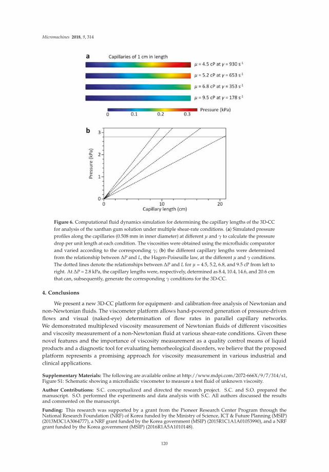
Micromachines 2018, 9, 314
Figure 6. Computational fluid dynamics simulation for determining the capillary lengths of the 3D-CCfor analysis of the xanthan gum solution under multiple shear-rate conditions. (a) Simulated pressureprofiles along the capillaries (0.508 mm in inner diameter) at different µ and γ to calculate the pressuredrop per unit length at each condition. The viscosities were obtained using the microfluidic comparatorand varied according to the corresponding γ; (b) the different capillary lengths were determinedfrom the relationship between ∆P and L, the Hagen-Poiseuille law, at the different µ and γ conditions.The dotted lines denote the relationships between ∆P and L for µ = 4.5, 5.2, 6.8, and 9.5 cP from left toright. At ∆P = 2.8 kPa, the capillary lengths were, respectively, determined as 8.4, 10.4, 14.6, and 20.6 cmthat can, subsequently, generate the corresponding γ conditions for the 3D-CC.
4. Conclusions
We present a new 3D-CC platform for equipment- and calibration-free analysis of Newtonian andnon-Newtonian fluids. The viscometer platform allows hand-powered generation of pressure-drivenflows and visual (naked-eye) determination of flow rates in parallel capillary networks.We demonstrated multiplexed viscosity measurement of Newtonian fluids of different viscositiesand viscosity measurement of a non-Newtonian fluid at various shear-rate conditions. Given thesenovel features and the importance of viscosity measurement as a quality control means of liquidproducts and a diagnostic tool for evaluating hemorheological disorders, we believe that the proposedplatform represents a promising approach for viscosity measurement in various industrial andclinical applications.
Supplementary Materials: The following are available online at http://www.mdpi.com/2072-666X/9/7/314/s1,Figure S1: Schematic showing a microfluidic viscometer to measure a test fluid of unknown viscosity.
Author Contributions: S.C. conceptualized and directed the research project. S.C. and S.O. prepared themanuscript. S.O. performed the experiments and data analysis with S.C. All authors discussed the resultsand commented on the manuscript.
Funding: This research was supported by a grant from the Pioneer Research Center Program through theNational Research Foundation (NRF) of Korea funded by the Ministry of Science, ICT & Future Planning (MSIP)(2013M3C1A3064777), a NRF grant funded by the Korea government (MSIP) (2015R1C1A1A01053990), and a NRFgrant funded by the Korea government (MSIP) (2016R1A5A1010148).
120

Micromachines 2018, 9, 314
Conflicts of Interest: The authors declare no conflict of interest.
References
1. Fügel, R.; Carle, R.; Schieber, A. Quality and authenticity control of fruit purées, fruit preparations andjams—A review. Trends Food Sci. Technol. 2005, 16, 433–441. [CrossRef]
2. Hoekman, S.K.; Broch, A.; Robbins, C.; Ceniceros, E.; Natarajan, M. Review of biodiesel composition,properties, and specifications. Renew. Sustain. Energy Rev. 2012, 16, 143–169. [CrossRef]
3. Lebedeva, N.; Malkova, E.; Vyugin, A.; Koifman, O.; Gubarev, Y. Spectral and hydrodynamic studies ofcomplex formation of tetraalkoxy substituted zinc(II)phthalocyanines with defatted and nondefatted bovineserum albumin. Biochip J. 2015, 10, 1–8. [CrossRef]
4. Jimtaisong, A.; Saewan, N. Utilization of carboxymethyl chitosan in cosmetics. Int. J. Cosmet. Sci. 2014, 36,12–21. [CrossRef] [PubMed]
5. Tao, W.; Ma, Y.; Chen, Y.; Li, L.; Wang, M. The influence of adhesive viscosity and elastic modulus on laserspot weld bonding process. Int. J. Adhes. Adhes. 2014, 51, 111–116. [CrossRef]
6. Chiarello, E.; Derzsi, L.; Pierno, M.; Mistura, G.; Piccin, E. Generation of Oil Droplets in a Non-NewtonianLiquid Using a Microfluidic T-Junction. Micromachines 2015, 6, 1825–1835. [CrossRef]
7. Sklodowska, K.; Debski, P.R.; Michalski, J.A.; Korczyk, P.M.; Dolata, M.; Zajac, M.; Jakiela, S. SimultaneousMeasurement of Viscosity and Optical Density of Bacterial Growth and Death in a Microdroplet.Micromachines 2018, 9, 251. [CrossRef]
8. Smith, M.M.; Chen, P.C.Y.; Li, C.-S.; Ramanujam, S.; Cheung, A.T.W. Whole blood viscosity and microvascularabnormalities in Alzheimer’s Disease. Clin. Hemorheol. Microcirc. 2009, 41, 229–239. [CrossRef] [PubMed]
9. Gertz, M.A.; Kyle, R.A. Hyperviscosity syndrome. J. Intensive Care Med. 1995, 10, 128–141. [CrossRef][PubMed]
10. McKennell, R. Cone-plate viscometer. Anal. Chem. 1956, 28, 1710–1714. [CrossRef]11. Cooke, B.M.; Stuart, J. Automated measurement of plasma viscosity by capillary viscometer. J. Clin. Pathol.
1988, 41, 1213–1216. [CrossRef] [PubMed]12. Gupta, S.; Wang, W.S.; Vanapalli, S.A. Microfluidic viscometers for shear rheology of complex fluids and
biofluids. Biomicrofluidics 2016, 10, 043402. [CrossRef] [PubMed]13. Srivastava, N.; Davenport, R.D.; Burns, M.A. Nanoliter viscometer for analyzing blood plasma and other
liquid samples. Anal. Chem. 2005, 77, 383–392. [CrossRef] [PubMed]14. Srivastava, N.; Burns, M.A. Analysis of non-Newtonian liquids using a microfluidic capillary viscometer.
Anal. Chem. 2006, 78, 1690–1696. [CrossRef] [PubMed]15. Kim, W.-J.; Kim, S.; Huh, C.; Kim, B.K.; Kim, Y.J. A novel hand-held viscometer applicable for point-of-care.
Sens. Actuators B 2016, 234, 239–246. [CrossRef]16. Liu, M.; Xie, S.; Ge, J.; Xu, Z.; Wu, Z.; Ru, C.; Luo, J.; Sun, Y. Microfluidic Assessment of Frying Oil
Degradation. Sci. Rep. 2016, 6, 27970. [CrossRef] [PubMed]17. Li, Y.; Ward, K.R.; Burns, M.A. Viscosity Measurements Using Microfluidic Droplet Length. Anal. Chem.
2017, 89, 3996–4006. [CrossRef] [PubMed]18. Kang, Y.J.; Yang, S. Integrated microfluidic viscometer equipped with fluid temperature controller for
measurement of viscosity in complex fluids. Microfluid. Nanofluid. 2013, 14, 657–668. [CrossRef]19. Kang, Y.J.; Ryu, J.; Lee, S.-J. Label-free viscosity measurement of complex fluids using reversal flow switching
manipulation in a microfluidic channel. Biomicrofluidics 2013, 7, 44106. [CrossRef] [PubMed]20. Choi, S.; Park, J.K. Microfluidic rheometer for characterization of protein unfolding and aggregation in
microflows. Small 2010, 6, 1306–1310. [CrossRef] [PubMed]21. Tassieri, M.; Del Giudice, F.; Robertson, E.J.; Jain, N.; Fries, B.; Wilson, R.; Glidle, A.; Greco, F.; Netti, P.A.;
Maffettone, P.L.; et al. Microrheology with optical tweezers: Measuring the relative viscosity of solutions ‘ata glance’. Sci. Rep. 2015, 5, 8831. [CrossRef] [PubMed]
22. Oh, S.; Kim, B.; Lee, J.K.; Choi, S. 3D-printed capillary circuits for rapid, low-cost, portable analysis of bloodviscosity. Sens. Actuators B 2018, 259, 106–113. [CrossRef]
23. Oh, S.; Kim, B.; Choi, S. A 3D-Printed Multichannel Viscometer for High-Throughput Analysis of Frying OilQuality. Sensors 2018, 18, 1625. [CrossRef] [PubMed]
121

Micromachines 2018, 9, 314
24. Mao, M.; He, J.; Li, X.; Zhang, B.; Lei, Q.; Liu, Y.; Li, D. The Emerging Frontiers and Applications ofHigh-Resolution 3D Printing. Micromachines 2017, 8, 113. [CrossRef]
25. Waheed, S.; Cabot, J.M.; Macdonald, N.P.; Lewis, T.; Guijt, R.M.; Paull, B.; Breadmore, M.C. 3D printedmicrofluidic devices: Enablers and barriers. Lab Chip 2016, 16, 1993–2013. [CrossRef] [PubMed]
26. Kim, B.; Choi, S. Smart Pipette and Microfluidic Pipette Tip for Blood Plasma Separation. Small 2016, 12,190–197. [CrossRef] [PubMed]
27. Kim, B.; Hahn, Y.K.; You, D.; Oh, S.; Choi, S. A smart multi-pipette for hand-held operation of microfluidicdevices. Analyst 2016, 141, 5753–5758. [CrossRef] [PubMed]
28. Kim, B.; Oh, S.; You, D.; Choi, S. Microfluidic Pipette Tip for High-Purity and High-Throughput BloodPlasma Separation from Whole Blood. Anal. Chem. 2017, 89, 1439–1444. [CrossRef] [PubMed]
29. You, D.; Oh, S.; Kim, B.; Hahn, Y.K.; Choi, S. Rapid preparation and single-cell analysis of concentrated bloodsmears using a high-throughput blood cell separator and a microfabricated grid film. J. Chromatogr. A 2017,1507, 141–148. [CrossRef] [PubMed]
30. Truskey, G.A.; Yuan, F.; Katz, D.F. Transport Phenomena in Biological Systems, 1st ed.; Pearson Education:Upper Saddle River, NJ, USA, 2004.
© 2018 by the authors. Licensee MDPI, Basel, Switzerland. This article is an open accessarticle distributed under the terms and conditions of the Creative Commons Attribution(CC BY) license (http://creativecommons.org/licenses/by/4.0/).
122

micromachines
Article
3D Printed Microfluidic Features Using Dose Controlin X, Y, and Z Dimensions
Michael J. Beauchamp 1, Hua Gong 2, Adam T. Woolley 1,* and Gregory P. Nordin 2,*
1 Department of Chemistry and Biochemistry, Brigham Young University, Provo, UT 84602, USA;[email protected]
2 Department of Electrical and Computer Engineering, Brigham Young University, Provo, UT 84602, USA;[email protected]
* Correspondence: [email protected] (A.T.W.); [email protected] (G.P.N.); Tel.: +1-801-422-1701 (A.T.W.);+1-801-422-1863 (G.P.N.)
Received: 6 June 2018; Accepted: 26 June 2018; Published: 28 June 2018
Abstract: Interest has grown in recent years to leverage the possibilities offered by three-dimensional(3D) printing, such as rapid iterative changes; the ability to more fully use 3D device volume; andease of fabrication, especially as it relates to the creation of complex microfluidic devices. A majorshortcoming of most commercially available 3D printers is that their resolution is not sufficient toproduce features that are truly microfluidic (<100 × 100 µm2). Here, we test a custom 3D printer formaking ~30 µm scale positive and negative surface features, as well as positive and negative featureswithin internal voids (i.e., microfluidic channels). We found that optical dosage control is essentialfor creating the smallest microfluidic features (~30 µm wide for ridges, ~20 µm wide for trenches),and that this resolution was achieved for a number of different exposure approaches. Additionally,we printed various microfluidic particle traps, showed capture of 25 µm diameter polymer beads,and iteratively improved the trap design. The rapid feedback allowed by 3D printing, as well as theability to carefully control optical exposure conditions, should lead to new innovations in the typesand sizes of devices that can be created for microfluidics.
Keywords: 3D printing; microfluidics; particle traps; stereolithography
1. Introduction
3D printing is a valuable technique for custom and rapid design change and optimizationin fabrication of millifluidic devices [1]. Miniature device applications stand to benefit from theadvantages offered from 3D printing, such as the ability to create and test devices with rapid feedback,allowing changes to be quickly tested. Device optimization based on empirical results could save timeand money compared to traditional device fabrication techniques that involve conventional machiningor micromachining.
A number of groups have recently sought to use 3D printing to produce fluidic devices for variousapplications. Devices for nitrite [2] or anemia [3] detection, measuring endocrine secretion [4], sortingbacteria [5], and cell culture [6,7], have all been shown to name a few. Although these are promisingassays, a key issue from these works is the size of printed features. Most commercially available printersand resins are only able to achieve feature sizes down to 250 µm, with typical features around 500 µm,which are not suitable for many microfluidics applications. Additionally, these commercial printers lackflexibility in terms of resin development, individual layer custom exposure time control, or multipleexposures per layer. For 3D printing of fluidic devices with low surface roughness, stereolithography(SLA) printers are the best suited [8]. The material left in the channels after printing is a liquid and thusis much easier to clear than solid sacrificial materials formed with either polyjet or fused depositionmodeling printers [9–11]. Reviews of 3D printing over the past several years have offered helpful
Micromachines 2018, 9, 326; doi:10.3390/mi9070326 www.mdpi.com/journal/micromachines123

Micromachines 2018, 9, 326
insights regarding types of printers and their applications. Many different outlooks are given for futuredirections in 3D printing of fluidic devices, such as resin improvements, material removal techniques,throughput, and printer resolution [1,12–16]. Several groups have undertaken work to investigateand compare the resolution of various 3D printers in an effort to make fluidic devices [8,11,17–19];however, much of this work is still well above 100 µm needed for most microfluidic applications.
Our group has developed an SLA 3D printer, as well as a custom resin formulated specificallyfor creating truly microfluidic structures with this printer [20], and we have made small (18 × 20 µm)microfluidic channels [21], as well as fluid control systems involving pumps and valves [22]. To makethe smallest channels, an edge compensation technique was employed which overexposed the pixelsat the channel edge to make it narrower [21]. However, we have not yet examined how this edgecompensation approach affects features in the channels.
In this work, we investigate precise control over printing exposure areas and dosage conditionsto create microscale substructures within microfluidic features. First, we look at positive and negativefeatures on the exterior of prints to see what size features can be printed with various exposuretimes and with exposure edge compensation. Next, we evaluate positive and negative features ininterior void areas to see the impact of exposure times and edge compensation. Finally, we createmicrofluidic particle traps to demonstrate how the ability to control specific dosing parameters allowsimproved function.
2. Materials and Methods
2.1. Material Sources
Acetone, 2-propanol (IPA), and 25 µm polystyrene microspheres were purchased fromThermo-Fisher Scientific (Salt Lake City, UT, USA). Triethoxysilyl propylmethacrylate, hydroxypropylcellulose (HPC) and polyethylene glycol diacrylate (PEGDA, 258 Da MW) were purchased fromSigma-Aldrich (Milwaukee, WI, USA). Toluene and glass microscope slides (3” × 1” × 1.2 mm) werepurchased from Avantor (Center Valley, PA, USA). 2-Nitrodiphenylsulfide (NPS) was purchased fromTCI America (Portland, OR, USA). Phenylbis (2,4,6-trimethylbenzoyl)phosphine oxide (Irgacure 819)was provided by BASF (Midland, MI, USA). All chemicals were used as received.
2.2. Glass Slide Preparation
Glass microscope slides were scored on one side using a laser cutter (Universal Laser Systems,Scottsdale, AZ, USA). The settings for cutting were 50% power, 10% speed, and 165 points per inch.The glass slides were then broken along the scored mark, washed with acetone and IPA, and dried withair. A fresh preparation of 10% triethoxysilyl propylmethacrylate in toluene was made. Glass slideswere submerged in this silane solution in a shallow covered dish for a minimum of two hours, afterwhich they were rinsed with IPA and dried with air. For longer term storage, slides were kept in acontainer under toluene.
2.3. Resin Preparation
The resin was prepared by mixing 2% NPS with 1% Irgacure 819 in 97% PEGDA. The resinwas sonicated until all solid components dissolved and was stored in an amber bottle wrapped inaluminum foil to protect it from light. Details regarding resin formulation can be found in reference [21]for the choice of photoinitiator and absorber matched to the LED of the printer.
2.4. Device Designs
Designs for 3D printed parts were made using open source OpenSCAD software (openscad.org).Schematics of the resolution prints can be seen in Figure 1. For the exterior ridges (Figure 1a) andtrenches (Figure 1b), the features are 100 µm tall or deep, and the widths are from 1 to 10 pixels (7.6 to76 µm), with a spacing between individual ridges or trenches of 100 pixels.
124

Micromachines 2018, 9, 326
For the interior resolution features (Figure 1c), the height of the feature area is 100 µm. The internalridges are all 5 pixels wide, 250 pixels long, and have heights from 1 to 10 layers (10 to 100 µm). For thetrench sections, the trenches are all 100 µm deep and vary in width from 1 to 10 pixels. The pillars aredesigned with diameters ranging from 1 to 10 pixels, and all of the pillars in a given row are identical.In between each internal feature (or set of features with the pillars) is a support beam to help holdup the microchannel ceiling. These ceiling supports are all 5 pixels wide and go from the floor of thefeature areas to the ceiling.
The trapping devices consist of 6 straight channels 30 pixels wide and 8 layers tall with fluidicreservoirs at both ends (Figure 1d). The traps consist of two L-shaped pieces facing each other thatare 8 pixels long, 4 pixels wide, and spaced 2 pixels apart (Figure 1e). The traps are spaced 20 pixelsapart down the length of the channel. Each print contains 6 different channels for testing a variety oftrap layouts. Three different configurations of the traps were tested, one with traps only down thecenter of the channel, one with traps staggered along the edges, and one with traps staggered in themiddle of the channel and along the sides (see Figure 1d, inserts).
(a) (b)
(c)
1 mm
1 mm 1 mm
Figure 1. Cont.
125

Micromachines 2018, 9, 326
(d)
(e)
1 mm
10 m
Figure 1. OpenSCAD designs of prints for exterior and interior resolution features. (a) Ridge device.The ridges are shown in red and there is a support box around the ridges. The ridges are 100 µmtall and have widths of 1–10 pixels (7.6–76 µm) from left to right. The cutout shows a zoom view;(b) Trench device with the trenches shown in orange. The trenches are 100 µm deep and have widthsof 1–10 pixels (7.6–76 µm) from left to right. The cutout shows a zoom view; (c) Interior features device.The top layers of the device have been removed in the schematic to show the features. From leftto right the regions are ridges, trenches with exposure compensation, pillars, and trenches withoutexposure compensation. Each set of features has a series of ceiling support ridges running the length ofthe feature area. Below each feature void area is a zoom view; (d) Bead trap device design showing6 channels and traps within channels. Inserts show a zoom view of the three different trap layouts;(e) Schematic of bead trap. The large gap is designed to allow the beads to enter and the smaller gapallows fluid to pass through the trap.
2.5. 3D Printing Parameters
The 3D printer used for this work is the same as described in reference [21]. This printer operateswith a nominally 385 nm light source and 7.6 µm pixel size in the image plane. The build layerheight for all prints was 10 µm, the image plane irradiance was 21.2 mW·cm−2, and the exposuretime was chosen to be either 500, 750, 1000, or 1500 ms to ensure thorough attachment of the printto the glass slide the first four layers were overexposed for 20, 10, 5, and 1 s, respectively. For printsin which the normal layer exposure time exceeded 1 s, only the first three layers were exposed inthis manner. After printing, the remaining liquid resin in the print was flushed out three times withIPA using vacuum. Finally, the device was cured under an 11 mW 430 nm LED (ThorLabs, Newton,NJ, USA) for 10 min before use. This LED allows the photoinitiator to further cure the print at awavelength at which the UV absorber (NPS) does not absorb the light.
2.6. Edge Compensation Technique
An edge compensation technique similar to the one in reference [21] was used where indicatedfor both interior and exterior trenches (negative features). This technique exposes the two pixelsforming the edge of the trench for double the normal exposure time. The purpose of this technique isto cause a wider trench design to be narrower when printed. For example, a 3D printed trench thatis designed to be 4 pixels wide without compensation has the same width as a 6 pixel wide designformed with compensation.
2.7. Measurement of Print Featuures
Exterior feature heights, depths, and widths were measured using a Zeta 20 optical profilometer(Zeta Instruments, San Jose, CA, USA). The width was measured as the full width at half heightor depth. SEM imaging was done using an ESEM XL30 (FEI, ThermoFisher Scientific, Waltham,MA, USA). Samples were prepared by cutting them open with a razor blade and sputtering with 80:20
126

Micromachines 2018, 9, 326
Au:Pd to allow the side profile to be observed. Images were processed using ImageJ (NIH) to measurethe widths and heights of interior pillars, ridges, and trenches.
For trapping experiments, imaging was done using a Zeiss AXIO Observer A1 invertedmicroscope (Thornwood, NY, USA) using a 10× objective connected to a Photometrics coolSNAP HQ2CCD camera (Tucson, AZ, USA). The exposure time for the CCD was 10 ms. The images were recordedand processed using ImageJ. Measurement of print features was performed three times (n = 3), and thestandard deviation is given for each measurement.
For our printer and this resin, surface roughness has previously been characterized using opticalprofilometry with prints at various exposure times [22]. For all exposure times tested (600–1200 ms),the RMS surface roughness was less than 100 nm, typically 55–60 ± 15 nm. While some surfaces mayappear to show pixelation (Figure 4 and Supplementary Materials) as they did in this previous work,it is expected that the surface roughness should still be the same.
2.8. Trapping Opperation
The bead solution for trapping was made by suspending the beads in deionized water at aconcentration of 1 mg/mL with 0.5% HPC to prevent aggregation. 1.5 µL of bead solution waspipetted into the left reservoir as oriented in Figure 1d and drawn through the channel with vacuumover ~7 s, which resulted in a flow rate of 13 µL/min. This was repeated three times so a total of 4.5 µLof bead solution was pulled through the channel, after which CCD images were taken.
3. Results and Discussion
3.1. Exterior Features
3.1.1. Ridges
Initial testing focused on the exterior resolution features of our 3D printer by testing a set of ridgesand trenches on the surface of prints. The purpose of these features is to evaluate how positive featuresturn out on the surface of print. For the surface ridges, the design shown in Figure 1a was created;the design was printed three times with exposure times of 500, 1000, or 1500 ms for each build layer.We found that the ends of the ridges became warped when they were not anchored, so a support boxwas placed around the ridges. A photograph though the microscope can be seen in Figure 2a, showingexample ridges that are 3 and 4 pixels wide for 1500 ms exposure. The complete set of images canbe found in the Supplementary Materials (Figures S1–S3). The heights and widths of these featureswere then measured with an optical profilometer. Figure 3a shows the measured ridge width plottedagainst the designed width for ridges that reached >90% of the full height. This shows that increasinglight dosage from 500 ms (blue line in Figure 3a) to 1500 ms (red line in Figure 3a) allows smallerridges to successfully reach full height and be closer to their designed width. Additionally, a ridgethat is designed to a certain width will print smaller than expected if the exposure time is insufficient.The minimum width ridge that could be successfully printed was 30 ± 1 µm, which was with anexposure time of 1500 ms. These positive features benefit from increased light exposure, indicating theneed to be able to give sufficient exposure to positive features.
127
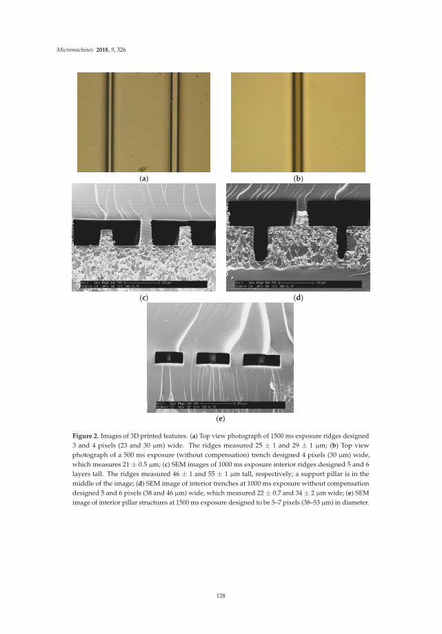
Micromachines 2018, 9, 326
(a)
(b)
(c)
(d)
(e)
Figure 2. Images of 3D printed features. (a) Top view photograph of 1500 ms exposure ridges designed3 and 4 pixels (23 and 30 µm) wide. The ridges measured 25 ± 1 and 29 ± 1 µm; (b) Top viewphotograph of a 500 ms exposure (without compensation) trench designed 4 pixels (30 µm) wide,which measures 21 ± 0.5 µm; (c) SEM images of 1000 ms exposure interior ridges designed 5 and 6layers tall. The ridges measured 46 ± 1 and 55 ± 1 µm tall, respectively; a support pillar is in themiddle of the image; (d) SEM image of interior trenches at 1000 ms exposure without compensationdesigned 5 and 6 pixels (38 and 46 µm) wide, which measured 22 ± 0.7 and 34 ± 2 µm wide; (e) SEMimage of interior pillar structures at 1500 ms exposure designed to be 5–7 pixels (38–53 µm) in diameter.
128

Micromachines 2018, 9, 326
(a)
(b)
(c) (d)
(e)
Figure 3. Designed feature width versus measured width for different exposure conditions.Only features that reached >90 µm in height (ridges) or depth (trenches) were included. For thepillars, only those that were attached floor to ceiling were included. Standard deviations are indicatedfor each included point (n = 3). (a) Exterior ridges; (b) Exterior trenches; (c) Interior ridges; (d) Interiortrenches; (e) Interior pillars.
3.1.2. Trenches
For the exterior negative features, we created the design shown in Figure 1b. This design wasprinted with and without the exposure compensation pattern at 500, 1000, and 1500 ms for a total
129

Micromachines 2018, 9, 326
of six prints. An example microscope image showing a trench 4 pixels wide with 500 ms exposurecan be seen in Figure 2b with the full data in Figures S4–S9. The heights and depths of these trencheswere measured with optical profilometry. As seen in Figure 3b, measured width was plotted againstdesigned width; only the features that achieved >90% of the designed feature depth were included.The first observation is that the compensation pattern caused the trenches to turn out narrower thanthe uncompensated devices due to the additional exposure at the trench edge. The second effect thatcan be seen is that increasing the layer exposure time for the uncompensated case results in narrowertrenches, as expected. Finally we note that, to achieve a minimum trench width at full depth, thereare three different possibilities: 500 ms exposure without compensation, 1000 ms exposure withoutcompensation, or 1000 ms exposure with compensation. All three of these approaches produced atrench 100 µm deep and about 20 ± 0.5 µm wide; however, the designed widths were all different (4,5, and 6 pixels, respectively). These results show that having precise control over both exposure andprinting parameters allows for careful control of final feature sizes for exterior trenches.
3.2. Interior Features
For interior feature resolution, we undertook a similar study of positive and negative featuresin a confined space according to our design in Figure 1c. When prototyping this design, we foundthat a large void space without a support for the ceiling resulted in irregular top layers and erraticfeature measurements. Thus, an alternating pattern of feature and ceiling support pieces exists ineach of the interior feature areas. Each print contains two sets of trenches, either with or withoutexposure compensation, such that both could be tested in a single print. Additionally, Figure 2c–eshows characteristic SLA printing artifacts including uneven sides showing where each layer of theprint sits on the next one, as well as a somewhat trapezoidal shape for the interior ridges and ceilingsupport pieces. Smaller layer thicknesses (finer z resolution) could help mitigate the layering, whilethe trapezoidal shape may be a result of material shrinkage.
3.2.1. Ridges
We again used ridges as positive features to determine the types of structures that could beplaced in an interior void in a 3D printed part. Five pixels width was chosen, because it formedreliably for surface ridges. An example SEM image of two ridges at 1000 ms exposure is shown inFigure 2c; the interior ridge 5 layers tall is shown on the left, with the ceiling support in the middle,and the ridge 6 layers tall is on the right. For interior ridges, we measured the gap between thetop of the ridge and the ceiling of the void area, which gave information about interior z resolution.Gap distance (excluding any ridges that attached to the ceiling) is plotted for these interior ridgesas shown in Figure 3c. The 500 ms exposure time resulted in a void region that was taller than thedesigned 100 µm, due to insufficient adhesion between layers, as can be observed in the SupplementaryMaterials (Figure S10). The ceiling support pieces appear to have broken off, resulting in voids tallerthan the designed size. For 1000 and 1500 ms, the void height is smaller than designed, likely dueto exposure of the top layer of the chamber polymerizing significantly more than to 10 µm of resin,thereby making the first ceiling layer substantially thicker than designed, resulting in reduced overallchamber height and hence reduced gap size (Figures S11–S12). This is consistent with our previouswork, in which we analyzed the layer exposure profile as a function of z [20]. The height of the voidarea was about 70–75 µm instead of 100 µm, and thus any ridges designed to be >7 layers tall wereattached to the ceiling. For the ridges that were not attached, however, there was a linear relationshipbetween the designed and measured gap distance. From this data, gaps between the feature and ceilingarea as small as 7 ± 0.7 µm can be produced with either 1000 or 1500 ms exposures. As long as theprint receives sufficient light exposure (>500 ms for this formulation), the gap height between featuresand ridges is independent of the exposure time for 1000 and 1500 ms exposures, as seen in Figure 3c.
130

Micromachines 2018, 9, 326
3.2.2. Trenches
For the interior trenches, a similar approach to the exterior trenches was used. The widths ofprinted trenches were measured with SEM imaging, and an example image is shown in Figure 2d for1000 ms exposure (without compensation) of trenches that were designed to be 5 and 6 pixels (38 and46 µm) wide. In this image the trench 6 pixels wide is on the left, and the trench 5 pixels wide is on theright, with the ceiling support pillar in the middle. The full set of interior trench images can been foundin the Supplementary Materials Figures S13–S18. The measured width was compared to the designedwidth in Figure 3d, including only those trenches that reached >90% of full depth. The 500 ms trenches(both with and without compensation) turn out wider than the 1500 ms trenches, indicating that lowerexposure times work better for forming wider trenches. Similar to the effect observed with the exteriortrenches, the use of a compensation pattern leads to trenches smaller than they would have otherwiseprinted, as the compensated trenches are all narrower than the uncompensated ones. Similar to theexterior trenches, the smallest trenches that successfully formed were about 20 µm wide, though theywere printed with different exposure times: 5 pixels wide for 1000 ms with compensation (21 ± 0.8 µm),6 pixels wide for 1500 ms without compensation (21 ± 0.7 µm), and 7 pixels wide for 1500 ms withcompensation (18 ± 0.7 µm). This again demonstrates the concept that there are several different waysto obtain a minimum feature size if the right exposure conditions are determined, especially whenthere is full control over the exposure properties.
3.2.3. Pillars
A final type of resolution feature we investigated was cylindrical pillars in the interior of avoid area. SEM images were taken of the pillars, and an example can be seen in Figure 2e showing1500 ms exposure pillars that are 5–7 pixels wide (38–53 µm), with more data in Figures S19–S21 ofthe Supplementary Materials. Figure 3e shows a plot comparing the designed pillar diameter and themeasured diameter, including only those pillars which were fully formed. From this graph, it can beseen that the pillars all printed narrower than their designed width and followed the trend that longerexposure times led to wider pillars. The smallest pillars that were successfully printed were about14 ± 1 µm in diameter, printed with 1000 ms exposure for a 5 pixel designed width. The dependencyof pillar diameter on light exposure is another example of how control over dosing parameters isessential to achieve desired feature dimensions during SLA 3D printing.
3.2.4. Trapping Devices
To demonstrate the utility of tight control of both positive and negative interior features wecreated trapping devices to catch particles as they flowed through a channel, as a first step towardtrapping of cells. The beads selected were 25 µm in diameter, approximately the same size as thesmallest trench that was successfully printed. Because our 3D printing designs can be easily edited tooptimize configurations and print parameters, we attempted a number of different trap placements(see Figure 1d inserts) to determine the best trapping efficiency. Figure 4 shows images of channelsafter trapping experiments were carried out. We found that traps exclusively in the center of thechannel (Figure 4a) did not trap as efficiently as traps along the sides (Figure 4b), which in turn werenot as efficient as traps that alternated between the channel sides and center (Figure 4c). This waslargely due to the flow of the beads around (instead of through) the traps. Additionally, we found thattraps that were 3 layers tall did not trap as efficiently as traps that were the full height of the channel;when the traps are shorter many beads simply pass over the traps.
Finally, it is critical to have traps that have the correct dimensions. The degree of trap opennesscould be controlled through the exposure time used for the print. If the exposure time was too short(<600 ms), the traps would be partially formed, and the beads would pass through the trap withoutgetting caught. Conversely, if the exposure time was too high (>1000 ms), the traps would end upoverexposed, and there would be no flow through the traps, which would result in no beads being
131
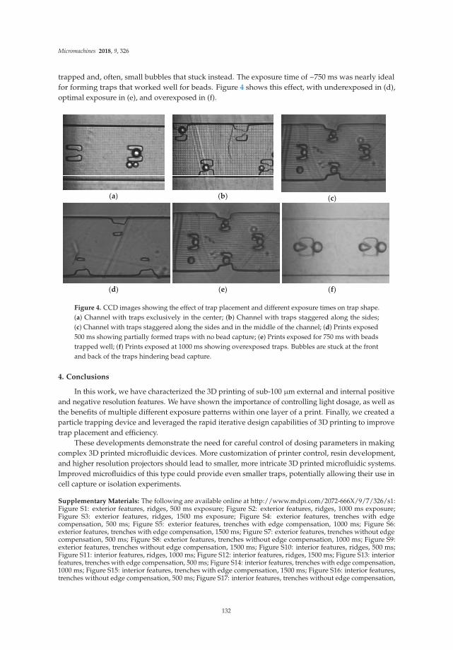
Micromachines 2018, 9, 326
trapped and, often, small bubbles that stuck instead. The exposure time of ~750 ms was nearly idealfor forming traps that worked well for beads. Figure 4 shows this effect, with underexposed in (d),optimal exposure in (e), and overexposed in (f).
(a)
(b)
(c)
(d) (e) (f)
Figure 4. CCD images showing the effect of trap placement and different exposure times on trap shape.(a) Channel with traps exclusively in the center; (b) Channel with traps staggered along the sides;(c) Channel with traps staggered along the sides and in the middle of the channel; (d) Prints exposed500 ms showing partially formed traps with no bead capture; (e) Prints exposed for 750 ms with beadstrapped well; (f) Prints exposed at 1000 ms showing overexposed traps. Bubbles are stuck at the frontand back of the traps hindering bead capture.
4. Conclusions
In this work, we have characterized the 3D printing of sub-100 µm external and internal positiveand negative resolution features. We have shown the importance of controlling light dosage, as well asthe benefits of multiple different exposure patterns within one layer of a print. Finally, we created aparticle trapping device and leveraged the rapid iterative design capabilities of 3D printing to improvetrap placement and efficiency.
These developments demonstrate the need for careful control of dosing parameters in makingcomplex 3D printed microfluidic devices. More customization of printer control, resin development,and higher resolution projectors should lead to smaller, more intricate 3D printed microfluidic systems.Improved microfluidics of this type could provide even smaller traps, potentially allowing their use incell capture or isolation experiments.
Supplementary Materials: The following are available online at http://www.mdpi.com/2072-666X/9/7/326/s1:Figure S1: exterior features, ridges, 500 ms exposure; Figure S2: exterior features, ridges, 1000 ms exposure;Figure S3: exterior features, ridges, 1500 ms exposure; Figure S4: exterior features, trenches with edgecompensation, 500 ms; Figure S5: exterior features, trenches with edge compensation, 1000 ms; Figure S6:exterior features, trenches with edge compensation, 1500 ms; Figure S7: exterior features, trenches without edgecompensation, 500 ms; Figure S8: exterior features, trenches without edge compensation, 1000 ms; Figure S9:exterior features, trenches without edge compensation, 1500 ms; Figure S10: interior features, ridges, 500 ms;Figure S11: interior features, ridges, 1000 ms; Figure S12: interior features, ridges, 1500 ms; Figure S13: interiorfeatures, trenches with edge compensation, 500 ms; Figure S14: interior features, trenches with edge compensation,1000 ms; Figure S15: interior features, trenches with edge compensation, 1500 ms; Figure S16: interior features,trenches without edge compensation, 500 ms; Figure S17: interior features, trenches without edge compensation,
132

Micromachines 2018, 9, 326
1000 ms; Figure S18: interior features, trenches without edge compensation, 1500 ms; Figure S19: interior features,pillars, 500 ms; Figure S20: interior features, pillars, 1000 ms; Figure S21: interior features, pillars, 1500 ms.
Author Contributions: Conceptualization: A.T.W., G.P.N. and M.J.B.; methodology: A.T.W., G.P.N., H.G. andM.J.B.; software: H.G.; validation: A.T.W. and M.J.B.; formal analysis: A.T.W. and M.J.B.; investigation: M.J.B.;data curation: M.J.B.; writing—original draft preparation: M.J.B.; writing—review & editing: A.T.W., G.P.N. andM.J.B.; visualization: M.J.B.; supervision: A.T.W. and G.P.N.; funding acquisition: A.T.W. and G.P.N.
Funding: This research was funded by The United States National Institutes of Health grant numbers R01EB006124and R15GM123405-01A1.
Conflicts of Interest: The authors declare no conflict of interest. The founding sponsors had no role in the designof the study; in the collection, analyses, or interpretation of data; in the writing of the manuscript; or in thedecision to publish the results.
References
1. Au, A.K.; Huynh, W.; Horowitz, L.F.; Folch, A. 3D-printed microfluidics. Angew. Chem. Int. Ed. 2016, 55,3862–3881. [CrossRef] [PubMed]
2. Shallan, A.I.; Smejkal, P.; Corban, M.; Guijt, R.M.; Breadmore, M.C. Cost effective 3D printing of visibletransparent microchips within minutes. Anal. Chem. 2014, 86, 3124–3130. [CrossRef] [PubMed]
3. Plevniak, K.; Campbell, M.; Myers, T.; Hodges, A.; He, M. 3D Printed Auto-Mixing chip enables rapidsmartphone analysis of anemia. Biomicrofluidics 2016, 10, 054113. [CrossRef] [PubMed]
4. Brooks, J.C.; Fort, K.I.; Holder, D.H.; Holtan, M.D.; Easley, C.J. Macro to micro interfacing to microfluidicchannels using 3d printed templates: Application to time resolved secretion sampling of endocrine tissue.Analyst 2016, 141, 5714–5721. [CrossRef] [PubMed]
5. Lee, W.; Kwon, D.; Choi, W.; Jung, G.Y.; Au, A.K.; Folch, A.; Jeon, S. 3D-printed microfluidic device for thedetection of pathogenic bacteria using size-based separation in helical channel with trapezoid cross-section.Sci. Rep. 2015, 5, 7717. [CrossRef] [PubMed]
6. Takenaga, S.; Schneider, B.; Erbay, E.; Biselli, M.; Schnitzler, T.; Schöning, M.J.; Wagner, T. Fabrication ofbiocompatible lab-on-chip devices for biomedical applications by means of a 3D-printing process. Phys. Status
Solidi A 2015, 212, 1347–1352. [CrossRef]7. Urrios, A.; Parra-Cabrera, C.; Bhattacharjee, N.; Gonzalez-Suarez, A.M.; Rigat-Brugarolas, L.G.; Nallapatti, U.;
Samitier, J.; DeForest, C.A.; Posas, F.; Carcia-Cordero, J.L.; et al. 3D printing of transparent bio-microfluidicdevices in PEGDA. Lab Chip 2016, 16, 2287–2294. [CrossRef] [PubMed]
8. Macdonald, N.P.; Cabot, J.M.; Smejkal, P.; Guit, R.M.; Paull, B.; Breadmore, M.C. Comparing microfluidicperformance of three-dimensional (3D) printing platforms. Anal. Chem. 2017, 89, 3858–3866. [CrossRef][PubMed]
9. Sochol, R.D.; Sweet, E.; Glick, C.C.; Venkatesh, S.; Avetisyan, A.; Ekman, K.G.; Raulinaitis, A.; Tsai, A.;Wienkers, A.; Korner, K.; et al. 3D printed microfluidic circuitry via multijet based additive manufacturing.Lab Chip 2016, 16, 668–678. [CrossRef] [PubMed]
10. Lee, K.G.; Park, K.J.; Seok, S.; Shin, S.; Kim, D.H.; Park, J.Y.; Heo, Y.S.; Lee, S.J.; Lee, T.J. 3D printed modulesfor integrated microfluidic devices. RSC Adv. 2014, 4, 32876–32880. [CrossRef]
11. Lee, J.M.; Zhang, M.; Yeong, W.Y. Characterization and evaluation of 3D printed microfluidic chip for cellprocessing. Microfluid. Nanofluid. 2016, 20, 1–15. [CrossRef]
12. He, Y.; Wu, Y.; Fu, J.; Gao, Q.; Qiu, J. Developments of 3D printing Microfluidics and Applications inChemistry and Biology: A Review. Electroanalysis 2016, 28, 1–22. [CrossRef]
13. Yazdi, A.A.; Popma, A.; Wong, W.; Nguyen, T.; Pan, Y.; Xu, J. 3D Printing: An emerging tool for novelmicrofluidics and lab-on-a-chip applications. Microfluid. Nanofluid. 2016, 20, 1–18. [CrossRef]
14. Chen, C.; Mehl, B.T.; Munshi, A.S.; Townsend, A.D.; Spence, D.M.; Martin, R.S. 3D-printed microfluidicdevices: Fabrication, advantages and limitations-a mini review. Anal. Methods 2016, 8, 6005–6012. [CrossRef][PubMed]
15. Waheed, S.; Cabot, J.M.; Macdonald, N.P.; Lewis, T.; Guijt, R.M.; Paull, B.; Breadmore, M.C. 3D printedmicrofluidic devices: Enablers and barriers. Lab Chip 2016, 16, 1993–2013. [CrossRef] [PubMed]
16. Beauchamp, M.J.; Nordin, G.P.; Woolley, A.T. Moving from millifluidic to truly microfluidic sub-100 µmcross-section 3D printed devices. Anal. Bioanal. Chem. 2017, 409, 4311–4318. [CrossRef] [PubMed]
133

Micromachines 2018, 9, 326
17. Ukita, Y.; Takamura, Y.; Utsumi, Y. Direct digital manufacturing of autonomous centrifugal microfluidicdevice. Jpn. J. Appl. Phys. 2016, 55, 06GN02. [CrossRef]
18. Walczak, R.; Adamski, K. Inkjet 3D printing of microfluidic structures-on the selction of the printer towardsprinting your own microfluidic chips. J. Micromech. Microeng. 2015, 25, 085013. [CrossRef]
19. Fuad, N.M.; Carve, M.; Kaslin, J.; Wlodkowic, D. Characterization of 3D-printed moulds for soft lithographyof millifluidic devices. Micromachines 2018, 9, 116. [CrossRef]
20. Gong, H.; Beauchamp, M.J.; Perry, S.; Woolley, A.T.; Nordin, G.P. Optical approach to resin formulation for3D printed microfluidics. RSC Adv. 2015, 5, 106621–106632. [CrossRef] [PubMed]
21. Gong, H.; Bickham, B.P.; Woolley, A.T.; Nordin, G.P. Custom 3D printer and resin for 18 µm × 20 µmmicrofluidic flow channels. Lab Chip 2017, 17, 2899–2909. [CrossRef] [PubMed]
22. Gong, H.; Woolley, A.T.; Nordin, G.P. 3D printed high density, reversible, chip-to-chip microfluidicinterconnects. Lab Chip 2018, 4, 639–647. [CrossRef] [PubMed]
© 2018 by the authors. Licensee MDPI, Basel, Switzerland. This article is an open accessarticle distributed under the terms and conditions of the Creative Commons Attribution(CC BY) license (http://creativecommons.org/licenses/by/4.0/).
134

micromachines
Review
3D-Printed Biosensor Arrays for Medical Diagnostics
Mohamed Sharafeldin 1,2, Abby Jones 1 and James F. Rusling 1,3,4,5,*
1 Department of Chemistry (U-3060), University of Connecticut, 55 North Eagleville Road, Storrs, CT 06269,USA; [email protected] (M.S.); [email protected] (A.J.)
2 Analytical Chemistry Department, Faculty of Pharmacy, Zagazig University, Zagazig 44519, Sharkia, Egypt3 Institute of Materials Science, University of Connecticut, 97 North Eagleville Road, Storrs, CT 06269, USA4 Department of Surgery and Neag Cancer Center, UConn Health, Farmington, CT 06032, USA5 School of Chemistry, National University of Ireland, Galway, University Road, Galway, Ireland* Correspondence: [email protected]; Tel: +1-860-486-4909
Received: 14 June 2018; Accepted: 2 August 2018; Published: 7 August 2018
Abstract: While the technology is relatively new, low-cost 3D printing has impacted many aspectsof human life. 3D printers are being used as manufacturing tools for a wide variety of devices in aspectrum of applications ranging from diagnosis to implants to external prostheses. The ease of use,availability of 3D-design software and low cost has made 3D printing an accessible manufacturingand fabrication tool in many bioanalytical research laboratories. 3D printers can print materials withvarying density, optical character, strength and chemical properties that provide the user with a vastarray of strategic options. In this review, we focus on applications in biomedical diagnostics andhow this revolutionary technique is facilitating the development of low-cost, sensitive, and oftengeometrically complex tools. 3D printing in the fabrication of microfluidics, supporting equipment,and optical and electronic components of diagnostic devices is presented. Emerging diagnosticssystems using 3D bioprinting as a tool to incorporate living cells or biomaterials into 3D printing isalso reviewed.
Keywords: 3D printing; diagnostics; optics; bioprinting; electronics; microfluidics
1. Introduction
Charles W. Hull in 1986 was the first to report stereolithography [1] as a tool to fabricate 3Dstructures. Since then, 3D printing has evolved into a multifunctional fabrication tool that offersunique advantages for biomedical applications including diagnostics [2], scaffolds for 3D implants [3],prosthesis [4] and tissue engineering [5]. In recent years, the ability to convert computer-assisted design(CAD) files into 3D-printed pieces, also known as additive manufacturing, has sparked significantprogress in the field of diagnostics [6]. 3D printing has been utilized in a wide spectrum of applicationswith excellent design and performance. As an additive manufacturing technique, production costsare lower compared to traditional subtractive manufacturing techniques like milling or ablationdue to reduction of the labor and material cost. In addition, versatile 3D printers can be used toproduce different devices and parts without the need for pre-fabrication changes normally requiredin subtractive manufacturing techniques [7,8]. These criteria make 3D printing a valuable tool inprototyping, testing and production of tools and equipment for analytical and diagnostic laboratories.In principle, CAD files of previously reported devices can be downloaded and printed in any laboratory.In this way, advanced diagnostic tools can be directly utilized by researchers without the need forpurchase from a commercial vendor. This approach has the potential to bring advanced diagnostictools more rapidly to the research lab than ever before.
In this review, we focus on applications of 3D printing techniques in medical diagnostics.We discuss different 3D printing techniques and how these techniques impact many design aspects
Micromachines 2018, 9, 394; doi:10.3390/mi9080394 www.mdpi.com/journal/micromachines135

Micromachines 2018, 9, 394
including resolution, cost and fabrication of complex diagnostic devices in a continuous process [9–11].3D-printed microfluidic devices have been used to fabricate semi and fully automated diagnosticapproaches for diseases like cancer [12,13], infectious diseases [14–16], and xenobiotic genotoxicity [17].3D printing can also make tailored supporting devices that improve performance of existing diagnosticslike spectrophotometers [18] and Polymerase Chain Reaction (PCR) devices [14,19] and is used toassist with smartphone integration for remote sensing [20,21]. The ability to print materials withspecial properties allows for the creation of new equipment that can dramatically reduce the cost ofdiagnostic devices like Surface Plasmon Resonance (SPR) [22]. All these applications use 3D printingfor cost-effective multifunctional production to integrate several functions in one device [23].
Fabrication of diagnostic devices with embedded electronics and circuits have also beenaccomplished by 3D printing. The ability to print different materials simultaneously permits thefabrication of electrodes that can be incorporated into the insulator plastic matrices allowing forsubsequent electrochemical detection of metals [24–26], organic compounds [27,28] and biologicallyactive molecules [29]. 3D printing avoids disadvantages associated with screen printing like the needfor masking and drying steps, while exhibiting better resolution and faster fabrication [30].
3D bioprinting is another emerging modification to traditional 3D printing where cells, enzymesor proteins may be encapsulated or loaded into printable bio-ink solutions [31]. A major focus ofthis technique is to provide cell growth medium for tissue and organ repair and regeneration, but ithas also been explored as a tool for diagnostic applications [32]. Bioprinting offers an opportunity tofabricate 3D-printed implantable sensors that are biocompatible, geometrically complex, and cheap.With 3D printing, there is a limited need for specialized training, and devices can be tailored to theusers’ requirements [33,34]. In this review, the most common techniques for 3D-printed diagnosticsare briefly described with several examples of diagnostic platforms incorporating microfluidics, devicesupports, optical components, electronics and biomaterials.
2. Additive Manufacturing Techniques
2.1. Fused Deposition Modeling (FDM)
This technique utilizes thermoplastic polymeric materials extruded to print objects layer-by-layerfrom a heated nozzle onto a surface or platform where it is cooled to below its thermoplastictemperature (Figure 1). Several materials have been utilized in this printing technique, includingacrylonitrile butadiene styrene (ABS), polycarbonate (PC), PC-ABS blend, and polylactic acid(PLA) [35]. Single-, double- and triple-print-head machines are available for FDM, making it a goodchoice for simultaneous multi-material 3D printing [36]. The ability to incorporate conductive materialslike pyrolytic graphite, graphene, carbon nanotubes and metal nanoparticles into the thermoplasticmatrix enables FDM printing of conductive inks to fabricate electrodes and circuits [37–40]. FDMis good for rapid prototyping and fabrication of holders and supporting devices, but still suffersfrom several limitations, including mechanical strength, roughness and shape integrity of the finalproduct. Microfluidic devices printed using FDM can show leakage and shape deformation if printingparameters and the thermoplastic polymer are not carefully tuned [37]. FDM has been successfullyused to print 3D scaffolds that can be seeded with living cells without loss of cell viability [41,42] andto print bio-friendly polymer materials [43,44].
136

Micromachines 2018, 9, 394
Figure 1. Schematic representation of a dual-head fused deposition modeling 3D printer. Thermoplasticpolymer is extruded from a heated nozzle into a printing platform, where it is cooled to below itsthermoplastic temperature. Reproduced with permission from [35]. Copyright (2015) Springer.
2.2. Direct Ink Writing
Similar to fused deposition modeling, Direct Ink Writing (DIW) relies on extrusion of ink througha fine deposition nozzle to form a 3D structure in layer-by-layer approach [45]. Two different strategiesare utilized in this technique, based on the ink type. First is the extrusion of low-viscosity ink thatundergoes gelation via a chemical, photochemical or noncovalent process [46]. The second strategyis the use of a shear thinning hydrogel ink that possesses a viscoelastic response toward appliedpressure. Hydrogels like sodium alginate and gelatin are commonly used [47]. In addition to hydrogelinks, epoxy-based direct writing was developed by Compton and Lewis [48], where epoxy ink withsignificant shear thinning is extruded through the printing nozzle. Once extruded, the ink has sufficientshear to maintain its printed filamentary shape. Direct ink writing is utilized in the 3D fabrication ofinjectable therapeutics [49], cell-laden scaffolds [50,51], degradable biomaterials [52] and stretchablecomplex cellularized structures [53]. The utilization of DIW in bioprinting offers a tool to developmultifunctional diagnostic devices with high resolution, which may improve assay sensitivities.
2.3. Stereolithography
Stereolithography, or digital light processing, employs a photocurable polymeric resin which,when exposed to light, cures into a solid. Initially, curing was only possible with UV light, but polymerscured with visible wavelengths have recently been introduced. Highly focused lasers or LED beamswith high intensity are used and the spot size of the light beam determines printing resolution [54].Each layer of the object is printed as a point-by-point 2D cross section cured by the scanning focusedbeam onto a printing platform immersed in a photocurable tank that holds the liquid resin [5]
137

Micromachines 2018, 9, 394
(Figure 2A). Recently, projection-based stereolithography has been introduced with a promise todecrease print time while maintaining almost the same resolution as line-based stereolithography.Projection-based stereolithography replaces point-by-point curing with entire-layer curing underone single UV or visible light exposure [55,56] (Figure 2B). Stereolithography resin materials havebeen extensively studied to produce devices with different properties, including transparency, color,flexibility and thermal stability [57]. Stereolithography has also been used for printing cells usingbiocompatible resins maintaining >90% cell viability after printing [58].
Figure 2. Schematic representation of stereolithographic 3D printing. (A) Scanning laser stereolithography,where the focused laser beam scans point-by-point to cure a layer of resin on top of a previouslyfabricated layer. (B) Projection-based stereolithography, where an entire layer is printed in a singlestep by projecting the entire layer on top of the previous layer. In both strategies, a printing platformis immersed in a tank filled with liquid photocurable resin. Reproduced with permission from [54].Copyright (2014) American Chemical Society.
2.4. Photopolymer Inkjet Printing (Multi-Jet Modeling—MJM)
This technique utilizes multi-head printers with print heads similar to inkjet printers. The printhead extrudes layers of photocurable resin or molten wax, usually with a second head printing supportmaterial to maintain the shape of the design until cured (Figure 3). After printing, the object is curedby UV irradiation or heat and support material can be removed by heating or dissolving in a specificsolvent [59]. Researchers have been able to utilize this printing technique to print metal nanoparticlesfor printed electronics [60], preceramic polymers for 3D-printed ceramics [61] and even metallicelectrodes on flexible substrates [62]. The ability to print multiple materials with varying chemical andphysical properties simultaneously makes MJM a good candidate for diagnostic device fabrication.Microfluidic channels integrated with either electrodes for electrochemical signal detection [63] orporous membranes that can be seeded with viable cells for drug permeability and toxicity studies havebeen printed using this technique [64]. Most printing resins and materials are proprietary, which makesthe cost of using MJM relatively higher than other 3D-printing techniques [65].
138

Micromachines 2018, 9, 394
Figure 3. Schematic representation of multi-jet printing technique, a photocurable resin is printedsimultaneously with a support material that can be removed after curing. Up to 10 printing heads canbe used. Reproduced with permission from [59]. Copyright (2014) American Chemical Society.
2.5. Selective Laser Sintering (SLS)
A focused Infra-Red (IR) laser beam supplies enough localized energy to sinter a fine powderedpolymer into layers of solid. The IR laser scans through the surface of powder in the shape ofeach layer of the sliced 3D design (Figure 4). Due to the high energy required to sinter powders,high-energy CO2/Nd:YAG laser sources are typically used [66]. SLS can be divided into two distinctivesubcategories based on the printing temperature. The first is solid-state sintering, where bindingoccurs at a temperature lower than the melting temperature and is usually used with polymers likepolycarbonate. The second is full melting SLS and is used for metals and ceramics where sinteringrequires a high temperature above the melting temperature [67]. Printing resolution is affected bypowder particle size and can be controlled by the scan speed and intensity of the laser beam, which alsoaffects the density and strength of the printed parts [68]. SLS has utilized several printing substrates,including natural and synthesized polymers like cellulose and polycarbonate, making it compatiblewith bioprinting for tissue engineering and cartilage repair [69]. Other printing substrates includemetals, ceramics and polymer/ceramic composites. It is important to note that the printing resolutionof polymers is much lower compared to that of metals or ceramics [70]. Due to the high-energy lasersource required and the substrate specifications, SLS is currently considered to be the most expensive3D printing technique [71]. Recently, Formlabs introduced Fuse1, a desktop SLS printer that providesend-users with a more affordable option [72].
Figure 4. Schematic representation of Selective Laser Sintering, a rolling ball pushes powdered substrateto the surface of the printing platform. A high-energy focused laser beam scans the surface where itsinters the powder particles into a solid layer. The printing chamber is sealed under vacuum or inertgas atmosphere. Reproduced with permission from [70]. Copyright (2015) Springer Nature availableunder Creative Commons Attribution.
139

Micromachines 2018, 9, 394
2.6. Direct Laser Writing (DLW) 3D Lithography
Direct laser writing is an emerging technique for 3D printing of high-resolution structures utilizinga highly pulsed femtosecond laser beam to cure a photosensitive resin material [73]. Two-photonabsorption and polymerization facilitates fast fabrication of 3D scaffolds with high resolution [74].This short pulsed laser is suitable for encapsulating living cells and biomaterials in 3D structures as itdoes not generate localized overheating or UV toxicity. Due to versatility in substrate materials and theability to print high-resolution 3D scaffolds, DLW has been used in piezoelectric scaffolds for in vitrocell stimulation [74], cartilage tissue engineering [75] and cells and whole organisms containing 3Dstructures [76–78]. Due to the high resolution achieved by DLW, it has been utilized in fabrication ofmicrovalve assembly [79], custom microstructures [80,81] and complex microfluidic constructs [82,83].
2.7. Summary of 3D Printing Techniques
In order to select the appropriate 3D printing technique, the user must have in mind the propertiesrequired for the printed piece. Several criteria, such as flexibility, resolution, complexity, transparency,thermal and chemical stability, are crucial in determining the best technique. Table 1 summarizes the3D printing techniques discussed in this section.
Table 1. Summary of 3D printing techniques. FDM: fused deposition modeling, PLA: polylacticacid, ABS: acrylonitrile butadiene styrene, PC: polycarbonate, DIW: direct ink writing, SLA:stereolithography, MJM: multijet modeling, SLS: selective laser sintering, DLW: direct laser writing.
3D PrintingTechnique
Principle Materials Pros ConsCommercially
Available Printers
FDM[35,36]
Filament ExtrusionPLA, ABS, PC,
AcrylatesInexpensive, Fast,Multiple Materials
Low resolution,Roughness, Leakage
Makerbot,Ultimaker Prusa
DIW[46–48]
Ink ExtrusionAlginates, Gelatin,
Hyaluronates,Epoxy resin
Biocompatible,High Resolution
ExtensiveOptimization
Required
3D-Bioplotter,BioAssemblyBot
SLA[54,55]
Light AssistedPolymerization
AcrylatesGood Resolution,
FlexibilitySingle Material
Form2, FabPro,Nobel
MJM[59,64,65]
PrintablePhotocurable Resin
on SupportMultiple Materials
Multiple Materials,High Resolution
Expensive ProJet, Multijet
SLS[67,68]
IR Beam to SinterPowdered Polymer
Ceramics, Metals,Polymers
Good Resolution,Variety ofSubstartes
Expensive, Specialhandling
Fuse 1, Sintratec
DLW[73,74]
Two-PhotonnAbsorption andPolymerization
Polymeric ResinExceptionalResolution,
BiocompatibleBulky Instrument
Femtowriter,Tungsten-LAM
3. Applications of 3D Printing in Diagnostics
3D printing has improved biomedical diagnostics in many ways, specifically with advantagesin ease of onsite design and fabrication, providing researchers with the means to develop or modifydevices and equipment. Here we concentrated on the main areas in which biomedical diagnosticresearch has been focused recently.
3.1. 3D-Printed Microfluidics
The most representative use of 3D printing technology in diagnostics is the design anddevelopment of microfluidic devices. The ability to fine-tune geometrically complex structuresat the micrometer level is an attractive feature 3D printing can offer while maintaining low-costand time-efficient processing. Several applications that have used 3D-printed microfluidic devicesare discussed.
140

Micromachines 2018, 9, 394
3.1.1. Sample Pretreatment
Sample pretreatment is an essential step in many diagnostics, as it helps reduce the complexity ofthe matrix and improve the sensitivity of the assay. 3D-printed microfluidics facilitates the integrationof sample pretreatment compartments into real applications including sample injection valves [84,85],preconcentration [86] and sample reactors [87]. Rafeie et al. utilized 3D printing to fabricate anultrafast microfluidic blood plasma separator, an essential sample pretreatment step in most assaysrequiring blood samples. They were able to fabricate a spiral microfluidic device (Figure 5A) wherecells would flow close to the inner wall of the channel and concentrate in a narrow band near theoutlet allowing the separation of cell/platelet free plasma. [88]. Lee et al. separated pathogenicbacteria, E. coli, from milk using a 3D-printed helical channel [89]. They flowed magnetic nanoclustersthrough the helical microfluidic channel (Figure 5B) where free magnetic nanoclusters were separatedfrom bacteria-bound clusters. Yan et al. proposed a portable hand operated microfluidic devicethat can specifically separate platelets from peripheral blood mononuclear cells [90]. Their deviceis composed of a microfluidic channel equipped with a groove (Figure 5C) that effectively sortsplatelets from blood samples with 100% purity where the user pumps the fluid manually with ahand-held syringe. While fluctuation in the flow rate did not affect the platelet purity, the percentrecovery of blood mononuclear cells varied. A microfluidic pre-concentrator for detection of E. coli
was also proposed by Park et al. [91]. Magnetic nanoparticles labeled with E. coli-specific antibodieswere allowed to capture bacteria from blood samples. The microfluidic device was equipped with amagnet to separate (Figure 5D) magnetic nanoparticles from the blood matrix which then transferredwith buffer for adenosine triphosphate (ATP) luminescence analysis. Although these devices areinteresting applications for 3D printing in sample pretreatment, they still require a manual transfer ofthe treated samples for detection. This manual transfer can negatively affect the assays sensitivity andreproducibility required for a good diagnostic approach.
Figure 5. 3D-printed devices for sample pretreatment. (A) Spiral microfluidic device to separate bloodcells and platelets from plasma, as the cells and platelets tend to flow in a narrowing band near theinner wall of the spiral channel. Reproduced with permission from [88]. Copyright (2016) RoyalSociety of Chemistry. (B) Helical microfluidic device to separate magnetic nanoclusters coupled toE. coli from free magnetic nanoclusters. Reproduced with permission from [89]. Copyright (2015)Springer Nature, available under Creative Commons Attribution. (C) A hand-driven microfluidicchannel with a groove-like structure to separate platelets from blood mononuclear cells. Reproducedwith permission from [90] Copyright (2018) Springer Nature. (D) Trapezoidal filter equipped with amicrofluidic channel for the preconcentration of E. coli captured on magnetic beads. Reproduced withpermission from [91] Copyright (2017) Elsevier.
141

Micromachines 2018, 9, 394
3.1.2. Microfluidic Flow Devices
Microfluidic devices offer the most promising approach for miniature fluidic devices dueto their ability to handle small sample volumes and assay reagents in a controlled manner. 3Dprinting has pushed prototyping and development of microfluidics forward by supporting fast andeasy design with lower production costs compared to traditional microfabrication techniques. 3Dprinting also offers an efficient tool to generate geometrically complex microfluidic devices with theaid of 3D design software, thus eliminating the hassle associated with traditional manufacturingtools. Utilizing these advantages, Oh et al. designed and fabricated a 3D-printed blood viscosityanalysis capillary circuit [92]. They designed a hand-held device that can be operated and readmanually that measures blood viscosity using the same principle as commercial viscometers whichare very expensive and complex (Figure 6A). Surprisingly, their device did not utilize the resolutionadvances of 3D printing, but instead they added Tygon tubing, with inner diameter of 0.508 mm, tobuild a capillary circuit inside a 3D-printed channel. Santangelo et al. proposed a highly sensitive3D-printed continuous-flow microfluidic device for quantification of adenosine triphosphate (ATP)molecules (Figure 6B). The device comprised two main functions: mixing of the ATP samplewith the luminescence reagent mixture (Luciferin/Luciferase mixture) and a detection chamberthat brings the produced luminescence close to a silicon photomultiplier detector [93]. Tang et al.utilized 3D printing to fabricate a unibody ELISA-inspired chemiluminescence assay to detect andquantify prostate specific antigen (PSA) and platelet factor-4 (PF-4) as cancer biomarker proteins(Figure 6C) [94]. They proposed a design that can reduce the assay time to 30 min while approachingan ultra-low sensitivity. Their design is divided into three connected compartments: first, a mixingchamber to accelerate the interaction between reagents; second, a compartment of sample and reagentreservoirs; and third, a transparent detection compartment. The ability to 3D print transparent objectsallowed them to directly detect the chemiluminescent signal in their device using a CCD camerawithout the need for complex processing. Recently, a Lego-like modular microfluidic capillary-driven3D-printed flow device was introduced by Nie et al. [95]. This approach proposed a strategy to buildmicrofluidic devices tailored to different applications. Flow in such devices is driven by capillary forces,with improved flow rate programmability and biocompatibility. They were able to design differentmodules assembled in various designs and utilized them in diverse applications, like degradable bonescaffolds and cell culture. Kadimisetty et al. proposed a 3D-printed microfluidic unit that manuallycontrols the flow of sample and assay reagents for electrochemiluminescent detection of PSA, PF-4 andprostate specific membrane antigen (PSMA) in human serum [12]. The printed device had a slot toincorporate a screen-printed carbon electrode labeled with detection antibodies for each of the selectedprotein biomarkers (Figure 6D). Similar 3D-printed microfluidic flow devices were fabricated andutilized for flow chemical analysis [96], evaluation of blood components [97], electrochemiluminescenceDNA studies [98] and salivary cortisol detection [99]. In these discussed examples, 3D printing wasthe key for better diagnostic performance by providing low-cost incorporation of multiple fluidicfunctions easily and without the need for laborious manufacturing procedures.
142

Micromachines 2018, 9, 394
Figure 6. 3D-printed microfluidic devices for flow control. (A) Viscometer like 3D-printed syringeattachment for blood viscosity measurement. Reproduced with permission from [92]. Copyright (2018)Elsevier. (B) Mixing and detection microfluidic device for luminescent detection of ATP. Reproducedwith permission from [93]. Copyright (2018) Elsevier. (C) Unibody 3D-printed microfluidic chip fordetection of PSA and PF-4. Reproduced with permission from [94]. Copyright (2017) Royal Society ofChemistry. (D) Manually controlled flow regulatory system for electrochemiluminescence detection ofPSA, PSMA and PF-4. Reproduced with permission from [12]. Copyright (2016) Elsevier.
3.1.3. Microfluidic Mixers
Efficient mixing can be used to improve diagnostic tests by enhancing interaction kinetics betweenreactants. Microfluidics can be configured for efficient mixing to enhance chaotic convection insolutions, increasing the frequency of interactions between solution components [100]. 3D-printedmicrofluidic mixers have been successfully used to improve passive mixing enhancing mixing efficiencythat improve diagnostics sensitivity [101]. Devices equipped with 3D-printed mixers have been usedin amperometric quantitation of hydrogen peroxide [102] and DNA assembly [103]. 3D-printed mixershave been successfully integrated with optical spectroscopic probes including UV/Vis, infrared andfluorescence probes [104]. Plevniak et al. proposed a 3D-printed microfluidic mixer for diagnosisof anemia (Figure 7A). In their work, they were able to integrate the device with smartphone-aidedcolorimetric signal detection to overcome the distance barrier for efficient screening [105]. The devicecan analyze a finger prick of blood (~5 µL) driven by capillary force into the mixing chamber where itis mixed with an oxidizing agent in less than 1 sec with cost 50 cents/chip. Another mixing devicewas introduced by Mattio et al. [106], where a complex valve design was fabricated using 3D printing(Figure 7B). The device has eight inlets for sample and reagents connected to a valve where samplesand reagents are mixed and transferred to detector. The device was used to quantify Lead andCadmium in water samples extracted from soil. One inlet was used for nitric acid required for columnconditioning, other inlets were used for fluorescence reagent, Rhod-5N™, and co-reagents potassiumiodide, N,N,N′,N′-tetrakis-(2-Pyridylmethyl)ethylenediamine (TPEN) and ammonium oxalate.
143

Micromachines 2018, 9, 394
Figure 7. 3D-printed microfluidic mixers. (A) Microfluidic mixer for tele-diagnosis of anemia. Less thanone second of mixing required for the blood sample with the oxidizing agent; generated colorimetricsignal detected with a smartphone. Reproduced with permission from [105]. Copyright (2016) AIPPublishing. (B) A lab on valve complex 3D-printed microfluidic chip for quantification of lead andcadmium in water samples. Reproduced with permission from [106]. Copyright (2018) Elsevier.
3.1.4. Multifunctional Microfluidics
In the previous examples, 3D printing was utilized to fabricate microfluidics that servedonly one purpose. Several researchers have proposed multifunctional 3D-printed microfluidicdevices capable of performing several tasks simultaneously. Kadimisetty et al. introduced amicrofluidic device that can analyze extracts from e-cigarette vapors [17]. The device is equippedwith sample and reagent reservoirs, in addition to an electrochemiluminescence signal detectioncompartment (Figure 8A). Another multifunctional microfluidic device was also introduced recentlyby Kadimisetty et al. [9], where they were able to extract, concentrate and isothermally amplifynucleic acids in different bodily fluids as an approach for microfluidic point of care diagnostics(Figure 8B). The microfluidic device is integrated with a membrane to isolate nucleic acids, thenplaced in a chamber where loop mediated isothermal amplification is induced. Finally, the signal iseither detected colorimetrically by a mobile phone or by fluorescence with a portable USB fluorescencemicroscope. This demonstrates the promising utility of 3D-printed microfluidic devices in Point-of-care(POC) applications. Other multifunctional microfluidic devices have been proposed to detect Humanimmunodeficiency virus (HIV) antibodies [107], zika virus [108] and glucose [109].
Figure 8. Multifunctional 3D-printed microfluidics. (A) A 3D-printed chip to detect genotoxicity ofmetabolites from e-cigarette extracts. The device has a sample and reagent reservoir compartmentand a detection compartment equipped with platinum counter electrode and Ag/AgCl referenceelectrode. Reproduced with permission from [17]. Copyright (2017) American Chemical Society. (B) A3D-printed microfluidic array for isolation of nucleic acids equipped with a separation membrane andheating compartment to amplify nucleic acids using loop mediated isothermal amplification that canbe attached to a USB microscope for fluorescence detection. Reproduced with permission from [9].Copyright (2018) Elsevier.
144

Micromachines 2018, 9, 394
3.2. 3D-Printed Sensing Electronics
A number of researchers, especially those employing electrochemistry, are interested in 3Dprinting for its ability to design and fabricate sensing electronics. Supported by the versatility ofprintable materials, 3D printers have the ability to produce well defined shapes without maskingrequired in traditional screen printing or photolithography This enables 3D printing to fabricateintegrated electrode biosensors and electronic sensors that can be utilized as personal diagnosticsdevices and POC sensors. Li et al. used a home-made 3D printer to print a conductive polymer inpolydimethylsiloxane (PDMS) or EcoflexTM to fabricate stretchable electrode sensors [110] (Figure 9A).Using this 3D printer, they achieved a resolution of 400 µm with an electrode height of 1 mm anddetected sodium chloride electrochemically with a 1 µM detection limit and good sensitivity andreproducibility. Another approach for 3D printing electrodes using fused deposition modeling wasproposed by Palenzuela et al. [111]. A commercially available graphene/polylactic acid filament wasused to print electrodes of distinctive shapes designed on CAD software (Figure 9B). The printedelectrodes were characterized using different redox probes and utilized to detect picric acid andascorbic acid in solution. In order to fabricate more complex electronics, Leigh et al. used a triple-headfused deposition modeling printer to impede conductive filament within a nonconductive ABS or PLAmatrix [38]. Using this approach, they were able to fabricate a variety of complex functional objectslike a 3D flex sensor, capacitive buttons and a smart vessel (Figure 9C). The ability of 3D printingto develop electronic biosensing devices was demonstrated in the fabrication of strain sensors inbiological systems [112,113] and skin-like sensors using thermo-responsive hydrogels [114]. Most ofthese applications are directed towards the fabrication of electronic skin, a promising diagnostic toolthat composed of flexible and stretchable sensor that can perform several health monitoring functionslike temperature, glucose, sodium chloride and pressure sensing [115].
Figure 9. 3D-printed electronics. (A) 3D-printed tactile electrode sensor. Conductive PDMS dopedwith carbon nanotubes were printed on PDMS or EcoflexTM to fabricate flexible electrode sensors.Reproduced with permission from [110]. Copyright (2018) IOP Publishing. (B) A 3D-printedgraphene/polylactic acid electrode with ring or disc shape. Reproduced with permission from [111].Copyright (2018) American Chemical Society. (C) A 3D-printed conductive carbon black electrodein different objects from left to right: flexible glove sensor, capacitive buttons and smart vessel.Reproduced from [38]. Copyright (2012) PLOS available under Creative Commons Attribution.
145

Micromachines 2018, 9, 394
3.3. 3D-Printed Supporting Devices
Versatility, ease of design and modification in a fast and economic manner made 3D printingthe method of choice to develop the supporting equipment and pieces required for diagnostics.Shanmugam et al. used 3D printing to fabricate a custom designed mobile phone microscopysupport unit. This unit perfectly aligns the sample compartment with simple optics and a mobilephone camera (Figure 10A) [116]. They also proposed a holder that can incorporate a microfluidicchamber for analyzing flowing samples rather than stationary samples (Figure 10B). Using suchequipment, they were able to perform screening of soil-transmitted parasitic worms in resource-limitedareas. Another supporting device for a paper-based electrochemical sensor was proposed byScordo et al. [117]. A reagent-free sensor was proposed to test butyrylcholinesterase activity bydetecting thiocholine. A 3D-printed support equipped with a sample application hole was used toprovide the supporting strength and insulation required for electric connections (Figure 10C). Several3D-printed supports for mobile phone-assisted diagnostics have been developed [118–120], in additionto equipment pieces that can lower the cost of current diagnostic strategies [19,121,122] withoutcompromising performance.
Figure 10. 3D-printed support devices. (A) Soil analysis system with 3D-printed mobile phone holderequipped with a glass slide holder where samples were fixed in a lens in between the mobile cameraand the sample holder. This jig has a replaceable filter just above the lens for fluorescence imaging.Reproduced from [115]. Copyright (2018) PLOS available under Creative Commons Attribution.(B) Alternate soil analysis system with the same support components, but modified to hold amicrofluidic chip for flowing samples. Reproduced from [115]. Copyright (2018) PLOS available underCreative Commons Attribution. (C) Support device with sample application hole for paper-basedelectrochemical detection of butyrylcholinesterase activity. Reproduced with permission from [116].Copyright (2018) Elsevier.
3.4. 3D-Printed Optics
Despite the current limitations of the 3D printing of fully transparent surfaces without defectsthat could affect light reflection and transmission, researchers have tried to print functional opticalcomponents to reduce the cost and improve the performance of diagnostic devices. An interestingexample from Hinamn et al. describes a 3D-printed prism that can be used for plasmonic sensing [22](Figure 11A). In order to prove functionality, they deposited a layer of gold on one side of the prismand used it to detect cholera toxins. They also printed prisms with different geometries and usedthem to monitor nanoparticle growth (Figure 11B). Other researchers used two-photon polymerization3D printing to fabricate high-resolution micro-optic components of optic fiber ends [123] and othermicro-optics [124]. 3D-printed optical tweezers for sample trapping [125] were also developed to aidchemical and spectroscopic sample analysis. Some other 3D-printed fine optics that have not beenused yet in diagnostics have also been proposed [126,127]. Integrating compact, lost-cost, effective
146
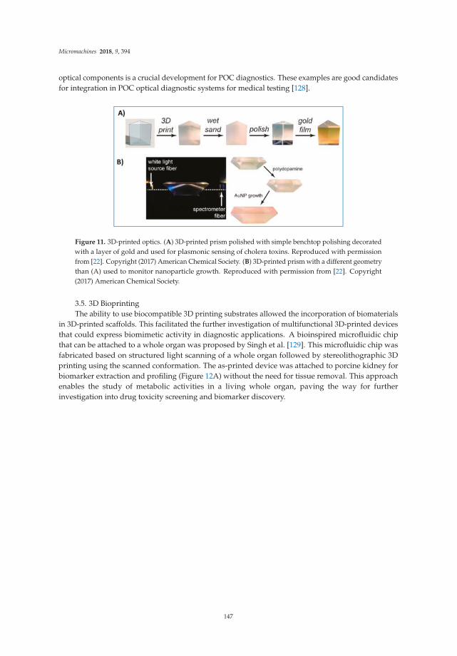
Micromachines 2018, 9, 394
optical components is a crucial development for POC diagnostics. These examples are good candidatesfor integration in POC optical diagnostic systems for medical testing [128].
Figure 11. 3D-printed optics. (A) 3D-printed prism polished with simple benchtop polishing decoratedwith a layer of gold and used for plasmonic sensing of cholera toxins. Reproduced with permissionfrom [22]. Copyright (2017) American Chemical Society. (B) 3D-printed prism with a different geometrythan (A) used to monitor nanoparticle growth. Reproduced with permission from [22]. Copyright(2017) American Chemical Society.
3.5. 3D BioprintingThe ability to use biocompatible 3D printing substrates allowed the incorporation of biomaterials
in 3D-printed scaffolds. This facilitated the further investigation of multifunctional 3D-printed devicesthat could express biomimetic activity in diagnostic applications. A bioinspired microfluidic chipthat can be attached to a whole organ was proposed by Singh et al. [129]. This microfluidic chip wasfabricated based on structured light scanning of a whole organ followed by stereolithographic 3Dprinting using the scanned conformation. The as-printed device was attached to porcine kidney forbiomarker extraction and profiling (Figure 12A) without the need for tissue removal. This approachenables the study of metabolic activities in a living whole organ, paving the way for furtherinvestigation into drug toxicity screening and biomarker discovery.
147
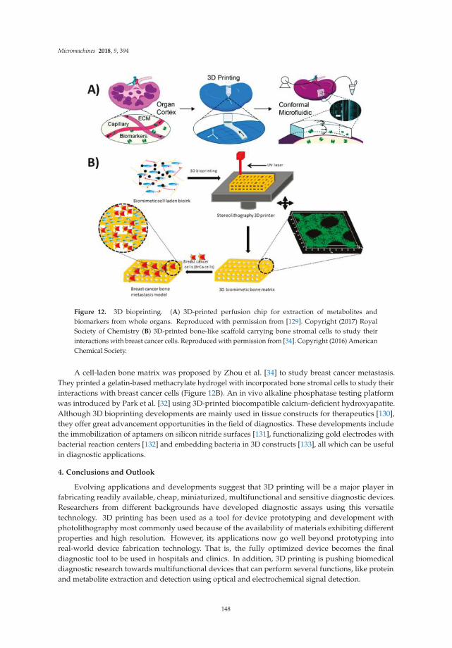
Micromachines 2018, 9, 394
Figure 12. 3D bioprinting. (A) 3D-printed perfusion chip for extraction of metabolites andbiomarkers from whole organs. Reproduced with permission from [129]. Copyright (2017) RoyalSociety of Chemistry (B) 3D-printed bone-like scaffold carrying bone stromal cells to study theirinteractions with breast cancer cells. Reproduced with permission from [34]. Copyright (2016) AmericanChemical Society.
A cell-laden bone matrix was proposed by Zhou et al. [34] to study breast cancer metastasis.They printed a gelatin-based methacrylate hydrogel with incorporated bone stromal cells to study theirinteractions with breast cancer cells (Figure 12B). An in vivo alkaline phosphatase testing platformwas introduced by Park et al. [32] using 3D-printed biocompatible calcium-deficient hydroxyapatite.Although 3D bioprinting developments are mainly used in tissue constructs for therapeutics [130],they offer great advancement opportunities in the field of diagnostics. These developments includethe immobilization of aptamers on silicon nitride surfaces [131], functionalizing gold electrodes withbacterial reaction centers [132] and embedding bacteria in 3D constructs [133], all which can be usefulin diagnostic applications.
4. Conclusions and Outlook
Evolving applications and developments suggest that 3D printing will be a major player infabricating readily available, cheap, miniaturized, multifunctional and sensitive diagnostic devices.Researchers from different backgrounds have developed diagnostic assays using this versatiletechnology. 3D printing has been used as a tool for device prototyping and development withphotolithography most commonly used because of the availability of materials exhibiting differentproperties and high resolution. However, its applications now go well beyond prototyping intoreal-world device fabrication technology. That is, the fully optimized device becomes the finaldiagnostic tool to be used in hospitals and clinics. In addition, 3D printing is pushing biomedicaldiagnostic research towards multifunctional devices that can perform several functions, like proteinand metabolite extraction and detection using optical and electrochemical signal detection.
148

Micromachines 2018, 9, 394
3D printing technology still needs improvement in order to enhance current diagnostic abilities.First, simultaneous printing of multiple materials with high resolution and good compatibilityis essential, especially for functional materials like conductive inks and biomimetic substrates.Printing multiple materials with different physical properties would greatly improve the capabilities of3D printers to produce more complex functional architectures. The ability to print active biomaterialslike enzymes and proteins in 3D formats without compromising their basic activity is also an importantrequirement for better diagnostic devices.
Given the progressive nature of 3D printing, more complex microfluidic architectures canbe expected in the near future. Recent research has focused on the development of microfluidicpumps [134], automated flow control valves [135], atomic force microscopes [136] and sophisticatedscanning electron microscope sample holders [137]. These are examples of very complex architecturesthat cannot be readily approached in the averaged bioanalytical laboratory without 3D printers.This illustrates again the significance of incorporating 3D printing in bioanalytical and diagnostictesting research providing a platform for achieving what was believed to be imaginary in the pre-3Dprinting era.
Funding: The authors thank the University of Connecticut for an Academic Plan Project Grant and NIH and forGrants No. ES03154 from the National institute of Environmental Health Sciences (NIEHS), and No. EB016707from the National Institute of Biomedical Imaging and Bioengineering (NIBIB), for financial support in preparingthis article.
Conflicts of Interest: The authors declare no conflict of interest.
References
1. Hull, C. Apparatus for Production of Three-Dimensional Objects by Stereolithography. U.S. PatentNo 4,575,330, 11 March 1986.
2. Gross, B.; Lockwood, S.Y.; Spence, D.M. Recent Advances in Analytical Chemistry by 3D Printing. Anal. Chem.
2017, 89, 57–70. [CrossRef] [PubMed]3. Chia, H.N.; Wu, B.M. Recent advances in 3D printing of biomaterials. J. Biol. Eng. 2015, 9, 4. [CrossRef]
[PubMed]4. Diment, L.E.; Thompson, M.S.; Bergmann, J.H. Three-dimensional printed upper-limb prostheses lack
randomised controlled trials: A systematic review. Prosthet. Orthot. Int. 2018, 42, 7–13. [CrossRef] [PubMed]5. Bose, S.; Vahabzadeh, S.; Bandyopadhyay, A. Bone tissue engineering using 3D printing. Mater. Today 2013,
16, 496–504. [CrossRef]6. Waheed, S.; Cabot, J.M.; Macdonald, N.P.; Lewis, T.; Guijt, R.M.; Paull, B.; Breadmore, M.C. 3D printed
microfluidic devices: Enablers and barriers. Lab Chip 2016, 16, 1993–2013. [CrossRef] [PubMed]7. Why 3D Printing Could Be a Manufacturing and Logistics Game Changer. Available online:
https://www.manufacturing.net/blog/2013/10/why-3d-printing-could-be-manufacturing-and-logistics-game-changer (accessed on 30 April 2018).
8. Au, A.K.; Lee, W.; Folch, A. Mail-order microfluidics: Evaluation of stereolithography for the production ofmicrofluidic devices. Lab Chip 2014, 14, 1294–1301. [CrossRef] [PubMed]
9. Kadimisetty, K.; Song, J.; Doto, A.M.; Hwang, Y.; Peng, J.; Mauk, M.G.; Bushman, F.D.; Gross, R.; Jarvis, J.N.;Liu, C. Fully 3D printed integrated reactor array for point-of-care molecular diagnostics. Biosens. Bioelectron.
2018, 109, 156–163. [CrossRef] [PubMed]10. Yazdi, A.A.; Popma, A.; Wong, W.; Nguyen, T.; Pan, Y.; Xu, J. 3D printing: An emerging tool for novel
microfluidics and lab-on-a-chip applications. Microfluid. Nanofluid. 2016, 20, 50. [CrossRef]11. Zhang, Z.; Xu, J.; Hong, B.; Chen, X. The effects of 3D channel geometry on CTC passing pressure—Towards
deformability-based cancer cell separation. Lab Chip 2014, 14, 2576–2584. [CrossRef] [PubMed]12. Kadimisetty, K.; Mosa, I.M.; Malla, S.; Satterwhite-Warden, J.E.; Kuhns, T.M.; Faria, R.C.;
Lee, N.H.; Rusling, J.F. 3D-printed supercapacitor-powered electrochemiluminescent protein immunoarray.Biosens. Bioelectron. 2016, 77, 188–193. [CrossRef] [PubMed]
149

Micromachines 2018, 9, 394
13. Damiati, S.; Peacock, M.; Leonhardt, S.; Damiati, L.; Baghdadi, M.A.; Becker, H.; Kodzius, R.; Schuster, B.Embedded Disposable Functionalized Electrochemical Biosensor with a 3D-Printed Flow Cell for Detectionof Hepatic Oval Cells (HOCs). Genes 2018, 9, 89. [CrossRef] [PubMed]
14. Mulberry, G.; White, K.A.; Vaidya, M.; Sugaya, K.; Kim, B.N. 3D printing and milling a real-time PCR devicefor infectious disease diagnostics. PLoS ONE 2017, 12, e0179133. [CrossRef] [PubMed]
15. Singh, H.; Shimojima, M.; Shiratori, T.; An, L.V.; Sugamata, M.; Yang, M. Application of 3D PrintingTechnology in Increasing the Diagnostic Performance of Enzyme-Linked Immunosorbent Assay (ELISA) forInfectious Diseases. Sensors 2015, 15, 16503–16515. [CrossRef] [PubMed]
16. Chudobova, D.; Cihalova, K.; Skalickova, S.; Zitka, J.; Rodrigo, M.A.M.; Milosavljevic, V.; Hynek, D.; Kopel, P.;Vesely, R.; Adam, V.; et al. 3D-printed chip for detection of methicillin-resistant Staphylococcus aureuslabeled with gold nanoparticles. Electrophoresis 2015, 36, 457–466. [CrossRef] [PubMed]
17. Kadimisetty, K.; Malla, S.; Rusling, J.F. Automated 3-D Printed Arrays to Evaluate Genotoxic Chemistry:E-Cigarettes and Water Samples. ACS Sens. 2017, 2, 670–678. [CrossRef] [PubMed]
18. Schäfer, M.; Bräuler, V.; Ulber, R. Bio-sensing of metal ions by a novel 3D-printable smartphone spectrometer.Sens. Actuators B Chem. 2018, 255, 1902–1910. [CrossRef]
19. Mendoza-Gallegos, R.A.; Rios, A.; Garcia-Cordero, J.L. An Affordable and Portable Thermocycler forReal-Time PCR Made of 3D-Printed Parts and Off-the-Shelf Electronics. Anal. Chem. 2018, 90, 5563–5568.[CrossRef] [PubMed]
20. Wang, L.-J.; Sun, R.; Vasile, T.; Chang, Y.-C.; Li, L. High-Throughput Optical Sensing Immunoassays onSmartphone. Anal. Chem. 2016, 88, 8302–8308. [CrossRef] [PubMed]
21. Chen, Y.; Fu, Q.; Li, D.; Xie, J.; Ke, D.; Song, Q.; Tang, Y.; Wang, H. A smartphone colorimetric readerintegrated with an ambient light sensor and a 3D printed attachment for on-site detection of zearalenone.Anal. Bioanal. Chem. 2017, 409, 6567–6574. [CrossRef] [PubMed]
22. Hinman, S.S.; McKeating, K.S.; Cheng, Q. Plasmonic Sensing with 3D Printed Optics. Anal. Chem. 2017,89, 12626–12630. [CrossRef] [PubMed]
23. Rusling, J.F. Developing Microfluidic Sensing Devices Using 3D Printing. ACS Sens. 2018, 3, 522–526.[CrossRef] [PubMed]
24. Lee, K.Y.; Ambrosi, A.; Pumera, M. 3D-printed Metal Electrodes for Heavy Metals Detection by AnodicStripping Voltammetry. Electroanalysis 2017, 29, 2444–2453. [CrossRef]
25. Rymansaib, Z.; Iravani, P.; Emslie, E.; Medvidovic-Kosanovic, M.; Sak-Bosnar, M.; Verdejo, R.; Marken, F.All-Polystyrene 3D-Printed Electrochemical Device with Embedded Carbon Nanofiber-Graphite-PolystyreneComposite Conductor. Electroanalysis 2016, 28, 1517–1523. [CrossRef]
26. Honeychurch, K.C.; Rymansaib, Z.; Iravani, P. Anodic stripping voltammetric determination of zinc at a3-D printed carbon nanofiber–graphite–polystyrene electrode using a carbon pseudo-reference electrode.Sens. Actuators B Chem. 2018, 267, 476–482. [CrossRef]
27. Cheng, T.S.; Nasir, M.Z.M.; Ambrosi, A.; Pumera, M. 3D-printed metal electrodes for electrochemicaldetection of phenols. Appl. Mater. Today 2017, 9, 212–219. [CrossRef]
28. Tan, C.; Nasir, M.Z.M.; Ambrosi, A.; Pumera, M. 3D printed electrodes for detection of nitroaromaticexplosives and nerve agents. Anal. Chem. 2017, 89, 8995–9001. [CrossRef] [PubMed]
29. Liyarita, B.R.; Ambrosi, A.; Pumera, M. 3D-printed electrodes for sensing of biologically active molecules.Electroanalysis 2018, 30, 1319–1326. [CrossRef]
30. Lewis, J.A.; Ahn, B.Y. Device fabrication: Three-dimensional printed electronics. Nature 2015, 518, 42–43.[CrossRef] [PubMed]
31. Derakhshanfar, S.; Mbeleck, R.; Xu, K.; Zhang, X.; Zhong, W.; Xing, M. 3D bioprinting for biomedical devicesand tissue engineering: A review of recent trends and advances. Bioact. Mater. 2018, 3, 144–156. [CrossRef][PubMed]
32. Park, C.S.; Ha, T.H.; Kim, M.; Raja, N.; Yun, H.; Sung, M.J.; Kwon, O.S.; Yoon, H.; Lee, C.-S. Fast and sensitivenear-infrared fluorescent probes for ALP detection and 3D printed calcium phosphate scaffold imagingin vivo. Biosens. Bioelectron. 2018, 105, 151–158. [CrossRef] [PubMed]
33. Knowlton, S.; Onal, S.; Yu, C.H.; Zhao, J.J.; Tasoglu, S. Bioprinting for cancer research. Trends Biotechnol. 2015,33, 504–513. [CrossRef] [PubMed]
150

Micromachines 2018, 9, 394
34. Zhou, X.; Zhu, W.; Nowicki, M.; Miao, S.; Cui, H.; Holmes, B.; Glazer, R.I.; Zhang, L.G. 3D bioprinting acell-laden bone matrix for breast cancer metastasis study. ACS Appl. Mater. Interfaces 2016, 8, 30017–30026.[CrossRef] [PubMed]
35. Mohamed, O.A.; Masood, S.H.; Bhowmik, J.L. Optimization of fused deposition modeling processparameters: A review of current research and future prospects. Adv. Manuf. 2015, 3, 42–53. [CrossRef]
36. Dul, S.; Fambri, L.; Pegoretti, A. Fused deposition modelling with ABS–graphene nanocomposites.Compos. Part Appl. Sci. Manuf. 2016, 85, 181–191. [CrossRef]
37. Wang, X.; Jiang, M.; Zhou, Z.; Gou, J.; Hui, D. 3D printing of polymer matrix composites: A review andprospective. Compos. Part B Eng. 2017, 110, 442–458. [CrossRef]
38. Leigh, S.J.; Bradley, R.J.; Purssell, C.P.; Billson, D.R.; Hutchins, D.A. A Simple, Low-Cost ConductiveComposite Material for 3D Printing of Electronic Sensors. PLoS ONE 2012, 7, e49365. [CrossRef] [PubMed]
39. Cruz, M.A.; Ye, S.; Kim, M.J.; Reyes, C.; Yang, F.; Flowers, P.F.; Wiley, B.J. Multigram synthesis of cu-agcore–shell nanowires enables the production of a highly conductive polymer filament for 3D printingelectronics. Part. Part. Syst. Charact. 2018, 25, 1700385. [CrossRef]
40. Lee, J.-Y.; An, J.; Chua, C.K. Fundamentals and applications of 3D printing for novel materials. Appl. Mater.
Today 2017, 7, 120–133. [CrossRef]41. Rimington, R.P.; Capel, A.J.; Christie, S.D.; Lewis, M.P. Biocompatible 3D printed polymers via fused
deposition modelling direct C 2 C 12 cellular phenotype in vitro. Lab Chip 2017, 17, 2982–2993. [CrossRef][PubMed]
42. Rosenzweig, D.H.; Carelli, E.; Steffen, T.; Jarzem, P.; Haglund, L. 3D-Printed ABS and PLA Scaffolds forCartilage and Nucleus Pulposus Tissue Regeneration. Int. J. Mol. Sci. 2015, 16, 15118–15135. [CrossRef][PubMed]
43. Skliutas, E.; Kasetaite, S.; Jonušauskas, L.; Ostrauskaite, J.; Malinauskas, M. Photosensitive naturally derivedresins toward optical 3-D printing. Opt. Eng. 2018, 57, 041412. [CrossRef]
44. Voet, V.S.D.; Strating, T.; Schnelting, G.H.M.; Dijkstra, P.; Tietema, M.; Xu, J.; Woortman, A.J.J.; Loos, K.;Jager, J.; Folkersma, R. Biobased acrylate photocurable resin formulation for stereolithography 3D printing.ACS Omega 2018, 3, 1403–1408. [CrossRef]
45. Malek, S.; Raney, J.R.; Lewis, J.A.; Gibson, L.J. Lightweight 3D cellular composites inspired by balsa.Bioinspir. Biomim. 2017, 12, 026014. [CrossRef] [PubMed]
46. Smith, P.T.; Basu, A.; Saha, A.; Nelson, A. Chemical modification and printability of shear-thinning hydrogelinks for direct-write 3D printing. Polymer 2018, in press. [CrossRef]
47. He, Y.; Yang, F.; Zhao, H.; Gao, Q.; Xia, B.; Fu, J. Research on the printability of hydrogels in 3D bioprinting.Sci. Rep. 2016, 6, 29977. [CrossRef] [PubMed]
48. Compton, B.G.; Lewis, J.A. 3D-printing of lightweight cellular composites. Adv. Mater. 2014, 26, 5930–5935.[CrossRef] [PubMed]
49. Loebel, C.; Rodell, C.B.; Chen, M.H.; Burdick, J.A. Shear-thinning and self-healing hydrogels as injectabletherapeutics and for 3D-printing. Nat. Protoc. 2017, 12, 1521–1541. [CrossRef] [PubMed]
50. Fedorovich, N.E.; Schuurman, W.; Wijnberg, H.M.; Prins, H.-J.; van Weeren, P.R.; Malda, J.; Alblas, J.;Dhert, W.J.A. Biofabrication of osteochondral tissue equivalents by printing topologically defined, cell-ladenhydrogel scaffolds. Tissue Eng. Part C Methods 2011, 18, 33–44. [CrossRef] [PubMed]
51. Billiet, T.; Gevaert, E.; De Schryver, T.; Cornelissen, M.; Dubruel, P. The 3D printing of gelatin methacrylamidecell-laden tissue-engineered constructs with high cell viability. Biomaterials 2014, 35, 49–62. [CrossRef][PubMed]
52. Ifkovits, J.L.; Burdick, J.A. Review: Photopolymerizable and degradable biomaterials for tissue engineeringapplications. Tissue Eng. 2007, 13, 2369–2385. [CrossRef] [PubMed]
53. Hong, S.; Sycks, D.; Chan, H.F.; Lin, S.; Lopez, G.P.; Guilak, F.; Leong, K.W.; Zhao, X. 3D printing of highlystretchable and tough hydrogels into complex, cellularized structures. Adv. Mater. 2015, 27, 4035–4040.[CrossRef] [PubMed]
54. Gross, B.C.; Erkal, J.L.; Lockwood, S.Y.; Chen, C.; Spence, D.M. Evaluation of 3D Printing and Its PotentialImpact on Biotechnology and the Chemical Sciences. Anal. Chem. 2014, 86, 3240–3253. [CrossRef] [PubMed]
151

Micromachines 2018, 9, 394
55. Gauvin, R.; Chen, Y.-C.; Lee, J.W.; Soman, P.; Zorlutuna, P.; Nichol, J.W.; Bae, H.; Chen, S.; Khademhosseini, A.Microfabrication of complex porous tissue engineering scaffolds using 3D projection stereolithography.Biomaterials 2012, 33, 3824–3834. [CrossRef] [PubMed]
56. Zhang, A.P.; Qu, X.; Soman, P.; Hribar, K.C.; Lee, J.W.; Chen, S.; He, S. Rapid Fabrication of Complex3D Extracellular Microenvironments by Dynamic Optical Projection Stereolithography. Adv. Mater. 2012,24, 4266–4270. [CrossRef] [PubMed]
57. Macdonald, N.P.; Cabot, J.M.; Smejkal, P.; Guijt, R.M.; Paull, B.; Breadmore, M.C. Comparing MicrofluidicPerformance of Three-Dimensional (3D) Printing Platforms. Anal. Chem. 2017, 89, 3858–3866. [CrossRef][PubMed]
58. Lin, H.; Zhang, D.; Alexander, P.G.; Yang, G.; Tan, J.; Cheng, A.W.-M.; Tuan, R.S. Application ofvisible light-based projection stereolithography for live cell-scaffold fabrication with designed architecture.Biomaterials 2013, 34, 331–339. [CrossRef] [PubMed]
59. Hofmann, M. 3D printing gets a boost and opportunities with polymer materials. ACS Macro Lett. 2014,3, 382–386. [CrossRef]
60. Kamyshny, A.; Steinke, J.; Magdassi, S. Metal-based inkjet inks for printed electronics. Open Appl. Phys. J.
2011, 4, 19–36. [CrossRef]61. Zocca, A.; Gomes, C.M.; Staude, A.; Bernardo, E.; Günster, J.; Colombo, P. SiOC ceramics with ordered
porosity by 3D-printing of a preceramic polymer. J. Mater. Res. 2013, 28, 2243–2252. [CrossRef]62. Bucella, S.G.; Nava, G.; Vishunubhatla, K.C.; Caironi, M. High-resolution direct-writing of metallic electrodes
on flexible substrates for high performance organic field effect transistors. Org. Electron. 2013, 14, 2249–2256.[CrossRef]
63. Munshi, A.S.; Martin, R.S. Microchip-based electrochemical detection using a 3-D printed wall-jet electrodedevice. Analyst 2016, 141, 862–869. [CrossRef] [PubMed]
64. Anderson, K.B.; Lockwood, S.Y.; Martin, R.S.; Spence, D.M. A 3D printed fluidic device that enablesintegrated features. Anal. Chem. 2013, 85, 5622–5626. [CrossRef] [PubMed]
65. Bhattacharjee, N.; Urrios, A.; Kang, S.; Folch, A. The upcoming 3D-printing revolution in microfluidics.Lab Chip 2016, 16, 1720–1742. [CrossRef] [PubMed]
66. Williams, J.M.; Adewunmi, A.; Schek, R.M.; Flanagan, C.L.; Krebsbach, P.H.; Feinberg, S.E.; Hollister, S.J.;Das, S. Bone tissue engineering using polycaprolactone scaffolds fabricated via selective laser sintering.Biomaterials 2005, 26, 4817–4827. [CrossRef] [PubMed]
67. Shirazi, S.F.S.; Gharehkhani, S.; Mehrali, M.; Yarmand, H.; Metselaar, H.S.C.; Kadri, N.A.; Osman, N.A.A.A review on powder-based additive manufacturing for tissue engineering: Selective laser sintering andinkjet 3D printing. Sci. Technol. Adv. Mater. 2015, 16, 033502. [CrossRef] [PubMed]
68. Kolan, K.C.R.; Leu, M.C.; Hilmas, G.E.; Velez, M. Effect of material, process parameters, and simulated bodyfluids on mechanical properties of 13-93 bioactive glass porous constructs made by selective laser sintering.J. Mech. Behav. Biomed. Mater. 2012, 13, 14–24. [CrossRef] [PubMed]
69. Yeong, W.Y.; Sudarmadji, N.; Yu, H.Y.; Chua, C.K.; Leong, K.F.; Venkatraman, S.S.; Boey, Y.C.F.; Tan, L.P.Porous polycaprolactone scaffold for cardiac tissue engineering fabricated by selective laser sintering.Acta Biomater. 2010, 6, 2028–2034. [CrossRef] [PubMed]
70. Wu, G.-H.; Hsu, S. Review: Polymeric-based 3D printing for tissue engineering. J. Med. Biol. Eng. 2015,35, 285–292. [CrossRef] [PubMed]
71. Olakanmi, E.O.; Cochrane, R.F.; Dalgarno, K.W. A review on selective laser sintering/melting (SLS/SLM) ofaluminium alloy powders: Processing, microstructure, and properties. Prog. Mater. Sci. 2015, 74, 401–477.[CrossRef]
72. Fuse 1: Benchtop Selective Laser Sintering (SLS) 3D Printer. Available online: https://formlabs.com/3d-printers/fuse-1/ (accessed on 10 July 2018).
73. Malinauskas, M.; Žukauskas, A.; Hasegawa, S.; Hayasaki, Y.; Mizeikis, V.; Buividas, R.; Juodkazis, S. Ultrafastlaser processing of materials: From science to industry. Light Sci. Appl. 2016, 5, e16133. [CrossRef]
74. Marino, A.; Barsotti, J.; de Vito, G.; Filippeschi, C.; Mazzolai, B.; Piazza, V.; Labardi, M.; Mattoli, V.;Ciofani, G. Two-photon lithography of 3D nanocomposite piezoelectric scaffolds for cell stimulation. ACS
Appl. Mater. Interfaces 2015, 7, 25574–25579. [CrossRef] [PubMed]
152

Micromachines 2018, 9, 394
75. Maciulaitis, J.; Deveikyte, M.; Rekštyte, S.; Bratchikov, M.; Darinskas, A.; Šimbelyte, A.; Daunoras, G.;Laurinaviciene, A.; Laurinavicius, A.; Gudas, R.; et al. Preclinical study of SZ2080 material 3Dmicrostructured scaffolds for cartilage tissue engineering made by femtosecond direct laser writinglithography. Biofabrication 2015, 7, 015015. [CrossRef] [PubMed]
76. Ovsianikov, A.; Mühleder, S.; Torgersen, J.; Li, Z.; Qin, X.-H.; Van Vlierberghe, S.; Dubruel, P.; Holnthoner, W.;Redl, H.; Liska, R.; et al. Laser photofabrication of cell-containing hydrogel constructs. Langmuir 2014,30, 3787–3794. [CrossRef] [PubMed]
77. Torgersen, J.; Ovsianikov, A.; Mironov, V.; Pucher, N.; Qin, X.; Li, Z.; Cicha, K.; Machacek, T.; Liska, R.;Jantsch, V.; et al. Photo-sensitive hydrogels for three-dimensional laser microfabrication in the presence ofwhole organisms. J. Biomed. Opt. 2012, 17, 105008. [CrossRef] [PubMed]
78. Gruene, M.; Deiwick, A.; Koch, L.; Schlie, S.; Unger, C.; Hofmann, N.; Bernemann, I.; Glasmacher, B.;Chichkov, B. Laser printing of stem cells for biofabrication of scaffold-free autologous grafts. Tissue Eng.
Part C Methods 2011, 17, 79–87. [CrossRef] [PubMed]79. Schizas, C.; Melissinaki, V.; Gaidukeviciute, A.; Reinhardt, C.; Ohrt, C.; Dedoussis, V.; Chichkov, B.N.;
Fotakis, C.; Farsari, M.; Karalekas, D. On the design and fabrication by two-photon polymerization of areadily assembled micro-valve. Int. J. Adv. Manuf. Technol. 2010, 48, 435–441. [CrossRef]
80. Qu, J.; Kadic, M.; Naber, A.; Wegener, M. Micro-structured two-component 3D metamaterials with negativethermal-expansion coefficient from positive constituents. Sci. Rep. 2017, 7, 40643. [CrossRef] [PubMed]
81. Jonušauskas, L.; Skliutas, E.; Butkus, S.; Malinauskas, M. Custom on demand 3D printing of functionalmicrostructures. Lith. J. Phys. 2015, 55, 227–236. [CrossRef]
82. Amato, L.; Gu, Y.; Bellini, N.; Eaton, S.M.; Cerullo, G.; Osellame, R. Integrated three-dimensional filterseparates nanoscale from microscale elements in a microfluidic chip. Lab Chip 2012, 12, 1135–1142. [CrossRef][PubMed]
83. Paiè, P.; Bragheri, F.; Carlo, D.D.; Osellame, R. Particle focusing by 3D inertial microfluidics. Microsyst.
Nanoeng. 2017, 3, 17027. [CrossRef]84. Rogers, C.I.; Qaderi, K.; Woolley, A.T.; Nordin, G.P. 3D printed microfluidic devices with integrated valves.
Biomicrofluidics 2015, 9, 016501. [CrossRef] [PubMed]85. Su, C.-K.; Hsia, S.-C.; Sun, Y.-C. Three-dimensional printed sample load/inject valves enabling online
monitoring of extracellular calcium and zinc ions in living rat brains. Anal. Chim. Acta 2014, 838, 58–63.[CrossRef] [PubMed]
86. Su, C.-K.; Peng, P.-J.; Sun, Y.-C. Fully 3D-printed preconcentrator for selective extraction of trace elements inseawater. Anal. Chem. 2015, 87, 6945–6950. [CrossRef] [PubMed]
87. Su, C.-K.; Yen, S.-C.; Li, T.-W.; Sun, Y.-C. Enzyme-Immobilized 3D-Printed Reactors for Online Monitoring ofRat Brain Extracellular Glucose and Lactate. Anal. Chem. 2016, 88, 6265–6273. [CrossRef] [PubMed]
88. Rafeie, M.; Zhang, J.; Asadnia, M.; Li, W.; Warkiani, M.E. Multiplexing slanted spiral microchannels forultra-fast blood plasma separation. Lab Chip 2016, 16, 2791–2802. [CrossRef] [PubMed]
89. Lee, W.; Kwon, D.; Choi, W.; Jung, G.Y.; Au, A.K.; Folch, A.; Jeon, S. 3D-printed microfluidic device for thedetection of pathogenic bacteria using size-based separation in helical channel with trapezoid cross-section.Sci. Rep. 2015, 5, 7717. [CrossRef] [PubMed]
90. Yan, S.; Tan, S.H.; Li, Y.; Tang, S.; Teo, A.J.T.; Zhang, J.; Zhao, Q.; Yuan, D.; Sluyter, R.; Nguyen, N.T.; et al.A portable, hand-powered microfluidic device for sorting of biological particles. Microfluid. Nanofluid. 2018,22, 8. [CrossRef]
91. Park, C.; Lee, J.; Kim, Y.; Kim, J.; Lee, J.; Park, S. 3D-printed microfluidic magnetic preconcentrator for thedetection of bacterial pathogen using an ATP luminometer and antibody-conjugated magnetic nanoparticles.J. Microbiol. Methods 2017, 132, 128–133. [CrossRef] [PubMed]
92. Oh, S.; Kim, B.; Lee, J.K.; Choi, S. 3D-printed capillary circuits for rapid, low-cost, portable analysis of bloodviscosity. Sens. Actuators B Chem. 2018, 259, 106–113. [CrossRef]
93. Santangelo, M.F.; Libertino, S.; Turner, A.P.F.; Filippini, D.; Mak, W.C. Integrating printed microfluidicswith silicon photomultipliers for miniaturised and highly sensitive ATP bioluminescence detection. Biosens.
Bioelectron. 2018, 99, 464–470. [CrossRef] [PubMed]94. Tang, C.K.; Vaze, A.; Rusling, J.F. Automated 3D-printed unibody immunoarray for chemiluminescence
detection of cancer biomarker proteins. Lab Chip 2017, 17, 484–489. [CrossRef] [PubMed]
153

Micromachines 2018, 9, 394
95. Nie, J.; Gao, Q.; Qiu, J.; Sun, M.; Liu, A.; Shao, L.; Fu, J.; Zhao, P.; He, Y. 3D printed Lego®-like modularmicrofluidic devices based on capillary driving. Biofabrication 2018, 10, 035001. [CrossRef] [PubMed]
96. Symes, M.D.; Kitson, P.J.; Yan, J.; Richmond, C.J.; Cooper, G.J.T.; Bowman, R.W.; Vilbrandt, T.; Cronin, L.Integrated 3D-printed reactionware for chemical synthesis and analysis. Nat. Chem. 2012, 4, 349–354.[CrossRef] [PubMed]
97. Chen, C.; Wang, Y.; Lockwood, S.Y.; Spence, D.M. 3D-printed fluidic devices enable quantitative evaluation ofblood components in modified storage solutions for use in transfusion medicine. Analyst 2014, 139, 3219–3226.[CrossRef] [PubMed]
98. Bishop, G.W.; Satterwhite-Warden, J.E.; Bist, I.; Chen, E.; Rusling, J.F. Electrochemiluminescence at bareand dna-coated graphite electrodes in 3D-printed fluidic devices. ACS Sens. 2016, 1, 197–202. [CrossRef][PubMed]
99. Zangheri, M.; Cevenini, L.; Anfossi, L.; Baggiani, C.; Simoni, P.; Di Nardo, F.; Roda, A. A simple and compactsmartphone accessory for quantitative chemiluminescence-based lateral flow immunoassay for salivarycortisol detection. Biosens. Bioelectron. 2015, 64, 63–68. [CrossRef] [PubMed]
100. Suh, Y.K.; Kang, S. A review on mixing in microfluidics. Micromachines 2010, 1, 82–111. [CrossRef]101. Shallan, A.I.; Smejkal, P.; Corban, M.; Guijt, R.M.; Breadmore, M.C. Cost-effective three-dimensional printing
of visibly transparent microchips within minutes. Anal. Chem. 2014, 86, 3124–3130. [CrossRef] [PubMed]102. Bishop, G.W.; Satterwhite, J.E.; Bhakta, S.; Kadimisetty, K.; Gillette, K.M.; Chen, E.; Rusling, J.F. 3D-printed
fluidic devices for nanoparticle preparation and flow-injection amperometry using integrated prussian bluenanoparticle-modified electrodes. Anal. Chem. 2015, 87, 5437–5443. [CrossRef] [PubMed]
103. Patrick, W.G.; Nielsen, A.A.K.; Keating, S.J.; Levy, T.J.; Wang, C.-W.; Rivera, J.J.; Mondragón-Palomino, O.;Carr, P.A.; Voigt, C.A.; Oxman, N.; et al. DNA assembly in 3D printed fluidics. PLoS ONE 2015, 10, e0143636.[CrossRef] [PubMed]
104. Kise, D.P.; Reddish, M.J.; Dyer, R.B. Sandwich-format 3D printed microfluidic mixers: A flexible platform formulti-probe analysis. J. Micromech. Microeng. 2015, 25, 124002. [CrossRef] [PubMed]
105. Plevniak, K.; Campbell, M.; Myers, T.; Hodges, A.; He, M. 3D printed auto-mixing chip enables rapidsmartphone diagnosis of anemia. Biomicrofluidics 2016, 10, 054113. [CrossRef] [PubMed]
106. Mattio, E.; Robert-Peillard, F.; Vassalo, L.; Branger, C.; Margaillan, A.; Brach-Papa, C.; Knoery, J.;Boudenne, J.-L.; Coulomb, B. 3D-printed lab-on-valve for fluorescent determination of cadmium and lead inwater. Talanta 2018, 183, 201–208. [CrossRef] [PubMed]
107. Guo, T.; Patnaik, R.; Kuhlmann, K.; Rai, A.J.; Sia, S.K. Smartphone dongle for simultaneous measurementof hemoglobin concentration and detection of HIV antibodies. Lab Chip 2015, 15, 3514–3520. [CrossRef][PubMed]
108. Chan, K.; Weaver, S.C.; Wong, P.-Y.; Lie, S.; Wang, E.; Guerbois, M.; Vayugundla, S.P.; Wong, S. Rapid,affordable and portable medium-throughput molecular device for zika virus. Sci. Rep. 2016, 6, 38223.[CrossRef] [PubMed]
109. Fernandes, A.C.; Semenova, D.; Panjan, P.; Sesay, A.M.; Gernaey, K.V.; Krühne, U. Multi-function microfluidicplatform for sensor integration. New Biotechnol. 2018, in press. [CrossRef] [PubMed]
110. Li, K.; Wei, H.; Liu, W.; Meng, H.; Zhang, P.; Yan, C. 3D printed stretchable capacitive sensors for highlysensitive tactile and electrochemical sensing. Nanotechnology 2018, 29, 185501. [CrossRef] [PubMed]
111. Manzanares Palenzuela, C.L.; Novotný, F.; Krupicka, P.; Sofer, Z.; Pumera, M. 3D-printedgraphene/polylactic acid electrodes promise high sensitivity in electroanalysis. Anal. Chem. 2018,90, 5753–5757. [CrossRef] [PubMed]
112. Lind, J.U.; Busbee, T.A.; Valentine, A.D.; Pasqualini, F.S.; Yuan, H.; Yadid, M.; Park, S.-J.; Kotikian, A.;Nesmith, A.P.; Campbell, P.H.; et al. Instrumented cardiac microphysiological devices via multimaterialthree-dimensional printing. Nat. Mater. 2017, 16, 303–308. [CrossRef] [PubMed]
113. Muth, J.T.; Vogt, D.M.; Truby, R.L.; Mengüç, Y.; Kolesky, D.B.; Wood, R.J.; Lewis, J.A. Embedded 3D printingof strain sensors within highly stretchable elastomers. Adv. Mater. 2014, 26, 6307–6312. [CrossRef] [PubMed]
114. Lei, Z.; Wang, Q.; Wu, P. A multifunctional skin-like sensor based on a 3D printed thermo-responsivehydrogel. Mater. Horiz. 2017, 4, 694–700. [CrossRef]
115. Skin to E-Skin. Available online: https://www.nature.com/articles/nnano.2017.228 (accessed on3 August 2018).
154

Micromachines 2018, 9, 394
116. Shanmugam, A.; Usmani, M.; Mayberry, A.; Perkins, D.L.; Holcomb, D.E. Imaging systems and algorithmsto analyze biological samples in real-time using mobile phone microscopy. PLoS ONE 2018, 13, e0193797.[CrossRef] [PubMed]
117. Scordo, G.; Moscone, D.; Palleschi, G.; Arduini, F. A reagent-free paper-based sensor embedded in a3D printing device for cholinesterase activity measurement in serum. Sens. Actuators B Chem. 2018,258, 1015–1021. [CrossRef]
118. Xiao, W.; Huang, C.; Xu, F.; Yan, J.; Bian, H.; Fu, Q.; Xie, K.; Wang, L.; Tang, Y. A simple and compactsmartphone-based device for the quantitative readout of colloidal gold lateral flow immunoassay strips.Sens. Actuators B Chem. 2018, 266, 63–70. [CrossRef]
119. Knowlton, S.; Joshi, A.; Syrrist, P.; Coskun, A.F.; Tasoglu, S. 3D-printed smartphone-based point of care toolfor fluorescence- and magnetophoresis-based cytometry. Lab Chip 2017, 17, 2839–2851. [CrossRef] [PubMed]
120. Kühnemund, M.; Wei, Q.; Darai, E.; Wang, Y.; Hernández-Neuta, I.; Yang, Z.; Tseng, D.; Ahlford, A.;Mathot, L.; Sjöblom, T.; et al. Targeted DNA sequencing and in situ mutation analysis using mobile phonemicroscopy. Nat. Commun. 2017, 8, 13913. [CrossRef] [PubMed]
121. Park, J.; Park, H. Thermal cycling characteristics of a 3D-printed serpentine microchannel for DNAamplification by polymerase chain reaction. Sens. Actuators Phys. 2017, 268, 183–187. [CrossRef]
122. Mulberry, G.; White, K.A.; Kim, B.N. 3D printed real-time PCR machine for infectious disease diagnostics.Biophys. J. 2017, 112, 462a. [CrossRef]
123. Bianchi, S.; Rajamanickam, V.P.; Ferrara, L.; Fabrizio, E.D.; Liberale, C.; Leonardo, R.D. Focusing and imagingwith increased numerical apertures through multimode fibers with micro-fabricated optics. Opt. Lett. 2013,38, 4935–4938. [CrossRef] [PubMed]
124. Malinauskas, M.; Žukauskas, A.; Belazaras, K.; Tikuišis, K.; Purlys, V.; Gadonas, R.; Piskarskas, A. Laserfabrication of various polymer microoptical components. Eur. Phys. J. Appl. Phys. 2012, 58, 20501. [CrossRef]
125. Liberale, C.; Cojoc, G.; Bragheri, F.; Minzioni, P.; Perozziello, G.; Rocca, R.L.; Ferrara, L.; Rajamanickam, V.;Fabrizio, E.D.; Cristiani, I. Integrated microfluidic device for single-cell trapping and spectroscopy. Sci. Rep.
2013, 3, 1258. [CrossRef] [PubMed]126. Kirchner, R.; Chidambaram, N.; Schift, H. Benchmarking surface selective vacuum ultraviolet and thermal
postprocessing of thermoplastics for ultrasmooth 3-D-printed micro-optics. Opt. Eng. 2018, 57, 041403.[CrossRef]
127. Thiele, S.; Arzenbacher, K.; Gissibl, T.; Giessen, H.; Herkommer, A.M. 3D-printed eagle eye: Compoundmicrolens system for foveated imaging. Sci. Adv. 2017, 3, e1602655. [CrossRef] [PubMed]
128. Zhu, H.; Isikman, S.O.; Mudanyali, O.; Greenbaum, A.; Ozcan, A. Optical imaging techniques forpoint-of-care diagnostics. Lab Chip 2013, 13, 51–67. [CrossRef] [PubMed]
129. Singh, M.; Tong, Y.; Webster, K.; Cesewski, E.; Haring, A.P.; Laheri, S.; Carswell, B.; O’Brien, T.J.;Aardema, C.H.; Senger, R.S.; et al. 3D printed conformal microfluidics for isolation and profiling ofbiomarkers from whole organs. Lab Chip 2017, 17, 2561–2571. [CrossRef] [PubMed]
130. Jang, J.; Park, J.Y.; Gao, G.; Cho, D.-W. Biomaterials-based 3D cell printing for next-generation therapeuticsand diagnostics. Biomaterials 2018, 156, 88–106. [CrossRef] [PubMed]
131. Chatzipetrou, M.; Massaouti, M.; Tsekenis, G.; Trilling, A.K.; van Andel, E.; Scheres, L.; Smulders, M.M.J.;Zuilhof, H.; Zergioti, I. Direct Creation of Biopatterns via a combination of laser-based techniques and clickchemistry. Langmuir 2017, 33, 848–853. [CrossRef] [PubMed]
132. Chatzipetrou, M.; Milano, F.; Giotta, L.; Chirizzi, D.; Trotta, M.; Massaouti, M.; Guascito, M.R.; Zergioti, I.Functionalization of gold screen printed electrodes with bacterial photosynthetic reaction centers by laserprinting technology for mediatorless herbicide biosensing. Electrochem. Commun. 2016, 64, 46–50. [CrossRef]
133. Schaffner, M.; Rühs, P.A.; Coulter, F.; Kilcher, S.; Studart, A.R. 3D printing of bacteria into functional complexmaterials. Sci. Adv. 2017, 3, eaao6804. [CrossRef] [PubMed]
134. Alam, M.N.H.Z.; Hossain, F.; Vale, A.; Kouzani, A. Design and fabrication of a 3D printed miniature pumpfor integrated microfluidic applications. Int. J. Precis. Eng. Manuf. 2017, 18, 1287–1296. [CrossRef]
135. 3D Printing: A New Era for Valve Manufacturing? Available online: http://www.valvemagazine.com/web-only/categories/trends-forecasts/7689-3d-printing-a-new-era-for-valve-manufacturing.html (accessed on8 May 2018).
155

Micromachines 2018, 9, 394
136. Building Atomic Force Microscope with 3D Printing, Electronics and LEGO. Available online: http://www.robaid.com/tech/building-atomic-force-microscope-with-3d-printing-electronics-and-lego.htm (accessed on8 May 2018).
137. Meloni, G.N.; Bertotti, M. 3D printing scanning electron microscopy sample holders: A quick and costeffective alternative for custom holder fabrication. PLoS ONE 2017, 12, e0182000. [CrossRef] [PubMed]
© 2018 by the authors. Licensee MDPI, Basel, Switzerland. This article is an open accessarticle distributed under the terms and conditions of the Creative Commons Attribution(CC BY) license (http://creativecommons.org/licenses/by/4.0/).
156

micromachines
Article
A 3D-Printed Millifluidic Platform Enabling BacterialPreconcentration and DNA Purification for MolecularDetection of Pathogens in Blood
Yonghee Kim †, Jinyeop Lee † and Sungsu Park *
School of Mechanical Engineering, Sungkyunkwan University, Suwon 16419, Korea;[email protected] (Y.K.); [email protected] (J.L.)* Correspondence: [email protected]; Tel.: +82-31-290-7431† The authors contributed equally to this work.
Received: 13 August 2018; Accepted: 14 September 2018; Published: 17 September 2018
Abstract: Molecular detection of pathogens in clinical samples often requires pretreatment techniques,including immunomagnetic separation and magnetic silica-bead-based DNA purification to obtain thepurified DNA of pathogens. These two techniques usually rely on handling small tubes containing afew millilitres of the sample and manual operation, implying that an automated system encompassingboth techniques is needed for larger quantities of the samples. Here, we report a three-dimensional(3D)-printed millifluidic platform that enables bacterial preconcentration and genomic DNA (gDNA)purification for improving the molecular detection of target pathogens in blood samples. The deviceconsists of two millichannels and one chamber, which can be used to preconcentrate pathogens boundto antibody-conjugated magnetic nanoparticles (Ab-MNPs) and subsequently extract gDNA usingmagnetic silica beads (MSBs) in a sequential manner. The platform was able to preconcentrate verylow concentrations (1–1000 colony forming units (CFU)) of Escherichia coli O157:H7 and extract theirgenomic DNA in 10 mL of buffer and 10% blood within 30 min. The performance of the platformwas verified by detecting as low as 1 CFU of E. coli O157:H7 in 10% blood using either polymerasechain reaction (PCR) with post gel electrophoresis or quantitative PCR. The results suggest that the3D-printed millifluidic platform is highly useful for lowering the limitations on molecular detection inblood by preconcentrating the target pathogen and isolating its DNA in a large volume of the sample.
Keywords: immunomagnetic separation (IMS); bacterial pathogen; 3D printing; preconcentration;DNA purification; molecular diagnostics
1. Introduction
It is important to accurately detect pathogens in clinical samples at very low concentrations [1,2].Methods for detecting pathogens in clinical samples, such as blood and saliva, include bacterial cultureand polymerase chain reaction (PCR) [3]. However, when detecting pathogens in clinical samples,there are limitations because of the presence of substances that inhibit PCR [3,4]. Thus, such methodsof detection still require sample pretreatment to isolate the target microorganisms and purify theirnucleic acids [3–5]. Among these pretreatment techniques, immunomagnetic separation (IMS) [5,6] andmagnetic silica bead (MSB)-based DNA purification [7–9] are the most popular. However, these twotechnologies usually rely on handling small tubes containing several millilitres of the sample andmanual operation; thus, there is an urgent need for automated systems that can process large volumesof the samples simultaneously because higher concentrations of purified DNA can be obtained bypreconcentrating the pathogens and purifying DNA from larger volumes of samples.
In the past few decades, microfluidic devices (µFDs) have been developed as platforms thatcan detect pathogens [10–12]. In particular, µFDs offer several advantages for detection when
Micromachines 2018, 9, 472; doi:10.3390/mi9090472 www.mdpi.com/journal/micromachines157

Micromachines 2018, 9, 472
integrating IMS. For example, µFDs have a large surface area, thus allowing antibody-conjugatedmagnetic nanoparticles (Ab-MNPs) and targeted bacterial cells to quickly bind to each other [13].In addition, the magnetic interaction between the Ab-MNPs and permanent magnets is very strongin the thin microchannels of the µFDs, and the bacteria–Ab-MNP complexes can be trapped easilyand quickly [14]. Recently, efforts have been made to extract and isolate target DNA using eitherMSBs or IMS in µFDs [7–9,15,16]. However, conventional µFDs [13–16] are typically not suitable forprocessing samples larger than 1 mL due to the small dimensions (~1 mm) of their microchannels.In addition, their fabrication requires multiple layers and several bonding steps, making them difficultto mass-produce. Most recently, we have demonstrated that a three-dimensional (3D)-printed µFD(3DpµFD) is an excellent platform for detecting pathogens because of its high speed, integration,and automation [17]. Compared to photolithography and soft lithography, 3D printing has manyadvantages when printing µFDs because this technique easily enables the printing of high aspect ratiostructures and does not require complex binding steps to form a monolithic structure. In recent years,considerable efforts have been devoted to the development of 3D printing microfluidic platforms forseparation and detection [17–19]. However, to the best of our knowledge, there have been no reportsshowing the integration of both IMS and DNA purification functions into a single device.
In the present study, we report a 3D-printed millifluidic device (3DpmFD) that can perform IMSand DNA purification of the target pathogen in 10 mL or higher volumes of samples. The performanceof the 3DpmFD was tested with Escherichia coli O157:H7 and Staphylococcus aureus in a buffer andspiked blood samples. The performance of the device was verified by standard methods, such ascolony counting, PCR, and quantitative PCR (qPCR).
2. Materials and Methods
2.1. 3D Printing of the Millifluidic Device
The millifluidic device was 3D-printed using a digital light processing (DLP) 3D printer (IM-96)(Carima Co., Seoul, Korea). This 3D-printing technique was based on photopolymerisation by emittingvisible light at 405 nm onto a photocurable resin. The 3D sketch of the device was designed usingthe Student edition of Inventor® Professional (Autodesk Inc., Seoul, Korea). This 3D sketch was cutinto 100-µm-thick layers in the z-axis direction using the Carima Slicer software and was separatedinto 115 layers. Each layer was irradiated for 1.5 s. After the 3D-printing, the printed structure waswashed with 70% ethanol for 5 min to eliminate any uncured resin. Then, the structure was solidifiedfor 10 min using visible light to improve its mechanical strength. The entire process, including thesolidification step, takes 30 min and does not require any additional assembly steps.
Figure 1a,b show that the 3DpmFD (width × length × height dimensions of 20 × 30 × 10 mm3)consists of a cylindrical chamber (diameter: 5 mm, height: 2 mm) connected to two microchannels,a sample inlet (diameter: 2 mm), and DNA and waste outlets (diameter: 2 mm).
158
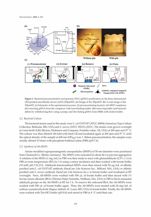
Micromachines 2018, 9, 472
Figure 1. Bacterial preconcentration and genomic DNA (gDNA) purification on the three-dimensional(3D)-printed microfluidic device (µFD) (3DpmFD). (a) Design of the 3DpmFD. (b) A scale image of the3DpmFD. (c) Schematic of the operational processes: (i) preconcentrating bacteria–Ab-MNP complexes;(ii) extracting gDNA from the complexes with lysis-binding buffer; (iii) removing buffer and bacterialdebris by withdrawing flow using a pump; and (iv) eluting gDNA from MSBs with elution buffer.
2.2. Bacterial Culture
The bacterial strains used in this study were E. coli O157:H7 (ATCC 43894) (American Type CultureCollection, Bethesda, MD, USA) and S. aureus (ATCC 29213) (ATCC, The strains were grown overnightin Luria broth (LB)) (Becton, Dickinson and Company, Franklin Lakes, NJ, USA) at 200 rpm and 37 ◦C.The culture was then diluted 100-fold with fresh LB and incubated again at 200 rpm and 37 ◦C untilthe optical density of the sample at 600 nm (OD600) was 1. Before preconcentration, the samples wereserially diluted 10 times with phosphate-buffered saline (PBS) (pH 7.4).
2.3. Synthesis of Ab-MNPs
Amine-modified superparamagnetic nanoparticles (MNPs) of 50 nm diameter were purchasedfrom Chemicell Co. (Berlin, Germany). The MNPs were sonicated for about 40 s to prevent aggregation.A solution of the MNPs (1 mg/mL) in PBS was then made to react with glutaraldehyde (2.5% v/v) inPBS at room temperature (RT) for 1 h using a rotary incubator and then washed with borate buffer(10 mM, pH 7.0) [20]. Aldehyde-functionalised MNPs were then mixed with 50 µg/mL of affinitypurified anti-E. coli O157:H7 antibody (SeraCare Life Sciences Inc., Milford, MA, USA) or affinitypurified anti-S. aureus antibody (SeraCare Life Sciences Inc.) in borate buffer and incubated at RTovernight. Next, Ab-MNPs were washed with 500 µL of borate buffer and then mixed with 1%bovine serum albumin (BSA) (Thermo Fisher Scientific, Waltham, MA, USA) in PBS to block unreactedaldehyde groups on the Ab-MNPs at RT for 1 h. To remove the unbound BSA, the Ab-MNPs werewashed with 500 µL of borate buffer again. Then, the Ab-MNPs were treated with 20 mg/mL ofsodium cyanoborohydride (Sigma-Aldrich, St. Louis, MO, USA) in borate buffer. Finally, the Ab-MNPswere washed with Tris-HCl buffer (pH 8.0) and stored in PBS at 4 ◦C until their use.
159
Micromachines 2018, 9, 472
2.4. Effect of Flow Rates on Bacteria Capturing Efficiency in the 3DpmFD
Ten millilitres (10 mL) of PBS containing E. coli O157:H7 at 104 colony-forming units (CFU)/mLwere mixed with 200 µL of MNPs (1013 particles/mL, final concentration) conjugated withaffinity-purified E. coli O157 antibodies and the mixture was incubated at 37 ◦C and 200 rpm for20 min in a beaker. Then, the mixture was injected into the 3DpmFD through the sample inlet using asyringe pump (Harvard Apparatus, Boston, MA, USA) at various flow rates (1–10 mL/min) whileplacing a permanent magnet (diameter: 15 mm, height: 1.5 mm, magnetic flux density: 1720 G)underneath the chamber of the 3DpmFD.
The number of preconcentrated bacterial cells was estimated by counting the difference betweenthe number of uncaptured bacterial cells and the total number of bacterial cells using the standardcolony counting method [21]. Bacteria capturing efficiency was calculated using the followingequation [17]:
Capturing efficiency (%) = (Nt − Ne)/Nt × 100% (1)
where Nt is the number of bacterial cells in the sample and Ne is the number of uncaptured bacterialcells in the sample.
2.5. Effect of MSB and Bacterial Concentration on DNA Purification
The 3DpmFD packed with MSBs (Chemicell Co., Berlin, Germany) was prepared by introducing1 mL of PBS containing different concentrations (109 to 5 × 10¹⁰ particles/mL) of MSBs at 2 mL/minthrough the sample inlet while placing a permanent magnet under the chamber and closing the DNAoutlet with a plastic pin. Different volumes (1–100 mL) of PBS containing E. coli O157:H7 or S. aureus atvarious concentrations (1–105 CFU/mL, final concentration) were first mixed with MNPs conjugatedwith antibodies specific to the pathogens and the mixture was incubated at 37 ◦C and 200 rpm for20 min in a beaker. Then, the mixture was injected into the 3DpmFD packed with MSBs through thesample inlet using a syringe pump at 2 mL/min as shown in Figure 1c-i.
To lyse preconcentrated bacterial cells, 100 µL of Lysis and Binding buffer (Chemicell Co.) wereloaded into the chamber as shown in Figure 1c-ii. The 3DpmFD was agitated by the automatedmini-vibration system (DVM-N20 vibration motor, D&J WITH Co., Ltd., Seoul, Korea) at RT for 5 minand the blocking pins were removed from the 3DpmFD before placing it on the magnet. The buffer wasremoved from the chamber through the waste channel, and then 500 µL of washing buffer I (ChemicellCo.) and 500 µL of 70% ethanol were injected into the 3DpmFD sequentially. For the elution step,50 µL of RNase free water was loaded into the 3DpmFD without placement on the magnet. After allthe inlets and outlets were blocked with the pins again, the device was agitated on a thermo-shakerat 1200 rpm and 65 ◦C for 15 min. Finally, the DNA released from the MSBs was removed from thedevice through the DNA outlet.
2.6. Effect of Dilution Factor of Blood on Efficiency of Sample Preparation in 3DpmFD
The use of blood was approved by the Institutional Review Board (IRB) of the university (SKKU)and its approval number was SKKU 2017-11-006. Whole blood was purchased from InnovativeResearch, Inc. (Novi, MI, USA) and this product was treated with 0.1% K2 ethylenediaminetetraaceticacid (EDTA) to prevent blood coagulation. The hematocrit (hct) value was about 39%, which wasmeasured using FisherbrandTM Microhematocrit capillary tubes (Fisher Scientific Co LLC, Pittsburgh,PA, USA) and a MicroHematocrit Centrifuge (Thomas Scientific Inc., Swedesboro, NJ, USA). Then,1 mL of whole blood containing 105 CFU/mL of E. coli O157:H7 was diluted to 10, 25, and 50% withPBS and 200 µL of Ab-MNPs.
160

Micromachines 2018, 9, 472
2.7. Bacterial Preconcentration and DNA Purification in Spiked Blood Samples
Then, 1 mL of whole blood was mixed with 8 mL of PBS, 1 mL of E. coli O157:H7 (10–104 CFU/mL),and 200 µL of Ab-MNPs. The subsequent procedures were the same as those for the bacterialpreconcentration and DNA purification steps.
2.8. Detection of Bacteria by PCR and qPCR Samples
Purified bacterial genomic DNA (gDNA) was amplified by PCR, and the amplification of targetgenes was verified by gel electrophoresis. The primers that were designed to amplify the 150-basepairs (bp) of eae gene coding intimin adherence protein in E. coli O157:H7 consist of a forwardprimer (GGCGGATTAGACTTCGGCTA) and a reverse primer (CGTTTTGGCACTATTTGCCC).The 207-bp of nuc gene coding the thermonuclease of S. aureus consists of a forwardprimer (ACACCTGAAACAAAGCATCC) and a reverse primer (TAGCCAAGCCTTGACGAACT).The conventional PCR was performed using a PCR reagent by MJ MINI™ thermocycler (Bio-RAD,Hercules, CA, USA). The PCR products were separated in a 1.5% TAE (Tris base, acetic acid, and EDTA)(50 ×) agarose gel at 100 V for 30 min.
The qPCR was performed using LightCycler® Nano (Roche, Basel, Switzerland), and its cyclethreshold (Ct) value was determined. The same primer sets as those used for the PCR were used here.
3. Results and Discussion
3.1. Effect of Flow Rate on Bacteria Capturing Efficiency in the 3DpmFD
The capturing efficiencies at flow rates of 1, 2, 5, and 10 mL/min were 94%, 92.5%, 62.1%,and 47.9%, respectively (Figure 2). The results show that it is difficult to capture bacteria–Ab-MNPscomplexes at high flow rates, such as 5 mL/min and 10 mL/min, with the magnetic force of thepermanent magnet located at the bottom of the device. Since there was no statistical difference in1 mL/min and 2 mL/min, we selected 2 mL/min as a flow rate for the following experiments.
Figure 2. Effect of flow rate on bacteria capturing efficiency in 3DpmFD. Ten millilitres (10 mL)of PBS containing E. coli O157:H7 (104 CFU/mL) and Ab-MNPs (1013 particles/mL) were injectedinto 3DpmFD at different flow rates (1–10 mL/min). *: p < 0.05, ***: p < 0.001. Student t-test.Sample number = 3.
161

Micromachines 2018, 9, 472
3.2. Optimisation of MSB Concentrations for DNA Purification using 3DpmFD
To find the optimal number for MSBs for DNA purification using the 3DpmFD, it was packed withdifferent particle numbers (1 × 10⁹ to 5 × 10¹⁰) of MSBs before introducing 10 mL of PBS containing103 CFU/mL and Ab-MNPs containing 1013 particles/mL. All the bacteria capturing efficiencies wereabout 90%, suggesting that the number of MSBs does not affect the bacterial capturing efficiency onthe 3DpmFD.
Figure 3a shows that gDNA concentrations obtained using the 3DpmFDs increase as MSBconcentrations in the range of 109 to 1010 particles/mL increase. The maximum gDNA concentrationwas obtained using the 3DpmFD packed with 1010 particles/mL of MSBs. However, the gDNAconcentrations at 5 × 10¹⁰ MSBs/mL were lower than those at 1010 MSBs/mL. This may beattributed to the fact that 50 µL of the elution buffer was not sufficient to fully wet the MSBs inthe 3DpmFD. Thus, some DNA might not have been released from some of the MSBs, resulting inlower gDNA concentrations.
Figure 3. Effect of MSB and bacteria concentrations on DNA purification on the 3DpmFD: (a) gDNAconcentration with different concentrations (109–5 × 10¹⁰ particles/mL) of MSBs for 103 CFU/mL of E.
coli O157:H7; (b) gDNA concentration with different concentrations (1–105 CFU/mL) of E. coli O157:H7using 1010 particles/mL of MSBs *: p < 0.05, ***: p < 0.001. Student t-test. Sample number = 3.
When the 3DpmFDs packed with 1010 MSBs/mL were injected along with 10 mL of PBS containingE. coli O157:H7 at different concentrations (1–105 CFU/mL) at a rate of 2 mL/min, the gDNAconcentration obtained using the 3DpmFDs increased as the bacterial concentrations increased in therange of 1 to 103 CFL/mL, but did not increase any further at concentrations of 104 and 105 CFU/mL(Figure 3b), thus indicating that the surfaces of the MSBs were saturated with gDNA at such highconcentrations. For such high concentrations, the sample solutions should be diluted to obtainaccurate measurements.
3.3. Effect of Preconcentration and gDNA Purification Using 3DpmFD on Molecular Amplification of Genesin PBS
Once 10 mL of the Gram-negative pathogen E. coli O157:H7 at different concentrations(1–103 CFU/mL) was preconcentrated and its gDNA was purified in a sequential manner usingthe 3DpmFD, the gDNA was amplified using either PCR or qPCR to verify the yield. The results
162

Micromachines 2018, 9, 472
were compared to those obtained from either untreated samples or samples prepared with only thepreconcentration step using 3DpmFD. In the samples with the preconcentration–purification steps,a concentration as low as 1 CFU/mL was detectable using PCR with gel electrophoresis (Figure 4c),whereas in the untreated samples and samples with only the preconcentration step, concentrationsas low as 103 CFU/mL and 10 CFU/mL were detectable, respectively (Figure 4a,b). A similar trendwas observed with qPCR. Considering that Ct values below 35 are reliable, a concentration as low as1 CFU/mL was detectable in the samples with the preconcentration–purification steps using qPCRbecause its Ct value was 30.7 (Figure 4f). Concentrations as low as 103 CFU/mL and 10 CFU/mLwere respectively detectable in the untreated samples and samples with only the preconcentration stepbecause their respective Ct values were 30.8 and 33.4 (Figure 4d,e). This remarkable improvement inthe samples with the preconcentration–purification steps in detection using PCR and qPCR can beexplained as follows. In the sample with only the preconcentration step, the Ab-MNPs can improve thedetection by providing higher numbers of bacterial cells to the PCR and qPCR. However, Ab-MNPs andcell debris can inhibit DNA polymerase, so that the benefit offered by the bacterial preconcentration isdecreased due to the modest interference from Ab-MNPs and cell debris in DNA amplification [22].By including both preconcentration and purification steps in the 3DpmFD, only purified gDNA can beprovided to the PCR and qPCR. This results in the enhancement in detection using PCR and qPCR.
Figure 4. Confirmation of E. coli O157:H7 preconcentrating and DNA purifying efficiency using eitherPCR with gel electrophoresis and qPCR; (a) Gel electrophoresis of PCR products (eae gene) from 10 mLPBS containing E. coli O157:H7 at different concentrations (1–103 CFU/mL) before preconcentration;(b) after preconcentration; (c) after bacterial preconcentration and DNA purification; (d–f) qPCR resultsof (a–c), respectively.
The performance of the 3DpmFDs were further tested by preconcentrating the Gram-positivepathogen S. aureus at different concentrations (1–103 CFU/mL) and purifying its gDNA usingthe 3DpmFD. Similar to the results (Figure 4) for E. coli O157:H7, significant improvements inthe detection of S. aureus by both molecular diagnostics techniques, PCR post gel electrophoresisand qPCR, were observed in the samples with the preconcentration–purification steps. The lowestconcentration for the detection in the samples with both preconcentration–purification steps using
163

Micromachines 2018, 9, 472
PCR post gel electrophoresis was 102 CFU/mL (Figure 5c), whereas those for the samples with onlythe preconcentration step were 103 CFU/mL (Figure 5b). However, S. aureus at all the concentrations(1–103 CFU/mL) in the untreated samples was not detectable (Figure 5a). A similar trend wasobserved using qPCR. The cell walls of Gram-positive bacteria are thicker than those of theGram-negative ones [7] and are hard to lyse by thermocycling of PCR. As a result, even at 103 CFU/mL,the concentration of gDNA released from the lysed cells was not sufficient to be detected using PCRgel electrophoresis and qPCR. With the preconcentration step, bacterial numbers increased and theirgDNA was detectable in the sample containing 103 CFU/mL. Further improvement in the detectionwas possible when the preconcentration and purification steps were included in the 3DpmFD becausethe Lysis and Binding buffer in the DNA purification step induces cell lysis. Together with theresults in samples containing E. coli O157:H7, these results suggest that gDNA purification is requiredas an addition in the 3DpmFD to improve the detection of bacterial pathogens using moleculardiagnostic methods.
Figure 5. Confirmation of Staphylococcus aureus preconcentrating and DNA purifying efficiency usingPCR with gel electrophoresis and qPCR; (a) Gel electrophoresis of PCR products (nuc gene) from 10 mLPBS containing S. aureus at different concentrations (1–103 CFU/mL) before preconcentration; (b) afterpreconcentration; (c) after bacterial preconcentration and DNA purification; (d–f) qPCR results of(a–c), respectively.
3.4. Dilution Effect on Preconcentration–Purification Efficiency in Blood Samples
We investigated the effect of dilution of blood on the preconcentration–purification efficiency by3DpmFD. The bacteria capturing efficiency increased as the dilution factor increased. It was about 82%in the whole blood, while it was about 100% in 10% blood. These results suggest that the capturingefficiency was negatively affected by blood and blood dilution is required for the preconcentrationstep (Figure S1).
Post gel electrophoresis with PCR (Figure 6a) shows that blood should be diluted at least 50% todetect 105 CFU/ml of E. coli O157:H7 in the blood samples (Figure 6a). A similar trend was observedin the qPCR result (Figure 6b). There, 105 CFU/ml of E. coli O157:H7 in all the diluted blood sampleswas detectable because their Ct values were lower than 35. However, Ct values increased as the ratio
164

Micromachines 2018, 9, 472
of blood in the diluted blood samples increased, suggesting that the ratio of blood should be loweredto 10%.
Figure 6. Confirmation of effect of dilution factor of blood on preconcentrating and gDNA purificationefficiency with E. coli O157:H7 using PCR with gel electrophoresis and qPCR; (a) Gel electrophoresis ofPCR products (eae gene) from different blood dilutions (10, 25, 50, and blood) containing 105 CFU/mLof E. coli O157:H7 after bacterial preconcentration and DNA purification; (b) qPCR result.
3.5. Spike Test in 10% Blood
Blood has a lot of molecular diagnostic inhibitors, such as hematin and haemoglobin, and theyprevent the action of Taq polymerase [23]. IgG in the blood also interferes with the activation ofTaq polymerase as it interacts with single-strand DNA at high temperatures [24]. To minimize thisinhibitory effect on molecular amplification, users have to use commercial kits and systems forpurifying bacterial DNA from blood [25–28]. The QIAamp blood mini kit can purify DNA in 200 µLof blood without any dilution but cannot differentiate bacterial DNA from the DNA of blood cells.Microfluidic devices are not suitable for processing a large volume of samples, such as 10 mL, due toits slow flow rates in the range of 1–10 µL/min [27,29]. The hollow spinning disk system does notrequire the dilution of blood samples but only about 40% of bacteria can be isolated from the plasma bythe system [30]. Figure 7 shows that the performance of the 3DpmFD for the sample preparation from10 mL of 10% diluted blood with E. coli O157:H7 is excellent because E. coli O157:H7 can be detectedfor a concentration of up to 1 CFU/mL with the preconcentration and purification steps, which is 100and 10 times lower than without sample treatment (Figure 7a,b). These results are also confirmed byqPCR through the difference between the Cq values of the samples (Figure 7d–f). The Cq value ofthe 1 CFU/mL is 30.6 and that of the 103 CFU/mL without sample preparation is 33.8. These resultssuggest that the 3DpmFD can selectively preconcentrate the bacterial pathogen of interest and purifybacterial DNA from diluted blood samples.
For this reason, Figure 7a shows that the limit of detection is 103 CFU/mL without samplepreparation. Thus, it is very hard to detect pathogens in blood samples using PCR without any samplepreparation steps. However, Figure 7c shows that the 3DpmFD can eliminate the molecular diagnosticinhibitors effectively. This is equivalent to a 50-fold improvement of sensitivity compared with themicrofluidic device for the detection of E. coli O157:H7 in 10% blood [31]. These results suggest that
165

Micromachines 2018, 9, 472
3DpmFD is well-suited for improving the level of detection (LOD) in blood by including both bacterialpreconcentration and DNA purification steps.
Figure 7. Confirmation of preconcentrating and DNA purification efficiency of E. coli O157:H7 in 10%blood using PCR with post gel electrophoresis after PCR (a–c) and qPCR (d–f). (a) Gel electrophoresis ofPCR products (eae gene) from 10 mL of 10% blood containing E. coli O157:H7 at different concentrations(1–103 CFU/mL) without preconcentration; (b) after preconcentrating; (c) after preconcentrating andDNA purification; (d–f) qPCR results of (a–c), respectively.
4. Conclusions
In this study, we report an improvement in detection for molecular diagnostics by successfullyintegrating both bacterial preconcentration and DNA purification in the 3DpmFD. The performanceof the 3DpmFD shows that it is possible to preconcentrate very low concentrations of pathogens in10 mL of 10% blood within 30 min, and 1 CFU/mL of E. coli O157:H7 can be detected by either PCRwith post gel electrophoresis or qPCR. These results demonstrate that it is highly useful for improvingmolecular diagnostic methods in blood samples with the addition of the DNA purification step.
Supplementary Materials: The following are available online at t http://www.mdpi.com/2072-666X/9/9/472/s1,Figure S1: The effect of the dilution factor of blood on capturing efficiency with 103 CFU/mL of E. coli O157:H7 *:p < 0.05, Student’s t-test. Sample number = 3.
Author Contributions: Conceptualisation, Y.K. and S.P.; Methodology, Y.K. and J.L.; Data Curation, Y.K. and J.L.;Writing (Original Draft Preparation), Y.K. and J.L.; Writing (Review & Editing), J.L. and S.P.; Supervision, S.P.
Acknowledgments: This research was supported by the BioNano Health-Guard Research Center as a GlobalFrontier Project (H-guard NRF-2018M3A6B2057299) through the National Research Foundation (NRF) of theMinistry of Education, Science and Technology (MEST) in Korea.
Conflicts of Interest: The authors declare no conflict of interest.
166

Micromachines 2018, 9, 472
References
1. Yang, L.; Banada, P.P.; Chatni, M.R.; Lim, K.S.; Bhunia, A.K.; Ladisch, M.; Bashir, R. A multifunctionalmicro-fluidic system for dielectrophoretic concentration coupled with immuno-capture of low numbers oflisteria monocytogenes. Lab Chip. 2006, 6, 896–905. [CrossRef] [PubMed]
2. Hara-Kudo, Y.; Takatori, K. Contamination level and ingestion dose of foodborne pathogens associated withinfections. Epidemiol. Infect. 2011, 139, 1505–1510. [CrossRef] [PubMed]
3. Varshney, M.; Li, Y.; Srinivasan, B.; Tung, S. Microfluidics and interdigitated array microelectrode-basedimpedance biosensor in combination with nanoparticles immunoseparation for detection of Escherichia coli
O157:H7 in food samples. Sens. Actuators B Chem. 2007, 128, 99–107. [CrossRef]4. Pengsuk, C.; Chaivisuthangkura, P.; Longyant, S.; Sithigorngul, P. Development and evaluation of a highly
sensitive immunochromatographic strip test using gold nanoparticle for direct detection of Vibrio choleraeO139 in seafood samples. Biosens. Bioelectron. 2013, 42, 229–235. [CrossRef] [PubMed]
5. Weagent, S.D.; Bound, A.J. Evaluation of techniques for enrichment and isolation of Escherichia coli O157:H7from artificially contaminated sprouts. Int. J. Food. Microbiol. 2001, 71, 87–92. [CrossRef]
6. Banada, P.P.; Chakravorty, S.; Shah, D.; Burday, M.; Mazzella, F.M.; Alland, D. Highly sensitive detection ofStaphylococcus aureus directly from patient blood. PLoS ONE 2012, 7, 31126. [CrossRef] [PubMed]
7. Chung, Y.C.; Jan, M.S.; Lin, Y.C.; Lin, J.H.; Cheng, W.C.; Fan, C.Y. Microfluidic chip for high efficiency DNAextraction. Lab Chip. 2004, 4, 141–147. [CrossRef] [PubMed]
8. Karle, M.; Miwa, J.; Czilwik, G.; Auwärter, V.; Roth, G.; Zengerle, R.; von Stetten, F. Continuous microfluidicDNA extraction using phase-transfer magnetophoresis. Lab Chip. 2010, 10, 3284–3290. [CrossRef] [PubMed]
9. Geng, T.; Bao, N.; Sriranganathanw, N.; Li, L.; Lu, C. Genomic DNA extraction from cells by electroporationon an integrated microfluidic platform. Anal. Chem. 2012, 84, 9632–9639. [CrossRef] [PubMed]
10. Azimi, S.M.; Nixon, G.; Ahern, J.; Balachandran, W. A magnetic bead-based DNA extraction and purificationmicrofluidic device. Microfluid. Nanofluid. 2011, 11, 157–165. [CrossRef]
11. Witek, M.A.; Llopis, S.D.; Wheatley, A.; McCarley, R.L.; Soper, S.A. Purification and preconcentrationof genomic DNA from whole cell lysates using photoactivated polycarbonate (PPC) microfluidic chips.Nucleic Acids Res. 2006, 34, e74. [CrossRef] [PubMed]
12. Mahalanabis, M.; Al-Muayad, H.; Kulinski, M.D.; Altman, D.; Klapperich, C.M. Cell lysis and DNA extractionof gram-positive and gram-negative bacteria from whole blood in a disposable microfluidic chip. Lab Chip.
2009, 9, 2811–2817. [CrossRef] [PubMed]13. Xia, N.; Hunt, T.P.; Mayers, B.T.; Alsberg, E.; Whitesides, G.M.; Westervelt, R.M.; Ingber, D.E. Combined
microfluidic-micromagnetic separation of living cells in continuous flow. Biomed. Microdevices 2006, 8, 299.[CrossRef] [PubMed]
14. Ganesh, I.; Tran, B.M.; Kim, Y.; Kim, J.; Cheng, H.; Lee, N.Y.; Park, S. An integrated microfluidic PCR systemwith immunomagnetic nanoparticles for the detection of bacterial pathogens. Biomed. Microdevices 2016,18, 116. [CrossRef] [PubMed]
15. Jayamohan, H.; Gale, B.K.; Minson, B.; Lambert, C.J.; Gordon, N.; Sant, H.J. Highly sensitive bacteriaquantification using immunomagnetic separation and electrochemical detection of guanine-labeledsecondary beads. Sensors 2015, 15, 12034–12052. [CrossRef] [PubMed]
16. Lein, K.Y.; Liu, C.J.; Lin, Y.C.; Kuo, P.L.; Lee, G.B. Extraction of genomic DNA and detection of singlenucleotide polymorphism genotyping utilizing an integrated magnetic bead-based microfluidic platform.Microfluid. Nanofluid. 2009, 6, 539–555. [CrossRef]
17. Park, C.; Lee, J.; Kim, Y.; Lee, J.; Park, S. 3D-Printed microfluidic magnetic preconcentrator for thedetection of bacterial pathogen using an atp luminometer and antibody-conjugated magnetic nanoparticles.J. Microbiol. Methods 2017, 132, 128–133. [CrossRef] [PubMed]
18. Lee, W.; Kwon, D.; Choi, W.; Jung, G.Y.; Au, A.K.; Folch, A.; Jeon, S. 3D-Printed microfluidic device for thedetection of pathogenic bacteria using size-based separation in helical channel with trapezoid cross-section.Sci. Rep. 2015, 5, 7717. [CrossRef] [PubMed]
19. Lee, W.; Kwon, D.; Chung, B.; Jung, G.Y.; Au, A.; Folch, A.; Jeon, S. Ultrarapid detection of pathogenicbacteria using a 3D immunomagnetic flow assay. Anal. Chem. 2014, 86, 6683–6688. [CrossRef] [PubMed]
167
Micromachines 2018, 9, 472
20. Zhao, L.; Yang, B.; Dai, X.; Wang, X.; Gao, F.; Zhang, X.; Tang, J. Glutaraldehyde mediated conjugation ofamino-coated magnetic nanoparticles with albumin protein for nanothermotherapy. J. Nanosci. Nanotechnol.
2010, 10, 7117–7120. [CrossRef] [PubMed]21. Herigstad, B.; Hamilton, M.; Heersink, J. How to optimize the drop plate method for enumerating bacteria.
J. Microbiol. Methods 2001, 44, 121–129. [CrossRef]22. Higashi, T.; Minegishi, H.; Nagaoka, Y.; Fukuda, T.; Echigo, A.; Usami, R.; Maekawa, T.; Hanajiri, T. Effects
of superparamagnetic nanoparticle clusters on the polymerase chain reaction. Appl. Sci. 2012, 2, 303–314.[CrossRef]
23. Akane, A.; Matsubara, K.; Nakamura, H.; Takahashi, S.; Kimura, K. Identification of the heme compoundcopurified with deoxyribonucleic acid (DNA) from bloodstrains, a major inhibitor of polymerase chainreaction (PCR) amplification. J. Forensic Sci. 1994, 39, 362–372. [CrossRef] [PubMed]
24. Al-Soud, W.A.; Jönsson, L.J.; Rådström, P. Identification and characterization of immunoglobulin G in bloodas a major inhibitor of diagnostic PCR. J. Clin. Microbiol. 2000, 38, 345–350. [PubMed]
25. Hassan, M.M.; Ranzoni, A.; Cooper, M.A. A nanoparticle-based method for culture-free bacterial DNAenrichment from whole blood. Biosens. Bioelectron. 2018, 99, 150–155. [CrossRef] [PubMed]
26. Lopes, A.L.K.; Cardoso, J.; dos Santos, F.R.C.C.; Silva, A.C.G.; Stets, M.I.; Zanchin, N.I.T.; Soares, M.J.;Krieger, M.A. Development of a magnetic separation method to capture sepsis associated bacteria in blood.J. Microbiol. Methods 2016, 128, 96–101. [CrossRef] [PubMed]
27. Zelenin, S.; Hansson, J.; Ardabili, S.; Ramachandraiah, H.; Brismar, H.; Russom, A. Microfluidic-basedisolation of bacteria from whole blood for sepsis diagnostics. Biotechnol. Lett. 2015, 37, 825–830. [CrossRef][PubMed]
28. Jin, C.E.; Koo, B.; Lee, E.Y.; Kim, J.Y.; Kim, S.-H.; Shin, Y. Simple and label-free pathogen enrichment viahomobifunctional imidoesters using a microfluidic (slim) system for ultrasensitive pathogen detection invarious clinical specimens. Biosens. Bioelectron. 2018, 111, 66–73. [CrossRef] [PubMed]
29. Wu, Z.; Willing, B.; Bjerketorp, J.; Jansson, J.K.; Hjort, K. Soft inertial microfluidics for high throughputseparation of bacteria from human blood cells. Lab Chip. 2009, 9, 1193–1199. [CrossRef] [PubMed]
30. Alizadeh, M.; Wood, R.L.; Buchanan, C.M.; Bledsoe, C.G.; Wood, M.E.; McClellan, D.S.; Blanco, R.;Ravsten, T.V.; Husseini, G.A.; Hickey, C.L.; et al. Rapid separation of bacteria from blood—Chemicalaspects. Colloids Surf. B 2017, 154, 365–372. [CrossRef] [PubMed]
31. Wang, S.; Inci, F.; Chaunzwa, T.L.; Ramanujam, A.; Vasudevan, A.; Subramanian, S.; Chi Fai Ip, A.;Sridharan, B.; Gurkan, U.A.; Demirci, U. Portable microfluidic chip for detection of Escherichia coli inproduce and blood. Int. J. Nanomed. 2012, 7, 2591.
© 2018 by the authors. Licensee MDPI, Basel, Switzerland. This article is an open accessarticle distributed under the terms and conditions of the Creative Commons Attribution(CC BY) license (http://creativecommons.org/licenses/by/4.0/).
168

micromachines
Article
Fabrication of a Malaria-Ab ELISA Bioassay Platformwith Utilization of Syringe-Based and 3D PrintedAssay Automation
Christopher Lim 1, Yangchung Lee 1 and Lawrence Kulinsky 2,*
1 Department of Chemical Engineering and Materials Science, University of California, Irvine,916 Engineering Tower, Irvine, CA 92627-2575, USA; [email protected] (C.L.);[email protected] (Y.L.)
2 Department of Mechanical and Aerospace Engineering, University of California, Irvine,5200 Engineering Hall, Irvine, CA 92627-2700, USA
* Correspondence: [email protected]; Tel.: +1-949-824-6769
Received: 30 August 2018; Accepted: 30 September 2018; Published: 2 October 2018
Abstract: We report on the fabrication of a syringe-based platform for automation of a colorimetricmalaria-Ab assay. We assembled this platform from inexpensive disposable plastic syringes,plastic tubing, easily-obtainable servomotors, and an Arduino microcontroller chip, which allowedfor system automation. The automated system can also be fabricated using stereolithography (SLA)to print elastomeric reservoirs (used instead of syringes), while platform framework, including rackand gears, can be printed with fused deposition modeling (FDM). We report on the optimization ofFDM and SLA print parameters, as well as post-production processes. A malaria-Ab colorimetric testwas successfully run on the automated platform, with most of the assay reagents dispensed fromsyringes. Wash solution was dispensed from an SLA-printed elastomeric reservoir to demonstratethe feasibility of both syringe and elastomeric reservoir-based approaches. We tested the platformusing a commercially available malaria-Ab colorimetric assay originally designed for spectroscopicplate readers. Unaided visual inspection of the assay solution color change was sufficient forqualitative detection of positive and negative samples. A smart phone application can also beused for quantitative measurement of the assay color change.
Keywords: diagnostics; liquid handling; microfluidics; multiplex assays and technology;stereolithography; sample preparation; 3D printing
1. Introduction
1.1. Preface
Lab-on-a-chip systems are used to perform personalized health diagnostic tests (like bioassays)away from the lab [1]. Implementation of bioassay automation reduces the cost of medical personneland diminishes the incidence of human errors [2,3]. Point-of-care (POC) diagnostic platforms arerequired to have low cost, low power use, be reliably automated, and free of sophisticated detectiontechnologies [4]. POC platforms have already been realized in the form of lateral flow immunoassays(pregnancy tests) and paper fluidic colorimetric assays [5]. Unfortunately, the aforementioned POCdevices are based on capillary flow, and therefore do not work well when more complex multi-stepbioassays are performed [6]. In these cases, some other fluid propulsion mechanisms instead ofcapillary flow are required. There are many POC devices that rely on active propulsion techniques,like centrifugal propulsion, electrowetting, and magnetic beads [7,8]. These tests typically entailincreased fabrication and material cost, complex automation schemes, and sophisticated hardware.
Micromachines 2018, 9, 502; doi:10.3390/mi9100502 www.mdpi.com/journal/micromachines169

Micromachines 2018, 9, 502
In this work, we developed two distinct approaches for the realization of an inexpensiveautomated colorimetric immunoassay with multiple wash steps: (1) A fused deposition modeling(FDM)-printed (non-disposable) frame was used and a disposable fluidic chip that includes anelastomeric dome and fluidic channels fabricated using SLA, was printed, where the fluidicmovement was facilitated by servomotors pushing on the elastomeric dome, and propelling thereagents or wash from the domed reservoirs through fluidic channels to the test chamber, or (2) anFDM-printed non-disposable frame was used, with servomotors connected to standard inexpensiveand readily-available disposable plastic syringes filled with wash and reagents to automate the stepsof the assay.
Draining of the test chamber was performed with a syringe attached to a servomotor,where negative pressure was created by the pulling on the syringe plunger. All automation wascontrolled by a program uploaded to the Arduino-based electronic board of the platform via a computer.The test results of the colorimetric bioassay can be assessed by eye (for qualitative measurements) orwith a smart phone for quantitative measurement, and e-mailed or texted to a hospital or doctor’soffice [9,10]. In this work, we created a proof-of-principle platform that utilized elements of bothapproaches (1) and (2), as outlined above.
We used plastic syringes for most of the platform reagent reservoirs, including drainage and waste.The wash reservoir consisted of an SLA-printed elastomeric dome. Thus, the feasibility of bothapproaches was tested at the same time. The automated platform demonstrated in the presented workproved the viability of both approaches: (1) Construction of an automated bioassay platform usingsyringes only, or (2) a printed dome-based bioassay platform. To our knowledge, this study constitutesthe first demonstration of an SLA-based dome bioassay platform and a syringe-based automatedbioassay platform. The concepts developed in the present work build on prior research that utilizedFDM to fabricate a fluidic chip with embedded microchannels [11]. Fluid leakage was a recurring issuein the design, due to the layer-by-layer deposition nature of FDM. Our present fabrication approachutilizes syringes and photocurable resin crosslinked using SLA, thus mitigating the problem of fluidleakage. The present platform employs FDM printing for the fabrication of parts that are not in contactwith fluids, such as the non-disposal platform frame and the gear/rack mechanisms. Additionally,the prior fluidic platform design used molded silicone domes that needed to be sealed to the body of3D printed fluidic chip. Our present fabrication route avoids the need to seal the domes to the plasticchip by 3D-printing the integrated dome.
The proposed approach is useful in making POC bioassays more widespread. All of the parts andmaterials required for the demonstrated platforms are inexpensive and widely available. For example,a hospital in rural India with an FDM printer could be sent a stereolithography file (STL file) to printa frame. The Arduino electronic board and other parts, such as servomotors, can be easily acquired.All the parts and materials to produce our automated platform cost less than $100, while all disposablematerials, including syringes, tubing, and reagents, cost around $5 per test.
If an exclusively syringe-based platform is utilized, the only disposable parts needed are plasticsyringes. The syringes would be filled with a prescribed volume of reagents, and the required programuploaded to the Arduino board. This approach provides the most flexibility to perform a wide rangeof bioassays on the spot, as it does not require all the reagents in typical pre-packaged volumes.This simplifies assay logistics, including that of cold storage of reagents [12]. We expect that ourproposed recipes and programs will be readily available for download by non-profit organizationsand reagent makers.
There is a growing interest in manufacturing functional parts inexpensively with high-aspect-ratiogeometry and complex topologies [13]. Additive manufacturing (AM), including various types of 3Dprinting, is an increasingly popular form of fabrication [14]. The AM process requires a part to bedesigned using a CAD program, such as SolidWorks, followed by the extrapolation of the structuralinformation into an STL file. The STL file partitions the CAD drawing into a series of volumetricpixels, which are digitally sliced into layers along the Z direction [15]. These layers are physically
170

Micromachines 2018, 9, 502
deposited onto a substrate in layer-by-layer manner, using various AM methods, including FDMand SLA. FDM and SLA accommodate a variety of material choices, including elastomeric materials,allowing for the fabrication of flexible parts such as the dome-based elastic pumps presented inthis work.
In this work, we conducted a brief review of microfluidic device fabrication methods,and emphasized recent developments in additive manufacturing. We followed this review witha description of the fabrication processes selected for our bioassay platform. Lastly, we detailed anoutline of our experimental procedures, and described the experimental results of a malaria bioassayperformed on our automated platform.
1.2. Fabrication Techniques for Microfluidic Devices
The first traditional microfluidic devices were fabricated using glass and silicon, utilizing mostly atoolbox of lithographic techniques employed in the semiconductor industry [16]. Equipment selectionwas subsequently further developed to include femtosecond lasers to fabricate glass microfluidicchips [17,18], and the selection of materials employed for fluidic chips was also expanded to includesuch materials as “liquid Teflon” [19] and environmentally-sensitive materials such as hydrogels [20].With the advent of soft lithography and 3D printing, there was a push to develop inexpensive andreliable microfluidic platforms with biocompatible plastics and resins, demonstrated by the recentfabrication trends outlined below [21–24].
1.2.1. Soft Lithography
Soft lithography is based on a three-step process where microfabrication techniques are first usedto produce a reusable mold, which is then filled with a curable epoxy Polydimethylsiloxane (PDMS)and subsequently separated from the mold after an appropriate curing time. The molded part istypically attached to a glass substrate using plasma treatment [25]. The soft lithography approachallows for the usage of more expensive high-precision cleanroom lithographic techniques to producea mold. Once the mold is produced, it can be used multiple times to fabricate identical fluidic chips,dramatically reducing the cost of individual fluidic microdevices.
The soft lithography approach has allowed for much more widespread adoption of lab-on-a-chipdevices, and for the production of intricate parts such as elastomeric valves. For example, the PDMSvalves used by the Quake group have facilitated the implementation of large-scale microfluidicbioreactors for drug discovery and other applications [26]. However, when the device is assembledfrom separately produced parts, the manufacturability is restricted, due to cumbersome alignment,bonding, and assembly [24,27].
3D printing presents an approach where a complete microfluidic device is produced withoutpost-processing alignment and assembly steps. Commercial 3D printers are beginning to challenge theresolutions achievable by soft lithography [28].
1.2.2. Inkjet 3D Printing (i3DP)
Inkjet 3D printing is based on inkjet technology and can operate in continuous ordrop-on-demand mode. To achieve high accuracy performance in i3DP, there are four criticalelements that must be considered: ink material, substrate properties, printing platform, and dropletgeneration [29]. Inconsistency or change in any of the parameters affects the process reliability.To maintain steady performance, i3DP needs to be used regularly; the clogging of apertures in aprint head due to drying of the ink is a persistent problem. There is considerable cost involvedin changing from one material to another, since the previous material must be flushed out by thenew resin.
One of the greatest advantages of i3DP is its ability to deliver multiple materials at the sametime during the fabrication process, allowing for a wide range of material properties (hard and softplastics, elastomers), and the utilization of inks of different color [30,31]. Creating prototypes with
171
Micromachines 2018, 9, 502
smooth finishes and complex shapes is possible with i3DP; flow channels have been integrated withporous semi-permeable membranes supporting cell culture to study the transport and profiling ofdrugs [32,33].
Hwang et al. utilized i3DP to print pillars with a diameter of 250 µm and found that the resolutionof the process depended on the droplet size, the printer nozzle spacing, and the reflow of the materialprior to UV curing. These factors affected the droplet spreading, changing the final dimensions of theprinted devices [34].
Paydar et al. examined multi-material 3D printing for microfluidic interconnects. They fabricateda specialized interconnector part, composed of two rigid clamps for the mechanical attachment of aflexible elastomeric O-ring gasket to a microfluidic device. The parts were printed in a single step,eliminating the need for adhesives or additional assembly. While the cost of manufacturing was low,the interconnector was characterized by low maximum sealing pressure due to material fatigue [35].
1.2.3. Two-Photon Polymerization (2PP)
Two-photon polymerization (2PP) is a laser-based technique that utilizes a femtosecond laser tocreate 3D structures in the bulk of photocurable epoxy resin, employing a highly localized processwhere two photons are absorbed simultaneously by the molecule being cured [36]. The synergisticeffects of optical, chemical, and material non-linearity make it possible to achieve reproducibleresolution of tens of nanometers [37].
2PP has shown great potential for fabrication in microfluidics. Kumi et al. described the fabricationof a master for casting PDMS with rectangular microchannels of high aspect ratios by modifying SU-8resist (material for the master) with a photoacid generator that then allows for the use of 2PP onSU-8 resist. By using the modified resin, the fabrication speed was also increased from 200 µm·s−1 to10,000 µm·s−1 with a print time of 1 h. This technique required extensive resin preparation and had aslow build speed [38].
Kawata et al. achieved resolutions of 120 nm, and other attempts included the use of newphoto-initiators, a continuous scanning mode, a shorter wavelength, a longer exposure time,and confining the polymerization phenomenon using a quencher molecule [39]. Sugioka et al.conducted a comprehensive review of the fundamentals and fabrication of 3D micro- andnano-components based on 2PP [40].
While 2PP currently produces the highest resolution for microfabricated three-dimensionalstructures, it is a very time-consuming process: the time required to fabricate a 1 mm3 volumemicrofluidic structure exceeds 104 days [41]. The high cost of femtosecond lasers, positioning systems,optics, and the difficulty of working with multi-material systems are some factors hindering theutilization of 2PP for the mass-production of microfluidic devices.
1.2.4. Fused Deposition Modeling (FDM)
FDM is one of the most widely used additive manufacturing techniques. Many polymers usedwith FDM techniques are inherently biocompatible [42]. In FDM, filament material is extruded throughnozzles and deposited onto a heated substrate [43]. Due to the inherent propensity of melted fiberto solidify as a line, there are limitations in the dimensional accuracy and the surface texture of theproduced parts, resulting in a staircase pattern that is ubiquitous on many parts that are producedwith FDM.
Lee et al. printed microfluidic features via FDM and evaluated the printing resolution, accuracy,biocompatibility, and surface roughness of acrylonitrile butadiene styrene (ABS) with P430 filament.They found that the accuracy of the printed features had an average deviation of 60.8 µm and 71.5 µmalong the Y and X axis, respectively. The surface of the printed channels was rough with protrudingfilament strands [44].
Kitson et al. fabricated polypropylene reactionware with cylindrical channels 0.8 mm in diameter.The devices could be fabricated in a few hours and could avoid blockages due to the formation of
172

Micromachines 2018, 9, 502
precipitates. The potential of 3D manufacturing was demonstrated by stopping mid-point in thefabrication process to deposit solid reagents into a chamber, which was then sealed with the printer.This is a valuable feature not so easily realized with i3DP or stereolithography [45].
Bishop et al. created a semi-transparent fluidic device using poly(ethyleneterephthalate) withthreaded ports, enabling the integration of commercial tubing as well as specially designed 3Dfittings [46]. The transparent device included 800 µm × 800 µm square channels. A low-cost desktopMakerbot (New York, NY, USA) 3D printer was used for fabrication of the device. Prussian bluenanoparticles were synthesized in their lab and mixed in a 3D printed channel and applied to electrodesurfaces for sensing of H2O2.
Recently, Dolomite (Royston, UK) launched a production line that offered an FDM printerspecifically designed for fabrication of microfluidic platforms [47]. The printer head design allowedfor reliable printing of cyclic olefin copolymer (COC). Their new software guided the production toguarantee smooth surface finish inside the channels. This is contrasted with conventional 3D printing,which emphasizes outside surface texture.
1.2.5. Stereolithography (SLA)
SLA is an attractive option for microfluidics due to increasing availability of SLA printers utilizinginexpensive micromirror-based projectors, including some printer kits costing as little as $100 [48].The performance of SLA printers is quantified by the dimensional accuracy and the surface roughnessof the printed object [49,50]. These factors are influenced by the fabrication settings: object orientation,layer thickness, resin properties, and build style. The minimum cross-sectional area of a microchannelmade by SLA depends on the laser spot size and the resin viscosity. This resin must be drainedpost-print [51].
Recent developments have expanded the SLA material selection for a single print to includeelastomers and ceramics, while some printers are capable of using multiple resins. It is predictedthat in the future it will be possible to use SLA to fabricate metallic sensors and actuators on flexiblemembranes [51–53].
Comina et al. used a Miicraft (Hsinchu, Taiwan) 3D printer to fabricate a reusable mold for PDMScasting [54]. The molds had structures of multiple feature sizes ranging from 50 µm to several mm.The resin had to be manually coated with protective ink to be properly used with PDMS. The Miicraftwas also used to print a device with open fluidic channels that are subsequently sealed on top with theadhesive tape. In another study, Comina et al. printed a unibody lab-on-a-chip (LOC) consisting ofa separate microfluidic level, and a layer with optical components. The integrated finger pump wasused to initiate the preparatory sequence of mixing two reagents and three analytes. The colorimetricglucose sensing assay was read by a smart phone [55].
Wang et al. demonstrated an effective approach to fabricating structural devices using 3D printing.A monomer initiator was added to the Miicraft resin to allow for modification of the surface propertiessuch as hydrophobicity and hydrophilicity [56].
Shallan et al. used a Miicraft printer for the fabrication of a transparent microfluidic device withenclosed 250 µm diameter channels [57]. The dimension of the printed channels had a deviation of 50 to100 µm from the designed dimensions, and the roof of the sealing channel was rough. This could beimproved through changing the curing depth, intensity, exposure wavelength, and time. They arguedthat inexpensive Miicraft provides a sufficient resolution for most microfluidic devices.
Patrick et al. printed fluidic open channels using a laser-rastering SLA printer (Form1+, Formlabs,Somerville, MA, USA) [58]. They found that the smallest achievable diameter of a circular channel was900 µm, and the smallest channel side for a square channel was 650 µm. The surface topology wasinspected using SEM and visible striations were discovered. Overall, the cost of the materials for eachfluidic chip was around $6.
A sample library of standardized microfluidic components was manufactured using SLAby Lee et al. and Bhargava et al. [59,60]. These parts were then used to create a number of
173
Micromachines 2018, 9, 502
modular and reconfigurable microfluidic units. This approach allowed for the creation of complexmicrofluidic designs based on simple interlocking fluidic modules. The library allowed for the furtherminiaturization of microfluidic elements and materials.
The Folch lab has printed diaphragm valves and a peristaltic pump integrated within a LOCdevice printed using SLA with biocompatible Somos WaterShed XC 11122 resin (Elgin, IL, USA) [61].The valves were leakage free at a closing pressure of 6 psi (provided by the compressed air), and theywere operated over many cycles. These valves are regarded as functional modules: two valves canbe paired to build a switch, or three valves can be put together in a series to build a pump [62].However, the portability of these microfluidic devices was limited by the need to use peripherals suchas gas canisters.
1.3. Combining Several Fabrication Techniques to Manufacture an Automated Fluidic Malaria Enzyme-LinkedImmunosorbent Assay (ELISA) Bioassay Platform
Each of the techniques discussed thus far has its own set of advantages and disadvantages.For example, stereolithography, while allowing for higher resolution, is more expensive and lessaccessible than fused deposition modelling [63]. Therefore, in this work, we applied a combination offabrication techniques.
In one approach when only an FDM printer is available, we developed a system based ondisposable plastic syringes coupled to programmable servomotors. FDM was used to print thenon-disposable frame for an automated colorimetric malaria detection test based on enzyme-linkedimmunosorbent assay (ELISA). In another approach, when the end user has access to an SLAsystem, we developed a fabrication approach for SLA to produce elastomeric domes withintegrated microfluidic channels. Flow of reagents was facilitated by servomotors compressingthe elastomeric dome, and propelling the reagents through a microfluidic channel into a connectedtest chamber. In this approach, the frame was still printed using an FDM printer. We avoidedfabricating microfluidic channels using FDM, because filament-based deposition often resulted in a“staircase effect” as discussed previously, causing fabricated structures to be prone to leakages.
2. Materials and Methods
2.1. Fused Deposition Modeling and Stereolithography
The FDM parts were manufactured using a acrylonitrile butadiene styrene (ABS) filamenton a dual extruder AirWolf HD2x printer (Costa Mesa, CA, USA). The printing parameters,including extrusion, travel speeds, and printer head temperature, were optimized as discussed in the“Results and Discussion” section below. A Formlabs’ (Somerville, MA, USA) Form 1+ SLA printer wasused to produce the elastomeric domes and integrated fluidic microchannel from proprietary flexibleclear resin GPCL02 sold by Formlabs.
2.2. Automation of Malaria-Ab Colorimetric ELISA
A malaria-Ab ELISA colorimetric detection kit (IBL International GmbH, Hamburg, Germany)was used to test functionality of the fabricated automated platform. The colorimetric assay wasdesigned to detect antibodies in subjects infected with four Plasmodium species that cause malaria.The most significant parasitic diseases in humans are: P. falciparum, P. vivax, P. ovale, and P. malariae [64].
The ELISA kit contained clear polystyrene wells coated with recombinant antigens. When the testsample (either serum or plasma) was added to the well, the specific antibodies in the sample combinedwith antigens in the well. Subsequently, a conjugate solution of recombinant antigens conjugated tohorseradish peroxidase was added to the well, and these antigens reacted with the specific antibodies,if they were present.
When the substrate solution of urea peroxide and tetramethyl benzidine was added to the well,it led to a change in solution color from colorless (in case of no specific antibodies present) to blue
174

Micromachines 2018, 9, 502
(when antibodies were present), and finally to yellow when the stop solution was added. It is possibleto determine the concentration of the antibodies in the sample by measuring the color intensity withspectral analysis, but in this proof-of-concept study, we limited our experiments to the positive andnegative controls provided with the kit. The full details on the recommended volumes of reagentsand incubation temperatures were provided by the kit manufacturers and they are summarized inTable 1 [65].
Table 1. Malaria-Ab Enzyme-linked Immunosorbant Assay (ELISA) instructions as provided by the kitmanufacturer and modified steps executed by the automated bioassay platform.
ELISA Step Malaria-Ab ELISA Kit Instruction Automated Assay Modifications
Sample
Add 50 µL of the undiluted sample toa coated well. Mix on a plate shakerfor 30 s. Incubate (covered) at 37 ◦Cfor 30 min.
50 µL of sample is pipetted into the wells (O).Incubation occurs for 1 hr at room temperature.
Wash
Wash five times with 300 µL ofworking strength wash buffer. A shortsoak time of about 30 s isrecommended between eachwash cycle. Tap out excess liquid.
The well is flushed with 300 µL wash solutioncontained within the elastomeric dome (N) asthe movable arm (M) compresses the dome.The arm is controlled by the servomotor (L)and Arduino board (J). The dirty wash solutionis aspirated from the well using an aspirationsyringe located on the bottom platform.The syringe is driven by 3D printedrack-and-gear set (B) and the servomotor (C).The wash/aspiration cycle is repeatedthree times.
ConjugateIncubation
Add 50 µL of diluted (1:10) conjugateto each well. Incubate (covered) at37 ◦C for 30 min.
50 µL of diluted malaria conjugate is dispensedinto the reagent well (O) from a syringe (F).The barrel of this syringe is pushed using aservomotor (H) controlled by the Arduinoboard (D). Incubation occurs for 30 min at roomtemperature.
Wash See wash step above. See wash step above.
SubstrateIncubation
Add 50 µL substrate /chromogenTetramethylbenzidine (TMB) mixtureto each well. Incubate at roomtemperature for 30 min. As thesubstrate is photosensitive, it isrecommended that the plate beprotected from light duringthis incubation.
50 µL of TMB substrate solution is dispensedinto the reagent well (O) from a syringe on thesyringe platform (F). The barrel of this syringeis pushed using a servomotor (G) controlled bythe Arduino board (D). Incubation occurs for15 min.
StopAdd 50 µL stop solution to each well.(Blue color changes to yellow).
50 µL of stop solution is dispensed into thereagent well (O) from a syringe (F). The barrelof this syringe is pushed using a servomotor (E)controlled by the Arduino board (D).
Detection
Read with fluorescent microplatereader at 450 nm (A450). Use of areference filter at 620–690 nm willeliminate the effects of scratches,bubbles, etc.
A color change is accessed visually or via a cellphone positioned on the frame (P) with phonecamera aligned to the reagent wells (O) to readthe results using a colorimetricdetection application.
We performed incubation not at the recommended 37 ◦C, but at a room temperature, usually 20 ◦Cto 23 ◦C. Where the kit instructions recommended draining the test tube and tapping it to make surethat all fluid exited the tube, we implemented automation where a plastic tube is placed within the testwell to reach the bottom. This tube was connected to the aspiration syringe (labeled “I” on Figure 1)
175

Micromachines 2018, 9, 502
whose plunger was pulled out by the gear and rack hardware controlled by the servomotor. Pulling ofthe plunger created the suction necessary to aspirate solutions from the test well.
Figure 1. The automated bioassay platform is composed of two stackable boards: The bottom platformcontains a battery (A), an aspiration syringe (I) connected via a printed rack-and-gear set (B) to theservomotor (C), which is controlled with an Arduino board (D) that also controls other servomotors(E, G, H) that push on syringes (F) with conjugate, substrate, and stop solutions. The syringes onthe bottom board are connected via plastic tubes (4 mm outer diameter, 2 mm inner diameter) to thewell (O) on the top platform, where another battery (K) and Arduino board (J) power and control theservomotor (L) that through arm (M), presses on an elastomeric dome (N) containing wash. The topplatform also contains a printed frame (P) onto which a smart phone can be placed to detect colorchanges in the well.
Each fluidic step of the assay was performed by an action of a servomotor controlled through theArduino board. The servomotors’ plastic arms pushed onto the plungers of plastic syringes filled withreagents (conjugate solution, substrate, stop solution). We elected to dispense the wash solution froman SLA-printed elastomeric dome containing integrated microfluidic channels, in order to demonstratean alternative part to syringes for all steps of the assay. The elastomeric dome is easily substitutedwith another syringe to transition to a completely syringe-based automated fluidic ELISA platform.The complete automated bioassay platform is presented in Figure 1.
The sequence of the bioassay steps is summarized below. Steps of the malaria-Ab ELISA assay asrecommended by the kit manufacturer, and the modified steps are executed by the automated platformare listed in Table 1.
(1) Pipette 50 µL of sample into the wells (O). Incubate for 1 hr at room temperature.(2) Aspirate the sample from the well. Flush the well with wash solution contained within the
elastomeric dome (N). The wash solution is dispensed using the movable arm (M) to compressthe dome.
(3) Aspirate the dirty wash solution from the well using an aspiration syringe located on the bottomplatform. Repeat three times.
176

Micromachines 2018, 9, 502
(4) Dispense 50 µL of malaria conjugate into the reagent well (O) from a syringe (F). The barrel ofthis syringe is pushed using a servomotor (H). Incubate for 30 min at room temperature.
(5) Aspirate the conjugate from the well. Repeat step 3.(6) Dispense 50 µL of the TMB substrate solution into the reagent well (O) from a syringe on the
syringe platform (F). The barrel of this syringe is pushed using a servomotor (G). Incubate for15 min at room temperature.
(7) Dispense 50 µL of stop solution into the reagent well (O) from a syringe on the syringe platform (F).The barrel of this syringe is pushed using a servomotor (E).
(8) Visually inspect the color change if the platform is used for qualitative, rather than quantitativeanalysis. Alternatively, position a cell phone on the frame (P) and align the phone camera to thereagent wells (O) to read the results using a special colorimetric detection app, Color Catcher(Cloud Innovation Team, Austin, TX, USA) [66]. This app reads RBG values from scanned orphotographed images.
2.3. Hardware
There were five servomotors used with this automated assay platform: three TowerPro-SG5010(Shenzhen Hao Qi Core Technology Co., Ltd., Shenzhen, China) servomotors (E, G, and H on Figure 1).These servomotors were used to push onto the plungers of syringes with the stop solution, with TMBsubstrate, and with the malaria conjugate. A continuous Airtronics Servo 94102 (Sanwa Denshi Co.,Tokyo, Japan) (part C in Figure 1) was used in conjunction with a 3D printed rack-and-gear set (B)to pull out the plunger of the aspiration syringe. An Ultra Torque HS-645MG (Hitec RCD USA Inc.,Poway, CA, USA) (M) servomotor was used to rotate the arm that pushed on the elastomeric dome (N)containing the wash. The servomotors were programmed to follow the ELISA steps, dispensing theappropriate amount of reagent between each step. These directions were uploaded to the Arduinoboards (D, J) (Seeedstudio, Shenzen, China) controlling the servomotors. The arm position of aservomotor was determined by the pulse width-modulated (PWM) signal sent via the control board.
3. Results
3.1. Fused Deposition Modeling Optimization
The extrusion temperature for FDM was tested in the range from 225 ◦C to 240 ◦C in 5 ◦Cincrements. At 225 ◦C, the filament did not have sufficient adhesion to the base plane of the printer,while at 240 ◦C, the filament extruded out of the nozzle was difficult to control, as it was not viscousenough. The optimal extrusion temperature was found to be in the range between 230 ◦C and 235 ◦C.
The travel speed of the printer head significantly influenced the quality of the final build. Figure 2presents the test samples produced with the optimized extrusion temperature, and with travel speedsof 15, 20, and 30 mm/s (left to right). The test samples had a geometry of 2.5 cm × 2.5 cm square, with athickness of 1.5 mm. On top of the sample, there were two structures: a T-shaped wall placed at theedge of the test sample, and a microfluidic channel in the middle of the test sample. The microfluidicchannel had an inner diameter of 1.5 mm and an outer diameter of 3 mm. As Figure 2 indicates,the best quality of the printed structures resulted with the extruder’s travel speed of 15 mm/s.
177

Micromachines 2018, 9, 502
Figure 2. Test samples produced with fused deposition modeling (FDM) using travel speeds of theextruder (left to right) of 15, 20, and 30 mm/s.
3.2. Stereolithographic Fabrication Optimization
For microfluidic parts produced with SLA, one of the major challenges was the process of clearingout the uncrosslinked resin from the enclosed microfluidic channel [67]. We evaluated the smallestchannel diameter achievable with SLA by printing chips with 1 cm, 3 cm, and 5 cm long microchannels.Each sample contained five channels with different hydraulic diameters of 0.7 mm, 1.0 mm, 1.4 mm,1.7 mm, and 2.1 mm (Figure 3a). The longer the channel and the smaller its diameter, the more difficultit was to clear the channel from uncross-linked resin. For example, all of the channels in the 5 cm longtest chip were clogged, even with 30 min of soaking time in isopropyl alcohol (IPA).
a
c
b
Figure 3. Test Samples containing microchannels with diameters of 2.1 mm, 1.7 mm, 1.4 m, 1.0 mm,and 0.7 mm (right to left). The test chip lengths are 5 cm, 3 cm, and 1 cm. Prolonging the isopropylalcohol (IPA) soak from 30 min (a) to 6 h (b) helps with clearing the microchannels from uncrosslinkedresin. (c) A comparison between IPA soaking cleaning (left) and IPA injection cleaning (right) for the3 cm long microchannels. IPA injection cleaning achieved superior results in cleaning the channelsfrom uncrosslinked resin.
Extending the IPA soak time of the SLA fabricated sample from 30 min (Figure 3a) to 6 h (Figure 3b)helped to clear out channels better. Further extending the soak time in IPA past 6 h did not result inany noticeable change, while the cross-linked resin started to deteriorate. The channels with diametersof 1.75 mm and larger were cleared out even in the 5 cm long test pieces.
For straight channels, it was possible to remove the uncross-linked resin by feeding a thin wirethrough the channel, but in case of tortuous channels (of sinusoidal or zig-zag geometry), this techniquewas difficult to execute successfully, as the wire could not navigate the bends of the tortuous channels.
178
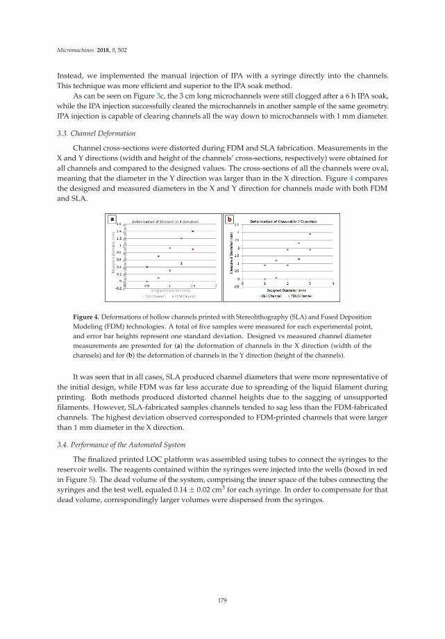
Micromachines 2018, 9, 502
Instead, we implemented the manual injection of IPA with a syringe directly into the channels.This technique was more efficient and superior to the IPA soak method.
As can be seen on Figure 3c, the 3 cm long microchannels were still clogged after a 6 h IPA soak,while the IPA injection successfully cleared the microchannels in another sample of the same geometry.IPA injection is capable of clearing channels all the way down to microchannels with 1 mm diameter.
3.3. Channel Deformation
Channel cross-sections were distorted during FDM and SLA fabrication. Measurements in theX and Y directions (width and height of the channels’ cross-sections, respectively) were obtained forall channels and compared to the designed values. The cross-sections of all the channels were oval,meaning that the diameter in the Y direction was larger than in the X direction. Figure 4 comparesthe designed and measured diameters in the X and Y direction for channels made with both FDMand SLA.
Figure 4. Deformations of hollow channels printed with Stereolithography (SLA) and Fused DepositionModeling (FDM) technologies. A total of five samples were measured for each experimental point,and error bar heights represent one standard deviation. Designed vs measured channel diametermeasurements are presented for (a) the deformation of channels in the X direction (width of thechannels) and for (b) the deformation of channels in the Y direction (height of the channels).
It was seen that in all cases, SLA produced channel diameters that were more representative ofthe initial design, while FDM was far less accurate due to spreading of the liquid filament duringprinting. Both methods produced distorted channel heights due to the sagging of unsupportedfilaments. However, SLA-fabricated samples channels tended to sag less than the FDM-fabricatedchannels. The highest deviation observed corresponded to FDM-printed channels that were largerthan 1 mm diameter in the X direction.
3.4. Performance of the Automated System
The finalized printed LOC platform was assembled using tubes to connect the syringes to thereservoir wells. The reagents contained within the syringes were injected into the wells (boxed in redin Figure 5). The dead volume of the system, comprising the inner space of the tubes connecting thesyringes and the test well, equaled 0.14 ± 0.02 cm3 for each syringe. In order to compensate for thatdead volume, correspondingly larger volumes were dispensed from the syringes.
179

Micromachines 2018, 9, 502
Figure 5. Top view of the assembled automated ELISA bioassay platform. Test wells are indicated bythe red frame on the picture. See the caption of Figure 1 for a description of the individual componentsof the automated platform.
An assay was performed using the automation process described in the Section 2.2 above.A close-up photo of the positive and negative results is provided in Figure 6. The wells with theblue solution were the positive controls, and the colorless wells represented the negative control.The positive control solution changed from blue to yellow when the stop solution was added, while thecolorless negative controls did not change color. The positive and negative control color change wascorrect, signifying the successful demonstration of the automated malaria-Ab assay.
Figure 6. Colorimetric bioassay results after the stop solution is added. The wells with the blue solutionare the positive controls and the colorless wells represent the negative controls.
Five assays were performed on the automated platform. Each assay consisted of four test wells:two wells with positive controls and two wells with negative controls. The tests were performedusing one well at a time. Subsequent test runs were performed by replacing the tubes and manuallypositioning them into another test well. All of the assays were performed successfully without anyfalse readings. Minor test-to-test variations (within 0.05 cm3) of the dispensed wash did not affect thetest results.
180

Micromachines 2018, 9, 502
A Windows Nokia Lumia 521 (Nokia, Espoo, Finland) smart phone with the installed ColorCatcher (Cloud Innovation Team, Austin, TX, USA) app was used to capture the RBG color code of thesolution in the well at the end of each test. There was no need to withdraw the tubes from the test wellduring this image acquisition. While the color change was easily distinguishable with the naked eye,such captured color codes are useful for performing quantitative bioassays. The video of the operationof the automated bioassay platform during the test can be viewed online as part of the SupplementalMaterials for this article.
4. Conclusions
We have reported on the fabrication of an automated colorimetric Malaria-Ab immunoassayplatform based on readily-available parts, such as servomotors and disposable syringes. We havealso outlined an alternative syringe-based automated assay that utilizes elastomeric reservoirs(printed using SLA) with programmable servomotors compressing elastomeric reservoirs to injectreagents or to wash a test well. The aspiration syringe actuated by a continuous servomotor facilitatedthe draining of test wells after specific assay steps.
To demonstrate the validity of our approach, we fabricated a hybrid system that included syringesfor all of the reagents except for the wash, which was contained in an elastomeric dome reservoir.Successful validation of the automated platform was performed with positive and negative controls,and with the reagents included in the commercial malaria-Ab immunoassay kit.
The demonstrated syringe-based automation is easily expanded to a wide variety of assays tocreate flexible and affordable point-of-care platforms. Implementation of the platform is simplifiedby providing rural clinics with syringe kits with pre-measured reagent syringes sealed in metallizedpouches. These pouches can be punctured by the syringe plunger during the corresponding assaystep when conducting the bioassay. Additional validation is required before the application of thepresented automated platform for qualitative (rather than quantitative) tests.
Supplementary Materials: The following are available online at http://www.mdpi.com/2072-666X/9/10/502/s1,Video S1: Validation of a syringe-based automated point-of-care malaria-Ab immunoassay.
Author Contributions: Conceptualization, C.L., Y.L., and L.K.; methodology, C.L. and L.K.; software, Y.L.;validation, C.L. and Y.L.; formal analysis, C.L., Y.L., and L.K.; investigation, C.L. and Y.L.; resources, L.K.; datacuration, C.L. and Y.L.; writing—original draft preparation, C.L.; writing—review and editing, C.L., Y.L., and L.K.;visualization, C.L.; supervision, L.K.; project administration, L.K.; funding acquisition, L.K.
Funding: This research received no external funding.
Conflicts of Interest: The authors declare no conflict of interest.
References
1. Urrios, A.; Parra-Cabrera, C.; Bhattacharjee, N.; Gonzalez-Suarez, A.M.; Rigat-Brugarolas, L.G.; Nallapatti, U.;Samitier, J.; DeForest, C.A.; Posas, F.; Garcia-Cordero, J.L.; et al. 3D-printing of transparent bio-microfluidicdevices in PEG-DA. Lab Chip 2016, 16, 2287–2294. [CrossRef] [PubMed]
2. Crowther, J. The Elisa Guidebook; Springer Science & Business Media: Berlin, Germany, 2009; p. 54.3. Wiltbank, T.; McCaroll, D.; Wartick, M. An undetectable source of technical error that could lead to false
negative results in enzyme linked immunosorbent assay of antibodies to HIV-1. Rapid Commun. 1988,29, 75–77. [CrossRef]
4. Knowlton, S.; Yu, C.H.; Ersoy, F.; Emadi, S.; Khademhosseini, A.; Tasoglu, S. 3D-printed microfluidic Chipswith patterned, cell-laden hydrogel constructs. Biofabrication 2016, 8, 025019. [CrossRef] [PubMed]
5. Ellerbee, A.K.; Phillips, S.T.; Siegel, A.C.; Mirica, K.A.; Martinez, A.W.; Striehl, P.; Jain, N.; Prentiss, M.;Whitesides, G.M. Quantifying colorimetric assays in paper-based microfluidic devices by measuring thetransmission of light through paper. Anal. Chem. 2009, 81, 8447–8452. [CrossRef] [PubMed]
6. Lutz, B.; Liang, T.; Fu, E.; Ramachandran, S.; Kauffman, P.; Yager, P. Dissolvable fluidic time delaysfor programming multi-step assays in instrument-free paper diagnostics. Lab Chip 2013, 13, 2840–2847.[CrossRef] [PubMed]
181

Micromachines 2018, 9, 502
7. Schaller, V.; Sanz-Velasco, A.; Kalabukhov, A.; Schneiderman, J.F.; Öisjöen, F.; Jesorka, A.; Astalan, A.P.;Krozer, A.; Rusu, C.; Enoksson, P.; et al. Towards an electrowetting-based digital microfluidic platform formagnetic immunoassays. Lab Chip 2009, 9, 3433–3436. [CrossRef] [PubMed]
8. Nguyen, N.T.; Hejazian, M.; Ooi, C.H.; Kashaninejad, N. Recent advances and future perspectives onmicrofluidic liquid handling. Micromachines 2017, 8, 186. [CrossRef]
9. Cevenini, L.; Calabretta, M.M.; Tarantino, G.; Michelini, E.; Roda, A. Smartphone-interfaced 3D printedtoxicity biosensor integrating bioluminescent “sentinel cells”. Sens. Actuators 2016, 225, 249–257. [CrossRef]
10. Comina, A.; Suska, A.; Filippini, G. A 3D printed device for quantitative enzymatic detection using cellphones. Anal. Methods 2016, 8, 6135–6142. [CrossRef]
11. Bauer, M.; Kulinksy, L. Fabrication of a lab-on-chip device using material extrusion (3D printing) anddemonstration via Malaria-Ab ELISA. Micromachines 2018, 9, 27. [CrossRef]
12. Crowther, J. The Elisa Guidebook; Springer Science & Business Media: Berlin, Germany, 2009; p. 332.13. Becker, H.; Locascio, L. Polymer microfluidic devices. Talanta 2002, 56, 267–287. [CrossRef]14. Zhang, Y.; Wu, L.; Kane, S.; Deng, Y.; Jung, Y.G.; Lee, G.H.; Zhang, J. Additive manufacturing of metallic
materials: A review. J. Mater. Eng. Perform. 2018, 27, 1–13. [CrossRef]15. Parra-Cabrera, C.; Achille, C.; Kuhn, S.; Ameloot, R. 3D printing in chemical engineering and catalytic
technology: Structured catalysts, mixers and reactors. Chem. Soc. Rev. 2018, 47, 209–230. [CrossRef][PubMed]
16. Betancourt, T.; Brannon-Peppas, L. Micro- and nanofabrication methods in nanotechnological medical andpharmaceutical devices. Int. J. Nanomed. 2006, 1, 483–495. [CrossRef]
17. Sugioka, K.; Cheng, Y. Femtosecond laser processing for optofluidic fabrication. Lab Chip 2012, 12, 3576.[CrossRef] [PubMed]
18. Yalikun, Y.; Hosokawa, Y.; Lino, T.; Tanaka, Y. An all-glass 12 µm ultra-thin and flexible micro-fluidic chipfabricated by femtosecond laser processing. Lab Chip 2016, 16, 2427–2433. [CrossRef] [PubMed]
19. Rolland, J.P.; Van Dam, R.M.; Schorzman, D.A.; Quake, S.R.; DeSimone, J.M. Solvent-resistant photocurable“liquid teflon” for microfluidic device fabrication. J. Am. Chem. Soc. 2004, 126, 232. [CrossRef] [PubMed]
20. Beebe, D.J.; Moore, J.S.; Yu, Q.; Liu, R.H.; Kraft, M.L.; Jo, B.H.; Devadoss, C. Microfluidic tectonics:A comprehensive construction platform for microfluidic systems. Proc. Natl. Acad. Sci. USA 2000,97, 13488–13493. [CrossRef] [PubMed]
21. Lee, S.; Kim, H.; Lee, W.; Kim, J. Finger-triggered portable PDMS suction cup for equipment-free microfluidicpumping. Micro Nano Syst. Lett. 2018, 6, 1–5. [CrossRef]
22. Yazdi, A.; Popma, A.; Wong, W.; Nguyen, T.; Pan, Y.; Xu, J. 3D printing: an emerging tool for novelmicrofluidics and lab-on-a-chip applications. Microfluid. Nanofluid. 2016, 20, 50. [CrossRef]
23. He, Y.; Wu, Y.; Fu, J.Z.; Gao, Q.; Qiu, J.J. Developments of 3D printing microfluidics and applications inchemistry and biology: A review. Electroanalysis 2016, 28, 1658–1678. [CrossRef]
24. Zhang, C.; Bills, B.; Manicke, N. Rapid prototyping using 3D printing in bioanalytical research. Bioanalysis
2017, 9, 329–331. [CrossRef] [PubMed]25. Tang, S.; Whitesides, G. Basic Microfluidic and Soft Lithographic Techniques. Available online: https:
//gmwgroup.harvard.edu/pubs/pdf/1073.pdf (accessed on 25 May 2018).26. Unger, M.A.; Chou, H.P.; Thorsen, T.; Scherer, A.; Quake, S.R. Monolithic microfabricated valves and pumps
by multilayer soft lithography. Science 2000, 288, 113–116. [CrossRef] [PubMed]27. Thorsen, S.; Maerkl, S.J.; Quake, S.R. Microfluidic large-scale integration. Science 2002, 298, 580–584.
[CrossRef] [PubMed]28. Waheed, S.; Cabot, J.M.; Macdonald, N.P.; Lewis, T.; Guijt, R.M.; Paull, B.; Breadmore, M.C. 3D printed
microfluidic devices: Enablers and barriers. Lab Chip 2016, 16, 1993–2013. [CrossRef] [PubMed]29. Hopkinson, N.; Smith, P. Handbook of Industrial Inkjet Printing: A full System; John Wiley & Sons: Hoboken,
NJ, USA, 2018.30. Pilipovic, A.; Raos, P.; Šercer, M. Experimental analysis of properties of materials for rapid prototyping. Int. J.
Adv. Des. Manuf. Technol. 2009, 40, 105–115. [CrossRef]31. Mueller, J.; Courty, D.; Spielhofer, M.; Spolenak, R.; Shea, K. Mechanical properties of interfaces in inkjet 3D
printed single- and multi-material parts. 3D Print. Addit. Manuf. 2017, 4, 193–199. [CrossRef]32. Anderson, K.B.; Lockwood, S.Y.; Martin, R.S.; Spence, D.M. A 3D printed fluidic device that enables
integrated features. Anal. Chem. 2013, 85, 5622–5626. [CrossRef] [PubMed]
182

Micromachines 2018, 9, 502
33. Lockwood, S.Y.; Meisel, J.E.; Monsma, F.J., Jr.; Spence, D.M. A diffusion-based and dynamic 3D-printeddevice that enables parallel in vitro pharmacokinetic profiling of molecules. Anal. Chem. 2016, 88, 1864–1870.[CrossRef] [PubMed]
34. Hwang, Y.; Paydar, O.; Candler, R. 3D printed molds for non-planar PDMS microfluidic channels.Sens. Actuators A Phys. 2015, 226, 137–142. [CrossRef]
35. Paydar, O.H.; Paredes, C.N.; Hwang, Y.; Paz, J.; Shah, N.B.; Candler, R.N. Characterization of 3D-printedmicrofluidic chip interconnects with integrated O-rings. Sens. Actuators A Phys. 2014, 205, 199–203.[CrossRef]
36. Staudinger, U.; Zyla, G.; Krause, B.; Janke, A.; Fischer, D.; Esen, C. Development of electrically conductivemicrostructures based on polymer/CNT nanocomposites via two-photon polymerization. Microelectron. Eng.
2017, 179, 48–55. [CrossRef]37. Xing, J.F.; Zheng, M.L.; Duan, X.M. Two-photon polymerization microfabrication of hydrogels: An advanced
3D printing technology for tissue engineering and drug delivery. Chem. Soc. Rev. 2015, 44, 5031–5039.[CrossRef] [PubMed]
38. Kumi, G.; Yanez, C.; Belfield, K.; Fourkas, J.T. High-speed multiphoton absorption polymerization:Fabrication of microfluidic channels with arbitrary cross-sections and high aspect ratios. Lab Chip 2010,10, 1057–1060. [CrossRef] [PubMed]
39. Kawata, S.; Sun, H.B.; Tanaka, T.; Takada, K. Finer features for functional microdevices. Nature 2001,412, 697–698. [CrossRef] [PubMed]
40. Sugioka, K.; Cheng, Y. Femtosecond laser three-dimensional micro- and nanofabrication. Appl. Phys. Rev.
2014, 1, 041303. [CrossRef]41. Ziemian, C.M.; Crawn, P.M. Computer aided decision support for fused deposition modelling.
Rapid Prototyp. J. 2001, 7, 138–147. [CrossRef]42. Modjarrad, K.; Ebnesajjad, S. Handbook of Polymer Applications in Medicine and Medical Devices;
William Andrew Publishing: Norwich, NY, USA, 2014.43. Chia, H.; Wu, B. Recent advances in 3D printing of biomaterials. J. Biol. Eng. 2015, 9, 4. [CrossRef] [PubMed]44. Lee, J.; Zhang, M.; Yeong, W. Characterization and evaluation of 3D printed microfluidic chip for cell
processing. Microfluid. Nanofluid. 2016, 20, 1–15. [CrossRef]45. Kitson, P.J.; Symes, M.D.; Dragone, V.; Cronin, L. Combining 3D printing and liquid handling to produce
user-friendly reactionware for chemical synthesis and purification. Chem. Sci. 2013, 4, 3099–3103. [CrossRef]46. Bishop, G.W.; Satterwhite, J.E.; Bhakta, S.; Kadimisetty, K.; Gillette, K.M.; Chen, E.; Rusling, J.F. 3D-printed
fluidic devices for nanoparticle preparation and flow-injection amperometry using integrated prussian bluenanoparticle-modified electrodes. Anal. Chem. 2015, 87, 5437–5443. [CrossRef] [PubMed]
47. Sher, D. “Dolomite’s Fluidic Factory 3D Prints $1 Microfluidic Chips.” 3D Printing Industry, 2015. Availableonline: https://3dprintingindustry.com/news/dolomites-fluidic-factory-3d-prints-1-microfluidic-chips-60883/ (accessed on 25 May 2018).
48. 3D Systems, Inc. Available online: https://www.3dsystems.com/ (accessed on 25 May 2018).49. Au, A.; Lee, W.; Folch, A. Mail-order microfluidics: Evaluation of stereolithography for the production of
microfluidic devices. Lab Chip 2014, 14, 1294–1301. [CrossRef] [PubMed]50. Zhou, C.; Chen, Y.; Yang, Z.G.; Khoshnevis, B. Development of a multi-material mask-image-projection-based
stereolithography for the fabrication of digital materials. Rapid Prototyp. J. 2013, 19, 153–165. [CrossRef]51. Zhang, X.; Jiang, X.N.; Sun, C. Micro-stereolithography of polymeric and ceramic microstructures.
Sens. Actuators A Phys. 1999, 77, 149–156. [CrossRef]52. Amend, P.; Hentschel, O.; Scheitler, C.; Baum, M.; Heberle, J.; Roth, S.; Schmidt, M. Fast and flexible
generation of conductive circuits. J. Laser Micro/Nanoeng. 2013, 8, 276–286. [CrossRef]53. Comina, G.; Suska, A.; Filippini, D. PDMS lab-on-a-chip fabrication using 3D printed templates. Lab Chip
2014, 14, 424–430. [CrossRef] [PubMed]54. Comina, G.; Suska, A.; Filippini, D. Low cost lab-on-a-chip prototyping with a consumer grade 3D printer.
Lab Chip 2014, 14, 2978–2982. [CrossRef] [PubMed]55. Comina, G.; Suska, A.; Filippini, D. Autonomous chemical sensing interface for universal cell phone readout.
Chem. Int. Ed. 2015, 54, 8708–8712. [CrossRef] [PubMed]56. Wang, X.; Cai, X.; Guo, Q.; Zhang, T.; Kobe, B.; Yang, J. i3DP, a robust 3D printing approach enabling genetic
post-printing surface modification. Chem. Commun. 2013, 49, 10064–10066. [CrossRef] [PubMed]
183

Micromachines 2018, 9, 502
57. Shallan, A.I.; Smejkal, P.; Corban, M.; Guijt, R.M.; Breadmore, M.C. Cost-Effective Three-DimensionalPrinting of Visibly Transparent Microchips within Minutes. Anal. Chem. 2014, 86, 3124–3130. [CrossRef][PubMed]
58. Patrick, W.G.; Nielsen, A.A.; Keating, S.J.; Levy, T.J.; Wang, C.W.; Rivera, J.J.; Mondragón-Palomino, O.;Carr, P.A.; Voigt, C.A.; Oxman, N.; et al. DNA assembly in 3D printed fluidics. PLoS ONE 2015, 10, 1–18.[CrossRef] [PubMed]
59. Lee, K.G.; Park, K.J.; Seok, S.; Shin, S.; Park, J.Y.; Heo, Y.S.; Lee, S.J.; Lee, J.L. 3D printed modules forintegrated microfluidic devices. RSC Adv. 2014, 4, 32876–32880. [CrossRef]
60. Bhargava, K.; Thompson, B.; Malmstadt, N. Discrete elements for 3D microfluidics. PNAS 2014,111, 15013–150138. [CrossRef] [PubMed]
61. Lai, H.; Folch, A. Design and dynamic characterization of “single-stroke” peristaltic PDMS micropumps.Lab Chip 2011, 11, 336–342. [CrossRef] [PubMed]
62. Bhushan, B.; Caspers, M. An overview of additive manufacturing (3D printing) for microfabrication.Microsyst. Technol. 2017, 23, 1117. [CrossRef]
63. Garcia, J.; Yang, Z.; Mongrain, R.; Leask, R.L.; Lachapelle, K. 3D printing materials and their use in medicaleducation: A review of current technology and trends for the future. BMJ. Simul. Technol. Enhanc. Learn.
2018, 4, 27–40. [CrossRef] [PubMed]64. World Health Organization. Malaria. Available online: http://www.who.int/mediacentre/factsheets/
fs094/en (accessed on 26 May 2018).65. Malaria-Ab-ELISA. Available online: http://www.ibl-international.com/media/catalog/product/R/E/
RE58601_IFU_en_Malaria-Ab_ELISA_V4_2011-08-03_sym3.pdf (accessed on 26 May 2018).66. Color Catcher. Available online: http://appcrawlr.com/android/color-catcher-free (accessed on
26 May 2018).67. Zhou, Y. The recent development and applications of fluidic channels by 3D printing. J. Biomed. Sci. 2017,
24, 80. [CrossRef] [PubMed]
© 2018 by the authors. Licensee MDPI, Basel, Switzerland. This article is an open accessarticle distributed under the terms and conditions of the Creative Commons Attribution(CC BY) license (http://creativecommons.org/licenses/by/4.0/).
184

micromachines
Article
Assessing the Reusability of 3D-PrintedPhotopolymer Microfluidic Chips forUrine Processing
Eric Lepowsky 1, Reza Amin 1 and Savas Tasoglu 1,2,3,4,5,*
1 Department of Mechanical Engineering, University of Connecticut, Storrs, CT 06269, USA;[email protected] (E.L.); [email protected] (R.A.)
2 Department of Biomedical Engineering, University of Connecticut, Storrs, CT 06269, USA3 Institute of Materials Science, University of Connecticut, Storrs, CT 06269, USA4 Institute for Collaboration on Health, Intervention, and Policy, University of Connecticut,
Storrs, CT 06269, USA5 The Connecticut Institute for the Brain and Cognitive Sciences, University of Connecticut,
Storrs, CT 06269, USA* Correspondence: [email protected]; Tel.: +1-860-486-5919
Received: 26 September 2018; Accepted: 14 October 2018; Published: 15 October 2018
Abstract: Three-dimensional (3D) printing is emerging as a method for microfluidic device fabricationboasting facile and low-cost fabrication, as compared to conventional fabrication approaches, such asphotolithography, for poly(dimethylsiloxane) (PDMS) counterparts. Additionally, there is an increasingtrend in the development and implementation of miniaturized and automatized devices for healthmonitoring. While nonspecific protein adsorption by PDMS has been studied as a limitation forreusability, the protein adsorption characteristics of 3D-printed materials have not been well-studied orcharacterized. With these rationales in mind, we study the reusability of 3D-printed microfluidics chips.Herein, a 3D-printed cleaning chip, consisting of inlets for the sample, cleaning solution, and air, and auniversal outlet, is presented to assess the reusability of a 3D-printed microfluidic device. Bovine serumalbumin (BSA) was used a representative urinary protein and phosphate-buffered solution (PBS) waschosen as the cleaning agent. Using the 3-(4-carboxybenzoyl)quinoline-2-carboxaldehyde (CBQCA)fluorescence detection method, the protein cross-contamination between samples and the proteinuptake of the cleaning chip were assessed, demonstrating a feasible 3D-printed chip design andcleaning procedure to enable reusable microfluidic devices. The performance of the 3D-printedcleaning chip for real urine sample handling was then validated using a commercial dipstick assay.
Keywords: microfluidics; 3D printing; reusability; biofouling
1. Introduction
There is significant interest in microfluidics due to its large variety of applications, including cancerscreening [1–3], micro-physiological system engineering [4,5], high-throughput drug testing [6,7],and point-of-care diagnostics [8–13]. In particular, point-of-care devices can help to enable routinehealth monitoring and preventative care, which can improve public health while increasing healthcaresavings. In a study reported by Health Affairs, it has been shown that a 90% increase in specificpreventative screenings back in 2006 would have saved more than 2 million lives without a significantincrease in healthcare costs—in fact, a 0.2% decrease in costs was estimated [14]. Microfluidic deviceshave a proven record of being effective analytical devices, capable of controlling the flow of fluidsamples, containing reaction and detection zones, and displaying results, all within a compact footprint,and are therefore appropriate for addressing this need for routine and preventative care [15–20].
Micromachines 2018, 9, 520; doi:10.3390/mi9100520 www.mdpi.com/journal/micromachines185

Micromachines 2018, 9, 520
While microfluidic devices are low-cost in terms of material cost, conventional fabricationis challenging and costly. Furthermore, there is an unmet need to address the convenience ofimplementing microfluidic devices in sophisticated medical devices: users should not need to replacethe chips routinely. To address the burdensome and expensive fabrication of microfluidic devices,as well as the need for convenience with respect to medical devices, there is an increasing need todevelop microfluidic devices for long-term use [21–24]. While single-use microfluidic chips maybe practical for some applications, such as for prototyping and experimental testing, devices thatallow for multiple uses are better suited for high-throughput testing and point-of-care diagnostics,as the limited lifetime of microfluidic devices has been cited as a barrier to commercialization [25].Furthermore, market trends indicate that by 2018, the field of microfluidics was estimated toreach $3.6–5.7 billion [26], demonstrating the continued growth of the field, particularly withinclinical diagnostics, pharmaceutical research, point-of-care diagnostics, and analytical applications.Thus, multiuse devices will prove very useful while combatting the waste that accumulateswith disposable chips in these applications. For these reasons, the reusability of conventionalpoly(dimethylsiloxane (PDMS) microfluidic devices has previously been assessed [24].
Microfluidic devices are traditionally fabricated by combining photolithography techniques formaking a master mold and soft lithography using PDMS and bonding. The process as a wholeis complex, expensive, laborious, as well as time-consuming [27]. There exist several alternativeapproaches, one of which being 3D printing. Using hydrogels, Beebe et al. developed an ultrafastfabrication platform combining liquid-phase polymerization and lithography compatible with avariety of geometries and valve designs [28]. Another alternative is Teflon, which was demonstrated byRolland et al. [29]. Unlike PDMS, the liquid-Teflon, a type of photocurable perfluoropolyether (PFPE),is resistant to swelling in common organic solvents, in addition to being liquid at room temperatureand exhibiting low surface energy, low modulus, high gas permeability, and low toxicity. Glasscan also be used for microfluidic device fabrication. For instance, femtosecond laser direct writingcan modify the interior of glass through multiphoton absorption to form microfluidic channels andoptofluidic components [30]. Femtosecond laser processing can even be used to fabricated ultrathin,flexible microfluidic chips [31]. Microfluidic devices can also be fabricated using plastics. A studyby Wan et al. indicated that poly(methyl methacrylate) (PMMA) can be recycled for biologicalmicrofluidic device applications. In this experiment, researchers pumped bleach and ethanol throughthe microfluidic channels after the chip was used, and then they melted the PMMA so that the plasticcould be reused for multiple chip iterations [32]. While studies have indicated that the recyclingof plastic-based microfluidic chips is possible, there is a lack of research being conducted on thereusability of microfluidic chips. Reusability is advantageous over recyclability since recycling involvesthe remanufacturing of the device. Investigation is needed to determine if merely rinsing the channelswith a cleaning agent, such as a phosphate-buffered solution (PBS) or deionized (DI) water, will allowfor the microfluidic chip to be reused with negligible protein absorption and cross-contaminationbetween samples.
3D printing is a new technique that can bypass many limitations seen with PDMS-basedapproaches, such as expensive equipment and clean room facilities, thus making the fabricationprocess easier, cheaper, and more flexible [26,27,33,34]. There are various 3D printing techniques thatcan be used to fabricate microfluidics. The most applicable ones to microfluidics are stereolithography(SLA), multijet modeling (MJM), and fused deposition modeling (FDM) [27,33–35]. All techniquesuse a computer-aided design (CAD) sketch as a blueprint and build the structure layer-by-layer fromprinting material, which can be plastic filaments, liquid resin, or powder [27,36]. The most commonlyused commercialized 3D printing technology for micro-fabrication is the SLA technique, which isdefined as a method for making solid objects by successively printing thin layers of a curable material(i.e., a UV-curable liquid resin) on top of the other [35]. In SLA printing, a laser beam or projector isused to crosslink the resin in the predetermined pattern [33]. For microfluidic devices, a microchannelis built by photo-polymerizing the channel walls and then draining the uncured resin from the channel
186

Micromachines 2018, 9, 520
cavity after the printing is complete [37]. For the purpose of microfluidic devices which involveimaging, clear resin is available.
When a microfluidic device is first manufactured and put into use, it is assumed that the channelswill provide a clean environment for the samples to flow through. However, the size and compositionof these devices can make it unusable after just a few experiments if not designed with reusabilityin mind [38]. Within the channels of a microfluidic device, the surface area-to-volume ratio is high,meaning more of the fluid is exposed to the surfaces of the channel per unit volume. If the deviceis made of a porous or hydrophobic material, it can allow molecules to stick to the channel walls,rendering it unusable. In addition, the charge on a molecule can cause them to stick to the channelwalls if the chip is made of a polar material [39]. Further, if there are areas in the channel where thefluid flow becomes static, especially around channel intersections, there is a high likelihood that amolecule buildup will occur, causing elevated levels of absorption or contamination by the molecule,or even reducing or completely inhibiting the flow through that channel [38]. Nonetheless, the changein flow through the channel should not overshadow the larger issue: the buildup of molecules,and possibly cells, can cause largely inaccurate results in sample testing. A primary challenge inproducing microfluidic devices for long-term use is the biofouling that often occurs on the surface ofintegrated channels and features [39,40]. This phenomenon occurs, due to surface interactions betweenthe walls of the channels and the biological sample flowing through the channels. To address thelong-term use of microfluidic devices, there has been a growing research interest in developing newanti-fouling methods and materials [21,22,41–43]. Additionally, other alternatives, such as recyclablechips or reusable chips, are actively being explored [23,24,32,44].
Leveraging the advantages of 3D printing with the aim of addressing the need for reusablemicrofluidic devices due to their potential societal impact, herein, a 3D-printed microfluidic chipwas designed to assess the reusability of 3D-printed chips by means of quantifying its absorptioncharacteristics. The proposed solution serves to validate the ability to deliver a sample and clean thedevice for reusability. The core function of the demonstrated 3D-printed microfluidic cleaning chipis to integrate a cleaning procedure into a pre-existing single-use device such that the chip/devicemay be reused (Figure 1b). To facilitate the cleaning process, the cleaning chip is connected to asyringe pump to deliver either the sample, cleaning solution, or air, at a controlled rate, dependingupon which inlet the pump is attached to; the inlet channels converge to a single outlet. In areal-world application, the sample would flow from the outlet of the cleaning chip into the samplehandling portion of the pre-existing device (Figure 1a,b). For the purpose of assessing the proteinuptake by the chip, a calibration curve (Figure 1c) was created by injecting protein samples ofknown concentration into channels of equal dimensions to the cleaning chip, performing fluorescentassays, and using a fluorescence microscope to quantify the fluorescent light intensity, in whicha greater light intensity corresponds to a greater concentration of protein present. Specifically,the 3-(4-carboxybenzoyl)quinoline-2-carboxaldehyde (CBQCA) fluorescence detection method wasused, in which the CBQCA fluoresces green in the presence of protein when excited by a blue lightsource. For assessing the cross-contamination between samples, the sample from the outlet wascollected, CBQCA was added to the samples, and a plate reader was used to quantify the fluorescence,thereby reflecting the amount of protein present in the samples. By performing the CBQCA assay onsamples over time during the cleaning procedure, the cross-contamination as a function of washingvolume was determined (Figure 1d).
187

Micromachines 2018, 9, 520
Figure 1. Design, core functionality, and experimental overview: (a) Generalized design of cleaningchip. The cleaning chip device consists of inlets for the sample, cleaning solution, and air, all connectedto a single outlet. This design allows for a cleaning procedure to be performed on the chip itself andany external microfluidic device that is connected to the cleaning chip’s outlet; (b) Core functionalityof the cleaning chip. The cleaning chip may be used in conjunction with a pre-existing microfluidicdevice, which may itself perform sample handling, analysis, quantification, etc., in order to renderthe external device a reusability microfluidic device by connecting the outlet of the cleaning chip tothe inlet of the pre-existing device; (c) Experimental preview of chip protein uptake. The 3D-printedcleaning chip was connected to a syringe pump, and the cleaning solution was collected from the outletof the cleaning chip for protein cross-contamination quantification, while the chip itself was assessedfor protein absorption. A fluorescence detection method was used to determine the concentration ofprotein present in the collected samples from the outlet and within the chip itself; the CBQCA assayused fluoresces green by excitation with blue light. Above, the two images shown provide an exampleof the fluorescent images with their respective protein concentrations. Below, the calibration curveused for determining protein uptake by the chip was constructed by injecting known concentrations ofprotein into channels of a chip and imaging the channels using a fluorescence microscope, where theraw light intensity (on a scale from 0 to 255) was used as the independent variable; (d) Experimentalpreview of cross-contamination results. Collected samples were quantified by using a plate readerto measure the fluorescence of the cleaning solution from the outlet. The observed trend showed thedecreasing protein concentration with the increasing washing volume.
2. Materials and Methods
2.1. Design and Fabrication of 3D-Printed Microfluidic Cleaning Chip
Microfluidic cleaning chips were designed using SolidWorks CAD modeling software (SolidWorks2017–2018, Dassault Systèmes SOLIDWORKS Corp, Waltham, MA, USA), as seen in Figure 2a. The chip
188

Micromachines 2018, 9, 520
consisted of four channels: a biological sample inlet, a cleaning solution inlet, an air inlet, and auniversal outlet. For each iteration of the chip, the outer dimensions were slimmed down to reducematerial waste, and a viewing window was added to the top and bottom of the chip to improvethrough-chip visibility, while the channel width was held constant at 1000 µm. The CAD models werethen fabricated using the Formlabs Form 2 3D SLA printer (Form 2, Formlabs Inc., Somerville, MA,USA). This 3D printer was chosen due to its high-resolution capabilities. Furthermore, clear resin wasused to fabricate the chips, so it would be possible to view the channels externally (Clear Resin GPCL04,Formlabs Inc., Somerville, MA, USA). The clear resin also allowed for fluorescence readings to be takenthrough the chip. After 3D-printed chips were fabricated, 1 mL of PDMS (Cell Guard Encapsulation Kit,ML Solar, Campbell, CA, USA) was deposited to the viewing windows on each side of the chip in orderto improve clarity by filling pores of the surface roughness of the 3D-printed material (Figure 2a,b).The PDMS was degassed and then baked for 20–25 min at 80 ◦C. The refractive indices of PDMS andthe clear resin have been reported as 1.4 and 1.5, respectively [45,46]. For reference, the refractiveindex of mineral oil, which is often used to improve optical clarity of a rough surface, is around 1.47;however, the bottom viewing window of the 3D-printed chip would necessitate the mineral oil-coatedsurface to be overturned, which could pose a risk to the microscope used for protein quantification [47].Due to the very similar refractive indices of the PDMS and 3D-printed material used in the fabricationof the chip, there was negligible light interference at the interface between the two materials.
Figure 2. Overview of fabrication and experimental methods: (a) Microfluidic chip is first designed inSolidWorks, and then 3D-printed using a Formlabs Form 2 printer. Post-printing, a thin layer of PDMSis poured and cured on both faces of the chip; (b) Addition of the PDMS coating on the outside of thechip improves visibility. See a comparison of the chip with PDMS (on the left) to the chip without PDMS(on the right); (c) Image of experimental setup, showing the 3D-printed chip connected to a syringepump. The sample from the outlet of the chip was collected in microcentrifuge tubes for fluorescencedetection analysis; (d) Schematic representation of the experimental design and implementation ofthe 3D-printed microfluidic chip. The concentrated BSA solution, and phosphate buffered solution(PBS) as a cleaning solution, and air each have designated inlets which all converge to a single outlet.The sample from the outlet, collected at set intervals, and the chip itself are then analyzed for the proteinconcentration by the CBQCA quantitation method using a plate reader and microscope, respectively.
To determine the optimum channel height for the microfluidic chip, dimensions ranging from100 µm to 1000 µm were tested. Printing success was assessed by measuring the length of each openchannel and comparing this to the expected channel length. Using 500 µm as a benchmark channel
189

Micromachines 2018, 9, 520
height, which printed semi-reliably and of which success depended greatly on printing parameters,the ideal printing orientation was determined by analyzing the printing success, as described above,in relation to print orientation with respect to the build platform of the 3D printer. Ultimately, the chipswere printed with an angled vertical orientation, such that the channels could self-drain excess resinduring printing. Additionally, the Form 2 had higher resolutions in the x- and y-directions than inthe z-direction. The highest-resolution layer height, 0.025 mm, was used; in the x- and y-directions,the laser could fabricate lines down to 140 microns and holes down to 25 microns. By orienting thechips vertically, the smallest feature size (the channels) benefited from the higher resolution of theprinter. Furthermore, by angling the chips, the cross-sectional area of the features was effectivelyincreased. The final chip design was assessed for printing accuracy by measuring the width of theprinted channels using a desktop microscope and comparing this to the expected 1000 µm width.
2.2. Cleaning Procedure
The 3D-printed cleaning chip was designed to enable the reusability of microfluidic chips byimplementing a simple cleaning procedure to reduce biofouling and cross-contamination betweenthe samples. The cleaning procedure utilized a syringe pump and the four channels of the cleaningchip (Figure 2c,d). First, the biological sample inlet was used: a representative protein sample,2 mL of bovine serum albumin (BSA) at a high concentration (20 mg/mL), was pumped throughthe chip, with the cleaning solution and air inlets sealed, using a syringe pump set to 1 mL/min(Thermo Fisher Scientific, Waltham, MA, USA). Following the BSA, air was pumped from the air inletand through all three non-air channels individually by sealing the remaining two channels, with 0.5 mLof air for each channel, also set at 1 mL/min. The cleaning agent was then pumped, with the biologicalsample and air inlets sealed, for a total of 10 mL at 1 mL/min. Pure PBS and DI water were testedas the cleaning agent (Thermo Fisher Scientific, Waltham, MA, USA); PBS was determined to be thesuperior choice. The cleaning procedure ended with a second round of the air to dry all the channelsof the chip.
2.3. Protein Cross-Contamination Quantification
While a cleaning agent was pumped through the chip during the cleaning procedure, 200 µLsamples from the outlet were collected at 13 intervals: 200, 400, 600, 800, 1000, 1200, 1400, 1600, 1800,2000, 3000, 5000, and 10,000 µL. The protein level of these samples passing through the device wasquantified using a CBQCA fluorescence detection method (CBQCA Protein Quantitation Kit (C-6667),Molecular Probes, Inc., Eugene, OR, USA). Using this method, BSA protein as little as 10 ng canbe detected. In the presence of protein, the CBQCA fluorescence green when excited by blue light.To measure the cross-contamination level of the cleaning solution after passing through the system,5 µL of KCN (20 mM) and 10 µL of CBQCA reagent (5 mM) were added to 135 µL of each samplein a microplate. After allowing the samples in the microplate to incubate for 1 hour in darkness,the fluorescence level was measured using a BioTek Synergy H1 plate reader (Synergy H1 HybridMulti-Mode Reader, BioTek, Winooski, VT, USA).
2.4. Protein Uptake by Cleaning Chip Calibration and Quantification
In order to quantify the protein uptake by the cleaning chip, a calibration chip consisting of 10channels of equal width and height as the channels of the cleaning chip was designed and 3D-printed.Each channel was filled with 135 µL of a BSA-in-PBS solution of known concentrations (1, 0.5, 0.25,0.1, 0.08, 0.06, 0.04, 0.02, 0.01, and 0 mg/mL) mixed with 5 µL of KCN (20 mM) and 10 µL of CBQCAreagent (5 mM). After incubating for 1 hour in darkness, the channels of the chip were imaged usinga Zeiss Observer z1 fluorescence microscope (Carl Zeiss Microscopy GmbH, Jena, Germany) on the2.5x objective. The greater the concentration of protein present, the greater the intensity of the greenfluorescence. Intensity was measured using ImageJ (v1.48k, National Institutes of Health, Bethesda,MD, USA).
190

Micromachines 2018, 9, 520
The protein absorption by the chip—the same chip as the cross-contamination experiment afterbeing exposed to the 20 mg/mL BSA solution—was then characterized by adding a mixture of 135 µLof PBS, 5 µL of KCN (20 mM), and 10 µL of CBQCA reagent (5 mM) to the chip’s channels. After a1-hour incubation period in darkness, the channels of the chip were imaged using the fluorescencemicroscope. The light intensity of the channels was compared to the intensity of the calibration chip todetermine the amount of protein absorbed by the chip. The protein uptake was quantified for fourcases: a single-use chip with DI, a single-use chip with PBS, a 6-cycle chip with PBS, and a 6-cyclechip with PBS and a post-cleaning treatment of 10 mL of 0.25% trypsin (Trypsin-EDTA (0.25%), phenolred, 25200-056, Thermo Fisher Scientific, Waltham, MA, USA). Trypsin is a protease which hydrolysesother proteins, and therefore reduces the levels of protein uptake by the cleaning chip significantly bydigesting the adhered and absorbed proteins.
2.5. Longitudinal Protein Cross-Contamination
The longitudinal sample protein cross-contamination was characterized by repeatedly performingthe same analysis as for protein cross-contamination. After completion of each round of pumpingsamples through the chip, the chip was cleaned following the prescribed cleaning process.This procedure of flowing the biological/protein sample, collecting the PBS samples from the outlet,and cleaning the chip was repeated to demonstrate the collective contamination as a result of repeateduse of the chip.
2.6. Protein Quantification for Urine Processing
The reusability of the 3D-printed cleaning chip for real urine sample handling was validatedby assessing the protein cross-contamination between samples and the protein uptake by the chip.Urine samples were collected from volunteers according to protocol # H17-043, approved by theUniversity of Connecticut Institutional Review Board. All subjects provided informed consent.For studying cross-contamination, samples were pumped through the microfluidic device and collectedin microcentrifuge tubes. Commercially available urine analysis dipsticks (Urinalysis Reagent Strips,HealthyWiser LLC., Los Angeles, CA, USA) were then dipped into the collected samples and allowedto incubate for 60 seconds before being imaged with a DSLR camera (REBEL T6, Canon, Melville,NY, USA) in the RAW image mode with flash for consistent lighting. The captured images were thenconverted to grayscale, such that the light intensity of the grayscale image could be correlated to aspecific protein concentration. To facilitate this quantification, a calibration curve was constructed byleast-squares curve fitting of the light intensities from images of the dipstick protein assay pads forvarious BSA concentrations (0, 0.15, 0.3, 1, 3, 10, and 20 g/L).
The cross-contamination was studied for an “extreme-case” scenario, in which pumped samplesalternated between urine and high-concentration (20 g/L) BSA. A modified cleaning procedure wasperformed between each sample: in addition to pumping PBS (the cleaning solution) through theuniversal exit channel, PBS was also pumped through the sample inlet channel. For each cycle,four samples were collected and analyzed using the dipstick assay: urine, post-urine PBS, BSA, andpost-BSA PBS. The protein uptake by the chip was also studied for this “extreme-case,” in addition toexposure to pumped urine samples for 30 and 90 min. The total sample volume of the “extreme-case”was approximately equal to the volume of the 30-min exposure to urine. For each of the three urineexperiments, protein uptake by the chip was quantified using the previously described CBQCAfluorescent detection method and fluorescent microscope.
3. Results
3.1. Design and Fabrication of 3D-Printed Microfluidic Cleaning Chip
An early chip design (the top-most design depicted in Figure S1a in Supplementary Materials)was fabricated with a 500 µm channel height by 3D printing at different orientations. That is, the chip
191
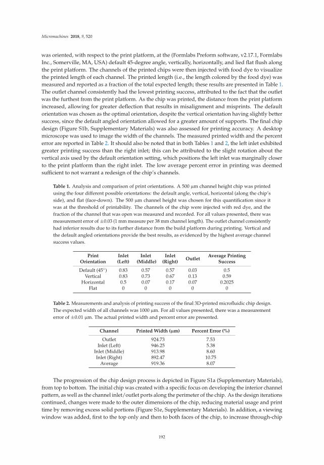
Micromachines 2018, 9, 520
was oriented, with respect to the print platform, at the (Formlabs Preform software, v2.17.1, FormlabsInc., Somerville, MA, USA) default 45-degree angle, vertically, horizontally, and lied flat flush alongthe print platform. The channels of the printed chips were then injected with food dye to visualizethe printed length of each channel. The printed length (i.e., the length colored by the food dye) wasmeasured and reported as a fraction of the total expected length; these results are presented in Table 1.The outlet channel consistently had the lowest printing success, attributed to the fact that the outletwas the furthest from the print platform. As the chip was printed, the distance from the print platformincreased, allowing for greater deflection that results in misalignment and misprints. The defaultorientation was chosen as the optimal orientation, despite the vertical orientation having slightly bettersuccess, since the default angled orientation allowed for a greater amount of supports. The final chipdesign (Figure S1b, Supplementary Materials) was also assessed for printing accuracy. A desktopmicroscope was used to image the width of the channels. The measured printed width and the percenterror are reported in Table 2. It should also be noted that in both Tables 1 and 2, the left inlet exhibitedgreater printing success than the right inlet; this can be attributed to the slight rotation about thevertical axis used by the default orientation setting, which positions the left inlet was marginally closerto the print platform than the right inlet. The low average percent error in printing was deemedsufficient to not warrant a redesign of the chip’s channels.
Table 1. Analysis and comparison of print orientations. A 500 µm channel height chip was printedusing the four different possible orientations: the default angle, vertical, horizontal (along the chip’sside), and flat (face-down). The 500 µm channel height was chosen for this quantification since itwas at the threshold of printability. The channels of the chip were injected with red dye, and thefraction of the channel that was open was measured and recorded. For all values presented, there wasmeasurement error of ±0.03 (1 mm measure per 38 mm channel length). The outlet channel consistentlyhad inferior results due to its further distance from the build platform during printing. Vertical andthe default angled orientations provide the best results, as evidenced by the highest average channelsuccess values.
PrintOrientation
Inlet(Left)
Inlet(Middle)
Inlet(Right)
OutletAverage Printing
Success
Default (45◦) 0.83 0.57 0.57 0.03 0.5Vertical 0.83 0.73 0.67 0.13 0.59
Horizontal 0.5 0.07 0.17 0.07 0.2025Flat 0 0 0 0 0
Table 2. Measurements and analysis of printing success of the final 3D-printed microfluidic chip design.The expected width of all channels was 1000 µm. For all values presented, there was a measurementerror of ±0.01 µm. The actual printed width and percent error are presented.
Channel Printed Width (µm) Percent Error (%)
Outlet 924.73 7.53Inlet (Left) 946.25 5.38
Inlet (Middle) 913.98 8.60Inlet (Right) 892.47 10.75
Average 919.36 8.07
The progression of the chip design process is depicted in Figure S1a (Supplementary Materials),from top to bottom. The initial chip was created with a specific focus on developing the interior channelpattern, as well as the channel inlet/outlet ports along the perimeter of the chip. As the design iterationscontinued, changes were made to the outer dimensions of the chip, reducing material usage and printtime by removing excess solid portions (Figure S1e, Supplementary Materials). In addition, a viewingwindow was added, first to the top only and then to both faces of the chip, to increase through-chip
192
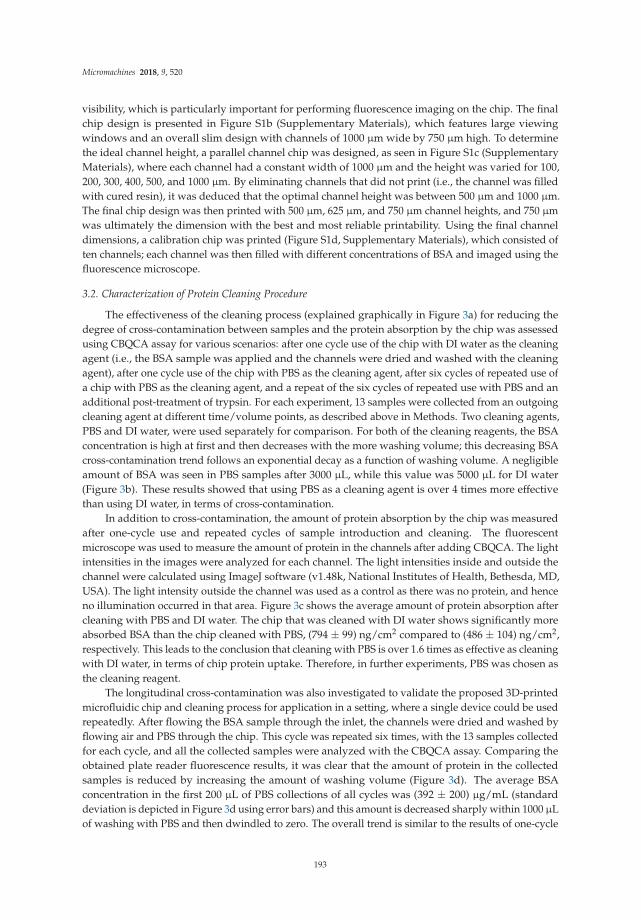
Micromachines 2018, 9, 520
visibility, which is particularly important for performing fluorescence imaging on the chip. The finalchip design is presented in Figure S1b (Supplementary Materials), which features large viewingwindows and an overall slim design with channels of 1000 µm wide by 750 µm high. To determinethe ideal channel height, a parallel channel chip was designed, as seen in Figure S1c (SupplementaryMaterials), where each channel had a constant width of 1000 µm and the height was varied for 100,200, 300, 400, 500, and 1000 µm. By eliminating channels that did not print (i.e., the channel was filledwith cured resin), it was deduced that the optimal channel height was between 500 µm and 1000 µm.The final chip design was then printed with 500 µm, 625 µm, and 750 µm channel heights, and 750 µmwas ultimately the dimension with the best and most reliable printability. Using the final channeldimensions, a calibration chip was printed (Figure S1d, Supplementary Materials), which consisted often channels; each channel was then filled with different concentrations of BSA and imaged using thefluorescence microscope.
3.2. Characterization of Protein Cleaning Procedure
The effectiveness of the cleaning process (explained graphically in Figure 3a) for reducing thedegree of cross-contamination between samples and the protein absorption by the chip was assessedusing CBQCA assay for various scenarios: after one cycle use of the chip with DI water as the cleaningagent (i.e., the BSA sample was applied and the channels were dried and washed with the cleaningagent), after one cycle use of the chip with PBS as the cleaning agent, after six cycles of repeated use ofa chip with PBS as the cleaning agent, and a repeat of the six cycles of repeated use with PBS and anadditional post-treatment of trypsin. For each experiment, 13 samples were collected from an outgoingcleaning agent at different time/volume points, as described above in Methods. Two cleaning agents,PBS and DI water, were used separately for comparison. For both of the cleaning reagents, the BSAconcentration is high at first and then decreases with the more washing volume; this decreasing BSAcross-contamination trend follows an exponential decay as a function of washing volume. A negligibleamount of BSA was seen in PBS samples after 3000 µL, while this value was 5000 µL for DI water(Figure 3b). These results showed that using PBS as a cleaning agent is over 4 times more effectivethan using DI water, in terms of cross-contamination.
In addition to cross-contamination, the amount of protein absorption by the chip was measuredafter one-cycle use and repeated cycles of sample introduction and cleaning. The fluorescentmicroscope was used to measure the amount of protein in the channels after adding CBQCA. The lightintensities in the images were analyzed for each channel. The light intensities inside and outside thechannel were calculated using ImageJ software (v1.48k, National Institutes of Health, Bethesda, MD,USA). The light intensity outside the channel was used as a control as there was no protein, and henceno illumination occurred in that area. Figure 3c shows the average amount of protein absorption aftercleaning with PBS and DI water. The chip that was cleaned with DI water shows significantly moreabsorbed BSA than the chip cleaned with PBS, (794 ± 99) ng/cm2 compared to (486 ± 104) ng/cm2,respectively. This leads to the conclusion that cleaning with PBS is over 1.6 times as effective as cleaningwith DI water, in terms of chip protein uptake. Therefore, in further experiments, PBS was chosen asthe cleaning reagent.
The longitudinal cross-contamination was also investigated to validate the proposed 3D-printedmicrofluidic chip and cleaning process for application in a setting, where a single device could be usedrepeatedly. After flowing the BSA sample through the inlet, the channels were dried and washed byflowing air and PBS through the chip. This cycle was repeated six times, with the 13 samples collectedfor each cycle, and all the collected samples were analyzed with the CBQCA assay. Comparing theobtained plate reader fluorescence results, it was clear that the amount of protein in the collectedsamples is reduced by increasing the amount of washing volume (Figure 3d). The average BSAconcentration in the first 200 µL of PBS collections of all cycles was (392 ± 200) µg/mL (standarddeviation is depicted in Figure 3d using error bars) and this amount is decreased sharply within 1000 µLof washing with PBS and then dwindled to zero. The overall trend is similar to the results of one-cycle
193

Micromachines 2018, 9, 520
cross contamination assessment. As seen in Figure 3d, the standard deviation in the measured BSAconcentration for the first four samples of each cycle is significant due to the accumulation of BSAin the chip after each cycle; in other words, the large error bars represent the variation betweenthe increased number of cycles. For example, higher cycles would lie closer to the top of the errorbars, while the beginning cycles would be towards the bottom. The error bars shorten afterwards,which demonstrated that no matter how many times the chip was used, after washing with as much as5000 µL, all the possible BSA has been removed, or only negligible BSA is present afterwards. It shouldbe noted that it does not mean that all the BSA has been washed out, as some of the BSA was absorbedand accumulated in the chip.
Figure 3. Protein cleaning characterization: (a) Graphical representation of one-cycle of the cleaningprocedure. The PBS from the outlet was collected at set intervals for the cross-contaminationresults; (b) Cross-contamination of a single-use chip using deionized (DI) water compared to PBSas a cleaning solution with the BSA concentration in the output PBS or DI sample using a newchip. Cross-contamination is significantly reduced by using PBS, as compared to DI; (c) Proteinabsorption by a single-use 3D-printed chip after cleaning with DI compared to PBS. After cleaningwith PBS, approximately half as much protein uptake remained, as compared to after cleaning with DI;(d) Cross-contamination of a repeated-use chip with the BSA concentration in the output PBS samplefor 6 cycles using the same chip repeatedly, graphed as the mean with standard deviation error bars;(e) Protein absorption by the 3D-printed chip after 6 cycles of repeated use. By adding a post-cleaningtreatment of trypsin after the 6 cycles of repeated use, the protein uptake is decreased by nearly half.
The protein uptake after six repeated cycles was shown to be (758 ± 30) ng/cm2 (Figure 3e),which is approximately twice the amount of uptake after single use of the chip. This showed apromising trend that even after six repeated cycles of use, chip protein uptake less-than doubles,demonstrating a favorable relationship in that there was not a one-to-one relationship between cycles
194

Micromachines 2018, 9, 520
(and therefore exposure to BSA sample) and protein uptake. This can be taken to mean that the totalprotein uptake by the chip may approach a plateau after a relatively low number of cycles of use.Furthermore, by flowing 10 mL of trypsin after the six cycles of samples and cleaning, the proteinuptake was reduced to (412 ± 66) ng/cm2. These favorable results are due to the protease functionof the trypsin, which digests a portion of the BSA on the chip. This means that by adding trypsin,the effectiveness of the cleaning procedure can be further improved.
3.3. Protein Quantification for Urine Processing
The 3D-printed cleaning chip was demonstrated for application to urine testing usingcommercially available dipstick protein assay pads. For handling multiple samples, the cleaningprocedure, depicted graphically in Figure 4a, was slightly modified to include PBS cleaning of both thesample inlet channel and the universal outlet channels. Additionally, the volume of cleaning solutionwas reduced to 300 µL. Using this modified cleaning procedure, urine samples and high-concentration(20 g/L) BSA were alternatingly pumped through the chip. The resulting protein uptake by the chipwas (657 ± 69) ng/cm2 (Figure 4b). Comparatively, the protein uptake after 30 min of pumping urine(approximately the same total sample volume) with no intermediate cleaning was (364 ± 54) ng/cm2.The difference between these values is attributed to the high-concentration BSA, which was used inthe former experiment. When the exposure time to urine without cleaning was increased to 90 min,the protein uptake was (443 ± 70) ng/cm2. This is a favorable result because for tripling the exposuretime to urine, and tripling the volume of urine processed by the chip, the protein uptake only increasedby 21.7%.
The cross-contamination between samples was also studied for the alternating urine andhigh-concentration (20 g/L) BSA. The protein assay pads of commercially available dipsticks weredipped in BSA samples of various concentrations (0, 0.15, 0.3, 1, 3, and 10 g/L). The resulting colorchange was converted into a change in grayscale light intensity. A calibration curve was created usingleast-squares curve fitting; the resulting curve, depicted on the left of Figure 4c, was found to bey = −0.000002618x4 + 0.001382x3 + 0.2630x2 + 20.8829x − 552.0138 with a correlation coefficient ofR2 = 0.963. The calibration curve was then verified by comparing the protein concentration calculatedvia image analysis to the actual protein concentration of the samples, as shown on the right of Figure 4c.
Figure 4d shows the longitudinal quantification of protein concentration for 20 cycles of urinesamples, post-urine PBS cleaning solution, BSA samples, and post-BSA PBS cleaning solution (a totalof 81 pumping steps). The average protein concentration in the urine samples after pumping throughthe cleaning chip, represented by the orange dotted line, was 0.8072 g/L, as compared to the true valueof 0.4958 g/L. This deviation is attributed to the low sensitivity of the urine dipstick assay for lowprotein concentrations; in fact, for this range of protein concentration, the color key provided by thedipstick manufacturer only discerns between 0.3 g/L and 1.0 g/L. The average protein concentrationof the PBS, represented by the green dotted line, was 4.0715 g/L. Although there is no protein presentin the PBS cleaning solution originally, the protein concentration after pumping through the chip iselevated as it washes out protein from the previous sample. Despite the cross-contamination betweenthe high-concentration BSA and subsequent PBS cleaning solution, the cleaning and air-drying stepsare sufficient for yielding consistent urine concentration results. Figure 4e shows images of the dipstickpads for the gray region of Figure 4d.
195

Micromachines 2018, 9, 520
Figure 4. Performance of 3D-printed cleaning chip for urinary protein measurement: (a) Graphicalrepresentation of one-cycle of the modified cleaning procedure; (b) Protein absorption by the 3D-printedcleaning chip after 30 min of pumping urine (without cleaning), 90 min of pumping urine (withoutcleaning), and 20 cycles of alternating urine and high-concentration BSA samples (with cleaningbetween samples); (c) Left: calibration curve for the actual protein concentration versus the grayscaleintensity of protein assay pads, calculated by least-squares curve fitting. Right: comparison of thecalculated protein concentration using the calibration curve versus the actual concentration of thesamples. Far right: photographs of the protein assay pads for 0, 0.15, 0.3, 1, 3, 10, and 20 g/L,shown in full color and grayscale; (d) Longitudinal protein concentration measurement for 20 cycles(81 pumping steps) of urine, PBS cleaning, high-concentration BSA, and a second round of PBS cleaning.Urine samples, PBS and BSA are represented by blue, green, and blue lines, respectively. Dotted linesrepresent the average protein concentration for the respective sample; (e) Photographs of the proteinassay pads for Cycle 6, Steps 21–25.
4. Discussion
Reusability of microfluidic devices is critical for any devices that will go to market; however,fouling of the devices’ channels can pose a significant challenge. For a microfluidic device capableof being commercialized, it must work reliably over a long period of time and for a wide variety of
196

Micromachines 2018, 9, 520
samples [38]. Characterization of the protein absorption of 3D-printed material, specifically FormlabsClear Resin for SLA printing, was performed to validate the reusability of 3D-printed microfluidicchips. Furthermore, the cleaning chip and cleaning procedure proposed here is an efficient and cost-and time-effective solution for enabling the reusability of microfluidic devices. 3D printing is a low-cost,rapid-prototyping method for fabrication that is simpler, cheaper, and faster than soft lithography.The reusable design of this 3D-printed microfluidic chip also replaces the need for fabrication anddisposal of many separate devices for the delivery and testing of multiple samples.
As the proposed cleaning chip design has shown favorable results, i.e., minimal proteincross-contamination and protein absorption has occurred, our work here sets a precedent forconsidering reusability when designing 3D-printed microfluidic devices. Future research directionsmay look to further assess other factors contributing to the reusability of devices. It is knownthat the nature of the sample, the materials from which the device is fabricated, and the flow ofsamples can all contribute to the fouling that occurs. Other 3D-printed materials may be studiedto determine their respective absorption characteristics. BSA, a protein often found in urine,was chosen as a representative protein sample; however, different mixtures of proteins may exhibitdifferent absorption characteristics based on charge, hydrophobicity/hydrophilicity, or other surfaceinteractions. With different constituents in the mixture, proteins may unfold; for instance, a protein maybe hydrophilic on the surface, but upon unfolding, it might expose a hydrophobic interior, which canaffect its absorption behavior. Additionally, since bacteria can feed on residual samples left in thechip and can further contribute to the fouling problem, bacteria adsorption and cross-contaminationstudies may be performed. It is important to quantify and characterize the bacterial contamination asbacteria could negatively impact the results of some assays. Other future work may also consider theinfluence of flow rate. Finally, in order to achieve the goal of integrating the demonstrated cleaningchip into a functional microfluidic chip, in the future, the cleaning procedure should be automatedand self-contained.
Supplementary Materials: The following is available online at http://www.mdpi.com/2072-666X/9/10/520/s1,Figure S1: Design iterations of the 3D-printed microfluidic chip for reusability assessment.
Author Contributions: S.T. designed the experiments. E.L. and R.A. performed the experiments. E.L. and S.T.wrote and edited the manuscript.
Acknowledgments: S.T. acknowledges the American Heart Association Scientist Development Grant(15SDG25080056), Connecticut Innovations Biopipeline Award, and the University of Connecticut ResearchExcellence Program award for financial support of this research. The authors acknowledge Julia Dugas, PatrickMadaus, and Farnoosh Saeedinejad for their assistance.
Conflicts of Interest: S.T. is a founder of, and has an equity interest in mBiotics, LLC, a company that is developingmicrofluidic technologies for point-of-care diagnostic solutions. S.T. and R.A. are a founder of, and has an equityinterest in QRfertile, LLC, a company that is developing microfluidic technologies for fertility testing. S.T.’s andR.A.’s interests were viewed and managed in accordance with the conflict of interest policies. The authors haveno other relevant affiliations or financial involvement with any organization or entity with a financial interest inor financial conflict with the subject matter or materials discussed in the manuscript, apart from those disclosed.
References
1. Wankhede, S.P.; Du, Z.; Berg, J.M.; Vaughn, M.W.; Dallas, T.; Cheng, K.H.; Gollahon, L. Cell detachmentmodel for an antibody-based microfluidic cancer screening system. Biotechnol. Prog. 2006, 22, 1426–1433.[CrossRef] [PubMed]
2. Leoncini, E.; Ricciardi, W.; Cadoni, G.; Arzani, D.; Petrelli, L.; Paludetti, G.; Brennan, P.; Luce, D.; Stucker, I.;Matsuo, K.; et al. Lab-on-a-chip for oral cancer screening and diagnosis. Head Neck 2014, 36, 1391. [CrossRef]
3. Kim, L. Overview of the microfluidic diagnostics commercial landscape. In Microfluidic Diagnostics. Methods
in Molecular Biology (Methods and Protocols); Jenkins, G., Mansfield, C., Eds.; Humana Press: Totowa, NJ, USA,2013; Volume 949.
4. Srinivasan, V.; Pamula, V.K.; Fair, R.B. An integrated digital microfluidic lab-on-a-chip for clinical diagnosticson human physiological fluids. Lab Chip 2004, 4, 310–315. [CrossRef] [PubMed]
197

Micromachines 2018, 9, 520
5. Hsu, Y.-H.; Moya, M.L.; Hughes, C.C.W.; George, S.C.; Lee, A.P. A microfluidic platform for generatinglarge-scale nearly identical human microphysiological vascularized tissue arrays. Lab Chip 2013, 13, 2990.[CrossRef] [PubMed]
6. Toh, Y.-C.; Lim, T.C.; Tai, D.; Xiao, G.; van Noort, D.; Yu, H. A microfluidic 3D hepatocyte chip for drugtoxicity testing. Lab Chip 2009, 9, 2026. [CrossRef] [PubMed]
7. Yu, L.; Chen, M.C.W.; Cheung, K.C. Droplet-based microfluidic system for multicellular tumor spheroidformation and anticancer drug testing. Lab Chip 2010, 10, 2424. [CrossRef] [PubMed]
8. Chin, C.D.; Linder, V.; Sia, S.K. Commercialization of microfluidic point-of-care diagnostic devices. Lab Chip
2012, 12, 2118. [CrossRef] [PubMed]9. Sia, S.K.; Kricka, L.J. Microfluidics and point-of-care testing. Lab Chip 2008, 8, 1982. [CrossRef] [PubMed]10. Foudeh, A.M.; Fatanat Didar, T.; Veres, T.; Tabrizian, M. Microfluidic designs and techniques using
lab-on-a-chip devices for pathogen detection for point-of-care diagnostics. Lab Chip 2012, 12, 3249. [CrossRef][PubMed]
11. Yenilmez, B.; Knowlton, S.; Tasoglu, S. Self-Contained Handheld Magnetic Platform for Point of CareCytometry in Biological Samples. Adv. Mater. Technol. 2016, 1, 1600144. [CrossRef]
12. Knowlton, S.; Joshi, A.; Syrrist, P.; Coskun, A.F.; Tasoglu, S. 3D-Printed Smartphone-Based Point of CareTool for Fluorescence- and Magnetophoresis-Based Cytometry. Lab Chip 2017, 17, 2839–2851. [CrossRef][PubMed]
13. Lepowsky, E.; Ghaderinezhad, F.; Knowlton, S.; Tasoglu, S. Paper-based assays for urine analysis.Biomicrofluidics 2017, 11, 051501. [CrossRef] [PubMed]
14. Maciosek, M.V.; Coffield, A.B.; Flottemesch, T.J.; Edwards, N.M.; Solberg, L.I. Greater use of preventiveservices in U.S. health care could save lives at little or no cost. Health Aff. 2010, 29, 1656–1660. [CrossRef][PubMed]
15. Ashraf, M.W.; Tayyaba, S.; Afzulpurkar, N. Micro Electromechanical Systems (MEMS) based microfluidicdevices for biomedical applications. Int. J. Mol. Sci. 2011, 12, 3648–3704. [CrossRef] [PubMed]
16. Jivani, R.R.; Lakhtaria, G.J.; Patadiya, D.D.; Patel, L.D.; Jivani, N.P.; Jhala, B.P. Biomedical microelectromechanicalsystems (BioMEMS): Revolution in drug delivery and analytical techniques. Saudi Pharm. J. 2016, 24, 1–20.[CrossRef] [PubMed]
17. Fujii, T. PDMS-based microfluidic devices for biomedical applications. Microelectron. Eng. 2002, 61–62, 907–914.[CrossRef]
18. Dario, P.; Carrozza, M.C.; Benvenuto, A.; Menciassi, A. Micro-systems in biomedical applications.J. Micromech. Microeng. 2000, 10, 235–244. [CrossRef]
19. Knowlton, S.; Yu, C.H.; Jain, N.; Ghiran, I.C.; Tasoglu, S. Smart-phone based magnetic levitation formeasuring densities. PLoS ONE 2015, 10, 1–17. [CrossRef] [PubMed]
20. Knowlton, S.; Yenilmez, B.; Tasoglu, S. Towards Single-Step Biofabrication of Organs on a Chip via 3DPrinting. Trends Biotechnol. 2016, 34, 685–688. [CrossRef] [PubMed]
21. Zhang, H.; Chiao, M. Anti-fouling coatings of poly(dimethylsiloxane) devices for biological and biomedicalapplications. J. Med. Biol. Eng. 2015, 35, 143–155. [CrossRef] [PubMed]
22. Picher, M.M.; Küpcü, S.; Huang, C.-J.; Dostalek, J.; Pum, D.; Sleytr, U.B.; Ertl, P. Nanobiotechnology advancedantifouling surfaces for the continuous electrochemical monitoring of glucose in whole blood using alab-on-a-chip. Lab Chip 2013, 13, 1780. [CrossRef] [PubMed]
23. Lepowsky, E.; Tasoglu, S. Emerging Anti-Fouling Methods: Towards Reusability of 3D-Printed Devices forBiomedical Applications. Micromachines 2018, 9, 196. [CrossRef]
24. Amin, R.; Li, L.; Tasoglu, S. Assessing reusability of microfluidic devices: Urinary protein uptake byPDMS-based channels after long-term cyclic use. Talanta 2018, 192, 455–462. [CrossRef]
25. Shields, C.W.; Ohiri, K.A.; Szott, L.M.; López, G.P. Translating microfluidics: Cell separation technologiesand their barriers to commercialization. Cytom. Part B Clin. Cytom. 2017, 92, 115–125. [CrossRef] [PubMed]
26. Amin, R.; Joshi, A.; Tasoglu, S. Commercialization of 3D-printed microfluidic devices. J. 3D Print. Med. 2017,1, 85–89. [CrossRef]
27. Amin, R.; Knowlton, S.; Hart, A.; Yenilmez, B.; Ghaderinezhad, F.; Katebifar, S.; Messina, M.; Khademhosseini, A.;Tasoglu, S. 3D-printed microfluidic devices. Biofabrication 2016, 8, 022001. [CrossRef] [PubMed]
198

Micromachines 2018, 9, 520
28. Beebe, D.J.; Moore, J.S.; Yu, Q.; Liu, R.H.; Kraft, M.L.; Jo, B.-H.; Devadoss, C. Microfluidic tectonics: Acomprehensive construction platform for microfluidic systems. Proc. Natl. Acad. Sci. USA 2000, 97, 13488–13493.[CrossRef] [PubMed]
29. Rolland, J.P.; Van Dam, R.M.; Schorzman, D.A.; Quake, S.R.; DeSimone, J.M. Solvent-Resistant Photocurable“Liquid Teflon” for Microfluidic Device Fabrication. J. Am. Chem. Soc. 2004, 126, 2322–2323. [CrossRef] [PubMed]
30. Sugioka, K.; Cheng, Y. Femtosecond laser processing for optofluidic fabrication. Lab Chip 2012, 12, 3576–3589.[CrossRef] [PubMed]
31. Yalikun, Y.; Hosokawa, Y.; Iino, T.; Tanaka, Y. An all-glass 12 µm ultra-thin and flexible micro-fluidic chipfabricated by femtosecond laser processing. Lab Chip 2016, 16, 2427–2433. [CrossRef] [PubMed]
32. Wan, A.M.D.; Devadas, D.; Young, E.W.K. Recycled polymethylmethacrylate (PMMA) microfluidic devices.Sens. Actuators B Chem. 2017, 253, 738–744. [CrossRef]
33. Au, A.K.; Huynh, W.; Horowitz, L.F.; Folch, A. 3D-Printed Microfluidics. Angew. Chem. Int. Ed. 2016, 55,3862–3881. [CrossRef] [PubMed]
34. Ho, C.M.B.; Ng, S.H.; Li, K.H.H.; Yoon, Y.-J. 3D printed microfluidics for biological applications. Lab Chip
2015, 15, 3627–3637. [CrossRef] [PubMed]35. Waheed, S.; Cabot, J.M.; Macdonald, N.P.; Lewis, T.; Guijt, R.M.; Paull, B.; Breadmore, M.C. 3D printed
microfluidic devices: enablers and barriers. Lab Chip 2016, 16, 1993–2013. [CrossRef] [PubMed]36. Brennan, M.D.; Bokhari, F.F.; Eddington, D.T. Open design 3D-printable adjustable micropipette that meets
the ISO standard for accuracy. Micromachines 2018, 9. [CrossRef]37. Bhattacharjee, N.; Urrios, A.; Kang, S.; Folch, A. The upcoming 3D-printing revolution in microfluidics.
Lab Chip 2016, 16, 1720–1742. [CrossRef] [PubMed]38. Mukhopadhyay, R. When Microfluidic Devices Go Bad. Anal. Chem. 2005, 77, 429A–432A. [CrossRef] [PubMed]39. Wong, I.; Ho, C.M. Surface molecular property modifications for poly(dimethylsiloxane) (PDMS) based
microfluidic devices. Microfluid. Nanofluidics 2009, 7, 291–306. [CrossRef] [PubMed]40. Goyanes, A.; Buanz, A.B.M.; Hatton, G.B.; Gaisford, S.; Basit, A.W. 3D printing of modified-release
aminosalicylate (4-ASA and 5-ASA) tablets. Eur. J. Pharm. Biopharm. 2015, 89, 157–162. [CrossRef] [PubMed]41. Leslie, D.C.; Waterhouse, A.; Berthet, J.B.; Valentin, T.M.; Watters, A.L.; Jain, A.; Kim, P.; Hatton, B.D.;
Nedder, A.; Donovan, K.; et al. A bioinspired omniphobic surface coating on medical devices preventsthrombosis and biofouling. Nat. Biotechnol. 2014, 32, 1134–1140. [CrossRef] [PubMed]
42. Tu, Q.; Wang, J.C.; Liu, R.; He, J.; Zhang, Y.; Shen, S.; Xu, J.; Liu, J.; Yuan, M.S.; Wang, J. Antifouling propertiesof poly(dimethylsiloxane) surfaces modified with quaternized poly(dimethylaminoethyl methacrylate).Colloids Surf. B Biointerfaces 2013, 102, 361–370. [CrossRef] [PubMed]
43. Sunny, S.; Cheng, G.; Daniel, D.; Lo, P.; Ochoa, S.; Howell, C.; Vogel, N.; Majid, A.; Aizenberg, J. Transparentantifouling material for improved operative field visibility in endoscopy. Proc. Natl. Acad. Sci. USA 2016,113, 201605272. [CrossRef] [PubMed]
44. Carve, M.; Wlodkowic, D. 3D-printed chips: Compatibility of additive manufacturing photopolymericsubstrata with biological applications. Micromachines 2018, 9. [CrossRef]
45. Whitesides, G.M.; Tang, S.K.Y. Fluidic optics. Proc. SPIE 2006, 6329, 63290A. [CrossRef]46. Refractive Index of Clear Resin. Available online: https://forum.formlabs.com/t/refractive-index-of-clear-
resin/9282 (accessed on 14 October 2018).47. International Gem Society Refractive Index List of Common Household Liquids. Available online:
https://www.gemsociety.org/article/refractive-index-list-of-common-household-liquids/ (accessed on14 October 2018).
© 2018 by the authors. Licensee MDPI, Basel, Switzerland. This article is an open accessarticle distributed under the terms and conditions of the Creative Commons Attribution(CC BY) license (http://creativecommons.org/licenses/by/4.0/).
199


MDPI
St. Alban-Anlage 66
4052 Basel
Switzerland
Tel. +41 61 683 77 34
Fax +41 61 302 89 18
www.mdpi.com
Micromachines Editorial Office
E-mail: [email protected]
www.mdpi.com/journal/micromachines


MDPI
St. Alban-Anlage 66
4052 Basel
Switzerland
Tel: +41 61 683 77 34
Fax: +41 61 302 89 18
www.mdpi.com ISBN 978-3-03897-468-0