3D graphics rendering time modeling and control for mobile terminals
10
Copyright © 2004 by the Association for Computing Machinery, Inc. Permission to make digital or hard copies of part or all of this work for personal or classroom use is granted without fee provided that copies are not made or distributed for commercial advantage and that copies bear this notice and the full citation on the first page. Copyrights for components of this work owned by others than ACM must be honored. Abstracting with credit is permitted. To copy otherwise, to republish, to post on servers, or to redistribute to lists, requires prior specific permission and/or a fee. Request permissions from Permissions Dept, ACM Inc., fax +1 (212) 869-0481 or e-mail [email protected]. © 2004 ACM 1-58113-845-8/04/0004 $5.00 3D Graphics Rendering Time Modeling and Control for Mobile Terminals Nicolaas Tack * IMEC Leuven - Belgium Also PhD student at KU Leuven Francisco Morán † Universidad Politécnica de Madrid Gauthier Lafruit ‡ IMEC Leuven - Belgium Rudy Lauwereins § IMEC Leuven - Belgium Also professor at KU Leuven Abstract 3D graphics has found its way to mobile devices such as Personal Digital Assistants (PDA) and cellular phones. Given their limited battery capabilities, these devices typically have less computational resources available than their counterparts connected to a power supply. Additionally, the workload of 3D graphics applications changes very drastically over time. These different and changing conditions make the creation of 3D content a real challenge for the content creators. To allow the rendering of arbitrary content on a mobile device without the need of ad-hoc content creation. We present a framework to adapt the resolution of 3D objects to the available processing resources. An MPEG-4 scalable geometry decoder is used to change the resolution and an analytical model of the workload of a mobile renderer is presented for controlling the scalable decoder. Because of the scarce computational resources, a good balance between accuracy and complexity is needed. The presented approach has an error and a complexity overhead of less than 10% for most practical cases. CR Categories:I.3.8 [Computer Graphics]: Applications. Keywords: Mobile terminals, Rendering time modeling, MPEG-4 WSS, Rendering time control. 1. Introduction 3D graphics has found its way to mobile devices such as Personal Digital Assistants (PDA) and cellular phones. Given their limited battery capabilities, these devices have typically less computational resources available than their counterparts that are connected to a power supply. For example, online games distribute their 3D content to users playing at home (on a graphics PC) or on the road (on a mobile). This challenges content creators to design 3D content suited for every possible terminal. -------------------------------------------- * e-mail: [email protected] † e-mail: [email protected] ‡ e-mail: [email protected] § e-mail: [email protected] Progressive, multiresolution 3D coding formats support low complexity decoding (albeit at lower quality) on low performance terminals, without jeopardizing high quality decoding on more powerful devices. The selection of a suitable Level Of Detail (LOD) for controlling the average workload on the terminal is taken by using simple benchmarks, e.g. triangle and pixel fill rate. Unfortunately, 3D graphics applications are often very dynamic. With a constant LOD, the workload can vary over one order of magnitude [Lafruit et al. 2000]. For example, a virtual house walkthrough from an empty room to a room filled with furniture will change the instantaneous processing requirements very drastically. Therefore, in order to guarantee an acceptable frame rate at all times, the multi-resolution decoders should adapt the resolution of the content to the instantaneous workload. Reactive rendering time control engines that monitor the instantaneous processing load and then modify the resolution might be appropriate in applications with slowly and/or consistently varying scenes (e.g., terrain rendering and flight simulation), but such engines cannot deal well with abrupt changes as in virtual walkthroughs. These can only be tackled by adaptive techniques that actively predict the rendering time for proper adaptation [Funkhouser et al. 1993] This paper contributes to the work on mobile 3D graphics by proposing an analytical model of the execution time of a triangular 3D rendering engine. The analytical model is exploited to appropriately adapt the 3D geometry to the terminal’s resources. An additional layer of control to support a large number of objects has been reported in [Pham et al.2002; Raemdonck et al. 2002] and is a topic of on-going research. Such decision taking mechanisms for distributing the workload over a multitude of objects are based on constrained optimization techniques, which are recognized to be practically solvable only by heuristics. These aspects are not studied in the current paper, whose main contribution is the accurate workload modeling for enabling rendering time control on a mobile device. An overview of the framework is given in Section 3. Section 4 explains the workload model of our mobile renderer, while Section 5 describes the dynamic adaptation mechanisms, exploiting the workload models and the unique, view-dependent multiresolution features of the MPEG-4 Wavelet Subdivision Surfaces. 2. Related work 2.1 PDA rendering With the advent of 3D graphics applications for mobile devices (e.g., community gaming) graphical 3D rendering chips for mobiles are rapidly gaining interest. The issue there is to keep good performance at low cost (i.e. price of end-product) and low 109
Transcript of 3D graphics rendering time modeling and control for mobile terminals

Copyright © 2004 by the Association for Computing Machinery, Inc.
Permission to make digital or hard copies of part or all of this work for personal or
classroom use is granted without fee provided that copies are not made or distributed
for commercial advantage and that copies bear this notice and the full citation on the
first page. Copyrights for components of this work owned by others than ACM must be
honored. Abstracting with credit is permitted. To copy otherwise, to republish, to post on
servers, or to redistribute to lists, requires prior specific permission and/or a fee.
Request permissions from Permissions Dept, ACM Inc., fax +1 (212) 869-0481 or e-mail
© 2004 ACM 1-58113-845-8/04/0004 $5.00
3D Graphics Rendering Time Modeling and Control for Mobile TerminalsNicolaas Tack*
IMEC Leuven - BelgiumAlso PhD student at KU
Leuven
Francisco Morán†
Universidad Politécnica deMadrid
Gauthier Lafruit‡
IMEC Leuven - BelgiumRudy Lauwereins§
IMEC Leuven - BelgiumAlso professor at KU Leuven
Abstract
3D graphics has found its way to mobile devices such as PersonalDigital Assistants (PDA) and cellular phones. Given their limitedbattery capabilities, these devices typically have lesscomputational resources available than their counterpartsconnected to a power supply. Additionally, the workload of 3Dgraphics applications changes very drastically over time. Thesedifferent and changing conditions make the creation of 3D contenta real challenge for the content creators.
To allow the rendering of arbitrary content on a mobile devicewithout the need of ad-hoc content creation. We present aframework to adapt the resolution of 3D objects to the availableprocessing resources. An MPEG-4 scalable geometry decoder isused to change the resolution and an analytical model of theworkload of a mobile renderer is presented for controlling thescalable decoder. Because of the scarce computational resources,a good balance between accuracy and complexity is needed. Thepresented approach has an error and a complexity overhead of lessthan 10% for most practical cases.
CR Categories:I.3.8 [Computer Graphics]: Applications.
Keywords: Mobile terminals, Rendering time modeling, MPEG-4WSS, Rendering time control.
1. Introduction
3D graphics has found its way to mobile devices such as PersonalDigital Assistants (PDA) and cellular phones. Given their limitedbattery capabilities, these devices have typically lesscomputational resources available than their counterparts that areconnected to a power supply. For example, online gamesdistribute their 3D content to users playing at home (on a graphicsPC) or on the road (on a mobile). This challenges content creatorsto design 3D content suited for every possible terminal.
--------------------------------------------*e-mail: [email protected]†e-mail: [email protected]‡e-mail: [email protected]§e-mail: [email protected]
Progressive, multiresolution 3D coding formats support lowcomplexity decoding (albeit at lower quality) on low performanceterminals, without jeopardizing high quality decoding on morepowerful devices. The selection of a suitable Level Of Detail(LOD) for controlling the average workload on the terminal istaken by using simple benchmarks, e.g. triangle and pixel fill rate.
Unfortunately, 3D graphics applications are often very dynamic.With a constant LOD, the workload can vary over one order ofmagnitude [Lafruit et al. 2000]. For example, a virtual housewalkthrough from an empty room to a room filled with furniturewill change the instantaneous processing requirements verydrastically. Therefore, in order to guarantee an acceptable framerate at all times, the multi-resolution decoders should adapt theresolution of the content to the instantaneous workload.
Reactive rendering time control engines that monitor theinstantaneous processing load and then modify the resolutionmight be appropriate in applications with slowly and/orconsistently varying scenes (e.g., terrain rendering and flightsimulation), but such engines cannot deal well with abruptchanges as in virtual walkthroughs. These can only be tackled byadaptive techniques that actively predict the rendering time forproper adaptation [Funkhouser et al. 1993]
This paper contributes to the work on mobile 3D graphics byproposing an analytical model of the execution time of atriangular 3D rendering engine. The analytical model is exploitedto appropriately adapt the 3D geometry to the terminal’sresources. An additional layer of control to support a large numberof objects has been reported in [Pham et al.2002; Raemdonck etal. 2002] and is a topic of on-going research. Such decision takingmechanisms for distributing the workload over a multitude ofobjects are based on constrained optimization techniques, whichare recognized to be practically solvable only by heuristics. Theseaspects are not studied in the current paper, whose maincontribution is the accurate workload modeling for enablingrendering time control on a mobile device.
An overview of the framework is given in Section 3. Section 4explains the workload model of our mobile renderer, whileSection 5 describes the dynamic adaptation mechanisms,exploiting the workload models and the unique, view-dependentmultiresolution features of the MPEG-4 Wavelet SubdivisionSurfaces.
2. Related work
2.1 PDA rendering
With the advent of 3D graphics applications for mobile devices(e.g., community gaming) graphical 3D rendering chips formobiles are rapidly gaining interest. The issue there is to keepgood performance at low cost (i.e. price of end-product) and low
109

power consumption. Woo et al. [2003] used the conventionaltriangle based algorithms to design a 210 mW rendering engine.The ARM MBX [Stevens] core uses the powerVR [powerVR]rendering architecture. PowerVR uses tile based rendering forlimiting the number of external memory accesses. This limitsmemory bandwidth and power consumption, since externalmemory accesses typically are one of the most energy consumingoperations. Akenenine and Ström [2003] also acknowledged thelatter. They proposed a new hardware architecture for rasterizingtextured triangles. Although this research into hardwareaccelerated mobile devices is evolving rapidly, currently fewmobile devices support 3D hardware acceleration. For thesemobiles, software-rendering engines such as Swerve3D[Swerve3D] and pocketGL [Leroy] are used. The latter isconsidered within the scope of the current paper.
2.2 Rendering time control
Funkhouser et al.[1993] and Gobetti et al. [1999] did somepioneering work on the rendering time control for 3D graphics.Both implement a benefit/cost model to deliver the best qualitywhile minimizing the cost. Gobetti extended the work ofFunkhouser by using multiresolution representations of thegeometry instead of discrete LODs. Wimmer and Wonka [2003]investigated a number of algorithms for estimating an upper limitfor rendering times on consumer hardware. Unfortunately, allthese approaches rely on experimentally determined costheuristics for estimating the rendering time. To model all possiblechanges of working parameters, such as screen size, number oflight sources, etc., experimental data must be gathered underevery possible situation (including all possible systemarchitectures), which leads to long and only approximatecalibration processes. Our proposal circumvents this problem byextracting from the source code specification of the 3D rendereran analytical model requiring only a limited set of calibrations.
2.3 Multiresolution representations
The field of multiresolution object representation has been veryfertile so far. We only refer to the work that directly influencedthe MPEG-4 Wavelet Subdivision Surfaces (WSS) used in thecurrent paper. MPEG-4 WSS directly builds upon the work ofKhodakovsky et al. [2000] and Morán [2001].
3. Adaptation framework overview.
Because of the limited availability of hardware acceleration formobiles, we have chosen to analyze 3D software renderingengines: Mesa-3D [Paul] and PocketGL [Leroy]. Mesa is a well-known implementation of the OpenGL specification, but becauseof the lack of floating point hardware on our experimental PDA(with Intel 80200 processor), it only gives reasonable performancefor low-resolution 3D objects without texture rendering.PocketGL addresses this problem by implementing a completefixed-point texture-rendering engine.
Figure 1, shows our 3D rendering framework, which includes ascalable MPEG-4 Wavelet Subdivision Surfaces (WSS) decoder.This decoder operates in three different modes:
1. Uniform adaptation of the 3D content, where all meshtriangles are equally treated without any distinction inimportance.
2. Static Non-Uniform decoding/rendering. In this mode, thecurvature of the base mesh is used to statically select whichtriangles are more important than others.
3. View-dependent rendering/decoding. As stated by Benichouet al. [1999], silhouette preservation is important for thevisual quality of 3D geometry. In this third mode, the WSSdecoder therefore shows the silhouette at a higher resolutionand eliminates back facing triangles.
Figure 1: The 3D rendering framework.
The scalable decoder introduces overhead, which increases theexecution time for the complete chain. To limit this overhead, thecurvature and silhouette detections are done on the base mesh (atthe lowest resolution), accompanied by a so-called subdivisioncode (see Section 5) for controlling the non-uniformdecoding/rendering. When the available memory is not an issue,the bit streams of the MPEG-4 encoded 3D objects are uniformlydecoded and adapting the mesh resolution is then only a matter ofselecting the right triangles using the aforementioned subdivisioncode. However, with limited memory, it may be necessary todecode only the visible portions of the mesh. In the latter case, anupdate of the mesh is needed every time the viewpoint changessignificantly. The influence on the execution time is discussed inSection 5.
Finally, the performance estimation block of Figure 1 estimatesthe decoder parameters for regulating the execution time for thedecoding/rendering chain. This estimator also contributes to theexecution time and a proper trade-off should be found betweenaccuracy and complexity. Section 4 describes the performanceestimator and discusses how the base mesh can be used toestimate the parameters with limited complexity.
4. 3D Rendering performance model
This section describes the performance model for the 3Drendering engine. In the first subsection, all parametersinfluencing the performance are discussed. In the secondsubsection, it is shown how they can be derived with littleoverhead from the MPEG-4 base mesh and in the last subsection,the calibration procedure for initializing the model is explained.
4.1 The 3D rendering parameters
As typically done in embedded systems, the rendering pipeline ofPocketGL is a limited version of those used on desktops, e.g.,Mesa-3D. PocketGL’s optimizations and constraints hide a lot ofinteresting information about the performance modeling.Therefore, both rendering engines are discussed and it is shownwhere PocketGL differs from Mesa-3D.
Figure 2: Mesa-3D rendering pipeline
110

Figure 2 shows the different stages for the Mesa-3D renderingpipeline. The parameters determining the execution time of thisrendering pipeline can be derived through a careful analysis of thesource code. These parameters are found by looking for theimportant loop bounds and the if-conditions changing programpath and execution time. The more parameters taken into account,the higher the accuracy but also the higher the complexity. In asoftware renderer, the different pipeline steps of Figure 2 areexecuted sequentially. The total execution time T is thus equal tothe sum of the execution times for the different pipeline stages.The resulting model is given in Equation (1).
( ) ( ) ( )[ ]( ) ( )
�����
⋅+⋅+⋅+⋅−
++⋅⋅⋅−+⋅+
+
⋅=
RPRSRFCculled
VLLshadedclippedMPC
fixed
TPTSTFFp
TTpLpTVV
T
aT
1
1 (1)
Where:
• The parameter a equals 0 if the system detects that an object iscompletely outside the viewing frustum and prevents it from beingrendered. The parameters a equals 1 when the object is partially orcompletely inside the viewing frustum.
• Tfixed is the time needed to execute parameter independentcode. E.g. clearing the color and z-buffer, initialization code, …
• TMP is the time needed for the modelview transformation, theprojection, the perspective division and the clip tests for 1 vertex.This execution time is multiplied with the number V of verticesincremented with VC the number of vertices introduced byclipping. Clipping a triangle on the canonical viewing volume,possibly introduces new vertices and triangles. We approximatethe real situation by adding these vertices VC and triangles FC tothe original number of vertices V and triangles F. The body of theclip test loop (iterating over all vertices) contains some branchinstructions, but the complexity of the different paths of thebranches is very low and similar. These branches are thereforehidden in the performance model. PocketGL implements thesame, but simplified loops, as Mesa-3D. PocketGL also usesfixed-point calculation instead of floating point operations, whichis important for the performance on mobile devices missing afloating-point unit. Clipping in PocketGL is done in screen spaceand only the near plane clips triangles
• TL and TVL are respectively the time needed to shade onevertex and the time to initialize this shading added with the timefor the viewport mapping of one vertex. The Shading andviewport mapping of a vertex falling outside the canonicalviewing volume is however prevented. This is taken into accountwith pclipped, which is the probability that a vertex is falling outsidethe canonical viewing volume. The lighting stage computes thecontribution of every light source to the color of every vertex.Some if conditions check whether the light source is close enoughto the object and whether the vertex is actually seen by the lightsource. These branches significantly change the code complexityfor every vertex and are modeled by pshaded. PocketGL onlysupports texture rendering and the lighting step is limited tochanging the intensity of the different vertices (pixels in therasterization) instead of the full color computation in Mesa-3D.
• TRF, TRS and TRP are the rasterization times respectively pertriangle (F), line span (S) and pixel (P).
Figure 3: The rasterization for Mesa-3D and PocketGL.
As shown in Figure 3, both PocketGL and Mesa-3D firstinterpolate the vertex attributes for all endpoints of the line spans(Ei). For every span, the endpoints are used in an interpolation forcalculating the pixel attributes (Pi). These parameters are the samefor all texturing modes (flat shaded, smooth shaded and texturedrendering).
4.2 Parameter estimation
The rendering time estimation relies on accurately estimating theparameter values and weighting constants in Equation (1). Theparameters V, F and L are easily monitored. Approximately halfthe objects in our scenes are lit and therefore we have chosen afixed value 0.5 for pshaded. Monitoring the other parameters is quitecumbersome since they are only known at late stages in therendering pipeline. For a correct estimation of the rendering time,a correct estimation of these parameters for every frame of the 3Dgraphics animation is needed. Lafruit et al. [2000] proposed tocalculate P in a preprocessing step for a number of viewpoints,out of which information for other viewpoints is determined byinterpolation. In the present paper, we use the following algorithmfor calculating the parameters:
1. Transform the vertices from object to world coordinates
2. Iterate over all triangles:
a. When all vertices are clipped continue to next triangle.Adapt pclipped with the number of clipped vertices.
b. Calculate the number of introduced vertices and facets,based on the number of vertices outside the frustum.
c. Calculate the projected area of the triangle.d. If area < 0, then the triangle is culled and go to step a.e. Calculate the number of spans S for the base mesh
triangle.
This algorithm is more accurate and it estimates all parametersinstead of only the number of projected pixels P, but at the sametime it is more computationally expensive. However, if it is onlyapplied on the base mesh (placing a constraint on the base mesh,i.e. it has to preserve the shape of the original object), thecomplexity is limited and the challenge is shifted to finding aneasy relation between the parameters for the base and theparameters for the higher resolution meshes. These relationsdepend on the technique used for multiresolution modeling, whichis therefore explained in Section 5.
Rendering the base mesh, which only occurs in a few cases, theexecution time overhead for estimating the parameters is around25% for mesa-3D, while restricted to around 10% for PocketGL.All successive higher-level resolutions (most occurring situation)multiply the number of rendered triangles with four, yieldingcomparatively a rapidly decreasing estimation overhead below 6%from LOD 1 on. The high overhead of 25% for rendering the basemesh with Mesa-3D is again due to the extra floating pointoperations introduced by the estimation.
111

4.3 Calibration
This subsection explains how a limited set of calibrationsdetermines the weighting constants T in Equation (1).
A first calibration is done with the test mesh completely clipped.Normally the sending of a completely clipped mesh to the pipelineis prevented, but for calibration purposes this feature is disabled.The pipeline then stops rendering after the modelview andprojection steps and equation (1) reduces to:
MPfixed TVTT ⋅+=1 (2)
For this situation, T is measured for different values of V and alinear regression yields Tfixed and TMP.
With Tfixed and TMP known, the test mesh is set completely insidethe viewing frustum, while culling is enabled for front- and backfacing triangles, preventing the rasterization itself. Lighting isenabled but all lights remain disabled. In this case, only theinitialization of the lighting is done and Equation (1) reduces to:
VLTVTT ⋅+= 12 (3)
Using linear regression on multiples measures calibrates TVL. Thesame procedure is then repeated for calibrating TL with the lightsources enabled.
The calibration of the times TR is a little different because thenumber S of spans and the number P of pixels depend on eachother.
Figure 4: Calibration of the rasterization times with perspectivecorrect texture rendering for PocketGL.
A rectangle consisting of 512 triangles (512 because TRF must belarge enough to measure it) is rendered in different positions,yielding different values for P and S. The rendering time ismeasured (the dots in Figure 4) and a second order linearregression (the plane) is used for calibrating the times TR. ForMesa-3D, the same procedure is applied for the differentrendering modes: flat shading, smooth shading and texturerendered with different texture parameters. For PocketGL (Figure4), the choices are limited to perspective correct, perspectiveincorrect texture rendering and flat shaded rendering. Figure 4shows how the parameters TR can be derived from the planeequation.
Because of the analytical model and the knowledge of thealgorithms, the number of calibrations is limited to 6 forPocketGL and to 18 with Mesa-3D (Mesa-3D has a lot morepossible combinations of texture parameters than PocketGL).
4.4 Deficiencies of the model
Profiling Mesa-3D, we noticed three situations in which the modelis not accurate (and which were hidden by the optimizations ofPocketGL):
1. When an object is partially or completely hidden behindanother object, texturing, alpha blending, etc. are prevented bythe z buffering (when rendered from front to back). This is notnoticed in our simple PDA renderer because this pixelprocessing is very limited, but when the pixel shaders becomemore elaborate, the processing time and errors will increase.
2. Estimating the number of vertices and triangles added by theclipper for Mesa-3D is inaccurate, because no easyrelationships exist for estimating these numbers for higherLODs given the numbers for the base mesh. However, forPocketGL, clipping is done in screen space, which onlyinfluences the number of projected pixels and scan line spans.
3. Texture size: this parameter is not directly visible in thesource code but influences the execution time through thecache performance of the processor. This depends on thetexture size and the angle from which a triangle is seen. Withincreasing texture size, the distance between texture samplesgrows and also the number of cache misses increases.
Figure 5: a scan line span (black line) in a textured objectseen from two different orientations.
Figure 5 shows an object with a simple texture, rendered withtwo different orientations. With the orientation of Figure 5.a, ascan line span (black bold line in Figure 5.a) sweepshorizontally through the texture. With a different orientationsuch as in Figure 5.b, a scan line span remains horizontal, butthe orientation of the texture changes. For that reason, the scanline span samples the texture on different lines, resulting in ahigher cache miss rate. This is illustrated in Figure 6, whichshows the number of cache misses for Mesa-3D on an AMDprocessor for different texture sizes and different orientations.
Figure 6: Cache misses for different texture sizes and differentorientations (in degrees). (Measured on AMD processor with
PAPI [Browne et al.]).
Because of the limited processing power available on ourexperimental PDA, texture mapping using Mesa-3D is notfeasible. PocketGL implements perspective correct texture
112

mapping, but it only supports nearest sampling, also becauseof performance reasons. The maximum texture size withPocketGL is limited to 128x128. As suggested in Figure 6,PocketGL’s small texture sizes do not incur cache effects.However, Mesa-3D’s texture sizes could cause annoyingcache effects, slowing down the processing.
4.5 Results
Figure 7 shows an example of a prediction and a measurement ofthe rendering time on our PDA with an Intel 80200 processor. Forcomparison reasons and to show that the model is also applicableto other types of processors, a measurement and prediction is alsoshown for a Pentium IV PC. The average error on the PC platformis 3% and the maximum error is 20%. The mean error on the PDAplatform is 1.5% and the maximum error is 22%. The maximumerrors occur when one of the objects is partially clipped. This canbe solved by a better estimation (at the cost of higher overhead) ofthe number of introduced vertices and triangles.
Figure 7 starts with a Venus mesh at LOD 1, i.e. the base meshsubdivided once. For the PC platform, the resolution is increasedto LOD 3, which results in a rendering time of 25 ms. On thePDA, the LOD is set at 1 resulting in a rendering time of 500 ms.Figure 7 clearly shows the effect of user interaction (rotation,zoom in/out in frames 3 to 120) on the rendering time. At frame120, the Stanford bunny is no longer completely clipped and theexecution time changes very abruptly. For illustrative purposes,this situation is maintained in a number of successive frames.Later, at frame 127, the LOD is decreased to control the renderingtime. The Stanford bunny then disappears after the Venus meshillustrating that for the simple pixel processing allowed by thePDA, the deviations are indeed negligible.
A rendering time of 500 ms yields 2 frames per second, which isclearly not enough for smooth animations and user interactions.The use of a simplified fixed-point renderer, such as PocketGL,decreases the rendering time, such that the textured Bunny andVenus meshes can be drawn at LOD 2 for a rendering time of20ms. The mean error, measured on different test-sets, of theexecution time estimation for PocketGL is also below 10%.
5. Adaptation Framework
For controlling the rendering time, an adaptation frameworkreading MPEG-4 Wavelet Subdivision Surfaces (WSS) bitstreams was developed. The framework is based on the work ofMoran [2001], to which adaptive subdivision has been added forfiner control because with uniform subdivision the mesh sizechanges in steps of a factor four, which only allows a coarseregulation of the rendering time.
5.1 Uniform Adaptation
For uniform adaptation, the base mesh is recursively andsystematically subdivided to increase the LOD. Since subdivisiononly smoothes the base mesh, MPEG-4 WSS encoded detailinformation is added to the “predicted” mesh to make it match thesurface of the original/target high-resolution mesh. The followingparagraphs explain the relationship of the different parameters ofEquation (1) between different LODs.
Figure 7: Measurement (black line) and model (grey line) of therendering time for mesa-3D on the PDA and PC.
Figure 8: Midpoint Subdivision of triangle a doubles the numberof spans S in triangle b.
The contribution of a particular triangle to the number of scan-linespans S is mainly determined by its height in screen coordinates,which is halved by midpoint subdivision. Therefore, the numberof scan-line spans of any of the four triangles of Figure 8.b is halfthat of their mother triangle, depicted in Figure 8.a. Bearing inmind that between successive higher mesh resolutions the numberof triangles is multiplied by four, the net result is that S doubles ateach subdivision step. Of course, this reasoning is not completelyaccurate for more general subdivision schemes where verticesmay be displaced at each subdivision step. However, important asthese displacements might be for the final appearance of therendered surface, they have a negligible impact on its size onscreen, so that it is most reasonable to say that each subdivisionstep doubles S. For exactly the same reason, it can be argued thatP, the total number of pixels covered by the mesh, hardly changesbetween LODs.
113
If a top-level triangle of the base mesh is culled or completelyclipped, all triangles originating from that triangle will most likelybe culled or completely clipped as well. The ratios pculled of culledand pclipped of clipped vertices are therefore also constant fordifferent LODs (while still varying with the viewpoint).
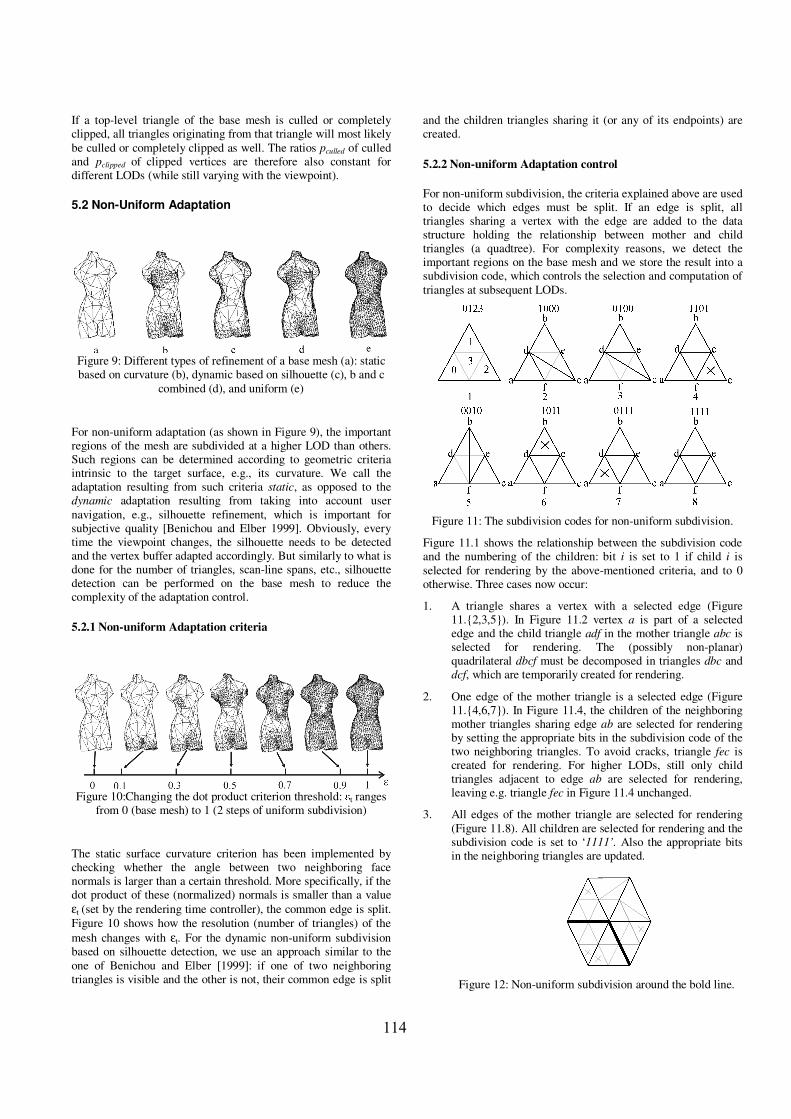
5.2 Non-Uniform Adaptation
Figure 9: Different types of refinement of a base mesh (a): staticbased on curvature (b), dynamic based on silhouette (c), b and c
combined (d), and uniform (e)
For non-uniform adaptation (as shown in Figure 9), the importantregions of the mesh are subdivided at a higher LOD than others.Such regions can be determined according to geometric criteriaintrinsic to the target surface, e.g., its curvature. We call theadaptation resulting from such criteria static, as opposed to thedynamic adaptation resulting from taking into account usernavigation, e.g., silhouette refinement, which is important forsubjective quality [Benichou and Elber 1999]. Obviously, everytime the viewpoint changes, the silhouette needs to be detectedand the vertex buffer adapted accordingly. But similarly to what isdone for the number of triangles, scan-line spans, etc., silhouettedetection can be performed on the base mesh to reduce thecomplexity of the adaptation control.
5.2.1 Non-uniform Adaptation criteria
Figure 10:Changing the dot product criterion threshold: � t rangesfrom 0 (base mesh) to 1 (2 steps of uniform subdivision)
The static surface curvature criterion has been implemented bychecking whether the angle between two neighboring facenormals is larger than a certain threshold. More specifically, if thedot product of these (normalized) normals is smaller than a valueεt (set by the rendering time controller), the common edge is split.Figure 10 shows how the resolution (number of triangles) of themesh changes with εt. For the dynamic non-uniform subdivisionbased on silhouette detection, we use an approach similar to theone of Benichou and Elber [1999]: if one of two neighboringtriangles is visible and the other is not, their common edge is split
and the children triangles sharing it (or any of its endpoints) arecreated.
5.2.2 Non-uniform Adaptation control
For non-uniform subdivision, the criteria explained above are usedto decide which edges must be split. If an edge is split, alltriangles sharing a vertex with the edge are added to the datastructure holding the relationship between mother and childtriangles (a quadtree). For complexity reasons, we detect theimportant regions on the base mesh and we store the result into asubdivision code, which controls the selection and computation oftriangles at subsequent LODs.
Figure 11: The subdivision codes for non-uniform subdivision.
Figure 11.1 shows the relationship between the subdivision codeand the numbering of the children: bit i is set to 1 if child i isselected for rendering by the above-mentioned criteria, and to 0otherwise. Three cases now occur:
1. A triangle shares a vertex with a selected edge (Figure11.{2,3,5}). In Figure 11.2 vertex a is part of a selectededge and the child triangle adf in the mother triangle abc isselected for rendering. The (possibly non-planar)quadrilateral dbcf must be decomposed in triangles dbc anddcf, which are temporarily created for rendering.
2. One edge of the mother triangle is a selected edge (Figure11.{4,6,7}). In Figure 11.4, the children of the neighboringmother triangles sharing edge ab are selected for renderingby setting the appropriate bits in the subdivision code of thetwo neighboring triangles. To avoid cracks, triangle fec iscreated for rendering. For higher LODs, still only childtriangles adjacent to edge ab are selected for rendering,leaving e.g. triangle fec in Figure 11.4 unchanged.
3. All edges of the mother triangle are selected for rendering(Figure 11.8). All children are selected for rendering and thesubdivision code is set to ‘1111’. Also the appropriate bitsin the neighboring triangles are updated.
Figure 12: Non-uniform subdivision around the bold line.
114

Figure 12 shows a small mesh of triangles for which thebold edges are selected to be split. In Figure 12, trianglesand vertices in grey) are added following the guidelines ofFigure 11 and it shows that the resolution is locallyincreased without introducing cracks.
Figure 13: Inheritance of the code
Because further splits happen next to the same base mesh edge,the subdivision code for the children is directly derived from themother’s subdivision code. E.g., if the triangle of Figure 11.6 isfurther subdivided, the edges af and fc as shown in Figure 13 mustbe split, resulting in the same subdivision code 1011 for thetriangles adf and fec. For the child triangle fed, only the childtriangle near vertex f must be created and it derives the code 0010.This procedure can be recursively repeated until the desiredsubdivision level is reached.
Once the subdivision code is derived for the base mesh, we knowexactly which vertices and triangles are needed at all LODswithout checking neighboring triangles. Consequently, thecurvature and silhouette detection can be performed at the basemesh with a low overhead. The subsivision code can then be usedto select vertices and triangles for rendering from a uniformlydecoded WSS mesh, but it can also be used to select the verticesand triangles that need to be computed with non-uniformdecoding. The latter is computationally more expensive, but maybe needed because of limited memory in the mobile device.
5.2.3 Rendering time model
This subsection explains how the parameters of Equation (1)depend on the non-uniform adaptation. For complexity reasons,all these parameters (see Subsection 4.2) were calculated on thebase mesh. Unfortunately, some of them change with the LOD,and therefore good approximations should be determined at thecurrent resolution level.
Figure 14: The effect on the rendering time of varying εt for thebunny mesh.
When dynamic adaptation is enabled, invisible triangles aredetected and not sent to the rendering pipeline, therefore avoidingany culled triangles at all (pCulled=0). The number P of projected
pixels is still more or less the same as for the base mesh.Experimental results show that as long as � t is below a certainvalue � , the parameters of the base mesh can be used and those ofthe uniformly subdivided mesh are taken otherwise (e.g., 0.5 givesgood results for the Venus mesh).
5.2.4 Rendering time control
Figure 15:The number of triangles as a function of εt and the LODfor the Venus mesh.
With a time budget given, Equation (1) must be used to estimatethe number of triangles. Figure 15 shows how a triangle budget istranslated in the WSS decoder parameters. This is used in thefollowing algorithm:
1. Compute base mesh parameters.2. From Equation (1), compute the number of triangles T, using
the base mesh parameters. The number of vertices V is moreor less half the number of triangles because WSS meshes aresemi-regular.
3. Using T and Figure 15, select the decoder parameters εt andLOD. A high LOD and low εt gives a lot of detail at the veryimportant (very local) regions, while a high εt takes moreregions into account, but with less detail. Multiple solutionsare possible, but experimental results show that the one withthe highest εt gives the best quality.
4. With these decoder parameters, the number of spans can beestimated. Go to step 2 using the new number of spans.
We do not take the overhead time into account in our performancemodel. We have made this choice because taking it into accountgives a larger overhead complexity, further reducing the renderingtime on our mobile (the time budget is divided between overheadand rendering). For example, for estimating the time needed todecode extra triangles, the subdivision code is needed, forcing thecomputation of this code in multiple iterations. Moreover, withstatic non-uniform subdivision, the largest part of the overhead isoccurring only when the mesh is really adapted, i.e. when theperformance model computes a significant change of the decoderparameters. This results in a framerate, which is some fps lowerthan the estimated one in the frames with active adaptation.
With dynamic non-uniform adaptation, the situation is morecomplex because the viewpoint is an extra decoder parameter,which forces a redistribution of the triangles every time theviewpoint changes. With view-dependent adaptation, one candetect the back facing triangles and exclude them from rendering,which increases the performance. On the other hand, performancedecreases, because silhouette preservation increases the number oftriangles at the silhouette.
Figure 16 shows two situations in which the performanceincreases (a) or decreases (b) by using dynamic view-dependent
115

adaptation. In Figure 16.a, a lot of back facing triangles areeliminated while a small number is added, while in Figure 16.b,the situation is reversed as shown in Table 1 (the depicted timesinclude the extra overhead).
Figure 16: Pros (a) and cons (b) of dynamic adaptation
Non-uniform time(% of uniform time)
LODFigure 16.a Figure 16.b
1 87 135
2 75 172
3 42 142
Table 1: Pros and cons of dynamic adaptation.
In our current framework, view-dependent adaptation is disabledwhen it decreases the performance. Future research is needed tobetter exploit the possibilities of view-dependent adaptation.
6. Conclusion
We have presented an adaptation framework, which allows fine-grained control of the time needed to decode and rendermultiresolution 3D surfaces through adaptive wavelet subdivision.This allows high quality 3D content, which is originally designedfor high performance terminals, to be accessed and adapted to themobile device’s processing capabilities.
To control this adaptation, we have derived an analytical modelfor the rendering times of the Mesa-3D and PocketGL pipelines.A good trade-off between estimation overhead and accuracy hasbeen found: parameters from the base mesh are extrapolated to thehigher resolution meshes for accurate execution time estimation.
To further enhance the subjective quality of the rendered objects,a non-uniform subdivision of the base mesh is performed. Thusreduces the triangle cost but preserves: (i) intrinsic shapeproperties of the 3D objects, e.g., creases and curvatures, and (ii)dynamic shape properties e.g. silhouette.
To limit the overhead of non-uniform subdivision control, wehave developed a control based on a subdivision code, whichallows the detection of important regions on the base mesh anddrives their selective refinement to obtain the higher resolutionmeshes.
With all aforementioned trade-offs, a high rendering quality isobtained with a control overhead limited to 10%, while thedifference between the workload model estimations and themeasured execution times is also below 10%.
The Mesa-3D pipeline gives a very high flexibility but because ofits high complexity, the rendering time is only acceptable for low-resolution objects without texture rendering. Therefore, rendererssuch as PocketGL optimize the pipeline by implementing acomplete fixed-point pipeline and by introducing a lot ofconstraints. This illustrates the need for hardware accelerated 3Don mobile terminals and it initiates a topic of future research:validating and updating the workload model and control forupcoming 3D graphics hardware accelerated mobile terminals.
7. Acknowledgement
Part of this work was funded by the IWT (Instituut voor deaanmoediging van Innovatie door Wetenschap en Technologie inVlaanderen) and the European Project OZONE (IST-2000-30026).
References
AKENINE-MÖLLER., STRÖM, J.,2003. Graphics for the masses: AHardware Rasterization Architecture for Mobile Phones, Inproceedings of ACM SIGGRAPH 2003,ACM press/ACMSIGGRAPH
BENICHOU, F, AND ELBER, G.,1999, Output Sensitive Extraction ofSilhouettes from Polygonal Geometry, in The Seventh PacificConference on Computer Graphics and Applications.
BROWNE, S., DEANE, C., HO, G., MUCCI, P., 1999, PAPI: APortable Interface to Hardware Performance Counters,Proceedings of Department of Defense HPCMP Users GroupConference
FUNKHOUSER, A. T., SEQUIN, C. H., 1993. Adaptive DisplayAlgorithm for Interactive Frame Rates During Visualizationof Complex Virtual Environments., In proceedings of ACMSIGGRAPH 1993., 247-254.
GOBBETI, E., AND BOUVIER, E, 1999. Time-CriticalMultiresolution Scene Rendering., In proceedings of IEEEVisualization 1999., 123-130.
LAFRUIT, G., NACHTERGAELE, L., DENOLF K., AND BORMANS J.2000. 3D Computational Graceful Degradation. InProceedings of ISCAS - Workshop and Exhibition on MPEG-4, III-547 - III-550.
LEROY, P., PocketGl, www.sundialsoft.freeserve.co.uk/
KHODAKOVSKY, A, SHRÖDER, P., SWELDENS, W., 2000,Progressive Geometry Compression, In Proceedings of ACMSIGGRAPH, pp. 271-278.
PAUL, B., Mesa-3D, www.mesa3D.org
MORÁN, F., 2001, Hierarchical Modelling of 3D Objects withSubdivision Surfaces, PhD thesis, Technical University ofMadrid.
PHAM NGOC, N., VAN RAEMDONCK, W., LAFRUIT, G. DECONINCK,G. AND LAUWEREINS R," A QoS Framework for Interactive 3DApplications ," The 10-th International Conference onComputer Graphics and Visualization'2002, WSCG'2002 , pp.317-324 , Feb. 2002
VAN RAEMDONCK, W., LAFRUIT, G. STEFFENS, E.F.M, OTERO
PÉREZ, C.M., BRIL, R.J." Scalable 3D Graphics Processing inConsumer Terminals," ICME, 2002
116

WOO, R. CHOI, S. SOHN, J.H. SONG, S.J,. BAE, Y.D, YOON, C.WNAM, B.G. WOO, J.H KIM, S.E. PARK, I.C SHIN, S. YOO, K.D.CHUNG, J.Y. AND YOO, H.J. A 210mW Graphics LSIImplementation Full 3D Pipeline with 264Mtexels/s Texturingfor Mobile Multimedia Applications. In proceedings of ISSCC2003, 2003, pp 44-45.
POWERVR, www.powervr.com
STEVENS, A., ARM 3D Graphics Solutions White Paper, availableat: www.arm.com
SWERVE3D, www.swerve3D.com
WIMMER, M., WONKA, P. 2003. Rendering time estimation forReal-Time Rendering, In proceedings of the EurographicsSymposium on Rendering, pages 118-129. June 2003
117

118