
3D Breast Shape Reconstruction for a Non-Invasive Early Cancer Diagnosis System
14
Breast Shape Reconstruction for a Non-Invasive Early Cancer Diagnosis System MihaelaCostin*, AncaIgnat**, Octavian Baltag***, SilviuBejinariu*, CiprianaŞtefănescu***, Florin Rotaru*, DoinaCostandache*** *Computer Science Institute, Romanian Academy (IIT) Iaşi, **Informatics Faculty, AlexandruIoanCuzaUniversity (UAIC) Iaşi, ***University of Medicine and Pharmacy, ”Gr. T. Popa”(UMF) Iaşi 8/21/2007 IEEE - SOFA International Workshop on Soft Computing Applications 1 Abstract • Early breast cancer diagnosis is a stringent necessity, as osteophyl neoplasia is the most frequent cancer in the world. • Agressions affecting women’s breasts health: the environment, the increasing endocrine modifications, stress or fashion, the iatrogen aggression, affects women’s breasts health. • Long term negative influence may also appear due to invasive cancer investigation techniques. • Alternative methods are continuously researched. • Stage in the implementation of a non-invasive microwaves technique under research, meant to early uncover the developing malignant processes, we designed a 3D breast shape reconstruction process – compulsory step previous to the tumor volumetric shape reconstruction, to apply in breast surgery. 8/21/2007 IEEE - SOFA International Workshop on Soft Computing Applications 2 Breast Cancer Statistics • The most prevalent cancer in the world is breast cancer (4.4 million survivors up to 5 years following diagnosis) www.cancer.org • In Romania, in 2002, there were declared 1,696 breast cancer death cases with mortality of 16%. • In Hungary there were declared 2,239 with a mortality of 15.9%. • In 2002, the “first“countries on this aspect were Denmark (1,306) with 26.4%, Netherlands (3,461), with 25.3% and United Kingdom (14,114) with 25.1% mortality. • United States were marked with 43,644 and 20.3% mortality on the new arisen cases in 2002. • Therefore, there is still much to do in this domain. 8/21/2007 IEEE - SOFA International Workshop on Soft Computing Applications 3 3 D Body Positioning and Data Collection • The research on 3D reconstruction is one of the most interesting topics in computer vision and computer graphics. • When using a non-invasive cancer diagnosis technique, the resulting microwave map or thermograph registrations, are better interpreted if they are spatially situated in well measurable space inside the virtual generated 3D breast shape. • In order to accurately reproduce and further measure, therapeutically purposed, the 3D shape of the breast malignant areas, it is important to have very precise initial coordinates. 8/21/2007 IEEE - SOFA International Workshop on Soft Computing Applications 4
-
Upload
independent -
Category
Documents
-
view
0 -
download
0
Transcript of 3D Breast Shape Reconstruction for a Non-Invasive Early Cancer Diagnosis System

Breast Shape Reconstruction
for a Non-Invasive Early
Cancer Diagnosis System
Mihaela Costin*, Anca Ignat**, Octavian Baltag***,
Silviu Bejinariu*, Cipriana Ştefănescu***, Florin Rotaru*, Doina Costandache***
*Computer Science Institute, Romanian Academy (IIT) Iaşi,
**Informatics Faculty, Alexandru Ioan Cuza University (UAIC) Iaşi,
***University of Medicine and Pharmacy, ”Gr. T. Popa” (UMF) Iaşi
8/21/2007 IEEE - SOFA International Workshop on Soft Computing Applications
1
Abstract• Early breast cancer diagnosis is a stringent necessity, as osteophyl
neoplasia is the most frequent cancer in the world.
• Agressions affecting women’s breasts health: the environment, the increasing endocrine modifications, stress or fashion, the iatrogenaggression, affects women’s breasts health.
• Long term negative influence may also appear due to
invasive cancer investigation techniques.
• Alternative methods are continuously researched.
• Stage in the implementation of a non-invasive microwaves techniqueunder research, meant to early uncover the developing malignant processes, we designed a 3D breast shape reconstruction process –compulsory step previous to the tumor volumetric shape reconstruction, to apply in breast surgery.
8/21/2007 IEEE - SOFA International Workshop on Soft Computing Applications
2
Breast Cancer Statistics• The most prevalent cancer in the world is breast cancer (4.4
million survivors up to 5 years following diagnosis) www.cancer.org
• In Romania, in 2002, there were declared 1,696 breast cancer death cases with mortality of 16%.
• In Hungary there were declared 2,239 with a mortality of 15.9%.
• In 2002, the “first“ countries on this aspect were Denmark (1,306) with 26.4%, Netherlands (3,461), with 25.3% and United Kingdom (14,114) with 25.1% mortality.
• United States were marked with 43,644 and 20.3% mortality on the new arisen cases in 2002.
• Therefore, there is still much to do in this domain.
8/21/2007 IEEE - SOFA International Workshop on Soft Computing Applications
3
3 D Body Positioning and Data Collection
• The research on 3D reconstruction is one of the most interesting topics in computer vision and computer graphics.
• When using a non-invasive cancer diagnosis technique, the resulting microwave map or thermograph registrations, are better interpreted if they are spatially situated in well measurable space inside the virtual generated 3D breast shape.
• In order to accurately reproduce and further measure, therapeutically purposed, the 3D shape of the breast malignant areas, it is important to have very precise initial coordinates.
8/21/2007 IEEE - SOFA International Workshop on Soft Computing Applications
4
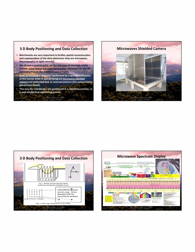
3 D Body Positioning and Data Collection
• Benchmarks are very important in further spatial reconstruction
and superposition of the data (wherever they are microwave,
thermography or optic records).
• We choose a central point, on the sternum, as an origin of the
system, using lateral left/right extremities references for the 3D
reconstruction of the studied breast volume.
• Body positioning is “a priory” performed by a spatial localization
of the human body in special designed microwave-shielded
camera and dedicated bed, in reversed posture (the patient being
placed face down).
• This way the coordinates are positioned in a repetitive manner, in
a well-established registering system.
8/21/2007 IEEE - SOFA International Workshop on Soft Computing Applications
5
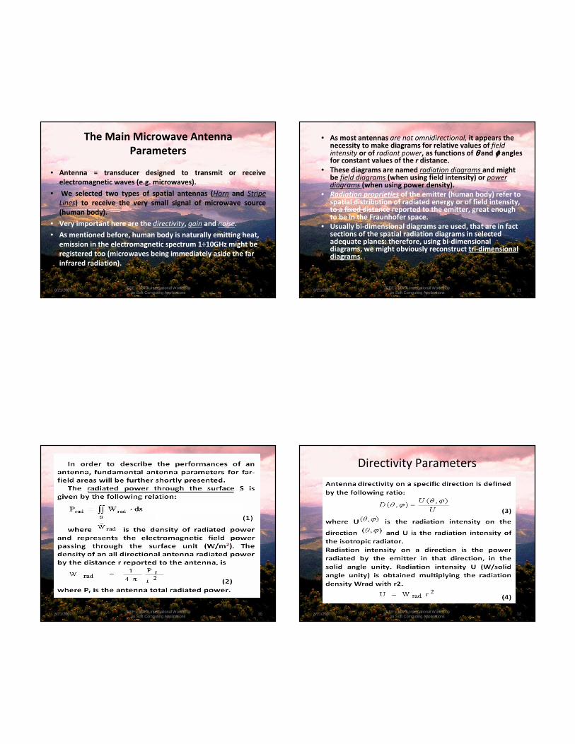
3 D Body Positioning and Data Collection
8/21/2007 IEEE - SOFA International Workshop on Soft Computing Applications
6
Microwaves Shielded Camera
8/21/2007 IEEE - SOFA International Workshop on Soft Computing Applications
7
Microwave Spectrum Display
8/21/2007 IEEE - SOFA International Workshop on Soft Computing Applications
8
The Main Microwave Antenna
Parameters
• Antenna = transducer designed to transmit or receive
electromagnetic waves (e.g. microwaves).
• We selected two types of spatial antennas (Horn and Stripe
Lines) to receive the very small signal of microwave source
(human body).
• Very important here are the directivity, gain and noise.
• As mentioned before, human body is naturally emitting heat,
emission in the electromagnetic spectrum 1÷10GHz might be
registered too (microwaves being immediately aside the far
infrared radiation).
8/21/2007 IEEE - SOFA International Workshop on Soft Computing Applications
9
8/21/2007 IEEE - SOFA International Workshop on Soft Computing Applications
10
• As most antennas are not omnidirectional, it appears the necessity to make diagrams for relative values of field intensity or of radiant power, as functions of θθθθ and ϕϕϕϕ angles for constant values of the r distance.
• These diagrams are named radiation diagrams and might be field diagrams (when using field intensity) or power diagrams (when using power density).
• Radiation proprieties of the emitter (human body) refer to spatial distribution of radiated energy or of field intensity, to a fixed distance reported to the emitter, great enough to be in the Fraunhofer space.
• Usually bi-dimensional diagrams are used, that are in fact sections of the spatial radiation diagrams in selected adequate planes: therefore, using bi-dimensional diagrams, we might obviously reconstruct tri-dimensional diagrams.
8/21/2007 IEEE - SOFA International Workshop on Soft Computing Applications
11
Directivity Parameters
8/21/2007 IEEE - SOFA International Workshop on Soft Computing Applications
12

8/21/2007 IEEE - SOFA International Workshop on Soft Computing Applications
13
.
• Directivity represents the ability of an antenna to radiate
more power in certain directions and less power in other
directions, compared to an omnidirectional antenna.
• When the direction (θ,ϕ) is not specified, by the directivity
of an antenna we understand its maximum directivity.
• In the case of some antennas with orthogonal polarizing
components we can define two partial directivities, one for
each polarization: partial directivity of an antenna, for a given
polarity and for a given direction, is the rate between that
radiation intensity and the total radiation intensity (for all
the directions and for both polarities).
8/21/2007 IEEE - SOFA International Workshop on Soft Computing Applications
14
.
8/21/2007 IEEE - SOFA International Workshop on Soft Computing Applications
15
.
• Due to the circuit losses and due to the reflected power, the
effective radiated power is less than the initial one (than the
power in the entering port).
• From this reason the parameter G(θθθθ,ϕϕϕϕ), antenna gain, was
introduced.
• The antenna gain is defined as the ratio between the
radiation intensity on a given direction, and the total power
applied on a reference antenna entrance, supposed to be
isotropic.
• The gain is a parameter that describes better the
performances of an antenna, taking into account factors
that characterize the antennas efficiency not only directivity
properties.
8/21/2007 IEEE - SOFA International Workshop on Soft Computing Applications
16
.
8/21/2007 IEEE - SOFA International Workshop on Soft Computing Applications
17
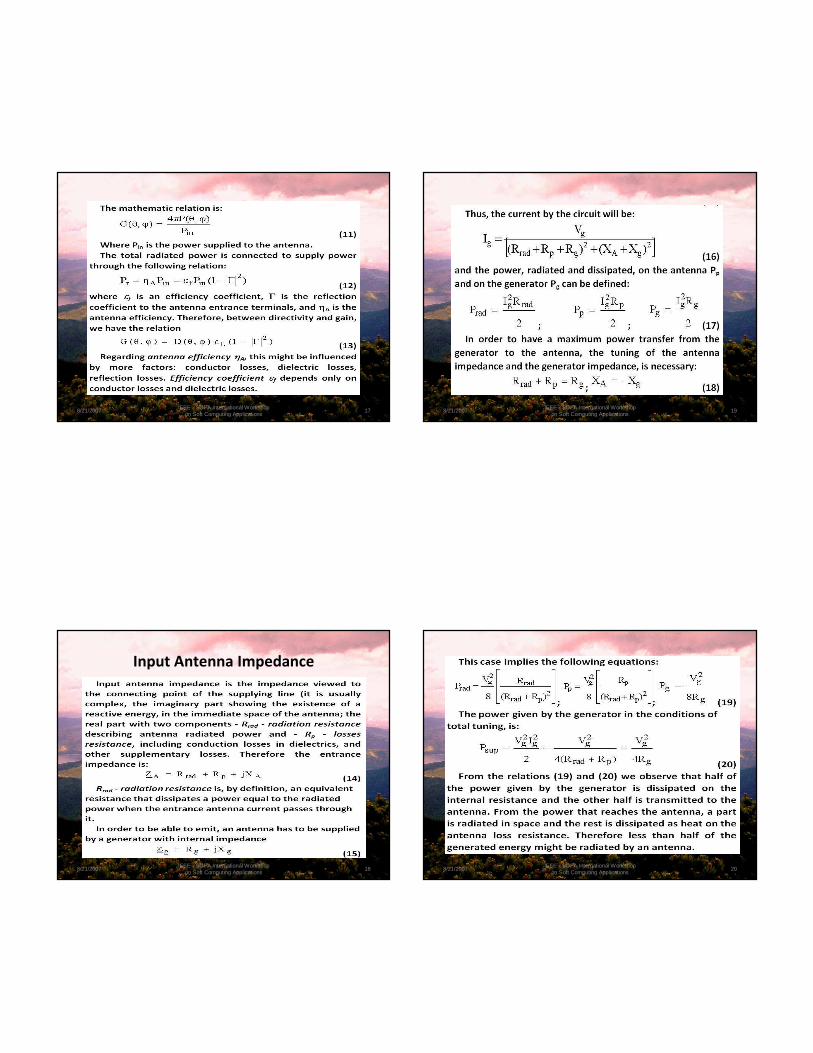
Input Antenna Impedance
8/21/2007 IEEE - SOFA International Workshop on Soft Computing Applications
18
.
8/21/2007 IEEE - SOFA International Workshop on Soft Computing Applications
19
.
8/21/2007 IEEE - SOFA International Workshop on Soft Computing Applications
20

.
8/21/2007 IEEE - SOFA International Workshop on Soft Computing Applications
21
.
8/21/2007 IEEE - SOFA International Workshop on Soft Computing Applications
22
3D Model Reconstruction
• The outer surface of an object in 3D space (e.g. human body,
breast shape), may be represented by a finite number of
manifold polygons (usually by a set of triangles).
• Each polygon is a representation of a surface patch on the
real object's outer surfaces.
• The goal of 3D reconstruction is to obtain the complete
representation of the objects using manifold polygons.
• A 3D surface model of a real object may be reconstructed by
either passive or active techniques.
8/21/2007 IEEE - SOFA International Workshop on Soft Computing Applications
23
.
• The active technique uses a projected spot light which scans
over the object of interest.
• The passive technique means that a vision system works only
on naturally occurring images produced by reflected light from
the scene or object. Depth from stereo and depth from motion
are two most obvious examples.
8/21/2007 IEEE - SOFA International Workshop on Soft Computing Applications
24
Range Image
• Range image is a 2D depth image of a scene of interest, which is obtained from a single view direction of a range sensor.
• It represents the geometric 3D structure of the scene from the given viewpoint.
• Most range sensors produce the range image of a scene in terms of a 2D image, where its intensity is the measure of depth from the sensor to the scene.
• Therefore, strictly speaking, range image is a 2.5 D image rather than a 3 D image.
• If we obtain a range image of the object from a single viewpoint, it is only a partial surface of the object's whole structure.
• Recently, there have been many investigations on complete 3D reconstruction which produces full 3D structures and shapes of the object.
8/21/2007 IEEE - SOFA International Workshop on Soft Computing Applications
25
.
• The central technique of complete 3D reconstruction, is
merging multi-view range images into a single and closed 3D
model.
• Multi-view range images are obtained from multiple
viewpoints in order to collect geometric structures of all
visible surfaces of the object.
• Range images obtained from multiple views of the object
must be brought into a common coordinate system so that
their geometrical and photometrical structures are aligned.
This requires determining rigid transformations from the all
multiple view points to the common coordinate system.
• Two methods for 3D reconstruction are further presented.
8/21/2007 IEEE - SOFA International Workshop on Soft Computing Applications
26
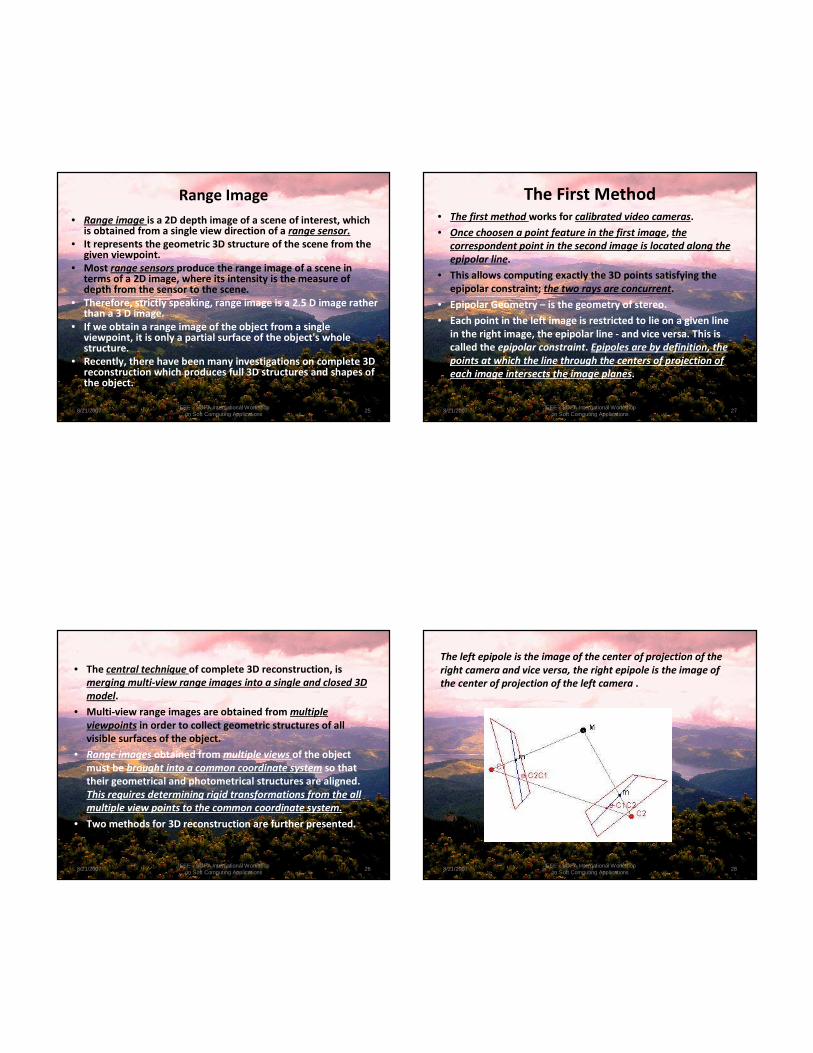
The First Method• The first method works for calibrated video cameras.
• Once choosen a point feature in the first image, the
correspondent point in the second image is located along the
epipolar line.
• This allows computing exactly the 3D points satisfying the
epipolar constraint; the two rays are concurrent.
• Epipolar Geometry – is the geometry of stereo.
• Each point in the left image is restricted to lie on a given line
in the right image, the epipolar line - and vice versa. This is
called the epipolar constraint. Epipoles are by definition, the
points at which the line through the centers of projection of
each image intersects the image planes.
8/21/2007 IEEE - SOFA International Workshop on Soft Computing Applications
27
The left epipole is the image of the center of projection of the
right camera and vice versa, the right epipole is the image of
the center of projection of the left camera .
8/21/2007 IEEE - SOFA International Workshop on Soft Computing Applications
28
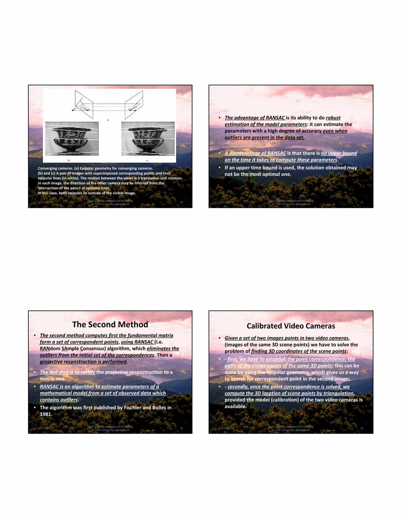
Converging cameras. (a) Epipolar geometry for converging cameras.
(b) and (c) A pair of images with superimposed corresponding points and their
epipolar lines (in white). The motion between the views is a translation and rotation.
In each image, the direction of the other camera may be inferred from the
intersection of the pencil of epipolar lines.
In this case, both epipoles lie outside of the visible image.
8/21/2007 IEEE - SOFA International Workshop on Soft Computing Applications
29
The Second Method• The second method computes first the fundamental matrix
form a set of correspondent points, using RANSAC (i.e.
RANdom SAmple Consensus) algorithm, which eliminates the
outliers from the initial set of the correspondences. Then a
projective reconstruction is performed.
• The last step is to rectify the projective reconstruction to a
metric one.
• RANSAC is an algorithm to estimate parameters of a
mathematical model from a set of observed data which
contains outliers.
• The algorithm was first published by Fischler and Bolles in
1981.
8/21/2007 IEEE - SOFA International Workshop on Soft Computing Applications
30
.
• The advantage of RANSAC is its ability to do robust
estimation of the model parameters: it can estimate the
parameters with a high degree of accuracy even when
outliers are present in the data set.
• A disadvantage of RANSAC is that there is no upper bound
on the time it takes to compute these parameters.
• If an upper time bound is used, the solution obtained may
not be the most optimal one.
8/21/2007 IEEE - SOFA International Workshop on Soft Computing Applications
31
Calibrated Video Cameras
• Given a set of two images points in two video cameras,
(images of the same 3D scene points) we have to solve the
problem of finding 3D coordinates of the scene points:
• - first, we have to establish the point correspondence, the
pairs of the image points of the same 3D points; this can be
done by using the epipolar geometry, which gives us a way
to search for correspondent point in the second image;
• - secondly, once the point correspondence is solved, we
compute the 3D location of scene points by triangulation,
provided the model (calibration) of the two video cameras is
available.
8/21/2007 IEEE - SOFA International Workshop on Soft Computing Applications
32
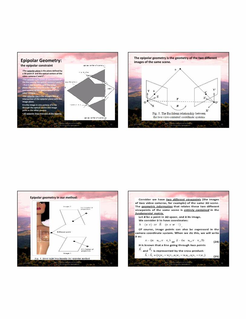
Epipolar Geometry: the epipolar constraint
•The epipolar plane is the plane defined by
a 3D point B and the optical centers of the
video cameras C and C’.
•The epipole is the point of intersection of
the line joining the optical centers C and C’
- that is the baseline, with the image
plane. Thus the epipole is the image, in
one camera, of the optical centre of the
other camera.
•The epipolar line is the straight line of
intersection of the epipolar plane with the
image plane.
It is the image in one camera of a ray
through the optical centre and image
point in the other camera.
• All epipolar lines intersect at the epipole.
8/21/2007 IEEE - SOFA International Workshop on Soft Computing Applications
33
Epipolar geometry in our method:
8/21/2007 IEEE - SOFA International Workshop on Soft Computing Applications
34
The epipolar geometry is the geometry of the two different
images of the same scene.
8/21/2007 IEEE - SOFA International Workshop on Soft Computing Applications
35
.
8/21/2007 IEEE - SOFA International Workshop on Soft Computing Applications
36

.
• We shall study the geometric properties of the set of two views
obtained from two video cameras using the main new geometric
property known in computer vision as the epipolar constraint. There
are two ways of extracting the “real” structure from a pair of
images.
• In the first case, we assume that the two video cameras are
calibrated with respect to some known coordinate system. To
retrieve the three-dimensional Euclidean structure from the two
images we compute the essential matrix of the system.
• The second case corresponds to the way in which biological systems
determine three-dimensional structure from vision, the two video
cameras are un-calibrated. In this situation, the fundamental matrix
is calculated from image correspondences, and then, this is used to
determine the projective three-dimensional structure of the imaged
scene.
8/21/2007 IEEE - SOFA International Workshop on Soft Computing Applications
37
.
8/21/2007 IEEE - SOFA International Workshop on Soft Computing Applications
38
.
• The matrix E is a 3x3 matrix but it only depends on five
parameters.
• The solution T=0 is obvious, but it offers no information
about the 3D scene, for this reason, it is usually excluded.
• In the uncalibrated case, we don't know the rotation matrix
R and the translation vector T; all we have are image
coordinates in the image plane.
• Nevertheless, the correspondence between an image point
b and its epipolar line lb is very simple; in fact it is linear in
projective coordinates, as we can see by the following
analysis.
8/21/2007 IEEE - SOFA International Workshop on Soft Computing Applications
39
.
8/21/2007 IEEE - SOFA International Workshop on Soft Computing Applications
40
.
8/21/2007 IEEE - SOFA International Workshop on Soft Computing Applications
41
.
8/21/2007 IEEE - SOFA International Workshop on Soft Computing Applications
42
.
8/21/2007 IEEE - SOFA International Workshop on Soft Computing Applications
43
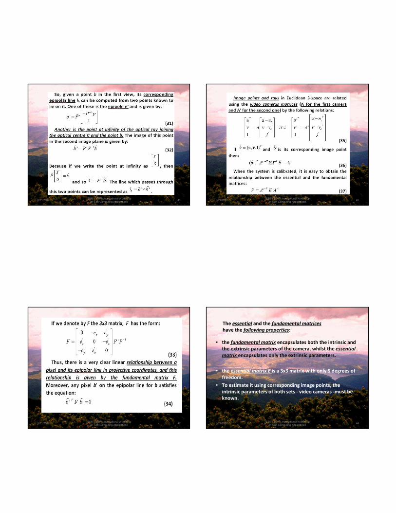
The essential and the fundamental matrices
have the following properties:
• the fundamental matrix encapsulates both the intrinsic and
the extrinsic parameters of the camera, whilst the essential
matrix encapsulates only the extrinsic parameters.
• the essential matrix E is a 3x3 matrix with only 5 degrees of
freedom.
• To estimate it using corresponding image points, the
intrinsic parameters of both sets - video cameras -must be
known.
8/21/2007 IEEE - SOFA International Workshop on Soft Computing Applications
44

8/21/2007 IEEE - SOFA International Workshop on Soft Computing Applications
45
Conclusion
• The algorithms based on epipolar reconstruction constitute in
our approach the fundamental software tools for further
spatial matching the microwave emitting loci of the normal
and malignant tissue.
• We situate the body microwaves emission detected with the
radiometer, inside the 3D breast shape, generated on
computer in the most exactly possible way.
• The 3D model correctness can be improved by using multiple
range images. For simulation applications, sequences of
frames from a stereo video camera system are employed, to
analyze the model shape evolution, in a simulation
environment.
8/21/2007 IEEE - SOFA International Workshop on Soft Computing Applications
46
The precision of 3D reconstruction depends on the accuracy of the
input images and positioning of the two video cameras, being
related to the real complexity of the model.
Acknowledgements:
The research is part of a CEEX National Excellence Research Project
CANCERDET, coordinated by the University of Medicine and Pharmacy,
Bioengineering Faculty, Iasi, Principal Coordinator Professor Octavian
Baltag.
8/21/2007 IEEE - SOFA International Workshop on Soft Computing Applications
47
References
• http://www.caonline.amcancersoc.org/cgi/
• Web Cancer Organizations http://www.cancer.org/
• Box BA, Russel CA.- Breast Cancer, Casciato D, Lowitz BB (ed): Manual of Clincal
Oncology. 5th edition. Lippincott-Williams& Wilkins, Philadelphia, pp. 233-253,
2004.
• American National Standards Institute: Safety level of electromagnetic radiation
with respect to persone C95.1-1991, The IEEE NY, 1991.
• R. Tipa, O. Baltag, Microwave Thermography for Cancer Detection, Romanian
Journal of Physics, Publishing House of the Romanian Academy, Vol. 51, Nos. 3-4,
p. 371–377, Bucharest, 2006.
• O. Baltag, R. S. Tipa, Microwaves Biomedical Applications, Experiments and
Fundamental Proprieties, Ed. Performantica, 2004.
• M. Costin, C. Ştefănescu, Medical Imaging Processing in Scintimetry, pp. 90-103,
Tehnopress Ed., 2006.
• N. Balanis „Antenna Theory: Analysis and Design”, sec. edition, John
Wiley&Sons, N.Y., 1997.
8/21/2007 IEEE - SOFA International Workshop on Soft Computing Applications
48

• S. Silver „Microwave Antenna Theory and Design” MIT Radiation Laboratory
Series, Vol. 12, McGraw-Hill, N.Y., pg. 349-376, 1949.
• http://www.scienceworld.wolfram.com/physics/FraunhoferDiffraction.html
• R. Hartley, A. Zisserman. Multiple View Geometry in Computer Vision.
Cambridge University Press, Second Edition,.2004.
• E. Trucco, A. Verri, Introductory Techniques for 3D Computer Vision, Prentice
Hall, 1998.
• Y. Ma, S. Soatto, J. Kosecka, S. S. Sastry. An Invitation to 3-D Vision. From Images
to Geometric Models, Springer, 2004.
• O. Faugeras, Q. T. Luong. Geometry of Multiple Images, MIT, 2001.
• G. Xu and Z. Zhang. Epipolar Geometry in Stereo, Motion and Object Recognition,
Kluwer Academic Publishers, 1996.
• R. Hartley, P.Sturm, Triangulation, Computer Vision and Image Understanding,
pp.146-157, November 1997.
• F. Rotaru, D. Galea, S. Bejinariu, I. Pavaloi, A. Ciobanu, Advances in Intelligent
Systems and Technologies, 4th European Conf. on Intelligent Systems and
Technologies, Iasi, Romania, Proc. ECIT 2006.
8/21/2007 IEEE - SOFA International Workshop on Soft Computing Applications
49
And now…an unusual thing…
… A word about the slides background
The view upon Modavia from
TOACA – CEAHLAU MOUNTAIN,
• the highest point in the Eastern CarpatianMountains
Why?
• Because the battle against cancer is a
struggle
as a difficult mountain climbing
and we always HAVE TO finish
CONQUERING it by all means …
… having a beautiful new view upon
LIFE
… AND DISIPATING ALL THE
UNCERTAINTY CLOUDS…

• THANK YOU !THANK YOU !THANK YOU !THANK YOU !