20100910.pdf - Bhabha Atomic Research Centre
90
-
Upload
khangminh22 -
Category
Documents
-
view
1 -
download
0
Transcript of 20100910.pdf - Bhabha Atomic Research Centre


ISSUE NO. 316 • SEP. - OCT. 2010
BARC NEWSLETTERBARC NEWSLETTER
1 Innovative Process Flowsheet for the recovery of Uranium from
Tummalapalle Ore
A.K. Suri
2 Simultaneous measurement of particle velocity and shock
velocity for megabar laser driven shock studies
S. Chaurasia et al
3 U-Ti alloy as a promising storage material for hydrogen isotopes
S.C. Parida et al
4 Shelf life extension of Litchi and overcoming quarantine barriers for
international trade using Radiation Technology
S. Gautam et al
5 Development of a Novel Spent Fuel Chopper for PHWR Fuel
S. Karunakaran et al
IN THE FORTHCOMING ISSUE
1ISSUE NO. 316 • SEP. - OCT. 2010
BA
RC
C
ELEB
RA
TES
FO
UN
DER
’S D
AY
√÷”√£÷÷Ø÷ç˙ ◊§¸æ÷√÷ - 2010õ¸÷Ú. ¡÷flç„ ¥÷÷∏¸ ≤÷Ú≠÷ï÷·Ü¨μ÷Å÷, Ø÷∏¸¥÷÷ù÷„ â˙ï÷÷‘ Ü÷μ÷÷Íê÷ ãæ÷”√÷◊ì÷æ÷, ≥÷÷∏¸ü÷ √÷∏¸ç˙÷∏¸, Ø÷∏¸¥÷÷ù÷„ â˙ï÷÷‘ ◊æ÷≥÷÷ê÷ ç˙÷ √÷”≤÷÷Í ÷≠÷
“◊Ø÷œμ÷ √÷÷◊£÷μ÷÷Î,
ÜØ÷≠÷Í Ø÷∏¸¥÷◊Ø÷œμ÷ √÷”√£÷÷Ø÷ç˙ õ¸÷Ú. Δ¸÷Í¥÷fl ï÷Δ¸÷”ê÷fl∏¸ ≥÷÷≥÷÷ çÍ 101æ÷Îï÷≠¥÷-◊§¸æ÷√÷ çÍ Üæ÷√÷∏¸ Ø÷∏¸ ¥÷Ô Ü÷Ø÷ √÷≤÷ç˙÷Í ø÷„≥÷ç˙÷¥÷≠÷÷ã” ü÷£÷÷≤÷¨÷÷á‘ §Íü÷÷ ΔÊ—Ö ï÷Ó√÷fl◊ç˙ Ø÷∏¸¥Ø÷∏¸÷ ΔÓ, á√÷ ◊§¸≠÷ Δ¸¥÷ ≤÷flü÷Í Δ„ã æ÷¬÷‘ ç˙flàØ÷ª÷¤≤¨÷μ÷÷Î ç˙÷ Üæ÷ª÷÷Íç˙≠÷ ç˙∏¸ü÷Í ΔÔ Ü÷Ó∏¸ ÜØ÷≠÷Í ç˙÷μ÷‘ç˙ª÷÷Ø÷÷Î çÍ◊æ÷◊≥÷Æ÷ Ø÷Δ¸ª÷„Ü÷Î çÍ ¥÷÷¨μ÷¥÷ √÷Í ∏¸÷¬ô“ ç˙÷Í ¥÷ï÷≤÷Êü÷fl Ø÷œ§¸÷≠÷ ç˙∏¸≠÷Í
ΔÍü÷„ ÜØ÷≠÷Í Ü÷Ø÷ ç˙÷Í Ø÷„≠÷:√÷¥÷ŸØ÷ü÷ ç˙∏¸ü÷Í ΔÔÖ ◊Ø÷î˚ª÷÷ √÷÷ª÷ æμ÷÷Ø÷ç˙Å÷Í°÷ ¥÷Î ¥÷Δ¸üæ÷Ø÷Êù÷‘ àØ÷ª÷¤≤¨÷μ÷÷Î, ç˙÷μ÷‘çŒ ¥÷÷Î ¥÷Î Ø÷œ≥÷÷æ÷ø÷÷ª÷fl Ø÷œê÷◊ü÷æ÷÷ª÷÷ √÷÷ª÷ ∏¸Δ¸÷ ΔÓ ◊ï÷√÷¥÷Î Ü≠÷Íç˙ ≤÷õÕfl Ø÷Δ¸ª÷Î ç˙fl ê÷á’Ö ¥÷Ô Üê÷ª÷Íç„ î˚ ◊¥÷≠÷ô¸÷Î ¥÷Î á≠÷ àØ÷ª÷¤≤¨÷μ÷÷Î ç˙÷ ãç˙ √÷”◊Å÷Øü÷ ◊æ÷æ÷∏¸ù÷ Ø÷œ√ü÷„ü÷ç˙∏¸≠÷÷ ì÷÷Δ¸ü÷÷ ΔÊ—Ö
ï÷≤÷ Δ¸¥÷ ◊Ø÷î˚ª÷Í æ÷¬÷‘ ◊¥÷ª÷Í £÷Í ü÷≤÷ √÷Í, §¸÷Í ≠÷ã ≠÷÷◊≥÷ç˙flμ÷ ◊æ÷™„ü÷◊∏¸ãåô¸∏¸÷Πܣ÷÷‘ü÷À ∏¸÷ï÷√£÷÷≠÷ Ø÷∏¸¥÷÷ù÷„ ◊æ÷™„ü÷ Ø÷◊∏¸μ÷÷Íï÷≠÷÷-áç˙÷á‘ 5ü÷£÷÷ 6 ç˙÷ ◊≠÷¥÷÷‘ù÷ Ø÷Ê∏¸÷ ◊ç˙μ÷÷ ê÷μ÷÷ Ü÷Ó∏¸ à≠÷ç˙÷ æ÷÷◊ù÷¤ïμ÷ç˙Ø÷œì÷÷÷ª÷≠÷ Ø÷œ÷∏”≥÷ Δ„Ü÷Ö á√÷çÍ √÷÷£÷ Δ¸fl §Íø÷ ¥÷Î Ø÷œì÷÷÷ª÷≠÷∏¸ü÷ Ø÷∏¸¥÷÷ù÷„◊æ÷™„ü÷ ◊∏¸ãåô¸∏¸÷Î ç˙fl ç„ ª÷ √÷”èμ÷÷ 19 Δ¸÷Í ê÷á‘ ΔÓ ◊ï÷≠÷ç˙fl ç„ ª÷√£÷÷◊Ø÷ü÷ Å÷¥÷ü÷÷ 4560 ¥÷Íê÷÷æ÷÷ô¸-á‘ ΔÓÖ ±˙flõ¸∏¸÷Î ç˙÷Í ãç˙ √÷÷£÷≤÷§¸ª÷≠÷Í çÍ ≤÷÷§¸ ∏¸÷ï÷√£÷÷≠÷ Ø÷∏¸¥÷÷ù÷„ ◊≤÷ï÷ª÷flë÷∏¸ ç˙fl áç˙÷á‘ 2 ç˙÷Í◊ê÷œõ¸ çÍ √÷÷£÷ ◊±˙∏¸ √÷Í ÿ√÷çŒ ÷Í≠÷÷áï÷ ◊ç˙μ÷÷ ê÷μ÷÷Ö ≠÷∏¸÷Í∏¸÷ Ø÷∏¸¥÷÷ù÷„◊≤÷ï÷ª÷flë÷∏¸ ç˙fl áç˙÷á‘ 2 çÍ ø÷flü÷ª÷ç˙ ì÷Ó≠÷ª÷÷Î ç˙÷Í ãç˙ √÷÷£÷ ≤÷§¸ª÷≠÷Í(á‘ã¥÷√÷fl√÷flÜ÷∏¸) Ü÷Ó∏¸ à√÷çÍ àÆ÷μ÷≠÷ (ÜØ÷ê÷œÍõÍø÷≠÷) ç˙÷ ç˙÷¥÷Ø÷Ê∏¸÷ ◊ç˙μ÷÷ ê÷μ÷÷ Ü÷Ó∏¸ à√÷Í ◊Ø÷î˚ª÷Í ¥÷Δ¸fl≠÷Í ◊ê÷œõ¸ çÍ √÷÷£÷ ◊±˙∏¸ √÷Íÿ√÷çŒ ÷Í≠÷÷áï÷ ◊ç˙μ÷÷ ê÷μ÷÷Ö ç˙ç˙∏¸÷Ø÷÷∏¸ Ø÷∏¸¥÷÷ù÷„ ◊≤÷ï÷ª÷flë÷∏¸ ç˙fl μ÷Ê◊≠÷ô¸1 çÍ á‘ã¥÷√÷fl√÷flÜ÷∏¸ Ü÷Ó∏¸ á‘ã¥÷ã±˙Ü÷∏¸ çÍ √÷÷£÷-√÷÷£÷ à√÷ç˙÷àÆ÷μ÷≠÷ ≥÷fl ª÷ê÷≥÷ê÷ Ø÷Ê∏¸÷ Δ¸÷Í≠÷Í æ÷÷ª÷÷ ΔÓÖ
Ü÷ø÷÷ ΔÓ ◊ç˙ çÓ ê÷÷ ç˙fl áç˙÷á‘ 4, ç˙÷ Ø÷œì÷÷ª÷≠÷ Üê÷ª÷Í §¸÷Í ¥÷÷Δ¸ ¥÷Îø÷„∫˛ Δ¸÷Í ï÷÷μ÷Íê÷÷Ö ç„ õ¸≠÷ç„ ª÷¥÷ ¥÷Î ∫˛√÷fl Ø÷◊∏¸√÷”ë÷ çÍ ü÷ç˙≠÷flç˙fl√÷Δ¸μ÷÷Íê÷ √÷Í 1000 ¥÷Íê÷÷æ÷÷ô¸-á‘ Å÷¥÷ü÷÷ æ÷÷ª÷Í §¸÷Í √÷÷¨÷÷∏¸ù÷ ï÷ª÷◊∏¸ãåô¸∏¸÷Î çÍ ◊≠÷¥÷÷‘ù÷ ç˙÷ ç˙÷¥÷ Ø÷Ê∏¸÷ Δ¸÷Í≠÷Í æ÷÷ª÷÷ ΔÓÖ
ç˙÷ç˙∏¸÷Ø÷÷∏¸ Ø÷∏¸¥÷÷ù÷„ ◊æ÷™„ü÷ Ø÷◊∏¸μ÷÷Íï÷≠÷÷-3 ãæ÷” 4 ü÷£÷÷ ∏¸÷ï÷√£÷÷≠÷Ø÷∏¸¥÷÷ù÷„ ◊æ÷™„ü÷ Ø÷◊∏¸μ÷÷Íï÷≠÷÷-7 ãæ÷” 8 ç˙fl Ø÷◊∏¸μ÷÷Íï÷≠÷÷Ü÷Î çÍ ç˙÷μ÷‘Ø÷œ÷∏”≥÷ ◊ç˙ã ï÷÷ ì÷„çÍ ΔÔ¸Ö √æ÷§Íø÷fl ∫˛Ø÷ √÷Í ◊õ¸ï÷÷á≠÷ ◊ç˙ã ê÷ã á≠÷ì÷÷∏¸ §¸÷◊≤÷ü÷ ≥÷÷∏¸fl Ø÷÷≠÷fl ◊∏¸ãåô¸∏¸÷Î ¥÷Î √÷Í Ø÷œüμ÷Íç˙ ç˙fl Å÷¥÷ü÷÷ 700¥÷Íê÷÷æ÷÷ô¸-á‘ ΔÓÖ ç„ õ¸≠÷ç„ ª÷¥÷ Ø÷∏¸¥÷÷ù÷„ ◊æ÷™„ü÷ Ø÷◊∏¸μ÷÷Íï÷≠÷÷ 3 ãæ÷” 4
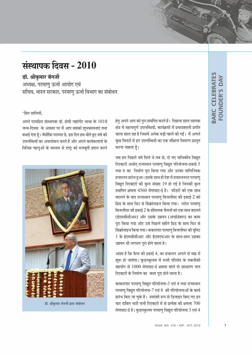
õ¸÷Ú. ¡÷flç„ ¥÷÷∏¸ ≤÷Ú≠÷ï÷· ´¸÷∏¸÷ √÷”≤÷÷Í ÷≠÷

2
BARC NEWSLETTERBARC NEWSLETTER
ISSUE NO. 316 • SEP. - OCT. 2010
BA
RC
C
ELEB
RA
TES
FO
UN
DER
’S D
AY
¥÷Î Ø÷◊∏¸μ÷÷Íï÷≠÷÷-Ø÷Êæ÷‘ ê÷◊ü÷◊æ÷◊¨÷μ÷÷” ø÷„∫˛ ç˙∏¸ §¸fl ê÷á‘ ΔÔ¸Ö ï÷Óü÷÷Ø÷„∏¸≠÷÷◊≥÷ç˙flμ÷ ◊æ÷™„ü÷ Ø÷◊∏¸μ÷÷Íï÷≠÷÷-1 ãæ÷” 2 çÍ √÷”≤÷” ÷ ¥÷Î æ÷÷√ü÷◊æ÷ç˙∫˛Ø÷ √÷Í ≥÷Ê◊¥÷ ç˙÷Í ÜØ÷≠÷Í ç˙≤ï÷Í ¥÷Î ª÷Í≠÷Í ç˙÷ ç˙÷μ÷‘ ◊ç˙μ÷÷ ï÷÷ ∏¸Δ¸÷ ΔÓÖ
ã≠÷Ø÷fl√÷flÜ÷á‘ãª÷ ≠÷Í ≥÷÷∏¸ü÷ ¥÷Î ≠÷÷◊≥÷ç˙flμ÷ ◊æ÷™„ü÷ √÷”μ÷”°÷÷Í” ç˙fl √£÷÷Ø÷≠÷÷çÍ˙ ◊ª÷ã ã≠÷ô¸flØ÷fl√÷fl ◊ª÷◊¥÷ô͸õ¸, á”◊õ¸μ÷≠÷ Ü÷Úμ÷ª÷ ç˙÷∏¸Ø÷÷Í∏͸ø÷≠÷◊ª÷◊¥÷ôÍõ¸, ≠÷Íø÷≠÷ª÷ ܪμ÷„◊¥÷◊≠÷μ÷¥÷ ç˙÷∏¸Ø÷÷Í∏Íø÷≠÷ ◊ª÷◊¥÷ôÍõ¸, ç˙÷Í◊∏¸μ÷÷áª÷Ó¤åô“ç˙ Ø÷÷æ÷∏¸ ç˙÷∏¸Ø÷÷Í∏Íø÷≠÷ çÍ √÷÷£÷ ◊¥÷ª÷ç˙∏¸ ç˙÷¥÷ ç˙∏¸≠÷Í çÍ◊ª÷ã √÷¥÷ó÷÷Óü÷÷ ñ÷÷Ø÷≠÷÷Í” Ø÷∏¸ Δ¸√ü÷÷Å÷∏¸ ◊ç˙ã ΔÔ¸Ö ◊æ÷ø÷ͬ÷ Ø÷œç˙÷∏¸ çÍãå√÷÷Í◊ô¸ç˙ á√Ø÷÷ü÷÷Î ü÷£÷÷ ≤÷õÕÍ Ü÷ç˙÷∏¸ ç˙fl ±˙÷Í⁄ï÷ê÷÷Î çÍ ◊æ÷◊≠÷¥÷÷‘ù÷çÍ ◊ª÷ã á√÷≠÷Í Δ¸ï÷fl∏¸÷ ¥÷Î ãç˙flçÈ ü÷ √÷„◊æ÷¨÷÷ √£÷÷◊Ø÷ü÷ ç˙∏¸≠÷Í çÍ ◊ª÷ã¥÷Í√÷√÷‘ ª÷÷√÷‘≠÷ ã”õ¸ ôÊ≤÷Œ÷Í çÍ √÷÷£÷ ◊¥÷ª÷ç˙∏¸ ãç˙ √÷”μ÷„åü÷ à™¥÷ç” Ø÷≠÷fl √£÷÷◊Ø÷ü÷ ç˙∏¸≠÷Í çÍ ◊ª÷ã ãç˙ √÷¥÷ó÷÷Óü÷÷ ñ÷÷Ø÷≠÷ Ø÷∏¸ ≥÷fl Δ¸√ü÷÷Å÷∏¸◊ç˙μ÷÷ ΔÓÖ ¥÷÷ª÷ø÷Íï÷ ë÷÷ô¸ ¥÷Î ãç˙ 600 ¥÷Íê÷÷æ÷÷ô¸ Å÷¥÷ü÷÷ ç˙÷Ø÷≠÷◊≤÷ï÷ª÷fl √÷”μ÷”°÷ √£÷÷◊Ø÷ü÷ ç˙∏¸≠÷Í çÍ˙ ◊ª÷ã ≠μ÷ʤåª÷μ÷∏¸ Ø÷÷æ÷∏¸ç˙÷∏¸Ø÷÷Í∏Íø÷≠÷ Ü÷Ú±˙ á”◊õ¸μ÷÷ ◊ª÷◊¥÷ôÍõ¸ Ü÷Ó∏¸ ◊ô¸Δ¸∏¸fl Δ¸÷áõ“÷Í-áª÷ͤåô“ç˙Ø÷÷æ÷∏¸ ç˙÷∏¸Ø÷÷Í∏Íø÷≠÷ çÍ ≤÷flì÷ √÷¥Ø÷Æ÷ ãç˙ √÷¥÷ó÷÷Óü÷÷ ñ÷÷Ø÷≠÷ çÍ Ü”ü÷ê÷‘ü÷◊æ÷√ü÷Èü÷ Ø÷◊∏¸μ÷÷Íï÷≠÷÷ ◊∏¸Ø÷÷Íô‘ Ø÷œ√ü÷„ü÷ ç˙fl ê÷á‘ ΔÓÖ
μ÷Ê∏Í◊≠÷μ÷¥÷ Ü≠æ÷ͬ÷ù÷ çÍ Å÷Í°÷ ¥÷Î, Ü÷” ÷– Ø÷œ§Íø÷, ∏¸÷ï÷√£÷÷≠÷ Ü÷Ó∏¸ ¥÷Íë÷÷ª÷μ÷¥÷Î ª÷ê÷≥÷ê÷ 15,000 ¥÷flô¸∏¸fl ô¸≠÷ Ü◊ü÷◊∏¸åü÷ μ÷Ê∏Í◊≠÷μ÷¥÷ √÷”√÷÷¨÷≠÷ç˙fl ◊æ÷™¥÷÷≠÷ü÷÷ ç˙÷Í Ø÷œ¥÷÷◊ù÷ü÷ ◊ç˙μ÷÷ ê÷μ÷÷ ΔÓÖ §Íø÷ çÍ μ÷Ê∏Í◊≠÷μ÷¥÷√÷”√÷÷¨÷≠÷÷Î ç˙fl ç„ ª÷ Å÷¥÷ü÷÷ ≤÷úÕç˙∏¸ 1,40,000 ô¸≠÷ U
30
8 √÷Í
ç„ î˚ Ü◊¨÷ç˙ Δ¸÷Í ê÷á‘ ΔÓ¸Ö à¢÷∏¸fl ◊§¸ªª÷fl ±˙÷ͪõ¸ ≤÷ÍÓªô¸ Ü÷Ó∏¸ ∏¸÷ï÷√£÷÷≠÷¥÷Î ª÷÷î˚∏¸fl ¥÷Î; à¢÷∏¸÷è÷”õ¸ ¥÷Î ô¸Ÿø÷μ÷∏¸fl ≤÷Í◊√÷≠÷ ¥÷Î; ¥÷¨μ÷ Ø÷œ§Íø÷ ¥÷Î¥÷Δ¸÷ç˙÷Óø÷ª÷ ¥÷Íô¸÷ √÷Í◊õ¸¥÷Îô÷Í” ¥÷Î Ü÷Ó∏¸ àõÕfl√÷÷ ¥÷Î Ü÷á‘Ü÷Íï÷fl ≤÷Í◊√÷≠÷¥÷Î μ÷Ê∏Í◊≠÷μ÷¥÷ ç˙fl ¥÷Δ¸üæ÷Ø÷Êù÷‘ ◊æ÷√÷”ê÷◊ü÷μ÷÷— §Íè÷fl ê÷á‘ ΔÔÖ
ó÷÷∏¸è÷”õ¸ çÍ √÷∏¸÷μ÷çÍ ª÷÷-è÷√÷‘æ÷÷≠÷ ◊ï÷ª÷Í ¥÷Î ¥÷÷ÍΔ„ª÷õ¸flΔ¸ μ÷Ê∏Í◊≠÷μ÷¥÷è÷≠÷≠÷ Ø÷◊∏¸μ÷÷Íï÷≠÷÷, Ü÷Ó∏¸ Ü÷” ÷– Ø÷œ§Íø÷ ¥÷Î ü÷„¥÷ªª÷÷Ø÷ªª÷fl μ÷Ê∏Í◊≠÷μ÷¥÷è÷≠÷≠÷ ü÷£÷÷ Ø÷ͬ÷ù÷ Ø÷◊∏¸μ÷÷Íï÷≠÷÷, Ü÷Ó∏¸ ç˙≠÷÷‘ô¸ç˙ ¥÷Î ê÷÷Íê÷fl ¥÷ÎÜ≠æ÷ͬ÷ù÷÷ü¥÷ç˙ è÷≠÷≠÷ ç˙÷ ç˙÷¥÷ ◊ç˙μ÷÷ ï÷÷ ∏¸Δ¸÷ ΔÓÖ Ü÷” ÷– Ø÷œ§Íø÷ ¥÷Ϊ÷÷¥≤÷÷Ø÷„∏¸ ¥÷Î Ü÷Ó∏¸ ¥÷Íë÷÷ª÷μ÷ ◊ç˙ª÷Îê÷ ÿØ÷õÎê÷√÷÷Í◊Δ¸μ÷÷”ê÷, ¥÷÷æ÷£÷÷≤÷÷Δ¸(çÍ Ø÷flã¥÷) ¥÷Î μ÷Ê∏Í◊≠÷μ÷¥÷ Üμ÷√ç˙ ç˙fl è÷≠÷≠÷ ü÷£÷÷ Ø÷ͬ÷ù÷ Ø÷◊∏¸μ÷÷Íï÷≠÷÷Ü÷ÎçÍ ◊ª÷ã Ø÷◊∏¸μ÷÷Íï÷≠÷÷-Ø÷Êæ÷‘ ç˙÷μ÷‘ ◊ç˙ã ï÷÷ ∏¸ΔÍ ΔÔÖ
≠÷÷◊≥÷ç˙flμ÷ á’ ÷≠÷ √÷¤¥¥÷¡÷, ΔÓ§¸∏¸÷≤÷÷§¸ ¥÷Î §¸÷◊≤÷ü÷ ≥÷÷∏¸fl Ø÷÷≠÷fl ◊∏¸ãåô¸∏¸á’ ÷≠÷ ≤÷”õ¸ª÷÷Î, ï÷ç˙÷Ï◊≠÷μ÷¥÷ √Ø÷”ï÷, §¸÷◊≤÷ü÷ ≥÷÷∏¸fl Ø÷÷≠÷fl ◊∏¸ãåô¸∏¸ á’ ÷≠÷ô¸∂Ê≤÷÷Î, ì˚õÕ Ø÷§¸÷£÷‘ Ü÷Ó∏¸ ≠÷÷μ÷÷Í◊≤÷μ÷¥÷ ÷÷ü÷„ ç˙÷ Ü≤÷ ü÷ç˙ ç˙÷ √÷æ÷÷‘◊¨÷ç˙àüØ÷÷§¸≠÷ ◊ç˙μ÷÷ ê÷μ÷÷Ö ü÷◊¥÷ª÷≠÷÷õ„¸ ¥÷Î Ø÷ó÷÷μ÷ç˙μ÷÷ª÷ ¤√£÷ü÷ ï÷ç˙÷Ï◊≠÷μ÷¥÷
ç˙÷¥Ø÷ª÷Íå√÷ ¥÷Î ï÷ç˙÷Ï◊≠÷μ÷¥÷ Ü÷Úå√÷÷áõ¸ ç˙÷ àüØ÷÷§¸≠÷ ø÷„∫˛ Δ¸÷Í ê÷μ÷÷ΔÓÖ ã≠÷ã±˙√÷fl ≠÷Í, æ÷Ó¤øæ÷ç˙ √Ø÷¨÷÷‘ ¥÷Î Ü”ü÷∏¸÷‘¬ô“flμ÷ Ø÷∏¸¥÷÷ù÷„ â˙ï÷÷‘ãï÷Î√÷fl √÷Í Ø÷œ÷Øü÷,ì ü÷„ç˙· Ø÷∏¸¥÷÷ù÷„ â˙ï÷÷‘ Ø÷œ÷◊¨÷ç˙∏¸ù÷ á’ ÷≠÷ ü÷üæ÷ ã”õ¸çÓ Ø÷ æ÷Ó‹ªõ¸ê÷ μ÷Ê◊≠÷ô î çÍ ◊æ÷◊≠÷¥÷÷‘ù÷, Ü÷Ø÷ÊŸü÷, √£÷÷Ø÷≠÷ ü÷£÷÷ ç˙¥÷flø÷ÿ≠÷ê÷çÍ ãç˙ Ü÷§Íø÷ ç˙÷Í √÷±˙ª÷ü÷Ø÷Ø÷Êæ÷‘ç˙ Ø÷Ê∏¸÷ ◊ç ¸μ÷÷Ö
Ü≥÷fl çÍ æ÷ª÷ ü÷fl≠÷ √÷Øü÷÷Δ¸ Δ„ã Δ¸÷Îê÷Í ï÷≤÷◊ç˙ á”◊§¸∏¸÷ ê÷÷” ÷fl Ø÷∏¸¥÷÷ù÷„Ü≠÷„√÷”¨÷÷≠÷ çÎ˙¶¸ çÍ˙ ±˙÷√ô¸ ≤÷Œflõ¸∏¸ ô͸√ô¸ ◊∏¸ãåô¸∏¸ ü÷£÷÷ ∏͸◊õ¸μ÷÷Í-¨÷÷ü÷„ç˙Ÿ¥÷ç˙fl Ø÷œμ÷÷Íê÷ø÷÷ª÷÷Ü÷Î ≠÷Í ÜØ÷≠÷fl ∏¸ï÷ü÷ ï÷μ÷”ü÷fl ¥÷≠÷÷μ÷fl ΔÓÖá√÷ Üæ÷√÷∏¸ Ø÷∏¸, ª÷ê÷≥÷ê÷ 165 ¥÷Íê÷÷æ÷÷ô¸ D/T çÍ ≤÷≠÷‘-ÜØ÷æ÷÷ª÷Í ≠÷æ÷fl≠÷ ◊¥÷◊¡÷ü÷ ç˙÷≤÷÷‘áõ¸ á’ ÷≠÷ çÍ Ø÷œ≥÷÷æ÷ø÷÷ª÷fl ç˙÷μ÷‘◊≠÷¬Ø÷÷§¸≠÷ç˙fl Ü”ü÷∏¸÷‘¬ô“flμ÷ ◊æ÷ø÷ͬ÷ñ÷÷Î ≠÷Í Ø÷œø÷”√÷÷ ç˙flÖ ç˙ªØ÷÷åç˙¥÷ ¥÷Î ≤÷≠÷÷ãï÷÷ ∏¸ΔÍ 500 ¥÷Íê÷÷æ÷÷ô¸-á‘ Å÷¥÷ü÷÷ æ÷÷ª÷Í Ø÷œ÷Íô¸÷Íô¸÷áØ÷ ±˙÷√ô¸ ≤÷Œflõ¸∏¸◊∏¸ãåô¸∏¸ çÍ ◊≠÷¥÷÷‘ù÷ ç˙÷ ª÷ê÷≥÷ê÷ 60 Ø÷œ◊ü÷ø÷ü÷ ç˙÷μ÷‘ Ø÷Ê∏¸÷ Δ¸÷Í ê÷μ÷÷ΔÓÖ Ø÷œ÷Íô¸÷Íô¸÷áØ÷ ±˙÷√ô¸ ≤÷Œflõ¸∏¸ ◊∏¸ãåô¸∏¸ ôÍ√ô¸ àØ÷-Ü√÷Í¥≤÷ª÷fl ≠÷ͱ˙÷√ô¸ ≤÷Œflõ¸∏¸ ôÍ√ô¸ ◊∏¸ãåô¸∏¸ ¥÷Î ç˙∏¸fl≤÷ 110,000 ¥÷Íê÷÷æ÷÷ô¸ D/T ç˙÷ ≤÷≠÷‘ÜØ÷ §¸ï÷‘ ◊ç˙μ÷÷ ΔÓ ï÷≤÷◊ç˙ á√÷ç˙fl ü÷„ª÷≠÷÷ ¥÷Î Ü◊≥÷ç˙¤ªØ÷ü÷≤÷≠÷‘ÜØ÷ 100,000 ¥÷Íê÷÷æ÷÷ô¸ D/T £÷÷Ö
√÷÷¨÷≠÷÷ - √÷÷Í◊õ¸μ÷¥÷ ¥÷Î Ø÷œ÷Íô¸÷Íô¸÷áØ÷ ±˙÷√ô¸ ≤÷Œflõ¸∏¸ ◊∏¸ãåô¸∏¸ √÷”∏¸Å÷÷ê÷œÍõ¸ ç˙fl Å÷μ÷ â˙¬¥÷÷ ◊≠÷¬ç˙÷√÷≠÷ √÷”≤÷” ÷fl Ø÷∏¸flÅ÷ù÷ çÍ ◊ª÷ã ãç˙ √÷÷Í◊õ¸μ÷¥÷ª÷ÊØ÷ ç˙¥÷flø÷≠÷ ◊ç˙μ÷÷ ê÷μ÷÷ £÷÷ Ü÷Ó∏¸ ◊ç˙ã ê÷ã Ø÷∏¸flÅ÷ù÷÷Î √÷Í √÷”ë÷ô¸ç˙Ü÷Ó∏¸ Ø÷œù÷÷ª÷fl ç˙fl ◊õ¸ï÷÷á≠÷ àØ÷μ÷„åü÷ Ø÷÷μ÷fl ê÷μ÷fl ΔÓÖ Ü”ü÷∏¸÷‘¬ô“flμ÷Ø÷∏¸¥÷÷ù÷„ â˙ï÷÷‘ ãï÷Î√÷fl ç˙fl ãç˙ Ü”ü÷∏¸÷‘¬ô“flμ÷ √÷Δ¸μ÷÷Íê÷÷ü¥÷ç˙ Ø÷◊∏¸μ÷÷Íï÷≠÷÷,◊ï÷√÷¥÷Î ≥÷÷∏¸ü÷, ì÷fl≠÷, μ÷Ê∏¸÷ÍØ÷flμ÷ Ü÷μ÷÷Íê÷, ç˙÷Í◊∏¸μ÷÷ ê÷ù÷∏¸÷ïμ÷ ü÷£÷÷∫˛√÷ ç˙fl ≥÷÷ê÷fl§¸÷∏¸fl ΔÓ, ç˙÷Í á”◊§¸∏¸÷ ê÷÷” ÷fl Ø÷∏¸¥÷÷ù÷„ Ü≠÷„√÷” ÷÷≠÷ çÍ ≠¶¸¥÷Î Ø÷œ÷∏¸¥≥÷ ◊ç˙μ÷÷ ê÷μ÷÷Ö á√÷ Ø÷◊∏¸μ÷÷Íï÷≠÷÷ çÍ ãç˙ Ü”ê÷ çÍ ∫˛Ø÷ ¥÷Î,Å÷μ÷ â˙¬¥÷÷ ◊≠÷¬ç˙÷√÷≠÷ Ø÷œù÷÷ª÷fl ç˙÷ ܨμ÷μ÷≠÷ ◊ç˙μ÷÷ ê÷μ÷÷ ΔÓ Ü÷Ó∏¸Ø÷œ÷Øü÷ Ø÷◊∏¸ù÷÷¥÷÷Í” √÷Í ≥÷÷æ÷fl ±˙÷√ô¸ ≤÷Œflõ¸∏¸ ◊∏¸ãåô¸∏¸÷Î ç˙fl ◊õ¸ï÷÷á≠÷ çÍ◊ª÷ã ¥÷Δ¸üæ÷Ø÷Êù÷‘ ï÷÷≠÷ç˙÷∏¸fl Ø÷œ÷Øü÷ Δ„á‘ ΔÓÖ
±˙÷√ô¸ ≤÷Œflõ¸∏¸ ◊∏¸ãåô¸∏¸÷Î çÍ˙ ◊ª÷ã Ü÷æ÷øμ÷ç˙ √÷¥÷È®¸ ≤÷÷Í∏¸÷Ú≠÷ çÍ˙Ü÷Ó™÷Í◊ê÷ç˙ √ü÷∏¸ Ø÷∏¸ àüØ÷÷§¸≠÷ ΔÍü÷„ §Íø÷ ç˙fl Ø÷Δ¸ª÷fl §¸÷Í √÷„◊æ÷¨÷÷ã”ü÷÷ª÷î÷Í∏¸ Ü÷Ó∏¸ ¥÷ù÷„ê÷„π˝ ¥÷Î √£÷÷◊Ø÷ü÷ ç˙fl ê÷á’Ö μ÷Í √÷„◊æ÷¨÷÷ã” çŒ ¥÷ø÷:◊æ÷◊≠÷¥÷μ÷ Ü÷√÷æ÷≠÷ ü÷£÷÷ Ü÷μ÷≠÷ ◊æ÷◊≠÷¥÷μ÷ çŒ ÷Í¥÷Íô¸÷Íê÷œ÷±˙fl Ø÷∏¸ Ü÷¨÷÷◊∏¸ü÷ΔÔÖ √÷¥÷È®¸ KBF4 ç˙÷Í ◊æ÷™„ü÷-ÜØ÷ë÷ô¸≠÷ Ø÷œ◊çŒ μ÷÷ Ø÷∏¸ Ü÷¨÷÷◊∏¸ü÷ü÷÷¤üæ÷ç˙ ≤÷÷Í∏¸÷Ú≠÷ ¥÷Î Ø÷◊∏¸æ÷Ÿü÷ü÷ ç˙∏¸≠÷Í çÍ ◊ª÷ã ãç˙ √÷”μ÷”°÷ ≥÷fl ≥÷÷∏¸flØ÷÷≠÷fl √÷”μ÷”°÷, ¥÷ù÷„ê÷„π˝ ¥÷Î √£÷÷◊Ø÷ü÷ ◊ç˙μ÷÷ ê÷μ÷÷Ö æ÷¬÷‘ çÍ §¸÷Ó∏¸÷≠÷ ≥÷÷∏¸flØ÷÷≠÷fl √÷”μ÷”°÷÷Î ç˙fl Å÷¥÷ü÷÷ ç˙÷ 100% √÷Í ≥÷fl Ü◊¨÷ç˙ àØ÷μ÷÷Íê÷ ◊ç˙μ÷÷ê÷μ÷÷Ö ¥÷Í√÷√÷‘ KHNP, §¸◊Å÷ù÷ ç˙÷Í◊∏¸μ÷÷ ç˙÷Í 11 ¥÷flô¸∏¸fl ô¸≠÷ ≥÷÷∏¸fl
3ISSUE NO. 316 • SEP. - OCT. 2010
BA
RC
C
ELEB
RA
TES
FO
UN
DER
’S D
AY
Ø÷÷≠÷fl ç˙fl Ü÷Ø÷ÊŸü÷ ΔÍü÷„ ≥÷÷∏¸fl Ø÷÷≠÷fl ≤÷÷Íõ‘ ç˙÷Í 16æ÷÷” ◊≠÷μ÷÷‘ü÷ Ü÷§Íø÷Ø÷œ÷Øü÷ Δ„Ü÷Ö ¸
ª÷Íõ¸ √÷ͪ÷÷Î ¥÷Î Ø÷œê÷ü÷ á’ ÷≠÷ ΔÍü÷„ ç˙ª÷Ø÷÷åç˙¥÷ ¤√£÷ü÷ √÷”Δ¸ü÷ Ø÷„≠÷√÷’√÷÷¨÷≠÷√÷„◊æ÷¨÷÷ (ç˙÷Í∏¸ª÷) ¥÷Î 155 ê÷flê÷÷æ÷÷ô¸ d/t çÍ ≤÷≠÷‘ÜØ÷ æ÷÷ª÷Í ±˙÷√ô¸≤÷Œflõ¸∏¸ ôÍ√ô¸ ◊∏¸ãåô¸∏¸ √÷Í Ø÷œ÷Øü÷ ≥÷„åü÷ ø÷ͬ÷ á’ ÷≠÷ àØ÷-Ü√÷Í¥≤÷ª÷fl ç˙÷Ø÷„≠÷√÷’√÷÷¨÷≠÷ ◊ç˙μ÷÷ ê÷μ÷÷ Ü÷Ó∏¸ ◊æ÷è÷”õ¸≠÷flμ÷ Ø÷§¸÷£÷‘ ç˙÷Í Ø÷„≠÷: á’ ÷≠÷ çÍ∫˛Ø÷ ¥÷Î √÷”◊æ÷∏◊î÷ü÷ ç˙∏¸ à√÷Í æ÷÷Ø÷√÷ ◊∏¸ãåô¸∏¸ ¥÷Î ª÷÷Íõ¸ ◊ç˙μ÷÷ ê÷μ÷÷Öá√÷ Ø÷œç˙÷∏¸ ±˙÷√ô¸ ◊∏¸ãåô¸∏¸ á’ ÷≠÷ ì÷çŒ ¸ ç˙÷Í √÷±˙ª÷ü÷÷Ø÷Êæ÷‘ç˙ Ø÷Ê∏¸÷◊ç˙μ÷÷ ê÷μ÷÷Ö
á√÷ æ÷¬÷‘ ÜØ÷œÍÓª÷ ¥÷Î, ª÷ê÷≥÷ê÷ ì÷÷∏¸ §¸ø÷ç˙ Ø÷Δ¸ª÷Í ◊§¸ªª÷fl ◊æ÷¿æ÷◊æ÷™÷ª÷μ÷´¸÷∏¸÷ ç˙≠÷÷õ¸÷ √÷Í Ü÷μ÷÷ü÷ ◊ç˙μ÷÷ ê÷μ÷÷ ãç˙ Ø÷„∏¸÷≠÷÷ ê÷÷¥÷÷ √÷ͪ÷§„≥÷÷‘êμ÷æ÷ø÷ ◊§¸ªª÷fl çÍ ç˙≤÷÷õÕfl ≤÷÷ï÷÷∏¸ ¥÷Î Ø÷Δ„”î÷ ê÷μ÷÷ ◊ï÷√÷çÍØ÷◊∏¸ù÷÷¥÷√æ÷∫˛Ø÷ ç„ î˚ æμ÷¤åü÷μ÷÷Î Ø÷∏¸ ◊æ÷◊ç˙∏¸ù÷ ç˙÷ Ø÷œ≥÷÷æ÷ Ø÷õÕ÷Öá√÷ √÷”ç˙ô¸ç˙÷ª÷fl≠÷ ë÷õÕfl ¥÷Î, ãç˙ ≤÷õÕfl √÷”èμ÷÷ ¥÷Î ≥÷÷≥÷÷ Ø÷∏¸¥÷÷ù÷„Ü≠÷„√÷” ÷÷≠÷ çÍ ≠¶¸, ≠÷∏¸÷Í∏¸÷ Ø÷∏¸¥÷÷ù÷„ ◊≤÷ï÷ª÷flë÷∏¸, Ø÷∏¸¥÷÷ù÷„ è÷◊≠÷ï÷◊≠÷§Íø÷÷ª÷μ÷, à¢÷∏¸fl Å÷Í°÷ ü÷£÷÷ Ø÷∏¸¥÷÷ù÷„ â˙ï÷÷‘ ◊≠÷μ÷÷¥÷ç˙ ≤÷÷Íõ‘ çÍΔ¸¥÷÷∏Í √÷Δ¸ç˙Ÿ¥÷μ÷÷Î ≠÷Í, ◊æ÷◊ç˙∏¸ù÷√÷◊çŒ μ÷ √÷÷¥÷ê÷œfl ç˙÷Í Ø÷„≠÷: Ø÷œ÷Øü÷ ç˙∏¸≠÷ÍÜ÷Ó∏¸ √÷„∏¸◊Å÷ü÷ ∫˛Ø÷ √÷Í à√÷ç˙÷ ◊≠÷Ø÷ô¸÷≠÷ ç˙∏¸≠÷Í, ü÷£÷÷ Ø÷Ê∏Í Å÷Í°÷ ç˙÷Í◊æ÷√÷”§Ê◊¬÷ü÷ ç˙∏¸≠÷Í çÍ ◊ª÷ã ª÷ê÷÷ü÷÷∏¸ ç˙÷¥÷ ◊ç˙μ÷÷Ö ¥÷Ô à≠÷ √÷≤÷çÍØ÷œ◊ü÷ ÜØ÷≠÷÷ √÷¥÷÷§¸∏¸ Ø÷œç˙ô¸ ç˙∏¸ü÷÷ ΔÊ—Ö
Ø÷∏¸¥÷÷ù÷„ â˙ï÷÷‘ ◊æ÷≥÷÷ê÷ ≠÷Í õ¸÷Ú. ≤÷fl. ≤÷π˝Ü÷ çÔ √÷∏¸ √÷”√£÷÷≠÷, ê÷„æ÷÷Δ¸÷ô¸flçÍ Ø÷„≠÷≠÷‘æ÷flç˙∏¸ù÷ çÍ ◊ª÷ã, à¢÷∏¸-Ø÷Êæ÷· Ø÷◊∏¸¬÷§ Ü÷Ó∏¸ Ü√÷¥÷ √÷∏¸ç˙÷∏¸çÍ √÷÷£÷ ü÷fl√÷∏Í ◊°÷-Ø÷Å÷flμ÷ ç˙∏¸÷∏¸ Ø÷∏¸ Δ¸√ü÷÷Å÷∏¸ ◊ç˙μ÷÷ ΔÓÖ μ÷Δ¸Ü√Ø÷ü÷÷ª÷ à¢÷∏¸-Ø÷Êæ÷· Å÷Í°÷ ¥÷Î çÔ √÷∏¸ çÍ áª÷÷ï÷ Ü÷Ó∏¸ à√÷çÍ ◊≠÷μ÷”°÷ù÷çÍ ◊ª÷ã ãç˙ Å÷Í°÷flμ÷ çÔ √÷∏¸ çÍ ≠¶¸ (Ü÷∏¸√÷fl√÷fl) ΔÓÖ
Ü”ü÷∏¸÷‘¬ô“flμ÷ Ø÷∏¸¥÷÷ù÷„ â˙ï÷÷‘ ãï÷Î√÷fl, ≥÷÷∏¸ü÷ ê÷ù÷∏¸÷ïμ÷ Ü÷Ó∏¸ √÷÷Íø÷◊ª÷√ô¸◊∏¸Ø÷¤≤ª÷ç˙ Ü÷Ú±˙ ◊æ÷μ÷ü÷≠÷÷¥÷ çÍ˙ ≤÷flì÷ Δ„¸ã ç˙∏÷∏¸ çÍ˙ Ü≠÷„√÷÷∏¸◊æ÷μ÷ü÷≠÷÷¥÷ ç˙÷Í çÔ˙√÷∏¸ ◊ì÷◊ç˙ü√÷÷ çÍ˙ ◊ª÷ã ãç˙ ≥÷÷≥÷÷ô“¸÷Ú≠÷ §Ê¸∏¸◊ì÷◊ç˙ü√÷÷ ¥÷ø÷fl≠÷ §¸÷≠÷ ¥÷Î §¸fl ê÷á‘Ö á√÷ ¥÷ø÷fl≠÷ ç˙÷ à§Àë÷÷ô¸≠÷ 28ÜØ÷œÓª÷, 2010 ç˙÷Í ◊æ÷μ÷ü÷≠÷÷¥÷ ¥÷Î çÓ˙≠÷ £÷÷Í Ü≤÷„‘§¸ ◊æ÷ñ÷÷≠÷(Ü÷≠ç˙÷ͪ÷÷Ú◊ï÷) Ü√Ø÷ü÷÷ª÷ ¥÷Î ◊ç˙μ÷÷ ê÷μ÷÷Ö ãÍ√÷fl Δ¸fl §¸÷Í Ü÷Ó∏¸μ÷Ê◊≠÷ôÍ”, ãç˙ ¡÷flª÷”ç˙÷ ç˙÷Í Ü÷Ó∏¸ §Ê√÷∏¸fl ãç˙ ܱœ flç˙fl §Íø÷ ç˙÷Í §¸÷≠÷¥÷Î §¸fl ï÷÷ ∏¸Δ¸fl ΔÓ”Ö ◊æ÷◊ç˙∏¸ù÷ ü÷£÷÷ Ü÷á√÷÷Íô¸÷ÍØ÷ Ø÷œ÷Ó™÷Í◊ê÷ç˙fl ≤÷÷Íõ‘ ¥÷Îá≠÷-Δ¸÷à√÷ àüØ÷÷◊§¸ü÷ ì÷„”≤÷ç˙flμ÷ √÷ͪ÷„ª÷÷Í√÷ ç˙ù÷÷Î Ø÷∏¸ Ü÷¨÷÷◊∏¸ü÷ªμ÷Ê◊ô¸≠÷÷áÿï÷ê÷ Δ¸÷¥÷÷‘Í≠÷ (ãª÷ãì÷) çÍ ◊ª÷ã √÷„ê÷¥÷ü÷÷ √÷Í àØ÷μ÷÷Íê÷ ç˙flï÷÷ √÷ç˙≠÷Í æ÷÷ª÷fl ãç˙ Ü÷á‘Ü÷∏¸ã¥÷ã ◊ç˙ô¸ ◊æ÷ç˙◊√÷ü÷ ç˙fl ê÷á‘Ö
Ü◊≥÷ç˙ª÷≠÷fl (ç” Øμ÷ÊôÍø÷≠÷ª÷) Ü÷¤ùæ÷ç˙ ê÷◊ü÷ç˙fl, Ø÷§¸÷£÷‘ ¥÷÷Úõ¸ÿª÷ê÷,◊∏¸ãåô¸∏¸ çŒ ÷Íõ¸ Ø÷◊∏¸ç˙ª÷≠÷ Ü÷Ó∏¸ √÷”∏¸Å÷÷ ◊æ÷øª÷ͬ÷ù÷, ¥÷÷Ó√÷¥÷ √÷”≤÷” ÷fl¥÷÷Úõ¸ª÷ ü÷Óμ÷÷∏¸ ç˙∏¸≠÷Í Ü÷Ó∏¸ ç” Øμ÷Êô¸∏¸ √÷Δ¸÷μ÷ü÷÷ μ÷„åü÷ á”ï÷fl◊≠÷μ÷ÿ∏¸ê÷Ü≠÷„Ø÷œμ÷÷Íê÷÷Î çÍ Å÷Í°÷÷Î ¥÷Î àØ÷≥÷÷Íåü÷÷Ü÷Î ç˙fl ≤÷õÕÍ Ø÷Ó¥÷÷≠÷Í Ø÷∏¸ √÷”èμ÷÷ü¥÷ç˙Ü◊≥÷ç˙ª÷≠÷ ç˙fl Ü÷æ÷øμ÷ç˙ü÷÷Ü÷Î ç˙÷Í Ø÷Ê∏¸÷ ç˙∏¸≠÷Í çÍ ◊ª÷ã á”◊§¸∏¸÷ê÷÷” ÷fl Ø÷∏¸¥÷÷ù÷„ Ü≠÷„√÷” ÷÷≠÷ çÍ ≠¶¸ ¸÷∏¸÷ àîî÷ ç˙÷μ÷‘-◊≠÷¬Ø÷÷§¸≠÷ æ÷÷ª÷Íãç˙ √÷÷¥÷÷≠ü÷∏¸ Ü◊ü÷î÷÷ª÷ç˙ åª÷√ô¸∏¸ ç˙÷ ç˙¥÷flø÷≠÷ ◊ç˙μ÷÷ ê÷μ÷÷Ö±˙÷√ô¸ ≤÷Œflõ¸∏¸ ◊∏¸ãåô¸∏¸÷Î Ü÷Ó∏¸ √÷”≤÷®¸ á’ ÷≠÷ ì÷çŒ √÷„◊æ÷¨÷÷Ü÷Î çÍ¥÷÷Úõ¸ª÷÷Î ç˙fl Ø÷◊∏¸ç˙ªØ÷≠÷÷ çÍ ◊ª÷ã á”◊§¸∏¸÷ ê÷÷” ÷fl Ø÷∏¸¥÷÷ù÷„ Ü≠÷„√÷” ÷÷≠÷çÍ ≠¶¸ ¥÷Î ãç˙ Ø÷œê÷ü÷ Ø÷◊∏¸ç˙ªØ÷≠÷÷ çÍ ≠¶,¸ ãç˙ ◊æ÷¿æ÷√ü÷∏¸flμ÷ Ø÷Êù÷‘á¥÷Ÿ√÷æ÷ Ø÷œù÷÷ª÷fl ≥÷fl ç˙¥÷flø÷≠÷ ç˙fl ê÷á‘Ö
Δ¸÷ª÷ Δ¸fl ¥÷Î á√÷ ¥÷÷Δ¸ çÍ §¸÷Ó∏¸÷≠÷ §¸÷Í √÷Øü÷÷Δ¸÷Î çÍ ◊ª÷ã Ø÷Ê∏Í ◊æ÷¿æ÷ ≠÷Í≠÷á‘ ◊§¸ªª÷fl ¥÷Î Ü÷μ÷÷Í◊ï÷ü÷ ç˙÷Ú¥÷≠÷æ÷ͪ£÷ è÷ͪ÷÷Î ç˙÷ ≥÷æμ÷ √÷¥÷÷∏¸÷ÍΔ¸§Íè÷÷Ö ¥÷„ó÷Í Ü÷Ø÷ç˙÷Í μ÷Δ¸ ≤÷ü÷÷ü÷Í Δ„ã ≤÷Δ„ü÷ Ø÷œ√÷Æ÷ü÷÷ Δ¸÷Í ∏¸Δ¸fl ΔÓ ◊ç˙Ø÷∏¸¥÷÷ù÷„ â˙ï÷÷‘ ◊æ÷≥÷÷ê÷ ≠÷Í à√÷ √÷¥÷÷∏¸÷ÍΔ¸ çÍ √÷±˙ª÷ Ü÷μ÷÷Íï÷≠÷ ¥÷Î ≥÷flÜØ÷≠÷fl ≥÷Ê◊¥÷ç˙÷ ܧ¸÷ ç˙flÖ áª÷Íåô“÷◊≠÷å√÷ ç˙÷∏¸Ø÷÷Í∏Íø÷≠÷ Ü÷Ú±˙ á”◊õ¸μ÷÷◊ª÷◊¥÷ôÍõ¸ ≠÷Í á≠÷ è÷ͪ÷÷Î çÍ ◊ª÷ã 230 ç˙∏¸÷ÍõÕ çÍ ¥÷ʪμ÷ √÷Í Ü◊¨÷ç˙çÍ àØ÷√ç˙∏¸÷Î ç˙fl Ü÷Ø÷ÊŸü÷ ç˙flÖ §Íø÷ ç˙fl ◊æ÷◊≥÷Æ÷ √÷„∏¸Å÷÷ ãï÷Î◊√÷μ÷÷ÎçÍ ç˙÷Ÿ¥÷ç˙÷Î ç˙÷Í ◊æ÷◊ç˙∏¸ù÷ ƒ÷÷Íü÷÷Î ç˙÷ Ø÷ü÷÷ ª÷ê÷÷≠÷Í Ü÷Ó∏¸ ◊æ÷◊ç˙∏¸ù÷√÷Í àüØ÷Æ÷ ◊ç˙√÷fl ≥÷fl Ü÷Ø÷÷ü÷ç˙÷ª÷fl≠÷ ¤√£÷◊ü÷ √÷Í ◊≠÷Ø÷ô¸≠÷Í çÍ ◊ª÷ããç˙ ≤÷õÕfl √÷”èμ÷÷ ¥÷Î Ø÷œ◊ø÷◊Å÷ü÷ ◊ç˙μ÷÷ ê÷μ÷÷Ö á√÷çÍ Ü◊ü÷◊∏¸åü÷, á≠÷è÷ͪ÷÷Î çÍ §¸÷Ó∏¸÷≠÷ ◊æ÷◊ç˙∏¸ù÷ æ÷Óñ÷÷◊≠÷ç˙÷Î ç˙÷ ãç˙ §¸ª÷ ◊æ÷◊ç˙∏¸ù÷ ç˙fl◊≠÷ê÷∏¸÷≠÷fl çÍ ◊ª÷ã è÷ͪ÷ √£÷ª÷ Ø÷∏¸ ◊≠÷μ÷„åü÷ ◊ç˙μ÷÷ ê÷μ÷÷Ö
∏¸÷ï÷÷ ∏¸÷¥÷Æ÷÷ Ø÷œê÷ü÷ Ø÷œ÷Ó™÷Í◊ê÷ç˙fl çÍ ≠¶¸ ¥÷Î √÷≠÷‘ Ü≠÷„Ø÷œμ÷÷Íê÷ çÍ ◊ª÷ã◊æ÷ç˙◊√÷ü÷ ãç˙ ö¸÷Í√÷ Üæ÷√£÷÷ Ø÷œ◊ü÷ç˙÷◊∏¸ü÷ (ç˙÷¥Ø÷≠√÷ÍôÍõ¸) ¥÷÷õ„ª÷Íô¸∏¸≠÷Í ◊≠÷¨÷÷‘◊∏¸ü÷ ◊æ÷◊≠÷§Ïø÷ Ø÷œ÷Øü÷ ◊ç˙μ÷÷ Ü÷Ó∏¸ à√÷Í √÷≠÷‘ §¸ª÷ ¸÷∏¸÷ √æ÷flç˙÷∏¸◊ç˙μ÷÷ ê÷μ÷÷Ö ¸∏¸÷ï÷÷ ∏¸÷¥÷Æ÷÷ Ø÷ œê÷ü÷ Ø÷ œ÷ Ó™÷Í◊ê÷ç˙fl çÍ˙≠¶¸ ≠÷ ÍÜ”ü÷∏¸◊æ÷¿æ÷◊æ÷™÷ª÷μ÷ üæ÷∏¸ç ¸ çÍ ≠¶¸ (Ü÷á‘μ÷Êã√÷fl), ≠÷á‘ ◊§¸ªª÷fl çÍ√÷Δ¸μ÷÷Íê÷ √÷Í §¸÷Í Ø÷œ÷Íô¸÷Íô¸÷áØ÷ 1.3 ê÷flê÷÷ Δ¸üï÷Ñ ãç˙ª÷ Ø÷œç˙÷ͬö¸Ü◊ü÷î÷÷ª÷ç˙ ê÷„◊Δ¸ç˙÷Ü÷Î (çÓ ◊æ÷◊ô¸μ÷÷Î) ç˙÷ √÷”◊æ÷∏¸î÷≠÷ ◊ç˙μ÷÷ Ü÷Ó∏¸à≠÷ç˙÷ 22 ã¥÷á‘æ÷fl/ã¥÷ Ø÷œæ÷ù÷ü÷÷ çÍ ◊ª÷ã Ü¥÷∏¸flç˙÷ ç˙fl ±˙¥÷·Ø÷œμ÷÷Íê÷ø÷÷ª÷÷ ¥÷Î Ø÷∏¸flÅ÷ù÷ ◊ç˙μ÷÷ ê÷μ÷÷Ö
æ÷¬÷‘ çÍ §¸÷Ó∏¸÷≠÷ ≥÷÷∏¸ü÷ ≠÷Í Ø÷∏¸¥÷÷ù÷„ â˙ï÷÷‘ çÍ ø÷÷”◊ü÷Ø÷Êù÷‘ àØ÷μ÷÷Íê÷÷Î ¥÷Î√÷Δ¸μ÷÷Íê÷ çÍ ◊ª÷ã ç˙á‘ §Íø÷÷Î çÍ √÷÷£÷ ◊ ¸Ø÷Å÷flμ÷ ç˙∏¸÷∏¸÷Î Ü÷Ó∏¸ √÷¥÷ó÷÷Óü÷÷ ñ÷÷Ø÷≠÷÷Î Ø÷∏¸ Δ¸√ü÷÷Å÷∏¸ ◊ç˙ã ΔÔÖ à≠÷¥÷Î √÷Í ç„ î˚ §Íø÷ ≠÷÷¥÷fl◊≤÷μ÷÷,¥÷”ê÷÷Í◊ª÷μ÷÷, ∫˛√÷fl Ø÷◊∏¸√÷”ë÷ Ü÷Ó∏¸ ç˙≠÷÷õ¸÷ Ü÷◊§¸ ΔÔÖ á√÷≠÷Í μ÷Ê≠÷÷áôÍõ¸ÿç˙êõ¸¥÷ çÍ √÷÷£÷ Ü√÷Ó≠μ÷ ≠÷÷◊≥÷ç˙flμ÷ √÷Δ¸μ÷÷Íê÷ çÍ ◊ª÷ã ãç˙ √÷”μ÷„åü÷

4
BARC NEWSLETTERBARC NEWSLETTER
ISSUE NO. 316 • SEP. - OCT. 2010
BA
RC
C
ELEB
RA
TES
FO
UN
DER
’S D
AY
ë÷÷ͬ÷ù÷÷ ≥÷fl ç˙fl £÷flÖ ≥÷÷∏¸ü÷ ≠÷Í √÷”ª÷μ÷≠÷ â˙ï÷÷‘ Ü≠÷„√÷” ÷÷≠÷ çÍ Å÷Í°÷ ¥÷ √÷Δ¸μ÷÷Íê÷ΔÍü÷„ μ÷Ê∏¸÷Í◊Ø÷μ÷≠÷ ãô¸÷Ú◊¥÷ç˙ ã≠÷ï÷· ç˙¥μ÷„◊≠÷ô¸fl çÍ √÷÷£÷ ãç˙ ç˙∏¸÷∏¸ Ø÷∏¸ ≥÷flΔ¸√ü÷÷Å÷∏¸ ◊ç˙ã ΔÓ”Ö
¥÷Ô≠÷Í Ü≥÷fl-Ü≥÷fl ç„ î˚ à≠÷ Ø÷œ¥÷„è÷ àØ÷ª÷¤≤¨÷μ÷÷Î ç˙÷ પ÷Íè÷ ◊ç˙μ÷÷ ΔÓ ï÷÷Í◊æ÷≥÷÷ê÷ ¸÷∏¸÷ ◊Ø÷î˚ª÷Í æ÷¬÷‘ çÍ §¸÷Ó∏¸÷≠÷ Δ¸÷◊√÷ª÷ ç˙fl ê÷μ÷fl ΔÓ ”Ö æ÷√ü÷„ü÷: Δ¸¥÷÷∏¸÷ç˙÷μ÷‘çŒ ¥÷ ≤÷Δ„ü÷ ü÷Íï÷Ãfl √÷Í Ü÷ê÷Í ≤÷úÕ ∏¸Δ¸÷ ΔÓÖ ¥÷Ô á√÷ ¥÷÷ÍõÕ Ø÷∏¸, Üê÷ª÷Í §¸ø÷ç˙çÍ Ü”ü÷ ü÷ç˙, ÜØ÷≠÷Í ≥÷÷æ÷fl Ø÷◊∏¸•¸øμ÷ ç˙fl ãç˙ ü÷√æ÷fl∏¸ Ü÷Ø÷çÍ √÷÷¥÷≠÷Í ∏¸è÷≠÷÷ì÷÷Δ¸ü÷÷ ΔÊ— :
� Ü÷ï÷ Δ¸¥÷÷∏¸fl ≠÷÷◊≥÷ç˙flμ÷ ◊æ÷™„ü÷ àüØ÷÷§¸≠÷ ç˙fl √£÷÷◊Ø÷ü÷ Å÷¥÷ü÷÷ ª÷ê÷≥÷ê÷4500 ¥÷Íê÷÷æ÷÷ô¸ ç˙fl ΔÓÖ Ü÷ø÷÷ ΔÓ ◊ç˙ Δ¸¥÷ æ÷¬÷‘ 2020 ¥÷Î 30,000¥÷Íê÷÷æ÷÷ô¸ √÷Í Ü◊¨÷ç˙ ç˙fl Å÷¥÷ü÷÷ Δ¸÷◊√÷ª÷ ç˙∏¸ ª÷Îê÷ÍÖ
� Ü÷ï÷ §Íø÷ ¥÷Î ≠÷÷◊≥÷ç˙flμ÷ ◊æ÷™„ü÷ àüØ÷÷§¸≠÷ Ø÷œ÷£÷◊¥÷ç˙ ∫˛Ø÷ √÷Í §¸÷◊≤÷ü÷≥÷÷∏¸fl Ø÷÷≠÷fl ◊∏¸ãåô¸∏¸÷Î çÍ ¥÷÷¨μ÷¥÷ √÷Í Δ¸÷Íü÷÷ ΔÓÖ ãç˙ §¸ø÷ç˙ çÍ ≤÷÷§¸, Δ¸¥÷ª÷ê÷≥÷ê÷ 10,000 ¥÷Íê÷÷æ÷÷ô¸ ü÷ç˙ ç˙fl Å÷¥÷ü÷÷ çÍ §¸÷◊≤÷ü÷ ≥÷÷∏¸fl Ø÷÷≠÷fl ◊∏¸ãåô¸∏¸÷Îç˙÷ Ø÷œî÷÷ª÷≠÷ ç˙∏¸ ∏¸ΔÍ Δ¸÷Îê÷ÍÖ á√÷çÍ Ü◊ü÷◊∏¸åü÷, Δ¸¥÷÷∏Í Ø÷÷√÷ ◊æ÷◊≥÷Æ÷ Ø÷œç˙÷∏¸çÍ √÷÷¨÷÷∏¸ù÷ ï÷ª÷ ◊∏¸ãåô¸∏¸, æ÷flæ÷flá‘Ü÷ï÷Ñ, á‘Ø÷flÜ÷ï÷Ñ, ≤÷÷Úμ÷ÿª÷ê÷ æ÷÷ô¸∏¸ ◊∏¸ãåô¸∏¸ü÷£÷÷ ãØ÷fl-1000 Δ¸÷Îê÷ÍÖ ±˙÷√ô¸ ≤÷Œflõ¸∏¸ ◊∏¸ãåô¸∏¸, à≠÷¥÷Î √÷Í ç˙¥÷ √÷Í ç˙¥÷ ü÷fl≠÷,Ø÷œê÷ü÷ ≥÷÷∏¸fl Ø÷÷≠÷fl ◊∏¸ãåô¸∏¸, §¸÷Í≠÷÷Î Δ¸fl ت÷Êô¸÷Í◊≠÷μ÷¥÷ ü÷£÷÷ ç˙¥÷ √÷¥÷È®¸ μ÷Ê∏Í◊≠÷μ÷¥÷√÷Í Ø÷œî÷÷◊ª÷ü÷ ◊ç˙ã ï÷÷ü÷Í ΔÔÖ ≥÷÷∏¸ü÷flμ÷ ◊õ¸ï÷÷á≠÷ çÍ √÷÷¨÷÷∏¸ù÷ ï÷ª÷ ◊∏¸ãåô¸∏¸÷Îç˙÷ ◊≠÷¥÷÷‘ù÷ ç˙÷μ÷‘ ≥÷fl ø÷„π˝ ◊ç˙μ÷÷ ï÷÷ãê÷÷Ö
� çÓ ¤Øô¸æ÷ ≠÷÷◊≥÷ç˙flμ÷ ◊≤÷ï÷ª÷flë÷∏¸ ≥÷÷∏¸ü÷flμ÷ ∏ͪ÷æ÷Í ç˙÷Í ÜØ÷≠÷fl √÷Íæ÷÷ã”Ø÷œ§¸÷≠÷ ç˙∏Îê÷Í, Ü÷Ó∏¸ ãç˙ Ø÷œ÷μ÷÷Í◊ê÷ç˙ àîî÷ ü÷÷Ø÷¥÷÷≠÷ ◊∏¸ãåô¸∏¸ ≠÷÷◊≥÷ç˙flμ÷â˙ï÷÷‘ ¸÷∏¸÷ Δ¸÷áõ“÷Íï÷≠÷ çÍ àüØ÷÷§¸≠÷ ç˙÷Í Ø÷œ§¸Ÿø÷ü÷ ç˙∏Íê÷÷, Ü÷Ó∏¸ á√÷ Ø÷œç˙÷∏¸Ø÷◊∏¸æ÷Δ¸≠÷ çÍ Å÷Í°÷ ¥÷Î ≠÷÷◊≥÷ç˙flμ÷ â˙ï÷÷‘ ç˙fl ≥÷Ê◊¥÷ç˙÷ ç˙÷Í √£÷÷◊Ø÷ü÷ ç˙∏Íê÷÷Ö
� ≥÷÷∏¸ü÷flμ÷ à™÷Íê÷ á√÷ ¤√£÷◊ü÷ ¥÷Î Δ¸÷Íê÷÷ ◊ç˙ æ÷Δ¸ ≠÷÷◊≥÷ç˙flμ÷ §¸÷≤÷ Ø÷÷°÷÷Î, ≤÷õÕÍÜ÷ç˙÷∏¸ çÍ ô¸≤÷÷Ï ï÷Í≠÷Í∏Íô¸∏¸÷Î √÷◊Δ¸ü÷ √÷≥÷fl Ø÷œ¥÷„è÷ Ø÷œù÷÷◊ª÷μ÷÷Î ü÷£÷÷ àØ÷√ç˙∏¸÷Î ç˙flÜ÷Ø÷ÊŸü÷ ≠÷ çÍ æ÷ª÷ √æ÷§Íø÷fl ï÷∫˛∏¸ü÷÷Î ç˙÷Í Ø÷Ê∏¸÷ ç˙∏¸≠÷Í çÍ ◊ª÷ã ç˙∏¸ √÷çÍ ê÷÷≤÷¤ªç˙ ≥÷÷∏¸ü÷ ≠÷÷◊≥÷ç˙flμ÷ Ü÷Ø÷ÊŸü÷ç˙ü÷÷‘Ü÷Î ç˙÷ ãç˙ ãÍ√÷÷ çÍ ≠¶¸ ≤÷≠÷ √÷çÍ ê÷÷ï÷÷Í ◊æ÷¿æ÷ ç˙fl ï÷∫˛∏¸ü÷÷Î ç˙÷Í Ø÷Ê∏¸÷ ç˙∏¸ √÷çÍ Ö
� §Íø÷ çÍ Ü≠÷Íç˙ ≥÷÷ê÷÷Î ¥÷Î μ÷Ê∏Í◊≠÷μ÷¥÷ è÷÷≠÷Í” ü÷£÷÷ ◊¥÷ª÷Î Ø÷œì÷÷◊ª÷ü÷ ç˙flï÷÷ã”ê÷flÖ á√÷çÍ Ü◊ü÷◊∏¸åü÷, Δ¸¥÷÷∏Í Ø÷÷√÷ ◊æ÷§Íø÷÷Î ¥÷Î μ÷Ê∏Í◊≠÷μ÷¥÷ Ø÷◊∏¸√÷¥Ø÷◊ü÷μ÷÷—Δ¸÷Îê÷fl ï÷Δ¸÷— √÷Í Δ¸¥÷Î ÜØ÷≠÷Í ≠÷÷◊≥÷ç˙flμ÷ ç˙÷μ÷‘çŒ ¥÷ çÍ ◊ª÷ã μ÷Ê∏Í◊≠÷μ÷¥÷ ç˙fl ◊≠÷≤÷÷‘ ÷Ü÷Ø÷ÊŸü÷ √÷„◊≠÷¤øì÷ü÷ ç˙fl ï÷÷ãê÷flÖ
� §Íø÷ ¥÷Î √÷¥÷È◊®¸ç˙∏¸ù÷ ç˙fl Å÷¥÷ü÷÷ ç˙÷Í á√÷ √ü÷∏¸ ü÷ç˙ ≤÷úÕ÷μ÷÷ ï÷÷ãê÷÷ ◊ç˙√÷¥÷È®¸ á’ ÷≠÷ ç˙fl Ü÷æ÷øμ÷ç˙ü÷÷ ç˙fl ãç˙ ≤÷õÕfl ¥÷÷°÷÷ √æ÷§Íø÷fl ∫˛Ø÷ √÷Í àØ÷ª÷≤¨÷ç˙∏¸÷á‘ ï÷÷ √÷çÍ Ö
� Δ¸¥÷ ≤÷õÕÍ Ø÷Ó¥÷÷≠÷Í çÍ ãç˙flçÈ ü÷ Ø÷„≠÷√÷’√÷÷¨÷≠÷ √÷”μ÷”°÷÷Î ç˙÷ Ø÷œì÷÷ª÷≠÷ ç˙∏¸√÷çÎ ê÷Í, ◊ï÷≠÷¥÷Î √÷Í §¸÷Í μ÷÷ ü÷fl≠÷ √÷”μ÷”°÷÷Î ¥÷Î √÷Í Ø÷œüμ÷Íç˙ 500 ô¸≠÷ √÷Í Ü◊¨÷ç˙≥÷÷∏¸fl ÷÷ü÷„ ç˙÷ Ø÷œΔ¸√ü÷≠÷ (ΔÔõ¸ÿª÷ê÷) ç˙∏ ∏¸Δ¸÷ Δ¸÷Íê÷÷Ö
� Δ¸¥÷÷∏Í √÷÷¥÷◊∏¸ç˙ ç˙÷μ÷‘çŒ ¥÷ ç˙÷Í áü÷≠÷÷ √÷ø÷åü÷ ◊ç˙μ÷÷ ï÷÷ãê÷÷ ◊ç˙ ≠μ÷Ê≠÷ü÷¥÷◊æ÷¿æ÷√÷≠÷flμ÷ Ø÷œ◊ü÷∏¸÷Í ÷ç˙ Å÷¥÷ü÷÷ (◊õ¸ô¸∏Îô¸) √÷„◊≠÷¤øî÷ü÷ ç˙fl ï÷÷ √÷çÍ Ö æ÷Ó™„ü÷ì÷„¥≤÷ç˙flμ÷ Ü÷Ó∏¸ àîî÷ ø÷¤åü÷ ç˙fl √÷ÊÅ¥÷ü÷∏”ê÷ μ÷„¤åü÷μ÷÷— Δ¸¥÷÷∏¸fl ◊¥÷√÷÷áª÷∏¸Å÷÷ Ø÷œù÷÷ª÷fl ¥÷Î √÷Æ÷¨÷ Δ¸÷Îê÷flÖ
� üæ÷∏¸ç˙÷Î çÍ Å÷Í°÷ ¥÷Î, ãç˙ 2.5 ê÷flê÷÷ æ÷÷ͪô¸ ÿ√÷çŒ ÷Íô“÷Ú≠÷ á”õ¸√÷-II, ¥÷„åü÷áª÷Íåô“÷Ú≠÷ ª÷Í√÷∏¸ √÷◊Δ¸ü÷ Ü≠μ÷ Ø÷œê÷ü÷ Ø÷œç˙÷ø÷ ƒ÷÷Íü÷ Ü◊ü÷ì÷÷ª÷ç˙ √÷÷áåª÷÷Íô“÷Ú≠÷,◊æ÷◊ç˙∏¸ù÷ √÷◊çŒ μ÷ Ü÷μ÷≠÷ ◊ç˙∏¸ù÷Ø÷„”ï÷ √÷„◊æ÷¨÷÷ã”, ◊ì÷◊ç˙ü√÷flμ÷ √÷÷áåª÷÷Íô“÷Ú≠÷,ãç˙ Ü◊ü÷ì÷÷ª÷ç˙ ª÷÷á≠÷Íç˙ ´¸÷∏¸÷ Ø÷œÍ◊∏¸ü÷ Ø÷ͪ÷Íô“¸÷Ú≠÷, Ü÷Ó∏¸ √÷¥÷„üè÷”õ¸≠÷(√Ø÷÷ª÷Íø÷≠÷) ≠μ÷Êô“÷Ú≠÷ ƒ÷÷Íü÷ Ü÷Ó∏¸ àîî÷ â˙ï÷÷‘ áª÷Íåô“÷Ú≠÷ üæ÷∏¸ç˙÷Î ç˙÷Í, ≠÷çÍ æ÷ª÷ àìì÷ â˙ï÷÷‘ ≥÷÷Ó◊ü÷ç˙◊æ÷ñ÷÷◊≠÷μ÷÷Î ç˙÷Í, ≤÷¤ªç˙ Ø÷§¸÷£÷‘ æ÷Óñ÷÷◊≠÷ç˙÷Î,∏¸√÷÷μ÷≠÷ñ÷÷Î, ï÷flæ÷æ÷Óñ÷÷◊≠÷ç˙÷Î ü÷£÷÷ Ü◊≥÷μ÷”ü÷÷Ü÷Î ç˙÷Í ≥÷fl æμ÷÷Ø÷ç˙ √ü÷∏¸ Ø÷∏¸ç˙á‘ Ø÷œç˙÷∏¸ ç˙fl Ø÷œ÷μ÷÷Í◊ê÷ç˙ √÷„◊æ÷¨÷÷ã” àØ÷ª÷≤¨÷ ç˙∏¸÷≠÷Í çÍ ◊ª÷ã à≠÷çÍ á¬ô¸ü÷¥÷√ü÷∏¸ ü÷ç˙ Ø÷œî÷÷◊ª÷ü÷ ◊ç˙μ÷÷ ï÷÷ãê÷÷Ö
� ≥÷÷∏¸ü÷ ¥÷Î √£÷÷◊Ø÷ü÷ ≠μ÷Êô“fl≠÷÷Î æ÷Í ÷ø÷÷ª÷÷ (Ü÷á‘ã≠÷Ü÷Í), ◊æ÷¿æ÷≥÷∏¸ çÍæ÷Óñ÷÷◊≠÷ç˙÷Î ç˙÷Í Ø÷œê÷ü÷ Ü≠÷„√÷” ÷÷≠÷ çÍ ◊ª÷ã √÷„◊æ÷¨÷÷ã” àØ÷ª÷≤¨÷ ç˙∏¸÷ãê÷flÖ
� Ü”ü÷∏¸÷‘¬ô“flμ÷ æ÷Óñ÷÷◊≠÷ç˙ √÷¥÷„§¸÷μ÷ çÍ √÷÷£÷ Δ¸¥÷÷∏Í √÷”≤÷” ÷÷Î ç˙÷Í Ü÷Ó∏¸ ¥÷ï÷≤÷Êü÷◊ç˙μ÷÷ ï÷÷ãê÷÷Ö Δ¸¥÷ √÷≠÷‘, Ü÷á‘ãª÷ãª÷, ê÷Í◊≠÷ª÷, Ü≠μ÷°÷ ÿ√÷çŒ ÷Íô“÷Ú≠÷ ≤÷fl¥÷ª÷÷á≠÷÷Î, ï÷ʪï÷Ã Δ¸÷Í∏¸÷Í◊æ÷ôÀï÷à ◊∏¸ãåô¸∏¸ ¥÷Î ◊ç˙ã ï÷÷≠÷Í æ÷÷ª÷Í Ø÷∏¸flÅ÷ù÷÷Î ¥÷Î √÷◊çŒ μ÷∫˛Ø÷ √÷Í ≥÷÷ê÷ ª÷Îê÷ÍÖ Δ¸¥÷ Ü÷á‘ô¸flá‘Ü÷∏¸ √÷„◊æ÷¨÷÷Ü÷Î çÍ ç˙¥÷flø÷≠÷≠÷ çÍ Ü”◊ü÷¥÷ì÷∏¸ù÷ ¥÷Î Δ¸÷Îê÷ÍÖ
� ç˙á‘ √÷÷Ó ≥÷÷≥÷÷ô“÷Ú≠÷ ü÷£÷÷ §¸◊√÷μ÷÷Î áª÷Íåô“÷Ú≠÷ üæ÷∏¸ç˙ Δ¸¥÷÷∏Í §Íø÷ ç˙÷Í◊æ÷◊ç˙∏¸ù÷ Ü≤÷„‘§¸ (Ü÷≠÷ç˙÷ͪ÷÷Úï÷fl) ◊æ÷ñ÷÷≠÷ √÷„◊æ÷¨÷÷ã” àØ÷ª÷≤¨÷ ç˙∏¸÷ã”ê÷ÍÖ∏¸÷¬ô“flμ÷ çÔ √÷∏¸ ◊ê÷œõ¸ §Íø÷≥÷∏¸ ¥÷Î àØ÷ª÷≤¨÷ √÷„◊æ÷¨÷÷Ü÷Î ç˙÷Í ãç˙flçÈ ü÷ ç˙∏Íê÷÷Ö
� ≥÷÷∏¸ü÷flμ÷ ◊ç˙√÷÷≠÷÷Í” ç˙÷Í æμ÷÷Ø÷ç˙ Ü≠÷„Ø÷œμ÷÷Íê÷÷Î çÍ ◊ª÷ã ◊æ÷◊≥÷Æ÷ ◊ç˙√¥÷ çÍ◊ç˙∏¸◊ù÷ü÷ àüØ÷◊∏¸æ÷ü÷· (¥μ÷ÊôÍ≠ô¸)˙≤÷flï÷ ◊¥÷ª÷Îê÷ÍÖ á√÷ç˙÷ ◊æ÷√ü÷÷∏¸ ◊ü÷ª÷Δ¸≠÷÷ÎÜ÷Ó∏¸ §÷¸ª÷÷Î √÷Í ª÷Íç˙∏¸ ç˙á‘ Ü≠μ÷ è÷÷™÷Æ÷÷Î ¥÷Î ◊ç˙μ÷÷ ï÷÷ãê÷÷Ö ê÷÷¥÷÷ Ü÷Ó∏¸áª÷Íåô“÷Ú≠÷ ◊ç˙∏¸ù÷≠÷, è÷÷™ Ø÷◊∏¸∏¸Å÷ù÷ çÍ ◊ª÷ã ≤÷õÕÍ Ø÷Ó¥÷÷≠÷Í Ø÷∏¸ àØ÷μ÷÷Íê÷ ¥÷Ϊ÷÷ã ï÷÷ã”ê÷ÍÖ ç˙á‘ áª÷Íåô“÷Ú≠÷ ◊ç˙∏¸ù÷ç˙÷Î ç˙÷Í √÷÷áª÷÷Î, ◊ï÷≠÷ç˙÷ àØ÷μ÷÷Íê÷

5ISSUE NO. 316 • SEP. - OCT. 2010
BA
RC
C
ELEB
RA
TES
FO
UN
DER
’S D
AY
√æ÷÷√£μ÷ç˙∏¸ è÷÷™ Ø÷§¸÷£÷÷Ì çÍ ≥÷”õ¸÷∏¸ù÷ çÍ ◊ª÷ã ◊ç˙μ÷÷ ï÷÷ü÷÷ ΔÓ, √÷Í √÷”≤÷®¸◊ç˙μ÷÷ ï÷÷ãê÷÷Ö
� §Íø÷ çÍ √÷≥÷fl Ø÷œæ÷Íø÷ Ü÷Ó∏¸ ◊≠÷ç˙÷√÷ ´¸÷∏¸÷Î ï÷Ó√÷Í ◊ç˙ ≥÷Ê◊¥÷, √÷¥÷„¶¸ Ü÷Ó∏¸Δ¸æ÷÷á‘ ¥÷÷ê÷÷‘Í” ç˙÷Í, ≠÷÷◊≥÷ç˙flμ÷ √÷÷¥÷ê÷œfl çÍ Ü≠÷◊¨÷çÈ ü÷ ∫˛Ø÷ √÷Í ª÷÷≠÷Í ª÷Í ï÷÷≠÷ÍçÍ ◊æ÷π˝¸®¸ √÷„∏¸Å÷÷ Ø÷œ§¸÷≠÷ ç˙∏¸≠÷Í ç˙fl •¸¤¬ô¸ √÷Í ◊æ÷◊≥÷Æ÷ Ø÷œç˙÷∏¸ çÍ √çÓ ≠÷∏¸÷Î √÷Í√÷„√÷¤ïï÷ü÷ ◊ç˙μ÷÷ ï÷÷ãê÷÷Ö
� ç˙á‘ ≠÷÷◊≥÷ç˙flμ÷ ◊≠÷ª÷‘æ÷ù÷flç˙∏¸ù÷ √÷”μ÷”°÷÷Í” ç˙÷ Ø÷œì÷÷ª÷≠÷ ◊ç˙μ÷÷ ï÷÷ãê÷÷Ö
� Δ¸¥÷÷∏Í Ü≠÷„√÷” ÷÷≠÷ çÍ ≠¶¸ §Íø÷ çÍ à≠÷ μ÷„æ÷÷ Ø÷œ◊ü÷≥÷÷ø÷÷ª÷fl ì˚÷°÷÷Î ç˙÷ÍÜüμ÷◊¨÷ç˙ ì÷„≠÷÷Óü÷fl ≥÷∏Í Ü≠÷„√÷” ÷÷≠÷ çÍ Üæ÷√÷∏¸ Ø÷œ§¸÷≠÷ ç˙∏Îê÷Í ◊ï÷≠ΔÎ à≠÷Üæ÷√÷∏¸÷Î çÍ ◊ª÷ã ç˙Δ¸‡ Ü÷Ó∏¸ ≠÷Δ¸‡ §Íè÷≠÷÷ Ø÷õÕÍê÷÷Ö Δ¸¥÷ ◊æ÷◊≥÷Æ÷ ◊æ÷¨÷÷Ü÷ÎÜ÷Ó∏¸ Ü”ü÷∏¸÷Ø÷Ȭö¸ (á≠ô¸∏¸±Í √÷) Å÷Í°÷÷Î ¥÷Î Ü≠÷„√÷” ÷÷≠÷ ç˙÷Í ≤÷úÕ÷æ÷÷ §Í≠÷Í çÍ ◊ª÷ã≤÷flî÷ çÍ Üæ÷∏¸÷Í ÷÷Í” ç˙÷Í √÷¥÷÷Øü÷ ç˙∏¸≠÷Í ¥÷Î √÷±˙ª÷ Δ¸÷Í Ø÷÷ã”ê÷ÍÖ Δ¸¥÷ ≠÷ çÍ æ÷ª÷
ÜØ÷≠÷fl ◊æ÷≥÷÷ê÷flμ÷ ê÷◊ü÷◊æ÷◊¨÷μ÷÷Î çÍ ◊ª÷ã, Ü◊Ø÷ü÷„ √÷¥÷Êì÷Í §Íø÷ ¥÷Î Ø÷œê÷ü÷◊æ÷ñ÷÷≠÷ Ü÷Ó∏¸ Ø÷œ÷Ó™÷Í◊ê÷ç˙fl çÍ ◊ª÷ã ≥÷fl ≤÷õÕÍ Ø÷Ó¥÷÷≠÷Í Ø÷∏¸ ¥÷÷≠÷æ÷ √÷”√÷÷¨÷≠÷ ü÷Óμ÷÷∏¸ç˙∏¸ ∏¸ΔÍ ΔÔÖ
≠÷ã çÍ ≠¶¸, ï÷Ó√÷Í ◊ç˙ ≥÷÷≥÷÷ Ø÷∏¸¥÷÷ù÷„ Ü≠÷„√÷” ÷÷≠÷ çÍ ≠¶¸ ç˙÷ ◊æ÷ï÷÷ê÷ Ø÷◊∏¸√÷∏¸,ô¸÷ô¸÷ ¥÷ʪ÷≥÷Êü÷ Ü≠÷„√÷” ÷÷≠÷ çÍ ≠¶¸, ΔÓ§¸∏¸÷≤÷÷§¸ ç˙÷ Ø÷◊∏¸√÷∏¸ Ü÷Ó∏¸ à√÷çÍ Ü≠μ÷çÍ ≠¶¸ ï÷Ó√÷Í◊ç˙ Ü”ü÷∏¸÷‘¬ô“flμ÷ √÷Ó®¸÷”◊ü÷ç˙fl ܨμ÷μ÷≠÷ çÍ ≠¶¸ Ü÷Ó∏¸ ∏¸÷¬ô“flμ÷ï÷flæ÷-◊æ÷ñ÷÷≠÷ çÍ ≠¶¸, ≤÷”ê÷ª÷÷Ó∏¸ æ÷Óñ÷÷◊≠÷ç˙ Ü≠÷„√÷” ÷÷≠÷ çÍ Å÷Í°÷ ¥÷Î ≥÷÷∏¸ü÷ ç˙÷Í≠÷Íü÷Èüæ÷ ç˙fl ≥÷Ê◊¥÷ç˙÷ çÍ §¸÷μ÷∏Í ¥÷Î ª÷÷≠÷Í ¥÷Î Ø÷œ¥÷„è÷ ≥÷Ê◊¥÷ç˙÷ ◊≠÷≥÷÷ã”ê÷ÍÖ
¥÷Ô≠÷Í ï÷÷Í ç„ î˚ ≥÷fl ç˙Δ¸÷ ΔÓ æ÷Δ¸ æ÷÷√ü÷æ÷ ¥÷Î à√÷ √÷¥÷μ÷-√÷fl¥÷÷ çÍ Ü”§∏¸ √÷”≥÷æ÷ΔÓ ◊ï÷√÷ç˙÷ ¥÷Ô≠÷Í àªª÷Íè÷ ◊ç˙μ÷÷ ΔÓ Ö ï÷≤÷ Δ¸÷Í¥÷fl ≥÷÷≥÷÷ ≠÷Í ãç˙ ãÍ√÷Í ≠÷ã à◊§¸ü÷∏¸÷¬ô“, ◊ï÷√÷çÍ Ø÷÷√÷ √÷fl◊¥÷ü÷ Ü÷¨÷÷∏¸≥÷Êü÷ √÷„◊æ÷¨÷÷ã” £÷fl” Ü÷Ó∏¸ ï÷÷Í ÜØ÷≠÷ÍÜ◊√ü÷üæ÷ ç˙÷Í ≤÷≠÷÷ã ∏¸è÷≠÷Í çÍ ◊ª÷ã √÷” ÷¬÷‘ ç˙∏¸ ∏¸Δ¸÷ £÷÷, ç˙fl Ø÷Ȭö¸≥÷Ê◊¥÷ ¥÷Î ãç˙Ø÷Êù÷‘ √æ÷§Íø÷fl Ø÷∏¸¥÷÷ù÷„ â˙ï÷÷‘ ç˙÷μ÷‘çŒ ¥÷ ç˙fl Ø÷◊∏¸ç˙ªØ÷≠÷÷ ç˙fl £÷fl ü÷÷Í æ÷Δ¸ ãç˙√÷Ø÷≠÷÷ ¥÷÷ª÷Ê¥÷ Ø÷õÕü÷÷ £÷÷Ö ◊Ø÷î˚ª÷Í î˚: §¸ø÷ç˙÷Î ¥÷Î à≠÷çÍ Ü◊¨÷ç˙÷”ø÷ √÷Ø÷≠÷÷Îç˙÷Í √÷÷ç˙÷∏¸ ◊ç˙μ÷÷ ê÷μ÷÷ ΔÓ, æ÷Δ¸ ≥÷fl ü÷≤÷ ï÷≤÷ Δ¸¥÷≠÷Í æ÷√ü÷„ü÷: ãç˙ Ø÷Êù÷‘ü÷:ãç˙÷ç˙fl Ø÷◊∏¸¤√£÷◊ü÷μ÷÷Í” ¥÷Î ç˙÷μ÷‘ ◊ç˙μ÷÷ ΔÓÖ Ü÷ï÷, ï÷≤÷ Δ¸¥÷ ÜØ÷≠÷Í ≥÷◊æ÷¬μ÷ çÍ≤÷÷∏Í ¥÷Í ”√÷÷Íì÷ü÷Í ΔÔ, ü÷÷Í Δ¸¥÷ à≠ΔÎ √÷Ø÷≠÷Í ≠÷Δ¸‡ ç˙Δ¸ √÷ç˙ü÷Í, åμ÷÷Î◊ç˙ Δ¸¥÷ ◊≠÷¤øì÷ü÷∫˛Ø÷ √÷Í à≠ΔÎ Ø÷Ê∏¸÷ ç˙∏¸ √÷ç˙ü÷Í ΔÔÖ Δ¸¥÷Î à≠ΔÎ ÜØ÷≠÷÷ ª÷Åμ÷ ¥÷÷≠÷≠÷÷ ì÷÷◊Δ¸ãÖ á≠÷ª÷Åμ÷÷Î ç˙÷Í Δ¸÷◊√÷ª÷ ç˙∏¸≠÷Í çÍ ◊ª÷ã Δ¸¥÷Î ≠÷ çÍ æ÷ª÷ ç˙õÕfl ¥÷ÍΔ¸≠÷ü÷ ç˙∏¸≠÷fl Ø÷õÕÍê÷fl,≤÷¤ªç˙ Ø÷∏¸√Ø÷∏¸ à≠÷¥÷Î ü÷÷ª÷¥÷ͪ÷ ≤÷Óö¸÷≠÷Í çÍ ◊ª÷ã ÜØ÷≠÷Í ç˙÷μ÷‘ç˙ª÷÷Ø÷÷Î ¥÷Î√÷÷¥÷”ï÷√μ÷ ≥÷fl ≤÷Óö¸÷≠÷÷ Ø÷õÕÍê÷÷Ö ï÷Ó√÷÷ ◊ç˙ ¥÷Ô≠÷Í Ø÷Δ¸ª÷Í ≥÷fl પ÷Íè÷ ◊ç˙μ÷÷ ΔÓ,Ø÷œüμ÷Íç˙ Å÷Í°÷ ¥÷Î Δ¸¥÷≠÷Í àªª÷Íè÷≠÷flμ÷ Ø÷œê÷◊ü÷ ç˙fl ΔÓ Ü÷Ó∏¸ ¥÷Ô ãÍ√÷÷ ç˙÷Íá‘ ç˙÷∏¸ù÷≠÷Δ¸‡ §Íè÷ü÷÷ ◊ç˙ Δ¸¥÷ ÜØ÷≠÷Í √÷¤¥¥÷◊ª÷ü÷ Ø÷œμ÷÷√÷÷Î √÷Í à≠÷ ª÷Åμ÷÷Î ç˙÷Í Δ¸÷◊√÷ª÷ ≠÷
ç˙∏¸ Ø÷÷ã”Ö §Ê√÷∏Í ø÷≤§¸÷Î ¥÷Î ¥÷Ô μ÷Δ¸ ç˙Δ¸ √÷ç˙ü÷÷ Δ—Ê ◊ç˙ Δ¸¥÷≠÷Í ¥÷¨μ÷ Å÷Í°÷ ¥÷Î ç˙÷±˙flÜìî˚÷ Ø÷œ§¸ø÷‘≠÷ ◊ç˙μ÷÷ ΔÓÖ Ü≤÷ √÷¥÷μ÷ Ü÷ ê÷μ÷÷ ΔÓ ◊ç˙ Δ¸¥÷ ÜØ÷≠÷Í ª÷Åμ÷ ç˙÷ÍØ÷œ÷Øü÷ ç˙∏Í” Ü÷Ó∏¸ ¥÷Ô ÜØ÷≠÷Í √÷≥÷fl √÷÷◊£÷μ÷÷Î √÷Í μ÷Δ¸ Ü÷≈æ÷÷≠÷ ç˙∏¸≠÷÷ ì÷÷Δ—Êê÷÷ ◊ç˙æ÷Í Ø÷Ê∏Í ◊æ÷¿æ÷÷√÷ Ü÷Ó∏¸ àü√÷÷Δ¸ çÍ √÷÷£÷ æ÷Í ç˙÷μ÷‘ Δ¸÷£÷ ¥÷Î ª÷Î ï÷÷Í Δ¸¥÷÷∏Í §Íø÷æ÷÷◊√÷μ÷÷Îç Í ï÷flæ÷≠÷ ç˙÷Í √Ø÷ø÷‘ ç˙∏Í”Ö √÷¥÷Êî÷÷ ◊æ÷¿æ÷ ü÷£÷÷ Δ¸¥÷÷∏Í §Íø÷æ÷÷√÷fl Δ¸¥÷÷∏¸fl Ü÷Í∏¸≤÷Δ„ü÷ Ü÷ø÷÷ ≥÷∏¸fl ◊≠÷ê÷÷Δ¸÷Î √÷Í §Íè÷ ∏¸ΔÍ ΔÔÖ Ü÷áã Δ¸¥÷ ÜØ÷≠÷Í §Íø÷æ÷÷◊√÷μ÷÷Î ç˙flÜ÷ø÷÷Ü÷Î ç˙÷Í Ø÷Ê∏¸÷ ç˙∏¸≠÷Í ç˙÷ ≥÷∏¸√÷ç˙ Ø÷œμ÷÷√÷ ç˙∏Î Ü÷Ó∏¸ á√÷ Ø÷œ◊çŒ μ÷÷ ¥÷Î ◊æ÷¿æ÷ç˙÷Í Δ¸¥÷ μ÷Δ¸ ◊§¸è÷÷ §Î ◊ç˙ ≥÷÷∏¸ü÷flμ÷ æ÷Óñ÷÷◊≠÷ç˙ Ü÷Ó∏¸ Ø÷œ÷Ó™÷Í◊ê÷ç˙fl◊æ÷§À æ÷÷√ü÷æ÷¥÷Î ª÷÷è÷÷Î-ç˙∏¸÷ÍõÕ÷Î ª÷÷Íê÷÷Î çÍ ï÷flæ÷≠÷ ç˙÷Í ≤÷§¸ª÷ √÷ç˙ü÷Í ΔÔ Ü÷Ó∏¸ §Íø÷ ç˙÷Í ãç˙◊æ÷ç˙÷√÷ø÷flª÷ ∏¸÷¬ô“ √÷Í ãç˙ ≤÷õÕfl ø÷¤åü÷ çÍ ∫˛Ø÷ ¥÷Î ≤÷§¸ª÷¸ √÷ç˙ü÷Í ΔÔÖ æ÷÷√ü÷æ÷¥÷Î μ÷Δ¸ √÷”√£÷÷Ø÷ç˙ Δ¸÷Í¥÷fl ≥÷÷≥÷÷ çÍ Ø÷œ◊ü÷ Δ¸¥÷÷∏fl ≤÷Δ„ü÷ ≤÷õÕfl ¡÷®¸÷”ï÷◊ª÷ Δ¸÷Íê÷flÖ
ï÷μ÷ ◊Δ¸≠§¸Ö”

6
BARC NEWSLETTERBARC NEWSLETTER
ISSUE NO. 316 • SEP. - OCT. 2010
BA
RC
C
ELEB
RA
TES
FO
UN
DER
’S D
AY
“Dear Colleagues,
I extend my warm greetings and compliments to
all of you on the occasion of the 101st birth
anniversary of our beloved founder Dr. Homi Jehangir
Bhabha. As is customary on this day, we take stock
of the year gone by and rededicate ourselves for
the cause of strengthening the Nation through
various facets of our activities. The last year
witnessed landmark achievements, impressive
growth in programmes, and major initiatives,
covering a wide spectrum. I intend to present a
brief account of some of these achievements in the
next few minutes.
Since we met last year, construction of two new
nuclear power reactors viz. Rajasthan Atomic Power
Project – Unit 5&6 was completed and they
commenced commercial operation. With this the
total number of nuclear power reactors in operation
in the country has become 19 with total installed
capacity of 4560 MWe. The Unit 2 of RAPS was
resynchronised with the grid after completing its
enmasse feeders replacement. Enmasse coolant
channel replacement (EMCCR) and upgradation of
Unit 2 of Narora Atomic Power Station was
completed and it was resynchronised to the grid
last month. The upgradation including EMCCR and
EMFR of Unit 1 of Kakrapar Atomic Power Station
is nearly complete.
Kaiga Unit 4 is expected to become operational
within next two months. Two light water reactors
of 1000 MWe each being built in technical
Address by
Dr. Srikumar BanerjeeChairman, Atomic Energy Commission &Secretary to Government of India,Department of Atomic Energy
cooperation with the Russian Federation at
Kudankulam are advancing towards completion.
The project works on Kakarapar Atomic Power
Project-3&4 and Rajasthan Atomic Power
Project-7&8 have been started. These four
indigenously designed PHWRs are of 700 MWe
each. Pre-project activities on Kudankulam Nuclear
Power Project - 3&4 have been initiated. In respect
of Jaitapur Nuclear Power Project -1&2, the physical
possession of land is in progress.
The Nuclear Power Corporation of India Ltd. has
signed MoUs with NTPC Ltd., Indian Oil
Corporation Ltd., National Aluminium Corporation
Ltd., Korea Electric Power Corporation etc. to work
together for setting up nuclear power plants in India.
It also signed an MoU with M/s Larsen & Toubro to
incorporate a Joint Venture Company to set up an
integrated facility at Hazira for the manufacture of
special exotic steels and large size forgings. Under
an MoU between NPCIL and Tehri Hydro-electric
Power Corporation for setting up a 600 MW
hydroelectric plant at Malshej Ghat, Detailed
Project Report has been submitted.
In the field of uranium exploration, about 15,000
tonnes of additional uranium resources have been
established in Andhra Pradesh, Rajasthan and
Meghalaya. The country’s uranium resources have
been updated to a little more than 1,40,000 tonnes
of U3O8. Promising uranium anomalies have been
located in the North Delhi Fold Belt and Lachhri in
Rajasthan; Tertiary basin in Uttarakhand; Mahakoshal
7ISSUE NO. 316 • SEP. - OCT. 2010
BA
RC
C
ELEB
RA
TES
FO
UN
DER
’S D
AY
meta sediments in Madhya Pradesh and IOG Basin
in Orissa.
Mohuldih Uranium Mining Project in the Saraikela-
Kharsawan district of Jharkhand and Tummalapalle
Uranium Mining & Milling Project in Andhra
Pradesh and Exploratory Mining at Gogi in Karnataka
are advancing. Pre-project activities for Uranium
ore mining and milling projects at Lambapur in
Andhra Pradesh and Kylleng Pyndengsohiong,
Mawthabah (KPM) in Meghalaya are on.
Highest ever production of PHWR fuel bundles,
Zirconium sponge, PHWR fuel tubes, rod material
& Niobium metal was achieved at the Nuclear Fuel
Complex, Hyderabad. The Zirconium Complex at
Pazhayakayal, Tamil Nadu has started production
of Zirconium Oxide. NFC successfully executed an
order received from IAEA against global
competition for manufacture, supply, erection and
commissioning of fuel element end-cap welding
unit to Turkish Atomic Energy Authority.
Hardly three weeks back, the Fast Breeder Test
Reactor and the Radio-metallurgy Labs of IGCAR
celebrated their Silver Jubilee. On the occasion, the
spectacular performance of the novel mixed carbide
fuel with a burn-up of about 165 MWD/T received
applause from international experts. The 500 MWe
PFBR being constructed at Kalpakkam has achieved
about 60 % physical progress. The PFBR test
sub-assembly has logged a burn-up of close to
110, 000 MWD/T in the FBTR against the designed
burn-up of 100,000 MWD/T.
SADHANA- a Sodium loop for testing of PFBR
Safety Grade Decay Heat Removal in sodium was
commissioned and experiments have qualified
the component and system design. An IAEA
international collaborative project, with participation
of India, China, European Commission, Republic
of Korea and Russia, has been initiated at
IGCAR. As part of this project, study of decay heat
removal system has been carried out and the
results provide significant inputs for design of future
FBRs.
Country’s first two industrial scale production
facilities for enriched boron, required for the fast
breeder reactors, were commissioned at Talcher
and Manuguru. These are based on exchange
distillation and ion exchange chromatography
respectively. A plant for converting the enriched
KBF4 into elemental Boron based on the process of
electrolysis was also set up at HWP, Manuguru.
The capacity utilization of heavy water plants, during
the year exceeded 100%. Heavy Water Board
bagged the sixteenth export order for supply of
11 MT heavy water to M/s KHNP, South Korea.
At the Compact Reprocessing facility for Advanced
Fuels in Lead cells (CORAL), Kalpakkam, the spent
fuel subassembly from FBTR with a burnup of
155 GWd/t was reprocessed and the fissile material
was re-fabricated as fuel and loaded back into the
reactor. This marked the successful closing of the
fast reactor fuel cycle.
This year in April, an old Gamma Cell imported by
Delhi University about four decades back from
Canada, unfortunately landed in a scrap market in
Delhi resulting in radiation exposure of a few
persons. At the time of this emergency, a large
number of our colleagues from BARC, Narora
Atomic Power Station, AMD Northern Region and
AERB worked relentlessly for recovery and safe
disposal of the radioactive material and
decontamination of the whole area. I offer my
compliments to all of them.
DAE has signed the Third Tripartite Agreement with
the North-Eastern Council and the Government of

8
BARC NEWSLETTERBARC NEWSLETTER
ISSUE NO. 316 • SEP. - OCT. 2010
BA
RC
C
ELEB
RA
TES
FO
UN
DER
’S D
AY
Assam, for the revitalization of the Dr. B. Barooah
Cancer Institute, Guwahati. This hospital is a
Regional Cancer Centre (RCC) for cancer treatment
and control in the North-Eastern Region.
A Bhabhatron teletherapy machine for cancer
therapy was donated to Vietnam as per an
agreement between International Atomic Energy
Agency, Republic of India and Socialist Republic of
Vietnam. The machine was inaugurated at Can Tho
Oncology Hospital in Vietnam on April 28, 2010.
Two more such units are being donated – one to
Sri Lanka and the other to an African country. At
BRIT, a user-friendly IRMA kit for Luteinizing
hormone (LH) based on in-house produced
magnetizable cellulose particles was developed.
A parallel high-performance supercomputing cluster
has been commissioned by IGCAR to cater to the
large-scale numerical computational requirements
of users in the areas of computational molecular
dynamics, material modelling, reactor core
calculations & safety analysis, weather modelling
and computer aided engineering applications. An
advanced visualization centre, a world-class fully
immersive system has also been commissioned at
IGCAR to visualize the models of fast breeder
reactors and associated fuel cycle facilities.
Recently for two weeks during this month, the
whole world saw the spectacular Common Wealth
Games held at New Delhi. I am particularly glad to
share with you that DAE had its own share in the
success of this event. ECIL supplied equipments
worth over Rs. 230 Crores for the games. A large
number of personnel from various security agencies
in the country were trained on detection of any
radiation sources and mitigation of any radiation
emergency. In addition, during the games, a team
of radiation scientists was deputed at the venue for
radiation surveillance.
An all solid state bouncer compensated modulator
developed at RRCAT for a CERN experiment achieved
rated specifications and was accepted by the CERN
team. RRCAT fabricated two prototype 1.3 GHz
single cell superconducting cavities in collaboration
with the Inter University Accelerator Centre (IUAC),
New Delhi and they were tested at Fermi Lab, USA
for 22 MeV/m gradiant.
During the year India has entered into bilateral
agreements and MoUs with many countries for
cooperation in peaceful uses of atomic energy. Some
of these countries are Namibia, Mongolia, the
Russian Federation and Canada etc. It also had a
joint declaration with the United Kingdom on Civil
Nuclear Cooperation. India also signed an agreement
with the European Atomic Energy Community for
cooperation in the field of Fusion Energy Research.
I have just highlighted some of the major
achievements that have been accomplished by
the Department during the last year. We are infact
going through a period of very rapid growth of our
programme. At this turning point, let me paint a
scenario for our future, at the end of next decade :
Today we are having an installed nuclear power
production capacity at a level of about 4500 MWe.
In 2020, we hope to reach a level exceeding 30000
Mwe.
Today nuclear power generation in the country is
primarily through PHWRs. After a decade we will
be operating PHWRs to a capacity of about 10000
MWe. In addition we will have Light Water Reactors
of different kinds, VVERs, EPRs, BWRs and AP-
1000. Fast Breeder Reactors, atleast three of them,
Advanced Heavy Water Reactors, both plutonium
and low enriched uranium driven. Construction of
Light Water Reactors of Indian design will also
begin.

9ISSUE NO. 316 • SEP. - OCT. 2010
BA
RC
C
ELEB
RA
TES
FO
UN
DER
’S D
AY
Captive nuclear power stations will serve Indian
Railways and an experimental High Temperature
Reactor will demonstrate generation of hydrogen
by nuclear energy, thus establishing the role of
nuclear energy in Transport Sector.
Indian industry will be in a position to supply all
major systems and equipment including nuclear
pressure vessels, large sized turbo generators not
only to meet the domestic needs but also for making
India a hub for nuclear suppliers for global
requirements.
Uranium mines and mills will operate in several
parts of the country. On top of it, we will have
uranium assets abroad from where unhindered flow
of uranium will be assured for our nuclear
programme.
The enrichment capacity in the country will be
enhanced to a level that a substantial quantity of
enriched fuel requirement will be met indigenously.
We will be operating large scale integrated
reprocessing plants, 2 or 3 of them each handling
over 500 tons of heavy metal.
Our strategic programme will be further strengthened
to assure minimum credible detterents – our triad
of the delivery system will be fully functional.
Electromagnetic and high power microwave devices
will be deployed in our missile defence system.
In the area of accelerators, a 2.5 Gev synchrotron
Indus-II, other advanced light source including free
electron laser, superconducting cyclotrons,
Radioactive Ion Beam Facilities, medical cyclotrons,
pelletron boosted by a super conducting LINAC,
Spallation Neutron source and high energy electron
accelerators will be operational at their optimum
level to provide a wide variety of experimental
facilities to not only high energy physicists but also
to material scientists, chemists, biologists and
engineers.
India based Nutrineu Observatory (INO) will be
providing scientists world over facilities for advanced
research.
Our association with the international scientific
community will be further strengthened. We will
be actively participating in experiments in CERN,
ILL, GANIL synchrotron beam lines elsewhere, Jules
Horowitz reactor. We will be in the final stages of
commissioning ITER facilities.
Several hundred Bhabhatrons alongwith several tens
of electron accelerators will provide radiation
oncology services to our country. The national
cancer grid will integrate the facilities available all
over the country.
Indian farmers will get a variety of radiation mutated
seeds for widescale applications. The scope will
expand beyond oil seeds and pulses to many other
foodgrains. Gamma and electron irradiation will
be deployed on a large scale for food preservation.
Several Electron irradiators will be attached to silos
meant for hygienic food storage.
All the entry and exit points to the country – land,
sea and air – will be equipped with scanners of
different kinds to provide security against any
unauthorised movement of nuclear materials.
Several nuclear desalination plants will become
operational.
Our research centres will be offering most
challenging research opportunities to fresh talents
in the country who do not have to look for
opportunities elsewhere. We will be successful in

1 0
BARC NEWSLETTERBARC NEWSLETTER
ISSUE NO. 316 • SEP. - OCT. 2010
BA
RC
C
ELEB
RA
TES
FO
UN
DER
’S D
AY
breaking the barriers between the disciplines and
promoting research in several interface areas. We
are building up a large human resource not only
for our own departmental activities, but also for
advanced science and technology in the country as
a whole.
The new centres such as BARC Vizag Campus, TIFR
Hyderabad campus and its other centres such as
International Centre for Theoretical Studies and
National Centre for Biological Sciences in Bangalore
will play a major role in bringing India in a leadership
role in scientific research.
All that I have mentioned are indeed possible in the
timeframe that I have indicated. When Homi Bhabha
thought of a completely indigenous atomic energy
programme in the backdrop of a new-born nation
with limited infrastructure, striving for survival, it
was a dream. In the last six decades most of his
dreams have been realised, that too when we
operated essentially in complete isolation. Today,
when we think of our future, we cannot call them
as dreams because they are definitely realisable. We
should consider them to be our targets. To achieve
these targets, not only we have to work very hard,
but also we have to harmonise our activities to bring
synergy. In each of the areas I mentioned earlier,
we have made substantial advances and I do not
see any reason why by concerted efforts of all of us
we will not be able to achieve them. In a lighter
vein I can say that we have played in the mid field
quite well. A time has come when we should score
goals and I call upon all my colleagues to have the
determination and the zeal to take up the work
which will touch the lives of all our countrymen.
The whole world as well as our own countrymen
are looking at us with great expectations. Let us try
our best to fulfill the aspirations of our countrymen
and in the process show the world that Indian
scientists and technologists can indeed change the
life of millions and bring about a transition of a
country from developing state to a major power.
This will indeed be the most fitting tribute to our
founder Homi Bhabha.
- Jai Hind -”

1 1ISSUE NO. 316 • SEP. - OCT. 2010
BA
RC
C
ELEB
RA
TES
FO
UN
DER
’S D
AY
õ¸÷Ú. ≤÷Ú≠÷ï÷·, ܨμ÷Å÷, Ø÷∏¸¥÷÷ù÷„ â˙ï÷÷‘ Ü÷μ÷÷Íê÷, Ø÷∏¸¥÷÷ù÷„ â˙ï÷÷‘ Ø÷◊∏¸æ÷÷∏¸çÍ μ÷Δ¸÷— àØ÷¤√£÷ü÷ æ÷◊∏¸¬ö¸ √÷§¸√μ÷ê÷ù÷ ãæ÷” ¸ ◊Ø÷œμ÷ √÷÷◊£÷μ÷÷Î,
¥÷Í∏Í ◊ª÷ã æ÷÷√ü÷æ÷ ¥÷Î μ÷Δ¸ ≤÷õÕfl Ø÷œ√÷Æ÷ü÷÷ ãæ÷” ¸ ê÷æ÷‘ ç˙÷ ◊æ÷¬÷μ÷ ΔÓ ◊ç˙¥÷Ó” á√÷ ¥÷Δ¸÷≠÷ √÷”√£÷÷≠÷, ≥÷÷≥÷÷ Ø÷∏¸¥÷÷ù÷„ Ü≠÷„√÷” ÷÷≠÷ çÎ ¶¸ çÍ √÷”√£÷÷Ø÷ç˙õ¸÷Ú. Δ¸÷Í¥÷fl ï÷Í. ≥÷÷≥÷÷ çÍ 101 æ÷Î ï÷≠¥÷◊§¸æ÷√÷ Ø÷∏¸ Ü÷Ø÷ √÷≥÷fl ç˙÷ê÷¥÷‘ï÷÷Íø÷fl √÷Í √æ÷÷ê÷ü÷ ç˙∏¸ ∏¸Δ¸÷ ΔÊ ”Ö
Δ¥÷ Ø÷œ◊ü÷ æ÷¬÷‘ 30 Üåü÷Ê≤÷∏¸ ç˙÷Í Δ¸÷Í¥÷fl ≥÷÷≥÷÷ çÍ˙ ï÷≠¥÷ ◊§¸æ÷√÷√÷¥÷÷∏¸÷ÍΔ¸ ¥÷≠÷÷ü÷Í ΔÔ ü÷£÷÷ ◊Ø÷î˚ª÷Í æ÷¬÷‘ çÍ §¸÷Ó∏¸÷≠÷ Ø÷œ÷Øü÷ àØ÷ª÷¤≤¨÷μ÷÷Îç˙÷ ª÷Íè÷÷-ï÷÷Íè÷÷ ª÷Íü÷Í ΔÔ Ü÷Ó∏¸ ≠÷÷◊≥÷ç˙flμ÷ ◊æ÷ñ÷÷≠÷ ãæ÷” Ø÷œ÷Ó™÷Í◊ê÷ç˙fl
çÍ ◊æ÷ç˙÷√÷ √÷Í √÷”≤÷”◊¨÷ü÷ ª÷Åμ÷ çÎ ◊¶¸ü÷ ç˙÷μ÷÷Ì çÍ Ø÷œ◊ü÷ ÜØ÷≠÷Í Ü÷Ø÷ç˙÷Í Ø÷„≠÷:√÷¥÷ŸØ÷ü÷ ç˙∏¸ü÷Í ΔÔ Ö
Ø÷∏”Ø÷∏¸÷ çÍ √÷÷£÷ ì÷ª÷ü÷Í Δ„ã, á√÷ æ÷¬÷‘, Δ¸¥÷ á√÷ √÷¥÷÷∏¸÷ÍΔ¸ ç˙÷Í 30Üåü÷Ê≤÷∏ çÍ Ø÷Êæ÷‘ Ü”◊ü÷¥÷ ç˙÷μ÷‘ ◊§¸æ÷√÷ Ü£÷÷‘ü÷ ãç˙ ◊§¸≠÷ Ø÷Δ¸ª÷Í ¥÷≠÷÷∏¸ΔÍ ΔÓ ” åμ÷÷Î◊ç˙ ¸à√÷ ◊§¸≠÷ √÷Øü÷÷Δ¸÷”ü÷ ç˙fl ¸fl ΔÓ Ö
◊Ø÷î˚ª÷Í ãç˙ æ÷¬÷‘ çÍ §¸÷Ó∏¸÷≠÷, ¸≥÷÷.Ø÷.Ü. çÍ ≠¶¸ ç˙fl Ü≠÷Íç˙ ¥÷Δ¸üæ÷Ø÷Êù÷‘àØ÷ª÷¤≤¨÷μ÷÷” ∏¸Δ¸fl ΔÔ Ö à≠ΔÎ Ø÷Êù÷‘ü÷Ñ ≠÷ §¸÷ÍΔ¸∏¸÷ü÷Í Δ„ã ¥÷Ô Ø÷Ê∏¸÷ Ø÷œμ÷ü≠÷ç˙∫” ê÷÷ ◊ç˙ ◊§¸ã ê÷ã √÷¥÷μ÷ ¥÷Î Ü÷Ø÷ç˙÷Í Δ¸¥÷÷∏¸fl √÷ü÷ü÷ Ø÷œê÷◊ü÷ ç˙÷§¸ø÷‘≠÷ ç˙∏¸æ÷÷ √÷çÊ” μ÷Δ¸÷” ¥÷Ô çÍ æ÷ª÷ Δ¸÷ª÷ Δ¸fl ¥÷Î Ø÷œ÷Øü÷ ç„ î˚ àØ÷ª÷◊≤¨÷μ÷÷Îç˙fl ì÷î÷÷‘ ç˙∫” ê÷÷Ö¥÷Ô Ü÷Ø÷ç˙÷Í, ৸¸÷Δ¸∏ù÷ü÷Ñ ì÷”§¸ ø÷≤§¸÷Î ¥÷Î ãç˙√÷”◊Å÷Øü÷ Ø÷◊∏¸Ø÷œÍÅμ÷ §Í≠÷÷ ì÷÷ΔÊ”ê÷÷Ö
Ü≠÷„√÷”¨÷÷≠÷ ◊∏¸ãåô¸∏¸
◊§¸≠÷÷”ç˙ 10 ï÷„ª÷÷á‘, 2010 ç˙÷Í √÷÷á∏¸√÷ çÍ 50 æ÷¬÷‘ ç˙÷ Ø÷œ÷ª÷≠÷Ü÷Ó∏¸ ◊§¸≠÷÷”ç˙ 8 Üê÷√ü÷, 2010 ç˙÷Í ÷–„æ÷÷ çÍ 25 æ÷¬÷‘ ç˙÷ Ø÷œî÷÷ª÷≠÷Ø÷Ê∏¸÷ Δ¸÷Í≠÷÷ ≥÷÷Ø÷ÜçÎ ¶¸ çÍ á◊ü÷Δ¸÷√÷ ¥÷Î §¸÷Í Ü◊ü÷◊æ÷◊ø÷¬ô¸ ãæ÷” ¥÷Δ¸üæ÷Ø÷Êù÷‘¥÷flª÷ çÍ Ø÷ü£÷∏¸ ΔÓ ”Ö ¥÷„ó÷Í ◊æ÷øæ÷÷√÷ ΔÓ ¸◊ç˙ Ü÷Ø÷ ≥÷fl ¥÷„ó÷√÷Í √÷Δ¸¥÷ü÷Δ¸÷Îê÷Í, ◊ç˙ æ÷¬÷‘ 2010 ¥÷Î μ÷Í §¸÷Í Üæ÷√÷∏¸ Δ¸¥÷÷∏Í √÷”√£÷÷Ø÷ç˙ õ¸÷Ú. Δ¸÷Í¥÷fl≥÷÷≥÷÷ çÍ Ø÷œ◊ü÷ √÷æ÷÷Ï¢÷¥÷ ¡÷®¸÷”ï÷◊ª÷ ΔÓÖ á≠÷ §¸÷Í≠÷÷Î ◊∏¸ãåô¸∏¸÷Î ≠÷Í Δ¸¥÷÷∏ÍÜ÷á√÷÷Íô¸÷ÍØ÷ àüØ÷÷§¸≠÷, ¥÷ʪ÷≥÷Êü÷ Ü≠÷„√÷” ÷÷≠÷, Ø÷§¸÷£÷‘ Ø÷∏¸flÅ÷ù÷ ãæ÷”¥÷÷≠÷æ÷ √÷”√÷÷¨÷≠÷ ◊æ÷ç˙÷√÷ ç˙fl ê÷◊ü÷◊æ÷◊¨÷μ÷÷Î ¥÷Î ¥÷Δ¸üæ÷Ø÷Êù÷‘ μ÷÷Íê÷§¸÷≠÷◊§¸μ÷÷ ΔÓ Ö
ÜØ√÷∏¸÷ ◊∏¸ãåô¸∏¸ ç˙÷Í 52 æ÷¬÷‘ ç˙fl √÷±˙ª÷ √÷Íæ÷÷ çÍ Ø÷øì÷÷ü÷ ï÷Ê≠÷,2009 ¥÷Î ø÷ô¸ õ¸÷à≠÷ ◊ç˙μ÷÷ ê÷μ÷÷ ãæ÷” ◊∏¸ãåô¸∏¸ çŒ ÷Íõ¸ ç˙÷Í 2MWü÷ç˙ àÆ÷μ÷≠÷ ç˙∏¸≠÷Í çÍ ◊ª÷ã à√÷ç˙fl ◊æ÷ç˙¥÷flø÷≠÷≠÷ ê÷◊ü÷◊æ÷◊¨÷μ÷÷—ª÷ê÷≥÷ê÷ Ø÷Ê∏¸fl Δ¸÷Í ì÷„ç˙fl ΔÓ”Ö ÜØ√÷∏¸÷ çŒ ÷Íõ¸ á’ ÷≠÷ ç˙÷ ô“÷”≤÷Í çÍ ≤÷÷Δ¸∏¸Ø÷◊∏¸æ÷Δ¸≠÷ ç˙÷ ç˙÷μ÷‘ Ø÷œ÷∏”≥÷ Δ¸÷Í ì÷„ç˙÷ ΔÓÖ ÜØ√÷∏¸÷ ç˙fl ≠÷á‘ ◊õ¸ï÷Ã÷á≠÷ ¥÷ÎÜ≠÷Íç˙ Ø÷œê÷ü÷ √÷„◊æ÷¨÷÷ã” Δ¸÷Îê÷fl ◊ï÷√÷¥÷Î Ø÷œê÷ü÷ Ø÷◊∏¸Å÷ÍØ÷ù÷ Ø÷œç˙÷∏¸ ç˙÷◊√÷◊ª÷ç˙÷áõ¸ á’ ÷≠÷ Δ¸÷Íê÷÷Ö ≠÷ã ◊√÷◊ª÷ç˙÷áõ¸ á’ ÷≠÷ çÍ àüØ÷÷§¸≠÷ ΔÍü÷„Ø÷œ◊çŒ μ÷÷ ç˙÷ Ø÷Êù÷‘ü÷: ◊æ÷ç˙÷√÷ ãæ÷” √£÷÷Ø÷≠÷ ◊ç˙μ÷÷ ï÷÷ ì÷„ç˙÷ ΔÓ Ö
õ¸÷Ú. Ü÷∏¸.çÍ . ◊√÷≠Δ¸÷◊≠÷§Íø÷ç˙, ≥÷÷≥÷÷ Ø÷∏¸¥÷÷ù÷„ Ü≠÷„√÷” ÷÷≠÷ çÎ ¶¸¸÷∏¸÷
√÷”√£÷÷Ø÷ç˙ ◊§¸æ÷√÷ √÷”≤÷÷Í ÷≠÷ø÷„çŒ æ÷÷∏¸ 29 Üåü÷Ê≤÷∏¸, 2010
õ¸÷Ú. Ü÷∏¸.çÍ . ◊√÷≠Δ¸÷ ´¸÷∏¸÷ √÷”≤÷÷Í ÷≠÷

1 2
BARC NEWSLETTERBARC NEWSLETTER
ISSUE NO. 316 • SEP. - OCT. 2010
BA
RC
C
ELEB
RA
TES
FO
UN
DER
’S D
AY
Ü÷¨÷„◊≠÷ç˙ ≥÷Êç˙¥Ø÷flμ÷ ¥÷÷≠÷§”õ¸÷Í ç˙÷Í Ø÷Ê∏¸÷ ç˙∏¸≠÷Í çÍ ◊ª÷ã ◊∏¸ãåô¸∏¸ç˙fl Ø÷„∏¸÷≠÷fl √÷”∏¸ì÷≠÷÷ ç˙÷ ¥÷ʪμ÷÷”ç˙≠÷ ◊ç˙μ÷÷ ê÷μ÷÷Ö μ÷Δ¸ Ø÷÷μ÷÷ ê÷μ÷÷ ◊ç˙≤÷÷Δ¸∏¸fl √÷”∏¸ì÷≠÷÷ ç˙÷Í ≤÷§¸ª÷ ç˙∏¸ àìì÷ü÷∏¸ ≥÷Êç˙¥Ø÷ Ø÷œ◊ü÷∏¸÷Í ÷ç˙ Ü÷¨÷„◊≠÷ç˙√÷”∏¸î÷≠÷÷ ü÷Óμ÷÷∏¸ ç˙fl ï÷÷ãÖ ÜØ√÷∏¸÷ çÍ Ø÷„∏¸÷≠÷Í ≥÷æ÷≠÷ ç˙÷Í ◊ê÷∏¸÷≠÷Í çÍ≤÷÷§¸ ≠÷ã ≥÷æ÷≠÷ ç˙÷ ◊≠÷¥÷÷‘ù÷ ◊ç˙μ÷÷ ï÷÷ãê÷÷ Ü÷Ó∏¸ á√÷¥÷Í” μ÷Δ¸ ¨μ÷÷≠÷∏¸è÷÷ ï÷÷ãê÷÷ ◊ç˙ ≠÷μ÷÷ ≥÷æ÷≠÷ ≤÷≠÷÷ü÷Í √÷¥÷μ÷ Ø÷„∏¸÷≠÷Í ≥÷æ÷≠÷ ç˙fl √÷≥÷flæ÷÷√ü÷„∏Íè÷flμ÷ ◊æ÷ø÷ͬ÷ü÷÷ã” ≤÷∏¸ç˙∏¸÷∏¸ ∏¸ΔÎÖ
Ø÷œê÷ü÷ ≥÷÷∏¸fl Ø÷÷≠÷fl ◊∏¸ãåô¸∏¸ (AHWR) ãæ÷” 540 MWePHWR ΔÍü÷„ çŒ ÷”◊ü÷ç˙ √÷„◊æ÷¨÷÷ (CF) ç˙÷Í ◊æ÷◊≥÷Æ÷ Ø÷œμ÷÷Íê÷÷Î çÍ◊ª÷ã 74 Üæ÷√÷∏¸÷Î Ø÷∏¸ Ø÷œì÷÷◊ª÷ü÷ ◊ç˙μ÷÷ ê÷μ÷÷Ö ê÷œÓ±˙÷áô¸ ◊∏¸∞ª÷ÍÍåô¸∏¸∏¸flï÷≠÷ ¥÷Î 13 ≠÷÷◊≥÷ç˙flμ÷ √÷”√÷Êî÷ç˙÷Î ç˙÷ Ø÷∏¸flÅ÷ù÷ ◊ç˙μ÷÷ ê÷μ÷÷Ö £÷÷Í◊∏¸μ÷÷ü÷£÷÷ μ÷Ê∏Í◊≠÷μ÷¥÷ ◊Ø÷≠÷ μ÷„åü÷ á’ ÷≠÷ ê÷„îî˚ çÍ ≥÷∏¸ù÷ çÍ Ø÷øì÷÷ü÷,Ü≠÷Íç˙ ¥÷÷Ø÷≠÷ ç˙÷μ÷‘ √÷”ü÷÷ͬ÷ï÷≠÷ç˙ ∫˛Ø÷ √÷Í ◊ç˙ã ê÷ãÖ á√÷ √÷„◊æ÷¨÷÷ç˙÷ Ø÷œμ÷÷Íê÷ ≠μ÷Êô“÷Ú≠÷ √÷◊çŒ μ÷ù÷ ◊æ÷øª÷ͬ÷ù÷ ΔÍü÷„ (NAA) ≤÷ÈΔ¸ü÷À Ü÷μ÷ü÷≠÷≠÷¥÷Ê≠÷÷Î çÍ ◊æ÷◊ç˙∏¸ù÷ çÍ ◊ª÷ã ≥÷fl ◊ç˙μ÷÷ ê÷μ÷÷Ö
AHWR ç˙÷μ÷‘çŒ ¥÷
ããì÷õ¸≤ªμ÷ÊÜ÷∏¸ ΔÍü÷„ √æ÷ê÷ÈΔÍ ◊æ÷ç˙◊√÷ü÷ ãç˙ Ü◊ü÷◊∏¸åü÷ 3 MWμ÷”°÷flçÈ ü÷ á’ ÷≠÷ î˚õÕ ê÷„ìî˚ Ü≠÷„ç˙÷∏¸ç˙ çÍ √÷÷£÷ Ø÷Êù÷‘ √ü÷∏¸flμ÷ √÷¥÷ê÷œØ÷∏¸flÅ÷ù÷ ª÷ÊØ÷ ç˙÷ √÷”æ÷¨÷‘≠÷ ◊ç˙μ÷÷ ê÷μ÷÷Ö μ÷Δ¸ √÷”æ÷Ÿ¨÷ü÷ √÷„◊æ÷¨÷÷ ì÷Ó≠÷ª÷ø÷¤åü÷ ¥÷÷Ø÷≠÷ ãæ÷” ܤ√£÷∏¸ü÷÷ çÍ √÷”√÷Êì÷˚≠÷ ï÷Ó√÷fl Ü≠÷Íç˙ ≠÷á‘ ü÷ç˙≠÷flç˙÷ÎçÍ ¥÷÷≠μ÷ç˙∏¸ù÷ ΔÍü÷„ ãç˙ ï÷÷”ì÷ çÎ ¶¸ çÍ ∫˛Ø÷ ¥÷Î ç˙÷μ÷‘ ç˙∏Íê÷fl Ö
Ø÷Ó◊√÷æ÷ Ø÷÷Úáï÷≠÷ á”ï÷Íåø÷≠÷ ◊√÷√ô¸¥÷ (PPIS), AHWR ¥÷Î àØ÷ª÷≤¨÷ç˙∏¸÷á‘ ê÷á‘ ãç˙ ◊æ÷◊ø÷¬ô¸ Ø÷œù÷÷ª÷fl ΔÓ ï÷÷Í æ÷÷μ÷õ‘ ø÷ô¸õ¸÷à≠÷ ◊√÷√ô¸¥÷÷Í”çÍ ◊æ÷±˙ª÷ Δ¸÷Í≠÷Í ç˙fl ¤√£÷◊ü÷ ¥÷Î ø÷ô¸õ¸÷à≠÷ ç˙÷μ÷‘ ç˙÷Í Ø÷Ê∏¸÷ ç˙∏Íê÷flÖAHWR çÍ PPIS ¥÷Î Ø÷œμ÷÷Íê÷ ◊ç˙ã ï÷÷≠÷Í æ÷÷ª÷Í ëØ÷÷Úáï÷≠÷ á”ï÷Íåø÷≠÷Ø÷Ó◊√÷æ÷ æ÷÷ªæ÷ (PPIV)í çÍ Ø÷œ÷Íô¸÷Íô¸÷áØ÷ ç˙÷ ◊õ¸ï÷Ã÷á‘≠÷ ü÷£÷÷ ◊æ÷ç˙÷√÷ç˙∏¸çÍ Ü≠÷„ç˙÷◊∏¸ü÷ ¤√£÷◊ü÷μ÷÷Î ¥÷Î à√÷ç˙÷ Ø÷∏¸flÅ÷ù÷ ◊ç˙μ÷÷ ê÷μ÷÷ Ö μ÷Δ¸æ÷÷ªæ÷ ¥÷„èμ÷ â˙¬¥÷÷ æ÷Δ¸≠÷ (MHT) ◊√÷√ô¸¥÷ àîî÷ §¸÷≤÷ Ø÷∏¸Ø÷œæ÷Ÿü÷ü÷ Δ¸÷Íü÷÷ ΔÓ ãæ÷” ◊∏¸ãåô¸∏¸ ç˙÷Í ◊≠÷¤¬çŒ μ÷ Ø÷®¸◊ü÷ √÷Í ø÷ô¸ õ¸÷à≠÷ç˙∏¸ §Íü÷÷ ΔÓÖ AHWR ç˙fl ◊æ÷◊≥÷Æ÷ √÷”∏¸Å÷÷ Ø÷œù÷÷◊ª÷μ÷÷Î ΔÍü÷„ ◊æ÷ç˙◊√÷ü÷μ÷Δ¸ ª÷ê÷÷ü÷÷∏¸ ü÷fl√÷∏¸÷ ◊≠÷¤¬çŒ μ÷ æ÷÷ªæ÷ ΔÓ, ◊ï÷√÷√÷Í ◊≠÷¤¬çŒ μ÷ æ÷÷ªæ÷◊õ¸ï÷Ã÷á≠÷ ãæ÷” ◊æ÷ç˙÷√÷ çÍ Å÷Í°÷ ¥÷Î Ø÷œ÷Ó™÷Í◊ê÷ç˙ Ø÷◊∏¸Ø÷åæ÷ü÷÷ ◊√÷®¸Δ¸÷Íü÷fl ΔÓÖ
AHWR çÍ Ø÷œ¥÷„è÷ ë÷ô¸ç˙÷Î ¥÷Î ç„ î˚ Ü◊≥÷≠÷æ÷ ◊æ÷ø÷ͬ÷ü÷÷Ü÷Î çÍ◊æ÷ç˙÷√÷ ΔÍü÷„ Δ¸¥÷ ≥÷÷∏¸ü÷flμ÷ à™÷Íê÷÷Î çÍ √÷÷£÷ √÷”Ø÷ç‘ ç˙∏¸ ∏¸ΔÍ ΔÓ ”ÖØ÷œê÷ü÷ ≥÷÷∏¸fl Ø÷÷≠÷fl ◊∏¸ãåô¸∏¸ (AHWR) çÍ æ÷÷¬Ø÷ õ“¥÷ ¥÷Î ãç˙flçÈ ü÷≠÷÷Íï÷ê÷÷Í”, á≠÷ª÷Íô¸ ΔÍõ¸∏¸ ü÷£÷÷ ã”õ¸ ◊±˙◊ô”êï÷ çÍ ◊ª÷ã Ø÷„ª÷ Ü÷àô¸Ø÷œ÷Ó™÷Í◊ê÷ç˙fl çÍ ◊æ÷ç˙÷√÷ çÍ ◊ª÷ã ≠÷÷◊≥÷ç˙flμ÷ ë÷ô¸ç˙÷Î çÍ Üê÷œù÷fl ◊≠÷¥÷÷‘ü÷÷çÍ √÷÷£÷ ãç˙ √÷¥÷ó÷÷Óü÷÷ ñ÷÷Ø÷≠÷ Ø÷∏¸ Δ¸√ü÷÷Å÷∏¸ ◊ç˙ã ê÷ã Ö
àìì÷ ü÷÷Ø÷flμ÷ ◊∏¸ãåô¸∏¸ ç˙÷μ÷‘çŒ ¥÷
àìì÷ ü÷÷Ø÷flμ÷ ◊∏¸ãåô¸∏¸ ç˙÷ ≥÷÷Ó◊ü÷ç˙fl Ü◊≥÷ç˙ªØ÷≠÷ ç˙÷μ÷‘ Ü÷Ó∏¸ Ü÷ê÷Í≤÷úÕ÷ ΔÓÖ ◊∏¸ãåô¸∏¸ √ô¸÷ô‘ ÜØ÷ Ü÷Ó∏¸ ◊≠÷μ÷¥÷≠÷ çÍ Ø÷œμ÷÷Íï÷≠÷ ΔÍü÷„ çŒ ÷Íõ¸ãæ÷” ◊∏¸ãåô¸∏¸ Ø÷÷°÷ çÍ ≤÷÷Δ¸∏¸ √÷”√÷Êì÷ç˙ √£÷÷≠÷÷Î Ø÷∏ ≠μ÷Êô“÷Ú≠÷ ∞ª÷å√÷ç˙÷ Ü≠÷„¥÷÷≠÷ ª÷ê÷÷≠÷Í çÍ ◊ª÷ã ¥÷÷Ú≠ôÍ ç˙÷Úª÷÷Ï Ü≠÷„ç˙÷∏¸ù÷ ◊ç˙ã ê÷ã Ö
PHWR ç˙÷μ÷‘çŒ ¥÷
NPCIL ç˙÷Í ç˙÷ª÷Ø÷œ≥÷÷æ÷≠÷ Ø÷œ≤÷” ÷≠÷ ê÷◊ü÷◊æ÷◊¨÷μ÷÷Î çÍ ◊ª÷ã ü÷ç˙≠÷flç˙flãæ÷” ◊æ÷øª÷ͬ÷ù÷÷ü¥÷ç˙ √÷Δ¸÷μ÷ü÷÷ Ø÷œ§¸÷≠÷ ç˙fl ê÷á‘Ö ≠÷◊ª÷μ÷÷Î ç˙fl Üæ÷◊ø÷¬ô¸Ü÷μ÷„ çÍ Ø÷Êæ÷÷‘≠÷„¥÷÷≠÷ ΔÍü÷„ Δ¸÷áõ“÷Íï÷≠÷/õÀμ÷Ê◊ô¸◊∏μ÷¥÷ ◊≠÷¨÷÷‘∏¸ù÷ çÍ ◊ª÷ãRAPS-3 ãæ÷” KAPS -2 ◊∏¸ãåô¸∏¸÷Î ç˙fl §¸÷≤÷ ≠÷◊ª÷μ÷÷Î ç˙flè÷„∏¸î÷≠÷ μ÷„åü÷ ≠÷¥÷Ê≠÷Í Ø÷œ÷Øü÷ ç˙∏¸≠÷Í çÍ ◊ª÷ã √÷±˙ª÷ü÷÷Ø÷Êæ÷‘ç˙ ¸Ü÷¶‘è÷„∏¸ì÷≠÷ ◊ç˙μ÷÷ ê÷μ÷÷ Ö
≠÷÷◊≥÷ç˙flμ÷ á’ ÷≠÷ ç˙÷μ÷‘çŒ ¥÷
ç˙ª÷Ø÷÷åç˙¥÷ ¤√£÷ü÷ FBTR ãæ÷” PFBR (◊≠÷¥÷÷‘ù÷÷¨÷fl≠÷) √÷◊Δ¸ü÷¶„ü÷ ◊∏¸ãåô¸∏¸ ç˙÷μ÷‘çŒ ¥÷ çÍ ◊ª÷ã ≥÷÷Ø÷Ü çÎ ¶¸ ´¸÷∏¸÷ ت÷Êô¸÷Í◊≠÷μ÷¥÷μ÷„åü÷ á’ ÷≠÷ ç˙fl Ü÷Ø÷ÊŸü÷ ç˙fl ï÷÷ü÷fl ΔÓ Ö
≥÷÷Ø÷Ü çÎ ¶¸ ¸÷∏¸÷ Ø÷Δ¸ª÷Í ◊≠÷Ÿ¥÷ü÷ ãæ÷” Ü÷Ø÷ÊŸü÷ ◊ç˙ã ê÷ã Ø÷œμ÷÷Íê÷÷ü¥÷ç˙PFBR MOX á’ ÷≠÷ ç˙÷Í FBTR ¥÷Î ◊ç˙∏¸◊ù÷ü÷ ◊ç˙μ÷÷ ï÷÷ ∏¸Δ¸÷ΔÓÖ μ÷Δ¸ á’ ÷≠÷ 100,000 MWd/T çÍ ◊õ¸ï÷Ã÷á≠÷ ô¸÷ê÷Ïô¸ ≤÷≠÷‘ÜØ÷ √÷Í Ü÷ê÷Í ≤÷úÕç˙∏¸ Ü≤÷ 107,000 MWd/T ç˙fl ≤÷≠÷‘ ÜØ÷Å÷¥÷ü÷÷ ü÷ç˙ Ø÷Δ„”ì÷ ê÷μ÷÷ ΔÓÖ
àìì÷ Ø÷œï÷≠÷≠÷ Ü≠÷„Ø÷÷ü÷ æ÷÷ª÷Í Ø÷œê÷ü÷ ¶„ü÷ Ø÷œï÷≠÷ç˙ ◊∏¸ãåô¸∏¸÷Î ΔÍü÷„¨÷÷¤üæ÷ç˙ á’ ÷≠÷÷Î Ø÷∏¸ Δ¸¥÷÷∏Í Ü≠÷„√÷” ÷÷≠÷ ãæ÷” ◊æ÷ç˙÷√÷ çÍ Ü”ü÷ê÷‘ü÷≥÷÷Ø÷Ü çÎ ¶¸ ¥÷Î ãç˙ ≠÷æ÷fl≠÷ ü÷÷Ø÷ ≥÷÷Ó◊ü÷ç˙ ê÷„ù÷¨÷¥÷‘ ¥÷ʪμ÷÷”ç˙≠÷Ø÷œμ÷÷Íê÷ø÷÷ª÷÷ ç˙fl √£÷÷Ø÷≠÷÷ ç˙fl ê÷á‘ ΔÓ¸Ö á√÷ Ø÷œμ÷÷Íê÷ø÷÷ª÷÷ ¥÷Î

1 3ISSUE NO. 316 • SEP. - OCT. 2010
BA
RC
C
ELEB
RA
TES
FO
UN
DER
’S D
AY
U-15% á’ ÷≠÷ ΔÍü÷„ ◊æ÷◊≥÷Æ÷ ü÷÷Ø÷ ≥÷÷Ó◊ü÷ç˙ ê÷„ù÷¨÷¥÷÷Ì ç˙÷ ◊≠÷∫˛Ø÷ù÷◊ç˙μ÷÷ ê÷μ÷÷ ΔÓÖ ü÷÷Ø÷≥÷÷Ó◊ü÷ç˙fl ê÷„ù÷¨÷¥÷÷Ì Ø÷∏¸ ◊æ÷è÷ùõ¸≠÷ àüØ÷÷§¸÷Î ç˙÷Ø÷œ≥÷÷æ÷ μ÷£÷÷ ü÷÷Ø÷ ì÷÷ª÷ç˙ü÷÷, ü÷÷Ø÷ Ø÷œ√÷÷∏¸ù÷ áüμ÷÷◊§¸ Ø÷∏¸ ܨμ÷μ÷≠÷◊ç˙ã ê÷ã ΔÔÖ
á’ ÷≠÷ Ø÷„≠÷√÷’√÷÷¨÷≠÷ ãæ÷” ÜØ÷◊ø÷¬ô¸ Ø÷œ≤÷” ÷≠÷
◊æ÷™„ü÷ ◊∏¸ãåô¸∏¸ á’ ÷≠÷ çÍ Ø÷„≠÷√÷‘”√÷÷¨÷≠÷ ΔÍü÷„ ü÷÷∏¸÷Ø÷„∏¸ ¥÷Î ROP(Revamping of PREFRE) ≠÷÷¥÷ç˙ ãç˙ ≠÷ã Ø÷„≠÷√÷‘”√÷÷¨÷≠÷√÷”μ÷”°÷ ç˙÷ ◊≠÷¥÷÷‘ù÷ ◊ç˙μ÷÷ ê÷μ÷÷Ö á√÷ √÷”μ÷”°÷ ç˙÷Í ◊õ¸ï÷÷á≠÷ ç˙∏¸ü÷Í√÷¥÷μ÷ §Íø÷ çÍ Ü≠μ÷ Ø÷„≠÷√÷‘”√÷÷¨÷≠÷ √÷”μ÷”°÷÷Î çÍ ◊≠÷¥÷÷‘ù÷ ãæ÷” Ø÷œî÷÷ª÷≠÷çÍ Ü≠÷„≥÷æ÷ ç˙÷Í μ÷÷≠÷ ¥÷Î ∏¸è÷÷ ê÷μ÷÷Ö √÷”μ÷”°÷ ç˙÷ ◊≠÷¥÷÷‘ù÷ ç˙÷μ÷‘ √÷”Ø÷Æ÷Δ¸÷Í ì÷„ç˙÷ ΔÓ ãæ÷” á√÷ç˙÷ ç˙¥÷flø÷≠÷≠÷ ç˙÷μ÷‘ Ø÷œê÷ü÷ √ü÷∏¸ Ø÷∏¸ ΔÓÖ ¥÷„ó÷Íμ÷Δ¸ ë÷÷ͬ÷ù÷÷ ç˙∏¸ü÷Í Δ„ã Δ¸¬÷‘ Δ¸÷Í ∏¸Δ¸÷ ΔÓ ◊ç˙ Ü÷ï÷ √÷„≤÷Δ¸ 6.45 ≤÷ï÷Íç˙¥÷flø÷≠÷≠÷ Ø÷œ◊çŒ μ÷÷ çÍ Ü”ü÷ê÷‘ü÷ ≥÷„åü÷ø÷ͬ÷ á’ ÷≠÷ çÍ √£÷÷≠÷ Ø÷∏¸ ◊≠÷¤¬çŒ μ÷Ø÷œ÷çÈ ◊ü÷ç˙ μ÷Ê∏Í◊≠÷μ÷¥÷ Ü÷¨÷÷◊∏¸ü÷ á’ ÷≠÷ ç˙÷ Ø÷œμ÷÷Íê÷ ç˙∏¸ü÷Í Δ„ã √÷”μ÷”°÷ç˙÷ ç˙÷ͪõ¸ ô“÷μ÷ª÷ ∏¸≠÷ Ø÷œ÷∏”≥÷ ◊ç˙μ÷÷ ê÷μ÷÷Ö 30 á’ ÷≠÷ ê÷„ìî˚÷Î çÍ√÷±˙ª÷ü÷÷Ø÷Êæ÷‘ç˙ ì÷÷ÿØ÷ê÷ çÍ Ø÷øî÷÷ü÷ ◊æ÷ª÷μ÷≠÷≠÷ Ø÷œ◊çŒ μ÷÷ ï÷÷∏¸fl ΔÓÖ
Ü≠÷„√÷” ÷÷≠÷ ◊∏¸ãåô¸∏¸÷Î √÷Í ≥÷„åü÷ø÷ͬ÷ á’ ÷≠÷ ç˙÷Í Ø÷„≠÷√÷’√÷÷◊¨÷ü÷ ç˙∏¸≠÷Í çÍ◊ª÷ã ت÷Êô¸÷Í◊≠÷μ÷¥÷ √÷”μ÷”°÷ ç˙÷ Ø÷œì÷÷ª÷≠÷ ï÷÷∏¸fl ∏¸Δ¸÷Ö
ã¥÷ãØ÷flã√÷ √÷Í Ø÷œ÷Øü÷ ≥÷„åü÷ ø÷ͬ÷ á’ ÷≠÷ ç˙÷ ≥÷„åü÷ø÷ͬ÷ á’ ÷≠÷ √÷„◊æ÷¨÷÷(SFSF), ç˙ª÷Ø÷÷åç˙¥÷ ¥÷Î ≥÷”õ¸÷∏¸ù÷ ◊ç˙μ÷÷ ê÷μ÷÷ Ü÷Ó∏¸ á√÷ç˙÷ç˙÷Ø÷‘ √÷„◊æ÷¨÷÷ ¥÷Î √÷”√÷÷¨÷≠÷ ï÷÷∏¸fl ∏¸Δ¸÷Ö
≠÷÷◊≥÷ç˙flμ÷ ÜØ÷◊ø÷¬ô¸ Ø÷œ≤÷”¨÷≠÷ çÍ˙ Å÷Í°÷ ¥÷Î Δ¸¥÷÷∏¸fl પ÷Íè÷≠÷flμ÷àØ÷ª÷¤≤¨÷μ÷÷Î ¥÷Î Ü◊ü÷◊∏¸åü÷ ÜØ÷◊ø÷¬ô¸ ô”ç˙fl ±˙÷¥÷‘ (AWTF) ç˙÷ç˙¥÷flø÷≠÷≠÷ ãæ÷” ≥÷„åü÷ ø÷ͬ÷ á’ ÷≠÷ ≥÷”õ¸÷∏¸ù÷ √÷„◊æ÷¨÷÷ (SFSF) ¥÷Î90% ≥÷”õ¸÷∏¸ù÷ √÷„◊æ÷¨÷÷ ç˙÷ àØ÷μ÷÷Íê÷ çÍ √÷÷£÷ √÷÷£÷ á’ ÷≠÷ çÍ úÍ∏¸μ÷„åü÷ ∏Ôç˙ çÍ ≥÷Êç” Ø÷flμ÷ ¥÷÷≠μ÷ç˙∏¸ù÷ Ø÷∏¸ ◊æ÷√ü÷Èü÷ ç˙÷μ÷‘ ø÷÷◊¥÷ª÷ ΔÓÖ
ÜØ÷◊ø÷¬ô¸ ◊≠÷øì÷ª÷flç˙∏¸ù÷ √÷”μ÷”°÷, ç˙ª÷Ø÷÷åç˙¥÷ ¥÷Î ◊ ¸ü÷flμ÷ ◊√÷∏Í◊¥÷ç˙ê÷ª÷ç˙ Ø÷∏¸ Ø÷œμ÷÷Íê÷ Ü÷∏”≥÷ Δ¸÷Í ê÷ã ΔÔ Ü÷Ó∏¸ ç˙ª÷ Ø÷œÍ∏¸ù÷ ü÷÷Ø÷≠÷ ∏¸≠÷ ç˙flø÷„π˝Ü÷ü÷ Δ„á‘ ΔÓÖ
ç˙÷ͪõ¸ çŒÊ ◊√÷≤÷ª÷ á”õ¸åø÷≠÷ ¥÷ͪô¸∏¸ ç˙÷Í ◊≠÷μ÷◊¥÷ü÷ ∫˛Ø÷ √÷Í Ø÷œì÷÷◊ª÷ü÷◊ç˙μ÷÷ ê÷μ÷÷ ü÷÷◊ç˙ Ø÷œì÷÷ª÷≠÷ õ¸÷ô¸÷ ü÷Óμ÷÷∏¸ ◊ç˙μ÷÷ ï÷÷ √÷çÍ Ö §¸÷Í ç˙÷Úáª÷á”õ¸åô¸∏¸ ◊√÷√ô¸¥÷ ç˙÷ Ø÷œμ÷÷Íê÷ ç˙∏¸ü÷Í Δ„ã ê÷÷ª÷ç˙ çÍ Ø÷ì÷÷ª÷≠÷ ç˙÷Í√÷±˙ª÷ü÷÷Ø÷Êæ÷‘ç˙ ◊≠÷§¸Ÿø÷ü÷ ◊ç˙μ÷÷ ê÷μ÷÷Ö
Ü¥ª÷flμ÷ àìì÷ √ü÷∏¸ ÜØ÷◊ø÷¬ô¸ √÷Í ∏Í◊õ¸μ÷÷Í √÷fl◊ï÷Ãμ÷¥÷ ç˙fl Ø÷œ÷¤Øü÷ ΔÍü÷„Ø÷œçŒ ¥÷-◊ì÷°÷ ü÷£÷÷ ∏¸åü÷ ◊ç˙∏¸ù÷ç˙ ΔÍü÷„ ◊æ÷◊ç˙∏¸ù÷ ƒ÷÷Íü÷ çÍ ∫˛Ø÷ ¥÷ÎØ÷œ÷Øü÷ √÷fl◊ï÷Ãμ÷¥÷ çÍ˙ ∫˛Ø÷÷ü÷”∏¸ù÷ ç˙÷ √÷±˙ª÷ü÷÷Ø÷Êæ÷‘ç˙ ◊≠÷∫˛Ø÷ù÷Ü≠÷„ç˙÷◊∏¸ü÷ ÜØ÷◊ø÷¬ô¸ √÷◊Δ¸ü÷ ç˙∏¸ ◊ª÷μ÷÷ ê÷μ÷÷ ΔÓÖ
◊æ÷◊ç˙∏¸ù÷ ≥÷ͬ÷ï÷flμ÷ Ü≠÷„Ø÷œμ÷÷Íê÷÷Î ¥÷Î àØ÷μ÷÷Íê÷ ΔÍü÷„ àìì÷ √ü÷∏¸flμ÷ ÜØ÷◊ø÷¬ô¸¥÷Î àØ÷¤√£÷ü÷ 90Sr ãæ÷” 160Ru ç˙÷Í Ø÷„≠÷:Ø÷œ÷Øü÷ ◊ç˙μ÷÷ ê÷μ÷÷Ö
√æ÷÷√£μ÷, √÷”∏¸Å÷÷ ãæ÷” Ø÷μ÷÷‘æ÷∏¸ù÷
¥÷÷μ÷÷Ø÷„∏fl¸, ◊§¸ªª÷fl ¥÷Î ë÷◊ô¸ü÷ ◊æ÷◊ç˙∏¸ù÷ç˙flμ÷ ë÷ô¸≠÷÷ Ø÷∏¸ Ü÷Ø÷÷ü÷ç˙÷ª÷fl≠÷Ü≠÷„◊çŒ μ÷÷ çÎ ¶¸ (á‘Ü÷∏¸√÷fl), ≥÷÷Ø÷Ü çÎ ¶¸ ¸÷∏¸÷ ü÷„∏¸≠ü÷ Ø÷œ◊ü÷◊çŒ μ÷÷(ç˙÷μ÷‘æ÷÷Δ¸fl) ç˙fl ê÷á‘Ö Co-60 ƒ÷÷Íü÷÷Í” ç˙÷Í Ø÷Δ¸ì÷÷≠÷≠÷Í æ÷ è÷÷Íï÷≠÷ÍÜ÷Ó∏¸ √÷„∏¸◊Å÷ü÷ ∫˛Ø÷ √÷Í à≠ΔÎ ∞ª÷÷√ç˙÷Î ¥÷Î Ø÷◊∏¸∏¸◊Å÷ü÷ ç˙∏¸çÍ ≠÷∏¸÷Í∏¸÷Ø÷Δ„”ì÷÷≠÷Í ¥÷Î á‘Ü÷∏¸√÷fl ◊§¸ªª÷fl, ≠÷∏¸÷Í∏¸÷, ∏¸÷¬ô“flμ÷ Ü÷Ø÷§¸÷ Ü≠÷„◊çŒ μ÷÷≤÷ª÷ ãæ÷” ãá‘Ü÷∏¸≤÷fl ≠÷Í Ü≠÷„◊çŒ μ÷÷ §¸ª÷ ç˙÷Í √÷Δ¸÷μ÷ü÷÷ Ø÷œ§¸÷≠÷ ç˙flÖØ÷œ≥÷÷◊æ÷ü÷ §„ç˙÷≠÷÷Î ç˙÷Í ◊æ÷√÷”§Ê◊¬÷ü÷ ◊ç˙μ÷÷ ê÷μ÷÷ ü÷£÷÷ ì˚õÕ÷Í” ç˙÷Í à◊î÷ü÷Ø÷œç˙÷∏¸ √÷Í ç” çŒ flô¸ ç˙fl ¥÷÷Íô¸fl Ø÷∏¸ü÷ ¥÷Î Ø÷„≠÷: §¸≤÷÷ ◊§¸μ÷÷ ê÷μ÷÷, ü÷÷◊ç˙Ø÷œ≥÷÷◊æ÷ü÷ Å÷Í°÷÷Î ¥÷Î Ø÷Ȭö¸≥÷Ê◊¥÷ç˙ ◊æ÷◊ç˙∏¸ù÷ ç˙÷Í ë÷ô¸≠÷÷-Ø÷Êæ÷‘ √÷÷¥÷÷≠μ÷√ü÷∏¸ Ø÷∏¸ ª÷÷μ÷÷ ï÷÷ √÷çÍ Ö
≥÷÷≥÷÷ Ø÷∏¸¥÷÷ù÷„ Ü≠÷„√÷” ÷÷≠÷ çÎ ¶¸ ¥÷Î ç˙÷≤÷‘≠÷ ª÷Í◊Ø÷ü÷ ãªμ÷Ê¥÷fl◊≠÷μ÷¥÷Ü÷Úå√÷÷áõ¸ Ü÷¨÷÷◊∏¸ü÷ Ø÷œç˙÷ø÷ à߸fl◊Ø÷ü÷ √÷”§¸fl¤Øü÷ (OSL)±˙÷Ú√±Ã ÷Í∏¸√÷ ç˙÷ ◊æ÷ç˙÷√÷ ◊ç˙μ÷÷ ê÷μ÷÷Ö ãç˙ ≠÷μ÷÷ ì÷÷∏¸ ãª÷fl¥÷Í≠ô¸æ÷÷ª÷÷ OSL ¥÷÷°÷÷¥÷÷Ø÷fl ≤÷Óï÷ Ü÷Ó∏¸ Ø÷œ÷Íô¸÷Íô¸÷áØ÷ OSL ¥÷÷°÷÷¥÷÷Ø÷fl≤÷Óï÷ ∏¸flõ¸∏¸ ç˙÷ ◊æ÷ç˙÷√÷ ◊ç˙μ÷÷ ê÷μ÷÷ ΔÓÖ Ø÷œμ÷÷Íê÷ çÍ ü÷÷Ó∏¸ Ø÷∏¸◊æ÷◊≥÷Æ÷ √÷„◊æ÷¨÷÷Ü÷Î ç˙÷Í OSLD ≤÷Óï÷ Ø÷œ§¸÷≠÷ ◊ç˙μ÷÷ ê÷μ÷÷ Ö
ª÷fl◊£÷μ÷¥÷ ¥÷Óê≠÷fl◊ø÷μ÷¥÷ ±˙÷Ú√±˙Íô¸¸ ≠÷÷¥÷ç˙ ãç˙ Ü÷Ó∏¸ ±˙÷Ú√±˙∏¸(LiMgPO
4 : Tb) ç˙÷ √÷”øª÷ͬ÷ù÷ ◊ç˙μ÷÷ ê÷μ÷÷ ΔÓ Ö á√÷ç˙fl
OSL √÷”æ÷ͧ¸≠÷ø÷flª÷ü÷÷Ü÷Î, ¥÷≠§¸ Ü÷Ó∏¸ ∏Ó◊è÷ç˙ü÷÷ Ü◊≥÷ª÷Å÷ù÷÷Î √÷ͪ÷ê÷÷ü÷÷∏¸ àü√÷÷Δ¸æ÷¨÷‘ç˙ Ø÷◊∏¸ù÷÷¥÷ Ø÷œ÷Øü÷ Δ„ã ΔÔÖ ◊ç˙√÷fl ≥÷fl ë÷ô¸ç˙ç˙÷ Ü÷μ÷÷ü÷ ◊ç˙ã ◊≤÷≠÷÷ Δ¸fl á√÷ ±˙÷Ú√± ÷Í∏¸√÷ ç˙÷ ≤÷õÕÍ Ø÷Ó¥÷÷≠÷Í Ø÷∏¸àüØ÷÷§¸≠÷ ◊ç˙μ÷÷ ï÷÷ √÷ç˙ü÷÷ ΔÓÖ
3 ê÷flê÷∏¸ ¥÷„ª÷∏¸ (GM) ô¸∂Ê≤÷÷Î æ÷÷ª÷Í (◊æ÷◊ç˙∏¸ù÷ √ü÷∏¸ √÷”√÷Êî÷≠÷ ç˙fl◊≠÷¥≠÷ ∏Îï÷ ΔÍü÷„ 2 Ü÷Ó∏¸ àìì÷ ∏Îï÷ ΔÍü÷„ ãç˙) Ø÷μ÷÷‘æ÷∏¸ù÷flμ÷ ◊æ÷◊ç˙∏¸ù÷¥÷÷Ú≠÷flô¸∏¸÷Î çÍ ≠÷æ÷fl≠÷ ¥÷÷Úõ¸ª÷ ç˙÷ √÷±˙ª÷ü÷÷Ø÷Êæ÷‘ç˙ ◊æ÷ç˙÷√÷ ◊ç˙μ÷÷ê÷μ÷÷ ΔÓÖ μ÷Í ÜØ÷≠÷Í Ü÷Ø÷ ¥÷Î ◊≠÷∏¸÷ª÷Í, √÷÷Ó∏¸ ø÷¤åü÷ √÷Í Ø÷◊∏¸Ø÷Êù÷‘ Ø÷œù÷÷◊ª÷μ÷÷”GSM ãæ÷” LAN Ü÷¨÷÷◊∏¸ü÷ √÷”ì÷÷∏¸ μ÷„¤åü÷μ÷÷— ΔÔ Ü÷Ó∏¸ √÷„§Ê ”∏¸

1 4
BARC NEWSLETTERBARC NEWSLETTER
ISSUE NO. 316 • SEP. - OCT. 2010
BA
RC
C
ELEB
RA
TES
FO
UN
DER
’S D
AY
Å÷Í°÷÷Î ¥÷Î √£÷÷Ø÷≠÷ ΔÍü÷„ ≤÷≠÷fl ΔÓ” ãæ÷” √æ÷μ÷” Ø÷œì÷÷◊ª÷ü÷ ΔÔ Ö §Íø÷ çÍ◊æ÷◊≥÷Æ÷ ≥÷÷ê÷÷Î ¥÷Î á√÷fl Ø÷œç˙÷∏¸ çÍ Ø÷î÷÷√÷ ¥÷÷Ú≠÷flô¸∏¸÷Î ç˙÷Í √£÷÷◊Ø÷ü÷◊ç˙μ÷÷ ï÷÷ ì÷„ç˙÷ ΔÓÖ
Δ¸÷ª÷ Δ¸fl ¥÷Î 07 Üê÷√ü÷, 2010 ç˙÷Í ¥÷„”≤÷á‘ è÷÷õÕfl ¥÷Î ë÷◊ô¸ü÷ ü÷ͪ÷◊∏¸√÷÷æ÷ ç˙fl ë÷ô¸≠÷÷ çÍ Ø÷œ≥÷÷æ÷ çÍ Ü÷ç˙ª÷≠÷ Ø÷∏¸ ܨμ÷μ÷≠÷ ◊ç˙ã ê÷ãΔÔ Ö √÷÷μ÷∏¸√÷ ï÷ͺ¸fl çÍ Ü÷ê÷ü÷ ◊≤÷≠§„Ü÷Î √÷Í √÷¥÷„¶¸ ï÷ª÷ çÍ ≠÷¥÷Ê≠÷ͪ÷Íç˙∏¸ à√÷¥÷Î ü÷ͪ÷ æ÷ ê÷œfl√÷ ç˙fl ¥÷÷°÷÷ ç˙÷ ª÷ê÷÷ü÷÷∏¸ ◊æ÷øª÷ͬ÷ù÷ ◊ç˙μ÷÷ê÷μ÷÷ ü÷£÷÷ á√÷ç˙÷ õ¸÷ô¸÷ ¥÷Δ¸÷∏¸÷¬ô“ Ø÷œ§Ê¬÷ù÷ ◊≠÷μ÷”°÷ù÷ ≤÷÷Íõ‘ ç˙÷Í ≥÷Íï÷÷ê÷μ÷÷Ö
◊æ÷™„ü÷ ÜØ÷ë÷ô¸≠÷ √÷”ê÷œΔ¸ ãæ÷” Ø÷œ√±„ ∏¸ù÷ √÷ͪ÷ ◊√÷®¸÷”ü÷÷Î Ø÷∏¸ Ü÷¨÷÷◊∏¸ü÷≤÷Ôì÷-ô¸÷ÚØ÷ Ø÷÷ÍôÏ≤÷ª÷ √÷ü÷ü÷ ∏Íõ¸÷Ú≠÷ ¥÷÷Ú≠÷flô¸∏¸÷Î ç˙÷ ◊æ÷ç˙÷√÷ ◊ç˙μ÷÷ ê÷μ÷÷ΔÓ Ö √æ÷§Íø÷ ¥÷Î ◊æ÷ç˙◊√÷ü÷ á≠÷ μ÷”°÷÷Î ¥÷Î àìì÷ü÷∏¸ √÷”æ÷ͧ¸≠÷ø÷flª÷ü÷÷,Ü÷æ÷Í◊ø÷ü÷ Å÷μ÷ àüØ÷÷§¸÷Î Ø÷∏¸ Ü÷¶‘ü÷÷ Ø÷œ≥÷÷æ÷÷Î ΔÍü÷„ Å÷◊ü÷Ø÷ÊŸü÷, ≠÷Íô¸æ÷⁄ç˙ê÷Å÷¥÷ü÷÷ã” ΔÔ ü÷£÷÷ μ÷Í æμ÷÷Ø÷÷◊∏¸ç˙ ∫˛Ø÷ √÷Í àØ÷ª÷≤¨÷ ¥÷÷Ú≠÷flô¸∏¸÷Î ç˙flü÷„ª÷≠÷÷ ¥÷Î √÷√ü÷Í ΔÔÖ
√÷„§Ê∏¸ Δ¸√ü÷≠÷ ãæ÷” ∏¸÷Í≤÷÷Í◊ô¸ç˙fl
ç˙÷”Ø÷Óåô¸ ª÷ÓØ÷œ÷Í√ç˙÷Í◊Ø÷ç˙ ¥÷Ó◊≠÷Ø÷„ª÷Íô¸∏¸ (CoLaM) ≠÷÷¥÷ç˙ ãç˙∏¸÷Í≤÷÷Í◊ô¸ç˙ μ÷”°÷ ç˙÷ ◊æ÷ç˙÷√÷ ª÷ÓØ÷œ÷Í√ç˙÷Í◊Ø÷ç˙ √÷ï÷‘∏¸fl çÍ §¸÷Ó∏¸÷≠÷ ã”õ¸÷Í√ç˙÷ÍØ÷(§¸ø÷· àØ÷ç˙∏¸ù÷) ç˙÷Í ◊≠÷μ÷”◊°÷ü÷ ç˙∏¸≠÷Í çÍ ◊ª÷ã ◊ç˙μ÷÷ ê÷μ÷÷ ΔÓ ◊ï÷√÷Íï÷÷Úμ÷¤√ô¸ç˙ Ü÷Ó∏¸ ¤√æ÷ì÷÷Î çÍ Ø÷œμ÷÷Íê÷ ¸÷∏¸÷ Ø÷Ó∏¸÷Î √÷Í ì÷ª÷÷μ÷÷ ï÷÷ √÷ç˙ü÷÷ΔÓÖ á√÷çÍ ¸÷∏¸÷ ø÷ªμ÷ ◊ì÷◊ç˙ü√÷÷ §¸÷Í≠÷÷Î Δ¸÷£÷÷Î ¥÷Î ø÷ªμ÷◊çŒ μ÷÷ çÍÜ÷Óï÷Ã÷∏¸ Δ¸÷Í≠÷Í çÍ ≤÷÷æ÷ï÷ʧ¸ √÷fl¨÷Í ü÷÷Ó∏¸ Ø÷∏¸ ø÷ªμ÷ ◊çŒ μ÷÷ æ÷÷ª÷Í √£÷÷≠÷ç˙÷Í §Íè÷ç˙∏¸ ◊≠÷μ÷”◊°÷ü÷ æ÷ √÷¥÷÷μ÷÷Í◊ï÷ü÷ ç˙∏¸ √÷ç˙ü÷÷ ΔÓÖ á√÷ Ø÷œç˙÷∏¸ç˙÷ Ø÷Δ¸ª÷÷ Ø÷œ÷Íô¸÷Íô¸÷áØ÷ μ÷”°÷ á√÷ æ÷¬÷‘ 22 ◊√÷ü÷”≤÷∏¸ ç˙÷Í √£÷÷≠÷flμ÷Ø÷œμ÷÷Íê÷÷Î çÍ ◊ª÷ã ◊çŒ ¤√ô¸μ÷≠÷ ¥÷Í◊õ¸ç˙ª÷ ç˙÷Úª÷Íï÷ (CMC) æ÷ͪª÷÷Í∏ç˙÷Í √÷÷”ÓØ÷÷ ê÷μ÷÷ Ö
áª÷Íåô“÷Ú◊≠÷ç˙fl ü÷£÷÷ μ÷”°÷flç˙∏¸ù÷
≠÷Óø÷≠÷ª÷ ≠÷÷Úª÷Íï÷ ≠÷Íô¸æ÷ç‘ (NKN) çÍ ¥÷÷¨μ÷¥÷ √÷Í ±œ ÷”√÷ çÍ ê÷œÍ≠÷÷Í≤÷ª÷¥÷Î ¤√£÷ü÷ ÿ√÷çŒ ÷Íô“÷≠÷ FIP ≤÷fl¥÷ª÷÷á≠÷ ü÷ç˙ Ü◊≥÷ê÷¥÷≠÷ ü÷£÷÷ à√÷çÍ√÷„§Ê∏¸ ◊≠÷μ÷”°÷ù÷ ΔÍü÷„ ≥÷÷Ø÷Ü çÎ ¶¸ ¥÷Î ãç˙ √÷„◊æ÷¨÷÷ √£÷÷◊Ø÷ü÷ ç˙fl ê÷á‘ΔÓ¸Ö
≥÷÷Ø÷Ü çÎ ¶¸ ¥÷Î Ü÷Ó™÷◊ê÷ç˙ √÷Δ¸≥÷÷ê÷fl çÍ √÷÷£÷ ◊¥÷ª÷ç˙∏¸ ãç˙ √çÓ ÿ≠÷ê÷áª÷Íåô“÷Ú≠÷ √÷ÊÅ¥÷§¸ø÷· ç˙÷ ◊æ÷ç˙÷√÷ ◊ç˙μ÷÷ ê÷μ÷÷ ΔÓÖ á√÷¥÷Î 30 KVØ÷∏¸ 4 ≠÷Ó≠÷÷Í¥÷flô¸∏¸ ç˙÷ ◊æ÷≥÷ͧ¸≠÷ Ü÷Ó∏¸ Ü◊¨÷ç˙ü÷¥÷ 1,50,000 ü÷ç˙ç˙÷ Ü÷æ÷¨÷‘≠÷ ◊ç˙μ÷÷ ï÷÷ √÷ç˙ü÷÷ ΔÓ Ö
PIN √÷Êì÷≠÷÷ àØ÷ª÷≤¨÷ ç˙∏¸æ÷÷≠÷Í ΔÍü÷„ RFID ç˙÷õ‘ ∏¸flõ¸∏¸ ç˙÷Ø÷œμ÷÷Íê÷ ç˙∏¸ü÷Í Δ„ã ç˙÷Ÿ¥÷ç˙÷Î ç˙fl Ø÷Δ¸ì÷÷≠÷ çÍ √÷üμ÷÷Ø÷≠÷ çÍ ◊ª÷ã≥÷÷Ø÷Ü çÎ ¶¸ ¥÷Î ãç˙ Ü◊≥÷≠÷æ÷ ãæ÷” √÷”Δ¸ü÷ ΔÓ”õ¸ √çÓ ≠÷ ≤÷÷μ÷÷Í¥÷Ó◊ô“ç˙◊√÷√ô¸¥÷ (HSBS) ç˙÷ ◊æ÷ç˙÷√÷ ◊ç˙μ÷÷ ê÷μ÷÷ ΔÓÖ ≠÷Íô¸æ÷ç‘ õ¸ ¥÷÷Íõ¸Ø÷∏¸ ç˙÷μ÷‘∏¸ü÷ HSBS ç˙fl ì÷÷∏¸ áç˙÷áμ÷÷Í” ç˙÷Í à≠÷çÍ ¥÷ʪμ÷÷”ç˙≠÷ çÍ◊ª÷ã ≥÷÷Ø÷Ü çÎ ¶¸ ¥÷Î √£÷÷◊Ø÷ü÷ ◊ç˙μ÷÷ ê÷μ÷÷ ΔÓÖ
Co-60, Cs- 137 Ü÷◊§¸ ∏Í◊õ¸μ÷÷Í√÷◊çŒ μ÷ ≠μ÷Êåª÷÷áõ¸÷Î çÍ √÷”√÷Êì÷≠÷Δ͸ü÷„ ãç˙ √÷”Δ¸ü÷ ãæ÷” Ø÷÷Íôϸ≤÷ª÷ Ø÷œù÷÷ª÷fl (ΔÔ¸õ¸Δ͸ªõ¸ ô͸ª÷fl ∏͸◊õ¸μ÷÷Í≠μ÷Êåª÷÷á‘õ¸ ◊õ¸ôÍåø÷≠÷ ◊√÷√ô¸¥÷ ±˙÷Ú∏¸ ç˙æ÷ô‘ Ü÷ÚØ÷∏Íø÷≠÷) ç˙÷ ◊æ÷ç˙÷√÷◊ç˙μ÷÷ ê÷μ÷÷ ΔÓÖ ◊≠÷¤øì÷ü÷ √÷fl¥÷÷ √÷Í Ü¤¨÷ç˙ √÷◊çŒ μ÷ü÷÷ √÷”√÷Ê◊ì÷ü÷Δ¸÷Í≠÷Í Ø÷∏¸ Ø÷œù÷÷ª÷fl ¸÷∏¸÷ ¥÷÷Í≤÷÷áª÷ ±˙÷Í≠÷ Ø÷∏¸ ãª÷÷¥÷‘ ≥÷Íï÷÷ ï÷÷ü÷÷ ΔÓÜ÷Ó∏¸ ◊∏¸¥÷÷Íô¸ √÷æ÷‘∏¸ Ø÷∏¸ ≥÷fl §Íø÷÷≠ü÷∏¸ ∏Íè÷÷”ø÷ æ÷ ÜÅ÷÷”ø÷ √÷Êì÷≠÷÷√÷◊Δ¸ü÷ ãç˙ ܪ÷÷¥÷‘ ≥÷Íï÷÷ ï÷÷ü÷÷ ΔÓ Ö
Ø÷§¸÷£÷‘ ãæ÷” ¨÷÷ü÷„ç˙fl
≠÷÷◊≥÷ç˙flμ÷ ¡÷Íù÷fl ≤÷Í◊∏¸◊ª÷μ÷÷ ç˙÷˙àüØ÷÷§¸≠÷ ç˙∏¸≠÷Í çÍ ◊ª÷ã ãç˙ Ø÷÷áª÷ô¸√÷„◊æ÷¨÷÷ ç˙fl √£÷÷Ø÷≠÷÷ ç˙fl ê÷á‘ ï÷÷Í CHTR ãæ÷” Ø÷„≠÷√÷‘¤ïï÷ü÷ ÜØ√÷∏¸÷◊∏¸ãåô¸∏¸ çÍ ◊ª÷ã ¥÷”§¸ç˙-√÷Δ¸-Ø÷∏¸÷æ÷ü÷‘ç˙ ΔÓ Ö
CHTR ΔÍü÷„ Ø÷œμ÷÷Íê÷ ¥÷Î Ü÷≠÷Í æ÷÷ª÷Í ç˙◊ù÷ç˙ á’ ÷≠÷ çÍ ãç˙ª÷ Ü◊≥÷μ÷÷≠÷¥÷Î √÷≥÷fl Ø÷∏¸ü÷÷Î çÍ ª÷ÍØ÷≠÷ ç˙÷Í Ü÷Ú≠÷ª÷÷á≠÷ ◊≠÷μ÷”◊°÷ü÷ ç˙∏¸≠÷Í çÍ ◊ª÷ãç˙ù÷÷Î çÍ TRISO ª÷ÍØ÷≠÷ Ø÷∏¸ ܨμ÷μ÷≠÷ ◊ç˙ã ê÷ã ΔÔÖ
àìì÷ü÷÷Ø÷ ◊∏¸ãåô¸∏¸÷Î ü÷£÷÷ ¶„”ü÷ ◊∏¸ãåô¸∏¸÷Î ¥÷Î ≠μ÷Êô“÷Ú≠÷ Üæ÷ì÷ʬ÷ç˙÷Î çÍÜ◊ü÷◊∏¸åü÷ Δ¸÷á‘Ø÷∏¸√÷÷Í◊≠÷ç˙ ∏¸flã≠ô“fl æ÷Í◊Δ¸ç˙ª÷ ç˙fl ü÷÷Ø÷flμ÷ √÷”∏¸Å÷÷ï÷Ó√÷fl àîî÷ ü÷÷Ø÷¥÷÷≠÷ √÷”∏¸ì÷÷≠÷÷Ü÷Î çÍ ◊ª÷ã ≤÷÷Í∏¸÷Ú≠÷ ç˙÷≤÷÷‘áõ¸ ãæ÷”§„¸ê÷‘ª÷≠÷flμ÷/◊æ÷∏¸ª÷ ¥÷ȧ¸÷ ¨÷÷ü÷„ ≤÷÷Í∏¸÷áõ¸ çÔ˙◊õ¸õ͸ô¸ Ø÷§¸÷£÷‘ Δ¸÷Íü÷Í ΔÔ¸Öü÷Øü÷ §¸÷≤÷≠÷ ç˙fl ü÷„ª÷≠÷÷ ¥÷Î ç˙÷±˙fl ◊≠÷¥≠÷ ü÷÷Ø÷¥÷÷≠÷ Ø÷∏¸ √÷¥÷È®¸ ≤÷÷Í∏¸÷Ú≠÷ç˙÷≤÷÷‘áõ¸, ΔÓ±˙◊≠÷μ÷¥÷ õ¸÷á≤÷÷Í∏¸÷áõ¸, ï÷Ãç˙÷Ï◊≠÷μ÷¥÷ õ¸÷á≤÷÷Í∏¸÷áõ¸ ãæ÷”ô¸÷áôÍ◊≠÷μ÷¥÷ õ¸÷á≤÷÷Í∏¸÷áõ¸÷Î çÍ √÷◊Æ÷ç˙ô¸ √÷Ó®¸÷”◊ü÷ç˙ √÷ë÷≠÷ ÿØ÷õ¸÷Î ç˙÷Í√Ø÷÷ç‘ Øª÷÷ï÷Ã¥÷÷ √÷„◊æ÷¨÷÷ ç˙÷ Ø÷œμ÷÷Íê÷ ç˙∏¸ü÷Í Δ„ã √÷¥÷Í◊ç˙ü÷ ◊ç˙μ÷÷ê÷μ÷÷Ö
ª÷Í√÷∏¸ ت÷÷ï¥÷÷ ãæ÷” üæ÷∏¸ç˙ Ø÷œ÷Ó™÷Í◊ê÷ç˙fl
¶¸æ÷ μ÷Ê∏Í◊≠÷μ÷¥÷ ΔÍü÷„ ܤ≥÷≠÷æ÷ ◊√÷∏Í◊¥÷ç˙ √÷”∏¸Å÷ù÷÷ü¥÷ç˙ ª÷ÍØ÷≠÷÷Í” çÍ◊æ÷ç˙÷√÷ ç˙fl è÷÷Íï÷ ¥÷Î ôÓ≠ôͪ÷¥÷ çŒÊ ◊√÷≤÷ª÷ Ø÷∏¸ ï÷¥÷Í Δ„ã ت÷÷ï¥÷÷√Ø÷œÓõ¸ μ÷fl◊ô“μ÷÷ ª÷ÍØ÷≠÷÷Î ç˙÷ Ø÷∏¸flÅ÷ù÷ ◊ç˙μ÷÷ ê÷μ÷÷ ü÷÷◊ç˙ ◊æ÷ø÷ͬ÷ ∫˛Ø÷ √÷ÍÜ◊≥÷ç˙¤ªØ÷ü÷ √÷„◊æ÷¨÷÷ ¥÷Î ¥÷÷ͪôÍ≠÷ μ÷Ê∏Í◊≠÷μ÷¥÷ ç˙÷ Ü÷çŒ ¥÷ù÷ Δ¸÷Í≠÷Í Ø÷∏¸
1 5ISSUE NO. 316 • SEP. - OCT. 2010
BA
RC
C
ELEB
RA
TES
FO
UN
DER
’S D
AY
Ø÷œ◊ü÷∏¸÷Í ÷ ◊ç˙μ÷÷ ï÷÷ √÷çÍ Ö μ÷Í ª÷ÍØ÷≠÷ ª÷ê÷÷ü÷÷∏¸ 120 ë÷”ô¸÷Î çÍ ôÓ√ô¸∏¸≠÷ çÍ §¸÷Ó∏¸÷≠÷ ü÷£÷÷ 400 ë÷”ô¸÷Î √÷Í Ü◊¨÷ç˙ √÷”ì÷μ÷fl ôÓ√ô¸ ∏¸≠÷ çͧ¸÷Ó∏¸÷≠÷ ¤√£÷∏¸ ∏¸ΔÍ Ü÷Ó∏¸ ∏¸÷√÷÷μ÷◊≠÷ç˙ Ü÷çŒ ¥÷ù÷ √÷Δ¸≠÷ ç˙∏¸ ê÷ãÖ
3MevDC üæ÷∏¸ç˙ ç˙÷Í ◊≠÷μ÷◊¥÷ü÷ ∫˛Ø÷ √÷Í 1.0 MeV ≤÷fl¥÷ã≠÷ï÷· ãæ÷” 4.6mA≤÷fl¥÷ ç˙∏≠ô¸ Ø÷∏¸ Ø÷œì÷÷◊ª÷ü÷ ◊ç˙μ÷÷ ê÷μ÷÷Ö ãç˙√£÷÷≠÷flμ÷ ◊≠÷¥÷÷‘ü÷÷ √÷Í õ¸÷Í√÷fl¥÷flô¸∏¸ ◊±˙ª¥÷÷Î (B3) ãæ÷” 2.5 mm¥÷÷ÍôÍ ∏¸≤÷∏¸ çÍ ≠÷¥÷Ê≠÷÷Î ç˙÷Í àåü÷ ∏Íÿô¸ê÷ Ø÷∏¸ 2.2m Ø÷œ◊ü÷ ◊¥÷≠÷ô¸ ç˙flê÷◊ü÷ Ø÷∏¸ 80 Ø÷÷√÷÷Í” çÍ ◊ª÷ã ◊ç˙∏¸◊ù÷ü÷ ◊ç˙μ÷÷ ê÷μ÷÷ Ü÷Ó∏¸ à≠÷ç˙÷◊æ÷øª÷ͬ÷ù÷ ◊ç˙μ÷÷ ê÷μ÷÷Ö
LEHIPA ãç˙ ì◊õ“¸∞ô¸ ô¸∂Ê≤÷ ª÷÷á≠÷Íç˙î ΔÓ¸ ◊ï÷√÷¥÷Î √£÷÷μ÷flì÷„”≤÷ç˙, ï÷ª÷ ø÷fl◊ü÷ü÷ ◊õ“∞ô¸ ≠÷◊ª÷μ÷÷Î (DTís) ç˙÷Í õ¸flô¸fl ô”ç˙fl çÍÜÅ÷ çÍ √÷÷£÷ ª÷ê÷÷μ÷÷ ï÷÷ü÷÷ ΔÓÖ ≥÷÷Ø÷Ü çÎ ¶¸ ´÷∏¸÷ §¸÷Í Ø÷œ÷Íô¸÷Íô¸÷áØ÷◊õ“∞ô¸ ô¸∂Ê≤÷÷Î ç˙÷ ◊õ¸ï÷÷á≠÷ ãæ÷” √÷”◊æ÷∏¸ì÷≠÷ ◊ç˙μ÷÷ ê÷μ÷÷Ö á≠÷ ≠÷◊ª÷μ÷÷Îç˙fl ì÷„”≤÷ç˙flμ÷ ∞ª÷å√÷ ¥÷÷Ø÷≠÷ ãæ÷” ø÷flü÷ª÷≠÷ ï÷÷”ì÷ (Ü≠÷„ç˙÷◊∏¸ü÷ â˙¬¥÷÷≥÷÷∏¸ √÷◊Δ¸ü÷) √÷±˙ª÷ü÷÷ Ø÷Êæ÷‘ç˙ ç˙fl ê÷á‘Ö
Ü÷á√÷÷Íô¸÷ÍØ÷ Ü≠÷„Ø÷œμ÷÷Íê÷
177 Lu-DOTATATE, ≠÷÷¥÷ç˙ ãç˙ Ø÷ÍØô¸÷áõ¸ Ü÷¨÷÷◊∏¸ü÷∏Í◊õ¸μ÷÷Í≥÷ͬ÷ï÷ √÷±˙ª÷ü÷÷Ø÷Êæ÷‘ç˙ ü÷Óμ÷÷∏¸ ◊ç˙μ÷÷ ê÷μ÷÷ ΔÓ Ü÷Ó∏¸ á√÷Í ≥÷÷∏¸ü÷çÍ 5 Ü√Ø÷ü÷÷ª÷÷Î çÍ √÷Δ¸μ÷÷Íê÷ √÷Í ∏¸÷Íê÷ª÷÷Å÷◊ù÷ç˙ (¤åª÷◊≠÷ç˙ª÷)μ÷÷Íï÷≠÷÷ ¥÷Î Ø÷œμ÷÷Íê÷ ΔÍü÷„ Ü÷Ó∏¸ ü÷”◊°÷ç˙÷ Ü”ü÷:ƒ÷÷æ÷fl (≠μ÷Ê∏¸÷Íã≠õ¸÷ÍçŒ fl≠÷)ô¸∂Ê¥÷∏¸÷Î √÷Í ê÷œ◊√÷ü÷ ∏¸÷Í◊ê÷μ÷÷Î çÍ àØ÷ì÷÷∏¸ ¥÷Î á√÷çÍ Ø÷œμ÷÷Íê÷ ΔÍü÷„ Ø÷œ§¸Ÿø÷ü÷◊ç˙μ÷÷ ê÷μ÷÷ ΔÓÖ Ü≤÷ ü÷ç˙, 100 √÷Í ≥÷fl Ü◊¨÷ç˙ ∏¸÷Í◊ê÷μ÷÷Î çÍ ◊ª÷ã177Lu-DOTATATE ç˙÷ Ø÷œμ÷÷Íê÷ ç˙∏¸çÍ Δ¸¥÷÷∏¸fl ◊æ÷◊¨÷ √÷ÍÜ÷Ó∏¸ Δ¸¥÷÷∏Í çÎ ¶¸ ¥÷Î àüØ÷÷◊§ü÷ àìì÷ ç˙÷Í◊ô¸ çÍ Lu177 √÷Í è÷„∏¸÷çÍ”ü÷Óμ÷÷∏¸ ç˙fl ê÷á‘ ΔÔ Ö
∏¸÷¬ô“flμ÷ √÷”√£÷÷≠÷÷Î ï÷Ó√÷Í õ¸flÜ÷∏¸õ¸flÜ÷Í, á√÷∏¸÷Í, Ü÷á‘ï÷flç˙÷∏¸ ç˙÷Í à≠÷çÍÜ≠÷„√÷” ÷÷≠÷ ΔÍü÷„ 55Fe, 57Co ãæ÷” 63Ni ç˙fl Ü÷Ø÷ÊŸü÷ ç˙fl ê÷á‘ ΔÓÖá≠÷¥÷Î √÷Í Ü≠÷Íç˙ ƒ÷÷Íü÷ Ü÷μ÷÷ü÷ ◊ç˙ã ê÷ã ƒ÷÷Íü÷÷Î √÷Í ç˙÷±˙fl √÷√ü÷Í ΔÔÜ÷Ó∏¸ ç„ î˚ è÷∏¸fl§¸ çÍ ◊ª÷ã àØ÷ª÷≤¨÷ Δ¸fl ≠÷Δ¸‡ ΔÓÖ
Δ¸¥÷÷∏Í ◊æ÷◊ç˙∏¸ù÷ Ü÷Ó¬÷¨÷ çÎ ¶¸ ¥÷Î çÔ √÷∏¸ ΔÍü÷„ àØ÷ì÷÷∏¸÷ü¥÷ç˙ ç˙¥÷‘ç˙æ÷÷ª÷Í §¸÷Í ∞ª÷÷Í∏¸fl≠÷-18 (F-18), çÔ˙√÷∏¸ ¥÷Î á¥÷Í◊ï÷”ê÷ √÷ͪ÷Ø÷œ÷Í÷◊ª÷◊±˙∏Íø÷≠÷ ΔÍü÷„ ∞ª÷Ê∏¸÷Í£÷÷á◊¥÷õ¸÷á≠÷ ãæ÷” ô¸∂Ê¥÷∏¸ ¥÷Î Δ¸÷áØ÷÷Ú¤å√÷ç˙ç˙÷∏¸ù÷÷Î çÍ á¥÷Í◊”ï÷ê÷ ΔÍü÷„ [18-F] ∞ª÷Ê∏¸÷Í◊¥÷√÷÷Í◊≠÷õ¸÷ï÷÷ͪ÷ ([F-18] FMISO) çÍ ◊ª÷ã √÷”øª÷ͬ÷ù÷ ≠÷μ÷÷ì÷÷∏¸, ◊æ÷◊ç˙∏¸ù÷ ∏¸√÷÷μ÷≠÷¥÷ʪμ÷÷”ç˙≠÷ ãæ÷” æμ÷÷æ÷√÷÷◊μ÷ç˙ àüØ÷÷§¸≠÷÷Î ç˙÷ ◊æ÷ç˙÷√÷ ◊ç˙μ÷÷ ê÷μ÷÷Ö
∏¸√÷÷μ÷≠÷ á”ï÷fl◊≠÷μ÷∏¸fl
áª÷Íåô“÷Ú◊≠÷ç˙ ¡÷Íù÷fl (Ø÷œç˙÷∏¸ E-III/Ø÷œç˙÷∏¸ E-IV) æ÷÷ª÷Í Ü◊ü÷-ø÷„®¸ ï÷ª÷ çÍ àüØ÷÷§¸≠÷ ΔÍü÷„ ãç˙ áª÷Íåô“÷Í-◊æ÷-Ü÷μ÷≠÷flç˙∏¸ù÷ (EDI)μ÷Ê◊≠÷ô¸ ç˙÷Í ◊≠÷¥≠÷ ü÷÷Ø÷¥÷÷≠÷ æ÷÷¬Ø÷flç˙∏¸ù÷ (LTE) √÷¥÷„¶¸ ï÷ª÷◊≠÷ª÷‘æ÷ù÷flç˙∏¸ù÷ √÷””μ÷”°÷ çÍ √÷÷£÷ √÷¥÷÷ç˙◊ª÷ü÷ ◊ç˙μ÷÷ ê÷μ÷÷ ΔÓ ◊ï÷√÷¥÷Îì÷÷ª÷ç˙ü÷÷ 0.1 ¥÷÷áçŒ ÷Í√÷fl¥÷Í≠÷√÷/cm Ü÷Ó∏¸ ◊√÷◊ª÷ç˙÷ ü÷üæ÷ 50ppb √÷Í ç˙¥÷ ΔÔ ü÷£÷÷ ◊ï÷√÷çÍ √÷„Ø÷∏¸-ç ”Øμ÷Êô¸∏¸ çÍ √÷¥÷÷≠÷ àìì÷√÷fl¥÷÷ ü÷ç˙ Ü≠÷„Ø÷œμ÷÷Íê÷ ΔÔÖ
ãç˙ ãÍ√÷Í ◊ ¸ì÷∏¸ù÷flμ÷ √Ø÷≠§¸ ô¸∂Ê≤÷ çŒ ÷μ÷÷ÍçÊ ª÷∏¸ ç˙÷ ◊æ÷ç˙÷√÷ ◊ç˙μ÷÷ê÷μ÷÷ ◊ï÷√÷¥÷Î Δ¸fl◊ª÷μ÷¥÷ Ø÷œø÷flü÷≠÷ çÍ ∫˛Ø÷ ¥÷Î ç˙÷μ÷‘ ç˙∏¸ü÷fl ΔÓÖ á√÷¥÷Î2.8 çÍ ª÷◊æ÷≠÷ çÍ ◊≠÷¥≠÷ü÷¥÷ ü÷÷Ø÷¥÷÷≠÷ ü÷ç˙ Ø÷Δ„” ¸î÷≠÷Í ç˙fl Å÷¥÷ü÷÷ ΔÓÖ çŒ ÷μ÷÷ÍçÊ ª÷∏¸ ç˙÷ àØ÷μ÷÷Íê÷ çŒ ÷μ÷÷Íï÷Í◊≠÷ç˙ Ü≠÷„Ø÷œμ÷÷Íê÷÷Î ΔÍü÷„ ü÷÷Ø÷¥÷÷≠÷√÷”æ÷ͧ¸ç˙ çÍ Üø÷÷”ç˙≠÷ çÍ ◊ª÷ã ◊ç˙μ÷÷ ï÷÷ãê÷÷Ö
≠÷÷◊≥÷ç˙flμ÷ μ÷”°÷flç˙∏¸ù÷ ç˙÷μ÷‘çŒ ¥÷ çÍ Ü”ü÷ê÷‘ü÷ ت÷æ÷ √÷”√ü÷∏¸ ü÷ç˙≠÷flç˙çÍ ¥÷÷¨μ÷¥÷ √÷Í ãç˙ª÷ ◊√÷◊ª÷ç˙÷Ú≠÷ ◊çŒ √÷ô¸ª÷ ç˙÷Í è÷‡î÷≠÷Í çÍ ◊ª÷ãØ÷œì÷÷ª÷≠÷ Ø÷œ÷ì÷ª÷ ç˙fl √£÷÷Ø÷≠÷ ç˙fl ê÷á‘Ö ãç˙ª÷ ◊çŒ √ô¸ª÷÷Î çÍ ¥÷„èμ÷Ø÷œì÷ª÷÷Î çÍ Ü◊≥÷ª÷Å÷ù÷≠÷ ◊ç˙ã ê÷ã Ü÷Ó∏¸ à≠ΔÍ” Ü”ü÷∏¸∏¸÷‘¬ô“flμ÷ ¥÷÷≠÷ç˙÷ÎØ÷∏¸ √÷”ü÷÷ͬ÷ï÷≠÷ç˙ Ø÷÷μ÷÷ ê÷μ÷÷Ö
≥÷÷Ó◊ü÷ç˙ ◊æ÷ñ÷÷≠÷
ç˙ª÷÷ ◊æ÷Ø÷μ÷÷‘√÷ Ø÷œ◊ü÷◊≤÷¥≤÷≠÷ √÷„◊æ÷¨÷÷ [(±Í˙ï÷ ç˙”ô“¸÷√ô¸ á¥÷Íÿï÷ê÷±Ó˙◊√÷◊ª÷ô¸fl) (ï÷÷Í ≥÷÷∏¸fl ü÷üæ÷÷Î çÍ˙ ãç˙ Ü÷æμ÷ÊΔ¸ ¥÷Î Δ¸ªçÍ˙ ü÷üæ÷Ø÷œ÷ͱ˙÷áª÷ ç˙÷ à§Àë÷÷ô¸≠÷ ç˙∏¸≠÷Í ¥÷Î √÷¥÷£÷‘ ΔÓ)] Ü÷Ó∏¸ ≠μ÷Êô“÷Ú≠÷ Ø÷œÍ◊∏¸ü÷áª÷Íåô“÷Ú≠÷ ∏Í◊õ¸μ÷÷Íê÷œ÷±˙fl √÷„◊æ÷¨÷÷ (ï÷÷Í §¸√ü÷÷æ÷Íï÷÷Î, Ø÷Îÿô¸ê÷ ü÷£÷÷ ï÷Ó◊æ÷ç˙≠÷¥÷Ê≠÷÷Î ç˙fl ï÷÷”ì÷ ç˙∏¸≠÷Í ¥÷Î ª÷÷≥÷§¸÷μ÷ç˙ ΔÓ) ç˙÷ Δ¸÷ª÷ Δ¸fl ¥÷Î √÷÷á∏¸√÷¥÷Î ç˙¥÷flø÷≠÷≠÷ ◊ç˙μ÷÷ ê÷μ÷÷Ö
ê÷÷¥÷÷-∏Í √÷”√÷Êì÷≠÷ ¥÷Î Ü≠÷„Ø÷œμ÷÷Íê÷÷Í” ΔÍü÷„ àìì÷ ê÷„ù÷æ÷¢÷÷ æ÷÷ª÷Í £÷Ó◊ª÷μ÷¥÷¥÷÷◊§¸ü÷ √÷fl◊ï÷μ÷¥÷ Ü÷μ÷÷Íõ¸fl≠÷ ãç˙ª÷ ◊çŒ √ô¸ª÷÷Î ç˙fl æ÷È◊®¸ ç˙fl ê÷á‘Ö
Ø÷∏¸¥÷÷ù÷„ è÷◊≠÷ï÷ Ü≠æ÷ͬ÷ù÷ ãæ÷” Ü≠÷„√÷” ÷÷≠÷ ◊≠÷§Íø÷÷ª÷μ÷ (AMDER)çÍ ≥÷Ê-ç˙÷ª÷÷≠÷„çŒ ¥÷flμ÷ Ü≠÷„Ø÷œμ÷÷Íê÷÷Î ¥÷Î àØ÷μ÷÷Íê÷ çÍ ◊ª÷ã àìì÷ Ø÷◊∏¸ø÷„®ü÷÷¸çÍ √÷÷£÷ Ü÷á√÷÷Íô¸÷ÍØ÷ Ü≠÷„Ø÷÷ü÷ ¥÷÷Ø÷≠÷ ΔÍü÷„ ãç˙ ≠÷ã √÷Øü÷ √÷”ê÷œ÷Δ¸ç˙ëü÷÷Ø÷flμ÷ Ü÷μ÷≠÷≠÷ ¶¸æμ÷¥÷÷≠÷ √Ø÷Íåô“¥÷¥÷÷Ø÷flí ç˙÷ Ü◊≥÷ç˙ªØ÷≠÷ ü÷£÷÷◊æ÷ç˙÷√÷ ◊ç˙μ÷÷ ê÷μ÷÷Ö

1 6
BARC NEWSLETTERBARC NEWSLETTER
ISSUE NO. 316 • SEP. - OCT. 2010
BA
RC
C
ELEB
RA
TES
FO
UN
DER
’S D
AY
∏¸÷√÷÷μ÷◊≠÷ç˙ ◊æ÷ñ÷÷≠÷
Ü÷Ú≠÷ª÷÷á≠÷ √÷”Å÷÷∏¸ù÷/◊≠÷ë÷¬÷‘ù÷ (æ÷ÍÜ∏¸) §¸∏¸ ¥÷÷Ø÷≠÷ çÍ ◊ª÷ã ü÷≠÷„√ü÷∏¸ √÷◊çŒ μ÷ù÷ (◊£÷≠÷ ª÷Íμ÷∏¸ ã¤åô¸æ÷Íø÷≠÷) ◊æ÷◊¨÷ ç˙÷ Ø÷œμ÷÷Íê÷ ç˙∏¸çÍãç˙ ◊çŒ μ÷÷◊æ÷◊¨÷ √£÷÷◊Ø÷ü÷ ç˙fl ê÷á‘ ΔÓÖ PHWR ±˙flõ¸∏¸÷Î ¥÷Î Ø÷œæ÷÷Δ¸üæ÷◊∏¸ü÷ √÷”Å÷÷∏¸ù÷ (FAC) ¥÷÷Ú◊≠÷ô¸ÿ∏¸ê÷ ¥÷Î á√÷ ◊çŒ μ÷÷◊æ÷◊¨÷ ç˙÷ √÷fl¨÷÷àØ÷μ÷÷Íê÷ ◊ç˙μ÷÷ ï÷÷ √÷ç˙ü÷÷ ΔÓÖ
ãç˙ ãÍ√÷fl Ø÷÷Úª÷fl¥÷∏¸ Ø÷œù÷÷ª÷fl ç˙÷ ◊æ÷ç˙÷√÷ ◊ç˙μ÷÷ ê÷μ÷÷ ΔÓ ◊ï÷√÷¥÷Îåª÷÷Í∏¸fl≠÷ Ü÷å√÷÷áõ¸ ç˙÷Í ◊≠÷∏¸≠ü÷∏¸ √æ÷√£÷÷≠÷Í àüØ÷÷◊§¸ü÷ ç˙∏¸≠÷Í ç˙flÅ÷¥÷ü÷÷ ΔÓ Ü÷Ó∏¸ ◊ï÷√÷Í Δ¸÷ª÷ Δ¸fl ¥÷Î ï÷Óæ÷-Ø÷◊∏¸§Ê¬÷ù÷ ◊≠÷μ÷”°÷ù÷ ç˙¥÷‘ç˙ çÍ∫˛Ø÷ ¥÷Î àìì÷ç˙÷Í◊ô¸ ç˙÷ ï÷flæ÷≠÷÷ø÷fl √æ÷flç˙÷∏¸ ◊ç˙μ÷÷ ï÷÷≠÷Í ª÷ê÷÷ ΔÓÖ
≠÷÷◊≥÷ç˙flμ÷ çÈ ◊¬÷
¥÷Ê”ê÷±˙ª÷fl Ü÷Ó∏¸ ü÷Ê∏¸ §¸÷Í≠÷÷Í ç˙fl ãç˙-ãç˙ Ü£÷÷‘ü÷À §¸÷Í Ü÷Ó∏¸ ≠÷á‘ ◊ç˙√¥÷Í”,çŒ ¥÷ø÷: Ü÷” ÷–Ø÷œ§Íø÷ ü÷£÷÷ ¥÷Δ¸÷∏¸÷¬ô“ ∏¸÷ïμ÷÷Í” ç˙fl æ÷Í∏¸÷μ÷ô¸fl ◊∏¸ª÷flï÷√÷◊¥÷◊ü÷μ÷÷Î ¸÷∏¸÷ ï÷÷∏¸fl ç˙fl ê÷á‘ ΔÔ Ü÷Ó∏¸ á≠÷ç˙fl çÎ ¶¸flμ÷ Ü◊¨÷√÷Êì÷≠÷÷ç˙fl Ø÷œü÷flÅ÷÷ ç˙fl ï÷÷ ∏¸Δ¸fl ΔÓÖ á√÷√÷Í á√÷ çÎ ¶¸ ¥÷Î ◊æ÷ç˙◊√÷ü÷ àüØ÷◊∏¸æ÷ü÷·Ø÷œï÷≠÷ç˙ ≤÷flï÷ ◊ç˙√¥÷÷Î ç˙fl ç„ ª÷ √÷”èμ÷÷ à≠÷ü÷÷ª÷fl√÷ Δ¸÷Í ï÷÷ü÷fl ΔÓÖ
≠÷÷◊≥÷ç˙flμ÷ çÈ ◊¬÷ ãæ÷” ï÷Óæ÷ Ø÷œ÷Ó™÷Í◊ê÷ç˙fl Ø÷œ≥÷÷ê÷, ≥÷÷Ø÷Ü çÎ ¶¸ çÍ ¥÷÷ê÷‘§¸ø÷‘≠÷¥÷Î §Íø÷ çÍ ◊æ÷◊≥÷Æ÷ √£÷÷≠÷÷Î ¥÷Î 50 ◊≠÷√÷ê÷‘ä˙ù÷ ö¸÷Í√÷ ÜØ÷◊ø÷¬ô¸ àØ÷î÷÷∏¸√÷”μ÷”°÷÷Î ç˙fl √£÷÷Ø÷≠÷÷ ç˙fl ê÷á‘Ö
è÷÷™ Ø÷œ÷Ó™÷Í◊ê÷ç˙fl
◊æ÷◊≥÷Æ÷ Ø÷œ÷çÈ ◊ü÷ç˙ ï÷Óæ÷ ≤÷Δ„ª÷ç˙÷Î ç˙÷ Ø÷œμ÷÷Íê÷ ç˙∏¸çÍ ï÷Óæ÷-◊≠÷¥≠÷flμ÷(≤÷÷μ÷÷Í◊õ¸ê÷œÍõÍ≤÷ª÷) ü÷£÷÷ ∏¸÷Íê÷÷ù÷„∏¸÷Í ÷fl Ø÷ÓçÍ ÿï÷ê÷ Ø÷§¸÷£÷‘ ü÷Óμ÷÷∏¸ ◊ç˙μ÷÷ê÷μ÷÷Ö ¤êª÷√÷∏¸÷Úª÷ ç˙÷ àØ÷μ÷÷Íê÷ ت÷÷¤√ô¸√÷÷áï÷Ã∏¸ çÍ ∫˛Ø÷ ¥÷Î ü÷£÷÷Ü÷æ÷øμ÷ç˙ æ÷÷¬Ø÷ø÷flª÷ ü÷ͪ÷÷Í” ç˙÷ àØ÷μ÷÷Íê÷ ∏¸÷Íê÷÷ù÷„∏¸÷Í ÷fl ãï÷Îô¸÷Î çÍ∫˛Ø÷ ¥÷Í” ◊ç˙μ÷÷ ê÷μ÷÷Ö
¥÷÷áçŒ ÷Í◊≤÷μ÷ª÷ Ø÷œù÷÷ª÷fl Ø÷∏¸ ◊ç˙ã ê÷ã á≠÷-◊æ÷ô“÷Í Ø÷œμ÷÷Íê÷÷Î √÷Í Ø÷ü÷÷ì÷ª÷÷ ΔÓ ◊ç˙ ø÷Δ¸§¸ ¥÷Î Ø÷œ◊ü÷Ø÷◊∏¸æ÷ü÷‘ï÷◊≠÷ç˙ ãæ÷” ◊æ÷◊ç˙∏¸ù÷-√÷”∏¸Å÷÷ê÷„ù÷¨÷¥÷‘ Δ¸÷Íü÷Í ΔÔÖ
¥÷÷≠÷æ÷ √÷”√÷÷¨÷≠÷ ◊æ÷ç˙÷√÷
≥÷÷Ø÷Ü çÎ §¸ Ø÷œ◊ø÷Å÷ù÷ ◊æ÷™÷ª÷μ÷ ≠÷Í ÜØ÷≠÷Í Ü÷¨÷÷∏¸≥÷Êü÷ ú÷”î÷Í çÍàÆ÷μ÷≠÷ çÍ ◊ª÷ã ü÷£÷÷ ÜØ÷≠÷Í ª÷ê÷÷ü÷÷∏¸ ì÷ª÷≠÷Í æ÷÷ª÷Í ◊ø÷Å÷ù÷ ç˙÷μ÷‘çŒ ¥÷çÍ ãç˙ Ü”ê÷ çÍ ∫˛Ø÷ ¥÷Î æ÷Óñ÷÷◊≠÷ç˙÷Î ãæ÷” á”ï÷fl◊≠÷μ÷∏¸÷Î çÍ ±˙÷μ÷§Í çÍ◊ª÷ã √÷÷μ÷”ç˙÷ª÷fl≠÷ æμ÷÷èμ÷÷≠÷ ø÷„∫˛ ç˙∏¸≠÷Í çÍ ◊ª÷ã ç˙á‘ àØ÷÷μ÷ ◊ç˙ãÖ
◊ì÷◊ç˙ü√÷flμ÷ √÷„◊æ÷¨÷÷ã”
Δ¸÷ª÷ Δ¸fl ¥÷Î ≥÷÷Ø÷Ü çÎ ¶¸ Ü√Ø÷ü÷÷ª÷ ç˙fl Üæ÷√÷”∏¸ì÷≠÷÷ ¥÷Î ◊æ÷√ü÷÷∏¸◊ç˙μ÷÷ ê÷μ÷÷ ΔÓ ü÷÷◊ç˙ Ø÷∏¸¥÷÷ù÷„ â˙ï÷÷‘ ◊æ÷≥÷÷ê÷ çÍ Ü”ø÷§¸÷μ÷fl √æ÷÷√£μ÷√÷Íæ÷÷ μ÷÷Íï÷≠÷÷ çÍ ◊Δ¸ü÷ê÷œ÷◊Δ¸μ÷÷Î ç˙÷Í ◊æ÷√ü÷Èü÷ ◊ì÷◊ç˙ü√÷÷ √÷Íæ÷÷ã” Ø÷œ÷Øü÷Δ¸÷Í √÷çÎ Ö
◊Ø÷œμ÷ √÷÷◊£÷μ÷÷Î,
√÷÷¥÷◊∏¸ç˙ Ø÷◊∏¸•¸øμ÷ ¥÷Î ◊ç˙ã ê÷ã ◊æ÷ø÷÷ª÷ μ÷÷Íê÷§¸÷≠÷ çÍ Üª÷÷æ÷÷Δ¸¥÷÷∏Í çÎ ¶¸ çÍ 15000 √÷Í Ü◊¨÷ç˙ ª÷÷Íê÷÷Î ¸÷∏¸÷ ◊æ÷◊≥÷Æ÷ æ÷Óñ÷÷◊≠÷ç˙ãæ÷” ü÷ç˙≠÷flç˙fl ◊æ÷¬÷μ÷ ¥÷Î ◊ç˙ã ê÷ã Ü◊≥÷≠÷æ÷ ç˙÷μ÷÷Ì ç˙÷ æ÷ù÷‘≠÷ áü÷≠÷Íç˙¥÷ √÷¥÷μ÷ ¥÷Î ç˙∏¸ Ø÷÷≠÷÷ Ü√÷”≥÷æ÷ ΔÓÖ ÜØ÷≠÷Í ≥÷÷¬÷ù÷ ¥÷Î à≠÷ √÷≤÷ ç˙÷◊ï÷ÃçŒ ≠÷ ç˙∏¸ Ø÷÷≠÷Í Ø÷∏¸ ≥÷fl à≠÷ √÷≤÷ ç˙÷μ÷÷Ì ç˙÷ ¥÷Δ¸üæ÷ ç˙¥÷ ≠÷Δ¸‡ Δ¸÷Íï÷÷ü÷÷Ö
¥÷Ó”≠÷Í ◊Ø÷î˚ª÷Í ãç˙ æ÷¬÷‘ çÍ §¸÷Ó∏¸÷≠÷ ≥÷÷≥÷÷ Ø÷∏¸¥÷÷ù÷„ Ü≠÷„√÷” ÷÷≠÷ çÎ ¶¸ ç˙flàØ÷ª÷¤≤¨÷μ÷÷Î ç˙÷ √÷÷∏¸ Ø÷œ√ü÷„ü÷ ç˙∏¸≠÷Í ç˙fl Δ¸∏¸ √÷”≥÷æ÷ ç˙÷Í◊ø÷ø÷ ç˙fl ΔÓÖ∏÷¬ô“flμ÷ √÷„∏¸Å÷÷ √÷Í √÷”≤÷”◊¨÷ü÷ Å÷Í°÷ ¥÷Î Δ¸¥÷÷∏Í ◊æ÷√ü÷Èü÷ μ÷÷Íê÷§÷≠÷ ç˙÷Í ¥÷Ô≠÷Íμ÷Δ¸÷” ø÷÷◊¥÷ª÷ ≠÷Δ¸‡ ◊ç˙μ÷÷ ΔÓÖ ¥÷Í∏Í ≥÷÷¬÷ù÷ ¥÷Î μ÷◊§¸ ç„ î˚ ≤÷÷ü÷Í” ìÊô¸ ê÷á‘Δ¸÷”Í ü÷÷Í á√÷ç˙÷ Ü£÷‘ μ÷Δ¸ ≠÷Δ¸fl” ΔÓ ◊ç˙ à≠÷ç˙÷ ¥÷Δ¸üæ÷ ç˙¥÷ ΔÓÖ
ÜØ÷≠÷÷ √÷”≤÷÷Í ÷≠÷ √÷¥÷÷Øü÷ ç˙∏¸ü÷Í Δ„ã, ¥÷Ô á√÷ ≤÷÷ü÷ Ø÷∏¸ ï÷÷Í∏¸ §Í≠÷÷ì÷÷ΔÊ”ê÷÷ ◊ç˙ Δ¸¥÷÷∏Í Ü÷ê÷Í ≤÷Δ„ü÷ √÷fl ì÷„≠÷÷Ó◊ü÷μ÷÷” ΔÔÖ ¥÷„ó÷Í Ø÷Êù÷‘ ◊æ÷øæ÷÷√÷ΔÓ ◊ç˙ ≥÷÷≥÷÷ Ø÷∏¸¥÷÷ù÷„ Ü≠÷„√÷” ÷÷≠÷ çÎ ¶¸ çÍ æ÷Óñ÷÷◊≠÷ç˙÷Î, á”ï÷fl◊≠÷μ÷∏¸÷Îü÷£÷÷ Ø÷œø÷÷√÷ç˙÷Î çÍ √÷Δ¸μ÷÷Íê÷÷ü¥÷ç˙ Ø÷œμ÷÷√÷ √÷Í, Δ¸¥÷ ≥÷÷≥÷÷ Ø÷∏¸¥÷÷ù÷„Ü≠÷„√÷” ÷÷≠÷ çÎ ¶¸ ç˙fl Ø÷∏”Ø÷∏¸÷ çÍ Ü≠÷„∫˛Ø÷ ≥÷◊æ÷¬μ÷ ç˙fl ì÷„≠÷÷Ó◊ü÷μ÷÷Î ç˙÷√÷÷¥÷≠÷÷ ç˙∏¸≠÷Í ¥÷Î √÷±˙ª÷ Δ¸÷Îê÷ÍÖ
√÷÷◊£÷μ÷÷Î, Ü”ü÷ ¥÷Î á√÷ ◊æ÷ø÷ͬ÷ ◊§¸æ÷√÷ Ø÷∏¸ Ü÷áã Δ¸¥÷ •¸úÕü÷÷Ø÷Êæ÷‘ç˙√÷”ç˙ªØ÷ ª÷Î ◊ç˙ Δ¸¥÷ ÜØ÷≠÷Í §Íø÷ ç˙fl ï÷≠÷ü÷÷ ç˙fl àÆ÷◊ü÷ çÍ ◊ª÷ã≠÷÷◊≥÷ç˙flμ÷ ◊æ÷ñ÷÷≠÷ ãæ÷” Ø÷œ÷Ó™÷Í◊ê÷ç˙fl çÍ Üê÷œù÷fl Å÷Í°÷÷Î ¥÷Î √÷ü÷ü÷ ¡÷ͬö¸ü÷÷çÍ ◊ª÷ã ÜØ÷≠÷Í-Ü÷Ø÷ç˙÷Í √÷¥÷ŸØ÷ü÷ ≤÷≠÷÷ã ∏¸è÷Îê÷ÍÖ
¨÷≠μ÷æ÷÷§¸
ï÷μ÷ ÿΔ¸§¸Ö”
1 7ISSUE NO. 316 • SEP. - OCT. 2010
BA
RC
C
ELEB
RA
TES
FO
UN
DER
’S D
AY
Address by
Dr. R.K. SinhaDirector, BARC
Dr. Banerjee, Chairman, Atomic Energy
Commission, senior members of DAE family present
here and dear colleagues.
It is indeed a matter of great pleasure and proud
privilege for me to extend a warm welcome to you
all to celebrate the 101st birth anniversary of
Dr. Homi Jahangir Bhabha – the founder of this
great institution, Bhabha Atomic Research Centre.
We celebrate Homi Bhabha’s birthday every year
on the 30th October by taking stock of our
achievements during the previous year and
rededicating ourselves towards our mission oriented
tasks related to the development of nuclear science
and technology.
This year, In keeping with the tradition, we are
having this function today, the last working day
before the 30th, which happens to fall on a week-
end.
During the last one year, there have been numerous
noteworthy achievements of BARC. In the given
time my effort will be directed to give you a broad
over-view of our continued progress, taking only a
few of the recent achievements, as examples.
Research Reactors
The completion of 50 years of operation of CIRUS
on July 10, 2010 and 25 years of operation of
Dhruva on August 8, 2010 are two very unique
and significant milestones in the history of BARC. I
am sure, you all will agree with me, that these two
events in the year 2010 are fitting tributes to the
memory of our founder Dr. Homi Bhabha. Both
these reactors have served extremely well in our
activities of isotope production, basic research,
material testing and human resource development.
The APSARA reactor was shut down in June 2009
after 52 years of useful service and thereafter its
decommissioning activities have been nearly
completed. Transport of APSARA core fuel out of
Trombay has commenced. The new design of
APSARA will have several advanced features that
include advanced dispersion type uranium silicide
fuel. The process for production of the new silicide
fuel has already been fully developed and
established. The core will have a capability to deliver
2 MWth power at a neutron flux, which will be as
high as that existing in the CIRUS reactor.
The old reactor structure has been evaluated for
the fulfillment of modern seismic criteria. It was
found that the external building structure would
need to be replaced with a modern structure of
higher seismic resistance. The new building of
APSARA will be built after demolishing the old
building and all care has been taken to retain the
major architectural features of the old building in
the new building.
The Critical Facility (CF) for Advanced Heavy Water
Reactor (AHWR) and 540 MWe PHWR was operated
on 74 occasions for various experiments. Thirteen
nuclear detectors were tested in graphite reflector
region. After loading of a fuel cluster containing
Thoria and Uranium pins, several measurements
have been carried out satisfactorily. This facility
was also utilised for large volume sample irradiations
for Neutron Activation Analysis (NAA).
AHWR Programme
The full scale Integral Test loop for AHWR has been
augmented with an additional 3 MW, instrumented
1 8
BARC NEWSLETTERBARC NEWSLETTER
ISSUE NO. 316 • SEP. - OCT. 2010
BA
RC
C
ELEB
RA
TES
FO
UN
DER
’S D
AY
fuel rod cluster simulator developed in-house. The
augmented facility will serve as a test bed for
validation of many new techniques, such as that
for channel power measurement and detection of
instability.
The Passive Poison Injection System (PPIS) is a unique
system provided in AHWR to fulfill the shutdown
function in the event of failure of wired shutdown
systems. A prototype ‘Poison Injection Passive
Valve ( PIPV)’ to be used in PPIS of AHWR has
been designed, developed and tested under
simulated conditions. This is the third passive
valve in succession, developed for various safety
systems of AHWR, proving the technological
maturity in the area of passive valve design and
development.
We are interacting with the Indian industries for
the development of some unique features in the
major components of AHWR. An MOU for
development of Pull-out technology for integrated
nozzles in steam drum, inlet header and end fittings
of Advanced Heavy Water Reactor (AHWR) was
signed with a leading manufacturer of nuclear
components.
High Temperature Reactor Programme
The physics design of the Compact High Temperature
Reactor progressed further. Monte Carlo simulations
have been performed to estimate the neutron flux
in the core and at detector locations outside the
reactor vessel for the purpose of reactor start-up
and regulation.
PHWR programme
Technical and analytical support to NPCIL was
provided for the ageing management activities. Wet
scraping was successfully used to obtain scraped
material samples from pressure tubes of RAPS-3 and
KAPS-2 reactors, to determine hydrogen/deuterium
contents for predicting residual service life of the
tubes.
Nuclear Fuels Programme
BARC supplies Plutonium bearing fuels for the Fast
Reactor Programme, including FBTR and PFBR (under
construction) at Kalpakkam.
The experimental PFBR MOX fuel earlier
manufactured and supplied by BARC has been
undergoing irradiation at FBTR. The fuel has now
reached a burn-up of 107,000 MWd/T, exceeding
the design target burn-up of 100,000 MWd/T.
As a part of our R&D on metallic fuel for the
advanced fast breeder reactors with high breeding
ratio, a new thermophysical property evaluation
laboratory has been set up in BARC. In this laboratory,
various thermophysical properties for U-15%Pu fuel
have been determined. Effect of fission products
on thermophysical properties like thermal
conductivity, thermal expansion etc. have been
studied.
Fuel Reprocessing and Waste Management
A new reprocessing plant called ROP (Revamping
of PREFRE) has been constructed at Tarapur for
carrying out the reprocessing of power reactor fuel.
The design of this plant takes into account the
experience of construction and operation of other
reprocessing plants in the country. I am glad to
announce that this morning at 6.45 AM as a part
of the commissioning process, the cold trial run of
the plant has been started with the use of inactive
natural uranium based fuel, in place of spent fuel,
which will follow later. After the successful chopping
of 30 fuel bundles the dissolution process is
currently in progress.
Operation of Plutonium Plant, Trombay was
continued to reprocess spent fuel from research
reactors.
Storage of spent fuel received from MAPS in Spent
Fuel Storage Facility (SFSF) at Kalpakkam and its

1 9ISSUE NO. 316 • SEP. - OCT. 2010
BA
RC
C
ELEB
RA
TES
FO
UN
DER
’S D
AY
processing at KARP facility were continued.
In the area of nuclear waste management our
noteworthy achievements include Additional Waste
Tank Farm (AWTF) commissioning and 90% storage
capacity utilisation in Spent Fuel Storage Facility
(SFSF), following extensive work on seismic
validation of stacked fuel racks.
The trials on second ceramic melter at Waste
Immobilisation Plant, Kalpakkam have started with
the initiation of the induction heating run yesterday.
The Cold Crucible Induction Melter was operated
on regular basis to generate the operational data.
Starting of the melter using a two coil inductor
system was successfully demonstrated.
Flow sheets for recovery of radio-caesium from
acidic high level waste and conversion of recovered
caesium as a radiation source for blood irradiator
have been successfully demonstrated with simulated
waste.
90Sr and 106 Ru present in high level waste were
recovered for use in radio pharmaceutical
applications.
Health, Safety & Environment
The nodal Emergency Response Centre (ERC) at
BARC responded quickly to the radiological incident
that occurred at Mayapuri, Delhi. The response team
was also assisted by ERC Delhi, Narora, National
Disaster Response Force and AERB in identifying
and locating the Co-60 source and safely securing
and transporting them in the shielded flasks to
Narora. The affected shops were decontaminated
and the roads suitably resurfaced with thick
concrete, so as to bring down the background
radiation in the affected area to normal pre- incident
level.
The carbon doped aluminium oxide based Optically
Stimulated Luminescence (OSL) phosphor has been
developed in BARC. A new four element OSL
dosimeter badge and a prototype OSL dosimeter
badge reader have been developed. OSLD badges
have been given to various facilities on trial basis.
Another phosphor, namely Lithium Magnesium
Phosphate (LiMgPO4:Tb) has been synthesised. Its
OSL sensitivities, fading and linearity characteristics
have yielded consistently promising results. This
phosphor can be readily produced on a mass scale
without imported components.
New model of environmental radiation monitors
(IERMON) having 3 Geiger Muller (GM) tubes (two
for lower range and one for higher range of radiation
level detection) has been developed successfully.
These are stand alone, solar powered systems with
GSM and LAN based communication devices and
are meant for installation at remote location and
unattended operation. Fifty such monitors have
already been installed at different places in the
country.
Studies have been carried out to assess the impact
of recent oil spill incident occurred on 7th Aug.,
2010 on Mumbai bay. Continuous analysis of oil &
grease in sea water samples collected at intake point
of CIRUS Jetty was carried out and the data
submitted to Maharashtra Pollution Control Board.
Bench-top and portable continuous radon monitors
have been developed, based on electrostatic
collection and scintillation cell principles. These
indigenous instruments have higher sensitivity,
compensation for humidity effects on charged decay
products, networking capabilities and are lower in
cost, compared to commercially available ones
Remote Handling and Robotics
A robotic device named Compact Laparascope
Manipulator (CoLaM) for control of endoscope
(viewing apparatus) during a laparoscopic surgery
2 0
BARC NEWSLETTERBARC NEWSLETTER
ISSUE NO. 316 • SEP. - OCT. 2010
BA
RC
C
ELEB
RA
TES
FO
UN
DER
’S D
AY
using foot-operated joystick and switches has been
developed. This allows the surgeon to directly
control and adjust the view of the operating area,
inspite of the fact that both his hands are engaged
with surgical tools. The first prototype of this device
has been delivered to Christian Medical College
(CMC), Vellore, on 22nd September this year for
field trials.
Electronics & Instrumentation
A facility has been setup at BARC for remote control
and accessing the synchrotron FIP beamline located
at Grenoble, France, through the National
Knowledge Network (NKN).
A Scanning Electron Microscope (SEM) has been
developed in BARC in association with an industry
partner. It features a resolution of 4 nanometers at
30 KV and a maximum magnification of 1,50,000.
BARC has developed a prototype of a unique and
compact Hand Scan Biometric System (HSBS) for
verification of identity of personnel using an RFID
card reader to provide PIN information. Four units
of the HSBS, working in networked mode have been
installed in BARC for evaluation.
A compact and portable system (Handheld Tele
Radio Nuclide Detection System for covert
operation) has been developed for detection of
radioactive nuclides like Co-60, Cs-137 etc. On
detection of activity above a set limit, the system
sends alarm to a mobile phone and to a remote
server along with longitude and latitude
information.
Materials and Metallurgy
A pilot facility has been setup for producing
nuclear grade beryllia, which is moderator cum
reflector for CHTR and for refurbished APSARA
reactor.
Studies have been carried on TRISO coating of
particle type fuel to be used for CHTR, for online
control of the coating of all layers in single
campaign.
Boron carbide and refractory / rare earth metal
borides are candidate materials for high temperature
structures such as thermal protection of hypersonic
re-entry vehicles, in addition to neutron absorbers
in high temperature reactors and fast reactors. Near
theoretical dense bodies of enriched boron carbide,
hafnium diboride, zirconium diboride and titanium
diborides were consolidated using spark plasma
facility at relatively lower temperature, as compared
to hot pressing.
Laser, Plasma and Accelerator Technology
In the search for development of novel ceramic
protective coatings for liquid uranium, the plasma
sprayed yittria coatings deposited on tantalum
crucible were tested for resistance to attack by molten
uranium in a specially designed facility. These
coatings were stable and withstood chemical attack
during continuous test run for 120 hours and a
cumulative test run for over 400 hours,
The 3 MeV DC accelerator was regularly operated
at 1.0 MeV beam energy and 4.6 mA beam current.
Dosimeter films (B3) and 2.5 mm thick rubber
samples from a local manufacturer have been
irradiated for 80 passes at 2.2 m/min speed at the
above ratings and analysed.
LEHIPA is a “Drift Tube Linac” in which permanent
magnet, water cooled drift tubes (DT’s) are lined
up along the axis of the DT tank. Two prototype
DT’s were designed and fabricated by BARC.
Magnetic flux measurements and cooling tests (with
simulated heat loads) of these tubes were also
successfully carried out.

2 1ISSUE NO. 316 • SEP. - OCT. 2010
BA
RC
C
ELEB
RA
TES
FO
UN
DER
’S D
AY
Isotope Aplications
177Lu-DOTATATE, a peptide based
radiopharmaceutical has been successfully
prepared for use in clinical setting and demonstrated
for its use in treatment of patients suffering from
neuroendocrine tumors, by collaborating with
5 hospitals in India. Till date, more than 100 patient
doses have been prepared using the
177Lu-DOTATATE prepared using our method and
the high grade Lu177 produced at our Centre.
National Institutions like DRDO, ISRO, IGCAR have
been supplied 55Fe , 57Co and 63Ni sources for their
research work. Many of these sources are far less
expensive than the imported sources and some are
not even available for buying.
In our Radiation Medicine Centre, the development
of synthesis protocols, radiochemical evaluation and
commercial production was carried out for two
Flourine-18 (F-18) containing diagnostic agents
for cancer viz; [18F] Fluorothymidine ([18F] FLT) for
imaging cell-proliferation in cancers and [18-F]
Fluoromisonidazole ([F-18] FMISO) for imaging of
hypoxic regions in tumours.
Chemical Engineering
An Electro-De-Ionisation (EDI) unit has been
integrated to Low Temperature Evaporation (LTE)
sea water desalination plant for producing electronic
grade (Type E-III/ Type E-IV) ultra-pure water with
conductivity less than 0.1 micro-siemens/cm and
silica content less than 50 ppb for high end
applications such as super-computers.
A two stage pulse tube cryocooler with Helium as
refrigerant was developed. It is capable of reaching
a lowest temperature of 2.8 Kelvin. The cryocooler
will be utilised for calibration of temperature sensors
for cryogenic applications.
Under nuclear instrumentation programme,
operating parameters for pulling single silicon crystal
through float zone technique were established.
Characterisation of major parameters of single crystal
have been carried out and are satisfactory with
respect to international standard.
Physical Sciences
Phase contrast imaging facility (capable of revealing
light element profile in a matrix of heavy elements)
and Neutron induced electron radiography facility
(useful for inspecting documents, painting and
biological samples) have been recently
commissioned at CIRUS.
High quality thallium doped caesium iodide single
crystals for applications in gamma-ray detection have
been grown.
A new seven collector ‘Thermal Ionization Mass
Spectrometer‘ has been designed and developed
for Atomic Minerals Directorate for Exploration and
Research (AMDER) for high precision isotope ratio
measurements in its geo-chronological
applications.
Chemical Sciences
A procedure has been established for online
corrosion/wear rate measurement using Thin Layer
Activation method. This work has direct application
in Flow Accelerated Corrosion (FAC) monitoring in
PHWR feeders
A polymer system has been developed, with a
capability of continuous in-situ production of
chlorine dioxide, a superior biocide currently gaining
acceptance as a bio-fouling control agent. The
biocide-releasing polymer will have application in
biomedical fields and in industrial settings.
Nuclear Agriculture
Two more new varieties of mutant breeder seed
varieties developed in BARC, one each of groundnut

2 2
BARC NEWSLETTERBARC NEWSLETTER
ISSUE NO. 316 • SEP. - OCT. 2010
BA
RC
C
ELEB
RA
TES
FO
UN
DER
’S D
AY
and tur (pigeonpea) are released by State Variety
Release Committee, Andhra Pradesh and
Maharashtra respectively, and are awaiting Central
notification. This brings the total number of mutant
breeder seed varieties developed in this Centre to
thirtynine.
Fifty Nisargaruna solid waste treatment plants were
established in various places in the country under
the guidance of Nuclear Agriculture & Bio-
Technology Division, BARC.
Food Technology
Biodegradable and antimicrobial packaging material
was prepared using different natural biopolymers.
Glycerol was used as a plasticizer and essential oils
as antimicrobial agents.
In-vitro experiments on a microbial system have
shown that honey has anti-mutagenic and radio-
protective properties.
Human Resource Development
The BARC Training School took several steps to
upgrade its infrastructure and start evening lectures
for the benefit of scientists and engineers as part of
its continuing education programme.
Medical Facilities
The infrastructure available at our BARC Hospital
has been recently expanded to provide further
enhanced medi-care services to beneficiaries under
the DAE’s Contributory Health Service Scheme.
Dear Colleagues,
Even without a mention of our voluminous
contributions in the strategic domain, a coverage
of all the highlights of recent work done by our
organisation of more than 15,000 persons,
spanning practically all scientific and technological
disciplines, is impossible in a short time. Any
omissions in my speech do not undermine the
importance of the value of all such work.
While concluding my address, I would like to
emphasise that with the envisaged massive growth
in the nuclear sector in the country, we have plenty
of challenges ahead. With the synergetic effort of
all of us in BARC, I am sure, we will be able to rise
to the occasion to meet these challenges in a manner
consistent with the tradition of BARC.
Friends, finally on this very special day, let us firmly
resolve and rededicate ourselves to continue our
pursuit of excellence in the frontier areas of nuclear
science and technology for the betterment of life of
our people.
Thank you
-Jai Hind-

2 3ISSUE NO. 316 • SEP. - OCT. 2010
BA
RC
C
ELEB
RA
TES
FO
UN
DER
’S D
AY
DAE (Excellence in Science, Engineering &
Technology) Awards – 2009
The DAE awards scheme was instituted in the year
2006 to recognize outstanding accomplishments
and exceptional achievements of the DAE staff,
who are engaged in scientific research, technology
development, engineering /project implementation,
teaching, healthcare and support services.
These awards are given annually.
The awards for the year 2009 were given on the
eve of Founder’s Day (October 30th) which was
celebrated this year on October 29th, 2010 in BARC.
These were presented to the winners by Honourable
Mr. Prithvi Raj Chauhan, Minister of State in the
Prime Minister’s Office, GOI.
These Awards were in the following categories:
1. Homi Bhabha Science & Technology
Awards
2. Scientific & Technical Excellence Awards
3. Young Applied Scientist / Technologist
Awards
4. Young Scientist Awards
5. Young Engineer Awards
6. Group Achievement Awards
7. Special Contributions Awards
8. Meritorious Service Awards
1. Homi Bhabha Science & Technology Award
carries a Cash award of Rs 5 Lakh, a
Citation and a Medal. There were eight award
winners: six from BARC and one each from IGCAR
and VECC.
1. Dr. S. Chattopadhyay, Head, BOD, CG, BARC
2. Dr. P. K. Mohapatra, SO/G, RCD, RC&IG, BARC
3. Dr. (Smt) Sadhana Mohan, Head, HWD, ChEG,
BARC
4. Dr. B. K. Nayak, SO/H, NPD, PG, BARC
5. Mr. P. Sreenivas, SO/H, RPD, RPG, BARC
6. Dr. Dinesh Srivastava, SO/H, MSD, MG, BARC.
Dr. S. Chattopadhyay was awarded for his
innovative contributions in green chemistry/
biochemistry (biocatalysts, ionic liquids, metallo-
organics and herbal drugs), redox biology and
supramolecular chemistry to develop nuclear
solvents, radiopharmaceuticals, drugs, laserdyes and
functional materials for use in nuclear sciences.
Mr. Prithvi Raj Chauhan presenting the
Homi Bhabha Science & Technology
Award 2009 to Dr. S. Chattopadhyay
Dr. P.K. Mohapatra was awarded for his excellent
contributions in the development of selective
separation processes that will help in radioactive
waste remediation and mitigate their long term
hazards to the environment.
These include flow sheet development for actinide
partitioning and lanthanide-actinide separations
using novel hollow fibre supported liquid membrane
technique, and development of crown ether and
calix-crown-6 based solvent systems for Sr & Cs
recovery from high level wastes.
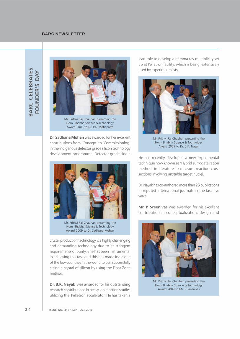
2 4
BARC NEWSLETTERBARC NEWSLETTER
ISSUE NO. 316 • SEP. - OCT. 2010
BA
RC
C
ELEB
RA
TES
FO
UN
DER
’S D
AY
Mr. Prithvi Raj Chauhan presenting the
Homi Bhabha Science & Technology
Award 2009 to Mr. P. Sreenivas
Mr. Prithvi Raj Chauhan presenting the
Homi Bhabha Science & Technology
Award 2009 to Dr. B.K. Nayak
Mr. Prithvi Raj Chauhan presenting the
Homi Bhabha Science & Technology
Award 2009 to Dr. Sadhana Mohan
Dr. Sadhana Mohan was awarded for her excellent
contributions from ‘Concept’ to ‘Commissioning’
in the indigenous detector grade silicon technology
development programme. Detector grade single
lead role to develop a gamma ray multiplicity set
up at Pelletron facility, which is being extensively
used by experimentalists.
Mr. Prithvi Raj Chauhan presenting the
Homi Bhabha Science & Technology
Award 2009 to Dr. P.K. Mohapatra
crystal production technology is a highly challenging
and demanding technology due to its stringent
requirements of purity. She has been instrumental
in achieving this task and this has made India one
of the few countries in the world to pull successfully
a single crystal of silicon by using the Float Zone
method.
Dr. B.K. Nayak was awarded for his outstanding
research contributions in heavy ion reaction studies
utilizing the Pelletron accelerator. He has taken a
He has recently developed a new experimental
technique now known as ‘Hybrid surrogate ration
method’ in literature to measure reaction cross
sections involving unstable target nuclei.
Dr. Nayak has co-authored more than 25 publications
in reputed international journals in the last five
years.
Mr. P. Sreenivas was awarded for his excellent
contribution in conceptualization, design and

2 5ISSUE NO. 316 • SEP. - OCT. 2010
BA
RC
C
ELEB
RA
TES
FO
UN
DER
’S D
AY
development of special heavy structural reactor
equipment and high pressure – high temperature
special valves for nuclear steam generating plants
for various projects of national importance. These
were the first of their kind to be made in the country.
Dr. D. Srivastava was awarded for his excellent
contributions in the field of understanding of the
physical metallurgy aspects of all major diffusional
and diffusionless phase transformations of Zr base
alloys mainly of Zr-2.5Nb, Zr-1Nb, Zircaloy-2 and
Zircaloy-4.
4. Dr. A.C. Bhasikuttan, SO/G, RPCD, CG, BARC
5. Dr. Dibyendu Bhattacharya, SO/F, ApSD, PG,
BARC
6. Dr. R.C. Bindal, SO/H, DD, ChEG, BARC
7. Dr. Jayanta Chattopadhyay, SO/G, RSD,
RD&DG, BARC
8. Mr. Santanu Das, SO/F, UED, MG, BARC &
9. Mr. Raj Kumar, SO/D, UED, MG, BARC
10. Dr. Ashutosh Dash, SO/G, RPhD, RC&IG, BARC
11. Mr. R. Dinesh Babu, SO/G, LWRD, RPG, BARC
12. Dr. Anurag Gupta, SO/F, RPDD, RDDG, BARC
13. Dr. D.C. Kar, SO/G, DRHR, DMAG, BARC
14. Mr. Arbind Kumar, SO/F, QAD, NFG, BARC
15. Mr. K. Madhusoodanan,SO/H, RED, RD&DG,
BARC
16. Ms. Smitha Manohar, SO/G, PDD, NRG, BARC
17. Dr. Hari Sharan Misra, SO/F, MBD, BMG, BARC
18. Dr. S.C. Parida, SO/F, PDD, RC&IG, BARC
19. Dr. Chandra Nath Patra, SO/G, TCS, CG, BARC
20. Mr. H.R. Pimparkar, SO/G, NRB, BARC
21. Dr. S. Pradhan, SO/G, RPD, RPG, BARC
22. Mr. Shyamal Roy, SO/G, RTD, RD&DG, BARC
23. Dr. Alok Samanta, SO/G, TCS, CG, BARC
24. Mr. Sanjay Sethi, SO/F, L&PTD, BTDG, BARC
25. Dr. Jung Bahadur Singh, SO/G, MMS, MG,
BARC
25. Mr. J.L. Singh, SO/H, PIED, NFG, BARC
27. Ms. Padmini Sridharan, SO/G, ED, E&I Group,
BARC
28. Mr. M. Srinivasa Rao, SO/G, RPD, RPG, BARC
29. Dr. Dinesh Venkatesh Udupa, SO/G, ApSD, PG,
BARC.
3. Young Applied Scientist / Technologist
Award carries a Cash award of Rs 50,000/-,
a Citation and a Medal. There were ten award
winners: eight from BARC and one each from IGCAR
and VECC.
1. Mr. Kamlesh Chandra, SO/E, MSD, MG, BARC
2. Dr. Shivanand Chaurasia, SO/E, LNPD, PG, BARC
3. Mr. B. K. Sahoo, SO/D & Mr. Jitendra J. Gaware,
SA/E, RPAD, HS&EG, BARC
4. Mr. Shaji Karunakaran, SO/E, TDD, NRG, BARC
Mr. Prithvi Raj Chauhan presenting the
Homi Bhabha Science & Technology
Award 2009 to Dr. D. Srivastava
The resulting modifications in the process and
microstructure have also resulted in superior
mechanical and corrosion properties, better yield
and enhanced quality of the components.
2. Scientific & Technical Excellence Award
carries a Cash award of Rs 1 Lakh, a Citation and
a Medal. There were thirty eight award winners:
twenty nine from BARC and five from IGCAR, two
from VECC and one each from RRCAT and NFC.
1. Dr. Raghunath Acharya, SO/F, RCD, RC&IG,
BARC
2. Mr. Kailash Agarwal, SO/H, NRB, BARC
3. Dr. Sharmila Banerjee, SO/G RPhD, RC&IG,
BARC

2 6
BARC NEWSLETTERBARC NEWSLETTER
ISSUE NO. 316 • SEP. - OCT. 2010
BA
RC
C
ELEB
RA
TES
FO
UN
DER
’S D
AY
5. Mr. Ramakrishna. P, SO/E, RTD, RD&DG, BARC
6. Mr. P. S. Sarkar, SO/E, LNPD, PG, BARC
7. Mr. Vivek Shrivastav, SO/E, LWRD, RPG, BARC
8. Mr. Ved Prakash Sinha, SO/E, MFD, NFG, BARC.
4. Young Scientist Award carries a Cash award of
Rs 50,000/-, a Citation and a Medal. There were six
award winners: five from BARC and one from RRCAT.
1. Dr. Amit Kumar, SO/D, RB&HSD, BMG, BARC
2. Dr. Atanu Barik, SO/E, RPCD, CG, BARC
3. Dr. (Ms.) Vinita Grover Gupta, SO/E ,Chem.Div.,
CG, BARC
4. Dr. Sanjay Kumar Mishra, SO/D, SSPD, PG, BARC
5. Dr. Pramod Sharma, SO/E, Chemistry Division,
CG, BARC.
5. Young Engineer Award carries a Cash award
of Rs 50,000/-, Citation and a Medal. There were
twelve award winners: ten from BARC and two from
NFC.
1. Mr. Indranil Banerjee, SO/E, RMP, BARC
2. Mr. Radhelal Bharadwaj, SO/F, L&PTD, BTDG,
BARC
3. Mr. Bhuvaneshwar Gera, SO/D, RSD, HS&EG,
BARC
4. Mr. Mukesh Goyal, SO/E, CrTD, ChEG, BARC
5. Mr. M.K. Mishra, SO/E, DRHR, DM&AG, BARC
6. Mr. S.B. Patil, SO/E, TDD, NRG, BARC
7. Mr. Bibhu Narayan Rath, SO/E, PIED, NFG,
BARC
8. Mr. J. Sreejith, SO/E, LWRD, RPG, BARC
9. Ms. Menka Sukhwani, SO/D, ED, E&IG, BARC
10. Mr. Anil Kumar Tiwari, SO/E, CTD, CTG, BARC.
6. Group Achievement Award winners received
cash awards a medal and a Citation. A total number
of forty six Groups received these awards. Out of
these, twenty eight groups were from BARC, six
from IGCAR, four from NFC, three from RRCAT,
two from VECC and one each from DCSEM, BRIT
and HWB. Following were the Group Leaders from
BARC, who received the awards.
1. Mr. H.S. Kamath, Director, NFG, BARC
2. Dr. P.K. Tewari, Head, DD, BARC & Shri A.Y.
Dangore, Plant Supdt., NDDP(Kalpakkam)
3. Mr. P.K. Dey, OS, Head, FRD,BARC& Shri S.K.
Munshi, OS, Chief Supdt., RF, NRG
4. Mr. Arun Kumar, Head, RMD, BARC
5. Mr. R.L. Suthar, Head, CDM, BARC & Shri D.
Saha, A.Director, RD&DG, BARC
6. Dr. S. L. Chaplot, DS, Head, SSPD, BARC
7. Mr. Manjit Singh, Director, DM&AG,BARC
8. Dr. Inderjit Singh, Head, ET&MDS, BARC
9. Dr. A.M. Patankar, Head, TT&CD, BARC
10. Dr. K.C. Mittal, OS, Project Manager, EBC,
BARC
11. Dr. S.M. Sharma, OS, Head, HP&SR Physics
Div., BARC & Dr. N.K. Sahoo, Head, ASD,
BARC
12. Mr. Arup Kumar Pal, SO(G), RED, BARC
13. Mr. V.K. Mehra, Director, RPG, BARC
14. Mr. V.K. Mehra, Director, RPG, BARC
15. Mr. K. Agarwal, SO/H, NRG, BARC
16. Dr. G.P. Kothiyal, OS, TPD, BARC
17. Dr. D. Sathiyamoorthy, OS, Head, PMD, MG,
BARC
18. Dr. V.K. Jain, SO (H+), CD, BARC
19. Dr. Pradeep Kumar K.S., RSSD, BARC
20. Mr. Kalyan Banerjee, SO(H), SWPS, NRG, BARC
21. Mr. R.J. Patel, OS, RTD, BARC
22. Mr. A. Nandkumar, SO(H+), RMP,Mysore
23. Mr. S. Sarkar, PM(Process), RMP/BARC/Mysore
24. Mr. J.K. Mukherjee, SO(H), E&IG,BARC
25. Mr. C Ajayanandan, Head, PSS, RMP, BARC
26. Dr.Sharmila Banerjee, SO(G), RPhD, BARC
27. Mr. A. Rama Rao, SO(H), RED, BARC
28. Mr. Rakesh Kumar Gupta, SO(G), MDD, BARC.
7. Special Contributions Award carries a cash
award of Rs. 50,000/-, a Citation and a Medal.
There were sixty two award winners; sixty one from
BARC and one from DAE.
1. Mr. Gaurav Pandey, BARC
2. Mr. Amit Rav, BARC
3. Mr. Trilok Singh, BARC
4. Mr. S.B. Menon, BARC

2 7ISSUE NO. 316 • SEP. - OCT. 2010
BA
RC
C
ELEB
RA
TES
FO
UN
DER
’S D
AY
5. Mr. P. Ramakrishnan, BARC
6. Dr. M.S. Kale, BARC
7. Mr. P.B. Chaudhary, BARC
8. Mr. S.B. Khune, BARC
9. Mr. T.G. Unni, BARC
10. Mr. R. Mallick, BARC
11. Mr. A.T. Sushibine, BARC
12. Mr. Y.T. Kumbhar, BARC
13. Mr. Jose Joseph, BARC
14. Mr. S.K. Sahoo, BARC
15. Mr. M.B. Kamble, BARC
16. Mr. K.K. Singh, BARC
17. Mr. A.R. Khot, BARC
18. Mr. S.H. Shinde, BARC
19. Mr. S. Mondal, BARC
20. Mr. C. Subramanian, BARC
21. Mr. N.E. Mawal, BARC
22. Mr. D. Selvaraj, BARC
23. Mr. B.T. Nair, BARC
24. Mr. Mohd. Afzal, BARC
25. Mr. N.K. Karnani, BARC
26. Mr. S.T. Pawar, BARC
27. Mr. V.D. Patil, BARC
28. Mr. V.K. Keni, BARC
29. Mr. N. Purushothaman, BARC
30. Mr. B.C. Jamsandekar, BARC
31. Mr. S.K. Pal, BARC
32. Mr. G.P. Mishra, BARC
33. Mr. R.S. Mahadik, BARC
34. Mr. M.N.B. Pillai, BARC
35. Mr. S.N. Pillai, BARC
36. Mr. N. Malviya, BARC
37. Mr. P.F. Pereira, BARC
38. Mr. R.R. Singh, BARC
39. Mr. Suman Lal, BARC
40. Dr. S.K. Sali, BARC
41. Dr. N.K. Kulkarni, BARC
42. Mr. A. K. Pradhan, BARC
43. Dr. D.R. Ghadse, BARC
44. Dr. (Smt.) K. Jayanthi, BARC
45. Mr. B.D. Thakur, BARC
46. Mr. D.D. Patil, BARC
47. Mr. A.K. Ghoderao, BARC
48. Mr.A.K. Singh, BARC
49. Mr. T.P. Chaturvedi, BARC
50. Dr. S.V. Godbole, BARC
51. Mr. C.P. Paul, BARC
52. Mr. D.B. Sutar, BARC
53. Mr. P.C. Lad, BARC
54. Mr. K. Venkataramana, BARC
55. Mr. Rajit Kumar, BARC
56. Mr. Ajay Kumar, BARC
57. Mr. M.H. Rao, BARC
58. Mr. T.B. Walunj, BARC
59. Mr. A.M. Chalke, BARC
60. Mr. D.N. Salunke, BARC
61. Mr. C.G. Vhatkar, BARC.
8. Meritorious Service Awards winners received
Cash award of Rs 20,000/-, a Citation and a Medal.
There were twenty five award winners; nineteen
from BARC, one each from DAE and VECC and
four from IGCAR.
1. Mr.Hiraman Chand Ahire, Sr. Technician/H, RED,
BARC
2. Ms. Kakali Banerjee, APO, PD, BARC
3. Mr. S. N. Bodele, T/H, RSD, HSEG, BARC
4. Mr. N. Chatterjee, Foreman-B, RRMD, BARC
5. Mr. P. S. Ghadge, T’man/H, DRHR, BARC
6. Mr. Sadanand S. Jadhav, Sr. Tech.(J), L&PTD,
BTDG, BARC
7. Mr. N. J. Jagtap, T/E, (Traffic Supervisor), BARC
8. Mr. Mahendra Arjun Kadave, Technician/D, DM/
PD/BARC
9. Mr. Muthathian Krishnan, SA/F, WMD, NRG,
BARC
10. Mr. Mallappa Majjagi, T/G, Assembly Facility,
RMP, BARC
11. Mr. Sharad D. Nalavade, Assistant, PD, BARC
12. Mr. Yagya Narayan Prasad, F/C, AFD, BARC
13. Ms. Mohini P. Raval, SO/F, SIRD, KMG, BARC
14. Mr. Ankush Nagu Sarangule, T/G, ECMS, MG,
BARC
15. Mr.S. S. Sharma, Foreman/C, AFFF, BARC, Tarapur
16. Mr. Vishnu J. Shinde, Foreman/B, RRMD, Reac-
tor Group, BARC
17. Mr. R. B. Shinde, T/G, RMD, NFG, BARC
18. Ms. Malini Suresh, AO, Accounts Division, BARC
19. Mr. H.S. Tamore, Mali D, L & CMS, AG, BARC.

2 8
BARC NEWSLETTERBARC NEWSLETTER
ISSUE NO. 316 • SEP. - OCT. 2010
BA
RC
C
ELEB
RA
TES
FO
UN
DER
’S D
AY
22nd DAE All India Essay Writing Contest
The 22nd DAE All India Essay Contest on Nuclear
Science and Technology for students at the
undergraduate level was held in 2010. A total of
169 essays were received on the following three
topics. The essays were written in English and Hindi.
Topic 1: Bridging the Energy Gap – Role of Nuclear
Energy in India
Topic 2: Recent Developments in Application of
Radiation and Radioisotopes for Societal Benefits.
Topic 3: Recent Uses of Power Beams (Plasma, Laser
and Electrons) in Nuclear Energy and Environment
Management.
Out of the 169 essays received for the contest, 26
were shortlisted. 12 in the merit list for Topic 1, 8
in the merit list for Topic 2 and 6 in the merit list
for Topic 3. The contestants of these essays were
invited to Mumbai, to visit the various facilities of
the Department of Atomic Energy (BARC, BRIT,
ACTREC, Electron Beam Centre at Kharghar, Tarapur
Atomic power Station 1-4) and to make an oral
presentation of their essays before a panel of judges.
The oral presentation was held on October 28, 2010
at the DAE Headquarters at OYC and 23 contestants
made their presentations.
The Chairman AEC, gave away the prizes to the
winners on the Founder’s Day, celebrated on Friday,
October 29, 2010.
The First, Second and Third Prize winners in each
topic were:
Topic 2: Recent Developments in
Application of Radiation and Radio
Isotopes for Societal Benefits
I Prize winner
Mr. Manpreet Singh
Giru B. Tech.II
Coimbatore;
English
II Prize winner
Mr. Kiran Sankar
Chatterjee B.Sc.II
Birbhum;
English
III Prize winner
Ms Dimpee Lahkar MBBS 7th Sem
Dibrugarh;
English
Topic 1: Bridging the Energy Gap – Role
of Nuclear Energy in India
I Prize Winner
Ms. Sonia Sharma Final Year,
BVsc &
AH Bikaner;
Hindi
II Prize Winner
Mr. Paul Benjamin S B.Tech.II
Coimbatore;
English
III Prize winner
Mr. Debmalya Nandy B.Sc. III
Kolkata;
English

2 9ISSUE NO. 316 • SEP. - OCT. 2010
BA
RC
C
ELEB
RA
TES
FO
UN
DER
’S D
AY
Participants of 22nd DAE All India Essay Contest on Nuclear Science and Technology
Topic 3: Recent Uses of Power Beams
(Plasma, Laser and Electrons) in Nuclear
Energy and Environment Management
I Prize winner
Mr. Fasaluraham
Parakkal B.Sc.III
Calicut; English
II Prize winner
Mr. Amit Shastri K. B.Sc.IIMangalore; English
III Prize winner
Mr. Dattatreya Jana B.Sc.II
Kolkata; English
The remaining 14 students were awarded
consolation prizes.

3 0
BARC NEWSLETTERBARC NEWSLETTER
ISSUE NO. 316 • SEP. - OCT. 2010
BA
RC
C
ELEB
RA
TES
FO
UN
DER
’S D
AY
Industrial Safety Awards at BARC
The Industrial Safety Awards Scheme was introduced
by the Industrial Hygiene and Safety Section, RSSD
in the year 2004. These awards in the form of
Industrial Safety Shields are given exclusively to
BARC Units annually based on their safety
performance. The entries from the various Divisions/
Sections/ Units of BARC for the year 2009 were
invited from three different categories of units/
facilities, namely: Category A: Operating Plants,
Category B: R&D Labs and Industrial Units and
Category C: Engineering, Projects and Support Units.
A thorough scrutiny of the entries were made and
a comparative study of all the entries in each
Category was carried out based on the different
parameters in respect of Safety Statistics and Safety
Management Indicators including that of training
and motivational efforts. During the Founder’s Day
programme on October 29, 2010, Shri N.D.
Sharma, Chairman, Industrial Safety Award Scheme
Committee and Chairman, Conventional and Fire
Safety Review Committee announced the winning
units for the year 2009, which were as follows:
A: Operating Plants - Reactor Operations
Division(ROD)-CIRUS Reactor
B: R&D Labs and Industrial Units - Radiometallurgy
Division (RMD),
C: Engineering, Projects and Support Units - N R G
Projects, Kalpakkam.
Representatives from the respective units received
the shield at the hands of Dr. R.K.Sinha, Director,
BARC. The award comprised one Rotating Shield
and a small replica for retention by the respective
winning unit.
On behalf of Reactor Operations Division-CIRUS
Reactor, Mr. S Duraisamy, Head, ROD, N. Ramesh,
Reactor Superintendent, CIRUS Reactor and
S.Mahato, Safety coordinator, CIRUS Reactor
received the shield. Dr T.R.G. Kutty, RMD and
Mr. P.V.Hegde, Safety Coordinator, RMD received
the shield on behalf of Radiometallurgy Division.
Lastly, Mr. Amitava Roy, Project Director and
Mr. A.K.Jha, NRG Projects received the shield on
behalf of NRG Projects, Kalpakkam.
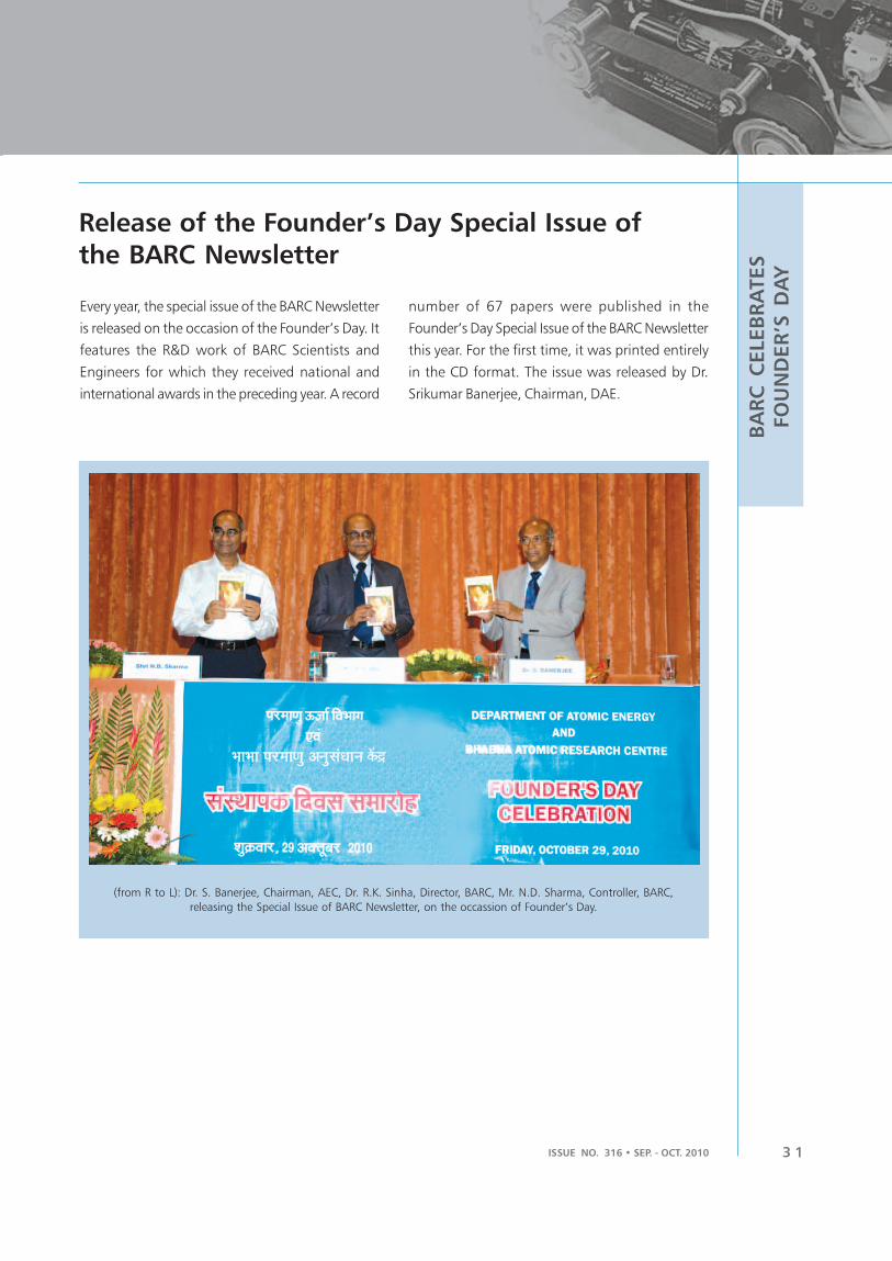
3 1ISSUE NO. 316 • SEP. - OCT. 2010
BA
RC
C
ELEB
RA
TES
FO
UN
DER
’S D
AY
Release of the Founder’s Day Special Issue of
the BARC Newsletter
Every year, the special issue of the BARC Newsletter
is released on the occasion of the Founder’s Day. It
features the R&D work of BARC Scientists and
Engineers for which they received national and
international awards in the preceding year. A record
number of 67 papers were published in the
Founder’s Day Special Issue of the BARC Newsletter
this year. For the first time, it was printed entirely
in the CD format. The issue was released by Dr.
Srikumar Banerjee, Chairman, DAE.
(from R to L): Dr. S. Banerjee, Chairman, AEC, Dr. R.K. Sinha, Director, BARC, Mr. N.D. Sharma, Controller, BARC,
releasing the Special Issue of BARC Newsletter, on the occassion of Founder’s Day.

3 2
BARC NEWSLETTERBARC NEWSLETTER
ISSUE NO. 316 • SEP. - OCT. 2010
BA
RC
C
ELEB
RA
TES
FO
UN
DER
’S D
AY
Founder’s Day Lecture (a brief outline)
by Honourable Mr. Prithvi Raj Chauhan,Minister of State, Prime Minister’s Office, GOI
Mr. Prithvi Raj Chauhan began his talk by
remembering Dr. Homi Jehangir Bhabha on the
occasion of Founder’s Day. It was his farsightedness
which had put India in a position of strength in the
area of Nuclear Science and Technology. He spoke
about the beginning and the subsequent
development of Atomic Energy programme in India
and the contributions of Dr. Bhabha, other Senior
Scientists and Engineers and the unstinting support
of Pandit Jawaharlal Nehru. According to him, India
needed to be more self reliant in all the core
strategic areas as well as the non strategic areas of
national development. Innovation would be the key
to further progress in R&D. He then spoke about
the future energy requirements of India and the
need for innovation and R&D in bio-fuels and other
fuels of the future. Honourable Mr. Chauhan
emphasized the need to reduce the cost of
innovation, which would make any technology
feasible. For this purpose, fusion and deep
commitment between R&D and industry would be
necessary, which would facilitate the transition from
research/innovation to the international market.
Apart from strategic applications of energy and
defence, R&D/Industry cooperation, in other non
strategic applications in Nuclear Science and
Technology such as in Health, Agriculture, Food
and Water also needed to be increased. He summed
up his talk by reiterating that Science, Technology
and Innovation were the three cornerstones of
national development and a New India.
Mr. Prithvi Raj Chauhan, Minister of State, Prime Minister’s Office, GOI delivering the Founder’s Day
Lecture at the Central Complex auditorium
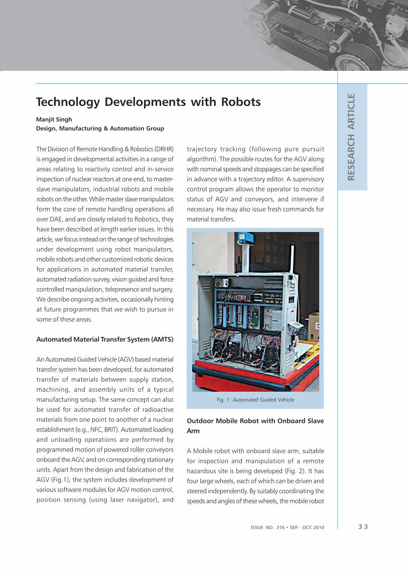
ISSUE NO. 316 • SEP. - OCT. 2010 3 3
RESEA
RC
H A
RTIC
LE
The Division of Remote Handling & Robotics (DRHR)
is engaged in developmental activities in a range of
areas relating to reactivity control and in-service
inspection of nuclear reactors at one end, to master-
slave manipulators, industrial robots and mobile
robots on the other. While master slave manipulators
form the core of remote handling operations all
over DAE, and are closely related to Robotics, they
have been described at length earlier issues. In this
article, we focus instead on the range of technologies
under development using robot manipulators,
mobile robots and other customized robotic devices
for applications in automated material transfer,
automated radiation survey, vision guided and force
controlled manipulation, telepresence and surgery.
We describe ongoing activities, occasionally hinting
at future programmes that we wish to pursue in
some of these areas.
Automated Material Transfer System (AMTS)
An Automated Guided Vehicle (AGV) based material
transfer system has been developed, for automated
transfer of materials between supply station,
machining, and assembly units of a typical
manufacturing setup. The same concept can also
be used for automated transfer of radioactive
materials from one point to another of a nuclear
establishment (e.g., NFC, BRIT). Automated loading
and unloading operations are performed by
programmed motion of powered roller conveyors
onboard the AGV, and on corresponding stationary
units. Apart from the design and fabrication of the
AGV (Fig.1), the system includes development of
various software modules for AGV motion control,
position sensing (using laser navigator), and
Technology Developments with Robots
trajectory tracking (following pure pursuit
algorithm). The possible routes for the AGV along
with nominal speeds and stoppages can be specified
in advance with a trajectory editor. A supervisory
control program allows the operator to monitor
status of AGV and conveyors, and intervene if
necessary. He may also issue fresh commands for
material transfers.
Manjit Singh
Design, Manufacturing & Automation Group
Fig. 1: Automated Guided Vehicle
Outdoor Mobile Robot with Onboard Slave
Arm
A Mobile robot with onboard slave arm, suitable
for inspection and manipulation of a remote
hazardous site is being developed (Fig. 2). It has
four large wheels, each of which can be driven and
steered independently. By suitably coordinating the
speeds and angles of these wheels, the mobile robot

BARC NEWSLETTERBARC NEWSLETTER
ISSUE NO. 316 • SEP. - OCT. 20103 4
RESEA
RC
H A
RTIC
LE
can move along a straight line, turn on an arc, turn-
in-place, and crab. The mobile robot will be
teleoperated from a console equipped with a steering
wheel and paddles for acceleration and brake. It has
an onboard panoramic camera and display software
to enhance situational awareness of the operator.
The vehicle has an Attitude and Heading Reference
System (AHRS) that consists of MEMS based Inertial
Measurement Unit (IMU), integrated GPS and 3-
axis digital compass to make it suitable for
autonomous navigation in a pre-surveyed outdoor
environment. This mobile robot can drive at a speed
of 1m/s on terrains such as pavement, grass, tar
roads etc., and can negotiate a slope of 20% grade.
A slave manipulator will be mounted on the vehicle.
It will be teleoperated with a miniature master arm
located at the control console.
In the near future, we wish to build wheeled and
tracked platforms capable of negotiating stairs, curbs,
ditches and rubbles. With an onboard foldable
manipulator, this kind of robot can be compact and
as locating sources of radiation are routine
requirements in many areas of a nuclear installation.
In order to reduce radioactivity exposure to the
human operators, a small mobile robot equipped
with onboard radiation detectors (1 ìR/hr to 2000
R/hr) has been developed, in collaboration with the
Radiation Safety Systems Division (RSSD) of BARC
(Fig. 3). This battery powered robot is equipped
with a camera for driving remotely using radio
communication from a Graphical User Interface
(GUI) on a host computer. The GUI allows a user to
build a radiation map of a contaminated area. It
also helps in identifying the direction of source of
radiation.
A variant of this robot is being constructed for
monitoring from control room the gamma and
neutron dose in vault areas during operation of
superconducting cyclotron at VECC, Kolkata. In the
future, we have plans to build an array of mobile
robots for radiation survey in indoor as well as
outdoor environments. For building radiation map
over a wide area, coordination of multiple robots
will also be necessary.
Fig. 2: Outdoor Mobile Robot
robust against shocks. Such robots may be gainfully
deployed in anti-insurgency operations.
Automated Radiation Monitoring using
Mobile Robot
Monitoring and mapping of radiation level, as well
Fig. 3: Robot for radiation survey in
indoor environment
Magnetic Climbing Robot
Developed under an MoU with NTPC during July
2007 for inspection of boiler tubes, this robot
comprises two sets of pulley-belt arrangement
individually driven by two high-torque DC geared
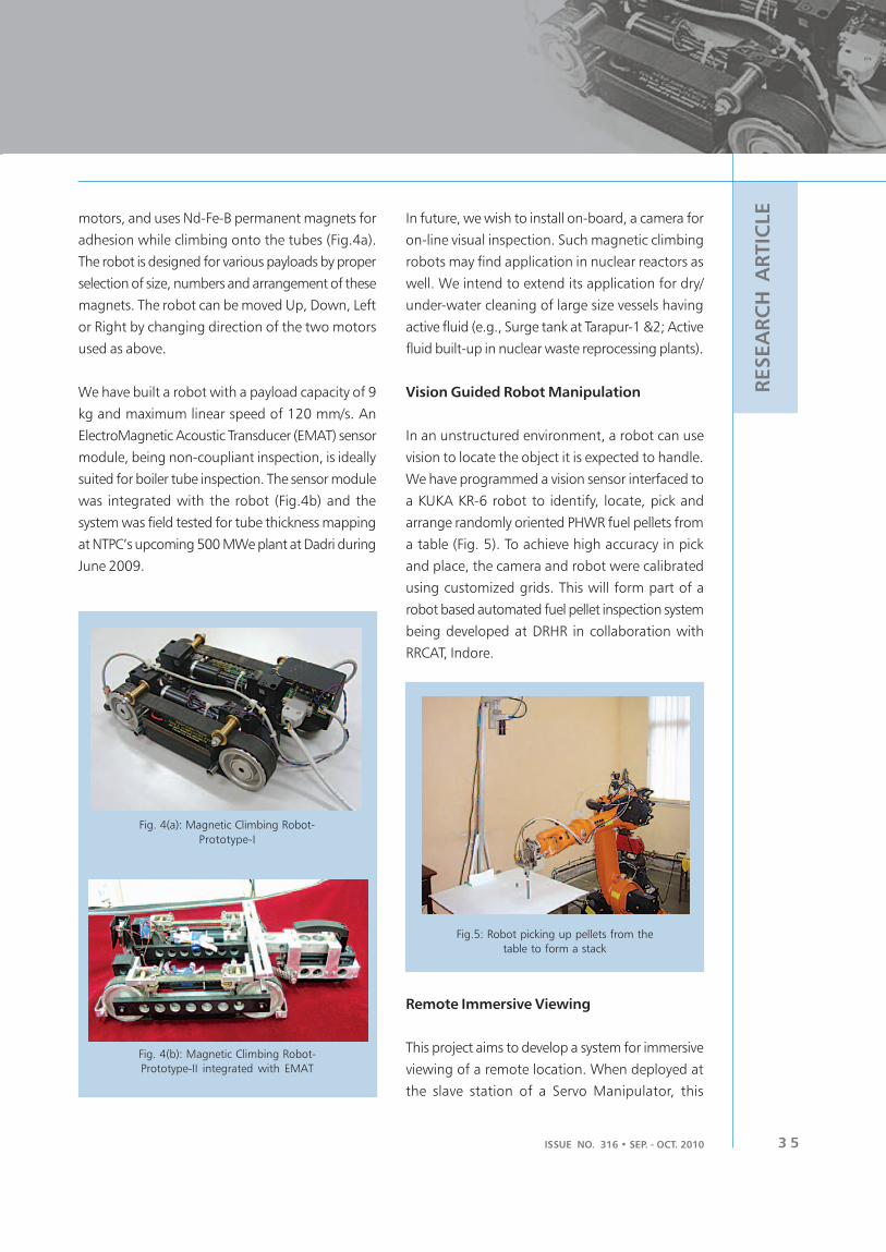
ISSUE NO. 316 • SEP. - OCT. 2010 3 5
RESEA
RC
H A
RTIC
LE
motors, and uses Nd-Fe-B permanent magnets for
adhesion while climbing onto the tubes (Fig.4a).
The robot is designed for various payloads by proper
selection of size, numbers and arrangement of these
magnets. The robot can be moved Up, Down, Left
or Right by changing direction of the two motors
used as above.
We have built a robot with a payload capacity of 9
kg and maximum linear speed of 120 mm/s. An
ElectroMagnetic Acoustic Transducer (EMAT) sensor
module, being non-coupliant inspection, is ideally
suited for boiler tube inspection. The sensor module
was integrated with the robot (Fig.4b) and the
system was field tested for tube thickness mapping
at NTPC’s upcoming 500 MWe plant at Dadri during
June 2009.
In future, we wish to install on-board, a camera for
on-line visual inspection. Such magnetic climbing
robots may find application in nuclear reactors as
well. We intend to extend its application for dry/
under-water cleaning of large size vessels having
active fluid (e.g., Surge tank at Tarapur-1 &2; Active
fluid built-up in nuclear waste reprocessing plants).
Vision Guided Robot Manipulation
In an unstructured environment, a robot can use
vision to locate the object it is expected to handle.
We have programmed a vision sensor interfaced to
a KUKA KR-6 robot to identify, locate, pick and
arrange randomly oriented PHWR fuel pellets from
a table (Fig. 5). To achieve high accuracy in pick
and place, the camera and robot were calibrated
using customized grids. This will form part of a
robot based automated fuel pellet inspection system
being developed at DRHR in collaboration with
RRCAT, Indore.
Fig. 4(a): Magnetic Climbing Robot-
Prototype-I
Fig. 4(b): Magnetic Climbing Robot-
Prototype-II integrated with EMAT
Fig.5: Robot picking up pellets from the
table to form a stack
Remote Immersive Viewing
This project aims to develop a system for immersive
viewing of a remote location. When deployed at
the slave station of a Servo Manipulator, this

BARC NEWSLETTERBARC NEWSLETTER
ISSUE NO. 316 • SEP. - OCT. 20103 6
RESEA
RC
H A
RTIC
LE
enhances the master operator’s ability to manipulate
remotely. The system consists of a pair of cameras
mounted parallel on a pan-Tilt-unit (PTU) and
stationed at the remote (slave) site, and a Head
Mounted Display (HMD) and a head-tracker
installed on the master operator’s head. With signals
from the head-tracker, the camera unit is made to
follow the pitch and yaw motion of the operator’s
head. Head mounted system displays videos from
left and right cameras of the slave environment in
front of respective eyes of the operator. This creates
the desired immersive experience - the operator feels
as if he is present in the slave environment.
Subsequently, parallel cameras were replaced with
toed-in type camera arrangement to achieve better
fusion of left and right eye images of objects close
to the cameras. Other capturing and visualization
techniques such as encoded video streams displayed
on various types of stereoscopic and auto-
stereoscopic display systems are also being designed
and integrated under this project. A typical
arrangement of remote immersive viewing system
is indicated in Fig. 6.
interface, as well as haptic interface through wearable
exoskeleton as master, with cyberglove /cybergrasp
to manipulate a robotic hand on the slave
manipulator.
Force Sensing and Control in Robot
Manipulation
For tasks in which a robot has to operate being in
contact with external objects, it is necessary to sense
the forces of interaction, so it can control its motion
in a way that the task objective is achieved while
keeping forces within their safety limits. A Schunk
Force/Torque (F/T) sensor has been installed at the
wrist of a KUKA KR-6 robot arm, and the robot
programmed for some simple contour following
operations (Fig.7). Here the robot is asked to follow
a certain trajectory exerting a constant force on the
surface of the object. Otherwise, for following
complex shapes in the absence of an F/T sensor, the
programmer has to teach numerous intermediate
points. Even then, if the path does not coincide
exactly with the surface and dimensions of the part,
it may damage the object or tooling. With the help
of an F/T sensor, the robot can easily adapt its path
over the complex contour of the object. This type of
control has applications in robotic machining,
finishing, deburring and polishing operations with
axial or radial tools.
Fig.6: Immersive viewing system
deployed on Mini MSM
In future, we wish to build a telepresence station
for the master operator as an immersive interface
to the remote slave environment. In addition to
visual immersion, it will include stereo audio
Fig. 7: KUKA robot with F/T sensor
tracing a slope

ISSUE NO. 316 • SEP. - OCT. 2010 3 7
RESEA
RC
H A
RTIC
LE
We have also programmed the robot for ‘lead by
hand’, in which the robot is guided to a desired
position, by applying a gentle pressure with hand.
This makes it possible to move heavy loads with
the help of a robot, without having to program it.
Parallel Manipulators
Parallel manipulators are a class of robots; their
architecture and mechanisms give them very high
rigidity and accuracy within a limited workspace.
Various types of Parallel manipulators have been
designed and developed. They can perform high
precision manoeuvres and can handle payloads
higher than their self-weight. Fig. 8 shows a three-
degrees-of-freedom parallel manipulator developed
in the division.
Snake-Arm Robot
Quite often, inspection needs to be carried out in
inaccessible locations, such as the rear side of a
cluster of pipes. No fixed-size manipulator can
access all bends in such a constricted space. Only a
Snake-arm robot may be able to access such a
location. A Snake-arm robot is made up of a large
number of independently controlled segments, so
it can assume various shapes to suit the application.
It can carry a payload ranging from 2kg to 20kg
depending on the number of bends and the distance
it has to cover. We have developed a prototype
snake-arm robot having a total length of 1m (Fig.
10). A second version with a different mounting
configuration is currently under development.
The snake-arm robot can be considered as a human
spine comprising a number of vertebrae. Each
segment is controlled by a set of wire ropes
terminating at various points along the length of
the snake. This permits control of each segment
and thus the curvature and plane of curvature. Using
a servo motor, the length of each wire rope is
controlled independently. The control software
calculates necessary lengths of all the wires to
produce the desired shape. There are sixteen servo
motors controlled simultaneously using a bus
protocol. The software has many modes of
Fig.8: A Three-Degrees-of-Freedom
Parallel Manipulator
Force-Torque Sensor (F-T Sensor)
A jointless parallel mechanism based six-axis Force-
Torque sensor has been developed, along with a
DSP based signal conditioning, processing and
communication system. It is designed to measure
very small forces (1.5N) and moments (50N mm).
Fig. 9 shows the F-T sensor acting as a working
table while performing a robotic operation in
association with a parallel robot.
Fig.9: F-T sensor acting as a sensing support table
during robotic operation
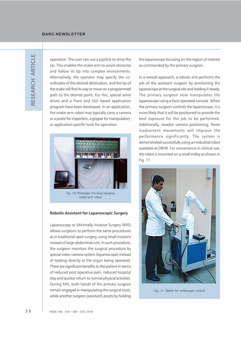
BARC NEWSLETTERBARC NEWSLETTER
ISSUE NO. 316 • SEP. - OCT. 20103 8
RESEA
RC
H A
RTIC
LE
operation. The user can use a joystick to drive the
tip. This enables the snake arm to avoid obstacles
and follow its tip into complex environments.
Alternatively, the operator may specify the co-
ordinates of the desired destination, and the tip of
the snake will find its way or move on a programmed
path to the desired point. For this, special servo
drives and a front end GUI based application
program have been developed. In an application,
the snake-arm robot may typically carry a camera
or a probe for inspection, a gripper for manipulation,
or application specific tools for operation.
the laparoscope focusing on the region of interest
as commanded by the primary surgeon.
In a revised approach, a robotic arm performs the
job of the assistant surgeon by positioning the
laparoscope at the surgical site and holding it steady.
The primary surgeon now manipulates the
laparoscope using a foot-operated console. When
the primary surgeon controls the laparoscope, it is
more likely that it will be positioned to provide the
best exposure for the job to be performed.
Additionally, steadier camera positioning, fewer
inadvertent movements will improve the
performance significantly. The system is
demonstrated successfully using an industrial robot
available at DRHR. For convenience in clinical use,
the robot is mounted on a small trolley as shown in
Fig. 11.
Fig. 10: Prototype 1m long hanging
snake-arm robot
Robotic Assistant for Laparoscopic Surgery
Laparoscopy or Minimally Invasive Surgery (MIS)
allows surgeons to perform the same procedures
as in traditional open surgery, using small incisions
instead of large abdominal cuts. In such procedure,
the surgeon monitors the surgical procedure by
special video camera system (laparoscope) instead
of looking directly at the organ being operated.
There are significant benefits to the patient in terms
of reduced post operative pain, reduced hospital
stay and quicker return to normal physical activities.
During MIS, both hands of the primary surgeon
remain engaged in manipulating the surgical tools,
while another surgeon (assistant) assists by holding
Fig. 11: Robot for endoscope control

ISSUE NO. 316 • SEP. - OCT. 2010 3 9
RESEA
RC
H A
RTIC
LE
As an alternative and cost-effective solution, another
system is also being developed. It has three degrees
of freedom, and all the motions are decoupled. It
can be mounted on the surgical table and can be
powered from a small rechargeable battery. The
basic operations were successfully demonstrated
using the prototype shown in Fig. 12. Both the
systems are planned to be thoroughly tested on
animals at the Christian Medical College (CMC),
Vellore, before using on humans.
The robotic system under development consists of
three miniature (slave) arms - two for holding
interchangeable modular surgical tools; the third
one for manipulating the camera. The surgeon will
sit comfortably at a remote console holding two
master arms.
Programme in Autonomous Robotics at IIT Delhi
A programme, as a collection of projects in
Autonomous Robotics, has been initiated at IIT
Delhi, with support from the Board of Research in
Nuclear Sciences (BRNS). The purpose is to involve
the academia in technology developments in
Robotics. The initial pool of projects relate to force
controlled and vision-guided manipulation with
robots, exploring alternative configurations for
master slave manipulation with an industrial robot,
developing telepresence solutions for immersive
interface to a remote environment, as well as
developing solutions for coordinated operation of
multiple mobile robots. As we already have ongoing
activities in these areas, we expect the programme
to supplement our efforts through development of
technically sound and refined approaches. Some of
these solutions are aimed at meeting two basic
challenges of inserting fuel pellets into clad – under
program control, as well as through teleoperation
using a telepresence interface.
Fig. 12: Alternative robot configuration
for endoscope control
Robotic System for Minimally Invasive Surgery
Although laparoscopic surgery has been a boon in
many surgical procedures, the laparoscopic tools
have limited dexterity, restricting the procedure to
relatively simple operations. Also, these operations
are quite demanding for the surgeons. As an
alternative, a Surgeon can perform operations using
miniature robotic arms in master-slave mode, sitting
comfortably at a remote location. Robots are not
to replace the surgeon, but to extend human skills.
Improved 3D view of the surgical site, force
reflection, tremor-filtration etc., can drastically
improve the surgical performance. Similar devices
are successfully being used in DAE for nuclear (hot-
cell) applications. Miniaturization and some more
improvements can make it suitable for medical
applications.

BARC NEWSLETTERBARC NEWSLETTER
ISSUE NO. 316 • SEP. - OCT. 20104 0
RESEA
RC
H A
RTIC
LE
1. MULTI-SCALE MATERIAL MODELLING
(MMM)
The candidate materials to be used in fusion reactor
applications are low activation or reduced activation
ferritic/martensitic steels (with 9-10% chromium)
due to their high resistance to radiation
embrittlement. The mechanical behaviour of these
materials is not fully understood under the
conditions of fusion environment. The irradiation
of metals by energetic particles, causes significant
degradation of the mechanical properties, most
notably an increased yield stress and decreased
Material Modelling to Assess Properties of
Irradiated Material
ductility. Although these phenomena have been
known for many years, the underlying fundamental
mechanisms and their relation to the irradiation field
have not been clearly demonstrated.
The microstructure of irradiated materials evolves a
wide range of length and time scales, making
radiation damage an inherently multi-scale
phenomenon. At the shortest scales (nano meters,
and pico seconds), recoil-induced cascades of
energetic atomic displacements give rise to highly
non equilibrium concentration of point defects and
point defects clusters. Over micro- macroscopic
B.K. Dutta, P.V. Durgaprasad and K.K.Vaze
Reactor Safety Division
and
N. Naveen Kumar
DGFS-Ph.D. Student, HBNI
Abstract
Development programs for materials for future fusion power reactors are being carried out all over
the world. Possible structural materials for the reactor chamber first wall and blanket structure are
limited, because these materials are expected to operate above 500 oC and see a damage of upto
150-200 dpa. Ferritic/martensitic steels are candidate structural materials to operate at such extreme
conditions. Mechanical behaviour of these materials under irradiation conditions are studied, using
both numerical and experimental techniques. Recent progress in computational materials science,
allows us to understand the behaviour of irradiated materials through numerical simulations.
Multi-scale material modelling is such one computational tool, that helps in the determination of
macroscopic material deformation (MD) behaviour in a hierarchical way. It helps in understanding
the role of nano, micro and meso level defects (voids, dislocations, micro cracks, grain boundaries,
dislocation interactions etc.) in plasticity of materials, so as to support laboratory experiments.
In the present article, we describe BARC in-house work in the area of atomistic modelling of mechanical
behaviour of irradiated materials, with focus on ferritic/martensitic steels. This work also forms part
of ongoing research, on use of multi-scale material modelling methodology, in the determination of
mechanical properties of irradiated structural materials.

ISSUE NO. 315 • SEP. - OCT. 2010 4 1
RESEA
RC
H A
RTIC
LE
length and time scales, these defects can migrate/
diffuse and alter the chemistry and microstructure,
often inducing significant degradation of mechanical
and other properties at continuum scale. It is also
found, that the high energy neutrons produced in
fusion reactions are capable of inducing (n, α)
transmutation reactions in the structural materials
resulting in the production of helium and hydrogen
gas. It has been estimated that the blanket material
in its service life of 5 years receives a dose of
150-200 dpa (Najmabadi et al 2006, Janeschitz et
al 2006) and a helium production of 10-15 appm/
dpa (Juslin et al 2009). These gases, in particular
helium have detrimental effects on the mechanical
behaviour of the materials (Juslin et al 2009, Wirth
et al 2004),
There is ongoing research all over the world on the
use of MMM methodology in the determination of
irradiated material properties. A diagram showing
the use of hierarchical materials modelling is shown
in Fig. 1. The different numerical models at each
scale in MMM are well developed and current
research in MMM is largely devoted to finding
suitable linking mechanisms from one-scale to
another. In the present article, we describe BARC
in-house efforts in MMM for irradiated materials
with focus on MD simulations of dislocation-defect
interactions in Fe, Fe-Cr and Fe-Cr-He systems.
2. ATOMISTIC MODELLING
The present section describes the MD setup to run
dislocation-defect interactions, the methodology of
applying strain to the simulation cell and the
inter-atomic potentials used. The MD simulations
are carried out using public domain molecular
dynamics code LAMMPS (Plimpton et al (1995)).
2.1 Inter-atomic potential for Fe, Fe-Cr and
Fe-Cr-He crystals
The potentials available in published literature are
used for the simulation purpose. The inter-atomic
Fig. 1: Schematic diagram showing multiscale material modeling stages.
(Source http://iron.nuc.berkeley.edu/~bdwirth/Public/WRG/wrg.html)
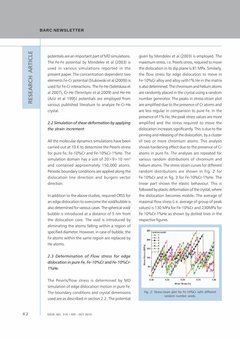
BARC NEWSLETTERBARC NEWSLETTER
ISSUE NO. 316 • SEP. - OCT. 20104 2
RESEA
RC
H A
RTIC
LE
potentials are an important part of MD simulations.
The Fe-Fe potential by Mendelev et al (2003) is
used in various simulations reported in the
present paper. The concentration dependent two
elements Fe-Cr potential (Stukowski et al (2009)) is
used for Fe-Cr interactions. The Fe-He (Seletskaia et
al 2007), Cr-He (Terentyev et al 2009) and He-He
(Aziz et al 1995) potentials are employed from
various published literature to analyze Fe-Cr-He
crystal.
2.2 Simulation of shear deformation by applying
the strain increment
All the molecular dynamics simulations have been
carried out at 10 K to determine the Peierls stress
for pure Fe, Fe-10%Cr and Fe-10%Cr-1%He. The
simulation domain has a size of 20×9×10 nm3
and contained approximately 150,000 atoms.
Periodic boundary conditions are applied along the
dislocation line direction and burgers vector
direction.
In addition to the above studies, required CRSS for
an edge dislocation to overcome the void/bubble is
also determined for various cases. The spherical void/
bubble is introduced at a distance of 5 nm from
the dislocation core. The void is introduced by
eliminating the atoms falling within a region of
specified diameter. However, in case of bubble, the
Fe atoms within the same region are replaced by
He atoms.
2.3 Determination of Flow stress for edge
dislocation in pure Fe, Fe-10%Cr and Fe-10%Cr-
1%He.
The Peierls/flow stress is determined by MD
simulation of edge dislocation motion in pure Fe.
The boundary conditions and crystal dimensions
used are as described in section 2.2. The potential
given by Mendelev et al (2003) is employed. The
maximum stress, i.e. Peierls stress, required to move
the dislocation in its slip plane is 81 MPa. Similarly,
the flow stress for edge dislocation to move in
Fe-10%Cr alloy and alloy with1% He in the matrix
is also determined. The chromium and helium atoms
are randomly placed in the crystal using a random
number generator. The peaks in stress-strain plot
are amplified due to the presence of Cr atoms and
are less regular in comparison to pure Fe. In the
presence of 1% He, the peak stress values are more
amplified and the stress required to move the
dislocation increases significantly. This is due to the
pinning and releasing of the dislocation, by a cluster
of two or more chromium atoms. This analysis
shows hardening effect due to the presence of Cr
atoms in pure Fe. The analyses are repeated for
various random distributions of chromium and
helium atoms. The stress-strain curves for different
random distributions are shown in Fig. 2 for
Fe-10%Cr and in fig. 3 for Fe-10%Cr-1%He. The
linear part shows the elastic behaviour. This is
followed by plastic deformation of the crystal, where
the dislocation becomes mobile. The average of
maximal flow stress (i.e. average of group of peak
values) is 130 MPa for Fe-10%Cr and 230MPa for
Fe-10%Cr-1%He as shown by dotted lines in the
respective figures.
Fig. 2: Stress-strain plot for Fe-10%Cr with different
random number seeds.

ISSUE NO. 315 • SEP. - OCT. 2010 4 3
RESEA
RC
H A
RTIC
LE
2.4 Determination of CRSS for edge dislocation
interacting with voids and bubbles.
2.4.1 Interaction of edge dislocation with voids in
Pure Fe, Fe-10%Cr and Fe-10%Cr-1%He.
The MD simulations of interaction of edge dislocation
with voids/bubbles are carried out, to determine
the CRSS. These can be used as inputs, in the higher
length scale models, such as Discrete Dislocation
Dynamics (DDD). It has been found experimentally
that the vacancies produced in radiation cascade,
accumulate to form vacancy clusters. These clusters
subsequently grow to form nano-metric voids. The
dislocation motion shows the general behaviour
described as follows:
i. Free movement of dislocation in initial stage at
low stress values.
ii. Attraction of edge dislocation by void, resulting
in bending of dislocation and drop in applied
stress.
iii. Pinning and subsequent bowing of dislocation
leading to increase in applied stress with more
and more strain increment.
iv. Release of dislocation by void, resulting in sharp
drop in flow stress, with the formation of step
on the void surface.
A step is formed on the spherical void surface on
slip plane, due to shearing of the void by dislocation.
The dislocation bends due to pinning action of void
with strain increment. In the following section,
interaction of edge dislocation with void in Fe,
Fe-10%Cr and Fe-10%Cr-1%He is discussed. The
boundary conditions and crystal dimensions used
are as described in section 2.2.
The MD simulation of interaction of edge dislocation
with voids in pure Fe is carried out. The void
diameter is varied from 0.8 to 1.6 nm. Fig. 4 shows
stress-strain plot for interaction of edge dislocation
with voids of different diameter. The initial drop in
stress values due to dislocation attraction by void
increases with void size as shown in figure. It is
also observed that the CRSS increases approximately
linearly with void diameter up to 1.6 nm. Similarly,
the interaction of edge dislocation with a void of
diameter 1.6nm is considered for Fe-10%Cr. The
10% Cr atoms are randomly distributed in Fe matrix
with two random number seeds. The stress-strain
behavior is found to be similar as that of pure Fe
with slightly higher CRSS i.e. an increase of 38 MPa
in CRSS is observed due to addition of 10%Cr in Fe
matrix.
The MD simulation of edge dislocation interaction
with voids is carried out for Fe-10%Cr alloy with
1%He. The 10% Cr atoms and 1% He atoms are
distributed randomly in Fe matrix with three different
random number seeds. The stress-strain plot for
interaction of edge dislocation with a void of
diameter 1.6 nm is shown in Fig. 5. The CRSS value
for 1.6 nm voids is 992 MPa. In comparison to
pure Fe, an increase of 190 MPa for 1.6 nm diameter
void is observed. An increase of 150 MPa for 1.6
nm void diameter is observed in comparison to
Fe-10% Cr. There is a significant increase in CRSS
due to the presence of 1%He. Fig. 6 shows the
two stages of interaction of dislocation with void
in Fe-10%Cr-1%He system.
Fig. 3: Stress-strain plot for Fe-10%Cr-1%He
with different random number seeds.
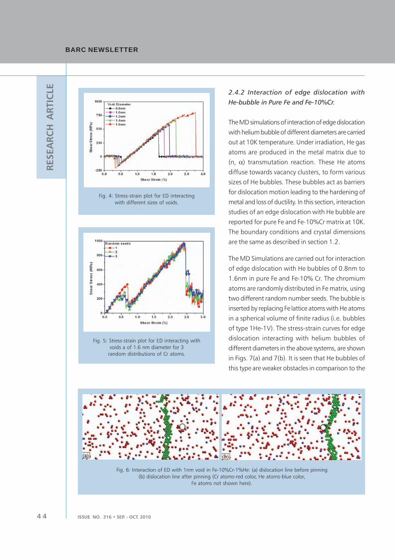
BARC NEWSLETTERBARC NEWSLETTER
ISSUE NO. 316 • SEP. - OCT. 20104 4
RESEA
RC
H A
RTIC
LE
2.4.2 Interaction of edge dislocation with
He-bubble in Pure Fe and Fe-10%Cr.
The MD simulations of interaction of edge dislocation
with helium bubble of different diameters are carried
out at 10K temperature. Under irradiation, He gas
atoms are produced in the metal matrix due to
(n, α) transmutation reaction. These He atoms
diffuse towards vacancy clusters, to form various
sizes of He bubbles. These bubbles act as barriers
for dislocation motion leading to the hardening of
metal and loss of ductility. In this section, interaction
studies of an edge dislocation with He bubble are
reported for pure Fe and Fe-10%Cr matrix at 10K.
The boundary conditions and crystal dimensions
are the same as described in section 1.2.
The MD Simulations are carried out for interaction
of edge dislocation with He bubbles of 0.8nm to
1.6nm in pure Fe and Fe-10% Cr. The chromium
atoms are randomly distributed in Fe matrix, using
two different random number seeds. The bubble is
inserted by replacing Fe lattice atoms with He atoms
in a spherical volume of finite radius (i.e. bubbles
of type 1He-1V). The stress-strain curves for edge
dislocation interacting with helium bubbles of
different diameters in the above systems, are shown
in Figs. 7(a) and 7(b). It is seen that He bubbles of
this type are weaker obstacles in comparison to the
Fig. 4: Stress-strain plot for ED interacting
with different sizes of voids.
Fig. 5: Stress-strain plot for ED interacting with
voids a of 1.6 nm diameter for 3
random distributions of Cr atoms.
Fig. 6: Interaction of ED with 1nm void in Fe-10%Cr-1%He: (a) dislocation line before pinning
(b) dislocation line after pinning (Cr atoms-red color, He atoms-blue color,
Fe atoms not shown here).

ISSUE NO. 315 • SEP. - OCT. 2010 4 5
RESEA
RC
H A
RTIC
LE
voids of same size as highlighted by Schaublin et al
(2007). The stages of interaction of dislocation with
He bubbles as obtained by present computation
are shown in Fig. 8.
3. CONCLUSIONS
The following conclusions may be drawn from the
present simulations:
Fig. 7: Stress-strain plot for interaction of ED with He bubbles of diameter
1.0nm to 1.6nm in a) pure Fe and b) Fe-10%Cr.
Fig. 8: Different stages of interaction of ED-1.6 nm bubble, (a) initial configuration, (b) dislocation attraction,
(c) bowing of dislocation due to pinning by bubble.
BARC NEWSLETTERBARC NEWSLETTER
ISSUE NO. 316 • SEP. - OCT. 20104 6
RESEA
RC
H A
RTIC
LE
1. The average of maximal stress (i.e. flow stress)
for dislocation motion in Fe, Fe-10%Cr, and
Fe-10%Cr-1%He are obtained as 80MPa,
130MPa and 230MPa respectively.
2. In dislocation void interaction, it is found that
the CRSS increases linearly with increase in
void diameter from 0.8 nm to 1.6 nm in
pure Fe.
3. The CRSS required for edge dislocation to
overcome the void of diameter 1.6 nm in
Fe-10%Cr is slightly higher (35-40MPa) than
that of pure Fe. However, the same for Fe-
10%Cr-1%He is significantly (150-160MPa)
higher.
4. The CRSS for interaction of edge dislocation
with He bubble (1He-1V) is close to that of
the void up to 1.0 nm diameter. The same
has been found to be less for the bubbles
having diameter more than 1 nm.
5. The results obtained through the present MD
simulations will be useful in higher length
scale simulations, such as dislocation
dynamics studies.
REFERENCES
1. Aziz R.A., Alec R. Janzen and Michael R.
Moldover, 1995, Physical review letters, 74,
NUM 9.
2. Classical molecular dynamics code: LAMMPS
(http://lammps.sandia.gov).
3. Haghighat H., Fikar J. and Schäublin R.,
2008, Journal of Nuclear Materials, 382,
147–153.
4. Juslin N. and Nordlund K., 2009, Nuclear
Instruments and methods in physics Research
B, 267, 3420-3423.
5. Janeschitz G., Boccaccini L., Fietz W.H.,
Goldacker W., Ihli T., Meyder R., Moeslang
A. and Norajitra P., 2006, Fusion Engineering
and Design, 81, 2661-2671.
6. Mendelev M. I., Srolovitz D. J., Ackland G.
J., Sun D. Y. and Asta M., 2003,
Philosophical magazine ,83, 3977.
7. Najmabadi F., et al. 2006, Fusion Engineering
and Design, 80, 3-23.
8. Plimpton S. J., 1995, Journal of
Computational Physics, 117, 1-19.
9. Stukowski A., Babak Sadigh, Paul Erhart and
Caro A., 2009, Modeling and simulation in
materials science and engineering, 17,
075005.
10. Schaublin R. and Chiu Y. L., 2007, Journal
of nuclear materials, 362, 152-160.
11. Seletskaia T., Yu N Osetsky, Stoller R. E. and
Stocks G. M., 2007, Journal of nuclear
materials, 367-370, 355-360.
12. Terentyev D., Juslin N., Nordlund K. and
Sandberg N., 2009, Journal of applied
physics, 105, 103506.

4 7
TEC
HN
OLO
GY
D
EV
ELO
PEM
EN
T
AR
TIC
LE
ISSUE NO. 316 • SEP. - OCT. 2010
INTRODUCTION
Sugarcane (Saccharum spp.) is an important
industrial crop, ranking among the ten most planted
crops in the world. Besides being the major sugar
contributor with more than 70% of the world’s
sugar, sugarcane is important as the raw material
for sugar producing and allied industries. India is
the largest single producer of sugar, including
traditional cane sugar sweeteners, khandsari and
Gur equivalent to 26 million tonnes raw value
followed by Brazil in the second place [1]. The
Saccharum complex includes the agronomically and
industrially important sugarcane genotypes
obtained from S. officinarum, S. spontaneum and
S. robustum crosses. Although conventional
breeding has contributed to the development of
agronomically improved cultivars, limitations such
as narrow gene pool, complex genome, poor fertility
and the long breeding/selection cycle make it
difficult to undertake further improvement. In
Biotechnological interventions in sugarcane
improvement: Strategies, methods and progress
addition, modern cultivars have a variable
chromosome number (2n=100-120) and rarely
flower. Sugarcane is a typical glycophyte and hence
exhibits stunted growth or no growth under salinity,
with its yield falling to 50% or less than its true
potential. To sustain sugarcane production and to
improve the productivity, tolerance to biotic and
abiotic stresses, nutrient management, improved
sugar recovery are some of the concerns. Both the
conventional and biotechnological methods have
greatly contributed in solving some of these
constraints. This article describes the development
of in vitro culture systems and biotechnological
approaches for use in sugarcane improvement.
IN VITRO CULTURE SYSTEMS - SOMATIC
EMBRYOGENESIS
Plant regeneration in sugarcane can occur through
two main routes, direct and indirect morphogenesis.
In direct morphogenesis, plants are regenerated
P. Suprasanna
Nuclear Agriculture & Biotechnology Division
Abstract
Sugarcane is one of the most important field crops grown in the tropics and sub-tropics. Conventional
and biotechnological research inputs have contributed in solving some of the constraints limiting crop
productivity. However, limitations such as complex genome, narrow genetic base, poor fertility,
susceptibility to biotic and abiotic stresses and long duration to breed elite cultivars, hinder crop
improvement programmes. Sugarcane, thus, is a suitable candidate for application of plant biotechnology
and genetic engineering tools. In this direction, we have been working towards employing in vitro
culture system combined with radiation induced mutagenesis in the improvement of sugarcane.
Several radiation induced mutants with agronomically desirable traits were isolated and evaluated
under field conditions, besides studying abiotic stress responses using biochemical, physiological and
molecular tools. This article describes the developments in the in vitro culture systems and related
biotechnologies that are evolving as novel strategies in the recent years for use in sugarcane
improvement.
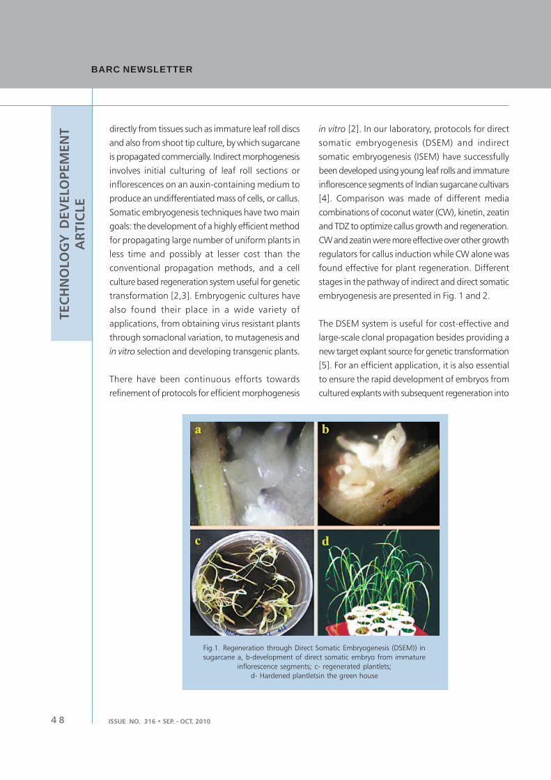
4 8 ISSUE NO. 316 • SEP. - OCT. 2010
TEC
HN
OLO
GY
D
EV
ELO
PEM
EN
T
AR
TIC
LE
BARC NEWSLETTERBARC NEWSLETTER
directly from tissues such as immature leaf roll discs
and also from shoot tip culture, by which sugarcane
is propagated commercially. Indirect morphogenesis
involves initial culturing of leaf roll sections or
inflorescences on an auxin-containing medium to
produce an undifferentiated mass of cells, or callus.
Somatic embryogenesis techniques have two main
goals: the development of a highly efficient method
for propagating large number of uniform plants in
less time and possibly at lesser cost than the
conventional propagation methods, and a cell
culture based regeneration system useful for genetic
transformation [2,3]. Embryogenic cultures have
also found their place in a wide variety of
applications, from obtaining virus resistant plants
through somaclonal variation, to mutagenesis and
in vitro selection and developing transgenic plants.
There have been continuous efforts towards
refinement of protocols for efficient morphogenesis
in vitro [2]. In our laboratory, protocols for direct
somatic embryogenesis (DSEM) and indirect
somatic embryogenesis (ISEM) have successfully
been developed using young leaf rolls and immature
inflorescence segments of Indian sugarcane cultivars
[4]. Comparison was made of different media
combinations of coconut water (CW), kinetin, zeatin
and TDZ to optimize callus growth and regeneration.
CW and zeatin were more effective over other growth
regulators for callus induction while CW alone was
found effective for plant regeneration. Different
stages in the pathway of indirect and direct somatic
embryogenesis are presented in Fig. 1 and 2.
The DSEM system is useful for cost-effective and
large-scale clonal propagation besides providing a
new target explant source for genetic transformation
[5]. For an efficient application, it is also essential
to ensure the rapid development of embryos from
cultured explants with subsequent regeneration into
Fig.1. Regeneration through Direct Somatic Embryogenesis (DSEM)) in
sugarcane a, b-development of direct somatic embryo from immature
inflorescence segments; c- regenerated plantlets;
d- Hardened plantletsin the green house

4 9
TEC
HN
OLO
GY
D
EV
ELO
PEM
EN
T
AR
TIC
LE
ISSUE NO. 316 • SEP. - OCT. 2010
complete plants. The plants derived through DSEM
have been found to be uniform in growth pattern
with more vigour compared to plants derived
through indirect somatic embryogenesis pathway.
When analyzed at the molecular level using RAPD
markers, the plants exhibited no variation [6]. This
method also yielded a large number of plants (7-8
per explant) in a short span of seven weeks.
Assuming an average of 24 segments per
inflorescence, the total number of plants that can
be generated could be around 185–200 [5].
Subsequently this technique of direct somatic
embryogenesis has been extended to several other
sugarcane cultivars suggesting wide adaptability,
and plants raised have been field planted for
performance evaluation.
The induction and maintenance of highly
embryogenic callus is critical for commissioning
research efforts aimed at genetic manipulation of
sugarcane. To optimize the somatic embryogenesis
system, we proposed that analysis of elemental
composition would offer valuable information on
the specificity of the elements with a stage of
development and to provide data that can be used
in formulating suitable nutrient medium to favour
a developmental pattern. Energy-dispersive X-ray
fluorescence technique (EDXRF) was employed to
analyze elemental accumulation during somatic
embryogenesis [7]. Considerable variation was
observed in Mg, K, Ca, Mn, Fe, Cu and Zn with
specific elemental accumulation [higher Mg, K and
Fe] was seen in the early phase of embryogenesis.
The information on the elemental profile could be
useful in formulating specific media for induction
of high frequency of embryogenesis and provision
of modified amounts of elements in culture medium
can have greater benefits for modulating pathways
of differentiation.
BROADENING GENETIC VARIABILITY
THROUGH IN VITRO MUTAGENESIS AND
SELECTION
Induced mutations have contributed significantly
and several mutant varieties have been developed
through mutation breeding. We have been working
towards employing in vitro culture combined with
radiation induced mutagenesis in the improvement
of sugarcane [8]. Somaclonal variation in
combination with in vitro mutagenesis can be
beneficial for the isolation of salinity and drought
tolerant lines in a short duration employing in vitro
selection. Earlier studies using radiation induced
mutagenesis and in vitro techniques led to the
development of salt tolerant mutants in sugarcane
Fig. 2. In vitro selection for salt tolerance in sugarcane : (a) regeneration on control
(without salt) medium, (b) 85.6 mM salt medium respectively,
(c) rooting of the 85.6 mM salt selected plantlets

5 0 ISSUE NO. 316 • SEP. - OCT. 2010
TEC
HN
OLO
GY
D
EV
ELO
PEM
EN
T
AR
TIC
LE
BARC NEWSLETTERBARC NEWSLETTER
using 5, 20, 40 and 60 Gy gamma-ray irradiated
cultures. In our studies, we have used in vitro
mutagenesis in combination with cellular selection
for salt tolerance in popular sugarcane cv. CoC-671
[9]. Embryogenic calli were subjected to gamma
irradiation at different doses (0 - 50 Gy) and exposed
to NaCl (42.8 to 342.2 mM). Cell viability
decreased and higher levels of osmolytes like free
proline and glycine betaine were found to
accumulate in stressed calli as compared to control.
Electrolyte leakage was 2.8 times more under salt
stress and leached out Na+ and K+ were much more
than that of retained in both the adapted and
unadapted callus cultures. The results are indicative
that physiological and biochemical attributes are
critical in alleviating salt stress effects and in
improving salt tolerance in sugarcane.
Under the DAE-BRNS collaborative research with
Dr. Punjabrao Deshmukh Krishi Vidyapeeth, Akola,
field trials of the gamma-ray irradiated plant
population were conducted [8]. The field
performance of the selections was evaluated and
results indicated a broad range of mutations for
morphological, quality and yield contributing
characters were observed (Fig. 3). Mutation
spectrum varied among the cultivars employed for
the study: broader mutation spectrum was observed
for morphological traits in Co 94012, while for
quality and yield traits, Co 86032 showed a wide
range of mutations. A total of 44 clones were
identified for different desirable agronomic traits.
Better performance over respective checks was
recorded for average cane weight and H.R. Brix (%
sucrose) (AKTS 2, 7, 11 of CoC 671; AKTS 22, 26,
27 of Co 86032; AKTS 36,38,39, 44 of Co 94012).
The mutant clones are currently undergoing further
evaluation in rod-row trials for stability in
performance.
PARTIAL DESICCATION STIMULATES SOMATIC
EMBRYO DIFFERENTIATION
In vitro techniques can be employed in various steps
of a mutation-breeding programme and in such a
process, meristematic cells or tissues and mitotically
active cells can be propagated under tissue culture
conditions to prepare sufficient amount of material
for mutagenic treatments. Intrasomatic competition
discriminating mutagen affected cells and
Fig. 3. Mutant with multiple tillering and field view of the irradiated plant population

5 1
TEC
HN
OLO
GY
D
EV
ELO
PEM
EN
T
AR
TIC
LE
ISSUE NO. 316 • SEP. - OCT. 2010
potentially causing a loss of their cell progenies may
be controlled by modifying in vitro conditions
resulting in a better competitiveness of mutant cells.
In sugarcane, we have successfully demonstrated
that partial desiccation for 4-6 hr can be used to
stimulate and enhance somatic embryo
differentiation and regeneration response of gamma-
irradiated embryogenic callus cultures [10].
Subsequently this method has successfully been
extended to other sugarcane cultivars. Water deficit,
directly through partial desiccation, is known to
stimulate ethylene evolution that may influence
morphogenetic response in vitro. Partial desiccation
treatment can offer as a simple and novel approach
in stimulating regeneration response of higher dose
gamma- irradiated cultures.
PRIMING MEDIATES THE INDUCTION OF
STRESS TOLERANCE
Priming methods have been used to accelerate
synchronized seed germination, improve seedling
establishment, stimulate vegetative growth and crop
yield in many field crops, and to perform better
under sub-optimal conditions such as salinity stress.
Improved stress tolerance of primed plants is thought
to arise from the activation of cellular defense
responses, better osmotic adjustment and a better
antioxidant system in primed plants on exposure to
stress. The molecular mechanisms responsible for
priming effects are thought to involve accumulation
of signaling proteins or transcription factors. Priming
is also thought to bring about chromatin
remodeling, which possibly facilitates quicker and
more potent responses to subsequent stress
exposure [11]. In our studies, the effect of
halopriming in improving germination and
subsequent growth was analyzed in four sugarcane
cultivars varying in salt tolerance [12]. Priming
during germination of the sets improved both the
percent and rate of germination. Improved growth
performance of two month-old sugarcane plants in
terms of shoot length, shoot and root fresh weight
was observed when subjected to 15 days iso-
osmotic (-0.7 MPa) NaCl (150mM) or polyethylene
glycol (PEG 8000; 20% w/v) stress. The primed
plants also exhibited lower salt- and dehydration-
induced leaf senescence. Improved osmotic
adjustment appeared to be more critical than
improved antioxidant capacity in facilitating growth
under stress conditions. Steady state transcript
expressional analysis of stress responsive genes
revealed up regulation of NHX and down regulation
of SUT1, P5CS and PDH. The results suggest
halopriming can be useful as an efficient strategy
for imparting abiotic stress tolerance in sugarcane.
MOLECULAR DETAILING OF STRESS RELATED
GENES
The development of genomic technologies that can
yield structural and functional information about
key genes provides useful information through
profiling experiments and/or through the candidate
gene approach. The candidate gene approach is
facilitated by the large number of sequences and
freely available gene information found in plant
genetic databases to identify potential candidate
genes and pathways involved in stress tolerance.
In our studies, we have analyzed the expression
of different stress related genes NHX and
SUT1, P5CS and PDH, involved in direct protection
of plant cells (osmoprotectants, antioxidant
enzymes, ion transporters) or regulatory functions
(signaling genes and transcription factors). On long-
term exposure to salt or PEG stress the steady state
levels of both P5CS, a gene coding for an important
enzyme of the proline biosynthesis pathway and
PDH, which codes for an enzyme which plays a
role in proline catabolism, increased, which
also correlated to proline accumulation under these
stress conditions.

5 2 ISSUE NO. 316 • SEP. - OCT. 2010
TEC
HN
OLO
GY
D
EV
ELO
PEM
EN
T
AR
TIC
LE
BARC NEWSLETTERBARC NEWSLETTER
Plant GSK3/Shaggy-like kinases are involved in
hormone signaling, development and stress
response. We have used PCR based cDNA
suppression subtractive hybridization (SSH)
technique to construct sugarcane salt (NaCl) stress
specific forward and reverse subtracted cDNA library
from salt (NaCl) stressed shoot and root tissues.
Sequencing the clones from the forward subtracted
cDNA library, identified shaggy like protein kinase
(hereafter referred as sugarcane shaggy like protein
kinase-SuSK; NCBI GenBank EST database Acc:
FG804674). The sequence analysis of the SuSK
revealed homology (inclusive of the catalytic
domain) to Arabidopsis thaliana shaggy-related
protein kinase delta (E value: 1e-108), dzeta and iota.
Spatial and temporal transcript expression profiling
of the SuSK gene based on Real Time PCR revealed
significant induction of transcript expression in
response to short-term salt (NaCl 200mM) or
polyethylene glycol-8000 (PEG 20% w/v) induced
osmotic stress in leaves and shoots of sugarcane
plants [13].
TRANSGENIC SUGARCANE
The range of potential applications through the
transfer of genes from a wide variety of plant and
non-plant sources (i.e. creating transgenics) is
increasing rapidly in sugarcane [5]. Some of these
genes include, insect resistance and herbicide
resistance, altered sucrose content via down-
regulation of pyrophosphate-dependent
phosphofructokinase and sucrose accumulation with
antisense soluble antisense acid invertase gene.
Further, genetic engineering of sugarcane varieties
that can produce high-value compounds such as
pharmaceutically important proteins, functional
foods and nutraceuticals, biopolymers and
precursors and enzymes and biopigments is paving
ways to launch sugarcane as a biofactory in coming
years. With the availability of efficient transformation
systems, it should be possible to improve
commercially important traits in elite germplasm
that subsequently can lead to the development of
an ideal plant type of sugarcane.
CONCLUSIONS AND FUTURE DIRECTIONS
The availability of cellular and molecular toolbox
has opened up a plethora of prospects in sugarcane.
Current research is centered on developing
innovative in vitro culture systems with potential
for rapid propagation and generating novel
germplasm with desirable traits. The advances in
sugarcane biotechnology could become remarkable
in the coming years, both in terms of improving
plant productivity as well as gaining ground from a
commercial viewpoint.
ACKNOWLEDGEMENTS
The author gratefully acknowledges the constant
encouragement and support of Dr. S.F. D’Souza,
Associate Director (A), BMG, and Head, NABTD,
during the course of the sugarcane work. Sincere
thanks are also due to all my colleagues, research
associates and students who were closely associated
and contributed to this program. This article is a
tribute to their cooperation and to the belief that
‘team work always prospers’.
REFERENCES
1. Indian Sugar. 2008. Sugar Statistics Vii (11):
57&70
2. Suprasanna, P. and Bapat, V.A. Advances in
the development of in vitro culture systems
and transgenics in sugarcane. Int. Symp.
Technologies to improve sugar productivity
in developing countries. China. (2006) Pp.
629-636.
5 3
TEC
HN
OLO
GY
D
EV
ELO
PEM
EN
T
AR
TIC
LE
ISSUE NO. 316 • SEP. - OCT. 2010
3. Lakshmanan, P., Geijskes, R.J., Aitken, K.S.,
Christopher L.P. Grof, Bonnett, G.D. and
Smith, G.R. Sugarcane Biotechnology: the
challenges and opportunities. In Vitro Cell.
Dev. Biol.—Plant 41(2005):345–363.
4. Desai, N.S, Suprasanna, P. and Bapat, V.A. A
simple and reproducible method for direct
somatic embryogenesis from immature
inflorescence segments of sugarcane. Current
Science 87(6) (2004a): 764-768.
5. Suprasanna, P, Patade YV and Bapat, VA.
Sugarcane Biotechnology - A Perspective On
Recent Developments And Emerging
Opportunities. In: Advances in Plant
Biotechnology. Rao, G.P., Yipeng, Zhao.,
Volodymyr, V.R., Bhatnagar, S. (Ed.) Science
Publishers, USA. (2007) Pp 313-342.
6. Suprasanna, P., Desai, N.S., Sapna, G. and
Bapat V.A. Monitoring genetic fidelity in
plants derived through direct somatic
embryogenesis in sugarcane by RAPD
analysis. Journal of New Seeds 8(3) (2006):
7. Desai, N.S., Joseph, D., Suprasanna, P. and
Bapat, V.A. Study of elemental variations
during somatic embryogenesis in sugarcane
using photon induced X-ray probe. Nuclear
Instruments and Methods - B (NIMB)
252(2007): 299-302.
8. Patade, V.Y. and Suprasanna, P. An in vitro
radiation induced mutagenesis-selection
system for salinity tolerance in sugarcane.
Sug Tech. 11(3) (2009):246-251
9. Patade, V.Y., Suprasanna, P. and Bapat, V.A.
Gamma irradiation of embryogenic callus
cultures and in vitro selection for salt tolerance
in sugarcane (Saccharum offcinarum L.).
Agricultural Sciences in China (2008) 7(9):
101-105.
10. Suprasanna, P, Rupali, C, Desai, N,S, and
Bapat, V.A. Partial desiccation improves plant
regeneration response of gamma-irradiated
embryogenic callus in sugarcane (Saccharum
Spp.). Plant Cell Tiss Org Cult.
92(2008):101–105
11. Bruce, T.J.A., Matthes, M.C., Napier, J.A. and
Pickett, J.A. Stressful ‘‘memories’’ of plants:
Evidence and possible mechanisms. Plant
Science, 173(2007): 603–608.
12. Patade, V.Y., Sujata, B. and Suprasanna,
P. Halopriming imparts tolerance in sensitive
sugarcane cultivar to salt and PEG induced
drought stress. Agri Ecosys. Environ.
134(2009): 24–28
13. Patade, V.Y., Rai, Archana N. and Suprasanna,
P. Transcript expression analysis of sugarcane
shaggy-like kinase (SuSK) gene identified
through cDNA subtractive hybridization in
sugarcane (Saccharum officinarum L.).
Protoplasma 248 (2010), In Press.

BARC NEWSLETTERBARC NEWSLETTER
ISSUE NO. 316 • SEP. - OCT. 20105 4
FEA
TU
RE A
RTIC
LE
1. INTRODUCTION
Computer-based systems are increasingly being used
to implement safety functions as part of
Instrumentation and Control (I&C) systems in Nuclear
Power Plants (NPPs). Any breach of security in these
systems can potentially affect the plant safety.
Besides, the plant availability depends on
smooth operation of I&C systems. I&C
security deals with securing functions of
these I&C systems against malicious
attacks. It is necessary to design, operate
and maintain these systems keeping in
mind the security objectives. For this
purpose, it is necessary to evolve a
systematic, comprehensive and dynamic
methodology to take care of the current
threat scenarios and new threats that could
show up in the future.
Unlike physical security and information
security, I&C security (see box - Definitions)
is a more recent branch of study and
sufficient awareness and importance of this
topic may not be prevalent among all stake
holders. This article attempts to elucidate
the concept, the issues and the
I&C Security for Nuclear Power Plants: A Study
methodology related to managing I&C security,
which is causing increasing concern to the NPP
regulators and operators all over the world.
2. I&C SECURITY
Computer-based I&C systems are extensively used
in NPPs for various purposes: reactor protection,
R.M. Suresh Babu, U. Mahapatra, G.P. Srivastava
Electronics & Instrumentation Group
Abstract
Instrumentation & Control (I&C) security, dealing with protection of I&C functions against unauthorized
modifications, needs to be managed by a systematic, comprehensive and dynamic methodology.
This paper outlines such a methodology based on national and international standards and practices.
It also touches upon typical threats and vulnerabilities related to computer-based systems and associated
safeguards. The article concludes with a brief description of present work and other complementary
approaches and emerging methodologies related to this topic.
Definitions
I&C security: Deals with protecting the functions of
Instrumentation & Control (I&C) systems – especially those
important to NPP safety. This is also termed as computer
system security, cyber security or software security in some
standards/guides.
Physical security: Deals with protecting installation,
equipment, building, etc.
Information security: Deals with protecting information
and information systems from unauthorized access, use,
etc.
Vulnerability: A feature or weakness that can be exploited
to bring out an undesirable consequence.
Threat: Potential to cause an undesirable consequence.
Risk: Perceived consequences of a successful attack:
combination of probability of a security related event and
its consequences.
Malicious code: Virus, Trojan horse, time-bomb, hidden
functions, etc.

ISSUE NO. 315 • SEP. - OCT. 2010 5 5
FEA
TU
RE A
RTIC
LEpower regulation, supervisory controls, control
room displays, data acquisition systems, etc.
Unauthorised modification of these systems (in
software or hardware) or disruption of its functions
can significantly affect the plant operation. It may
affect the plant safety (if safety functions are
affected) or normal operation (if safety related or
other control functions are affected) or it can lead
to mal-operation by the operator (if control room
functions are affected). I&C security is related to
developing safeguards to protect the functions of
I&C systems from these malicious attacks, which
may even be programmed to act at certain time or
condition of the plant. The safeguards should be
systematic – the security features should be built
into the system design and the system development
process; the ‘security patches’ coming as ‘after-
thought’ never give a complete solution. The
safeguards should be comprehensive – covering all
aspects of the system and its operating environment;
the omissions are the ones mostly exploited by
potential attackers. The safeguards should be
dynamic – they should be assessed and updated
on a continuous basis; new vulnerabilities show up
with time and new counter-measures are to be put
in place.
3. SECURITY REQUIREMENT AND OBJECTIVES
The I&C security requirement can be stated as
follows:
“I&C systems of NPPs should be designed, operated
and maintained with adequate security measures
to protect these systems against (sabotage by
insiders or outsiders by) unauthorised modification
of system resources or disruption of its services”
There are three security objectives, namely integrity,
availability and confidentiality. Integrity refers to
correctness of the asset (software/hardware/
configuration, etc.); protection against unauthorized
modification is essential to preserve integrity.
Availability ensures reliable and timely operation/
access of the asset; protection against denial/
disruption of service is essential for meeting this
objective. Confidentiality relates to the restrictions
on the access and disclosure of the asset; this is
generally not relevant to NPP I&C systems, except
in cases where the operational data is confidential.
4. THREATS & VULNERABILITIES
Typical threats to computer-based systems are:
1. Introduce (deliberately/unintentionally) malicious
code in software. This may happen during
development or Operation & Maintenance
(O&M) phase. The malicious code may
be introduced via USB, CD-drive, Ethernet
etc. Malicious code could be virus, Trojan
horse, time-bomb (which is dormant and acts
at a particular time or condition of the plant),
etc.
2. Unauthorized modification of software or
setpoints
3. Alter system configuration (e.g. alter board
settings, I/Os)
4. Jam/disrupt network services
5. Tampering of sensors or sending erroneous data
through network, to give wrong information
about plant status.
Vulnerabilities may exist in the product (e.g. the
system or the software) as well as in the process
(e.g. development). Listed below are some of the
product vulnerabilities:
1. Inadequate safeguard features (e.g. in access
control) or bugs in application software. This
allows potential attacker to gain control & alter
the system resources

BARC NEWSLETTERBARC NEWSLETTER
ISSUE NO. 316 • SEP. - OCT. 20105 6
FEA
TU
RE A
RTIC
LE 2. Unused/unprotected hardware such as USB, CD-
drive etc. These are means to introduce malicious
codes
3. Security holes in Operating System (OS) or
insecure OS. The attacker exploits inherent
vulnerabilities of the OS to gain control of the
system
4. Unknown security bugs in or ‘contaminated’
Pre-Developed Software (PDS).
Unlike in-house products, PDS is not subjected to
thorough Verification & Validation, making it
difficult to understand their inherent security
deficiencies. PDS also may contain hidden functions
or viruses.
It may be noted that use of standard technologies
or products, such as commercial operating systems,
Ethernet network, etc. makes a system more
vulnerable. Hence, use of such products must be
justified for critical systems and adequate care should
be taken in selection, acquisition, qualification and
deployment of such products.
Some of the process vulnerabilities are listed below:
1. Insecure development, testing or validation
environment. This is exploited to mix malicious
software with genuine software, making it very
difficult to detect & eliminate.
2. Insecure/inadequate configuration management
Intermediate or final software products developed
or verified are modified before integrating into
the system. This is applicable to development
phase as well as O&M phase
3. Inadequate verification/validation. Malicious code
goes undetected although subjected to V&V.
5. REGULATORY REQUIREMENTS
AERB safety guide D-25[1] (see box – standards
and guides for computer-based I&C systems) has
recently been updated with specific security
requirements to be satisfied by I&C systems. This
includes protection against unauthorized
modification of setpoints and other resources, role
based access restrictions, tamper proof event logs,
sanitization of pre-developed software, etc.
Unfortunately D-25 does not have enough design
guidance and does not include global issues related
to the complete I&C system and the O&M phase.
International standards of IEC (which are referred
from D-25) are more comprehensive in this respect.
IEC 61513-2001[2] stipulates that an overall security
plan should be prepared for overall I&C systems
and a system security plan - based on the overall
plan and system specific features - should be
prepared for individual systems. IEC 60880-2006[3]
and IEC 62138-2004[4] spell out security
requirements related to software used in class IA
and class IB&IC systems respectively. IEC-60880,
specifically stipulates security requirements to
protect against introduction of malicious code
during software development. I&C security has
invited adequate attention from other international
organizations too.
6. I&C SECURITY FRAMEWORK
Based on AERB and international standards and
guides, mentioned above, a typical I&C security
framework is illustrated in Fig. 1.
An overall security plan should be prepared
addressing the global and common issues related
to all I&C systems. Based on this plan and system
specific security features - revealed by security
analysis of a system – a system security plan should
be prepared for each system. Based on the plan
document and relevant regulatory and enterprise
standards, security policies and procedures are
prepared for the overall I&C system and for individual
system. The plan documents, policies and

ISSUE NO. 315 • SEP. - OCT. 2010 5 7
FEA
TU
RE A
RTIC
LE
procedures give rise to specific system/software
requirements, which are used in the system/software
development. The verification & validation (V&V)
activity assesses, a) if the security requirements are
adequately translated into system/software
requirements; and b) if the system/software design
conforms to the specified requirements, policies and
procedures. The O&M phase uses the
security plans, policies and procedures to
securely operate and maintain the I&C
systems. A security audit should be
conducted periodically to check if the
security plans, policies procedures are
complied with. Security certification may
be obtained from appropriate authorities
to determine the extent to which the
plans, policies and procedures are
implemented correctly, operating as
intended, and producing the desired
results.
These security plans are described in detail
below.
6.1 Overall Security Plan
A preliminary version of this plan may be
prepared by the plant I&C designer taking
into account the overall I&C architecture.
The final version of the plan should be
prepared, maintained and updated by the
utility.
The plan shall specify the security
requirements so as to meet the security
objectives of integrity, availability and
confidentiality. It shall consider the
operating environment of the plant and the
I&C architecture. It should describe set
security controls, which when implemented
would most cost-effectively comply with
the stated security requirements and also
demonstrate the organization’s commitment to
security. There are three types of security controls:
management, operational and technical.
Management controls are techniques and concerns
that are normally addressed by management.
Operational controls address security methods
Standards and Guides for Computer-based I&C Systems
of NPP
I&C systems of Indian NPP’s are governed by AERB safety
guides D-10 – for safety class IA systems – and D-20 – for
safety class IB and IC systems. For computer-based I&C
systems, additional regulatory requirements are specified in
D-25[1].
IEC has a series of standards applicable to I&C systems used
in NPPs. IEC-61513[2] is applicable the system; IEC-60880[3]
and IEC-62138[4] are applicable to software used in class IA
and IB&IC systems respectively.
IAEA safety guides: NS-G-1.3 is applicable to NPP I&C systems
important to safety; and NS-G-1.1 is applicable to software
used in such systems.
Fig. 1: I&C Security Framework

BARC NEWSLETTERBARC NEWSLETTER
ISSUE NO. 316 • SEP. - OCT. 20105 8
FEA
TU
RE A
RTIC
LE focusing on mechanisms, primarily implemented
and executed by people (as opposed to systems).
Technical controls focus on security controls that
the computer system executes. Listed below are
typical security controls addressed in overall security
plan:
1) Management Control
a) Security Planning
b) Security Assessments & Certification
c) Risk Assessment
2) Operational Control
a) Security awareness & training
b) Configuration Management
c) Physical and Environmental Protection
d) System Integrity Monitoring
3) Technical Control
a) Access Control
b) Audit & Accounting
c) Identification and Authentication
d) System and Communication Protection.
Additionally, the overall security plan may dictate
specific security controls to be exercised during
system development.
6.2 System Security Plan
The system security plan is prepared by the system
designer.
As a first step, a security analysis should be
conducted. The security analysis consists of asset
analysis and vulnerability analysis. Asset analysis
examines the importance of the assets, to be secured,
and impact of their failure on the three security
objectives: integrity, availability and confidentiality.
Vulnerability analysis studies the threats and
vulnerabilities associated with the system. The
vulnerability analysis should cover all relevant life-
cycle phases of the system. The overall security
impact of the assets and vulnerability analysis results,
are used to select the right combination of security
controls in system security plan.
The system security plan is prepared by selecting
(and if required augmenting) the security
requirements and security controls from overall I&C
security plan that are applicable to the system and
based on the results of security analysis.
Listed below are typical security controls addressed
in system security plan:
1) Sanitization of PDS, such as operating system
Examples: Validate/scan PDS before using,
execute intrusion tests, use of trusted OS, etc.
2) Configuration management during development
Examples: Use digital signature to authenticate
intermediate software products or the final
validated code. Similar technique may also be
used online to check tampering of the binary
code executing on the target.
3) Access control, Identification and Authentication
4) System and Communication Protection
Examples: Removal/disabling/blocking of
USB ports/Pen drives, on-line checks on
unauthorised network access or abnormal
network activity etc.
5) Integrity checks & system monitoring
Examples: Monitor system/network activity to
detect deviation from normal behavior.
6) Rigorous V&V and intrusion resistance tests.
6.3 Policies and Procedures
Based on the security plans and other governing
standards, policies and procedures are formulated
for overall I&C systems and individual systems or a
group of systems. Like the security plans, these
policies and procedures also should be assessed
periodically and be updated when required.
ISSUE NO. 315 • SEP. - OCT. 2010 5 9
FEA
TU
RE A
RTIC
LE7. CURRENT WORK
The Control Instrumentation Division, E&I Group,
BARC has prepared generic documents for system
security plan, overall security plan and system security
analysis – asset analysis and vulnerability analysis –
based on the methodology described above. These
documents can be adapted and implemented
appropriately to ensure, that the security requirements
have been percolated into the software/system
requirements and software/system design as well as
in the development process. Formulation of these
plans, policies and procedures a priori to development
of a system is expected to make the system more
robust against security related attacks.
8. OTHER APPROACHES/METHODOLOGIES
There are many approaches/methodologies that
complement the methodology given in this article.
Some of these attempt to quantify security attributes
and some attempt to manage risks associated with
various attack scenarios.
The risk management methodology uses a process
by which particular combinations of threat,
vulnerability and impact are identified, documented
and appropriate protective controls are devised. The
process identifies the susceptibility of computer
systems to sabotage, evaluates the system’s
robustness, and provides cost-effective counter
measures to ‘fix the holes’. An example of risk
assessment based approach on a Korean NPP is given
in the paper [5].
There are emerging methodologies [6] that attempt
to quantify security attributes, such as cost of attack,
impact, etc. These models attack scenarios and rely
on probabilistic techniques using attack trees and
Markov chains to derive these attributes. Use of these
techniques in real applications is yet to be established.
9. CONCLUSION
I&C security is a nascent topic, considerable work
is to be done to evolve a robust and cost-effective
approach to manage I&C security. Besides, there is
a need to spread awareness and importance of this
topic among the utilities and I&C system designers,
as I&C security is going to be one of the
key elements for ensuring safe and smooth operation
of NPPs in the future. It must be emphasized that
I&C security is equally applicable to any
plant/installation/device, which uses computer-
based control, and for which any of the security
attributes – safety, availability or confidentiality -
are critical.
10. REFERENCES
1. AERB safety guide for computer based systems
of pressurised heavy water reactor, AERB/SG/D-
25 January 2010.
2. IEC 61513-2001, “NPP I&C systems important
to safety - General requirements”, 2001.
3. IEC 60880-2006, “NPP I&C systems important
to safety - Software aspects of computer based
systems performing category A functions”,
2006.
4. IEC 62138-2004, “NPP I&C systems important
to safety - Software aspects of computer based
systems performing category B or C functions”,
2004.
5. “Risk Assessment-based Cyber Security
Requirements for Design of SFR Safety I&C”,
CK Lee, IAEA Technical Meeting, November
2008, Beijing.
6. “Modeling and Quantification of Security
Attributes of Software Systems”, K.S Trivedi, B.
Madan, K. Goseva-Popstojanova and K.
Vaidyanathan, Performance Evaluation, Vol. 56,
issues 1-4, pp.167-186, March 2004.

BARC NEWSLETTERBARC NEWSLETTER
ISSUE NO. 316 • SEP. - OCT. 20106 0
FEA
TU
RE A
RTIC
LE
1. INTRODUCTION
U-rich U-Zr alloys are of interest, because of their
potential use in low power or research reactors;
since Zr has a low thermal-neutron cross section.
Also, the U-Zr binary alloy system is an important
subsystem of the U-Pu-Zr ternary system that has
been recognized as a promising metallic fuel for
fast breeder reactors. Moreover, uranium alloyed
with Zr shows excellent corrosion resistance and
dimensional stability during thermal cycling. These
favorable properties have led to the development
of uranium-zirconium fuel for reactor use in several
countries. In fact, the U-10wt%Zr alloy was used
in EBR-II, USA in early 1985 [1]. The present study
details the following aspects of U-rich, U-Zr alloy
alloys –
i. Evolution of the as-cast microstructures in U-
rich U-Zr alloys.
ii. Formation of UZr2 phase (δ-phase) in U-rich U-
Zr alloy.
iii. Mechanism of the γ δ→ phase
transformation in U-50wt%Zr alloy.
Phase Transformations in U-Zr Alloy System
2. PRE-CHARACTERIZATION
METHODOLOGIES
U-rich U-Zr alloys (upto 10wt%Zr) were melted in
a vacuum induction melting furnace at
approximately 100°C above their liquidus
temperature. The Zr-rich U-Zr alloy (e.g. 50wt%Zr),
on the other hand, was melted in a non-consumable
vacuum arc melting furnace. In both melting
practices, oxygen impurity in Ar gas was removed,
by passing it over hot uranium turnings. In the case
of arc melting, the alloy buttons were remelted
several times to ensure chemical homogeneity. The
alloy buttons were then jacketed in copper tubes
and hot rolled at 850°C to 75% reduction in
thickness.
Though U-Zr alloys are amenable to the standard
metallographic practice, the etching characteristic
varies considerably with Zr content. For U-rich
U-Zr alloys, water and phosphoric acid mixture
(1:1 V/V) was used for both electro-polishing
and electro-etching, with a constant open
Chandra Bhanu Basak
Materials Science Division
Abstract
U-Zr alloy system is a potential candidate for metallic fuels for nuclear reactors. In this context, it is
important to understand the phase transformation characteristics of this alloy, as it will govern the
in-pile behaviour. The present study is limited to the U-rich part of the U-Zr system, i.e. alloys containing
upto 10wt%Zr. However, the U-50wt%Zr composition was also thoroughly investigated to obtain
a deeper understanding of the phase transformations involving gamma and delta (UZr2) phases. The
results of the present work provide a new insight into the structural and microstructural changes in
U-Zr alloys. The present work also tries to address some of the important aspects of phase transformation
reported in literature that were either misinterpreted or inadequately addressed.
Keywords: Uranium, Zirconium, Delta phase, Phase transformation, Characterization
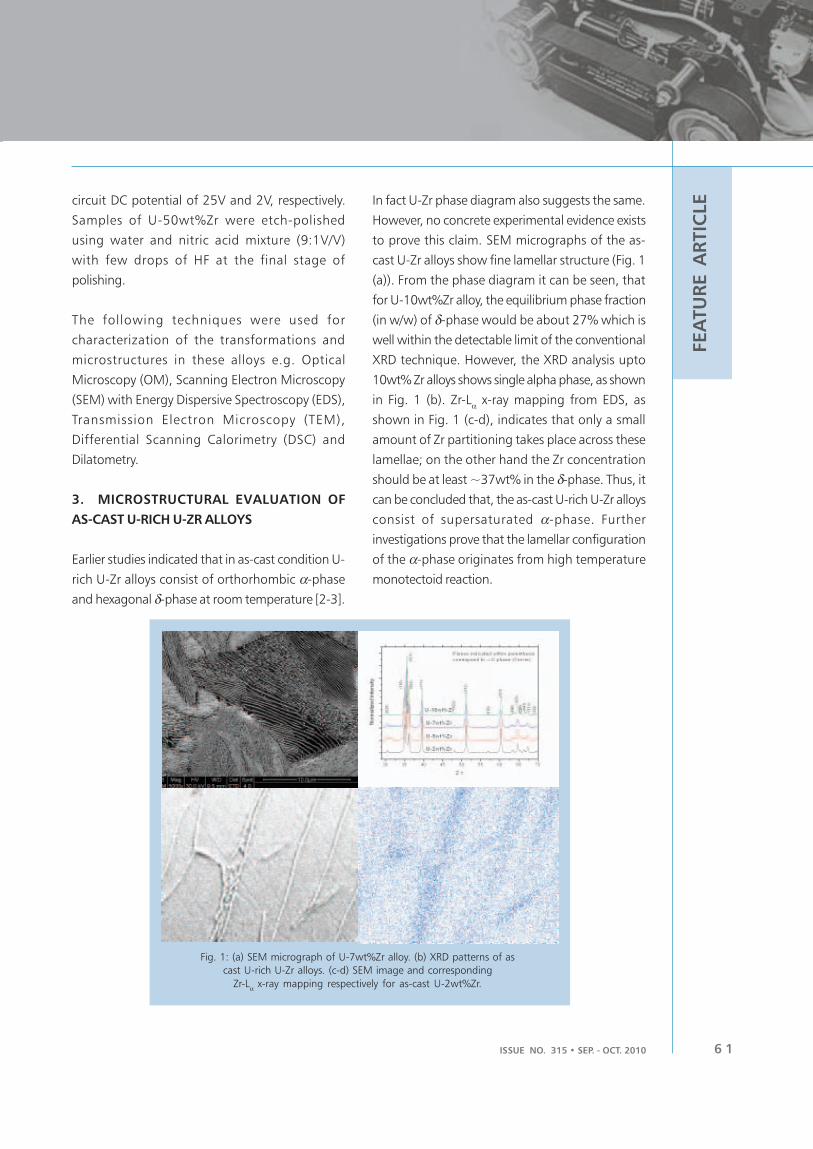
ISSUE NO. 315 • SEP. - OCT. 2010 6 1
FEA
TU
RE A
RTIC
LEcircuit DC potential of 25V and 2V, respectively.
Samples of U-50wt%Zr were etch-polished
using water and nitric acid mixture (9:1V/V)
with few drops of HF at the final stage of
polishing.
The following techniques were used for
characterization of the transformations and
microstructures in these alloys e.g. Optical
Microscopy (OM), Scanning Electron Microscopy
(SEM) with Energy Dispersive Spectroscopy (EDS),
Transmission Electron Microscopy (TEM),
Differential Scanning Calorimetry (DSC) and
Dilatometry.
3. MICROSTRUCTURAL EVALUATION OF
AS-CAST U-RICH U-ZR ALLOYS
Earlier studies indicated that in as-cast condition U-
rich U-Zr alloys consist of orthorhombic α-phase
and hexagonal δ-phase at room temperature [2-3].
In fact U-Zr phase diagram also suggests the same.
However, no concrete experimental evidence exists
to prove this claim. SEM micrographs of the as-
cast U-Zr alloys show fine lamellar structure (Fig. 1
(a)). From the phase diagram it can be seen, that
for U-10wt%Zr alloy, the equilibrium phase fraction
(in w/w) of δ-phase would be about 27% which is
well within the detectable limit of the conventional
XRD technique. However, the XRD analysis upto
10wt% Zr alloys shows single alpha phase, as shown
in Fig. 1 (b). Zr-Lα x-ray mapping from EDS, as
shown in Fig. 1 (c-d), indicates that only a small
amount of Zr partitioning takes place across these
lamellae; on the other hand the Zr concentration
should be at least ~37wt% in the δ-phase. Thus, it
can be concluded that, the as-cast U-rich U-Zr alloys
consist of supersaturated α-phase. Further
investigations prove that the lamellar configuration
of the α-phase originates from high temperature
monotectoid reaction.
Fig. 1: (a) SEM micrograph of U-7wt%Zr alloy. (b) XRD patterns of as
cast U-rich U-Zr alloys. (c-d) SEM image and corresponding
Zr-Lα x-ray mapping respectively for as-cast U-2wt%Zr.

BARC NEWSLETTERBARC NEWSLETTER
ISSUE NO. 316 • SEP. - OCT. 20106 2
FEA
TU
RE A
RTIC
LE
With the help of free-energy composition diagram
and (C0, T
0) trace it might be possible to see if it is
thermodynamically possible to get the supersaturated
α-phase at room temperature. Being a substitutional
solid solution it could be expected that the diffusivity
of Zr in α-U would be low. Though there is no data
available on the α-phase, even the high temperature
bcc γ-phase in U-Zr system shows one order
magnitude of lower inter-diffusion coefficient than that
of fcc Au-Ni system [4]. Thus in order to predict the
thermodynamic origin of the as-cast structure, the
concept of lowest common tangent could no longer
be applicable. So, the as-cast structure in U-Zr system
cannot be explained by the global thermodynamic
equilibrium as predicted by the phase diagram.
Comparing the Fig. 2 (a) and (b) it is apparent that as
temperature decreases the C0 value for α-γ pair shifts
towards higher Zr content. The (C0, T
0) trace,
superimposed on the phase diagram, is presented in
Fig. 2 (c) showing the hatched area where only α-
phase is stable under supersaturated condition.
4. FORMATION OF UZr2 PHASE (δδδδδ−−−−−PHASE) IN
U-RICH U-ZR ALLOY
Naturally the question arises as how the UZr2 phase
forms in U-rich U-Zr alloys. To answer this question
a prolonged heat-treatment schedule was designed
where, the holding time was increased below the
monotectoid and eutectoid isotherms. The
heat-treatment schedule consists of 480hrs. of
holding at 680°C followed by 1520hrs. of soaking
at 650C and a final soaking at 600°C for 500hrs
and 2880hrs respectively.
The XRD results confirm the presence of delta phase
even in Zr-lean U-2wt%Zr alloy as shown in Fig. 3
(a). In fact using GSAS computer program, the lattice
parameter and site occupancy of the α-matrix in
different alloys were determined with high
precision. After, 2880hrs. of soaking at 600°C it
was seen that the lattice parameters of the Zr-lean
α-matrix do not vary significantly from one alloy to
another. This clearly indicates that the phases in
these heat treated alloys have reached the
equilibrium state in terms of compositions and
structure. The SEM micrograph of U-7wt%Zr alloy
is presented in Fig. 3 (b) showing the precipitates
of the delta phase in the α-matrix. In fact one can
clearly see the striking difference between the as-
cast microstructure and the microstructure
containing δ-phase comparing Fig. 1(a) to Fig. 3
(b). Also, EDS results (not shown here) clearly
indicate the Zr content of these particles is nearly
37% whereas the same in the matrix is below
detectable limit. These results clearly show that
formation of δ-phase in U-rich U-Zr alloys is
kinetically very sluggish in nature. Evidently, in U-
rich U-Zr alloys formation of the δ-phase is highly
unlikely in as-cast condition.
Fig. 2. (a-b) Traces of (C0, T
0) at 600°C and 200°C respectively and (c) region of
supersaturated alpha phase (hatched area) superimposed on the phase diagram.
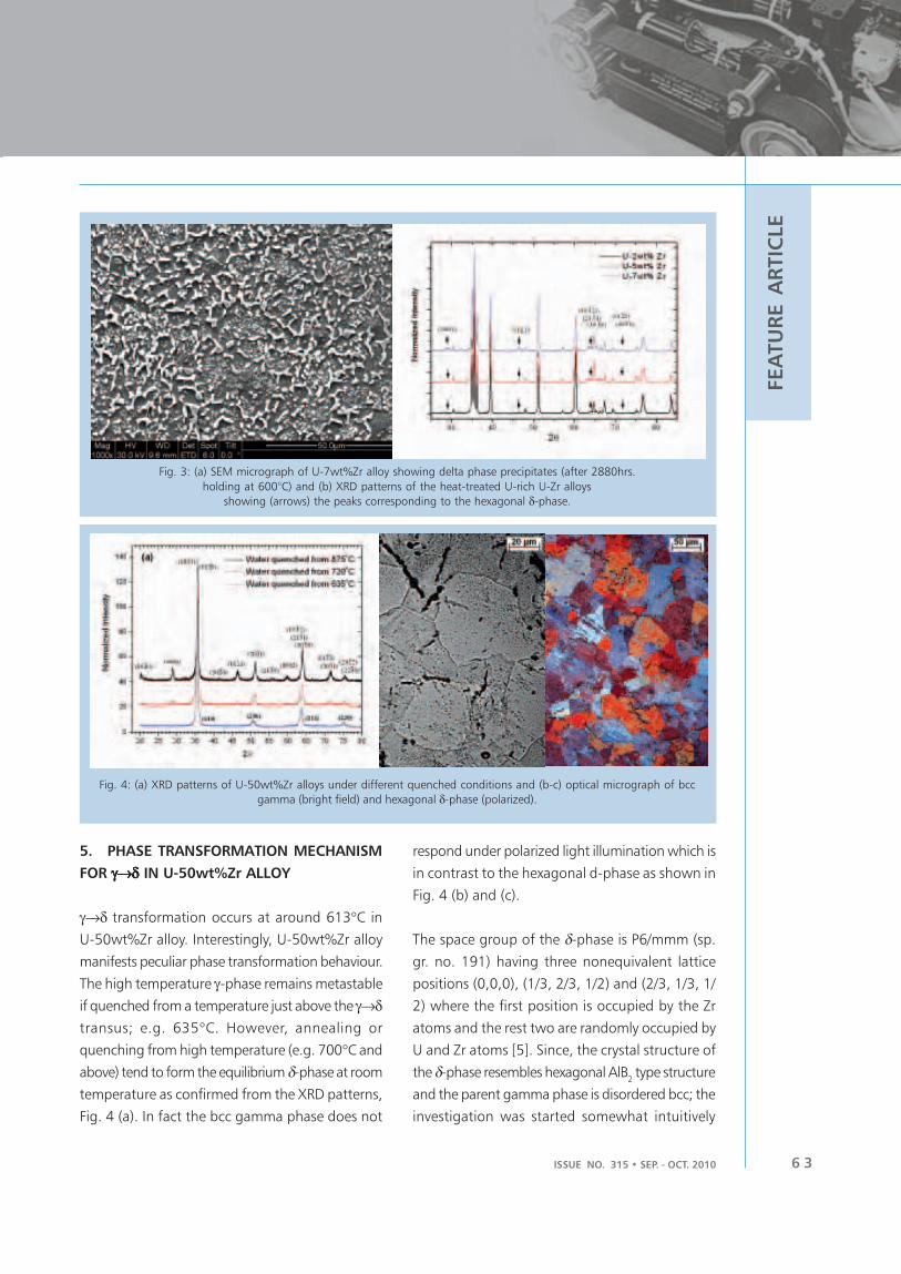
ISSUE NO. 315 • SEP. - OCT. 2010 6 3
FEA
TU
RE A
RTIC
LE
5. PHASE TRANSFORMATION MECHANISM
FOR γ→δγ→δγ→δγ→δγ→δ IN U-50wt%Zr ALLOY
γ→δ transformation occurs at around 613°C in
U-50wt%Zr alloy. Interestingly, U-50wt%Zr alloy
manifests peculiar phase transformation behaviour.
The high temperature γ-phase remains metastable
if quenched from a temperature just above the γ→δtransus; e.g. 635°C. However, annealing or
quenching from high temperature (e.g. 700°C and
above) tend to form the equilibrium δ-phase at room
temperature as confirmed from the XRD patterns,
Fig. 4 (a). In fact the bcc gamma phase does not
Fig. 3: (a) SEM micrograph of U-7wt%Zr alloy showing delta phase precipitates (after 2880hrs.
holding at 600°C) and (b) XRD patterns of the heat-treated U-rich U-Zr alloys
showing (arrows) the peaks corresponding to the hexagonal δ-phase.
Fig. 4: (a) XRD patterns of U-50wt%Zr alloys under different quenched conditions and (b-c) optical micrograph of bcc
gamma (bright field) and hexagonal δ-phase (polarized).
respond under polarized light illumination which is
in contrast to the hexagonal d-phase as shown in
Fig. 4 (b) and (c).
The space group of the δ-phase is P6/mmm (sp.
gr. no. 191) having three nonequivalent lattice
positions (0,0,0), (1/3, 2/3, 1/2) and (2/3, 1/3, 1/
2) where the first position is occupied by the Zr
atoms and the rest two are randomly occupied by
U and Zr atoms [5]. Since, the crystal structure of
the δ-phase resembles hexagonal AlB2 type structure
and the parent gamma phase is disordered bcc; the
investigation was started somewhat intuitively

BARC NEWSLETTERBARC NEWSLETTER
ISSUE NO. 316 • SEP. - OCT. 20106 4
FEA
TU
RE A
RTIC
LE
towards exploring the omega transformation
mechanism.
TEM investigation reveals the presence of a very
small amount of δ-phase in the metastable γ-phase,
which otherwise could not be detected in XRD.
Ageing of this metastable γ-phase shows diffuse
streaking in the diffraction patterns. With increasing
ageing time, these streaks finally transform into spots
and further ageing finally promotes single variant d-
phase; as shown in Fig.5 (a-c). These observations
clearly indicate that the γ→δ transformation takes
place by omega transformation where 2/3 of the
(111) planes of bcc gamma phase collapse and give
rise to hexagonal UZr2 δ-phase. Clearly, ageing for
longer duration indeed promotes the growth of the
different variants of the delta phase.
6. CONCLUSIONS
The present article emphasizes the following points
related to the phase transformation behaviour in U-
Zr alloy system –
i. In U-rich U-Zr alloys (upto 10wt%Zr), the
as-cast structure is lamellar due to the higher
thermodynamic driving force below the
monotectoid isotherm. Only a small amount
of solute (Zr) partitioning takes place across
the lamellae. So, the as cast structure of the
U-rich U-Zr alloys could be considered as
Zr-supersaturated α-phase.
ii. Formation of δ-phase in the U-rich U-Zr alloy
could be established beyond doubt by a
specially designed heat-treatment schedule.
This further emphasizes that δ-phase cannot
be formed under as-cast condition.
iii. U-50wt%Zr alloy exhibits metastable γ-phase
if it is quenched from a temperature just
above the equilibrium transformation
temperature (~613°C). This retention is due
to the lack of driving force for omega
transformation. The metastable γ-phase,
upon ageing, eventually transforms into
equilibrium δ-phase by plane collapsing
omega transformation mechanism.
REFERENCES
1. L.C. Walters, J. Nucl. Mat. 270 (1999) 39-
48
2. F. A. Rough, Report No. BMI-1030, Battelle
Memorial Institute, Metallurgy and ceramics,
M-3697, 16th Ed. (1955) 1.
3. A. A. Bauer, Report No. BMI-1350, Battelle
Memorial Institute, UC-25 Metallurgy and
ceramics, TID-4500, 15th Ed. (1959) 1.
4. T. Ogata, M. Akabori, A. Itoh, T. Ogawa, J.
Nucl. Mat. 232 (1996) 125.
5. M Akabori, T Ogawa, A Itoh, Y Morii,
J. Phys.: Condens. Matter. 7 (1995) 8249.
Fig. 5. Selected Area Electron Diffraction (SAED) patterns of U-50wt%Zr alloy along [110] zone axis showing;
(a) metastable γ-phase with streaking, (b) multi-variant δ-phase after ageing at 300°C for 4 hrs. and
(c) single variant δ-phase after ageing at 300°C for 24 hrs.

ISSUE NO. 315 • SEP. - OCT. 2010 6 5
FEA
TU
RE A
RTIC
LE
1. INTRODUCTION
In India, high temperature reactor development
programme was initiated because of a need to
develop alternate energy carrier to substitute fossil
fuel based transport fuel [1]. Hydrogen production
processes by thermo-chemical splitting of water
need either electricity or process heat at high
temperature, or both depending upon the process
of hydrogen production selected. High temperature
nuclear reactors have a large potential for sustainably
supplying energy for these hydrogen production
processes at required high temperature conditions.
BARC is currently developing high temperature
nuclear reactors capable of supplying process heat
at a temperature around 1000 ºC. Presently,
technology development for a small power Compact
High Temperature Reactor (CHTR) capable of
supplying high temperature process heat at
1000 ºC is being carried out. In addition, preliminary
design of a 600 MWth reactor, capable of supplying
Indian High Temperature Reactor
Programme: An Overview
heat at 1000 ºC for large scale hydrogen production,
is in progress.
2. COMPACT HIGH TEMPERATURE REACTOR
The CHTR [2] is being developed as a prototype
reactor, for the development and demonstration of
technologies associated with high temperature
reactors. The reactor is modular in design and is
being designed to be compact in weight and size
for ease in its deployment in remote locations for
its use as a compact power pack. It has a prismatic
core configuration consisting of nineteen hexagonal
shaped beryllium oxide (BeO) moderator blocks.
These blocks contain centrally located fuel tubes.
Fuel tubes would be made of high density, isotropic,
nuclear grade carbon-carbon composite or graphite.
They would be coated with oxidation-resistant
coatings. Each fuel tube carries fuel compacts inside
longitudinal bores made in its wall. Thorium-233U
based fuel compacts are made-up of Tri-Isotropic
I.V. Dulera
Reactor Engineering Division
and
R.K. Sinha
Reactor Design & Development Group
Abstract
High temperature reactors have a large potential to provide necessary high temperature process
heat for hydrogen production, through high efficiency hydrogen production processes. BARC is
carrying out developmental work related to various aspects of high temperature nuclear reactors.
Besides design, R & D work encompasses development of high temperature high burn-up fuel,
special materials, joining technologies, coatings, characterization techniques, instrumentation, passive
systems for high temperature thermal management, high temperature heat pipes, systems for reactor
safety. Studies planned to be carried out include, seismic behaviour, irradiation behaviour of fuel and
materials, inter material compatibility, oxidation and corrosion-related studies.

BARC NEWSLETTERBARC NEWSLETTER
ISSUE NO. 316 • SEP. - OCT. 20106 6
FEA
TU
RE A
RTIC
LE (TRISO) coated particle fuel [3], facilitating high
burnup and high temperature application. The fuel
tube also serves as coolant channel. Molten Lead-
Bismuth Eutectic (LBE) alloy has been chosen as
coolant. Twelve movable and six fixed reflector blocks
of BeO surround the moderator blocks. These are in
turn surrounded by graphite reflector blocks. These
components are contained in a reactor shell of a
material, resistant to corrosion against LBE, and
provided for return of the cold coolant to lower
plenum. The reactor shell is surrounded by two gas
gaps that act as insulators during normal reactor
operation and reduce heat loss in the radial direction.
These gas gaps help in dissipating neutronically
limited power to an external sink, in case of a
postulated accident. A passive system has been
provided to fill these gas gaps with molten metal in
case of abnormal rise in coolant channel outlet
Fig. 1: Cross-sectional view of Compact High Temperature Reactor
suitable for high temperature applications. Cross-
sectional layout of the reactor is shown in Fig.1.
Top and bottom closure plates of similar high
temperature and corrosion-resistant material, close
this reactor shell. Above the top cover plate and
below the bottom cover plate, cyclindrical vessels
called coolant plenums are provided for coolant
exit and entry into the core respectively. Upper
plenum has graphite block for guiding coolant flow,
between the fuel tube and down comer tube
temperature. Nuclear heat from the reactor core is
removed passively by natural circulation based flow
of coolant between the two plenums, upward
through the fuel tubes and returning through the
downcomer tubes. On top of the upper plenum,
the reactor has heat utilization vessels to provide
an interface to systems for high temperature process
heat applications. A set of sodium heat pipes
passively transfer heat from the coolant to these
heat utilization vessels. To shut down the reactor, a
set of seven tantalum alloy based shut-off rods has
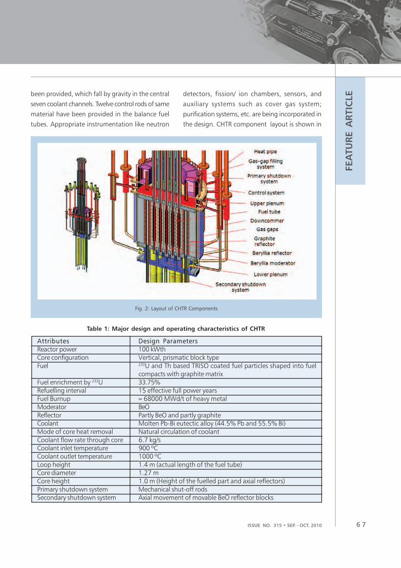
ISSUE NO. 315 • SEP. - OCT. 2010 6 7
FEA
TU
RE A
RTIC
LEbeen provided, which fall by gravity in the central
seven coolant channels. Twelve control rods of same
material have been provided in the balance fuel
tubes. Appropriate instrumentation like neutron
detectors, fission/ ion chambers, sensors, and
auxiliary systems such as cover gas system;
purification systems, etc. are being incorporated in
the design. CHTR component layout is shown in
Fig. 2: Layout of CHTR Components
Table 1: Major design and operating characteristics of CHTR
Attributes Design Parameters
Reactor power 100 kWth
Core configuration Vertical, prismatic block type
Fuel 233U and Th based TRISO coated fuel particles shaped into fuelcompacts with graphite matrix
Fuel enrichment by 233U 33.75%
Refuelling interval 15 effective full power yearsFuel Burnup ≈ 68000 MWd/t of heavy metal
Moderator BeO
Reflector Partly BeO and partly graphiteCoolant Molten Pb-Bi eutectic alloy (44.5% Pb and 55.5% Bi)
Mode of core heat removal Natural circulation of coolant
Coolant flow rate through core 6.7 kg/sCoolant inlet temperature 900 ºC
Coolant outlet temperature 1000 ºC
Loop height 1.4 m (actual length of the fuel tube)Core diameter 1.27 m
Core height 1.0 m (Height of the fuelled part and axial reflectors)
Primary shutdown system Mechanical shut-off rodsSecondary shutdown system Axial movement of movable BeO reflector blocks

BARC NEWSLETTERBARC NEWSLETTER
ISSUE NO. 316 • SEP. - OCT. 20106 8
FEA
TU
RE A
RTIC
LE Fig. 2 and major design and operating parameters
are listed in Table 1.
2.1 Current status of CHTR
CHTR has led to initiation of R & D activities in
many areas of nuclear engineering. This includes
development of high chemical purity special
materials like beryllium oxide, carbon based materials
like graphite and carbon-carbon composites,
refractory metal alloys with oxidation and corrosion
resistant coatings, and TRISO coated particle based
fuel. In addition, many passive systems are being
developed for heat removal. There is also a need to
establish design rules for brittle materials as well as
high temperature components, not covered in
conventional design codes. A feasible design of the
CHTR and associated systems has been established.
An experimental facility to carry out studies related
to liquid metals is in operation. The manufacturing
capabilities for BeO, carbon components and fuel
micro-spheres have been demonstrated. Trials for
TRISO coatings have started. These activities are
being pursued in different divisions of BARC.
Demonstration of technologies for CHTR has been
planned under on going plan projects in two stages.
The first stage is based on demonstration with non-
nuclear heating, use of surrogate materials and at
temperature around 500 ºC. In the next stage, it
would be demonstrated as a critical facility operating
at 1000 ºC.
3. 600 MWTH INNOVATIVE HIGH
TEMPERATURE REACTOR (IHTR)
BARC is carrying out design of a 600 MWth reactor
for commercial hydrogen production [3]. For this
reactor, various design options as regards fuel
configurations, such as prismatic bed and pebble bed
were considered for thermal hydraulics and
temperature distribution analysis. Coolant options such
as molten lead, molten salt and gaseous medium like
helium were analyzed. Besides these, other criteria
such as ease in component handling, irradiation related
material and fuel degradation, better fuel utilization
and passive options for coolant flow etc. were also
considered. Initial studies carried out indicate selection
of pebble bed reactor core with molten salt-based
coolant. Table 2 shows proposed specifications and
Fig. 3 shows schematic of the reactor.
Table 2: Proposed general specifications of the IHTR
Reactor power 600 MWth for following deliverables
• Hydrogen: 80,000 Nm3/hr
• Electricity: 18 MWe
• Drinking water: 375 m3/hr
Coolant outlet/ inlet temperature 1000 ºC / 600 ºC
Moderator and reflector High density, isotropic, nuclear grade graphite
Coolant and mode of cooling Molten salt by passive natural circulation of coolant
Fuel in the form of pebbles 233UO2 & ThO
2 based high burn-up TRISO coated particle fuel
Energy transfer systems Intermediate heat exchangers for heat transfer to system for
hydrogen production + High efficiency turbo-machinery for
electricity generation + Desalination system for potable water
H2 production process High efficiency thermo-chemical processes
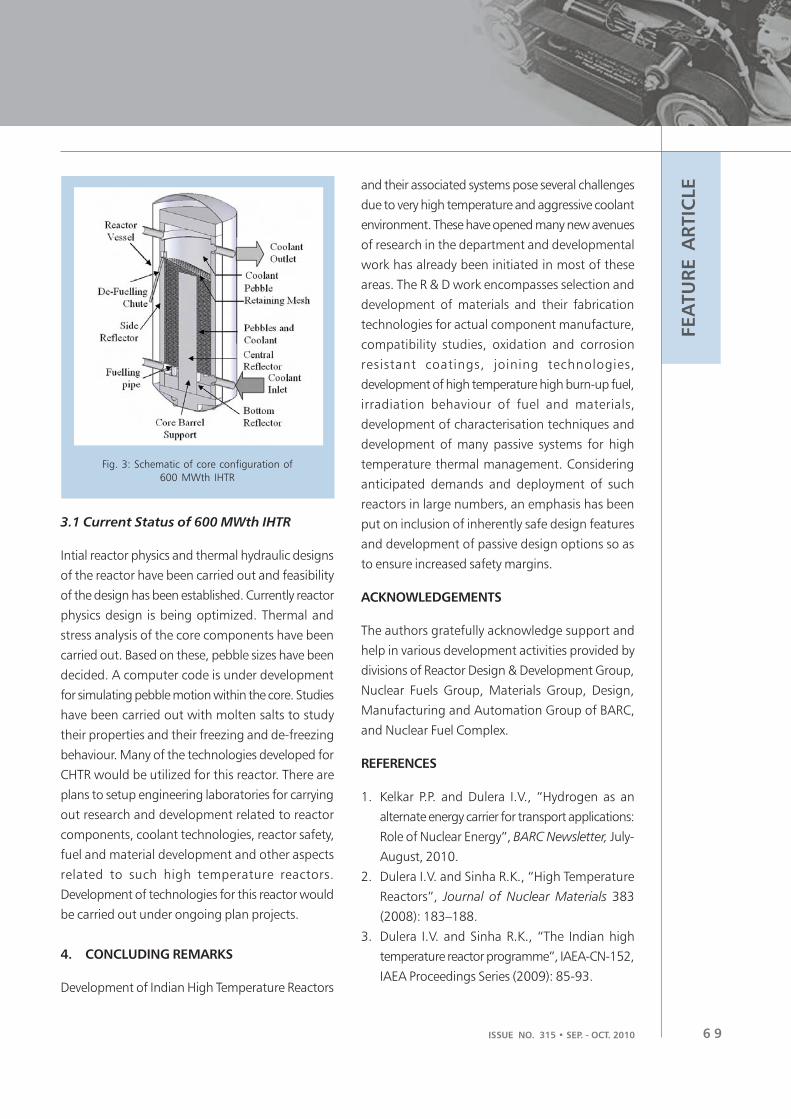
ISSUE NO. 315 • SEP. - OCT. 2010 6 9
FEA
TU
RE A
RTIC
LE
3.1 Current Status of 600 MWth IHTR
Intial reactor physics and thermal hydraulic designs
of the reactor have been carried out and feasibility
of the design has been established. Currently reactor
physics design is being optimized. Thermal and
stress analysis of the core components have been
carried out. Based on these, pebble sizes have been
decided. A computer code is under development
for simulating pebble motion within the core. Studies
have been carried out with molten salts to study
their properties and their freezing and de-freezing
behaviour. Many of the technologies developed for
CHTR would be utilized for this reactor. There are
plans to setup engineering laboratories for carrying
out research and development related to reactor
components, coolant technologies, reactor safety,
fuel and material development and other aspects
related to such high temperature reactors.
Development of technologies for this reactor would
be carried out under ongoing plan projects.
4. CONCLUDING REMARKS
Development of Indian High Temperature Reactors
Fig. 3: Schematic of core configuration of
600 MWth IHTR
and their associated systems pose several challenges
due to very high temperature and aggressive coolant
environment. These have opened many new avenues
of research in the department and developmental
work has already been initiated in most of these
areas. The R & D work encompasses selection and
development of materials and their fabrication
technologies for actual component manufacture,
compatibility studies, oxidation and corrosion
resistant coatings, joining technologies,
development of high temperature high burn-up fuel,
irradiation behaviour of fuel and materials,
development of characterisation techniques and
development of many passive systems for high
temperature thermal management. Considering
anticipated demands and deployment of such
reactors in large numbers, an emphasis has been
put on inclusion of inherently safe design features
and development of passive design options so as
to ensure increased safety margins.
ACKNOWLEDGEMENTS
The authors gratefully acknowledge support and
help in various development activities provided by
divisions of Reactor Design & Development Group,
Nuclear Fuels Group, Materials Group, Design,
Manufacturing and Automation Group of BARC,
and Nuclear Fuel Complex.
REFERENCES
1. Kelkar P.P. and Dulera I.V., “Hydrogen as an
alternate energy carrier for transport applications:
Role of Nuclear Energy”, BARC Newsletter, July-
August, 2010.
2. Dulera I.V. and Sinha R.K., “High Temperature
Reactors”, Journal of Nuclear Materials 383
(2008): 183–188.
3. Dulera I.V. and Sinha R.K., “The Indian high
temperature reactor programme”, IAEA-CN-152,
IAEA Proceedings Series (2009): 85-93.

BARC NEWSLETTERBARC NEWSLETTER
ISSUE NO. 316 • SEP. - OCT. 20107 0
FEA
TU
RE A
RTIC
LE
1.0 INTRODUCTION
Rolling element bearings are often used under severe
environmental conditions such as high contact
pressure, high temperatures and absence of
lubrication. One such demanding application is in
nuclear reactor fuel handling system, where bearings
are submerged in water environment of controlled
chemistry. In conventional applications, small trace
of water infiltration in lubricant and contamination
can cause flaking of rolling contact surfaces of the
bearings, hence selection of bearings for fuel
handling applications poses a major challenge. One
of the solutions used is a composite bearing having
races made of Martensitic stainless steel AISI 440C
and rolling elements of Stellite [1]. 440C offers good
corrosion resistance to water environment and
provides sufficient surface hardness for rolling
element bearing to operate. However performance
of these bearings has not always been satisfactory,
as 440C contains coarse eutectic carbides which
act as crack initiators under Hertzian stress. These
coarse carbides are produced during solidification
and remain unchanged even after heat treatment.
They reduce Cr content in martensitic matrix, leading
to reduction in corrosion resistance [2]. While taking
Technology Development for Indigenous Water
lubricated bearings
up indigenous development of water lubricated
bearing a major challenge was to assure quality of
AISI 440C. Other aspects of bearing design like cage
design, clearances, osculation also plays an
important role in the performance of these bearings.
These bearings were developed indigenously
covering complete aspects of bearing manufacturing
technology right from material to endurance testing.
Lessons were learnt from continuous testing and
were applied to the development cycle.
2.0 PRIOR INVESTIGATIONS OF WATER
LUBRICATED BEARINGS
WLB are in use at various NPPs in fuelling machines.
Operating experience from various plants indicate
random failures of these bearings. Most of the early
failures were due to cracking of inner or outer races
or crushing of balls. Failures after some service life
are related to wear or non fatigue related surface
distress. One of the systematic tests carried out by
RTD and NPC by G. Murlidhar1 et al, resulted in
failure due to cracked races and cage.
Microstructural evaluation and root cause analysis
indicated that failures are due to poor microstructure
of the 440C and excessive loading. Later RTD
P.K.Limaye, N.L.Soni and R.G.Agrawal
Refuelling Technology Division
Abstract
Water Lubricated Bearings (WLB) are used in various mechanisms of fuel handling systems of PHWRs
and AHWR. Availability and random failures of these bearings was a major factor in refuelling
operations. Indigenous development of these bearings was taken up and 7 types of antifriction
bearings in various sizes (totaling 37 variants) for PHWR, AHWR and Dhruva applications were
successfully developed. This paper deals with various aspects of WLB development.
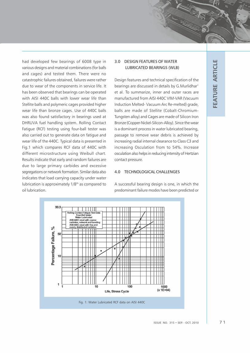
ISSUE NO. 315 • SEP. - OCT. 2010 7 1
FEA
TU
RE A
RTIC
LEhad developed few bearings of 6008 type in
various designs and material combinations (for balls
and cages) and tested them. There were no
catastrophic failures obtained, failures were rather
due to wear of the components in service life. It
has been observed that bearings can be operated
with AISI 440C balls with lower wear life than
Stellite balls and polymeric cages provided higher
wear life than bronze cages. Use of 440C balls
was also found satisfactory in bearings used at
DHRUVA fuel handling system. Rolling Contact
Fatigue (RCF) testing using four-ball tester was
also carried out to generate data on fatigue and
wear life of the 440C. Typical data is presented in
Fig.1 which compares RCF data of 440C with
different microstructure using Weibull chart.
Results indicate that early and random failures are
due to large primary carbides and excessive
segregations or network formation. Similar data also
indicates that load carrying capacity under water
lubrication is approximately 1/8th as compared to
oil lubrication.
3.0 DESIGN FEATURES OF WATER
LUBRICATED BEARINGS (WLB)
Design features and technical specification of the
bearings are discussed in details by G.Murlidhar1
et al. To summarize, inner and outer races are
manufactured from AISI 440C VIM-VAR (Vacuum
Induction Melted- Vacuum Arc Re-melted) grade,
balls are made of Stellite (Cobalt-Chromium-
Tungsten alloy) and Cages are made of Silicon Iron
Bronze (Copper-Nickel-Silicon-Alloy). Since the wear
is a dominant process in water lubricated bearing,
passage to remove wear debris is achieved by
increasing radial internal clearance to Class C3 and
increasing Osculation from to 54%. Increase
osculation also helps in reducing intensity of Hertzian
contact pressure.
4.0 TECHNOLOGICAL CHALLENGES
A successful bearing design is one, in which the
predominant failure modes have been predicted or
Fig. 1: Water Lubricated RCF data on AISI 440C

BARC NEWSLETTERBARC NEWSLETTER
ISSUE NO. 316 • SEP. - OCT. 20107 2
FEA
TU
RE A
RTIC
LE identified. Very little design information for WLB
could be obtained from literature. So for taking up
large scale development of WLB for AHWR, PHWR
and Dhruva Fuelling machines, The following
challenges were considered for prime focus:
4.1 Material Qualifications
Raw material qualification is one of the most
challenging tasks. Chemical and mechanical testing
standard has been provided by ASTM. However
inclusion rating and microstructure plays a major
role in selection of the material. In annealed
condition ideal microstructure shall consist of
chromium rich spherodized carbide particles in ferrite
matrix. These eutectic carbide size shall be 10μm
less and they shall be evenly dispersed in the matrix.
It has been observed that these carbides are often
of larger size. Large size carbide particles not only
induce stress concentration during Hertzian contact
but also decrease the hardness during tempering.
These carbides have a tendency to form networked
clusters or bands in the direction of working, thus
increasing occurrence of crack generation and
propagation.
4.2 Bearing Design and Manufacturing
tolerances
Dimensional features of conventional and existing
bearings were studied and new designs of the
bearings were prepared. Key difference in design is
the number of balls used. To prevent RCF and surface
fatigue, the Hertzian stress intensity shall be reduced.
To achieve this more number of smaller dia balls
were provided. This facilitates better load sharing,
reducing stress on maximum loaded contact. This
also allowed race design to be thicker, providing
better control on the grinding process. The cage
pocket ball clearances were kept marginally higher
to allow wear debris passage. Cages were designed
for Inner Ring Land Rider (IRLR) configuration as
these have given best results in earlier tests.
Emphasis was given on selection of geometrical
tolerances.
4.3 Load Carrying Capacity
Formulas suggested by ISO 281 and ISO 76 were
used, to calculate dynamic and static load ratings
of the bearings respectively, using geometrical
features. These formulas give load ratings for
conventional bearings, hence the factor discussed
above was used to calculate optimum dynamic load
carrying capacity.
4.4 Selection of Heat treatment process
Heat treatment is the most important aspect of
bearing manufacturing. Various heat treatments
cycles were studied and experimented. Bearing rings
were stress relieved at 650 °C for 2 Hrs, Preheated
to 850 °C for 1 Hr, austinized at 1060 °C for 60min
and quenched in a mixture of Air+Nitrogen. Rings
were treated to sub zero tempreture in dry ice at -
75 °C for 6 Hrs and then double tempered at 200
°C for 2 to 3 Hrs. Heat treatment is carried out in
vacuum furnace to avoid any kind of contamination.
This treatment has given fine grain martensitic
structure of ASTM 8, no retained austenite and well
dispersed secondary carbide.
4.5 Manufacturing and Stage wise inspection
Although conventional manufacturing techniques
were used for machining and grinding of races,
selection of tool and grinding wheel played a crucial
role in process optimization. Dimensions and
geometrical tolerance were controlled during various
stages of grinding by adopting special comparators
for each type of bearing. Single piece machined
cages were used for all types of bearings, except

ISSUE NO. 315 • SEP. - OCT. 2010 7 3
FEA
TU
RE A
RTIC
LEdeep groove ball bearings. Special jigs were
manufactured for machining the cage pockets. In
deep groove ball bearings due to higher no. of balls
limited space was available for riveting two pieces,
hence special SS 304 rivets were manufactured and
riveting was done using die.
5.0 TESTING OF BEARINGS
With proper attention to bearing design,
manufacture and application, all other modes of
rolling bearing failure are avoided with the exception
of RCF and wear. In that situation, the life of any
one bearing, operating in the application, can differ
significantly from that of an apparently identical
unit. During testing of conventional bearings,
vibration data is used to detect initiation of failure,
however in case of water lubricated bearings this
method cannot be applied as bearing operates in
boundary lubrication mode, and metal to metal
contact prevailed. In such case, increase in frictional
torque and monitoring of Radial Internal Clearances
(RIC), gives better idea of useful life of the bearing.
A test setup was designed (shown in Fig. 2) to test
various type and sizes of bearings. The setup has a
facility to apply radial as well as axial load through
hydraulic loading and can test deep groove, angular
contact, thrust ball and taper roller bearings of
various sizes ranging from 25mm ID to 120mm
ID. Online measurement of frictional torque along
with other parameters like applied load, RPM etc
were incorporated. Out of 37 variants of bearings
developed, 8 types of bearing covering range of
size and type were selected for endurance testing.
Since the lot size was smaller, it was decided to test
four bearings of each selected size. No failures were
observed during the initial phase of the testing (i.e.
4 bearings of each type for the rated life). To
establish failure parameters, it was decided to carry
out extended testing by either increasing load or
test duration till a failure was noticed. Failures are
attributed to cage and race wear, spalling and
smearing. Figs. 3 (a & b) show some of the failed
components.
Fig. 2: Water lubricated bearing test setup
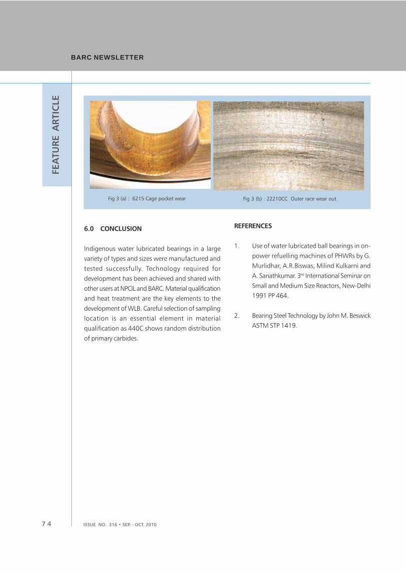
BARC NEWSLETTERBARC NEWSLETTER
ISSUE NO. 316 • SEP. - OCT. 20107 4
FEA
TU
RE A
RTIC
LE
Fig 3 (b) : 22210CC Outer race wear outFig 3 (a) : 6215 Cage pocket wear
6.0 CONCLUSION
Indigenous water lubricated bearings in a large
variety of types and sizes were manufactured and
tested successfully. Technology required for
development has been achieved and shared with
other users at NPCIL and BARC. Material qualification
and heat treatment are the key elements to the
development of WLB. Careful selection of sampling
location is an essential element in material
qualification as 440C shows random distribution
of primary carbides.
REFERENCES
1. Use of water lubricated ball bearings in on-
power refuelling machines of PHWRs by G.
Murlidhar, A.R.Biswas, Milind Kulkarni and
A. Sanathkumar. 3rd International Seminar on
Small and Medium Size Reactors, New-Delhi
1991 PP 464.
2. Bearing Steel Technology by John M. Beswick
ASTM STP 1419.

ISSUE NO. 315 • SEP. - OCT. 2010 7 5
FEA
TU
RE A
RTIC
LECollaborative R&D Activities under BRNS: Past,
Present and Future – An Overview
S. G. Markandeya
Scientific Secretary, BRNS
Planning & Coordination Division
BRNS, an extra-mural funding agency, born even before independence of India, has undergone
significant transformation in its structure, activities and functioning over the past 5 to 6 decades.
With the ambitious programmes of the DAE in the next few decades, it has probably a bigger role
to play. There are bigger challenges ahead, which would be met by BRNS by way of increased
participation of R&D personnel from DAE, adoption of newer tools in information technology and
effective project management and administration. This article brings out the role of BRNS in
collaborative research activities of the DAE in the past, present and in the time to come.
1.0 INTRODUCTION
The Department of Atomic Energy (DAE) has been
pursuing the R&D activities in the diverse areas,
not only pertaining to nuclear power technology,
but also in the frontier areas of basic sciences and
several other allied disciplines related to applications
of radiation technology in the fields of agriculture,
food preservation, hydrology, water desalination,
medicine, industry, etc. which are of societal
importance and also in the strategic areas which
are important in the context of national security.
The Board of Research in Nuclear Sciences (BRNS)
under DAE has emerged as a unique institution for
strengthening the network of researchers and
research institutes in the country and involving them
in collaborative R&D activities leading to the various
objectives of the departmental programmes.
Historically, the Atomic Energy Committee, which
was formed in the year 1945 under the aegis of
Council of Scientific Research (CSIR), was renamed
as Atomic Research Committee in (ARC) in 1947,
which subsequently became Board of Research in
Atomic Energy (BRAE) under the Atomic Energy
Commission which was formed during 1947-48,
Following this, in the year 1955, the BRAE was
again renamed as Board of Research in Nuclear
Sciences (BRNS). In its role of an advisory body to
the DAE, one of the prime mandates of BRNS (be it
in the form of ARC or BRAE) has been to build
strong linkages with the national R&D labs and
universities for their active participation in the
departmental R&D activities in the collaborative
mode and thereby generate a large pool of qualified
and skilled human resources to cater to the needs
of the department in the time to come.
It would be of interest to everyone who is associated
with the DAE’s activities, as well as to those who
wish to contribute to this cause, to carefully examine
as to how far BRNS has succeeded in fulfilling this
mandate so far. It would also pave ways to chalk
out future strategies towards betterment, particularly
in the current scenario of much higher expectations
of performance from DAE and the rapid reforms
taking place within and outside the country in the
areas of technology and knowledge management
at global level. Since, BRNS had undergone major
restructuring during 1998, it would be logical to
understand the role and activities of BRNS, its
achievements and impact in two phases, viz., the
first four decades prior to 1998 and the current
decade (mainly after 1998 till date). In the light of
such afore-mentioned observations, it should be

BARC NEWSLETTERBARC NEWSLETTER
ISSUE NO. 316 • SEP. - OCT. 20107 6
FEA
TU
RE A
RTIC
LE possible to refine and refocus the objectives of BRNS
and chalk out the strategies to meet challenges in
the coming future.
The present article briefly brings out the role of
BRNS in collaborative R/D activities of DAE, its
methodology of functioning and contributions to
the departmental programmes. Based on the
experiences gained over the last 4 to 5 decades,
ideas for improving its impact as well as its way of
functioning have been also proposed.
2. BRNS - THE FIRST FOUR DECADES
BRNS in its earliest form i.e. Atomic Research
Committee (ARC), between its formation year (1945)
and the year of formation of Atomic Energy
Commission (1947), had the following terms of
reference:
. To explore the availability of raw materials
required for generating atomic energy,
. To suggest ways and means of harnessing
the materials for production of atomic energy,
and
. To keep in touch with similar organizations
functioning in other countries and to make
suggestions for coordinating the work of this
committee on an international basis.
Obviously, during this period for all purposes, this
institution was almost playing the role of Atomic
Energy Commission. During the years 1947 to 1954,
it started functioning as Board of Research in Atomic
Energy (BRAE) under AEC. This was the period when
the well conceived three phase nuclear power
programme for the country was being put on the
firm footing by none other than Dr. Bhabha himself,
by way of institution building and starting several
core activities with the help of carefully chosen
teams of experts within the department. During this
period, BRAE was being looked upon as an advisory
body with the responsibility to advice about the
distribution of research grants to the universities
and research institutions.
In 1955-56, when BRAE was renamed as BRNS, it
continued functioning, with the help of only three
advisory committees, towards the two main
mandates, viz. a) enhance collaborative activities
between the R&D units of DAE and the national
universities, R&D institutions and national research
labs and b) contribute to human resource
development activities. The initially set up three
committees were later increased to eight to
encompass many facets of DAE’s R&D programmes
in science and technology, under the purview of
BRNS. Accordingly, the two major activities pursued
by BRNS during this period were; a) to sponsor and
provide financial grant for the R&D projects to
universities and R&D labs and b) to provide support
for organizing national /international conferences
and seminars. The R&D projects supported by BRNS,
during this phase, were generally of “coordinated”,
rather than “collaborated” type of projects. The
method followed those days was to send a circular
from BRNS to a large number of universities, R&D
institutes and research labs in the country inviting
R&D proposals in the specified frontier areas of
interest of DAE. In response to this, R&D projects
were conceived and formulated by the prospective
project investigators (PI) themselves and submitted
to BRNS. Based on the peer review, the projects
used to get selected for BRNS sponsorship. The
progress of these projects was coordinated by the
respective appointed project coordinators (PC) from
within DAE. With a little peep into the sponsoring
activities of BRNS, one may conclude that most of
the R&D activities carried out through BRNS projects
were of “supplementary” nature to the departmental
R&D activities. This being the period, during which
the IITs grew as the outstanding centres of higher
education in the country, they had probably a larger
share of participation in the BRNS activities, next to
national universities.
No specific attempt has been made here to throw
much light on the impact of BRNS during this period

ISSUE NO. 315 • SEP. - OCT. 2010 7 7
FEA
TU
RE A
RTIC
LEin respect of major programmes, extent of funding
and its distribution pattern, overall impact of the
R&D projects in terms of their outcome, etc., due
to difficulties in extracting the needed information.
3. BRNS – THE CURRENT DECADE
The BRNS, born in the pre-independence period,
can be called as the first extra-mural funding agency
of Government of India for sponsored R&D activities
in the country. However, this unique position held
by BRNS changed soon with the CSIR extramural
research funding becoming available, especially with
the creation of the Department of Science and
Technology (DST). With time, DST had grown into
a major funding agency for R&D activities in all
branches of science and technology. In the light of
these developments, it became more eminent to
make BRNS more focused for the DAE’s needs.
Accordingly, BRNS was restructured in the year
1998, with an independent BRNS secretariat headed
by Scientific Secretary, who is assisted by the
Programme Officers (chosen among scientists and
engineers from within BARC) and the requisite
administrative staff. The advisory committees were
reduced to following six advisory committees based
on the broader aspects of DAE’s programme.
. Advanced Technology Committee (ATC). Basic Sciences Committee (BSC). Nuclear Reactor and Fuel Cycle Committee
(NRFC). Radiation Technology and Applications
Committee (RTAC). Strategic Studies Advisory Committee (SSAC). DAE Graduate Fellowship Scheme Committee
(DGFS)
Some of the significant reforms introduced to
improve the effectiveness and impact of the BRNS
in respect of a) sponsored R&D projects, b)
sponsoring of conferences, c) human resources
development and d) other miscellaneous activities
during the current decade are briefed below.
3.1 Sponsored R&D Projects
The nature of sponsored R&D projects has undergone
a change from the “supplementary departmental
R&D activities” to the “complimentary departmental
R&D activities”. As a result, one of the major
modifications in formulating the new R&D project
proposals has been the introduction of process of
joint formulation (both by PI and PC together) of
the project proposals to ensure that project outcome
is of direct use to the PCs departmental activities
and the PC actively collaborates (rather than
coordinates) to achieve the targeted outcome of
the project. Several other new things introduced
for the overall improvement in execution and quality
of R&D projects is as listed below:
. Stronger outreach programme based on
pro-active steps by the advisory committees
to interactively formulate R&D project
proposals. Thematic Sub-committees to formulate,
generate, scrutinize, review projects and assist
the advisory committees. Technical Programme Discussion Meetings
(TPDMs) for review of fresh as well as
ongoing projects. Young Scientist Projects for encouraging
younger faculty below the age of 35 years. Categorization of projects based on total
research grant (for speedier processing) in 3
categories; viz. a) below Rs. 25 lakh, b)
between Rs. 25 lakh to 35 lakh and c) above
Rs. 35 lakh. Mega projects in the MoU mode and Multiple
Projects (on identical theme) in the
Coordinated Research Project (CRP) mode. Prospective Research Projects for DAE
employees to encourage taking up
challenging R&D activities not covered under
the plan project activities of the department. Special extension of projects for enabling

BARC NEWSLETTERBARC NEWSLETTER
ISSUE NO. 316 • SEP. - OCT. 20107 8
FEA
TU
RE A
RTIC
LE
3.2 Sponsoring of Conferences
Conducting national and international conferences,
seminars, and workshops facilitates researchers to
exchange ideas on their research findings and to
chalk out further research programmes to fill up
the gaps or to take up newer thrust activities. BRNS
has been providing grants for organizing such events
in the country. In order to make this activity more
focused, Prof. Joshi’s committee appointed by the
BRNS board had recommended a list of 17
conferences (Pl. see Box-1) to be fully funded by
BRNS which are of direct interest to DAE and which
should be periodically organized by DAE. A concept
of Thematic Meetings was also introduced to
organize meetings among smaller group of experts
from within as well as outside the country, including
participation of experts from abroad, to conduct
brain storming discussions on the issues required
to be resolved by DAE on priority and for chalking
out the required R&D activities in collaborative
mode.
Besides fully funded DAE conferences, BRNS has
been providing partial support to several other
conferences hosted by non-DAE organizations,
provided the topic has relevance to the DAE’s
programme or it is important in the national /
international context. Such events have been the
major platforms exploited by the BRNS officials to
give a boost to the collaborative R&D activities under
BRNS. Fig.3 depicts the year wise BRNS funding for
fully funded and partially funded conferences in
the country. Again, the four fold increase in the
support to BRNS sponsored conferences/symposia
in the past 5 years has been highly impressive and
indicative of the dent BRNS has made at the national
level.
Fig. 1: BRNS Expenditure in Crores
Fig. 2: Normalized distribution of numbers of projects
among different institutes for two
different committees in last 2 years
project research staff complete their doctoral
programmes.
With the introduction of these mechanisms, BRNS
could indeed expand its activities of sponsoring R&D
projects in terms of disbursement of R&D grant in
a big and fruitful way. Fig.1 depicts the increasing
annual BRNS budget over the past 10 years. Almost
more than ten times increase in the financial outlay
of BRNS in the past ten years has been phenomenal
and unprecedented in the history of BRNS ever
since its inception. Fig.2 depicts the research grant
disbursed by one of the advisory committees
(NR&FC) in the last two years, among universities,
national R&D labs and IITs (including IISc). The
commonly prevailing misgiving, that most of the
research grant of BRNS goes to elite academic
institutes (such as IITs and IISc) in the country, can
be seen to be incorrect from Fig.2. Since the
inception of NITs in the country, their participation
in BRNS activities is also seen to be growing steadily
in the past few years.
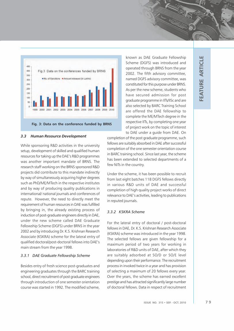
ISSUE NO. 315 • SEP. - OCT. 2010 7 9
FEA
TU
RE A
RTIC
LE
Fig. 3: Data on the conference funded by BRNS
3.3 Human Resource Development
While sponsoring R&D activities in the university
setup, development of skilled and qualified human
resources for taking up the DAE’s R&D programmes
was another important mandate of BRNS. The
research staff working on the BRNS sponsored R&D
projects did contribute to this mandate indirectly
by way of simultaneously acquiring higher degrees
such as PhD/ME/MTech in the respective institutes
and by way of producing quality publications in
international/ national journals and conferences of
repute. However, the need to directly meet the
requirement of human resources in DAE was fulfilled
by bringing in, the already existing process of
induction of post-graduate engineers directly in DAE,
under the new scheme called DAE Graduate
Fellowship Scheme (DGFS) under BRNS in the year
2002 and by introducing Dr. K.S. Krishnan Research
Associate (KSKRA) scheme for the lateral entry of
qualified doctoral/post-doctoral fellows into DAE’s
main stream from the year 1998.
3.3.1 DAE Graduate Fellowship Scheme
Besides entry of fresh science post-graduates and
engineering graduates through the BARC training
school, direct recruitment of post graduate engineers
through introduction of one semester orientation
course was started in 1992. The modified scheme,
known as DAE Graduate Fellowship
Scheme (DGFS) was introduced and
operated through BRNS from the year
2002. The fifth advisory committee,
named DGFS advisory committee, was
constituted for this purpose under BRNS.
As per the new scheme, students who
have secured admission for post
graduate programme in IITs/IISc and are
also selected by BARC Training School
are offered the DAE fellowship to
complete the ME/MTech degree in the
respective IITs, by completing one year
of project work on the topic of interest
to DAE under a guide from DAE. On
completion of the post graduate programme, such
fellows are suitably absorbed in DAE after successful
completion of the one semester orientation course
in BARC training school. Since last year, the scheme
has been extended to selected departments of a
few NITs in the country.
Under the scheme, it has been possible to recruit
from last eight batches 118 DGFS fellows directly
in various R&D units of DAE and successful
completion of high quality project works of direct
relevance to DAE’s activities, leading to publications
in reputed journals.
3.3.2 KSKRA Scheme
For the lateral entry of doctoral / post-doctoral
fellows in DAE, Dr. K.S. Krishnan Research Associate
(KSKRA) scheme was introduced in the year 1998.
The selected fellows are given fellowship for a
maximum period of two years for working in
laboratories of R&D units of DAE, after which they
are suitably adsorbed at SO/D or SO/E level
depending upon their performance. The recruitment
process in invoked twice in a year and has provision
of selecting a maximum of 20 fellows every year.
Over the years, the scheme has earned excellent
prestige and has attracted significantly large number
of doctoral fellows. Data in respect of recruitment

BARC NEWSLETTERBARC NEWSLETTER
ISSUE NO. 316 • SEP. - OCT. 20108 0
FEA
TU
RE A
RTIC
LE
Fig. 4: Data on the KSKRA fellowship
of KSKRAs over last 11 years, depicted in Fig. 4, is a
testimony to the success of this scheme.
3.4 Other Miscellaneous Activities
Besides the above described activities, several other
important schemes of DAE are also operated
through BRNS. These are:
• Raja Ramana Fellowship (earlier known as
Senior Scientist Scheme)
• DAE Visiting Scientist Scheme
• DAE-Science Research Council Awards (
instituted in 2005)
• Support to HBCSE for participating in
International Olympiad Programmes
• Foreign Travel Assistance to young
researchers through CCSTDS
• Funding for scientific publications such as
IANCAS bulletin, Current Science, Resonance,
etc.
4. IMPACT OF BRNS ACTIVITIES
During last one decade, the activities of BRNS have
been multi-dimensional and have made significant
impact all over the country. As regards its activities
of sponsored R&D projects, its visibility is obvious
through a large number of state-of-the-art facilities
built/being built and used/being used extensively
for collaborative R&D activities at various institutes
in the country. Only a few of the prominent
activities, both completed and
ongoing are listed below:
4.1 Test Facilities and
Research Programmes
in
Engineering:
1. SITAC facility at IIT Bombay,
Mumbai and Advanced Seismic
Testing And Research Lab at SERC,
Chennai for seismic qualification of
nuclear power plant components
and equipment
2. Center for design and
verification of software (CFDVS) at IIT,
Bombay
3. LOCA qualification test facility at ERDA,
Vadodara
4. Design, development and supply of high
pressure, high temperature two phase
gamma ray (3-beam) densitometer for use
in FISBE in BARC at Flow Control Research
Institute, (FCRI), Palghat, Kerala
5. High pressure, high temperature Test facility
at Jadavpur University, Kolkata to study Leak-
Before-Break (LBB) phenomena
6. Centre for Non-Destructive Evaluation of
Reactor Components at IIT, Madras, Chennai
7. National Facility for Advanced Electron
Microscopy (NFAEM) at IISc, Bangalore and
at IIT Bombay, Mumbai
8. CRP (8 projects) on Thermal Ecology Studies
at MAPS, Kaiga NPS and Kudankulam NPP
sites
9. CRP (5 projects) on Baseline studies in a
region of 30 km radius around Kudankulam
site
10. CRPs (15 projects) on “Uranium mining
related issues specific to Jadugoda site” and
(10 projects) on “Baseline Studies on

ISSUE NO. 315 • SEP. - OCT. 2010 8 1
FEA
TU
RE A
RTIC
LEproposed Uranium Mining Sites at KP
Mawathabah (Domiasiat) in Meghalaya and
24 projects at Tumalapalle, Lambapur-
Pedagattu, Sherepalle (Andhra Pradesh) &
Gogi (Karnataka).
11. Ongoing CRPs (17 projects) at NPP sites for;
a) evaluation of transfer factors, b)
epidemiological and demographic surveys
and c) effect of exposures to X-rays in hospitals
against natural background radiation fields.
12. Establishment of “Centre for Radio-ecological
Studies” at Guru Jambeshwar Univ., Hisar,
Harayana
13. Initiation of projects for establishment of
“Marine Radio-ecological Centre” at Central
Institute of Fishery Education (CIFE), Mumbai
14. Initiation of projects for establishment of
“Centre for robotic Studies” at IIT, Delhi
4.2 Major Research Programmes in
Advanced Technologies:
1. Production and Supply of Special Nd-doped
Phosphate glass Source Cylinder for use in
High Power Laser.
2. Establishment of 8 MeV Linear Accelerator ,
Microtron Centre for R & D in Radiation
Physics and Interdisciplinary areas of Science
& Technology at Mangalore University
3. Development of indigenous, robust CFD code
ANUPRAVAH-KIIT at IIT, Kanpur
4. Establishment of Electron Beam Welding
Technology Development at IIT, Kharagpur
5. Establishment of a facility for Development
, Production and supply of Microwave
Substrates for High Power Micro Wave
Amplifiers at C-MET, Thrissur, Kerala
6. Establishment of a Facility for Development
and Supply of laser glass rods and slabs at
Sri Venkateswara University, Tirupati
7. Setting up of Laser Facility for Medical and
Technological Applications at Anna
University, Chennai
8. Setting up a Programme in Left Handed
Maxwell ( LHM ) Systems at SAMEER Kolkota
Centre , Kolkota.
4.3 Major Research Programmes in Basic
Sciences:
1. Establishment of a “National Centre for Free
Radical Research (NCFRR)” at University of
Pune,
2. CRP ( 8 projects) on “Spintronic materials
and applications.”
4.4 Major facilities based on the
Applications of Radiation Technology :
1. Establishment of Radiotracer Laboratory at
College of Agriculture, Jabalpur and
Multilocation Testing of BARC Crop Varieties”
at Jawaharlal Nehru Krishi Vishwa Vidyalaya
(JNKVV), Jabalpur
2. Establishment of Radiotracer Laboratory and
Multi-location Testing of BARC Crop Varieties
at Rajasthan Agricultural University (RAU),
Bikaner:
3. Installation and Commissioning of Gamma
Chambers at JNKVV, Jabalpur and TNAU,
Coimbatore
4. Facility for Production of Safe and Quality
Meat Products using gamma irradiation
5. Establishment of Isotope Hydrology
Laboratory for Himalayan Environmental
Studies and Conservation Organization
(HESCO), Deharadun
6. Initiation of establishment of “Centre for
Advanced Applications of Radiation
Technologies – CAART” at Mangalore
university, Mangalore.

BARC NEWSLETTERBARC NEWSLETTER
ISSUE NO. 316 • SEP. - OCT. 20108 2
FEA
TU
RE A
RTIC
LE 4.5 Some examples of scientific and Technical
outcome under BRNS projects:
There are quite a large number of excellent
achievements reported every year under the BRNS
projects. Just to give a glimpse of the quality of
work carried out under the BRNS projects, a few
examples are illustrated below.
Fig.5 depicts a 2-stage pulse tube cryocooler along
with its components developed under a project at
IISc, Bangalore. This cryocooler produces a no load
temperature of ~ 2.5 K in the second stage cold
head, while the first stage reaches a temperature ~
60K. The cooling power achieved presently is
approximately 300 mW at 4.2 K. With this power,
a small NbTi wire wound superconducting magnet
of 10 mm internal diameter, 50 mm length, was
successfully cooled down from room temperature
down to 3.5 K. The magnet was charged with
current to obtain a magnetic field of ~0.25 Tesla.
The magnet could be operated in persistent mode
and system performance was stable for several tens
of hours.
Fig. 5 : 2-stage pulse tube cryocooler along
with its components developed under
aproject at IISc, Bangalore
Filled PTFE substrates are ideal choice for microwave
circuit fabrication owing to their exceptional
electrical, mechanical and thermal properties. USA
is the leading manufacturer of this technologically
important class of materials. As a part of
indigenization of these strategic materials, C-MET
have developed a proprietary processing
methodology comprising of Sigma Mixing,
Extrusion, Calendering followed by Hot pressing
(SMECH) processes to fabricate dimensionally
stable, planar, isotropic PTFE/ceramic composite
laminates through BRNS funding. Sodium
naphthalate based chemical etching methods have
been employed to modify the surface of filled PTFE
substrates for better adhesion with metal conductor
layers. Copper cladding technology has been
established through vacuum lamination process to
realize fine circuitry over flexible substrates.
Typical RegeneratorPulse Tube Refrigerator Vacuum jacket Typical pulse Tubes
A few numbers of Cu-cladded microwave substrates
of 5" x 5" size (Fig.6) were handed over to RRCAT,
Indore for testing and qualification. RRCAT has used
these laminates to develop solid state RF amplifiers
(Fig.7) operating at centre frequency of 352 MHz
and successfully tested at 700 watts, which is more
than twice the full rated power of 270W. The
performance of the substrates in terms of output
power, gain and efficiency was very good. CMET
will start production of the laminates on a pilot
plant scale soon.
Experiments performed at RRCAT established that
the indigenously developed microwave circuit
boards can, not only be utilized for the particle
accelerator applications but can also be
commercially exploited for variety of microwave
circuit applications in the international market.
Moreover, such a reliable and novel Indian product
and the devices fabricated out of them can forge

ISSUE NO. 315 • SEP. - OCT. 2010 8 3
FEA
TU
RE A
RTIC
LE
are being getting benefitted through extensive use
of this facility. Fig. 10 shows the test being carried
out for seismic qualification of the spent fuel storage
pool using 25 ton shake table.
Fig.7 : Prototype high power solid state
amplifiers fabricated at RRCAT, IndoreFig.6: Cu-cladded microwave substate
19 cm (L) x 13 cm ( B) x 0.16 cm
(T) developed at C-MET
fruitful scientific internal collaborations especially
in joint ventures such as ITER, Large Hadron Collider
experiment, etc.
As a part of studies on Leak Before Break
phenomena, a Leak Test facility was established at
Jadavpur University, Kolkata under BRNS project with
the objective of measuring critical flow rate through
a simulated crack on the pipe surface using
circumferential slit geometry (simulating pipe crack)
and validating the in-house developed computer
code as well as the international code RELAP5 using
the test data. The facility (Fig.8) consists of a High
Pressure High Temperature (HPHT) loop capable of
generating PHWR and AHWR coolant condition
(70-90 bar, 220-270°C), a N2 system required to
maintain the slit/crack upstream pressure and a test
section where slit/crack pipes can be placed. The
facility is getting augmented where bending moment
on the crack pipe can be created with servo
hydraulic machine.
Seismic qualification of various equipment,
components and instruments used in nuclear power
plants is an essential safety requirement. A seismic
test facility has been established at SERC, Chennai,
comprising of 25 ton and 5 ton shake tables
(Fig. 9) as well as a pseudo test facility under the
Advanced Seismic Test And Research Lab (ASTAR
lab), which is operational for the past couple of
years. Several users from BARC, IGCAR and NPCIL
From the detailed reports on each of the above listed
activities (which are only indicative), which are
available in the BRNS Secretariat, it can be seen
that R&D efforts through BRNS sponsored activities
have generated a wealth of high quality information
in almost every facet of nuclear technology (except
probably in the area of back end technology) and
in many other advanced technologies as well. While
several technologies have been / are being patented,
some of them are being explored for commercial
exploitation. The development of qualified and
skilled human resources through this route has been
equally impressive, both in qualitative and
quantitative terms.
Thus, with the various reforms introduced during
the current decade, BRNS has been overwhelmingly
successful in fulfilling the main mandates given by
DAE.
5. BRNS - IN THE COMING FUTURE
The implementation of the three stage Indian nuclear
power programme, carved out by Dr. Bhabha, has
been the mainstay of DAE’s activities. While DAE
has successfully implemented and achieved excellent
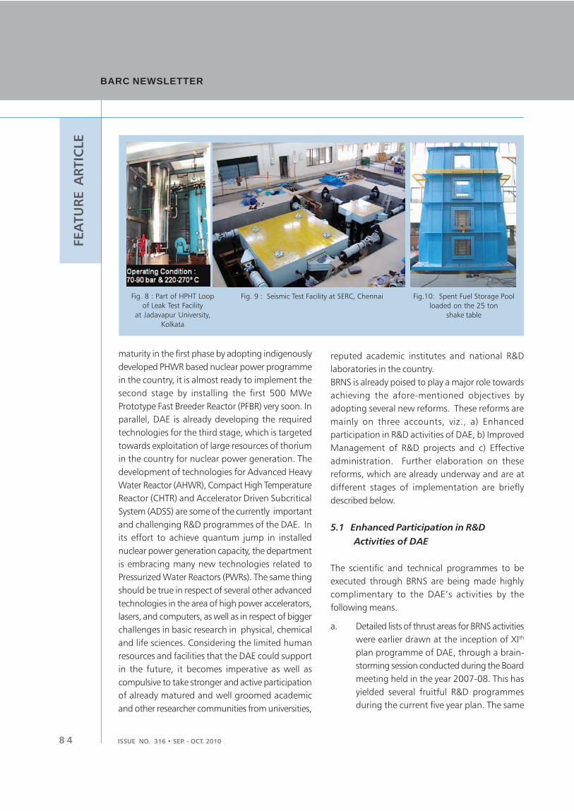
BARC NEWSLETTERBARC NEWSLETTER
ISSUE NO. 316 • SEP. - OCT. 20108 4
FEA
TU
RE A
RTIC
LE
maturity in the first phase by adopting indigenously
developed PHWR based nuclear power programme
in the country, it is almost ready to implement the
second stage by installing the first 500 MWe
Prototype Fast Breeder Reactor (PFBR) very soon. In
parallel, DAE is already developing the required
technologies for the third stage, which is targeted
towards exploitation of large resources of thorium
in the country for nuclear power generation. The
development of technologies for Advanced Heavy
Water Reactor (AHWR), Compact High Temperature
Reactor (CHTR) and Accelerator Driven Subcritical
System (ADSS) are some of the currently important
and challenging R&D programmes of the DAE. In
its effort to achieve quantum jump in installed
nuclear power generation capacity, the department
is embracing many new technologies related to
Pressurized Water Reactors (PWRs). The same thing
should be true in respect of several other advanced
technologies in the area of high power accelerators,
lasers, and computers, as well as in respect of bigger
challenges in basic research in physical, chemical
and life sciences. Considering the limited human
resources and facilities that the DAE could support
in the future, it becomes imperative as well as
compulsive to take stronger and active participation
of already matured and well groomed academic
and other researcher communities from universities,
reputed academic institutes and national R&D
laboratories in the country.
BRNS is already poised to play a major role towards
achieving the afore-mentioned objectives by
adopting several new reforms. These reforms are
mainly on three accounts, viz., a) Enhanced
participation in R&D activities of DAE, b) Improved
Management of R&D projects and c) Effective
administration. Further elaboration on these
reforms, which are already underway and are at
different stages of implementation are briefly
described below.
5.1 Enhanced Participation in R&D
Activities of DAE
The scientific and technical programmes to be
executed through BRNS are being made highly
complimentary to the DAE’s activities by the
following means.
a. Detailed lists of thrust areas for BRNS activities
were earlier drawn at the inception of XIth
plan programme of DAE, through a brain-
storming session conducted during the Board
meeting held in the year 2007-08. This has
yielded several fruitful R&D programmes
during the current five year plan. The same
Fig. 8 : Part of HPHT Loop
of Leak Test Facility
at Jadavapur University,
Kolkata
Fig.10: Spent Fuel Storage Pool
loaded on the 25 ton
shake table
Fig. 9 : Seismic Test Facility at SERC, Chennai

ISSUE NO. 315 • SEP. - OCT. 2010 8 5
FEA
TU
RE A
RTIC
LEprocess will be continued to renew the list
of thrust areas for every future five year plan.
It would not be a too ambitious target to
define more than 800 R&D projects under
BRNS (per five year plan), by formulating 2
or more BRNS projects from each of the 400
sub-projects under the DAE’s 32 Apex
Projects. Execution of these BRNS projects
by the pre-identified PCs from among the
R&D units of DAE and the PI/s from the
academic institutes based on available
expertise and infrastructure should result in
much more significant and fruitful
contribution of BRNS to the DAE’s activities.
b. Identification and introduction of other
important frontier thrust areas of R&D in the
national and international context (which
may not have immediate direct relevance to
the DAE’s activities) is currently being carried
out by conducting highly focused thematic
meetings, in which exerts from within and
outside the country are invited to participate.
Such activities will be further strengthened
based on the advice from academia and by
keeping vigil on the current trends of research
world over.
c. The existing provision of sponsoring R&D
projects to private R&D houses has never been
exploited by BRNS till now, probably due to
lack of such competent bodies. However,
with the fast changing scenario in the country
in the field of academics, industrial R&D and
larger availability of expertise with private
houses, this would be worth giving a trial to
start with on a lower scale, followed by its
expansion, matching with the likely success
in returns.
d. Fully funded DAE-BRNS conferences
(Table:1) are proved to be the major platforms
of interactions among DAE and non-DAE
researchers. Introduction of more number
of DAE’s fully funded and periodically held
conferences / seminars /workshops and
theme meetings and improvement in their
quality is already being planned to meet the
said objectives.
5.2 Improved Management of R&D Projects
The success of sponsored R&D activities lies in good
project management on the part of PI and PC and
ensuring excellent provisions for periodic review by
the peers, timely flow of funds & other
administrative help and good incentives to the
project investigators for successful completion of
the work. High quality research and maximum utility
of the research findings to complement the DAE’s
activities would be possible only through a well
conceived project, effective project management
and active participation of the PCs in the project
activities.
Almost all the afore-mentioned provisions are
currently in place in the present BRNS setup, except
probably the incentives to the PI and PC. Such
incentives need not necessarily be monetary.
Probably, incentives by way of instituting awards in
different categories, such as; best project award,
best thesis award, best publication in high impact
national/international journal, patent, etc. could be
thought of to make the BRNS activities more
competitive. This is all the more important, because
a thoroughly professional approach in project
management is being adopted by the project
reviewers, who are empowered to recommend
termination/short-closure the project due to lack of
adequate progress, which helps in curbing
mediocrity.
5.3 Effective Administration
Effective administration is a must for smoothly
running any organization. This would be yet more
important in case of BRNS because all the
deliverables are proposed to have direct bearing on
the progress of the plan projects of DAE. Following
provisions are being taken up / introduced for
improving the effectiveness of administration in the
BRNS secretariat.

BARC NEWSLETTERBARC NEWSLETTER
ISSUE NO. 316 • SEP. - OCT. 20108 6
FEA
TU
RE A
RTIC
LE a. Expansion of BRNS secretariat both in terms
of space and manpower and spreading its
wings in other R&D units of DAE
b. Exploitation of tools and facilities under
information technology, viz. fully internet
based highly interactive office management,
record handling and archival creation. This
activity is currently underway.
c. Accounts handling is an important activity
under the administration, the delays in which
are extremely detrimental to the programme.
Efforts are being made to make accounts as
an integral part of the BRNS secretariat.
BRNS, with the above reforms currently underway,
should be able to make a stronger contribution to
the departmental programme in the years to come.
A larger participation from within the DAE researcher
community and pro-activeness to tap excellence in
terms of expertise and facilities should help to achieve
S. No. Name of the Symposia Frequency
1. DAE-BRNS National Symposium on Nuclear and Radiochemistry Biennial
(NUCAR)
2. Trombay Symposium on Radiation and Photochemistry (TSRP) Biennial
3. DAE Symposium on Nuclear Physics Annual
4. DAE Solid State Physics Symposium Annual
5. High Energy Physics Symposium/ Workshop (alternate year) Annual
6. BRNS Symposium on Environment Annual/now biennial
7. Water and Steam Chemistry Symposia Biennial/ Triennial
8. Symposium on Intelligent Nuclear Instrumentation Biennial
9. National Laser Symposium (NLS) Annual
10. National Symposium on Thermal Analysis Biennial
11. National Conference on Physics/ Astrophysics of QGP Biennial
12. Nuclear Reactor Technology Biennial
13. Technology of Nuclear Fuel Cycle Biennial
14. National Symposium on Physics and Technology of Accelerators Biennial
15. Separation Science & Technology Biennial
16. IANCAS workshop on “Radiochemistry and Applications on Radioisotopes” 3 per year
17. DAE-BRNS Training Programme on IAEA Protocol- TRS-398 2 per year
Table 1: List of Fully Funded series of DAE-BRNS Symposia/ Conferences / Workshops*
* BRNS also gives full funding to select conferences in addition to those listed above
the goal in terms of reaching annual financial layout
of more than Rs 100 crore and meeting its mandate
of mission towards implementing collaborative
research programmes and nurturing human
resources for the DAE.
6. CONCLUDING REMARKS
BRNS, an important organ of DAE, has made a
significant impact during the past more than 10
years in the national context and is currently poised
to further boost these activities, which are
complementary to the research activities of DAE.
Its effectiveness and quality of contributions are
being improved further by way of introducing some
of the reforms which are presented in this article.
With the successful implementation of these, BRNS
should be ready to take up the bigger challenges
commensurate with the DAE’s ambitious
programme for the coming future.
ISSUE NO. 316 • SEP. - OCT. 2010
BARC Scientists Honoured
Name of the Scientist : Srikumar Banerjee, Chairman, AEC
Conferred : D.Sc.
Conferred by : IIT Kharagpur at its Convocation on 17th July 2010
Name of the Scientist : Zafar Ahmed, Nuclear Physics Division
Conferred : D.Sc.
Conferred by : Mumbai University at its Convocation in April 2010
Name of the Scientist : Dr. K.K. Singh, Chemical Engineering Division
Title of the Paper : “Studies on Hydrodynamics of Pump-mix Mixer Settlers at IIT,
Bombay”
Award : Award for Excellence in Thesis Work (for his PhD, from IIT, Mumbai)
Presented at : Annual Convocation at IIT, Mumbai, held on 6th August, 2010
Name of the Scientist : Mr. Joseph Amal Nathan, Reactor Physics Design Division
Honour : Appointed as Deputy Leader of the Indian team that represented
India at the International Mathematical Olympiad held at Astana,
Kazakhstan from July 5-14, 2010.
Appointed by : National Board for Higher Mathematics/DAE.
Name of the Scientist : Dr. A.K. Tyagi, Chemistry Division
Award : Rajib Goyal Prize in Chemical Sciences
Awarded by : Kurukshetra University on April 19, 2010.
Name of the Scientist : A. Jain and S.M. Yusuf
Solid State Physics Division
Title of the Paper : “Magnetism of geometrically frustrated quasi-one-dimensional-spin-
chain compounds Ca3Co
2-xFe
xO
6”
Award : Best Poster Award
Presented at : Conference on Advances in Magnetism: Phenomena and Materials
(AMPM 2010) held at Manali, India, during June 3–5, 2010.