10450052.pdf - International Nuclear Information System (INIS)
52
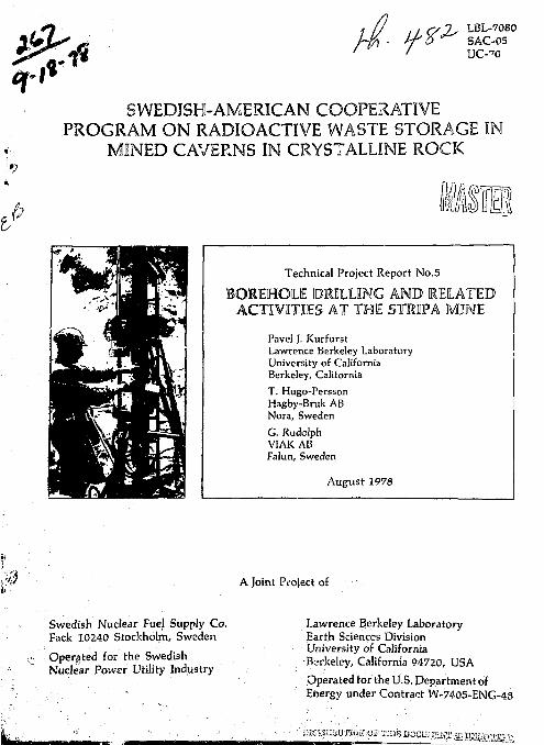
$ * //• ft* LBL-70S0 SAC-05 UC-TC SWEDISH-AMERICAN COOPERATIVE PROGRAM ON RADIOACTIVE WASTE STORAGE IN MINED CAVERNS IN CRYSTALLINE ROCK b III Technical Project Report No.5 BOREHOLE DRILLING AND RELATED ACTIVITIES AT THE STRIPA MINE Pavel J. Kurfurst Lawrence Berkeley Laboratory University of California Berkeley, Calitornia T. Hugo-Persson Hagby-Bruk AB Nora, Sweden G. Rudolph VIAK AB Falun, Sweden August 1978 A Joint Project of Swedish Nuclear Fuel Supply Co. Fack 10240 Stockholm, Sweden Operated for the Swedish Nuclear Power Utility Industry Lawrence Berkeley Laboratory Earth Sciences Division University of California -Berkeley, California 94720, USA Operated for the U.S. Department of Energy under Contract W-7405-ENG- L'lS'i'iiSBUTIOK.Oi? IEIS DOC lUilEK.S Jg BHiiiiOSga
-
Upload
khangminh22 -
Category
Documents
-
view
2 -
download
0
Transcript of 10450052.pdf - International Nuclear Information System (INIS)
$ *
//• ft* LBL-70S0 SAC-05 UC-TC
SWEDISH-AMERICAN COOPERATIVE PROGRAM ON RADIOACTIVE WASTE STORAGE IN
MINED CAVERNS IN CRYSTALLINE ROCK
b III Technical Project Report No.5
BOREHOLE DRILLING AND RELATED ACTIVITIES AT THE STRIPA MINE
Pavel J. Kurfurst Lawrence Berkeley Laboratory University of California Berkeley, Calitornia T. Hugo-Persson Hagby-Bruk AB Nora, Sweden G. Rudolph VIAK AB Falun, Sweden
August 1978
A Joint Project of
Swedish Nuclear Fuel Supply Co. Fack 10240 Stockholm, Sweden
Operated for the Swedish Nuclear Power Utility Industry
Lawrence Berkeley Laboratory Earth Sciences Division University of California
-Berkeley, California 94720, USA
Operated for the U.S. Department of Energy under Contract W-7405-ENG-
L'lS'i'iiSBUTIOK.Oi? IEIS DOC lUilEK.S Jg BHiiiiOSga
LBL-7080 SAC-05
BOREHOLE DRILLING AND RELATED ACTIVITIES
AT THE STR1PA MINE
Pavel J . Kurfurst Lawrence Berkeley Laboratory
Univers i ty of C a l i f o r n i a Berkeley, Ca l i fo rn i a
T. Hugo-Pcrsson Hagby-Bruk AS
Nora, Sweden
and
G. Rudolph VIAK AB
Falun, Sweden
August 1978
fl
I'KKFACK
This ruport is une nf .-i series documenting the results ni i he Swflish-American cooperative research program in which Uie cooperat in;; <̂ if nt ist.s explore t he j-jool oj;i ca 1 , j;cophys i ca I , hydro lo;.;i en 1 , ̂ cochemi ca 1 , and st rue-tural effccLs anticipated from the use of a lar^c crystal ) ine rock r:..iss as a ttcol n^i c roposi Lory for nnc fear wast c . Th i s program ha1-: been sponsor ft] hv the Swedish Nuclear Power Lu'lities ihruiifjb the Swedish Nuclear f u - • 1 Siipfly Company (SKliFj » and tlie L'.S. Department of Lncr;;y (\)(ih) f. hronjdi Hi" Lawrence Berkeley Laboratory (LIU.;.
The pr i nc i pa 1 i nvesL i j;a I ors are L. p,, Ni 1 sson and 0. [)e;;ei ;nan lor SKIJF, and N. fj. W. Cm.k, 1'. A. Witherspoon, and J. L. '.ale lm Li'.L. ether part ic i pant s will appear as authors of subset; uent rcp,<r i s.
Frev iuusly pub.1 j shed Lechn i ca 1 repor I s an- I i -.t ed b" I nw.
!. Swed i sh~ Amur, i can Cooperative Procjram on Kadi 'rj.i'-i : v • w<j:-it<- :;t<>r.j<;>-in MJned Caverns by V. A. Wi Llicrspnon and 0. I)ej',--rman.
O.riL-7049, SAC-UI )
2. Large Scale Permoabi 1J tty Test of the Granit.-- in ihf :<iripa Mine and Thermal Conductivity Test by Lars LundsLrom and liakan Si i i 1 <•.
(I.BL-7() r)2, SAC-02)
3. The Mechanical Properties of the Stripa Granite by Graham Sw in
(Lb!-7074, SAOO'j)
4. Stress Measurements in the Stripa Granite hv Hans Carlsson '
(LHL-7078, SAO04)
V
TABLE OF CONTENTS
LIST UK FIGURES vi
LIST Or TABLES vl
ABSTRACT vi i
1. INTRODUCTION 1
I. DIULL1NC 2
2.1 Surface Drilling 2
2.2 Subsurface Drilling /
2.3 Drilling Costs and Rales 21
2. U Borehole Core Logging 22
3. SURVf.YiNU 26
3.1 Surface Surveying 26
'3.2 Subsurface Surveying 28
4. RELATED ACTIVITIES 34
5. SUMMARY 36
b. REFERENCES 37
7. APPENDIX: Theoretical and Real Borehole Coordinates 39
VI
LIST OF FIGURES
Work Schedule and Deployment of Drills 2
General View of To ram 2x20 Drill 3
Longyear 44 Drill in Operation 5
General View of Cop 4 Drill 6
General Plan of Test Site 8
Borehole Layout in the Time-scaled Drift 9
Borehole Layout in the Pull-Scale Drift 10
Borehole Layout In the Extensometer Drift - Heater H 9 Area - • -11
Borehole Layout in the Extensometer Drift - Heater H 10 Area • • 12
Borehole Layout in the Ventilation Drift 13
General View of Diamec 250 Drill 14
General View of XF 60/90 11 Drill 15
Detailed View of the 0 406 mm Core Barrel and the Expander • - • 18
Detailed View of the Hydraulic Wedge J 9
0 406 mm Core Being Winched Out, Using the Expander 20
LIST OF TABLES
Costs of Core Drilling Per Meter 22
Average Rates of Drilling 23
Standard Deviation of Subsurface Borehoie Surveys 33
vii
ABSTRACT
The drilling operations for the joint Swedish-U.S. program on radioactive waste storage in mined caverns commenced in early August, 1977 and continued until April, 1978. At the peak of drilling, six drills were active—one on the surface and five underground. Some 160 boreholes of various lengths were drilled, including over 700 meters of core drilling on the surface, and over 1800 meters underground. boreholes ranged from 38 mm to 406 mm in diameter, the latter to accomodate the main heaters. Special techniques and drilling equipment were developed to drill and remove the large cores.
Instrumentation and heater installations required strict drilling specifications, including angular deviations of ^0.5 degree for the short underground boreholes and ;+3 degrees for the long inclined boreholes on the surface. The required accuracy was achieved and even surpassed by the use of the best available drilling equipment and techniques, and by extensive surveying control before, during, and after the drilling.
Detailed descriptions of the fractures and other relevant rock properties required orientation of the core as well as special recovery techniques. To assure the best possible quality of the core, a triple-tube core barrel was used to drill all boreholes 76 mm diameter and larger. Complete core logs, kept for all boreholes, contained drilling information and characterization of the discontinuities in the core.
Very detailed planning and scheduling kept the project within the time constraints, and avoided any conflict between the drilling program and simultaneously conducted excavations of the underground test drifts, as well as a number of hydrological and geophysical activities.
-1-
1. INTRODUCTION
The Swedish-U, S. Cooperat i ve Program to f nvest i gate rad i o;ir.t i ve
waste s t o r a g e in mined caverns was I n i t i a t e d in spr ing 1977. Af tor the
agreement between U.S. iiKDA and Swedish SKIiF (Nurlcar Kuel Supply Company.)
was signed July 1, 1977, work s ta r t e r ] a t the Sr .-ipa mine in Guldsmeds-
hyt t an . The Swedi '<<•• par t ol the program wan under the d i rec t i on of KiiS
( N u c l e a r Fuel Sa fe ty P rog ram) , wh i l e t h e U.S . p a r t was c a r r i e d out by
LBL.
The f i r s t s tage of the program involved ex tens ive mine exrav. i t i ;
and d r i l l i n g ope rat ions to provide working space and I act 1 i Lute the I ;tt,, -s c a l e e x p e r i m e n t s . A d r i l l i n g company, Hngby ISruk AB, was c o n t r a c t e d
to d r i l l some 3000 in of boreho les . Over 160 boreho les , ranging in s i z e fr>m
(3 38 mm to 0 A0f> mm, were dri l i ed between August 8, 1977 and Apr i L h, 1978 using several d i f f e r e n t d r i l I s . At the peak of d ri 1. I i ng, s ix d r i l l s
were a c t i v e — f i v e underground and one on the s u r f a c e . The d e t a i l e d d r i l l i n g
schedule and the deployment of the d r i l l s a re .shown in Fig. 1.
The Swedish engineer ing and surveying company V. AK Aii conducted
t h e r e q u i r e d s u r v e y s and oversaw a d h e r e n c e t o tlie s t r i c t d r i l l i n g and
s p e c i f i c a t i o n s se t up by K13S and L3L. The d r i l l i n g p a t t e r n was complex,
and in s t rumen ta t ion and i iea te rs had to be emplaced with h Lgh accuracy.
D r i l l i n g of unusual ly high p r e c i s i o n was needed to ensure the s tr . i igh tness
of the boreholes and the sma l l e s t poss ib l e dev i a t i on from t h e i r theore t Leal
d i r e c t i o n , and l o c a t i o n of the c o l l a r and bottom.
= diameter
DRILLING SCHEDULE Locotcr I'
2 5 .35JFACE A * i - i = - s :a ledd r i f t
j icmec r \ Toram N° I XF60/90
B Full-scale d r i f t Diarncc N°! Torom IT I XF 60/90 Diamec N°2 Torom N°2
C Extensometer d r i f t -
Oiamec N°l
Torom N°l
D. Vent i la t ion dr i f t
Toram N" I
Toram N° 2
iigust Sep Oct
i 76 mm
• 1977 -
r/W6rr
t̂ > 3 8 rn rn
Nov Dec
<f> 76 m m
j>7Smm
<ft38mm 076mm
•pUKm $38mtn,56rnm, 127mm
d> 406rnm,76mm
4> 38mm,46mm
Jon Feb Mar Apr
> 76 mm
-1978-
gb76mm <j>76mm
2. DRILLING
XBL 787-1981
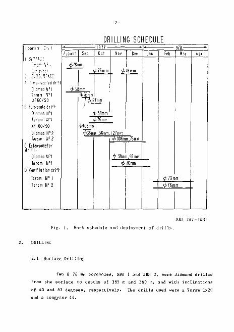
Fig. 1. Work schedule anil deployment of d r i l l s .
2.1 Surface D r i l l i n a
Two 0 76 mm boreholes , SBH 1 and SBH 2, were diamond d r i l l e d
from the su r f ace to depths of 385 m and 360 in, and with i n c l i n a t i o n s
of 45 and 52 deg rees , r e s p e c t i v e l y . The d r i l l s used were a Toram 2x20
and a Longyear 44.
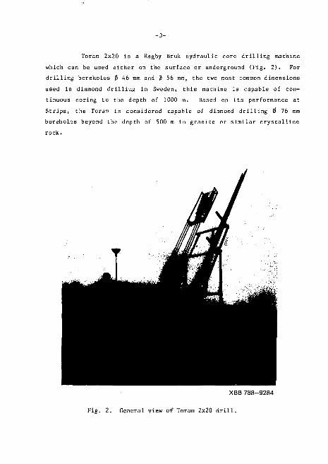
Toram 2x20 is a Hagby Bruk hydraulic core drilling machine which can be used either on the surface or underground (Fig. 2). For drilling boreholes 0 46 mm and 0 56 mm, the two most common dimensions used in diamond drilling in Sweden, this machine is capable of continuous coring to the depth of 1000 m. Based on its performance at Stripa, the Toram is considered capable of diamond drilling 0 76 mm boreholes beyond the depth of 500 m in granite or similar crystalline rock.
XBB 788-9284
Fig- 2 . General view of Toram 2x20 d r i l l .
-4-
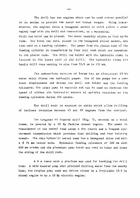
The drill has two engines which can be used either parallel or in series to provide two speed and torque ranges• Using transmission, the engines drive a hexagonal socket in which either a water swivel head with the drill rod connections, or a mechanical drill rod hoist can be placed. The motor assembly slides on four guide rods. The front two rods, placed In the liexagonal driver socket, are also used as a feeding cylinder. The power from the piston rods of the feeding cylinder is transferred by four pull rods which -are connected to the piston rods. The drill rod holder with the hydraulic clamp is located in the lower part of the drill. The hydraulic clamp can handle drill rods varying in slue from 33.5 mm to 101 mm.
The subsurface version of Toram has an electrical 45 kW motor which drives two hydraulic pumps. One of the pumps has a constant displacement and drives the drill rod holder and the feeding cylinders. The other pump is variable and can be used to increase the speed of either the hydraulic motors of spindle rotation or the feeding cylinders during the uptake.
The drill body is mounted on skids which allow drilling of inclined boreholes between 45 and 90 degrees from the vertical.
The Longyear 44 diamond drill (Fig. 3), mounted on a steel frame, is powered by a 90 Hp Perkins diesel engine. The power is transferred to the swivel head using a dry clutch and a 4-speed syn-chromesh transmission which provides four drilling and four hoisting speeds. The twin hydraulic swivel head has a hexagonal drive rod wit'i a 0 76 mm center hole. Hydraulic feeding cylinders of 100 mm with 600 mm stroke and the planetary gear hoist are used to hoist and lower the string of the drill rods.
A 6 m tower with a platform was used for handling the drill rods. A skid mounted pump unit provided drilling water from the nearby lake; the triplex pump used was driven either by a 2-cylinder 15.5 Hp diesel engine or by a 10 Hp electric engine.
-5-
^XBB 788-9286
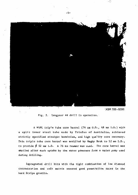
Fig. 3. Longyear 44 drill in operation.
A NLMC triple tube core barrel (76 mm O.D., 48 mm I.D.) with a split inner steel tube made by Triefus of Australia, achieved strictly specified straight boreholes, and high quality core recovery. This triple tube core barrel was modified by Hagby Bruk to 52 mm I.D., to provide $ 52 mm I.D. A 76 mm reamer was used. The core barrel was emptied after each uptake by the water pressure from a water pump used during drilling.
Impregnated drill bits with the right combination of low diamond concentration and soft matrix ensured good penetration rates in the hard Stripa granite.
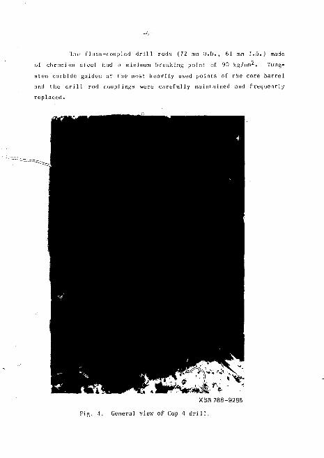
'1 hu fl ush-coupled d r i l l rods (72 rntr, O.D. , 61 mm 1.0. ) made
of chromium steel. had a minimum breaking point of 90 kg/mm2* Tung
s ten carbide guides at the most heavi ly used po in t s of the core b a r r e l
and the a r i11 rod coup]i ngs were ca re fu l ly maintained and f requent ly
r ep laced .
XB3 788-9285
Fig. A. Genera] view of Cop A d r i l l .
i o . a c h i e v e good c o r e r e c o v e r y , t h e b i t p r e s s u r e w;is k e p t
v e r y l o w a; ,d t iie d r i l l r o d s t r i ng w a s ca r e f u 11 v g u i d e d a n d k e p t
s r i f f . A l l ^ T y was o r i e n t e - 1 : Af f o r e v e ry u p t a k e a s t o o l b a r w i t h a
h a r d met a l p o i n t was l o w e r e d by s t e e l c a b l e i n t o t h e b o r e h o l e . S1 i d i ng
a l o n g t h e b o r e h o l e wal i , t h e b a r l i l t t lie l o w e s t po i nt of t h e r o c k ,
maki ng a v i s i b l e i n d e n t a t i on wh i cb was u s e d a s an n r i e n t a t i on mark .
Seven w a t e r t a b l e b o r e h o l e s w e r e d r y d r i l l e d on t h e s u r f a c e t o
d e p m s of i>0 in t o 100 m, u s i n g an A l l , i s C>p <> Cop 4 p e r c u s s i o n d r i l l
w i t l i c o m p r e s s e d a i r ( F i g * 4 ) . The t o o s e v e r a L met e r s ol e a c h b o r e h o 1 e
were c a s e d w i t h 125 mm O.D, s t e e l c a s i ng . D r i l l hi I d i .imi-t i-r was
c h a n g e d g r a d u a i ly from 1 15 mm in t lie t o p p a r t of t h e b o r e h o ] << t o 1 f)'i mm
in t lie hot t urn p a r t . A t wo-man c r e w d r i l l ed f rum •'* m t o 10 m In an H
l iour s h i f t , d e p e n d i n g on bo r e ho l e d e p t h and t lie qua 1 i t y ol t he e n -
c o u n t e r e d r o c k . B e c a u s e t h e b o r e h o l e s w e r e p e r c u s s i o n d r i l l e d , t h e
w a l l s were p l u g g e d w i t h t h e d r i l l f i n e s t o t h e d e p t h of s e v e r a l nm,
t bus s l o w i ng down t h e p r o c e s s of g r o u n d w a t e r t a b 1 e l e v e l r e c o v e r y .
2.2 Subsurface Drilling
Subsurface drilling was carried out in the full-scale, t ime-scaied, extensomerer, and vent ilation drifts. Over 150 boreholes ranging in diameter from 38 mm to 406 mm and varying in depth from 4.5 m to 14.5 m were diamond drilled using Toram, Diamec, and XF 60/90 drill machines. All boreholes were cored, and all core from boreholes larger than 0 56 mm was oriented. The general plan of the drifts is shown in Fig. 5, and a detailed borehole layout in each drift in Figs. 6 to 10.
The subsurface drill was a modified version of the Toram 2x20 drill used on the surface (see section 2.1). A high torque version of the Toram was used for 0 406 mm coring to overcome the initial drilling problems.
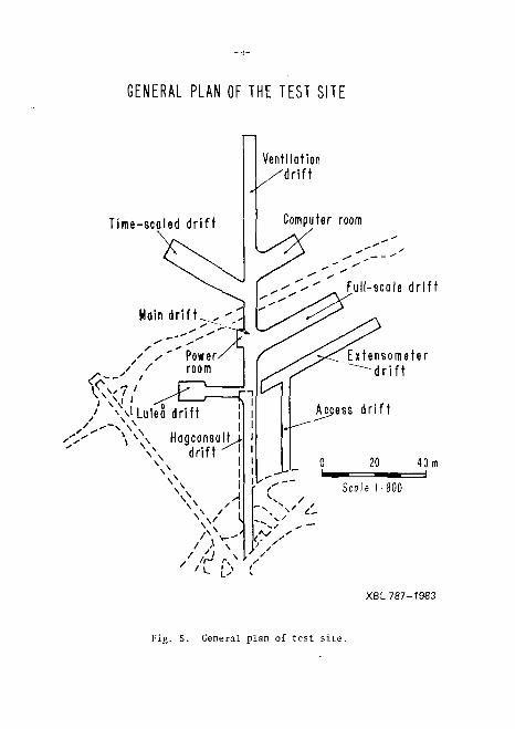
GENERAL PLAN OF THE TEST SITE
Ventilation ' d r i f t
Time-scaled d r i f t
' \ \ ' Lulea dri
Full-scale d r i f t
sorneter r i f t
XBL787-1983
Fig. 5. General plan of test site.
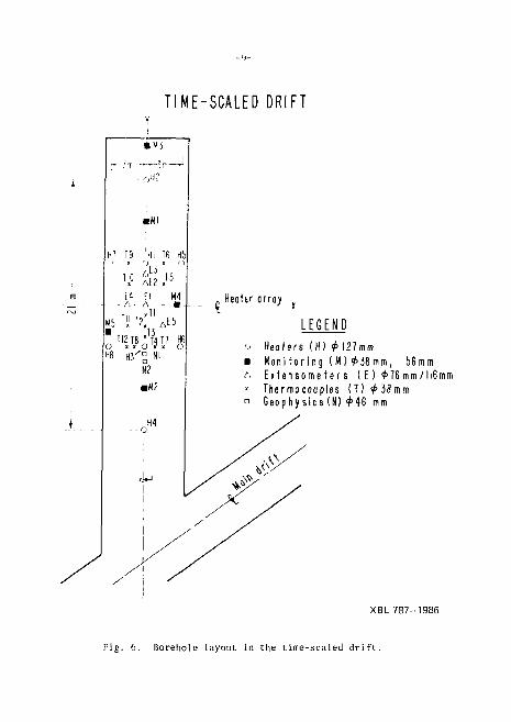
TIME-SCALED DRIFT
- r>?
H7 19 HI 16 H5
H° £1 J 5
F.1 E l /', • A
M4
,,E5 M5 TIJ ' 2 , TI2 T8 "TfaT7
H8 H 3 ^ Nl N2 •M?
1 Heottr orroy
LEGEND Heofers ( H ) 0 1 2 7 m m M o n i t o r i n g (M ) 0 3 8 m m , 56mm E x t e n s o m e t e r s ( E ) 0 7 6 m m / 116mm Thermocouples ( T ) 0 3 8 m m G e o p h y s i c s (N) 0 4 6 mm
XBL 7 8 7 - 1 9 8 6
Fig. 6. Borehole layout in the t ime-sca led d r i f t .
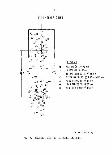
FULL-SCALE DRIFT
22 m
a o"' -,U3 D 1 Me
116, TMi i C I
Eli ° » T1I3„ ri5 A " T IB l H 9
II' T l 6 n , U
M8 r, A Af6 n | 4 C2
E10 O A "
Ub 0 A " - 5 m
I
-JI20
-4119 ^ ' -iMIO
EIL fc 'B f 4 " EI6 ^ HI8. s ..
I J 3 • i
T21 E l - 5 *TZ4JLTI8*HI2
HI67T ?,^HI0 —HIS C5+- \ ] T 2 2 y i 5 Q HI51 *HI4
OiJII JJ:6 -U13 I
o i i u
,EI4
-JII2
o * a
LEGEND HEATERS (H)<*> 406 mm HEATERS(H)4> 38mm THERMOCOUPLES ( T ) <P 38mm EXTENS0METERS(E)4>76 mm/116 mm USBM GAUGES(U) ^ 3 8 m m IRAD GAUGES ( C ) ^ 38mm MONITORING (M) <t> 56mm
XBL 787-I982A (B)
Fig . 7. Borehole layout in the f u l l - s c a l e d r i f t .
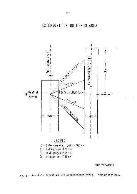
EXTENSOMETER D R I F T - H 9 AREA
L E G E N D (E) Exfensomefers <^76ram/l l6mm (U) USBM gauges <^38mm ( 0 IRAD gauges <^ 38 mm (N) Geophysics ^ 4 6 m m
XBL 787-1985
Borehole layout in the extensometer drift - heater H 9 area.
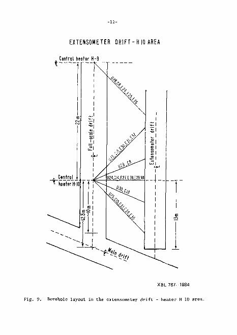
EXTENSOMETER D R I F T - H 10 AREA
Central heater H-9
XBL 787-1984
Fig. 9. Borehole layout in the extensometer dr i f t - heater H 10 area.
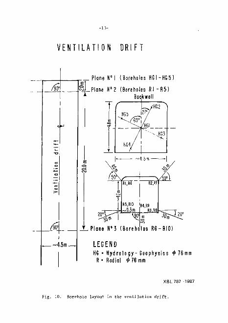
V E N T I L A T I O N D R I F T
(W i
-4.5 m -
Plane N ° l (Boreholes HG I -HG 5 ]
.Plane N°2 (Boreholes Rl - R 5 ) Backwall
J L Plane N°3 (Boreho les R 6 - R I 0 )
LEGEND HG - H y d r o l o g y - G e o p h y s i c s 9 7 6 m m
R • Radial 9 76 mm
XBL 787-1987
Fig. 10. Borehole layout in the ventilation dr i f t .
The Diamec 250 (Fig. 11) is an Atlas Copco drill machine developed mainly for rore drilling 0 38 mm and 0 46 mm boreholes to depths of approximately 250 m. At Stripa, this machine was used to
XBB 788-9282
Fig. 11. General view of Diamec 250 d r i l l .
n ' t < . . / >?.v.
XBB 788-9287
Fig. 12. General view of XF 60/90 H drill.
drill 0 38 mm, j5 lib ram, 0 56 mm, and 0 127 ram boreholes. The drill consists of three main parts: feeding frame with a rotation unit
-lf,-
and a d r i l l rod ho lde r , con t ro l panel with a detached power uni t (25 lip
e l e c t r i c motor^, and a hyd rani ic tank wi th a pump un Lt. Tin-- r o t a t ion
u n i t and t h e d r i l l rod h o l d e r a r e used t o h a n d l e the d r i l l m d s .
The XF 60/90 II d r i l l (Fig . 12) i s an At las Copco conventional
mechanical d r i l l wh ich was used to core 0 127 mm and 0 40 f. ;nn bnru-
h o l e s . The skid-moun ted d r i l l frame .nd the gui di ng rod . have an
e l e c t r i c motor with an LIS-coupl ing a t t a c h e d . The d r i l l has -i 3-'-;pi-ed
gear box, with power t ransmi t ted from the !.R-coupl i ngs to t i c d r i l l
Head; i t i s equipped with a hydraul ic chuck for handling the d r i l l
rods .
0 38 mm boreho le s . A t o t a l of s even ty - s ix 0 'Hi mm instnir.i-n-
t a t i o n and h e a t e r boreholes was d r i l l e d with the Dinmec 250 d r i l l in
the f u l l - s c a l e , t ime-scaled , and extensometer d r i f t s tn depths ranr, i n;\ from 6 m to 14 m. The boreholes d r i l l e d were e i t h e r v e r t i c a l (in the
f u l l - s c a l e and t ime-scaled d r i f t s ) or hor i zon ta l ( in the cxtonsomr-tur
d r i f t ) . To d r i l l the h o r i z o n t a l boreho les , the d r i l l was bol ted to thr-
rock wal l and the d r i l l e r s operated from the s ca f fo ld ing . The standard
T 36 core b a r r e l s , type 1500/2 mm with core b i t s (3K mm O.U. J .md
reamers (38.2 mm O.D.) , were used.
0 46 mm b o r e h o l e s . Four 0 4 6 mm b o r e h o l e s f o r thu g e o
phys ica l survey were d r i l l e d in the t ime-sca led and extensomeier d r i f t s
to depths of 11 m to 13 m, with the Diamec 250 d r i l l using the s tandard
T 4b double tube core b a r r e l .
0 56 mm boreho le s . Two 0 56 mm boreholes were d r i l l e d to a depth of 5.5 m in the f u l l - s c a l e d r i f t with the Diamec 250 and '.'•.f 60/00 d r i l l s . The boreholes were used as p i l o t holes for the 0 406 mm na in h e a t e r bo reho les . Standard T 56 core b i t s , core b a r r e l s , and reamrrs were used. Six a d d i t i o n a l 0 56 mm boreholes ranging from 10 in to 14 m in depth were d r i l l e d in the f u l l - s c a l e and t ime-scaled d i f t s for the geophysical survey, us ing the same d r i l l i n g equipment.
-17-
0 7b mm boreho le s . A t o t a l of f i f t y - f i v e 0 76 mm ins t rumen
t a t i o n and h y d r o l o g i c a l b o r e h o l e s was d r i l l e d i n t h e f u l l - s c a l e ,
t ime-sca led , extensometer , and v e n t i l a t i o n d r i f t s . The boreholes were
d r i l l e d v e r t i c a l l y , h o r i z o n t a l l y , and at v a r i o u s a n g l e s from t h e
h o r i z o n t a l plane to depths of 5 tn ro 40 m, with a Toram 2x20 d r i l l . To
accomodate i n s t a l l a t i o n of the i n s t rumen t s , 35 of these boreho les were
reamed to a ft 116 mm to a depth of i m below s u r f a c e . The t r i p l e tube
core b a r r e l and the s tandard T 76 double core b a r r e l , both with s p l i t
inner tubes , were u s e d - - t h e former produced core of h igher q u a l i t y .
To d r i L l t h e h o r i z o n t a l or i n c l i n e d b o r e h o l e s , t h e d r i l l was
bolted to the rock wal l and the d r i l l e r s nper.itcd from the scnffoldLng.
ft 127 mm b o r e h o l e s . Eight ft 127 mm hea t e r boreholes were
d r i l l e d in the t ime-sca led d r i f t with the Diamec 250 and XF 60/90
d r i l l s to depths of 11 m. Only one h e a t e r borehole was d r i l l e d with the
Diamec us ing the t h i n wal l core b a r r e l . Core was of poor q u a l i t y and
d i f f i c u l t to recover due to frequent breakage of the core c a t c h e r .
Even a f t e r using the XF 60/90 d r i l l and the s i n g l e tube core b a r r e l
with a B-type core b i t (127 mm O.D., 116 mm l .D . ) t o d r i l l the remain
ing hea t e r boreholes , d r i l l i n g proceeded at a slow r a t e . D r i l l i n g
boreholes of t h i s diameter would be improved by using the high torque
vers ion of the Toram d r i l l with the s tandard B-type d r i l l b i t s , core
b a r r e l s , and the heavy d r i l l rods .
0 406 mm b o r e h o l e s . Two ft 406 mm h e a t e r b o r e h o l e s were
d r i l l e d in the f u l l - s c a l e d r i f t to a depth of 5.5 m. In the f i r s t ,
there were problems with the XF 60/90 d r i l l , and with core recovery ,
mainly due to changes in the borehole dimensions. For the second, a
high torque Toram d r i l l was used, along with a s p e c i a l l y b u i l t core
b a r r e l (F ig . 13), with 408 mm O.D., 399 mm I,D. and seve ra l suppor t s
and s t e e r i n g s . No f u r t h e r p rob lems were e n c o u n t e r e d ; t h e second
borehole was succes s fu l ly completed in th ree 8-hour s h i f t s .
-18-
XBB 788-9283
Fig. 13. Detailed view of the 0 406 mm core barrel and the expander.
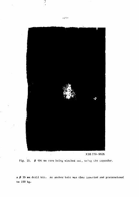
The 0 56 mm pilot boreholes had been drilled to the required depths before the drilling of the )3 406 mm borehole started. To break the 0 406 core at 50 - 75 cm, a hydraulic wedge was inserted in the space between the borehole wall and the core (Fig. 14). After the core was broken off, an expander attached to a steel cable was inserted into the pilot borehole and the core was 1 if ted wi th a winch (Fig. 15). This method of core recovery proved to be very efficient and fast, with no damage to either the core or the borehole wall.
Large core. For the laboratory triaxial fracture permeability and deformation tests, Stallbergsbolagen drilled one large core that included at least two natural fractures perpendicular to the
-19-
XBB 779-9509 Fig. 14. Detailed view of the hydraulic wedge.
longi tudina l a x i s . This core, d r i l l e d a t the 360 m level in the Hagconsult d r i f t , was 100 cm in diameter and 180 cm long, and weighed approximately 3500 kg.
A pilot center borehole of 0 64 mm was percussion dril led to the depth of 25 cm. The borehole was extended to a 160 era depth using
XBB 779-9505
Fig. 15. 0 406 mm core being winched out, using the expander.
a p 35 mm drill bit. An anchor bolt was then inserted and pretensioned to 100 kg.
An A t l a s C o p c o F—12 0 p e r c u s s i o n d r i l l w a s u s e d L <i d r i l l
b o t h t h e c e n t e r p i l o t b o r e h o l e and t h e p e r i p h e r a l h o l e s . For t h e
c o r e , t h e s l o t d r i l 1 i n g t e c h n i q u e d e v e l o p e d by St Hi l b e r g s b n l . i g o n -v.is
u s e d . A f t e r t h e a n c h o r b o l t was i n p l a c e , a 15 c m - l o n g c e n t e r p i n of
t h e d r i l l r i ^ was p l a c e d i n t o t h e p i l o t b o r e h o l e . U s i n g a 0 51 mm
J r i L l r o d , '> 2 p e r i p h e r a l h o l e s w e r e d r i l l e d a l o n g t h e p e r i m e t e r
uf t h e c o r e . The f i r s t p e r i p h e r a l h o l e was d r i 1 1 e d r o n v e n t i o n a l l y ;
t h e o t h e r s weru d r i l l e d u s i n g a s p e c i a l l y b u i l t g u i d e a t t a c h e d t o t h e
d r i l l rod and i n s e r t e d i n t o t h e p r e v i o u s l y d r i J l e d h o ] p . A f t e r t h e
l a s t p e r i p h e r a l h o l e was romp] e t e d , t h e c o r e b r o k e a l ong t h e p r o -
d e t e r m i n e d f r a c t u r e p l a n e , and was l i f t e d o u t of t h e b o r e h o l e w i t h
a w i n c h .
A 2-man d r i l l i n g c r e w c o m p l e t e d d r i l l i n g o p e r a t i o n , i n c l u d i n g
t he d r i l l s e t - u p , i n f o u r 8 - h o u r s h i f t s .
2*3 Drilling Costs and Rates
Costs of drilling varied widely, depending on diameter, location, and depth of the boreholes; types of drills and core barrels used; ?nd driller's time. The breakdown of costs and the average costs per meter are summarized in Table I.
Drilling rates varied considerably from 1.6 m/8 hr. shift for the 0 127 boreholes to 10.7 m/8 hr. shift for the 0 46 mm boreholes. The rate oJ drilling depended on size of the borehole, type of core barrel used (single, double, or triple tube), location of the drill (mounted on the floor or on the walls), orientation of the borehole (vertical, horizontal, or inclined), and other associated factors.
The average rates of drilling for various borehole sizes for both surface and subsurface drilling are given in Table II. In audition to actual drilling time, these rates include time required for positioning, depositioning, and moving the drills; repairs; surveying; and Fotobor survey.
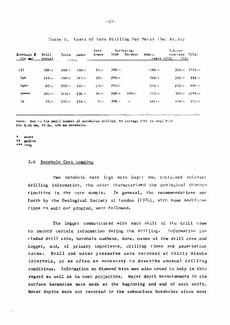
Table L. Costs of Core DrlJlinfi Her Merer fSw. kr./rr,)
Borehole f OriJ1 (In ma) rental
Tooja tabor Core boxen
Surveying: V1AK Fotobor
Subron-AdoiJ n. tractors TfTAI.
127
76*
7b**
7 b***
38
336:- 290:- 730:- 45:- 200:
145:- 190:- 313:- 20: - 200:
60 : - 205:- 122:- 20: - 200:
160:- 245:- 238:- 20: - 200:
65: - 105:- 219:- 5: - 200:
1569:
748;.
456: •
743:.
441:
210:- 1779:
216.— 95«:
210:- 666:
315:- 1058:
210:- 651:
Note: IJue (o t h e Btnall number of b o r e h o l e s d r i l l e d , no ave rage coat 1B a v a i l a b l e {o r 0 .46 mm, 56 OBI, 406 mm b o r e h o l e s .
s h o r t medium
' long
2.4 Borehole Core LoRRing
Two borehole core logs were kept": one contained relevant drilling information, the other characterized the geological discontinuities tn the core sample. In general, the recommendations set forth by the Geological Society of London (1970), witii some modifications to suit our program, were followed.
The logger communicated with each shift of thu drill crew to record certain information during the drilling. Information included drill site, borehole numbers, date, names of the drill crew and logger, and, of primary importance, drilling times and penetration rates. Drill and water pressures were recorded at thirty minute intervals, or as often as necessary to describe unusual drilling conditions. Information on diamond bits was also noted to help in this regard as well as in cost projection. Water depth measurements in the surface boreholes were made at the beginning and end of each shift. Water depths were not recorded in the subsurface boreholes since most
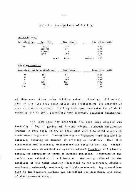
Table II. Average Rates of Drilling
i u r f a c e I ) r i l l i r i R :
bo reho l e 0 (sen) Depth (a) Time ( h o u r s ) Met crb/fl h r . s h i f t
7b 0-1OG 100-2DO 2OO-30C >300
213 25? 375 280
7.55 6.22 4.27 5.71
TOTAL: 1124 AVKRACr.: 5.30
bubBurfjicf D r l l l l n p :
Boretiole 0 (mmj luTAL LENGTH (m) Time (hourn) He te ra /H t i r . s l i l f l
3fe 693 b72 H.25 4t. 4H 3d 10.1)6 56 M 100 5.92 76 1011 1012 B.OO
127 da 440 1.61 406 5.5 27 1.63
of them were either under drilling water or flowing. All activities at the site that could affect the condition of the borehole or rock core were recorded: drilling technique, contamination of drill water by oil or fuel, incomplete core recovery, equipment breakdowns.
The form used for recording all rock core samples was basically a log of geological discontinuities, although distinctive changes in rock type, color, or grain size were also noted along with their exact locations. Discontinuities or fractures were described as naturally occuring or induced by drilling or handling. When this distinction was difficult* uncertainty was noted in the log. Natural fractures were described as open or closed in-situ, and planar, curved, or irregular in terms of surface qualities. Toughness of thp surface was estimated in millimeters. Weathering referred to the condition of the joint coatings, described as non-weathered, slightly weathered, moderately weathered, or highly weathered. Any mineralization on the fracture surface was identified and described, and signs of shear movement noted.
-2A-
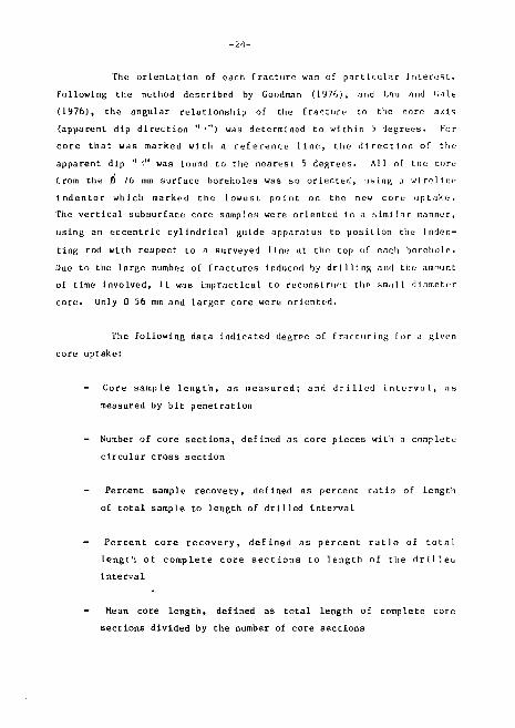
The orientation of each fracture was of particular interest. Following the method described by Goodman (1976), and Lau and 'iale (1976), the angular relationship of the fracture to the core a/is (apparent dip direction "'") was determined to within 5 degrees. For core that was marked with a reference line, the direction of theap pa rent dip " .'" was found to the nearest 5 degrees. All of the core from the JO 76 mm surface boreholes was so oriented, usin^ j wireline indentor which marked the lowest point on the new core uptake. The vertical subsurface core samples were oriented in a similar manner, using an eccentric cylindrical guide apparatus to posit ion the inden-ting rod with respect to a surveyed line at the top of each borehole. Due to the large number of fractures induced by drilling and the amount of time Involved, it was impractical to reconstruct the small diameter core. Only D 56 mm and larger core were oriented,
The following data indicated degree of fracturing for a given core uptake:
- Core sample length, as measured; and drilled interval, as measured by bit penetration
- Number of core sections, defined as core pieces with a complete circular cross section
Percent sample recovery, defined as percent ratio of length of total sample to length of drilled interval
- Percent core recovery, defined as percent ratio of total length of complete core sections to length of the drilleo interval
- Mean core length, defined as total length of complete core sections divided by the number of core sections
-25-
Hxact boreliole depLhs were determined for eacli core uptake in the subsurface drilling. In is permitted an accurate measurement of fracture locations on the core relative to the top of the borehole, since the bottom of a core interval rarely coincided with its drilled depth. While it was impractical to measure exact borehole depths with eacli core uptake for the surface drilling, subsequent borehole TV logging provided a mure accurate r. or re la t ion of core samp le with t rue depth.
For the surface boreholes, Polaroid photographs of the core were taken immod lately upon recovery, before core was 1 oggetl or removed J roro the spl j I inner barrel. Mel r ic sea ] PK were i nr luded in the pictures, and drill intervals were clearly 1 abe 1 led at each end of the sample. Four frames we re usually necessa ry In cover an entire 2.5 to 3.0 m uptake. These photographs were later spliced together and filed in the data repository. Photographs of dry core samples produced a clearer view of the fractures. After the Polaroid photography, the core sample was transferred to a plastic split tube and set into its core box, thereby minimizing handling disturbance prior to marking the reference line. After a complete core box (about 5 to 6 m of core) was logged, 35 mm black and white prints were taken of the rock in a dry condition. The reference lines, scale, and fracture labellings were always visible in the photographs. Again, the photographs of each box were spliced together and filed in the data repository.
For subsurface drilling, Polaroid photographs of the core were taken after an entire box had been logged, instead of immediately after an uptake. After the boxes were transported to the surface, 35 mm black and white photographs were taken in the manner described above. All photographs were catalogued and placed in the data files.
Core boxes were permanently stored in a separate building equipped with storage racks. Boxes were stacked individually, in a clear pattern which was posted on a location chart in the building. To
-26-
check out core samples, permission was obtained from KBS and the LBL site manager, and the checkout form filled out. A wooden dowel, cut to the same length as the removed section, was labelled as on the checkout form and placed in the vacant interval of the box.
3. SURVEYING
3.1 Surface Surveying
Surveying on the surface included positioning the drills and detailed measurements of two inclined boreholes, SBH 1 and SBH 2 (3H5 m and 360 m deep, respectively). Drill position was based on a traverse network set up by VIAK AB in June 1977; this network was calculated botli in plane and elevation using the mine survey system- Exact positions were measured directly on the drill rods using tlu- theodolite, Kern DKM 2 AE; an electrooptical distance measuring instrument, Kern DM 500; and a calibrated measuring tape. The location, direction, and Inclination of the boreholes were stipulated by the mine engineer, P-A. Halen.
Hagby Bruk AB subcontracted an independent consultant, M. Haglund, to supervise measurement of the actual position, dip, and deviation of each borehole during drilling with the Reflex-Fotobor dip and direction instrument. He was also responsible for all calculations and evaluations.
The Reflex-Fotobor probe consists of the power pack, camera, optics, and four 3-m rod sections. Each section includes a reflector ring placed 3, 6, 9 and 12 m from the camera. The whole assembly is attached to conventional drill rods and lowered into the borehole. After the camera is switched on, it functions automatically, taking one frame every 1 or 2 minutes. The reflector rings are illuminated during the camera exposure time by small lamps placed in front of the lens. As the probe bends due to changes in the dip and direction.
deviat i on of the borehole, the p ictures taken show I he changes in r lie posit ion of th,e reflector rings in re 1 a t ion to each other and to its center line. The pictures also show the pos f t i on of t hr bu-*b I e that defines the vertical plane. The developed frames are projected onto a screen und the angula r deflect ion of each r ing is measured. A total nf 0 vaJues is measured f rom t-ach f rame. Three vnlucH, wh ich refer to rhe pos it ion of the rings in relat ion to the vertical line def i ned by the bubble, gIve the deviat i on. The other three values, whIch represent the position of the lateral axis from the vertical, give the dip. These 6 values are compared with values of the displacement nnglos of the reflector rings obtained In the straight test borehole. The data a re r ;il cu 1 a t cd and r on ve r I ed into actual borehole c nord i na t es at desired intervals, using the computer program.
All ca leu J. at ions were based on measuremenfs taken by V1AK AB at depths between 0 and 12 m. Two independent measurements ensured accuracy. The results we re di rectly comparab]e for direction and dip values. The maximum difference between two measurements was:
SBH 1: Direction - 0.0222 grads; dip - 0.0557 grads. SBH 2: Direction - 0.1055 grads; dip - 0.0448 grads;
elevation - 0.002 m; plan - 0.009 m;
The largest differences from the theoretical values were:
SBH 1: Direction - 0.8930 grads; dip - 0.6530 grads. SBH 2: Direction - 0.3156 grads; dip - 0.0753 grads.
Tolerances stipulated in the i n i t i a l specifications allowed a maximum directional deviation at the collar of borehole of + 1.111 grads, and a to ta l deviation at the bottom of borehole of + 3.3333 grads.
The de ta i l ed surface borehole coordinates are ava i l ab l e in LBL's index of data from experiments in Stripa.
-28-
3.2 Subsurface Surveying
The subsurface surveying was carried out in the full-scale, time-scaled, extensometer, and ventilation drifts and included positioning of the drills and surveying during and after the drilling operation.
Traverse network. All traverse network survey points in the full scale, time-scaled, extensometer, and ventilation drifts were measured and calculated using Kern DKM 2 AE and Kern DM 500 instruments and a calibrated measuring tape. The final errors in the traverse net were within the following tolerances:
Plan: 0.004 *L m, where L is the length of traverse in meters;
Elevation: 0.005 m.
The traverse points in the main drift, ventilation drift, and the adit to the extensoraeter drift were marked by roof markers of the conventional type. The traverse points in the full-scalev time-scaled, and extensometer drifts were marked using the fixed consoles attached to the rock walls with expander rock bolts. A horizontal panel with a center hole and an attached Kern instrument was located at the front of these consoles. The traverse points were defined as the center of the center hole and the center of the sighting axis of the theodolite, which was located 197 ram above the top surface of the panel. The traverse points in the individual drifts were determined by triangulation and by the net of triangulation compensation, which produced the following results:
-29-
Average error in Average error in Drift length per 100 m direction
Full-scale 0.0006 m 0.0006 grads
Time-scaled 0.0018 m 0.0024 grads
Extensometer 0.0032 m 0.0009 grads
Ventilation 0.0016 m 0.0017 gtad.s
Two survey points defining the center line of the drifts were installed in the roof of each of the full-scale, time-scaled, extensometer, and ventilation drifts. In the extensometer drift these points were marked along the center line of the drift, perpendicular to the center line of the main heater boreholes H 9 and H 10.
Survey before and after drilling. In the full-scale and tirae-scaled drifts, where all boreholes were drilled vertically, the Kern DKM 2 AE theodolite was used. The location of the boreholes was calculated using all consoles, while at least two consoles were used to measure the angle of the drill. Vertically the drills were aligned using the theodolites to plumb the drill rods. A special grooved square set made by Hagby Bruk was used to align the d':ill rods in plan at the borehole collar directly along the center line of the drill rods. In addition special plates were made for each drill to mark the anchor bolt holes used to secure the drill to the rock.
A Kern DKM 1 theodolite with an auxiliary tube was used to survey ^he vertical boreholes after drilling was completed. The center point of this instrument, a tip of a special signal rod, was determined by intersection from at least two fixed consoles. The bottom of the boreholes was determined by measuring the horizontal and vertical angles and the distances to the reference point, which was
-30-
lowered to the bottom of the borehole. The reference point was placed inside the drill rods and then illuminated from beluw. The diameter of the drill rod varied, depending on the diameter of the measured borehole.
In principle the measurements in the extensometer drift were taken in a similar way. Special pillars installed on the opposite wall from the boreholes simplified setting up the instrument by providing a base for a vertically and laterally adjustable console. A cross-slide, allowing horizontal movements, was fitted to the console. A micrometer allowing vertical movement and the Kern DKH 2 M7. theodolite were mounted on the top of the cross-slide.
The drills were positioned by direct alignment of the center of each drill, and special reference points were placed on their front and back. A frame was made to bolt the drills to the rock wall. Because the drills could be only slightly adjusted, they were very precisely positioned by aligning a groove on a specially made "tongue." The "tongue," together with the drill frame, could be turned towards the theodolite placed in the extension of the borehole direction. Reference points of the same type employed for the vertical boreholes were used for the final borehole measurements. In addition, a sectional cylinder with a center point was used to check the collar of the boreholes and to allow parallel movement of the drills when required.
The theoretical borehole coordinates were first converted into the mine coordinate system, then the borehole location and distances were calculated using either the IBM 1130 computer or the HP 97 calculator.
The location of the boreholes in the full-scale and time-scaled drifts was determined by intersection from at least two fixed consoles. The angle of the drills was trued by directioning at the drill rods. Immediately after the start of the drilling and during the
-31-
first meter of the drilling, the position, direction, and angle of the drill rods were continuously observed and checked from at least two consoles. In order to orient the core samples, scribed lines were marked on the rock surface and aligned parallel to the center line of each drift. With the drill in place, a well defined point on the drill was surveyed and a borehole depth at the end of drilling was calculated. The depth was then measured from ilie base of the drill frame.
In the extensomcter drift, thu theodolite was first placed on the adjustable console attached to the pillar. The location of the instrument in plan and elevation had been calculated in advance. The theodolite was then moved to its correct position lining a three-dimensional intersection; and the direction, dip, and length of e/ich borehole were measured directly. Initially the drilling frame was mounted on the rock wall. When the frame was aligned to an acceptable extent, the exact alignment and adjustment of the drill was made with the theodolite in the same position. The exact position was then checked during the iirst meter of drilling, or until the first core sample was recovered. As soon as any deviation became not iceable, drilling was stopped immediately and the drill adjusted.
To ensure proper orientation of the core samples, a vertical scribed line from the center of the borehole was marked on the rock wall before the start of drilling. After that, the core-orienting procedure used in the other drifts and on the surface was followed.
After completion of drilling, the top and bottom points of the reamed section were measured. In the full-scale and time-scaled drifts, the borehole collars were measured by intersection from the fixed consoles. The bottom of the borehole was measured both in plane and elevation by surveying the reference point lowered into the borehole. The position of the theodolite was then measured both in plan and elevation by a three-dimensional intersection from at least two fixed consoles.
-32-
In the extensometer drift, the theodoltte was placed on the adjustable console on the pillar. The borehole collar, the reamed-out section, and the bottom of the borehole were then surveyed in relation to the known position of the theodolite. The final measurements were carried out twice and were entirely independent.
The following tolerances were stipulated in the initial specifications:
Location of the survey points (2 roof markers in each experiment drift):
Plan + 50 mm, Elevation + 100 mm
Collar of boreholes: Plan + 20 mm (calculated perpendicular to the direction of borehole), Direction +_ 0.5556 grads
Bottom of borehole: Direction + 1.1111 grads
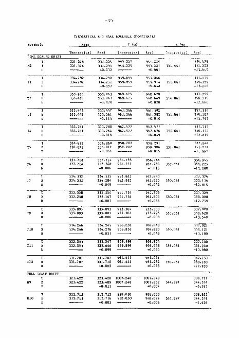
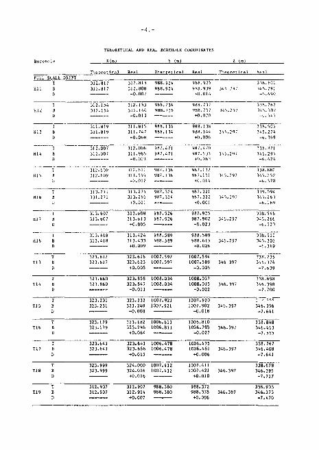
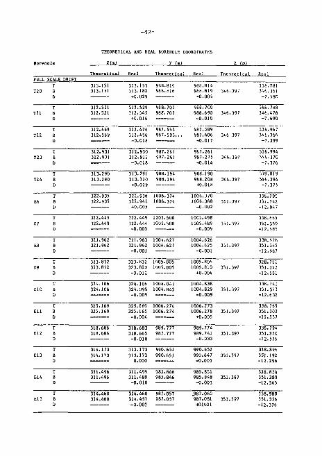
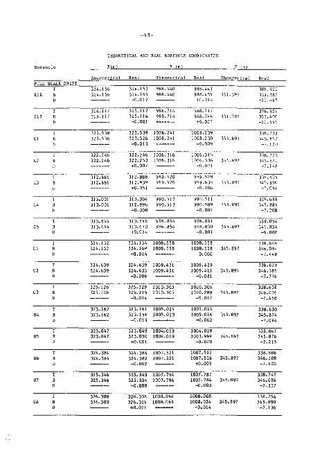
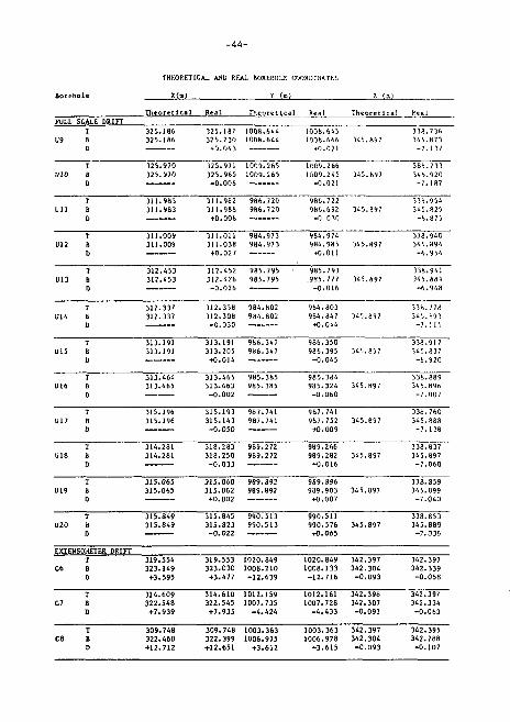
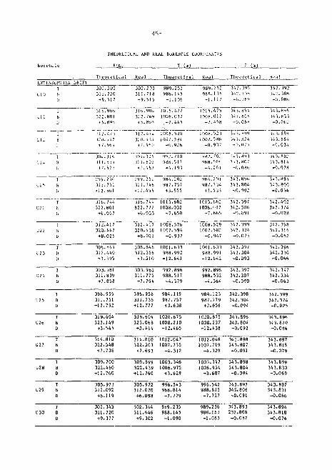
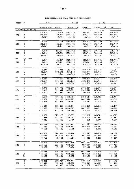
In general, the survey results were less than i/lOth of rhe required tolerances. The detailed survey results of all subsurface boreholes, showing the theoretical and real coordinates for the collar and bottom of the boreholes, are summarized in the Appendix.
Computations. After the borehole survey was completed, the following calculations were carried out: traverse network, partly by the IBH 1130 computer and partly manually; net of triangulation by the HP 9830 A calculator; theoretical borehole coordinates by rhe IBM 1130 computer and by the HP 97 calculator; measurements after completion of drilling by the HP 97 calculator.
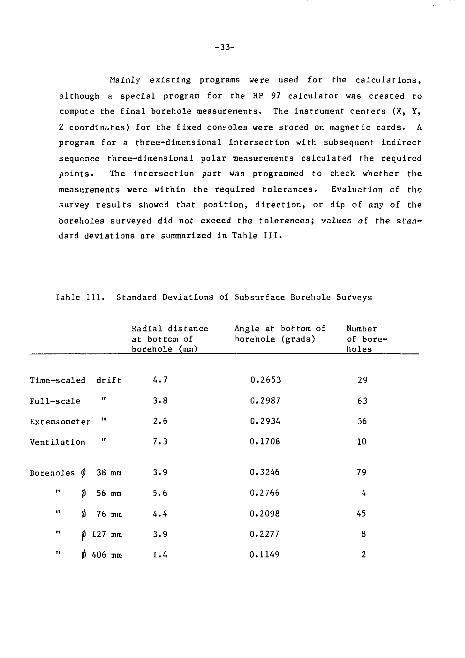
Mainly existing programs were used for the calculations, although a special program for the HP 97 calculator was created to compute the final borehole measurements. The instrument centers (X, Y, Z coordinates) for the fixed consoles were stored on magnetic cards. A program for a three-dimensional intersection with subsequent indirect sequence three-dimensional polar measurements calculated the required points. The intersection part was programmed to check whether the measurements were within the required tolerances. Evaluation of the survey results showed that position, direction, or dip of any of the boreholes surveyed did not exceed the tolerances; values of the standard deviations are summarized in Table 111.
Table III. Standard Deviations of Subsurface Borehole Surveys
Radial distance at bottom of borehole (mm)
Angle at bottom of Number borehole (grads) of bore-
holes
Time-scaled drift 4.7
Full-scale " 3.8
Extensometer " 2.6
Ventilation " 7.3
0.2653
0.2987
0.2934
0.1708
29
63
36
10
Boreholes 0 38 mm 3.9
" 0 56 mm 5.6
" it 76 mm 4.4
f 127 mm 3.9
" 0 406 mm 1.4
0.3246
0.2766
0.2098
0.2277
0.1149
79
4
45
8
2
-34-
4. RELATED ACTIVITIES
Several associated activities were conducted concurrently with the drilling operation. In addition to excavations of the drifts, the most time consuming activities included construction of the computer and instrumentation houses, walkways, and safety ^ates, and installation of the power and instrumentation cables. The other activities were mainly part of or in support of the hydrologlcal and geophysical programs. All activities were carried out either by LBL personnel directly or by subcontractors or other participating agencies t Stallbergsbolagen; the Swedish Geology Survey (SGU); the Tennessee Valley Authority (TVA); the University of Saskatchewan; the University of Waterloo; VIAK AB; Hagconsult AB; Undervattensfoto AB; the Atomic Energy of Canada Limited (AECL)j.
Although the subsurface drilling started in the first part of August 1977, excavation of the ventilation drift, the extensomerer drift, and its access adit continued until early the next month. Since the drilling was done only in the full-scale and time-scaled drifts during the morning and afternoon shifts and the blasting for excavat ions was done mainly during the night shift, there was no interference and both operations proceeded without interrupt ion.
Geophysical surveys were carried out both in the surface and subsurface boreholes by LBL, TVA, SGU, and University of Saskatchewan. The surveys included a set of conventional techniques (resistivity, SP, etc.), and special techniques (sonic waveform and in-hole and cross-hole ultrasonics.)
The following activities were part of the overall assessment of fracture hydrology: geological mapping, stereophotography, fracture mapping, IV logging, water inflow measurements, geochemical water sampling and testing of fracture fillings, and pressure and injection tests.
b(jl." J id genera 1 geo log ica l map pi ng on t he surf nco and de -
t a i l ed capping '.if t he underground d r i f t s , i nr hid ing const rue t ion of the
overa l1 geologi ra l map of t lie rock t ypes present and the d e t a i l e d
p r o f i l e s pe r t inen t to t lie LBL-KBS hea te r exper iments . I'iie d e t a i l e d
resu l t s have been issued as a se-pa rat e KBS report by i) 1 ki ew i </,, et a 3 .
(llJ7ti).
Uet a i Led s tereoi:niotu (;raphs of t he wa 1 l.-> and I" I ours in s c a l e
J: JO were t aken by I lie -.ui'vey i ng f i nr VIAK AB In the t i me -sea 1 ed and
ext ens < met er d r i f t s . In add i t ion, LKi. pcrsunnc1 t uok a se I of pho to
graphs oi I In' w.i l ls , i l n n r s , and c e i l i n g s in the f u l l - s c a l e , i mnpulor,
and vt'iil i 1 at j on d r i f t s . '1 hose piml ographs were l a t e r used in const rur t
a del ai 1 ed plint omosaic needed fur I he f r ac tu re map pi ng and i ,v,ihi. ,i1' Ion.
A very del ai led f ract ure napping of t h j wnlhi and f. 1 oors ' n
t iie i ul 1-sca le , t inie-scalcd, and vent i la f ion d r i f t s was ca r r i ed ou l by
the LiiL personne L. in Jd i t ion t o the maps, s eve ra l prof i 1 e.s f rom t i.r?
h e a l e r and ins t rumental i. on ho les were cons t ruc ted to suppl ement the
base maps and heLp in determin ing the th ree-d imens iona l f r a c t u r e system
of the St r ipa g r a n i t e .
Immedia te ly a f t e r c o m p l e t i o n of d r i l l i n g i n each d r i f t ,
the consul t ing company {Hagconsult AB) TV logged a l l boreholes 0 76 mm
and l a r g e r , l'o compare d i f f e r e n t techniques and equipment used or to
supplement the r e s u l t s a l ready ob ta ined , two o ther companies (Under-
v a t t e n s f o t u , and the AECL) c a r r i e d out a d d i t i o n a l logging both in the
su r f ace and subsur face bo reho les .
Water inflow i n t o the boreholes was measured repea ted ly by
the LBL personnel in a l l boreholes ^ 76 mm and l a r g e r . To ob ta in the
r e p r e s e n t a t i v e v a l u e s , measurements were taken e i t h e r d i r e c t l y or wi th
the upper h ighly f r ac tu red zones packed off.
Ongoing geochemical sampling, r e l a t e d d i r e c t l y to the d r i l
l i n g ope ra t ion , included borehole water sampling and t e s t i n g of the.
-36-
fracture fillings; The tests were performed either directly in situ by the LBL personnel or in the laboratory by the University of Waterloo or other subcontracted agencies.
Pressure and injection tests were carried out by LBL, University of Waterloo, or SGU personnel in the surface and subsurface boreholes. Since the majority of tests in the deep su ace boreholes was done during drilling, it was impossible to avoid some slowdown of the drilling operation.
5. SUMMARY
The drilling operation and associated activities at the Strips mine were a large undertaking completed in less than H months. The complexity of the drilling pattern, the accuracy and precision required of the drilling, and time constraints necessitated the highest possible quality of drilling and surveying. Due to the very large scope of the other ongoing activities and the time requirements, very detailed planning and scheduling was necessary to avoid any interference with the drilling program.
feveral different drill types were used on the surface and underground to core drill more than 160 boreholes of various diameters and inclinations. The surveying results show that the accuracy and precision of drilling as required by the very strict specifications have been achieved and surpassed tor all boreholes.
Several new methods have been developed and tested at Stripa. The smoothwall blasting technique was employed to excavate large drift openings with a relatively small degree of disturbance to the rock surfaces. Using the specially designed core barrels and a high torque version of the Toram drill, the ft 406 mm core was drilled and recovered. The slot drilling technique was utilised to drill 1 m and larger-diameter cores.
-37-
All these techniques were developed, tested, and used with success and are recommended for future excavation and drilling operations for similar waste disposal programs in crystalline rock,
6. REFERENCES
Geological Society of London, "The Logging of Rock Cores for Engineering Purposes," Q. J. Engng. Geol., Vol. 3, 1970, pp. 1-24.
Goodman, R.L., METHODS OF GEOLOGICAL ENGINEER IMC IN DISCONTINUOUS ROCKS, West Publ. Co., N.Y., 1976.
Lau, J. S. 0. and J. E. Gale, "The Determination of Attitudes of Planar Structures by Stereographic Projection and Spherical Trigonometry," Report of Activities, Part C, Geol. Surv. Can., Paper 7G-1C, 1976, pp. 175-177.
Olkiewicz, A., et. al., "Geological and Hydrogeological Documentation of the Strlpa Test Station," KBS Technical Report No. 63, 1978.
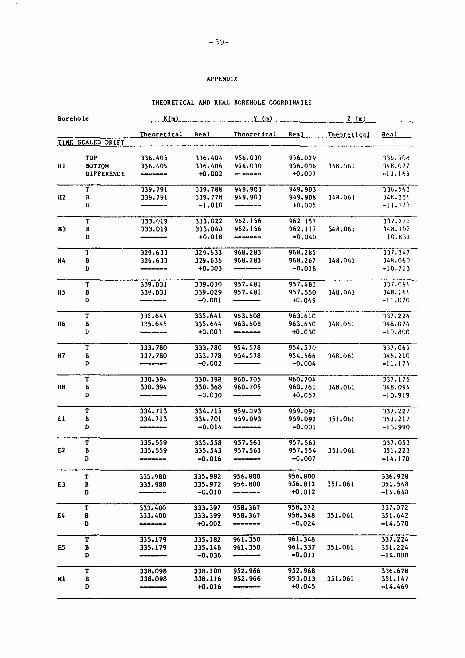
APPENDIX
THEORETICAL AND REAL ftOREHOLE COORDINATES
Boreho le X(m) Y (m) 7. (mj
T h e o r e t i c a l Real T h e o r e t i c a l Real T h e o r e t i c a l Real TIME SCALED DRIFT
TOP 336.405 336.404 956.030 956.029 336.9Of, HI BOTTOM 336.405 336.406 956.030 956.036 348.061 34ft. 0 77
DIFFERENCE 40 .002 +O.007 - 1 1 . 1 6 9
112 T B D
339.791 339.791
339.788 339.778 -1.010
949.903 949.903
949.903 949.908 -t-0.005
348.06! 336.563 348.336 -11.773
T B D
339.788 339.778 -1.010
949.903 949.903
949.903 949.908 -t-0.005
348.06! 336.563 348.336 -11.773
U3 T B D
333.019 333.019
333.022 333.040 tO.018
962.156 962.156
962 157 962.117 -0.040
348.061 337.271 148.102 10.831
H4 T B D
329.633 329.633
329.633 329.636 +0.003
96B.283 968.283
968.285 968.267 -0.018
348.061 337.347 348.060 -10.713
T B D
329.633 329.636 +0.003
968.285 968.267 -0.018
348.061 337.347 348.060 -10.713
H5 T B 0
339.031 339.031
339.030 339.029 -0.001
957.481 957.481
957.481 957.550 tO.069
348.061 337.096 348.166 -11.070
T B 0
339.031 339.031
339.030 339.029 -0.001
957.481 957.550 tO.069
348.061 337.096 348.166 -11.070
T 335.645 335.641 963.608 963.610 337.224 116 B 335.645 335.644 963.608 963.640 348.061 348.024
D tO.003 tO.030 -10.800
H7 T B D
333.780 337.780
333.780 333.778 -0.002
954.578 954.578
954.570 954.566 -0.004
348.061 337.065 348.210 -11.175
T B D
333.780 333.778 -0.002
954.570 954.566 -0.004
348.061 337.065 348.210 -11.175
I1B T B D
330.394 330.394
330.398 330.368 -0.030
960.705 960.705
960.704 960.761 tO.057
348.061 337.175 348.094 -10.919
El T B D
334.713 334.713
334.715 334.701 -0.014
959.093 959.093
959.091 959.092 -0.001
351.061 337.227 351.217 -13.990
T B D
334.715 334.701 -0.014
959.091 959.092 -0.001
351.061 337.227 351.217 -13.990
E2 T B D
335.559 335.559
335.558 335.543 -0.016
957.561 957.561
957.561 957.554 -0.007
351.061 337.053 351.223 -14.170
T B D
335.558 335.543 -0.016
957.561 957.561
957.561 957.554 -0.007
351.061 337.053 351.223 -14.170
T 335.980 335.982 956.800 956.800 336.928 E3 B 335.980 335.972 956 .800 956.812 351.061 351.568
D - 0 . 0 1 0 tO .012 - 1 4 . 6 4 0
E4 T B D
333.400 333.400
333.397 333.399 tO.002
958.367 958.367
958.372 958.348 -0.024
351.061 337.072 351.642 -14.570
T B D
333.400 333.400
333.397 333.399 tO.002
958.372 958.348 -0.024
351.061 337.072 351.642 -14.570
E5 I B D
335.179 335.179
335.182 335.146 -0.036
961.350 961.350
961.348 961.337 -0.011
351.061 337.224 351.224 -14.000
I B D
335.182 335.146 -0.036
961.348 961.337 -0.011
351.061 337.224 351.224 -14.000
T 338.098 338.100 952.966 952.968 336.678 Ml B 338.098 338.116 952.966 953.013 351.061 351.147
D tO.016 tO.045 -14.469
THEORETICAL AND REAL BOREHOLE GOGRfllNATES
X ( n ) Y ( a ) 1- '•*>
Theoretical Theoretical Real Theoretical TIHE SCALED DRIFT
331.326 331.326
331.326 311.294 -0 .0 )2
965.220 964.220
964.220 965.221 +0.001
116.678 151.202 - 1 3 . 8 4 0
334.292 334.292
3)4.288 334.2)1 -0.05)
959.855 959.855
959.866 959.914
•+0.048
3 ) 7 . 1 ) 9 350.359 - 1 3 . 2 2 0
333.866 333.866
333.445 333.445
3)3.863 3)3.84) -O.02O
33).447 333.561
tO.114
960.625 960.625
960.629 960.649 +0.020
961.392 961.382
- 0 . 0 1 0
337.255 350.11b - 1 2 . 8 6 0
) ) 7 . 3 I 4 350.107 - 1 2 . 7 9 )
333.781 333.781
333.780 333.764 - 0 . 0 1 6
962.577 962.5/7
962.577 962.626
+0.049
337.313 350.132 - 1 2 . 8 1 9
336.872 336.872
336.868 336.812 -0.056
958.287 958 .287
958.291 958 .306
+0 .015
337.244 351.2 34 -1 . . 9 9 0
T T12 B
D
U10 B D
337.718 337.718
1)7.714 ))7.708 -0.006
956.755 956.755
956.764 956.780 +0.016
331.707 331.707
331.707 331.710 +0.003
961.431 961.431
961.431 961.484 +0.053
312.713 312.713
312.713 988.030 312.716 988.030 +0.003
988.030 988.024 -0.006
336.945 350.225 -13.280
T7 T B D
334.332 334.332
334.333 334.284 -0.049
962.882 962.882
962.BB3 962.925 +0.042
350.061 337.326 350.136 -12.810
T B D
334.332 334.332
334.333 334.284 -0.049
962.BB3 962.925 +0.042
350.061 337.326 350.136 -12.810
IB T B D
332.258 332.258
332.254 332.167 -0 .087
961.736 961.736
961.739 961.805 +0.066
350.061 537.329 350.088 -12.759
T B D
332.254 332.167 -0 .087
961.739 961.805 +0.066
350.061 537.329 350.088 -12.759
T9 T B D
335.093 335.093
335.093 335.087 -0.006
955.304 955.304
955.303 955.295 -0 .008
351.061 337.0P0 350.620 -13.540
T B D
335.093 335.087 -0.006
955.304 955.304
955.303 955.295 -0 .008
351.061 337.0P0 350.620 -13.540
110 T B D
334.246 334.246
334.245 334.276 +0.031
956.836 956.836
956.840 956.889 +0.049
350.061 337.021 350.121 -13.100
T B D
334.245 334.276 +0.031
956.840 956.889 +0.049
350.061 337.021 350.121 -13.100
T i l T B D
332.553 332.553
332.547 332.646 +0.099
959.899 959.899
959.904 959.948 +0.044
351.061 337.240 351.220 -13.980
T B D
332.547 332.646 +0.099
959.904 959.948 +0.044
351.061 337.240 351.220 -13.980
337.230 350.160 -12.930
FULL SCALE DRIFT T
H9 B D
323.422 323.422
323 .420 323 .409
- 0 . 0 1 1
1007.248 1007.248
1007.248 1007.252
+0 .004 344.397
338.777 344.374 - 5 . 5 9 7
T H9 B
D
323.422 323.422
323 .420 323 .409
- 0 . 0 1 1
1007.248 1007.252
+0 .004 344.397
338.777 344.374 - 5 . 5 9 7
338.953 344.379 -5.426
- . 1 1 -
THEORETICAL AND REAL BOREHOLE COORDINATES
T h e o r e t i c a l T h e o r e t i c a l FULL SCALL DRIFT
H l l I B D
312.817 312.817
312.815 312.808 -0.007
988.924 988.924
988.925 988.939
+0.014 34 5 29;
33B.B01 145.29] -6 .490
HI.! 1 B L>
312.154 317.154
312.153 312.140 -0.013
988.736 988.736
988.737 988.757 +O.02O
34 5 .297 33B.762 345.307 -(,.545
HI 3 1 b II
311.819 311.819
311.815 311.747 -0.068
988.114 9B6.I14
988.138 988.144 +0.006
345 .297 338.905 345.274 -6.369
H14 1 a D
312.007 312.007
312.006 311.985 -0 .02 ]
987.47] 987.471
9B7.470 987.5)1 +O.D61
345, ,29,' 138.171 145.295 -6 .4 24
815 I H U
312. 609 312.609
312.611 311.599 -0.012
987.]36 9B7.136
9H7 . ] ) / 987.151 +0.01 •'.
34 5. 297 338.882 145.252 -6 .370
I H U
312.611 311.599 -0.012
987.]36 9B7.136
9H7 . ] ) / 987.151 +0.01 •'.
34 5. 297 338.882 145.252 -6 .370
Hlb T B L>
313.271 331.271
313.274 313.295 +0.021
987.324 987.324
987.321 987.322 +O.001
345. 297 119.094 145.263 -6.169
T B L>
313.274 313.295 +0.021
987.321 987.322 +O.001
345. 297 119.094 145.263 -6.169
H17 I B
313.607 313.607
313.6D8 313.613 +0.005
987.926 987.926
987.925 987.902 -0 .023
345. 297 338.946 345.266 -6 .320
313.418 313.418
313.424 988.5B9 313.433 988 .589 +0 .009
988 .589 988.615 345.297 +0.026
338.912 345.301 -6.389
323.617 323.617
323.618 1007.597 323.623 1007.597 +0 .005
1007.594 338.735 1007.589 346 397 346.374
-0.005 -7.039
T14 T B D
323.860 323.860
323 .858 323 .847
- 0 . 0 1 1
1008.034 1008.034
1008.037 1008.015
- 0 . 0 2 2 346, .397
338.69B 346.398
- 7 . 7 0 0
T15 T B U
323.231 323.231
323.232 323.240 +0.00B
1007.921 1007.921
1007.920 1007.902
- 0 . 0 1 B 346. 397
1' ' . 7 t ^ 346.396
- 7 . 6 4 1
T B U
323.232 323.240 +0.00B
1007.920 1007.902
- 0 . 0 1 B 346. 397
1' ' . 7 t ^ 346.396
- 7 . 6 4 1
T16 T B D
323.179 323 .179
323.182 323 .246 +0 .064
1006.811 1006.811
1006.810 1006.7B3
- 0 . 0 2 7 346, ,397
338.848 346 .413
- 7 . 5 6 5
T B D
323.179 323 .179
323.182 323 .246 +0 .064
1006.810 1006.7B3
- 0 . 0 2 7 346, ,397
338.848 346 .413
- 7 . 5 6 5
1 323.641 T17 B 323.641
D
323.641 1006.478 323.656 1006.478 +0 .015
1006.475 1006.481 346.397 +0.006
338.767 346.408 -7.641
323.999 323.999
324.000 1007.412 324.016 1007.412 +0.016
1007.411 1007.421 346.397
+0 .010
338.678 346.395 -7.717
T 312.907 119 B 312.907
112.907 988.380 988.372 338.903 112.914 988.380 988.378 346.397 346.373 +0.007 +0.006 -7 .470
- 4 2 -
THEORETICAL AUD REAL BOREHOLE COORDINATES
Boreho le H(a ) Y (m> 2 (»)
Theoretical Real Theoretical Real Theoretical Real FULL SCALE DRIFT ____
T 313.151 313.153 9B8.816 988.814 338.781 T20 B 313.151 313.182 968.816 988.819 346.39? 346.361
D +0.029 +0.005 -7.580
121 T B D
312.521 312.521
312.529 312.545 +0.016
988.703 988.703
988.700 988.690 -0.010
346. 397 388.788 346.478 -7.690
T22 T 8 D
312.469 312.569
312.474 312.456 -0.018
987.593 987.593...
987.589 987.606 +0.017
346 397 338.967 346.366 -7.399
T 8 D
312.474 312.456 -0.018
987.593 987.593...
987.589 987.606 +0.017
346 397 338.967 346.366 -7.399
T23 T B D
312.931 312.931
312.930 312.912 -0.018
987.261 9B7.261
987.261 987.275 +0.014
346, .397 338.994 346.370 -7.376
T24 T B D
313.290 313.290
313.291 313.320 +0.029
9B8.194 988.194
988.190 988.208 +0.018
346, ,397 339.019 346.394 -7.375
E6 T B V
322.935 322.935
322.936 322.941 +0.005
1006.374 1006.374
1006.370 1006.368 -0.002
351. ,397 338.795 351.742 -12.947
T B V
322.935 322.935
322.936 322.941 +0.005
1006.370 1006.368 -0.002
351. ,397 338.795 351.742 -12.947
E7 T B D
322.449 322.449
322.449 322.444 -0.005
1005.500 1005.500
1005.498 1005.489 -0.009
351. 397 338.665 351.350 -12.685
T B D
322.449 322.444 -0.005
1005.500 1005.500
1005.498 1005.489 -0.009
351. 397 338.665 351.350 -12.685
E8 T B D
321.962 321.962
321.963 321.962 -0.001
1004.627 1004.627
1004.626 1004.625 -0.001
351. 397 338.678 351.345 -12.667
T B D
321.963 321.962 -0.001
1004.627 1004.627
1004.626 1004.625 -0.001
351. 397 338.678 351.345 -12.667
E9 T B a
323.832 323.832
323.832 323.820 -0.012
1005.805 1005. B05
1005.806 1005.810 +0.004
351. 397 328.761 351.342 -12.581
T B a
323.832 323.820 -0.012
1005.805 1005. B05
1005.806 1005.810 +0.004
351. 397 328.761 351.342 -12.581
T 324.106 324.106 1004.843 1004.838 338.741 E10 B 324.106 324.095 1004.843 1004.829 351.397 351.373
D -0.009 -0.009 -12.632
Ell T B D
325.169 325.169
325.169 325.165 -0.004
1006.274 1006.274
1006.273 1006.278 +0.005
351, .397 338.765 351.302 -12.537
T B D
325.169 325.165 -0.004
1006.273 1006.278 +0.005
351, .397 338.765 351.302 -12.537
E12 T B D
318.686 318.686
318.683 318.665 -0.018
989.777 987.777
989.774 989.741 -0.033
351 .397 338.794 351.870 -12.576
E13 T B D
314.173 314.173
313.173 313.173 0.000
990.651 990.651
990.652 990.647 -0.005
351, ,397 338.896 351.192 -12.296
T B D
313.173 313.173 0.000
990.652 990.647 -0.005
351, ,397 338.896 351.192 -12.296
El 4 T B D
311.496 311.496
311.499 311.489 -0.010
985.846 985.846
985.851 985.848 -0.003
351, ,397 338.624 351.389 -12.565
T B D
311.499 311.489 -0.010
985.846 985.846
985.851 985.848 -0.003
351, ,397 338.624 351.389 -12.565
I 314.460 314.460 987.057 .987.060 338.980 E15 B 314.460 314.457 987.057 987.081 351.397 351.356
D -0.003 +01021 -12.376
THEORETICAL AND REAL BOREHOLE COORDINATES
("' Theoretical Real Theoretical Real Theoreilcal Real
FULL SCALE DRIFT 314.156 314.156
314.153 986.440 314.165 986.440 +O.012
988.441 988.4 55
314.117 315.117
315.117 988.714 315.116 988.714 -0.001
968.717 968.744 +0.027
388.922 351.387
338.854 351.400 -12.546
123.538 323.536
323.539 IOOB.24I 323.526 1008.241 -0.013
1008.239 1008.2 30 34 -0.009
322.246 322.246
322.246 1006.316 322.253 1006.316 +0.007
1006.315 1006.3 36
312.886 312.886
312.888 989.520 312.939 989.520 +0.051
9B9.529 989.635 345.897 +0.10t.
313.001 313.001
313.004 990.513 312.996 990.513 -0.008
990.511 990.509 345.897 -0.002
338.732 345.852 - 7 . 1 2 0
338.723 145.871
138.804 14 5.890 -'.'.086
3)8.684 145.884 -7.200
313.644 313.644
313.646 986.854 313.670 986.854 +0.024
986.851 9B6.850 -0.001
324.639 324.639
324.639 1009.431 324.633 1009.431 -0 .006
1009.429 1009.411 345.897
-0.081
139.054 345.854 -6 .800
1 324. .152 324. .154 1008, .558 1008, .558 338 .646 Ul B 324. 152 324, .168 1008. ,558 1008, .558 345, .897 346 .094
D +0. .014 0, ,000 -7, .448
338.619 346.385 -7.776
325.126 325.126
325.129 1010.305 325.115 1010.305 - 0 . 0 1 4
1010.306 1010.289 345.897
- 0 . 0 1 7
324.384 324.384
324.384 1D07.521 324.382 1007.521 -0.002
1007.521 1007.526 +0.005
3B.608 46.006 -7.458
U4 T B D
323.162 323.162
323.161 323.146 -0.015
1005.014 1005.013
1005.014 1005.016 +0.002
345.897 338.830 345.874 -7.044
T B D
323.161 323.146 -0.015
1005.014 1005.016 +0.002
345.897 338.830 345.874 -7.044
115 T B D
323.047 323.047
323.049 323.050 +0.001
1004.019 1004.019
1004.019 1003.999 -0.020
345.897 338.661 345.876 -7.215
T B D
323.049 323.050 +0.001
1004.019 1004.019
1004.019 1003.999 -0.020
345.897 338.661 345.876 -7.215
338.688 346.108 -7.420
325.346 325.346
325.343 1007.794 325.334 1007.796 -0.009
1007.787 1007.784 345.B97 -0.003
338.747 346.086 -7.337
326.308 326.308 1008.068 1008.068 338.754 326.303 326.319 1008.068 1008.054 345.897 345.890
+0.011 -0.014 -7.136
FULL SCALE DRIFT
U12 B D
U13 Fi D
THEORETICAL AND REAL BOREHOLE COORDINATES
X(m) Y (a)
Theoretical Real
J25.970 325.970
311.983 311.9B1
311.009 311.009
312.453 312.453
Theoretical Real
325.187 1008.644 325.230 1008.644 +0.043
"325.971 1009.265 325.965 1009.265 -0.006
311.982 986.720 311.988 986.720 +0.006
311.011 984.973 311.038 984.973 +0.027
312.452 985.795 312.426 985.795 -0.026
1008.645 1008.666 +0.021
1009.2 66 1009.245 -0.021
986.722 986.692 -0 010
~984.9 74 984.985 +0.011
985.793 .985.777 -0.016
1- ('1 Theoretical
1)8.736 145.873 -7.137
386.733 345.920 -7.187
118.954 145.829 -6.875
138.940 145.894 -6.954
318.941 345.8d9 -6.948
T U15 B
U17 B
U18 B D
312.337 312.337
313.191 313.191
313.464 313.465
315.196 315.196
314.281 314.281
312.338 312.308 -0 .030
313.191 313.205 +0.014
313.465 313.463 -0 .002
315.193 315.143 -0 .050
318.283 318.250 -0.033
984.802 984.802
986.347 986.347
985.3B5 985.385
987.741 987.741
9B9.272 9B9.272
984.803 984.847
•O.044
986.350 986.395 +0.045
985.384 985.324 -0.060
9B7.741 987.752 +0.009
9b9.266 989.282 +0.016
318.778 345.891 -7.115
118.917 145.817 -6.920
318.889 145.896 -7.007
338.760 345.888 -7.128
138 .817 345 .897 -7 .060
338. ,859 145 .899 -7 .040
315.065 315.065
315.060 315.062 +0.002
989.892 989.892
989.896 989.903 +0.007
T U20 B
D
315.849 315.849
315.845 315.823 -0.022
990.513 990.513
990.511 990.576 +0.065
345.897 338.853 345.889 -7.036
T U20 B
D
315.845 315.823 -0.022
990.511 990.576 +0.065
345.897 338.853 345.889 -7.036
EXTENSOHETER DRIFT T
C6 B D
319.554 323.149 +3.595
319.553 323.030 +3.477
1020.849 1008.210 -12.639
1020.849 1008.133 -12.716
342.397 342.304 -0.093
342.197 342.339 -0.058
T C7 B
D
314.609 322.548 +7.939
314.610 322.545 +7.935
1012.159 1007.735 -4.424
1012.161 1007.728 -4.433
342.398 342.307 -0.091
342.397 342.334 -0.063
C8 B D
309.748 322.460 +12.712
309.748 1003.363 1003.363 342.397 322.399 1006.975 1006.978 342.304 +12.651 +3.612 +3.615 -0.093
342.395 342.288 -0.107
- 4 5 -
THEORETICAL AND REAL BOREHOLE COORDINATES
Xt°u V (»)
Ttie.- jret lcal Real T h e o r e L l c a l Real T l u - o r c l l c a l Hra! EX1ENSUKETER DRIFT
T CIO B
3 0 2 . : 0 3 311.720 -.9.517
3 0 : . 2 0 3 311.718 ••9.511
989.251 988. 145
- 1 . 1 0 6
989.252 988 .135
- 1 . 1 1 7
342.395 342.10*
342.392 3 .2 .30 ' ! - 0 . 0 8 ' ,
1 3 i b . y o ' j 3 1 b . 9 0 A 1 0 1 5 . 4 7 7 1 0 1 5 . 4 7 5 3 4 3 . 8 9 i 34 3 . 8 9 5
- 1 1 h 3 2 2 . 8 0 1 3 2 2 . 769 1 0 0 8 . 0 3 2 1 0 0 8 . 0 1 7 34 3 . 8 0 6 ( 4 1 . 8 1 3 :; • t - j . t m + 5 . S 6 S , - 7 . 4 4 5 - ? , 4 S » -O.OHK - 0 . 0 6 2
J I ^ . 4 / j 3 1 2 . 4 7 * 1 0 0 8 . 5 2 0 1 0 0 8 . 5 2 1 3 - J . H 9 9 V . 3 . B 9 B
L I4 . b j r. J - « ^ 2" 1 : 0 . 4 3 . ; w o / . 594 1 0 0 7 . 5 8 6 34 3. .424 14 3 . 8 6 4
+ 7.9t>4 + 7.9' i-*. - 0 . 9 2 b - 0 . 9 3 7
14 3 . 8 9 1
- 0 . 0 3 4
'I 30 . . . ) I 'J t o - . , a 1 *j 99 2 . / 1 0 9 V 2 . 7 0 7 14 3 . 8 9 1 14 3 . 8 9 2
c i - 8 J l I . H J 9 J l 1 . 802 9 8 8 . 5 1 7 9KH.SOI, V . 1 . 8 0 7 J4 1 . 8 1 4
It • 7. 5 2 "1 + , ' . 4 8 7 - 4 . 1 9 3 - 4 . 2 M - 0 . 0 86 - 0 . 0 7 8
I 2 9 9 . 2 V ' 2 9 4 . 2 b . 9 8 4 . 2 0 2 9 8 4 . ? f U 34 3 . 8 9 b 1 4 1 . H 9 / ,
U 5 K 3 1 1 . 7 5 1 3 1 1 . 7 4 ( 1 9 8 7 . 7 3 7 9 8 7 . 7 3 4 34 3 . 8 0 4 3 4 1 . 8 0 0 IJ + 1 2 . 5 0 1 • 1 2 . 4 9 5 + 3 . 5 5 5 t 3 . 5 i l - 0 . 0 9 2 - 0 . 0 9 4
1 3 1 6 . 7 4 4 3 1 b . 7 4 4 1 0 1 5 . 6 8 2 1 0 1 5 . 6 8 2 3 4 2 . 3 9 7 3 4 2 . 4 0 2
L'21 i i 3 2 2 . » 0 1 8 2 2 . 7 7 7 1 0 0 8 . 0 3 2 1 0 0 8 . 0 1 7 34 2 . 3 0 6 3 4 2 . 3 7 4
ly + 6 . 0 5 7 + 6 . 0 3 3 - 7 . 6 5 0 - 7 . 6 6 5 - 0 . 0 9 1 - 0 . 0 2 8
C22 I
D
3 1 2 . 4 1 7 3 2 0 . 4 4 2
+ 8 . 0 2 5
3 1 2 . 4 1 7 3 2 0 . 4 3 8
+ 8 . 0 2 1
1 0 0 8 . 5 2 0 1 0 0 7 . 5 9 4
- 0 . 9 3 2
1 0 0 8 . 5 2 9 1 0 0 7 . 5 8 2
- 0 . 9 4 7
3 4 2 . 3 9 9 3 4 2 . 3 2 4
- 0 . 0 7 5
3 4 2 . 3 9 8 3 4 2 . 3 1 6
- 0 . 0 8 2
U23 T B 0
3 0 8 . 8 4 5 3 1 2 . 4 4 0
+ 3 . 5 9 5
3 0 8 . 8 4 6 3 1 2 . 3 5 6 + 3 . 5 1 0
1 0 0 1 . 6 3 3 9 8 8 . 9 9 2 - 1 2 . 6 4 1
1 0 0 1 . 6 3 3 9 8 8 . 9 9 1 - 1 2 . 6 4 2
3 4 2 . 3 9 / 3 4 2 . 3 0 4 - 0 . 0 9 3
3 4 2 . 3 9 6 3 4 2 . 3 3 0
- 0 . 0 6 6
0 2 4 7 B D
3 0 3 . 9 8 1 3 1 1 . 8 3 9
+ 7 . 8 5 8
3 0 3 . 9 8 1 3 1 1 . 7 7 5
+ 7 . 7 9 4
9 9 2 . 8 9 6 9 8 8 . 5 1 7
- 4 . 3 7 9
9 9 2 . 8 9 6 9 B B . 5 3 2
- 4 . 3 6 4
3 4 2 . 3 9 7 3 4 2 . 3 0 7
- 0 . 0 9 0
3 4 2 . 3 9 7 3 4 2 . 3 3 4
- 0 . 0 6 3
398.959 398.958 964.119 984 .123 342 .398 342.399 311.751 311.735 987.757 987 .779 342.304 342.374 +12.792 +12 .777 +3 .638 +3 .656 - 0 . 0 9 4 - 0 . 0 2 5
U26 T B D
319.604 323.149 +3.545
319.604 323.068 +3.464
1020.675 1008.210 -12.465
1020.675 1008.237 -12.438
343.896 343.804 -0.092
34 3.896 343.610 -0.086
U27 T B D
314.810 322.548 +7.738
314.810 322.503 +7.693
1012.047 1007.735
-4 .312
1012.048 1007.719
-4.329
343.898 343.807 -0.091
343.897 343.818 -0.079
0 2 8 T B D
309.700 322.460 +12.760
309.699 322.439 +12.760
1003.346 1006.975
+3.629
1003.347 1006.954
+3.607
343.898 343.804 -0.094
343.899 343.830 -0 .069
U29 T B D
305.973 312.092 +6.119
305.972 312.070 +6.098
996.543 988.814 -7.729
996.542 988.615 -7.727
343.897 343.806 -0.091
343.897 34 3.831 -0 .066
302.343 302.344 989.235 989.236 343.893 343.894 311.720 311.646 988.145 988.153 232.806 343.818 +9.377 +9. 302 -1 .090 -1.083 -0.087 -0.076
THEORETICAL AND REAL BOREHOLE COORDINATE:
X ( P ) Y ( a ) 7- (mj
Theoretical Heal Theoretical fica] Theoretical EXTENSOMETER DRIFT
£18 T B 1)
314.639 322.548
•7.909
314.638 322.493 +7.855
1012.143 1007.735
-4.408
1012.141 1007.77'.
-4.366
341.903 340.997 -O.906
341.903 340.986 -0.917
El 9 T B D
.4.759 3.12.548
(7.789
314.759 322.526 +7.767
1012.076 1007.731
-4.341
1012.074 1007.757
-4.317
34 3.393 342.947 -0.446
343.393 342.937 -0.456
E20 T B D
' 14.950 . . '4 .732. •9.782
314.950 324.674 +9.724
1011.969 1006.518
-5.451
1011.969 1006.576
-5.393
345.140 344.859 -0.281
345.142 344.8 30 -0.312
E21 T B D
9.529 .:2.149 .3.620
319.529 323.161 +3.632
1020.940 1008.210 -12.710
1020.940 1008.202 -12.718
34 1.906 340.968 -0.938
341.905 340.932 -0.973
E22 T B D
19.588 23.149 •3.561
319.588 323.157 •3.569
1020.730 1008.210 -12.520
1020.730 1008.210 -12.500
343.393 342.932 -0.461
341.39/ 342.909 -0.488
£23 T B D
319.624 3.3.149
•3.525
319.625 323.146 +3.521
1020.604 1008.210 -12.394
1020.604 1008.24 7 -12.357
345.143 344.916 -0.198
345.145 344.880 -0.285
E24 T B D
•; >9. 745 1- 2.460 - .2 .715
309.745 322.441 +12.696
1003.359 1006.975
+3.616
1003.360 1007.026
+3.666
34 1.902 340.968 -0.934
341.906 340.925 -0.981
£25.' T B D
9.584 3 2.460 1.2.876
309.585 322.423 +12.838
1003.313 1006.975
+3.662
1003.313 1007.026
+3.713
34 3.406 342.932 -0.474
343.407 342.«92 -0.315
E26 T B D
3 9.B57 3.2.460 - 2.603
309.B57 322.419 +-12.1 62
1003.391 1006.975
+3.584
1003.389 1007.021
+3.632
345.146 344.915 -0.231
345.149 344.8 70 -0.279
E27 T B h
. 3.926 : .1 .839 +7.913
303.925 311.824 +7.899
992.927 9B8.517 -4 .410
992.926 988.541
-4.385
341.90.: 340.997 -0.906
341.903 340.993 -0 .910
E28 T B D
304.289 311.839
7.550
304.288 311.822 +7.534
992.725 988.517 -4.208
992.723 988.549 -4.174
343.379 342.947
-0.432
343.382 342.930 -0.452
E29 T B D
304.307 314.023 +9.716
304.308 313.946 +9.638
992.714 987.300 -5 .414
992.715 987.376 -5.339
345.138 344.859 -0.279
345,138 344.844 -0.294
E30 T B r
2)8.813 312.440 +3.627
308.811 312.401 +3.590
1001.746 988.992 -12.754
1001.746 989.054 -12.692
341.905 340.968 -0.937
341.906 340.927 -0.979
£31 T B D
308.835 : 2.440
3.605
308.832 312.416 +3.5B4
1001.669 988.992 -12.677
1001.668 989.044 -12.624
343.398 342.932 -0.466
343.400 342.882 -0.518
E32 B D
5)8.855 308.854 1001.598 1001.598 345.146 345.149 312.440 312.454 988.992 998.99*. 34...915 34..868 +3.585 +3.600 -12.606 -12.602 -0.231 -0.281
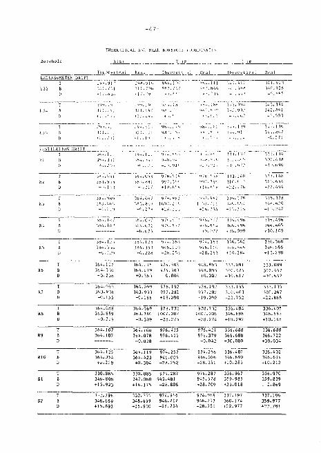
rHKUkKTiCA;. AS:J HLAI . Bi>Rhfcu:.s
HXTi.SSuKETEK DRIFT
9 8 ? . ; ; ? l i l .<(13 3-'.r .<»2K
_ r . - i n 1 ,
3 i 3 . 3<U 342
. ' ) f i 3
ITT ~i~uT 3 V . . K',?
VhNill.AI ION DR11T
l r t . .09 i
] H . ] ' „ +0.-V9
976.5 lh 997.39*
3 6 4 . 1 : : 364.3 30 +O.2OB
3 6 4 . 0 / 1 / 9 / ~ . 4 : i l 3 8 3 . 8 0 * I 00 7 . J ] f.
- D . : ' M + 2 6 . . : ; ,
3 6 4 . 1 1 6 9 7 4 . 5 8 3 3 6 4 . 4 7 9 9 7 4 . 5 8 3 + 0 . 3 6 3 G.OOG
3J<>.378 : . . ' . . 654
- ! " . ? . 76
1 6 4 . 0 7 2
- 6 . 0 2 5
3 8 4 . T 5 5 " 9 / ' . . 3 6 3
3 8 4 . 3 5 3 9 4 6 . 1 1 1 H i . 2 2 8 - 2 6 . 2 5 1
3 6 6 . 4 9 6
9 7 4 . 3 6 3 9 4 6 . 1 1 6
3 1 6 . 3 6 2 W 6 . 6 . . 6
4 1 0 . 2 H . .
9 4 8 . 8 9 3 9 4 8 . 8 9 5
+ 0 . 0 0 2
3 3 3 . 0 9 1
- 3 0 . 6 1 7
33 I . 148 3 1 0 . 6 5 4 - 2 2 . 4 9 4
3 3 6 . 3 7 8 3 4 ' . . 6 2 0
3 3 6 . 4 9 6 3 6 6 . 6 0 6 + 3 0 . 1 0 9
3 3 6 . 3 6 8 3 4 6 . 6 6 6 + 1 3 . 2 9 8
3 3 3 . 0 8 9 3 0 2 . 4 4 7 - 3 0 . 6 4 2
3 6 - . 0 9 3 3 6 3 . 9 3 8
- 0 . 1 5 5
3 6 4 . 0 9 9 9 7 8 . 1 9 2 3 6 3 . 9 3 3 9 9 7 . 2 8 2 - 0 . 1 6 b + 1 9 . 0 9 0
9 7 8 . 1 9 2 9 9 7 . 2 8 2 - 1 9 . 0 9 0
3 3 3 . 1 5 5 3 1 0 . 4 0 3
3 3 3 . 1 3 5 3 1 0 . 2 6 7 - 2 2 . 8 6 8
3 6 3 . 8 5 9 - 0 . 2 2 9
3 6 4 . 0 8 9 9 7 B . 7 3 2 3 6 3 . 7 8 0 1 0 0 7 . 0 0 7
- 0 . 3 0 9 + 2 8 . 2 7 5
9 7 8 . 7 3 2 1 0 0 7 . 0 0 6 + 2 8 . 2 7 4
3 3 6 . 4 0 4 3 4 6 . 6 9 6 + 1 0 . 2 9 2
336.405 346.553 +10.148
364.107 364.107
364.106 976.415 364.078 976.415 -0.028
976.421 976.379 -0.042
336.688 366.688 +30.000
364.125 364.354 +U.229
364.119 974.257 364.423 946.005 +0.304 -2B.252
974.256 946.00b -28.251
336.407 346.690 +10.283
336.688 366.722 +30.034
336.402 346.614 +10.212
330.885 346.808 +15.923
1-2.796 348.689 +15.893
330.885 974.287 347.060 945.481 +16.175 -28.806
332.796 974.966 348.699 946.212 +15.900 -28.754
974.287 945.578 -28.709
974.96? 946.217 -28.751
336.967 359.985 +23.018
337.197 360.174 +22.977
336.970 359.839 : 2.869
337.196 359.977