A three-phase to single-phase matrix converter for high-frequency induction heating
Upload
khangminh22Category
view
0download
0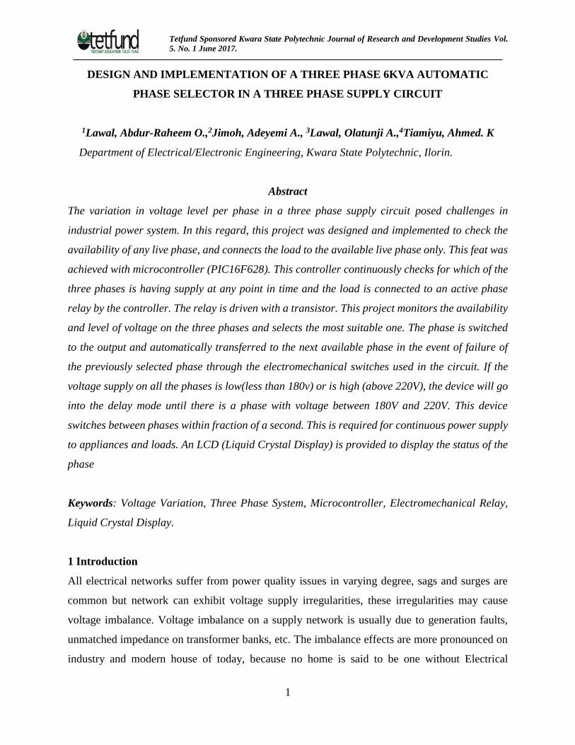
Tetfund Sponsored Kwara State Polytechnic Journal of Research and Development Studies Vol.
5. No. 1 June 2017.
1
DESIGN AND IMPLEMENTATION OF A THREE PHASE 6KVA AUTOMATIC
PHASE SELECTOR IN A THREE PHASE SUPPLY CIRCUIT
1Lawal, Abdur-Raheem O.,2Jimoh, Adeyemi A., 3Lawal, Olatunji A.,4Tiamiyu, Ahmed. K
Department of Electrical/Electronic Engineering, Kwara State Polytechnic, Ilorin.
Abstract
The variation in voltage level per phase in a three phase supply circuit posed challenges in
industrial power system. In this regard, this project was designed and implemented to check the
availability of any live phase, and connects the load to the available live phase only. This feat was
achieved with microcontroller (PIC16F628). This controller continuously checks for which of the
three phases is having supply at any point in time and the load is connected to an active phase
relay by the controller. The relay is driven with a transistor. This project monitors the availability
and level of voltage on the three phases and selects the most suitable one. The phase is switched
to the output and automatically transferred to the next available phase in the event of failure of
the previously selected phase through the electromechanical switches used in the circuit. If the
voltage supply on all the phases is low(less than 180v) or is high (above 220V), the device will go
into the delay mode until there is a phase with voltage between 180V and 220V. This device
switches between phases within fraction of a second. This is required for continuous power supply
to appliances and loads. An LCD (Liquid Crystal Display) is provided to display the status of the
phase
Keywords: Voltage Variation, Three Phase System, Microcontroller, Electromechanical Relay,
Liquid Crystal Display.
1 Introduction
All electrical networks suffer from power quality issues in varying degree, sags and surges are
common but network can exhibit voltage supply irregularities, these irregularities may cause
voltage imbalance. Voltage imbalance on a supply network is usually due to generation faults,
unmatched impedance on transformer banks, etc. The imbalance effects are more pronounced on
industry and modern house of today, because no home is said to be one without Electrical

Tetfund Sponsored Kwara State Polytechnic Journal of Research and Development Studies Vol.
5. No. 1 June 2017.
2
appliances like cookers water heaters, radios, televisions, fans, water pumps etc., all of which need
electricity to operate. Unfortunately, erratic public power supply in Nigeria has pushed her citizens
to seek alternatives. This has resulted in individuals installing wind turbines, solar panels,
generating sets and so on. In many cases, phase absence or low voltage on a phase might be
responsible for poor performance of single phase appliances in homes, offices and industries. This
research work comes with a design to check the availability of power supply in any phase, and
transfer the load to the active or live phase only. This feat is achieved with a Microcontroller
(PIC16F628). This controller continuously checks for power supply conditions of all the phases
connected to it, and the controller connects the load to the active phase, using a relay which is
driven by a transistor. If two or three phases are live, the load will be connected to one of the
phases only and if the phase in use fails, the load will be automatically transferred to the next
available phase. In the event of mains outage none of the phases is connected until mains is fully
restored. An LCD (Liquid Crystal Display) is provided to display the status of the phase condition.
This project uses a regulated 12V,500mA power supply; full-wave bridge rectifier was used to
rectify the 220VAC output of the step down transformer to 12VDC which was filtered and fed into
the microcontroller. The microcontroller used makes the circuit more intelligent while switching
between phases. The system is basically designed to select between the three phases at reasonable
speed, and also addresses phase imbalance with respect to loads. This means automatic switching
between the three phases with a single phase output. In other words, the switching consideration
demonstrates the real and practical situation for mainly domestic, commercial and small industrial
loads. A manual change-over switch requires manual monitoring and switching over between
phases. This method requires human presence, human effort doing the switching, and the switching
time is noticeable. In the processes of manual change-over, valuable time is wasted in addition to
device or machine damage from human error during the process, which could bring losses and
accident.
Hospitals, industries and airports require continuous electricity. It is therefore important to design
and construct an automatic phase selector device which would save time and eliminate the danger
likely to be encountered during manual changing over. The system was designed to supply loads
in homes and offices but not for industrial use, this is because 30Amperes relay switches were
used which can only accommodate total load not above 6KVA.

Tetfund Sponsored Kwara State Polytechnic Journal of Research and Development Studies Vol.
5. No. 1 June 2017.
3
2. Literature review
In most developing and underdeveloped parts of the world, the supply of electricity for industrial,
commercial and domestic use is highly unstable. This gives rise to the frequent use of alternative
sources of power supply to meet up with the energy demands. The Automatic three phase selector
automatically switches over to the alternative phases when there is a power outage. The Automatic
three phase selector is a device that links the load and the three phases and relay switches. This
device maintains constant power supply to the load by automatically activating the phases when
there is need. To ensure the continuity of power supply, many homes, offices and industrial
facilities require a steady and stable power supply, and because of the growing complexity of
electrical systems it becomes imperative to give attention to supply phases reliability and stability.
Over the years many approaches have been implored in selection of phases. Some of them are
discussed below.
In the past the regular practice had been to manually select the required phase in a three phase
system with the help of a cut off (an electrical connector devices).This is used by appropriately
interconnecting end and selecting between the phases by manually plugging in to premeasured or
detected voltage. This is known as the conventional approach to phase selection. Its limitations are
as follows
i. It is strenuous to operate.
ii. It causes device to damage.
iii. It can cause fire outbreak and/or electrocution.
The sequential logic control was used to effect the detection and control of the phase voltage
whereas the measurement can be done manually or equally automated by the same sequential
circuit. This approach involves an appreciable level of both automatic and manual control. Hence
it is more efficient than just the manual control (Alkar & Buhur 2005). Its limitations are as follows
i. Clock rate is determined by the slowest logic path in the circuit; hence the circuit operation
is slower.
ii. It consumes a relatively large amount of power and dissipates much heat
Tetfund Sponsored Kwara State Polytechnic Journal of Research and Development Studies Vol.
5. No. 1 June 2017.
4
This approach uses a comparator (an operational amplifier), a device that compares two voltages
and currents and outputs a digital signal indicating which is larger. It has two analog input
terminals (non-inverting and inverting) and one binary digital output. When the non-inverting
input (v+) is at higher voltage than the inverting input (v-), the gain of the op-amp causes the output
to saturate at the highest positive voltage. When the non-inverting input (v+) drops below the
inverting input (v-), the output saturates at the most negative voltage. The op-amp’s output voltage
is limited by the supply voltage . (Adedokun and Osunpidan 2010). Its limitations are stated below
i. An op-amp makes a floppy comparator with propagation delays that can be as long as tens
of microsecond.
ii. Many op-amp have back to back diodes between their inputs, this diodes can cause
unexpected current through inputs.
iii. Compatibility with digital logic must be verified while using op-amp as a comparator.
In view of the limitations of the above previous works, this project implements a phase selection
system that drastically reduces the shortcomings (the switching time between phases, large power
consumption and heat generation). A PIC16F628 microcontroller was also incorporated to help
improve the speed of automation. The system is controlled by a software program embedded in
the microcontroller. This work is handy and portable compared to the bulky works done
previously. It also has an important feature like the liquid crystal display (LCD) which makes the
system user friendly. Economically, this project is of low cost due to the use of ICs in place of
discrete components. This project uses a regulated 12V,500mA power supply; full-wave bridge
rectifier was used to rectify the 220VAC output of the step down transformer to 12VDC which
was filtered and fed into the microcontroller. The microcontroller used makes the circuit more
intelligent while switching between phases. The system is basically designed to select between the
three phases at reasonable speed, and also addresses phase imbalance with respect to loads. This
means automatic switching between the three phases with a single phase output. In other words,
the switching consideration demonstrates the real and practical situation for mainly domestic,
commercial and small industrial loads.
The construction of this section was carried out stage by stage with proper testing after each
completion. The construction of this section include the input stage, sensing stage, processing and
Tetfund Sponsored Kwara State Polytechnic Journal of Research and Development Studies Vol.
5. No. 1 June 2017.
5
logic control stage, switching stage, output stage and the casing. The input stage is basically the
power supply unit. The components in this stage include a step down transformer, bridge rectifier
and filter capacitor (figure 1)
Figure 1: The input stage
The input voltage from all the phases is step down by the step down transformer, rectified by the
bridge rectifier, filtered by the capacitor and the dc output is fed to comparator’s sensing stage.
The same dc voltage is used to supply the relay that controls the load.
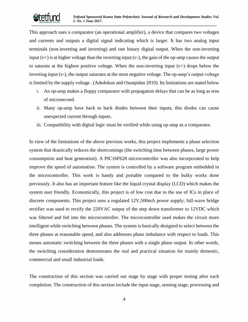
The sensing stage includes zener diode, resistor and transistor (figure 2)
Figure 2: The sensing stage
The DC voltage is compared to a reference voltage across the zener diode. The output voltage
taken at the collector terminal of the transistor is fed to the microcontroller. Its output is logic 1
Tetfund Sponsored Kwara State Polytechnic Journal of Research and Development Studies Vol.
5. No. 1 June 2017.
6
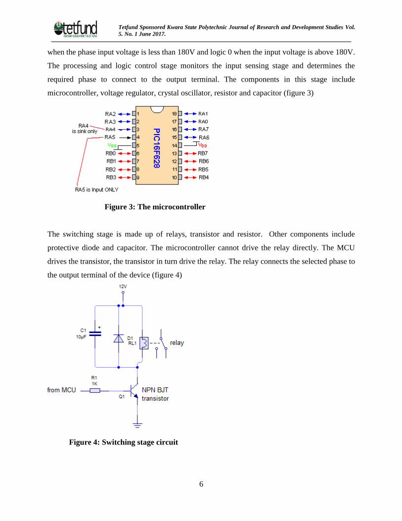
when the phase input voltage is less than 180V and logic 0 when the input voltage is above 180V.
The processing and logic control stage monitors the input sensing stage and determines the
required phase to connect to the output terminal. The components in this stage include
microcontroller, voltage regulator, crystal oscillator, resistor and capacitor (figure 3)
Figure 3: The microcontroller
The switching stage is made up of relays, transistor and resistor. Other components include
protective diode and capacitor. The microcontroller cannot drive the relay directly. The MCU
drives the transistor, the transistor in turn drive the relay. The relay connects the selected phase to
the output terminal of the device (figure 4)
Figure 4: Switching stage circuit

Tetfund Sponsored Kwara State Polytechnic Journal of Research and Development Studies Vol.
5. No. 1 June 2017.
7
The output stage is made up of the LCD (Liquid Crystal Display) and the terminal where the load
is connected to. The LCD display is a liquid crystal display used to display the information
concerning the state of the mains power supply (figure 5). This information ranges from
availability of phases to output voltage. The value of output load is determined by the maximum
current rating of the relay. The maximum load this device can handle is 6KVA.
Figure 5: LCD Display
3. Methodology and calculations
Where the main supply is 220V/50Hz, the transformer used is a 220/12V according to
Es/Ep = Ns/N1 = Ip/Is = Vs/Vp = K,
where k= transformation ratio. Vp = primary voltage of the transformer= 220V and
Vs = secondary voltage of the transformer= 12V Hence for 220V/12V transformer,
K= 12/220 = 0.05455, Vrms = Vmax/√2
where Vmax is the maximum or peak voltage, hence for the secondary of the transformer and Vrms=
12v
Vmax=12√2 =16.97V
The type of diodes used for the full wave rectification is 1N4001, and from its datasheet, its peak
current (Ip) is 1A, maximum voltage is 50V, and the bias voltage is 0.7V. For the full-wave
rectifier, the peak inverse voltage (PIV) must be within a safe limit for every components used in
the circuit (Theraja and Theraja 2005) i.e. the PIV must not be more than the breakdown voltage
of any of the components. Kirchhoff’s law implies that
PIV =2Vp
for full wave rectifier. Hence from the above,
PIV = 2(16.97) = 33.94V.
The PIV is the maximum voltage that occurs across the rectifying diode in the reverse direction.
The 7805 voltage regulator maintains the voltage supply to the logic control section (i.e.
PIC16F628) at 5Vdc. Transistor (figure6) is selected such that

Tetfund Sponsored Kwara State Polytechnic Journal of Research and Development Studies Vol.
5. No. 1 June 2017.
8
IB=(VBB - VBE)/RB (i)
IC = β(VBB-VBE)/ RB (ii)
IE= [VBB (β + 1)–VBE (β - 1)]/RB (iii)
Considering the collector wing; VCE = voltage across collector emitter junction such that
VCE = VCC - RCIC (iv)
Putting equation (ii) into equation (iv);
VCE = VCC - RC[β(VBB-VBE)/ RB]
VCE = VCC – [RCβ(VBB-VBE)]/ RB (v)
For NPN transistor, the minimum proper VBE is given as follows; a) When Si transistor is used,
VBEQ=0.7V and b) When Ge transistor is used VBEQ=0.3V Using a silicon transistor, VBE = 0.7V.
Also, the voltage on any pin of the PIC16F628 with respect to VSS (except for VDD, /MCLR and
RA4) has a maximum value of VDD - 0.3. Since VDD = 5V, voltage supplied to the base of the NPN
transistor from the PIC16F628 (i.e. VBB) = 5 - 0.3 =4.7V The maximum output current sourced by
any input/output pin = 25mA. Assume that β = 60, then from equation (i);
IB=(VBB - VBE)/RB =(4.7– 0.7)/1000 = 4.0mA.
This is still below the maximum output current of 25mA sourced by any input/output pin; hence
the Microcontroller will not be overloaded. The NPN transistor in the circuit is acting like a buffer
for the microcontroller, providing current and power gain. From equation (ii);
IC= β(VBB-VBE)/RB,= 60(5.0-0.7)/1000,= 258mA,
This is sufficient to power relay connected individually with a series resistor of 400Ω. From
equation (iii);
IE= [VBB (β + 1)–VBE (β - 1)]/RB,= [5.0 (60 + 1)–0.7 (60 - 1)]/1000 = 263mA
From equation (v);
VCE = VCC – [RCβ(VBB-VBE)]/ RB = 10.69 – [400 x 60(5.0-0.7)]/1000 = 10.69 – 9.108 = 1.384V
Tetfund Sponsored Kwara State Polytechnic Journal of Research and Development Studies Vol.
5. No. 1 June 2017.
9
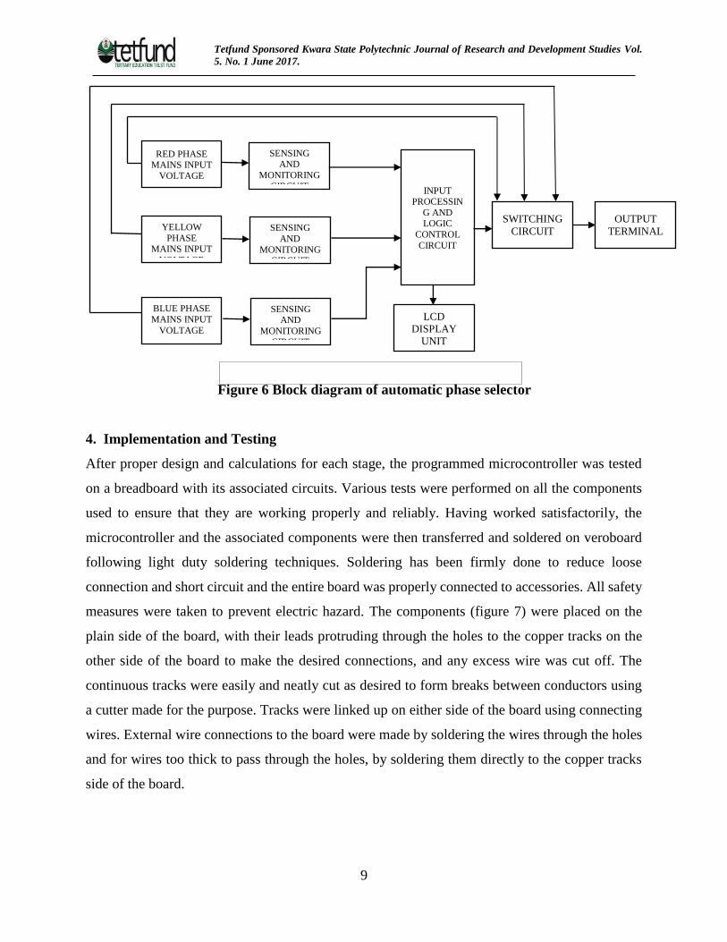
Figure 6 Block diagram of automatic phase selector
4. Implementation and Testing
After proper design and calculations for each stage, the programmed microcontroller was tested
on a breadboard with its associated circuits. Various tests were performed on all the components
used to ensure that they are working properly and reliably. Having worked satisfactorily, the
microcontroller and the associated components were then transferred and soldered on veroboard
following light duty soldering techniques. Soldering has been firmly done to reduce loose
connection and short circuit and the entire board was properly connected to accessories. All safety
measures were taken to prevent electric hazard. The components (figure 7) were placed on the
plain side of the board, with their leads protruding through the holes to the copper tracks on the
other side of the board to make the desired connections, and any excess wire was cut off. The
continuous tracks were easily and neatly cut as desired to form breaks between conductors using
a cutter made for the purpose. Tracks were linked up on either side of the board using connecting
wires. External wire connections to the board were made by soldering the wires through the holes
and for wires too thick to pass through the holes, by soldering them directly to the copper tracks
side of the board.
RED PHASE MAINS INPUT
VOLTAGE
YELLOW
PHASE MAINS INPUT
VOLTAGE
BLUE PHASE
MAINS INPUT
VOLTAGE
SENSING
AND
MONITORING CIRCUIT
SENSING AND
MONITORING
CIRCUIT
INPUT PROCESSIN
G AND LOGIC
CONTROL
CIRCUIT
SENSING AND
MONITORING
CIRCUIT
LCD
DISPLAY
UNIT
OUTPUT
TERMINAL
SWITCHING
CIRCUIT
Tetfund Sponsored Kwara State Polytechnic Journal of Research and Development Studies Vol.
5. No. 1 June 2017.
10
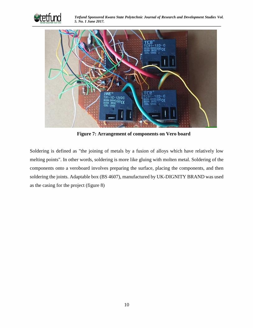
Figure 7: Arrangement of components on Vero board
Soldering is defined as "the joining of metals by a fusion of alloys which have relatively low
melting points". In other words, soldering is more like gluing with molten metal. Soldering of the
components onto a veroboard involves preparing the surface, placing the components, and then
soldering the joints. Adaptable box (BS 4607), manufactured by UK-DIGNITY BRAND was used
as the casing for the project (figure 8)
Tetfund Sponsored Kwara State Polytechnic Journal of Research and Development Studies Vol.
5. No. 1 June 2017.
11
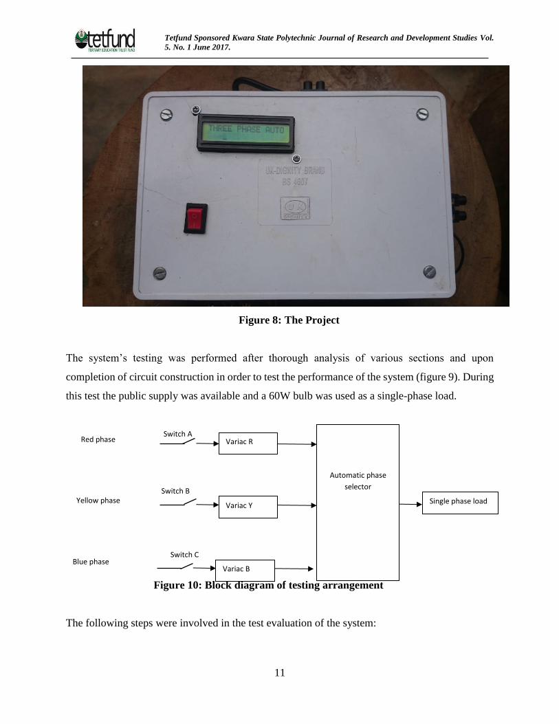
Figure 8: The Project
The system’s testing was performed after thorough analysis of various sections and upon
completion of circuit construction in order to test the performance of the system (figure 9). During
this test the public supply was available and a 60W bulb was used as a single-phase load.
Figure 10: Block diagram of testing arrangement
The following steps were involved in the test evaluation of the system:
Automatic phase
selector
Variac R
Single phase load Variac Y
Variac B
Red phase
Blue phase
Yellow phase
Switch A
Switch B
Switch C
Tetfund Sponsored Kwara State Polytechnic Journal of Research and Development Studies Vol.
5. No. 1 June 2017.
12
• Step 1: The system was set up as shown above, where all the voltage sources to the device’s
inputs were connected to variable transformers ( Variac R, Y and B)
• Step 2: Switches A, B and C was opened (OFF) to simulate phase supply outage. Also,
switches A, B and C are closed (ON) to indicate phase supply availability.
• Step 3: The supplied voltage to the system inputs are varied, while the output voltages are
displayed on the LCD.
5 Conclusion
The inputs to the device are connected to three phase power source (red, yellow and blue), with
switches A,B and C to demonstrate when utility power supply is available and when it is not by
switching ON and OFF. The switches were connected to three different Variacs(R, Y and B) to
vary the input voltages to the device and a 60W bulb was used as a single phase load. When all
the switches were OFF, indicating there is no availability of utility power supply on all the three
phases, the bulb did not light up because there was no power supply to the device. Switches B and
C were ON while switch A was OFF, indicating there is no power supply on the red phase. The
bulb lights up through the supply from the blue phase because Variac Y (yellow phase) is below
preference voltage which is 180volt.
In summary, from the result obtained, it can be seen that the device will only supply power to the
load when there is availability of power supply on one or two of the phases provided the voltage
on any of the phases is between 180volt and 220volt. When the same acceptable voltage is
available on the two phases, say on red, and yellow phase, power is supplied to the load through
the red phase because the order of preference or priority was set to be red phase, yellow phase and
blue phase respectively. If voltage is lower than 180v or greater than 220volt in all the available
phases, the device will switch to “delay mode” until set voltage is available.
Automatic Phase Selector using microcontroller has been designed, implemented and tested. The
system operates according to the specification and quite satisfactorily.With the use of
microcontroller, this device is guaranteed to work perfectly. The switching speed is fast, when
compared to manual switching. This device is more reliable, is of less cost and maintenance free.
Whenever there is power outage in any one or two of the three phases, it performs automatic
Tetfund Sponsored Kwara State Polytechnic Journal of Research and Development Studies Vol.
5. No. 1 June 2017.
13
changeover process. Thus the system reduces stress and delay associated with manual changeover.
In future, the device can be designed to accommodate starting a generator, detecting the fuel level,
and stopping the generator when the mains power is restored or when fuel level is low.
References
Adedokun, G and Osunpidan, I.B (2010) Panacea to Epileptic Power Supply in Nigeria. The
Pacific Journal of Science and Technology.11, 164-170.
Alkar, A. Z. and Buhur, U (2005) An Internet Based Wireless Home Automation System for
Multifunctional Devices. IEEE ConsumerElectronics, 51(4), 1169-1174. Retrieved 6th July,
Delgado, A. R, Picking, R and Grout, V (2006) Remote-controlled home automation systems with
different network technologies
Oni, J. O, Abdulsalam, A. O, Tiamiyu, A. K, Lawal, S. A, Okedare, S. D (2015): Design and
construction of automatic phase changer. Final year HND project submitted to Kwara State
Polytechnic, Ilorin. PIC16F628 Data sheet available at http://www.microchips
/downloads/en/devicedoc/30292c.pdf Retrieved 11th May, 2016
Theraja, B. L and Theraja A. K (2005): A Textbook of Electrical Technology Vol. 1. New Delhi.
S. chand & Co Ltd
Copyright © 2022 FDOKUMEN