Thyristor power units TC3000 Three-phase load control User ...
116
I Thyristor power units TC3000 Three-phase load control User Manual © Copyright Eurotherm Automation 1996 All rights reserved. All reproduction or transmission in any form or using any procedure (electronic or mechanical, including photocopying and recording) without the written permission of EUROTHERM AUTOMATION is strictly prohibited. EUROTHERM AUTOMATION have taken particular care to ensure the accuracy of these specifications. However, in order to maintain our technological lead, we are dedicated to the continual improvement of our products and this may lead to modifications or omissions in the current specifications. We cannot be held responsible for any material or bodily damage, losses or costs incurred. Part No : HA174835 ENG - Issue 3.1 - 06/01 (Old part No : HA 174836)
-
Upload
khangminh22 -
Category
Documents
-
view
0 -
download
0
Transcript of Thyristor power units TC3000 Three-phase load control User ...
II
Thyristor power units
TC3000
Three-phase load control
User Manual
Thyristor power units
TC3000
Three-phase load control
User Manual
© Copyright Eurotherm Automation 1996All rights reserved. All reproduction or transmission in any form or using any procedure (electronic or mechanical, including photocopying andrecording) without the written permission of EUROTHERM AUTOMATION is strictly prohibited. EUROTHERM AUTOMATION have takenparticular care to ensure the accuracy of these specifications. However, in order to maintain our technological lead, we are dedicated to thecontinual improvement of our products and this may lead to modifications or omissions in the current specifications. We cannot be heldresponsible for any material or bodily damage, losses or costs incurred.
Part No : HA174835 ENG - Issue 3.1 - 06/01 (Old part No : HA 174836)

IIII
EUROPEAN DIRECTIVES
The TC3000 products installed and used in accordance with this User Manual aredesigned to comply with the essential protection requirements of the EuropeanLow Voltage Directive 73/23/EEC dated 19/02/73 (amended by Directive 93/68/EECdated 22/07/93).
SAFETY
TC3000 User Manual
MARKThe CE Mark of TC3000 products implies that the essential protectionrequirements of the European Low Voltage Directive are observed.
The TC3000 Technical Construction File is approved by a Notified Body, LCIE(Laboratoire Central des Industries Électriques).
DECLARATION OF CONFORMITYA CE Declaration of Conformity is available on request.For further information on CE Mark, please contact your nearest Eurotherm office.
The TC3000 products are considered as components without any directfunction as defined in the EMC Directive. The system or installation in whichthese products are incorporated must complies with the essential protectionrequirements of the EMC Directive.
However, Eurotherm certifies that the TC3000 products, when installedand used in accordance with their User Manual, meets the following EMC teststandards and enables the system or installation in which there are installed to complywith the EMC Directive in regards to the TC3000 products.
ELECTROMAGNETIC COMPATIBILITY (EMC)For industrial environments, excluding residential environments
IIIIII
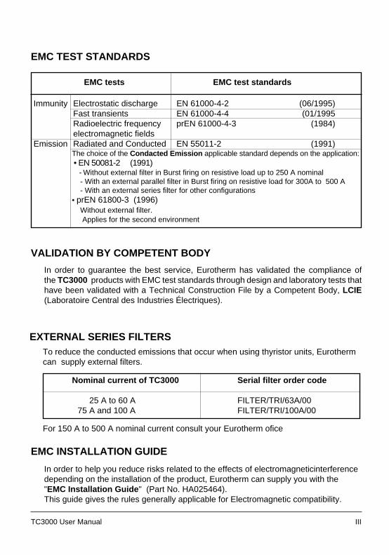
EMC TEST STANDARDS
EMC tests EMC test standards
Immunity Electrostatic discharge EN 61000-4-2 (06/1995)Fast transients EN 61000-4-4 (01/1995Radioelectric frequency prEN 61000-4-3 (1984)electromagnetic fields
Emission Radiated and Conducted EN 55011-2 (1991)The choice of the Condacted Emission applicable standard depends on the application: • EN 50081-2 (1991) - Without external filter in Burst firing on resistive load up to 250 A nominal - With an external parallel filter in Burst firing on resistive load for 300A to 500 A - With an external series filter for other configurations• prEN 61800-3 (1996) Without external filter. Applies for the second environment
TC3000 User Manual
In order to help you reduce risks related to the effects of electromagneticinterferencedepending on the installation of the product, Eurotherm can supply you with the"EMC Installation Guide " (Part No. HA025464).This guide gives the rules generally applicable for Electromagnetic compatibility.
EMC INSTALLATION GUIDE
In order to guarantee the best service, Eurotherm has validated the compliance ofthe TC3000 products with EMC test standards through design and laboratory tests thathave been validated with a Technical Construction File by a Competent Body, LCIE(Laboratoire Central des Industries Électriques).
VALIDATION BY COMPETENT BODY
To reduce the conducted emissions that occur when using thyristor units, Eurothermcan supply external filters.
EXTERNAL SERIES FILTERS
For 150 A to 500 A nominal current consult your Eurotherm ofice
Nominal current of TC3000 Serial filter order code
25 A to 60 A FILTER/TRI/63A/0075 A and 100 A FILTER/TRI/100A/00
IVIV TC3000 User Manual
MANUALS IN USE
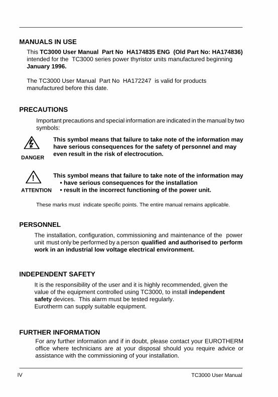
Important precautions and special information are indicated in the manual by twosymbols:
PRECAUTIONS
This symbol means that failure to take note of the information mayhave serious consequences for the safety of personnel and mayeven result in the risk of electrocution.
This symbol means that failure to take note of the information may • have serious consequences for the installation • result in the incorrect functioning of the power unit.
DANGER
These marks must indicate specific points. The entire manual remains applicable.
!ATTENTION
PERSONNEL
The installation, configuration, commissioning and maintenance of the powerunit must only be performed by a person qualified and authorised to performwork in an industrial low voltage electrical environment.
INDEPENDENT SAFETY
It is the responsibility of the user and it is highly recommended, given thevalue of the equipment controlled using TC3000, to install independentsafety devices. This alarm must be tested regularly.Eurotherm can supply suitable equipment.
FURTHER INFORMATION
TC3000 User Manual
MANUALS IN USE
Important precautions and special information are indicated in the manual by twosymbols:
PRECAUTIONS
This symbol means that failure to take note of the information mayhave serious consequences for the safety of personnel and mayeven result in the risk of electrocution.
This symbol means that failure to take note of the information may • have serious consequences for the installation • result in the incorrect functioning of the power unit.
DANGER
These marks must indicate specific points. The entire manual remains applicable.
!ATTENTION
PERSONNEL
The installation, configuration, commissioning and maintenance of the powerunit must only be performed by a person qualified and authorised to performwork in an industrial low voltage electrical environment.
INDEPENDENT SAFETY
It is the responsibility of the user and it is highly recommended, given thevalue of the equipment controlled using TC3000, to install independentsafety devices. This alarm must be tested regularly.Eurotherm can supply suitable equipment.
FURTHER INFORMATIONFor any further information and if in doubt, please contact your EUROTHERMoffice where technicians are at your disposal should you require advice orassistance with the commissioning of your installation.
For any further information and if in doubt, please contact your EUROTHERMoffice where technicians are at your disposal should you require advice orassistance with the commissioning of your installation.
This TC3000 User Manual Part No HA174835 ENG (Old Part No: HA174836)intended for the TC3000 series power thyristor units manufactured beginningJanuary 1996.
The TC3000 User Manual Part No HA172247 is valid for productsmanufactured before this date.
This TC3000 User Manual Part No HA174835 ENG (Old Part No: HA174836)intended for the TC3000 series power thyristor units manufactured beginningJanuary 1996.
The TC3000 User Manual Part No HA172247 is valid for productsmanufactured before this date.
TC3000 User Manual Cont.1TC3000 User Manual Cont.1
Page
TC3000 USER MANUAL
Page
General introduction to the TC3000 series .........................1-2Technical data .....................................................................1-7Coding ..............................................................................1-10
Simplified or complete coding ...................................1-12Coding example ........................................................1-13
Thyristor unit and installation parameters .............1-13Coding ..................................................................1-13
Serial number labels ........................................................ 1-14
Safety during installation .....................................................2-2Dimensions .........................................................................2-3Installation details ................................................................2-5
Safety during wiring .............................................................3-2Power wiring diagrams ........................................................3-4
Star without neutral configuration ...................................3-4Star with neutral configuration ........................................3-5Closed delta configuration ..............................................3-6Open delta configuration ................................................3-7
User terminal blocks ............................................................3-8General introduction .......................................................3-8Auxiliary power supply ..................................................3-10Reference neutral .........................................................3-11Alarm contacts ..............................................................3-12
Control cables ...................................................................3-13Fixing ............................................................................3-13Connection of the shield to the ground .........................3-14
Control terminal blocks......................................................3-15General introduction .....................................................3-16External control input ....................................................3-17Manual control ..............................................................3-17Auxiliary input / output ..................................................3-18Alarm acknowledge ......................................................3-18
Chapter 1 IDENTIFYING THE THYRISTOR UNITS
Chapter 3 WIRING
Chapter 2 INSTALLATION
CONTENTS
TC3000 USER MANUAL
General introduction to the TC3000 series .........................1-2Technical data .....................................................................1-7Coding ..............................................................................1-10
Simplified or complete coding ...................................1-12Coding example ........................................................1-13
Thyristor unit and installation parameters .............1-13Coding ..................................................................1-13
Serial number labels ........................................................ 1-14
Safety during installation .....................................................2-2Dimensions .........................................................................2-3Installation details ................................................................2-5
Safety during wiring.............................................................3-2Power wiring diagrams ........................................................3-4
Star without neutral configuration ...................................3-4Star with neutral configuration ........................................3-5Closed delta configuration ..............................................3-6Open delta configuration ................................................3-7
User terminal blocks............................................................3-8General introduction .......................................................3-8Auxiliary power supply ..................................................3-10Reference neutral .........................................................3-11Alarm contacts ..............................................................3-12
Control cables ...................................................................3-13Fixing ............................................................................3-13Connection of the shield to the ground .........................3-14
Control terminal blocks......................................................3-15General introduction .....................................................3-16External control input ....................................................3-17Manual control ..............................................................3-17Auxiliary input / output ..................................................3-18Alarm acknowledge ......................................................3-18
Chapter 1 IDENTIFYING THE THYRISTOR UNITS
Chapter 3 WIRING
Chapter 2 INSTALLATION
CONTENTS
Cont.2 Cont.2TC3000 User Manual TC3000 User Manual
Contents (Continued) Page
Chapter 4 CONFIGURATION
Safety during configuration ........................................................ 4-2Power board ............................................................................... 4-3
Voltage selection ................................................................ 4-4Adaptation to the load connection type .............................. 4-5
Driver board ............................................................................... 4-6Auxiliary power supply ....................................................... 4-8Main setpoint configuration ................................................ 4-9Process value configuration ............................................... 4-9Auxiliary input / output configuration ................................ 4-10Thyristor firing mode configuration ................................... 4-11Load type and configuration type ..................................... 4-12Alarm relay contact type................................................... 4-12Under-voltage alarm level ................................................ 4-13Initial ramp........................................................................ 4-13Calibration/Operation ....................................................... 4-14
Block diagram ............................................................................ 5-2Thyristors ................................................................................ 5-3Power board ........................................................................... 5-3Potentiometer board ............................................................... 5-3Display .................................................................................... 5-3Diagnostic socket .................................................................... 5-3Driver board ............................................................................ 5-4
Thyristor firing modes................................................................. 5-5'Phase angle' mode ................................................................ 5-5'Logic' mode ............................................................................ 5-8'Burst firing' mode ................................................................. 5-11
Setting potentiometer functions ............................................... 5-13'PA Ramp/CY Delay' potentiometer ...................................... 5-15
Setpoint change ramp ....................................................... 5-16Soft start/end ..................................................................... 5-18Delay angle ....................................................................... 5-21
'Response time' potentiometer ............................................. 5-22Standard reponse time in 'Phase angle' ............................ 5-22Number of mains cycle in the Burst firing basic cycle ....... 5-23
'Setpoint limit' potentiometer ................................................. 5-24Control operation ..................................................................... 5-25
Squared load voltage ............................................................ 5-26External measurement.......................................................... 5-26
Chapter 5 OPERATION
PageContents (Continued)
Chapter 4 CONFIGURATION
Safety during configuration ........................................................ 4-2Power board ............................................................................... 4-3
Voltage selection ................................................................ 4-4Adaptation to the load connection type .............................. 4-5
Driver board ............................................................................... 4-6Auxiliary power supply ....................................................... 4-8Main setpoint configuration ................................................ 4-9Process value configuration ............................................... 4-9Auxiliary input / output configuration ................................ 4-10Thyristor firing mode configuration ................................... 4-11Load type and configuration type ..................................... 4-12Alarm relay contact type ................................................... 4-12Under-voltage alarm level ................................................ 4-13Initial ramp........................................................................ 4-13Calibration/Operation ....................................................... 4-14
Block diagram ............................................................................ 5-2Thyristors ................................................................................ 5-3Power board ........................................................................... 5-3Potentiometer board ............................................................... 5-3Display .................................................................................... 5-3Diagnostic socket .................................................................... 5-3Driver board ............................................................................ 5-4
Thyristor firing modes ................................................................. 5-5'Phase angle' mode ................................................................ 5-5'Logic' mode ............................................................................ 5-8'Burst firing' mode ................................................................. 5-11
Setting potentiometer functions ............................................... 5-13'PA Ramp/CY Delay' potentiometer ...................................... 5-15
Setpoint change ramp ....................................................... 5-16Soft start/end ..................................................................... 5-18Delay angle ....................................................................... 5-21
'Response time' potentiometer ............................................. 5-22Standard reponse time in 'Phase angle' ............................ 5-22Number of mains cycle in the Burst firing basic cycle ....... 5-23
'Setpoint limit' potentiometer ................................................. 5-24Control operation ...................................................................... 5-25
Squared load voltage ............................................................ 5-26External measurement .......................................................... 5-26
Chapter 5 OPERATION
TC3000 User Manual Cont.3TC3000 User Manual Cont.3
Page
Commissioning procedure safety ............................................. 6-2Checking the characteristics ..................................................... 6-3
Load current ........................................................................ 6-3Load configuration type ....................................................... 6-3Power supply voltage .......................................................... 6-4Auxiliary power supply voltage ............................................ 6-4Input signals ........................................................................ 6-4
Diagnostic unit .......................................................................... 6-5Thyristor unit calibration............................................................ 6-7
Load voltage calibration ..................................................... 6-9 Calibration in calibration mode position ........................ 6-9 Calibration in normal operation position ..................... 6-9Line voltage calibration ....................................................... 6-9
Commissioning ....................................................................... 6-10Preliminary settings ........................................................... 6-10Power-up ...........................................................................6-11Delayed firing setting on inductive load ............................ 6-12
Contents (Continued) Page
General ..................................................................................... 7-2Steady messages ..................................................................... 7-2Flashing messages ................................................................... 7-3
Error .................................................................................... 7-3Failures ............................................................................... 7-4
Microprocessor failure .............................................................. 7-4
Chapter 6 COMMISSIONING
Chapter 7 DISPLAY MESSAGES
Commissioning procedure safety ............................................. 6-2Checking the characteristics ..................................................... 6-3
Load current ........................................................................6-3Load configuration type .......................................................6-3Power supply voltage .......................................................... 6-4Auxiliary power supply voltage ............................................ 6-4Input signals ........................................................................6-4
Diagnostic unit ..........................................................................6-5Thyristor unit calibration ............................................................6-7
Load voltage calibration ..................................................... 6-9 Calibration in calibration mode position ........................ 6-9 Calibration in normal operation position ..................... 6-9Line voltage calibration .......................................................6-9
Commissioning ....................................................................... 6-10Preliminary settings ........................................................... 6-10Power-up ........................................................................... 6-11Delayed firing setting on inductive load ............................ 6-12
Contents (Continued)
General .....................................................................................7-2Steady messages .....................................................................7-2Flashing messages ...................................................................7-3
Error ....................................................................................7-3Failures ...............................................................................7-4
Microprocessor failure ..............................................................7-4
Chapter 6 COMMISSIONING
Chapter 7 DISPLAY MESSAGES
Cont.4 Cont.4TC3000 User Manual TC3000 User Manual
Page
Thyristor protection ................................................. 9-2Fuses...................................................................... 9-2 Thyristor protection fuses ................................... 9-3 Fuse blown indication micro-switch ................... 9-4 Auxiliary voltage connection protection fuses ... 9-5 Neutral protection fuse ...................................... 9-5Servicing ................................................................. 9-5Tools ....................................................................... 9-6
Contents (Continued) Page
Alarm strategy ........................................................ 8-2High level alarms .................................................... 8-4 Absence of power supply phases...................... 8-4 Under-voltage .................................................... 8-4 Frequency error ................................................. 8-5 Neutral failure .................................................... 8-5 External measurement signal failure ................. 8-5Low level alarm ...................................................... 8-6Alarm acknowledgement ........................................ 8-6Alarm management ................................................ 8-7Alarm relay ............................................................. 8-8
Chapter 8 ALARMS
Chapter 9 MAINTENANCE
Thyristor protection ................................................. 9-2Fuses ...................................................................... 9-2 Thyristor protection fuses ................................... 9-3 Fuse blown indication micro-switch ................... 9-4 Auxiliary voltage connection protection fuses ... 9-5 Neutral protection fuse ...................................... 9-5Servicing ................................................................. 9-5Tools ....................................................................... 9-6
Contents (Continued)
Alarm strategy ........................................................ 8-2High level alarms .................................................... 8-4 Absence of power supply phases ...................... 8-4 Under-voltage .................................................... 8-4 Frequency error ................................................. 8-5 Neutral failure .................................................... 8-5 External measurement signal failure ................. 8-5Low level alarm ...................................................... 8-6Alarm acknowledgement ........................................ 8-6Alarm management ................................................ 8-7Alarm relay ............................................................. 8-8
Chapter 8 ALARMS
Chapter 9 MAINTENANCE
TC3000 User Manual 1-1 TC3000 User Manual 1-1
IdentificationIdentification
Chapter 1
IDENTIFYING THE THYRISTOR UNITS
Contents page
General introduction to the TC3000 series .........................1-2Technical data .....................................................................1-7Coding ..............................................................................1-10
Simplified or complete coding ...................................1-12Coding example ........................................................1-13
Thyristor unit and installation parameters .............1-13Coding ..................................................................1-13
Serial number labels ........................................................ 1-14
TC3000 User Manual 1-2
Identification Identification
1-2 TC3000 User Manual
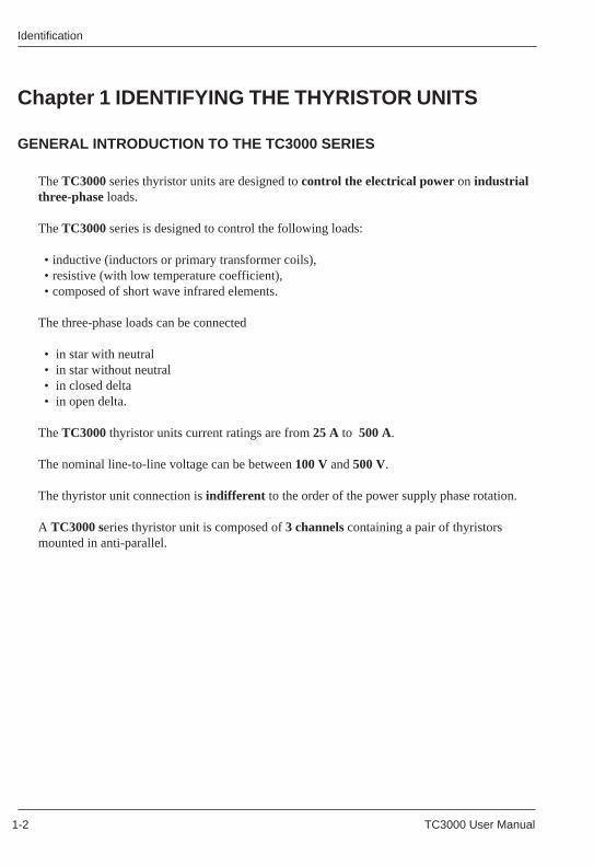
The TC3000 series thyristor units are designed to control the electrical power on industrialthree-phase loads.
The TC3000 series is designed to control the following loads:
• inductive (inductors or primary transformer coils),• resistive (with low temperature coefficient),• composed of short wave infrared elements.
The three-phase loads can be connected
• in star with neutral• in star without neutral• in closed delta• in open delta.
The TC3000 thyristor units current ratings are from 25 A to 500 A.
The nominal line-to-line voltage can be between 100 V and 500 V.
The thyristor unit connection is indifferent to the order of the power supply phase rotation.
A TC3000 series thyristor unit is composed of 3 channels containing a pair of thyristorsmounted in anti-parallel.
Chapter 1 IDENTIFYING THE THYRISTOR UNITS
GENERAL INTRODUCTION TO THE TC3000 SERIES
TC3000 User Manual 1-3 TC3000 User Manual 1-3
IdentificationIdentification
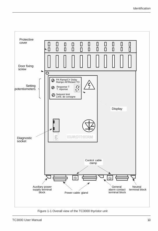
Figure 1-1 Overall view of the TC3000 thyristor unitFigure 1-1 Overall view of the TC3000 thyristor unit
PA Ramp/CY DelayRampe AP/Retard TO
Response TT. réponse
Setpoint limitLimit. de consigne
Settingpotentiometers
Diagnostic socket
Protective cover
Display
Door fixing screw
EUROTHERMε
Power cable gland
Neutral terminal block
General alarm contact terminal block
Auxiliary power supply terminal
block
Control cable clamp
TC3000 User Manual 1-4
Identification Identification
1-4 TC3000 User Manual
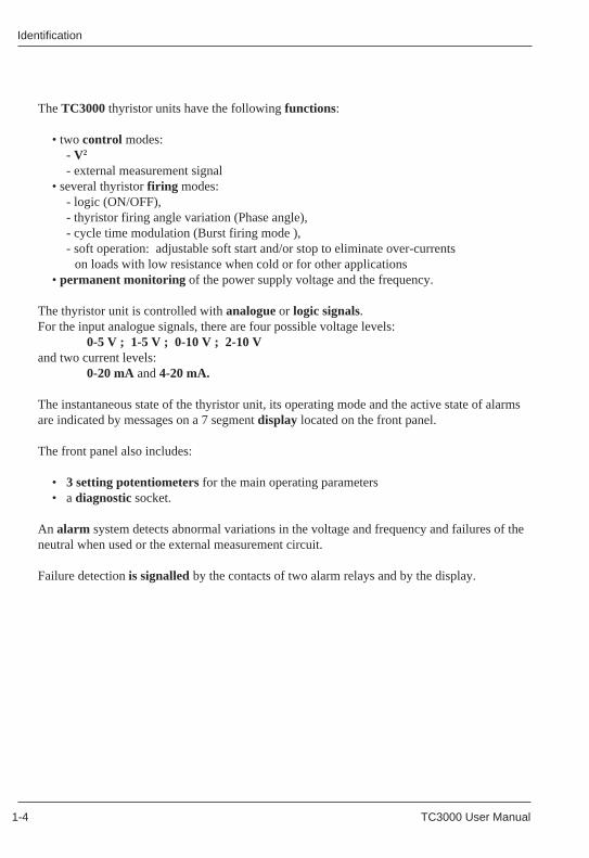
The TC3000 thyristor units have the following functions:
• two control modes:- V2
- external measurement signal• several thyristor firing modes:
- logic (ON/OFF),- thyristor firing angle variation (Phase angle),- cycle time modulation (Burst firing mode ),- soft operation: adjustable soft start and/or stop to eliminate over-currents
on loads with low resistance when cold or for other applications• permanent monitoring of the power supply voltage and the frequency.
The thyristor unit is controlled with analogue or logic signals.For the input analogue signals, there are four possible voltage levels:
0-5 V ; 1-5 V ; 0-10 V ; 2-10 Vand two current levels:
0-20 mA and 4-20 mA.
The instantaneous state of the thyristor unit, its operating mode and the active state of alarmsare indicated by messages on a 7 segment display located on the front panel.
The front panel also includes:
• 3 setting potentiometers for the main operating parameters• a diagnostic socket.
An alarm system detects abnormal variations in the voltage and frequency and failures of theneutral when used or the external measurement circuit.
Failure detection is signalled by the contacts of two alarm relays and by the display.
TC3000 User Manual 1-5 TC3000 User Manual 1-5
IdentificationIdentification
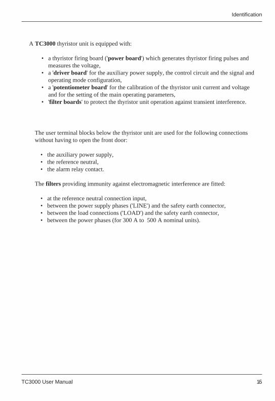
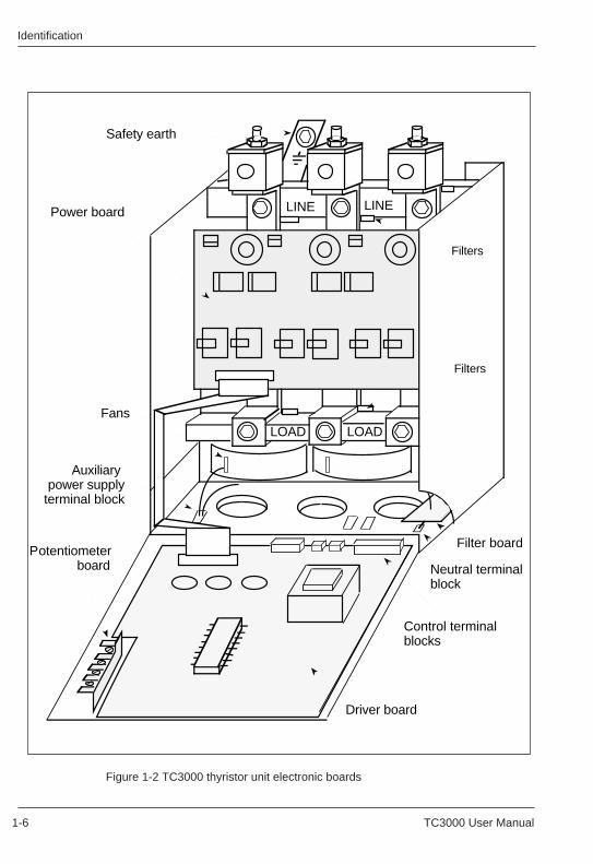
A TC3000 thyristor unit is equipped with:
• a thyristor firing board ('power board') which generates thyristor firing pulses andmeasures the voltage,
• a 'driver board ' for the auxiliary power supply, the control circuit and the signal andoperating mode configuration,
• a 'potentiometer board' for the calibration of the thyristor unit current and voltageand for the setting of the main operating parameters,
• 'filter boards ' to protect the thyristor unit operation against transient interference.
The user terminal blocks below the thyristor unit are used for the following connectionswithout having to open the front door:
• the auxiliary power supply,• the reference neutral,• the alarm relay contact.
The filters providing immunity against electromagnetic interference are fitted:
• at the reference neutral connection input,• between the power supply phases ('LINE') and the safety earth connector,• between the load connections ('LOAD') and the safety earth connector,• between the power phases (for 300 A to 500 A nominal units).
TC3000 User Manual 1-6
Identification Identification
1-6 TC3000 User Manual
Figure 1-2 TC3000 thyristor unit electronic boards
LINE LINE
LOAD LOAD
Power board
Driver board
Potentiometerboard
Safety earth
Filters
Filters
Fans
Control terminal blocks
Filter board
Neutral terminalblock
Auxiliary power supply
terminal block
Figure 1-2 TC3000 thyristor unit electronic boards
LINE LINE
LOAD LOAD
Power board
Driver board
Potentiometerboard
Safety earth
Filters
Filters
Fans
Control terminal blocks
Filter board
Neutral terminalblock
Auxiliary power supply
terminal block
TC3000 User Manual 1-7 TC3000 User Manual 1-7
IdentificationIdentification
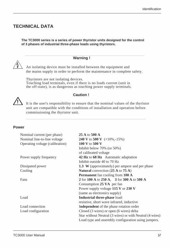
TECHNICAL DATA
Nominal current (per phase) 25 A to 500 ANominal line-to-line voltage 240 V to 500 V (+10%,-15%)Operating voltage (calibration) 100 V to 500 V
Inhibit below 70% (or 50%)of calibrated voltage
Power supply frequency 42 Hz to 68 Hz Automatic adaptationInhibit outside 40 to 70 Hz
Dissipated power 1.3 W (approximately) per ampere and per phaseCooling Natural convection (25 A to 75 A)
Permanent fan cooling from 100 AFans 2 for 100 A to 250 A, 3 for 300 A to 500 A
Consumption 25 VA per fanPower supply voltage 115 V or 230 V(same as electronics supply)
Load Industrial three-phase load:resistive, short wave infrared, inductive
Load connection Independent of the phase rotation orderLoad configuration Closed (3 wires) or open (6 wires) delta
Star without Neutral (3 wires) or with Neutral (4 wires)Load type and assembly configuration using jumpers.
Power
Warning !
An isolating device must be installed between the equipment andthe mains supply in order to perform the maintenance in complete safety.
Thyristors are not isolating devices.Touching load terminals, even if there is no loads current (unit inthe off-state), is as dangerous as touching power supply terminals.
Caution !
It is the user's responsibility to ensure that the nominal values of the thyristorunit are compatible with the conditions of installation and operation beforecommissioning the thyristor unit.
The TC3000 series is a series of power thyristor units designed for the controlof 3 phases of industrial three-phase loads using thyristors.
!
TECHNICAL DATA
Nominal current (per phase) 25 A to 500 ANominal line-to-line voltage 240 V to 500 V (+10%,-15%)Operating voltage (calibration) 100 V to 500 V
Inhibit below 70% (or 50%)of calibrated voltage
Power supply frequency 42 Hz to 68 Hz Automatic adaptationInhibit outside 40 to 70 Hz
Dissipated power 1.3 W (approximately) per ampere and per phaseCooling Natural convection (25 A to 75 A)
Permanent fan cooling from 100 AFans 2 for 100 A to 250 A, 3 for 300 A to 500 A
Consumption 25 VA per fanPower supply voltage 115 V or 230 V(same as electronics supply)
Load Industrial three-phase load:resistive, short wave infrared, inductive
Load connection Independent of the phase rotation orderLoad configuration Closed (3 wires) or open (6 wires) delta
Star without Neutral (3 wires) or with Neutral (4 wires)Load type and assembly configuration using jumpers.
Power
The TC3000 series is a series of power thyristor units designed for the controlof 3 phases of industrial three-phase loads using thyristors.
!
Warning !
An isolating device must be installed between the equipment andthe mains supply in order to perform the maintenance in complete safety.
Thyristors are not isolating devices.Touching load terminals, even if there is no loads current (unit inthe off-state), is as dangerous as touching power supply terminals.
Caution !
It is the user's responsibility to ensure that the nominal values of the thyristorunit are compatible with the conditions of installation and operation beforecommissioning the thyristor unit.
TC3000 User Manual 1-8
Identification Identification
1-8 TC3000 User Manual
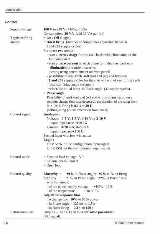
Supply voltage 100 V to 240 V (+10%; -15%)Consumption: 20 VA (add 25 VA par fan)
Thyristor firing • On / Off (Logic)modes • Burst firing (number of firing times adjustable between
1 and 255 supply cycles).For these two modes:
- start at zero voltage for resistive loads with elimination of the DC component
- start at zero current on each phase for inductive loads with elimination of transient currents (setting using potentiometer on front panel)- possibility of adjustable soft start and (or) end between 1 and 255 supply cycles for the start and end of each firing cycle (thyristor firing angle variation)- selectable initial ramp in Phase angle (32 supply cycles).
• Phase anglePossibility of soft start and (or) end with a linear ramp on asetpoint change (increase/decrease), the duration of the ramp from0 to 100% firing is 0.1 s to 40 H(setting using potentiometer on front panel).
Control signal Analogue :Voltage: 0-5 V; 1-5 V; 0-10 V or 2-10 V
Input impedance ≥100 kΩCurrent: 0-20 mA; 4-20 mA
Input impedance 100 ΩSecond input with low win actionLogic :
On ≥ 50% of the configuration input signalOff ≤ 25% of the configuration input signal
Control mode • Squared load voltage V 2
• External measurement• Open loop
Control quality Linearity : ±1% in Phase angle; ±2% in Burst firingStability : ±1% in Phase angle; ±2% in Burst firing
with variations:- of the power supply voltage +10%, -15%;- of the temperature 0 to 50 °C
Adjustable response time.To change from 10% to 90% power:- in Phase angle - 120 ms to 1.5 s- in Burst firing - 0.3 s to 150 s
Retransmissions Outputs (0 to 10 V) of the controlled parameter(DC signal).
ControlControl
Supply voltage 100 V to 240 V (+10%; -15%)Consumption: 20 VA (add 25 VA par fan)
Thyristor firing • On / Off (Logic)modes • Burst firing (number of firing times adjustable between
1 and 255 supply cycles).For these two modes:
- start at zero voltage for resistive loads with elimination of the DC component
- start at zero current on each phase for inductive loads with elimination of transient currents (setting using potentiometer on front panel)- possibility of adjustable soft start and (or) end between 1 and 255 supply cycles for the start and end of each firing cycle (thyristor firing angle variation)- selectable initial ramp in Phase angle (32 supply cycles).
• Phase anglePossibility of soft start and (or) end with a linear ramp on asetpoint change (increase/decrease), the duration of the ramp from0 to 100% firing is 0.1 s to 40 H(setting using potentiometer on front panel).
Control signal Analogue :Voltage: 0-5 V; 1-5 V; 0-10 V or 2-10 V
Input impedance ≥100 kΩCurrent: 0-20 mA; 4-20 mA
Input impedance 100 ΩSecond input with low win actionLogic :
On ≥ 50% of the configuration input signalOff ≤ 25% of the configuration input signal
Control mode • Squared load voltage V 2
• External measurement• Open loop
Control quality Linearity : ±1% in Phase angle; ±2% in Burst firingStability : ±1% in Phase angle; ±2% in Burst firing
with variations:- of the power supply voltage +10%, -15%;- of the temperature 0 to 50 °C
Adjustable response time.To change from 10% to 90% power:- in Phase angle - 120 ms to 1.5 s- in Burst firing - 0.3 s to 150 s
TC3000 User Manual 1-9 TC3000 User Manual 1-9
IdentificationIdentification
!
Caution !Due to the continual improvement of products, Eurotherm may be required tomodify specifications without prior notice. For any further information and inthe event of doubt, contact your Eurotherm Office.
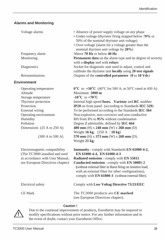
Alarms and Monitoring
Voltage alarms • Absence of power supply voltage on any phase• Under-voltage (thyristor firing stopped below 70% or
50% of the nominal thyristor unit voltage)• Over-voltage (alarm for a voltage greater than the
nominal thyristor unit voltage by 20%)Frequency alarm Above 70 Hz or below 40 HzMonitoring Permanent data on the alarm type and its degree of severity
with a display and with relaysDiagnostics Socket for diagnostic unit used to adjust, control and
calibrate the thyristor unit locally using 20 test signalsRetransmissions Outputs of the controlled parameter (0 to 10 Vdc)
Operating temperature 0°C to +50°C (40°C for 500 A; at 50°C rated at 450 A)Altitude Maximum 2000 mStorage temperature -10°C to +70°CThyristor protection Internal high speed fuses. Varistor and RC snubberProtection IP20 on front panel (according to Standards IEC 529)External wiring To be performed according to the Standards IEC 364Operating environment Non-explosive, non-corrosive and non-conductiveHumidity RH from 5% to 95% without condensationPollution Degree 2 admissible, defined by IEC 664Dimensions (25 A to 250 A) 480 mm (H) x 248 mm (W) x 268 mm (D)
Weight 16 kg, (250 A : 18 kg) (300 A to 500 A) 570 mm (H) x 373 mm (W) x 268 mm (D).
Weight 21 kg.
Electromagnetic compatibility Immunity : comply with Standards EN 61000-4-2,(The TC3000 installed and used EN 61000-4-4, EN 61000-4-3in accordance with User Manual,Radiated emission : comply with EN 55011see European Directives chapter)Conducted emission : comply with EN 50081-2
(without external filter in Burst firing on resistive load;with an external filter for other configurations),comply with EN 61800-3 (without external filter).
Electrical safety Comply with Low Voltag Directive 73/23/EEC
CE Mark The TC3000 products are CE marked(see European Directives chapter).
Environment
!
Caution !Due to the continual improvement of products, Eurotherm may be required tomodify specifications without prior notice. For any further information and inthe event of doubt, contact your Eurotherm Office.
Alarms and Monitoring
Voltage alarms • Absence of power supply voltage on any phase• Under-voltage (thyristor firing stopped below 70% or
50% of the nominal thyristor unit voltage)• Over-voltage (alarm for a voltage greater than the
nominal thyristor unit voltage by 20%)Frequency alarm Above 70 Hz or below 40 HzMonitoring Permanent data on the alarm type and its degree of severity
with a display and with relaysDiagnostics Socket for diagnostic unit used to adjust, control and
calibrate the thyristor unit locally using 20 test signalsRetransmissions Outputs of the controlled parameter (0 to 10 Vdc)
Operating temperature 0°C to +50°C (40°C for 500 A; at 50°C rated at 450 A)Altitude Maximum 2000 mStorage temperature -10°C to +70°CThyristor protection Internal high speed fuses. Varistor and RC snubberProtection IP20 on front panel (according to Standards IEC 529)External wiring To be performed according to the Standards IEC 364Operating environment Non-explosive, non-corrosive and non-conductiveHumidity RH from 5% to 95% without condensationPollution Degree 2 admissible, defined by IEC 664Dimensions (25 A to 250 A) 480 mm (H) x 248 mm (W) x 268 mm (D)
Weight 16 kg, (250 A : 18 kg) (300 A to 500 A) 570 mm (H) x 373 mm (W) x 268 mm (D).
Weight 21 kg.
Electromagnetic compatibility Immunity : comply with Standards EN 61000-4-2,(The TC3000 installed and used EN 61000-4-4, EN 61000-4-3in accordance with User Manual,Radiated emission : comply with EN 55011see European Directives chapter)Conducted emission : comply with EN 50081-2
(without external filter in Burst firing on resistive load;with an external filter for other configurations),comply with EN 61800-3 (without external filter).
Electrical safety Comply with Low Voltag Directive 73/23/EEC
CE Mark The TC3000 products are CE marked(see European Directives chapter).
Environment
TC3000 User Manual 1-10
Identification Identification
1-10 TC3000 User Manual
25 amperes 25A40 amperes 40A60 amperes 60A75 amperes 75A
100 amperes 100A150 amperes 150A250 amperes 250A300 amperes 300A400 amperes 400A500 amperes 500A
100 volts 100110 volts 110115 volts 115120 volts 120200 volts 200220 volts 220230 volts 230240 volts 240277 volts 277380 volts 380400 volts 400415 volts 415440 volts 440480 volts 480500 volts 500
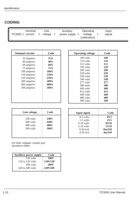
CODING
Operating voltage Code Nominal current Code
CODING
Nominal Line Auxiliary Operating Input TC3000 / current / voltage / power supply / voltage / signal
(calibration)
Nominal Line Auxiliary Operating Input TC3000 / current / voltage / power supply / voltage / signal
(calibration)
0-5 volts 0V51-5 volts 1V5
0-10 volts 0V102-10 volts 2V100-20 mA 0mA204-20 mA 4mA20
Input signal Code Line voltage Code
240 volts 240V440 volts 440V480 volts 480V500 volts 500V
For other voltages, contact yourEurotherm Office
Auxiliary power supply Code110 volts 100V
110 to 120 volts 110V120200 volts 200V
220 to 240 volts 220V240
25 amperes 25A40 amperes 40A60 amperes 60A75 amperes 75A
100 amperes 100A150 amperes 150A250 amperes 250A300 amperes 300A400 amperes 400A500 amperes 500A
100 volts 100110 volts 110115 volts 115120 volts 120200 volts 200220 volts 220230 volts 230240 volts 240277 volts 277380 volts 380400 volts 400415 volts 415440 volts 440480 volts 480500 volts 500
Operating voltage Code Nominal current Code
0-5 volts 0V51-5 volts 1V5
0-10 volts 0V102-10 volts 2V100-20 mA 0mA204-20 mA 4mA20
Input signal Code Line voltage Code
240 volts 240V440 volts 440V480 volts 480V500 volts 500V
For other voltages, contact yourEurotherm Office
Auxiliary power supply Code110 volts 100V
110 to 120 volts 110V120200 volts 200V
220 to 240 volts 220V240
TC3000 User Manual 1-11 TC3000 User Manual 1-11
IdentificationIdentification
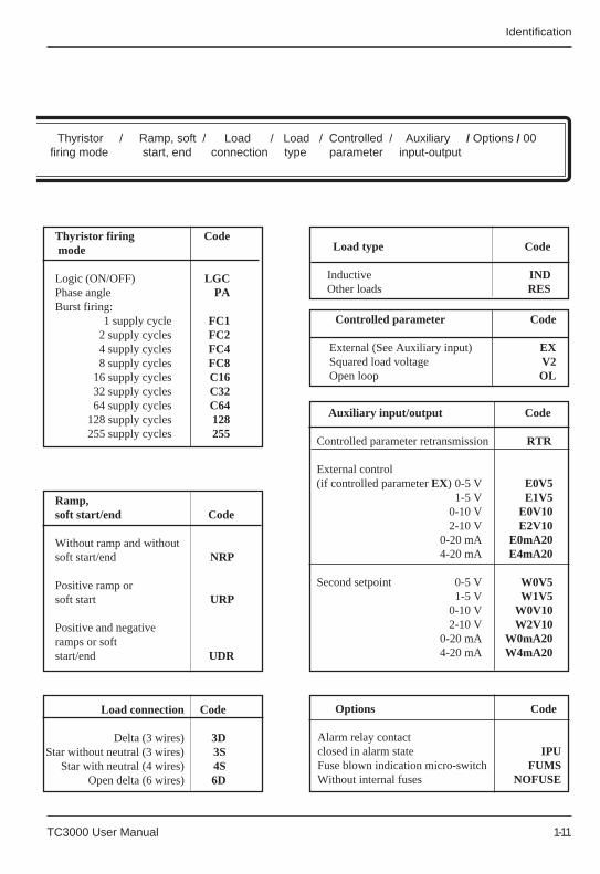
Thyristor / Ramp, soft / Load / Load / Controlled / Auxiliary / Options / 00 firing mode start, end connection type parameter input-output
Thyristor firing Code mode
Logic (ON/OFF) LGCPhase angle PABurst firing:
1 supply cycle FC12 supply cycles FC24 supply cycles FC48 supply cycles FC8
16 supply cycles C1632 supply cycles C3264 supply cycles C64
128 supply cycles 128255 supply cycles 255
Options Code
Alarm relay contactclosed in alarm state IPUFuse blown indication micro-switch FUMSWithout internal fuses NOFUSE
Thyristor / Ramp, soft / Load / Load / Controlled / Auxiliary / Options / 00 firing mode start, end connection type parameter input-output
Load connection Code
Delta (3 wires) 3DStar without neutral (3 wires) 3S
Star with neutral (4 wires) 4SOpen delta (6 wires) 6D
Ramp,soft start/end Code
Without ramp and withoutsoft start/end NRP
Positive ramp orsoft start URP
Positive and negativeramps or softstart/end UDR
Load type Code
Inductive IND Other loads RES
Controlled parameter Code
External (See Auxiliary input) EX Squared load voltage V2 Open loop OL
Auxiliary input/output Code
Controlled parameter retransmission RTR
External control (if controlled parameter EX) 0-5 V E0V5
1-5 V E1V50-10 V E0V102-10 V E2V10
0-20 mA E0mA204-20 mA E4mA20
Second setpoint 0-5 V W0V51-5 V W1V5
0-10 V W0V102-10 V W2V10
0-20 mA W0mA204-20 mA W4mA20
Thyristor firing Code mode
Logic (ON/OFF) LGCPhase angle PABurst firing:
1 supply cycle FC12 supply cycles FC24 supply cycles FC48 supply cycles FC8
16 supply cycles C1632 supply cycles C3264 supply cycles C64
128 supply cycles 128255 supply cycles 255
Options Code
Alarm relay contactclosed in alarm state IPUFuse blown indication micro-switch FUMSWithout internal fuses NOFUSE
Load connection Code
Delta (3 wires) 3DStar without neutral (3 wires) 3S
Star with neutral (4 wires) 4SOpen delta (6 wires) 6D
Ramp,soft start/end Code
Without ramp and withoutsoft start/end NRP
Positive ramp orsoft start URP
Positive and negativeramps or softstart/end UDR
Load type Code
Inductive IND Other loads RES
Controlled parameter Code
External (See Auxiliary input) EX Squared load voltage V2 Open loop OL
Auxiliary input/output Code
Controlled parameter retransmission RTR
External control (if controlled parameter EX) 0-5 V E0V5
1-5 V E1V50-10 V E0V102-10 V E2V10
0-20 mA E0mA204-20 mA E4mA20
Second setpoint 0-5 V W0V51-5 V W1V5
0-10 V W0V102-10 V W2V10
0-20 mA W0mA204-20 mA W4mA20
TC3000 User Manual 1-12
Identification Identification
1-12 TC3000 User Manual
Simplified or complete coding
Coding can be performed with a complete code (all fields) or with a simplified code in whichonly the following are specified:
• the nominal current,• the line voltage,• the auxiliary power supply,• the calibration voltage (operating voltage),• the options.
With a simplified code, the TC3000 thyristor unit is supplied configured as shown below:
• Input signal 4 - 20 mA• Thyristor firing mode Phase angle• Ramp, soft start / end Without ramp or
soft start / end• Load connection Star without neutral (3 wires)• Load type Inductive• Under-voltage alarm threshold 70% of nominal voltage• Start-up Initial safety ramp
(32 supply cycles)
TC3000 User Manual 1-13 TC3000 User Manual 1-13
IdentificationIdentification
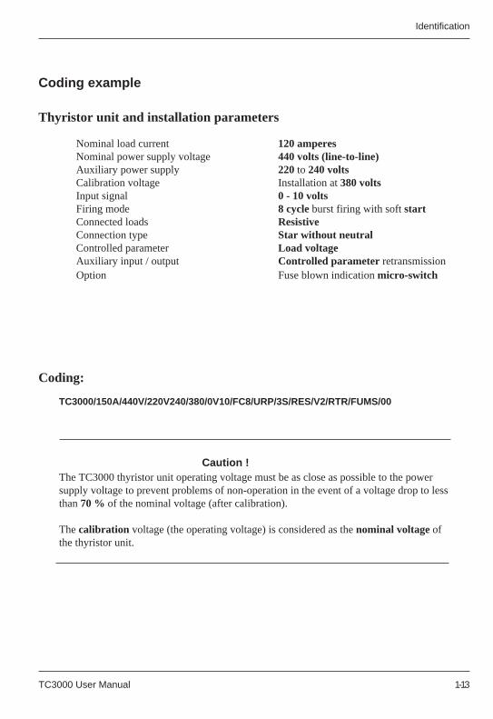
Nominal load current 120 amperesNominal power supply voltage 440 volts (line-to-line)Auxiliary power supply 220 to 240 voltsCalibration voltage Installation at 380 voltsInput signal 0 - 10 voltsFiring mode 8 cycle burst firing with soft startConnected loads ResistiveConnection type Star without neutralControlled parameter Load voltageAuxiliary input / output Controlled parameter retransmissionOption Fuse blown indication micro-switch
Caution !The TC3000 thyristor unit operating voltage must be as close as possible to the powersupply voltage to prevent problems of non-operation in the event of a voltage drop to lessthan 70 % of the nominal voltage (after calibration).
The calibration voltage (the operating voltage) is considered as the nominal voltage ofthe thyristor unit.
Coding example
Thyristor unit and installation parameters
Coding:
TC3000/150A/440V/220V240/380/0V10/FC8/URP/3S/RES/V2/RTR/FUMS/00
Nominal load current 120 amperesNominal supply voltage 440 volts (line-to-line)Auxiliary power supply 220 to 240 voltsCalibration voltage Installation at 380 voltsInput signal 0 - 10 voltsFiring mode 8 cycle burst firing with soft startConnected loads ResistiveConnection type Star without neutralControlled parameter Load voltageAuxiliary input / output Controlled parameter retransmissionOption Fuse blown indication micro-switch
Caution !The TC3000 thyristor unit operating voltage must be as close as possible to the powersupply voltage to prevent problems of non-operation in the event of a voltage drop to lessthan 70 % of the nominal voltage (after calibration).
The calibration voltage (the operating voltage) is considered as the nominal voltage ofthe thyristor unit.
Coding example
Thyristor unit and installation parameters
Coding:
TC3000/150A/440V/220V240/380/0V10/FC8/URP/3S/RES/V2/RTR/FUMS/00
TC3000 User Manual 1-14
Identification Identification
1-14 TC3000 User Manual
!
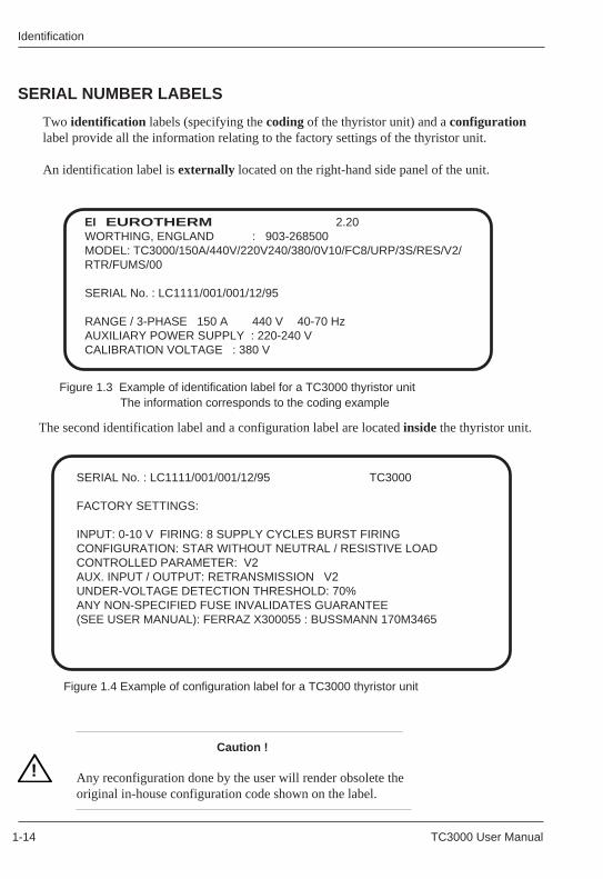
SERIAL NUMBER LABELS
Two identification labels (specifying the coding of the thyristor unit) and a configurationlabel provide all the information relating to the factory settings of the thyristor unit.
An identification label is externally located on the right-hand side panel of the unit.
EI EUROTHERM 2.20WORTHING, ENGLAND : 903-268500MODEL: TC3000/150A/440V/220V240/380/0V10/FC8/URP/3S/RES/V2/RTR/FUMS/00
SERIAL No. : LC1111/001/001/12/95
RANGE / 3-PHASE 150 A 440 V 40-70 HzAUXILIARY POWER SUPPLY : 220-240 VCALIBRATION VOLTAGE : 380 V
Figure 1.3 Example of identification label for a TC3000 thyristor unit The information corresponds to the coding example
The second identification label and a configuration label are located inside the thyristor unit.
SERIAL No. : LC1111/001/001/12/95 TC3000
FACTORY SETTINGS:
INPUT: 0-10 V FIRING: 8 SUPPLY CYCLES BURST FIRINGCONFIGURATION: STAR WITHOUT NEUTRAL / RESISTIVE LOADCONTROLLED PARAMETER: V2AUX. INPUT / OUTPUT: RETRANSMISSION V2UNDER-VOLTAGE DETECTION THRESHOLD: 70%ANY NON-SPECIFIED FUSE INVALIDATES GUARANTEE(SEE USER MANUAL): FERRAZ X300055 : BUSSMANN 170M3465
Figure 1.4 Example of configuration label for a TC3000 thyristor unit
!
SERIAL NUMBER LABELS
Two identification labels (specifying the coding of the thyristor unit) and a configurationlabel provide all the information relating to the factory settings of the thyristor unit.
An identification label is externally located on the right-hand side panel of the unit.
EI EUROTHERM 2.20WORTHING, ENGLAND : 903-268500MODEL: TC3000/150A/440V/220V240/380/0V10/FC8/URP/3S/RES/V2/RTR/FUMS/00
SERIAL No. : LC1111/001/001/12/95
RANGE / 3-PHASE 150 A 440 V 40-70 HzAUXILIARY POWER SUPPLY : 220-240 VCALIBRATION VOLTAGE : 380 V
Figure 1.3 Example of identification label for a TC3000 thyristor unit The information corresponds to the coding example
The second identification label and a configuration label are located inside the thyristor unit.
SERIAL No. : LC1111/001/001/12/95 TC3000
FACTORY SETTINGS:
INPUT: 0-10 V FIRING: 8 SUPPLY CYCLES BURST FIRINGCONFIGURATION: STAR WITHOUT NEUTRAL / RESISTIVE LOADCONTROLLED PARAMETER: V2AUX. INPUT / OUTPUT: RETRANSMISSION V2UNDER-VOLTAGE DETECTION THRESHOLD: 70%ANY NON-SPECIFIED FUSE INVALIDATES GUARANTEE(SEE USER MANUAL): FERRAZ X300055 : BUSSMANN 170M3465
Figure 1.4 Example of configuration label for a TC3000 thyristor unit
Caution !
Any reconfiguration done by the user will render obsolete theoriginal in-house configuration code shown on the label.
Caution !
Any reconfiguration done by the user will render obsolete theoriginal in-house configuration code shown on the label.
Installation Installation
TC3000 User Manual 2-1 TC3000 User Manual 2-1
Chapter 2
INSTALLATION
Contents page
Safety during installation .................................................. 2-2Dimensions ...................................................................... 2-3Installation details ............................................................ 2-5
Chapter 2
INSTALLATION
Contents page
Safety during installation .................................................. 2-2Dimensions ...................................................................... 2-3Installation details ............................................................ 2-5
InstallationInstallation
2-2 TC3000 User Manual 2-2 TC3000 User Manual
!
Chapter 2 INSTALLATION
SAFETY DURING INSTALLATION
For installations in fan-cooled cabinets, it is recommended to place a fan failuredetection device or a thermal safety control in the cabinet.
Bulkhead mountings are possible with TC3000 series units.
The units must be mounted with the heatsink positioned vertically and with noobstructions either above or below which could block the passage of the ventilation air.
If multiple units are installed in the same cabinet, they should be arranged in such a wayway that the exhaust air from one unit cannot be admitted into the unit located above it.
!
TC3000 series power thyristor units have permanent fan cooling from 100 A nominal.
Chapter 2 INSTALLATION
SAFETY DURING INSTALLATION
For installations in fan-cooled cabinets, it is recommended to place a fan failuredetection device or a thermal safety control in the cabinet.
Bulkhead mountings are possible with TC3000 series units.
The units must be mounted with the heatsink positioned vertically and with noobstructions either above or below which could block the passage of the ventilation air.
If multiple units are ins talled in the same cabinet, they should be arranged in such away that the exhaust air from one unit cannot be admitted into the unit located above it.
TC3000 series power thyristor units have permanent fan cooling from 100 A nominal.
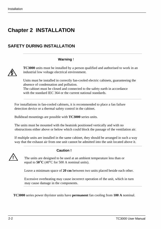
Warning !
TC3000 units must be installed by a person qualified and authorised to work in anindustrial low voltage electrical environment.
Units must be installed in correctly fan-cooled electric cabinets, guaranteeing theabsence of condensation and pollution.The cabinet must be closed and connected to the safety earth in accordancewith the standard IEC 364 or the current national standards.
The units are designed to be used at an ambient temperature less than orequal to 50°C (40°C for 500 A nominal units).
Leave a minimum space of 20 cm between two units placed beside each other.
Excessive overheating may cause incorrect operation of the unit, which in turnmay cause damage in the components.
Caution !
Installation Installation
TC3000 User Manual 2-3 TC3000 User Manual 2-3
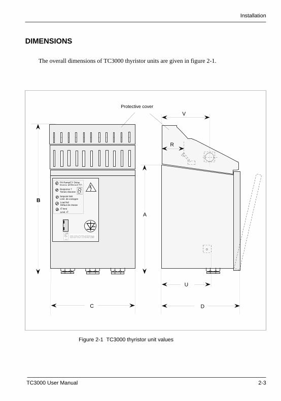
DIMENSIONS
The overall dimensions of TC3000 thyristor units are given in figure 2-1.
Figure 2-1 TC3000 thyristor unit values
Protective cover
D
A
C
B
U
V
R
Load failDéfaut de charge
PA Ramp/CY DelayRampe AP/Retard TO
Response TTemps réponse
Setpoint limitLimit. de consigne
I2 limit
Limit. I2
EUROTHERMε
InstallationInstallation
2-4 TC3000 User Manual 2-4 TC3000 User Manual
Nominal thyristorunit current 25 to 150 A 250 A 300 to 500 A
Weight (kg) 16 18 21
Dimensions (mm)
Values Nominal thyristor unit current Description
(fig.2-1) 25 to 150A 250A 300 to 500 A
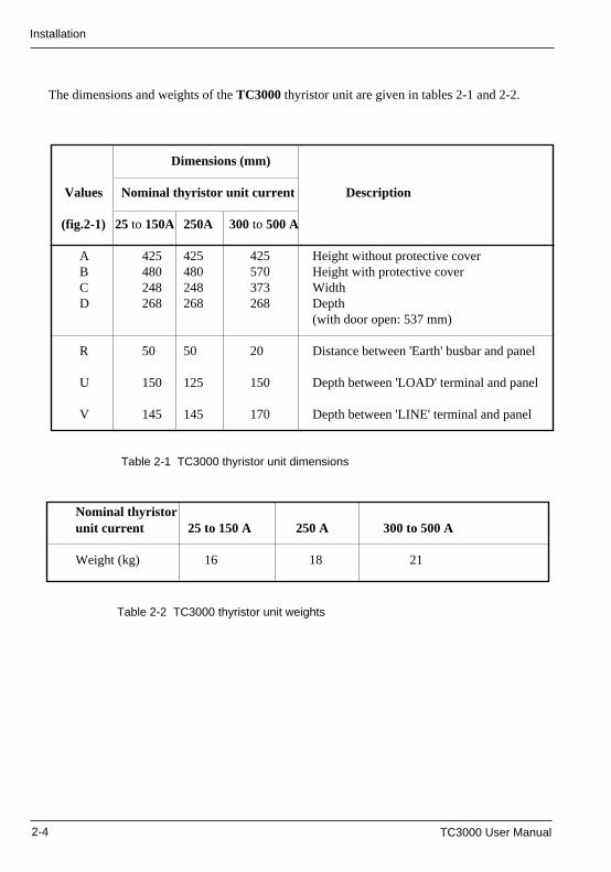
A 425 425 425 Height without protective coverB 480 480 570 Height with protective coverC 248 248 373 WidthD 268 268 268 Depth
(with door open: 537 mm)
R 50 50 20 Distance between 'Earth' busbar and panel
U 150 125 150 Depth between 'LOAD' terminal and panel
V 145 145 170 Depth between 'LINE' terminal and panel
Dimensions (mm)
Values Nominal thyristor unit current Description
(fig.2-1) 25 to 150A 250A 300 to 500 A
A 425 425 425 Height without protective coverB 480 480 570 Height with protective coverC 248 248 373 WidthD 268 268 268 Depth
(with door open: 537 mm)
R 50 50 20 Distance between 'Earth' busbar and panel
U 150 125 150 Depth between 'LOAD' terminal and panel
V 145 145 170 Depth between 'LINE' terminal and panel
The dimensions and weights of the TC3000 thyristor unit are given in tables 2-1 and 2-2.
Table 2-1 TC3000 thyristor unit dimensions
Nominal thyristorunit current 25 to 150 A 250 A 300 to 500 A
Weight (kg) 16 18 21
Table 2-2 TC3000 thyristor unit weights
The dimensions and weights of the TC3000 thyristor unit are given in tables 2-1 and 2-2.
Table 2-1 TC3000 thyristor unit dimensions
Table 2-2 TC3000 thyristor unit weights
Installation Installation
TC3000 User Manual 2-5 TC3000 User Manual 2-5
TC 3000 series units are designed to be mounted directly on panels at the fixing pointslocated on the rear of the unit.TC 3000 thyristor units are equipped with two protective covers (upper and lower).
The thyristor units can be fixed with their protective covers in place.However, for configuration, the upper protective cover must be removed.In order to do this, open the door by unfastening the front screw located at the top left of thedoor. Then raise the door in order to release it from its notches and open it completely bypulling it towards you.
INSTALLATION DETAILS
Figure 2-2 Fixing details
Ø9
13
Ø18
Ø9
10
E
328
4 drilling holes for M8
screws
Without protective cover
18.5
M N
ZS
25
T
P O25
W
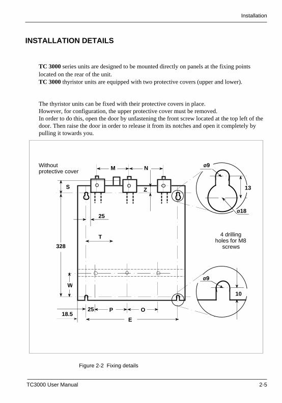
InstallationInstallation
2-6 TC3000 User Manual 2-6 TC3000 User Manual
Dimensions (mm)Values Nominal current Descriptionfig.2-2 25A to 150A 250A 300A to 500A
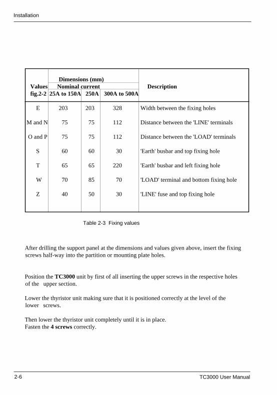
E 203 203 328 Width between the fixing holes
M and N 75 75 112 Distance between the 'LINE' terminals
O and P 75 75 112 Distance between the 'LOAD' terminals
S 60 60 30 'Earth' busbar and top fixing hole
T 65 65 220 'Earth' busbar and left fixing hole
W 70 85 70 'LOAD' terminal and bottom fixing hole
Z 40 50 30 'LINE' fuse and top fixing hole
Dimensions (mm)Values Nominal current Descriptionfig.2-2 25A to 150A 250A 300A to 500A
E 203 203 328 Width between the fixing holes
M and N 75 75 112 Distance between the 'LINE' terminals
O and P 75 75 112 Distance between the 'LOAD' terminals
S 60 60 30 'Earth' busbar and top fixing hole
T 65 65 220 'Earth' busbar and left fixing hole
W 70 85 70 'LOAD' terminal and bottom fixing hole
Z 40 50 30 'LINE' fuse and top fixing hole
Table 2-3 Fixing values
After drilling the support panel at the dimensions and values given above, insert the fixingscrews half-way into the partition or mounting plate holes.
Position the TC3000 unit by first of all inserting the upper screws in the respective holesof the upper section.
Lower the thyristor unit making sure that it is positioned correctly at the level of thelower screws.
Then lower the thyristor unit completely until it is in place.Fasten the 4 screws correctly.
TC3000 User Manual 3-1TC3000 User Manual 3-1
Wiring Wiring
Chapter 3
WIRING
Contents page
Safety during wiring ...................................................................... 3-2Power wiring diagrams ................................................................. 3-4
Star without neutral configuration ............................................ 3-4Star with neutral configuration .................................................3-5Closed delta configuration .......................................................3-6Open delta configuration ......................................................... 3-7
User terminal blocks .....................................................................3-8General introduction ................................................................ 3-8Auxiliary power supply ........................................................... 3-10Reference neutral .................................................................. 3-11Alarm contacts ....................................................................... 3-12
Control cables ............................................................................ 3-13Fixing ..................................................................................... 3-13Connection of the shield to the ground .................................. 3-14
Control terminal blocks............................................................... 3-15General introduction .............................................................. 3-16External control input ............................................................. 3-17Manual control ....................................................................... 3-17Auxiliary input / output ........................................................... 3-18Alarm acknowledge ............................................................... 3-18
Chapter 3
WIRING
Contents page
Safety during wiring ...................................................................... 3-2Power wiring diagrams ................................................................. 3-4
Star without neutral configuration ............................................ 3-4Star with neutral configuration ................................................. 3-5Closed delta configuration ....................................................... 3-6Open delta configuration ......................................................... 3-7
User terminal blocks..................................................................... 3-8General introduction ................................................................ 3-8Auxiliary power supply ........................................................... 3-10Reference neutral .................................................................. 3-11Alarm contacts ....................................................................... 3-12
Control cables ............................................................................ 3-13Fixing ..................................................................................... 3-13Connection of the shield to the ground .................................. 3-14
Control terminal blocks............................................................... 3-15General introduction ..............................................................3-16External control input ............................................................. 3-17Manual control ....................................................................... 3-17Auxiliary input / output ........................................................... 3-18Alarm acknowledge ............................................................... 3-18
WiringWiring
3-2 TC3000 User Manual 3-2 TC3000 User Manual
!
Chapter 3 WIRING
SAFETY DURING WIRING
Warning !Wiring must be performed by personnel who are qualified to work with lowvoltage electrical equipment.It is the user's responsibility to wire and protect the installation in accordancewith current professional standards.A suitable device guaranteeing electrical separation of the equipment and thepower supply must be installed upstream from the unit in order to perform the operationin complete safety.
Caution !
To ensure the correct grounding of the TC3000 unit, make sure that the fixing is onthe reference ground surface (panel or bulkhead).Failing this, it is necessary to add a ground connection at most 10 cm long betweenthe earth connection and the reference ground surface.
Warning !
This connection which is intended to ensure good ground conductivity, can neverbe used to replace the safety earth connection.
TC3000 series units possess two protective covers: upper and lower.The upper cover should be raised to facilitate wiring.After connection and before power-up, put the upper protective cover back in place toensure the specified degree of protection.
!
The safety earth is connected to the screw located on the busbar provided for thispurpose in the top part of the unit, behind the phase terminal and labelled as follows:
Warning !
Before any connection or disconnection, make sure that the power and controlcables and wires are isolated from the voltage sources.For safety reasons, the safety earth cable must be connected before any otherconnection during wiring and the last cable to be disconnected.
Chapter 3 WIRING
SAFETY DURING WIRING
Warning !Wiring must be performed by personnel who are qualified to work with lowvoltage electrical equipment.It is the user's responsibility to wire and protect the installation in accordancewith current professional standards.A suitable device guaranteeing electrical separation of the equipment and thepower supply must be installed upstream from the unit in order to perform the operationin complete safety.
Caution !
To ensure the correct grounding of the TC3000 unit, make sure that the fixing is onthe reference ground surface (panel or bulkhead).Failing this, it is necessary to add a ground connection at most 10 cm long betweenthe earth connection and the reference ground surface.
Warning !
This connection which is intended to ensure good ground conductivity, can neverbe used to replace the safety earth connection.
TC3000 series units possess two protective covers: upper and lower.The upper cover should be raised to facilitate wiring.After connection and before power-up, put the upper protective cover back in place toensure the specified degree of protection.
The safety earth is connected to the screw located on the busbar provided for thispurpose in the top part of the unit, behind the phase terminal and labelled as follows:
Warning !
Before any connection or disconnection, make sure that the power and controlcables and wires are isolated from the voltage sources.For safety reasons, the safety earth cable must be connected before any otherconnection during wiring and the last cable to be disconnected.
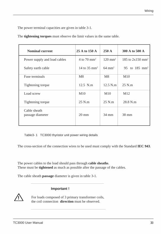
TC3000 User Manual 3-3TC3000 User Manual 3-3
Wiring Wiring
Nominal current 25 A to 150 A 250 A 300 A to 500 A
Power supply and load cables 4 to 70 mm2 120 mm2 185 to 2x150 mm2
Safety earth cable 14 to 35 mm2 64 mm2 95 to 185 mm2
Fuse terminals M8 M8 M10
Tightening torque 12.5 N.m 12.5 N.m 25 N.m
Load screw M10 M10 M12
Tightening torque 25 N.m 25 N.m 28.8 N.m
Cable sheathpassage diameter 20 mm 34 mm 38 mm
!
The cross-section of the connection wires to be used must comply with the Standard IEC 943.
The power cables to the load should pass through cable sheaths.These must be tightened as much as possible after the passage of the cables.
The cable sheath passage diameter is given in table 3-1.
Important !
For loads composed of 3 primary transformer coils, the coil connection direction must be observed.
Table3- 1 TC3000 thyristor unit power wiring details
!
The power terminal capacities are given in table 3-1.
The tightening torques must observe the limit values in the same table.
Nominal current 25 A to 150 A 250 A 300 A to 500 A
Power supply and load cables 4 to 70 mm2 120 mm2 185 to 2x150 mm2
Safety earth cable 14 to 35 mm2 64 mm2 95 to 185 mm2
Fuse terminals M8 M8 M10
Tightening torque 12.5 N.m 12.5 N.m 25 N.m
Load screw M10 M10 M12
Tightening torque 25 N.m 25 N.m 28.8 N.m
Cable sheathpassage diameter 20 mm 34 mm 38 mm
Table3- 1 TC3000 thyristor unit power wiring details
The power terminal capacities are given in table 3-1.
The tightening torques must observe the limit values in the same table.
The cross-section of the connection wires to be used must comply with the Standard IEC 943.
The power cables to the load should pass through cable sheaths.These must be tightened as much as possible after the passage of the cables.
The cable sheath passage diameter is given in table 3-1.
Important !
For loads composed of 3 primary transformer coils, the coil connection direction must be observed.
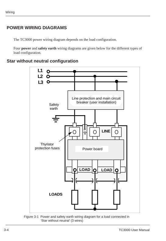
WiringWiring
3-4 TC3000 User Manual 3-4 TC3000 User Manual
Figure 3-1 Power and safety earth wiring diagram for a load connected in 'Star without neutral' (3 wires)
POWER WIRING DIAGRAMS
The TC3000 power wiring diagram depends on the load configuration.
Four power and safety earth wiring diagrams are given below for the different types ofload configuration.
Star without neutral configuration
Power boardThyristor
protection fuses
L1
LOADS
LOADLOAD
LINE
Line protection and main circuitbreaker (user installation)
Safetyearth
L3L2
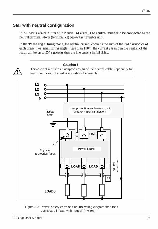
TC3000 User Manual 3-5TC3000 User Manual 3-5
Wiring Wiring
!
Star with neutral configuration
In the 'Phase angle' firing mode, the neutral current contains the sum of the 3rd harmonics ofeach phase. For small firing angles (less than 100°), the current passing in the neutral of theloads can be up to 25% greater than the line current in full firing.
Caution !This current requires an adapted design of the neutral cable, especially forloads composed of short wave infrared elements.
If the load is wired in 'Star with Neutral' (4 wires), the neutral must also be connected to theneutral terminal block (terminal 71) below the thyristor unit.
!
Figure 3-2 Power, safety earth and neutral wiring diagram for a load connected in 'Star with neutral' (4 wires)
Power board
L1
N
LOADS
LOADLOAD
LINE
Thyristor protection fuses
Line protection and main circuitbreaker (user installation)Safety
earthN
eutra
l co
nnec
tion
L2L3
71
Star with neutral configuration
In the 'Phase angle' firing mode, the neutral current contains the sum of the 3rd harmonics ofeach phase. For small firing angles (less than 100°), the current passing in the neutral of theloads can be up to 25% greater than the line current in full firing.
Caution !This current requires an adapted design of the neutral cable, especially forloads composed of short wave infrared elements.
If the load is wired in 'Star with Neutral' (4 wires), the neutral must also be connected to theneutral terminal block (terminal 71) below the thyristor unit.
Figure 3-2 Power, safety earth and neutral wiring diagram for a load connected in 'Star with neutral' (4 wires)
Power board
L1
N
LOADS
LOADLOAD
LINE
Thyristor protection fuses
Line protection and main circuitbreaker (user installation)Safety
earth
Neu
tral
conn
ectio
n
L2L3
71
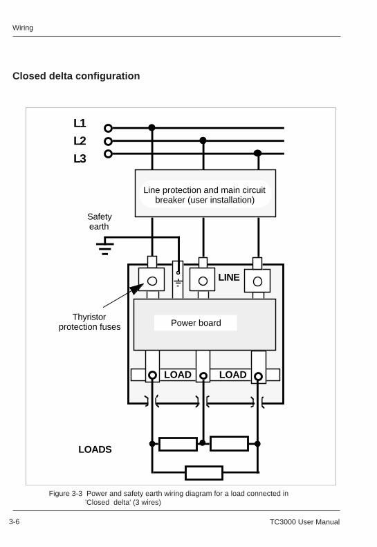
WiringWiring
3-6 TC3000 User Manual 3-6 TC3000 User Manual
Closed delta configuration
Figure 3-3 Power and safety earth wiring diagram for a load connected in 'Closed delta' (3 wires)
Power board
L1
LOADS
LOADLOAD
LINE
Thyristor protection fuses
Line protection and main circuit breaker (user installation)
Safetyearth
L2
L3
Closed delta configuration
Figure 3-3 Power and safety earth wiring diagram for a load connected in 'Closed delta' (3 wires)
Power board
L1
LOADS
LOADLOAD
LINE
Thyristor protection fuses
Line protection and main circuit breaker (user installation)
Safetyearth
L2
L3
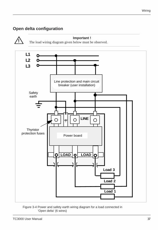
TC3000 User Manual 3-7TC3000 User Manual 3-7
Wiring Wiring
!
Open delta configuration
Important !The load wiring diagram given below must be observed.!
Figure 3-4 Power and safety earth wiring diagram for a load connected in 'Open delta' (6 wires)
Power board
Thyristor protection fuses
L1
LOADLOAD
LINE
Load 3
Load 1
Load 2
Line protection and main circuit breaker (user installation)
Safetyearth
L3L2
Open delta configuration
Important !The load wiring diagram given below must be observed.
Figure 3-4 Power and safety earth wiring diagram for a load connected in 'Open delta' (6 wires)
Power board
Thyristor protection fuses
L1
LOADLOAD
LINE
Load 3
Load 1
Load 2
Line protection and main circuit breaker (user installation)
Safetyearth
L3L2
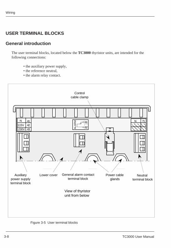
WiringWiring
3-8 TC3000 User Manual 3-8 TC3000 User Manual
USER TERMINAL BLOCKS
General introduction
The user terminal blocks, located below the TC3000 thyristor units, are intended for thefollowing connections:
• the auxiliary power supply,• the reference neutral,• the alarm relay contact.
Figure 3-5 User terminal blocks
USER TERMINAL BLOCKS
General introduction
The user terminal blocks, located below the TC3000 thyristor units, are intended for thefollowing connections:
• the auxiliary power supply,• the reference neutral,• the alarm relay contact.
Figure 3-5 User terminal blocks
View of thyristor unit from below
Lower cover
71
Auxiliarypower supply terminal block
N
ALA
RM 61
62
414243
115V230V
N
General alarm contact terminal block
Neutral terminal block
Controlcable clamp
Power cable glands
View of thyristor unit from below
Lower cover
71
Auxiliarypower supply terminal block
N
ALA
RM 61
62
414243
115V230V
N
General alarm contact terminal block
Neutral terminal block
Controlcable clamp
Power cable glands
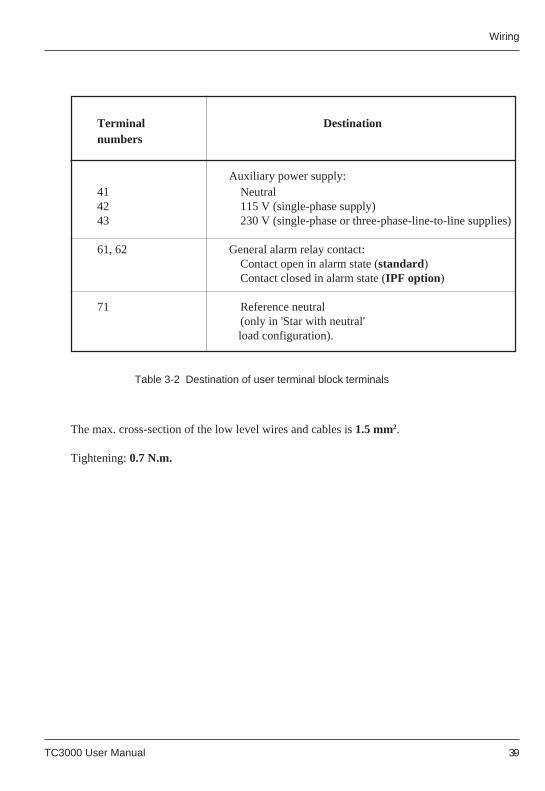
TC3000 User Manual 3-9TC3000 User Manual 3-9
Wiring Wiring
Terminal Destinationnumbers
Auxiliary power supply:41 Neutral42 115 V (single-phase supply)43 230 V (single-phase or three-phase-line-to-line supplies)
61, 62 General alarm relay contact:Contact open in alarm state (standard)Contact closed in alarm state (IPF option)
71 Reference neutral(only in 'Star with neutral'load configuration).
Table 3-2 Destination of user terminal block terminals
The max. cross-section of the low level wires and cables is 1.5 mm2.
Tightening: 0.7 N.m.
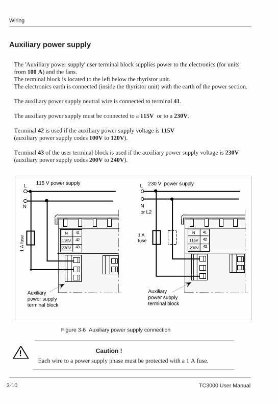
WiringWiring
3-10 TC3000 User Manual 3-10 TC3000 User Manual
!
Auxiliary power supply
Caution !
Each wire to a power supply phase must be protected with a 1 A fuse.!
Figure 3-6 Auxiliary power supply connection
The 'Auxiliary power supply' user terminal block supplies power to the electronics (for unitsfrom 100 A) and the fans.The terminal block is located to the left below the thyristor unit.The electronics earth is connected (inside the thyristor unit) with the earth of the power section.
The auxiliary power supply neutral wire is connected to terminal 41.
The auxiliary power supply must be connected to a 115V or to a 230V.
Terminal 42 is used if the auxiliary power supply voltage is 115V(auxiliary power supply codes 100V to 120V).
Terminal 43 of the user terminal block is used if the auxiliary power supply voltage is 230V(auxiliary power supply codes 200V to 240V).
Auxiliary power supply
Caution !
Each wire to a power supply phase must be protected with a 1 A fuse.
Figure 3-6 Auxiliary power supply connection
The 'Auxiliary power supply' user terminal block supplies power to the electronics (for unitsfrom 100 A) and the fans.The terminal block is located to the left below the thyristor unit.The electronics earth is connected (inside the thyristor unit) with the earth of the power section.
The auxiliary power supply neutral wire is connected to terminal 41.
The auxiliary power supply must be connected to a 115V or to a 230V.
Terminal 42 is used if the auxiliary power supply voltage is 115V(auxiliary power supply codes 100V to 120V).
Terminal 43 of the user terminal block is used if the auxiliary power supply voltage is 230V(auxiliary power supply codes 200V to 240V).
Auxiliarypower supply terminal block
41
42
43
115V
230V
N
115 V power supply
Auxiliarypower supply terminal block
230 V power supply
1 A
fuse
1 Afuse
41
42
43
115V
230V
N
N
L
N or L2
L
Auxiliarypower supply terminal block
41
42
43
115V
230V
N
115 V power supply
Auxiliarypower supply terminal block
230 V power supply
1 A
fuse
1 Afuse
41
42
43
115V
230V
N
N
L
N or L2
L
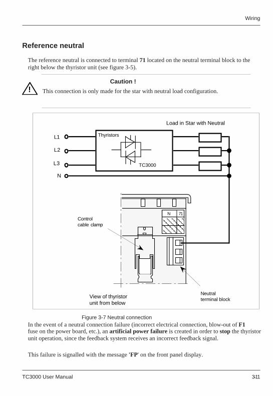
TC3000 User Manual 3-11TC3000 User Manual 3-11
Wiring Wiring
In the event of a neutral connection failure (incorrect electrical connection, blow-out of F1fuse on the power board, etc.), an artificial power failure is created in order to stop the thyristorunit operation, since the feedback system receives an incorrect feedback signal.
This failure is signalled with the message 'FP' on the front panel display.
!
Figure 3-7 Neutral connection
Reference neutral
The reference neutral is connected to terminal 71 located on the neutral terminal block to theright below the thyristor unit (see figure 3-5).
Caution !
This connection is only made for the star with neutral load configuration.!
In the event of a neutral connection failure (incorrect electrical connection, blow-out of F1fuse on the power board, etc.), an artificial power failure is created in order to stop the thyristorunit operation, since the feedback system receives an incorrect feedback signal.
This failure is signalled with the message 'FP' on the front panel display.
Figure 3-7 Neutral connection
Reference neutral
The reference neutral is connected to terminal 71 located on the neutral terminal block to theright below the thyristor unit (see figure 3-5).
Caution !
This connection is only made for the star with neutral load configuration.
View of thyristor unit from below
71N
Neutralterminal block
Controlcable clamp
Thyristors
TC3000
L2
N
Load in Star with Neutral
L3
L1
View of thyristor unit from below
71N
Neutralterminal block
Controlcable clamp
Thyristors
TC3000
L2
N
Load in Star with Neutral
L3
L1
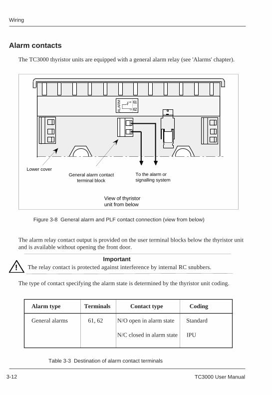
WiringWiring
3-12 TC3000 User Manual 3-12 TC3000 User Manual
!
Alarm contacts
The TC3000 thyristor units are equipped with a general alarm relay (see 'Alarms' chapter).
The type of contact specifying the alarm state is determined by the thyristor unit coding.
The alarm relay contact output is provided on the user terminal blocks below the thyristor unitand is available without opening the front door.
ImportantThe relay contact is protected against interference by internal RC snubbers.!
Table 3-3 Destination of alarm contact terminals
Alarm type Terminals Contact type Coding
General alarms 61, 62 N/O open in alarm state Standard
N/C closed in alarm state IPU
Alarm contacts
The TC3000 thyristor units are equipped with a general alarm relay (see 'Alarms' chapter).
The type of contact specifying the alarm state is determined by the thyristor unit coding.
The alarm relay contact output is provided on the user terminal blocks below the thyristor unitand is available without opening the front door.
ImportantThe relay contact is protected against interference by internal RC snubbers.
Table 3-3 Destination of alarm contact terminals
Alarm type Terminals Contact type Coding
General alarms 61, 62 N/O open in alarm state Standard
N/C closed in alarm state IPU
Figure 3-8 General alarm and PLF contact connection (view from below) Figure 3-8 General alarm and PLF contact connection (view from below)
To the alarm or signalling system
View of thyristor unit from below
Lower cover
ALA
RM 61
62
General alarm contact terminal block
To the alarm or signalling system
View of thyristor unit from below
Lower cover
ALA
RM 61
62
General alarm contact terminal block
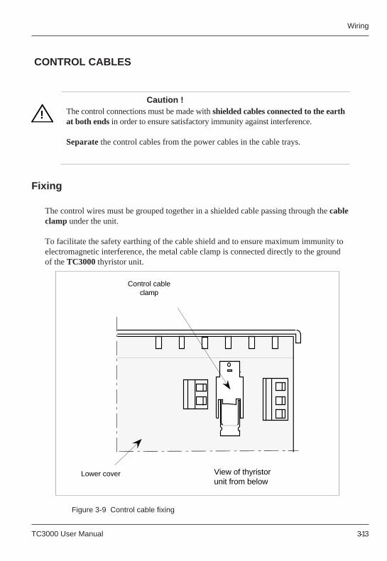
TC3000 User Manual 3-13TC3000 User Manual 3-13
Wiring Wiring
!!Caution !
The control connections must be made with shielded cables connected to the earthat both ends in order to ensure satisfactory immunity against interference.
Separate the control cables from the power cables in the cable trays.
Figure 3-9 Control cable fixing
CONTROL CABLES
Fixing
The control wires must be grouped together in a shielded cable passing through the cableclamp under the unit.
To facilitate the safety earthing of the cable shield and to ensure maximum immunity toelectromagnetic interference, the metal cable clamp is connected directly to the groundof the TC3000 thyristor unit.
Caution !The control connections must be made with shielded cables connected to the earthat both ends in order to ensure satisfactory immunity against interference.
Separate the control cables from the power cables in the cable trays.
Figure 3-9 Control cable fixing
CONTROL CABLES
Fixing
The control wires must be grouped together in a shielded cable passing through the cableclamp under the unit.
To facilitate the safety earthing of the cable shield and to ensure maximum immunity toelectromagnetic interference, the metal cable clamp is connected directly to the groundof the TC3000 thyristor unit.
View of thyristor unit from below
Lower cover
Control cable clamp
View of thyristor unit from below
Lower cover
Control cable clamp

WiringWiring
3-14 TC3000 User Manual 3-14 TC3000 User Manual
• Strip the shielded cable as shown in figure 3-10,a.
The control wires must be long enough for the connection between the metal cable clamp andthe driver board user terminal blocks, with the door open.The wiring inside the unit must be as short as possible.
Figure 3-10 Control cable stripping
The possible cable diameters with the shield folded back are 5 to 10 mm per cable clamp.Figure 3-11 Cable tightening and shield grounding
• Fold back the shield on the isolating sheath (figure 3-10,b)• Insert the cable in the metal cable clamp so that the shield is located in the stirrup and does not enter the unit (it must not pass the lower cover).• Tighten the stirrup (4 x 1 flat screwdriver; tightening: 0.7 N.m.).
Connection of the shield to the ground
1.5 to 2 cm
20 to 40 cm
Isolating sheathShieldControl wires
Shield folded back
a)
b)
Cable Shield folded back
Wires
Lower cover
Cable clampTightening screw
Left-hand side view
TC3000 User Manual 3-15TC3000 User Manual 3-15
Wiring Wiring
The control wires are connected on the driver board for:
• the control setpoint connection• the retransmissions of the voltage and controlled parameter indications.
Control terminal tightening: 0.7 N.m.
The driver board terminal blocks can be accessed with the front door open.To open the door, unfasten the front screw, release the door from its notches by raising it and pullit towards you.
!
The control wires are connected on the driver board for:
• the control setpoint connection• the retransmissions of the voltage and controlled parameter indications.
Control terminal tightening: 0.7 N.m.
The driver board terminal blocks can be accessed with the front door open.To open the door, unfasten the front screw, release the door from its notches by raising it and pullit towards you.
CONTROL TERMINAL BLOCKS
Warning !
With the door open, dangerous live parts may be accessible if theTC3000 thyristor unit supply is switched on.
Caution !
For electromagnetic compatibility reasons, the connection must bemade with shielded cables and wires which are shielded and earthed(or grounded) at both ends.
!
CONTROL TERMINAL BLOCKS
Warning !
With the door open, dangerous live parts may be accessible if theTC3000 thyristor unit supply is switched on.
Caution !
For electromagnetic compatibility reasons, the connection must bemade with shielded cables and wires which are shielded and earthed(or grounded) at both ends.
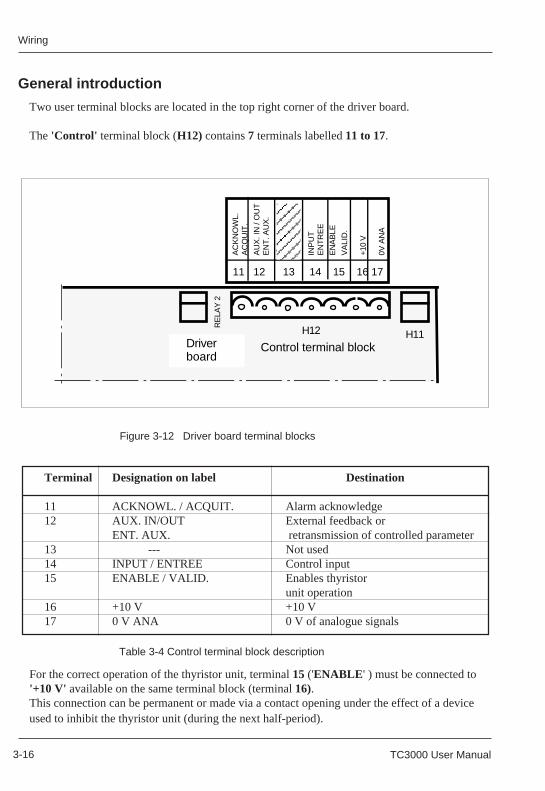
WiringWiring
3-16 TC3000 User Manual 3-16 TC3000 User Manual
General introduction
Two user terminal blocks are located in the top right corner of the driver board.
The 'Control' terminal block (H12) contains 7 terminals labelled 11 to 17.
For the correct operation of the thyristor unit, terminal 15 ('ENABLE ' ) must be connected to'+10 V' available on the same terminal block (terminal 16).This connection can be permanent or made via a contact opening under the effect of a deviceused to inhibit the thyristor unit (during the next half-period).
Terminal Designation on label Destination
11 ACKNOWL. / ACQUIT. Alarm acknowledge12 AUX. IN/OUT External feedback or
ENT. AUX. retransmission of controlled parameter13 --- Not used14 INPUT / ENTREE Control input15 ENABLE / VALID. Enables thyristor
unit operation16 +10 V +10 V17 0 V ANA 0 V of analogue signals
Table 3-4 Control terminal block description
Figure 3-12 Driver board terminal blocks
H12
Control terminal block
AC
KN
OW
L.A
CQ
UIT
.
AU
X. I
N /
OU
TE
NT
. AU
X.
I2
LIM
IT
LIM
IT.
I2
INP
UT
EN
TR
EE
EN
AB
LE
VA
LID
.
+10
V
0V A
NA
RE
LAY
2
Driver board
H11
11 12 13 14 15 16 17
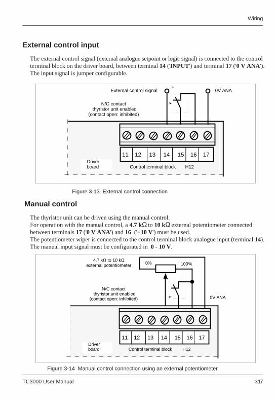
TC3000 User Manual 3-17TC3000 User Manual 3-17
Wiring Wiring
Figure 3-13 External control connection
Manual control
Figure 3-14 Manual control connection using an external potentiometer
0V ANAExternal control signal
N/C contact thyristor unit enabled
(contact open: inhibited)
Control terminal block H12 Driver board
11 12 13 14 15 16 17
+
Control terminal block H12 Driver board
11 12 13 14 15 16 17
0V ANA
4.7 kΩ to 10 kΩ external potentiometer
N/C contact thyristor unit enabled
(contact open: inhibited)
0% 100%
External control input
The external control signal (external analogue setpoint or logic signal) is connected to the controlterminal block on the driver board, between terminal 14 ('INPUT ') and terminal 17 ('0 V ANA ').The input signal is jumper configurable.
Figure 3-13 External control connection
Manual control
The thyristor unit can be driven using the manual control.For operation with the manual control, a 4.7 kΩ to 10 kΩ external potentiometer connectedbetween terminals 17 ('0 V ANA') and 16 ('+10 V') must be used.The potentiometer wiper is connected to the control terminal block analogue input (terminal14).The manual input signal must be configurated in 0 - 10 V.
Figure 3-14 Manual control connection using an external potentiometer
0V ANAExternal control signal
N/C contact thyristor unit enabled
(contact open: inhibited)
Control terminal block H12 Driver board
11 12 13 14 15 16 17
+
Control terminal block H12 Driver board
11 12 13 14 15 16 17
0V ANA
4.7 kΩ to 10 kΩ external potentiometer
N/C contact thyristor unit enabled
(contact open: inhibited)
0% 100%
External control input
The external control signal (external analogue setpoint or logic signal) is connected to the controlterminal block on the driver board, between terminal 14 ('INPUT ') and terminal 17 ('0 V ANA ').The input signal is jumper configurable.
The thyristor unit can be driven using the manual control.For operation with the manual control, a 4.7 kΩ to 10 kΩ external potentiometer connectedbetween terminals 17 ('0 V ANA') and 16 ('+10 V') must be used.The potentiometer wiper is connected to the control terminal block analogue input (terminal14).The manual input signal must be configurated in 0 - 10 V.
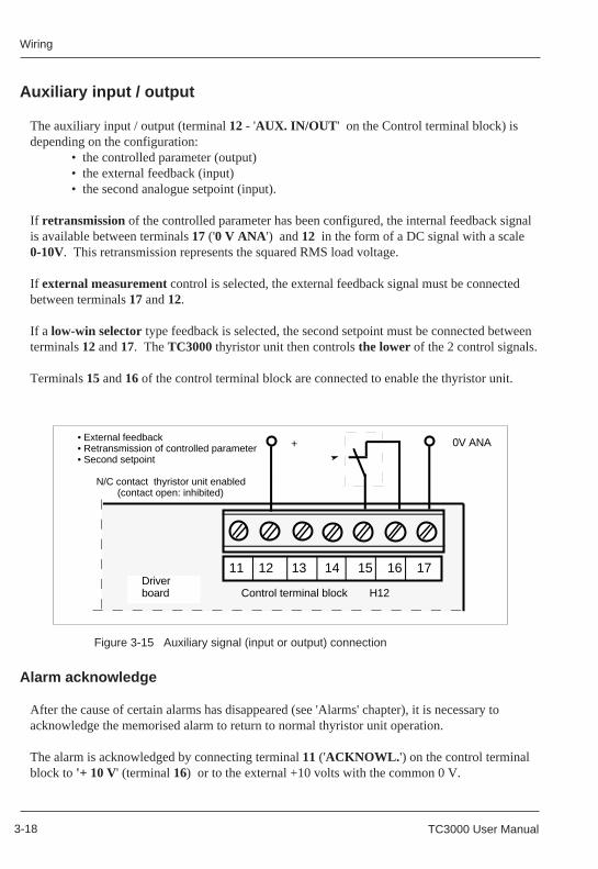
WiringWiring
3-18 TC3000 User Manual 3-18 TC3000 User Manual
Auxiliary input / output
The auxiliary input / output (terminal 12 - 'AUX. IN/OUT ' on the Control terminal block) isdepending on the configuration:
• the controlled parameter (output)• the external feedback (input)• the second analogue setpoint (input).
If retransmission of the controlled parameter has been configured, the internal feedback signalis available between terminals 17 ('0 V ANA ') and 12 in the form of a DC signal with a scale0-10V. This retransmission represents the squared RMS load voltage.
If external measurement control is selected, the external feedback signal must be connectedbetween terminals 17 and 12.
If a low-win selector type feedback is selected, the second setpoint must be connected betweenterminals 12 and 17. The TC3000 thyristor unit then controls the lower of the 2 control signals.
Terminals 15 and 16 of the control terminal block are connected to enable the thyristor unit.
Figure 3-15 Auxiliary signal (input or output) connection
After the cause of certain alarms has disappeared (see 'Alarms' chapter), it is necessary toacknowledge the memorised alarm to return to normal thyristor unit operation.
The alarm is acknowledged by connecting terminal 11 ('ACKNOWL. ') on the control terminalblock to '+ 10 V' (terminal 16) or to the external +10 volts with the common 0 V.
Alarm acknowledge
Control terminal block H12 Driver board
11 12 13 14 15 16 17
0V ANA• External feedback• Retransmission of controlled parameter• Second setpoint
N/C contact thyristor unit enabled(contact open: inhibited)
+
Auxiliary input / output
The auxiliary input / output (terminal 12 - 'AUX. IN/OUT ' on the Control terminal block) isdepending on the configuration:
• the controlled parameter (output)• the external feedback (input)• the second analogue setpoint (input).
If retransmission of the controlled parameter has been configured, the internal feedback signalis available between terminals 17 ('0 V ANA') and 12 in the form of a DC signal with a scale0-10V. This retransmission represents the squared RMS load voltage.
If external measurement control is selected, the external feedback signal must be connectedbetween terminals 17 and 12.
If a low-win selector type feedback is selected, the second setpoint must be connected betweenterminals 12 and 17. The TC3000 thyristor unit then controls the lower of the 2 control signals.
Terminals 15 and 16 of the control terminal block are connected to enable the thyristor unit.
Figure 3-15 Auxiliary signal (input or output) connection
After the cause of certain alarms has disappeared (see 'Alarms' chapter), it is necessary toacknowledge the memorised alarm to return to normal thyristor unit operation.
The alarm is acknowledged by connecting terminal 11 ('ACKNOWL. ') on the control terminalblock to '+ 10 V' (terminal 16) or to the external +10 volts with the common 0 V.
Alarm acknowledge
Control terminal block H12 Driver board
11 12 13 14 15 16 17
0V ANA• External feedback• Retransmission of controlled parameter• Second setpoint
N/C contact thyristor unit enabled(contact open: inhibited)
+
Configuration
TC3000 User Manual 4-1 TC3000 User Manual 4-1
Configuration
Chapter 4
CONFIGURATION
Contents page
Safety during configuration ................................................................ 4-2Power board ...................................................................................... 4-3
Voltage selection ...................................................................... 4-4Adaptation to the load connection type .................................... 4-5
Driver board ....................................................................................... 4-6Auxiliary power supply .............................................................. 4-8Main setpoint configuration ....................................................... 4-9Process value configuration ..................................................... 4-9Auxiliary input / output configuration ...................................... 4-10Thyristor firing mode configuration ......................................... 4-11Load type and configuration type ........................................... 4-12Alarm relay contact type ......................................................... 4-12Under-voltage alarm level ....................................................... 4-13Initial ramp .............................................................................. 4-13Calibration/Operation .............................................................. 4-14
ConfigurationConfiguration
4-2 TC3000 User Manual 4-2 TC3000 User Manual
!
The thyristor unit is configured in the factory using moveable jumpers and soldered links.The thyristor unit can be reconfigured on site using jumpers.
Important !The thyristor unit is supplied fully configured inaccordance with the code on the identification label.
This chapter is included in order to
• check that the configuration is compatible with the application• modify, if necessary, certain characteristics of the thyristor unit on-site.
Warning !
For safety reasons, the reconfiguration of the thyristor unit using jumpersmust be performed with the unit switched off and by qualified personnelauthorised to work in an industrial low voltage electrical environment.
Before starting the reconfiguration procedure, check that the thyristor unitis isolated and that an occasional power-up is impossible.
After the reconfiguration of the unit, correct the codes on the identificationlabel to prevent any maintenance problems later.
Chapter 4 CONFIGURATION
SAFETY DURING CONFIGURATION
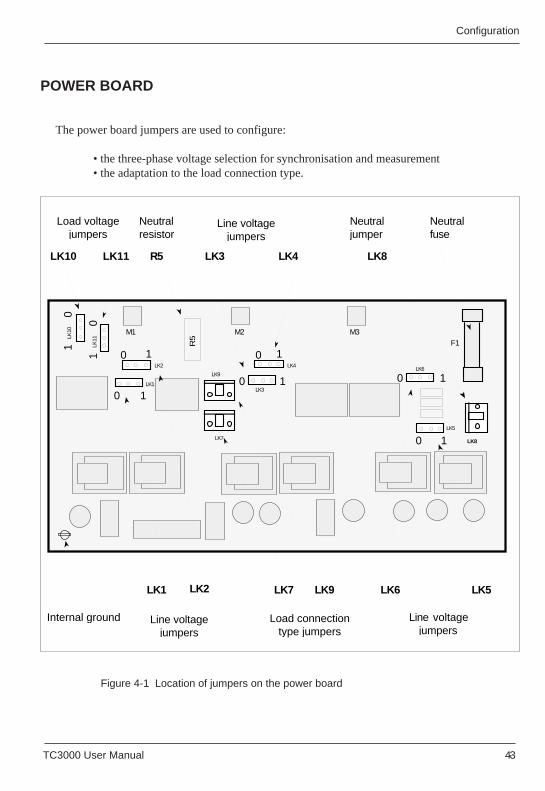
Configuration
TC3000 User Manual 4-3 TC3000 User Manual 4-3
Configuration
POWER BOARD
The power board jumpers are used to configure:
• the three-phase voltage selection for synchronisation and measurement• the adaptation to the load connection type.
Figure 4-1 Location of jumpers on the power board
LK8LK11LK10 LK4LK3
LK6 LK5LK7 LK9LK2LK1
LK11LK
100
1
0LK2
1
LK8LK7
LK9 0 1LK6
LK5
0LK4
LK3
1
Load connectiontype jumpers
Line voltage jumpers
Neutral jumper
Line voltage jumpers
Line voltage jumpers
Load voltage jumpers
M1 M2 M3
01
0LK1
10 1
0 1
F1
Neutral fuse
Internal ground
R5
Neutral resistor
R5
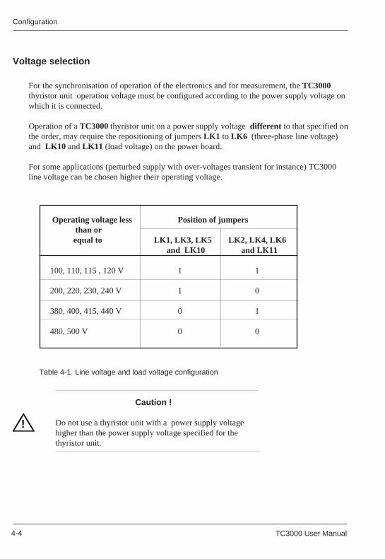
ConfigurationConfiguration
4-4 TC3000 User Manual 4-4 TC3000 User Manual
!
For the synchronisation of operation of the electronics and for measurement, the TC3000thyristor unit operation voltage must be configured according to the power supply voltage onwhich it is connected.
Operation of a TC3000 thyristor unit on a power supply voltage different to that specified onthe order, may require the repositioning of jumpers LK1 to LK6 (three-phase line voltage)and LK10 and LK11 (load voltage) on the power board.
For some applications (perturbed supply with over-voltages transient for instance) TC3000line voltage can be chosen higher their operating voltage.
Operating voltage less Position of jumpers than or equal to LK1, LK3, LK5 LK2, LK4, LK6
and LK10 and LK11
100, 110, 115 , 120 V 1 1
200, 220, 230, 240 V 1 0
380, 400, 415, 440 V 0 1
480, 500 V 0 0
Table 4-1 Line voltage and load voltage configuration
Caution !
Do not use a thyristor unit with a power supply voltagehigher than the power supply voltage specified for thethyristor unit.
Voltage selection
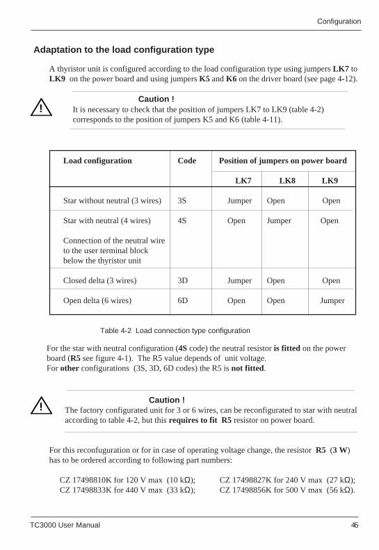
Configuration
TC3000 User Manual 4-5 TC3000 User Manual 4-5
Configuration
Adaptation to the load configuration type
A thyristor unit is configured according to the load configuration type using jumpers LK7 toLK9 on the power board and using jumpers K5 and K6 on the driver board (see page 4-12).
Caution !It is necessary to check that the position of jumpers LK7 to LK9 (table 4-2)corresponds to the position of jumpers K5 and K6 (table 4-11).
!
For the star with neutral configuration (4S code) the neutral resistor is fitted on the powerboard (R5 see figure 4-1). The R5 value depends of unit voltage.For other configurations (3S, 3D, 6D codes) the R5 is not fitted .
Caution !The factory configurated unit for 3 or 6 wires, can be reconfigurated to star with neutralaccording to table 4-2, but this requires to fit R5 resistor on power board.
For this reconfuguration or for in case of operating voltage change, the resistor R5 (3 W)has to be ordered according to following part numbers:
CZ 17498810K for 120 V max (10 kΩ); CZ 17498827K for 240 V max (27 kΩ);CZ 17498833K for 440 V max (33 kΩ); CZ 17498856K for 500 V max (56 kΩ).
Load configuration Code Position of jumpers on power board
LK7 LK8 LK9
Star without neutral (3 wires) 3S Jumper Open Open
Star with neutral (4 wires) 4S Open Jumper Open
Connection of the neutral wire to the user terminal block below the thyristor unit
Closed delta (3 wires) 3D Jumper Open Open
Open delta (6 wires) 6D Open Open Jumper
Table 4-2 Load connection type configuration
Adaptation to the load configuration type
A thyristor unit is configured according to the load configuration type using jumpers LK7 toLK9 on the power board and using jumpers K5 and K6 on the driver board (see page 4-12).
Caution !It is necessary to check that the position of jumpers LK7 to LK9 (table 4-2)corresponds to the position of jumpers K5 and K6 (table 4-11).
!
For the star with neutral configuration (4S code) the neutral resistor is fitted on the powerboard (R5 see figure 4-1). The R5 value depends of unit voltage.For other configurations (3S, 3D, 6D codes) the R5 is not fitted .
Caution !The factory configurated unit for 3 or 6 wires, can be reconfigurated to star with neutralaccording to table 4-2, but this requires to fit R5 resistor on power board.
For this reconfuguration (or for in case of operating voltage change) R5 has to be orderedaccording to following part numbers:
CZ 17498810K for 120 V max; CZ 17498827K for 240 V max;CZ 17498833K for 440 V max; CZ 17498856K for 500 V max.
Load configuration Code Position of jumpers on power board
LK7 LK8 LK9
Star without neutral (3 wires) 3S Jumper Open Open
Star with neutral (4 wires) 4S Open Jumper Open
Connection of the neutral wire to the user terminal block below the thyristor unit
Closed delta (3 wires) 3D Jumper Open Open
Open delta (6 wires) 6D Open Open Jumper
Table 4-2 Load connection type configuration
!!
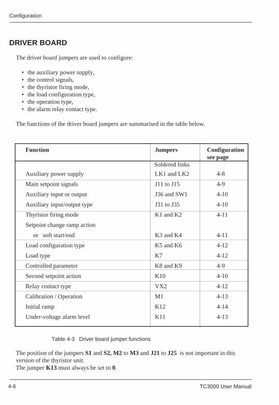
ConfigurationConfiguration
4-6 TC3000 User Manual 4-6 TC3000 User Manual
Function Jumpers Configurationsee page
Soldered links
Auxiliary power supply LK1 and LK2 4-8
Main setpoint signals J11 to J15 4-9
Auxiliary input or output J36 and SW1 4-10
Auxiliary input/output type J31 to J35 4-10
Thyristor firing mode K1 and K2 4-11
Setpoint change ramp action
or soft start/end K3 and K4 4-11
Load configuration type K5 and K6 4-12
Load type K7 4-12
Controlled parameter K8 and K9 4-9
Second setpoint action K10 4-10
Relay contact type VX2 4-12
Calibration / Operation M1 4-13
Initial ramp K12 4-14
Under-voltage alarm level K11 4-13
DRIVER BOARD
The driver board jumpers are used to configure:
• the auxiliary power supply,• the control signals,• the thyristor firing mode,• the load configuration type,• the operation type,• the alarm relay contact type.
The functions of the driver board jumpers are summarised in the table below.
Table 4-3 Driver board jumper functions
The position of the jumpers S1 and S2, M2 to M3 and J21 to J25 is not important in thisversion of the thyristor unit.The jumper K13 must always be set to 0.
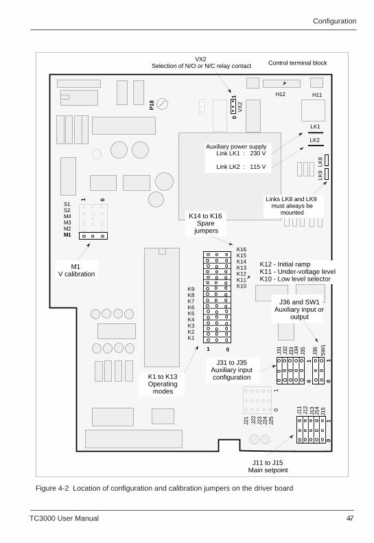
Configuration
TC3000 User Manual 4-7 TC3000 User Manual 4-7
Configuration
Figure 4-2 Location of configuration and calibration jumpers on the driver board
VX
2
01
J11
J12
J13
J14
J15
01
J36
SW
1
01
J31
J32
J33
J34
J35
01
J21
J22
J23
J24
J25
K9K8K7K6K5K4K3K2K1
K16K15K14K13K12K11K10
01
S1S2M4M3M2M1
01
K14 to K16Spare
jumpers
J31 to J35Auxiliary input configuration
J11 to J15Main setpoint
01
LK1
P18
LK8
LK9
VX2 Selection of N/O or N/C relay contact
K1 to K13Operating
modes
M1 V calibration
Links LK8 and LK9 must always be
mounted
H11
LK2
H12
J36 and SW1Auxiliary input or
output
Auxiliary power supplyLink LK1 : 230 V
Link LK2 : 115 V
K12 - Initial ramp K11 - Under-voltage level K10 - Low level selector
Control terminal block
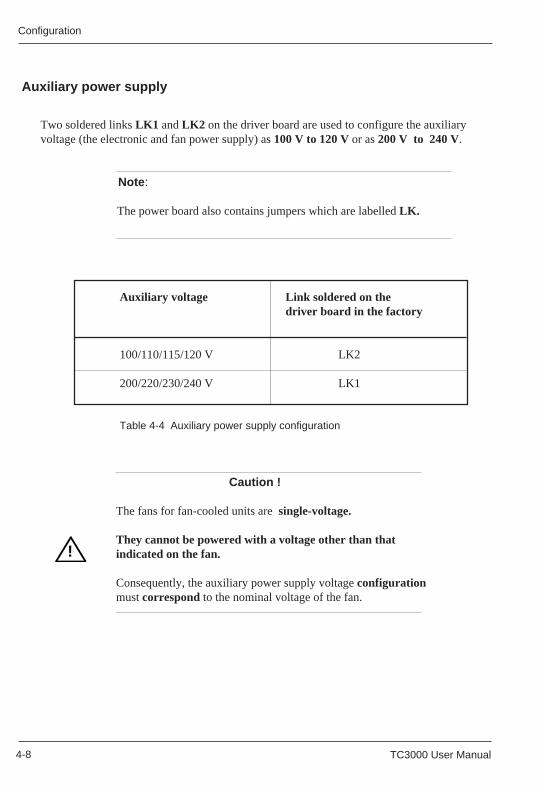
ConfigurationConfiguration
4-8 TC3000 User Manual 4-8 TC3000 User Manual
!
Two soldered links LK1 and LK2 on the driver board are used to configure the auxiliaryvoltage (the electronic and fan power supply) as 100 V to 120 V or as 200 V to 240 V.
Note :
The power board also contains jumpers which are labelled LK.
Auxiliary voltage Link soldered on thedriver board in the factory
100/110/115/120 V LK2
200/220/230/240 V LK1
Table 4-4 Auxiliary power supply configuration
Caution !
The fans for fan-cooled units are single-voltage.
They cannot be powered with a voltage other than thatindicated on the fan.
Consequently, the auxiliary power supply voltage configurationmust correspond to the nominal voltage of the fan.
!
Auxiliary power supply
Two soldered links LK1 and LK2 on the driver board are used to configure the auxiliaryvoltage (the electronic and fan power supply) as 100 V to 120 V or as 200 V to 240 V.
Note :
The power board also contains jumpers which are labelled LK.
Auxiliary voltage Link soldered on thedriver board in the factory
100/110/115/120 V LK2
200/220/230/240 V LK1
Table 4-4 Auxiliary power supply configuration
Caution !
The fans for fan-cooled units are single-voltage.
They cannot be powered with a voltage other than thatindicated on the fan.
Consequently, the auxiliary power supply voltage configurationmust correspond to the nominal voltage of the fan.
Auxiliary power supply
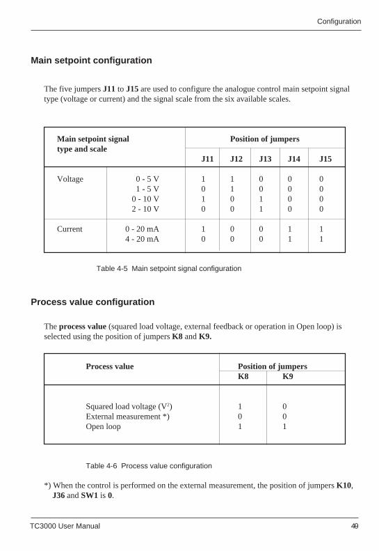
Configuration
TC3000 User Manual 4-9 TC3000 User Manual 4-9
Configuration
Main setpoint configuration
The five jumpers J11 to J15 are used to configure the analogue control main setpoint signaltype (voltage or current) and the signal scale from the six available scales.
Main setpoint signal Position of jumperstype and scale
J11 J12 J13 J14 J15
Voltage 0 - 5 V 1 1 0 0 01 - 5 V 0 1 0 0 0
0 - 10 V 1 0 1 0 02 - 10 V 0 0 1 0 0
Current 0 - 20 mA 1 0 0 1 14 - 20 mA 0 0 0 1 1
Table 4-5 Main setpoint signal configuration
Process value configuration
The process value (squared load voltage, external feedback or operation in Open loop) isselected using the position of jumpers K8 and K9.
Process value Position of jumpersK8 K9
Squared load voltage (V2) 1 0External measurement *) 0 0Open loop 1 1
Table 4-6 Process value configuration
*) When the control is performed on the external measurement, the position of jumpers K10, J36 and SW1 is 0.
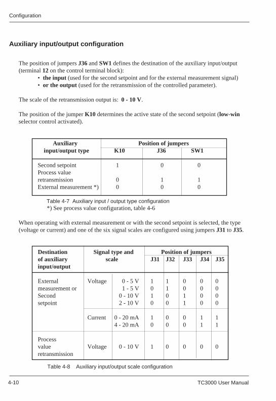
ConfigurationConfiguration
4-10 TC3000 User Manual 4-10 TC3000 User Manual
The position of jumpers J36 and SW1 defines the destination of the auxiliary input/output(terminal 12 on the control terminal block):
• the input (used for the second setpoint and for the external measurement signal)• or the output (used for the retransmission of the controlled parameter).
The scale of the retransmission output is: 0 - 10 V.
The position of the jumper K10 determines the active state of the second setpoint (low-winselector control activated).
Auxiliary Position of jumpers input/output type K10 J36 SW1
Second setpoint 1 0 0Process valueretransmission 0 1 1External measurement *) 0 0 0
Table 4-7 Auxiliary input / output type configuration *) See process value configuration, table 4-6
When operating with external measurement or with the second setpoint is selected, the type(voltage or current) and one of the six signal scales are configured using jumpers J31 to J35.
Auxiliary input/output configuration
Destination Signal type and Position of jumpersof auxiliary scale J31 J32 J33 J34 J35input/output
External Voltage 0 - 5 V 1 1 0 0 0measurement or 1 - 5 V 0 1 0 0 0Second 0 - 10 V 1 0 1 0 0setpoint 2 - 10 V 0 0 1 0 0
Current 0 - 20 mA 1 0 0 1 14 - 20 mA 0 0 0 1 1
Processvalue Voltage 0 - 10 V 1 0 0 0 0retransmission
Table 4-8 Auxiliary input/output scale configuration
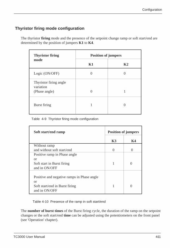
Configuration
TC3000 User Manual 4-11 TC3000 User Manual 4-11
Configuration
Thyristor firing Position of jumpersmode
K1 K2
Logic (ON/OFF) 0 0
Thyristor firing anglevariation(Phase angle) 0 1
Burst firing 1 0
Soft start/end ramp Position of jumpers
K3 K4Without rampand without soft start/end 0 0Positive ramp in Phase angleorSoft start in Burst firing 1 0and in ON/OFF
Positive and negative ramps in Phase angleorSoft start/end in Burst firing 1 0and in ON/OFF
Table 4-9 Thyristor firing mode configuration
Table 4-10 Presence of the ramp in soft start/end
Thyristor firing mode configuration
The thyristor firing mode and the presence of the setpoint change ramp or soft start/end aredetermined by the position of jumpers K1 to K4.
The number of burst times of the Burst firing cycle, the duration of the ramp on the setpointchanges or the soft start/end time can be adjusted using the potentiometers on the front panel(see 'Operation' chapter).
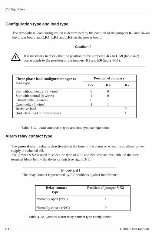
ConfigurationConfiguration
4-12 TC3000 User Manual 4-12 TC3000 User Manual
K5 K6 K7
!
Configuration type and load type
The three-phase load configuration is determined by the position of the jumpers K5 and K6 onthe driver board and LK7 , LK8 and LK9 on the power board.
Caution !
It is necessary to check that the position of the jumpers LK7 to LK9 (table 4-2)corresponds to the position of the jumpers K5 and K6 (table 4-11).
Table 4-11 Load connection type and load type configuration
Three-phase load configuration type orload type
Position of jumpers
K5 K6 K7
Star without neutral (3 wires) 0 0Star with neutral (4 wires) 1 0Closed delta (3 wires) 0 1Open delta (6 wires) 1 1Resistive load 0(Inductive load or transformer) 1
!
Alarm relay contact type
The general alarm relay is deactivated at the time of the alarm or when the auxiliary powersupply is switched off.The jumper VX2 is used to select the type of N/O and N/C contact available on the userterminal block below the thyristor unit (see figure 3-1).
Relay contact Position of jumper VX2 type
Normally open (N/O) 1
Normally closed (N/C) 0
Table 4-12 General alarm relay contact type configuration
Configuration type and load type
The three-phase load configuration is determined by the position of the jumpers K5 and K6 onthe driver board and LK7 , LK8 and LK9 on the power board.
Caution !
It is necessary to check that the position of the jumpers LK7 to LK9 (table 4-2)corresponds to the position of the jumpers K5 and K6 (table 4-11).
Table 4-11 Load connection type and load type configuration
Three-phase load configuration type orload type
Position of jumpers
Star without neutral (3 wires) 0 0Star with neutral (4 wires) 1 0Closed delta (3 wires) 0 1Open delta (6 wires) 1 1Resistive load 0(Inductive load or transformer) 1
Alarm relay contact type
The general alarm relay is deactivated at the time of the alarm or when the auxiliary powersupply is switched off.The jumper VX2 is used to select the type of N/O and N/C contact available on the userterminal block below the thyristor unit (see figure 3-1).
Relay contact Position of jumper VX2 type
Normally open (N/O) 1
Normally closed (N/C) 0
Table 4-12 General alarm relay contact type configuration
Important !The relay contact is protected by RC snubbers against interference.
Important !The relay contact is protected by RC snubbers against interference.
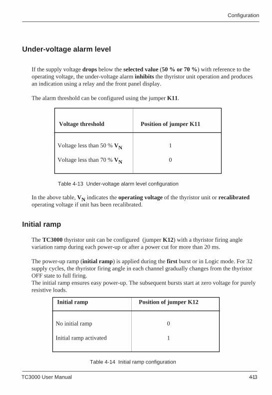
Configuration
TC3000 User Manual 4-13 TC3000 User Manual 4-13
Configuration
Under-voltage alarm level
If the supply voltage drops below the selected value (50 % or 70 %) with reference to theoperating voltage, the under-voltage alarm inhibits the thyristor unit operation and producesan indication using a relay and the front panel display.
The alarm threshold can be configured using the jumper K11.
Voltage threshold Position of jumper K11
Voltage less than 50 % VN 1
Voltage less than 70 % VN 0
Table 4-13 Under-voltage alarm level configuration
In the above table, VN indicates the operating voltage of the thyristor unit or recalibratedoperating voltage if unit has been recalibrated.
Initial ramp Position of jumper K12
No initial ramp 0
Initial ramp activated 1
Table 4-14 Initial ramp configuration
The TC3000 thyristor unit can be configured (jumper K12) with a thyristor firing anglevariation ramp during each power-up or after a power cut for more than 20 ms.
The power-up ramp (initial ramp ) is applied during the first burst or in Logic mode. For 32supply cycles, the thyristor firing angle in each channel gradually changes from the thyristorOFF state to full firing.The initial ramp ensures easy power-up. The subsequent bursts start at zero voltage for purelyresistive loads.
Initial ramp
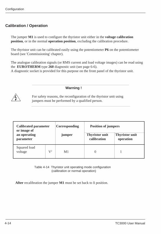
ConfigurationConfiguration
4-14 TC3000 User Manual 4-14 TC3000 User Manual
The jumper M1 is used to configure the thyristor unit either in the voltage calibrationposition, or in the normal operation position, excluding the calibration procedure.
The thyristor unit can be calibrated easily using the potentiometer P6 on the potentiometerboard (see 'Commissioning' chapter).
The analogue calibration signals (or RMS current and load voltage images) can be read usingthe EUROTHERM type 260 diagnostic unit (see page 6-6).A diagnostic socket is provided for this purpose on the front panel of the thyristor unit.
Calibrated parameter Corresponding Position of jumpersor image ofan operating jumper Thyristor unit Thyristor unitparameter calibration operation
Squared loadvoltage V2 M1 0 1
Calibration / Operation
Warning !
For safety reasons, the reconfiguration of the thyristor unit usingjumpers must be performed by a qualified person.
Table 4-14 Thyristor unit operating mode configuration (calibration or normal operation)
Calibration / Operation
Table 4-14 Thyristor unit operating mode configuration (calibration or normal operation)
Warning !
For safety reasons, the reconfiguration of the thyristor unit usingjumpers must be performed by a qualified person.
After recalibration the jumper M1 must be set back to 1 position. After recalibration the jumper M1 must be set back to 1 position.
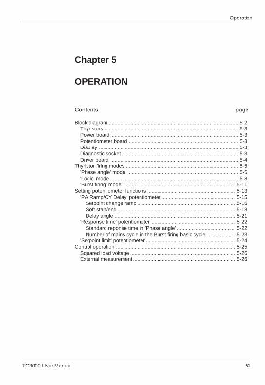
OperationOperation
TC3000 User Manual 5-1 TC3000 User Manual 5-1
Chapter 5
OPERATION
Contents page
Block diagram .......................................................................................... 5-2Thyristors ............................................................................................. 5-3Power board ......................................................................................... 5-3Potentiometer board ............................................................................ 5-3Display ................................................................................................. 5-3Diagnostic socket ................................................................................. 5-3Driver board ......................................................................................... 5-4
Thyristor firing modes .............................................................................. 5-5'Phase angle' mode ............................................................................. 5-5'Logic' mode ......................................................................................... 5-8'Burst firing' mode .............................................................................. 5-11
Setting potentiometer functions ............................................................. 5-13'PA Ramp/CY Delay' potentiometer ................................................... 5-15
Setpoint change ramp .................................................................... 5-16Soft start/end .................................................................................. 5-18Delay angle .................................................................................... 5-21
'Response time' potentiometer .......................................................... 5-22Standard reponse time in 'Phase angle' ........................................ 5-22Number of mains cycle in the Burst firing basic cycle .................... 5-23
'Setpoint limit' potentiometer .............................................................. 5-24Control operation ................................................................................... 5-25
Squared load voltage ......................................................................... 5-26External measurement ....................................................................... 5-26
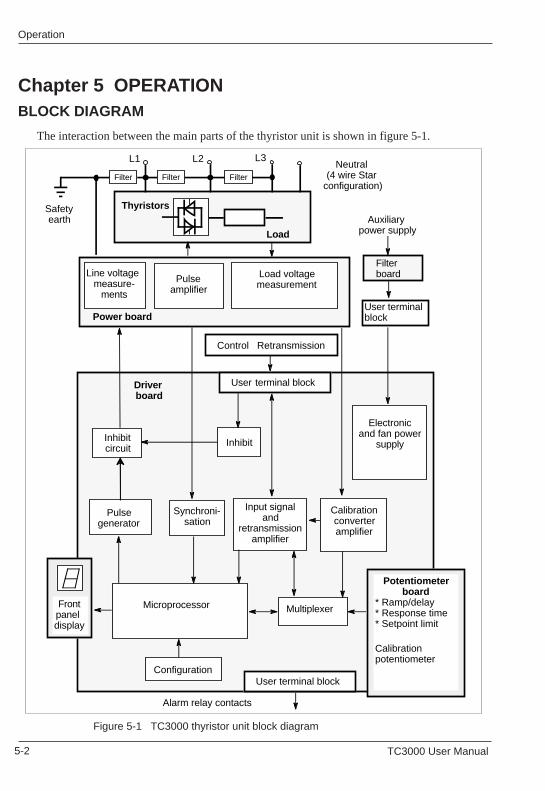
5-2 TC3000 User Manual 5-2 TC3000 User Manual
OperationOperation
Figure 5-1 TC3000 thyristor unit block diagram
Chapter 5 OPERATIONBLOCK DIAGRAM
The interaction between the main parts of the thyristor unit is shown in figure 5-1.
Pulse amplifier
Line voltage measure-
ments
Load voltagemeasurement
Thyristors
Pulse generator
Synchroni-sation
Calibration converteramplifier
Microprocessor Multiplexer
Potentiometer board* Ramp/delay* Response time* Setpoint limit
Calibrationpotentiometer
Frontpanel display
Electronicand fan power
supply
L3
Load
L2L1
Driver board
Input signal and
retransmission amplifier
User terminal block
Control Retransmission
Configuration
Power board
Neutral (4 wire Star
configuration)
InhibitInhibitcircuit
Safety earth
Filter Filter Filter
Auxiliary power supply
User terminal block
Filter board
User terminal block
Alarm relay contacts
OperationOperation
TC3000 User Manual 5-3 TC3000 User Manual 5-3
The 3 pairs of thyristors modulate the power supply voltage which is applied to the three-phase load.
The thyristor firing pulses, generated by the driver board, are amplified and transmitted to thethyristors via pulse transformers which provide isolation.
A voltage transformer is used to measure the load voltage.
Three voltage transformers are used for synchronisation on the power supply voltage.
Three operation potentiometers located on the potentiometer board (which is mountedperpendicular to the driver board) can be accessed on the front panel. They are used to adjust themain thyristor unit operating parameters without having to open the front door.One calibration potentiometer can be accessed when the front door is open.
The functions of the operation potentiometers are indicated on the front panel of the thyristorunit and are explained in the relevant paragraph (page 5-13).
If the thyristor unit is replaced, the potentiometer board can be transferred to the new thyristorunit and thus retain all the settings specific to the application concerned.
The 7 segment display is used for steady and flashing messages indicating the current operatingmode of the thyristor unit, the alarm state and the error or failure type.
The values from the control and the operation of the thyristor unit are available on the diagnosticsocket located on the front panel. It is used to measure the voltages of 20 points on the electroniccircuit with a EUROTHERM type 260 diagnostic unit.
Thyristors
Warning !Thyristors up to 250 A nominal current are mounted in a module isolated from theheatsink. The 300 A to 500 A unit heatsinks are not isolated from the thyristors.
Power board
Display
Potentiometer board
Diagnostic socket
5-4 TC3000 User Manual 5-4 TC3000 User Manual
OperationOperation
The analogue control signals and parameter retransmission are applied to the driver board userterminal blocks.
The pulse generator emits the firing pulses for the thyristor gates at the request ofthe microprocessor.
An inhibit line stops the oscillations if the thyristor unit is disabled (by disconnecting the'Enable' input from the '+10V' terminal on the user terminal block or via the external input).
The synchronisation circuit supplies the microprocessor with three signals corresponding tothe sign of the line voltages measured and a signal corresponding to the zero voltage crossing.
A squaring circuit supplies one signal corresponding to the square of the measurement loadvoltage: V2.
The multiplexer selects the signal applied to the analogue/digital converter inside themicroprocessor from the measurements, front panel potentiometer voltages and the controlsignals, according to the program procedure.
The driver board microprocessor controls the entire operation of the thyristor unit and themessage display.
The amplification of the input signals converts the low level signals and amplifiesthe retransmission.
A relay is used for the external detection of the active alarm state.
A diagnostic socket located on the front panel of the thyristor unit is used, with theEUROTHERM type 260 diagnostic unit, to control or measure the main thyristor unitoperating parameters.
The watchdog monitors the correct functioning of the software; in the event of a fault, it sendsa 'Reset' signal to the microprocessor.
Driver board
Important !
Each external link, each control or retransmission signal and the auxiliarypower supply are protected against interference by an internal filter.
!Important !
Each external link, each control or retransmission signal and the auxiliarypower supply are protected against interference by an internal filter.
!
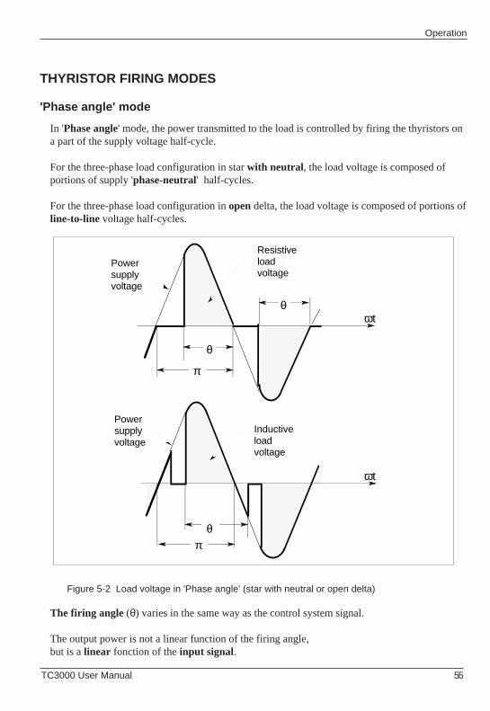
OperationOperation
TC3000 User Manual 5-5 TC3000 User Manual 5-5
THYRISTOR FIRING MODES
'Phase angle' mode
Figure 5-2 Load voltage in 'Phase angle' (star with neutral or open delta)
THYRISTOR FIRING MODES
'Phase angle' mode
In 'Phase angle' mode, the power transmitted to the load is controlled by firing the thyristors ona part of the supply voltage half-cycle.
For the three-phase load configuration in star with neutral , the load voltage is composed ofportions of supply 'phase-neutral' half-cycles.
For the three-phase load configuration in open delta, the load voltage is composed of portions ofline-to-line voltage half-cycles.
Figure 5-2 Load voltage in 'Phase angle' (star with neutral or open delta)
θ
π
θωt
Powersupplyvoltage
Resistiveloadvoltage
θπ
ωt
Powersupplyvoltage
Inductiveloadvoltage
θ
π
θωt
Powersupplyvoltage
Resistiveloadvoltage
θπ
ωt
Powersupplyvoltage
Inductiveloadvoltage
The firing angle (θ) varies in the same way as the control system signal.
The output power is not a linear function of the firing angle,but is a linear fonction of the input signal.
In 'Phase angle' mode, the power transmitted to the load is controlled by firing the thyristors ona part of the supply voltage half-cycle.
For the three-phase load configuration in star with neutral , the load voltage is composed ofportions of supply 'phase-neutral' half-cycles.
For the three-phase load configuration in open delta, the load voltage is composed of portions ofline-to-line voltage half-cycles.
The firing angle (θ) varies in the same way as the control system signal.
The output power is not a linear function of the firing angle,but is a linear fonction of the input signal.
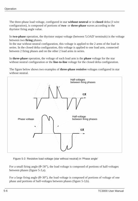
5-6 TC3000 User Manual 5-6 TC3000 User Manual
OperationOperation
The three-phase load voltage, configured in star without neutral or in closed delta (3 wireconfiguration), is composed of portions of two- or three-phase waves according to thethyristor firing angle value.
In two-phase operation, the thyristor output voltage (between 'LOAD' terminals) is the voltagebetween two firing phases.In the star without neutral configuration, this voltage is applied to the 2 arms of the load inseries. In the closed delta configuration, this voltage is applied to one load arm, connectedbetween 2 firing phases and on the other 2 load arms in series.
In three-phase operation, the voltage of each load arm is the phase voltage for the starwithout neutral configuration or the line-to-line voltage for the closed delta configuration.
The figure below shows two examples of three-phase resistive voltages configured in starwithout neutral.
Figure 5-3 Resistive load voltage (star without neutral) in 'Phase angle'
For a small firing angle (θ<30°), the load voltage is composed of portions of half-voltagesbetween phases (figure 5-3,a).
For a large firing angle (θ>30°), the load voltage is composed of portions of voltage of onephase and portions of half-voltages between phases (figure 5-3,b).
ωt
Half-voltagesbetween firing phases
ωt
Half-voltagebetween firing phasesPhase voltage
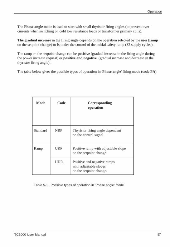
OperationOperation
TC3000 User Manual 5-7 TC3000 User Manual 5-7
The Phase angle mode is used to start with small thyristor firing angles (to prevent over-currents when switching on cold low resistance loads or transformer primary coils).
The gradual increase in the firing angle depends on the operation selected by the user (rampon the setpoint change) or is under the control of the initial safety ramp (32 supply cycles).
The ramp on the setpoint change can be positive (gradual increase in the firing angle duringthe power increase request) or positive and negative (gradual increase and decrease in thethyristor firing angle).
The table below gives the possible types of operation in 'Phase angle' firing mode (code PA).
Mode Code Corresponding operation
Thyristor firing angle dependenton the control signal
Positive ramp with adjustable slopeon the setpoint change.
Positive and negative rampswith adjustable slopeson the setpoint change.
NRP
URP
UDR
Standard
Ramp
Table 5-1 Possible types of operation in 'Phase angle' mode
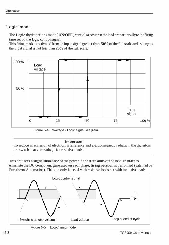
5-8 TC3000 User Manual 5-8 TC3000 User Manual
OperationOperation
'Logic' mode
Figure 5-4 'Voltage - Logic signal' diagram
The 'Logic' thyristor firing mode ('ON/OFF') controls a power in the load proportionally to the firingtime set by the logic control signal.This firing mode is activated from an input signal greater than 50% of the full scale and as long asthe input signal is not less than 25% of the full scale.
0 25 50 100 %
100 %
50 %
75
Input signal
Load voltage
'Logic' mode
Figure 5-5 'Logic' firing mode
Figure 5-4 'Voltage - Logic signal' diagram
The 'Logic' thyristor firing mode ('ON/OFF') controls a power in the load proportionally to the firingtime set by the logic control signal.This firing mode is activated from an input signal greater than 50% of the full scale and as long asthe input signal is not less than 25% of the full scale.
0 25 50 100 %
100 %
50 %
75
Input signal
Load voltage
Switching at zero voltage
t
Stop at end of cycle
Logic control signal
Load voltage
Important !To reduce an emission of electrical interference and electromagnetic radiation, the thyristorsare switched at zero voltage for resistive loads.
This produces a slight unbalance of the power in the three arms of the load. In order toeliminate the DC component generated on each phase, firing rotation is performed (patented byEurotherm Automation). This can only be used with resistive loads not with inductive loads.
Figure 5-5 'Logic' firing mode
Switching at zero voltage
t
Stop at end of cycle
Logic control signal
Load voltage
Important !To reduce an emission of electrical interference and electromagnetic radiation, the thyristorsare switched at zero voltage for resistive loads.
This produces a slight unbalance of the power in the three arms of the load. In order toeliminate the DC component generated on each phase, firing rotation is performed (patented byEurotherm Automation). This can only be used with resistive loads not with inductive loads.
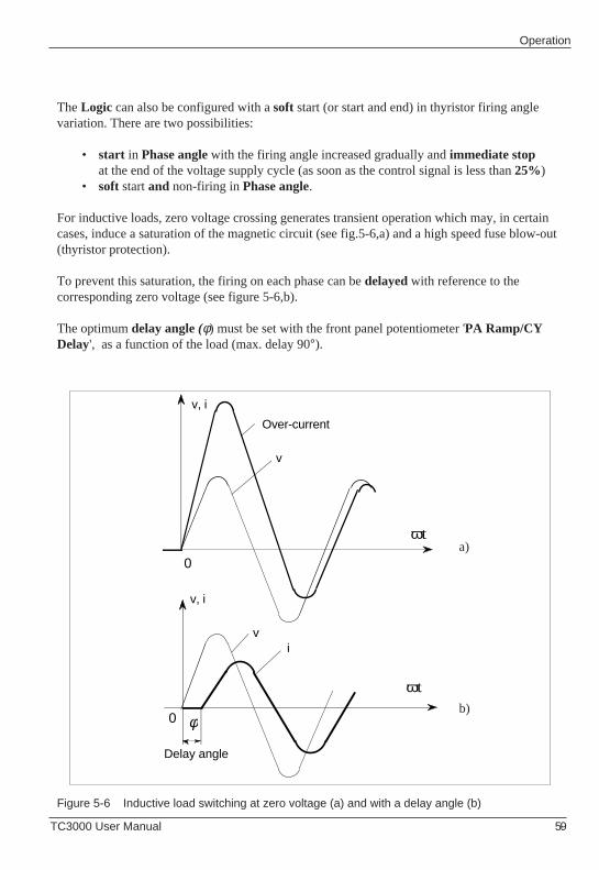
OperationOperation
TC3000 User Manual 5-9 TC3000 User Manual 5-9
a)
b)
The Logic can also be configured with a soft start (or start and end) in thyristor firing anglevariation. There are two possibilities:
• start in Phase angle with the firing angle increased gradually and immediate stopat the end of the voltage supply cycle (as soon as the control signal is less than 25%)
• soft start and non-firing in Phase angle.
For inductive loads, zero voltage crossing generates transient operation which may, in certaincases, induce a saturation of the magnetic circuit (see fig.5-6,a) and a high speed fuse blow-out(thyristor protection).
To prevent this saturation, the firing on each phase can be delayed with reference to thecorresponding zero voltage (see figure 5-6,b).
The optimum delay angle (φ) must be set with the front panel potentiometer 'PA Ramp/CYDelay', as a function of the load (max. delay 90°).
Figure 5-6 Inductive load switching at zero voltage (a) and with a delay angle (b)
a)
b)
Over-current
0
v, i
ωt
φ0
ωt
Delay angle
v
v, i
v i
The Logic can also be configured with a soft start (or start and end) in thyristor firing anglevariation. There are two possibilities:
• start in Phase angle with the firing angle increased gradually and immediate stopat the end of the voltage supply cycle (as soon as the control signal is less than 25%)
• soft start and non-firing in Phase angle.
For inductive loads, zero voltage crossing generates transient operation which may, in certaincases, induce a saturation of the magnetic circuit (see fig.5-6,a) and a high speed fuse blow-out(thyristor protection).
To prevent this saturation, the firing on each phase can be delayed with reference to thecorresponding zero voltage (see figure 5-6,b).
The optimum delay angle (φ) must be set with the front panel potentiometer 'PA Ramp/CYDelay', as a function of the load (max. delay 90°).
Figure 5-6 Inductive load switching at zero voltage (a) and with a delay angle (b)
Over-current
0
v, i
ωt
φ0
ωt
Delay angle
v
v, i
v i
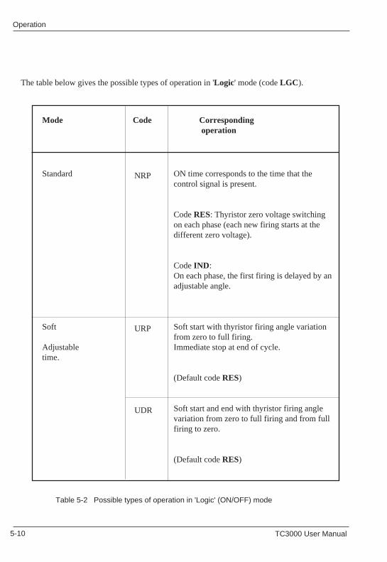
5-10 TC3000 User Manual 5-10 TC3000 User Manual
OperationOperation
NRP
URP
UDR
The table below gives the possible types of operation in 'Logic' mode (code LGC ).
ON time corresponds to the time that thecontrol signal is present.
Code RES: Thyristor zero voltage switchingon each phase (each new firing starts at thedifferent zero voltage).
Code IND :On each phase, the first firing is delayed by anadjustable angle.
Soft start with thyristor firing angle variationfrom zero to full firing.Immediate stop at end of cycle.
(Default code RES)
Soft start and end with thyristor firing anglevariation from zero to full firing and from fullfiring to zero.
(Default code RES)
NRP
URP
UDR
Mode Code Corresponding operation
Table 5-2 Possible types of operation in 'Logic' (ON/OFF) mode
Standard
Soft
Adjustabletime.
The table below gives the possible types of operation in 'Logic' mode (code LGC ).
ON time corresponds to the time that thecontrol signal is present.
Code RES: Thyristor zero voltage switchingon each phase (each new firing starts at thedifferent zero voltage).
Code IND:On each phase, the first firing is delayed by anadjustable angle.
Soft start with thyristor firing angle variationfrom zero to full firing.Immediate stop at end of cycle.
(Default code RES)
Soft start and end with thyristor firing anglevariation from zero to full firing and from fullfiring to zero.
(Default code RES)
Mode Code Corresponding operation
Table 5-2 Possible types of operation in 'Logic' (ON/OFF) mode
Standard
Soft
Adjustabletime.
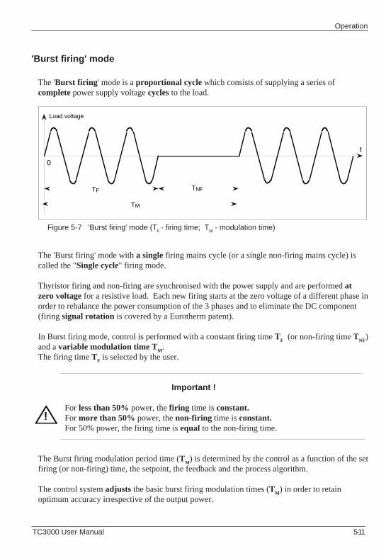
OperationOperation
TC3000 User Manual 5-11 TC3000 User Manual 5-11
!
'Burst firing' mode
The 'Burst firing ' mode is a proportional cycle which consists of supplying a series ofcomplete power supply voltage cycles to the load.
The 'Burst firing' mode with a single firing mains cycle (or a single non-firing mains cycle) iscalled the "Single cycle" firing mode.
Thyristor firing and non-firing are synchronised with the power supply and are performed atzero voltage for a resistive load. Each new firing starts at the zero voltage of a different phase inorder to rebalance the power consumption of the 3 phases and to eliminate the DC component(firing signal rotation is covered by a Eurotherm patent).
In Burst firing mode, control is performed with a constant firing time TF (or non-firing time T
NF)
and a variable modulation time TM.
The firing time TF is selected by the user.
Important !
For less than 50% power, the firing time is constant.For more than 50% power, the non-firing time is constant.For 50% power, the firing time is equal to the non-firing time.
The Burst firing modulation period time (TM) is determined by the control as a function of the set
firing (or non-firing) time, the setpoint, the feedback and the process algorithm.
The control system adjusts the basic burst firing modulation times (TM) in order to retain
optimum accuracy irrespective of the output power.
Figure 5-7 'Burst firing' mode (TF - firing time; TM - modulation time)
!
'Burst firing' mode
The 'Burst firing ' mode is a proportional cycle which consists of supplying a series ofcomplete power supply voltage cycles to the load.
The 'Burst firing' mode with a single firing mains cycle (or a single non-firing mains cycle) iscalled the "Single cycle" firing mode.
Thyristor firing and non-firing are synchronised with the power supply and are performed atzero voltage for a resistive load. Each new firing starts at the zero voltage of a different phase inorder to rebalance the power consumption of the 3 phases and to eliminate the DC component(firing signal rotation is covered by a Eurotherm patent).
In Burst firing mode, control is performed with a constant firing time TF (or non-firing time T
NF)
and a variable modulation time TM.
The firing time TF is selected by the user.
Important !
For less than 50% power, the firing time is constant.For more than 50% power, the non-firing time is constant.For 50% power, the firing time is equal to the non-firing time.
The Burst firing modulation period time (TM) is determined by the control as a function of the set
firing (or non-firing) time, the setpoint, the feedback and the process algorithm.
The control system adjusts the basic burst firing modulation times (TM) in order to retain
optimum accuracy irrespective of the output power.
Figure 5-7 'Burst firing' mode (TF - firing time; T
M - modulation time)
t
Load voltage
0
TM
TNFTF
t
Load voltage
0
TM
TNFTF
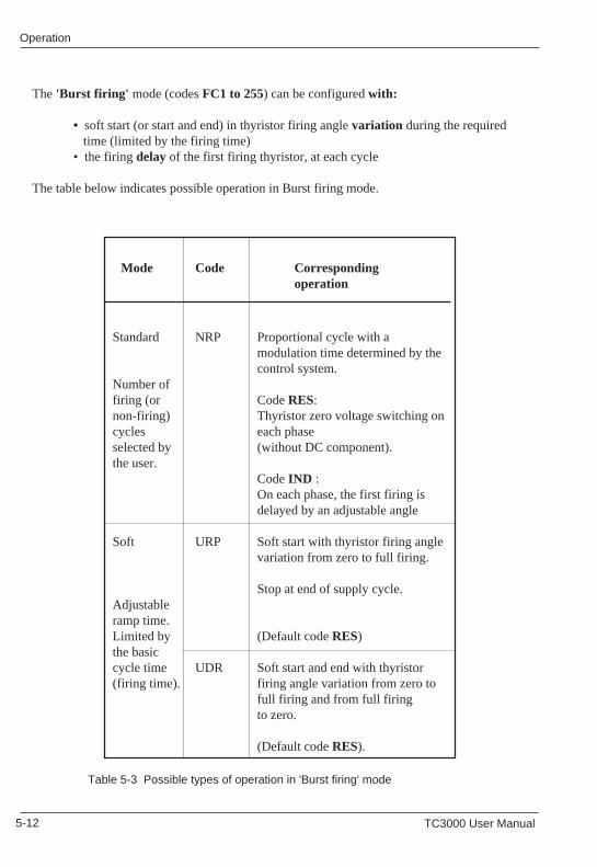
5-12 TC3000 User Manual 5-12 TC3000 User Manual
OperationOperation
Mode Code Correspondingoperation
NRP
URP
UDR
The 'Burst firing' mode (codes FC1 to 255) can be configured with:
• soft start (or start and end) in thyristor firing angle variation during the required time (limited by the firing time)• the firing delay of the first firing thyristor, at each cycle
The table below indicates possible operation in Burst firing mode.
NRP
URP
UDR
Proportional cycle with amodulation time determined by thecontrol system.
Code RES:Thyristor zero voltage switching oneach phase(without DC component).
Code IND :On each phase, the first firing isdelayed by an adjustable angle
Soft start with thyristor firing anglevariation from zero to full firing.
Stop at end of supply cycle.
(Default code RES)
Soft start and end with thyristorfiring angle variation from zero tofull firing and from full firingto zero.
(Default code RES).
Standard
Number offiring (ornon-firing)cyclesselected bythe user.
Soft
Adjustableramp time.Limited bythe basiccycle time(firing time).
Table 5-3 Possible types of operation in 'Burst firing' mode
Mode Code Correspondingoperation
The 'Burst firing' mode (codes FC1 to 255) can be configured with:
• soft start (or start and end) in thyristor firing angle variation during the required time (limited by the firing time)• the firing delay of the first firing thyristor, at each cycle
The table below indicates possible operation in Burst firing mode.
Proportional cycle with amodulation time determined by thecontrol system.
Code RES:Thyristor zero voltage switching oneach phase(without DC component).
Code IND :On each phase, the first firing isdelayed by an adjustable angle
Soft start with thyristor firing anglevariation from zero to full firing.
Stop at end of supply cycle.
(Default code RES)
Soft start and end with thyristorfiring angle variation from zero tofull firing and from full firingto zero.
(Default code RES).
Standard
Number offiring (ornon-firing)cyclesselected bythe user.
Soft
Adjustableramp time.Limited bythe basiccycle time(firing time).
Table 5-3 Possible types of operation in 'Burst firing' mode
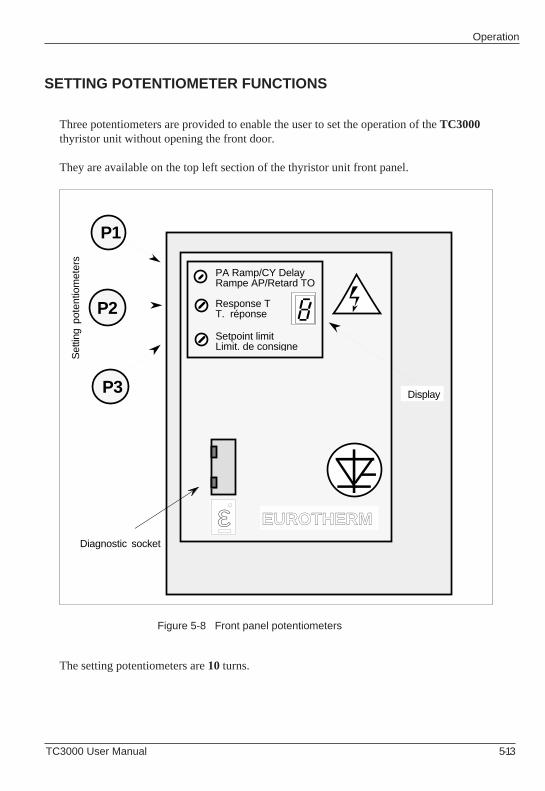
OperationOperation
TC3000 User Manual 5-13 TC3000 User Manual 5-13
SETTING POTENTIOMETER FUNCTIONS
Three potentiometers are provided to enable the user to set the operation of the TC3000thyristor unit without opening the front door.
They are available on the top left section of the thyristor unit front panel.
The setting potentiometers are 10 turns.
SETTING POTENTIOMETER FUNCTIONS
Three potentiometers are provided to enable the user to set the operation of the TC3000thyristor unit without opening the front door.
They are available on the top left section of the thyristor unit front panel.
The setting potentiometers are 10 turns.
Figure 5-8 Front panel potentiometers Figure 5-8 Front panel potentiometers
PA Ramp/CY DelayRampe AP/Retard TO
Response TT. réponse
Setpoint limitLimit. de consigne
Set
ting
pot
entio
met
ers
Diagnostic socket
Display
EUROTHERMε
P1
P3
P2
PA Ramp/CY DelayRampe AP/Retard TO
Response TT. réponse
Setpoint limitLimit. de consigne
Set
ting
pot
entio
met
ers
Diagnostic socket
Display
EUROTHERMε
P1
P3
P2
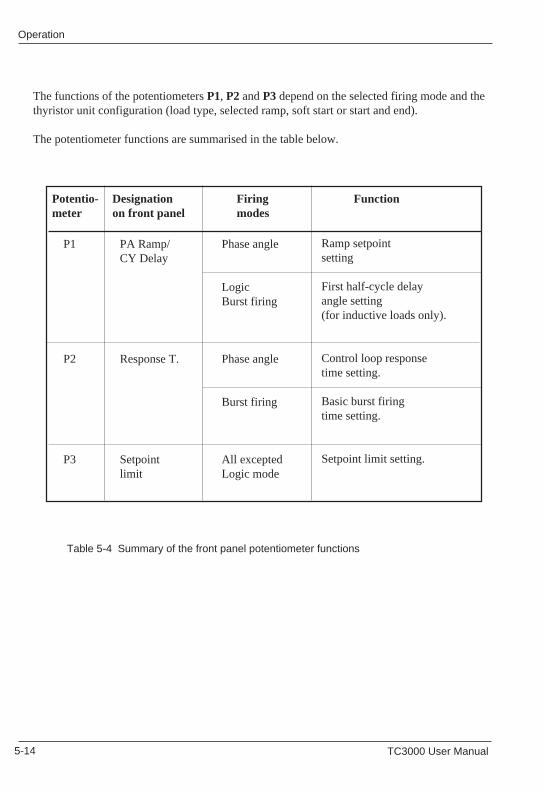
5-14 TC3000 User Manual 5-14 TC3000 User Manual
OperationOperation
P1
P2
P3
P1
P2
P3
Phase angle
LogicBurst firing
Phase angle
Burst firing
All exceptedLogic mode
PA Ramp/CY Delay
Response T.
Setpointlimit
Potentio- Designation Firing Functionmeter on front panel modes
Ramp setpointsetting
First half-cycle delayangle setting(for inductive loads only).
Control loop responsetime setting.
Basic burst firingtime setting.
Setpoint limit setting.
Table 5-4 Summary of the front panel potentiometer functions
The functions of the potentiometers P1, P2 and P3 depend on the selected firing mode and thethyristor unit configuration (load type, selected ramp, soft start or start and end).
The potentiometer functions are summarised in the table below.
Phase angle
LogicBurst firing
Phase angle
Burst firing
All exceptedLogic mode
PA Ramp/CY Delay
Response T.
Setpointlimit
Potentio- Designation Firing Functionmeter on front panel modes
Ramp setpointsetting
First half-cycle delayangle setting(for inductive loads only).
Control loop responsetime setting.
Basic burst firingtime setting.
Setpoint limit setting.
Table 5-4 Summary of the front panel potentiometer functions
The functions of the potentiometers P1, P2 and P3 depend on the selected firing mode and thethyristor unit configuration (load type, selected ramp, soft start or start and end).
The potentiometer functions are summarised in the table below.

OperationOperation
TC3000 User Manual 5-15 TC3000 User Manual 5-15
Conditions and positions of jumpers Functions of potentiometer P1Firing 'PA Ramp / CY Delay'mode Operation
Phase No ramp K3 = 0 No actionangle Positive ramp K3 = 1 Ramp duration settingK1 = 0 K4 = 0 (number of supply cycles)K2 = 1 for setpoint changes.
The ramp is enabled for powerincrease requests
Positive and K3 = 1 Ramp duration settingnegative ramp K4 = 1 (number of supply cycles) for
both power increase anddecrease requests
Logic Resistive load. K7 = 0 No actionK1 = 0 No soft start K3 = 0K2 = 0 K4 = 0
Inductive load. K7 = 1 Setting of firstBurst No soft start K3 = 0 alternation firing delayfiring from 0° to 90°K1 = 1 All loads K3 = 1 Start duration settingK2 = 0 Soft start K4 = 0 (number of supply cycles) in
thyristor firing angle variation.Immediate stop after first 0 crossing.
All loads K3 = 1 Setting of both start andSoft start and end K4 = 1 end duration in thyristor firing
angle variation
Table 5-5 Functions of the potentiometer P1 for the various firing modes
Note: For the Burst firing and Phase angle burst modes, the soft operation timeis limited by the basic cycle.
'PA Ramp / CY Delay' potentiometer
The potentiometer P1 labelled 'PA Ramp / CY Delay' on the front panel is used to setthe following:
• the ramp on the setpoint changes (Phase angle firing mode);• the soft start/end (Burst firing and Logic firing modes);• the delay angle (Burst firing and Logic firing modes).
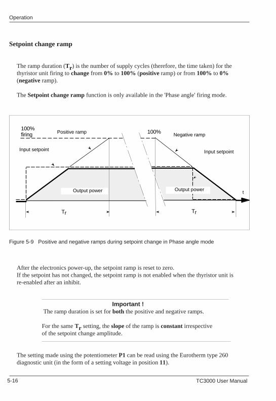
5-16 TC3000 User Manual 5-16 TC3000 User Manual
OperationOperation
The ramp duration (Tr ) is the number of supply cycles (therefore, the time taken) for thethyristor unit firing to change from 0% to 100% (positive ramp) or from 100% to 0%(negative ramp).
The Setpoint change ramp function is only available in the 'Phase angle' firing mode.
Figure 5-9 Positive and negative ramps during setpoint change in Phase angle mode
Setpoint change ramp
After the electronics power-up, the setpoint ramp is reset to zero.If the setpoint has not changed, the setpoint ramp is not enabled when the thyristor unit isre-enabled after an inhibit.
Important ! The ramp duration is set for both the positive and negative ramps.
For the same Tr setting, the slope of the ramp is constant irrespective of the setpoint change amplitude.
The setting made using the potentiometer P1 can be read using the Eurotherm type 260diagnostic unit (in the form of a setting voltage in position 11).
100%firing
Input setpoint
Output power
Tr
Positive ramp 100%
Input setpoint
Output power t
Tr
Negative ramp
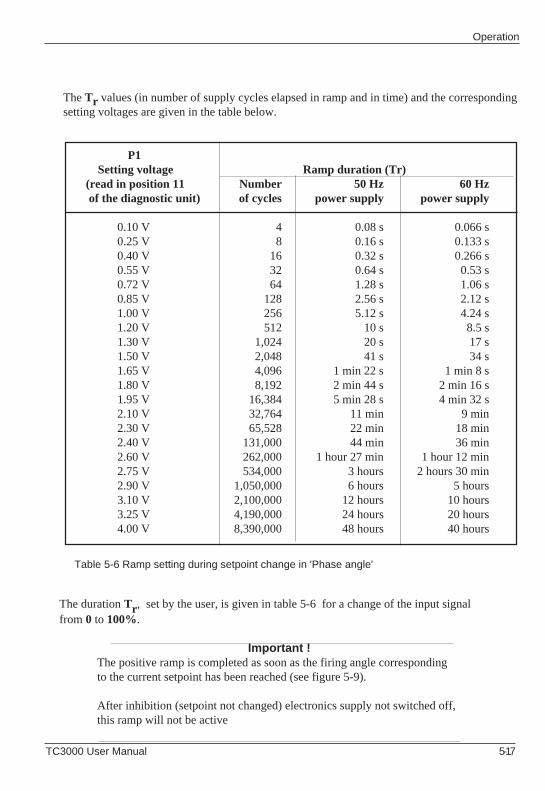
OperationOperation
TC3000 User Manual 5-17 TC3000 User Manual 5-17
The Tr values (in number of supply cycles elapsed in ramp and in time) and the correspondingsetting voltages are given in the table below.
Table 5-6 Ramp setting during setpoint change in 'Phase angle'
P1 Setting voltage Ramp duration (Tr)(read in position 11 Number 50 Hz 60 Hz of the diagnostic unit) of cycles power supply power supply
0.10 V 4 0.08 s 0.066 s0.25 V 8 0.16 s 0.133 s0.40 V 16 0.32 s 0.266 s0.55 V 32 0.64 s 0.53 s0.72 V 64 1.28 s 1.06 s0.85 V 128 2.56 s 2.12 s1.00 V 256 5.12 s 4.24 s1.20 V 512 10 s 8.5 s1.30 V 1,024 20 s 17 s1.50 V 2,048 41 s 34 s1.65 V 4,096 1 min 22 s 1 min 8 s1.80 V 8,192 2 min 44 s 2 min 16 s1.95 V 16,384 5 min 28 s 4 min 32 s2.10 V 32,764 11 min 9 min2.30 V 65,528 22 min 18 min2.40 V 131,000 44 min 36 min2.60 V 262,000 1 hour 27 min 1 hour 12 min2.75 V 534,000 3 hours 2 hours 30 min2.90 V 1,050,000 6 hours 5 hours3.10 V 2,100,000 12 hours 10 hours3.25 V 4,190,000 24 hours 20 hours4.00 V 8,390,000 48 hours 40 hours
The duration Tr , set by the user, is given in table 5-6 for a change of the input signalfrom 0 to 100%.
Important !The positive ramp is completed as soon as the firing angle correspondingto the current setpoint has been reached (see figure 5-9).
After inhibition (setpoint not changed) electronics supply not switched off,this ramp will not be active
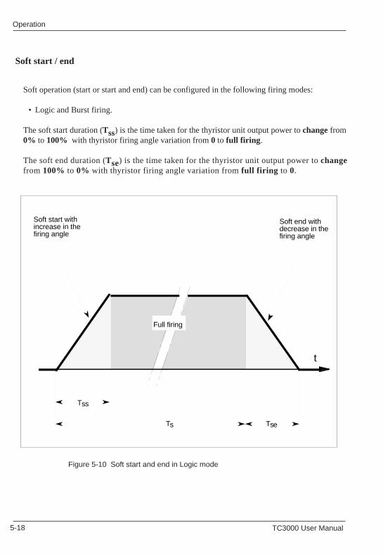
5-18 TC3000 User Manual 5-18 TC3000 User Manual
OperationOperation
Soft operation (start or start and end) can be configured in the following firing modes:
• Logic and Burst firing.
The soft start duration (Tss) is the time taken for the thyristor unit output power to change from0% to 100% with thyristor firing angle variation from 0 to full firing .
The soft end duration (Tse) is the time taken for the thyristor unit output power to changefrom 100% to 0% with thyristor firing angle variation from full firing to 0.
Soft start / end
Figure 5-10 Soft start and end in Logic mode Figure 5-10 Soft start and end in Logic mode
Soft start withincrease in thefiring angle
Soft end withdecrease in thefiring angle
Tss
Tse
Full firing
t
Ts
Soft start withincrease in thefiring angle
Soft end withdecrease in thefiring angle
Tss
Tse
Full firing
t
Ts
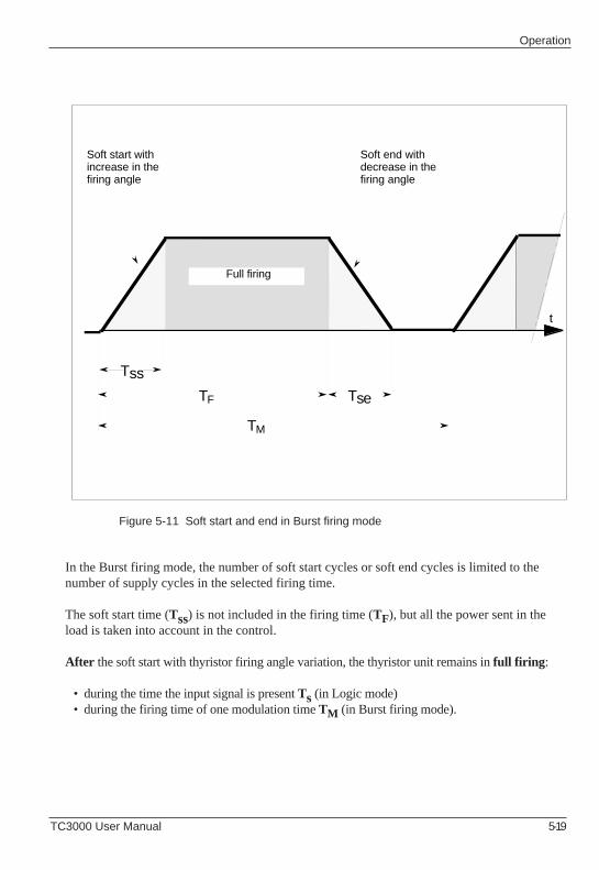
OperationOperation
TC3000 User Manual 5-19 TC3000 User Manual 5-19
Figure 5-11 Soft start and end in Burst firing mode
In the Burst firing mode, the number of soft start cycles or soft end cycles is limited to thenumber of supply cycles in the selected firing time.
The soft start time (Tss) is not included in the firing time (TF), but all the power sent in theload is taken into account in the control.
After the soft start with thyristor firing angle variation, the thyristor unit remains in full firing :
• during the time the input signal is present Ts (in Logic mode)• during the firing time of one modulation time TM (in Burst firing mode).
Full firing
Tss
Soft start withincrease in thefiring angle
Tse
Soft end withdecrease in thefiring angle
TF
TM
t
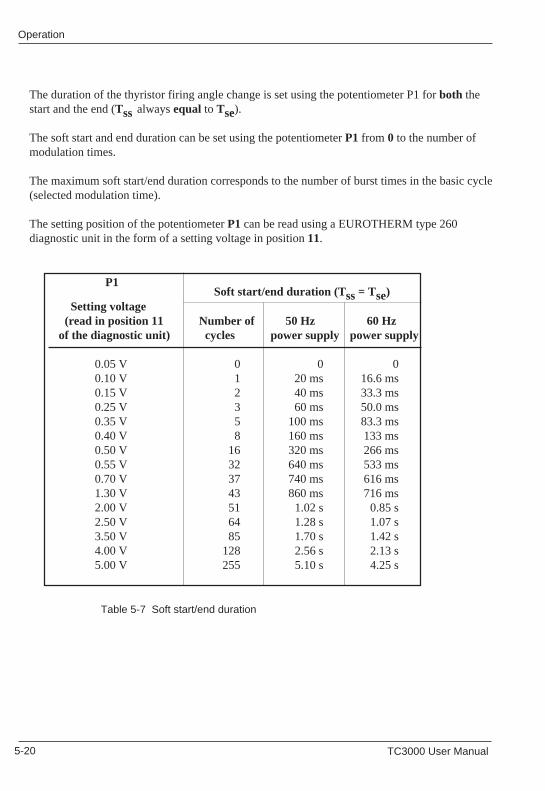
5-20 TC3000 User Manual 5-20 TC3000 User Manual
OperationOperation
P1 Soft start/end duration (Tss = Tse)
Setting voltage (read in position 11 Number of 50 Hz 60 Hz of the diagnostic unit) cycles power supply power supply
0.05 V 0 0 00.10 V 1 20 ms 16.6 ms0.15 V 2 40 ms 33.3 ms0.25 V 3 60 ms 50.0 ms0.35 V 5 100 ms 83.3 ms0.40 V 8 160 ms 133 ms0.50 V 16 320 ms 266 ms0.55 V 32 640 ms 533 ms0.70 V 37 740 ms 616 ms1.30 V 43 860 ms 716 ms2.00 V 51 1.02 s 0.85 s2.50 V 64 1.28 s 1.07 s3.50 V 85 1.70 s 1.42 s4.00 V 128 2.56 s 2.13 s5.00 V 255 5.10 s 4.25 s
P1
Table 5-7 Soft start/end duration
The duration of the thyristor firing angle change is set using the potentiometer P1 for both thestart and the end (Tss
always equal to Tse).
The soft start and end duration can be set using the potentiometer P1 from 0 to the number ofmodulation times.
The maximum soft start/end duration corresponds to the number of burst times in the basic cycle(selected modulation time).
The setting position of the potentiometer P1 can be read using a EUROTHERM type 260diagnostic unit in the form of a setting voltage in position 11.
Soft start/end duration (Tss = Tse) Setting voltage (read in position 11 Number of 50 Hz 60 Hz of the diagnostic unit) cycles power supply power supply
0.05 V 0 0 00.10 V 1 20 ms 16.6 ms0.15 V 2 40 ms 33.3 ms0.25 V 3 60 ms 50.0 ms0.35 V 5 100 ms 83.3 ms0.40 V 8 160 ms 133 ms0.50 V 16 320 ms 266 ms0.55 V 32 640 ms 533 ms0.70 V 37 740 ms 616 ms1.30 V 43 860 ms 716 ms2.00 V 51 1.02 s 0.85 s2.50 V 64 1.28 s 1.07 s3.50 V 85 1.70 s 1.42 s4.00 V 128 2.56 s 2.13 s5.00 V 255 5.10 s 4.25 s
Table 5-7 Soft start/end duration
The duration of the thyristor firing angle change is set using the potentiometer P1 for both thestart and the end (Tss
always equal to Tse).
The soft start and end duration can be set using the potentiometer P1 from 0 to the number ofmodulation times.
The maximum soft start/end duration corresponds to the number of burst times in the basic cycle(selected modulation time).
The setting position of the potentiometer P1 can be read using a EUROTHERM type 260diagnostic unit in the form of a setting voltage in position 11.
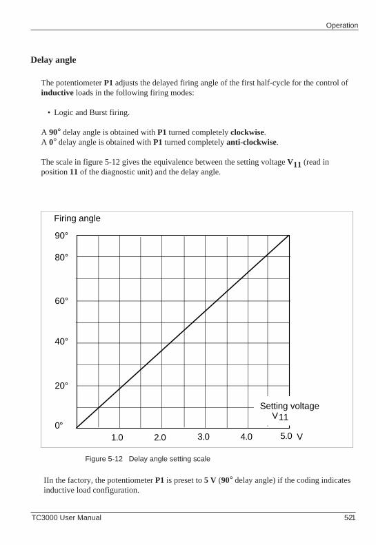
OperationOperation
TC3000 User Manual 5-21 TC3000 User Manual 5-21
The potentiometer P1 adjusts the delayed firing angle of the first half-cycle for the control ofinductive loads in the following firing modes:
• Logic and Burst firing.
A 90° delay angle is obtained with P1 turned completely clockwise.A 0° delay angle is obtained with P1 turned completely anti-clockwise.
The scale in figure 5-12 gives the equivalence between the setting voltage V11 (read inposition 11 of the diagnostic unit) and the delay angle.
Delay angle
Figure 5-12 Delay angle setting scale
IIn the factory, the potentiometer P1 is preset to 5 V (90° delay angle) if the coding indicatesinductive load configuration.
90°
80°
60°
40°
20°
0°1.0 2.0 3.0 4.0 5.0 V
Setting voltage V11
Firing angle
The potentiometer P1 adjusts the delayed firing angle of the first half-cycle for the control ofinductive loads in the following firing modes:
• Logic and Burst firing.
A 90° delay angle is obtained with P1 turned completely clockwise.A 0° delay angle is obtained with P1 turned completely anti-clockwise.
The scale in figure 5-12 gives the equivalence between the setting voltage V11 (read inposition 11 of the diagnostic unit) and the delay angle.
Delay angle
Figure 5-12 Delay angle setting scale
In the factory, the potentiometer P1 is preset to 5 V (90° delay angle) if the coding indicatesinductive load configuration.
90°
80°
60°
40°
20°
0°1.0 2.0 3.0 4.0 5.0 V
Setting voltage V11
Firing angle
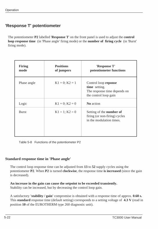
5-22 TC3000 User Manual 5-22 TC3000 User Manual
OperationOperation
Standard response time in 'Phase angle'
The control loop response time can be adjusted from 13 to 52 supply cycles using thepotentiometer P2. When P2 is turned clockwise, the response time is increased (since the gainis decreased).
An increase in the gain can cause the setpoint to be exceeded transiently.Stability can be increased, but by decreasing the control loop gain.
A satisfactory 'stability / gain' compromise is obtained with a response time of approx. 0.68 s.This standard response time (default setting) corresponds to a setting voltage of 4.3 V (read inposition 10 of the EUROTHERM type 260 diagnostic unit).
'Response T' potentiometer
Standard response time in 'Phase angle'
The control loop response time can be adjusted from 13 to 52 supply cycles using thepotentiometer P2. When P2 is turned clockwise, the response time is increased (since the gainis decreased).
An increase in the gain can cause the setpoint to be exceeded transiently.Stability can be increased, but by decreasing the control loop gain.
A satisfactory 'stability / gain' compromise is obtained with a response time of approx. 0.68 s.This standard response time (default setting) corresponds to a setting voltage of 4.3 V (read inposition 10 of the EUROTHERM type 260 diagnostic unit).
The potentiometer P2 labelled 'Response T' on the front panel is used to adjust the controlloop response time (in 'Phase angle' firing mode) or the number of firing cycle (in 'Burst'firing mode).
Firing Positions 'Response T'mode of jumpers potentiometer functions
Phase angle K1 = 0; K2 = 1 Control loop reponsetime setting.The response time depends onthe control loop gain
Logic K1 = 0; K2 = 0 No action
Burst K1 = 1; K2 = 0 Setting of the number offiring (or non-firing) cyclesin the modulation times.
Table 5-8 Functions of the potentiometer P2
'Response T' potentiometer
The potentiometer P2 labelled 'Response T' on the front panel is used to adjust the controlloop response time (in 'Phase angle' firing mode) or the number of firing cycle (in 'Burst'firing mode).
Firing Positions 'Response T'mode of jumpers potentiometer functions
Phase angle K1 = 0; K2 = 1 Control loop reponsetime setting.The response time depends onthe control loop gain
Logic K1 = 0; K2 = 0 No action
Burst K1 = 1; K2 = 0 Setting of the number offiring (or non-firing) cyclesin the modulation times.
Table 5-8 Functions of the potentiometer P2
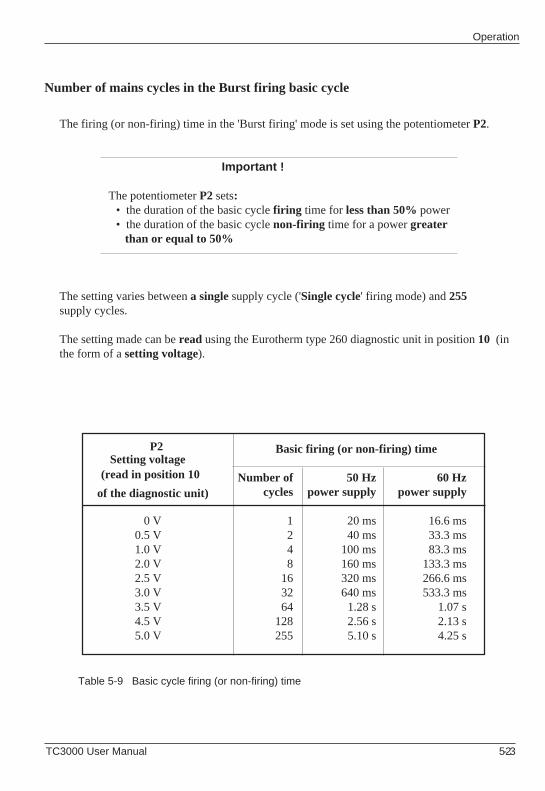
OperationOperation
TC3000 User Manual 5-23 TC3000 User Manual 5-23
Basic firing (or non-firing) time
Number of 50 Hz 60 Hz cycles power supply power supply
0 V 1 20 ms 16.6 ms0.5 V 2 40 ms 33.3 ms1.0 V 4 100 ms 83.3 ms2.0 V 8 160 ms 133.3 ms2.5 V 16 320 ms 266.6 ms3.0 V 32 640 ms 533.3 ms3.5 V 64 1.28 s 1.07 s4.5 V 128 2.56 s 2.13 s5.0 V 255 5.10 s 4.25 s
The firing (or non-firing) time in the 'Burst firing' mode is set using the potentiometer P2.
Important !
The potentiometer P2 sets:• the duration of the basic cycle firing time for less than 50% power• the duration of the basic cycle non-firing time for a power greater than or equal to 50%
The setting varies between a single supply cycle ('Single cycle' firing mode) and 255supply cycles.
The setting made can be read using the Eurotherm type 260 diagnostic unit in position 10 (inthe form of a setting voltage).
P2
Number of mains cycles in the Burst firing basic cycle
Table 5-9 Basic cycle firing (or non-firing) time
P2 Setting voltage(read in position 10
of the diagnostic unit)
The firing (or non-firing) time in the 'Burst firing' mode is set using the potentiometer P2.
Important !
The potentiometer P2 sets:• the duration of the basic cycle firing time for less than 50% power• the duration of the basic cycle non-firing time for a power greater than or equal to 50%
The setting varies between a single supply cycle ('Single cycle' firing mode) and 255supply cycles.
The setting made can be read using the Eurotherm type 260 diagnostic unit in position 10 (inthe form of a setting voltage).
Number of mains cycles in the Burst firing basic cycle
Table 5-9 Basic cycle firing (or non-firing) time
Basic firing (or non-firing) time
Number of 50 Hz 60 Hz cycles power supply power supply
0 V 1 20 ms 16.6 ms0.5 V 2 40 ms 33.3 ms1.0 V 4 100 ms 83.3 ms2.0 V 8 160 ms 133.3 ms2.5 V 16 320 ms 266.6 ms3.0 V 32 640 ms 533.3 ms3.5 V 64 1.28 s 1.07 s4.5 V 128 2.56 s 2.13 s5.0 V 255 5.10 s 4.25 s
Setting voltage(read in position 10
of the diagnostic unit)
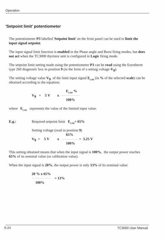
5-24 TC3000 User Manual 5-24 TC3000 User Manual
OperationOperation
The potentiometer P3 labelled 'Setpoint limit ' on the front panel can be used to limit theinput signal setpoint.
The input signal limit function is enabled in the Phase angle and Burst firing modes, but doesnot act when the TC3000 thyristor unit is configured in Logic firing mode.
The setpoint limit setting made using the potentiometer P3 can be read using the Eurothermtype 260 diagnostic box in position 9 (in the form of a setting voltage-V9).
The setting voltage value V9 of the limit input signal ELIM
(in % of the selected scale) can beobtained according to the equation:
ELIM
%V9 = 5 V x
100%
where ELIM
represents the value of the limited input value.
E.g.: Required setpoint limit ELIM
= 65%
Setting voltage (read in position 9)65%
V9 = 5 V x = 3.25 V100%
This setting obtained means that when the input signal is 100%, the output power reaches65% of its nominal value (or calibration value).
When the input signal is 20%, the output power is only 13% of its nominal value:
20 % x 65%= 13%
100%
'Setpoint limit' potentiometer
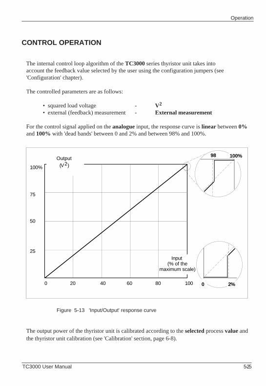
OperationOperation
TC3000 User Manual 5-25 TC3000 User Manual 5-25
The internal control loop algorithm of the TC3000 series thyristor unit takes intoaccount the feedback value selected by the user using the configuration jumpers (see'Configuration' chapter).
The controlled parameters are as follows:
• squared load voltage - V2
• external (feedback) measurement- External measurement
For the control signal applied on the analogue input, the response curve is linear between 0%and 100% with 'dead bands' between 0 and 2% and between 98% and 100%.
CONTROL OPERATION
Figure 5-13 'Input/Output' response curve
The output power of the thyristor unit is calibrated according to the selected process value andthe thyristor unit calibration (see 'Calibration' section, page 6-8).
100%
75
50
25
0 40 60 80 100
Output(V2)
Input (% of the
maximum scale)
20
98 100%
0 2%
5-26 TC3000 User Manual 5-26 TC3000 User Manual
OperationOperation
Squared load voltage
The V2 controlled parameter is the square of the RMS load voltage:This voltage is taken according to the load configuration type.
• The control voltage is taken between phases 1 and 2 of the load for closed or open delta and star without neutral configurations,
• The control voltage is taken between phase 1 of the load and the neutral for a star with neutral configuration.
External measurement
The external feedback signal has four voltage scales and two current scales.
• Voltage:0 - 5 V ; 1 - 5 V, 0 - 10 V, 2 - 10 V.Input impedance ≥ 100 kΩ.
• Current:0 - 20 mA ; 4 - 20 mAInput impedance 100 Ω.
TC3000 User Manual 6-1
Commissioning Commissioning
TC3000 User Manual 6-1
Chapter 6
COMMISSIONING PROCEDURE
Contents page
Commissioning procedure safety ....................................................... 6-2Checking the characteristics ............................................................... 6-3
Load current ................................................................................. 6-3Load configuration type ................................................................ 6-3Power supply voltage ................................................................... 6-4Auxiliary power supply voltage ..................................................... 6-4Input signals ................................................................................. 6-4
Diagnostic unit .................................................................................... 6-5Thyristor unit calibration ...................................................................... 6-7
Load voltage calibration .............................................................. 6-9 Calibration in calibration mode position ................................. 6-9 Calibration in normal operation position ................................. 6-9Line voltage calibration ................................................................. 6-9
Commissioning ................................................................................. 6-10Preliminary settings .................................................................... 6-10Power-up .................................................................................... 6-11Delayed firing setting on inductive load ...................................... 6-12
6-2 TC3000 User Manual 6-2 TC3000 User Manual
CommissioningCommissioning
Chapter 6 COMMISSIONING PROCEDURE
COMMISSIONING PROCEDURE SAFETY
Read this chapter carefully before commissioning thethyristor unit
!
Important !
Eurotherm cannot be held responsible for any damage to persons or property orfor any financial loss or costs resulting from the incorrect use of the product or thefailure to observe the instructions contained in this manual.
It is therefore the user's responsibility to ensure that all the nominal values ofthe power unit are compatible with the conditions of use and installationbefore commissioning the unit.
Warning !
Dangerous live parts may be accessible when the front door is open.
Only personnel qualified and authorised to work in industrial low voltageelectrical environments can access inside the unit.
Access to internal components of the thyristor unit is prohibited to users whoare not authorised to work in industrial low voltage electrical environments.
The temperature of the heatsink may exceed 100°C.Avoid all contact, even occasional, with the heatsink when the unit is inoperation. The heatsink remains hot approximately 15 min after the unit hasbeen switched off.
!
Chapter 6 COMMISSIONING PROCEDURE
COMMISSIONING PROCEDURE SAFETY
Read this chapter carefully before commissioning thethyristor unit
Important !
Eurotherm cannot be held responsible for any damage to persons or property orfor any financial loss or costs resulting from the incorrect use of the product or thefailure to observe the instructions contained in this manual.
It is therefore the user's responsibility to ensure that all the nominal values ofthe power unit are compatible with the conditions of use and installationbefore commissioning the unit.
Warning !
Dangerous live parts may be accessible when the front door is open.
Only personnel qualified and authorised to work in industrial low voltageelectrical environments can access inside the unit.
Access to internal components of the thyristor unit is prohibited to users whoare not authorised to work in industrial low voltage electrical environments.
The temperature of the heatsink may exceed 100°C.Avoid all contact, even occasional, with the heatsink when the unit is inoperation. The heatsink remains hot approximately 15 min after the unit hasbeen switched off.
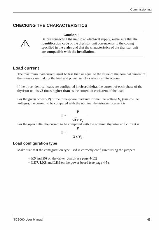
TC3000 User Manual 6-3
Commissioning Commissioning
TC3000 User Manual 6-3
!
S'assurer que le type de montage utilisé est correctement configuré à l'aide des cavaliers
• K5 et K6 sur la carte commande (voir page 4-12)• LK7 , LK8 et LK9 sur la carte puissance (voir page 4-5).
The maximum load current must be less than or equal to the value of the nominal current ofthe thyristor unit taking the load and power supply variations into account.
If the three identical loads are configured in closed delta, the current of each phase of thethyristor unit is √3 times higher than as the current of each arm of the load.
For the given power (P) of the three-phase load and for the line voltage VL (line-to-line
voltage), the current to be compared with the nominal thyristor unit current is:
PI =
√3 x VL
For the open delta, the current to be compared with the nominal thyristor unit current is: P
I = 3 x V
L
!
CHECKING THE CHARACTERISTICS
Make sure that the configuration type used is correctly configured using the jumpers
• K5 and K6 on the driver board (see page 4-12)• LK7 , LK8 and LK9 on the power board (see page 4-5).
Load current
Load configuration type
Caution !Before connecting the unit to an electrical supply, make sure that theidentification code of the thyristor unit corresponds to the codingspecified in the order and that the characteristics of the thyristor unitarecompatible with the installation.
The maximum load current must be less than or equal to the value of the nominal current ofthe thyristor unit taking the load and power supply variations into account.
If the three identical loads are configured in closed delta, the current of each phase of thethyristor unit is √3 times higher than as the current of each arm of the load.
For the given power (P) of the three-phase load and for the line voltage VL (line-to-line
voltage), the current to be compared with the nominal thyristor unit current is:
PI =
√3 x VL
For the open delta, the current to be compared with the nominal thyristor unit current is: P
I = 3 x V
L
CHECKING THE CHARACTERISTICS
Load current
Load configuration type
Caution !Before connecting the unit to an electrical supply, make sure that theidentification code of the thyristor unit corresponds to the codingspecified in the order and that the characteristics of the thyristor unitarecompatible with the installation.
6-4 TC3000 User Manual 6-4 TC3000 User Manual
CommissioningCommissioning
Power supply voltage
The voltage applied to thyristors in the OFF state, depends on the load configuration type.
For the star without neutral , closed or open delta configurations, the nominal value of thethyristor unit voltage must be greater than or equal to the line-to-line voltage of the powersupply used.
For the star with neutral configuration, the nominal thyristor unit voltage can be greater than orequal to the voltage between the phase and neutral of the power supply used.
A thyristor unit can be used on a three-phase power supply of a voltage less than the voltagespecified for the thyristor unit, by reconfiguring it (see table 4-1, page 4-4).
If the power supply voltage is less than 70% of the nominal thyristor unit voltage (or 50%depending on selected configuration), after 5 s of integration, the thyristor unit changes to inhibit(thyristor control withdrawn).The thyristor unit is re-enabled automatically if the voltage returns to a value greater than orequal to 70 % or 50% of the nominal value of the thyristor unit.
The jumper configurations on the driver board must be compatible with the selected levels of theanalogue signals used for:
• control (see page 4-9)• the external measurement (see pages 4-9 and 4-10).
Input signals
The auxiliary power supply voltage must correspond to the supply available.
The voltage is selected in the factory, according to the order code, using soldered links on thedriver board (see page 4-7).
Auxiliary power supply voltage
Caution !Given the inhibit at 70 % (or 50%) of the nominal voltage, the operating(calibration) voltage must be as close as possible to the nominal power supplyvoltage used.
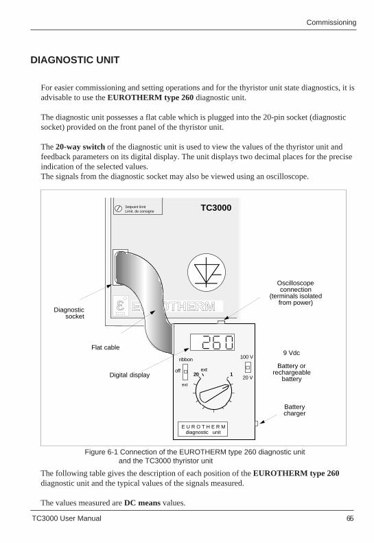
TC3000 User Manual 6-5
Commissioning Commissioning
TC3000 User Manual 6-5
DIAGNOSTIC UNIT
For easier commissioning and setting operations and for the thyristor unit state diagnostics, it isadvisable to use the EUROTHERM type 260 diagnostic unit.
The diagnostic unit possesses a flat cable which is plugged into the 20-pin socket (diagnosticsocket) provided on the front panel of the thyristor unit.
The 20-way switch of the diagnostic unit is used to view the values of the thyristor unit andfeedback parameters on its digital display. The unit displays two decimal places for the preciseindication of the selected values.The signals from the diagnostic socket may also be viewed using an oscilloscope.
The following table gives the description of each position of the EUROTHERM type 260diagnostic unit and the typical values of the signals measured.
The values measured are DC means values.
Figure 6-1 Connection of the EUROTHERM type 260 diagnostic unit and the TC3000 thyristor unit
120
E U R O T H E R M diagnostic unit
ext
100 V
20 V
ribbon
off
ext
Flat cable
Digital display
9 Vdc
Battery or rechargeable
battery
Batterycharger
Diagnostic socket
EUROTHERM
E U R O T H E R M diagnostic unit
Oscilloscope connection
(terminals isolated from power)
TC3000Setpoint limitLimit. de consigne
ε
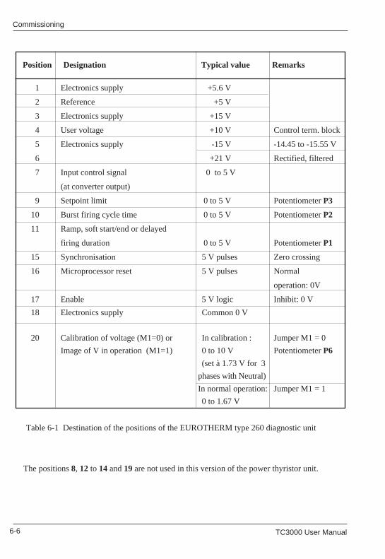
6-6 TC3000 User Manual 6-6 TC3000 User Manual
CommissioningCommissioning
Position Designation Typical value Remarks
1 Electronics supply +5.6 V
2 Reference +5 V
3 Electronics supply +15 V
4 User voltage +10 V Control term. block
5 Electronics supply -15 V -14.45 to -15.55 V
6 +21 V Rectified, filtered
7 Input control signal 0 to 5 V
(at converter output)
9 Setpoint limit 0 to 5 V Potentiometer P3
10 Burst firing cycle time 0 to 5 V Potentiometer P2
11 Ramp, soft start/end or delayed
firing duration 0 to 5 V Potentiometer P1
15 Synchronisation 5 V pulses Zero crossing
16 Microprocessor reset 5 V pulses Normal
operation: 0V
17 Enable 5 V logic Inhibit: 0 V
18 Electronics supply Common 0 V
20 Calibration of voltage (M1=0) or In calibration : Jumper M1 = 0
Image of V in operation (M1=1) 0 to 10 V Potentiometer P6
(set à 1.73 V for 3
phases with Neutral)
In normal operation: Jumper M1 = 1
0 to 1.67 V
Table 6-1 Destination of the positions of the EUROTHERM type 260 diagnostic unit
The positions 8, 12 to 14 and 19 are not used in this version of the power thyristor unit. The positions 8, 12 to 14 and 19 are not used in this version of the power thyristor unit.
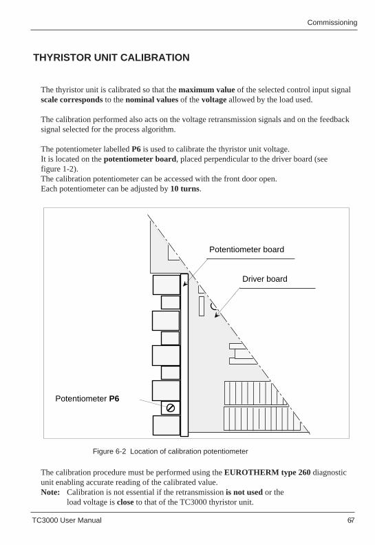
TC3000 User Manual 6-7
Commissioning Commissioning
TC3000 User Manual 6-7
The thyristor unit is calibrated so that the maximum value of the selected control input signalscale corresponds to the nominal values of the voltage allowed by the load used.
The calibration performed also acts on the voltage retransmission signals and on the feedbacksignal selected for the process algorithm.
The potentiometer labelled P6 is used to calibrate the thyristor unit voltage.It is located on the potentiometer board, placed perpendicular to the driver board (seefigure 1-2).The calibration potentiometer can be accessed with the front door open.Each potentiometer can be adjusted by 10 turns.
Figure 6-2 Location of calibration potentiometer
The calibration procedure must be performed using the EUROTHERM type 260 diagnosticunit enabling accurate reading of the calibrated value.Note: Calibration is not essential if the retransmission is not used or the
load voltage is close to that of the TC3000 thyristor unit.
THYRISTOR UNIT CALIBRATION
Potentiometer P6
Driver board
Potentiometer board
Potentiometer P6
Driver board
Potentiometer board
6-8 TC3000 User Manual 6-8 TC3000 User Manual
CommissioningCommissioning
There are two possible types of calibration depending on the position of calibration jumper M1:
• non-firing calibration or• full firing calibration.
Normally, calibration must be performed during non-firing (the jumper M1 on the driver boardis set to position 0). The calibration of the thyristor unit during non-firing does not require theoperation of the installation under nominal conditions.
Once the non-firing calibrations have been performed, the calibration jumpers must be reset tothe operating position (1).
Full firing calibration is performed if it is necessary to fine-tune or readjust the calibrationduring thyristor unit operation .In this case, the calibration jumper must be left in the operating position.
In the factory, the calibration signal is adjusted for the nominal voltage specified in the thyristorunit order.The following calibration procedure is optional and is only to be performed for conditions whenthe nominal load voltage can be changed.
Important !
If the value is calibrated at its nominal value, thecorresponding reading on the diagnostic unit inposition 20 is 1 V(jumper M1 in calibration position).
For the firing calibration, it should be taken into account that in full firing (sinusoidal currentoperation), the DC values (rectified sinusoidal signals, double alternations) read in positions 20of the EUROTHERM type 260 diagnostic unit are 1.67 V (1.885 V RMS or 2.61 V peak to peakon the oscilloscope).
TC3000 User Manual 6-9
Commissioning Commissioning
TC3000 User Manual 6-9
!
Load voltage calibration
Line voltage calibration
Calibration in calibration mode position (M1 = 0) . TC3000 cannot conduct
Calibration in normal operation mode position (M1 = 1)
!
Load voltage calibration
Line voltage calibration
To calibrate the voltage of the TC3000 thyristor unit, calculate the calibration voltage (VCA)according to the following ratio:
VUNVCA(V) = 1 V x
VLNwhere VUN
- nominal thyristor unit voltage (see identification label)VLN - nominal load voltage (line-to-line voltage of the power supply used).
Important ! For a star with neutral configuration, VCA must be multiplied by √3.
• By turning the potentiometer P6, display the value VCA
calculated on the diagnostic unit display in position 20,• Reset the jumper M1 in the operating position (1).
Example 1 : Nominal TC3000 thyristor unit voltage VUN = 400 V
Line voltage, 3 wire configuration VLN = 380 VVUN 400 V
Calibration voltage: VCA = 1 V x = 1 V x = 1.05 V VLN
380 VThe potentiometer P6 must be turned to obtain 1.05 V in position 20 on the display.
Example 2 : Same conditions as in example 1, but in star with neutral configuration.Calibration voltage VCA = 1.05 V x √3 = 1.82 VThe potentiometer P6 must be turned to obtain 1.82 V in position 20 on the display.
The signal read by the diagnostic unit is the rectified value, corresponding to the voltageactually measured.
In full firing (sinusoidal load voltage operation), the DC value read on position 20 mustbe1.67 V (for normal load voltage in full conduction).
The line voltage read by the microprocessor can be adjusted using the potentiometer(labelled P18) located on the driver board (see figure 4-2, page 4-7).
Caution ! This setting is made in the factory (4 V in point-test PT11) and must not be modified.
Calibration in calibration mode position (M1 = 0) . TC3000 cannot conduct
Calibration in normal operation mode position (M1 = 1)
To calibrate the voltage of the TC3000 thyristor unit, calculate the calibration voltage (VCA)according to the following ratio:
VUNVCA(V) = 1 V x
VLNwhere VUN
- nominal thyristor unit voltage (see identification label)VLN - nominal load voltage (line-to-line voltage of the power supply used).
Important ! For a star with neutral configuration, VCA must be multiplied by √3.
• By turning the potentiometer P6, display the value VCA
calculated on the diagnostic unit display in position 20,• Reset the jumper M1 in the operating position (1).
Example 1 : Nominal TC3000 thyristor unit voltage VUN = 400 V
Line voltage, 3 wire configuration VLN = 380 VVUN 400 V
Calibration voltage: VCA = 1 V x = 1 V x = 1.05 V VLN
380 VThe potentiometer P6 must be turned to obtain 1.05 V in position 20 on the display.
Example 2 : Same conditions as in example 1, but in star with neutral configuration.Calibration voltage VCA = 1.05 V x √3 = 1.82 VThe potentiometer P6 must be turned to obtain 1.82 V in position 20 on the display.
The signal read by the diagnostic unit is the rectified value, corresponding to the voltageactually measured.
In full firing (sinusoidal load voltage operation), the DC value read on position 20 mustbe1.67 V (for normal load voltage in full conduction).
The line voltage read by the microprocessor can be adjusted using the potentiometer(labelled P18) located on the driver board (see figure 4-2, page 4-7).
Caution ! This setting is made in the factory (4 V in point-test PT11) and must not be modified.
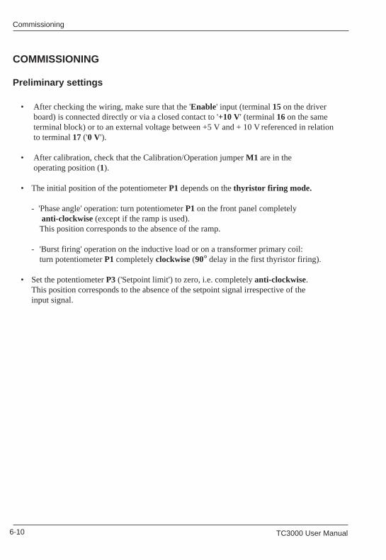
6-10 TC3000 User Manual 6-10 TC3000 User Manual
CommissioningCommissioning
• After checking the wiring, make sure that the 'Enable' input (terminal 15 on the driver board) is connected directly or via a closed contact to '+10 V' (terminal 16 on the same terminal block) or to an external voltage between +5 V and + 10 V referenced in relation to terminal 17 ('0 V').
• After calibration, check that the Calibration/Operation jumper M1 are in the operating position (1).
• The initial position of the potentiometer P1 depends on the thyristor firing mode.
- 'Phase angle' operation: turn potentiometer P1 on the front panel completely anti-clockwise (except if the ramp is used).This position corresponds to the absence of the ramp.
- 'Burst firing' operation on the inductive load or on a transformer primary coil:turn potentiometer P1 completely clockwise (90° delay in the first thyristor firing).
• Set the potentiometer P3 ('Setpoint limit') to zero, i.e. completely anti-clockwise.This position corresponds to the absence of the setpoint signal irrespective of theinput signal.
COMMISSIONING
Preliminary settings
• After checking the wiring, make sure that the 'Enable' input (terminal 15 on the driver board) is connected directly or via a closed contact to '+10 V' (terminal 16 on the same terminal block) or to an external voltage between +5 V and + 10 Vreferenced in relation to terminal 17 ('0 V').
• After calibration, check that the Calibration/Operation jumper M1 are in the operating position (1).
• The initial position of the potentiometer P1 depends on the thyristor firing mode.
- 'Phase angle' operation: turn potentiometer P1 on the front panel completely anti-clockwise (except if the ramp is used).This position corresponds to the absence of the ramp.
- 'Burst firing' operation on the inductive load or on a transformer primary coil:turn potentiometer P1 completely clockwise (90° delay in the first thyristor firing).
• Set the potentiometer P3 ('Setpoint limit') to zero, i.e. completely anti-clockwise.This position corresponds to the absence of the setpoint signal irrespective of theinput signal.
COMMISSIONING
Preliminary settings
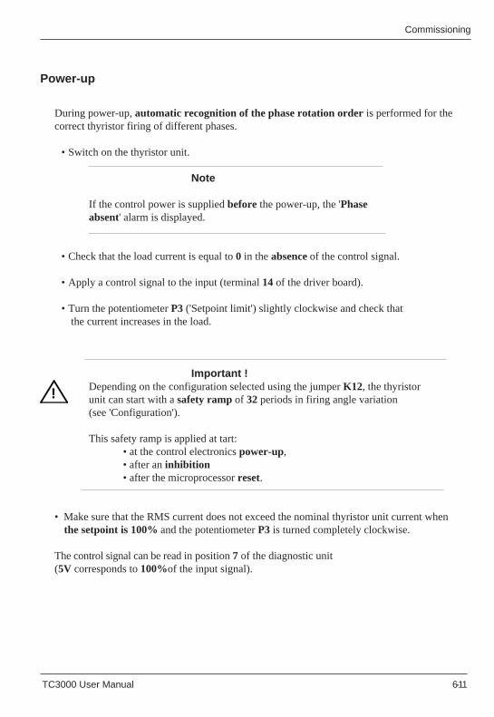
TC3000 User Manual 6-11
Commissioning Commissioning
TC3000 User Manual 6-11
!
During power-up, automatic recognition of the phase rotation order is performed for thecorrect thyristor firing of different phases.
• Switch on the thyristor unit.
Note
If the control power is supplied before the power-up, the 'Phaseabsent' alarm is displayed.
• Check that the load current is equal to 0 in the absence of the control signal.
• Apply a control signal to the input (terminal 14 of the driver board).
• Turn the potentiometer P3 ('Setpoint limit') slightly clockwise and check that the current increases in the load.
Important !Depending on the configuration selected using the jumper K12, the thyristorunit can start with a safety ramp of 32 periods in firing angle variation(see 'Configuration').
This safety ramp is applied at tart:• at the control electronics power-up,• after an inhibition• after the microprocessor reset.
• Make sure that the RMS current does not exceed the nominal thyristor unit current when the setpoint is 100% and the potentiometer P3 is turned completely clockwise.
The control signal can be read in position 7 of the diagnostic unit(5V corresponds to 100%of the input signal).
Power-up
!
During power-up, automatic recognition of the phase rotation order is performed for thecorrect thyristor firing of different phases.
• Switch on the thyristor unit.
Note
If the control power is supplied before the power-up, the 'Phaseabsent' alarm is displayed.
• Check that the load current is equal to 0 in the absence of the control signal.
• Apply a control signal to the input (terminal 14 of the driver board).
• Turn the potentiometer P3 ('Setpoint limit') slightly clockwise and check that the current increases in the load.
Important !Depending on the configuration selected using the jumper K12, the thyristorunit can start with a safety ramp of 32 periods in firing angle variation(see 'Configuration').
This safety ramp is applied at start:• at the control electronics power-up,• after an inhibition• after the microprocessor reset.
• Make sure that the RMS current does not exceed the nominal thyristor unit current when the setpoint is 100% and the potentiometer P3 is turned completely clockwise.
The control signal can be read in position 7 of the diagnostic unit(5V corresponds to 100%of the input signal).
Power-up
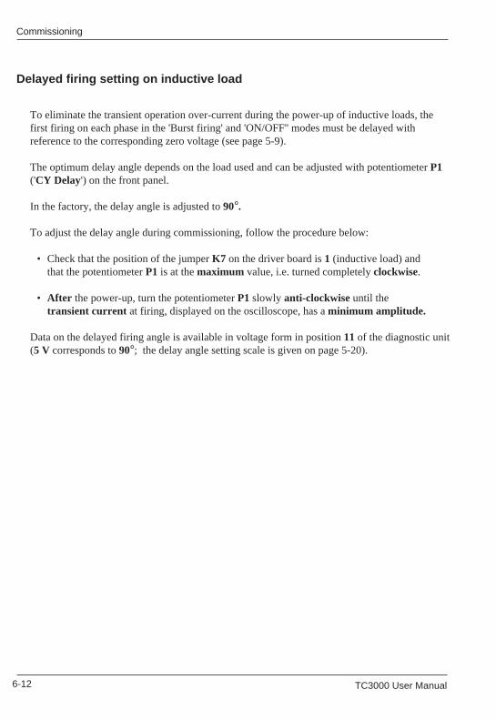
6-12 TC3000 User Manual 6-12 TC3000 User Manual
CommissioningCommissioning
Delayed firing setting on inductive load
To eliminate the transient operation over-current during the power-up of inductive loads, thefirst firing on each phase in the 'Burst firing' and 'ON/OFF'' modes must be delayed withreference to the corresponding zero voltage (see page 5-9).
The optimum delay angle depends on the load used and can be adjusted with potentiometer P1('CY Delay') on the front panel.
In the factory, the delay angle is adjusted to 90°.
To adjust the delay angle during commissioning, follow the procedure below:
• Check that the position of the jumper K7 on the driver board is 1 (inductive load) andthat the potentiometer P1 is at the maximum value, i.e. turned completely clockwise.
• After the power-up, turn the potentiometer P1 slowly anti-clockwise until thetransient current at firing, displayed on the oscilloscope, has a minimum amplitude.
Data on the delayed firing angle is available in voltage form in position 11 of the diagnostic unit(5 V corresponds to 90°; the delay angle setting scale is given on page 5-20).

TC3000 User Manual 7-1 TC3000 User Manual 7-1
Display messagesDisplay messages
Chapter 7
DISPLAY MESSAGES
Contents page
General ..............................................................................................7-2Steady messages .............................................................................. 7-2Flashing messages ............................................................................ 7-3
Error ..........................................................................................7-3Failures ..................................................................................... 7-4
Microprocessor failure ....................................................................... 7-4
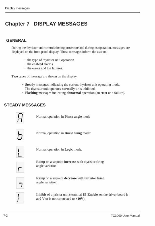
7-2 TC3000 User Manual 7-2 TC3000 User Manual
Display messagesDisplay messages
STEADY MESSAGES
Chapter 7 DISPLAY MESSAGES
GENERAL
Normal operation in Phase angle mode
Normal operation in Burst firing mode:
Normal operation in Logic mode.
Ramp on a setpoint increase with thyristor firingangle variation.
Ramp on a setpoint decrease with thyristor firingangle variation.
Inhibit of thyristor unit (terminal 15 'Enable' on the driver board isat 0 V or is not connected to +10V).
During the thyristor unit commissioning procedure and during its operation, messages aredisplayed on the front panel display. These messages inform the user on:
• the type of thyristor unit operation• the enabled alarms• the errors and the failures.
Two types of message are shown on the display.
• Steady messages indicating the current thyristor unit operating mode. The thyristor unit operates normally or is inhibited.• Flashing messages indicating abnormal operation (an error or a failure).
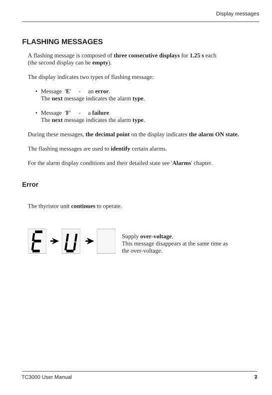
TC3000 User Manual 7-3 TC3000 User Manual 7-3
Display messagesDisplay messages
FLASHING MESSAGES
A flashing message is composed of three consecutive displays for 1.25 s each(the second display can be empty).
The display indicates two types of flashing message:
• Message 'E' - an error .The next message indicates the alarm type.
• Message 'F' - a failureThe next message indicates the alarm type.
During these messages, the decimal point on the display indicates the alarm ON state.
The flashing messages are used to identify certain alarms.
For the alarm display conditions and their detailed state see 'Alarms' chapter.
The thyristor unit continues to operate.
Supply over-voltage.This message disappears at the same time asthe over-voltage.
Error
FLASHING MESSAGES
A flashing message is composed of three consecutive displays for 1.25 s each(the second display can be empty).
The display indicates two types of flashing message:
• Message 'E' - an error .The next message indicates the alarm type.
• Message 'F' - a failureThe next message indicates the alarm type.
During these messages, the decimal point on the display indicates the alarm ON state.
The flashing messages are used to identify certain alarms.
For the alarm display conditions and their detailed state see 'Alarms ' chapter.
The thyristor unit continues to operate.
Supply over-voltage.This message disappears at the same time asthe over-voltage.
Error
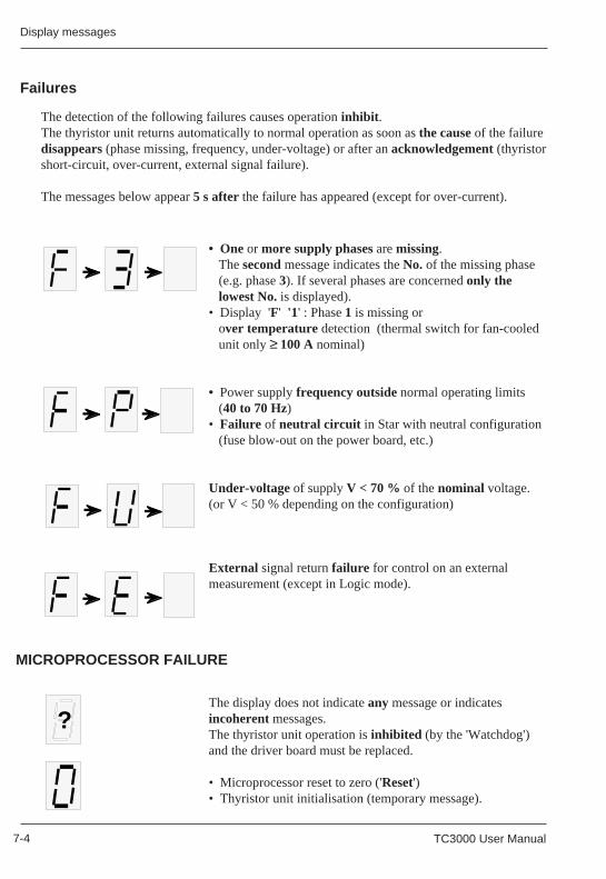
7-4 TC3000 User Manual 7-4 TC3000 User Manual
Display messagesDisplay messages
Failures
The detection of the following failures causes operation inhibit .The thyristor unit returns automatically to normal operation as soon as the cause of the failuredisappears (phase missing, frequency, under-voltage) or after an acknowledgement (thyristorshort-circuit, over-current, external signal failure).
The messages below appear 5 s after the failure has appeared (except for over-current).
?
• One or more supply phases are missing. The second message indicates the No. of the missing phase (e.g. phase 3). If several phases are concerned only the lowest No. is displayed).• Display 'F' '1' : Phase 1 is missing or over temperature detection (thermal switch for fan-cooled unit only ≥ 100 A nominal)
• Power supply frequency outside normal operating limits (40 to 70 Hz)• Failure of neutral circuit in Star with neutral configuration (fuse blow-out on the power board, etc.)
Under-voltage of supply V < 70 % of the nominal voltage.(or V < 50 % depending on the configuration)
External signal return failure for control on an externalmeasurement (except in Logic mode).
The display does not indicate any message or indicatesincoherent messages.The thyristor unit operation is inhibited (by the 'Watchdog')and the driver board must be replaced.
• Microprocessor reset to zero ('Reset')• Thyristor unit initialisation (temporary message).
MICROPROCESSOR FAILURE
TC3000 User Manual 8-1 TC3000 User Manual 8-1
AlarmsAlarms
Chapter 8 ALARMS
Contents page
Alarm strategy ........................................................ 8-2High level alarms .................................................... 8-4 Absence of power supply phases ...................... 8-4 Under-voltage .................................................... 8-4 Frequency error ................................................. 8-5 Neutral failure .................................................... 8-5 External measurement signal failure ................. 8-5Low level alarm ...................................................... 8-6Alarm acknowledgement ........................................ 8-6Alarm management ................................................ 8-7Alarm relay ............................................................. 8-8
Chapter 8 ALARMS
Contents page
Alarm strategy ........................................................ 8-2High level alarms .................................................... 8-4 Absence of power supply phases ..................... 8-4 Under-voltage .................................................... 8-4 Frequency error ................................................. 8-5 Neutral failure .................................................... 8-5 External measurement signal failure ................. 8-5Low level alarm ...................................................... 8-6Alarm acknowledgement ........................................ 8-6Alarm management ................................................ 8-7Alarm relay ............................................................. 8-8
8-2 TC3000 User Manual 8-2 TC3000 User Manual
Alarms Alarms
The alarms used by the TC3000 thyristor unit protect the thyristors and the installation againstabnormal operation and give the user information on the type of failures that have occurred.
Warning !
Alarms cannot be used to replace personnel protection.
It is the user's responsibility and it is highly recommended, given the value of theequipment controlled by the TC3000, to install independent safety devices whichshould be checked regularly.For this purpose, Eurotherm can supply several types of alarm detectors.
The TC3000 thyristor unit alarms are entirely managed by the microprocessor of the driverboard which retransmits its data (alarms enabled or not) using the display on the thyristor unitfront panel and the alarm relay.
The alarms are given levels (see figure 8-1). The detection of a high level alarm inhibits theprocessing of lower level alarms.
The enabled state of all the alarms is indicated by the front panel display (see pages 7-2 to7-4) and the alarm relay.
The highest level alarms detect the following failures:- absence of one or more power supply phases- under-voltage- supply frequency deviation- external measurement signal failure.- neutral failure (fuse blow-out on the power board).
The detection of one of these failures causes the thyristor unit operation to be inhibited(display 'F' '...').
The low level alarms (display 'E' '...') monitor the over-voltage without a thyristor unitoperation inhibit.
Chapter 8 ALARMS
ALARM STRATEGY
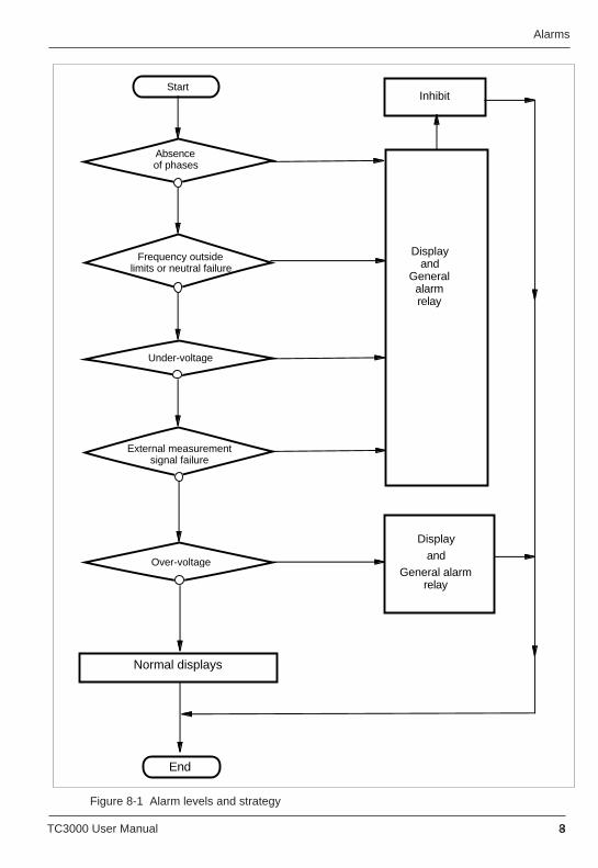
TC3000 User Manual 8-3 TC3000 User Manual 8-3
AlarmsAlarms
Figure 8-1 Alarm levels and strategy
Displayand
Generalalarmrelay
Inhibit
Under-voltage
Absenceof phases
Display
and
General alarm relay
Start
Frequency outsidelimits or neutral failure
External measurement signal failure
Over-voltage
Normal displays
End
Figure 8-1 Alarm levels and strategy
Displayand
Generalalarmrelay
Inhibit
Under-voltage
Absenceof phases
Display
and
General alarm relay
Start
Frequency outsidelimits or neutral failure
External measurement signal failure
Over-voltage
Normal displays
End
8-4 TC3000 User Manual 8-4 TC3000 User Manual
Alarms Alarms
HIGH LEVEL ALARMS
High level alarms detect the absence of or a significant drop in the power supply voltage,whether the frequency limits have been exceeded, neutral failure in the power board in thestar with neutral configuration and external measurement signal failure.
These alarms are integrated for 5 s before being handled.
High level alarms stop the operation of the thyristor unit by inhibiting thyristor gate pulsesand activate the general alarm relay.Thyristor firing is stopped at the first zero current crossing.
The state of the high level alarms is indicated by flashing messages on the front panel displayand by the general alarm relay contact (N/O or N/C depending on the configuration).
This alarm appears when one or more power supply phases are absent.The phase absence alarm can be activated by power supply failures, by fuse blow-out, by theopening of the circuit breakers or line contactors, and also by the opening of a permanentcooling thyristor unit safety thermal switch (in this case display 'F' '1').
The active alarm state can be seen on the display (messages 'F' '1', 'F' '2' or 'F' '3' dependingon the absent phase) and is signalled by the general alarm relay contact.
If several phases are cut off, a single message is displayed with the lowest phase number ofthe absent phase numbers.
The power supply phase absence alarm is not memorised and disappears as soon as the threephases are present. The thyristor returns to normal operation automatically.
If the line voltage drops by over 30% (or 50% depending on the configuration) in relation tothe calibrated nominal value, the under-voltage alarm is detected, which:
• inhibits the thyristor unit,• activates the general alarm relay• displays the flashing message 'F' 'U' on the front panel display.
The Under-voltage alarm uses the voltage between phases 1 and 2 as a reference.
This alarm is not memorised and disappears as soon as the power supply voltage is greaterthan the set threshold. The thyristor unit is started up again automatically, if the voltagereturns to over 70% (or 50% depending on the configuration) of the nominal voltage.
Absence of power supply phases
Under-voltage
TC3000 User Manual 8-5 TC3000 User Manual 8-5
AlarmsAlarms
Frequency error
If the supply frequency is outside the normal operating limits (40 to 70 Hz), the frequencyerror alarm:
• activates the general alarm relay• inhibits the thyristor unit• displays the flashing message 'F' 'P' on the front panel display.
This alarm is not memorised and disappears as soon as the power supply frequency returns tothe normal operating limits.
Neutral failure
For the correct operation of the thyristor unit in the star with neutral configuration (4 wires), theneutral must be connected to the power board. The Neutral user terminal block below the thyristor unit,the neutral fuse and the jumper LK8 on the power board are used for the connection.
In the event of a failure of this circuit or a neutral fuse blow-out (only in 4 wire Star loadconfigurations), the Neutral failure alarm:
• activates the general alarm relay• inhibits the thyristor unit• displays the flashing message 'F' 'P' on the front panel display.
This alarm is not memorised and disappears as soon as the connection of the neutral to thepower board is restored.
This alarm appears when the absence of the external measurement signal is detected if controlon an external measurement is selected (coding 'EX' and 'E*** ') and the output power is notzero (alarm deactivated in Logic mode).
The detection of an external signal failure:• inhibits the thyristor unit,• activates the general alarm relay,• displays the message 'F' 'E'.
The unit can be restarted after the alarm acknowledgement.
External measurement signal failure
8-6 TC3000 User Manual 8-6 TC3000 User Manual
Alarms Alarms
LOW LEVEL ALARM
ALARM ACKNOWLEDGEMENT
The low level alarm does not inhibit the thyristor unit.The anomaly detected (over-voltage) is displayed with a change in the relay contacts and withthe message on the display.
The low level alarm is only active 5 s after the corresponding failure has appeared.
If the line voltage is greater than the nominal thyristor unit voltage by more than 20%, theover-voltage alarm is detected:
• the general alarm relay is activated,• the flashing message 'E' 'U ' appears on the front panel display.
In the event of over-voltage, the thyristor unit is not inhibited, the control keeps the value ofthe controlled parameter for the given operating point constant.
If the unit returns to a voltage less than 110% of the nominal thyristor unit voltage, the relayreturns to the non-alarm state.
The thyristor unit can only be started up again after inhibition due to memorised alarms(external measurement failure) after an acknowledgement.
To acknowledge the alarms, it is possible to:
• switch off the auxiliary power supply of the driver board,• connect terminal 11 ('Acknowledge') on the driver board to terminal 16 ('+10 V')• apply a +10 V external signal to terminal 11 ('Acknowledge').
Alarms can only be acknowledged using terminal 11 when the voltage between phases 1 and 2 isnot available (display 'F' '1').
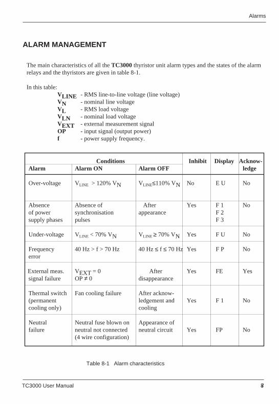
TC3000 User Manual 8-7 TC3000 User Manual 8-7
AlarmsAlarms
ALARM MANAGEMENT
The main characteristics of all the TC3000 thyristor unit alarm types and the states of the alarmrelays and the thyristors are given in table 8-1.
In this table:VLINE - RMS line-to-line voltage (line voltage)VN - nominal line voltageVL - RMS load voltageVLN - nominal load voltageVEXT - external measurement signalOP - input signal (output power)f - power supply frequency.
Conditions Inhibit Display Acknow-Alarm Alarm ON Alarm OFF ledge
Over-voltage VLINE > 120% VN VLINE≤110% VN No E U No
Absence Absence of After Yes F 1 Noof power synchronisation appearance F 2supply phases pulses F 3
Under-voltage VLINE < 70% VN VLINE ≥ 70% VN Yes F U No
Frequency 40 Hz > f > 70 Hz 40 Hz ≤ f ≤ 70 Hz Yes F P Noerror
External meas. VEXT = 0 After Yes FE Yessignal failure OP ≠ 0 disappearance
Thermal switch Fan cooling failure After acknow-(permanent ledgement and Yes F 1 Nocooling only) cooling
Neutral Neutral fuse blown on Appearance offailure neutral not connected neutral circuit Yes FP No
(4 wire configuration)
Table 8-1 Alarm characteristics
8-8 TC3000 User Manual 8-8 TC3000 User Manual
Alarms Alarms
ALARM RELAYS
The general alarm relay is located on the driver board.
The detection of any other alarm changes the state of the general alarm relay.
The contact (N/O or N/C depending on the configuration) can be used to indicate the alarmstate or in the monitoring system.
The contact is available on the user terminal block below the thyristor unit (terminals 61-62).
The relay contact can be connected without opening the front door of the thyristor unit.
The alarm relay contact connections are given on page 3-12.
The switch cut-off capacity is 0.25 A (250 Vac or 30 Vdc).
The cut-off voltage must never be greater than 250 Vac.
The Alarm relay is deactivated in the alarm state or when the thyristor unit is switched off.
TC3000 User Manual 9-1 TC3000 User Manual 9-1
Maintenance Maintenance
Chapter 9
MAINTENANCE
Contents page
Thyristor protection ........................................................................ 9-2Fuses ............................................................................................. 9-2 Thyristor protection fuses ......................................................... 9-3 Fuse blown indication micro-switch .......................................... 9-4 Auxiliary voltage connection protection fuses .......................... 9-5 Neutral protection fuse ............................................................. 9-5Servicing ........................................................................................ 9-5Tools .............................................................................................. 9-6
9-2 TC3000 User Manual 9-2 TC3000 User Manual
Maintenance Maintenance
Warning !
The thyristor unit must be maintained by qualified personnel onlyauthorised to work in an industrial low voltage electrical environment.
Chapter 9 MAINTENANCE
THYRISTOR PROTECTION
The thyristors of the TC3000 series thyristor units are protected as follows:
• internal high speed fuses against over-currents• RC snubbers and varistors against excessively fast voltage variations and transient over-voltages when the thyristors are not firing.• thermal switches (in the event of accidental overheating of the cooler of fan-cooled thyristor units, the thermal switch opens, which causes the thyristor firing to be stopped).
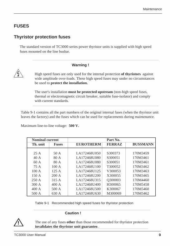
TC3000 User Manual 9-3 TC3000 User Manual 9-3
Maintenance Maintenance
!
FUSES
Thyristor protection fuses
Table 9-1 contains all the part numbers of the original internal fuses (when the thyristor unitleaves the factory) and the fuses which can be used for replacements during maintenance.
Maximum line-to-line voltage: 500 V.
Nominal current Part No. Th. unit Fuses EUROTHERM FERRAZ BUSSMANN
25 A 50 A LA172468U050 S300373 170M345940 A 80 A LA172468U080 S300051 170M346160 A 80 A LA172468U080 S300051 170M346175 A 100 A LA172468U100 T300052 170M3462
100 A 125 A LA172468U125 V300053 170M3463150 A 200 A LA172468U200 X300055 170M3465250 A 315 A LA172468U315 Q300003 170M4460300 A 400 A LA172468U400 H300065 170M5458400 A 500 A LA172468U500 K300067 170M5460500 A 630 A LA172468U630 M300069 170M5462
Table 9-1 Recommended high speed fuses for thyristor protection
Caution !
The use of any fuses other than those recommended for thyristor protectioninvalidates the thyristor unit guarantee.
The standard version of TC3000 series power thyristor units is supplied with high speedfuses mounted on the line busbar.
Warning !
High speed fuses are only used for the internal protection of thyristors againstwide amplitude over-loads. These high speed fuses may under no circumstancesbe used to protect the installation.
The user's installation must be protected upstream (non-high speed fuses,thermal or electromagnetic circuit breaker, suitable fuse-isolator) and complywith current standards.
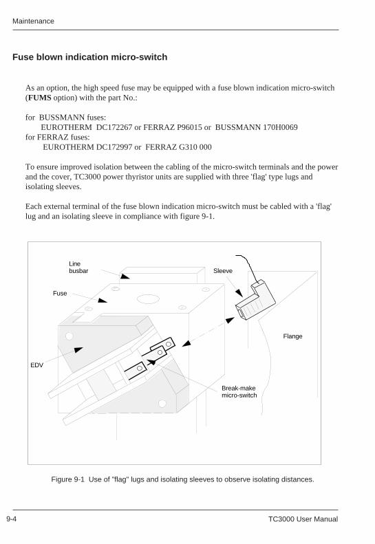
9-4 TC3000 User Manual 9-4 TC3000 User Manual
Maintenance Maintenance
As an option, the high speed fuse may be equipped with a fuse blown indication micro-switch(FUMS option) with the part No.:
for BUSSMANN fuses:EUROTHERM DC172267 or FERRAZ P96015 or BUSSMANN 170H0069
for FERRAZ fuses: EUROTHERM DC172997 or FERRAZ G310 000
To ensure improved isolation between the cabling of the micro-switch terminals and the powerand the cover, TC3000 power thyristor units are supplied with three 'flag' type lugs andisolating sleeves.
Each external terminal of the fuse blown indication micro-switch must be cabled with a 'flag'lug and an isolating sleeve in compliance with figure 9-1.
Fuse blown indication micro-switch
Figure 9-1 Use of "flag" lugs and isolating sleeves to observe isolating distances.
Fuse
Line busbar Sleeve
Flange
Break-make micro-switch
EDV
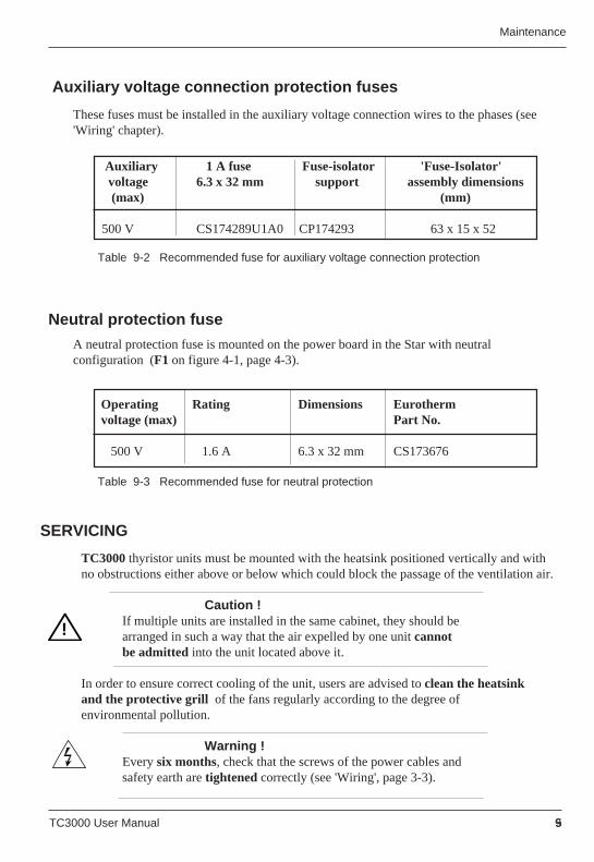
TC3000 User Manual 9-5 TC3000 User Manual 9-5
Maintenance Maintenance
Auxiliary voltage connection protection fuses
Auxiliary 1 A fuse Fuse-isolator 'Fuse-Isolator' voltage 6.3 x 32 mm support assembly dimensions (max) (mm)
500 V CS174289U1A0 CP174293 63 x 15 x 52
Table 9-2 Recommended fuse for auxiliary voltage connection protection
These fuses must be installed in the auxiliary voltage connection wires to the phases (see'Wiring' chapter).
TC3000 thyristor units must be mounted with the heatsink positioned vertically and withno obstructions either above or below which could block the passage of the ventilation air.
Caution !If multiple units are installed in the same cabinet, they should bearranged in such a way that the air expelled by one unit cannotbe admitted into the unit located above it.
In order to ensure correct cooling of the unit, users are advised to clean the heatsinkand the protective grill of the fans regularly according to the degree ofenvironmental pollution.
Warning !Every six months, check that the screws of the power cables andsafety earth are tightened correctly (see 'Wiring', page 3-3).
!
SERVICING
Neutral protection fuse
A neutral protection fuse is mounted on the power board in the Star with neutralconfiguration (F1 on figure 4-1, page 4-3).
Operating Rating Dimensions Eurotherm voltage (max) Part No.
500 V 1.6 A 6.3 x 32 mm CS173676
Table 9-3 Recommended fuse for neutral protection
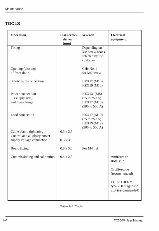
9-6 TC3000 User Manual 9-6 TC3000 User Manual
Maintenance Maintenance
TOOLS
Operation Flat screw- Wrench Electrical driver equipment (mm)
Fixing Depending onM8 screw headsselected by thecustomer
Opening (closing) CHc No. 4of front door for M5 screw
Safety earth connection HEX17 (M10)HEX19 (M12)
Power connection HEX13 (M8) (supply side) (25 to 250 A)and fuse change HEX17 (M10)
(300 to 500 A)
Load connection HEX17 (M10)(25 to 250 A)HEX19 (M12)(300 to 500 A)
Cable clamp tightening 0.5 x 3.5Control and auxiliary powersupply voltage connection 0.5 x 3.5
Board fixing 0.8 x 5.5 For M4 nut
Commissioning and calibration 0.4 x 2.5 Ammeter orRMS clip.
Oscilloscope(recommended)
EUROTHERMtype 260 diagnosticunit (recommended)
Table 9-4 Tools