
0 MD Notes Machine Design
54
1
Transcript of 0 MD Notes Machine Design

1

BELTS AND CHAINS (FLEXIBLE CONNECTING DRIVES)
Belt, ropes, chains and other flexible elements are used in conveying systems and in the transmission of power over comparatively long distances.They are preferred where it is not important to maintain an exactspeed ratio between the two shafts. Power loss due to slip and creep can be as much as 5% for most belts.
Types ofBelts
The four main types of belts commonly in use are:
Flat Belts Round Belts V Belts Timing Belts
Flat Belts: They are usually fitted on crown pulleys. They are usually thin and subjected to centrifugal loads. They work well over small pulleys at speeds exceeding 9,000ft/min. They have efficiencies of between 90% - 98%. They may require tensioner to produce frictional grip over the pulley (see Figure 4.1.1). Thesehigh tensions tend to shorten bearing life.Flat BeltMaterials: Urethane, Rubber – impregnated fabric, Leather etc. Relative quiet run.
2
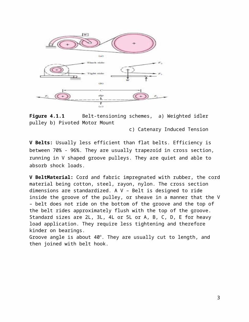
Figure 4.1.1 Belt-tensioning schemes, a) Weighted idler pulley b) Pivoted Motor Mount
c) Catenary Induced Tension
V Belts: Usually less efficient than flat belts. Efficiency is between 70% - 96%. They are usually trapezoid in cross section, running in V shaped groove pulleys. They are quiet and able to absorb shock loads.
V BeltMaterial: Cord and fabric impregnated with rubber, the cordmaterial being cotton, steel, rayon, nylon. The cross section dimensions are standardized. A V – Belt is designed to ride inside the groove of the pulley, or sheave in a manner that the V– belt does not ride on the bottom of the groove and the top of the belt rides approximately flush with the top of the groove. Standard sizes are 2L, 3L, 4L or 5L or A, B, C, D, E for heavy load application. They require less tightening and therefore kinder on bearings.Groove angle is about 40o. They are usually cut to length, and then joined with belt hook.
3

Figure 4.1.2 Some characteristics of types belts
Figure 4.1.3
Round Belts: Used primarily when the shafts are not parallel. Also used for light load applications. The belt can usually be stretched over the pulley and snapped into place. They are purchased in endless length, and cut to size. The ends are then joined together with belt hooks.
4
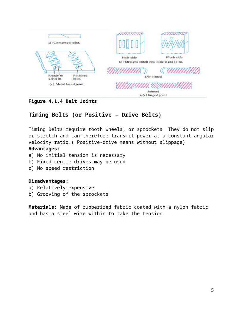
Figure 4.1.4 Belt Joints
Timing Belts (or Positive – Drive Belts)
Timing Belts require tooth wheels, or sprockets. They do not slipor stretch and can therefore transmit power at a constant angularvelocity ratio.( Positive-drive means without slippage) Advantages: a) No initial tension is necessaryb) Fixed centre drives may be usedc) No speed restriction
Disadvantages:a) Relatively expensiveb) Grooving of the sprockets
Materials: Made of rubberized fabric coated with a nylon fabric and has a steel wire within to take the tension.
5

Figure 4.1.5 Timing Belt
Some Common Applications of Belts and ChainsCompressors BicyclesSewing machines MotorcyclesTextile machines Power lawn mowersAutomotive devices Chain sawswater pumps Cranesalternators Hoistsfans Paper – mill machineryMixing machines ConveyersWashing machines Textile machineryPrinting machinery All terrain vehiclesPumpsMachine toolsCrushing machinery
Some Belt Drive Configurations
6
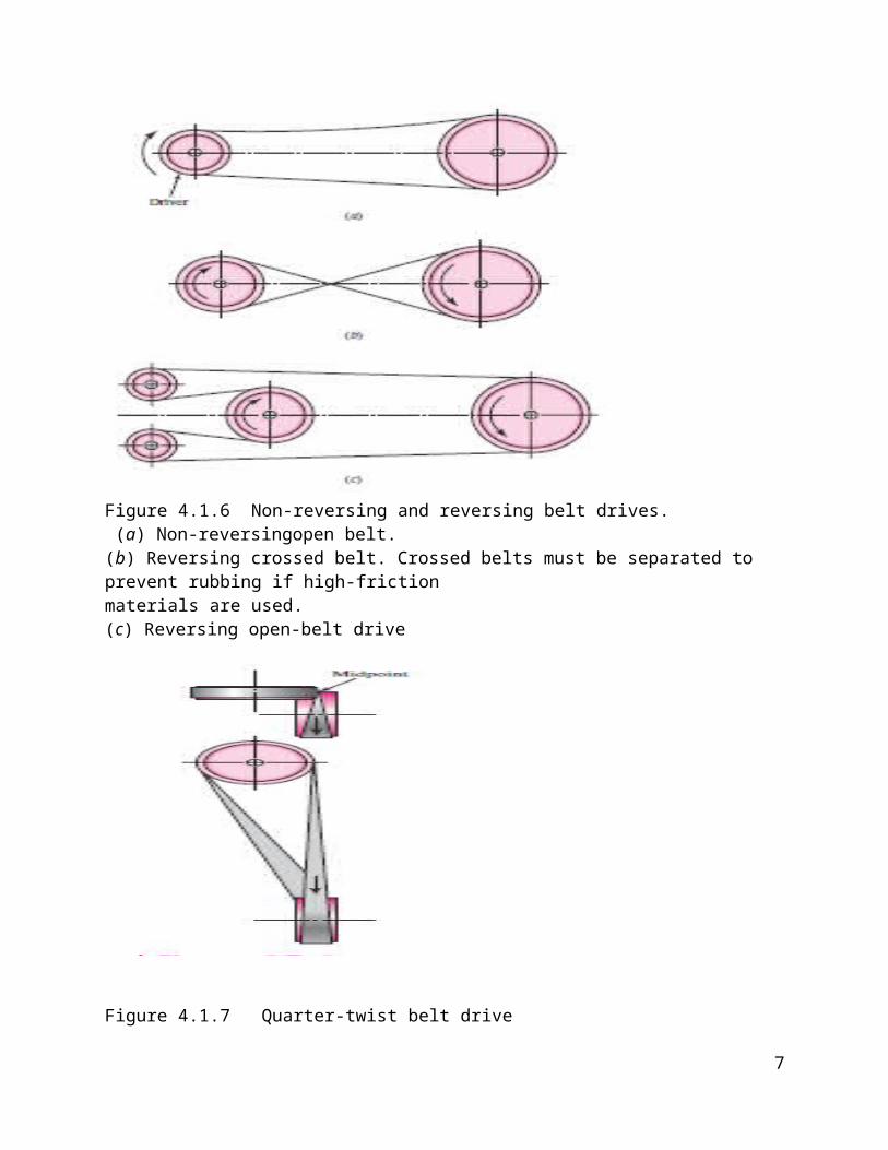
Figure 4.1.6 Non-reversing and reversing belt drives. (a) Non-reversingopen belt. (b) Reversing crossed belt. Crossed belts must be separated to prevent rubbing if high-frictionmaterials are used.(c) Reversing open-belt drive
Figure 4.1.7 Quarter-twist belt drive
7

( Positive-drive means without slippage)
Angle of Wrap of A Belt
8
Formulae Summary
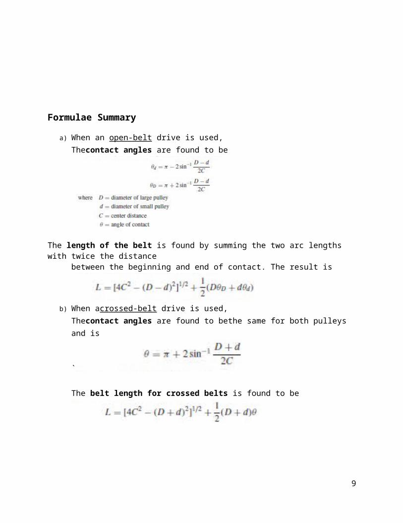
a) When an open-belt drive is used,Thecontact angles are found to be
The length of the belt is found by summing the two arc lengths with twice the distance
between the beginning and end of contact. The result is
b) When acrossed-belt drive is used,Thecontact angles are found to bethe same for both pulleys and is
`
The belt length for crossed belts is found to be
9

10
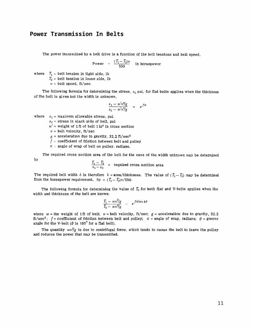
Power Transmission In Belts
11

Worked Examples
12
Classification of Chains
The chains, on the basis of their use, are classified into the following three groups:
Hoisting and hauling (or crane) chains, Conveyor (or tractive) chains, and Power transmitting (or driving) chains.
These chains are discussed, in detail below.
Hoisting and Hauling Chains
13

These chains are used for hoisting and hauling purposes and operate at a maximum velocity of0.25 m / s. The hoisting and hauling chains are of the following two types:1. Chain with oval links. The links of this type of chain are of oval shape, as shown in Fig. 21.4(a). The joint of each link is welded. The sprockets which are used for this type of chain have receptaclesto receive the links. Such type of chains are used only at low speeds such as in chain hoists and inanchors for marine works.
Figure 4.4.1Hoisting and Hauling Chains2. Chain with square links. The links of this type of chain are of square shape, as shown in Fig.21.4 (b). Such type of chains are used in hoists, cranes, dredges. The manufacturing cost of this type of chain is less than that of chain with oval links, but in these chains, the kinking occurs easily on overloading.
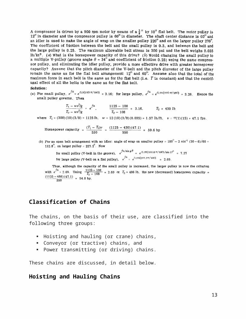
Conveyor Chains
These chains are used for elevating and conveying the materials continuously at a speed up to2 m / s. The conveyor chains are of the following two types:1. Detachable or hook joint type chain, as shown in Figure 4.4.2 (a), and2. Closed joint type chain, as shown in Figure 4.4.2 (b).
14
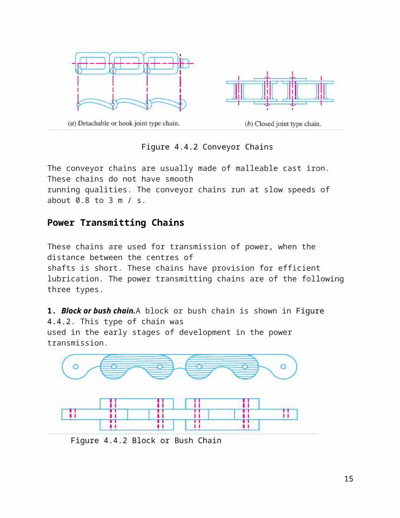
Figure 4.4.2 Conveyor Chains
The conveyor chains are usually made of malleable cast iron. These chains do not have smoothrunning qualities. The conveyor chains run at slow speeds of about 0.8 to 3 m / s.
Power Transmitting Chains
These chains are used for transmission of power, when the distance between the centres ofshafts is short. These chains have provision for efficient lubrication. The power transmitting chains are of the following three types.
1. Block or bush chain.A block or bush chain is shown in Figure 4.4.2. This type of chain wasused in the early stages of development in the power transmission.
Figure 4.4.2 Block or Bush Chain
15

It produces noise when approaching or leaving the teeth of the sprocket because of rubbingbetween the teeth and the links. Such type of chains are used to some extent as conveyor chain atsmall speed.
2. Bush roller chain.A bush roller chain as shown in Fig. 21.7, consists of outer plates or pinlink plates, inner plates or roller link plates, pins, bushes androllers. A pin passes through the bush which is secured in the holes of the roller between the two sides of the chain. The rollers are free to rotate on the bush which protect the sprocketwheel teeth against wear. The pins, bushes and rollers are made of alloy steel.
A roller chain can be used to transmit power between parallel shafts and has features that are common to both gears and pulleys. Like gears, roller chains do not require an initial tension; hence, no slippage occurs. Because of their similarity to pulleys as wrapping connectors, roller chains are suitable forrelatively long or short center distances. Compared to belts, chains are more compact, they can operate in a dirty and gritty environment, they are not affected by oil, and they can be used at the high temperatures encountered in ovens. The power transmission efficiency of a roller chain is high – 98% to 99%.
16

Figure 4.4.3 Bush Roller Chain
Figure 4.4.4 Photo of a Motorcycle Chain Drive3. Silent chain. A silent chain (also known as inverted tooth chain) is shown in Figure 4.4.5
Figure 4.4.5 Silent Chains
It is designed to eliminate the evil effects caused by stretchingand to produce noiselessrunning. When the chain stretches and the pitch of the chain increases, the links ride on the teeth
17
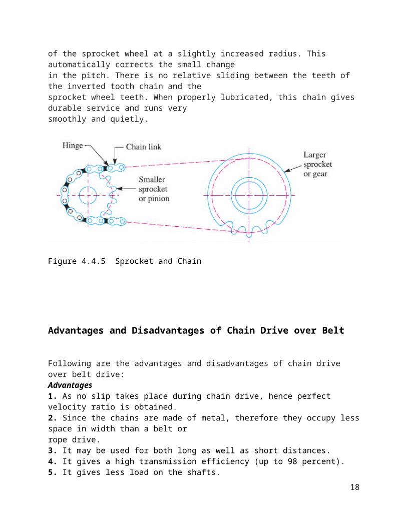
of the sprocket wheel at a slightly increased radius. This automatically corrects the small changein the pitch. There is no relative sliding between the teeth of the inverted tooth chain and thesprocket wheel teeth. When properly lubricated, this chain gives durable service and runs verysmoothly and quietly.
Figure 4.4.5 Sprocket and Chain
Advantages and Disadvantages of Chain Drive over Belt
Following are the advantages and disadvantages of chain drive over belt drive:Advantages1. As no slip takes place during chain drive, hence perfect velocity ratio is obtained.2. Since the chains are made of metal, therefore they occupy lessspace in width than a belt orrope drive.3. It may be used for both long as well as short distances.4. It gives a high transmission efficiency (up to 98 percent).5. It gives less load on the shafts.
18

6. It has the ability to transmit motion to several shafts by onechain only.7. It transmits more power than belts.8. It permits high speed ratio of 8 to 10 in one step.9. It can be operated under adverse temperature and atmospheric conditions.Disadvantages1. The production cost of chains is relatively high.2. The chain drive needs accurate mounting and careful maintenance, particularly lubricationand slack adjustment.
1. The chain drive has velocity fluctuations especially when unduly stretched.
Advantagesof Flexible Connecting Drives over Gears/Shafts
Less installation work (relatively simple design) Less maintenance High reliability High peripheral velocities Good adaptability to the individual application In some cases, shock- and sound-absorbing In some cases, with continuously variable speed (variable-
speed belt drive) Lower cost Better ability to damp out and isolate the effects of
vibration.
Disadvantagesof Flexible Connecting Drives compared to Gears/Shafts
Limited power transmission capacity Limited transmission ratio per pulley step In some cases, synchronous power transmission impossible
(slip) In some cases, large axle and contact forces required
19

20
CLUTCHES,BRAKES, AND FLYWHEELS
CLUTCH
A clutch is a device that connects and disconnects two collinear shafts. Unlike coupling, a clutch must be capable of engaging and disengaging rotating shaft. The clutch performs this function by producing and transferring torque across the shaft. The torque transmitted is related to the actuating force, the coefficient of friction, and the geometry of the clutch. Most clutches rely on friction to operate are known as friction clutches, however some clutches, known as positive drive clutches, do not rely on friction. Rather they rely on compressive and shear forces to provide the driving force. An example of such clutches is the jaw clutch that permits one shaftto drive another through a direct contact of interlocking jaws.
A friction clutch has its principal application in the transmission of power of shafts andmachines which must be started and stopped frequently. Its application is also found in cases in which power is to be delivered to machines partially or fully loaded.A positive drive type of clutch is used where engagement and disengagement in motion and under load is not necessary.
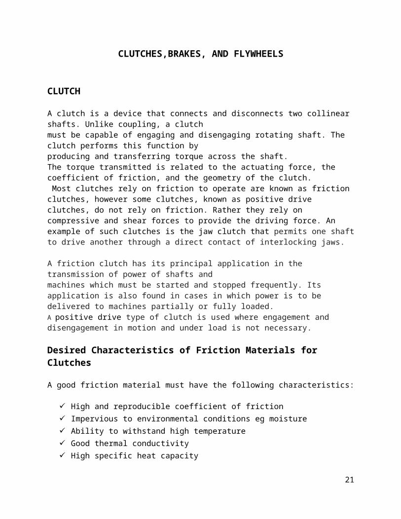
Desired Characteristics of Friction Materials for Clutches
A good friction material must have the following characteristics:
High and reproducible coefficient of friction Impervious to environmental conditions eg moisture Ability to withstand high temperature Good thermal conductivity High specific heat capacity
21
High Resistance to wear Good resilience
(that is, must be able to recover its size and shape after being strained)
High flexibility
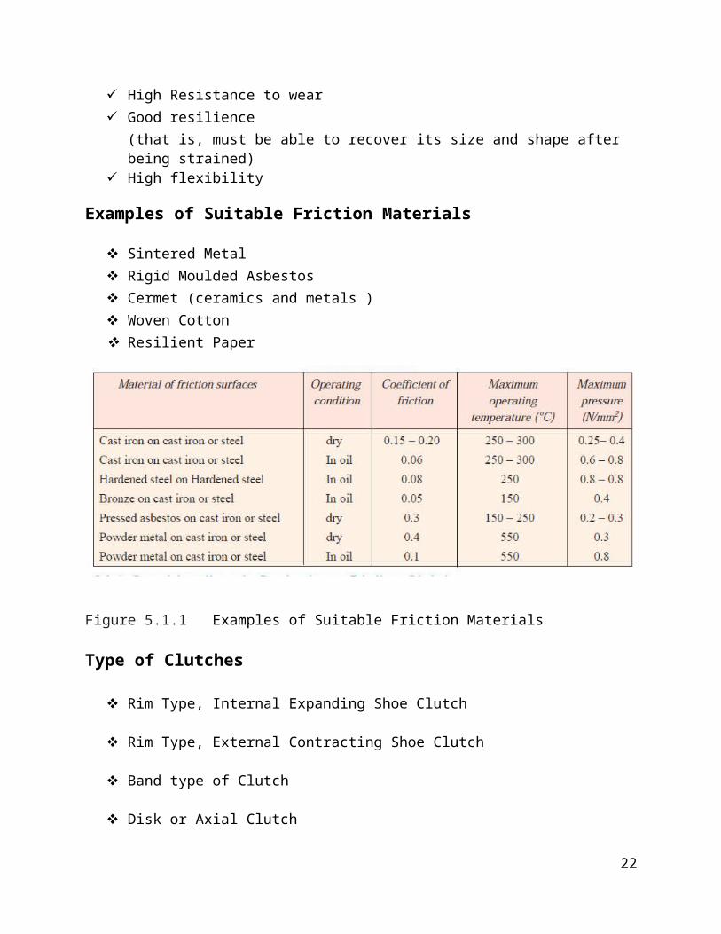
Examples of Suitable Friction Materials
Sintered Metal Rigid Moulded Asbestos Cermet (ceramics and metals ) Woven Cotton Resilient Paper
Figure 5.1.1 Examples of Suitable Friction Materials
Type of Clutches
Rim Type, Internal Expanding Shoe Clutch
Rim Type, External Contracting Shoe Clutch
Band type of Clutch
Disk or Axial Clutch
22

Cone Clutch
Miscellaneous type of Clutch (eg jaw clutch)
Internal Expanding Rim Type of Clutch
The internal shoe rim clutch shown below consist essentially of
the following three elements:
The mating frictional surfaces
The means of transmitting the torque to and from the
surfaces
The actuating mechanism
Figure 5.1.1 Internal Expanding Shoe Clutch
23

The expanding shoes are pivoted at certain points shown in Fig
5.1.1. The actuating force is
provided by the pistons in the wheel cylinder. The shoes are
pressed against the rotating
wheel, causing it to come to a rest. When the actuating force is
released the helical
springs disengage the clutch shoes. The hinge pin may be movable
in so-called “floating shoe” design.
External contracting Rim Clutches
The externally hinged shoes are made to contract internally, and
thereby engaging the connecting shafts. Operating mechanism may
be
Solenoids
Levers/linkages
Linkage with spring loading
Hydraulic or pneumatic
Images are shown below:
24

Figure 5.1.2a External contracting Rim Clutch
Figure 5.1.2b External contracting Rim Clutch
25

Band Type Clutch
The actuating mechanism exerts the actuating force F2 to transfer
the torque.
Flexible clutch and brake bands are used in power excavators and in hoisting and othermachinery.
Figure 5.1.3 Band clutch
(Automotive) Disk or Axial Clutches
A single disc or plate clutch, as shown in Fig 5.1.5, consists ofa clutch plate that are faced with a frictional material on both sides. It is mounted on the hub which is free tomove axially along the splines of the driven shaft. The pressure plate is mounted inside the clutch body which is bolted to the flywheel. Both the pressure plate and the flywheel rotate with the engine crankshaft or the driving shaft. The pressure plate pushes the clutch plate towards the flywheel by a set of strong springs which are arranged radially inside the body. The three levers (also known as release levers or fingers) are carried on
26
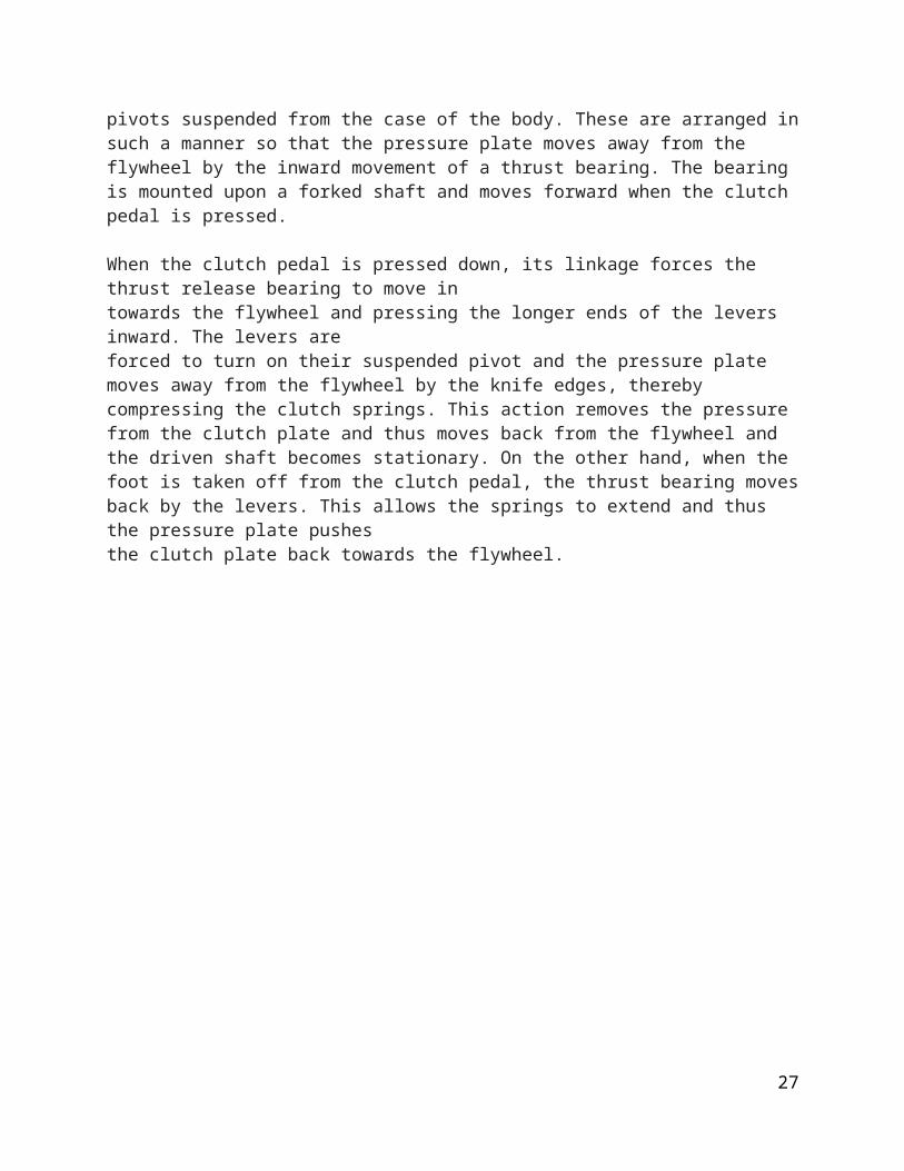
pivots suspended from the case of the body. These are arranged insuch a manner so that the pressure plate moves away from the flywheel by the inward movement of a thrust bearing. The bearing is mounted upon a forked shaft and moves forward when the clutch pedal is pressed.
When the clutch pedal is pressed down, its linkage forces the thrust release bearing to move intowards the flywheel and pressing the longer ends of the levers inward. The levers areforced to turn on their suspended pivot and the pressure plate moves away from the flywheel by the knife edges, thereby compressing the clutch springs. This action removes the pressure from the clutch plate and thus moves back from the flywheel and the driven shaft becomes stationary. On the other hand, when the foot is taken off from the clutch pedal, the thrust bearing movesback by the levers. This allows the springs to extend and thus the pressure plate pushesthe clutch plate back towards the flywheel.
27

Figure 5.1.5a Automotive Disk or Axial Clutch
Figure 5.1.5a Automotive Disk or Axial Clutch
Cone Clutch
28
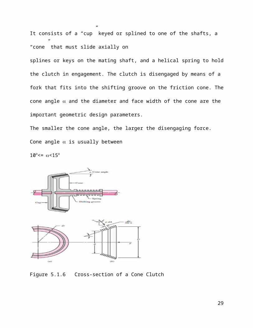
It consists of a “cup” keyed or splined to one of the shafts, a
“cone” that must slide axially on
splines or keys on the mating shaft, and a helical spring to hold
the clutch in engagement. The clutch is disengaged by means of a
fork that fits into the shifting groove on the friction cone. The
cone angle and the diameter and face width of the cone are the
important geometric design parameters.
The smaller the cone angle, the larger the disengaging force.
Cone angle is usually between
10o<=<15o
Figure 5.1.6 Cross-section of a Cone Clutch
29
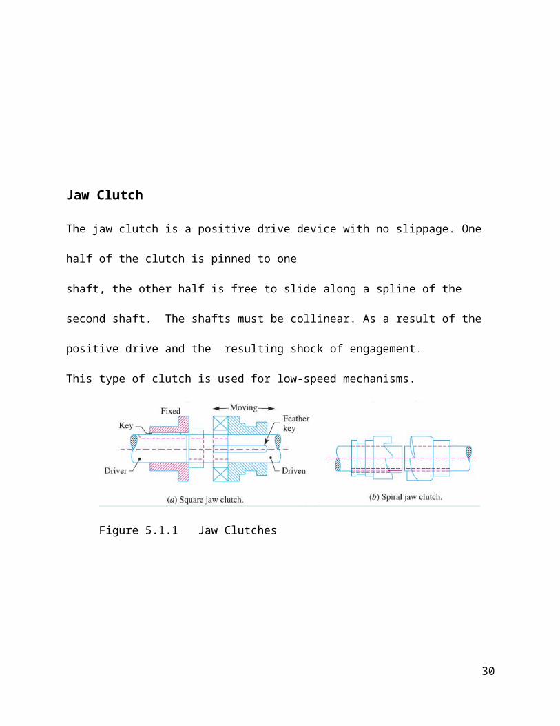
Jaw Clutch
The jaw clutch is a positive drive device with no slippage. One
half of the clutch is pinned to one
shaft, the other half is free to slide along a spline of the
second shaft. The shafts must be collinear. As a result of the
positive drive and the resulting shock of engagement.
This type of clutch is used for low-speed mechanisms.
Figure 5.1.1 Jaw Clutches
30

BRAKES
A brake is a device that is used to bring a rotating shaft or anyother rotating member to rest or
simply to reduce its speed.
Braking action is produced by friction as a stationary part bearson a moving part.A brake should not generate any significant shock loading during operation. It must also be fastacting and easy to operate. A brake converts all the kinetic energy of the moving part into thermal energy. This energy is notdesired and must be dissipated quickly. Excessively high temperature causes rapid decline in the coefficient of friction in the brake. This results in a brake failure condition known as “brake fade”. In cars this temperatureis around 230 oC.
Desired Characteristics of Friction Materials for Brakes
A good friction material must have the following characteristics:
High and reproducible coefficient of friction
31

Impervious to environmental conditions eg moisture Ability to withstand high temperature Good thermal conductivity High specific heat capacity High Resistance to wear Good resilience
(that is, must be able to recover its size and shape after being strained)
High flexibility
Examples of Suitable Friction Materials
Sintered Metal Rigid Moulded Asbestos Cermet (ceramics and metals ) Woven Cotton Resilient Paper
Figure 5.2.1 Examples of Suitable Friction Materials
Types of Brakes
32
Drum Brake (Similar to Rim Type, Internal Expanding Shoe
Clutch)
Band Brake
Disk or Axial Brake
Block Brake (Similar to Rim Type, External Contracting Shoe
Clutch)
The drum brake and the disk brake are the type employed in the
automotive industry.
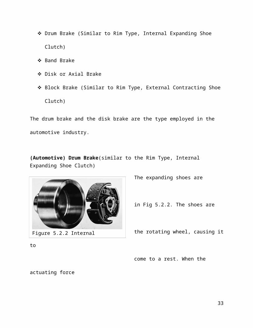
(Automotive) Drum Brake(similar to the Rim Type, Internal Expanding Shoe Clutch)
The expanding shoes are
pivoted as shown
in Fig 5.2.2. The shoes are
pressed against
the rotating wheel, causing it
to
come to a rest. When the
actuating force
33
Figure 5.2.2 Internal
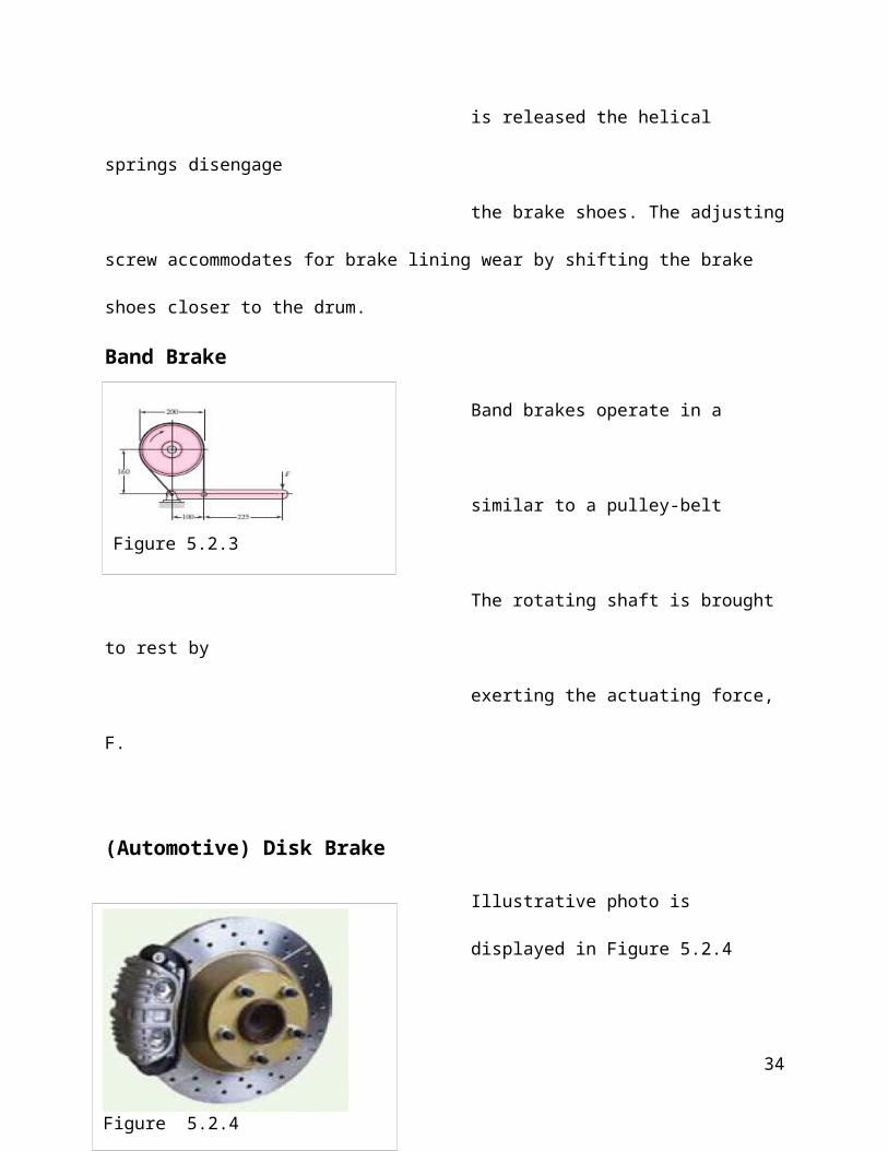
is released the helical
springs disengage
the brake shoes. The adjusting
screw accommodates for brake lining wear by shifting the brake
shoes closer to the drum.
Band Brake
Band brakes operate in a
manner that is
similar to a pulley-belt
system.
The rotating shaft is brought
to rest by
exerting the actuating force,
F.
(Automotive) Disk Brake
Illustrative photo is
displayed in Figure 5.2.4
34
Figure 5.2.4
Figure 5.2.3

Both sides of the brake disk
are used thus
providing a large frictional
surface as well
as a large cooling surface.
The thickness allows the disk
to act as a heat-sink, and
also to distribute heat more
evenly.
Block Brake
A block brake in its simplest form is a properly shaped block pressed against a rotating wheel as shown in Figure 5.2.5. The applied force is usually delivered by means of a lever to obtain a
35
Figure 5.2.5 Block Brake
Mechanical advantage. The block is usually covered with a friction material that is replaced when worn out.
Energy Absorbed By Brakes
If applied brakes reduces the velocity of a moving body of mass mfrom V1 to V2 the energy E absorbed by the brakes is given by
E = m(V12-V2
2)/2
This energy is usually dissipated as heat to the surroundings.
Dissipated Heatisestimatedas,H= C(t1-t2)A
Where C = coefficient of heat transfer A= radiating surface(t1-t2) = temperature difference between surrounding and the
radiating surface.
36

Calculations Involving Brakes And Clutches
Self-Locking Brakes
37
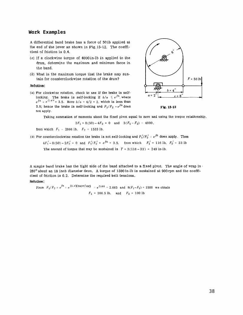
Work Examples
38

Worked Examples
39

FLYWHEELS
A flywheel is a device that acts as a reservoir that stores energy during the period when the supply of energy is more than the energy requirement, and releases it during the period when the requirement of energy is more than the supply, and redistributes the energy to control speed.
In case of steam engines, internal combustion engines, reciprocating compressors and pumps, the energy is developed during one stroke and the engine is to run for the whole cycle onthe energy produced during this one stroke.The excess energy developed during power stroke is absorbed by the flywheel, and itis released to the crankshaft during other strokes in which no energy is developed.
Figure 5.5.1a Flywheel
40

Figure 5.5.1b Flywheel
41
GEARS
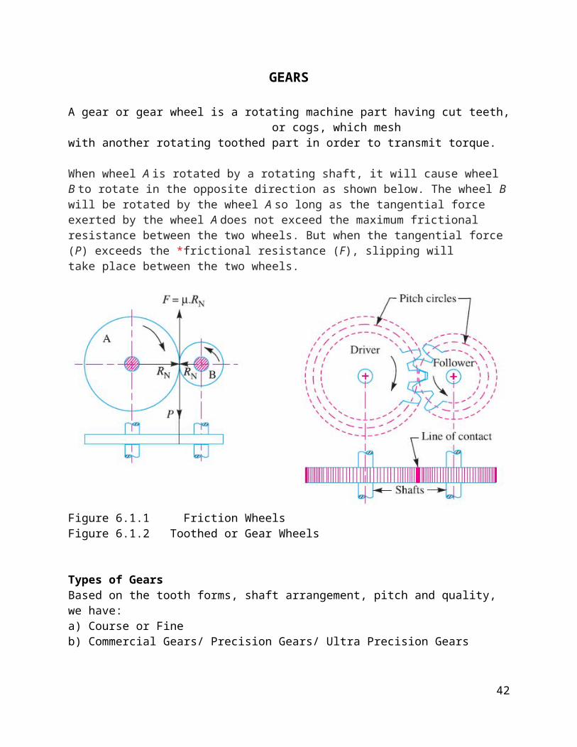
A gear or gear wheel is a rotating machine part having cut teeth,or cogs, which mesh
with another rotating toothed part in order to transmit torque.
When wheel A is rotated by a rotating shaft, it will cause wheel B to rotate in the opposite direction as shown below. The wheel B will be rotated by the wheel A so long as the tangential force exerted by the wheel A does not exceed the maximum frictional resistance between the two wheels. But when the tangential force (P) exceeds the *frictional resistance (F), slipping willtake place between the two wheels.
Figure 6.1.1 Friction Wheels Figure 6.1.2 Toothed or Gear Wheels
Types of GearsBased on the tooth forms, shaft arrangement, pitch and quality, we have:a) Course or Fine b) Commercial Gears/ Precision Gears/ Ultra Precision Gears
42

Tooth Form Shaft ArrangementSpur Gears ParallelHelical Gears Parallel or SkewWorm Gears SkewBevel Gears IntersectingHypoid Gears Skew
Spur Gears (Herring bone): Have teeth parallel to the axis of rotation and are used to transmit motion and rotation from one shaft to another parallel shaft. Spur Gears are the simplest in design.
Figure 6.1.3 Spur Gears
Helical Gears: Have teeth inclined to the axis of rotation. They provide a more quieter means of transmitting motion from one shaft to another, because of the more grading engagement of the teeth during meshing. Suitable for transmitting torque between unparallelshafts.
Figure 6.1.4 Helical Gears
43

Bevel Gears: Have teeth formed on conical surfaces and are used mostly for transmitting motion between intersecting shafts.
Figure 6.1.5 Bevel Gear
Worm Gears: Resembles a screw. The direction of rotation of the worm gear, also called the worm wheel, depends upon the directionof rotation of the worm and upon whether the worm teeth are cut right-hand or left-hand. Worm gear sets are also made so that theteeth of one or both wrap partly around the other. Used for high speed ratio applications (typically 3 or more)
Figure 6.1.6 Worm Gear
Methods of GearingThey are three methods of gearing, illustrated below.
44
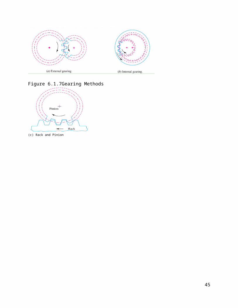
Figure 6.1.7Gearing Methods
(c) Rack and Pinion
45

Geometry and Terminology of a Gear
Pitch Circle: The pitch circle is the imaginary circle on whichmost gear calculations are based. When two gears mesh, theirpitch circles are tangent to each other. If two friction rollers(with circles equal to the pitch circles of a pair of meshingspur gears) were to roll together without sliding, they wouldhave the same speed ratio as the gears.
Pitch Diameter (D) and Pitch Radius (r): Pitch diameter and pitchradius are the diameter and radius of the pitch circle.
Pitch Point: The pitch point is the point on the imaginary linejoining the centers of two meshing gears where the pitch circlestouch.
Addendum Circle: The addendum circle is the circle that boundsthe outer ends of the teeth and whose center is at the center ofthe gear.
Figure 6.1.8Nomenclature of spur-gear teeth.
46

Dedendum Circle: The dedendum circle is the circle that boundsthe bottoms of the teeth and whose center is at the center of thegear.
Addendum (b): The addendum is the radial distance from the pitchcircle to the outer end of the tooth.Dedendum (b): The dedendum is the radial distance from the pitchcircle to the bottom of the tooth.Circular Pitch (p): The circular pitch is the distance betweencorresponding points on adjacent teeth, measured along the pitchcircle. The circular pitches of meshing gears must be equal ifthey are to operate properly. This is because of our method ofgear.
Diametral Pitch (P):Diametral pitch specifies the number of teethper inch of pitch diameter. For example, a gear wheel with 20teeth and a pitch diameter of 4 inches has a diametral pitchimplies a large tooth size.When the word pitch is used by itself, it implies the diametralpitch (not circular pitch). Gear catalogues usually list gearsaccording to their diametral pitches, listing all the sizesavailable for a diametral pitch of, say, 2 ½ together. The reasonfor arranging catalogs this way is that mating gears must havethe same diametral pitch (as will be proved later).
Tooth Space: Tooth space is the space between adjacent teeth,measured along the pitch circle.
Tooth Thickness: Tooth thickness is the thickness of the tooth,measured along the pitch circle. The pitch circle cuts each toothat such a location that the tooth thickness equals the toothspace, assuming there is no backlash (see Definition below).
Face Width (W): Face width is the length of the tooth, measuredparallel to the axis of the gear.
Face: The face is the surface between the pitch circle and thetop of the tooth.
47

Flank: The flank is the surface between the pitch circle and thebottom of the tooth.
Pressure Angle (ϕ): The pressure angle is the angle between theline of action and a line tangent to the two pitch circles at thepitch point.
Line of Action: The line of action is the locus of all the pointsof contact between two meshing teeth from the time the teeth gointo contact until they lose contact. Thus the load istransmitted from one gear to another along the line of action.
Pinion: The pinion is the smaller of the two meshing gears. Thelarger is called the gear.
Blacklash: Blacklash is the difference (clearance) between thetooth thickness of one gear and the tooth space of the meshinggear, measured along the pitch circle. With blacklash, there islooseness between meshing teeth, which becomes apparent when thedirection of rotation of the driver is reversed by hand.To be precise, the tooth thickness along the pitch circle equalsone – half the circular pitch minus the blacklash. The values forblacklash are somewhat standardized in the following amounts:0.030in./P, and 0.005in./P.
Hence, a typical range of values for blacklash would be 0.005 in.to 0.020 in., depending on the teeth size. The value selectedshould be the largest one acceptable, since the manufacture ofgears with small values of blacklash is very expensive. Also, toosmall a value of blacklash can cause binding (see Figure 7.5 foran illustration of blacklash).
Clearance (c): Clearance is the addendum minus the dedendum (seeFigure 7.5). Clearance and blacklash are both required to preventbinding.
Working Depth: Working depth is the distance that one tooth of ameshing gear penetrates into the tooth space.
48
Base Circle: The base circle is an imaginary circle about whichthe tooth involute profile is developed. Most spur gear teethhave an involute shape that runs from the base circle to the topof the tooth. The base circle is always tangent to the line ofaction.Fillet: The fillet is the radius that occurs where the flank ofthe tooth meets the dedendum circle.
Module: The term module replaces diametral pitch in the metricsystem. It is found by dividing the pitch diameter by the numberof teeth (the reciprocal of diametral pitch).
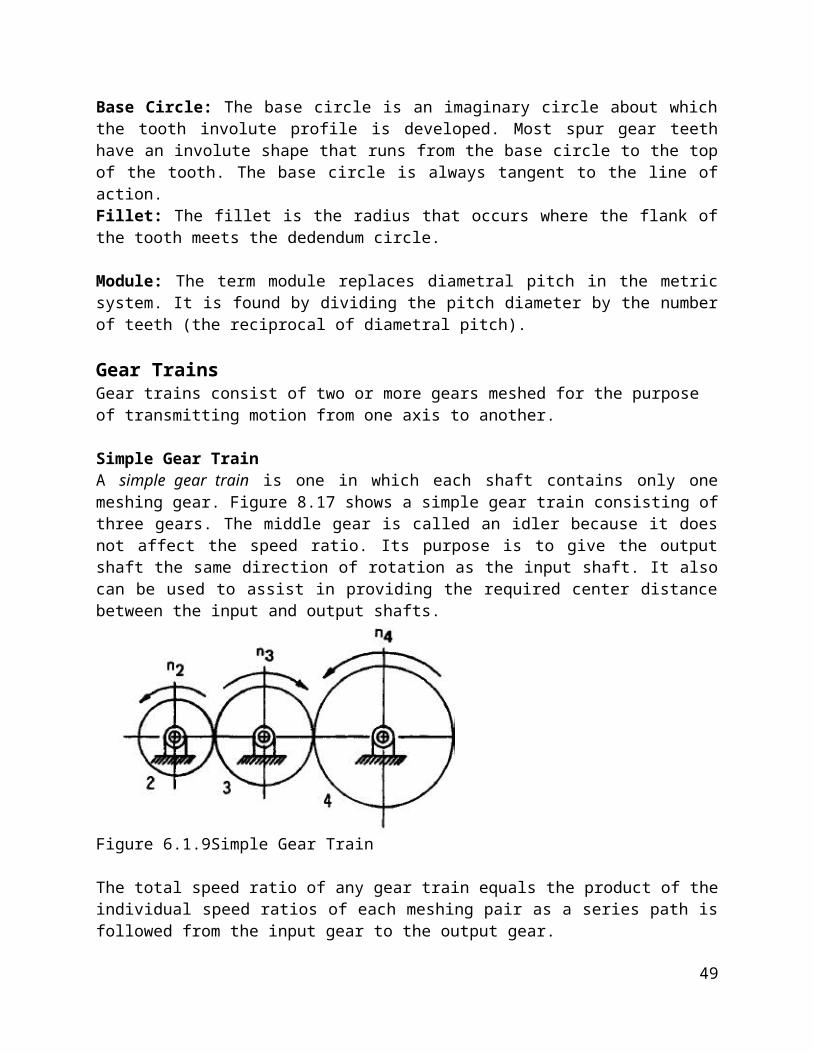
Gear TrainsGear trains consist of two or more gears meshed for the purpose of transmitting motion from one axis to another.
Simple Gear TrainA simple gear train is one in which each shaft contains only onemeshing gear. Figure 8.17 shows a simple gear train consisting ofthree gears. The middle gear is called an idler because it doesnot affect the speed ratio. Its purpose is to give the outputshaft the same direction of rotation as the input shaft. It alsocan be used to assist in providing the required center distancebetween the input and output shafts.
Figure 6.1.9Simple Gear Train
The total speed ratio of any gear train equals the product of theindividual speed ratios of each meshing pair as a series path isfollowed from the input gear to the output gear.
49

Speed ratio = wo = Di = Ni
wi Do No
where subscript, o, refers to the output gearsubscript, i, refers to the input gear
w = the speed of the gearD = the pitch diameter of the gearN = the number of teeth on the gear.
Compound Gear TrainA compound gear train is one in which there are two or moredifferent gear pairs connected in series. As a result, some ofthe shafts will contain more than one gear.
Figure 6.1.10Compound Gear Train
The speed ratio of a compound gear equals the product of all thetooth numbers of the driving gears divided by the of all thetooth numbers of all the driven gears.
The Epicyclic (Planetary) Gear Train
Up to now, all the gears discussed have been mounted on shaftssupported by bearings in stationary housings. Thus the axis ofrotation was fixed. An epicyclic, or planetary, gear train is onethat has one or more gears rotating about a moving axis. It isnormally used for speed ratios ranging from 1.2:1 to 12:1. Theplanetary gear train is usually more compact than other types oftrains for the same speed ratio and also a singe planetary gear
50
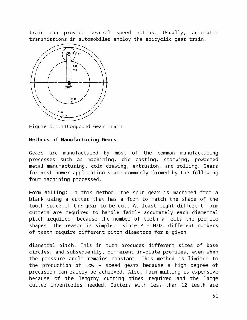
train can provide several speed ratios. Usually, automatictransmissions in automobiles employ the epicyclic gear train.
Figure 6.1.11Compound Gear Train
Methods of Manufacturing Gears
Gears are manufactured by most of the common manufacturingprocesses such as machining, die casting, stamping, powderedmetal manufacturing, cold drawing, extrusion, and rolling. Gearsfor most power application s are commonly formed by the followingfour machining processed.
Form Milling: In this method, the spur gear is machined from ablank using a cutter that has a form to match the shape of thetooth space of the gear to be cut. At least eight different formcutters are required to handle fairly accurately each diametralpitch required, because the number of teeth affects the profileshapes. The reason is simple: since P = N/D, different numbersof teeth require different pitch diameters for a given
diametral pitch. This in turn produces different sizes of basecircles, and subsequently, different involute profiles, even whenthe pressure angle remains constant. This method is limited tothe production of low – speed gears because a high degree ofprecision can rarely be achieved. Also, form milting is expensivebecause of the lengthy cutting times required and the largecutter inventories needed. Cutters with less than 12 teeth are
51

not used because of the resulting undercutting. A picture of arotating form milting cutter is shown in figure 7.15.
Rack Generation: A rack is considered to be a gear of infiniteradius (as stated before).Thus a tool shaped like a rack can bemade of hardened steel with cutting edges all around the ends ofthe teeth. The tool is given a reciprocating motion parallel tothe gear blank axis. Simultaneously, the gear blank is rotatedvery slowly while the race cutter continues to reciprocateaxially. The rack cutter is rotated very slowly while thevelocity to match the pitch line velocity of the gear blank. Thusthe material between the gear teeth is removed, leaving theinvolute teeth. Only one tool for each diametral pitch isrequired each time the rack cutter length has been exhausted. SeeFigure 7.16 for a picture of a rack cutter.
Hobbing: A hob is a cylindrical tool around which a thread of thesame form as a rack tooth has been helically cut. In appearance,a hob looks like a large – led threaded screw, except that thethread is given a series of axial gashes around its periphery.This is done so that cutting edges can be ground on the hardenedsteel hob (see Figure 7.17). Initially, the hob is placed to givethe correct depth of cut into the gear blank. It is then rotatedand, mathematically, the cutting action is equivalent to that ofa rack cutter.
The transverse motion of the rack cutter of the speeding methodis simulated by the lead of the helix of the hob as it rotates.The hob is fed axially along the blank until the teeth are cutalong the entire face width of the gear blank. A hob is thussimilar to a tap used for threading holes. Hobbing is acontinuous process, and therefore no indexing is required. It ispresently the most popular method of generating gear teeth and isrecommended for gears whose pitch line speeds are in the 2000 fpmto 4000 fpm range (for higher speeds the teeth manufactured bythis method should be ground or lapped).
52

Fellows Gear Shaper Method: This process uses a hardened steelcutter that is similar in appearance to the gear to be machined.Figure 7.18 shows a pinion shaped cutter. The cutter and gearblank are mounted on parallel axes. The cutting process is begunwith the gear blank held stationary and the cutter fed radiallywhile it reciprocates axially until the proper depth for thetooth is obtained. Then the gear blank and cutter are rotatedslowly as the cutter continues to reciprocate axially. The bigadvantage of this method is that only one cutter is needed forall gears required. As in the hobbing process, the Fellows gearshaper method is considered a precision machining operation.
Strength Of A Gear Tooth – Lewis Equation
Hunting ratio is a ratio of numbers of gear and pinion teeth which ensures that each tooth in the pinionwill contact every tooth in the gear before it contacts any tootha second time. (For example, 13 to48 is a hunting ratio; 12 to 48 is not a hunting ratio.) Give three examples of hunting ratios. Explainwhat the advantages of using hunting ratios in gear teeth.Solution: Examples of hunting ratios are 11:60, 17:36 and 19:40. The main advantage to a huntingratio are that a given gear tooth will contact every one of the teeth on the opposing gear before itcontacts the same tooth a second time. The advantages include:(a) Wear will be more even, since a critical tooth combination will not compromise the gear set.(b) Vibrations will be more controlled. When teeth are manufactured, there is always some departurefrom the ideal tooth profile. If a hunting profile is not used, then two teeth that have larger
53

deviations will produce a forcing function that results in large vibrations.(c) Lower tolerances are allowable for the same performance on the gearset.
54

![(2Z,N 0 0 0 E)-N 0 0 0 -[(2-Hydroxy-1-naphthyl)- methylidene]furan-2-carbohydrazonic acid](https://static.fdokumen.com/doc/165x107/631360d4b033aaa8b2100e91/2zn-0-0-0-e-n-0-0-0-2-hydroxy-1-naphthyl-methylidenefuran-2-carbohydrazonic.jpg)