! LMN Prosthetic Control EEG
10
IEEE TRANSACTIONS ON BIO-MEDICAL ENGINEERING, VOL. BME-18, NO. 6, NOVEMBER 1971 A New Approach to Prosthetic Control: BEG Motor Signal Tracking With an AMtMQYKARD Designed Phase-Locked Loop NOV419 NOV 4 1971 LLOYD M. NIRENBERG, MEMBER, IEEE, JOHN HANLEY, ER IEEE, AND EDWIN B. STEAR, MEMBER, IEEE INON-CULArjNC Do Not Remove From Library Abstract-The feasibility of using brain waves to control an ex- ternally powered prosthetic device for amputees was investigated. Two subjects were studied; one normal and one with a right hand disarticulation. Each subject, otherwise at rest, performed the proto- col of voluntarily, repetitively opening and closing his hand. The normal accomplished this, while the amputee attempted to use her missing limb as if it were present. The time between opening and the next closing, and between closing and the next opening, was ap- proximately 2 s. Simultaneously with this procedure, electroenceph- alograms (EEGs) were recorded from scalp electrodes presumably overlying the motor cortex on the left side, and an electromyogram (EM G) was taken from right forearm surface electrodes. The EEG and EMG were recorded on a polygraph and on magnetic tape. The latter recording was later sampled at 128 samples/s and quan- tized to 210 levels. Results were obtained by adaptively choosing the parameters for a phase-locked loop (PLL) to implement on-line monitoring of the EEG. Use was made of an interactive, graphical display com- puter system. It was discovered that threshold logic applied to the PLL multiplier output V yields a promising method to detect, based on the EEG, motor action in the normal subject and amputee. Obvi- ous motion and blink artifacts were accounted for. The PLL param- eters, optimized by visual inspection of V, were identical in both cases, except for the center frequencies of the voltage-controlled oscillator. The final thresholds were only slightly different. (The PLL in each case had a first-order linear filter.) I. INTRODUCTION .4. The Problem Tq HIS investigation concerns the feasibility of using an amputee's brain xvaves to control an externally powered prosthetic device (EPPD). We are moti- vated byr the fact that the most consistent complaint of amputees about their present day prosthetics is that an inordinate amount of mental attention is required to control the device. It seems clear that a scheme whereby Manuscript received Auguist 24, 1970; revised March 4, 1971. This research was accomplished while L. M. Nirenberg held a Hulghes Doctoral Fellowship. Computing assistance was obtainied from the Health Sciences Computinig Facility, U.C.L.A., sponsored by NIH Grant FR-3. This work was supported in part by the Air Force Of- fice of Scienitific Research unider AFOSR Gran-t 699-67, Bioengineer- in-g Grant GM\ 6098 NIGMS, and AFOSR Grant AF-49(638)-1387. This paper was presenited at the 1970 Hawaii System Sciences Con- ferenice. L. M. Nireniberg wvas with HuLghes Aircraft Company, Culver Cityv, Calif. He is nlow with the Space Biology Laboratory, Brain Research ItnstitLute, University of Californiia, Los Angeles, Calif. J. Hanley is with the Departtmienit of Psychiatry and Space Bi- ology Laboratory, Braini Research Instituite, University of California, Los Angeles, Calif. E. B. Stear is with the Departmiienit of Electrical Enigineeriig, University of California, Sianta Barbara, Calif. an amputee subliminally controls his EPPD eliminates this problem of "attention." We elaborate on these points below. Succinctly put, we must pursue the ques- tions, "Does the electroencephalogramn (EEG) of an amputee contain a detectable motor signal representa- tion?" and if the answer is yes, "Can w-e discover a scheme which can reliably detect various aspects of these signal representations, such as presence or absence and time of arrival?" [When we speak of detecting a motor signal representation (component) in the EEG, we mean to say we are detecting the presence of a motor signal in the nervous system through noisy observations (i.e., the EEG) of that signal.] Our preliminary studies with an adaptively designed phase-locked loop (PLL) lend some hope that we can answer these questions affirmatively. There are two basic approaches to the problem of control of externally powered prosthetic devices. One method, that of sensing brain waves, has been com- pletely ignored. The other approach, for which there has been extensive research over the years and a moderate degree of success, utilizes some residual muscle or nerve functions in the amputated extremity of the amputee in order to activate and control his substitute limb. An excellent discussion of these concepts is given in Alter [1]. I\Iore recently, Moss Rehabilitation Center, in conjunction with Temple University, has developed ani effective prosthetic device along these lines.1 The residual approach presents some inherent draw- backs. As a result of the residual approach, the amputee is forced to devote a significant amount of attention to the manipulation of his prosthetic device. This is a seri- ous problem since the amputee's overall effectiveness is thereby limited. This is primarily because of the fol- lowing. 1) The prosthetic use of the residual functions must be learned. 2) The residual functions have inherent limitations in their effectiveness in applications for which they are not normally used; furthermore, the residual functions (nerve endings, for example) may themselves lose effec- tiveness due to the amputation, or may not even exist, as in the congenital case. 1 R. Wirta, personal comniuinicatio, 389 Authorized licensed use limited to: Lloyd Nirenberg. Downloaded on November 1, 2009 at 20:59 from IEEE Xplore. Restrictions apply.
-
Upload
independent -
Category
Documents
-
view
1 -
download
0
Transcript of ! LMN Prosthetic Control EEG

IEEE TRANSACTIONS ON BIO-MEDICAL ENGINEERING, VOL. BME-18, NO. 6, NOVEMBER 1971
A New Approach to Prosthetic Control: BEG
Motor Signal Tracking With an AMtMQYKARD
Designed Phase-Locked Loop NOV419NOV 4 1971
LLOYD M. NIRENBERG, MEMBER, IEEE, JOHN HANLEY, ER IEEE,AND EDWIN B. STEAR, MEMBER, IEEE INON-CULArjNC
Do Not RemoveFrom Library
Abstract-The feasibility of using brain waves to control an ex-ternally powered prosthetic device for amputees was investigated.Two subjects were studied; one normal and one with a right handdisarticulation. Each subject, otherwise at rest, performed the proto-col of voluntarily, repetitively opening and closing his hand. Thenormal accomplished this, while the amputee attempted to use hermissing limb as if it were present. The time between opening and thenext closing, and between closing and the next opening, was ap-proximately 2 s. Simultaneously with this procedure, electroenceph-alograms (EEGs) were recorded from scalp electrodes presumablyoverlying the motor cortex on the left side, and an electromyogram(EMG) was taken from right forearm surface electrodes. TheEEG and EMG were recorded on a polygraph and on magnetic tape.The latter recording was later sampled at 128 samples/s and quan-tized to 210 levels.
Results were obtained by adaptively choosing the parametersfor a phase-locked loop (PLL) to implement on-line monitoring ofthe EEG. Use was made of an interactive, graphical display com-puter system. It was discovered that threshold logic applied to thePLL multiplier output V yields a promising method to detect, basedon the EEG, motor action in the normal subject and amputee. Obvi-ous motion and blink artifacts were accounted for. The PLL param-eters, optimized by visual inspection of V, were identical in bothcases, except for the center frequencies of the voltage-controlledoscillator. The final thresholds were only slightly different. (ThePLL in each case had a first-order linear filter.)
I. INTRODUCTION
.4. The ProblemTq HIS investigation concerns the feasibility of using
an amputee's brain xvaves to control an externallypowered prosthetic device (EPPD). We are moti-
vated byr the fact that the most consistent complaint ofamputees about their present day prosthetics is that aninordinate amount of mental attention is required tocontrol the device. It seems clear that a scheme whereby
Manuscript received Auguist 24, 1970; revised March 4, 1971.This research was accomplished while L. M. Nirenberg held a HulghesDoctoral Fellowship. Computing assistance was obtainied from theHealth Sciences Computinig Facility, U.C.L.A., sponsored by NIHGrant FR-3. This work was supported in part by the Air Force Of-fice of Scienitific Research unider AFOSR Gran-t 699-67, Bioengineer-in-g Grant GM\ 6098 NIGMS, and AFOSR Grant AF-49(638)-1387.This paper was presenited at the 1970 Hawaii System Sciences Con-ferenice.
L. M. Nireniberg wvas with HuLghes Aircraft Company, CulverCityv, Calif. He is nlow with the Space Biology Laboratory, BrainResearch ItnstitLute, University of Californiia, Los Angeles, Calif.
J. Hanley is with the Departtmienit of Psychiatry and Space Bi-ology Laboratory, Braini Research Instituite, University of California,Los Angeles, Calif.
E. B. Stear is with the Departmiienit of Electrical Enigineeriig,University of California, Sianta Barbara, Calif.
an amputee subliminally controls his EPPD eliminatesthis problem of "attention." We elaborate on thesepoints below. Succinctly put, we must pursue the ques-tions, "Does the electroencephalogramn (EEG) of anamputee contain a detectable motor signal representa-tion?" and if the answer is yes, "Can w-e discover ascheme which can reliably detect various aspects ofthese signal representations, such as presence or absenceand time of arrival?" [When we speak of detecting amotor signal representation (component) in the EEG,we mean to say we are detecting the presence of a motorsignal in the nervous system through noisy observations(i.e., the EEG) of that signal.] Our preliminary studieswith an adaptively designed phase-locked loop (PLL)lend some hope that we can answer these questionsaffirmatively.There are two basic approaches to the problem of
control of externally powered prosthetic devices. Onemethod, that of sensing brain waves, has been com-pletely ignored. The other approach, for which there hasbeen extensive research over the years and a moderatedegree of success, utilizes some residual muscle or nervefunctions in the amputated extremity of the amputee inorder to activate and control his substitute limb. Anexcellent discussion of these concepts is given in Alter[1]. I\Iore recently, Moss Rehabilitation Center, inconjunction with Temple University, has developed anieffective prosthetic device along these lines.1The residual approach presents some inherent draw-
backs. As a result of the residual approach, the amputeeis forced to devote a significant amount of attention tothe manipulation of his prosthetic device. This is a seri-ous problem since the amputee's overall effectiveness isthereby limited. This is primarily because of the fol-lowing.
1) The prosthetic use of the residual functions mustbe learned.
2) The residual functions have inherent limitationsin their effectiveness in applications for which they arenot normally used; furthermore, the residual functions(nerve endings, for example) may themselves lose effec-tiveness due to the amputation, or may not even exist,as in the congenital case.
1 R. Wirta, personal comniuinicatio,
389
Authorized licensed use limited to: Lloyd Nirenberg. Downloaded on November 1, 2009 at 20:59 from IEEE Xplore. Restrictions apply.

IEEE TRANSACTIONS ON BIO-MEDICAL ENGINEERING, NOVEMBER 1971
xternal ~ Hardware
( L ~~~~~~controls l
VVsual observotion of | |Hardware|Ihardware dynamics ldynomics
Fig. 1. Braini wave-sensing approach to conitrol of EPPDs.
On the other hand, in view of certain recent develop-mlents in brain-wave research by Hanley [2] of theUhT.C.L.A. Brain Research Iinstitute, it seems reasonablethat sensing brain waves can eliminate the problemsarising from the residual method and at the same timecan present no inherent problems of their own. Here itis assumed that the amputee retains the ability to gen-erate the brain command signal which he would havepresented to his normal limb, and that this may becapitalized on.
Fig. 1 depicts the brain-wave sensing system. We seekan algorithm which can detect, from brain-wave mea-
surements, the actual command signal that the amputeegenerates as if he had the normal limb instead of theprosthesis. UpoTn detecting the command signal, a suit-able control signal is generated in order to drive theEPPD. The imiajor goal of this research is to find a
pattern-recognition algorithm2 which can detect thissignal. We elaborate on the philosophy of this svstem inSection II.
Further problems renmaining to be solved in order toobtain an economically feasible EPPD, given the exis-tence of the pattern-recognizing algorithm, are of a
technological nature: electrodes to the brain are neededand the pattern recognizer has to be either extremelysmall (and portable) or in contact with the amiputee bytelemetry [3]. While these problems are formidable, we
expect their difficulty will be reduced as the state of theelectronics art advances. It is not the intention of thisresearch to consider this aspect of the problem, nor thatof the actual design of an EPPD.
B. Background Research
There has been significant EEG research concernedwith motor activity, and the papers extant indicatemotor signals do affect ongoing EEG scalp and depthrecordings. Jasper [4], Bates [5], and Gastaut [6] were
among the first investigators in this area. Chatrian [7],Gilden [8], Walter [9], and Hanley [2] made further
2 Be use the terms "pattern-recoginitioni algorithm," "decisionrule," and "statistical-decisiotn riule" initerchatngeably to stand forche logic of making decision based uiponi test statistic provided bysign'adl processi g.
signiificant studies. Results obtained by these researcherslead us to expect imiotor state represenitations in the EEGrecorded during mzotor action. Below, we report on theutility of PLL sigilal processing comibined wvith thresh-old decision logic used to extract EEG imiotor signalcomlponients.
IL. EXPERIMENTAL PROCEDUtRESA. Introduction
Before wve proceed to collect data, we need to be morespecific as to the actual miiode of operation of an EPPD,subliminally controlled. As a basic idealization, we seeka brain-wave sensing device which, based upon theEEG, determines at each instant of time whether or notan amputee at the wrist, say, wants to clench or uIn-clench his artificial hand. Either outcome of this on-going, real-time decision process will switch the EPPDto one of the two states, "close" or "open." It is impor-tant, ideally, to require that the brain signal thatswitches the EPPD be the saml-e signal as if there wereno amputation. This means, for example, in the case ofa wrist amputee, that by attempting to open or close hisphantom limb (hand) he actually controls an EPPD.Furthermore, in this case, the control is accompaniedby actual contractions of the muscles in the forearmjust as they would contract in opening or closing theoriginal normal hand. For brevity we omit discussionhere of certain basic philosophical questions concerningmotor function in an amputee. These are examined byNirenberg [10].
B. Methods and MllaterialsBecause they encompassed a wvide range of mlotor-
function ability, the subjects we chose to study were anormal adult male and an adult female with a right-wrist disarticulation. We use the term "adult" in thiscontext to indicate an adult EEG as opposed to a child'sEEG. The subjects were right handed. The traumaticamputee lost her hand at age 12, and Nas 18 years oldat the time of the experiments.We decided to place surface disk electrodes (Grass
model E-5G) on the scalp presumably lying over themotor cortex, since it seems a priori m-ost likely that thestrongest motor correlates in the EEG will be recordedfrom this region. Further details are given by Nirenberg[10]. The physiological basis for the geometry shown inFig. 2 is given by Schaltenbrand [11] and Ruch [12].
Electrodes were connected on the sides of the eyes inorder to record electrooculargram (EOG) signals. Thesegive an indication of the occurrence of eye blinks, whichare wrell known to sometimes cause erroneous distur-bances in the EEG. (ELe movemient is also included inour use of the term "blink.")
Finally', wve recorded electromyograrn (ELIG) signalsfrom the forearms of the normal and traumatic subjects.These are essential, for they enable US to have an inde-
390
Authorized licensed use limited to: Lloyd Nirenberg. Downloaded on November 1, 2009 at 20:59 from IEEE Xplore. Restrictions apply.
NIRENBERG et al.: PROSTHETIC CONTROL: EEG MOTOR SIGNAL TRACKING
H1 NasionH2 TragusH,3 InionL1 = 0.1 L, measured along surface of head, in plane of dashed line.
The diamonid has sides of approximately 1.0 in.
Fig. 2. Electrode arrangemen-t.
CODE ~~~~~~~~~Codepulse 200 1,1 llsl1l
A-R. Eor
8-R. Ear
C- R. EorEEG _W~
D- R. Ear
A-D
EMG 8<
OPEN CLOSE"> T38,-- Tl --_-T
R. Eye - R. Ear BLINK
EOG L. Eye - R. Eor
Fig. 3. Typical epochs from the paper trace.
pendent and sufficiently accurate indication of the timeof occurrence of contractions. This point is further de-veloped later in the paper. The ElVIG electrodes, con-
structed in the U.C.L.A. Space Biology Laboratory, were
connected to the subject's forearm by a Velcro strap.These electrodes were used with an electrolyte alsoprepared in the Space Biology Laboratory.We designate individual EEG, EIG, and EOG
channels by the pair of electrodes (shown in Fig. 2)hich provide the corresponding potential difference.The EEG and EM\IG waveforms were recorded simul-
taneously on a Grass polwygraph (with Grass model P511preamplifier) y,ielding a paper trace of voltage versus
time and on magnetic tape by an Ampex CP-100 14-channel tape recorder. (This recorder has a frequencyresponse of 0 to 600 Hz.) Simultaneously with the re-cording of EEG and EAIG, we recorded a BCD codetrain on both the paper and the tape, thereby providinga timne base with respect to the first of the coded pulses.An Airborne Instruments Laboratory code generatorfurnished the code train.The EEG voltages wvere recorded in various electrode
comlbiniations as shown in Fig. 3. Here we can see thepaper trace of the EEG, EM\IG, and EOG from the am-putee. One can also see a code pulse representing thenumber 200 in this figure. We note that the Grass EEGrecorders reverse the usual polarity directions, so that"up" is "negative." The EOG signals were recorded onpaper. Electronic isolation of the channels preventselectronic cross coupling. For clarity, Fig. 3 does notillustrate 5 channels of EEG recorded from additionalcombinations of electrode pairs.
C. The Experimental ProtocolsIn each case, the subject was at rest in the laboratory,
in a relaxed state, with his eyes open. Each subject wasinstructed to voluntarily close and open his right hand(normal subject), or attempt to close and open his phan-tom limb (traumatic amputee).The closings were roughly 4 s apart with the limb (as
the case may be) remaining closed for roughly 2 s.We chose voluntary movement because voluntary
movements must control a prosthetic device. We choseopening and closing of the hand for two reasons: firstly,the motions were well defined and easily distinguishableby use of the ENIG traces; secondly, a highly desirablefeature of any hand EPPD is the grasp.The time intervals were chosen as a tradeoff between
maximizing the total number of events in a fixed timefor statistical reasons, and minimizing the amount ofsignal degradation (accommodation) usually observeddue to tiredness after long repetitive events. We ob-tained roughly 500 sequences of close-open states in themanner described.By visually observing the motion of open and close
along with the ENIG trace, we were able to determinesufficiently accurately (in the context of the followinganalysis) the points of the EMIG epochs associated withopen and close.The subjects were recorded in the Clinical Neuro-
physiology Laboratory of the Neuropsychiatric Insti-tute of U.C.L.A. The magnetic tapes were digitized bythe A/D converter at the Brain Research Institute ofU.C.L.A. The amplified analog EEG and ENIG sigrnalswere sampled at a rate of 256 samples/s and quantizedto 210 levels. The resulting sequences of quantized sam-ples were then recorded on magnetic tape suitable forinput to the 1B13 360/91 at the Health Sciences Com-putinig Facility, of U.C.L.A.
391
Authorized licensed use limited to: Lloyd Nirenberg. Downloaded on November 1, 2009 at 20:59 from IEEE Xplore. Restrictions apply.

IEEE TRANSACTIONS ON BIO-MEDICAL ENGINEERING, NOVEMBER 1971
X (t) imM.pulse response VCOh It)
Av sin (wot + (t) )
VCO: voltage controlled oscillatorX (t)= -C cos (wOt +8(t) ) + n(t)
Fig. 4. T'he PLL.
III. PLL SIGNAL PROCESSING
.A. A-otivation for UTse of a PLL
A PLL is a nonlinear feedback system 7which can bedesigned to provide estimates of the phase of a sinu-soidal input signal in the presence of additive noise.Communication system engineers use the PLL to ac-quire a coherent reference for the optimum detection ofsignals in noise [13]. A brief description of the use of thePLL in the context of telecommilunication systems mayenable us to understand how it can be applied to thepresent problem.
Fig. 4 illustrates a PLL. The linear filter with inmpulseresponse h(t) operates on the multiplier output V(t). Thevoltage-controlled oscillator has output amplitude Ar,center frequency coo, and instantaneous frequencydeviation
de(t)= C,Z(t). (1)
dt
In the communications context, 0(t) is an estimate of thechannel phase 0(t). This phase is observed through thenoisy input signal
x(t) = - C cosQ(oot + 0(t)) + n(t) (2)where C is a constant amplitude, and n(t) is a Gaussiannoise process. The spectral density of n(t) is nonzeroImostly in the frequency region X <coo. The error in theestimate e(t) =0(t) -6(t) must remain small. It can beshown [13] that
A,[C1V(t) = Lv- sin E(t) + f(G) (3)
where fi(t) is another Gaussian random process whichdepends on n(t). This is the multiplier output. If thePLL is tracking accurately, c(t) «<<1 and ii(t) is negligi-ble. Hence, V(t) is essentially constant and small. Nowif x(t) suddenly takes large values at some time duringthe tracking mode, E(t) will no longer be small. Then theintegrator effects, storing the error, further increasee(t) [13]. Hence the loop "loses lock," and due to thesin (-) nonlinearity, allows V(t) to oscillate. The PLLnow tries to reacquire 0(t). Thus, a loss of lock is indi-cated whenever V(t) goes from steady small values tolarge oscillatory values. This loss of lock cain be caused
by any transienit input to the loop wvith significant powerat a frequency wvithin the bandwidth of the loop.Suppose that C =0. Then
A.,I. () = _ (t) (4)
X/2
and the loop is being driven by background noise withmost of its power concentrated in the frequency rangefco: IW <a,o} .3 As soon as a signal with pow!er at fre-quency coo is received, C>0 and V(t) is given by (3). Wetherefore conclude that if we input our EEG instead ofa noisy sinie wxvave, it miay be possible to use the outputV(t) of a PLL to detect, by the resulting transient, thearrival of a signal containing power \w-ithin the band Upto ccO, which represents an EEG motor signal conmpo-nent.
B. Application of the PLL to EEG Data
To enable our investigation of the PLL for motorsignal tracking we used an interactive graphical displaycomputer svsteml (IBM\1 360/91 and IBM1\ 2250 displayconsole). We thereby elimilinated drift problems of ana-log devices and completely simulated on-line processing.But most important, the graphics system allows us totrain the PLL. That is, we can choose a data sequenceand then visually observe the multiplier output whileadjusting parameters until the output gives a desiredresponse. Then we can process miore data and readjustthe loop parameters if necessary. Finally, we can thenproceed to test the loop response on the remaining data.We could, of course, avoid the graphics system as atraining device by specifying various criteria for themiultiplier output to satisfy and then letting the comin-puter search through a set of specified loop parametersfor a maxima of the criterion function. However, webelieve that a hunman operator can obtain a maximumfaster, in terms of computer central processor unit time,than can the computer. Furthermore, determining thePLL parameters using a human teacher allows his paral-lel processing of visual data to give mluch needed inisightto this nonparanmetric data source.
Here, we give the equations for the sampled-dataPLL. Next, we describe the details of the completediscrete-time decision making system, for wThich thecentral idea is the PLL. We conclude this section with achart of the training interactions between operator andcomputer.
In Fig. 5 wre detail the discrete-time PLL. WithY,, = Y( [n - 1 ]A), etc. the loop equations are given by
1", = .4, sin (.,) X n > 1 (5i)
I It is not necessary for the noise process n(t) to have significantpower only for w| <Co. Rather, n(t) can have power at all frequienciesbut only the portion within the passband of the PLI is significant.Clearly, this passband minst have a (single-sided) width n1o greaterthani wo.
392
(4)
Authorized licensed use limited to: Lloyd Nirenberg. Downloaded on November 1, 2009 at 20:59 from IEEE Xplore. Restrictions apply.

NIRENBERG et al.: PROSTHETIC CONTROL: EEG NMOTOR SIGNAL TRACKING3
Xn S
whrenve fie
wvhere we definle
we(canl write
A. Sill £*, II = I
- 'AA Siin (Q* + (*l - l) Aw, + AC )WO,nz > 2. (15)
Fig. 5. I)iscrete-time PLl.
and
Q--I 1CI7- CcI, +1 lC,vn, II > 1
xwhere A is the sampling timle anid is the reciprocal ofsamnpling frequency F,.The input to the VCO is
In order to avoid aliasing errors [14] we need tosamlple our data faster than twice its highest significantfrequency, fuiiax. If, however, we are interested onlv illthe frequencies up tofo fxnax, xve need only to choose thesampliig frequency greater than fo+Fftx. This will en-sure no aliasing of frequencies below fo. A generallyaccepted [15], [16] value of fniax for EEG studies is100 Hz, and we are concerned with frequencies below
(6) 25 Hz, so that we believe the decimlated sampling rateof 128 samples/s is sufficient for our purposes.
t.sing the PLL as just described, ve simnulated anlon-line decision system for the two-state control desired
(7) for close and open. First, xre used a "soft limiiter" QI(.)to preprocess the EEG sequence X, }. QU') is given
the AFt 7j-2 < X.< 71+72(16)Q1(X) = *-Yl - 72, A < 71 - Y2
(YI+ 72, x> Yy1+ '
Z =l= G > gn-kVk,k-=i
n,> 1
and
k>1
where we let {Xk} stand for the contiguous sequenmEEG samlples.We have chosen the linear filter
gka= ok, k > 01 0 < a <
which iminiediately allows Lis to xrite
Z1 = GXiY
zit = aZ,, + GX, L}1+i, 71 > 1.
By defining
S hSri =: E Zk.2
r'-1
enabling us to wvrite
= {GXY7,S, 1 + Z,t?
,I> 1
1i = 1
*n > 2
(8) We can adjust yT and Y2 so that we can symmetricallyclip the larger amplitudes of the EEG sequence X" }.This capability will prove useful below, although it isnot required for our major results. Except where other-
(9) wvise noted below-, we chose 72 large enough so thatce of Ql(x)=xforallx.
According to the discussion of Section Ill-A, themiiultiplier output is the crucial function to observe forloss-of-lock transients. To detect these transients, we
(10) may performl a threshold test on the fullwave rectifiedimiultiplier outputs, called d(n) }, where
d(n) = V1|. (1 7)We recall that these transient oscillations are supposed
(11) to signify the arrival of noisy motor signals. Let us use"state" to indicate a control signal for either open orclose, and A, for the threshold. Nowx we must not onlymake decisions as to close or open, but whether or not
(12) to mlaintain a previous state. Additionally, these deci-sions mllust be imiade on line, sample by sample. There-fore, xve may appropriately try decision logic:
(13)[decide at time n:
change state I s~ [d((n)"
A,].
_ maintain state!
(18)
and usiIng (6) and (7) comiibined as
Q*,
S*+ (, - 1)Aw,+AC,,EZ,kl=1
The interactions with the computer are diagrammllied- l in Fig. 6. Initially, xve can only guess values for a parani-
eter set P = (Au Ct,cvCo, a, TY, 72, C, Av) and for the initialii > 2 (14) phase Q*, and we type these into the computer 1y the
keyboard, alonig xith the samiipling rate F,sWe theni type
39 "
52l = t2*
V4 = Xk "k
Authorized licensed use limited to: Lloyd Nirenberg. Downloaded on November 1, 2009 at 20:59 from IEEE Xplore. Restrictions apply.

IEEE TRANSACTIONS ON BIO-MEDICAL ENGINEERING, NOVEMBER 1971
EEGStart: Initiolize P select
IF,£n and NBLOC
Read NBLOC datapoints fromdisc storage
Comnpute response.1
C Plot: CRpsupnse e Vrsothreshoid s, E:EG
and EMG sequences
MPnin System Cr aNo e more Yes
data ?
Fig. 6. Flow chart of compuiter initeractions.
in the number of sampleS NBLOC we desire to processwith this parameter set. We can vary this number as wewish,4 but we usually keep it fixed at 385, which corre-sponds to 3 s of data when F8 = 128. The computer usesthese parameters in (5)-(16) to compute the sequence
V,, }. Then these values are displayed on the cathoderay tube (CRT), along with the corresponding sequenceof X,,=EEG(n) and EAMfG(n). The operator is therebyenabled to decide, based upon the onset of open andclose as deternm-inied fromd the Ef\IG display, whether ornot the set P is acceptable.The operator then has these options: he can use the
same EEG sequence to try another parameter set P, orhe can procesS NBLocnmore samples from the overallsequence with the samne P or with an updated version ofP. The operator can then get a "feel" for the responseto the loop, and adjust the various parameters accord-ingly.Weco}mment that the decision logic was performed
visually, with the aid of thresholds plotted on the dis-plays of the test statistic d(n). This point is clarified inthe next section when we discuss the results.
C. Experimental ResultsWe chose visually "clean" 4-mm data segments from
each subject. 4-mmi segments (corresponding to 30 781samples) were chosen as a compromise between the on-line disk-storage capability of the IBM 360/91 and thedesire to store all the recorded data. Another constrainton selection of the data segments was artifact elimina-tion. It is difficult to obtain a long data epoch withoutartifact. Therefore, there are some blink andmrotionartifacts in these 4-mm continuous records, but it wasdetermined that these did not affect the results de-scribed below.
Using the interactive system described in SectionIWe-B, we determined a "good" parameter set P. We
We are constrained in this by certain system requirements, e.g.,the buffer which stores the data to be displayed and the instructionsfor the display must not overflow. This liMitS NBLOC to 400.
EMG
v , . ~~~~~~~~~~~~~~~~. r~~~~~~~~~~~~~~~~~~~~~~~I -Time
ifIThresholds
Fig. 7. Correct PLL response to open-close seqtuence in amputee'sEEG data.
decided P was good based upon the display of Vn, }, thesequence obtained at the multiplier output of the PLL.In Fig. 7 we illustrate a photograph of a display of 3 sof the amputee's EEG and EMIG, and the correspondinggood response { Vn }. We use the term good because theloop loses lock, as described in Section Ill-A, with onlyslight delay, after the onset of open or close and tracksthe background noise between these events. (The EMIGis used only to mark the onset of close and opein, and isInot used to compute { V, }.)The thresholds5 shown oIn the display of V in the
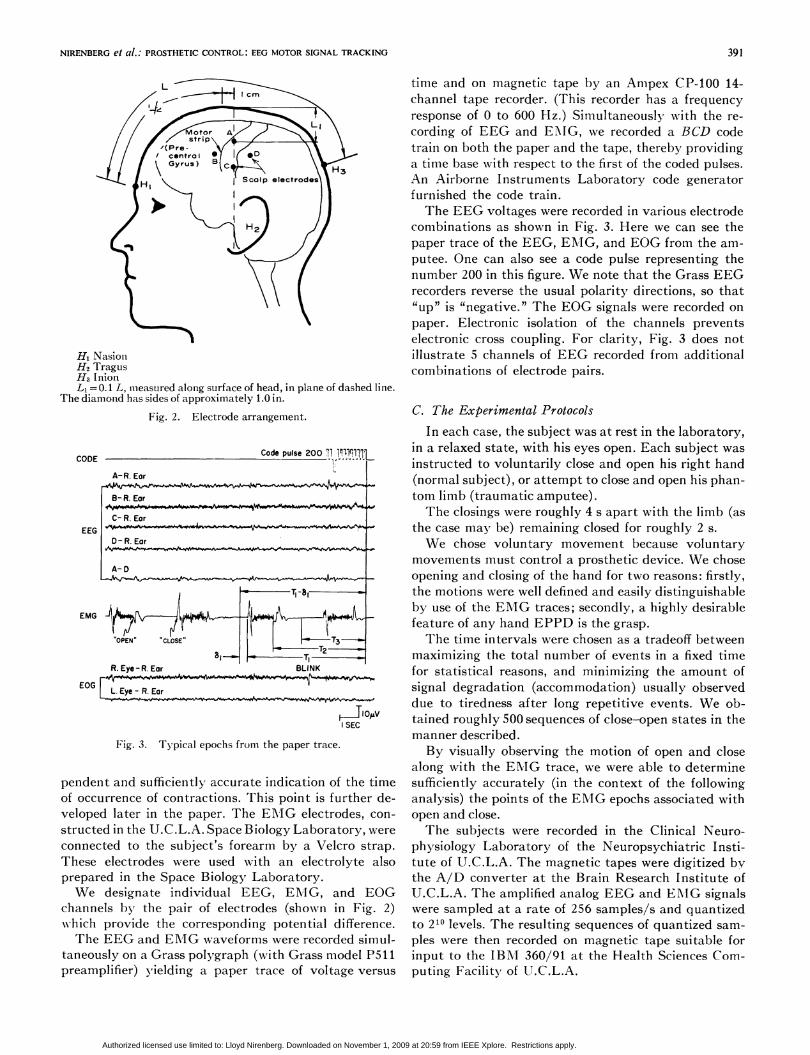
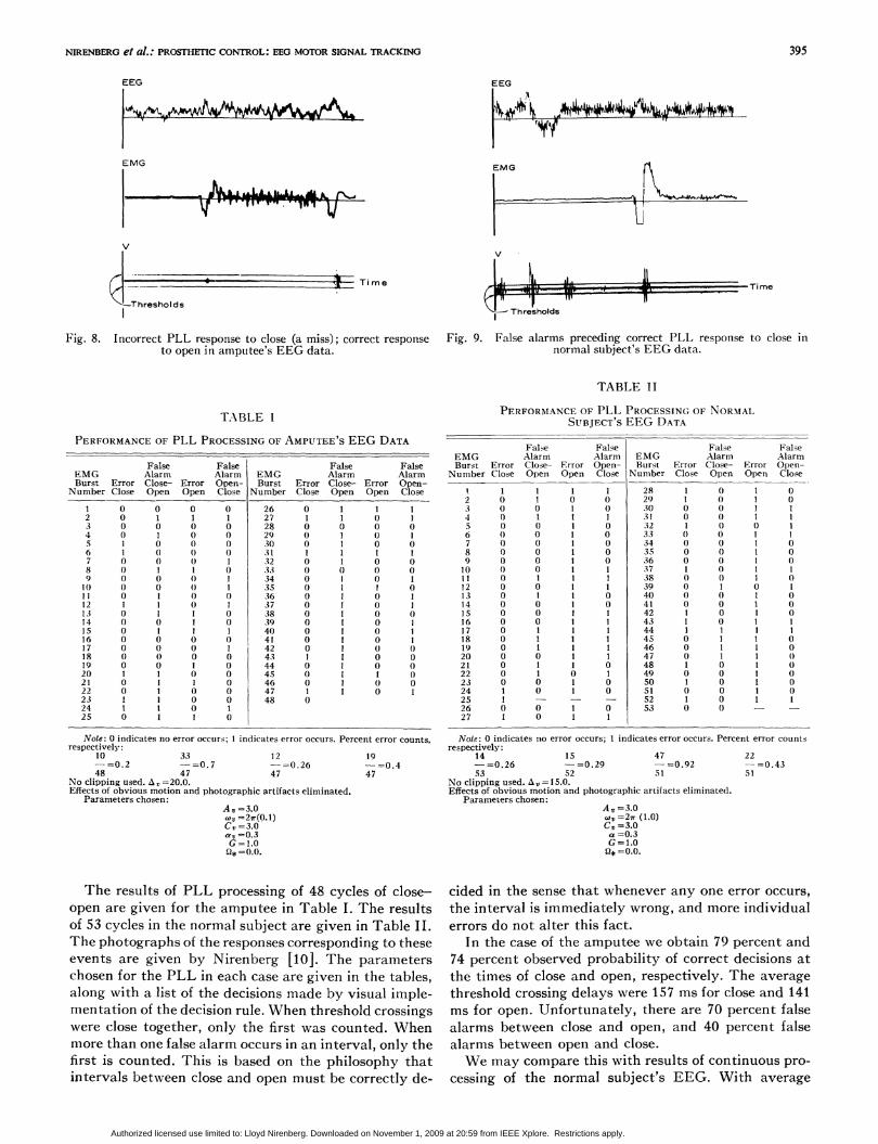
figure are used for visual impleimienitation of logic on thetest statistic d(n). While Fig. 7 illustrates correct re-sponse of the PLL to the input EEG, Fig. 8 shows howthe PLL can completely miss an event, in this case closefor the amputee. Fig. 9 showrs examiiples of false alarmsoccurring as the PLL processes the normal subject'sEEG. In these three displays, the terms "correct" and"false alarm" are used in the context of the decision logicoperating on d(n). That is, if V, crosses either displayedthreshold, we change state. We maintain the presentstate when the thresholds are not crossed. Thresholdcrossings were declared correct if they occurred within250 Imls after the onset of close or open. A false alarmwas declared if a threshold crossing occurred in a timeinterval beginning 250 ms after close or open and endingat the next open or close, respectively.
In Figs. 7-9 certain lines appear thicker than whatone would expect. This is dLie to the beam retrace per-sisting on the screen. The reader should also be awarethat the magnification provided by the display accountsfor the significantly improved detail structure of theEEG and EMIG over that of the paper trace, as illus-trated in Fig. 3. Another reason for this improvemiient ofdetail is the fact that the pens of the paper recorder havea more restricted frequency response than the magnetictape recorder, from which the computer display isgenerated.
WWe plot I V,, } and uise two thresholds to implement the logic onthe CRT, instead of plotting I VI7 I anid using one threshold. This isjust to enable the operator to observe I V, } .
394
Authorized licensed use limited to: Lloyd Nirenberg. Downloaded on November 1, 2009 at 20:59 from IEEE Xplore. Restrictions apply.
NIRENBERG et al.: PROSTHETIC CONTROL: EEG MOTOR SIGNAL TRACKING
EEG
EMG
V- { _~~~~~~~~J hi-, T
395
EEG
I .M
EM G _
1 -
U
rime
-'Threshol ds
l .11-11 l*I i . Ti me
Thresholds
IX
Fig. 8. Incorrect PLL response to close (a miss); correct response Fig. 9. False alarms preceding correct PLL response to close into open in amptitee's EEG data. normal subject's EEG data.
TABLE II
TABLE I
PERFORMANCE OF PLL PROCESSING OF AMPUTEE'S EEG DATA
False False False FalseEMG Alarm Alarm EMG Alarm AlarmBurst Error Close- Error Open- Burst Error Close- Error Open-
Number Close Open Open Close Number Close Open Open Close
1 0 0 0 0 26 0 1 1 12 0 1 1 1 27 1 1 0 13 0 0 0 0 28 0 0 0 04 0 1 0 0 29 0 1 0 15 I 0 0 0 30 0 1 0 06 1 0 0 0 31 1 1 1 17 0 0 0 1 32 0 1 0 08 0 1 1 0 33 0 0 0 09 0 0 0 1 34 0 I 0 1tO 0 0 0 1 35 0 1 1 011 0 1 0 1) 36 0 1 0 112 1 1 0 1 37 0 1 0 113 0 1 1 (1 38 0 1 0 014 1) 0 1 0 39 0 1 0 11s 0 1 1 1 40 0 1 0 116 0 0 0 0 41 0 1 0 117 0 1) 0 1 42 0 1 0 018 0 0 0 0 43 1 1 0 019 0 0 1 0 44 0 1 0 020 1 1 0 0 45 0 1 1 1)21 0 1 1 0 46 0 1 0 022 0 1 0 0 47 1 1 0 123 1 1 0 0 48 024 1 1 0 125 0 1 1 0
Note: 0 indicates no error occurs; 1 indicates error occurs. Percent error counts,respectively:
10 33 12 19-=0.2 -=0o. 7 -=0.26 -=0.448 47 47 47
No clipping used. A!=20.0.Effects of obvious motion and photographic artifacts eliminated.
Parameters chosen:Au=3.0wv=2r(Q.1)C, =3.0av =0.3G = 1.0Q* =0.0.
The results of PLL processing of 48 cycles of close-open are given for the amputee in Table I. The resultsof 53 cycles in the normal subject are given in Table II.The photographs of the responses corresponding to theseevents are given by Nirenberg [10]. The parameterschosen for the PLL in each case are given in the tables,along with a list of the decisions made by visual imple-mentation of the decision rule. When threshold crossingswere close together, only the first was counted. Whenmore than one false alarm occurs in an interval, only thefirst is counted. This is based on the philosophy thatintervals between close and open must be correctly de-
PERFORMANCE OF PLL PROCESSING OF NORMALSUBJECT'S EEG DATA
False False False FalseEMG Alarm Alarm EMG Alarmn AlarmBurst Error Close- Error Open- Burst Error Close- Error Open-
Number Close Open Open Close Numiiber Close Open Open Close
1. 1 1 1 1 28 1 0 1 02 0 1 0 0 29 1 0 1 03 0 0 1 0 30 0 0 1 14 0 1 1 1 31 0 0 1 15 0 0 1 0 32 1 0 0 16 0 0 1 0 33 0 0 1 17 0 0 1 0 34 0 0 1 08 0 0 1 0 35 0 0 1 09 0 0 1 0 36 0 0 1 010 0 0 1 1 37 1 0 1 111 0 1 1 1 38 0 0 1 012 0 0 1 1 39 0 1 0 113 0 1 1 0 40 0 0 1 014 0 0 1 0 41 0 0 1 015 0 0 1 1 42 1 0 1 016 0 0 1 1 43 1 0 1 117 0 1 1 1 44 1 1 1 118 0 1 1 1 45 0 1 1 019 0 1 1 1 46 0 1 1 020 0 0 1 1 47 0 1 1 1)21 0 1 1 0 48 1 0 1 022 0 1 0 1 49 0 0 1 023 0 0 1 0 50 1 0 1 024 1 0 1 0 51 0 0 1 025 1 - - - 52 1 0 1 126 0 0 1 0 53 0 0 - -
27 1 0 1 1
Note: 0 indicates no error occurs; 1 indicates error occturs. Percent error countsrespectively:
14 15 47 22-=0.26 -=0.29 -=0.92 -=0.4353 52 51 51
No clipping used. A =15.0.Effects of obvious motion and photographic artifacts eliminated.
Parameters chosen:At, =3.0ov=2sr (1.0)C5 =3.0a =0.3G =1.0Q* =0.0.
cided in the sense that whenever any one error occurs,the interval is immediately wrong, and more individualerrors do not alter this fact.
In the case of the amputee we obtain 79 percent and74 percent observed probability of correct decisions atthe times of close and open, respectively. The averagethreshold crossing delays were 157 ms for close and 141ms for open. Unfortunately, there are 70 percent falsealarms between close and open, and 40 percent falsealarms between open and close.We may compare this with results of continuous pro-
cessing of the normal subject's EEG. With average
v
.1
Authorized licensed use limited to: Lloyd Nirenberg. Downloaded on November 1, 2009 at 20:59 from IEEE Xplore. Restrictions apply.

IEEE TRANSACTIONS ON BIO-MEDICAL ENGINEERING, NOVEMBER 1971
TABLE IIICONFIDENCE INTERVALS
Meastired estimate P, of Pr(correct decision) with 100 90 percent confidence interval
decisions for 100 decisions
0.5 (41, 59)0.55 (45, 63)0.6 (52, 68)0.65 (56, 72)0.7 (62, 78)0.75 (66, 81)0.8 (72, 86)0.85 (78, 90)0.9 (82, 94)
MeasuLred estimate P, of Pr(correct decision) with 50 de- 90 percent confidence interval
cisionis for 50 decisions
0.5 (38, 62)0.55 (43, 68)0.6 (48, 72)0.65 (53, 77)0. 7 (58, 81)0.75 (63, 85)0.8 (68, 89)0.85 (74, 92)0.9 (80, 96)
threshold crossing delays of 1 2 Imis for close and 115 illsfor open, Table IL indicates 74 percent and 8 percentprobabilities of being correct in closing and opening,respectively, and 29 percent and 43 percent probabilitiesof making false alarms in the intervals close-open andopen-close, respectively. Confidence intervals for theseobservations may be conmputed from Table III. It isseen that the intervals for 50 tests are only slightly widerthan for 100 tests.
D. Discussion of ReszultsLet us begin by confrotnting the possibility that
artifacts cause the PLL to unlock, instead of motor sig-nal representations. Examinatioin of the EOG papertraces recorded duriilg the time interval selected forPLL processing of the EEG reveals that the times ofoccurrence of blinks are not the samiie as the timlles whenthe PLL unlocks. Furthernmore, the results during nmo-tion artifact were simply not included in the analysis.Therefore, we may neglect the obvious effects due toblink and motion artifacts. Another possibility forspurious results stenms from the influence of the ENIGitself. That is, one may wonder if somehow the muchlarger ENIG signals were able to influence the EEG andthereby unlock the PLL. In order to counter this possi-bility we need only recall that there is electroinic isola-tion between all recorded channels. Artifacts due toscalp ET\IG or jaw mi-iotion were not observed.There are, however, additional possible explanations
for the observed PLL behavior in terms of the nervousand muscle systems. In the first place, the muscle con-tractions which do occur may themiiselves cause inlputsto the peripheral nervous systenm thereby feeding backsignals to the brain. These feedback signals may bepropagated into the EEG and affect PLL performance.This possibility is to be distinguished from feedback to
the brain from the proprioceptive system. These signalsmay also influence the EEG.We cannot directly evaluate these aforementioned
effects at this time. However, we can observe that asidefrom the blink and motion artifacts, the other effects areassociated with the attempt to control the hand, andoccur only when the attempt is made.6
Comparison of the threshold phase-locked loop(TPLL) results reported in Tables I and IL is revealing.We see that for both cases the PLL parameters are thesame except for the VCO frequency. The amputee'sVCO wvas tuned to 0.1 Hz and the normal subject's to1.0 Hz. The thresholds are different, the amputee using20.0 and the normal subject 15.0, but the results are notunduly sensitive to threshold deviations of + 5.0.
Similarities are also seen in the test scores, as well asimportant differences. The amputee's EEG yielded 79percent correct decisions as to the onset of close, against74 percent for the normal subject. There were 40 percentand 43 percent respective false alarm rates in the inter-val between open and the next close. But whereas theamlputee had a 74 percent rate of correct decisions as tothe onset of open, preceded by a 70 percent false alarmirate in the interval between the close and open, thenormal subject had 8 percent and 29 percent, respec-tively. The results are tabulated in Table IV-A. Oneshould keep in mind that a detection is counted at thetime of close or open only if a threshold crossing occursin the 250nms interval following the onset of that event,whereas a false alarmii can occur anywhere in a signifi-cantly longer interval.
Physical insight to the meaning of these results maybe gained in the following nmanner. Let us examine theway in which errors occur preceding the decision to closeor to open. We compute the relative frequency for eachof the joint events:
(false alarm) C\ (error) = 00, 01, 10, 11
from the infornmation in Tables I and II. This gives usa nieasure of the significance of false alarms in the inter-val preceding a transition to the close or open state. Forexample, (false alarm)fl (error) = 10 is the event whena correct decision to open is preceded by a false alarm inthe interval following the last onset of the actual closestate. These relative frequencies are given in TablesIV-B and IV-C.From Table IV-B we see that for both subjects, the
dominant events in terms of relative frequency are 00and 10. It appears just as likely for correct decisions atclose times to be preceded by a false alarm as it is for nofalse alarm to precede that correct decision. This isconsistent with the similarity in single event probabil-ities cited above. We maay conclude that in these experi-ments, the TPLL scheme is fairly good at detecting theonset of close, and this performance seems unrelated tothe EEG state during the preceding time period,
6We neglect tonic inputs because they are not associated withmotion; nor do we seek to detect tonic inputs.
396
Authorized licensed use limited to: Lloyd Nirenberg. Downloaded on November 1, 2009 at 20:59 from IEEE Xplore. Restrictions apply.

NIRENBERG et al.: PROSTHEC CONTROL: EEG MOTOR SIGNAL TRACKING
TABLE IV
RELATIVE FREQUENCIES OF EVENTS
Definitions
1) FA00,,=Event that a false alarm occuirs in the time interval be-
tween the onset of "close" and the onset of "open."2) E, =Event that the oniset of "open" is m-issed at the end of the
interval described in (1).3) F.40. Event that a false alarm occurs in the time interval be-
tween the onset of "open" and the onset of "close."4) E,=-Event that the onset of "close" is missed at the end of
the interval described in (3).5) ()indicates the complemenit of ani event(
A. Single Event Relative Frequencies
Ec FAco To FAoc
Amputee 0.79 0.70 0.74 0.40
Normal Subject 0.74 0.29 0.08 0.43
B. MLultiple Event Relative Frequencies for FAoc,nE,00 01 10 11
Amputee
Normal Subject
0.405 0.180 .382 .022
0.375 .196 .375 .059
C. Multiple Event Relative Frequencies for FACOnEG00 01 10 11
AAmputee
Normal Subject
0.26 0.043 0.49 0.216
0.02 0.69 0.059 0.235
wherein the subject's hand (real or phantom) is relaxedand open.
From Table IV-C it becomes clear that the amputee'sdata is most likely to exhibit false alarms preceding cor-
rect decisions at open times. The TPLL applied to thenormal subject's EEG is most likely to exhibit no falsealarms preceding wrong decisions at the time of open.
Putting aside for the moment the fact that the prob-abilities of correct decisions at close and open are nothigh enough at present for practical application, we are
faced with the interesting performance differences be-tween the subjects for the FA00 and Eo events. It is pos-sible that there is less power required by the signals inthe central nervous system for the transition from theclosed state to open than required for the transitionfrom the opened state to close. Accordingly, this mayexplain lower detection rates for open than for close. Thenormal subject clearly exhibits this.
In the case of the amputee, however, we may furthersuggest that she mentally concentrates significantlyharder to maintain the closed state of her phantom limbthan for her normal limb and accordingly this increasednervous system activity is monitored by the TPLLthrough the EEG and manifests itself in higher falsealarm and detection rates for FAco and Eo than in thenormal subject. This is a point we can verify experi-
mentally by changing the experimental protocol so thatafter repetitive opening and closing of one hand (real or
phantom) during simultaneous EEG, EMG, and EOGrecording, the subject repeats the procedure with hisother hand. However, in terms of the time spent in the
laboratory by a subject, the cost of this procedure wasprohibitive in our initial study.
Let Us now consider the problemii of the time delaysbefore threshold detections. Because the PLL requiresa certain amount of time to acquire the input frequencyand phase, and because this acquisition time is coIm-putable only for restricted classes of inputs to the PLL[13] (e.g., noiseless sine waves) which we certainly donot have, the acquisition timie for our system is un-known. Similarly, the time that the PLL requires torespond to the arrival of power within its bandwidth isnot computable for our input data. For these reasons wecannot infer the time at which the EEG input initiatesloss of lock in the PLL, and therefore we cannot relatethis time to the onset of motion. We are still faced byfalse alarm and detection rates which are unacceptablefor practical application. For the present we might keepin mind that the lower than desirable probabilities ofcorrect detection at close and open can be compensatedfor by simply repeating the attempt. The false alarms,however, appear to require modifications in the datacollection or signal processing procedures, or both. Weelaborate on this point in Nirenberg [10].Those readers familiar with the study of the CNV by
Walter7 may wonder if the dc shift apparent in Fig. 7 iscausing the PLL to unlock. We conclude this is not truefor two reasons. First of all, the dc shift associated withthe CNV was observed by Walter only after time-lockedaveraging. The dc shift apparent here is so much larger(inasmuch as it is immediately visually distinguishable)that it is difficult to associate it with that of Walter'sCNV. Furthermore, use of the clipper [10] allowed usto remove all EEG find structure, leaving only a dclevel. But in this case the loop never crossed the thresh-old, whereas it did previously. Hence, the dc level isinsufficient to cause the loop to break lock. Accordingly,we may conclude the CNV is not pertinent to ourresults.
REFERENCESt1] R. Alter, "Bioelectric control of prostheses," M.I.T. Res. Lab.
of Elec., Cambridge, Tech. Rep. 446, Dec. 1966.[21 J. Hanley, D. 0. Walter, J. R. Rhodes, and UV. R. Adey,
"Chimpanzee performance: computer analysis of electro-encephalograms," Nature, vol. 220, Nov. 1968, pp. 879-881.
[3] J. R. Zweizig, R. T. Kado, J. Hanler, and WV. R. Adey, "Thedesign and use of an FM/AM radiotelemetry system for multi-channel recording of biological data," IEEE Trans. Biomed.Eng., vol. BME-14, Oct. 1967, pp. 230-238.
[41 H. Jasper and WV. Penfield, "Electrocorticograms in man: effectof voluntary movement upon the electrical activity of the pre-central gyrus," Arch. Psychiat. Nervenkr., vol. 183, 1949, pp.163-174.
[51 J. A. V. Bates, "Electrical activity of the cortex accompanyingmovement," J. Physiol. (London), vol. 113, 1951, pp. 240-257.
[61 H. Gastaut, 'Etude electrocorticographique de la reactivititedes rythmes Rolanidiques," Rev. Neurol., vol. 87, 1952, pp. 176-182.
7Walter et al. [91 report a "continlgent negative variation'"(CNV) wave in the EEG. This CNV occurs in the EEG in thefollowing manner. The subject is told that after seeing a flash oflight, he will hear, approximately 1 s later, a series of clicks which hecan stop by pressinig a button. By time-locked averaging it, Waltershows that the subject's EEG has a marked negative variation im-mediately preceding the time when he stops the clicks. This negativevariation is contingent on the subject's expectancy of the sequenceof clicks.
397
Authorized licensed use limited to: Lloyd Nirenberg. Downloaded on November 1, 2009 at 20:59 from IEEE Xplore. Restrictions apply.

398
[7] G. E. Chatrian, M. C. Petersen, and J. A. Lazarte, "The block-ing of the Rolandic wicket rhythm and some central changesrelated to movement," Electroencephalogr. Clin. Neurophysiol.,vol. 11, 1959, pp. 497-510.
[8] L. Gilden, H. G. Vaughn, and L. D. Costa, "Summated humanEEG potentials with voluntary movement," Electroencephalogr.Clin. Neurophysiol., vol. 20, 1966, pp. 433-438.
[9] W. Grey Walter, R. Cooper, V. J. Aldridge, W. C. McCallum,and A. L. Winter, "Contingent negative variation: an electricsign of sensori-motor association and expectancy in the humanbrain," Nature, vol. 203, July 1964, pp. 380-384.
[10] L. M. Nirenberg, "Pattern recognition and signal processingtechniques applied to EEG motor signal analysis," Ph.D. dis-sertation, School Eng. and Applied Sci., Univ. California,Los Angeles, Dec. 1969.
IEEE TRANSACTIONS ON BIO-MEDICAL ENOINEERING, NOVEMBER 1971
[11]; G. Schaltenbrand and P. Bailey, Introduction to Stereotaxis, withan Atlas of the Human Brain. Stuttgart, Germany: GeorgThieme Verlag, 1959, part 2.
[12] T. C. Ruch and J. F. Fulton, Medical Physiology and Biophysics.Philadelphia, Pa: Saunders, 1960.
[13] A. J. Viterbi, Principles of Coherent Communication. NewYork: McGraw-Hill, 1966.
[14] P. M. DeRusso, R. J. Roy, and C. M. Close, State Variables forEngineers. New York: Wiley, 1965.
[151 E. Kaiser, 1. Petersen, U. Sellden, and N. Kagawa, "EEG datarepresentation in broad band frequency analysis," Electroen-cephalogr. Clin. Neurophysiol., vol. 17, 1964, pp. 76-80.
[16] L. H. Zetterberg, "Estimation of parameters for a linear dif-ference equation with application to EEG analysis," Univ.Stockholm, Stockholm, Sweden, Tech. Rep. 18, Apr. 1968.
Lloyd M. Nirenberg (S'63-M'67) was born in New York, N. Y., on August 8, 1943. He received theB.S.E. degree in electrical engineering from the University of Michigan, Ann Arbor, in 1964, andthe M.S. and Ph.D. degrees in engineering from the University of California, Los Angeles, in 1967and 1969, respectively. From 1965 to 1967, he was a Hughes Masters Fellow, and in 1969 held aHughes Staff Doctoral Fellowship.
From 1965 to 1971 he was with Hughes Aircraft Company, Culver City, Calif., working in theareas of detection theory, coding and synchronization systems, multiple access communications,data compression techniques, and digital filtering. In 1971 he joined the Space Biology Laboratoryat the University of California, Los Angeles, as a postdoctoral fellow, where he pursues applicationsof computers to brain research.
John Hanley (M'67) was born in England. He was a Leopold Schepp Foundation scholar in medicalschool and received the M.D. degree from Boston University, School of Medicine, Boston, Mass., in1961. He completed a residency in psychiatry at the University of California Medical Center, Los Ange-les, in 1961 and was awarded a mental health postdoctoral fellowship for the 1965-1966 residency year.
He was an EEG Consultant for the NASA Biosatellite III project and a Consultant to NASAand HEW on patient monitoring systems. He is currently a Member of the Space Biology Labora-tory of the Brain Research Institute, University of California, Los Angeles, and a full-time memberof the Department of Psychiatry.
Dr. Hanley is a member of the American Neuroscience Society and the Neuroelectric Society.l
Edwin B. Stear (A'57-M'70) was born in Peoria, Ill., on December8,1932. He received the M.S. degreein mechanical engineering from the University of Southern California, Los Angeles, in 1956 and thePh.D. degree in engineering from the University of California, Los Angeles, in 1961.
From 1954 to 1959, he was employed as a Member of the Technical Staff of Hughes AircraftCompany, Culver City, Calif., where he worked on various aspects of air-to-air missile design andanalysis. While at Hughes, he held the Hughes Master of Science Fellowship from 1954 to 1956 andthe Hughes Doctoral Fellowship from 1956 to 1958. From 1959 to 1961, he was an Assistant ResearchEngineer at the University of California, Los Angeles, where he did research on control systemstheory. From 1961 to 1963 he was a Project Officer in the U. S. Air Force in charge of several appliedresearch programs in aerospace vehicle flight control. From 1963 to 1964 he was Manager of theControl and Communications Laboratory at Lear Siegler, Inc., where he directed research programsin control and communications theory and practice. He joined the University of California, LosAngeles faculty in 1964 as an Assistant Professor, where he taught and supervised graduate studentsin the control and systems area. In 1969 he transferred to the University of California, Santa Bar-bara, where he is currently an Associate Professor in the Department of Electrical Engineering, incharge of the academic program in control and systems science. He has published over twenty papersin various aspects of control and systems theory and practice, including several papers on hormonalcontrol. He is also coeditor of the book, Hormonal Control Systems (published by American Elsevier).He has consulted widely for various government organizations and is currently Senior TechnicalConsultant to the Air Force Space and Missile Test Center.
Dr. Stear is a member of the American Institute of Aeronautics and Astronautics and Sigma Xi,and is currently a Member of the Scientific Advisory Board to the Chief of Staff of the Air Force.
Authorized licensed use limited to: Lloyd Nirenberg. Downloaded on November 1, 2009 at 20:59 from IEEE Xplore. Restrictions apply.