• INSTALLATION & START-UP MANUAL • OPERATION ...
122
BATTERY BACK-UP SYSTEM (BBS2000) Model: CT2.0A0100N1-20 • INSTALLATION & START-UP MANUAL • OPERATION MANUAL STATE OF CALIFORNIA Documentation # 6002-1842 Revision A This manual applies to the following units: CT20100 through CT20200
-
Upload
khangminh22 -
Category
Documents
-
view
0 -
download
0
Transcript of • INSTALLATION & START-UP MANUAL • OPERATION ...

BATTERY BACK-UP SYSTEM (BBS2000) Model: CT2.0A0100N1-20
• INSTALLATION& START-UP MANUAL
• OPERATION MANUAL
STATE OF CALIFORNIA
Documentation # 6002-1842
Revision A
This manual applies to the following units: CT20100 through CT20200

6002-1842 Rev A ECO# 8881
i
IMPORTANT EMERGENCY SHUTDOWN PROCEDURE IS IN THE BACK COVER OF THIS
DOCUMENT
SAVE THESE INSTRUCTIONS
HEADQUARTERS Online Power Los Angeles, CA
Phone: (800) 227-8899 Phone: (323) 721-5017 FAX No.: (323) 721-3929
email: [email protected]

6002-1842 Rev A ECO# 8881
ii
TABLE OF CONTENTS Page
1. INSTALLATION AND START-UP MANUAl…………………………………..…1 2. OPERATOR’S MANUAL……………………………………………………………19

6002-1842 Rev A ECO# 8881
iii
Congratulations on selecting one of the fine products from OnLine Power, the Leader in Power Protection Technology. Our wide product offerings includes Uninterruptible Power Systems (UPS), Power Conditioners, Automatic Voltage Regulators and Specialty Transformers (e.g.,computer-grade, medical-grade). Since our founing in 1975, OnLine Power has shipped thousands of these fine products around the world, to discerning customers, for use on sensitive equipment and critical applications. Our customers, both new and long-time, continue to enjoy security and peace of mind as they realize what it means”When the lights go out, we turn on”.
HEADQUARTERS OnLine Power Los Angeles, CA
SALESPhone (800) 227-8899Phone (323) 721-5017FAX No. (323) 721-3929 email: [email protected]
Office Hours 7:30 AM to 5:00 PM PST
NOTICE: THIS DOCUMENT CONTAINS PROPRIETARY INFORMATION
This document contains proprietary and confidential information of On-Line Power, Inc. (”On-Line Power”). In consideration of the receipt of this document, the recipient agrees not to copy any of its contents, nor disclose them to or allow them to be used by any person not currently a On-Line Power employee or an employee of the recipient having a need to know, without the express written consent of On-Line Power, and further agrees to surrender this document to On-Line Power when the reason for its receipt has terminated.

6002-1842 Rev A ECO# 8881
iv
IMPORTANT SAFTERY INSTRUCTIONS ARE CONTAINED IN THIS MANUAL
Safety precautions are important when operating or servicing electrical equipment. The following symbols are used extensively throughout this manual. Always lead these precautions since they are essential to the safe operation and servicing of this product.
CAUTION
RISK OF ELECTRICAL SHOCK
THIS DANGER SYMBOL IDENTIFIES A CONDITION WHERE HIGH VOLTAGE EXISTS.USE EXTREME CAUTION.
c 2008 Online Power-All rights reserved
6002-1842 Rev A ECO# 8881
v
THIS UNIT WAS DESIGNED FOR SPECIFIC APPLICATIONS. IT SHOULD NOT BE MODIFIED AND/OR USED FOR ANY APPLICATION OTHER THAN FOR THAT WHICH IT WAS DESIGNED. OPTIONAL EQUIPMENT NOT DESCRIBED IN THE SALES LITERATURE OR THIS MANUAL SHOULD NOT BE INSTALLED WITHOUT FIRST CHECKING WITH THE SERVICE DEPARTMENT. IF YOU HAVE ANY QUESTIONS ABOUT THIS UNIT’S APPLICATION CALL THE SERVICE DEPARTMENT AT THE NUMBER SHOWN ON THE PREVIOUS PAGE.
Only qualified personnel should service this product
ATTENTION: IMPORTANT OPERATING INSTRUCTIONS. FOLLOW THEM CLOSELY.
IMPORTANT SAFTERY PRECUATIONS

6002-1842 Rev A ECO# 8881
vi
Battery Backup System Safety Checklist: Carefully unpack the System report any shipping damage at once Read this manual. If you have any questions contact Online power customer
service department. Before installing, confirm the voltage and current input requirements of the load(s) is
compatible to the system’s requirement. The system should be installed on the dedicated circuit. Use proper lifting techniques to move the system. When installing the system in different cabinets other than approved cabinets,
ensure the cabinet meets the requirements of the environment required and the specification in this manual.
SAVE THIS MANUAL This technical manual contains important instructions that should be followed during installation and maintenance of the BBS System.
DANGER: Sealed–acid batteries with high energy and chemical hazards are used,
this manual contains important safety instruction.
DANGER: Risk of electric shock. Do not remove cover. No user serviceable parts are inside.
to reduce the risk of fire, replace only with the same type and rating of fuse.

6002-1842 Rev A ECO# 8881
vii
IMPORTANT SAFETY INSTRUCTIONS (Continued) BATTERY / STORAGE AND SAFTEY CHECK LIST There is dangerous voltage used in the system. Only qualified personnel should
perform installation and maintenance. Live batter wire must not touch the chassis or any metal objects. This can cause fire
and or explosions. Inspect the batteries once a year for sings for cracks, leads or swelling. When batteries are in storage, charge them at least once every three months for
optimum performance and lifetime. Replace batteries only with batteries supplied by or approved by Online Power Inc.
If you substitute batteries not supplied by OLP, unit’s listing may be void and you may create an unsafe condition and the equipment may fail. Always replace batteries with ones of identical type and rating. Never install old or untested batteries. Never mix old with new batteries.
Do not dispose of battery in fire. They may explode. Do not attempt to open the batteries. The electrolyte is toxic and corrosive. The following precautions should be taken when replacing the battery Remove
watches, rings, etc. Use tools with insulated handles. Battery is supplied as separate individual quantity. Connection should be in series
and DC volt is 48 VDC. Standby Generator Note: when connected to line power, and the UPS constantly switches back and forth between Battery and Line mode, because of line fluctuations, the UPS’s parameters should be broadened from Normal to Generator.

6002-1842 Rev A ECO# 8881
viii
STORAGE OF BATTERY BACKUP SYSTEM: When not installed or used, store the unit and MBS/PTR assemble within the, Temperature rang of (-) 40 deg. To +74 deg C. Relative humidity of 0 to 95% non-condensing. Altitude of 40,000 feet max. Battery should be stored on the shelf around 25 deg. C (77 deg F) for maximum life. Battery should be charged after 4 months of shelf storage to prevent aging and deterioration.
UNPACKING AND INSPECTION CHECKLIST:
Carefully open the shipping package and remove the unit and other contents and make sure the following items are included.
One UPS controller unit with temperature sensor.
One installation and start-up manual and operator’s
Any ordered options.
NOTE: If any items are missing or damaged, contact Online Power at once.

6002-1842 Rev A ECO# 8881
ix
RECORD ALL SERIAL NUMBERS FOR THE UPS CONTROL UNIT AND, BATTERY PACK / PACKS. THESE SERIAL NUMBERS WILL BE REQUIRED IF YOUR SYSTEM NEEDS SERVICE. KEEP THIS MANUAL IN A PLACE WHERE YOU CAN REFERENCE THE SERIAL NUMBERS IF SERVICE IS REQUIRED! BBS UNIT SERIAL NUMBER: ____________________________________________________________ MODEL NUMBER: ______________________________________________________________________ PURCHASE DATE: ________________________________________________________________________ BATTERY CABINET OR SERIAL NUMBER: ____________________________________________________ ADDITIONAL ITEMS: _________________________________________ _______________________________________ _________________________________________ _______________________________________ _________________________________________ _______________________________________ _________________________________________ _______________________________________ _________________________________________ _______________________________________
SAVE THESE INSTRUCTIONS

6002-1842 Rev A ECO# 8881 1
SECTION 1
INSTALLATION AND START-UP MANUAL
ONLINE POWER BATTERY BACK UP SYSTEM
BBS2000 Model: CT2.0A0100N1-20
Battery Backup System (BBS2000)

6002-1842 Rev A ECO# 8881 2
TABLE OF CONTENTS INSTALLATION AND START-UP MANUAL PAGE
1.1 DESCRIPTION (Theory of Operation) 3
1.1.1 SYSTEM DESCRIPTION 4 1.1.2 UPS CONTROL UNIT 5 1.1.3 MBS / (MANUAL BYPASS SWITCH) 6
AND PTR (POWER TRANSFORMER RELAY) 1.1.4 BATTERIES 7
1.2 TOOLS REQUIRED 7 1.3 INSTALLATION 7 1.4 WIRING 8 1.5 START-UP 12 1.6 SHUTDOWN 13
1.6.1 UPS CONTROLER UNIT SHUT-DOWN 13 1.6.2 MBS / PTR SHUT 14
1.7 TROUBLESHOOTING 15 1.8 GLOSSARY 16

6002-1842 Rev A ECO# 8881 3
1.1 DESCRIPTION Purpose: Describes the operation of Online Power Battery Backup system. (Figures 1.1,1.2,1.3)
Theory of Operation:
The BBS provides backup power to traffic control and signal equipment when the utility line out of range or absent all together.
• It consists of the following: (Refer to Figure 1.1 for detail) UPS controller unit Battery charger Microprocessor board Display board Monitoring board
• MBS/PTR (Maintenance By-pass Switch/Power Transfer Relay). • Batteries
The BBS operates as an offline UPS, to supply AC power to a Critical Load when the MBS is in the BBS position, while charging the batteries at the same time. It converts DC power from batteries to usable 120VAC 60Hz power. When external or utility power is present and within range, the BBS remains in a charging mode. When the external or utility power is out of range (98VAC to132VAC), or absent, the unit will switch to the BBS mode and provides power to the intersection without interruption. When the utility power is present or within range, the BBS transfers to utility power and stand-by mode to charge the batteries. When the MBS is on the BBS position, the input power supplies AC voltage directly to Critical load. When the input voltage is out of the operating range (98VAC to 132VAC), which is set by a microprocessor, the inverter supplies AC output to the critical load within a maximum 65 milliseconds transfer time. Battery run time in this mode will last for minimum of 2 hours at;1500 watt load. When the input voltage has recovered to the normal Range (105V t o125V ± 2V) and has been stable for 30 second, the inverter will automatically transfer back to utility power to support the critical load within maximum of 65-milliseconds. The Power Transfer Relay continuously monitors line voltage. When the voltage is out of range, a transfer to inverter power takes place. The BBS provides remote sensing through a DB9 connector and 3 sets of contactors available on a panel mount terminal block.The first set of NO and NC contacts are energized when the unit switches to Battery Power.The second set of NO and NC contacts are energized when the battery approaches approximately 40% of remaining useful capacity. The third set of NO and NC contacts are energized 2 hours after the unit switches to battery power.The MBS will allow the BBS to be removed from the circuit for anything requiring attention such as battery replacement or other installation requirements.

6002-1842 Rev A ECO# 8881 4
1.1.1 SYSTEM DESCRIPTION The OnLine Power battery back-up system provides uninterruptible power to traffic control and signal equipment. The total maximum power is 1500 watt at 74°C. The Battery Backup System has a unique system protection scheme to supply uninterrupted power to the critical traffic control and signal system whether the input power line voltage is out of specified range or fails. This is accomplished by providing a Power Transfer Relay (PTR) and manual Maintenance Bypass Switch (MBS) and batteries to provide back-up power when the input power line voltage is out of the specified range or fails. These three components can be mounted in an enclosure as specified in California Department of Transportation (Caltrans) Specifications.
The line power is applied to the MBS / PTR Assembly. The line power supports the critical load when the input line voltage is within the specified range. When the line voltage is out of range or fails (off-line UPS) the UPS controller detects these conditions and sends a signal to the PTR causing the relay to transfer the load from the line to the UPS output until the line power recovers or the batteries are fully discharged. The operating time of this mode depends upon the battery’s status and the size of load. The Online Power BBS is designed for a maximum of two hours operation from battery source with 1500 watt load.
UPS CONTROL UNIT
BATTERIES
J2
J2
+
-
P2
P2
+
-
CB3
BATT. C.B.INPUT C.B.
CB1 CB2
OUTPUT C.B.
TB2-1
TB918 19
TB2-4 TB3-1 TB3-3TB2-1
TB1-4
1
3
BBSMANUAL
5
7BBS
MANUAL
TB1-1
UP STREAMINPUT C.B.
LINE INPUT AC
2/4
6/8
CRITICALLOADDOWN STREAM OUTPUT
CIRCUIT BREAKER OR FUSE
OUTPUT - (H)
MBS / PTS ASSY
MBSK
(+)
(-)
(K1) (PTS)N/O
N/C
CONTROL SIGNAL FOR PTS RELAY
SIMPLIFIED BBS BLOCK DIAGRAM
FIGURE 1.1
C
B
A

6002-1842 Rev A ECO# 8881 5
1.1.2 UPS CONTROLLER UNIT: The OnLine Power Battery Backup System
The UPS controller unit provides the control function and monitors the input line voltage continuously to detect its condition.
For details, refer the Operator’s manual in section 2
BBS UNIT (UPS CONTROLLER UNIT)
5.25
17.00
A
Figure A
AC INPUT& OUTPUTCIRCUIT
BREAKER
AC INPUTNL
48V BATTERY
Battery temperatureSensor
CONNECTOR
C; COMMON NC:NORMALLY CLOSED NO:NORMALLY OPEN
1 2
L N
C
SERIAL INTERFACE
L NAC OUTPUTS
USB
C3 C4 C5 C6C NCNONCCNC NOCC NONC
CONTACTS MAXIMUM RATING: 1A, 240V
ESC
C1 C2C NONCNC NO
OUTPUT
ALARM
Read the Operator'sManual Before Installationor servicing
+NO
SELFTEST
-
PTS
Heavy Object46.2lbs, 21Kg
Warning
+
BATTERYCIRCUIT
BREAKER
48VDC 3A MAXEXTERNAL FAN
+
+BATTERY VOLTAGE
TEST POINT

6002-1842 Rev A ECO# 8881 6
1.1.3 MBS / PTR (MANUAL BYPASS SWITCH AND POWER TRANSFER RELAY:
The Power Transfer Relay (PTR) provides off-line UPS function and allows the UPS controller unit to be removed for replacement without interruption of power to the critical load. It provides a power flow path to the critical load from the UPS controller unit when the input line voltage is out of range or fails. The Manual Bypass Switch (MBS) provides a means of transferring the input line power directly to the critical load and allows the Battery Backup System to be removed.
B
Figure 1.3
M BS/PTR UNIT
17.0
3.5
4.25

6002-1842 Rev A ECO# 8881 7
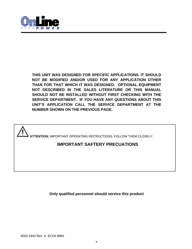
1.1.4 Batteries:
The four-battery string voltage is 48 VDC (12V / battery). Batteries are sized to aupport a 1500w traffic load for two hours. Different size batteries can be used in the BBS to provide various backup times. A battery connection diagram is enclosed in each BBS shipping packages for different configurations.
1.2 TOOLS REQUIRED:
The following tools are required to install the Battery Backup System, MBS/PTR, and batteries.
♦ Philips screw driver ♦ Flat screw driver ♦ Socket wrench ♦ Multimeter
1.3 INSTALLATION: Purpose: Describes how to mount the BBS2000 System in an enclosure.(The BBS2000 system
components can be mounted in a single external cabinet or in the existing traffic cabinet). EXTERNAL MOUNT:
The factory supplied external cabinet can be bolted onto the existing or a new traffic cabinet. It can also be mounted on a concrete slab or be pole mounted. To make installation easy for the contractor, OnLine Power can provide a separate base for cabinet installation on a concrete slab, bolts and hardware for attaching to the side of a traffic cabinet, bushings for wire ducts and brackets for pole mounting along with all required accessories including mechanical hardware and electrical wiring could be supplied as an option. External outdoor cabinets such as the BC100 or BC80 are weatherproofed and provided with an internal exhaust fan that is temperature controlled, an intake filter that can be cleaned or replaced, a three-point lockable handle with dual keys and a unique internal keyed lock. The factory-supplied cabinet meets or exceeds the requirements of various NEMA classifications.
INTERNAL MOUNT:
The BBS2000 components can also be mounted inside an existing NEMA, 332 or various other traffic cabinets. The special Swing Tray, designed to hold the four batteries, is easily mounted inside an existing 332 type or other equivalent cabinets using the hardware that is provided or batteries can be shelf mounted in a NEMA or equivalent cabinet. The BBS2000 can be bolted into an industry standard 19” rack using the supplied brackets, or it can be shelf mounted in a NEMA type enclosure. The MBS/PTS supplied with or without optional generator switch can be shelf mount or 19” rack mount.
C
Caution 1. Wear protective clothing and eye wears. For all voltage battery systems, wear
rubber gloves and boots. 2. Remove rings and metal wristwatches or other metal object and jewelry. Don’t
carry metal objects in your pockets where the objects can fall onto the batteries or into the electronics or battery cabinet.
3. Tools must have insulated handles and must be insulated so that they will not short battery terminals. Do not allow a tool to short a battery terminal to another battery terminal or to the cabinet at any time. Do not lay tools or metal parts on top of the batteries and do not lay them where they could fall onto the batteries or into the cabinet.

6002-1842 Rev A ECO# 8881 8
1.4 WIRING: Before wiring the system determine size of the load:
Load/Input Wiring:
Figure 1.4
G BUS
332 CABINET
LINE
GND
LINEUTILITY
NEUTRAL
AC OUTPUT
EXTERNAL CABINET
UTILITY LINE IN
N BUS
GL NNEU
MBS/PTR
GND
7060-1091-01HARNESS
DANGER: If this is a new traffic signal installation with Utility AC power going directly to UPS, make sure the upstream circuit breaker feeding the Utility Power is OFF before beginning wiring. If this is addition of a UPS to an existing traffic signal cabinet, DO NOT terminate the power cable from the signal cabinet to the UPS at the signal cabinet end until the final step after all other connections have been completed. This will minimize the length of time the traffic signals must be off for final power connection.
DANGER: There are many different ways that the Utility AC can be wired into the traffic signal cabinet. The intent of this manual is only to explain proper connection of utility AC at the UPS end of
the cable. How the Utility AC is routed from the service entrance or through the traffic signal cabinet (hereafter referred to as the “power source”) to the UPS shall be determined by a licensed electrician in accordance with local electrical codes.
DANGER: The utility input power line must have circuit breaker or fuse protection as per the local electrical code. It is referred as “Upstream Circuit Breaker” in this manual.
TIP: The suggested method of wiring utility AC to the UPS from the traffic signal cabinet is to connect the UPS at the traffic cabinet after the main cabinet breaker and surge suppressor so that the UPS is also protected by the cabinet surge suppressor.

6002-1842 Rev A ECO# 8881 9
HARNESS 7060-1090-01
UTILITY LINE IN
HARNESS 7060-1163-01
GND NEUTRAL
LINE
UTILITYLINE N
332 CABINET
GL
G BUSN BUS
AC INPUT& OUTPUTCIRCUIT
BREAKER
AC INPUTNL
48V BATTERY CONNECTOR
Battery temperatureSensor
C; COMMON NC:NORMALLY CLOSED NO:NORMALLY OPEN
1 2
L N
C
SERIAL INTERFACE
L NAC OUTPUTS
USB
C3 C4 C5 C6C NCNONCCNC NOCC NONC
CONTACTS MAXIMUM RATING: 1A, 240V
ESC
C1 C2C NONCNC NO
OUTPUT
ALARM
Read the Operator'sManual Before Installationor servicing
+NO
SELFTEST
-
PTS
48VDC 3A MAXEXTERNAL FAN
+
Heavy Object46.2lbs, 21Kg
Warning
+
BATTERYCIRCUIT
BREAKER
+BATTERY VOLTAGE
TEST POINT
EXTERNAL CABINET
BBS UNIT
HARNESS 7060-1164-01
AC OUTPUT
NEU
GNDHARNESS
7060-1091-01
MBS/PTR
J2P2
Interconnection wiring between UPS Control unit and MBS/PTR Assembly Figure 1.5

6002-1842 Rev A ECO# 8881 10
44
AC INPUT& OUTPUTCIRCUIT
BREAKER
AC INPUTNL
48V BATTERY CONNECTOR
Battery temperatureSensor
C; COMMON NC:NORMALLY CLOSED NO:NORMALLY OPEN
1 2
L N
C
SERIAL INTERFACE
L NAC OUTPUTS
USB
C3 C4 C5 C6C NCNONCCNC NOCC NONC
CONTACTS MAXIMUM RATING: 1A, 240V
ESC
C1 C2C NONCNC NO
OUTPUT
ALARM
Read the Operator'sManual Before Installationor servicing
+NO
SELFTEST
-
PTS
48VDC 3A MAXEXTERNAL FAN
+
Heavy Object46.2lbs, 21Kg
Warning
+
BATTERYCIRCUIT
BREAKER
+BATTERY VOLTAGE
TEST POINT
444
4
BATT+
11 J2/P2
-
33
22
44
+1
1J3/P3
-3
3
BATT
22
+1
1 J4/P4
-
33
BATT
22
BBS UNIT
HARNESS 7060-1162-01
+1
1 J1/P1
-
33
BATT
22
Interconnection between Battery and UPS Control unit
Figure 1.6
♦ Tape or seal the Battery Temperature Sensor to the case of the top battery. Plug the connector on the other end into the BBS at “Battery Temperature Sensor”. Wrap a tie around the strain relief loop and the battery temperature sensor to prevent the connector from disconnecting during an earthquake or other severe vibrations.
TIP: The 48V BATTERY CONNECTOR must ‘click’ when inserted for proper connection. A common source of problems is that the battery connector is not fully inserted. The BBS will Alarm when turned on if the batteries are not properly connected.
NOTE: The LCD Display and keypad on the BBS are shipped with a protective plastic film over them. This film should be removed by peeling from one corner before first use of the system. The LCD display will be difficult to read if the film is left on.

6002-1842 Rev A ECO# 8881 11
BBS UNIT
+
BATT
11
BATT
+1
1
-
23234
4
-34 2
34 2J2/P2
BATT BATT
+2
2
HARNESS 7060-1162-01
+1
1
-
4 34 3J3/P3
22
-
33J4/P44
4 11 J1/P1
G BUS
332 CABINET
L
UTILITY
LINENEUTRAL
GND
LINE
EXTERNAL CABINET
HARNESS 7060-1163-01
AC OUTPUT
UTILITY LINE IN
HARNESS 7060-1090-01
N BUS
NG
HARNESS 7060-1164-01
NEU
7060-1091-01HARNESS
MBS/PTR
GND
AC INPUT& OUTPUTCIRCUIT
BREAKER
AC INPUTNL
48V BATTERY CONNECTOR
Battery temperatureSensor
C; COMMON NC:NORMALLY CLOSED NO:NORMALLY OPEN
1 2
L N
C
SERIAL INTERFACE
L NAC OUTPUTS
USB
C3 C4 C5 C6
C NCNONCCNC NOCC NONC
CONTACTS MAXIMUM RATING: 1A, 240V
ESC
C1 C2
C NONCNC NO
OUTPUT
ALARM
Read the Operator'sManual Before Installationor servicing
+NO
SELFTEST
-
PTS
48VDC 3A MAXEXTERNAL FAN
+
Heavy Object46.2lbs, 21Kg
Warning
+
BATTERYCIRCUIT
BREAKER
+BATTERY VOLTAGE
TEST POINT
J2P2
Complete Installed unit: (Shown with 332A cabinet) Figure 1.7
.
TIP: Each of the six contacts are of form C type, meaning Normally Open (NO), common (C) and Normally Closed(NC) dry contact rated for 1 Amp at 120VAC. Each of these contacts can be individually programmed to energize and stay latched for ON BATTERY, LOW BATTERY, TIMER, ALARM, FAULT and many other conditions as described in subsequent chapters. The ON BATTERY contact(s) are activated as soon as the BBS is transferred to Battery mode. LOW BATTERY contact(s) are activated only in the Battery mode as soon as the discharged battery reaches the lower value battery capacity as set by user and remains latched as long as the system remains in Battery mode. The TIMER contact(s) are activated only in the Battery mode after the user-programmed time is attained, that can be set in 15-minute intervals from 15 minutes to 8 hours.

6002-1842 Rev A ECO# 8881 12
1.5 STAR-UP: Purpose: Describes how to start the system
Step 1. Put the By-Pass Switch in the MBS/PTR box is in the “BBS POSITION”. Step 2. Close input Circuit Breaker. Step 3. Close Battery Circuit Breaker.
UNIT WILL TURN ON IN ABOUT 30 SECONDS.
MBS/PTR UNIT
Read the Operator'sNL NLL NAC INPUT or servicing
Manual Before InstallationAC OUTPUTS
EXTERNAL FAN48VDC 3A MAX Sensor
Battery temperature
STEP 2
BREAKERCIRCUIT
& OUTPUTAC INPUT
Warning
46.2lbs, 21KgHeavy Object
C; COMMON NC:NORMALLY CLOSED NO:NORMALLY OPEN
NONCC2
USBALARM
OUTPUT
SERIAL INTERFACE
C NONC CC1
21 PTS
ESC
-TESTSELF
CONTACTS MAXIMUM RATING: 1A, 240V
NC NOC C NONC C NC NO NONCCC6C5C4C3
+
STEP 3
CONNECTOR
TEST POINTBATTERY VOLTAGE
+
+
BREAKERCIRCUIT
+
48V BATTERY BATTERY
BBS UNIT
MANUAL BYPASS SWITCH
CABINETPOWER
GNDUTILITYLINE
NEU AC TO323
3TB1
1 2 4BBS BYPASS
STEP 1

6002-1842 Rev A ECO# 8881 13
1.6 SHUT DOWN:
1.6.1 UPS control unit Shutdown:
Step 1. Put the By-Pass Switch in the MBS/PTR box is in the “BYPASS”
Position. Step 2. Turn off the battery circuit breaker. Step 3. Turn off the input circuit breaker. Step 4. Unplug the 48V EXT battery connector from the unit. Step 5. Disconnect the PTR control signals by un-plugging the J2/P2 Step 6. Disconnect the input and output wires from AC INPUT & AC OUTPUT
terminal block of the BBS unit. and isolate the wires individually using electrical tape.
This completely removes the wire from the BBS unit. It is now safe to remove the unit for maintenance.
MBS/PTR UNIT
Read the Operator'sNL NLL NAC INPUT or servicing
Manual Before InstallationAC OUTPUTS
EXTERNAL FAN48VDC 3A MAX Sensor
Battery temperature
BREAKERCIRCUIT
& OUTPUTAC INPUT
Warning
46.2lbs, 21KgHeavy Object
C; COMMON NC:NORMALLY CLOSED NO:NORMALLY OPEN
NO
STEP 3
NCC2
USBALARM
OUTPUT
SERIAL INTERFACE
C NONC CC1
21 PTS
ESC
-TESTSELF
CONTACTS MAXIMUM RATING: 1A, 240V
NC NOC C NONC C NC NO NONCCC6C5C4C3
+
STEP 2
CONNECTOR
TEST POINTBATTERY VOLTAGE
+
+
BREAKERCIRCUIT
+
48V BATTERY BATTERY
STEP 4
STEP 5STEP 6
BBS UNIT
DANGER! Even when the unit is off, there are potentially dangerous voltages within the unit due to the batteries and line power connection. Exercise extreme care when working within the BBS system.
MANUAL BYPASS SWITCH
CABINETPOWER
GNDUTILITYLINE
NEU AC TO323
3TB1
1 2 4BBS BYPASS
STEP 1

6002-1842 Rev A ECO# 8881 14
1.6.2 MBS / PTR Shutdown:
Step 1. Perform the UPS shutdown 1.6.1. Step 2. Remove the input power from the source. Step 3. Disconnect wire from TB1,TB2 and TB4. Step 4. Un-plug connector P2/J2 at TB3 cable. This completely removes the power from the unit It is now safe to remove the unit for maintenance.
1
TB2
2 3TB3
1 2 3
MANUAL BYPASS SWITCH
UTILITYLINE
POWER CABINET
NEU GND
TB11 2 3
323AC TO
4BBS BYPASS
1 32
TB4
INPUT OUTPUT
STEP 3
STEP 2STEP 4
J2/P2
TOBBS18 (-)
BBS19 (+)
TO

6002-1842 Rev A ECO# 8881 15
1.7 TROUBLE SHOOTING:
SYMPTOM CAUSE REMEDY
CONNECT LINE POWER AND RE-START POWER ON CIRCUIT IS DISABLED WAIT 5 MINUTES FOR THE POWER CIRCUIT
TO RESET
DEAD BATTERY CONNECT A KNOWN GOOD BATTERY
BATTERY CIRCUIT BREAKER OFF TURN THE BATTERY CIRCUIT BREAKER ON
BBS DOES NOT TURN ON WHEN BATTERY CIRCUIT BREAKER IS TURNED ON
NONE OF THE ABOVE CONTACT ONLINE POWER
VERIFY CONNECTION TO THE LINE NO LINE POWER MAKE SURE THE UPSTREAM CIRCUIT
BREAKER IS ON
LINE VOLTAGE TOO LOW WAIT FOR VOLTAGE TO RISE TO AN ACCEPTABLE LEVEL
ON-LINE MODE DOES NOT COME ON
AC INPUT & OUTPUT CIRCUIT BREAKER TURNED OFF TURN BREAKER ON
ON BATTERY MODE DOES NOT COME ON DURING A POWER FAILURE OR DURING A MANUAL START
LOW BATTERY CHARGE
CHARGE THE BATTERIES. IF THE PROBLEM IS NOT RESOLVED, CONTACT ONLINE POWER
BATTERY IS NOT FULLY CHARGED FULLY RECHARGE THE BATTERY, THEN TEST BACKUP TIME
DEAD BATTERY CONNECT A GOOD BATTERY BATTERY CIRCUIT BREAKER OFF TURN THE BATTERY CIRCUIT BREAKER ON
CLEAN AND TIGHTEN BATTERY CONNECTIONS BATTERY FAILURE CHECK BATTERY AND REPLACE IF NEEDED
BACK-UP TIME IS LESS THAN RATED OR THERE IS A FLASHING LOW BATTERY LED
NONE OF THE ABOVE CONTACT ONLINE POWER
CORRECT FAULT FAULT LED IS ON OR FLASHING CHECK FAULT CODES
CONTACT ONLINE POWER
NOTE: If the unit fails to perform a specific function, the listing on the following table shows typical problem symptoms, the causes and the solutions, starting with the most obvious and working systematically. If you can not fix a particular problem contact Online Power’s Customer Service Department. By following this manual’s guidelines, you will have many years of trouble free service.

6002-1842 Rev A ECO# 8881 16
1.8 GLOSSARY A:---------------------------------------------------------------------Ampere AC: ----------------------------------------------------------------- Alternating Current AC+: -----------------------------------------------------------------120 Volt AC, 60 hertz ungrounded
power source AC-: -----------------------------------------------------------------120 Volt AC, 60 hertz grounded
return to power source Ambient Temperature: ---------------------------------------Surrounding Temperature; usually
referred to as room temperature Ampere-Hour: ---------------------------------------------------Expresses battery capacity and
the number of ampere-hours that can be delivered by a storage battery under specific condition as to temperature, rate of discharge and final voltage.
BBS: --------------------------------------------------------------- Battery Backup System Capacity: --------------------------------------------------------- The ability of a fully charged
battery to deliver a specified quantity of electricity (Amp-Hr, AH) at a given rate (Amp, A) over a specified period of time (Hr) is defined by its capacity
Charging: ---------------------------------------------------------The procedure to convert the chemicals in a storage battery to their original condition by passing a higher voltage electrical current through the plate and electrolyte
Current: ----------------------------------------------------------- The time rate of flow of electricity. Normally expressed as amperes
Controller Unit: ------------------------------------------------- The portion of the controller assembly devoted to the operational control of the logic decisions programmed into the assembly
DB: ----------------------------------------------------------------- Decibel DC: ----------------------------------------------------------------- Direct Current DIN: -----------------------------------------------------------------Deutsche Industry Norm Discharge: ------------------------------------------------------- Conversion of a battery’s chemical
energy into electrical energy EPROM: -----------------------------------------------------------Ultraviolet Erasable, Programmable, Read Only Memory Device EEPROM: ---------------------------------------------------------Electrically Erasable,

6002-1842 Rev A ECO# 8881 17
Programmable, Read Only Memory Device FUSE: --------------------------------------------------------------A component of a circuit placed in series and designed to open at
a specific level of current. Fuses protect circuits from dead shorts and or a rapid increase of circuit current
Hz: ----------------------------------------------------------------- Hertz IC: ----------------------------------------------------------------- Integrated Circuit IEEE: --------------------------------------------------------------- institute of Electrical and Electronic Engineers IP: -------------------------------------------------------------------Internet Protocol ISP: -----------------------------------------------------------------Internet Service Provider ISO: -----------------------------------------------------------------international Standard
Organization JUMPER: --------------------------------------------------------- A means of connecting or
disconnecting two or more conductors by soldering or
desoldering a wire or by a PCB post jumper
KB: ----------------------------------------------------------------- Kilobytes Lead-Acid Battery: -------------------------------------------- A storage battery using lead (Pb)
and lead Peroxide (PbO2) as the active Materials and an electrolyte solution of water and sulfuric acid (H2 SO4).
LED: ----------------------------------------------------------------Light Emitting Diode LOGIC: ------------------------------------------------------------ Negative Logic Convention
(Ground True) State m: --------------------------------------------------------------------Milli MBS: --------------------------------------------------------------- Maintenance Bypass Switch MOS: ---------------------------------------------------------------Metal-Oxide Semiconductor MOV: ---------------------------------------------------------------Metal-Oxide Varistor N.C.: ----------------------------------------------------------------Normally Close N.O.: ----------------------------------------------------------------Normally Open OHM: ---------------------------------------------------------------A unit of electrical resistance OHMMETER:----------------------------------------------------- An instrument used to measure
resistance in an electrical circuit PCB: --------------------------------------------------------------- Printed Circuit Board Polarity: -----------------------------------------------------------The quality of an object characterized by two opposite
charges, as in the positive and negative poles of a battery
PPm: --------------------------------------------------------------- Parts per million PTR: --------------------------------------------------------------- Power Transfer Relay

6002-1842 Rev A ECO# 8881 18
PWM: -------------------------------------------------------------- Pulse Width Modulation VAC: --------------------------------------------------------------- Voltage Alternating Current VDC: --------------------------------------------------------------- Voltage Direct Current Volt: ---------------------------------------------------------------- The unit of measurement of
electromotive force, being the force needed to send a current of one ampere through a conductor with a resistance of one ohm
Voltmeter: -------------------------------------------------------- the meter or instrument used to measure the amount of voltage in a circuit
Watt:---------------------------------------------------------------- The unit of measurement for electrical power (W)

6002-1842 Rev A ECO# 8881 19
SECTION 2
OPERATOR’S MANUAL
ONLINE POWER CT2.0A0100N1-20
BATTERY BACKUP SYSTEM
THIS SECTION INTRODUCES THE VARIOUS FEATURES OF THE
ONLINE POWER BATTERY BACKUP SYSTEM

6002-1842 Rev A ECO# 8881 20
HEADQUARTERS OnLine Power, Inc Los Angeles, CA
OnLine Power, Inc. Los Angeles, CA
SALES: MANUFACTURING: Phone (800) 227-8899 Phone (323) 720-4125 Inside CA (323) 721-5017 Fax (323) 889-6636 FAX No. (323) 721-3929
http://www.onlinepower.com email: [email protected]
SERVICE Phone (800) 797-7782 (PWR-SRVC) FAX No. (323) 721-3929
OnLine Power, Inc. Proprietary Information
Reproduction is not authorized
Distribution is forbidden
Reproduction or distribution of this manual is forbidden unless express written permission is first obtained from Online power.
NOTICE: THIS DOCUMENT CONTAINS PROPRIETARY INFORMATION
This document contains proprietary and confidential information of OnLine Power, Inc. (”OnLine Power”). In consideration of the receipt of this document, the recipient agrees not to copy any of its contents, nor disclose to or allow the information contained herein to be used by any person who is not currently an Online Power employee or an employee of the recipient having a need to know, without the express written consent of Online Power, and furthermore agrees to surrender this document to Online Power when the reason for its receipt no longer exists.
© 2006, Online Power, Inc.

6002-1842 Rev A ECO# 8881 21
TABLE OF CONTENTS Page
2.1 INTRODUCTION 22 2.1.1 OLP UPS CONTROLLER UNIT 23 2.1.2 OVERVIEW OF THE UPS CONTROLLER UNIT 24
2.2 OPERATION 28 2.3 COMMUNICATION 47 2.4 MAINTENANCE 70 2.5 Parts List / Schematic Diagrams / PCBD Layout, Installation figures 91 2.6 EMERGENCY SHUDOWN PROCEDURE 111 2.7 WARRANTY 112

6002-1842 Rev A ECO# 8881 22
2.1 INTRODUCTION: 2.1.1 OLP UPS CONTROLLER UNIT
2.2.4 OVERVIEW OF THE UPS CONTROLLER UNIT

6002-1842 Rev A ECO# 8881 23
2.1.1 OLP UPS CONTROLLER UNIT
The Online Power Battery Backup System Model, CT.75A0100N1-20 provides conditioned AC power to a critical load and assures continuity of power during primary power outages for up to two hours. Henceforth, the system shall be referred to interchangeably as the BBS (Battery Backup System) or UPS (Uninterruptible Power Supply).
The system features include:
HOT SWAPABLE QUICK DISCONNECT BATTERY TEST POINT WIDE OPERATING RANGE QUICK TRANSFER TIME SMART CHARGING MIN. 2 HRS OPERATION FROM BATTERY (FULL LOAD 1500 W) MAX. 20 HRS RECHARGING TIME COLD START SHORT LINE RECOVERY TIME ADVANCED SURGE SUPPRESSOR SERVICE FRIENDLY (THE BATTERIES CAN BE CHANGED WITHOUT SHUTTING DOWN THE
LOAD OR THE UNIT) ADVANCED COMMUNICATION
Basic system description: The battery charger converts the input AC power into to DC in order to provide temperature controlled charging current to the battery bank and supply a DC source to the up-chopper. A 30 Amp power relay contact provides the AC power to the critical load. The up-chopper raises the battery DC voltage to the proper DC level, which powers the inverter. In the event of an input power disturbance such as power failure or if the input AC voltage is out range, the inverter converts the DC power stored in the battery bank to AC and regulates the AC to provide conditioned power to the critical load. The inverter operates from the battery if charged with or without the battery charger operating. Should the batteries cease to be available, the unit will shutdown upon input failure. Cooling: Fans located in the rear of the unit provides cooling. Another AC fan is located inside the unit near the output transformer.
Caution: Battery Polarity:
The battery bank must be connected with proper polarity or the equipment will be damaged. The positive battery terminal (Anderson connector) is red and marked (+) while the negative battery terminal is black and marked (-).

6002-1842 Rev A ECO# 8881 24
2.1.2 QUICK OVER VIEW OF BATTERY BACKUP SYSTEM:
Purpose: Describes the various controls connectors and switches on the unit front panel.
Figure 2.1
1 48VDC Battery Connector: Connects the battery string to the unit. The battery string voltage is 48VDC.
2 Battery Circuit Breaker:
Acts as an ON/OFF switch for battery power. It must be in the ON position for normal operation. 3 Battery Voltage Test Points:
Battery Voltage can be measured at these test jacks only when the battery circuit breaker is turned ON.
TIP: Test jacks are not DC power outlet terminals and cannot provide any significant DC amps.
4 Liquid Crystal Display (LCD) and Touch Pad: The UPS can be controlled and monitored via the LCD Panel. See Section 2.2 for further information.
5 AC Input & Output Circuit Breaker: Acts as a line and output power ON/OFF switch to facilitate the unit’s maintenance or replacement.
It must be in the ON position for normal operation.
6 AC Output: Two sets of Terminal Blocks are provided for AC output at least one of which is the “FROM UPS OUT” cable to the Power Transfer Switch.
SERIAL INTERFACE
7 6
5
L
9
USB
AC INPUT& OUTPUTCIRCUIT
BREAKER
AC OUTPUTSAC INPUTN L N
1
L N
2
15
10 13
4
CONTACTS MAXIMUM RATING: 1A, 240VC; COMMON NC:NORMALLY CLOSED NO:NORMALLY OPEN
8
OUTPUT
ALARMESC
C2NC
Manual Before Installationor servicing
Read the Operator's
C1CNC NOC NO
C3 C4NCCC NONCNO
C5NONCC
46.2lbs, 21KgHeavy Object
Warning
SELFTEST
C6C NC NO -
PTS
+
12 11 14
48V BATTERY CONNECTOR
TEST POINTBATTERY VOLTAGE
2
+
BATTERYCIRCUIT
BREAKER
+
+
48VDC 3A MAXEXTERNAL FAN Battery temperature
Sensor
3
1

6002-1842 Rev A ECO# 8881 25
7 AC Input: Connection for line (utility) power input via the “TO UPS IN” cable from the Power Transfer Switch.
8 Serial Interface / RS-232 Connector:
This DB-9 female connector is used to connect the BBS2000 to a computer for remote control, monitoring and calibration using HyperTerminal commands. Any standard RS-232 cable may be used (not included with BBS2000). See Section 2.3 for more details about connection and use.
Note: The interface is opto-isolated and shares a common ground with the green control terminal block. 9 USB Interface:
This USB connector is used to connect the BBS2000 to a computer for remote control, monitoring and calibration with HyperTerminal commands. Any standard USB cable may be used (not included with BBS2000). See Section 2.3 for more details about connection and use.
10 Green Control Terminal Block: This 22 position terminal block provides communication with the intersection controller, controls the Power Transfer Switch (PTS) and starts the self-test. Figure 7 shows its layout and operation.
Note: This terminal block is opto-isolated and shares a common ground with the Serial Interface. Each of the six programmable contacts can be set for one of five functions listed below or be disabled. The relay contacts are Form C type, i.e., each of the six programmable contacts has Common (C), Normally Closed (NC) and Normally Open (NO) contact positions.
• OnBatt: Default setting for relays C1 and C2. Energizes when Utility Input line power is unqualified and the inverter turns on to provide AC power from the DC batteries.
TIP: When the AC Input and Output Circuit Breaker is turned OFF, an auxiliary switch on the circuit breaker opens which disables the On Batt. contact at the Green Control Terminal Block. This prevents the UPS from sending a signal to put the intersection signal lights in flash if the UPS is NOT in service.
• Low Battery: Default setting for relays C3 and C4. Energizes when the battery string drops below the programmed battery capacity. The default value is 47.5 volts which is approximately 40% Battery Capacity.
TIP: You can change the preprogrammed value to match the batteries used and the actual operating conditions. See Section 2.3.6.4, “Maintenance” # 35, “Battery Voltage Level % Capacity Remaining”.
• Timer: Default setting for relays C4 and C5. Energizes after the unit has been in Battery mode for the programmed time. The factory default value is 2 hours.
TIP: The time can be programmed to be from 15 min. to 8 hours in 15 minute increments
• Alarm: Energizes on any alarm or a specific alarm. • Fault: Energizes on any fault or a specific fault. • Self-Test: To initiate self test, jumper the TB 19 & 20 at the Green Control Terminal Block.
TIP: It is much easier to initiate a self-test from the Control submenu on the LCD display touch pad.

6002-1842 Rev A ECO# 8881 26
• PTS: BBS sends a 48VDC signal from battery to the PTS, which activates the PTS, resulting in transfer from Input Power to Battery Power. See manual section 1.4 Wiring, for connection instructions.
Figure 7 Green Control Terminal Block, Layout and Operation
11 Battery Temperature Sensor:
The battery temperature probe attaches to the unit at this plug. The charging voltage is temperature dependent. The microprocessor on the smart charger adjusts the voltage for optimum charging. The probe connector must be plugged in for normal operation. The sensor end should be firmly attached to the case of the middle or top battery with high strength tape.
12 External Fan 48VDC:
Provides DC Power (48VDC, 4 Amp Max), which could be used to power an optional 48VDC fan mounted inside the enclosure for regulation of the interior temperature during power outages.
13 Internal Fan: Microprocessor-controlled fan regulates the unit’s internal temperature. It must not be blocked. The filter in front of the fan is removable for cleaning.
TIP: Inspect the filter every 6 months or as often as required. Clean it by removing and running water through the filter and air-drying before reinstallation.

6002-1842 Rev A ECO# 8881 27
14 Grounding Lug: Attach copper ground wire here to ground the UPS controller to the cabinet and electrical system.
15 Ethernet option: Consult Online Power for ordering this option.

6002-1842 Rev A ECO# 8881 28
2.2 OPERATION:
THIS SECTION DESCRIBES THE THEORY OF OPERATION AND HOW TO START, SHUDOWN AND OPERATE THE
ON-LINE POWER BATTERY BACKUP SYSTEM
2.2.1 LCD panel
2.2.2 BBS2000 Operating Modes
2.2.3 Self-Test
2.2.4 Start-Up
2.2.5 Manual Start Up On Battery / Reset
2.2.6 Shutdown
2.2.7 Generator Operation
2.2.8 Battery Replacement
2.2.9 LCD Menu Tree
2.2.10 STATUS Submenu
2.2.11 CONTROL Submenu
2.2.12 SETTINGS Submenu
2.2.13 MAINTENANCE Submenu
2.2.14 ALARM Submenu
2.2.15 FAULT Submenu
2.2.16 Event Log View
2.2.17 Low Battery Mode Status 2.2.18 Parameter Changes

6002-1842 Rev A ECO# 8881 29
2.2.1 LCD PANEL Purpose: Describes the LCD display menus (Figure 8) and use of user-friendly submenus (Figure 9).
TIP: The complete LCD menu tree is shown in Section 2.2.9, Figure 11.

6002-1842 Rev A ECO# 8881 30
2.2.2 BBS2000 Operating Modes Purpose: Describes the Operating modes.
TIP: The LCD automatically displays the following modes when they change.
LCD Shows Explanation
STANDBY
This mode is displayed when the unit is first turned on. The inverter remains off and the BBS2000 does not provide output power to the loads. If Input line power is qualified, it automatically switches to Line mode. To provide battery power to the loads, use the Manual On function (see Section 2.2.11)
ON LINE The normal operating mode. Input Line power is provided to the loads, the batteries are charging and the BBS2000 is ready to provide backup power.
BOOST* The unit automatically transfers to BOOST mode to raise the low Input line voltage when output drops below the user programmable preset limit.
ON BATT The unit automatically transfers to Battery when Input line power is unqualified. The batteries provide power to the loads.
BUCK* The unit automatically transfers to BUCK mode to reduce the high Input line voltage when output rises above the user programmable preset limit.
SELF TEST
When “Self Test” mode is active, the unit will enter “Battery Mode” automatically to test or check if output voltage and waveform are correct, then the unit returns to “Line Mode” in 1 minute. Users may use “Maintenance Mode” to configure longer time for the self-test. Default time for the self-test is 1 minute.
LOW BATT The battery begins to discharge on “Battery mode.” If the battery voltage falls below the user programmed value (40% default setting), “Low Bat” warning appears.
* When enabled.
The following mode may be programmed by the User (see Section 2.2.12)

6002-1842 Rev A ECO# 8881 31
Sense Type (Generator / Normal Mode)
This is used to broaden the input parameters to accommodate the voltage fluctuations created by a backup generator or a noisy line. The factory default setting is Normal, where the unit runs on Normal parameters. Switching to Generator makes it run on noisy Generator parameters. If the unit constantly switches between Line and Battery modes due to a noisy line, select Generator mode to prevent unnecessary transfers / returns.
G e n e ra to r P a ra m e te rsN o rm a l P a ra m e te rs L in e M o d e N o rm a l P a ra m e te rs G e n e ra to r P a ra m e te rs
N o rm a l L in e G e n e ra to r o r N o is y L in e
F ig u re 1 0 N o rm a l a n d G e n e ra to r P a ra m e te rs

6002-1842 Rev A ECO# 8881 32
2.2.3 Self Test: Purpose: Describes the Self-Test:
The Self Test confirms that the unit can transfer into and out of Battery mode while supporting the output load at the same time.
Procedure:
Caution! This procedure should not be performed when critical loads are running that depend on the unit for backup power.

6002-1842 Rev A ECO# 8881 33
2.2.4 Start up Purpose: Describes the Start Up procedure.
Within 30 seconds or less depending on line qualify time setting, the LCDdisplay Changes to "ON LINE", The Green Output LED is lit indicatinginput power to be within acceptablefrequency and voltage range and the output is powered from Utility
Turn ON the Battery Circuit Breaker
The LCD display shows STANDBY
Verify that the AC input & output and Battery Circuit Breaker on the BBS is OFF
Turn ON AC input & outputCircuit Breaker
Turn ON the upstream Utility input Circuit Breakerif it is not already ON
Verify the load has power
Place the Manual Bypass Switch in MBS/PTR assy in BBS position
START
START UP FINISHED
Observe the RED ALARM LED, if itis ON or FLASHING. follow the troubleshooting sequence as below:
1 Investigate the alarm 2 Perform a self-test with the load (s) connected3 if unit passes the self test Verify that loads are operating normally4 See the troubleshooting table in the BBS2000 Manual section 2.4.35 Contact Online Power Customer Service
WARNING: Never run the BBS when it is overloaded. Damage to the inverter, batteries or unexpected shutdowns may result. If the unit detects a load greater than 2000 VA, it will automatically shut down after 3 minutes.

6002-1842 Rev A ECO# 8881 34
2.2.5 Manual start up on Battery/Reset Purpose: Describes the Start Up procedure when AC power is not available. When AC power is not available, the BBS2000 can manually be turned on and function only ON BATTERY. When utility AC power returns, the BBS2000 will qualify the line for 30 seconds (default) and then resume normal operation in the ON LINE mode.
This function is available only when the unit is first turned on and the LCD shows STANDBY. Verify that the AC Input & Output and Battery Circuit Breakers on the BBS2000 are OFF.
START
Verify that the AC input & output and Battery Circuit Breaker on the BBS is OFF
The BBS is now supplying AC power to the Loads.it will automatically resume normal operation when utility AC power is provided. No further action is required to deactivate MANUAL ON operation.
Arrow down to MANUAL ON/RESET and Press ENTER which manually stars the inverter and suppliesoutput power from batteries
Place the Manual Bypass Switch in the BBS position
START UP FINISHED
The LCD display shows STANDBY
Turn ON AC input & outputCircuit Breaker
Turn ON the upstream Utility input Circuit Breakerif it is not already ON
Turn ON the Battry Circuit Breaker
Arrow down to CONTROLsubmenu and press ENTER
Press ENTER key to activate theBBS menu
Place the Manual Bypass Switch inMBS/PTR Assy in BYPASS position

6002-1842 Rev A ECO# 8881 35
2.2.6 Shutdown Purpose: Describes the normal shutdown procedure.
Turn OFF Battery Circuit Breaker
Turn OFF the AC input & output Circuit Breaker
Shutdown finish
Place the Manual Bypass Switch inMBS/PTR Assy in BYPASS position
START
2.2.7 Generator Operation Purpose: Describes the procedure for supplying power from a backup generator.
Place Generator Switch in GENERATOR position
The GENERATOR is now supplying AC power
Plug in Generator at Generator Inlet Plug
Set BBS SENSE TYPETO GENERATOR in the SETTING submenu
START
IMPORTANT! Although the Power Transfer Switch stays aligned to utility if the BBS is shut down so the traffic signals continue to operate on AC, for safety place the Manual Bypass Switch in BYPASS to positively remove power from the PTS and BBS AC input terminal block.
DANGER Connecting an inexpensive generator with poor power quality to traffic signal controls can cause the traffic control conflict monitor to put the intersection in flash. The Generator Transfer Switch simply reroutes the incoming AC from Utility to Generator at the MBS/PTS. The BBS does not change the AC sine wave (remove noise, etc) unless it goes ON BATTERY. Generators in the $200 to $500 price range at home improvement stores are not adequate. Generators such as the Yamaha 2800 that cost more than $1000 are needed for adequate power quality and reliability in industrial use.
DANGER: Shutting down the BBS2000 does not necessarily disconnect power to the loads.

6002-1842 Rev A ECO# 8881 36
2.2.8 Battery Replacement
Purpose: Describes how to change one or more batteries.
NOTE: If batteries are not properly connected or the harness is not fully plugged into the BBS controller, the Alarm LED will flash when the Bypass Switch is returned to UPS and the AC Input-Output breaker is ON.
Caution! Since the batteries are connected in series, disconnecting the battery harness to any one battery disconnects the entire string. Therefore, while a battery is being changed, the BBS cannot provide backup power. This procedure should not be done while critical loads are running that depend upon the BBS’s backup power.
IMPORTANT!Although it is not essential that the Manual Bypass Switch be placed in BYPASS since the Power Transfer Switch stays aligned to the utility, if the BBS is shut down or batteries are unavailable, it is a good safety practice to also place the Manual Bypass Switch in BYPASS to positively remove power from the PTS and BBS AC input terminal block whenever any maintenance is performed.

6002-1842 Rev A ECO# 8881 37
2.2.9 LCD Menu Tree
Purpose: Shows the Menu Tree (Figure 11) for the LCD display screen.
TIP:
• The Alarm and Fault submenus alert the operator to a problem with the BBS2000. When the RED ALARMLED is FLASHING or ON, press ENTER to go to the STATUS submenu and use the down arrow key until theAlarm or Fault menu appears. Press ENTER and one of the Alarm or Fault conditions described in Section2.2.14 or 2.2.15 appears on the LCD.
• The STATUS submenu provides measurements of important BBS2000 inputs, outputs, and other parametersvia the LCD (Section 2.2.10).
• The CONTROL submenu allows the operator to manage the BBS2000 (Section 2.2.11).• To learn the value of a specific measurement when it appears on the LCD, press the ENTER button.• To start a command when it appears on the LCD, press the ENTER button.
NOTE: See Section 2.2.16 for details on Event Log View under the Maintenance submenu.
Figure 11 LCD Menu Tree

6002-1842 Rev A ECO# 8881 38
2.2.10 Status Submenu Purpose: Describes how to use the Status Submenu to measure the input and output parameters.
Procedure: When the desired item appears on the LCD, press ENTER To measure it. To see the updated reading, press ENTER again

6002-1842 Rev A ECO# 8881 39
2.2.11 Control submenu Purpose: Describes how to use the control submenu to operate the unit.
Procedure: When the desired function appears on the LCD, pressing the ENTER button calls it up. Many functions have more than one option available. Scroll through them by pressing the toggle buttons. When the desired option appears, pressing the ENTER button switches the unit to the new option.

6002-1842 Rev A ECO# 8881 40
2.2.12 Setting submenu Purpose: Describes how to access and program various critical parameters.
Procedure: When the desired function appears on the LCD, pressing the ENTER button calls it up. Many functions have more than one option available. Scroll through them by pressing the toggle buttons. When the desired option appears, pressing the ENTER button switches the unit to the new option.

6002-1842 Rev A ECO# 8881 41

6002-1842 Rev A ECO# 8881 42
2.2.13 Maintenance submenu Purpose: Describes how to access, view and modify various parameters for maintenance
This Menu is normally used ONLY by the qualified person, hence the Password protection option is provided to access this Menu.

6002-1842 Rev A ECO# 8881 43
2.2.14 Alarm Submenu Purpose: Describes the Alarm Submenu and how to use the LCD for troubleshooting. (Figures 12, 13 and 14)
Procedure:
When the red ALARM LED is FLASHING, the unit has an alarm, a condition not serious enough to stop it from providing output power. To see what the alarm condition is, go to the STATUS submenu, then use the down arrow key until the Alarm menu appears. Press ENTER and one of the Alarm conditions described in Figure 14 appears on the LCD.

6002-1842 Rev A ECO# 8881 44
2.2.15 Fault Submenu Procedure:
When the red ALARM LED is continuously ON, the unit has a fault, a condition where backup power is unavailable. To see what the fault condition is, go to the STATUS submenu, then use the down arrow key until the Fault menu appears. Press ENTER and one of the Fault conditions described in Figure 15 appears on the LCD.
TIP: When the unit has a fault and Input line power is qualified and available, the output loads are directly connected to the Input line with no line conditioning or backup power provided.

6002-1842 Rev A ECO# 8881 45
2.2.16 Event Log View Purpose: Describes how to view and interpret the Event Log or Alarm Log. Procedure:
In the LCD panel, scroll down to the last menu after status, control and settings. Enter the password using the up / down arrows to access the Maintenance submenu. The password is required only when the access to this submenu is password protected in the control submenu. The factory default password is 1111. Consult the factory if the programmed password is lost or forgotten. The last item in the Maintenance submenu is the EVENT LOG VIEW. It is in digital binary form on the LCD panel, however the descriptive details can be seen using a PC via the com port menus.
ALARM IS DISPLAYED IN THE DIGITAL BINARY FORM Two blocks of numbers appears in the second line of the LCD screen. Each block has 8 digits, for a total of 16 digits. The position of each one of the 16 digits indicates a unique event. Digit 1 indicates the presence of an event represented by the position of that digit, while 0 indicates an absence of that event. The assignment of events for each of these 16 digits is identified below.
Example

6002-1842 Rev A ECO# 8881 46
2.2.17 Low Battery Mode Status Purpose: Describes the various states of the Low Battery Mode (Figure 18).
Note: Not to scale. All values are shown for illustrative purpose only and will charge under different operating and battery conditions. Actual times will be different. Perform a Battery Backup Time Test (Section 2.4.1) for your operating conditions.
Low Battery Warning
The Batteries still power the loads, but they are almost discharged and cannot power them much longer.
TIP: The operator should shut down unnecessary loads to extend battery backup time.
Low Battery Shutdown
When the battery decreases to 42.5VDC for 3 seconds, the unit automatically shuts output OFF. The LCD display will show STANDBY. The batteries are considered fully discharged and can no longer power the load, but they have enough power to keep the unit’s monitoring, control and communications (RS232/USB) circuits active. This housekeeping power supply is kept on. The unit will return to normal operation automatically and begin battery charging when AC power returns.
Low Battery Disconnect
When the housekeeping load further drains the battery to 40VDC for 10 seconds, the unit automatically shuts down completely. It should take a week or more from low battery shutdown for the housekeeping loads to drain the batteries to this point unless the batteries are damaged or there is a short or other parasitic load on the DC circuits. The batteries are disconnected from the unit to protect them from damage via deep discharge. Both the LED and LCD shut OFF, showing the unit is shut off. The unit stays off until line power or a backup generator is available or fresh batteries are connected. The unit will restart automatically and begin battery charging when AC power returns. If the system is to remain off for more than a short time, to prevent battery damage, the AC Input/Output and battery circuit breakers must be switched OFF and the Manual Bypass switch must be switched to the Bypass position. For additional protection disconnect the Anderson battery connector from the BBS. 2.2.18 Parameter Changes All parameter changes should be performed by authorized personnel as it will affect the performance of the traffic intersection.

6002-1842 Rev A ECO# 8881 47
2.3 COMMUNICATON:
This section describes how to communicate with BBS2000 using any Personal computer via RS-232, USB or Ethernet communications
Section 2.3 Communication 2.3.1 RS-232 Set-up
2.3.2 USB Set-up
2.3.3 Ethernet Converter Set-up
2.3.4 HyperTerminal Set-up
2.3.5 The Com Port Main Menu
2.3.6 The Com Port Menu Tree & submenu
2.3.7 Com port Menu Tutorial
2.3.8 Log File Capture
2.3.9 Firmware Upgrade

6002-1842 Rev A ECO# 8881 48
2.3.1 RS-232 Set-up

6002-1842 Rev A ECO# 8881 49
2.3.2 USB Set-up Purpose: Describes how to set-up communication between any PC and BBS2000 using a Universal Serial Bus (USB). When a Universal Serial Bus (USB) cable is used to connect to the BBS2000, the drivers for the USB port must first be loaded on the PC. The drivers can be downloaded from the Prolific Technology Inc. web site:
http://www.prolific.com.tw/eng/downloads.asp?ID=31 Install the drivers on the computer that will be used to interface.
Note: Please follow this installation order. First, run the Install Shield wizard. Second, plug in the USB cable from the BBS2000 to the Computer. The following steps will show how to install the USB drivers under Windows XP. The procedures are also similar for other Windows operating systems. 1. Power on your computer and boot to Windows. 2. Run or double-click the InstallShield driver setup program “PL-2303 Driver Installer.exe”. The
InstallShield Wizard will be displayed on your screen to inform you that the PL-2303 USB-to-Serial driver will be installed on your computer. Click Next to continue and start the installation.
3. Wait until the InstallShield Wizard informs you that driver installation is successfully installed. Click
the Finish button to close the InstallShield program. If you have plugged the USB cable into the PC while running the setup installation, unplug and replug the cable for the system to detect the device.
4. Locate the USB port of your computer and plug in the USB cable. Windows should detect the
driver as Prolific USB-to-Serial Com Port. Before Windows installs this, it may prompt you that this device driver has not yet passed Windows XP Logo compatibility. Click Continue Anyway. Windows will then start to install the driver for the USB-to-Serial Com Port.
Configure the communications parameters to the values shown in the terminal set up table in section 2.3.1.
TIP: In Windows 3.1, click the Terminal icon. In Windows newer versions the path is Start/Programs/Accessories/Communication/HyperTerminal.
For a tutorial on how to connect the unit with Window’s HyperTerminal, see Section 2.3.4, “HyperTerminal Set Up.”

6002-1842 Rev A ECO# 8881 50
2.3.3 Ethernet Converter Set-up Purpose: Describes how to set-up communication between a network or PC and BBS2000 using the optional Ethernet card.
The optional Ethernet Card can be installed on BBS2000 to permit remote access to the system. For the Ethernet Option Consult Online Power Sales at 1800-227-8899 or visit us at http://www.onlinepower.com/ 2.3.4 HyperTerminal Set-up Purpose: Describes how to set up BBS2000 Com ports using Windows
© HyperTerminal
program (see Figurers 20 to 27)
The following HyperTerminal setting is recommended for local or remote communication between the BBS2000 and a PC. For this tutorial, Com 1 is used. Verify the designation of COM port, where RS-232/USB cable to PC is connected such as COM1, COM2, etc.
Step 1: The path is Programs/ Accessories/Communications/HyperTerminal as shown on Figure 20.
Figure 20

6002-1842 Rev A ECO# 8881 51
Figure 21 Connection Description Screen
Figure 22 Connect To Screen
Step 2: Click on the Hypertrm.exe icon. The connection Description screen (Figure 21) appears as shown. Enter a name and icon for your unit and click OK.
Step 3: The Connect To screen (Figure 22) appears.Select the COM port used from the drop down menu as shown.

6002-1842 Rev A ECO# 8881 52
Figure 23
COM Properties Screen
* BBS Inverters with a manufacture date of 3/04/04 or later use a baud (Bits per second) rate of 2400
Figure 24 Advanced Port Settings Screen
Figure 25
BBS’s Screen
Step 4:
The COM Properties screen appears (Figure 23). Select the port settings as shown.
Step 5: Click the Advanced button.
Step 6:
In the Advanced Port Settings screen (Figure 24). Select the fields as shown. NOTE: Use FIFO buffers only applies to computers with 56Kbs modems or faster. For slower connections, leave it unchecked.
Click OK.
The COM Properties Screen reappears (Figure 23). Click OK.
Step 7:
A blank window with the entered file name appears (Figure 25).
In the File menu, go to Properties and Click.

6002-1842 Rev A ECO# 8881 53
Figure 26
Properties Screen
Figure 27 ASCII Setup Screen
Step 8: The [Name of Unit] Properties screen appears (Figure 26). Click on the Settings Tab. Select the fields as shown.
Step 9: Click the ASCII Setup button.
Step 10: Select the fields in the ASCII Setup screen (Figure 27) as shown.
Step 11: Click OK. The [Name of Unit] properties window (Figure 26) reappears.
Step 12: Click OK. ASCII Setup Screen HyperTerminal setup is completed.
Press Enter to go to BBS’s screen (Figure 25).
Press Enter to access the unit via com port communications.
The Com Port Main Menu (Figure 28) appears.

6002-1842 Rev A ECO# 8881 54
2.3.5 Comport Main Menu
Purpose: Describes the Main Menu seen via the com ports (Figures 28 to 31).
The menus are hierarchical. The top-level “the main menu” (Figure 28), is accessed by pressing Enter.
Figure 32 shows the entire menu tree accessible via the com ports.
The main menu displays the sub menu numbers, the line status, the unit’s output status and any faults or alarms that may be present.
TIP: The factory set default password 1111 is required to access and set many functions, such as in menu 34 and menu 35.
Procedure:
To access a particular sub menu, type in the sub menu number and press Enter. To update the screen, press Enter.
Figure 28 Com Port Main Menu Screen

6002-1842 Rev A ECO# 8881 55
Tabulation of various items that appears under the Line Status, Output Status, Faults and Alarms are shown in Figures 29, 30, and 31.

6002-1842 Rev A ECO# 8881 56

6002-1842 Rev A ECO# 8881 57
2.3.6 Com Port Menu Tree & Submenu
Purpose: Describes the Menu Tree accessible via the com ports and the unit Specifications, Input/Output Values, Maintenance and Line Slow Detection Setup Submenus (Figures 32 to 37)
2.3.6.1 Com Port Menu Tree The complete Com Port MENU Tree is shown on the next page with all default values

6002-1842 Rev A ECO# 8881 58

6002-1842 Rev A ECO# 8881 59
2.3.6.2 Unit Specifications: Menu 1 below (Figure 33) lists the BBS2000’s specifications.
Procedure: At the main menu, type 1 and press Enter. The screen displays the unit specifications as shown below. To return to the main menu, press Enter.
Unit Model BBS2000 The model name [1-Unit Specifications ]
Unit Freq 60 hertz Nominal operating frequency
Input Voltage 120 Volts Nominal Input voltage
Output Voltage 120 Volts Nominal output voltage
Output VA 2000 VA The output VA capacity
Battery Voltage 48 Volts Nominal battery voltage Max Charge Current 10 amps MAX charge capacity
EEPROM Version 4.1 EEPROM version of the BBS2000 Figure 33
Unit Specifications Menu
2.3.6.3 Input / Output Values Menu 2 below (Figure 34) lists the actual measurements of various input / output parameters.
Procedure: At the main menu, type 2 and press Enter. The screen displays the unit specifications as shown below. To return to the main menu, press Enter.
Figure 34
Input/Output Values Menu
{2-INPUT/OUTPUT VALUES} INPUT:
Voltage 120 Volts The Input voltage
Freq. 60.1 Hertz The Input frequency
OUTPUT:
Voltage 120 Volts The Output voltage
Freq 60.1 Hertz The Output frequency
Power 0000 Watts The Output Power in Watts BATTERY: Temperature 25 °C The ambient temperature of the battery case as read via
attached temperature probe Voltage 53.8 The Battery DC voltage
Evt/Timer Inv Event 00012 The Number of Input Power Failure
Evt Timer 13 Hours 36 Minutes Total time that the battery was Discharged since the last RESET

6002-1842 Rev A ECO# 8881 60
2.3.6.4 Maintenance Menu 3 below (Figure 35) lists the various maintenance options.
Procedure:
At the main menu, type 3 and press ENTER. The Maintenance Menu shown below is displayed. To return to the main menu, press ENTER.
3-MAINTENANCE }
30 Battery Test Options
The start - stop for the Battery Test / Self Test is initiated here. The test duration is user programmable in 1 minute intervals from 1 to 255 minutes. The factory default setting is 1 minute. Tip: The time duration can be changed only in the line mode. [3 – Maintenance]
31 OUTPUT SHUTDOWN This allows output to be switched OFF or Shutdown. BBS switches to STANDBY mode when this option is activated.
32 INVERTER ON/OFF
During ON BATTERY or STANDBY mode, this option allows the inverter to switch OFF or turn ON after the user programmable delay time. The delay can be user programmable in 0.5 second steps from 0 to a maximum setting of 255 steps (128 seconds). The delay is only available in Standby or Battery modes. When the unit returns to line mode, the delay resets to a default of 0 seconds. During a battery discharge or ON BATTERY mode, the operator can stop the inverter immediately after the user programmable delay time of 0 seconds to a maximum of 300 seconds, prior to making the intersection dark.
33 CHANGE PASSWORD*
This option allows for the change of password. The factory set default password is 1111. Tip: Password can only be changed in line mode.
34 LINE QUALIFY TIME When input power returns and it is qualified, i.e., it is within the acceptable range, the retransfer from Battery mode to Line mode is delayed by user programmed 3 / 10 / 30 seconds to insure the line AC is stable and prevent unit cycling. The factory set default value is 30 seconds.
35 BATTERY VOLTAGE LEVEL % Capacity Remaining
The level for LOW BATTERY ALARM as well as the activation of Normally Open relay contact on com port connector is set here. The Voltage level is user programmable in 0.5VDC increments from 42VDC to 55 VDC. The factory default setting is 47.5VDC or 40%. The relationship between remaining % capacity of the battery and its DC Voltage depends on the characteristics of the batteries used.
36 Load Shed Timer ON/OFF (available in Battery Mode only)
The programmable Timer contacts are manually activated / deactivated ON DEMAND using this option. Certain Loads / Signals connected to this Timer can be shed or dropped earlier to extend the back-up time. This function is available only in “Battery Mode”.
Figure 35 Maintenance Menu (continued next page)

6002-1842 Rev A ECO# 8881 61
37. Reset The Event/Timer Counters (available in Line Mode)
Resets Event to 0. Resets Timer to 0.
38. Battery Charging Temperature Compensation
A temperature compensated smart charger is utilized in BBS2000. The rate of charging is adjusted based on the battery case temperature. The factory default value is set at -3mv/deg °C/Cell. It can be configured to –3 / -4 / -5 mv/deg °C/Cell.
39. Ext. Fan on/off by Temperature
Set the temperature in °C above which 48VDC power will be provided for external cooling fan. The temperature can be set in 1°C increments from 20 to 55 °C. The factory default temperature is set at +25°C.
Figure 35
Maintenance Menu *Password Changing Procedure
1. Go to Menu 33. 2. Type the current password (the factory set password is 1111) and press Enter. 3. The words “Enter New Password” appears on the screen. Type the new password (any
combination of 4 digits) and press Enter.
NOTE: The password can be four digits ONLY – NO LETTERS 4. The words “Re-enter new Password” appear on the screen. Retype the new password and
press Enter. If the wrong password is retyped, the screen displays “Error in entering data… please try again.” Type the correct password and press Enter.
If the retyped password is correct, the screen returns to the main menu.
For a tutorial on how to use the com port menu screens, see Section 2.3.7.

6002-1842 Rev A ECO# 8881 62
2.3.6.5 Line Slow Detection Parameters This option allows the user to change various detection and warning levels for input AC voltages, qualified and unqualified values, transfer and retransfer set points for going in and out of Battery / Boost / Buck modes. The factory set default values are consistent with those specified by major DOTs (Department of Transportations). See Figure 37 for a description of each parameter. Purpose: shows how to upgrade the UPS CPU firmware from the communications ports.
2.3.6.5.1 Parameter Change Procedure
1. Go to the Menu 4. 2. “Enter Password” appears (the factory set password is 1111). Type the password and press Enter. If the wrong password is typed, the screen displays “Error in entering data… please try again.” Type the correct password.
3. The Parameter Change Screen appears (Figure 36). Type the new value that is within the range of acceptable parameter limits and press Enter.
The screen returns to the Line Slow Detection Screen. For example:
For a tutorial on how to use the com port menu screen, see Section 2.3.7
CAUTION!
Improperly set parameter values can cause permanent damage to the unit and they should onlybe changed by factory trained personnel.
Contact Customer Service before making any adjustment.

6002-1842 Rev A ECO# 8881 63
2.3.6.6 Parameter Descriptions (All levels are user programmable)

6002-1842 Rev A ECO# 8881 64
2.3.7 Com Port Menu Tutorial Purpose: shows how to use the menus accessible via the com ports (Figures 38 to 41)
This tutorial shows how to change the Battery Test Options. The other menus work the same way.
1. At the main menu (Figure 28), type 3 and press Enter.
The Maintenance Menu 3 appears as below (Figure 38).
To the left of each maintenance option is a Menu number. Typing 30 and pressing Enter calls up the Battery Test Options screen (Figure 39). 2. Numbers or words inside square brackets show the present status value of that menu item.

6002-1842 Rev A ECO# 8881 65
3. To change the battery test period, type 300 and press Enter.
The words “Enter password” appear on the screen. Type the password (the factory set password is 1111) and press Enter. If the wrong password is typed, the screen displays “Error in entering data… please try again.” Type the correct password and press Enter.
The Set Battery Test Period screen appears as below (Figure 40).
Type in the new value within the acceptable range and press Enter to change the test period and go back to the maintenance menu screen.
4. To change the Battery Test On/Off status, type 301 and press Enter. The words “Enter password”
appear on the screen. Type the password and press Enter. The battery Test Screen appears (Figure
41).
Figure 41 Battery Test Screen
Type 1 to start the battery test or 2 to stop the battery test and press Enter. This changes the battery test status and sends you back to the maintenance menu screen.

6002-1842 Rev A ECO# 8881 66
2.3.8 Log File Capture 1. Connect to the UPS with HyperTerminal as described in section 2.3.4. 2. On the computer’s HyperTerminal screen, click on Transfer in the top menu bar, then Capture Text in
the
Figure 42
HyperTerminal Capture Text 3. Type in a file location and name in the Capture Text box that opens or click Browse to find an
existing location on the computer. It is recommended that the filename take the form: location_logfile_mm-dd-yy, for example D:\Data\BBS2000\intersectionname_log file_5-23-07.TXT
4. Click the Start button 5. Type 60 and press Enter to scroll the log file on the screen. 6. Click on Transfer in the top menu bar, then Capture Text…and Stop in the drop down lists. 7. The log file has now been saved on your computer. Note that any information including a copy of
all settings can be copied in a text file the same way. 8. Close the HyperTerminal window by clicking the X in upper right corner of the screen. 9. To view the log file on the computer find the filename where it was saved and double click it to
open. An example is shown.

6002-1842 Rev A ECO# 8881 67
Figure 43 Example Captured Log File
Purpose: shows how to upgrade the UPS CPU firmware from the communications ports.

6002-1842 Rev A ECO# 8881 68
2.3.9 Firmware Upgrade Purpose: shows how to upgrade the UPS CPU firmware from the communications ports.
1. Install UPS. Connect DC input (AC power is not needed). If already installed, place Manual Bypass
Switch in Bypass. Connect RS-232/USB communication cable. 2. Turn on DC breaker. UPS will go into STANDBY mode. 3. Start SmartKing2 program.
Figure 44
SmartKing2 Screen
4. Check communication port setting in SmartKing2 (Port menu). It should be 2400-8-n-1. If setting is correct, press F11 to enable COM port. Check communication function. Press “ENTER” key in Terminal text box (the black text box, it functions like HyperTerminal). PC must receive BBS2000 main menu. If not, check communication cable and that COM port shown at bottom of screen is the COM port used on the laptop. COM port can be changed under Port menu.
5. Record important setting values (only required if default values have been previously changed). Use “P’, “V” and “F” commands to read back setting values. NOTE: Commands are case sensitive. These commands are capital letters P, V, or F. Response should be similar to below:
P 55 55 55 55 V 192 130 125 126 123 113 108 105 100 F #120.0 030 048.0 60.0
NOTE: • •This procedure can only be performed on BBS2000 UNITS with a Date of Manufacture (DOM) of
2006-12-13 or later (DOM on side label of unit). • Before executing this procedure, install SmartKing2 software first (available from manufacturer).
This software will be used for UPS firmware upgrade. • •If any problems are encountered during firmware upgrade, the UPS will hold in firmware upgrade
mode. If this situations occurs, download a correct firmware and repeat the procedure to upload it to the UPS.

6002-1842 Rev A ECO# 8881 69
6. Initiate firmware upgrade procedure. Enter “pU<enter>” and “UG<enter>” in Terminal text box. UPS will enter into firmware upgrade mode. Wait to download new firmware. In this mode, LCD will be turned off and the text box will receive waiting signal repeatedly. Note: <enter> means “press ENTER”.
7. Press F9 in SmartKing2 firmware upgrade window, shown below. If it shows “Ready...” in blue, it means the UPS and SmartKing2 are ready to execute the upgrade procedure. If not, please go to step 1 and check everything again.
Figure 45 SmartKing2 Firmware Upgrade Window
8. Press “Load BIN file” button to load new firmware file. Browse your PC to locate the bin file to upload.
The new firmware file must be in binary format, and its file length 65536 bytes (file length can be checked by right clicking on the file name and selecting Properties). Incorrect file length may cause UPS fault. Nothing is entered in the Ver: box.
9. Press “Upgrade” button to start procedure. When the procedure finishes correctly, SmartKing2 will display a “Completed !! Press OK to restart the CPU”. Press “OK” to restart the UPS. Note: After Completed box OK is clicked, com error!! will display in the firmware upgrade window. Close this window, place the cursor in the HyperTerminal window, and press ENTER – you should see a normal communication response.
10. Check important setting values. Settings should not change during firmware upgrade. Use “P”, “F” and “V” to read settings.

6002-1842 Rev A ECO# 8881 70
2.4 MAINTENANCE: This section describes how to maintain the BBS2000 Section 2.4 Maintenance 2.4.1 Battery Back-up Time Test
2.4.2 BBS2000 Return Instructions
2.4.3 Troubleshooting
2.4.4 Contrast Adjustment for the LCD Display
2.4.5 Battery Maintenance
2.4.6 Specifications

6002-1842 Rev A ECO# 8881 71
2.4.1 Battery Back-up Time Testup Time Test Purpose: Describes how to measure the back up capacity of batteries.
This test provides a measurement of back-up time during a power outage by actually discharging the batteries. The back-up time is dependant on load and battery age. More back-up time is available with less load (in Amps or Watts) and less time with more load.
Tip: We recommend performing this test every 6 months.
Tip: Make sure the batteries are fully charged before starting the test. The STATUS submenu should show V (batt) of approximately 55.2 VDC at 25°C (77°F).
DANGER! If the actual intersection signals are used as the load for this test, and the load is left on the batteries beyond the low battery alarm (AC line power is not restored), the batteries will continue to discharge down to the Low Battery Shutdown, at which point power output to the intersection from the UPS is automatically shut off to avoid damaging the batteries. The intersection will go DARK.

6002-1842 Rev A ECO# 8881 72
2.4.2 BBS2000 Return Instructions
Purpose: Describes how to return the BBS2000 for repairs.
Note: Manufacturer does not assume responsibility for damage caused by improper packaging of returned units. The BBS2000 weighs approximately 46 lbs and should only be shipped in a box or carton of sufficient thickness to withstand handling. Before returning a BBS or any system component for repair or replacement, including batteries, a Return Material Authorization (RMA) number must be obtained from Customer service at the following Telephone / Address. Clearly write the RMA number on the original shipping container. If you do not have the original container, pack the unit with at least three inches of shock absorbing material, but do not use popcorn type material.
Contact Customer Service to order any parts or obtain service.
CONTACT
Online Power Los Angeles, CA
Phone: (800) 227-8899 Phone: (323) 721-5017 FAX No.: (323) 721-3929 email: [email protected]/

6002-1842 Rev A ECO# 8881 73
2.4.3 Trouble shooting Purpose: Describes the most common problems with the BBS2000. There are NO user maintainable items inside the BBS. The unit should be opened or serviced only by factory authorized service personnel in order not to void the WARRANTY. If the unit fails to perform a specific function, Figure 48 below lists typical symptoms, causes and solutions. If you cannot resolve a problem, contact Customer Service (see 2.4.2 above).

6002-1842 Rev A ECO# 8881 74

6002-1842 Rev A ECO# 8881 75

6002-1842 Rev A ECO# 8881 76

6002-1842 Rev A ECO# 8881 77

6002-1842 Rev A ECO# 8881 78

6002-1842 Rev A ECO# 8881 79

6002-1842 Rev A ECO# 8881 80

6002-1842 Rev A ECO# 8881 81

6002-1842 Rev A ECO# 8881 82

6002-1842 Rev A ECO# 8881 83

6002-1842 Rev A ECO# 8881 84

6002-1842 Rev A ECO# 8881 85

6002-1842 Rev A ECO# 8881 86

6002-1842 Rev A ECO# 8881 87

6002-1842 Rev A ECO# 8881 88
2.4.4 Contrast Adjustment for the LCD Display 1. While pushing the ESC button on the front panel 2. Press the ENTER button and adjust the contrast using the up and down arrow key. 3. Press ENTER when adjustment is complete. 2.4.5 Battery Maintenance
The batteries are Valve-Regulated Lead Acid/Absorbed Glass Matt (VRLA/AGM) and are maintenance-free, but their service life can be affected by many factors such as: operating temperature, charging temperature, number of discharges during the battery’s life, extent of discharge, and time left in discharged state. This system complies with the battery manufacturer’s specifications for optimum performance and the longest possible battery life.

6002-1842 Rev A ECO# 8881 89
2.4.6 Specifications

6002-1842 Rev A ECO# 8881 90

6002-1842 Rev A ECO# 8881 91
2.5 Parts List / Schematic Diagrams / PCBD Layout, Installation figures (System wiring, PCBD Schematic System interconnect, Battery Connection, Typical installed System)

6002-1842 Rev A ECO# 8881 92

6002-1842 Rev A ECO# 8881 93

6002-1842 Rev A ECO# 8881 94
BY
PA
SS
BY
PA
SS
BY
PA
SS
BY
PA
SS
ON
-LIN
E P
OW
ER
PR
OP
RIE
TA
RY
CO
NF
IDE
NT
IAL
INF
OR
MA
TIO
N
5 642 31
ABUT
ILIT
YL
1
SW
1
TB
1T
B1
C2/4
2/4 L12/4
2/4
NG
223
1111
4CO
MC
OM
CO
MC
OM
3333
D
6/8
6/8
5555 6/8
6/8
CO
MC
OM
CO
MC
OM
7777
MA
NU
AL
BY
PA
SS
SW
ITC
HM
AN
UA
L B
YP
AS
S S
WIT
CH
MB
S/P
TR
AS
SY
AS
SY
AB
BY
PA
SS
BY
PA
SS
BY
PA
SS
BY
PA
SS
7060
-109
4-01
BB
SB
BS
BB
SB
BS
C
BB
SB
BS
BB
SB
BS
D
612
0-90
2
MB
S/P
TR
AS
SY
* C
ON
FID
EN
TIA
L IN
FO
RM
AT
ION
*
CO
MC
OM
CO
MC
OM
22K
, 3W
22K
, 3W
122K
, 3W
22K
, 3W
E
INP
UT
LT
B2
F
3
NG
2
R16/
36/
36/
36/
3
L 1
N/O
N/O
N/O
N/O
48V
DC
48V
DC
AP
PR
OV
AL
SH
ER
RI S
.A
PP
RO
VE
DH
.BA
IK
GN
23
8/2
8/2
8/2
8/2
CO
NT
RA
CT
NO
.
CH
EC
KE
D
OU
TP
UT
DR
AW
N
TB
4
S.S
.
File
nam
e11
/02/
07
G
CA
D\6
120\
Nu
mbe
r
*PR
OP
ER
TY
OF
ON
-LIN
E P
OW
ER
*
DA
TE
11/0
2/07
11/0
2/07
Titl
e
PO
WE
R T
RA
NS
FE
R R
ELA
YP
OW
ER
TR
AN
SF
ER
RE
LAY
L1E
K1
5/4
5/4
5/4
5/4
N/C
N/C
N/C
N/C
F
BB
SB
BS
TO
18 (
-)18
(-)
TB
3T
B3
77NC
77
11
NC 22
TO
B
BS
BB
S1
9 (+
)1
9 (+
)
2222
33
G
H
She
etof
11
5 6
AR
ev
4
H
2 31

6002-1842 Rev A ECO# 8881 95

6002-1842 Rev A ECO# 8881 96

6002-1842 Rev A ECO# 8881 97

6002-1842 Rev A ECO# 8881 98

6002-1842 Rev A ECO# 8881 99

6002-1842 Rev A ECO# 8881 100

6002-1842 Rev A ECO# 8881 101

6002-1842 Rev A ECO# 8881 102

6002-1842 Rev A ECO# 8881 103
Power / Control PCBD Schematic diagram: Control Board Layout::

6002-1842 Rev A ECO# 8881 104
Power Board Layout::

6002-1842 Rev A ECO# 8881 105

6002-1842 Rev A ECO# 8881 106

6002-1842 Rev A ECO# 8881 107

6002-1842 Rev A ECO# 8881 108
6002-1842 Rev A ECO# 8881 109
Battery connection Diagram:
F R O N T P A N E L
J 2 /P 21
34
21
34
2
B B S U N IT
4 8 V E X T B A T T
-
-
+
+
J 1 /P 1
J 4 /P 4
J 3 /P 3
223
1
43
1
4
34
34
22
234
1234
1
11
4 X B A T T E R Y C O N N E C T IO N D IA G R A MB A T T E R Y B A C K -U P S Y S T E MT itle :
D a te
* C O N F ID E N T IA L IN F O R M A T IO N *
F ile n a m e
+
-
o fS h e e t 1 1
B A T T
-
+
-
-
+
+
B A T T E R Y B A C K -U P S Y S T E M4 X B A T T E R Y C O N N E C T IO N D IA G R A M

6002-1842 Rev A ECO# 8881 110
BBS UNIT
4X BATTERY
CABINET
TB3
19 (+)
21
NCTO
18 (-)BBS
3
TOBBS
TB2321
INPUT OUTPUT
1
LINEPOWER
UTILITY
TB132
NEU GND
MANUAL BY-PASS SWITCH
BYPASSMANUAL BYPASS SWITCHBBS
4
323AC TO
BBS Typ. installation external cabinet with 4 Batteries For other cofiguraions consult Online Power
TB41 2 3
AC INPUT& OUTPUTCIRCUIT
BREAKER
AC INPUTNL
48V BATTERY CONNECTOR
Battery temperatureSensor
C ; COMMON NC:N OR MA LLY CL OSED NO:NORMALLY OPEN
1 2
L N
C
SER IA L IN TERFACE
L NAC OUTPUTS
USB
C3 C4 C5 C6
C NCNONCCNC NOCC NONC
C ON T AC TS MA XIMU M RATING: 1A, 240V
ESC
C1 C2
C NONCNC NO
OUTPUT
ALARM
Read the Operator'sManual Before Installationor servicing
+NO
SELFT EST
-
PTS
48VDC 3A MAXEXT ER NA L FAN
+
Heavy Object46.2lbs, 21Kg
Warning
+
BATTERYCIRCUIT
BREAKER
+B ATTERY VOLTAGE
TEST POINT

6002-1842 Rev A ECO# 8881 111
2.6 Emergency Shudown Precedure
Turn OFF the Battery Circuit Breaker
Disconnect Battery Harness
Disconnect and Saftey Tape the Cable to UPS Input terminals
Place the Manual Bypass Switch in Bypass position
Turn OFF the AC Input & Output Circuit Breaker
AC OUTPUTS
USB
1
AC INPUTL NNL
AC INPUT& OUTPUTCIRCUIT
BREAKER
NO
CONTACTS MAXIMUM RATING: 1A, 240V
Manual Before Installation
C; COMMON NC:NORMALLY CLOSED NO:NORMALLY OPEN2
C3 C4
NCCC NONC
ESC
L N
C1 C2
C NONCNC NOC
SERIAL INTERFACE
OUTPUT
ALARM
Read the Operator's
or servicing
+C5 C6
C NC NONONCC
SELFTEST
-
PTS
Heavy Object46.2lbs, 21Kg
Warning
BATTERY 48V BATTERY
BATTERY VOLTAGE TEST POINT
CONNECTOR
+
CIRCUIT BREAKER
+
Battery temperatureSensor48VDC 3A MAX
EXTERNAL FAN
+
For Service, Pars or Technical information
Contact:
Online Power Los Angeles, CA
Phone: (800) 227-8899 Phone: (323) 721-5017 FAX No.: (323) 721-3929

6002-1842 Rev A ECO# 8881 112
2.7 WARRANTY: