भारतीय रेऱ INDIAN RAILWAYS
334
के वऱ सररकारी उपयोग हेतु सयमेव जयते भारत सरकार रेऱ मंाऱय (रेवे बोड ) GOVERNMENT OF INDIA MINISTRY OF RAILWAYS (RAILWAY BOARD) भारतीय रेऱ रेऱ पथ नियमावऱी INDIAN RAILWAYS PERMANENT WAY MANUAL DISCLAIMER: THIS COMPILATION IS ONLY FOR REFERENCE. FOR DETAILS PLEASE REFER CORRECTION SLIPS ISSUED BY RAILWAY BOARD Second Reprint 2004 Embodying all advance correction slips upto 139 CS no 100 dated 21-06-2006 shown as CS from 101 to 136 dtd. 14-11-2014 shown as ………………. CS from 137 to 139 dtd. 08-02-2016 shown as ……………….
-
Upload
khangminh22 -
Category
Documents
-
view
1 -
download
0
Transcript of भारतीय रेऱ INDIAN RAILWAYS

कवऱ सररकारी उपयोग हत For Official Use Only
सतयमव जयत
भारत सरकार रऱ मतराऱय (रलव बोरड)
GOVERNMENT OF INDIA
MINISTRY OF RAILWAYS (RAILWAY BOARD)
भारतीय रऱरऱ पथ नियमावऱी
INDIAN RAILWAYS
PERMANENT WAY
MANUAL
DISCLAIMER: THIS COMPILATION IS ONLY FOR REFERENCE. FOR DETAILS
PLEASE REFER CORRECTION SLIPS ISSUED BY RAILWAY BOARD
Second Reprint 2004
Embod ying all advance correction slips upto 139
CS no 100 dated 21-06-2006 shown as
CS from 101 to 136 dtd. 14-11-2014 shown as ……………….
CS from 137 to 139 dtd. 08-02-2016 shown as ……………….
SSTW
Highlight
F O R E W O R D(to First Edition)
The “Indian Railways Way and Works Manual” incorporating uniform procedure
and practices to be followed on Indian Railways was first published in 1954. With
the introduction of modernization of track structure, Mechanical maintenance of track
and introduction of high speed trains in seventies and thereafter, the provisions in
the manual relating to track needed updating. This has now been done by bringing
out a separate “Indian Railways Permanent Way Manual”. It is hoped that the
procedures and practices envisaged in the manual will help the Permanent Way
men in maintaining the track to better standards, ensuring safety, economy and
eff ic iency.
New Delhi, T. N. RAMACHANDRAN
Dated 17th July 1984 Member/Engineering, Railway Board

PREFACE(to First Edition)
The Indian Railways Way and Works Manual was last published in l967. Since then there have beenconsiderable changes in the Track Standards, Maintenance practices and Track Monitoring. The TrackStandards Committee had, vide Item 678 of the 49th Report, recommended the appointment of an Officer onSpecial Duty by the Railway Board for revising the Way and Works Manual. The Committee also recommendedthat the revised manual should be split into three separate parts, for Permanent Way, Bridges and Works.
Pursuant to the above recommendations of the T.S.C., the following three officers worked in successionas Officers on Special Duty and compiled this part of the manual dealing with Permanent Way :
Shri Y.G.Patwardhan .. Mayl978 - August 1979.
Shri P. O. Thomas .. August 1979 - January 1981.
Shri K. S. Swaminathan .. March 1982 onwards.
The Draft Chapters, as compiled, were then scrutinised by a Select Committee consisting of thefollowing Officers :-
SarvashriY.G.Patwardhan .. Principal, IRIATT, Pune.
N.Gopalan .. Director Standards, Civil, RDSO
Y. P. Anand .. Director, Track, Railway Board.
J.S.Mundrey .. Chief Track Engineer, N. Railway.
N.S.Raghavan .. Chief Track Engineer, S. Railway.
Y. V.Aswathnarayana ..Chief Track Engineer, E. Railway. N.P.Ghose }
Shri K. S. Swaminathan, Officer on Special Duty and CPDE/South Central Railway acted as Memberand Convenor of the Committee.
While revising the Manual, the provisions in the Indian Railway General Rules 1976, Indian RailwaysCode for the Engineering Department, 1982 Edition and the accepted recommendations of the Committee setup for Review of Track Standards for Broad Gauge and Metre Gauge have been taken into account.
The Manual of Instructions on LWR/CWR 1979, the Manual of Instructions on Directed TrackMaintenance, and instruction manual on Measured Shovel Packing have been incorporated as Annexures tothis Manual. The provisions of SWR Manual have been incorporated in the relevant chapters of the Manual asmajor portion of the track in the Indian Railways is on SWR track.
In a volume of this type, it is not possible to provide for every contingency that may arise during thecourse of the working, though every effort has been made to make the instructions comprehensive. The ChiefEngineers of Zonal Railways may therefore supplement, where necessary, the practices and procedurescontained herein with such further instructions/orders, as would suit local circumstances on their Railway.Such instructions must not of course contravene any of the provision in this manual, the codes of the variousdepartments of the Railways, General Rules, or any of the statutory regulations in force.
The Railway Board will be glad to consider any comments and suggestion from RailwayAdministrations. Any errors or omissions found in this Edition may be brought to the notice of the Board.
New Delhi, TIRATH PRAKASHDated 17th July 1984 Director, Civil Engineering Railway Board

FOREWORD TO FIRST REPRINT TO IRPWM (1986)
A separate “Indian Railways Permanent Way Manual” incorporating procedure and practices to be
followed on Indian Railways after modernisation of the track commenced in the seventies was first
published in 1986. It has been decided to reprint the existing IRPWM updating the same by incorporating
all the Advance Correction Slips issued so far (i.e. Advance Correction Slip Nos. 1 to 27). It is hoped that
this updated manual will help the Permanent Way Men in maintaining the track to prescribed standards.
New Delhi, (V. K. Agnihotri)June 1999 Member Engineering
Railway Board
PREFACE TO FIRST REPRINT TO IRPWM (1986)
A Separate “Indian Railways Permanent Way Manual” was published in 1986 pursuant to the
recommendations of the 49th Track Standards Committee. With the passage of time, certain changes in
Track Standards, maintenance practices, track monitoring, etc. have occurred and Advance Correction Slips
have been issued from time to time. It was decided by the Railway Board to reprint the IRPWM incorporating
all the Advance Correction Slips No. 1 to 27. Further, as a separate LWR Manual (1996) has already been
published, Annexure-M2 of the IRPWM (1986) has been deleted.
Railway Board will be glad to consider any comments and suggestions from the Railway
Administrations.
New Delhi, (N. C. Bindlish)June 1999 Additional Member Civil Engineering Railway Board

FOREWORD TO SECOND REPRINT TO IRPWM (1986)
“Indian Railways Permanent Way Manual” was published in the year
1986, as per the recommendations of the 49th Track Standards
Committee. Thereafter, it was reprinted in the year 1999, incorporating
Advance Correction Slip Nos. 1 to 27.
The present manual was issued in English only. It is now being
issued in diglot form ( Hindi as well as English ) for the first time. This
reprint incorporates Advance Correction Slips upto No. 93.
A Compact Diskett, containing the full content in PDF form has also
been attached to the back cover. This will facilitate the viewing of the
manual on a Personal Computer as well as for taking print, if
considered necessary.
It is hoped, that this updated manual will help the Permanent Way
men, in maintaining the track upto the prescribed standards.
New Delhi (S.P.S. Jain)May, 2004 Member Engineering
Railway Board

CONTENTSCHAPTER I
DUTIES OF PERMANENT WAY OFFICIALS/MEN
PART ‘A’ 1 - 3
Duties of Assistant Engineer/Assistant Divisional Engineer
General 101. Essential duties of Assistant Engineer 102. Knowledge of rules and regulations 103. Co-ordination with officials of other departments 104. Inspection by higher officials 105. Inspection by AssistantEngineer 106. Inspection of Permanent Way 107. Execution of Works 108. Measurement of Ballast 109.Action in case of emergencies 110. Accompanying Track Recording/Oscillograph Cars 111. Control overExpenditure 112. Training of probationers 113. Witnessing payments to staff 114. Inspection of office andstores of Inspectors 115. Staff matters 116. Relinquishment of charge 117.
PART ‘B’ 4 - 9
Duties of Permanent Way Inspectors / Section Engineer (P Way)Duties of Permanent Way Inspectors (in overall charge)
General responsibility 118. Knowledge of rules and regulations 119. Co-ordination with works, bridgeand staff of other departments 120. Keeping of materials 121. Accompanying on inspections of higher officials122 Testing of running qualities of track 123. Routine inspection of track 124. Revised Schedule of Inspectionof track 124A. Safety of track 125. Check on Patrolling 126. Execution of works affecting Track 127. Actionin case of emergency 128. Inspection and maintenance of LWR/CWR Track 129. Measurement of Ballast130. Station Yards 131. Witnessing payment to staff 132. Other Establishment matters 133. Correspondenceand records 134, Relinquishment of charge 135.
Duties of Permanent Way Inspectors (not in overall charge)
General responsibilities 136. Knowledge of rules and regulations 137. Co- ordination with Works,Bridge and Staff of other departments 138. Routine Inspection of Track 139. Revised Schedule of Inspection oftrack 139A. Annual maintenance works 140. Check on patrolling 141. Execution of works affecting Track 142.Action in case of emergency 143. Maintenance of LWR/CWR Track 144. Witnessing payments to staff 145.
PART ‘C’ 10 - 10
Duties of Permanent Way Mistries
General responsibilities 146. Knowledge of rules and signals 147. Permanent Way Mistry in-charge ofgangs 148.
PART ‘D’ 11 -14
Duties of Mates, Keymen and GangmenGeneral
Knowledge of rules and signals 149. Safety of the line 150. Equipment at site of work 151. Musters andGang Charts/Diary books 152. Observance of sleeper packing during passage of train 153 Precautions whenview is obstructed. 154. Tidiness of section 155. Safe custody of tools 156. Action when line is unsafe or in theevent of accident 157. Patrolling during abnormal rainfall 158. Commencing work affecting safety of trains159. Weekly inspection of gang length by mate 160. Preventing trespass and theft of Permanent way fittings161. Relief arrangement in emergencies 162. Assistance to Posts and Telegraph staff 163. Assistance inprotection of trains 164. Assistance in placing fog signals 165. Responsibilities of the Mate in LWR track 166.
Duties of KeymanSelection and training of Keyman 167. Keyman’s daily inspection 168(1). Roster duty hours of Keyman 168(2).
Equipment of Keyman 169. Duties of Keyman 170. Keyman’s book 171.
( i )

CHAPTER IITHE MAINTENANCE OF PERMANENT WAY
PART ‘A’ 15 - 29
General Instructions
Responsibility of Engineering officials 201. Classification of lines 202. Systems of track maintenance203. Annual programme of track maintence 204. Maintenance planning 205. Record of gang work 206. Attentionto Inspection Notes 207. Record of work of artisans and other workmen employed 208. Special reports on thecondition of Permanent way 209. Permanent Way Inspector’s section register 210. Permanent way plans anddiagrams 211. Records of materials under trial 212. Strength of gangs 213. Musters 214. Custody of gangtools 215. Section Limit Board 216. Kilometre and gradient posts 217. Telegraph pole number 218. Verificationof land boundaries 219. Trolly refuges 220. Standard dimensions 221. Felling of trees obstructing view 222.Side drains, catch water drains and water-ways 223.
PART ‘B’ 30 - 55
Regular Track Maintenance
Through packing—Conventional maintenance by beater packing 224. Maintenance by Measured shovelpacking (deleted) 225. Track maintenance by machines 226. Systematic overhauling 227. 3-tier system oftrack maintenance 228. Picking up slacks 229. Observance of sleepers under passage traffic 230. Sample ofstandard section off track 231. Checking work of gangs by PWI 232. Lifting of track 233. Lowering of track 234.Distance pieces to platform lines 235. Fouling marks 236. Inspection and maintenance of Points and Crossings237.
PART ‘C’ 56 - 65
Works incidental to regular track maintenance
Deep screening of ballast 238. Side and catch water drains and water-ways 239. Drainage in stationyards 240. Lubrication of rail joints 241. Counteraction and adjustment of creep 242. Buckling of track 243.
PART ‘D’ 66 - 73
Sleepers and Fastenings
Laying of sleepers 244. Wooden sleepers 245. Cast iron sleepers 246. Steel trough sleepers 247.
PART ‘E’ 74 -83
Rails and Fastenings
Standard sections of rails 248. Causes of rail deterioration 249. Rail maintenance to reduce raildeterioration 250. Maintenance of rail joints 251. Inspection of rails in service 252. Action to be taken in thecase of rail fractures/weld failures 253. Stacking of rails 254. Handling of rails 255. Rail closures 256. Railfailures 257 Careful usage of fish-plates 258. Combination fish-plates 259. Fish plate failures 260.
PART ‘F’ 84 - 91
Ballast and Ballast Depots
Type of ballast in use 261. Size of ballast 262. Ballast profiles/Sections/Depths of cushion 263.Assessment of ballast requirements 264. Collection and training out of ballast 265. Depot collection ofballast 266. Along side collections 267. Handing over charge by AEN 268. Unloading ballast along the line269. Surplus ballast along the line 270. Ballasting new formation 271.
( ii )

PART ‘G’ 92 - 97
Track structure on Bridges
Rail and rail joints on Bridges 272. Bridge timbers 273. Use of rail free fastenings in girder bridges274. Provision of guard rails on bridges 275. Provision of walkways 276. Inspection and maintenance oftrack on approaches of bridges 277. Inspection and maintenance of Track on bridge proper 278.
PART ‘H’ 98 - 99
Maintenance of Track in track circuited areas
Precautions to be taken while working. 279. Insulated joints 280. Glued insulated joints 281.
PART ‘J’ 100 - 104
Maintenance in Electrified areas
General instructions 282. Special instructions 283. Maintaining continuity of track 284. Catch sidings285. Additional precautions in A. C. Traction area 286. Fire in Electrified areas 287. Permanent Way Tools 288.Treatment of persons suffering from Electric shock 289. Accident to power lines of outside bodies 290.
PART ‘K’ 105 - 110
Treatment of Formation
Classification of formation 291. Nature of formation problems 292. Site investigations 293. Soilinvestigations and testing 294. Remedial measures suggested 295.
CHAPTER III 111 - 129
PERMANENT WAY RENEWALS
Classification of renewals 301. Factors governing Permanent Way renewal 302. Planning of Renewals303. Track renewal programme 304. Track standards for renewals 305. Planning for posting of staff and otherfacilities 306. Traffic facilities for renewals 307. Speed restrictions 308. Project Report for track renewal works309 A. Preliminary Works 309 B. Unloading of rails, sleepers and fastenings 310. Methods of carrying outrenewal 311. Relaying with Mechanical equipment 312. Complete relaying Method (Manual) 313. Piecemealmethod of Relaying (Manual) 314. Essential points to be observed during linking 315. Track laying standards316. Renewal of points and crossings 317. Sleepers in yards and running lines 318. Rails in station yards 319.Classification and use of released materials 320. Marking of Permanent Way material 321. Identification ofdifferent qualities of rails in field 322. Works to be attended after completion of relaying 323.
CHAPTER IVCURVED TRACK AND REALIGNMENT OF CURVES
PART ‘A’ 130 - 139
General
Determination of radius 401. The reference rail 402. Gauge on curves 403 Definitions 404. Safe Speedon curves 405. Superelevation, cant deficiency and cant excess 406. Length of transition curve and settingout transitions 407. Running out superelevation 408. Indicators/Boards provided in curves 409. Speed overturn-out curves 410. Permissible speed over curved main line at turn-outs 411. No change of superelevationover turn-outs 412. Curves of contrary flexure 413. Curves of similar flexure 414. Curves with cross overs415. Curves with diamond crossings 416. Extra clearance on curves 417. Compensation for curvature ongradient 418. Vertical curve 419.
( iii )
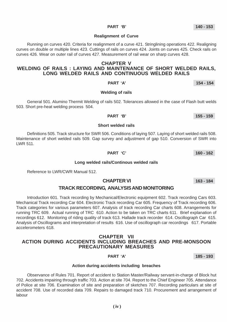
PART ‘B’ 140 - 153
Realignment of Curve
Running on curves 420. Criteria for realignment of a curve 421. Stringlining operations 422. Realigningcurves on double or multiple lines 423. Cuttings of rails on curves 424. Joints on curves 425. Check rails oncurves 426. Wear on outer rail of curves 427. Measurement of rail wear on sharp curves 428.
CHAPTER VWELDING OF RAILS : LAYING AND MAINTENANCE OF SHORT WELDED RAILS,
LONG WELDED RAILS AND CONTINUOUS WELDED RAILS
PART ‘A’ 154 - 154
Welding of rails
General 501. Alumino Thermit Welding of rails 502. Tolerances allowed in the case of Flash butt welds503. Short pre-heat welding process 504.
PART ‘B’ 155 - 159
Short welded rails
Definitions 505. Track structure for SWR 506. Conditions of laying 507. Laying of short welded rails 508.Maintenance of short welded rails 509. Gap survey and adjustment of gap 510. Conversion of SWR intoLWR 511.
PART ‘C’ 160 - 162
Long welded rails/Continous welded rails
Reference to LWR/CWR Manual 512.
CHAPTER VI 163 - 184
TRACK RECORDING, ANALYSIS AND MONITORING
Introduction 601. Track recording by Mechanical/Electronic equipment 602. Track recording Cars 603.Mechanical Track recording Car 604. Electronic Track recording Car 605. Frequency of Track recording 606.Track categories for various parameters 607. Analysis of track recording Car charts 608. Arrangements forrunning TRC 609. Actual running of TRC 610. Action to be taken on TRC charts 611. Brief explanation ofrecordings 612. Monitoring of riding quality of track 613. Hallade track recorder 614. Oscillograph Car 615.Analysis of Oscillograms and interpretation of results 616. Use of oscillograph car recordings 617. Portableaccelerometers 618.
CHAPTER VIIACTION DURING ACCIDENTS INCLUDING BREACHES AND PRE-MONSOON
PRECAUTIONARY MEASURES
PART ‘A’ 185 - 193
Action during accidents including breaches
Observance of Rules 701. Report of accident to Station Master/Railway servant-in-charge of Block hut702. Accidents impairing through traffic 703. Action at site 704. Report to the Chief Engineer 705. Attendanceof Police at site 706. Examination of site and preparation of sketches 707. Recording particulars at site ofaccident 708. Use of recorded data 709. Repairs to damaged track 710. Procurement and arrangement oflabour
( iv )
711. Diversion 712. Transhipment 713. Funds required during Emergencies 714. Obstructions found on track715. Flooded Causeways/Dips 716. Special precautions when track is submerged 717. Driver’s report ondefects in track 718. Abnormal occurrences attributable to locomotives and other rolling stock 719. Accidentsnot affecting through traffic 720. Records of accidents 721. Accident statements to the Railway Board 722.
PART ‘B’ 194 - 201
Pre-monsoon precautionary measures
General precautions to be taken before monsoon 723. Materials for emergencies 724. Service spansand Rail clusters 725. Railway affecting works (including Railway affecting tanks) 726. Vigilance over Railwayaffecting tanks during heavy rains 727. Weather warnings and action to be taken 728.
CHAPTER VIII 202 - 215
ENGINEERING RESTRICTIONS AND INDICATORS AND USE OF DETONATING ANDFLARE SIGNALS
Work involving danger to train or traffic 801. Carrying out of works, in case of emergency 802. Responsibilityof the Railway servant in-charge of the work 803. Precautions before commencing operations which wouldobstruct the line 804. Categories of Engineering works 805. Works of short duration 806. Works of long duration807. Temporary Engineering Fixed Signals—Location and details 808. Procedure for passing trains at stop-dead restrictions 809. Procedure for Blocking line for Engineering purposes 810. Work at time of poor visibility811. Temporary signals in emergency 812. Periodical Notice of Engineering restrictions 813. Permanent speedrestriction indicators 814. Indicators (General) 815. Detonating signals 816. Care and custody 817. Stock withEngineering staff 818. Use of detonators 819. Testing 820. Life of detonators 821. Disposal of time-barreddetonators 822. Safety range 823. Flare signals—Description 824. Use of flare signals 825. Safeworking ofContractors 826.
CHAPTER IX 216 - 243
LEVEL CROSSING AND GATEMAN
General location 901. Classification of Level Crossings 902. Categories of Roads 903. Standards fordifferent classes of level crossings 904. Gates and locking arrangements 905. Skew level crossings 906.Normal position of gates 907. Gate lamps and blinders 908. Traffic and Engineering gates 909. Equipment atlevel crossings 910. Siting of gate-lodges 911. Appointment of Gatemen, rosters and medical fitness certificates912. Duties of Gatemen 913. Maintenance of level crossing, examination of gate - equipment and Gateman inrules 914. Level crossing registers 915. Level crossing indicators 916. Visibility requirements for unmannedlevel crossings 917. Provision of speed breakers on the approaches of unmanned level crossings 918. Censusof traffic at level crossings, unmanned/manned 919. Unmanned ‘ C ‘ class level crossings 920. Track structurein level crossings 921. Manning of the unmanned level crossings through Member of Parliament Local AreaDevelopment Scheme (MPLADS) 922. Level Crossings on National Highways/ State Highways and otherimportant roads 923. Provision of new level Crossings/Manning/Demanning/Elimination 924. Criteria forReplacement of existing level crossings (other than those provided on ‘Deposit Terms’) with road Over/UnderBridges on cost sharing basis 925.
CHAPTER X 244 - 252
PATROLLING OF THE RAILWAY LINE
Types of Patrolling 1001. Protection of line in case of Emergency 1002. Commencement and termination1003. Preparation of Patrol Charts 1004. Distribution of Patrol Charts 1005. Patrol Books and SystematicPatrolling 1006. Equipment of patrolman 1007. Selection of Patrolman 1008. Certificate to be submitted byP.W.I. 1009. Duties of Patrolmen 1010. Action when damage is observed 1011. Responsibility of EngineeringOfficials in the matter of Patrolling 1012. Action by A.E.N. and P.W.1. on receipt of information regardingDamage to the Line 1013. Vulnerable locations (Points) 1014.
( v )

CHAPTER XI 253 - 265
THE WORKING OF TROLLIES, MOTOR TROLLIES AND LORRIES
General Instructions 1101. Distinction between Trolly, Motor Trolly and Lorry 1102. Certificate of competency1103. Officials’ permitted to use Trollies, Motor Trollies and Lorries 1104. Responsibility for safe working 1105.Efficient brakes 1106. Attachment to Trains Prohibited 1107. Working on track circuited Sections and Sectionsprovided with treadles 1108. Numbering of Trollies/Motor Tollies/Lorries 1109. Conveyance of Trollies/MotorTrollies/Lorries by trains 1110. Trollies/Motor Trollies/Lorries not in use 1111. Conveyance of non-railway officials1112. Trolly-permits for private sidings 1113. Military officers using trollies in Ordnance depots 1114. Trollyrefuges and observation posts 1115. Equipment for Trolly/Motor Trolly/Lorry 1116. Signals for Trolly/Motor Trolly/Lorry 1117. Working of Trollies 1118. Working of Motor Trollies 1119. Working of Lorries 1120. Working of CycleTrollies and Moped Trollies 1121. Working of Rail Dolleys 1122.
CHAPTER XII 266 - 272
WORKING OF MATERIAL TRAINS AND TRACK MACHINESRules for working 1201. Material Train 1202. Economical working 1203. Restrictions in running 1204.
Brake-vans and Shelter wagons 1205. Ordering of Material trains 1206. Issue of ‘ Fit-to-run ‘ certificate 1207.Official-in-charge of Material train 1208. Equipment 1209. Testing of brake power 1210. Working in BlockSection 1211. Pushing of Material trains 1212. Procedure to be followed while pushing back 1213. Running onGhat Section and descending grade 1214. Passage over points 1215. Speed of material trains 1216. Stablingof a material train 1217. Reporting deficiencies and damages 1218. Warning to workers on material trains1219. Engine Crew’s hours of duty 1220. Loading at Ballast depots 1221. Working trip 1222. Operation ofHoppers 1223. Training out materials and daily reports of working 1224. Charges for material train working1225. Register of Engineering vehicles 1226. Working of Track maintenance machines 1227.
CHAPTER XIII 273 - 284PROCEDURE FOR OBTAINING SANCTION AND CARRYING OUT WORKS AFFECTING
SAFETY OF THE RUNNING LINE AND FOR OPENING NEW WORKS
Reference to rules 1301. Works requiring sanction of C.R.S. and notice there for 1302. Application forsanction of works 1303. Documents to accompany application 1304. Submission of Safety Certificate 1305.Deviations from plans approved by C.R.S. 1306. Applications for running of new types of locomotives and/orrolling stock and for increase in speed 1307. Notification to Railway officials when opening works 1308. Worksarising out of accidents including breaches 1309. Opening of new lines 1310.
CHAPTER XIV 285 - 292LAYING AND MAINTENANCE OF CONCRETE SLEEPERS
Types of concrete sleepers 1401. Identification of sleepers at Site 1402. Fittings to be used 1403. Locationswhere concrete sleepers are used 1404. Laying of concrete sleepers 1405. Operations connected with relaying1406. Procedure for manual laying 1407. Maintenance of concrete sleeper Track 1408. Casual renewal ofconcrete sleepers 1409. Corrosion of Steel in concrete sleepers 1410. Maintenance of concrete sleeperfastenings 1411. Action in case of derailment 1412. Laying of fanshaped turnout sleepers 1413.
CHAPTER XV 293 - 295
TRAINING FOR PERMANENT WAY STAFF
Types of Training Courses 1501. Initial/Induction Courses 1502. Promotional courses 1503. RefresherCourses 1504. Special Courses 1505.
CHAPTER XVI 296 - 299
BOOKS OF REFERENCE
Books of reference 1601. Circulation of Technical papers 1602.
( vi )

LIST OF ANNEXURES
Annexure No. Particulars of sketch/Proforma Para reference
2/1 Railway Map of India / BG showing group ‘A’ and ‘B’ routes 202
2/2 Railway Map of India/MG showing group ‘ Q ‘ routes . . 202
2/3 Typical gang chart . . . . . . . . 206
2/4 Track diagram . . . . . . . . 211
2/5 Permanent way diagram of station yard . . . . 211
2/6 Pro forma for inspection of points and crossings . . 237
2/7 Pro forma of creep register . . . . . . . . 242
2/8 Reconditioning of holes in wooden sleepers . . . . 245
2/9 Criteria for declaring rails as defective by Ultrasonic Testing 252 (Deleted)
2/10 Pro forma for reporting rail failures . . . . . . 257
2/11 Ballast profile for LWR Track/BG . . . . . . 263
2/12 Ballast profile for LWR Track/MG . . . . . . 263
2/13 Ballast profile for other than LWR/BG . . . . . . 263
2/14 Ballast profile for other than LWR/MG . . . . . . 263
2/15 Ballast profile for NG . . . . . . . . 263
2/16 Preparation of Bridge Timber 273
2/17 Temporary connection during relaying operations (Electrified areas). 284
2/18 Locations where soil sampling is to be done . . . . 294
2/19 Half yearly Permanent Way report . . . . 209
2/20 Proforma for measurement of liner bite/ corrosion of rail CS-124 dt 14.2.2011)
250(2)
3/1 Pro forma for justification for complete track renewal . . 304
3/2 Pro forma for loss of weight of released scrap (P. Way components) . . 320(3)(5)
3/3 Pro forma for summary of summary of P. Way material to be released . . 320(3)(8)
4/1 Cant and speed in BG for different Radii . . . . 405
4/2 Cant and speed in MG for different Radii . . . . 405
4/3 Maximum speed and cant in non-transitioned curves with cant on 405
virtual transition.
4/4 Maximum speed and cant in non-transitioned curves without cant. 405
4/5 Proforma of curve register . . . . . . . . 420
5/1 Rail temperature Zone Map . . . . . . . . 505
5/2 Pro forma for Gap Survey and rectification of gaps . . 510
6/1 Sample chart of TRC (Mechanical)/BG . . . . . . 610
6/2 Sample chart of TRC (Electronic)/BG . . . . . . 610
6/3 Sample chart of TRC (Electronic)/MG . . . . . . 610
6/4 Sample Hallade chart . . . . . . . . 614
6/5 Oscillograph car chart/BG . . . . . . . . 615
6/6 Portable accelerometer chart . . . . . . . . 618
7/1 Details to be collected in the case of accidents for preparation of a sketch. 707
( vii )

( viii )
LIST OF ANNEXURES– contd...
Annexure No. Particulars of sketch/Pro forma Para reference
7/2 Pro forma showing the Permanent way particulars to be collected in the 708
case of accident.
8/1 Works of short duration – Protection of line in case of stop dead 806
restriction.
8/2 Works of short duration – Protection of line in case of reduced speed. 806
8/3 Location of Engineering indicators for dead stop and non-stop restrictions. 807 & 808
8 / 3 A Position of engineering indicators in case of multi speed restrictions . . 807 & 808
8/4 Details of Engineering indicators for temporary/permanent – restrictions. 807 & 808
8 /5 Competency Certificate 826 (iv)
9/1 Classification and Standard Specification for level crossings 904
9/2 Details of Stop disc and Safety chain to be used in emergencies 905
9/3 Protection diagram in emergencies in the case of level crossing 913
9/4 Pro forma for level crossing register . . . . . . 915
9/5 Details of Whistle Boards on the approaches of level crossings 916
9/6 Speed Breaker Plan . . . . . . 918(2)
9/7 Warning Signs . . . . . . 918(2)
10/1 Specimen patrol chart – Low density line . . . . . . 1004
10/2 Specimen patrol chart – Heavy density line – 2 Beats . . 1004
10/3 Specimen patrol chart – Heavy density line – 3 Beats . . 1004
11/1 Specimen of Indemnity Bond for Trolly use by outsiders . . 1112
11/2 Specimen of Indemnity Bond for siding users . . . . 1113
11/3 Trolly/Lorry notice . . . . . . . . . . 1118 &1120
11/4 Protection of Trolly on line . . . . . . . . 1118
11/5 Protection of Lorry on line . . . . . . . . 1120
12/1 Daily report of Material train working . . . . 1224
13/1 to 13/3 Application for CRS sanction and Annexures . . . . 1304
13/4 Safety certificate in the case of new Locomotive/Rolling Stock. 1307
13/5 Safety certificate while opening works . . . . . . 1305
13/6 Form of telegram to be sent while opening works . . 1309
14/1 Proposed Disposition of Fan shaped Concrete Layout . . . . 1413
16/1 List of Books of Reference . . . . . . . . 1601
M/1 Instruction Manual for Measured Shovel Packing . . (Deleted)
M/2 Manual of Instructions on Long Welded Rails (1979) . . (Deleted)
M/3 Manual of Instructions for Directed Track Maintenance . . (Deleted)
M/4 & M5 Concordance Table (Old) . . . . . . . . (Deleted)
M/6 Concordance Table (New) . . . . . . . . ••

DUTIES OF PERMANENT WAY OFFICIALS/ MEN
CHAPTER I
DUTIES OF PERMANENT WAY OFFICIALS/ MEN
PART ‘A’
Duties of Assistant Engineer/Assistant
Divisional Engineer
101. General – The Assistant Engineer is generally responsible for the maintenance and safety of all way and works in his charge, for the accuracy, quality and progress of new works and control over all expenditure in relation to budget allotment.
102. Essential Duties of Assistant Engineer– The duties of the Assistant Engineer are detailed in various chapters of the Indian Railways Permanent Way Manual, the Indian Railway Works Manual and the Indian Railway Bridge Manual, the most essential being :
1 Inspection and maintenance of track and all structures in a satisfactory and safe condition;
2 Preparation of plans and estimates; execution and measurement of works including track works;
3 Verification of stores held by stock-holders;
4 Submission of proposals for inclusion in the track renewal programme, revenue budget and the works programme.
103. Knowledge of Rules and
Regulations– He shall observe the rules and procedures laid in the General and Subsidiary Rules, The Indian Railways Permanent Way Manual, The Indian Railway Works Manual, The Indian Railway Bridge Manual, the Engineering Code and other departmental codes and orders and circulars issued from time to time relating to his duties. He shall ensure that all the staff under him are acquainted with the relevant rules and working methods connected with their duties and that they perform their allotted duties.
104. Co-ordination with Officials of other Departments – The Assistant Engineer should co-operate effectively with officers and staff of other departments in matters that warrant co-ordination.
105. Inspection by Higher Officials – (1)
When the Assistant Engineer has to accompany a periodical or special inspection such as that of the Territorial Heads of Departments, the Chief Engineer, the General Manager, the Commissioner of Railway Safety or any officer of the Railway Board, he should have with him the under mentioned drawings and registers for reference as required-
(a) Permanent Way diagrams of the section and of station yards.
(b) Index plans and sections. (c ) The bridge inspection register. (d) Plans and current files of important
works recently completed, on hand and proposed.
(e) Progress reports on works, and any other papers and plans that are likely to be required for discussion.
(f) Working time table. (g) Inspection notes of higher officers and
compliance reports. (2) All Inspection notes should receive
prompt attention within a reasonable time. 106. Inspection by Assistant Engineer –
The Assistant Engineer shall conduct inspection in his jurisdiction as per the Schedules laid down by the Administration from time to time. He should maintain the records of the results of his inspection and ensure compliance of the instructions within a reasonable time. He should submit to the Divisional Engineer copies of the inspection diagram at the end of every month indicating the inspection carried out during the month. 107. Inspection of Permanent Way - The important inspections to be carried out by the Assistant Engineer are summarized below: (1) Trolley Inspection - The entire sub-division should be inspected by trolley once in two months on pro-rata basis systematically covering from one end to other end of his jurisdiction, as much inspection as possible being done by push trolley. Unimportant branch lines having less than 2 GMT traffic should be inspected once in 3 months. On sections having multiple lines running closely parallel, trolley inspection may be carried out on any of the lines. The inspection by trolley should be intensive, which should include checking of attendance of gang, gang work and equipment and examination of gang charts/diary books with reference to the prescribed schedule of track maintenance. During his inspection, he should check the work done by minimum one gang in each SSE/P.Way's jurisdiction every quarter and record the results of his inspection. (CS-132 Dtd 08.4.2013)
1

DUTIES OF PERMANENT WAY OFFICIALS/ MEN (2) Fast Train inspection - The entire subdivision should be covered either by Engine/Rear Window of a fast train or by TRC/OMS once in a month. (3) Inspection of Level Crossings - He should inspect all the manned level crossings once in six months. He should examine the Gatemen's knowledge of rules, check the equipment, track, road approaches and all other safety aspects. (4) Checking of curves - The Assistant Engineer shall check at least one curve in each SSE/P.Way's jurisdiction every quarter by verifying its versine and super-elevation. Priority shall be given for curves having persistent bad riding. (5) Checking of Points and Crossings - He shall inspect once a year all points and crossings on passenger lines and 10 percent of the points and crossings on other lines. (6) Monsoon Patrolling - When Monsoon Patrolling is introduced he should check the work of Patrolmen at night once in a month, either by Train or by Push Trolley or Motor Trolley. (7) Track on Bridges - The track on Girder Bridges should be inspected as a part of the annual Bridge inspection, besides normal track inspections. (8) Review of Inspection by Sub-ordinates - He should scrutinize the records maintained by SSE/P.Way, such as records for Creep measurement, Inspection of Curve, Points and Crossing, SEJ and Buffer rail, Gap Survey and Section register during his regular trolley inspection, to see whether the schedules of inspection are being adhered to by the JE/SSE's and whether the necessary follow up action has been taken. He should also test check the work of SSE/P.Way/USFD at least once in each round of testing in his jurisdiction. (9) Inspections of LWR/CWR Track - The Assistant Engineer shall inspect the SEJs/Buffer rails provided in the LWR/CWR track once in every six months. He shall check the creep records of LWR/CWR regularly. The duties of the Assistant Engineer with reference to the maintenance of LWR/CWR are detailed in Manual of instructions on Long Welded Rails. (10) Night foot plate inspection - He should carry out night inspection once a month to check alertness of Gatemen/Station staff, patrolmen, stationary watchmen, observance of speed limits by drivers, visibility of signals/ engineering fixed signals/hectometer posts, riding quality etc. Inspection should preferably be done between 00:00 hrs to 04:00 hrs.
(11) Inspection of AT welding site - The Assistant Engineer shall inspect AT welding site as much as possible but at least once in a month. (C.S.No:132 Dated 08.04.2013)
2
Note: The Assistant Engineer shall inspect the cuttings in his jurisdiction as per applicable provisions of Bridge Manual ����������� �������������
108. Execution of Works – (1) General – The Assistant Engineer should ensure that all works are carried out according to plans and specifications laid down.
Important works should be set out personally by the Assistant Engineer.
Every works should be efficiently organized and so programmed that it progresses speedily and is completed within the time specified. Periodical progress reports on works should be submitted to the Divisional Engineer on prescribed forms.
(2) Track Renewals – (a) The Assistant Engineer shall examine the track at the kilometrages where renewals are required before submitting proposals to the Divisional Engineer for inclusion in the Preliminary works programme. b) Every sanctioned renewal work should be programmed in detail and labour organized in an efficient manner. Level and centre line pegs given by the JE/SSE should be test-checked by the Assistant Engineer 108. 2. (b) He should also inspect Track Renewal/Deep screening site in his section as much as possible but minimum once in a month.(C.S.No:132 Dated:08.04.2013) 108 (2)(c) - Inspection of ongoing works of construction and other organization e.g. RVNL, etc - He should inspect the works going on in his section as much as possible during Foot plate/Trolley inspection to check quality and safety of the running trains (C.S.No:132 Dated:08.04.2013)
109. Measurement of Ballast – In the Open Line
Organisation, the Assistant Engineer may either measure and record the measurements of ballast himself or carry out 100 per cent check on quality and quantity, if the measurements are recorded by Inspectors.
In the case of construction projects, the measurements and classification of Ballast will be done by the Assistant Engineer himself.
110. Action in case of Emergencies – In the case of an accident, including a breach, affecting the running of trains, he should proceed to the site by the quickest available means. On the way, he should ascertain the requirements of materials and men at site and arrange for the same. He should also order for the Accident Relief Equipment as necessary. He should take all possible measures to restore the traffic quickly.

DUTIES OF PERMANENT WAY OFFICIALS/ MEN 111. Accompanying Track Recording/ Oscillograph Cars – The Assistant Engineer should accompany the Track Recording/ Oscillograph Car runs in his jurisdiction and take down notes regarding the spots needing attention, and issue instructions for rectifying the defects after the run.
112. Control over Expenditure– The Assistant Engineer shall exercise due care in passing requisitions for materials and tools and in the execution of new and maintenance works, ensuring in all cases that the expenditure is within the allotment or provision in the sanctioned estimate.
113. Training of Probationers – The
Assistant Engineer should interest himself in all probationers sent to him for training and see that the training is given according to the specified programme. He should periodically examine the notes made by them.
114. Witnessing Payment to Staff– The
Assistant Engineer should witness payments to workmen (labour) under one or more Inspector each month. This should be done without warning.
115. Inspection of Office and Stores of Inspectors (a) - The Assistant Engineer shall carry out an inspection of each Inspector’s Office and Stores at least once a year.
When checking stores, he should pay particular attention to the imprest and its distribution, Engineering indicators, protection equipment and important items in stores.
(b) The Assistant Engineer shall carry out inspection once in six months of all the small machines including light duty (Chinese type) tampers under the charge of the Inspectors for proper upkeep and good running condition by PWIs.
116. Staff matters – The Assistant Engineer will ensure, that :
(1) strict discipline is maintained within the frame work of the rules;
(2) service and leave records are maintained correctly and up-to-date;
(3) appeals and representations are dealt with promptly;
(4) selection for the various posts like Mates and Keymen are made in time and the posts promptly filled up;
(5) all the Inspectors and other staff working under him receive proper training in maintenance practices, safety and protection rules at the appropriate stage.
117. Relinquishment of charge – (a)
Instructions on “Transfer-of-charge” are contained in Paras 143 & 144 of the Indian Railway Code for the Engineering Department.
The Assistant Engineers handing over/taking over should carry out joint inspections of such works or lengths of track as necessary.
The Assistant Engineer taking over shall test check the balance of ballast, rubble-stone, boulders and bricks in depots and tools and plants as also the along-side collections of ballast. He shall also examine all registers of the sub-division, dockets of rules and orders in vogue and important current files and initial them with the date of inspection
(b) The “Transfer-of-charge” statement should be prepared in triplicate and signed by both the Assistant Engineers and two copies sent to the Divisional Engineer who will forward one copy to the Chief Engineer.
Errors and discrepancies which are noticed should be recorded in the statement and the Divisional Engineer’s special attention invited to them.
3

DUTIES OF PERMANENT WAY OFFICIALS/ MEN
PART ‘ B’
DUTIES OF SSE/P.Way (C.S.No:132 dt. 8.4.13 ) / SECTIONENGINEER(P.WAY)
Duties of Permanent Way Inspectors
(in overall charge ) 118. General Responsibility – The
SSE/P.Way (C.S.No:132 dt. 8.4.13) is generally responsible for :
(1) Maintenance and inspection of track in a satisfactory and safe condition for traffic.
(2) Efficient execution of all works incidental to track maintenance, including track relaying works.
(3) Accountal and periodical verification of stores and tools in his charge.
(4) Maintenance of land boundaries between stations and at unimportant stations as may be specified by the administration.
119. Knowledge of Rules and
Regulations– (1) Every SSE/P.Way (C.S.No:132 dt. 8.4.13) shall have in his possession up-to-date copies of the following codes and manuals with all correction slips up-to-date –
(i) Indian Railways Permanent Way Manual, Bridge Manual and Works Manual.
(ii) Indian Railway General and Subsidiary Rules.
(iii) Indian Railway Track Manual. (iv) Indian Railway Code for the
Engineering Department. (v) Schedule of Dimensions. (vi) Circulars issued by the higher authorities.
(2) He shall be well acquainted with the rules, regulations and procedures concerning his work and duties as enjoined in the above codes and manuals. He shall keep himself in touch with the orders and circulars issued by higher authorities from time to time and efficiently act upon them.
(3) He shall ensure that all staff working under him are well acquainted with the relevant rules and working methods and efficiently perform their duties.
120. Co-ordination with Works, Bridge and Staff of other Departments – The SSE/P.Way (C.S.No:132 dt. 8.4.13) should keep close co-ordination with the Works, Bridge, Signalling and
Electrical Staff, when they are required to work jointly.
121. Keeping of Materials – The SSE/P.Way (C.S.No:132 dt. 8.4.13) shall see to the security of rails, chairs, sleepers and other materials in his charge and ensure that unused materials are stacked properly clear of the line, so as not to interfere with the safe running of trains.
122. Accompanying on Inspections of Higher Officials – (1) When the Permanent Way Inspector accompanies a periodical or special inspection by the higher officials he should have with him the following registers and documents pertaining to his section, other than the codes and manuals mentioned in para 119 :
(a) Working Time Table. (b) Permanent way diagrams of section
and yards. (c) Section register. (d) Results of track recording /
oscillograph runs. (e) Creep and gap survey register. (f) Curve register. (g) Points and crossing register. (h) SEJ / Buffer rail register. (j) List of Permanent and Temporary
speed restrictions. (k) List of works and other details. (l) Inspection notes of higher officials with
compliance notes.
(2) The SSE/P.Way (C.S.No:132 dt. 8.4.13) shall arrange to carry the following measuring devices on these inspections :
(a) Gauge-cum - level. (b) Flangeway gauge. (c) Canne-a-boule or wooden mallet. (d) Fishing cord. (e) Tape. (f) Metric scale. (g) Tapered gauge. (h) Magnifying glass and mirror. (j) Versine measuring equipment. (k) Inspection hammer.
4

DUTIES OF PERMANENT WAY OFFICIALS/ MEN 123. Testing of Running Qualities of Track- (1) The SSE/P.Way shall devote sustained attention to Permanent way as regards safety, smooth running, economy and neatness. (2) He should travel on the foot place of Engine/Rear brake-van/last Vehicle of fast trains at least once in a month, and take down notes of bad running kilometrages, and get them rectified. (3) He should accompany each Track Recording/Oscillograph car runs over his section, take down kilometrages which are not running well and take action to rectify the defects. (4) He should observe the behavior of track under passing trains to detect inadequate packing during routine inspections. (C.S.No:132 Dated:08.04.2013) 124. Routine inspection of Track – (1) Inspection of Gangs/Trolley Inspection: (a) The Senior Section Engineer/P.Way (SSE/P.Way) should inspect the entire section by Push Trolley/Motor Trolley at least once in a month or more often as necessary in a systematic manner in which all gangs shall be inspected. (b) In sections where no separate inspection is being carried out by sectional Junior Engineer (JE/P.Way), the inspection should be carried out by the SSE/P.Way In-charge every fortnight. (c) During such inspections the SSE/P.Way should - (i) Check the quality of work done by gang earlier and ensure prompt action on items requiring attention; (ii) Arrange to give the programme of work to the gang; (iii) Record details of track maintenance work in gang chart and diaries; (iv) Check the attendance of gang; (v) Instruct men in methods of maintenance (d) He should examine all the gang tools at least once in two months and arrange for repair and replacement as necessary. (e) He should ensure that every man in the gang is aware of safety rules by examining them periodically at least once in two months. (f) During his trolley inspection, he should also carry out the routine check and review of inspection done by his subordinates. (C.S.No:132 Dated:08.04.2013)
(2) Level Crossing Inspection- (a) He should ensure that all the level crossings are opened out as per schedule to examine the condition of rails, sleepers and fastenings and defects are rectified. (Refer Para 914). (b) He shall ensure that all level crossings are inspected once in a month during push trolley inspection in a systematic manner by rotation with JE/P.Way. He shall see that the necessary stop boards, whistle boards, and other equipments are provided as laid down. (c) He shall check the equipment with the Gateman during inspection. (d) He shall examine their knowledge of safety rules during inspection. (e) He shall arrange to take the census of all level crossings as per the schedules laid down. (3) Points and Crossing Inspection- The SSE/P.Way in overall charge and his assistant should carry out the inspection of points and crossings in passenger and running lines once in three months by rotation and on other lines and yards lines once in six months by rotation. For Points and crossings laid on PSC sleepers, the detailed inspection as per Para 237/5 (Annexure2/6) should be done once in a year and all other in between inspections should be carried out as per proforma given in Annexure-2/6(A). (4) Curve Inspection- The SSE/P.Way in overall charge and his Assistant should carry out checks of versines and super-elevations of each curve once in six months in systematic manner by rotation. (5) Foot Inspection- SSE/P.Way shall carry out foot inspection as much as possible, on prorata basis so as to cover entire section at least once a year. (6) Night foot plate inspection- He should carry out night foot plate inspection once in a month to check alertness of Gatemen/Station staff, patrolmen, stationary watchmen, observance of speed limits by drivers, visibility of signals/engineering fixed signals/hectometer posts, riding quality etc. Inspection should preferably be done between 00:00 hrs to 04:00 hrs. (7) Inspection Records- The SSE/P.Way will maintain proper record of all the inspections carried out during the month as per the schedules on the proforma laid down and submit the same to the Divisional Engineer through Assistant Engineer every month bringing out the reasons for shortfall in adhering to schedules of inspections, if any. (C.S.No:132 Dated:08.04.2013) 5

Para :124 (A) deleted (C.S.No:132 Dated:08.04.2013) Note:The Senior Section Engineer /P.way (SSE/P.Way) Shall inspect the cuttings in his jurisdiction as per applicable provisions of Bridge Manual (C.S.No:135 Dated:07.05.2014)
125. Safety of Track – (1) The Permanent Way Inspector is directly responsible for the safety of the track. He shall be vigilant to locate faults in the Permanent Way and promptly remedy them.
The defects which are beyond his powers to remedy should be immediately brought to the Assistant Engineer’s notice by the Permanent Way Inspector and mentioned of the same made in the half-yearly report on the condition of Permanent Way of the section.
(2) Independent of detailed periodical inspections, the Permanent Way Inspector, during his routine inspections, should watch for any signs of weakness in bridges and structures affecting track and promptly report any matter demanding the Assistant Engineer’s attention.
(3) Trees in proximity to and liable to foul the track during a storm should be felled.
126. Check on Patrolling- He should arrange for patrolling of track as laid down, by deputing suitably selected men from gangs and arrange to supply them with Patrol books and equipments needed . The SSE/P.Way in overall charge will check the night patrolman once a fortnight by train and by trolley during the monsoon as per the schedules laid down by the administration. 127. Execution of Works affecting Track – (1) Before commencing any work the SSE/P.Way in overall charge or his Assistant shall ensure that he is in possession of all necessary materials and tools. He shall ensure that Engineering Signals are exhibited at the specified distances according to rules and Flagmen are posted with necessary equipment. (2) He should programme the works by organizing the labour in an efficient manner. He should maintain detailed accounts of materials received and issued to the work. He should exercise as much as possible checks but minimum once in a
month on quality and quantum of work and submit progress reports on works periodically as may be prescribed. (3) Quality of welding and avoidable fractures- The direct responsibility for quality of AT welding being done in the section shall rest on the SSE/P.Way in-charge of the section. He should carry out inspection of AT welding site as much as possible but at least once in a month. Responsibility for avoidable fractures taking place in the section shall also rest with the SSE/P.Way in-charge of the section, except in cases where the USFD testing was done and found good up to three months before the fractures. (4) Inspection of ongoing work of construction and other organizations e.g. RVNL etc- He should inspect the works going on in his section as much as possible during Footplate/Trolley inspection to check quality and safety of the running trains.(C.S.No:132 Dated:08.04.2013)
128. Action in case of Emergency – On receipt of intimation of the occurrence of an accident (including breaches) affecting any part of track, restricting free passage of trains, the SSE/P. Way (C.S.-132) should proceed to site by the quickest available means. On the way he should collect information regarding the damage, the men and material requirement at site for restoration and arrange for movement of men and materials and thereafter the restoration.
129. Inspection and Maintenance of
LWR/CWR Track: The duties and responsibilities of the SSE/P.Way in overall charge is clearly laid down in Manual of Instructions on Long Welded Rails. All the LWRs should be inspected once in fortnight during two coldest and two hottest months, otherwise once in two months by rotation with JE/P.Way. .(C.S.No:132 Dated:08.04.2013)
130. Measurement of Ballast – The SSE/P. Way (C.S.-132) in overall charge will measure the ballast if so directed by the Assistant Engineer and record measurements. He will keep proper records of training out and spreading of ballast in the track.
6

DUTIES OF PERMANENT WAY OFFICIALS/ MEN
131. Station Yards – The SSE/P. Way (CS-
132) shall ensure cleanliness of station yards. Under- growth should be cleared every year, usually in the month of August, before the seed has ripened. At stations where it is proposed to stack engineering or contractor’s materials, the stacking area should be carefully selected and clearly demarcated. The materials should be stacked methodically in a tidy manner.
132. Witnessing Payment to Staff – (1) Payment to both Permanent and Temporary staff, working under the SSE/P. Way (CS-132), will be made by the Pay Clerk in the presence of the SSE/P. Way (CS-132). If the SSE/P. Way (CS-132) working in the section is not readily available, the Assistant Engineer may depute another Inspector to witness the payment.
(2) The SSE/P. Way (CS-132) is responsible for correct identification of the payee and should satisfy himself that the correct amount is paid.
(3) Payments to Permanent Way gangs should, as far as practicable, be made on the beat of each gang during working hours.
(4) The witnessing official should certify to the payment individually or by group, at the same time specifying, both in words and figures at the foot of the muster-sheet, the total amount paid on each date. If any person out of a gang is not present when, the gang is paid on its beat, “Not Paid” should be written immediately against his name. When subsequently payment is made, the place (km.) where payment is made should be entered. Payment made subsequent to the filling in of the certificate should be separately certified on the pay sheet.
133. Other Establishment Matters – (1) The SSE/P. Way (CS-132) should ensure that all staff, including Casual labour, are sent for medical examination and are fit for the medical standards, as per the relevant instructions in force, before appointment or promotion. He will also ensure that the staff under him are sent for periodical medical examination as laid down in the relevant rules.
(2) He will arrange to maintain the Service Cards/leave account of all the permanent staff working under him. In the case of casual labour he will arrange to issue the necessary Service Card to them and will maintain the L.T.I. register.
(3) He will ensure that the relevant provisions
(4) of the Payment of Wages Act, Workmen’s
Compensation Act, Hours of Employment Regulations etc., as amended from time to time are followed and complied with.
(4) He will arrange to carry out the other Establishment works, such as issue of passes, preparation of pay bills etc., as may be allotted to him by the administration.
(5) He will ensure proper training of the men working under him at the appropriate time.
(6) He will carry out selection of proper Gatemen and Patrolmen from the existing Gangmen and train them in their duties.
(7) He will arrange for the prompt filling up of the vacancies.
134. Correspondence and Records – The SSE/P.Way (C.S.No:132 dt. 8.4.13) shall keep his correspondence up-to-date and see that the office records, registers and stores ledgers are maintained systematically and posted regularly.
135. Relinquishment of Charge – (1) On relinquishing charge of a section the SSE/P. Way (CS-132) shall prepare, in triplicate, the specified “Transfer-of-charge” statement which will briefly contain the following :
(a) Extent of the section. (b) Establishment (service and leave
records). (c) Works in progress, relaying,
scattered renewals and other works incidental to track maintenance.
(d) Kilometrage of banks, cuttings, curves, bridges and structures requiring special attention.
(e) Kilometrages where trouble may be expected during the monsoon.
(f) Certificate of stores-check and correctness of stock.
(g) General notes.
(2) The SSE/P. Way (CS-132) handing over and taking over charge should together trolly over the whole section, inspect all the works in progress, check staff, all tools, plants and materials.
7

DUTIES OF PERMANENT WAY OFFICIALS/ MEN
(3) The relieving Inspector will examine all books pertaining to rules and orders in vogue and all registers pertaining to the section to see that they are kept up-to-date and initial them with date.
(4) The statement referred to in sub-para (1)
should be signed by both the SSE/P.Way (C.S.No:132 dt. 8.4.13) and two copies submitted by the relieving Inspector to the Assistant Engineer who will forward one copy to the Divisional Engineer for record.
Errors and discrepancies which are noticed should be recorded in the statement and the Assistant Engineer’s special attention invited to them. Duties of JE/P.Way (CS-132)(not in overall charge) 136. General Responsibilities – The Junior Engineer (P.Way) is generally responsible for: (a) Inspection and maintenance of track in his jurisdiction (sub-section) in a safe and satisfactory condition for traffic, including execution of all works incidental to track maintenance. (b) Efficient execution of Special Works, such as Renewals, Directed Track Maintenance, Curve realignment and deep Screening, as per approved plans and specifications. (c) He should work in the SSE/P.Way office and assist the SSE/P.Way in overall charge as required. (C.S.No:132 Dated:08.04.2013)
137. Knowledge of Rules and Regulations– Provision of Para 119 will apply in this case also .
138. Co-ordination with Works, Bridge and Staff of Other Departments – He should keep close co-ordination with the Works, Bridge, Signalling and Electrical staff, when required to work jointly with them.
139. Routine Inspection of Track – 1) The Junior Engineer (P.Way) should inspect the entire section in his charge by push trolley at least once in a fortnight systematically. 2) During Push Trolley inspection all gangs/MMUs, their work, equipments and knowledge about safety rules and other working instructions shall be checked. He shall spend as much time as possible with MMUs. Track patrolling by keymen shall be checked. He should carry out the inspection of gangs as detailed in Para 124(1) (b) & (c). He will spend as many days in the week as possible with the gangs. He should cover all the gangs within a fortnight. He should train the Permanent Way Supervisors, Mates, Key men,
Gagmen and Gatemen in their duties. He should teach them the maintenance practices. (2) He will carry out inspection of points and crossings on passenger and running lines once in three months by rotation and other lines and yard lines once in six months, by rotation with SSE/P.Way. For points and crossings laid on PSC sleepers, the detailed inspection as per Para 237/5 (Annexure 2/6) should be done once in a year and all other in between inspections should be carried out as per proforma given in Annexure-2/6(A). He will arrange for the rectification of defects noticed during the inspection. (3) He, along with the SSE(P.Way) in overall charge, will arrange to check the versine and super-elevation of all the curves once in six months by rotation. He should take action to correct the curves based on the readings. (4) He will arrange to inspect all the Level crossings in his jurisdiction once in a month, during Push Trolley inspection, in systematic manner, by rotation with SSE(P.Way). All level crossings will continue to be inspected once in a month alternatively between SSE(P.Way) and JE (P.Way) and equipment be checked. He will examine the Gatemen in rules periodically. (5) JE/P.Way should inspect his entire section by loco/brake van/Rear window once in a month and take down notes of bad running kilometrages and get them rectified. (6) Junior Engineer (P.Way) should inspect entire section on foot at least once in six months in a systematic manner (every month on pro rata basis so as to cover entire length of running track). (7) JE/P.Way should accompany alternate run of TRC/OMS in his section. (8) He should carry out night inspection once in a month to check alertness of Gatemen/Station staff, patrolmen, stationary watchmen, observance of speed limits by drivers, visibility of signals/ engineering fixed signals/hectometer posts, riding quality etc. Inspection should preferably be done between 00:00 hrs to 04:00 hrs. (9) He should carry out at least two inspection of AT welding site in a month. (10) He should inspect the ongoing work of construction and other organizations e.g. RVNL etc going on in his section as much as possible during Footplate/Trolley inspection, to check quality and safety of the running trains.(C.S.No:132 Dated:08.04.2013)
139 (A) deleted.(C.S.No:132 Dated:08.04.2013) Note:The Junior Engineer (P.Way) Shall inspect the cuttings in his jurisdiction as per applicable provisions of Bridge Manual (C.S.No:135 Dated:07.05.2014)
8

DUTIES OF PERMANENT WAY OFFICIALS/ MEN
140. Annual Maintenance Works – He will carry out maintenance works such as curve realignment, attention to points and crossings, adjustments of creep, etc, as assigned to him by SSE/P.Way (C.S.No:132 dt. 8.4.13) in overall charge.
141. Check on Patrolling – He will cover his section once in a fortnight by train and check the night patrolling. He will also check the night patrolling by trollying in the night as per the schedules laid down. During inspections, he will check the patrol books, the knowledge of rules of Patrolmen, their equipment, etc.
142. Execution of works affecting Track – The provision of Para 127 will apply.
143. Action in case of Emergency –
Provision of Para 128 will apply.
144. Maintenance of LWR/CWR Track – Duties and the responsibilities of Junior Engineer (P.Way) in-charge of sub-section with reference to maintenance of L.W.R. are laid down in Manual of Instructions on Long Welded Rails. All the LWRs should be inspected once in fortnight during two coldest and two hottest months, otherwise once in two months by rotation with SSE/P.Way.(C.S.No:132 Dated:08.04.2013)
145. Witnessing Payments to Staff – When JE/P. Way (CS-132) not in overall charge is deputed to make payments to staff, he will follow the provisions of Para 132 of the Manual.
9

DUTIES OF PERMANENT WAY OFFICIALS/ MEN
PART ‘C’
Duties of Permanent Way Mistries
146. General Responsibilities – They are normally in-charge of items of works which require a higher level of supervision that can be exercised by Gang Mate.They will carry out the following specific works, or such other works pertaining to track maintenance, as may be allotted to them by the Permanent Way Inspector :
(i) Attention to bad spots,
(ii) Directed track maintenance,
(iii) Maintenance LWR track, if he has been issued with a competency certificate(responsibilities have been listed out in para 9.1.3 of LWR / CWR Manual),
(iv) Isolated renewal of sleepers, (v) Lubrication of rail joints, (vii) Assist in supervision of pre and post machine attention, when machine is, deployed in his gang beat.
(C.S.No:118 Dated:30.07.2009)
147. Knowledge of Rules and Signals –
Every Permanent Way Mistry shall have a correct knowledge of hand and detonating signals and shall be conversant with the following rules :
(i) Protecting line in an emergency and during work affecting track.
(ii) Method of fixing and safety range of detonators.
(iii) Action to be taken when train is noticed to have parted .
(iv) “Safety first” rules . (v) Action to be taken when sabotage is
suspected. (vi) Patrolling in emergencies . (vii) Rules for working of a trolly and lorry if
he is authorised to operate the same .
148. Whenever Permanent Way Mistries are in-charge of gangs /units , they will carry out all the duties and responsibilities assigned to the Mate as laid down in Part ‘D’ of this Chapter.
10

DUTIES OF PERMANENT WAY OFFICIALS/ MEN
PART ‘D’ Duties of Mates, Keymen and Gangmen -
General
149. Knowledge of Rules and Signals – (1) Every Mate, Keyman and Gangman shall have the correct knowledge of hand and detonating signals and shall be conversant with the following rules :
(a) Protecting the line in an emergency and during work affecting the track.
(b) Method of fixing and safety range of detonators.
(c) Action to be taken when a train is noticed to have parted .
(d) “Safety first” rules (e) Action to be taken where sabotage is
suspected, and patrolling in emergencies.
(2) Every Mate and Keyman shall see that
the signals, supplied to the Gangs are kept in good order and ready for use and that every man in his Gang has a correct knowledge of all the signals.
150. Safety of the line – Every Mate shall see that his length of line is kept safe for the passage of trains. Kilometrages needing urgent attention shall be picked up without waiting for orders from the Permanent Way Inspectors.
151. Equipment at site of work – (1) Every Mate shall ensure that the following tools and equipments are with him at the site of work :
(a) Level-cum-gauge, square, hemp cord, metre stick, keying and/or spiking hammer, fish-bolt spanner, 2 sets of H.S. flags (2 H.S. lamps/Tricolor torches in the night), 2 no. whistle thunderers, 10 detonators, marking chalk and Rail thermometer. (C.S.No:135 Dated:07.05.2014)
(b) Sufficient number of shovels or phowrahs, beaters, crow bars, ballast forks or rakes, mortar pans or baskets and wooden mallet.
(2) The Mate shall keep in his charge in the tool box other tools and equipment as may be prescribed.
152. Musters and Gang Charts/Diary
Books– (1) The muster and Gang chart /diary shall
be in the possession of each Mate. The Gang chart should be carefully kept in a container provided for the purpose.
(2) The muster should normally be marked by the Mate, checked and initialled by the Permanent Way Inspectors.
(3) The Mate shall see that the prescribed system of track maintenance is adhered to and the tasks allotted, according to verbal instructions or entries made in his Gang chart / diary, and explained to him, are efficiently carried out. If capable of entering details of work done in his Gang diary, the Mate should do so.
153. Observance of sleeper packing during passage of Train – During the passage of the first and last trains in working hours, the Mate and his men should stand on the cess, each about one rail length apart, and observe the effect on the sleepers. Loose sleepers should then be marked and adequately packed. On double line, the Gangs shall invariably stand on the cess side and not in between the tracks.
154. Precautions when view is obstructed–
(1) On double and multiple lines on curves, the view is temporarily obstructed due to a train passing over a track other than that on which the Gangmen are working. It is worsened when trains are crossing each other. The noise of a train passing over one track prevents hearing the noise or whistle of another train approaching the work site.
(2) When working at a place from which an approaching train cannot be seen, at least 600 metres away in the case of B G and 400 metres in the case of M G and N G a Gangman with hand signals should be sent out by the Mate :
(a) On double line in the direction of approaching trains,
(b) On a single line in the direction the view is obstructed (in both directions if view is obstructed on both sides ).
11
DUTIES OF PERMANENT WAY OFFICIALS/ MEN
It will be the duty of such Flagman to warn the Mate by means of signals when a train is approaching. The Mate will be responsible for warning the Gang in good time to enable them to get clear off the track. It may be deemed expedient, as an additional precaution, to issue portable whistle boards of the type indicated in Para 815 (2) to the Mates, who should fix them at least 600 metres on B. G. and 400 metres on M G and N.G, from the work-site, in the direction the view obstructed to less than this distance. In the case of M G high speed routes, the distance may be increased suitably as per the directives of the administration.
155. Tidiness of Section – The Mate shall see that the whole of his Gang length is kept neat and tidy and that all loose materials are collected and brought to stations, gangs quarters or gate lodges.
156. Safe Custody of Tools – The Mate shall be responsible for the safe custody of tools used by him, the Keymen and Gangmen. He should see that Gangmen on work remove their tools clear of the track on the approach of a train. After the day’s work the Mate should secure the tools in the toolbox. In no case should Gangmen be permitted to take tools home. Before they break for mid-day meals the Mate should see that the tools are kept away from track.
157. Action when line is unsafe or in the event of Accident – (1) If a Mate or his keyman considers that the line is likely to be rendered unsafe, or that any train is likely to be endangered in consequence of any defect in the permanent way or works, or abnormal rain or flood or any other occurrence, he shall take immediate steps to secure the safety of trains by using the prescribed signals to “Proceed with Caution” or to “Stop” as necessity may require, vide Para 806, and shall, as soon as possible, report the circumstances to the nearest Station Master and the Permanent Way Inspector.
(2) In the event of an accident, the Mate, Keymen and Gangmen should lookout for broken fittings of wagons and track components and see that these are not disturbed until they have been seen and recorded by a responsible official.
158. Patrolling during Abnormal Rinfall – During abnormal rainfall, the Mate should organise patrolling on the gang-length, whether or not Patrolmen are on duty. In the event of damage being
detected, action should be taken to safeguard traffic by protecting the line in accordance with Para 812.
159. Commencing work Affecting Safety of trains – No work, which may involve danger to trains, should be under taken by the Mate except under the personal supervision of the Permanent Way Inspector, or a competent Railway servant authorised by special instructions, unless it is an emergency where the requirements of safety warrant the commencement of the work. In such cases the Mate shall ensure that Engineering Signals are exhibited at the specified distances according to rules and Flagmen are posted with necessary equipment to man them before commencing the work.
160. Weekly Inspection of Gang Length by Mate – The Mate shall inspect the whole Gang length once a week, on which day he will carry out the keyman’s work and duties and the Keyman will remain in-charge of the Gang.
161. Preventing Trespass and Theft of P. way Fittings – Every Mate and his men shall endeavour to prevent trespass in Railway limits by persons or cattle on his length of line and report any attempts at encroachment or unauthorised structures when noticed. He along with Gang, should also attempt to prevent theft of P. way fittings and report any attempt to steal, to his Permanent Way Inspector.
162. Relief arrangement in Emergencies – The Mate shall arrange immediate relief for Keymen, Gatemen, Patrolmen and Watchmen when, due to sickness, they are unable to perform their duties.
163. Assistance to P. and T. Staff – Where interruption to the telegraph line has occured through obviously visible causes, the permanent way staff should render all possible assitance. The staff must, for example, remove trees or branches of trees which, after a storm, are seen to foul the wires. Where wires are seen to be broken or entangled, the occurrence should be reported to the nearest Station Master.
164. Assitance in protection of Trains – The Mate and his men should render assitance to Guards and Drivers of the trains for the protection of the trains in the event of an accident between stations, when called upon to do so.
12

DUTIES OF PERMANENT WAY OFFICIALS/ MEN
165. Assitance in placing Fog Signals –On requisition from the Station Master, the Mate of a yard gang may depute, if available, two Gangmen for placing of detonators, during time of poor visibility, in the rear of approach signals of the station.
166. Responsibilities of the Mate in L.W.R.Track – The duties and responsibilities of the Mate in LWR sections are detailed in L W R Manual.
Duties of Keyman
167 Selection and training of keyman - The selection of Gangman to perform the duties of a keyman is to be considered as a step in his training as Mate. Keyman trained in laying and maintenance of LWR/CWR on concrete sleeper and possessing valid competency certificates issued by Zonal/ Divisional Training center should only be posted on LWR/CWR section.
168 (1) Keyman’s daily inspection - The keyman shall inspect by foot his entire beat once a day, both the tracks and bridges, and return along the opposite rail to that taken on his outward journey in case of single line. On double line, keyman will carry out one round of inspection in morning hours by going along up line and then returning along down line or vice-versa. On the days of Gang holidays and rest, he shall perform the usual duties and get one day’s rest in the week as per the roster duties in force. On rest days or during absence or leave or sickness, a senior intelligent gangman should be deputed in place of the regular keyman.
(2) Roster duty hours of keyman - Theroster duty hours of keyman for winter months should be so adjusted as to ensure one round of track inspection in early morning to enable detection of any rail or weld fractures that might have occurred during the night or early morning. DEN/Sr.DEN of the section shall decide and notify the exact timings and the period of each section.
169 Equipment of keyman - The keyman shall carry with him on his rounds two red flags, and green flag, ten detonators, a flangeway gauge if required, for unmanned level crossings, a keying and spiking hammer, a fish bolt spanner, and two fish bolts, spare fittings and a rail closure of 30mm size. For the work of greasing of elastic rail clips wherever applicable, keyman shall carry a wire brush, emery paper, a duster and grease.
170 Duties of Keyman -
(1) While walking over his length, he should lookfor defects, such as loose fish bolts, SEJfittings in switches and crossings, fittings ongirder bridges and open top culverts, brokenor burnt sleepers, broken plates or tie bars,attend to them as necessary. If he finds thatfittings are consistently working loose evenafter repeated attention, he should report thematter to the Mate, PWM and PermanentWay Inspector. If the defects are serious, heshould at once inform the Mate of the gangprotecting the line in the meantime, ifnecessary, according to rules.
(2) He shall keep a special watch on the railsand welds marked for observation by theUSFD team.
(3) If he should notice any condition of danger,such as broken rail, broken weld or washaway of ballast, theft of fittings in largenumbers etc., he shall at once protect theline as per rules, take such action as ispossible and report the matter to the Mate,the nearest Station Master and PermanentWay Inspector.
(4) At unmanned level crossings, he shallmaintain the flange ways between the checkand the running rails clear of obstructions.
(5) In track other than with elastic fastenings, thekeyman in addition to his normal round of thewhole beat and inspection and tightening ofloose fittings, should attend one telegraphpost (TP) on one line thoroughly on everyday. This thorough attention should consist oftightening of each bolt and fittings in theseTPs of the beat during that particular day.Missing keys and other missing fittings will berecouped by him. He shall also ensurecorrect driving of fittings in this stretch.
(6) (a) Where the beat of Keyman consists ofPRC sleepers - The Keyman should ensurethat, in addition to his normal duty ofinspection and tightening of fittings, heshould also carry out in a systematic mannerfrom one end, greasing of the ERC and eyesof inserts at the rate of 20 sleepers per day.Greasing shall be done as per the procedurelaid down in para 1411 (5) (b) of IRPWM.
13

DUTIES OF PERMANENT WAY OFFICIALS/ MEN (b) Where the beat of Keyman consists of PRC
as well as other types of sleepers, SE (P. way) should make roster of keyman on monhly basis in the proportion of the beat, so that work mentioned in para 170(5) and 170(6)(a) are completed in respective length. On any particular day however, he will do duties either as per 170(5) or 170(6)(a) only.
(7) Keyman with the assistance of one gangman will also carry out rail end examination, lubrication of fish plated joints as per direction of PWI/PWM.
(8) For imposing of caution after stopping the train or otherwise wherever required for safety, Keyman will be provided cyclostyled slips by PWI. Keyman after filling location and speed will hand over the same to Driver or ASM and obtain acknowledgement.
(9) The following are the special duties and responsibilities of the keyman in LWR/CWR territories:- (i) Periodical (fortnightly) oiling and greasing
of SEJ, checking and retightening of fastenings at SEJ and other sleepers, if necessary (Para 6.2.6 of LWR Manual)
(ii) Replacement of missing fastenings not requiring lifting or slewing of track as per Para 6.2.6 (I) of LWR Manual.
(iii) To ensure that all creep anchors where provided butt against the sleepers and in case of large scale displacement of anchors, he shall report the matter to Mate/PWM/PWI (Subsection)/PWI (incharge).
(iv) To watch for sun kinks, loose or missing fastening which may result in buckling or any damage to LWR/ CWR and SEJ. On noticing any buckling or damage to track, he shall take necessary action to protect the track and report the same immediately to PWI (Sub-section)/ PWI (incharge), Station Master. However, he will continue to perform his Keyman’s duties of daily inspection.
(v) To keep a sharp look out in cold mornings, especially during winters to detect any fractures which may occur, in case of rail/weld fracture, he shall take prompt action to protect the track and carry out
14
emergency repairs to permit the restoration of traffic promptly and report to PWI (Subsection)/ PWI(Incharge)/nearest Station Master (Para 7.2.2 and 7.2.3 LWR manual)
(10) The Kayman shall promptly report to Mate/ PWI any encroachment or unauthorised structures as and when they take place in the Railway land in his beat.
(11) After completing inspection of the beat, the Keyman should assist the Mate in the day’s work being done.
(12) When materials, such as dynamo-belts, engine tools and personal articles of passengers, are found on line, the Keyman should collect them and arrange for handing them over to the nearest Station Master.
(13) The Keyman will remain incharge of the gang in absence of the Mate once a week. On that day, the Mate is required to carry out the work and duties of Keyman.
(14) Whenever directed he will supervise rail dolly working. However, he must have competency certificate for the same.
(15) Key man shall watch height gauges for any damage. In case of any such damage, he shall also look for any damage/shifting of girder, infringement to track or damage to overhead electrical installations and shall report the matter to the Mate, the nearest Station Master and Permanent Way Inspector. He shall also protect the line as the situation warrants. (CS-123 Dtd. 27.01.11)
171 Keyman’s book-
(i) Printed keyman’s book should be supplied to every keyman.
(ii) The keyman shall maintain the book upto date wherein all special work done, missing fittings and their recoupment with location and date are to be entered.
(iii) PWI should make a date wise schedule and enclose with the Keyman’s book the Kms/ TPs that the Keyman has to attend on each day of the month to complete the task required to be done as per sub Para 6, 7, 9(i) of Para 170 above. PWIs and AENs during their inspections should check to ensure that such Kms have really been thoroughly attended to and initial against the entries.
(iv) Special locations to be watched by the keyman should be entered in the book.
(v) The special fittings like joggled fish plates and other material provided in the section which are vital for safety and for restoration of traffic should also be mentioned in the book.

THE MAINTENANCE OF PERMANENT WAY
CHAPTER IITHE MAINTENANCE OF
PERMANENT WAYPART ‘A’
General Instructions
201. Responsibility of Engineering Officials– The Engineering officials shall devotecareful and continous attention towards the efficient upkeep of the permanent way and the achievement of good and smooth running road.
The running qualities of track should be adjudged by riding as frequently as possible on the locomotives or in the rear vehicles of fast trains on the section. Such inspection should be carried out by the Permanent Way Inspectors, the Assistant Engineers, and the Divisional Engineer. Where track geometry is recorded at regular intervals the Divisional Engineer, the Assistant Engineer, and the Permanent Way Inspector should accompany such runs.
The conditions of the track is best judged by track recording cars, oscillograph cars, portable accelerometers, Hallade track recorders, etc. Full use should be made of the records of such runs. Bad spots should immediately be attended to. The Permanent Way Inspector should strive to achieve excellence against each of the parameters recorded by these cars, consistent with the maintainability of the track.
The reports from drivers regarding oscillations or lurching of engines should be promptly investigated and track attended at the kilometerage concerned.
The Assistant Engineers and their Divisional Engineers should maintain records of the results of their inspections either in the form of a notebook or a file and should ensure the compliance of instructions by the inspectors within a reasonable time. These records should be examined by the Headquarters officers during their inspections.
202. Classification of Lines –
(1) Broad Gauge - The BG lines have been classified into six groups ‘A’ to ‘E’ on the basis of the future maximum permissible speeds as under-
Group ‘A’ - Speeds upto 160km./hour:(i) New Delhi to Howrah – Rajdhani Route (via the Grand Chord and Howrah-Burdhwan Chord).(ii) New Delhi to Mumbai Central (Frontier Mail Route).
iii) New Delhi to Chennai Central (Grand Trunk Route).(iv) Howrah – Nagpur-Mumbai CST.Group ‘B’ - Speeds upto 130 km./hour:(i) Allahabad-Katni-Jabalpur-Itarsi-Bhusaval.(ii) Kalyan-Pune-Daund-Wadi-Secunderabad-Kazipet.(iii) Kharagpur-Waltair-Vijayawada.(iv) Wadi-Raichur-Arakkonam-Chennai Central.(v) Howrah-Bandel-Barddhaman.(vi) Khanna-Barharwa-Farakka Bridge-Malda Town.(vii) Sitarampur-Madhupur-Kiul-Patna-Mughal Sarai.(viii) Kiul-Bhagalpur-Sahibganj-Barharwa.(ix) Delhi-Panipet-Ambala Cantt. Kalka.(x) Ambala Cantt.-Ludhiana-Jallandhar-Pathankot.(xi) Ambala Cantt.- Moradabad-Lucknow-Pratapgarh-Mughul Sarai.(xii) Arakkonam-Jolarpettai-Salem-Erode-Coimbatore-Ernakulam.(xiii) Vadodara-Ahmedabad.(xiv) Jolarpettai-Bangalore.(xv) Ahmedabad-Ajmer-Jaipur-Bandikui-Rewari-Delhi.(xvi) Malda Town-Barsoi-New Jalpaiguri.(xvii) Chennai Beach-Dindigul.(xviii) Bangalore-Dharmavaram-Gooty.(xix) Ghaziabad-Saharanpur.(xx) Chennai Beach-Chennai Egmore 3rd line(xxi) Bandikui-Agra Fort(xxii) Sawaimadhopur-Jaipur(xxiii) Bellary-Guntkal(xxiv) Gudur-Renigunta(xxv) Pagadipalli-Nadikudi-Guntur-Tenali(xxvi) Vijaywada-Guduwada-Bhimavaram-Nidadavolu(xxvii) Guntkal-Guntur & Guntur-Krishna canal(xxviii) Manmad-Mudkhed-Secundrabad(xxix) Secundrabad-Dhone(xxx) Renigunta-Tirupati-Pakala-katpadi Annexure 2/1 shows, Group ‘A’ and ‘B’ Routes.Group ‘C’ - Suburban Sections of Mumbai, Delhi, Chennai and Kolkatta as listed below.(i) CSTM – Ravli - Kurla – Panvel(ii) Ravali –Mahim-Andheri(iii) Churchgate – Mumbai Central – Borivali- Virar(iv) Chennai Central – Basin Bridge – Veysarpadi – Arakonam
15

(v) Chennai Central – Basin Bridge- Washermanpet – Chennai Breach – Tambaram (vi) Chennai – Central – Basin Bridge – Korukkupet – Tondiarpet – Tiruvottiyar – Gummidipundi (vii) - Chennai Beach-Thirumayilai-Tiruvanmiyur-Velachery.(C.S.No:133 Dated:04.06.2013) (viii) Sealdah – Dumdum – Naihti – Kalyani – Ranaghat – Krishnanagar (ix) Sealdah – Sonarpur – Baruipur-Lakshmikantapur-Namkhana (x) Ballygunj – Budge Budge (xi) Seoraphuli – Tarakeshwar (xii) Dum Dum Jn – Barasat Jn-Bangaon Jn (xiii) Howrah – Panskura – Kharagpur (xiv) Ranaghat-Bangaon (xv) Kalyani-Kalyani Simanta (xvi) Ranaghat-Gede (xvii) Kankurgachi-Ballygunge (xviii) Kalinarayanpur-Shantipur (xix) Barasat-Hasnabad (xx) Sonarpur-Canning (xxi) Baruipur-Diamond-Harbour (xxii) Dum Dum Jn-Princep Ghat-Majerhat (xxiii) Dum Dum-Dankuni (xxiv) Dum Dum Jn-Chitpur (xxv) Bandel-Naihati (xxvi) Bandel-Katwa (xxvii) Liluah-Belur Math (xxviii) Palval-Okhla-Tilak Bridge (xxix) Okhla-LPNR-DBSI, DLI-DKZ-DBSI-NDAZ (xxx) SBB-DSA-DLI Group ‘D’ Spl.- Speeds upto 110 kmph and the annual traffic density is 20 GMT or more. Group ‘D’- Speeds upto 110 kmph and the annual traffic density is less than 20 GMT. Note - While classifying route, in case of double and multiple lines, annual traffic density on each line shall be considered separately. The route shall be classified based on the highest GMT on any one line. List of routes either in group D’Spl. or group D are as under, (They shall be reclassified in D’Spl. or D routes based on note mentioned above).
(i) Bina-Katni-Annupur-Bilaspur (ii) Bhopal-Ujjain-Nagda (iii) Udhna-Jalgoan (iv) Ahemdabad-Viramgoan (v) Bellary-Hospet (vi) Champa-Gevra Road (vii) Anara-Sini (viii) Kharagpur-Adra (ix) Jharsuguda-Titlagarh-Vijaynagaram (x) Titlagarh-Raipur (xi) Barabanki-Gorakhpur Cantt-Chapra Kacheri (xii) Burhwal-Sitapur (xiii)Delhi-Ghaziabad-Hapur-Moradabad (xiv) Kanpur-Lucknow (xv) Varanasi-Zafarabad-Sultanpur-Utartia-Lucknow (xvi) Hajipur-Chapra (xvii) Hajipur-Mujjafarpur-Samastipur-Barauni (xviii) Hajipur-Bachawara (xix) Barauni-Katihar (xx) Gomoh-Chandrapura (xxi) Barakakhana-Gevraroad-Sonenagar (xxii) Gevraroad-Chopan (xxiii) Kota-Chittorgarh-Neemuch-Ratlam (xxiv) Kota-Ruthiyai-Bina (xxv) Bayan-Agra-Tundla (xxvi) Ujjain-Indore (xxvii) Viramgoan-Okha (xxviii) Kanalus-Porbandar (xxix) Surendranagar-Dhola-Dhasa (xxx) Dhola-Pipavav (xxxi) Rajkot-Junagarh (xxxii) Dhola-Bhavnagar (xxxiii) Palanpur-Samakhali-Gandhidham (xxxiv) Ghandhidham-Kalol (xxxv) Banglore-Ariskere-Hubli (xxxvi) Banglore-Maysore-Hasan-Ariskere (xxxvii) Hasan-Manglore (xxxviii) Hospet-Hubli-Londa-Miraj-Pune (xxxix) Baiyappanahalli-Omlur (xl) Vikarabad-Parlivaijnath-Parbani (xli) Nadikuide-Macherla (xlii) Samalkot-Kakinada Port (xliii) Gooty-Pendekallu
16

(xliv) Karur-Dindigal-Madurai-Vanchchimaniyachchi (xlv) Ernakulam-Thiruvananthapuram (xlvi) Ernakulam-Alappuzha-Kayanlwlam (xlvii) Thoke-Manglore-Shoranur (xlviii) Mayipaduturai-Kumbakonam-Thanjavur-Trichchirapalli (xlix) Jodhpur-Marwar (l) Udaipur-Chittorgarh-Ajmer (li) New Jalpaiguri-Lumbding-Tinsukia (lii) NJP-“Alipurdwar-Samukhala Road (liii) Kumedpur-Katihar (liv) Bhatni-Varanasi-Allahabad (lv) Manakpur-Ayodhya (lvi) Aunrihat-Chapra (lvii) Laskar-Haridwar (lviii) Lucknow-Faizabad-Zafarabad (lix) Janghad-Phaphamav-Allahabad (lx) Phaghamau-Unchahar (lxi) Daund-Manmad (lxii) Pen-Roha (lxiii) Diva-Vasai Road (lxiv) Gorakhpur-Vaknujubagar (lxv) Thave-Siwan (lxvi) Mau-Sahganj (lxvii) Indore-Peptina (lxviii) Salempur-Barjtaj Bazar (lxix) Jhansi-Kanpur (lxx) Jhansi-Manikpur (lxxi) Bhimsen-Kharirar (lxxii) Delhi-Bhatinda-Firojpur Cantt (lxxiii) Jalandhar-Amritsar (lxxiv) Baraiti-Chandausi (lxxv) Nerunti-Talchar (lxxvi) Cuttack-Paradeep (lxxvii) Barey-Rajatgarh (lxxviii) Kapilash Road-Salegoin (lxxix) Kiraudur-Kottavalsa (lxxx) Nerunti-Talchar (lxxxi) Koraput-Singhpur Road (lxxxii) Sambalpur-Angul (lxxxiii) Manuguru-Dornakul (lxxxiv) Karepalli-Singareni (lxxxv) Bypass Sanatnagar-Moula Ali (lxxxvi) Bandamundi-Barsuan (lxxxvii) Barajaunda-Gkua (lxxxviii) Barajamdu-Bolanikhadas (lxxxix) Bhojudh-Mohuda (GC)
(xc) Molunda-Gomoh (xci) Muri-Barlakhana (xcii) Muri-Rajabera (xciii) Padapahar-Banspani (xciv) Panskura-Haldia (xcv) Rajkhurcur-Badajaml (xcvi) Talgoria-Bokaro (xcvii) Annuim-Bidhranpur (xcviii) Boridand-Khirmiri (xcix) Durg-Dallirajahara (c) Urkura-Saronal (ci) Londa-Vasco-Da-Gama (cii) Katihar - Mukuria Group ’E’ - All other Sections and branch lines with speed upto 100 kmph. (C.S.No:109 Dated:15.02.2008)
(2) The M.G. lines have been classified into three categories based on the speed potential and traffic density in the section as under -
(a) ‘Q’ routes.– The ‘Q’ routes consist of the routes where the maximum permissible speed will be more than 75 km.p.h. The traffic density is generally more than 2.5 G.M.T. the following routes will fall under category ‘Q’ :- (i) Delhi-Sarairohilla-Rewari-Ratangarh (ii) Rewari-Ringus-Phulera (iii) Ratangarh-Degana (iv) Ajmer-Ratlam-Khandwa (v) Jaipur-Phulera-Ajmer (vi) Bandikui-Agra Fort (vii) Ahmedabad-Bhavnagar (viii) Agra-Mathura-Bhojipura-Lalkuan (ix) Bhojipura-Lucknow (x) Villupuram-Thanjavur-Tiruchchirappalli. (xi) Chennai Beach-Villupuram. (xii) Dindigul-Madurai.
(b) ‘R’ routes – These routes will have a speed potential of 75 km.p.h. And the traffic density is more than 1.5 G.M.T. ‘R’ routes are further classified into
16 A

THE MAINTENANCE OF PERMANENT WAY three categories as follows depending upon the volume of traffic carried:- (i) R-1 : when the traffic density is more than 5 G.M.T. (ii) R-2 : when traffic density is between 2.5 to 5 G.M.T.. (iii) R-3 : when traffic density is between 1.5 to
2.5 G.M.T. R-1 route: (i) Gandhidham-Palanpur
R-2 route: (i) Secunderabad-Mudkhed (ii) Guntakal-Bellary (iii) Guntakal-Villupuram (iv) Tiruchchirappalli-
Manamadurai-Virudunagar R-3 route: (i) Madurai-Rameswaram (ii) Virudunagar-Tenkasi (iii) Dindigul-Pollachi (iv) Ratangarh-Bikaner
Note : The following two routes also carry a traffic density of more than 5 G.M.T :
(i) Katihar-New Bongai Gaon (ii) Gauhati-Tinsukia
These have not been included in R1 routes as they are slated for conversion.
(c) ‘S’ Routes – These will be the routes where the speed potential is less than 75 km.p.h. and the traffic density is less than 1.5 G.M.T.
Annexure 2/2 shows the ‘Q’ routes. 203. Sytems of Track Maintenance – (1)
System to be adopted- The track should be maintained either by conventional system of track
maintenance or by 3-tier system of track maintenance.
(2) Details Of Maintenance Works – (a) In both the systems, track requires to be overhauled periodically with the object of restoring it to best possible condition, consistent with its maintainability. Periodicity of overhauling depends on several factors, such as type of track structure, its age, volume of traffic, rate of track deterioration, maximum permissible speed, system of traction, condition of formation etc. Irrespective of the system of track maintenance adopted, it is obligatory to overhaul specified lengths of gang beat annually. The length of the section to be overhauled shall be such that complete overhauling of track will be accomplished within a specific period (normally 3 to 5 years).
(b) Immediately after cessation of monsoon, the run down lengths should be quickly attended to, to restore the section to good shape. After this is done overhauling/through packing of track should be taken in hand. After completion of one cycle of systematic through maintenance, track should be attended to wherever required.
(c) In any system of maintenance it is necessary to allot certain number of days in a week for ‘picking up slacks’ to ensure that whole gang length is in safe condition for passage of trains .
204. Annual Programme of Track Maintenance – The annual programme of regular track maintenance and works incidental thereto shall be based on the programme given as shown below, with such variations to suit local conditions, as may be specified by the Chief Engineer. This applies to any system of maintenance
Annual Programme for Regular Track Maintenances Period Work
(a) Attention to run down lengths in the entire gang beat to restore the section to good shape. 1. Post monsoon attention: (b) One cycle of conventional systematic through
For about six months packing / systematic directed track maintenance after end of monsoon from, one end of the gang length to the others including overhauling of nominated sections as detailed in para 203.2. (c) Normally 4 to 5 days per week should be allotted for works under item (b) and the remaining days for picking up of slacks, attention to bridge approaches, level crossings and points and crossings over the entire Gang beat. Works such as lubrication of rail joints, joint gap adjustments as required and realignment of curves should be done during this period.
1 7

THE MAINTENANCE OF PERMANENT WAY
2. Pre monsoon attention for Normally 2 to 4 days in a week should be devoted about 2 months prior to break to clearing of side and catch water drains, earthwork repairs of monsoon. to cess, clearing water ways and picking up slacks. In the rest of the days normal systematic maintenance will be carried out.
3. Attention during monsoon Attention to track as required. This will consist for about four months primarily of picking up slacks and attention to side and catch water drains and water ways. During abnormally heavy rains, patrolling of the line by gangs should be carried out in addition to regular monsoon patrolling. Note :- (1) Scattered renewals, creep adjustments and earth work repairs should be done as necessary.
(2) For maintenance schedule on LWR/ CWR, special instructions in the LWR/CWR Manual should in addition be followed.
205. Maintenance Planning – (1) Every Permanent Way Inspector must prepare a perspective maintenance plan of his section one month in advance. The plan should include, apart from normal inspection, inspection of point and crossings, curves and level crossings, realignment of curves, adjustment of creep, deep screening, casual renewal, renewal of points and crossings, welding of joints, destressing of long welded rails etc. so that optimum utilization of time and labour resources is possible. He should also ensure that arrangements are made for adequate materials, tools, labour, man power and necessary caution orders/books, as may be necessary.
(2) For sections nominated for mechanised maintenance, annual plan for deployment of various track machines shall be finalised by CTE(MC)/CTE of the Zonal Railway and he shall arrange to deploy the machines accordingly.
206. Record of Gang Work – (1) Each Mate should be supplied with a gang chart and a gang diary. In the gang chart, details of track maintenance work done over the gang length, on a day-to-day basis shall be recorded by the Permanent Way Inspepctor, according to extant instructions. The work set to the gang should also be indicated in the gang chart by suitable notations. A typical gang chart is enclosed as Annexure 2/3. In the gang diary supplied to each gang, weekly programme of work should be entered by the Permanent Way Inspector. At the end of the week, the Inspector should carry out a quantitative and qualitative assessment of the work done during the week after thorough inspection and make suitable observations in the gang diary. Each gang chart/diary should be adequate for recording the work during the
complete year. Temporary gangs employed in work allied to track maintenance, should also be supplied with gang diary, wherein the details of the work set and the work carried out will be entered by the Permanent Way Inspector. Details of maintenance work carried out by these gangs should be entered in the gang chart of respective permanent gang.
(2) Gang charts/diaries should be checked by the Assistant Engineers and Divisional Engineers during their inspections. They should record their observation in the gang diary. (3) On withdrawal of gang chart/diary and supply of fresh ones, the Permanent Way Inspector should carefully analyse the work done and take notes of kilometerages that frequently gave trouble during the previous year, with a view to formulating such special measures as may be necessary. Action may be taken to preserve the gang charts for a period of five years(C.S.No:114 Dated:10.10.2008) (4)Maintenance attention given to the signalled loop lines and turnouts should be recorded on the chart. (5)Whenever the gang equipments are checked by PWIs, the same should be recorded in gang chart against the date on which such inspection is done. Inspecting officials should initial against the date on the chart and also make suitable entries in gang diary. (6)Six months after the end of each year, the gang charts will be collected by the PWIs and maintained as record. Thus, for the overlapping period of six months, the gang will have two gang charts with them. A six months record will, therefore, always be available with the gang for reference. Normally, this record should be kept for at least five years. When a particular kilometer or section is under special observation, the record may be maintained for a longer period at the discretion of P.Way officials.
1 8

THE MAINTENANCE OF PERMANENT WAY
207. Attention To Inspection Notes – Notes on inspections carried out by officers whether on foot, by push or motor trolley, on foot plate of the locomotive or by rear carriage of fast trains, should be sent to the Permanent Way Inspectors concerned for necessary action. The Permanent Way Inspectors should send compliance reports to the concerned officers within reasonable time.
208. Record of Work of Artisans and Other Workmen Employed – Each artisan/workman will be supplied with a diary in which entries will be made by the artisan/workman showing his movement by train and the details of daily work performed by him. The Permanent Way Inspector will scrutinise the work during his inspection and make suitable observations in the artisan’s/workman’s diary. At the end of the month these diaries will be sent to the Office of the Permanent Way Inspector.
209. Half yearly report on the condition of Permanent Way : (a) The Permanent Way Inspector shall submit half-yearly Reports on the state of track in his charge, to the Divisional Engineer through the Assistant Engineer in the format place at Annexure-2/19.
(b) In this Report the Permanent Way Inspector shall make candid statement of the defects in the track, reasons for defects and proposals for rectifying them.
(c) The Assistant Engineer should check the track during his trolley inspections and verify the conditions mentioned by the Permanent Way Inspector, and also study the proposed remedial actions. Remedial actions as necessary should be ordered within his power or referred to the Divisional Engineer for further orders.
(d) The Divisional Engineer should scrutinize the half-yearly reports of the Permanent Way Inspector and the comments forwarded by the Assistant Engineer, and give his orders thereon to the permanent Way Inspector through the Assistant engineer. The Assistant Engineer and Permanent Way Inspector should promptly attend to orders issued by the Divisional Engineer.
(e) Submission of half-year reports does not absolve the Permanent Way Inspector of this basic responsibility of maintaining the track in fit condition for the load and speed sanctioned for the section.
210. Permanent Way Inspector’s Section Register – (1) Each Permanent Way Inspector shall maintain a Section register containing all important information including a brief history of the section.
Entries shall be brief and categorised under various sections as indicated below : (a) Administration –
(i) Change in Permanent Way Inspectors, Permanent Way Mistries and Clerks.
(ii) Change in jurisdiction. (b) Permanent Way –
(i) Formation – Sections giving frequent trouble with brief history and remedial measures adopted, if any.
(ii) Track structure, method of maintenance, details of particular locations giving frequent trouble and remedial measures adopted if any.
(iii) Details of kilometerages of track laid as short welded panels, long welded rails, continuous welded rails, etc. incidence of buckling, maximum and minimum rail temperatures observed, behaviour of S.E.J. and buffer rails.
(iv) Grades – Regrading done, with brief details of lifting or lowering of track.
(v) Curves – Realignment and/or transitioning of curves.
(vi) Ballast – Kilometerages where there is deficiency of ballast and details of recoupment done. Particulars of deep screening carried out yearwise.
(vii) Creep Adjustment – Details of Creep adjustment done and action taken to reduce creep - Details of Gap survey carried out and adjustment done.
(viii) Permanent Way renewals – Major renewal carried out as relaying, rerailing and resleepering; large scale renewal of track components at a section should also be shown.
(ix) Station yards and sidings – Extension or alteration to sidings, platforms and renewal of points and crossings.
(x) Rail failures – Brief particulars of all types of rail failures, including weld failures should be noted in the section register, connecting references to the failure reports.
(xi) Rail Testing and Renewals – Records of rail testing by Ultrasonic Testing Method - Brief details of all rails removed with reasons for removal. This will form the basis of justification for through rail renewals/ casual renewals.
1
APE
9

THE MAINTENANCE OF PERMANENT WAY
(xii) Brief particulars of fish-plate failures with details of fish plates and reasons for failure.
(xiii) Lubrication of rail joints : Particulars of work done with dates each year.
(xiv) Material under trial : Brief particulars - Connect reference to notes in the ‘Materials-under-trial’ register.
(xv) Track recording : summary of the results of the various track recording runs
(c) Bridges and Floods –
(i) Yearly record of rainfall showing month wise distribution
(ii) Important repairs and renewal to bridges, details of extensive repairs to bridges, dismantling and rebuilding bridges, strengthening of girders, renewal of girders, extension of bridges and through renewal of sleepers, should be shown. Ordinary repairs need not be recorded.
(iii) Damage due to floods : Extent of damage with particulars of rainfall, arrangements made for labour and material, time and labour spent for restoration and approximate cost. Cause of damage and notes of remedial measures
(iv) List of Railway affecting Works with brief history.
(v) List of vulnerable locations, where stationary watchmen are to be posted.
(d) Miscellaneous –
(i) Availability of labour on section for works.
(ii) Encroachment and steps taken to remove them.
(iii) Infringement particulars (iv) Accidents attributable to Permanent
Way with details (v) List of reference books available in the
section. (vi) Any other important information
necessary. (2) The entries made in the section registers
shall be brought up-to-date from time-to-time and these shall be scrutinised in the beginning of every year by the Assistant Engineer.
211. Permanent Way Plans and Diagrams –
(1) The Assistant Engineers shall have in their possession complete sets of the following :
(i) The I.R.S. Track manual or I.R.S. type plans, pertaining to track sections and turnouts extent over their jurisdictions.
(ii) Plans and longitudinal sections of the line, to a scale of 50 meters to 1 cm horizontal (1/5,000) and 5 meters to 1 cm vertical (1/500) and Index Plans and sections to a scale of 0.5 km.S to 1 cm horizontal (1/50,000) and 10 meters to 1 cm vertical (1/1,000) showing the physical features, alignment, grades, location of bridges and level crossings. The longitudional section of the line shall be updated by surveying the longitudinal profile of the line atleast once in five years. The necessary action for elimination of humps, sags and uneveness or providing vertical curves as provided in para 419 of IRPWM be taken if the survey reveals variations in grades. Such an action may also become necessary as a result of track works viz. renwal of rail/ sleepers, lifting/lowring of track, bridge works etc.
(iii) Drawing of bridges, level crossings and protective works and yard layouts over their jurisdiction.
(iv) Working drawings or diagrams pertaining to track and components on their sections, issued from time-to-time.
(v) The Permanent Way track diagram of the railway line showing the type of track and fittings when laid, type of ballast, type of formation with classification of soil (to be carried out as per RDSO’s Circular No : GE-P1-May 2003), blanket thickness, type of formation trouble (if any) and indication of how the railway boundary is demarcated. Change points in the track diagram shall be indicated correct to the nearest meter (details as in Annexure 2/4).
2 0

THE MAINTENANCE OF PERMANENT WAY
(vi) The Permanent Way diagrams of station yards showing complete dimension of running lines, sidings, type of track and turnouts. (Details as per Annexure 2/5).
(2) The Permanent Way Inspectors shall have in their possession complete sets of drawings and diagrams mentioned in item (i) and (iv) to (vi) pertaining to their jurisdictions ; he shall have in his possession the land plans pertaining to his jurisdictions covering those between stations and unimportant station yards.
(3) Plans pertaining to their jurisdictions shall be maintained up-to-date by the Assistant Engineer and Permanent Way Inspector.
212. Records of Material Under Trial – (1) CTEs of Zonal Railways may order
limited trials of simple items which do not infringe with existing provisions of standard specification or instructions laid down in Manuals/codes. Before undertaking the trial, complete scheme of trial should be well chalked out including the parameters to be periodically measured/checked, official to measure/ check, periodicity of measurement/checking and proforma in which measurements/ observations to be recorded. CRS shall also be kept informed about such trials.
(2) The Zonal Railways should periodically inform RDSO about such trials to maximize advantage.
(3) Registers - Registers of materials under trial duly indexed shall be maintained by the Assistant Engineer; sufficient number of pages being allotted for each item.
(4) Particulars of entries - Particulars regarding each item should be completed in regard to :
(i) Name of material (ii) Kilometerage where laid (iii) Date of laying (iv) Object of trial (v) Nature and condition of ballast (vi) Nature and type of formation (vii) Track details (viii) Behavior (ix) Any other relevant information In the case of items designed for improved
track performance, notes should be made about the extent to which such appliances are producing the desired results, particulars being quoted, whenever possible.
(5) Trial Lengths - Material under trial should,
where practicable be laid near Assistant Engineer’s headquarters. In the case of sleepers under trial, a special kilometer or kilometer should be utilized for the purpose.
(6) Indication Plates - Materials under trial should be indicated by plates of suitable dimensions fixed on the cess at either end of the trial length, the description and number of item, date laid and kilometerage, being shown thus :
Reconditioned sleepers Nos. 1000, January 1980
Km. 72/0-Km. 72/12 (7) Removal of materials under trial - In every
case where sleepers or other materials under trial have to be removed because of relaying or alterations, the Asst. Engineer concerned should report to the divisional Engineer and ask for disposal instructions. When material is removed for any reason, a full note should be made by the Assistant Engineer on its condition after through examination. When materials under trials is removed and re-laid in another Assistant Engineer’s length, the previous history of the material shall be copied in the register of the sub-division where it is now laid.
(8) Submission of Assistant Engineer’s Register to Divisional Engineer - The ‘Materials under trial’ register should be submitted by the Assistant Engineer to the Divisional Engineer as often as required. The Divisional Engineer will submit reports on trials carried out to the Chief Engineer, as may be required.
(9) Permanent Way Inspector’s Records - The Permanent Way Inspector shall maintain in manuscript form record of all materials under trial on his length with necessary particulars. Notes should be made therein a regular intervals. The Assistant Engineer shall scrutinize the records during his inspections.
(10) The Divisional Engineer should take interest in the trials in progress in his jurisdiction and ensure that the stretch where such material is laid, is maintained to the desired standard.
213. Strength of Gangs – The strength of each maintenance gang shall be decided by the Chief Engineer. A register should be maintained by each Permanent Way Inspector and in the Office of the Divisional Engineer and Assistant Engineers having the sanctioned strengths of gangs, Gatemen, Watchmen, Lookoutmen, Trolleymen and other staff. No deviation from the sanctioned strength of gangs and other staff shall be permitted without the approval of the Chief Engineer.
2 1

THE MAINTENANCE OF PERMANENT WAY
214. Musters – (1) The attendance of the Permanent Way staff and artisans and others shall be checked by the Inspector under whom the staff are employed according to such instructions as issued by the Administration.
(2) No over-writing in the muster sheet should be permitted. Corrections should be attested and initialled by the Inspector.
(3) Separate musters should be allotted and issued to each batch of workmen such as Gangmen, Gatemen, Trollymen and Artisans. Muster sheet should be kept by the head of each batch and at the site of work for checking attendance by the Inspector concerned. The muster sheet of trollymen and office staff should be kept and maintained in the office concerned.
(4) For each wage period, the muster sheet should be collected and fresh ones issued. Before commencement of a month, the Assistant Engineer should issue requisite number of blank muster sheet forms to each Inspector for the purpose of recording the attendance. Each blank muster sheet before issue, must be initialled on the top by Assistant Engineer, as a token of its authenticity.
(5) The leave availed by each employee should be recorded in the leave register debiting this leave to his account before the musters are dispatched to the Divisional Engineer’s office.
(6) The Assistant Engineer should check the musters of all the staff on their sub- division and initial the muster sheet at least once a month during his inspection.
215. Custody Of Gang Tools – For the safe custody of gang tools, boxes should be provided at appropriate locations with proper locking arrangements. They may be provided near gang quarters, gate lodges or in stations. The Gangmate shall ensure that all tools are deposited in the tool box after working hours and kept locked.
Gangmen should not leave any tool unprotected during the course of working or during mid-day-break.
216. Section Limit Boards – (1)Boards at jurisdictional limits should be provided thus:
(a) End of Divisions:
BB DIVN. BSL DIVN. D.E.N./BB D.E.N./BSL A.E.N./IGP A.E.N./MMR P.W.I./IGP P.W.I./DVL
(b) End of Sub-Divisions:
A.E.N./TNA A.E.N./KYN P.W.I./KYN P.W.I./VSD
(c) End of Sections:
P.W.I./ TNA PWI/ KYN (d) End of Gang lengths:
G-3 G-4 1+1+14 1+1+13
(2) If the gang beat ends in a curve the beat
should be so adjusted that the entire curve lies in one of the beats. Similarly in case of yards gang beats should be so adjusted that the yard is maintained as far as possible by one gang, exception being in the case of big yards where the yard may have to be maintained by more than one gang.
(3) Suitable boards should also be provided indicating the state and district boundaries.
(4) When a board has to be located at an exact kilometre, it should be fixed by the side of the kilometre post.
(5) The boards which may be of scrap iron or R.C.C. should throughout a division be fixed on the cess on the same side of the line. The letters and figures should be painted black on white background.
217. Kilometre and Gradient Posts – These may preferably be of R.C.C. of suitable dimensions and fixed at right angles to the track on the cess so as to be distinctly visible. The figures, arrows and letters should be painted in black on a white background.
218. Telegraph Pole Numbers – (1) Kilometrages should be indicated on one line of telegraph poles either by painting or providing number plates thereon.
2 2

THE MAINTENANCE OF PERMANENT WAY
(2) Where single plates are provided, they should be fixed at 45 degrees to the track and face alternatively in the up and down directions. Where one piece angle type plates are provided, they should be fixed so that either face is at 45 degrees to the track. Figures should be painted in black on white background.
(3) In deep-cuttings or tunnels, telegraph pole numbers should be repeated at cess-level.
(4) On double line section where one line is located away from the line along which the telegraph poles are provided and from where the figures on the telegraph poles cannot be easily read, additional rail posts should be provided along the other line which should indicate the corresponding telegraph pole numbers.
(5) On electrified sections the kilometrage is indicated on the structure posts. The responsibility of providing number plates or painting kilometrage on the Electric structure devolves on the Electrical Department.
219. Verification of Land Boundaries: (1) Every Railway Administration is responsible for the demarcation and periodical verification of the boundaries and the maintenance of proper records in connection therewith of all land in the possession of that Railway (Para 1048 - E).
(2) The Permanent Way Inspector is responsible for maintaining the railway land boundaries between stations and at unimportant stations. The unimportant stations where the land boundaries are to be maintained by the Permanent Way Inspector should be specified by the administration.
(3) The Permanent Way Inspector is responsible for reporting any encroachment that may occur as soon as they are noticed, to the Assistant Engineer who will on receipt of such report initiate measures to remove the encroachments.
(4) The Permanent Way Inspector shall submit, by the prescribed date every year, a certificate to the Assistant Engineer, copy endorsed to the Divisional Engineer for information, in the following form :
I certify that I have inspected the railway land boundaries on my section during the year ending ... …… and that they are in accordance with the land
plans. There have been no encroachments except at the following kilometres that have been reported by me vide reference given against each. I further certify that missing boundary stones at the kilometrages shown below have been replaced.
No Date: .........……………………
Permanent Way Inspector
(5) During his inspection the Assistant Engineer shall ensure that railway boundaries are demarcated correctly and that there are no encroachments. In cases where he cannot prevail on the parties to remove the encroachments, he must report the facts with particulars to the Divisional Engineer who will take up the matter with the Local Authorities.
220 – Trolly Refuges: (1) Maximum distance apart of trolly refuges shall not exceed 1 km, subject to following:
(a) Cuttings – 200m on straight and 100 m in curve.(b) High banks – 200 m.
However Railways may provide trolly refuges
at closer interval depending upon site conditions such as speed of the trains in section, visibility, timings of the trains, gradients etc.(C.S.No:116 Dated:23.04.2009)
(2) On double line these should be staggered, alternate trolly refuges being on up and down sides respectively. The space between the track should be filled with ballast and leveled up to the rail level for easy off-tracking of the trollys opposite to the trolly refuges.(C.S.No:116 Dated:23.04.2009)
(3) –Maximum distance apart of trolly refuges on bridges will be as under:-
(i) On bridges with main spans of less than 100 metres – 100 metres.
(ii) On bridges with main spans of 100 metres or more – A refuge over each pier.(C.S.No:119 Dated:18.08.2009)
(4) In the case of tunnels, the maximum distance apart of trolly refuges shall not exceed 100 metres.
For easy identification of the location of trolly refuges in tunnels and deep cuttings a distinguishing mark such as a rail post, painted with luminous paint with a mark ‘R’ may be erected by the side of the trolly refuge.. ( C. S. No.116 Dated : 23.04.2009)
2 3

THE MAINTENANCE OF PERMANENT WAY
221. Standard Dimensions – (1) Infringement: The Permanent Way Inspector should refer any work resulting in infringement of standard dimension to the Assistant Engineer for instructions. Work involving permanent infringement should be referred to the Railway Board for sanction through the Commissioner of Railway Safety.
Permanent way staff shall be on the alert to prevent occurrence of :
(i) ‘Slacks’ in platform line causing the platform heights to exceed the standard dimension.
(ii) Errors in alignment causing the minimum distance to adjacent structures infringed, for example, platform coping, water columns, overbridges, O.H.E. structures.
(iii) Excessive lifting of the track , causing minimum height to overhead structure to be infringed, for example, underside of overbridge, roofs of tunnels, overhead contact wires.
(2) Verification and preparation of yearly
statements of infringements: Once a year, the standard dimensions over their sections shall be verified personally by the Permanent Way Inspector according to the profiles shown in the schedule of dimensions and statements of infringements, if any, submitted to the Assistant Engineer by the end of March. The Assistant Engineer after scrutiny should forward these to the Divisional Engineer.
The statement shall briefly indicate against each infringement the reasons for its continuance together with reference to the sanction of Railway Board/ Commissioner of Railway Safety. The Divisional Engineer after scrutinising the yearly returns will issue necessary instructions to the Assistant Engineer. Important items should be referred to the Chief Engineer.
222. Felling of trees obstructing view – Trees and bushes that interfere or tend to interfere with the view from a train or trolley, of signals or level crossings or along the inside of curves, shall be cut. When cut, it should be ensured that they do not foul the track.
When trees and bushes require to be cut in terms of sub-para above, on private lands, action should be taken as laid down in Section 14 of the Railways Act 1989 (24 of 1989) reproduced below :
14. (1) Where in the opinion of a railway administration - (a) there is imminent danger that any tree, post or structure may fall on the railway so as to obstruct the movement of rolling stock; or (b) any tree, post, structure or light obstructs the view of any signal provided for movement of rolling stock; or (c) any tree, post or structure obstructs any telephone or telegraph line maintained by it, it may take such steps as may be necessary to avert such danger or remove such obstruction and submit a report thereof to the Central Government in such manner and within such time as may be prescribed.” (C.S.No:111 Dated:23.04.2008)
223. Side drains, catch water drains and Water-ways: (a) The permanent way staff shall keep all side drains and catch water drain clear. They should ensure that the outfall of these drains and the water-ways of al Bridges and Culverts are kept free from obstruction. The spoils from cleaning drains or cuttings should not be deposited at a place from where it is likely to be washed back into the drains. (b) The JE/P-way shall inspect all side drains, catch water drains, bridge waterways at least once in a year in the month of April prior to monsoon. The SSE/P-Way shall inspect all side drains, catch water drains, bridge waterways at least once in a year prior to monsoon. (c) The Assistant Engineer shall ensure that all side drains, catch water drains, bridge waterways are properly inspected before onset of rains.(C.S.No:132 Dated:08.04.2013)
24

THE MAINTENANCE OF PERMANENT WAY
25
RAILWAY MAP OF INDIABROAD GAUGESHOWING GROUP
‘A’ AND ‘B’ ROUTES•
••
•
• •
••
•
• • •••
• ••
• • •
• ••
•••
••
••
•
• ••
•
•
• •
•
•
•
• • ••
•••
•
•
•
••
•
••
•
•
•
PATHANKOT
KALKA
AMBALALUDHIANA
N E WD E L H I
MORADABAD
M A T H U R A
KANPUR
LUCKNOW
MUGHAL
SARI
P AT N
A
K I U L
M A L D AT O W N
JALPAIGURIFARAKA BAR
SOI
B A R H A R W AALLAHABAD
VARANASIG A Y A
SITARAMPUR
K H A N N A
BARDWANH O W R A H
RATLAM
JHANSI
JABPALPURBHOPAL
ITARSI BILASPUR
TATANAGAR
KHARAGPUR
CUTTAKN A G P U R
W A R D H A R A I P U R
AHMEDB
AD
VADODARA
BHUSAVAL
KALYAN
P U N E
MUMBAI
SECUNDERABAD
W A D I
KAZIPET
R A I C H U R
GUNTAKALG O O T Y
C H E N N A IA R K O N A M
DHARMAVARAM
B A N G A -L O R E
JOLARPETTAI
S E L U M
COIMBATORESHORANPUR
ERNAKULAM
C H E N N A IB E A C H
W A L T A R
VIJAYWADA
!
!DINDIGUL
!
LEGEND :
1. GROUP ‘A’
2. GROUP ‘B’ - - - - - -
ANNEXURE - 2/1 PARA 202
SAHARANPUR
G H A Z I A B A D

THE MAINTENANCE OF PERMANENT WAY
26
ANNEXURE-2/2 PARA 202
•
•
•
••
••
•
•• • •
••
•
••
•
•
•
• •
•
••
••
•
KATHGODAM
BHOJIPURA
LUCKNOW
DELHI
MATHURA
AGRA
REWARI
BANDIKUI
PHULERA
RINGUS
RATANGARH
DENGANA
JODHPUR
RATLAM
KHANDWA
A H M E D A B A D
BHAVNAGAR
MIRAJ
LONDHA
HUBLI
BANGALORECHENNAI BEACH
THANJAVURMADURAI
LEGEND :
1. GROUP ‘Q’ ------
RAILWAY MAP OF INDIAMETRE GAUGE
SHOWING GROUP‘Q’ ROUTES
JAIPUR
↓↓↓↓↓ ↓↓↓↓↓
VILLUPURAM
TIRUCHIRAPALLI ↓↓↓↓↓
A J M E R
!DINDIGUL

THE MAINTENANCE OF PERMANENT WAY
27
ANNEXURE-2/3 PARA 206GANG CHART
DIVISION____________SUB-DIVN._____________PWI_______________
SUB SEC.___________ SECT BET_____________AND__________
M K G TOTAL KILOMETER LOOP No. T/OUT No
ATTENDANCE SIGNALLED LOOP LINES T/OUTS ON RUNNING LINES
KM KM KM KM
1 CHART FOR GANG No
_____________ OVERHAULING WORK SET WORK DONE
2 KILOMETRE
_____________ ORDINARY THROUGH PACKING
WORK SET WORK DONE
3 MATE (NAME)
_____________ PICKING UP SLACKS
WORK SET WORK DONE
4 GANG STRENGTH
_____________ ATTENTION TO PTS. & XING
WORK SET WORK DONE
5 RAILS
_____________ PRETAMPING OPERATION
WORK SET WORK DONE
6 SLEEPERS
_____________ MACHINE TAMPING OPERATION
WORK SET WORK DONE
7 FASTENINGS
_____________ POST TAMPING OPERATION
WORK SET WORK DONE
8 DEPTH OF BALLAST CUSHION BELOW SLEEPER (mm)
_____________ MISC/SQUARING JOINTS
WORK SET WORK DONE
9 DEEP SCREENING
_____________ CLEANING SIDE DRAINS
WORK SET WORK DONE
10 OVER HAULING
_____________ ATTENTION TO CESS REPAIRS
WORK SETWORK DONE
11 DESTRESSING
_____________ PULLING BACK CREEP
WORK SET WORK DONE
12 GAP SURVEY & RECTIFICATION _____________ REALIGNMENT OF CURVES
WORK SET WORK DONE
13 DETAILS OF CURVES/BRIDGES _____________ CASUAL SLEEPER RENEWAL
WORK SET WORK DONE
14 L-XING & SEJ _____________ CASUAL RAIL RENEWAL
WORK SET WORK DONE
OVERHAULING OF L XING
WORK SET WORK DONE
TP
TR
PRT PRT
MT
(MT)
POT
POT
SD
SD
CR
CR
CSR
CRR
(LC)
(LC)
(CSR)
CRR
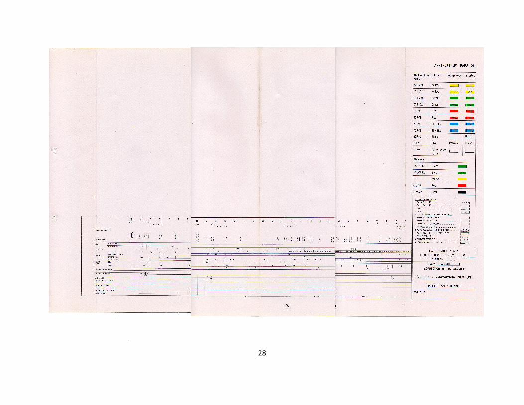
���
APE
28

APE
29

THE MAINTENANCE OF PERMANENT WAY
30
PART ‘B’
Regular Track Maintenance
224. Through Packing: ConventionalMaintenance By Beater Packing :– (1) General:Through packing shall consist of the followingoperations in sequence. The length of track openedout on any one day shall not be more than that canbe efficiently tackled before the end of the day:
(a) Opening of the road.
(b) Examination of rails, sleepers andfastenings.
(c) Squaring of sleepers.
(d) Slewing of track to correct alignment.
(e) Gauging.
(f) Packing of sleepers.
(g) Repacking of joint sleepers.
(h) Boxing of ballast section and tidying.
Through packing is best done continuouslyfrom one end of a gang length towards the other.
(2) Each of the above operations should becarried out as detailed below :– (a) Opening of Road:Ballast should be opened out on either side of therail seats to the extent shown hereunder to a depthof 50 mm. below the packing surface withoutdisturbing the cores under the sleepers:
(i) Broad Gauge : End of sleepers to 450mm.inside of the rail seat.
(ii) Metre Gauge : End of sleepers to 350mm.inside of the rail seat.
(iii) Narrow Gauge (762mm.) : End of sleepersto 250mm. inside of the rail seat.
In case of cast iron plate or pot sleepers, theopening out should be to the extent of the plates orpots to enable packing being done conveniently.
The ballast should be drawn by powrahs/shovels outwards and inwards i.e., that portion of theballast on the outside of the rail should be drawnoutwards, the portions between the rails being drawntowards the centre, care however, should be takento see that the ridge between the rails does not projectmore than 50mm. above rail level.
(b) Examination of Rails, Sleepers andFastenings – (i) Rails should be examined, theunderside for corrosion, the ends for cracks, the headfor top and side wear, rail joints for wear on the fishing
planes, fish bolts for tightness. If rails on curves wearat an unusually rapid rate, lubrication of the gaugeface should be done. Rust and dust must be removedfrom the corroded rails by using wire brushes; kinksin rails should be removed by jimcrowing.
(ii) Sleepers should be inspected for theircondition and soundness particularly at the rail seats.In case of wooden sleepers, plate screws, spikesand fang-bolts should be examined for their firm grip.Sleepers should be checked for split and decay.
In case of cast iron sleepers, the condition andfirmness of cotters and keys should be examined.Loose keys should be tightened by providing linersor replaced by appropriate oversized keys. In thecase of wear in the rail seat of CST. 9 plates, suitablepad/saddle plates may be provided. Fastenings andfittings should be examined to ensure that they arein good order, appropriately tightened so that theyfirmly hold the rails. Broken ones should be replacedimmediately.
(c) Squaring of sleepers :– Gauge variationsand kinks inevitably result from sleepers getting outof square.
(i) The spacing of sleepers on the sightingrail should first be checked and correctly chalk-marked. Corresponding marks should then be madeon the other rail using the square at every point. Thecore of sleepers that are out-of-square should thenbe ‘picked’ with the pick ends of beaters, thefastenings loosened and the sleepers levered andsquared to correct position.
(ii) Squaring should be done by planting thecrow bars firmly against the sleeper and pushing it.Under no circumstances should sleepers behammered. Sleepers that are squared should beregauged immediately, the fastenings tightened andrepacked.
(d) Slewing of track to correct alignment: -(i)Heavy slewing will only be required duringrealignment of curves when it will be necessary toloosen the rail, joints and in case of steel sleepersand cast iron sleepers to loosen the fastenings, thepacking cores being broken with the pick-ends ofbeaters. Slewing for normal maintenance will be of asmall order and should be done after opening outthe road, loosening the cores at ends and drawingout sufficient ballast at the ends of the sleepers.

THE MAINTENANCE OF PERMANENT WAY
(ii) Slewing of track shall be directed by the Mate who on straights should sight the rail from a distance of 30 to 60 metres. On curves, he should sight the outer rail. Slewing is best done in the morning unless it is cloudy, as later on, sighting conditions become unfavourable.
When slewing, the crow bars should be planted well into the ballast at an angle not more than 30 degrees from the vertical; otherwise lifting of the track may result.
(e) Gauging :– (i) Preservation of gauge is an important part of track maintenance especially through points and crossings. For good riding, the basic requirement is uniform gauge over a continuous stretch of track and such gauge should be allowed to continue so long as it is within the permissible limits of tightness or slackness.
(ii) Gauging should only be done after ensuring that sleepers are truly square. Standard keying hammers shall always be used. Beaters and heavier hammers should not be used, as this causes overdriving of keys and strained lugs on metal sleepers.
(iii) The track gauge should be held firm with one lug against the base rail, and the other end being swivelled over the opposite rails. The tightest position obtained determines the correct point to test the gauge. The gauge should not be forced as that causes considerable wear on the gauge lug.
(iv) The track gauge should be adjusted to correct gauge on the rail opposite to the base rail. The required slackness on sharp curves should be attained by using liners of the requisite thickness against the lug of the gauge in the case of ordinary track iron gauge.
(v) While it is desirable to maintain correct gauge, it may not be possible to maintain correct gauge due to age and condition of the sleeper. It is good practice to work within the following tolerances of gauge, provided generally uniform gauge can be maintained over long lengths::
Broad Gauge
a) On straight -6mm to +6mm
b) On curves with radius -6mm to +15mm 440 m or more
c) On curves with radius upto +20mm less than 440 m
Note : These tolerances are with respect
to nominal gauge of 1676 mm. Metre Gauge
a) On straight -3mm to +6mm
b) On curves with radius 290 m or more -3mm to +15mm
c) On curves with radius Upto +20mm less than 290 m
Note : These tolerances are with respect to nominal gauge of 1000mm.
Narrow Gauge a) On straight -3mm to +6mm
b) On curves with radius -3mm to +15mm of more than 175m
c) On curves with radius Upto +20mm less than 175 m
Note : The above tolerance are with
respect to nominal gauge of 762mm. (C.S.No:130 Dated:16.11.2012)
(f) Packing of sleepers ( i ) The aim of
packing is to have each sleeper firmly and uniformly packed to ensure that the rails are at their correct relative levels i.e., level on the straight track and to the required cant on curves and that no sleeper has any void between it and its bed.
(ii) Before packing is commenced, it is necessary to ensure that the chairs/bearing plates are firmy fixed to the sleepers and the rails are bearing on the chairs/ bearing plates. In case of rails resting directly on sleepers it should be ensured that there is no gap between the bottom of the rail and top of the sleeper.
(iii) The base rail shall be sighted by the Mate with eye along the lower edge of the head of rail and any dip or low joint lifted correctly. The adjacent sleepers should then be packed and the top checked. After two rail lengths have been attended to, the rail on the other side should be brought to the correct level by checking cross level with the straight edge and spirit level or gauge-cum level at every rail joint and at every fourth sleeper. The next two rail lengths should then be taken up and the process continued.
(iv) No joint or dip should be lifted higher than the proper level in the expectation that it will settle to the correct level. Instead it will settle more under traffic as a result of being high and cause rough running.
31

THE MAINTENANCE OF PERMANENT WAY
32
(v) Having aligned the track and adjusted the‘top’ the Gangmen should be distributed in batchesof two for packing all sleepers in a systematicmanner, commencing from one end. Four menshould deal with every sleeper successively, two ateach rail seat. The ballast under the sleeper shouldbe packed by the men standing back-to-back andworking their beaters diagonally under the rail seatat the same time to ensure firm packing.
(vi) It is important that men should thoroughly‘break’ the cores with the pick-ends and then use theblunt-ends (head-ones), as otherwise, uniformpacking will not be achieved and elasticity of the road-bed affected. After packing the rail seat the packingshould be continued outwards and inwards to therequisite extent on each side of the rail seat i.e., endof the sleeper to 450 mm. inside on the B.G. and endof sleeper to 350 mm. inside on the M.G. and end ofsleepers to 250 mm. inside on the N.G. (762 mm.).The beaters should not be lifted above the chest level,the strokes being kept as nearly horizontal aspossible. Care must be taken to avoid forcing underthe sleeper any stones so large as to cause unevenbearing and to avoid striking the edges of the sleepersand timbers. All men should aim to work the beaterfrom the same height (chest level) so that thesleepers are uniformly packed. Higher or lower liftingof the beaters results in uneven compactness.
(vii) In case of steel trough and woodensleepers, packing under the rail seat causes theballast to work towards the center. Before finaldressing is done, it should be ensured that no sleeperis centre-bound by working the pick-ends over thecentral range. Centre bound sleepers cause vehiclesto roll from side to side.
(viii) In the case of CST. 9 sleepers it shouldbe ensured that the end pockets or bowls are filledwith ballast and the main packing should be done atcorners. The central flat portion of the plate shouldnot be packed hard but only tamped lightly. On potsleepers the ballast should be punned through theholes provided at the top of the pot and rammed inwith crow-bars.
(ix) Care must also be taken while packing toensure that the work does not result in the sleepersadjoining those being packed, lifted off their bed, thuscreating artificial voids under them.
(x) The packing on the inside and outside atevery rail seat should, before boxing the track, bechecked by the Mate by tapping with a wooden mallet
or a canne-a boule. A hollow sound would indicatedefective packing which should be attended to again.
(xi) As soon as the packing is completed, slightdistortions in alignment and top should be checkedand corrected by the Mate, the sleeper disturbed forthis purpose being finally repacked.
(g) Repacking of joint sleepers: The joint and‘shoulder’ sleepers should be repacked, beforeboxing is done and the cross-levels at joints checked.The rail joint being the weakest portion, firmness ofits support is essential.
(h) Boxing to Ballast section and Tidying – (i)After completing the preceding operations insequence, clean ballast should be worked in withballast forks or rakes. The ballast section should bedressed to the specified dimensions, a templatebeing used for the purpose. Hemp cords 6 mm. dia.of sufficient length should be used for lining the topand bottom edges of the ballast section. Where thequantity of ballast is inadequate, full section of ballastshould be provided near the rail seat, the deficiencybeing reflected along the centre of the track and notunder the rails or in the shoulders.
(ii) The cess should then be tidied up. Whereearth ridging is existing at the edge of the bank, thisshould be removed. Cess should be maintained tothe correct depth below rail level according to theballast-section and formation profile. Too high a cessaffects drainage; too low a cess results in ballast-spread and wastage.
225. Maintenance By Measured ShovelPacking – Deleted.
226. Track Maintenance by Machines – (1)General - Mechanical maintenance of track involvinguse of “on track machines” should be planned, onlong continuous lengths.
(2) Pre-requisites to introduction of mechanicalmaintenance – (a) A minimum depth of 150 mm. ofclean ballast is recommended for the properfunctioning of the tie tampers. Adequate ballast shouldbe available in the shoulders and cribs.
(b) For this purpose, planning and executionof deep screening of ballast where required, as wellas running out of ballast, should be done well inadvance.
(c) These machines require line occupationand availability of blocks for their working. It is

THE MAINTENANCE OF PERMANENT WAY
33
desirable for these machines to be given a singleblock of at least 4 hours per day or two separateblocks of 2½ hours each, for better working. It isnecessary to have longer blocks, so that the netavailable time for working on the line is as high aspossible. On the double line section, temporary singleline working may be introduced whenever possible.Diversion of some trains along alternative routes mayalso be resorted to, wherever possible. An idealsituation would be to provide for time allowance forworking the machines in the working time table. Theblock time should be interpolated in the master chartfor passenger and goods trains that is prepared withevery change in time table. It is as much theresponsibility of the Operating Department as thatof the Engineering Department to ensure provisionof adequate time for economical working ofmachines. For this purpose it is desirable to frame aprogramme of working the machines in consultationwith the Operating Department.
(d) Sanction of the Commissioner of RailwaySafety is to be taken before introducing any new typeof ‘on - track’ machine on a section.
(3) Pre-tamping attention – To achieve goodresults the P.W.I. should carry out the followingpreparatory work before taking up the tamping:
(a) Ballasting where there is shortage ofballast.
(b) Heaping up of ballast in the tampingzone, to ensure effective packing.
(c) Making up of low cess.
(d) Cleaning of pumping joints andproviding additional clean ballast, wherenecessary.
(e) Attending to Hogged joints beforetamping.
(f) Tightening of all fittings and fasteningslike fish bolts and keys, splitting ofcotters, and replacement of worn outfittings.
(g) Renewing broken and damagedsleepers.
(h) Squaring of sleepers and spacingadjustment; regauging to be done asnecessary.
(i) Adjusting creep and expansion gap inrails.
(j) Examination of rails for cracks etc.
(k) Realigning of curves which are badlyout of alignment.
(l) Clearing of ballast on sleepers to makethem visible to the operator.
(m) All obstructions such as signal rods,cables, pipes, level crossing checkrails, etc., likely to be damaged by thetampers should be clearly marked andmade known to the tamping operatorbefore he starts work. Tight overheadclearance should also be brought to hisnotice; the beginning and end oftransitions should be marked. Superelevation should be marked on everysecond sleeper so that it can guide theoperator for levelling up correctly.
(4) Attention during Tamping: – The followingpoints should be observed by the machine operatorand the Permanent Way Inspector :
(a) The tamping depth i.e. gap between the topedge of the tamping blade and the bottom edge ofthe sleeper in closed position of the tamping toolshould be adjusted depending on the type of sleepers.This is particularly important in the case of steeltrough sleeper because of its shape. Care shouldbe taken to ensure that tamping tools are insertedcentrally between the sleepers into the ballast toavoid any damage to the sleepers.
(b) The tamping (squeezing ) Pressure shouldbe adjusted according to the track structure, as perthe recommendations of the manufacturer.
(c) The number of insertions of tamping tools,per sleeper tamped, varies with the type of sleeper -
(i) CST-9 sleepers and steel troughsleepers require tamping twice beforepassing on to the next sleeper.
(ii) Wooden Sleepers - Normally oneinsertion upto 20 mm. Lift and twoinsertions for lifts above 20 mm maysuffice. One additional insertion for jointsleepers will be required.
(iii) Concrete Sleepers-Generally oneinsertion is adequate. Two insertionsmay be necessary if the lift is above 30mm.

THE MAINTENANCE OF PERMANENT WAY
34
(d) While Tamping CST-9 and Steel TroughSleepers, it should be checked that the keys areproperly driven and they are tight.
(e) The shoulders should be compacted alongwith tamping, where separate provision for shouldercompaction is available.
(f) A run-off ramp of 1 in 1000 should be givenbefore closing the day’s work.
(5) Post Tamping Attention – The PermanentWay Inspector shall pay attention to the followingpoints :
(a) As some of the rigid fastenings mightget loose, tightening of fittings shouldbe done immediately after tamping.
(b) Any broken fitting should be replaced.
(c) It is preferable to check gauge and dogauging, wherever necessary, aftertamping.
(d) Proper quality check of work done bytamping machine is important.Immediately after the tamping work,the track should be checked, inrespect of cross levels andalignment, and action taken asconsidered necessary.
(e) The ballast should be dressed neatlyand proper consolidation of ballastbetween the sleepers should bedone.
(6) General Notes on Working by Machines.:
(a) As far as possible machines shouldbe worked in pairs in the same blocksection to make effective use ofblock.
(b) Where shoulder and crib compactingequipment is available with tietamping machine, the same shouldinvariably be used.
(c) Only trained and experiencedpersons should be deputed to manthe machines.
(d) While stabling the machine, it shouldbe ensured that all the locking devicesare properly secured and theswitches are put ‘off’.
(e) Before putting the machine intocommission all the devices should bechecked and made sure that they are
in proper working order.
(f) The machine should never be run ata speed higher than that permitted/sanctioned by the Commissioner ofRailway Safety.
(g) While passing trains, on adjacenttrack(s) on double / multiple lines, itshould be ensured that no part of thetamping machine is fouling the othertrack.
(h) The prescribed schedules ofpreventive maintenance should beadhered to. Suitable maintenanceorganisation should be created in theRailways as necessary. Sufficientspares should be arranged. Anassessment of requirement ofspares, based on the experienceshould be made.
227. Systematic Overhauling – (1) Sequenceof operations- Overhauling as described briefly inpara 203 (2) should consist of the followingoperations in sequence :–
(a) Shallow screening and making up ofballast.
(b) All items attended to, while doingthrough packing as detailed in Para224 (1).
(c) Making up the cess.
(2) Shallow Screening and making up of Ballast–
(a) For good drainage periodical screening ofballast is essential.
(b) In the case of manual maintenance, the cribballast between sleepers is opened out to a depth of50 to 75 mm. below the bottom of sleepers, slopingfrom the centre towards sleeper end. For machinemaintained section, the crib ballast in the shouldersshould be opened out to a depth of 75 to 100mm.below the bottom of sleepers, sloping from the centretowards sleeper end. The ballast in the shouldersopposite to the crib as well as the sleepers is removedto the full depth. A slope is given at the bottom slopingaway from the sleeper end. The ballast is thenscreened and put back. Care should be taken to seethat the packing under the sleepers is not disturbedand the muck removed is not allowed to raise thecess above the correct level.

THE MAINTENANCE OF PERMANENT WAY
35
(c) Two contiguous spaces between sleepersshould not be worked at the same time.
(d) Screening should be progressed in alternatepanels of one rail length. In no circumstances shouldseveral rail lengths of track be stripped of ballast.
(e) Where drains across the track exist, theyshould be cleaned and filled with boulders or ballastto prevent packing from working out and formingslacks.
(f) After screening, full ballast section shouldbe provided, extra ballast being run out previouslyfor the purpose. Work should be commenced aftermaking sure that the ballast will not be seriouslydeficient. Deficiency, if any, should be shown in thecentral portion of sleeper and this also should bemade up soon.
(3) Through packing of track – The detailedoperations are described in Para 224. Throughpacking may be done either by conventional beaterpacking, or by using machines.
(4) Making up of Cess – Cess when highshould be cut alongwith overhauling and when lowshould be made up. A template should be used forthis purpose.
(5) General – Overhauling should be completedbefore the end of March. In the case of L.W.R.territory, the provisions in L.W.R. Manual should befollowed.
(6) Screening in Welded area – In the case ofS.W.R. area screening may be carried out at railtemperatures and conditions as detailed in Para 509.
228. 3-tier system of track maintenance :–
(1) 3-tier System of track maintenance shall beadopted on sections nominated for mechanisedmaintenance. This shall consist of the following 3tiers of track maintenance:
(i) On-track machines (OMU)(ii) Mobile Maintenance Units (MMU)(iii) Sectional Gangs
(2) Large track machines for trackmaintenance include Tie-tamping machines for plaintrack and points and crossings, shoulder ballastcleaning machines, ballast cleaning machines, ballastregulating machines and dynamic track stabilizers.These machines shall be used as per the variousinstructions issued in Indian Railways Track
Machines Manual. These machines shall bedeployed to carry out the following jobs:
(a) Systematic tamping of plain track aswell as Points & Crossings;
(b) Intermediate tamping of plain track aswell as Points & crossings;
(c) Shoulder ballast cleaning;
(d) Ballast profiling/redistribution;
(e) Track stabilization;
(f) Periodical deep screening.
(3) Mobile Maintenance Units–
(a) The mobile maintenance units (MMU)shall consist of two groups:
(i) MMU-I : One for each PWI's section.
(ii) MMU-II: One for each sub-division
(b) The functions of MMU shall be asbelow:
MMU-I - (Rail-cum-Road Vehicle based)one with each PWI incharge with ajurisdiction of 40-50 Kms double lineor 90-100 Kms single line:
(i) Need based spot tamping;
(ii) In-Situ rail welding
(iii) Casual Renewal and repairs exceptplanned renewals
(iv) Overhauling of Level Xings
(v) Replacement of glued joints
(vi) Rail cutting/drilling and chamfering
(vii) Permanent repairs to fractures
(viii) Creep or gap adjustments involvinguse of machines
(ix) Destressing of LWR/CWR
(x) Loading/Unloading of materials
(xi) Any other functions assigned.
MMU-II - (Road Vehicle Based ) one witheach sub division
(i) Reconditioning of Turnouts
(ii) Minor repairs to the equipments ofMMU
(c) The MMU shall be equipped with thefollowing equipments. These equipments shall beused according to the working instructions, as andwhen issued.

THE MAINTENANCE OF PERMANENT WAY
36
List of equipments for MMU-I:
(A) Communication Equipment
1. Walkie Talkie 4 sets2. Portable field telephones 4 sets
(B) Rail Cutting/Drilling Equipment
3. Disc Cutter 1
4. Rail Cutting Machine 1
5. Rail Drilling Machine 1
6. Chamfering kit 1
(C) Rail Welding Equipment
7. Rail Welding Equipment 2 sets
8. Weld Trimmer 1 set
9. Rail Profile Grinder forwelded joints 1 set
(D) Spot Tamping with Lifting Lining10. Off Track Hand Held
Tamper with Generators 1 set11. Lifting Jack-hydraulic/
mechanical 4 sets12. Lifting-cum-Slewing
Device 2 sets
(E) Destressing Equipment
13. Rail Tensors- Hydraulic/mechanical 2 sets
14. Rollers, wooden mallets 1com-plete setforDestre-ssing 3Km LWR
(F) Inspection Gadgets15. Inspection Kit 1 No.16. Gauge cum Level 1 No.17. Rail Thermometer 1 No.18. Vernier Calipers 1 No.19. Micrometer 1 No.
(G) Material Handling Equipment20. Rail Dolly 6 No.21. Mono Rail Wheel Borrow 2 No.
(H) Safety and Protection Equipments22. Warning System23. Red Banner Flag24. Red Hand Signal Flag25. Green Hand Signals Flag26. Detonators
(I) Gas Cutting Equipments withAccessories: 1 set.
List of Equipments for MMU-II:
(A) Points and Crossing ReconditioningEquipment :
1. Welding Generator 1 set
2. Arc Welding Equipment 1 set
3. Hand Held Rail Grinder 2 sets
(B) For Minor Repairs to Equipments:4. Spanner of sizes 2 sets5. Turfer 26. Files of Sorts 2 sets7. Bench Drill 28. Vice Bench 29. Bench Grinder 2
(4) Sectional Gangs:The sectional gangs, under 3-tiersystem of track maintenance shallperform the following functions:
(a) Patrolling of track:(i) Keyman's daily patrol(ii) Hot/cold weather patrolling(iii) Monsoon Patrolling
(b) Watching vulnerable locations(c) Attention of emergencies viz. temporary
repairs of fractures.(d) Need-based attention to bridges,
turnouts, SEJs and approaches oflevel crossings.
(e) Greasing of ERCs, lubrication ofjoints, casual changing of rubber padsand other fittings
(f) Minor cess repairs(g) Cleaning of drains and boxing of ballast(h) Attention to loops(i) Creep and gap adjustment not involving
use of machines(j) Cleaning of crib ballast for effective cross
drainage(k) Pre & post tamping attention(l) Assistance to MMU & OMU as required(m) Any other functions assigned.

THE MAINTENANCE OF PERMANENT WAY
37
229. Picking up Slacks – Slacks usually occuron stretches of yielding formation on high banks andcuttings, on approaches of bridges, on badly alignedcurves, where ballast is poor in quality or quantity orwhere drainage is defective. Attention to slacks shouldbe need based, need for the same being determinedby inspections and results of track recording. Pickingup slacks shall be done where the alignment is kinkyor top level is uneven and the track has to be restoredto normal condition quickly. The quantum of workturned out by a gang during the day will depend onthe extent of slacks. In all cases sighting is done, thedefects assessed and marks made on sleepers tobe dealt with in chalk. The marked sleepers shouldthen be dealt with as in through packing care beingtaken to see that the packing of adjacent sleepersdoes not get disturbed. In case a large percentageof sleepers needs attention in a rail length, the entirerail length should be attended to. The marking ofdefects shall be as indicated below :
Defects Symbol Place of indication
Cross levels C-2 On the sleeper insidegauge face.
Loose packing H or P On the sleeper outsidethe gauge face
Gauge O ± On the sleeper insidethe gauge face
Unevenness → ← On the rail web on ↓ gauge face side
Alignment → On the foot of railinside the gauge face
It is imperative that when joints are picked up,at least three sleepers on either side of the joints arepacked. Picking up slacks may be done, byconventional method or by off-track tampers. In thecase of a low joint, the fish plates should be slightlyloosened and the joint tapped, so that the rail endsare, rendered free and are capable of being lifted.After the joint is thoroughly packed the fish platesshould be tightened again.
230. Observance of Sleepers underpassage of traffic – During the passage of the firstand last trains within working hours, the Mate andGangmen at the work site should stand on the cesseach about one rail-length apart on either side of theportion of track they are attending to, whether through
packing or picking up slacks and observe themovement of sleepers under load.
Immediately after the passing of train, loosesleepers should be marked, packed uniformly andthe packing tested. In respect of other trains, the Mateand the Gangmen should observe the sleepers nearwhere they are working and take similar action. Firmand uniform packing is the primary need for goodtrack maintenance.
231. Sample of standard section of track– At or near the commencement of each gang lengthbetween stations a sample of three rail lengths oftrack should be maintained to accord with allstandards laid down –
(a) Formation of standard width and levelbelow rail.
(b) Clean ballast of correct size, quantity andcross section.
(c) Correct alignment, level and gauge.
(d) Sleepers and fastenings in goodcondition.
The object of the sample track is to indicatethe standard to which the track should be maintainedthroughout the gang length.
232. Checking work of Gangs byPermanent Way Inspectors – (1) Examinationof Gang’s Work– The work done by a gang either onthe previous day or during the interval when thePermanent Way Inspector is next with the gangshould be examined for alignment, surfacing andboxing throughout. The Permanent Way Inspectorshould inspect rails and sleepers and their fasteningsand check cross levels, gauge, squareness ofsleepers, packing, joint maintenance, profile of ballastand depths of cess below rail level. The Mate’sMuster Sheet should be checked and initialled.Instructions to the Mates should be recorded in thegang diaries.
(2) Examination of tools and equipment - (a)The Permanent Way Inspector should examineevery month and replace, when necessary, worn outtools and equipment.
(b) He should check the accuracy of the spiritlevel/gauge and straight edge every month, the resultof this examination being entered in the Mate’s diarybook.

THE MAINTENANCE OF PERMANENT WAY
(c) Each gang should have the following minimum equipment:
(i) Level-cum-gauge. (ii) One set of hand signal flags, red and
green (2 hand signal lamps at night).
(iii) 12 detonators. (iv) Steel scale 30cm. long. (v) Straight edge 1 metre long. (vi) Square. (vii) Hump chord. (viii) Keying and spiking hammer. (ix) Marking chalk. (x) Rail thermometer. (xi) Sufficient No. of shovels, Phowrahs,
beaters, crow-bars, Ballast-forks or rakes, mortar pans or baskets.
(xii) Wooden mallet or Canne-a-Boule. (xiii) Feeler gauge.
(xiv) – 2 no. whistle thunderers. (C.S.No:120 Dated:16.04.2010)
(3) Instructions and Tuition – The permanent Way Inspector should ensure that every man in each gang is aware of the following rules in which the men should be examined periodically and on appointment, promotion or transfer :–
Protecting the lines in an emergency or during work affecting the running of trains.
Method of fixing and safety range of detonators.
Showing of signals with or without hand signal flags during day and with hand signal lamps during night.
Action to be taken when a train is noticed to have parted.
‘Safety first’ rules. Patrolling of the line during heavy rains
/storms and hot weather on LWR lengths.The Permanent Way Inspector should instruct the men in the proper use of tools and upkeep of the road. The instructions should not be of a casual nature; they should be demonstrative.
233. Lifting Of Track – (1) Lifting of track will become necessary during regrading and for elimination of minor sags, which develop through improper maintenance or yielding soil, to keep a good top.
38
(2) Correct level pegs should be fixed at
suitable intervals, before lifting is commenced. (3) Heavy lifting should always be carried
out under suitable speed restriction and under the protection of corresponding engineering signals. Lifting should not exceed 75 mm. at a time so as to allow proper consolidation. The easement gradient for the passage of trains should not be steeper than 25 mm. in one rail length of 13 metres. The operation should be repeated until the required level is attained when the track should be finally ballasted, through packed and boxed, the cess being made up to proper level.
(4) Lifting should commence from the down hill end carried out in the direction of rising grade in case of single line. It should proceed in the opposite direction to traffic, in case of double line, care being taken not to exceed the easement grade.
(5) While lifting track under bridges and overhead structures and in tunnels it should be ensured that there is no infringement of standard dimensions.
(6) In case of curves, it is usual to set the inner rail to the correct level and grade and to raise the outer rail to give the required superelevation, care being taken to see that the cant gradient is within the permissible limit.
234. Lowering of Track – (1) Lowering of the track should not be resorted to except where it can not be avoided and if resorted to, it should be done under suitable speed restriction and under the protection of Engineering signals.
(2) When lowering is to be done, trenches should be made across the track at every 30 M. to the final level in order to give a continuous indication, while the work is in progress. The ballast should be removed sufficiently far away from the track to prevent it getting mixed up with excavated material.
(3) The procedure is to clear the spaces between the sleepers, then slightly lift the track, break the packing beneath and level it into the space between sleepers. This material is then removed and the operation repeated until the final level is reached. The road should then be ballasted, through packed and boxed, the cess being cut down to proper level.
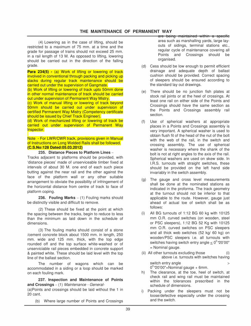
THE MAINTENANCE OF PERMANENT WAY
(4) Lowering as in the case of lifting, should be
restricted to a maximum of 75 mm. at a time and the grade for passage of trains should not exceed 25 mm. in a rail length of 13 M. As opposed to lifting, lowering should be carried out in the direction of the falling grade. Para 234(5) - (a) Work of lifting or lowering of track involved in conventional through packing and picking up slacks during regular track maintenance should be carried out under the supervision of Gangmate. (b) Work of lifting or lowering of track upto 50mm done in other normal maintenance of track should be carried out under supervision of Permanent Way Mistry. (c) Work of manual lifting or lowering of track beyond 50mm should be carried out under supervision of certified Permanent Way Mistry (Competency certificate should be issued by Chief Track Engineer). (d) Work of mechanized lifting or lowering of track be carried out under supervision of Permanent Way Inspector. Note - For LWR/CWR track, provisions given in Manual of Instructions on Long Welded Rails shall be followed. (C.S.No:128 Dated:05.03.2012)
235. Distance Pieces to Platform Lines – Tracks adjacent to platforms should be provided, with ‘distance pieces’ made of unserviceable timber fixed at intervals of about 30 M. one end of each such piece butting against the near rail and the other against the face of the platform wall or any other suitable arrangement to obviate the possibility of infringement of the horizontal distance from centre of track to face of platform coping.
236. Fouling Marks – (1) Fouling marks should be distinctly visible and difficult to remove.
(2) These should be fixed at the point at which the spacing between the tracks, begin to reduce to less than the minimum as laid down in the schedule of dimensions.
(3) The fouling marks should consist of a stone /cement concrete block about 1500 mm. in length, 250 mm. wide and 125 mm. thick, with the top edge rounded off and the top surface white-washed or of unserviciable rail pieces embedded in concrete support & painted white. These should be laid level with the top line of the ballast section.
The number of wagons which can be accommodated in a siding or a loop should be marked on each fouling mark.
237. Inspection and Maintenance of Points and Crossings – (1) Maintenance - General- (a)Points and crossings should be laid without the 1 in 20 cant.
(b) Where large number of Points and Crossings
are being maintained within a specific area such as marshalling yards, large lay-outs of sidings, terminal stations etc., regular cycle of maintenance covering all Points and Crossings should be organised.
(d) Cess should be low enough to permit efficient
drainage and adequate depth of ballast cushion should be provided. Correct spacing of sleepers should be ensured according to the standard lay out drawings.
(e) There should be no junction fish plates at
stock rail joints or at the heel of crossings. At least one rail on either side of the Points and Crossings should have the same section as the Points and Crossings assembly rail section.
(f) Use of spherical washers at appropriate
places in a Points and Crossings assembly is very important. A spherical washer is used to obtain flush fit of the head of the nut of the bolt with the web of the rail, in the switch and crossing assembly. The use of spherical washer is necessary where the shank of the bolt is not at right angles to the axis of the rail. Spherical washers are used on skew side. In I.R.S. turnouts with straight switches, these should be provided on the left hand side invariably in the switch assembly.
(g) The gauge and cross level measurements
shall be done at the nominated stations as indicated in the proforma. The track geometry at the turnout should not be inferior to that applicable to the route. However, gauge just ahead of actual toe of switch shall be as follows:
(i) All BG turnouts of 1:12 BG 60 kg with 10125 mm O.R. curved switches (on wooden, steel or PSC sleepers), 1:12 BG 52 Kg with 10125 mm O.R. curved switches on PSC sleepers and all thick web switches (52 kg/ 60 kg) on wooden/PSC sleepers i.e. all turnouts with switches having switch entry angle < 00°20’00" = Nominal gauge.
(ii) All other turnouts excluding those (i)above i.e. turnouts with switches having
switch entry angle >00°20’00"=Nominal gauge + 6mm.
h) The clearance, at the toe, heel of switch, at check rail and wing rail must be maintained within the tolerances prescribed in the schedule of dimensions.
i) Packing under the sleepers must not be loose/defective especially under the crossing and the switch.
39

THE MAINTENANCE OF PERMANENT WAY
40
(j) The chairs and fastenings and all otherfittings must be properly secured.
(k) The Points and Crossings assembly, shouldbe in good condition and alignment with therest of the track without kinks.
(l) Adequate creep anchors should be providedto arrest creep. Box anchoring of at leastone rail length ahead of stock rail isrecommended. Creep posts should beerected at all interlocked facing pointsopposite the toe of the switch and creepshould not be allowed to exceed permissiblelimits. In case of PSC sleeper layout withelastic fastening, creep anchors need notbe provided. In case excessive creep isobserved at such layouts, the condition ofelastic fastenings may be examined andsuitable action be taken.
(m) It is desirable to weld stock and lead jointson the Points and Crossings assembly.
(2) Maintenance of Switches –(a) In case of straight switches, correct
amount of bend should be given to thestock rail on the turnout side at thetheoretical toe of switch, to avoid badalignment and kink.
(b) The condition of stock & tongue railsshould be carefully examined. Badlyworn and damaged stock and tonguerails should be replaced by serviceableones. A tongue rail may be classified asworn/damaged when -It is chipped/cracked over small lengthsaggregating to 200 mm. within a distanceof 1000 mm. from its toe (i) chippedlength will be the portion where tonguerail has worn out for a depth of more than10 mm over a continuous length of 10mm.(ii) it has developed knife edged tip(thickness of top edge being less than 2mm) over a length of more than 100 mmany where upto a distance of 1000 mmfrom its toe.(iii) it is badly twisted or bent and doesnot house properly against the stock railcausing a gap of 5mm or more at thetoe, the limit described in the I.R.S.E.M.The tongue rail can, however, be reusedafter reconditioning of the broken/worn/damaged tip by welding.
(iv)Tongue rail should be replaced/reconditioned when vertical/lateral wearexceeds the values laid down. The wearshall be measured at a point with 13 mmhead width and at the point where tongueand stock rails are at same level. Thislocation is indicated in table at Annexure2/6/1.Vertical Wear – 8mm for 60 kg
– 5mm for 52 kg and 90R– 3mm for 75R and 60R
Lateral Wear – 8mm for 60 kg– 6mm for 52 kg and 90R– 5mm for 75 R and 60R
(v) Wear on stock rail shall not exceedthe limits laid down in para -302 ofIRPWM. However, proper housing oftongue rails is to be ensured.Burred stock rail likely to obstruct the lockbar, should be replaced, if necessary.
(c) Rail Gauge ties, rodding etc., hinderproper packing and ordinary beatersbecome ineffective. Yard gangstherefore, should use tamping bars atsuch locations.
(d) To check the housing of the tongue railand also the throw of the switch, all non -interlocked points should be operated byhand lever and other points from thesignal frame, when traffic permits doingso. If the tongue rail is found to be nothousing properly against the stock rail,the defect must be rectified by thePermanent Way Staff in case of non-interlocked points and jointly with signaland telecommunication staff, in case ofinterlocked or partially interlocked points.
(e) Tongue rail should bear evenly on all theslide chairs. This will be ensured whenall the sleepers are packed properly.
(f) When the tongue rail is in closed position,it must bear evenly against distancestuds or blocks.
(g) All bolts on switches should be kept tight.

THE MAINTENANCE OF PERMANENT WAY
41
limits:
Built up/welded crossing - 6mm
CMS crossings - 8mm
Note :
(i) In case of CMS crossings, followingdimensions should be deducted (toaccount for slope in casting of wingrails to 1:20 cant) from the observedwear measurements to find out theactual wear.
for 52 kg section : 2.0mm.
for 60 kg section : 2.5mm.
(ii) In case of welded heat treatedcrossings, the dimensions to bededucted from the observed wear forfinding out actual wear is as shownon the relevant layout drawing.
(f) In the case of steel trough sleepers usedin crossings, use of wooden blocksadded to the contour of the underside ofsleepers, strengthens the support andhelps in better maintenance. However,for sleepers strengthened by providingsteel ribs on their underside, use ofwooden block is not required.
(4) Maintenance of lead portion and turn incurve–
(a) The leads and radii of turnout should becorrect according to the section of therail and the angle of crossing used.
(b) Initially, the lead curve correctnessshould be ensured by measuring offsetsfrom the gauge face of the straight track.During maintenance, stations at 3.0 Mintervals should be marked and theversines checked and track attended asnecessary.
(c) The versines of turn in curves on loopsshould be recorded at stations at 3.0 Mintervals on 6.0m chord length during theinspection of points and crossings tocheck the sharpness of the curve andrectified as necessary. The turn-in curveshould also be checked for condition ofsleepers and fastenings.
(h) Slight wide gauge at the toe of switchover and above the required widening tohouse the tip of the tongue rail, may beadjusted by providing suitable steelpacking between the web of the stockrail and the lug of the slide chair whereverfeasible.
(i) Stretcher bars connected to the pull rodshall be maintained jointly by thePermanent Way Staff and the SignaxllingStaff. All other stretcher bars shall bemaintained by the Permanent WayInspector. Stretcher bars insulated fortrack circuit purposes shall not beinterfered with unless signal staff arepresent.
(j) Wear on switches can be reduced bylubrication of the gauge face of tonguerail.
(k) On wooden sleeper layout assembly, theslide chairs should be fixed to timbersby plate screws; Round spikes shouldnot be used for this purpose.
(3) Maintenance of Crossings –
(a) If any damage to the nose of crossing isnoticed, its cause must be traced, whichmay be due to tight gauge or due toexcessive clearance at the check rail.
(b) If wing rails or check rails are badly wornlaterally, it could be due to wide gauge atthe crossing. Gauge can be maintainedproperly by the provision of a gauge tieplate under the nose of crossing, onlayout of wooden sleepers.
(c) In obtuse crossings, the distancebetween the throat and the nose mustbe maintained correctly.
(d) In diamond crossings, obtuse crossingsshould be laid square to each other withrespect to the centre line of the acutecrossings.
(e) Maximum permissible vertical wear onwing rails or nose of crossing shall be10mm. However, on Rajdhani/Shatabdiroutes, as a good maintenance practice,crossing and the wing rails should beplanned for reconditioning/resurfacing bywelding on reaching the following wear
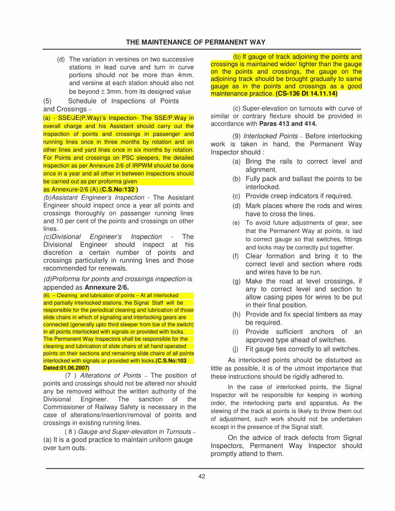
THE MAINTENANCE OF PERMANENT WAY
(d) The variation in versines on two successive stations in lead curve and turn in curve portions should not be more than 4mm. and versine at each station should also not be beyond ± 3mm. from its designed value
(5) Schedule of Inspections of Points and Crossings – (a) - SSE/JE(P.Way)’s Inspection- The SSE/P.Way in overall charge and his Assistant should carry out the inspection of points and crossings in passenger and running lines once in three months by rotation and on other lines and yard lines once in six months by rotation. For Points and crossings on PSC sleepers, the detailed inspection as per Annexure 2/6 of IRPWM should be done once in a year and all other in between inspections should be carried out as per proforma given as Annexure-2/6 (A).(C.S.No:132 ) (b)Assistant Engineer’s Inspection - The Assistant Engineer should inspect once a year all points and crossings thoroughly on passenger running lines and 10 per cent of the points and crossings on other lines. (c)Divisional Engineer’s Inspection - The Divisional Engineer should inspect at his discretion a certain number of points and crossings particularly in running lines and those recommended for renewals. (d)Proforma for points and crossings inspection is appended as Annexure 2/6. (6) – Cleaning and lubrication of points – At all interlocked and partially interlocked stations, the Signal Staff will be responsible for the periodical cleaning and lubrication of those slide chairs in which of signaling and interlocking gears are connected (generally upto third sleeper from toe of the switch) in all points interlocked with signals or provided with locks. The Permanent Way Inspectors shall be responsible for the cleaning and lubrication of slide chairs of all hand operated points on their sections and remaining slide chairs of all points interlocked with signals or provided with locks.(C.S.No:103 Dated:01.06.2007)
(7 ) Alterations of Points – The position of points and crossings should not be altered nor should any be removed without the written authority of the Divisional Engineer. The sanction of the Commissioner of Railway Safety is necessary in the case of alterations/insertion/removal of points and crossings in existing running lines.
( 8 ) Gauge and Super-elevation in Turnouts – (a) It is a good practice to maintain uniform gauge over turn outs.
(b) If gauge of track adjoining the points and
crossings is maintained wider/ tighter than the gauge on the points and crossings, the gauge on the adjoining track should be brought gradually to same gauge as in the points and crossings as a good maintenance practice. (CS-136 Dt 14.11.14)
(c) Super-elevation on turnouts with curve of
similar or contrary flexture should be provided in accordance with Paras 413 and 414.
(9) Interlocked Points – Before interlocking work is taken in hand, the Permanent Way Inspector should :
(a) Bring the rails to correct level and alignment.
(b) Fully pack and ballast the points to be interlocked.
(c) Provide creep indicators if required. (d) Mark places where the rods and wires
have to cross the lines. (e) To avoid future adjustments of gear, see
that the Permanent Way at points, is laid to correct gauge so that switches, fittings and locks may be correctly put together.
(f) Clear formation and bring it to the correct level and section where rods and wires have to be run.
(g) Make the road at level crossings, if any to correct level and section to allow casing pipes for wires to be put in their final position.
(h) Provide and fix special timbers as may be required.
(i) Provide sufficient anchors of an approved type ahead of switches.
(j) Fit gauge ties correctly to all switches. As interlocked points should be disturbed as
little as possible, it is of the utmost importance that these instructions should be rigidly adhered to.
In the case of interlocked points, the Signal Inspector will be responsible for keeping in working order, the interlocking parts and apparatus. As the slewing of the track at points is likely to throw them out of adjustment, such work should not be undertaken except in the presence of the Signal staff.
On the advice of track defects from Signal Inspectors, Permanent Way Inspector should promptly attend to them.
42

THE MAINTENANCE OF PERMANENT WAY
43
(10) Date of Laying Points and Crossings –The month and year of laying a new or second handpoints and crossings should be painted in white blockletters on the webs of switches about 500mm. fromthe heel joint and the webs of crossings about500mm. from the joint connected to the lead rails.
When second hand points and crossings aresubsequently laid at another site, the dates previouslymarked should not be obliterated; an indication of thetotal life will then be available. In the case ofreconditioning of switches and crossings the date ofreconditioning should also be painted.

Annexure 2/6
Performa For Inspection of Point and Crossing CS-135 dt 7.5.14
Station: Point No:
Location: Rail Section:
Type of Sleeper/Assembly: Angle of crossing :
Nominal Gauge of T/out: Left Hand or Right Hand :
Laid on Straight or on curve of Radius: Similar/Contrary Flexure:
Date of Laying sleepers (mm/yyyy): Type of crossing:
Details of Deep screening:
Date(mm/yyyy):
1st 2nd 3rd 4th
Manual/Mechanised
Date of laying new/reconditioned Crossing (mm/yyyy):
1st 2nd 3rd 4th
Crossing Unique No:
Manufacture:
Date of Laying new/Reconditioned switch - (mm/yyyy):
1st 2nd 3rd 4th
LH:
RH:
I) General 1) Condition of ballast and drainage
in turnout. (clean cushion to be measured only once in a year)
II) Switch Assembly and Lead 2) Condition of sleepers, slide chairs, plate screws,heel and distance blocks, other fittings of switch including tightness of bolts etc :
44
Dt. Of Inspection Action taken with date&sign
Dt. Of Inspection
Action taken with date&sign
Dt. Of Inspection Action taken with date&sign
Dt. Of Inspection
Action taken with date&sign
APE
APE
Annexure 2/6 Performa For Inspection of Point and Crossing CS-135 dt 7.5.14 Station: Point No: Location: Rail Section: Type of Sleeper/Assembly: Angle of crossing : Nominal Gauge of T/out: Left Hand or Right Hand : Laid on Straight or on curve of Radius: Similar/Contrary Flexure: Date of Laying sleepers (mm/yyyy): Type of crossing: Details of Deep screening: Date(mm/yyyy): 1st 2nd 3rd 4th Manual/Mechanised Date of laying new/reconditioned Crossing (mm/yyyy): 1st 2nd 3rd 4th Crossing Unique No: Manufacture: Date of Laying new/Reconditioned switch - (mm/yyyy): 1st 2nd 3rd 4th LH: RH: I) General 1) Condition of ballast and drainage in turnout. (clean cushion to be measured only once in a year) II) Switch Assembly and Lead 2) Condition of sleepers, slide chairs, plate screws,heel and distance blocks, other fittings of switch including tightness of bolts etc : Dt. Of Inspection Action taken with date&sign Dt. Of Inspection Action taken with date&sign Dt. Of Inspection Action taken with date&sign Dt. Of Inspection Action taken with date&sign
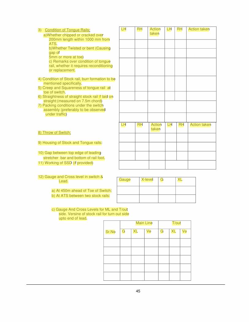
3) Condition of Tongue Rails: a)Whether chipped or cracked over
200mm length within 1000 mm from ATS. b)Whether Twisted or bent (Causing gap of 5mm or more at toe) c) Remarks over condition of tongue rail, whether it requires reconditioning or replacement.
4) Condition of Stock rail, burr formation to be
mentioned specifically. 5) Creep and Squareness of tongue rail at
toe of switch. 6) Straightness of straight stock rail if laid on
straight:(measured on 7.5m chord) 7) Packing conditions under the switch
assembly (preferably to be observed under traffic)
8) Throw of Switch: 9) Housing of Stock and Tongue rails: 10) Gap between top edge of leading stretcher bar and bottom of rail foot. 11) Working of SSD (if provided)
12) Gauge and Cross level in switch & Lead.
a) At 450m ahead of Toe of Switch: b) At ATS between two stock rails: c) Gauge And Cross Levels for ML and T/out
side. Versine of stock rail for turn out side upto end of lead.
Sr.No
Main Line T/out
G XL Ve G XL Ve
45
LH RH Action taken
LH RH Action taken
LH RH Action taken
LH RH Action taken
Gauge X-level G XL
APE
3) Condition of Tongue Rails: a)Whether chipped or cracked over 200mm length within 1000 mm from ATS. b)Whether Twisted or bent (Causing gap of 5mm or more at toe) c) Remarks over condition of tongue rail, whether it requires reconditioning or replacement. 4) Condition of Stock rail, burr formation to be mentioned specifically. 5) Creep and Squareness of tongue rail at toe of switch. 6) Straightness of straight stock rail if laid on straight:(measured on 7.5m chord) 7) Packing conditions under the switch assembly (preferably to be observed under traffic) 8) Throw of Switch: 9) Housing of Stock and Tongue rails: 10) Gap between top edge of leading stretcher bar and bottom of rail foot. 11) Working of SSD (if provided) 12) Gauge and Cross level in switch & LH RH Action taken LH RH Action taken LH RH Action taken LH RH Action taken Gauge X-level G XL
APE
a) At 450m ahead of Toe of Switch: b) At ATS between two stock rails: c) Gauge And Cross Levels for ML and T/out side. Versine of stock rail for turn out side upto end of lead. Sr.No Main Line T/out G XL Ve G XL Ve
APE
Lead.
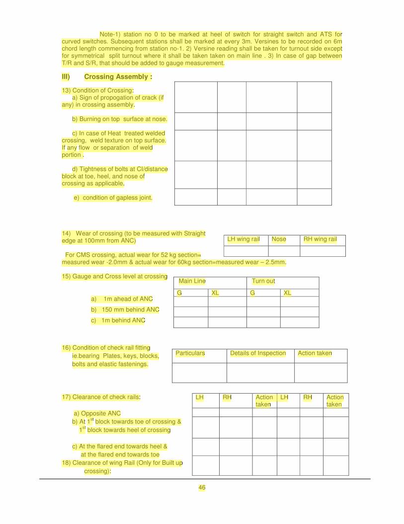
Note-1) station no 0 to be marked at heel of switch for straight switch and ATS for curved switches. Subsequent stations shall be marked at every 3m. Versines to be recorded on 6m chord length commencing from station no-1. 2) Versine reading shall be taken for turnout side except for symmetrical split turnout where it shall be taken taken on main line . 3) In case of gap between T/R and S/R, that should be added to gauge measurement.
III) Crossing Assembly :
13) Condition of Crossing: a) Sign of propogation of crack (if any) in crossing assembly. b) Burning on top surface at nose. c) In case of Heat treated welded crossing, weld texture on top surface. If any flow or separation of weld portion . d) Tightness of bolts at CI/distance block at toe, heel, and nose of crossing as applicable. e) condition of gapless joint. 14) Wear of crossing (to be measured with Straight edge at 100mm from ANC) For CMS crossing, actual wear for 52 kg section= measured wear -2.0mm & actual wear for 60kg section=measured wear – 2.5mm. 15) Gauge and Cross level at crossing
a) 1m ahead of ANC
b) 150 mm behind ANC
c) 1m behind ANC
16) Condition of check rail fitting ie.bearing Plates, keys, blocks, bolts and elastic fastenings. 17) Clearance of check rails: a) Opposite ANC b) At 1st block towards toe of crossing & 1st block towards heel of crossing c) At the flared end towards heel & at the flared end towards toe 18) Clearance of wing Rail (Only for Built up
crossing):
46
LH wing rail Nose RH wing rail
Main Line Turn out
G XL G XL
Particulars Details of Inspection Action taken
LH RH Action taken
LH RH Action taken
APE
Note-1) station no 0 to be marked at heel of switch for straight switch and ATS for curved switches. Subsequent stations shall be marked at every 3m. Versines to be recorded on 6m chord length commencing from station no-1. 2) Versine reading shall be taken for turnout side except for symmetrical split turnout where it shall be taken taken on main line . 3) In case of gap between T/R and S/R, that should be added to gauge measurement. III) Crossing Assembly : 13) Condition of Crossing: a) Sign of propogation of crack (if any) in crossing assembly. b) Burning on top surface at nose. c) In case of Heat treated welded crossing, weld texture on top surface. If any flow or separation of weld portion . d) Tightness of bolts at CI/distance block at toe, heel, and nose of crossing as applicable. e) condition of gapless joint. 14) Wear of crossing (to be measured with Straight edge at 100mm from ANC) For CMS crossing, actual wear for 52 kg section= measured wear -2.0mm & actual wear for 60kg section=measured wear – 2.5mm. 15) Gauge and Cross level at crossing a) 1m ahead of ANC b) 150 mm behind ANC c) 1m behind ANC 16) Condition of check rail fitting ie.bearing Plates, keys, blocks, bolts and elastic fastenings. 17) Clearance of check rails: a) Opposite ANC b) At 1st block towards toe of crossing & 1st block towards heel of crossing c) At the flared end towards heel & at the flared end towards toe 18) Clearance of wing Rail (Only for Built up crossing): 46 LH wing rail Nose RH wing rail Main Line Turn out G XL G XL Particulars Details of Inspection Action taken LH RH Action taken LH RH Action taken

IV) Turn in Curve
Turn in curve – stations to be marked at 3m interval. Versines to be measured on 6m chord. Station no-0 to be marked at the centre of last long sleeper in case of PSC sleepers otherwise at heel of crossing.
20) Availability of 150mm additional ballast Shoulder width on out side of turn in curve.
V) General: 21) Any other special feature/defects: 22) Signature of the Inspecting official with date. (Note- Locations where the gauge and cross levels
are to be checked should be painted on the web of the rail.)
47
St.no Ve G XL St.no Ve G XL
APE
IV) Turn in Curve Turn in curve – stations to be marked at 3m interval. Versines to be measured on 6m chord. Station no-0 to be marked at the centre of last long sleeper in case of PSC sleepers otherwise at heel of crossing. 20) Availability of 150mm additional ballast Shoulder width on out side of turn in curve. V) General: 21) Any other special feature/defects: 22) Signature of the Inspecting official with date. (Note- Locations where the gauge and cross levels are to be checked should be painted on the web of the rail.) St.no Ve G XL St.no Ve G XL
APE
CS-135 dt 7.5.2014
APE
CS-135 dt 7.5.2014

Annexure- 2/6(A)
For intermediate inspections of points and crossings on PSC sleepers Station: ________________________________________________________ Point No.: ________________________________________________________ Location: ________________________________________________________ Type of Rail: ________________________________________________________ Date of laying: ________________________________________________________ Date of laying reconditioned crossing: _____________________________________ 1st 2nd 3rd 4th Date of laying reconditioned switch: LH 1st 2nd 3rd 4th RH 1st 2nd 3rd 4th Type of sleeper/assembly: ______________________________________________ Angle of crossing: ______________________________________________ Nominal gauge of turnout: ______________________________________________ Left hand or right hand: ______________________________________________ Laid on straight or on curve of radius: _____________________________________ Similar/contrary flexure: ________________________________________________ Particulars Details of
inspection Action with date and sign
Details of inspection
Action taken with date and sign
I. General 1. Condition of ballast, packing and drainage
II) Switch assembly and lead portion: 2) Condition of Tongue Rail: a) Whether chipped or cracked over 200 mm length within 1000 mm from ATS LH RH
�
48
APE
CS-134 dt. 18.7.13
APE
CS-134 dt. 18.7.13
APE
Annexure- 2/6(A)
APE
For intermediate inspections of points and crossings on PSC sleepers Station: ________________________________________________________ Point No.: ________________________________________________________ Location: ________________________________________________________ Type of Rail: ________________________________________________________ Date of laying: ________________________________________________________ Date of laying reconditioned crossing: _____________________________________ 1st 2nd 3rd 4th Date of laying reconditioned switch: LH 1st 2nd 3rd 4th RH 1st 2nd 3rd 4th Type of sleeper/assembly: ______________________________________________ Angle of crossing: ______________________________________________ Nominal gauge of turnout: ______________________________________________ Left hand or right hand: ______________________________________________ Laid on straight or on curve of radius: _____________________________________ Similar/contrary flexure: ________________________________________________ Particulars Details of inspection Action with date and sign Details of inspection Action taken with date and sign I. General 1. Condition of ballast, packing and drainage II) Switch assembly and lead portion: 2) Condition of Tongue Rail: a) Whether chipped or cracked over 200 mm length within 1000 mm from ATS LH RH � 48 CS-134 dt. 18.7.13

b) Vertical wear Right hand. At point with 13 mm head width ( as per Annexure 2/6/1)
Left Hand 1) At point with 13 mm head width ( as per Annexure 2/6/1)
c) Lateral wear: To be measured at 13 mm to 15 mm below top of stock rail (As per Annex. 2/6/1) LH RH
3. Condition of stock rail: a) Right hand: i) Vertical wear ii) Lateral wear (To be measured at 13 mm to 15 mm below of stock rail (As per Annex. 2/6/1)
b) Left hand: i) Vertical wear ii) Lateral wear (To be measured at 13 mm to 15 mm below of stock rail (As per Annex. 2/6/1).
4. Gauge and Cross level in switch portion: a) At ATS bet. The two stock rail. b) at 150 mm behind toe of switch (only gauge): i) For straight road ii) For turn out
III. Crossing Assembly. 5. Condition of crossing. a)sign of propagation of crack (if any) in crossing assembly.
49
APE
b) Vertical wear Right hand. At point with 13 mm head width ( as per Annexure 2/6/1) Left Hand 1) At point with 13 mm head width ( as per Annexure 2/6/1) c) Lateral wear: To be measured at 13 mm to 15 mm below top of stock rail (As per Annex. 2/6/1) LH RH 3. Condition of stock rail: a) Right hand: i) Vertical wear ii) Lateral wear (To be measured at 13 mm to 15 mm below of stock rail (As per Annex. 2/6/1) b) Left hand: i) Vertical wear ii) Lateral wear (To be measured at 13 mm to 15 mm below of stock rail (As per Annex. 2/6/1). 4. Gauge and Cross level in switch portion: a) At ATS bet. The two stock rail. b) at 150 mm behind toe of switch (only gauge): i) For straight road ii) For turn out III. Crossing Assembly. 5. Condition of crossing. a)sign of propagation of crack (if any) in crossing assembly. 49

6. Wear of CMS crossing: (wear to be measured with straight edge) i) On left wing rail (opp. A N C). ii) On nose actual wear for 52kg . section: measured wear: 2.0mm.
Actual wear per 60 kg section measured wear: 2.5mm 3. On right wing rail (opp. ANC)
7. Condition of check rail fitting bearing plate, blocks, bolts and elastic fastings.
8. Condition of welding of slide chairs and lugs.
9. Condition of gapless joint in CMS Xing.
10. Any other special feature/defects
11. Signature of Inspecting official with date.
50 �
APE
6. Wear of CMS crossing: (wear to be measured with straight edge) i) On left wing rail (opp. A N C). ii) On nose actual wear for 52kg . section: measured wear: 2.0mm. Actual wear per 60 kg section measured wear: 2.5mm 3. On right wing rail (opp. ANC) 7. Condition of check rail fitting bearing plate, blocks, bolts and elastic fastings. 8. Condition of welding of slide chairs and lugs. 9. Condition of gapless joint in CMS Xing. 10. Any other special feature/defects 11. Signature of Inspecting official with date.

DIAMOND CROSSING
Acute Crossing 2
Line 2
51
DIAMOND CROSSING
Annexure-2/6(B), Para 237(5)
Obtuse Crossing 1 Acute Crossing 1
Line 1
Obtuse Crossing 2
Line 2
2/6(B), Para 237(5)
Acute Crossing 1
Line 1
APE
51 Annexure-2/6(B), Para 237(5)
APE
51 DIAMOND CROSSING Annexure-2/6(B), Para 237(5)
APE
CS- 134 dtd 18.7.13
APE
CS- 134 dtd 18.7.13

Annexure-2/6 (B) Para 237(5) PROFORMA FOR INSPECTION OF POINTS AND CROSSINGS
Diamond Crossing
Station _____________________________________________________________________________________________ Point No. ___________________________________________________________________________________________ Location ___________________________________________________________________________________________ Type of rail _________________________________________________________________________________________ Date of laying _______________________________________________________________________________________ Date of laying reconditioned crossings : ________________________________________________________________ Type of sleeper/assembly ____________________________________________________________________________ Angle of crossing ____________________________________________________________________________________ Nominal gauge of turnout ____________________________________________________________________________
1 Sleeper Details 1.1 Condition of sleeper 1.2 Squaring 1.3 Spacing 2 Ballast Details 2.1 Condition of ballast 2.2 Condition of drainage 2.3 Ballast in shoulders and cribs 2.4 Clean ballast cushion (mm)
3 Gauge and X-level between crossings Line 1 Line 2
Gauge X-Level Gauge X-Level
Station 0
1
2
At 3 m interval in lead portion 3
52
APE
CS - 134 dtd 18.7.13
APE
Station _____________________________________________________________________________________________ Point No. ___________________________________________________________________________________________ Location ___________________________________________________________________________________________ Type of rail _________________________________________________________________________________________ Date of laying _______________________________________________________________________________________ Date of laying reconditioned crossings : ________________________________________________________________ Type of sleeper/assembly ____________________________________________________________________________ Angle of crossing ____________________________________________________________________________________ Nominal gauge of turnout ____________________________________________________________________________ 52 18.7.13
APE
Annexure-2/6 (B) Para 237(5) PROFORMA FOR INSPECTION OF POINTS AND CROSSINGS Diamond Crossing Station _____________________________________________________________________________________________ Point No. ___________________________________________________________________________________________ Location ___________________________________________________________________________________________ Type of rail _________________________________________________________________________________________ Date of laying _______________________________________________________________________________________ Date of laying reconditioned crossings : ________________________________________________________________ Type of sleeper/assembly ____________________________________________________________________________ Angle of crossing ____________________________________________________________________________________ Nominal gauge of turnout ____________________________________________________________________________ 52 CS - 134 dtd 18.7.13
APE
1.1 Condition of sleeper 1.2 Squaring 1.3 Spacing 2 Ballast Details 2.1 Condition of ballast 2.2 Condition of drainage 2.3 Ballast in shoulders and cribs 2.4 Clean ballast cushion (mm)
APE
3 crossings Line 1 Line 2 Gauge X-Level Gauge X-Level Station 0 1 2 At 3 m interval in lead portion 3

. 4
5
4 Condition of Crossing Acute Xing 1 Acute Xing2 Obtuse Xing 1 Obtuse Xing 2
4.1 Sign of Propogation of crack (if any)
4.2 Burring on top surface at nose
5 Type of Crossing
6 Wear of Crossing Acute Xing 1 Acute Xing 2 Left On Right Left On Right Wing Nose Wing Wing Nose Wing Rail Rail Rail Rail
Obtuse Xing 1 Obtuse Xing 2
Nose 1 Nose 2 Nose 1 Nose 2
On Wing On Wing On Wing On Wing Nose Rail Nose Rail Nose Rail Nose Rail
7 Clearance of wing rail opposite nose of Acute Xing 1 Acute Xing 2 Obtuse Xing 1 Obtuse Xing 2
crossing and upto 450 mm towards heel end
Inner
Outer Inner Outer
Inner
Outer Inner Outer
8 Gauge and Cross Level Acute Xing 1 Acute Xing 2 Obtuse Xing 1 Obtuse Xing 2
Line 1 Line 2 Line 1 Line 2 Line 1 Line 2 Line 1 Line 2
8.1 1 m ahead of ANC Gauge
X-Level
8.2 150 mm ahead ANC Gauge
X-Level
8.3 150 mm behind ANC Gauge
X-Level
8.4 1 m behind ANC Gauge
53
APE
Wing Wing Nose Wing Rail Rail Rail Rail Obtuse Xing 1 Obtuse Xing 2 Nose 1 Nose 2 Nose 1 Nose 2 53
APE
5 4 Condition of Crossing Acute Xing 1 Acute Xing2 Obtuse Xing 1 Obtuse Xing 2 4.1 Sign of Propogation of crack (if any) 4.2 Burring on top surface at nose 5 Type of Crossing 6 Wear of Crossing Acute Xing 1 Acute Xing 2 Left On Right Left On Right Wing Nose Wing Wing Nose Wing Rail Rail Rail Rail Obtuse Xing 1 Obtuse Xing 2 Nose 1 Nose 2 Nose 1 Nose 2 53
APE
4 5 4 Condition of Crossing Acute Xing 1 Acute Xing2 Obtuse Xing 1 Obtuse Xing 2 4.1 Sign of Propogation of crack (if any) 4.2 Burring on top surface at nose 5 Type of Crossing 6 Wear of Crossing Acute Xing 1 Acute Xing 2 Left On Right Left On Right Wing Nose Wing Wing Nose Wing Rail Rail Rail Rail Obtuse Xing 1 Obtuse Xing 2 Nose 1 Nose 2 Nose 1 Nose 2 53
APE
On Wing On Wing On Wing On Wing Nose Rail Nose Rail Nose Rail Nose Rail 7 Clearance of wing rail opposite nose of Acute Xing 1 Acute Xing 2 Obtuse Xing 1 Obtuse Xing 2 crossing and upto 450 mm towards heel end Inner Outer Inner Outer Inner Outer Inner Outer 8 Gauge and Cross Level Acute Xing 1 Acute Xing 2 Obtuse Xing 1 Obtuse Xing 2 Line 1 Line 2 Line 1 Line 2 Line 1 Line 2 Line 1 Line 2 8.1 1 m ahead of ANC Gauge X-Level 8.2 150 mm ahead ANC Gauge X-Level 8.3 150 mm behind ANC Gauge X-Level 8.4 1 m behind ANC Gauge

X-Level
9 Condition of check rail and its fittings Acute Xing 1 Acute Xing 2 Obtuse Xing 1 Obtuse Xing 2
9.1 Raised Check Rail
9.2 Other bearing, plates, keys, blocks, bolts and
elastic fastening
10 Check Rail Clearance Acute Xing 1 Acute Xing 2 Obtuse Xing 1 Obtuse Xing 2
Inner Outer Inner Outer Inner Outer Inner Outer
10.1 Opposite ANC
10.2 500 mm ahead towards toe of crossing
10.3 500 mm behind heel of crossing
10.4 At the flared end towards heel
10.5 At the flared end towards toe
11 Remarks
54
APE
10 Check Rail Clearance Acute Xing 1 Acute Xing 2 Obtuse Xing 1 Obtuse Xing 2 Inner Outer Inner Outer Inner Outer Inner Outer 10.1 Opposite ANC 10.2 500 mm ahead towards toe of crossing 54
APE
9 Condition of check rail and its fittings Acute Xing 1 Acute Xing 2 Obtuse Xing 1 Obtuse Xing 2 9.1 Raised Check Rail 9.2 Other bearing, plates, keys, blocks, bolts and elastic fastening 10 Check Rail Clearance Acute Xing 1 Acute Xing 2 Obtuse Xing 1 Obtuse Xing 2 Inner Outer Inner Outer Inner Outer Inner Outer 10.1 Opposite ANC 10.2 500 mm ahead towards toe of crossing 54
APE
X-Level
APE
10.3 500 mm behind heel of crossing 10.4 At the flared end towards heel 10.5 At the flared end towards toe 11 Remarks

DIAMOND CROSSING: WITH SINGLE SLIP
Obtuse Crossing 1
Acute Crossing 2
Line 2
54 A
ND CROSSING: WITH SINGLE SLIP
Annexure-
Obtuse Crossing 1 Acute Crossing 1
Switch 1 Line 1
Obtuse Crossing 2 Switch 2
Line 2
-2/6(C) Para 237(5)
Line 1
APE
54 A Annexure- Obtuse Crossing 1 Acute Crossing 1 2/6(C) Para 237(5)
APE
SLIP 54 A Annexure- Obtuse Crossing 1 Acute Crossing 1 -2/6(C) Para 237(5)
APE
CROSSING:
APE
SINGLE
APE
WITH
APE
DIAMOND

Annexure-2/6 (C) Para 237(5) PROFORMA FOR INSPECTION OF POINTS AND CROSSINGS
Diamond Crossing: with single slip
Station ________________________________________________________________________________________________ Point No. ______________________________________________________________________________________________ Location ______________________________________________________________________________________________ Type of rail ____________________________________________________________________________________________ Date of laying _________________________________________________________________________________________ Date of laying reconditioned crossings : ___________________________________________________________________ Date of laying reconditioned switches : ____________________________________________________________________ Type of sleeper/assembly _______________________________________________________________________________ Angle of crossing _______________________________________________________________________________________ Nominal gauge of turnout _______________________________________________________________________________
1 Sleeper Details
1.1 Condition of sleepers 1.2 Squaring 1.3 Spacing 2 Ballast Details 2.1 Condition of ballast 2.2 Condition of drainage 2.3 Ballast in shoulders and cribs 2.4 Clean ballast cushion (mm) 3 Condition of Switch Assembly Switch 1 Switch 2
3.1
Whether chipped or cracked over 200 mm Inner
length within 1000 mm from ATS
Outer
3.2 Whether twisted or bent (causing gap of 5 mm Inner
or more at toe) Outer �
�
54 B
APE
PROFORMA FOR INSPECTION OF POINTS AND CROSSINGS Diamond Crossing: with single slip Station ________________________________________________________________________________________________ Point No. ______________________________________________________________________________________________ Location ______________________________________________________________________________________________ Type of rail ____________________________________________________________________________________________ Date of laying _________________________________________________________________________________________ Date of laying reconditioned crossings : ___________________________________________________________________ Date of laying reconditioned switches : ____________________________________________________________________ Type of sleeper/assembly _______________________________________________________________________________ Angle of crossing _______________________________________________________________________________________ Nominal gauge of turnout _______________________________________________________________________________ 1 Sleeper Details 54 B
APE
Annexure-2/6 (C) Para 237(5) PROFORMA FOR INSPECTION OF POINTS AND CROSSINGS Diamond Crossing: with single slip Station ________________________________________________________________________________________________ Point No. ______________________________________________________________________________________________ Location ______________________________________________________________________________________________ Type of rail ____________________________________________________________________________________________ Date of laying _________________________________________________________________________________________ Date of laying reconditioned crossings : ___________________________________________________________________ Date of laying reconditioned switches : ____________________________________________________________________ Type of sleeper/assembly _______________________________________________________________________________ Angle of crossing _______________________________________________________________________________________ Nominal gauge of turnout _______________________________________________________________________________ 1 Sleeper Details 54 B
APE
1.1 Condition of sleepers 1.2 Squaring 1.3 Spacing 2 Ballast Details 2.1 Condition of ballast 2.2 Condition of drainage 2.3 Ballast in shoulders and cribs 2.4 Clean ballast cushion (mm) 3 Condition of Switch Assembly Switch 1 Switch 2 3.1 Whether chipped or cracked over 200 mm Inner length within 1000 mm from ATS Outer 3.2 Whether twisted or bent (causing gap of 5 mm Inner or more at toe) Outer

3.3� Whether knife edge� Inner� � � � � � �
Outer� � � � � � �
3.4� Seating of tongue rails on slide chairs� Inner� � � � � � �
Outer� � � � � � �
3.5� Housing of stock and tongue rails� Inner� � � � � � �
Outer� � � � � � �
3.6� Condition of fitting of switches� � � � � � �
3.7� Packing condition under switch assembly� � � � � � �
4 Creep at toe of switch � � � � � �
5 Throw of Switch at ATS
Inner� � � � � � �
Outer� � � � � � �
6 Divergence At Heel Block
Inner� � � � � � �
Outer� � � � � � �
7� Straightness of Straight ( Measured on 10 mt. chord)�
Stock Rail � � � � � �
Tongue Rail � � � � � �
8� Wear in Tongue Rail and Stock Rail Switch 1� Switch 2� � � � �
Inner Outer Inner Outer � � � �
8.1� Tongue Rail�
At point with 13 mm head width (as per Annexure 2/6/1)�
Vertical � � � � �
Lateral � � � � � � � �
8.2� At point where tongue rail and stock rail level is same�
Vertical � � � � � � � �
Lateral � � � � � � � �
� � � � � � � � � �
� � � � � � � � � �
� � � � � � � � � �
8.3 Stock At point where tongue rail and stock Vertical
Rail rail level is same
Lateral
9 Distance between gauge faces of stock rails at JOH Switch 1 Switch 2
10 Distance between web to web of Tongue Rails
10.1 Leading stretcher bar
54 C
APE
3.3� Whether knife edge� Inner� � � � � � � Outer� � � � � � � 3.4� Seating of tongue rails on slide chairs� Inner� � � � � � � Outer� � � � � � � 3.5� Housing of stock and tongue rails� Inner� � � � � � � Outer� � � � � � � 3.6� Condition of fitting of switches� � � � � � � 3.7� Packing condition under switch assembly� � � � � � � 4 Creep at toe of switch � � � � � � 5 Throw of Switch at ATS Inner� � � � � � � Outer� � � � � � � 6 Divergence At Heel Block Inner� � � � � � � Outer� � � � � � � 7� Straightness of Straight ( Measured on 10 mt. chord)� Stock Rail � � � � � � Tongue Rail � � � � � � 8� Wear in Tongue Rail and Stock Rail Switch 1� Switch 2� � � � � Inner Outer Inner Outer � � � � 8.1� Tongue Rail� At point with 13 mm head width (as per Annexure 2/6/1)� Vertical � � � � � Lateral � � � � � � � � 8.2� At point where tongue rail and stock rail level is same� Vertical � � � � � � � � Lateral � � � � � � � � � � � � � � � � � � � � � � � � � � � � � � � � � � � � � � 8.3 Stock At point where tongue rail and stock Vertical Rail rail level is same Lateral 9 Distance between gauge faces of stock rails at JOH Switch 1 Switch 2 10 Distance between web to web of Tongue Rails 10.1 Leading stretcher bar 54 C

10.2 Ist following stretcher bar
10.3 IInd following stretcher bar
11 Gap between top edge of stretcher bar and bottom of
rail foot
11.1 Leading stretcher bar Inner
Outer
11.2 Ist following stretcher bar Inner
Outer
11.3 IInd following stretcher bar Inner
Outer
12 Clearance at JOH
12.1 On Open tongue rail side Straight
Turnout
12.2 On Closed tongue rail side Straight
Turnout
13 Gauge and X-Level in Switch and Lead Portion Straight Side Turnout Side
Switch 1 Switch 2 X- X- X-
Gauge Level Gauge Level Gauge Level
13.1 At 450 mm ahead of toe of switch
13.2 At ATS between the two stock rails
13.3 At 150 mm behind toe of switch
13.4 At heel of switch
13.5 At 3 m interval in lead portion: Station 0 1
2
3
4
5
54 D
APE
10.2 Ist following stretcher bar 10.3 IInd following stretcher bar 11 Gap between top edge of stretcher bar and bottom of rail foot 11.1 Leading stretcher bar Inner Outer 11.2 Ist following stretcher bar Inner Outer 11.3 IInd following stretcher bar Inner Outer 12 Clearance at JOH 12.1 On Open tongue rail side Straight 54 D
APE
Turnout 13 Gauge and X-Level in Switch and Lead Portion Straight Side Turnout Side Switch 1 Switch 2 X- X- X- Gauge Level Gauge Level Gauge Level 13.1 At 450 mm ahead of toe of switch 13.2 At ATS between the two stock rails 13.3 At 150 mm behind toe of switch 13.4 At heel of switch 13.5 At 3 m interval in lead portion: Station 0 1 2 3 4 5
APE
Turnout 12.2 On Closed tongue rail side Straight

14 Versine in Switch and Lead Portion
Switch 1 and Switch 2
Inner Outer
(Heel/ATS) 0
1
2
3
4
5
15 Condition of Crossing Acute Xing 1 Acute Xing 2 Obtuse Xing 1 Obtuse Xing 2
15.1 Sign of Propogation of crack (if any)
15.2 Burring on top surface at nose
16 Type of Crossing
17 Wear of Crossing Acute Xing 1 Acute Xing 2
Left Wing
Rail On Nose
Right Wing Rail
Left Wing Rail On Nose
Right Wing Rail
Obtuse Xing 1 Obtuse Xing 2
Nose 1 Nose 2 Nose 1 Nose 2
On Wing On Wing On Wing On Wing
Nose Rail Nose Rail Nose Rail Nose Rail
18 Clearance of wing rail opposite Nose of crossing and upto 450 mm
towards heel end Acute Xing 1 Acute Xing 2 Obtuse Xing 1 Obtuse Xing 2
Inner Outer Inner Outer Inner Outer Inner Outer
19 Gauge and Cross Level Acute Xing 1 Acute Xing 2 Obtuse Xing 1 Obtuse Xing 2
Straight Turnout Straight Turnout Straight Turnout Straight Turnout
19.1 1 m ahead of ANC
Gauge
X-Level
54 E
APE
Switch and Lead Portion Inner Outer (Heel/ATS) 0 1 2 3 4 5 15 Condition of Crossing Acute Xing 1 Acute Xing 2 Obtuse Xing 1 Obtuse Xing 2 15.1 Sign of Propogation of crack (if any) 15.2 Burring on top surface at nose 16 Type of Crossing 54 E
APE
14 Versine in Switch and Lead Portion Inner Outer (Heel/ATS) 0 1 2 3 4 5 15 Condition of Crossing Acute Xing 1 Acute Xing 2 Obtuse Xing 1 Obtuse Xing 2 15.1 Sign of Propogation of crack (if any) 15.2 Burring on top surface at nose 16 Type of Crossing 54 E
APE
Switch 1 and Switch 2
APE
Acute Xing 1 Acute Xing 2 Left Wing Rail On Nose Right Wing Rail Left Wing Rail On Nose Right Wing Rail Obtuse Xing 1 Obtuse Xing 2 Nose 1 Nose 2 Nose 1 Nose 2 On Wing On Wing On Wing On Wing Nose Rail Nose Rail Nose Rail Nose Rail 18 Clearance of wing rail opposite Nose of crossing and upto 450 mm towards heel end Acute Xing 1 Acute Xing 2 Obtuse Xing 1 Obtuse Xing 2 Inner Outer Inner Outer Inner Outer Inner Outer 19 Gauge and Cross Level Acute Xing 1 Acute Xing 2 Obtuse Xing 1 Obtuse Xing 2 Straight Turnout Straight Turnout Straight Turnout Straight Turnout 19.1 1 m ahead of ANC Gauge X-Level

19.2 150 mm ahead ANC Gauge
X-Level
19.3 150 mm behind ANC Gauge
X-Level
19.4 1 m behind ANC Gauge
X-Level
20 Condition of check rail and its fittings Acute Xing 1 Acute Xing 2 Obtuse Xing 1 Obtuse Xing 2
20.1 Raised Check Rail 20.2 Other bearing, plates, keys, blocks, bolts and elastic
fastening 21 Check Rail Clearance Acute Xing 1 Acute Xing 2 Obtuse Xing 1 Obtuse Xing 2
Inner Outer Inner Outer Inner Outer Inner Outer
21.1 Opposite ANC
21.2 500 mm ahead towards toe of crossing
20.3 500 mm behind heel of crossing
20.4 At the flared end towards heel
20.5 At the flared end towards toe
22 Remarks
54 F
APE
150 mm ahead ANC X-Level 19.3 150 mm behind ANC Gauge X-Level 19.4 1 m behind ANC Gauge X-Level 20 Condition of check rail and its fittings Acute Xing 1 Acute Xing 2 Obtuse Xing 1 Obtuse Xing 2 20.1 Raised Check Rail 20.2 Other bearing, plates, keys, blocks, bolts and elastic fastening 21 Check Rail Clearance Acute Xing 1 Acute Xing 2 Obtuse Xing 1 Obtuse Xing 2 54 F
APE
19.2
APE
Gauge
APE
21.1 Opposite ANC 21.2 500 mm ahead towards toe of crossing 20.3 500 mm behind heel of crossing 20.4 At the flared end towards heel 20.5 At the flared end towards toe 22 Remarks
APE
Inner Outer Inner Outer Inner Outer Inner Outer

DIAMOND CROSSING: WITH DOUBLE SLIP
Obtuse Crossing 1
Switch 2
Acute Crossing 2
Line 2
54 G
DIAMOND CROSSING: WITH DOUBLE SLIP Annexure-
Obtuse Crossing 1 Switch 4
Acute Crossing 1
Switch 2 Switch 1 Line 1
Acute Crossing 2 Switch 3 Obtuse Crossing 2
Line 2
-2/6(D) Para 237(5)
Acute Crossing 1
Line 1
APE
54 G Annexure- Obtuse Crossing 1 Switch 4 Acute Crossing 1 2/6(D) Para 237(5)
APE
54 G SLIP Annexure- Obtuse Crossing 1 Switch 4 Acute Crossing 1 -2/6(D) Para 237(5)
APE
CROSSING:
APE
DIAMOND
APE
WITH
APE
DOUBLE

Annexure-2/6 (D) Para 237(5)
PROFORMA FOR INSPECTION OF POINTS AND CROSSINGS Diamond Crossing: with Double Slip
Station _____________________________________________________________________________________________________________ Point No. ___________________________________________________________________________________________________________ Location ____________________________________________________________________________________________________________ Type of rail _________________________________________________________________________________________________________ Date of laying _______________________________________________________________________________________________________ Date of laying reconditioned crossings : ________________________________________________________________________________ Date of laying reconditioned switches : _________________________________________________________________________________ Type of sleeper/assembly ____________________________________________________________________________________________ Angle of crossing ____________________________________________________________________________________________________ Nominal gauge of turnout ____________________________________________________________________________________________
1 Sleeper Details
1.1 Condition of sleepers
1.2 Squaring
1.3 Spacing
2 Ballast Details
2.1 Condition of ballast
2.2 Condition of drainage
2.3 Ballast in shoulders and cribs
2.4 Clean ballast cushion (mm)
3 Condition of Switch Assembly Switch 1 Switch 2 Switch 3 Switch 4
54 H
APE
___________________________________________________________________________________________________________ Location ____________________________________________________________________________________________________________ Type of rail _________________________________________________________________________________________________________ Date of laying _______________________________________________________________________________________________________ Date of laying reconditioned crossings : ________________________________________________________________________________ Date of laying reconditioned switches : _________________________________________________________________________________ Type of sleeper/assembly ____________________________________________________________________________________________ Angle of crossing 54 H
APE
PROFORMA FOR INSPECTION OF POINTS AND CROSSINGS Diamond Crossing: with Double Slip
APE
5)
APE
Annexure-2/6 (D) Para 237(5) PROFORMA FOR INSPECTION OF POINTS AND CROSSINGS Diamond Crossing: with Double Slip Station _____________________________________________________________________________________________________________ Point No. ___________________________________________________________________________________________________________ Location ____________________________________________________________________________________________________________ Type of rail _________________________________________________________________________________________________________ Date of laying _______________________________________________________________________________________________________ Date of laying reconditioned crossings : ________________________________________________________________________________ Date of laying reconditioned switches : _________________________________________________________________________________ Type of sleeper/assembly ____________________________________________________________________________________________ Angle of crossing 54 H
APE
Nominal gauge of turnout ____________________________________________________________________________________________ 1 Sleeper Details 1.1 Condition of sleepers 1.2 Squaring 1.3 Spacing 2 Ballast Details 2.1 Condition of ballast 2.2 Condition of drainage 2.3 Ballast in shoulders and cribs 2.4 Clean ballast cushion (mm) 3 Condition of Switch Assembly Switch 1 Switch 2 Switch 3 Switch 4

3.1 Whether chipped or cracked over 200mm length within 1000 mm from ATS
Inner
Outer 3.2 Whether twisted or bent ( Causing
gap of 5mm or more at toe) Inner Outer
3.3 Whether knife edge Inner Outer
3.4 Seating of tongue rails on slide chairs
Inner Outer
3.5 Housing of stock and tongue rails Inner Outer
3.6 Condition of fitting of switches 3.7 Packing condition under switch assembly 4 Creep at toe of switch
5 Throw of Switch at ATS Inner Outer
6 Divergence At Heel Block Inner Outer
7 Straightness of Straight ( Measured on 10 mt. Chord)
Stock rail Tongue rail
8 Wear in Tongue Rail and Stock Rail Switch 1 Switch 2 Switch 3 Switch 4 Inner Outer Inner Outer Inner Outer Inner Outer
8.1 Tongue rail
At point with 13 mm head width (as per Annexure 2/6/1)
Vertical
Lateral 8.2 At point where tongue
rail and stock rail level is same
Vertical
Lateral 8.3 Stock
rail At point where tongue rail and stock rail level is same
Vertical
Lateral
�
54 I
APE
6 Divergence At Heel Block Inner Outer 7 Straightness of Straight ( Measured on 10 mt. Chord) Stock rail Tongue rail 8 Wear in Tongue Rail and Stock Rail Switch 1 Switch 2 Switch 3 Switch 4
APE
3.1 Whether chipped or cracked over 200mm length within 1000 mm from ATS Inner Outer 3.2 Whether twisted or bent ( Causing gap of 5mm or more at toe) Inner Outer 3.3 Whether knife edge Inner Outer 3.4 Seating of tongue rails on slide chairs Inner Outer 3.5 Housing of stock and tongue rails Inner Outer 3.6 Condition of fitting of switches 3.7 Packing condition under switch assembly 4 Creep at toe of switch 5 Throw of Switch at ATS Inner Outer 54 I
APE
8.1 Tongue rail At point with 13 mm head width (as per Annexure 2/6/1) Vertical Lateral 8.2 At point where tongue rail and stock rail level is same Vertical Lateral 8.3 Stock rail At point where tongue rail and stock rail level is same Vertical Lateral
APE
Inner Outer Inner Outer Inner Outer Inner Outer

9 Distance between gauge faces of stock rails at JOH
Switch 1 Switch 2 Switch 3 Switch 4
10 Distance between web to web of Tongue Rails
10.1 Leading stretcher bar 10.2 Ist following stretcher bar 10.3 IInd following stretcher bar
11 Gap between top edge of stretcher bar and bottom of rail foot
11.1 Leading stretcher bar Inner Outer
11.2 Ist following stretcher bar Inner Outer
11.3 IInd following stretcher bar Inner Outer
-212 Clearance at JOH
12.1 On Open tongue rail side Straight Turnout
12.2 On Closed tongue rail side Straight Turnout
13 Gauge and X-Level in Switch and Lead Portion Straight Side Turnout Side Switch 1 and Switch Switch 3 and Switch Switch 1 and Switch Switch 2 and Switch
2 4 3 4 Gauge X-Level Gauge X-Level Gauge X-Level Gauge X-Level
13.1 At 450 mm ahead of toe of switch 13.2 At ATS between the two stock rails 13.3 At 150 mm behind toe of switch 13.4 At heel of switch
13.5 At 3 m interval in lead portion: Station
0
APE
54 J
APE
9 Distance between gauge faces of stock rails at JOH Switch 1 Switch 2 Switch 3 Switch 4 10 Distance between web to web of Tongue Rails 10.1 Leading stretcher bar 10.2 Ist following stretcher bar 10.3 IInd following stretcher bar 11 Gap between top edge of stretcher bar and bottom of rail foot 11.1 Leading stretcher bar Inner Outer 11.2 Ist following stretcher bar Inner Outer 11.3 IInd following stretcher bar Inner Outer -2 12 Clearance at JOH 12.1 On Open tongue rail side Straight Turnout 12.2 On Closed tongue rail side Straight Turnout 13 Gauge and X-Level in Switch and Lead Portion Straight Side Turnout Side Switch 1 and Switch Switch 3 and Switch Switch 1 and Switch Switch 2 and Switch 2 4 3 4 Gauge X-Level Gauge X-Level Gauge X-Level Gauge X-Level 13.1 At 450 mm ahead of toe of switch 13.2 At ATS between the two stock rails
APE
13.3 At 150 mm behind toe of switch 13.4 At heel of switch 13.5 At 3 m interval in lead portion: Station 0 54 J
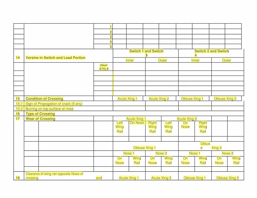
1 2 3 4 5
14 Versine in Switch and Lead Portion
Switch 1 and Switch 3
Switch 2 and Switch 4
Inner Outer Inner Outer (Heel/ ATS) 0
1 2 3 4 5
15 Condition of Crossing Acute Xing 1 Acute Xing 2 Obtuse Xing 1 Obtuse Xing 2 15.1 Sign of Propogation of crack (if any) 15.2 Burring on top surface at nose 16 Type of Crossing 17 Wear of Crossing Acute Xing 1 Acute Xing 2
Left On Nose Right Left On Right Wing Wing Wing Nose Wing Rail Rail Rail Rail
Obtuse Xing 1 Obtuse Xing 2
Nose 1 Nose 2 Nose 1 Nose 2 On Wing On Wing On Wing On Wing
Nose Rail Nose Rail Nose Rail Nose Rail
18 Clearance of wing rail opposite Nose of crossing and Acute Xing 1 Acute Xing 2 Obtuse Xing 1 Obtuse Xing 2
APE
54 K
APE
1 2 3 4 5 14 Versine in Switch and Lead Portion Switch 1 and Switch 3 Switch 2 and Switch 4 Inner Outer Inner Outer (Heel/ ATS) 0 1 2 3 4 5 15 Condition of Crossing Acute Xing 1 Acute Xing 2 Obtuse Xing 1 Obtuse Xing 2 15.1 Sign of Propogation of crack (if any) 15.2 Burring on top surface at nose 16 Type of Crossing 17 Wear of Crossing Acute Xing 1 Acute Xing 2 Left On Nose Right Left On Right Wing Wing Wing Nose Wing Rail Rail Rail Rail Obtuse Xing 1 Obtus e Xing 2 Nose 1 Nose 2 Nose 1 Nose 2 On Wing On Wing On Wing On Wing Nose Rail Nose Rail Nose Rail Nose Rail 18 Clearance of wing rail opposite Nose of crossing and Acute Xing 1 Acute Xing 2 Obtuse Xing 1 Obtuse Xing 2

upto 450 mm towards heel end Inner Outer Inner Outer Inner Outer Inner Outer
19 Gauge and Cross Level Acute Xing 1 Acute Xing 2 Obtuse Xing 1 Obtuse Xing 2
Straight Turnout Straight Turnout Straight Turnout Straight Turnout
19.1 1 m ahead of ANC Gauge
X-Level
19.2 150 mm ahead ANC Gauge
X-Level
19.3 150 mm behind ANC Gauge
X-Level
19.4 1 m behind ANC Gauge
X-Level
20 Condition of check rail and its fittings Acute Xing 1 Acute Xing 2 Obtuse Xing 1 Obtuse Xing 2
20.1 Raised Check Rail
20.2 Other bearing, plates, keys, blocks, bolts and elastic
Fastening
21 Check Rail Clearance Acute Xing 1 Acute Xing 2 Obtuse Xing 1 Obtuse Xing 2
Inner Outer Inner Outer Inner Outer Inner Outer
21.1 Opposite ANC
21.2 500 mm ahead towards toe of crossing
20.3 500 mm behind heel of crossing
20.4 At the flared end towards heel
20.5 At the flared end towards toe
22 Remarks
APE
54 L
APE
upto 450 mm towards heel end Inner Outer Inner Outer Inner Outer Inner Outer 19 Gauge and Cross Level Acute Xing 1 Acute Xing 2 Obtuse Xing 1 Obtuse Xing 2 Straight Turnout Straight Turnout Straight Turnout Straight Turnout 19.1 1 m ahead of ANC Gauge X-Level 19.2 150 mm ahead ANC Gauge X-Level 19.3 150 mm behind ANC Gauge X-Level 19.4 1 m behind ANC Gauge X-Level 20 Condition of check rail and its fittings Acute Xing 1 Acute Xing 2 Obtuse Xing 1 Obtuse Xing 2 20.1 Raised Check Rail 20.2 Other bearing, plates, keys, blocks, bolts and elastic Fastening 21 Check Rail Clearance Acute Xing 1 Acute Xing 2 Obtuse Xing 1 Obtuse Xing 2 Inner Outer Inner Outer Inner Outer Inner Outer 21.1 Opposite ANC 21.2 500 mm ahead towards toe of crossing 20.3 500 mm behind heel of crossing 20.4 At the flared end towards heel 20.5 At the flared end towards toe 22 Remarks
APE
CS- 134 dtd 18.7.2013
APE
CS- 134 dtd 18.7.2013
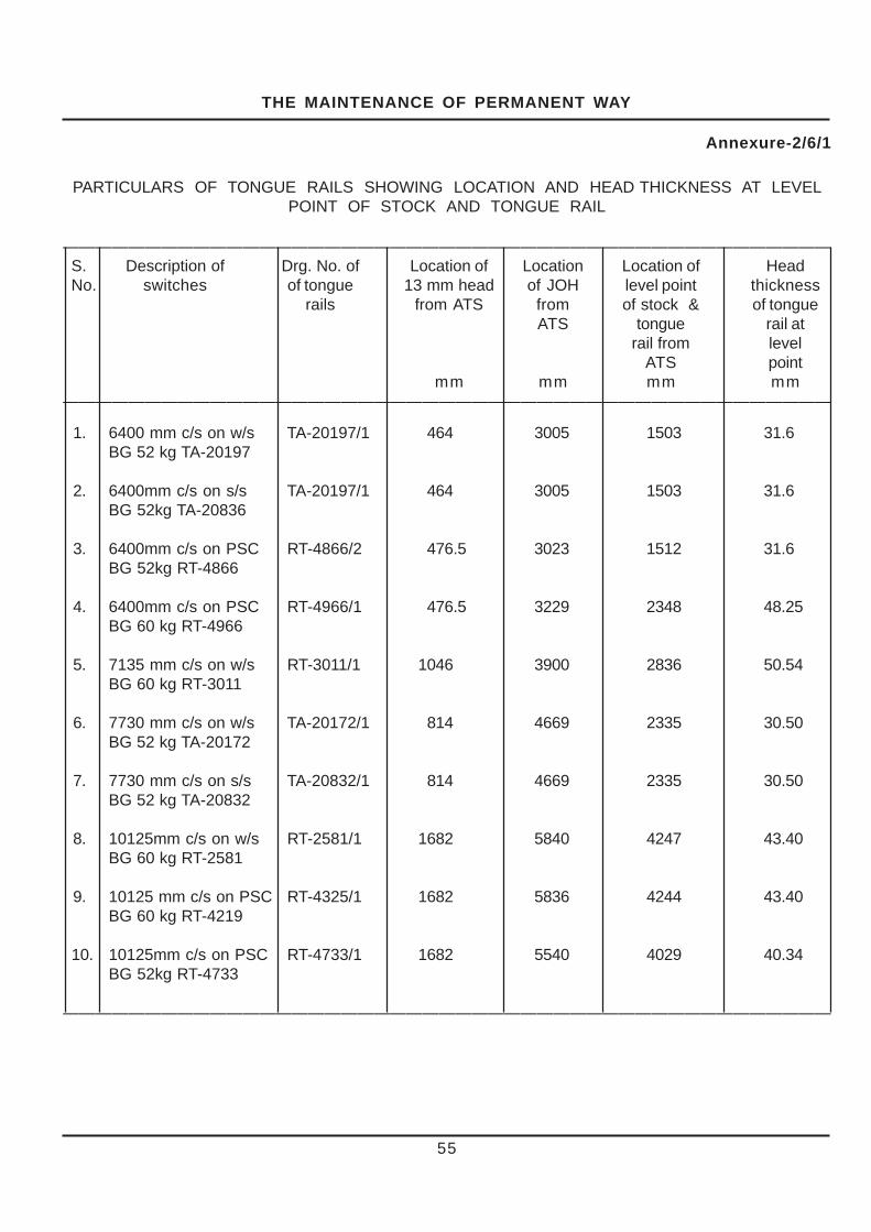
THE MAINTENANCE OF PERMANENT WAY
55
Annexure-2/6/1
PARTICULARS OF TONGUE RAILS SHOWING LOCATION AND HEAD THICKNESS AT LEVELPOINT OF STOCK AND TONGUE RAIL
———————————————————————————————————————————————S. Description of Drg. No. of Location of Location Location of HeadNo. switches of tongue 13 mm head of JOH level point thickness
rails from ATS from of stock & of tongueATS tongue rail at
rail from levelATS point
mm mm mm mm———————————————————————————————————————————————
1. 6400 mm c/s on w/s TA-20197/1 464 3005 1503 31.6BG 52 kg TA-20197
2. 6400mm c/s on s/s TA-20197/1 464 3005 1503 31.6BG 52kg TA-20836
3. 6400mm c/s on PSC RT-4866/2 476.5 3023 1512 31.6BG 52kg RT-4866
4. 6400mm c/s on PSC RT-4966/1 476.5 3229 2348 48.25BG 60 kg RT-4966
5. 7135 mm c/s on w/s RT-3011/1 1046 3900 2836 50.54BG 60 kg RT-3011
6. 7730 mm c/s on w/s TA-20172/1 814 4669 2335 30.50BG 52 kg TA-20172
7. 7730 mm c/s on s/s TA-20832/1 814 4669 2335 30.50BG 52 kg TA-20832
8. 10125mm c/s on w/s RT-2581/1 1682 5840 4247 43.40BG 60 kg RT-2581
9. 10125 mm c/s on PSC RT-4325/1 1682 5836 4244 43.40BG 60 kg RT-4219
10. 10125mm c/s on PSC RT-4733/1 1682 5540 4029 40.34BG 52kg RT-4733
———————————————————————————————————————————————

THE MAINTENANCE OF PERMANENT WAY
Part C Works Incidental to Regular Track
Maintenance
238. Deep Screening of Ballast-
(1) General – (a) It is essential that track is well drained for which screening of ballast should be carried out periodically as described in Para 238(2). Due to presence of bad formation, ballast attrition, excessive rain fall and dropping of ashes and ore, ballast gets choked up and track drainage is impaired. In such situations, it becomes necessary to screen the entire ballast right up to the formation level /sub-ballast level. Further through screening restores the resiliency and elasticity of the ballast bed, resulting in improved running quality of track. Such screening is called “Deep screening”, as distinguished from the shallow screening, which is done, during overhauling.
(b) Deep screening should be carried out in the following situations by providing full ballast cushion :
(1) Prior to complete track renewal. (2) Prior to through sleeper renewal. (3) Where the caking of ballast has resulted in
unsatisfactory riding. (4) Before converting existing track, fish plated
or SWR into LWR or CWR; or before introduction of machine maintenance, unless the ballast was screened in recent past.
(5) - Deep screening of Track shall be done after 500 GMT or 10 years, whichever is earlier. However, deep screening shall also be carried out if the existing clean ballast cushion is less than 150 mm to ensure proper machine tamping. (CS - 132)
(c) The need for intermediate screening between track renewals may be decided by the Chief Engineer depending on the local conditions.
(d) At the time of deep screening, standard ballast section should be provided invariably.
(e) In case of the bad formation, formation treatment should be carried out along with the deep screening.
(f) The work of deep screening should be carried out continuously from one end of the section to the other.
(2) Procedure for systematic Deep screening (not applicable to LWR Sections) – (a) Survey : Before deep screening of a section is undertaken, it is necessary to survey the section. This will consist of the following operations :
56
�(i) A longitudinal section of the track should be
taken indicating the rail levels at every 30 meters, as also at changes of the grades, obligatory points like culverts, bridges, over line structures, tunnels, level crossings, Signal gantries, ash pits, and points and crossings etc.
(ii) In station yards, on run through lines, cross sections at every 50 meters should be taken and plotted including platform levels, rail levels and clearance to underside of overline structures.
(iii) On the basis of longitudinal and cross sections, the final levels will be decided by the Divisional Engineer, keeping in view -
The depth of ballast cushion to be provided; The relative implications of lifting or lowering of
track; The possibility of eliminating humps, sags, and
unevenness in the existing longitudinal section.
It is not necessarily the intention that the original longitudinal section of the line should be restored .
(b) Preparation of Estimates – The estimate for the work of deep screening and full ballasting should also include provision of survey mentioned in sub para 2(a) of this para.
(c) Preliminary works. - (i) Additional ballast required, should be unloaded/spread out opposite to the place where it is required. When ballast is collected along the track, care should be taken to see that the new ballast is not mixed with the unscreened ballast .
(ii) Cess should be brought up to correct level in relation to the final rail level.
(iii) Pegs should be provided at intervals of 30 metres to indicate the final rail levels.
(iv) Slewing of curves should be done in advance.
(v) Sleeper renewal as necessary should be carried out in advance. (d) Screening operations - General – (i) The work of manual deep screening would be done under the supervision of an official not lower in rank than the certified Permanent Way Mistry (Competency certificate should be issued by Chief Track Engineer). However, the work of mechanized deep screening would be done under the supervision of an official not lower in rank than the Permanent Way Inspector.
Note – For LWR/CWR track, provisions given in Manual of Instructions on Long Welded Rails shall be followed.
(ii) The daily output should be pre-determined, depending on the time allowance, availability of labour, extent of ballasting/screening to be done etc.

THE MAINTENANCE OF PERMANENT WAY
57
(iii) Taking the length to be deep screened daily,planning of speed restriction should be done andnecessary notice should be issued to all concernedand speed restriction boards put up.
(iv) It will be desirable to proceed with the workof deep screening in the direction opposite to that ofthe traffic on double line.
(e) Detailed procedure – A day’s length will bedeep screened as per the procedure detailed below:
Stage I The ballast should be removedfrom space ‘A’ and ‘B’ on eitherside of the sleeper ‘1’ down tofinal formation level and woodenblocks provided to support therail for passing trains.
Stage II The ballast is removed fromunder sleeper ‘1’ down to finalformation level/sub-ballastlevel.
Stage III The ballast should then bescreened and placed backunder sleeper ‘1’ which shouldthen be packed.
Stage IV The wooden blocks from space‘A’ should then be removed.
Stage V The ballast from space ‘C’ downto formation level should beremoved and after screening,be placed in space ‘A’ uptobottom of sleeper .The balancemay be taken outside the trackand screened .The rail in space‘C’ should be supported withwooden blocks.
Stage VI The ballast should be removedfrom under sleeper ‘2’ down toformation level.
Stage VII Screened ballast should beprovided under sleeper ‘2’ andsleeper well packed.
Stage VIII The ballast from space ‘D’ downto formation level should beremoved and after screening,be placed in space ‘B’ uptobottom of sleeper; the balancemay be taken outside the track
and screened. The woodenblocks should be removed fromspace ‘B’ and placed to supportthe rail in space ‘D’.
Stage IX The ballast from under sleeper‘3’ should be removed and soon till the whole rail length isprovided with screened ballastupto level of the bottom ofsleepers.
Final Stage The track should be lifted toprovide additional cushionwhere required. The trackshould be packed in the finalposition and then boxed.
Sequence of the operations is shown in thesketch on next page:
(f) The following points may be kept in view whiledoing the work – (i) No unscreened length should beleft between screened lengths of the track at thesame time.
(ii) It should be ensured, that when ballast isbeing removed from any sleeper, invariably, there areat least four fully supported sleepers between it andthe next sleeper worked upon.
(iii) Lifting should be limited to 50 mm. at a time.
(iv) It should be ensured that packing, crosslevels and grade run off are satisfactory before closingthe day’s work.
(v) The work should be done under a speedrestriction of 20 km.p.h.
(vi) The speed should be gradually raised asin Para (g) below which will vary depending on thetype of maintenance in the section.
(g) Schedule for working and speed restrictionto be observed, in deep screening works.-

THE MAINTENANCE OF PERMANENT WAY
58
12
34
12
34

THE MAINTENANCE OF PERMANENT WAY
59
TABLE IPROPOSED SCHEDULES FOR DEEP SCREENING
(MANUAL PACKING)
Details of Work Day of Speed restrictions and their length
Work Broad Gauge Metre Gauge
Deep screening and initial packing … … 1
First through packing … … … … … 2 20 km.p.h. 20 km.p.h.
Second through packing … … … … 3
4
5
6
Picking up slacks as required … … 7 45 km.p.h. 30 km.p.h.
8
9
Third through packing … … … … … 10
11
12
13
14
Picking up slacks as required … … 15 75 km.p.h. 60 km.p.h.
16
17
18
19
Fourth through packing ..... … … … 20
21 Normal Normalonwards Sectional speed sectional speed
{
{
(i) With Manual Packing – The details of the work to be carried out in stages on various days, after thestarting of the screening operation and the speed restriction recommended to be imposed are shown in Table1. According to the above schedule normal Sectional speed can be resorted on the 21st day.

THE MAINTENANCE OF PERMANENT WAY
(ii) With Machine Packing – The details of work to be carried out in stages on various days after the start of the screening operations and the speed restriction recommended to be imposed are indicated in the schematic representation in Table II. According to this schedule, normal sectional speed can be resumed on the tenth day.
TABLE II PROPOSED SCHEDULE FOR DEEP SCREENING (MACHINE PACKING /B.G.)
Details of work Day of Speed restrictions and their
work lengths
Deep screening with initial packing …. 1
First machine packing … … …. .. 2 20 km.p.h.
{
3
Picking up slacks as required … … 4 5 45 km.p.h.
Second machine packing … … … … … 6
Picking up slacks as required …. { 7
8
Third machine packing … …. … … … … 9 75 km.p.h.
10
onwards Normal sectional speed
The period mentioned in the schedules shown above is the minimum and can be suitably increased
to suit local condition of the track consolidation. Para 238(2)(g)(iii) - Deep Screening with BCM (Ballast Cleaning Machine) and followed by Tamping and Stabilisation of Track with TTM (Tie Temping Machine) and DTS (Dynamic Track Stabliser) respectively for BG - The work is to be carried out in stages on various days after the start of the screening operations and the speed restriction recommended to be imposed are indicated in the schematic representation in table – III below. According to the schedule, normal sectional speed can be resumed on the 8th day.
Table – III
Schedule of speed restriction for deep screening by BCM followed by Tamping and Stabilisation by TTM and DTS machines for BG
Details of Work Days of Work
Speed Restriction
Deep screening of track by BCM, ballast equalisation followed by initial packing and initial stabilization by DTS.
1st day 40 Kmph
60

First round of tamping followed by stabilization of track by DTS.
2nd day
(1st Tamping)
40 Kmph
Survey of track for design tamping mode as per Annexure 5.3 of IRTMM-2000, boxing of ballast section and tiding.
3rd day
40 Kmph
Second round of tamping followed by stabilization of track by DTS.
4th day
(2nd Tamping)
40 Kmph
Survey of track for design tamping mode as per Annexure 5.3 of IRTMM-2000, boxing of ballast section and tiding.
5th day
40 Kmph
Third round of tamping in design mode followed by third round of stabilization by DTS.
6th day
(3rd Tamping)
75 Kmph
Inspection of track, boxing of ballast section and tiding.
8th day Normal speed of the section.
The period of the schedule shown above can be suitably increased to suit local conditions of the track consolidation. Para 238(2)(g)(iv) - Precautions to be taken during deep screening of track by BCM followed by TTM and DTS machines;
(i) All precautions laid down in LWR manual (specially those in para no.6.3.2) shall be strictly followed.
(ii) Hard Sal wood blocks of size 600 X 300 X 300mm (six numbers) duly end bounded shall be arranged for supporting ends of three adjoining sleepers where cutter bar is left in the track and remains untamped.
(iii) Sleepers of cutter bar area shall be manually packed and ballast under cutter bar location sleepers shall be removed only half an hour before the expected traffic block. Adequate care shall be taken to ensure that wooden blocks are not dislodged before arrival of BCM at site.
(iv) Fish-plated joint shall not be located in cutter bar location.
(v) Ramp shall not be located in locations like level crossing, girder bridge, transition portion of curve etc. It shall be kept minimum two rail length away.
(vi) In case of fracture or cut in CWR/LWR, a speed restriction of 20 Km/h shall be imposed till it is repaired as per para 7.2.3 of LWR Manual.
(vii) In case of malfunctioning of TTM and/ or DTS, deep screening shall be stopped and track which has not been tamped and stabilized shall be attended manually by ballast ramming and correction of track geometry to ensure safety of running trains. Speed restriction shall be imposed and relaxed in terms of IRPWM para 238 (2) (g) (i) or (ii) which ever is the case.
60 A

(viii) In case of non-availability of traffic block on subsequent days of deep screening by BCM, speed restrictions shall be imposed and relaxed in terms of IRPWM para 238 (2) (g) (i) or (ii) which ever is the case.
(ix) When BRM is not deployed, adequate track men shall be deputed to recoup ballast, particularly in shoulder and maintain ballast profile after machine working.
(x) Lifting of track shall be resorted after ensuring adequate availability of ballast for maintaining ballast profile for planned lifting.
(xi) Adequate arrangements for supply and training out of ballast prior to deep screening should be made. Special care shall be taken by deploying watchman on stretches overdue for rail renewal.
239. Side and Catch water drains and Waterways – (1) For efficient drainage of cuttings, side and catch water drains of suitable type and size should be provided. The bottom of side drains should be at least 30 cm. below the formation level.
(2) Adequate openings to take the full flow of side drains should be provided under level crossings where they exist in or at the end of the cuttings.
(3) In cutting of black cotton soil and similar soils, catch water drain should be provided sufficiently away from the top of the cutting to avoid any danger of a breach occurring between the drain and the cutting itself. The excavated spoil should be used to form a ‘bund’ between the drain and the top of the cutting.
(4) Ballast walls, where provided in cuttings, should be regularly inspected. The efficient maintenance of ballast walls includes regular cleaning of weep holes, the provision of weep holes where none exist and rebuilding where necessary.
60 B
(5) The Permanent Way Staff shall carry out cleaning of side and catch water drains, clearing of obstructions from outfalls and cleaning water-ways of bridges and culverts methodically and complete the work before the monsoon sets in. The spoil from cleaning drains or cuttings should not be deposited at a place from where it is likely to be washed back into the drains.
(6) In the Municipal areas, where the outfall of Railway drains is in the municipal drains, close co-ordination should be maintained with the municipal authorities to ensure free flow from Railway drains.
240. Drainage in Station Yards – (1) The network of cross and longitudinal drains in yards whether earthen or masonry, should be so planned that storm water is led away in least possible time. The system of surface drains of water columns carriage-watering and carriage washing hydrants should be efficiently maintained.

THE MAINTENANCE OF PERMANENT WAY
61
241. Lubrication of Rail Joints – (1) Thepurpose of lubricating rail joints is not only to facilitateexpansion of rails but also to retard wear on thefishing planes of the rail and the fish plate. Reducedwear on the fishing planes is one of the preventivesof the low joints.
(2) The lubricant to be used should be specifiedby the Chief Engineer. A stiff paste of plumbago(Graphite) and kerosene oil, made in the proportionof 3 Kg. of plumbago to 2 Kg. of kerosene oil may beused. Black oil or reclaimed oil may be used for fishbolts and nuts. Alternatives to the above may beused, with the specific approval of Chief Engineer.
(3) All rail joints should normally be lubricatedonce a year on a programmed basis during the coldweather months after the monsoon, from Octoberto February. Lubrication should not be carried out inextremes of weather both hot and cold. In yards thisperiod may be extended to 2 years with the approvalof the Chief Engineer.
(4) Creep in excess of 150 mm. should beadjusted before the work of lubrication of rail joints isundertaken.
(5) The lubrication of rail joints should normallybe carried out by gangs working under the directsupervision of at least a qualified Permanent WayMistry. The work should be carried out under cautionorders arranged to be issued daily by the PermanentWay Inspector and under protection of engineeringsignals, as per Para 806(2). In this case theprocedure to be followed for lubrication of rail jointswill be as follows :
(i) The nuts are unscrewed and the fish boltsand fish-plates are removed.
(ii) The fishing surfaces of the fish-plates andrail are then cleaned with a wire brush.
(iii) The rail ends are inspected for cracks,and the fishing surfaces of rails and fish-plates arechecked for wear. A magnifying glass and a mirrorshould be used for detecting cracks in rail ends andfish-plates.
(iv) The fishing surfaces of the rails andfish-plates are then lubricated.
(v) The fish bolts are then put back in reverseposition and tightened using a standard fish boltspanner, the inner two bolts being tightened first.
(vi) While tightening overstraining of bolts shallbe avoided.
(vii) Spare fish-plates and bolts should beavailable for replacement of cracked ones.
(6) Alternatively, the work of lubrication may becarried out by the Keymen of the gang, assisted byone or more men on such sections as may bespecified by the Divisional Engineer. In such casesthe Keymen shall exhibit a red signal flag at the siteof the work and act as lookout man also. Normallynot more than one joint should be opened at a timeunder this procedure.
In this case the lubrication of rail joints andreversing of fish bolts should be carried out as follows:
(i) The nuts are unscrewed and the fish-plateon the nut-side is then removed leaving the other fishplate and bolts in position.
(ii) The fishing surfaces of the fish-plate andthe rails are cleaned with a wire brush. The rails endsare examined for cracks and fishing planes of railsand fish-plates for wear, a mirror and a magnifyingglass should be used to detect cracks. Suchconditions shall be brought to the notice of PermanentWay Mate/Mistry for necessary action. The fish-plates are lubricated and put back in position.
(iii) The fish bolts are taken out one at a time,and then put back, after oiling.
(iv) The other fish-plate and fishing surface ofthe rail is treated similarly.
(v) The nuts are replaced and tightened to theextent possible with the standard fish bolt spannerwithout overstraining the bolts.
(vi) Two joints opposite each other orconsecutive joints shall not be opened out at the sametime. It should be particularly noted that at no timeduring the operation there is less than one fish-plate and three fish bolts without nuts connecting thetwo rails. The men should sit facing the direction oftrain while doing the work.
(vii) Both fish-plates should be fixed and atleast one fish bolt and nut on either side of each jointshould be tightened when a train is approaching thesite of Work.
(viii) Spare fish-plates and bolts should becarried for renewal of cracked ones.
(7) The Chief Engineer may issue subsidiaryinstructions as necessary.

THE MAINTENANCE OF PERMANENT WAY
62
(8) The lengths over which the rail joints arelubricated together with dates shall be recorded inthe gang chart of the section and in the PermanentWay Inspector’s section register. In the month ofApril, Permanent Way Inspectors should submit tothe Assistant Engineers certificates of lubrication ofrail joints giving reasons for any exception. Copiesof these certificates should be forwarded with theAssistant Engineer’s comments to the DivisionalEngineer for scrutiny and record.
(9) During all works such as relaying, railrenewals and renewals of turnouts, etc. rail jointsshould be lubricated. The importance of going overand re-tightening the bolts after the fish-plates havetaken a bearing under traffic should be impressedon the staff.
(10) Insulated fish-plates should not begreased.
242. Counteraction and Adjustment ofcreep – (1) General.-Rails have a tendency to movegradually in the direction of the dominant traffic. It isbelieved to be caused by the ‘ ironing out ’ of yieldingtrack by the moving load, augmented by brakingloads, and by the impact of the wheels on therunning-on ends of the rails, particularly at timeswhen they are in a state of expansion or contraction.Among the troubles caused by ‘ creep ’ are -
(a) Sleepers getting out of square.(b) Distortion of gauge.(c) Loosening of joints.(d) Shearing and breaking of spikes, bolts andfish-plates.(e) Buckling in extreme cases.
(2) Causes for creep in Track – The followingare some of the avoidable causes to which creep isattributed :
(a) Inadequate toe loads of the rail to sleeperfastening and rails not secured properly tosleeper.
(b) Inadequate ballast resistance to themovement of sleepers due to poor orinsufficient ballast or other causes.
(c) Inefficient or badly maintained rail joints.
(d) Rails too light for the traffic they carry.
(e) Improper expansion gaps.
(f) Decaying sleepers, uneven spacing ofsleepers.
(g) Lack of proper drainage.
(h) Yielding formation resulting in unevencross levels.
(i) Loose/uneven packing.
(j) Rail seat wear in metal sleeper road.
(3) Precautions to reduce creep – (a) Forreducing creep, it must be ensured that the rails areheld firmly to the sleepers and adequate ballastresistance is available. All spikes, screws and keysshould be driven home, the sleepers properly packedand crib and shoulder ballast should be compacted.Rail anchors should be provided wherevernecessary.
(b) With steel trough and cast iron platesleepers and in the case of sleepers where elasticfastenings and other fastenings with adequate toeload are used, no trouble is normally experienced.Careful watch should be kept for a series of jammedjoints. Not more than six jammed joints continuouslyshould be permitted in the case of single rails . Incase of SWR not more than two consecutivejammed joints should be permitted at railtemperatures lower than “tm” in the case of Zone Iand II and “tm-5” in the case of Zone III and IV. Ongirder bridges adjustment may be necessary atregular intervals. Anti-creep devices should beprovided on the approaches of girder bridges foradequate length.
(c) : The PSC sleepers with elastic fasteningsare considered as creep resistant and therefore noother creep anchors are required. In case, excessivecreep is observed on PSC sleeper road, the conditionof elastic fastenings, sleepers and adequacy ofballast resistance should be examined. Action forreplacement/renewal of fittings, sleepers andproviding adequate ballast resistance etc. should betaken as necessary.
(4) Creep Register – Creep registers shouldbe maintained in the pro forma given inAnnexure 2/7. Entries should be complete asregards kilometerage, section and length of rail,sleeper density, type and number of anchors per raillength used. Periodical readings of creep should berecorded in the prescribed pro forma . Separate pageshould be allotted for each km. Frequency ofrecording of creep should be specified by theDivisional Engineer taking into consideration the rateof creep. The Assistant Engineer should test checkthe register frequently, particularly sections which areprone to creep.

THE MAINTENANCE OF PERMANENT WAY
63
(e) The machine is next attached to the railahead of it, keys, spikes and fish bolts loosened forthat rail and those beyond it. These rails are thenpulled until only the normal expansion gap is leftopposite the machine. The operation leaves someof the gaps wide and it is then necessary to fix themachines further ahead in order to close them uptonormal by pulling against expansion liners.
(f) When the value of total gap existing is morethan the standard expansion gap required for thetemperature at the time of adjustment multiplied bythe number of joints, it is necessary to provide closurerails. When closure rails are put in, a speed restrictionof 30 km/h should be imposed,which should beremoved, when closure rail is changed.
(g) During adjustment of creep, the sleeperspacing should be adjusted, if necessary, specialattention being given to the joint and shoulder sleeperspacing.
(8) Provision of Anchors to arrest Creep -Toarrest excessive creep on wooden sleepered road,not provided with anti-creep fastenings, adequatenumber of anchors of approved design should beprovided; no anchors being provided at the jointsleepers. Both rail seats of the sleepers should beanchored on the same side. In addition to sufficientdirectional anchors being provided, back up anchorsmay be provided if considered necessary.
(9) Prevention of creep on metal sleeper road–Creep on cast iron plate sleepers should becounteracted as follows :
(a) On C.I. plate sleepers all keys should bedriven in the direction of traffic on the double line andalternately in the opposite direction on single line.
(b) On steel trough road normally keys aredriven as indicated in S.S.I. sheet 3 of 4 of IndianRailway Standard Track Manual. However, whereheavy creep is experienced on double line, all thefour keys may be driven in the direction of the creep(generally in the direction of traffic). On single linekeys may be driven in the opposite direction onalternate sleepers.
(5) Creep indication Posts – Creep indicationposts square to the track should be erected on eitherside of the track on the cess at intervals of aboutone km. These may be un serviceable rail posts withchisel mark square to the joints . The top of the postshould be about 25 mm. above the rail level and theamount of creep one way or the other measured witha fishing cord stretched over the chisel marks.
(6) Permissible amount of creep – Creep inexcess of 150 mm. shall not be permitted.
(7) Adjustment of creep – Adjustments of creepshould be carried out in the following manner :
(a) Careful measurement of expansion gaps,as existing, should be done and appropriate lengthwhich can be dealt with in one operation should bechosen. The total amount of gap in the length shouldbe equal to the standard expansion gap required forthe temperature at the time , multiplied by the numberof joints in the length.
(b)Work should start at the running-on end ofthe length, commonly just beyond the points andcrossings or level crossings. The work of creepadjustments should be carried out under theprotection of Engineering signals by the PermanentWay Inspector as envisaged in Para 806(2). Beforepulling back is commenced the keys are knockedout and fish-plates removed or eased. Correctexpansion liners should be used and the rails shouldbe pulled back with bars. If the fish-plates areremoved, the bars can pull against a tommy barthrust through a bolt hole. Next, the rail is keyed up,the bolts of joints correctly tightened up, and theexpansion liner moved to the next joint, whereuponthe process is repeated.
(c) It is a good practice to adjust creep beforethe commencement of summer. It is desirable topull back the rails during the cool hours of the day.
(d) Mechanical and hydraulic devices areavailable for adjustment of creep. Such a device canbe set with the wide joints behind it and the tight jointsahead of it. Expansion liners are put in all the widejoints, all keys, spikes and fish bolts are loosened.
The adjuster then closes up the rails behind itby pushing, leaving a gap of some centimetresbetween the rail ends opposite the machine. Thecorrected rails are then fastened up.

THE MAINTENANCE OF PERMANENT WAY
64
243. Buckling of Track – (1) General -Buckling of track occurs when high compressiveforces are created in the rails associated withinadequacy of lateral resistance in the track at theplace. A special watch should be kept on the junctionof two stretches of track, one liable to creep and theother held against creep, such as when track laid onwooden sleepers with inadequate anchors andscanty ballast or track laid on metal sleepers withloose keys butts against track laid on new sleeperswith tight fastenings or track anchored and ballastedas with welded track. As one side of such a junctionpoint is held firmly against creep, the movement ofrails due to creep from the other side is resistedresulting in heavy compressive force being exertedwhich will tend to buckle the track. Jammed rail jointsat such junctions are therefore an indication of thetrack being subjected to undue strain.
(2) Conditions which Induce Buckling –
(a) The following conditions create highcompressive forces in the rail :
(i) Inadequate expansion gaps,
(ii) Failure to counteract creep in time.
(iii) Non-lubrication of rail joints,
(iv) Failure to remove rail closuresfrom track.
(b) The lateral resistance gets impaired due toinadequacy of ballast and due to carrying out ofoperations such as deep screening, lifting of trackand slewing of track, without adequate precautions.
(3) Precautions against Buckling – It shouldbe seen that -
(a) Operations which impair the lateralresistance of track are not carried out when railtemperatures are high.
(b) The greasing of fish-plates is done beforethe hot weather sets in.
(c) The joint gap survey is done in the case ofS.W.R. and adjusted before the hot weather (SeePara 510). Similarly in case of single rail panel, jointgaps should be adjusted wherever necessary.
(d) Adequate precautions are taken to reducecreep as detailed in Para 242 (3).
(e) Overtightening of fish bolts is avoided - butthey should be reasonably tight.
(f) Particular attention is also paid to stretchesof track, one liable to creep and the other held againstcreep (refer para above). Jammed joints at suchjunctions call for remedial measures. Extra shoulderballast should be provided at such places.
(4) Action on buckling of track - If a bucklingdoes occur or appears imminent, the track shouldbe protected immediately with hand signal flags anddetonators as per the protection rules laid down. Thebuckled rails shall preferably be cut adequately apartnot less than 6.5 metres. The track shall then beslewed to the correct alignment and cut rails of therequired length shall be inserted to close the gapsmaking due provision for welding of joints on bothrails. The cut rails shall then be connected by use ofspecial fish plates and screw clamps and the lineopened to traffic with speed restriction. It may notbe possible to do any more until the temperaturedrops when the joints must be adjusted. Particularcare must be taken to see that the factors whichcontributed to the buckling i.e. jammed joints, seizedfish plates or shortage of ballast receive appropriateattention without delay.

THE MAINTENANCE OF PERMANENT WAY
65
Annexure-2/7 Para 242(4)
PR
OF
OR
MA
OF
CR
EE
P R
EG
IST
ER
DA
TE
OF
RE
CO
RD
ING
L. H
. RA
IL
PO
SIT
IVE (+
)C
RE
EP
IN m
m.
01&01&*82
01&03&*82
01&05&*82
01&07&*82
R. H
. RA
IL
0!
117
mm
.!
!
! !
!
137
mm
.
145
mm
.150
mm
.0
8 mm
.
100
mm
.!
!
! !
!
125
mm
.
140
mm
.
145
mm
.
!
12
mm
.
SE
CT
ION
UP
DO
WN
LIN
E
PA
RT
ICU
LAR
S O
F R
AIL
& F
ITT
INE
GS
DE
TAIL
S O
F A
NC
HO
RS
PR
OV
IDE
D
NE
GA
TIV
E ¼&½
PO
SIT
IVE (
+)
CR
EE
P IN
mm
.
NE
GA
TIV
E ¼&½
RE
MA
RD
ING
DA
TE O
F P
ULL
ING
BA
CK
AD
JUS
TME
NT
DA
TE O
F
RE
CO
RD
ING
DA
TE O
F P
ULL
ING
BA
CK
AD
JUS
TME
NT
RE
MA
RK
S
200m
m. 150m
m. 100m
m. 50m
m.
ZER
O &50m
m. &100m
m. &150m
m. &200m
m.
200
mm
. 150
mm
. 100
mm
. 50
mm
.
ZERO &50
mm
. &100
mm
. &150
mm
. &200
mm
.
KIL
OM
ET
RE
DE
TAIL
S O
F S
LEE
PE
R &
FIT
TIN
GS
AN
Y S
PE
CIL
S S
PE
CIA
L F
EA
TU
RE
10&05&*82
PU
LL
ED
B
AC
K
TO
Z
ER
O
CR
EE
P
EX
TR
A
TW
O
AN
CH
OR
S
PE
R R
AL
PR
OV
IDE
D

THE MAINTENANCE OF PERMANENT WAY
Part ‘D’
Sleepers and Fastenings
244. Laying of Sleepers – (1) General - Sleepers shall be laid and maintained square to the rails on straights and radially on curves. Rail joints should be suspended.
(2) Sleeper Spacing – (a) The sleeper spacing on straights and curves shall be in accordance with approved plans. The
sleeper spacing should be marked on the outer rail in case of curved track. Closer spacing should be provided at the joint sleepers of fish-plated joints and between the joint sleeper and shoulder sleeper.
(b) The following standard spacing should be adopted on fish-plated track : Centre to centre spacing (maximum)
Spacing Wooden Sleepers Metal Sleepers
B.G. M.G. B.G. M.G. 1. Between joint sleepers 30 cm. 25 cm. 38 cm. 33 cm.
2. Between joint sleepers and first 61 cm. 58 cm. 61 cm. 58 cm. shoulder sleeper.
3. Between first shoulder sleeper Spacing to be of a value between 2 and 4. and second shoulder sleeper.
4. Between intermediate sleeper... To be equal and in whole number of cm.
(c) In the case of LWR on B.G. and M.G. the
sleeper spacing shall be maintained at 65cm, as per para 5.4.2 of L.W.R. Manual.
(d) In the case of SWR, the sleeper spacing for M+4 and M+7 densities will be as shown on the next page.
(e) Where concrete sleepers are required to be laid in unavoidable circumstances, in SWR track, the sleeper spacing including at fish-plated joint, shall be kept uniform. In addition, 1 m long fishplates, be provided at fish plated joints.(C.S. No:102 Dated:29.05.2007) (e) In B.G. where SWR is expected to be
converted into LWR within a year or two, 62 Nos. of sleepers shall be used per panel of 3x13m. length as shown on next page.
(g) Where SWR is to be converted into LWR
soon after its being laid, sleeper spacing as prescribed for LWR in the LWR Manual should be adopted.
(h) The sleeper spacings under welded joints of all types with or without holes in rails shall be the same as the intermediate sleeper spacings.
(3) Sleeper Density – The sleeper density is the number of sleepers used per rail length and is described as M+1, M+2 etc., where M is the length of Standard Single rail in metres. In the case of LWR and CWR this is expressed as the number of sleepers per km. of track. The sleeper density is fixed duly taking into consideration the maximum permissible speed and the traffic density of the section.
66

THE MAINTENANCE OF PERMANENT WAY
67
B.G. 3 x13 m RAIL M.G. 3x12 m RAIL
Type of Type Type of Type
Sleeper n S sleeper at of X Y Z Sleeper n S sleeper at of X Y Z
Density (mm) FP 300 MT Weld (mm) (mm) (mm) Density (mm) FP 300 MT Weld (mm) (mm) (mm)
F.B./ 150 643 750 F.B./ 120 600 708Wooden G.P. Wooden G.P.
A.T. 150 645 780 A.T. 120 600 740M + 4 46 780 M + 4 43 770
F.B./ 190 620 733 F.B./ 160 580 688Metal G.P. Metal G.P.
A.T. 190 625 760 A.T. 160 600 700
F.B./ 150 573 610 F.B./ 120 603 620Wooden G.P. Wooden G.P.
A.T. 150 595 620 A.T. 120 615 640M + 7 55 660 M + 7 52 640
F.B./ 190 563 580 F.B./ 160 573 610Metal G.P. Metal G.P.
A.T. 190 575 600 A.T. 160 595 620
X
X
X
X
X
X
X
X
650
650
57 x 650 mm.
57 x 650 mm.
300
639 639 639 639
400400 400400 300
BEFORE CONVERSION INTO LWR (TOTAL 62 SLEEPERS)
AFTER CONVERSION INTO LWR (TOTAL 60 SLEEPERS)2) SLEEPERS SPACING SHOWN ARE FROM CENTRE
SLEEPER SPACINGS FOR SWR EXPECTED TO BE CONVERTEDINTO LWR WITHIN A YEAR OR TWO YEARS.
SLEEPER SPACINGS FOR SWRs FOR (M+4) & (M+7) DENSITIES
XX Y YZ Z X
X
X
X
n X s
WELDFISHPLATED JOINT
MINIMUM SLEEPER SPACING AT ANY LOCATION EXCEPT ATFISHPLATED JOINT 560 mm
NOTE : FOLLOWING ASSUMPTIONS HAVE BEEN MADE WHILE CALCULATING SLEEPER SPACINGS.
i) SLEEPERS SPACINGS SHOWN ARE FROM CENTRE TO CENTRE OF SLEEPERS.
ii) TOTAL REDUCTION IN LENGTH AT EACH FLASH- BUTT OR GAS-PRESSURE WELDED JOINT 20 mm.
iii) LENGTH OF B.G. FREE RAILS 13000 mm.
LEGEND :
O A.T. WELDED JOINT
X WELDED JOINT
= FISH PLATED JOINT

THE MAINTENANCE OF PERMANENT WAY 4) Minimum Sleeper Density (a) Broad Gauge – The minimum sleeper density for all track renewals (complete track renewal and through sleeper renewal), doubling, gauge conversion, new line construction works for main lines may be 1660 nos. per km and for loop lines & sidings (permissible speed upto 50kmph) it may be 1540 nos. per km. For sidings with permissible speed more than 50kmph minimum sleeper density may be 1660 nos. per km.
(c) Meter Gauge – In the case of MG track renewals, the sleeper densities as recommended for various MG routes are given below –
Sleeper Density for MG
Route Q R1 R2 R3 S
Sleeper density
M+7
M+7
M+7
M+4
M+3
Note for BG & MG:-
(i) Higher sleeper density may be provided with the approval of the Principal Chief Engineer.
(ii) For existing LWR/CWR on main lines, loop lines and sidings, provisions of para 4.3.3 of LWR manual may be followed.
(iii) In case of SWR, the minimum sleeper density is fixed as 1340 nos. per km.
(CS 130 dtd 16.11.2012 superceeding CS 117 dtd 19.5.2009)
(5) Respacing of sleepers :
(a) When respacing wooden sleepers dog
spikes/rail screws should be loosened, just enough to permit sleepers being shifted.
(b) When respacing cast iron or steel trough sleepers, the keys should be removed and the packing core broken before shifting the sleepers.
245. Wooden Sleepers – (1) Classification of Wooden Sleepers - All wooden sleepers shall be classified into two categories viz. ‘U’ (untreated) and ‘T’ (treated). Category ‘U’ (untreated) shall comprise of all sleepers from natural durable species only. The rest shall be classified as ‘T’ (treated) category.
(2) Inspection and Renewals- The average
life of wooden sleepers varies with the species of timber. In the interest of both safety and economy, it is essential that wooden sleepers more than 5 years old are thoroughly inspected every year according to the following procedure :
(a) The Permanent Way Inspector should carefully examine the track and bridge sleepers during annual through packing/overhauling. Those requiring renewals during the year should be painted with two white lines (Category I) and sleepers requiring reconditioning with one white line (Category II) at the end. Details of these telegraph-post/O.H.E. mast-wise should then be intimated to the Assistant Engineer. The Permanent Way Inspector will maintain a Sleeper replacement/reconditioning register in the following proforma :
68

THE MAINTENANCE OF PERMANENT WAY
69
(b) The Assistant Engineer should then testcheck the requirement given by the Permanent WayInspector at site and examine about 50 sleepers perKm. particularly at places where the sleepers aremore than 5 years old, and where the percentage ofdeteriorating sleepers is reported to be 20 per centor more. The requirements together with theAssistant Engineer’s observations should then besubmitted to the Divisional Engineer.
(c) The Divisional Engineer should personallycheck these sections where abnormal increase inthe number of deteriorating sleepers is reported toensure that serviceable sleepers are not condemnedprematurely.
(d) (i) Generally a sleeper is classified asunserviceable if even after reconditioning it cannotperform the essential function of holding the gauge,providing a satisfactory rail seat, permitting sleeperfastenings being maintained in a tight condition, andretaining packing.
(ii) It is advisable to carry out through sleeperrenewal, before the percentage of unserviceablesleeper reaches a level, when imposition of speedrestriction may become necessary. On branch lines,however, only casual renewals may be resorted to.
(e) While doing casual/scattered renewals,priority should be given in replacing unserviceablejoint sleepers and unserviceable consecutivesleepers. Through sleeper renewals should becarried out in continuous stretches and releasedsleepers after reconditioning should be used forscattered renewals. New sleepers should not beused in sidings. If the percentage of unserviceablesleepers becomes high, speed restrictions may haveto be imposed.
(3) Stacking of Wooden Sleepers – (i) ‘U’category sleepers should be stacked in accordancewith one of the methods shown in the sketch belowin lots of 100s and covered with at least 150mm.
O.H.E. Mast/ No. of sleepers No. of sleepers No. of sleepersKm. Telegraph Post marked replaced reconditioned and
From To Category reusedI II
thickness of earth as a protective measure. Theground should be dressed to a flat slope and clearedof grass and undergrowth.
(ii) Treated wooden sleepers, released secondhand and scrap wooden sleepers awaiting disposalshould be stacked in horizontal layers without anygap, each stack being covered with 150mm. layerof earth.
(iii) A fire zone of about 10m. in width shouldbe left around each group of 25 stacks and kept clearof grass and other combustible materials.
(4) Preparation of Sleepers – (a) End Binding -To protect the inner untreated portion of sleepers frombeing exposed to attack by insects/fungi due toshatter and splitting of sleepers in track, a systematicpractice of end binding all new reconditioned sleepersshould be adopted. This should be done for ‘T’category sleepers in the treatment plants, beforetreatment and for ‘U’ category sleepers, in theDivisional Track reconditioning depots. For effectiveend binding both ends of the sleepers shall be heldin a press so as to close all the cracks and splitsnear the ends and end binding should be done usingwire, hoop iron or clips. In reconditioning depots, itmay be preferable to deploy end strapping machinesfor end binding.
150 mm. 150 mm.
RAILS OROLD SLEEPERS
METHOD 1 METHOD 5
50 mm GAPIN CASE OF'U' CATEGORYAND NO GAPIN CASE OF'T' CATEGORY
EARTHEARTH
METHOD 1 METHOD 2

THE MAINTENANCE OF PERMANENT WAY
70
(b) Adzing of Sleepers – (i) When woodensleepers are used without bearing plates, the railseats should be adzed to a slope of 1 to 20, planedfor the section of the rail with the correct template. Itis desirable to accommodate the rail foot in a recess3 to 5mm. deep in the adzed portion of the sleeper torestrict the lateral forces being transmitted to thespike and to protect the sleeper from getting spikekilled. The operation of adzing and recess cuttingshould be carried out preferably in the trackconditioning depot, where the adzed rail seat maybe treated with coal tar/creosote.
(ii) For treated sleepers adzing and recesscutting should be done before treatment.
(iii) Sleepers should not be adzed in the caseof points and crossings.
(iv) When bearing plate or chairs are used itshould be ensured that the seat is adzed or planedto ensure even bearing and that the two bearingareas are truly in the same horizontal plane.
(c) Auguring of Sleepers – (i) Spike holesshould be bored right through the sleeper verticallywhere bearing plates are used and at right angles tothe rail seat where the rail rests directly on the sleeper.The size of augur for boring should be as givenbelow :
(ii) During the process of boring, the tips ofaugurs should frequently be dipped in oil to facilitatework. When sleepers are being bored outside thetrack, correct templates should be used. When beingbored or rebored while in the track, the auguringshould be done correctly with the gauge held inposition. The holes after being bored should be givena coating of coal tar or creosote.
(iii) For ‘T’ category sleepers boring should bedone before treatment.
(iv) When extracting dog spikes, the fulcrumon which the crow bar works should be raised sothat the spikes can be withdrawn vertically withoutenlarging the dog spike hole.
(v) Plate/Rail screws should always bescrewed by box spanners and not driven byhammers.
(5) Use of Bearing Plates :– (a) Bearing platesshould be provided invariably on ‘T’ categorysleepers.
(b) They should be compulsorily used in thefollowing locations :
(i) All sleepers on girder bridges.
(ii) All sleepers of turn outs.
(iii) All timbers of ash pits and examinationpits.
(iv) All joint sleepers.
(v) On sharp curves of radius less than600m. on B.G. and M.G.
(c) Bearing plates should receive two coats ofblack oil prior to their being fixed to the sleepers.
(6) Screws/Spikes at Rail Seat – (a) Thenumber of spikes/screws per rail seat should beas given below :–
(i) All joint sleepers,bridge timbers,turn out sleepers and ashpit timbers Four
Diameter of Augur in mm.
For 22mm. dia. rail/Name of some For 20mm dia. plate screws Drg. No.
common species screws Drg. No. RDSO/ RDSO/T. 10673 toT. 10677 to 10679 10676
Sleepers having C. S. I. Chir, Fir, Deodar, 16 18values upto 63 (925) Hollock, Hingori.
Sayal, Nahor, Sal,Sleepers having C. S. I. Jutili, Kindal, Poon, 18 20values above 63 (925) Gurjan, Hollong,
Kokko

THE MAINTENANCE OF PERMANENT WAY
71
(ii) Intermediate sleepers Threeon curves on other ( Two outsidethan branch lines and One inside)
(iii) Intermediate sleepers Two ( Oneon curves on branch inside andlines and on straights One outside).
(b) Where A.C. bearing plates are used onintermediate sleepers for arresting creep the numberof screws/spikes per plate should be four for B.G.and three for M.G.
(c) (i) When two screws/spikes are used, theouter ones should be in line on one side and the innerones on the other side of the centre line of thesleeper.
(ii) Screws/Dog spikes should be dipped incoal tar before use. If it is necessary to draw and re-drive spikes or to drive spikes in holes other thanthose freshly bored, such spike holes should firstbe carefully plugged with tightly fitting tarred woodenplugs and rebored before spikes are driven.
(iii) Additional screws/spikes may be providedat the discretion of Chief Engineer wherevernecessary.
(7) Reconditioning of Wooden Sleepers – (a)Reconditioning of all released wooden sleepersbefore their reuse should be carried out in acentralised depot. To arrest deterioration in track,systematic practice of reconditioning ‘in-situ’, thespike killed sleepers, otherwise in good condition,should be resorted to.
(b) Procedure for Plugging Spike killedSleepers ‘in-situ’ - Sleepers without bearing plate canbe reconditioned without removing the sleepers fromtrack. The sequence of operations should be asunder:
(i) The fastenings viz. spikes, screws etc. areremoved and the sleeper shall be cleaned of all dust.
(ii) The existing holes should be rebored so asto ensure that the existing holes are adequatelyscrapped all round.
(iii) The rebored and cleaned spike holes shallbe plugged using tapered octogonal plugs of size ofslightly bigger than the holes. These plugs are madefrom scrap hard wood sleepers in a centralizeddepot.
(iv) Before driving the plugs, the plugs aredipped in a mixture of creosote and coal tar. Theplug should be driven right upto the bottom of theholes.
(v) After plugging, a new hole would be boredat some distance in line with the old holes, parallel tothe centre line of the track. Then sleeper fasteningsare re-inserted in new holes. (Annexure 2/8).
(c) Procedure for reconditioning of releasedwooden sleepers in Permanent Way Depots -
In the case of sleepers with bearing plates,repairs to spike killed holes which would involveremoval of the sleeper from the track for the purposeof plugging the existing holes, readzing of the rail seatand boring holes in new position are best carried outin a centralised depot. When reconditioning ofsleepers is done in a depot, the following works arealso carried out:-
(i) End binding;(ii) Readzing of rail seat;(iii) Spraying with coal tar or creosote.
(d) Conversion of B.G. into M.G./N.G.Sleepers– Broad Gauge wooden sleepers which areclassified as unserviceable and removed from trackas such, can be conveniently converted toserviceable Metre Gauge or Narrow Gauge sleeperswhenever their condition permits of suchconversions.
Another method is to crop the two ends of thedamaged/split sleeper, salvage the middle length touse them for making two block sleepers held togetherby second hand tie bars, with two long bolts holdingtie bars in each block.
The aim should be to obtain maximum life outof sleepers before classifying them as unserviceable.With tamping methods of track maintenance andproper ballast cushion associated with propertreatment of sleepers, the service life of sleepers canbe enhanced appreciably.
(8) Dating – When wooden sleepers are laid,the year of laying should be cut or branded on eachsleeper at the centre or one end omitting the first twodigits of the century. Thus ‘83’ will indicate that thesleeper was laid in the year ‘1983’. All dates shall bein one direction, which in the case of double line shallbe the direction of traffic and in the case of singleline, in the direction of increasing kilometrage.
In the case of ‘U’ category of sleepers thedating will be done at the time of laying and in thecase of ‘T’ category sleepers, the dating will be donein the treatment plant before treatment.
THE MAINTENANCE OF PERMANENT WAY
72
(9) Important Points to be borne in mind in aWooden Sleepered Track – (a) Intermixing of ‘U’category and ‘T’ category sleepers should beavoided.
(b) No holes should normally be drilled in thetreated sleeper in the field, nor adzing/planing done.But if new holes are to be drilled or adzing/planing tobe done unavoidably, the holes/surface should betreated with hot creosote.
(c) To avoid damage to the sleeper by beaterpacking, M.S.P. should be introduced.
(d) ‘U’ category sleeper shall be laid with sapwood on top and heart wood below. ‘T’ categorysleepers should be laid with heart wood on top andsap wood below.
246. Cast Iron Sleepers – (1) General - (a)CST.9 type cast iron sleepers are widely used inIndian Railways. However, these are notrecommended for use in high speed routes in B.G..
(b) The usual defects noticed in CST.9sleepers are detailed below-
(i) Cracks at rail seats or fracture.(ii) Wear of lug and rail seat so that the sleeper
no longer grips the rail firmly and the keys work loose,resulting in creep.
(iii) Tie bars weakened by corrosion, brokenor damaged by falling brake gears, wagon parts etc..
(iv)Corrosion of tie bars inside the cast ironplate resulting in removal and adjustment becomingdifficult.
(c) Cast Iron Sleepers should be consideredfor replacement when they are cracked or there isexcessive wear at the rail seat making remedialmeasures ineffective. Such sleepers may be usedin unimportant lines or scrapped .
(2) Precautions during maintenance – (i)Imperfect packing is the cause of majority ofbreakages of cast iron plates or pots . Care shouldbe taken to see that the plate is packed evenly, sothat it may not tilt either inward or outward. Tiltingwould disturb the gauge and will not give properbearing. Defective plates should not be boxed withballast unless replaced.
(ii) Cast iron plates tend to corrode in channelsthrough which the tie bars pass. To prevent tie barsfrom being corroded into a solid mass, periodicallyalternate tie bars should be drawn out of thesleepers, treated with coal tar between the cotterslots and replaced
The Divisional Engineer will specify the intervalat which the above action is to be taken. Action oncein 5 to 7 years should suffice.
(iii) When owing to wear the keys on CST. 9sleepers exceed the limit of key driving, the keysshould be used with appropriate size of liners orreplaced by oversized keys.
(iv) When driving keys, no hammer which isheavier than the standard keying hammer(1.8 kg.)should be used. Beaters should not be used fordriving keys.
(v) While fixing cotters for CST.9 plates, it shallbe ensured that the tapered side of the cotter is incontact with the sloped face of the CST.9 plate andthe cotters are split sufficiently so that they remaintight.
(vi) When there is wear on the rail seat ,padplates (saddle plates) of suitable thickness shouldbe tried for arresting the creep.
247. Steel Trough Sleepers – (1) General- (a) Steel sleepers are liable to corrode and thereforethey should not be used near coastal and other areas,vulnerable to corrosion. They should not be used nearashpits and platform lines where trains stop.
(b) The usual defects noted in the steelsleepers are detailed below –
(i) Rusted and corroded metal
(ii) Cracks at the rail seat or near the lugs.
(iii) Elongation of holes.
Steel sleepers that are over 20 years old shouldbe inspected in detail for defects every year in thesame way as wooden sleepers.
(2) Precautions during maintenance –(a)Corroded or damaged sleepers should not beboxed with ballast until replaced.
(b)In steel trough sleepers with loose jaws andtwo way keys, the holes in the sleepers get elongateddue to wear. Half-moon tapered washers should beused, to make up for the wear on the holes.Indiscriminate driving of keys should be avoided.Standard keying hammers (1.8kg.) should be used.
(3) Reconditioning of steel sleepers – Old steel,trough sleepers having worn out rail seats can bereconditioned by strengthening the rail seats withM. S. pads altering them suitably for use with ‘elasticrail clip’ fastening. S.T. sleepers worn at rail seats orwith elongated holes can also be reconditioned bywelding a pad plate and drilling new holes.

THE MAINTENANCE OF PERMANENT WAY
73
ANNEXURE-2/8 PARA 245 (7)
LENGTH TO SUIT
SLEEPER THICKNESS
MINIMUMa: 25 mm.
b: 40 mm.
a
a
b
b
OLDPLUGGED UP HOLE
MIN. 25 mm.
MIN. 25 mm.
NEW HOLES

THE MAINTENANCE OF PERMANENT WAY
PART ‘E’
Rails and Fastenings
248.Standard Sections of Rails – (1) General – Rail sections are normally selected to suit the standard of loading and the speeds. C.S.No:117 Dated:19.05.2009)
(2) Recommended Rail Section ( a)
Broad Gauge – Track Renewals, Doubling, New Lines and Gauge Conversions- 60 kg rails with minimum 90UTS.
Note:- For Gauge conversion works & new line works having projected traffic of less than 5GMT, 60kg (SH) rails, if available with Railways, can be used depending upon future projected extension of lines etc.
Loop Lines:
60 kg (SH) or 52 kg (SH) should be used. New rails may be used on loop lines of Group A, B & C routes with
prior approval of Board.
Private and other sidings:
(i) Sidings taking off from DFC or feeder routes to DFCor 25t axle load routes.
60 kg
(ii) Sidings other than (i) above with permissible speedup to 50 kmph.
52kg (SH) or
52 kg (IU)
(iii) Sidings other than (i) above with permissible speedmore than 50 kmph
60 kg
(C.S.No:129 Dated:28.06.2012),& (C.S.No:139 Dated:08.02.2016)
74
APE
Broad
SSTW
Highlight
SSTW
Highlight

THE MAINTENANCE OF PERMANENT WAY
75
(b) Metre gauge – The following rail sections are recommended on M .G. routes:-
Route Rail Section recommended‘Q’ and ‘R1’ .. .. .. .. 52 Kg (SH)/90 R (New)*
‘R2’ and ‘R3’ .. .. .. .. 52 Kg (SH)/90 R (SH)
‘S’ .. .. .. .. 52 Kg (SH)/90 R (SH)/75R (SH)* 90R (New) to be only used with specific approval of railway Board, in case no suitable 52-Kg (SH)rails are available for use on MG during renewal.
(c) Narrow gauge (762 mm.) – Suitable new or second hand rails 50 lbs. and above.
249. Causes of Rail Deterioration – Theprincipal factors causing rail deterioration are detailedbelow :
(1) Corrosion and rusting – Corrosion is causednot so much by the dampness as by acid gasesdissolved in the film of moisture which frequentlycoats the rails. Corrosion is generally heavy in thefollowing locations :
(a) Platform lines where trains makeprolonged halts.
(b) Sidings where saline or corrosivegoods are dealt with .
(c) Where the rails are affected by thedropping of engine ashes, such as atash pits.
(d) Near water columns due to insufficientdrainage.
(e) Tunnels and damp cuttings.
(f) Areas near the sea coast.
(g) Industrial belts.
Corrosion is generally noticed on the web andfoot of the rail.
(2) Wear on Rail Table – Normally this is of avery small order. The amount of wear increases withheavy traffic density as in suburban section, thoughnot proportionately.
(3) Flattening of rail table — This mostly occurson the inner rail of a curve by high contact stressescombined with horizontal forces. The verticalpressure may be due to heavy axle load, largeunsprung mass or under equilibrium speed on cantedtrack. The horizontal forces are associated with slowrunning on canted track, which condition producesslipping of wheel sets. Spreading of rail table is anindication of overloading on one rail and suchtendency can be reduced by providing appropriatecant.
(4) Wear on Gauge Face – The outer rail of acurve has to withstand heavy pressure from thewheels which results in the running edge becomingworn or ‘side-cut’. Wear on gauge face is speciallypronounced in case of suburban sections wheremultiple unit coaches are provided with laterallyunsprung traction motors.
(5) Hogging of rail end – A hogged rail is onewith its end or ends bent in vertical direction. Ahogged rail end in the track is ascertained by unfishingthe joints, removing the fastenings and thenmeasuring the extent of hog at the rail end by placinga 1 metre long straight edge over the rail table,centrally over the joint as shown in the sketch below–
(6) Battering of rail ends – Rail end batteroccurs where the joint gaps are excessive. It iscaused by the impact of wheels on end of a railparticularly if the fish-plates do not fit snugly. Railend batter is measured as the difference in heightsof the rail at its end and at a point 30 cm. away fromthe rail end as shown in the sketch as shown below.

THE MAINTENANCE OF PERMANENT WAY
(7) Wheel burns – Wheel slipping occurs usually on adverse gradients or while starting on rising grades when considerable heat is generated and top of the rail is torn off in patches, causing depressions known as wheel burns, from which cracks may develop. This also occurs when train brakes are applied suddenly and wheels lock and slide. Wheel burns cause the wheels to hammer the rails and lead to difficulties in keeping the sleepers packed firmly and fastenings tight. Such rail should be kept under observation and changed, in case repair by welding is not feasible. The incidents of wheel burns is predominant where the mode of traction is electric or diesel-electric.
(8) Corrugation – In certain locations, rail table develops ridges and hollows called corrugation and when vehicles pass over these rails, a roaring sound ensues. Such rails are called “roaring rails”.
In such locations, excessive vibrations are caused, due to which fastenings and packing tend to get loose, track needing frequent attention at these places.
250. Rail Maintenance to reduce Rail Deterioration – (1) Efficient maintenance of rails results in increased service life of rails. The following precautions/maintenance practices if observed ,will effectively reduce rail deterioration. (2) Prevention of corrosion – (a) Identification and measurement - (i) Areas prone to corrosion of rails shall be identified by the Principal Chief Engineer of the Railway on the basis of reports sent by Divisional Engineers. (ii) In corrosion prone areas identified in accordance with above para, measurement of depth of corrosion pits both vertically and laterally (reduction in bottom flange width of rail), shall be done using straight edge and feeler gauge or any other suitable device at a fixed periodicity of once in a year on every 100 sleepers by removing Elastic Rail Clips and liners and such measurements shall be recorded in a register to be maintained by each Section Engineer (P. Way) as per Annexure- 2/20. (iii) For new line/gauge conversion projects, corrosion prone areas shall be identified by CAO(C)/Chief Engineer(C) in consultation with Principal Chief Engineer.
(b) Anti-corrosive painting – (i) In case of the new rails to be laid during track renewal/doublings/other construction projects in identified corrosion prone areas, anti-corrosive bituminous coating as per procedure mentioned in (iii) below should be provided before laying in track. This should preferably be done in Flash Butt Welding Plants. For severe corrosion prone areas, wherever possible, Zinc metalisation in lieu of bituminous painting in centralized plant/ Flash Butt Welding plant can also be done. The Zinc metalisation shall be done as per procedure laid down in RDSO Circular no. CT/ACP dated 24-02-2006. (ii) In case of rails that are already laid in track in identified corrosion prone areas, anticorrosive bituminous coating to rails should be given in the track itself as per procedure mentioned in (iii) below. (iii) Surface preparation of rails shall be done, with the help of had operated or power operated tools i.e. scrappers, wire brushes, sand paper, pumice stones etc. Wire brushing shall invariably be done at the end so as to obtain uniform rubbed surface. The surface prepared shall be checked visually for uniformity of surface. Special care should be taken in surface preparation at weld collars and liner contact areas. Surface preparation should not be done when ambient temperature is below 100C or above 500C, in rainy season, during night, in winter before 8AM, in summer between 11AM to 3PM and in extremely windy/misty/dusty conditions. Chemical should not be used for surface preparation. Painting should be done in two coats of thickness of 100 microns each by anti corrosive bituminous black paint confirms to IS: 9862 after an interval of 8 hours between two coats. All the liners and Elastic Rail Clips shall also be painted with anti corrosive black bituminous paint after duly cleaning the surface. (iv ) In identified corrosion prone areas, bituminous painting of rails shall be done once in a year on inside of gauge face including web and foot and once in three years on non-gauge face side of rail including web and foot. In other areas, wherever signs of corrosion are seen in isolated patches, prompt action for anti-corrosive painting shall be taken. 75 A

(c) Greasing and sealing of liner contact area – In identified corrosion prone areas, the rail liner seat should be greased using graphite grease to the RDSO specification after proper cleaning. The grease is also applied all around the liner on the rail foot on gauge face side to prevent the ingress of toilet droppings in the gap between the liner and the rail foot. Greasing and sealing of liners contact area shall be done once in year for gauge face side and once in two years on non-gauge face side of rail. (d) Shifting of liner locations – Shifting of liner location on rail foot at regular intervals is desirable to ensure that the effect of corrosion is not allowed to build up at liner locations and render rails vulnerable to fractures due to increased depth of liner bite pits. After new rails are laid in an identified corrosion prone area, regular watch on the effect of corrosion shall be kept by taking measurement of depth of pits and shifting of the liner biting locations by de-stressing of rails in LWR track and pulling back rails in SWR/fish-plated track as per frequency and guidelines approved by the Chief Track Engineer based on local conditions. (e) Rail flanges/web should be kept free of the muck particularly at stations. (f) Periodical cleaning of rubbish should be done in goods shed siding lines. (g) Train watering arrangements/Water columns should be avoided on the run through main lines as far as possible. Proper drainage should be ensured in yard/station lines including washing lines, washable aprons, train watering lines etc.
(C.S.No:124 Dated:14.02.2011) (3) Reducing side wear on rails-(Gauge face
of outer rails) – (a)On sharp curves where the tendency to wear on the outer rail is noticeable, lubricators should be installed or hand lubrication of gauge face should be done, care being taken not to apply the lubricant on the top of the table.
(b) Increased life can be obtained by turning the rails when side wear reaches the permissible limit. At the time of turning, matching of rail ends on the gauge face should be ensured. Spot renewals should not be carried out with new rails particularly, if the heads of the existing rails are worn badly. These should be spot renewed with matching sections of serviceable rails.
(4) Repairs to wheel burns – This could be carried out at site by in situ welding. 76
251. Maintenance Of Rail Joints – (1)Special care is needed for maintenance of fish-plated joints to get better rail life as well as improved running. (2) The efficient maintenance of joint depends on :
(a) Efficiency of fastenings. (b) The efficiency of packing and correct
spacing of sleepers. (c) The provision and maintenance of
correct expansion gaps. (d) The proper lubrication and fishing of
the joints. (e) The correct maintenance of gauge and
cross levels and proper packing. (f) Efficient drainage.

THE MAINTENANCE OF PERMANENT WAY
77
(3) Defects in rail joints – Some of the majordefects, noticed at the rail joints and the preventivemeasures suggested to rectify or minimise thedeficiencies /defects noticed are detailed below –
(a) Slack sleepers – Maintenance of joints byMeasured Shovel Packing in case of flat bottomedsleepers improves the condition of the joints. In thecase of conventional maintenance by beater packingit should be ensured that the sleepers do not get tilted.
(b) Loose Fish-Plates – Fish bolts must be kepttight, but not so tight as to prevent expansion orcontraction of rails, by using standard spanners.
(c) Wear of Fish-Plates and Rails at fishingsurfaces – When wear takes place on the fishingplanes of rails and fish-plates, the joint dips down.The wear is generally greatest at the centre of thetop of the fish-plates and least at the ends.
Two types of devices are used forcompensating the wear of the fishing planes :
(i) Repressed fish-plates.
(ii) Tapered shims.
(i) Repressed Fish-Plates – The repressed fish-plates are those which are hot forged so as to forma bulge in the middle part of the fish-plate conformingto the wear most prevalent.
(ii) Tapered shims – Tapered shims are piecesof steel, shaped to fit the usual pattern of wearbetween the top fishing surfaces. They are made invarying thicknesses, each size being designated bythe wear in mm. between the fishing surfacesmultiplied by 10. Thickness of shim is varied in stepsof 0.5 mm. from 1.5 mm. to 3.8 mm. Length of theshims should be determined on the basis of actualwear pattern of different sections of rails. Shims aretapered in thickness from one to the other to conformto the wear. The sketch shown as below indicatesthe type of tapered shim, which is commonly used :
(d) Battering of Rail ends – Battering can beavoided by packing the joint sleepers firmly and bymaintaining correct expansion gaps. Battering of railends can be repaired by in situ welding. It can alsobe improved by end cropping.
(e) Hogged Rail Joints – De-hogging can bedone by de-hogging machines. De-hogging of railends can be done by Measured Shovel packing. Inthis method the joint sleepers are normally packedto a specified height above the normal, taking intoconsideration the dip at the joint and voids below thesleepers, leaving the shoulder sleepers withoutpacking. After allowing traffic for about two days, theshoulder sleepers are packed without lifting them.De-hogging is effected by traffic passing over thejoints. Use of repressed fish-plates helps inimproving the hogged joints. Hogging can also beeliminated by cropping the rail ends.
(f) Broken Fish-plates – Broken or cracked fish-plates must be replaced with new or reconditionedfish-plates.
(g) Cracked or Broken Rail ends – The fishbolt and bond holes at rail ends weaken the rails.When maintenance is poor, rail end fractures occur,the fracture almost always starting as a fine crackfrom the fish bolt or bond holes. During lubrication ofrail joints, opportunity should be taken to observethe rail ends carefully for any fine cracks. If cracksare noticed rails should be replaced. Chamfering ofbolt holes and bond holes should be done. Ultrasonictesting of rails helps in detecting the cracks whichare difficult to detect by visual examination.
(h) Pumping of Joints – Immediately after themonsoon, the ballast at such joints should beremoved. Sand blanketting should be provided onthe top layer of the formation which will preventupward rise of clay slurry. On top of this blanketclean and adequate ballast should be put. Crossdrains should be provided between first and secondshoulder sleepers. Geotextiles can also beadvantageously used.
(4) Other important points regarding jointmaintenance – (a) Gap survey should be undertakenperiodically and gap adjusted, as detailed in Para 510.
(b) Use of wooden sleepers at fish-platedjoints, on a metal sleepered road, is desirable.
(c) Ordinary fish-plated track could beconverted into three rail panel, wherever all otherconditions for SWR are satisfied.
e
L
E
E = MAX. THICKNESS.e = MIN. THICKNESS.L = LENGTH OF SHIM

THE MAINTENANCE OF PERMANENT WAY
78
(5) Chamfering of bolt holes in rails-
(a) General : (i) Chamfering of bolt holes workhardens the periphery of holes and thereby delaysthe formation of star cracks. The chamfering of holetakes 5 minutes per hole. Each drilled hole shall bechamfered.
(ii) Existing bolt holes in fracture prone zonesshould be chamfered if not elongated. In case ofelongated holes, the chamfering bit will not be incontact with the full edge of the bolt holes and therewill be uneven hardening of the metal resulting instress concentration in weaker-zones. Therefore,such portion of rail should be removed; holes shouldbe drilled and chamfered.
(b) Equipment for chamfering of boltholes: Work hardening of bolt holes should be donewith chamfering kit of approved make. Thechamfering kit consists of the following: Equipment (as per Fig.1)
Qty.
(i) High tensile bolt M-20 1 No.
(ii) High tensile nut for M-20 bolt 1 No.
(iii) Sets of 2 H.S.S. chamfering bits 1 set
(iv) 19mm sq. drive sockets size 32mm 8 Nos.
(v) Set of 2 packing pieces (sleeves) 1 set
(vi) T-400 torque-wrench with built-inrachet Mechanism 1.25m length 1 No.
(c) (i) Chamfering of bolt holes in the weldedrail panels should be done before despatch in theFlash Butt Welding Plants, if situation so warrants.
(ii) When rails in track are end-cropped, newbolt holes should be chamfered at site.
(iii) Bolt holes in new rails received directly fromsteel plant should be chamfered before rails are laidin track.
(d) Procedure for chamfering of boltholes: (i) The nut of high tensile steel bolt is removedand one packing piece is inserted in the shankfollowed by one side of the H.S.S. chamfering bit.
(ii) The high tensile steel bolt is inserted with 2pieces in the rail hole.
(iii) On the other face of the rail hole, the secondhalf of the HSS chamfering bit is inserted over theshank followed by the second packing piece.
(iv) The nut on the high tensile steel bolt isreplaced.
(v) Pre-set torque-wrench on nut at torquevalue of 52 Kg-m equivalent to an axial force of 12.5tonnes, is applied. The nut is tightened with the torquewrench. As soon as the preset torque is attained,the torque wrench will automatically trip indicatingcomplete tightening to preset torque value.
(vi) The nut by reversing the torque wrench isunscrewed and HTS bolt is removed. The processis repeated on other rail holes.
(e) Chamfering of each hole should be doneunder the supervision of Mate/Keyman.
252. Inspection of Rails In Service –(1) General – Rails should be inspected for flawsspecially, when the rails show signs of fatigue andthe rail wear is excessive. The detection of rail flawsis done either by visual examination of the rail or byultrasonic rail flaw detection.
(2) Visual examination of Rails – Most of therail flaws develop at the rail ends. Rail ends shouldbe examined for cracks during the lubrication of railjoints by cleaning the surface of the rail by wirebrushes and using a magnifying glass. A smallmirror is of assistance in examining the undersideof rails. Such an inspection on the important griderbridges and their approaches should be done twicea year.
Fig.1
20 Ø HTS BOLT
SLEEVE CHAMFERING
TOOL
SLEEVE CHAMFERING TOOL
WEB OF RAIL

THE MAINTENANCE OF PERMANENT WAY
(3) “Ultrasonic testing of rails is specialized
activity and the inspectors carrying out the ultrasonic
testing of rails shall be trained by RDSO, in the
technique of USFD testing. Each zonal railway shall
create adequate number of ex-cadre posts of
inspectors to ensure that entire track length in their
jurisdiction is ultrasonicaliy tested at the laid down
periodicity.
Detailed instructions for ultrasonic testing of
rails and welds are contained in the Manual for
Ultrasonic Testing of Rails and Welds, August,
1998, which along with its correction slips may be
referred to as Annexure to this Manual, It is very
important that instructions contained therein are
carefully studied by the Permanent Way Officials
connected with the laying and maintenance of track”.
(4) USFD Testing of Service Rails:- No railuntested by USFD shall be laid in the track whether for new lines or layouts or renewals or for repair works or even temporarily such as service rails for PQRS work. For repairs and casual renewals, a location-wise imprest of tested rails of various lengths (13m, 9m, 6m) shall be prescribed for each PWI by Sr.DEN/DEN.
253. Action to be taken in the case of Railfractures/Weld failures – (1) It is of paramount importance that whenever a fracture of a rail/welded joint is noticed, immediate action is taken to restore the track, if necessary with restricted speed, with the l east possible delay.
(2) The Mate/Keyman/Gangman, as soon as henotices the rail fracture/weld failure should first protect the track, while the repairs are being carried out. He
should also send information to the P.W.I. and theStation Master of the nearest station.
(3) If the fracture is with a gap of less than 30
mm. in the case of fish-plated/SWR track, thefractured portion should be supported on woodenblock or by shifting the nearest sleepers on bothsides. In the case of LWR the fractured rail should also be clamped.
(4) When the fracture gap is more than 30 mm., aclosure of appropriate length should be used with clampand further action taken as in sub-para (3) above.
(5) In cases where a small portion or piece ofrail has come off or in the case of multiple fracture, the rail has to be changed.
(6) In the case of weld failure, joggled fish-plates andclamps should be used.
(7) After doing the emergency repairs the trains
may be passed at 20 km.p.h. by a Mate/Keyman, until the Permanent Way Official replaces the rail and restores full speed.
(8) If there is a spate of rail fractures, additionalKeyman’s patrol should be introduced in the early hours of the morning.
254(1) Stacking of Rails – In stacking rails, care shall be taken that -
loading, unloading, handling and laying is liable to cause damage which will not only contribute towards bad running but also result in irrepairable damage to, or incipient failures of rails. During loading and unloading, ramps of un-serviceable rails should be made and the rails
slid over them, intermediate supports being given to prevent excessive sagging.
(2) When conveyed in bolster -wagons, the rails should
be loaded to obtain equal over hang at each end beyond the bolsters and securely chained.
(3) Carrying rails, on the head or shouldersshould be avoided. For handling rails, slings or tongs should be used. When hauled into position, prior to linking or otherwise, rails should be so spread as to rest evenly along their entire length or on supports closely spaced. Flat footed rails should lie on the foot. Those that are found with kinks should be straightened.
(4) When housing rails into metal sleepers or
chairs, the sleepers should be properly aligned and levelled. Forced insertion of rails with hammer blows should be avoided.
(5) During yard surveys, curve adjustments andrealigning operations, chisel or punch marking of rails should be avoided.
(6) Detailed guidelines on stacking of rails as contained inRDSOs Guidelines for Handling and Stacking of Rails , October 2014 (CT-35) shall be followed. (CS 137 dtd. 18-06-2015)
256.Rail Closures–The following instructions regarding use ofrail closures should be observed.
79
(a) The ground is level and well drained.
(b) Free rails are supported at least at four points,evenly along in their length. Welded rail panels shall be spread on cess as to rest evely along their entire length on supports spaced at 4 meters to center tlo prevent formation of kinks.
(c) Each stack of the rail should be of the same(c) Detailed guidelines on stacking of rails as contained inRDSOs Guidelines for Handling and Stacking of Rails ,October 2014 (CT-35) shall be followed. (CS 137 dtd.18-06-2015)
section and class.255. Handling of Rails – (1) Any carelessness in
SSTW
Highlight
SSTW
Highlight
SSTW
Highlight
SSTW
Highlight
SSTW
Highlight

THE MAINTENANCE OF PERMANENT WAY
1) (a) Permanent closure in running lines shouldnot be less than 5.5 metre in length. However, for locations such as 500 metre length on both side approaches of tunnels, tunnel proper, major and important bridges including bridge proper, deep cuttings and high embankments, the stipulations of para 1 (b) below shall apply.
(b) Permanent closure in running lines, onlocations specified in para 1 (a) above, should not be less than 11 metre in length, between two adjoining fish plates.
The closure rails existing in track which are less than 11 metre, should be welded at least at one joint on either side to make the minimum rail length of 11 metre between two adjoining fish plated joints. Till such time this welding is done and the length of at least 11 metre is achieved, speed restriction of 30 kmph shall be imposed.
(2) The use of closures should be limited andreduced to the minimum possible.
(3) Closures should not be located near eachother in the same portion of track nor in proximity to-
(a) Junctions of different types of rails and/orsleepers.
(b) Bridges, level crossings, ash pits, and pointsand crossings
(4) Closures should be obtained by hacksawcutting and not by gas cutting.
(5) It is better not to use closures opposite toeach other but stagger the same.
257. Rail Failures – (1) Definition of a Railfailure– A rail is said to have failed if it has fractured in track or it is considered necessary to remove it from track on account of defects other than those due to accidental damages due to buckling, kinking, derailments, abnormal wheel burns etc.
(2) Action to be taken in case of Rail failures–When a rail fails in track, action as detailed in items (i), (ii) and (iii) below is to be taken -
(i) Entry in the Permanent Way Inspector’ssection register as detailed in sub para (3) below.
(ii) Preparation of a detailed report of the failurein cases where applicable as laid down in sub-para (4) as mentioned below.
(iii) Detailed metallurgical investigation in cases,where applicable, as per sub-paras (4) & (5)
(3) Register of Rail failures – All the cases of railfailures have to be entered in the section register by the Permanent Way Inspector as laid down in Para 210. For this purpose all failures whether in running lines, points and crossing rails etc. and irrespective of type
and age of the rails, have to be entered in the section register. This recod is intended to serve as a basic record which should be available in the office of the Permanent Way Inspectors and will serve to furnish data, if required subsequently for any statistical analysis or for framing out proposals for track renewal works. Care should therefore be taken by the Permanent Way Inspectors for filling up all the details as per Para 210. The Assistant Engineer concerned shall call for the P. W. I.’s register once every year and initial the same in token of his perusal. (4) - Reports of Rail failures – In addition to therecords maintained in the section register, asdetailed above, a report has to be prepared as perAnnexure 2/10 in all cases of rail failures occurringin track with the exception of the cases noted below-(a) Rail failures occurring in non-running lines.(b) Non-standard and obsolete rails.(c) Rails removed due to casual renewals onaccount of accidental damages to the rails such aswheel burns and scabbings, buckling, kinks,derailments, abnormal slipping of loco wheels,excessive wear, loss of section by corrosion,battering, elongation of holes etc.(d) Machined rails such as mitred joints, switchexpansion joints, switches and crossings
For this purpose, the Permanent Way Inspector will prepare a ‘Rail failure’ Report in quadruplicate as per proforma at Annexure 2/10 and shall forward 3 copies to the Assistant Engineer, who will transmit all the copies with his remarks to the Divisional Engineer, for onward transmission of one copy each to the Chief Engineer and Executive Director (M&C)/RDSO/Lucknow. In case of failures requiring metallurgical investigation, the report should be prepared in quaintuplicate, the extra copy being sent to the Chemist and Metallurgist of the Zonal Railway along with the samples as detailed in the sub-para (7) below. Efforts should be made by DivisionalEngineer so that the report reaches the ExecutiveDirector (M&C)/RDSO within a fortnight of the railfailure. Sketches illustrating the fractures will beprepared and submitted with the failure reports oneach case, care being taken that the running face ofthe rail is indicated thereon.It is particularly essential to record the type of failurein the failure reports against item No. 5.3 as perR.D.S.O. monograph “Rail Failures - Description,Classification and Reporting”.The Executive Director (M&C) will arrange to carry out analysis of rail failures from the reports received from the Permanent Way Inspectors and the Chemist and
80

metallurgical investigation. However, in cases mentioned in sub-para (5) below, it is obligatory to take up full metallurgical examination by the Chemist and Metallurgist of the Railway concerned with a view to ascertaining the exact cause of failure. In such cases the rail failure report should be made out in the prescribed proforma inserting the most Railway’s Chemist and Metallurgist by the Permanent Way Inspector direct, along with a copy of the rail failure report, only for such cases which come under the category listed in sub-para (5) below. In other cases, i.e., those detected by ultrasonic flaw detectors, the railpieces of 1m length (500mm + 500mm) containing theflaw shall be sent for metallurgical test only from thoserails which are removed from track based on the criteriafor removal of rails and falling in the category listed insub-para (5) below. The test pieces for metallurgicalexamination are to be sent only for rail failures whichoccur within test free period subject to maximum of 10years of rolling and for which detailed reports are to beprepared. In case of repetitive failures of rails of samerolling mark, irrespective of the type of fracture/flaw,short rail piece of approximately 1m long (500mm +500mm) containing the fracture/flaw detected visually orby ultrasonic flaw detector should be sent to theChemist and Metallurgist together with a rail failurereport for metallurgical investigation. Chief TrackEngineer of zonal railway shall forward the cases ofrepetitive failure of rails of same rolling mark on accountof chemical & metallurgical reasons to ExecutiveDirector/M&C/RDSO along with investigation reportsfrom Chemist and Metallurgist. The rail pieces ofapproximately 1m long (500mm + 500mm) containingthe fracture should be sent to Executive Director(M&C)/RDSO together with a rail failure report formetallurgical investigation where rail/ weld failure isprima facie cause of train accident. To sum up, beforesending the test pieces to the Chemist and Metallurgistor RDSO, it should be ensured that –(i) The rail failure is within test free period subject tomaximum of 10 years of rolling of rail, irrespective of thetype of fracture/flaw.(ii) The rails have been removed from track as aresult of visual or ultrasonic detection and rail failurefalls in categories listed in sub para (5) below.(iii) The rail where rail/ weld failure is prima faciecause of train accident should be sent to RDSO.(iv) The rails with repetitive failure of same rollingmark irrespective of type of failure.
In cases of failures of imported rails occurring within guarantee period, stipulation of sub para (6) shall be followed. (C.S.No:122 Dated:23.11.2010)
(5) Type of rail failures for whichmetallurgical investigation is required -
(a) 100/200 - Transverse breakage withapparentorigin (suddenbreakage)
(b) 1212/2212 - Head, surface, shallowsurface defect(line).
(c) 1321/2321 - Web horizontal crack at topfillet radius.
(d) 1322/2322 - Web horizontal crack atbottom fillet radius.
(e) 1323/2323 - Web horizontal crack not atfillet radius.
(f) 238 - Web diagonal cracks not at ahole.
(g) 253 - Foot , vertical, longitudinalcrack in foot half-moon break
(h) 1511/2511 - Foot transverse break at railseat.
(i) 1512/2512 - Foot transverse break not atrail seat.
(j) 111/211 - Internal flaw in head,transverse breakage.
(k) 112/212 - Internal flaw in head, horizontalcrack.
(l) 113/213 - Internal flaw in head, verticallongitudinal split
(m) 133/23 - Web, vertical longitudinalsplitting
(n) 139/239 - Web, lap.(o) 153/253 - Foot, vertical longitudinal
split.
(6) - Failure of imported rails within the Guaranteeperiod - In all cases of failure of imported railoccurring within the guarantee period, irrespectiveof the type of fracture/flaw rail pieceapproximately 1m long (500mm + 500mm)containing the fracture/ flaw detected visually orby ultrasonic flaw detector should be sent to theChemist and Metallurgist together with a railfailure report for metallurgical investigation(C.S.No:122 Dated:23.11.2010)
(7) - Procedure for sending samples formetallurgical investigation - In case of fracturedrail, both the pieces of approximately 500 mmlong each i.e. total 1m long containing fracturedfaces/flaw should be sent to the Chemist andMetallurgist for investigation. To avoid damagein transit, the fractured faces shall be protectedwith mineral jelly and suitably covered withhessian cloth. Cracked rails may also besuitably protected at the crack location to avoiddamage in transit. Pieces having internaldefects may be dispatched as such.
81

THE MAINTENANCE OF PERMANENT WAY
The Chemist and Metallurgist of the Railway will carry out metallurgical investigation, as required, and forward one copy of the report each to the Chief Engineer of the Railway and the Executive Director (M&C)/RDSO.
In case of failures of imported rails within the guarantee period, attributable to manufacturing defects as revealed by metallurgical investigation, the Chief Engineer should immediately lodge a provisional claim with the manufacturer pending Executive Director (M&C)’s confirmation of the findings submitted by the Chemist and Metallurgist of the Railway. The Executive Director (M&C)/RDSO will scrutinize the report submitted by the Chemist and Metallurgist and if he agrees with the findings as submitted, inform the Chief Engineer accordingly. Where the Executive Director (M&C)/RDSO feels the need for carrying out further investigation before giving his verdict, he will call for the sample from the Chemist and Metallurgist of the Railway and carry out confirmatory tests, as necessary and intimate the findings to the Chief Engineer. On the basis of Executive Director (M&C)’s advice, the Chief Engineer will then finalise the claim with the manufacturer.
In case of failures of rails other than imported, the Executive Director (M&C)/RDSO will call for samples from the Chemist and Metallurgist, for confirmatory test, where necessary. Based on the trend indicated by the numerical analysis of the rail failures for the period under review, the Executive Director (M&C) will bring to the notice of the indigenous manufacturers and Inspecting Agency, any predominance of failures attributable to manufacturing defects, to enable corrective action being taken.(C.S.No:122 Dated:23.11.2010)
258. Careful usage of Fish-Plates – (1) Thehammering of the fish-plates should be strictly forbidden. For removing a fish-plate which has seized to the rails, the fish-plate may be tamped gently, by a hammer by interposing a wooden piece.
(2) Over tightening of fish-plates shall beavoided. Fish bolt spanner of standard length 680 mm to 760 mm on B.G. and 530 mm to 610 mm on M.G. and N.G. (762 mm) shall be used. Alternatively mechanical torque wrenches with predetermined torque should be used. When tightening bolts the two central bolts should be tightened first.
259. Combination Fish-Plates – Rails atjoints should butt against each other and fishbolts tightened. A set of four combination fishplates is to be used at joints of two different rail sections. The 4 fishplates are different from each other and are marked I.R., OR., I.L. or O.L. apart from their part numbers. On either side of combination fishplates, full length of rail should be used. Combination rails prepared by welding two rail sections as per standard drawings should, preferably be used in place of combination fish-plates.
260. Fish-plates failures – (a) A fish-plate issaid to have failed if it fractures or cracks in service in track for reasons other than service wear and tear, accidents, or excessive wheel grazing noticed on it, and it becomes necessary to remove it from track.
(b) All cases of failure of fish-plates shall beentered by the Permanent Way Inspector in the section register allotting separate pages for the same.
(c) Renewal of worn fish-plates should beconsidered when condition has reached a stage where remedial measures like use of tapered shims are ineffective.
82

THE MAINTENANCE OF PERMANENT WAY
83
.........................................RAILWAY
ANNEXURE-2/10 Para 257 (4)
Pro forma for Reporting Rail Failures
Broken/Cracked/Defective rail removed on ..................................................day of 19..........
1.0 General Information
1.1. Division.
1.2. Section (name of line or branch).
1.3. Between Stations ..........................................................and..................................................
1.4. Kilometrage.
1.5. Line.
1.5.1. Up/Down/Single.
1.5.2. B.G./M.G./N.G.
1.6. Alignment.
1.6.1. Straight/Curve(indicate degree of curvatures).
1.6.2. Inner/Outer in case of curve.
2.0. Charateristics of Traffic and Traction.
2.1. Traffic density in G. T. K. M./annum.
2.2. Total traffic carried in G. M. T. before failure (for realeased rails, also add previous trafficcarried).
2.3. Maximum axle load with type of vehicle on section.
2.4. Maximum permissible speed.
3.0. Characteristics of Rail.
3.1. Rail Section .........................kg./m.
3.2. Rolled marking ...................................
3.3. Total number of years in service..................
3.4. Cast No.
4.0 Characteristics of Track.
4.1. If fracture occured at or within 100mm. of weld, indicate date of welding.
4.2. Position of fracture.
4.3. Type of sleepers and density.
4.4. Depth of ballast.
5.0. Particulars of defect or fracture.
5.1. Detected–Visually/By flaw detector.
5.2. Remarks, if any.................................................
5.3. Classification of failure in code........................
.................................. ....................................... ............................Signature of Permanent Way Signature of Asst. Engineer Signature of Divi. Engineer
Inspector

THE MAINTENANCE OF PERMANENT WAY
PART - ‘F’
Ballast and Ballast Depots
261. Type of ballast in use - Stone ballast shall be used on all lines including points and crossings.
262. Size of the Ballast – The gauge of stone ballast shall be as follows:
As per specifications issued from time to time.
263. Ballast Profiles/Sections/Depths of Cushion – (1) Ballast Profiles/Sections to be adopted - The following ballast profiles shall be provided for the various groups of track in B.G., M.G., and N.G. :–
LWR/CWR other than LWR/CWR
B.G. .. Annexure 2/11 ... Annexure 2/13
M.G. .. Annexure 2/12 ... Annexure 2/14
N.G. .. ... ... Annexure 2/15
In the case of conversion to CWR/LWR in both B.G. and M.G., the ballast profiles should be made up as per the Manual.The approximate quantity of ballast required per metre run of track for each of these standard ballast sections has been worked out and shown in the sketch itself.
(2) Minimum depths of Ballast Cushion – (a) The recommended minimum depth of the ballast below the bottom of the sleepers at the rail seat should be as under –
(2) Depths of Ballast Cushion – (a) The minimum depth of the ballast below the bottom of the sleepers at the rail seat should be as under-
(i) Broad Gauge – In case of Mini depth of
all BG routes (mm)
Track renewals ( Complete track renewals and through sleeper renewals)
300*
All doubling, gauge conversion and New Line construction works.
350
Loop Lines 250 * Where possible a depth of 350 mm may be
provided Sidings: Private and other sidings
Sidings with permissible speed up to 50kmph
300
For sidings with permissible more than to 50kmph
350
(CS.126 dtd 21.6.11) �
�
(ii) Metre Gauge –
Groups Minimum Depth for track renewals
‘Q’ routes - 250mm (300 mm when speed is 100 kmph) ‘R1’ route - 250 mm
‘R2’ and ‘R3’ routes - 200 mm
‘S’ routes - 150 mm
(iii) Narrow Gauge -150 mm
(CS. 117 dtd 19.5.09)
Note:- (i). In case of SWR the recommended depth is 200mm.
(ii) Whenever primary renewals are carried out
even on ‘E’ routes, the minimum depth of ballast of 200mm shall be provided.
(iii) Minimum depth of ballast under the rail seat of the sleepers shall be 150mm except under PRC sleepers where it shall be 250mm.
(iv) Wherever 22.1 t Axle load rolling stock is nominated to run the minimum depth of ballast shall be 350mm.
(b) Increase in ballast cushion to make up the recommended depth will be carried out during complete track renewal, through sleeper renewal or programmed deep screening.
(3) On wooden sleepered road, for a distance of 50 m. outside of stop signals and at every place where steam engines are likely to stop, it is a good practice to cover the central portion of the sleepers with ballast to reduce the risk of fire.
(4) At locations where there is a change in the type of sleepers, special precaution should be taken and six rail lengths on either side of the junction should be fully boxed. Similar action should be taken for bridge and level crossing approaches.
264. Assessment of Ballast Requirements– (1) The requirement of ballast shall be assessed separately for (a) making good the deficiencies as existing in track, (b) making good deficiencies arising out of overhauling, through packing and deep screening, (c) for providing adequate cushions in the case of mechanical tamping, (d) For providing extra cushion while converting into LWR 84

(2) The ballast required for maintenance purposesshall be estimated by assessing the quantity
approximately if necessary by a survey, over a raillength in every 1 km. Care should be taken that thecores under the sleepers are not disturbed. (3) In case of deep screening, assessment of
ballast required for recoupment and providingstandard section should be made by deep screeningthe ballast section to the full depth in a rail length fortwo to three sleepers at every 1/2 to 1 km. In this casescreening is done under the sleepers as well.
84 A

THE MAINTENANCE OF PERMANENT WAY
85
(4) In new line construction, ballastrequirements will be assessed as per the profile (tobe adopted) given in para 263 (1)
(5) The quantities assessed vide sub-para in(2), (3) and (4) above will be the net quantities ofballast required to recoup the deficiencies or toprovide required profile / sections. The above netquantities may be enhanced suitably (say 8%) toarrive at gross quantities of ballast for the purposeof procurement action in case measurements areproposed to be taken in stacks or in wagons atoriginating station.
265. Collection and Training out of Ballast–The collection of ballast can either be done- (a) byresorting to alongside collection, or (b) by collectingat depots and training them out in ballast trains.
The mode of collection will have to be decidedtaking into account proximity of quarry, availability ofgood stone ballast, service roads along side the linefor carrying of ballast,availability of ballast trains, theturn round of ballast trains and availability of blockfor unloading.
266. Depot collection of ballast – (1) Registerof ballast collection and training out - The Inspector-in-charge of the depot shall maintain a registershowing all transactions in respect of stoneballast,moorum and sand ballast. If the depot dealswith boulders also, the same should also find a placein a register.
(2) Loading from the Depot - At all depots thefollowing instructions should be followed :
(a) The space along the sides of the Railwaysiding, meant for stacking, should be divided intoconvenient number of zones and demarcated.
(b) For each depot, a depot diagram shall bemaintained, which should indicate the site details ofall the measured stacks.
(c) Each stack in each zone should be seriallynumbered.
(d) The operations of collecting and training outmaterials should not be carried out at the same timein any one zone.
(e) The ground on which the stacks are madeshould be selected and levelled.
(f) Where practicable, no stack should be lessthan one metre in height.
(g) Measurements should be taken of completestacks. The measured stacks should be identifiedsuitably by lime sprinkling or any other method.
(h)Before training out of Ballast or othermaterial is undertaken on contract, a copy of eachof the depot diagram should be kept with thepermanent Way Inspector, the Ballast Train Guardand the Contractor, the original being with theAssistant Engineer. As each stack is lifted, thisshould be recorded on the depot diagram whichshould always be kept up-to-date. Challans shouldbe prepared after loading the ballast into wagons.
(3) Quantity trained out – When settlingaccounts for training out ballast, checks should bemade by comparing the quantities as per stackmeasurements recorded in the measurement books,with those deduced from wagon measurements asrecorded in the ballast train reports, due allowancebeing given for sinkage as per rules.
Should the wagon measurements differ fromthe recorded measurements by more than 5 percent,the matter should be investigated immediately andreported to the Divisional Engineer. In special casesdirect measurement of ballast in wagons may beresorted to with the approval of the Chief Engineer.
267. Along side Collections (CessCollections) – In the case of along side collectionsthe Inspector-in-charge should maintain separateregister showing the measurement of stacks as wellas its disposition(Between km. to km.). The stacksshould be serially numbered between the successiveposts. Any entry should be made in the registerwhenever the stacks are removed and ballast putinto the track. Record should show the place wherethe removed ballast has been used with the date ofremoval.
268. Handing over charge by AssistantEngineer – During transfer of charge of a subdivision, the Assistant Engineer taking over, shouldsatisfy himself by test checking some of the stacksat each depot and along the cess to the effect thatthe quantities of materials shown in the registers arecorrect. He should certify that this has been done byinitialling each entry so checked.

THE MAINTENANCE OF PERMANENT WAY
86
269. Unloading Ballast along the line –When unloading ballast along the line care shall betaken that the heaps at the sides and the centre areclear of prescribed running dimensions.
Ballast shall not be unloaded upon signal wiresor point rods. Care should be taken to ensure thatno stone is left inadvertently between the stock railand tongue rail.
270. Surplus Ballast along the line – Allsurplus ballast left along side the line should becollected and stacked in regular heaps and not leftscattered on the slopes to be overgrown by grassand lost.
271. Ballasting New Formation – Banksshould be preferably compacted in which caseballasting can be done straightaway. If compactionis not done initially, the ballast punctures the formationand ballast pockets are formed which give rise toproblems in maintaining correct track geometry. Onbanks where track has to be laid before properconsolidation, it is desirable to use coarse sand ormoorum for packing and boxing. Quarry grit andstone chips can be used if available. Ash, cinder,slag and fine and medium sand should not be used.After consolidation, the road should be opened to thebottom of the sleeper, all surplus material removed,the track raised to final level on stone ballast andpacked.

(C.S.No:135 Dated:07.05.2014) 8.Cross slope of 1 in 40 mentioned above is replaced with 1 in 30 for new construction works. However, existing formation need not be disturbed.”(C.S.No:130 Dated:16.11.2012)
APE
87

THE MAINTENANCE OF PERMANENT WAY
88
AN
NE
XU
RE
- 2/
12 P
ara
263
GG
auge
Type
of
Sle
eper
AB
C*
DE
*F
F1
H
Qua
ntity
of B
alla
stpe
r m
eter
inR
emar
ks
Str
aigh
t
Trac
k M
3
1. T
he M
inim
uim
Cle
an S
tone
Bal
last
cus
hion
bel
ow th
e bo
ttom
of s
leep
er
i. e
., A
250
mm
.2.
For
rou
tes
whe
re in
crea
se in
spe
eds
ar
e to
be
mor
e th
an 1
00 K
m.p
.h. A
30
mm
. or
200
mm
. alo
ng w
ith 1
50 m
m.
s
ub-b
alla
st.
3. S
uita
ble
dwar
f wal
ls s
hall
be p
rovi
de
in c
ase
of c
uttin
gs, i
f nec
essa
ry fo
r
ret
aini
ng b
alla
st.
4. *
On
oute
r si
de o
f cur
ves
only
.5.
Ces
s m
ay b
e w
iden
ed w
here
req
uire
d
epen
ding
on
loca
l con
ditio
ns a
nd
out
side
of c
urve
s.6.
All
dim
ensi
ons
are
in m
m.
1000
mm
.
Woo
den
" "
250
300
350 " "
500 " "
1,76
0" "
1,93
0" "
5,85
0" "
5,25
0" "
510
560
610
1.17
91.
331
1.48
2
1.28
41.
407
1.56
7
Ste
elTr
ough
250
300
350 " "
500 " "
1,79
0" "
1,94
0" "
5,85
0" "
5,25
0" "
520
570
620
1.29
01.
443
1.60
0
1.35
31.
514
1.67
4
CS
T-9
" "
250
300
350 " "
500 " "
1,73
0" "
1,88
0" "
5,85
0" "
5,25
0" "
510
560
610
1.23
51.
385
1.53
5
1.29
51.
453
1.60
9
PR
C" "
250
300
350 " "
500 " "
1,94
0" "
2,10
0" "
5,85
0" "
5,25
0" "
590
640
690
. . . . . .
. . . . . .
Trac
k M
3
Cur
ved
7.
200
over
150
Sub
-Bal
last
.
¶¶ ¶¶

RECOMMENDED DEPTHS OF BALLAST AND BALLAST REQUIREMENTS FISH-PLATED TRACK
Quantity of Ballast Required/Metre
Recommended On Straight and Curves of Group Depth of Ballast Curves of Radius Radius Sharper
Cushion Flatter than 600 M than 600 M Y
A 300 mm. 1.588 M3 1.634 M3
B & C 250 mm. 1.375 M3 1.416 M3
D 200 mm 1.167 M3 1.202 M3
E 150 mm. 0.964 M3 0.996 M3
ANNEXURE 2/13 – Para 263 (C.S.No:135 Dated:07.05.2014) Note : (1) In the case of ordinary fish-plated track : * To be
increased on the outside of curves to 400 mm. in the case of curves sharper than 600 M. radius.
(2) In short welded panel Track * To be increased
to 400 mm. on outside of all curves, flatter than 875m radius and to 450mm. In the case of curves sharper than 875m. radius.
(3) *To be increased to 550 mm. on the outside of
turn in curves of turn-outs in passenger yards. (4) In the case of S. W. R. track, the minimum
depth of cushion shall be 200 mm.
(5) “Cross slope of 1 in 40 mentioned above is replaced with 1 in 30 for new construction works. However, existing formation need not be disturbed.”(C.S.No:130 Dated:16.11.2012)
TH
E M
AIN
TEN
AN
CE
OF P
ER
MA
NE
NT W
AY
APE
89

THE MAINTENANCE OF PERMANENT WAY
90
No
te :
(1)
In t
he
ca
se o
f fi
sh-p
late
d t
rack
: *
To
be
incr
ease
d on
the
outs
ide
of c
urve
s to
400
mm
.in
the
case
of c
urve
s sh
arpe
r tha
n 60
0 M
. rad
ius.
(2)
In s
hort
wel
ded
pane
l : *
To
be in
crea
sed
to 3
30m
m. i
n th
e ca
se o
f all
curv
es fl
atte
r tha
n 60
0 M
.ra
dius
, an
d to
380
mm
. in
the
cas
e of
cur
ves
shar
per
than
600
M. r
adiu
s.
(3)
*To
be in
crea
sed
to 5
50 m
m. o
n th
e ou
tsid
e of
turn
in c
urve
s of
turn
-out
s in
pas
seng
er y
ards
.
(4)
In th
e ca
se o
f S. W
. R. t
rack
, the
min
imum
dep
thof
cus
hion
sha
ll be
200
mm
.
ANNEXURE 2/14 – Para 263
RE
CO
MM
EN
DE
D D
EP
TH
S O
F B
AL
LA
ST
AN
DB
AL
LA
ST
RE
QU
IRE
ME
NT
SF
ISH
-PL
AT
ED
TR
AC
K
5850
Rou
tes
Rec
om-
men
ded
Dep
th o
fB
alla
stC
ushi
on
Qua
ntity
of B
alla
st r
equi
red
per
Met
re o
n
On
Str
aigh
t and
Cur
ves
of R
adiu
sF
latte
r th
an 6
00 M
.
Cur
ves
of R
adiu
s S
harp
erth
an 6
00 M
.
Q R
oute
s 10
0 K
m. p
. h.
.
.
. .
Q R
oute
s of
less
than
100
Km
. p. h
. .
.R
-1 R
oute
s
. .
. .
.
.R
-2 R
oute
s w
here
LW
R is
con
tem
plat
edR
-2 R
oute
s w
here
LW
R is
not
Con
tem
plat
ed.
R-3
Rou
tes
. .
. .
.
.S
Rou
tes
. .
.
.
. .
.
.
300
mm
.25
0 m
m.
250
mm
.25
0 m
m.
200
mm
.20
0 m
m.
150
mm
.
1.07
0 M
3
0.96
5 M
3
0.96
5 M
3
0.96
5 M
3
0.81
7 M
3
0.81
7 M
3
0.67
3 M
3
1.14
5 M
3
1.03
3 M
3
1.03
3 M
3
1.03
3 M
3
0.90
5 M
3
0.90
5 M
3
0.72
5 M
3
Y

THE MAINTENANCE OF PERMANENT WAY
91
No
te :
(1)
*To
be i
ncre
ased
on
the
outs
ide
of c
urve
s, t
o30
0 m
m. i
n th
e ca
se o
f cur
ves
shar
per t
han
300
M.
radi
us.
(2)
* To
be
incr
ease
to 4
50 m
m in
the
case
of t
urn
in c
urve
s of
turn
-out
s in
pas
seng
er y
ards
.
Rec
omm
ende
d D
epth
of
Bal
last
Cus
hion
Qua
ntity
of B
alla
st r
equi
red
per
Met
re o
fTr
ack
On
Str
aigh
tC
urve
s of
Tra
ckS
harp
er th
an 3
00 m
Rad
ius.
150
mm
.
. ..
0.54
3 M
30.
584
M3
AN
NE
XU
RE
2/1
5 –
Par
a 26
3

THE MAINTENANCE OF PERMANENT WAY
PART – ‘G’
Track Structure on Bridges
272. Rail and rail joints on Bridges – (1)Longitudinal Profile of Rails – In standard plate girders no camber is provided. Open web girders of span 30.5 m. and above are provided with camber. Track on these bridges are laid correctly following the camber of the girder. While retimbering is done it should be ensured that the longitudinal level of rails follows the camber of girders.
(2) Rail Cant – On Bridges the rail should belaid with an inward cant of 1 in 20 by continuing the same cant as on the approaches.
(3) Rail joints over the Bridge – In the caseof small bridge openings less than 6.1 m. rail joints should be avoided. For other spans, the preferred position of the rail joint is at 1/3 the span from either end.
SWR on Bridges – SWR may be continued over girder bridges with unballasted decks upto 13.3 m. opening if the length of SWR is symmetrical to the centre line of bridge and upto 6.1 m. opening if the length of SWR is unsymmetrical to the centre line of the bridge. No fish-plated joint should be located on the girder or within six metres from either abutment. In all such cases rail free fastenings, such as rail screws, dog spikes or rail free clips shall be used, so that relative movement between rail and sleepers may take place. 272(4) (a) – 26m long rolled rail may be laid on bridges with 1.0 m long fish plate and 06 bolts.Joint gaps to provided and maintained as per para 508 & 510 (3) (CS-125 dtd 21.2.13).
(5)LWR/CWR on Bridges – In the case oflaying LWR/CWR, provisions of LWR Manual should be followed.
(a) In the case of girder bridges (unballasteddeck) LWR can be continued overbridges where
overall length is not more than 20 m. In case of bridges where the overall length is between 20 and 43 m., LWR can be continued on B.G., in case the track is laid with 52 kgs. and 90-R rails under certain conditions as laid down in LWR/ Manual.
(b) LWR with rail free fastenings can beprovided from pier to pier with S.E.Js. on each pier over the free end in the case of rollers on one side
and rockers on other side. Box anchoring for a few sleepers should be done at the fixed end. In case of roller bearings on both sides, the central portion of the welded rails shall be box anchored on a few sleepers.
(c) LWR can be continued over a girder bridgewith the provision of S.E.J. at the far end of the approach of the bridge using rail free fastenings over girder bridge. The length of the girder bridge will be restricted as per the table given in LWR Manual.
(6) Precautions for arresting Creep – Trackon girder bridges with un-ballasted deck is always laid with rail free fastenings in all cases. Track on girder bridges laid with standard single rails and fish-plated joints be isolated from the SWR if existing, on approaches on either side by providing at least two well anchored Standard rail lengths. Similarly the track on the girder bridges not laid with LWR/CWR shall be isolated from LWR/CWR by a minimum length of 36 metres of well anchored SWR on either side.
273 (a) Bridge Timbers (C.S.No:128 dated05.03.2012) – (1) Minimum requirements of depth, length and spacing-Provisions in the Schedule of dimensions, indicating the minimum length of sleeper, minimum depth of sleeper and the maximum clear distance between the sleepers for the three gauges are summarized below (nearest to 5 mm) (CS-102 Dt 29.5.2007):
92

Clear distance Depth of sleepers Gauge between consecutive (exclusive of notching) Length of sleepers
sleepers not to exceed not less than
Outside to outside of girder
B.G.
510 mm, For all new works like rebuilding, regirdering or through sleeper renewal this shall be kept as 450mm. 150 mm flanges plus 305 mm. but not
less than 2440 mm.
Outside to outside of girder M.G. 305 mm 125 mm flanges plus 305 mm. but not
less than 1675 mm.
Outside to outside of girder
N.G. 152 mm (for 610 mm gauge)
254 mm (for 762 mm gauge). 125 mm flanges plus 305 mm. but not less than 1525 mm Note: The details are for timbers directly resting on longitudinal girders. (C.S.No:102 Dated 29.05.2007) 273(b) - Steel Sleepers on bridges: (1) Terminology: Steel Sleepers on bridges refer to both Steel Channel Sleepers and Steel H-Beam Sleepers. (2) Design, Dimensions and sections: Steel sleepers to be used on girder bridges should be fabricated as per approved drawings. For girder bridges on curves, steel sleepers should be designed to suit the specific locations. This may require special arrangement such as special bearing plates, special hook bolts and other arrangements as necessary to provide required cant on curve. (3) Sleeper spacing: Maximum centre to centre sleeper spacing should be 600 mm. The clear distance between two sleepers should not be more than 450 mm. The clear distance between joint sleepers should not be more than 200 mm. (4) Fabrication of Steel sleeper and other components: (a) Fabrication of Steel Sleepers on bridges and its protective coating should be in conformity with BS-45 issued by RDSO. (b) For girder, location of Steel Sleepers should be marked and numbered after detailed survey of the girder. The fabrication of Steel Sleeper should be location specific considering the girder centre, top flange cover plates, rivets pitch etc. (c) In case of bridge on curves, the location of Steel Sleepers should be marked after taking into account the realigned curve. In case transition curve lies on bridge fully or partially, the thickness of steel pad plate should take care of cant gradient. (5) Laying of Steel sleepers on bridges: (a) Before laying Steel Sleepers, creep if any, should be pulled back and rail joints should be so located that after laying sleepers, joints should not become supported joints. (b) The top flange of girder should be cleaned of old paint and then re-painted as specified. (c) Wherever required the existing cross level and misalignment of girder/track should be corrected in advance of Steel Sleeper laying. (d) During the course of laying sleepers at least JE/II/P.Way should supervise the work. (e) Single pad plate below Steel sleeper is preferable. Packing plates can be used along with pad plate to adjust parameters, wherever required. The pad plates are not required where neoprene pad is provided to cover the rivet head.
92 A

(6) Maintenance:
(a) After laying Steel sleepers, tightening of all fittings including hook bolts should be done once in 15days for initial one month. Thereafter it should be done once a month for next six months and subsequentlyit should be on need basis as observed by inspecting officials. Regarding hook bolts Para 278(3) ofIRPWM should be followed.(b) Guard rail fittings should be tightened once in three month for 1st six months and thereafter on needbasis.(c) The above will be in addition to daily attention by keyman.(d) Replacement of grooved rubber pads & elastomeric pads shall be done on condition basis.(e) Suitable stock of spare fittings should always be maintained keeping different types of girders inview.(f) Suitable quantity of the Steel sleepers along with fittings should be kept as emergency reserve.Emergency reserve stock of channel sleepers should be maintained keeping different types of girders inview.(g) In case Galvanized coating gets damaged, it should be repaired as specified.(7) Inspection Schedule (only for channel sleepers):(a) Condition of Channel Sleepers shall be thoroughly inspected by ADEN and SSE/SE(P.Way)incharge once in a year by rotation. During intensive inspection, the condition of Rivets, distortion or crackin sleepers or any sign of crack in girder flange and tightness of fittings should be looked for. All loosefittings should be tightened after inspection, if required. For few days in the beginning a watch may be keptdepending upon the need.(b) SSE/SE/P.Way and SSE/SE/S&T should jointly inspect insulated Steel Sleepers, every six monthsfor checking the effectiveness of insulation in track circuited areas. SSE/SE/S&T should coordinate this.
(C.S.No:102 Dated:29.05.2007)
92 B

THE MAINTENANCE OF PERMANENT WAY
93
in the case of double line shall be in the direction oftraffic and in the case of single line, in the directionof increasing kilometrage.
(d) Cambering :– Provision of para 272(1)shall apply. Preferably sleepers of standardthickness should be used. Where pad plates arenecessary, it should be ensured that their width shallcover the full sleeper seat and hook bolts shall alsopass through the pad plate.
(5) Use of Packing Plates :– Packing platesare used to make up for the difference in levels onthe top boom of the girder due to cover plates, etc.These plates should be of mild steel, as thick as thecover plates, and of sufficient width to take the hookbolts. In case cover plates exist only for part width ofthe girder, the sleepers are to be notched to the sameshape.
(6) Preparation of Timber before laying :–(a)The position of sleepers should be marked on topflange of the girder.
(b)Sleepers are numbered serially on everysleeper span-wise.
(3) Clear distance between joint sleepers :–The clear distance between joint sleepers should notexceed 200 mm. both for B.G. and M.G.
(4) Treatment, end-binding and dating :–(a)Treatment:- Bridge sleepers should initially receivea coating of boiling coal tar before their use.Underside of the sleepers resting on girders shouldreceive two coats. To each litre of coal tar 50 gms. ofquick lime should be added. In case, this treatmenthas not been given in a depot, the P.W.I. should paintthe sleepers with coal tar before insertion. Retarringof sleepers after insertion may be done once in fiveto seven years, as found necessary.
(b) End-Binding :– To prevent splitting at theends, the sleeeper ends, after being pressed, shouldbe bound firmly with wire or hoop iron, or clamped.End bolts may be provided only when the sleeperssupplied are severely split.
(c) Dating and Branding :– The year of layingsleepers should be cut or branded on each sleeperat the centre or at the end omitting the first two digitsof the year. All dates shall be in one direction which
Note : The details are for timbers directly resting on logitudinal girders.
(2) Size of Bridge Timber to be used for different Spans( B.G. and M.G.)
(a) A table showing the minimum thickness of timber for various girder spacings for B.G. and M.G. isgiven below (applies to sleepers of sal wood or similar timber with a permissible fibre stress of 140 kg./cm2 forsleeper width of 250 mm. in B.G. and 200 mm in M.G.) :
B.G. M.G.
Centre to Centre of Depth of sleeper Centre to Centre of Depth of sleeperGirder excluding notching girder excluding notching
Up to 1,850 150 mm. Up to 1,250 150 mm.Up to 2,000 180 mm. Up to 1,650 200 mm.Up to 2,300 240 mm. Up to 2,000 240 mm.
(b) A table showing the size of bridge timber required for the standard spans that are now being adoptedis appended below for guidance :–
B.G. M.G.
Spans in R.D.S.O. Drawing Size of sleeper R.D.S.O. Drawing Size of sleeperMeters No. b x d No. b x d
Up to 12.2 BA-11073 250 x 150mm. BA-11023 200 x 150 mm.
Up to 18.3 BA-11074 250 x 150 mm. BA-11024 200 x 200 mm.
Up to 24.4 BA- 11075 250 x 180 mm. BA-11025 200 x 200 mm.
Up to 30.5 BA -11076 250 x 240 mm. BA-11026 200 x 240 mm.

THE MAINTENANCE OF PERMANENT WAY
94
(c) For accuracy and increased output it isdesirable to prepare a stand by bracing two piecesof R.S.Js. about 600 mm. long. The distance betweenthe centres of flanges of R.S.Js. should be the sameas that of the centres of the girders on the bridge.
(d) Annexure 2/16 describes the details ofthe method of notching to be carried out in the sleeper.The sleeper should be kept as shown in Fig. 1 andchecked for rocking. Rocking should be eliminatedby planing the seats of the sleepers.
(e) The position of sleeper seats should bemarked on both faces of the sleepers. The sleepershould now be placed with level(non-rocking) surfaceon the R.S.J stand. The required depth of sleepershould be marked along with the length of the sleeperseat, as shown in Fig. 2.
(f) A notch should be made up to the depthmarked as shown in Fig. 3.
(g) The notched surface should be tested witha template. The two notched bearing surfaces willbe in one plane when the template sits evenly anddoes not rock, as shown in Fig. 4.
(h) The holes for the hook bolts should bedrilled from the notched side to ensure full grip ofthe bolts.
(i) The new cut surface of the sleeper shouldbe coal tarred.
(7) Laying of Sleepers :– (a) Creep should beadjusted before taking up the work of re-sleepering.Rails and old sleepers should be removed under lineblock.
(b) The contact surface of steel work betweenthe sleepers and girders(top of flange under sleeperseat) should be painted after thorough scraping.
(c) Sleepers are then placed in position andwith a light mallet the sleeper is hammeredsufficiently for the rivet head to mark their positionon the notch surface, when pad plates are notprovided.
(d) The gauging or grooving is done on thesemarks to house the rivet heads.
(e) The sleepers should be prepared 3 mm.thicker than required and finally levels adjusted bystretching a string over the rail seats from one endof the girder to the other. A levelling instrument maybe used, if necessary, to fix levels. Standard mildsteel canted bearing plates with 4 rail screws should
be fixed in position after tightening the hook bolts.Care should be taken to ensure that the rails on thebridge are in alignment with the approach track.
(8) Fixing up of Hook bolts – (a) there are twotypes of hook bolts (22 mm.dia) one with straight lipsuitable for securing sleepers to plate girders andother with sloping lip for securing sleepers to R.S.Js.In both types the hook is an integral part of the bolt.
A 75x75x6 mm. mild steel square washer isused along with each hook bolt to prevent the nutfrom cutting into the sleeper.
(b) Two hook bolts are used for each sleeper.These hook bolts must be on the outside of the girderand not on the inside. The diameter of the holeaugured should not be more than the diameter ofthe hook bolt. On the top end of each hook bolt therewill be an arrow mark chiselled indicating the directionof the hook of the bolt. The arrow grooved on the topend of the bolt should be perpendicular(square) tothe rail and pointed towards it when the hook holdsthe girder flange. This enables the maintenance staffto see from above and ensure that the lips of thehooks are in proper position.
274. Use of Rail Free Fastening in GirderBridges – Rail free fastenings such as canted mildsteel bearing plates with four rail screws may be usedon wooden sleepers. No anti-creep bearing platesshould be used. If channel sleepers are used, suitablydesigned canted bearing plates with rubber pads andrail free clip and bolt type of fastening should be used.
275. Provision of Guard Rails on Bridges –(1) Location- Guard rail should be provided
on all girder bridges (including prestressed Concretegirder bridges without deck slab) whether major orminor. Guard rails should also be provided on allmajor and important ballasted bridges and also onsuch other minor bridges where derailment maycause serious damages.
On all flat top, arch and prestressed concretegirder bridges with deck slab, where guard rails arenot provided the whole width of the bridge betweenthe parapet walls shall be filled with ballast upto thetop of sleeper level.

THE MAINTENANCE OF PERMANENT WAY
(2) Design of Guard rails – The typical arrangement of a guard rail, with the important dimensions for B.G., M. G.and N.G. are shown in the sketch and table as shown below –
L2
L1
GA
UG
E
FACE OF THE
BALLAST WALL
GUARD RAIL a
RUNNING RAIL
G
AU
GE
RUNNING RAIL
FACE OF THE BALLAST WALL
PARTICULARS SKETCH B.G. M.G. N.G.
No .REF.
CLEARANCE BETWEEN GUARD RAIL AND RUNNING “a” 25+050 mm 200+25 mm 150+25 mm RAIL
LENGTH OF GUARD RAIL OUTSIDE BALLAST WALL AND MAINTAINED TO L1 1825 mm 1825 mm 1825 mm CLEARANCES MENTIONED IN ITEM - 1
LENGTH OF GUARD RAILS TO BE BENT SO AS TO BE L2 4875 mm 3655 mm 3200 mm BROUGHT TOGETHER AT THE MIDDLE OF THE TRACK.
The top table of the guard rail should not be
lower than that of the running rail, by more than 25 mm. In the case of bridges on curves with canted track the difference should be measured with reference to a straight line connecting the running tables of inner and outer rails. (3) Fixing of Guard rails: The ends of guard rails should be bent vertically and buried and a block of timber fixed at the end to prevent entanglement of hanging loose couplings. To ensure that guard rails are effective, they should be spiked down systematically to every sleeper with two spikes towards the center of track and one spike on the opposite side. Notching of the rail foot for fixing the spikes of guard rails should be done on everysleeper. Sleepers should be tied at both ends by MSFlats/tie bars fixed through holding downbolts. The
fixing of guardrail on concrete sleepers shall be done as shown in drawing no. RDSO/T-4088 to 4097 by proper tightening of rail screws. Provision of MS flats/tie bars for tying PRC sleepers together at ends is not required.(C.S.No:102 Dated:29.05.2007) (4) Splaying of Guard rails- In the case of through girder bridges on double lines, the guard rails should be splayed on both ends on both lines. In the case of bridges other than through bridges on double lines, the splaying need be done only on the facing direction of the particular line. However, the non-splayed end should be bent downwards after it is stopped at the end of the abutment and wooden block provided.
95

THE MAINTENANCE OF PERMANENT WAY
276. Provision of walkways – Overall girder bridges, footways (walkways) should be provided in the center of track over sleepers to help the Engineering staff for inspection. The footways (walkways) should be made of chequered plates with holes.(C.S.No:102 Dated:29.05.2007.
277. Inspection and maintenance of Track on Approaches of Bridges :– (a) For all Bridges- (1) On the bridge approaches, sleepers with arrangement for fixing guard rails should be provided for provision of guard rails as per Para 275 above.
(2) Full complement of track fittings at bridge approaches up to 100 metres should be provided to maintain required track geometry and effort should be made to immediately recoup deficiency noticed, if any. (3) Rail level of track at approaches of bridges should be maintained as per designed L- section and dips in rail level immediately after the abutments should be avoided. The alignment and super elevation in case of curved track should also be maintained as per provisions of chapter IV of IRPWM. (C.S.No:105 Dated:22.08.2007)
( 4 ) Rail joints should be avoided within three metres of a bridge abutment.
( 5 ) In case of LWR track, full ballast section as specified in LWR Manual should be provided up to 100 metres from the abutment. ( 6 ) Switch expansion joints should be provided at the bridge approaches in LWR/CWR track as per provisions of LWR manual. Para 277 (a) (7) - Joggled fish plate with clamps or two far end bolts on good AT welds shall be provided on bridges having length of water way as 100m or more and on approaches upto 100 m length.
(2) (C.S.No:131 Dated:11.01.2013)
(b) For important and major bridges - In addition to Para (a) above, following should also be provided.
(1) In case of CST-9 or wooden sleeper track, concrete/steel trough sleepers with elastic fastenings should be provided up to 100m/upto full breathing length wherever LWR is provided in approach of bridge.
(2) On the bridge approaches, for a length of abut 100 metres, width of cess should be 90 cm
clear of full ballast section to maintain ballast profile. For maintaining ballast section, suitable ballast retaining arrangement should also be provided.
278. Inspection and Maintenance of Track
on Bridge proper – (1) Condition of track :– It should be ascertained whether it is central on the rail bearers and the main girders and in good line and level.
Departure from line is caused by incorrect seating of girders, shifting of girders laterally or lengthwise, incorrect seating of sleepers on girders or rails on sleepers, varying gauge or creep.
Departure from level is caused by errors in level of bed blocks or careless sleepering. The adequacy of clearances of running rails over ballast walls or ballast girders at the abutments and condition of timbers and fastening on the run off and skew spans should be inspected.
(2) Sleepers - The condition of sleepers and fastenings should be checked. The spacing of sleepers should not exceed the limits laid down in paras 273(1) and 273(3). Squareness of sleepers shall be ensured. Sleepers requiring renewals should be marked with paint, and renewals carried out. End bolts should be provided on sleepers which have developed end splits.
(3) Hook Bolts – Hook bolts should be checked for their firm grip. Position of arrows on top of the bolts should be at right angles to the rails pointing towards the rail. Hook bolts should be oiled periodically to prevent rusting.
(4) Creep and joint gaps should be checked and rails pulled back wherever necessary. Rail fastenings should be tight. Defective rails should be replaced. Where switch expansion joints are provided on the girder bridge, it should be ensured that free movement of the switch is not hindered.
(5) Guard rails – Adequacy of guard rail arrangements should be checked. Correct distance between the running rail and guard rail should be maintained as per the prescribed dimensions.
(6) Camber packing where provided should be in sound condition.
(7) On girder bridges adequacy of path ways for inspection should be checked.
(8) Sand bins which are provided for putting out fires should be filled with dry and loose sand.
96

THE MAINTENANCE OF PERMANENT WAY
97
ANNEXTURE-2/16 PARA 273(6)
21

THE MAINTENANCE OF PERMANENT WAY
PART – ‘H’ Maintenance of Track in Track Circuited
Area 279. Provision and maintenance of signalling fixtures in track:
(1) Provision of signalling fixtures in track:
(a) No signal fixtures / installation which interfere with maintenance of track should be provided on track unless the approval for same is available from Track Directorate of RDSO or Railway Board.
(b) S&T Department shall provide adequate number of personnel for opening of signal rod, gears etc. to facilitate mechanized track maintenance.
(2) Precautions to be taken while working in Track Circuited Area:
(a) The Permanent Way Inspector should instruct the staff not to place across or touching two rails in the track, any tool or metal object which may cause short circuiting.
(b) All gauges, levels, trolleys and Lorries used in the track circuited length should be insulted.
(c) Steel or C.I. pipes used for carrying water /gas under the track should be run sufficiently below the rails to prevent any short circuiting.
(d) While carrying out the track maintenance, care should be taken to see that no damage of track circuit fittings like rail bonding wires, lead wires to rails, boot leg, jumper wires etc., takes place.
(e) Use of steel tapes should be avoided in track circuited section.
(f) Pulling back of rails should be done in track circuited areas in the presence of S&T staff, where signaling connections are involved.
(g) Proper drainage should be ensured so as to avoid flooding of track, during rains, particularly in yards, where watering of coaches is done and in water columns and ashpits. It would be desirable to provide washable concrete aprons on platform lines at originating stations, in track circuited areas.
(h) Ballast must be kept clean throughout the track circuited section and care should be taken to see that minimum ballast resistance per kilometer of track should not be less than 2 ohms per km in station yard and 4 ohms per km in the block section as per Signal Engineering Manual Para 17.28. Wherever, PSC sleepers are used, availability of insulated liners upto a minimum level of 97% shall be ensured.(CS-136 dt 14.11.14)
280. Insulated joints – (1) Description :–
Track circuited sections are ‘insulated’ electrically from the track on either side by insulated joints.
The standard insulated joint in normal use, is
made out of ordinary fish-plates duly planed on the fishing planes for accommodating channel type insulation between rails and fish-plates with ferrules/ bushes over the fish bolts and end posts between the rail ends.
Failure of insulated joints results in failure of track circuits. Hence more care has to be exercised in maintenance of insulated joints.
(2) Laying and Maintenance :– (a) Insulated joints wherever provided shall be maintained as square joints. Where staggering cannot be avoided, the distance between staggered joints should not exceed the minimum wheel base of the vehicles.
(b) Rail ends of the insulated joints shall be square and true. All rough edges and burrs should be removed from bolt holes. Battered ends must be put right and the gap between the rails should be equal to the thickness of the end post.
(c) Fish bolts at the joints must be kept tight and the sleepers well packed in the vicinity of the joints.
(d) Rail ends shall be kept free from brake dust, dirt sand, rust, other foreign materials etc. All rough edges and burrs at the rail ends must be removed.
(e) The heads of dog spikes/screws should not be allowed to touch the fish-plates.
(f) Keys of anti-creep bearing plates on adjacent sleepers to the insulated joints should not be allowed to touch each other, as they may cause short circuiting.
(g) Particular care should be taken to ensure that the spikes/screws do not protrude below the sleepers.
(h) To avoid crushing of end posts of insulated joints, creep should be effectively arrested. At least one rail length on either side of the insulated joint should be provided with anti-creep devices.
(i) Rail screws should preferably be used in place of dog spikes at insulated joints.
98

THE MAINTENANCE OF PERMANENT WAY
281. Glued insulated joints – (1) General - (a) Glued insulated joints have been developed using resin adhesives. These joints consist of web-fitting fish-plates glued to the rails with a high polymer adhesive and bolted with high tensile steel bolts. The insulation is provided by special type of insulating side channels, bushes and end posts made of fiber glass cloth rovings.
(b) In all future works of Track circuiting Glued insulated joints which have better insulation qualities should preferably be provided in place of standard insulated joints.
(c) The instructions for Fabrication, installation and Maintenance of Glued insulated rail joints as given in the Manual for Glued Insulated Rail joints, 1998' issued by RDSO,should be strictly followed.
(2) Maintenance of Glued Insulated Joints:
(a) The joint normally does not need any special maintenance other than that required for normal track.
(b) The ballast used in track in the vicinity of glued insulated joints shall be clean to ensure efficient packing and drainage. Care should be taken to see that the ballast is clear of rails and rail fastenings. The clearance from underside of the rail must not be less than 50mm.
(c) As in the case of standard insulated
joints, the metal burrs at the end of the rails shall be removed well in time to avoid short circuiting, without damaging end posts.
(d) In the glued joints, normally no relative
movement occurs between rails and fish-plates. In case, failure of joints occur by separation of rail, fish-plate surfaces, with consequent relative movement, the damaged glued joint shall be replaced.
(e) It shall be ensured that live cinders which
can cause damage to glued insulated joints are removed from the vicinity of joints. At locations prone to such droppings, provision of protective boxes of asbestos or other material of suitable design may be thought of.
99

THE MAINTENANCE OF PERMANENT WAY
100
PART – ‘J’Maintenance in Electrified Areas
282. General Instructions to staff – (1)General Knowledge of Engineering Staff- (a) Everyengineering official working in electrical traction areashall be in possession of a copy of rules framed forthe purpose of the operation of the Traction PowerDistribution system pertaining to EngineeringDepartment and ensure that staff working under himare also acquainted with the rules. He will ensurethat rules pertaining to carrying out engineering worksare strictly observed.
(b) All electrical equipment, every power lineor cable shall be regarded as being ‘live’ at all times.No work shall be commenced adjacent to anyelectrical equipment except on authority issued inwriting by a competent official of the ElectricalDepartment to the effect that the equipment has beenmade dead and earthed.
(2) Defects in a Overhead Equipment:–Defects or break-downs in the overhead equipmentincluding track and structure bonds noticed by theEngineering staff shall be reported immediately tothe Traction Power Controller. When defects in theoverhead equipment that are likely to cause damageto pantographs or trains, are noticed and it is notpossible to convey information to Station Mastersor signalmen to enable them to issue caution orders,the line shall be protected by the staff noticing suchdefects according to General Rule 3.62.
(3) Traction Bonds – In electrified areas thereturn current fully or partially flows through the rail.To ensure a reliable electrical circuit continuity andalso to ensure proper earthing in case of leakage ofcurrent, various types of traction bonds as describedbelow are provided at suitable places and maintainedby the Electrical Traction Department.—
(a) Longitudinal Rail Bonds – In the case ofD.C. traction system, practically the whole returncurrent flows through the rail. Therefore, two flexiblecopper bonds offering minimum resistance to theflow of current are provided at each rail joint underthe fish-plates. Two solid lugs at the two ends of thecopper bonds are inserted in holes drilled at the tworail ends between the fish bolt holes and are pressedby using a bend press to rivet them firmly to the rail.On points and crossings and at junction fish-plateswhere continuity bonds of the above type can not beprovided due to space constraint, continuity of return
current path is achieved by using mild steel strapsor G.I. wire ropes.
Absence of such bonds may cause unsafeworking condition and in extreme cases maydamage the rail ends.
(b) Cross Bonds (D.C.) :– Cross bonds areprovided between adjacent tracks at regular intervalsto reduce resistance of the current to the minimum.Such cross bonds are also known as transversebonds.
(c) Structure Bonds :– All structures supportingoverhead equipment either in A.C or D.C. trackcircuited areas are connected to the running rails forensuring good earthing. Failure of insulator or leakageof current switches off the supply from the sub-stationso that men coming in contact with supportingstructure etc. do not get electric shock. Removal ortampering of such bonds can, therefore, result inunsafe conditions. Since the structures are groutedin concrete, they are likely to become charged incase such bonds are kept disconnected. Similarlyother steel structures such as foot-over bridges,sheds, etc., in the vicinity of O.H.E. lines are alsoconnected to rails through similar structure bonds.
283. Special Instructions To StaffWorking In Traction Area -
(1) Need for Precautions – Precautions arerequired to be taken on account of following :—
(a) Proximity of a Live Conductor – The risk ofdirect contact with live O.H.E. is ever present whileworking in electrified sections such as for painting ofsteel work of through spans of bridges and platformcover.
(b) Build up of potential due to return currentin rails. - The return current in the rails may cause apotential difference –
(i) Between rail and the surrounding massof earth.
(ii) Between two ends of a fractured rail.
(iii) Between the two rails at an insulated joint.
(iv) Between earth and any other metallicmass.
(2) The following precautions should, therefore,be taken while working in traction areas :–
(a) No work shall be done within a distanceof two metres from the live parts of the O.H.E. withouta ‘permit-to-work’.

THE MAINTENANCE OF PERMANENT WAY
101
(b) For work adjacent to overhead equipmentthe Engineering Inspector shall apply to the properauthority sufficiently in advance for sanctioning thetraffic and power block required.
The Traction Power Controller through TractionForeman will arrange to isolate and earth the sectionconcerned on the date and at the time specified inconsultation with the Traffic Controller. He shall thenissue ‘permit-to-work’ to the Engineering Inspector.
On completion of the work the ‘Permit-to-work’ should be cancelled and Traction PowerController advised, who will then arrange to removethe earth and restore power supply.
(c) "No part of the tree shall be nearer than 4mts from the nearest live conductor. Any tree orbranches likely to fall on the live conductor shouldbe cut or trimmed periodically to maintain the safetyclearances. The responsibility for wholesale cuttingof the trees, i.e. cutting of tree trunks, will rest withthe Engineering Department. In the electrifiedterritories, however, the cutting of the trees shall bedone by the Engineering Department in the presenceof authorized TRD staff to ensure safety andsatisfactory completion of the work. The day to daytrimming of the tree branches, wherever required, tomaintain the 4 m safety clearances from OHE shallbe done by the authorized TRD staff andSupervisors.
In case of dispute, the decision whether to cutor trim a tree, shall be taken through a joint inspec-tion of Engineering and Electrical officials.
The modalities to be adopted for cutting / trim-ming of the trees i.e. contractually or departmentally,may be decided by the respective departmentsbased on local conditions. Accountal and disposalof trees cut wholesale will be done by the Engg.Deptt. While the disposal of the trimmed treebranches will be the responsibility of the TRD De-partment. The expenditure for cutting / trimming oftrees to maintain safe clearance for OHE, shall bedebited to revenue grant of TRD Department."
(d) No fallen wire or wires shall be touchedunless power is switched off and the wire or wiressuitably earthed. In case the wires drop at a levelcrossing, the Gatekeeper shall immediately makearrangements to stop all road traffic.
(e) Work on Station roofs and Signal Gantries.-Staff working on station roofs and signal gantries andsimilar structures adjacent to Live Overhead
Equipment shall not use any measuring tapes, toolsand materials when there is a possibility of their beingdropped or carried by wind on to the live overheadequipment.
(f) Earth work – For excavation work adjacentto tracks, the following action is taken :–
(i) In D. C. traction areas, intimation should begiven in writing sufficiently in advance to theconcerned Traction Distribution Officer to enable himto depute the Traction staff to be present in order toprevent possible damage to the traction undergroundfeeder cables witch are always located near therunning lines.
(ii) In A. C. traction areas, intimation should begiven to the concerned officers of the ElectricalGeneral services and also S.&T. Department, sinceall the S. & T. and Electrical lines are cabled onaccount of Electrical Induction.
In all A. C. and D. C. traction areas, cablemarkers showing location of cables are provided bythe Traction Department. In addition, the cables areprotected by tiles and bricks, and during excavationif workmen come across such tiles or bricks in anarranged manner, they should at once report thematter to the higher officials. Any further excavationshould be carried out only in the presence of theauthorised staff of Electrical Traction and or S. & T.Department as the case may be.
(g) Alteration to Tracks – The relativealignments of the centreline of the track with respectto the alignment of the contact wire must bemaintained within the specified tolerances. Thisapplies to both horizontal and vertical clearances.Slewing or lifting of track must not be done outsidethe agreed maintenance limits, unless the positionof the contact wire is altered at the same time.Adjustment of cant has a magnified effect of thehorizontal displacement of the centreline of the trackwith respect to the alignment of the contact wire.
Horizontal clearances to structures within thelimits laid down in the Schedule of Dimensions mustbe maintained. For Slewing or alterations to trackinvolving adjustment of contact wire (outside theagreed maintenance limits) sufficient notice shouldbe given to the traction staff so that they arrange toadjust the overhead equipment.

THE MAINTENANCE OF PERMANENT WAY
102
(h) Alterations to Track bonding :– All bondsremoved by the staff of the Engineering Departmentshall be replaced by the staff of the EngineeringDepartment and all such removals and replacementsshall be reported to the Assistant Electrical Engineer,Traction Distribution in-charge, concerned withoutdelay.
(j) Working of Cranes :– No crane shall beworked except on the authorised ‘permit-to-work’.In every case of working a crane, arrangementshould be made for the presence of authorisedoverhead equipment staff to ensure that all safetyprecautions are taken.
(k) Inspection of Tunnels :– For inspection ofroofs and sides of a tunnel, the overhead equipmentshall be rendered ‘dead’. Special insulated apparatusshould be used if sounding the unlined portions tolocate loose rock in the roof and sides, is required tobe carried out, when the overhead equipment is ‘live’.
(l) As far as possible closed wagons shall beused for material trains. In case open or hopperwagons are used, loading and unloading of suchwagons in electrified tracks shall be done under thesupervision of an Engineering Official not below therank of a Permanent Way Mistry, who shallpersonally ensure that no tool or any part of body ofthe workers comes within the ‘danger zone’ i.e., within2m. of O.H.E.
(m) Steel tapes or metallic tapes with wovenmetal reinforcement should not be used in electrifiedtracks. Linen tapes are safer and, therefore, shouldbe used eventhough they are not accurate.
(n) The top foundation blocks in electrifiedstructures should be kept clear of all materials.
284. Maintaining continuity of track – (1)During maintenance or renewal of track, continuityof the rails serving electrified tracks shall invariablybe maintained. For bridging gaps which may becaused during removal of fish-plates or rails,temporary metallic jumpers of approved design shallbe provided as under. The necessary jumper will beprovided by the Electrical Department on requisition.
(2) In case of rail fracture, the two ends of thefractured rail shall be first temporarily connected bya temporary metallic jumper of approved design (asshown in the sketch below). In all cases ofdiscontinuity of rails, the two parts of the rail shallnot be touched with bare hands; Gloves of approvedquality shall be used.
(3) In the case of track renewals temporaryconnection shall be made as shown in annexure2/17.
(4) In the case of defective or broken rail bond,a temporary connections shall be made as shownin sub-para [2] above.
(5) Before fish-plates are loosened or removedtemporary connection shall be made in as in sub-para [3] above.
TEMPORARY JUMPERING OF RAILSIN CASE OF RAIL FRACTURES
150 mNAKED COPPER WIRE4 mm. DIA.

THE MAINTENANCE OF PERMANENT WAY
103
285. Catch Sidings – Normally all catchsidings except those which are sanded shall be keptalive. On sanded catch siding, the rails shall be keptclear of sand for a length of 21.5 metres, beyond thesection insulators in the overhead lines and theswitches controlling the sanded catch sidings shallbe kept in the neutral position. If an electric engine orsingle or multiple unit train runs into the sanded lengthof a catch siding, it may possibly be insulated fromearth except through the buffers or couplings ifconnected to other vehicles, therefore these sidingsshall not be made alive when an electric engine orsingle or multiple unit train or any vehicle coupledthereto are standing in the sanded tracks until all staffhave been moved away from positions where theyare likely to make contact between the permanentway formation and any part of the locomotive or singleor multiple unit train or coupled vehicles. No personshall attempt to enter, or leave or in any other waymake contact between the permanent way formationand the electric engine or single or multiple unit trainor any vehicles coupled thereto while the overheadequipment of the sanded length of siding is alive.
286. Additional precautions in A. C.Traction area – The following additional precautionsare required to be taken in A. C. traction areas:-
(1) Build-up of potential due to induction inmetallic bodies situated close to O.H.E. – It isimportant to note that dangerous voltages may beinduced in metallic masses such as fencing posts inthe vicinity of traction conductors. To avoid possibilityof shock due to such voltages, the metallic structuresare bonded together and earthed.
(2) Unloading of rails – When unloading railsalong tracks, care shall be taken to ensure that railsdo not touch each other to form a continuous metallicmass of length greater than 300 metres.
(3) Permanent way staff are advised to keepclear of the tracks and avoid contact with the railswhen an electrically hauled train is within 250 m.
287. Fire in electrified areas – ThePermanent Way Officials noticing a fire likely to resultin loss of life or cause damage to property shall takeall possible steps to prevent it from spreading and toextinguish it. In case the fire is on adjacent to anyelectrified equipment, the Permanent Way Officialshall make no attempt to extinguish the fire but shallreport the occurrence of fire to the nearest StationMaster by most expeditious means.
288. Permanent way Tools – PermanentWay tools (insulated and uninsulated) along withgloves shall be used in manner as approved by theChief Engineer of the railway.
289. Treatment of persons suffering fromElectric shock – When persons receive electricshock, practically in every case they can be revivedwith prompt application of First-Aid.
Method of Resuscitation.- The method ofresuscitation resorted to should be that known asartificial respiration.
Continuity of Treatment – The efforts to restorebreathing must be continued regularly and withperseverance, and must not be discontinued until aDoctor has taken charge of the case.
290. Accident to power lines of outsidebodies– The Engineering Inspector shall be inpossession of the name and address of the officer-in-charge of each power line across Railway land toenable an immediate report of any defect or accidentappertaining thereto being made, under advice to theAssistant Engineer/Divisional Engineer.

THE MAINTENANCE OF PERMANENT WAY
104
T.C.
T.C.
T.C.
T.C.
T.C.
T.C.
T.C.
T.C.
A
A
A
A
A
A
A
A
A
A
1) REMOVING OF ONE RAIL(BOTH THE RAILS INSULATED FOR TRACK CIRCUITING)
2) REMOVING BOTH THE RAILS, SIMULTANEOUSLYOF ONE LINE
(BOTH THE RAILS INSULATED FOR TRACK CIRCUITING)
INSULATED JOINT
TRACK CIRCUITED RAIL
NON TRACK CIRCUITED RAIL
3) REMOVING OF ONE RAIL(ONE RAIL ONLY INSULATED FOR TRACK CIRCUITING)
4) REMOVING BOTH THE RAILS SIMULTANEOUSLYOF ONE LINE
(ALTERNATIVE TO NO. 2 ABOVE)
TC TEMPORARY CONNECTIONS.
NOTE:IN ADDITION, PROVISION OF INDIAN RAILWAY PERMANENT WAYMANUAL ARE TO BE STRICTLY FOLLOWED IN CONNECTION WITHTRACK CIRCUITED LINES.
FIGURE - A
ANNEXTURE-2/17 PARA 284

THE MAINTENANCE OF PERMANENT WAY
105
PART – ‘K’
Treatment of Formation
291. Classification of FormationRequiring Treatment – Formation requiringtreatment shall be categorised as under-
(a) Very bad - Where either speed restrictionsare imposed on this account or number of normalattentions to track in a year is more than 12.
(b) Bad - Where the number of normalattentions to track is between 6 to 12 in a year.
292. Nature of Formation Problems – In suchstretches, the track levels get disturbed frequentlycausing problems in track maintenance. Theseproblems are attributable to –
(a) Excessive or uneven settlement ofbanks.
(b) Slope and the failure of soil leading toslips, heaving beyond the toe, creep orbulging of slopes.
(c) Ballast penetration and mud pumping ofpoor subgrade material.
(d) Swelling and shrinkage of expansivesoils in fills such as black cotton soil.
293. Site Investigations – The followingdata should be collected for determining the type oftreatment to the formation :–
(a) History of the affected section –
• Period when constructed;
• Method of construction;
• Date of opening to traffic;
• Subsoil bank settlements;
• Slips if any; and
• Speed restrictions on formation account.
(b) Site details –
• Bank heights;
• Depth of cutting;
• Nature of existing slopes(Turfed or not,with or without berms);
• Drainage conditions;
• Stagnation of water;
• Condition and proximity of borrow pits;• Signs of movement and bulging in the
slopes;• Ground water level and its position
during rains.
(c) Number of attentions to track – Theparticulars of the number of attentions to track shouldbe obtained from gang charts for the last five years,to get an idea about track maintainability. Man-daysutilised for maintenance per Km should also becollected vis-à-vis men required for normalmaintenance.
(d) Ballast penetration profiles – These profilesshould be obtained at regular intervals of onetelegraph post/O.H.E. mast, to indicate the extent ofballast penetration and condition of ballast (loose,caked, mixed with cinder/sand moorum etc.)
(e) Exact nature of present troubles – The exactnature of the present trouble should be identifiedwhether it is due to –
• Bulging of ballast between cribs or at thecess;
• Mud pumping;• Slope movement;• Slope failure; etc.
294. Soil investigations and testing – (1)Soil investigation – (a) Undisturbed soil samplesshould generally be collected at every telegraph post/O.H.E. mast. Undisturbed soil samples in 100mm.sampling tubes should be collected from the followingplaces as necessary :–
(i) From the formation below the depthupto which the ballast has penetrated.
(ii) From inside the bank along theprobable circle through which the sliphas occurred, where the bank hasbeen found to be structurally unstable.
(iii) From various depths below theground level at the toe of the bank,where base failures/settlements haveoccurred.
(iv) From two sections in the slippedportion and one section at the toeadjoining the site where slip has notoccurred in the past (Annexure 2/18).
(b) Two cross sections of the bank in both thesections should also be taken by means of preciselevelling.

THE MAINTENANCE OF PERMANENT WAY
106
(c) In addition to this, disturbed soil samplesshould also be collected at regular intervals of atelegraph post/O.H.E. mast, to determine the indexproperties of the formation soil.
(2) Soil Testing – Selected undisturbed/disturbed soil samples should be tested at the soilMechanics Laboratory, to determine the followingproperties :–
(a) Index properties viz., grain size analysisand Atterrberg limits(i.e., L.L.,P.L.,S.L.).
(b) Natural moisture content and natural drydensity.
(c) Optimum moisture content and optimumdry density.
(d) Shear property.
(e) Differential free swell.
For banks which are structurally weak/unstable, the shear property of the soil sample isvery important and sufficient number of samplesmust be tested so as to get an accurate idea of theshear strength of the bank soil and soil strata belowground level.
For banks where settlement has occurred,consolidation test should also be carried out.

THE MAINTENANCE OF PERMANENT WAY
107
SLIPPEDBANK
ADJOININGSTABLEBANK
TWO SECTIONS INSLIPPED BANK
ONE SECTION INUN SLIPPED BANK
PLAN SHOWING LOCATIONS OF SOIL SAMPLING(NOT TO SCALE)
NOTES:-
1. DEPENDING ON THE TYPE OF FAILURE, BORES ARE TO BE MADE AT THE TOP OF EMBANKMENT, MID SLOPE OF EMBANKMENT AND NEAR TOE AS SHOWN ABOVE.2. SOIL SAMPLES TO BE COLLECTED UP TO THE DEPTH AS INDICATED ABOVE AT INTERVALS OF 1.5 TO 3 METRES.3. ONE SET OF BORES ARE REQUIRED FROM ADJOINING STABLE BANK FOR COMPARISON OF SOIL BEHAVIOR.
BORE HOLE
ORIGINAL BANK SLOPE 2:1
BORE HOLE
BORE HOLE
SLIPPED PORTION
G. L.
SLIPPED BANK
SOIL
FORMATION SOIL
FORMATION LEVELOF TRACK
SOIL SAMPLES TO BE COLLECTEDUPTO 3 METRES DEPTHBELOW FAILURE PLANE OR TO ADEPTH EQUAL TO THE HEIGHTOF FILL, WHICHEVER IS GREATER
FAILURE PLANE
CL
ANNEXURE 2/18 PARA 294
CROSS SECTION SHOWING SAMPLINGLOCATIONS ON SLIPS OF BANKS
ANNEXTURE-2/18 PARA 294

THE MAINTENANCE OF PERMANENT WAY
108
HALF-YEARLY PERMANENT WAY REPORT
Report for the half-year ending31st March }.....regarding the section of track under Permanent Way Inspector30th September }
Name...........................................................Section............................
Hd.Qrs......................................................Km.....................to Km...........
Item Particulars AEN’s DEN’s Details to beNo. of item remarks remarks entered under
column Problemareas by PWI
PWI’s remarks
1. Track
2. Points andcrossings
3. Bridges &approaches
4. Levelcrossings
5. Fencing andBoundary Post
Problemareas
Assistancerequired
MajorImportantworkdone inlast6months
Rails fastenings,sleepers, ballast,formation anddrainage
Details of turnoutsrequiring frequentattention
Details of bridgeshaving problem ofcreep, condition ofsleepers andfittings
Details of levelcrossings havingroad surface andapproach roadrequiringattention, slope ofapproachroad,visibility,overdueoverhauling
ANNEXTURE-2/19 PARA 209

THE MAINTENANCE OF PERMANENT WAY
109
6. Imprest(Store/Cash)
7. Man power
8. Infrastructure
9. Vulnerablelocations
10. EngineeringMaterial in ARTs
11. Small trackmachines
12. Functioning ofReconditioningworkshop forturnouts and SEJs
13. Periodic MedicalExamination/Refresher of safetycategory staff
14. Encroachment onRly. Land betweenstations
15. Items to whichspecial attention isdirected in theinterest of the safety of the travellingpublic
16. Material under trial
Complete or not, anydelay in supply/recoupment
Adequate or not,absence for sickness,seasonal absence, lowoutput due to overage/higher average age,man days lost due tospecial features ( suchas patrolling etc.)vacancies.
Availability of trafficblock, working ofmaterials trains/ballasttrains, machines formaintenance andrenewal works (theirworkings and shortfallsin schedule andproblems, if any)
Details of staff overduefor Periodic MedicalExamination/Refresher
Reference to be madeto previous items andwhere the supply ofstores is involved,requisition numbersshould be quoted
Progress andperformance
ANNEXTURE-2/19 PARA 209 (Contd.)

…………..RAILWAY
ANNEXURE- 2/20 Para 250 (2) (a) (ii)
Proforma for Measurement of Liner bite/corrosion of Rail
Division Section Between Stations
Track Structure (rail) Sleeper Density Annual GMT
Whether corrosion prone area (Yes/No)
Date of recording
Location (KM/TP)
Sleeper No.
Corrosion depth in mm Remarks with
signature Left Rail Right Rail
Vertical Lateral
Vertical
Lateral
GF NGF GF NGF GF NGF GF NGF
(1) (2) (3) (4) (5) (6) (7) (8) (9) (10) (11) (12)
Where
GF - gauge face side, NGF- non gauge face side.
109 A

THE MAINTENANCE OF PERMANENT WAY
110
295. Remedial measures suggested – Based on the site investigations and soil testing, the relevantremedial measures should be formulated.
Some of the remedial measures suggested for the formation troubles generally encountered are listedbelow :
(a) Track level variations due to —
(i) Inadequate drainage due to high cess, dirtyballast
(ii) Weakening of soil at formation top on contactwith rain water resulting in mud pumping.
(iii) Strength failure below ballast causing heavingof cess or between sleepers.
(iv) Seasonal variation in moisture in formation topin expansive soils causing alternate heaving,shrinkage of formation.
(v) Gradual subsidence of the bank core underlive loads due to inadequate initial compaction/consolidation of embankment.
(vi) Gradual consolidation of earth belowembankment.
(vii) Creep of formation soil.
(vii) Coal ash pockets due to treatment of previousslips.
(b) Instability of Bank/Cutting slopes due to –
(i) Inadequate side slopes causing bank slipsafter prolonged rains.
(ii) Consolidation/settlements of sub-soil causingbank slips.
(iii) Hydro-static pressure built up under live loadsin ballast pockets containing water causingbank slips.
(iv) Creep of soil.
(v) Swelling of over consolidated clay side slopesin cuttings causing loss of shear strength andslipping.
(vi) Erosion of banks
Suggested treatment (any one or in conjunction)
Improve side drainage by lowering the cess andscreening of ballast.
(i) Cationic bituminous emulsion below ballast.
(ii) Provision of moorum/sand blanket of 20-30cm. depth below ballast.
(iii) Laying of geotextiles.
(i) Provision of 30-60 cm. deep blanket belowballast.
(ii) Provision of Sub-ballast.
(i) Treatment with lime slurry pressure injection.
(ii) Moorum blanket 30-45 cm. with moorum lining.
(i) Cement grouting of ballast pockets if ballastpockets are permeable.
(ii) Sand or boulder drains.
(i) Lime piling in sub-soil.
(ii) Sand drains in sub-soil.
Easing of side slopes.
(i) Sand drains below deepest level of coal ash.
(ii) Cement pressure grouting.
Treatment
Flattening slopes and provision of berms,improvement in drainage.
Provision of sand drains to expedite consolidation.
(i) Draining out of ballast pockets by sand orboulder drains.
(ii) Cement sand pressure grouting of ballastpockets.
Reducing stresses by provision of side bermsor flattening the slopes.
Flattening side slopes.
Provision of turfing, mats, etc.
R.D.S.O.’s help, wherever necessary, may be taken for formulating the remedial measures.

PERMANENT WAY RENEWALS�
��������
���������� � ������ ���
301. Classification of Renewals – (1) All track renewals can be classified generally into one ofthe following categories :
(1) Complete Track Renewal (Primary) abbreviated as C.T.R.(P)(2) Complete Track Renewal (Secondary) abbreviated as C.T.R.(S)(3) Through Rail Renewal (Primary) abbreviated as T.R.R.(P)(4) Through Rail Renewal (Secondary) abbreviated as T.R.R. (S)(5) Through Sleeper Renewal (Primary) abbreviated as T.S.R. (P)(6) Through Sleeper Renewal (Secondary) abbreviated as T.S.R. (S)(7) Casual Renewals.(8) Through Turn-out renewal (TTR)(9) Through Fitting renewal (TFR)(10) Through Weld renewal (TWR)(11) Through Bridge timber renewal (TBTR)(12) Scattered renewal
�
(2) Primary renewals are those where only newmaterials are used and secondary renewals are thosewhere released serviceable materials are used.
(3) Scattered Renewal- In this case, unserviceablerails, sleepers and fastenings are replaced by identicalsections of serviceable and nearly the same vintagetrack components. These are carried out in isolatedlocations and not more than10 rails and/or 250 sleepersin a gang beat in a year. Such renewals are a part ofnormal maintenance operations.
(4) Casual Renewal- In this case, unserviceable rails,sleepers and fastenings are replaced by identicalsections of serviceable and nearly the same vintageor new track components. These are carried out inisolated locations of continuous but small stretches.Such renewals are not a part of normal maintenanceoperations and cannot be covered under scatteredrenewals.
302. Factors Governing Permanent WayRenewal(1) Criteria for Rail Renewal - The following are to beconsidered in connection with the criteria of rail renewals :-
• Incidence of rail fractures/failures.• Wear on rails.• Maintainability of track to prescribed standards.• Expected service life in terms of Gross million
tonnes carried. • Plan based renewals.
�(a) Incidence of Rail Fractures/Failures – A
spate of rail fractures on a particular sections having 5 withdrawals of rails per 10 km. in a year due to fracture and/or rail flaws detected ultrasonically falling in the category of IMR will have priority while deciding rail renewals. In case the rail failures at fish plated/ welded joints are pre-dominant, end cropping with or without welding could be considered. Through Rail Renewal is also allowed in locations of track where more than 30 defective welds per track km are existing.(C.S.No:129 Dated:28.06.2012)
(b) Wear on Rails – (i) Limiting loss of Section-Section– The limiting loss in rail section, as a criterion for recommending rail renewals shall be as under: Gauge Rail Section Loss in
Section in Percentage
B. G. 52 Kg/m 6 90R 5
M. G. 75R 4.2 60R 3.25
Rail wear may be determined by actual weighment, taking rail profiles at ends after unfishing joints and taking rail profiles with special profile measuring gadgets.
111

PERMANENT WAY RENEWALS
(ii) Wear due to corrosion - Corrosion beyond 1.5 mm in the web and foot may be taken as thecriterion for wear due to corrosion. Existence of the localized corrosion such as corrosion pits,specially on the underside of the foot and liner biting etc. on rail foot, act as stress raisers for theorigin of fatigue cracks and would necessitate renewals. (C.S.No:130 Dated:16.11.2012)
(iii) Vertical Wear – When the reduction of the depth of the rail head reaches a point beyond whichthere is a risk of wheel flanges grazing the fish-plates, such rails should be renewed. The limits of vertical wear at which renewals are to be planned are given as below.
Vertical wear
Gauge Rail Vertical Section Wear
B. G. .. .. 6 0 Kg./ metre .. 13.00 mm. 52 Kg./ metre .. 8.00 mm. 90 R.. .. 5.00 mm.
M. G. .. .. 75 R.. .. 4.50 mm. 60 R.. .. 3.00 mm
A typical profile showing the measure of vertical wear of the rail is given below :
Vertical wear is to be measured at the centre of the rail either by measuring the height of the worn out rail by callipers or by plotting the profile. In the first case, the wear is the difference between the height of the new rail and the height of the worn out rails.
(iv) Lateral Wear – Limits of lateral wear from relaying considerations are as under :
Section Gauge Category of track Lateral wear
B.G. .. Group ‘A’ & ‘B’ Routes.. 8 mm.
Curves .. .. Group ‘C’ & ‘D’ Routes .. 10 mm.
M.G. .. Group ‘Q’ & ‘R’ Routes .. 9 mm.
B.G. .. Group ‘A’ & ‘B’ Routes.. 6 mm.
Straight .. .. Group ‘C’ & ‘D’ Routes .. 8 mm.
M.G. .. ‘Q’ Routes .. .. 6 mm.
‘R’ Routes .. .. 8 mm.
APE
112
APE

PERMANENT WAY RENEWALS
A typical profile of the worn rail showing the measurement of lateral wear is shown as below.
LATERAL WEAR (L)
WEAR MEASURED AT
A POINT 13 TO 15 mm.
NEW PROFILE
BELOW RAIL TABLE
WORN PROFILE
LATERAL WEAR
Lateral wear is to be measured at 13 to 15 mm. below the rail top table. Worn rail profile should be recorded and superimposed over new rail profile to find out the lateral wear.
(c) Maintainability of track to prescribed standards – ( i ) There may be cases, where renewals may be necessary on the following considerations viz., (1) Poor running quality of track in spite of extra maintenance labour engaged for maintaining the same,
(2) Disproportionate cost of maintaining the portion of track in safe condition.
(ii) The condition of rails with regard to hogging/battering,scabbing and wheel burns and other conditions
such as excessive corrugation of rail as can be ascertained by visual inspections, which affects the running quality of track, and make the track maintenance difficult and uneconomical, should be taken into account while proposing renewals.
(iii) Renewals of rail due to hogged and battered rails ends should be considered only if other remedies have not been found to be effective.
(d) Renewals on consideration of service life in terms of total G.M.T. of traffic carried – The rail shall be planned for through renewal after it has carried the minimum total traffic as shown below –
Gauge Rail Section Total G.M.T. carried Total GMT carried for for T.12 Med. Manganese rails 90 UTS rails
B.G. .. .. 60 Kg/ m .. 550 800
52 Kg/ m .. 350 525
90 R .. .. 250 375
M.G. .. .. 75 R .. .. 150 -
60 R .. .. 125 -
(e) - The service life in terms of total GMT of
traffic carried for considering through rail renewal on the bridge proper and in approaches (upto 100 m on either side) for all the important brides and such of the major bridges where height of bank is in excess of 4.0 m, all tunnels and their approaches (upto 100 m on either side) shall be half of the GMT specified in para 302 (1) (d) above.
The released P.way material shall be dealt with in
accordance with para 320 of lRPWM. (f) Plan based Renewals – Renewals to pre-
determined plan with the objective of modernising the track structure on selected routes in the quickest possible time may be planned even if it involves premature renewals.
113

PERMANENT WAY RENEWALS
114
(2) Secondary Rail Renewals – (a) In thecase of Secondary Renewals, if the condition of railis satisfactory, it is a good practice to crop the railends and weld them into SWR and use them in lesserimportant lines. The rails should be ultrasonicallytested before use.
(b) Building up of chipped rail ends by weldingwill also improve the service life.
(c) The rails released from primary relaying andnot fit for use in secondary relayings shouldbe used in sidings.
(3) Criteria for Renewal of Sleepers – Generallya sleeper is serviceable if it can hold gauge, providesatisfactory rail seat and permit rail fastenings beingmaintained in tight condition, and retain the packingunderneath the sleepers. Such sleepers that are notlikely to fulfil the above functions even afterreconditioning should be renewed. Where re-sleepering only is justified this should be carried outin continuous stretches, the released serviceablesleepers being utilised for casual renewalselsewhere. The conditions indicative for the need forrenewal of sleepers are given in para 245(2) in caseof wooden sleepers, and in paras246(1) and247(1) in the case of cast iron and steel troughsleepers respectively.
On girder bridges when several sleepers aredefective, renewals should be carried out for the fullspan, the released serviceable sleepers being usedfor casual renewals on the other spans. Before re-using the sleepers, they should be reconditioned.
303. Planning of Renewals – Renewalsmay be planned in as long and continuous lengthsas practicable, within the available resources withpriorities to meet the projected traffic. Short isolatedstretches of 10 kms. and less, not due for renewalon condition basis may be programmed along withthe adjoining lengths, if these stretches do notconfirm to the required standards. Priority in planningrenewals should be given to busy and important lines.
Track renewal programmes shall be framedby the Chief Engineer of each Railway taking intoconsideration the proposals submitted by theDivisional Engineers.
304. Track Renewal Programme –
(1) Initiation of Proposals – Track renewal
proposals are submitted to the Divisional Engineerby the Assistant Engineer on condition basis and alsoon the basis of various inspections carried out duringthe year. The Divisional Engineer shall personallycheck the details submitted by the AssistantEngineers at site and compile and initiate the trackrenewal programme indicating the priorities. Thejustification for track works shall be prepared on thebasis of factually correct data and submitted inproforma given at Annexure 3/1. It shall include anabstract estimate of the cost of work and detailednarrative justification covering technical and financialaspects. The Divisional Engineer should personallysatisfy himself about the reasonableness of theproposal and certify that the justification furnished isfactually correct. The Assistant Engineer should keepa close watch on the condition of all track on theirsub-divisions so that every length which after carefuland judicious examination requires renewal, isincluded in the proposals, bearing in mind that theprogramme is prepared a year in advance and asmuch as two years may elapse before renewals arecarried out. The proposals should reach the ChiefEngineer’s Office by end of March.
(2)Verification of proposals by the Track Cellin the Chief Engineer’s Office – Important itemsrelating to complete track renewal, through sleeperrenewal or through rail renewal shall be test checkedby the nominated administrative officer of theHeadquarters who will –
(a) Co-ordinate the proposals received fromthe divisions;
(b) Frame programmes for renewal taking intoaccount the sections planned for renewal;
(c) Decide priority for the works;
(d) Satisfy himself that the renewal isunavoidable in the case of track renewal proposalswhich are justified primarily on condition basis butare premature as far as quantum of traffic carried(G.M.T.) is concerned and;
(e) Finalise the track renewal programme andsubmit the same to the Chief Track Engineer/ChiefEngineer for his approval. On receipt of RailwayBoard’s sanction to the track renewal programme,arrangements will be made by the Headquarters forsupply of track materials to the Divisions and for co-ordinated execution and control over the works.

PERMANENT WAY RENEWALS
115
305. Track Standards for Renewals –(1) Rails – The recommended section of rail
to be adopted for track renewals shall be inaccordance with para 248(2).
(2) Sleepers and Fastenings – Therecommended types of sleepers and fastenings tobe adopted for track renewals should be as givenbelow.
(i) All primary renewals in future shall be car-ried out with 60-kg PRC sleepers.
(ii) PRC or ST sleepers may be used on looplines and private sidings.
(iii) ST sleepers used on loop lines and privatesidings may be with elastic or rigid fastenings.
(iv) All renewals on Metre Gauge shall be withconcrete, steel and CST-9 sleepers (new or secondhand).
(3) Sleeper Density and Sleeper Spacing –Sleeper density for various groups on Broad Gaugeand Metre Gauge will be in accordance with para244(4).
The spacing of sleepers for Broad Gauge andMetre Gauge shall be in accordance with theprovisions in para 244(2)
As far as possible in metal sleepered road,wooden sleepers should be provided at joints.
(4) Ballast Section – The ballast section to beadopted should confirm to the standards laid downin para 263.
306. Planning for posting of staff andother facilities – (1) Special Permanent WayInspectors with clerical staff at the executive andoffice levels as provided in the estimates shall beposted in good time. Provision of gazetted staff maybe made in the estimate in the case of large scalepermanent way renewals according to the yardsticks laid down.
(2) The Permanent Way Inspector in-chargeof track renewal will take over the maintenance ofsuitable lenghts of the section to be relaid a few daysin advance of the actual commencement of the work.He will be responsible for its maintenance till thesection is handed over to the maintenancePermanent Way Inspector after completion of thework.
(3) Experienced labour shall be recruited forrelaying works which should be so programmed thatgangs move from one work to the next. Watchmanfor materials at site and at depots should be appointed.Watchman should be drawn from the permanentgangs and resultant vacancies filled by casual labour.
(4) The Special Permanent Way Inspector shallmake all arrangements for the training out ofmaterials, selection of camp sites, housing of labourwith requisite amenities such as water supply,drainage etc. A fully equipped First Aid Box shouldbe kept at the site of work. Labour camp should beso located that men are not required to walk a longdistance to reach the site of work.
307. Traffic facilities for Renewals – (1)In the case of big relaying works, additional sidingsas necessary should be provided at the depots forreceipt and dispatch of materials.
(2) Arrangements for special rakes formovement of rails and sleepers should be made bythe Divisional Engineer in consultation with theOperating Department. Where necessary, separatepower and crew should be arranged. Provision ofEngineering time allowance in the working time tableshould be arranged with the Traffic Department.
(3) Traffic blocks may be necessary dependingon the method of relaying adopted. In such casesthe Divisional Engineer must give adequate noticeto the Operating Department before framing of thetime table for the period during which the trackrenewal work will be carried out. Such information isuseful to the Operating Department in framing thetime table and making the required time available byregulating certain trains, as necessary. In case ofany difficulty, the Divisional Engineer should refer thematter to the Chief Engineer, who will arrange for therequired blocks in consultation with the ChiefOperating Superintendent. A minimum block of 2 to3 hours duration is necessary where renewal worksare carried out manually. In the case of mechanicalrelaying, a minimum block of 4 hours is desirable.
(4) When work is being carried out betweentrains in a location from where the Inspectors-in-charge cannot readily communicate with the StationMaster at either side of the block section, a fieldtelephone, on controlled sections may be installed,in order to permit of every suitable interval betweentrains being utilised.

PERMANENT WAY RENEWALS
116
(5) The Divisional Engineers, in consultationwith the Operating Department Officers, shouldmanage to carry out permanent way renewals withthe minimum obstruction and detention to traffic.
Whenever possible, the followingarrangements should be made in consultation withthe Operating Department :
(a) On double line, the traffic of both lines maybe worked over the unaffected line under the “Singleline-working” regulations.
(b) If there are triple or more lines, two linesmay be worked as the up line and the down linerespectively, subject to compliance with single lineworking regulations in respect of the line over which
trains run in a direction contrary to the normal usageof that line.
(6) Arrangements should be made for –(a) Notification by the Operating Department,
authorising Engineering Department to undertake thework.
(b) Imposition of blocks and protection bytemporary Engineering fixed signals.
(c) Issue of caution orders to Drivers by StationMasters on daily advice of actual kilometragesreceived from the Inspector-in-charge of the work.
308. Speed Restrictions – The speedrestrictions to be imposed during various sequencesof work are given in Table I and II which are as shownbelow :
Table 1Broad and Metre Gauge - Manual Packing
Speed in Km. p. h.
Day Sequence of events B.G. M.G.1st Opening, relaying and initial packing 20 20
2nd 1st through packing 20 20
3rd 2nd through packing 20 20
4th to 9th Picking up of slacks as required 45 (after second 30 (after
through packing) second packing)
10th 3rd through packing 45 30
11th to 19th Picking up of slacks as required 75 (after third 60 (after third
through packing) packing)
20th 4th and final through packing 75 60
21st ..... Normal sectional Normal
speed. sectional speed.
Table IIBroad Gauge - Machine Packing
Day Sequence of events Speed in Km. p.h.
1st .. Opening, relaying and packing .. .. .. .. 20
2nd .. 1st tamping .. .. .. .. .. 20
3rd to 5th Attention to track as required .. .. .. ... 45 (after completion of1st tamping)
6th .. 2nd tamping .. .. .. .. .. 45
7th to 8th Attention to track as required .. .. .. .. 75 (after completion of2nd tamping)
9th .. 3rd tamping .....
10th .. .... Normal sectionalspeed.
Note : The work of Track renewals on double line should normally proceed in the direction opposite to Traffic.

PERMANENT WAY RENEWALS
117
309 A. Project report for track renewalworks : Systematic and meticulous planning forvarious items of execution of track works is essentialfor achieving quality, economy and timely completionof works. For every sanctioned track work e.g. CTR,TSR, TRR, deep screening, bridge timber renewal,etc. a detailed project report should be prepared. Thereport should inter alia, cover the following aspects:
(i) Details of Work - Pink book detail, scope ofwork, locational details, cost and estimate particularsetc.
(ii) Existing track structure - Inventory ofexisting track structure including the rails, sleepers,fittings, ballast quantity/deficiency in track, type,width of formation and other details should be takenas prescribed in P.Way diagram, details of levelcrossings, bridges, electrical fittings, curves, heightof bank/cuttings, yards, sidings, etc.
(iii) Classification of track materials - Duringinventory of the existing track structure by foot byfoot survey, identification, classification and colourmaking of existing track materials as second handand scrap would be done as provided in Para 320of IRPWM. The classification should be approvedby the competent authority. Action plan for stacking/storage and disposal of the released materials shouldbe clearly indicated. Inventory of existing trackmaterials would normally be prepared jointly by thePWI of the section and the PWI (Spl) for the renewal.
(iv) Proposed track structure - The proposedP.Way diagram of the affected length should beprepared in the same format as done for the existingtrack structure and incorporated in the project report.
(v) Existing/proposed gradient profile - Thelevels of existing track should be taken at every 20metres and a gradient diagram prepared.Introduction of vertical curves should be criticallyexamined and the proposed profile of track shownin red line indicating the proposed grades. Loweringof track should be avoided. Precise lift of track atgirder bridges should be worked out and a separatescheme developed for lifting of girders on each ofthe affected bridges. Similarly, the magnitude of liftingat level crossing should be worked out and indicatedin the report. Care should be exercised to keep theroad surface in one level on level crossings spanningto across multiple tracks. This may require regradingof adjacent lines too.
(vi) Realignment of curves - All curves should
be measured afresh and slews worked out forrealignment wherever necessary, keeping theobligatory points in view.
(vii) Method of execution - The work shouldbe executed "bottom upwards" i.e. sequence ofexecution of works will be in the following order -
Formation Ballast Sleepers Rails
viii) Formation:
(a) Repair and widening of cess: Theproject report should indicate therequirement of and plan for wideningof formation in both banks andcuttings wherever necessary.Provision of proper drains in cuttingsshould also be planned.
(b) Formation treatment: Areas needingformation rehabilitation should beidentified and a study for possiblesolutions and method of execution ofthe rehabilitation scheme should formpart of the project report.
(ix) Ballast - The requirement indicatingbifurcation of cess supply and depot supply and thesource and means of each should be spelt out clearly.Mode of providing ballast cushion i.e. deep screeningor raising should be identified along with sketches ofcross sections present and proposed. Sleeperrenewal would normally not be started unlessadequate arrangements for supply of ballast havebeen made.
(x) Transportation of P. Way materials - Themode of transportation for various track componentsand unloading of rails and sleepers in particular, atthe work sites should be indicated in the projectreport.
(xi) Welding -The complete details of weldingrequirements, the arrangements need to be madefor its execution whether departmentally or throughcontract should be clearly indicated in the report.
(xii) Renewal of turnouts, bridge timbers, etc -The project report should cover the complete detailsof turnouts, bridge timbers, level crossings, etc.where renewal is to be carried out. Whether turnoutsare to be laid manually or by mechanized means,should be clearly brought out indicating thearrangements made. The report should also includethe mode and agency for overhauling and relayingand making up of road surface at the level crossings.

PERMANENT WAY RENEWALS
118
(xiii) Use of machines - The requirement ofmachines for renewal (if machanised renewal isplanned) deep screening ( if mechanized deepscreening is planned) and tamping/stabilizing and theduration for which the machines are required shouldbe indicated. The machines that would be deployedshould be identified and staff nominated. The planningfor repair of machines at the works site, supply offuel and other consumables should be planned. Therequirement of additional lines in the existing yardsfor making base depot and arrangements made forthe same should be indicated in the report.
(xiv) Contracts - The contracts that arerequired to be entered into for various activities ofworks and the activities, which are to be donedepartmentally, should be spelt out. The planning fordeployment of staff/supervisors for execution atvarious activities should be indicated.
(xv) Material Planning - The materialrequirement should indicate the materials to bearranged by the headquarters and by the Divisions.Against each material, the proper nomenclature anddrawing number should be indicated. Rails nos. andsizes (including lead rails, check rails etc.), sleepers(including specials), rails and sleeper fastenings,switches and crossings, level crossing and bridgesleepers and fittings, etc. should be fully covered.The consignee particulars and the destination, themode of transport should also be indicated.
(xvi) Manpower Planning - The requirement ofmanpower including the officers, supervisors, artisanand other staff should be worked out with minutedetails. The arrangements made for camping of theseofficials and mobilization should be reflected in thereport.
(xvii) LWR/CWR plans - For welding of railsinto LWR/CWR, the LWR plan should be gotapproved by the competent authority in advance.Such plan should form part of the project reports.
(xviii) Requirement of speed restrictions, trafficblocks and other material train - Planning forexecution of track renewal works should be suchthat the time loss on account of speed restriction isminimal and is within the permissible limits. The reportshould indicate requirement of speed restrictions andtraffic blocks together with duration. The corridor forblocks is required to be planned in consultation withthe Operating Department and accordingly reflected
in the report after obtaining the approval of DRM.Arrangements made for various types of wagons fortransportation of ballast, sleepers, etc. together withrequirement of locomotives should be indicated inthe report in consultation with Sr. DOM and with theapproval of DRM.
(xix) Monitoring mechanism - The list of allactivities involved and the time estimation for eachactivity should be worked out. These activities shouldbe sequenced and co-related in logical manner andnetwork diagram prepared using CPM method. Thecritical activities should thus be identified. Theseshould form part of the project report.
(xx) The detailed project report covering thevarious points as mentioned above should beprepared as soon as the approval of Board to includethe works in FWP is conveyed to the Railways.These reports should be submitted to headquartersfor scrutiny and approval.
309 B. Preliminary Works – (1) Ballastrequired for making good possible deficiency incushion due to deep screening should be unloadedon both sides of the track opposite to the place whereit is actually required. It should be pulled back on thecess so as not to permit its admixture with un-screened ballast. Where complete track renewal orthrough sleeper renewal is planned, deep screeningof ballast should also be planned and executed. Theprogress of deep screening should match with theprogress of renewals and should precede completetrack renewal or through sleeper renewal by a coupleof days. In the case of LWR track, the additionalrequirement of ballast for the extra profile should alsobe ensured.
(2) Treatment of bad formation should becarried out in advance of the relaying.
(3) Centre line and level pegs made out ofscrap tie bars as also the pegs for realignment ofcurves should be fixed before hand. Wherenecessary, curves should be realigned andtransitioned. Longer transitions should be providedto cater for future increase in speed whereverpossible. In case heavy slewing is necessary forproviding longer transitions, centre line pegsindicating revised alignments should be fixed and newtrack laid accordingly. The formation should besuitably widened.
PERMANENT WAY RENEWALS
119
(4) On sections where creep is noticeable,joints should be squared and gaps rectified for shortlength at the point of commencement.
(5) Where wooden sleepers are used, adzing,auguring, end binding etc. should be done sufficientlyin advance of the daily requirements. In the case ofCST. 9 sleepers and two block concrete sleepers,tie bars should be given a coat of coal tar beforelaying. The underside of bearing plates should betreated with black oil before re-use. A few extra bolts,nuts, keys, spikes, rail screws, etc. should bearranged.
(6) As a preliminary measure the PermanentWay Inspector should actually mark out the positionof the new rail joints with a tape. The lengths markedout should be the length of the new rail together withone expansion space. On a curve the rail lengthsshould be set out along each rail, starting from a pointon the straight where the sites of the two joints havebeen set out opposite one another by means ofsquare. The square should be used at each joint onthe curve to determine the amount by which the innerrails gaining over the outer rail. As soon as the leadof the inner rail is equal to half the distance betweenfish bolt holes, a length shall be sawn off the end ofthe rail equal to the full distance and a new fish bolthole drilled. The length of cut rails varies accordingto the degree of each curve, and should bedetermined before hand; a cut rail will be requiredafter every two or three or four full length railsdepending on the curvature.
(7) Sufficient track gauges, gauge-cum-levels,spanners, keying and spiking hammers, augurs,crow bars, tommy bars, claw bars, grip gauges,cotter splitters, beaters, ballast rakes, wire claws,forks, wire brushes, ballast screens, mortar pansscreening baskets, shovels, powrahs, railthermometers, expansion liners, slotted fish-plates,rail closures, combination fish-plates, wooden blocksand wedges and all tools and equipment necessaryfor efficient execution of work including that for railcutting and rail drilling and mechanical tampers whereused, should be arranged by the Permanent WayInspector, in advance. Before starting and during thecourse of work, the track gauges and the gauge-cum-levels should be checked periodically for theiraccuracy.
(8) Labour should be properly organized andsuitably distributed to ensure maximum efficiency.
(9) Before carrying out track renewal work inelectrified areas sufficient notice should be given tothe Electrical Traction Distribution Department so thatthey can arrange for adjustment of overhead wiresto conform to the new alignment and level. They willalso arrange for bonding the new track. In trackcircuited sections and in yards where change in yardlayout is contemplated notice should be given to theSignalling Department for getting assistance inexecuting joint works. Advance Notice as laid downby the respective railway should be given to theOperating Department of the actual commencementof work by the Permanent Way Inspector, for sendingadvice to all concerned. The safety of traffic is ofparamount consideration.
310. Unloading of Rails, Sleepers andFastenings – (1) It should be ensured that materialsare unloaded fairly opposite to the position where theyare to be laid. Care should be taken to avoid unloadingof materials in excess of the actual requirement, soas to avoid double handling.
(2) Utmost care should be exercised inunloading rails. Ramps made of unserviceable railsshould be used for unloading. Short welded panelsas well as rail panels for laying welded rails may beunloaded by “end-off-loading” method, whereverpossible.
(3) The unloaded panels should be carefullystacked on a level base, care being taken to preventformation of kinks. Flat footed rails, as a rule shouldrest on the foot. Any carelessness in unloading andstacking is liable to cause irreparable damage,resulting in bad running. While carrying rails theyshould be supported at several places by rail tongsor rail slings. Carrying of rails and heavy articles onthe head or shoulder should be avoided. Kinked railsmust be jim-crowed and straightened. Punch markson rails or marking by chisel should be prohibited asthese cause incipient failures.
(4) New rails should be unloaded on one sideof the track preferably on the cess leaving the otherside free for stacking released rails. Care should betaken not to unload rails and C.I. sleepers one overthe other, as this practice causes bending of railsand breakage of C.I. sleepers.
(5) New rails and sleepers for the next day’swork should be hauled from the place of unloadingto opposite to the place, where they are to be laid.

PERMANENT WAY RENEWALS
120
(2) Complete dismantling of old track andrelaying with new track(manual).
(3) Piecemeal method in which resleepering andrerailing are carried out separately.Detailed instructions shall be issued by the
Assistant Engineer regarding the method of relaying which depends on the site conditions.
312. Relaying with mechanical equipment– This method should be adopted while carrying out track renewals with concrete sleepers, as the manual handling of concrete sleepers is difficult and may cause damage to the sleepers. It can be used with advantage for carrying out relayings with other types of sleepers also.
The preliminary (preparatory) work prior to relaying at site, the actual relaying process at site and the post relaying operations are described in detail in Paras 1405 and 1406.
313. Complete Relaying Method(Manual) –
(1) Preparatory Work before Block Period –
(a) Track should be deep screened one or two
days in advance of the relaying as described in Para
238. The ballast section should be made up, uptobottom of sleeper to facilitate relaying. The balancequantity of screened ballast should be stacked onthe section for use after relaying.
(b) work is carried out under block protection
(c) A speed restriction of 20 Km. p.h. is imposed
at the site of work, Temporary fixed Engineeringsignals are erected at appropriate places.
( d) Fish bolts are oiled and eased one day inadvance of the actual block day.
(e) A couple of hours before the actualoperation of the block, the outer fish bolts of eachjoint and fastenings of alternate sleepers areremoved.
(2) Work during the Block Period –
(a) Dismantling of old track – Immediately afterthe commencement of the block, the remaining fishbolts and fastenings are removed. To prevent loss,care should be taken to screw the nuts of releasedfish bolts on to those bolts immediately after theyare removed from fish-plates. The old track isdismantled and released materials are removed onone side of the line opposite to where the newmaterials have been unloaded, due care being taken,not to disturb the centre line and level pegs. Ballastin the sleeper bed is then levelled.
(b) Linking New Track – (i) New sleepers arespread out to correct spacing with the help of tapes/spacing rods on which the sleeper spacing ismarked. The new rails are then linked over thesleepers,using correct expansion liners, givingcorrect expansion gaps.
(ii) Only two bolts per joint are put and tightenedlightly. The rails are then straightened up and roughlyaligned and the sleepers adjusted to the correctspacing as per making on the new rails. They keysand spikes are then fixed to the rails. It is essentialthat the base rail is aligned first and fixed in positionbefore the other rail is linked to correct gauge.
(iii) Having reached the predetermined lengthof track in the above manner, rail closures should beinserted to connect the new track with the old track.Combination fish-plates should be used wherenecessary. The track is then lifted and packed. Thetraffic block is cleared and the traffic passed at arestricted speed of 20 Km. p. h., after ensuring thatall sleepers are supported by initial packing.
(iv) While renewals are being carried out,advantage may be taken of the block period forloading new materials as also for picking up thereleased materials.
(3) Work during Post Block Period. (a) Duringthis period new track is attended by different packingparties-at suitable intervals.
These parties generally attend to the track inall respects paying special attention to –
(i) Squaring of sleepers
(ii) Tightening of fittings,
(iii) Gauging,
(6) Material new or old, lying along side thetrack is always a potential source of danger and efforts should be made to keep the quantity down as low as possible.
(7)Detailed guidlines on unloading of rails andrelated to operation of End Unloading Roller Rakes as contained in RDSOs Guidelines for Handling and Stacking of Rails October 2014(CT-35) shall be followed (CS 137 dtd. 18-06-2015)
311. Methods of carrying out renewal –Complete track renewal is carried out by any one of the
the following methods:- (1) With mechanical equipment.
SSTW
Highlight

PERMANENT WAY RENEWALS
121
(iv) Splitting of cotters,
(v) Packing the sleepers,
(vi) Correcting cross levels,
(vii) Providing correct superelevation andproviding curve boards and pillars foreach curve,
(Viii) Aligning and surfacing,
(ix) Boxing and providing full ballast section,
(x) Making up cess to correct depth, and
(xi) Clearing of side drains.
(b) The speed restriction should be relaxedprogressively after attending to the track, as per theschedules laid down in Para 308. The track willalways require attention for some time and additionallabour should be provided to help the sectional gangs.Arrangements should be made to train out releasedmaterials.
314. Piecemeal method of Relaying(Manual) – (1) General–In this method ThroughSleeper Renewals (T.S.R.) is carried out first.Through Rail Renewal (T.R.R.) is carried out afterthe track gets consolidated by three rounds of throughpacking and also on account of passage of trains.This method can be carried out when the section ofthe new rail is the same as the existing rail or where90-R rails are renewed by 52 kg. rails in B. G.
(2) Preparatory Work before Relaying – (a) Theexact position of rail joints after allowing for oneexpansion gap each is marked accurately with steeltape on the base rail.
(b) Position of new sleepers is then markedon the base rail with white paint and transferred tothe opposite rail by means of T-square.
(c) A speed restriction of 20 Km.p.h. is imposedand temporary Engineering restriction boards arefixed at appropriate places.
(3) Work during Block Period – (a) Deepscreening is carried out under speed restriction.While carrying out the deep screening work, renewalof sleepers is also carried out simultaneously. Thework is a so programmed that at the end of a day’swork both deep screening and re-sleepering iscompleted in a continuous stretch without leavingany gap.
(b) At the end of the day’s work, the track islifted and packed to the final level and suitable rampshould be provided to meet with the levels of theexisting track.
(c) After three rounds of through packing,through rail renewal is carried out under suitable shortblock.
(d) The final round of through packing isundertaken and the speed relaxed to normal inaccordance with the time scheduled described inPara 308.
Note – If adequate blocks are available forcarrying out the work of deep screening, both thedeep screening and sleeper renewal works arecarried out in a continuous stretch. If, however, thework is carried out under speed restriction, asdescribed above, every fifth sleeper is renewedleaving at least four sleeper space between intact.
(4) Post Relaying Works – During this period,special attention is given to the following items :–
(a) Attending to the alignment, surfacing, gauging,packing cross-levels and tightening of fittings.
(b) Boxing and providing full ballast section.
(c) Making up cess to the required depth.
(d) Providing curve boards over each curve,providing correct super-elevation on curves.
(e) Cleaning of side drains,
(f) Removal of all released materials andclearing the site.
315. Essential Points to be observedduring Linking – (1) Laying of Rails –
(a) Correct expansion gap should be providedaccording to the temperature at the time of laying, inaccordance with the existing instructions ascontained in Para 508 in the case of SWR. In thecase of free rails (single rails) the recommendedinitial laying gap for 12/13 M. rail length for varioustemperature ranges is as follows :
erutarepmetliaRegnar
laitinidednemmoceR.M31/21rofpaggniyal
htgnelliar
01ot0 0 C52ot01 0 C04ot52 0 C55ot04 0 C07ot55 0 C07evobA 0 C
mm01mm8mm6mm4mm2oreZ

PERMANENT WAY RENEWALS
122
The liners shall be made of steel and so shapedthat the wheels of a train can pass over them. Eachliner must have stamped on it the correspondingexpansion space in millimeters. Details of a suitablepattern is given below.
SKETCH SHOWING A LINER
The expansion liners should be kept in positionat the joints for at least six rail lengths at a time andthe rails butting against expansion pieces.
(b) Fishing surfaces of rail and fish-platesshould be greased before putting the fish-plates inposition.
(c) Bent rails shall on no account be put intothe road. These should be straightened with a jimcrow, before laying.
(d) The rails used at Level Crossings andStation Yards should be given a coat of coal tar beforelaying.
(e) Rails should be laid with a cant of 1 in 20towards the centre of the track.
(f) The shortest length of rails to be used intrack shall not be less than 5.5 M. except as atemporary measure, when cut pieces can be used,with suitable speed restrictions. Short rails shouldbe laid in yards except where required forapproaches of Bridges and Level Crossing.
(g) Rails of the same length should be used inpairs.
(2) Rail Joints – (a) Rail joints shall be laidsquare to track. Provisions of Paras 424 and 425will apply while laying track on curves.
(b) Provision of rail joints in Level Crossingsand approaches will be governed by provision inPara 921.
(c) Provision of rail joints on Bridges andapproaches will be governed by provisions in Paras272 and 277.
HOLE 10 mm.
5mm.
65 mm.
25 m
m.
(3) Spacing of Sleepers – Para 244(2) laysdown the standard spacings to be adopted in thecase of fishplated track, SWR and LWR.
(4) Gauge on Straights and Curves – Thestandards laid down for gauge as in Para 403 maybe followed while relaying is carried out.
(5) Provisions of Creep Posts – Provision inPara 242(5) may be followed.
316. Track Laying standards – (1) Utmostcare should be taken during linking to ensure goodquality of work, which on no account should beallowed to suffer.
(2) As a good practice, the laying standards oftrack geometry measured in floating condition (asshown on the next page) during primary renewalsfor Broad Gauge and Metre Gauge should beachieved (Track laid with new materials). The trackgeometry will be recorded three months after thespeed is raised to normal – (see on page 122)
317. Renewal of Points and Crossing -(1) It may become necessary to replace points andcrossings due to the following reasons :–
(a) Wear on the switches and crossings: Thelimits of wear have been specified in Para 237.
(b) Sleeper renewal when the sleepers are not able to hold the gauge and maintain cross levels.
(c) When the rail section on either side is changed to a higher section in through running lines.
(2) Any modification in the layout of passenger lines should be carried out with the sanction of the Commissioner of Railway Safety.
(3) The following aspects should be considered while relaying points and crossings in station yards:–
(a) When points and crossings are renewed, particular care should be taken to effect improvements in the lay out.
(b) The renewal should as a rule be carried out with standard rail sections, in accordance with the standard drawings and not with obsolescent sections. Special crossing in main line, loops and sidings should be replaced with standard crossings.(CS 137 dtd. 18-06-2015)
(c) All turn-outs negotiated by passenger trains should be 1 in 12 or a flatter turn out; where adequate space is not available, 1 in 8-1/2 turn-outs with curved switches may be used.
SSTW
Highlight
SSTW
Highlight

PERMANENT WAY RENEWALS
(a) Gauge .. .. sleeper to sleeper variation .. 2 mm.
(b) Expansion gap .. Over average gap worked out + 2mm.by recording 20 successive gaps
(c) Joints .. .. Low joints not permittedHigh joints not more than . . + 2mmSquareness of joints on straight + 10mm
(d) Spacing of sleepers .. . With respect to theoretical spacing + 20mm
(e) Cross level .. .. To be recorded on every 4th sleeper. + 3mm(f) Alignment .. .. On straight on 10M. Chord.. + 2mm
On curves of Radius more than600 M. On 20 M. Chord.
Variation over theoretical versines: 5 mm
On curves of Radius less than600 M. On 20 M. Chord.
Variation over theoretical versines:-. 10 mm
(g) Longitudinal level .. Variation in longitudinal level with . 50 mmreference to approved longitudinal sections.
(d) 1 in 8-1/2 symmetrical split turn-outsshould generally be used for snag dead- ends;special crossings 1 in 8-1/2 for snag dead ends maybe used in Broad Gauge.
(e) Track at either end of the turn-out shouldbe adequately anchored. At least one rail length oneither side of the turn-out should have the samesection of rail as the turn-out.
(f) The following aspects should beconsidered while relaying points and crossings instation yards:–
Stock rail on turnout side of straight switches orcurved switches having switch entry angle of morethan 0°20’00'’ (all turnouts excluding those mentionedat clause 237-1 (g-i) should be bent at theoretical toeof switch to such an extent that after the switchassembly is laid in track, the guage measuredbetween two stock rails just ahead of actual toe ofswitch is equal to nominal gauge + 6mm.
(g) Centre line pegs must be fixed for the newassembly, particular care being taken to fixaccurately the inter-section point of the turn-outtrack and the main line track, from whichmeasurements are taken to fix other points.
(h) Joints on the SRJ and lead rail should bewelded.
(i) In case of LWR/CWR territory, three normalrail lengths shall be provided between stock rail joint
(SRJ) and SEJ as well as between crossing and SEJ.These normal rail lengths shall be provided with elasticrail clips/anchors to arrest creep. However, whereconcrete sleeper turnouts are laid, instead of threenormal rail lengths, one three rail panel shall be providedbetween SEJ and SRJ as well as between heel ofcrossing and SEJ.(C.S.No:114 Dated:10.10.2008)
(j)Gauge tie Plates – New gauge tie plates inreplacement of the unserviceable ones should befitted jointly by the Permanent Way Inspector andthe Signal Inspector. The Permanent WayInspector will be responsible for the correctgauging of the switches and the Signal Inspectorfor the correct fixing of the interlocking apparatus.
(k)Stretcher Bars – Standard Stretcher barsshould be so fitted that the “throw” of the switchis as specified in the Schedule of Dimensionsand the clearance between its top edge and thebottom of the stock rail shall be atleast 1.5 mm,but nor more than 3.0mm. The Permanent WayInspector shall be responsible for the correctfixing of the leading and the following stretcherbars. These should be fixed with the tongue railsopened to half the throw on both the sides. Thesignal inspector shall be responsible for thecorrect fixing of the split stretcher bar blades,wherever these are required to be fixed.
123

PERMANENT WAY RENEWALS
124
(l) Switches – Before stretcher bars areconnected, each tongue rail should be examined tosee that it lies properly housed against the stock railfor the full length of the planing of the switch withoutany pressure being applied to keep it in position. If atongue rail does not fit properly against the stock rail,it should be carefully jim-crowed.
In case of interlocked points close co-ordination should be maintained by the PermanentWay Inspector with the Signal Inspector and in caseof electrified sections with the Electrical Inspectorand work should be carried out jointly.
(4) Actual procedure of carrying out renewals–(a) Before renewing points and crossings, the ballastin the layout should be deep screened. After deepscreening the ballast should be laid only upto thebottom of the sleepers and extra quantity of ballastkept ready by the side of the layout for fully ballastingthe layout, after renewal. Equipment for rail cuttingand rail drilling should be kept ready at site.
(b) Renewals can be carried out by any of thefollowing methods :
(i) Building up at the site – In this method allthe Permanent Way materials for the turn-out arebrought to the site and the turn-out assembled at sitein its correct position after dismantling the old turn-out. This method is followed in the case of laying outnew yards.
(ii) Pre-assembling and slewing in at site – Thelayout is assembled by the side of the existing layout.The ground on which the turn-out is to be assembledis leveled first. If necessary room is not available,additional space is created by doing extra earth workor by constructing a working platform with the oldrails and sleepers. The assembly is usually built ona rail grid, the top surface of which is greasedbeforehand to facilitate easy slewing. During the blockperiod the existing layout is dismantled and removedand the pre-assembled layout is slewed in its correctposition, aligned and packed.
(iii) Pre-assembling in depots – In this methodthe layout is assembled in a central depot on aspecially built platform for this purpose. Afterassembling the layout the corresponding partsshould be suitably numbered indicating the matchingrail ends of the various components when the layoutis split into components. The layout is thendismantled and the component parts kept in propersequence according to their relative position. The old
layout is dismantled and the new layout laid in itsposition. In this method the workmanship achievedis of a high standard and therefore it should bepreferred to other methods.
318. Sleepers in Yards and RunningLines –
(1) Sleeper Density –
(a) Passenger loops, other running lines andbusy lines in the yards should have a sleeper densityof M + 4.
(b) Other yard lines should have a sleeperdensity of M + 2.
(c) For symmetrical splits where speeds onthe main and loop lines will be the same, the sleeperdensity to be adopted on the loop line shall be thesame as that on the main line.
(2) Types of Sleepers –
(a) At large stations the use of steel sleepersshould be avoided in running lines as far as possibleas at these locations, sleepers are prone tocorrosion.
(b) On lines proposed to be track circuited,concrete or wooden sleepers should be used.
(c) On other lines, as far as possible, R.C. twinblock sleepers should preferably be used. CST. 9sleepers may be used as an alternative. At least inimportant stations CST. 9 sleepers may be used inpreference to wooden sleepers which are liable tobe damaged by fire droppings.
319. Rails In Station Yards – (1) Renewalsin Passenger Loops should normally be carried outwith new or second hand serviceable rails of the samesection as laid between stations, except in terminalyards where all trains stop and loops where speedis to be restricted to 50 Km.p.h. in which case secondquality rails of the same section may be used.
(2) While carrying out through rail renewalsor complete track renewal in yards, short weldedpanels of 3 rail length may be used.
(3) LWR may be provided in yards in terms ofand subject to conditions laid down in L.W.R. Manual.

PERMANENT WAY RENEWALS
125
320. Classification and use of releasedmaterial- (1) (a) After a section of track has beenrenewed, the released material shall be carefullysorted out so that greatest possible use may bemade of them. They should then be classified bythe Sr.Section Engineer (P.Way). Tools and plant leftover should also be classified and action taken ontheir disposal.
(b) The rails should be graded according to theirweight and condition into groups suitable for re-usein running lines, non-running lines and for conversioninto posts or structural members for variouspurposes or for sale as scrap. Where rail-ends areworn or hogged, the feasibility of “Cropping” the endsshould be considered if the condition of the rail isotherwise satisfactory.
(c) The sleepers should be sorted into variousgrades suitable for re-use in the track or asunserviceable material not fit for use in track works.The possibility of converting unserviceable BroadGauge wooden sleepers to Metre Gauge or NarrowGauge (762 mm.) should be considered before theirclassification as scrap. The unserviceable woodensleepers may be used for temporary road-ways andother sundry purposes.
(d) Fish-plates, fish bolts, keys and dog-spikesshould be sorted into those suitable for re-use andthe rest as scrap.
(e) If the switches and crossings themselvesare too badly worn to be re-used, the small fittingssuch as stretcher bars, switch anchors, stud-boltsand blocks can generally be used. Crossings shouldbe reconditioned by welding, if the wear is not toosevere, as also the switches.
(f) The timbers should be carefully inspectedto decide the best use that can be made of them. Ifthey are not too severely worn, the holes can be filledwith a suitable compound or plugged and the timbersre-used in less important positions. It often happensthat long timber is not decayed throughout its lengthand it is frequently possible to cut short lengths. Ifcut lengths so obtained are not long enough for re-use, two such pieces may be spliced and boltedtogether to form a composite sleeper for use inimportant sidings, interlaced with through sleepers.
(2) Basis for Classification – For the purposeof classification, Permanent Way materials shouldbe divided into three classes depending upon thesection and condition as detailed below –
(a) Class I material is that which is new and ofstandard section. New items of obsolescent sectionswhich are interchangeable with standard materialsand are purchased from time to time to preventwastage of other serviceable material, should bebrought on to the stock account as Class I material.These items should be included in the price lists forthe miscellaneous and common items.
No other material of an obsolescent section isto be treated as Class I, even though it may neverhave been put in the road.
(b) Class II material includes all new materialof obsolescent sections other than those includedunder Class I and all standard and obsolete materialreleased from the road and fit for further use on track.
Class II released rails should be classified andsub-divided as under –
Class II (a) rails fit for use in running lines.
Class II (b) rails fit for use in non-running lines.
(c) Class III materials shall include all materialsthat has become unserviceable. This is either metalscrap or unserviceable timber. This class will includeall rails which are neither Class I nor Class II.
Class III sleepers, wooden or steel should befurther sub-divided as follows :–
(i) Wooden sleepers – Class III-A not fit for usein track but fit for walling of enclosures or for paving.
Class III-B not fit for use in track but fit forscantling or manufacturing keys or plugs.
Class III-C fit for fire-wood only.
(ii) Steel sleepers – Class III-A unserviceable,suitable for reconditioning or conversion to smallergauge. Class III-B unserviceable scrap.
(d)Valuation of released material – The valueof Class I, II and III materials should be fixed inconsultation with the Financial Adviser and ChiefAccounts Officer and shown in the price list for D. I.class materials.
(3) Accountal of released P.Way materials:
(1) The quantity of released materials fromevery work included for track renewal/gaugeconversion will be based on yardsticks for loss ofweight to be fixed on the basis of data collected duringfoot by foot survey. If there is more than one workon the same route, near to each other and undersimilar ground conditions, only one set of yardstickswould suffice.

PERMANENT WAY RENEWALS
126
(2) List of materials likely to be released willbe prepared indicating the quantum of suchmaterials separately as second hand (SH) and scrapfollowing the instructions given in Para 320(2)above.
(3) While second hand materials will beindicated only in length/nos. in case of scrapmaterials, the accountal will be as follows:
(i) Rails - in length, then converted to weight.
(ii) Sleepers - Nos. separately as whole andin parts and then converted to weight.
(iii) Fittings & fastenings - by weight.
(4) During foot by foot survey, actualobservations will be recorded jointly by PWI and ISA/Stock Verifier giving the percentage loss of weightover the new component for each and every materiallikely to be declared as `SCRAP'. This can be doneby actual weighment of few representative samples.
(5) The yardsticks will then be approved bythe Sr.DEN/DEN personally based on the report dulytest checked by AEN or DEN. These will specifythe maximum percentage loss of weight for differentcomponents under different ground conditions as performat given in the Annexure-3/2.
(6) The conversion to weight in case of eachof the items for purpose of accountal will then bedone by the Section Engineer (P.Way) on the basisof the specified percentage loss of weight over thenew components. In case, however, some abnormalvariation of weight is observed after the materialshave been released and the percentage loss is morethan that specified for that category, specificjustification will have to be recorded for the same bythe Senior Section Engineer (P.Way) and all suchcases would have to be certified by DEN/Sr.DENafter actual sample checking at site.
(7) In case however, the actual loss afterrelease is seen to be lower than the yardstick theaccountal will be done on the basis of the actual.
(8) After actual releases of materials, theSection Engineer (P.Way) will take the releases onbooks on the basis of summary sheet as perAnnexure-3/3.
(9) The sectional AEN will carry out testchecks to the extent of 20% of each item and makeentries to this effect in the summary sheet. The
sectional DEN/Sr.DEN will also carry out randomchecks to ensure that the category and weight ofreleases are correct to the maximum possible extent.
(10) The periodical returns for track renewals/gauge conversions are to be submitted at the laiddown periodicity as per rules and the existingprocedure for checking should be streamlined toensure that the returns are looked into detail in theAEN's office in nos. as also their conversion in weight.The returns will be specifically checked with regardto the correctness of input/output materials havingbeen prepared on the basis of instructions given inpara-2 above.
(11) As an internal check by the department,one of the works accountants in the division withengineering department or with constructiondepartment should be made responsible to carry outmethodical checks of all MAS accounts of trackrenewals/gauge conversion works.
(12) In cases where the track work is to bedone by contractor, the list of released materials shallbe jointly prepared on the basis of a field survey tobe conducted by the Sr.Sec. Engineer (P.Way) andcontractors representative after the work has beenawarded but before the dismantling work is allowedto commence. The contractor shall be bound to handover the materials according to the said agreed listand should be responsible for any shortages.
321. Marking of Permanent Way Material –All Permanent Way material should be distinguishedas follows or as otherwise directed :
(1) Class I - No marks.
(2) (a) For rails-
(i) Class II (a) Second hand rail fit to be relaidin running lines-Ends to be painted with a daub ofwhite.
(ii) Class II (b) Second hand rail fit for use innon-running lines-Ends to be painted with a daub ofyellow.
(iii) Unserviceable rails not fit for use – Endsto be painted with a daub of red.
(b) For other track materials like sleepers etc.–
(i) Class II i.e., Second hand fit for use in trackworks to be painted with a daub of white.

PERMANENT WAY RENEWALS
(ii) Unserviceable material not fit for use - Ends to be painted with a daub of red.
It should be ensured by the Assistant Engineer and Permanent Way Inspector that the materials of each class including fittings, are separately stacked for convenience of accounting and despatch and indication plates erected there at.
322. Identification of different qualities of rails in the Field –
(1) ‘Prime Quality’ Rails – Indian Railway Specification IRS-T-12/2009 provides the detailed specification of flat bottom rails 68kg/m, 60kg/m, ZU-1-60 & 52 kg/m of grade 880 MPa, 1080MPa CR and 1080 MPa HH. These rails shall be classified as Class ‘A’ and Class ‘B’ rails based on tolerance in End straightness. This specification also specifies the requirements of special class of rail steel such as Niobium (NB), Vanadium (VN), Corrosion Resistant rail steel Copper Molybdenum (CM), Nickel Chromium Copper (NC). The rolling mark on rails shall indicate rail section, the grade of steel, identification marks of the manufacturer, process of steel making and direction of rolling of rails. (2) ‘Industrial Use’ Rails (IU rails) – In addition to above ‘Industrial Use’ rails are arising at steel plants, particularly during the inspection of rails as per IRS-T-12/2009 while producing ‘Prime Quality’ rails. There is no deviation in chemical composition or mechanical properties in ‘Industrial Use’ rails form that of ‘Prime Quality’ rails. The deviations exist only in tolerances for parameters as mentioned in IRS-T-12/2009. These rails can be used in industrial sidings with speed restriction of 50 kmph. IU rails shall be identified by blue paint on both sides end face of flange on either side for distance of 500 mm from each end. The letter ‘IU’ (Industrial Use Grade) shall be stamped in 15 mm size on both end faces of rails in addition to colour marking. (C.S.No:117 Dated:19.05.2009)
323. Works to be attended after completion of relaying – (1) Classification and loading of released materials – Materials as and when removed during the progress of relaying should be collected and classified and despatched to the destination. No released material should be left lying about at the site of the renewals. A relaying work shall not be considered complete until all released materials are removed from site and necessary credit afforded.
(2) Temporary strengthening of gangs – After the relaying is completed it would be necessary to strengthen the regular maintenance gangs temporarily to maintain it to the required standard for the maximum permissible speed on the section.
(3) Description Boards–Boards displaying information in regard to track materials laid for special or experimental purposes should be erected at each end of the length over which the trial is being conducted & maintained only for so long as the materials remain under trial.
(4) Dating of wooden sleepers – The date of laying should be cut out or branded on each wooden sleeper in accordance with Para 245(8).
(5) Revision of Permanent Way Diagrams – As soon as the re-railing /or the re-sleepering work is completed, the Permanent Way diagrams & the station yard diagrams and the index section that embody the detailed particulars of the track in regard to the year of laying, section of rail, type of sleepers, fish plates & fittings should be amended up-to-date in the Divisional Engineer’s office and the head-quarters advised. Copies of amended diagrams should be issued by the Divisional Engineer to the Assistant Engineer & Permanent Works inspector concerned for record in their offices.
(6) Closing of the Accounts – The account for relaying works should be closed within 3 months of completion of the work & completion report submitted.
127

ANNEXURE-3/1 PARA 304(1)
JUSTIFICATION FOR COMPLETE TRACK RENEWAL
DIVISION—————— SECTION——————— FROM Km. —————— TO Km.—————
1. RAILWAY —————————-
2. TOTAL SERVICE TRAFFIC CARRIED SO FAR (G. M. T.) —————————————-
3. PRESENT ANNUAL TRAFFIC DENSITY (G. M. T.) : Single line ——————————————————
4. PRESENT NATURE OF TRAFFIC:- ...(1) AVERAGE NO. OF TRAINS PER DAY——————
(2) MAXIMUM PERMISSIBLE SPEED ————————
(3) HEAVIEST LOCOMOTIVE IN USE: Type......Axle load........
(5)PRESENT TRACK STRUCTURE: RAILS ————— SLEEPERS ————— DENSITY —————-
OBSERVATION
Sl. No Items Km. from the beginning of the Designation of theproposed renewal (excluding official recording
loops &sidings in yards) observations
0-1 1-2 3-4 5-61. Rails—
(a)Type (b)Age (c ) % wear of rails (d) Corrosion in mm. (also give
condition regarding pitting etc.) (e) Rail failures (During last 5 years) (i) Rail ends (Nos.) (ii) Manufacturing (Nos.)(f) Rail ends (i) hogged % / KM. (ii) battered % / KM(g) Scabbed rails % / KM(h) Other defects (Corrugation etc.)
2. Sleepers (a)Type (b) Age (c ) Condition (d) Unserviceable (%)
3. Ballast Cushion (cm.)4. Formation
(i) Soil (ii)Condition (iii)Treatment proposed if any
5. Casual Renewals (during last 3 yrs.) (i) Rails (nos.) (ii) Sleepers (nos.)
PERMANENT WAY RENEWALS
128

PERMANENT WAY RENEWALS
129
ANNEXURE-3/2 PARA 320(3)(5)
LOSS OF WEIGHT OF RELEASED SCRAP (P.WAY COMPONENTS)
DESCRIPTION OF WORK:FOOT BY FOOT SURVEY CARRIED OUT BY: _________ Railway
_________Division
DATE :
S.No. Description of Material Weight of New Max. % loss of Weight of Remarksitem weight on released
release item
(1) Rails
(2) SLEEPERS :
(a) Steel
(b) CST-9
(c) Wooden
(3) FISH PLATE
(4) TIE BAR
(5) OTHER FITTINGS
(a) Bearing Plates
(b) ACP
(c) ERC
(d) Two way key, other fittings
ANNEXURE-3/3 PARA 320(3)(8)
SUMMARY OF P.WAY MATERIAL TO BE RELEASED.
NAME OF WORK___________________________________________________________
DIVISION____________________SECTION________________PWI__________________
DEN/SR.DEN______________________________________________________________
PERIOD OF EXECUTION OF WORK FROM (date)____________ to (Date)____________
Km Category Name of List of material to be released Remarks for Sign. of Test Remarksof section material abnormality PWI check
if any by AEN
Service If scrapable orscrap No/ Rate WT.
Length (WT.)
PERMANENT WAY RENEWALS

CURVED TRACK AND REALIGNMENT OF CURVES
130
CHAPTER IVCHAPTER IVCHAPTER IVCHAPTER IVCHAPTER IVCURVED TRACK ANDCURVED TRACK ANDCURVED TRACK ANDCURVED TRACK ANDCURVED TRACK AND
REALIGNMENT OF CURVESREALIGNMENT OF CURVESREALIGNMENT OF CURVESREALIGNMENT OF CURVESREALIGNMENT OF CURVESPART ‘A’GENERAL
401. Determination of Radius – (1) Theradius of a curve is determined by measuring theversine on a chord of known length, from theequation,
R = 125 C2 where R = Radius in metres;
VC = Chord length in
metres; and
V = Versine in millimetres.
(2) Curves can be designated by the radius inmetres or by its degree. The angle subtended at thecenter by a chord of 30.5 metres, is the degree ofthe curve.
A 10 curve is thus of
360 x 30.5 =1750
metres radius; a 20 curve has a radius of
1750 = 875 metres and so on.
Curves shall be described invariably by theradius in metres.
(3) For measuring versines of a curve, 20metres overlapping chords should normally be usedwith stations at 10 metres intervals. For checkingthe radii of turn-out and turn-in curves overlappingcurve of 6 metres should be used and the versinemeasuring stations should be located at every 1.5metres. (The turn-out curve can also be checked byoff-sets from the straight with the versine measuringstations 1.5 metres apart.)
(4) The versine is obtained by stretching afishing/nylon chord or wire taut between the end ofchord length decided upon, and the measuringdistance between the cord/wire and gauge face ofthe rail at the middle point of the chord. Care shouldbe taken that the cord or wire is applied to the side ofthe head of the rail at the gauge point.
2 π
RAIL LEVEL AND THE GAUGE
402. The Reference Rail –
The level of inner rail of any curve is taken asreference level. Superelevation is provided by raisingthe outer rail. For reverse curves, however,stipulation as laid down in Para 408(3) shall apply.
403. Gauge On Curves – The gauge oncurve shall be to the following standards : –
(1) On new lines and on lines where completerenewal or through sleeper renewal is carried out,the track should be laid to the following standards –
(2) Gauge on the wooden sleepered roadhowever, need not be disturbed, if it is likely to causespike killing of sleepers. Uniformity of the gaugeshould be stressed in all cases to get better trackriding quality.
(3) These limits are not applicable to curveslaid with different gauge widening by railways as trialmeasure in consultation with RDSO.
Note : For narrow Gauge sections for whichspecial schedules have been prescribed by theZonal Railways, provisions in those schedulesshould be observed.
2
Radius in metres Gauge
a) Broad Gague (1676 mm.)
i) Straight including curves of -5mm. to +3mm.radius upto 350m. and more
ii) For curves of radius less Upto +10mm.than 350m.
b) Metre Gague (1000mm.)
i) On straight including curves with -2mm. to +3mm.radius 290m. and more
ii) On curves with radius less Upto +10mm.than 290m.
c) Narrow Gague (762mm.)
i) Straight including curve with -3mm. to +3mm.radius upto 400m.
ii) For curves with radius less Upto +10mm.than 400m. and upto 100m.
iii) Curves with radius less Upto +15mm.than 100m.

CURVED TRACK AND REALIGNMENT OF CURVES
131
TRANSITIONS, SAFE SPEED ANDSUPERELEVATION ON CURVES404. Definitions – (1) Cant or superelevation
is the amount by which one rail is raised above theother rail. It is positive when the outer rail on a curvedtrack is raised above inner rail and is negative whenthe inner rail on a curved track is raised above theouter rail.
(2) Equilibrium speed is the speed at whichthe centrifugal force developed during the movementof the vehicle on a curved track is exactly balancedby the cant provided.
(3) Cant deficiency – Cant deficiency occurswhen a train travels around a curve at a speed higherthan the equilibrium speed. It is the differencebetween the theoretical cant required for such higherspeed and actual cant provided.
(4) Cant excess – Cant excess occurs whena train travels around a curve at a speed lower thanthe equilibrium speed. It is the difference betweenthe actual cant and the theoretical cant required forsuch a lower speed.
(5) Maximum permissible speed of the curve–It is the highest speed which may be permitted on acurve taking into consideration the radius of thecurvature, actual cant, cant deficiency, cant excessand the length of transition. When the maximumpermissible speed on a curve is less than themaximum sectional speed of the section of a line,permanent speed restriction becomes necessary.
(6) Cant gradient and cant deficiency gradientindicate the amount by which cant or deficiency ofcant is increased or reduced in a given length oftransition e.g., 1 in 1000 means that cant or deficiencyof cant of 1mm. is gained or lost in every 1000mm.of transition length.
(7) Rate of change of cant or rate of change ofcant deficiency is the rate at which cant or cantdeficiency is increased or reduced per second, atthe maximum permissible speed of the vehiclepassing over the transition curve, e.g., 35 mm. persecond means that a vehicle when traveling at amaximum speed permitted will experience a changein cant or deficiency of cant of 35mm. in each secondof travel over the transition.
(8) Transition curve is an easement curve, inwhich the change of radius is progressive throughoutits length and is usually provided in a shape of a
cubic parabola at each end of the circular curve. Itaffords a gradual increase of curvature from zero atthe tangent point to the specified radius of circulararc and permits a gradual increase of superelevation, so that the full superelevation is attainedsimultaneously with the curvature of the circular arc.
405. Safe Speed On Curves – (1) Fullytransitioned curves – The maximum permissiblespeed for transitioned curves should be determinedfrom the following formulae –
(a) BROAD GAUGE –
V = 0.27 √√√√√ R (Ca + Cd)
(This is on the assumption that the centre tocentre distance between railheads is 1750 mm.)
(b) METRE GAUGE –
V = 0.347 √√√√√ R (Ca + Cd)
(This is on the assumption that the centre to centredistance between railheads is 1057 mm.)
(c) NARROW GAUGE (762 mm.) –
V = 3.65√ (R-6) subject to maximum of 50 km.p. h.
V = speed in km. p. h.
R = radius in metres.
Ca = Actual cant in mm.
Cd = permissible cant deficiency in mm.
Graphs showing (i) maximum permissiblespeed for transitioned curves of different radii andequilibrium cant are appended in Annexures 4/1and 4/2 for B G and M G respectively.
(2) (a) Non transitioned curves with cant onvirtual transition –
The determination of the maximumpermissible speed on curves without transitioninvolves the concept of the virtual transition. Thechange in the motion of a vehicle from straight tocurve conditions takes place over the distancebetween the bogie centres, commencing on thestraight at half the distance before the tangent pointand terminating on the curve at the same half distancebeyond the tangent point. Normally, the length ofvirtual transition is taken as 14.6 meter on B G, 13.7meter on M G and 10.3 meter on N G The cant orsuperelevation is gained over the virtual transition.

CURVED TRACK AND REALIGNMENT OF CURVES
The cant gradient in any case should not be steeper than 1 in 360 ( 2.8 mm. per metre) on B.G. and 1 in 720 (1 .4 mm. per metre ) on M. G. and N. G.
Graph showing the safe speeds over the non-transitioned curves in case of virtual transition, both for B. G. and M. G. is appended as Annexure 4/3.
(b) Non-transitioned curves with no cant provided –
In case of non-transitioned curves where no cant is provided, the safe speed over the curve can be worked out from the graph appended as Annexure 4/4.
(3) For curves laid with inadequate length of transition, the safe permissible speed should be worked out on the basis of actual cant/cant deficiency, which can be provided taking into consideration the limiting values of cant/cant deficiency gradient and the rate of change of cant and cant deficiency.
(4) The speed as determined above shall not exceed the maximum permissible speed of the section.
406. Superelevation, Cant deficiency and Cant excess – (1) Superelevation/cant
(a)The equilibrium superelevation/cant necessary for any speed is calculated from the formula
GV2 C = _________
127R
Where C is cant / superelevation in mm. G is the gauge of track + width of rail head in mm. R is the radius of the curve in metres.
(b) The equilibrium speed for determination of
cant to be provided shall be decided by the Chief Engineer, after taking into consideration the maximum speeds which can be actually attained by fast and slow trains, the proximity of permanent speed restriction in the route, junctions, stopping places, gradients which may reduce the speeds of goods trains, without appreciably affecting the speed of fast trains and their relative importance. For this purpose the entire section may be divided into a certain number of sub sections with a nominated equilibrium speed for each sub section, fixed on the basis of speeds which can be actually attained by fast or slow trains over the sub section, so that the need for imposing any speed restrictions for limiting
the cant excess for slow trains and cant deficiency for fast trains is avoided. On sections where all trains run at about the same maximum permissible speeds like suburban section, it will be preferable to provide cant for that speed.
(c) The amount of superelevation to be actually provided will be calculated by the formula given in sub-para (a) for the equilibrium speed determined on the basis of sub-para (b) above.
(d) Maximum cant on curved track shall be as under –
(1)(i) Broad Gauge – Group ‘A’, ‘B’ and ‘C’ routes-165 mm.
Note :– Maximum cant of 185 mm. may be assumed for the purpose of locating all permanent structures etc., by the side of the curves on new constructions and doubling on group ‘A’ routes having potential for increasing the speed in future. The transition length should also be provided on the basis of 185 mm. cant for the purpose of planning and layout of the curve.
(ii) Broad gauge – Group ‘D’ and ‘E’ routes-140 mm.
(iii) Metre Gauge – 90 mm. ( can be increased to 100 mm. with special permission of Chief Engineer)
(iv) Narrow Gauge (762 mm.) – 65 mm. (can be increased to 75 mm. with special permission of Chief Engineer)
For Narrow gauge sections for which special schedules are prescribed by the Zonal Railways provisions in these schedules should be observed.
(e) Cant for each curve should be specified and indicated on web of the inside face of the inner rail to the nearest 5 mm.
In every case, the superelevation to be provided should be specified when the line is originally laid and thereafter altered only with the prior approval of the Chief Engineer. (2) Cant Deficiency- Maximum value of cant deficiency-
(a) On routes with track maintained ……… 100 mm. to C&M-I,Vol-I standard for nominated rolling stock with permission of Principal Chief Engneer. (CS 136 dt 14.11.14)
132

CURVED TRACK AND REALIGNMENT OF CURVES
133
(b) For Broad Gauge routes notcovered by above ...............................75 mm.
(c) Metre Gauge ......................................50 mm.
(d) Narrow Gauge (762 mm.) ..................40mm.
For Narrow Gauge sections for which specialschedules are prescribed by the Zonal Railways,provisions in those schedules should be observed.
(3) Cant Excess-Maximum values of cantexcess –
On Broad Gauge cant excess should not beallowed to exceed 75 mm. and on Metre Gauge 65mm. for all types of rolling stock. The cant excessshould be worked out taking into consideration thebooked speed of goods trains on a particular section.In the case of a section carrying predominantlygoods traffic, the cant excess should be preferablykept low to minimize wear on inner rail.
407. Length Of Transition Curve AndSetting Out Transitions –
(1) The desirable length of transition ‘L’ shallbe maximum of the following three values –
(a) L= 0.008 Ca X Vm
(b) L= 0.008 Cd X Vm
(c) L= 0.72 Ca
Where : L = the length of transition in metres.
Vm = maximum permissible speed in km.p.h.
Cd = cant deficiency in millimetres.
Ca
= actual superelevation on curve inmillimetres.
The formula (a) and (b) are based on rate ofchange of cant and of cant deficiency of 35 mm. persecond. The formula ( c ) is based on the maximumcant gradient of 1 in 720 or 1.4 mm. per metre.
(2) For the purpose of designing future layoutsof curve, future higher speeds (such as 160 km./h.for Group ‘A’ routes and 130 km./h. for Group ‘B’routes) may be taken into account for calculatingthe length of transitions.
(3) In exceptional cases where room is notavailable for providing sufficiently long transitions inaccordance with the above, the length may bereduced to a minimum of 2/3 of the desirable lengthas worked out on the basis of formula (a ) and (b)above or 0.36 Ca (in metres ) whichever is greater.This is based on the assumption that a rate of changeof cant/cant deficiency will not exceed 55 mm. per
second and the maximum cant gradient will belimited to 2.8 mm. per metre or 1 in 360. Thisrelaxation shall apply to Broad Gauge only. ForNarrow Gauge and Metre Gauge sections, cantgradient should not be steeper than 1 in 720. ForMetre Gauge the rate of change of cant/cantdeficiency should not exceed 35 mm./ second.
(4) At locations where length of transition curveis restricted, and therefore, may be inadequate topermit the same maximum speed as calculated forthe circular curve, it will be necessary to select alower cant and/or a lower cant deficiency which willreduce the maximum speed on the circular curvebut will increase the maximum speed on the transitioncurve. In such cases, the cant should be so selectedas to permit the highest speed on the curve as awhole.
An example is illustrated withcalculations below –
A curve of 600 metres radius has a limitedtransition of 40 metres length. Calculation ofmaximum permissible speed and superelevation isas follows :–
Speed on transition = Speed on circular curve curve.
Rate of change of cant X L X 3.6 =0.27√√√√√ R (Ca + Cd)Ca
Best values of speed are obtained when Ca = Cd.
(3.6 is a factor used for converting ‘M’ /Sec. to km./hr.)
Adopting the same units and the maximumvalue of rate of change of cant of 55 mm. per secondfor Broad Gauge –
55 x 40 x 3.6 = 0.27√√√√√ (600 x 2Ca) Ca
Solving Ca = 89.50 or 90 mm.
Limiting the value of Cd to 75 mm.
Maximum speed ....= 0.27√ R (Ca + Cd)
= 0.27 √√√√√ 600 (90 + 75)
= 84.95 say 85 km.p.h.90 1
Cant gradient = _________ = ______40000 444
which is within the permissible limits.
The rate of change of cant at 85 km.p.h. worksout to 53.12 mm. / second which is also within thepermissible limits.

CURVED TRACK AND REALIGNMENT OF CURVES
134
(5) Laying transition – (a) A transition curve islaid out as a cubic parabola and to accommodatethis, the main circular arc is moved inwards by anamount called the “Shift”.
“Shift” is calculated from the formula :
L2
S = 4.2 ______R
Where S = shift in centimetres.
L & R being in metres.
(b) The off-set in centimetres from the straightto any point on the transition curve is calculated fromthe formula –
X3
Y = 16.7_____ LR
Where Y = off-set from the straight in centimetres.
X = distance from the commencement of thecurve in metres, and L & R length oftransition and radius of curverespectively in metres.
( c) The arrangement of a transition curve isshown in the figure below –
The original circular curve TC is tangential tothe straight at T. The curve is shifted to ZY and TZ isthe amount of shift. The transition curve MNP bisectsthe shift TZ at N. A typical example of working outmaximum permissible speed on a curve, calculatingthe length of transition and detailed calculation oflaying the transition are given in sub-para(6).
(6) Example – A 600 metres radius curve isintroduced between straight portions of a BroadGauge Railway line intersecting to form a totaldeviation of 70 degrees. The speed for determiningthe equilibrium cant is fixed at 80 km.p.h. and themaximum sectional speed is 110 km.p.h. Calculatethe equilibrium cant, the maximum permissiblespeed, length of transition and the off-set for settingout the transition curve. The maximum permissiblecant and cant deficiency are 165 mm. and 100 mm.respectively.
Solution –GV2 1750 X 802
Equilibrium cant = _____ = _________ .= 146.98 mm.127 R 127 X 600
Cant for maximum = 1750 X 1102 = 277.88 mm.sectional speed
127 X 600
Cant deficiencyfor maximum = 277.88 — 146.98 = 130.90 mm.sectional speed
which is more than the permitted cantdeficiency of 100 mm. With 100 mm. C
d, actual cant
= 277.88 - 100 = 177.88 mm. But actual cant is to belimited to 165 mm.
Cant excess : Cant for a speed of 50 km.p.h. whichis the booked speed of a goods train (assumed).
1750 X 502
= ___________ = 57.41 mm127 X 600
∴ Cant excess = 165 — 57.41 = 107.59 mm. whichis in excess of 75 mm. permitted value.
Provide actual cant = 57.41+ 75 =132.41, say 130mm.
_________Maximum permissible speed Vm = 0.27 √R(Ca+Cd)
______________= 0.27 √ 600(130+100)
= 100.3 or 100 kmph
Length of transition -(a) L = 0.008 X Ca X Vm = 0.008 X 130 X 100 = 104 M.
(b) L = 0.008 X Cd X V
m = 0.008 X 100 X 100 = 80 M
(c) L = 0.72 Ca = 0.72 X 130 = 93.6 M.
The maximum value obtained is 104 M.
Provide 100 M. length of transition. Cantgradient will be 130 mm. in 100 M. which is equal to1 in 769. At 100 km.p.h. maximum speed, the rate ofchange of cant works out to be 36 mm. per second.
L2
Shift = 4.2 X ______ (see figure on the nextpage)
R
1002
= 4.2 X _________ = 70 cm.600
CF = 600 + 0.7 = 600.70 M.
FA = 600.7 tan 350 = 420.61 M.
M
R
T O
PY CV
N
Z
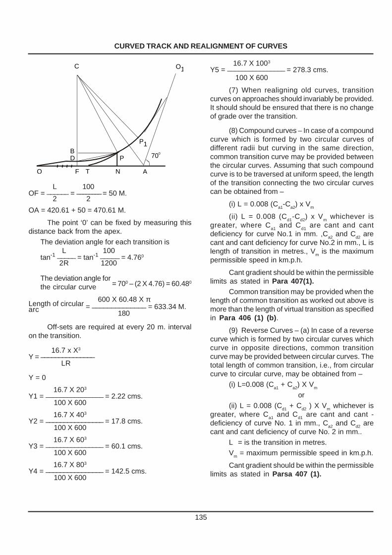
CURVED TRACK AND REALIGNMENT OF CURVES
135
L 100OF = ______ = ________ = 50 M.
2 2
OA = 420.61 + 50 = 470.61 M.
The point ‘0’ can be fixed by measuring thisdistance back from the apex.
The deviation angle for each transition isL 100
tan-1 _____ = tan-1 _____ = 4.760
2R 1200
The deviation angle for = 700 – (2 X 4.76) = 60.480
the circular curve
600 X 60.48 X πLength of circular = ______________ = 633.34 M.arc 180
Off-sets are required at every 20 m. intervalon the transition.
16.7 x X3
Y = _______________LR
Y = 0
16.7 X 203
Y1 = ________________ = 2.22 cms.100 X 600
16.7 X 403
Y2 = ________________ = 17.8 cms.100 X 600
16.7 X 603
Y3 = ________________ = 60.1 cms.100 X 600
16.7 X 803
Y4 = ________________ = 142.5 cms.100 X 600
16.7 X 1003
Y5 = ________________ = 278.3 cms.100 X 600
(7) When realigning old curves, transitioncurves on approaches should invariably be provided.It should should be ensured that there is no changeof grade over the transition.
(8) Compound curves – In case of a compoundcurve which is formed by two circular curves ofdifferent radii but curving in the same direction,common transition curve may be provided betweenthe circular curves. Assuming that such compoundcurve is to be traversed at uniform speed, the lengthof the transition connecting the two circular curvescan be obtained from –
(i) L = 0.008 (Ca1-Ca2) x Vm
(ii) L = 0.008 (Cd1
-Cd2
) x Vm whichever is
greater, where Ca1
and Cd1
are cant and cantdeficiency for curve No.1 in mm. ,C
a2 and C
d2 are
cant and cant deficiency for curve No.2 in mm., L islength of transition in metres., V
m is the maximum
permissible speed in km.p.h.
Cant gradient should be within the permissiblelimits as stated in Para 407(1).
Common transition may be provided when thelength of common transition as worked out above ismore than the length of virtual transition as specifiedin Para 406 (1) (b).
(9) Reverse Curves – (a) In case of a reversecurve which is formed by two circular curves whichcurve in opposite directions, common transitioncurve may be provided between circular curves. Thetotal length of common transition, i.e., from circularcurve to circular curve, may be obtained from –
(i) L=0.008 (Ca1
+ Ca2
) X Vm
or
(ii) L = 0.008 (Cd1 + Cd2 ) X Vm whichever isgreater, where Ca1 and Cd1 are cant and cant -deficiency of curve No. 1 in mm., Ca2 and Cd2 arecant and cant deficiency of curve No. 2 in mm..
L = is the transition in metres.
Vm = maximum permissible speed in km.p.h.
Cant gradient should be within the permissiblelimits as stated in Parsa 407 (1).
C O1
700
P1
PBD
F TO N A

CURVED TRACK AND REALIGNMENT OF CURVES
136
(b) For high speeds, in group ‘A’ and ‘B’ routes,a straight with a minimum length of 50 M. shall bekept between two transitions of reverse curves. Inthe case of M. G. high speed routes the distance tobe kept will be 30 metres. On groups ‘A’ and ‘B’ routeson B. G., straights less than 50 metres betweenreverse curves and on M. G. high speed routes,straights less than 30 metres should be eliminatedby suitably extending the transition lengths. In doingso, it should be ensured that the rate of change ofcant and versine along the two transitions soextended is kept the same. Whenever such straightsbetween reverse curves can neither be eliminatednor the straight length increased to over 50 metresin B. G. and 30 metres in M. G. speed in excess of130 km.p.h. in B. G. and 100 km.p.h. in M.G.shouldnot be permitted.
408. Running out Superelevation – (1) Ontransitioned curves, cant should be run up or run outon the transition, not on the straight or on the circularcurve, increasing or decreasing uniformly throughoutits length.
(2) On non-transitioned curves, cant shouldbe run up or run out on the ‘virtual transition’.
(3) Longitudinal profile of transition on thereverse curve may be in one of the following twoalternatives :
In case no. 1, the level of one of the rails ismaintained and the super elevation is run out onthe other rail by lowering it over half the transitionlength and raising it to the required amount of cantover the remaining half portion of the transition.
In case no. 2, the level of the centre line of thetrack is maintained the same throughout, and thecant is provided by raising one rail by half the amountof cant and lowering the other rail by the equalamount. Cant is run out or gained over the length ofthe transition by raising and lowering both the railsby equal amount symmetrically, with respect to thelevel of the centre line track.
In case of no.1, the level of the centre of thetrack gets disturbed whereas in case of No. 2, it ismaintained the same throughout.
(4) Special cases of superelevation run outmay be approved by the Chief Engineer.
409. Indicators/Boards provided incurves– (1) Curve Board – Each approach of acurve should be provided with a curve board at thetangent point fixed on the outside of the curve. ThisBoard should indicate the radius of the curve, thelength of the curve, length of transition in metres andthe maximum cant provided on the circular portionof curve in millimetres.
(2) Rail Posts Indicating Tangent Points – Onthe inside of the curve, rail posts should be erectedon each approach of the curve, to indicate thepositions of the begining and end of transition curves.These rail posts may be painted in red and whitecolours respectively. In the case of non transitioned
curve, similar rail post should be erected on thetangent track and on the circular curve over whichthe cant is run out, indicating the begining and end ofthe virtual transition.
CASE : I
CASE : II
VERSINE OR CANT DIAGRAM
RAIL 1
RAIL 2
CENTRE LINE OFTHE TRACK
LONGITUDINAL
PROFILE

CURVED TRACK AND REALIGNMENT OF CURVES
137
(3) Indication of cant on track – Superelevationor cant should be indicated by painting its value onthe inside face of the web of the inner rail of the curveand at every versine station, begining with zero atthe commencement of the transition curve. The valueof cant should be indicated on the circular curve atits begining and at the end. In the case of long circularcurve the cant value should be indicated atintermediate stations at a distant not exceeding 250metres.
(4) Cant boards – Cant boards supplied to thegangs should be graduated in steps of 5 mm. Themaximum height of these should be 165 mm. forB. G., 100 mm. for M. G. and 75 mm. for N. G.(762mm.)
(5) When curves are realigned, therepositioning of the curve boards and posts andrepainting of values of superelevation at intermediatepoints should be done, as required.
410. Speed over Turn-out Curves – (1)Provision in general rules-Relevant Para 4.10of General Rules,1976 Edition is reproducedbelow-
(i) The speed of trains over non-interlockedfacing points shall not exceeed 15 kilometres perhour in any circumstances and the speed over turn-out and cross overs shall not exceed 15 kilometresper hour, unless otherwise prescribed by approvedspecial instruction, which may permit a higher speed.
(ii) Subject to provision of sub-rules (i) a trainmay run over interlocked facing points at such speedas may be permitted by the standard of interlocking.
(2) Turn-outs on running lines with passengertraffic – Turn-outs in running lines over whichpassenger trains are received or despatched shouldbe laid with crossing, not sharper than 1 in 12 forstraight switch. However, 1 in 8-1/2 turn-out withcurved switches may be laid in exceptionalcircumstances, where due to limitation of room, it isnot possible to provide 1 in 12 turn-outs. Sharpercrossings may also be used when the turn-out istaken off from outside of a curve, keeping the radiusof lead curve within the following limits :–
Gauge Minimum radius oflead curve
Broad Gauge 350 M.
Metre Gauge 220 M.
Narrow Gauge(762 mm.) 165 M.
Where it is not practicable to achieve theradius of curvature of turn in curves as specifiedabove on account of existing track centres for theturn-out taking off from curves, the turn in curves maybe allowed upto a minimum radius of 220m for B.G.and 120m for M.G.subject to the following :–
(a) Such turn in curves should be provided eitheron PSC or steel trough sleepers only, with sleeperspacing same as for the main line.
(b) Full ballast profile should be provided asfor track for main line
Emergency cross overs between double ormultiple lines which are laid only in the trailing directionmay be laid with 1 in 8-1/2 crossings.
In the case of 1 in 8-1/2 turn-outs with straightswitches laid on passenger running lines, the speedshall be restricted to 10 km.p.h. However, on 1 in8-1/2 turn-outs on non passenger running lines,speed of 15 km.p.h. may be permitted.
(3) Speed over interlocked turnouts - Speed inexcess of 15 kmph may be permitted for straights ofinterlocked turnouts only under approved special in-structions in terms of GR 4.10.
In the case of 1 in 8.5, 1 in 12 and flatter turn-outs provided with curved switches, higher speedsas permitted under approved special instructionsmay be allowed on the turnout side, provided the turn-in curve is of a standard suitable for such higherspeeds. While permitting speed beyond 15 kmph,provisions of Para 410 (4) may be kept in view.
The permissible speed on turnouts taking offon the inside of the curve should be determined bytaking into consideration the resultant radius of leadcurve which will be sharper than the lead curve forturnouts taking off from the straight. 1 in 8.5 turnoutsshould not be laid on inside of curves.
(4) Upgradation of speeds on Turnouts andLoops to 30 kmph - (a) Length of Section -Upgradation of speeds on turnout should cover anumber of contiguous stations at a time so as toderive a perceptible advantage of the higher speedin train operation. The works described below, shouldcover all the running loops on the stretch of line takenup.
(i) Turnouts - Speed, in excess of 15 kmph,should be permitted on turnouts laid with ST or PRCsleepers only. All turnouts on the running loops shallbe laid with curved switches, with minimum rail sec-tion being 52 Kg. All rail joints on these turnoutsshould also be welded to the extent possible.

CURVED TRACK AND REALIGNMENT OF CURVES
138
For different type of curved switches permissiblespeed are as under:-
S. Type of PermissibleNo. Turnout (BG) speed
1. 1 In 8.5 curved switch 15 kmph
2. 1 in 8.5 symmetrical 30 kmphsplit with curved switches
3. 1 in 12 curved switch 30 kmph
(ii) Track on running loops - Speed in excessof 15 kmph, should not be permitted on running loopslaid with wooden sleepers. The minimum track struc-ture on the running loops should be 90R rails laid asShort Welded Panels, M+4 density on PRC, ST, CST-9 sleepers and 150 mm ballast cushion. Out of 150mm total cushion, clean cushion of 75 mm at leastshould be available. Proper drainage of the areashould also be ensured.
(iii) Turn-in curves - Speed in excess of 15kmph, should not be permitted on Turn-in curves laidwith wooden sleepers. Turn-in curves should be laidwith the same rail section as on the turn-out withPRC, ST or CST-9 sleepers with sleeper spacingbeing 65 cm centre to center (maximum).
Turn-in curve should conform to Para 410 (2)of IRPWM and especially so in respect of curvatureof the lead curve.
Extra shoulder ballast of 150 mm should beprovided on outside of the turn-in curve.
The frequency of inspection of turn-in curvesshould be same as that for main line turn-outs.
(b) The following should be ensured, if CST-9sleepers are used in running loops or turn-in curves :-
(i) There is no crack or fracture at rail seat intwo consecutive sleepers.
(ii) There is no excessive wear of lug and railseat.
(iii) All the fittings, keys, cotters and tie barsare fitted properly. Rail is held firmly with sleepers.
(iv) Tie bars should not be broken or damagedby falling brake gear, wagon parts etc. and they shouldnot have excessive corrosion or elongated holes. Thecorrosion of tie-bars inside the CST-9 plate shouldbe especially checked as this results in their removaland adjustment becoming difficult.
(c) The following should be ensured, if STsleepers are used in Turnouts, Turn-in curves or run-ning loops:-
(i) There is no crack or fracture at rail seat in
two consecutive sleepers.(ii) There is no excessive wear of lug, MLJ and
rail seat.(iii) All the fittings are effective and rail is held
with sleepers properly.(iv) The sleepers and fittings do not have ex-
cessive corrosion, elongated holes etc.
411. Permissible Speed over curved Mainline at Turn-outs – Subject to the permissible runthrough speed governed by the interlocking standard,speed over the main line will be determined takinginto consideration the maximum cant which can beprovided on the main line and the permissible amountof cant deficiency. In the case of turn-out of similarflexure, the maximum cant that can be provided, onthe main line will be the sum of equlibrium cant forthe turn-out and permissible cant excess. In the caseof turn-outs of contrary flexure, the maximum canton the main line (negative superelevation on turn-out) will be the difference between the maximumpermissible cant deficiency and cant determined forturn-out from the formula given in Schedule ofDimensions as indicated in para 413. Thepermissible speed on the main line will be workedout by the formula as given in para 405(1)
412. No change of superelevation overturn-outs– There should be no change of cantbetween points 20 metres on B. G.,15 metres on M.G., and 12 metres on N. G. outside the toe of theswitch and the nose of the crossing respectively,except in cases where points and crossings have tobe taken off from the transitioned portion of a curve.Normally, turn-outs should not be taken off thetransitioned portion of a main line curve. However, inexceptional cases, when such a course isunavoidable a specific relaxation may be given bythe Chief Engineer of the Railway. In such caseschange of cant and/or curvature may be permittedat the rates specified in para 407 or such lesser ratesas may be prescribed.
413. Curves of contrary flexure – On themain line curve from which a curve of contrary flexuretakes off, the cant of the main line (which is thenegative superelevation on the turn-out) should becalculated from the formula given in the Schedule ofDimension and the permissible speed on the mainline determined from the allowable cant deficiencyand cant on the main line. The speed so determinedshall be subject to limitations governed by thestandard of interlocking and the sectional speed.

CURVED TRACK AND REALIGNMENT OF CURVES
139
414. Curves of similar flexure – (1) Notfollowed by reverse curves-On a main line curve fromwhich a curve of similar flexure takes off, not followedimmediately by a reverse curve, the turn-out curveshall have the same cant as the main line curve.
(2) Followed by reverse curves – A change ofcant on the turn-out may be permitted starting behindthe crossing and being run out at a rate not steeperthan 2.8 mm. per metre and subject to the maximumcant on the main line turn-out being limited to 65 mm.on Broad Gauge, 35 mm. on Metre Gauge and 25mm. on Narrow Gauge (762 mm.)
The permissible speed on the main line is thendetermined from the allowable cant-deficiency andsubject to limitations governed by the standard ofinterlocking and the safe speed limit.
415. Curves with cross overs – On curveson double line connected by cross over road, thespeed and the cant for both roads are governed bythe inner road to which the cross over road is a curveof contrary flexure. On the outer road, it is a curve ofsimilar flexure. The permissible speed and thenecessary cant on the inner road shall be calculatedin accordance with para 413. The same speed andthe same cant shall be allowed on the outer road.
The outer track shall be raised so that bothroads lie in the same inclined plane in order to avoidchange in cross-level on the cross over road. Wherethis is not possible, both main line and the turn-outshould be laid without cant and suitable speedrestriction imposed.
416. Curves with diamond crossing –Normally straight diamond crossings should not beprovided in curves as these produce kinks in the curveand uniform curvature cannot be obtained. However,where provision of such diamonds cannot be avoidedor in case where such diamonds already exists inthe track, the approach curves of these diamondsshould be laid without cant for a distance of at least20 metres on either side of the diamond crossings.Cant should be uniformly runout at the rate specifiedin para 407 beyond 20 metres. The speed restrictionson the approach curve shall be decided in each case
70R 52.5
R
35R
by the Chief Engineer taking into consideration thecurvature, cant deficiency and lack of transition butshall in no case be more than 65 km.p.h. in the caseof Broad Gauge, 50 km.p.h. in the case of MetreGauge and 40 km.p.h. in the case of Narrow Gauge(762 mm.) No speed restriction shall, however beimposed on the straight track on which the diamondis located. In the case of diamond crossings on astraight track located in the approach of a curve, astraight length of minimum 50 M. between the curveand the heel of acute crossing of diamond isnecessary for permitting unrestricted speed over thediamond, subject to maximum permissible speedover the curve from consi-derations of cant deficiency,transition length etc.
417. Extra clearance on curves – On curves,additional lateral clearances, in excess of the fixeddimensions should be provided as laid down in theSchedule of Dimensions –
(a) between adjacent tracks and(b) between curved track and fixed structure.
418. Compensation for curvature ongradient– Compensation for curvature should begiven in all cases where the existing gradient whenadded to the curve compensation exceeds the rulinggradient. The compensation to be allowed shouldordinarily be percent.(0.04 percent per degreeof curvature) for Broad Gauge, per cent (0.03percent per degree of curvature) for Metre Gaugeand per cent (0.02 per cent per degree ofcurvature) for Narrow Gauge(762 mm.) where R isthe radius of curvature in metres.
Thus for a ruling gradient of 0.5 per cent or 1in 200, the gradient for 583 metre radius of curvatureon Broad Gauge should be flattened to –
700.5 – _____ or 0.5 X 0.04 = 0.38 per cent or 1 in 264.
583
419. Vertical curve :– A vertical curve shall beprovided only at the junction of the grade when thealgebraic difference between the grades is equal toor more than 4 mm. per metre or 0.4 per cent.
The minimum radius of the vertical curve shall be kept as under –
Broad Gauge Metre Gauge
Group Minimum Radius Group Minimum Radius
A 4000 metres
B 3000 metres All Routes 2500 metres
C ,D & E 2500 metres

CURVED TRACK AND REALIGNMENT OF CURVES
PART ‘ B’ Realignment of Curve
420. Running on curves – (1) For smooth and satisfactory running on curves –
(a) there should be no abrupt alteration of curvature and/or superelevation (cant), and (b) the superelevation should be appropriate to the curvature, at each point.
(2) On Group ‘A’ and ‘B’ routes, gauge, versines and superelevation on each curve must be checked once in every four months and on other routes every six months. such checks should also be carried out whenever the running over curves is found to be unsatisfactory. The versines, superelevation and gauge should be recorded by the Permanent Way Inspector in the curve register as per the pro forma given as Annexure 4/5. Curve registers of groups ‘A’ and ‘B’ routes should also be provided with cumulative frequency diagrams for each curve to get a graphic idea about the condition of geometry of curve. The A.E.N shall check at least one curve of each Permanent way Inspector every quarter by taking its versine and superelevation as well as gauge from end to end. The decision to realign should be taken by the Permanent Way Inspector-in -charge or Assistant Engineer. The realignment of curve should be carried out in dry season and not during rainy season except when this is unavoidable. Para 421. Criteria for realignment of a curve – (1) When as a result of inspection by trolley or locomotive or by carriage or as a result of Track Recording carried out, the running on a curve is found to be unsatisfactory the curve should be realigned. (2) The running over a curve depends not only on the difference between the actual versine and the designed versine but also on the station to station variation of the actual versine values. This is because, it is the station to station variation of versine which determines the rate of change of lateral acceleration, on which depends the riding comfort. Service limit for station to station versine variation for 3 speed group viz, Below 140 kmph and upto 110 kmph, Below 110 kmph and upto 50 kmph and below 50 kmph, should be considered as tabulated below: S. No.
Speed on curve Limits of station to station variation of versine (mm).
1 Below 140 kmph and upto 110 kmph
10 mm (15 mm for speed of 110 kmph) or 20% of average versine on circular portion, whichever is more.
2 Below 110 kmph and upto 50 kmph
20 mm or 20% of average versine on circular portion, whichever is more.
3 Below 50 kmph 40 mm or 20% of average versine on circular portion, whichever is more.
In case exceedence of the above limit is observed during inspection, local adjustment may be resorted to in cases where the variation of versine between adjacent stations is only at few locations, at the earliest possible. If more than 20% stations are having versine variations above the limits prescribed, complete realignment of curve should be planned within a month. (CS.136 dt 14.11.14)
140

CURVED TRACK AND REALIGNMENT OF CURVES
141
422. Stringlining operations :– (1) The workof realigning and transitioning curves consist of thefollowing three main operations :–
(a) Survey of the existing curve bymeasurement of versines.
(b) Determination of the revised alignment andcomputation of slews, including provision of correctsuperelevation.
(c) Slewing of the curve to the revisedalignment.
(2) Chord Length – Chord length of 20 metresshould be used for recording versine. The stationsshould be at 10 metres intervals and versines shouldbe recorded at these stations with overlapping chordof 20 metres.
(3) Versine survey of curve – OperationNo. 1 :– Versine readings shall be taken along thegauge face of the outer rail.
To ensure inclusion of the point ofcommencement of the curve, a mark is made onthe gauge face of the outer rail at a distance of aboutthree half-chord lengths behind the apparent tangent
point and numbered zero. From this point, half-chorddistances are measured with steel tape along thegauge face of the outer rail over the whole length ofthe curve and numbered serially 1, 2, 3, 4 and so onand carried upto about three half-chord lengthsbeyond the apparent tangent point at the other end.These “stations” should be marked and numberedin white paint on the rail. With a fishing cord or wirestretched out over the full length of the chord,versines are measured to 1 mm. accuracy seriallyat each station from one end of the curve to the otherwith the rule held normal to the line and recorded.
Features which restrict slewing of the trackeither inwards or outwards should be recorded,mentioning the maximum extent inwards andoutwards to which slewing is possible (i) in existingcircumstances and (ii) if a moderate expenditure beincurred in removing the “restriction”. The existingsuperelevation should also be measured andrecorded against each “Station”.
For purposes of check, this process shouldbe repeated in the reverse direction with the personsrecording and measuring versines interchanging theirduties.
The record obtained would be in the following form
Curve from km.........................................................................................to km.............…….....
Between station...............................................…….....................…and station.........................
Date of survey...............................................................……......................................................
Jurisdiction of Assistant Engineer/Permanent Way Inspector……..............................................
Station at Half-chord Versine in Cant existing Remarks regardingintervals (mm) restrictions to slewing
0 0 Zero1 2 5 mm2 4 10 mm
3 4 20 mm4 10 25 mm.
5 11 .. 1.6 metres.
6 23 .. G. B. obligatory point
7 30 .. Low or high bank, moorumetc., etc. or rock cutting etc.

CURVED TRACK AND REALIGNMENT OF CURVES
142
Where there are two or more lines, trackcentres at intervals should be recorded. After theversine-survey, the curve alignment shall not bedisturbed until the realignment is commenced. Thisinterval should be the least possible.
In the case of reverse curves, the versinesurvey should be continuous, but transferred to theouter rail at points where the curvature changes sign.It is probable that the exact point will not be definite;it is therefore, desirable to keep the original rail faceas the base until the change is certain to enable plusor minus versines to be read from the same rail, it isonly necessary to hold the fishing cord or wire 20mm. clear of the rail edge at each end by usingspecial gadget and substracting 20 mm. from thereading at the centre.
(4) Determination of revised alignment andcomputation of slews :–
Operation No. 2 :–
(a) The basic principles of string lining are asfollows :–
(i) The chord length being identical, the sumtotal of the existing versines should be equal to thesum total of the proposed versines.
(ii) The slew in any direction at a station affectsthe versines at the adjacent stations by half theamount in the opposite direction, when the track isnot disturbed at the adjacent stations.
(iii) The second summation of versinedifference represents half the slew at any station.
(iv) At the first and at the last station, the slewsshould be zero.
(b) Success in obtaining the most suitablealignment depends on the proper selection ofversines.
(c) In actual practice the calculations arecarried out in the following manner :–
(i) After recording the versines in mm.,proposed versines are selected in such a way as toobtain uniform rate of change of versines over thetransition curve and uniform versines over thecircular portion of the curves.
(ii) The difference between the proposed andthe existing versines are worked out for each station,the positive sign being used, if the proposed versineis greater than the existing versine and negative signif it is less (Ref.Col. 4 -Table 1, at the end of thissub- para (4), wherein a solution to a realignment of
curve is worked out).
(iii) First and second summations of thedifferences of proposed and existing versines arethen worked out (Ref. Cols. 5 & 6).
(iv) The first summation at any station, givesthe cumulative versine difference at each station. Tobegin with this value for station ‘ 0 ’ is the same asthe versine difference (Col. 4). To obtain thecorresponding value for station No. 1 the cumulativeversine difference of station ‘0’ (Col. 5) is added tothe versine difference of station No. 1 (Col. 4)diagonally downward as shown by the arrowindication and the resultant value is written againstStation No.1(Col. 5) Similarly the cumulative versinedifference is calculated at each station till the laststation is reached. Since the sum total of the existingand the proposed versines is the same, the figureagainst the last station will be ‘0’ (Col. 5).
(v) The second summation at any station givesthe cumulative effect of the figures of firstsummations upto the previous station. It can beproved theoretically that this represents half the slewrequired at each station to obtain the proposedversine. To start with, this value for station‘0’ is takenas zero.To obtain the corresponding value of StationNo.1, the second summation value of thestation‘0’(i.e., the previous station ) is added to thefirst summation value of the same station ‘0’,asshown by horizontal arrow. This value is shownagainst Station No. 1(Col. 6). Similarly the secondsummation for Station No. 2 is the sum of the figuresof the first summation and second summation ofStation No.1(Col.5 and 6). The second summationis obtained against each station till the last station isreached. The slew at the last station should be zero.Otherwise the track beyond the last station will beaffected by the slew at the last station. Normally thisfigure at the last station will not be zero. To bring thisto zero correcting couples are applied.
(vi) Method of applying correcting couples -For correcting the half-throws to zero the procedureshall be as follows :–

CURVED TRACK AND REALIGNMENT OF CURVES
143
When the final half-throw is negative, add tothe versines having the lower station numbers andsubstract an equal amount from the versines havingthe higher station numbers, selecting “station” in pairssuch that the sum of the products of the differenceof the “station” numbers taken in pairs and theamount added to the versines, equals the numericalamount of the negative half-throw to be cleared.
When the final half -throw is positive, substractfrom the versines having the lower station numbersand add an equal amount to the versiness havingthe higher station numbers, selecting the stations inpairs such that the sum of the product of differencesof the station numbers in pairs and the amountsubstracted from the versines, equals the numericalamount of the positive half throw to be cleared.
(vii) For computing slews when realigning and/or transitioning a complete curve the followingprocedure should be adopted :–
Calculate the length of transition from Para407(1). This determines the versine gradient on thetransition.
Work out versine difference, first and secondsummations as discussed above at the initial stationswith a view to foreseeing and exercising due controlover the slews(col. 4, 5 and 6). Review the figuresof proposed versines (col 8) if necessary andcontinue the process until the transition at the otherend on which the specific versine gradient shouldbe observed. In the process it must be ensured thatdifference of versines(col. 4) should sum up to zero.
Apply correcting couples to control the slew atobligatory points and to close the slew at the end tozero. The slews must be limited to the minimumpossible.
Determine correct cant to be provided, pointsof zero and maximum cant and the cant run-off.
Curve realignment can be worked out bygraphical method. Mechanical and electronic deviceswhere available may be used to determine the finalvalues of slew, thus avoiding the lengthy process offirst and second summation and application ofcorrecting couples.
(viii) Maximum Slew – Maximum slew at anystation is usually limited by practical considerations.The distance between tracks and adequateclearance to existing structures must be maintainedand track must not be slewed too near the edge ofthe formation. At certain locations like bridges, it may
not be possible to slew the curve at all .
(ix) In carrying out the calculations for therealignment of a long curve of more than 50 stationsit is best to write down values of about 10 proposedversines at a time and see that the sum isapproximately the same as that of the correspondingold versines and then workout the second summationto ensure that slews are minimum. A final adjustmentto ensure that the sum of the existing and proposedversines is equal and that the slew at last station iszero can then be made.
A numerical example is given in table 1 on thenext page which will illustrate the method of workingout the solution for realignment of a curve.
(See Table No. 1)(5) Slewing the curve to revised alignment :–Operation No. 3 :– The revised alignment of
the curve should be staked out with a steel tape byusing the pegs cut from the bars (or wooden stakeswith tack marks) which should be fixed on the cesson the inner side of the curve square to the trackand at such a distance according to the value of theslews, so that the final alignment of the track is atone gauge distance from the face of the pegs or thetacks on wooden pegs to the outer edges of the innerrail. In narrow cuttings with sharp curves or in tunnelsit may not not be possible to measure versines onthe pegs driven on the inner cess of the curve due tothe face of the cutting fouling the fishing cord. In suchcases, the pegs may be driven on the outer cess.Their correctness should be checked by measuringthe versines on these pegs and verifying that theycorrespond with the final versines of the alignment.The curve should then be correctly slewed to therealignment of pegs.
Whether or not permanent pegs should befixed is left entirely to the discretion of DivisionalEngineer. In no case should these be fixed onformation that is not firm or at locations where theyare liable to the disturbed or tampered with.
Where it is considered more expedient, thestaking of the realigned curve may be done by drivingtie-bar pegs of about 750 mm. in length against eachstation down to rail level along the centre line of therevised alignment and slewing the track to thesepegs.
It is important that the slewing is done to 2 mm.accuracy and actual versines again taken to ensurethat they accord with the calculated versines of therealigned curve.

CURVED TRACK AND REALIGNMENT OF CURVES
Along with slewing of the curve to the revised alignment correct superelevation should be provided at each station to accord with the curvature, particular attention being paid to the run -off on the transition. Repositioning of posts on the cess to indicate zero and maximum superelevation and remarking of cant values on the inside web of the inner rail should be done.
423. Realigning curves on double or multiple lines :– On double or multiple tracks each curve should be stringlined independently. No attempt should be made to realign any curve by slewing it to a uniform centre to centre distance from the realigned curve as –
(a) The existing track centres may not be uniform and relatively small throw on one may entail a much larger (even prohibitively large) throw on the adjacent track
(b) It is nearly impossible to measure the centre to centre distance of curved tracks along the true radial lines and a small error in angular direction of measurement would mean an appreciable error in true radial distance.
(c) The transitions at the entry and exit may be of different lengths which make it impracticable to maintain uniform centres on them even though the degree of the circular curves may be nearly the same.
424. Cuttings of rails on curves :– Rails are usually laid with square joints on curve. On curved track the inner rail joints gradually lead over the outer rail joints. When the inner rail of the curve is ahead of the outer rail by an amount equal to half the pitch of bolt holes, cut rails should be provided to obtain square joints. Cut rail is a rail which is shorter than the standard length of rail by an amount equal to the pitch of the bolt holes. The excess length ‘d’ by which the inner rail gains over the outer rail is calculated by the formula –
LG d = _______
R where ‘d’ is the length in mm. by which the inner
rail joint is ahead of the outer rail joint over the entire length of the curve, if cut rails are not provided.
L = length of the curve in meters R= radius of the curve in meters G= the gauge + width of the rail head in mm.
The number of cut rails for a particular
curve is worked out by the formula – d
N = ———————————————— pitch of the bolt holes in mm. It must be ensured that rail joints are
square at beginning and at the end of the curve.
425. Joints on curves :– Rails joints on curves normally be laid square. On the sharp curves less than 400 meters on the Broad Gauge and 300 meters on the Metre Gauge the rail joints may be staggered, where elbows and kinks are likely to develop if rail joints are laid square.
426. Check rails on curves :– Check rails should be provided on the inside of the inner rail of the curve as stipulated in the schedule of dimensions.
Appropriate clearances should be provided between the check rail and the running rail as stipulated in the schedule of dimensions. Check rails reduce the risk of derailment on the sharp curves.
Location where check rails should be provided shall be decided by the Chief Engineer taking into considration the negotiability of the rolling stock and the curve geometry.
427. Wear on outer rail of curves :– (1) This can be reduced effectively
(a) by lubricating the gauge face of outer rails on the curves.
(b) by maintaining correct curve geometry and superelevation.
(c) Provision of the suitable check rail. (2) Track mounted automatic Gauge Face Lubricators should be provided on curves of radius 875m (20) and sharper on broad gauge and of radius 300 m and less on meter gauge to reduce rail gauge face wear.
On routes where rail grinding is in practice, Track mounted automatic Gauge Face Lubricators should be provided on curves of radius 1400m (1.250) and sharper on Broad Gauge. While deciding the location of lubricators, following should be considered: -
144
(a) It is located on tangent track at the beginning of transition curve where wheel flanging is just beginning to occur. On single lines, the lubricator shall be located in the direction of heaviest traffic.
(b) Lubricators should be located away from switches, crossings and other areas where discontinuity in LWR track may exist. (C.S.No:136 dt 14.11.2014)
428. Measurement of rail wear on sharp
curves:– The wear of rails of curves having radius of 600 M. or less on B. G. and 300 M. or less on M. G. shall be periodically recorded. Railways should prescribe the periodicity of measurement of wear on those sharp curves. The lateral, vertical and total loss of section should be recorded. Proper record of the measurements should also be maintained.
429 . Maintenance of Thermit Welds on curves: Joggled fish plate with clamps or two far end bolts on good AT welds shall be provided on curves of 3 or sharper.(C.S.No:131 dt 11.1.2013)
144/A

CURVED TRACK AND REALIGNMENT OF CURVES
145
Table 1
Realignment of curve by stringlining method
1 2 3 4 5 6 7 8 9 10 11 12
0 2 2 0 0 0 -1 -1 -0 0 1
1 0 8 +8 +8 0 -1 -2 -1 -1 -2 7
2 14 16 +2 +10 +8 -1 -3 -3 +5 +10 15
3 28 24 -4 +6 +18 -1 -4 -6 +12 +24 23
4 30 32 +2 +8 +24 -1 -5 -10 +14 +28 31
5 36 32 -4 +4 +32 -1 -6 -15 +17 +34 31
6 36 32 -4 0 +36 -1 -7 -21 +15 +30 31
7 24 32 +8 +8 +36 -1 -8 -28 +8 +16 31
8 32 32 0 +8 +44 -8 -36 +8 +16 32
9 28 32 +4 +12 +52 -8 -44 +8 +16 32
10 36 32 -4 +8 +64 -8 -52 +12 +24 32
11 34 32 -2 +6 +72 -8 -60 +12 +24 32
12 32 32 0 +6 +78 -8 -68 +10 +20 32
13 34 32 -2 +4 +84 +1 -7 -76 +8 +16 33
14 36 32 -4 0 +88 +1 -6 -83 +5 +10 33
15 24 32 +8 +8 +88 +1 -5 -89 -1 -2 33
16 24 24 0 +8 +96 +1 -4 -94 +2 +4 25
17 28 16 -12 -4 +104 +1 -3 -98 +6 +12 17
18 0 8 +8 +4 +100 +1 -2 -101 -1 -2 9
19 6 2 -4 0 +104 +1 -1 -103 +1 +2 3
20 0 0 0 0 +104 +1 0 -104 0 0 1
+ Slew inside. – Slew Outside
Sta
tion
num
ber.
Exi
stin
g ve
rsin
es in
mm
on
20 M
cho
rd
Pro
pose
d ve
rsin
e in
mm
.
Ver
sine
diff
eren
ceco
lum
n 3
-co
lum
n 2
1st s
umm
atio
n of
ver
sine
diffe
rnce
2nd s
umm
atin
on o
f ve
rsin
edi
ffere
nece
or
half
thro
w in
mm
.
Cor
rect
ing
vers
ine
in m
m
1st
sum
mat
ion
ofco
rrec
ting
vers
ine
2nd s
umm
atio
n of
corr
ectin
g v
ersi
ne
Res
ulta
nt h
alf s
lew
col
9 +
col.6
in m
m
Res
ulta
nt fu
ll sl
ew in
mm
Res
ulta
nt v
ersi
ne in
mm
col 3
+co
l 7
Correcting couple
→ →
→
→
→
→→→
→→ →
→→
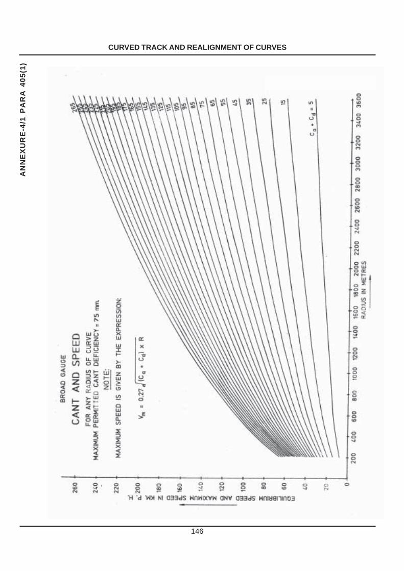
CURVED TRACK AND REALIGNMENT OF CURVES
146
AN
NE
XU
RE
-4/1
PA
RA
40
5(1
)

CURVED TRACK AND REALIGNMENT OF CURVES
147
AN
NE
XU
RE
-4/2
PA
RA
40
5(1
)

CURVED TRACK AND REALIGNMENT OF CURVES
148
AN
NE
XU
RE
-4/3
PA
RA
40
5(2
)
CA
NT
LIM
ITE
D T
O 4
0 m
m. T
O M
AIN
TAIN
CA
NT
GR
AD
IEN
T O
F I
IN 3
60
120
100 80 60 40 20 0
Ca
V
BR
OA
D G
UA
GE
200
400
600
800
1000
1200
1400
1600
1800
2000
2200
2400
2600
2800
3000
3200
3400
360060 50 40 30 20 10 0
RA
DIU
S IN
ME
TR
ES
CANT IN MILLIMETRES
'V' MAX SPEED IN KILOMETRES/HOUR
NO
N T
RA
NS
ITIO
NE
D C
UR
VE
S W
ITH
CA
NT
ON
VIR
TU
AL
TR
AN
SIT
ION
MA
XIM
UM
SP
EE
D A
ND
CA
NT
FO
R A
NY
RA
DIU
S O
F C
UR
VE
BR
OA
D G
AU
GE
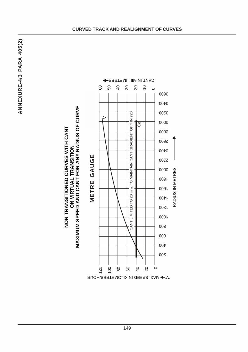
CURVED TRACK AND REALIGNMENT OF CURVES
149
AN
NE
XU
RE
-4/3
PA
RA
40
5(2
)
ME
TR
E G
AU
GE
120
100 80 60 40 20 0
60 50 40 30 20 10 0
NO
N T
RA
NS
ITIO
NE
D C
UR
VE
S W
ITH
CA
NT
ON
VIR
TU
AL
TR
AN
SIT
ION
MA
XIM
UM
SP
EE
D A
ND
CA
NT
FO
R A
NY
RA
DIU
S O
F C
UR
VE
V
CANT IN MILLIMETRES
RA
DIU
S IN
ME
TR
ES
'V' MAX. SPEED IN KILOMETRES/HOUR
Ca
ME
TR
E G
AU
GE

CURVED TRACK AND REALIGNMENT OF CURVES
150
AN
NE
XU
RE
-4/4
PA
RA
40
5(2
)
BR
OA
D G
AU
GE

CURVED TRACK AND REALIGNMENT OF CURVES
151
AN
NE
XU
RE
-4/4
PA
RA
40
5(2
)
ME
TR
E G
AU
GE
120
100 80 60 40 20 0
60 50 40 30 20 10 0
NO
N T
RA
NS
ITIO
NE
D C
UR
VE
WIT
HO
UT
CA
NT
MA
XIM
UM
SP
EE
D F
OR
AN
Y R
AD
IUS
OF
CU
RV
E
V
CANT IN MILLIMETRES
RA
DIU
S IN
ME
TR
ES
'V' MAX. SPEED IN KILOMETRES/HOUR
ME
TR
E G
AU
GE

CURVED TRACK AND REALIGNMENT OF CURVES
152
ANNEXURE-4/5 PARA 420 (2)
PRO FORMA OF CURVE REGISTER
ABSTRACT OF CURVES
.................................RAILWAY .....................................Section
SI. Curve Between Kilometres R.H.or Degree ofNo. No. Stations From To L.H. curve(1) (2) (3) (4) (5) (6) (7)
Radius of S.E. Length of Total Length Whether joints Whether referencecurve Transition Circular of curve are square or pillars have
curve staggered been provided(8) (9) (10) (11) (12) (13) (14)
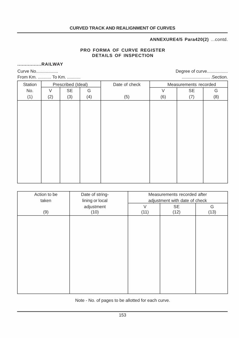
CURVED TRACK AND REALIGNMENT OF CURVES
153
ANNEXURE4/5 Para420(2) ...contd.
PRO FORMA OF CURVE REGISTERDETAILS OF INSPECTION
................RAILWAY
Curve No.................. Degree of curve.................From Km. ........... To Km. ........... ....................... .Section.
Station Prescribed (Ideal) Date of check Measurements recordedNo. V SE G V SE G(1) (2) (3) (4) (5) (6) (7) (8)
Action to be Date of string- Measurements recorded aftertaken lining or local adjustment with date of check
adjustment V SE G(9) (10) (11) (12) (13)
Note - No. of pages to be allotted for each curve.

WELDING OF RAILS : LAYING AND MAINTENANCE OF SHORT WELDED RAILS, LONG WELDED RAILS AND CONTINUOUS WELDED RAILS
CHAPTER V
WELDING OF RAILS : LAYING AND MAINTENANCE OF SHORT WELDED RAILS, LONG WELDED RAILS AND
CONTINUOUS WELDED RAILS
PART ‘A’
Welding of rails
501. General – The welding of rails is carried out in a depot by the “Flash butt welding process and at site by the “Thermit Welding” process. The length to which the rails can be welded in a depot depends on the transport facilities available.
502. Alumino Thermic Welding of Rails:
(1) Alumino Thermic Welding of rails may be carried out in accordance with the detailed procedure laid down in the ‘Manual for Fusion Welding of Rails by Alumino Thermit Process’. A thermit weld done in-situ shall be joggled fish-plated with two clamps and supported on wooden blocks till tested as good by USFD. (CS 136 Dt 14.11.14)
2) Joggled fish plate with clamps or two far
end bolts on good AT welds shall be provided on banks having height 5m or more.
(3) Joggled fish plates with far end tight bolt shall be provided on AT welds which have undertaken traffic equal to or more than 50% of stipulated fatigue life (GMT) of the rail.
(4) For bridges and curves, action as per para 277(a) (7) and para 429 shall be taken. (C.S.No.131 dated 11.01.2013)
503. Tolerances allowed in the case of flash butt welds —The tolerances allowed in the case of flash butt welds are the same as allowed in the case of Alumino-thermit welds (para 502). In addition to the tolerances mentioned for thermit weld, the following additional item of tolerance is specified–
Web zone : + 3.0 mm – 0.0 mm of parent contour
In the case of old rails welded together the
tolerances can not exceed double the above values stipulated for new rails, keeping the tolerances to the minimum.
504.Short pre-heat welding process –(1) General – The conventional thermit welding process takes about 60 minutes for welding of a joint. To reduce this time in view of non availability of longer time interval between trains this method with shorter preheating time is used.
The principle of this process is essentially the same as thermit process except that –
(i) Prefabricated mould is used in place of green sand, to reduce the time due to drying of sand.
(ii) Larger gap of 22 to 24 mm. is provided at
the rail ends. (iii) Rail ends are heated only to 600
o C
against 950oC.
(iv)Preheatin time is reduced to 10 to 12 minutes. (v) Thermit portion is double the quantity for
this process . (vi) A stronger burner with larger fuel flow is used.
In this case also, the traffic can be allowed
only after 30 minutes have elapsed after welding of the joint. The code of practice for welding of rail joints Alumino thermic process issued by R. D. S. O. should be refered for complete details regarding selection of rails for welding, preliminary work prior to welding, the actual details of work of execution of welding, and inspection of welds.
154
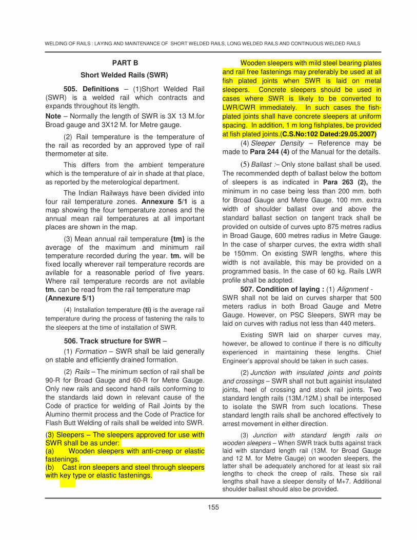
WELDING OF RAILS : LAYING AND MAINTENANCE OF SHORT WELDED RAILS, LONG WELDED RAILS AND CONTINUOUS WELDED RAILS
PART B
Short Welded Rails (SWR)
505. Definitions – (1)Short Welded Rail (SWR) is a welded rail which contracts and expands throughout its length. Note – Normally the length of SWR is 3X 13 M.for Broad gauge and 3X12 M. for Metre gauge.
(2) Rail temperature is the temperature of the rail as recorded by an approved type of rail thermometer at site.
This differs from the ambient temperature which is the temperature of air in shade at that place, as reported by the meterological department.
The Indian Railways have been divided into four rail temperature zones. Annexure 5/1 is a map showing the four temperature zones and the annual mean rail temperatures at all important places are shown in the map.
(3) Mean annual rail temperature {tm} is the average of the maximum and minimum rail temperature recorded during the year. tm. will be fixed locally wherever rail temperature records are avilable for a reasonable period of five years. Where rail temperature records are not avilable tm. can be read from the rail temperature map (Annexure 5/1)
(4) Installation temperature (ti) is the average rail temperature during the process of fastening the rails to the sleepers at the time of installation of SWR.
506. Track structure for SWR – (1) Formation – SWR shall be laid generally
on stable and efficiently drained formation.
(2) Rails – The minimum section of rail shall be 90-R for Broad Gauge and 60-R for Metre Gauge. Only new rails and second hand rails conforming to the standards laid down in relevant cause of the Code of practice for welding of Rail Joints by the Alumino thermit process and the Code of Practice for Flash Butt Welding of rails shall be welded into SWR. (3) Sleepers – The sleepers approved for use with SWR shall be as under: (a) Wooden sleepers with anti-creep or elastic fastenings. (b) Cast iron sleepers and steel through sleepers with key type or elastic fastenings.
Wooden sleepers with mild steel bearing plates
and rail free fastenings may preferably be used at all fish plated joints when SWR is laid on metal sleepers. Concrete sleepers should be used in cases where SWR is likely to be converted to LWR/CWR immediately. In such cases the fish-plated joints shall have concrete sleepers at uniform spacing. In addition, 1 m long fishplates, be provided at fish plated joints.(C.S.No:102 Dated:29.05.2007)
(4) Sleeper Density – Reference may be made to Para 244 (4) of the Manual for the details.
(5) Ballast :– Only stone ballast shall be used. The recommended depth of ballast below the bottom of sleepers is as indicated in Para 263 (2), the minimum in no case being less than 200 mm. both for Broad Gauge and Metre Gauge. 100 mm. extra width of shoulder ballast over and above the standard ballast section on tangent track shall be provided on outside of curves upto 875 metres radius in Broad Gauge, 600 metres radius in Metre Gauge. In the case of sharper curves, the extra width shall be 150mm. On existing SWR lengths, where this width is not available, this may be provided on a programmed basis. In the case of 60 kg. Rails LWR profile shall be adopted.
507. Condition of laying : (1) Alignment - SWR shall not be laid on curves sharper that 500 meters radius in both Broad Gauge and Metre Gauge. However, on PSC Sleepers, SWR may be laid on curves with radius not less than 440 meters.
Existing SWR laid on sharper curves may, however, be allowed to continue if there is no difficulty experienced in maintaining these lengths. Chief Engineer’s approval should be taken in such cases.
(2) Junction with insulated joints and points and crossings – SWR shall not butt againist insulated joints, heel of crossing and stock rail joints. Two standard length rails (13M./12M.) shall be interposed to isolate the SWR from such locations. These standard length rails shall be anchored effectively to arrest movement in either direction.
(3) Junction with standard length rails on wooden sleepers – When SWR track butts against track laid with standard length rail (13M. for Broad Gauge and 12 M. for Metre Gauge) on wooden sleepers, the latter shall be adequately anchored for at least six rail lengths to check the creep of rails. These six rail lengths shall have a sleeper density of M+7. Additional shoulder ballast should also be provided.
155

WELDING OF RAILS : LAYING AND MAINTENANCE OF SHORT WELDED RAILS, LONG WELDED RAILS AND CONTINUOUS WELDED RAILS
(4) Regarding laying of SWR in Level Crossings and Bridges, Para 921 of Chapter on Level Crossings, Para 272(4) of Chapter on Permament Way Maintenance-Track Structure on Bridges may be referred to. 508. Laying of short welded rails (SWR) - The gaps to be provided for SWR at the time of laying shall be in accordance with Table I depending on the installation temperature (ti) and the Zone in which the rails are laid -. TABLE I Initial laying gaps for SWR for various installation temperatures For Zones I and II Rail temperature at the time of installation (ti) (in centigrade) –
tm-17.5 tm-12.5 tm-7.5 tm-2.5 tm+2.6 tm+7.6
to to to to to to
tm-12.6 tm-7.6 tm-2.6 tm+2.5 tm+7.5 tm+12.5
Initial laying gaps in mm –
For 39 m panels 12mm 10mm 8mm 6mm 4mm 2mm For 26 m rolled Rail 10mm 9mm 7mm 6mm 5mm 3mm
For Zones III and IV Rail temperature at the time of installation (ti) (in centigrade) –
tm-22.5 tm-17.5 tm-12.5 tm-7.5 tm-2.4 tm+2.6
to to to to to to
tm-17.6 tm-12.6 tm-7.6 tm-2.5 tm+2.5 tm+7.5
Initial laying gaps in mm –
For 39 m panels 12mm 10mm 8mm 6mm 4mm 2mm For 26 m rolled Rail 10mm 9mm 7mm 6mm 5mm 3mm
If the laying has to be done outside the
temperature range given in table above, or whichever joint gaps could not be provided as per the table, readjustment of gap shall be carried out within two days of laying before the track consolidates. Along with the gap adjustment, any re-spacing of sleepers, if required, must be carried out.(C.S.No. 125 dated 21.02.2011)
509. Maintenance of short welded rails – Regular maintenance operation –
(1) Regular track maintenance including all operations involving packing, lifting, aligning, local adjustment of curves, screening of ballast other than
deep screening, and scattered renewal of sleepers may be carried out without restriction when the rail temperature is below tm. +25o C in the case of zone I & II and tm + 20o C in the zone III and IV. However on curves of less than 875 metres radius Broad Gauge,and less than 600 meteres radius in Metre Gauge or yielding formation, the above temperature limit shall be restricted to tm. +15o C in the case of Zone I and II and tm. + 10oC in the case of Zone III and IV.
156

WELDING OF RAILS : LAYING AND MAINTENANCE OF SHORT WELDED RAILS, LONG WELDED RAILS AND CONTINUOUS WELDED RAILS
157
(2) If the maintenance operations have to beundertaken at temperature higher than thatmentioned above in Para 509 (1), not more than30 sleeper spaces in one continuous stretch shallbe opened, leaving at least 30 fully boxed sleeperspacer between adjacent lengths which are openedout. Before the end of the days work it shall beensured that the ballast is boxed up.
(3) As an additional precaution, during summermonths, to be specified by the Chief Engineer, forattention to run down track, even if temperature isless the temperature specified in Para 509 (1) notmore than 30 sleepers in one continuous stretch shallbe opened, leaving at least 30 boxed sleeper spacesbetween adjacent lengths which are opened up.Further, if joint gaps are not available at the time ofopening of the track even when rail temperature areless than those specified in clause Para 509 (1). notmore than 30 sleepers in one continuous stretchshould be opened leaving at least 30 boxed sleeperspaces between adjacent lenghts which are openedup.
(4) Major lifting, major alignment of track, deepscreening and renewal of sleepers in continuouslength. - Each of these operations shall be doneunder suitable precautions and normally when therail temperature is below tm. +15
0 C in the case of
Zones I and II, and tm. +100 C in the case of Zones
III and IV. If it becomes necessary to undertake suchworks at rail temperature exceeding the above valuesadequate speed restrictions shall be imposed.
(5) Adequate number of joggled fish-plates withspecial clamps shall be provided to the gangs foruse in emergencies.
(6) In the case of any fracture in the weld or inthe rail, the portion of rail with fracture is cut, andremoved for a length of not less than 4 M. to carryout the rewelding duly introducing a rail piece ofequivalent length, also ensuring that no weld liescloser than 4M. from the fish-plated joint.
(7) Conversion of 10 rail/5 rail panels intoshorter panels – It will be desirable to convert theexisting 10 rail panels and 5 rail panels into 2-1/2 railpanels wherever maintenance problems cannot besolved otherwise. Whereever conditions permit,conversion of SWR into LWR may also beconsidered.
510. Gap survey and adjustment of gap –
(1) General - Gap survey and rectification ofgaps is to be carried out, in stretches where trackdevelops excessive creep jammed joints, sun kinks,buckling, wide gaps, battered and hogged joints,fractures at joints and bending of bolts etc. In SWRthe gap survey and adjustment should normally bedone before the end of February once a year (i.e.,before onset of Summer).
(2) Gap Survey – (a) The gap survey shall beconducted on a clear and sunny day in the cool hoursof the day.
(b) The length over which gap survey is to bedone should, whereever possible, be divided intosuitable sub-sections, each bounded by fixed pointssuch as level crossings, points and crossings etc.The survey should be completed during as short atime as possible, by employing adequate number ofparties so that the rail temperature is not likely tovary appreciably.
(c) The joint gaps shall be measured by tapergauge in mm. (shown below) and the readingsentered in the pro forma as shown inAnnexure 5/2.
6
25
24 22 20 18 16 14 12 10 8 64
240
2 1
10 1010
LETTERS TO BE STAMPED
TAPER GAUGE

WELDING OF RAILS : LAYING AND MAINTENANCE OF SHORT WELDED RAILS, LONG WELDED RAILS AND CONTINUOUS WELDED RAILS
510 (3) Recommended range of value of gaps – The recommended range of value of gaps (in mm.) during service for various ranges of rail temperature is indicated in the table given below :– TABLE II
For Zones 1 and II
Temperature during gap survey ( in centigrade) –
tm-12.5 tm-7.5 tm-2.5 tm+2.6 tm+7.6 tm+12.6
to to to to to to
tm-7.6 tm-2.6 tm+2.5 tm+7.5 tm+12.5 tm+17.5
Permissible values of gap –
For 39m Panel 11 to14mm 9 to13mm
6 to 11 mm 7 to 11mm 5 to 10 mm
5 to 9 mm 3 to 8 mm
3 to 7mm 2 to 7mm
1 to 5mm 1 to 5 mm
For 26m rolled Rail 8 to 13 mm For Zones III and IV
Temperature during gap survey ( in centigrade) –
tm-17.5 tm-12.5 tm-7.5 tm-2.4 tm+2.6 tm+7.6
to to to to to to
tm-12.6 tm-7.6 tm-2.5 tm+2.5 tm+7.5 tm+12.5
Permissible values of gap –
For 39m panel 11 to14mm 9 to 13mm 7 to 11mm 5 to 9mm 3 to 7mm 1 to 5mm For 26m rolled Rail 8 to 13 mm 6 to 11mm 5 to 10mm 3 to 8mm 2 to 7mm 1 to 5mm Note : –
(i) The gaps given above are to be distinguished from the values given in Para 508 (Table I) which are intended to be provided at the time of initial laying of SWR.
(ii) Gap survey should be carried out when rail temperature is in rising trend only. ( C.S.No:125 Dated : 21.02.2011)
(4) Calculations for adjustment – The average of the measured gaps is worked out as shown in the pro forma for gap survey (Annexure 5/2). A comparison of the results of the gap measurements recorded and the permissible values of gap (concerned range for gap) given above will lead to one of the following cases :–
Case 1 – Average gap is within the recommended range, but some of the individual gaps fall outside the range.
Case 2 – Average gap falls outside the recommended range.
Case 3 – Average gap as well individual gaps fall
within the range.
(5) Action to be taken – The action to be taken is as follows :–
Case 1 – Rectification work should be restricted to correcting the individual gaps, which falls outside the recommended range. Rectification should be done by pulling the minimum number of rails. Under no circumstances shall the adjustment be done by cutting a rail or introducing a longer rail.
158

WELDING OF RAILS : LAYING AND MAINTENANCE OF SHORT WELDED RAILS, LONG WELDED RAILS AND CONTINUOUS WELDED RAILS
159
Case 2 – The joint gaps shall be systematicallyadjusted from one end to the other end of the sub-section. The rails shall be unfastened over convenientlenghts, the gaps adjusted to the initial laying gapsas per Para 508 and rails fastened. In this caseintroduction of a longer or shorter rail will be involved.Efforts should be made to see that only the minimumnumber of joint sleepers are disturbed.
Case 3 – No action is to be taken.
As far as possible, the day chosen forrectification should be a day on which the railtemperature is not likely to vary much duringrectification period.
511. Conversion of SWR into LWR – Thefollowing additional precuations should be observedwhen converting SWR into LWR :–
(1) The anticipated residual life shall be at least10 years.
(2) The rails shall be tested ultrasonically andall defective rails replaced before conversion intoLWR.
(3) Rail ends which are hogged or battered orhave a history of cracks in bolt hole region, shall becropped before conversion into LWR.

160
WELDING OF RAILS : LAYING AND MAINTENANCE OF SHORT WELDED RAILS, LONG WELDED RAILS AND CONTINUOUS WELDED RAILS
PART ‘C’
Long welded rails/Continuous welded rails
512.Referenceto LWR/CWR Manual - Detailed instructions for laying and maintenance of long weldedrails/continuous welded rails are contained in the “Manual of Instructions on long welded rails 1996”.It is very important that instructions contained thereon are carefully studied by all Permanent Way officialsconnected with the laying and maintenance of long welded rails/ continuous welded rails.

WELDING OF RAILS : LAYING AND MAINTENANCE OF SHORT WELDED RAILS, LONG WELDED RAILS AND CONTINUOUS WELDED RAILS
161
ANNEXURE-5/1 PARA 505
MAP OF INDIA SHOWING RAIL TEMPERATURE ZONES
(1) The range of rail temperature obtainingat a station and the annual mean railtemperature have been indicatedoutside and inside the bracketsrespectively.
(2) The above stated values are based oncivil engineering research report,‘‘Investigations on welded track,progress report No. 2-Study of RailTemperatures in India’’, R.D.S.O.
(3) This sketch is based on R.D.S.O. Drg.No. EDO/T-1430.
LEGEND -
Z O N E RANGE OF TEMPI 40 TO 50OCII 51 TO 60OCIII 61 TO 70OCIV 71 TO 76OC

WELDING OF RAILS : LAYING AND MAINTENANCE OF SHORT WELDED RAILS, LONG WELDED RAILS AND CONTINUOUS WELDED RAILS
162
ANNEXURE 5/2 Para 510 (4)
PROFORMA FOR GAP SURVEY AND RECTIFICATION OF GAPSBetween stations Nawabpalem and Survey details Rail temperature — Adjustment details —
Nidadavole/Down Line. Date : 28th February 1981 Date: 2nd March 1981. Time: 4-30 hrs. –
Between Kms. 551/13 - 551/0. Time : 12-00 hrs. At start .. 44oC.
Rails 52 kgs. on S.T. sleeper M + 7 Rail temperature —
density. At close .. 46oC. At start .. 40
oC. At close .. 45
oC.
Mean annual rail temperature tm. Average temperature: 42.5oC.(tm.+4.5
oC.)
tm .= 38oC Zone II. Recommended range of gap for
Average rail temperature 45oC 45
oC. noted at the time of survey To be adjusted to the gap as shown in
(tm+7) during gap survey. as per Table II: 5 to 9 mm. Table I = 4 mm.
Location and descripton of Serial No. Gap in mm. Action taken with P. W. l.’s initials and date Adjusted gaps in mm.immovable point of points
Left Right Left Right
Girder Bridge at km. 551/13 1 15 11 Gaps systematically adjusted from one end to the 4 4(first Fixed point). 2 14 9 other end and by providing a longer rail on 2nd 4 4
3 17 14 March 1981 and gap adjusted to 4 mm. 4 44 14 15 4 45 10 15 (Sd.) 4 46 15 15 P. W. I. 4 47 17 14 4 48 17 12 4 49 15 10 4 410 14 9 4 411 11 6 4 412 8 10 4 413 11 12 4 414 5 9 4 415 13 12 4 416 8 13 4 417 15 15 4 418 12 14 4 419 14 14 4 420 15 14 4 421 13 16 4 422 14 14 4 423 15 17 4 4
Km. 551/0 Level crossing 24 18 20(Second fixed point). 25 19 10 4 4
26 20 20 4 4Total .. 359 340 4 4Average 13.8 13.1 104 104
This falls in case II.

TRACK RECORDING, ANALYSIS AND MONITORING
163
CHAPTER VICHAPTER VICHAPTER VICHAPTER VICHAPTER VITRATRATRATRATRACK RECORDINGCK RECORDINGCK RECORDINGCK RECORDINGCK RECORDING,,,,, ANANANANANALALALALALYYYYYSISSISSISSISSIS
AND MONITAND MONITAND MONITAND MONITAND MONITORINGORINGORINGORINGORING
601. Introduction – Inspection by foot, trollies,locomotives and rear vehicles enable the PermanentWay staff to carry out assessment of the quality oftrack. These inspections, though important, arequalitative and enable assessment based onindividual experience. Objective assessment of trackis done by track recording cars, Oscillograph carsand portable accelerometers.
602. Track Recording by Mechanical /Electronic Equipment – The following trackrecording equipments are in use in Indian Railwaysat present :–
(1) Track recording cars.
(2) Hallade track recorder.
(3) Oscillograph car.
(4) Portable accelerometers.
603. Track Recording Car – There are twotypes of track recording cars currently in use in IndianRailways, one mechanical and the other electronic.With these track recording cars, it is possible to havea continuous record of the track geometry underloaded conditions, by running the cars at nominatedintervals.
604. Mechanical Track Recording Car(B.G.)– (1) It has two bogies one of two axles andthe other of three axles. The measuring bogie has abase of 3.6 metres, and is three axled with an axleload of 7.0 tons. It gives a continuous record of –
(a) Unevenness - Left rail.
(b) unevenness - Right rail.
(c) Gauge.
(d) Twist.
(e) Curvature/alignment - Left rail.
(f) Curvature/alignment - Right rail.
(g) Speed
(2) The manner of recording of each parameteris indicated below :–
(a) Unevenness – The longitudinal unevennessof rails is measured as a deviation in the vertical plane(depression or rise) of the middle axle of themeasuring bogie with reference to the average
position of the two outer axles. The outer axles arespaced 3.6 metres apart and unevenness isrecorded to scale of 1:1 on a base of 3.6 M. for leftand right rail separately.
(b) Gauge – The changes in gauge are pickedup by spring loaded gauge feelers which are incontact with the gauge faces at about 18 mm. belowthe rail table. The recording is done to a scale of 1:1.The feelers are so made that they can pass over thepoints and crossings and through check rails at levelcrossings without difficulty.
(c) Twist – Twist is measured as the relativeout of planeness of one of the four wheels withrespect to the plane formed by the other threewheels, of the outer axles of the measuring bogie. If,a, b, are the movements of the axle boxes of theleading axle and c, d, are the relative movements ofthe axle boxes of the rear axle then (a+d) - (b+c)gives the twist over a base of 3.6 M. The points fromwhere these movements are picked up from theframe connected to the outer axles are so locatedas to compensate for the frame spacing being widerthan the gauge. The twist is also recorded to full scaleof 1:1.
(d) Curvature/Alignment – Curvature isdeduced from the angle between the tangent and achord of known length at any point of the rail,assumed to be circular. Two spring loaded feelerspress against the rails from the tangents. The linejoining the centres of the pivots of the two bogiesforms the chord. By arrangement of cables attachedto these feelers, the differential movement of thefeelers with respect to the chord is transmitted to therecording table. The curvature is recorded asversines in mm. on a 7.2 M. chord. This measurement,however, is somewhat vitiated due to transverse playexisting between the various parts of the vehicle suchas between wheels and rails, between axles andbogie and between bogie and the vehicle. Themagnitude of inaccuracy on this account is of a smallorder and the recording gives general guidanceregarding the condition of alignment.
605. Electronic Track Recording Car – (1)Broad Gauge – (a) The construction features of thiscar are the same as those of the mechanical carexcepting that the sensing elements of various trackparameters transmit impulses electrically. Electricaltrack recorder gives out the various track parametersin analogue form on a graph paper.

TRACK RECORDING, ANALYSIS AND MONITORING
164
(b) Details of the items of measurement - Withthe indigenously modified electronic track recordingcars, it is possible to get a continuous record ofalignment of each rail on a 7.2 M. chord in addition tothe parameters described in Para 604 (1) above.
(c) Manner of Recording – In the electroniccar, alignment is measured by versines on a chordlength of 3.6 M. The mid-chord processor facilitatesthe conversion of the versines measured on 3.6 Mbase to 7.2 M base, electronically. This is accordingto formula V = V1 + 2V2 + V3 where V = Versine on7.2 M. chord. V1, V2, V3 are the versines on 3.6 M.chord.
(2) Metre Gauge - (a) Construction features -The Metre Gauge track recording car is equippedwith a measuring frame similar to the one providedin B.G. Track recording car. The transmission iselectronic and the recording is done on a six channelB.N.L. recorder. The vertical and lateral accelerationare measured by an accelerometer fitted on the floorof the coach.
(b) Items of measurements – For Metre Gaugean indigenous track recording car is in use forrecording the following parameters :
(i) Gauge.
(ii) Twist.
(iii) Unevenness - Left rail.
(iv) Unevenness - Right rail.
(v) Speed.
(c)(i) Gauge – The gauge is recorded at 14mm. below the rail surface to a scale of 1:1. Feelersare pressed against the rail surfaces by spring loadedarrangement. The relative movements of the feelersare picked up by L.V.D. Ts. (Linear VariableDifferential Transducer) and transferred to therecording table electrically.
(ii) Twist – It is recorded to a base of 2.74metres, the distance between the two outer axles ofa three axle bogie. The relative movements of theouter wheels with respect to carriage frames ispicked up by L.V.D. Ts. In recording the twist someamplification is made to give appreciable record onthe chart. A record of 5 mm. on chart is equivalent to1 mm. / metre.
(iii) Unevenness is recorded over a base of2.74 M. The relative movements of central axle withrespect to the outer axles connected by a longitudinalbeam is picked up with the help of suitable L.V.D.Ts.
606. Frequency of Track Recording - Track geometry monitoring of Metre Gauge routes is not to be doneby track recording car. The Broad Gauge routes should be mointored by TRC as per the following frequencies(except for the routes where track recording is to be dispensd with):-
i) Routes with existing speeds above 130 kmph - Once in 2 months
ii) Routes with existing speeds above 110 kmph and - Once in 3 monthsupto 130 kmph.
iii) Other Group ‘A’ and ‘B’ routes - Once in 4 months
iv) Group ‘C’, ‘D’ and ‘D Spl.’ routes - Once in 6 months
v) Group ‘E’ and ‘E Spl.’ routes - Once in 12 months
607. (1) Track categories for various Parameters – The track charts record - Imperfections in the formof peaks and the magnitude of the peaks is an indication of the extent of the defect. For each track parameter,track should be classified kilometre-wise based on the number of peaks and their magnitude occurring in thatkilometre. The specified values for different categories for various parameters are given on next page –

TRACK RECORDING, ANALYSIS AND MONITORING
165
sretemaraP yrogetaC seitiralugerrifotnetxE
eguaGdaorB
)drohc.M6.3(ssennevenU)1(
)esab.M6.3(tsiwT)2(
trahcno.mm6.3=.M/.mm1–etoN
eguaG)3(
)drohc.M2.7(tnemngilA)4(
A
B
C
D
A
B
C
D
A
B
C
A
B
C
)evisulcni(.mm6-0
)evisulcni(.mm01ot)evisulcxe(.mm6
)evisulcni(.mm51ot)evisulcxe(.mm01
.mm51evobA
93.1foevisulcnidnaotpu(trahcno.mm0.5-0)M/.mm
80.2otM/.mm93.1(trahcno.mm5.7-5)evisulcni.M/.mm
87.2otM/.mm80.2(trahcno.mm0.01-5.7)evisulcni.M/.mm
87.2evoba(trahcno.mm00.01evobA
.M/.mm )dnaotpU + )evisulcni(.mm3
±+ &ot.mm3 + )evisulcni(.mm6
evobA ±+ .mm6
)evisulcni(enisrev.mm3otpU
.mm5nahtsseldna.mm3nahteroM.enisrev
evobadnaenisrev.mm5
eguaGerteM
)drohc.M47.2(ssennevenU)1(
)esab.M47.2(tsiwT)2(
trahcno.mm5=M/mm1:etoN
eguaG)3(
)esab.M2.7(tnemngilA)4(
A
B
C
D
A
B
C
D
A
B
C
A
B
C
)evisulcni(.mm3ot0
)evisulcni(.mm5ot.mm3
)evisulcni(.mm8ot.mm5
.mm8evobA
0 1dnaotputrahcno)evisulcni(mm5ot)evisulcni(.M/.mm
ot.mm1-trahcno)evisulcni(mm01ot5)evisulcni(.M/.mm2
ot.mm2trahcno)evisulcni(.mm51ot01)evisulcni(.M/.mm3
)M/.mm3evoba(trahcno.mm51evobA
dnaotpU + )evisulcni(.mm3
+ ot.mm3 + .mm6
evobA + .mm6
)evisulcni(.mm3-0
)evisulcni(.mm5-3
.mm5evobA

TRACK RECORDING, ANALYSIS AND MONITORING
166
Note : (i) 10 points exceeding the outer limit of an irregularity under each category is allowed in 1 Km. length of track. If more than 10 peaks in one Km. cross the outer limits of ‘A’ category the kilometer is classified ‘B’ and so on. Based on the number of peaks and extent of irregularity the track is classified into ‘A’, ‘B’, ‘C’, and ‘D’ categories separately for each parameter-gauge twist, unevenness and alignment.
(ii) The number of peaks in each kilometerexceeding the outer limit for the ‘B’ category is indicated as a suffix.
607(2) The following limits of track tolerances are prescribed for the guidance of the Engineering officials on the suitability* of standard of maintenance of track for sanctioned speeds above 100 Km/hr. and upto 140 km/hr on BG track.
(i) Alignment defects - (versine measured ona chord of 7.5 metres under floating conditions)
a) On Straight Track - 5mm; values upto10mm could be tolerated at few isolated locations**.
b) On Curves- E5mm over the averageversine, Values up to E7mm could be tolerated at few isolated locations**.
Total change of versine from chord to chord should not exceed 10mm.
(ii) Cross Level Defects - No special tolerancelimits. As regards cross levels, the track should be maintained, to standards generally superior to that at present available on main line track on which un-restricted speeds upto 100 Km/hr. are permitted.
(iii) Twist- (to be measured on a base of 3.5 m)
(a) On straight and curve track, other than ontransitions - 2mm/metre except that at isolated lo-cations**, this may go upto 3.5mm/metre.
(b) On transitions of curves - Local defects
should not exceed 1mm/metres, except that at iso-lated locations** this may go upto 2.1 mm per metre.
(iv) Unevenness rail joint depressions (versinemeasured on a chord of 3.5m) - 10mm in generaland 15mm for isolated locations**.
(v) Gauge variations - No special specifica-tions. The maximum limits for tight and slack gaugeshould be as indicated in Para 224(2) (e).
(*) Suitability - Suitability refers to good riding quality for passenger comfort and not from stability point of view.
(**)In above `few isolated locations' has been taken as not exceeding 10 per km.
607(3). The stability of trains against derailment, depends upon several factors such as track geometry, vehicle characteristics & state of their maintenance and speed of the particular vehicle at relevant point of time etc. Rail wheel interaction is thus, a complex phenomenon and therefore, safety tolerances for track alone cannot be prescribed in isolation. With this in view, safety tolerances for maintenance of track, have not been prescribed on Indian Railways. Each derailment case, therefore, needs careful examination of all available evidence, in respect of Track, Rolling Stock, speed and other factors considered relevant, to arrive at the cause.
The provision and tolerances mentioned in Para 607(2) and elsewhere in this Manual are with a view to maintain track geometry for good riding comfort.
607(4). For maintenance of track at location where speeds are to be reduced due to work at work sites or in yard lines where speed potential is generally low following track parameters for guidance of filed officials are stipulated.
608. Analysis of track recording Car Charts–Prompt analysis of Track Recording Charts should be carried out in the track cell of Chief Engineer’s Office. Analysis is done kilometre-wise for each parameter i.e., unevenness, twist, gauge and alignment and is classified into categories A, B, C and D for each parameter. The peaks on the points and crossings need not be counted in the number of peaks for categorisation. However, the quality of maintenance on points and crossings is judged solely on the basis of the peaks recorded. Statements are prepared, giving the results of the analysis of various parameters, P.W.I. - wise and A.E.N. - wise. Typical statements 1 to 9 as prepared for a Broad Gauge Section are enclosed as Statements 1 to 9. Similar statements are prepared for Metre Gauge sections with variations as necessary and the corresponding peak values adopted in categorisation.
Speed Band (in kmps)
45
Peak value of UN inmm at 3.6 m chord
Permissible Gauge range(in mm)
Peak value of Twist in mm at 3.6 m chord
2230 25
-10 to +2724
22
15-10 to +27
3033 -10 to +27
(CS 139 dtd. 08-02-2016)
SSTW
Highlight
SSTW
Highlight
SSTW
Highlight
SSTW
Highlight
SSTW
Highlight
SSTW
Highlight
SSTW
Highlight
SSTW
Highlight
SSTW
Highlight
SSTW
Highlight
SSTW
Highlight
SSTW
Highlight
SSTW
Highlight
SSTW
Highlight
SSTW
Highlight
SSTW
Highlight
SSTW
Highlight
SSTW
Highlight
SSTW
Highlight

TRACK RECORDING, ANALYSIS AND MONITORING
167
STATEMENT No. 1Analysis of Amsler Track Recording (Para 608)
Location-wise AnalysisUnevenness above 10mm.
P.W.I/PDPL. Section: BPQ-KZJ (Down)A.E.N./RDM. Date of run : May 1982
.mK liaRthgiRssennevenU liaRtfeLssennevenU
morF oT skaeP skaeP
mm51ot11 mm51dna
evoba
mm51ot11 mm51dna
evobafo.oNskaep
dnanoitacoLeulav
fo.oNskaep
noitacoLeulavdna
492 592 2 8-7/492).mm11(
21-11/492).mm21(
...
...
...
....
...
....
...
....
592 692 2 2-1/592)mm21(
0/692-51/592)mm31(
....
....
2
....
1-0/592).mm21(
4-3/592)mm11(
....
.... osdnA.no

TRACK RECORDING, ANALYSIS AND MONITORING
168
STATEMENT No.2Analysis of Amsler Track Recording (Para 608)
Location-wise AnalysisTwist above 10 mm
P.W.I./PDPL Section: BPQ—KZJ (Down)A.E.N./RDM Date of run : May 1982
.mK tsiwT)eulavhtiwmm01gnideecxeskaepfo.oNdnanoitacoL(
morF oT
492
592
692
592
692
792
----
).mm31(31-21/5921
).mm11(41-31/6921
.noosdna
STATEMENT No. 3Analysis of Amsler Track Recording (Para 608)
Location-wise Analysis—Gauge + 6mm
P.W.I./PDL Section:BPQ—KZJ(Down Line)A.E.N./RDM Date of run :May 1982
.mK eguaGgnideecxeskaepfo.oNdnanoitacoL + .mm6
morF oT
492
592
692
592
692
792
----
1 )mm9+(9-8/592
.mm7-(,)mm7+(7-6/6924 )).mm8-(41-31/692)mm8+(51-41/692
.noosdna

TRACK RECORDING, ANALYSIS AND MONITORING
169
STATEMENT No.4Analysis of Amsler Track Recording (Para 608)
Location-wise Analysis
P.W.I./PDPL. Section: BPQ—KZJ (Down Line)A.E.N./RDM Date of run : May 1982
.mK ssennevenU tsiwT eguaG skrameR
morF oT liaRtfeL liaRthgiR
492
592
692
592
692
792
2B
2B
0A
0B
2B
0AnoosdnA
5B
2A
3B
0A
0A
0A
STATEMENT No. 5A.E.N.-wise Comparative Statement—Category (Para 608)
Section
noitceS.N.E.Afo
etaDfotseT
htgneL-drocer
de
%ssennevenU %tsiwT %eguaG
A B C D A B C D A B C
MDR yaM2891
.mK37 09 01 .. .. 65 83 6 .. 29 8 ..
noosdnA

TRACK RECORDING, ANALYSIS AND MONITORING
170
STATEMENT NO. 6A.E.N-wise Comparative Statement (Para 608)
No. of peaks—Unevenness
noitceS.N.E.Afo
foetaDtseT
.smKdedroceR
eniLnwoD
sgnissorC&stnioPgnidulcniskaepfo.oNlatoT
noitcesehtniskaepfo.oNlatoT fo.oN.C&.P-rocer
ded
.C.&.Pfo.oNhcihw
eromdedrocer.mm01naht
01nahteroM.mm
nahteroM.mm51
nahteroM.mm02
..MDR 2891yaM .smK37 87 liN liN 23 23.noosdna
STATEMENT NO. 7A.E.N-wise Comparative Statement (Para 608)
No. of peaks—Twist
noitceS.N.E.Afo
foetaDtseT
.smKdedroceR
eniLnwoD
sgnissorC&stnioPgnidulcniskaepfo.oNlatoT
nahteroM.mm01
nahteroM.mm51
nahteroM.mm02
.C&.Pfo.oNdedrocer
fo.oN.C.&.P
hcihwdedrocernahterom
.mm01
..MDR 2891yaM .smK37 69 22 1 23 23noosdna
STATEMENT NO. 8
A.E.N-wise Comparative Statement (Para 608)No. of peaks—Gauge
noitceS.N.E.Afo
foetaDtseT
.smKdedroceR
eniLnwoD
fo.oN6+skaep
dna.mmevoba
rep.oN.mK
fo.oNskaep.mm6
dnaevoba
rep.oN.mK
fo.oNskaep
± .mm6dna
evoba
rep.oN.mK
/.N.E.A.MDR
2891yaM 37 .. .. .. .. 05 96.0osdna
no
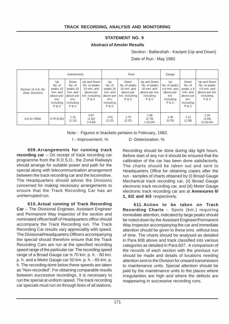
TRACK RECORDING, ANALYSIS AND MONITORING
171
609. Arrangements for running trackrecording car – On receipt of track recording carprogramme from the R.D.S.O., the Zonal Railwaysshould arrange for suitable power and path for thespecial along with telecommunication arrangementbetween the track recording car and the locomotive.The Headquarters should advise the Divisionsconcerned for making necessary arrangements toensure that the Track Recording Car has anuninterrupted run.
610. Actual running of Track RecordingCar – The Divisional Engineer, Assistant Engineerand Permanent Way Inspector of the section andnominated officer/staff of Headquarters office shouldaccompany the Track Recording run. The TrackRecording Car results vary appreciably with speed.The Divisional/Headquarters Officers accompanyingthe special should therefore ensure that the TrackRecording Cars are run at the specified recordingspeed range of the particular car. The recording speedrange of a Broad Gauge car is 70 km. p. h. - 80 km.p. h. and a Metre Gauge car 50 km. p. h. - 65 km. p.h. The recording done below these speeds are takenas “Non-recorded”. For obtaining comparable resultsbetween successive recordings, it is necessary torun the special at uniform speed. The track recordingcar specials must run on through lines of all stations.
Recording should be done during day light hours.Before start of any run it should be ensured that thecalibration of the car has been done satisfactorily.The charts should be taken out and sent toHeadquarters Office for obtaining copies after therun - samples of charts obtained by (i) Broad GaugeMechanical track recording car, (ii) Broad Gaugeelectronic track recording car, and (iii) Meter Gaugeelectronic track recording car are at Annexures 6/1, 6/2 and 6/3 respectively.
611. Action to be taken on TrackRecording Charts – Spots (km.) requiringimmediate attention, indicated by large peaks shouldbe noted down by the Assistant Engineer/PermanentWay Inspector accompanying the car and immediateattention should be given to these kms. without lossof time. The charts should be analysed as detailedin Para 608 above and track classified into variouscategories as detailed in Para 607. A comparison ofthe records of each section with the previous runshould be made and details of locations needingattention sent to the Division for onward transmissionto maintenance units. Special attention should bepaid by the maintenance units to the places whereirregularities are high and where the defects arereappearing in successive recording runs.
STATEMENT NO. 9
Abstract of Amsler Results
Section : Ballarshah - Kazipet (Up and Down)
Date of Run : May 1982
.sN.E.AfonoitceS)noisiviD-buS(
ssennevenU tsiwT eguaG
pUfo.oN01skaepdna.mmrepevoba
.mkgnidulcni
C&P
nwoDfo.oN01skaepdna.mmrepevoba
.mkgnidulcni
C&P
nwoDdnapUskaepfo.oNdna.mm01repevoba
gnidulcni.mkC&P
pUfo.oN01skaepdna.mmrepevoba
.mkgnidulcni
C&P
nwoDskaepfo.oNdna.mm01repevoba
gnidulcni.mkC&P
nwoDdnapUskaepfo.oN
dna.mm01.mkrepevoba
gnidulcniC&P
pUskaepfo.oN
± dna.mm6repevoba
.mkgnidulcni
C&P
nwoDfo.oN
skaep ± 6dna.mmrepevoba
.mkgnidulcni
C&P
nwoDdnapUskaepfo.oN
± dna.mm6.mkrepevoba
gnidulcniC&P
.MDR/.N.E.A )29.0(97.051.1)21.1(
79.0)20.1(
%9.4=I
10.1)22.1(
57.1)73.2(
83.1)97.1(%9.22=I
63.1)57.0(
21.1)03.1(
42.1)30.1(%4.02=D
Note : Figures in brackets pertains to February, 1982.
I - Improvement. % D -Deterioration. %
± ± ±

TRACK RECORDING, ANALYSIS AND MONITORING
172
612. Brief explanation of recordings –Explanation of the important parameters viz., twist,gauge, alignment and unevenness is given below –
(1)Twist – When the recording car follows astraight path where both the rails are in one plane,the track of the twist line follows the datum line. Oncurves, however, the record will be as shown insketch below (sketch ‘A’)
Sketch ‘A’
The portions AB and CD indicate thetransitions and BC the circular portion. For the circularportion the trace follows the datum line because thereis no change of cross levels over the circular portion.The shift of the trace from the datum indicates thecant gradient.
A record as shown below will indicate thefollowing defects (sketch ‘B’) :-
Sketch ‘B’
(a) At the entry and exit of transitions there issudden change indicating shock at entry and exit;smoothening is necessary.
(b) In the case of transitions, particularly AB,cant gradient is not uniform.
(c) Peaks in the circular portion indicatedefective cross levels.
(2) Gauge – The trace indicates threeconditions viz., correct gauge, tight gauge or slackgauge as shown in Sketch ‘C’ below –
Sketch ‘C’
The shift of the mean above the datum lineindicates slack gauge as at BC. If the mean followsthe datum, it indicates correct gauge as at AB. Theshift of the mean below the datum line indicates tightgauge as at D. Uniform, tight or slack gauge isindicted by parallel shift of the track. In such casesgauge adjustment is not necessary provided thevariation is within permissible limits. Isolated peaksindicate the necessity of spot-gauging.
(3) Alignment – The trace on a truly straightportion will follow the datum line as at AB in sketch‘D’ below. On a curve the indication will be as atBCDE. The trace shows the versine diagram, BCand DE being the transitions.
Sketch ‘D’
If isolated peaks are observed, localadjustment will serve the purpose. If the cant gradientover transition portion is non-uniform and there iswide variation of versines between adjacent chords,such curves call for realignment. By calculating thevariation of versines over the mean line of the trace,cumulative frequency can be determined to decidethe need for realigning.
TRACK RECORDING, ANALYSIS AND MONITORING
173
On B.G. On M.G. On N.G.
On C & D routes 6 months On Q routes 4 months
On E routes Every year On R routes 6 months Every year
On S routes Every year
(4) Unevenness – Unevenness is recorded byvariation in the top level of each rail. It is normallynoticed at joints either low or high. It is necessary tocompare the records of both the rails. A peak onone of the rails only indicates twist which should beverified from the trace of the twist line.
The twist record should also be co-related tothe cross-level record. Change in cross-levels overshort length will indicate twist.
613. Monitoring of the riding quality oftrack– While the track recording cars can recordthe track geometry (i) the Hallade track recorders,(ii) the Oscillograph car, and (iii) the portableaccelerometers record vertical and lateralaccelerations, on which depends, the riding quality.
614. Hallade track recorder – (1) General–The Hallade track recorder is an instrument whichproduces a graphic record of defects in alignmentand surface of the track over which it is carried. Themain parts of the instrument are –
(a) a drum rotated at a fixed speed by a clockwork mechanism which carries a strip of paper100 mm. wide covered over a carbon on which thechart is plotted,
(b) four sets of pendulums sensitive tomovement in different directions which records theoscillations in those directions of the vehicle andtrack.
(2) Hallade Chart – Annexure 6/4 shows
sample section of the Hallade chart. The top line,marked Line 1, is a record of the features of theroute, on which telegraph posts, kilometre postsfacing and trailing points in station yards, long bridgesand tunnels are recorded by the Operator who makesthe needle point producing this line move side-waysas the train passes any of the features, so making asmall ‘tick’ in the line. A suitable convention for ‘ticks’should be adopted to distinguish the physicalfeatures of the section.
Line 2 represents the alignment and is drawnafter the test is carried out.
Line 3 represents the fore and aft “rolling” ofthe vehicle and registers sudden sags or humps andthe acceleration of deceleration.
Line 4 represents lateral oscillations of thevehicle. Side to side motion of the vehicle causesthe style to oscillate about the “medial line”. Theamount the style travels from the “medial line” is acomparative measure of the amount the vehiclediverges from its true path. Irregularities in alignment,uneven or incorrect superelevation on curves anduneven cross-levels are indicated.
Line 5 is a record of the vertical disturbanceto the coach. Low or high joints, a bad top generally,or “hanging sleepers” are indicated.
(3) Frequency of testing with Hallade - Onroutes where Hallade track recorder is exclusivelyused for the track monitoring the following frequenciesmay be adopted :-

TRACK RECORDING, ANALYSIS AND MONITORING
174
(4) Testing of track with Hallade –
(a) The Hallade track recorder should beplaced on the leading bogie of the trailing vehicle oron the last but one vehicle, but the position of thevehicle must be the same in every run on a particularsection.
(b) The Permanent Way Inspector shouldaccompany the Hallade run.
(c) The same vehicle should be there everytime preferably.
(d) Proper adjustment of the dampingmechanism (critical damping) should be done.
(e) After completing the test, the chart shouldbe completed in the following respects :-
(i) Heading the chart with particulars of date oftest, train no., from station .................. to station.................., vehicle no., speed of the paper roll, anddetails of damping.
(ii) Checking up markings of kilometre posts,telegraph posts (electric masts) and filling in thespeed of the train in km. p. h., km. by km.
(iii) Drawing line No. 2 indicating the right handand left hand curve with the radius of each curve.
(iv) Drawing the medial line on line No. 4.(v) Scrutinizing and marking track defects on
the chart.
Blue prints of the chart should be then takenand 3 copies sent to the Assistant Engineer within aweek of the test.
(5) Interpretation of the Charts – The chartsare then analysed in the track cell of Chief Engineer’sOffice Kilometre-wise and the actual kilometreswhere alignment and packing defects have beenrecorded are listed out and given to the AssistantEngineer and Permanent Way Inspector for attention.The number of defects per km. are also worked outto enable the assessment of the track condition. Theinterpretation of the various types of typical defectsnoticed in a track are shown in Annexure 6/4. Atypical analysis of an Hallade run in a P.W.I.’s/A.E.N.’s section may be seen in the Statements 1and 2, shown below.
Result of H.T.R. Test STATEMENT No. 1 (Para 614)
Comparative Statement of Defects Sub-Division, P.W.I.-wise Analysis
Date of Test : January 1981 Division : GuntakalA.E.N. Sub-Division : Guntakal/M.G.
noitceS .I.W.P
dedrocerstcefedfo.oNfo.oNegarevA.mkrepstcefed
elbarapmocfotseTsuoiverP0891yraurbeFdoirep
1891yraunaJtseTtnerruC suoiverPtseT
yraurbeF0891
tnerruCtseT
yraunaJ1891tnemngilA gnikcaP latoT tnemngilA gnikcaP
latoT
.MMD-LTGoD
KAP-MMD
LTG/.N.E.A
G.M/LTGPTA
YRK
1
7
01
02
13
13
12
83
14
3
7
9
31
63
62
61
34
53
56.0
45.0
35.0
05.0
16.0
44.0
.. 81 28 001 91 57 49 55.0 25.0

TRACK RECORDING, ANALYSIS AND MONITORING STATEMENT NO. 2
Detailed Notes
Date of Test : 12th January, 1981. Section : GTL-DMM-PAK
Train No. 86 Express Direction : Up
From : GTL Km. 279/0
To : KDT Km. 246/15 P.W.I. Section : GTL (M.G.)
Packing Speed A lignment Speed
249/8-9 60 250/9-10 65
257/15-14 65 270/15-16 70
258/7-8 65 277/13-14 60
258/11-12
269/4-5 70
270/3-4 70
272/10-11 70 Note -
Alignment defects 3
273/15-16 70
Packing defects 13
274/11-11 70 ___
Total 16
274/12-13 70
___
275/7-8 65
276/5-6 65
(6) Attention to track defects recorded : – The
Permanent Way Inspector should verify track defects indicated by chart at site, take expeditious action and report to the Assistant Engineer within a month.
On receipt of the Assistant Engineer’s report the Divisional Engineer should get the chart examined with previous records and issue any orders he may consider necessary.
615. Oscillograph Car (1) Brief description of the car :– The main equipment in this car is an accelerometer, which consists essentially of a mass attached to one end of thin flexible plate, the other end of the plate being fixed firmly to the casing of the accelerometer. The space within the accelerometer casing is filled with a damping fluid (usually silicon liquid). The cantilever plate is strain gauged so that the deflection of the mass ‘m’ is sensed. This is calibrated to indicate the acceleration to which the mass is subjected. This acceleration is recorded in the form of an accelerogram. Thus the vertical and lateral acceleration on any part of the vehicle where the accelerometer is installed can be recorded. In track monitoring runs the accelerations at the loco
cab floor are recorded by keeping the accelerometer as close to bogie pivot as possible.
(2) Details of recording : – the following parameters are recorded in the oscillograph car runs:–
(a) Vertical acceleration of loco cab. (b) Lateral acceleration of loco cab.
In addition to the above, timing marks-one for every second-telegraph and km. marks and even marks such as station buildings,bridges etc., are also recorded on the chart. The primary spring deflections left and right are also recorded.
The chart obtained in an oscillograph car run can be seen at Annexure 6/5.
(3) Frequency of recording – On BG routes
Oscillograph cars are used to monitor all group A routes. These cars are run once in six months to assess the riding quality of track as distinct from actual track geometry recorded by the Track Recording Cars. Recording is done at the maximum sanctioned speed of the section.(C.S.No:107 Dated:12.11.2007)
175

TRACK RECORDING, ANALYSIS AND MONITORING
176
616. Analysis of oscillograms andinterpretation of results –
(1) The Oscillograms obtained from theoscillograph car are analysed for the vertical andlateral acceleration.
(2) The analysis of records is done on thefollowing lines :–
(a) All peaks are to be measured from the baseor zero line i.e.,no allowance is to be given when thetrace shifts because of cant deficiency on curves.However, for the purpose of “ride index” calculations,lateral acceleration peaks are to be measured fromthe shifted base line on curves.
(b) The vertical and lateral accelerations abovethe threshold values are separately counted:
Threshold value of acceleration may be takenas follows :–
(i) In Loco Cab floor – The threshold value ofacceleration in vertical mode is taken as 0.20 g. forall locos (Diesel and Eletric).
The threshold value of acceleration in lateralmode is taken as 0.20g. for diesel and electric locoswith double stage suspension (i.e., for WDM-3,
WDM-4, WDM-1, WDM-2/3 and WAG-2) with theexception of WDM-2 modified with single stagesuspension.
In case of other locos, with single stagesuspension (i.e.,WDM-2 std., WAM-1, WAM-4,WAG-1,WAG-3,WAG-4,WCG-2, WCAM, WCM,WCM-2, WCM-4 and WCM-5) the threshold valuemay be taken as 0.30g.
(ii) On Passenger Coach Floor :– The thresholdvalue of acceleration for both vertical and lateralmodes shall be taken as 0.15g.
(iii) The analysis is done kilometer-wise andresults are given under the following heads, aftercounting the peaks above threshold value for theparticular locomotive –
Station Yards,
Other than Station Yards(Isolated locations),
Active continuous stretches,
Speed grouping table is also prepared.
Typical Statement prepared in connection withan Oscillograph run are given below (Statement‘A’ to ‘C’) –
STATEMENT ‘ A ’
Oscillograph Results (Para 616)
Total length of Section : 232 Kms. Section : BBQ—KZJ.Length recorded : 185 Kms. Loco No.......................Date of recording : 22nd March 1982 Type of Loco................
Station Yards (Peaks above Threshold values)
.oN.IS draYfoemaNnoitacoLdna
nideepS.h.p.mK
lacitreVnoitarelecca
laretaLnoitarelecca
skrameR
1 RURS2-PF
001 .. 62.0
2 ICM1-PT2-PT
001001
22.022.0
..
3 ZPP1-PF2-PF
001501
02.002.0
..
..
4 FSGB11-01/423
011 .. 22.0
5 LPO6-5/343
001 62.0 ..
6 PSH1-PT
001 02.0 ..

TRACK RECORDING, ANALYSIS AND MONITORING
177
STATEMENT ‘ B ’
Date of recording : 22nd March 1982. Section : BPQ—KZJ (K.m. 367-K.m. 135)
Loco No............................. Length recorded: 185 Km.
Type of Loco....................... Total length: 232 Kin.
Oscillograph Results in Places other than Station Yards
Isolaled Locations (Peaks above Threshold value)
.oN.IS noitacoL .m.KnideepS.h.p
lacitreVnoitarelecca
laretaLnoitarelecca
skrameR
12
34
56
78
901
...2-1/64161-51/841
...8-7/941
...8-7/941
...9-8/151
...9-8/151
...21-11/151...8-7/061
...01-9/461...2-1/861
001011
011011
011011
501011
011001
..
..
82.053.0
..
..
..
..
42.0.noosdna
82.082.0
..
..
42.023.0
42.022.0
..03.0
.evruC.rB
.rB
evruC
STATEMENT ‘ C ’Date of recording : 22nd March 1982. Section : BPQ—KZJ (Km. 135-Km. 367)
Loco No. :................................. Length recorded : 185Km.
Type of Loco :.......................... Total lenth :232Km.
OSCILLOGRAPH RESULTSActive Continuous Stretches
.oN.IS
.smKecnatsiD.mKni
deepSni
.h.p.mK
nievitcAedom
oNlatoTskaepfo
evoba.g’02.0
mumixaMeulav
fo.oNskaepneewteb.g02.0.g53.0
fo.oNskaepevoba.g52.0
skrameR
morF oT
liN
Note – If there are on an average more than 10 peaks above the threshold value per km., the length may beincluded in this statement.

TRACK RECORDING, ANALYSIS AND MONITORING
178
617. Use of Oscillograph Car recordings:–
(1) Threshold values of acceleration are givenin Para 616(2)/b. For ensuring good riding, trackshould be attended to at such locations where peaksabove threshold values are noticed.
(2) Efforts should be made not only to checkthe extent of defect but also to find out whether it isoccurring in an active patch; as such condition maylead to excessive oscillations.
618 Portable Accelerometers-
(1) General- OMS-2000 equipment’s areportable accelerometers used for Oscillationmonitoring using a portable accelerometer andtransducers converting the oscillations to electricalsignals which can be recorded electronically andprocessed on PC.
(2) Operation- The OMS Accelerometer is keptin the cabin of locomotive or on the coach floor, asclose to the bogie pivot as possible. It is preferablethat same coach and the same vehicular positionare used in successive runs. The accelerationsrecorded are transferred to electronic recorder andare readable on the LCD display on real time basis.The stored data can be downloaded on TMSComputer for maintenance planning.
This equipment measures the TrackPerformance by measurement of vehicle responsein terms of vertical and lateral accelerations. Thereal time output of the equipment is in the form ofvalue of peaks exceeding the limiting value, theirlocation and Ride Index. These values are availablefor both vertical and lateral accelerations.
(3) Frequency of Recording:
(A) Broad Gauge :
Speed above 100 Kmph Once every month.
Others Once in two months
(B) Meter Gauge :
Speed above 75 Kmph Once every month
Others Once in two months
The above schedule is only a guideline. ChiefEngineers may vary it, depending upon theavailability of instrument and its use. For the timebeing A, B and C routes are to be covered once amonth and other routes can be covered as percapacity and need.
(4) Recording of Defects: To assess the trackquality, vertical and lateral acceleration peaksexceeding the values as below are to be considered:
Broad Gauge:
High Speed Routes above greater than 0.15 g.110 Kmph On A & B routes
Other Routes upto greater than 0.2 g110 Kmph
Meter Gauge : greater than 0.2 g
(5) Classification of Track Quality - To classify acontinuous section's (PWI's jurisdiction/sub-division/division) track quality, the following criteria is to beused (average total number of peaks per km.):
Very Good Good Average
High Speed Less than 1.0 1 - 2 Greater than 2
Others Less than 1.5 1.5-3.0 Greater than 3
The above criteria are for judging the quality of track. However, if the average number of peaks of verticaland lateral accelerations exceeding 0.30g is more than 0.25 per km or more than one in any particular kilometer,the track will need attention : At locations where peaks of lateral and vertical accelerations exceed 0.35g, thetrack will have to be attended to urgently.

TRACK RECORDING, ANALYSIS AND MONITORING
179
AN
NE
XU
RE
- 6
/1 P
AR
A 6
07
SA
MP
LE
CH
AR
T O
F T
RC
ME
CH
AN
ICA
L/B
.G.
15

180
AN
NE
XU
RE
- 6
/2 P
AR
A 6
07
SA
MP
LE
CH
AR
T O
F T
RC
EL
EC
TR
ON
IC/B
.G.
TRACK RECORDING, ANALYSIS AND MONITORING

181
AN
NE
XU
RE
- 6
/3 P
AR
A 6
07
SA
MP
LE
CH
AR
T O
F T
RC
EL
EC
TR
ON
IC/M
.G.
TRACK RECORDING, ANALYSIS AND MONITORING
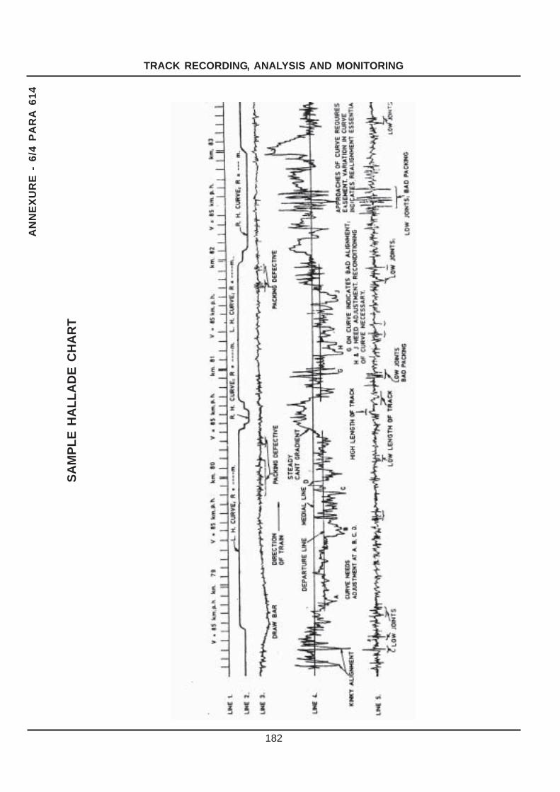
182
AN
NE
XU
RE
- 6
/4 P
AR
A 6
14
SA
MP
LE
HA
LL
AD
E C
HA
RT
TRACK RECORDING, ANALYSIS AND MONITORING

183
AN
NE
XU
RE
- 6
/5 P
AR
A 6
15
TY
PIC
AL
CH
AR
T O
F A
N O
SC
ILL
OG
RA
PH
CA
R/B
.G.
TRACK RECORDING, ANALYSIS AND MONITORING

184
AN
NE
XU
RE
- 6
/6 P
AR
A 6
18
SA
MP
LE
CH
AR
T O
F P
OR
TAB
LE
AC
CE
LE
RO
ME
TE
R
TRACK RECORDING, ANALYSIS AND MONITORING

��������
������ �������� �����
���� �������������� �����
� ��������������������
� �������
PART ‘A’ Action during Accidents including Breaches
701. Observance of Rules – (1) Any
occurrence which does or may affect the safety of the Railways, its engines, rolling stock, permanent way, works, passengers or servants which affects the safety of others or which does or may cause delays to trains or loss to the Railway, is termed an accident.
Occurrence outside the Railway limits threatening the safety of the line or trains should also be reported as accidents. For instance a flood outside Railway limits may seriously threaten the safety of the line and should be treated as an accident. (2) Rules for reporting and joint enquiries into the accidents are contained in the Accident Manual issued by Railways and in the Railway (Notices of and Enquiries into Accident) Rules, 1998, issued under Section 122 of Railways Act,1989 (24 of 1989).(C.S.No:111 Dated:23.04.2008).
(3) Rule 2.11 of General Rules, 1976 Edition enjoins that –
(a) Every Railway servant shall – (i) see that every exertion is made for
ensuring the safety of the public ; (ii) promptly report to his superior any
occurrence affecting the safe or proper working of the railway which may come to his notice; and
(iii) render on demand all possible assistance in the case of an accident or obstruction.
(b) Every Railway servant who observes – (i) that any signal is defective; (ii) any obstruction, failure, or threatened
failure of any part of the way or works; (iii) anything wrong with a train; or (iv) any unusual circumstance likely to
interfere with the safe running of trains or the safety of the public;
shall take immediate steps, such as the circumstances of the case may demand, to prevent accident; and where necessary, advise the nearest Station Master by the quickest possible means:
Provided that in the case of a train having parted, he shall not show a stop hand signal but shall endeavour to attract the attention of the Driver or Guard by shouting, gesticulating or other means.
702. Report of Accident to the Station Master / Railway servant in-charge of Block Hut– (1) Engineering representative (if he is the first to reach the site of the accident ) while reporting an accident to the nearest Station Master/Railway servant in charge should furnish the following information to enable the Station Master/Railway servant in-charge to issue an all concerned message:
• Station at or stations between which the accident has occurred.
• Kilometrage at which the accident has occurred.
• Number and description of the train or trains involved.
• Date and time of the accident. • Particulars of loss of life and injuries to
passengers and staff. • Nature and cause, if known, of accident. • Damage to Permanent Way, Works,
Bridges, Overhead equipment (in case of electrified section), signal and interlocking gear, engines or vehicles.
• Probable duration the line may be blocked. • Whether transhipment is required and if so
whether it is feasible. • Assistance ( if any required) such as
Medical assistance, break-down train etc.
(2) Acknowledgment of the receipt of message should invariably be taken from the Station Master.
185

ACTION DURING ACCIDENTS INCLUDING BREACHES AND PRE-MONSOON PRECAUTIONARY MEASURES
186
703. Accidents impairing through traffic–(1) Engineers and Inspectors to proceed to site –
(a) On receipt of intimation of the occurrenceof an accident resulting in damage to any part of theWay/ Works /Bridges and affecting the free passageof trains, the concerned Permanent Way Inspector /Works or Bridge Inspector and the AssistantEngineer shall proceed to the site of accident, bythe quickest available means. On their way, theyshould collect information about the extent of damageto Permanent Way / Works / Bridges and arrangefor movement of materials required for restoration.They should also collect additional staff and tools asrequired; the engineering tool van should be sent tothe site, if so considered necessary, by the quickestmeans.
(b) On receipt of intimation of an accident, theDivisional Engineer shall contact the section controland the Assistant Engineer in-charge and get theinformation regarding the extent of damage toPermanent Way and Works, check on thearrangements made for labour and materials, etc.,supplement them if necessary and proceed to thesite of the accident by the quickest available means,if the seriousness of the accident requires hispersonal supervision and direction.
(2) Accident in an adjacent division-In the eventof an accident taking place on a division, whereassistance could be more expeditiously rendered byofficials of an adjacent division, such officials andthe Assistant Engineer/ Divisional Engineer of theconcerned adjacent division should be advised;these officials should proceed at once to the site ofaccident with their Inspectors and render everypossible assistance.
704. Action at site – (1) By Permanent Wayand other Engineering Inspectors –
(a) Protect Train – Any engineering staffavailable at the site of the accident shall assist theGuard and Driver to protect the train in accordancewith the General Rules 6.03 and 9.10 (1976). TheInspector should ensure that protection has beenafforded to the train in front and in the rear, inaccordance with the rules. In the case of double line,if the other line is also affected by the accident, stepsshall be taken to protect both the lines. If noinfringement exists, trains must be controlled andpassed cautiously on the unaffected track.
(b) First aid and Rescue – The Inspectorshould arrange for first aid to injured passengers and
Railway staff and rescue of trapped persons. If thereis any Medical Practitioner on the train, hisassistance should be obtained.
(c) Advice to nearest Station Master – After arapid survey of the position, particulars should besent to the nearest Station Master as in (Para 702)above. In case of controlled sections, a fieldtelephone should be got commissioned at once.
(d) Line Clear examination - If the Engineeringofficial has reached the site and no traffic official isavailable he should carefully secure the line cleartoken or ticket and any caution order, wherenecessary. If the accident has occurred in a stationyard, the train register book must be seized and ifnecessary, statement of staff concerned recorded;if line badges are in use, it should be recorded as toin whose possession each line badge was. Theposition of block instruments, signals, points, pointlevers, indicators, keys, etc. should be noted andrecorded, jointly with the Inspectors of the otherconcerned departments, available at site.
(e) Preliminary clearing operation andpreservation of clues –
(i) In all instances in which the means takenfor the restoration of communication are likely toobliterate marks on the road and other evidenceneeded at a joint enquiry, the senior official whoarrives first on the spot should carefully examine thetrack, train or vehicle and as soon as possible makenotes, sketches etc. and hand over the same to hissuperior or produce them at the enquiry. He will, whenthe nature of the accident is such as will involve thequestion of eye-sight of any of the staff, verify ( incase of those permitted to wear glasses) that theyhad worn glasses at the time of the accident andhad carried a spare pair of glasses with them.
(ii) In all cases of accidents, the cause of whichmight possibly due to sabotage, it is essential thatthe clearance and restoration operations are notcommenced till the Police officials arrive at the siteand intimate their agreement to the commencementof clearance and restoration work, after, makingthorough investigations.
A factual note of the conditions obtaining at thesite prior to restoration work should be prepared andsigned jointly by the senior-most Police and Railwayofficials at the site. In the event of any difference ofopinion between the Police and the Railway officials,such difference of opinion may be recorded on thejoint factual note.

ACTION DURING ACCIDENTS INCLUDING BREACHES AND PRE-MONSOON PRECAUTIONARY MEASURES
187
This should not, however, be allowed tointerfere with rendering of first aid to the injured, whichis the first essential in all accidents.
(iii) In other cases, clearance and restorationoperations can commence even before the arrival ofthe Police and it is not necessary that all the rails,sleepers and fastenings involved in an accidentshould be preserved, but only those, whetherserviceable or otherwise, which bear wheel marks,etc., specially between the points of mount and drop.In all cases of serious derailments, these areessential for a later reconstruction of the scene andshould be preserved and/or recorded by the firstresponsible official to reach the site of the accident,as these would be valuable evidence to ascertainthe cause of the accident.
(iv) After the injured persons have beenattended to and arrangements made for the onwardjourney of the stranded passengers, the Railwayofficers at the site of the accident should arrange torecord the preliminary statements of the staffconcerned, as any delay in doing so, might result insome facts being suppressed or some evidencebeing fabricated during subsequent enquiries.
(v) In case sabotage is suspected, theprocedure as outlined in clause (ii) above should befollowed. In addition it should be ascertained promptlyfrom the C.R.S. if he would like to inspect the site,etc. before the commencement of clearance andrestoration work and then action should be taken inaccordance with his wishes. Before clearance andrestoration operations are commenced all relevantclues, materials and damages and the deficiencieson Rolling Stock, etc. must be noted and preserved.In other serious accidents, however, the sameprocedure as outlined in Clause (iii) above shouldbe strictly followed.
(f) Contacting higher officials – The inspectorshould get in touch with the Assistant Engineer orDivisional Engineer, explain the position on telephone,wherever possible ; if not, he should himself organisethe restoration of through running including orderingof ballast trains, requisitioning of required materialsand tools and send information to Assistant Engineerand Divisional Engineer of the preliminary measuresundertaken, by the quickest possible means.
(g) Recording of details and advice regardingrestoration time – He should arrange to record thedetails of the accident and prepare notes on anyspecial features bearing on its cause, which may be
of help in the enquiry. He should send by any meansavailable and relay a concise report of the accidentas per (Para 702) to the nearest Station Master toenable him to issue all concerned message.
(h) Preservation of clues – He should arrangeto preserve all clues to enable reconstruction of thescene of the accident as detailed vide (Para 704 )
(i) Photographs showing the details of damageto Permanent Way and Rolling Stock at the site ofaccident should be taken wherever necessary; incase of suspected sabotage, the photographs of thesite of the accident showing the damage and possibleclues should invariably be taken.
(2) By Assistant Engineer –
(a) He should ensure that action specifiedunder sub-para 704 (1) has been taken by theInspector. If he is the first to arrive at site, theAssistant Engineer should take action as specifiedin the case of the Inspector.
(b) He should get in touch with the DivisionalEngineer and the Controller / Chief Controller andfurnish complete information advising the details ofaction being taken and the probable time for restoringthrough running.
(c) He should arrange to organise the measurefor expeditious restoration of through running andensure incessant working until this is effected.
(d) A preliminary report should be prepared.
(3) By Divisional Engineer –
(a) He should examine the adequacy ofmeasures taken for restoration of through runningand ensure expeditious work.
(b) He should assess and advise the positionto the Divisional Railway Manager and ChiefEngineer, with brief particulars (over the fieldtelephones on Controlled Sections) and probabletime of restoration. The Chief Engineer / Addl. ChiefEngineer may proceed to site in case of very seriousaccidents.
(c) A report should be prepared and submittedto the Chief Engineer and Divisional RailwayManager.
(d)The Divisional Engineer shall ensure thatthe fractured pieces of rail/weld are preserved andsent to RDSO for detailed investigations, at theearliest possible, in all cases of accidents, whererail/weld is a prima facie cause of the train accident.

ACTION DURING ACCIDENTS INCLUDING BREACHES AND PRE-MONSOON PRECAUTIONARY MEASURES
(4) The senior-most Railway Officer at the scene of accident shall be responsible for the general appraisal of the situation and co-ordination of all works.
705. Report to the Chief Engineer – (1) Report – (a) the Senior Engineer at the site of the accident shall after initiating measures for restoring traffic, submit a brief report to the Chief Engineer with a copy to the Divisional Railway Manager which will include the following particulars:
(i) Nature of the accident, (ii) Cause, if known. (iii) Particulars of loss of life and
injuries to passengers and staff. (iv) Extent of damage to Way, Works
and Bridges. (v) Particulars of rainfall and patrolling,
in the case of damage by floods. (vi) Steps taken for resumption of traffic. (vii) Probable time, when normal
working is likely to be resumed. (viii) Whether transhipment is necessary
and if so, for how long. (ix) Whether a diversion is necessary and if
so, when it is likely to be opened. (x) Details of any assistance required,
such as additional staff, labour, ballast trains and other Permanent Way and Bridging materials.
(b) A sketch showing important dimensions, positions of vehicles, tracks made by derailed vehicles, marks on rails, particulars of condition of track for an adequate distance in the rear of the point of derailment and any other information likely to be of use in elucidating the cause of accident should accompany the report.
(2) Remedial measures – In the case of damages caused by floods, the Divisional Engineer should initiate necessary investigation and submit a technical report with drawings, to the Chief Engineer, detailing the remedial measures required, with the past history, if any, of the kilometrage affected, within a month of the occurrence.
706. Attendance of Police at site – Arrangements should be made for the police to attend the scene of accident in the case of derailment of a train carrying passengers (or of any other train when it is considered necessary) in order that they
may observe the extent of disturbances caused to the line, keeping guard over loose materials laying about and over any evidence affecting the cause of the accident and safeguard passengers’ luggage and mail as required.
707. Examination of site and preparation of sketches – The first Engineering representative to arrive at site shall attend to the following :–
(1) He should examine the entire site inclusive of track over which the train has passed immediately before derailing, noting down any unusual features observed, especially any parts of vehicles or other material lying on or near the track.
(2) A dimensioned sketch should be prepared covering the entire site of accident, showing all relevant features inclusive of track leading up to point of derailment, showing position of derailed vehicles, point of mount and drop and other relevant details. All the details given in Annexure 7/1 should be incorporated in the sketch.
(3) He should record the particulars as detailed in Para 708(1).
(4) An examination of the derailed vehicle/ vehicles for defects not caused by the derailment but which may have been the cause of the derailment should be made. He should make out notes for inclusion in the joint report.
(5) He should examine the gang-charts/diary books to ascertain the date when track was last attended.
(6) Details of Engineering works in progress, if any, at the site of accident, caution orders in force and nature of protection should be noted.
708. Recording particulars at site of accident – (1) Permanent Way particulars – Permanent Way particulars shall be recorded jointly with the Inspectors of the other concerned departments as per Annexure 7/2. These records will inter alia include particulars of the track structures, the condition of the track components, track geometry and other relevant details. Note: - The maintenance tolerances given in different Para of IRPWM are for mainline track only on consideration of comfort and not for yard lines and other lines having low speed potentials.(CS 136 dt 14.11.14)
(2) Particulars with respect to Rolling Stock and signalling – Engineering representative should associate himself with the concerned representative of the other departments in recording measurements of –
188

ACTION DURING ACCIDENTS INCLUDING BREACHES AND PRE-MONSOON PRECAUTIONARY MEASURES
189
(a) The locomotive and tender;
(b) Carriages and Wagons; and
(c) Signalling and Telecommunicationequipment.
(3) Operating particulars – The followingoperating particulars should also be recordedwherever relevant :–
(a) Speed – The actual speed at the time ofderailment, from the speedometer graph or if thelocomotive is not provided with the speedometergraph, by referring to inter-station timings.
(b) The direction of the locomotive i.e.,shorthood or longhood leading.
(c ) The brake power of the train.
(d) The marshalling of the train with referenceto orders applicable on the section.
(e) Whether there has been sudden applicationof brakes.
(f) Whether there was sudden opening ofregulators.
(g) Condition of loading in wagons, speciallyunequal loading, light loading, empties betweenloaded vehicles, over loading, moving loads and anyinfringement to standard dimensions.
(h) Particulars of Caution Orders issued to theDriver/Guard.
709. Use of Recorded Data – The object ofrecording all available data at site and of evidence isto ascertain the cause of the accident with a view toprevent its recurrence, and where the cause is dueto negligence, to fix responsibility.
Restoration of Through Running
710. Repairs to damaged track :– Repairs tothe track should in the first instance, be kept to theminimum necessary to restore traffic with the leastpossible delay, the required materials beingexpeditiously arranged for. Soon after, the trackshould be brought to its proper standard.
711. Procurement and Arrangement ofLabour – (1) Adequate labour is the very firstessential for restoration of through running. Engineersand Inspectors should acquaint themselves with allpossible sources from which labour could be readilyobtainable in the event of a breach or a seriousderailment on their section. Labour should, as far as
practicable, be conveyed to the site of accident bytrain.
(2) Labour should be obtained in one or moreof the following ways :
(a)By ordering temporary gangs such asrelaying gangs, special gangs, construction gangs,remodelling gangs, yard gangs, within a reasonabledistance to proceed to the site.
(b)By ordering two or more men from eachpermanent gangs to proceed to the site.
(c)By obtaining labour from adjoining divisions,of considered necessary and possible.
(d)By calling on the Revenue authorities tosupply labour.
(e)By recruiting temporary labour locally orfrom known sources.
(f)By arranging labour through reliableContractors (wages should be fixed prior to theirengagement).
(3) In case contractor’s labour is engaged, it ispreferable to allot work in such a way that thedepartmental labour and contractor’s labour do notget mixed up. Settlement of claims should be prompt.Labour should be organised in batches under thecharge of Inspectors. Proper muster sheets shouldbe maintained.
(4) In emergencies, Assistant Engineers/Permanent Way Inspectors may authorise StationMasters by telegram/memo to issue proceed orderfor the journey of Gangman/Labour required for thework along with their tools and equipment fromspecified station to the nearest station from the siteof accident. As far as possible, all departmentallabour shall move with complete tools and equipment.
(5) Adequate arrangements should be madefor food, shelter, water and lighting.
712. Diversion – (1) General – Should adiversion be decided upon, the work should becommenced as quickly as possible.
(2) Classification of diversions – These maybe classified as –
(a) Temporary
(b) Semi-permanent
A temporary diversion is one which is not likelyto be in use, for more than 10 days. All trains must“Stop-dead” before entering a temporary diversionand proceed at 10 Km./h. speed.
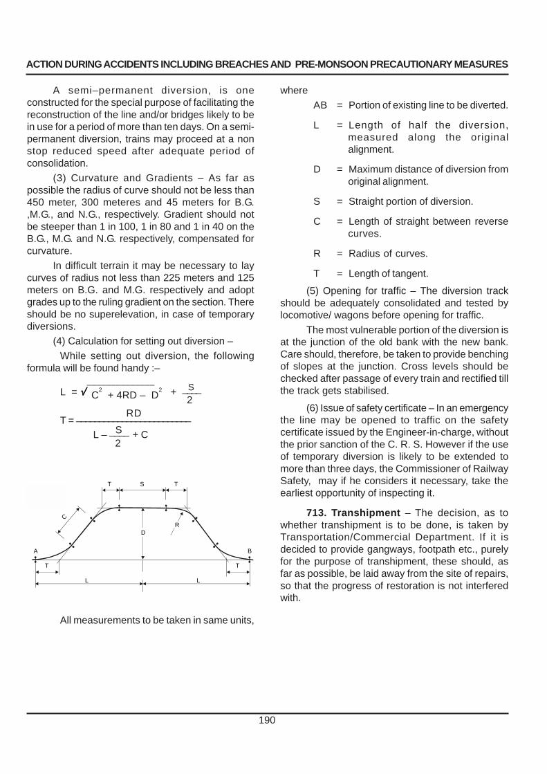
ACTION DURING ACCIDENTS INCLUDING BREACHES AND PRE-MONSOON PRECAUTIONARY MEASURES
190
A semi–permanent diversion, is oneconstructed for the special purpose of facilitating thereconstruction of the line and/or bridges likely to bein use for a period of more than ten days. On a semi-permanent diversion, trains may proceed at a nonstop reduced speed after adequate period ofconsolidation.
(3) Curvature and Gradients – As far aspossible the radius of curve should not be less than450 meter, 300 meteres and 45 meters for B.G.,M.G., and N.G., respectively. Gradient should notbe steeper than 1 in 100, 1 in 80 and 1 in 40 on theB.G., M.G. and N.G. respectively, compensated forcurvature.
In difficult terrain it may be necessary to laycurves of radius not less than 225 meters and 125meters on B.G. and M.G. respectively and adoptgrades up to the ruling gradient on the section. Thereshould be no superelevation, in case of temporarydiversions.
(4) Calculation for setting out diversion –
While setting out diversion, the followingformula will be found handy :–
______________SL = √√√√√ C
2 + 4RD – D
2 + ____
2RD
T = _________________________ SL – ____ + C 2
All measurements to be taken in same units,
where
AB = Portion of existing line to be diverted.
L = Length of half the diversion,measured along the originalalignment.
D = Maximum distance of diversion fromoriginal alignment.
S = Straight portion of diversion.
C = Length of straight between reversecurves.
R = Radius of curves.
T = Length of tangent.
(5) Opening for traffic – The diversion trackshould be adequately consolidated and tested bylocomotive/ wagons before opening for traffic.
The most vulnerable portion of the diversion isat the junction of the old bank with the new bank.Care should, therefore, be taken to provide benchingof slopes at the junction. Cross levels should bechecked after passage of every train and rectified tillthe track gets stabilised.
(6) Issue of safety certificate – In an emergencythe line may be opened to traffic on the safetycertificate issued by the Engineer-in-charge, withoutthe prior sanction of the C. R. S. However if the useof temporary diversion is likely to be extended tomore than three days, the Commissioner of RailwaySafety, may if he considers it necessary, take theearliest opportunity of inspecting it.
713. Transhipment – The decision, as towhether transhipment is to be done, is taken byTransportation/Commercial Department. If it isdecided to provide gangways, footpath etc., purelyfor the purpose of transhipment, these should, asfar as possible, be laid away from the site of repairs,so that the progress of restoration is not interferedwith.
ST
L
T
T
A
L
T
B
CR
D

ACTION DURING ACCIDENTS INCLUDING BREACHES AND PRE-MONSOON PRECAUTIONARY MEASURES
714. Funds required during Emergencies – (1) The divisional Engineer or the Assistant Engineer on his behalf may draw upon the station earnings according to the instructions prescribed by the Administration under note to (Para 1405-G) for the following purposes :–
(a) Payment to daily labour employment at the site of breach or accident.
(b) Purchase of tools or materials required in connection with accident which cannot be supplied in time by the Store Department.
(c) To provide food to engineering labour at the site of breach or accident with the assistance of Station Master or Inspectors of the Commercial Department.
(Supply of food free of charge is permitted in special circumstances at the discretion of the administration to facilitate expeditious restoration of traffic.
When food is supplied free at the site of an accident to engineering and other labour, the expenditure per head per day shall not exceed the prescribed limit).
(2) The Accounts Officer should be advised immediately by telegram of each sum taken from station earnings.
In all cases, Engineers obtaining advances from Station earnings should do so under a clear receipt. The purpose for which the money has been drawn should be clearly stated on the receipt.
A complete account should be submitted at the earliest possible date to the Accounts Department supported by pay sheets and vouchers.
(3) All payment to labour should be witnessed by the Assistant Engineer at site.
715. Obstructions found on track – When obstructions are found on the track those should be cleared after protecting the line and informing the nearest Station Master. Where sabotage is suspected, the Police should be advised immediately. The Permanent Way Inspector should, if so required, arrange to meet the Police Official at the place of occurrence. A detailed report should be submitted by Permanent Way Inspector to the Assistant/ Divisional Engineer. The Divisional Engineer should in turn report such occurrences whether or not sabotage is suspected to the Divisional Railway Manager and Chief Engineer.
716. Flooded Causeways / Dips – (1) Permissible depth of water for passage of
trains – In the case of causeways that are flooded and the velocity of current is insignificant, trains may be permitted to pass when the depth of water above rail-level does not exceed the following values, provided in each case Permanent Way Inspector has satisfied himself by walking over and probing that Permanent Way is intact and in a fit condition :–
Gauge Passenger and
Goods train
Mixed trains
B.G. 300mm. 450mm.
M.G. 230mm. 300mm.
N.G. 230mm. 230mm.
(2) (a) Indication posts - Indication posts about 1200 mm. in height shall be fixed at each dip, one at each end of the level portion, with flat bar attached to them to indicate level mentioned in Para 716(1). (b) The posts should be painted black and white in 300 mm. length so arranged that the flat bars which shall be painted white, show up against 300 mm. length of black colour. (c ) The posts shall be fixed 3 metres from the center of the track in the case of Broad Gauge and 2.5 metres from the center of track in the case of Metre and Narrow Gauge. (d) The details for fixing indication Posts have been shown in Annexure 7/3.(C.S.No:102 Dated:21.06.2007)
(3) In the section where electric locos/stock and or diesel locos ply, special gauges may be provided by the administration at the place liable to flooding, indicating the depth at which these locos/ stock have to be stopped from the operation. These depths should be specified for each type of locos/ stock by the administration.
717. Special precautions when track is submerged – (1) The following precautions shall be observed when the track is submerged :
(a) In all cases train shall be stopped dead and allowed to proceed at a speed not exceeding 10 km. p. h.
(b) If water rises over the top of the ballast but is below rail level, the track should be checked before each train, by two men walking abreast one at either end of the sleepers, and only if the track has not been disturbed, should the train be allowed over the track.
191

ACTION DURING ACCIDENTS INCLUDING BREACHES AND PRE-MONSOON PRECAUTIONARY MEASURES
192
(c) When water overtops the rails, thePermanent Way Inspector shall pilot the train, afterensuring that the track is safe, by walking over thetrack and checking by means of probing, subject todepths specified in Para 716 not being exceeded.
(2) Telegraphic advise should be sent by thePermanent Way Inspector to the Assistant andDivisional Engineer, Divisional Railway Manager andChief Engineer when water rises above ballast leveland again when it subsides. This should be followedup by special reports to the Assistant Engineer andDivisional Engineer. Records of such occurrencesshould be entered in the Permanent Way Inspector’ssection register.
718. Driver’s Report on Defects in Track– (1) Intimation of defects – (a) When a driver reportsto a Station Master that the track over which his trainhas passed is unsafe for the passage of any furthertrain, with particulars of location, the Station Masterwill block the section concerned and issue a wire tothe Permanent Way Inspector, copying it to theAssistant Engineer, Divisional Engineer and Control.No train will be admitted on the section concerned,until the Permanent Way Inspector has inspectedthe kilometrage and certifies to the Station Masterthat the section is safe for the passage of trains,specifying the speed restriction, if necessary.
(b) When a Driver reports to a Station Masterthat the track over which his train has passedrequires a restriction of speed, with particulars oflocation, the Station Master will impose the speedrestriction over the section concerned and issue awire to the Permanent Way Inspector copying it tothe Assistant Engineer, Divisional Engineer andControl. Caution orders will continue to be issued onthe section concerned until the Permanent WayInspector has inspected the kilometrage and certifiesto the Station Master that the section is safe forpassage of trains specifying the revised speedrestriction, if necessary.
(2) Action on receipt of reports of defectivetrack – (a) By Permanent Way Inspector –
The Permanent Way Inspector shall –
(i) Proceed as quickly as possible to site,inspect the length of track reported on and recordparticulars in detail. Then arrange to rectify the trackand remove or modify the restriction imposed, asfound necessary.
(ii) Submit a detailed report to the AssistantEngineer and copy the same to the DivisionalEngineer.
(b) By Assistant Engineer – Wheneverpossible, the Assistant Engineer should personallyexamine the track reported on for defects and makea detailed report to the Divisional Engineer.
719. Abnormal occurrences attributable toLocomotives and other Rolling Stock –
(1) Whenever distortion of track or any otherabnormal occurrence attributable to locomotives orany other rolling-stock is noticed, the PermanentWay Inspector shall –
(a) Immediately impose speed restriction asnecessary and arrange protection of the line as perrules.
(b) Report the occurrence by wire to the LocoForeman concerned copying the message to theAssistant Engineer/Divisional Engineer andDivisional Mechanical Engineer, Control and StationMaster on either side of the block section. Wheneverpossible, the number of engine/rolling-stockconsidered to be responsible for distorting the trackshould be given.
(c) Make a careful examination of the affectedtrack with a view to finding out if any inherentweakness or defect in the track has contributed inbringing about the “abnormal occurrences”,Particulars of defects should be noted in detail.
(d) Attend to defects as necessary and havingdone this, remove or modify the restriction asnecessary.
(e) Submit a detailed report to the AssistantEngineer and copy the same to the DivisionalEngineer.
(2) On receipt of intimation of any abnormaloccurrence attributable to locomotive/Rolling-stock,Assistant Engineer should proceed to the site,examine the track minutely with reference to thereport made by Permanent Way Inspector and submita special report to the Divisional Engineer on thepossible cause of damage with suggestion to preventrecurrence.
720. Accident not affecting through traffic–(1) The Permanent Way Inspector shouldimmediately proceed to the site of the accident andtake such measures, as necessary, to clear theobstruction and restore the line.

ACTION DURING ACCIDENTS INCLUDING BREACHES AND PRE-MONSOON PRECAUTIONARY MEASURES
193
(2) The accident report in the prescribed formtogether with a sketch and statements of trackparticulars taken over sufficient length should besubmitted in duplicate by the Permanent WayInspector to the Assistant Engineer who will forwardone copy of the report to the Divisional Engineer withremarks.
Accident reports should be scrutinised by theDivisional Engineer in all respects with particularreference to the time taken in restoring the line. Suchinstructions may be issued by the Divisional Engineerto the Assistant Engineers and Permanent WayInspectors and to other departments, as may bedeemed necessary.
The accident report form shall includeparticulars of date and time, kilometerage,description of accident, cause if known, number andtype of train, engine, vehicles involved, names ofDrivers and Guards, extent and cost of damage tothe permanent way and rolling stock, time ofrestoration and the Permanent Way Inspector’sspecial remarks. Accidents such as damage to thegate leaves/barriers by road vehicles, cattle run overand fire in which track is not affected, should bereported separately.
(3) As far as possible the Assistant Engineershould proceed to the site of accident of sufficientimportance, such as derailments on running lines,gathering lines and of locomotives.
721. Records of accidents – (1) Apart fromindividual files, all important accidents, breaches,washouts and subsidence of track should becarefully recorded with complete particulars in thesection register by Permanent Way Inspector.
(2) In the case of damage by flood at importantbridges, detailed particulars with remedial measuresadopted should be entered by Assistant Engineer inthe Rivers and Floods Register and reference madethereto in the Bridge Inspection Register.
(3) Records of all the accidents should bemaintained systematically in the offices of PermanentWay Inspectors, Assistant Engineer and DivisionalEngineer so as to facilitate supply of statistical andother information as may be required.
722. Accident statements to the RailwayBoard – (1) Returns of the accidents under specifiedcategories are compiled by the OperatingDepartments for submission to the Railway Board.Relevant particulars should be promptly furnishedby the Divisional Engineer and Works Manager/Deputy Chief Engineer of Engineering Workshopsto the proper authority on such forms as may beprescribed.
(2) Workshop accident fall under Factories Actand should be reported according to the rules in forceand to such local authority as may be specified.

ACTION DURING ACCIDENTS INCLUDING BREACHES AND PRE-MONSOON PRECAUTIONARY MEASURES
194
PART ‘B’
Pre-Monsoon Precautionary Measures
723. General precautions to be takenbefore monsoon – It is necessary to take certainprecautions, and carry out certain essential worksbefore the commencement of monsoon, such as
(1) All catch water drains and side drains mustbe cleared of silt, vegetation and other obstructionsto ensure free flow and quick drainage of storm water.
The waterways of bridges must be cleared ofvegetation and other obstructions. If silting is noticedin some spans, it should be removed to ensure thatthe full waterways is available for the discharge offlood water. During desilting, care should be takento remove the silt only upto the bed level.
(2) Protective and river training works mustbe maintained in good condition and repairs carriedout wherever necessary. Scour holes should be filledwith boulders.
(3) The High Flood Level (HFL), Full SupplyLevel (FSL) in the case of canals, and Danger Level(DL) must be painted. The danger level mark shallbe painted with bright red band across each pieradjacent to the abutment so as to be clearly visibleto the Patrolmen, Special Watchmen and Drivers.Flood gauges shall be painted on important bridgesas specified.
(4) Water shall not be allowed to stagnate onthe track. For this purpose, cross drains should beprovided at regular intervals. In yards, cross drainsand longitudinal drains should be cleared/providedto proper grades.
(5) In hilly areas, where there is incidence offalling boulders, a survey should be carried out tolocate loose boulders. Such loose boulders shouldbe dropped in a systematic manner.
(6) Selection of Patrolman and Watchmanshould be made in accordance with Para 1008 andthey must be trained and tested for their knowledgeof rules. The duties to be performed by them shouldbe clearly explained to them.
The equipment of Patrolmen and otherwatchman shall be complete in all respects.
(7) Spare trollies should be kept in readinessat the headquarters of the Permanent Way Inspectorand at other stations in the proximity of vulnerable
locations. Motor Trollies must be overhauled and keptin fit condition.
(8) Rivers in the upstream reaches should beinspected for guarding against possible change inwater course.
(9) The prescribed reserve stock of boulders,empty cement bags, wire netting and sand/quarrydust should be kept at specified locations for rushingto site, in case of emergency and should be madegood, in case of deficiency.
(10) Action should be taken as envisaged inPara 726(3) in the case of Railway affecting works.
(11) The temporary Engineering indicatorsmust be painted and kept ready for use.
(12) The rain gauges should be inspectedbefore the monsoon and it should be ensured thatthey are in perfect working condition.
(13) Vulnerable locations/kilometrages shouldbe reviewed jointly by the Assistant Engineers andDivisional Engineers and on the basis of past historyand pre-monsoon inspections and the register ofvulnerable locations should be brought up-to-date.
724. Materials for Emergencies – (1)Arrangements should be made to stock sufficientquantities of rails, sleepers, materials for cribs,ballast, sand/quarry dust and boulders at suitablepoints near vulnerable locations, so that the materialsmay be rushed to site as required.
(2) Before the onset of monsoon, specifiednumber of wagons loaded with sand/quarry dust,ballast and boulders should be kept at appropriatestations for quick movement to vulnerable locations.”
(3) During monsoon, as far as possible, ballasttrain should be programmed to work in the vicinity ofthe vulnerable zones so that they may be utilisedwithout delay in emergency.
(4) Locations and quantities of reserve stocksshould be made known to all Divisional Engineersand Assistant Engineers by the Chief Engineer.Reserve stock should not be used except in anemergency. When it is used, it should be recouped.
Divisional Engineer should send a certificateto the Chief Engineer to the effect that monsoonreserve stock is in order and to the scale laid down,by the prescribed date.

ACTION DURING ACCIDENTS INCLUDING BREACHES AND PRE-MONSOON PRECAUTIONARY MEASURES
(5) Bridge Engineer/ Divisional Engineer should arrange to keep equipment like service spans, trestles, cribs, derricks, compressor, equipment and materials required for blasting, pavement breakers, welding sets etc., ready for use in emergencies. These should be stocked at convenient places so that they can be despatched to the site of breaches without delay.
725. Service Spans and Rail Clusters
(1) Service spans – details of temporary service spans available on each railway should be listed and circulated for the guidance of Assistant Engineers and Divisional Engineers before the monsoon.
(2) Rail Clusters- It is some times necessary to provide rail clusters to pass traffic in emergencies. Rail cluster may be used as a temporary measure in emergency subject to following conditions :–
(i) Speed restriction shall be 10 km. p. h. (ii) Rails forming clusters must be clamped
together with head and foot alternatively. (iii) Rail cluster must extend over the full
dimension of the sleeper crib and must be spiked to the top sleepers.
Drawings showing details of section of rail/ No. of rails/clear span to be used under each running rail, shall be issued by the Chief Engineer of the railway for the guidance of Permanent Way Inspectors and Assistant Engineers, who should be in the possession of the same.
726. Railway Affecting Works (including Railway Affecting Tanks) – (1) Definition – The term “Railway affecting Work” may broadly be taken to mean any work which if not constructed and maintained properly, or not operated properly may result in danger to Railway Line (Bridge/ embankment). This may include tanks, storage works, canals, bunds, etc.
(2) Register of Railway affecting works – The Divisional Engineer/ Assistant Engineer will maintain an up-to-date list of Railway affecting works as jointly approved by the Railway and the state Government. The list shall invariably show the particulars of state Authority responsible for maintenance of each railway affecting work.
(3) Inspection of Railway affecting tanks – Where as per current practice the Public Works or
Revenue Department forwards to the Divisional Engineer every year, their inspection reports on the condition of these tanks which are classified as Railway affecting, action should be taken as follows:–
(a) The Divisional Engineer should peruse the reports carefully and mark those tanks which he considers are not in satisfactory state of repair. He should then forward the reports to the Assistant Engineer with instructions that the tanks so marked should be inspected and reported on.
(b) Assistant Engineer shall jointly inspect with civil authorities, all RAW/RAT before the monsoon every year and arrange for their safe maintenance to avoid any danger to nearby tracks and structures. Records of the annual inspections should be kept in registers as prescribed. Assistant Engineer should report to the Divisional Engineer details of the action being taken by the Public Works or Revenue Department. The Divisional Engineer should timely prevail on the authorities concerned to carry out all necessary repairs before the ensuing monsoon and take other actions to ensure safety of Railway assets. (C.S.No:112 Dated:25.04.2008).
(C)Copies of the inspection notes of ‘Railway Affecting’ tanks as received from the Public Works or Revenue Department with particulars of date of inspection and notes of action taken or proposed by him should be included in the Register of Railway Affecting Works maintained by the Assistant Engineer.
727. Vigilance over Railway Affecting tanks during heavy rains – (1) the Divisional Engineer and the Assistant Engineer should arrange with the local authorities/village headman in whose jurisdiction ‘Railway Affecting’ tanks are situated to watch them during periods of heavy rain and give timely intimation to the nearest Station Master, if there is likelihood of any tank failing. The Station Master will telephone/ telegraph reports received from village Headman to the Permanent Way Inspector, Assistant Engineer and Divisional Engineer.
(2) When the railway line is threatened, the Assistant Engineer and Permanent Way Inspector shall take adequate steps to ensure the safety of Railway property and staff and arrange patrolling of the line and or post watchmen with necessary equipment at the place or places threatened and advise the Divisional Engineer accordingly.
(3) All the Bridges which are likely to be affected by Railway affecting tanks or other storage works should be provided with a tablet on top of one of the parapets, with the letters RAW engraved on it, followed by an arrow mark pointing in the direction of the railway affecting storage work in question.
195
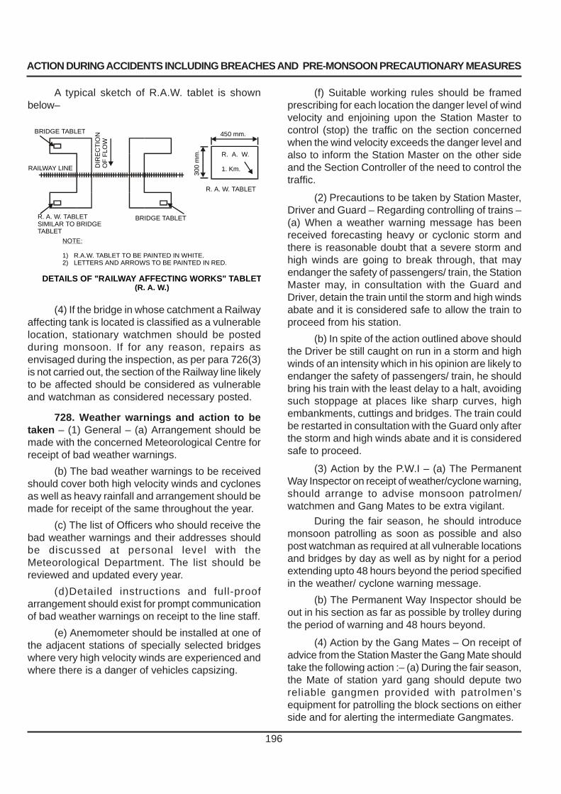
ACTION DURING ACCIDENTS INCLUDING BREACHES AND PRE-MONSOON PRECAUTIONARY MEASURES
196
A typical sketch of R.A.W. tablet is shownbelow–
(4) If the bridge in whose catchment a Railwayaffecting tank is located is classified as a vulnerablelocation, stationary watchmen should be postedduring monsoon. If for any reason, repairs asenvisaged during the inspection, as per para 726(3)is not carried out, the section of the Railway line likelyto be affected should be considered as vulnerableand watchman as considered necessary posted.
728. Weather warnings and action to betaken – (1) General – (a) Arrangement should bemade with the concerned Meteorological Centre forreceipt of bad weather warnings.
(b) The bad weather warnings to be receivedshould cover both high velocity winds and cyclonesas well as heavy rainfall and arrangement should bemade for receipt of the same throughout the year.
(c) The list of Officers who should receive thebad weather warnings and their addresses shouldbe discussed at personal level with theMeteorological Department. The list should bereviewed and updated every year.
(d)Detailed instructions and full-proofarrangement should exist for prompt communicationof bad weather warnings on receipt to the line staff.
(e) Anemometer should be installed at one ofthe adjacent stations of specially selected bridgeswhere very high velocity winds are experienced andwhere there is a danger of vehicles capsizing.
(f) Suitable working rules should be framedprescribing for each location the danger level of windvelocity and enjoining upon the Station Master tocontrol (stop) the traffic on the section concernedwhen the wind velocity exceeds the danger level andalso to inform the Station Master on the other sideand the Section Controller of the need to control thetraffic.
(2) Precautions to be taken by Station Master,Driver and Guard – Regarding controlling of trains –(a) When a weather warning message has beenreceived forecasting heavy or cyclonic storm andthere is reasonable doubt that a severe storm andhigh winds are going to break through, that mayendanger the safety of passengers/ train, the StationMaster may, in consultation with the Guard andDriver, detain the train until the storm and high windsabate and it is considered safe to allow the train toproceed from his station.
(b) In spite of the action outlined above shouldthe Driver be still caught on run in a storm and highwinds of an intensity which in his opinion are likely toendanger the safety of passengers/ train, he shouldbring his train with the least delay to a halt, avoidingsuch stoppage at places like sharp curves, highembankments, cuttings and bridges. The train couldbe restarted in consultation with the Guard only afterthe storm and high winds abate and it is consideredsafe to proceed.
(3) Action by the P.W.I – (a) The PermanentWay Inspector on receipt of weather/cyclone warning,should arrange to advise monsoon patrolmen/watchmen and Gang Mates to be extra vigilant.
During the fair season, he should introducemonsoon patrolling as soon as possible and alsopost watchman as required at all vulnerable locationsand bridges by day as well as by night for a periodextending upto 48 hours beyond the period specifiedin the weather/ cyclone warning message.
(b) The Permanent Way Inspector should beout in his section as far as possible by trolley duringthe period of warning and 48 hours beyond.
(4) Action by the Gang Mates – On receipt ofadvice from the Station Master the Gang Mate shouldtake the following action :– (a) During the fair season,the Mate of station yard gang should depute tworeliable gangmen provided with patrolmen’sequipment for patrolling the block sections on eitherside and for alerting the intermediate Gangmates.
450 mm.
300
mm
.
R. A. W.
1. Km.
R. A. W. TABLET
BRIDGE TABLET
DIR
EC
TIO
NO
F F
LOW
RAILWAY LINE
R. A. W. TABLETSIMILAR TO BRIDGETABLET
BRIDGE TABLET
NOTE:
1) R.A.W. TABLET TO BE PAINTED IN WHITE.2) LETTERS AND ARROWS TO BE PAINTED IN RED.
DETAILS OF "RAILWAY AFFECTING WORKS" TABLET(R. A. W.)

ACTION DURING ACCIDENTS INCLUDING BREACHES AND PRE-MONSOON PRECAUTIONARY MEASURES
197
(b) During monsoon period also the Mate ofthe station yard gang should send two gangmen inopposite directions to alert intermediate Gangmates,patrolmen and watchmen.
(c) Should there be very heavy rain or a severestorm weather during the monsoon or fair season,the Mate and Gangmen of all gangs on their owninitiative should commence monsoon patrolling byday as well as night. Similar action to carry out
patrolling should be taken on receipt of bad weatherwarning for the duration of warning and 48 hoursbeyond.
(5) The individual Railway may issueinstructions in the form of joint circular to suit thelocal requirements.
(6) Inspecting officials should test theknowledge of Gang Mates and Gangmen aboutthese instructions issued.
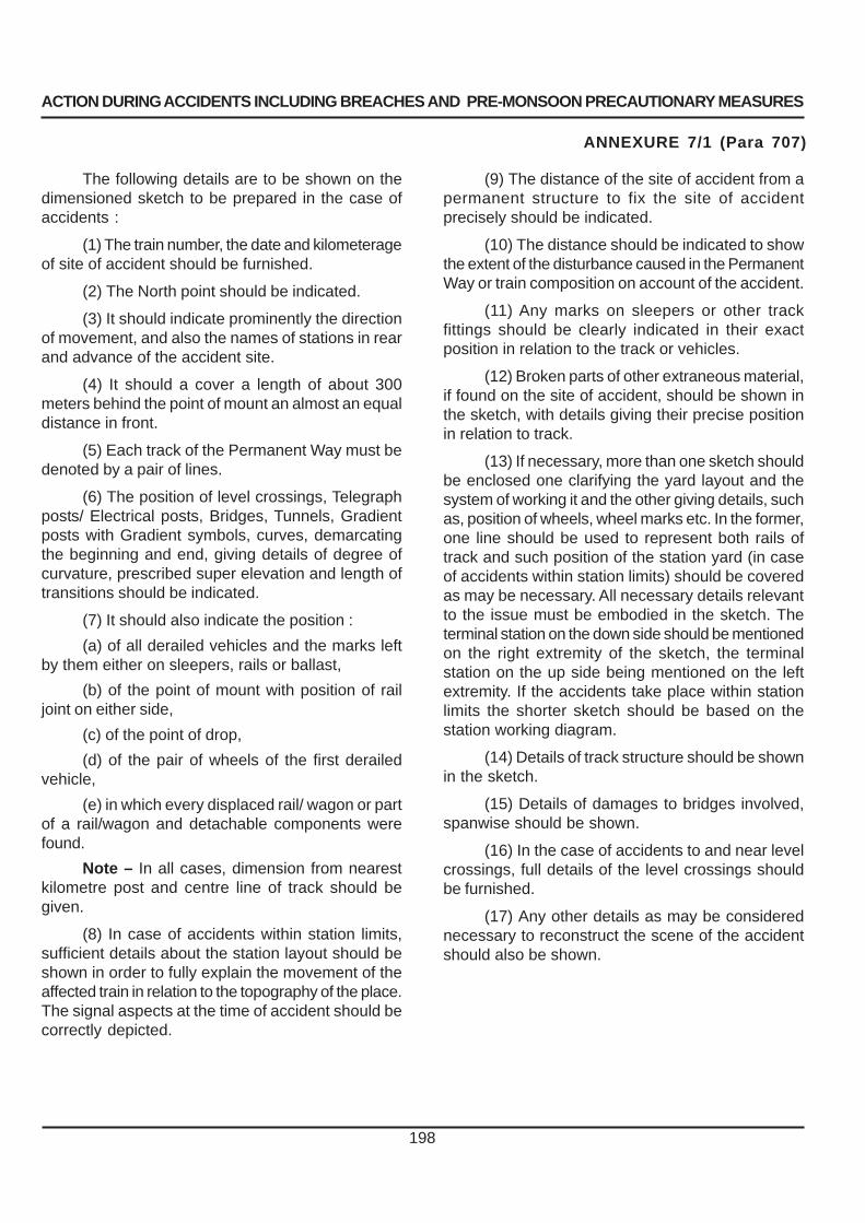
ACTION DURING ACCIDENTS INCLUDING BREACHES AND PRE-MONSOON PRECAUTIONARY MEASURES
198
The following details are to be shown on thedimensioned sketch to be prepared in the case ofaccidents :
(1) The train number, the date and kilometerageof site of accident should be furnished.
(2) The North point should be indicated.
(3) It should indicate prominently the directionof movement, and also the names of stations in rearand advance of the accident site.
(4) It should a cover a length of about 300meters behind the point of mount an almost an equaldistance in front.
(5) Each track of the Permanent Way must bedenoted by a pair of lines.
(6) The position of level crossings, Telegraphposts/ Electrical posts, Bridges, Tunnels, Gradientposts with Gradient symbols, curves, demarcatingthe beginning and end, giving details of degree ofcurvature, prescribed super elevation and length oftransitions should be indicated.
(7) It should also indicate the position :
(a) of all derailed vehicles and the marks leftby them either on sleepers, rails or ballast,
(b) of the point of mount with position of railjoint on either side,
(c) of the point of drop,
(d) of the pair of wheels of the first derailedvehicle,
(e) in which every displaced rail/ wagon or partof a rail/wagon and detachable components werefound.
Note – In all cases, dimension from nearestkilometre post and centre line of track should begiven.
(8) In case of accidents within station limits,sufficient details about the station layout should beshown in order to fully explain the movement of theaffected train in relation to the topography of the place.The signal aspects at the time of accident should becorrectly depicted.
ANNEXURE 7/1 (Para 707)
(9) The distance of the site of accident from apermanent structure to fix the site of accidentprecisely should be indicated.
(10) The distance should be indicated to showthe extent of the disturbance caused in the PermanentWay or train composition on account of the accident.
(11) Any marks on sleepers or other trackfittings should be clearly indicated in their exactposition in relation to the track or vehicles.
(12) Broken parts of other extraneous material,if found on the site of accident, should be shown inthe sketch, with details giving their precise positionin relation to track.
(13) If necessary, more than one sketch shouldbe enclosed one clarifying the yard layout and thesystem of working it and the other giving details, suchas, position of wheels, wheel marks etc. In the former,one line should be used to represent both rails oftrack and such position of the station yard (in caseof accidents within station limits) should be coveredas may be necessary. All necessary details relevantto the issue must be embodied in the sketch. Theterminal station on the down side should be mentionedon the right extremity of the sketch, the terminalstation on the up side being mentioned on the leftextremity. If the accidents take place within stationlimits the shorter sketch should be based on thestation working diagram.
(14) Details of track structure should be shownin the sketch.
(15) Details of damages to bridges involved,spanwise should be shown.
(16) In the case of accidents to and near levelcrossings, full details of the level crossings shouldbe furnished.
(17) Any other details as may be considerednecessary to reconstruct the scene of the accidentshould also be shown.

ACTION DURING ACCIDENTS INCLUDING BREACHES AND PRE-MONSOON PRECAUTIONARY MEASURES
199
ANNEXURE-7/2 PARA 708 (1)
PART - A
Pro forma showing the detailed particulars to be collected in the case of Permanent Way during an Accident
lioS
foepyTnoitamroF
llaFniaR
tsallaB
.lS.oN
,ydnaS.g.eepyT,yalcymaol
kcalB,murooM.ctenottoc
,mrif-noitidnoC.cteyhsuls,tew
,enots/epyT,dnaS,murooM
.ctehsA
wolebhtpeDmottobrepeelsgnitatS.smcni
ronaelcrehtehwdekac
eganiarD
1 2 3 4 5 6 7 8
foedistuomorf.mcnisredluohsfohtdiWsrepeelS
liaR
tfeL thgiR tfeL thgiRTSCnedooW-epyT.ctehguortleets9-
weN-noitidnoC,dnahdnoces
-civresnu,degamad.cteelbae
ytisneDtonroerauqS
roesoolgnikcaPdnuos
9 01 11 21 3141
51 61 71

ACTION DURING ACCIDENTS INCLUDING BREACHES AND PRE-MONSOON PRECAUTIONARY MEASURES
200
sliaR sgninetsafliaR stniojliaR
/.gK25thgieW.cteR57/R09
raewfonoitidnoCfieliforpliarhcatta(
)yvaehsiraew
,srettoc,srabeit,syek,sekipswercs/goD.cteswajesool
deggoH:noitidnoC.ctewol,derettab
erauqsrodereggatS
dnanoitceriD-peerCfoepyt,peercfotnetxehtiwdesusrohcnapeerc
ehtniliarrepsrebmunnoitcesdetceffa
reprebmuNtaesrepeels
rothgiT:noitidnoCni(gnissimroesool
)repeelshcae
81 91 02 12 22 3242
skramerlareneGroskcarctuoba-hsiffoerutcarf
dnastlobhsif,setalpstnenopmocrehto
-itnafonoitpircseDserusaemegatobas
swajesreverekil.ctesliardedlew
tnuomfostniopfonoitacoL tnemliaredfostniopfonoitacoL
norehtehWroevruc,thgiarts
noitisnart
gnillafanorehtehWgnisirrolevel,edarggasnorodnaedarg
,thgiartsnorehtehWnoitisnartroevruc
gnillafanorehtehWgnisirrolevel,edarggasnorodnaedarg
52 62 72 82 92 03
Note –
(1) Left and right are with respect to direction of Train movement.
(2) The data in Col. 2 to 25 need not be collected when the defect is obviously and indisputably on account of sabotageand/or obstruction on track.
(3) Only broken track material which is not indisputably to be broken after the accident should be included in Col. 25 andshould be preserved.
(4) Col. 26 need be filled in only when there is a suspicion about sabotage being the cause of derailment.
(5) Sag extends 90 metres on either side of theoretical junction of the grade lines Col. 28 and 30.
ANNEXURE-7/2 Contd...

ACTION DURING ACCIDENTS INCLUDING BREACHES AND PRE-MONSOON PRECAUTIONARY MEASURES
ANNEXURE-7/2 Contd... PARA 708 (1)
PART - B Track Measurements
Station No.
Distance apart in metres
Gauge slack or tight from the exact (mm.)
Cross Level (mm.) Under no load condition
Marks on sleepers or rail top
Grinding or rubbing marks on rails
1 2 3 4 5 6
Examination of alignment for perceptible kinds of track distortion in the vicinity of the point of derailment
Subsidence of track
Versine in mm. Remarks regarding length of transition, degree of curve and specified superelevation general alignment etc.
Longitudinal level to be recorded in the case of M. G. and N. G. in case of sags and curves
On 20 M. or 10 M. chord depending on practice prevalent on the Railway for flat curves more than 600 M. radius
On 10 M. or such shorter Chords as considered necessary for sharp curves (less than 600 M. radius on B. G. and M. G.)
7 8 9 10 11 12
(CS 136 Dt 14.11.14) Note – (1) The point of mount should be marked station No. 0 and the stations numbered serially as (+) for
measurements ahead of site of derailment and (—) for measurements in rear. (2) The cross level will be measured on the left rail only as determined from the direction of
movement. (3) Normally measurement will be taken at station 3 M. apart for a distance of 45 metres on either side
of 0 station if the cause of derailment is indisputably known, otherwise they will be taken for a distance of 90 metres in rear and 45 metres ahead of zero station.
(4) Where necessary measurements for Col. 3, 4 and 5 may in addition be taken at individual sleepers.
(5) This proforma need not be filled when the cause of derailment is obviously established as due to sabotage, obstruction on track, broken axle, and/or spring having fallen off prior to point of derailment.
(6) Longitudinal levels should be recorded for 300 metres on rear and 100 metres in front, in case of straights at the middle of each rail and at versine recording points on curves @ 20/10 M intervals.
201
APE
� �� ���!� � ���˜����������� ˜���������� ��� � � � ����� ��� ����������,� ˜ �� � ��� � ���˜ ˜���� �� ���� ���� �����˜�� � ˜ � �˜������� ������� � � �� ˙���˜��� ���������˜ � ˜� � � ����)� ����
APE
� �� ���!� � ���˜����������� ˜���������� ��� �� �˛������)���� � � � ����� ��� ����������,� ˜ �� � ��� ���˛ � ��˜� � ���˜ ˜���� �� ���� ���� �����˜�� � ����� ˜ � �˜������� ������� � �� ˛�� �������� � +���/ �)���������� ��� �� ˙���˜��� ���������˜ � ˜� � � ����)� ���� ������ ���˛ �� ˇ� ��������'
APE

CHAPTER VIII
ENGINEERING RESTRICTIONS
AND INDICATORS AND USE OF DETONATING AND
FLARE SIGNALS
801. Work involving Danger to Train or Traffic– A gang shall not commence or carry on any work which will involve danger to trains or to traffic without the previous permission of the Inspector of Way and Works or of some competent Railway servant appointed on this behalf by special instructions. The Railway servant who has given the permission should be himself present at the site to supervise the work.
802. Carrying out of Works, in case of Emergency – In the case of emergency, when the requirements of safety warrant the commencement of the work by the gangmate, before the arrival of the railway servant, the gangmate shall himself ensure that Engineering signals are exhibited at specified distances according to rules and flagmen are posted with necessary equipment to man them, before commencing the work.
803. Responsibility of the Railway servant in-charge of the work – The Railway servant in-charge of the work, who is present at the site work, shall ensure that Engineering signals are exhibited at the specified distance according to rules and flagmen are posted with necessary equipment to man them. Trains shall be permitted over the track under repair at such restricted speed as is specified, only after the track is rendered safe for the traffic. He should ensure that the provisions of Para 804 are fulfilled before commencing the work.
804. Works which obstruct the line:
(1) Precautions before commencing operations which would obstruct the line - No person employed on the way, works or bridges shall change or turn a rail, disconnect points or signals or commence any other operation which would obstruct the line without obtaining the written permission of the Station Master who shall ensure that all necessary signals have been placed at ‘ON’. In addition, the employee mentioned above shall also ensure that the necessary stop signals like banner flags and detonators and hand signal flags have also been placed/exhibited at the prescribed locations as per Para 806.
Provided further that in emergent cases the persons undertaking such operations shall first bring the train to stop as stipulated in Para 812 and advise the driver of the train about the need to stop the train through a
written memo. The railway servant shall simultaneously arrange to send a message to the Station Master for the need to block the track as per para 810 and obtain written confirmation of the same. The work which may lead to obstruction to the track shall however be done only during the traffic block, the written confirmation for which shall be obtained from the concerned Station Master. On completion of the work again the authorized railway servant shall advise the driver through a written memo to proceed at the prescribed speed. (2) Works requiring complete block protection - The following category of works will necessarily require completed block protection:
(i) Category of works where track is required to be
occupied: (a) Working of on-track machines (b) Working of material trains or girder specials (c) Working of dip-lorries (d) Working of motor trollies (e) Working of push trolley in heavily graded
sections. (f) Working of push trolley in sections where visibility
is obstructed (g) Push trolley in long tunnels.
(ii) Works where discontinuity in track is created or such conditions are created which may result in discontinuity or obstruction to running track:
(a) Through rail renewal (b) Casual replacement of rail (c) Replacement of SEJs or replacement of buffer
rails with SEJs (d) Insertion or replacement of glued joints (e) Temporary/Permanent repairs of rail fractures (f) Temporary/Permanent repairs of rail to buckling (g) Replacement of switch/crossing or any part of
turnouts (h) De-stressing of LWRs (i) in- situ welding of rails (j) End cropping and welding (k) Through renewal of bridge sleeper (l) Replacement of girders with slabs (m) Removal of rail from track for any purpose (n) Renewal of sleeper on important and major
bridges. (o) Changing of guard rails on important and major
bridges. Note: (1) Some of the works listed above may also necessitate mandatory imposition of speed restrictions.
(2) The list of works indicated above is indicative only and other works may also be required to be done under block protection based on site specific conditions as decided by P. Way officials. (CS 136 Dt 14.11.14)
202

805. Categories of Engineering Works –
Engineering works can be broadly divided into three categories –
(1) Category 1 – Works of routine maintenance, requiring no speed restriction, not necessitating exhibition of hand signals and involving no danger to trains or traffic.
These include works of routine maintenance such as through packing, picking up slacks and overhauling of track etc.
(2) Category 2 – Works of short duration –
(a) Works such as casual renewals of rails and sleepers, adjustment of creep and lubrication of rail joints which are completed by sunset of the day of commencement and no restriction of speed
thereafter is required, are termed “works of short duration”.
(b) Hand-signal and banner flags and fog-signals shall be used at specified distances to afford protection to trains.
(3) Category 3 – Works of long duration –
(a) Works such as relaying, bridge construction, diversions which extend over a few days, or weeks during which period a continuous restriction of speed is to be in force, are termed as “works of long duration”.
(b) Temporary Engineering fixed signals shall be used at specified distances to afford protection to trains. These works should be carried out to a programme, about which all concerned will be advised in advance.
202/ A

ENGINEERING RESTRICTIONS AND INDICATORS AND USE OF DETONATING AND FLARE SIGNALS
203
806. Works of short duration – Protectionin block section and procedure for passing of trains– Before commencing any work of such categorythe Permanent Way Inspector or authorised Railwayservant should issue a notice to the Station Master/Block hut in-charge at each end of the Block sectionand obtain their acknowledgment. Depending as towhether the train is to be passed through the worksite, after stopping or at a restricted speed, the lineshould be protected in the following manner :–
(1) When the train is required to stop at thesite of work ( in Block section) –
(a) Post a flagman with hand signals at adistance of 30 metres in rear of the place ofobstruction, to show stop hand signals.
(b) Post a flagman with hand signals and placea banner flag across the track at a distance of 600metres on Broad Gauge and 400 metres on MetreGauge and Narrow Gauge in rear of the work. Theflag man will show stop hand signals
(c) Post a flagman with hand signals anddetonators at a distance of 1200 metres in the caseof Broad Gauge and 800 metres in the case of Metreand Narrow Gauge in rear of the work. The flagmanshall fix three detonators on the line 10 metres apartand take stand at a place not less than 45 metresfrom the three detonators, from where he can obtaina clear view of the approaching train. He will showstop hand signals.
Note – In M.G. Sections with trains runningat a maximum speed of more than 75 km.p.h. thedistances (b) and (c ) shall be as specified underapproved special instructions.
(d) The man at the site of obstruction shall giveproceed hand signal to indicate to the Driver, whenhe may resume normal speed after the train hasbeen hand signalled past the obstruction (Annexure8/1).
(2) When the train can pass over the workspotat restricted speed in Block section – Keeping in viewthe provisions in para 1501.1(C) /GR.1976 thefollowing protections should be adopted in the abovecases :–
(a) Post a flagman exhibiting caution handsignals at a distance of 30 metres from the place ofobstruction.
(b) Post a flagman exhibiting caution handsignals at a distance of 1200 metres for BroadGauge and 800 metres for Metre Gauge and NarrowGauge from the place of obstruction.
(c ) Post a intermediate flagman with handsignals at a distance of 600 metres for Broad Gaugeand 400 metres for Metre Gauge and Narrow Gaugefrom the place of obstruction. He will also place abanner flag across the track. The intermediate bannerflag must be kept across the line until the speed ofthe train has been reduced, after which the bannerflag shall be removed and the train hand signalledforward.
In Metre Gauge sections with trains running ata maximum speed of more than 75 km.p.h. thedistance in (b) & (c) shall be increased as specifiedunder approved special instructions.
(d) The railway servant at the site of workshould give proceed hand signals to indicate to theDriver, that he may resume normal speed after thetrain has been signalled past the site of work-(Annexure 8/2).
(3) The following points should be kept in view,while protecting the track in the cases mentioned insub-para (1) and (2) above :–
(a) On single line, the line must be so protectedon both sides of the work.
(b) At places where there are curves or fallinggradients and at times of poor visibility the distanceslaid down in sub-paras (1) and (2) above may besuitably increased wherever necessary andintermediate flagman posted to relay hand signals.
(c ) The location of the banner flag, detonatorsand hand signals should be so selected as to avoidstopping of trains, as far as possible, on continuoussteep rising gradients.
(d) If in an emergency, it becomes necessaryto carry out such works at night, the provisions forprotection of line as detailed in sub-pares (1) and (2)must be complied with except that red light must beexhibited in the direction of approaching trains inplace of red hand signaling flags and banner flags.
(e) In an Emergency, when it is necessary onconsiderations of safety, the Permanent WayInspector, or authorised railway servant maycommence such work after protecting the line beforeissuing notice to the Signalman. If the work is likelyto be prolonged he should notify the Signalman assoon as possible.
(4) Works to be carried out in station limits –(a) No work should be commenced on running
line at a station without the written permission of theStation Master and until the relevant signals havebeen placed at ‘ON’.

ENGINEERING RESTRICTIONS AND INDICATORS AND USE OF DETONATING AND FLARE SIGNALS
204
(b) Before commencing a work on a line whichcan be isolated from the other running lines, thePermanent Way Inspector should ensure that the linehas been isolated and retain the keys of lockingdevice in his possession. Where isolation is effectedby the setting of points, they must be locked bymeans of clamps or bolts and cotters.
(c ) Before commencing work on a line whichcannot be isolated from other running lines thePermanent Way Inspector should provide theprescribed hand signals, detonators and banner flagsas detailed in para 806.
(5) Works in Automatic Territory – In automaticterritory, if the distance from the place of works/obstruction to the automatic signal controlling entryof a train into the signalling section is less than 1200metres on Broad Gauge and 800 metres on MetreGauge/Narrow Gauge and the automatic signal issecured at ‘ON’ the banner flag and three detonatorsmay be provided at 90 and 180 metres respectively.
807. Works of long duration –(1) Preliminary arrangements –(a) For doing such works the Engineering
Department will arrange with the OperatingDepartment for the issue of the circular notice asper extant instructions.
(b)The concerned Divisional Engineer will beresponsible for obtaining the sanction ofCommissioner of Railway Safety wherevernecessary and sending Safety Certificate oncompletion of such works.
(c ) The Permanent Way Inspector shouldobtain permission to commence work from D.E.N./A.E.N. and should arrange to block the line whenwork is proposed to be done under block with thepermission of the Controller/Chief Controller on theday of block and issue a notice to the Station Masteron either side.
(d) Caution orders will be issued by the StationMasters concerned as necessary.
(e) The necessary temporary Engineeringfixed signals as prescribed should be provided.
(f) In an emergency, when it is necessary onconsiderations of safety, the Permanent WayInspector, or Authorised Railway servant maycommence such work before issuing the notice,under the protection of hand signals and banner flags.As soon as possible, he should issue the notice andreplace the hand signals and banner flags bytemporary engineering fixed signals.
(2) Protection of line in block section –
(a) In case where stop dead restriction is to beimposed when restriction is to last for more than aday, the following temporary Engineering indicatorsshould be exhibited at the appropriate distance :–
(i) Caution indicator.(ii) Stop indicator.(iii) Termination indicators. (b) In case where the train is not required to
stop ( non-stop restriction) and the restriction is likelyto last for more than a day the following temporaryEngineering indicators should be exhibited at theappropriate distances :–
(i) Caution indicator.(ii) Speed indicator.(iii) Termination indicators.Note — (i) Annexure 8/3 and 8/3 A indicate
the distances at which these are to be fixed.
(ii) When during the course of the work, onconsideration of safety it is not desirable to pass trainsover the site of work for the time being, the trackshould be further protected by hand signals andbanner flags, by the authorised Railway servant.
(3) Protection of line in station limits – Specialinstructions will be issued by the Divisional RailwayManager (Operating) after consultations withDivisional Engineer and Divisional Signal andTelecommunication Engineer in regard to the use oftemporary Engineering signals in conjunction withstation fixed signals. In urgent cases these will beissued by the Station Master at the request ofPermanent Way Inspector.
808. Temporary Engineering FixedSignals-Location and details – (1) These consistsof :
(a) Caution indicator.(b) Speed indicator.(c ) Stop indicator.(d) Termination indicators ( T/P & T/G).(2)(a) Multi Speed Restriction (i.e. existence
of two or more than two speed restrictions incontinuation): When work of deep screening orsleeper renewal is in progress, there is situation ofhaving two or more than two speed restrictions incontinuation. In such situation, placement of speedboards for following speed restriction shall be asunder:

ENGINEERING RESTRICTIONS AND INDICATORS AND USE OF DETONATING AND FLARE SIGNALS
205
(i) In case of following speed restriction beingmore restrictive, a minimum of 200m track shouldbe under earlier speed restriction zone. If not, thenonly one SR board should be provided, consideringthat the previous speed restriction is at par with thefollowing SR, which is more restrictive.
(ii) In case of following speed restriction beingless restrictive, corresponding speed indicator boardfor following speed restriction shall be placed at adistance equal to the length of the longest goods trainoperating on the section after termination point ofprevious speed restriction zone.
(2) (b)The details and position of fixing eachindicator are detailed in Annexures 8/4, 8/3 and
8/3 A.
(3) During the hours of night, the lamps of thetemporary indicators which are not reflective typeshould be lit at sunset and kept burning till sunrise,where trains run at night. Reflective type temporaryindicators need not be lit.
(4) For intermediate tracks on triple or multiplelines, Engineering indicators should be fixed betweentracks to within 300 mm. from rail-level, to avoidinfringements of standard dimensions.
(5) All indicators should be placed on the lefthand side as seen by the Drivers except on CTCsections (single line) where they should be placedon Right hand side.
(6) Each Permanent Way Inspector shouldhave in his possession at least one complete set ofsignals consisting of 2 caution indicators, 2 speedindicators, 2 stop indicators and two sets oftermination indicators (2 Nos T/P & T/G indicators).
(7) One termination indicator bearing letters T/G should be located at a distance equal to the lengthof the longest goods trains operating on the sectionfrom the place of work. Another Termination indicatorbearing the letters T/P should be located at adistance equal to the length of the longest passengertrain operating on the section from the place of workwhich will help the passenger trains to pick up speedafter reaching T/P indicator, without losing time. TheGuard of a passenger train shorter than the longestpassenger train will exhibit an “all-clear” signal to hisDriver when the rearmost vehicle has cleared therestricted length and the Driver will resume normalspeed. In the case of light-engines or single unit railcars, the Drivers will resume normal speed afterclearing the restricted length.
809. Procedure for Passing Trains atstop dead Restrictions – The flagman at the stopindicators shall present his restriction book to theDriver who should stop in the rear of the stopindicator.
The “restriction book” should be to the following form:
Engineering indicator at km…………………
etaD .oNniarT emiTfoerutangiS
revirDeht
After the flagman has obtained the signatureof the Driver at the indicator, he should exhibitproceed with caution signal to the Driver. The Driverwill then be authorised to pass the stop indicator andcontinue at this speed until his train has cleared therestricted length, after which he will resume normalspeed.
810. Procedure for blocking line forEngineering purposes – (1) Arrangements forblock–
(a) Except in very urgent cases arrangementsfor Blocking the lines between stations shall be madeby the Divisional Engineer in consultation with theDivisional Operating Manager, sometime before theblock is imposed.
(b) The Divisional Operating Manager will issueinstructions to the Station Masters on either side ofthe section to be blocked and Station Masters/YardMasters of train ordering stations concerned aboutthe last train to pass over the section before the blockis imposed, the trains to be cancelled because ofthe block and any other particulars and will concludeby stating which official of the EngineeringDepartment will impose and remove the block. Theinstructions will be acknowledged by those to whomissued.
(c ) In an emergency when there is no time torefer to Divisional Operating Manager or where blockwill not interfere appreciably with the traffic the StationMaster ( after consulting control on controlled section)will arrange directly with the Engineering Officialrequiring the block.

ENGINEERING RESTRICTIONS AND INDICATORS AND USE OF DETONATING AND FLARE SIGNALS
206
(2) Imposition of Engineering Block – (a)TheInspector or authorised railway servant who blocksthe line should transmit a message to the StationMaster on either side of the block section to beblocked, copy to the Divisional Engineer, AssistantEngineer, Loco Foreman, Controller on controlledsections and Divisional Operating Manager, advisingthem of the time from which the block is to beimposed and the kilometrage and asking foracknowledgement from the concerned StationMasters.
(b) The Station Master receiving the messagefor transmission will sign for it, noting the time ofreceipt and shall transmit the message to the StationMaster on the other side of the block section, whichis to be blocked, and to the Controller.The StationMaster on the other side will acknowledge receiptby a message addressed to Permanent WayInspector or authorised railway servant and theStation Master of the transmitting station.
(c ) On receipt of this message the StationMaster of the station from which the message wastransmitted will block the line in the mannerprescribed and hand over a signed copy to theInspector.
(d) Field telephone should be used for liaisonwith the Control during the block.
(3) Removal of Engineering Block – (a) Whenremoving a block the Inspector or authorised railwayservant responsible will transmit a message to theStation Master on either side of the block sectionblocked, copy to the Divisional Engineer, AssistantEngineer, Loco Foreman, Controller, DivisionalOperating Manager etc., advising them that the blockhas been removed and asking for acknowledgementfrom Station Masters. Particulars of kilometrage,restriction of speed and position of EngineeringIndicators should be given in the telegram.
(b) The Station Master who receives themessage for transmission will sign for it, noting thetime of receipt and transmit the message to theStation Master of the other station. The messagemust be acknowledged by the latter, addressed tothe Inspector and Station Master of the transmittingstation.
On receipt of this acknowledgement the StationMaster who originally imposed the block, will removeit in the manner prescribed. The Control or theDivisional Operating Manager, will advise the StationMasters on the train ordering stations when a blockis finally removed.
(4) Issue of Caution Orders to Drivers –Caution order to Drivers of all trains will be issuedby the Station Masters for temporary engineeringrestrictions. Caution order will indicate the exactkilometrage, speed restrictions, stops, as the casemay be, but will not include permanent restrictionsthat are notified in the working time-table.
811. Works at times of poor visibility –In thick foggy or tempestuous weather impairingvisibility, no rail shall be displaced and no other workwhich is likely to cause obstruction to the passageof trains shall be performed except in case ofemergency.
When such work has to be undertaken andthe site is protected by temporary engineering fixedsignals, 2 detonators on the line 10 metres apartshould be fixed not less than 270 metres in rear ofthe caution indicator and a caution hand signalexhibited to approaching trains.
812. Temporary Signals in Emergency –
(1) Whenever in consequence of anobstruction of a line or for any other reason it isnecessary for a railway servant to stop approachingtrain he shall plant a danger signal at the spot andproceed with all haste in the direction of anapproaching train with a danger signal (red flag byday and red light by night) to a point 600 metres forBroad Gauge and 400 metres for Metre Gauge andNarrow Gauge from the obstruction and place onedetonator on the line after which he shall proceedfurther for not less than 1200 metres for BroadGauge and 800 metres for Metre Gauge and NarrowGauge from the obstruction and place threedetonators on the line 10 metres apart. He shouldthen take a stand at a place not less than 45 metresfrom there from where he can obtain a good view ofan approaching train and continue to exhibit thedanger signal, until recalled. If recalled, he shall leaveon the line three detonators and on his way backpick up the intermediate detonator continuing to showthe danger signal. In case of those Metre Gaugesections where the maximum speed is more than75 km.p.h. these distances will be as per approvedspecial instructions.
(2) On single line the line must be protectedon each side of obstruction.

ENGINEERING RESTRICTIONS AND INDICATORS AND USE OF DETONATING AND FLARE SIGNALS
207
(3) Where there are adjacent lines and it isnecessary to protect such lines, action should betaken on each such line in a similar manner.
813. Periodical notice of EngineeringRestrictions – For works involving restriction ofspeeds of trains the Divisional Engineer will arrangepublication in the periodical gazette of the railwayfurnishing following details :–
(1) The names of the block stations on eitherside of the site where the engineering work will beundertaken in order that caution orders may beissued.
(2) Kilometrage of site of work.
(3) Restricted speed and stop dead restrictionto be observed by the Driver.
(4) Nature of work being undertaken or reasonsfor restriction.
(5) Probable duration.
814. Permanent speed restrictionindicators– (1) Permanent speed restriction boards–
(a) Permanent speed restrictions in force are notified in working time-tables. The speed indicators are erected to indicate to the Drivers the speed restrictions to be observed e.g., between stations, and at stations due to weaker track/bridges, restrictions on curves, grades and points and crossings etc.(CS. 137 dtd. 18-06-2015)
(b) The indicators to be used are similar to those used for temporary restrictions, namely, caution indicator, speed/stop indicators and termination indicators (T/P&T/G). The details of the indicators and the distance at which they are to be fixed are the same in both the cases (Annexure 8/3 & 8/4 ).
(c) The permanent indicators need not be flood lit at night as in the case of temporary indicators/signals.
(2) Siding Boards.- When speed restriction has been imposed on account of facing points of an outlying siding an ‘S’ marker (a circular board of 1 metre dia. painted yellow, with 300 mm. letter ‘S’ painted in black on it ) should be fixed at the points in addition to the speed and caution boards fixed in rear of the points. Where however, the sanctioned speed of the section does not exceed 50 km.p.h. the speed
indicator and the ‘S’ board need not be providedexcept where the speed over the points is less thansanctioned speed of the section. ‘S’ marker shouldbe so fixed that the centre of the board is 2 metresabove the rail level.
(3) Board indicating speed over points – Wherethe speed over the points at a station is less than thespeed sanctioned at other stations on the samesection, a permanent speed indicator should be fixedon the first approach signal of the station.
(4)The posts of permanent speed indicatormarker boards should be painted with 300 mm. highbands in white and black.
(5) Where a permanent speed restriction is inforce on any intermediate track on triple or multiplelines, the engineering indicators should be fixedbetween tracks to within 300 mm. from rail-level toavoid infringement of standard dimensions.
815. Indicators (General) – (1) Whereindicators are provided under special instructions tofurnish information to Drivers, these should be inblack letters or figures on yellow back ground.
(2) Whistle indicator – (a) Whistle boardsshould be provided in rear of all places where theview of the Drivers is obstructed by cuttings or tunnelsor curves and where it is necessary to give audiblewarnings of the approach of a train to those workingon the track. The whistle boards are fixed at adistance of 600 metres.
(b) Whistle indicator for level crossings –Whistle boards are also provided on the approachof all unmanned level crossings and in case ofmanned level crossings, where a clear view is notobtained. These bear the letters W/L. The details ofthese whistle boards are described in Para 916(1)/Chapter on Level Crossings and Gateman.
(3) Shunting limit Boards – They are providedat an adequate distance in advance of the trailingpoints. This shall consist of 600 mm. x 1000 mm.rectangular board painted yellow with a black crosson the top and words “shunting limit” written in blackbelow it. Its height should be 2 metres from the raillevel to the underside of the portion containing thecross and the post on which it is fixed, painted with300 mm. high bands in white and black. It should befitted with a lamp showing white light in bothdirections.
SSTW
Highlight
SSTW
Highlight

ENGINEERING RESTRICTIONS AND INDICATORS AND USE OF DETONATING AND FLARE SIGNALS
208
816. Detonating signals – Detonatingsignals otherwise known as detonators or fog signalsare appliances which are fixed on the rails, and whenan Engine (or vehicle) passes over them, theyexplode with a loud report so as to attract theattention of the Driver.
817. Care and Custody – (1) Detonatorsshould be protected against damp. They should bestored in tin cases with papers wrapped over them,a layer of waste cotton must be kept at bottom andtop of the tin cases to avoid contact with the metal.
(2) In one tin case not more than twelvedetonators should be kept.
(3) The tin cases should be stored in woodenboxes which should be kept in dry places and notleft in contact with the brick walls, damp wood,chloride of lime or other disinfectants; these shouldnot be exposed to steam or other vapours.
(4) Unexploded detonators should not be asfar as possible sent from place to place byconsignment; they should be conveyed personallyor by a messenger.
818. Stock with Engineering Staff – (1) Eachway, Works and Bridge Inspector shall have a stockof detonators sufficient to recoup the numberannually tested and any which may be exploded forworks and emergency. The Permanent Way Inspectorshall ensure that all Gangs, Gatemen, Keymen,Patrolmen and Watchmen are equipped with thespecified number of detonators.
(2) Every Assistant Engineer, Gangmate,Keyman, Gateman, Patrolman and Watchman,whose duties include protection of track shall carrythe specified stock of detonators with him on duty,for use during an emergency.
(3) The month and year of manufacture areshown on the label outside each case and alsostamped on each detonator. Detonators should beused in the order of the dates stamped on them, theoldest being used first. To facilitate ready withdrawalin this sequence, they should be stored alsoaccordingly.
819. Use of Detonators – (1) The staff inpossession of detonators shall not make anyimproper use of them. Engineers and Inspectors areresponsible to ensure that the staff working underthem know how and when to use detonators.
(2) A detonator when required to be used shallbe placed on the rail with the label or brand facingupwards and shall be fixed to the rail by bending theclasps around the head of the rail.
(3)In the case of a mixed gauge, detonatorsshall be placed on the common rail or on the rail ofeach gauge.
820. Testing – (1) Once a year, one detonatorshall be taken by the Permanent Way Inspector fromhis own stock and from Gangmate, Keyman,Gateman, Patrolman and Watchman for testing, onealso from each of the lots in the personal custody ofDivisional Engineer, Bridge Engineer, AssistantEngineer, works and relieving Permanent WayInspector where the headquarters of these officialsfalls within the P.W.I.’s jurisdiction. The oldestdetonators should be selected for the test.
(2) The testing of detonators should be doneunder an empty 4-wheeled B.G./M.G./N.G. wagonpropelled by an engine and moving at walking speedunder the direct supervision of the Permanent WayInspector, who shall ensure safety range duringtesting. Results of tests should be entered in aRegister.
(3) The P.W.I. shall submit by the end of theyear (31st December) a certificate in duplicate to theAssistant Engineer to the effect. “I certify that I havetested the detonators from stocks mentioned belowin accordance with standing orders for the yearending ….. and append a list of those that failed toexplode.” The Assistant Engineer shall countersignand forward one copy of the certificate to theDivisional Engineer with remarks, if any. Ordersregarding the return or destruction of those lots, thesamples from which failed to explode, shall be issuedby the Divisional Engineer.
821. Life of detonators – The normal life ofdetonators is seven years. The life of the detonatorscan be extended to ten years on an yearly basissubject to the condition that two detonators from eachlot of over 7 year old ones are tested for the explosivecontent and the results being found satisfactory. Suchtime extended detonators can be used on all sectionsafter satisfactory testing. In case the results are notsatisfactory, they should be destroyed as envisagedin Para 822. In any case no detonator should bekept in use after ten years.

ENGINEERING RESTRICTIONS AND INDICATORS AND USE OF DETONATING AND FLARE SIGNALS
822. Disposal of time-barred Detonators – No detonator that bears any sign of rust and is time-barred shall be held in stock. Such detonators shall be destroyed by one of the following methods
(1) By soaking them in light mineral oil for 48 hours and then throwing them one by one into fire with due precautions.
(2) By burning them in incinerator. (3) By detonating them under wagon during
shunting operations. (4) By throwing them in deep sea. The destruction of time-barred detonators
should be done in the presence of a Permanent Way Inspector who should ensure that every care is taken to see that splinters of detonators do not cause any injury to life and property. They should not be buried or thrown in places from where they could be recovered.
823. Safety Range – When detonators are being tested, no person should be allowed within a radius of 50 metres from the detonators to be exploded; the engine crew shall remain well within the cab. In practice, splinters from detonators when exploded seldom fly in a direction to the rear of the wheel which detonates them. Staff should therefore, when observing the safety radius, place themselves, as far as possible on the rear side.
824. Warning signal- Descriptions - The signals to be used to warn the incoming train of an obstruction shall be a red flashing hand signal lamp at night or red flag during day as per Para 3.65 of General Rules. (CS 136 Dt 14.11.14)
825. Use of flare signals – When it becomes necessary to protect an obstruction in a Block section, a warning signal may be used, as prescribed under Para 3.66 of GR, while the railway servant proceeds to place detonators. A warning signal is to be shown to give timely warning to a driver of approaching train of any obstruction such as derailed train obstructing adjacent lines, breaches, wash away, floods, landslides etc., when the railway servant does not have adequate time to do the protection in the normal manner with the detonators as envisaged under rules. The knowledge and possession of warning signals shall be ensured by every railway servant concerned with the use of warning signals as stipulated in Para 3.67 of GR. (CS 136 Dt 14.11.14)
826. Safeworking of contractors - A large number of men and machinery are deployed by the contractors for track renewals, gauge conversions, doublings, bridge rebuilding etc. It is therefore essential that adequate safety measures are taken for safety of the trains as well as the work force. The following measures should invariably be adopted:
(i) The contractor shall not start any work without the presence of railway supervisor or his representative and contractors supervisor at site.
(ii) Wherever the road vehicles and/or machinery are required to work in the close vicinity of railway line, the work shall be so carried out that there is no infringement to the railway’s schedule of dimensions. For this purpose the area where road vehicles and/or machinery are required to ply, shall be demarcated and acknowledged by the contractor. Special care shall be taken for turning/reversal of road vehicles/machinery without infringing the running track. Barricading shall be provided wherever justified and feasible as per site conditions.
(iii) The look out and whistle caution orders shall be issued to the trains and speed restrictions imposed where considered necessary. Suitable flagmen/detonators shall be provided where necessary for protection of trains.
(iv) The supervisor/workmen should be counselled about safety measures. A competency certificate to the contractor’s supervisor as per proforma annexed shall be issued by AEN which will be valid only for the work for which it has been issued. (Annexure 8/5).
(v) The unloaded ballast/rails/sleepers/other P.Way materials after unloading along track should be kept clear off moving dimensions and stacked as per the specified heights and distance from the running track.
(vi) Supplementary site specific instructions, wherever considered necessary, shall be issued by the Engineer in Charge.
(vii) The Engineer in-charge shall approve the methodology proposed to be adopted by the contractor, with a view to ensure safety of trains, passengers and workers and he shall also ensure that the methods and arrangements are actually available at site before start of the work and the contractor’s supervisors and the workers have clearly understood the safety aspects and requirements to be adopted/ followed while executing the work.
There shall be an assurance register kept at each site, which will have to be signed by both, i.e. Railway Supervisor or his representative as well as the contractor’s supervisor as a token of their having understood the safety precautions to be observed at site.
209

CS-110 dtd 4.3.2008
210

CS-110 dtd 4.3.2008
211

ENGINEERING RESTRICTIONS AND INDICATORS AND USE OF DETONATING AND FLARE SIGNALS
212
ANNEXURE 8/3 - PARA 807 & 808
TG
10
TP
TG
TP
Note :When, during the course of the work, on consideration of safety, it is not desirable topass trains over the site of work for the time being, the track should be further protectedby hand signals and banner flags, by the authorized Railway servant.
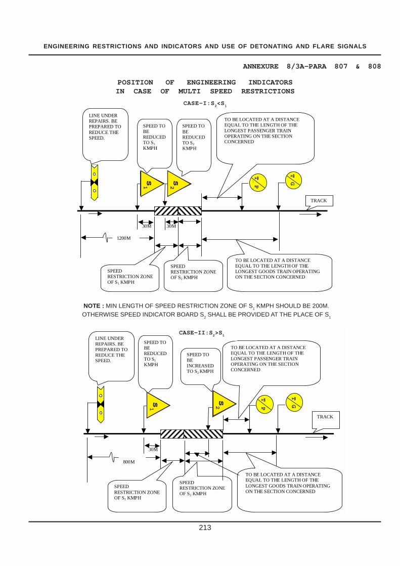
ENGINEERING RESTRICTIONS AND INDICATORS AND USE OF DETONATING AND FLARE SIGNALS
213
ANNEXURE 8/3A-PARA 807 & 808
30M
S
T P
S1
LINE UNDER REPAIRS. BE PREPARED TO REDUCE THE SPEED.
SPEED TO BE REDUCED TO S1
KMPH
SPEED TO BE INCREASED TO S2 KMPH
800M
SPEED RESTRICTION ZONE OF S1 KMPH
SPEED RESTRICTION ZONE OF S2 KMPH
TO BE LOCATED AT A DISTANCE EQUAL TO THE LENGTH OF THE LONGEST PASSENGER TRAIN OPERATING ON THE SECTION CONCERNED
TO BE LOCATED AT A DISTANCE EQUAL TO THE LENGTH OF THE LONGEST GOODS TRAIN OPERATING ON THE SECTION CONCERNED
TRACK
CASE-II: S2 > S1
T T
P Gs1
s2
30M 30M S
2
T P
S
LINE UNDER REPAIRS. BE PREPARED TO REDUCE THE SPEED.
SPEED TO BE REDUCED TO S1
KMPH
SPEED TO BE REDUCED TO S2
KMPH
1200M
SPEED RESTRICTION ZONE OF S1 KMPH
SPEED RESTRICTION ZONE OF S2 KMPH
TO BE LOCATED AT A DISTANCE EQUAL TO THE LENGTH OF THE LONGEST PASSENGER TRAIN OPERATING ON THE SECTION CONCERNED
TO BE LOCATED AT A DISTANCE EQUAL TO THE LENGTH OF THE LONGEST GOODS TRAIN OPERATING ON THE SECTION CONCERNED
TRACK
CASE-I: S2 < S1
T T
P
Gs2
s1
POSITION OF ENGINEERING INDICATORSIN CASE OF MULTI SPEED RESTRICTIONS
CASE-I:S2<S
1
CASE-II:S2>S
1
NOTE : MIN LENGTH OF SPEED RESTRICTION ZONE OF S1 KMPH SHOULD BE 200M.OTHERWISE SPEED INDICATOR BOARD S2 SHALL BE PROVIDED AT THE PLACE OF S1

ENGINEERING RESTRICTIONS AND INDICATORS AND USE OF DETONATING AND FLARE SIGNALS
214
ANNEXURE 8/4 - PARA 807 & 808
TP
TG
10
ENGINEERING INDICATORSFOR TEMPORARY RESTRICTIONS
1400
1.0 m. DIA.
LETTER250 mm. HIGH40 mm. THICK
LIT UPAT NIGHT
LETTER250 mm. HIGH40 mm. THICK
25 mm.BLACKBAND
25 mm.BLACKBAND
U/S RAIL POST TOBE PAINTED WITH 300 mm. HIGH BANDSOF WHITE & BLACK
U/S RAIL POST TOBE PAINTED WITH 300 mm. HIGH BANDSOF WHITE & BLACK
TERMINATIONINDICATOR FOR
PASSENGER TRAINS
TERMINATIONINDICATOR FOR GOODS TRAINS
1.0 m. DIA.
CAUTIONINDICATOR
STOPINDICATOR
SPEEDINDICATOR
R. L.
R. L. R. L.1650
mm
.AB
OV
ER
.L.
1650
mm
.AB
OV
ER
.L.
R. L.
LIT UP AT NIGHT.
STEEL FLAT400 mm. x 10 mm.
U/S RAIL POST TO BEPAINTED WITH 300 mm.HIGH BANDS OF WHITE AND BLACK.
700
700400
400
2.0
m.
2.0
m.
AB
OV
ER
.L.
AB
OV
ER
.L.
400
700
1400 1 m.EQUILATERAL
FIGURES300 mm. HIGH40 mm. THICK.
470
LIT UPAT NIGHT

ENGINEERING RESTRICTIONS AND INDICATORS AND USE OF DETONATING AND FLARE SIGNALS
215
ANNEXURE 8/5 - PARA 826 (iv)
COMPETENCY CERTIFICATE
Certified that shri......................................................................................................... P.way supervisor of M/s.
.................................................................................................................. has been examined regarding P.Way
working on .......................................... work. His knowledge has been found satisfactory and he is capable of
supervising the work safely.
Assistant Engineer

LEVEL CROSSING AND GATEMAN
216
CHAPTER IX
LEVEL CROSSING AND
GATEMAN
901 General Location : As far as possible,new Level Crossings may not be located in busystation yards where heavy detention to the road trafficand other operational problems are likely to beencountered. If provision of Level Crossing isinescapable, it may be located outside the outermostfacing points. For Level Crossings already locatedwithin busy station yards affecting Railway operationsand causing heavy detention to the road traffic, effortsshould be made to replace them by Road Over/Under Bridges as per extant rules or shift themoutside the outer most facing points, especiallyduring planning of gauge conversions, yard re-modeling and doublings and its operation from thecabin should be possible.
902. Classification of Level Crossings –
(1) The classification of level crossings shallbe based on the volume of rail and road traffic andvisibility conditions.
(2) The classification of level crossings shallbe as under:
Class Criteria(a) ‘Special .. for roads TVUs greater than 50,000(b) ‘A’ class .. for roads TVUs between 50,000 &
30,000OrLine capacity utilization80% (on single line) andnumber of road vehiclesgreater than 1000
(c) ‘B’ class…for roads TVUs between 30,000and 20,000 and numberof road vehicles greaterthan 750
‘B’ Class is further subdivided as following :B1 class…for roads TVUs between 30,000
and 25,000B2 class…for roads TVUs between 25,000
and 20,000(d) ‘C’ class…for roads All other level crossings
for road not covered inabove classes
(e) ‘D’ class … for cattle crossings.
(3) Level crossings over colliery, factory andother similar sidings where Railway traffic is light mayhowever be dealt with according to local conditions,subject to the approval of the Commissioner ofRailway Safety concerned being obtained in eachcase to the measures adopted for the safe workingof trains over the crossing.
903. Categories of Roads – (1) For thepurpose of this standard, Roads shall be categorisedas under –
(a) Class I roads –(i) National Highways,(ii) State Highways,(iii) Important roads within municipal towns, and(iv) Roads in and around towns where road
and rail traffic is heavy.
(b) Class II roads –(i) Major and other District roads,(ii) Unimportant roads within municipal towns,(iii) Roads within non-Municipal towns including
those within shunting limits of Railway stations, and(iv) Other surfaced roads.
(c) Class III roads –(i) Earth roads, and(ii) Cart tracks.
(d) Class IV roads –Cattle crossings and foot-path.
904. Standards for different classes oflevel crossings – The standards to be follow2ed(within the Railway limits ) for the various parametersin respect of different classes of level crossings willbe as shown in Annexure 9/1. These standardsare applicable to all new constructions and also inthe case of upgradation of the existing level crossings.The existing level crossings which are of a lowerstandards than those prescribed in Annexure 9/1need not be altered or modified merely to suit thesestandards.
905. Gates and Locking Arrangements –(1) Gates –(a) The gates may be in the form of chains,
lifting barriers or movable gates of approved design.(b) At new manned level crossings or when
existing unmanned level crossings are upgraded tomanned level crossings, lifting barriers shouldnormally be provided which should be coupled so
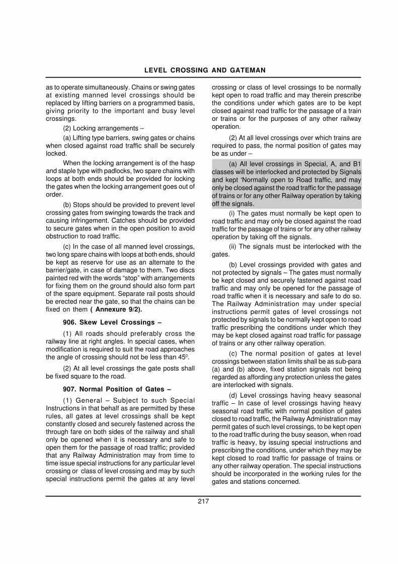
LEVEL CROSSING AND GATEMAN
217
as to operate simultaneously. Chains or swing gatesat existing manned level crossings should bereplaced by lifting barriers on a programmed basis,giving priority to the important and busy levelcrossings.
(2) Locking arrangements –(a) Lifting type barriers, swing gates or chains
when closed against road traffic shall be securelylocked.
When the locking arrangement is of the haspand staple type with padlocks, two spare chains withloops at both ends should be provided for lockingthe gates when the locking arrangement goes out oforder.
(b) Stops should be provided to prevent levelcrossing gates from swinging towards the track andcausing infringement. Catches should be providedto secure gates when in the open position to avoidobstruction to road traffic.
(c) In the case of all manned level crossings,two long spare chains with loops at both ends, shouldbe kept as reserve for use as an alternate to thebarrier/gate, in case of damage to them. Two discspainted red with the words “stop” with arrangementsfor fixing them on the ground should also form partof the spare equipment. Separate rail posts shouldbe erected near the gate, so that the chains can befixed on them ( Annexure 9/2).
906. Skew Level Crossings –
(1) All roads should preferably cross therailway line at right angles. In special cases, whenmodification is required to suit the road approachesthe angle of crossing should not be less than 450.
(2) At all level crossings the gate posts shallbe fixed square to the road.
907. Normal Position of Gates –
(1) General – Subject to such SpecialInstructions in that behalf as are permitted by theserules, all gates at level crossings shall be keptconstantly closed and securely fastened across thethrough fare on both sides of the railway and shallonly be opened when it is necessary and safe toopen them for the passage of road traffic; providedthat any Railway Administration may from time totime issue special instructions for any particular levelcrossing or class of level crossing and may by suchspecial instructions permit the gates at any level
crossing or class of level crossings to be normallykept open to road traffic and may therein prescribethe conditions under which gates are to be keptclosed against road traffic for the passage of a trainor trains or for the purposes of any other railwayoperation.
(2) At all level crossings over which trains arerequired to pass, the normal position of gates maybe as under –
(a) All level crossings in Special, A, and B1classes will be interlocked and protected by Signalsand kept ‘Normally open to Road traffic, and mayonly be closed against the road traffic for the passageof trains or for any other Railway operation by takingoff the signals.
(i) The gates must normally be kept open toroad traffic and may only be closed against the roadtraffic for the passage of trains or for any other railwayoperation by taking off the signals.
(ii) The signals must be interlocked with thegates.
(b) Level crossings provided with gates andnot protected by signals – The gates must normallybe kept closed and securely fastened against roadtraffic and may only be opened for the passage ofroad traffic when it is necessary and safe to do so.The Railway Administration may under specialinstructions permit gates of level crossings notprotected by signals to be normally kept open to roadtraffic prescribing the conditions under which theymay be kept closed against road traffic for passageof trains or any other railway operation.
(c) The normal position of gates at levelcrossings between station limits shall be as sub-para(a) and (b) above, fixed station signals not beingregarded as affording any protection unless the gatesare interlocked with signals.
(d) Level crossings having heavy seasonaltraffic – In case of level crossings having heavyseasonal road traffic with normal position of gatesclosed to road traffic, the Railway Administration maypermit gates of such level crossings, to be kept opento the road traffic during the busy season, when roadtraffic is heavy, by issuing special instructions andprescribing the conditions, under which they may bekept closed to road traffic for passage of trains orany other railway operation. The special instructionsshould be incorporated in the working rules for thegates and stations concerned.

�
�
�
�
LEVEL CROSSING AND GATEMAN (3) Gateman, where provided, shall at all level crossings other than those controlled by gates designed to close across the line, be prepared, wherever such level crossings be open to road traffic, to show a danger signal to any approaching train and for this purpose invariably keep a hand signal lit during night to show Red throughout the period the level crossing is open to Road traffic.
908.Gate Lamps and Blinders – (1) Fixture of gate lamps and indicators to road
users – Gate lamp should be mounted preferably in rectangular sockets over gates so as to give correct indication to road users vide item 6 of Annexure 9/1. The lamp should be lighted by the Gateman at sunset and remain lighted till sunrise.
(2) Provision of Blinders to Gate lamps – (a) All gate lamps should be provided with
blinders to conform with item 6 of Annexure 9/1. (b) Drivers of trains shall get no light
indication from the gate lamp except at “Special Class” level crossings where they will observe red lights when the gates are closed across the railway line and are open for road traffic.
909. Traffic and Engineering Gates – (1) Traffic Gates – (a) The manning and operation of the gates
at level crossings located between the outermost stop signals shall be under the control of Operating Department. The level crossings and structures pertaining thereto shall be maintained by the Engineering Department.
(b) When protected by signals the equipment shall be governed by the signals of the station/block hut and the operation as per the station working rules.
(2) Engineering Gates – (a) Level crossings beyond the outermost
stop signals shall be under the control of the Permanent Pay Inspectors both as regards to their operation and maintenance.
(b) Where the level crossing is protected by Signals, fixed signals shall be provided in each direction in accordance with the relevant general rules(G.R.3.34 New Rules)/approved special instructions.
(3) The maintenance of signals, interlocking and communication equipment will rest with the Signal Department in the case of all level crossing
gates, whether located within or outside the outermost stop signals.
(4) (a) The working instructions including the signalling diagram of level crossings equipped with gate signals and situated beyond the outermost stop signals in either direction of a block station and/or provided with telephone connections with the nearest adjacent station on either side, shall be kept at the gate-lodge. A copy of the working instructions shall also be kept at the station concerned.
(b) The working instructions in English and local language of every level crossing within outermost stop signals of a block station, and also of level crossing beyond the outermost stop signals which are provided with telephone connections and whose operation is governed by the system of exchange of private numbers under special instructions, should be incorporated as an appendix to the Station Working Rules of the station concerned and kept at the gate-lodge.
910. Equipment At Level Crossings – (1) The equipment for a manned level crossing shall be as follows; in addition to such others as may be prescribed by special instructions :–
(a) 2 hand signal lamps, tri-colour provided with bright reflectors,
(b) 1 hand signal flag, green. (c) 2 hand signal flags, red. (d) 1 staff suitable for exhibition of red
lamp or red flag. (e) 2 long spare chains with “stop” marked disc
attachment at the center to cover the full width of the gate, for use in case the gates/barriers are damaged (Annexure 9/2).
(f) 2 spare small chains and padlocks for locking gates, in case locking arrangements of gates become defective.
(g) 10 No. detonators in tin case(C.S.No:135 Dated:07.05.2014).
(h) 1 tin case for flags. (i) 2No.Banner Flag(C.S.No:135
Dated:07.05.2014. (j) 1 canister for muster sheet. (k) 1 can for oil. (l) 1 tommy bar. (m)1 water pot or bucket. (n) 1 mortar pan.
218

LEVEL CROSSING AND GATEMAN
(o) 1 powrah. (p) 1 rammer. (q) 1 pick-axe. (r) 1 tool list (with columns drawn for checking of
tools). (s) 1 book of safety rules in Hindi or regional
language. (t) Duty roster. (u) Complaint book for road users. (v) Inspection register. (w) Level crossing working instructions (in local
language) where applicable. (x) Two gate lamps. (y) Gatemen working on double line/ multiple
lines, ghats, suburban and automatic block territories shall be provided with three warning signals as prescribed in Para 824. Gatemen working on single line sections shall be supplied with one warning signal.(CS 136 Dt 14.11.14)
(z) Diagram indicating the method of protection to be adopted, in case of obstruction in the level crossing.
z(i) Wall clocks in gate-lodges at all manned level crossings to enable the gateman to correctly record the time of exchange of private number, expected and actual time of passage of train, time for opening and closing of level crossing, etc
Note: Incase of level crossings in multiple lines the hand signal flags/lamps, detonators and Banner flags shall be increased suitably
(C.S.No:135 Dated:07.05.2014). (2) There should be sufficient supply of kerosene
oil, wicks and matches at the gate-lodge. The Gateman should always keep their hand signal lamps trimmed and ready for lighting and use at a moment’s notice. During night, one of the hand signal lamps should be kept lit throughout to show danger stop signal to an approaching train. When the level crossing is closed to road traffic, the hand signal lamps should be kept lit dimly only.
(3) At every manned level crossing there should be distinct indication at 600 meters and 1200 meters on Broad Gauge and 400 meters and 800 meters on Meter Gauge and Narrow Gauge and at specified distances suitably increased on M. G. high speed routes where trains run at speeds above 75 km.p.h.,on either side to guide the Gateman for
placing the detonators in case of obstruction at the level crossing. Indicator posts should be provided with one dot and three dots at these distances to indicate the number of detonators to be placed. Arrangements for exhibiting the danger signal at a distance of 5 meters during emergency should be made at each level crossing.
(4) Height Gauges on Electrified Sections.- (a) Adequate arrangements shall be made to erect height gauges on either side of the overhead equipment or other equipment at every level crossing so as to ensure that all vehicles and moving structures passing under the height gauge also pass under the overhead equipment or other equipment with adequate clearance.
(b) The adequate clearance referred to in sub-rule (a) shall be sanctioned under approved special instructions.
(c) Height Gauges should be located at a minimum distance of 8 metre from gate posts. In exceptional circumstances where site condition do not permit, Chief Engineer can give exemption in these standards subject to a minimum of 8 metre distance from the centre line of the track. Road surface upto this point may be at the same level as the road surface inside the gate posts.
(d) Vehicles and moving structures, which can not pass under the height gauge without striking or touching it, shall not be permitted to pass the overhead equipment or other equipment except in accordance with special instructions.
911. Siting of Gate-Lodges – (1) Gate-Lodges shall be so sited that a clear and
unobstructed view is obtained of all approaching trains and road vehicles, care being taken that allowance is made for all future extensions, e.g., doubling of line or widening of roadway.
(2) Where the level crossing is on a curve, the gate-lodge
should be built on the outside of the curve.
(3) Level crossing at cuttings or near cuttings should be avoided as far as possible.
912. Appointment of Gatemen, Rosters and Medical fitness Certificates –
(1) Before appointment, the Permanent Way Inspector should ensure that competent men selected as gatemen have obtained Certificates of fitness for class A3 from the Medical Department and
219

LEVEL CROSSING AND GATEMAN
220
that they are examined thereafter at periods stipulatedby the rules in force. In all level crossings providedwith telephone connections literate Gateman capableof exchanging private numbers, should be posted.
(2) The hours of duty for the Gateman shouldbe laid down and must confirm to the regulations inforce. The rosters detailing the hours of duty and restfor each Gateman shall be maintained at the gate-lodge. The roster should indicate clearly as to whichgateman is required to be on duty at any particulartime. No Gateman shall change his hours of dutywithout the order of the Permanent Way Inspector.
(3) Full particulars regarding the periodicalmedical examination and vision test of each Gatemanshall be maintained at the gate-lodge.
(4) When handing or taking over charge, theGateman and their relievers should jointly check allthe equipment and test all the gears to see that theyare in order.
(5) Every Gateman shall be fully conversantwith the use of hand signals, detonators, fusees andprotection rules.
913. Duties of Gateman –(1) Alertness – The Gateman should be on the
alert and be prepared to take immediate action,should danger be apprehended. The keys of the gatesshall be on his person.
(2) Position during passage of trains – TheGatemen should stand facing the track on the gate-lodge side of the approaching train. He shouldobserve all passing trains and be prepared to takesuch action as may be necessary to ensure safetyof trains.
(3) Action in emergency – In case of anobstruction at the level crossing the Gateman shouldmaintain the gate signals, if any, in the “ON” positionand if unable to remove it, protect the line as under-
(a) On double line, if both lines are obstructedduring day, he shall plant a red banner flag at adistance of 5 metres from the end of check rails onthe line on which a train is expected to arrive first,then plant another red banner flag on the other line atthe site of obstruction. He shall then pick up redhand signal and showing it, proceed on that linetowards the direction of an approaching train to apoint 600 metres on Broad Gauge and 400 metreson Metre Gauge and Narrow Gauge from the levelcrossing and place one detonator on the line, after
which proceed further to not less than 1200 metresfrom the level crossing on Broad Gauge and 800metres on Metre Gauge and Narrow Gauge andplace 3 detonators on the line about 10 metres apart.Having thus protected the line on which a train isexpected to approach first, he should return to thelevel crossing, picking up the intermediate detonatorson his way back. He shall then proceed on the otherline showing red hand signal, place detonatorssimilarly and return to the site of obstruction to warnthe Driver of an approaching train.
Provided that on those Metre Gauge sectionswhere trains run at more than 75 Km/h, thedetonators shall be placed at distance to be specifiedunder special instructions by the Administration(Annexure 9/3).
(b) On single line, if the line is obstructed duringday, he shall plant a red banner flag at a distance of5 metres from the end of check rails towards thedirection from which a train is expected to arrive first,then plant another banner flag towards the oppositedirection at the site of obstruction. He shall then pickup red hand signal and as in sub-para (a) above,protect the line in the direction from which a train isexpected to approach first, return to the site ofobstruction, and proceed with all haste in the otherdirection to protect the line. Having protected theline on both sides, he should station himself at theplace of obstruction to warn the Driver of anapproaching train (Annexure 9/3).
(c) At night the Gateman should light the twohand signal lamps and take action to exhibit red lightand protect the lines as in sub-paras (a) and (b)above.
(d) Gateman should take immediate action toinform the Mate, P.W.I. and the nearest StationMaster about the obstruction at the level crossingthrough messenger or other means available.
(4) Parting of a Train -If a Gateman noticesthat a train has parted he shall not show a stop handsignal to the Driver, but shall endeavour to attractthe attention of the Driver and the Guard by shouting,gesticulating or other means.
(5) The Gateman should ensure that the gatelamps and lamps of all gate signals are lighted andkept burning continuously from sunset to sunrise.
(6) No Gateman shall leave his gate unlessother Gateman has taken charge of it. If it is

LEVEL CROSSING AND GATEMAN
221
necessary to leave his gate in an emergency, beforedoing so, he should close and lock the gates againstthe public road.
(7) The Gateman should see that the channelfor the flange of the wheel is kept clear.
(8) The Gateman should keep the road surfacewell watered and rammed.
(9) At level crossings, if any gate or barriergets damaged / out of order the Gateman should usethe spare chain and disc, for closing against the roadtraffic.
(10) As soon as possible, the Gateman shouldreport to the nearest Station Master, Gang Mate orPermanent Way Inspector any defect in his gate orthe apparatus pertaining to it.
(11) At gates the signal or signals of whichhave become defective, the Gateman should closeand lock the gates on sighting of train and hand signalor pilot the train past the defective signal. In suchcase he should inform the Driver to report about thedefective signal or signals to the Station Master atthe next station.
(12) In the event of a gate signal becomingdefective the Gateman should maintain the signal inthe ‘ON’ position by disconnecting the signal or thewire if necessary.
(13) The Gateman should ensure that theequipment supplied to the gate is in good order andready for immediate use.
(14) Every Gateman shall as for as possibleprevent trespassing by persons or cattle.
914. Maintenance of Level Crossing,Examination of Gate equipment and Gatemanin Rules – (1) By Permanent Way Inspectors –
(a) Obstruction of view – All trees, bushes orundergrowth that interfere or tend to interfere withthe view from the Railway or road way whenapproaching level crossings, should be cut downtaking care to comply with the procedure laid downin para 222.
(b) Inspection and Maintenance – (i) Each levelcrossing except those laid with PSC sleepers mustbe opened out and the condition of sleepers andfittings, rails and fastenings inspected at least oncea year or more frequently, as warranted byconditions. However, level crossings laid with PSCsleepers should be overhauled with each cycle ofmachine packing or more frequently as warranted
by conditions and in no case shall opening be delayedby more than two years. In all cases, rails andfastenings in contact with the road shall be thoroughlycleaned with wire brush and a coat of coaltar/anti-corrosive paint applied. Flange way clearances,cross level, gauge and alignment should be checkedand corrected as necessary, and the track packedthoroughly before reopening the level crossing forroad traffic.(ii) The painting of gates and discs should be doneat regular intervals.(iii) The Permanent Way Inspector should keep amanuscript register of repairs for all level crossingson his section. This register should show the date ofopening, the condition of sleepers with their age andtime, the date and type of each sleeper changed andother requisite particulars.
(iv) The Permanent Way Inspector will beresponsible for the proper upkeep and maintenanceof whistle boards and ‘STOP’ boards provided onthe approaches to level crossings.
(v) Check rails of level crossing are required tobe removed for tamping operations, overhauling oflevel crossings, distressing of LWR or track renewalsetc. Check rails should be re-fixed as quickly aspossible and preferably before leaving site.
Should a situation arise where check railscannot be re-fixed for any reason and trains have tobe passed, a speed restriction of 30 kmph shouldbe imposed besides ensuring that road traffic isdiverted till the check rails are put in place. In casesuch diversion is not possible, temporaryarrangements should be made for passage of roadtraffic till the check rails areput in place. However, inboth these cases, the check rails should necessarilybe provided latest by close of next day. In suchcases, a stationary watchman shall be posted toensure safety.
(c) Checking equipment and examination ofGateman in rules – (i) The equipment with theGateman shall be checked by Permanent WayInspector once in a month.
(ii) The Permanent Way Inspector shall ensure thatthe Gateman have a correct knowledge of rules byexamining them periodically during his trollyinspection and on appointment, promotion or transfer.He should not only educate them in rules, but alsoconduct practical demonstration of protection of levelcrossing in case of emergency.

�
�
�
� LEVEL CROSSING AND GATEMAN
(d) Surprise day/night inspection of level
crossing should be carried out to ensure presence and alertness of Gateman. (2) By Assistant Engineer –
The Assistant Engineer should inspect the equipment at every manned level crossing on the sub-division once in six months, and examine the Gateman in rules during his inspection.
The Assistant Engineer should scrutinise the manuscript register of level crossings maintained by the Permanent Way Inspectors and inspect as many level crossings as possible, when they are completely opened out during the year.
915. Level Crossing Registers – In the office of the Divisional Engineer, Assistant Engineer and Permanent Way Inspector, complete particulars of level crossings in serial order should be maintained in a register as shown in Annexure 9/4.
Whenever additions and alterations or improvement to level crossings are made, the level crossing registers should be amended and where necessary a copy of the new or revised working instructions with the revised signal and interlocking diagram posted at the gate-lodge.
916. Level Crossing indicators – (1) Whistle indicator – (i) At the approaches to
all unmanned ‘C’ class level crossings or manned level crossings where the view is not clear on either side for a distance of 600 meters and those which have normal position open to road traffic, without interlocking and protection by signals, under special conditions, bilingual whistle boards as per design (Annexure 9/5) should be erected at 600 meters along the track from the level crossing to enjoin the Drivers of approaching trains to give audible warning of the approach of a train to the road users. The Drivers of approaching trains should whistle continuously from the time they pass whistle boards to the time they cross the level crossing. sentence added vide A&C No.100 dated 21.06.2006 at the bottom of sub-para(1)(i) of para 916 of IRPWM as reproduced below shall stand deleted.(C.S.No:128 dated 05.03.2012)
(ii) The whistle indicator shall consist of two 600 mm. square boards painted yellow and bearing letter W/L in black. Its height shall be 2100 mm. from the rail level to the underside and the post on which it is fixed, painted with 300 mm. high bands in white and black. It shall not be lighted at night.
(2) ‘Stop’ Boards – (a) On the road
approaches to all unmanned ‘C’ class level crossings ‘Stop’ boards should be provided on the road at either side of the level crossings at suitable points, within the railway boundary.
(b) This shall consist of a board 675 mm.X525 mm. on a suitable post bearing the indication of an engine and the legend “Stop, look out for trains before crossing” in English, Hindi and Regional language. The paint used shall preferably be of luminous variety. The distance of the “Stop” board from the track on the approaches of the unmanned level crossings shall be 5 meters from centre line of the nearest track, within the Railway boundary.
(c) The vertical post shall be painted black and white, each strip to be 300 mm. in height starting with black paint at the bottom.
917. Visibility Requirements for unmanned Level Crossings – For new unmanned level crossings the visibility requirements for road users along the track shall be 600 M. with single or double line track. Where this is not feasible, the distance may be reduced suitably with the approval of the Chief Engineer provided the maximum permissible speed is less than 100 km.p.h. and/or there is only a single track to be crossed on the level crossing. Visibility of trains for road users at unmanned level crossing may be assessed, from a distance of 5 meters from the centre of the track.
918. Provision of speed breakers on the approaches of level crossing –
Provision of rumble strips on approaches of level crossings as per the standard design is the responsibility of Road authorities. Matter may be persued with all State Governments/Road authorities to ensure that rumble strips are provided on all level crossings as per standard design over the total width of the road i.e. edge of the berm to edge of berm with proper road warning signs as per the standard design. However, it is incumbent upon Railways to provide speed breakers as per the standard design on both manned as well as unmanned level crossing irrespective of whether the approach road are metalled or un-metalled, as a temporary safety measure, till such time these are replaced with rumble strips of proper design by the Road authorities. While providing speed breakers, following guidelines may be observed:- 222

�
�
�
�
LEVEL CROSSING AND GATEMAN
1) One speed breaker should be provided on either approach of level crossings at a distance of about 20m from the gate post of the Level Crossing, covering full width of the road including berms as per Annexure-9/6. This may require construction of speed breaker by Railway outside Railway boundary. For roads with central median/One-Way Roads, speed breaker is to be provided on the entry side of the road only. For safety reasons, the paint marking should be provided and their maintenance ensured.(C.S.No:128 Dated:05.03.2012)
(1) Standard warning signs for speed breakers as per Annexure - 9/7 should be invariably provided at a prescribed distance as indicated in item 19 of Annexure 9/1 to Para 904.
(2) Speed breakers should be constructed with hot pre-mix bituminous material, well compacted after laying on well prepared surface. Enough time is to be allowed for the bituminous material to harden before opening it to the traffic. On berms and unmetalled roads, the speed breakers should be supported on proper base of compacted road metal.
919. Census of Traffic at Level Crossings, Unmanned/Manned – (1) Periodical census of traffic at all level crossings, unmanned/manned shall be taken once every three years. This shall be carried out for 7 days and total Train vehicle Units (TVUs)/ day (train units x Road vehicle units) are worked out. Train, Road vehicle, Bullock carts and Tongas being considered as one unit; cycle rickshaw/Auto rickshaw being considered as half unit. The census shall be carried out by a multi-disciplinary inspectorial team consisting of representatives of CE, S&T and Traffic Departments. The mechanism shall be set up by the Divisional Railway Manager to ensure that the representatives are present for the census by laying down advance time table for carrying out of census of level crossings.
(2) In the case of unmanned level crossing involved in an accident, census should be conducted immediately, to determine whether manning is required.
(3) In the case of manned level crossings, the quinquennial census should be substituted by a census-cum-job analysis so as to avail of the opportunity of checking up the adequacy of men on consideration of Hours of Employment Regulations.
920. Unmanned ‘C’ class Level Crossings – The upkeep of all unmanned ‘C’ class level crossings should be to the same standard of maintenance as that of manned level crossings. The posts at such
unmanned level crossings may be either of unserviceable steel sleepers or unserviceable rail pieces, painted white.
The keyman during his daily beat should pay requisite attention to the general condition of such level crossings and keep the flange ways clear and free from obstruction.
921. Track Structure in Level Crossings (1) In level crossings ‘U’ category sleepers
(durable) should preferably be used.
(2) All sleepers used in level crossings should be provided with suitable bearing plates.
(3) Rail joints should be avoided in check rails and on the running rails, within the level crossings and three meters on either side.
(4) In each rail seat, four spikes should be provided.
(5) In the case of S.W.R., the short welded panel may be continued through the level crossing, avoiding fish plated joint on the level crossing and within six meters from the end of level crossing.
(6) The level crossing should not fall within the breathing length of L.W.R., as per the provisions contained in L.W.R. Manual.
922. Manning of the unmanned Level crossings through Member of Parliament Local Area Development Scheme (MPLADS) :
(1) The manning of unmanned Level Crossings has been included in the list of works covered under Member of Parliament Local Area Development Scheme (MPLADS). The funds for capital cost of construction covering the cost of road, provision of lifting barrier, arrangement of water and electricity, quarters for the gatemen, duty hut etc. will be provided by Member of Parliament from MPLADS Fund and recurring maintenance and operation cost will be borne by the Railways.
(2) Unmanned level crossings equal to number of level crossings manned through Member of Parliament Local Area Development Scheme, will be converted into manned level crossing at Railway's cost as selected in consultation with Member of Parliament concerned.
(3) Preferably, selected unmanned Level Crossings, should fall in the category I-V with priority given to Level Crossings falling in Category-I followed by Category-II, III, IV, V. For Level crossings falling in the same category on different routes, priority shall
223

�
�
�
�
LEVEL CROSSING AND GATEMAN be given to A route followed by B, C, D-Spl., E-Spl, D and E-routes.
(4) Divisional Railway Managers will liaison with the District Authorities and the Hon'ble Member of Parliaments in selecting the Level Crossings for manning. On identification of the Level Crossings, Member of Parliament will send his recommendations to the District Magistrate/ Dy. Commissioner for releasing the funds. Railway will provide an estimate for the work and any other details to the District Administration as required. Departmental charges shall not be levied on these works and supervision and establishment charges will be kept to the minimum as provided in the case of similar Railway works. Separate accounts shall be maintained for each work and Utilisation Certificate' will be submitted to the District Administration on completion of the work.
923. Level Crossings on National Highways/State Highways and Other Important roads.
(1) In case of National Highway/State Highways or their bypasses and important city roads, no new Level Crossing to be provided and only grade separators agreed to be provided.
(2) In case of other important roads, it is preferable to provide grade separators. However, depending upon the traffic density envisaged, manned Level Crossings can also be considered.
(3) Relaxation of the above (1) will require Board's prior approval.
924. Provision of New Level Crossings/ Manning/Demanning/Elimination:-
(a) Provision of the new level crossings: If, provision of new level crossing is inescapable, then only manned level crossing is to be provided. This is applicable to all existing lines, new constructions and gauge conversions. However, these instructions are not applicable in case of private sidings. b ( i) - Based on traffic density and visibility etc. unmanned level crossings have been categorized into I to III for manning at Railways cost in a phased manner as per following priority: Category I - All Unmanned Level Crossings with TVU above 3000. Category II - All Unmanned Level Crossings with visibility restricted to 800 metres for road users and TVU above 2500.
Category III – All Unmanned Level Crossings which do not fall in Category – I & II above and which cannot be eliminated by any other methods like construction of diversion road, subway, closure of gates having low TVU or any other means as per extant policy instructions. Note for Category III: Divisional Railway Manager shall, ensure identification of unmanned level crossings, which can be eliminated by any other means, get necessary works sanctioned and simultaneously obtain No Objection Certificate (NOC) i.e. consent for closure of unmanned level crossings from the State Govt./District Magistrate to avoid delay in closure. For remaining unmanned level crossings, i.e. which cannot be eliminated by any other methods and where manning is the only solution; Divisional Railway Manager shall recommend proposals of manning of unmanned level crossings, in order of priority, for timely sanction by the competent authority. Manning of level crossings can be prioritized in order of TVU or any other relevant site specific factors. Manning of such unmanned level crossing gates will require specific approval of the General Manager. (C.S.No:128 Dated:05.03.2012)(ii) All unmanned level crossings on Rajdhani and Shatabdi routes where maximum permissible speed is 120 Kmph or more should be manned on priority.
Further train route wise priority to be followed for manning will be ‘A’ route followed by ‘B’ ‘C’ ‘D’ ‘D Spl” ‘E Spl’ and ‘E’ para 924 (b) iii deleted.(C.S.No:128 Dated:05.03.2012) c) - Elimination of Level Crossing: A detailed review/survey of the existing level crossings both manned and unmanned should be carried out with a view to eliminate them by, (i) Construction of Subways, along with adequate drainage arrangements. (ii) Construction of roads along Railway boundary to divert road traffic to the nearest level crossing/grade separator/existing Railway bridge, wherever adequate land width is available, (iii) Closure of low TVU gates, (iv) Construction of ROB/RUB as per Para 925, etc.(C.S.No:128 Dated:05.03.2012). However Railways may de-man an existing level crossing gate in case the TVU level falls below 80% of the value of the criteria laid down for manningin sub-para (b) (i) above 224
APE
etc.

LEVEL CROSSING AND GATEMAN
225
for replacement with Road Over/Under Bridges on`Cost Sharing' basis. However, this could be relaxedin the following cases:-
(a) Suburban sections having high frequencyof train services; and
(b) Near stations where detentions to roadtraffic are very high on account of either shuntingoperations or multi-directional receipt/despatch oftrains or stabling of trains etc.
(2) Preference should be given to the LevelCrossings located on trunk routes vis-à-vis thoselocated on branch lines. In any case, minimumnumber of times the level crossing is required to beclosed against the road traffic should at least be 12times per day.
(3) Subject to (1) and (2) above, priority shouldgenerally be accorded by the concerned StateGovernment giving preference to Level crossings onNational Highways.
(4) In case of Road Over/Under Bridgesconstructed in replacement of busy level crossingssituated in Municipal/ Corporation/ Metropolitan areaswhere Light Vehicular traffic is considerable andwhere the Railways are satisfied that closure of thelevel crossings would cause hardship, additionalprovision may be made for construction of the sub-way or a light Over Bridge with ramps for the use oflight vehicular traffic at the time of framing the proposalfor the construction of Road Over/Under Bridges.The proposals for providing the ramps/sub-wayshould be examined critically and should be providedfor only in the case of genuine hardships and not asa matter of course. The cost of these ramps/subwaywill be shared equally with the Sponsoring Authorityon 50:50 basis.
(5) Closure of the Level Crossings should beensured before commissioning of the Road Over/Under Bridges. All such cases where State/LocalAuthorities do not agree to abide by this should bereported to the Railway Board promptly.
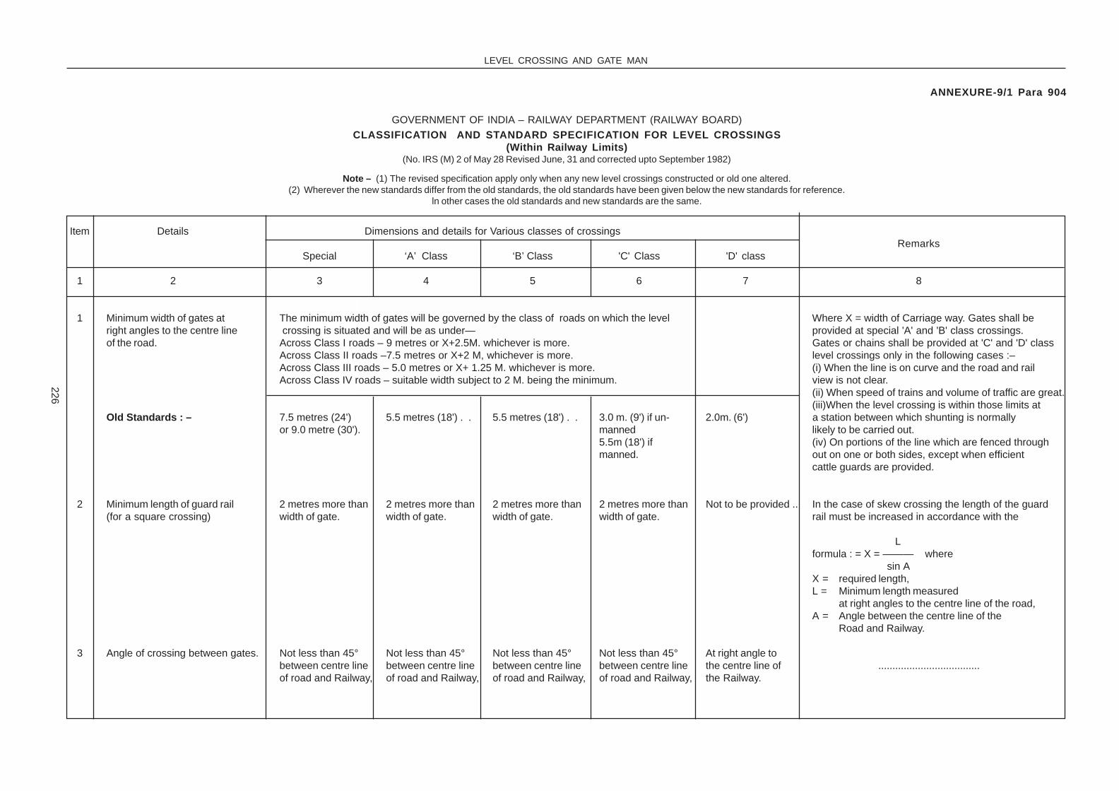
LEVEL CROSSING AND GATE MAN
226
ANNEXURE-9/1 Para 904
GOVERNMENT OF INDIA – RAILWAY DEPARTMENT (RAILWAY BOARD)
CLASSIFICATlON AND STANDARD SPECIFICATION FOR LEVEL CROSSINGS(Within Railway Limits)
(No. IRS (M) 2 of May 28 Revised June, 31 and corrected upto September 1982)
Note – (1) The revised specification apply only when any new level crossings constructed or old one altered.(2) Wherever the new standards differ from the old standards, the old standards have been given below the new standards for reference.
ln other cases the old standards and new standards are the same.
Item Details Dimensions and details for Various classes of crossingsRemarks
Special ‘A’ Class ‘B’ Class 'C' Class 'D' class
1 2 3 4 5 6 7 8
1 Minimum width of gates at The minimum width of gates will be governed by the class of roads on which the level Where X = width of Carriage way. Gates shall beright angles to the centre line crossing is situated and will be as under— provided at special 'A' and 'B' class crossings.of the road. Across Class I roads – 9 metres or X+2.5M. whichever is more. Gates or chains shall be provided at 'C' and 'D' class
Across Class II roads –7.5 metres or X+2 M, whichever is more. level crossings only in the following cases :–Across Class III roads – 5.0 metres or X+ 1.25 M. whichever is more. (i) When the line is on curve and the road and railAcross Class IV roads – suitable width subject to 2 M. being the minimum. view is not clear.
(ii) When speed of trains and volume of traffic are great.(iii)When the level crossing is within those limits at
Old Standards : – 7.5 metres (24') 5.5 metres (18') . . 5.5 metres (18') . . 3.0 m. (9') if un- 2.0m. (6') a station between which shunting is normallyor 9.0 metre (30'). manned likely to be carried out.
5.5m (18') if (iv) On portions of the line which are fenced throughmanned. out on one or both sides, except when efficient
cattle guards are provided.
2 Minimum length of guard rail 2 metres more than 2 metres more than 2 metres more than 2 metres more than Not to be provided .. In the case of skew crossing the length of the guard(for a square crossing) width of gate. width of gate. width of gate. width of gate. rail must be increased in accordance with the
Lformula : = X = ——— where
sin AX = required length,L = Minimum length measured
at right angles to the centre line of the road,A = Angle between the centre line of the
Road and Railway.
3 Angle of crossing between gates. Not less than 45° Not less than 45° Not less than 45° Not less than 45° At right angle tobetween centre line between centre line between centre line between centre line the centre line of ....................................of road and Railway, of road and Railway, of road and Railway, of road and Railway, the Railway.

LEVEL CROSSING AND GATE MAN
227
4 Provision of Wicket gates To be provided To be provided To be provided "To be provided on the Not to be Design of Wicket gate should be such that trespassingfor foot passengers. except where foot except where foot except where foot need basis after assessing provided . . by cattle is prevented.
over bridges are over bridges are over bridges are the requirents by comm- provided. provided. provided. ittee constituted by Rly." (CS.128 dt 5.3.12)
5 Position of gates when Across or towards Away from or Away from or Away from or towards Same as ‘ C ‘ (i) At new manned level crossing or when existingopen to road traffic. the line. towards but not towards but not but not across the line class but stakes unmanned level crossings are upgraded to manned
across the line. across the line. if gates are provided. shall be fixed level crossings, lifting barriers should normally bebetween the gate provided, which should be coupled, so as toposts to prevent operate simultaneously Chain and Swing gates atpassage of Road existing manned level crossings should be replaced
by lifting barriers on a programmed baste, givingpriority to the important and busy level crossings.
(ii) Where lifting barriers are provided, the beams willbe in vertical position.
6 Provision of lights on Red when either Red when either Red when either Red when either gate Not to be (iii) At all important level crossing gates wheregates at nights. gate is closed to the gate is closed to the gate is closed to the is closed to the road, provided . . electric power supply is available flashing lights to(a) Light as observed Road, white when Road, white when Road, white when white when both gates give indication to the road users about lowering orby road users. both gates open to both gates open to both gates open to are open to the Road. raising of lifting barriers should be provided.
the Road. the Road. the Road. But provision of gate An economical arrangement would be to fit thelamps is not obligatory gate lamp to the revolving hinge post and to fit theand should normally fixed gate post a cowl to mask the lamp in bothbe provided at only directions along the track. If local conditions make itthose level crossings expedient to fit the lamp in the centre of the gate,where there is Motor a suitable rod operated cowl must be provided.Traffic. Where there isno Motor Traffic thegate should be paintedwhite and red discprovided. If posts andchains are provided theposts should be paintedwhite with red discprovided on the chainsat the centre andreflectors, luminous
Item Details Dimensions and details for Various classes of crossingsRemarks
Special ‘A’ Class ‘B’ Class 'C' Class 'D' class
1 2 3 4 5 6 7 8
APE
Not to be provided
APE
on the
APE
ittee constituted by Rly."
APE
the requirents by comm-
APE
need basis after assessing
APE
(CS.128 dt 5.3.12)

LEVEL CROSSING AND GATE MAN
228
paint or scotchlite tapemay be provided onthe red disc as analternative to lamps.
(b) Light as observed Red when gates Nil. Nil. Nil. Nil.by Drivers of approaching trains. are closed across
track.7 Minimum distance of gate For B.G. 3 metres 3 metres 3 metres 3 metres 3 metres
posts from centre line of track. For M.G. } 2.5 M. 2.5 metres 2.5 metres 2.5 metres 2.5 metresand N.G. }
8 Minimum distance of gatelogde from –(a) Centre line of nearest track. 6 metres 6 metres 6 metres 6 metres 6 metres If the line of approach road is on a curve at or near a
level crossing, the gate lodge must be built on the outside of curve.
(b) Edge of Road metalling. 6 metres 6 metres 6 metres 6 metres 6 metres
Old Standards – 6 metres 4.5 metres 4.5 metres 3 metres 3 metres
9 Interlocking and CommunicationDevices to be provided
(a) Normal Position of gate Open to road traffic Open to road traffic Closed to road traffic. Closed to road traffic.Can be kept open to Can be kept open toroad traffic provided road traffic providedeither gates are either gates areinterlocked with signals interlocked withand provided telephone signals and providedcommunication with telephone communicationadjacent stations/ with adjacent stations/cabins or when the cabins or when thefollowing conditions are following conditions aresatisfied: satisfied:
Item Details Dimensions and details for Various classes of crossingsRemarks
Special ‘A’ Class ‘B’ Class 'C' Class 'D' class
1 2 3 4 5 6 7 8

�
�
�
�
LEVEL CROSSING AND GATE MAN 229
Item Details Dimensions and details for Various classes of crossings
Remarks
Special
‘A’ Class
‘B’ Class 'C' Class 'D' class
1 2 3 4 5 6 7 8
(i) L.C. should not be (i) L.C. should not be
located in a Suburban located in a Suburban
Section. Section.
(ii) L.C. should not be (ii) L.C. should not be
in Automatic Block in Automatic Block
Signallling or Automatic Signallling or Automatic
permissible block permissible block
signallling territories. signallling territories.
(iii) Should have a (iii) Should have a
telephone connection telephone connection
with the nearest station with the nearest station
with exchange of with exchange of
private numbers. private numbers.
(iv) Visibility at the (iv) Visibility at the
level crossing level crossing
should be good. should be good.
(v) Should be provided (v) Should be provided
with whistle boards on with whistle boards on
either side at adequate either side at adequate
distance to enjoin the distance to enjoin the
Drivers of approaching Drivers of approaching
trains to give audible trains to give audible
warning of the warning of the
approach of a train approach of a train
to the road users. to the road users.
(vi) As long as the (vi) As long as the
level crossing gate is level crossing gate is
kept open to road kept open to road
traffic a red flag by day traffic a red flag by day
time and red light (by time and red light (by
using hand signal using hand signal
lamp) during night, lamp) during night,
should be displayed should be displayed
towards the towards the
approaching trains on approaching trains on
either side of level either side of level
crossing. crossing.
Note*:The above decision should be taken personally by DRM’s approved by P.C.E./C.E. (Co-ordination) and C.O.M. and position reviewed every two years.(C.S.No:115 Dated:24.11.2008).

LEVEL CROSSING AND GATE MAN
230
(b) Interlocking of gates with Should be Should be Should be interlocked Should be interlocked (i) The level crossing inside station limits should besignals – interlocked with interlocked with with signals. with signals. beyond the limits upto which shunting is normally
station signals. station signals. (i) In Suburban (i) Within station limits carried out or at an adequate distance of at least(i) If within station limits. Sections. where operated from 250 metres ahead of the starters and trailing points of
(ii) In non-Suburban cabin, (ii) in automatic the station where Advanced Starters/Shuntingsections where signalling and Limit Boards are not provided.operated from cabins. Automatic permissive(iii) In Automatic block terriories. (ii) In case of level crossings falling on SuburbanSignalling and Sections they may be considered for upgradationautomatic permissive to 'B' class in the event of their not qualifyingblock territories. for upgradation to "Special" or 'A' class and when
so upgraded to ' B ' class the facilities as indicatedin column 5 should be provided.
(ii) If outside station limits. Should be Should be To be interlocked To be interlocked in (i) In the case of level crossings protected byinterlocked with interlocked with (1) In luburban automatic signalling signals where the sighting of the signal by an enginegate signals, gote signals, sections and automatic Driver is inadequate a warning board should be placed
(2) In autoinatic permi-ssive block at not less than the emergency braking distance insignalling and territories. rear of the gate stop signal. The board should beautomatic permissive vertical 2000 mm. by 450 mm. with alternate blackblock territories. and yellow strips 125 mm. wide painted on it at an
angle of 45°. The top of the board should be 4 M.above Rail level. The board need not be lit at nightbut should as far as possible be provided withscotchlite or other effective light reflectors.(ii) Where level crossing is situated outside stationlimits but in close proximity thereof, the cleardistance between the level crossing and an outersignal should not be less than a full train length.
(c) Telephone Communicationfrom gate-lodge –
(i) Within station limits. Telecommunication Telecommunication Telecommunication Telecommunication In cases where communication with A. S. M. iswith A. S. M.’s Office with A. S. M.’s Office with A. S. M.’s Office with A. S. M.’s Office stipulated, the connection may be given to theto be provided. to be provided. to be provided. to be provided in case Switchman in the Cabin as per the local condition.
of manned levelcrossings.
(ii) Outside station limits. Telecommunication Telecommunication Telecommunication Telecommunicationwith A. S. M.’s Office with A. S. M.’s Office with adjoining station with adjoining stationof adjoining station of adjoining station to be provided on— to be provided –should be provided. should be provided.
Item Details Dimensions and details for Various classes of crossingsRemarks
Special ‘A’ Class ‘B’ Class 'C' Class 'D' class
1 2 3 4 5 6 7 8

LEVEL CROSSING AND GATE MAN
231
(a) All level crossings (a) On all levelon Rajdhani route; croissings on
Rajdhani route;
(b) On suburban (b) On Suburbansections; and sections; and
(c) On curves (c) On curvesobstructing the view obstructing the viewof the level crossing of the level crossingfrom approaching from approachingtrain and vice versa. train* and vice versa.
(d) warning bell operated by Should be provided Should be provided Shall be provided Shall be provided Provision of warning bells operated by approachingapproaching train. where L.C. is outside where L.C. is outside where L.C. is outside where L.C. is outside trains should be confined to interlocked level
station limits. station limits in all a station limits. In all station limits in all crossings only,suburban sections suburban sections Suburban sectionsand on non-suburban and on non-suburban and non-Suburbansections provided sections provided with sections providedwith automatic automatic signalling with automaticsignalling and in and in APB territories. signalling and inAPB territories. APB territories.
10 Minimum no. of Gate Keepers. Three Two Two Two if manned (one if Two if manned (one if Note.—the gate is closed and the gate is closed and (1) Gate Keepers will not be provided at 'C' and 'D'locked at night in locked at night in class level. crossings where gates/chains are notaccordance with the accordance with the provided.provision of provision of (2) Gate Keepers may be dispensed with at gatesGR.16.03). GR.16.03). within station limits when operated by station staff
in accordance with special instructions.(3) Gate Keepers may be dispensed with at 'C' classlevel crossings on canal roads which are providedwith gates if the following conditons are fulfilled :—(a) The gates are generally closed to the road and locked.(b) The roads are the private property of the Irrigation,Public Works Department and are not public thoroughfares.
Item Details Dimensions and details for Various classes of crossingsRemarks
Special ‘A’ Class ‘B’ Class 'C' Class 'D' class
1 2 3 4 5 6 7 8

LEVEL CROSSING AND GATE MAN
232
Item Details Dimensions and details for Various classes of crossingsRemarks
Special ‘A’ Class ‘B’ Class 'C' Class 'D' class
1 2 3 4 5 6 7 8
(c) The keys of the gates are issued to a fewresponsible Government Officials.
(d) The traffic over the level crossing is very light.(4) One Gate Keeper may be dispensed with if there is
no traffic in the night in accordance with GR. 16.03.
11 Fencing on lines which are not Minimum length of Minimum length of Minimum length of Minimum length of Fencing should befenced throughout • their length. 15 m. from each 15 m. from each 15 m. from each 15 M. for manned provided for level
gate post parallel gate post parallel gate post parallel level crossing outside crossings if mannedto track to track to track station limits and level with gates/chains
crossing within station within station limitslimits provided with for 15 M. length.gates/chains.
12 Width of metalling—(a) Between gates ... Same as that of the Same as that of the Same as that of the same as that of the same as that of the
width of gates. width of gates. width of gates. width of gates or the width of gates or thewidth between gate width between gateposts where gate posts where gateleaves are not provided. leaves are not
provided.
(b) Outside gates ... Minimum width of metalling immediately outside gates (but taperingoff to the existing carriage way width within a distance of 30 M fromthe gate) shall be as follows depending on the class of road overwhich the L. C. is situated :—
Class I road : 7 M Class II Road: 5.5 M Class III road: 3.78 M Class IV road, suitableor the width of or the width of or the width existing width subject to 2Mexisting carriage existing carriage of carriage way being the minimum.way whichever is way whichever whichever is greater.greater. is greater.
Old Strands - Same width as metalling outside the Railway Boundry. If the surface outside is cement concrete, blacktop surface may be provided.
13 (a) Type of pavement between Same standard as that of the road surface outside the Railway Boundary. For class I and II roads, it is desirable to havegates. black topped surface for a distance of at least(b) Outside gates ... Same standard as that of the road surface outside the Railway Boundary. 30 M beyond each gate.
14 Minimum width of road formation Depending on the class of road ove rwhich level crossing is situated the minimum widthoutside the gates for a distance of road formation will be as under –of 30 M beyond the gate.
Class I roads:C+5M. Class II roads:C+5M. Class III roads:C+5M. Class IV roads,suitable width 3 metresbeing the minimum.
Note.—C = width of metalling just outside the gate.

LEVEL CROSSING AND GATE MAN
233
Item Details Dimensions and details for Various classes of crossingsRemarks
Special ‘A’ Class ‘B’ Class 'C' Class 'D' class
1 2 3 4 5 6 7 8
Old Standards – ‘Special class' — 'A' Class— ‘B’ Class— C' Class— 'D' Class—Same as rest of the 4 metres 3 metres ' 2 metres 3m.road outside wider than metalling. wider than metalling. wider than metalling.Railway Boundary
15 Level length and gradients –(a) Between gates... Level Level Level Level Level
(b) Outside gates ... Depending upon the class of road over which the level crossing is situated the level lengthand gradient will be as follows:—
Class I roads— Class II roads— Class III roads— Class IV roads— Vertical curves should be-provided at changeLevel upto ... 15 metres beyond. 8 metres beyond. 8 metres beyond. of grades within Railway Boundary according to
Indian Road Congress Standard, beyond theNot steeper than 1 in 40 beyond. ... 1 in 30 beyond. ... 1 in 20 beyond. ... 1 in 15 beyond. ... level portion.Old Standards — Special — ‘A' Class — ‘B' Class — ‘C' Class — ‘D' Class —
Level for ,... 8 metres beyond. 6 metres beyond. 6 metres beyond. 6 metres beyond.
Not steeper than 1 in 40 beyond. 1 in 30 beyond. 1 in 30 beyond. 1 in 20 beyond. 1 in 10 beyond.
16 Minimum radius of centre line of (i) In the case of Level crossings situated on National or State Highways,road on curved approaches. the following minimum radius may be adopted ;— i Plain or rolling country ... 250 metres.
Hilly country ... ... 90 metres.
(ii) In difficult terrain, the radius may he reduced with the concurrence of road authorities.
(iii) The aim should be to provide the greatest possible radius.
(iv) In the case of other roads the best possible radius, having regard to safety of Roadtraffic may be adopted.
Old Standards — Special — ‘A' Class — ‘B' Class — ‘C' Class — ‘D' Class —60 M. (200 ft.) 45 M. (150 ft.) 30 M. (100 ft.) 21 M. (70 ft.) 8 M. (25 ft.)

LEVEL CROSSING AND GATE MAN
234
Item Details Dimensions and details for Various classes of crossingsRemarks
Special ‘A’ Class ‘B’ Class 'C' Class 'D' class
1 2 3 4 5 6 7 8
17 Minimum and desirable straight Depending on the class of road over which the level crossing islength of Road outside the gate. situated the following minimum and desirable length may be adopted:-
Class I — Class II — Class III —
(i) Desirable 30 M. 22.5 M 15 • M.
(ii) Minimum 15 M. 9 M. 4.5 M.
Old Standards — Special — ‘A' Class — ‘B' Class — ‘C' Class — ‘D' Class —12 M. 9 M. 6 M. 3 M. Nil.
18 Minimum sight distance of level Depending on the class of road over which the level crossing iscrossing gate from road in the situated the following sight distances may he adopted :— vicinity of level crossing
Class I — Class II — Class III — At unmanned level crossings sight triangle may hedemarcated in the four corners on the basis ofspeeds of trains and the road vehicles, clear of any
(i) Plain or rolling country. 120 M. 60 to 90 M. 40 M. obstruction to sight.
(ii) Hilly country ... 60 M. 40 to 50 M. 30 M.
19 Warning to road traffic of The distance of road sign posts from level crossing :— 1) Road signs conforming to the standardsproximity of level crossing— prescribed must be erected by the Road Authority
in advance of the level crossing at the specifieddistances.
Class I — Class II — Class III —
2) 'Stop' boards bearing the prescribed legend to(a) Plain country ... 120 M. 60 to 90 M. 40 M. be provided on the road on either side at suitable
points within the Railway Boundary at theapproaches to all unmanned level crossings.
3) Gate posts should be provided invariably. Even(b) Hillycountry ... 60 M. 40 to 50 M. 30 M. in cases where no gates are provided posts should
be painted white. Gates should be painted whitewith a red disc not less than 600 mm. dia. in thecentre of gate.

LEVEL CROSSING AND GATEMAN
235
ANNEXURE 9/2 PARA 905
1m
.
1m
.
40 mm
SEPARATE RAIL POSTINDEPENDENT OF THEGATE POST
8 mm. DIA
STOP BOARDCHAIN TO BE FIXEDON THIS SIDE
ARRANGEMENTS TO BEMADE FOR HANGING THECHAIN IN THE RAIL POSTBY A HOOK
15 cm.
CHAIN HUNG ON ASUITABLE HOOK ATTHE CENTRE
REARELEVATION
FRONTELEVATION
SIDEELEVATION
ROD15 mm.
PIPE EMBEDDEDINTO THECENTREOF ROAD
HOOK (BENT PLATE) FIXEDTO DISC FOR HANGING THE CHAIN
M.S. PLATE15mm. THICK
10 cm.
15cm
60cm
RED BACKGROUNDWITH WHITE LETTERS
DETAILS OF STOP DISC TO BE PROVIDEDALONG WITH SAFETY CHAIN
AT MANNED LEVEL CROSSINGS
HEIGHTNOT LESS THAN
1 METRE

LEVEL CROSSING AND GATEMAN
236
ANNEXURE 9/3 PARA 913 (3)
BANNER
BANNER
END OF CHECK RAIL
BANNER
END OF CHECK RAILS
PROTECTION FOR THE DIRECTION OPPOSITE TO THAT OFAPPROACHING TRAIN TO BE REPEATED ON THE OTHER SIDE ALSO.

LEVEL CROSSING AND GATEMAN
237
ANNEXURE-9/4 PARA 915
.................. RAILWAY
LEVEL CROSSING REGISTER
Division ............................... Sub Division ................................ P. W. I’s Section .............................................
General Details of Level Crossings
Level Crossing No. ....................... Kilometrage ................. Between Stations......................... Inside sta-tion Limits of Station ...............................................................................................................................................
Class of Level Crossing ............................................ Manned / Unmanned / ...............................................If manned No. of Gate keepers .................................................. Roster Classification .......................................
Type of Barrier : Movable/lifting/gates/chains/.................................................. whether located in subur-ban/A. P. B. territory/Automatic block signalling ...................................................................................................
Whether interlocked or not ...................................... Whether Provided with telephone .............................
1. Particulars of Road Across which the Level Crossing is Situated –
a) Name of Road ... ... ... ...........................................................
b) Road connecting village/town ... ... ...........................................................
c) Class of Road (whether Class I, II, III or IV) ... ...........................................................
d) Road authority in-charge of maintenance of road ...........................................................(National Highway/State Highway/Municipality/Panchayat/P. W. D./Others.)
e) Civil District where located ... ... ... ...........................................................
f) State in which located ... ... ... ...........................................................
g) Type of road surface (Kutcha/Moorum/Water ...........................................................Bound Macadam/Bituminous surface/concrete etc.)
2. Width of gates at right angles to centre line of road...........................................................
3. Length of check rails/check flats ... ... ...........................................................
4. Angle of crossing of road way, if skew ... ... ...........................................................
5. Whether wicket gates or stiles have been provided ...........................................................for pedestrians.
6. Position of gates when open to Road traffic Across/ ...........................................................Away from tracks.
7. a) Whether lamps have been provided on the gate ...........................................................on both sides for the road users.
b) In the absence of lamps, whether the gate has ...........................................................been painted white and red disc provided.
c) Whether reflectors have been provided on the ...........................................................stop disc on both sides of the gate.

LEVEL CROSSING AND GATEMAN
238
8. Whether the red light meant for road users has ...........................................................been blanked off towards the approaching trainexcept for special class level crossing wheregates are closed across the track.
9. Distance of gate posts from centre line of track ... ...........................................................
10. a) Whether gate-lodge/bunk has been provided ... ...........................................................
b) Distance of gate-lodge from centre line of nearest ...........................................................track.
c) Distance of gate-lodge from edge of metalling ... ...........................................................
d) If on a curve, whether gate-lodge is located on ...........................................................outside of the curves.
e) Whether quarters have been provided for ...........................................................Gateman ? If so, How many.
11. Type of fencing and length ... ... ... Left side ............. Right side ..............
Prior. Prior.
Left side ............ Right side ..............
after. after.
12. Interlocking and Communication Devices Provided –
a) Normal position of gate (whether closed to road ...........................................................traffic or open to road traffic).
b) Whether barriers/gates are interlocked with ...........................................................separate signals or with the station signals.
c) Distance of gate signals and warning boards from Up Direction ......................................level crossing.
Dn. Direction .....................................
d) Whether there is a telephone (Magneto), ...........................................................connection and facility for exchange of privateNos. and the station to which connected.
e) Whether there is warning bell-operated by ...........................................................approaching train.
f) Whether the gate/barriers can be operated ...........................................................simultaneously.
13. Details of Road and Approaches –
a) Width of road-way at right angle to centre line of ...........................................................Road outside gate.
b) Width of metalling between gates... ... ...........................................................
c) Width of metalling outside gates ... ... ...........................................................
d) Minimum width of road formation outside gates ...........................................................for a distance of 30 M. beyond gate.
e) Whether it is level between gates ... ... ...........................................................

LEVEL CROSSING AND GATEMAN
239
f) Level length outside the gates. Details of L H side ...........................................gradient on approaches
R H side ..........................................
g) Length of straight outside gates. L H side ...........................................R H side ..........................................
h) Whether rumble strip has been provided. ...........................................................(Manned Level Crossing only).
i) Whether speed breaker/bumps has been provided ...........................................................on either approach (unmanned level crossing only).
14. Visibility, Road, Signs, Whistle Boards etc. –
a) Has Whistle boards (W/L.) been provided on the Up Direction ......................................approach of Level Crossing. If so distance ofwhistle boards from the Level Crossing. Down Direction ..................................
b) Distance of clear view of approaching trains from Up Direction ......................................Level Crossing (gate lodge) at manned levelcrossing. Down Direction ..................................
c) Visibility of trains for road users at unmanned Up Direction ......................................level crossings at a distance of 5 metres.
Down Direction ..................................
d) Whether warning boards for road users have L H side ...........................................been provided. If so, the type and the distanceat which it is provided. R H side ...........................................
e) Whether stop boards have been provided on both ...........................................................the approaches at the gate in the case ofunmanned level crossings.
15. a) Dates of taking last Census (for seven days) ... ...........................................................
b) No. of trains per day ... ... ... ...........................................................
c) No. of Trains/Vehicle Units per day ... ... ...........................................................
d) Whether there is motor traffic and No. of motorvehicles per day.
16. Track structure at Level Crossing –
a) Type of Track - Free rail/S W R/L W R/C W R. .............................................................................. lbs./kgs. Rails on .......... sleepers.
b) Date of last overhauling ... ... ... ...........................................................
c) Date of painting gate ... ... ... ...........................................................

LEVEL CROSSING AND GATEMAN
240
17. Safety Items –
a) Whether locking arrngements have been provided ...........................................................for both gates.
b) Whether stops have been provided to prevent gatesfrom swinging towards track.
c) Whether spare chains have been provided for ...........................................................emergencies.
d) Whether working instructions of level crossing in ...........................................................English and Local language are available at thegate.
e) Whether distinct indications are provided for ...........................................................guiding the gateman to place the detonatorsand also the staff/lamp near the gate, to warnthe approaching train in case of emergency.
f) Whether height gauge have been provided on ...........................................................both sides of level crossing, in the case ofelectrical terriory.
g) Whether protection diagram has been exhibited ...........................................................at gate.
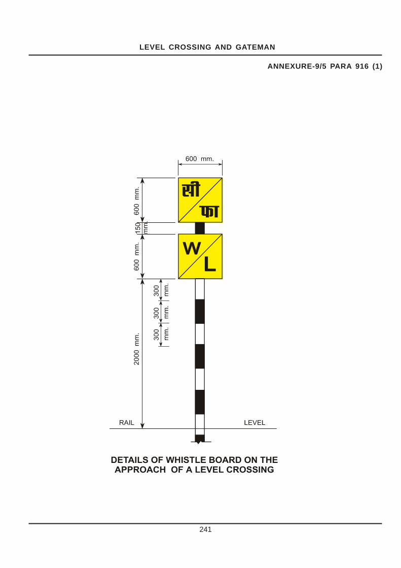
LEVEL CROSSING AND GATEMAN
241
ANNEXURE-9/5 PARA 916 (1)

LEVEL CROSSING AND GATEMAN
242
ANNEXURE-9/6 PARA 918 (1)
200 CM
SPEED BREAKER – SECTION –‘AA’
ROAD SURFACE 12.5 CM
R=4M
30 CM 30 CM
50 CM
50 CM
YELLOW
WHITE
ROAD C/LINE
200 CM
AA
30 CM X 50 CM
SPEED BREAKER DESIGN
NOTE - THE HUMP SHOULD EXTEND TO THE FULL ROADWAY WIDTH. APPROPRIATE BASE
COURSEMATERIAL SHOULD BE EXTENDED OVER THE SHOULDERS FOR PLACING THE HUMPSOVER THESE.

�
�
�
�
Colour of speed breaker sign has changed from yellow to black) (C.S.No:135 Dated:07.05.2014)
243

PATROLLING OF THE RAILWAY LINES
�������� ������� ������������� ����� �
1001. Types of Patrolling : (1) The following are the types of patrolling in vogue :
( a) Keyman’s daily patrol.
(b) Gang patrol during abnormal rainfall or storm.
( c) Night patrolling during monsoon.
1 Security patrolling during civil disturbances and for movement of VIP specials.
2 Hot weather patrolling for long welded rails/ continuous welded rails.
(f ) Watchmen at vulnerable locations.
(a) Keyman’s Daily Patrol - Every portion of the permanent way shall be inspected daily on foot by the keyman of the beat in which the portion of the track falls. Provided that the interval between such inspections may, under special instructions, issued by Chief Engineer be increased to once in two days in the case of specified section of lines with light and infrequent traffic.
(b) Gang Patrol during Abnormal Rainfall or Storm – In the event of abnormal rainfall or storm during day or night, the Mate should, on his own initiative organise patrolling over the length affected, independently of other patrolling, if any being done. This patrol should, in case of heavy rainfall, confine its inspection to known points of danger, such as cutting or culverts likely to scour, banks affected by tanks likely to breach and bridge approaches. In case of high winds, the patrolman should inspect the length of track likely to be fouled by falling of tree etc.
Arrangements exist with the Meteorological Department of the Government of India for issuing telegrams of warning, wherever storms, gales, or heavy rainfall are expected. On receipt of such information from the Control, the Permanent way Inspector will arrange to advise monsoon patrolmen, watchmen and gangmates to be extra vigilant and be prepared to introduce patrolling, as necessary (for detailed instructions Para 728 of IRPWM may be referred to).
(4) Night Patrolling during Monsoon – During the monsoon, certain section of the railway line, as may be specified, shall be patrolled to detect damage by flood, such as breaches, settlements, slips and
scours and immediate action taken to protect trains, when so warranted.
(5) Security Patrolling during Civil Disturbance and on Special occasions –
(a) On apprehension of a Civil disturbance, the Divisional authorities should contact the local Civil authority and arrange, as circumstances may warrant for security patrolling of the railway line. This may be arranged on the pattern of the monsoon patrolling with modifications, as deemed necessary, in consultation with Civil authorities.
b) Security patrolling on special occasions should be carried out according to the special instructions issued by the administration.
(c )The primary duty of the patrolman employed on Security patrolling shall be to protect trains against any condition of danger, such as tampering with track or obstruction placed on line.
(6) Hot weather Patrolling for LWR/CWR – Hot weather patrol is carried out when the rail temperature exceeds- (i) td + 25o C on PSC sleeper track with sleeper density 1540 nos. per km and above. (ii) td + 20o C on PSC sleeper track with sleeper density less than 1540 nos. per km and track other than PSC sleeper. The patrolling should be done in accordance with the provisions of Manual of Long Welded Rails. (C.S.No:130 Dated:16.11.2012)
(7) Watchmen at vulnerable locations. In addition
to patrolmen, stationary watchmen are posted at known or likely locations of danger or trouble.
1002. Protection of line in case of Emergency – Should any patrolman/stationary Watchman/Gangman/Keyman deputed for the purpose of patrolling notice any condition likely to affect the safety of trains, he shall at once protect the line and report the damage to the nearest Station Master as laid down in Para 1011.
Monsoon Patrolling
1003. Comencement and Termination – The sections, which are normally to be patrolled during monsoon will be identified and notified by the Divisional Engineer. For every such section, the Divisional Engineer shall prescribe the period of year, when normal monsoon patrolling is to be done; patrolling should be started on these notified sections on the dates specified. If the local conditions warrant, the Permanent Way Inspector of the section concerned may introduce or continue night patrolling outside the stipulated dates, duly advising all concerned.
244
PATROLLING OF THE RAILWAY LINE
245
1004. Preparation of Patrol Charts – (1)The Divisional Engineer will prepare patrol charts foreach of the sections where monsoon patrolling isrequired to be done, taking into consideration the traintimings of the time table in force during this period.The principles governing the preparation of patrolcharts shall be -
(a) Ordinarily patrolling will be carried out by asingle patrolman, but in regions where danger fromwild animals, dacoits and other risks as in ghatsections exist, patrolling in pairs may be introducedwith the approval of the Chief Engineer.
(b) All trains carrying passengers betweensunset and sunrise get the maximum protectionpossible.
(c ) As far as possible, each block section willbe treated as a unit and the length will be dividedinto equal beats. The length of each patrol beatshould not normally exceed 5 km. Where the blocksection is more than 10 km. an intermediate flagstation, if any, or any other suitable point may befixed as intermediate station, to keep the length ofbeat at about 5 km.
(d) The walking speed of a patrolman may betaken as 3 km. per hour.
(e) The maximum distance covered by apatrolman should not normally exceed 20 km. in aday.
(f) A period of at least half an hour rest isdesirable between consecutive beats.
(g) If the frequency of train services is high,and one set of patrolmen is not able to cover all thetrains in the section, a second set of patrolmen maybe introduced to reduce the interval.
(h) For giving better protection to all passengertrains, between sun-set and sun-rise it would beadvantageous to plot the scheduled paths of allpassenger trains and then plot the patrol movementin such a way, so as to minimise the time intervalbetween patrolling of the beat and passage of train.
(i) Patrol charts should show all vulnerablelocations where stationary watchmen are posted.
(2) Sample patrol charts are appended forguidance, as Annexure 10/1, 10/2, 10/3.
1005. Distribution of Patrol Charts –Before commencement of the monsoon, requisite
number of copies of patrol charts should be suppliedby the Divisional Engineer to the Assistant Engineers,Permanent Way Inspectors, the Divisional OperatingSuperintendent (for distribution to the Control staff),Station Masters and Foremen of running sheds. TheForemen will acquaint Drivers of passenger trains,when they may expect to pass patrolmen, if runningto time. By inviting drivers to lookout for patrolling,an immediate and practical means of supervisingthe patrolmen is introduced. The task of dispatchingpatrolmen at the right time and signing their patrolbook when they arrive at or depart from a stationdevolves upon the Station Master/Block Hut-in-charge.
1006. Patrol books and SystematicPatrolling – A patrol book containing sufficientnumber of pages should be supplied to each patrolwith a tin case.
The books shall be serially numbered tocorrespond with the number of patrol on each section.The first page of the book shall contain the name ofpatrolman, kilometrage of patrol section and itsnumber. The remaining pages will contain columnsfor date, station, time of arrival and departure andsignature of Station Master.
Patrolmen shall be on duty at the time specifiedfor each in the patrol chart.
The patrolman whose beat commences/terminates at a station shall present the patrol-bookin his possession to the Station Master/Block hut-in-charge who will enter therein the time of arrival anddeparture and sign the book. The Station Master/Block hut-in-charge will also record the time of arrivaland departure in his Diary/Train Register Book. Thepatrolman shall then patrol his length at the end ofwhich, he will exchange his patrol book with that ofthe next patrolman and retrace his beat. Theintermediate patrols do likewise. In this way eachpatrol-book will be conveyed from one station to theother and back again. Owing to close proximity ofstations, patrolbooks may be passed through one ormore intermediate stations, before it is returned tothe original station.
If a patrolman on arrival at the end of his beatdoes not find the next patrolman to take over thebook, he must proceed ahead, until he meets him.The patrolman should report the absence of any manfrom his beat to the Mate the next day.

PATROLLING OF THE RAILWAY LINES
Station Maters will see that the men come on duty sober and fully equipped, that their lamps are trimmed and filled with oil and that they leave for their patrol duty in time.
If a patrolman who is due to arrive at a station does not turn in time or does not turn up at all, the Station Master/Block hut-in-charge will advise Station Master/Block hut-in-charge at the other end of the block section of the absence of the patrolman and both Station Masters/Block hut-in-charges will issue caution orders to all trains entering the section until the patrolman from the other end of the “patrol-section” arrives at the station and reports that all is well.
1007. Equipment of Patrolmen – (1) Each patrolman shall be provided with the following equipment and such other, as may be prescribed by special instructions:
(a) One staff. (b) Number plate 15 cm. Square (to be
numbered consecutively from the beginning of each Permanent Way Inspector’s length in white letters on black background).
(c) 10 detonators in a tin case (C.S.No:135 Dated:07.05.2014)
(d) Two tricolour hand signal lamps. (e) Protective clothing according to local dress
regulations. (f) One match box. (g) Two red flags and one green flag (day patrol
only). (h) Patrol book in a tin case (i) One three cell Electric torch. (j) Whistle thunderer. (k) One haversack. (l) Three warning signals as prescribed in para
824 on double/ multiple lines, ghats, suburban and automatic block territories and one warning signal on single line sections. (CS 136 dt 14.11.14)
(2) Where patrolling is undertaken in pairs or stationary patrol consists of two men, the equipment need not be duplicated but the additional patrolman will be provided with an extra hand signal lamp, whistle thunderer and protective clothing.
1008. Selection of Patrolman – Intelligent, experienced and trustworthy men should be selected from the Permanent Gangs by Permanent Way Inspectors to work as Patrolmen and Watchmen,
246
preferably those who can read bridge and telegraph post numbers. Temporary substitutes should be appointed in their places to work for the gangs. Twice the number required should be selected to serve as relief, in case of illness, to provide for rest giver patrolman etc. The men selected from each gang should be sent to the Divisional Medical Officer for vision test and shall not be employed as patrolmen unless they have passed the requisite medical test.
1009. Certificate to be submitted by Permanent Way Inspector – The Permanent Way Inspector shall submit a certificate to the Divisional Engineer through Assistant Engineer a month in advance before the commencement of the monsoon that he has made all arrangements for monsoon patrolling and for watching vulnerable locations/ bridges and that the patrolmen and the watchmen have been made conversant with their duties, rules for the protections of the line and vulnerable locations in their beats. He will also submit to the Assistant Engineer a list of names of patrolmen and watchmen with their duties/locations assigned during the patrolling season.
1010. Duties of Patrolmen – (1) The duties of a patrolman shall be as follows :
(i) Walk to and fro over the beat in accordance with the chart pertaining to his “patrol-section” looking out for subsidence, slips, signs of erosion, trees blown across the track during storms or any other causes likely to endanger the safety of line. Bridges and their approaches should be especially watched.
(ii) Apprehend damage to line when (viii) the flood exceeds danger level at any of the
bridges. (ix) when there is damage to the protection
work or on approaches even before danger level is reached.
(x) the water on one side of the embankment is at a much higher level than on the other side.
(xi) when any obstruction such as a fallen tree is blocking the water-way of a bridge.
(xii) the track shows signs of a settlement.
(c) Take immediate steps in accordance with Para 1011 to stop trains when any portion of the line is likely to be rendered unsafe due to abnormal rain or flood or any other cause.

PATROLLING OF THE RAILWAY LINE
247
(d) When no danger is apprehended, stand onthe cess on the left hand side facing the train andexhibit his number plate, turning the light of his lampon to it, so that the number can be seen from thepassing train. He should also blow the whistle, whenthe engine and the brake-van of the train pass him.
(e) Obtain the signature of the Station Master/Block Hut-in-charge on duty at the Station/ Block Hutconcerned for his arrival and departure and exchangepatrol books with adjacent patrolmen.
(f) Exchange the reports as to the conditionson their beats with adjacent patrol men and stationarywatchmen on the way.
(g) Heed instructions from drivers who mayreport a condition of danger at a kilometrage andproceed to the place indicated and take necessarymeasures.
(2) It is of supreme importance that patrolmenand watchmen thoroughly understand what theyhave to do in the event of emergency. Every effortshould be made to instruct and drill the men in theirduties. In the event of an emergency the patrolmenshould devote their whole time and energy to theprotection of the line and summoning of assistance.Having protected the line and summoned assistance,they should resume their patrolling.
1011. Action When Damage is Observed– In the event of any portion of the line being breachedor otherwise rendered unsafe for traffic the followingprocedure shall be observed
(A) In the case where two patrolmen areemployed :
(1) Protecting the line – a) The second lampshould be lit and danger signals shown at once inboth the directions.
(b) The two patrolmen shall then proceed inopposite directions showing the danger signals(redflag by day and red light by night) and when at 600M.on Broad Gauge and 400 M. on Metre Gauge andNarrow Gauge from the point of danger, each shouldplace one detonator on to the rail; they shall thenproceed to a distance of 1200 M. on Broad Gaugeand 800 M. on Metre Gauge/Narrow Gauge fromthe point of danger where they should place threedetonators on the rail about 10 metres apart.
On the double line the detonators must beplaced on the line, in the direction on which the trainswill approach. On Metre Gauge sections where
trains run at maximum permissible speed of morethan 75 km.p.h. the distances at which the detonatorsare to be placed shall be specified by theadministration.
(c) Should the nature of obstruction be suchas to render it impossible for either of patrolmen toget across the gap, as for instance a wash awaywith strong flood, one of the men should show thedanger signal and endeavour to stop trainsapproaching the gap from the other side while theother man should proceed towards the station onhis side of the gap, fix the detonators and act as in(b).
(2) Reporting the damage to Station Masterand Gangmate – (a) After protecting the track one ofthe two patrolmen who is nearest to the station andin case mentioned in (c) the patrolmen who hasprotected the track will proceed in all haste, showingthe danger signal, to the station and inform the stationmaster of the danger. On his way back, if he meetswith any gang quarter, he should inform the Mate ofthe occurrence and the gang must immediatelyproceed to the affected kilometrege and takenecessary action to attend to the repairs.
b) After protecting the track the other patrolmanwill proceed to the site of obstruction, and remainthere showing the danger signal, until the firstpatrolmen joins him. In case the other patrolman hasnot been able to locate the gang hut on his way backfrom the station, one of them should proceed to thegang hut and inform the gangmate.
B. In case where one patrol man isemployed–
(1) Protection of line – (a)When damage isdetected on single line –
(i) Place a red lamp during the night and a redflag during the day in a prominent position to warn atrain which may approach from one direction. Thenrun in the opposite direction from which direction trainis likely to come, with a danger signal (red flag byday and red light by night) and place one detonatorat 600 M. on Broad Gauge and 400 M. on MetreGauge and Narrow Gauge and three detonators at10 metres apart at 1200 M. on Broad Gauge and800 M. on Metre Gauge/ Narrow Gauge from thesite of obstruction/damage.
Provided that on those Metre Gauge Sectionswhere trains run at maximum speed of more than75km.p.h., the distances at which the detonators areto be placed shall be specified by the administration.

PATROLLING OF THE RAILWAY LINES
248
(ii) Return to the site of obstruction/ damageand protect the other side with detonators similarly.
(iii) In the event of it being impossible to getthe other side of the obstruction/damage (as in awashaway) place the red lamp so that it can be seenfrom as great distance as possible by a trainapproaching from that direction and protect the otherside with the detonators etc. as detailed in sub-para(a) (i).
(b) When damage is detected on double line –
(i) Place the red flag/ lamp in prominent positionso as to warn an approaching train on one track. Thenrun along the other track on which train is expectedfirst and place the detonators as in sub-para(a) (i)
(ii) Run back and protect with detonators theline on which the lamp/flag was prominently placedearlier.
(2) Reporting the damage to the StationMaster– The patrolman will return to the site ofobstruction after protecting the line in both thedirections and shall remain at the place of obstructionand send word about the danger through the firstrailway employee or other persons he is able tocontact at the spot itself.
1012. Responsibility of EngineeringOfficials in the Matter of Patrolling –
(1) Inspection of Patrol Books – The PermanentWay Inspector must examine the patrol books, initialthe entries each time he trollies and take upirregularities. The Assistant Engineer should examinethe patrol books during his inspection.
(2) Supply of Equipment to Patrolmen andWatchmen – The Permanent Way Inspectors willbe responsible for seeing that each (patrolman) isprovided with the equipment specified, and forperiodical distribution of consumable stores likekerosene oil, match box etc. The Mate will beresponsible for seeing that the patrolman andstationary watchman posses the correct equipmentspecified.
(3) The Permanent way Inspector will beresponsible for instructing the patrolmen in their
duties, in the rules for the protection of the lines andin acquainting them with all vulnerable points on theirbeats. In addition to oral instructions, the PermanentWay Inspector shall by practical demonstrations, drillthe patrolmen in their detailed duties andresponsibilities.
(4) Inspection Of Equipment- The permanentway Inspector should check the equipment of allpatrolmen and watchmen once a month, record theresults in patrolbook and take steps to recoupdeficiencies.
(5) Check over Patrolling at Nights – (a) ByPermanent Way Inspectors- The following are theschedule of inspection of night patrolling for theinspector Grade III/ II and the Permanent WayInspectors- in - charge; by train/trolly :
(b) The Assistant Engineer shall cover hisentire sub-division once in a month by train/pushtrolly/ Motor trolley in the night and check thepatrolmen.
1013. Action by Assistant Engineer andPermanent Way Inspectors On Receipt ofInformation Regarding Damage to the line –On the receipt of information of any damage to theline, the Assistant Engineer and the Permanent WayInspector -in-charge and Permanent Way Inspector(Grade III/II) concerned should proceed to site bythe quickest possible means and take necessaryaction for restoration.
1014 Vulnerable locations (points)–(1)Definition – Vulnerable locations (points) are those,where conditions unsafe for the passage of trainsare apprehended and there is need for stopping oftrains in time in case such conditions develop e.g.-
(a) Bridges, having inadequate water-way,liable to scour in foundations, oblique/ parallel flow ofwater to the approaches, rise of flood above dangerlevel frequently.
(b) Bad banks liable to slips and subsidence.
(c) Bridges located across river courses fedby Railway affecting tanks.
Official By train By trolly
P.W.I. Gr. III/II Once a fortnight Frequency to be prescribed by the ChiefP.W.I. in- charge Once a month Engineer depending on the local condition

PATROLLING OF THE RAILWAY LINE
(d) Cutting and Hills designated as vulnerable by DEN/Sr.DEN (C.S.No:135 Dated:07.05.2014) (d) Water over flowing over the track. (e) And any other condition likely to
affect the safety of the track. (2) List of Vulnerable locations – A list of
vulnerable locations should be maintained by each Assistant Engineer/Divisional Engineer in a register form and should be reviewed and brought up-to-date.
(3) Guarding of vulnerable locations – (a)
Stationary watchman should be posted round the clock at every nominated location during the monsoon period.
(b)He should keep a watch on vulnerable
location and in case he apprehends danger he should take action to protect the line in accordance with Para 1011.
( c ) The equipment for the watchman should be on the same scale as patrolman except that a watch man will not be provided with –
(iv) Number plate.
(v) Haversack.
(vi) Patrol book in tin case.
A notebook should however be provided to the watch man.
249

PATROLLING OF THE RAILWAY LINES
250
ANNEXURE-10/1 PARA 1004
2
21
19.41
23.44
3.51
18.22
21.00
18.22
21.00
22.25 22.25
5.10 5.10
1
2
21404 DN. 20.18 (a)
21.18 (a)
23.50 (a)
406 DN. 5.13 (d) 5.23 (a)
8.45 Km.0
18.23
HOURS
5
4
3
2
1
24
23
22
20
19
18
17
5
4
3
2
1
24
23
22
20
19
18
17
1 2 3 4 5 6 7 8 8.45
HANWANT
1. INDICATES PETROL MEN.
2. INDICATES TIME OF ARRIVAL & DEPARTURE OF PETROL MEN..
REFERENCE :
SALAWAS
20.28 (a)
21.02 (D) TRAIN 241 UP
23.39 (d) TRAIN 405 UP
HOURS
1
BK No.1
BK No.
BK No.2
BK No.2
BK No.2
1
BK No.1
BK No.1
BK No.2
SPECIMEN PATROLLING CHART
MAIN LINE & BRANCH LINE DENSITY TRAFFIC
2 BEATS LENGTH 8.45 Kms.JODHPUR - MARWAR SECTION

PATROLLING OF THE RAILWAY LINE
251
ANNEXURE-10/2 PARA 1004
17.11
19.17
21.55
0.33
2.59
3.32
2.13
20.36
23.14
2.13
4.18
20.36
23.14
2.13
17.11
HOURS
BK No.1
BK No.1
BK No.2
BK No.3
BK No.2
BK No.4
BK No.3
BK No.2
BK No.1
BK No.3BK No.1
BK No.2
BK No.4
HOURS
17 17
18
19
20
21
22
23
24
1
2
3
4
5
3.35 (a)
PITAMBERPUR TEISUE
1) INDICATES PETROL MEN
2) INDICATES TIME OF ARRIVAL AND DEPARTURE OF PETROL MEN.
REFERENCE:
5.02 (d)
18.20 (a) 18.38 (a)
18.07 (d) TRAIN 15 UP18.32 (d) TRAIN 73 UP
20.43 (d) TRAIN 317 UP
23.17 (d) TRAIN 75 UP
0.31 (d) TRAIN 303 UP
4.56 (d) TRAIN 351 UP
22.02 (d)
20.51 (d) 352 DN21.49 (d)
23.23 (d)
0.37 (a)
304 DN3.29 (d)
76 DN 4.18 (d)318 DN 4.52 (d)
5.07 (d)
18
19
20
21
22
23
24
1
2
0 1 2 3 4
8.45 Kms.
5 6 7 8 8.4
3
4
5
2
2
2
4
4
4
2
4
1
1
1 2
1
3
3
3
3
18.30
BK No.4
BK No.4
SPECIMEN PATROLLING CHART
MAIN LINE HEAVY DENSITY TRAFFIC2 BEATS LENGTH 8.45 Kms.
ROSA - BAREILLY SECTION ( DOUBLE LINE)

PATROLLING OF THE RAILWAY LINES
252
ANNEXURE-10/3 PARA 1004
17.30 17.30
16.25
18.35
21.01
0.480.53
3.50
5.22
18.35 18.35
19.40 19.40
19.56
21.01
21.0622.11
22.11
23.43 23.43
0.480.53 0.53
1.58 1.582.07
2.463.003.12
4.174.00
19.56
21.0121.06
21.26 (d)22.14 (d)
0.48
4.05
5.05
HOURS
KALANDUR
SPECIMEN PATROLLING CHART
MAIN LINE HEAVY DENSITY TRAFFIC 3 BEATS LENGTH 10.47 Kms.
SAHARANPUR - LUDHIANA SECTION( DOUBLE LINE )
SARSAWA
350 DN 5.06 (d)
8.46 (a)
450 DN 19.37 (d)
2 SRM DN 22.19 (d)
312 DN 0.56 (d)74 DN 1.32 (d)
334 DN 1.52 (d)2.08 (a)
32 DN 2.10 (d)2.29 (d)
3.49 Km.
16 16
18.32 (d) 315 UP
19.52 (d)
21.06
5.22 (d)
22.34(a)
1.16 (a)1.47 (a)1.54 (d) 31 UP2.10 (a)2.18 (d) 73 UP2.32 (a)
3.54 (d) ISRN UP4.05 (a) 31 ISRN UP4.19 (d) ISRN UP( A.L.T.)
21.01 (d) IDSU - UP
22.04 (d) 349 - UP
17
18
19
20
22
23
24
2
3
17
18
19
20
22
23
24
3
2
4
6
3.49 Km. 3.49 Km.
0 1 2 33.49 6.98
4 5 6 7 8 9 1010.47
10.47 Kms.
HOURS
BK No.2
BK No.2
BK No.3
BK No.2
BK No.2
BK No.2
BK No.2
BK No.4
BK No.4
BK No.2
BK No.4
BK No.1
BK No.1
BK No.1
BK No.4
BK No.4
BK No.1
BK No.1BK No.3
BK No.3
BK No.3
BK No.3
1
2 3 6
1
1
2
2
2
3
4
4
6
6
6
5
4
4
3
5
5
3
5
REFERENCE :
1. PETROL MEN 1 3 & 5 EXCHANGE BOOK No. 1 & 2.
2. PETROL MEN 2 4 & 6 EXCHANGE BOOK No. 3 & 4.
4

THE WORKING OF TROLLIES, MOTOR TROLLIES AND LORRIES
253
CHAPTER XICHAPTER XICHAPTER XICHAPTER XICHAPTER XITHE WORKING OF TROLLIES,THE WORKING OF TROLLIES,THE WORKING OF TROLLIES,THE WORKING OF TROLLIES,THE WORKING OF TROLLIES,
MOMOMOMOMOTTTTTOR OR OR OR OR TRTRTRTRTROLLIES OLLIES OLLIES OLLIES OLLIES AND LAND LAND LAND LAND LORRIESORRIESORRIESORRIESORRIES
1101. General instructions – The Rulesfor working trollies, motor trollies and lorries arecontained in Paras 15(18) to 15(27) of chapterXV-B of General Rules (1976), supplementedby the subsidiary rules issued by individual railways.The instructions contained in this chapter are inamplification of these rules and will not supersedethe general and subsidiary rules of Railways.
1102. Distinction between Trolly, MotorTrolly and Lorry –
(i) A vehicle which can be lifted bodily off theline by four men shall be deemed to be a trolly. Anysimilar but heavier vehicle (which includes Dip Lorry)shall be deemed to be a lorry.
(ii) Any trolly which is self-propelled, by meansof a motor, is a motor trolly.
(iii) A trolly shall not, except in cases ofemergency, be used for the carriage of permanentway or other heavy material, and when a trolly is soloaded, it shall be deemed, to be a lorry.
1103. Certificate of Competency –(i) No trolly, motor trolly or lorry shall be placed
on the line except by a qualified person appointed inthis behalf by special instructions.
(ii) Such qualified person shall accompany thetrolly, motor trolly or lorry and shall be responsiblefor its proper protection and for its being used inaccordance with special instructions.
(iii) The qualified person shall hold a certificateof competency which shall be issued according toprescribed instructions.
(iv) Staff in whose favour a certificate is issuedshould be literate, having knowledge of Hindi or otherlocal languages, should have passed the prescribedMedical test and should be conversant with the rulesfor working of trollies, motor trollies and lorries, asthe case may be. The certificate of competency willbe issued for a specified period by an officerauthorised to do so and renewed periodically.
1104. Officials Permitted to use Trollies,Motor Trollies and Lorries – Subject to their beingcertified competent, the following officials of theEngineering Department are permitted to use trollies/lorries :
(i) Trollies/Lorries –
(a) All officers and inspectors of EngineeringDepartment.
(b) Permanent way Mistries and Section Mates,Head Trollymen as may be authorised.
(ii) Motor Trollies – All officers of EngineeringDepartment - motor trolly Drivers and such Inspectorsas may be authorised.
1105. Responsibility for safe working –(1) The official-in-charge of trolly/ motor trolly/
lorry is responsible at all times for its safe working.When more than one person holding competencycertificate travels in a trolly, the official working thetrolly is responsible for its safe working.
(2) It shall be clearly understood by officersand staff that they are to take every possibleprecaution and protection against accidents. Whenentering a tunnel or cutting or proceeding over a longbridge or curve, the official-in-charge will make surethat no train is likely to be met. While approaching alevel crossing the official-in-charge, should look outfor road traffic and ensure safe passage of his vehicleover the level crossing.
1106. Efficient Brakes – No lorry, trolly ormotor trolly shall be placed on the line unless, it isfitted with efficient brakes. The brakes should betested before the commencement of each journey. Itis desirable that trollies and lorries working on ghatsection are fitted with screw down brakes in additionto ordinary hand/foot brakes. It will be theresponsibility of the official-in-charge to ensure theadequacy of braking.
1107. Attachment to Trains Prohibited – Notrolly / motor trolly/ lorry shall be attached to a train.
1108. Working on Track Circuited Sectionsand Sections Provided with Treadles – EachRailway shall issue subsidiary rules for the workingof trollies/ motor trollies/ lorries in sections wheretreadles or track circuits form part of the Blockinstruments or where automatic signalling has beenprovided.
1109. Numbering of Trollies/ Motor Trollies/Lorries – Each trolly/ motor trolly and lorry shall bemarked with its number, code initials of thedepartment, the designation and headquarters of theofficial-in-charge.

THE WORKING OF TROLLIES, MOTOR TROLLIES AND LORRIES
1110. Conveyance of Trollies/ Motor Trollies/ Lorries by Trains –
No trolly, motor trolly/ lorry should be loaded in a train without the consent of the Guard in-charge of the train, who will direct where it is to be placed.
In the case of an accident/emergency, trollies/ motor trollies may be carried by Mail /Express trains on which there are restrictions normally for loading of trolly/ motor trolly.
When loading a motor trolly with petrol in the tank , the following rule extracted from Para 1106 of the I.R.C.A. Coaching Tariff No. 21, Part I (k) 1972 as applicable to carriages, motor-cars, boats etc., should be adhered to –
“ ………………. a quantity of petrol not exceeding 9.00 litres may be left in the tank provided that,
(o) The flow of petrol in the carburettor has been cut off;
(p) Any pressure has been released from the tanks;
(c ) The tank is in sound condition and closed by a well fitting cap;
(d) The engine has been run by the official-in-charge until the carburettor has become exhausted and the engine stops automatically.”
1111. Trollies, Motor Trollies and Lorries not in use –
(2) A trolly, motor trolly or lorry, when not in use shall be placed clear of the line, and wheels thereof secured with a chain and padlock.
(3) When a trolly / motor trolly is placed on a platform to be loaded into a train, it should be under the charge of a trollyman and placed where it will not be in the way of passengers or working staff.
(4) Whenever possible, motor trollies, should be placed in a shed, the key of which, shall be in the possession of the official-in-charge.
1112. Conveyance of Non-Railway officials–
Trollies shall not be used for the conveyance of persons other than railway officials. In special cases, Magistrates, Police, Civil, Telegraph, Military, Medical and Forest Department Personnel or a person requiring medical aid, may be conveyed by trolly by order of the competent authority (The
Assistant Engineer or above), after a bond on form in Annexure 11/1 is signed indemnifying the Railways against all liabilities and risks.
Contractors and their Agents may be conveyed on trolly in connection with works, provided they have executed a general indemnity bond similar to Form Annexure 11/1.
1113. Trolly-Permits for Private Sidings – A non-railway official is permitted to use a trolly on private sidings when he is in possession of a permit signed by the competent authority. Such permits are granted for use of the trolly on sidings where there is no passenger traffic. The party shall execute a bond on Form Annexure 11/2 indemnifying the Railways against all liabilities and risks. The issue of trolly permits will be subject to such rules as may be prescribed. In such cases, the Head trollyman shall hold a certificate of competency issued by the authorised Railway Official.
1114. Military officers using trollies in Ordnance Depots – The Military authorities are aware that the Railway Board are not prepared to accept any liability whatsoever for damage or compensation arising out of accidents caused in the working of trollies used by Military Officers on duty in Ordnance Factories in respect of claims of Officers themselves or third persons.
1115. Trolly Refuges and Observation Posts–
(b) Trolly Refuges – Trolly refuges over long Bridges should be provided at such intervals, as prescribed in the Schedule of Dimensions. In cuttings and high banks trolly refuges should be provided at suitable intervals.
(c) Observation Posts – Where, owing to curves in cuttings or other causes view of the line is restricted, “observation posts” should be established at such sites as command the best view in both directions for the use of Flagmen, thus enabling hand signals being conveyed to the trolly on line.
1116. Equipment for Trolly/ Motor Trolly / Lorry – Each trolly/ motor trolly/ lorry shall have the following equipment :
(a) Two hand signal lamps; (b) Two red and two green hand signal flags;
(c) Detonators 10 Nos. (C.S.No:135 Dated:7.05.2014)
254

THE WORKING OF TROLLIES, MOTOR TROLLIES AND LORRIES
255
(d) A chain and a padlock;
(e) A copy of the Working Time Table and allcorrection slips and appendices, if any, in force onthat section of the railway over which the trolly, lorryor motor trolly is to run;
(f) A motor horn and a search light (for motortrolly only);
(g) Two banner flags and additional detonators(for lorry only); and
(h) Such other articles as may be prescribedby the Railway Administration in this behalf.
Note – The official-in-charge of the trolly/ motortrolly / lorry shall also be in possesion of a watch inaddition to the prescribed equipment.
1117. Signals for Trolly/ Motor Trolly /Lorry–
(1) Day Signal - Every trolly, Motor trolly orLorry when on the line shall show a red flag by day,fixed to a staff which will be placed on a socket andconspicuously visible in both directions.
(2) Night Signal – On a double line the nightsignal shall be red light in the direction from whichtrains are expected and white in the other directionand on a single line, red in both directions. Whereon double line, single line working is introduced, thenight signal should be as per a single line. Whenworking within the station limits, the light displayedat night shall be red in both directions.
(3) Signals within long tunnels – On sectionswhere there are long and dark tunnels, the nightsignals prescribed must be displayed during the dayin addition to the red flag, in the case of Trollies, Motortrollies and Lorries. In the case of thick foggy ortempestuous weather impairing visibility, light signalsmust be displayed in addition to the red flag.
(4) Removal of Trolly/ Motor trolly/ Lorry – Assoon as a Trolly/ Motor trolly/ Lorry is removed fromthe track and placed clear of it, the red flag or lightsignal shall be removed, but care should be taken tosee that this signal is not taken off before the lineshave been cleared of all the obstructions.
1118. Working Of Trollies –
(1) Manning of trollies – Trollies in all casesshall be manned by four men.
(2) Mode of working of trolly – Trollies in allcases should be pushed and not pulled.
(3) Working under Block protection –(a) Trolly may be worked under Block
protection wherever it is possible to do so withoutinterference to train service.
(b) Trollies should be worked under Blockprotection in the night.
(c ) During day time in foggy weather andduring dust storm, when the visibility is poor, a Trollyshould be worked under Block protection.
(d) Sections with restricted visibility due tocurves, cuttings or due to other local conditionsspecified by Railway Administration, whereverpracticable, should be traversed under Blockprotection.
(e) When working under Block protectionTrollies will be worked in the same manner as trains.
(4) Working without Block protection –
(a) During day time in sections with normalvisibility the official-in-charge shall before leaving astation/ Block post, ascertain the whereabouts of thetrains likely to be met and set off on trolly.
(b) In sections with restricted visibility [specifiedsections, Ref-Para 1118(3) (d) ] when the official-in-charge, is not able to block the section and workunder Block protection, he will follow the followingprocedure :
(i) The Station Master/ Signalman will on receiptof advice from official-in-charge (in triplicate on FormAnnexure 11/3 ) giving his trolly programmeascertain and fill in particulars of trains running onthe section, retain one copy and return the other twoto the official-in-charge of the trolly.
(ii) As a reminder that the block section isoccupied by the trolly and caution orders must beissued, a small placard with words “ Trolly on line”,will be hung in front of the block instrument, untiladvice of the removal of the trolly is received.
(iii) If telegraph and telephone communicationsare interrupted and the Station Master/ Signalman isunable to communicate with the station at the otherend of the block section, the official-in-charge of thetrolly will be advised of this fact and form Annexure11/3 endorsed accordingly. When communicationbetween the two stations is restored, the messagesreferred to above will be exchanged, if the trolly hasnot cleared the section or removal report has notbeen received.

THE WORKING OF TROLLIES, MOTOR TROLLIES AND LORRIES
256
(iv) From the time of exchange of themessages, until intimation has been received thatthe trolly has cleared the block section, the StationMaster/ Signalman at both ends of the block sectionshall issue caution orders to Drivers of all trainsentering the block section. On the double line, cautionorder should be issued for both up and down trains.
(v) The issue of caution orders in no wayrelieves the official-in-charge of the duty of complyingstrictly with the rules for protecting the trolly.
(vi) On arrival of the trolly at the other end ofthe block section, the person-in-charge of the trollyshall fill in the removal report and send it to the StationMaster/Signalman who will return the third copysigned. The Station Master/Signalman will thenadvise the Station Master/Signal man at the otherend of the block section of the trolly having clearedthe section.
(vii) If the trolly is removed from the track atthe station not provided with telegraph or telephoneinstruments or in the block section and if it is notintended to place it on the track again, the official-in-charge of the trolly shall fill in the removal report andsend it to the Station Master / Signalman at thenearest block station. In the former case, the StationMaster will send written advice by the first train ineither direction to the next block station. The StationMaster / Signalman at the latter station should thenadvise the Station Master / Signalman at the otherend of the removal of the trolly.
(viii) Station Masters/Signalmen at the bothends, of the block section will enter remarks in thetrain registers pertaining to the block sectionconcerned showing the times at which the trollyentered and cleared the block section and thenumber of the trolly.
(5) Protection In Block Section -
(a) When a trolly is worked other than underthe rules for working of trains i.e., without blockprotection and when a clear view is not obtainablefor an adequate distance of 1200 M. on Broad Gaugeand 800 M. on Metre Gauge / Narrow Gauge, thefollowing precautions should be taken (Annexure11/4) :–
(i) On a double line, he must depute a Flagmanwith detonators to precede or follow the trolly, and toexhibit a hand danger signal at a distance of not lessthan 1200 M. on Broad Gauge, and 800 M. on Metre
Gauge / Narrow Gauge in the direction from whichtrains may approach.
(ii) On single line, depute a Flagman withdetonators to precede and another to follow the trollyand to exhibit hand danger signals at a distance ofnot less than 1200 M. on Broad Gauge and 800 M.on Metre Gauge and Narrow Gauge.
(iii) Where necessary, intermediate Flagmanshould be posted to relay signals.
(b) The distance at which the signals are to beexhibited may be suitably increased in the case ofMetre Gauge High speed routes where the speedsare more than 75 km.p.h., under special instructionsby the Railway Administration.
(c) The flagman should only be withdrawnwhen a clear view of at least 1200 M. on Broad Gaugeand 800 M. on Metre Gauge and Narrow Gauge canbe obtained in the direction from which trains mayapproach.
(d) When a train is sighted, the Flagman shouldwave the red flag vigorously to warn the official-in-charge of the trolly of the approach of the train, andat the same time place three detonators 10 M. aparton the line to protect the trolly. The detonators shouldbe removed only on receipts of hand signals fromthe official-in-charge by waving of a green flag towithdraw the danger signal indicating that the trollyhas been removed.
When conditions are such that the Flagmancan not be seen by the official-in-charge of trolly, thelatter must arrange before entering the section totake with him sufficient men with hand signals whowill be placed in suitable positions between the trollyand the Flagman so that the signals from theFlagman can be repeated to the person-in-chargeof the trolly and vice versa.
(e) On sighting an approaching train or theFlagman’s signal, the trolly must be removed clearof the line and kept in such a manner that it can notroll towards the line.
(6) Trollies travelling together – When two ormore trollies are running together in the samedirection in the same line, care should be taken toensure that they are kept at least 100 M. apart tosafeguard the trolly in rear from colliding with the frontone, in case the front trolly has to be stoppedsuddenly for any reason.

THE WORKING OF TROLLIES, MOTOR TROLLIES AND LORRIES
257
1119. Working of Motor trollies – (1) Amotor trolly shall only be run in accordance withspecial instructions .
(2) A motor trolly may be worked under blockprotection or without block protection, as may beprescribed by the Railway Administration.
(3) Working under block protection – (a) Amotor trolly should be run only under block protection(i) during night; (ii) during day time, when the visibilityis poor due to fog or dust storm.
(b) Sections of restricted visibility shouldinvariably be traversed under block protection. A listof “sections of restricted visibility” may be specifiedfor the guidance of all concerned, either in thesubsidiary rules or in the working time table.
(c ) When a motor trolly that is worked underblock protection breaks down in the block section,the official-in-charge should remove it clear of theline and send a written advice to the nearest StationMaster / Block Hut -in-charge returning the line clearticket or token or in the case of a motor trolly whenthe token has been clamped for a preceding trainthe key of the padlock. He should not replace themotor trolly on the line without the written permissionof either Station Master / Block Hut-in-charge at theend of the block section concerned. On arrival at theother end, the official-in-charge will deliver theauthority to the Station Master after the trolly hasarrived complete.
(4) Following a Train /Motor trolly – Motor trollymay follow a fully vacuum brake train or another motortrolly in the same block section during day light hoursand in clear weather under special instructions issuedby the Railway Administration.
(5) Working without block protection – (a)When a motor trolly is worked without blockprotection, it should be manned by at least four men.
(b) In case a motor trolly is worked withoutblock protection, the procedure outlined in Para1118(4)(b) for trollies shall be followed for workingof the motor trollies.
(c ) When a motor trolly is worked withoutblock protection, as per special instructions, theprocedure outlined in Para 1118 (5) should befollowed for the protection of trolly in block section.
1120. Working of Lorries – (1) Mode ofworking of lorry – Lorries in all cases should be
pushed and never pulled. Riding of persons on thesame is prohibited.
(2) Manning of Lorries – When running underblock, a lorry must be accompanied on foot by notless than four men in addition to the number of menrequired for expeditiously loading and unloadingmaterials being conveyed on the lorry.
When running without block protection a lorryshould be accompanied on foot by an adequatenumber of men required to remove the lorry and itscontents readily off the line in addition to Flagmanfor its protection. The Duties of Flagman shouldinvariably be entrusted to trained men experiencedin the working of lorries and who have passed thevision test.
(3) Working under block protection – (a)Whenever it is possible to block the line withoutinterference to trains, the lorry shall be worked underblock protection, after blocking the line.
(b) A lorry shall be worked only under blockprotection when –
(i) It is necessary during an emergency to runit at night.
(ii) The visibility is restricted due to sharpcurves/cuttings etc., as on certain specified sections.
(iii) It is loaded with rails, girders or speciallyheavy materials which will cause delay in unloading.
(c ) Actual working of lorry – (i) Before obtainingline clear, the offiicial-in-charge of a lorry shouldadvise the Station Master / Block Hut-in-charge,whether it is his intention to return to that station, torun to the other end of block section, or to removethe lorry in mid-section.
(ii) The official-in-charge, after getting theauthority to proceed in the form of line clear ticket /token, double line certificate or shunting key, as thecase may be, should work his lorry.
(iii) He should, after completion of his work,hand over the authority to proceed to the concernedStation Master / Block Hut-in-charge and removehis lorry.
(iv) In case the lorry is off loaded in the midsection, the authority to proceed should be returnedby a special messenger to the nearest station afterensuring that the lorry is kept clear off the line.
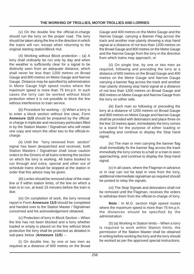
THE WORKING OF TROLLIES, MOTOR TROLLIES AND LORRIES
258
(v) On the double line the official-in-chargeshould run the lorry on the proper road. The lorryshould be taken along the line in the direction in whichthe trains will run; except when returning to theoriginal starting station/Block Hut.
(4) Working without Block protection – (a) Alorry shall ordinarily be run only by day and whenthe weather is sufficiently clear for a signal to bedistinctly seen from an adequate distance, whichshall never be less than 1200 metres on BroadGauge and 800 metres on Metre Gauge and NarrowGauge. Distance may be specified by administrationin Metre Gauge high speed routes where themaximum speed is more than 75 km.p.h. In suchcases the lorry can be worked without blockprotection when it is not possible to block the linewithout interference to train service.
(b) Procedure for working – (i) When a lorry isto enter a block section without line clear, FormAnnexure 11/3 should be prepared by the official-in-charge in triplicate and necessary particulars filledin by the Station Master / Signalman who will retainone copy and return the other two to the official-in-charge.
(ii) Until the “lorry removed from section”signal has been despatched and received, bothStation Masters / Signalman shall issue cautionorders to the Drivers of all trains entering the sectionon which the lorry is working. All trains booked torun through and extra, special and other out ofschedule trains should be stopped at the station inorder that this advice may be given.
(iii) Lorries should be removed clear of the mainline or if within station limits, of the line on which atrain is to run, at least 15 minutes before the train isdue.
(iv) On completion of work, the lorry removalreport in Form Annexure 11/3 should be completedand handed over to the Station Master / Signalmanconcerned and his acknowledgement obtained.
(c) Protection of lorry in Block Section – Whenthe line has not been blocked and a lorry whetherloaded or empty is placed on the line without blockprotection the lorry shall be protected as detailed insub-para below (Annexure 11/5) –
(i) On double line, by one or two men asrequired at a distance of 600 metres on the Broad
Gauge and 400 metres on the Metre Gauge and theNarrow Gauge, carrying a Banner Flag across thetrack and another man plainly showing a stop handsignal at a distance of not less than 1200 metres onthe Broad Gauge and 800 metres on the Metre Gaugeand the Narrow Gauge from the lorry in the directionfrom which trains may approach, or
(ii) On single line, by one or two men asrequired, following and preceding the lorry at adistance of 600 metres on the Broad Gauge and 400metres on the Metre Gauge and Narrow Gaugecarrying a banner flag across the track and anotherman plainly showing stop hand signal at a distanceof not less than 1200 metres on Broad Gauge and800 metres on Metre Gauge and Narrow Gauge fromthe lorry on either side.
(iii) Each man so following or preceding thelorry at a distance of 1200 metres on Broad Gaugeand 800 metres on Metre Gauge and Narrow Gaugeshall be provided with detonators and place three onthe line 10 metres apart, immediately the lorry comesto a stand for the purpose of either loading orunloading and continue to display the Stop handsignal.
(iv) The man or men carrying the banner flagshall immediatly fix the banner flag across the trackimmediatly the lorry comes to a halt or a train is seenapproaching, and continue to display the Stop handsignal.
(v) In all cases, where the Flagman in advanceor in rear can not be kept in view from the lorry,additional intermediate signalman as required shouldbe posted to relay the signals.
(vi) The Stop Signals and detonators shall notbe removed until the Flagman, receives the ordersto withdraw them from the official-in-charge of lorry.
Note : In M.G. section High speed routeswhere the maximum speed is more than 75 km.p.h.the distances should be specified by theadministration.
(5) (a) Working in Station limits – When a lorryis required to work within Station limits, thepermission of the Station Master shall be obtainedin writing before working the lorry and the lorry shouldbe worked as per the approved special instructions.

THE WORKING OF TROLLIES, MOTOR TROLLIES AND LORRIES
259
(b) Protection in Station limits – When a lorryworks in a station yard the Flagman must exhibitdanger signals at such a distance on both sides aswill ensure safety. When the lorry is required to remainstationary for more than 15 minutes, it must beprotected by banner flags placed at an adequatedistance supplemented by three detonators on bothsides.
(c) When a lorry has to work on a section witha steep down gradient (gradients steeper than 1/100), the same should not only be controlled by handbrakes, but by a rope tied in the rear and held intension by men following a lorry.
1121. Working of Cycle Trollies and MopedTrollies :– (1) Cycle Trollies – Cycle trollies are thosetrollies which are propelled, by pedalling instead ofpushing. It may be pushed when necessary but notpulled. A cycle trolly shall be manned by at least fourmen, including the persons pedalling or driving. Theymay be worked as per rules pertaining to a “Trolly”(Para 1118).
(2) Moped Trollies – These are light motortrollies, which can be lifted off the track normally bythree men. They should be manned by at least threemen including the Driver. These may be worked asper the rules pertaining to a Trolly, for which theRailway Administration may issue specialinstructions, as necessary.
1122. Rail Dolleys
(1) Rail dolley is a device with two or morewheels which in balanced condition can be movedmanually on one rail of track and can carry one rail/sleeper in suspended condition. When necessary,the suspended material can be dropped and raildolley cleared off the track.
(2) Manning of Rail Dolley
Every rail dolley shall be manned by not lessthan two able bodied persons. The person-in-chargefor the working of rail dolleys shall be a railway servantnot lower in rank than a keyman. The official in-charge should have passed in medical category A-3and must hold a valid certificate of competency forworking rail dolleys. Certificate of competency shallbe issued by a PWI of the section who must satisfyhimself that the person to whom competencycertificate is being issued is fully aware of the rulesfor the working of rail dolleys and is also wellacquainted with the concerned section.
(3) Working of Rail Dolleys
(i) The railway servant in-charge of rail dolleysmust inspect the section in advance particularly inreference to heaping of ballast, girder bridges andany other special features which make it difficult todrop the material and remove the rail dolley in theevent of an approaching train. He shall get the ballastheaps cleared and work the dolley(s) only when thevisibility is clear for at least 1200 metre on Broadgauge and 800 metre on MG/NG and the rails/sleepers can be dropped off safely without affectingthe safety of trains and workers both.
(ii) Rail dolley shall not be worked on sectionshaving gradients steeper than 1 in 200.
(iii) Not more than 6 rail dolleys should beworked in a group in any one block section.
(iv) Normally, not longer than 3 rail weldedpanels should be carried by rail dolleys. The raildolleys must not be worked after sunset and beforesunrise and in bad weather when the visibility is poor.Rail dolleys should not be worked in deep cuttings,steep grades, sharp curves and heavily built up areaswhere the visibility is not clear for 1200 metres onBG and 800 metre on MG/NG. In such locations,the rail dolleys should be worked under blockprotection.
(v) In case, a rail dolley is to carry rails longerthan 3 rail panel or it is required to move over x oversin yard crossing more than one line in deep cuttingsand curves then it should work under block protection.
(4) Working of Rail Dolleys
(i) No traffic block or caution order is normallynecessary for working of rail dolleys except asindicated in para 3(iv) and (v) above.
(ii) Every rail dolley/group of rail dolley whenon line shall exhibit a red flag.
(iii) The rail dolley shall be protected by aflagman at a distance of 1200 metre on Broad Gaugeand 800 metre on MG/NG from the rail dolley, on adouble line in the direction from which trains mayapproach, and by two flagmen one on either directionon single line. The flagmen shall also carry threedetonators for use in any emergency.
(iv) Where necessary intermediate Flagmanshould be posted to relay signals.

THE WORKING OF TROLLIES, MOTOR TROLLIES AND LORRIES
260
(vi) The official-in-charge of the rail dolley shallkeep a look out for approaching trains and will getthe rail dolley(s) and materials cleared off the trackas soon as an approaching train is sighted.
(vii) While approaching level crossings, theofficial in-charge shall look out for road vehicles andensure safe passage of rail dolleys.
(viii) The official in-charge shall be fullyresponsible for the safe working of rail dolleys.
(v) When a train is sighted, the Flagman shouldwave the red flag vigorously to warn the official-incharge of the dolley of the train and at the sametime place three detonators 10M apart on the line toprotect the rail dolley(s). The detonators should beremoved only on receipt of hand signals from theofficial-in-charge by waving of a green signal towithdraw the danger signals from indicating that raildolleys have been removed.
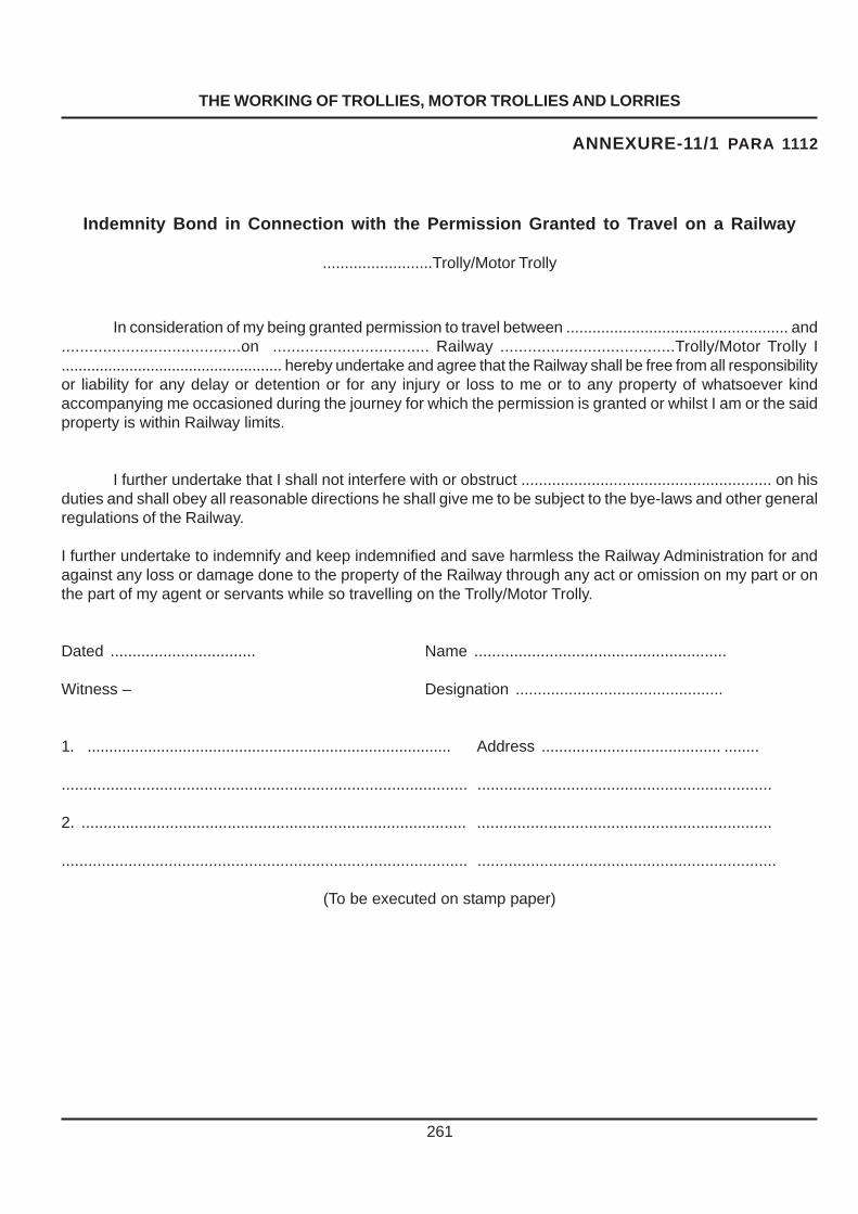
THE WORKING OF TROLLIES, MOTOR TROLLIES AND LORRIES
261
ANNEXURE-11/1 PARA 1112
Indemnity Bond in Connection with the Permission Granted to Travel on a Railway
.........................Trolly/Motor Trolly
In consideration of my being granted permission to travel between ................................................... and.......................................on .................................. Railway ......................................Trolly/Motor Trolly I.................................................... hereby undertake and agree that the Railway shall be free from all responsibilityor liability for any delay or detention or for any injury or loss to me or to any property of whatsoever kindaccompanying me occasioned during the journey for which the permission is granted or whilst I am or the saidproperty is within Railway limits.
I further undertake that I shall not interfere with or obstruct ......................................................... on hisduties and shall obey all reasonable directions he shall give me to be subject to the bye-laws and other generalregulations of the Railway.
I further undertake to indemnify and keep indemnified and save harmless the Railway Administration for andagainst any loss or damage done to the property of the Railway through any act or omission on my part or onthe part of my agent or servants while so travelling on the Trolly/Motor Trolly.
Dated ................................. Name .........................................................
Witness – Designation ...............................................
1. .................................................................................... Address ......................................... ........
........................................................................................... ..................................................................
2. ....................................................................................... ..................................................................
........................................................................................... ...................................................................
(To be executed on stamp paper)
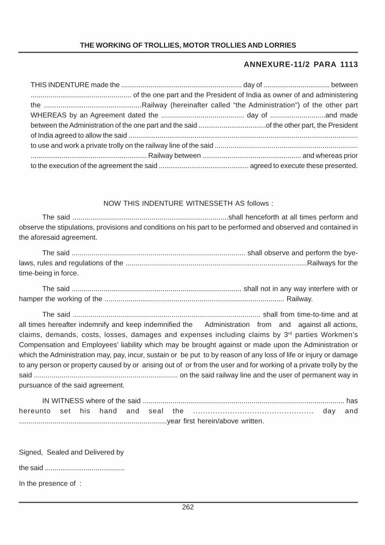
THE WORKING OF TROLLIES, MOTOR TROLLIES AND LORRIES
262
ANNEXURE-11/2 PARA 1113
THIS INDENTURE made the .............................................................. day of .................................. between................................................... of the one part and the President of India as owner of and administeringthe ...............................................Railway (hereinafter called “the Administration”) of the other partWHEREAS by an Agreement dated the .......................................... day of ............................and madebetween the Administration of the one part and the said ...................................of the other part, the Presidentof India agreed to allow the said ......................................................................................................................to use and work a private trolly on the railway line of the said ..................................................................................................................................... Railway between ................................................... and whereas priorto the execution of the agreement the said ............................................... agreed to execute these presented.
NOW THIS INDENTURE WITNESSETH AS follows :
The said ...............................................................................shall henceforth at all times perform andobserve the stipulations, provisions and conditions on his part to be performed and observed and contained inthe aforesaid agreement.
The said ........................................................................................ shall observe and perform the bye-laws, rules and regulations of the ............................................................................................Railways for thetime-being in force.
The said ...................................................................................... shall not in any way interfere with orhamper the working of the ........................................................................................... Railway.
The said ............................................................................................... shall from time-to-time and atall times hereafter indemnify and keep indemnified the Administration from and against all actions,claims, demands, costs, losses, damages and expenses including claims by 3rd parties Workmen’sCompensation and Employees’ liability which may be brought against or made upon the Administration orwhich the Administration may, pay, incur, sustain or be put to by reason of any loss of life or injury or damageto any person or property caused by or arising out of or from the user and for working of a private trolly by thesaid ......................................................................... on the said railway line and the user of permanent way inpursuance of the said agreement.
IN WITNESS where of the said ...................................................................................................... hashereunto set his hand and seal the ................................................. day and...........................................................................year first herein/above written.
Signed, Sealed and Delivered by
the said .........................................
In the presence of :

THE WORKING OF TROLLIES, MOTOR TROLLIES AND LORRIES
263
ANNEXURE-11/3 PARA 1118 (4)/1120 (4)
Trolly/Motor Trolly/Lorry Notice(Working without line clear)
Notice No. .............................................. Station ..................................Dated ....................................
ToThe Station Master/Signalman ....................................................... Station.Trolly / Motor Trolly / lorry No................................................................................ is required to work between
........................................................................... and ........................................ It will leave
....................................................................................... station at .............................. hoursKilometre ................................................................ at ................................................... hours } this day for
.................................................................... Station.Kilometre .........................................................
.............................................Offical - in - charge
ToThe Official-in-chargeDaily and extra trains due to arrive at or pass this station upto ............................... hours have actually
done so except.No .......................................................... minutes late............................................................................................................The following extra trains, special trains and light engines will enter ........................ section as shown.............................................................................................................I have exchanged advice with .................................... station/block post and shall issue caution orders to
all Drivers until I receive advice of removal of the trolly/motor trolly/lorry.
..........................................Station Master/Signalman
Removal ReportReference trolly/motor trolly/lorry Notice No. ................................................... dated .............................
trolly/motor trolly/lorry No. .......................................................... arrived at ........................................................................................................................................................................ at ..................... hours.
was removed from the track at kilometre.Removal report received at ................................................................. hours.Station Master/Signalman, ................................................................ Station.
Official - in - charge.

����
APE
264

����
APE
265

WORKING OF MATERIAL TRAINS AND TRACK MACHINES
266
CHAPTER XIICHAPTER XIICHAPTER XIICHAPTER XIICHAPTER XIIWWWWWORKING OF MAORKING OF MAORKING OF MAORKING OF MAORKING OF MATERIAL TERIAL TERIAL TERIAL TERIAL TRAINSTRAINSTRAINSTRAINSTRAINS
AND TRACK MACHINESAND TRACK MACHINESAND TRACK MACHINESAND TRACK MACHINESAND TRACK MACHINES
1201. Rules for Working – The rules forthe working of material trains are outlined in :
(1) Appendix IX of the Indian Railway Codefor the Engineering Department, and Paras 4.62to 4.65 of General Rules for Indian Railways(1976) and Subsidiary Rules thereto –
When the quantity of material is such as couldbe conveniently trained out in stages, wagon-loadsmay be attached to goods trains by arrangement withthe Operating Department.
1202. Material Train – Material Train means adepartmental train intended solely or mainly forcarriage of railway material when picked or put downfor execution of works, either between stations orwithin station limits. The railway material may includestone boulders, ballast, sand, cinder, moorum, rails,sleepers and fittings etc.
1203.Economical Working – Material trainshould be expeditiously and economically worked.The Assistant Engineer should arrange to form a trainof maximum capacity consistent with the haulagecapacity of the engine and tonnage approved for thesection. In consultation with the OperatingDepartment, the running of goods trains should besuitably regulated so as to provide as long a workingtime for material train as possible. Delays in workingshould be traced to their source and remedies appliedas circumstances demand.
1204. Restrictions in Running – (1) Exceptwith the permission of the Assistant Engineer orDivisional Engineer, a Material Train should not bepermitted to work during periods of poor visibility dueto fog, storm or any other cause.
(2) Except in an emergency such as, anaccident or breach of the railway line, working ofmaterial trains carrying labour should not be permittedbetween sunset and sunrise. If due to certaincircumstances it is necessary to work MaterialTrains during night, permission to do so should beobtained from the Divisional OperatingSuperintendent.
1205. Brake-vans and Shelter wagons –(1) A Material train must be equipped with at least
one brake- van in the rear. When running throughbetween stations the engine should be marshalledat one end of the train, and the brake-van at the otherend.
(2) Vehicles with vacuum brakes should beattached next to the engine when practicable andvacuum brake connected up with the engine.
(3) Covered wagons to afford shelter to thelabour may be coupled to the material train asrequired.
1206. Ordering of Material Trains –Authority Ordering – Operating Department is theauthority for ordering a material train. On receipt ofrequisition from the Assistant Engineer/DivisionalEngineer, the Divisional Operating Superintendentshall advise the staff concerned by letter, detailingthe composition of train, the loading kilometrages,the sections over which the train will work, the dateof commencement of work, the station at which therake will be stabled and the engineering official whowill be deputed to be in-charge of the train. The noticeto be given by the Engineering department shouldnot normally be less than a week.
1207. Issue of “Fit-to- Run” Certificate –Before a material train is allowed to work, thecomplete rake should be examined by the carriageand wagon staff and a “fit-to-run” certificate issuedto the Guard. The rake may also be examined bythe carriage and wagon staff each time it arrives atthe train examining station and whenever possible,once a week .
1208. Official -in -charge of Material Train–Whenever a material train is worked it shall beaccompanied by a Guard. As the Guard is notqualified to carry out such duties as working ofhoppers, distribution of ballast/materials, supervisingloading and unloading, maintaining muster rolls anddaily reports of labour and preparation of daily reportson material train working, a qualified engineeringofficial should be deputed on the train to ensureworking of material train to the programme specifiedby Assistant Engineer.
1209. Equipment – Every material trainGuard must have with him while on duty:
(a) A copy of General and Subsidiary Rules orsuch of them as relate to his duties.

WORKING OF MATERIAL TRAINS AND TRACK MACHINES
267
(b) An up-to-date copy of Working Time Tablewith correction slips and appendices, relating to thesection of the Railway over which the material trainis to be worked.
(c) A watch.(d) Hand signal lamps.(e) Two red flags and a green flag .(f) A whistle.(g) Not less than 12 detonators in a tin case.(h) A carriage key. (i) Padlocks as prescribed by special
instructions.(j) A set of clamp for point locking and/or other
locking devices.(k) A spare pair of glasses if he is required to
wear glasses.(l) First aid box.(m) Sprags and chains.(n) A tail lamp/L.V. Board.(o) Portable telephone ( on controlled
sections),and any other equipment and storesprescribed by special instructions.
1210. Testing of Brake Power – (1) Beforestarting from a station, the Guard should ensure thatthe train is equipped with requisite brake powerprescribed for the load.
(2) Each vehicle of material train whether ornot provided with vacuum brake, must be providedwith an efficient hand brake capable of being fasteneddown.
1211. Working in Block section – (1)Amaterial train shall be worked with the permission ofthe Station Master on either side and in accordancewith the provisions and system of working in forceon the section. Before a Material Train enters a blocksection for work, the Station Master should advisethe Driver and the Guard in writing of the time bywhich the train must clear the block and whether it isto proceed to the block station in advance or returnto the same station.
(2) On double line, a material train must notpush back to the Station in rear but should runthrough to the station in advance and return on properrunning line except when otherwise directed.
Where provided, lever collars or other visualindicators must be used to remind Station Masterthat the material train is working in the block section.
(3) The Guard/Engineering official-in chargeshall ensure efficient and proper working and adhereto sanctioned time and occupation of block section.Materials should not be left fouling the track, signalwires and interlocking gears. If it is necessary forthe train to leave the site of work before this is done,it should be ensured that sufficient labour is left to doso, in-charge of a competent railway servant andthat the site is protected until the work is completed.
(4) When a material train enters a block sectionto work under instructions of other than under thenormal system of working, the Guard and the Driverof the train shall ensure that the train is protectedfrom the direction a train is approaching on doubleline and in both directions on a single line inaccordance with General Rules.
If for any reason, it becomes necessary todetach the engine of a material train in the blocksection to run to the station in advance, the Guardshould ensure that the train is protected both in frontand rear.
(5) On stopping a material train on a gradethe Driver should give a long blast of the whistle tocall the attention of the Guard and thereafter threesharp blasts, the signal for application of hand brakes.The brakes must not be released until the Driver hassignalled for this by giving two sharp blasts.
Before entering a section on which a ballasttrain is required to stand on a grade of 1 in 50 orsteeper, the engine should be so attached that whenthe train is standing the engine is at the down-hillend of the train.
(6) A material train should not be dividedoutside station limits except in an emergency. Beforethe train is divided the Guard should put the handbrake in the brake-van hard on, and pin down thehand brakes of sufficient number of vehicles and ifnecessary, lock by means of safety chains or spragsa sufficient number of wheels, in each portion of thetrain. He should further ensure that the workers/labour are detrained before dividing the train.. Vehiclesshould not be detached from a material train on agrade of 1 in 100 and steeper. The engine itself maybe detached with the Guard’s permission after hehas ensured that hand brakes on each vehicle areproperly applied and the wheels spragged againstany movement.

WORKING OF MATERIAL TRAINS AND TRACK MACHINES
268
1212. Pushing of Material Trains – Ondown gradient steeper than 1 in 100, pushing is notpermitted. On gradient easier than 1 in 100 ascendingor descending pushing may be permitted at a speednot exceeding 25 Km./h. provided the brake-vanoccupied by Guard is the leading vehicle. Thespeed will be restricted to 10 Km./h., if thebrake van is not leading.
1213. Procedure to be followed whilepushing back – When it is necessary for a materialtrain to push back into the station from which it startedto work in the block section, the following procedureshould be observed :–
(1) No train must be allowed to push backwithout a written authority from the Station Master ofthe station from which it entered the section. Whereline clear tickets are in use, the Station Master shallendorse the line clear ticket as follows “ to push backto this station”.
(2) The Station Master of a station where thetrain starts from and pushes back to, must advisethe station in advance on the telephone or telegraphinstrument and also the Controller on controlledsections that the train will push back to the station.He will then obtain the acceptance of the “is line clearfor a train stopping in the section” signal on the blockinstruments or on the Morse instrument, where blockinstruments are not provided from the station inadvance and then give the “train entering section”signal in the usual way.
(3) On the return of the train, the Guard willintimate that the whole of the train has returned tothe station complete, from the section and sign inthe trains register book to the effect and return the“authority to push back” to the Station Master whichmust be cancelled by the latter. The Station Masterwill then give “cancel last signal ” signal on the blockor on the Morse instrument, as the case may be,and endorse the remarks that “ train pushed back”in the trains register book or the line clear enquirybook against the entry of the train.
(4) When it has been arranged for a train topush back from the section, it must always do soand not go through to the station in advance.
(5) Before starting, a green flag must be tied toa convenient fixture in front ( or on the tender if runningtender- foremost ) of the engine and also at the backof the rear brake-van to indicate to men working onthe line that the train will push back.
(6) On the double line, when the train is requiredto be pushed back into a station, the train must cometo a stand outside the advance starting signal andthe Driver shall whistle, when, if a line is clear for itsreception, it must be piloted into the station. If thereis no advance starting signal, the train must bebrought to a stand opposite the outer signal pertainingto the opposite direction and then be piloted into thestation.
(7) On the single line, when a train is requiredto be pushed back into an interlocked station, it mustcome to a stand outside the outer signal and whistle,when, if a line is clear the home and the outer signalsmay be taken “off” for its reception. At a non-interlocked station, the train must also come to astand outside the outer signal whence it must bepiloted into the station on signals being lowered.
(8) Except in an emergency, material trainsmay push back during day-light only. If in case of anaccident or for any other unavoidable reason, a trainhas to push back during the night, it must do so at awalking pace and the Guard or a competent railwayservant must walk at least 600 metres on B.G. and400 metres on M.G. and N. G. in advance, exhibitinga danger signal until the train comes to a stand asdetailed in sub-paras 6 & 7.
1214. Running on Ghat Section andDescending Grade – (1) On Ghat sections, it maybe necessary to attach an engine to bank the load inaddition to the engine in front.
(2) When a material train is descending a longand continuous steep grade, the brake levers of asmany wagons as may be necessary to assist incontrolling the speed, should be notched down bythe Guard under arrangements with the Driver.
1215. Passage over Points – The Driver of amaterial train should stop the train short of all catch,loop or spring points which are facing for his trainand which are not protected by signals. The Guardshould ensure that these are correctly set and lockedand then hand signal the Driver past the points.
1216. Speed of Material Trains – (1) Whenrunning between block stations with the engineleading, the speed of material train shall not exceedthat prescribed for a goods train with a similar load.

WORKING OF MATERIAL TRAINS AND TRACK MACHINES
269
(2) When the engine is pushing the train andwhen as in the case of emergencies the brake-vanis not leading -
(a) The speed must not exceed 10 km. p.h.
(b) The Guard must travel on the leadingvehicle and exhibit hand signals to the Driver.
(c) When passing over points, the Guard shouldtake action as in Para 1215 above.
1217. Stabling of a material train – (1)Material train shall not be stabled on running lines ata station, except in unavoidable circumstances.
(2) When a material train is stabled at a stationit shall be protected in the following manner andStation Master shall ensure that –
(a) The vehicles of the material train have beenproperly secured and are not fouling any points andcrossings,
(b) All necessary points have been set againstthe line on which the material train is stabled andsuch points have been secured with clamps or boltsand cotters and padlocks, and
(c) The keys of such padlocks are kept in hispersonal custody until the material train is ready toleave the siding or line.
(3) The Guard shall not relinquish charge untilhe has satisfied himself that the material train hasbeen protected as prescribed in this rule.
(4) When the train is ready to leave, the Guardmust advise the Station Master in writing. The StationMaster must then arrange for correct setting of thepoints.
(5) When a material train is stabled in anoutlying siding, the Guard must ensure that it is insidethe trap, clear of fouling marks and clear of runningline. He must pin down sufficient number of brakesand if necessary, lock by means of safety chains orsprag the wheels.
1218. Reporting Deficiencies andDamages– The Guard of the material train shouldat once bring to the notice of the Train Examinerunder advice to the Assistant Engineer, anydeficiency or damage which may have escaped theattention of the train examining staff. The Guard willalso keep a record of all damages caused to thevehicles during the work and report to the AssistantEngineer the circumstances in which they occurred.
In every case, the Assistant Engineer onreceipt of such reports should arrange for the train-examining staff to attend to the damages anddeficiencies expeditiously.
1219. Warning to workers on Material Trains–(1) The Guard of a material train shall before givingthe signal to start, see that all the workers are on thetrain, and warn them to sit down.
(2) Before moving his trains, the Driver mustsound the whistle, according to the prescribed code,as a warning to the labourers that the train is aboutto move.
(3) Before commencing any shunting with histrain, the Guard must ensure personally that alllabourers have been detrained.
(4) In the event of it being necessary to part amaterial train, the Guard must ensure personally thatall labourers have been detrained before doing so.
1220. Engine Crew’s Hours of Duty –Drivers, Assistant Drivers and Fireman employed onmaterial train should be relieved according to theirduty rosters. Only in exceptional and emergent casessuch as breaches on the line, may the engine crewbe kept on duty, for long hours, in which case, aspecial certificate should be given to the Engine Crewby the Engineering Official-in-charge.
LOADING AND UNLOADING FROMHOPPER BALLAST WAGONS
1221. Loading at Ballast Depots – The staffat the ballast depots are responsible to ensure thatthe wagons are loaded to the correct level.
1222. Working Trip – (1) The train Guard orEngineering official-in-charge shall be responsiblefor working the train to the instructions issued by theAssistant Engineer. The Permanent Way Inspectorshall arrange for the inspection and clearing of trackbehind the train.
(2) A “ Working Trip ” is a trip when one ormore wagons are to be unloaded between twostations. A “Running Trip” is a trip from one stationto the other when no wagons have to be unloadedon the way. Before departing on a ‘Working Trip’ thePermanent Way Inspector shall supply the MaterialTrain Guard/Official-in-charge with a memofurnishing the kilometrage at which the wagons shallbe unloaded and the quantity to be unloaded.

WORKING OF MATERIAL TRAINS AND TRACK MACHINES
270
1223. Operation of Hoppers – The hoppervalves shall be operated according to the prescribedinstructions under the direct supervision of the trainguard or official-in-charge. As far as possible onehopper may be unloaded at a time moving at walkingspeed. The official-in-charge should walk on the sideand instruct the labour as to when to open or closethe hopper valves. The train should not be stopped,while ballast is being discharged ; labour should notbe moved from the platform without first stoppingthe train.
1224. Training out material and dailyreports of working – (1) Training out of materialand ballast should be done to a programmesanctioned by the Divisional or Assistant Engineer.
(2) The Guard/Engineering official-in-chargeshould adhere to the sanctioned programme andsubmit daily report on prescribed form Annexure12/1 (Material Train Journal) to the AssistantEngineer through the concerned Inspector. Wherethe contract for the working of the material trainprovides for the employment of a minimum numberof labourers and the contractor is paid for the actuallabour so supplied for loading and unloading ofballast, permanent way or other materials the dailyreport should show the correct number of labourersof each class employed and the nature andapproximate quantity of work done. Muster rollsshould be maintained by the Guard or EngineeringOfficial-in-charge and checked and initialledfrequently by the Inspector concerned when thetraining out is done by departmental labour.
(3) In cases where the material is not loadedin bulk e.g., rail girders and bricks, the actual weightand number loaded should be given in the daily report.
(4) Sufficient number of copies of daily reportsshould be prepared by the Guard/Engineering Official-in-charge and submitted to the concerned officerse.g., Engineering, Operating, Mechanical etc.
(5) The number of wagons on the train withtheir capacity and painted numbers should beindicated on the form of daily report. Particulars ofdetention to the train other than for Engineering workshould also be indicated.
(6) Before forwarding the daily reports ofmaterial train working to the Assistant Engineer, theInspector may add relevant remarks as considerednecessary. The Assistant Engineer should scrutinise
the daily reports and take such action as considerednecessary to avoid or minimise detentions in theworking of the material train, before forwarding thesame to the Divisional Engineer for allocation, initialsand record.
1225. Charges for Material TrainWorking– For purposes of debiting the charges onaccount of Material train working to the heads ofrevenue working expenses concerned a monthly orfortnightly “Material Train Return” on the form givenin Para 1466-E will be prepared by OperatingDepartment and sent to the Divisional Engineer forcompletion and submission to the AccountsDepartment, for necessary action. On this return,the hire charges for wagons and engine will beseparately shown.
1226. Register of Engineering Vehicles– (1) When Engineering wagons are not in use, theseshould be stabled in the siding allotted for thispurpose in specific station yards.
(2) The Divisional Engineer and AssistantEngineer should maintain subdivision-wise acomplete inventory in the form of a register of allclosed wagons, open wagons, hoppers, etc., on thedivision. The register should contain :
Vehicle numbers;
Type of vehicle;
Capacity;
Condition of vehicle;Locations and particulars of periodical overhaul,when carried out and due.
The register should be kept current to facilitateissue of instructions when ordering a material train.
(3) A monthly return of engineering vehicleson the sub-division should be submitted by theAssistant Engineer to the Divisional Engineer withcomplete particulars of each vehicle for record in hisoffice. It should be the Assistant Engineer’sresponsibility to keep track of all Engineeringvehicles allotted to his sub-division and see thatthose that are sent to workshops for periodicaloverhaul are returned expeditiously.
1227. Working of Track MaintenanceMachines – (1) All ‘on track’ machines shall beworked only under traffic block with the permissionof the concerned Station Masters and in accordancewith the special instructions issued in this regard.

WORKING OF MATERIAL TRAINS AND TRACK MACHINES
271
(2) (a) Each machine shall be in direct chargeof a nominated track machine operator. The operatorshall be responsible for the working of the machineunder his charge. He shall be fully conversant withthe rules of working of trains and of protection in caseof emergency. He shall also ensure that the otherstaff deployed on the machine are fully conversantwith the protection rules. He shall hold a validcertificate of competency for driving and working ofthe machine.
(b) The track machine shall work under thedirect supervision of an engineering official not belowthe rank of PWI who will be responsible for takingthe traffic block, for protection of the line while thework is in progress and clearing of the block aftercompletion of the work when the last machine clearsthe block section and certifying that the track is fit fortrain movement.
(c) When the track machine is required tomove from one block station to another block station,the operator shall run the machine with the properauthority to proceed as defined in GR 1.02/6.
(3) Each unit shall carry all safety equipmentsas specified under Para 1209.
(4) When more than one track machine isrunning in a block section, there should be a minimumdistance of 120 metres between two units.
(5) While working on double/multiple lines, theengineering officials supervising the work of trackmachine shall ensure that no part of the machinefouls the adjacent track. In case infringement toadjacent track is inherent to the machine workingwhich can be cleared at a short notice, the workshould be carried out by protecting the infringed lineby Engineering signals by Permanent Way Inspectoras envisaged in Para 806.
(6) Each unit will run within the maximumpermissible speed sanctioned for that type ofmachine on that section.
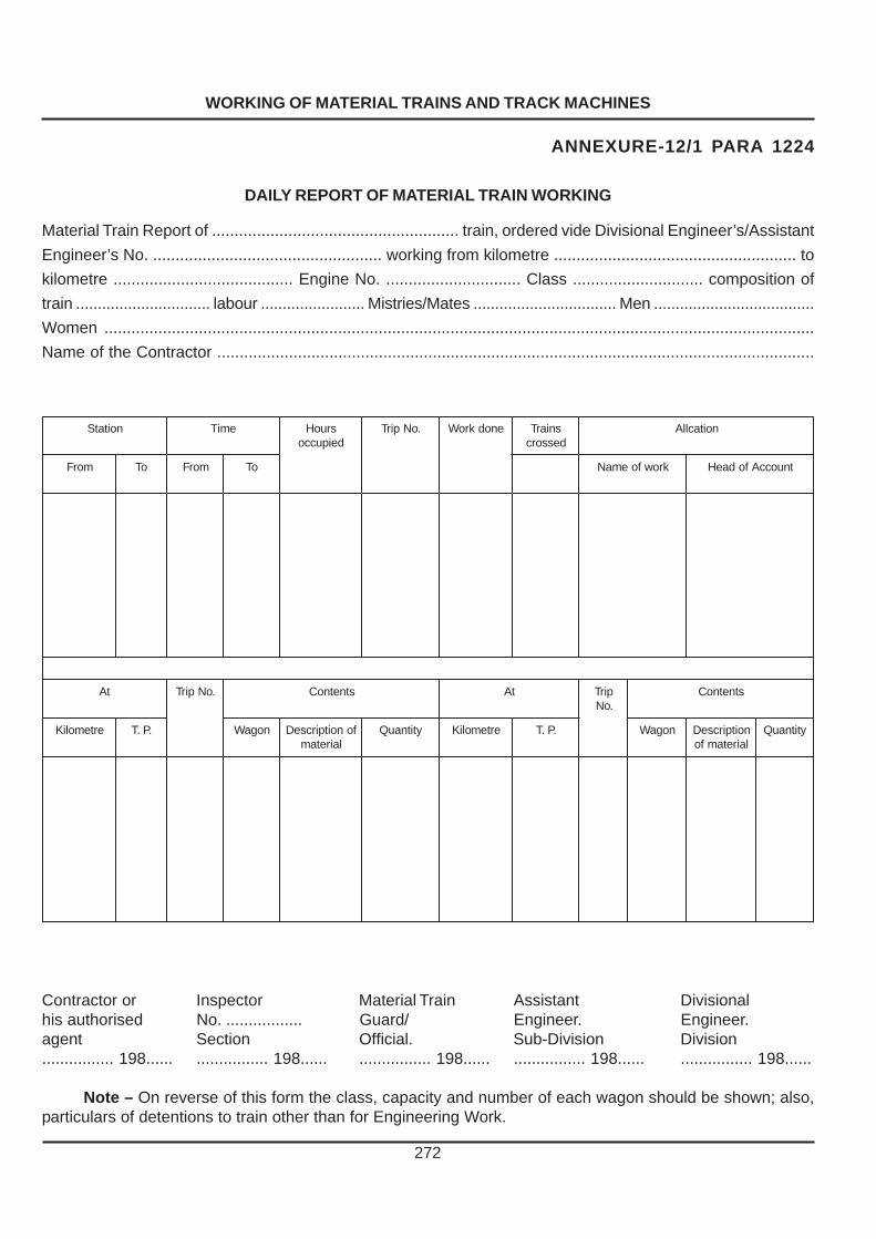
WORKING OF MATERIAL TRAINS AND TRACK MACHINES
272
ANNEXURE-12/1 PARA 1224
DAILY REPORT OF MATERIAL TRAIN WORKING
Material Train Report of ....................................................... train, ordered vide Divisional Engineer’s/Assistant
Engineer’s No. ................................................... working from kilometre ...................................................... to
kilometre ........................................ Engine No. .............................. Class ............................. composition of
train ............................... labour ........................ Mistries/Mates ................................. Men .....................................
Women ..............................................................................................................................................................
Name of the Contractor .....................................................................................................................................
noitatS emiT sruoHdeipucco
.oNpirT enodkroW sniarTdessorc
noitacllA
morF oT morF oT krowfoemaN tnuoccAfodaeH
tA .oNpirT stnetnoC tA pirT.oN
stnetnoC
ertemoliK .P.T nogaW fonoitpircseDlairetam
ytitnauQ ertemoliK .P.T nogaW noitpircseDlairetamfo
ytitnauQ
Contractor or Inspector Material Train Assistant Divisionalhis authorised No. ................. Guard/ Engineer. Engineer.agent Section Official. Sub-Division Division................ 198...... ................ 198...... ................ 198...... ................ 198...... ................ 198......
Note – On reverse of this form the class, capacity and number of each wagon should be shown; also,particulars of detentions to train other than for Engineering Work.

PROCEDURE FOR OBTAINING SANCTION AND CARRYING OUT WORKS AFFECTING SAFETY OF THE RUNNING LINE AND FOR OPENING NEW WORKS
��������
������ ���������������
��������������������� ��
� ����������������������������
� ������������������������
��� �� ����
GENERAL
1301 - References to Rules – (1) The safety of travelling public is governed (ensured)by the rules laid down in :(a) Railways Act 1989 (24 of 1989) (as amended fromtime-to-time),(b)The General Rules of Indian Railways,(c) The Railways (Opening for Public Carriage ofPassengers) Rules, 2000 (as amended from time-to-time), and(d) The Indian Railway Schedule of Dimensions (asamended from time-to-time).(C.S.No:111 Dated:23.04.2008)
(2) These rules specify the authority competent tosanction and the procedure for obtaining sanction for any work which affects a running line, before the work is started or brought into use and before a new section of line is opened for public traffic.
1302. Works requiring the sanction of Commissioner of Railway Safety and Notice therefor –
(1) Under section 23 of Railways Act, 1989 (24 of1989) and chapter VII of the “Railways (Opening for Public Carriage of Passengers) Rules, 2000”, the sanction of Commissioner of Railway Safety is required for the execution of any work on the open line, which will affect the running of trains carrying passengers and any temporary arrangement necessary for carrying it out, except in cases of emergency.(C.S.No:111 Dated:23.04.2008)
(2) For the commencement and opening of thefollowing works, when they are connected with or form part of Railway already opened, the sanction of the Commissioner of Railway Safety shall be obtained :
(a) Additions, extensions or alternations torunning lines.
(b) Alterations to points and crossings in runninglines.
(c ) New signalling and interlocking installations or alterations to existing installations.
(d) New stations, temporary or permanent.
(e) The construction (but not the removal) ofan ash pit on a running line.
(f) Heavy regrading of running linesinvolving lowering/ raising of track in excess of 500mm.
(g) New bridges including road over andunder bridges, foot over- bridges, strengthening, raising, reconstruction or extension of existing bridges, addition or replacement of existing girders, including, provision of temporary girders. Here, bridges shall include road over and under bridges, foot over bridges and subways affecting running lines. (CS 138 25-08-2015)
(CS. No. 127 Dtd. 28.11.2011) (h) Provision of new level crossing, shifting
of existing level crossing on running lines, demanning and downgrading of level crossing, manning of unmanned level crossings, upgrading of level crossing involving changes in the method of working or operation (such as interlocking) and closing down of manned level crossings. However, sanction of CRS shall not be required for providing lifting barriers in place of leaf/swing gates at interlocked/non-interlocked level crossing or closing of unmanned level /canal /cattle crossing. (C.S.No:121 Dated:12.07.2010)
(i) Permanent diversion (deviation) morethan 2 km in length without any station in between and irrespective of length, when a new station is involved.
Note:– Permanent diversions more than 2 km in length, and irrespective of length when a new station is involved, are to be treated as new lines covered by the provisions of section 21 to 23 of the Railways Act, 1989 (24 of 1989). (C.S.No:111 Dated:23.04.2008)
(k) Temporary diversion irrespective oflength, except those laid for restoration of through communication after accident.
(l) Addition or alterations to theelectrical installations of tracks equipped for electrical traction.
273
SSTW
Highlight
SSTW
Highlight

(3) Application for any alterations,reconstruction or additions that require the sanction of Commissioner of Railway Safety should ordinarily be made 30 days in advance of the expected commencement of such work.
If for any reason a sanctioned work is not taken in hand within 12 months from the date of sanction, the Commissioner of Railway Safety should be approached for renewal of the sanction.
1303. Application for sanction of Works –
(1) Application to the Commissioner ofRailway Safety, for sanction for carrying out works affecting the running lines should be submitted in the manner specified below :
(a) In the case of the Divisional Works theapplication should be made by Senior Divisional Engineer and/or Senior Divisional Signal and Telecommunication Engineer, for track, bridges and signalling and interlocking works as the case may be. When a Junior Administrative Grade Officer does not exist on the division in any department the Divisional Railway Manager / Additional Divisional Railway Manager should sign the application. In case of works executed by Construction Organisation whether for Civil Engineering or Signal and Interlocking, applications will be signed by the Junior Administrative Grade Officers for Chief Engineer(Construction), or Chief Signal and Telecommunication Engineer (Construction) as the case may be.
(b)For Divisional works which involve both CivilEngineering and Signal and Interlocking, application shall be signed jointly by the Junior Administrative Grade Officers of both Civil Engineering and Signal and Telecommunication Departments of the division. In the absence of a Junior Administrative Grade Officer, the application will be signed by Divisional Railway Manager/ Additional Divisional Railway Manager. In the case of works executed by Construction Organisation, application shall be signed by Junior Administrative Grade officers representing chief engineer (Construction) and Chief Signal and Telecommunication Engineer (Construction).
(c) (i) Signalling and Interlocking works onOpen Line undertaken by Railway Electrification Organisation shall be carried out as per instructions
for Signalling works included in the Indian Railways Signal Engineering Manual (IRSEM). Applications to CRS for such signalling works shall be prepared, signed and submitted by an Officer not below the rank of Deputy Chief Signal & Telecom Engineer (RE). Dy.CSTE/RE shall also countersign the Safety Certificate.’
(ii) While such Signalling and Interlocking works are executed by Railway Electrification Organisation, Dy.CSTE/RE and Sr.DSTE Open Line of Division shall sign a joint certificate indicating that all Safety precautions and necessary checks as per extant instructions have been carried out for commissioning the Signalling and Telecom works. (CS- 133 dtd 04.06.13
(2) In all cases, the name and designation ofthe signatory should invariably be given.
1304. Documents to accompany Applications – (1) Documents to accompany the application are detailed in Form (Annexure 13/1) and they should be complete in every respect.
(2)The officer should furnish along with hisapplication a Track Certificate where applicable, on Form (Annexure 13/2) signed by Deputy Chief Engineer (Track) and in his absence by Additional Chief Engineer (Track) to the effect that the track is suitable for the maximum axle loads stated therein. The certificate will be countersigned by the Chief Track Engineer/Chief Engineer.
(3) For a major bridge, or whenspecial spans ( designed and constructed by zonal railways based on site requirement.) are used, a certificate on Form (Annexure 13/3) issued by Deputy Chief Engineer (Bridges) to the effect that the bridge or bridges are designed to carry the axle loads proposed to be run, should accompany the application. The bridge certificate will be countersigned by the Chief Bridge Engineer/Chief Engineer. (CS 137 dtd. 18-06-2015)
274
APE
(c) (i) Signalling and Interlocking works on Open Line undertaken by Railway Electrification Organisation shall be carried out as per instructions
APE
for Signalling
APE
works included in the Indian
APE
Railways Signal Engineering Manual
APE
IRSEM).
APE
Applications
APE
to
APE
CRS
APE
for
APE
such signalling works
APE
shall be prepared, signed and submitted by
APE
an
APE
Officer
APE
&
APE
Telecom
APE
not
APE
below the rank of Deputy Chief Signal & Telecom Engineer (RE). Dy.CSTE/RE shall
APE
also countersign the Safety Certificate.’
SSTW
Highlight
SSTW
Highlight

(4) For purpose of Forms (Annexure 13/2
and 13/3) the Chief Operating Superintendent should be consulted in regard to the types of locomotives and rolling stock to be used, their axle loads and speeds. The rules for traffic working obtained from the Operating Department and particulars of electric block-signalling work, if any from the Signal and Telecommunication Department should accompany the application.
1305. Submission of Safety Certificate –
1) The Commissioner of Railway Safety in according his sanction may or may not propose to inspect the works.
2) If the Commissioner of Railway Safety
decide to inspect the work prior to opening, he will, after inspection in the company of the officers concerned, communicate in writing his sanction to open the work.
3) Should the Commissioner of Railway Safety
decide not to inspect the work prior to opening, the Safety Certificate in Form (Annexure 13/5), together with the certificates referred to therein shall be completed and submitted before the work is opened, by the Engineer(s)-in-charge and a telegram despatched to Commissioner of Railway Safety. Copies of Safety Certificate should be send to the Divisional Railway Manager and Chief Engineer and/ or Chief Signal and Telecommunication Engineer.
4) The Safety Certificate for engineering
works should be signed by the Assistant Engineer concerned and countersigned by the Divisional Engineer. If any conditional sanction is given, it should be specifically certified that the conditions as stipulated are fulfilled. If the signalling/interlocking work is involved, the Safety Certificate should be signed jointly by the officers of Signal and Tele-communication department. (5) Safety Certificate shall be despatched to the Commissioner of Railway Safety expeditiously. (6) When phase working is involved, separate Safety Certificate should be issued, whenever each phase of work is completed. 1306. Deviations from Plans approved by Commissioner of Railway Safety – If any deviations from the plans approved by the Commissioner of Railway Safety which affects the layout of lines or the arrangement of signals or the
working rules, are found necessary, his prior approval to such deviations should be obtained with reference to his sanction.
1307. Applications for running of new types of locomotives and/or rolling stock for increase in speed –
(1) Application to the Commissioner of Railway Safety for sanctioning the running of new types of locomotives or rolling stock or increasing the maximum permissible speed on a specified section or sections, or for Double Heading/Multiple Heading should ordinarily be made by the Chief Engineer one month in advance and accompanied by the following documents :
(viii) Load diagram.
(ix) Certificates for track-strength.
(c )Certificates for the strength of girders.
Speed clearance certificate issued
by the R. D. S. O.
Reports of test runs/oscillation trials (to be obtained from RDSO if required by C. R. S.)
Certificate on Form (Annexure 13/4) signed jointly by Chief Mechanical Engineer and Chief Engineer for steam and Diesel Locos and Chief Electrical Engineer and Chief Engineer in the case of straight electric locos and E. M. U. rolling stock. The certificate should also be signed by the Chief Operating Superintendent and Chief Signal and Telecommunication Engineer of the Railway, where maximum permissible speed for any class or classes of trains or rolling stock is proposed to be raised. (g) A statement in the Form XVII of the Railways (Opening for Public Carriage of Passengers) Rules, 2000, detailing any infringement of maximum and minimum dimensions involved in the running of the locomotive or rolling stock. (C.S.No:111 Dated:23.04.2008)
275

(2) On receipt of such an application, the
Commissioner of Railway Safety will, if he so desires inspect and/or try out the new locomotive and/or rolling stock and the Railway Administration will afford him the necessary assistance to do so.
1308. Notification to Railway Officials when opening works –
Except as described in (para 1309), no new work affecting the running of trains or the traffic working at stations should be brought into use until staff of all departments have been notified by means of a circular notice issued by the Divisional Safety Officer/Divisional Operating Superintendent. Timely intimation of the date of opening of works should be sent to the Divisional Operating Superintendent / Divisional Safety Officer, wherever any new or revised working rules are to be brought into operation, to enable him to give the running staff due notice.
1309. Works arising out of accidents including breaches – (1) - An abbreviated procedure to be adopted in the case of accidents as laid down in Section 24 of the Railways Act,1989 (24 of 1989) is reproduced below: “When an accident has occurred on a railway resulting in a temporary suspension of traffic, and either the original lines of rails and works have been restored to their original standard or a temporary diversion has been laid, for the purpose of restoring communication, the original lines of rails and works so restored, or the temporary diversion, as the case may be, may, without prior inspection by the Commissioner, be opened for the public carriage of passengers, subject to the following conditions, namely : (a) the railway servant in-charge of the works undertaken by reason of the accident has certified in writing that the opening of the restored lines of rails and works, or of the temporary diversion will not in his opinion be attended with danger to the public; and
(b) a notice of the opening of the lines of rails
and works or the diversion shall be sent immediately to the Commissioner. (C.S.No:111 Dated:23.04.2008)
(2) A certificate on Form (Annexure 13/6)
which is worded in accordance with Section 24 of Railways Act, 1989 (24 of 1989), must be written out and signed by representative of Engineering Department in-charge of the work before opening it. This certificate shall be dispatched by quickest means to the Officers concerned followed by confirmatory copies by letter. The Engineering representative should hand over a copy of the certificate to the representative of the Operating Department at the site of accident; the latter will not permit the passage of traffic over the restored road or the diversion until he is in possession of the certificate. (C.S.NO:111 Dated:23.04.2008)
(3) Diversions should, wherever possible, be tested by running a Material train, or light engine over them, before opening for public traffic.
(4)The Certificate to Commissioner of Railway
Safety need not be sent when the line is restored for through communication within 24 hours.
(C.S.NO:111 Dated:23.04.2008)
(5) Where the use of temporary diversion is likely to be extended for more than three days, the Commissioner of Railway Safety may if, he considers necessary take the earliest opportunity of inspecting it.
1310. Opening of New Lines – Whenever it is proposed to open a new line
for traffic, or to initiate the use of Electic Motive ower on a line already opened, or to commission a line here guage conversion has been done - Rules and procedure contained in the relevant Chapters of “Rules for opening of the Railway or a section of the Railway for the public carriage of passengers” shall be strictly followed. 276
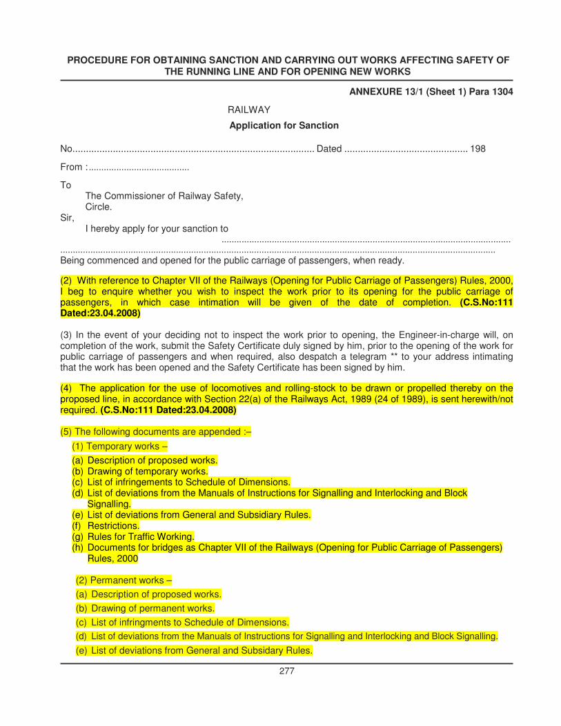
PROCEDURE FOR OBTAINING SANCTION AND CARRYING OUT WORKS AFFECTING SAFETY OF THE RUNNING LINE AND FOR OPENING NEW WORKS
ANNEXURE 13/1 (Sheet 1) Para 1304
RAILWAY Application for Sanction
No. ......................................................................................... Dated .............................................. 198 From : ........................................ To
The Commissioner of Railway Safety, Circle.
Sir, I hereby apply for your sanction to ...................................................................................................................
............................................................................................................................................................................. Being commenced and opened for the public carriage of passengers, when ready. (2) With reference to Chapter VII of the Railways (Opening for Public Carriage of Passengers) Rules, 2000, I beg to enquire whether you wish to inspect the work prior to its opening for the public carriage of passengers, in which case intimation will be given of the date of completion. (C.S.No:111 Dated:23.04.2008)
(3) In the event of your deciding not to inspect the work prior to opening, the Engineer-in-charge will, on completion of the work, submit the Safety Certificate duly signed by him, prior to the opening of the work for public carriage of passengers and when required, also despatch a telegram ** to your address intimating that the work has been opened and the Safety Certificate has been signed by him. (4) The application for the use of locomotives and rolling-stock to be drawn or propelled thereby on the proposed line, in accordance with Section 22(a) of the Railways Act, 1989 (24 of 1989), is sent herewith/not required. (C.S.No:111 Dated:23.04.2008) (5) The following documents are appended :–
(1) Temporary works – (a) Description of proposed works. (b) Drawing of temporary works. (c) List of infringements to Schedule of Dimensions. (d) List of deviations from the Manuals of Instructions for Signalling and Interlocking and Block
Signalling. (e) List of deviations from General and Subsidiary Rules. (f) Restrictions. (g) Rules for Traffic Working. (h) Documents for bridges as Chapter VII of the Railways (Opening for Public Carriage of Passengers)
Rules, 2000
(2) Permanent works – (a) Description of proposed works. (b) Drawing of permanent works. (c) List of infringments to Schedule of Dimensions. (d) List of deviations from the Manuals of Instructions for Signalling and Interlocking and Block Signalling. (e) List of deviations from General and Subsidary Rules.
277

PROCEDURE FOR OBTAINING SANCTION AND CARRYING OUT WORKS AFFECTING SAFETY OF THE RUNNING LINE AND FOR OPENING NEW WORKS
ANNEXURE 13/1 (Sheet 2) Para 1304 Cont.
(f) Restrictions. (g) Rules for Traffic Working.
(h) Documents for bridges as per Chapter VII of the Railways (Opening for Public Carriage of Passengers) Rules, 2000. (C.S.No:111 Dated:23.04.2008)
(6) Certified that a detailed examination of the strength and arrangement of the materials to be used in the temporary/permanent works in above connection, have been made and that the design and the materials to be used are upto the loads, which will be required to carry and that their opening for public carriage of passengers will not be attended with any danger.
(Delete temporary or permanent work, as the case may be). Yours faithfully,
No. .............................................................. Dated .......................................................... From
The Commissioner of Railway Safety,
................................................. Circle. To,
The ............................................................
................................................. Railway.
Sir,
Your No. .............................................................................
Sanction is accorded to the above work being carried out. (i) I do not propose to inspect the work prior to its opening for the carriage of passengers. When
ready, it may be opened on a Safety Certificate (vide Paragraph 3 of your letter), which should be submitted to me direct without any delay.
(ii) I propose to inspect the work prior to its opening for the public carriage of passengers. Advice of the date when the work will be ready for inspection should be intimated at least 14 days before it is proposed to open it.
Commissioner of Railway Safety. Note : * Strike out paragraph not applicable. * Here enter name of work and mention whether permanent or temporary. ** Form telegram – “Reference sanction No. .......................................... dated ............................. Work
opened for public traffic on ..................................... First train to pass ...................................... No danger to Public. Certificate signed”.
+ If any of the documents are not sent, “ NIL” to be written against such items. Working rules for extensive remodelling schemes may be sent in not later than one month before the date
on which the work is to be brought into use and in such cases ‘will follow’ should be written instead of ‘NIL’. 278

PROCEDURE FOR OBTAINING SANCTION AND CARRYING OUT WORKS AFFECTING SAFETY OFTHE RUNNING LINE AND FOR OPENING NEW WORKS
279
ANNEXURE 13/2 (Para 1304)
Track Certificate
(To accompany application)
I do hereby certify that the track on section................................(station..................tostation................................................) from.........................................km. to...........................km, the * weakestportion of which consists of................................kg. rails .................................................metres long each witha maximum wear of......................................% on..................................sleepers of density.............................andminimum depth of........................................ballast cushion below sleepers out ofwhich.............................minimum of clean ballast exists under sleepers on consolidated and stable formationis to the required strength which can safely take...................................rolling stock (brief description) **upto..............................tonnes axle load at a minimum speed of..............................km.p.h. subject of the localspeed restrictions noted below –
Sl.No. From To KM..........to Nature of restriction Brief reason for restrictionKM............
Countersigned by................................................ .....................................................Additional Chief Engineer (Track)/ Deputy
Chief Engineer (Track)
......................................................Chief Track Engineer/Chief Engineer
Note – * The weakest portion on which no speed restriction has been imposed only need to be given.
** The maximum number of locomotives proposed to be coupled together for multiple operationshall be specifically mentioned.

PROCEDURE FOR OBTAINING SANCTION AND CARRYING OUT WORKS AFFECTING SAFETY OFTHE RUNNING LINE AND FOR OPENING NEW WORKS
280
Annexure 13/3 (Para 1304)
Bridge Certificate(To accompany application)
1. Certified that the bridges on Section (station)..................................to..........................(station) from............................Km. to..............................K.m. the minimum strength of superstructurebeing..........................% of RBG/M. G., M. L. standard as per Bridge Rules 1941/1964 Revised corrected uptoand inclusive of...............................Correction slip No..............................dated..................................are safeto carry ........................................................................... (Rolling stock) not exceeding....................................units(in the case of locomotive) coupled together, at a maximum speed of ..........................km.p.h.subject to thefollowing restriction :
Sl.No. Bridge No. Location Km. Spans and description Nature of restriction Brief reasons
2. Sub-structures of all the bridges are in satisfactory condition and safe to carry the above rollingstock at the speed proposed, conforming to the provisions of the I. R. S. Sub-structure(Code...................)corrected upto Correction Slip No............................except those that are weak and distressedwhich will be kept under observation with adequate speed restrictions on the same as follows :–
Sl.No. Bridge No. Location Km. Spans and description Nature of restriction Brief reasons
Countersigned.
.................................Dy.Chief Engineer(Bridge Design)
Chief Engineer/Chief Bridge Engineer

PROCEDURE FOR OBTAINING SANCTION AND CARRYING OUT WORKS AFFECTING SAFETY OFTHE RUNNING LINE AND FOR OPENING NEW WORKS
281
ANNEXURE 13/4 Para 1307
Joint Safety Certificate for the use of New types ofLocomotive and/or Rolling Stock
Certified that it is safe to run..................................................................................... .........................(Particularsof locomotives and rolling stock proposed to run) not exceeding............................
..................................................units (in the case of locomotives) coupled together on the section(station)....................................to..........................(station) from.......................Km. to.......................................Km.of the.......................................Railway at a maximum speed of.....................................km.p.h. against a maximumspeed of............................................. km.p.h. certified by R.D.S.O. subject to the following speed restrictionsand conditions :
(a) Speed Restrictions
Sl.No. From Km.................. Nature of speed Brief reasons for restrictionsTo Km...................... restriction
......................................... ................................ C.M.E. C.E.
................................... .................................... ................................C.E.E. C.S.T.E. C. O. P. S.
Note —
(1) When the speed of a loco/rolling stock is to be increased or increase in speed is contemplated over themaximum sanctioned speed for that category of train (Passenger or Goods) over a particular section, theC. O. P. S. and C.S.T.E. should be associated.

PROCEDURE FOR OBTAINING SANCTION AND CARRYING OUT WORKS AFFECTING SAFETY OFTHE RUNNING LINE AND FOR OPENING NEW WORKS
282
(2) C.E.E. should also sign wherever electric traction is involved.
ANNEXURE 13/5 (Sheet 1) Para 1305
Safety Certificate
(When the Commissioner of Railway Safety does not inspect the work prior to opening, this certificatemust be signed before opening temporary or new works).
From
The Divisional Railway Manager / Divisional Engineer/ Divisional Signal & Telecommunication Engineer,
................................................................Division.
To
The Commissioner of Railway Safety, ..........................................................Circle.
Description of work ..............................................................................................................................
.........................................................................................................................................................................
Reference : Chief Engineer/Divisional Railway Manager................................................................
Application No........................................................................................dated........................... sanctioned under
Commissioner of Railway Safety No.......................................dated................... to commence and open the
above work.
Following Permanent / Temporary work has been done...........................................................................
....................................................................................................................................................
....................................................................................................................................................
.....................................................................................................................................................
(1) I do hereby certify that, in the work abovementioned –
(i) The Schedule of Dimensions has not been infringed* except in regard to the items sanctionedunder.................................letter No............................................dated............................................................
(ii) Engineering work has been carried out in accordance with Plan No...........................................
*except in regard to the alterations sanctioned under.................................letter no................. dated.................
(iii) *The weight of rails, strength of bridges and general structural character of the works are such
as have been prescribed under the rules.
(iv) The*Signalling/*Interlocking/*Block-signalling has been carried out in accordance with Signalling
Plan No...........................and the requirements laid down in the Manuals of Instructions for the installation and
maintenance of Signalling, Interlocking and *Block-signalling apparatus have been fully complied with *except
in regard to the items sanctioned under letter No............................................dated...........................................

PROCEDURE FOR OBTAINING SANCTION AND CARRYING OUT WORKS AFFECTING SAFETY OFTHE RUNNING LINE AND FOR OPENING NEW WORKS
283
ANNEXURE 13/5 — (Sheet 2) Para 1305 Contd.
(b) The work has been carried out in accordance with the documents already supplied.
(2) A certificate from the Divisional Operating Superintendent/Divisional Safety Officer stating that thenecessary working rules have been issued and giving reference in regard to sanction to deviation (if any) fromGeneral and Subsidiary Rules is attached/not required.
(3) I hereby certify that on the................................................19...., I have carefully inspected (and tested+) the above work and that I have satisfied myself that it has been properly completed (and is in good workingorder +) and that the work can be opened for public carriage of passengers without endangering the safety ofthe travelling public or of the employees of the Railway, *subject to the following speed restrictions :–
Temporary..................................................Km.p.h..........................................................dueTo.......................................................................................................................................................
Permanent........................................................Km.p.h...................................................dueTo.......................................................................................................................................................
(4) The work is being opened on............................................................................................
..................................................................Assistant Engineer Countersigned by ..........................................
Dated ................................ Dated....................................
................................................................ Countersigned by .........................................Assistant Signal & Telecommunication Engineer
..............................................................Assistant Bridge Engineer
Dated .........................
..............................................................................................................................................................................
No.................................................. Dated.................................
Copy forwarded to ................................................................for information.
Note – * To be scored out if not applicable.+ Necessary in case of Signalling and Interlocking works only.

PROCEDURE FOR OBTAINING SANCTION AND CARRYING OUT WORKS AFFECTING SAFETY OF THE RUNNING LINE AND FOR OPENING NEW WORKS
ANNEXURE 13/6 Para 1309
Certificate in connection with Restoration of through Running after Accidents. (C.S.No:111 Dated:23.04.2008)
Commissioner of Railway Safety,..................................
Copy—Chief Engineer, Chief signal and Telecommunication Engineer, Chief Operating Superintendent, Divisional Railway Manager, Divisional Engineer, Divisional Operating Superintendent, Divisional Signal and Telecommunication Engineer, Station Masters.
Station Master’s.................................................................................... All concerned Message
No..................................................................... dated...................................... Line and works restored to working order/temporary Diversion laid. Certificate signed. Work being opened to traffic without danger to public or goods, subject to a speed restriction of............................................................................................................. ................................km. p. h.
.................................................... Engineer-in-charge.
284

LAYING AND MAINTENANCE OF CONCRETE SLEEPERS
���������
�� �������������������� �����������������
GENERAL
1401. Types of concrete sleepers – Two
types of concrete sleepers are in use, on the Indian Railways–
3 Monoblock prestressed concrete sleepers consisting of two types, post-tensioned and pre-tensioned.
4 Two block reinforced concrete sleepers.
1402. Identification of Sleepers at Site – Concrete sleepers can be identified by the type-lettering showing the name of the manufacturer, the year of manufacture, and code letter of the sleeper type engraved on the top surface of sleepers. Permanent Way staff should take care to see that they are not obliterated during maintenance.
1403. Fittings to be used - Only approved types of fittings and fastenings shall be used with concrete sleepers.
1404. Locations where Concrete Sleepers are used - Concrete sleepers should normally be used only with LWR/CWR track. Hence the conditions for laying LWR/CWR should equally apply for laying concrete sleepers. Use of concrete sleepers on long lengths of track where provisions of check rails or guard rails is necessary, is prohibited unless special arrangements are made to provide the necessary flange way clearance.
Where concrete sleepers are used in yards with fish-plated track, the sleeper spacing at fish-plated joint shall be kept uniform. In addition, 1m long fishplates may preferably, be provided at such joints. (C.S.No:102 Dated:29.05.2007)
Laying of Concrete Sleepers
1405. Laying of Concrete Sleepers – Concrete sleepers are heavy and manual handling is not only difficult but may even cause damage to the sleepers. Mechanical handling of concrete sleepers, therefore, becomes necessary. For this purpose, the Mechanical Relaying Systems consisting of portal cranes are used. Normally a set will consist of two portal cranes. For laying of concrete sleepers for fan shaped turnout, the instructions given in Para 1413 be followed.
1406. Operations connected with
Relaying– (1) Preparatory work at site of relaying- (a) Since concrete sleepers are laid with LWR/CWR all preparatory works as listed in LWR Manual should be carried out before laying concrete sleepers. In addition, longitudinal section showing the existing rail levels should be plotted and proposed rail level determined taking into consideration the following points :–
(h) 300mm. ballast cushion is available below the concrete sleepers.
(i) Clearances to structures are maintained within the accepted limits.
(iii ) The track and the road surface are suitably raised and approaches regraded.
(iv) Where lifting of track is not possible at places like-below over line structures, on girder bridges and in yards, etc., suitable ramping out should be done.
(b) The proposed predetermined rail level should be indicated at suitable intervals along the tracks.
(c ) Auxiliary track should be laid at 3.4 M. gauge keeping its centre line same as that of the existing track.
(d) The existing welded rails should be converted into panels of suitable lengths such that the capacity of the portal crane is not exceeded by handling the old panel.
(2) Pre-assembly of Panels – Sleepers received from the Concrete Sleeper plant are unloaded and stacked at the base depot. Handling of Concrete Sleepers is done by portal cranes or separate cranes provided for the purpose. These sleepers are assembled into panels making use of service rails. While assembling the panels, elastic fastenings complete in all respects should be provided and correct uniform spacings of sleepers should be ensured.
The assembled panels are stacked and are later loaded in BFRs in three to four tiers. 285

LAYING AND MAINTENANCE OF CONCRETE SLEEPERS
286
(3) Formation of relaying train – The relaying train shall consists of two empty BFRs for loading releasedtrack panels, adequate number of BFRs loaded with pre assembled panels, BFRs loaded with portal cranes,one equipment and tool van, one crew rest van, one brake van and an engine. A typical marshalling order ofthe relaying train is indicated in the figure below :
CREW REST VAN
BRAKE VAN
ENGINE
MACHINE B.F.R.TO CARRY PORTALS
B.F.Rs LOADED WITHNEW ASSEMBLED PANELS(FOUR PANELS IN EACH)
EMPTY B.F.RsFOR LOADINGRELEASED PANELS
PORTALS CARRYINGNEW PANELS
MEN LEVELING BALLASTNEW TRACK
MECHANISED RELAYING OF CONCRETE SLEEPERS
(4) Actual Relaying – At speed restriction of20 km. p. h. is imposed at the place of relaying andpreliminary works such as loosening of fastenings,removal of ballast etc. are carried out in advance.On the day of relaying, traffic block is imposed andthe relaying train enters the block section. After therelaying train is positioned, the portal cranes unloadby themselves on the auxiliary track. The old trackis dismantled and loaded by the portal cranes on theempty BFRs. The ballast is then levelled and the pre-assembled panels are laid in position. The new andexisting tracks are joined by closure rails. After thelast panel is laid, a ramp is made in two rail lengthsbetween the existing track and the new track, to runout the difference in levels. The relaying train returnsto the base depot where the old track panels areunloaded.
(5) Post relaying works – In subsequent blocksthe service rails should be replaced by weldedpanels.
The newly laid track is tamped and speedrestrictions relaxed in stages as per schedulesmentioned in Para 308. Before relaxing the speedto normal, provisions of proper L.W.R. ballast profileshould be ensured.
1407. Procedure for Manual Laying – (1)Manual Laying will not normally be adopted exceptunder exceptional circumstances.
(2) Loading and Unloading –
(a) Concrete sleepers shall be placedperpendicular to the length of the BFR.
(b) Manual unloading shall be done sleeper bysleeper. Wooden sleepers provided with hooks atthe top ends for gripping the side of the BFR shall beused as ramps for sliding the sleepers down to thecess level. Damage by over-running shall beprevented by placing the lower ends of the rampseither inside an old motor truck tyre or between gunnybags filled with wood shavings and the sleeperallowed to move down the ramp. Two men shall standon the cess with crowbars planted into the cess andcontrol the downward sliding of the concrete sleepers
(c) After unloading, the sleepers shall be placedon the cess approximately alongside the finalposition. Where the width of the cess is sufficient,the concrete sleeper should be kept supported bywooden blocks so as to be approximately at thesame level as in its final position in track. Individualconcrete sleepers may be transported convenientlyon a rail dolly to R.D.S.O. Drawing No.MA.3031.
(3) Laying Procedure – The following procedureshall be adopted for manual laying of concretesleepers in place of existing fish-plate track :
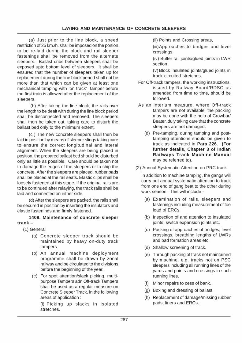
LAYING AND MAINTENANCE OF CONCRETE SLEEPERS
287
(a) Just prior to the line block, a speedrestriction of 25 km./h. shall be imposed on the portionto be re-laid during the block and rail sleeperfastenings shall be removed from the alternatesleepers. Ballast cribs between sleepers shall beexposed upto bottom level of sleepers. It shall beensured that the number of sleepers taken up forreplacement during the line block period shall not bemore than that which can be given at least onemechanical tamping with ‘on track’ tamper beforethe first train is allowed after the replacement of thesleepers.
(b) After taking the line block, the rails overthe length to be dealt with during the line block periodshall be disconnected and removed. The sleepersshall then be taken out, taking care to disturb theballast bed only to the minimum extent.
(c ) The new concrete sleepers shall then belaid in position by means of sleeper slings taking careto ensure the correct longitudinal and lateralalignment. When the sleepers are being placed inposition, the prepared ballast bed should be disturbedonly as little as possible. Care should be taken notto damage the edges of the sleepers or to chip theconcrete. After the sleepers are placed, rubber padsshall be placed at the rail seats. Elastic clips shall beloosely fastened at this stage. If the original rails areto be continued after relaying, the track rails shall belaid and connected on either side.
(d) After the sleepers are packed, the rails shallbe secured in position by inserting the insulators andelastic fastenings and firmly fastened.
1408. Maintenance of concrete sleepertrack –
(1) General
(a) Concrete sleeper track should bemaintained by heavy on-duty tracktampers.
(b) An annual machine deploymentprogramme shall be drawn by zonalrailway and be circulated to the divisionsbefore the beginning of the year.
(c) For spot attention/slack picking, multi-purpose Tampers adn Off-track Tampersshall be used as a regular measure onConcrete Sleeper Track, in the followingareas of application :
(i) Picking up slacks in isolatedstretches.
(ii) Points and Crossing areas,
(iii)Approaches to bridges and levelcrossings,
(iv) Buffer rail joints/glued joints in LWRsection,
(v) Block insulated joints/glued joints intrack circuited stretches.
For Off-track tampers, the working instructions,issued by Railway Board/RDSO asamended from time to time, should befollowed.
As an interium measure, where Off-tracktampers are not available, the packingmay be done with the help of Crowbar/Beater, duly taking care that the concretesleepers are not damaged.
(d) Pre-tamping, during tamping and post-tamping attentions should be given totrack as indicated in Para 226. (Forfurther details, Chapter 3 of IndianRailways Track Machine Manualmay be referred to).
(2) Annual Systematic Attention on PRC track
In addition to machine tamping, the gangs willcarry out annual systematic attention to trackfrom one end of gang beat to the other duringwork season. This will include -
(a) Examination of rails, sleepers andfastenings including measurement of toeload of ERCs.
(b) Inspection of and attention to insulatedjoints, switch expansion joints etc.
(c) Packing of approaches of bridges, levelcrossings, breathing lengths of LWRsand bad formation areas etc.
(d) Shallow screening of track.
(e) Through packing of track not maintainedby machine, e.g. tracks not on PSCsleepers including all running lines of theyards and points and crossings in suchrunning lines.
(f) Minor repairs to cess of bank.
(g) Boxing and dressing of ballast.
(h) Replacement of damage/missing rubberpads, liners and ERCs.

LAYING AND MAINTENANCE OF CONCRETE SLEEPERS
288
Period Work
(a) Post monsoon attention : Immediately after end of monsoon, attend to run down stretches inthe entire gang length. Thereafter, the following schedule of workshall be followed :
( For six-seven months after (i) Picking of slack 1-2 days in a weekend of monsoon) (ii) Remaining days shall be allotted to :
(a) Annual systematic attention.
(b) Overhauling of level crossings.
(c) Destressing of LWRs.
(d) Spot renewals of rails, sleepers etc.
(e) De-weeding.
(f) Cold weather patrolling, etc.
(b) Pre-monsoon attention : (i) Picking of slacks 1-2 days in a week.(ii) Remaining days shall be allotted to :
(For two months prior to onset (a) Cleaning and repairs to side and catch water drains and of monsoon) cleaning of waterways.
(b) Attention to yard drainage.
(c) Spot renewals of rails, sleepers etc.
(d) Shallow screening of specified lengths.
(e) Hot weather patrolling.
(c) Attention during monsoon : (a) Picking of slacks as required.
(b) Normal track maintenance of yard lines.
(For three-four months) (c) Cleaning, removal of loose boulders from cuttings and tunnels
to ensure free flow of water.
(d) Monsoon patrolling.
(e) Maintenance of side and catch water drains.
(f) Repairs to cess and bank.
(3) Annual Programme of maintenance of PRC track
The annual maintenance programme for machine maintained concrete sleeper track would be as under:-
Note : (i) For maintenance schedule onLWR track, special instructions inthe LWR Manual should, inaddition, be followed.
(ii) Spot renewal of rails and sleepersshall be done as per requirementany time of the year.
(iii) Destressing of LWRs shall be doneas per requirement and schedule
to be prepared by the PWI, as perprovisions of LWR Manual.
(iv) Main tamping, pre and posttamping works shall be done asper schedule of working of thetamper. PWI and AEN should beadvised at least one month inadvance of the programme of themachine to enable them tocomplete pre-tamping operations.
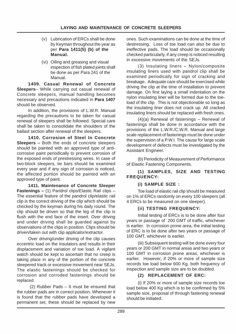
LAYING AND MAINTENANCE OF CONCRETE SLEEPERS
289
(v) Lubrication of ERCs shall be doneby Keyman throughout the year asper Para 1411(5) (b) of theManual.
(vi) Oiling and greasing and visualinspection of fish plated joints shallbe done as per Para 241 of theManual.
1409. Casual Renewal of ConcreteSleepers– While carrying out casual renewal ofConcrete sleepers, manual handling becomesnecessary and precautions indicated in Para 1407should be observed.
In addition, the provisions of L.W.R. Manualregarding the precautions to be taken for casualrenewal of sleepers shall be followed. Special careshall be taken to consolidate the shoulders of theballast section after renewal of the sleepers.
1410. Corrosion of Steel In ConcreteSleepers – Both the ends of concrete sleepersshould be painted with an approved type of anti-corrosive paint periodically to prevent corrosion ofthe exposed ends of prestressing wires. In case oftwo-block sleepers, tie bars should be examinedevery year and if any sign of corrosion is noticed,the affected portion should be painted with anapproved type of paint.
1411. Maintenance of Concrete SleeperFastenings – (1) Pandrol clips/Elastic Rail clips –The essential feature of the pandrol clip/elastic railclip is the correct driving of the clip which should bechecked by the keyman during his daily round. Theclip should be driven so that the leg of the clip isflush with the end face of the insert. Over drivingand under driving shall be guarded against byobservations of the clips in position. Clips should bedriven/taken out with clip applicator/extractor.
Over driving/under driving of the clip causeseccentric load on the insulators and results in theirdisplacement and variation of toe load. A vigilantwatch should be kept to ascertain that no creep istaking place in any of the portion of the concretesleepered track or excessive movement near SEJs.The elastic fastenings should be checked forcorrosion and corroded fastenings should bereplaced.
(2) Rubber Pads – It must be ensured thatthe rubber pads are in correct position. Whenever itis found that the rubber pads have developed apermanent set, these should be replaced by new
ones. Such examinations can be done at the time ofdestressing. Loss of toe load can also be due toineffective pads. The load should be occasionallychecked particularly, if any creep is noticed resultingin excessive movements of the SEJs.
(3) Insulating liners – Nylon/compositeinsulating liners used with pandrol clip shall beexamined periodically for sign of cracking andbreakage. Adequate care should be exercised whiledriving the clip at the time of installation to preventdamage. On first laying a small indentation on thenylon insulating liner will be formed due to the toe-load of the clip. This is not objectionable so long asthe insulating liner does not crack up. All crackedinsulating liners should be replaced with fresh ones.
(4)(a) Renewal of fastenings – Renewal offastenings shall be done in accordance with theprovisions of the L.W.R./C.W.R. Manual and largescale replacement of fastenings must be done underthe supervision of a P.W.I. The cause for large scaledevelopment of defects must be investigated by theAssistant Engineer.
(b) Periodicity of Measurement of Performanceof Elastic Fastening Components.
(1) SAMPLES, SIZE AND TESTINGFREQUENCY:
(i) SAMPLE SIZE :
Toe load of elastic rail clip should be measuredon 1% of ERCs randomly on every 100 sleepers (all4 ERCs to be measured on one sleeper).
(ii) TESTING FREQUENCY:
Initial testing of ERCs is to be done after fouryears or passage of 200 GMT of traffic, whicheveris earlier. In corrosion prone area, the initial testingof ERC is to be done after two years or passage of100 GMT, whichever is earlier.
(iii) Subsequent testing will be done every fouryears or 200 GMT in normal areas and two years or100 GMT in corrosion prone areas, whichever isearlier. However, if 20% or more of sample sizerecords toe load below 600 Kg. both frequency ofinspection and sample size are to be doubled.
(2) REPLACEMENT OF ERC:
(i) If 20% or more of sample size records toeload below 400 Kg which is to be confirmed by 5%sample size, proposal of through fastening renewalshould be initiated.

LAYING AND MAINTENANCE OF CONCRETE SLEEPERS
290
(ii) The provisions given above are only forguidance of Railways. The Railways on the basis ofthe overall condition of track, pattern of traffic andthe required level of maintenance should undertakethe large-scale replacement of the fastening.
(iii) Further, as the loss of toe load is reflectiveof conditions of other elastic fastening componentslike groove rubber sole plate, GFN/metal liners etc.as well, the railways may also record condition ofthese components along with measuring toe loadsfor elastic rail clips.
(5) Measures to prevent corrosion and seizureof E.R.Cs with M.C.I. inserts – (a) Initial treatment –At the base depot, all the elastic rail clips and M.C.I.Inserts should be thoroughly cleaned. Grease toIS:408-1981(Specification for Grease No. ‘O’Graphited) should then be applied on the centralleg of the E.R.C. and eye of the M.C.I. insert andthen the clip should be driven at the time of assemblyof the service panel.
(b) Lubrication of ERCs : Grease Graphite tothe specification IS-408-1981 Gr. O should beused for this purpose. This work should not be carriedout during extreme of summer and heavy rainfall. Ata time ERCs should not be removed form more thanone sleeper. If for any reasons mass lubrication ofERCs is taken up, at least 15 sleepers shall be keptintact between any two sleepers taken up forlubrication of ERCs at the same time. The ERCsshould be cleaned by wire brush and emery paper.The eye of the insert shall also be cleaned by suitablebrush. After cleaning, grease graphite shall beapplied to the inside surface of eye of insert and legof ERC. Inside/Outside ERCs should beinterchanged and fixed again.
(c) The lubrication of ERCs and insert at thetime of initial laying should be done 100% andthereafter should be done once in a year in corrosionprone areas & platform lines and once in two yearsin other areas.
1412. Action in case of Derailments –(1) When the damage is extensive and track isdistorted in such a way that it is not possible to passtraffic even at a restricted speed, the affected portionshould be isolated by introducing buffer rails on eitherend of the affected portion. The distorted track shouldbe removed and replaced by track laid on single railpanels with available type of rails and sleepers. Thetraffic should be restored at a restricted speed. The
section should then be converted to long weldedRails by using concrete sleepers taking usualprecautions as laid down in L.W.R. Manual.
(2) When the damage is not extensive and itis possible to pass traffic at a restricted speed,suitable speed restriction should be imposed afterassessing the damage to track. Sleepers should bereplaced as in the case of casual renewals takingprecautions as laid down in L.W.R. Manual. After allthe damaged sleepers are replaced, the affectedportion and 100 metres on either side adjacent to itshould be destressed, and normal speed should berestored after consolidation.
1413 Laying of fan shaped turnoutsleepers –
(1) Loading of PSC turnout sleepers in BFRs.
(a) Sleeper of the approach and sleepersmeant for lock bar crank will be loaded at right anglesto the track.
(b) The remaining sleepers will be loadedparallel to the track on the BFRs.
(c) Suitable nos. of wooden battens to supportthe sleepers in between layers of turnout sleeperswill be used as in case of main line sleepers toprevent damage.
(2) Unloading :
(a) Depending upon the process of laying ofthe turnout adopted, the sleepers shall be unloadedeither near the proposed location on firm & levelground or adjacent to a nearby siding or on a goodsplatform by means of a crane.
(b) While unloading due care shall be takenthat the sleepers or the inserts are not damaged.
(3) Site preparation for laying:(a) Ensure that a clean ballast cushion of 30
cm below the bottom of sleeper is available.
(b) These turnout sleepers are to be laid wherethe approach track is also laid with PRC sleepers.Thus there would be no need to lower the formationto provide adequate ballast cushion.
(c) The ballast bed has to be perfectly level.Any variation in level may affect the gauge adversely.
(d) Enough ballast shall be stacked along thecess to enable the filling of ballast in the cribs on thesame day.

LAYING AND MAINTENANCE OF CONCRETE SLEEPERS
291
(e) Longitudinal and cross drains may beprovided in turnout area to avoid accumulation ofwater.
(f) The site preparation to be completed wellbefore laying turnout ensuring deep screening ofballast in turnout length and 30m on either side alongthe track.
(4) Assembling:
(a) Ensure the availability of all fittings at sitestrictly as per requirement of latest drawings forswitch portion, lead and crossing portion.
(b) The complete turnout will be assembledon a level ground adjacent to the site of laying or onthe loop line connected to turnout.
(c) Red/blue rounded marking on the sleepersshould invariably be kept on the right hand sideirrespective of left hand or right hand turnout.
(d) Spacing of sleepers should be strictly asper layout drawing.
(e) The sleepers shall be perpendicular to thestraight track in switch portion only.
(f) In lead portion, the sleepers will be inclinedat half the angle between the normals to straight andcurved track at that point. Proposed disposition isappended as Annexure-14/1.
(g) To ensure correct layout, laying of sleeperfalling at transition from switch to lead and lead tocrossing portion should be paid special attention.Sleepers in the switch portion, lead portion andcrossing portion are as under:-
Turnout Switch Lead Crossing
1:8.5 1-13 14-41 42-54
1:12 1-20 21-64 65-83
(h) The spacing of the sleepers in the leadportion should be as per layout drawing to make aradial or fan shaped layout. The spacing has beenworked out separately for both the rails. Thisseparate spacing on two rails make the layout fanshaped in lead portion.
(i) The sleepers in the crossing portion shallbe perpendicular to bisecting line of crossing.
(j) Sleeper no. 3 & 4 may be placed for housingmotor with the extended portion of sleeper in reversedirection only in circumstances where it cannot beavoided.
(k) The approach sleeper in advance of switchportion should be provided without fail, they are forgradual elimination of slope of rail top (1:20).
(l) The exit sleepers behind the crossing portionshould also be provided for gradual introduction ofrail slope (1:20).
(5) Insertion of pre-assembled turnout :
The complete assembled turnout shall beinserted in position after breaking it into three panelsviz. Switch, lead and crossing portions by means ofcranes or rollers.
(6) Manual insertion - In case the PSC turnoutsleepers are to be manually inserted, then the samemust be done sleeper by sleeper ensuring that at notime the alignment and level is beyond permissiblelimits. This work may be done under a suitable speedrestriction if necessary and adequate mechanicalmeans for packing the sleepers must also beavailable.

LAYING AND MAINTENANCE OF CONCRETE SLEEPERS
292
ANNEXURE 14/1-PARA 1413
Ø
L H T/OUT
A
B
C
D
E
F
X
SWITCH SLEEPER ARE PERPENDICULAR TO MAIN LINE
CURVED LEAD SLEEPERS SHALL BE EXACTLY AT HALF ANGLE (Ø/2) AT EACH LOCATION
CROSSING PORTION SLEEPERS SHALL BE PERPENDICULAR TO BISECTOR OF CROSSING
PROPOSED DISPOSITION
R H T/OUT
A
B
C
D
F
E
PROPOSED DISPOSITION

TRAINING FOR PERMANENT WAY STAFF
293
CHAPTER XVCHAPTER XVCHAPTER XVCHAPTER XVCHAPTER XVTRAINING FOR PERMANENTTRAINING FOR PERMANENTTRAINING FOR PERMANENTTRAINING FOR PERMANENTTRAINING FOR PERMANENT
WWWWWAAAAAY STY STY STY STY STAFFAFFAFFAFFAFF1501. Types of Training Courses –
Permanent way staff need to be trained for their jobsboth through theoretical class room training andpractical work at site using the tools and equipmentsof the particular trade. Training is a continuousprocess right from the time of recruitment. Followingfour types of training courses should be organizedin the Training Institutes run by the RailwayAdministration :
(1) Initial/Induction Courses.
(2) Promotional Courses.
(3) Refresher Courses.
(4) Special Courses.
1502. Initial / Induction Courses –
(1) General – The Initial Courses is for newentrants and should include induction course as well.It is meant for directly recruited categories such asGangmen, Permanent Way Mistries and ApprenticePermanent Way Inspectors. The syllabi and thetraining programme for the initial course should bedrawn up by the Railway Administration, keeping inmind the guidelines given in the subsequent parasbelow.
(2) Induction Course for Gangmen/Gatemen–This course is intended to be held at the DivisionalTraining Centre under the direction of a PermanentWay Inspector. The course should be of about twoweeks duration. The course content should, inaddition to field training, include class room lecturesduring which time the new entrant is first introducedto the working of the Departments in general and tothe gang work, in particular. It should includeintroduction to the subject of permanent way in aclear and simple manner.
The Class room lectures should broadly coverthe following topics: - Personal safety and safeworking methods, Railway traffic movements, Basicsignalling, and action in case of emergencies.Emphasis should be more on the job-training in thefield, which should include the following items :–
Maintenance of track, Protection of track inemergencies, Track renewals, Level crossings andpatrolling.
(3) Initial/Induction Course for Permanent WayMistries – (a) Initial/Induction Course for PermanentWay Mistries should be held at the Zonal RailwayTraining Schools. The duration of the course shouldbe six months. The course content should includeclass room lectures as well as training in the field.
(b) The Class Room lectures should includethe following items :
(i) General – General working of the variousdepartments of the Railways.
Labour relations, Personnel rules pertaining toSalary, Leave, Discipline and Appeal Rules, Paymentof Wages Act, Muster Roll maintenance andChannels of Promotion etc.
(ii) Permanent Way – Organization ofPermanent Way, Maintenance and Incidental worksconnected with Permanent Way including renewals.
(iii) The lectures should cover – The Systemsand Methods of maintenance Ballast, Sleepers andfastenings, Rails and fastenings, Points andCrossings, Curves, Monsoon protection andPatrolling, Level Crossings, Track on Bridges,working of push/material trolly, Schedule ofdimensions, Accidents and Breaches, Re-timberingof girder bridges, Maintenance of welded track,Speed restrictions and Re-conditioning of Permanentway materials. It should also include instructionscontained in G. and S.R. pertaining to protection ofPermanent Way, the duties of various PermanentWay Officials and Safety in Permanent Way works.
(c) Practical training – Practical training in thefield should receive high priority and should includethe following items :
(i) Identification of various permanent waymaterials and tools and their use.
(ii) Rails and fastenings, Sleepers andfastenings, Ballast, Points and crossings, Bridges,Curves, Level Crossings, Annual maintenanceprogramme, Different systems and methods ofmaintenance, Maintenance of welded track,Lubrication of rail joints, Diversions, Track renewalsand Re-conditioning of Permanent Way Materials.
(4) Initial Course for Apprentice PermanentWay Inspectors – (a) This course should be held atthe Zonal Training School and the period of trainingshould be one year. The course content shouldinclude class room lectures, field demonstrations andpractical training.

TRAINING FOR PERMANENT WAY STAFF
294
(b) The Class Room lectures should include –
(i) General working of the railways andorganisation of various departments.
(ii) All establishment matters including extantrules and various Acts viz., Workmen’sCompensation Act, Factories Act, Industrial DisputesAct, Payment of Wages Act, Hours of EmploymentRegulations, Discipline and Appeal Rules, LabourRelations, and Permanent Negotiating Machinery,Rules regarding leave, salary and passes.
(iii) Permanent Way – Organisation anddistribution of permanent way staff. Maintenance ofPermanent Way consisting of the following :
Methods and systems, works incidental tomaintenance, Rails and fastenings, Rail joints,Sleepers and fastenings, Ballast, Formation,Maintenance in Electrified and Track circuited areas,Permanent Way renewals, Maintenance and layingof curved track, Inspection systems and speedindicators, Patrolling during monsoon andemergency, Pre-monsoon precautions, Action to betaken during accidents and breaches, Levelcrossings, working of Trollies, Motor Trollies andLorries, Laying and Maintenance of concretesleepers, S.W.R. and L.W.R./C.W.R., Maintenanceof High speed routes, Reclamation andreconditioning of permanent Way fittings, points andcrossings and Layouts-Maintenance and laying,Maintenance of tools and other common equipmentin use and Details of Track Structure.
(iv) Transportation – General Rules, fixed anddetonating signals, various systems of train workingand signalling, Failure of communication on single,double and Multiple lines.
(v) Office work – Correspondence,Recruitment of Casual Labour, Submission ofreturns, Accountal of stores and Permanent WayMaterials, Imprest, Tools and Plants, StockVerification, Classification and disposal of surplusmaterial and Materials at site Account.
(c) Practical Training – Practical training shallinclude visits to various sites where Permanent Waymaintenance/Construction work is being done. Itshould inter-alia include working with the gangs,linking of turn-outs, general maintenance of track,works incidental to maintenance such as deepscreening pulling back rails, lubrication of rail joints,re-timbering of bridges, realignment of curves, lifting
and lowering of track and relaying and remodellingworks. Training should also include exposure toworking at breach and accident sites, attending toyard derailments, practical training in stores, workingin an Engineering Stores depot, Engineeringworkshop, Bridge workshop and welding depots.Safety in Engineering works should also receivespecial attention.
1503. Promotional Courses – (1) General– The course for promotional training will benecessary in the case of staff promoted from a lowerto a higher status by a process of selection and isapplicable in the following cases :
(a) Promotion from Gangmen/Gatemen/Keymen to Mates.
(b) Promotion from Keymen/Mates toPermanent Way Mistries.
(c) Promotion from Permanent Way Mistriesto Permanent Way Inspector Grade III.
(2) Promotion from Gangmen/Gatemen/Keymen to Mates – (a) The Promotional Training forthe above should be held at the Divisional TrainingCentres. The promotional training courses should beundergone by the employees immediately after thepromotion at the first available opportunity. Theduration of training will be two weeks in this case.
(b) The course content will include class roomlectures as well as practical training/demonstrationsin the field. The subject to be covered shall be thesame as for initial course but to a reduced scale.
(3) Promotion from Keymen/Mates toPermanent Way Mistries – (a) The promotionaltraining will be imparted in the Zonal Training Schooland the duration of the course will be four weeks.The course shall include class room lectures, inassociation with practical working of the various itemsof work connected with Permanent way.
(b) Class room lectures shall include thefollowing items :
(i) Drafting of memos and maintenance ofregisters,
(ii) General working of the variousdepartments,
(iii) Permanent way – The lectures will coverthe same subjects as dealt with in the Initial Coursefor Permanent Way Mistries but with a reduced scale.

TRAINING FOR PERMANENT WAY STAFF
(c) Practical training – Practical training shall include working of material trains, push trollies/ material lorries, works connected with maintenance, measurement of versines on curves and local adjustments, linking of turn-outs, assembling of various types of sleepers, fixing of creep anchors, deep screening, pulling back rails, renewals of rails, sleepers and points and crossings, checking of monsoon patrolling and inspections of level crossings, bridges and gang working.
(4) Promotion from Permanent Way Mistries to PWI Grade III –
(a) General – The object of training Permanent Way Mistries for promotion to Permanent Way Inspectors Gr. III is to train them for effective working in a Supervisory category. The training should be imparted in the Zonal Training School for a period of six week. The course content should include class room lectures, field demonstrations, study tours and screening of instructional films. It should also include an assessment by an examination at the end of the course.
(b) The class room lectures shall be on the same subjects as prescribed for Initial Course for Permanent Way Inspectors Gr. III, but the extent of coverage shall be at a reduced scale, since the serving Permanent Way Mistries would be having adequate experience in all spheres of practical working. In addition, the lectures shall include procedure for obtaining traffic blocks including messages to be exchanged with the SMs, submission of requisitions for obtaining green notices, routine correspondence with superiors and officials of the other departments etc.
(c) The Instructional Tours should include visit to Relaying sites, Flash Butt welding plants,
Engineering Workshops, Engineering Stores Depots, offices of PWI & AEN, Control office, Loco Sheds, TXR Depots and S & T Workshop. Special emphasis should also be made on safe working methods.
1504. Refresher Courses – It will be necessary to conduct Refresher Courses to enable the staff to keep themselves abreast with the latest rules and techniques. Keymen, Mates, Permanent Way Supervisors and SSE/SE/JE (P.Way) should be sent for Refresher Courses once in five years. In the Refresher Courses, all subjects pertaining to the concerned categories shall be dealt with as enumerated under promotional courses but the extent of coverage will be on a limited scale. The duration of the Refresher Courses shall be two weeks. (C.S.No:113 Dated:03.06.2008)
1505. Special Courses – In addition to the regular courses mentioned above, special courses on any of the following subjects should also be arranged periodically to increase a sense of awareness of the staff on these subjects :–
Points and Crossings, Maintenance of SWR and LWR, Welding techniques, Track renewals, Ultrasonic Testing of rails, High Speed Track, Track recording, Curves and Reclamations of Permanent way materials.
All the above subjects should be for Permanent Way Inspectors Gr. III and for other categories of staff. It is desirable that the staff posted for the maintenance of welded track and on sections maintained by Machines, should be given a special training on the relevant subjects pertaining to their duties in a short course arranged for the purpose before they are posted on these areas.
295

BOOKS OF REFERENCE
296
CHAPTER XVICHAPTER XVICHAPTER XVICHAPTER XVICHAPTER XVIBOOKS OF REFERENCE
1601. Books of Reference – Books of reference listed in Annexure 16/1 andother publications from R.D.S.O. and IRICEN/Pune including Technical monogramsconsidered essential should be supplied to the officers and the Permanent Way Inspectorsof each Division.
The Chief Engineers’ and the Divisional Engineers’ Offices should be equipped withadequate number of copies of each publication. The publications should be accounted inthe Dead Stock Register. Officials for whose personal use publications are supplied shallbe responsible for their custody and handing them over prior to retirement from service.
1602. Circulation of Technical Papers – The Chief Engineer may arrange to circulatesufficient number of copies of the following publications and such other journals relating toPermanent Way as deemed necessary to the Headquarters Officers and DivisionalEngineers who in turn should circulate them to their Assistant Engineers :–
(a) Reports of the Track Standards Committee.
(b) Journal of the Institution of Permanent Way Engineers (India).
(c) Permanent Way Bulletins issued by IRICEN/Pune.
(d) Technical papers pertaining to Civil Engineering as and when published by theRailway Board.
(e) Permanent Way and Structures Digest.

BOOKS OF REFERENCE
297
ANNEXURE 16/1 Para 1601
List of Books of Reference
metI.oN
snoitacilbuP
noitacilbupehtfoypocahtiwdeppiuqeebdluohshcihwseciffO
lanosrepehtroFsreciffohcusfoesu
sasrotcepsnidnadebircserpebyam
lanoisiviDs’reenignE
eciffo
tnatsissAs’reenignE
eciffo
yaWtnenamrePs’rotcepsnI
eciffo
1 deussiseluRdnayticirtcelEnaidnI,tcA.snoitacilbuPtnemnrevoGetatSdna
.. 1 .. ..
2 etatSdnasevisolpxEnaidnI,tcA.snoitacilbuPtnemnrevoG
. 1
3 etatSdnaseirotcaFnaidnI,tcA.sooilacilbuPtnemnrevoG
.. 1 .. ..
4 etatSdnaseniMnaidnI,tcA.snoitacilbuPtnemnrevoG
.. 1 1 ..
5 etatSdnamuelortePnaidnI,tcAmuelortePdnasnoitacilbuPtnemnrevoG
.seluR
.. 1 1 1
6 ...syawliaRnaidnI,tcA .. 1 1. 1
7 etatSdnanoitisiuqcAdnaL,tcA.snoitacilbuPtnemnrevoG
.. 1 1 1
8 htiw,segaWfotnemyaP,tcA.deussisasnoitacifitoN
.. 1 1 1
9 ...noitasnepmoCsnemkroW,tcA ... 1 1 1
01 snoitatSyawliaRfotsiLlacitebahplA .. 1 1 1
11 :eR-tnemnrevoGetatSsralucriCdnastimilyawliaRraensnoitcurtsnoC
snoitaxaT
.. 1 1 ..
21 tnioJrotnemnrevoGetatSsralucriC.senilyawliaRgnitceffasknaTgnidrager
.. 1 1 1
31 gnireenignEehtrofyawliaRnaidnI,edoC.tnemtrapeD
.. 1 1 1
41 serotSehtrofyawliaRnaidnI,edoC.tnemtrapeD
.. 1 1 1
51 lacinahceM,ehtrofyawliaRnaidnI,edoC.tnemtrapeD
.. 1 .. ..
61 stnuoccAehtrofyawliaRnaidnI,edoC.tnemtrapeD
.. 1 .. ..
71 tnemhsilbatsEyawliaRnaidnI,edoC ... 1 1 1
8I lareneGyawliaRnaidnI,edoC ... 1 1 ..
91 IIItraP.snoitalugeRecnerefnoC .. 1 1 1
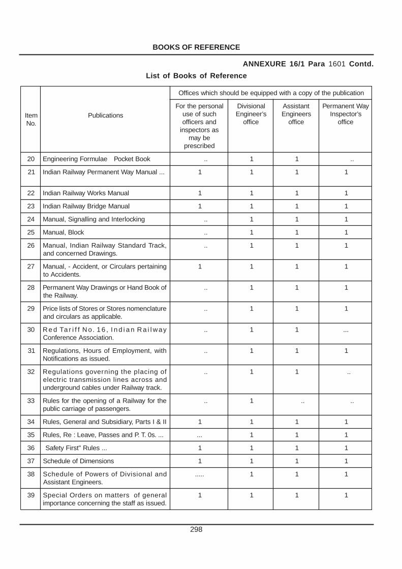
BOOKS OF REFERENCE
298
metI.oN
snoitacilbuP
noitacilbupehtfoypocahtiwdeppiuqeebdluohshcihwseciffO
lanosrepehtroFhcusfoesudnasreciffosasrotcepsni
ebyamdebircserp
lanoisiviDs’reenignE
eciffo
tnatsissAsreenignE
eciffo
yaWtnenamrePs’rotcepsnI
eciffo
02 kooBtekcoPealumroFgnireenignE .. 1 1 ..
12 ...launaMyaWtnenamrePyawliaRnaidnI 1 1 1 1
22 launaMskroWyawliaRnaidnI 1 1 1 1
32 launaMegdirByawliaRnaidnI 1 1 1 1
42 gnikcolretnIdnagnillangiS,launaM .. 1 1 1
52 kcolB,launaM .. 1 1 1
62 ,kcarTdradnatSyawliaRnaidnI,launaM.sgniwarDdenrecnocdna
.. 1 1 1
72 gniniatrepsralucriCro,tnediccA-,launaM.stnediccAot
1 1 1 1
82 fokooBdnaHrosgniwarDyaWtnenamreP.yawliaReht
.. 1 1 1
92 erutalcnemonserotSroserotSfostsilecirP.elbacilppasasralucricdna
.. 1 1 1
03 yawliaRnaidnI,61.oNffiraTdeR.noitaicossAecnerefnoC
.. 1 1 ...
13 htiw,tnemyolpmEfosruoH,snoitalugeR.deussisasnoitacifitoN
.. 1 1 1
23 fognicalpehtgninrevogsnoitalugeRdnassorcasenilnoissimsnartcirtcele
.kcartyawliaRrednuselbacdnuorgrednu
.. 1 1 ..
33 ehtrofyawliaRafogninepoehtrofseluR.sregnessapfoegairraccilbup
.. 1 .. ..
43 II&IstraP,yraidisbuSdnalareneG,seluR 1 1 1 1
53 ....s0.T.PdnasessaP,evaeL:eR,seluR ... 1 1 1
63 ...seluR"tsriFytefaS 1 1 1 1
73 snoisnemiDfoeludehcS 1 1 1 1
83 dnalanoisiviDfosrewoPfoeludehcS.sreenignEtnatsissA
..... 1 1 1
93 larenegfosrettamnosredrOlaicepS.deussisaffatsehtgninrecnocecnatropmi
1 1 1 1
ANNEXURE 16/1 Para 1601 Contd.
List of Books of Reference

BOOKS OF REFERENCE
299
metI.oN
snoitacilbuP
noitacilbupehtfoypocahtiwdeppiuqeebdluohshcihwseciffO
lanosrepehtroFhcusfoesudnasreciffosasrotcepsni
ebyamdebircserp
lanoisiviDs’reenignE
eciffo
tnatsissAs’reenignE
eciffo
yaWtnenamrePs’rotcepsnI
eciffo
04 gnireenignEsredrOgnidnatStnemtrapeD
1 1 1 1
14 gnitarepOsredrOgnidnatS...tnemtrapeD
--- 1 1 ---
24 edoChpargeleT 1 1 1 1
34 snoitacificepSsrepeelSnedoow --- 1 1 1
44 lareneGfokooBdnaHskroWdnatcartnoCfosnoitidnoCdnaslairetaMrofsnoitacificepS
.skroW
1 1 1 1
54 xidneppAdnaelbaTemiTgnikroWotereht
1 1 1 1
64 sa,stsioHdnasenarCfognikroW...deussi
--- 1 1 ---
74 gniyalrofsnoitcurtsnifolaunaM.senihcamhtiwsrepeelsetercnoc
--- 1 1 1
84 ,noitacirbafrofsnoitcurtsnifolaunaMdeulgfoecnanetniamdtfanoitallatsni
.stniojliardetalusni
--- 1 1 1
94 noitacificepSdradnatSyawliaRnaidnI.srepeelSetercnocdesserts-erprof
--- 1 1 ---
05 ttuBhsalFrofecitcarpfoedoC.sliarfognidleW
--- 1 1 1
15 liaRfognidleWrofecitcarPfoedoC.ssecorptimrehTonimulAybstnioj
--- 1 1 1
25 nosralucriCsreenigaEfeihC.’yaWtnenamreP’
--- 1 1 1
35 rofkroWnoitcetorPdnagniniarTreviRybmargonoMsegdirB-yawliaR
.enuP,.T.T.A.I.R.I
--- 1 1 1
45 ehtybdeussisnoitcurtsninoosnoMyawliaR
--- 1 1 1
ANNEXURE 16/1 Para 1601 Contd.
List of Books of Reference