Indian railways - world's largest commercial employer's social ...
Upload
khangminh22Category
view
0download
0
1
ORGANISATION OF INDIAN RAILWAYS
1.Indian Railways : Nation’s Life Line:
Indian Railways have continuously influenced the social, economic, cultural and
political life of the life of the people. Some of the important aspects of this influence
are: increased mobility of the common man, bringing together people from all castes,
communities and religions, growth of trade and commerce, development, rural
development, help in spread of education, contribution to national exchequer, influence
on literature, poetry, music, films etc. Thus, Railways have become Nation’s life line.
2.The Biggest Organization:
Indian Railways are the biggest organization in out country with 14.71 lakhs of
employees; 63,122 route kilometers traversing from Okha to Murkon Selek and
Udhampur to Kanyakumari; 6,906 Railway station; a feet of 7,681 locomotives, 44,756
passengers and other coaches, 2,14,760 goods wagons; carrying 4,971 million
originating passenger traffic and 542.7 million metric tones of originating goods traffic.
It has a total investment of 77,915.78 crore rupees.
History of Railway: The first Railway in India was opened in 1853 from Bombay to
Thane by great Indian Peninsular (GIP) Railway. The maiden trip of the first train took
place on 16th
April 1853 when it traversed a 21 Mile stretch between Bombay and
Thane in about 4 hours time . Starting from this humble beginning, the Indian Railway
system have grown up today into a giant network all over India.
The executive authority in connection with the Administration of the Railways vests
with Central Government and the same has been delegated to the Railway Board as per
the Indian Railway Act.
Corporate Mission : Indain Raiway’s mission to make the Indian Railways a model
system with sufficient capacity to met the country’s transportation needs for both
passenger and freight traffic based on an optimal inter model mix and to the society,
while maintaining financial viability of the system.
Ministry of Railway (Railway Board): The responsibility of the administration and
management of the Indian Railways rests with the Railway Board under the overall
supervision of the Minister of Railways who is a Minister of Cabinet rank and is
associated in this work by one or more Ministers who are of the status of Minister of
State or Deputy Minister. The Rly.Bd is the Chief Administrative and Executive body
assisting the Minister of Railways in the discharge of his functions. It was constituted
by a resolution of Government of India dated 18th
February 1905. It exercises the power
of the Central Govt. in respect of regulation construction, maintenance and operation of
the Railways.

2
Railway Board: Railway Board is the apex executive body which administers,
directs and supervises the functioning of the Railway system. The Board functions
under the Minister for Railways and is headed by the Chairman, who is equivalent to
Principal Secretary to Government of India. The other member are:
1.Financial Commissioner
2.Member staff
3.Member Traffic
4.Member Mechanical
5.Member Engineering
6.Member Electrical
The Board has several directorates. Major directorates are handed by an Advisor.
Health Services and RPF directorates have Director Generals. They are assisted by
Executive Directors, Directors, Joint Directors etc.
Zonal Railways:
The Indian Railways were divided into 16 zones.
No. Name of the Railway Formed on H.Q Route Kms
1 Southern 14.04.1951 Chinni 5,231
2 Central 05.11.1951 Mumbai
CST
3,766
3 Western 05.11.1951 Mumbai CG 6,559
4 Eastern 14.04.1952 Calcutta 2,383
5 Nothern 14.04.1952 New Delhi 3,398
6 North Eastern 14.04.1952 Gorakpur 3,398
7 North Eastern
Frontier
01.08.1955 Calcutta 2,432
8 South Central 15.01.1958 Maligaon 3,951
9 North Western 02.10.1966 Secundrabad 5,753
10 East Coast 01.10.2002 Jaipur 5,453
11 South Western 01.10.2005 Hajipur 3,495
12 East Coast 01.04.2003 Bhuvaneswar 2,513
13 South Western 01.04.2003 Hubli 3,074
14 West Central 01.04.2003 Jabalpur 2,909
15 North Central 01.04.2003 Allahabad 3,101
16 South East Central 01.04.2003 Bilaspur 2,397
Each zones Railway is controlled by a General Manager. The General Manager is
assisted by Principal HOD (Grade 22,000-525-24,500) namely: Addl. G.M, Sr.Dy.GM,
Financial Advisor & Chief Accounts Officer, Chief Engineer. Chief Machnical
Engineer, Chief Operating Manager, Chief Commercial Manager, Chief Electrical
Engineer, Chief signal & Telecommunication Engineer, Controller of Stores, Chief
personnel Officer, Chief medical Officer, Chief Security Commissioner.

3
Divisional Organization:
Each zonal Railway is further divided into Divisions headed by a Divisional Railway
Manager who is assisted by ADRM (18,400-500-22,400) and Divisional Officers
(14,300-400-18,300, 12000-375-16,500) namely : Sr. Divisional Engineer, Sr.
Divisional Mechanical Engineer, Sr. Divisional Operating Superintendent, Sr.
Divisional Commercial Super indent, Sr. Divisional Personnel Officer, Sr. Divisional
Controller of Stores.
Reorganized Zonal Railway with their Divisions:
Western Railway : Mumbai central, Baroda*, Ratlam*, Rajkot*,
Bhavnager, Ahamadabad**.
Central Railway : Mumbai CST*, Bhusaval, Nagper, Solapur*, Pune
Eastern Railway: Howrah, Sealdah, Asansol, Malda
Northern Railway: Delhi*, Moradabad, Firozpur, Lucknow, Ambala
North Eastern Railway : Izatnager*, Locknow, Varanasi
North Eat Frontier Railway : Katihar, Alipurduar*, Lumbding, Tinusukia, Rangiya
Southern Railway: Chennai, Palghat, Madurai, Trichi, Trivendrum.
South Eastern Railway: Kharagpur, Adra*, Chakradharpur*, Ranchi
South Central Railway: Secundrabad, Hyderabad*, Vijaiwada*, Guntakal*Guntur**,
Nanded
East Coast Railway: Bhubaneswar, Kurdharoad, Waltair, Sambalpur
South Western Railway: Hubli, Bangalore, Mysore
West Central Railway: Jabalpur, Bhopal, Kota*
North Central Railway: Allahbad*, Jhansi*, Agra*
South East Central Railway: Nagpur, Bilaspur, Raipur**.
North Western Railway: Jodhpur, Bikanager, Jaipur, Ajmer.
East Central Railway: Sonepur, Samstipur, Danapur, Mugalsarai, Dhanbad.
* Reorganized divisions and ** Newly created divisions.
Total No of Divisions = 59+8= 67
[ Above noted zones recognized and created under notification No.
97/E&R/700/1/Notification, dated 04.07.2002 and divisions reorganized and new
divisions created under Notification No. 98/E&R/700/1/Notification dated 04.07.2002]

ORGANISATION STRUCTURE
ZZOONNAALL RRllyy.. PPRROODDUUCCTTIIOONN UUNNIITTSS OOTTHHEERR UUNNIITTSS PPUUBBLLIICC SSEECCTTOORR
UUNNDDEERRTTAAKKIINNGG//
CCOORRPPOORRAATTIIOONN,,
EETTCC..
ZZOONNAALL RRAAIILLWWAAYY
DDiivviissiioonnss WWoorrkksshhooppss SSttoorree DDeeppoottss Loco Sheds – 103 (45 Nos) (215Nos includ PUStore depot) C&W Sick lines
& Rep. Depots - 303
MINISTER OF RAILWAYS- MR
MINISTER OF STATE FOR RAILWAYS – MRS (N)
MINISTER OF STATE FOR RAILWAYS – MRS
(V)
RAILWAY BOARD
MEMBER
ELCTRICAL MEMBER
STAFF
MEMBER
ENGNEERING
MEMBER
MECHANCAL MEMBER
TRAFFIC
FINANCIAL
COMMISIONER
CHAIRMAN RAILWAY BOARD
BBOARD
DIRECTOR GENERAL
RLY.HEALTH SERVICE
DIRCTOR GENRAL
RPF SECRETARY
ESTT.
MATTERS
ADMN. MATTERS
GM
ALL 16 ZONES
GM CLW DMW DLW ICF RCF RWF
CAO (R) CChhiieeff AAddmm OOffffiicceerr
((RRllyyss))..
((AAss oonn FFeebbrruuaarryy 99,,
22000055))
COFMOW
GM
NF RAILWAY (CONST.) METRO RLY. KOLKATA CORE
DIRECTOR GENERAL RLY. STAFF COLLEGE
DIRECTOR GENERAL & EX. OFFICIO GM
RDSO
IRCON RITES CRIS
CONCOR
IRFC KRC
IRCTC RCIL
MRVC
RVNL

ORGANISATIONAL SET UP OF C&W DEPARTMENT
Organisational set up of Mechanical officers and Supervisors of C&W wing in a
Division
Sr. Divisional Mechanical Engineer
DME DME DME
(ROH Depot) (Coaching Depot) (Divisonal HQ)
AME AME / CDO AME(Divisional HQ)
Sr.SE(C&W)
(Depot Incharge )
Sr.SE(C&W) SE(C&W) JEI(C&W) JEII(C&W)
Sr.SE(C&W)
(Depot Incharge)
Sr.SE(C&W) SE(C&W) JEI(C&W) JEII(C&W)
Sr.SE(C&W) Sr.SE(C&W) Sr.SE(C&W) Sr.SE(C&W)*
Work as a Work as a Work as a (Work as a
C&W C&W Material Safety
Inspector Controller Chaser Counsellor
(C&W)
This SSE (C&W) is under the administrative control of the Divisional Safety
Officers, but is responsible to DME (C&W) for all technical matters concerned with
the safety of Rolling stocks.

Important general information for maintenance
in open line Depot
C&W organisation set-up in a Division.
Codification and Numbering of Coaches.
Ineffective percentage.
Yard Stick.
Nomination of a Depot.
Concept of a Block Rakes.
Indication and Destination Boards.
Fire Extinguishers.
Brake Van Equipment.
Integrated Maintenance.
Rake link
Working Timetable.

ORGANISATIONAL SET UP OF C&W DEPARTMENT
Organisational set up of Mechanical officers and Supervisors of C&W wing in a
Division
Sr. Divisional Mechanical Engineer
DME DME DME
(ROH Depot) (Coaching Depot) (Divisonal HQ)
AME AME / CDO AME(Divisional HQ)
Sr.SE(C&W)
(Depot Incharge )
Sr.SE(C&W) SE(C&W) JEI(C&W) JEII(C&W)
Sr.SE(C&W)
(Depot Incharge)
Sr.SE(C&W) SE(C&W) JEI(C&W) JEII(C&W)
Sr.SE(C&W) Sr.SE(C&W) Sr.SE(C&W) Sr.SE(C&W)*
Work as a Work as a Work as a (Work as a
C&W C&W Material Safety
Inspector Controller Chaser Counsellor
(C&W)
This SSE (C&W) is under the administrative control of the Divisional Safety Officers, but is
responsible to DME (C&W) for all technical matters concerned with the safety of Rolling
stocks.
Railway Organisation for its effective control in working of trains, has an organizational setup at different levels. It can be classified into various levels as;
Railway Board Level

Zonal Level Divisional Level Depot level.
Sl No Name of the Railway Head Quarters
1 Central Railway Mumbai
2. Eastern Railway Kolkota
3. Northern Railway New Delhi
4. North Eastern Railway Ghorakpur
5. North Frontier Railway Maligon
6. Southern Railway Chennai
7. South Eastern Railway Kolkota
8. Western Railway Mumbai
9. South Central Railway Secundrabad
10. East Central Railway Hajipur
11. North Western Railway Jaipur
12. East Coast Railway Bhuvaneshwar
13. North Central Railway Allahabad
14. South East Central Railway Bilaspur
15. South Western Railway Hubli
16. West Central Railway Jabalpur
2. The organizational set up at the Railway Board level is as follows;
Chairman Railway Board
The Security and Medical department are under a separate directorate.
Member
Mech
Member
Elec
Member
Staff Member
Engg
Member
S&T
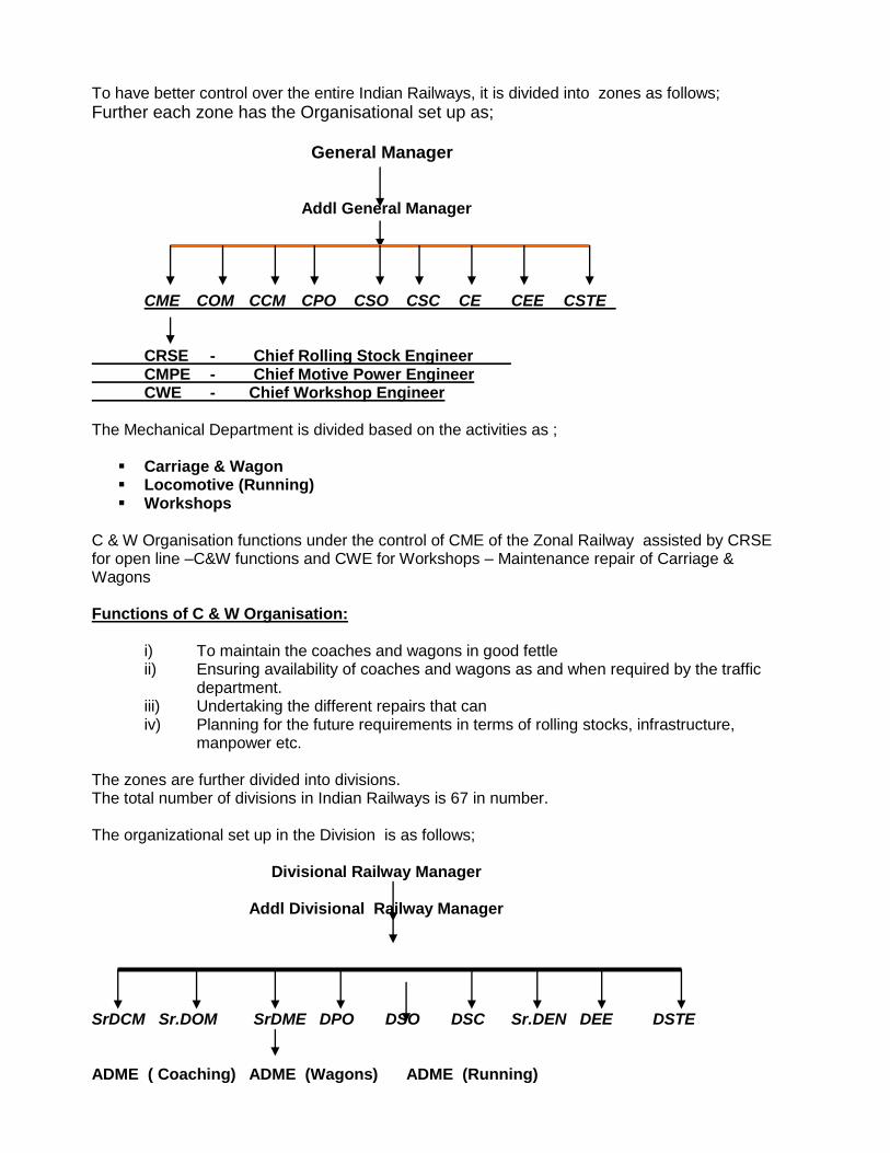
To have better control over the entire Indian Railways, it is divided into zones as follows;
Further each zone has the Organisational set up as;
General Manager
Addl General Manager
CME COM CCM CPO CSO CSC CE CEE CSTE
CRSE - Chief Rolling Stock Engineer CMPE - Chief Motive Power Engineer CWE - Chief Workshop Engineer The Mechanical Department is divided based on the activities as ;
Carriage & Wagon Locomotive (Running) Workshops
C & W Organisation functions under the control of CME of the Zonal Railway assisted by CRSE for open line –C&W functions and CWE for Workshops – Maintenance repair of Carriage & Wagons Functions of C & W Organisation:
i) To maintain the coaches and wagons in good fettle ii) Ensuring availability of coaches and wagons as and when required by the traffic
department. iii) Undertaking the different repairs that can iv) Planning for the future requirements in terms of rolling stocks, infrastructure,
manpower etc. The zones are further divided into divisions. The total number of divisions in Indian Railways is 67 in number. The organizational set up in the Division is as follows;
Divisional Railway Manager
Addl Divisional Railway Manager SrDCM Sr.DOM SrDME DPO DSO DSC Sr.DEN DEE DSTE ADME ( Coaching) ADME (Wagons) ADME (Running)

Each division will have one or more Carriage & Wagon depots depending on the holding of rolling stock. The Carriage & Wagon depots are classified as;
Super Mega depot (1000 coaches and above) headed by Sr.CDO, DME, ADME, ADEE and ACOS.
Mega depot (500 to 1000 coaches) headed by CDO, ADME, ADEE.
Medium depot (250 to 500 coaches) headed by ADME
In any Major Carriage & Wagon Depot, the typical organizational set up is as follows;
Depot In-charge (Sr.DME/DME/ ADME) ADME
SSE SE JE I JE II Sr Technician Technician Gr I Technician Gr II Technician Gr III Helper I Helper II
The major areas of work involved in a depot are divided into smaller areas and a Supervisor will head each. Based on the size of the depot and availability of supervisors, the rank may vary from place to place. For Example; SSE – Co-ordination SSE – Stores SSE – Maintenance SSE - ART SSE – IOH, sick line and so on.

Activities of Coaching Depot:
i. Maintenance of Coaches: There are different types of maintenance like primary, secondary and turn round. The depot to which the rake has been allotted is termed as primary maintenance depot where the trains are examined and certified fit in all respects. In secondary maintenance, at the terminal station the trains are checked and certified fit for its return trip and in turnaround maintenance, the necessary attention will be given at the platform itself.
ii. Repairs to the defective coaches: During service, due to wear and tear, varying load conditions and so many other factors, defects are likely to arise in a coach. Whenever a coach is diagnosed with a defect, it needs to be repaired so that the coach is made fit for traffic use. For this purpose, a sick line with sufficient infrastructure will be provided..
iii. Reception and dispatch of Trains: The trains which have been maintained and kept ready for movement needs to be dispatched and trains, which are reaching the terminating, stations needs to be received for further work. All these activities will be undertaken in the platform.
iv. Stores: For supplying all the spares, consumables and other items needed to maintain the rakes, a Stores with all the requisite materials are always kept ready for disposal.. As and when materials are required, they are drawn from the stores and the material is charged against that activity. As and when, the material has come to the minimum level; the stores personnel again recoup the same. The depot also has various Machineries and Plants required to undertake the different repairs in the coaches. Periodical maintenance, repairs and replacement of these are taken care of by the stores department.
I. IOH: Coaches which are covering more than 1.25 lakh kms in 6 ½ months must undergo Intermediate overhaul in the nominated depots which involves work like running out the bogies, overhauling all the components in the bogie, buffers, screw couplings, repairs to the interior components, overhauling and testing of the brake system, wheel reprofiling etc.
vi. ART – Accident Relief Train: In case of any accident for faster and quicker restoration work Accident relief trains are situated at various locations in each Railway. An ART may comprise of Medical Relief Van, MFD and Crane. Depending upon the seriousness of the accident and the assistance required any of the 3 could be pressed into service. A Senior supervisor assisted by many supervisors and staffs are always kept in readiness to rise to the occasion.
vii. Data Base Management: In every depot the data pertaining to the Coaches of their holding will be maintained. For this purpose, a history card is being maintained for each and every coach which gives the complete history of the trains in which the coach has run, when and for what reason a coach was marked sick and the different repairs which has been undertaken on the coach. The other maintenance requirements such as coaches due for different schedules, rake disturbance in enroute and at the destinations, coaches marked sick within 100 days of POH can be obtained for investigation purposes.

The different documents to be maintained in a depot are;
Register Details
RS 1 Repairs carried out on a rolling stock
RS 2 Oiling Register
RS 3 Repacking register
RS 4 Vacuum testing and repair register
RS 5 Incoming driver’s report on brake power
RS 6 Brake power Certificate
RS 7 TXRs’ Dairy
RS 8 Hot Box register
RS 9 Wheel Transaction register
RS 10 POH register
RS 11 Repairs carried out on the interior components
RS 12 Leaky Wagon Register
RS 13 Fire Extinguisher Maintenance
RS 14 Passenger Emergency Tool Box
RS 15 TXRs’ Hand Book
RS 16 Sick Memo
RS 17 Fit Memo
RS 18 Deficiencies in Rolling stock
RS 56 DRS Card
RS 66 Sick Label
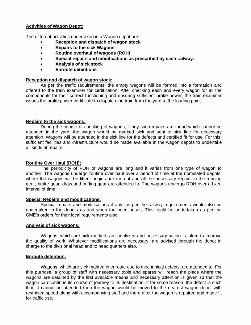
Activities of Wagon Depot: The different activities undertaken in a Wagon depot are;
Reception and dispatch of wagon stock
Repairs to the sick Wagons
Routine overhaul of wagons (ROH)
Special repairs and modifications as prescribed by each railway.
Analysis of sick stock
Enroute detentions Reception and dispatch of wagon stock: As per the traffic requirements, the empty wagons will be formed into a formation and offered to the train examiner for certification. After checking each and every wagon for all the components for their correct functioning and ensuring sufficient brake power, the train examiner issues the brake power certificate to dispatch the train from the yard to the loading point. Repairs to the sick wagons: During the course of checking of wagons, if any such repairs are found which cannot be attended in the yard, the wagon would be marked sick and sent to sick line for necessary attention. Wagons will be attended in the sick line for the defects and certified fit for use. For this, sufficient facilities and infrastructure would be made available in the wagon depots to undertake all kinds of repairs. Routine Over Haul (ROH); The periodicity of POH of wagons are long and it varies from one type of wagon to another. The wagons undergo routine over haul over a period of time at the nominated depots, where the wagons will be lifted, bogies are run out and all the necessary repairs in the running gear, brake gear, draw and buffing gear are attended to. The wagons undergo ROH over a fixed interval of time. Special Repairs and modifications: Special repairs and modifications if any, as per the railway requirements would also be undertaken in the depots as and when the need arises. This could be undertaken as per the CME’s orders for their local requirements also. Analysis of sick wagons: Wagons, which are sick marked, are analyzed and necessary action is taken to improve the quality of work. Whatever modifications are necessary, are advised through the depot in charge to the divisional head and to head quarters also. Enroute detention: Wagons, which are sick marked in enroute due to mechanical defects, are attended to. For this purpose, a group of staff with necessary tools and spares will reach the place where the wagons are detained by the first available means and necessary attention is given so that the wagon can continue its course of journey to its destination. If for some reason, the defect is such that, it cannot be attended then the wagon would be moved to the nearest wagon depot with restricted speed along with accompanying staff and there after the wagon is repaired and made fit for traffic use.

Railway Workshops: The purpose of having Railway workshops in each railway is to undertake the Periodical Over Haul (POH) of Rolling stocks both coaches and wagons and also overhauling of locomotives. Based on the work carried out, each workshop is given with a code for its identification. Each division has its nominated workshop whichever is near by who is going to undertake the POH repairs. The POH arisings are given by each division to the workshop, which is catering to their requirements. Based on this, the individual workshop plans for the various activities it should under take. They also carry out different modifications, retro fitments which are given from time to time. The planning activities must be so good, that the POH cycle time should not get affected by more/less arisings and also the division should not starve for want of coaches. The Workshops also undertake NPOH on rolling stock for those vehicles for which the repair cannot be undertaken in the sick lines of the depots, like rolling stock involved in derailments or accidents. They also undertake manufacture of certain special type of coaches/wagons and rolling stock components required for them and also for the divisions, which has asked for a specific component. The stocks, which are POHed in workshop, are checked by Neutral Control Train Examiners and certified fit. The organizational set up at the workshop could be;
Workshop In-charge (CWM) Dy. CME
WM
APO AWM APE SSE SE JE I JE II Sr Technician Technician Gr I Technician Gr II Technician Gr III Helper I Helper II

Historical Development -
Passenger Coaches • First generations coaches
• - Fully from Timber
• - Serious consequences in accidents
• 1948- 50 Hindustan Air Crafts Ldt Banglore
• started Steel bodied coaches
• 1955 ICF Was Set - Collaboration with Swiss Car & Elevator Manufacturing Corporation, Zuric, Switzerland for integral design.
– Fabricated bogie Coil primary springs
– Laminated secondary springs
– Speed potential of 96 km/h

Historical Development -
Passenger Coaches • Length of bolster hanger increased to 410 mm in place of
286 mm
• Secondary suspension modified to Coil springs
• Side bearers to transfer body weight in place of centre pivot
• 16t bogie for AC coaches
• Adoption of Air brakes
• Bogie mounted air brake system
• Composition brake blocks in place of Cast Iron

Historical Development -
Passenger Coaches • RCF set up at Kapurthala to make coaches to ICF
design
• Variants developed like:
– AC self-generating and End-on-generating
– MG versions
– 2-tier AC, AC chair cars, 3-tier AC

ICF coach - Speed Upgradation
Speed Year Remarks
96 1955 Original design of Schlieren
105 1965 All coil spring, weight transfer through
side bearer
120 1969 Improved track standards to C&M 1(Vol 1)
130 1971 Trials - Introduction of Rajdhani
140 1988 Trials - Introduction of Shatabdi

Design Objectives
• Corrosion Control
• Weight Reduction
• Increase in speed potential
• Increased Payload
• Increased train length
• Passenger amenity
• Safety and Maintainability

SALIENT FEATURES- ICF COACHES
• ALL METAL
• ALL WELDED
• INTEGRAL DESIGN, SKIN STRESSED
• LIGHT WEIGHT
• ANTI TELESCOPIC
• BETTER BOGIE DESIGN
• ANTI-TELESCOPIC
• REDUCED WHEEL DIA
• REDUCED FIRE HAZARD
• BETTER INTERIOR
• STANDARDISATION
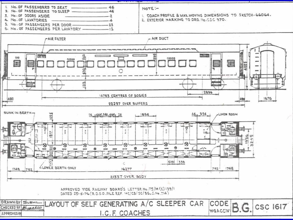

Construction of ICF Coach
• Coach
– Shell - Coach Body
– Running Gear • Bogie
• Braking
– Furnishing
– Train Lighting & Air conditioning

Design & construction • Static tubes- formed of
• - side wall
• - Under frame
• - Roof - similar to hollow tube
• Bracing to the tube by a series of hoops made of
– Side Pillars
– Carlines
– Floor cross bearers
• Hoop rings are connected together by sole bar, waist rails, cant rail, and stiffeners longitudinally
•


Design & Construction - ICF shell
• Anti telescopic - end wall box structure to
absorb major portion of the collision energy
• destructive tubular structure is added between
Trough floor and head stock to have a comp.
Weaker section.
• Trough floor made of corrugated sheet to absorb
a large portion of buffing forces


BASIC ASSUMPTIONS OF INTEGRAL SHELL
• TARE & PAY LOAD ARE EQUQLLY DISTRIBUTED
OVER THE BODY SHELL
• WEIGHT OF THE SHELL IS DISTRIBUTED OVER
THE ENTIRE PHERIPHERY OF THE SHELL
• WT OF THE EXTRA FLOORING & PAYLOAD IS
CARRIED BY THE FLOOR & LOWER PORTION OF
THE SIDE WALL
• HORIZONTAL SQUEEZ LOAD AT THE BUFFER
CENTRE LINE TAKEN BY THE TROUGH FLOOR &
SIDE LONGTUDINAL
• SHELL TREATED AS THIN WALLED
HOLLOW GIRDER.

Advantages of Integral Design
• Ability to withstand higher dynamic force, hence
greater safety in an accident
• Weight 20 % less than ordinary steel shell & 25 %
less than timber coach, hence less operating cost
• Superior Resistance against torsion & Bending
stress
• Extra-ordinary compression rigidity
• less fire hazard
• more amenable to mass production
Design Characteristics- coach Body • Adequate resistance to Horizontal Shearing forces –
Connection between SW & UF
• End Wall to Absorbs to collision energy before any
other part of coach body are deformed.
• No resonance Under all loading conditions -

INTERNATIONAL STANDARD FOR LOADS
FOR COACHES
UIC - 566
• The coach body load should with stand the following test loads without permanent deformation and without exceeding the permitted stress:
• A - STATIC COMPRESSIVE LOEDS At buffer level 200 t
• Diagonally at buffer level 50 t
• At 350 mm above buffer level 40 t
• At centre Rail 30 t
• At cant rail 30 t
•

INTERNATIONAL STANDARD
FOR LOADS FOR COACHES
• B. uniformly distributed load
• P =k ( P1 + P2 )
• where k = 1.3 ( a coefficient of Dynamic
augment)
• P1 = wt of body in tare condition
• P2 = 2 X no of seats x 80 kg

Crashworthiness
Crashworthiness Crashworthiness of rail coach body is its
characteristic to absorb the collision energy
in controlled and predictable manner such
that maximum safety is imparted to
traveling passengers

Crashworthiness- ICF SHELL
• Anti-telescopic shell of Schileren design
• Energy absorption capacity of 10 kJ per side
buffer
• Squeeze load up to 102t at each side-buffer level
• Vertical load of 2.165t per meter run, uniformly distributed
• Squeeze load of 60t at height of 305 mm above buffer
center line
• Horizontal load of 31t uniformly distributed over entire
over end wall

Crashworthiness- ICF SHELL
At reaction of 203 t – 10 g acceleration developed
Higher acceleration > more injury to passenger
Design to aim for controlled Deformation keeping
force below 2000 kN

Crashworthiness-
Improvement & Design Considerations
CBC coupler with tight lock & anti climbing features
Energy absorption capacity 30 KJ in LHB, now being increased to 45 KJ
45 KJ provide protection for impact speeds up to 9.5 Kmh
Stainless shell shell for better energy absorption capability.

Crashworthiness-Improvement &
Design Considerations
Design Considerations:
Managing collision energy
Collapse & occupants zones
Buckle imitators
Anticlimbing
Train Impact Simulationn
DESIGN OF
LHB SHELL
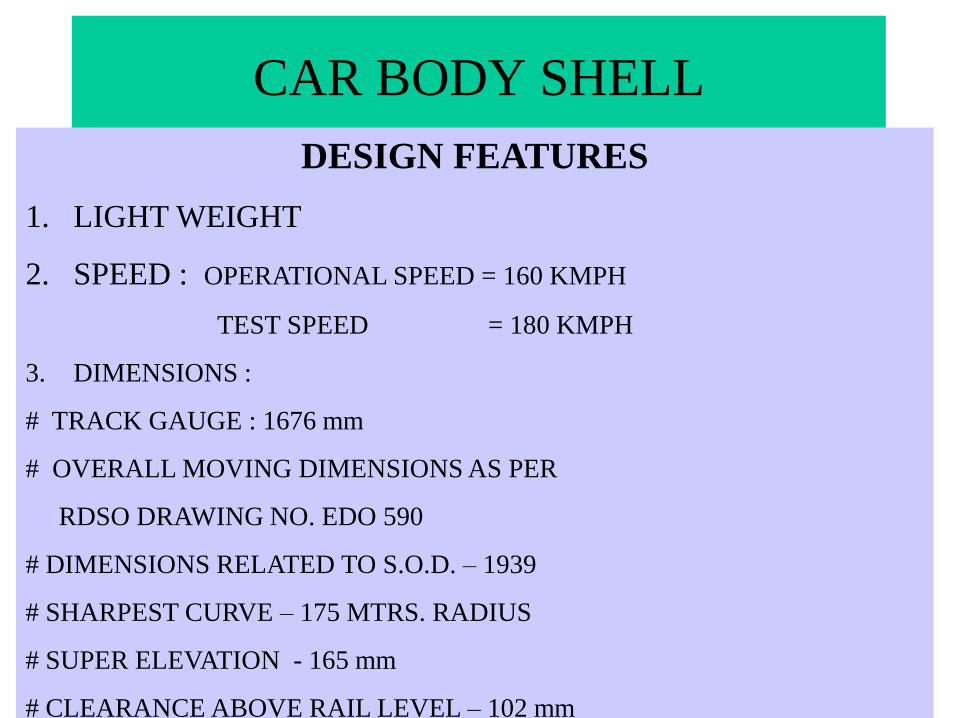
CAR BODY SHELL
DESIGN FEATURES
1. LIGHT WEIGHT
2. SPEED : OPERATIONAL SPEED = 160 KMPH
TEST SPEED = 180 KMPH
3. DIMENSIONS :
# TRACK GAUGE : 1676 mm
# OVERALL MOVING DIMENSIONS AS PER
RDSO DRAWING NO. EDO 590
# DIMENSIONS RELATED TO S.O.D. – 1939
# SHARPEST CURVE – 175 MTRS. RADIUS
# SUPER ELEVATION - 165 mm
# CLEARANCE ABOVE RAIL LEVEL – 102 mm

THE BODY SHELL BE OF INTEGRAL LIGHT
WEIGHT
CONSTRUCTION CONSISTING OF SEPARATE
ASSEMBLY GROUPS FOR U/F, SW, ROOF &
END WALL.
# WHOLE CAR BODY SHELL CONSISTS OF
THREE TYPES OF STEEL.
# THE INDIVIDUAL ASSEMBLIES ARE JOINED
TO EACH OTHER BY WELDING
BODY SHELL

OVERALL DIMENSIONS OF THE COACH
A LENGTH OVER BODY 23540 mm
B BUFFER CENTRES 1956 mm
C MAXIMUM WIDTH OVER BODY 3250 mm
D HEIGHT OF CENTRES OF COUPLER
FROM RAIL LEVEL
1105 mm
E HEIGHT OF COMPT. FLOOR FROM RAIL
LEVEL
1303 mm
F MAX. DIST. BETWEEN INNER WHEELS 12345 mm
G MAX. HEIGHT OF CENTRES OF BUFFERS
ABOVE RAIL LEVEL
1105 mm

TYPES OF STEELS USED IN LHB
SHELL S.
No.
TYPE OF STEEL APPLICATION
1. 1.4301(Austenitic) 1.25 mm
X5 Cr Ni 18 10
Trough floor & roof sheet
2. 1.4003(Ferritic) Carline –2mm.
Roof beam -2mm.
Side wall -2mm.
Window Sill -2.5mm.
Body Pillar -2.5mm.
Cant Rail - 4mm.
Restructure including
carlines, roofbeam, body
pillar, end wall structure,
side wall sheets, etc.
3. Corten-A All Parts of under frame
except trough floor
including Sole Bar.

•TIG WELDING OR LASER WELDING
OF SIDEWALL SHEETS
•LOW HEAT INPUT
•LESS DISTORTION
•NEGLIGIBLE SHRINKAGE
SIDEWALL

SIDE WALL
# THICKNESS OF SIDE WALL : 2mm
# LASER CUT, BUTT JOINT TIG WELDING OR
LASER WELDING, SPOT WELDING
# DOOR FRAMES IS A PART OF SUB ASSEMBLY
OF SIDE WALL, BUT FABRICATED SEPERATELY
# THICKNESS OF DOOR FRAME : 4mm
DOOR FRAMES ARE DESIGNED IN A MANNER TO
ENABLE THE COMPENSATION OF TOLERANCES
IN WHOLE SIDE WALL

• POSITIVE INTERLOCKING BETWEEN ALL HORIZONTAL
AND VERTICAL MEMBERS
•BETTER STRENGTH,
• REDUCTION OF SIDE WALL THICKNESS TO 60MM FROM
90 MM,
• BETTER GEOMETRICAL INTEGRITY
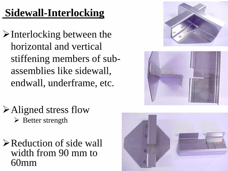
Sidewall-Interlocking
Interlocking between the
horizontal and vertical
stiffening members of sub-
assemblies like sidewall,
endwall, underframe, etc.
Aligned stress flow Better strength
Reduction of side wall width from 90 mm to 60mm
Better geometrical integrity Resistance to distortion

SITUATION BEFORE
INTERLOCKING TECHNIQUE
IN THE PAST, A LOT OF ROLLED
PROFILES HAVE BEEN USED IN FRAME
WORK OF SIDE WALL, END WALL AND
UNDER FRAME, WHICH RESULTS A LOT
OF WELD JOINTS, STRAIGHTENING AND
REWORKING. THIS CAUSED A QUALITY
REDUCTION AND INCREASE OF COST.
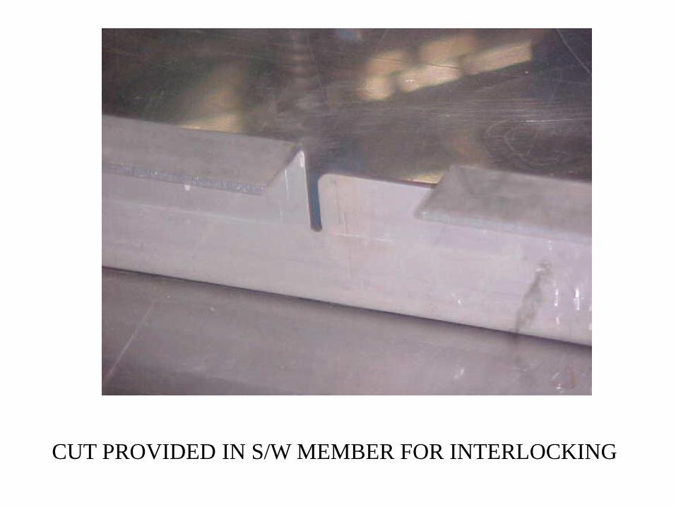
CUT PROVIDED IN S/W MEMBER FOR INTERLOCKING

COMPLETE SIDEWALL

•CARLINE (CANT RAIL IN CONV. COACHES) IS PART OF THE
SIDE WALL, UNLIKE CONV. COACHES WHERE IT IS A PART OF
ROOF
•BETTER RIGIDITY OF SIDE WALL
•POSITIVE LOCATION OF ROOF
14
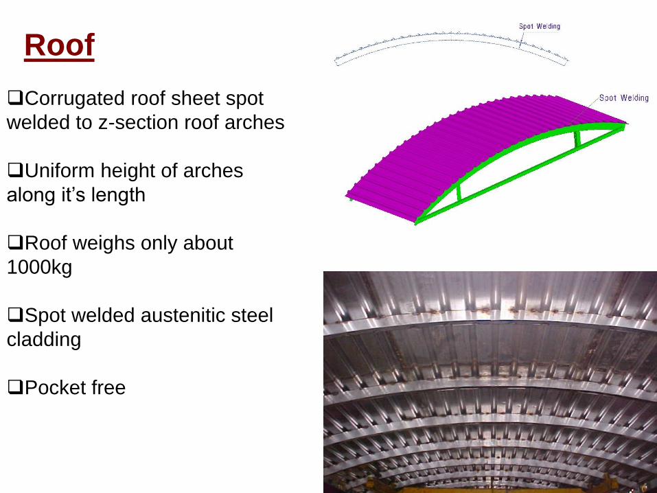
Corrugated roof sheet spot
welded to z-section roof arches
Uniform height of arches
along it’s length
Roof weighs only about
1000kg
Spot welded austenitic steel
cladding
Pocket free
Roof

HOLES PROVIDED IN
ALL STIFFENERS OF
END WALL TO
REDUCE WEIGHT
END WALL

•CORRUGATED ROOF SHEET
SPOT WELDED TO Z-SECTION
ROOF ARCHES
•UNIFORM HEIGHT OF ARCHES
ALONG IT’S LENGTH
•ROOF WEIGHS ONLY ABOUT
1000KG
ROOF

ROOF
• MIDDLE PART:
• CORRUGATED SHEET 1.25 mm THICK
AUSTENITIC STAINLESS STEEL
• # ROOF ARCHES : Z SECTION 30x80x30x2
• # HORIZONTAL CROSS BRACES : Z
SECTION 30x50x30x2
• END PARTS : THESE ARE PREPARED FOR
MATCHING THE TAPERING AT ENDS
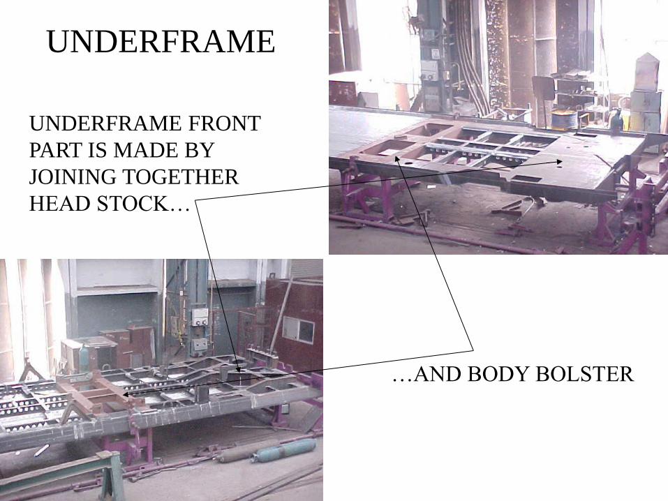
UNDERFRAME FRONT
PART IS MADE BY
JOINING TOGETHER
HEAD STOCK…
…AND BODY BOLSTER
UNDERFRAME
UNDER FRAME
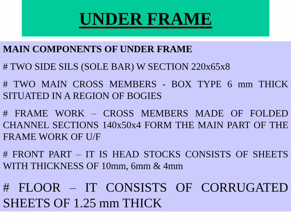
MAIN COMPONENTS OF UNDER FRAME
# TWO SIDE SILS (SOLE BAR) W SECTION 220x65x8
# TWO MAIN CROSS MEMBERS - BOX TYPE 6 mm THICK
SITUATED IN A REGION OF BOGIES
# FRAME WORK – CROSS MEMBERS MADE OF FOLDED
CHANNEL SECTIONS 140x50x4 FORM THE MAIN PART OF THE
FRAME WORK OF U/F
# FRONT PART – IT IS HEAD STOCKS CONSISTS OF SHEETS
WITH THICKNESS OF 10mm, 6mm & 4mm
# FLOOR – IT CONSISTS OF CORRUGATED
SHEETS OF 1.25 mm THICK

•UNDER FRAME CORRUGATED TROUGH FLOOR IS PLUG
WELDED FROM TOP WITH THE CROSS MEMBERS
•ALUMINIUM BASED WELDABLE PRIMER USED FOR
WELDING CORTEN STEEL TO SS TO PREVENT BI-METALLIC CORROSION

PROVISION FOR CBC AS WELL
A SIDE BUFFER MOUNTING IN
HEAD STOCK
FLOORING SUPPORT MEMBERS ON UNDERFRAME

WATER TANK MOUNTING
BRACKETS WELDED ON
THE UNDER FRAME
YAW DAMPER
(CONNECTED BETWEEN
UNDERFRAME AND
BOGIE FRAME)
BRACKETS WELDED ON
THE UNDERFRAME

Steels used in LHB Coach Shell
Shell Assemblies Steels used and their %agecompositions
UTSN/mm2
YieldStressN/mm2
Side wall, Endwall and Roofstructure
X2 Cr8 Ferritic Steel (SS 409M)( C < .03%, Cr 10-12%, Si 1%, Mn1.5%)
450-600
320
Roof sheet andTrough floor
X5 CrNi 18 10 Austenitic Steel (SS304)( C < .07%, Cr 18%, Ni 10 % Si 1%,Mn 2%)
700-850
235
Underframe IRS M-41 / CortenSteel( C < .01%, Cr .35 -.6%, Ni .2 - .4%Cu .3 - .6% Si .3 - .7%, Mn .25%)
440-480
320
SS 409M is a modified version of SS 409 offering higher
strength abrassion resistance and weldability
RCF KAPURTHALA 24
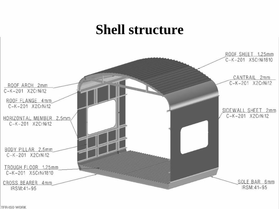
Shell structure

25
Laser Profile Cutting Of Components
Sidewall/Roof Spot Welding
Magnetic Skin Tensioning Of Shell
Manufacturing Techniques

JIGS & FIXTURES
S.NO. DESCRIPTION
1. BODY SHELL ASSEMBLY JIG

PROCESS CHART
STAGE 1
LOAD UNDERFRAME IN JIG
TACK WELD DOOR FRAMES
LOAD SIDE WALLS AND TACK WELD

TACK WELD LAV. SIDE WALLS
LOAD ROOF & TACK WELD
END WALLS ARE TACK WELDED WITH U/F

ROOF ELEMENT IS TACK WELDED
COMPLETE WELDING FROM INSIDE OF SHELL
CROSS BRACES ARE WELDED WITH ROOF INSIDE PART
PROCESS
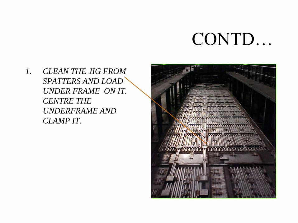
CONTD…
1. CLEAN THE JIG FROM
SPATTERS AND LOAD
UNDER FRAME ON IT.
CENTRE THE
UNDERFRAME AND
CLAMP IT.
CONTD…
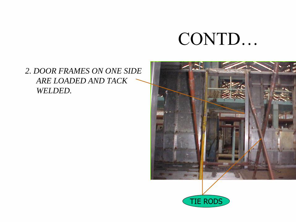
2. DOOR FRAMES ON ONE SIDE
ARE LOADED AND TACK
WELDED.
TIE RODS

CONTD…
3. SIDE WALLS ARE LOADED
IN THE JIG ON BOTH
SIDES AND TACK
WELDED. INTERNAL
DIMENSIONS ARE
MAINTAINED.

CONTD…
4. AGAIN DOOR FRAMES ARE
LOADED ON THE OTHER
END OF UNDERFRAME.
TIE RODS ARE USED TO
MAINTAIN THE INTERNAL
DIMENSIONS.

CONTD…
5. LAVATORY SIDE WALLS ARE
LOADED AND TACK
WELDED WITH
UNDERFRAME AND DOOR
FRAMES.

CONTD…
6. ROOF IS MOUNTED OVER
SIDE WALLS AND TACK
WELDED.

CONTD…
7. END WALL ASSEMBLIES
ARE LOADED ON THE
HEAD STOCK OF THE
UNDER FRAME AND TACK
WELDED.

CONTD… 8. ROOF ELEMENT IS
LOADED OVER LAV. SIDE
WALLS ON BOTH SIDES
AND TACK WELDED. IT IS
USED FOR FITTING OF AIR
CONDITIONER ASSEMBLY.
ROOF ELEMENT

CONTD…
9. COMPLETE WELDING OF FOLLOWING PARTS IS DONE FROM
INSIDE.
(i) ROOF WITH SIDE WALL.
(ii) SIDE WALL WITH UNDERFRAME.
(iii) SIDE WALL WITH DOOR FRAME.
(iv) LAV. SIDE WALL WITH END WALL.
(v) ROOF ELEMENT WITH DOOR FRAME.
(vi) UNDERFRAME WITH END WALL.

CONTD…
10. CROSS BRACES ARE
WELDED WITH ROOF
INSIDE SHELL FOR AIR
CONDITIONER’S DUCT.
THEN THE SHELL IS
MOVED TO STAGE 2.
CROSS BRACE


PROCESS CHART
STAGE 2
V-GROOVING OF SIDE WALL & U/F JOINT
APPLICATION OF WELDABLE PRIMER
COMPLETE WELDING OF SIDE WALL & U/F FROM OUTSIDE

1. V- GROOVING OF UNDERFRAME SOLE BAR WITH SIDE WALL JOINT IS DONE FROM OUTSIDE THE SHELL BY USING ANGLE GRINDER ON BOTH SIDES OF SHELL.
2. ‘META COT ‘SILVER GREY WELDABLE PRIMER IS APPLIED TO AVOID BIMETALLIC CORROSION.

3. SOLE BAR AND SIDE
WALL ARE WELDED
FROM EXTERIOR OF
SHELL USING
MAGNETIC TRACK
WELDING MACHINE.
4. GRINDING OF WELDED
JOINTS OF SOLE BAR
AND SIDE WALL IS
DONE.
WELDING JOINT
CONTD….

MAT.
THICKN-
ESS
NO. OF
LAYERS
WIRE
DIA
mm
WELDING
CURRENT
(AMP)
ARC
VOLTAGE
WIRE
FEED
M/MIN
TRAVEL
SPEED
CM/MIN
THROAT
THICKN-
ESS
(a mm)
1.6*1.6 1 0.8 100-120 22-24 5.0 50 1.2
2.0*2.0 1 0.8 100-120 22-24 5.0 45 1.6
2.0*5.0 1 1.2 100-120 22-24 5.0 45 2.5
5.0*5.0 1 1.2 200-220 26-27 6.5 40 3.2
WELDING PARAMETER FOR MAG CO2 WELDING

STAGEWISE ACTIVITIES OF SHELL
ASSEMBLY SAS-I
ACTIVITIES :- CLAMPING OF U/F BY CLAMPS.
# ALIGN WITH PIANO WIRE AT THREE LOCATIONS
# LOADING OF 5 INTERNAL JIGGING FRAME
# DOOR FRAME FITMENT
# MIDDLE SIDE WALL FITMENT
# TACKING OF SIDE WALL SHEET TO U/F FLANGE
# STRAIGHTNESS IS CHECKED WITH PIANO WIRE
# PLACEMENT OF ROOF
# ROOF CROSS BRACES FITMENT
# PLACEMENT OF FINAL ROOF ELEMENT
# END WALL FITTING

STAGES OF SHELL ASSEMBLY
SAS-II
# WELDING OF SIDE WALL WITH
SOLEBAR BOTH SIDES FROM
OUTSIDE WITH TRACTOR
WELDING. GRINDING OF ALL THE
HORIZONTAL & VERTICAL
WELDING JOINTS FOR PROPER
OUTER FINISH

STAGES OF SHELL ASSEMBLY
• SAS-III
• SENDER GRINDING TO REMOVE HIGH SPOTS
• COLD STRAIGHTENING THE SIDE WALL & END
WALL
• SKIN TENSIONING BY HEATING OF SIDE WALL
FROM INSIDE THROUGH PERFORATED PLATE
HOLES WITH MULTI HEAD TORCH BY USING
OXY ACETYLENE SET.
• CHECK THE SURFACE FINISH BEFORE & AFTER
SKIN TENSIONING.
• PIN WELDING ON ROOF (660 Nos ) BY PIN
WELDING MACHINE TO HOLD GLASS WOOL.

STAGES OF SHELL ASSEMBLY
SAS-IV
# FITTING OF PARTITION FRAME
WHERE REQUIRED
# WELDING PARTS CAR BODY
SHELL PP END & NPP END
# CBC FITMENT

STAGES OF SHELL ASSEMBLY
• CHECKING & INSPECTION
• # ALL DIMENSIONAL INSPECTION OF THE SHELL
• # DPT TEST FOR SIDE WALL JOINTS
• # TWIST CHECK
• # PLACING ON DIPLORY FOR SHIFTING TO NEXT STAGE


• TURN UNDER HAS BEEN ELIMINATED
• CLEAR APPROACH FOR SAND BLASTING AND PAINTING
• NO ACCUMULATION OF WATER AND MUCK
• PILLAR RESTS ON SOLEBAR AS COMPARED TO LOAD
TRANSFER THROUGH A VERTICAL WELDED JOINT IN
CONV. COACHES

SIDEWALL TO UNDERFRAME JOINT,
CONV. VS.LHB

END WALL
OVERHANGS
BEYOND HEAD
STOCK
-RELEASING
MORE SPACE
INSIDE
-REDUCING SPACE
AND HENCE WIND
RESISTANCE DUE
TO TURBULENCE
BETWEEN
COACHES.
-GAP BETWEEN END WALLS OF TWO COUPLED COACHES IS
300 MM ONLY

SEPARATE DOOR FRAME
FITTED BEFORE
SIDEWALLS IN LHB, NO
PROBLEM OF DOOR
SIZE/SQUARENESS ETC.
NO DOOR FRAME, DOOR
OPENING SQUARENESS
MAINTAINED BY FITTING
ONE SIDE’S DOOR CORNER
SHEET AFTER SIDE WALL

•WEIGHT PER METER LENGTH OF LHB COACHES IS
APPROXIMATELY 10% LESS THAN THE CONVENTIONAL
COACHES. BETTER PAYLOAD TO TARE WT RATIO.
•NO CHANGE REQUIRED IN SHELL DESIGN FOR SPEEDS OF
200KMPH
•DIMENSIONAL COMPARISON ICF LHB
LENGTH OVER BODY 21770 23540
LENGTH OVER BUFFER 22280 24700
WIDTH OVER BODY 3245 3240
INNER WIDTH 3065 3120
WINDOW OPENING (ac sleeper) 1220x610 1180x760

WINDOWS

Sealed window Glass Units •The window glass unit characteristics are:
–K value not lass than 1.6 W/M2K –Transparency > 39 % –Reflection > 40 –Total energy absorption < 21%
•The sealed window units consists of 8.4 mm outer laminated and 4 mm tempered inner glass with 6 mm Krypton/Argon gas filling
•Window glass is secured to Al extrusions by rubber profiles
•The Al frame is glued to the car body with the help of PU, elastic gap filling structural adhesive (Sikaflex-264 T & eq.). Capable of withstanding high dynamic stresses

Emergency
openable
window
• It is similar to the fixed unit
• Four units are provided each
coach to allow emergency
evacuation of passengers
• A handle connected to the
rubber profile opens the
glass unit of the emergency
window

HOPPER WINDOW FOR LAVATOTRY

Passenger Emergency Alarm
• 5 passenger emergency alarms
per coach in chair car have been
provided at following locations:
– 2 in passenger compartment
– 3 in lavatories
• There is no mechanical linkage
like a chain and these handles
directly operate a valve venting
the brake pipe
• Designed to stop the train not just
warn the driver


Wheel Shelling
Shelling can be identified by pieces of metal breaking out of the tread surface in several places more or less continuously around the rim.
Shelling takes place when small pieces of metal break out between the fine thermal checks.
These are generally associated with small skid marks or “chain sliding.”
Such wheels should be withdrawn from service and sent to
workshops for reprofiling.

Guidelines for wheel inspection in open line depots (Ref RDSO CMI-K003)
For this purpose, following shelling limits need to be followed.
1. Depth of shelling marks has reached to 1.5 mm.
2. Length of shelling marks has reached to 40 mm.
3. Depth of hollow tyre reached to 3 mm.
4. This limit of 3 mm is kept to study the effect of wheel
shelling and service life of wheels.
5. The rejectable limit of hollow tyre will continue as more than
5 mm as specified in IRCA part IV.

Following major causes have been identified
For wheel shelling: Non-optimal choke sizes of Dump Valves.
Obstructions in air-brake piping between dump valves and brake cylinders.
Wrong / Loose electrical connections of WSP system.
Jamming of Brake Calipers / Actuators.
Poor design of Junction Box prone to dust/water ingress.

Item wise consolidated list of instructions issued
by RDSO (2018-19):
1.Brake Cylinder Pressure
(Ref: RDSO letter no. MC/LHB/Brake dated 20.04.2018 to PCMEs All Zonal Rlys and PUs)
Zonal Railways / PUs should not resort to alteration in Brake Cylinder pressure of LHB Coaches from the specified value of 3.0+0.1kg/cm2 .

2.Dump Valve Chock Size (Ref: RDSO letter no. MC/LHB/Brake dated 27.09.2018 to PCMEs All Zonal
Rlys and PUs)
Dump valve chock size should be ensured as under.
Brake system Make/model
Exhaust chock size Charging chock size
KBIL (Model MGS2)
Remove existing 7mm chock
Replace existing 5 mm chock with 9mm chock
FTRIL (Model SWKP AS20R)
Remove existing 9mm chock
Replace existing 6 mm chock with 9mm chock
Above modification should be ensured in all newly manufactured as well as existing LHB coaches

3.Modification in air brake pipeline & associated fittings
in LHB Coaches. Ref: 1)RDSO letter no.MC/LHB/Brake dated 08.03.2019 to PCMEs/RCF,MCF,ICF
2)Presentation on wheel shelling by Bengaluru Division/SW Railway in 18th CMG
3) RDSO letter no.MC/LHB/Brake dated 12.04.2019 to PCMEs/All Zonal Rlys and Pus
1. Flexible Air Hose (600mm) for Bogie
During the field studies by RDSO at BCT/WR & SBC/SWR;
Problems are observed with the existing hose results in restriction in smooth air flow in pipe line.
Ultimately affects the performance of brake system which may leads to Wheel Shelling in case of wheel slip.


To overcome above issues, RDSO has developed a
standardized design of flexible hose
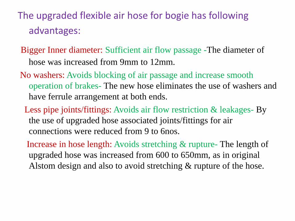
The upgraded flexible air hose for bogie has following
advantages:
Bigger Inner diameter: Sufficient air flow passage -The diameter of
hose was increased from 9mm to 12mm.
No washers: Avoids blocking of air passage and increase smooth
operation of brakes- The new hose eliminates the use of washers and
have ferrule arrangement at both ends.
Less pipe joints/fittings: Avoids air flow restriction & leakages- By
the use of upgraded hose associated joints/fittings for air
connections were reduced from 9 to 6nos.
Increase in hose length: Avoids stretching & rupture- The length of
upgraded hose was increased from 600 to 650mm, as in original
Alstom design and also to avoid stretching & rupture of the hose.


4.Self Lubricating Bushes for Brake calipers /Actuators
(Ref: RDSO letter no. MC/LHB/Brake dated 06.09.2018
1.Only Self lubricating bus.hes should be fitted in Brake calipers /Actuators.
2. Practice of oiling with self lubricating bushes needs to be stopped .
3. Due to use oil, the grease film of self lubricating bushes gets damaged and
these bushes no longer function as designed.
4.Also dust gets accumulated in form of muck which may obstruct freeness of
caliper and can affect brake releasing and application timing.

5.Ensuring Integrity of Electrical connections of WSP System and Free
movement of Brake calipers (Ref: RDSO letter no. MC/LHB/Brake dated 27.09.2018 to PCMEs All Zonal Rlys and PUs)
Integrity of Electrical connections of WSP System and Free movement
of Brake calipers during Brake application/release is absolutely vital
in reducing wheel shelling.


(Gap)
(Hunting)

(Angularity)


(Hammering effect)

• (W0bbling)

•
•
•
•

WHEEL &AXLE

Wheel, Tread and Axle
• Nomenclature
– Axle • Journal
• Collar
• Wheel seat
– Disc • Tread
• Hub
• Tyre profile
2

Wheel Gauge
3

Wheel Tyre Profile
4
• Standard wheel profile
• Worn wheel profile (Conforming profile)
• No Intermediate profile now.
5
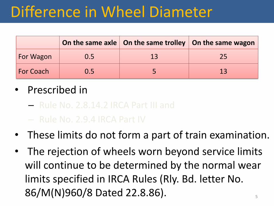
Difference in Wheel Diameter
• Prescribed in
– Rule No. 2.8.14.2 IRCA Part III and
– Rule No. 2.9.4 IRCA Part IV
• These limits do not form a part of train examination.
• The rejection of wheels worn beyond service limits will continue to be determined by the normal wear limits specified in IRCA Rules (Rly. Bd. letter No. 86/M(N)960/8 Dated 22.8.86).
On the same axle On the same trolley On the same wagon
For Wagon 0.5 13 25
For Coach 0.5 5 13

Wheel Profile Defects
• Flat tyre
• Hollow tyre
• Sharp flange
• False flange
• Deep flange
• Thin flange
• Root radius
6

Axle Guide Arrangement
ICF FIAT CASNUB
7

Function of Axle Guides
• Guides the axle w.r.t. bogie frame laterally as well as longitudinally.
• Transmits tractive & braking force between bogie frame & axle box.
• In ICF, acts as a single acting hydraulic vertical shock absorber for primary spring.
• In FIAT bogie, provides control flexibility between frame and axle.

Axle Box Bearing
• CASNUB bogie
– CTRB
• ICF bogie
– Spherical type roller bearing with self-align feature.
• Automatically adjust to the deviation in the centre line of the axle during run.
• FIAT bogie
– CTRB
9

Wheels
MSTC/GKP
Railway Wheels
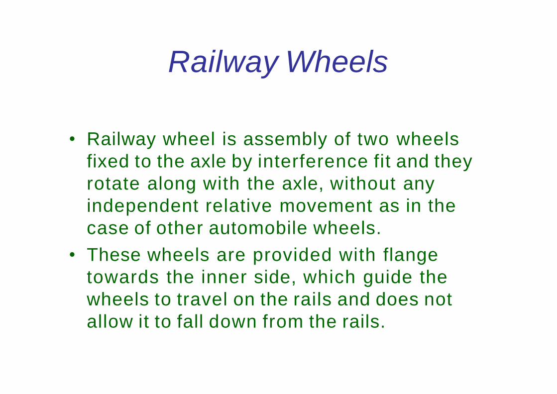
• Railway wheel is assembly of two wheels
fixed to the axle by interference fit and they
rotate along with the axle, without any
independent relative movement as in the
case of other automobile wheels.
• These wheels are provided with flange
towards the inner side, which guide the
wheels to travel on the rails and does not
allow it to fall down from the rails.

Railway Wheels
ICF Coach Wheel

Railway Wheels
LHB Coach Wheel

• Steel made by Electric or Basic Oxygen process
• Steel shall be of killed quality for forged steel
• The max hydrogen content shall not exceed 3 ppm
• The max nitrogen content shall not exceed 0.007%
Material of Wheel

Railway Wheels
BOXN Wheel

The procedure to calculate chemical composition will be in
accordance to IS:228
Material of Wheel
The chemical composition of the steel for Cast Wheel
C 0.47% to 0.57% for type A used for carriage stock
0.57% to 0.67% for type B used for wagon stock
Mn 0.60 to 0.80%
P 0.03% max
S 0.03% max
Cr 0.15% max
Ni 0.25% max
Mo 0.06% max
Combined % for Cr, Ni & Mo must be 0.40% max
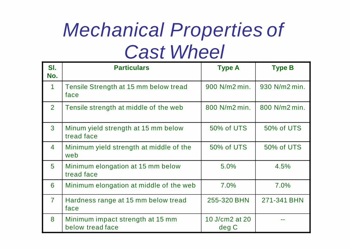
Mechanical Properties of Cast Wheel
Sl.
No.
Particulars Type A Type B
1 Tensile Strength at 15 mm below tread
face
900 N/m2 min. 930 N/m2 min.
2 Tensile strength at middle of the web 800 N/m2 min. 800 N/m2 min.
3 Minum yield strength at 15 mm below
tread face
50% of UTS 50% of UTS
4 Minimum yield strength at middle of the
web
50% of UTS 50% of UTS
5 Minimum elongation at 15 mm below
tread face
5.0% 4.5%
6 Minimum elongation at middle of the web 7.0% 7.0%
7 Hardness range at 15 mm below tread
face
255-320 BHN 271-341 BHN
8 Minimum impact strength at 15 mm
below tread face
10 J/cm2 at 20
deg C
--

Railway Wheels
The wheel is better understood by
dividing it into the following parts
• Hub
• Disc
• Tyre

Wheel
hub
• Hub is the centre portion of the wheel,
where the wheel is fixed to the axle by
means of interference fit.
• Thickness of the wheel is maximum at the
hub portion.
• UT details is marked on the Hub

Disc
• Disc is the portion of the wheel between
the hub and the tyre.
• This portion is the thinnest portion of the
wheel as it does not come in contact with
rail nor it is coming in contact with the
axle.

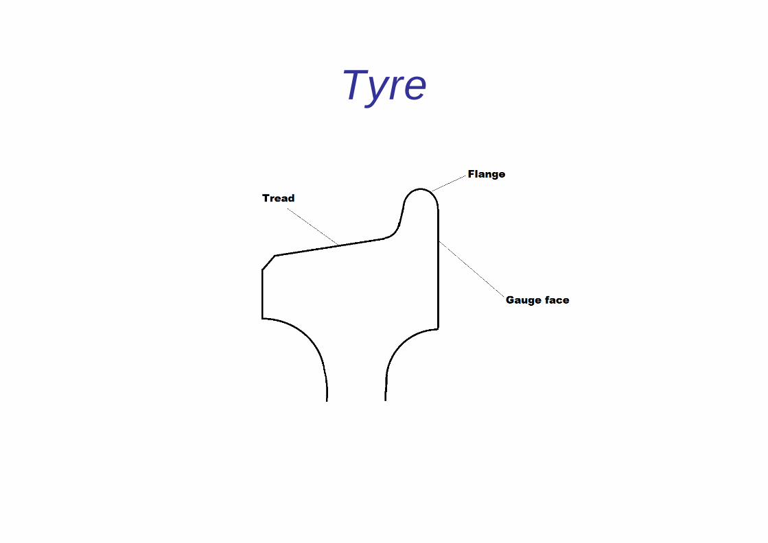
Tyre
• Tyre is the portion in contact with the
rail, which wears out in service.
• The profile of the tyre is significant for
safe running of the trains.
• Taper is given on the tread to have
higher diameter near the flange and
lower diameter at the outer edge, to
facilitate curve negotiation.
Tyre

Axles 13 t Axle for ICF coach

Axles 16.25 t Axle for ICF coach

Press fit of wheel on axles
• Wheel disc is pressed to axle with interference fit (the bore of the wheel should be 0.304 mm to 0.355 mm less than the outer dia of the wheel seat on the Axle)
• Wheel Gauge should be in between 1599 and 1602 mm
• Axial off centre should be within 1.0 mm (wagon) & 0.8 mm (coach)
• Radial off centre should be within 0.5 mm (wagon) & 0.25 mm (coach)
• The Journals should be protected with bituminous black to IS:9862
• All Axles fitted by workshop during POH or despatched to depot should be Ultrasonically tested

Press fit of wheel on axles
Hydraulic press is used for assembly of the wheel
with a force of 400 to 500 Kgs per mm dia of wheel
seat (approximate force used for different wheels
are given below)
Description Tonnage
13 tonne axle 68.8 to 103.2 t
16.25 tonne axle 71.2 to 106.8 t
BOXN & BLC 85 to 127 t

Stamping of particulars
Whenever axles are renewed the workshop shall
punch in 5 mm letters the following particulars on
the journal face
• Place of pressing
• Date of pressing
• Pressure of pressing
Whenever UT is done the details shall be stamped cold
on the inner hub fillet with 6 mm punch not more
than 1.5 mm depth

Stamping of particulars

Stamping of particulars

Stamping of particulars

Worn Wheel Profile
80 % of the track in Indian Railways is having
rails which are already worn in service.
Standard wheel profile running on these
tracks tend to wear to a specific profile
within short time itself, and further wear
from this profile is very slow. Hence if the
wheels are turned initially to this worn wheel
profile, it will increase the wheel life by
avoiding frequent re-profiling.

Worn Wheel Profile
The worn wheel profile is made standard for
all the wheels in Indian railways as the
standard wheel profile is found
uneconomical with lesser kilometres being
run by the wheels within condemnation.

Worn Wheel Profile

Step Sizes of Worn Wheel Profile
Further to reduce the metal removal during tyre
turning, intermediate worn wheel profile based on
the flange thickness is introduced.
Flange Thickness (X) Y Z
28 mm 42.23 mm 13.5 mm
27 mm 41.29 mm 13.0 mm
26 mm 40.34 mm 12.5 mm
25 mm 38.41 mm 11.5 mm
24 mm 37.44 mm 11.0 mm
23 mm 36.47 mm 10.5 mm
22 mm 35.49 mm 10.0 mm
21 mm 34.5 mm 9.5 mm
20 mm 33.5 mm 9.0 mm

Wheel Defects
• Manufacturing Defects
• Improper Assembly Practices
• Normal Wear and Tear during service

Manufacturing Defects
• Casting Defects
• Improper Heat treatment
• Machining Imperfections

Improper Assembly Practices
• Stipulated dimensional tolerances for Wheel seat
and bore not adhered to resulting in use of higher or
lower than the prescribed force during pressing
leading to improper wheel set assembly.
• Ovality on Journals - 0.02 mm (max)
• Taper on Journal - 0.01mm (max)
• Difference in dia of wheels on the same axle should
not exceed 0.5 mm

Wheel defects
Measurable wheel defects arising due to normal wear & tear during service
• Thin flange
• Deep flange
• Sharp flange • Less radius at root of flange
• Hollow tyre
• Thin tyre
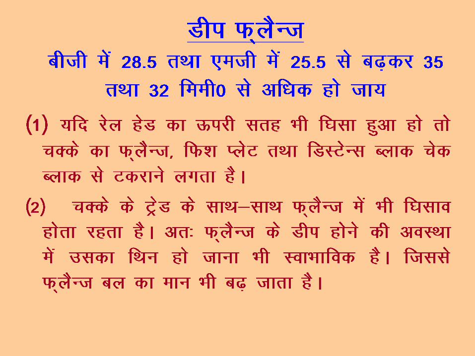
• Flat tyre

Std & cond limits
Defect Std Cond
Thin flange 28.5 22 (Coaches)
16 (Wagons)
Deep flange 28.5 35
Sharp flange (radius) 14.5 5
Less radius at root of
flange (radius)
14 (wwp) 13
Hollow tyre 5
Thin tyre Based on wheel dia
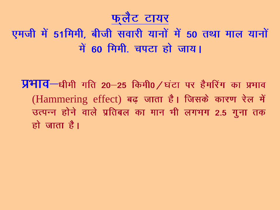
Flat tyre 50 (Coaches)
60 (wagons)

Tyre Defect Gauge

Checking for sharp flange
When X is parallel to Y, If there is Gap in the middle at A, the Wheel is serviceable
When X is parallel to Y, If there is gap on either side of A, the Wheel is rejectable

Checking the root of flange
When X is parallel to Y, If the gap is available at either side of ‘A’, the wheel is serviceable.
When X is parallel to Y , If there is a gap between gauge and the Root of Flange at A , the Wheel is Rejectable

Checking Thin flange
When X is parallel to Y, If there is gap between
‘A’ and the root of flange, the wheel is Serviceable
When X is Parallel to Y, If there is no gap between ‘A’ and the root of flange, the
wheel is rejectable
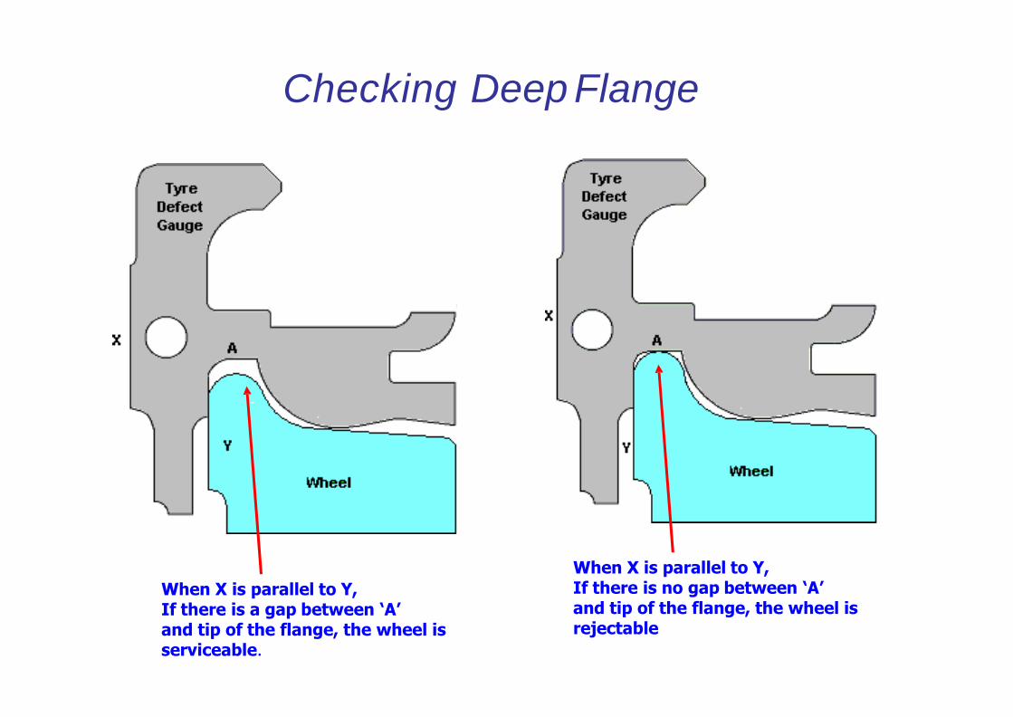
When X is parallel to Y, If there is a gap between ‘A’ and tip of the flange, the wheel is serviceable.
When X is parallel to Y, If there is no gap between ‘A’ and tip of the flange, the wheel is rejectable
Checking Deep Flange

Checking Hollow tyre
When X is parallel to Y, If the gauge touches the wheel tread at “A”,The wheel is rejectable.
When X is parallel to Y, If there is gap between the wheel tread and gauge at “A”,the wheel is serviceable
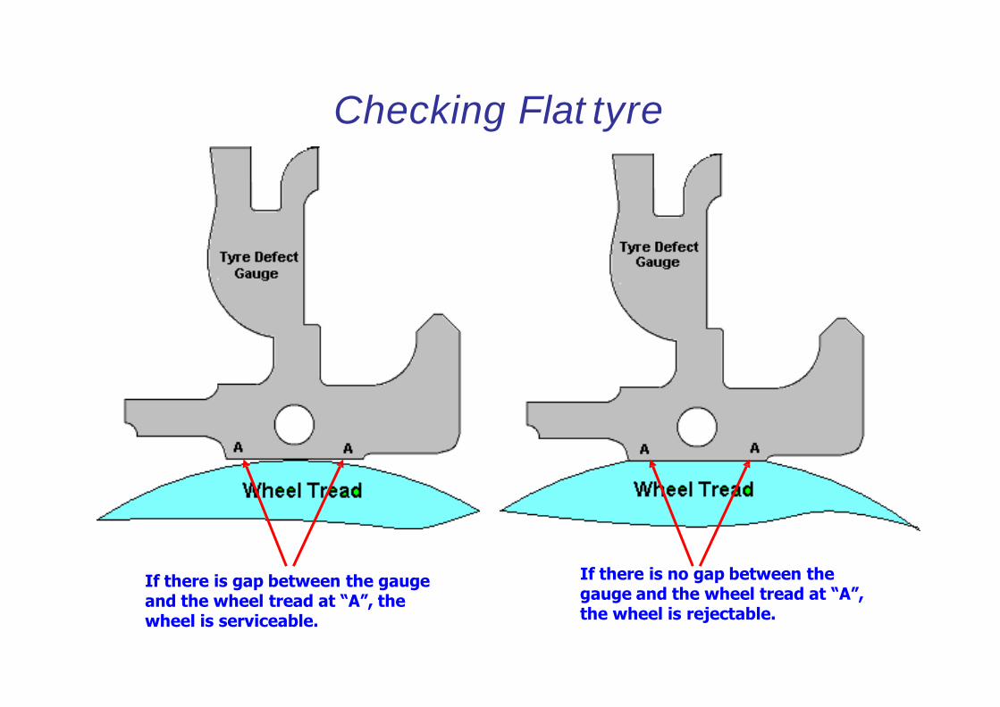
If there is no gap between the gauge and the wheel tread at “A”, the wheel is rejectable.
If there is gap between the gauge and the wheel tread at “A”, the wheel is serviceable.
Checking Flat tyre

Checking Thin tyre
If the mark S in the gauge is above the location A , the wheel is serviceable.
If the mark S in the gauge is in line or below the location A , the wheel is rejectable.

Wheel defect as per CMI K 003
• Shelled tread
• Shattered rim
• Spread rim
• Thermal crack
• Heat checks
• Disc crack
• Loose axle

Shelled Tread
Shelling can be identified by pieces of metal breaking out of the tread surface in several places more or less continuously around the rim. Shelling takes place when small pieces of metal break out between the fine thermal checks. These are generally associated with small skid marks or “chain sliding” Such wheels should be withdrawn from service and sent to workshops for re-profiling.

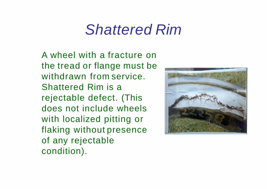
Shattered Rim
A wheel with a fracture on
the tread or flange must be
withdrawn from service.
Shattered Rim is a
rejectable defect. (This
does not include wheels
with localized pitting or
flaking without presence
of any rejectable
condition).

Spread Rim
If the rim widens out for a
short distance on the front
face, an internal defect
may be present. Spreading
of the rim is usually
accompanied by a
flattening of the tread,
which may or may not have
cracks or shelling on the
tread. Such wheels must
be withdrawn from
service.

Rim Flow
The condition of widening of the tread
should not be confused with a uniform
curling over of the outer edge of the
rim around the entire wheel, which is
called rim flow. Rim flow is not a
rejectable defect.

Thermal Crack
Thermal cracks appear on a wheel tread due to intense heating of the wheel arising out of severe brake binding. Such cracks occur on the tread and generally progress across the tread in a transverse & radial direction. Whenever such a crack becomes visible on the outer face of the rim or tread crack has reached the outer edge (non-gauge face) of the rim, the wheel should be withdrawn from service. If a crack becomes visible on the outer flange face, the wheel should be withdrawn from service. Such wheels should be sent to workshop for examination and subsequent rejection.

Thermal Crack
Wheels involved in brake
binding during service, should
be examined carefully during
the maintenance to rule out
the possibility of rejectable
thermal cracks. Such wheels
may be identified by presence
of flats (even within
acceptable limits) and severe
discoloration or blue/ black
heating marks on the tread.
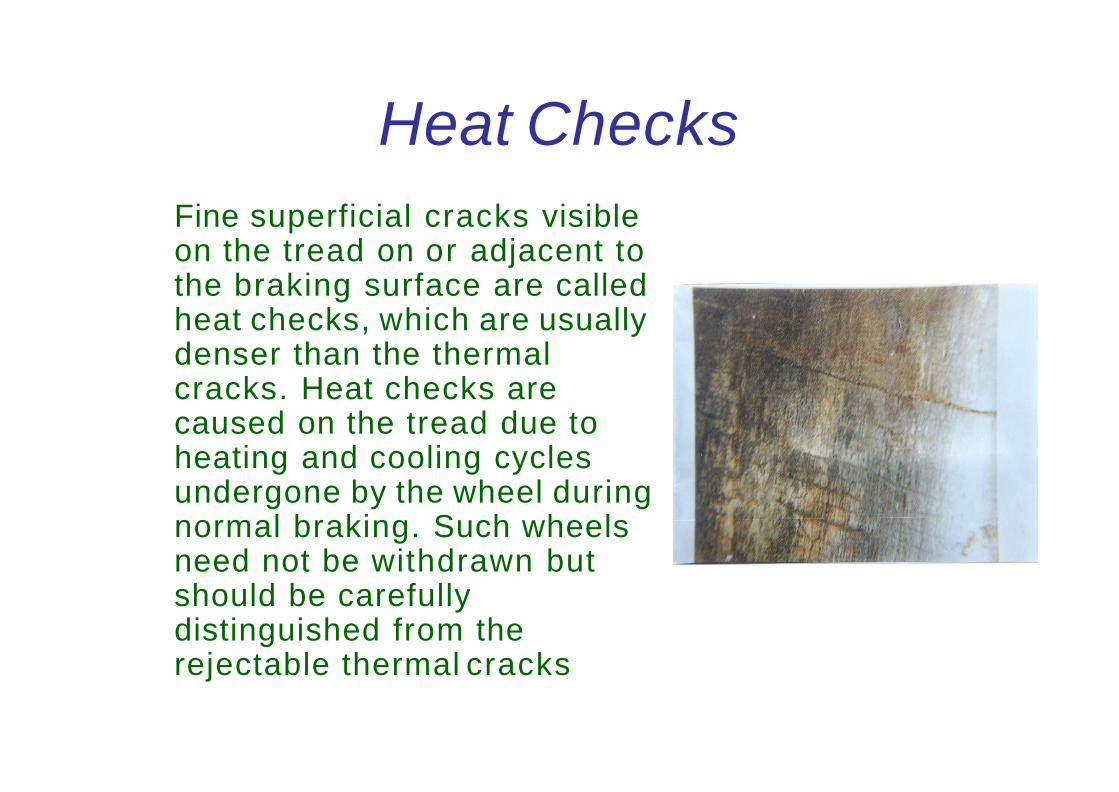
Heat Checks
Fine superficial cracks visible on the tread on or adjacent to the braking surface are called heat checks, which are usually denser than the thermal cracks. Heat checks are caused on the tread due to heating and cooling cycles undergone by the wheel during normal braking. Such wheels need not be withdrawn but should be carefully distinguished from the rejectable thermal cracks

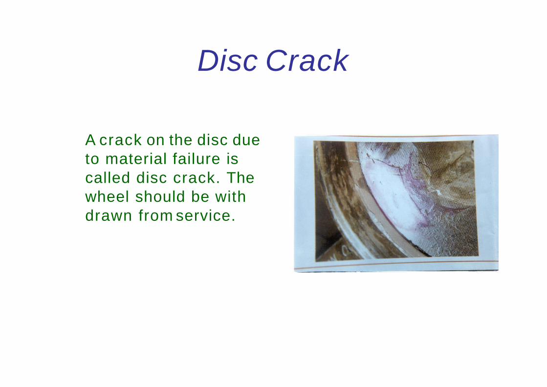
Disc Crack
A crack on the disc due
to material failure is
called disc crack. The
wheel should be with
drawn from service.

Loose Axle
• While assembling wheel with axle proper interference should be maintained between wheel and axle. Due to improper selection of interference the wheel may shift outwards or it may come out completely. Loose axle is a rejectable defect.
• Axles involved in Accidents should be magnaflux tested in addition to Ultrasonic test.
• Axle having notch should be withdrawn from service
• All wheel sets withdrawn from service for any of the conditions mentioned above must be sent to the associated workshops for detailed investigations and further disposal.
• The date and station code of the maintenance depot where the wheels are changed should be stencilled on the end panels. An entry should also be made in the maintenance card of the coach.
• No repairs, except wheel profiling of wheel sets is permitted to be done in the maintenance depot.

Wheel Gauge
Description Std Max Min
Coach MG 930 932 929
ICF coach BG 1600 1602 1599
LHB coach 1600 1601 1599
Wagons 1600 1602 1599

Wheel Diameter
Description Std Cond
Coach MG
ICF coach BG 915 825
LHB coach 915 845
BOXN 1000 906
UIC 1000 860
BLC 840 780

Wheel Changing
Wheels to be paired within the diameters variation
as below while changing the wheels
Type On the same
bogie
On the same
coach
Coach MG 5 10
Coach BG 5 13
Wagons 13 25
While tyre turning, it should be ensured that variation
on the same axle is within 0.5 mm
For in service wheels the variation on the same axle
shall be guided by the tyre defect gauge

Thank You

WHEEL &AXLE

Wheel, Tread and Axle
• Nomenclature
– Axle • Journal
• Collar
• Wheel seat
– Disc • Tread
• Hub
• Tyre profile
2

Wheel Gauge
3

Wheel Tyre Profile
4
• Standard wheel profile
• Worn wheel profile (Conforming profile)
• No Intermediate profile now.

5
Difference in Wheel Diameter
• Prescribed in
– Rule No. 2.8.14.2 IRCA Part III and
– Rule No. 2.9.4 IRCA Part IV
• These limits do not form a part of train examination.
• The rejection of wheels worn beyond service limits will continue to be determined by the normal wear limits specified in IRCA Rules (Rly. Bd. letter No. 86/M(N)960/8 Dated 22.8.86).
On the same axle On the same trolley On the same wagon
For Wagon 0.5 13 25
For Coach 0.5 5 13

Wheel Profile Defects
• Flat tyre
• Hollow tyre
• Sharp flange
• False flange
• Deep flange
• Thin flange
• Root radius
6

Axle Guide Arrangement
ICF FIAT CASNUB
7

Function of Axle Guides
• Guides the axle w.r.t. bogie frame laterally as well as longitudinally.
• Transmits tractive & braking force between bogie frame & axle box.
• In ICF, acts as a single acting hydraulic vertical shock absorber for primary spring.
• In FIAT bogie, provides control flexibility between frame and axle.

Axle Box Bearing
• CASNUB bogie
– CTRB
• ICF bogie
– Spherical type roller bearing with self-align feature.
• Automatically adjust to the deviation in the centre line of the axle during run.
• FIAT bogie
– CTRB
9


(Gap)
(Hunting)

(Angularity)

(Hammering effect)

• (W0bbling)

•
•
•
•


Wheels
MSTC/GKP

Railway Wheels
• Railway wheel is assembly of two wheels
fixed to the axle by interference fit and they
rotate along with the axle, without any
independent relative movement as in the
case of other automobile wheels.
• These wheels are provided with flange
towards the inner side, which guide the
wheels to travel on the rails and does not
allow it to fall down from the rails.

Railway Wheels
ICF Coach Wheel

Railway Wheels
LHB Coach Wheel

• Steel made by Electric or Basic Oxygen process
• Steel shall be of killed quality for forged steel
• The max hydrogen content shall not exceed 3 ppm
• The max nitrogen content shall not exceed 0.007%
Material of Wheel

Railway Wheels
BOXN Wheel

The procedure to calculate chemical composition will be in
accordance to IS:228
Material of Wheel
The chemical composition of the steel for Cast Wheel
C 0.47% to 0.57% for type A used for carriage stock
0.57% to 0.67% for type B used for wagon stock
Mn 0.60 to 0.80%
P 0.03% max
S 0.03% max
Cr 0.15% max
Ni 0.25% max
Mo 0.06% max
Combined % for Cr, Ni & Mo must be 0.40% max

Mechanical Properties of Cast Wheel
Sl.
No.
Particulars Type A Type B
1 Tensile Strength at 15 mm below tread
face
900 N/m2 min. 930 N/m2 min.
2 Tensile strength at middle of the web 800 N/m2 min. 800 N/m2 min.
3 Minum yield strength at 15 mm below
tread face
50% of UTS 50% of UTS
4 Minimum yield strength at middle of the
web
50% of UTS 50% of UTS
5 Minimum elongation at 15 mm below
tread face
5.0% 4.5%
6 Minimum elongation at middle of the web 7.0% 7.0%
7 Hardness range at 15 mm below tread
face
255-320 BHN 271-341 BHN
8 Minimum impact strength at 15 mm
below tread face
10 J/cm2 at 20
deg C
--

Railway Wheels
The wheel is better understood by
dividing it into the following parts
• Hub
• Disc
• Tyre

Wheel

hub
• Hub is the centre portion of the wheel,
where the wheel is fixed to the axle by
means of interference fit.
• Thickness of the wheel is maximum at the
hub portion.
• UT details is marked on the Hub

Disc
• Disc is the portion of the wheel between
the hub and the tyre.
• This portion is the thinnest portion of the
wheel as it does not come in contact with
rail nor it is coming in contact with the
axle.

Tyre
• Tyre is the portion in contact with the
rail, which wears out in service.
• The profile of the tyre is significant for
safe running of the trains.
• Taper is given on the tread to have
higher diameter near the flange and
lower diameter at the outer edge, to
facilitate curve negotiation.

Tyre

Axles 13 t Axle for ICF coach

Axles 16.25 t Axle for ICF coach

Press fit of wheel on axles
• Wheel disc is pressed to axle with interference fit (the bore of the wheel should be 0.304 mm to 0.355 mm less than the outer dia of the wheel seat on the Axle)
• Wheel Gauge should be in between 1599 and 1602 mm
• Axial off centre should be within 1.0 mm (wagon) & 0.8 mm (coach)
• Radial off centre should be within 0.5 mm (wagon) & 0.25 mm (coach)
• The Journals should be protected with bituminous black to IS:9862
• All Axles fitted by workshop during POH or despatched to depot should be Ultrasonically tested

Press fit of wheel on axles
Hydraulic press is used for assembly of the wheel
with a force of 400 to 500 Kgs per mm dia of wheel
seat (approximate force used for different wheels
are given below)
Description Tonnage
13 tonne axle 68.8 to 103.2 t
16.25 tonne axle 71.2 to 106.8 t
BOXN & BLC 85 to 127 t

Stamping of particulars
Whenever axles are renewed the workshop shall
punch in 5 mm letters the following particulars on
the journal face
• Place of pressing
• Date of pressing
• Pressure of pressing
Whenever UT is done the details shall be stamped cold
on the inner hub fillet with 6 mm punch not more
than 1.5 mm depth

Stamping of particulars

Stamping of particulars

Stamping of particulars

Worn Wheel Profile
80 % of the track in Indian Railways is having
rails which are already worn in service.
Standard wheel profile running on these
tracks tend to wear to a specific profile
within short time itself, and further wear
from this profile is very slow. Hence if the
wheels are turned initially to this worn wheel
profile, it will increase the wheel life by
avoiding frequent re-profiling.

Worn Wheel Profile
The worn wheel profile is made standard for
all the wheels in Indian railways as the
standard wheel profile is found
uneconomical with lesser kilometres being
run by the wheels within condemnation.

Worn Wheel Profile

Step Sizes of Worn Wheel Profile
Further to reduce the metal removal during tyre
turning, intermediate worn wheel profile based on
the flange thickness is introduced.
Flange Thickness (X) Y Z
28 mm 42.23 mm 13.5 mm
27 mm 41.29 mm 13.0 mm
26 mm 40.34 mm 12.5 mm
25 mm 38.41 mm 11.5 mm
24 mm 37.44 mm 11.0 mm
23 mm 36.47 mm 10.5 mm
22 mm 35.49 mm 10.0 mm
21 mm 34.5 mm 9.5 mm
20 mm 33.5 mm 9.0 mm

Wheel Defects
• Manufacturing Defects
• Improper Assembly Practices
• Normal Wear and Tear during service
Manufacturing Defects
• Casting Defects
• Improper Heat treatment
• Machining Imperfections

Improper Assembly Practices
• Stipulated dimensional tolerances for Wheel seat
and bore not adhered to resulting in use of higher or
lower than the prescribed force during pressing
leading to improper wheel set assembly.
• Ovality on Journals - 0.02 mm (max)
• Taper on Journal - 0.01mm (max)
• Difference in dia of wheels on the same axle should
not exceed 0.5 mm

Wheel defects
Measurable wheel defects arising due to normal wear & tear during service
• Thin flange
• Deep flange
• Sharp flange • Less radius at root of flange
• Hollow tyre
• Thin tyre
• Flat tyre

Std & cond limits
Defect Std Cond
Thin flange 28.5 22 (Coaches)
16 (Wagons)
Deep flange 28.5 35
Sharp flange (radius) 14.5 5
Less radius at root of
flange (radius)
14 (wwp) 13
Hollow tyre 5
Thin tyre Based on wheel dia
Flat tyre 50 (Coaches)
60 (wagons)

Tyre Defect Gauge

Checking for sharp flange
When X is parallel to Y, If there is Gap in the middle at A, the Wheel is serviceable
When X is parallel to Y, If there is gap on either side of A, the Wheel is rejectable

Checking the root of flange
When X is parallel to Y, If the gap is available at either side of ‘A’, the wheel is serviceable.
When X is parallel to Y , If there is a gap between gauge and the Root of Flange at A , the Wheel is Rejectable

Checking Thin flange
When X is parallel to Y, If there is gap between
‘A’ and the root of flange, the wheel is Serviceable
When X is Parallel to Y, If there is no gap between ‘A’ and the root of flange, the
wheel is rejectable

When X is parallel to Y, If there is a gap between ‘A’ and tip of the flange, the wheel is serviceable.
When X is parallel to Y, If there is no gap between ‘A’ and tip of the flange, the wheel is rejectable
Checking Deep Flange

Checking Hollow tyre
When X is parallel to Y, If the gauge touches the wheel tread at “A”,The wheel is rejectable.
When X is parallel to Y, If there is gap between the wheel tread and gauge at “A”,the wheel is serviceable

If there is no gap between the gauge and the wheel tread at “A”, the wheel is rejectable.
If there is gap between the gauge and the wheel tread at “A”, the wheel is serviceable.
Checking Flat tyre

Checking Thin tyre
If the mark S in the gauge is above the location A , the wheel is serviceable.
If the mark S in the gauge is in line or below the location A , the wheel is rejectable.

Wheel defect as per CMI K 003
• Shelled tread
• Shattered rim
• Spread rim
• Thermal crack
• Heat checks
• Disc crack
• Loose axle

Shelled Tread
Shelling can be identified by pieces of metal breaking out of the tread surface in several places more or less continuously around the rim. Shelling takes place when small pieces of metal break out between the fine thermal checks. These are generally associated with small skid marks or “chain sliding” Such wheels should be withdrawn from service and sent to workshops for re-profiling.
Shattered Rim
A wheel with a fracture on
the tread or flange must be
withdrawn from service.
Shattered Rim is a
rejectable defect. (This
does not include wheels
with localized pitting or
flaking without presence
of any rejectable
condition).

Spread Rim
If the rim widens out for a
short distance on the front
face, an internal defect
may be present. Spreading
of the rim is usually
accompanied by a
flattening of the tread,
which may or may not have
cracks or shelling on the
tread. Such wheels must
be withdrawn from
service.

Rim Flow
The condition of widening of the tread
should not be confused with a uniform
curling over of the outer edge of the
rim around the entire wheel, which is
called rim flow. Rim flow is not a
rejectable defect.

Thermal Crack
Thermal cracks appear on a wheel tread due to intense heating of the wheel arising out of severe brake binding. Such cracks occur on the tread and generally progress across the tread in a transverse & radial direction. Whenever such a crack becomes visible on the outer face of the rim or tread crack has reached the outer edge (non-gauge face) of the rim, the wheel should be withdrawn from service. If a crack becomes visible on the outer flange face, the wheel should be withdrawn from service. Such wheels should be sent to workshop for examination and subsequent rejection.

Thermal Crack
Wheels involved in brake
binding during service, should
be examined carefully during
the maintenance to rule out
the possibility of rejectable
thermal cracks. Such wheels
may be identified by presence
of flats (even within
acceptable limits) and severe
discoloration or blue/ black
heating marks on the tread.

Heat Checks
Fine superficial cracks visible on the tread on or adjacent to the braking surface are called heat checks, which are usually denser than the thermal cracks. Heat checks are caused on the tread due to heating and cooling cycles undergone by the wheel during normal braking. Such wheels need not be withdrawn but should be carefully distinguished from the rejectable thermal cracks
Disc Crack
A crack on the disc due
to material failure is
called disc crack. The
wheel should be with
drawn from service.

Loose Axle
• While assembling wheel with axle proper interference should be maintained between wheel and axle. Due to improper selection of interference the wheel may shift outwards or it may come out completely. Loose axle is a rejectable defect.
• Axles involved in Accidents should be magnaflux tested in addition to Ultrasonic test.
• Axle having notch should be withdrawn from service

• All wheel sets withdrawn from service for any of the conditions mentioned above must be sent to the associated workshops for detailed investigations and further disposal.
• The date and station code of the maintenance depot where the wheels are changed should be stencilled on the end panels. An entry should also be made in the maintenance card of the coach.
• No repairs, except wheel profiling of wheel sets is permitted to be done in the maintenance depot.

Wheel Gauge
Description Std Max Min
Coach MG 930 932 929
ICF coach BG 1600 1602 1599
LHB coach 1600 1601 1599
Wagons 1600 1602 1599

Wheel Diameter
Description Std Cond
Coach MG
ICF coach BG 915 825
LHB coach 915 845
BOXN 1000 906
UIC 1000 860
BLC 840 780

Wheel Changing
Wheels to be paired within the diameters variation
as below while changing the wheels
Type On the same
bogie
On the same
coach
Coach MG 5 10
Coach BG 5 13
Wagons 13 25
While tyre turning, it should be ensured that variation
on the same axle is within 0.5 mm
For in service wheels the variation on the same axle
shall be guided by the tyre defect gauge

Thank You


Construction of coaching stock
– Shell or the skeleton part
– Furnishing or the provisions of amenities
– Bogie (Trolley), the running gear

Running of passenger Coaches
with safety
Speed and Comfort mainly depends
on the bogie on which the coach is
placed.

Bogie

BOGIE (TROLLEY)
What ?
Why?

Bogie - What?
• It is an independent unit used under a long
vehicle.
• It is usually mounted on two pairs of wheels.
(In exceptional cases, such as special purpose
stocks or high capacity vehicles of well Wagons
or crocodile trucks, inspection carriages etc the
bogie may be mounted on three or more pairs of
Wheels)

Bogie - What?
• Normally two bogies are used under a Vehicle.
• Each bogie carries half the load of the vehicle
body and it’s loading.
• Each bogie is provided with a pivot on its central
transom or bolster for engagement with its male
counterpart provided underneath the vehicle
under frame.

Bogie - What?
• The bogie trucks can swivel about these pivots
with case and without restraining the vehicle
body while negotiating a curved truck.

Bogie - Why?
• Limitation of maximum rigid wheel base of a
vehicle
• Limitation of maximum axle load prescribed for
track
• Full utilisation of track loading density

Requirement of Bogie
• Sturdy construction to withstand vertical,
longitudinal and lateral shocks
• Satisfactory damping devices
• Suitable suspension gear

Requirement of Bogie
• Sturdy running gears to give trouble free service
• Easy negotiability on curved track without
restraining body structure

Main Units of a Bogie
1. Bogie Frame
2. Wheel and Axle
3. Bearing Arrangement
4. Bogie Frame – Axle Joint
5. Bolster
6. Primary Suspension
7. Secondary Suspension
8. Bogie – Body Joint
9. Brake System

Version of Coaching Bogie
• IRS Bogie
• SCHLIEREN Bogie (ICF Laminated Bogie)
• MAN-HAL Bogie (BEML Bogie)
• ICF All Coiled Bogie
• IR-20 Bogie
• Fiat Bogie (Similar to IR-20 Bogie)

IRS Bogie

IRS Bogie
Developed / Built by: British Make
Introduction to Railway : Since 1930 – 31
Status: Productions abolished and use
discontinued on Mail / express service.

SCHLIEREN Bogie
(ICF Laminated Bogie)

SCHLIEREN Bogie
(ICF Laminated Bogie)
Developed / Built by:
M/S Swiss Car and
Elevator manufacturing corporation Ltd,
Schlieren, Zurich
Introduction to Railway : Since 1951
Status: Productions abolished and use
discontinued on Mail / express service.

MAN-HAL Bogie
(BEML Bogie)

Developed / Built by:
M/S HAL Banglore
in collaboration with
M/S MAN Nurnberg (West Germany)
Introduction to Railway : Since 1958-59
Status: Productions abolished and use
discontinued on Mail / express service
having speed more than 105 KMPH.
MAN-HAL Bogie
(BEML Bogie)

ICF All Coiled Bogie

Developed / Built by: ICF & RCF
Introduction to Railway : Since 1965
Status: Productions continue by ICF & RCF.
ICF All Coiled Bogie

Fiat Bogie
(Similar to IR-20 Bogie)
Developed / Built by: RCF
Introduction to Railway : Since 1998
Status: Used in few coaches and production
abolished due to introduction of FIAT
bogie.
IR-20 Bogie

Developed / Built by: 24 Coaches imported from
Switzer land in 2000- 01.
Introduction to Railway : Since 2001
Status: Productions started in RCF.
FIAT Bogie

ICF BOGIE (Top View)
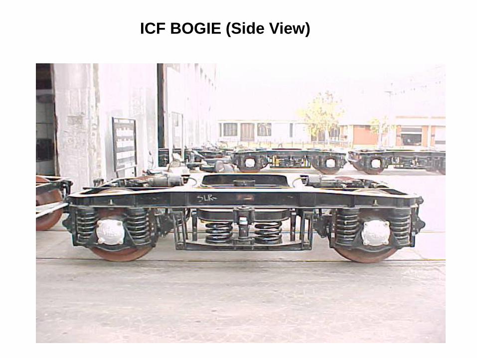
ICF BOGIE (Side View)
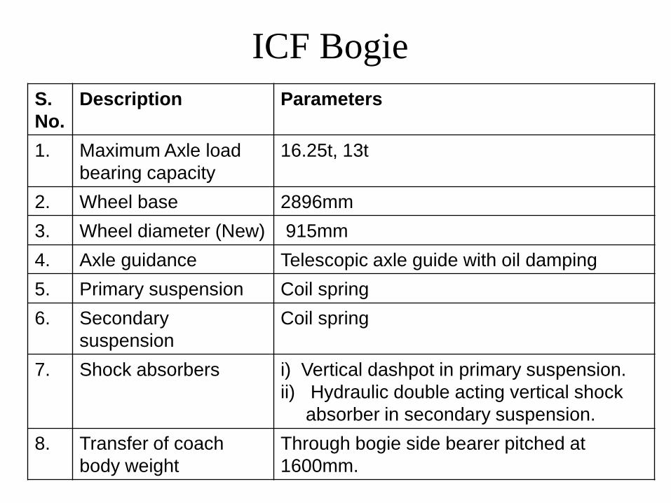
ICF Bogie
S.
No.
Description Parameters
1. Maximum Axle load
bearing capacity
16.25t, 13t
2. Wheel base 2896mm
3. Wheel diameter (New) 915mm
4. Axle guidance Telescopic axle guide with oil damping
5. Primary suspension Coil spring
6. Secondary
suspension
Coil spring
7. Shock absorbers i) Vertical dashpot in primary suspension.
ii) Hydraulic double acting vertical shock
absorber in secondary suspension.
8. Transfer of coach
body weight
Through bogie side bearer pitched at
1600mm.

ICF Bogie
• Manufactured by ICF/RCF
• Helical coil springs are used in both the
primary and the secondary stages.
• The axle guide device provides viscous
damping across primary springs while
hydraulic dampers are provided across the
secondary stage.

• Rigid axle box guide arrangement eliminates any longitudinal or transverse relative movement between the axles and the bogie frame.
• These guides are fitted with guide caps having nine holes of diameter 5 mm equidistant through which oil in the lower spring seat passes under pressure during dynamic oscillation of coach and provide necessary damping to primary suspension to enhance better riding quality of coach.
ICF Bogie

ICF Bogie
• Isolation of vibration is effected by rubber pads in primary and secondary suspension.
• The wheel sets are provided with self-aligning spherical roller bearings mounted in cast steel axle box housings.

ICF Bogie
• AIR VENT SCREWS
- On the bogie side frames, directly
above the dash-pots, tapped holes are
provided for replenishing oil in the dash
pots. Special screws with copper
asbestos washers are screwed on the
tapped hole to make it air tight.

ICF Bogie
• The quantity of oil required to achieve 40 mm oil level above the guide cap in modified arrangement is approximately 1.6 liters and in unmodified arrangement is approximately 1.4 liters. As it is not possible in open line to distinguish between modified and unmodified arrangements, 40 mm oil level is standardised for both.

ICF Bogie
• Side-bearers consist of lubricated metal
slides immersed in oil baths.
• The ends of the bogie bolsters rest on
the bolster helical springs placed over
the lower spring beam suspended from
the bogie frame by the inclined swing
links at an angle 7 degree.

ICF Bogie
• SILENT BLOCK
- This is a synthetic rubber bush fitted in
anchor link and center pivot of ICF
bogies to transmit force without shock
and reduce noise.

ICF Bogie
• The two anchor links diagonally positioned
are provided with silent block bushes. The
links prevent any relative movement
between the bogie frame and coach body.

ICF
• CENTRE PIVOT ARRANGEMENT
The centre pivot pin joins the body with the bogie
and transmits the tractive and braking forces on
the bogies. It does not transmit any vertical load. It
is equipped with rubber silent block bushes which
tend to centralise the bogies with respect to the
body and, to some extent, control and damp the
angular oscillations of the bogies.

Bogie Frame

Bogie Frame
• All welded light weight construction.
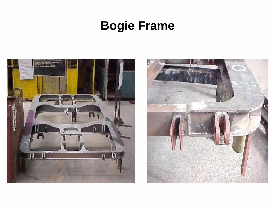
Bogie Frame


Suggested BSS bracket and
axle guide alignment gauges
13t bogies 16.25t bogies
Longitudinal gauge for BSS
brackets
14001.0 mm (7000.5
mm from longitudinal
center-line)
15001.0 mm (7500.5 mm
from longitudinal center-line)
Transverse gauge for BSS
brackets
2159 1.0 mm 2159 1.0 mm
Diagonal gauge for BSS
brackets
2573 1.0 mm 2629 1.0 mm
Longitudinal gauge for axle
guide
5701.0 mm (equidistant
from center-line of axle)
570 1.0 mm (equidistant
from center-line of axle)
Transverse gauge for axle
guide
21591.0 mm 21591.0 mm
Diagonal gauge for axle guide 36121.0 mm 36121.0 mm
Distance between BSS bracket
and adjacent axle guide
4631.0 mm 4131.0 mm
Longitudinal gauge for
suspension strap
8701.0 mm (equidistant
from center-line of axle)
8701.0mm (equidistant
from center-line of the axle)

Wheel & Axle

Axle Box Housing

Roller Bearing

Wheel & Axle
• Axles are located on the bogie by
telescopic dash pot and axle guide
assemblies.

Axle Box Spring

Dashpots and Axle Guide Assembles

Figure 3.2a
UNDER TARE
ASSEMBLING
142.5
10
4
SEALING WASHER
2. GUIDE
3. PROTECTIVE TUBE COMPLETE
4. UPPER RUBBER WASHER
5. TOP SPRING SEAT
6. DUST SHIELD SPRING
7. DUST SHIELD
8. HELICAL SPRING
9. GUIDE RING
10. RUBBER PACKING RING
11. GUIDE BUSH
12. CIRCLIP
13. COMPENSATING RING
14. LOWER RUBBER WASHER
15. SAFETY STRAP
16. LOWER SPRING SEAT
1
2
3
4
5
6
7
8
9
10
11
12
13
14
1516
1. SPECIAL SEREW WITH
POWER CAR-
EXCEPT POWER CARS
686 FOR ALL AC & NON-AC COACHES
X TO RAIL LEVEL-
X T
O R
AIL
LEVEL
OIL LEVEL BEFORE
OIL LEVEL
670 FOR BOGIE ON LUGGAGE SIDE
672 FOR BOGIE ON GENERATOR SIDE
92.5
40
MODIFIED AXLE BOX GUIDE ARRANGEMENT

Dashpots and Axle Guide Assembles

Dashpots and Axle Guide Assembles

Bolster Springs

Lower Spring Beam / Seat

Drawing code of springs for ICF BG coaches
(Reference RDSO Amendment slip no. 5 of September 2001
to STR WD-01-HLs- 94 (Rev.1 May 95)
Type of spring Type of bogies ICF Drg. No Drg. Code
No.
Axle box All Non AC ICF type F-0-1-006 A01
All AC ICF type WTAC-0-1-202 A03
Power car WLRRM2-0-1-202 A04
Double decker DD-0-1-001 A06
High capacity Power Car WLRRM8-0-1-802 A09
High capacity parcel van RDSO /SK-98017 A10
Bolster All Non AC ICF type F-0-5-002 B01
All AC ICF type WTAC-0-5-202 B03
Power car WLRRM2-0-5-202 B04
Double decker DD-0-5-003 B06
Bolster
High capacity Power car WLRRM8-0-5-802 B11
B13
High capacity Parcel van RDSO /SK-98018 B15
B16

Load deflection testing and grouping of Axle box spring
(B.G Main line coaches)
Code Wire
dia
Free
height
Test
Load
Acceptable
height under
test load
Groups as per loaded spring height
A B C
Yellow Oxford
Blue*
Green
A01 33.5 360 2000 279-295 279-284 285-289 290-295
A03 33.5 375 2800 264-282 264-269 270-275 276-282
A04 35 372 3000 265-282 265-270 271-276 277-282
A06 36 337 2400 269-284 269-273 274-279 280-284
A09 37 360 3000 277-293 277-282 283-288 289-293
A10 39 315 1800 276-289 276-279 280-284 285-289

Load deflection testing and grouping of Bolster spring
(B.G Main line coaches)
Code Wire
dia
Free
height
Test
Load
Acceptable
height under
test load
Groups as per loaded spring height
A B C
Yellow Oxford Blue
#
Green
B01 42 385 3300 301-317 301-305 306-311 312-317
B03 42 400 4800 291-308 291-296 297-303 304-308
B04 47 400 6100 286-304 286-291 292-297 298-304
B06 36 416 4200 280-299 280-286 287-292 293-299
B11 47 386 6700 306-322 306-311 312-317 318-322
B13 34
B15 40 393 6000 256-272 256-261 262-267 268-272
B16 32.5 286

Shock absorbers

Equalising stays

• Provided on bogies between the lower spring plank and the bolster
• To prevent lateral thrust on the bolster springs which have not been designed to take the lateral forces.
• Pin connections at both ends to swivel freely.
Equalising stays

Centre Pivot

Centre Pivot
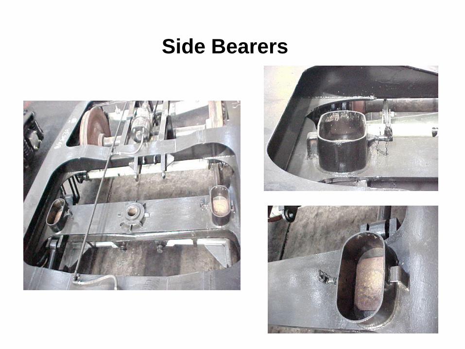
Side Bearers

• Consists of a machined steel wearing plate
immersed in an oil bath
• Floating bronze-wearing piece with a
spherical top surface kept in it
• The coach body rests on the top spherical
surface of these bronze-wearing pieces
through the corresponding attachments on
the bottom of the body-bolster.
Side Bearer

Side Bearer
Wear limit for wearing plate
New size Shop renewal
size
Condemning size
10 mm 9 mm 8.5 mm
Wear limit for wearing piece
New size Shop renewal
size
Condemning size
45 mm 43.5 mm 42 mm

Side Bearers

Side Bearer
Quantity of oil in Side bearer oil-bath (Each):
2 litres
Approved brands of oils.
– Servoline – 100 of IOC
– Yantrol – 100 of HPC
– Bharat univol – 100 of BPC

Anchor Links

Anchor links
• Pin connection to the Bolster sides and the Bogie Transoms.
• Can swivel universally to permit the bolster to rise and fall and sway side wards.
• One anchor link is provided on each side of the bolster diagonally across.
• Fitted with silent block bushes

Anchor link
• To hold in position longitudinally the
floating bogie bolster
• To design to take the tractive and
braking forces.

ANCHOR LINK WITH SILENT BLOCK Figure 3.5
Anchor link

Hanger and Hanger Blocks

Axle Box safety Strap

Hanger Pin Safety Stopper

NOSING
BOUNCING
PITCHING
LURCHING
SHUTTLING
ROLLING
Z
Z
Y
Y
X
X
Oscillation modes of vehiclesThere are six modes of oscillations:

Limitations of ICF bogie Design
• Longitudinal and transverse flexibilities of the axle guidance cannot be optimised independently as generally required for high-speed bogies.
• There are vertical space constraints to accommodate desirably softer secondary suspension springs and the consequent dynamic movements of the bogie bolster and coach body, as also to increase the length of the swing hangers.

Limitations of ICF bogie Design
• Friction damping in the transverse suspension is neither amenable to optimisation nor the same can be controlled during service.
• Headstocks increase the yaw inertia of the bogie frame and thereby influence the tendency for hunting.
• A large wheelbase, as that of ICF bogie, affects curvability and there by increases wheel flange wear.

Failure
Any part or assembly is considered to have failed
when any of three conditions takes place-
When it becomes completely inoperable.
When it is still operable but no longer able to perform
its intended functions satisfactorily.
When serious detoriation has been made it unreliable
and unsafe for continued use.

Fundamental source of failure
Deficiencies in design Deficiencies in selection of material Imperfection of material Deficiencies in processing Errors in assembly Improper service condition Improper maintenance

Brake Shoe head
• In order to fit the brake block snugly in the brake
head to avoid any movement between them.
• To avoid excessive wear at the ends of the brake
head.

Brake shoe key
• In order to fit the brake block snugly in the brake
head to avoid any movement between them.
Safety wire rope
• The old arrangement of safety straps is reported
to be falling in service due to ballast hitting.
• To improve the safety of brake beam falling on
the track safety wire rope introduced.

Brake block hanger
• To avoid brake block climbing over the wheel in
case of fully worn out wheels.
Standardization of equalizing stay
• The old equalizing stay had a pin dia of 25 mm.
The longer pin is found to be bending in service
resulting in removal difficulties.
• In the standardized equalizing stay the dia of pin
has been increased to 31 mm.

Pin for brake lever hanger
• To avoid slipping of nylon bush in the lever
hanger a washer is welded.
• Castle nut with split pin introduced.

Improved brake beam
• The old brake beam does not cater to the load
requirement of air braked coaches and it also
bends under extra loads.

Single piece brake block hanger
• Single piece design will avoid misalignment of
brake block with respect to wheel tread.
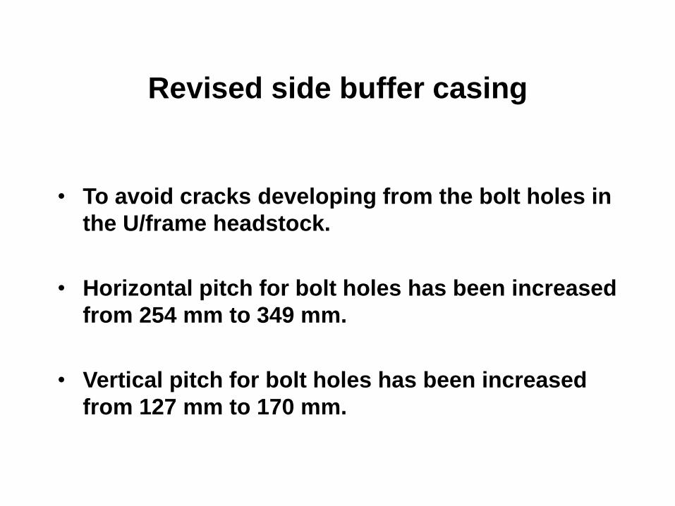
Revised side buffer casing
• To avoid cracks developing from the bolt holes in
the U/frame headstock.
• Horizontal pitch for bolt holes has been increased
from 254 mm to 349 mm.
• Vertical pitch for bolt holes has been increased
from 127 mm to 170 mm.

Provision of locking arrangement for
guide cap
• To avoid falling of guide cap due to breakage of
spring clip.
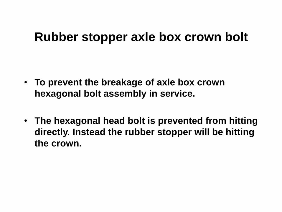
Rubber stopper axle box crown bolt
• To prevent the breakage of axle box crown
hexagonal bolt assembly in service.
• The hexagonal head bolt is prevented from hitting
directly. Instead the rubber stopper will be hitting
the crown.

Weld joint of bogie side frame with
head stock
• The side frame head stock joint below guide in
the old design was undesirable as the joint leads
to misalignment of guides.
• Shifted to headstock beyond brake hanger
brackets.

Slack adjuster articulation
• To provide freedom of rotation in horizontal plane
an additional pin joint has been provided.
• Freedom of rotation in vertical plane is also
ensured at the floating lever end.
• This arrangement is expected to minimize the
incidence of slack adjuster spring breakages.
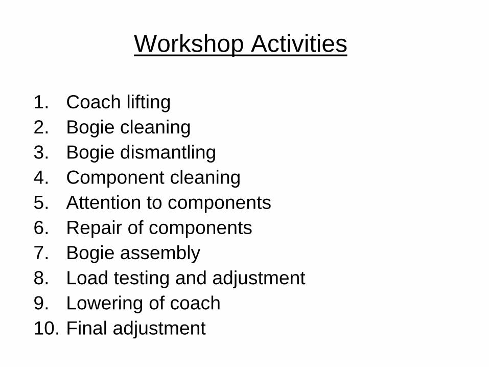
Workshop Activities
1. Coach lifting
2. Bogie cleaning
3. Bogie dismantling
4. Component cleaning
5. Attention to components
6. Repair of components
7. Bogie assembly
8. Load testing and adjustment
9. Lowering of coach
10. Final adjustment

Workshop Maintenance of
ICF Bogie- Flow diagram
LIFTING
SHOP
1
WASHINGPLANT
BOGIE
SHOP
SERVICE
SHOPS
(Fitting shop
&
Smith shop)9
10
2
43
7
5
86

L.S. BEAM
RAIL LEVEL
BOGIE FRAME
PART- I
D E
M
G
F
BOGIE BOLSTER
A
B
C
SUSPENSION DIAGRAMMATIC ARRANGEMENT
BOGIE BOLSTER
RAIL LEVEL
FIGURE 1.4a
BODY BOLSTER
BOGIE FRAME SIDE BEARER
PART- II
J
NI
L
2
NOTE - P1. Dimensions E & J shall be maintained with required number of compensating rings of standard thickness of 4 mm.P2. Axle box springs : WTAC -0-1-202P Bolster springs : WTAC -0-5-202
H
K
2
FOR SELF GENERATING AC COACHES (ICF DRAWING NO. ICF/SK -9-0-126)P 2

L.S. BEAM
RAIL LEVEL
BOGIE FRAME
PART- I
G#
Z
F
BOGIE BOLSTER
B
X
A
2896 (WHEEL BASE)
SUSPENSION DIAGRAMMATIC ARRANGEMENT
FOR NON AC COACHES (RCF DRAWING NO. CC90019)P
NOTE - P1. Dimensions A & B marked should be ensured less than dimensions C & D marked respectively.P2. # CR to drawingNo.-CC01140 to be provided.P3. * CR to drawing No. - CC05251 to be provided.P4. 'F' the variation in all the four bogie cornerheights must be less than or equal to 10 mm.P5. Drawing No. SG90002, SZ90004, SE90011, LB90002 are superseded by thisdrawing.P6. The height of Axle box spring and bolster spring in tare & gross conditions is for reference only.P7. The requirement of CR'sas shown in the columns for primary & 30 mm in secondary suspension.P8. Only blue bend springs both in primary and secondarystage are to be used in postal van coach.
FIGURE 1.4c
RAIL LEVEL
BOGIE FRAME
BODY BOLSTER
BOGIE BOLSTER
PART- II
SIDE BEARER
Y
H
Weight of each bogie = 5.9tPUnsprung mass/bogie = 3.2 tPBolsterweight = 0.4 tPC.R. =Compensating ring
C
D%
%c915

Type of
coach
Tare
weight of
coach
Normal
pay load
Total
pay load
Bogie frame
bolster
clearance
Body bogie
clearance
Crown clearance
AC In tonnes In tonnes In
tonnes
B dimension C Dimension A Dimension
Tare Gross Tare Gross Tare Gross
ACCW
(EOG)
44.8 3.68 3.68 405 505 703 603 283 203
ACCW
(SG)
49.1 3.68 3.68 405 505 703 603 303 223
ACCN
(EOG)
48.3 5.12 5.12 405 545 703 563 343 223
ACCN
(SG)
52.53 5.12 5.12 405 535 703 573 353 233
ACCZ
(EOG)
43.1 5.36 5.36 405 545 703 563 323 203
Check List

Type
of
coach
Tare
weight
of
coach
Normal
pay
load
Total
pay
load
Test load per
bogie
Bogie frame
bolster
clearance
Body bogie
clearance
Crown
clearance
AC In
tonnes
In
tonnes
In
tonn
es
Under
tare
Under
Gross
B dimension C Dimension A Dimension
In
tonnes
In
tonnes
Tare Gross Tare Gross Tare Gross
ACCZ
(SG)
46.83 5.84 5.84 17.22 20.14 405 565 703 543 353 223
FACZ
(EOG)
42.6 3.68 3.68 15.10 16.94 405 505 703 603 273 193
RA
(NON
AC)
41.3 1.20 1.20 14.45 14.05 405 445 703 663 203 173
VP
(HIGH
CAPAC
ITY)
32 23 23 9.8 21.3 405 815 703 293 363 113
IRQ
ACCN
(SG)
41.3 5.12 5.12 19.45 22.01 405 545 703 563 353 233
RA AC 46.69 1.20 1.20 17.14 17.14 405 435 703 673 223 193
Check List

Type
of
coach
Tare
weigh
t of
coach
Norm
al pay
load
Over
load
Total
pay
load
Test load per
bogie
Bogie frame
bolster
clearance
Body bogie
clearance
Crown
clearance
AC In
tonne
s
In
tonne
s
In
tonne
s
In
tonne
s
Under
tare
Under
Gross
B dimension C Dimension A Dimension
In
tonne
s
In
tonne
s
Tare Gross Tare Gross Tare Gross
GS 36.99 5.85 100% 11.70 12.6 18.45 405 743 703 363 473 203
SOC 37.00 7.02 100% 14.04 12.6 19.62 405 815 703 293 503 183
SCN 38.03 5.76 - 5.76 13.12 16.00 405 575 703 533 313 173
Check List
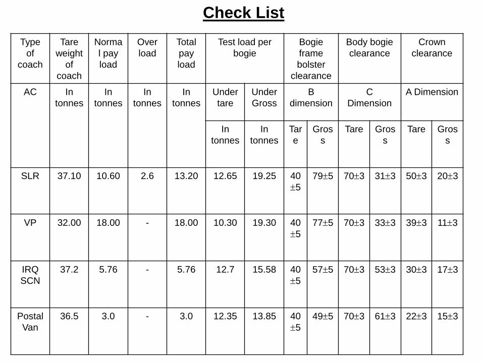
Type
of
coach
Tare
weight
of
coach
Norma
l pay
load
Over
load
Total
pay
load
Test load per
bogie
Bogie
frame
bolster
clearance
Body bogie
clearance
Crown
clearance
AC In
tonnes
In
tonnes
In
tonnes
In
tonnes
Under
tare
Under
Gross
B
dimension
C
Dimension
A Dimension
In
tonnes
In
tonnes
Tar
e
Gros
s
Tare Gros
s
Tare Gros
s
SLR 37.10 10.60 2.6 13.20 12.65 19.25 40
5
795 703 313 503 203
VP 32.00 18.00 - 18.00 10.30 19.30 40
5
775 703 333 393 113
IRQ
SCN
37.2 5.76 - 5.76 12.7 15.58 40
5
575 703 533 303 173
Postal
Van
36.5 3.0 - 3.0 12.35 13.85 40
5
495 703 613 223 153
Check List

Cause – Buffer height low
• Wear on wheel tread .
• Wear on wearing piece and wearing plate of the
side bearers .
• Wear on hanger , hanger block and pin of the
secondary suspension .
• Loss in free heights of primary and secondary
coil springs .
• Load deflection characteristics of the primary and
secondary springs not being within the
prescribed limit .

AXLE
Rajendra
Instructor C&W/MSTC GKP


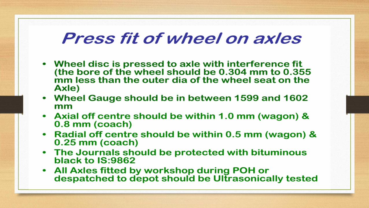


DEFECT OBSERVED ON THE AXLES AND
THEIR ORIGIN
The defects arising on the axle are therefore primarily due to short comings during manufacture and also during manufacture and also due to a variety of service conditions to which they are subjected.
The sources of various defects are –
a) steelmaking and shaping operation
b) machining operation
c) heat-treatment operation
d) assembly operation
e) Repair Practice
f) maintenance practice and g) corrosion.


HOT AXLE-
An axle, which has run hot, should be distinguished by stamping 5-mm size
star on the face of the affected journal as shown in Plate 25; wheel sets with
such axles must not be used in passenger carrying vehicles. If journal or end
of axle has any discolouration due to over heating or if
circumferential cracks determined by magnetic crack detection are found in
the journal, the axle may be scrapped and mutilated to prevent re-use.
Note: - Wheels with discoloured journals due to overheating should be sent to
workshops for checking cracks in the journal.

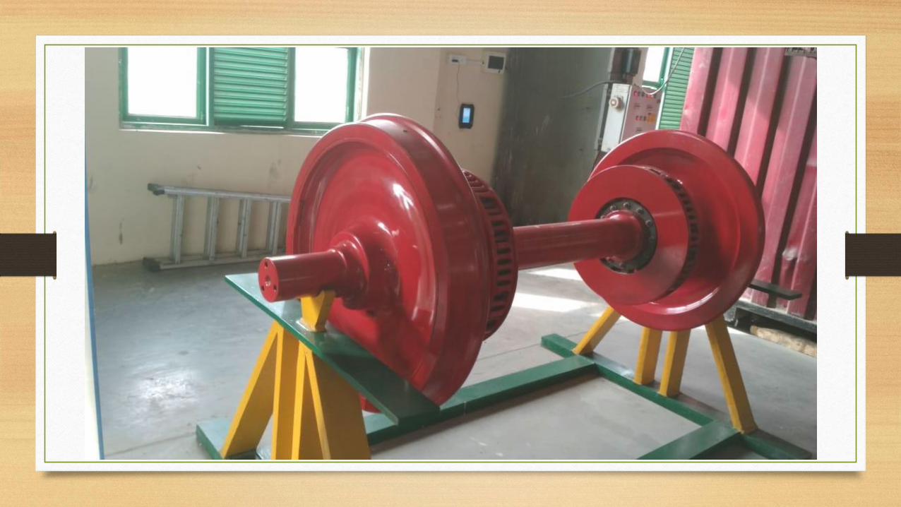


Rajendra
Instructor C&W/MSTC/N.E.Railway
Roller Bearing

Introduction A bearing is a device to permit constrained relative motion between two
parts, typically rotation or linear movement.
Bearings may be classified broadly according to the motions they allow
and according to their principle of operation

CLASSIFICATION OF BEARINGS

spherical roller bearing

SPHERICAL ROLLER BEARING
Spherical roller bearings have a large capacity for radial loads, axle loads in either
direction, and complex loads.
They are suited for the applications such as railway rolling stocks where vibrations and
shock loads are encountered.
Roller Bearings are named according to the shape of rollers. Roller Bearings with
spherical rollers are called as Spherical Roller Bearings
Spherical Roller bearing no. 22326/C3 with 130 mm parallel bore on the inner ring is
being used on ICF type coaches.
They are directly shrunk fit on the axle journals.


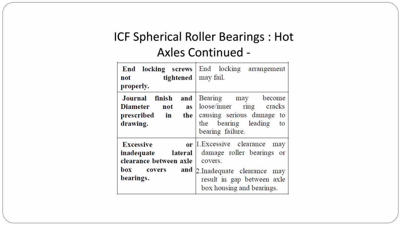


BEARING COMPONENTS
Outer ring
Outer ring for spherical roller bearings are manufactured from forged and rolled rings from bearing quality steel. It is through hardened and precision ground all over. The track or roller surface of bearing outer ring is spherical in shape for self-aligning.
Inner Ring
Inner ring for spherical roller bearing are also made from bearing quality steel which is forged and rolled. Inner rings are also precision machined heat treated and precision ground. Inner rings have two rolling surface which are ground together with high accuracy.
Roller
Roller are either forged or machined from bearing quality steel bars & then through hardened and ground to high degree of accuracies.
Cage
Spherical roller bearings are fitted with machined brass cages. These cages are made from brass centrifugal castings and then precision machined. Brass cages have advantage of assuring positive lubrication and cooler running of the bearing therefore are best recommended for railway applications.

GENERAL INSTRUCTIONS AND PRECAUTIONS
1. Do no drop the bearing.
2. Bearing should not be unpacked until it is ready for mounting.
3. All plastic wedges inserted between rollers to protect from any damage during
transportation, must be removed prior to fitment on axle journal.
4. Spherical Roller bearings are designed, manufactured and assembled to provide
a specific amount of radial clearance. Therefore, components of any spherical
roller bearings should never be interchanged with other bearing. This can lead to
poor performance or failure of the bearing.
5. Mounting, dismounting, inspection and maintenance work of bearings must be
done by trained/ qualified persons as per laid down procedures/ specifications.
6. Use only recommended tools for mounting / dismounting and maintenance
work.

Contd… 7. Use only those parts, which are new or otherwise satisfactory to reach the next
reconditioning interval after service.
8. Bearing parts of different roller bearing units or different manufacturers must
never be mixed or interchanged. This can disturb the radial and axial clearances,
which can lead to poor performance of the bearing during service.
9. Never mix two different brands of grease or used grease with fresh grease.
10. Lubricate both new and used cap screws prior to installation.

Periodicity of Inspection of Roller Bearing
All roller bearings should be cleaned, inspected and re-lubricated with fresh grease during each
attention to the wheel set /bearings in the workshop.
The roller bearings should be dismounted from the wheel set during every alternate attention
in the workshops for thorough inspection of the components,
rear cover and renewal of the felt sealing ring. The wheel bearing should however necessarily be
dismounted and overhauled in case of any warranted out of course of attention in the
workshop.

Radial Clearance In Bearings

Life of Spherical Roller Bearing
The codal life of spherical roller bearings type 22326 (16.25
t) used on BG main line coaches is fixed as 20 years.

Lubrication

Bearing should be rejected for the following defects
Pitted or flaked roller tracks and rollers.
Cracked or deformed or badly worn out cage.
Cracked inner or outer ring.
Scored or damaged outer surface of the outer ring.
Indentation on rings or rollers.
Scoring of roller tracks or rollers.
Rust/corrosion, damage or excessive fretting corrosion.
Brinelling or false brinelling.
Rings exhibiting deep straw or blue or purple colour indicating heat effect.
Excessive or less radial clearance.

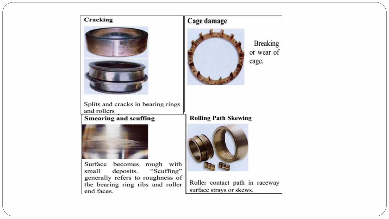


Copyright © 2022 FDOKUMEN