— Carlon® PVC conduit, elbows and fittings - ABB
100
— CATALOG Carlon® PVC conduit, elbows and fittings
-
Upload
khangminh22 -
Category
Documents
-
view
2 -
download
0
Transcript of — Carlon® PVC conduit, elbows and fittings - ABB

—C ATALOG
Carlon®PVC conduit, elbows and fittings

— Thomas & Betts is now ABBInstallation Products, but our longlegacy of quality products andinnovation remains the same. Fromconnectors that wire buildingson Earth to cable ties that help putmachines in space, we continue towork every day to make, market,design and sell products thatprovide a smarter, safer and morereliable flow of electricity, fromsource to socket.

— Table of contents
004 Carlon non-metallic push-in fittings
005 Carlon non-metallic expansion/ deflection coupling
006 Carlon non-metallic strain- relief fittings
007– 021 Electrical non-metallic tubing (ENT)
022– 034 Flexible raceway systems
035– 039 P&C Flex conduit and fittings
040– 041 Corrugated HDPE
042– 057 Elbows, sweeps and accessories
058– 067 Conduit bodies (for use with Schedule 40 and 80 conduit)
068– 072 Switch and junction boxes
073– 076 Straps, clamps and accessories
077– 082 Spacers
083– 088 Technical information
087– 097 Index

DescriptionTrade size
(in.)
Clamping range Suggested application(non metallic sheathed cable)
Packaging
Cat. No. Min. (in.) Max. (in.) Inner Outer
SNM12-6R Non-metallic fitting ½ in. 1 ⁄2 0.21 0.42 14/2 - 12/2 - 10/2 - 14/3 - 12/3 - 10/32 cables: 2 x 14/2 - 2 x 12/2 - 1 x 14/2 - 1 x 12/2
50 300
SNM12-100CP Non-metallic fitting ½ in. 1 ⁄2 0.21 0.42 14/2 - 12/2 - 10/2 - 14/3 - 12/3 - 10/32 cables: 2 x 14/2 - 2 x 12/2 - 1 x 14/2 - 1 x 12/2
100 1000
SNM34-6R Non-metallic fitting 3 ⁄4 in. 3 ⁄4 0.22 0.65 12/2 - 10/2 - 8/2 - 6/2 - 14/3 - 12/3 - 10/3 - 8/3 - 6/3 2 cables: 2 x 12/2 - 2 x 10/2 - 1 x 12/2 - 1 x 10/2
40 240
SNM34-100CP Non-metallic fitting 3 ⁄4 in. 3 ⁄4 0.22 0.65 12/2 - 10/2 - 8/2 - 6/2 - 14/3 - 12/3 - 10/3 - 8/3 - 6/3 2 cables: 2 x 12/2 - 2 x 10/2 - 1 x 12/2 - 1 x 10/2
100 1000
Features and benefits:• Easy push-in installation in knockouts – no tools
required• Certified for one or two cables• Insertion from inside or outside of enclosures
increases installation flexibility• Snug fit eliminates movement within knockout• Exceeds pull-out requirements for better cable
security• Distinctive colors to differentiate sizes:
1/2" gray, 3/4" blue• UL® Listed, CSA Certified
—02
—01
NEW
—Carlon® non-metallic push-in fittingsSuperior pull-out performace and cost efficiency
—01 Align the flat surface or opening with the burr ofthe knockout for easierinsertion.— 02 Insert the fitting into the knockout without the cables,from the inside or the outside of the enclosure.— 03 For two-cable installation:both cables may beinserted at once or oneafter the other.
—Carlon non-metallic push-in fittings
—03
4 C A R LO N P VC CO N D U IT, EL B OW S A N D FIT TI N G S

NEW
—Carlon® non-metallic expansion/deflection couplingInnovative design improves safety and saves labor time
Use the Carlon non-metallic expansion/deflection coupling to join two rigid PVC conduit runs in applications requiring movement in any direction at structural joints. It provides a flexible connection, safely accommodating axial or parallel deflection of up to 3⁄4" and angular deflection of up to 30° from relaxed position.
This coupling meets the requirements of 2014 National Electrical Code (NEC) Article 300.4(H) for use where a raceway crosses a structural joint intended for expansion, contraction or deflection in buildings, bridges, parking garages and similar structures.
Features and benefits:• Suitable for use indoors, outdoors, direct burial or
embedded in concrete in bridges, piers, parking garages, overhead walkways, hospitals and other buildings
• Flexible neoprene outer jacket with tamperproof stainless steel straps ensures superior protection and corrosion resistance suitable for wet locations
• Inner sleeve provides a constant, smooth inner diameter in any position to ease wire pulling and prevent wire insulation damage
• Up to five times faster to install than the traditional method
• Up to 5-to-1 SKU reduction• Can be used with Schedule 40 and Schedule• 80 rigid PVC conduit• UV resistant• Patent pending
Listings/compliances• cULus Listed• CSA certified to CSA C22.2 No. 85• 2014 NEC Article 300.4(H) compliant
Materials/finishes
• Coupling ends: smooth gray PVC• Inner sleeve: smooth gray PVC• Outer jacket: natural black molded neoprene• Jacket straps: stainless steel
Cat. No. Trade size (in.) Dimension A (in.) Dimension B (in.) UPC no.
XD1NM 1 ⁄2 7.28 2.40 034481-02041
XD2NM 3⁄4 7.36 2.66 034481-02043
XD3NM 1 7.66 2.96 034481-02042
XD5NM 1 1 ⁄2 8.26 3.60 034481-02044
XD6NM 2 9.14 4.34 034481-02045
XD7NM 2 1 ⁄2 10.75 5.15 034481-02046
XD8NM 3 11.36 5.60 034481-02047
XD10NM 4 12.25 7.17 034481-02048
*Add 0.25" to O.D. clearance for strap buckle
—Carlon non-metallic expansion/deflection coupling
A
B
Axial expansion from relaxed position Axial contraction from relaxed position Parallel deflection Angular deflect
5C A R LO N N O N - M E TA L L I C E X PA NSI O N/D EFL EC TI O N CO U PL I N G

DescriptionTrade
size (in.)NMD 90 cables
(LoomexTM-RomexTM)NMWU cables
(in.)Cord cables
(in.) PackagingCat. No.
SRTC-050 ½'' Non-metallic threaded strain relief fitting. 1 ⁄2 14/3, 12/3, 10/3, 14/2, 12/2, 10/2 14/3, 14/2 0.240 - 0.450 Bag of 1.25 bags per
outer 300SRC-075 3⁄4'' Non-metallic unthreaded strain relief fitting 3⁄4 14/3, 12/3, 10/3, 8/3, 14/2, 12/2, 10/2 14/3, 12/3, 10/3, 14/2, 12/2 0.240 - 0.590
SRTC-075 3⁄4'' Non-metallic threaded strain relief fitting
Features and benefits:• For quick and reliable outdoor electrical
installations• 4 interchangeable elastomer bushings,
accommodate a large range of NM-sheathed cables or cord cable size
Temperature rating: 90̊ C*85ºC with impact
Temperature rating: 90̊ C*85ºC with impact
NMD 90 cables(LoomexTM-RomexTM) NMWU cables
Cord cables diameter range(in.)Bushing
14/3 not applicable 0.240 to 0.340
12/3, 10/3 14/3 0.340 to 0.450
8/3 12/3, 10/3 0.450 to 0.590
14/2, 12/2, 10/2 14/2, 12/2 not applicable
NMD 90 cables(LoomexTM-RomexTM) NMWU cables
Cord cables diameter range(in.)Bushing
14/3 not applicable 0.240 to 0.340
12/3, 10/3 14/3 0.340 to 0.450
8/3 12/3 0.450 to 0.590
10/3 0.450 to 0.590
14/2, 12/2, 10/2 14/2 not applicable
—Carlon® non-metallic strain-relief fittings
—Carlon SRTC-050 fittings
—Carlon SRTC-075 & SRC-075 fittings
—Carlon non-metallic unthreaded strain relief fittings (to glue)
NEW
6 C A R LO N P VC CO N D U IT, EL B OW S A N D FIT TI N G S

E73317
Min. bendradius
(in.)Cat. No.Size (in.) Color
Nom.I.D.
(in.)
Nom.O.D. (in.)
Pilltape
Reel size (F x W) (in.)
Reel type(W=wood)
Reellength
Reel wt.(lbs.)
Wt. per100 Ft.
(lbs.)
12005AK-001 1⁄2 Blue .56 .84 Empty 6 36 x 24 W 1500 40 10
1205AKY-001 1⁄2 Yellow .56 .84 Empty 6 36 x 24 W 1500 40 10
1205AKR-001 1⁄2 Red .56 .84 Empty 6 36 x 24 W 1500 40 10
12005AKC-001 1⁄2 Blue .56 .84 Empty 6 36 x 24 W 1500 40 10
12007AA-001 3⁄4 Blue .76 1.05 Empty 6 36 x 24 W 1000 40 14
1207AAY-001 3⁄4 Yellow .76 1.05 Empty 6 36 x 24 W 1000 40 14
1207AAR-001 3⁄4 Red .76 1.05 Empty 6 36 x 24 W 1000 40 14
1207AAC-001 3⁄4 Blue .76 1.05 Empty 6 36 x 24 W 1000 40 14
12008-750 1 Blue 1.00 1.315 Empty 6 36 x 24 W 750 40 20
12008Y-750 1 Yellow 1.00 1.315 Empty 6 36 x 24 W 750 40 20
12008R-750 1 Red 1.00 1.315 Empty 6 36 x 24 W 750 40 20
12008C-750 1 Blue 1.00 1.315 Empty 6 36 x 24 W 750 40 20
12009-750 11⁄4 Blue 1.402 1.66 Empty 7 48 x 32 W 750 90 19
12010-750 11⁄2 Blue 1.554 1.90 Empty 81⁄4 48 x 32 W 750 90 39
12010Y-750 11⁄2 Yellow 1.554 1.90 Empty 81⁄4 48 x 32 W 750 90 39
12011-500 2 Blue 2.030 2.375 Empty 91⁄2 48 x 32 W 500 90 32
12011R-500 2 Red 2.030 2.375 Empty 91⁄2 48 x 32 W 500 90 32
12011Y-500 2 Yellow 2.030 2.375 Empty 91⁄2 48 x 32 W 500 90 32
* 11⁄4"–2" available in yellow & red, made to order; consult factory.
Canada Only
—Standard stock – reels
Flex-Plus ENT is a non-metallic flexible raceway for use in walls, floors and non-plenum ceilings. It’s lightweight, hand-bendable and free from sharp edges, which reduces installation time and saves money.
Options:• Sizes 1⁄2" through 2" • Colors can designate different voltages.
Examples: - Yellow color for communication circuits and
signaling cable - Red color for fire alarm circuits - Blue color for power circuits
• Packaging: coils or reels
—ENTFlex-Plus®
LR83580FT-4 Rated where noted by
EL EC TR I C A L N O N - M E TA L L I C T U B I N G 7

—Flex-Plus ENT
Nom.I.D.
(in.)
Nom.O.D. (in.)
Min. bendradius
(̀in.)
Coil length
(Ft.)
Wt. per100 Ft.
(lbs.)Cat. No.Size
(in.) ColorPill
tape
12005-200 1⁄2 Blue .56 .84 Empty 6 200 10
12005Y-200 1⁄2 Yellow .56 .84 Empty 6 200 10
12005R-200 1⁄2 Red .56 .84 Empty 6 200 10
12005C-370 1⁄2 Blue .56 .84 Empty 6 200 10
12007-100 3⁄4 Blue .76 1.05 Empty 6 100 14
12007Y-100 3⁄4 Yellow .76 1.05 Empty 6 100 14
12007R-100 3⁄4 Red .76 1.05 Empty 6 100 14
12007C-240 3⁄4 Blue .76 1.05 Empty 6 100 14
12008-100 1 Blue 1.00 1.315 Empty 6 100 22
12008Y-100 1 Yellow 1.00 1.315 Empty 6 100 22
12008R-100 1 Red 1.00 1.315 Empty 6 100 22
12008C-160 1 Blue 1.00 1.315 Empty 6 100 22
Canada Only
Nom.I.D.
(in.)
Nom.O.D.(in.)
Std. Wt.(lbs.)Cat. No.
Size (in.) Color
Std.Ctn.
12005-UPC 1⁄2 Blue .56 .84 10 ft. 1.02
12007-UPC 3⁄4 Blue .76 1.05 10 ft. 1.46
12008-010 1 Blue 1.00 1.315 10 ft. 2.96
—Standard stock – coils
—10-ft. Lengths
Note: The solid blue color of ENT conduit is a registered trademark of Carlon. ENT may show color deterioration in direct sunlight when stored outdoors over an extended period of time. It is suggested that all ENT products not be stored outside. Section 362.12(8) of the NEC ® prohibits ENT to be used in areas exposed to direct sunlight.
NEC and National Electrical Code are registered trademarks of the National Fire Protection Association, Inc.
E73317 LR83580FT-4 Rated where noted by
8 C A R LO N P VC CO N D U IT, EL B OW S A N D FIT TI N G S

EL EC TR I C A L N O N - M E TA L L I C T U B I N G
—Vertical stub down
—Vertical stub down transition adapter
—45° stub down
—90° stub down transition adapter
Cat. No. SizeStd. Ctn.
Std. Wt. (lbs.)
A210D 1⁄2 50 3.8
A210E 3⁄4 50 3.7
A210F 1 50 4.8
Cat. No. SizeStd. Ctn.
Std. Wt. (lbs.)
A200D 1⁄2" Female ENT to NPSC (Female)
50 2.3
A200E 3⁄4" Female ENT to NPSC (Female)
50 2.8
A200F 1" Female ENT to NPSC (Female)
50 3.9
Cat. No. SizeStd. Ctn.
Std. Wt. (lbs.)
A220D 1⁄2 25 1.8
A220E 3⁄4 25 2.0
A220F 1 25 2.6
A220G 11⁄4 25 2.8
A220H 11⁄2 25 3.3
A220J 2 25 4.1
Cat. No. SizeStd. Ctn.
Std. Wt. (lbs.)
A230D 1⁄2" Female ENT to NPSC (Female)
25 2.0
A230E 3⁄4" Female ENT to NPSC (Female)
25 2.4
A230F 1" Female ENT to NPSC (Female)
25 3.3
E86720 E86720
—Stub downs
Carlon vertical stub downs are designed to provide a quick, easy connection to a wood deck or transition from slab-to-slab using Carlon’s “Quick Connect” snap-in design…simply snap the ENT in place. The integral snaps provide a secure mount – preventing the ENT from pulling out while enabling easy removal of the fitting once the deck is removed. All in a concrete-tight application. The underside of this fitting provides ample room to attach a Carlon coupling to the ENT to continue the run. Carlon vertical stub downs are manufactured out of a highly engineered thermoplastic material to provide extra strength and durability and are available in sizes 1⁄2", 3⁄4" and 1".
Carlon non-metallic exclusive…Carlon vertical stub down transition adapters, like our vertical stub downs, provide a means to transition from ENT to another wire-management product where code requires other wire-management means. The integral snaps provide a secure mount – preventing the ENT from slipping or pulling out, while the deck-mount flange has a threaded port, enabling connection to other conduit system using a terminal adapter. Carlon vertical stub downtransition adapters are manufactured out of polycarbonate material to provide extra strength and durability. They’re concrete tight and available in sizes 1⁄2", 3⁄4" and 1".
Carlon 45° Stub downs are designed to provide a smooth transition from cross- deck ENT runs to vertical applications. The integral snaps provide a secure mount – preventing the ENT from slipping or pulling out – but also enable the stub to easily be removed. The underside of this fitting provides ample room to attach a Carlon coupling to the ENT to continue the run. Carlon 45° Stub downs are manufactured out of a highly engineered thermoplastic material to provide extra strength and durability. They’re concrete tight and available in sizes 1⁄2", 3⁄4" and 1".
Carlon non-metallic exclusive…Carlon 90° Stub Downs are designed to provide a smooth transition from cross-deck ENT runs to vertical applications where code requires other wire-management means. The integral snaps provide a secure mount – preventing the ENT from slipping or pulling out, while the deck-mount flange has a threaded port, enabling connection to any conduit system using a terminal adapter. Carlon 90° Stub Downs are manufactured out of polycarbonate material to provide extra strength and durability. They’re concrete tight and available in sizes 1⁄2", 3⁄4" and 1".
9

—Mud box assemblies
—Mud box base with blank cover
—Mud box base with ceiling ring
—Mud box with one-gang ring
Carlon mud box assemblies are available in five unique styles…blank, ceiling ring, one-gang, two-gang and 4-inch square. All mud box assemblies are manufactured out of polycarbonate material to provide extra strength and durability, are concrete tight and have twelve integral connectors…two 1", six 3⁄4" and four 1⁄2". Using our new ENT Reducers, this product will meet ANY jobsite application.
• Threaded brass inserts for fan (#10-32 screws) and fixture (#8-32 screws) mountings
• Listed for fixture support up to 50 lbs. • Listed for ceiling fans up to 35 lbs.
Cat. No. Size Std. Ctn. Std. Wt. (lbs.)
A863BC Mud Box with Blank Cover 24 12.3
Cat. No. Size Std. Ctn. Std. Wt. (lbs.)
A863CF Mud Box with Blank Cover 24 15.5
A863CFG Mud Box with Ceiling Ring & Ground Lug 24 16.1
Cat. No. Size Std. Ctn. Std. Wt. (lbs.)
A863S Mud Box with One-Gang Ring 24 16.8
A863SG Mud Box with One-Gang Ring & Ground Lug 24 16.2
Except where noted by
Features and benefits:
Except where noted by
E11461
E11461
E11461
10 C A R LO N P VC CO N D U IT, EL B OW S A N D FIT TI N G S

EL EC TR I C A L N O N - M E TA L L I C T U B I N G
—Mud box with two-gang ring
—Mud box with 4" square ring
—Mud box with one-gang ring
Carlon Mud Box Assemblies with mounting feet are specifically engineered and designed for use in Tunnel Form applications. The mounting feet are located on all four corners and enable the box to attach directly to the wall of the form using pop rivets. The pop rivets help keep the box in position during the pour and provide a safe, secure and rust-resistant mount.
• Threaded brass inserts for fan (#10-32 screws) and fixture (#8-32 screws) mountings
• Listed for fixture support up to 50 lbs. • Listed for ceiling fans up to 35 lbs.
Cat. No. Size Std. Ctn. Std. Wt. (lbs.)
A863D Mud box with two-gang ring 24 15.8
A863DG Mud box with two-gang ring & ground lug 24 16.6
Cat. No. Size Std. Ctn. Std. Wt. (lbs.)
A863-4SQ Mud box with 4-inch square ring 24 15.2
Cat. No. Size Std. Ctn. Std. Wt. (lbs.)
A863-4SQF 4-Square ring 24 17.15
A863CFF Ceiling ring 24 16.61
A863CFGF Ceiling ring and ground lug 24 17.46
A863DF Double-gang 24 17.42
A863DGF Double-gang and ground lug 24 17.99
A863SF Single-gang 24 17.15
A863SGF Single-gang and ground lug 24 17.44
Features and benefits:
—Mud box assemblies
Except where noted by
E11461
E11461
E11461
11

—Mounting brackets
—ENT Bridge
—Mud box base with blank cover
—Mud box base with blank cover
CARLON EXCLUSIVE…The Carlon ENT mounting bracket is specifically designed for use with Carlon ENT mud box assemblies in vertical concrete walls where one- or two-gang boxes are needed. The soft-steel strap enables the outlet box to be secured to rebar. The bracket combination ensures a straight box opening and a concrete-tight fit. Mud box not included.
CARLON EXCLUSIVE…The Carlon ENT Bridge is designed to support long ENT runs in concrete pour applications. This makes pulling wire/cable a snap. Installation is easy…simply mount the ENT bridge, using nails or screws, to the wood deck mounting and snap the ENT into place. The bridge is designed to hold the conduit in place while minimizing dips in the conduit over long runs. The Carlon ENT Bridge is manufactured out of a highly engineered thermoplastic material to provide extra strength and durability and can accommodate ENT sizes 1⁄2", 3⁄4" and 1". (The Carlon ENT bridge can be used with rigid non-metallic conduit too.)
Cat. No. Size Std. Ctn. Std. Wt. (lbs.)
A863MB Mud box mounting kit 1 .98
Cat. No. Size Std. Ctn. Std. Wt. (lbs.)
A293DEF ENT Bridge 50 9.0
Front view
Back view
12 C A R LO N P VC CO N D U IT, EL B OW S A N D FIT TI N G S

EL EC TR I C A L N O N - M E TA L L I C T U B I N G
—Transition adapters
—Male ENT to Schedule 40 and 80 PVC conduit
—ENT to EMT
—ENT to EMT
CARLON EXCLUSIVE…Carlon male ENT to Schedule 40 & 80 PVC conduit transition adapters are designed to connect Schedule 40 conduit to Carlon Flex-Plus Blue ENT boxes and fittings. Simply solvent cement the PVC adapter to the Schedule 40 conduit and snap the adapter into Carlon’s “Quick Connect” snap-in connector on the box or fitting. Carlon Male ENT to Schedule 40 & 80 adapters are concrete tight and available in sizes 1⁄2", 3⁄4" and 1".
Carlon ENT to EMT transition adapters are designed to easily transition from Carlon Flex-Plus Blue ENT to EMT using Carlon’s “Quick Connect” snap-in design. The EMT is held securely in place using the small screw (provided). This helps prevent the EMT from slipping/shifting out of the adapter. All ENT to EMT adapters are manufactured out of polycarbonate material to provide extra strength and durability. They’re concrete tight and available in sizes 1⁄2", 3⁄4" and 1".
CARLON EXCLUSIVE…Carlon ENT reducers are designed to provide an easy transition from 1" Carlon ENT to 3/4" ENT or from 3⁄4" Carlon ENT to 1⁄2" ENT. They’re concrete tight and manufactured out of polycarbonate material to provide extra strength and durability. Carlon ENT reducers provide flexibility while on the jobsite by minimizing the need to carry size-specific boxes and fittings. Carlon ENT reducers provide the versatility to convert Carlon fittings and boxes to many different sizes and configurations.
Cat. No. Size Std. Ctn. Std. Wt. (lbs.)
A263D 1⁄2" ENT to 1⁄2" Sch. 40 or Sch. 80 100 2.4
A263E 3⁄4" ENT to 3⁄4" Sch. 40 or Sch. 80 100 3.2
A263F 1" ENT to 1" Sch. 40 or Sch. 80 100 4.5
Cat. No. Size Std. Ctn. Std. Wt. (lbs.)
A245D 1⁄2" ENT to 1/2" EMT 100 3.4
A245E 3⁄4" ENT to 3/4" EMT 100 4.1
A245F 1" ENT to 1" EMT 100 5.4
Cat. No. Size Std. Ctn. Std. Wt. (lbs.)
A273DE 3⁄4"–1⁄2" 100 3.2
A273EF 1"–3⁄4" 100 2.4
E23018
E86720
E86720
13

—Outlet and switch boxes Eccentric knockouts
—Outlet box Divider
—Single-gang — 22 cu. in.
—Outlet box divider
—Single-gang — 38 cu. in.
CARLON EXCLUSIVE…Carlon ENT outlet and switch boxes with eccentric knockouts are designed to enable selective ENT openings – 1⁄2", 3⁄4" and 1" – based on application needs. They provide the largest capacity available on the market today – 22 cu. in. Single-gang, and 38 cu. in. Double-gang – and can be mounted to wood or steel studs. Carlon ENT outlet and switch boxes with eccentric knockouts are manufactured out of a highly engineered thermoplastic material to provide extra strength and durability and are available in single-gang and double-gang styles. Note: The double-gang version is also a 4-in. square box.
Carlon ENT outlet box divider is specifically designed for applications where a combined high- and low-voltage closed-back box is needed, such as for placement in a fire-rated wall. Just slip the divider into place to get the split box you need. The Carlon ENT outlet box divider is UL® Recognized for use with the Carlon A238 box only.
Cat. No. Size Capacity (cu. in.) Std. Ctn. Std. Wt. (lbs.)
A122 Single-gang 22 25 6.8
Cat. No. Size Std. Ctn. Std. Wt. (lbs.)
A238DIV – 50 1.87
Cat. No. Size Capacity (cu. in.) Std. Ctn. Std. Wt. (lbs.)
A238 Two-gang 38 25 8.9
E11461
A122
A238
14 C A R LO N P VC CO N D U IT, EL B OW S A N D FIT TI N G S

EL EC TR I C A L N O N - M E TA L L I C T U B I N G
Coupling
Threaded adapter
Snap-in adapter
—Quick-ConnectAdapters and couplings
—Rigid non-metallicConduit adapters and couplings
• Carlon one-piece ENT Quick-Connect couplings, threaded adapters and snap-in terminator adapters are suitable for damp locations
• Quick-Connect couplings and threaded adapters are concrete-tight when used with Carlon ENT
• All sizes of rigid non-metallic conduit fittings are compatible with ENT when using ENT cement
• Rigid non-metallic conduit fittings are recommended for use with Carlon 11/4"–2" Flex-Plus Blue ENT
• Use of ENT Blue Quick-set cement is required. See page 53 for details
• When one-piece Quick-Connect snap-in terminator adapters are installed in a concrete application, Carlon flat sealing washers must be used on the box connection ends
Features and benefits:
Cat. No.Size (in.)
Std. Ctn.
Std. Wt. (lbs.) Cat. No.
Size (in.)
Std. Ctn.
Std. Wt. (lbs.) Cat. No.
Size (in.)
Std. Ctn.
Std. Wt. (lbs.)
A240D 1⁄2 150 2.90 A243D 1⁄2 150 2.55 A253D 1⁄2 150 2.70
A240E 3⁄4 100 3.00 A243E 3⁄4 100 2.30 A253E 3⁄4 100 2.90
A240F 1 50 2.30 A243F 1 50 2.00 A253F 1 50 2.30
—Couplings
—Male terminal adapters
—Threaded adapters
—Snap-in adapters
—Standard couplings
LR92248E86720
C
B
S
L
D
AOD
BC
A
LI.D.
O.D.
Cat. No. SizeStd. Ctn.
TypicalMin.
DMax.
OD
Typical Std. Wt.
(lbs.)A B C S L
E943D 1⁄2 150 .852 .836 .597 11⁄8 5⁄8 9⁄16 15⁄16 2.8
E943E 3⁄4 125 1.064 1.046 .800 111⁄32 3⁄4 9⁄16 13⁄8 3.5
E943F 1 50 1.330 1.310 1.018 15⁄8 1 11⁄16 125⁄32 3
E943G 11⁄4 50 1.677 1.655 1.332 21⁄32 1 3⁄4 115⁄16 4
E943H 11⁄2 25 1.918 1.894 1.566 25⁄32 13⁄16 3⁄4 21⁄16 2.5
E943J 2 50 2.393 2.369 2.000 221⁄32 13⁄16 3⁄4 21⁄8 7
*All measurements in inches, unless otherwise noted.
Cat. No. SizeStd. Ctn.
Typical
Min. DMax.
OD
Typical Std. Wt.
(lbs.)A B C L
E940D 1⁄2 150 .852 .836 .728 17⁄64 11⁄16 11⁄2 2.8
E940E 3⁄4 100 1.064 1.046 .840 15⁄16 3⁄4 15⁄8 3.5
E940F 1 50 1.330 1.310 1.210 15⁄8 15⁄16 2 3
E940G 11⁄4 30 1.677 1.655 1.535 163⁄64 1 21⁄8 4
E940H 11⁄2 25 1.918 1.894 1.755 215⁄64 11⁄8 23⁄8 2.5
E940J 2 30 2.393 2.369 2.190 247⁄64 13⁄16 21⁄2 7
*All measurements in inches, unless otherwise noted.
LR31146E23018LR31146E23018
For adapting non-metallic conduits to boxes, threaded fittings, metallic systems. Male threads on one end, socket end on other.
All socket fittings should be attached using ENT Blue Quick-Set Cement (page 53). Using Carlon fittings with Carlon non-metallic conduit ensures system integrity.
Socket type for joining non-metallicconduit.
15

—21/2" and 4"Mud boxes and covers
—Base rings
—Covers
• UL Classified for 2-hour-or-less fire-resistant floor/ceiling assemblies
• Listed for use with ceiling fans up to 35 lbs and for fixture support up to 50 lbs.
Cat. No. Size Std. Ctn. Std. Wt. (lbs.)
A861 Without ground lug 10 2.5
C861G With ground lug 10 2.0
Cat. No. Size Std. Ctn. Std. Wt. (lbs.)
A862D 21⁄2 Deep (1⁄2" KOs) 10 2.5
A862E 21⁄2 Deep (3⁄4" KOs) 10 2.1
A864D 4 Deep (1⁄2" KOs) 10 2.9
A864E 4 Deep (3⁄4" KOs) 10 2.9
A864F 4 Deep (1" KOs) 10 3.0
Features and benefits:
LR31146E11461
16 C A R LO N P VC CO N D U IT, EL B OW S A N D FIT TI N G S
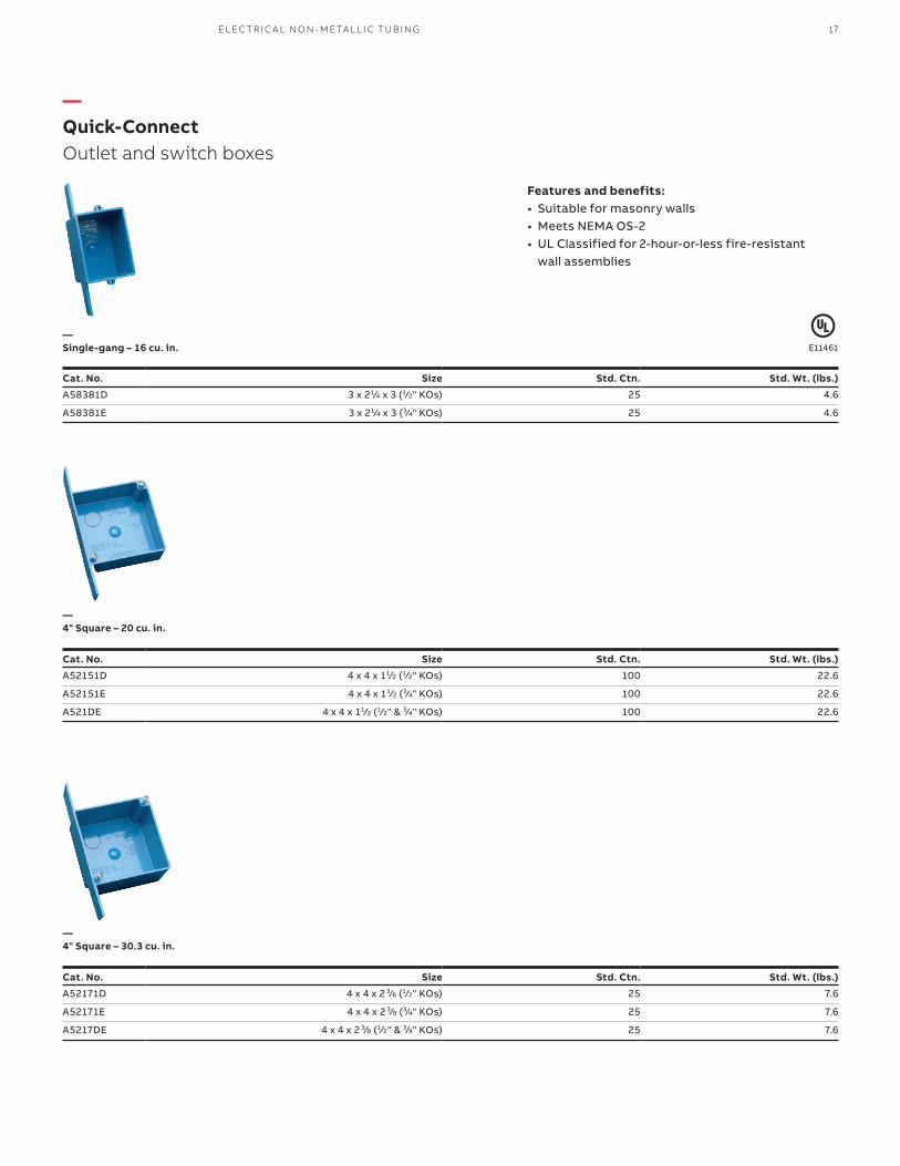
—Quick-ConnectOutlet and switch boxes
—Single-gang – 16 cu. in.
—4" Square – 20 cu. in.
—4" Square – 30.3 cu. in.
• Suitable for masonry walls• Meets NEMA OS-2• UL Classified for 2-hour-or-less fire-resistant
wall assemblies
Cat. No. Size Std. Ctn. Std. Wt. (lbs.)
A58381D 3 x 21⁄4 x 3 (1⁄2" KOs) 25 4.6
A58381E 3 x 21⁄4 x 3 (3⁄4" KOs) 25 4.6
Cat. No. Size Std. Ctn. Std. Wt. (lbs.)
A52151D 4 x 4 x 11⁄2 (1⁄2" KOs) 100 22.6
A52151E 4 x 4 x 11⁄2 (3⁄4" KOs) 100 22.6
A521DE 4 x 4 x 11⁄2 (1⁄2" & 3⁄4" KOs) 100 22.6
Cat. No. Size Std. Ctn. Std. Wt. (lbs.)
A52171D 4 x 4 x 2 3⁄8 (1⁄2" KOs) 25 7.6
A52171E 4 x 4 x 2 3⁄8 (3⁄4" KOs) 25 7.6
A5217DE 4 x 4 x 2 3⁄8 (1⁄2" & 3⁄4" KOs) 25 7.6
Features and benefits:
E11461
EL EC TR I C A L N O N - M E TA L L I C T U B I N G 17

—ENT BoxWith adapters
—ENT BoxExtenders
—4" Square – 24.75 cu. in. ENT box with adapters
—Single-gang
—Two-gang
—Box back wall support
• UL Classified for 2-hour-or-less fire-resistant wall assemblies
• UL Classified for 2-hour-or-less fire-resistant wall assemblies
Cat. No. Size Std. Ctn. Std. Wt. (lbs.)
A5329DE 4 x 4 x 13⁄4 (1⁄2" & 3⁄4" KOs) 50 14.8
Cat. No. Rise (in.) Cu. In. Std. Ctn. Std. Wt. (lbs.)
A410 1⁄2 3.5 100 7.7
A411 5⁄8 4.2 50 4.6
A412 3⁄4 5.0 50 5.1
A413 1 6.6 40 5
A414 11⁄4 8.1 30 4.4
Cat. No. Rise (in.) Cu. In. Std. Ctn. Std. Wt. (lbs.)
A400 Blank — — 7.7
A420 1⁄2 6.1 6.1 5.0
A421 5⁄8 7.4 7.4 4.2
A422 3⁄4 8.8 8.8 4.8
Cat. No. Size Std. Ctn. Std. Wt. (lbs.)
A540DS For use with 1⁄2" knockout 100 2.1
Features and benefits:
Features and benefits:
E11461
E11461
18 C A R LO N P VC CO N D U IT, EL B OW S A N D FIT TI N G S

E11461
—Round coversFor octagon ceiling boxes
—Round plaster rings
—Round blank covers
• Listed for fixture support up to 50 lbs.• UL Classified for 2-hour-or-less fire-resistant
assemblies
Cat. No. Rise (in.) Cu. In. Std. Ctn. Std. Wt. (lbs.)
A471 1⁄2 3.2 100 3.3
A472 3⁄4 4.0 100 3.7
Cat. No. Rise (in.) Cu. In. Std. Ctn. Std. Wt. (lbs.)
E460R-CAR Blank – 35 2.2
A470D Blank with 1⁄2" KO – 100 4.7
Features and benefits:
EL EC TR I C A L N O N - M E TA L L I C T U B I N G 19

—Quick Connect 4" Octagon ceiling boxes
—Ceiling box – 20.5 cu. in.
—Ceiling box with J mount – 20.5 cu. in.
—Ceiling box with L bracket – 20.5 cu. in.
—Ceiling box with adjustable hanger bar – 20.5 cu. in.
• Carlon ceiling boxes and round plaster rings are produced from a special high heat-resistant engineered plastic material developed specifically for fixture support
• Listed for fixture support up to 50 lbs.• UL Classified for 2-hour-or-less fire resistant floor/
ceiling assemblies
Cat. No. Size Std. Ctn. Std. Wt. (lbs.)
A615D (4) 2 1⁄8 Deep (1⁄2" KOs) 50 6.4
A615E (4) 2 1⁄8 Deep (3⁄4" KOs) 50 6.4
A615DE (4) 2 1⁄8 Deep (1⁄2" & 3⁄4" KOs) 50 6.4
Cat. No. Size Std. Ctn. Std. Wt. (lbs.)
A615DJ (4) 2 1⁄8 Deep (1⁄2" KOs) 50 18.7
Cat. No. Size Std. Ctn. Std. Wt. (lbs.)
A615DL (4) 2 1⁄8 Deep (1⁄2" KOs) 50 6.4
Cat. No. Size Std. Ctn. Std. Wt. (lbs.)
A615DH (4) 2 1⁄8 Deep (1⁄2" KOs) 25 13.6
Features and benefits:
E11461
E11461
E11461
E11461
20 C A R LO N P VC CO N D U IT, EL B OW S A N D FIT TI N G S
—Carlon Low VOC cement
Cat. No. Size Applicator Description Std. Ctn. Std. Wt. (lbs.)
VC9992 Quart Dauber All-Weather “Quick-Set” Blue 12 29.0
Meets ASTM D-2564.
(MSDS sheets available at www.carlon.com)
Recommended pipeapplication and sizes
Set-up time(Evaporation Rate)
Recommendedinstallation temp.
Lap Shear@ 73°F
Viscosity at 75°Fas manufactured
Required for use with Flex-Plus ENT (Electrical Non-Metallic Tubing), Riser-Gard, P&C Flex and Carlon PVC fittings.Up through 6" diameter.
-5°–10°F 6–8 Minutes -5° to 100°F 2 Hrs. 350 PSI 400–700 CPS
10°–30°F 4–5 Minutes 16 Hrs. 800 PSI
30°–50°F 3–4 Minutes 72 Hrs. 1500 PSI
50°–70°F 1–2 Minutes
70°–90°F 1⁄2–11⁄2 Minutes
—All Weather — ENT Blue
ENT cement required for use with ENT and rigid non-metallic conduit fittings.
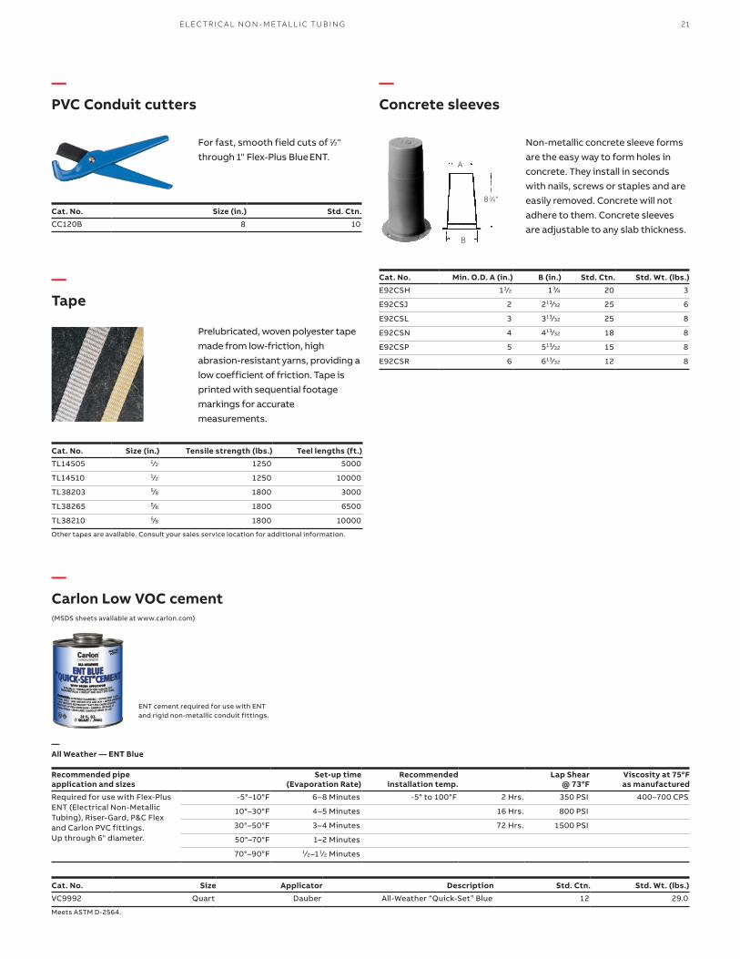
—PVC Conduit cutters
For fast, smooth field cuts of 1⁄2" through 1" Flex-Plus Blue ENT.
Cat. No. Size (in.) Std. Ctn.
CC120B 8 10
A
B
83⁄4"
—Concrete sleeves
Non-metallic concrete sleeve forms are the easy way to form holes in concrete. They install in seconds with nails, screws or staples and are easily removed. Concrete will not adhere to them. Concrete sleeves are adjustable to any slab thickness.
Cat. No. Min. O.D. A (in.) B (in.) Std. Ctn. Std. Wt. (lbs.)
E92CSH 11⁄2 13⁄4 20 3
E92CSJ 2 213⁄32 25 6
E92CSL 3 313⁄32 25 8
E92CSN 4 413⁄32 18 8
E92CSP 5 513⁄32 15 8
E92CSR 6 613⁄32 12 8
—Tape
Prelubricated, woven polyester tape made from low-friction, high abrasion-resistant yarns, providing a low coefficient of friction. Tape is printed with sequential footage markings for accurate measurements.
Cat. No. Size (in.) Tensile strength (lbs.) Teel lengths (ft.)
TL14505 1⁄2 1250 5000
TL14510 1⁄2 1250 10000
TL38203 5⁄8 1800 3000
TL38265 5⁄8 1800 6500
TL38210 5⁄8 1800 10000
Other tapes are available. Consult your sales service location for additional information.
EL EC TR I C A L N O N - M E TA L L I C T U B I N G 21

—Carlon®Plenum-Gard® Raceway
Cat. No. Size (in.)
Maximum flame propagation 5 ft.
Maximum peak optical smoke density 0.5
Maximum average optical smoke density 0.15
Cat. No. Size (in.) Color Pull tapeReel size
(F x W) (in.) Reel typeReel length
(ft.)Reel Wt.
(lbs.)Reel Wt. per
100 Ft. (lbs.)
CD4X1C-1500 1⁄2 Orange 200 lb. 34 x 23 Wood 1,500 30 7
CE4X1-1000 Orange Empty 34 x 23 Wood 1,000 30 8
CE4X1-1000S 3⁄4 Orange Empty/Split 34 x 23 Wood 1,000 30 8
CE4X1C-1000 Orange 900 lb. 34 x 23 Wood 1,000 30 8
CF4X1C-500 Orange 900 lb. 34 x 23 Wood 500 30 10
CF4X1C-1000 Orange 900 lb. 48 x 28 Wood 1,000 79 10
CF4X1C-1500 1 Orange 900 lb. 48 x 28 Wood 1,500 79 10
CF4X1C-5200 Orange 900 lb. 66 x 41 Wood 5,200 250 10
CF4X1C-6500 Orange 900 lb. 72 x 41 Wood 6,500 310 10
CF4X1C-8000 Orange 900 lb. 82 x 41 Wood 8,000 365 10
CG4X1C-500 Orange 900 lb. 48 x 28 Wood 500 79 14
CG4X1-500S Orange Empty/Split 48 x 28 Wood 500 79 10
CG4X1C-900 Orange 900 lb. 48 x 45 Wood 900 96 14
CG4X1C-1600 11⁄4 Orange 900 lb. 48 x 45 Wood 1,600 96 14
CG4X1C-3200 Orange 900 lb. 66 x 41 Wood 3,200 250 14
CG4X1C-6500 Orange 900 lb. 96 x 41 Wood 6,500 700 14
CG4X1-900S Orange Empty/Split 48 x 28 Wood 900 79 14
CH4X1C-350 Orange 900 lb. 48 x 28 Wood 350 79 16
CH4X1C-1200 11⁄2 Orange 900 lb. 48 x 45 Wood 1,200 96 16
CH4X1C-4000 Orange 900 lb. 82 x 41 Wood 4,000 365 16
CJ4X1-200S Orange Empty/Split 48 x 28 Wood 200 79 21
CJ4X1C-225 Orange 900 lb. 48 x 28 Wood 225 79 21
CJ4X1C-700 2 Orange 900 lb. 48 x 45 Wood 700 96 21
CJ4X1C-1400 Orange 900 lb. 82 x 41 Wood 1,400 365 21
CJ4X1C-2000 Orange 900 lb. 82 x 41 Wood 2,000 365 21
CJ4X1C-2800 Orange 900 lb. 82 x 41 Wood 2,800 365 21
CL4X1C-150 3 Orange 900 lb. 48 x 45 Wood 150 96 41
—Technical Info
—Standard stock – reels
E151168FT-6 Rated
Plenum-Gard is a UL® Listed non-metallic corrugated flexible conduit for use in plenum, riser and general purpose applications. Plenum-Gard is manufactured from PVDF resin, which is extremely durable and resistant to abrasion and mechanical damage before/after cable installation.
Plenum-Gard is listed to UL® 2024 in accordance with the National Electrical Code® for plenum, riser, general purpose and other cabling/optical fiber/telecommunication applications as defined in Articles 725, 770, 800 and 820.
Important: Installed cables must be plenum rated and the UL® Listing must be printed on the product. Abandoned cables MUST be removed (reference NEC®).
• Storage: -4° to 158°F• Handling: -4° to 104°F• No UV protection (not suitable for outdoor use)• Do not store outside
NEC and National Electrical Code are registered trademarks of the National Fire Protection Association, Inc.
—01 Applications: Plenum, riser and general purpose
—01
22 C A R LO N P VC CO N D U IT, EL B OW S A N D FIT TI N G S

—Technical Info
Features and benefits:• For use in plenum areas per NEC® Articles 725,
770, 800 and 820• Sizes 1⁄2” through 3”• Pre-installed pull tape available in sizes 1⁄2” through 3”• Outside diameters meet IPS dimensions• UL® Listed raceway meeting UL 2024• Footage sequentially marked• Single-peak design
• Custom orders are not returnable• Custom lengths are available in minimum
order quantities of 1,000 ft.• Custom color runs are available in minimum
order quantities of 10,000 ft.
Options:• Color: Black, blue, gray, red, white and yellow• Two-, three- or four-way parallel• Split duct
Cat. No. Size (in.) Color Pull tape Coil length (ft.) Product Wt. per 100 ft.(lbs.)
CD4X1C-500 1⁄2 Orange 900 lb. 500 7
CE4X1-350* 3⁄4 Orange Empty 350 8
CE4X1-350S Orange Empty/Split 350 8
CF4X1C-100* Orange 900 lb. 100 10
CF4X1-100S* Orange Empty/Split 100 10
CF4X1C-250* 1 Orange 900 lb. 250 10
CF4X1-250 Orange Empty 250 10
CF4X1-250S* Orange Empty/Split 250 10
CG4X1C-200* 11⁄4 Orange 900 lb. 200 14
CG4X1-200S Orange Empty/Split 200 14
CH4X1C-150* 11⁄2 Orange 900 lb. 150 16
CH4X1-150S Orange Empty/Split 150 16
CJ4X1C-100* 2 Orange 900 lb. 100 21
CJ4X1-100S Orange Empty/Split 100 21
* Overnight Shippable
Size (in.) I.D. Min. Ref. (in.) Min. O.D. (in.) Max. O.D. (in.) Min. bend radius (in.)1⁄2 .60 .815 .835 23⁄4 .74 1.025 1.045 2
1 1.00 1.292 1.312 3
11⁄4 1.35 1.630 1.650 3
11⁄2 1.50 1.868 1.888 4
2 2.00 2.329 2.439 4
3 3.00 3.422 3.452 4
Position 1 Product
Position 2 Size (in.)
Position 3 Type
Position 4 Wall
Position 5 Color
Position 6 Pull line
Position 7 Length
C = Plenum-Gard D = 1⁄2 4 = Corrugated X = Standard 1 = Orange C = 900 LB. Tape Example
E = 3⁄4 2 = Black -1000 = Feet
F = 1 3 = Gray -1000S = 1000 Feet Split
G = 11⁄4 4 = White
H = 11⁄2 5 = Blue
J = 2 7 = Yellow
L = 3 8 = Red
—Standard stock – coils
—Specifications
—Custom oders – how to build a part number:
—CarlonPlenum-Gard Raceway
23FL E X I B L E R ACE WAY S YS TEM ACCE SSO R IE S
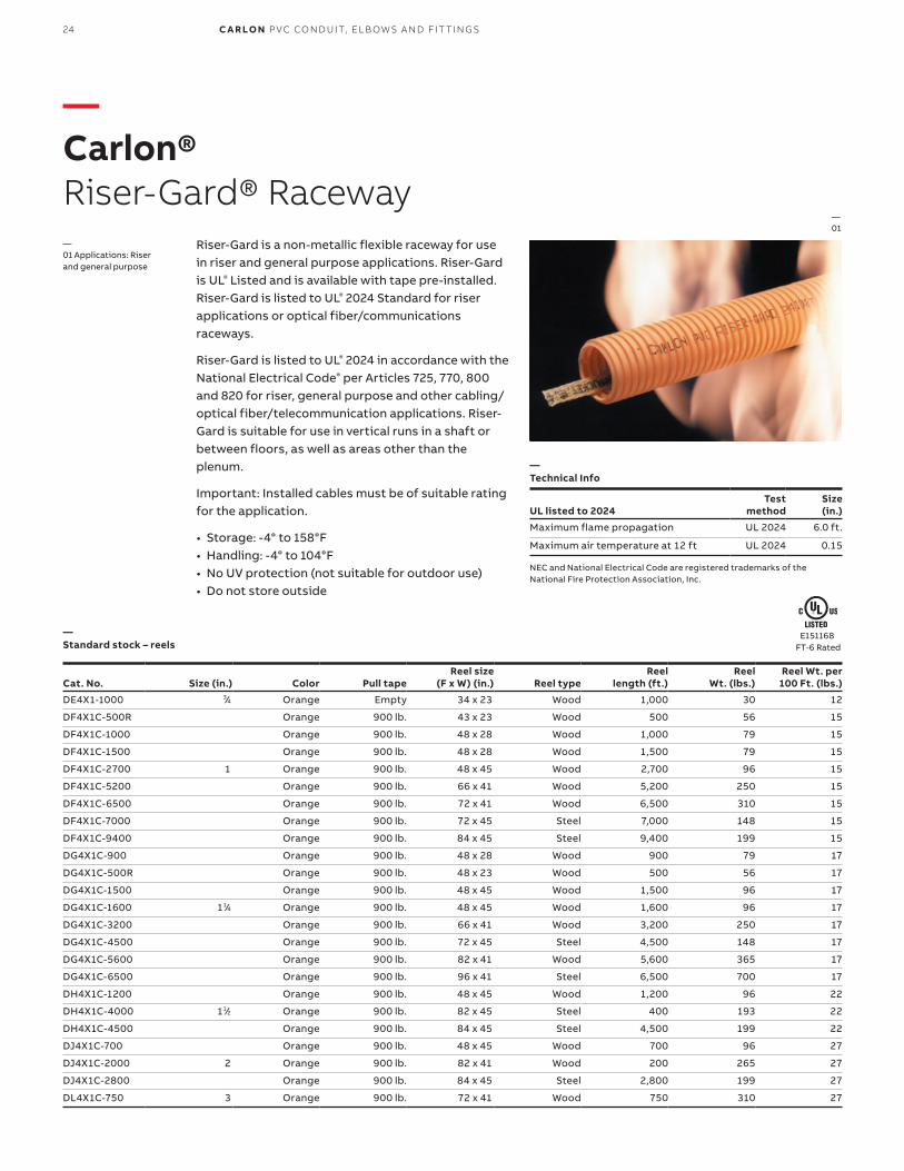
—Carlon®Riser-Gard® Raceway
Cat. No. Size (in.) Color Pull tapeReel size
(F x W) (in.) Reel typeReel
length (ft.)Reel
Wt. (lbs.)Reel Wt. per
100 Ft. (lbs.)
DE4X1-1000 3⁄4 Orange Empty 34 x 23 Wood 1,000 30 12
DF4X1C-500R Orange 900 lb. 43 x 23 Wood 500 56 15
DF4X1C-1000 Orange 900 lb. 48 x 28 Wood 1,000 79 15
DF4X1C-1500 Orange 900 lb. 48 x 28 Wood 1,500 79 15
DF4X1C-2700 1 Orange 900 lb. 48 x 45 Wood 2,700 96 15
DF4X1C-5200 Orange 900 lb. 66 x 41 Wood 5,200 250 15
DF4X1C-6500 Orange 900 lb. 72 x 41 Wood 6,500 310 15
DF4X1C-7000 Orange 900 lb. 72 x 45 Steel 7,000 148 15
DF4X1C-9400 Orange 900 lb. 84 x 45 Steel 9,400 199 15
DG4X1C-900 Orange 900 lb. 48 x 28 Wood 900 79 17
DG4X1C-500R Orange 900 lb. 48 x 23 Wood 500 56 17
DG4X1C-1500 Orange 900 lb. 48 x 45 Wood 1,500 96 17
DG4X1C-1600 11⁄4 Orange 900 lb. 48 x 45 Wood 1,600 96 17
DG4X1C-3200 Orange 900 lb. 66 x 41 Wood 3,200 250 17
DG4X1C-4500 Orange 900 lb. 72 x 45 Steel 4,500 148 17
DG4X1C-5600 Orange 900 lb. 82 x 41 Wood 5,600 365 17
DG4X1C-6500 Orange 900 lb. 96 x 41 Steel 6,500 700 17
DH4X1C-1200 Orange 900 lb. 48 x 45 Wood 1,200 96 22
DH4X1C-4000 11⁄2 Orange 900 lb. 82 x 45 Steel 400 193 22
DH4X1C-4500 Orange 900 lb. 84 x 45 Steel 4,500 199 22
DJ4X1C-700 Orange 900 lb. 48 x 45 Wood 700 96 27
DJ4X1C-2000 2 Orange 900 lb. 82 x 41 Wood 200 265 27
DJ4X1C-2800 Orange 900 lb. 84 x 45 Steel 2,800 199 27
DL4X1C-750 3 Orange 900 lb. 72 x 41 Wood 750 310 27
—Standard stock – reels
UL listed to 2024Test
methodSize
(in.)
Maximum flame propagation UL 2024 6.0 ft.
Maximum air temperature at 12 ft UL 2024 0.15
—Technical Info
Riser-Gard is a non-metallic flexible raceway for use in riser and general purpose applications. Riser-Gard is UL® Listed and is available with tape pre-installed. Riser-Gard is listed to UL® 2024 Standard for riser applications or optical fiber/communications raceways.
Riser-Gard is listed to UL® 2024 in accordance with the National Electrical Code® per Articles 725, 770, 800 and 820 for riser, general purpose and other cabling/optical fiber/telecommunication applications. Riser-Gard is suitable for use in vertical runs in a shaft or between floors, as well as areas other than the plenum.
Important: Installed cables must be of suitable rating for the application.
• Storage: -4° to 158°F• Handling: -4° to 104°F• No UV protection (not suitable for outdoor use)• Do not store outside
NEC and National Electrical Code are registered trademarks of the National Fire Protection Association, Inc.
—01 Applications: Riser and general purpose
—01
E151168FT-6 Rated
24 C A R LO N P VC CO N D U IT, EL B OW S A N D FIT TI N G S

—Technical Info
• Available in sizes 3⁄4" through 3"• Pull tape can be factory pre-installed in 1" through 3"• Outside diameters meet IPS dimensions• Footage sequentially marked
Features and benefits:• For use in riser and general purpose areas per NEC®
Articles 725, 770, 800 and 820• Riser-Gard is also suitable for direct burial, not
approved for exposed applications• UL® Listed raceway meeting UL 2024
• Custom orders are not returnable• Custom lengths are available in minimum
order quantities of 1,000 ft.• Custom color runs are available in minimum
order quantities of 10,000 ft.
Options:• Color: Black, blue, gray, red, white and yellow• Two-, three- or four-way parallel• Split duct• Custom print line
Cat. No. Size (in.) Color Pull tape Coil length (ft.) Product Wt. per 100 ft.(lbs.)
DE4X1-350* 3⁄4 Orange Empty 350 12
DF4X1C-125 Orange 900 lb. 125 15
DF4X1C-250* Orange 900 lb. 250 15
DF4X1-250 1 Orange Empty 250 15
DF4X1C-500 Orange 900 lb. 500 15
DF4X1-250S* Orange Empty/Split 250 15
DG4X1-200 Orange Empty 200 17
DG4X1-200S* 11⁄4 Orange Empty/Split 200 17
DG4X1C-200* Orange 900 lb. 200 17
DG4X1C-500 Orange 900 lb. 500 17
DH4X1-150S 11⁄2 Orange Empty/Split 150 22
DH4X1C-150* Orange 900 lb. 150 22
DJ4X1-100S 2 Orange Empty/Split 100 27
DJ4X1C-100* Orange 900 lb. 100 27
DL4X1C-250 3 Orange 900 lb. 250 27
* Overnight Shippable
Size (in.) I.D. Min. Ref. (in.) Min. O.D. (in.) Max. O.D. (in.) Min. Bend Radius (in.)3⁄4 .74 1.025 1.075 5
1 .98 1.290 1.340 6
11⁄4 1.31 1.640 1.690 8
11⁄2 1.54 1.880 1.930 10
2 2.00 2.350 2.400 12
3 3.00 3.422 3.452 18
Position 1 Product
Position 2 Size (in.)
Position 3 Type
Position 4 Wall
Position 5 Color
Position 6 Pull Line
Position 7 Length
D = Riser-Gard E = 3⁄4 4 = Corrugated X = Standard 1 = Orange C = 900 LB. Tape Example
F = 1 2 = Black -1000 = Feet
G = 11⁄4 3 = Gray -1000S = 1000 Feet Split
H = 11⁄2 4 = White
J = 2 5 = Blue
L = 3 7 = Yellow
8 = Red
—Standard stock – coils
—Specifications
—Custom oders – how to build a part number:
—CarlonRiser-Gard Raceway
25FL E X I B L E R ACE WAY S YS TEM ACCE SSO R IE S

—Carlon® Hal-FreeRiser-Gard® Raceway
UL listed to 2024Test
methodSize
(in.)
Maximum Flame Propagation UL 2024 3' 6" ft.
Maximum Air Temperature UL 2024 387°F
—Technical Info
Hal-Free Riser-Gard is a halogen-free non-metallic flexible raceway for use in riser and general purpose applications. In the event of a fire, this product will not release halogen elements into the air, which makes it ideal for applications in tunnels, laboratories and high-tech environments. Hal-Free Riser-Gard is listed to UL® 2024 in accordance with NEC® Articles 725, 770, 800 and 820. Custom lengths and split ducts are available upon request. Hal-Free Riser-Gard is available in white only.
Features:• Free from halogen elements• Compliant with NEC® Articles 725, 770, 800 and 820• Available in sizes 1" through 2"• Available in white only• Sequentially marked footage
NEC and National Electrical Code are registered trademarks of the National Fire Protection Association, Inc.
—01 Applications: Riser and general purpose
—01
Cat. No.Size (in.) Color
Nom. I.D. (in.)
Nom. O.D. (in.) Pull tape
Reel size (F x W) (in.) Reel type
Reel length (ft.)
Reel Wt. (lbs.)
Reel Wt. per 100 Ft. (lbs.)
HF4X4C-5000 1 White 1.049 1.365 900 lb. 72" x 41" W 5,000 310 7.5
HG4X4C-4000 11⁄4 White 1.250 1.550 900 lb. 72" x 41" W 4,000 310 7.5
HH4X4C-2000 11⁄2 White 1.500 1.850 900 lb. 66" x 41" W 2,000 250 12
HJ4X4C-2000 2 White 2.000 2.425 900 lb. 82" x 41" W 2,000 365 21
—Standard stock – reels
Position 1 Product
Position 2 Size (in.)
Position 3 Type
Position 4 Wall
Position 5 Color
Position 6 Pull Line
Position 7 Length
H = Hal-Free F = 1 4 = Corrugated X = Standard 4 = White C = 900 lb. Tape Example
G = 11⁄4 -1000 = Feet
H = 11⁄2 -1000S = 1000 Feet Split
—Custom oders – how to build a part number:
• Custom orders are not returnable• Custom lengths are available in minimum order
quantities of 1,000 ft.
• Storage and handling: -4° to 150°F• No UV protection (not suitable for outdoor use)• Do not store outside
E151168FT-4 Rated
26 C A R LO N P VC CO N D U IT, EL B OW S A N D FIT TI N G S

Cat. No. Size Applicator Description Std. Ctn. Std. Wt. (lbs.)
VC9963SC Pint Brush Resi-Gard solvent cement clear 24 28.0
—Low-VOC Resi-Gard- Clear
Up through 6" diameter.
Meets ASTM D-2564.
Recommended pipe viscosity at 75° F application and sizes
Set-up time (Evaporation rate)
Recommended installation temp
Lap Shear @ 73°F
Viscosity at 75°F as manufactured
For use with Resi-Gard, Riser-Gard, P&C Flex and Carlon PVC fittings.
10°–30° F 4–5 minutes 40° to 100° F 2 hrs. 350 psi 500–900 cps
30°–50° F 3–4 minutes 16 hrs. 800 psi
50°–70° F 1–2 minutes 72 hrs. 1,500 psi
70°–90° F 1 ⁄2–11 ⁄2 minutes
70°–90° F 1 ⁄2–11 ⁄2 minutesUp through 6" diameter.
—Carlon Hal-FreeRiser-Gard Raceway
27FL E X I B L E R ACE WAY S YS TEM ACCE SSO R IE S
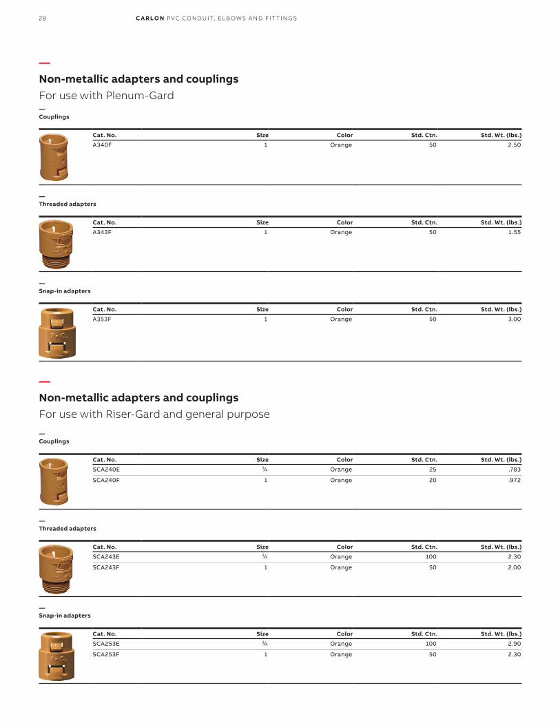
—Non-metallic adapters and couplingsFor use with Riser-Gard and general purpose
—Non-metallic adapters and couplingsFor use with Plenum-Gard
—Couplings
—Couplings
—Threaded adapters
—Threaded adapters
—Snap-in adapters
Cat. No. Size Color Std. Ctn. Std. Wt. (lbs.)
SCA240E 3⁄4 Orange 25 .783
SCA240F 1 Orange 20 .972
Cat. No. Size Color Std. Ctn. Std. Wt. (lbs.)
SCA243E 3⁄4 Orange 100 2.30
SCA243F 1 Orange 50 2.00
Cat. No. Size Color Std. Ctn. Std. Wt. (lbs.)
SCA253E 3⁄4 Orange 100 2.90
SCA253F 1 Orange 50 2.30
—Snap-in adapters
Cat. No. Size Color Std. Ctn. Std. Wt. (lbs.)
A340F 1 Orange 50 2.50
Cat. No. Size Color Std. Ctn. Std. Wt. (lbs.)
A343F 1 Orange 50 1.55
Cat. No. Size Color Std. Ctn. Std. Wt. (lbs.)
A353F 1 Orange 50 3.00
28 C A R LO N P VC CO N D U IT, EL B OW S A N D FIT TI N G S

—For usewith Plenum-Gard
Cat. No. Size (in.) Std. Ctn. Std. Wt. (lbs.)
255 3⁄4 10 12
256 1 100 25
257 11⁄4 100 28
258 11⁄2 100 35
259 2 50 19
Cat. No. Size (in.) Std. Ctn. Std. Wt. (lbs.)
E943EW 3⁄4 125 .45
E943FW 1 100 .46
E943GW 11⁄4 50 .44
E943HW 11⁄2 50 .45
E943JW 2 25 .42
—Metallic terminal adapter
—Flat sealing washer
Where a waterproof termination is required into any enclosure (metallic or non-metallic), install the neoprene washer over the threads of a terminal adapter before inserting into the enclosure. Use a standard locknut or threaded bushing to secure the assembly integrity.
E23018Except where noted by
D
CL
B
AO.D.
S
Socket type for joining non-metallic
conduit.
O.D.
A
BC
LI.D.
Cat. No.Size(in.)
Std. Ctn. Color
Dimensions (in.)
Std.Wt.
(lbs.)
Typical
Min. DMax. O.D.
Typical
A B C T L
E943E 3⁄4 125 Gray 1.064 1.046 .800 111⁄32 3⁄4 9⁄16 13⁄8 3.5
E943F 1 50 Gray 1.330 1.310 1.018 15⁄8 1 11⁄16 125⁄32 3
E943G 11⁄4 50 Gray 1.677 1.655 1.332 21⁄32 1 3⁄4 115⁄16 4
E943H 11⁄2 25 Gray 1.918 1.894 1.566 25⁄32 13⁄16 3⁄4 21⁄16 2.5
E943J 2 50 Gray 2.393 2.369 2.000 221⁄32 13⁄16 3⁄4 21⁄8 7
SCE943G 11⁄4 50 Orange 1.677 1.655 1.332 21⁄32 1 3⁄4 115⁄16 4
SCE943H 11⁄2 25 Orange 1.918 1.894 1.566 25⁄32 13⁄16 3⁄4 21⁄16 2.5
SCE943J 2 50 Orange 2.393 2.369 2.000 221⁄32 13⁄16 3⁄4 21⁄8 7
Cat. No.Size(in.)
Std. Ctn. Color
Dimensions (in.)Std.Wt.
(lbs.)
Typical
Min. DMax. O.D.
Typical
A B C L
E940E 3⁄4 100 Gray 1.064 1.046 .840 15⁄16 3⁄4 15⁄8 4.4
E940F 1 50 Gray 1.330 1.310 1.210 15⁄8 15⁄16 2 3.5
E940G 11⁄4 30 Gray 1.677 1.655 1.535 163⁄64 1 21⁄8 3.5
E940H 11⁄2 25 Gray 1.918 1.894 1.755 215⁄64 11⁄8 23⁄8 3.9
E940J 2 30 Gray 2.393 2.369 2.190 247⁄64 13⁄16 21⁄2 5.25
SCE940G 11⁄4 30 Orange 1.677 1.655 1.535 163⁄64 1 21⁄8 3.5
SCE940H 11⁄2 25 Orange 1.918 1.894 1.755 215⁄64 11⁄8 23⁄8 3.9
SCE940J 2 30 Orange 2.393 2.369 2.190 247⁄64 13⁄16 21⁄2 5.25
—For usewith Riser-Gard and General Purpose
—Non-metallic male terminal adapters
—Non-metallic standard couplings
For adapting non-metallic conduits to boxes, threaded fittings, metallic systems. Male threads on one end, socket end on other.
All socket fittings should be attached Using Carlon solvent cement. Using Carlon fittings with Carlon non-metallic conduit ensures system integrity.
29FL E X I B L E R ACE WAY S YS TEM ACCE SSO R IE S

—Low-voltageBoxes and brackets
Cat. No. Cover Volume Std. Ctn. Std. Wt. (lbs.)
SC200DV 1-Gang 20.5 cu. in 16 6.4
*U.S. Patent D463,376.
Cat. No. Cover Volume Std. Ctn. Std. Wt. (lbs.)
SC100A 1-Gang 3⁄4, 1, 11⁄4 24 5.3
SC200A 2-Gang 3⁄4, 1, 11⁄4 24 7.7
SC300A 3-Gang — 5 1.6
* U.S. Patent D457,140. U.S. Patent D462,664. U.S. Patent 6,812,405.
Cat. No. Size Std. Ctn. Std. Wt. (lbs.)
SC100SC 1-Gang 24 2.3
* U.S. Patent D459,312. U.S. Patent 6,710,245. U.S. Patent 6,872,884.
Cat. No. Size Std. Ctn. Std. Wt. (lbs.)
SC100ADJC 1-Gang 24 7.5
SC200ADJC 2-Gang 20 6.9
*U.S. Patent 5,289,934.
—Dual-voltage box/bracket*
—Low-voltage adjustable brackets*
—Low-voltage add-on bracket*
—Low-voltage brackets*
E11461
SC100A SC200A SC300A
E216492
E216492
E216492
30 C A R LO N P VC CO N D U IT, EL B OW S A N D FIT TI N G S

E151168
E151168
—Resi-Gard® Flexible Raceway
Ideal for providing a main chase from the main distribution panel to a secondary hub in the attic or basement, Resi-Gard non-metallic flexible raceway is available in 3⁄4" to 2" diameter sizes with factory-installed pull tape in sizes 1" to 2". The raceway is hand bendable, lightweight and easily cut to length to reduce scrap. Bright orange color clearly signifies a low-voltage installation.
Cat. No. Size (in.) Pull tape Description Reel length (ft.)
SCE4X1-100 3⁄4 Empty* Flexible Raceway 100
SCF4X1C-100 1 900 lbs. Flexible Raceway 100
SCG4X1C-100 11⁄4 900 lbs. Flexible Raceway 100
SCH4X1C-50 11⁄2 900 lbs. Flexible Raceway 50
SCJ4X1C-100 2 900 lbs. Flexible Raceway 50
FT-1 Rated * If installing own tape, a lubricated polyester is recommended.
—Standard-length coils
Cat. No. Size (in.) Pull tape Description Reel length (ft.)
SCE4X1-1000 3⁄4 Empty Flexible Raceway 1000
SCF4X1C-1500 1 900 lbs. Flexible Raceway 1500
SCJ4X1C-500 2 900 lbs. Flexible Raceway 500
* Made to orderFT-1 Rated
—Standard-length reels*
31FL E X I B L E R ACE WAY S YS TEM ACCE SSO R IE S

—Resi-Gard fittings
Cat. No. Size (in.) Std. Ctn.
SCA240E 3⁄4 25
SCA240F 1 20
Cat. No. Size (in.) Std. Ctn.SCA243E 3⁄4 25
SCA243F 1 20
Cat. No. Size (in.) Std. Ctn.
SCA253E 3⁄4 25
SCA253F 1 20
Cat. No. Size cu. in. Std. Ctn.
SCE943G 11⁄4 50
SCE943H 11⁄2 25
SCE943J 2 50
* Must be cemented to Resi-Gard® Flexible Raceway using ONLY Resi-Gard® Solvent Cement.
Cat. No. Size cu. in. Std. Ctn.
SCE940G 11⁄4 30
SCE940H 11⁄2 25
SCE940J 2 30
* Must be cemented to Resi-Gard® Flexible Raceway using ONLY Resi-Gard® Solvent Cement.
Cat. No. Size cu. in. Std. Ctn.
LT9E• 3⁄4 700
LT9F• 1 600
• UL Recognized.
—Quick-Connect couplings
—Quick-Connect threaded adapters
—Quick-Connect snap-in adapters
—Male terminal adapters*
—Standard couplings*
—PVC Lock nuts
E23018
E23018
E86720
E86720
E86720
32 C A R LO N P VC CO N D U IT, EL B OW S A N D FIT TI N G S

—Concrete encasement guidelinesfor Carlon® ENT
A. Do not use chemical primer or cleaner.B. Use a brush to apply a light, uniform coat of cement
labeled for use with ENT on the coupling and ENT. C. Do not use a dauber.D. Brush excess cement out of ENT grooves.E. Promptly insert ENT into fitting while cement is wet,
until the stop is reached, and give a quarter turn.F. Do not disturb until joint is set.
NEC and National Electrical Code are registered trademarks of the National Fire Protection Association, Inc.
Specifications:1.1 Electrical non-metallic tubing (ENT) is designed to replace EMT,
flexible metal conduit or other raceway or cable systems, for installation in accordance with Article 362 of the National Electrical Code® Section 12-1500 of the CEC, other applicable sections of the Code and local codes.
1.2 Any ENT used shall be listed to the requirements of UL Standard UL 1653 in accordance with Article 362 of the NEC® and Section 12-1500 of the CEC.
1.3 Any ENT used shall meet the requirements of BI National Standard CAN/CSA-C22.2 No. 227.1-UL1653 and shall be Listed/Certified in accordance to the Electrical Codes.
1.4 Carlon’s ENT shall be installed per the technical assessment prepared by fire cause analysis for use in 1-hour and 2-hour rated construction.
1.5 Penetration of fire-rated walls, floors or ceilings shall use Classified through-penetration Firestop systems described in the current Underwriters Laboratories Fire Resistance Directory.
1.6 Fittings and outlet boxes designed for use with ENT shall be listed. All fittings, boxes and accessories shall be from one manufacturer.
1.7 Only Carlon ENT Blue cement recommended specifically for use with ENT and rigid non-metallic fittings shall be used.
1.8 Unless indicated differently on drawings, ENT systems shall be color coded: BLUE for branch and feeder circuit wiring, YELLOW for communications and RED for fire alarm and emergency systems, or colors can designate different voltages.
1.9 ENT, fittings and accessories shall be manufactured by Carlon.
Features:• Recognized for use with PVC rigid non-metallic conduit fittings with
all sizes of ENT• ENT rated for 90°C conductors U.S., and 75°C Canada• One-piece ENT coupling, threaded terminator and RNC transition
fitting are rated concrete tight without tape• Recognized for use in 2-hour fire-resistive nonload-bearing and
load-bearing wall assemblies• Recognized for use in 1-hour fire-resistive nonload-bearing wall
assemblies• Recognized for use in a fire-resistive ceiling assembly (up to three
hours)• Recognized for through-penetration Firestop systems as classified
by UL to meet ICC building codes.• Conductors easily push through the raceway (up to approximately
50 feet)*• For use in buildings in accordance with NEC® Article 362/ CEC
Section 12-1500• Outside diameters meet IPS dimensions• Storage -4°F to 158°F• Handling -4°F to 104°F
1. Cut ENT square and clean.2. Insert end into fitting, making sure two (2) full corrugations are
snapped into fitting beyond flexible tabs (2 clicks).3. ENT should be tied to rebar at 2–3 foot intervals to prevent
flotation. Keep ENT straight. Small deflections over a long run may accumulate significant degrees of bend that will affect conductor installation. Suitable materials include wire, tie wraps and tape.
4. When using rigid non-metallic conduit fittings for concrete tight performance:
33

Approved uses:• Concrete slab – NEC® Article 362/CEC Section 12-1500• Walls – wood stud, masonry and metal stud –
NEC® Article 362/CEC Section 12-1500• Ceilings – permanent or dropped (free air only) –
NEC® Article 362/CEC Section 12-1500• Exposed – NEC® Article 362/CEC Section 12-1500• Public assembly – NEC® Section 518.4, in non-fire rated
and certain fire rated structures• Prewired – NEC® Article 362/CEC Section 12-1500• Classified by UL 1479 for through penetration Firestop systems in
UL Guide Category XHEZ and current UL Fire Resistance Directory• Three-hour rated floor/ceiling assembly• Raised floors – NEC® Section 645.5(E)(2)• Exposed or concealed in building above three floors when a fire
sprinkler system is installed in accordance with NFPA 13 – NEC® Section 362.10(2)
• For use in residential attics up to three feet above the bottom of the ceiling joist
• Maximum ambient temperature 140°F (60°C)
Typical applications:• Residential: low or high rise – multi or single family• Commercial: low or high rise – office, retail, hotel/motel,
restaurant, etc.• Nursing homes/hospitals in non-patient care areas only• Schools, classrooms, dormitories, offices• Fire alarm systems• Recreational vehicles and parks• Solar photovoltaic systems• Marinas and boatyards• Other uses per the current NEC® and CEC
NEC and National Electrical Code are registered trademarks of the National Fire Protection Association, Inc.
—Carlon innerduct guideWhen innerduct is being used inside the building…
Plenum• Must be UL® Listed• Plenum cable must be installed• Color: Industry standard orange
General purpose and riser• Must be UL® Listed• Riser rated cable must be used in riser applications• Color: Industry-standard orange
Note: HDPE innerduct will not meet codeSpecifying and installing UL Listed innerducts with the anticipation of future upgrades provides the building owner with a low-cost solution for the removal of abandoned cables.
Cat. No. Carlon size (in.)
CD4X1C 1⁄2
CE4X1C 3⁄4
CF4X1C 1
CG4X1C 11⁄4
CH4X1C 11⁄2
CJ4X1C 2
CL4X1C 3
Cat. No. Carlon size (in.)
DE4X1C 3⁄4
DF4X1C 1
DG4X1C 11⁄4
DH4X1C 11⁄4
DJ4X1C 2
DL4X1C 3
CL4X1C 3
—Concrete encasement guidelines for Carlon ENT (continued)
34 C A R LO N P VC CO N D U IT, EL B OW S A N D FIT TI N G S
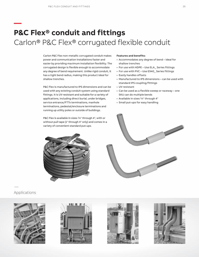
Carlon P&C Flex non-metallic corrugated conduit makes power and communication installations faster and easier by providing maximum installation flexibility. The corrugated design is flexible enough to accommodate any degree of bend requirement. Unlike rigid conduit, it has a tight bend radius, making this product ideal for shallow trenches.
P&C Flex is manufactured to IPS dimensions and can be used with any existing conduit system using standard fittings. It is UV resistant and suitable for a variety of applications, including direct burial, under bridges, service entrance/FTTx terminations, manhole terminations, pedestal/enclosure terminations and running up utility poles or outside of buildings.
P&C Flex is available in sizes 3 ⁄4" through 4", with or without pull tape (1" through 4" only) and comes in a variety of convenient standard put-ups.
Features and benefits:• Accommodates any degree of bend – ideal for
shallow trenches• For use with HDPE – Use ELA_ Series fittings• For use with PVC – Use E940_ Series fittings• Easily handles offsets• Manufactured to IPS dimensions – can be used with
standard IPS coupling/fittings• UV resistant• Can be used as a flexible sweep or raceway – one
SKU can do multiple bends• Available in sizes 3 ⁄4" through 4"• Small put-ups for easy handling
—
Applications
—P&C Flex® conduit and fittingsCarlon® P&C Flex® corrugated flexible conduit
P& C FL E X CO N D U IT A N D FIT TI N G S 35

—P&C Flex conduit and fittingsCarlon P&C Flex corrugated flexible conduit
—P&C Flex fittings
—P&C Flex fittings (continued)
Cat. No.Size (in.)
I.D. (in.)
O.D. (in.)
Pulltape
Reel/coil
Std. Ctn.(ft.)
Std. Wt.
(lbs.)
11807-350* 3⁄4 0.83 1.040 Empty Coil 350 39.9
1808-250C 1 1.000 1.315 Empty Coil 250 36.3
11808-5200 1 1.000 1.315 Empty Reel 5200 1019.0
11809-900 11 ⁄4 1.340 1.660 Empty Reel 900 243.0
11809-4500 11 ⁄4 1.340 1.660 Empty Reel 4500 972.0
11810-250 11 ⁄2 1.570 1.900 Empty Reel 250 75.8
11810-4500 11 ⁄2 1.570 1.900 Empty Reel 4500 1080.0
11810T-2300 11 ⁄2 1.570 1.900 1250 lb. Reel 2300 720.0
11810T-250 11 ⁄2 1.570 1.900 1250 lb. Reel 250 78.0
11811-1100 2 2.045 2.375 Empty Reel 1100 521.4
11811-250 2 2.045 2.375 Empty Reel 250 87.0
11811-2500 2 2.045 2.375 Empty Reel 2500 815.0
11811-500 2 2.045 2.375 Empty Reel 500 201.6
11811-700 2 2.045 2.375 Empty Reel 700 269.0
11811T-250 2 2.045 2.375 1250 lb. Reel 250 89.0
11812-250 21 ⁄2 2.469 2.875 Empty Reel 250 121.0
11812AG-001 21 ⁄2 2.469 2.875 Empty Reel 1300 516.1
11813-1200 3 3.068 3.500 Empty Reel 1200 850.8
11813-250 3 3.068 3.500 Empty Reel 250 192.0
11813-500 3 3.068 3.500 Empty Reel 500 523.0
11813-750 3 3.068 3.500 Empty Reel 750 554.3
11815-250 4 4.026 4.500 Empty Reel 250 324.0
11815-800 4 4.026 4.500 Empty Reel 800 778.4
*Pull tape not available for 3 ⁄4" conduit.
—P&C Flex conduit
—Couplings
—Female adapters
—Terminal adapters
Cat. No.Size (in.)
Std. Ctn.
Std. Wt.(lbs.)
E940E 3⁄4 100 4.6
E940F 1 50 3.5
E940G 11 ⁄4 30 3.2
E940H 11 ⁄2 25 3.4
E940J 2 30 5.3
E940K 21 ⁄2 20 7.5
E940L 3 25 14.7
E940N 4 15 12.5
Cat. No.Size (in.)
Std. Ctn.
Std. Wt.(lbs.)
E942E 3⁄4 100 4.3
E942F 1 50 3.7
E942G 11 ⁄4 30 3.3
E942H 11 ⁄2 25 3.3
E942J 2 30 5.4
E942K 21 ⁄2 20 6.6
E942L 3 25 11.8
E942N 4 15 10.8
Cat. No.Size (in.)
Std. Ctn.
Std. Wt.(lbs.)
E943E 3⁄4 125 4.2
E943F 1 50 3.0
E943G 11 ⁄4 25 4.1
E943H 11 ⁄2 25 2.7
E943J 2 5 6.9
E943K 21 ⁄2 20 6.3
E943L 3 45 16.6
E943N 4 15 11.7
—Bell ends (Schedule 40)
Cat. No.Size (in.)
Std. Ctn.
Std. Wt.(lbs.)
E997F 1 50 2.6
E997G 11 ⁄4 35 2.5
E997H 11 ⁄2 30 2.5
E997J 2 10 4.8
E997K 21 ⁄2 10 2.0
E997L 3 10 10.0
E997N 4 30 16.0
—Plugs
Cat. No.Size (in.)
Std. Ctn.
Std. Wt.(lbs.)
P258H 11 ⁄2 50 1.7
P258JT 2 60 3.1
P258K 21 ⁄2 25 1.5
P258LT 3 30 3.4
P258NT 4 48 8.3
Coupling
36 C A R LO N P VC CO N D U IT, EL B OW S A N D FIT TI N G S

P& C FL E X CO N D U IT A N D FIT TI N G S
—P&C Flex conduit and fittingsCarlon P&C Flex corrugated flexible conduit
Performance properties 3 ⁄4" 1" 11 ⁄4" 11 ⁄2" 2" 21 ⁄2" 3" 4"
Stiffness F/y at 5% deflection 200 200 200 200 200 130 130 90
Impact strength (ft./lbs.) 72° F 35 40 40 50 50 70 120 140
Impact strength (ft./lbs.) 32° F 5 8 8 15 25 35 60 60
Minimum bending radius (inches) 6 6 6 7 8 12 15 18
Conduit tensile strength 200 300 400 500 700 1000 1500 2000
Storage: -4° to 158° FHandling: -4° to 104° F
Radius Nom. Dia. (in.) Segment
18" required length of P&C Flex (in.)
24" required length of P&C Flex (in.)
36" required length of P&C Flex (in.)
48" required length of P&C Flex (in.)
60" required length of P&C Flex (in.)
90° 33 42 61 80 99
11 ⁄245° 19 23 33 42 52
30° 14 17 23 30 36
221 ⁄2° 12 14 19 23 28
90° 32 42 61 79 98
245° 18 23 32 42 51
30° 14 17 23 29 35
221 ⁄2° 11 12 18 23 28
90° 34 44 63 81 100
21 ⁄245° 20 25 33 44 53
30° 16 19 24 31 37
221 ⁄2° 13 15 20 25 30
90° 35 44 63 82 101
345° 20 25 34 44 53
30° 16 19 24 32 38
221 ⁄2° 13 16 20 25 30
90° 37 46 65 84 103
445° 22 27 37 46 55
30° 18 21 27 34 40
221 ⁄2° 15 18 22 27 32
For other radius sweeps, use this formula: .0175 x radius (inches) x angle° = Required length of P&C Flex in inches.
—Specifications
—Sweep and elbow conversion chart
—Technical information
P&C Flex conduit is flexible. Carlon P&C Flex non-metallic corrugated conduit is used to transition from Carlon P&C Duct Type DB. Despite equipment being mounted away from the pole, P&C Flex conduit remains flush to the pole.
When soil conditions do not permit direct burial of cable, use Carlon P&C Flex non-metallic corrugated conduit to protect the cable. A lower coefficient of friction provides easy wire pulls on location. Flexibility eliminates the need for elbows.
Carlon P&C Flex non-metallic corrugated conduit protects control cables in supervisory control and data acquisition equipment (SCADA) in distribution substations. Flexibility provides maximum utilization of equipment.
Control cables run in 1" or 11⁄2" P&C Flex conduit
Carlon Terminal adapters cemented to ends of P&C Flex
Substation SCADARTU cabinet
1Conduit clamps
1
Customer conduit
Flex conduit
Coupling
CouplingGuard
Rigid non-metallic conduit
Steel channels to supportRTU and provide space
under cabinet for conduit
Circuit Safe JIC Enclosurewith transducers and interposing relays mounted to steel structure or equipment
37

—P&C Flex conduit and fittingsCarlon P&C Flex corrugated flexible conduit
Suggested applications • Carlon P&C Flex non-metallic corrugated conduit is
the most versatile system available for power and communications applications
• P&C Flex combines high crush strength with flexibility
• Longer coil lengths reduce installation time
Here are a few application ideas that illustrate how P&C Flex can be effectively used:In single-phase underground primary systems, lower the cost of direct buried and standard conduit systems by installing P&C Flex non-metallic corrugated conduit with a vibratory plow.
Digging up faulty cable in frozen ground can be expensive and time consuming. Use Carlon P&C Flex from the customer service raceway to the temporary service pedestal to restore power on an interim basis. When the service length is more than 250 feet, use a splice box and an additional length of P&C Flex non-metallic corrugated Conduit.
Customer serviceraceway
Service cable inserted into2" Carlon P&C Flexcorrugated conduit
Temporary pedestalinstalled over existing
pedestal and servicewires connected
Pad mounttransformer
2" Carlon P&C Flexnon-metallic
corrugated conduit
Vibratoryplow
Pad mounttransformer
Carlon terminaladapters
cemented toP&C Flex
Circuit Safe JIC enclosure used assplice box where service length
is more than 125 feet
Meteradapter
38 C A R LO N P VC CO N D U IT, EL B OW S A N D FIT TI N G S
P& C FL E X CO N D U IT A N D FIT TI N G S
—P&C Flex conduit and fittingsCarlon P&C Flex corrugated flexible conduit
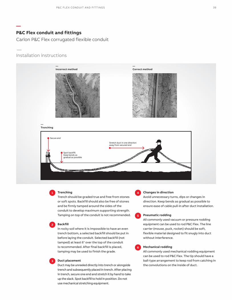
—Incorrect method
—Correct method
—Trenching
—Installation instructions
1 4
2
5
3
6
TrenchingTrench should be graded true and free from stones or soft spots. Backfill should also be free of stones and be firmly tamped around the sides of the conduit to develop maximum supporting strength.Tamping on top of the conduit is not recommended.
BackfillIn rocky soil where it is impossible to have an even trench bottom, a selected backfill should be put in before laying the conduit. Selected backfill (not tamped) at least 6" over the top of the conduitis recommended. After final backfill is placed, tamping may be used to finish the grade.
Duct placementDuct may be unreeled directly into trench or alongside trench and subsequently placed in trench. After placing in trench, secure one end and stretch it by hand to take up the slack. Spot backfill to hold in position. Do not use mechanical stretching equipment.
Changes in directionAvoid unnecessary turns, dips or changes in direction. Keep bends as gradual as possible to ensure ease of cable pull-in after duct installation.
Pneumatic roddingAll commonly used vacuum or pressure rodding equipment can be used to rod P&C Flex. The line carrier (mouse, puck, rocket) should be soft, flexible material designed to fit snugly into duct without interference.
Mechanical roddingAll commonly used mechanical rodding equipment can be used to rod P&C Flex. The tip should have a ball-type arrangement to keep rod from catching in the convolutions on the inside of duct.
Spot backfill.Keep bends as gradual as possible
Secure end
Stretch duct in one directionaway from secured end
39

PE Corrugated options:• Sizes 1’’ through 2’’• Sequentially marked footage• Multiple colors and stripes• Factory installed pull tape
Specifications:Installation temperature range: -20°F to 122°FHandling: -20°F to 104°F
Corrugated HDPE is manufactured from High Density Polyethylene (HDPE) and it is intended for innerduct applications. It’s ideal for pulls under 1000ft. and is designed to reduce surface contact when pulling cable. And because this product is lightweight and offers maximum flexibility, installation in small or restricted locations is made easier. HDPE corrugated duct is available in sizes 1’’ through 2’’ and is offered in a variety of colors. Custom options are also available to satisfy the requirements of most installations.
Applications:Placed inside existing ducts (innerducts)
Installation method:Pulled through existing conduit
—01 Pulled through existing conduits
—Carlon®Corrugated HDPE
Nominal size(in.)
Nom. I.D.
Nom. O.D.
Min. wall
Wt/ 100
(ft.)
Min bend radius
(in.)
Pull tensilereel
(lbs.)
1 1.260 1.340 .035 10.6 14 261
1-1/4 1.482 1.565 .035 11.2 5 319
1-1/2 1.745 1.825 .035 18.0 6 1,384
2 2.345 2.425 .035 20.8 5-1/2 493
—01
How to build a part number
Position 1 Product
Position 2 Size
Position 3 Type
Position 4 Wall
Position 5 Options
Position 6 Splits
Position 7 Color
Position 8 Stripes
Position 9 Tape
Position 10 Length
A = HDPE 5 = 1'' D = 2 = N = None - 1 = 1 way A = Black NN = None A = empty 1500
6 = 1-1/4'' corrugated None- corr E = Slit 2 = 2 way B = Blue 1A = Black stripe B = 1330 lbs. (Equals
9 = 1-1/2'' S = Standard 3 = 3 way C = Brown 1B = Blue stripe polyester tape 1500 ft)
13 = 2'' 6 4 = 4 way D = Buff 1C = Brown stripe C = 1250 lbs.
400 5 = 2 way E = Grey 1D = Buff stripe polyester tape
6 = 3 way F = Green 1E = Grey stripe E = 1800 lbs
7 = 4 way G = Lilac 1F = Green stripe polyester tape
H = Lt. Green 1G = Lilac stripe G = 2000 lbs.
J = Orange 1H = Lt. Green stripe polyester tape
K = Red 1J = Orange stripe J = 2500 lbs.
L = Terra Cotta 1K = Red stripe polyester tape
M = White 1L = Terra Cotta
N = Yellow stripe
1M = White stripe
1n = Yellow stripe
Customer orders are not returnableCustomer lengths are available in minimum order quantities. See Quote form.
—Custom orders
40 C A R LO N P VC CO N D U IT, EL B OW S A N D FIT TI N G S

—CarlonCorrugated HDPE
Size Color Part No.Nom.
I.D. Nom.
O.D. Pull tape
(lbs.)Reelsize
Reel length(ft.)
Prod. Wt. per 10 ft.
(lbs.)
1'' Orange A5D2S1JNNB1000 1.049 1.340 1130 48-30-24 1000 12.5
Orange A5D2S1JNNB1800 1.049 1.340 1130 48-30-24 1800 12.5
Orange A5D2S1JNNB2000 1.049 1.340 1130 48-41-24 2000 12.5
Orange A5D2S1JNNB2700 1.049 1.340 1130 48-21-24 2700 12.5
Orange A5D2S1JNNB5000 1.049 1.340 1130 66-41-24 5000 12.5
Orange A5D2S1JNNB6500 1.049 1.340 1130 72-41-24 6500 12.5
Orange A5D2S1JNNB7000 1.049 1.340 1130 72-45-24 7000 12.5
Orange A5D2S1JNNB8000 1.049 1.340 1130 82-41-24 8000 12.5
1-1/4'' Orange A6D2S1JNNB1000 1.250 1.565 1130 48-30-24 1000 14.4
Orange A6D2S1JNNB1600 1.250 1.565 1130 48-41-24 1600 14.4
Orange A6D2S1JNNB2500 1.250 1.565 1130 66-41-24 2500 14.4
Orange A6D2S1JNNB4000 1.250 1.565 1130 66-41-24 4000 14.4
Orange A6D2S1JNNB5000 1.250 1.565 1130 72-41-24 5000 14.4
Orange A6D2S1JNNB6000 1.250 1.565 1130 82-41-24 6000 14.4
Orange A6D2S1JNNB7000 1.250 1.565 1130 84-45-24 7000 14.4
1-1/2'' Orange A9D2S1JNNB1000 1.500 1.825 1130 66-41-24 1000 17.8
Orange A9D2S1JNNB2200 1.500 1.825 1130 66-41-24 2200 17.8
Orange A9D2S1JNNB2900 1.500 1.825 1130 72-41-24 2900 17.8
Orange A9D2S1JNNB4000 1.500 1.825 1130 82-41-24 4000 17.8
2'' Orange A13D2S1JNNB500 2.000 2.425 1130 48-30-24 500 25.0
Orange A13D2S1JNNB750 2.000 2.425 1130 48-41-24 750 25.0
Orange A13D2S1JNNB1000 2.000 2.425 1130 66-41-24 1000 25.0
Orange A13D2S1JNNB1500 2.000 2.425 1130 66-41-24 1500 25.0
Orange A13D2S1JNNB1800 2.000 2.425 1130 72-41-24 1800 25.0
Orange A13D2S1JNNB2000 2.000 2.425 1130 82-41-24 2000 25.0
*Pull tape not available for 3 ⁄4" conduit.
Size Color Part No.Nom.
I.D. Nom.
O.D. Pull tape
(lbs.)Reelsize
Reel length(ft.)
Prod. Wt. per 10 ft.
(lbs.)
1 Orange A5D2E1JNNA250 1.049 1.340 Empty Coil 250/split 12.5
Orange A5D2E1JNNA250b 1.049 1.340 Empty 34-14-34 250/split 12.5
Orange A5D2S1JNNB250 1.049 1.340 1130 lb. Coil 250 12.5
Orange A5D2S1JNNB250B 1.049 1.340 1130 lb. 34-14-34 250 12.5
Orange A5D2S1JNNB500 1.049 1.340 1130 lb. Coil 500 12.5
Orange A5D2S1JNNB500B 1.049 1.340 1130 lb. 39-15-39 500 12.5
1-1/4'' Orange A6D2E1JNNA250 1.250 1.565 Empty Coil 250/split 14.4
Orange A6D2E1JNNA250B 1.250 1.565 Empty 39-15-39 250/split 14.4
Orange A6D2S1JNNB250 1.250 1.565 1130 lb. Coil 250 14.4
Orange A6D2S1JNNB250B 1.250 1.565 1130 lb. 39-15-39 250 14.4
Orange A6D2S1JNNB500 1.250 1.565 1130 lb. Coil 500 14.4
Orange A6D2S1JNNB500B 1.250 1.565 1130 lb. 44-18-44 500 14.4
1-1/2'' Orange A9D2S1JNNB250 1.500 1.825 1130 lb. Coil 250 17.8
Orange A9D2S1JNNB250B 1.500 1.825 1130 lb. 44-18-44 250 17.8
Orange A9D2S1JNNB500 1.500 1.825 1130 lb. Coil 500 17.8
2'' Orange A13D2S1JNNB250 2.000 2.425 1130 lb. Coil 250 25
—Standard length - reels
—Standard length - coils
CO R R U G ATED H D PE 41
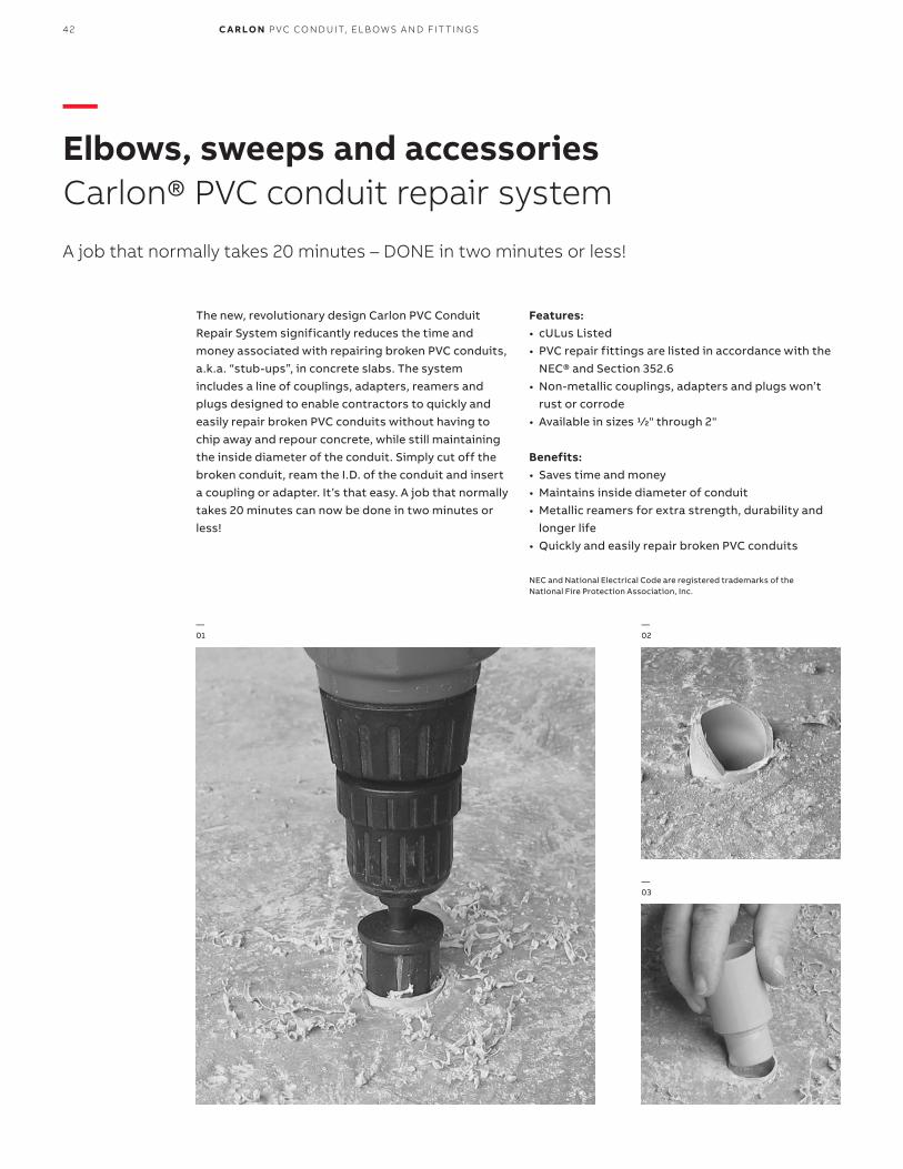
The new, revolutionary design Carlon PVC Conduit Repair System significantly reduces the time and money associated with repairing broken PVC conduits, a.k.a. “stub-ups”, in concrete slabs. The system includes a line of couplings, adapters, reamers and plugs designed to enable contractors to quickly and easily repair broken PVC conduits without having to chip away and repour concrete, while still maintaining the inside diameter of the conduit. Simply cut off the broken conduit, ream the I.D. of the conduit and inserta coupling or adapter. It’s that easy. A job that normally takes 20 minutes can now be done in two minutes or less!
Features:• cULus Listed• PVC repair fittings are listed in accordance with the
NEC® and Section 352.6• Non-metallic couplings, adapters and plugs won’t
rust or corrode• Available in sizes 1⁄2" through 2" Benefits:• Saves time and money• Maintains inside diameter of conduit• Metallic reamers for extra strength, durability and
longer life• Quickly and easily repair broken PVC conduits
NEC and National Electrical Code are registered trademarks of the National Fire Protection Association, Inc.
—01—02 —03
—Elbows, sweeps and accessoriesCarlon® PVC conduit repair system
A job that normally takes 20 minutes – DONE in two minutes or less!
—02
—01
—03
42 C A R LO N P VC CO N D U IT, EL B OW S A N D FIT TI N G S

EL B OW S , S W EEP S A N D ACCE SSO R I E S
—Elbows, sweeps and accessoriesCarlon PVC conduit repair system
Cat. No. Size (in.) Color Cat. No.
Size (in.) Color Cat. No.
Size (in.) Color Std. Ctn.
HL-6XR 1 ⁄2 Red HL-6XB 1 ⁄2 Blue HL-6XY 1 ⁄2 Yellow 1 Bag of 50
HL-10R 3 ⁄4 Red HL-10B 3 ⁄4 Blue HL-10Y 3 ⁄4 Yellow 1 Bag of 50
HL-13AR 1 Red HL-13AB 1 Blue HL-13AY 1 Yellow 1 Bag of 50
HL-16R 11 ⁄4 Red HL-16B 11 ⁄4 Blue HL-16Y 11 ⁄4 Yellow 1 Bag of 50
HL-18R 11 ⁄2 Red HL-18B 11 ⁄2 Blue HL-18Y 11 ⁄2 Yellow 1 Bag of 50
HL-21R 2 Red HL-21B 2 Blue HL-21Y 2 Yellow 1 Bag of 50
Cat. No. Trade size (in.) Std. Ctn.
E910D 1 ⁄2 25
E910E 3 ⁄4 25
E910F 1 15
E910G 11 ⁄4 10
E910H 11 ⁄2 10
E910J 2 10
Cat. No. Trade size (in.) Std. Ctn.
E920D 1 ⁄2 25
E920E 3 ⁄4 25
E920F 1 15
E920G 11 ⁄4 10
E920H 11 ⁄2 10
E920J 2 10
Cat. No. Trade size (in.) Std. Ctn.
E910REAMD 1 ⁄2 12
E910REAME 3 ⁄4 12
E910REAMF 1 10
E910REAMG 11 ⁄4 10
E910REAMH 11 ⁄2 10
E910REAMJ 2 10
E910REAMKIT All Sizes 5
—Schedule 40 plugs
—Couplings
—Male threaded adapters
—Reamers
Reamer
Reamer Kit
43

44 C A R LO N P VC CO N D U IT, EL B OW S A N D FIT TI N G S
Carlon rigid non-metallic conduit (RNC) fittings and accessories
• Ease of installation – Non-metallic fittings are 1 ⁄4 to 1 ⁄5 the weight of metallic systems, can be installed in less than half the time and are easily fabricated on the job.
• Safety – Non-metallic fittings are nonconductive, assuring a safe system.
• Impact Resistant – Schedule 40 and Schedule 80 non-metallic fittings are resistant to sunlight and are listed for exposed for outdoor usage. The use of expansion fittings allows the system to expand and contract with temperature variations.
Carlon Schedule 40 and Schedule 80 fittings are designed for use aboveground and underground as described in the National Electrical Code®.
Alternative to conduit repairs:Prior to concrete pour, measure and saw cut all conduit stub-ups to the thickness of the concrete pour. Insert plugs. Pour concrete flush to the conduit. When pour is complete, remove plugs and proceed with Step 3. This alternative method saves time/money by eliminating the need for transitions or use of metal elbows.
• Corrosion Resistant – Carlon fittings are non-metallic and will not rust or corrode. Carlon non-metallic Schedule 40 and Schedule 80 elbows are manufactured to NEMA TC-2, Federal specification WC1094A and UL 651 specifications. Fittings are manufactured to NEMA TC-3, Federal specification WC1094A and UL514B. Both conduit and fittings carry respective UL or ETL Listings and UL or ETL labels.
—Elbows, sweeps and accessoriesPVC conduit repair system instructions
—01 Cut broken conduit off flush.— 02 Insert plug to keep conduit clean/drythrough balance of rough-in. Once rough-in is complete, remove plug and continue with Step 3.— 03 With reamer tool and standard1 ⁄2" drill, ream I.D. of conduit. It isrecommended to use a variablespeed drill. Use slower speed toavoid overheating the conduit.— 04 The guide will direct the cutter; thestop will touch when completed.— 05 Insert the coupling and cement into place using the cementmanufacturer’s instructions below.
A. Clean socket I.D. and spigot O.D. of dirt and moisture.B. Apply a uniform coat of cement to spigot end and push onto socket bottom, rotating 1 ⁄4 turn.C. Allow time to set before disturbing. This will depend upon temperature.
—01
—02
—04
—03
—05
—Insert fitting.
—Rotate quarter turn.
—Apply a uniform coat of cement.

45EL B OW S , S W EEP S A N D ACCE SSO R I E S
Item Cat. No.Box type included
Size(in.)
Plain end Std. Ctn.
Belled end Std. Ctn.
90˚ elbow UA9AD UA9ADB 1 ⁄2 50 50
UA9ADR-CAR UA9ADB 1 ⁄2 25 50
UA9AE UA9AEB 3 ⁄4 25 25
UA9AFR-CTN UA9AFB-CTN 1 25 25
UA9AG UA9AGB 11 ⁄4 20 20
UA9AH UA9AHB 11 ⁄2 25 25
UA9AJ UA9AJB 2 20 20
UA9AK-CAR UA9AKB-CAR 21 ⁄2 10 10
UA9AL UA9ALB 3 1 5
UA9AM UA9AMB 31 ⁄2 1 20
UA9AN UA9ANB 4 1 1
UA9AP UA9APB 5 1 1
UA9AR UA9ARB 6 1 1
45° elbow UA7AD UA7ADB 1 ⁄2 50 50
UA7AE UA7AEB 3 ⁄4 25 25
UA7AF UA7AFB 1 20 20
UA7AF-CAR UA7AFB 1 15 20
UA7AG UA7AGB 11 ⁄4 20 20
UA7AH UA7AHB 11 ⁄2 20 20
UA7AJ UA7AJB 2 20 20
UA7AJ-CAR — 2 4 —
UA7AK UA7AKB 21 ⁄2 20 20
UA7AL UA7ALB 3 5 25
UA7AM UA7AMB 31 ⁄2 1 20
UA7AN UA7ANB 4 1 20
UA7AP UA7APB 5 1 1
UA7AR UA7ARB 6 1 1
30° elbow UA6AD UA6ADB 1 ⁄2 50 50
UA6AE UA6AEB 3 ⁄4 25 25
UA6AF UA6AFB 1 25 1
UA6AG UA6AGB 11 ⁄4 20 20
UA6AH UA6AHB 11 ⁄2 25 1
UA6AJ UA6AJB 2 20 20
UA6AK UA6AKB 21 ⁄2 10 20
UA6AL UA6ALB 3 1 1
UA6AM UA6AMB 31 ⁄2 1 1
UA6AN UA6ANB 4 1 1
UA6AP UA6APB 5 1 1
UA6AR UA6ARB 6 1 1
221 ⁄2° elbow UA5AD – 1 ⁄2 1 –
UA5AE – 3 ⁄4 1 –
UA5AF – 1 1 –
UA5AG – 11 ⁄4 1 –
UA5AH – 11 ⁄2 1 –
UA5AJ UA5AJB 2 25 1
UA5AK – 21 ⁄2 20 –
UA5AL UA5ALB 3 5 1
UA5AM – 31 ⁄2 1 –
UA5AN UA5ANB 4 1 1
UA5AP UA5APB 5 1 1
UA5AR UA5ARB 6 1 1
Item Cat. No.Box type included Size
Plain end Std. Ctn.
Belled end Std. Ctn.
111 ⁄4̊ elbow UA3AD – 1 ⁄2 1 –
UA3AE – 3 ⁄4 1 –
UA3AF – 1 1 –
UA3AG – 11 ⁄4 1 –
UA3AH – 11 ⁄2 1 –
UA3AJ – 2 1 –
UA3AK – 21 ⁄2 1 –
UA3AL – 3 1 –
UA3AM – 31 ⁄2 1 –
UA3AN UA3ANB 4 1 1
UA3AP – 5 1 –
UA3AR – 6 1 –
Available in plain and integral belled end for use with non-metallic solvent weld fittings.
Size (in.)
B Minus (Radius)
(in.)C Min.
(in.)1 ⁄2 .840 4 11 ⁄23 ⁄4 1.050 41 ⁄2 11 ⁄2
1 1.315 53 ⁄4 17⁄8
11 ⁄4 1.660 71 ⁄4 2
11 ⁄2 1.900 81 ⁄4 2
2 2.375 91 ⁄2 2
21 ⁄2 2.875 101 ⁄2 3
3 3.500 13 31 ⁄8
31 ⁄2 4.000 15 31 ⁄4
4 4.500 16 33 ⁄8
5 5.563 24 35 ⁄8
6 6.625 30 33 ⁄4
TradeSize (in.)
A (in.) at Entrance
B (in.) at Bottom
C (in.) Socket Depth
Max. Min Max. Min. Max. Min.1 ⁄2 0.86 0.844 0.844 0.828 1.500 0.6523 ⁄4 1.074 1.054 1.056 1.036 1.500 0.719
1 1.340 1.320 1.320 1.300 1.875 0.875
11 ⁄4 1.689 1.665 1.667 1.643 2.000 0.938
11 ⁄2 1.930 1.906 1.906 1.882 2.000 1.062
2 2.405 2.381 2.381 2.357 2.000 1.125
21 ⁄2 2.905 2.875 2.883 2.853 3.000 1.469
3 3.530 3.500 3.507 3.477 3.125 1.594
31 ⁄2 4.065 3.965 4.007 3.977 3.250 1.687
4 4.565 4.465 4.506 4.476 3.375 1.750
5 5.643 5.543 5.583 5.523 3.625 1.937
6 6.708 6.608 6.644 6.584 3.750 2.125
NEC and National Electrical Code are registered trademarks of the National Fire Protection Association, Inc.
90° R
R
45°
RR30°
22.5°R22.5°
11.25° RR11.25°
—Standard radius elbow dimensions (per NEC®)
—Integral belled end dimensions
45° 45° Elbow
C
C
C
C
A
A
B
B
A
C
B
C
A
B
E323335
90°Elbow
—Elbows, sweeps and accessoriesSchedule 40 elbows – standard radius

SegmentPlain end Cat. No.
Belled end Cat. No.
Nom.Dia.(in.)
Radius(in.)
Plain end Std. Ctn.
Belled end Std. Ctn.
90˚ elbow UA9CF UA9CFB 1 18 1 1
UA9DF UA9DFB 1 24 1 1
UA9EF UA9EFB 1 30 1 1
UA9FF – 1 36 1 –
UA9HF – 1 48 1 –
UA9CG UA9CGB 11 ⁄4 18 1 1
UA9DG UA9DGB 11 ⁄4 24 1 1
UA9FG UA9FGB 11 ⁄4 36 1 1
UA9HG – 11 ⁄4 48 1 –
UA9CH UA9CHB 11 ⁄2 18 1 1
UA9DH UA9DHB 11 ⁄2 24 1 1
UA9EH – 11 ⁄2 30 1 1
UA9FH UA9FHB 11 ⁄2 36 1 1
UA9HH – 11 ⁄2 48 1 –
UA9CJ UA9CJB 2 18 1 1
UA9DJ UA9DJB-UPC 2 24 1 1
UA9EJ UA9EJB 2 30 1 1
UA9FJ-UPC UA9FJB 2 36 1 1
UA9HJ UA9HJB 2 48 1 1
UA9JJ – 2 72 1 –
UA9CK UA9CKB 21 ⁄2 18 1 1
UA9DK UA9DKB-UPC 21 ⁄2 24 1 1
UA9EK UA9EKB 21 ⁄2 30 1 1
UA9FK-UPC UA9FKB 21 ⁄2 36 1 1
UA9HK UA9HKB 21 ⁄2 48 1 1
UA9CL UA9CLB 3 18 1 1
UA9DL UA9DLB-UPC 3 24 1 1
UA9EL UA9ELB 3 30 1 1
UA9FL UA9FLB 3 36 1 1
UA9HL UA9HLB 3 48 1 1
UA9IL – 3 60 1 –
UA9DM UA9DMB 31 ⁄2 24 1 1
UA9FM UA9FMB 31 ⁄2 36 1 1
UA9HM UA9HMB 31 ⁄2 48 1 1
– UA9CNB 4 18 – 1
UA9DN UA9DNB 4 24 1 1
UA9EN UA9ENB 4 30 1 1
UA9FN UA9FNB 4 36 1 1
UA9HN UA9HNB 4 48 1 1
UA9IN UA9INB 4 60 1 1
UA9JN – 4 72 1 –
UA9EP UA9EPB 5 30 1 1
UA9FP UA9FPB 5 36 1 1
UA9HP UA9HPB 5 48 1 1
UA9IP UA9IPB 5 60 1 1
UA9FR UA9FRB 6 36 1 1
UA9HR UA9HRB 6 48 1 1
UA9IR UA9IRB 6 60 1 1
UA9HT* – 8 48 1 –
SegmentPlain end Cat. No.
Belled end Cat. No.
Nom. Dia.(in.)
Radius(in.)
Plain end Std. Ctn.
Belled end Std. Ctn.
45˚ elbow UA7CF – 1 18 1 –
UA7DF – 1 24 1 –
UA7FF – 1 36 1 –
UA7CG – 11 ⁄4 18 1 –
UA7DG – 11 ⁄4 24 1 –
UA7FG – 11 ⁄4 36 1 –
UA7HG – 11 ⁄4 48 1 –
UA7CH – 11 ⁄2 18 1 –
UA7DH – 11 ⁄2 24 1 –
UA7FH UA7FHB 11 ⁄2 36 1 1
UA7HH – 11 ⁄2 48 1 –
— UA7BJB 2 12 – 1
UA7CJ UA7CJB 2 18 1 1
UA7DJ UA7DJB 2 24 1 1
UA7FJ UA7FJB 2 36 1 1
UA7HJ UA7HJB 2 48 1 1
UA7CK – 21 ⁄2 18 1 –
UA7DK UA7DKB 21 ⁄2 24 1 1
UA7FK UA7FKB 21 ⁄2 36 1 1
UA7HK – 21 ⁄2 48 1 –
UA7CL UA7CLB 3 18 1 1
UA7DL UA7DLB 3 24 1 1
UA7FL UA7FLB 3 36 1 1
UA7HL UA7HLB 3 48 1 1
UA7DM – 31 ⁄2 24 1 –
UA7DN UA7DNB 4 24 1 1
UA7EN UA7ENB 4 30 1 1
UA7FN UA7FNB 4 36 1 1
UA7HN UA7HNB 4 48 1 1
— UA7NNB 4 120 – 1
UA7EP UA7EPB 5 30 1 1
UA7FP UA7FPB 5 36 1 1
UA7HP UA7HPB 5 48 1 1
— UA7IPB 5 60 – 1
— UA7NPB 5 120 – 1
— UA7SPB 5 150 – 1
UA7FR UA7FRB 6 36 1 1
UA7HR UA7HRB 6 48 1 1
UA7FT* – 8 36 1 –
UA7HT* – 8 48 1 –
Note: Elbows 72" and larger may be shipped in segments. Consult factory for specifics.* 8" elbows are not UL Listed.
90° R
E323335
—Elbows, sweeps and accessoriesSchedule 40 elbows – special radius
45°R
46 C A R LO N P VC CO N D U IT, EL B OW S A N D FIT TI N G S

SegmentPlain end Cat. No.
Belled end Cat. No.
Nom. Dia.(in.)
Radius(in.)
Plain end Std. Ctn.
Belled end Std. Ctn.
30˚ elbow UA6CJ – 2 18 1 –
UA6DJ UA6DJB 2 24 1 1
UA6FJ UA6FJB 2 36 1 1
UA6HJ UA6HJB 2 48 1 1
UA6DK – 21 ⁄2 24 1 –
UA6CL – 3 18 1 –
UA6DL UA6DLB 3 24 1 1
UA6FL UA6FLB 3 36 1 1
UA6HL – 3 48 1 1
UA6FM – 31 ⁄2 36 1 –
UA6DN – 4 24 1 –
UA6FN UA6FNB 4 36 1 1
UA6HN UA6HNB 4 48 1 1
UA6FP UA6FPB 5 36 1 1
UA6HP UA6HPB 5 48 1 1
UA6FR UA6FRB 6 36 1 1
UA6HR UA6HRB 6 48 1 1
111/4̊ elbow UA3DJ UA3DJB 2 24 1 25
UA3FJ UA3FJB 2 36 1 1
UA3FL UA3FLB 3 36 1 1
UA3HL – 3 48 1 –
UA3DN UA3DNB 4 24 1 1
UA3FN UA3FNB 4 36 1 1
– UA3SNB 4 150 – 1
UA3HN UA3HNB 4 48 1 1
UA3FP UA3FPB 5 36 1 1
UA3HP – 5 48 1 –
UA3FR UA3FRB 6 36 1 1
UA3HR – 6 48 1 –
SegmentPlain end Cat. No.
Belled end Cat. No.
Nom. Dia.(in.)
Radius(in.)
Plain end Std. Ctn.
Belled end Std. Ctn.
221/2̊ elbow UA5FF – 1 36 1 –
UA5FH – 11 ⁄2 36 1 1
UA5CJ – 2 18 1 1
UA5DJ UA5DJB 2 24 1 25
UA5EJ – 2 30 1 1
UA5FJ UA5FJB 2 36 1 1
UA5CK – 21 ⁄2 18 1 –
UA5EK – 21 ⁄2 30 1 –
UA5FK – 21 ⁄2 36 1 –
– UA5CLB 3 18 – 1
UA5DL UA5DLB 3 24 1 1
UA5FL UA5FLB 3 36 1 1
UA5HL – 3 48 1 –
UA5DM – 31 ⁄2 24 1 –
UA5DN UA5DNB 4 24 1 1
UA5EN – 4 30 1 1
UA5FN UA5FNB 4 36 1 1
UA5HN UA5HNB 4 48 1 1
UA5IN – 4 60 1 –
– UA5SNB 4 150 1 1
– UA5DPB 5 24 – 1
– UA5EPB 5 30 1 1
UA5FP UA5FPB 5 36 1 1
UA5HP UA5HPB 5 48 1 1
UA5IP – 5 60 1 –
– UA5UPB 5 240 – 1
UA5FR UA5FRB 6 36 1 1
UA5HR UA5HRB 6 48 1 1
UA5IR – 6 60 1 –
UA5HT* – 8 48 1 –
Note: Elbows 72" and larger may be shipped in segments. Consult factory for specifics.* 8" elbows are not UL Listed.
E323335
—Elbows, sweeps and accessoriesSchedule 40 elbows – special radius (continued)
––
R30°
R
R22.5°
11.25°
47EL B OW S , S W EEP S A N D ACCE SSO R I E S

E323335
ItemPlain end Cat. No.
Belled end Cat. No.
Size(in.)
Plain end Std. Ctn.
Belled end Std. Ctn.
90˚ elbow UB9AD – 1 ⁄2 50 –
UB9AE – 3 ⁄4 25 –
UB9AF – 1 25 –
UB9AG – 11 ⁄4 20 –
UB9AH – 11 ⁄2 25 –
UB9AJ – 2 20 –
UB9AK – 21 ⁄2 10 –
UB9AL – 3 5 –
UB9AN – 4 1 –
UB9AP UB9APB 5 1 1
UB9AR – 6 1 –
45˚ elbow UB7AD – 1 ⁄2 50 –
UB7AE-UPC – 3 ⁄4 25 –
UB7AF-UPC – 1 20 –
UB7AG – 11 ⁄4 20 –
UB7AH – 11 ⁄2 20 –
UB7AH-CAR – 11 ⁄2 5 –
UB7AJ-UPC – 2 20 –
UB7AK – 21 ⁄2 20 –
UB7AL – 3 1 –
UB7AN – 4 1 –
UB7AP – 5 1 1
UB7AR – 6 1 –
30˚ elbow UB6AD – 1 ⁄2 50 –
UB6AE – 3 ⁄4 25 –
UB6AF – 1 25 –
UB6AG – 11 ⁄4 5 –
UB6AH – 11 ⁄2 25 –
UB6AJ – 2 20 –
UB6AK – 21 ⁄2 1 –
UB6AL – 3 1 –
UB6AN – 4 1 –
UB6AP – 5 1 –
UB6AR – 6 1 –
221/2̊ elbow UB5AL – 3 5 –
UB5AN – 4 1 –
UB5AP – 5 1 1
111/4̊ elbow UB3AL – 3 1 –
For use with non-metallic solvent weld fittings.
—Elbows, sweeps and accessoriesSchedule 80 elbows —Standard radius
—Special radius
R90°
R
45°
R30°
R22.5°
R11.25°
SegmentPlain end Cat. No.
Belled end Cat. No.
Nom.Dia.(in.)
Radius(in.)
Plain end Std. Ctn.
Belled end Std. Ctn.
90˚ elbow UB9CF – 1 18 1 –
UB9DF – 1 24 1 –
UB9FF – 1 36 1 –
UB9CG – 11 ⁄4 18 1 –
UB9DG – 11 ⁄4 24 1 –
UB9FG – 11 ⁄4 36 1 –
UB9CH – 11 ⁄2 18 1 –
UB9DH-UPC UB9DHB 11 ⁄2 24 1 1
UB9FH – 11 ⁄2 36 1 –
UB9HH – 11 ⁄2 48 1 –
UB9CJ – 2 18 1 –
UB9DJ-UPC UB9DJB 2 24 1 1
UB9FJ UB9FJB 2 36 1 1
UB9HJ – 2 48 1 –
UB9CK – 21 ⁄2 18 1 –
UB9DK-UPC UB9DKB 21 ⁄2 24 1 1
UB9FK UB9FKB 21 ⁄2 36 1 1
UB9HK – 21 ⁄2 48 1 –
UB9CL – 3 18 1 –
UB9DL UB9DLB 3 24 1 1
UB9FL UB9FLB 3 36 1 1
UB9HL – 3 48 1 –
UB9DN UB9DNB 4 24 1 1
UB9FN UB9FNB 4 36 1 1
UB9HN UB9HNB 4 48 1 1
UB9NN – 4 120 1 –
UB9FP – 5 36 1 –
UB9HP – 5 48 1 –
UB9IP – 5 60 1 –
UB9FR – 6 36 1 –
UB9HR – 6 48 1 –
UB9IR – 6 60 1 –
Note: Elbows 72" and larger may be shipped in segments. Consult factory for specifics.
R90°
48 C A R LO N P VC CO N D U IT, EL B OW S A N D FIT TI N G S
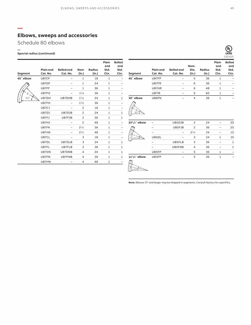
—Special radius (continued)
SegmentPlain end Cat. No.
Belled end Cat. No.
Nom(in.)
Radius(in.)
Plain end Std. Ctn.
Belled end Std. Ctn.
45˚ elbow UB7CF – 1 18 1 –
UB7DF – 1 24 1 –
UB7FF – 1 36 1 –
UB7FG – 11 ⁄4 36 1 –
UB7DH UB7DHB 11 ⁄2 24 1 1
UB7FH – 11 ⁄2 36 1 –
UB7CJ – 2 18 1 –
UB7DJ UB7DJB 2 24 1 1
UB7FJ UB7FJB 2 36 1 1
UB7HJ – 2 48 1 –
UB7FK – 21 ⁄2 36 1 –
UB7HK – 21 ⁄2 48 1 –
UB7CL – 3 18 1 –
UB7DL UB7DLB 3 24 1 1
UB7FL UB7FLB 3 36 1 1
UB7DN UB7DNB 4 24 1 1
UB7FN UB7FNB 4 36 1 1
UB7HN – 4 48 1 –
SegmentPlain end Cat. No.
Belled end Cat. No.
Nom. Dia.(in.)
Radius(in.)
Plain end Std. Ctn.
Belled end Std. Ctn.
45˚ elbow UB7FP – 5 36 1 –
UB7FR – 6 36 1 –
UB7HR – 6 48 1 –
UB7IR – 6 60 1 –
30˚ elbow UB6FN – 4 36 1 –
221/2̊ elbow – UB5DJB 2 24 – 20
– UB5FJB 2 36 – 25
– – 21 ⁄2 24 – 15
UB5DL – 3 24 1 10
– UB5FLB 3 36 – 1
– UB5FNB 4 36 – 1
UB5FP – 5 36 1 –
111/4̊ elbow UB3FP – 5 36 1 –
Note: Elbows 72" and larger may be shipped in segments. Consult factory for specifics.
R30°
R11.25°
R22.5°
E323335
R
45°
—Elbows, sweeps and accessoriesSchedule 80 elbows
49EL B OW S , S W EEP S A N D ACCE SSO R I E S

Cat. No. Size (in.) Std. Ctn.
E943F 1 50
E943H 11 ⁄2 25
E943J 2 50
E943L 3 50
E943N 4 20
E943P 5 5
E943R 6 10
Cat. No. Size (in.) Std. Ctn.
E997F 1 50
E997H 11 ⁄2 30
E997J 2 40
E997L 3 50
E997N 4 30
E997P 5 15
E997R 6 10
Cat. No. Size (in.) Std. Ctn.
E252LJ 3 x 2 50
E252NJS 4 x 2 25
E252NL 4 x 3 25
E252PN 5 x 4 20
E252RNS 6 x 4 6
E252RP 6 x 5 10
Cat. No. Size (in.) Std. Ctn.
E297JN 2 x 4 25
E297NT 4 x 10 15
E297PS 5 x 8 10
E297PT 5 x 10 10
E297RF 6 x 5 10
Cat. No. Size (in.) Std. Ctn.
E299JM 2 x 42 1
E299JR 2 x 78 1
E299NX7 4 x 84 1
Cat. No. Size (in.) Std. Ctn.
E297RR 6 (6 long) 10
Cat. No. Size (in.) Std. Ctn.
E942F 1 50
E942H 11 ⁄2 25
E942J 2 30
E942L 3 25
E942N 4 15
E942P 5 8
E942R 6 6
Cat. No. Size (in.) Std. Ctn.
E297J 2 40
E297L 3 50
E297N 4 30
E297P 5 15
—Elbows, sweeps and accessoriesP&C duct adapters
—P&C duct end bells
—P&C duct swedge reducer (male x male)
—P&C duct cable marker
—Male adapter
—End bell
—Female adapter
—Molded end bell
—Fabricated end bell
—Long-length end bell P&C duct
50 C A R LO N P VC CO N D U IT, EL B OW S A N D FIT TI N G S

—Split sleeve coupling
—Split sleeve sweeps
Cat. No. Size (in.) Description Length (in.) Split Std. Ctn. Std. Wt. (lbs.)
Schedule 40 and 80
E200JS6 2 Split coupling 6 1 25 6.1
E200KS7 21 ⁄2 Split coupling 7 1 25 21
E200LS7 3 Split coupling 7 1 25 15.5
E200LSS* 3 Split coupling 6.5 1 25 10
E200MS8 31 ⁄2 Split coupling 8 1 25 41.2
E200NS8 4 Split coupling 8 1 15 16
E200NSS* 4 Split coupling 6 2 25 17
E200PS8 5 Split coupling 8 1 15 25
E200PS9 5 Split coupling 9 1 8 16.4
E200RS1 6 Split coupling 10 1 6 24.2
C Duct
E900NS8 (White) 4 C Duct split coupling 8 1 15 19
E900NSW (White) 4 C Duct split coupling 6 1 25 22
* Two-piece design
Cat. No. Cat. No. Nom. Size (in.) Radius (in.) Std. Ctn. Std. Wt. (lbs.)
45° Sweep UA7DJSD 2 24 1 1.4
UA7FJSD 2 36 1 2.1
UA7FLSD 3 36 1 4.7
UA7HLSD 3 48 1 6.1
UA7IJSD 2 60 1 3.2
UA7ILSD 3 60 1 7.2
UA7INSD 4 60 1 10.2
221 ⁄2̊ sweep UA5INSD 4 60 1 6.1
111 ⁄4° Sweep UA3IJSD 2 60 1 1
UA3INSD 4 60 1 5.1
Two 45° elbows may be segmented for 90°.
—Elbows, sweeps and accessoriesSplit sleeve coupling
Split sleeve coupling For joining split duct to existing duct.
51EL B OW S , S W EEP S A N D ACCE SSO R I E S
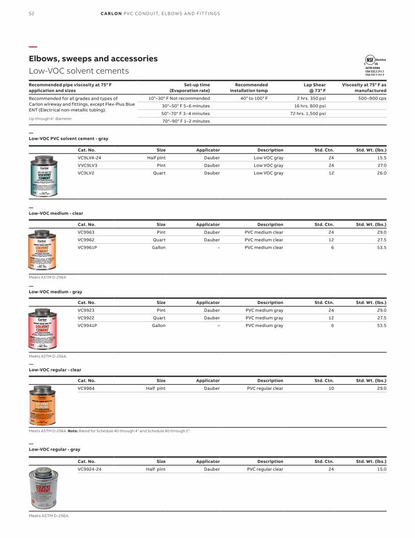
Cat. No. Size Applicator Description Std. Ctn. Std. Wt. (lbs.)
VC9LV4-24 Half pint Dauber Low VOC gray 24 15.5
VVC9LV3 Pint Dauber Low VOC gray 24 27.0
VC9LV2 Quart Dauber Low VOC gray 12 26.0
—Low-VOC PVC solvent cement - gray
Recommended pipe viscosity at 75° F application and sizes
Set-up time (Evaporation rate)
Recommended installation temp
Lap Shear @ 73° F
Viscosity at 75° F as manufactured
Recommended for all grades and types of Carlon wireway and fittings, except Flex-Plus Blue ENT (Electrical non-metallic tubing).
10°–30° F Not recommended 40° to 100° F 2 hrs. 350 psi 500–900 cps
30°–50° F 5–6 minutes 16 hrs. 800 psi
50°–70° F 3–4 minutes 72 hrs. 1,500 psi
70°–90° F 1–2 minutes
—Elbows, sweeps and accessoriesLow-VOC solvent cements
Up through 6" diameter.
Cat. No. Size Applicator Description Std. Ctn. Std. Wt. (lbs.)
VC9963 Pint Dauber PVC medium clear 24 29.0
VC9962 Quart Dauber PVC medium clear 12 27.5
VC9961P Gallon – PVC medium clear 6 53.5
—Low-VOC medium - clear
Meets ASTM D-2564.
Cat. No. Size Applicator Description Std. Ctn. Std. Wt. (lbs.)
VC9923 Pint Dauber PVC medium gray 24 29.0
VC9922 Quart Dauber PVC medium gray 12 27.5
VC9941P Gallon – PVC medium gray 6 53.5
—Low-VOC medium - gray
Meets ASTM D-2564.
Cat. No. Size Applicator Description Std. Ctn. Std. Wt. (lbs.)
VC9964 Half pint Dauber PVC regular clear 10 29.0
Cat. No. Size Applicator Description Std. Ctn. Std. Wt. (lbs.)
VC9924-24 Half pint Dauber PVC regular clear 24 15.0
—Low-VOC regular - clear
—Low-VOC regular - gray
Meets ASTM D-2564. Note: Rated for Schedule 40 through 4" and Schedule 80 through 2".
Meets ASTM D-2564.
52 C A R LO N P VC CO N D U IT, EL B OW S A N D FIT TI N G S

Cat. No. Size Applicator Std. Ctn. Std. Wt. (lbs.)
VC9903 Pint Dauber 24 27.0
VC9902 Quart Dauber 12 25.0
Cat. No. Size Applicator Std. Ctn. Std. Wt. (lbs.)
VC9932 Quart Dauber 12 25.0
Cat. No. Size Applicator Description Std. Ctn. Std. Wt. (lbs.)
VC9984 Half Pint Dauber All weather “Quick-Set” cement 10 7
VC9983 Pint Dauber All weather “Quick-Set” cement 24 30
VC9982 Quart Dauber All weather “Quick-Set” cement 12 29
VC9981P Gallon — All weather “Quick-Set” cement 6 54
Recommended pipe application and sizes Recommended installation temp
Recommended for use with Carlon cement 5° to 100° F
Recommended pipe viscosity at 75° F application and sizes
Set-up time (Evaporation rate)
Recommended installation temp
Lap Shear @ 73° F
Viscosity a t 75° F as manufactured
Recommended for all grades and types of Carlon wireway and fittings, except Flex-Plus Blue ENT (Electrical Non-Metallic Tubing).
-5°–10° F 6–8 minutes -5° to 100° F 2 hrs. 350 psi 400–700 cps
10°–30° F 4–5 minutes 16 hrs. 800 psi
30°–50° F 3–4 minutes 72 hrs. 1,500 psi
50°–70° F 1–2 minutes
70°–90° F 1 ⁄2–11 ⁄2 minutes
—Elbows, sweeps and accessoriesPrimers and Low-VOC "Quick-Set" cement
—Clear primer
—Purple primer
—Low-VOC All Weather - clear
Up through 6" diameter.
Meets ASTM F-686.
Meets ASTM F-686.
Meets ASTM D-2564.
53EL B OW S , S W EEP S A N D ACCE SSO R I E S
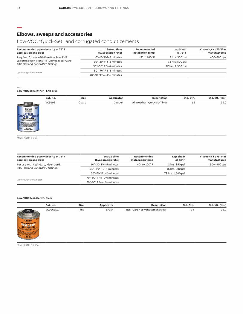
Cat. No. Size Applicator Description Std. Ctn. Std. Wt. (lbs.)
VC9992 Quart Dauber All Weather “Quick-Set” blue 12 29.0
Cat. No. Size Applicator Description Std. Ctn. Std. Wt. (lbs.)
VC9963SC Pint Brush Resi-Gard® solvent cement clear 24 28.0
—Elbows, sweeps and accessoriesLow-VOC "Quick-Set" and corrugated conduit cements
—Low-VOC all weather - ENT Blue
—Low-VOC Resi-Gard®- Clear
Up through 6" diameter.
Up through 6" diameter.
Meets ASTM D-2564.
Meets ASTM D-2564.
Recommended pipe viscosity at 75° F application and sizes
Set-up time (Evaporation rate)
Recommended installation temp
Lap Shear @ 73° F
Viscosity a t 75° F as manufactured
Required for use with Flex-Plus Blue ENT (Electrical Non-Metall ic Tubing), Riser-Gard, P&C Flex and Carlon PVC fittings.
-5°–10° F 6–8 minutes -5° to 100° F 2 hrs. 350 psi 400–700 cps
10°–30° F 4–5 minutes 16 hrs. 800 psi
30°–50° F 3–4 minutes 72 hrs. 1,500 psi
50°–70° F 1–2 minutes
70°–90° F 1 ⁄2–11 ⁄2 minutes
Recommended pipe viscosity at 75° F application and sizes
Set-up time (Evaporation rate)
Recommended installation temp
Lap Shear @ 73° F
Viscosity a t 75° F as manufactured
For use with Resi-Gard, Riser-Gard, P&C Flex and Carlon PVC fittings.
10°–30° F 4–5 minutes 40° to 100° F 2 hrs. 350 psi 500–900 cps
30°–50° F 3–4 minutes 16 hrs. 800 psi
50°–70° F 1–2 minutes 72 hrs. 1,500 psi
70°–90° F 1 ⁄2–11 ⁄2 minutes
70°–90° F 1 ⁄2–11 ⁄2 minutes
Up through 6" diameter.
Up through 6" diameter.
54 C A R LO N P VC CO N D U IT, EL B OW S A N D FIT TI N G S

EL B OW S , S W EEP S A N D ACCE SSO R I E S
Carlon non-metallic products are joined by means of solvent cement joints. Sizes 1 ⁄2" through 11 ⁄2" should be cut square (using a fine-tooth handsaw) and deburred. For sizes 2" through 6", a miter box or similar saw guide should be utilized to keep the material steady. After cutting and deburring, wipe ends clean of dust, dirt and shavings.
Joining process as follows:• Be sure that conduit end is clean and dry.• Apply coat of Carlon Solvent Cement (use dauber) to
end of conduit for the length of the socket to be attached.
• Push conduit firmly into fitting while rotating conduit slightly, about one-quarter turn to spread cement evenly.
• Allow joint to set approximately 10 minutes.
Carlon recommends the use of Carlon cement for proper solvent cement joints. Because this cement is prepared particularly for our product compounds and tolerances, we cannot guarantee joints assembled with cement materials supplied by other manufacturers. Regular-grade gray solvent cement will accommodate most application situations being of a general-purpose nature. In situations requiring an extremely fast-setting joint (low temperature or difficult installation conditions), Carlon All Weather Quick-Set Cement is recommended.Standard-grade clear cement is recommended for non-critical utility applications where gap filling and leak testing are not required.
—Elbows, sweeps and accessoriesInstallation instructions - cement joints
—01 Cementing PVC conduit: 1. Make square saw cut with fine-tooth saw.2. Deburr and round inside edge of the cut end.3. Clean socket I.D. and spigot O.D. of dirt and moisture.4. Apply a uniform coat of cement to spigot end and push onto socket bottom, rotating 1 ⁄4 turn.5. Allow time to set before disturbing. Setting time will depend upon temperature.
— 02 Cementing PVC conduit: for submerged areas requiring air or water tightness:1. Follow the procedure above for cementing conduit.2. Test workmanship by conducting a low pressure air (3.0–5.0 psi) test after system is installed and cemented joints are set.3. Plug and block ends to prevent movement prior to pressurization.4. Check for leaks with soap solution.5. Even low pressure air can cause high-thrust loads and caution must be observed.
— 03 Cementing ENT for concrete-tight applications:1. Use Carlon socket tight fittings or couplings.2. Do not use chemical primer or cleaner.3. Apply a light uniform coat of cement labeled for use with ENT.4. Use a brush to apply the cement.5. Brush excess cement out of ENT grooves.6. Promptly insert ENT into fitting while cement is wet until the fitting stop is reached and give 1 ⁄4 turn.7. Do not disturb until the joint is set.
Trade size(in.)
1 ⁄2 Pint8 oz.
Pint 16 oz.
Quart32 oz.
Gallon 128 oz.
1 ⁄2 140 275 550 2,2003 ⁄4 90 180 360 1,440
1 70 140 280 1,120
11 ⁄4 50 100 200 800
11 ⁄2 37 75 150 600
2 20 40 80 320
21 ⁄2 17 35 70 280
3 15 30 60 240
31 ⁄2 13 27 54 216
4 12 25 50 200
5 9 19 38 150
6 6 12 24 95
Can: Average shelf life of all Carlon cement is 24 months (unopened cans stored below 80° F). All Carlon cements are specially formulated to be used with Carlon PVC products, and do not require primers when parts are clean of dirt and moisture. MSDS available at www.carlon.com.
—Average number of joints per can
—02
—01
55

—Elbows, sweeps and accessoriesInstallation instructions - fittings and adapters for terminating non-metallic rigid conduit
Terminating non-metallic rigid conduit is quick and easy utilizing either of the methods indicated below. Terminations may be made in any electrical box or enclosure using standard size knockouts or drilled holes.
—
Method 1. Permanent termination
Apply solvent
Apply solvent cement to shoulder and shank of box adapter and insert through knockout from inside the enclosure. Push coupling over the shank of the box adapter, tight against the enclosure wall. Rotate the coupling about one-half turn while installing, and hold in position for a few seconds to permit setting of solvent cement. The coupling is now ready for theconduit to be installed. Only the shoulder of the box adapter extends inside the enclosure.
—
Method 2. Separable termination
If a “wet location” as defined in Article 100 of the NEC® construction is required, place a flat washer or O-ring over the threads of the terminal adapter, securely against the shoulder. Insert the adapter threads through knockout and secure using either a standard locknut or threaded bushing. If watertight construction is not required, eliminate flat washer.
—PVC Conduit cutters
E940Coupling
E943Terminal adapter
E996Box adapter
Locknutor bushing
PVC conduit
PVC conduit
E943_W Flat washer or O-Ring
Cat. No. Size (in.) Std. Ctn.
CC120B 8 10
—Small cutter - For fast, smooth field cuts of 1 ⁄2" through 1"non-metallicrigid conduit, Flex-Plus Blue ENT and Carflex liquidtight flexible non-metallic conduit.
56 C A R LO N P VC CO N D U IT, EL B OW S A N D FIT TI N G S

—White diamond braid rope
—Tape
Cat. No.
ReelLengths
(ft.)Diameter
(in.)
RecommendedWorking Load
(in.)
ApproximateAvg. Tensile
(lbs.)
Approximate Std. Wt.
(lbs.)
SB14105 5,000 1 ⁄4 260 1,700 1,000
Cat. No. Size (in.) Tensile strength (lbs.) Reel lengths (ft.)
TL14203 1 ⁄2 1,130 3,000
TL14505 1 ⁄2 1,250 5,000
TL14510 1 ⁄2 1,250 10,000
TL38203 5⁄8 1,800 3,000
TL38265 5⁄8 1,800 6,500
TL38210 5⁄8 1,800 10,000
—Elbows, sweeps and accessoriesConduit pulling lines for conductors or fiber optics
This rope is constructed of polyethylene over polyester, designed specifically for fiber optic pulling. The polyethylene jacket has a “slippery” feel that gives less drag in pulling through conduit.
Pre-lubricated, woven polyester tape made from low-friction, high abrasion-resistant yarns, provides a low coefficient of friction. Tape is printed with sequential footage markings for accurate measurements.
57EL B OW S , S W EEP S A N D ACCE SSO R I E S

E945 series expansion fittings are designed to compensate for length changes due to temperature variations in exposed conduit runs.
Features and benefits:• Exclusive molded-in mid-point indicator on the
piston• Exclusive 2" expansion fitting with an 8" travel
distance• Two-piece molded design with lubricated seals for
easier movement for the life of the product• Ridges on the fitting for easier installation
(sizes 2"–6" only)• Male terminal adapter end design (1 ⁄2"–2" NPT
Threads and 21 ⁄2"–6" NPSC threads)• Two O-rings to prevent leakage• Can be installed vertically or horizontally
Cat. No.
Male terminal adapter endCat. No. Size (in.) Std. Ctn. Travel length (in.)
E945D E945DX 1 ⁄2 20 4
E945E E945EX 3⁄4 15 4
E945F E945FX 1 10 4
E945G E945GX 11 ⁄4 5 4
E945H E945HX 11 ⁄2 5 4
E945J E945JX 2 15 8
E945K E945KX 21 ⁄2 10 8
E945L E945LX 3 10 8
E945M E945MX 31 ⁄2 5 8
E945N E945NX 4 5 8
E945P E945PX 5 1 8
E945R E945RX 6 1 8
Cat. No. Size (in.) Std. Ctn.
E955D 1 ⁄2 40
E955E 3⁄4 40
E955F 1 25
E955G 11 ⁄4 15
E955H 11 ⁄2 10
E955J 2 6
—Expansion fittings
—Short expansion couplings - Expand to a maximum of 2"
E23018
E23018
Coupling end
Male terminaladapter end
—Conduit bodies and fittingsFor use with Schedule 40 and 80 conduit
58 C A R LO N P VC CO N D U IT, EL B OW S A N D FIT TI N G S

Cat. No.Size (in.)
Std. Ctn.
Typical (in.) I.D. (in.)
O.D. (in.)
Typical (in.)
A B C L
E940D 1 ⁄2 150 .852 .836 .728 17⁄64 11 ⁄16 11 ⁄2
CE940DR-CTN 1 ⁄2 75 .852 .836 .728 17⁄64 11 ⁄16 11 ⁄2
E940E 3⁄4 100 1.064 1.046 .840 15⁄16 3 ⁄4 15 ⁄8
CE940ER-CTN 3⁄4 45 1.064 1.046 .840 15⁄16 3 ⁄4 15 ⁄8
E940F 1 50 1.330 1.310 1.210 15⁄8 15⁄16 2
CE940F-UPC 1 50 1.330 1.310 1.210 15⁄8 15⁄16 2
E940G 11 ⁄4 30 1.677 1.655 1.535 163 ⁄64 1 21 ⁄8
E940H 11 ⁄2 25 1.918 1.894 1.755 215⁄64 11 ⁄8 21 ⁄8
E940J 2 30 2.393 2.369 2.190 247⁄64 13 ⁄16 21 ⁄2
E940K 21 ⁄2 20 2.890 2.868 2.688 35⁄16 133 ⁄64 33 ⁄16
E940L 3 25 3.515 3.492 3.375 331 ⁄32 13 ⁄4 313 ⁄32
E940M 31 ⁄2 20 4.015 3.992 3.780 49⁄16 13 ⁄4 33 ⁄8
E940N 4 15 4.515 4.491 4.265 53⁄32 125 ⁄32 33 ⁄4
E940P 5 8 5.593 5.553 5.097 61 ⁄4 15 ⁄16 41 ⁄16
E940R 6 5 6.658 6.614 6.115 71 ⁄2 23 ⁄16 45⁄8
Canada only.
Cat. No.
Size (in.)
Std. Ctn.
Travel length (in.)
E945KXL 21 ⁄2 10 12
—Special long-line couplings (with conduit stop)
—Standard couplings
—Fabricated expansion couplings E23018
A
C
LI.D.
O.D.
B
LR33856
E23018Except where noted by
Socket type for joining non-metallic conduit.
Cat. No.
Size (in.)
Std. Ctn.
Std. Wt. (lbs.)
Length (in.)
E941H 11 ⁄2 40 9 3.19
E941J 2 25 8 3.59
E941K 21 ⁄2 15 8 4.29
E941L 3 15 14 6.44
E941N 4 10 15 6.96
E941PF 5 4 12 9.63
E941RF 6 5 21 11.75
—Conduit bodies and fittingsFor use with Schedule 40 and 80 conduit
All socket fittings should be attached using Carlon solvent cement.
59CO N D U IT B O D I E S A N D FIT TI N G S

Cat. No.
Size (in.)
Std. Ctn.
Std. Wt.(lbs.)
E442R 6 6 27
E442T 8 2 17
—Special Schedule 40 swedge couplings
E23018Except where noted by
—Conduit bodies and fittingsFor use with Schedule 40 and 80 conduit
Cat. No.
Size (in.)
Std. Ctn.
Std. Wt. (lbs.)
Length (in.)
E948H 11 ⁄2 25 6 4
E948J 2 25 5 3
E948K 21 ⁄2 25 16 6
E948L 3 25 13 4
E948N 4 10 8 6.5
E948P 5 14 33 7
E948R 6 6 16 6
E948JR 2 15 8 6
E948JS 2 (Sch. 40 split duct) 25 6 —
E948KS7 21⁄2 (Sch. 40 split duct) 25 19 7
E948L12 3 1 1 12
E948L6 3 15 15 6
E948LS 3 (Sch. 40 split duct) 25 17 —
E948N12 4 10 28 12
E948N7 4 15 25 7
E948NS 4 (Sch. 40 split duct) 10 15 —
E948PS 5 (Sch. 40 split duct) 1 2 —
E948R10 6 6 25 10
E948R12 6 6 25 12
E948RS 6 (Sch. 40 split duct) 1 2 —
—Special long-line sleeve couplings
Sleeve coupling (For repair work)No internal stop
Cat. No.Size (in.)
A (in.)(Length)
B (in.)
C(in.)
Thread size(in.)
Std. Ctn.
Std. Wt.(lbs.)
E954HX 11 ⁄2 80 1.567 .950 11 ⁄2 NPT 1 3.8
E954J 2 60 2.024 .825 2 NPT 1 3.7
E954JX 2 80 2.024 .825 2 NPT 1 5
E954K 21 ⁄2 60 2.418 .812 21 ⁄2 NPSC 1 6
E954KX 21 ⁄2 80 2.418 .812 21 ⁄2 NPSC 1 8.4
E954L 3 60 3.616 .798 3 NPSC 1 8.7
E954LX 3 80 3.616 .798 3 NPSC 1 11
—Schedule 40 risers
Thread Size
AC
Ref
B (I.D.)
60 C A R LO N P VC CO N D U IT, EL B OW S A N D FIT TI N G S

—Conduit bodies and fittingsFor use with Schedule 40 and 80 conduit
Cat. No.Size (in.)
Std. Ctn.
Typical (in.) Min. D (in.)
Max. O.D. (in.)
Typical (in.)
A B C S L
E942D 1 ⁄2 150 .852 .836 .620 17⁄64 11 ⁄16 3 ⁄4 19⁄16
E942E 3⁄4 100 1.064 1.046 .822 15⁄16 13 ⁄16 3 ⁄4 15 ⁄8
E942F 1 50 1.330 1.310 1.046 15⁄8 15 ⁄16 7⁄8 115 ⁄16
E942G 11 ⁄4 30 1.677 1.655 1.377 163 ⁄64 1 7⁄8 2
E942H 11 ⁄2 25 1.918 1.894 1.607 25⁄32 11 ⁄8 7⁄8 27⁄32
E942J 2 30 2.393 2.369 2.064 247⁄64 13 ⁄16 1 25⁄16
E942K 21 ⁄2 20 2.890 2.868 2.450 311 ⁄32 15⁄8 11 ⁄8 215 ⁄16
E942L 3 25 3.515 3.492 3.000 331 ⁄32 13 ⁄4 11 ⁄8 31 ⁄16
E942M 31 ⁄2 20 4.015 3.992 3.500 41 ⁄2 17⁄8 11 ⁄8 31 ⁄4
E942N 4 15 4.515 4.491 4.000 51 ⁄64 13 ⁄4 11 ⁄16 313 ⁄64
E942NX9* 4 15 (Call for information)
E942P 5 8 5.593 5.553 5.047 61 ⁄4 115 ⁄16 11 ⁄16 33 ⁄16
E942R 6 6 6.658 6.614 6.055 71 ⁄4 21 ⁄8 11 ⁄16 33 ⁄8
E942RX* 6 6 (Call for information)
* Long-Line Adapter
Cat. No.Size (in.)
Std. Ctn.
Typical (in.) Min. D (in.)
Max. O.D. (in.)
Typical (in.)
A B C S L
E943D 1 ⁄2 150 .852 .836 .594 1.042 .652 .545 1.310
E943E 3⁄4 125 1.064 1.046 .793 1.290 .809 .553 1.470
E943F 1 50 1.330 1.310 1.025 1.580 .965 .812 1.902
E943G 11 ⁄4 50 1.677 1.655 1.345 1.973 1.208 .816 1.986
E943H 11 ⁄2 25 1.918 1.894 1.574 2.188 1.155 .802 2.105
E943J 2 50 2.393 2.369 1.998 2.713 1.145 .825 2.093
E943K 21 ⁄2 25 2.890 2.868 2.400 3.290 1.490 .812 2.480
E943L 3 45 3.515 3.492 2.989 3.965 1.643 .797 2.660
E943M 31 ⁄2 30 4.015 3.992 3.405 4.515 1.720 .802 2.740
E943N 4 20 4.515 4.491 3.895 5.065 1.788 .733 2.830
E943P 5 5 5.593 5.553 4.900 6.104 1.935 .990 3.200
E943R 6 10 6.658 6.614 5.900 7.288 2.128 .985 3.410
—Female adapters
—Male terminal adapters
LR031146E23018Except where noted by
For adapting non-metallic conduits to threaded fittings, metallic systems. Female threadson one end, socket end on other.
For adapting non-metallic conduits to boxes, threaded fittings, metallic systems. Male threads on oneend, socket end on other.
A
C
T
L
O.D.
B
D
B
L
C
A D
S
OD
61CO N D U IT B O D I E S A N D FIT TI N G S

—Conduit bodies and fittingsFor use with Schedule 40 and 80 conduit
E23018
E23018E23018
Except where noted by
Except where noted by
Except where noted by
Adapts non-metallic conduit to all electrical enclosures by insertingadapter through knockout and cementing into Carlon couplings.
Cat. No.Size (in.)
Std. Ctn.
Min. D (in.)
OD (in.) Typical
Max. X (in.)
CM (in.) Typical
L (in.) Typical
E996D 1 ⁄2 100 .662 0.840 17⁄64 23 ⁄32 27⁄32
E996E 3⁄4 100 .824 1.050 121 ⁄64 25⁄32 29⁄32
E996F 1 100 1.049 1.315 15⁄8 61 ⁄64 13 ⁄32
E996G 11 ⁄4 50 1.380 1.660 131 ⁄32 11 ⁄16 11 ⁄4
E996H 11 ⁄2 50 1.610 1.900 213 ⁄64 13 ⁄16 13 ⁄8
E996J 2 25 2.067 2.375 229⁄32 11 ⁄4 17⁄16
E996K 21 ⁄2 15 2.469 2.875 37⁄16 17⁄8 115 ⁄16
E996L 3 20 3.068 3.500 41 ⁄8 2 21 ⁄16
E996N 4 10 4.026 4.500 51 ⁄8 21 ⁄2 21 ⁄4
—Box adapters for enclosures
L
X
D
CM
O.D.
Cat. No.
Size (in.)
Std. Ctn.
E9842D 1 1 ⁄2 25
E9842E 2 3 ⁄4 251 Fits 3 ⁄4" sockets2 Fits 1" sockets
Cat. No.
Size (in.)
Std. Ctn.
Std. Wt.(lbs.)
E971C 3 ⁄4 x 1 ⁄2 100 2
E971D 1 x 3 ⁄4 100 3
Cat. No.
Size (in.)
Std. Ctn.
Std. Wt.(lbs.)
P258JT 2 60 3
P258LT 3 30 3
P258NT 4 48 8
P258PT 5 30 6
P258RT 6 30 9
Cat. No.
Size (in.)
Std. Ctn.
Std. Wt.(lbs.)
P258H 11 ⁄2 50 2
P258K 21 ⁄2 25 1.5
—Threaded adapters
—Reducer plugs
—Plugs with pull tabs (Polyethylene)
—Plugs (Polyethylene)
62 C A R LO N P VC CO N D U IT, EL B OW S A N D FIT TI N G S

Cat. No.Size (in.)
Std. Ctn.
L (in.)Typical
A (in.) Typical
C (in.) Typical
E950ED 3⁄4 x 1 ⁄2 100 15⁄32 13 ⁄64 11 ⁄32
E950FD-CAR 1 x 1 ⁄2 25 111 ⁄32 3 ⁄16 57⁄64
E950FE 1 x 3 ⁄4 100 111 ⁄32 3 ⁄16 11 ⁄64
E950GE-CAR 11 ⁄4 x 3 ⁄4 10 115⁄32 3 ⁄16 11 ⁄64
E950GF 11 ⁄4 x 1 50 115⁄32 3 ⁄16 19⁄64
E950HF-CAR 11 ⁄2 x 1 10 119⁄32 3 ⁄16 19⁄64
E950HG-CAR 11 ⁄2 x 11 ⁄4 10 119⁄32 3 ⁄16 117⁄64
E950JG-CAR 2 x 11 ⁄4 10 13⁄4 7⁄32 117⁄64
E950JH-CAR 2 x 11 ⁄2 10 13⁄4 7⁄32 125 ⁄64
E950KJ-CAR 21 ⁄2 x 2 10 25⁄32 3 ⁄8 127⁄64
E950LJ-CAR 3 x 2 10 21 ⁄8 1 ⁄4 17⁄8
E950LK 3 x 21 ⁄2 25 115⁄16 1 ⁄4 111 ⁄16
E950NL 4 x 3 25 23⁄4 5 ⁄16 115 ⁄16
Size (in.)
Std. Ctn.
Dimensions (in.)
Cat. No. E F G H
E998D 1 ⁄2 5 1.76 .45 .45 –
E998E 3⁄4 20 1.76 .45 .45 –
E998E-CAR 3⁄4 5 1.76 .45 .45 –
E998F 1 15 2.26 .59 .58 –
E998F-CAR 1 5 2.26 .59 .58 –
E998G-CAR 11 ⁄4 5 3.52 .74 .71 .50
E998H-CAR 11 ⁄2 5 3.52 .74 .71 .50
E998J-CAR 2 5 4.26 .83 .78 .56
E998K-UPC 21 ⁄2 2 7.47 1.70 1.31 1.00
E998L 3 2 7.47 1.70 1.31 1.00
E998N 4 2 10.45 2.25 1.88 1.31
—Reducer bushings
—Service entrance caps (Vertical applications only)
L
A
C
Cat. No.
Size (in.)
Std. Ctn.
Std. Wt.(lbs.)
Male x male
E952JH 11 ⁄2 x 2 48 20
E952KJ 21 ⁄2 x 2 48 26
E952LJ 3 x 2 36 21
E952LK 3 x 21 ⁄2 36 32
E952NL 4 x 3 15 21
E952NM 4 x 31 ⁄2 15 25
E952PN 5 x 4 12 27
E952RP 6 x 5 10 31
Male x female
E952NJF 4 x 2 15 16
E952RNF 6 x 4 10 28
Cat. No.
Size (in.)
Std. Ctn.
Std. Wt.(lbs.)
E958D 1 ⁄2 100 3
E958E 3⁄4 100 4
E958F 1 75 5
E958G 11 ⁄4 40 4
E958H 11 ⁄2 30 4
E958J 2 25 5
E958K 21 ⁄2 10 4
E958L 3 10 5
E958N 4 5 17
E958P 5 5 11
E958R 6 5 13
Cat. No.
Size (in.)
Std. Ctn.
Std. Wt.(lbs.)
E935J 2 25 3
E935L 3 25 5
E935N 4 25 7
E935P 5 25 35
E935R 6 10 7
—Fabricated reducers
—End caps
—PVC riser caps
E23018
E23018
E23018
Except where noted by
Except where noted by
Except where noted by
For connecting different sizes of conduit. Bell x Spigot.
E13938
Ø GØ H
E
F 3 PLCS.
Knockouts for
Conductors
—Conduit bodies and fittingsFor use with Schedule 40 and 80 conduit
63CO N D U IT B O D I E S A N D FIT TI N G S
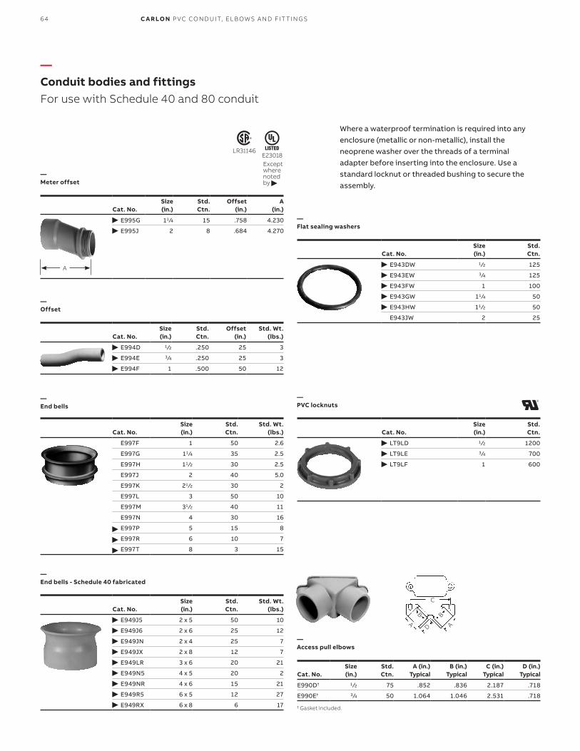
—Conduit bodies and fittingsFor use with Schedule 40 and 80 conduit
Cat. No.Size (in.)
Std. Ctn.
Offset(in.)
A (in.)
E995G 11 ⁄4 15 .758 4.230
E995J 2 8 .684 4.270
Cat. No.Size (in.)
Std. Ctn.
E943DW 1 ⁄2 125
E943EW 3⁄4 125
E943FW 1 100
E943GW 11 ⁄4 50
E943HW 11 ⁄2 50
E943JW 2 25
Cat. No.Size (in.)
Std. Ctn.
LT9LD 1 ⁄2 1200
LT9LE 3⁄4 700
LT9LF 1 600
Cat. No.Size (in.)
Std. Ctn.
A (in.) Typical
B (in.) Typical
C (in.) Typical
D (in.) Typical
E990D† 1 ⁄2 75 .852 .836 2.187 .718
E990E† 3 ⁄4 50 1.064 1.046 2.531 .718
† Gasket included.
Cat. No.Size (in.)
Std. Ctn.
Offset(in.)
Std. Wt.(lbs.)
E994D 1 ⁄2 .250 25 3
E994E 3⁄4 .250 25 3
E994F 1 .500 50 12
Cat. No.Size (in.)
Std. Ctn.
Std. Wt.(lbs.)
E997F 1 50 2.6
E997G 11 ⁄4 35 2.5
E997H 11 ⁄2 30 2.5
E997J 2 40 5.0
E997K 21 ⁄2 30 2
E997L 3 50 10
E997M 31 ⁄2 40 11
E997N 4 30 16
E997P 5 15 8
E997R 6 10 7
E997T 8 3 15
Cat. No.Size (in.)
Std. Ctn.
Std. Wt.(lbs.)
E949J5 2 x 5 50 10
E949J6 2 x 6 25 12
E949JN 2 x 4 25 7
E949JX 2 x 8 12 7
E949LR 3 x 6 20 21
E949N5 4 x 5 20 2
E949NR 4 x 6 15 21
E949R5 6 x 5 12 27
E949RX 6 x 8 6 17
—Meter offset
—Flat sealing washers
—PVC locknuts
—Access pull elbows
—Offset
—End bells
—End bells - Schedule 40 fabricated
A
LR31146E23018Except where noted by
Where a waterproof termination is required into any enclosure (metallic or non-metallic), install the neoprene washer over the threads of a terminaladapter before inserting into the enclosure. Use a standard locknut or threaded bushing to secure the assembly.
C
B
A
B
AD
64 C A R LO N P VC CO N D U IT, EL B OW S A N D FIT TI N G S

—Conduit bodies and fittingsFor use with Schedule 40 and 80 conduit
—Feature unthreaded hubs and textured lids with foam-in-place gaskets.
Cat. No.Min. O.D.
A (in.)B.
(in.)Std. Ctn.
Std. Wt.(lbs.)
† E92CSH 11 ⁄2 13 ⁄4 20 3† E92CSJ 2 213 ⁄32 25 6† E92CSL 3 313 ⁄32 25 8† E92CSN 4 413 ⁄32 18 8† E92CSP 5 513 ⁄32 15 8† E92CSR 6 613 ⁄32 12 8
Cat. No.Size (in.)
Vol. (cu.in.)
Std. Ctn.
E970CD 1 ⁄2 15.16 15
E970CE 3⁄4 15.16 15
Supplied with four stainless steel cover screws. Diameter 41 ⁄8", thickness 1 ⁄4".Not designed for use with wiring devices or light fixtures.
—HOLFORM Concrete sleeves
—Conduit bodies - Type LB
—Conduit bodies Type X with cover
E23018Except where noted by
LR31146Except where noted by †
HOLFORM™ non-metallic concrete sleeve forms are the easy way to form holes in concrete. They install in seconds with nails, screws or staples and are easily removed. Concrete will not adhere to them. Sleeves are adjustable to any slab thickness.
Four knock-out type socket openings, 90° spacing. Available with 1 ⁄2" or 3⁄4" socket outlets. Includes cover and gasket.Note: Not fixture rated.
8 3⁄4"
A
B GASKET
COVER
PORTS1⁄2"–E970CD3⁄4"–E970CE
4.625(117.48)
2.420(61.47)
Cat. No.Size (in.)
Std. Ctn.
Dimensions (in.)
Typical max. Typical Max. H
Max. Q
Max. W
Vol. Cu.(in.)C L1 L2 L3
E986D 1 ⁄2 25 11 ⁄16 45⁄16 37⁄32 31 ⁄16 15⁄16 111 ⁄32 11 ⁄2 4.0
E986E 3⁄4 15 29⁄32 69⁄32 59⁄32 425 ⁄32 125 ⁄32 13 ⁄4 21 ⁄32 12.0
E986F 1 10 29⁄32 69⁄32 59⁄32 425 ⁄32 125 ⁄32 13 ⁄4 21 ⁄32 12.0
E986G 11 ⁄4 10 13⁄32 731 ⁄32 613 ⁄32 6 25⁄16 21 ⁄2 23 ⁄4 32.0
E986H 11 ⁄2 10 13⁄32 731 ⁄32 613 ⁄32 6 25⁄16 21 ⁄2 23 ⁄4 32.0
E986J 2 10 15⁄32 931 ⁄32 813 ⁄32 71 ⁄4 29⁄16 35⁄32 315 ⁄32 63.0
E986K 21 ⁄2 4 15⁄8 147⁄8 131 ⁄4 1131 ⁄32 33 ⁄4 411 ⁄32 45⁄8 210
E986L 3 4 15⁄8 147⁄8 131 ⁄4 1131 ⁄32 33 ⁄4 411 ⁄32 45⁄8 210
E986M 31 ⁄2 4 125 ⁄32 1723 ⁄32 157⁄8 1417⁄64 47⁄16 511 ⁄32 521 ⁄32 390
E986N 4 4 125⁄32 1723 ⁄32 157⁄8 1417⁄64 47⁄16 511 ⁄32 521 ⁄32 390
Note: Covers are not sold as separate item.
C
HW
Q
L1L2
L3
LR31146E11461Except where noted by
65CO N D U IT B O D I E S A N D FIT TI N G S

—Conduit bodies and fittingsFor use with Schedule 40 and 80 conduit
—Feature unthreaded hubs and textured lids with foam-in-place gaskets.
—Conduit bodies - Type E
—Conduit bodies - Type C
Cat. No.Size (in.)
Std. Ctn.
Dimensions (in.)
Typical max. Typical Max. Q
Max. W
Vol. Cu.(in.)C L1 L2
988D 1 ⁄2 25 1 ⁄16 45⁄16 31 ⁄2 111 ⁄32 11 ⁄2 4.0
E988E 3⁄4 20 29⁄32 611 ⁄32 59⁄32 13 ⁄4 21 ⁄32 12.0
E988F 1 10 29⁄32 611 ⁄32 59⁄32 13 ⁄4 21 ⁄32 12.0
E988G 11 ⁄4 10 13⁄32 8 613 ⁄32 21 ⁄2 23 ⁄4 32.0
E988H 11 ⁄2 10 13⁄32 8 613 ⁄32 21 ⁄2 23 ⁄4 32.0
E988J 2 5 15⁄32 915 ⁄32 813 ⁄32 35⁄32 315⁄32 63.0
Cat. No.Size (in.)
Std. Ctn.
Dimensions (in.)
Typical max. Typical Max. Q
Max. W
Vol. Cu.(in.)C L1 L2
E987D 1 ⁄2 25 11 ⁄16 411 ⁄16 31 ⁄2 111 ⁄32 11 ⁄2 4.0
E987E-CAR 3⁄4 10 29⁄32 67⁄8 532 ⁄64 13 ⁄4 21 ⁄32 12.0
E987F-CAR 1 10 29⁄32 67⁄8 59⁄32 13 ⁄4 21 ⁄32 12.0
E987G 11 ⁄4 10 13⁄32 821 ⁄32 613 ⁄32 21 ⁄2 23 ⁄4 32.0
E987H 11 ⁄2 10 13⁄32 821 ⁄32 613 ⁄32 21 ⁄2 23 ⁄4 32.0
E987J 2 15 15⁄32 105⁄16 813 ⁄32 35⁄32 3115 ⁄32 63.0
W C
Q
L1L2
QH
WC C
L1L2
LR31146
E11461Except where noted by
66 C A R LO N P VC CO N D U IT, EL B OW S A N D FIT TI N G S

—Conduit bodies - Type LR
—Conduit bodies - Type T
—Conduit bodies - Type LL
Cat. No.Size (in.)
Std. Ctn.
Dimensions (in.)
Typical max. Typical Max. H
Max. Q
Max. W
Vol. Cu.(in.)C L1 L2 L3
E985D-CAR 1 ⁄2 10 11 ⁄16 45⁄16 37⁄32 31 ⁄16 15⁄16 111 ⁄32 11 ⁄2 4.0
E985E-CAR 3⁄4 10 29⁄32 69⁄32 59⁄32 425 ⁄32 125 ⁄32 13 ⁄4 21 ⁄32 12.0
E985F 1 10 29⁄32 69⁄32 59⁄32 425 ⁄32 125 ⁄32 13 ⁄4 21 ⁄32 12.0
E985G 11 ⁄4 10 13⁄32 731 ⁄32 613 ⁄32 6 25⁄16 21 ⁄2 23 ⁄4 32.0
E985H-CAR 11 ⁄2 5 13⁄32 731 ⁄32 613 ⁄32 6 25⁄16 21 ⁄2 23 ⁄4 32.0
E985J 2 10 15⁄32 931 ⁄32 813 ⁄32 71 ⁄4 29⁄16 35⁄32 315 ⁄32 63.0
Cat. No.Size (in.)
Std. Ctn.
Dimensions (in.)
Typical max. Typical Max. H
Max. Q
Max. W
Vol. Cu.(in.)C L1 L2 L3
E983D-CAR 1 ⁄2 10 11 ⁄16 411 ⁄16 37⁄32 211 ⁄32 15⁄16 111 ⁄32 11 ⁄2 4.0
E983E 3⁄4 15 29⁄32 67⁄8 59⁄32 47⁄16 125 ⁄32 13 ⁄4 21 ⁄32 12.0
E983F 1 20 29⁄32 67⁄8 59⁄32 37⁄16 125 ⁄32 13 ⁄4 21 ⁄32 12.0
E983G 11 ⁄4 10 13⁄32 821 ⁄32 613 ⁄32 421 ⁄64 25⁄16 21 ⁄2 23 ⁄4 32.0
E983H 11 ⁄2 10 13⁄32 821 ⁄32 613 ⁄32 421 ⁄64 25⁄16 21 ⁄2 23 ⁄4 32.0
E983J 2 10 15⁄32 105⁄16 813 ⁄32 55⁄32 29⁄16 35⁄32 315 ⁄16 63.0
Cat. No.Size (in.)
Std. Ctn.
Dimensions (in.)
Typical max. Typical Max. H
Max. Q
Max. W
Vol. Cu.(in.)C L1 L2 L3
E984D-CAR 1 ⁄2 10 11 ⁄16 45⁄16 37⁄32 21 ⁄16 15⁄16 111 ⁄32 11 ⁄2 4.0
E984E 3⁄4 20 29⁄32 69⁄32 59⁄32 425 ⁄32 125 ⁄32 13 ⁄4 21 ⁄32 12.0
E984F-CAR 1 10 29⁄32 69⁄32 59⁄32 425 ⁄32 125 ⁄32 13 ⁄4 21 ⁄32 12.0
E984G-CAR 11 ⁄4 5 13⁄32 731 ⁄32 613 ⁄32 6 25⁄16 21 ⁄2 23 ⁄4 32.0
E984H 11 ⁄2 10 13⁄32 731 ⁄32 613 ⁄32 6 25⁄16 21 ⁄2 23 ⁄4 32.0
E984J 2 10 15⁄32 99⁄32 813 ⁄32 71 ⁄4 29⁄16 35⁄32 315 ⁄16 63.0
—Conduit bodies and fittingsFor use with Schedule 40 and 80 conduit
—
Feature unthreaded hubs and textured lids with foam-in-place gaskets.
C
H
W
Q
L1L2
L3
LR31146E11461Except where noted by
CC
H
W
Q
L1L2
L3
C
H
W
Q
L1L2
L3
67CO N D U IT B O D I E S A N D FIT TI N G S

Cat. No.
Size H x W x D
(in.)Std. Ctn.
Dimensions (in.) Material
Min. AT
Min. AB
Min. B
Min. C TB TC PVC
Thermo-plastic
Std. Wt.
E989NNJ* 4 x 4 x 2 10 311 ⁄16 35⁄8 N/A 2 0.160 0.155 X 3
E987N* 4 x 4 x 4 10 311 ⁄16 31 ⁄2 N/A 4 0.160 0.155 X 4
E989NNR* 4 x 4 x 6 10 311 ⁄16 33 ⁄8 N/A 6 0.160 0.200 X 5
E989PPJ* 5 x 5 x 2 10 411 ⁄16 41 ⁄2 N/A 2 0.110 0.150 X 3
E987R-CAR* 6 x 6 x 4 2 6 55⁄8 N/A 4 0.190 0.190 X 3
E989RRR-UPC* 6 x 6 x 6 8 55⁄8 53 ⁄8 N/A 6 0.160 0.150 X 14
E989N-CAR 8 x 8 x 4 1 8 8 N/A 4 0.185 0.190 X 2
E989SSX-UPC 8 x 8 x 7 2 721 ⁄32 75⁄16 N/A 7 0.160 0.150 X 6
E989UUN 12 x 12 x 4 3 115⁄8 111 ⁄2 111 ⁄8 4 0.160 0.150 X 12
E989R-UPC 12 x 12 x 6 2 1115⁄16 117⁄8 117⁄16 6 0.265 0.185 X 10
*Gaskets are FIP (foam in place).
Features and benefits:• All Carlon junction boxes are UL Listed/CSA
Certified and maintain a minimum of a NEMA Type 4/4X Rating
• Part numbers with an asterisk (*) are UL Listed and maintain a NEMA Type 6P Rating and Type 4/4X Rating
• Covers are not sold as separate item• Temperature range: -250° F to 125° F• UL94V-2 flammability ratingNote: Not rated for pedestrian traffic.
Non-metallic junction boxes are UL Listed with a NEMA 6P rating per Section 314.29, Exception of the National Electrical Code® and CSA Certified per Section 12 of the Canadian Electrical Code. Manufactured from PVC or PPO thermoplastic molding compound and featuring foam in-place gasketed lids attached with stainless steel screws, these rugged enclosures offer all the corrosion resistance and physical properties you need for direct-burial applications.
Type 6P enclosures are intended for indoor or outdoor use, primarily to provide a degree of protection against contact with enclosed equipment, falling dirt, hose-directed water, entry of water during prolonged submersion at a limited depth and external ice formation.
D
AT
AB
C
TC
TB
W
BH
E11461
—Switch and junction boxesMolded non-metallic junction boxes – 6P rated
Except where noted by
—Molded non-metallic junction boxes – 6P rated
68 C A R LO N P VC CO N D U IT, EL B OW S A N D FIT TI N G S

Dimensions (in.) Std. Wt.(lbs.)Cat. No. A B C D E F G H
EP12128 12 12 8 8.25 1.00 10.5 10.5 12.75 11
EP181812 18 18 12 12.25 1.00 16 16 18.75 21
EP201808 20 18 8 8.25 1.00 18 16 18.75 20
EP202008 20 20 8 8.25 1.00 18 18 20.75 22
EP241808 24 18 8 8.25 1.00 22 16 18.75 24
EP242008 24 20 8 8.25 1.00 21.5 17.5 20.75 25
EP242408 24 24 8 8.25 1.00 21.5 21.5 24.75 29
EP302408 30 24 8 8.25 1.00 27.5 21.5 24.75 34
EP362408 36 24 8 8.25 1.00 33.5 21.5 24.75 39
Std. Wt.(lbs.)Cat. No. Description
ESMFK-1 “CleverMount” Mounting feet (Four feet and fasteners) 5
—Switch and junction boxesLarge PVC junction boxes – NEMA 4X
• Suitable for exposure of up to 90° C• PVC material enables the use of standard solvent
cements for fitting attachment• Junction boxes are available with or without
mounting flanges• Individual mounting feet are available and provided
in kits of four• Custom features such as windows or panel mounts
are available• Custom sizes are also available upon request• Made in the USANote: Not rated for pedestrian traffic.
Large PVC junction boxes are fabricated from Type II PVC sheet using a unique technology. Reduce the use of steel boxes and keep your wiring connections clean, safe and dry using these high-quality, fully gasketed junction boxes.
Features and benefits:• PVC Type II material with “Uni-Body” construction
and penetration welding providing a very strong, durable enclosure
• UL94V-0 flame rating
—Large PVC junction boxes – NEMA 4X
—Accessories
H
E D
A
G
F
B
C
69S W ITCH A N D J U N C TI O N B OX E S

—Switch and junction boxesSingle-gang FS boxes
Cat. No.Size (in.)
Vol. Cu. (in.)
Std. Ctn.
E980DFN 1 ⁄2 19 10
C980DFN-CTN 1 ⁄2 18 12
E980EFN 3⁄4 19 10
C980EFN-CTN 3⁄4 18 12
E980FFN 1 19 18
C980FFN-CTN 1 18 8
E980FFN-CAR 1 19 10
Canada only.
Cat. No.Size (in.)
Vol. Cu. (in.)
Std. Ctn.
E981DFN 1 ⁄2 19 15
C981DFN-CTN 1 ⁄2 18 12
E981EFN 3⁄4 19 15
C981EFN-CTN 3⁄4 18 12
E981FFN 1 19 18
E981FFN-CAR 1 19 10
C981FFN-CTN 1 18 8
Canada only.
Cat. No.Size (in.)
Vol. Cu. (in.)
Std. Ctn.
E982DFN 1 ⁄2 19 10
C982DFN-CTN 1 ⁄2 18 12
E982EFN 3⁄4 19 10
C982EFN-CTN 3⁄4 18 12
E982FFN 1 19 10
C982FFN-CTN 1 18 8
Canada only.
Cat. No.Size (in.)
Vol. Cu. (in.)
Std. Ctn.
E979DFN-CAR 1 ⁄2 19 10
C979DFN 1 ⁄2 18 15
E979EFN-CAR 3⁄4 19 10
C979EFN 3⁄4 18 15
E979FFN 1 19 15
C979FFN 1 18 15
Canada only.
—Type FSE
—Type FSC
—Type FSS
—Type FSCC
E11461LR31146Where noted by
E11461LR31146Where noted by
E11461LR31146Where noted by
E11461LR31146Where noted by
Features and benefits:• For dead-end terminations• All sizes take standard covers and accessories or
devices• Integral mounting feet provide easy mounting
Features and benefits:• For through terminations• All sizes take standard covers and accessories or
devices• Integral mounting feet provide easy mounting
5.70 (144.78)
3.281 (83.34)
2.27 (57.5)
5.24 (133.1)
2.80 (71.1)
Ø.20 (5.1)
4.54 (115.3)
.43 (11)
“B”
DIA. TO FIT DESIGNATED
CONDUIT SIZE
.938 (23.83)
2.3061.5
Features and benefits:• For multiple dead-end circuit terminations or where
additional support is required in stub-up applications
• All sizes take standard covers and accessories or devices
• Integral mounting feet provide easy mounting
Features and benefits:• For multiple through-circuit terminations or where
additional support is required in stub-up applications
• All sizes take standard covers and accessories or devices
• Integral mounting feet provide easy mounting
5.70 (144.78)
3.281 (83.34)
2.27 (57.5)
5.24 (133.1)
DIA. TO FIT DESIGNATED
CONDUIT SIZE
.938 (23.83)
4.54 (115.3)
.43 (11)
.43 (11)
“B”
2.3061.5
TYP
DIA. TO FIT DESIGNATED
CONDUIT SIZE
2.871.1
0.938 23.8
4.54 115.3
2.42 61.5
0.43 10.9
0.43 11
3.37 85.7
3.87 98.4
2.87 73 0.2
5.1Ø
TYP
DIA. TO FIT DESIGNATED
CONDUIT SIZE
2.871.1
0.938 23.8
2.42 61.5
3.37 85.7
3.87 98.4
2.87 73
0.2 5.1Ø
3.281 83.3
4.54 115.3
0.43 10.9
3.281 83.3
70 C A R LO N P VC CO N D U IT, EL B OW S A N D FIT TI N G S
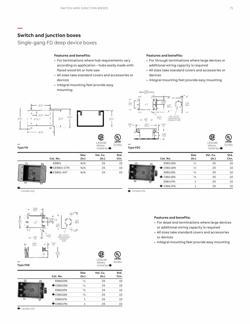
—Switch and junction boxesSingle-gang FD deep device boxes
Cat. No.Size (in.)
Vol. Cu. (in.)
Std. Ctn.
E9801 N/A 25 10
CE9801-CTN N/A 25 10
C9801-347 N/A 25 10
Canada only.
Cat. No.Size (in.)
Vol. Cu. (in.)
Std. Ctn.
E9811DN 1 ⁄2 25 10
C9811DN 1 ⁄2 25 10
E9811EN 3⁄4 25 10
C9811EN 3⁄4 25 10
E9811FN 1 25 10
C9811FN 1 25 10
Canada only.
Cat. No.Size (in.)
Vol. Cu. (in.)
Std. Ctn.
E9801DN 1 ⁄2 25 10
C9801DN 1 ⁄2 25 10
E9801EN 3⁄4 25 10
C9801EN 3⁄4 25 10
E9801FN 1 25 10
C9801FN 1 25 10
Canada only.
—Type FD
—Type FDC
—Type FDE
E11461 E11461LR31146Where noted by
LR31146Where noted by
LR31146Where noted by
Features and benefits:• For terminations where hub requirements vary
according to application – hubs easily made with flared wood bit or hole saw
• All sizes take standard covers and accessories or devices
• Integral mounting feet provide easy mounting
Features and benefits:• For through terminations where large devices or
additional wiring capacity is required• All sizes take standard covers and accessories or
devices• Integral mounting feet provide easy mounting
Features and benefits:• For dead-end terminations where large devices
or additional wiring capacity is required• All sizes take standard covers and accessories
or devices• Integral mounting feet provide easy mounting
E11461
2 7⁄8"
2 7⁄8"
4 5⁄8"
2 17⁄32" 2 7⁄8" 2 3⁄4"37⁄8"33⁄8"
CL
DIA. TO FIT DESIGNATED
CONDUIT SIZE
TYP
3.281 83.3
2.8 71.1
0.43 11
2.99 75.9
3.37 85.7
3.87 98.4
4.54 115.3
2.87 73
0.938 23.8
0.2 5.1Ø
DIA. TO FIT DESIGNATED
CONDUIT SIZE
3.281 83.3
2.8 71.1
0.43 11
0.43 11
2.99 75.9
3.37 85.7
3.87 98.4
4.54 115.3
2.87 73
0.2 5.1Ø
0.938 23.8
71S W ITCH A N D J U N C TI O N B OX E S

—Switch and junction boxesTwo-gang FS boxes
—Blank covers
Cat. No. Size (in.) Vol. Cu. (in.) Std. Ctn.
E9812D 1 ⁄2 32 10
CE9812D-CTN 1 ⁄2 32 10
E9812E 3⁄4 32 10
CE9812E-CTN 3⁄4 32 10
E9812F 1 32 10
C9812F 1 32 10
Canada only.
Cat. No. Size (in.) Vol. Cu. (in.) Std. Ctn.
E9802D 1 ⁄2 32 10
CE9802D-CTN 1 ⁄2 32 10
E9802E 3⁄4 32 10
CE9802E-CTN 3⁄4 32 10
E9802F 1 32 10
C9802F 1 32 1
Canada only.
Cat. No. Color Std. Ctn. Std. Wt. (lbs.)
E980CN-CAR Gray 12 1.60
E980CM-CAR White 12 1.60
Cat. No. Color Std. Ctn. Std. Wt. (lbs.)
E9802CN-CAR Gray 10 2.17
Cat. No. Size (in.) Vol. Cu. (in.) Std. Ctn.
E9802 N/A 32 10
CE9802 N/A 32 10
Canada only.
—Type 2FSC
—Type 2FSE
—Single-gang
—Two-gang
—Type FS
E11461 E11461LR31146Where noted by
LR31146Where noted by
LR31146Where noted by
Features and benefits:• For through terminations where two devices or
additional wiring capacity is required• All sizes take standard covers and accessories or
devices• Integral mounting feet provide easy mounting
Features and benefits:• For dead-end terminations where two devices or
additional wiring capacity is required• All sizes take standard covers and accessories or
devices• Integral mounting feet provide easy mounting
Features and benefits:• Fits Carlon single-gang FS boxes• Supplied with stainless steel mounting screws and
gasket
Features and benefits:• Fits Carlon two-gang FS boxes, other non-metallic
and metallic FS boxes• Supplied with stainless steel mounting screws and
gasket
Features and benefits:• For terminations where hub requirements vary
according to application – hubs easily made with flared wood bit or hole saw
• All sizes take standard covers and accessories or devices
• Integral mounting feet provide easy mounting
E11461
1.98
4.62 SQ.
2.31
5.10
2.55
1.633.25 Ø .20
R .25 X .14 THICK
4.620 (117.25)
4.620 (117.35)
5.100 (129.54)
3.250 (82.55)
1.980 (50.29)3.282
(83.35)
4.620 (117.35)
4.620 (117.35)
5.100 (129.54)3.282
(83.35)
3.250 (82.55)
1.980 (50.29)
5.600 (142.24)
72 C A R LO N P VC CO N D U IT, EL B OW S A N D FIT TI N G S

73
Size in. (mm)
Std.Ctn.
Std. Wt.(lbs.)
Dimensions in. (mm)
Cat. No. A B C D F G H J R
E978DC-CAR 1 ⁄2 40 1 0.80 0.75 1.63 .75 .68 1.08 1.36 .21 1.67
(16) (20.3) (1.90) (41.4) (19.1) (14.9) (25.1) (34.5) (5.33) (42.4)
E978EC-CAR 1 ⁄4 40 3 1.00 .88 1.92 .75 .79 1.29 1.58 .21 1.96
(21) (25.4) (22.4) (48.7) (19.1) (17.8) (30.4) (39.9) (5.33) (49.8)
E978FC-CAR 1 30 4 1.20 1.02 2.17 .75 .92 1.54 1.84 .21 2.22
(27) (30.5) (25.9) (55.1) (19.1) (21.1) (36.3) (46.7) (5.33) (56.3)
Size in. (mm)
Std.Ctn.
Std. Wt.(lbs.)
Dimensions in. (mm)
Cat. No. A B C D F G H J R
E978GC-CAR 11 ⁄4 15 4 1.66 2.75 3.23 1.00 1.07 1.90 2.15 .218 3.28
(35) (42.16) (69.9) (82.0) (25.4) (24.1) (45.2) (54.61) (5.54) (83.3)
E978HC-CAR 11 ⁄2 15 5 1.92 3.05 3.53 1.00 1.20 2.16 2.40 .218 3.58
(41) (48.77) (77.5) (89.7) (25.4) (27.4) (51.8) (60.96) (5.54) (90.9)
E978JC-CAR 2 10 5 2.34 3.50 4.00 1.00 1.43 2.59 2.86 .218 4.06
(53) (59.44) (88.9) (101.6) (25.4) (33.3) (63.0) (72.64) (5.54) (103.1)
Carlon’s Snap Strap offers a unique support strap designed especially for the installation of PVC conduit. Also usable for installations of rigid steel. This high-strength, non-metallic clamp enables conduit to expand and contract freely, eliminating the bowing commonly seen from the expansion and contraction of conduit caused by varying temperature changes. Finished installations have a neat, attractive appearance on exposed applications.
To be used in accordance with conduit spacing requirements per NEC® Section 352.30 and 12-1114 of the CEC. This part is not supplied with screws.
• UV inhibited for use in direct sunlight
NEC and National Electrical Code are registered trademarks of the National Fire Protection Association, Inc.
—Single mount
—Double mount
Single mount Double mount
R R
D D
C C
BB
FF
G GH
H
Ø A Ø A
B / 2
Ø J THRU 3 PLACES
Ø J THRU 2 PLACES
—Straps, clamps and accessoriesSnap Strap™ conduit support straps
S TR A P S , CL A M P S A N D ACCE SSO R IE S
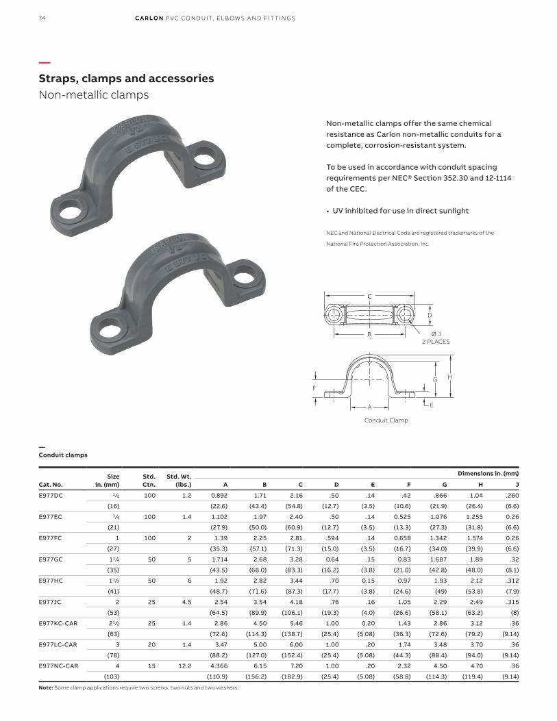
Size in. (mm)
Std.Ctn.
Std. Wt.(lbs.)
Dimensions in. (mm)
Cat. No. A B C D E F G H J
E977DC 1 ⁄2 100 1.2 0.892 1.71 2.16 .50 .14 .42 .866 1.04 .260
(16) (22.6) (43.4) (54.8) (12.7) (3.5) (10.6) (21.9) (26.4) (6.6)
E977EC 1 ⁄4 100 1.4 1.102 1.97 2.40 .50 .14 0.525 1.076 1.255 0.26
(21) (27.9) (50.0) (60.9) (12.7) (3.5) (13.3) (27.3) (31.8) (6.6)
E977FC 1 100 2 1.39 2.25 2.81 .594 .14 0.658 1.342 1.574 0.26
(27) (35.3) (57.1) (71.3) (15.0) (3.5) (16.7) (34.0) (39.9) (6.6)
E977GC 11 ⁄4 50 5 1.714 2.68 3.28 0.64 .15 0.83 1.687 1.89 .32
(35) (43.5) (68.0) (83.3) (16.2) (3.8) (21.0) (42.8) (48.0) (8.1)
E977HC 11 ⁄2 50 6 1.92 2.82 3.44 .70 0.15 0.97 1.93 2.12 .312
(41) (48.7) (71.6) (87.3) (17.7) (3.8) (24.6) (49) (53.8) (7.9)
E977JC 2 25 4.5 2.54 3.54 4.18 .76 .16 1.05 2.29 2.49 .315
(53) (64.5) (89.9) (106.1) (19.3) (4.0) (26.6) (58.1) (63.2) (8)
E977KC-CAR 21 ⁄2 25 1.4 2.86 4.50 5.46 1.00 0.20 1.43 2.86 3.12 .36
(63) (72.6) (114.3) (138.7) (25.4) (5.08) (36.3) (72.6) (79.2) (9.14)
E977LC-CAR 3 20 1.4 3.47 5.00 6.00 1.00 .20 1.74 3.48 3.70 .36
(78) (88.2) (127.0) (152.4) (25.4) (5.08) (44.3) (88.4) (94.0) (9.14)
E977NC-CAR 4 15 12.2 4.366 6.15 7.20 1.00 .20 2.32 4.50 4.70 .36
(103) (110.9) (156.2) (182.9) (25.4) (5.08) (58.8) (114.3) (119.4) (9.14)
Note: Some clamp applications require two screws, two nuts and two washers.
—Straps, clamps and accessoriesNon-metallic clamps
Non-metallic clamps offer the same chemical resistance as Carlon non-metallic conduits for a complete, corrosion-resistant system.
To be used in accordance with conduit spacing requirements per NEC® Section 352.30 and 12-1114 of the CEC.
• UV inhibited for use in direct sunlight
NEC and National Electrical Code are registered trademarks of the
National Fire Protection Association, Inc.
—Conduit clamps
Conduit Clamp
C
B
D
HG
EA
F
Ø J 2 PLACES
74 C A R LO N P VC CO N D U IT, EL B OW S A N D FIT TI N G S
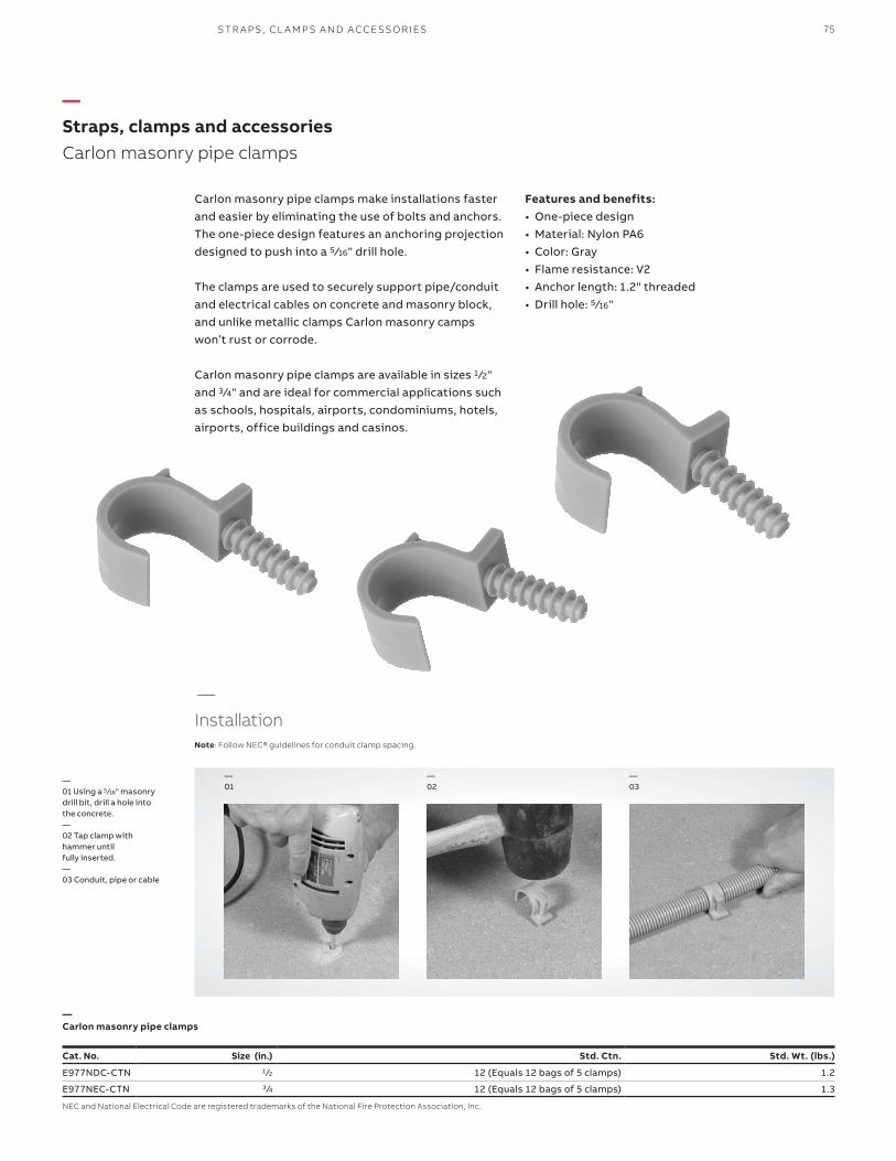
Cat. No. Size (in.) Std. Ctn. Std. Wt. (lbs.)
E977NDC-CTN 1 ⁄2 12 (Equals 12 bags of 5 clamps) 1.2
E977NEC-CTN 3⁄4 12 (Equals 12 bags of 5 clamps) 1.3
NEC and National Electrical Code are registered trademarks of the National Fire Protection Association, Inc.
—Straps, clamps and accessoriesCarlon masonry pipe clamps
Carlon masonry pipe clamps make installations faster and easier by eliminating the use of bolts and anchors. The one-piece design features an anchoring projection designed to push into a 5 ⁄16" drill hole.
The clamps are used to securely support pipe/conduit and electrical cables on concrete and masonry block, and unlike metallic clamps Carlon masonry camps won’t rust or corrode.
Carlon masonry pipe clamps are available in sizes 1 ⁄2" and 3 ⁄4" and are ideal for commercial applications such as schools, hospitals, airports, condominiums, hotels, airports, office buildings and casinos.
—Carlon masonry pipe clamps
Features and benefits:• One-piece design• Material: Nylon PA6• Color: Gray• Flame resistance: V2• Anchor length: 1.2" threaded• Drill hole: 5 ⁄16"
—01 Using a 5 ⁄16" masonry drill bit, drill a hole intothe concrete.—02 Tap clamp with hammer until fully inserted.—03 Conduit, pipe or cable
—
InstallationNote: Follow NEC® guidelines for conduit clamp spacing.
—02
—01
—03
75S TR A P S , CL A M P S A N D ACCE SSO R IE S

Size (in.)
ALength
B(Minimum) C
Threadsize
Std. Carton
Qty.
Std. Carton
Wt.(lbs.)Cat. No.
E954JXX 2 24.00 2.492 .83 2" NPT 20 46
E954JXS (Split) 2 24.00 2.492 .83 2" NPT 1 2.2
E954KXX 21 ⁄2 24.00 2.961 .81 21 ⁄2" NPSC 10 28
E954LXX 3 24.00 3.616 .80 3" NPSC 10 35
E954LXS (Split) 3 24.00 3.616 .80 3" NPSC 10 36
E977NEC-CTN 4 24.00 4.859 .77 4" NPSC 5 23NEC and National Electrical Code are registered trademarks of the National Fire Protection Association, Inc.
—Straps, clamps and accessoriesSlip meter risers
Carlon slip meter risers are designed for use in electrical service entrance applications. They provide solutions for applications requiring a non-rigid connection, with incoming service conduit diameters ranging from 2" to 4". The slip meter risers are fitted with a terminal adapter for easy installation at the service entrance location and provide a low-cost method to comply with NEC® 300.5(J), which requires protection for buried cables in areas subject to ground movement due to frost or trench settling.
Note: Meter box is not included.
(J) Ground movementWhere direct buried conductors, raceways, or cables are subject to movement by settlement or frost, direct buried conductors, raceways, or cables shall be arranged to prevent damage to the enclosed conductors or to equipment connected to the raceways.
(FPN) This section recognizes “S” loops in underground direct burial to raceway transitions, expansion joints in raceway risers to fixed equipment, and, generally, the provision of flexible connections to equipment subject to settlement or frost heaves.
—Slip meter risers
Features and benefits:• Designed to provide faster and easier
underground service entrance installations• Provides cable protection from ground movement• Accommodates incoming service conduit
diameters ranging from 2" to 4"• Fitted with terminal adapters for easy installing• Allows ground water in raceway system to drain• Complies with NEC® 300.5 paragraph 4, Schedule
80 rated
C REF
THREAD SIZE
Ø Bminimum
A minimum
Article 300 – Wiring methods
76 C A R LO N P VC CO N D U IT, EL B OW S A N D FIT TI N G S

Carlon Snap-Loc duct spacers provide stability, consistent separation and relieve direct stress for duct materials encased in concrete and direct-burial applications.
Non-metallic Snap-Loc spacers are designed specifically for use with non-metallic duct, with maximum O.D. dimensions as specified in NEMATC-2, TC-6 & 8 and ASTM F512. The innovative vertical and horizontal interlocking Snap-Loc design has tapered joining slots with maximum tolerances for easy jobsite assembly.
Features and benefits:• A side dovetail rail-and-groove design enabling side-
by-side interchangeability of conduit spacer sizes while maintaining horizontal stability
• Locking keyways incorporated into intermediate spacers eliminate the need for costly top spacers in each size. The locking keyways provide for the use of a beaded strap that secures the top section of conduit
• 1" and 2" Snap-Loc reducers enable fixturing of 1" or 2" conduit inside larger spacers
• The Snap-Loc Rebar holder provides stabilization on large banks of spacers
The spacers and Rebar holder are designed with a dovetail tongue-and-groove feature for easy installation.
If required to permanently fix the position of a group of Spacers and/or Rebar Holder, the following are recommended procedures:
1. Use Carlon Quick-Set cement glue during assembly or spot glue after assembly to secure.2. During assembly, deform the edge of the tongue or groove portion of the dovetail slide with a pair of pliers or similar tool. This deformation will create an interference, restricting movement.3. An assembled system may be wired together for additional support.
Note: Spacers are not UL® Listed.
Important:The use of duct spacers for direct burial may result in excessive point deflections unless proper design engineering is applied, such as the proper compaction of the appropriate backfill material.
Beaded strap &locking key way
Rebar holder
Snap-Loc® reducer
—Installation note
—SpacersCarlon® Snap-Loc® spacers
SPACER S 77

—Accessories
—Specifications
Suggested Specification:(Duct) (Conduit) bank shall be encased in concrete with at least three inches of concrete at the top and bottom and two inches on each side. A horizontal and vertical separation between the ducts of ____* inches shall be maintained by installing high-impact spacers with horizontal and vertical locking intervals of ____** feet.*Standard Separations of 1", 11 ⁄2", 2" and 3" are available.**Preferred interval between spacer assemblies is 8 to 10 feet.
Cat. No.Size (in.)
A (in.)
C (in.)
D (Dia.)(in.)
Std. Ctn.
S288JHN 2 x 11 ⁄2 4.25 4.12 2.50 100
S288JJN 2 x 2 4.25 4.62 2.50 100
S288JLN 2 x 3 4.25 5.62 2.50 100
S288LHN 3 x 11 ⁄2 4.81 5.25 3.63 90
S288LJN 3 x 2 4.81 5.75 3.63 80
S288LLN 3 x 3 4.81 6.75 3.63 60
S288NFN 4 x 1 4.50 5.75 4.63 70
S288NHN 4 x 11 ⁄2 5.31 6.25 4.63 50
S288NJN 4 x 2 5.31 6.75 4.63 50
S288NLN 4 x 3 5.31 7.75 4.63 60
S288PHN 5 x 11 ⁄2 5.84 7.31 5.69 50
S288PJN 5 x 2 5.84 7.81 5.69 60
S288PLN 5 x 3 5.84 8.81 5.69 50
S288RHN 6 x 11 ⁄2 6.38 8.38 6.75 50
S288RJN 6 x 2 6.38 8.88 6.75 50
S288RLN 6 x 3 6.38 9.88 6.75 40
S288SHN 8 x 11 ⁄2 7.38 10.3 8.75 30
S288SJN 8 x 2 7.38 10.76 8.75 30
* First number indicates trade size of duct, second number indicates separation * between conduits or ducts.
Cat. No.Size (in.)
A (in.)
C (in.)
D (Dia.)(in.)
Std. Ctn.
S289JHN 2 x 11 ⁄2 3.88 4.12 2.50 120
S289JJN 2 x 2 4.38 4.62 2.50 100
S289JLN 2 x 3 5.38 5.62 2.50 80
S289LHN 3 x 11 ⁄2 5.01 5.25 3.63 100
S289LJN 3 x 2 5.51 5.75 3.63 80
S289LLN 3 x 3 6.51 6.75 3.63 60
S289NFN 4 x 1 5.51 5.73 4.63 70
S289NHN 4 x 11 ⁄2 6.01 6.25 4.63 60
S289NJN 4 x 2 6.51 6.75 4.63 60
S289NLN 4 x 3 7.51 7.75 4.63 50
S289PHN 5 x 11 ⁄2 7.07 7.31 5.69 50
S289PJN 5 x 2 7.57 7.81 5.69 50
S289PLN 5 x 3 8.57 8.81 5.69 30
S289RHN 6 x 11 ⁄2 8.14 8.38 6.75 50
S289RJN 6 x 2 8.64 8.88 6.75 40
S289RLN 6 x 3 9.64 9.88 6.75 30
S289SHN 8 x 11 ⁄2 10.14 10.3 8.75 30
S289SJN 8 x 2 10.64 10.76 8.75 30
* First number indicates trade size of duct, second number indicates separation * between conduits or ducts.
—Dimensions – Base spacers
—Dimensions – Intermediate spacers
Cat. No. Size (in.) Std. Ctn.
S287F 1 100
S287J 2 100
Cat. No. Std. Ctn.
S258RH 100
Cat. No. Std. Ctn.
S28612 1 Bag of 250
—Snap-Loc reducer
—Rebar holder
—Beaded strap
15" in length
Hole Dia. = .688 min. .750 max.
B
C
A
3" Standard for all Base Spacers (with the exception of the 4X1-S288NFN)
—SpacersCarlon Snap-Loc spacers
78 C A R LO N P VC CO N D U IT, EL B OW S A N D FIT TI N G S

SPACER S
—SpacersCarlon® Snap-N-Stac™ combo spacers
Carlon Snap-N-Stac Combo Duct Spacers are specifically designed to replace the two-piece base and intermediate spacer system, by combining the conventional base and intermediate spacer into a single unit.
Manufactured out of highly engineered thermoplastic material, Snap-N-Stac Spacers are strong, durable and able to withstand the rigors of concrete construction. They feature an innovative horizontal and EXCLUSIVE vertical locking system, and can be used as either a base or intermediate spacer.
Snap-N-Stac Spacers are available in one-way, two-way and three-way configurations (one-way and three-way only available in sizes 2" and 4"). They accept 2", 3", 4", 5" and 6" pipe and can be installed horizontally, vertically or turned upright for unique duct bank configurations.
This NEW one-piece design makes underground duct bank installations faster and easier than the conventional two-piece system – saving material and labor costs.
Carlon Snap-N-Stac Combo Spacers… The IDEAL solution for underground duct bank installations.
Features and benefits:• Conventional base and intermediate spacer in a single
unit• Less inventory required• EXCLUSIVE vertical locking system• Horizontal locking system• Installs horizontally or turned upright• Molded-in rebar holder on two-way and three-way• One-, two- and three-way configurations (one way and
three-way only available in sizes 2" and 4")• Five sizes: 2", 3", 4", 5" and 6"• Reducer to accommodate smaller duct sizes• Can be used as either an intermediate or base spacer• Spacers interlock horizontally regardless of size• Non-metallic, non-corrosive, non-conductive• Strong and durable• Easy to handle• Fast installation
One-way Three-way
—02
—01
—03
—01 Horizontal Locking—02 Vertical Interlocking—03 With reducer
—Installations
79
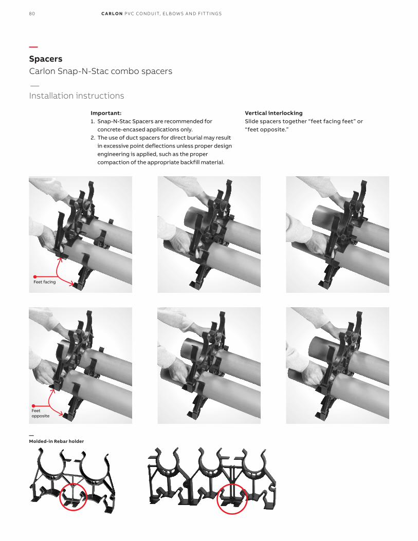
—SpacersCarlon Snap-N-Stac combo spacers
Important: 1. Snap-N-Stac Spacers are recommended for concrete-encased applications only.2. The use of duct spacers for direct burial may result in excessive point deflections unless proper design engineering is applied, such as the proper compaction of the appropriate backfill material.
Vertical interlockingSlide spacers together “feet facing feet” or “feet opposite.”
—Molded-in Rebar holder
Feet facing
Feet opposite
—Installation instructions
80 C A R LO N P VC CO N D U IT, EL B OW S A N D FIT TI N G S

—SpacersCarlon Snap-N-Stac combo spacers
—01 Vertical free standing If spacers are installed using free-standing method, it is recommended to install the spacer on the upper row mid-way between the two spacers on the bottom row.
—02 Reducer 1" and 2" Snap-Loc reducers enable fixturingof 1" and 2" conduit inside of larger spacers.
—03 Transition to various duct sizes Install spacers side-by-side by inserting the male adapter into the female adapter.
Note: All Snap-N-Stac spacers are designed to interlock horizontally, regardless of size.
—04 Odd number of ducts Two-way spacers, size 2" and 4" only, can easily be cut apart to produce two one-way spacers. Create three-way and five-wayspacers using the one-way spacer. Install spacers side-by-side by inserting the male adapter into the female adapter.
—01
—02
—03
—04
—Installation instructions
81SPACER S
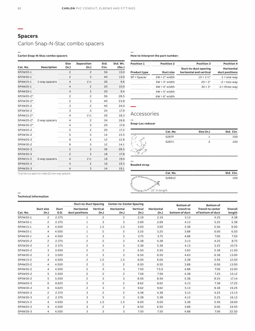
Cat. No.
DescriptionSize (in.)
Separation (in.)
Std. Ctn.
Std. Wt.(lbs.)
SP2W20-1 2 2 56 15.0
SP2W30-1 2 3 40 13.0
SP4W15-1 1-way spacers 4 11 ⁄2 26 9.6
SP4W20-1 4 2 20 10.0
SP4W30-1 4 3 20 9.4
SP2W20-2* 2 2 56 28.5
SP2W30-2* 2 3 40 23.8
SP3W20-2 3 2 40 24.0
SP3W30-2 3 3 24 17.9
SP4W15-2* 4 11 ⁄2 26 18.3
SP4W20-2* 2-way spacers 4 2 24 18.8
SP4W30-2* 4 3 20 17.6
SP5W20-2 5 2 20 17.2
SP5W30-2 5 3 14 15.5
SP6W20-2 6 2 12 12.8
SP6W30-2 6 3 12 14.1
SP2W20-3 2 2 36 28.5
SP2W30-3 2 3 18 17.8
SP4W15-3 3-way spacers 4 11 ⁄2 18 19.4
SP4W20-3 4 2 16 19.3
SP4W30-3 4 3 14 19.1
*Can be cut apart to make (2) one-way spacers.
Duct-to-Duct Spacing Center-to-Center Spacing Bottom of trench to
bottom of duct
Bottom of Trench to center
of bottom of ductCat. No. Duct size
(in.)Duct O.D.
Horizontal duct positions
Vertical(in.)
Horizontal(in.)
Vertical(in.)
Horizontal(in.)
Overall length
SP2W20-1 2 2.375 1 2 2 2.19 2.19 3.13 4.25 4.38
SP2W30-1 2 2.375 1 3 3 2.69 2.69 4.13 5.25 5.38
SP4W15-1 4 4.500 1 1.5 1.5 3.00 3.00 3.38 5.56 6.00
SP4W20-1 4 4.500 1 2 2 3.25 3.25 3.88 6.06 6.50
SP4W30-1 4 4.500 1 3 3 3.75 3.75 4.88 7.06 7.50
SP2W20-2 2 2.375 2 2 2 4.38 4.38 3.13 4.25 8.75
SP2W30-2 2 2.375 2 3 3 5.38 5.38 4.13 5.25 10.75
SP3W20-2 3 3.500 2 2 2 5.50 5.50 3.63 5.38 11.00
SP3W30-2 3 3.500 2 3 3 6.50 6.50 4.63 6.38 13.00
SP4W15-2 4 4.500 2 1.5 1.5 6.00 6.00 3.38 5.56 12.00
SP4W20-2 4 4.500 2 2 2 6.50 6.50 3.88 6.06 13.00
SP4W30-2 4 4.500 2 3 3 7.50 7.5.0 4.88 7.06 15.00
SP5W20-2 5 5.500 2 2 2 7.56 7.56 4.38 7.25 15.12
SP5W30-2 5 5.500 2 3 3 8.56 8.56 5.38 8.25 17.14
SP6W20-2 6 6.625 2 2 2 8.62 8.62 4.13 7.38 17.25
SP6W30-2 6 6.625 2 3 3 9.62 9.62 5.13 8.38 19.25
SP2W20-3 2 2.375 3 2 2 4.38 4.38 3.13 4.25 13.13
SP2W30-3 2 2.375 3 3 3 5.38 5.38 4.13 5.25 16.13
SP4W15-3 4 4.500 3 1.5 1.5 6.00 6.00 3.38 5.56 18.00
SP4W20-3 4 4.500 3 2 2 6.50 6.50 3.88 6.06 19.50
SP4W30-3 4 4.500 3 3 3 7.50 7.50 4.88 7.06 22.50
Position 1 Position 2 Position 3 Position 4
Product type
Duct sizeDuct-to-duct spacing
horizontal and verticalHorizontal
duct positions
SP = Spacer 2W = 2" width 15 = 11 ⁄2" -1 = one-way
3W = 3" width 20 = 2" -2 = two-way
4W = 4" width 30 = 3" -3 = three-way
5W = 5" width
6W = 6" width
—Carlon Snap-N-Stac combo spacers
—Technical information
—How to interpret the part number:
Cat. No. Size (in.) Std. Ctn.
S287F 1 100
S287J 2 100
Cat. No. Std. Ctn.
S28612 100
—Snap-Loc reducer
—Beaded strap
15" in length
—Accessories
—SpacersCarlon Snap-N-Stac combo spacers
82 C A R LO N P VC CO N D U IT, EL B OW S A N D FIT TI N G S

—Technical informationTypical properties of conduit raw material compound
—Weight comparison
Thermal ASTM Test Typical values
Co-effecient of thermal expansion-inch/inch/° F (properties @ 73.4° F)
D696 3.38 x 10⁻⁵
Heat distortion ° F at 264 psi D648 160° F
Thermal conductivity BTU (hr.) (ft.) (° F/in.) N/A 1.3
Mechanical ASTM Test Typical values
Specific gravity D792 1.43 - 1.6
Tensile strength (psi) @ 73.4° F D648 5,000-6,500
Izod impact ft lbs./in. of notch D256 .65 - 1.5
Flexural strength (psi) D790 12,500
Compressive strength (psi) D695 9,000
Hardness (Durometer D) D2240 85
Impedance(Volts lost per Ampere per 100 feet)
3Ø90%P.F.
80%P.F.
1Ø90%P.F.
80%P.F.
Steel conduit .0118 .0123 .0136 .0142
Schedule 40 .0105 .0106 .0121 .0122
Using 250 kcmil copper conductor. Comparable values for other conductor sizes.
ELECTRICAL ASTM Test Typical values
Dielectrical strength volts/mil D149 1100
Dielectric constant 60 CPS @ 30° C D150 4.00
Power factor 60 CPS @ 30° C D150 1.93
Nom. size(in.)
CarlonSchedule 40
rigid non-metallicconduit
CarlonSchedule 80
rigid non-metallicconduit Aluminum
Electricalmetallic
tubing(EMT)
Intermediatemetal
conduit(IMC)
Rigidmetal
conduit(RMC)
1 ⁄2 18 22 27 30 57 793⁄4 23 29 36 46 78 105
1 35 43 53 66 112 153
11 ⁄4 48 60 70 96 114 201
11 ⁄2 57 72 86 112 176 246
2 76 100 116 142 230 334
21 ⁄2 125 153 183 230 393 527
3 164 212 239 270 483 690
31 ⁄2 198 288 350 561 831
4 234 310 340 400 625 982
5 317 431 465 Not made Not made 1344
6 412 592 612 Not made Not made 1770
Carlon Schedule 40 rigid non-metallic conduit compared to other conduit in pounds per 100 feet (approx.)
83TECH N I C A L I N FO R M ATI O N

—Technical informationWire fill
Typeletters
Conductor size AWG,
KCMIL
Trade size1 ⁄2 3 ⁄4 1 11 ⁄4 11 ⁄2 2 21 ⁄2 3 31 ⁄2 4 41 ⁄4 5 6 8
THWN 14 13 24 39 69 94 154
12 10 18 29 51 79 114 164
THHN 10 6 11 18 32 44 73 194 160
8 3 5 9 19 22 36 51 71 106 136
FEP 6 1 4 6 11 15 26 37 57 76 98 125 154
(14 thru 2) 4 1 2 4 7 9 16 22 35 47 60 75 94 137 236
3 1 1 3 6 8 13 19 29 39 51 64 90 116 201
FEPB 2 1 1 3 5 7 11 16 25 33 43 54 67 97 169
(14 thru 8) 1 1 1 3 5 9 12 18 25 32 49 59 72 125
1/0 1 1 3 4 7 10 15 21 27 33 42 61 105
PFA 2/0 1 1 2 3 6 8 13 17 22 28 35 51 88
(14 thru 4/0) 3/0 1 1 1 3 5 7 11 14 18 23 29 42 73
4/0 1 1 1 2 4 6 9 12 15 19 24 35 61
PFAH 250 1 1 1 3 4 7 10 12 16 20 28 49
(14 thru 4/0) 300 1 1 1 3 4 6 8 11 13 17 24 42
350 1 1 1 2 3 5 7 9 12 15 21 37
Z 400 1 1 1 3 5 6 8 10 13 19 33
(14 thru 4/0) 500 1 1 1 2 4 5 7 9 11 16 27
600 1 1 1 1 3 4 5 7 9 13 22
XHHW 700 1 1 1 3 4 5 6 8 11 19
(4 thru 500) 750 1 1 1 2 3 4 6 7 11 19
6 1 3 5 9 13 21 30 47 63 81 102 128 185 320
XHHW600 1 1 1 1 3 4 5 7 9 13 22
700 1 1 1 3 4 5 6 7 11 19
750 1 1 1 2 3 4 6 7 10 18
NEC and National Electrical Code are registered trademarks of the National Fire Protection Association, Inc.
—Maximum number of conductors in Schedule 40 PVC conduit (Based on Table 1, Chapter 9 of the NEC®)
84 C A R LO N P VC CO N D U IT, EL B OW S A N D FIT TI N G S

—Technical informationWire fill (continued)
TypelLetters
Conductor size AWG,
KCMIL
Trade size1 ⁄2 3 ⁄4 1 11 ⁄4 11 ⁄2 2 21 ⁄2 3 4 5
#14 THW 4 8 13 24 34 57 82 128
THHN 10 19 33 58 81 135 194 0
12 THW 3 6 11 20 28 47 67 105 183
THHN 8 14 24 43 60 100 144 0
10 THW 3 5 9 16 22 37 54 85 148
THHN 5 9 15 27 38 64 92 143
8 THW 1 2 4 8 11 19 28 44 77 121
THHN 1 4 7 13 18 31 45 70 123 195
6 THW 1 1 3 6 8 14 20 32 56 88
THHN 1 3 5 9 13 22 32 50 88 140
4 THW 0 1 2 4 6 10 15 24 42 66
THHN 1 1 3 6 8 13 20 31 54 86
3 THW 0 1 1 4 5 9 13 20 36 57
THHN 1 1 2 5 7 11 17 26 46 73
2 THW 0 1 1 3 4 8 11 17 31 49
THHN 1 1 1 4 5 9 14 22 38 61
1 THW 0 1 1 1 3 5 8 13 22 35
THHN 0 1 1 3 4 7 10 16 28 45
0 THW 0 0 1 1 2 4 7 11 19 30
THHN 0 1 1 2 3 6 8 13 24 38
00 THW 0 0 1 1 1 4 6 9 16 26
THHN 0 1 1 1 3 5 7 11 20 32
000 THW 0 0 1 1 1 3 5 8 14 22
THHN 0 0 1 1 2 4 6 9 16 26
0000 THW 0 0 1 1 1 3 4 6 11 18
THHN 0 0 1 1 1 3 5 8 14 22
250 THW 0 0 0 1 1 1 3 5 9 14
THHN 0 0 0 1 1 2 4 6 11 18
300 THW 0 0 0 1 1 1 3 4 8 13
THHN 0 0 0 1 1 1 3 5 9 15
350 THW 0 0 0 1 1 1 2 4 7 11
THHN 0 0 0 1 1 1 3 4 8 13
400 THW 0 0 0 0 1 1 1 3 6 10
THHN 0 0 0 1 1 1 2 4 7 12
500 THW 0 0 0 0 1 1 1 3 5 8
THHN 0 0 0 0 1 1 1 3 6 10
600 THW 0 0 0 0 0 1 1 1 4 7
THHN 0 0 0 0 1 1 1 3 5 8
700 THW 0 0 0 0 0 1 1 1 3 6
NEC and National Electrical Code are registered trademarks of the National Fire Protection Association, Inc.
—Maximum number of conductors in Schedule 80 PVC conduit (Based on Table 1, Chapter 9 of the NEC®)
85TECH N I C A L I N FO R M ATI O N

0 = [ T max -T installed ] E∆T
Solvent weld
Pipe strap shouldbe anchored tightlyto barrel
Piston Opening
Pipe strap mounted
loosely to allow
movement
Solvent weldMid-point
mark
—Technical informationExpansion and contraction
Determine the piston openingThe expansion joint must be installed to allow both expansion and contraction of the conduit run. The correct piston opening for any installation condition should use the following formula:
Example380 ft. cf conduit is to be installed on the outside of a building exposed to the sun in a single straight run. It is expected that the conduit will vary in temperature from O°F in the winter to 140°F in the summer (this includes the 30°F for radiant heating from the sun.) The installation is to be made at a conduit temperature of 90°F. From this table, a 140°F temperature changewill cause a 5.7". length change in 100 ft. of conduit. The total change for this example is 5.7" x 3.8 = 21.67" which should be rounded to 22". The number of expansion fittings will be 22" x fitting range (4" for Carlon trade sizes 1 ⁄ 2" through 11 ⁄ 2", and 8" for sizes 2" through 6"). If the E945D fitting is used, the number will be 22"/ 4 = 5.50 which should be rounded to 6. The fitting should be placed at 62 ft. intervals (380 / 6). The proper piston setting at the time of installation is calculated as explained above.
Insert the piston into the barrel to the maximum depth. Place a mark on the piston at the end of the barrel. To properly set the piston, pull the piston out of the barrel to correspond to the 1.4" calculated above. See drawing at left.
Summary1. Anticipate expansion and contraction of PVC conduit in above ground, exposed installation.2. Use an expansion fitting when length change due to temperature variation will be 1 ⁄4" or greater per 352.44 of the NEC®.3. PVC conduit expands 4.1" for each 100 feet of run and a 100°F temperature change.4. Align expansion fitting with the conduit run to prevent binding.5. Follow the instructions to set the piston opening.6. Rigidly fix the outer barrel of the expansion fitting so it cannot move. Mount the conduit connected to the piston loosely enough to allow the conduit to move as the temperature changes.NEC and National Electrical Code are registered trademarks of theNational Fire Protection Association, Inc.
Temperature considerations for rigid non-metallicconduit compensation for linear expansion.
Like all construction materials, PVC will expandor contract with variations in temperatures.The coefficient of linear expansion in PVC conduitis 3.38 x 10⁻⁵ in./in./°F as compared to 1.2 x 10⁻⁵for aluminum and .6 x 10-5 for steel. An expansionfitting is needed whenever the change in lengthdue to temperature variation will be 1 ⁄4" orgreater per 352.44 of the NEC.
Add 30°F to the estimated temperature rangewhen conduit is installed in direct sunlight toallow for radiant heating.
An expansion fitting consists of two sections,one telescoping inside another. When installingexpansion fittings, alignment of piston and barrelis important. Be sure to mount expansion fittinglevel for best performance.
For a vertical run, the expansion fitting must beinstalled close to the top of the run with thebarrel jointing down, in order that rain water doesnot run into the opening. The lower end of theconduit run must be secured at the bottom sothat any length change due to temperaturevariation will result in an upward movement.
0 = [ 140-90 ] 4.0=1.4 in.140
86 C A R LO N P VC CO N D U IT, EL B OW S A N D FIT TI N G S

—Expansion characteristics of PVC rigid non-metallic conduit coefficient of thermal expansion = 3.38 x 10⁻⁵ in./in./°F
Temperaturechange indegrees F
Length change in inches per
100 ft. of PVC conduit
Temperaturechange indegrees F
Length change in inches per
100 ft. of PVC conduit
Temperaturechange indegrees F
Length change in inches per
100 ft. of PVC conduit
Temperaturechange indegrees F
Length change in inches per
100 ft. of PVC conduit
5 0.2 55 2.2 105 4.2 155 6.3
10 0.4 60 2.4 110 4.5 160 6.5
15 0.6 65 2.6 115 4.7 165 6.7
20 0.8 70 2.8 120 4.9 170 6.9
25 1.0 75 3.0 125 5.1 175 7.1
30 1.2 80 3.2 130 5.3 180 7.3
35 1.4 85 3.4 135 5.5 185 7.5
40 1.6 90 3.6 140 5.7 190 7.7
45 1.8 95 3.8 145 5.9 195 7.9
50 2.0 100 4.0 150 6.1 200 8.1
—Technical informationExpansion and contraction
87TECH N I C A L I N FO R M ATI O N

—Technical informationCorrosion resistance of Carlon Schedule 40 and Schedule 80 fittings
Carlon Schedule 40 and Schedule 80 fittings are generally acceptable for use in environments containing the chemicals below. These environmental resistance ratings are based upon tests where the specimens were placed in complete submergence in the reagent listed. Schedule 40 and Schedule 80 fittings can be used in many process areas where chemicals not on this list are manufactured or used because worker safety requirements dictate that any air presence or splashing be at a very low level.
If there are any questions about specific suitability in a given environment, prototype samples should be tested under actual conditions.
Chemical Environment
Acetic Acid O – 20% Bismuth Carbonate Copper Fluoride Hydrofluoric Acid 10% Perchloric Acid 10% Sodium Dichromate
Acetic Acid 20 – 30% Black Liquor Copper Nitrate Hydrofluorosilicic Acid Phenylhydrazine Sodium Ferricyanide
Acetic Acid 3O – 60% (Paper Industry) Copper Sulfate Hydrogen Phosphide Hydrochloride Sodium Ferrocyanide
Acetic Acid 80% Bleach – 12.5% Active Cottonseed Oil Hydrogen Sulfide – Dry Phosgene, Gas Sodium Fluoride
Acetic Acid – Glacial CL2 Cresylic Acid 50% Hydrogen Sulfide – Phosphoric Acid - Sodium Hydroxide
Acetic Acid Vapors Borax Crude Oil – Sour Aqueous Solution 0 - 25% Sodium Hypochlorite
Acetylene Boric Acid Crude Oil – Sweet Hydroquinone Phosphoric Acid - Sodium Nitrate
Adipic Acid Brine Demineralized Water Hydroxylamine Sulfate 25 - 50% Sodium Nitrite
Alum Breeder Pellets – Dextrin Iodine Phosphoric Acid - Sodium Sulfate
Aluminum Chloride Dane. Fish Dextrose Kerosene 50 - 85% Sodium Sulfide
Aluminum Fluoride Bromic Acid Diglycolic Acid Lactic Acid 28% Photographic Chemicals Sodium Sulfite
Aluminum Hydroxide Bromine – Water Disodium Phosphate Lauric Acid Plating Solutions Sodium Thiosulfate
Aluminum Oxychloride Butane Ethyl Alcohol Lauryl Chloride Potassium Bicarbonate (Hypo)
Aluminum Nitrate Butadiene Ethylene Glycol Lauryl Sulfate Potassium Bichromate Stannic Chloride
Aluminum Sulfate Butyl Alcohol Fatty Acids Lead Acetate Potassium Borate Stannous Chloride
Ammonia-Dry Gas Butyl Phenol Ferric Chloride Lime Sulfur Potassium Bromide Stearic Acid
Ammonium Bifluoride Butylene Ferric Nitrate Linoleic Acid Potassium Carbonate Sulfur
Ammonium Carbonate Butyric Acid Ferric Sulfate Linseed Oil Potassium Chloride Sulfur Dioxide – Gas Dry
Ammonium Chloride Calcium Bisulfite Ferrous Chloride Lubricating Oils Potassium Chromate Sulfur Trioxide
Ammonium Hydroxide Calcium Carbonate Ferrous Sulfate Magnesium Carbonate Potassium Cyanide Sulfuric Acid – 0 – 10%28% Calcium Chlorate Fluorine Gas – Wet Magnesium Chloride Potassium Dichromate Sulfuric Acid – 10 – 75%
Ammonium Calcium Chloride Fluorine Gas – Dry Magnesium Hydroxide Potassium Ferricyanide Sulfuric Acid – 75 – 90%Metaphosphate Calcium Hydroxide Fluoroboric Acid Magnesium Nitrate Potassium Ferrocyanide Sulfurous Acid
Ammonium Nitrate Calcium Hypochlorite Fluorosilicic Acid Magnesium Sulfate Potassium Fluoride Tannic Acid
Ammonium Persulfate Calcium Nitrate Formaldehyde Maleic Acid Potassium Hydroxide Titanium Tetrachloride
Ammonium Phosphate – Calcium Sulfate Formic Acid Malic Acid Potassium Nitrate TriethanolamineNeutral Carbonic Acid Fructose Mercuric Chloride Potassium Perborate Trimethyl Propane
Ammonium Sulfate Carbon Dioxide Gas – Gallic Acid Mercuric Cyanide Potassium Perchlorite Trisodium Phosphate
Ammonium Sulfide Wet Gas – Coke Oven Mercurous Nitrate Potassium Turpentine
Ammonium Carbon Dioxide – Gas – Natural (Dry) Mercury Permanganate 10% UreaThiocyanate Aqueous Solution Gas – Natural (Wet) Methyl Sulfate Potassium Persulfate Vinegar
Amyl Alcohol Carbon Monoxide Gasoline – Sour Methylene Chloride Potassium Sulfate Whiskey
Anthraquinone Caustic Potash Gasoline – Refined Mineral Oils Propane White Liquor
Anthraquinonesulfonic Caustic Soda Glucose Naphthalene Propyl Alcohol (Paper Industry)
Acid Chloracatic Acid Glycerine (Glycerol) Nickel Chloride Silicic Acid Wines
Antimony Trichloride Chloral Hydrate Glycol Nickel Nitrate Silver Cyanide Zinc Chloride
Aqua Regia Chlorine Gas (Dry) Glycolic Acid Nitric Acid, Anydrous Silver Nitrate Zinc Chromate
Arsenic Acid 80% Chlorine Gas (Moist) Green Liquor Nitric Acid 20% Silver Plating Solutions Zinc Cyanide
Arylsulfonic Acid Chlorine Water (Paper Industry) Nitric Acid 40% Sodium Acetate Zinc Nitrate
Barium Carbonate Chlorosulfonic Acid Heptane Nitric Acid 60% Sodium Arsenite Zinc Sulfate
Barium Chloride Chrome Alum Hexanol, Tertiary Nitrobenzene Sodium Benzoate
Barium Hydroxide Chromic Acid 10% Hydrobromic Acid 20% Nitrous Oxide Sodium Bicarbonate
Barium Sulfate Chromic Acid 30% Hydrochloric Acid Oils and Fats Sodium Bisulfate
Barium Sulfide Chromic Acid 40% 0% – 25% Oils – Petroleum – Sodium Bisulfite
Beet – Sugar Liquor Chromic Acid 50% Hydrochloric Acid (See Type) Sodium Bromide
Benzine Sulfonic Acid Citric Acid 25% – 40% Oleic Acid Sodium Chlorate10% Copper Chloride Hydrocyanic Acid or Oxalic Acid Sodium Chloride
Benzoic Acid Copper Cyanide Hydrogen Cyanide Palmitic Acid 10% Sodium Cyanide
88 C A R LO N P VC CO N D U IT, EL B OW S A N D FIT TI N G S
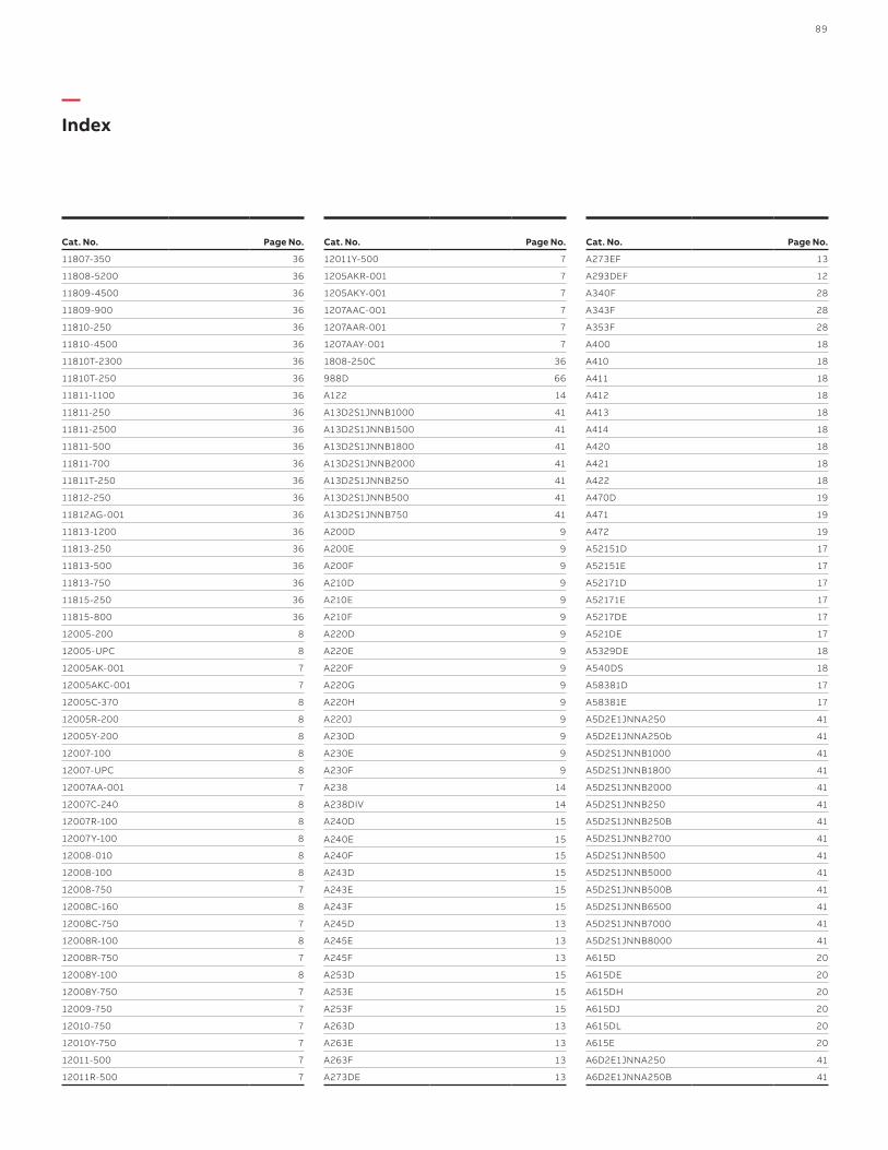
—Index
Cat. No. Page No.
11807-350 36
11808-5200 36
11809-4500 36
11809-900 36
11810-250 36
11810-4500 36
11810T-2300 36
11810T-250 36
11811-1100 36
11811-250 36
11811-2500 36
11811-500 36
11811-700 36
11811T-250 36
11812-250 36
11812AG-001 36
11813-1200 36
11813-250 36
11813-500 36
11813-750 36
11815-250 36
11815-800 36
12005-200 8
12005-UPC 8
12005AK-001 7
12005AKC-001 7
12005C-370 8
12005R-200 8
12005Y-200 8
12007-100 8
12007-UPC 8
12007AA-001 7
12007C-240 8
12007R-100 8
12007Y-100 8
12008-010 8
12008-100 8
12008-750 7
12008C-160 8
12008C-750 7
12008R-100 8
12008R-750 7
12008Y-100 8
12008Y-750 7
12009-750 7
12010-750 7
12010Y-750 7
12011-500 7
12011R-500 7
Cat. No. Page No.
12011Y-500 7
1205AKR-001 7
1205AKY-001 7
1207AAC-001 7
1207AAR-001 7
1207AAY-001 7
1808-250C 36
988D 66
A122 14
A13D2S1JNNB1000 41
A13D2S1JNNB1500 41
A13D2S1JNNB1800 41
A13D2S1JNNB2000 41
A13D2S1JNNB250 41
A13D2S1JNNB500 41
A13D2S1JNNB750 41
A200D 9
A200E 9
A200F 9
A210D 9
A210E 9
A210F 9
A220D 9
A220E 9
A220F 9
A220G 9
A220H 9
A220J 9
A230D 9
A230E 9
A230F 9
A238 14
A238DIV 14
A240D 15
A240E 15
A240F 15
A243D 15
A243E 15
A243F 15
A245D 13
A245E 13
A245F 13
A253D 15
A253E 15
A253F 15
A263D 13
A263E 13
A263F 13
A273DE 13
Cat. No. Page No.
A273EF 13
A293DEF 12
A340F 28
A343F 28
A353F 28
A400 18
A410 18
A411 18
A412 18
A413 18
A414 18
A420 18
A421 18
A422 18
A470D 19
A471 19
A472 19
A52151D 17
A52151E 17
A52171D 17
A52171E 17
A5217DE 17
A521DE 17
A5329DE 18
A540DS 18
A58381D 17
A58381E 17
A5D2E1JNNA250 41
A5D2E1JNNA250b 41
A5D2S1JNNB1000 41
A5D2S1JNNB1800 41
A5D2S1JNNB2000 41
A5D2S1JNNB250 41
A5D2S1JNNB250B 41
A5D2S1JNNB2700 41
A5D2S1JNNB500 41
A5D2S1JNNB5000 41
A5D2S1JNNB500B 41
A5D2S1JNNB6500 41
A5D2S1JNNB7000 41
A5D2S1JNNB8000 41
A615D 20
A615DE 20
A615DH 20
A615DJ 20
A615DL 20
A615E 20
A6D2E1JNNA250 41
A6D2E1JNNA250B 41
89
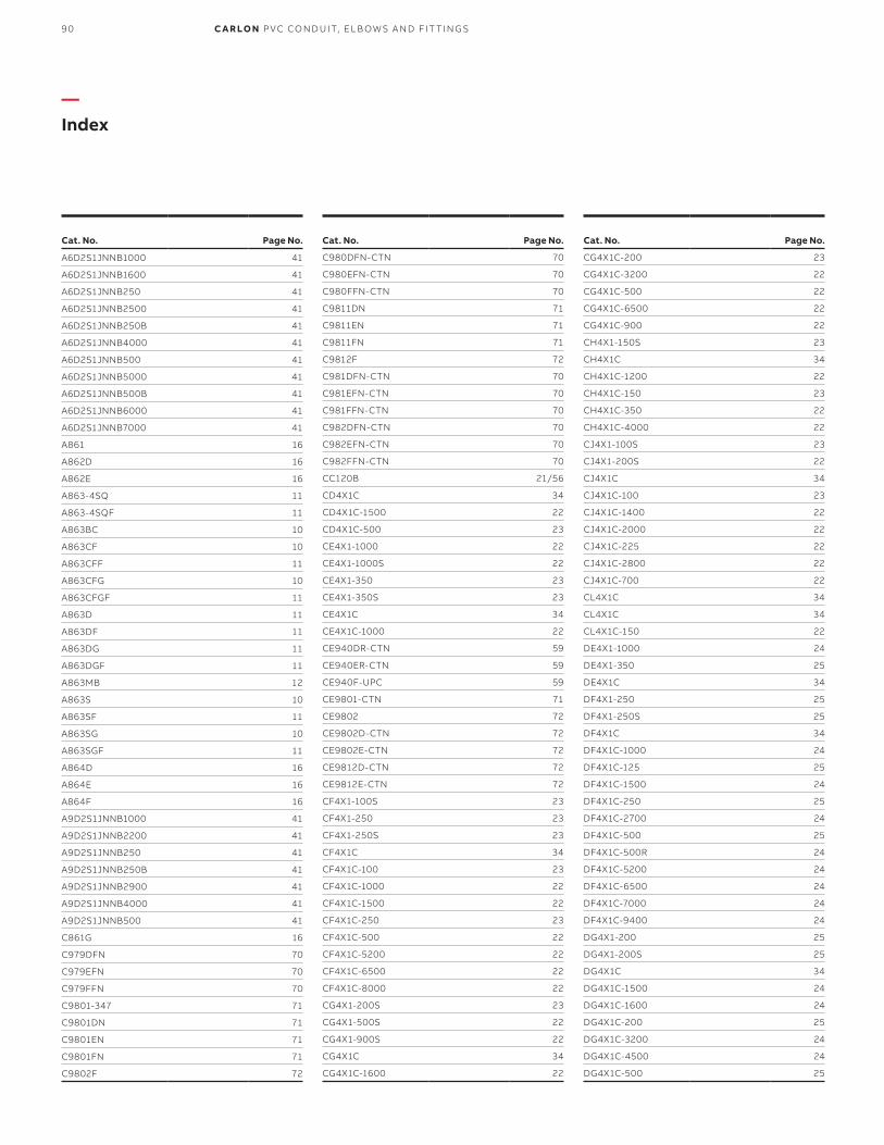
—Index
Cat. No. Page No.
C980DFN-CTN 70
C980EFN-CTN 70
C980FFN-CTN 70
C9811DN 71
C9811EN 71
C9811FN 71
C9812F 72
C981DFN-CTN 70
C981EFN-CTN 70
C981FFN-CTN 70
C982DFN-CTN 70
C982EFN-CTN 70
C982FFN-CTN 70
CC120B 21/56
CD4X1C 34
CD4X1C-1500 22
CD4X1C-500 23
CE4X1-1000 22
CE4X1-1000S 22
CE4X1-350 23
CE4X1-350S 23
CE4X1C 34
CE4X1C-1000 22
CE940DR-CTN 59
CE940ER-CTN 59
CE940F-UPC 59
CE9801-CTN 71
CE9802 72
CE9802D-CTN 72
CE9802E-CTN 72
CE9812D-CTN 72
CE9812E-CTN 72
CF4X1-100S 23
CF4X1-250 23
CF4X1-250S 23
CF4X1C 34
CF4X1C-100 23
CF4X1C-1000 22
CF4X1C-1500 22
CF4X1C-250 23
CF4X1C-500 22
CF4X1C-5200 22
CF4X1C-6500 22
CF4X1C-8000 22
CG4X1-200S 23
CG4X1-500S 22
CG4X1-900S 22
CG4X1C 34
CG4X1C-1600 22
Cat. No. Page No.
A6D2S1JNNB1000 41
A6D2S1JNNB1600 41
A6D2S1JNNB250 41
A6D2S1JNNB2500 41
A6D2S1JNNB250B 41
A6D2S1JNNB4000 41
A6D2S1JNNB500 41
A6D2S1JNNB5000 41
A6D2S1JNNB500B 41
A6D2S1JNNB6000 41
A6D2S1JNNB7000 41
A861 16
A862D 16
A862E 16
A863-4SQ 11
A863-4SQF 11
A863BC 10
A863CF 10
A863CFF 11
A863CFG 10
A863CFGF 11
A863D 11
A863DF 11
A863DG 11
A863DGF 11
A863MB 12
A863S 10
A863SF 11
A863SG 10
A863SGF 11
A864D 16
A864E 16
A864F 16
A9D2S1JNNB1000 41
A9D2S1JNNB2200 41
A9D2S1JNNB250 41
A9D2S1JNNB250B 41
A9D2S1JNNB2900 41
A9D2S1JNNB4000 41
A9D2S1JNNB500 41
C861G 16
C979DFN 70
C979EFN 70
C979FFN 70
C9801-347 71
C9801DN 71
C9801EN 71
C9801FN 71
C9802F 72
Cat. No. Page No.
CG4X1C-200 23
CG4X1C-3200 22
CG4X1C-500 22
CG4X1C-6500 22
CG4X1C-900 22
CH4X1-150S 23
CH4X1C 34
CH4X1C-1200 22
CH4X1C-150 23
CH4X1C-350 22
CH4X1C-4000 22
CJ4X1-100S 23
CJ4X1-200S 22
CJ4X1C 34
CJ4X1C-100 23
CJ4X1C-1400 22
CJ4X1C-2000 22
CJ4X1C-225 22
CJ4X1C-2800 22
CJ4X1C-700 22
CL4X1C 34
CL4X1C 34
CL4X1C-150 22
DE4X1-1000 24
DE4X1-350 25
DE4X1C 34
DF4X1-250 25
DF4X1-250S 25
DF4X1C 34
DF4X1C-1000 24
DF4X1C-125 25
DF4X1C-1500 24
DF4X1C-250 25
DF4X1C-2700 24
DF4X1C-500 25
DF4X1C-500R 24
DF4X1C-5200 24
DF4X1C-6500 24
DF4X1C-7000 24
DF4X1C-9400 24
DG4X1-200 25
DG4X1-200S 25
DG4X1C 34
DG4X1C-1500 24
DG4X1C-1600 24
DG4X1C-200 25
DG4X1C-3200 24
DG4X1C-4500 24
DG4X1C-500 25
90 C A R LO N P VC CO N D U IT, EL B OW S A N D FIT TI N G S

Cat. No. Page No.
DG4X1C-500R 24
DG4X1C-5600 24
DG4X1C-6500 24
DG4X1C-900 24
DH4X1-150S 25
DH4X1C 34
DH4X1C-1200 24
DH4X1C-150 25
DH4X1C-4000 24
DH4X1C-4500 24
DJ4X1-100S 25
DJ4X1C 34
DJ4X1C-100 25
DJ4X1C-2000 24
DJ4X1C-2800 24
DJ4X1C-700 24
DL4X1C 34
DL4X1C-250 25
DL4X1C-750 24
E200JS6 51
E200KS7 51
E200LS7 51
E200LSS 51
E200MS8 51
E200NS8 51
E200NSS 51
E200PS8 51
E200PS9 51
E200RS1 51
E252LJ 50
E252NJS 50
E252NL 50
E252PN 50
E252RNS 50
E252RP 50
E297J 50
E297JN 50
E297L 50
E297N 50
E297NT 50
E297P 50
E297PS 50
E297PT 50
E297RF 50
E297RR 50
E299JM 50
E299JR 50
E299NX7 50
E442R 60
Cat. No. Page No.
E442T 60
E460R-CAR 19
E900NS8 51
E900NSW 51
E910D 43
E910E 43
E910F 43
E910G 43
E910H 43
E910J 43
E910REAMD 43
E910REAME 43
E910REAMF 43
E910REAMG 43
E910REAMH 43
E910REAMJ 43
E910REAMKIT 43
E920D 43
E920E 43
E920F 43
E920G 43
E920H 43
E920J 43
E92CSH 21/65
E92CSJ 21/65
E92CSL 21/65
E92CSN 21/65
E92CSP 21/65
E92CSR 21/65
E935J 63
E935L 63
E935N 63
E935P 63
E935R 63
E940D 15/59
E940E 15/29/36/59
E940F 15/29/36/59
E940G 15/29/36/59
E940H 15/29/36/59
E940J 15/29/36/59
E940K 36/59
E940L 36/59
E940M 59
E940N 36/59
E940P 59
E940R 59
E941H 59
E941J 59
E941K 59
Cat. No. Page No.
E941L 59
E941N 59
E941PF 59
E941RF 59
E942D 61
E942E 36/61
E942F 36/50/61
E942G 36/61
E942H 36/50/61
E942J 36/50/61
E942K 36/61
E942L 36/50/61
E942M 61
E942N 36/50/61
E942NX9 61
E942P 50/61
E942R 50/61
E942RX 61
E943D 15/61
E943DW 64
E943E 15/29/36/61
E943EW 64
E943F 15/29/36/50/61
E943FW 64
E943G 15/29/36/61
E943GW 64
E943H 15/29/36/50/61
E943HW 64
E943J 15/29/36/50/61
E943JW 64
E943K 36/61
E943L 36/50/61
E943M 61
E943N 36/50/36
E943P 50/61
E943R 50/61
E945D 58
E945DX 58
E945E 58
E945EX 58
E945F 58
E945FX 58
E945G 58
E945GX 58
E945H 58
E945HX 58
E945J 58
E945JX 58
E945K 58
—Index
91

—Index
Cat. No. Page No.
E950JH-CAR 63
E950KJ-CAR 63
E950LJ-CAR 63
E950LK 63
E950NL 63
E952JH 63
E952KJ 63
E952LJ 63
E952LK 63
E952NJF 63
E952NL 63
E952NM 63
E952PN 63
E952RNF 63
E952RP 63
E954HX 60
E954J 60
E954JX 60
E954JXS (Split) 76
E954JXX 76
E954K 60
E954KX 60
E954KXX 76
E954L 60
E954LX 60
E954LXS (Split) 76
E954LXX 76
E955D 58
E955E 58
E955F 58
E955G 58
E955H 58
E955J 58
E958D 63
E958E 63
E958F 63
E958G 63
E958H 63
E958J 63
E958K 63
E958L 63
E958N 63
E958P 63
E958R 63
E970CD 65
E970CE 65
E971C 62
E971D 62
E977DC 74
Cat. No. Page No.
E945KX 58
E945KXL 59
E945L 58
E945LX 58
E945M 58
E945MX 58
E945N 58
E945NX 58
E945P 58
E945PX 58
E945R 58
E945RX 58
E948H 60
E948J 60
E948JR 60
E948JS 60
E948K 60
E948KS7 60
E948L 60
E948L12 60
E948L6 60
E948LS 60
E948N 60
E948N12 60
E948N7 60
E948NS 60
E948P 60
E948PS 60
E948R 60
E948R10 60
E948R12 60
E948RS 60
E949J5 64
E949J6 64
E949JN 64
E949JX 64
E949LR 64
E949N5 64
E949NR 64
E949R5 64
E949RX 64
E950ED 63
E950FD-CAR 63
E950FE 63
E950GE-CAR 63
E950GF 63
E950HF-CAR 63
E950HG-CAR 63
E950JG-CAR 63
Cat. No. Page No.
E977EC 74
E977FC 74
E977GC 74
E977HC 74
E977JC 74
E977KC-CAR 74
E977LC-CAR 74
E977NC-CAR 74
E977NDC-CTN 75
E977NEC-CTN 75/76
E978DC-CAR 73
E978EC-CAR 73
E978FC-CAR 73
E978GC-CAR 73
E978HC-CAR 73
E978JC-CAR 73
E979DFN-CAR 70
E979EFN-CAR 70
E979FFN 70
E9801 71
E9801DN 71
E9801EN 71
E9801FN 71
E9802 72
E9802CN-CAR 72
E9802D 72
E9802E 72
E9802F 72
E980CM-CAR 72
E980CN-CAR 72
E980DFN 70
E980EFN 70
E980FFN 70
E980FFN-CAR 70
E9811DN 71
E9811EN 71
E9811FN 71
E9812D 72
E9812E 72
E9812F 72
E981DFN 70
E981EFN 70
E981FFN 70
E981FFN-CAR 70
E982DFN 70
E982EFN 70
E982FFN 70
E983D-CAR 67
E983E 67
92 C A R LO N P VC CO N D U IT, EL B OW S A N D FIT TI N G S

I N D E X
Cat. No. Page No.
E983F 67
E983G 67
E983H 67
E983J 67
E9842D 62
E9842E 62
E984D-CAR 67
E984E 67
E984F-CAR 67
E984G-CAR 67
E984H 67
E984J 67
E985D-CAR 67
E985E-CAR 67
E985F 67
E985G 67
E985H-CAR 67
E985J 67
E986D 65
E986E 65
E986F 65
E986G 65
E986H 65
E986J 65
E986K 65
E986L 65
E986M 65
E986N 65
E987D 66
E987E-CAR 66
E987F-CAR 66
E987G 66
E987H 66
E987J 66
E987N 68
E987R-CAR 68
E988E 66
E988F 66
E988G 66
E988H 66
E988J 66
E989N-CAR 68
E989NNJ 68
E989NNR 68
E989PPJ 68
E989R-UPC 68
E989RRR-UP 68
E989SSX-UPC 68
E989UUN 68
Cat. No. Page No.
E990D 64
E990E 64
E994D 64
E994E 64
E994F 64
E995G 64
E995J 64
E996D 62
E996E 62
E996F 62
E996G 62
E996H 62
E996J 62
E996K 62
E996L 62
E996N 62
E997F 36/50/64
E997G 36/64
E997H 36/50/64
E997J 36/50/64
E997K 36/64
E997L 36/50/64
E997M 64
E997N 36/50/64
E997P 50/64
E997R 50/64
E997T 64
E998D 63
E998E 63
E998E-CAR 63
E998F 63
E998F-CAR 63
E998G-CAR 63
E998H-CAR 63
E998J-CAR 63
E998K-UPC 63
E998L 63
E998N 63
EP12128 69
EP181812 69
EP201808 69
EP202008 69
EP241808 69
EP242008 69
EP242408 69
EP302408 69
EP362408 69
ESMFK-1 69
HF4X4C-5000 26
Cat. No. Page No.
HG4X4C-4000 26
HH4X4C-2000 26
HJ4X4C-2000 26
HL-10B 43
HL-10R 43
HL-10Y 43
HL-13AB 43
HL-13AR 43
HL-13AY 43
HL-16B 43
HL-16R 43
HL-16Y 43
HL-18B 43
HL-18R 43
HL-18Y 43
HL-21B 43
HL-21R 43
HL-21Y 43
HL-6XB 43
HL-6XR 43
HL-6XY 43
LT9E 32
LT9F 32
LT9LD 64
LT9LE 64
LT9LF 64
P258H 36/62
P258JT 36/62
P258K 36/62
P258LT 36/62
P258NT 36/62
P258PT 62
P258RT 62
S258RH 78
S28612 78/82
S287F 78/82
S287J 78/82
S288JHN 78
S288JJN 78
S288JLN 78
S288LHN 78
S288LJN 78
S288LLN 78
S288NFN 78
S288NHN 78
S288NJN 78
S288NLN 78
S288PHN 78
S288PJN 78
—Index
93

—Index
Cat. No. Page No.
SCH4X1C-50 31
SCJ4X1C-100 31
SCJ4X1C-500 31
SNM12-100CP 4
SNM12-6R 4
SNM34-100CP 4
SNM34-6R 4
SP2W20-1 82
SP2W20-2 82
SP2W20-3 82
SP2W30-1 82
SP2W30-2 82
SP2W30-3 82
SP3W20-2 82
SP3W20-2 82
SP3W30-2 82
SP4W15-1 82
SP4W15-2 82
SP4W15-3 82
SP4W20-1 82
SP4W20-2 82
SP4W20-3 82
SP4W30-1 82
SP4W30-2 82
SP4W30-3 82
SP5W20-2 82
SP5W30-2 82
SP6W20-2 82
SP6W30-2 82
SRC-075 6
SRTC-050 6
SRTC-075 6
TL14203 57
TL14505 21/57
TL14510 21/57
TL38203 21/57
TL38210 21/57
TL38265 21/57
UA3DJ 47
UA3DJB 47
UA3DN 47
UA3DNB 47
UA3FJ 47
UA3FJB 47
UA3FL 47
UA3FLB 47
UA3FN 47
UA3FNB 47
UA3FP 47
Cat. No. Page No.
S288PLN 78
S288RHN 78
S288RJN 78
S288RLN 78
S288SHN 78
S288SJN 78
S289JHN 78
S289JJN 78
S289JLN 78
S289LHN 78
S289LJN 78
S289LLN 78
S289NFN 78
S289NHN 78
S289NJN 78
S289NLN 78
S289PHN 78
S289PJN 78
S289PLN 78
S289RHN 78
S289RJN 78
S289RLN 78
S289SHN 78
S289SJN 78
SB14105 57
SC100A 30
SC100ADJC 30
SC100SC 30
SC200A 30
SC200ADJC 30
SC200DV 30
SC300A 30
SCA240E 28/32
SCA240F 28/32
SCA243E 28/32
SCA243F 28/32
SCA253E 28/32
SCA253F 28/32
SCE4X1-100 31
SCE4X1-1000 31
SCE940G 29/32
SCE940H 29/32
SCE940J 29/32
SCE943G 29/32
SCE943H 29/32
SCE943J 29/32
SCF4X1C-100 31
SCF4X1C-1500 31
SCG4X1C-100 31
Cat. No. Page No.
UA3FPB 47
UA3FR 47
UA3FRB 47
UA3HL 47
UA3HN 47
UA3HNB 47
UA3HP 47
UA3HR 47
UA3IJSD 51
UA3INSD 51
UA3SNB 47
UA5AD 45
UA5AE 45
UA5AF 45
UA5AG 45
UA5AH 45
UA5AJ 45
UA5AK 45
UA5AL 45
UA5AM 45
UA5AN 45
UA5AP 45
UA5AR 45
UA5CJ 47
UA5CK 47
UA5CLB 47
UA5DJ 47
UA5DJB 47
UA5DL 47
UA5DLB 47
UA5DM 47
UA5DN 47
UA5DNB 47
UA5DPB 47
UA5EJ 47
UA5EK 47
UA5EN 47
UA5EPB 47
UA5FF 47
UA5FH 47
UA5FJ 47
UA5FJB 47
UA5FK 47
UA5FL 47
UA5FLB 47
UA5FN 47
UA5FNB 47
UA5FP 47
UA5FPB 47
94 C A R LO N P VC CO N D U IT, EL B OW S A N D FIT TI N G S

IN D E X
Cat. No. Page No.
UA5FR 47
UA5FRB 47
UA5HL 47
UA5HN 47
UA5HNB 47
UA5HP 47
UA5HPB 47
UA5HR 47
UA5HRB 47
UA5HT 47
UA5IN 47
UA5INSD 51
UA5IP 47
UA5IR 47
UA5SNB 47
UA5UPB 47
UA6AD 45
UA6AE 45
UA6AF 45
UA6AG 45
UA6AH 45
UA6AJ 45
UA6AK 45
UA6AL 45
UA6AM 45
UA6AN 45
UA6AP 45
UA6AR 45
UA6CJ 47
UA6CL 47
UA6DJ 47
UA6DJB 47
UA6DK 47
UA6DL 47
UA6DLB 47
UA6DN 47
UA6FJ 47
UA6FJB 47
UA6FL 47
UA6FLB 47
UA6FM 47
UA6FN 47
UA6FNB 47
UA6FP 47
UA6FPB 47
UA6FR 47
UA6FRB 47
UA6HJ 47
UA6HJB 47
Cat. No. Page No.
UA6HL 47
UA6HN 47
UA6HNB 47
UA6HP 47
UA6HPB 47
UA6HR 47
UA6HRB 47
UA7AD 45
UA7AE 45
UA7AF 45
UA7AF-CAR 45
UA7AG 45
UA7AH 45
UA7AJ 45
UA7AJ-CAR 45
UA7AK 45
UA7AL 45
UA7AM 45
UA7AN 45
UA7AP 45
UA7AR 45
UA7BJB 46
UA7CF 46
UA7CG 46
UA7CH 46
UA7CJ 46
UA7CJB 46
UA7CK 46
UA7CL 46
UA7CLB 46
UA7DF 46
UA7DG 46
UA7DH 46
UA7DJ 46
UA7DJB 46
UA7DJSD 51
UA7DK 46
UA7DKB 46
UA7DL 46
UA7DLB 46
UA7DM 46
UA7DN 46
UA7DNB 46
UA7EN 46
UA7ENB 46
UA7EP 46
UA7EPB 46
UA7FF 46
UA7FG 46
—Index
Cat. No. Page No.
UA7FH 46
UA7FHB 46
UA7FJ 46
UA7FJB 46
UA7FJSD 51
UA7FK 46
UA7FKB 46
UA7FL 46
UA7FLB 46
UA7FLSD 51
UA7FN 46
UA7FNB 46
UA7FP 46
UA7FPB 46
UA7FR 46
UA7FRB 46
UA7FT 46
UA7HG 46
UA7HH 46
UA7HJ 46
UA7HJB 46
UA7HK 46
UA7HL 46
UA7HLB 46
UA7HLSD 51
UA7HN 46
UA7HNB 46
UA7HP 46
UA7HPB 46
UA7HR 46
UA7HRB 46
UA7HT 46
UA7IJSD 51
UA7ILSD 51
UA7INSD 51
UA7IPB 46
UA7NNB 46
UA7NPB 46
UA7SPB 46
UA9AD 45
UA9ADR-CAR 45
UA9AE 45
UA9AFR-CTN 45
UA9AG 45
UA9AH 45
UA9AJ 45
UA9AK-CAR 45
UA9AL 45
UA9AM 45
95
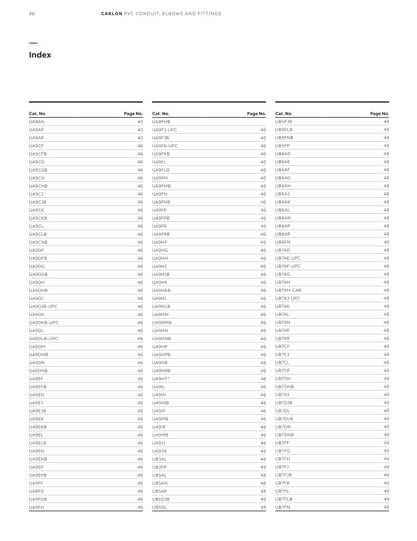
—Index
Cat. No. Page No.
UA9FHB
UA9FJ-UPC 46
UA9FJB 46
UA9FK-UPC 46
UA9FKB 46
UA9FL 46
UA9FLB 46
UA9FM 46
UA9FMB 46
UA9FN 46
UA9FNB 46
UA9FP 46
UA9FPB 46
UA9FR 46
UA9FRB 46
UA9HF 46
UA9HG 46
UA9HH 46
UA9HJ 46
UA9HJB 46
UA9HK 46
UA9HKB 46
UA9HL 46
UA9HLB 46
UA9HM 46
UA9HMB 46
UA9HN 46
UA9HNB 46
UA9HP 46
UA9HPB 46
UA9HR 46
UA9HRB 46
UA9HT* 46
UA9IL 46
UA9IN 46
UA9INB 46
UA9IP 46
UA9IPB 46
UA9IR 46
UA9IRB 46
UA9JJ 46
UA9JN 46
UB3AL 48
UB3FP 49
UB5AL 48
UB5AN 48
UB5AP 48
UB5DJB 49
UB5DL 49
Cat. No. Page No.
UB5FJB 49
UB5FLB 49
UB5FNB 49
UB5FP 49
UB6AD 48
UB6AE 48
UB6AF 48
UB6AG 48
UB6AH 48
UB6AJ 48
UB6AK 48
UB6AL 48
UB6AN 48
UB6AP 48
UB6AR 48
UB6FN 49
UB7AD 48
UB7AE-UPC 48
UB7AF-UPC 48
UB7AG 48
UB7AH 48
UB7AH-CAR 48
UB7AJ-UPC 48
UB7AK 48
UB7AL 48
UB7AN 48
UB7AP 48
UB7AR 48
UB7CF 49
UB7CJ 49
UB7CL 49
UB7DF 49
UB7DH 49
UB7DHB 49
UB7DJ 49
UB7DJB 49
UB7DL 49
UB7DLB 49
UB7DN 49
UB7DNB 49
UB7FF 49
UB7FG 49
UB7FH 49
UB7FJ 49
UB7FJB 49
UB7FK 49
UB7FL 49
UB7FLB 49
UB7FN 49
Cat. No. Page No.
UA9AN 45
UA9AP 45
UA9AR 45
UA9CF 46
UA9CFB 46
UA9CG 46
UA9CGB 46
UA9CH 46
UA9CHB 46
UA9CJ 46
UA9CJB 46
UA9CK 46
UA9CKB 46
UA9CL 46
UA9CLB 46
UA9CNB 46
UA9DF 46
UA9DFB 46
UA9DG 46
UA9DGB 46
UA9DH 46
UA9DHB 46
UA9DJ 46
UA9DJB-UPC 46
UA9DK 46
UA9DKB-UPC 46
UA9DL 46
UA9DLB-UPC 46
UA9DM 46
UA9DMB 46
UA9DN 46
UA9DNB 46
UA9EF 46
UA9EFB 46
UA9EH 46
UA9EJ 46
UA9EJB 46
UA9EK 46
UA9EKB 46
UA9EL 46
UA9ELB 46
UA9EN 46
UA9ENB 46
UA9EP 46
UA9EPB 46
UA9FF 46
UA9FG 46
UA9FGB 46
UA9FH 46
96 C A R LO N P VC CO N D U IT, EL B OW S A N D FIT TI N G S

IN D E X
Cat. No. Page No.
UB7FNB 49
UB7FP 49
UB7FR 49
UB7HJ 49
UB7HK 49
UB7HN 49
UB7HR 49
UB7IR 49
UB9AD 48
UB9AE 48
UB9AF 48
UB9AG 48
UB9AH 48
UB9AJ 48
UB9AK 48
UB9AL 48
UB9AN 48
UB9AP 48
UB9APB 48
UB9AR 48
UB9CF 48
UB9CG 48
UB9CH 48
UB9CJ 48
UB9CK 48
UB9CL 48
UB9DF 48
UB9DG 48
UB9DH-UPC 48
UB9DHB 48
UB9DJ-UPC 48
UB9DJB 48
UB9DK-UPC 48
UB9DKB 48
UB9DL 48
UB9DLB 48
UB9DN 48
UB9DNB 48
UB9FF 48
UB9FG 48
UB9FH 48
UB9FJ 48
UB9FJB 48
UB9FK 48
UB9FKB 48
UB9FL 48
UB9FLB 48
UB9FN 48
UB9FNB 48
Cat. No. Page No.
UB9FP 48
UB9FR 48
UB9HH 48
UB9HJ 48
UB9HK 48
UB9HL 48
UB9HN 48
UB9HNB 48
UB9HP 48
UB9HR 48
UB9IP 48
UB9IR 48
UB9NN 48
VC9902 53
VC9903 53
VC9922 52
VC9923 52
VC9924-24 52
VC9932 53
VC9941P 52
E942J 78
VC9961P 52
VC9962 52
VC9963 52
VC9963SC 27/54
VC9964 52
VC9981P 53
VC9982 53
VC9983 53
VC9984 53
VC9992 21/54
VC9LV2 52
VC9LV4-24 51
VVC9LV3 51
XD10NM 5
XD1NM 5
XD2NM 5
XD3NM 5
XD5NM 5
XD6NM 5
XD7NM 5
XD8NM 5
—Index
97

98 C A R LO N P VC CO N D U IT, EL B OW S A N D FIT TI N G S
Additional informationWe reserve the right to make technical changes or modify the contents of this document without prior notice. With regard to purchase orders, the agreed particulars shall prevail. ABB AG does not accept any responsibility whatsoever for potential errors or possible lack of information in this document.
We reserve all rights in this document and in the subject matter and illustrations contained therein. Any reproduction, disclosure to third parties or utilisation of its contents – in whole or in parts – is forbidden without prior written consent of ABB AG.

99

—USABB Installation ProductsElectrification business860 Ridge Lake Blvd.Memphis, TN 38120+1 901-252-5000 www.tnb.abb.com
7TK
K0
00
122
06
.07.
2019
© Copyright 2019 ABB. All rights reserved. Specifications subject to change without notice.