


Bahasa
Halaman
Hukum


THE MEASUREMENT
INDUCTION SHOCKS
A MANUAL FOR THE QUANTITATIVE
USE OF FARADIC STIMULI
ERNEST G. MARTIN ,PH . D .
ASSISTANT PROFESSOR OF PHYSIOLOGY IN
HARVARD MEDICAL SCHOOL
FI R S T E D I TI ON
FIRST THOUSAND
NEW YORK
JOHN W ILEY SONS
LONDON : CHAPMAN HALL, LIMITED
COPYRIGHT . 191 2 ,
ERNEST G. MARTIN
ll . G I LS O N CO M PA N Y
B O S TON.
00
0
PREFATORY NOTE
THE method of measuring induction shocks described
in the following pages was developed in a series of papers
published between 1908 and 19 1 1 in the American Jour
nal of Physiology. Extended use of the method by
myself and coworkers has shown it to have great value
in many physiological and psychological researches . In
order to make the method more readily available for
investigators, and with the hope that thereby quantita
tive studies may be more generally made,the scattered
material of the original papers has been assembled into
the form herein presented . Since the work aims to
serve rather as a manual than as an exposition of prin
ciples, only so much theoretical matter is included as is
necessary to make intelligible the procedures adopted .
E . G. M .
BOSTON , April, 19 1 2.

CONTENTS
CHAPTER I .
THE CHARACTERISTICS or INDUCED CURRENTSIntroductoryHistoricalStructure of the InductoriumPrinciple of the InductoriumThe Form of Make and Break Induced Currents
CHAPTER II.
FACTORS WHICH Am er THE STRENGTHS or FARADIC STIMULI .
Sources of VariationMethods Previously ProposedPflfiger
Meyer-FickKroneckerv. Fleischl
Wertheim-Salomonson
Hoorweg-Giltay
CHAPTER HI .
A SUMMARY or PROCEDUREInstruments Required for the CalibrationAmmeter and ShuntStimulating ElectrodesProcedure .
VI CONTENTS
CHAPTER IV.
THE PHYSICAL PRINCIPLES UNDERLYING THE MEASUREMENT . OFBREAK SHOCKS .
The Course of Break Induced Currents
PACE
CHAPTER V .
THE DETERMINATIONS or MUTUAL INDUCTION BETWEEN PRIMARYAND SECONDARY COILS
CHAPTER VI .
EFFECTS PRODUCED BY AN IRON CORE IN THE PRIMARY COIL .
CHAPTER VII.
COMPARISON OF ONE COIL WITH ANOTHER —THE VALUE OF L .
CHAPTER VIII.
THE PREPARATION OF A CALIBRATION SCALE FOR BREAK SHOCKS .
CHAPTER IX .
THE MAKE AND BREAK OF THE PRIMARY CIRCUIT .
The Knife-blade KeyThe Operating DeviceThe Short-circuiting Device
CHAPTER X .
THE INFLUENCE OF SECONDARY RESISTANCE AND OF CATHODESURFACE
The Relation of Tissue Resistance to Secondary Resistance asaWhole
Determination of Tissue ResistanceEfiect upon the Stimulus of Varying the Secondary ResistanceCurrent Density, an Important Factor
CONTENTS vii
CHAPTER X Continued.
PAGE
The Dependence of FactorA upon Inductorium Construction 78
Conditions in which the Specific Stimulus need not be Determined
A Standard of Inductorium Construction Necessary
CHAPTER X I .
THE MEASUREMENT OF MAKE SHOCKS .
Comparison of the General Formula for Break and MakeStimuli
CHAPTER XII.
ERRORS To BE AVOIDED
INDUCTION SHOCKS
CHAPTER I
THE CHARACTERISTICS OF INDUCED CURRENTS
Introductory. The inductorium has become one of
the most familiar and most useful instruments in the
physiological laboratory . There are few physiological
researches which do not involve artificial stimulation of
tissues ; and for the production of stimuli induction
shocks are in most cases the first choice . They are
easier to use and they subject the stimulated tissue to
less permanent modification than do other forms of
artificial stimulus . Induction shocks are,however
,very
variable in intensity ; and as commonly used there is
no means of knowing or of stating their physiological
efiectiveness in other than the most general terms . An
induction shock is weak,medium
,or strong . More
closely than that the user does not attempt to describe it.
This lack of knowledge as to the strengths of the
stimuli employed is often a serious handicap in the pros
ecution of individual researches, particularly such as
call for the use of stimuli of varying strengths . It also
2 INDUCTION SHOCKS
operates to make uncertain the attempts of investigators
to duplicate the experiments of others .
No one will question the desirability of being able to
measure faradic stimuli, both for the sake of controllingthe stimuli used in one’s own experiments
,and also in
order that these stimuli may be so described as to
enable other workers to duplicate them as occasion
arises .
The purpose of this work is to outline a system for
calibrating the apparatus used in generating induction
shocks,so that the value of the shocks may be expressed
in terms of stimulation units ; these units to be appli
cable to any properly constructed induction apparatus,
and to be based upon determinations which can be made
in any ordinarily equipped physiological laboratory .
The system proposed is not a new departure,but is an
extension and amplification of previous systems .
Historical. The phenomenon of electromagnetic in
duction was discovered by Faraday in 183 1 and its
physical characteristics were very thoroughly worked
out by him and by Henry about the same time . The
first suggestion for the physiological use of induction
shocks appears to have been made by Sturgeon “ in
1837, and from that time to the present their use in this
connection has continued .
Various forms of induction apparatus have been de
Annales de Sturgeon : 1837, p. 477.
THE CHARACTERISTICS OF INDUCED CURRENTS 3
vised, but for physiological purposes only one has come
into common use ; this form,designed by E . du Bois
Reymond in 1848 , is illustrated in Figs . 1 and 2 .
Such modifications of this design as have arisen since
its introduction have to do only with details,and not at
all with the underlying principle of the apparatus .
Structure of the Inductorium. The induction coil,as
adapted by du Bois-Reymond to physiological use , con
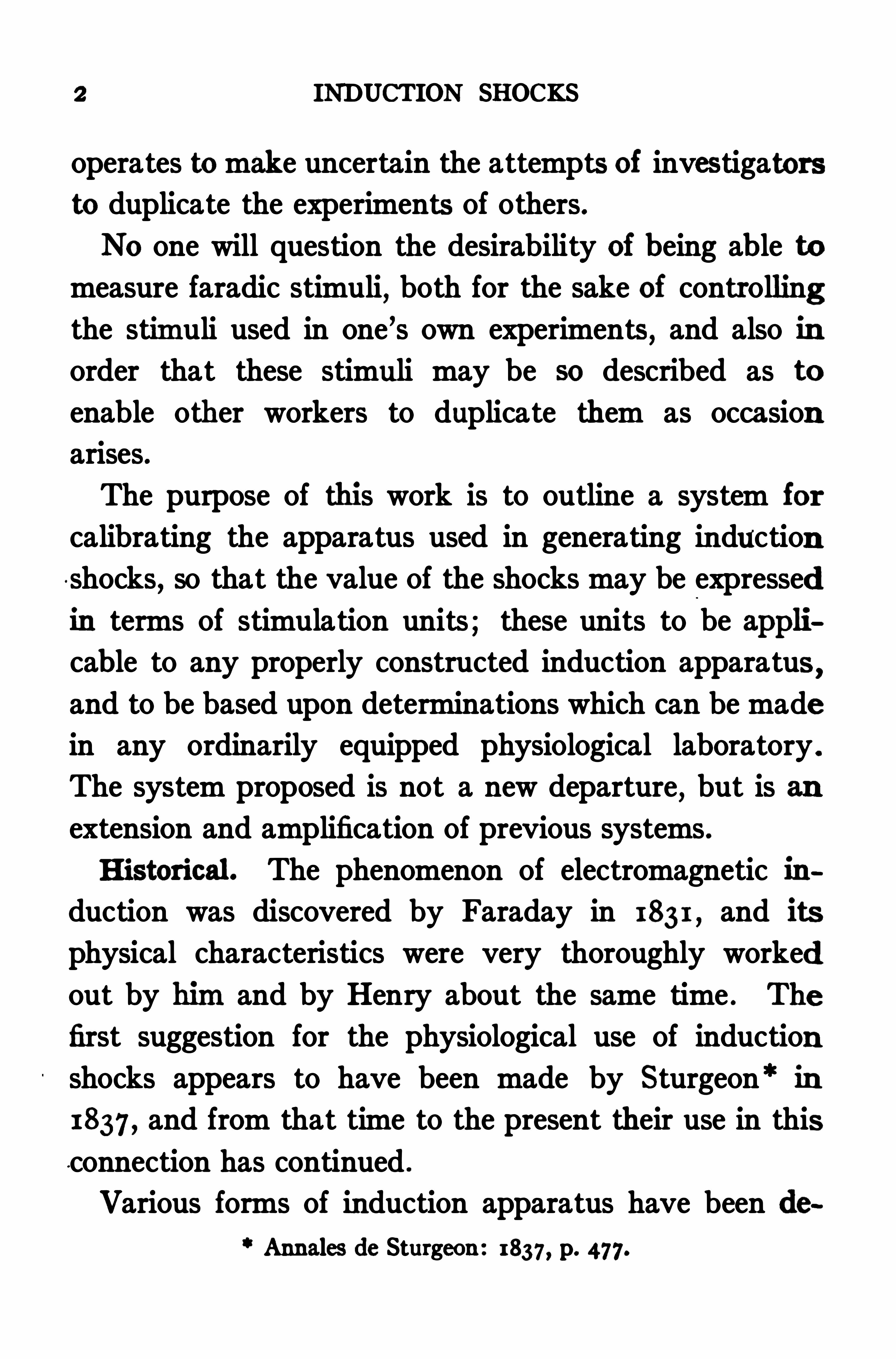
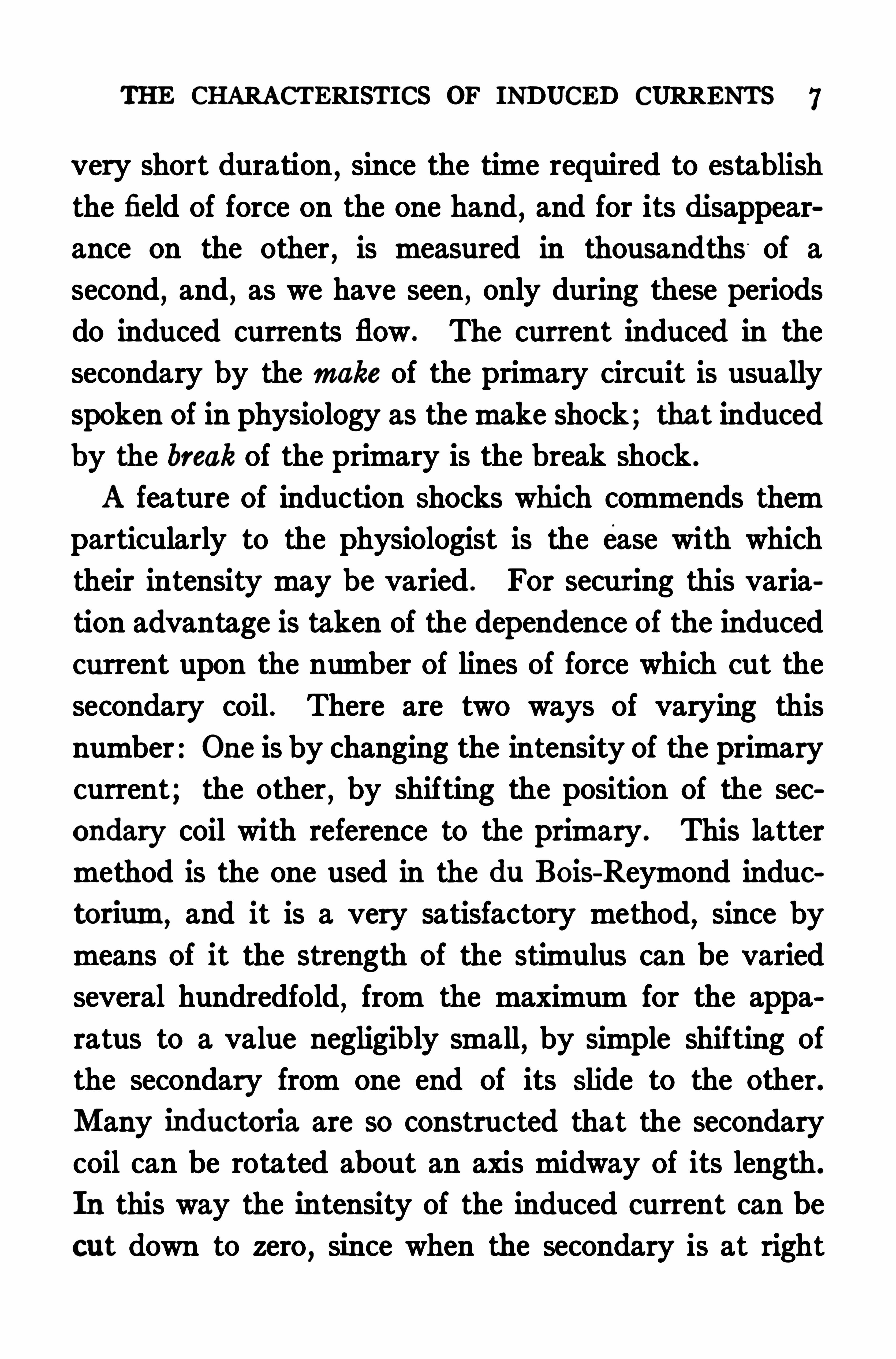
FIG. 1 . The induction coil as used for physiological purposes(du Bois-Reymond pattern) : A, the primary coil ; B , the secondarycoil ; P
’,binding posts to which are attached the wires from the battery
they connect with the ends of coil A P”,binding posts connecting
with ends of coil B,through which the Induction current is led ofi ; S ,
the slide, with scale, in which coil B ismoved to alter its distance fromA.
Sists,in essence
,of two coils of carefully insulated copper
wire . One of these, the primary coil, is made up of
two or three layers of rather coarse wire wound upon a
hollow core of nonconducting material. Usually the
outside diameter of this coil is about to 4 cm .,and
its length between 8 and 14 cm . The number of turns
du Bois-Reymond : Unters. fiber tierische Electrizitfit, 1848, Bd. I ,
S. 447 ; also, Bd. II, I , S . 393 .
4 INDUCTION SHOCKS
of wire does not ordinarily exceed 600. The coil is
mounted horizontally by one end upon a suitable support . The ends of the wire are brought to two
binding posts, situated at some convenient place on the
support .
The other coil,the secondary
,consists of numerous
turns of very fine insulated wire,wound upon a hollow
spool whose inside diameter is such that the secondarycoil can be brought over the primary . The number of
turns of wire is usually between 5000 and The
length of the secondary coil is about equal to that of
the primary . The ends of the wire are brought to
binding posts mounted upon the spool . A slide, 30 or
40 cm . long,projects from the support of the primary .
The secondary is mounted upon this slide with its axis
coincident with the axis of the primary . A scale,grad
uated in millimeters, is mounted on the Slide . A pointer
on the secondary coil is so placed that it indicates zero
on the scale when the secondary covers the primarycompletely . A device for making and breaking the
primary circuit automatically is usually included as
part of the apparatus ; and a bundle of soft iron wire, 80
constructed as to Slide into the hollow core of the pri
mary coil,is likewise provided .
Principle of the Inductorium. Whenever a steadycurrent is flowing through the primary coil there exists
about it a magnetic field of force. This field may be

THE CHARACTERISTICS OF INDUCED CURRENTS 5
pictured as consisting of lines of force each of which
passes lengthwise through the primary coil,and
,ex
tending a greater or less distance from it into space at
either end, curves outward and back so that the two
ends meet,making each line of force a closed ellipse .
The lines of force are very numerous near the primary
coil,but become less and less frequent as the distance
from the coil increases . The number of lines of force
present and the distance from the coil at which they can
be detected depend upon the intensity of the current
flowing through the coil .
If another coil of wire, the secondary, be placed
within the field of force about the primary in such
position that lines of force pass lengthwise through it,
any alteration in the number of lines of force compre
hended within the secondary generates within it a cur
rent which is the induced current. This current,which
depends upon changes within the field of force,ceases to
be generated whenever the field of force becomes steady,
and outlasts the change in the field only the brief frac
tion of a second required for the current to die away.
The direction of the induced current depends upon the
direction of the current through the primary coil, and also
upon whether the change in the field is an increase or a
decrease in the number of lines of force . The intensityof the currents induced in any secondary coil depends
upon the number of lines of force moving through it,
INDUCTION SHOCKS
and also upon the rate of their movement; the more rapid
the change in the field,the higher the intensity .
The method used in physiology for bringing about
alterations of the field within the secondary coil is to
make and break the current through the primary .
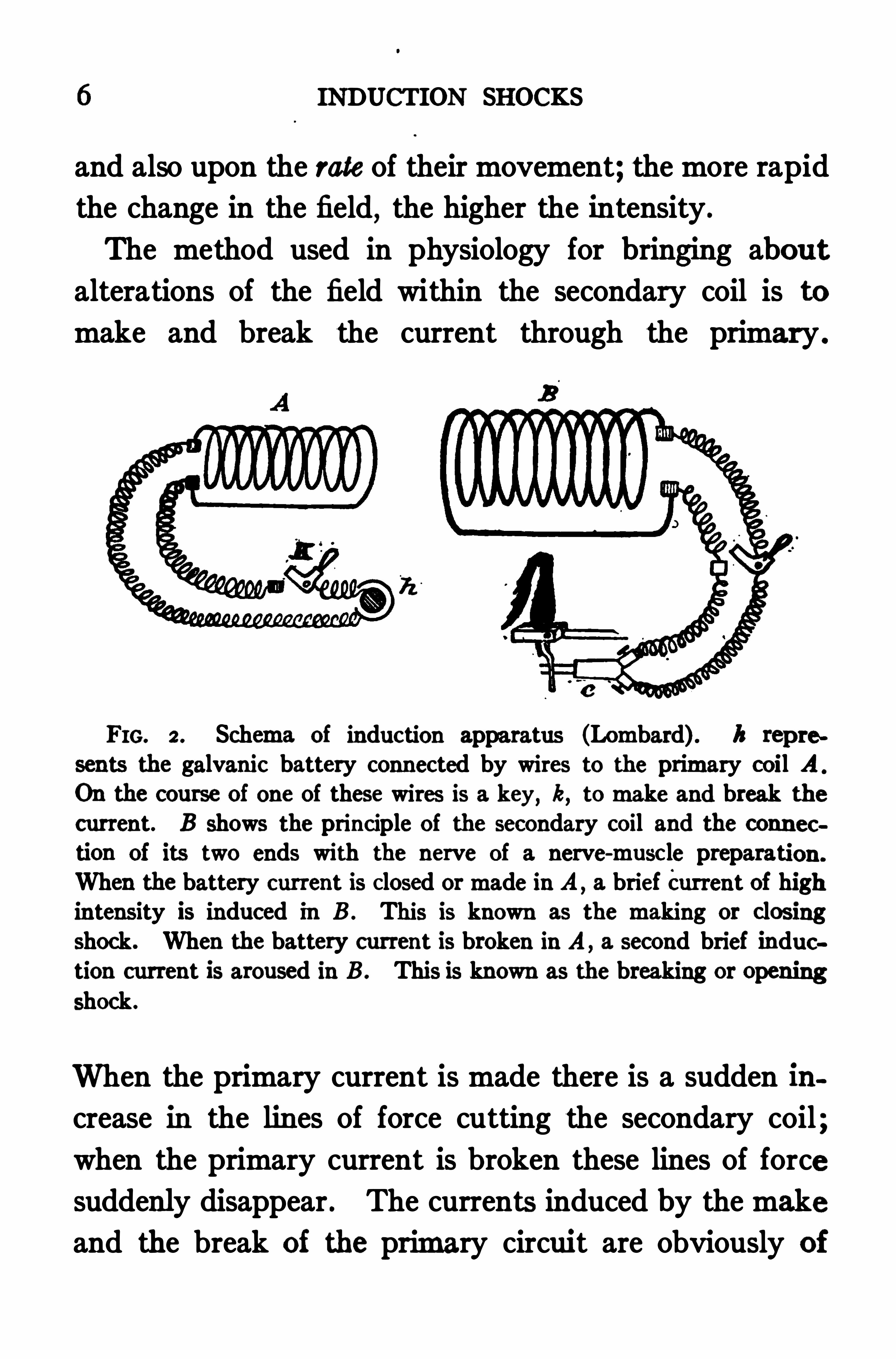
FIG. 2 . Schema of induction apparatus (Lombard) . h repre
sents the galvanic battery connected by wires to the primary coil AOn the course of one of these wires is a key, k, to make and break thecurrent. B Shows the principle of the secondary coil and the connec
tion of its two ends with the nerve of a nerve-muscle preparation.
When the battery current is closed or made in A, a brief Current of highintensity is induced in B . This is known as the making or closingshock. When the battery current is broken in A a second brief induction current is aroused in B . This is known as the breaking or openingshock .
When the primary current is made there is a sudden increase in the lines of force cutting the secondary coil ;when the primary current is broken these lines of force
suddenly disappear . The currents induced by the make
and the break of the primary circuit are obviously of
THE CHARACTERISTICS OF INDUCED CURRENTS 7
very short duration,since the time required to establish
the field of force on the one hand,and for its disappear
ance on the other,is measured in thousandths of a
second,and
,as we have seen
,only during these periods
do induced currents flow . The current induced in the
secondary by the make of the primary circuit is usually
spoken of in physiology as the make shock ; that induced
by the break of the primary is the break shock .
A feature of induction Shocks which commends them
particularly to the physiologist is the ease with which
their intensity may be varied . For securing this varia
tion advantage is taken of the dependence of the induced
current upon the number of lines of force which cut the
secondary coil . There are two ways of varying this
number : One is by changing the intensity of the primary
current ; the other , by shifting the position of the sec
ondary coil with reference to the primary . This latter
method is the one used in the du BoiS-Reymond induc
torium,and it is a very satisfactory method, since by
means of it the strength of the stimulus can be varied
several hundredfold,from the maximum for the appa
ratus to a value negligibly small,by simple shifting of
the secondary from one end of its Slide to the other.
Many inductoria are so constructed that the secondary
coil can be rotated about an axis midway of its length.
In this way the intensity of the induced current can be
cut down to zero,since when the secondary is at right
8 INDUCTION SHOCKS
angles to the primary no lines of force pass lengthwise
through it. For quantitative purposes, however, it is
better to have a rather long slide and to keep the sec
ondary coil always with its axis coincident with that of
the primary .
The Form of Make and Break Induced Currents .
When a circuit is closed through the primary coil of an
inductorium there is a growth of the current within this
coil from zero to its full value . Coincidently with this
growth of current there is being established a field of
force about the coil,and if there is a secondary coil
within this field a current is being induced therein .
This induced current also begins at zero and increases
in intensity during the establishment of the field of
force about the primary . As soon as the field is fully
established,so that movement of the lines of force
ceases,there is no further induction and the current
within the secondary dies away . We may represent the
successive changes in intensity of the induced current
by a curve such as that Shown in Fig . 3 in which the
height of the curve at any point represents the intensityof the induced current at that instant .
The rise of the make induced current from zero to the
maximum,although rapid, is by no means instantaneous,
there being a well marked delay in the establishment of
the current through the primary coil after the circuit is
closed . This delay is due to the phenomenon of induc

Io INDUCTION SHOCKS
ascending limb of the curve of Fig . 3 steeper, but will
also carry it higher ; that is, the current induced in the
secondary will not only reach its maximum intensitymore quickly, but that maximum will be greater ; this
result being due to the fact that the intensity is greater
the more rapid is the alteration in the field of force
cutting the coil.
While a current is flowing steadily through the pri
mary coil no induction is manifest ; but when the current
is broken there is produced in the secondary co il a
break induced current . The agency generating this cur
rent is the sudden withdrawal oi the field of force from
the secondary coil .
With the breaking of the primary circuit it wouldseem at first thought that the lines of force should dis
appear instantly and that there should be an instan
taneous leap of the break induced current from zero tomaximum . AS a matter of fact the growth of the b reak
current,although very rapid, is not instantaneous, for the
reason that with the breaking of the primary circuit
the energy absorbed from the current at its make by
the inductance within the coil is released and manifests
itself as the extra current, jumping across the points
of broken contact as a' spark and prolonging slightly
the decay of the primary current .
The chief difierence between Fig . 10,p . 33 , which rep
resents the course of a break induced current, and Fig . 3,
THE CHARACTERISTICS OF INDUCED CURRENTS I I
representing a make current,lies in the greater steep
ness of the ascending limb of the curve of the break cur
rent, due to the shorter period occupied by the spark
in passing . Here again any condition that hastens the
passage of the spark brings about increased intensity
of induced current by accelerating the disappearance of
the field of force .
Since under most conditions the delay in establishing
the primary current,due to inductance, is greater than
the delay in its disappearance , from sparking at the con
tacts, make shocks are usually less intense physiologi
cally than are break shocks.
CHAPTER II
FACTORS WHICH AFFECT THE STRENGTHS OFFARAD ICSTIMULI
ANY scheme for measuring induction Shocks,if it is
to be wholly satisfactory, must take into account all
the sources of possible variation present in the mechan
isms by which the shocks are generated and applied
to tissues. The numerous methods which have been
worked out hitherto have been uniformly based upon
sound physical principles, and give accurate results so
far as they go ; they leave something to be desired , how
ever,in that none of them deals with all the conditions
of variation which are actually present whenever tis
sues are stimulated, and their usefulness is limited byjust that much . The justification for the present work
lies in its attempt to take into account all the sources
of variation which exist . These are to be divided into
those whose influence upon the strength of stimuli is
in accordance with mathematical laws, determinable by
the experimenter,and those which are not apparently so
determinable . The former are made the basis for the
system of measuring stimuli herein described ; the latter
are studied with a view to showing how their efiects
may be minimized .
STRENGTHS OF FARADIC STIMULI 13
Sources of Variation. The induction apparatus, as
used in the physiological laboratory, consists of two cir
cuits : the primary, or inducing circuit, which includes
the primary coil of the inductorium,a source of current,
and a device for making and breaking the circuit,to
gether with the necessary connecting wires ; and the
secondary circuit, including the secondary coil, wires
leading thence to suitable stimulating electrodes, and
the tissue to be stimulated . In Fig . 2, p . 6, these cir
cuits are illustrated diagrammatically .
In any given primary circuit variations may arise
either in the amount of current yielded by whatever
source of current is used ; or in the key, whereby the
circuit is made and broken . In any given secondary
circuit variations may arise in the position of the sec
ondary coil with respect to the primary, this being, as
we have seen, the usual method of bringing about varia
tions in stimulating strength ; in the electrical resistance
of the tissue which is being stimulated ; and in the con
tacts between the stimulating electrodes and the tissue
to which they are applied. Also difl'
erent inductoria
usually present structural diflerences, such as difl'
erent
dimensions and diflerent numbers of turns of wire in
primary and secondary coils,which themselves bring
about wide diflerences in the strengths of stimuli gen
crated by the diflerent inductoria. The presence or
absence of an iron core within the primary coil is also
14 INDUCTION SHOCKS
a source of great modification of stimuli . Finally, as we
have seen, there is a difference in physiological efl ect
between make shocks and break shocks.
Of the sources of variation just de scribed the followingare subject to laws which are determinable
,and are to
be included,therefore
,in our quantitative scheme : The
construction of the inductorium,the position of the sec
ondary coil with respect to the primary, the presence or
absence of an iron core in the primary, the intensity and
voltage of the primary current, the use of make or b reak
shocks,the electrical resistance of the stimulated tissue
and the mode of contact of the stimulating electrodes
with the tissue .
The variable which is not determinable is the efl ect
on the stimulus of the manner of making or breakingthe primary circuit . This must be
, so far as possible,made uniform .
Methods Previously Proposed. The first attemp t to
measure induction Shocks is said to have been made by
Rosenthal in 18 Two years later Pflugermade quan
titative comparisons between shocks, varying their in
tensities by varying the primary current,leaving
'
all
other factors constant . His method gives accurate rela
tive results, but seems not to have commended itself tophysiologists
,probably because it calls for a rather com
See Garten : Handbuch der physiol. Methodik, 1908, Bd . II,Abt. 3 , S 393
STRENGTHS OF FARAB IC STIMULI I 5
plex mechanism for varying and at the same time
measuring the primary current.
The earliest method of mea suring induction shocks
which received wide recognition was worked out under
the direction of Fick by his student,Meyer, in
This method concerned itself altogether w ith the eflect
upon the intensity of break shocks of shifting the posi
tion of the secondary coil relative to the primary, and
amounts , therefore, to a mh'
bration of the slide upon
which the secondary coil moves . By such calibration
the relative intensities of the shocks given by the in
rately indica ted, so long as all the other variable factors
remain unchanged. A Similar calibration is an es sential
feature of any scheme for the quantitative use of the
inductorium,and indeed the only criticism of the Ficlr
method of mea suring stimuli is for its incompletenes s.
The Fick cah'
bration was accomplished by including in
the secondary circuit a galvanometer and determiningthe current induced in the secondary coil at its various
positions by the deflection produced when a given cur
rent was made or broken through the primary . This
method,although Simple in theory, was in fact rather
difi cult to put into practice with the electrimlmeasuring
Meyer :

16 INDUCTION SHOCKS
Kronecker,* in 1871 , introduced a modification of the
method whereby its application was simplified . He used
two inductoria, connected their secondary coils in series
with a galvanometer and connected both primary coils
with a single source of current in such fashion that the
two secondaries gave induced currents opposite in direc
tion when the primary circuit was broken. Thus the
galvanometer deflection was used merely as an indicator
that one induced current was stronger than the other,rather than as a measure of the strength of the induced
current itself .
With both secondaries at zero the primary current
was broken and the amount and direction of deflection
noted . The coil giving a stronger shock was then moved
outward till no deflection occurred . Then the weaker
coil was moved outward till a deflection equal to the
first one was obtained . This procedure was repeated
till the whole length of the slide had been traversed, the
number of times the stronger secondary was moved be
ing noted . If this number is multiplied by the original
galvanometer deflection we have a value which ex
presses how many times greater the galvanometer de
flection would be with the secondary at zero than at the
end of the slide . To calibrate the slide on the basis of
1000units, as Kronecker does, the total deflection noted
Kronecker: Arbeiten aus der physiologischen Anstalt zu Leipzig,187I , S. 186.
I8 INDUCTION SHOCKS
v. Fleischl,
‘ in 1875 , proposed a method of cah'
brating
the inductorium in which for the galvanometer deflec
tion was substituted the threshold contraction of a
nerve-muscle preparation . In this cah'
bration the de
creases in stimulating value which result from movingthe secondary coil outward were compensated by in
creasing the current through the primary coil, the in
creases required being taken as the measure of the
change in stimulating intensity resulting from the move
ment of the secondary . This method has the advantage
of being available in situations where no galvanometer
can be obtained . Its greatest importance lies,however
,
in confirming the assumption of Fick and of Kronecker
that the physiological intensities of break induced cur
rents are proportional to the galvanometer deflections
they produce .
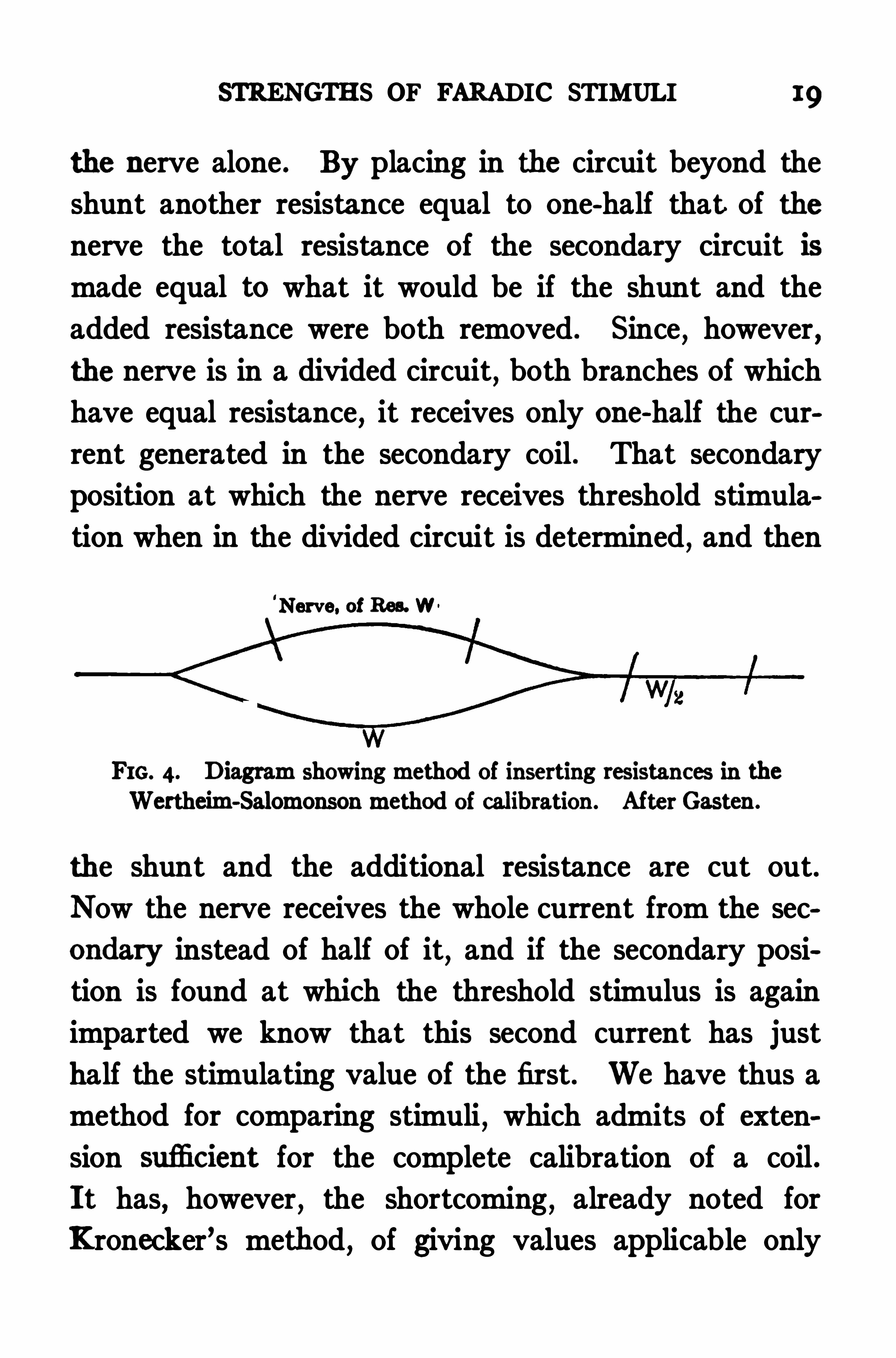
Wertheim-Salomonson'
l‘ has recently described a
method for obtaining a physiological calibration in
which variations in the primary current are avoided.
He places the nerve of the nerve-muscle preparation to
be used as an indicator in one branch of a divided sec
ondary circuit, and in the other branch places a re
sistance equal to that of the nerve . (See Fig . The
resistance of the divided circuit is then one-half that of
v. Fleischl: Sitzb . d. k. Akad. d. Wissensch. Wien, 1875 , Bd.
lxxn, Abth. III . Also Gee. Abh.,1893 , S. 475 .
1Wertheim-Salomonson : Zeitschr. f. Elektrother. I., 1899 , S. 97.
STRENGTHS OF FARADIC STIMULI 19
the nerve alone . By placing in the circuit beyond the
shunt another resistance equal to one-half that of the
nerve the total resistance of the secondary circuit is
made equal to what it would be if the shunt and the
added resistance were both removed . Since,however
,
the nerve is in a divided circuit, both branches of which
have equal resistance,it receives only one-half the cur
rent generated in the secondary coil . That secondary
position at which the nerve receives threshold stimula
tion when in the divided circuit is determined,and then
'
Nerve. of Res. W .
FIG. 4. Diagram showing method of inserting resistances in theWertheim-Salomonson method of calibration. After Gasten.
the shunt and the additional resistance are cut out.
Now the nerve receives the whole current from the sec
ondary instead of half of it, and if the secondary posi
tion is found at which the threshold stimulus is again
imparted we know that this second current has just
half the stimulating value of the first. We have thus a
method for comparing stimuli,which admits of exten
sion suflicient for the complete calibration of a coil .
It has, however, the shortcoming, already noted for
Kronecker’s method,of giving values applicable only

20 INDUCTION SHOCKS
to the single coil on which it is worked out . One very
important feature of a wholly satisfactory calibration
must be its general applicability, so that any properly
constructed inductorium can be calibrated in any labo
ratory to give results comparable with those obtained
from other calibrated instruments.
Moreover,it is not to be forgotten that no method
of calibration thus far described takes into account the
effects of strength of primary current,of tissue resistance,
or the method of applying the stimulating electrodes,
all of which are important,and at the same time de
terminable,and therefore to be included in a complete
calibration scheme ; nor do any of them consider the
strength of make shocks,all being available only for
breaks .
A device which is superior in certain respects to any
thus far described for measuring stimuli is the fara
dimeter of Edelmann . In this apparatus a galvanom
eter in the secondary circuit registers the voltage of the
induced current . The galvanometer readings give cor
rect indications of the values of stimuli only when a
current of definite,fixed amperage is broken in the
primary circuit . It is necessary,therefore
,to have a
source of currents specially selected to give this amper
age,and by means of an ammeter in the primary cir
cuit to insure that it is maintained . The Edelmann
method is an advance over others in that it takes
STRENGTHS OF FARAB IC STIMULI 2 1
account of the factor of primary current strength and
provides for its regulation . It does not, however, take
account of the influence upon the strength of stimulus
of variations in tissue resistance, since the quantity
measured by the galvanometer, namely the voltage, is
independent of the resistance . Nor does it consider the
effect of the method of application of the stimulating
electrodes . But so long as these two factors remain
constant the Edehnann faradimeter gives accurate re
sults for break shocks, and expresses them in terms
such that the stimuli used by one worker can,save for
the factors above mentioned,be duplicated by others .
The importance of taking secondary resistance into
account was brought out by Hoorweg* in 1893 . He
demonstrated the eflect of variations in resistance in
modifying stimulation strengths, and emphasized the
necessity of working out some method by which to
ascertain this effect. At his suggestion GiltayTde
signed an electrodynamometer by which the variations
in strength of stimulus due to varying secondary re
sistances can be read directly. This apparatus fulfils
admirably the purpose for which it was designed . It
is,however
,of little practical use in physiology
,since
its readings,to be comparable, must be made with the
Hoorweg : Diemedicinische Elektrotechnik und ihre physikalischenGrundlagen,
Leipzig, 1893 .
t Giltay : Annalen der Physik und Chemie, 1893 , Bd. so, S. 756.
2 2 INDUCTION SHOCKS
same inductorium or with inductoria of precisely similar
construction,and the position of the secondary coil
with respect to the primary must not be altered . In
view of the fact that moving the secondary coil is the
usual method among physiologists for varying the
strength of stimulus,this instrument clearly does not
altogether meet the requirements of physiological work .
It has,moreover
,the somewhat serious shortcoming
of taking no account of the method of applying the
stimulating electrodes,so that
,even were all the other
conditions met, the electrodynamometer would still fail
to give wholly complete measurements .
Our examination of the various systems hitherto pro
posed for measuring induction shocks bears out the
statement made at the outset that none of them meets
fully the requirements of quantitative work . We are
justified therefore in submitting a system which, although
not new,being an extension of the Fick-Kronecker
method, attempts to deal with all the factors concerned
in the production of faradic stimuli, so that henceforth
the values of stimuli may be expressed in such terms
that they can be duplicated or modified quantitatively
at will .
CHAPTER III
A SUMMARY or PROCEDURE
FOR the convenience of users of the method herein
presented it has been thought worth while to describe
briefly at the outset the various pieces of apparatus
used and to summarize the various procedures involved
in making the necessary calibrations and in using the
calibrated apparatus .
Instruments Required for the Calibration The in
ductorium to be calibrated should be of standard
construction (see p . that is, it should have a sec
ondary coil approximately 13 cm . long and having about
turns of wire . The number of turns and the
mean cross section of the secondary coil must be accu
rately known (p . The slide upon which the sec
ondary moves should be not less than 30 cm . long . It
should be accurately graduated in millimeters,and a
pointer fixed to the secondary coil in such position as to
stand at zero when the secondary is pushed completely
over the primary . To increase the stimulating effec
tiveness of the instrument the primary coil should have
a core made of a bundle of soft iron wires .
In addition to this inductorium there is needed a con
24 INDUCTION SHOCKS
stant source of current sufficient in amount to yield at
least I ampere through the resistance of the primary
coil . Where a charging current is available,probably a
good storage battery will be found most convenient as a
source of current . Several Daniell cells in series, how
ever, answer every pur
pose . A good ammeter
for measuring the inten
sityof the primary current
is required,as is also a
variable resistance for ad
justing its amount . Since
it is often necessary in
the course of the work
to use currents ranging
from ampere to 1
ampere the ammeter must
be able to cover this range .
No instrument is,of
course , able to measure
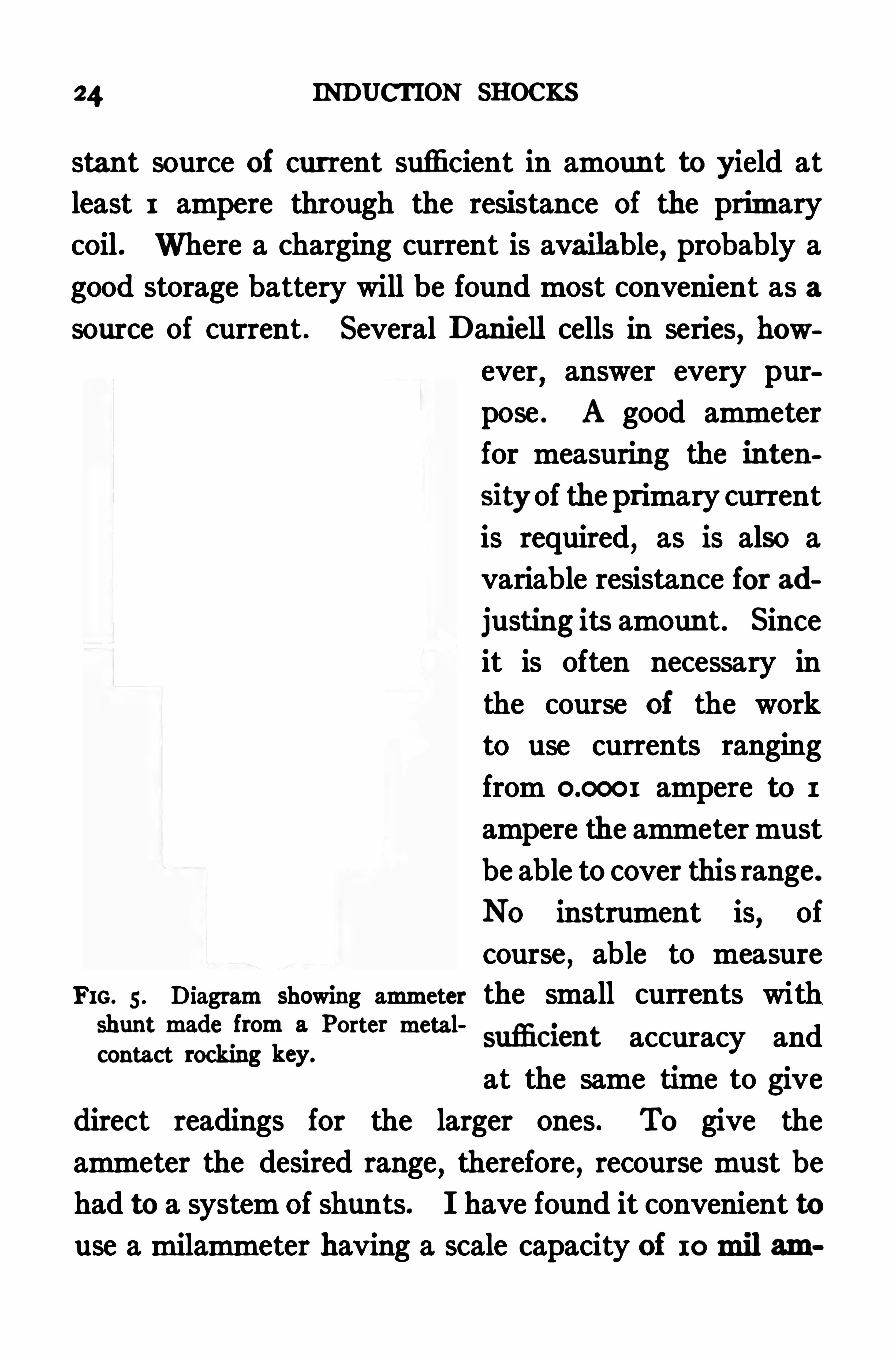
FIG. 5 . Diagram showing ammeter the small currents with
iflffikfifie;Pm “ metal'
suflicient accuracy and
at the same time to give
direct readings for the larger ones . To give the
ammeter the desired range,therefore, recourse must be
had to a system of shunts. I have found it convenient to
use a milammeter having a scale capacity of 10mil am
rcutfne af m ki'
ng fi x a fi n fim m h sh xb med m t
the qm rfrafive zs t cr’
fi t h hx tin cfi l as ' efl as for
made in any machine shop It cons'
s ts of a primary
coil, at l&st 75 cm. long and composed of a single layer
of hea vy insulated wire . carefully wound, and a sec
ondary coil, not over 1 5 cm. long . of about 2000 tums
of fine wire, placed exactly at the center of the primary
meter of the primary coil must be known, and the total
number of turns of the secondary .
Additional apparatus required in the use of the in
ductorium,but not in the cah
'
bration,is, first, a device
for determining tissue resistance, and, second, suitable
stimulating electrodes. I have found the Kohlrausch
method of measuring resistance perfectly satisfactory
(see p. This method requires an ordinary meter
A SUMMARY OF PROCEDURE 27
bridge,a small inductorium to give an alternating cur
rent,a telephone receiver for an indicator and a resist
ance box. By suitable wiring, illustrated in Fig . 1 5 ,
p . 73 , a single resistance box can be used both for vary
ing the primary current and as the known resistance in
the Kohlrausch determinations.
The stimulating electrodes must be selected with
special reference to uniformity of contact . Accurate
quantitative results cannot be gotten under conditions
of contact variation . For the direct stimulation of
muscles I have found platinum needle electrodes most
satisfactory . A piece of platinum wire to 3 cm .
long, and mm . in diameter,pointed somewhat at the
end with a file, is soldered to a suitable length of very
fine copper wire (diameter The platinum
needle is thrust directly into or through the muscle
tissue ; the copper wire, carried to the secondary ter
minal,aflords the very flexible connection necessary for
avoiding interference with the free movement of the
muscle .
For stimulating nerves the glass-inclosed electrodes
described by Sherrington are as reliable as any I know
of. They answer well either for the stimulation of nerves
deeply imbedded within the body , or for stimulating the
nerve of the ordinary nerve-muscle preparation . In the
use of this form of electrode care must be taken that the
Sherrington: Jour. of Physiol. , 1909 , xxxviii, p. 382.
28 INDUCTION SHOCKS
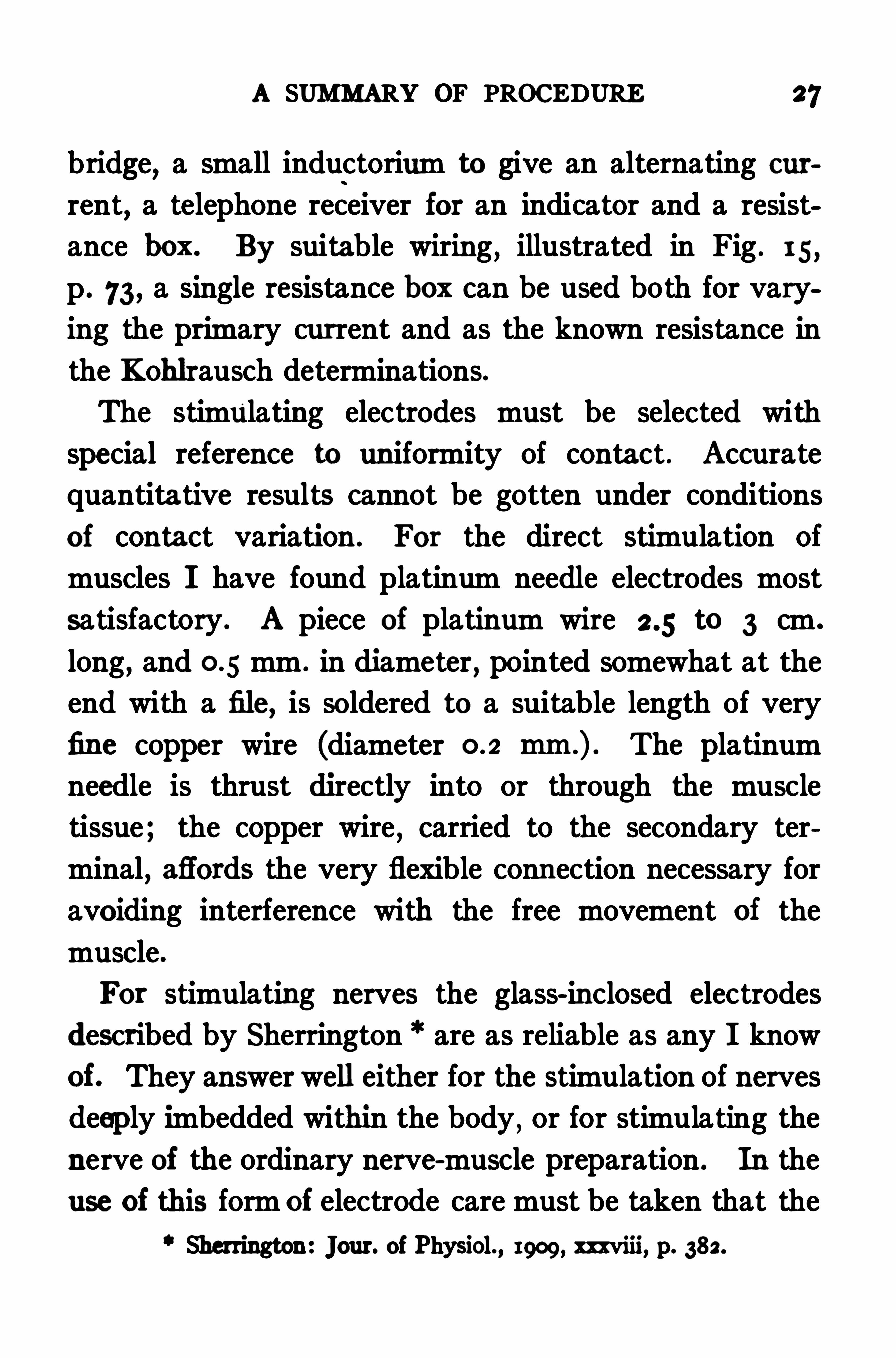
interior of the glass tube is clear of liquid . The elec
trode is shown in Fig . 6 ; contact is made by rotating
slightly the stopper carrying the two platinum wires.
For the determination of specific stimulation val
ues (see p . a rather large known resistance,ten
thousand to twenty thousand ohms,must be arranged to
be included in the secondary circuit as required .
FIG. 6. Shielded electrodes (Sherrington) .
The arrangement of apparatus for making the cali
bration is illustrated diagrammatically in Fig . 7 . The
procedure is by the following steps,for each of which
a page reference is given .
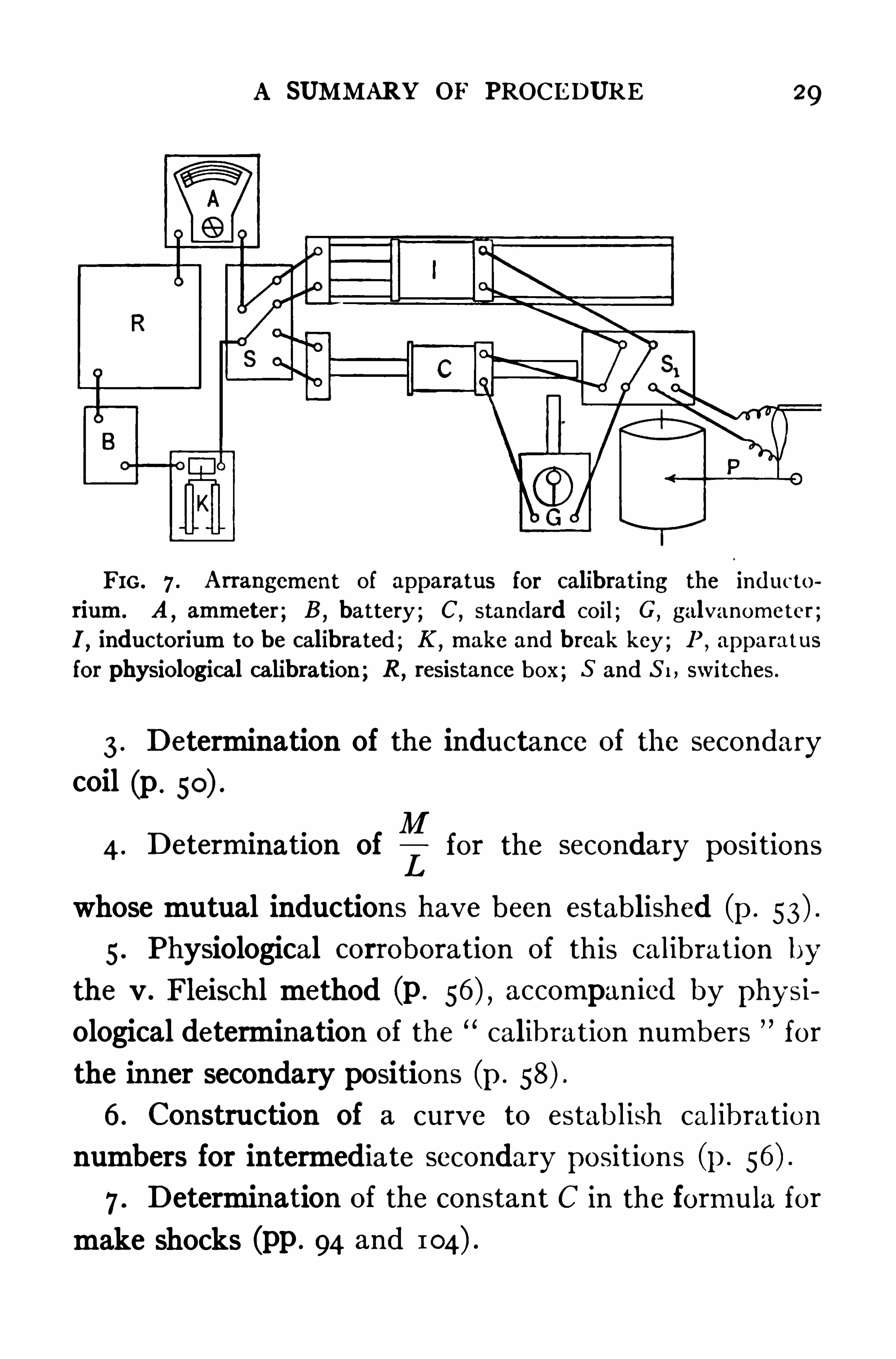
1 . Determination of the formula for core magnetiza
tion (p . 43)2 . Determination of the mutual induction for a series
of selected secondary positions from 1 2 cm. outward
(p.
SUMMARY OF PROCEDURE 29
FIG. 7 . Arrangement of apparatus for calibrating the inducto
rium. A,ammeter ; B ,
battery ; C,standard coil; G, galvanometer ;
I,inductorium to be calibrated ; K ,
make and break key ; P ,apparatus
for physiological calibration ; R,resistance box ; 5 and S 1, switches .
3 . Determination of the inductance of the secondary
coil (p .
4 . Determlnatlon ofLfor the secondary posrtlons
whose mutual inductions have been established (p .
5 . Physiological corroboration of this calibration by
the v . Fleischl method (p . accompanied by physi
ological determination of the calibration numbers for
the inner secondary positions (p .
6 . Construction of a curve to establish calibration
numbers for intermediate secondary positions (p .
7 . Determination of the constant C in the formula for
make shocks (pp . 94 and
30 INDUCTION SHOCKS
FIG. 8. Arrangement of apparatus for the use of the quantitativemethod . 1 , battery ; 2
,resistance box in primary circuit ; 3 , slide
wire resistance for fine adjustment ; 4, ammeter ; 5 , ammeter shunt ;6 , make and break key with automatic short-circuiting device for makeor break shocks; 7, inductorium; 8 ,
resistance box in secondary circuit ;9 , wires lea ding to stimulating electrodes .
FIG. 9 . View of apparatus in actual use. Significance of numbersis the same as inFig . 8.
A SUMMARY OF PROCEDURE 31
The of apparatus for the of the
quantitative method is indicated diagrammatically in
Fig. 8. The diagram is self-explanatory. As an addi
tional guide,a photograph of a set of apparatus in actual
use is reproduced in Fig . 9 . In the final chapter of the
book various precautions are described which much ex
perience with the method has suggested.
CHAPTER IV
MENT OF BREAK SHOCKS
HELMHOLTZ “ appears to have been the first to study
in detail break induction shocks . He established the
principles which are still accepted as to their formation
and course . His work was chiefly from the physical
standpoint,although he gave attention also to the physi
ological aspect of the problem . More recently Fleming 1“
has given a clear and concise discussion of break induc
tion shocks,his presentation agreeing in every essential
particular with the earlier one of Helmholtz . The fol
lowing statement is,in the main
, condensed from Flem
ing’s discussion .
The Course of Break Induced Currents. The current
induced in a secondary coil by the breaking of the
primary current may be represented graphically by such
a curve as is given in Fig . 10,beginning at zero
,increas
ing rapidly to a maximum,and then falling more slowly
away to zero . If the break of the primary were abso
Helmholtz : Poggendorf’s Annalen der Physik und Chemie, 185 1 ,
lxxxiii, S. 536. Also, Gee. Abh. , S . 459 .
t Fleming : The Alternate Current Transimmer, London, 1892 , i,
on 184 a we.
34 INDUCTION SHOCKS
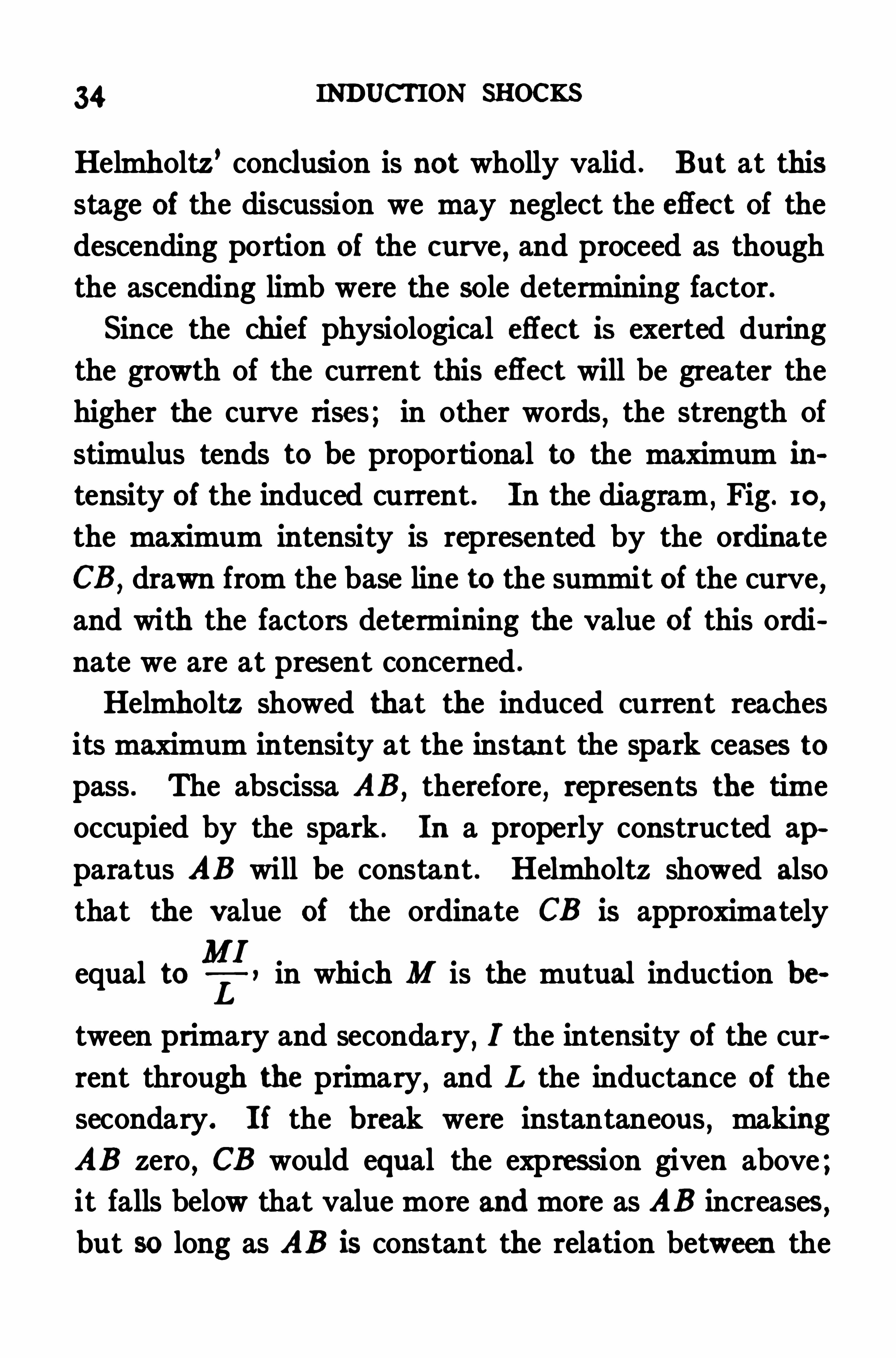
Helmholtz’conclusion is not wholly valid . But at this
stage of the discussion we may neglect the eflect of the
descending portion of the curve , and proceed as though
the ascending limb were the sole determining factor.
Since the chief physiological efl ect is exerted during
the growth of the current this eflect will be greater the
higher the curve rises ; in other words , the strength of
stimulus tends to be proportional to the maximum ih
tensity of the induced current . In the diagram,Fig . 10
,
the maximum intensity is represented by the ordinate
CB,drawn from the base line to the summit of the curve,
and with the factors determining the value of this ordi
nate we are at present concerned .
Helmholtz showed that the induced current reaches
its maximum intensity at the instant the spark ceases to
pass . The abscissa AB,therefore
,represents the time
occupied by the spark . In a properly constructed ap~
paratus AB will be constant . Helmholtz showed also
that the value of the ordinate CB is approximately
equal to in which M is the mutual induction be
tween primary and secondary,I the intensity of the cur
rent through the primary, and L the inductance of the
secondary. If the break were instantaneous , making
AB zero, CB would equal the expression given above ;it falls below that value more and more as AB increases,but so long as AB is constant the relation between the
THE MEASUREMENT OF BREAK SHOCKS 35
true value of CB and the value which it approxi
mates,does not vary.
MIWe may use the expressIon
Ltherefore
,as a physI
cal basis for the measurement of break shocks,although
we must note that the expression will not serve fully,
since the factor of secondary resistance is not included
in it,nor is there any factor for the influence of the
manner of applying the stimulating electrodes . More
over,the expression is proportional to the strength of
the stimulus only so long as the circuit is broken uni
formly. The expression serves in our quantitative
scheme,therefore
,only as a starting point . Its use even
so far is justifiable only if physiological tests confirm the
applicability of the physical relationships . That they
do so completely will be shown in due course .
Our next step is a consideration of the individual
factors in the expressionI
2]and a discussion of the
means whereby they are to be determined .
Of the three factors which make up the expression,
one,I,the intensity of the primary current
,is an easily
measured electrical quantity,and is best determined
directly by means of an ammeter in the primary circuit .
The other two, M and L
,are functions of the construe
tion of the inductorium,either by itself or as modified
36 INDUCTION SHOCKS
by the relative positions of the primary and secondary
coils . M, the mutual induction between the primary
and secondary coils , varies with changes in the position
of the secondary relative to the primary,but is fixed for
each position. It can therefore be determined once for
each position of the secondary coil,and the values thus
obtained used in all future calculations .
Since mutual induction is the factor which varies
with Shifts in the position of the secondary coil relative
to the primary,most of the calibrations hitherto pro
posed amount in efl'
ect to determinations of the relative
mutual inductions for the various secondary positions .
That the stimulating power should theoretically be pro
portional to the mutual induction so long as the other
factors remain constant is obvious from inspection of the
expression That the proportion really does exist
is proved by the experimental verification of the Fick ,Kronecker
,and Edelmann calibrations, as well as by the
experiments carried out in the development of the pres
ent method .
‘
L,the inductance of the secondary coil , is a function
of the construction of the coil and is therefore constant
for any given inductorium except as it is modified by
extraneous influences . When the inductorium is used
Martin : Amer. Jour. of Physiol. , 1908, n u, p. 1 23 .
THE MEASUREMENT OF BREAK SHOCKS 37
with an iron core in the primary,this acts to modify the
value of L whenever the secondary coil is directly over
the iron core .
The methods by which M and L are determined in
practice are outlined in succeeding chapters.
CHAPTER V
THE DETERMINATIONS OF MUTUAL INDUCTIONBETWEEN PRIMARY AND SECONDARY COILS
IN determining the mutual induction for the various
secondary positions advantage is taken of the fact that
this factor appears in the expression for the integral
efl'
ect of the induced current . This integral eflect is
represented in the diagram (Fig . by the entire area
ABCD ; its expression is3
21: in which M and I have
the same meanings as hitherto, and R equals the resist
ance in the secondary circuit . The integral efl ect can
be measured by means of the ballistic galvanometer .
For this purpose the secondary of the induction coil
under examination is connected in series with a good
ballistic galvanometer and with the secondary of a
standard induction coil , the latter apparatus being so
constructed that the mutual induction between its pri
mary and secondary coils can be computed from the con
struction of the apparatus and the current through the
primary . The special features of its construction are
found in the primary, which is a solenoid of one-layer
thickness, very evenly wound, and several times longer33
PRIMARY AND SECONDARY COILS 39
than the secondary . The lines of force through the
secondary,placed at the middle of the primary
,are then
practically straight . The arrangement of the apparatus
is shown diagrammatically in Fig . 7 .
The secondary of the inductorium whose values of
M are desired is set successively at points 1 or 2 cm .
apart . At each point the galvanometer deflection
caused by breaking a primary current of known inten
sity is determined . Since each galvanometer deflec
tion represents a certain integral effect,no matter how
produced,and Since the integral effect affords means
of computing M,a determination of the intensity of cur
rent which has to be broken in the primary of the
standard coil to produce these same deflections provides
all the data required for calculating the values sought .
The formula used for computing M is developed in the
following manner : The expression for the integral effect
MIIs
,as stated above
,
RLet thi s represent the gal
vanometer deflection caused by breaking a current of
intensity I in the primary of the coil whose values of M
R
galvanometer deflection caused by breaking a current of
intensity S through the primary of the standard coil .
MI M’S
Equating these,we have
R RThe method of
are desired . Let the expression represent the same
40 INDUCTION SHOCKS
connecting the secondaries is,as stated previously
, pur
posely such that the value of R is constant throughout .
It therefore disappears from the equation and we have
MI M’S . The value of M is computed from the
construction of the standard coil according to the formula
M’4 1rnNAS in which n equals the number of turns in
the primary coil per centimeter of length,N the total
number of turns in the secondary coil,A the area of the
cross section of the primary,and S the current through
the primary in electromagnetic units . Since this current
is measured in amperes,it is necessary in practice to
call S the intensity of the primary current in amperes
and divide the expression by 10 to reduce to electro
magnetic units . The formula for M then becomes
4 1rnNAS 4 1rnNA
10
standard coil,and once determined is substituted
M in the equation MI M'
S
To illustrate the process of determining mutual
ductions by this method, suppose the standard coil
the following dimensions :
The value is constant for any given
Number of turns in primary per centimeter .
Total number of turns in secondaryArea of cross section of primary
The value of4 1 mNA
is and the equation for
mutual induction is M Now suppose that
42 INDUCTION SHOCKS
directly as the values of M for those positions . By de
termining these values, then, we provide ourselves with
a calibration which reveals accurately the eflect on stim
ulating strength of shifting the secondary coil . Such a
calibration,as previously stated, is a necessary basis in
any scheme for the quantitative use of induction shocks.

CHAPTER VI
EFFECTS PRODUCED BY AN IRON CORE IN THEPRIMARY COIL
INASMUCH as the almost universal practice in physio
logical work is to use inductoria with iron cores,a brief
discussion of the eflects of such cores on stimulation
strengths seems desirable at this point . Thus the
method becomes at once applicable to inductoria with
iron cores as well as to those not provided with them .
The principal eflect of the iron core is that which has
led to its use, namely a great increase in the number of
lines of force surrounding the primary coil, with a cor
responding increase in the intensity of the stimuli gen
crated .
Another efiect is that noted in a previous paragraph
(p . of altering the eflectiveness of the stimuli gen
crated when the secondary coil is directly over the pri
mary, so that in these positions MI is not constant for a
constant stimulus . The method of correcting the cali
bration for this eflect of the iron core is given in Chap .
VIII, p . 58 .
The iron core has also an eflect upon stimulation
strength due to itsmagnetization by the primary current ,an efiect which appears
,however
,only when primary
currents of considerable intensity are used . Allowance
44 INDUCTION SHOCKS
for this efl ect in computing the values of MI must
be made , whenever I is large, by introducing a correc
tion factor. This factor can be obtained without difli
culty by the use of the ballistic galvanometer,since the
deflections of that instrument are afl ected by core magnetization. Inspection of the formula MI =M’
S (p . 40)shows that so long asM and M’remain constant
,I,the
current through the primary of the coil under examina
tion,must vary directly as S ,
the current through the
primary of the standard coil . This relationship is found
by experiment to hold in ordinary induction coils for
values of I up to ampere,but above that point the
value of S is always larger than the equation calls for.
In other words,when core magnetization is present the
primary current produces a greater deflection than it
does in the absence of this eflect . The variation due to
the magnetization of the core is not very diflicult to
correct, because , as repeated experiment has shown, the
ratio between the actual values of I and those computed
from the values of S depend upon an easily determined
factor which is constant for any given iron core .
To determine this factor some position of the second
ary coil must be selected at which primary currents up
to I ampere give galvanometer deflections not greater
than the entire scale . With the secondary in this posi
tion primary currents of increasing intensity , beginning
at about ampere,are broken, and the deflections
EFFECTS OF IRON CORE m THE PRIMARY COIL 45
produced by each carefully noted . Then with the stand
ard inductorium the values of S giving these same de
flections are determined. Al though at first the ratio
of S to I remains constant,as the values of I begin to
exceed 0. I ampere the ratio steadily increases . It is
evident, therefore, that large currents are producing
relatively greater deflections than small ones . By mul
tiplying the diflerent values of S by the ratio of S to I ,which was constant
,we obtain a series of computed values
of I representing the currents which would be required
to produce the observed galvanometer deflections if no
iron core were present . These are,of course
,the values
of I which are to be employed in computing the strengths
of stimuli according to the expressionL
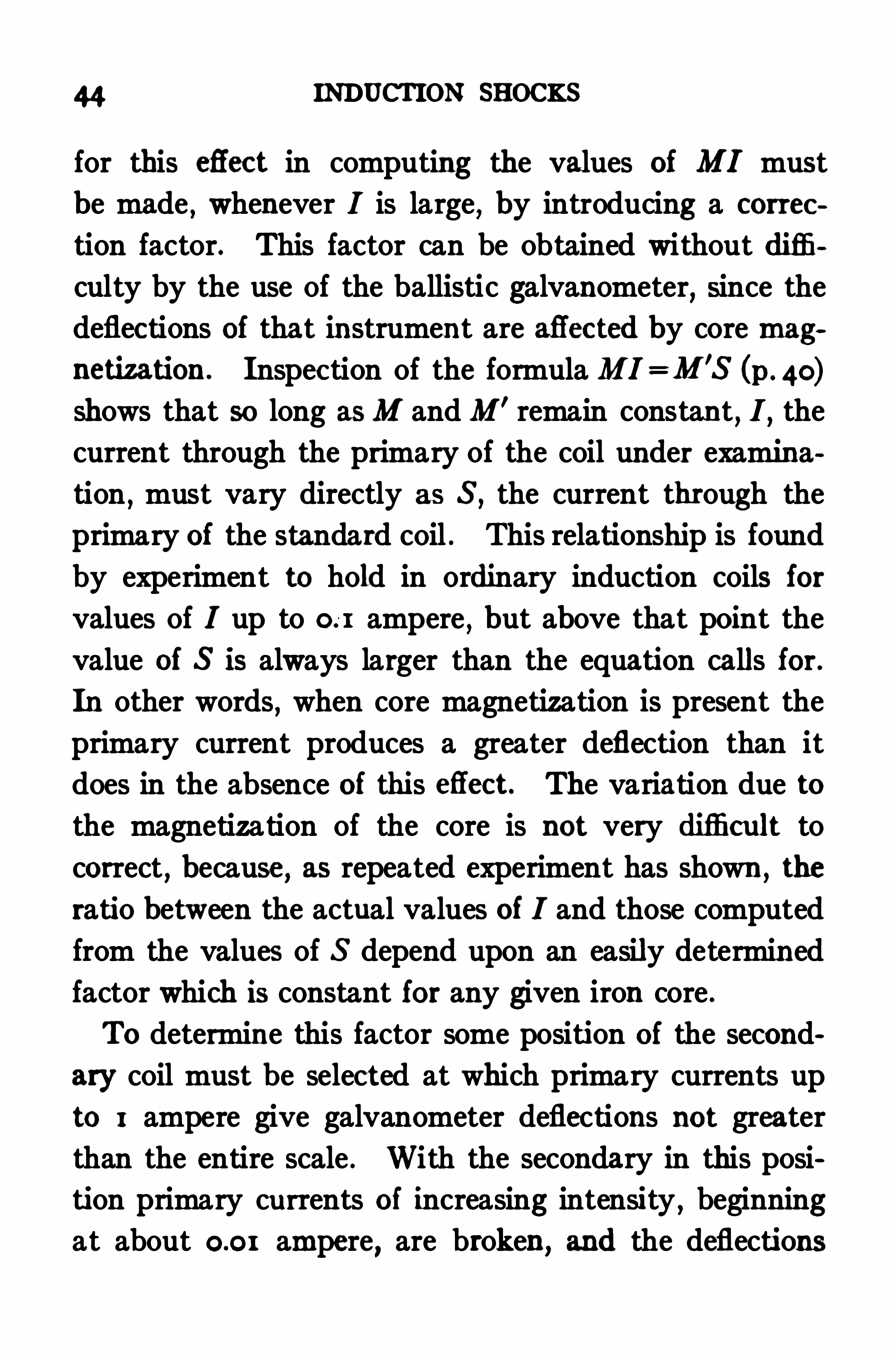
Table I,column 3 , gives the values of I computed
from a series of observed values of I and S in actual
experiments .TABLE I
uted In am value of I to Its
Value of I ob Value of 3 ohV
zlue of ] com Ratio computed
served.
peres . observed value .
46 INDUCTION SHOCKS
To derive the equation for obtaining I computed when
I observed is known we determine in a series of experi
ments the ratios of I computed to I observed (see co lumn
4 of the table) . If now the decimal part of each ratio is
divided by its corresponding value of I observed,a con
stant is obtained which represents the number by which
I observed must be multiplied to obtain this decimal part
of the ratio . This constant is Shown in column 5 .
After the constant is found it is used for computing I
according to the formula I. Io x (I KIo) . In thisformula Io is the computed value of I , Io is its observed
value,and K is the constant
,
— in the case cited in the
table equaling . 22 .
The method of correcting for the magnetization of
the iron core is given in detail since,in Spite of the abun
dant theoretical justification for the omission of the
iron core,especially where quantitative estimations are
sought,for the practical purposes of the physiologis t
the inductorium as commonly used , with the iron core
present,is usually to be preferred . The intensity of
stimulus,other factors being equal
,is at least five times
greater with the iron core than without it in inductoria
of the usual type . This increased efliciency makes it
possible to obtain with primary currents of moderate
intensity as strong stimuli as the physiologist ordinarily
requires . The use of moderate primary currents is of
great importance in quantitative estimations of induc
EFFECTS OF IRON CORE IN THE PRIMARY COIL 47
tion shocks, since thereby is avoided that heavy sparking
at the contacts which always accompanies the break of
a current of high intensity,and which aflects the
intensity of the stimulus in a manner that cannot be
foretold .
When the secondary coil of an inductorium is moved
from the zero position until nearly clear of the primary
coil,it enters a critical region where small changes in
position are accompanied by great changes in the in
tensity of the stimuli given by the instrument . The
impression seems to prevail among physiologists that
inductoria having iron cores show so much greater vari
ations of intensity in this critical region than do those
without iron cores as to make the omission of the iron
core a distinct advantage in many experiments . As a
matter of fact,however
,Kronecker inductoria
,such as
are used in most physiological laboratories, Show for
given changes in secondary position in the critical
region greater variations in stimulation intensity with
cores removed than with cores present . This is appar
ent when the Kronecker graduations of such coils are
compared with the calibrations made for them by the
method of the present work (see p . In the prep
aration of the Kronecker graduations the iron cores
were withdrawn from the instruments . For the cali
brations made in connection with this work the iron
cores were in place .
48 INDUCTION SHOCKS
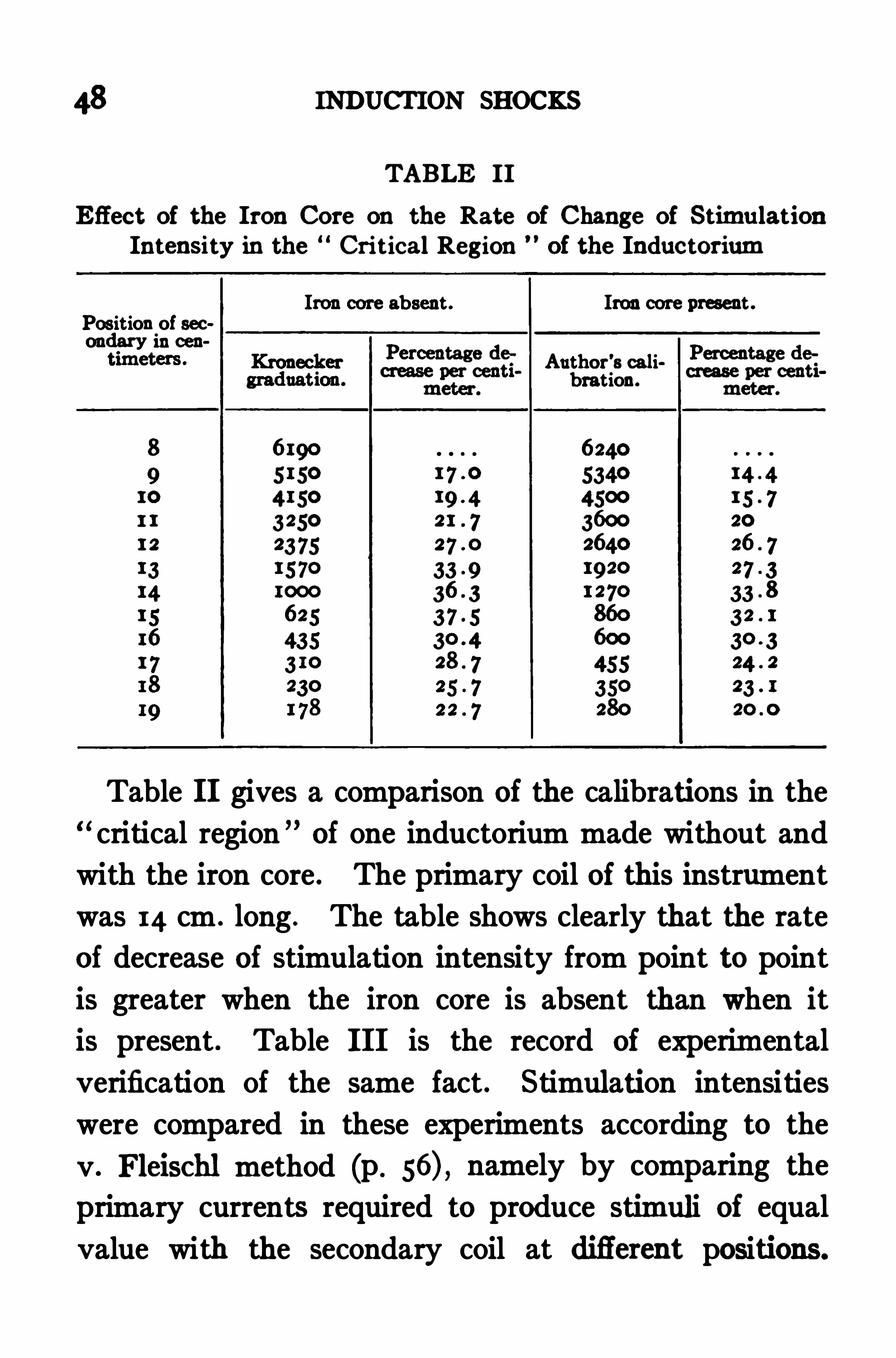
TABLE II
Effect of the Iron Core on the Rate of Change of StimulationIntensity in the Critical Region of the Inductorium
Iron core absent . Iron core present .Position of secondary in cen
Kronecker Author’s calibration.
Table II gives a comparison of the calibrations in the
critical region of one inductorium made without and
with the iron core . The primary coil of this instrument
was 14 cm . long . The table shows clearly that the rate
of decrease of stimulation intensity from point to point
is greater when the iron core is absent than when it
is present . Table III is the record of experimental
verification of the same fact . Stimulation intensities
were compared in these experiments according to the
v . Fleischl method (p . namely by comparing the
primary currents required to produce stimuli of equal
value with the secondary coil at diflerent positions.
CHAPTER VII
COMPARISON OF ONE COIL WITH ANOTHER—mVALUE OF L
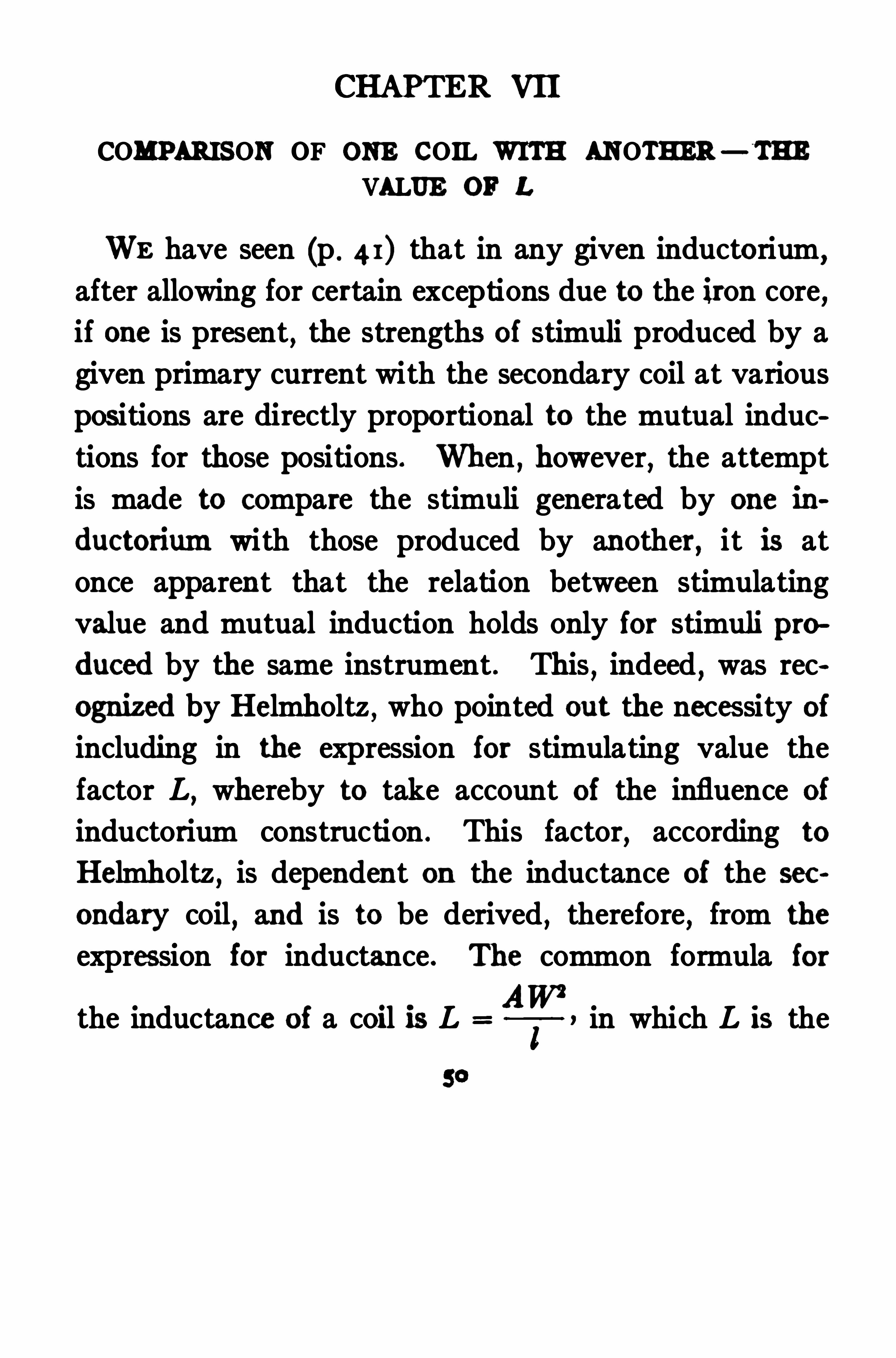
WE have seen (p . 4 1) that in any given inductorium,
after allowing for certain exceptions due to the iron core,if one is present
,the strengths of stimuli produced by a
given primary current with the secondary coil at various
positions are directly proportional to the mutual induc
tions for those positions . When , however, the attempt
is made to compare the stimuli generated by one in
ductorium with those produced by another,it is at
once apparent that the relation between stimulating
value and mutual induction holds only for stimuli pro
duced by the same instrument . This,indeed
,was rec
ognized by Helmholtz , who pointed out the necessity of
including in the expression for stimulating value the
factor L,whereby to take account of the influence of
inductorium construction . This factor,according to
Helmholtz,is dependent on the inductance of the sec
ondary coil, and is to be derived,therefore
,from the
expression for inductance . The common formula for
the inductance of a coil is L in which L is the
COMPARISON OF ONE COIL WITH ANOTHER 5 1
inductance of the coil,A its mean cross section
, W the
number of turns of wire composing it,and 1 its
length .
When, in the course of developing this method of
measuring stimuli,the attempt was made to apply the
above expression for L in the formula_M
L
Ithe curious oh
servation resulted that it applied perfectly with some
inductoria and not with others . That is to say,when
equal stimuli were generated by means of diflerent in
ductoria,equal values of
A
?were given by some, butnot by all
,of the instruments compared . Upon analyz
ing the reason for the diflerence the following fact came
L
Iwere given by those in
ductoria whose secondary coils had the same number ofturns of wire per centimeter of length, regardless of the total
number of turns of wire; unequal values were given by
those inductoria whose secondaries had diflerent numbers
of turns per centimeter of length. If we look now at the
out clearly ; equal values of
expression for L given above,i.e .
,L and sepa
1
rate within it the factor of turns per unit of length, the
expression reads L AW x The experimental re
sults showed as stated above that in all the inductoria

5 2 INDUCTION SHOCKS
having the same value of2: namely the same numberof turns per centimeter
,the expression L AW might
AW2
be substituted for the expression L _land equal
values of for equal stimuli would be given . The
next step was to see whether those inductoria which for
merly gave non-concordant results would give concordant
ones if for the value of L the expression AW,namely the
product of the cross section of the secondary by the num
ber of turns in it,were used . It was found that when this
was done all the inductoria examined gave for equal stim
uli corresponding values of AI
L
]; regardless of the dimen
sions of the coils,but subject to a certain restriction as
to secondary resistance to be discussed later (p .
In order to bring this point out clearly some of the ex
periments upon which it is based are cited below (Table
V) . The inductoria used are described in Table IV.
In this table only those inductoria are considered whose
secondaries have difierent numbers of turns per centi
meter,since only by them can be determined which of
the two expressions for L is correct . In all the experi
ments,comparisons were made between the various in
ductoria and a single one known as coil B . This is a
large inductorium with a Kronecker calibration whose
COMPARISON OF ONE con. WITH ANOTHER 53
secondary has 800 turns per centimeter ; it was selected
as a basis of comparison merely for convenience .
In Table IV,columns 5 and 6, are given, for the difler
ent inductoria examined, the values of L AW and
AW”I
To simplify the comparisons between the
various coils the values of as given in Table IV
were all divided by 800, the number of turns per centi
meter in the secondary of coil B ,thus making the value of
L for coil B the same by either formula . These values
are set down in column 7 of the table . To bring the
final results into convenient denominations these figures
and also those in column 5 were divided by 100. It is
understood, of course, that thesedivisions, made purely
for convenience,in no wise modify the relations between
the coils .
In Table V are set down the experimental results of
the comparisons between the various inductoria. Since
details would only confuse,they are omitted . The fig
ures presented in the table show clearly that the proper
Aexpression for L is AW rather than
I
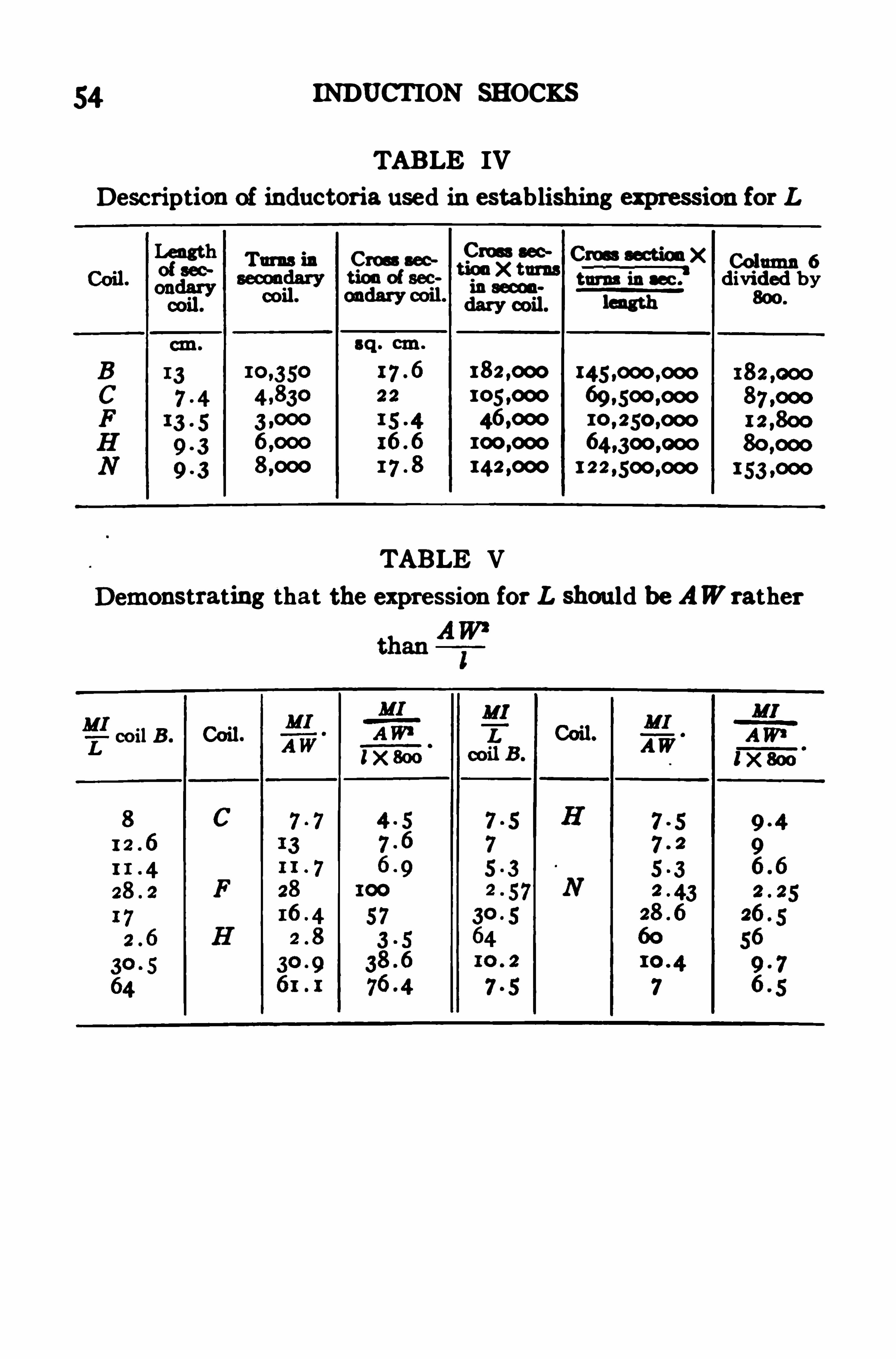
54 INDUCTION SHOCKS
TABLE IV
Description of inductoria used in establishing expression for L
Length a ns in Cross escCross eec Cmss aectionx Column 6
of sec:non of sec
“
3353“
I‘
m”_ia w e? divided by
TABLE V
Demonstrating that the expression for L should be AW rather
coil B .

CHAPTER VIII .
THE PREPARATION OF A CALIBRATION SCALE FOR
BREAK SHOCKS
IN previous chapters the methods of obtaining the
individual factors making up the expression for break
stimulation strength have been discussed in detail . To
Show how these methods are put into practice in pre
paring an inductorium for quantitative use is next in
order. The first step is the determination of the mutual
inductions by the method hitherto described,for a
series of positions,preferably not more than 2 cm .
apart,along the scale . If the instrument to be cali
brated is without the iron core these measurements
should be taken from the zero position outward ; if an
iron core is present there is no advantage gained by
determinations of mutual induction for secondary posi
tions in the region where the secondary coil overlaps
the primary . Having determined these values,each is
divided by L,the product of the cross section by the
number of turns of the secondary coil . The mean
cross section must be determined with great care, a
rather difficult procedure in completed inductoria, and
one which ought to be carried out in connection with
their manufacture .
56 INDUCTION SHOCKS
In order that the final stimulation units may be of
convenient size the value of L which has been adopted
in this scheme is not the direct product of the cross
section by the number of turns of the secondary,but is
that product divided by 100. Having determined this
value , the mutual inductions previously es tablished are
divided by it The resulting figures are the calibra
tion numbers for the particular secondary positions to
which they apply. To determine the numbers for in
termediate positions those determined as above are plot
ted on a rather large scale on cobrdinate paper and a
smooth curve is drawn connecting them . Since the
mutual induction necessarily diminishes,not by fits and
starts,but smoothly, as the secondary is moved out
ward,such a curve, if carefully made, will indicate the
Calibration numbers for intermediate positions with a
high degree of accuracy.
To prove the accuracy of the calibration the method
of v . Fleischl is employed (p . 18) in which the minimal
contraction of a frog’s gastrocnemius is used as the index
of a constant stimulus . In detail this procedure as carried
out by myself was as follows : The freshly isolated gas
trocnemius was suspended by its attached femur in a
moist chamber,and its lower end connected by a small
copper wire to a muscle lever whose effective weight was
about 10gm. ; the muscle was not afterloaded . The lever
had a magnification of about ten, and its point pressed
58 INDUCTION SHOCKS
origin of the muscle was in most cases made the cathode .
Wi th the minimal contraction of the muscle as the index,
the primary current necessary to arouse it, measured in
amperes,is determined with the secondary coil in various
positions . To allow for variations in irritability of the
tissue the experiment should be repeated a number of
times . If the calibration is carefully made in the be
ginning it will be found that in each individual experi
ment the product x I primary current times cali
bration number, is virtually constant,Showing that
the calibration is correct.
Should the inductorium being calibrated have an iron
core,there still remains the establishment of calibra
tion numbers for the region where the secondary coil
overlaps the primary . These,however
,can easily be
determined by extending the experiments,just de
scribed for proving the calibration, to cover this part of
the field . The value of X I is established in any
given experiment from the part of the field where ”A
;known ,
that is,where the calibration has already been
worked out . Since this is constant so long as the stim
ulus is unchanged a determination of the primary current,
I , for this stimulus, in the region where is unknown,
CALIBRATION SCALE FOR BREAK SHOCKS 59
yields at once data for computing By averaging
several experiments this part of the field can be cali
brated with sufficient accuracy.
It must be stated,however
,that in the innermost
part of the field,including about half of the length of
the primary coil from zero outward,the calibration num
bers determined by the v . Fleischl method will be found
to difler somewhat according as the tissue used as an
indicator has high or low resistance,high resistances
showing larger calibration numbers than low ones . For
this reason it is desirable to avoid using this region in
work which requires a high degree of accuracy,unless
a calibration has been previously worked out for the
resistance actually to be employed . Experience shows
that occasions when it is necessary to use the first 5 or
6 centimeters of the scale are of rare occurrence in most
kinds of experimental work .
CHAPTER IX .
FROM the beginning of the use of induction Shocks for
stimulating living tissues investigators have recognized
that the physiological intensities of these Shocks are
markedly afiected by the manner of making or breaking
the primary circuit. Helmholtz called attention to
this fact in his study of induced currents,and in the dis
cussion of the variable factors to be considered in the
attempt to measure induction shocks (p . I pointed
out that the manipulation of the primary key is a vari
able whose influence cannot be mathematically deter
mined , and which , therefore, must be made as uniformas possible .
Before entering upon a discussion of means whereby
the manipulation of the primary make and break key
can be made uniform, it is desirable to point out briefly
the manner in which variations in the break and make
of the primary circuit modify stimulating intensities .
In the account of the theoretical basis for the break
shock formula, Z I (p . the statement was
Helmholtz : Poggendorf’s Annalen der Physik und Chemie, 185 1 ,
lxn iii, P 538
THE MAKE AND BREAK OF THE PRIMARY CIRCUIT 61
made that this expression applies exactly only when the
break is instantaneous,although it holds relatively so
long as the time occupied by the break does not vary.
Since this in turn depends on the duration of the spark,our present inquiry resolves itself, so far as break shocks
are concerned,into a study of the conditions governing
contact sparking.
The duration of the spark at a broken primary con
tact depends in part upon the intensity of the primary
current,in part upon the amount of volatilization occur
ring at the contact,and in part upon the speed with
which the points are separated . This last factor ex
plains why keys operated by hand cannot be depended
upon to give uniform results,and why some form of
automatic key is required,since only thus can a uniform
speed of separation be secured . Moreover,ordinary
mercury keys cannot be depended on even when oper
ated automatically,because of the tendency of mercury
when not absolutely clean to cling in drops and thus
vary the speed with which the contact points actually
separate . In practically all keys there is some volatil
ization ; platinum contacts giving the least, ordinary
mercury contacts the most . It is impracticable to use
always primary currents of a single intensity ; but, in
primary currents not exceeding I ampere,the variation
is too Slight to be of practical importance .
The making of a primary circuit is not attended with
62 INDUCTION SHOCKS
sparking,so that the sources of error for makes are not
the same as for breaks . As a circuit is made the re
sistance falls from infinity to the resistance of the closed
circuit itself . It is during the change from the first of
these resistances to the second that the secondary cur
rent is induced . The more nearly instantaneous the
change,the greater is the physiological intensity of the
induced current . In hand-operated metal-contact keys
there can be no assurance that'
the contact points will be
pressed together with the same firmness twice in succes
sion,so that to secure uniformity of contact automatic
keys are required for make shocks as well as for breaks .
A further and more serious defect in metal-contact keys
for make shocks is their liability to rebound Slightly,or
to slip sidewiseithus giving not a single clean-cut make,but a succession of make, break ,
and make . So con
stantly has this defect Shown itself in my experiments,even with carefully constructed automatic metal-contact
keys,that I have found it necessary to use mercury con
tacts altogether in studying make Shocks .
The considerations stated above lead to the following
conclusions : That hand-operated keys are not to be de
pended on for uniform makes and breaks ; that for break
shocks platinum contacts are to be preferred to mercury
because‘
of their less volatilization , while for makeshocks
,on account of the rebound or side-slip of metal
contacts, mercury afiords the only trustworthy contact .
THE MAKE AND BREAK OFTHE PRIMARY CIRCUIT 63
It is, of course, wholly undesirable to equip the pri
mary circuit with two keys,
one of mercury to be
used for making the circuit,and another of platinum for
breaking it .
make and break key with
mercury contacts which has
been proved by several years’
experience to give uniform
breaks and makes .*
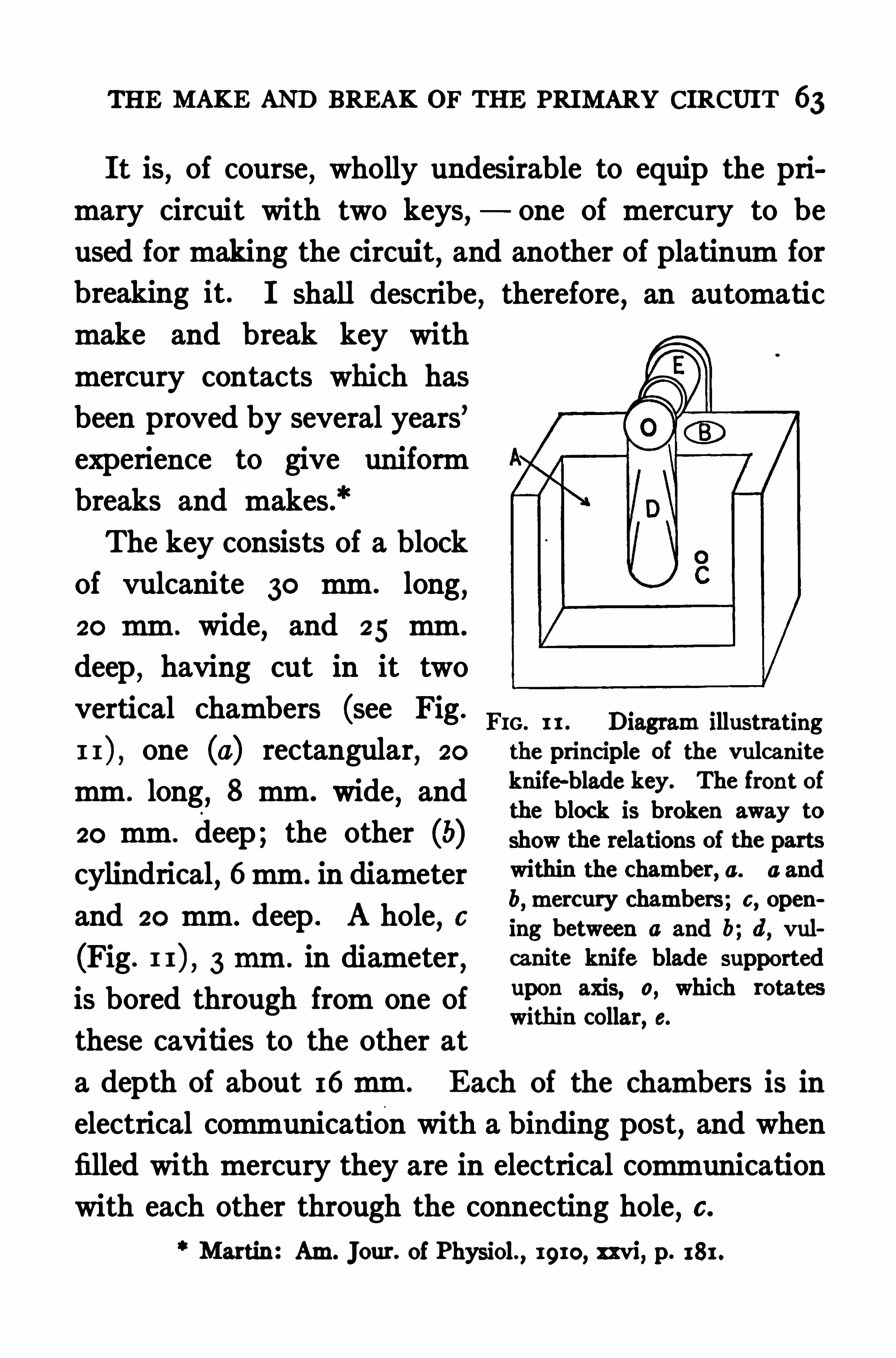
The key consists of a block
of vulcanite 30 mm . long,
20 mm . wide,and 25 mm .
deep,having cut in it two
vertical chambers (see Fig .
one (a) rectangular, 20
mm . long,8 mm . wide
,and
20 mm . deep ; the other (b)cylindrical
,6mm . in diameter
and 20 mm . deep . A hole,c
(Fig . 3 mm. in diameter,
is bored through from one of
these cavities to the other at
a depth of about 16 mm.
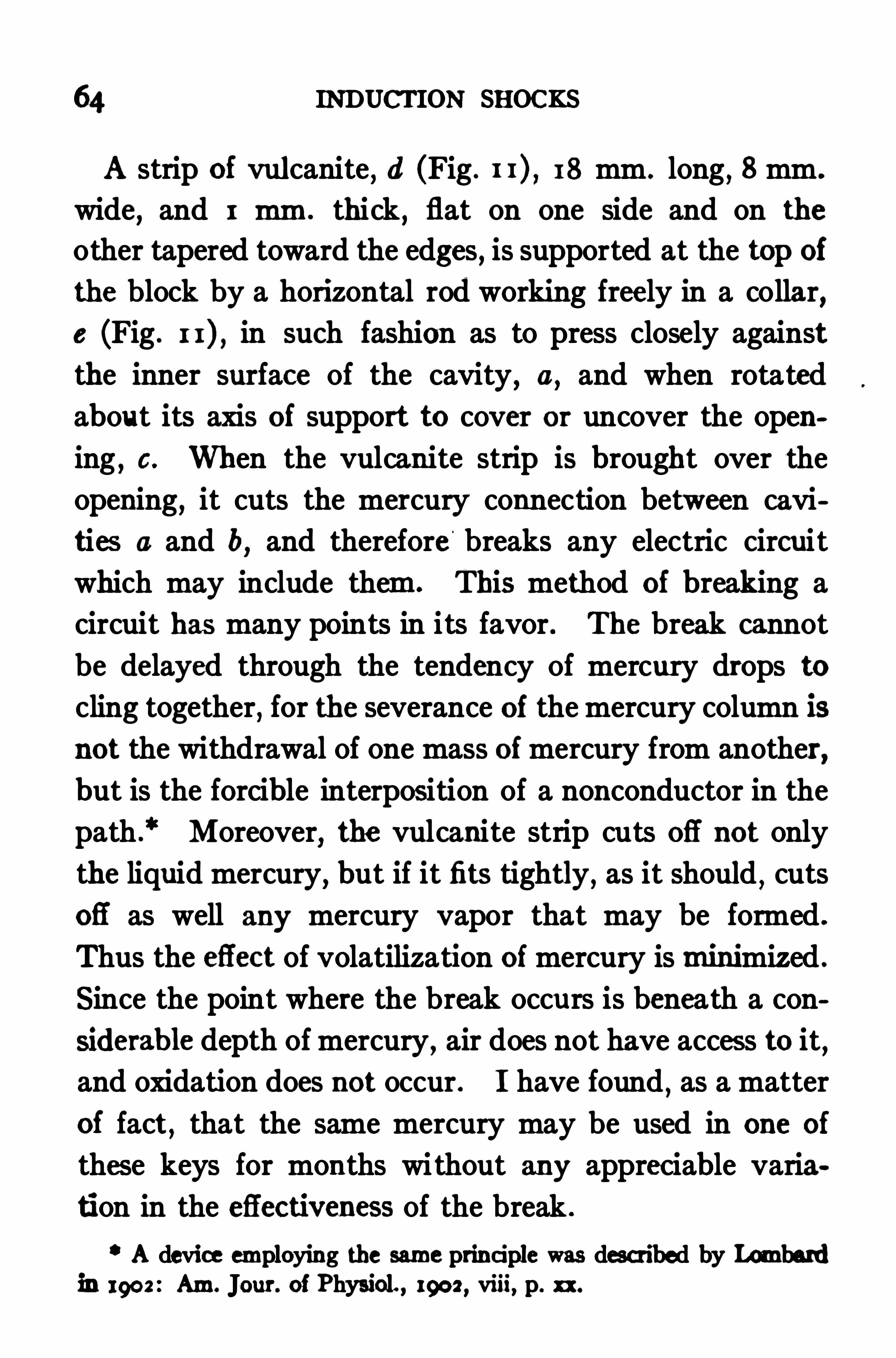
FIG. 1 1 .
I shall describe, therefore, an automatic
Diagram illustratingthe principle of the vulcaniteknife-blade key. The front ofthe block is broken away toshow the relations of the partswithin the Chamber, a. a and
b,mercury chambers ; c, open
ing between a and b ; d, vul
canite knife blade supportedupon axis, a, which rotateswithin collar, e.
Each of the chambers is in
electrical communication with a binding post,and when
filled with mercury they are in electrical communication
with each other through the connecting hole,6 .
Martin : Am. Jour. of Physiol. , 19 10, xxvi, p. 181 .
64 INDUCTION SHOCKS
A strip of vulcanite, d (Fig . 18 mm . long, 8 mm .
wide,and 1 mm . thick, flat on one side and on the
other tapered toward the edges, is supported at the top of
the block by a horizontal rod working freely in a collar,
e (Fig . in such fashion as to press closely against
the inner surface of the cavity, a, and when rotated
about its axis of support to cover or uncover the open
ing,c. When the vulcanite strip is brought over the
opening,it cuts the mercury connection between cavi
ties a and b,and therefore breaks any electric circuit
which may include them. This method of breaking a
circuit has many points in its favor . The break cannot
be delayed through the tendency of mercury drops to
cling together,for the severance of the mercury column is
not the withdrawal of one mass ofmercury from another,
but is the forcible interposition of a nonconductor in the
path .
‘ Moreover,the vulcanite strip cuts ofl
'
not only
the liquid mercury, but if it fits tightly, as it should , cuts
ofl as well any mercury vapor that may be formed .
Thus the eflect of volatilization ofmercury is minimized .
Since the point where the break occurs is beneath a con
siderable depth of mercury, air does not have access to it,and oxidation does not occur . I have found
,as a matter
of fact , that the same mercury may be used in one of
these keys for months without any appreciable varia
tion in the eflectiveness of the break .
A device employing the same principle was described by Lombardin 1902 : Am. Jour. of Physiol. , 1902 , viii, p. xx.
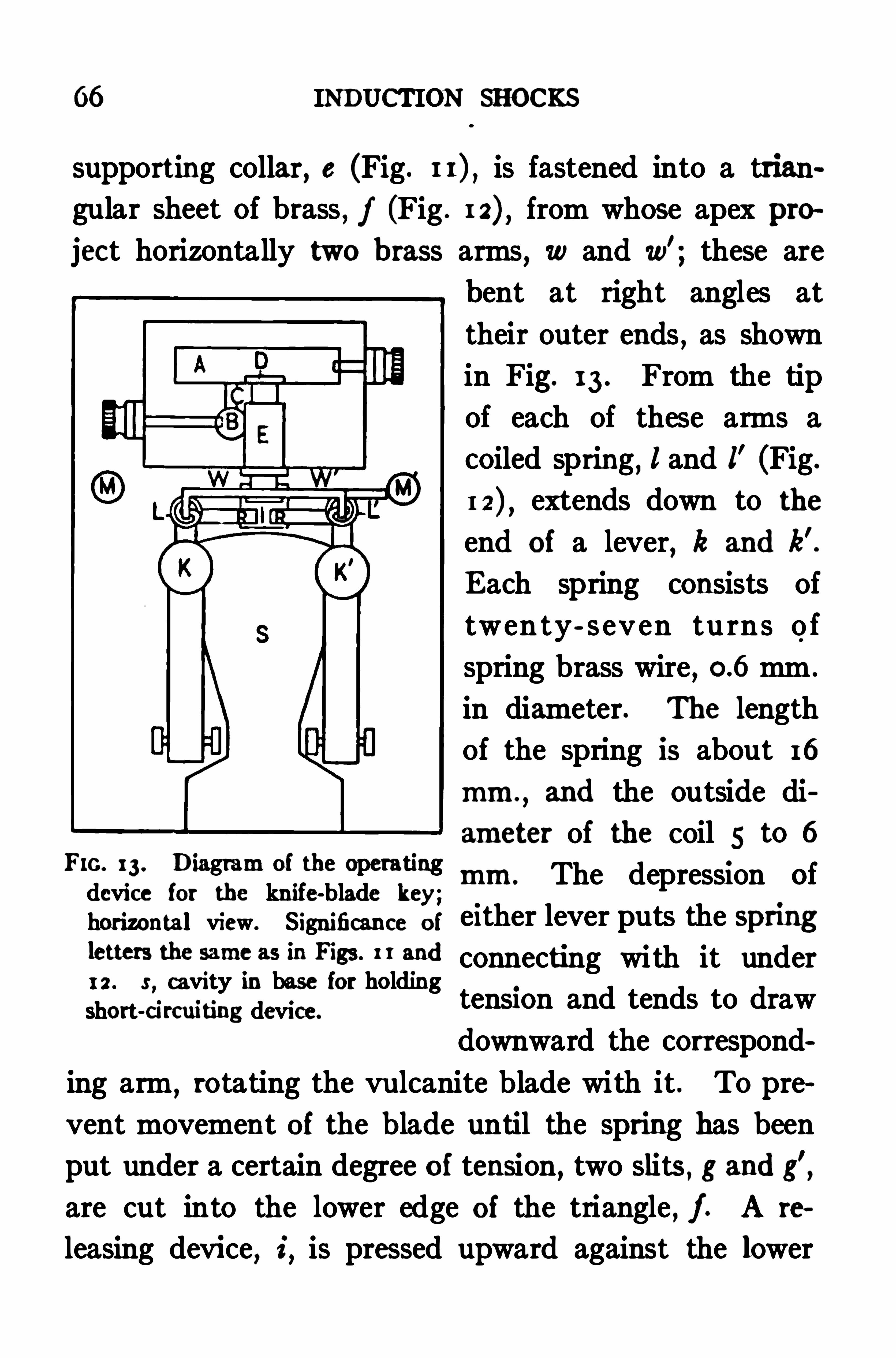
66 INDUCTION SHOCKS
supporting collar,8 (Fig . is fastened into a trian
gular sheet of brass, f (Fig . from whose apex pro
jcet horizontally two brass arms, 10 and w’; these are
bent at right angles at
their outer ends,as shown
in Fig. 13 . From the tip
of each of these arms a
coiled spring,I and l' (Fig.
extends down to the
end of a lever, k and k’.
Each spring consists of
twen ty- s even tu rn s o f
spring brass wire,
mm .
in diameter. The length
of the spring is about 16
mm.,and the outside di
ameter of the coil 5 to 6Fro. 13 . Diagram of the operatingdevice for the knife-blade key;
H
THL The depression Of
horizontal view. Significance of either lever puts the Spnng!mm the same as in I“83 ; and connecting with it under1 2 . s
,cavity in base for holding
short-d rcuifing device.
tension and tends to draw
downward the correspond
ing arm,rotating the vulcanite blade with it . To pre
vent movement oi the blade until the spring has been
put under a certain degree of tension, two slits , g and g'
,
are cut into the lower edge of the triangle , j. A re
leasing device,5,is pressed upward against the lower
THE MAKE AND BREAK OFTHE PRIMARY CIRCUIT 67
edge of f by a stout spring, in such fashion that when
either slit is engagedf is prevented from moving . Each
of the levers,k and k,
’bears at its tip an arm, r, r
’(Fig .
which presses upon the releasing device, and whenthe lever is depressed to a certain point disengages it
,
allowing the blade to rotate . The amount of motion
of the blade is limited by setting two posts,m and m’
,
at such positions that the lower apices of f strike them
when sufficient movement has occurred .
After experimentingwith various operating devices the
one described above has been adopted as combining the
greatest number of desirable features with the fewest
defects . The two levers, k and k’,which are depressed
alternately for making and breaking the circuit,are so
placed as to lie naturally under the first and second
fingers of either the right or the left hand . The springs,
l and l',need not be stiff
,hence little pressure need be
exerted upon the levers,and there is correspondingly
little fatigue from continuous operation of the key.
The springs are brought under tension only during the
use of the instrument ; when it is not in use, they hang
free . Thus their stifiness does not vary with the lapse
of time,as would be the case were one or the other under
constant tension .
The Short-circuiting Device . A desideratum in any
key which is to be used for stimulating tissues with single
induction shocks is a device for short-circuiting auto
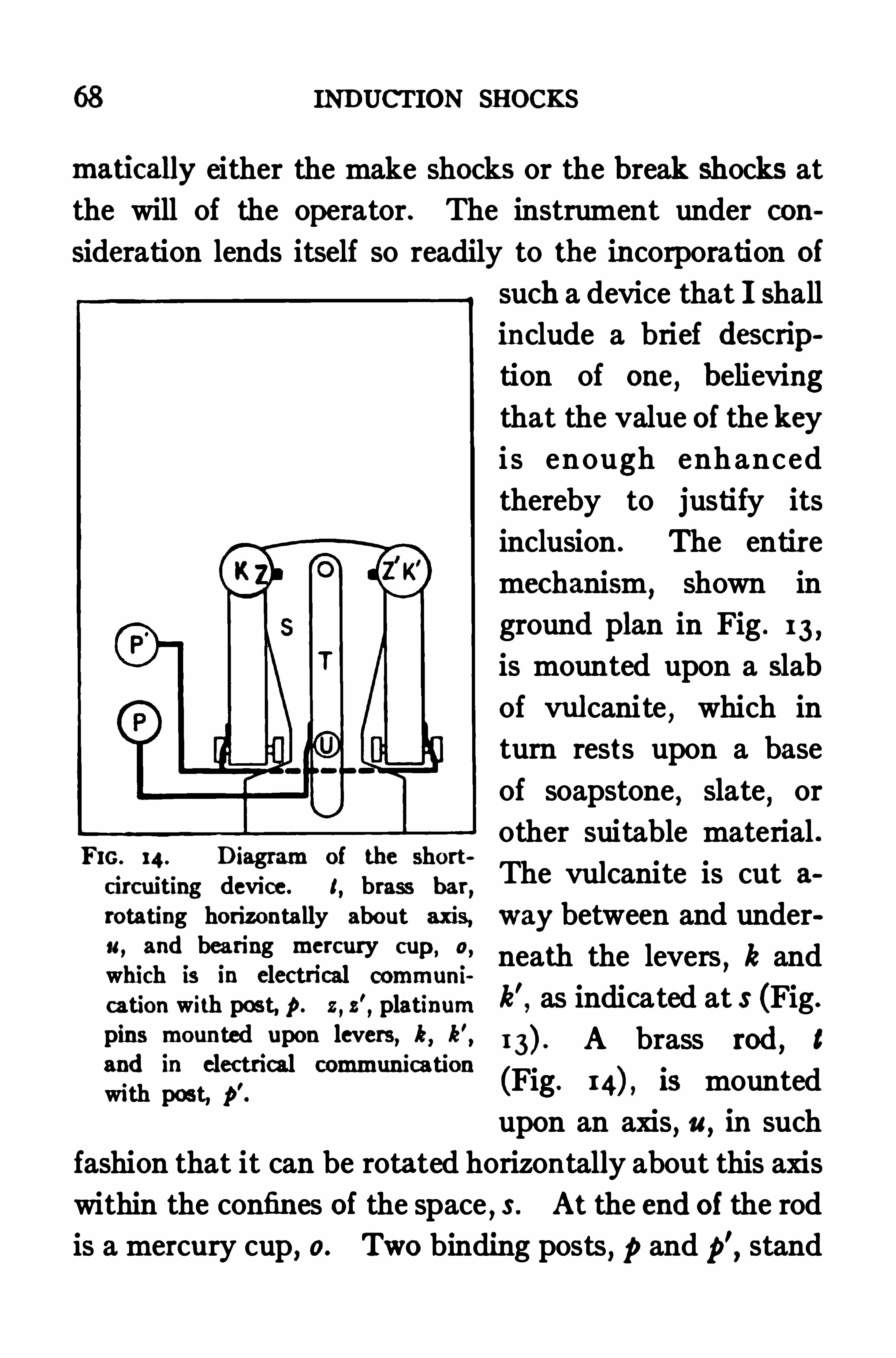
68 INDUCTION SHOCKS
matically either the make shocks or the break shocks at
the will of the operator. The instrument under con
sideration lends itself so readily to the incorporation of
Fro. 14 . Diagram of the shortcircuiting device. I
,brass bar
,
rotating horizontally about axis,
a, and bearing mercury cup ,0,
which is in electrical communi
cation with post, 9 . z,z'
,platinum
pins mounted upon levers, k, k',and in electrical communicationwith post, 9
'
such a device that I shall
include a brief description of one
,believing
that the value of the keyi s enough enhanced
thereby to justify its
inclusion The entire
mechanism,shown in
ground plan in Fig . 13 ,
is mounted upon a slab
of vulcanite,which in
turn rests upon a base
of soapstone,slate
,or
other suitable material .
The vulcanite is cut a
way between and under
neath the levers,k and
k'
,as indicated at s (Fig.
A brass rod, t
(Fig . is mounted
upon an axis,a, in such
fashion that it can be rotated horizontally about this axis
within the confines of the space,3 . At the end of the rod
is a mercury cup, 0. Two binding posts, p and p
’,stand
THE MAKE AND BREAK OFTHE PRIMARY CIRCUIT 69
at one margin of the base . From p a wire leads through
the body of the vulcanite block to the rod t to which it
is soldered near the axis of rotation of the rod . From
p’two wires are carried through the block, one to the
axis of rotation of the lever,k,to which it is soldered
,the
other to the axis of k’ where it is soldered likewise.
Thus both levers are in electrical connection with the
post, p
'
,and the rod
,t,in similar connection with the
post, p. Soldered to the levers
,k and k'
,at the points
,z
and z’, are pins of platinum projecting downward . These
pins are so placed that the mercury cup,0,can be
brought directly below one or the other of them according
as t is rotated . Their length is so adjusted that the pin
dips into the mercury when the lever is depressed enough
to release the mechanism,but is clear of the mercury at
all other times .
If the binding posts,p and p
’,are connected in parallel
into the secondary circuit of the inductorium and the
rod t is rotated so as to bring the mercury cup below the
lever which is pressed when the primary circuit ismade
(the left-hand one in this instrument) the make shocksare all short-circuited . Bringing the mercury cup be
low the other lever short-circuits all the break shocks.
When the rod is placed in an intermediate position,
neither makes nor breaks are afiected. To prevent all
possibility of accidental diversion of the secondary cur
rent into the hand of the operator,vulcanite shields are
7o INDUCTION SHOCKS
placed on the levers at the points where the fingers press
upon them,and upon the handle by which the rod t Is
rotated .
In addition to its applicability for both make and
break shocks this key has the advantage of preserving
uniformity of action for a long time with little attention .
In this respect it is superior even to platinum contact
keys,which
,as is well known, sufler from oxidation
after prolonged use . There is no doubt,however
,that
well made automatic platinum-contact keys,properly
looked after,give break shocks of sufficient uniformity
for the general purposes of the physiologist.
CHAPTER X
THE INFLUENCE OF SECONDARY RESISTANCE AND OF
CATHODE SURFACE
IN the preceding chapters the scheme for measuring
break shocks has been developed to the point where it
becomes necessai'y to turn from the induction apparatusto the tissue to be stimulated and to inqhire how varia
tions in the tissue may modify stimulation strengths .
Two possible modifying factors have been indicated
(p . as due to variations in the tissue ; they are sec
ondary resistance, and the manner of applying the elec
trodes .
The Relation of Tissue Resistance to Secondary Re
sistance as aWhole . The secondary circuit usually has
a comparatively high resistance . Most inductoria used
in physiological laboratories have secondary coils with
resistances mounting into hundreds of ohms,and the
resistances of the tissues undergoing stimulation are
usually high likewise . In numerous determinations of
the resistance of stimulated tissues I have met with only
one or two under 1000 ohms and have found many ex
ceeding ohms .
Since the stimuli imparted by faradic currents as71
72 INDUCTION SHOCKS
well as by those of galvanic origin arise from the cath
ode,
* and since the resistance of the physiological
cathodes must be small in comparison with that of the
whole mass of tissue traversed by the current,we are
justified in considering tissue resistance as external to
the actual seat of stimulation,and need make no dis
tinction between this and the other resistances that maybe included in the secondary circuit .
The Method of Experimentation. In studying the
influence of secondary resistance experimentally the
usual procedure has been to introduce known,non
inductive,resistances into the secondary circuit and to
Observe the efiect of their introduction upon the stimu
lating value of the shocks sent through the circuit . As
a check upon this method some experiments were per
formed in which different amounts of tissue were in
cluded between the stimulating electrodes, and thus the
resistance of the tissue itself was varied . This latter
method is of course les s certain than the former,since
the inclusion of more or less tix ue in the circuit may mean
a variation in the number and irritability of the physio
logical cathodes involved .
Tissue resistances were determined by means of an
ordinary Wheatstone bridge according to the Kohl
rausch method , with an alternating current to avoid
Chauveau: Journal de la physiologic, 1859 , ii, pp. 490, 5 53 . See
also Biedermann : Elektrophysiologie, Jena, 189 5 , ii, p. 622.
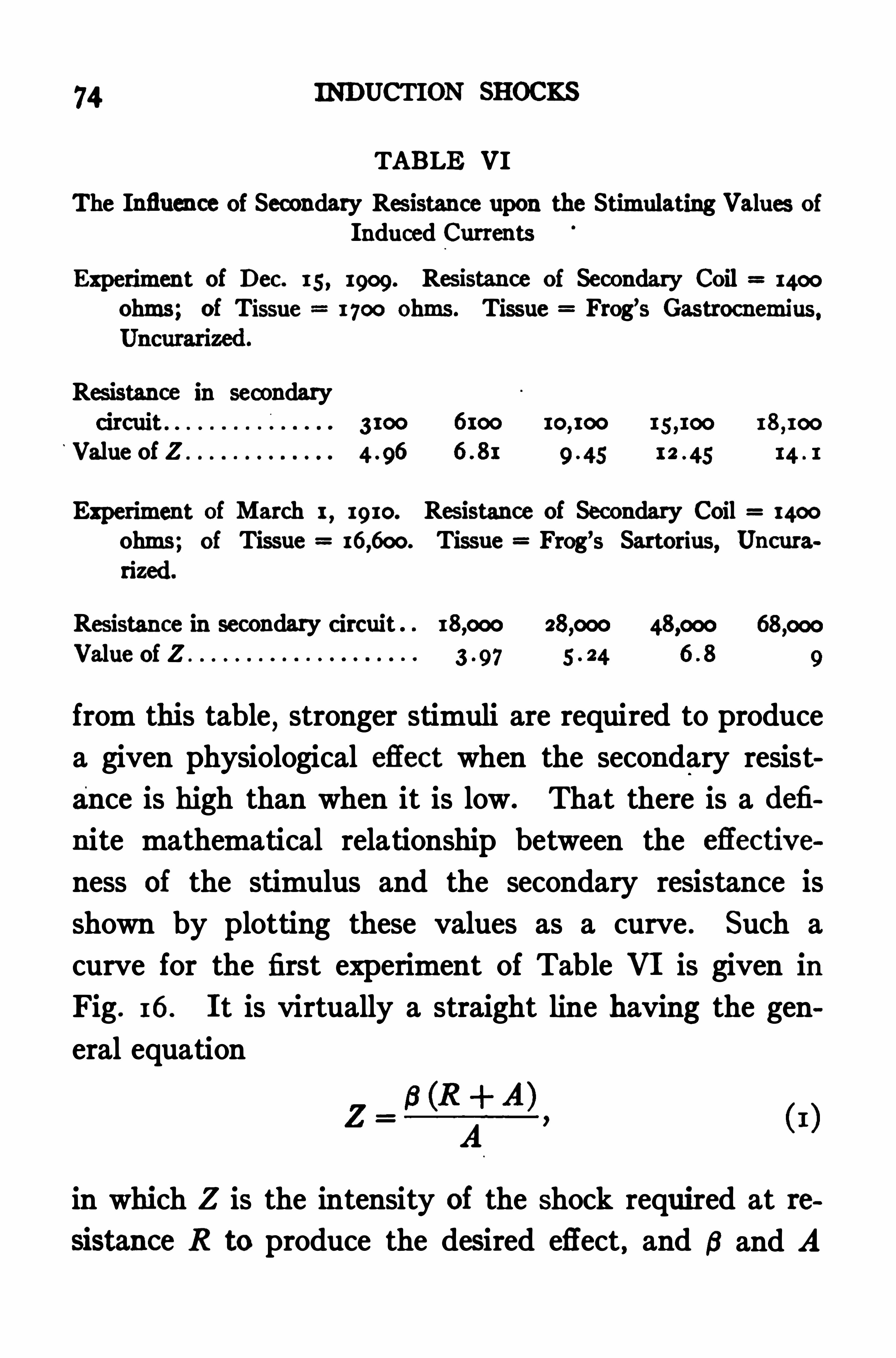
74 INDUCTION SHOCKS
TABLE VI
The Influence of Secondary Res istance upon the Stimulating Values of
Induced Currents
Experiment of Dec. 1 5 , 1909 . Res istance of Secondary Coil 1400
ohms; of Tissue 1 700 Ohms. Tissue Frog’s Gastrocnemius,
Res istance in secondary18 100
Value of Z
13t of March 1,19 10. Res istance of Secondary Coil 1400
ohms; of Tissue Tissue Frog’s Sartorius, Uncura
rized.
Resistance in secondary circuit 18 000
Value of Z
from this table, stronger stimuli are required to produce
a given physiological efiect when the secondary resist
ance is high than when it is low . That there is a defi
nite mathematical relationship between the efiective
ness of the stimulus and the secondary resistance is
shown by plotting these values as a curve . Such a
curve for the first experiment of Table VI is given in
Fig . 16 . It is virtually a straight line having the gen
eral equation
in which Z is the intensity of the Shock required at te
sistance R to produce the desired effect, and B and A
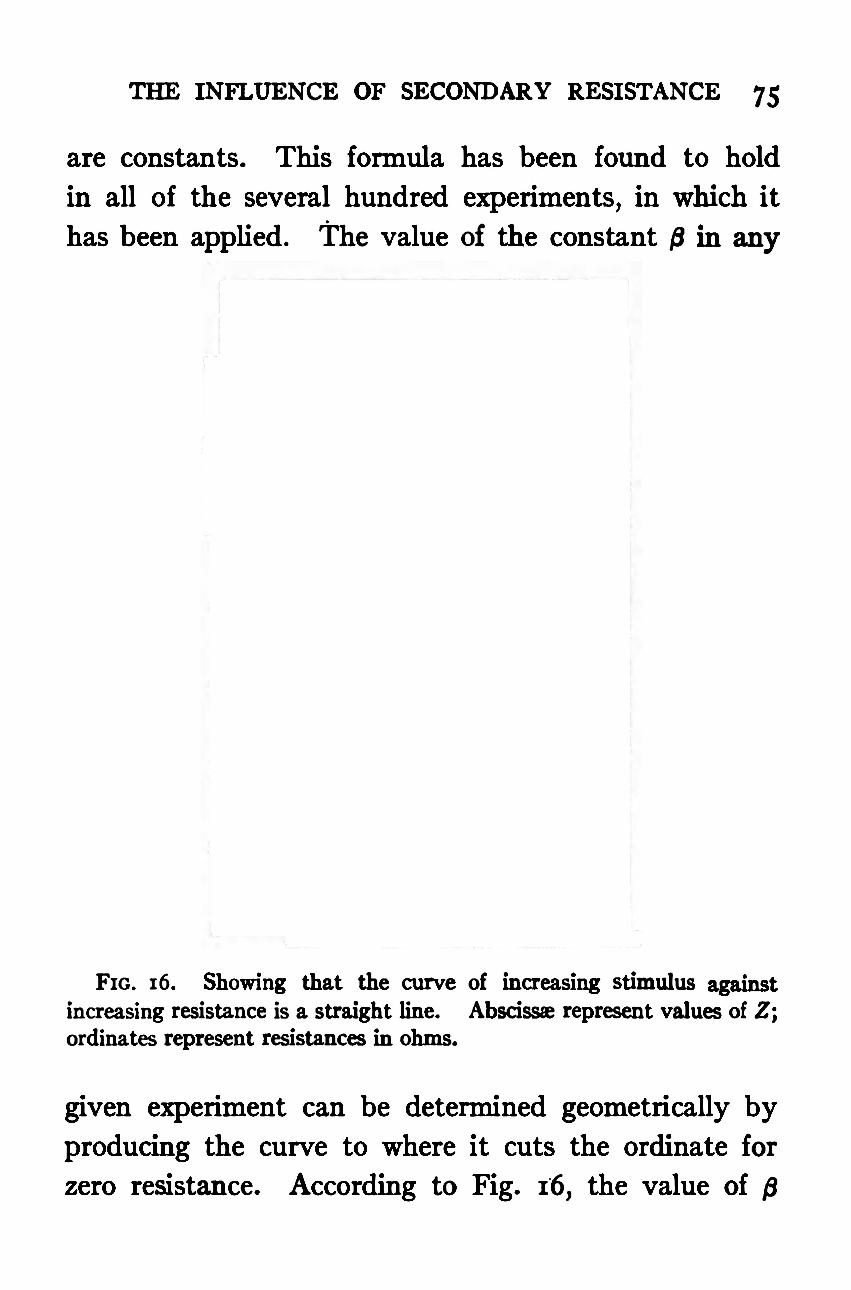
THE INFLUENCE OF SECONDARY RESISTANCE 75
are constants . This formula has been found to hold
in all of the several hundred experiments,in which it
has been applied . The value Of the constant 6 in any
FIG. 16. Showing that the curve of increasing stimulusincreasing resistance is a straight line. Abscissa represent values of Z ;ordinates represent resistances in Ohms .
given experiment can be determined geometrically by
producing the curve to where it cuts the ordinate for
zero resistance . According to Fig. 16,the value Of a
76 INDUCTION SHOCKS
for the experiment of Table VI from which that curve is
derived is 3 . Since this represents the value of Z,whose
effect at zero resistance would equal that of the various
other values of Z at their respective resistances,it
affords a measure of the irritability of the physiological
cathode where the stimulus actually arose,on the as
sumption that the resistance of the cathode is negligibly
small. We have,therefore
,in B an expression for the
value of any stimulus as it affects the seat of actual
stimulation,namely
,the physiological cathode
,irre
spective of the resistance of the secondary circuit .
By a Slight transposition of equation (I ) the equation
for 6 becomes :
and if the value of Z for any secondary resistance is
known, the actual or Specific stimulus can be calcu
lated from equation provided only the value of the
other constant, A,is known . For measuring stimuli
with reference to the resistance through which they are
applied there must be added to the determinations
previously required, therefore , not only the secondary
resistance. but a constant A .
CurrentDensity an ImportantFactor. That the stim
ulating effectiveness of electric currents varies with their
density has long been recognized} although practical
Bledcrmann: Lee. cit ., 1 , p. 185 .
THE INFLUENCE OF SECONDARY RESISTANCE 77
application of the fact has hitherto been reserved for
galvanic stimulation . The expression for 5 Shows that
current density is a factor to be taken into account in
measuring faradic stimuli as well .
The factor A in the expression 5 is the proZA
R A
vision by which allowance is made for the influence of
current density. The stimulating eflectiveness of dense
currents is'
greater than of diffuse ones . In order that
the expression for 5 agree with this fact the value of A
must increase as the density of the stimulating current
increases . Experimental evidence showing that A is
actually larger for dense currents than for difl'
use cur
rents is contained in an experiment cited on p . 109 ,
Chap . XII .
I do not know of any reliable method of determining
the value of the constant,A
,other than that used in
this work,namely to establish experimentally two or
more values of Z for difl erent secondary resistances,
and from these values compute the value of A . This
can be done by means of the equation
ZER’—ZE :R
ZR' ZR
in which Za and ZR: are the stimuli required, with re
sistances R and R’respectively
,to produce the minimal
contractions used as the index.
78 INDUCTION SHOCKS
The Dependence of Factor A upon Inductorium Con
struction. In discussing the method of comparing one
inductorium with another by the introduction of the
factor L in the expression Z i?’it was stated (p . 5 2)
that this comparison is subject to a certain restriction as
to secondary resistance . This restriction rests upon an
observation of Gildemeister,‘ according to which
,if two
dissimilar inductoria are compared quantitatively by the
method outlined here,in which the expression for the
value of a stimulus is Z A; x I , it will be found thatalthough equal stimuli may yield corresponding values
of Z from the two inductoria, with certain secondary
resistances,when other secondary resistances are used
equal stimuli will not give corresponding values of Z.
In earlier paragraphs of this chapter it was pointed
out that the true or specific value of a stimulus is not
afforded by the expression Z, but by the expression 3 ,which depends not only upon Z but upon the secondary
resistance and a constant A as well . The determination
of A,as previously shown
,is according to the formula
ZRR’
ZRR
2 3 . ZR
in which Z3 and Z3 ' are stimuli which,with resistances
Gildemeister : Archiv fur die gee. Physiologic, 19 10, Bd. 13 1 ,
THE INFLUENCE OF SECONDARY RESISTANCE 79
R and R’respectively,have equal physiological eflect.
Since dissimilar inductoria fail to give corresponding
values of Z at all secondary resistances,the value of A
determined by this formula from one inductorium will
not necessarily agree with its value as obtained from
another . The value of A,therefore
,does not depend
solely upon the surface of the physiological cathodes,
but in part also upon the construction of the inducto
This variation in the values of A determined from dis
similar inductoria, which might lead one to question the
validity of the equation in which A is employed, i.e.
,
s Aserves in fact to confirm strongly the valid
ity of that equation and the use of the expression 6 to
signify the specific value of the stimulus . This con
firmation rests upon the repeated observation that when
equal stimuli are generated by dissimilar inductoria the
values of B are equal even though the observed values of
Z and the computed values of A may be quite divergent.
An experiment illustrating this point is summarized in
Table VII . Details of the construction of the induc
toria used are given In Table VIII . The experiment
shows that dissimilar inductoria give for equal break
stimuli perfectly concordant values if all the factors
which make up the final expression for stimulation
strength are taken into account .
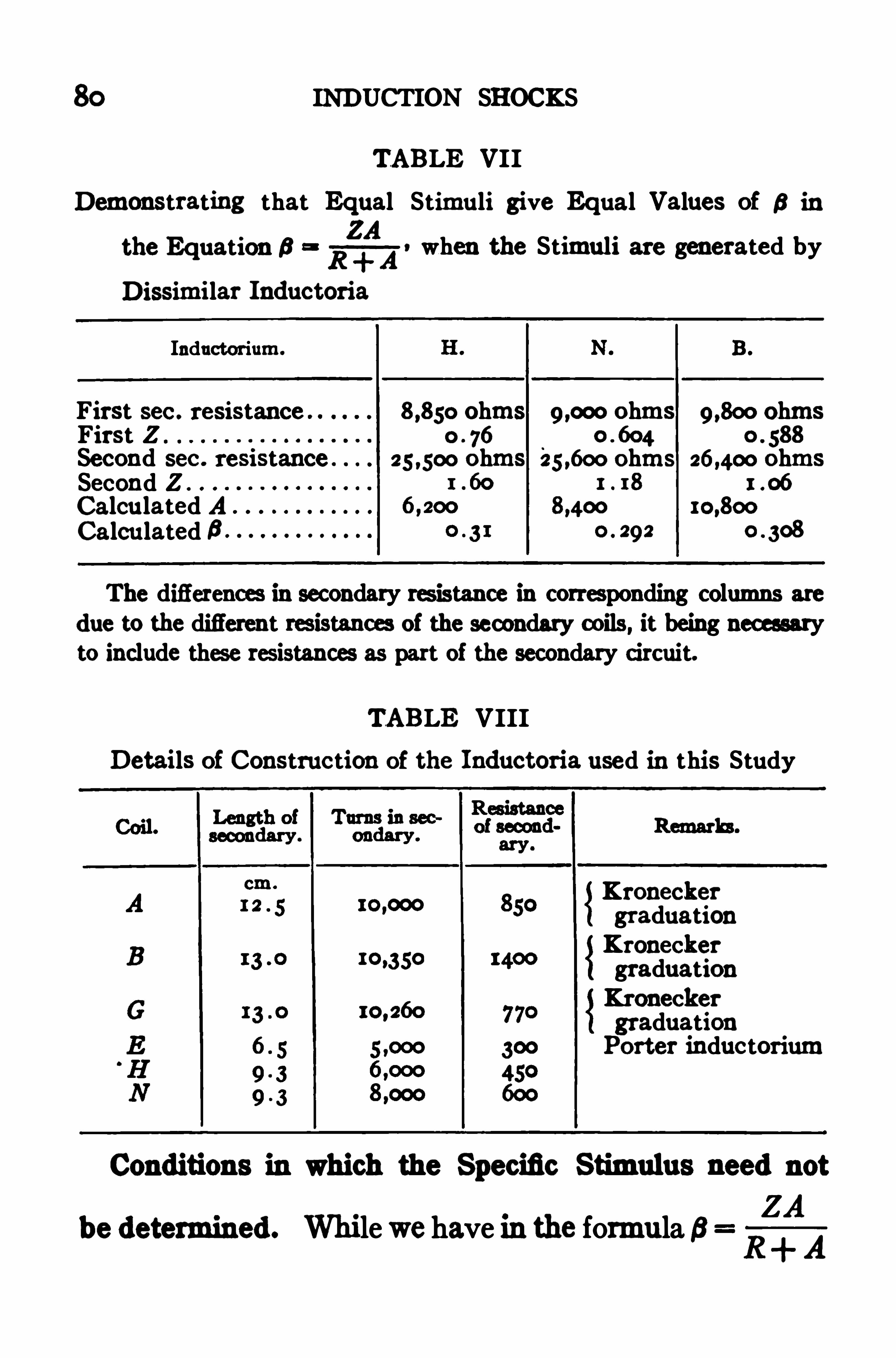
80 INDUCTION SHOCKS
TABLE VII
Demonstrating that Equal Stimuli give Equal Values of 6 in
the Equation 6R1
4
1!when the Stimuli are generated by
Dissimilar Inductoria
Inductorium.
First sec . resistance 8 ,850 ohms ohms ohmsFirst Z 0 76
Second sec . resistance . 25 ,500 ohms 25 600 ohms ohmsSecond Z .
Calculated ACalculated 6 0. 29 2 0 308
The differences in secondary res istance in corres ponding columns are
due to the different resistances of the secondary coils, it being necessaryto include thes e resistances as part of the secondary circuit.
TABLE VIII
Details of Construction of the Inductoria used in this Study
Conditions in which the Specific Stimulus need not
ZAbe determined. Whi le we havem the formula 6
R A
KroneckergraduationKroneckergraduationKroneckergraduationPorter inductorium
82 INDUCTION SHOCKS
the course of the experiment and so do not enter as
modifying factors.
Stimulation of Corresponding Tissues in Difierent
Animals. Next in importance are cases in which it is
desired to impart comparable stimuli to correspondingtissues through a series of experiments . Cases of this
sort arise frequently in the course of physiological re
search, and I have therefore given them special consid
oration.
While this subject was before me there was being car
ried on in the laboratory at Harvard an investigation
which involved,among other things
,determining in a
series of cats the threshold stimulus for producing ex
tension oi the wrist, when the stimulus was applied to
the deep branch of the radial nerve below the elbow ;and reflex flexion of the hind leg through stimulation of
the tibial . Here was presented a typical example of the
class of experiments described in the paragraph heading,and I therefore utilized it in the study of my problem .
In several cases the threshold stimulus was determined
when the tissue only was in the secondary circuit, and
immediately afterward, the threshold when an additional
resistance of ohms had been introduced . I was
thus able in these cases to compute the value of the con
stant A ,and from it to obtain the solution of the equa
tion for specific irritability, 5
Rift-
4
?In the ex
THE INFLUENCE OF SECONDARY RESISTANCE 83
periments of this series, ten in all, the secondary re
sistances ranged from 2800 ohms to 6000 ohms, averaging 3900 ohms . The values of A ranged from 4300 to
averaging 7800. The statistics for this series
are given in Table IX .
TABLE IX
Illustrating the Tendency of 5 and Z to vary similarly in D irection and Extent . Z represents the Stimulus producing JustPerceptible Wrist Extension in Cat . Stimulus applied to
Deep Branch of Radial Nerve
Secondary Value ValueDate . 1910.
resistance .
Value of A .
of Z . of5 .
As Above except that Stimulus was applied to Tibial Nerve , and
Reflex F lexion of Hind Leg was Movement Evoked
guly 18 .
uly 22
July 20.
Average
Inspection of the table reveals a definite tendency of
5 to vary as does Z . The closeness of this tendency is
brought out more strikingly,however
,in Fig. 1 7, in

84 INDUCTION SHOCKS
which the ratios of 5 to Z in successive experiments are
plotted . The horizontal line represents the average
ratio of 5 to Z as determined in thes e experiments ; the
variations from this line of the different actual ratios
are, as is seen,relatively inconsiderable
,the greatest
being per cent, the average of all Slightly under
1 1 per cent .
Assuming the data cited in Table IX to be fairly rep
resentative of the relations between 5 and Z that are
FIG. 17. Illustrating the relatively slight departures of individualratios of 5 to Z from the average . Ordinates repres ent successive ex
periments ; abscissa represent ratios of 5 to Z. The horizontal lineis drawn at the level of the average ratio.
likely to occur in experiments of the sort under consid
eration,to what extent are we justified in such experi
ments in making use of the values of Z for expressing
quantitative relationships?
The figures Show clearly, I think , that all except the
finest relationships are revealed with suflicient exactness
by the values of Z. While one cannot always know cer
tainly, in cases in which several nearly equal values of
Z are under comparison,which will give smaller and
THE INFLUENCE or SECONDARY RESISTANCE 85
which larger values of 5 , yet, if the experiments are
carefully performed, one can be practically certain ,
whenever the values of Z difler by more than 1 5 or 18
per cent,that the larger Z means alsoa larger 5 . With
this degree of accuracy assured,probably the demands
of most researches of this class are fully met,and all
such may safely disregard both the secondary resistance
and the cathode surfaces .
Diflering from the series of experiments quoted above
in that they offer wider variations in both secondary
resistance and electrode surface,and therefore greater
likelihood of error if these factors be disregarded,is a
series of observations on frogs’gastrocnemius muscles,
carried out by myself .
In the series of eighteen experiments cited in Table X
the secondary resistances ranged from 3 100 to
and the values of A from 2600 to Yet,in spite
of these wide ranges in the values of the factors deter
mining the relation of Z to 5 , this latter relation varies
to a surprisingly moderate degree . The average ratio
of 5 to Z is .49 . The Widest departures from this are
ratios of .3 2 and .64, amounting to 35 per cent and 3 1
per cent res pectively , while the average variation is only
1 5 per cent . If the experiments of Table X repres ent
fairly the variations in secondary resistance and cathode
surface likely to be met with in experiments on frogs’
gastrocnemii, we can safely conclude that the values of
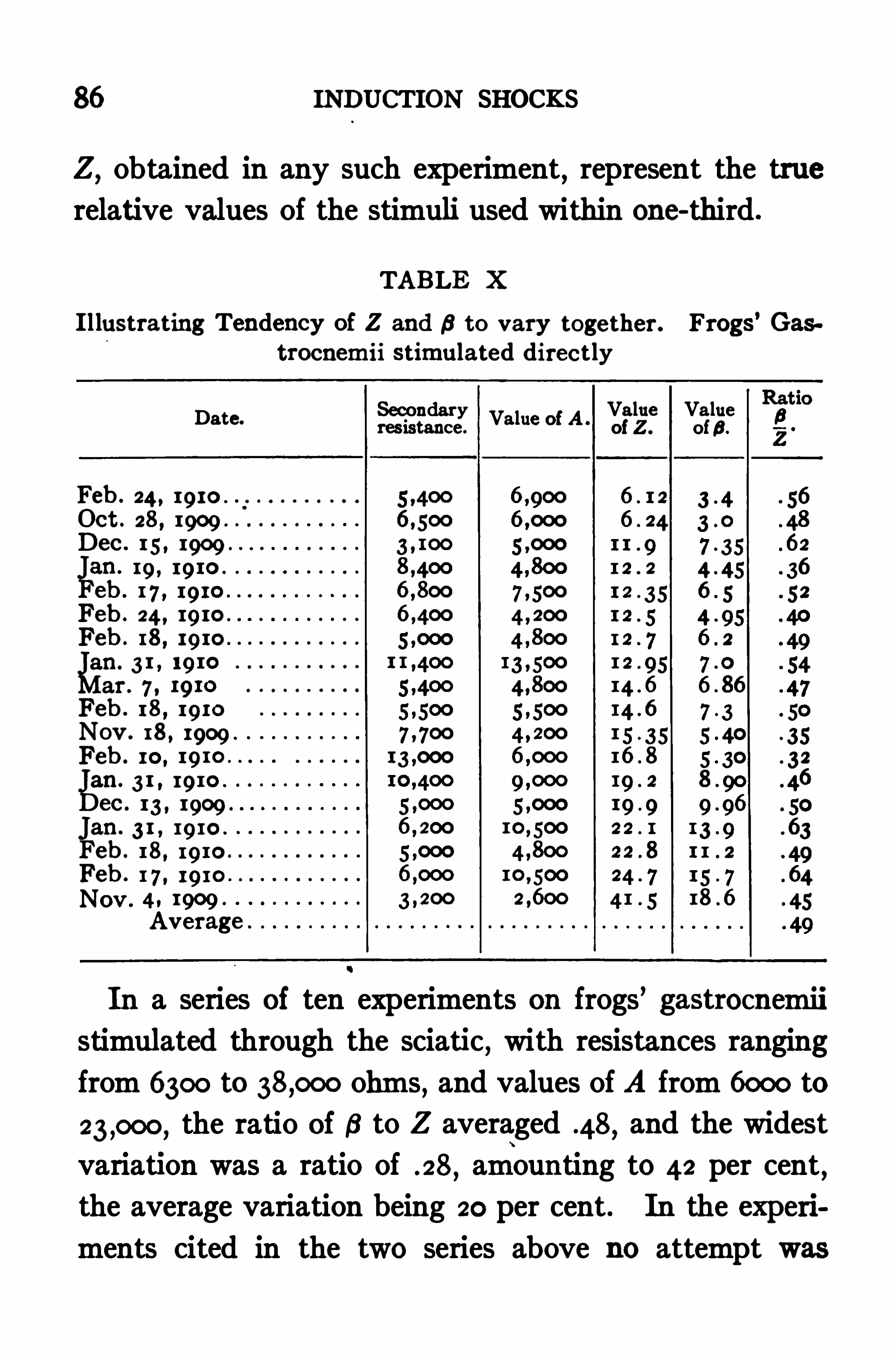
86 INDUCTION SHOCKS
Z,obtained in any such experiment
,represent the true
relative values of the stimuli used within one-third .
TABLE X
Il lustrating Tendency of Z and 5 to vary together. Frogs’Gas
trocnemii stimulated directly
Secondary Value ValueDate.
resistance .
Value Of A’of Z . of5 .
Feb . 24 , 19 10 .
Oct . 28 , 1909Dec . 1 5 , 1909
éan. 19 , 19 10
eb . 1 7 , 19 10
Feb . 24, 19 10
Feb . 18 , 19 10
gin. 3 1 , 19 10
ar . 7 , 19 10
Feb . 18 , 19 10
Nov . 18 , 1909 .
Feb . 10,
gain. 3 1 , 19 10.
ec . 13 , 1909
Jan. 3 1 , 19 10.
Feb . 18 , 19 10
Feb . 1 7 , 19 10
Nov . 4 , 1909 .
Average .
In a series of ten experiments on frogs’gastrocnemn
stimulated through the sciatic, with resistances ranging
from 6300 to ohms, and values of A from 6000 to
the ratio of 5 to Z averaged .48, and the widest
variation was a ratio of . 28,amounting to 42 per cent,
the average variation being 20 per cent . In the experi
ments cited in the two series above no attempt was
THE INFLUENCE OF SECONDARY RESISTANCE 87
made to keep conditions of tissue resistance and cathode
surface approximately uniform . On the contrary,these
conditions were purposely made to vary widely from one
experiment to another. I feel, therefore, that they cover
the range of variation likely to occur in ordinary experi
mentation .
These data seem to me to Show that in the hands of
a careful experimenter,who will take pains to keep his
conditions of stimulation as uniform as possible,quanti
tative results of great value may be obtained without the
labor involved in taking account of secondary resistance
and cathode surface . By the use of themethod out
lined in previous chapters the strengths of stimuli em
ployed in any given case may be expressed in terms of
stimulation units,and if the conditions of experimenta
tion,such as the nature of electrodes used
,distance be
tween them,and method of applying them
,are carefully
described,other experimenters can duplicate the sw uli
very closely. Certainly this method allows comparisons
of much greater accuracy than can be made by the ex
isting methods of describing stimuli . It is highly im
portant,however
,that investigators attempting to use
induction Shocks quantitatively recognize fully the limi
tations upon accuracy which are involved in disregard
ing the factors under discussion . So long as there is no
effort to draw conclusions which are not warranted by
the degree of accuracy actually obtained, no harm will
be done, but wherever the occasion exists for a high
degree of accuracy in determining stimuli,secondary re
sistance and cathode surface must be taken into account.
A Standard of Inductorium Construction Necessary.
In connection with this discussion of the circumstances
in which the factors of secondary resistance and cathode
surface may be disregarded, we must not forget that the
structure of the inductorium is interwoven with the
factor of cathode surface (see p . in such fashion
that the latter cannot be left out of account without
error unless the former has been provided for. This pro
vision is best made by adopting a standard of inducto
rium construction and using for quantitative purposes
only instruments conforming reasonably to it . Thus we
become at once independent of inductorium structure
as a complicating factor,and are free to measure stimuli
in many cases in the Simpler manner discussed above.
The desirability of having a standard of inductorium
construction for physiological and clinical use was recog
nized fully thirty years ago. In an attempt to establish
one the Paris Electrical Congress of 188 1 resolved at its
session of September 28th that the form of inductorium
at that time in use in the University of Berlin should be
adopted as the standard .
‘
See Lewandowski: Elektrodiegnoetik und Elektrotherapie , Wienund Leipzig, 1887 , S. 2 1 2 . Also Hoorweg : Die medicinische Elektrotechnik und ihre physikalischen Grundlagen, Leipzig, 1893 , S. 1 28 .

90 INDUCTION SHOCKS
ferred to the smaller ones recommended by the Paris
Congress .
Assuming as the standard,then
,an inductorium hav
ing coils about 13 cm . long and having in the secondary
approximately turns of wire,we may inquire
how widely an inductorium can vary from this standard
without introducing a significant error. For answering
this question I have made observations with six in
ductoria,three of which are of standard construction
and provided with Kronecker graduations,the other
three selected to give increasing degrees of divergence
from the standard . Details of the construction of the
six inductoria are set down in Table VIII.
The results of my numerous experiments with these
inductoria may be summarized as follows : . The three
standard coils,A
,B
,and G, give corresponding values
of Z for equal stimuli and equal secondary resistances
whatever the secondary resistance may be . In compar
ing them,therefore
,the factor of inductorium construc
tion does not enter.
In thirteen experiments in which coil N was compared
with coil B the secondary resistances ranged between
2850 ohms and ohms ; the average percentage
variation of ZN* from ZB was 6 per cent ; the greatest
variation was 1 per cent . ZN was greater than Z3
For convenience of expression a subscript is placed after the valueof Z to indicate with which coil the value was obtained.
THE INFLUENCE OF SECONDARY RESISTANCE 9 1
four times and ZB greater than ZN nine times. The
small average percentage difference between the two
coils, a difierence only slightly greater than the probable
experimental error,coupled with the fact that not all the
variations are in the same direction,seems to me to
Show that in coils difiering no more than these the in
fluence of inductorium construction as a special factor
can be disregarded without serious error .
An important effect of inductorium construction be
comes manifest when coils B and H are compared . The
average difierence between Za and ZH in twelve experi
ments was 16 per cent ; in four of the twelve cases ,more
over,the difierence exceeded 24 per cent . Analyzing the
series of experiments with reference to the secondary t e
sistances it appeared that the high average difierence is
due to large differences in the experiments with high sec
ondary resistance . Thus five experiments with second
ary resistance above ohms Show an average difier
ence between Z3 and ZH of per cent,while seven
experiments with secondary resistances below
ohms show an average difierence of only per cent .
In all five experiments with high secondary resistance
ZH was greater than Z3 . In the seven experiments with
low resistance ZH was larger than Za three times, smaller
than Za twice , and equal to it twice .
This series of experiments shows that in inductoria
differing even so widely as do coils B and H,inducto
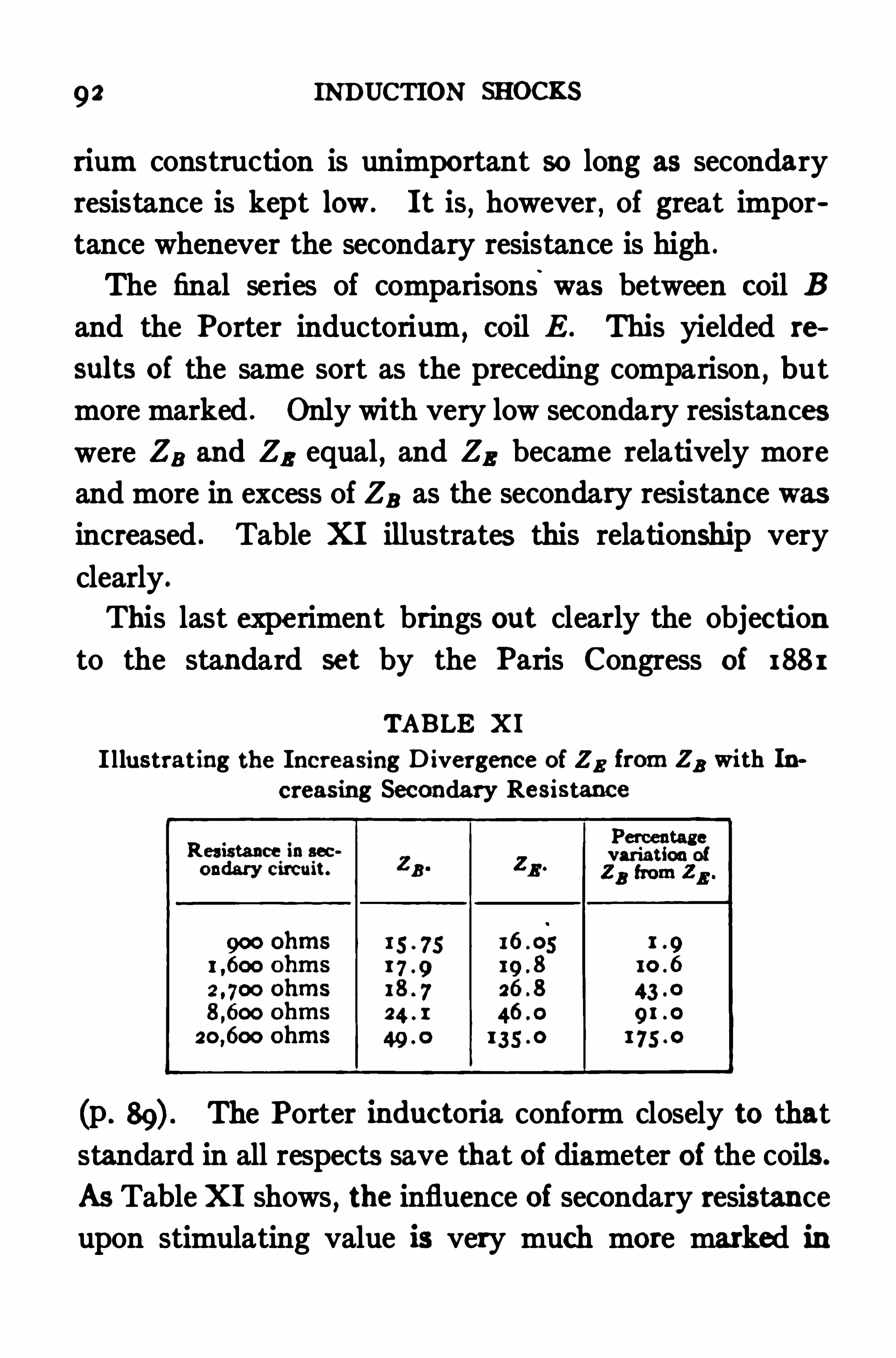
9 2 INDUCTION 5110c
rium construction is unimportant so long as secondary
resistance is kept low . It is,however, of great impor
tance whenever the secondary resistance is high .
The final series of comparisons was between coil B
and the Porter inductorium,coil E . This yielded re
sults of the same sort as the preceding comparison, but
more marked . Only with very low secondary resistances
were ZB and Z3 equal, and Z3 became relatively more
and more in excess of Za as the secondary resistance was
increased . Table XI illustrates this relationship very
clearly .
This last experiment brings out clearly the objection
to the standard set by the Paris Congress of 188 1
TABLE X I
I llustrating the Increasing D ivergence of Z3 from Z3 with Increasing Secondary Resistance
(p . The Porter inductoria conform closely to that
standard in all respects save that of diameter of the coils .
As Table XI shows, the influence of secondary resistance
upon stimulating value is very much more marked in
CHAPTER XI
THE MEASUREMENT or MAKE SHOCKS
IN order that the scheme for making induction shocks
quantitatively useful may be complete,a method for
measuring make shocks mustb e added to the one already
developed for break shocks . The method to be pre
sented in this chapter is based wholly on experimental
comparisons between make shocks and break shocks
by the v . Fleischl method previously described (p .
That it is valid can scarcely be doubted in view of the
large number of concordant experiments which support
it .
*
The expression for make shocks should, of course, be
directly comparable with the one” previously developed
for break shocks . The factors of secondary resistance
and cathode surface affect makes and breaks alike. We
may take as a starting point from which to develop a
formula for make shocks, therefore, the expression for
break shocks which takes account of neither of these
factors,namely Z The problem to be solved is
MIfL
how this expression must be modified so that the value
Martin : Am. Jour. of Physiology, 1909 , xxiv, p. 276 at seq.
94
THE MEASUREMENT OF MAKE SHOCKS 95
Z as applied to make shocks shall represent stimuli
equal in intensity to those given by break Shocks in
which the value of Z is determined as above. The ex
perimental procedure by which the problem was solved
was as follows : A series of equal make stimuli were
obtained with the secondary coil at various distances
from the primary . The calibration number for each
secondary position was then multiplied by the intensity
of primary current employed at that position,and the
products for each experiment were set down in a table .
*
For the inner positions of the secondary coil,positions
which have relatively large values ofI:
the product
ZX I was nearly constant ; as the secondary coil was
moved out into the parts of the field where the values
of% are small, the product_I X I became progressively
larger the farther out the secondary coil was pushed, and
consequently the smaller were the values ofI
merous repetitions of the experiment gave precisely sim
ilar results .
These experiments indicated quite clearly the exist
ence of a comparatively Simple relationship between
make and break stimuli,and also suggested a method
For experimental data see Martin: Lac. cit., p. 272.
96 INDUCTION SHOCKS
for expressing the relationship mathematically in the
simplest possible fashion, namely through the introduc
tion of a single factor into the break shock formula ,which when introduced would cause it to give equal
values for Z for equal make stimuli . Study of the
data showed that the factor to be introduced must be
relatively larger the smaller the value ofA
g,and must
tend to diminish A constant number has this efiect
if it is subtracted from The formula modified in
accordance with this idea becomes
In practically every experiment of a large series some
number could be selected to be substituted for K in
formula (1) with a fairly constant value!
oi Z resulting .
For each experiment the value of K had to be deter
mined empirically,and it varied widely in diflerent ex
periments. In all the experiments the values of K were
negligibly small in comparison with the values of for
secondary positions of 1 2 cm. or less .
The discovery of the above formula is a decided step
toward the ultimate solution of the problem of measur
To distinguish between break stimuli and make stimuli the formerare represented by Z! , the latter by
98 INDUCTION SHOCKS
This solved for Z,”andsimplified gives
FIG. 18. Curve obtained whenthe values of Z given by the
ap p l i c a t i o n of the formula
I to the experi
ments performed with a primaryvoltage of 2 are plotted againstthe values of K used in these ex
periments. Abscissa: representvalues of K ; ordinates representvalues of Z. The equation for
this curve is K 18 Z.
an equation which enables
us to determine the value
of make stimuli at any
given primary voltage,for
which the value of a is
known .
There remains now for
the completion of the make
Shock formula only the
establishment of a definite
relationship between the
values of a at various
primary voltages and the
voltages themselves . To
determine whether such a
relationship exists another
curve was plotted,prim
ary voltages against values
of a previously determined .
This curve is represented
in Fig . 19 . It has the
THE MEASUREMENT OF MAKE SHOCKS 99
simple equation
inwhichCrepresents a
constant . Substitut
ing in equation (4) the
value of a given by
equation we have
which is the general
equation for make in
duction Shocks . The
value of C is fixed
for each inductorium .
For the one with
which this equation
was developed, coil
B,its value is 36 .
E a -C,
FIG. 19 . Curve obtained by plottingagainst the difierent primary voltagesused in these experiments the values of
a obtained from curves plotted as inFig.
1 . The equation for this curve is E x a
36. Abscissa: represent values of a;
ordinates represent primary voltages.
Comparison of the General Formula for Break and
Make Stimuli. If the general equation for break Shocks
be written in the same form as the one for make shocks
and the two placed side by side,the Simple mathematical
relationship existing between make and break stimuli
becomes apparent . Written thus, the break Shock
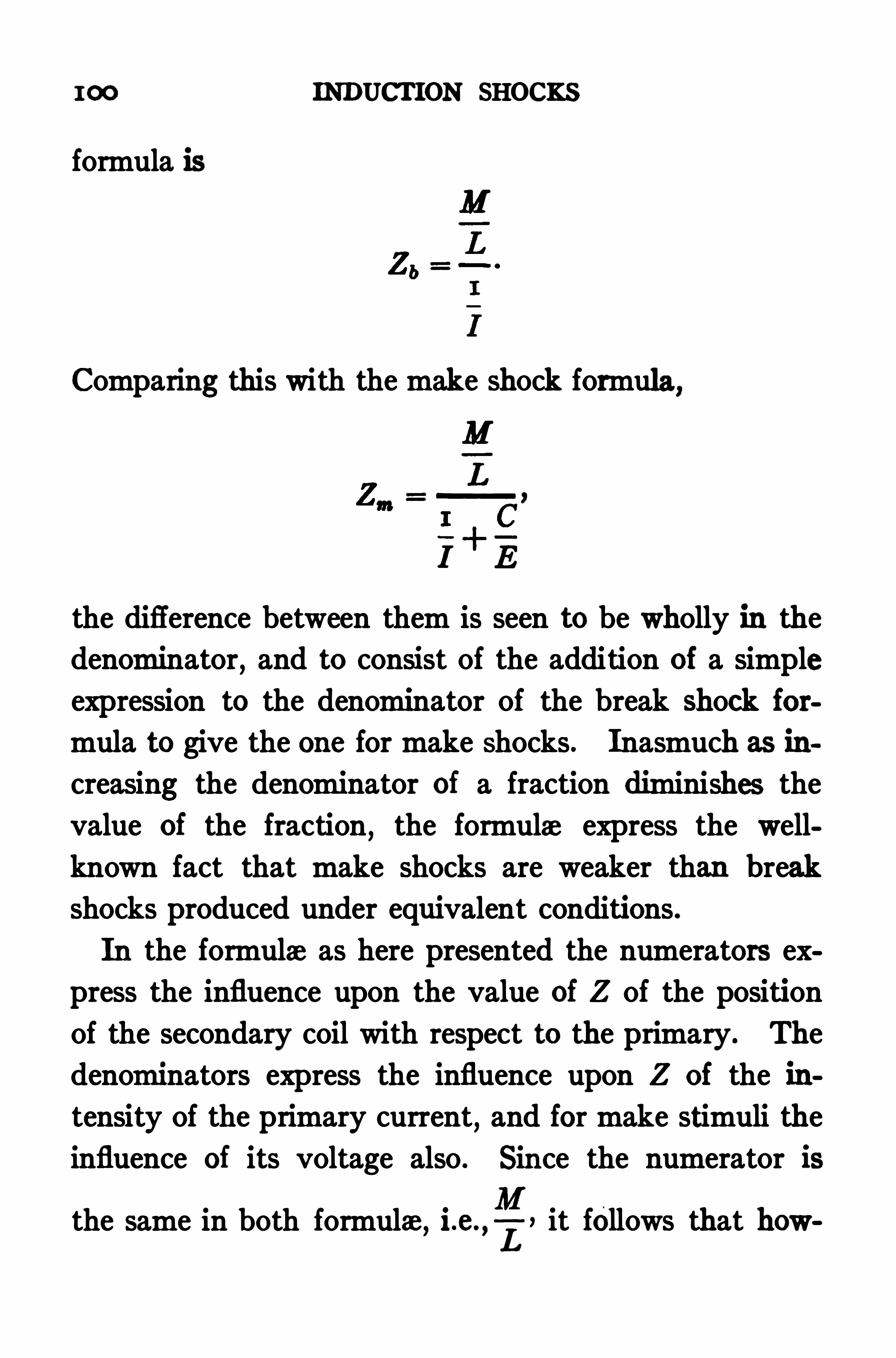
I00 INDUCTION SHOCKS
formula is
Comparing this with the make shock formula,
the difference between them is seen to be wholly in the
denominator, and to consist of the addition of a simple
expression to the denominator of the break Shock for
mula to give the one for make Shocks . Inasmuch as ih
creasing the denominator of a fraction diminishes the
value of the fraction, the formula express the well
known fact that make shocks are weaker than break
shocks produced under equivalent conditions .
In the formula as here presented the numerators ex
press the influence upon the value of Z of the position
of the secondary coil with respect to the primary. The
denominators express the influence upon Z of the in
tensity of the primary current,and for make stimuli the
influence of its voltage also . Since the numerator is
the same in both formula,i.e.
,I, it follows that how
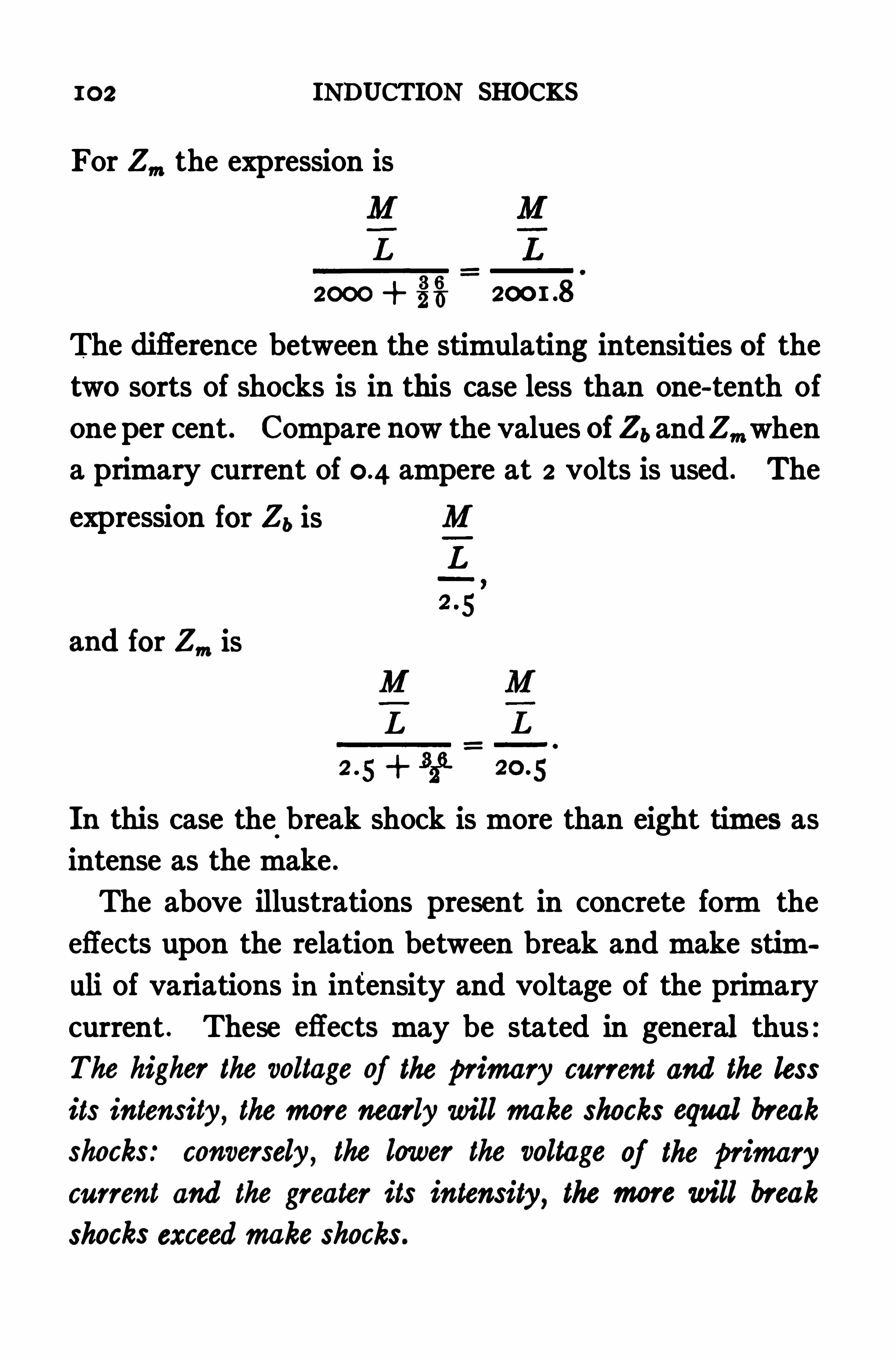
102 INDUCTION SHOCKS
For Z", the expression is
L
2000 3%
The diflerence between the stimulating intensities of the
two sorts of shocks is in this case less than one-tenth of
one per cent . Compare now the values of Zb andZ",when
a primary current of ampere at 2 volts is used . The
expression for Zb is M
L
and for Z n is
L
m+ %
In this case the break shock is more than eight times as
intense as the make .
The above illustrations present in concrete form the
eflects upon the relation between break and make stim
uli of variations in intensity and voltage of the primary
current . These eflects may be stated in general thus :
The higher the voltage of the primary current and the less
its intensity, the more nearly will make shocks equal break
shocks: conversely, the lower the voltage of the primarycurrent and the greater its intensity, the more will break
shocks exceedmake shocks.
THE MEASUREMENT OF MAKE SHOCKS 103
The make shock formula shows that make stimuli do
not vary directly with the intensity of the primary
current as break stimuli do . Although make shocks
increase absolutelywith every increase in primary intensity, other conditions remaining uniform,
the increase
is relatively Slight when primary intensities of consid
crable magnitude are compared . For example,if with
coil B a 2 volt primary current be increased from
ampere to ampere,the make stimuli will be increased
only 5 per cent, while break Shocks under the same Cir
cumstances would be doubled .
This peculiarity of relation of make shocks to primary
currents of high intensity Shows itself very strikingly in
many experiments in which minimal muscular contrac
tions are used as indicators of stimulation strength . In
the outer parts of the field of the inductorium,where the
values offare small
,primary currents of high intensity
must be employed to give shocks suflicient to elicit
visible response . I have often found when studying
make shocks,especially with primary currents of low
voltage,that as the secondary coil was pushed out to a
point where primary currents of or ampere failed
to elicit response,no increase of primary intensity up to
the limits of my apparatus would raise the stimulus to
the threshold . This frequent failure of relatively enor
mous primary currents to give detectable make stimuli
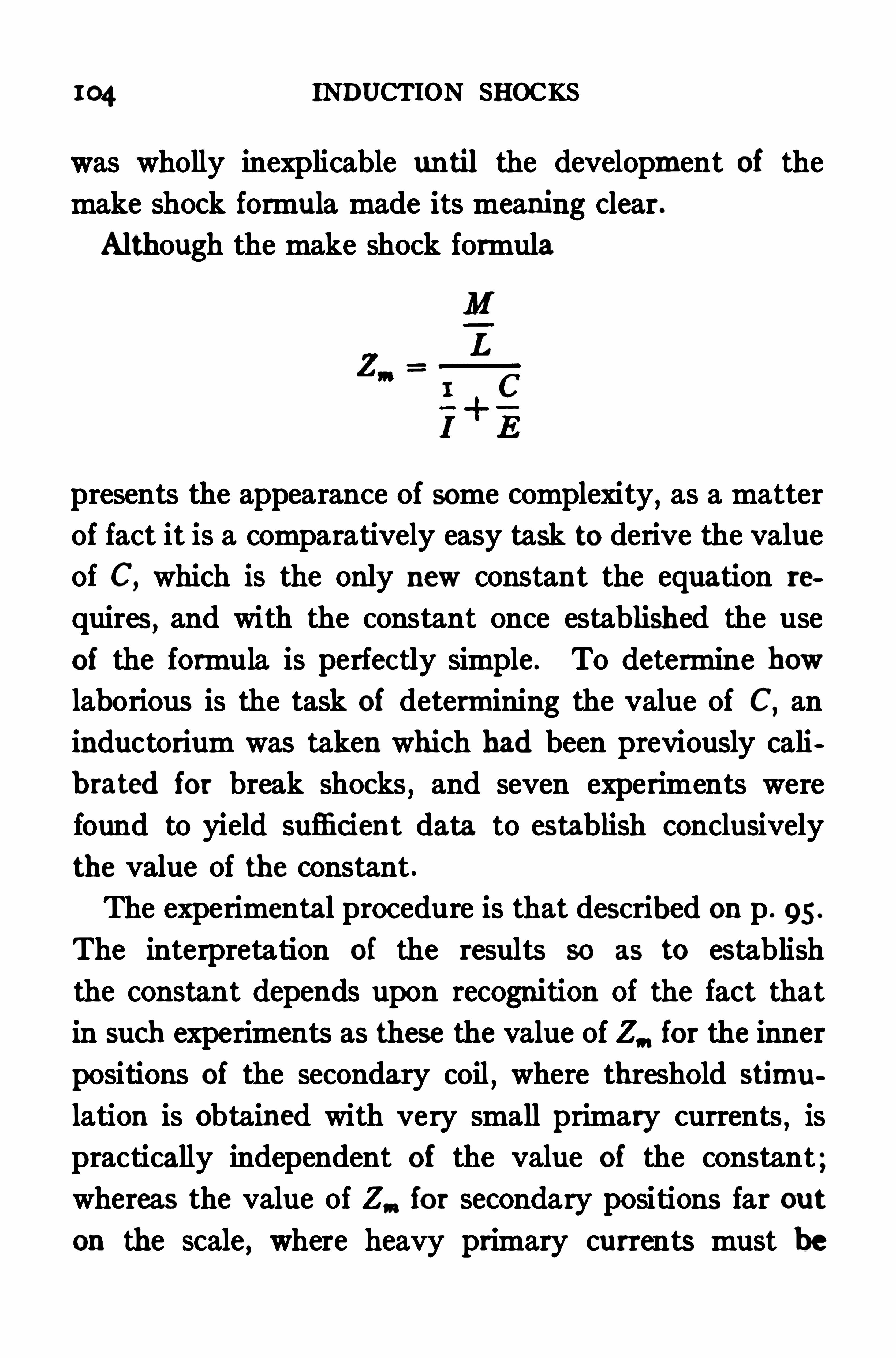
m4 INDUCTION SHOCKS
was wholly inexplicable until the development of the
make shock formula made its meaning clear .
Although the make shock formula
presents the appearance of some complexity,as a matter
of fact it is a comparatively easy task to derive the value
of C,which is the only new constant the equation re
quires, and with the constant once established the use
of the formula is perfectly simple . To determine how
laborious is the task of determining the value of C,an
inductorium was taken which had been previously cali
brated for break shocks , and seven experiments were
found to yield sufficient data to establish conclusively
the value of the constant .
The experimental procedure is that described on p . 95 .
The interpretation of the results so as to establish
the constant depends upon recognition of the fact that
in such experiments as these the value of Z, for the inner
positions of the secondary coil , where threshold stimu
lation is Obtained with very small primary currents,is
practically independent of the value of the constant ;whereas the value of Z,“ for secondary positions far out
on the scale , where heavy primary currents must be
106 INDUCTION SHOCKS
ments at primary voltage ranging from 2 to 1 2 . When
so applied,constant values of Zm were Obtained,
* thus
proving the correctness Of the determination .
For data see Martin : Amer. Jour. of Physiology, 1909 , xxiv,pp . 279 and 280.
CHAPTER X II
ERRORS TO BE AVOIDED
INCIDENTAL results of the several years of study spent
in developing the quantitative method here presented
have been to emphasize the importance of certain pre
cautions, and also to reveal the errors committed by
some users of induction shocks in their efiorts to make
quantitative comparisons by indirect methods .
Probably the most urgent general precaution calling
for discussion is that of maintaining good electrical con
tacts throughout . In a mechanism so complicated as
that shown in Fig. 8 loose contacts which may easily
escape observation are likely to render quantitative ob
servations completely valueless . The user of the appa
ratus must keep continually in mind the importance of
maintaining tight contacts,and by frequent inspection
must assure himself that they are so . The sliding con
tacts provided for the secondary coils in some forms of
inductoria are very untrustworthy and should not be
used if fixed ones are available .
In applying stimulating electrodes one must have in
mind that the induced current stimulates at the cathode,and must know which electrode this is. A simple
107
108 INDUCTION SHOCKS
means of distinguishing the poles of the secondary
cuit is to apply them to a sheet of filter paper moistened
with a mixture of starch paste and potassium iodide
solution . If a strong primary current is made and
broken rapidly,and the secondary makes or breaks are
short-circuited each time , a blue deposit presently ap
pears at the anode,indicating the accumulation there
of iodin ions which react with the starch . It should be
remembered that make shocks and break shocks are
opposite in direction,so that the pole which is revealed
as the anode for break shocks is the cathode for makes .
The development of a mathematical expression for the
influence of secondary resistance on stimulating value
has Shown the fallacy of a method sometimes employed
for varying stimulating strengths quantitatively by in
cluding known resistances in the secondary circuit and
assuming that the strength of stimulus is reduced in
exact proportion with the increase of resistance . As the
equation (p . 76) shows, the strength of stimulus not
only does not vary in exact proportion with the resist
ance, but the relationship actually existing is not apt to
be the same in two successive experiments,owing to the
interrelation between secondary resistance and cathode
surface .
This same interrelation explains the error of another
procedure which has sometimes been employed for
the purpose of overcoming inequalities in stimulation

I 10 INDUCTION SHOCKS
was stronger than in the second, whereas, if reliance were placed uponthe results given when the high additional resistance was in circuit, itwould appear that the second stimulus was more than twice as strongas the first. The subjoined tabulation will serve to emphasize the
error
Z (tissue only) 3
Ratio of 1st to 2d
In determining specific stimulation values by means
sl
Aparticularly when the
tissues stimulated have high resistances,errors in de
termining the value of A may easily vitiate the results .
It will usually be found desirable to determine values Of
Z for at least three secondary resistances in addition to
the tissue resistance itself . If the values of Z thus
obtained are plotted against their respective resistances
the curve which they yield reveals at once whether
errors have been made in the determinations . The
curve should be a straight line,cutting the ordinate for
zero resistance at some point above the base line. Minor
errors may be allowed for by drawing the curve to make
them balance one another . This precaution is unuse
essary when tissues of low resistance are studied, since
with them small errors in determining A are less sig
nificant .
These are among the less obvious sources of error in
of the expression 6
ERRORS TO BE AVOIDED I I I
quantitative work,and are therefore discussed here .
The more apparent ones need not be mentioned,since
they are sure to suggest themselves to any user of the
method here presented.
In the use of this quantitative method,as in most
procedures involving numerous factors,a technique
,
which seems at the outset highly complicated,becomes
with practice easy to carry out . Its inclusion as part
of the experimental routine of the worki ng physiologist
is therefore justified . To facilitate. such inclusion is
the purpose of this manual .


1 I4 INDEX
Density of current, importance of, 76.
Edelmann method of measuring induction shocks, 20.
Electrodynamometer ofHoorweg-Giltay, 2 1 .
Electrode contacts, effect of on strength of shocks, 13,Electrodes, needle, 27.
Sherrington, 27 .
Extra current, 10.
Faradimeter of Edelmann,20.
Fick-Meyermethod ofmeasuring induction shocks, 15 .
v . Fleischlmethod ofmeasuring induction shocks, 18.
application of, to calibration, 56.
Force, lines of, 5 .
Galvanometer, ballistic, 26.
Hoorweg-Giltay method ofmeasuring induction shocks, 2 1 .
Induced current, direction and intensity of, 5 .
form of, 8.
break,course of, 3 2.
make and break, 7.
measurement of, historical, 14.
method of varying, 7.
sources of variation in, 13 .
Inductance,8 .
of secondary coil, 34.
determination of, 50.
equation for, 53 .
Induction,discovery of, 2 .
mutual, 34.
determination of, 38.
relation of to calibration, 36.
Induction coil,standard, for use in calibration,
26.
structure of, 3 .
Induction shocks, apparatus for quantitative use of,break, course of, 3 2.
INDEx 1 1 5
Induction shocks, break, equation for, 35 .
comparison ofmake and break, 102.make, measurement of, 94.
equation for, 99 .
measurement of historical, 14.
Edelmann method, 20.
v. Fleischlmethod, 18.
Hoorweg-Giltsy methodKronecker method, 16.
Meyer-Fick method, 15 .
Pfltlger method, 14.
sources of variation in, 13 .
stimulate at cathode, 72, 107.Inductorium, du Bois Reymond type, 3 .
principle of, 4.
calibration of, apparatus required, 23 .
procedure, 28.
for break shocks, 55 .
formake shocks, 94.
in region of iron core, 58.
standard,”23 , 88.
Berlin standard, 88.
shortcomings of, 92.
structure of, 3 .
eflect of on strength of shock, 13 .
relation to determination of specific
ulus, 78.
eflect of on strength of shock, 13 , 43 .
in critical region, 47.magnetization of 43 .
correction for, 46.
Key, automatic, neces sity for, 61 .
knife-blade, construction of, 63 .
advantages of, 64, 67, 70.
1 16 INDEX
Key, knife-blade, short-circuiting device for, 67.
make and break, essentials of, 62 .
Kronecker method of measuring induction shocks, 16.
Magnetization of core, correction for, 46.
Make induced currents, 7.
shocks, equation for, 99 .
measurement of, 94.
constant, determination of, 104.
Meyer-Fick method of measuring induction shocks,
Pflllger method ofmeasuring induction shocks, 14.
Primary circuit,make and break of, 60.
variables concerned in, 13 .
variations in break of, 60.
in make of, 61 .
current, adjustment of, 25 .
measurement of, 24.
relation of to strength of shock , 13 .
voltage, relation of to make stimuli,
Resistance of tissue, apparatus for measuring, 26.
determination of, 72 .
eflect of on strength of shock, 13 , 73 .
relation of to secondary resistance, 71 .
Secondary circuit, variables concerned in, 13 .
Shocks, induction, sources of variation in, 13 .
comparison ofmake and break, 102 .
break, course of, 3 2 .
equation for, 35 , 60.
make, form of, 8.
equation for, 99 .
determination of constant for, 104.
Short-circuiting device for knife-blade key, 67 .
Shunt for ammeter, 24.
Specific stimuli, precautions neces sary in obtaining, 1 10.
Stimuli, faradic, historical, 14.


0 0 0 0 0 0 0 0 0 0 0 0 0 0 0 0 08 VO , ‘3Compound Riveted Girders as Applied '
InBuildings . 8v0.Plann ing and Construction of High Ofiice Bui ldings . 8vo ,
Ske leton Construction '
rn . . 8vo.
Briggs’8 Modern American Schoo l Buildings. “
8vo.
’
Byrne’8 Inspection of Materia lsandWorkmanship Employed In Construction .
16m0.
Carpenter’s Heating and Ventilating of Bui ldings. . 8v0.
Corthell’s Allowable Pres sure on Deep Foundations 12mo .
Eckel’8 Building Stones and Clays 8v0,
Freitag’s Architectural . 8v0,
Fire Prevention and Fire Protection (In Press .)Fireproofing of Steel Bui ldings 8 yo ,
Gerhard’s Guide to Sanitary Inspections. (Fourth Edition , Entirely Revised and En larged . l2mo .
Modern Baths and Bath . 8vo .
Sanitation of Public Buildings l2mo ,
Theatre Fires and Panics 12mo ,
The Water Supply, Sewerage and Plumbing of Modern City Buildings,8v0,
Johnson’s Statics by Algebraic and Graphic Methods. . 8v0,Ke llaway’s How to Lay Out Suburban Home Grounds . 8v0,K idder’s Architects’and Bui lders’Pocket-book 16mo , mor. ,
Merri ll’s Stones for Bui lding and Decoration . 8v0.
Monckton’s Stair-building . 4to .
Patton’s Practical Treatise on Foundations. . 8vo ,
Peabody’s Naval Architecture 8vc.
Rice’s Concrete-block Manufacture 8v0,
Richey’s Handbook for Superintendents of Construction 16mo . mor.
Building Foreman’s Pocket Book and Ready Reference . 16mo .mor.
Building Mechan ics’Ready Reference Series :Carpenters’and Woodworkers’EditionCement Workers’and P lasterers’Edition”Plumbers’ Steam-Fitters’, and Tinners’EditiOn”Stone andBrick-masons’Edition
Sabin’8 HouseSiebert and Biggin’5 Modern Stone-cutting
.
andMasonrySnow
’s Principal Species of Wood “
Wait’5 Engineering and Architectural Jun sprudence
Law of Contracts.
Law of Operations Preliminary to Construction in Engineering and
Architecture .
Sheep.Wilson’s Air Conditioning l2mo .
Worcester and Atkinson’s Small Hospitals. Establishment and Maintenance.Suggestions for Hospital Architecture , w ith P lans for a SmallHospital 12mo ,
ARMY AND NAVY.
Bernadou’s Smoke less Powder, N itro-cellulose , and the Theory of the Gellulose Molecule 12mo .
Chase’s Art of Pattern Making l 2mo .
Screw Propellers and Marine Propu lsion . . . 8v0,
C loke’s En listed Specialists’ . 8v0,
Gunner’s Examiner”Craig'sCrehore and Squier’s
.
POlo
arizing Photo-chronograph .
Davis '
8 Elements of Law”Treatise on the MilitaryLaw of United States 8v0.
Dudley’s Military Law and the Procedure of Courts-martial . .Large 121110,
Durand’s Resistance and Propu lsion of Ships . . 8v0.
“
Wk?
00
2 50
8
8
8
1 25
Eissler’s Modern High Explosives 8vo
Fiebeger’s Tex’t-book on Fie ld Fortification
.
.
Lar
ge 12mo ,
Hami lton and Bond’s The Gunner’s . l8mo ,
Hofi’s Elementary Naval . . 8vo.
Ingalls’s Handbook of Problems In DirectFire“
8vo ,
Interi or Ballistics . 8vo ,
Lissak’s Ordnance and 8vo .
Ludlow’s Logarithmic and Trigonometric.
Tables” . 8v0.
Lyons’s Treatise on Electromagnetic Phenomena.Vols. I . and II 8vO.each.Mahan’5 Permanent Fortifications . (Mercur . 8vo . ha lf mor.
16mo . mor.
Mercur’s Attack of Fortified Places 12mo
Elemen ts of the Art of War 8v0,
Nixon’s Adjutan ts’Manual 24m0.
Peabody’s Naval Architecture 8vo ,
Phelps’5 Practical Marine Surveying 8vo ,
Putnam’s Nautical Charts . 8v0,
Rust’S Ex-meridian Altitude, Azimuthand Star-Finding . 8vo ,
Selkirk’s Catechism of Manual of Guard Duty” 24mo ,
Sharpe’s Art of Subsisting Armies in War . l8mo . mor.
Taylor’s Speed and Power of Ships. 2 vols . Text 8vo , plates oblong 4to ,
Tupes and Poo le’s Manual of Bayonet Exercises and Musketry Fencing.
24mo . leather,Weaver’s Mi litary Explosives . . 8vo ,
Woodhull’s Military Hygiene for Officers of the Line Large 12mo ,
ASSAYING.
Betts’s Lead Refining by Electro lysis 8vo ,
‘Butler’s Handbook of B lowpipe Analysis 16mo ,
Fle tcher’s Practical Instructions in Quantitative Assaying with the B lowpipe .
16mo , mor.
Furman and Pardoe’s Manual of Practical Assaying 8vo .
Lodge’5 Notes on Assaying and Metallurgica l Laboratory Experiments . .8vo .
Low’5 Technical Methods of Ore 8vo .
Miller '
8 Cyanide Process l 2mo.
Manual of Assaying. 12mo.
Minet’s Production of Aluminum and its Industrial Use . (Wa ld0. ) l 2mo,
Ricketts and Miller’s Notes on Assaying. 8vc ,
Robine and Lenglen’s Cyanide Industry. (Le Clerc . ) 8vo ,
Seamon’5 Manual for Assayers and Chemists Large 12mo .
U lke’5 Modern Electro lytic Copper Refining . 8vo ,
Wilson’5 Chlorination Process . l2mo ,
Cyanide Processes. 12mo .
ASTRONOMY.
Comstock’s Fie ld Astronomy for Engineers .
Craig’s Azimuth.
Crandall’s Text-book on Geodesy and Least SquaresDoo little’s Treatise on PracticalHayford’5 Text book of Geodetic Astronomy”Hosmer
’s Azimuth .
Text book on Practical AstronomyMerriman
’5 Elements of Precise Surveying and Geodesy .
Michie and Harlow’s Practical AstronomyRust’s Ex-meridian Altitude , Azimuth and Star-Finding Tables .
Wh ite’s Elements of Theore tical and Descriptive Astronomy
CHEMISTRY.
ompenmumum o C h emrstry . (manner . eLarg 12mo . 3
Association of State and National Food and Dairy Departments, HartfordMeeting, 1906 8vo , 3
Jamestown Meeting, 1907 . . . .8vo 3
Austen '
s Notes for Chemical Stud ents .
.
12mo , 1
Bernadou’s Smokeless Powder.
—N itro-cellu lose , andTheoryOf the Ce llu loseMo lecu le l 2mo , 2
Biltz’s Introduction to Inorganic Chemistry . (Hall and l2mo , 1
Laboratory Methods of Inorganic Chemistry. (Hall and B lanchard . )8vo . 3
Bingham and White’5 Laboratory Manual of Inorganic Chemistry . . l 2mo . 1
B lanchard’3 Syn the tic Inorgan ic . 12mo , l
Bottler’8 German and American Varnish Making. (Sabin . . Large l 2mo, 3
Browne’s Handbook of Sugar Analysis. (In Press .)Browning’s Introduction to the Rat er Elements. . 8vo . l
Butler’s Handbook of B lowpipe Analysis 16m0, 0C laassen’s Beet-sugar Manufacture . (Hall and Ro lfe . . 8vo . 3
C lassen’s Quantitative Chemical Analysis by.
Electro lysis. (Ho ltwood .8vo , 3
Cohn '
s Indicators and Test-papers” . . 12m0. 2
Tests and Reagents 8v0. 3
Cohnheim’s Functions of Enzymes and Ferments . (In Press .)
Banneel’s Electrochemistry . l 2mo , l
Dannerth’s Methods of Textile Chemistry 12mo , 2
Duhem’s Thermodynamics and Chemistry . (Burgess ) . . 8vo .
Efiront’s Enzymes and their Applications . (Prescott ) 8y o . 3
Eissler’s Modern High Explosives 4
Fischer’s Oedema 8vo , 2
Physio logy of A limentation Large 12mo . 2
Fletcher’s Practical Instructions in Quantitative Assayingwith the Blowpipe .
16mo , mor. l
Fowler’s Sewage Works Analyses 12mo ., 2
Fresenius’s Manua l of Qua litative Chemical Analysis . (Wells ) .8vo. 5
Manual of Qualitative Chemical Analysis . Part I . Descriptive . (We lls )8v0. 3
Quantitative Chemical Analysis. (Cohn . ) 2 vo ls 8vc , 12
When So ld Separate ly, Vol. I , 86 . Vol. II , 88 .
Fuertes’s Water and Public HealthSurman and Pardoe’s Manual of Practical AssayingGetman
’s Exercises in Physical Chemistry”
Gill '8 Gas and Fue l Analysis forGooch’s Summary of Methods '
1n Chemical Analysis. (In Press .)Gooch and Browning’s Outlines of Qua litative Chemical Analysis .
Large 12mo . l
Grotenfelt’s Principles of Modern Dairy Practice . l2mo . 2
Gro th’s Introduction to Chemical Crystallography (Marshall) .
.
12mo . l
Hammarsten’s Text-book of Physio logica l Chemistry . (Mandel . . .8vo .
Hanausek’s Microscopy of Technical Products. 8vo , 5
Haskins and Macleod’s Organ ic . 12mo . 2
Herrick’s Denatured or Industrial Alcoho l” 8yo ,
Hinds’5 Inorganic Chemistry . 8vo. 3
Laboratory Manual for Students . l2mo . l
Ho lleman’5 Laboratory Manual of Organic Chemistry for Beginners .
(Walker. l2mo . 1
Text book of Inorganic Chemistry. (Cooper) . . 8vo , 2
Text book of Organic Chemistry . (Walker and Mot t ) . . 8vo . 2
Holley’s Analysis of Paint and Varnish Products . (In Press .)Lead and Zinc Pigments . Large 12mo. 3
Hopkins’s Oil-chemists’Handbook . . 8vo 3
Jackson’s Directions for Laboratory Work in Physio logical Chemistry . . 8vo . l
Johnson'
s Rapid Methods for the Chemical Analysis of Special Steels , Stee lmaking Alloys and Graphite Large l2mo . 3
Landauer’s Spectrum Analysis. (Tingle ) . . 8vo . 3
Lassar-Cohn’5 Application of Some General Reactions to Investigations inOrganic Chemistry. (Tingle . 12mo . l
Leach’s Inspection and Analysis of Food with Spec ia l Reference to State
8vo , 7
O!
C
8
8
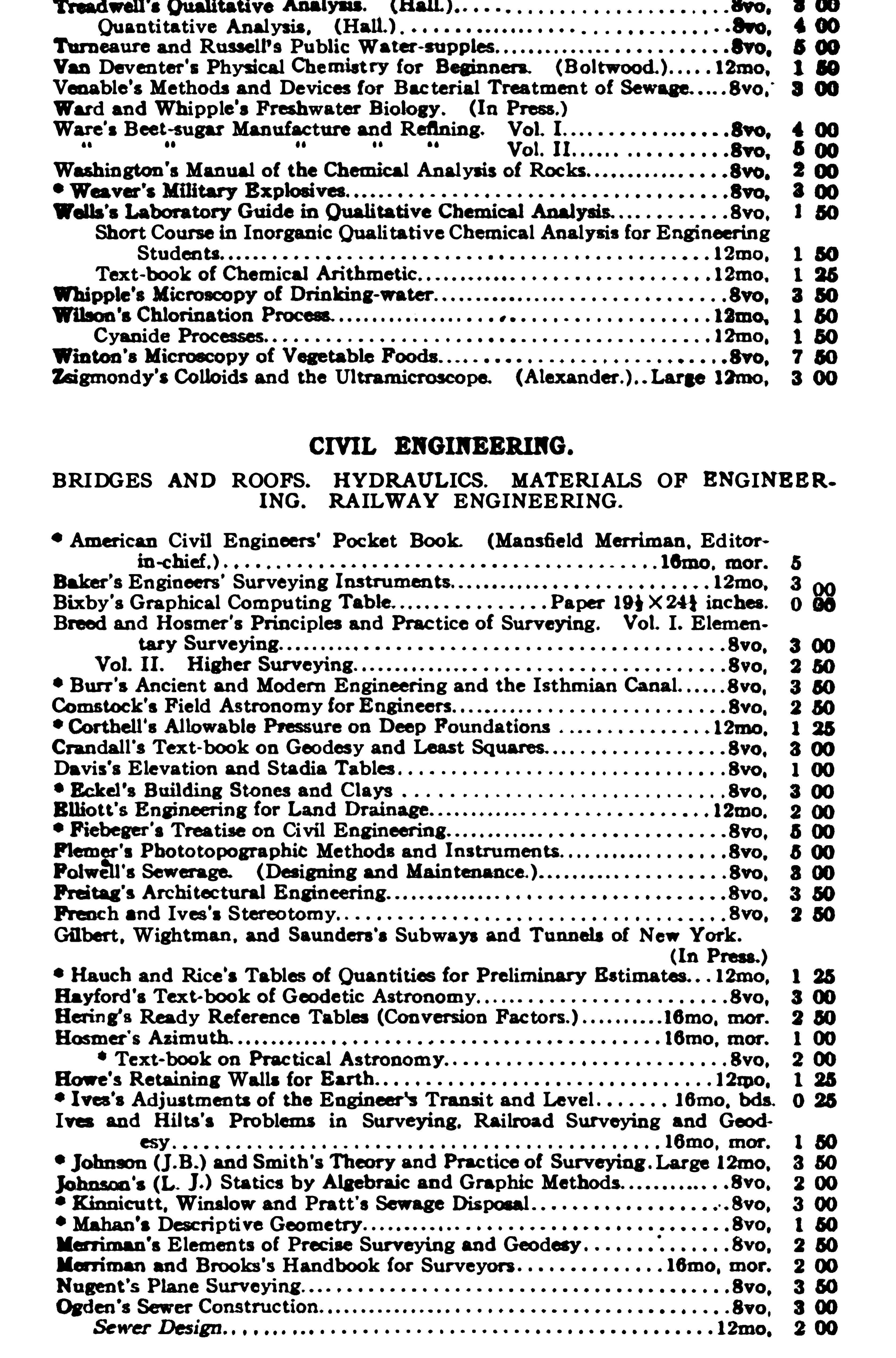
Quanti tative Analysis , (Hall) .
Turneaure and Russe ll’s Public Waw m plw ”
Van Deventer’s Physica l Chemist ry for Beginners 121110,Venable’s Methods and Devices for Bac teria l Treatmen t ofWard and Whipp le’s Freshwater B iology . (In Press.)Ware
’s Beet -sugar Manufacture and Refining.
301.
01
Washington’s Manual of the Chemical Analysis of Rocks”
8v0
Short Course in Inorganic Qua li tative Chemica l Analysis for EngineeringStudents 121110.
Text-book of Chemical Ari thmetic” . 121110.
Cyanide Processes l2mo .
Zsigmondy’s Co lloids and the Ultramicroscope. 121110.
BRIDGES AND ROOFS. HYDRAULICS . MATERIALS OF ENGINEERING. RA ILWAY ENGINEERING .
‘ American Civil Engineers’ Pocke t Book. (Mansfie ld Merriman. Editor!in -chief.
Baker’s Engineers’Surveying l 2mo.
Bixby's Graphical Computing .Paper 19} X 24} inches .
Breed and Hosmer'8 Principles and Prac tice of Surveying. Vol. I . Elemen
Burr’s Ancient and Modern Engineering and the Isthmian Cana l.Comstock’s Fie ld Astronomy for
Crandall ‘s Text-book on Geodesy and Least Squares.
Davis's Elevation and Stadia Tables
Fiebeger'
s Treatise on Civil Eng ineering .
Flam’s Pbo to topographic Methods and
F’s Sewerage. (Des igning and Mamtmance. )
Breu h and Ives’s Stereotomy 8vo .
Gilbert . Wightman . and Saunders s Subways and Tunnels of New York .
(In Press. )Ranch and Rice s Tables of Quantities fo r Preliminary Estimates . . 121110.
Hayford’s Text book of Geode tic Astronomy”
Heling’a Ready Reference Tables (Conversion Factors.
Hosmer'
s
Text-book on Prac tical Astronomy.
Howe’s Retaining Walls for 12190.
Ives’s Adjustments of the Engineer‘s Transi t and Level 161110. bds.
Ives and Bllts’s Problems in Surveying. Railroad Surveying and Good
Large 121110.
Iohnson‘
s (b J.) Statics b y Alg ebraic and Graphic Methods . . 8vo .
Kinnicutt . Winslow and Pratt's Sewage Disposal .. Syo .
Mahan’s Descriptive Geometry 8vo .
l erriman'
s Elements of Precise Surveying and Geodesy 8yo ,
Ma iman and Brooks’s Handbook for Surveyors lfimo . mor.
8
8
8
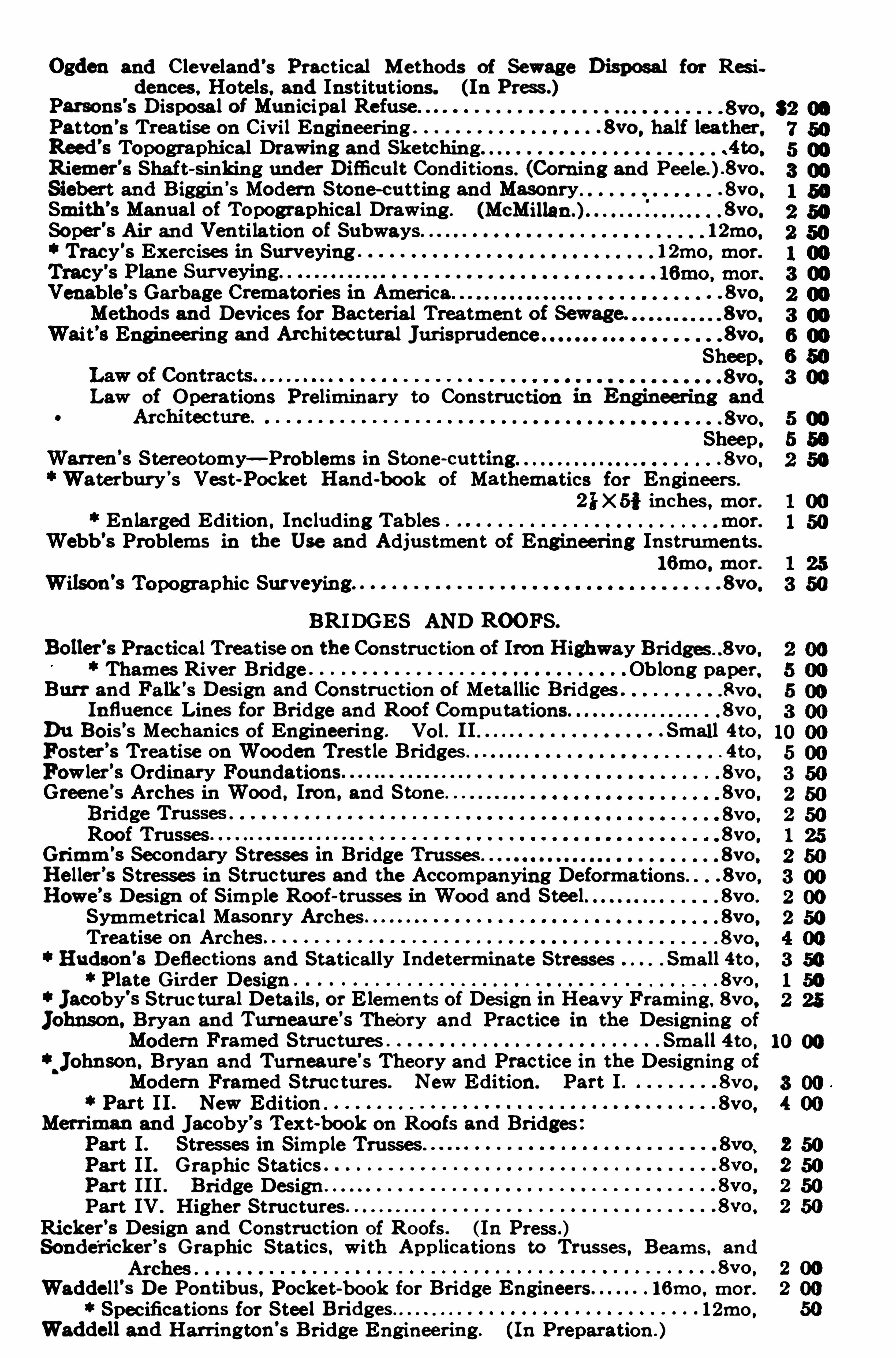
Ogden and Cleveland’s Practical Methods of Sewage Disposal for Residences , Hote ls , and Institutions. (In Press.)
Parsons's Disposal of Municipal RefusePatton’s Treatise on Civil Engineering . 8vo .
ha lf leather.Reed
’s Topographical Drawing and Sketching . .4to
Riemer’s Shaft-sinking under Dimcult Conditions . (Corning and Pee le . ) .8vo .
Siebert and Biggin’5 Modern Stone-cutting and Masonry . 8vo .
Smith’s Manual of Topographical Draw ing . 8ve .
Soper’s Air and Venti lation of Subways. l2mo.
Tracy’s Exercises in Surveying 12mo . mor.
Venable’s Garbage Crematories 1n America” . . 8vo .
Methods and Devices for Bacteria l Treatment of Sewage. 8vo .
Wait’3 Engineering and Archi tectural Jurisprudence . . 8ve .
Sheep..8vo ,
Law of Operations Preliminary to Construction in Engineering and
Sheep.Warren’3 Stereo tomy—Problems 1n Stone-cutting. . . 8vo .
Waterbury’s Vest-Pocket Hand book of Mathematics.
for Engineers .
2IX 5 i inches mor.
En larged Edition. Including Tables mor.
Webb’s Problems in the Use and Adjustment of Engineering Instruments .
l6mo . mor.
Wilson’s Topographic Surveying. 8vo .
BRIDGES AND ROOFS.
Boller’s Practical Treatise on the Construction of Iron Highway Bridges 8vo .
Thames River Bridge Ob long paper.Burr and Falk’s Design and Construction of Meta llic Bridges . Rvo .
Influence Lines for Bridge and Roof Computations. 8vo
Du Bois’s Mechanics of Engineering. Vo l. II . . . Small 4to ,
Foster’s Treatise on Wooden Trestle Bridges . . 4to .
Fow ler’s Ordinary Foundations 8vo .
Greene’s Arches in Wood. Iron. and Stone . 8vo .
8vo .
Roof Trusses 8vo .
Grimm’s Secondary Stresses 1n Bridge Trusses . 8vo .
He ller’s Stresses 1n Structures and the Accompanying Deformations . . 8vo .
Howe’s Design of Simple Roo f-trusses in Wood and Stee l 8vo .
Symmetrica l Masonry Arches 8vo.
Treatise on Arches 8vo .
Hudson’s Deflections and Statically Indeterminate Stresses Small 4to .
Plate Girder Design . 8vo .
Jacoby’s Struc tural Details , or Elemen ts of Design in Heavy Framing, 8vo.
Johnson. Bryan and Turneaure'
s Theory and Practice in the Design ing of
Modern Framed Structures Small 4to .
Johnson.Bryan and Turneaure
'
s Theory and Practice in the Designing ofModern Framed Structures New Edition. Part I . 8vc .
Part II . New Edition 8vo .
Merriman and Jacoby’s Text-book onRoots and Bridges .
Part I . Stresses in Simple Trusses .
Part II . Graphic StaticsPart III . Bridge DesignPart IV . Higher Structures
Ricker’s Design and Construction of Roofs . (In Press .)Sonde
‘
ricker’s Graphic Statics. with Applications to Trusses. Beams and
8vo .
Wadde ll’s De Pontibus. Pocket book for Bridge Engineers . 16mo , mor.
Specifications for Stee l 12mo .
Weddell and Harrington’s Bridge Engineering. (In Preparation . )
1000
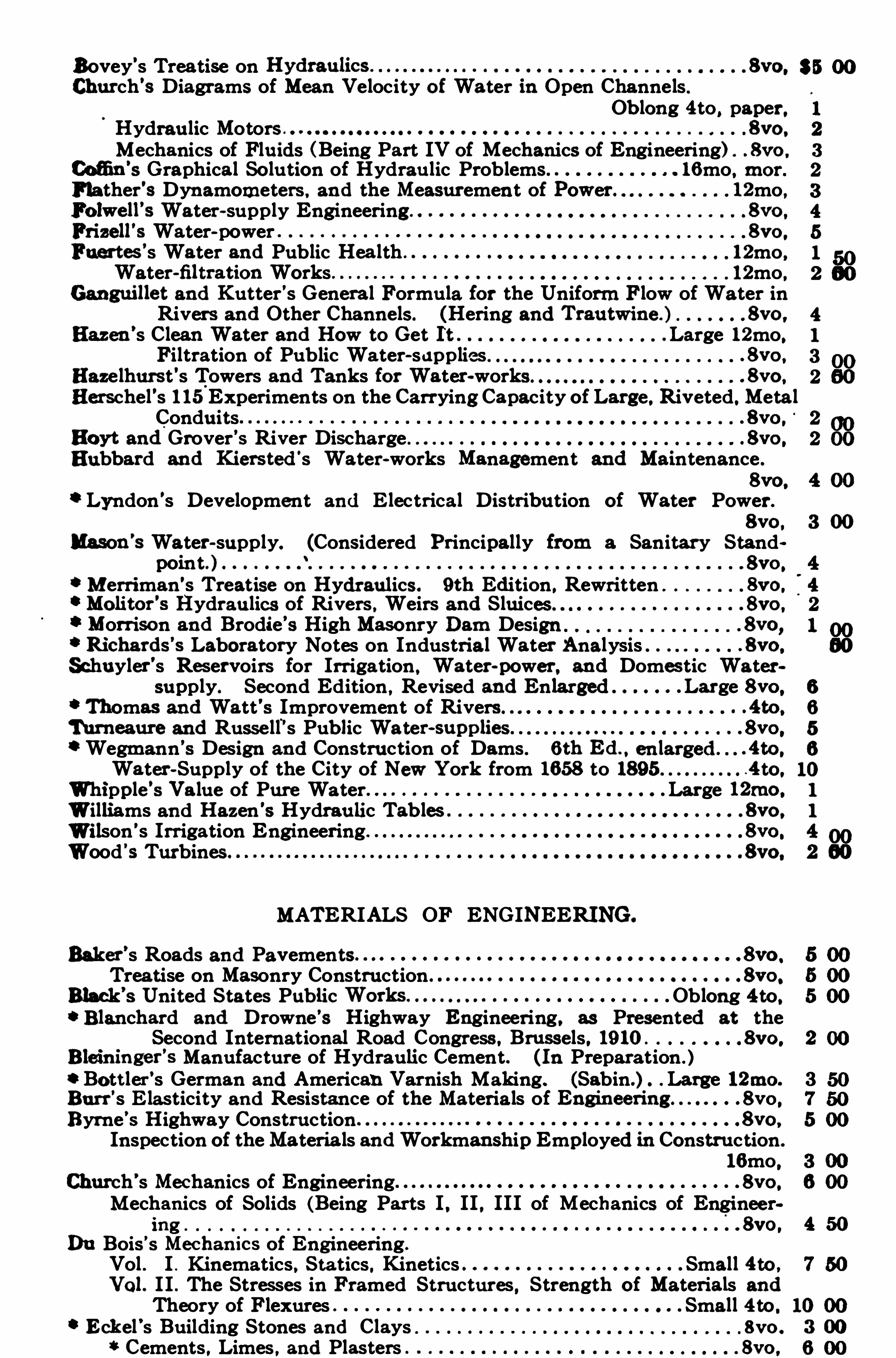
Bovey’s Treatise on 8vo.
Church’s Diagrams of Mean Velocity 0}Water.
1n Open ChannelsOblong 4to , paper,
Hydraulic Motors 8vc .
Mechanics of Fluids (Being Part IV of Mechanics of Engineering) . . 8vo .
Cofi n’s Graphical Solution of Hydraulic Problems 16mo, mor.
Flather's Dynamometers. and the Measurement of Power. 12mo ,Folwell
’s Water-supply Engineering 8vo .
Frizell'
s Water-power 8vc .
Fuertes’s Water and Public Health 12mo ,
Water-nltration Works 12mo.Ganguillet and Kutter's General Formula for the Uniform Flow of Water in
Rivers and Other Channels. (Hering and Trautwine . ) 8vo .
Hazen’s Clean Water and How to Get It . .Large 12mo.Filtration of Public Water-supplies . 8vo .
Hazelhurst's Towers and Tanks for Water-works. . 8vo .
Herschel's 115 Experiments on the Carrying Capacity of Large. Riveted.MetalConduits . 8vo .
Hoyt and Grover’5 River.
Discharge . 8vo .
Hubbard and Kiersted's Water-works Management and Maintenance .
8vo.
Lyndon 's Development and E lectrical Distribution of Water Power.
8vo .
Mason '
s Water-supply. (Considered Principally from a Sanitary Standpoint. ) . 8vo .
Merriman's Treatise on Hydraulics. 9th Edition. Rewritten 8vo.
0Molitor'
s Hydraulics of Rivers. Weirs and Sluices . . 8vo .
Morrison and Brodie’s High Masonry Dam Design . 8vo,Richards
’s Laboratory Notes on Industrial Water Analysis . . 8vo.
Schuyler’s Reservoirs for Irrigation , Water-power. and Domestic Watersupply. Second Edition , Revised and Enlarged Large 8vo .
Thomas and Watt'5 Improvement of Rivers . . .4to .
Turneaure and Russell 's Public Water . . 8vo .
Wegmann’5 Design and Construction of Dams 6th
.
Ed. , . 4to .
Water-Supply of the City of New York from 165 8 to 189 5 4 to.Whipple’5 Value of Pure Water Large 12mo .
Williams and Hazen 's Hydraulic Tables 8vo .
Wilson 's Irrigation Engineering 8yo .
Wood 's Turbines . 8yo.
MATERIALS OF ENGINEERING.
Baker’s Roads and Pavements . 8vo .
Treatise on Masonry Construction . . 8vo .
Black’8 United States Public .Oblong 4to.Blanchard and Drowne’s Highway Engineering. as Presented at the
Second International Road Congress . Brussels. 19 10 8vc .
Blein inger'
s Manufacture of Hydraulic Cement. (In Preparation . )Bott ler’s German and American Varnish Making. (Sabin.) Large l2mo.
Burr’s E lasticity and Resistance of the Materials of . . 8vo .
Byrne’5 Highway Construction 8vo.
Inspection of theMateria ls andWorkmanship Employed 1n Construction.
16mo ,Church’s Mechanics of Engineering 8vo .
Mechanics of Solids (Being Parts I . II . III of Mechanics of Enginee r8vo .
Du Bois’sn
Mechanics of Eng ineering.
Vol . I . K inematics , Statics. K inetics Small 4to ,Vol. I I . The Stresses in Framed Structures , Strength of Materials andTheory of Flexures Small 4to .
Eckel’s Building Stones and Clays . 8vo .
Cements , Limes , and Plasters . 8vo .
8
8
8
8
8
8
8
8
8
8
8
8
8
8
8
8
“
N
15
8
8
8
8
8
8
8
8
8
8
8
8
8
8
8
7 50
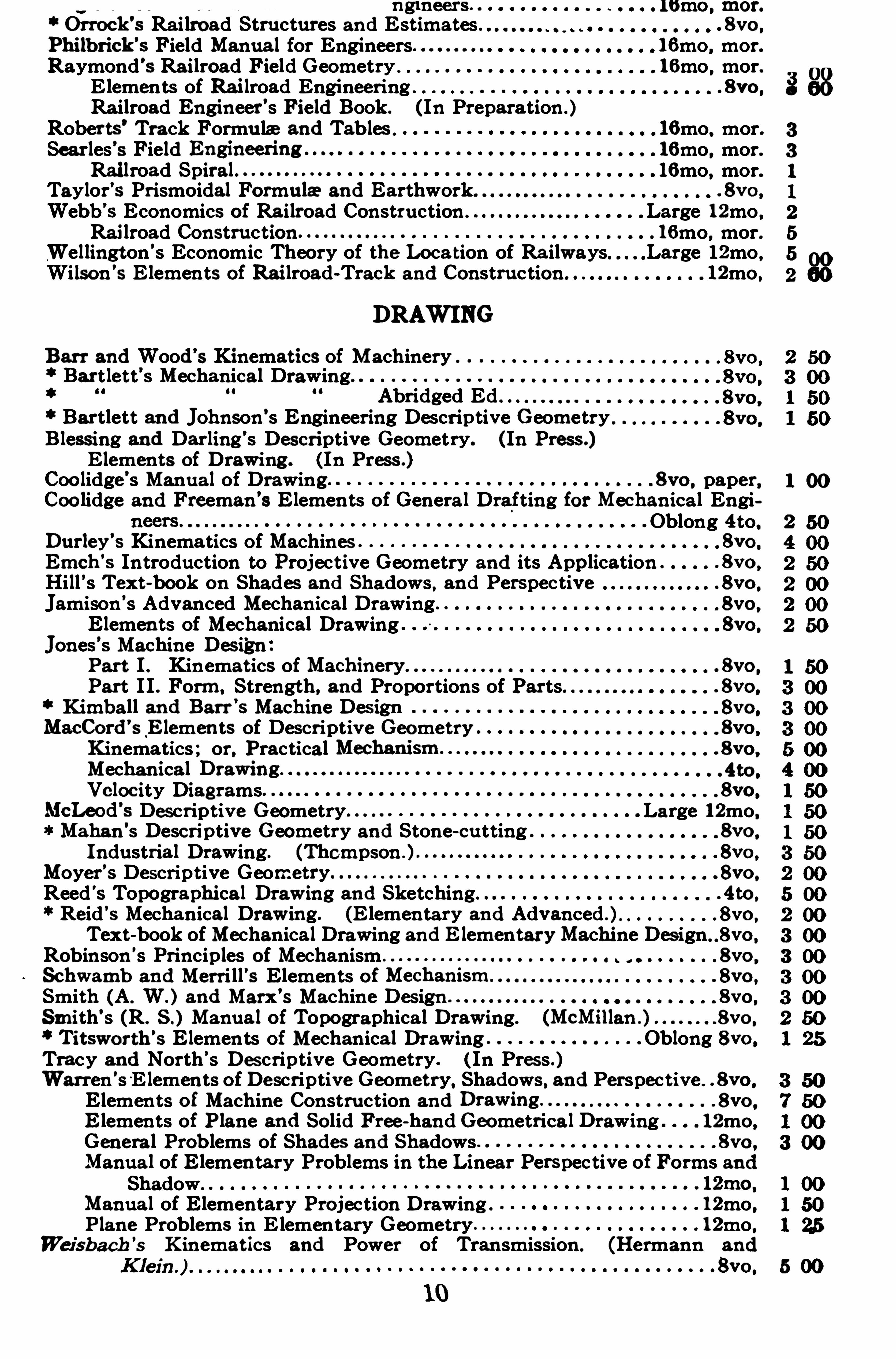
ng meers lomo , mor.
Orrock’s Railroad Structures and Estimates . . 8vo .
Philb rick’s Field Manual for Engineers 16mo , mor.
Raymond’s Railroad Field Geometry . 16mo , mor.E lements of Railroad Engineering . 8vo .
Railroad Engineer’s Field Book . ( In Preparation . )Roberts’Track Formula and Tables . 16mo, mor.Sear les’5 Field 16mo, mor.Railroad Spiral . 16mo, mor.
Taylor'5 Prismoidal Formula and Earthwork . 8vo .
Webb’5 Economics of Railroad Construction . Large 12mo.Railroad Construction 16mo , mor.
Wellington’s Economic Theory of the Loca tion of Railways Large 12mo.Wilson’s E lements of Railroad-Track and Construction . 12mo .
DRAWING
Barr and Wood’s Kinematics of Machinery .
Bartlett’s Mechanical DrawingAbridged Ed .
Bartlett and Johnson’s Engineering DescriptiveGeometryB lessing and Darling’s Descriptive Geometry. (In Press.)Elements of Drawing . (In Press .)
Coo lidge’s Manual of Drawing 8vc . paper,Coo lidge and Freeman's Elements of General Drafting for Mechanica l Engi
Oblong 4to,Durley
’s Kinematics of Machines 8vo .
Emch’s Introduction to Projective Geometry and its Application . . 8vo .
Hill’s Text-book on Shades and Shadows, and Perspective . 8vo .
Jamison’s Advanced Mechanical Drawing 8vo .
Elements of Mechanical Drawing 8vc .
Jones '5 Machine DesignPart I . Kinematics of . 8vo .
Part II . Form, Strength, and Proportions of Parts . 8vo.
K imball and Barr’5 Machine Design 8vc .
MacCord’sElements of Descriptive Geometry 8vo .
K inematics ; or, Practical . 8vo ,
Mechanica lVe locity Diagrams 8vo .
McLeod’s Descriptive Geometry Large 12mo.
Mahan’s Descriptive Geometry and Stone-cutting 8vo .
Industrial Drawing. (Thompson . . 8vo .
Moyer’8 Descriptive Geometry” . 8vo .
Reed '
s Topographical Draw ing and Sketching. . 4to ,
Reid’5 Mechanical Draw ing. (E lementary and Advanced . . .8vo
Text-book of Mechanical Drawing and E lementary Machine Design 8vo .
Robinson’s Principles of Mechanism” 8vo .
Schwamb and Merri ll’5 Elements of . 8vo .
Smith (A . W. ) and Marx’s Machine Design 8vo .
Smith’s (R. Manual of Topographica l Drawing. (McMillan . 8vo .
Titsworth’s Elements of Mechanical Drawing Oblong 8vo .
Tracy and North’s Descriptive Geometry. ( In Press . )Warren’s E lements of Descriptive Geometry, Shadows, and Perspective . . 8vo .
Elements of Machine Construction and 8vo .
Elements of P lane and Solid Free-hand GeometricalDrawing 12mo.Genera l Problems of Shades and Shadows 8vc .
Manua l of Elemen tary Problems in the Linear Perspective of Forms andShadow
Manual of Elementary Projection Drawing . 12mo.Plane Problems in E lementary Geometry 12mo.
Weisbach’s K inematics and Power of Transmission . (Hermann and
8vo .
N
U
C‘
N
Ht-‘ww
03
1003
00
“
8
8
8
8
8
8
8
8
8
8
8
8
8
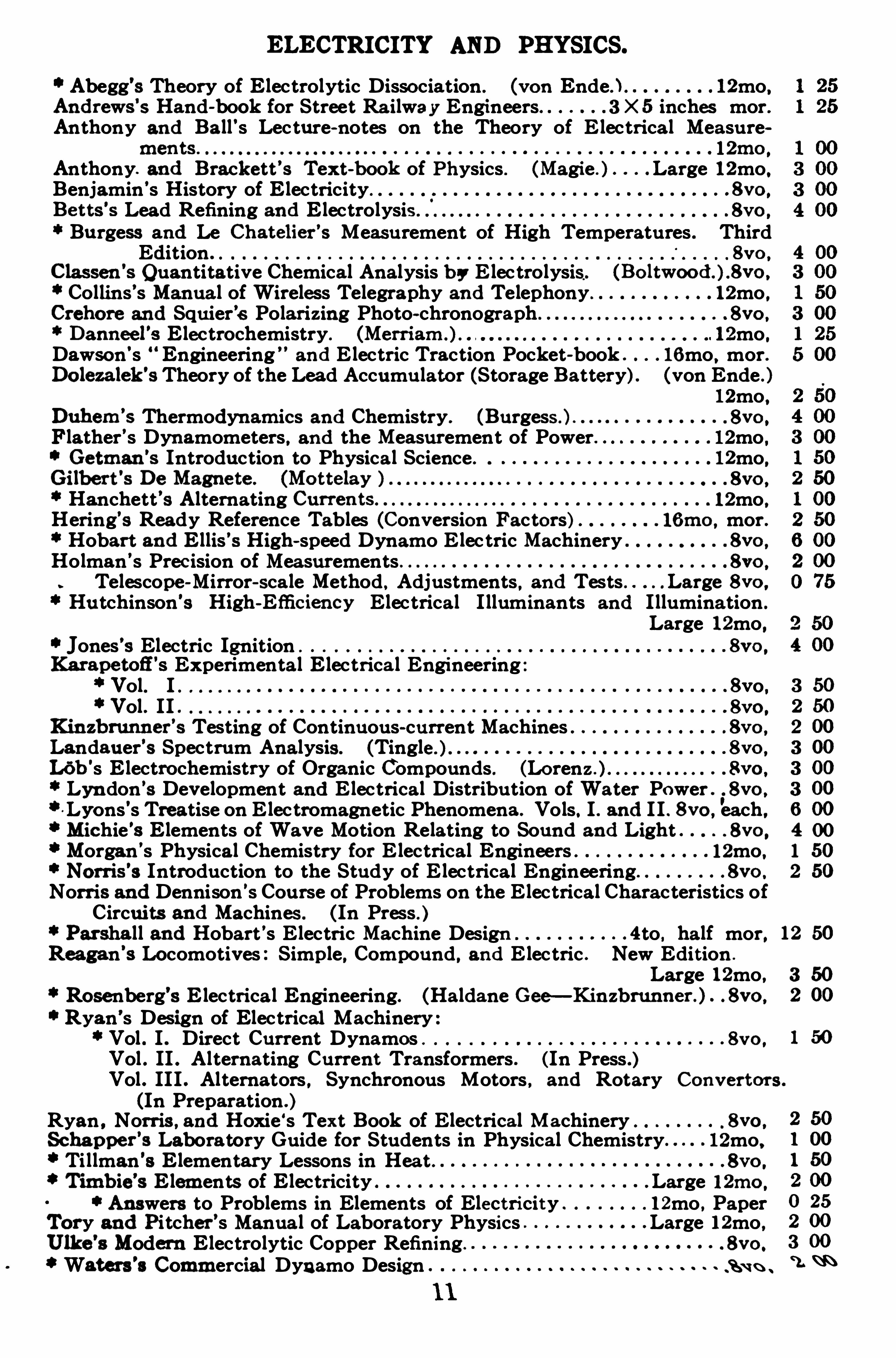
ELECTRICITY AND PHYSICS.
Abegg’s Theory of Electrolytic Dissociation . (von Ende. ) 12mo.Andrews
’s Hand-book for Street Ra ilway Engineers. . 3 X 5 inches mor.
Anthony and Ball’s Lecture-notes on the Theory of E lectrical Measurements . . 12mo ,
Anthony. and Brackett’3 Text bookof Physics . (Magie . ) . Large 12mo.Benjamin’s History of Electricity . 8vo .
Be tts'
s Lead Refining and Electrolysis . 8vo .
Burgess and Le Chatelier’s Measurement of High Temperatures . ThirdEdition . .8vo
Classen’s Quantitative Chemical Analysis b y E lectrolysis. (Bo ltwood . 8vo .
Collins’s Manua l of Wireless Telegraphy and Telephony 12mo .Crehore and Squier’s Polarizing Photo-chronograph . . 8vo .
Danneel’s Electrochemistry. 12mo .
Dawson's Engineering”and E lectric Traction Pocket-book . 16mo , mor.Do lezalek
’s Theory of the Lead Accumulator (Storage Battery) . (von Ende . )
12mo.Duhem
’s Thermodynamics and Chemistry. (Burgess ) . . 8vo ,
Flather’s Dynamometers, and the Measurement of Power. 12mo .Getman
’s Introduction to Physica l Science . 12mo.
Gilbert’
.s De Magnete . 8vo ,
Hanchett’s Alternating.
12mo ,Hering’s Ready Reference Tables (ConversionFactors) 161110, mor .Hobart and Ellis’5 High-speed Dynamo E lec tric Machinery 8vo ,
Holman’s Prec ision of Measurements 8vo .
Telescope-Mirror-sca le Method , Adjustments , and Tests Large 8vo .
Hutchinson’s High-Efficiency Electrical I lluminants and I llumination .
Large 12mo.Jones’s Electric Ignition . 8vo .
Karapetofi’8 Experimental Electrica l Engineering .
Vol. I 8yo.Vol . II . 8vo .
K inzb runner’s Testing of Continuous-current Machines 8vc ,
Landauer’s Spectrum Analysis. (Tingle ) . 8vo ,
L6b's Electrochemistry of Organic Compounds . (Lorenz . . 8vo .
Lyn don’8 Development and E lectrical Distribution of Water Power . . 8vo .
Lyons’s Treatise on E lectromagnetic Phenomena . Vols. I . and I I . 8vc each ,Michie’8 Elements of Wave Motion Relating to Sound and Light . 8vo .
Morgan’s Physical Chemistry for E lectrical Engineers 12mo.Norris
’s Introduction to the Study of E lectrical Engineering. . 8vo .
Norris and Dennison’s Course of Problems on the E lectrical Characteristics ofCircui ts and Machines . (In Press . )
Parsha ll and Hobart’s E lectric Machine Design . 4to , half mor,Reagan’s Locomotives : Simple, Compound , and E lectric . New Edition .
Large 12mo.Rosenberg’s Electrica l Engineering. (Haldane Gee—Kinzb runner . ) . 8vo .
Ryan’s Design of Electrical Machinery :Vol . I . Direct Current Dynamos . 8vc ,
Vol . II . Alternating Current Transformers . (In Press .)
Mc-
Q
OJ
OO
OO
MN
OJ
12
Vol . III . Alternators , Synchronous Motors , and Rotary Converters .
(In Preparation . )Ryan , Norris , and Hoxie‘s Text Book of Electrical Machinery . 8vo .
Schapper’s Laboratory Guide for Students in Physical Chemistry 12mo.
Tillman’s Elementary Lessons in Hea t . . 8vo .
Timb ie’s Elements of Electricity .Large l 2mo
,
Answers to Problems in Elements of Electricity 12mo , PaperTory and Pitcher’s Manual of Laboratory Physics Large 12mo ,Ulke
'
s Modern Electrolytic Copper Refining. . 8vo .
Waters’s Commercial Dynamo Design S u n .
50
00000000
5050
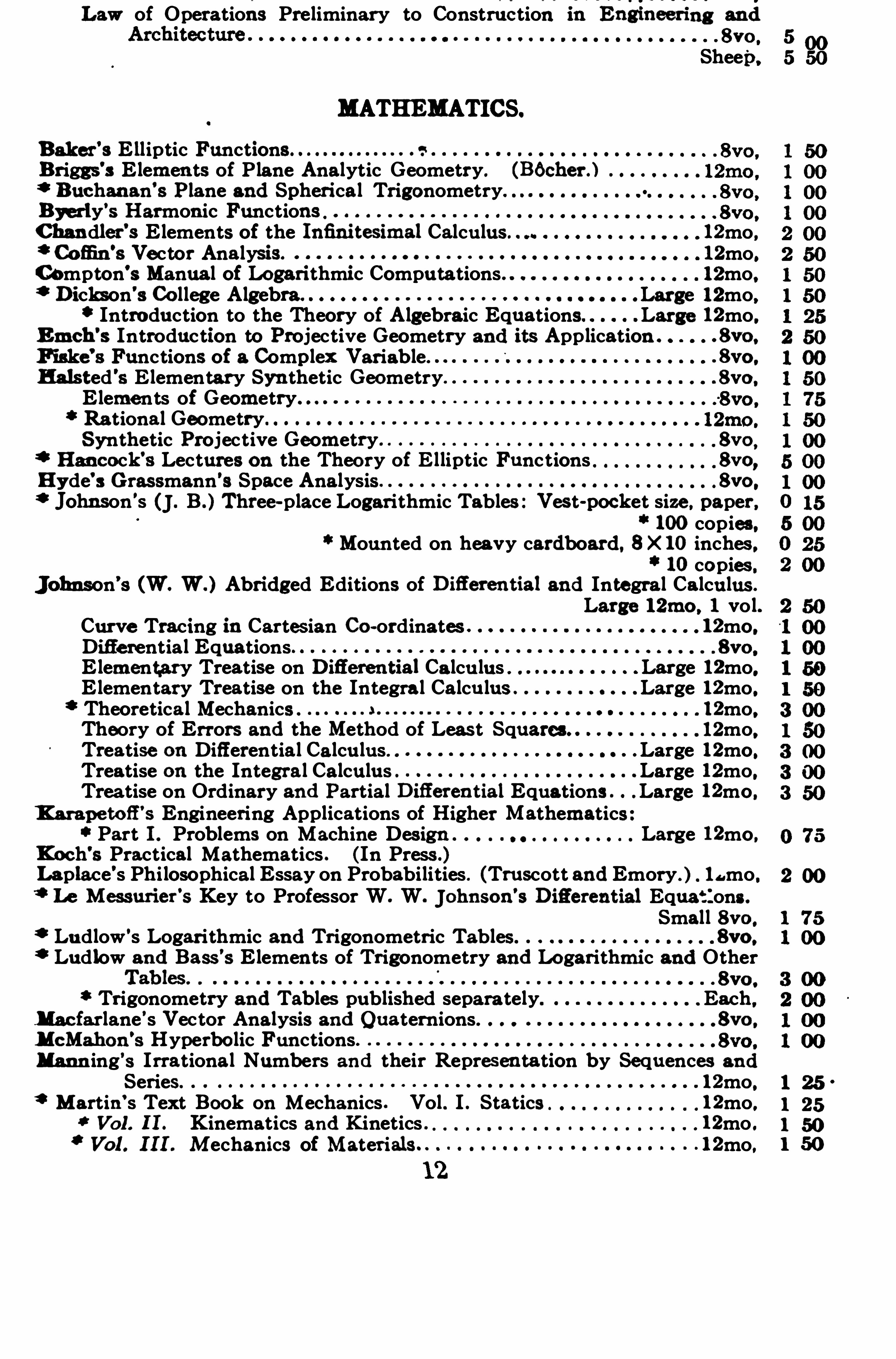
Law of Operations Preliminary to Construction.
inEngineenng and8vo .
Sheep,
MATHEMATICS.
Baker’8 Elliptic Functions s
Briggs’3 Elements of P lane Analytic Geometry. (B6cher . )
Buchanan’s Plane and Spheri cal TrigonometryByerly
’s Harmonic Functions
Chandler'8 Elements of the Infini tesimal Calculus. 12mo.Cofi n
’s Vector Analysis. 12mo.
Compton’s Manual of Logarithmic Computations 12mo.Dickson’3 Co llege Algebra Large 12mo.Introduction to the Theory of Algebraic Equations Large 12mo.
Emch’s Introduction to Projective Geometry and its Application . . 8vo .
Fiske’s Functions of a Complex Variable. . 8vo .
Halsted 's E lementary Syn thetic Geometry. . 8vo .
Elements of Geometry.
Rational GeometrySynthetic Projective Geometry 8vo
,
Hancock’s Lectures on the Theory of E lliptic Functions 8vo,Hyde’s Grassmann’s Space Analysis 8vo .
Johnson’s (J . B . Three-place Logarithmic Tables : Vest-pocket size . paper ,
100copies.Mounted on heavy cardboard, 8 X 10inches ,
10copies.Johnson’s (W. W . ) Abridged Editions of Difierential and Integral Calculus.
Large 12mo . 1 vol.Curve Tracing 1n Cartesian Co-ordinates 12mo.Differential Equations 8vo .
Elementary Treatise on Difierential.
Calcu lus” Large 12mo.Elementary Treatise on the Integral Calcu lus” Large 12mo.Theoretica l Mechanics . 12mo.Theory of Errors and the Method of Least Squares. 12mo.Treatise on Differential Calculus” Large 12mo.Treatise on the Integral Calculus . Large 12mo.Treatise on Ordinary and Partial Difierential Equations . Large 12mo.
K arape tofi’s Engineering Applications of Higher Mathematics
Part 1. Problems on Machine Design Large 12mo.Koch’s Practical Mathematics . (In Press .)Laplace’s Phi losophical Essay on Probabilities . (Truscott and Emory . ) l amo.7" Le Messurier
’s Key to Professor W. W. Johnson’s Difierential Equations .
Small 8vo .
Ludlow’s Logarithmic and Trigonometric Tables 8y o .
Ludlow and Bass’s Elements of Trigonometry and Lo garithmic and Other. . 8vo .
Trigonometry and Tables published separately. Each,Macfarlane’s Vector Analysis and Quaternions. 8vo .
McMahon’s Hyperbo lic Functions
Mann ing’s Irrational Numbers and their Representation by Sequences and
Series. 12mo.Martin’s Text Book on Mechanics . Vol . I . Statics 12mo.
Vol. II . Kinematics and K inetics 12mo .Vol. III . M echanics of Materials 12mo.
8
8
2
s
e
e
s
00
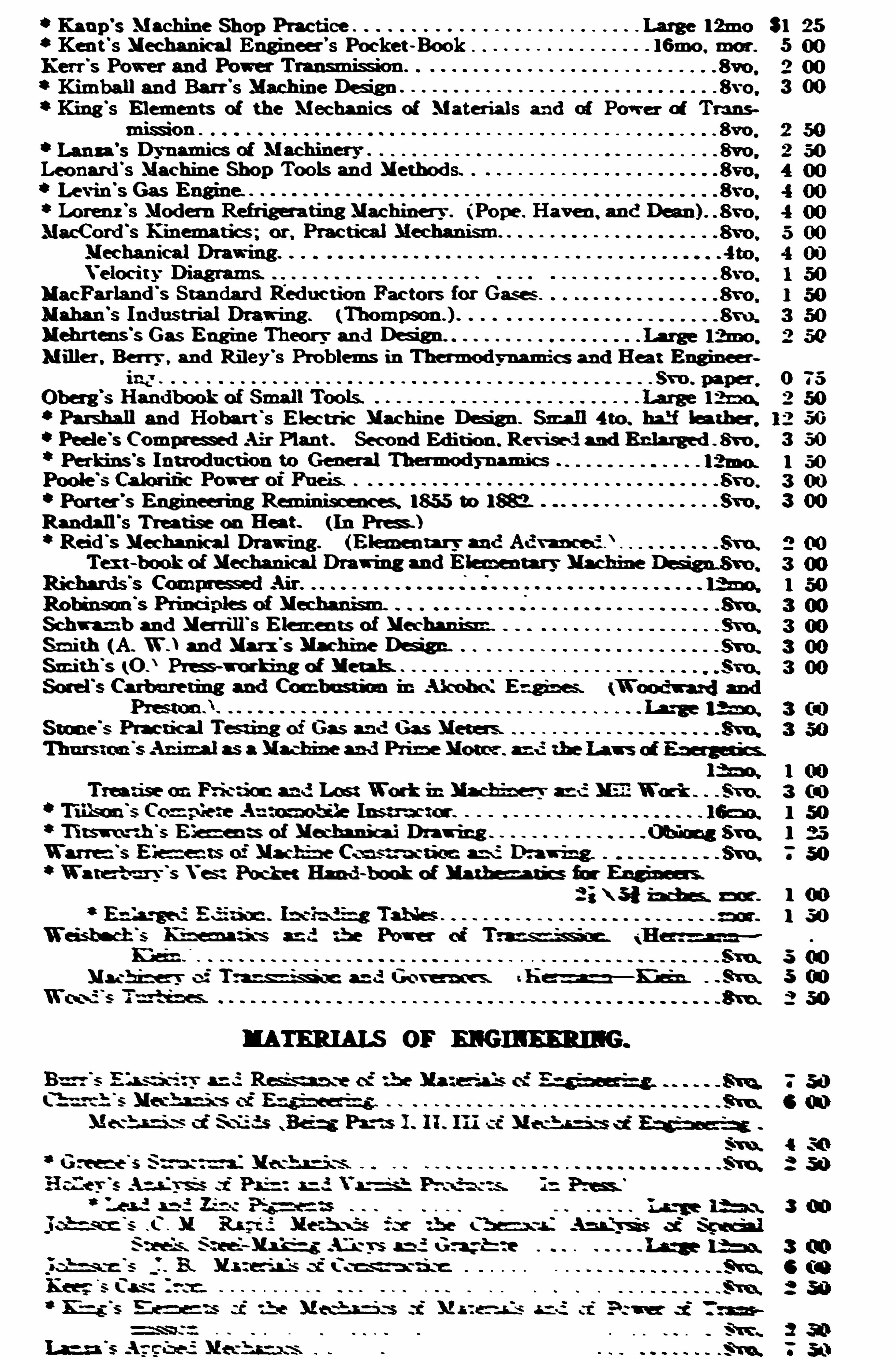
Kaup’s Machine Shop Practice 31 25
Kent 's Mechanical Engineer’s Pocke t -Book 16mo . mar . 5
2 00‘ Kimball and Barr ’s Machine Defl '
gn 3 00King 's Elements of the Mechanics of Materials and of Power of Trans
8vo .
Leonard 's Machine Shop Tools and Methods.
Lorenz ’s Moda n Refrigera'
tn g'
Machine -
y (Po pe . Haven ,
MacFarland'
s Stan dard Reduc tion Fac tors for Gase s
Mehrtens'
s Gas Eng ine Theory and Dd gn
Miller , Berry , and Riley’s Problems in Thermodynamics and Ha t Eng ineer
02
Parshall and Hobart 's Electric Machine Dd gn Small 4 to . half lea ther , 50Peele
'
s Comm-m ed Air Plan t . Second Edition . Revisedm d Enlarged fi vo . 3 50l 503 00
‘ Porter'
s Eng ineering Reminiscencss lfi S to lfi 3 00Randall
's Treatise on Heat. (In Pres . )
Reid'
s Mechanical Draw ing . (Elemen tary and Advanced ).
Schn mb and Merrill's Elemen ts of Mechan
'
s nz.
Smith (A. W .) and Marx
‘
s Machine Dd g n.
Smith'
s (O Pies -working of Metals.
Elemen ts of Mechanic-i Drawing
Waterb nrv'
s Vest Pock et Hand-b ook of Math s-antics fir Eng ineers.
2 ; \ 5 l inch es. a m . 1 ( i )
l 50
5 soMach inery o
f Tm and Go vernors. t h e m —mun . . S‘ml 5 no“
2 50
2
3 on
Su e-is. S teeLMs fé g Aliens and Gum -b ee
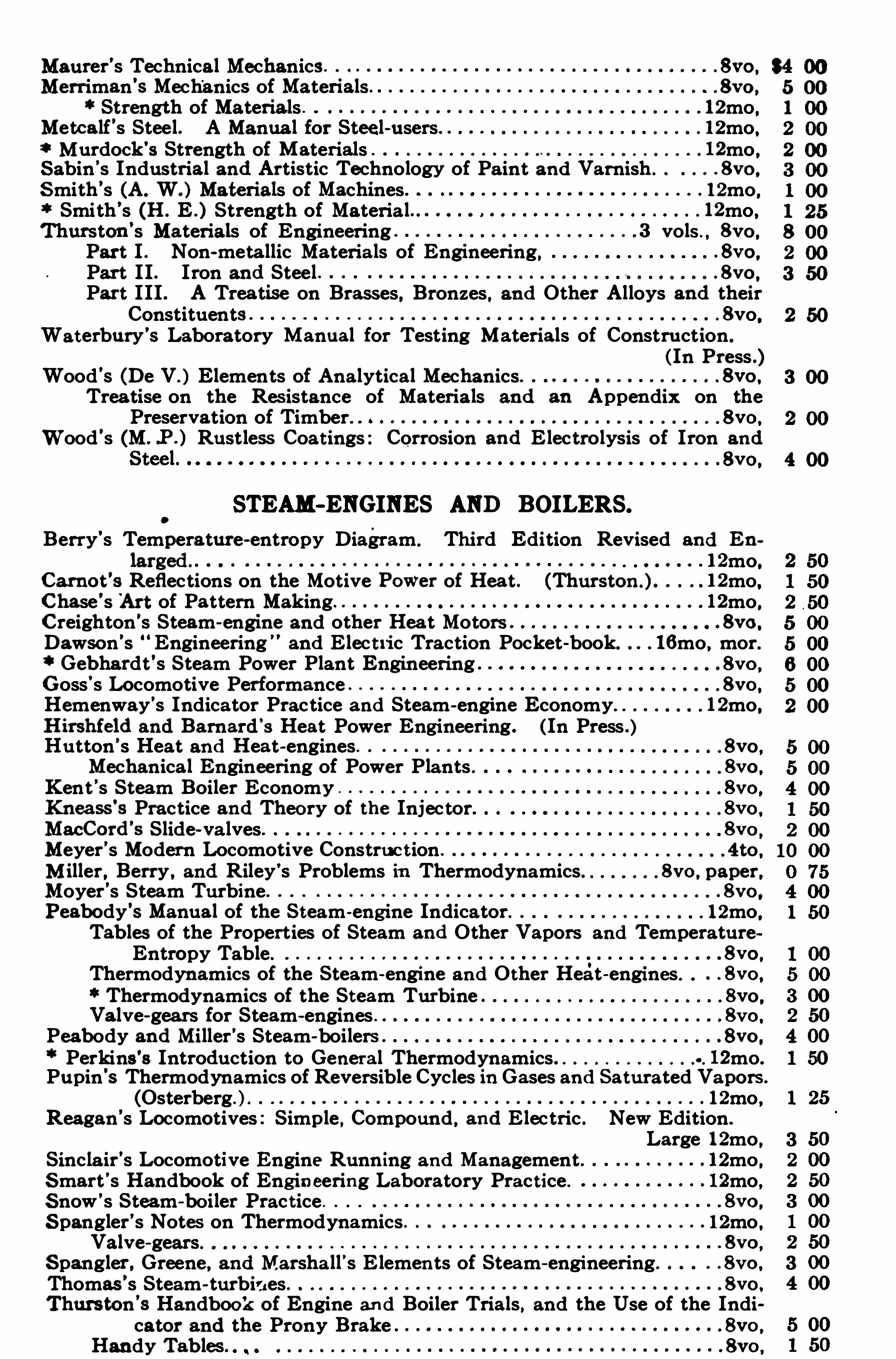
Maurer’s Technical Mechanics 8yo ,
Merriman’s Mechanics of Materials 8y o ,
Strength of Materials 12mo.Metcalf’s Steel . A Manua l for Steel-users 12mo.Murdock’s Strength of Materials 12mo .
Sabin’s Industrial and Artistic Technology of Paint and Varnish . 8vo ,
Smith’s (A. W. ) Materials of Machines . 12mo ,Smith’s (H . E . ) Strength of Material 12mo.
Thurston’s Materials of Engineering 3 vols , 8yo,Part I . Non-metallic Materials of Engineering, . 8vo ,
Part I I . Iron and Steel . 8vo ,
Part I II . A Trea tise on Brasses, Bronzes , and Other Alloys and theirConstituents 8yo,
Waterbury’s Laboratory Manual for Testing Materials of Construction .
(In Press .Wood’s (De V. ) Elements of Analytical Mechanics 8vo ,
Treatise on the Resistance of Materials and an Appendix on thePreservation of Timber” 8vo ,
Wood’s (M. .P . ) Rustless Coatings : Corrosion and E lectrolysis of Iron and
8vo ,
STEAM—ENGINES AND BOILERS.
Berry’s Temperature-entropy Diagram . Third Edition Revised and En
12mo.Carno t
’s Reflections on the Motive POWer of Heat . (Thurston ) 12mo.
Chase’s '
Art of Pattern Making 12mo.Creighton 's Steam-engine and other Hea t Motors . 8vo ,
Dawson’s “ Engineering and E lec t1ic Traction Pocket-book. 16mo , mor.Gebhardt’s Steam Power Plant Engineering . 8vo ,
Goss’s Locomotive Performance 8vo ,
Hemenway’s Indicator Practice and Steam-engine Economy . 12mo.Hirshfeld and Barnard’3 Heat Power Engineering. (In Press .Hutton’s Heat and Heat-engines 8yo ,
Mechanical Engineering of Power Plants . 8vo ,
Kent’s Steam Boiler Economy 8vc ,
Kneass’s Practice and Theo ry of the Injector 8vo ,
MacCord’s Slide-valves 8vc
Meyer’s Modern Locomotive Construc tion 4to ,M iller , Berry , and Riley’s Problems in Thermodynamics 8vo ,
paper,Moyer’s Steam Turbine . 8vo ,
Peabody’s Manual of the Steam-eng ine Indicator 12mo.Tables of the Properties of Steam and Other Vapors and TemperatureEntropy Table. . . 8vo ,
Thermodynamics of the Steam-engine and Other Heat-engines . . . 8vo ,
Thermodynamics of the Steam Turbine 8yo ,Valve-gears for Steam-engines 8vc ,
Peabody and Miller’s Steam boilers . . 8vo ,
Perkins’8 Introduction to General Thermodynamics 12mo.Pupin's Thermodynamics of Reversible Cycles in Gases and Saturated Vapors .
(Osterberg. 12mo.Reagan’s Locomotives : Simple , Compound , and E lectric . New Edition.
Large 12mo.Sincla ir’s Locomotive Engine Running and Management . 12mo .Smart’s Handbook of Eng ineering Laboratory Practice . 12mo ,S now’s Steam-bo iler Practice . 8vo ,
S pangler’s Notes on Thermodynamics 12mo .Valve-gears 8vo ,
S pangler , Greene, and Marsha ll's E lemen ts of Steam-engineering 8vo ,
Thomas’s Steam-turbines . 8vo ,
Thurston’s Handbook of Engine and Boiler Trials , and the Use of the Indicator and the Prony Brake . 8vo ,
Handy Tables . . 8vo ,
2 50
3 00
2
4
1 25
wWeisbach’s Heat , Steam, and Steam-engines (Du Bois ) . 8vo . 5 00Wh itham’
s Steam-engine Design . 1 8vo . 5 00Wood’s Thermodynamics, Heat Motors, and Refrigerating Machines . . 8vo , 4 00
MECHANICS PURE AND APPLIED.
Church’s Mechanics of Engineering . 8vo , 6
Mechanics of Fluids (Being Part IV of Mechanics of Engineering) . . 8vo . 3
Mechanics of Inter nal Work . 8vo . 1
Mechanics of Solids (Being PartsI , II , III of Mechanics of Engineering) .8y o , 4
Notes and Examples in Mechanics. . . 8vo , 2
Dana’3 Text book of Elementary Mechanics for Colleges and Schools .
.
12mo, 1
Du Bois’s E lementary Principles of Mechanics :Vol. I . Kinematics. . 8vo ,
Vol . I I . Statics . 8vo ,
Mechanics of Engineering . Vol . I . Smal l 4to,Vol . I I . Smal l 4to ,
Greene’s Structural Mechanics . . 8vo ,
Hartmann’s Elementary Mechanics for Engineering Students 12mo.James’s Kinematics of a Point and the Rational Mechanics of a Particle.
Large 12mo.Johnson’s (W. W. ) Theoretical Mechanics 1. 2mo,K ing’8 Elements of the Mechanics of Materials and of Power of Transmission . . 8vo ,
Lanza’s Applied Mechanics. 8vo,
Martin’3 Text Book on Mechanics . Vol . I , Statics 12mo.Vol . I I . Kinematics and KineticsVol . II I . Mechanics of Materials
Maurer’s Technical MechanicsMerriman’s Elements of Mechanics.
Mechanics of MaterialsMichie’s Elements of Analytical MechanicsRobinson’s Principles of MechanismSanborn’s Mechanics ProblemsSchwamb and Merrill’s Elements of MechanismWood's Elements of Analytical Mechanics.Principles of Elementary Mechanics
MEDICAL.
‘ZAbderhalden’s Physiological Chemistry in Thirty Lectures. (Hall and
Defren .) . 8vo ,
von Behring’s Suppression of Tuberculosis. 12mo.Bolduan
’s Immune Sera 12mo ,
Bordet’s Studies in Immunity. (Gay . ) 8vo,Chapin’s The Sources and Modes of Infection . . Large 12mo.Davenport’s Statistical Methods with Special Reference to B iological Varia
tions. 16mo, mor.Ehrlich’s Collected Studies on Immunity. (Bolduan ) . 8vo,Fischer’s Nephri tis Large 12mo .
Oedema 8y o ,
Physiology of Alimentation . Large 12mo.de Fursac’s Manual of Psychiatry. (Rosanofi and Collins.) Large 12mo.Hammarsten
’s Text-book on Physiological Chemistry . (Mandel ) . . 8vo ,
Jackson’s Directions for Laboratory Work in Physiological Chemistry . . 8vo .
Lassar-Cohn’s Praxis of Urinary Analysis. (Lo renz ) . 12mo.
Mandel’s Hand-book for the Bio-Chemical Laboratory 12mo.Nelson’s Analysis of Drugs and Medicines . 12mo,Pauli’s Physical Chemistry in the Service of Medicine. (Fischer. ) . . l2mo ,
Pozzi-Escot’s Toxins and Venoms and their Antibodies. 12mo.Rostoski
'
s Serum Diagnosis. 12mo.Ruddiman
’s Incompatibilities in Prescri ptions . 8vo ,
Whys in Pharmacy 121110,
S alkowski’s Physiological and Pathological Chemistry. (Orndorfl . ) . .8vo ,

Merrill’s Non-metallic Minerals : Their Occurrence and Uses 8vo ,
Stones for Building and Decoration sy o ,
Penfield’s Notes on Determinative Mineralogy and Record ofMineral Tes ts .
8vo , paper.Tables of Minerals, Including the Use of Minerals and Statistics ofDomestic Production 8vo ,
Pirsson’s Rocks and Rock Minerals 12mo.
Richards’s Synopsis of Mineral Charac ters. 12mo . mor.
Ries’s Clays : Their Occurrence, Properties and Uses. 8vo ,
Ries and Leighton’s History of the C lay-working 1nc1usrry of the United
Rowe’s Practical Mineralogy SimplifiedTillman’s Text-book of Important Minerals and RocksWashington’s Manual of the Chemical Analysis of Rocks.
MINING.
Beard’s Mine Gases and Explosions.
Crane’s Gold and Silver.
Index of Mining Engineering Literature.
Ore Mining MethodsDana and Saunders’s Rock Drilling . .
Douglas’3 Untechnical Addresses on Technical Subjects.
Eissler’5 Modern High Explosives
Goesel’s Minerals and Metals : A Reference Book
Ihlseng’s Manual of Mining .
I ies’s Lead Smelting.
Peele’s Compressed Air Plant
Riemer'
s Shaft Sinking Under Difficult Conditions.Weaver’s Military Explosives .
Wilson’s Hydrau lic and Placer Mining. 2d edition , rewritten .
Treatise on Practical and Theoretical Mine Ventilation
SANITARY SCIENCE.
Association of State and National Food and Dairy Departments, HartfordMeeting, 1906 . . 8vo ,
Jamestown Meeting , 1907 . 8vo ,
Bashore’s Outlines of Practical Sanitation 12mo.
Sanitation of a Coun try House 12mo,Sanitat ion of Recreation Camps and Parks 12mo.
Chapin’s The Sources and Modes of Infection . Large 12mo.Folwell
’s Sewerage. (Designing, Construction , and Maintenance .) 8vo ,
Water-supply Engineering. 8vo .
Fowler’s Sewage Works Analyses 12mo.Fuertes’s Water-filtration Works 12mo.Water and Public Health . 12mo.
Gerhard's Guide to Sanitary Inspections 12mo.Modern Baths and Bath Houses 8vo ,
San itation of Public Buildings 12mo.The Water Supply, Sewerage , and Plumbing of Modern City Bui ldings.
8vo ,
Hazen’s C lean Water and How to Get It . Large 12mo.Filtration of Public Water-supplies . 8vo .
Kinnicutt , Winslow and Pratt’s Sewage Disposal . . 8vo ,
Leach’s Inspection and Analysis of Foo d with Special Reference to StateControl . . 8vo ,
Mason’s Examination of Water . (Chemica l and Bacteriological) 12mo.Water-supply. (Considered principally from a Sanitary Standpoint) .
8vo ,
Mas t’s Ligh t and the Behavior of Organisms .Large 12mo.
0 50
Large 12mo.8vo ,
8vo .
8vo mor.8vo ,
8vo ,
12mo.8vo .
16mo, mor.8vo ,
12mo ,8vo .
(Corning and Peele . )8vo ,
8vo ,
12mo.12mo.
‘l'Merriman’s Elements of Sanitary Eng ineering 8vo . $2 00Ogden’s Sewer Construction 8vo ,
12mo ,Parsons
’s Disposa l of Municipal Refuse . 8vo ,
Pres cott and Winslow'
s Elemen ts ofWater Bacteriology , with Special Reference to Sanitary Water Analysis 12mo ,
Price’s Handbook on Sanitation 12mo,Richards
’s Conservation by Sanitation . . 8 vo ,
Cost of C leanness. 12mo,Cost of Food . A Study in Dietaries . 12mo ,Cost of Living as Modified by Sanitary Sc ience 12mo,Cost of Shelter. 12mo.
Richards and Woodman’s Air, Water, and Food from a Sanitary Standpoint
Richey’s Plumbers’, Steam-fitters’. and Tinners’ Edition (Building
Mechanics’Ready Reference Series) . 16mo , mor.Rideal
’s Disinfection and the Preservation of Food 8vo ,
Soper’s Air and Ventilation of Subways 12mo,Turneaure and Russell’s Public Water-supplies 8vo ,
Venable’s Garbage Crematories in America 8vo .
Method and Devices for Bacterial Treatment of Sewage 8vo ,
Ward and Whipple’s Freshwater Biology. ( In Press . )Whipple’s Microscopy of Drinking-water.
‘ Typhoid Fever.
Value of Pure Water
Winslow’s Systematic Relationship of the Coccacee ”
MISCELLANEOUS.
Burt’s Railway Station Service 12mo,Chapin’s How to Enamel 12mo .Emmons’s Geological Guide-book of the Rocky Mountain Excursion of the
International Congress of Geologists Large 8yo,Ferrel’s Popular Treatise on the Winds 8vo ,
Fitzgerald’s Boscon Machinist . 18mo,Fritz, Autobiog raphy of John . . 8vo ,Gannett’s Statistical Abstract of the World 24mo ,Haines’s American Railway Managemen t 12mo,Hanausek
’s The Microscopy of Technical Products . (Winton ) 8vo ,
Jacob s’s Betterment Briefs . A Co llection of Published Papers on Or
ganized Industrial Efficiency. 8yo,Metcalfe’s Cost of Manufactures , and the Administration of Workshops. .8vo ,
Parkhurst’s Applied Methods of Scientific Management 8vo ,
Putnam 's Nautical Charts. 8vo ,
Ricketts’s History of Rensselaer Polytechnic Institute 1824- 1894.
Large 12mo,Rotch and Palmer’s Charts of the Atmosphere for Aeronauts and Aviators.
Oblong 4to ,Ro therham
’s Emphasised New Testament Large 8vo ,
Rust’s Ex-Meridian Altitude, Azimuth and Star-finding Tables. . 8vo
S tandage’s Decoration of Wood . G lass, Metal , etc 12mo
Thome’s Structural and Physiological Botany. (Bennett) 16mo,Westermaier
’s Compendium of General Botany. (Schneider) . . 8vo ,
Winslow’s E lemen ts of Applied Microscopy. 12mo,
HEBREW AND CHALDEE TEXT-BOOKS.
Gas enius'
s Hebrew and Chaldee Lexicon to the O ld Testament Scriptures.
(Tregelles . ) Small 4to. half mor,Green’s Elemen tary Hebrew 8
8
Copyright © 2022 FDOKUMEN

