


Bahasa
Halaman
Hukum

JAERI-M
82-002
Japan Atomic Energy Research Institute
JAERI-Mv#-Hi . a
( =f319 -11 3c«!R»T.}iiier.SK«t-t 0 « . f-t W5£BrW) Ti«''f U I h %%\K\ <\i *• ti ZZ->X
n') it.
JAERI-M reports are issued irregularly.
Inquiries about availability of the reports should be addressed to Information Section, Division
of Technical Information, Japan Atomic Energy Research Institute, Tokai-mura, Naka-gun.
Ibaraki-ken 319-11, Japan.
©Japan Atomic Energy Research Institute, 1982
B * © f- 13 m i > a' f. £ fi] «']««
JAERI-M 82-002
i fciP'C.' • 5 A
1982
54 £FffiJ>d:LT?T->fc 19|alCDagj*SlRlcfcio^Tir ofc«HrrO*S5»ili:-o^T't'l!!]tfiffi-i L
(l)
i
(2)
C £
^U ) i
JAERI-M 82-002
Large Scale Reflood Test with Cylindrical Core Test
Facility (CCTF) • Core I • FY 1979 Tests
Analysis of Test Results
Yoshio MURAO, Hajime AKIM0T0, Tsutomu OKUBO
Takashi SUDOH and Kemmei HIRANO
Division of Reactor Safety,
Tokal Research Establishment, JAERI
(Received January 29, 1982)
This report presents the results of analysis of the data obtained
in the CCTF Core I test series (19 tests) in FY. 1979 as an interim
report.
The analysis of the test results showed that:
(1) The present safety evaluation model os the reflood phenomena
during LOCA conservatively represents the phenomena observed in
the tests except for the downcomer thertnohydrodynamic behavior.
(2) The downcomer liquid level rose slowly and it took long time for
the water to reach a terminal level or the spill-over level. It
was presume that such a results was due to an overly conservative
selection of the ECC flow rate. This presumption will be checked
against a future test result for an increased flow rate.
The loop-seal-water filling test was unsuccessful due to a prema¬
ture power shutdown by the coie protection circuit. The test will be
conducted again.
The tests to be performed in the future are summerized. Tests for
investigation of the refill phenomena were also proposed.
Keywords : Reactor Safety, Loss-of-coolant Accident, Hydrodynamics,
Reflood, ECCS, PWR, Downcomer
The work performed under contracts from Atomic Energy Bureau of Japan.
JAERI-M82-002
a <k
1. f? m j
2. mm^mtumyj-a 5 2.1 •F^isfciO'rtgRfiliaf!) 5
2.2 fg&^JESft 6
2.3 —8c^Ji/-r*>J;cJtECCS 7
2.4 ,!tillv/XT A 7
2. 5 tt.W~M 8
2 6 ®.Wk1\- 9
3. ttm.W&V>$tlb 50
4. MKISiKKHftW 100
A. 1 WMB!fc<fcaWflM:.riC«! 100
4.2 ' < • ? ^ - y ^ i a i 115
4.3 &&&& 129
4.4 ftmtimmm 134
4.5 *tJ6t^Jt i^o^SS 141
5. *S i 144
m s? 144
12- S- 145
JAERI-M 82-002
Contents
1. Introduction 1
2. Test facility and test procedures 5
2.1 Presure vessel and internals 5
2.2 Heated rod assembly 6
2.3 Primary loops and ECCS 7
2.4 Instrumentation system 7
2.5 Test procedures 8
2.6 Test conditions 9
3. Summary of test results , 50
4. Discussion of test results 100
4.1 Base case test and reproducability test 100
4.2 Parameter effect tests 115
4.3 Coupling tests 129
4.4 Special effect tests 134
4.5 Summary and subjects for a future study 141
5. Conclusions • 144
Acknowledgement > 144
Nomenclature 145
iv

Table
Table
Table
Table
Table
Table
Table
Table
Table
Table
Table
Table
Table
Table
Table
Table
Table
Table
Table
Table
Table
Table
Table
Table
Table
Table
Table
Table
Table
Table
Table
Table
Table
Table
Table
Table
^.1
2.2
2.3
3.1
3.2.1
3.2.2
3.2.3
3.2.4
3.2.5
3.2.6
3.2.7
3.2.8
3.2.9
3.2.10
3.2.11
3.2.12
3.2.13
3.2.14
3.2.15
3.2.16
3.2.17
3.2.18
3.2.19
3.3.1
3.3.2
3.3.3
3.3.4
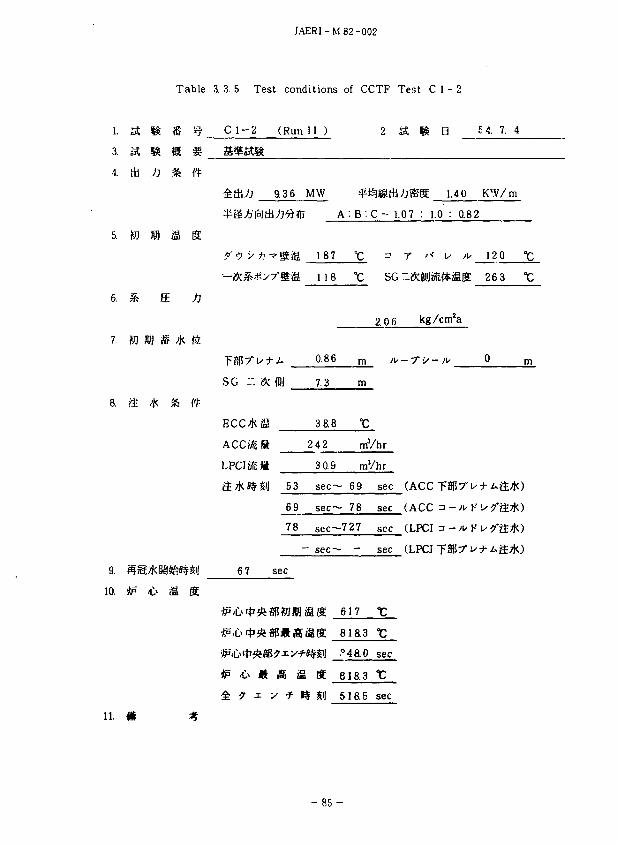
3.3.5
3.3.6
3.3.7
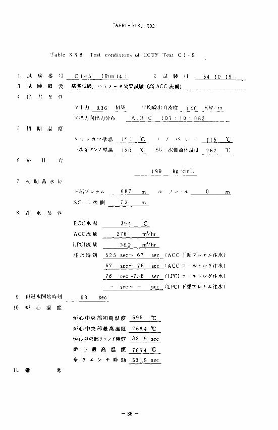
3.3.8
3.3.9
3.3.10
3.3.11
3.3.12
3.3.13
JAERI-M82-002
Table list
Component scaled dimensions
Test conditions of the base
Parameter ranges of 1
Summary of CCTF test
Summary of CCTF test
u
rr
it
II
II
it
il
M
II *
II
II
It
II
II
It
It
11
11
tests
of Cylindrical Core Test Facility
case test and their data bases
conditions
C1-SH3
C1-SH4
C1-SH5
Cl-1
Cl-2
Cl-3
Cl-4
Cl-5
Cl-6
Cl-7
Cl-8
Cl-9
Cl-10
Cl-11
Cl-12
Cl-13
Cl-14
Cl-15
Cl-16
Test conditions of CCTF Test
it
it
ii
it
it
it
it
ti
ii
ii
ii
ii
C1-SH3
C1-SH4
C1-SH5
Cl-1
Cl-2
Cl-3
Cl-4
Cl-5
Cl-6
Cl-7
Cl-8
Cl-9
Cl-10
JAERI-M82-002
Table 3.3.14 Test conditions of CCTF Test Cl-11
Table 3.3.15 « Cl-12
Table 3.3.16 « Cl-13
Table 3.3.17 .. Cl-14
Table 3.3.18 • • Cl-15
Table 3.3.19 .. Cl-16
Table A.1.1 Comparison of test conditions between Test Cl-2 and
Test Cl-11
Table 4.2.1 Test conditions of flow rate effect tests
Table 4.3.1 Comparison of test conditions between FLECHT 31O5B and
CCTF Test Cl-16
Table 4.3.2 Comparison of test conditions between PKL K7A and CCTF
Test C1-SH5
Table 4.4.1 Test conditions of "Refill simulation tests"
Table 4.5.1 Summary of the system behaviors
Figure list
Fig. 1.1 Mass and momentum balance in PWR system
Fig. 2.1 Schematic diagram of cylindrical core test facility
Fig. 2.2 Dimensions of pressure vessel
Fig. 2.3 Cross section of pressure vessel
Fig. 2.4 Schematic of internals
Fig. 2.5 Baffle plates in control rod guide tubes
Fig. 2.6 Upper plenum control rod guide tube
Fig. 2.7 Arrangement of internals
Fig. 2.8 Arrangement of rods in core
Fig. 2.9 8x8 heater rod bundle
Fig. 2.10 Bundle arrangement
Fig. 2.11 Heater rod
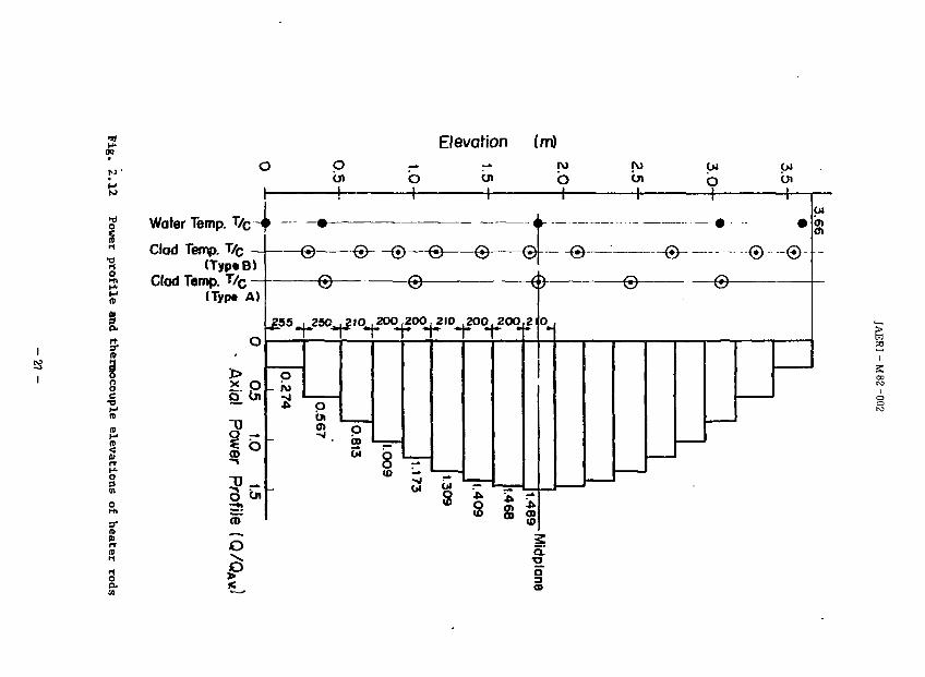
Fig. 2.12 Power profile and thermocouple elevations of heater rods
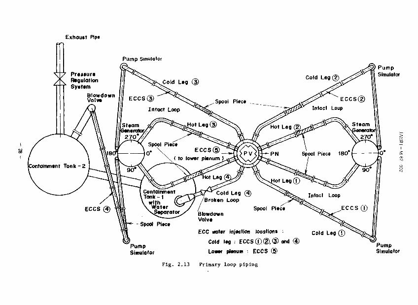
Fig. 2.13 Primary loop piping
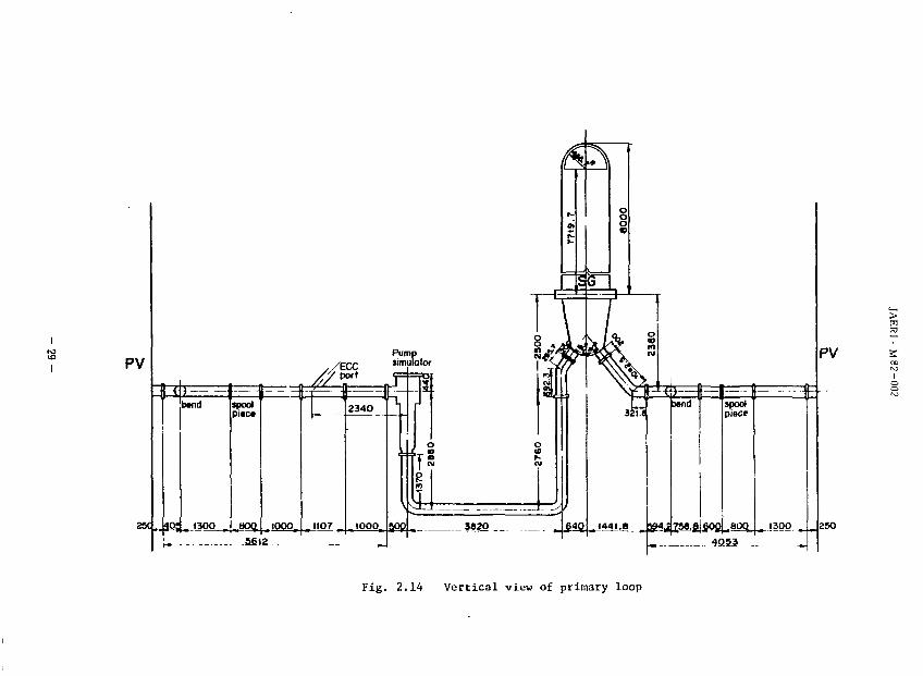
Fig. 2.14 Vertical view of primary loop
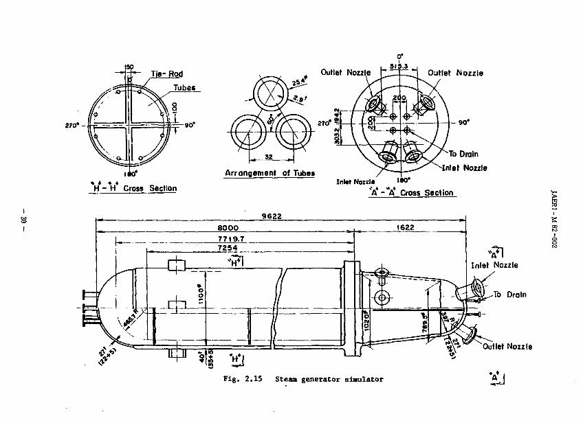
Fig. 2.15 Steam generator simulator
Fig. 2.16 Pump simulator
vi
Fig. i.
Fig. 2.
Fig. 2,
Fig. 2.
Fig. 2.
Fig. 2.
Fig. 2.
Fig. 2.
Fig. 2.
Fig. 2.
Fig. 2.
Fig. 2.
Fig. 2.
Fig. 3.
Fig. 3.
Fig. 3.
Fig. 3.
Fig. 3.
Fig. 3.
Fig. 3.
Fig. 3.
Fig. 3.
Fig. 3.
Fig. 3.
Fig. 3.
Fig. 3.
Fig. 3.
Fig. 3.
Fig. 3.
Fig. 3.
Fig. 3.
Fig. 3.
Fig. 4.
.17
.18
.19
,20
.21
,22
,23
,24
,25
26
27
28
29
1
2
3
4
5
6
7
8
9
10
11
12
13
14
15
16
17
18
19
1.1
JAERt-M 82-002
Data acquisition system-I
Data acquisition system-II
Data acquisition system-Ill
Locations of liquid level dstectors
Pressure, differential pressure and liquid level
instrumentation locations in pressure vessel
Location of instrumented rods
Elevation of each sensor of liquid level detectors
Thermocouple locations except pressure vessel and steam
generator simulators
Pressure, differential pressure and liquid level
instrumentation locations except pressure vessel
Thermocouple locations in pressure vessel
Location of thermocouples installed on instrumented rods
Thermocouple locations in steam generator slmulator-I
and -II
Diagram of sequence of test
Clad surface temperature (C1-SH3)
vCl-SH4)
.. (C1-SH5)
Cl-1)
(Cl-2)
.. (Cl-3)
.. (Cl-4)
«. (Cl-5)
.. (Cl-6) '
(Cl-7)
(Cl-8)
.. (Cl-9)
(Cl-10)
» (Cl-11)
.. (Cl-12)
(Cl-13)
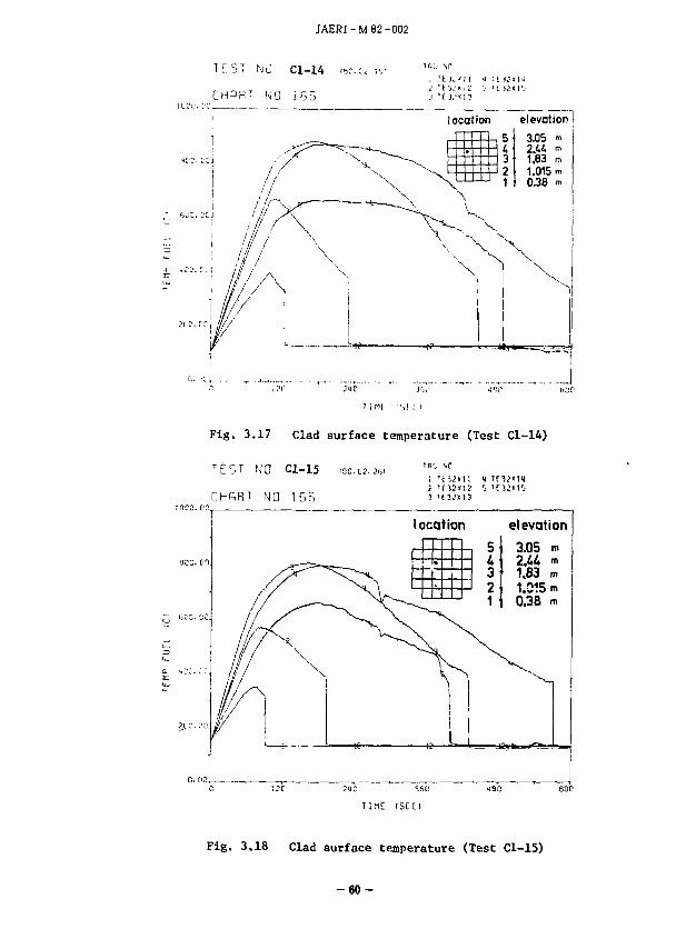
it (Cl-14)
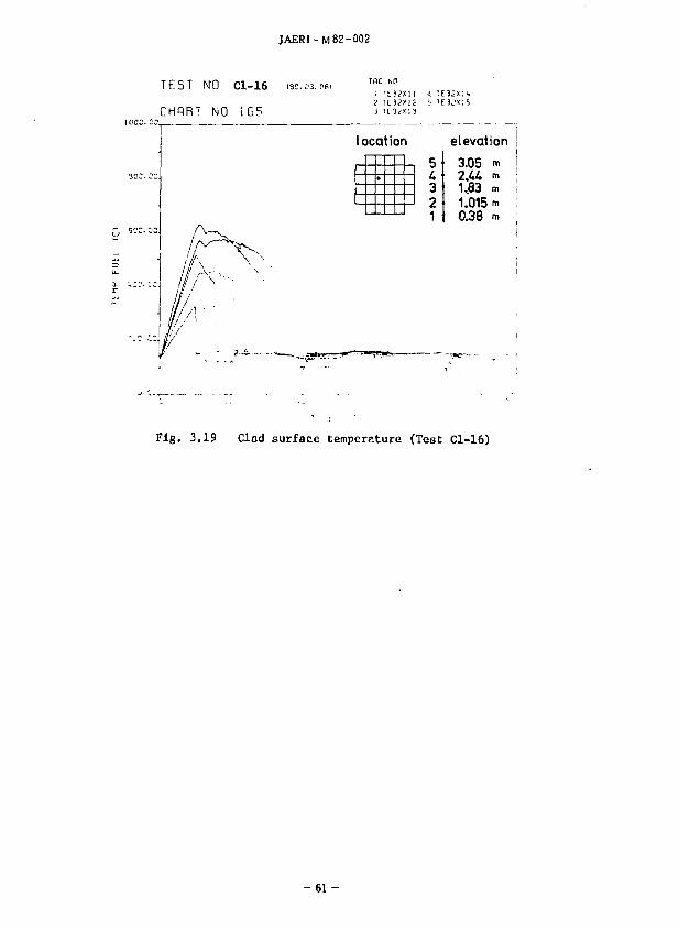
(Cl-15)
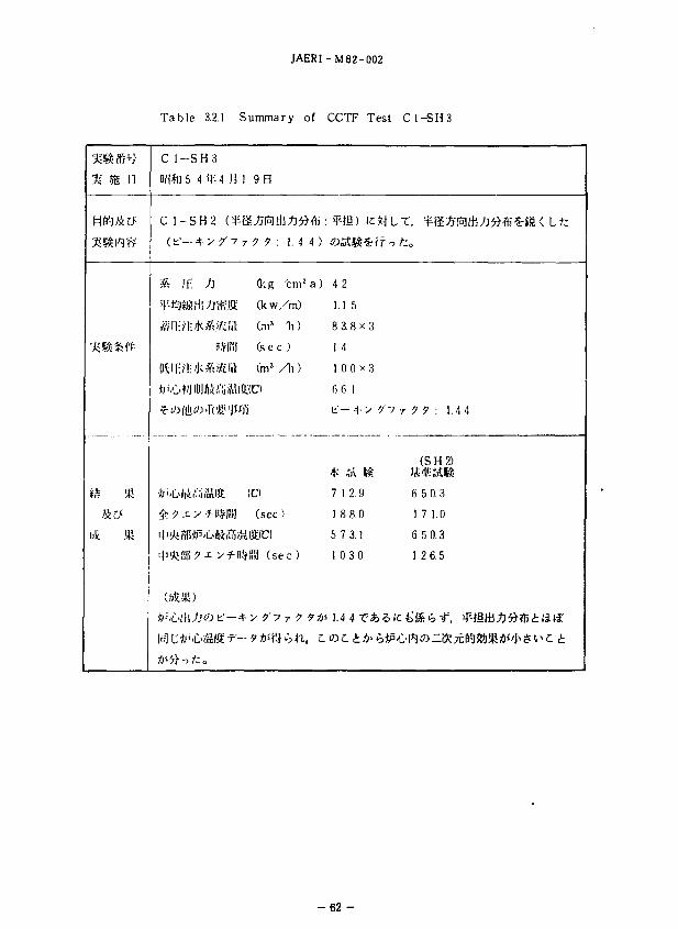
» (Cl-16)
Rod surface temperature just below the control rod guide
tubes (bundle 4 and bundle 5)
VII'
JAERI-M 82-002
Fig. 4.1.2 Rod surface temperature just below the control rod guide
tubes (bundle 29 and bundle 31)
Fig. 4.1.3 Downcomer head and core head
Fig. 4.1.4 Upper plenum water head
Fig. 4.1.5 Total pressure drop acros loop
Fig. 4.1.6 ECC water injection rate into lower plenum
Fig. 4.1.7 ECC water injection rate into each cold leg
Fig. 4.1.8 Total power supplied to the core
Fig. 4.1.9 Measured mass balance in system
Fig. 4.1.10 Symmetry of core head
Fig. 4.1.11 Symmetry of clad surface temperature histories to the
center axis
Fig. 4.1.12 Symmetry of downcomer head
Fig. 4.1.13 Symmetry of upper plenum water head
Fig. 4.1.14 Total pressure drop across loop
Fig. 4.1.15 Steam mass flow rate at loop seal
Fig. 4.1.16 Temperature in steam generator
Fig. 4.1.17 Flow behavior around ECC port of intact 1
Fig. 4.2.1 Effect of system pressure on clad surface temperature
Fig. 4.2.2 Effect of system pressure on mass flow rate at core inlet
Fig. 4.2.3 Effect of system pressure on pressure loss across loop
Fig. 4.2.4 Effect of flow rate on clad surface temperature
Fig. 4.2.5 Effect of ACC flow rate on water head and pressure loss
Fig. 4.2.6 Effect of LPCI flow rate on water head and pressure loss
Fig. 4.2.7 Effect of initial clad temperature on clad
temperature history
Fig. 4.2.8 Effect of initial clad temperature on pressure loss
across loop
Fig. 4.2.9 Effect of initial downcomer wall temperature on clad
temperature history
Fig. 4.2.10 Effect of initial downcomer wall temperature on fluid
temperature at core inlet
Fig. 4.2.11 Effect of initial downcomer wall temperature on downcomer
water head
Fig. 4.2.12 Pressure losses across loop in cold downcomer wall test
Fig. 3.2.13 Pressure losses across loop in base case
Fig. 4.2.14 Effect of loop flow resistance on clad surface temperature
viii
JAERI-MB2-002
Fig. 4.2.15 Effect of loop flow resistance on pressure loss across
loop
Fig. 4.2.16 Effect of loop flow resistance OK steam mass velocity
in loop
Fig. 4.2.17 Effect of loop flow resistance on clad surface temperature
at highest thermocouple elevation
Fig. 4.2.18 Effect of loop flow resistance on water accumulation on
UVSP
Fig. 4.2.19 Effect of ECC water temperature on clad surface temperature
Fig. 4.3.1 Axial power profile
Fig. 4.3.2 Core inlet velocity-
Fig. 4.3.3 Clad surface temperature
Fig. 4.3.4 Comparison of quench envelope between FLECHT 31O5B and
CCTF Cl-16
Fig. 4.4.1 Schematic diagram of primary loop
Fig. 4.4.2 Results of loop seal water filling test
Fig. 4.4.3 Differential pressure and liquid level transient in loop
seal water filling test
Fig. 4.4.4 Collapsed level of core and downcomer
Fig. 4.4.5 Clad surface temperature history
Fig. 4.4.6 Clad surface temperature history
Fig. 4.4.7 Fluid temperature at core inlet
Fig. 4.4.8 Collapsed water level in downcomer and core
Fig. 4.4.9 Water level in upper plenum
IX
JAERI-M82-002
1.
j K ? P W R ) o - ^ i
ECCS
a)
jitter, * i a N R c - e r a ^ © © ^ ^ ® ^ - K R E F L A , TRAC )omi:.nir-
KI£ L t , lI]f,?j*'<i>..>W}'<ii''i < Cylindrical Core Test
Facility, CCTF i»f.5i )/j<{B,i'i,J' \ imtfii
i, PWR » ->x r / . | ' j -c
Z&Zo ~ch!&, NW'&MWMlu. PWR «f|-.j-5 l.^Wffi,
Cl i i L/-;,, •Jj rOJilUridiMJr C100 JjKWW PWRcO I
21.4 , MUjWlzirk'tk, 4 * - • / » ^ ^ ^ ( i
a) (2)
(3)
(4)
(5) CCTFSSi^^', (i®a:gSSsSoSt|$ii@3ii^E-(D^^fe©Aii'-pA^'s:oA;J6, FLECHT
(6) •?•©«!!,
(7)
#(C, *l|-eff*3nfcPWR-FLECHTflK, FLECHT SET t i t ICfc^Tli .
* + •
- 1 -
JAERI-M82-002
(l)
, asses we A*?, ECCS ©*£>££ L.
- ' < — 7 D —
(2)
(3)
(4)
ECCS O/Ki (li
ic *t L r,
C t
x A $4* £ ©Mil HS"< 5 i i i f 5
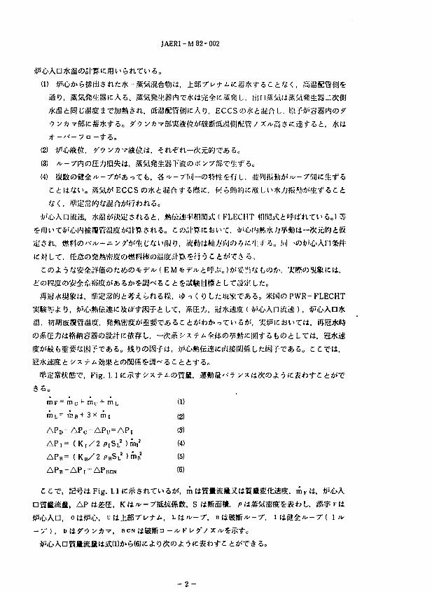
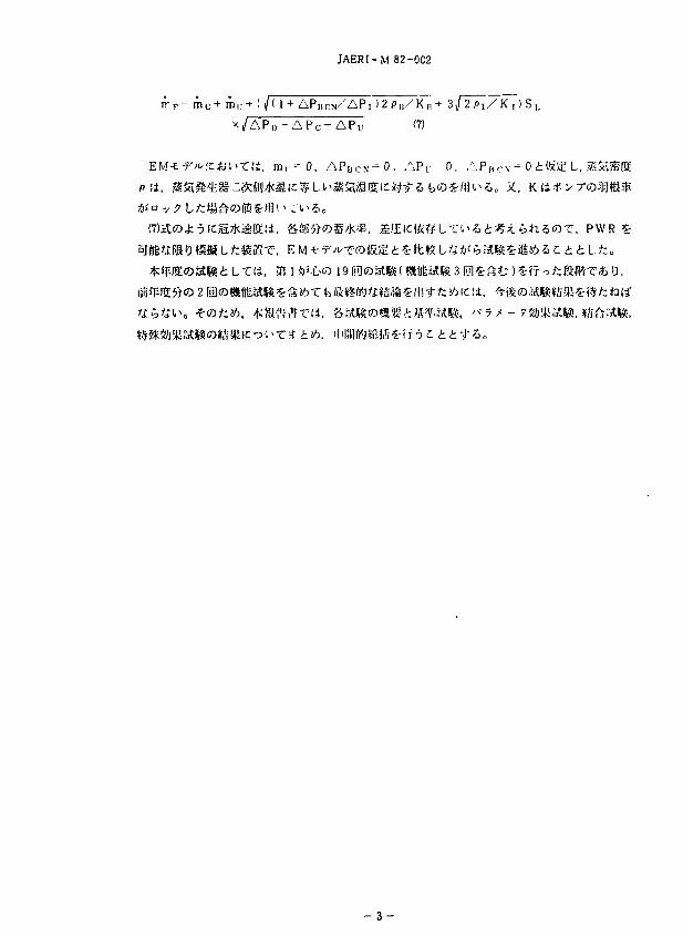
, Fig. 1.
# 5 ,
m F = m c + m u + m i,
iii L " n>- B + 3 x m [
APD-APC-APU = A
AP,= ( K j / 2 PiSj
APB= ( K B / Z
m,2
>'*-f 5 £ t
( FLECHT
L Tuik/K LfcD
* I S O P W R - F L E C H T
L.T, S E ^ ' , STki&
ig. 1.1
, A P i i S E , K &'*-
BCN
(1)
(2)
(3)
(4)
(5)
(6)
5", m (±B:lBStBXlil8fi2£'fti£lt
&, S ( i
"5ic
- : / { 1 *•
- 2 -
JAERI-M 82-0C2
i r P = m c + m u + ( / ( 1 + A P B C N / A P J ) 2 P B / K , , + 3<J2PJ/K , )S
x /AP» - A P C - APu (7)
: « , m, -" 0, APU CN-0. APL- 0, APB<;\ - 0 iftOil L,
, 351 ^.C>» 19 fiUoagK tSfjtagj 3 Igjs
2ig
- 3 -
Containment vessel
Steam generator Steam generator
B
Broken loop
Upper plenum I .mi I T
mecc> rr |Pump
,m0
Lower plenum
rh 0 L (liquid) rilov (steam)
-m ECC/LP
Intact loop ( x3 )
Downcomer
I i
s CO CO I
Fig. 1.1 Mass and momentum balance in PWR system
JAERI-M 82-002
2.
S ( CCTF ) (t
(1) PWR©
(1) gMtiHt, JliLf ® Trojan *Pli =t !)•' H * © ^cfifitf5 i t 5 «
(2) •> x -7- A © ,r;i $ /,• in'ffl -J?.fc fc J; O>'(#. ifi It, "Jf i t t
(3) ->x r
(4) M
(5) a - ^ K i x
(6) ECCSii,
(7) gfiaoia^C
IT
(9) t
ttl) ±g|37"ui-i.t|l|ig-Kl©iip:i(i, 17 x
Fig. 2.1 ic, §fflS©^!*ffi'M±5- Table 2.1
2.1 af
lil±, Fig. 2.
, Fig. , Fig. 2.'H ic^-TJ; TIC 61.5 mm©4-> y 7°
- 5 -
JAERI-M82-002
x 17
Fig. 2.4 IC^-nt .*S.^$nT^5o ^ © n S f r t f i a ^ O ^ - S l i , ^ © t l © 8/15 lt*S'h
7*S l t , Fig. 2.5
, Fig. 2.
Fig. 2.7
2.2
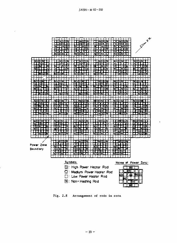
li, Fig. ZSICj^nSckT'i 32
Fig. 2.8 d ^
cfc-j tt 3 o©fi®IC^>/!)>n?>0 **ffi^li 4 -3lO'<-/ Kn,*»£ERf) ( M5 ) , ^niHiBWli 12 ©'-'
y K^A^Bjij (M6, M7, M8, M9), JH>SJI#I± 16 ©'<V K^A» i n t o T l 1 S(M 1. M2,
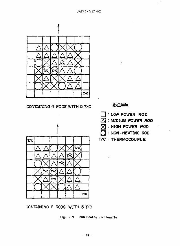
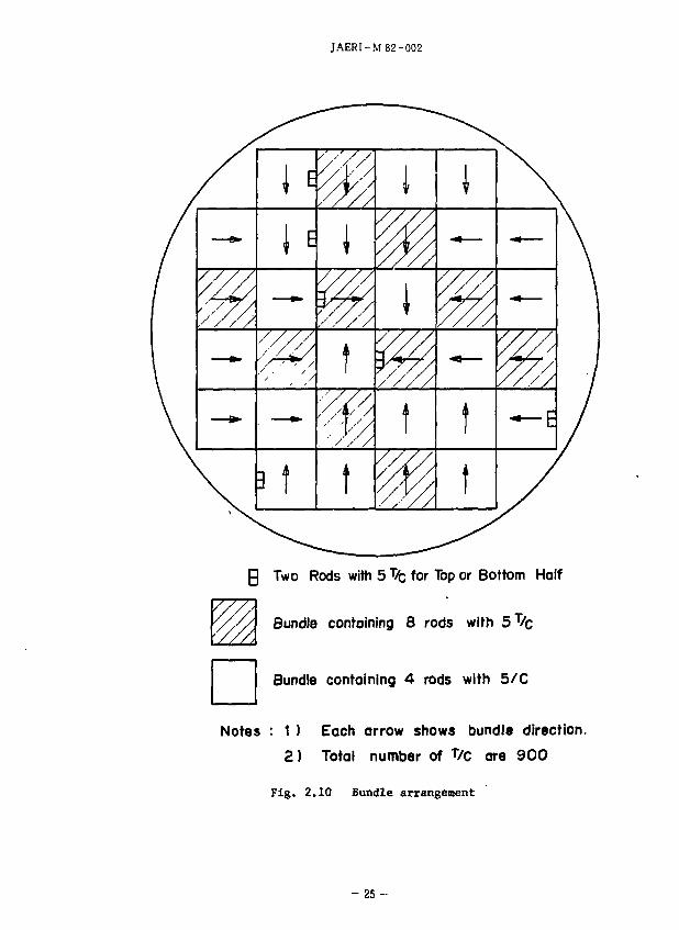
M3, M4)o§ffii^^Si|^lcSljaDt5CtfepI^T;*2)o S ' O ' K / u r t t : © ^ * ^ © ^ ^ t"- +
y 7%WLW Fig. 2.9 ic, f ti><v K^©^-[S]^ Fig. 2.10 I t ^ ^ n r ^ S o
; ? D A f f l » , Mt^f^-ytiU (MgO) i ^ { t * ^ * ( B N ) ffl»f.«iW. -f
600 ©${!#> bfig oTf'So Fig. 2.11 ICip^tlXi^ =fc ^ IC, BN It, ^ «
flli, 3.66mfciO* 10.7mm-e*!9, RWR ©IKSlsHfil^—T'*SO tSSli, 1.0 Fig.2.12
, 'J •. K * ^ - * ic £
f , f l t l « n i m T , PWR
'* *>-Xl$ 8.6 mm ic
- 6 -
JAERI- M82-002
2.3 -'XWl-fts
—&%••!'-fit, 3
, — &!iVf-7cDS2iH(±, Fig. 2.13 fc<fct>* 2.14
J -> x ^ ?•> o
li. U-r-ff -Vx ^ l o ^ f Fig. 2.15
2,9mint, *J!M PWR ffl 1.7 mm (Clt
->v /fcj;c>'/* K{SM{*i*'J 7 ^ xEA^fflfiK^n, Fig.
lJ, K 7 r ^ ?-2.'i©fe©*i95mmil'iiii, 10mm J£« >t tf* i t V1
0 ( K 7 7 9 9- 35
ECCS li, -^1/ K u- / S A P S ECC -t--
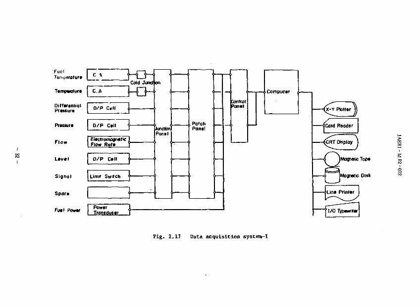
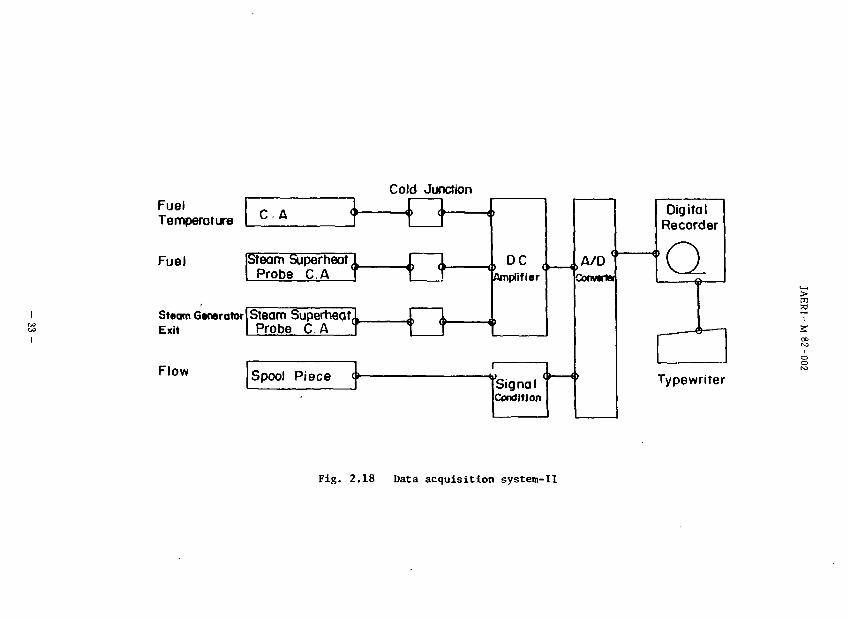
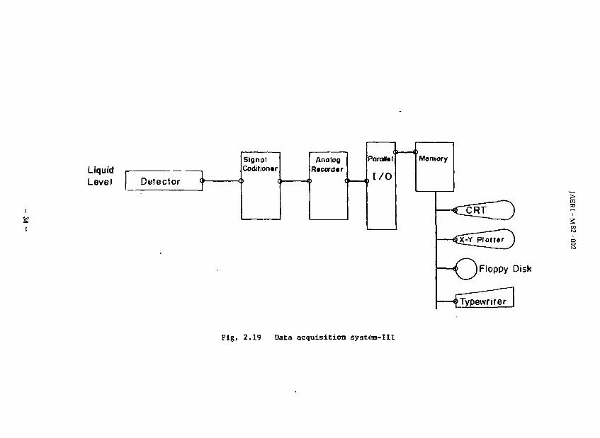
2.4
, Fig. 2. 17, 2.18, 2 . 1 9 K ^ * n r i ' 5 o Fig. 2.17 , Fig 2.18, 2.19 IC*$ Fig. 2.17 fflJS&icti, f-
Fig.2.l
Fig. 2.19 ICS5 USNRCffi$fflftftfta»t>ffir'-*li, T -f n / » i LTfiSSiT-
(1) -a m 0.5mmt?.
- 7 -
JAERI-M82-002
(2) E ts
± 0.3
(3) 1 E
SEffliJ^li, gEsi'Srffit^Tn-^tm, f-©.g«Mli-t 0.3 «
(4) * fe . Fig. 2.20 , 2. 21 ICTv-T J: ? IC. %&($&&flw©&ffiijg© 7
i e . 2.21
Fig. 2.20, 2. 21 IC^ f «t -5 It, * p g g i t D 6
. S * i 7 . 5 , 17, 17, 17
Fig. 2.20. 2.22ic,Tx$nTfco, r o - ^ r o
W.f«« Fig. 2.23IC/K*ftT0>3o
KjWj'^s^iifi* ^ ^ - 1 oftficimisgii, ^ -.^-=- / ^ - *-eif - . r*sn,
2 I /min-tTi&So (5) ?i(i a
. f h -
(6) .-fflBTt
, Fig. 2.24, 2.25IC
i, FiR. 2 21.
f S o •)p. ffl!tffli](f©fi!Sli. Fig. 2.22 IC^SnTfcf), f l i i , Fig. 2.27 K S J f t T ^ S , -«#?(C, S*©Itffl!ia.«l)*(Fig. 2. 27 CD type A) ^ i t
fciJ)1 5
2. 27 © type B ) „ BUS, Fig. 2. 27 ©£<»]©<£ -5 IC, ±© 5
i . Fig.
2.5
- 8 -
JAERI-M 62-002
(1) S
L,
(2)
(3)
( Fig. 2. 29 )„ JK~FKi£^& •>- T v * 14, •>x
(4)
(6) •ip.
ic, Tffl57V t A « t t * l l / ) 'b ACC »?|;;K£|5HW;t
(7) * ^
0 It
(8) l £ ^ 8 $ p B ^ i c A C C t t * « § f £ •£ . Nb,V(C LPCI ai/K^-liate^
(9) Mkfc8tfim& tc, ft" * n «• TSB 7• u- - A *> t. 3 - ^ K u ?**c WfiS x.
Q9
2.6
"5 ic, S
, SUf
ANSx 1.2+ r ^ - f - K )©•>+• v h ?"'?y
, FLECHT-fco ACCSEfili. SS7kM*&»»t. ACCa*i!5rt TIC 378 ~ 287 m3 'h ICgitl
L/:o LPCISEHIi, S^ffllllciSfcto, #BB(iO 3 /
- 9 -
JAERI-M 82-002
t i ECC
700°C, 80ntl LTIi,
, 22-40
FLECHT- SETOTiftill-tJUffltC/lil nfcWl ( FLECHTSETO
Lfc ) 24.45 5^l i«Lr 25 i L/•;„ c«- j ' 3 , * v-?'W>
*, ANS* l . 2 + T > f i K
r-, ANS x 1.2 + T
L, .
2.
Table 2.3 IC^to
, FLECHT-SET, PKL£fe[Ctti^-|fiJtU>j5JlSA>'ll«O, CCTF (
, CCTFfi,
- 1 0 -
JAERI-M82-002
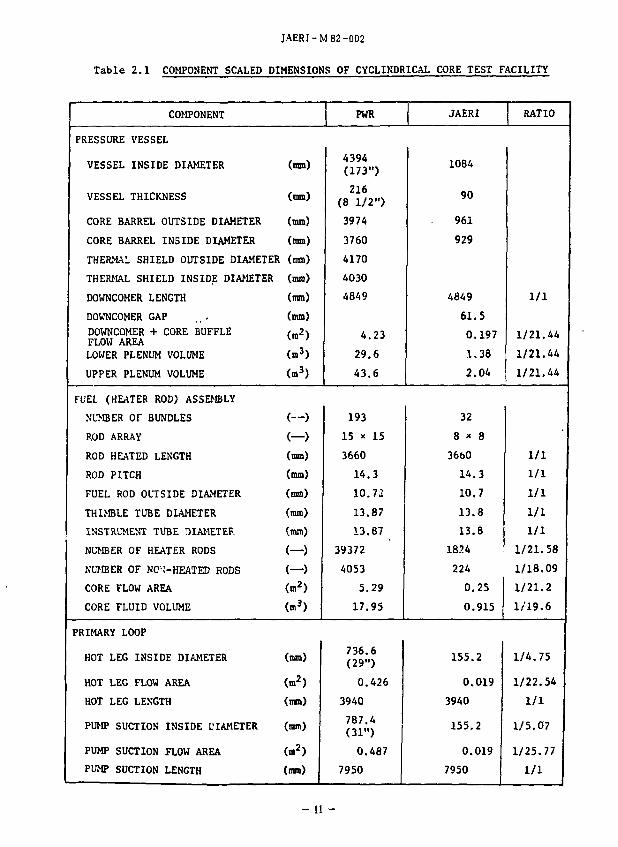
Table 2.1 COMPONENT SCALED DIMENSIONS OF CYCLINDRICAL CORE TEST FACILITY
COMPONENT
PRESSURE VESSEL
VESSEL INSIDE DIAMETER (am)
VESSEL THICKNESS (mm)
CORE BARREL OUTSIDE DIAMETER (mm)
CORE BARREL INSIDE DIAMETER (mm)
THERMAL SHIELD OUTSIDE DIAMETER (mm)
THERMAL SHIELD INSIDE DIAMETER (mm)
DOWNCOMER LENGTH (mm)
DOWNCOMER GAP ... (mm)
DOWNCOMER + CORE BUFFLE /_2\ FLOW AREA v ;
LOWER PLENUM VOLUME (m3)
UPPER PLENUM VOLUME (m3)
FUEL (HEATER ROD) ASSEMBLY
NUMBER Or BUNDLES (—)
ROD ARRAY (—)
ROD HEATED LENGTH (mm)
ROD PITCH (mm)
FUEL ROD OLTSIDE DIAMETER (mm)
THIMBLE TUBE DIAMETER (mm)
INSTRUMENT TUBE DIAMETER (mm)
NUMBER OF HEATER RODS (—)
NUMBER OF W;-HEATED RODS (—)
CORE FLOW AREA (in2)
CORE FLUID VOLUME (m3)
PRIMARY LOOP
HOT LEG INSIDE DIAMETER (nan)
HOT LEG FLOW AREA (m2)
HOT LEG LENGTH (ram)
PUMP SUCTION INSIDE L'lAMETER (mm)
PUMP SUCTION FLOW AREA (m2)
PUMP SUCTION LENGTH (mm)
PWR
4394 (173")
216 (8 1/2")
3974
3760
4170
4030
4849
4.23
29.6
43.6
193
15 x 15
3660
14.3
10.72
13.87
13.87
39372
4053
5.29
17.95
736.6 (29")
0.426
3940
787.4 (31")
0.487
7950
JAERI
1084
90
961
929
4849
61.5
0.197
1.38
2.04
32
8 x 8
36bO
14.3
10.7
13.8
13.8
1824
224
0.25
0.915
155.2
0.019
3940
155.2
0.019
7950
RATIO
1/1
1/21.44
1/21.44
1/21.44
1/1
1/1
1/1
1/1
1/1
1/21.58
1/18.09
1/21.2
1/19.6
1/4.75
1/22.54
1/1
1/5.07
1/25.77
1/1
-11 -
JAERI-M82-002
Table 2.1 (cont'd)
COMPONENT
COLD LEG INSIDE DIAMETER (mm)
COLD LEG FLOW AREA (m2)
COLD LEG LENGTH (mm)
STEAM GENERATOR
NUMBER OF TUBES (—)
TUBE LENGTH (AVERAGE) (m)
TUBE OUTSIDE DIAMETER (am)
TUBE INSIDE DIAMETER (mm)
TUBE WALL THICKNESS (mm)
HEAT TRANSFER AREA (m2)
TUBE FLOW AREA (m2)
INLET PLENUM VOLUME (m3)
OUTLET PLENUM VOLUME (m3)
PRIMARY SIDE VOLUME (m3)
SECONDARY SIDE VOLUME (m3)
CONTAINMENT TANK - I (ra3)
CONTAINMENT TANK - II (m3)
STORAGE TANK (m3)
ACC. TANK (m3)
SATURATED WATER TANK (m3)
ELEVATION
BOTTOM OF HEATER BUNDLE (mm)
TOP OF HEATER BUNDLE (mm)
TOP OF DOWNCOMER (mm)
BOTTOM OF DOWNCOMER (mm)
CENTER OF COLD LEG (mm)
BOTTOM OF COLD LEG INSIDE DIAMETER (mm)
CENTER OF LOOP SEAL LOWER END (mm)
BOTTOM OF LOOP SEAL LOWER END (mm)
PWR
698.5 (27.5")
0.383
5600
3388
20.5
22.225 (0.875")
19.7 (0.05")
1.27
4784 (51500 ft2)
1.03
.25
4.25
30.50 (1077 ft3)
157.33 (5556 ft3)
0
3660
4849
0
5198
4849
2056
1662
JAERI
155.2
0.019
5600
158
15.2
25.4
19.6
2.9
192
0.048
0.198
0.198
2.4
4.9
30
50
25
5
3.5
0
3660
4849
0
4927
4849
2047
1959
RATIO
1/4.50
1/20.26
1/1
1/21.44
1/1.35
1/1
1/24.92
1/21.44
1/21.44
1/21.44
1/15.25
1/26.22
0
0
0
- 271
0
- 9
+ 297
- 1 2 -
JAERf -M 82-002
Table 2.1 (cont'd)
COMPONENT
CENTER OF HOT LEG (mo)
BOTTOM OF HOT LEG INSIDE DIAMETER (mn)
BOTTOM OF UPPER CORE PLATE (am)
TOP OF LOWER CORE PLATE (mm)
BOTTOM OF TUBE SHEET OF STEAM GENERATOR (ran)
PLENUM LOWER END OF,STEAM GENERATOR (mm)
TOP OF TUBES OF STEAM GENERATOR (mm) (avg)
PWR
5198
4830
3957
- 108
7308
5713
17&52.7
JAERX
4927
4849
3957
- 50
7307
5712
14820
RATIO
- 271
+ 19
0
+ 58
- 1
I-I
- 13-
JAERI-M82-002
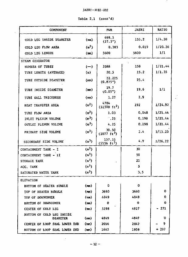
Table 2.2 Test conditions of the base case test and their data bases
Item Value Data bases
System pressure
Initial average linear power
ECC injection
ACC flow rate
ACC water temp.
ACC injection period
LPCI flow rate
LPCI water temp.
Maximum initial clad temp.
SG secondary side water temp.
Downcomer wall temp, /wall temp, of vessel\ V below cold legs /
Wall temp, of non-specified structures
^factor °* primary loops
Decay curve of power
Radial power factor
Axial power factor
Local power factor
Total peaking factor
2 kg/cm2a
1.4 kw/m
280 m3/h
35 8C
14 sec
30 m3/h .
35 °C
600 °C
2.5^1.5 kg/cm2a (Takahama 3.4)
1.34-^1.37 kw/m /Trojan 2% ever power \ \30 sec after shutdown/
/Data referred\ \in FLECHT-SET/ 378^287 m3/h
35 °C
14 sec
40 m3/h
35 °C
870 °C (Sendai 1)
265 °C
198 °C
119 °C (Saturation temp.
265 °C
/ Equivalent "\ \wall temp. /
. 5
ANSxl.2 + Actinidexi.i
/Delayed neutron \ 1 effect is considered 1 \in the initial power/
1.15
1.49
1.1
1.885
24.45 (FLECHT-SET)
ANSxl.2 + Actinidex l.i + Delayed neutron
1.435
1.546
1.027
2.278
(Sendai 1]
- 14 -
JAERI-M82-002
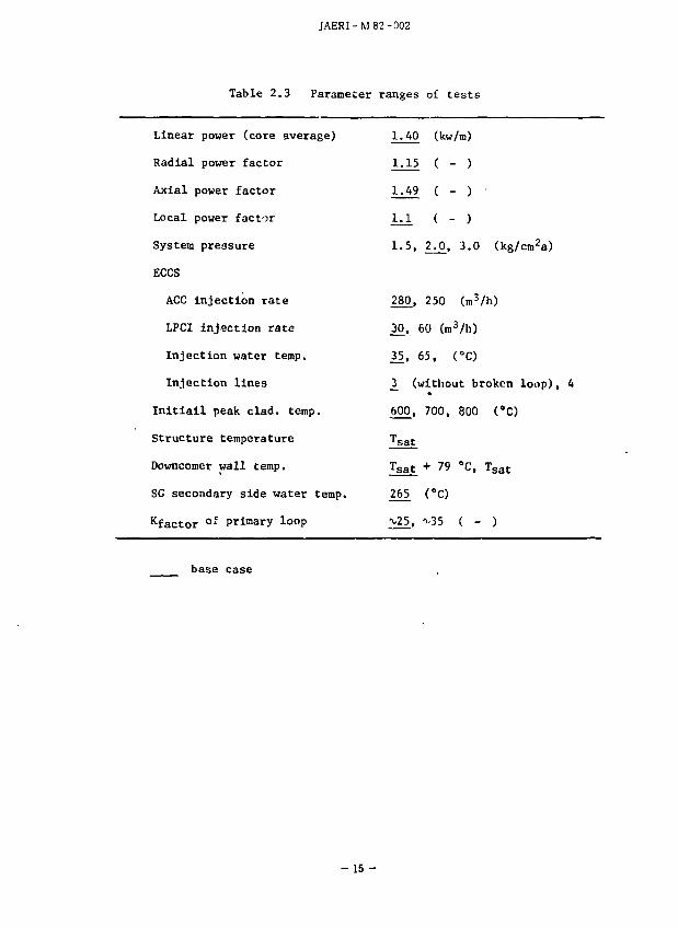
Table 2.3 Parameter ranges of tests
Linear power (core average)
Radial power factor
Axial power factor
Local power factor
System pressure
ECCS
ACC injection rate
LPCI Injection rate
Injection water temp.
Injection lines
Initiail peak clad. temp.
Structure temperature
Downcomer wall temp.
SG secondary side water temp.
Kfactor of Primary loop
base case
1.40 (kw/m)
1.15 ( - )
1.49 ( - )
1.1 < - )
1.5, 2^0, 3.0 (kg/cm2a)
280, 250 (m3/h)
30, 60 (ro3/h)
35, 65, (°C)
3_ (without broken loop),
600, 700, 800 (6C)
Tsat
Tsat + 79 °C, T s a t
265 C O
>25. O 5 ( - )
- 15-
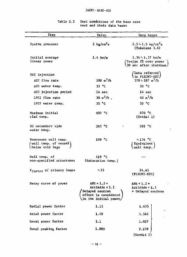
To Exhaust
Water Purification System
I^Gas Supply System
Steam Supply Line
Prewurizer
Air Compressor
Ace Tank -
Drain
Steam Supply
^Containment Tank-1 \ Containment Tank -1
Ace Line
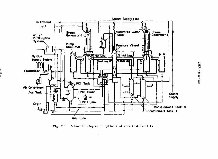
Fig. 2.1 Schematic diagram of cylindrical core test facility
i
S 00
JAERI-M82-002
r 8 8
o
to
Upper
Plenum
Core
6th
** 5th
4th
3rd
2nd
1st
Lower Plenum
Bottom of SMpport Plate
Loop Nozzle Center
Bottom of Core Plate
Top of Heated Length
Downcomer
Core Baffle Region
Top of 1st Spacer
Bottom of Heated Length Top of Core Rate
8otfom of Lower Spacer.
Top of Bottom Plate
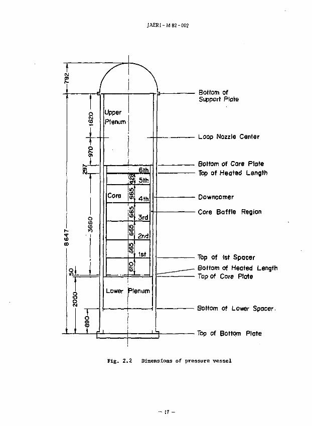
Fig. 2.2 Dimensions of pressure vessel
- 17 -
JAERI-M82-002
Vessel Wo 11 Downcomer Core Boffle Region 6x8 Heater Rod Assembly Pipes for Pressure Measurements
Tntact Cold Leg
Nozzle for Downcomer Differential Pressure Measurement
Intact Cold Leg
Intact Hot Leg
Intact Hot Leg
T-Tp^ Bundle Containing L<._SJ 8 Rods with 5 T/C
j j Bundle Containing
Plant North
Intact Hot Leg
iXi i I I N y ' ! I
Cold Leg
L__J 4 Rods w,'h 5 T/C B r Q k e n H o f L e g B r o k e n j ^ U g
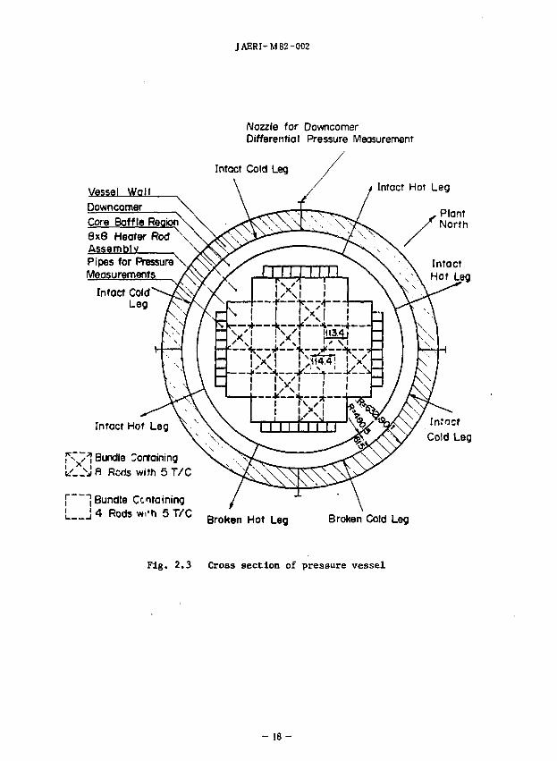
Fig. 2.3 Cross section of pressure vessel
- 1 8 -
JAERI-M 82-002
Hot Leg Nozzle
Support Plate A-A' Cross Section h-101.6*-
B-B' Cross Section
Support Column
Control Rod Guide Tube
Orifice Plate
Open Hole
Upper Core Plate
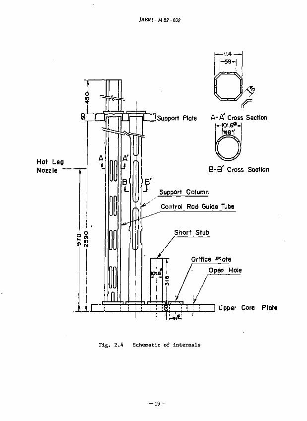
Fig. 2.4 Schematic of internals
- 19-
\
JAERI -M 82-002
\V
L_ (VI O «
z -e 01
•H
•d
8
8
10
60 •H to
- 2 0 -
JAERI-M 82-002
\upptr Cora Support P W
Unit '• mm
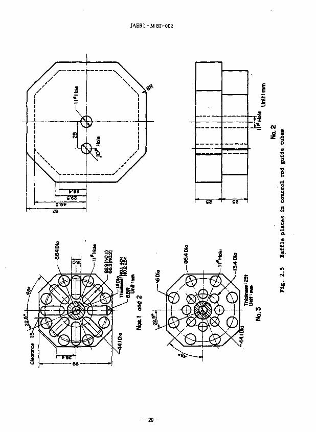
Fig. 2.6 Upper plenum control rod guide tube
-21 -
JAERI-M82-002
Stub Mixer
Control Rod Guide Tube
Open Hole
Support Column W/Mixer
Orifice Plate
Hot Leg Nozzle
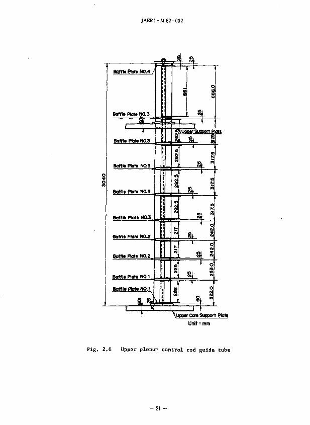
Fig. 2.7 Arrangement of internals
- 2 2 -
JAERI-M 82-002
S • • « •
•
IX - rr f * •
t • 3E : !
'it' I:: x.: ±..
i : : !
/
r* \ • •
• • •
: 5 _ _ i : i .
• • s • • •
. 3 - - : : : . . • : 3 - - - - * : :
• • y
. 3 - . 5 : » . . •
* * ' " " t"
7 .... r.L . Powtr Zont • •«« * - -Boundary
IK • *Th '• 1 T
t , ; I \ * * 1 * \ • • « • 1
« • I * * id
* * \
I • • y [j
S • • i , • • • "j • • y s • •
•
- M • ' M • '
• • •
- ^ : : i . -
y • • >
— I s - - - 5
* ? r
_ _ S i j - - H j • • • ^
- _ 1 2 : 1 * "-
m
y •
• • y •
• «
- . i : 1 •
1 •
i « 7 « «
y •
• ^ •
y • • • »
s1 • *
• yl
y a •
• •
•
c i.
! : i
i ; -
2 I _ t • •
M H «
• •
- S a
•
[" I
JL
1 "1"
r
T
5 • •
y «
• «
I
• •
F • •
E : S
s i ; i
• •
• ! l_
|
i
i
1
1-
9
;
X
i t
•
•,
r,
•
•
•
V
•
«
•
•
•
•
-
Symbols Norm of Pow«r Zone
0 : High Power Heater Rod 0 : Medium Power Heafer Rod D : Low Power Heater Rod IE : Non-Heating Rod
HJ
u.
(« I
1
u
1
1 rJ
j
j
Fig. 2.8 Arrangement of rods In core
- 2 3 -
JAERI-M82-002
A A /* *\ v l i i r / X X f -\
A A
T/C
A X
r \
A A &> X X
X A & A X f \
XX) A A A A A
X X! . /
A A
T/C
CONTAINING 4 RODS WITH 5 T/C
T/C
A A
x x
A A X \ / T/C
A X
v >
A A
T/C
X
X A A A X / - • >
\ J
X T/C
A A A A
T/C
X X
A A
T/C
CONTAINING 8 RODS WITH 5 T/C
Symbols
• : LOW POWER ROD (Aj : MIDIUM POWER ROO ^ : HIGH POWER ROD Q : NON-HEATING ROD
T/C : THERMOCOUPLE
Fig. 2.9 8x6 Heater rod bundle
- 2 4 -
JAERI-M 82-002
Two Rods with 5 Vc for Top or Bottom Holf
Bundle contoining 8 rods with 5T/c
Bundle contoining 4 rods with 5/C
Notes : 1 ) Each arrow shows bundle direction.
2 ) Total number of T/C ore 9 0 0
Fig. 2.10 Bundle arrangement
- 25-
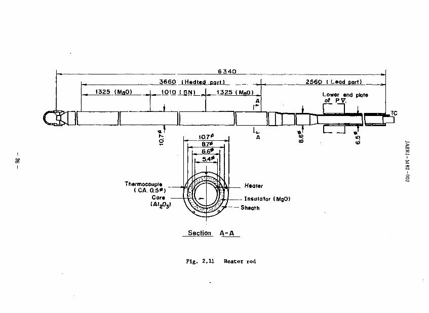
6 34O
3660 (Hedted part)
_ 1325 (MBO) ^iP. IO ( SN) 1325 (MgO)
j i
I
§? i
Thermocouple (CA.0.5*)
Core
Heater
2560 ( Leod part)
Insulator (MgO)
Sheath
Lower end plate of PV.
A T»' L u> GO
— I ^ in ID
Section A - A
Fig. 2.11 Heater rod
Elevation (m)
to • (-" to
•a
3
t
3 s i (-< I rr § (I) O HI 3"
B rr
p en b in
- t -
04
b
Water Temp. T/c H • —
Clad Temp. T/£ -(Typ«B)
Clad Temp. ?/c
(Typ« A)
o b
o bi
O
p
p 2 i——-
2 0 0 210 2 0 0
oi —• 8 s
ZOO
04 at
-©-
2 1 0
a. "5. a <D
Exhaust Pip»
Pre*sure Regulation System
Pump Simulator
S e p a r a t o r / Slowdown Valve
Spool Piece
ECC water injection locations :
Cold leo •• E C C S © . ® , ® ond
Lower plenum . ECCS ® Pump Simulator
Pump Simulator
Fig. 2.13 Primary loop piping
s I
PV
250
Fig. 2.14 Vertical view of primary loop
ZfO* -
1*0*
*H-*H* Cross Section
Arrangement of Tubes
9622
Outlet Nozzle
- 9 0 '
To Drain
nlet Nozzle
Inl«t Nozzl* 180*
"A*-*A* Cross Section
tfl Inlet Nozzle
To Drain
Outlet Nozzle
Fig. 2.15 Steam generator simulator
JAERI-M82-0D2
500
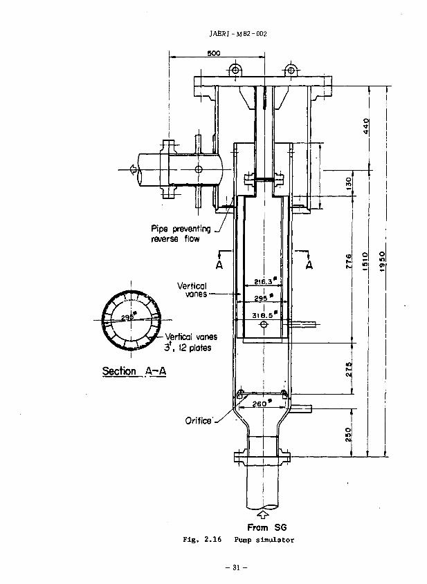
Pipe preventing reverse flow
Vertical vanes
Verticai vanes 3*. 12 plates
Section A-A
Orifice
From SG Fig. 2.16 Pump simulator
- 31 -
T U G I Temperature
Temperature
Differential Pressure
Pressure
Flow
Level
Signal
Spare
Fuel Power
Cold Junction
C.A
D/P
D /P Cell
Elecrromoonettcl Flow Rote T"
D/P Cell
Limit Switch
Power Transducer
Ibnctton] Pont I
Patch Panel
Control Panel
Computer
f I/O Typewriter
Fig. 2.17 Data acquisition system-I
Cold Junction Fuel Temperature
Fuel
Steam Generator Exit
Flow
C-A <
Steam Superheat Probe C.A
Steam SuperheqtJ Probe C A
Spool Piece (
• « 1
i (
. I 1 T
> <
. D C < Amplifier
Signal Condition
A/D ' COfNWt*
<
Dig itc Recor
i |
der
v . y
Typewriter
S3
Fig. 2.18 Data acquisition system-II
Liquid Level Detector
Signal Coditioner
Analog Recorder
< i——<>
Parade I
I/O
Memory
Floppy Disk
Fig. 2.19 Data acquisition system-Ill
V M M I Wall
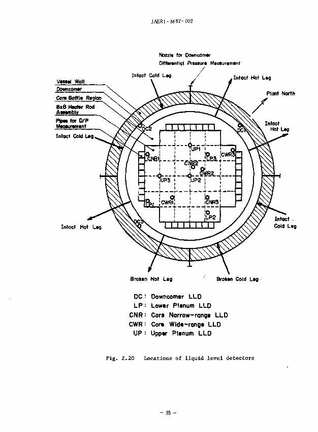
Intact Hot Lag
JAERI-M82-002
Nozzl* for Oowncomw Differential Pressure Mtasuremtnt
Intact Hot L«g
Plant North
Intact . Cold L«g
Broktn Hot Leg Brokwt Cold L«g
DC : Downcomtr LLD
L P : Lowtr PUnum LLD
CNR: Cora Narrow-rang* LLD
CWR: Cora Wld«-rang« LLD
UP = Upp«r Plenum LLD
Fig. 2.20 Locations of liquid level detectors
- 3 5 -
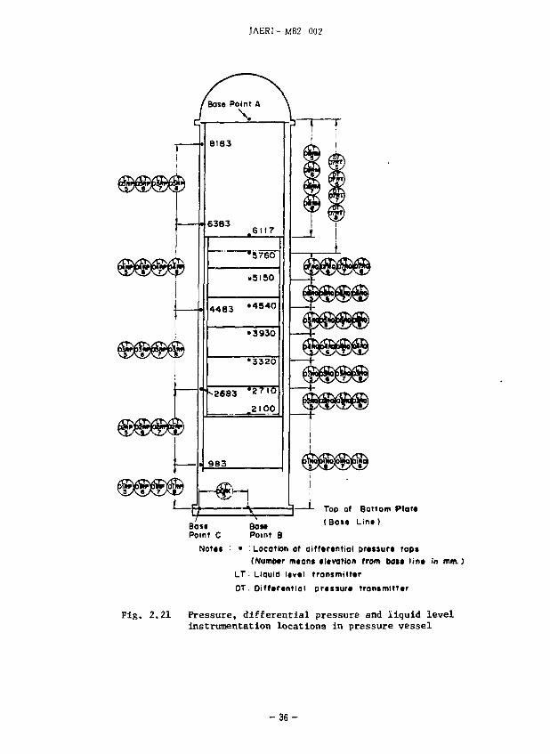
JAERI- M82-002
BOM Point B
Top of Bottom Plat* (Boss Lint)
Notat : • ' Location of difftrtntiol prcssun taps (NumMr mtan* «l*varion from bos* lin* in mm.)
L.T'• Liquid l*v*l front mi tttr DT. Diff*r*ntiol prassur* trantmitttr
Fig. 2.21 Pressure, differential pressure and liquid level instrumentation locations in pressure vessel
- 3 6 -
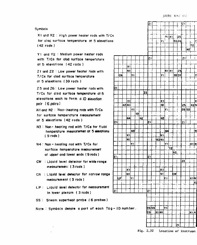
JAERI MKJ OIIL;
Symbols
XI and X2 : High power heater rods with T/Cs for clad surface temperature at 5 elevations (42 rods )
Y1 and Y2 : Medium power heater rods with T/Cs for clad surface temperature at 5 elevations (42 rods )
Zl and Z2 • Low power heater rods with T/Cs for clod surface temperature at 5 elevations (39 rods )
Z 5 and Z6 • Low power heater rods with
T/Cs for clad surface temperature at 5
elevations eoch to form a 10 elevation
pair ( 6 pairs)
Nl and N2 • Non-heating rods with T/Cs for surface temperature measurement at 5 elevations (42 rods )
N3 : Non- heating rod with T/Cs for fluid temperature measuremen at 5 elevations ( 9 rods)
N4 : Non - heating rod with T/Cs for surface temperature measurement at upper and lower ends ( 9 rods)
CW • Liquid level detector for wide range
measurement ( 3 rods )
CN : Liquid level detector for narrow range
measurement ( 3 rods )
LP • Liquid level detector for measurement
in lower plenum ( 3 rods )
SS '• Steam superheat probe ( 6 probes }
Note : Symbols denote a part of each Tag
s
Zl
21
Z_h
Zl
CN
LP
X2
XI
Nl
XI
N l
N4
XI
Nt
X I
N1
Yl
Yl
N3
Yt
Yl
- I D number
YZ
N2
ZZ
Zt
z
24
Zt
Z1
6
5
SS
xz
Y
Y
X
N
N3
XI
Nl
X I
Nl
Nl
Nl
Nl
Y l
N4
Y1
Y1
Yt
X
X
Y2
SS
SS
HZ
CW
|Z5
Z6
Z5
ze
Z(
Z l
Z5
Z6
Z l
zz
Y
Y2
SS
Y
X
X2N
N
XI N
XI H X
XI N
Fig. 2.22 Location of instrumei
JAERI -M 82 -002
N2
Z2
Z
Zl
1
1
6
5
SS
i 1
X2
XI
|
r Y
Yl
XI
Nl
N3
XI
Nl
XI
Nl
Nl
1 Nl
Nl
Yl
N4
Yl
1
Yl
X
XI
Y2
SS
SS
N2
W
Z5
Z6
Z5
Z6
U
z
z
Z5 Z6
Zl
Z2
N2
SS
Y2
X2
XI
XI
XI
Y
Yl
XI Nl
N3
Nl
Nl
X2
Nt
X2
N
N<
Yl
Yl
Yl
Yl
X1
X<
iz
Y2
N3
N4
N2
N4
N2
N3
N4
Z£
Z2
Zl
Zl
Zl
Zl
Zl
Zl
zs Z6
Z2
Nl
N3
N2
CN
N2
SS
N4
N3
Y2
Y2
XI
XI
Yl
Yl
Yl
Yl
Nl
Nl X2
N
X2
N
Nl
Nl XI
Yl
Yl
X
XI
XI
X2
Y2
yt
N2
Z2
Zl
Zl
Zl
Zl 1
LP
N2
CN
LP
I i
Y2
X«
XI
Yl
Yl
Yl
N4
Yl
Nl
Nl
Nl
Nl
XI
Nl XI
NJ
Nl
XI
Yl
VI
X
X2
Zl
Zl
Zl
Zl
•
Z2
N2
Y2
Yl
Yl
N3
Yl
Yl
Nl
XI
Nt XI
N4
Nl Xt
Nt
XI
X2
cw
ss
zt
Zl
Zl
Zl
Z5
Z6
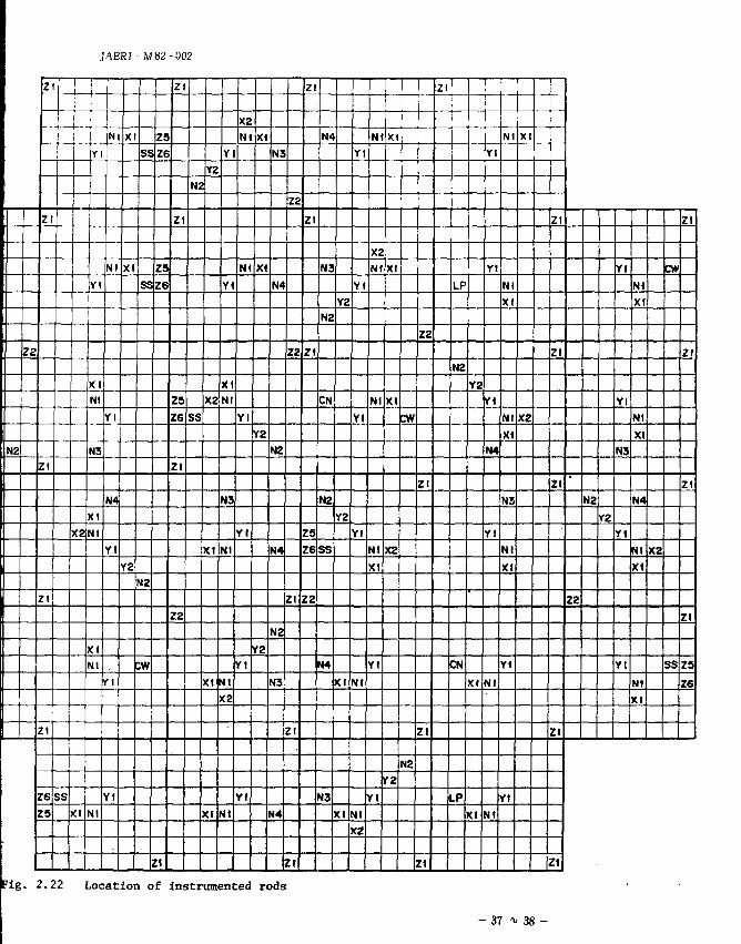
'ig. 2.22 Location of instrumented rods
- 37 i- 38 -
JAERI-MB2-002
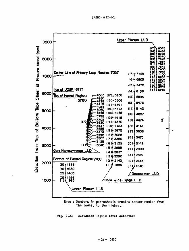
8
1 UJ
9000
8000
7000
6000
5OOO WWWW
4000
3000
2000
1000
-
—
Centerl
Topof \
top of r
_
Line of Primary Loop
JCSP:6U7
tooted Realon: r -5760 JZ
Jt ma
W/z. .1 Core Narrow-ronae L L D ^
Bottom
~ (5) (4) (3) (2)
of Heated Regions
1898 1650 1403 1156
L 995
\Lower Plenum
Upper
Nozzlt«:7O27
4363
4198 4115
3950 3668 3782 3702 3620 3537 3455 3373 3290 3207 3125 3042
s
100
LLD
(17)
(16) (15) (14) (13)
(12) ( t i l (10) (9) (8 ) ( 7 ) ( 6 )
(5) (4)1
13) (2)
7 ZOT*
5856
5608 5361 3113 4865 4618 4370 4123 3673 3628 3380 3132
2885 2637 2390 2142 1895
Plenum LLD
(17)
116)
(15)
(14)
(12)
(11)
(10)
(9)
(8)
(7)
(6 )
( 5 )
( 4 )
( 3 )
(2)
(1);
7138
6805
6472
6139
5806
5473
5140
4807
4474
4141
3803
3475
3142
2809
2476
1810 /
/Downcomer
wide-range LLD
0 7 > (16) (15) (14) (13) (12) ( I D (10) ( 9 ) (8 ) ( 7 ) ( 6 ) (5 ) ( 4 ) (3}' (2)' (1)1
• 8585 8436 8288 8140 7992 -7884 7695 7547 7400 7250 7100 6953 ~ 6804 6655 6507 6357 6210
4
-
LLD
Note : Numbers in parenthesis denotes sensor number from the lowest to the highest.
Fig. 2.23 Elevation liquid level detectors
- 3 9 - (40)
JAICR] - M 8L' -1>UL"
Sreom Generator-I ( 1 and 2)
LPCI Pump LPCI Tank Col
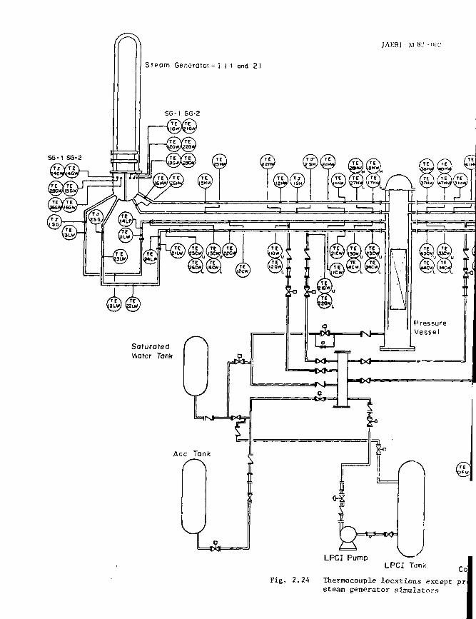
Fig. 2.24 Thermocouple locations except prJ steam generator simulators
JAERI- M 82-002
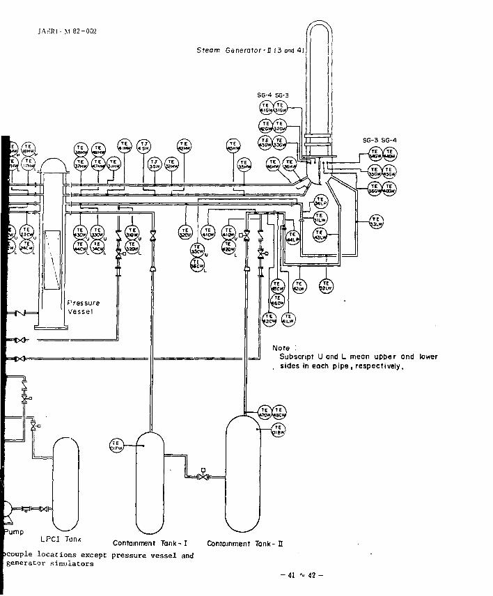
Sfeom Generator - I 13 and 4)
Note : Subscript U and L mean upper and lower
. sides in each pipe , respectively.
S3 \
'ump
LPCI Tank Containment Tank-1 Comomment Tank-I I
icouple locations except pressure vessel and generator simulators
- 41 ~ 42 -
JAERI -M
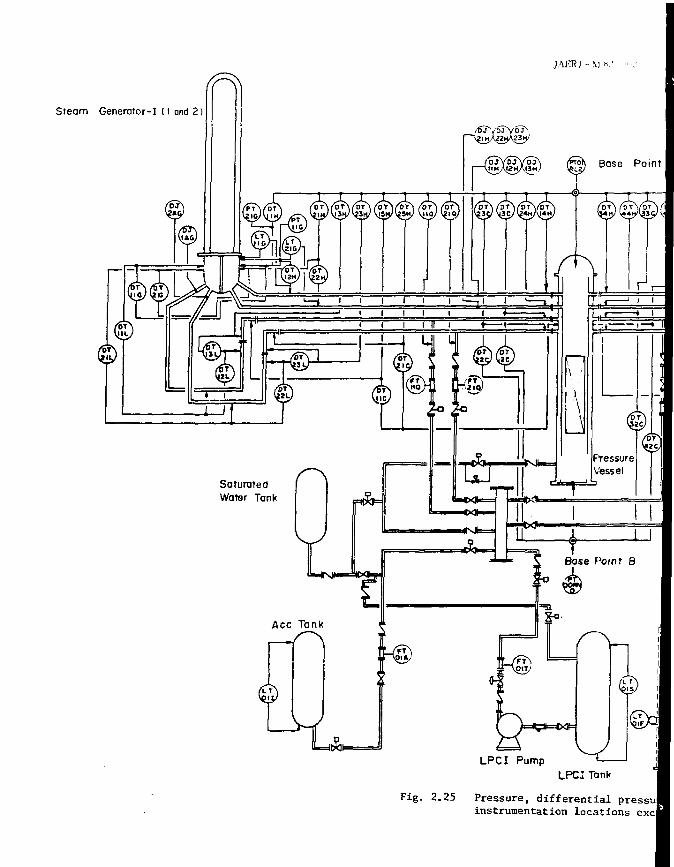
Steam Generator-I (I and 2)
_ / 1 > T Y 6 T Y O J S \
Base Point
LA. LPCI Pump
UPC: Tank
Fig. 2.25 Pressure, differential pressul instrumentation locations excl
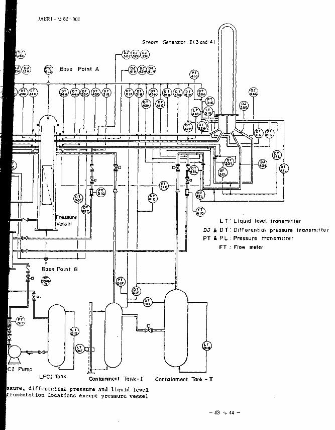
JAERJ-M 82-002
Sreom Generator-Il3and 4]
\ Base Point B
LT. Liquid level transmitter DJ k DT! Differential pressure transmitter PT It P L : Pressure transmitter
FT : Flow meter
ICI Pump LPCJ Tank Containment Tank-I Containment Tank-fl
ssure, differential pressure and liquid level Itrumentation locations except pressure vessel
- 43 t 44 -
JAERI-M 62-002
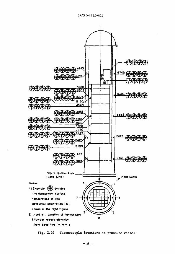
Top of Bottom Plot* (Baft Lint) ' } ' _Plant North
Notts
I) Example pwt) dtnorts
tht downcomtr surfact
ttmptroturt In tht
aztmutha! orltntatlon (5 )
shown in tht right flgurt.
2) o and • : Location of thtrmocoupM
(Numbtr mtons tlnvotion
from bott lint in mm. )
Fig. 2.26 Thermocouple locations in pressure vessel
-45 -
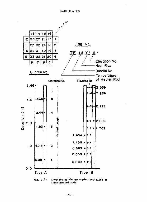
JAERI-M 82-002
12
ft
to 9
13
26
25
24
23
8
14
£7
32
31
22
7
(5
28
29
30
21
6
16
17
18
19
20
5
Bundle No.
1
2
3
4
3.66
3.0
c o
° UJ
2.0
! .0
0 . 0
.3.05
2.44
1.83
-1.015
0.38
Elevation No.
t
i !
o X
Tag. No.
14 Y l 4
/ *— Elevation No. Heat Rux
Bundle No. Temperature
Elation NO. of Heater Rod
1.454
1. 139
0.889
0.639
0.289
e-8
6-4
6-3
6-2
6-1
5-5
5-4
5-3
5-2
5-1
3.539
3.289
2.719
2.089
1 .769
Type A Type 8
Fig. 2.27 Location of thermocouples installed on instrumented rods
- 4 6 -
JAERI M H2 002
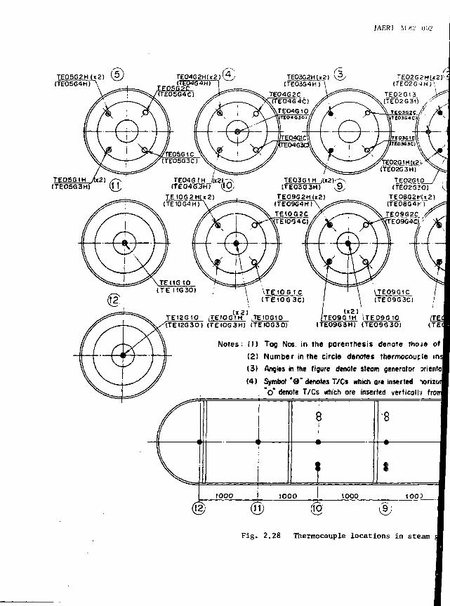
T E O S G 2 H ( K 2 ) ( 5 (TE0SG4H)
TE056IH Ax2) / f> (TE05G3H) (H,
),^\
(K). TEIOG2H(ii2)
(TE10G4H)
\TEIOG TC (TEtOG3C)
(TE12G3O) (TEIOG3H) (TE1OG3O)
TEO3G1 M /1«2) (TEO3G3H)
TE09G2HU2) (TE09G4H)\ TE1OG2C TEI004C)
TE02G1Q (TEO2S3O)
TE0BG2H«2) (TE08G4f
IEQ9G2C. TE69G4C),'
, (xZ) JTE09G 1H \TE09G1Q
(TE09G3H) (TE09G30) (TEC
Notes: (1) Tag Nos. in the parenthesis denote those of
(2) Number in the circle denotes thermocouple ins
(3) Angles in the figure denote steam generator xiental
(4) Symbol '9" denotes T/Cs which are inserted "wrizorj , "o* denote T/Cs which ore inserted vertically fro
8
i
•8
IOOO 1000 1000 1003
12) (H) (10- (9;
Fig. 2.28 Thermocouple locations in steam
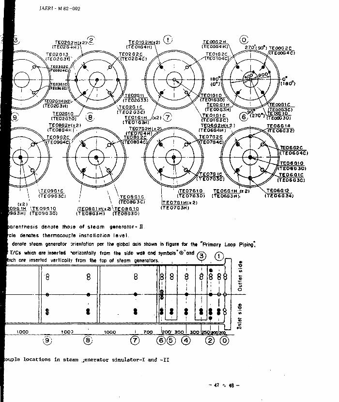
JAER1- M 82-002
TE02G2H()c2)\gr.. (TE02G4H)
TEO2G1 (TE02G»0)
TEO8G2H«2) (TE08G4H | TEO9G2C rE09G4C)/
&
\TE02GtC (TEO2G3C)
TE016IH / («2) (7 (TE01G3H) ^
TE07G2H(<2: (TE07G4H)
TE0SG2C TE08G4C
270(90*) TEO0G2C TTE0064C)
TEOIGtO (TEO1G3O)
TEOOGIH (TEO0G3H)
\TE0tG1C (TE0IG3C) TE06G2H(»2)
(TE06G4H) '
\TE09G1C (TE09G3C)
»2) , i 1H \TE09G10
D9G3H) (TE09G30)
/ \ \TEOBGIC ' \ (TE0aG3C)
/TE08G1HU 3 \ T E 0 8 G 1 0 (TE08S3H) (TE0aG30)
ITE07G10 TEO6G1H it Si (TE07G30) (TE06G3H).
TE07G\H(»2) (TE07G3H)
TE0SG14
TE0602C (TE06G4C)
ri-06010 '(TE06G30) TE060IC
ITE0603C)
T£06Gtg (TE06G34J
parenthesis denote tho;e of steam generator- H.
fcle denotes thermocouple installation level .
denote steam generator orientation per the global axis shown in figure for the "Primary Loop
ST/Cs which are inserted "wrizontally from the side wall and symbols'©"and /j\ / r \
tich ore inserted vertically from the top of steam generators. , , , \ ^ , _ ~ - J ~
Piping,
•8 8 8 8 8 8 8 8 3
o
1 1 «
1000 tOOJ 1000 1. 700 '200' 300 300 LJ 250;top!;oo.
® louple locations in steam jenerator simulator-I and -II
- 47 % 48 -
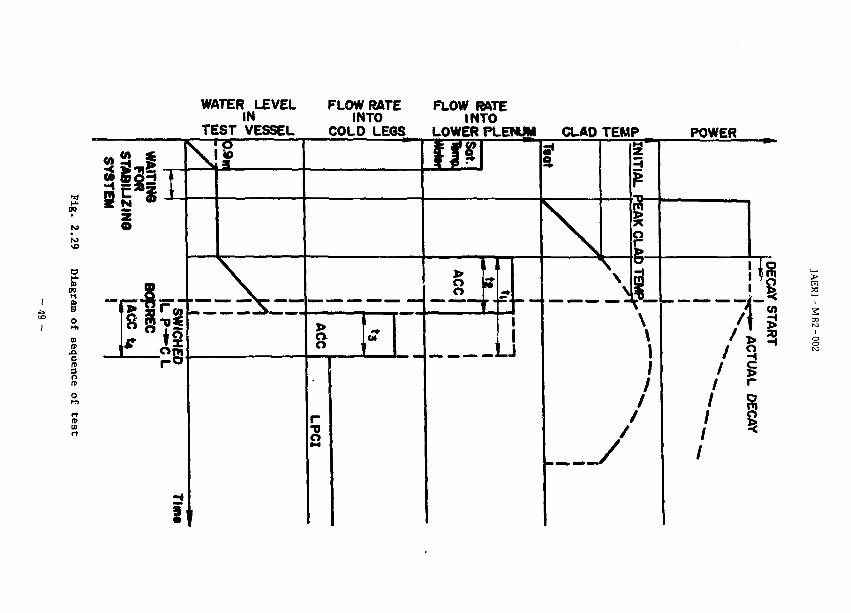
WATER LEVEL IN
TEST VESSEL
FLOW RATE INTO
COLD LEGS
FLOW RATE INTO
LOWER PLENUM CLAO TEMP POWER
to to
00 H
I n>
1 S
YS
TEM
3 . * N •
i
*• i s • o 5
f-
ACC *
— . — —
1
1
Ttat
\ \
\ \
N
[INITIA
L 1
i p
\ \ | /
/
/ /
A s /I
/ s / § / * /
00
JAERI- M 82-002
3.
54 5F-fflft£ L t i f ' i ->£ l9l"]<OS&MHDm%>S: Table 3.1 (C*
(1) segass&^'jjjigntags c i 2. c 1 11 (2) ^ - 5 ><-*s!jjRs£g&
^ E / / C 1 10 ( P 1.5) , C 1 12 ( P 3 )
E C C S B C l 5 (G A ( - , -A; ) , C 1 9 ( G , . , - < - i ' M
C 1 13 ( ACCftAUJflTO. I . C I 6 ( G , . P n
ram/jiwffiS: c i 7 ( 7 0 0 "c >, c i 14 f 800 r )
y 'V y ^J v(s - ia c i - 3 (fi'iSfiuMis;)
C i i ( K ~ ~ 3 S )
i C 1 S i ! 3 ( t - -t > '/ ' ,• 7 9 - 144 )
i C 1 S I M ( f)5"C )
(3) KfiO,iX.fM ' i t l i W K C T i ^ t t i ' i ^ ) ^ ^ - ^ ^ ^ , . )
F L E C H T C l S H 2 ( 1708B ) , C 1 16 ( 3105 B )
PKL C 1 S H 5
(4) t**S41li™«S8
'J 7 f / f tSia^SS C 1 4 ( «*Vi )
C 1 S H 1 f * ; ' . L - 4 I U ] | ] $ , b \ s - - > ? ' )
C ] - 15 ( ' ^Jiiti^ )
C l 9 ( IN (11 • 4 'U.-7J317K )
C l 8 ( ^ - r - v -
< 4 ^ -
ELECHT SET?4»iS3!fe© PKL ®.
L, ^*p<£.>?ftJn**iHiA>©l®Htr-iS«iL,
1.5 m
- 5 0 -
JAERI-M 82-002
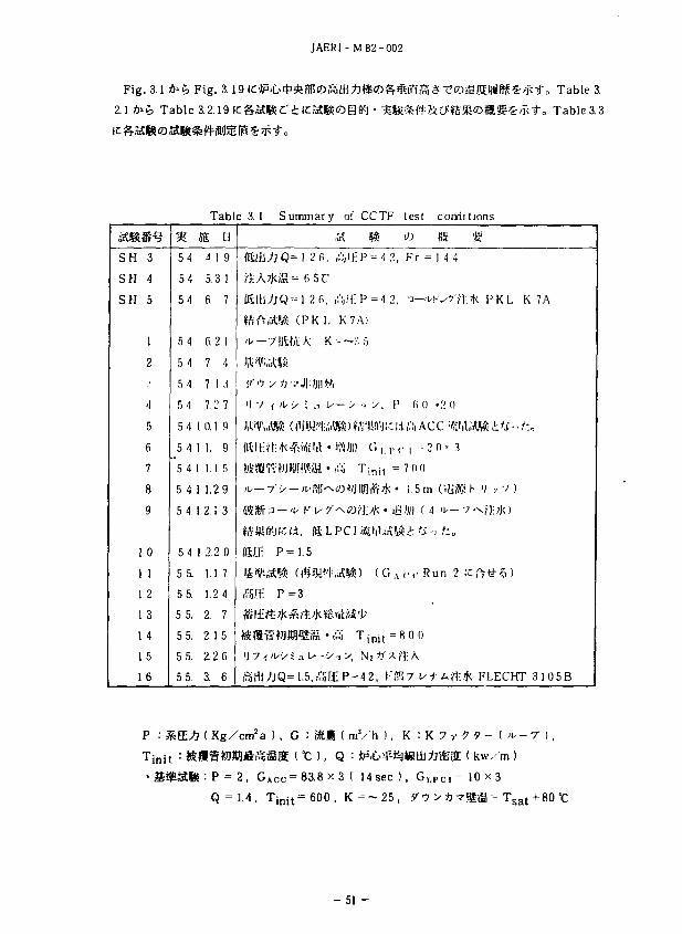
Fig. 3.1 *>£ Fig. 3.
2.1 ^ t > Table 3.2.19
Table 3. Table 3.3
SH
SH
SH
1
1
1
1
1
1
1
3
4
5
1
2
.!
4
5
6
7
8
9
0
1
2
3
4
5
6
%
54
54
5
5
5
5
5
5
5
5
5
5
5
5
5
5
4
4
4
4
4
•1
4
4
4
4
4
5.
5.
5.
5 5.
5 5.
5 5.
IS
1
1
1
1
1
1
4
5
6
fi
7
7
7
rable 3. 1
1
3
2
1
2
0.1
1.
1.
1.
2.
1
n 9
1
7
1
4
3
7
9
9
5
29
1
2.2
1.
1.
2.
2.
2.
3.
1
2
1
2
3
0
7
4
7
5
6
6
fiiii
ft A
ISA >\,-
?-••;
1 ) 7
urn Kit;
«»?
a*
'J7-,
Summary
; j Q = 1 . 2 6,
MS = 6 5 C
;jQ-1.2fi, ,
, r ^ ( P K L
7)1W/U K
y ft vj|:. jnth
7?MI9H$ia •.
P = 1 . 5
$& (t1*t'l:r
P = 3
5-WRU5IS • ,'
^Q=1.5.SE
Ol
"it
"ill K'
- ~
W/J
P
CCTF
- : P - 4 2,
: P = 4 2,
A)
;-:s
•. y . P
1 G | . | M
'•'init =
)« ;* • ifc
0 (GA
Tinit =
= 4 2 , Kffl
test conditions
* «5 •£•
Fr = 1.4 4
3—UKU?71-:TK P K L K 7A
(i 0 '2 0
I --- 2 0 > 3
7nn
1.5 m G l i » > V , 7 )
c c Run 2 ICftti-5)
^0 0
W i ' t i f f i * FLECHT 3 1 0 5 B
< k w / m )
P : SE^7 ( Kg/cm2a ) , G : »EM ( mV'h ), K : T i n i t : »fl |f tDfflfiilSS ( X: ). Q :
i : P = 2, GACc=83.8 x 3 ( 14 sec ), Gi.PCi = 10 x 3 Q = 1.4, T i n i t=600, K - - 2 5 , 90 > *-rfijg - T s a t +80 °C
- 5 1 -
JAER1-M82-002
TEST NO C1-SH3 .73.LM..3.
CHPRT NO 165
g 6C2.S0.
200. M
TRC NO
1 TE32X11 •! TE32X1H 2 TE32X12 5 TE32X1S 3 TE32X13
location elevation
•
5
3 o
1
3.05 m 2M m 1,83 m 1.015 m 0.38 n.
360
HUE ISEC)
600
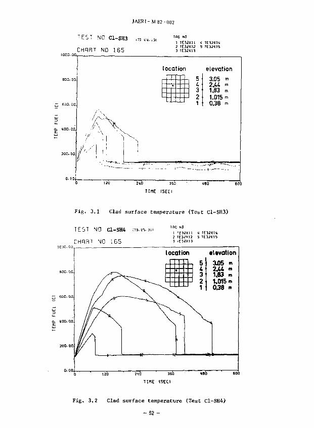
Fig. 3.1 Clad surface temperature (Test C1-SH3)
TEST NO C1-SH4 oa.us. m
CHPRT NO 165
1 T E 3 2 X I 1 ij 1 IE3i«12 5 TE3iX!b 3 IE32XI3
0. DO.
locatior
•
i
36D
TIME (SEC)
5 4 3 2 1
• t tvat ion
3JO5 •« 2wU 1,83 m 1.015 m 0^8 <n
Fig. 3.2 Clad surface temperature (Test C1-SH4)
-52 -
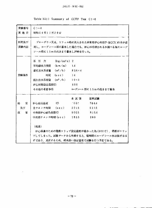
JAER1-M82-002
TEST NO C1-SH5
CHPRT NO 165
Q- UOO.OO.
locatior
• L 3 2 1
elevation
3.05 m 2M <» 1,83 m 1.015 m 0.38 m
IIMf ISf.O
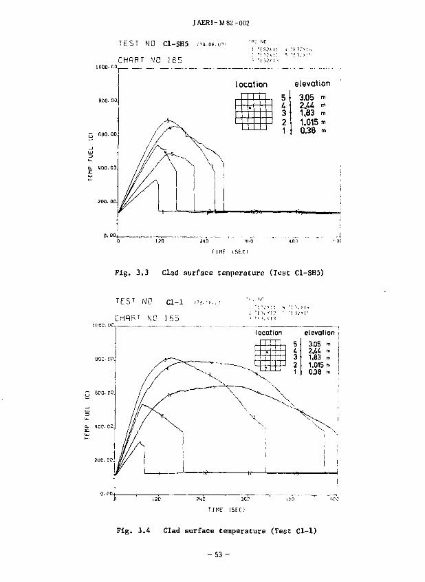
Fig. 3.3 Clad surface temperature (Test C1-SH5)
T E S T N O C l - 1 i 7 i . ;*..-• "•--i".r > t i
NO 155 • ' J i ' i i
T I M E I S E C )
Fig. 3.A Clad surface temperature (Test Cl-1)
- 5 3 -
JAERI-M82-002
T E b : :-iC c i - 2
CHQRT [JO i 55
location elevation
TIME I 5 K 1
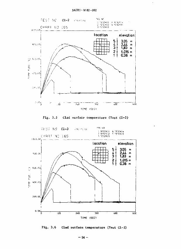
Fig. 3.5 Clad surface temperature (Test Cl-2)
NO Cl-3
NO 165
" > G NO
1 1 E 3 3 M I 1 T E 3 5 K I I 4
1 0 0 0 . DO
locatior
• 5 4 3 2 1
elevation
3.05 m 2.44 m 1,83 m 1.015 m 0.38 m
0 120 2U0 360 USO
TIME (SEC)
Fig. 3.6 Clad surface temperature (Test Cl-3)
- 5 4 -
JAERI -M 82-002
TEST NO C l - 4 C79.07.271
CHRRT NO 155
a- 100. 00.
1 TE3JKI 1 u 'F3?x'. i4 2 1 E 3 2 X 1 2 5 T E 3 2 x : b
3 U 1 2 X : 3
elevation
T | MP T i l ( 1
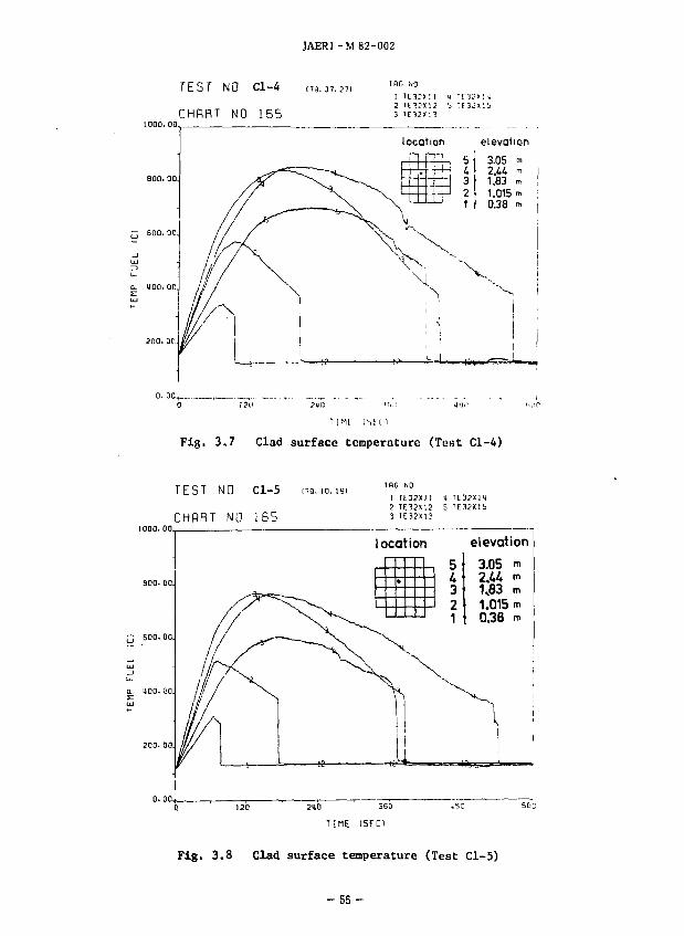
Fig. 3.7 Clad surface temperature (Test Cl-A)
T E S T NO C l - 5 i 7 9 . i o . i 9 i
CHflRT NO 1 6 5 1 IE3?»I I <i 2 TE32X12 5 3 TE32XI3
- BOO. 00.
locatior
•
2H0 360
TIME ( S E C )
5 U 3 2 1
elevation
3.05 m 2M m
1.83 m 1.015 m 0.38 m
60C
Fig. 3.8 Clad surface temperature (Test Cl-5)
- 5 5 -
JAERI-M82-002
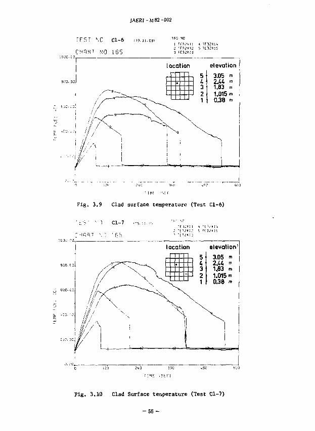
T E S T NO Cl-6 .79.ii.09>
CHQRT NO 165 1 TE32XI 1 4 TE32XIU 2 TE32X12 5 TE3JX15 3 rE32XI3
1 I MI :')i r
Fig. 3.9 Clad surface temperature (Test Cl-6)
Fig. 3.10 Clad Surface temperature (Test Cl-7)
- 5 6 -
JAERI-M82-002
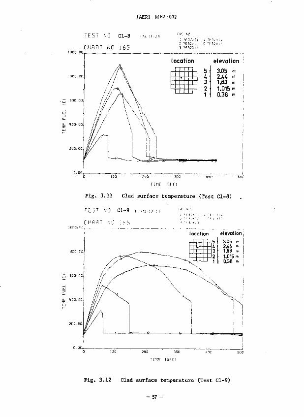
TEST NO C l - 8 i79. i i . i9
NO 1 6 5
~u'*!; 4 n ^ >: 4
location elevation '
•
5
3
1 , - B0C.00
3.05 m 2M m 1.83 m 1.015 m 0.38 m
4t}0 CulO
I I HE iSf. I")
Fig. 3.11 Clad surface temperature (Test Cl-8)
T F_ S T NO C l - 9 i ,;n.,.?.!) M : '"•'
CHflRT" M ; i b 5 "' •' >.'•<:'•<
1 locat ion elevation
•
s i. 3 2 1
3.05 m 2.44 •» I 1,83 m ! 1.015 m 0.38 m
212 350
TIME ISEC1
Fig. 3.12 Clad surface temperature (Test Cl-9)
- 5 7 -
JAERI-M 82-002
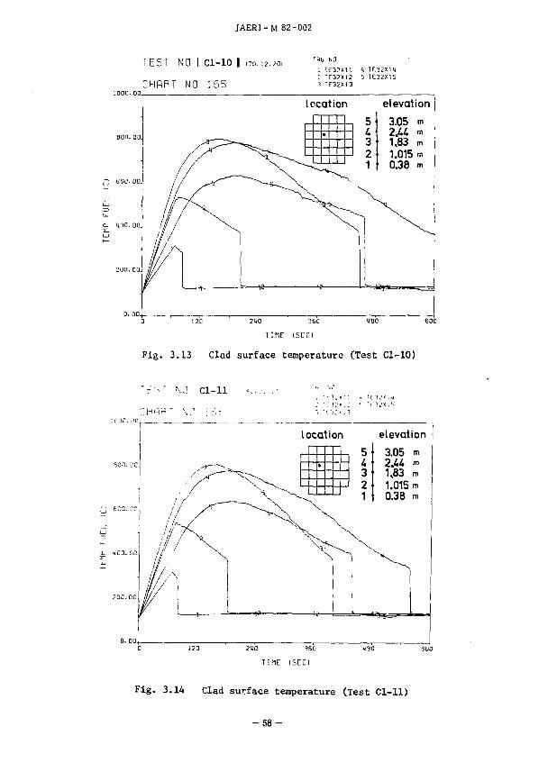
TEST NO I C l - 1 0 | .79.12.201
CHHRT NO 1 6 5
TRG NO
i If32X1 1 "i 1E32X1U J TT32X12 5 TE32X15 3 TE32X13
0- HOO.OO.
locatior
•
5 4 3 2 1
elevation
3.05 2.44 «> 183
TIME ISET)
Fig. 3.13 Clad surface temperature (Test Cl-10)
TF'- r \ J Cl-11 •=...•. .- "" '"'
locatior
• h 4
elevation
3.05 m 2.44 m 1,83 m 1.015 tn 0.38 n,
210 3S0
T I M E ( S E C )
Fig. 3.14 Clad surface temperature (Test Cl-11)
- 5 8 -
JAERI-M 82-002
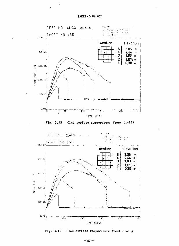
TEST NO Cl-12 I9Q.DI.7UI
CHRFT NO 165
Q- HOC 00.
location elevction
• 1 4
J 3 3 2
1
3.05 m 2.44 m 1,83 m 1.015 m 0.38 m
0. CiD(_.
Tint iset)
Fig. 3.15 Clad surface temperature (Test Cl-12)
T K : T N C C l - 1 3 i-: • : . '• .'•' ,
location elevation
3.05 m
3 1J83 m 2 1.015 m
0.38 m
T 1 M F ( S E C I
Fig. 3.16 Clad surface temperature (Test Cl-13)
- 5 9 -
JAERI-M82-002
TEST NO Cl-14
NO i 6 5
Fig. 3.17 Clad surface temperature (Test Cl-14)
T E S T N O C l - 1 5 I8C.0J.36I
CHCiRT NO 1 6 5
IOC 1,0
Fig. 3.18 Clad surface temperature (Test Cl-15)
- 6 0 -
JAERI-M82-002
TEST HO d-16 (9D.J3.P6.
CHPRT NO i 65
TflC UC
1 ' E 3 2 X 1 I <; T E 3 2 X K 2 T C J i X l S 5 ' E 3 J « I S 3 T f i ^ x i l
locatior
• 5 U 3 2 1
elevation
3.05 m 2.44 m 1,83 m 1.015 m 0.38 m
Fig. 3.19 Clad surface tempernture (Test Cl-16)
-61 -
JAERI -M 82-002
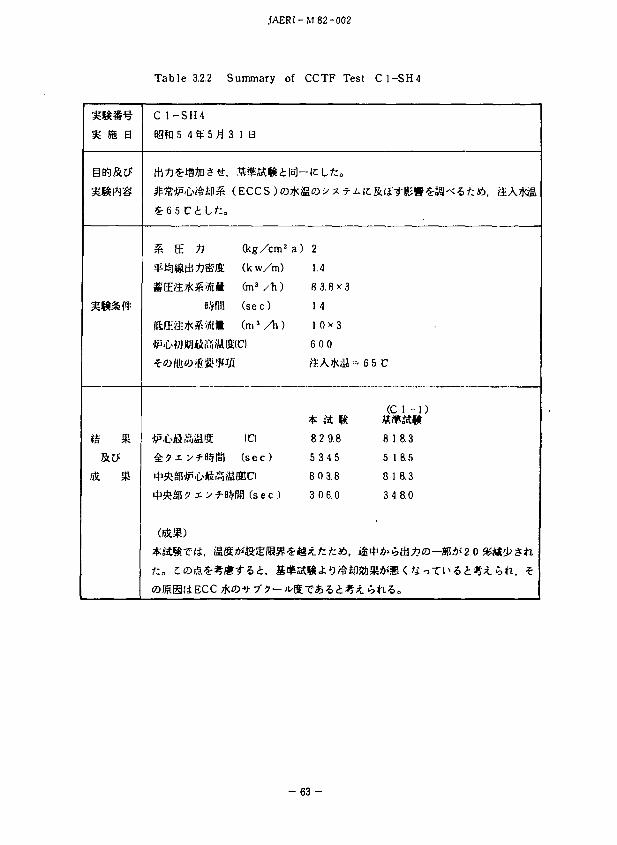
Table 3.2.1 Summary of CCTF Test C1-SH3
% m n
in&tf
«S «
C1-SH3
Bffft 5 4 «?•- 4 ft
C 1 - S H 2 ('+'
(f— + y Y 7
& /h J
^n-:/!":/K*.«£Jil
Will
1 9B
(kg
(kw.
(m3
(sec
(m3 /
*ii-iL« Mini w.'.'.'i uimo
^ ? x y ^B$|!J)
'J'!*i8|5'J!P'll>iftfiiiSi
i t '*i51>?x i"^B
(bSMJ)
(C!
( sec)
iUEIC)
<fliil ( s e
1. 4
cm2
'm)
1i)
)
1i)
c )
7- ?
4
a
?
i :
)
)
C
Wi) «c«
42
1.1 5
8 3.8 x 3
I 4
I 0.0 v 3
fifi I
7 I 2.9
I 8 8.0
5 7 3.1
I 0 3.0
1.4 4T*I
L t ,
7 •, ?
M 6
I
6
I
? : I. 4 4
(SH2)
5 0.3
7 l.O
5 0.3
2 6.5
i< If:
- 6 2 -
JAERI-M 82-002
Table 3.2.2 Summary of CCTF Test C1-SH4
n ffi a
% %
C 1 - S H 4
agjpo 5 4 ^ 5 3 1 a
& E ^ (kg/cm2
sptellSiii^&'ffi (kw/m)
SEft*^'ia 0n3/Ti)
BSfiS! (se c )
f&G-'S^&ftiit ( m ' / l i )
• •C<WWI<ii'.'.1iMffi(C)
^ ? x y-f H§RIJ ( s e c )
^ i t a l ! 0 -31 > f'BSH ( s e c )
O l ^ H t i E C C 7KO-9- y'9 — >
a) 2
1.4
8 3.8 x 3
14
1 0*3
600
SA*il
8 2 9.8
5 3 4 5
8 0 3.8
3 0 6.0
€-*8x.fcfc*.
= 65 C
(C 1 - 1)
8 18.3
5 1 8.5
8 1 8.3
3 4 8.0
- 6 3 -
JAERI-M82-002
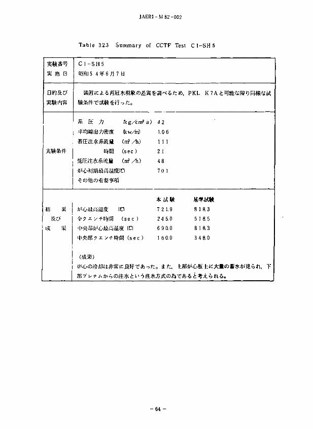
Table 3.2.3 Summary of CCTF Test C1-SH5
?« Jffi p
1* SK
)& »
C 1 - S H 5
agft 5 4 if 6 ^ 7 B
rk IE ti ikg/cirf a)
#^SItB^®ffi (kw/rri)
lEif£7K^aiEfi (trf / h )
B#R3 ( sec)
.'fiOift kfs iS (nf/h)
•b''iL>Ai[1.1!ii;iiilS; I d
^ • ^ x y ^ - D § | ! 3 ( s e c )
|t1!fcui5iJ!)3'L>fiit5i;S9[ (C)
• tP 'C 'O^ini i^SKSJf Tab -ofc
42
1.0 6
1 1 1
21
48
70 1
7 2 1.9
2 4 5.0
6 9 0.0
1 6 0.0
„ ttl. 1
\ PKL
«H 8 1
5 1
81
34
mm 8.3
8.5
B.3
8.0
- 6 4 -
JAERI-M82-002
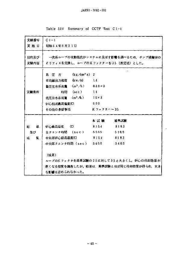
Table 3.2.4 Summary of CCTF Test C1 -1
•mm I I B
Ci- l
BSftl 5 4 *£ 6 £ 2 I B
si" 'J 7 4 x £32$ L, A— 7°©
& BE ti (kg/tm*a)
^VsMfaffl&fli (kw/ni)
»$IBJ (se c )
(5Efi**iiJ£» (ni1 /^)
^ j r x y f-B$R)l ( s e c )
2
1.4
8 3 . 8 x 3
1 4
1 0 x 3
6 00
K 7 r > J = -
8 15.4
5 5 65
8 IS.4
3 4 0.0
- 3 5
8 1 6.3
5 1 8.5
81 8.3
3 4 8.0
- 65 -
JAERI -M 82-002
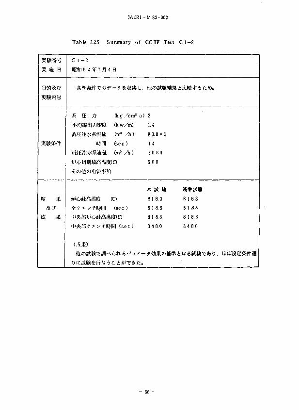
Table 3.Z5 Summary of CCTF Test C1—2
IS
B
C l - 2
Bg*n 5 4 ?P 7 n
3k ffi ^J
B$RJ1
fiSfl: *!•*&«£ ft
4 B
Ckg/cm
(kw/m)
(m3 / h )
feec )
(ms / h )
(C)
(sec )
SltlC)
*IB1 (sec)
L,
a) 2
1.4
8 3.8x3
1 4
10X3
6 00
8 18.3
S ! 8 5
8 1 8.3
3 4 8.0
81
51
81
34
8.3
8.5
8.3
8.0
- 66 -
JAERI-M82-002
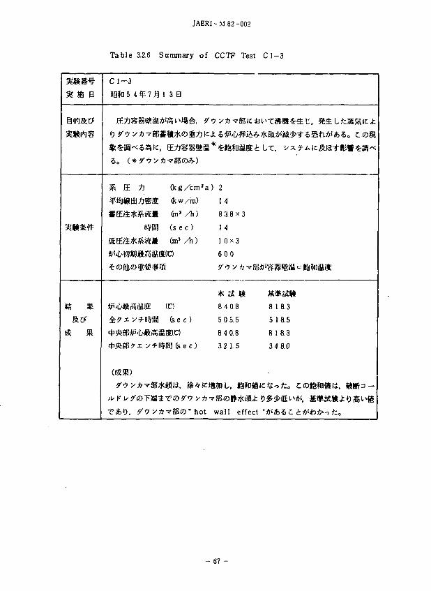
Table 3.2.6 Summary of CCTF Test C 1 - 3
mm B
ss**8
*s *
r$L *
C 1—3
BSfQ 5 4 ^ 7 ^ 1 3 B
% & -ft ( k g / c m ' a )
^P^Wtil/Jffiffi Ocw/m)
* E a * ^ M t * (hi3 ,/Ti)
B$fi!] ( s e c )
t&ff.&fcXMfk (m'/h)
4 ? i y f BSCBI ( s e c )
**g |5^xy^Btp B Tfe e c)
T * 0 . y"? yfi-7950" hot
> y*-7S|5icii
2
1.4
8 3.8^3
1 4
1 0x3
6 0 0
8 4 0.8
5 0 5.5
8 4 0.8
3 2 1.5
MDL, lafiJjgi
•95ffl|>7KaBJ;
wall effect
^BJjAsJ*ii>^"5SftAJ*5o C O S
«».*(.
8 1 8.3
5 1 8 5
8 18.3
3 4 8.0
67 -
JAERI- M 82-002
Table 3.2.7 Summary of CCTF Test C1-4
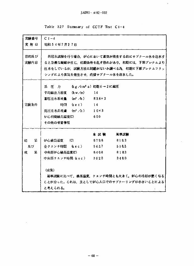
*S »
iS *
C 1-4
BSfU 5 4 *f 7 £ 2
Sja/fci4BI£f?
Jh S. fi
B*RH
fftfl: « • * * « £ •
*i.c>wioj»it5iina:(
*5'C«assK (
£ * * v-Hsua
7B
(kg/cm8 a)
fltw/m)
&n3/h)
(sec)
(m'/h)
C)
C)
(sec)
SIC)
'pi fe e c )
Mi, £iLT
#1*8 6 — 2 K
1.4
83.8X3
14
! 0 x 3
600
4** Sft 1R
8 7 9.8
5 6 3.7
8 4 0.8
3 6 2.0
:? xy-f l^rB
***?
%
8
5
8
3
life
1 8.3
ias I a3 4 ao
JAERI-M82-002
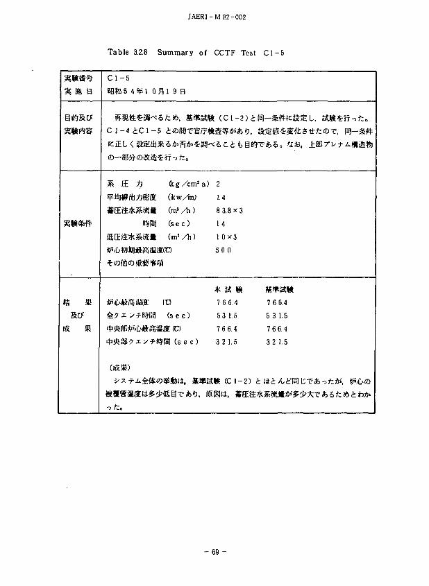
Table 3.28 Summary of CCTF Test C l - 5
H S6 B
e *
C l - 5
B9fn5 4 *
C 1 - 4 i C
B
*fflfflJfflJIB
(fiSJB)
1 0 ^ 1 9 3
1-5 £®ffl?trf#
k g / c m 2 a)
SS (kw/tn)
(tit (tns / h )
Wlj ( s ec )
i t* ( m s / h )
Jli.1 ( s e c )
'f-B^Pol ( s e c )
2
1.4
8 3.8X3
14
1 0x3
50 0
7 6 6.4
53 1.5
7 6 6.4
3 2 1.5
K (C 1-2) i
7 6 6.4
5 3 1.5
7 6 6.4
3 2 1.5
- 6 9 -
JAERI-M 82-002
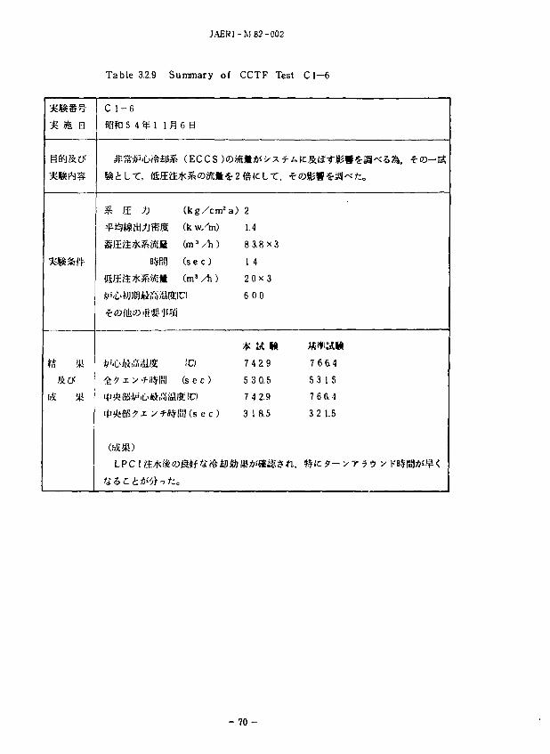
Table 3.2.9 Summary of CCTF Test C1—6
% m a
ZS
$& Ml
f£ 5(1
C 1 -6
ag?a 5 4 ^ 1
& E /]
fgEa*^«
OS*)
lfl 6 B
(kg/cm2 a)
S (k w/m) fi (m3/h) rBT ( s e c )
» (m'/h)
IC)
K] ( s e c )
^ 8 8 ( s e c )
2
1.4
8 3 .8x3
1 4
2 0 x 3
6 0 0
* a M 7 4 2.9
5 3 0.5
7 4 2.9
3 18.5
u, 7
5
7
3
6 6.4
3 1.5
66 4
2 1.5
- 7 0 -
JAERI-M 82-002
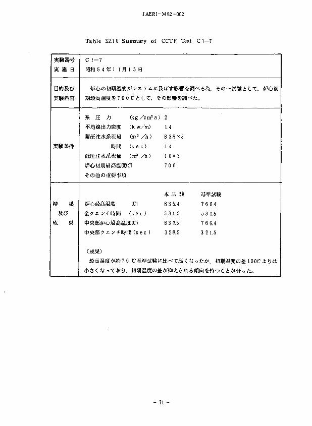
Table 3.2.10 Summary of CCTF Test C 1—7
•mm-} <& tfc •
» * *
f£ *
C 1-7
ag*n 5 4 1 u
^ ff 1
SEft*^«ta
(5Ea7k^«t»
(SL^7 /h*<ttoT*f»:
^15 8
(kg/cm2 a)
(k. w/m)
(m3/h)
( s e c )
(m3 / t i )
( s e c )
JUS] ( s e c )
0 Ctf*^sS^!c
2
1.4
8 3.8 x 3
1 4
1 0 x 3
70 0
8 3 5.4
531 .5
8 3 3.5
3 2 8.5
76
5 3
76
3 2
6.4
1.5
6.4
1.5
- 7 1 -
JAL-JI-M82-002
Table 3.2.1 1 Summary of CCTF Test Cl—8
PI ffls B
•%&&&•
IS JR
ScO'
fS Jg
C 1 - 8
B3ft 5 4 ^ 1 1 £ 2 9B
7'a — ?'•} vX.lt, ') 7 <
i&L, >\/—-f;v—
% & tl
WK£fc%ffiS. B#RS
•#5jC^liofc46c
f t * * ) , Hffi ~'
(kg/cm2
(kw/m)
(m3 /h) (sec)
(m3 /h)
C)
(C)
( sec )
l ( s e c )
oSi i t-')
i tztb, #
a) 2
1.4
8 3.8x4
1 4
1 0x3
600
* a « 1 o o. •: 2 2 1.5
9 0 0.5
1 8 3.5
^ffl'JtP'll>^ifl>?- (ECCS XD/k^iM
o
1. 5 m OjgSS S T ' S f *
7 6 6.4
5 3 1.5
8 15.4
280
ofc& (9 0 0 C) , If j g ^ l> '; v
B#PB1 ic/i/—y •>—Ji>%.i±iiitf z> it
- 7 2 -
JAER1 -M 82 -002
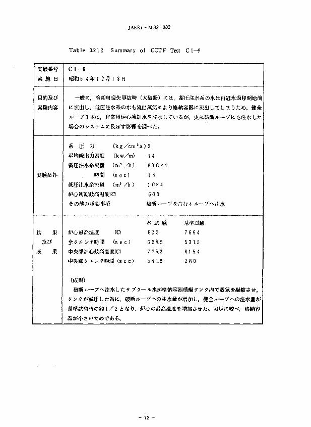
Table 3.2.12 Summary of CCTF Test C I—9
^ OB a
* « & « • •
*s »
C l - 9
BgftJ5 4 fp 1 2
,*TL ?y /A* i f
3R E 1]
(Sfl:?.l:**-«£H
©Si >\s—-f^
fl I 3 B
&*&©*&
(k g /cm
(k w/m)
(ms /h) ( s e c )
(m» A\)
(C)
( s e c )
^05! ( s e c )
1 / 2 11£ K>
2 a ) 2
1.4
8 3.8 x 4
1 4
1 0 ^ 4
600
$ it K B23
6 2 8.5
7 7 5.3
3 4 1.5
V(J
H 7
5
8
2
6 6 4
3 1.5
1 5.4
80
- 7 3 -
JAERI-M 82-002
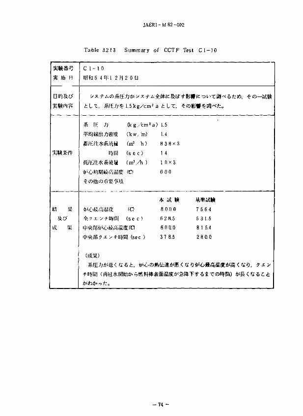
T a b l e 3.2.13 S u m m a r y of C C T F T e s t C l - 1 0
%m H
C l - 1 0
BBfrl 5 4 % 1 2 /1203
i l x , &E;j£1.5kg/cm2a
* E ti (kg/cm !a)
^iSjStlM'j/JiSSE (kw/ 'm)
fi/f ?!:**.«£» (m3 h)
H^lil] ( s e c )
fftMitt-jfc&ijfcB ( m ' / h )
*''C>»/J«BA4,!'liiSiia' (CI
<5^9 i y - f D,VI!!| ( s e c )
•^'iJiiB^ i v-f B$|i3 (sec )
i L T , *©
1.5
1.4
8 3.8x3
1 4
1 0 X 3
fiOO
^ lit HI
8 0 0.0
6 2 8.5
8 0 0.0
3 7 8.5
&mn>m < n»
7 6 6.4
5 3 1.5
8 1 5.4
2 8 0.0
- 7 4 -
JAERI-M82-002
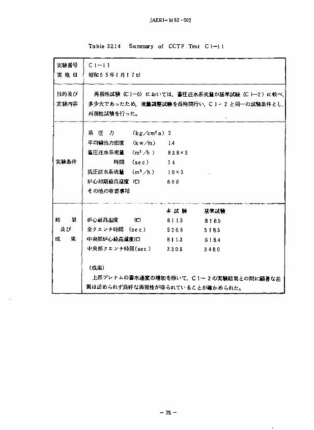
Table 3.2.14 Summary of CCTF Test C 1-1 1
nm B
i£ *
C 1-1 1
B9fD 5 5 1 fl 1 7 B
ffa«yt* <ci-« K* i^
& E # (kg/cm2a)
¥i S9ti!:*jS?lS (kw/m) SElft*S«ti l (mJ/1i )
BvfUil (se c )
BSEtf:*^^£R (m 3 / h )
fr''L>W)Wlftil5ifflK (C)
*P'll>li(T5ia(g (C)
: £ ? i yf-BSPul ( s e c )
2
1.4
8 3.8 x 3
1 4
1 0 * 3
600
8 1 1.3
5 2 0.5
8 1 1.3
3 3 0.5
S-KS^T, Cl
%atil*iS¥l«» (C 1-2 ) ICUK
iv c i -2 tH-oanftt t iu
8 1 8.5
5 18.5
6 1 8.4
3 4 8.0
- 7 5 -
JAERI - M 8 2 - 0 0 2
T a b l e 3.2.15 S u m m a r y of C C T F T e s t C l - 1 2
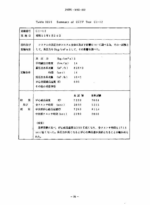
IS. SU
C l - 1
flam 5
I T .
% E
€!£•&
(SEa
^ ? x
<rS-se c )S
2
5
Hi
*
m 35
<
9M fl2
B-Vii.1
Ulff
4 B
(kg/cm2
(kw/m)
( m ' / h )
(sec)
(m3 / h )
(Cl
(Cl
(sec )
8 0
ffl (sec)
i L T , i<DKWi
a) 3
1.4
8 3.8x3
14
1 0 X 3
600
* a » 7 269
3 6 0.0
7 2 6.9
2 3 9.0
Elf I i3 9.5 Ci&<,
76
5 3
81
28
tit)
6.4
1.5
5.4
0.0
, i^iyfUrifc 17 1.5
- 7 6 -
jAERr-M 82-002
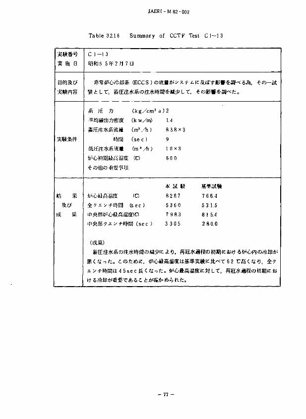
Table 3.2.16 Summary of CCTF Test C1—1 3
I I B
ts * &#
C 1-13
nafti 5 5 fp 2 R 7 a
#sf *P'D#£|J& (ECCS )«
S E J (kg/cm2
T^i^StU^^S (k w/m)
SE:S^Kl^»!itt (ma / h )
B5RS] ( s e c )
(S E f t 7Kf? WL1 (m3 / h )
£?xy-f8§ | i i j ( sec)
ti'i^ulJ^'x > f"8$lal ( s e c )
§ ( fi T fco C Of;£6it, ^'C
xy-^B§(ia](i45secS lC^-^
a ) 2
1.4
8 3.8x3
9
1 0 X 3
6 0 0
8 2 8.7
5 3 6 0
7 9 8.3
3 3 0.5
7C6.4
5 3 1.5
8 1 5.4
2 8 0.0
- 77 -
JAERI - M 82-002
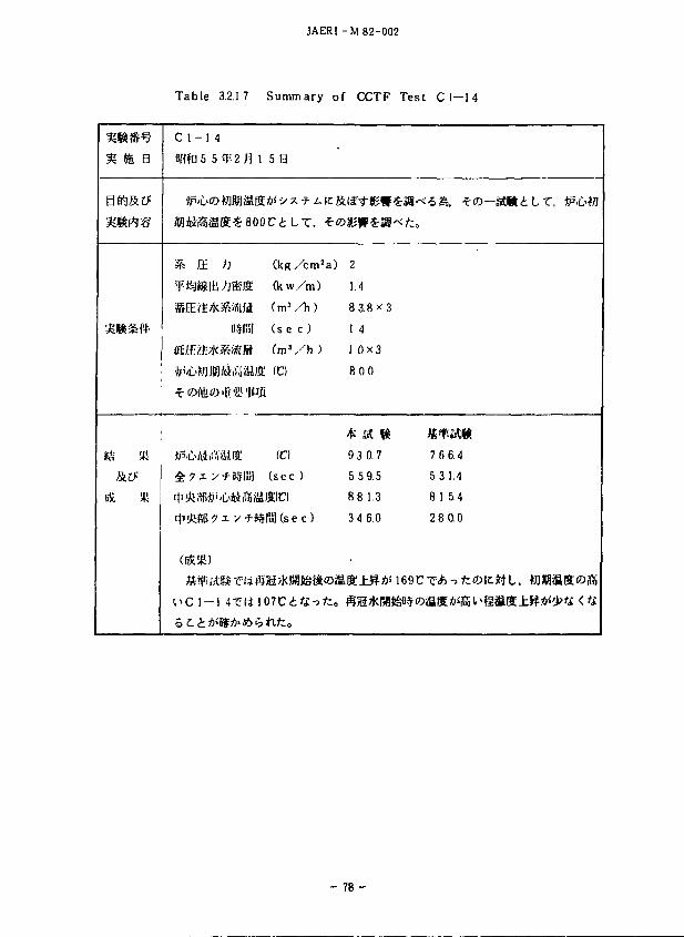
Table 3.2.1 7 Summary of CCTF Test C 1—14
•mm-
C 1-1 4
BHfU 5 5
£p'C>©
^?xy
**»?
(ijESfi)
I ' C 1-1
^2n i 5a
S«-800C£LT. •€•«
) (kg/cm2a)
;j*ia (kw/m)
WMii (m3 A )
B$f!i! ( s e c )
&tf£tt ( m ' / h )
MiVJiaiffi (C)
i|fig. 'Jtr/i
^ffi (C)
*fl$lii] ( s e c )
xy-J-B#RU(sec)
4-eiil07C£4--3/;o
2
1.4
8 3.8*3
I 4 1 0x3
800
4* fit l i
9 3 0.7
5 5 9.5
881.3
3 4 6.0
mm 7 6 6.4
5 3 1.4
8 1 5.4
2 8 0.0
- 7 8 -
JAERI-M82-002
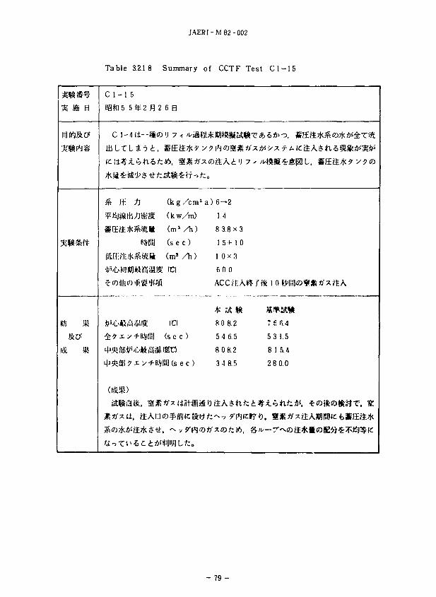
Table 3.2.18 Summary of CCTF Test C 1 — 1 5
m m B
ifl&CF
BX *
C 1-1 5
HSftl5 5 ^ 2 ^ 2 6 3
C 1-411—81©'J 7 -f ^J i l
It \&tj JLtotXhtz J6, SSS^?'
S E J (kg/cm2
¥t=J*»Ui ffi!t (kw/ra)
SrEa-^SStlt (mJ/h)
B-VliS) ( s e c )
(ftJHI;M«*>Klit (m3 / h )
*''C»WJW)ttiY!iffllff (Cl
^ ^ x y - H S l i i ! ( s e c )
WS?x.fWi(sec)
(fiXS)
UStfxil, ttAao^Biilclftf
a) 6-2
1.4
8 3.8 x
15+1
1 0 x 3
6 0 0
ACC^I
* IA 1
8 0 8.2
5 4 6.5
8 0 8.2
3 4 8.5
'J 7 ^
3
0
*,
« 10
7£
5 3
81
28
fi.4
1.5
5.4
0.0
- 79 -
JAERI-M82-002
Table 3.2.19 Summary of CCTF Test C 1—1 6
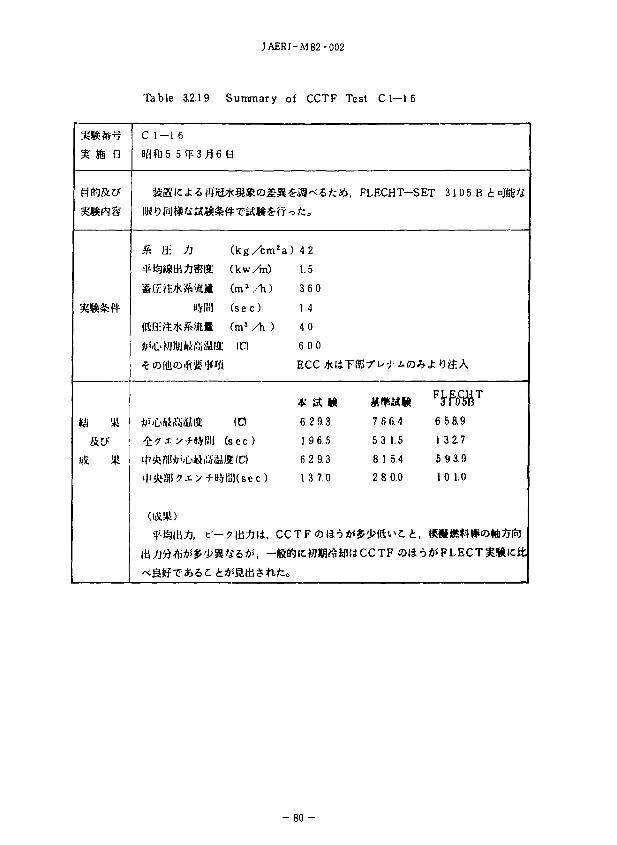
i s«
mm
s a
sex
Hi
C 1—1 6
agfn 5 53:3 £ 6 B
KB K> l§ i$&i£l^#TJ*&£?f r>
* E n ( kg / cm 2 a )
¥* ifeStilAS!ffi (kw/m)
SE?t?K^SRli ( m 3 / h )
8?fPn1 (sec)
<SH:'ft7K 'iftS (m3 /h )
•feJ'OAiiSjiMffi (Cl
t ? i x-fH.VI'!! (sec )
42
1.5
360
1 4
40
6 00
A- &-f H A
4*1 »A W
6 2 9.3
1 9 6.5
6 2 9.3
13 7.0
FLECHT—SET 3 1 0 5 B t *MU
mm 7 6 6.4
5 3 1.5
8 1 5.4
2 8 0.0
lU^iJ'*B* i?ii>ll^5* i, —UftWlcfillBi^illliCCTF Oii
65R9
1 3 2.7
5 9 3.9
10 1.0
•5#FLECTHI*li : i t
- 8 0 -
JAERI-M 82-002
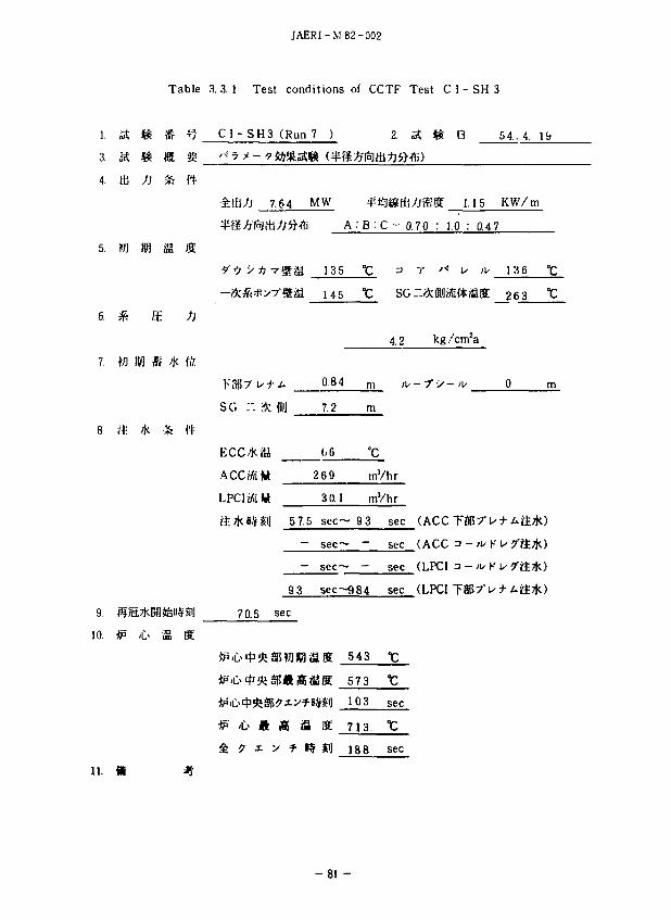
Table 3.3.1 Test conditions of CCTF Test C 1 - SH 3
2. A f£ B 54.. 4. 19
3.
4.
5.
6.
7.
8.
9.
10.
JS & #5
tb Jj ik
tfl KB i S
* HE
to iw ft *
» * *
*P 'C> im
H
IS
/}
{ft
ft
1$
£UtfJ 7.64
?9 ->1j TUS
F3|!7' i/+ A
SO : : 3< ffli]
ECC*iU
ACC«t«
LPCItfttt
MW ipj
5 A : B :
135 °C
145 "C
084 m
7.2 m
(.6 °C
fli)
/Jffiffi 1.
C = 0.70 : 1.0 :
3
SG
4.2
2 69 mVhr
3 0.1 m'/hr
&. * B$ £iJ 5 7.5 sec ~ 9 3
93
70.5 sec
*P 't> ft IS 8
^ ^ x > f-
- sec~ -
- sec~ —
sec~984
?SS 543
iffiffi 573
FB# l] 103
I ffi 7 1 3 -
Rf Si) 188
sec
sec
sec
sec
•c
sec
sec
kg /cm1
-7" •>-/!/
(ACC TS
(ACC a -
(LPCI 3 -
(LPCI T 3
15 KW/m
0.4 7
;u 13 6 °C
SK 263 *C
0 m
|57"U-^-Aft*)
• * K u / f t * )
^ U ^ - A f t * )
- 8 1 -
JAERI-M 82-002
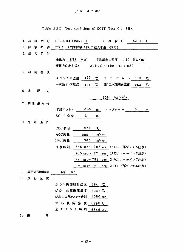
Table 3.3.2 Test conditions of CCTF Test C 1 - S H 4
1- SS ft & "s C 1 - S H 4 (Run 8 ) 2. St f* B 5 4. 5. 31
3. a ft e g »• 7 > - * 3ft%a% ( ECC &A*a 65 -4. * ^J & ft
9.37 MW ¥*9*8tfc^£& 1.40 KW/ra
A : B : C = l.OB : 1.0 : 0.82
5. ffl KB fi ffi
LLL_JQ. n r '•>' u /i/ 118 °c
i 2 i t SGziekfiii«t(*iaK 264 t
fE /J
2.0 6 kg /cm'a
0 .85 m <t> - 7' •> -
S G ." * ffli] 7.1 m
ECC*i!A 67.5 "C
ACCMiB 286 mVhr
LPCIiffil 3 0.5
5 3.5 s e c - 70.5 sec (ACC ~F8&7°is+&>&&)
70.5 sec~ 77 sec (ACC 3 - ;u K
77 s e c - 7 9 8 sec ([PCI 3 -
- sec— - sec (LPCI
9. HJEE*B8&B#£I] 6 5 sec
10. itp £> S K
*P it it
11. ft *
K S
Si]
K
m
594
803.8
306.0
829.8
534.5
t
sec
t sec
- 8 2 -

JAERI-M82-002
Table 3.3.3 Test conditions of CCTF Test C 1 - S H 5
L a 8 I f C 1 - S H 5 (Run 9 ) 2. M 8 B 5 4. 6. 7
3. g H 1 I *§&Stf& (PKL - K7A)
4. m n & it
7.09 MW -KJlSdJ/jft-ffi 1.06 KW/ra
A : B : C = 1.02 : 1.0 : 1,01
5. ftj ffl S ffi
?0 V t> vjgflia 138 "C =i T '-' U ^ 144
SG ..:, <*; ffli) 7.1 m
/K ft ft
ACC»(flft 131 mVhr
LPCIoftll 4 8.3 mVhr
| 83.5 sec-119.5 sec (ACC
160 sec
<l> ft S6 M m. 721.9 t
4 J i y f H Si] 24S sec
m %
u s °c SG -(jcffldat^affi 268 "c
6. ^ E >J
4 26 kg/cmza
7. W KM m * (ft
0.85 m ^ - 7°•>- /u 0 m
119.5 sec~133.5 sec (ACC 3 - * K
13a5 sec~484 sec (LPCI a - ^ K
- sec- - sec (LPC1
9. SS*FJteB$^l] 101 sec
10. *p -C> S «
620 *C
690.0 °C
- 83 -
JAERI-M82-002
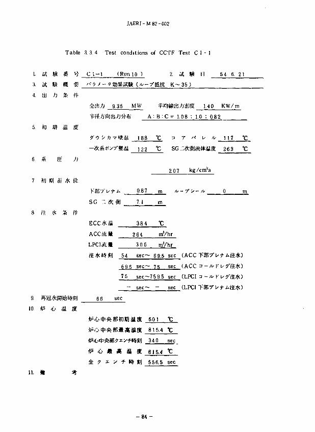
Table 3. 3. 4 Test conditions of CCTF Test C 1 - 1
1. IS 8 »
a at is ss
4. tb /J &
5. to 181 ffl S
ffi /J
8. ft; * fc ('(•
a 10. <P /t> S ffi
11. fit
C 1-1 (Run
'kthf) 9 35
IMIA-lSift
—ftS'-tt^:
SG i" <);
Ecc*a Accata LPCI Mi *
&*»**]
66
*p 'C> * * i
*&**(
£p 'C> ft
4 ? i :
54
10 )
MW
i
188
122
0.87
7.1
3 8 4
264
3 0.6
sec-
6 9.5 sec-
75
sec
•7-ffita
A : B :<
°C
"C
m
m
t
2. ;
: = i.
SG
2.07
mVhr
mVhr
- 6 9.5
- 75
sec~7 5 9.5
• sec~
as
•«im
i *
_ -
601
815.4
340
815.4
556.5
sec
sec
sec
sec
•c sec
°C
sec
St m H 5 4. 6. 21
35 )
tl&Bt 1.40 KW/ra
08 : 1.0 : 0.82
r >< u iv H 7 "C
-*fflH«t#fflK 263 °C
kg /cm!a
- r > - / u 0 in
(ACCTS|57"utAa*)
(ACC a -'H-'u/ftTJO
(LPCI 3 - * K u ^*ii*)
(LPCI TSRT-t'-J-AftTtO
- 8 4 -
JAERI-M82-002
Table 3. 3. 5 Test conditions of CCTF Test C 1 - 2
L U Ji I ^ C l - 2 (Run 11 ) 2. IS $ B 5 4. 7. 4
a a si is §?- a*Pt*s$
4. tb # * ft
9.36 MW ¥*9»di.ft®8 1.40 KW/m A : B : C = 1.07 : 1.0 : 0.82
5. fij Jffl iS ffi
9'? i/ fi -yjjia 187 °C ^ r '>* u ' " ' _
118 °C SG r.ftfflK#Sffi 263 TC
6 ^ IE /J
2.06 kg/cm'a
7. iw m m * te ' 0-86 m / u - r v - . ^ 0 m
SG ~ * ffl 7,3 rn
a a- * * ft-
ACCiKS 242 mVhr
LPCISJM 3 0.S mYhr
53 sec- 69 sec (ACC T%-7"\st Ajt^)
69 sec - 78 sec (ACC n -A/K
78 sec-727 sec (LPCI 3 - * K
- sec— - sec (LPCI
9. S5a*ia4&B#£i] 6 7 sec
10. *p i|> S S
617 t
818.3 t
?48.0 sec
<£,» « a a K 818.3
£ ? i x * 1$ #J 518.5 sec
11. « #
- 8 5 -
JAERI- .VJ82-002
T a b l e 3 .3 .6 T e s t <mditions of C C T F T e s t C l - 3
1. t£ & II ^ C 1 ~ 3 CRunl2 ) 2. IS & B 5 4. 7. 13
3. a a i n 4. HbS ft % #
9.35 MW ^^« | i± j^^g 1.40 KW/m
A : B : C = 1.0'< : 1.0 : 0.82
5. m m & & 9 0 v ti ? l i S u s °C u r '< u >\s 110 °C
-fr&X-yfmU 120 °C SG -~ l l f r i g g 2 64 °C
6. & S /J
2.0 5 kg /cm*a
7. tt 88 H * & 0.85 m M / - - 7 ' > - ' U 0 m
SG r . i^ fflij 7.4 m
8. i£ 7k £ ft
38.0 °C
: 2 5 2. mVhr
L P C I B E S 3 0.8 mVhr
5 2 sec— 6 7 sec (ACC
67 s e c - 77 sec (ACC 3 - n< K
7 7 sec~86 1 sec (LPCI 3 - ^ K
- sec— - sec (LPa
9. SS*§84&B#^1J 6 5 sec
10. *p ,£.> fi K
617
840.8
321.5
840.8
50 5.5
'C
°c sec
°C
sec
l i .
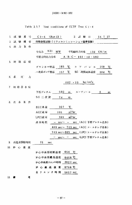
J A E R I - M 8 2 - 0 0 2
T a b l e 3 . 3 . 7 T e s t c o n d i t i o n s of C C T F T e s t C l - 4
1.
3.
4.
5.
6.
7
3.
).
}.
IH
m
*
i t i& i>
& m. s-/J £ ft-
n u n
Mi ; j
)W $ 'K (>'/.
;K S ft-
-C> fi IS
C 1 - 4
'/ *) V 1] •
.--#;#:* >-
S G T- f>C
ECC*S
ACCJSIft
LPCIffi lit
& * m m
75
* P • * * •
*P *> ft
(Run 13 )
9.31 M W ,-jij/
2.
'— >
j ^ ^ f f i A : B : C = 1
vHt f i i 1 8 5 °C
?®& 157 °C
fi.O2
-A 0.8 2 m
01'] 7.4 m
3 0 7 °C
SG
• 20
195 mVhr
30.5 mVhr
— sec— —
4fi.5 s e c - 7 4.5
74.5 s e c - 8 8 5
— sec— ~
sec
SUMWSffi 654
SfiiiraSffi 840.8
S?xy*0$£lJ 36 2.0
f3i iS ut tj y 9.8
y * »S Si] 56 3.7
sec
sec
sec
sec
•c
°c sec
•c
sec
1.03 :
7 ' <
kR-
-/•
(ACC
(ACC
(LPCI
(LPCI
H 5 4. 7. 27
mm
1.39 KW/m
1.0 : 0.82
V iu 158 °C
mUlS. 26 4 "C
- 'i- 0 in
11. <f
• 8 7 -
J A E R I - M 8 2 - 0 0 2
T a b l e 3 . 3 . 8 T e s t c o n d i t i o n s of C C T F T e s t C l - 5
I.
3.
•1
r>
7
8.
9
10
oil Effl
111 y j
M 101
*
M IW
ft <fc
flj-Si 'Kl
Ak Iff
ii; /J
* * w
s ct
£ S
C 1-5
stsass
'rii'Jj
v •'; y
SG .".
F C C *
ACCriK
1.PCI oft
?1.*8§
6 3
(Run
:. '*7 *
9.36
* ••' "•« U
r-s-'V.Ai
W
a «l| 5 2!
67
76
_
sec
a s s
14 )
MW
i
120
0 87
7 3
394
278
3 0.2
5 s ec -
sec~
am (
f t
A • B :
°c "C
m
m
°c
2
M ACC jiftit)
-jesfii
C 1
sc.
1 9 9
m3/hr
mVhr
- 67
- 76
s e c - 7 3 8
sec~
as
i S
IS Si]
- _
595
7 6 6.4
3 2 1 5
7 6 6 4
531.5
sec
sec
sec
sec
°C
X. sec
t sec
. 0 7 : 1
/ y
(ACC
<ACC
fLPCl
(LPCI
11
1
0 :
I
(in'
'V
54. 1 0
4 0 K W '' m
0 82
'' 115
Mia 262
a
0
! r \y + L.i\.k
i ru + Art*
19
t t
m
)
)
)
)
u. m
JAERI-M 82-002
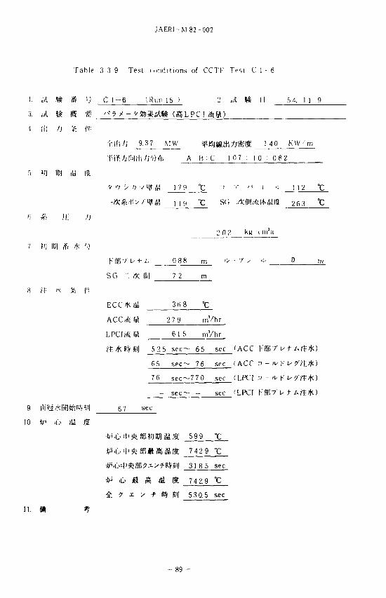
T a b l e 3 3 9 T e s t i o n d i l ions of C C T F Tes t C l - 6
I. i t » I t '•; C 1 - 6 ( R u n 15 ) 2 .A |$ I I 5 4. 1 1 . 9
1 !fi 'J ft ft
Ti l l ,0 9.3 7 MW JpiSjfilth/jSfBt I 40 KW-'m
f - i¥^ l» l l l l /J ' ;> f l i A • B : C 1 0 7 : 1 0 : 0 82
.ri w »! a i i
V -•; y ?; / ' U i!m 1 7 0 ° C i •>• / < i -i \\2 °C
,', 119 "c SO .MI'IMiM^ia 26 3 °C
•> 0 2
7 OJ 101 A 'K ''A
+ i . 0 8 8 m 'U
SO '. ft W 7 2 m
ECC/K & 36 8 °C
ACCMtlft 27 9 mVhr
LPC] i&m 615 mVhr
52.5 s e c - 65 sec (ACC Tf357'> t
65 sec— 76 sec (ACC => - ^ K u ?'7t:/tO
76 sec —770 sec (LPC1 3 - ^ K I ' f
- s e c - - sec fLPCI Kg(?7" u t
9. flffet/Kfl ftftft#%"'l 6 7 sec
10 *p ;il> itJ IS
*P 'L> ' l ' *8 l$«£ iSJ t 74 2 9
318 5 sec
•)P i> « I S S 742.9 t
^ ? x y ^ »# £l| 53 0 5 sec
11. fid #
- 8 9 -
J A E R I - M 8 2 - 0 0 2
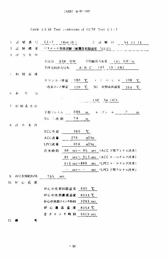
T a b l e 3 . 3 . 1 0 T e s t c o n d i t i o n s of C C T F T e s t C l - 7
1. ^ & (S '} C l - 7 ( R u n 16 ) 2. J. MS II 5 4 1 1 . 1 5
3 & & ffi •«:• '.<5'-9®m3Kmm<gmw&m TOO-a
V ill >) * ft-
t i l 1 , / ) 9.38 MW •VV.miW'VtiflL 1 4 1 K W - . n
T-i¥. hI'MHi /J'/} fli A B C - 107 1 0 : 0 8 2
m IBI iM /a v ••; > / j . - i f fdUl 1 8 0 t i i- ' < L 'V 1 0 8 °C
"c s i ; *(iiij/)itW./Mia 264
I 98
H /(; K 3fc f'l
3 9.0 °C
: 2 7 9 mVhr
LPC!tf t« 30 4 mVhr
68 s e c - 85. sec (ACC
85 s e c - 9 1.5 sec ( A C C 3 - * K I / 7 ' t t
9 1 5 s e c ~ - 8 8 8 sec (LPCI 3 - ^ K u frf.fc)
sec (LPCI
9. I'vHi'KBflstnWfS1) 79 5 sec
10. •&' ,£< Wi S
K 693
833.5
328.5 sec
#* '6 « £ £ I* 835.4 t
£ ? x y f- 1% JiJ 53 1.5 sec
m %
- 90 -
JAERI -M 82-002
1.
3
1
5
7
8
9.
10.
J.
A
ill
W
*
M
/!;
Table
I t <S •}
>J ft fi
101 (,'„' 10.
)l ; ))
x» ft 'K <;/
'K * ft-
* .0 <U *
3. 3. 1 1 Tesi
C l - 8
9 '') y
- * * • - .
KSI57
S G .
ACCrttt
LPCItft
65
'jj"1 ;|\\ til
'Jp iL* f-t
4 * .
(
Mill
>) •
u +
M
frt
•kt.
t conditions
(Run 17 )
It (- 'U-7 > -
13 7 M W
/j^/li A
•' H» dil 1 8 3
" N U 120
A 0 8 7
(llij 7 4 5
369
279
3 0.9
5 3 sec —
7 0 5 s e c -
7 7 s ec—
sec —
sec
M fi S
/ * n $i|
of CCTF
: B . C
"C
"c «;
2 0 8
m
°C
mVhr
mVhr
7 0.5 sec
7 7 sec
408 sec
sec
59 7 °C
900.5 t
18 3.5 sec
900.5t
2 2 1.5 sec
Test C
«k ^
1 5 m )
1 07 1
k _
( A C C
( A C C
(LPC1
(LPCI
1 - 8
11 5 4 1 1 2 9
1 4 0 K W / ' m
0 : 0 8 2
L •!- 110 °C
t<*(M/tt 26 4 t
• u 1 4 6 m
F3!7'ut Art-:*)
:i - ;u K U^r t*)
u.
- 91 -
J A E R I - M 8 2 - 0 0 2
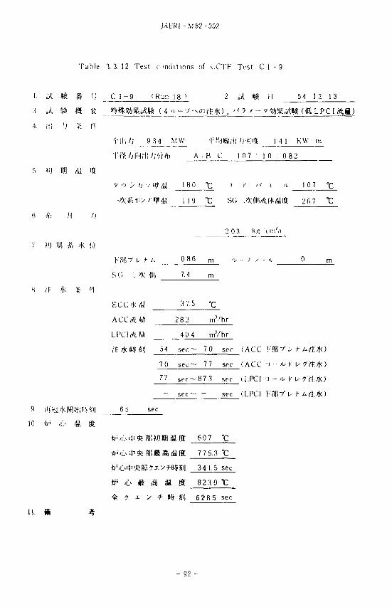
T a b l e 3 3. 1 2 T e s t c o n d i t i o n s of v . C T F T e s t C l - 9
1. J. I t rft '•', C l - 9 ( R u n 1 8 > 2 ^ & i I 5 4 1 2 1 3
3 ^ I* ta •«; mEgftifeaiS (4 a -
•1. in i) •£ n
9 3 4 MW fi'-Jtaiti /jftlft I 4 1 KW m
'\"ft.h\")l\\))'/)fa A • B : C 1 0 7 1 0 : 0 8 2
f. f;j 101 /U 10.
9 ••} y ij .- HVn.', 1 8 0 ° C ' '' ">' i 'i- 1 0 7 ° c
•tk&l'yrWti 1 1 9 °C SG * p | * ( / K « i a 2fi7 °C
fi * M h
2 0 3 k« t in"Vi
KfSiV I , ) - ; , 0 8 6 m
S G ". * ffli| 7.4
ACCMitt 283 rnVhr
LPClrfttt 404 mVhr
54 s e c - 7 0 sec (ACC F
70 s e c - 77 sec (ACC :> - ^ K
77 s e c - 8 7 3 sec (I.PCt n - ii, y
sec (LPCI V8R7 u- +
9- |ir*£>Kra<tf;B.Hi| 6 5 sec
10 '£P 'i * Z 5 f ?
i f f 607 °C
775.3
34 15 sec
ip 6 « g fi fi 823.0 t
f 7 i y f l | fi 62 8 5 sec
m %
- 92 -
JAERl-M 82-002
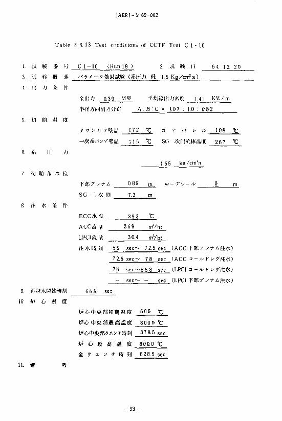
Table 3.3.13 Test conditions of CCTF Test C 1 - 10
1. St & ffi 'i C l - 1 0 (Run 19 ) 2 . A %k II 54. 12. 20
3. aC & (S •£ "°7 * - ? & » & % (%Etl (5 1.5 Kg/cm8 a)
1. II) Ai .% ft-
^ l l ' j j 9.39 MW f-fcJftllli/'Ji'ftia: 1.4 1 KW/m
A : B . C -- 1.07 : 1.0 : 0.B2
) « Iff
y •'; 'spi nr ?M 17 2 "c a r /< u- ^ 108 "c
-**.f^71<?7(lll1 u s t SG :MMMU\%. 267 ~C
ii; ;j
1.5 5 kR/cm';i
089
S G I". »: ffli] 7.3 m
8. rf: * % ft-
ECC/kjg 39.3 °C
ACCffiH 269 rnVhr
LPCISitffl 30.4 mYhr
55 sec— 7 2.5 sec (ACC TfiB7"H-
7 2.5 s e c - 7 8 sec (ACC a - ;u K
78 s e c - 8 5 8 sec (LPCl a - ^ K U / f t
- s e c - - sec (LPCl TS
9. Sa7kH&B#Si| 6 6.5 sec
10. *P ;L> S ffi
606
800.0 °C
37 8.5 sec
•& <fr g M S ffi 800.0 t
4 ? i y f Kf SI 628.5 sec
- 9 3 -
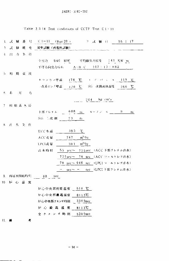
JAERI-M 82-002
Table 3.3 14 Test conditions of CCTF Tost C l - 11
1. J. S£ (S '•; C l - n (Run 20 ) 2 „£ t& II 5 5. 1 17
•1 i l l >J £ ft
'Nti/J 94 0 MW •\'V--ffll\\>r-titH. 1 4 1 K W i n
•\'\1>M\\'>h'>)<\\ A : B C 1 0 7 : 1 0 : 0 8 2
t
9Q "c sr, *(iniA^/mtia 26fi "c
'^0 4
0 8 8
SC, ". /K ffl 7 3 m
« ii: 'K % f'l
; ^ 3 9 o °c
ACCrftW 242 m3/hr
30 1
B5 SPC— 7 2 5sec (ACC KSB71 u t i.f
72 5 s e c - 79 sec (ACC :' - ^ K ^ 77
79 s e c - 948 sec (LPC1 n - ^ K u-
- s e c - - sec (LPC1 h'Sfl-T l / t Aft.*)
6 8 sec
610
tn -C> ft i€ fi
• ^ i y + KF
81 1.
330
81 1
520
3°C
5sec
3 t 5sec
- 94 -
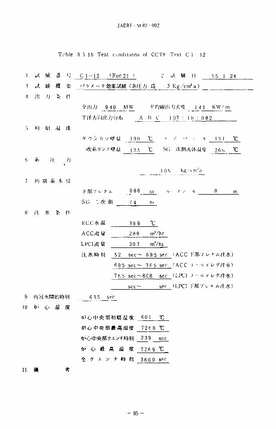
JAERI-M 82-002
Trble .1.3. 15 Test conditions of CCTF Trsl C 1 - 12
1. J. & S ' I C l - 1 2 (Run 21 > 2 J. & \\ 55 1 24
3. & m <s •«!• " 7 > -?a>i%a& (&H-:;J a 3 Kg , w a)
•1 i l l >] 16 f t
'fltiJ) 9.4 0 MW f i'.MU'Ji-Mti I 41 KW/111
l i M ) f l i _A_ H C 10 7 : 1 0 : 0 8 2
' / •"; > / j v H? C 1 9 0 " C ' ( • ' - ' ! ' i 1 3 1 ° C
- * * .-t- -y >' <?. u 13 3 "c s i ; * (iii| flit 1 a m 2 6 5 'C
n. /j
3 0 f>__ kg -cni ;ri
S 4c !>'/.
( • ' S ! 7 b f i 0.8 6 ,n 'U '/ y i\, 0 m
SG ". fK t l 7.4 ni
n ECC*ff l 39.9 "C
ACCofttt 28 9 mVhr
LPCInftSl 3 0.7 mVhr
52 s e c - 6 9.5 sec (ACC l-'fflSV
69.5 sec— 76 5 sec (ACC i - ' i - F U
7h.5 s e c ~ 8 0 8 sec (l.PCI -1 - - ^ K u ?'f£/K)
sec (LPCI KSPVu +
9 ltySi'kP4!te(KH~l] 6 3.5 sec
10. fr' O £ S
,lf 601
•tp .L> m M, U
4 ? 1 y f II
11. m #
726
239
726
360
0
9
0
sec
•c
sec
- 95 -
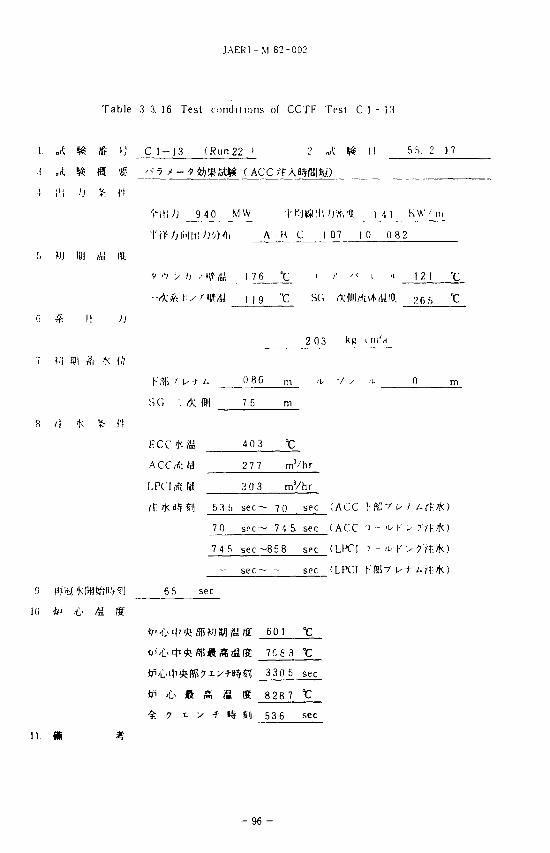
JAER1- M 82-002
Table 3 3. 16 Test conditions of CCTF Tesl C 1 - 13
1.
3
1
J.
ill ))
(ft
m. ' J
« •
ft
c ,<
1 - 1 3
7 i- -
( R u n 2 2 »
^%3?a« (AC
9 4 0 M W
2 A
C rtA«*fB|«)
5 5. 2 17
m
I 4 1 K W ' m
A • H . C 1 07 10 0 82
V ••; y I] .-lya | 7_6 jC_ ' '' "•' i " 12 1 "C
•-*#.|^/IM M J T_ SC,
fi * II J
2 03 k
7 »U 10! ^ r >K (>>
h;^ ' "U+/ - 0 86 m -u /
S G ". * ffli| 7 5 m
8 /I 'K * (1
ECC^KiJJ 40 3 t
ACCAW 277 m3
LPCWttt 3 0 3 mVhr
5 3h s e c - 7Q sec (ACC ( • K ' / l /
7 0 sec— 7 4 S sec (ACC ' ' - 'L- K U
74 5 sec - 8 5 8 sec (LPCI :' - 'U K
sec (LPC1
9 fijyKFflfc-B^J 6 5 sec
10 ^ .(!• (4i S
"> * SB
«r
IS
,fff
r?i|
K
Si)
601
7c e
330.
8 28.
536
3
5
7
t
sec
t sec
- 9 6 -
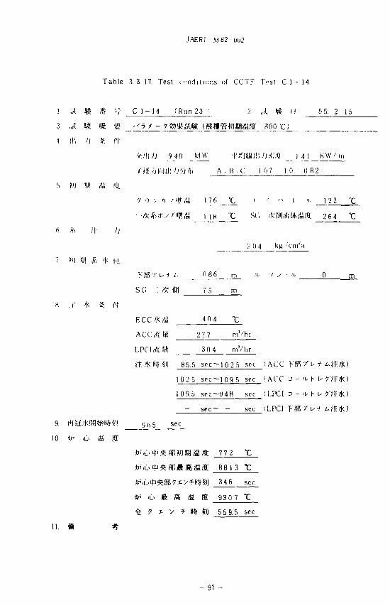
JAERI -M82-UU2
T a b l e 3 .3 .17 Tes t c n d i t i o n s of C C T F Tes t C l - 1 4
S '-/ C l - 1 4 ( R u n 23 i 2 , 4 $ 11 5 5. 2 15
3 .A 58 It «- ' - ' T ^ - 9 fll%&%(»«•£?ftJffliiaflE 300 C)
1 tl! I) £ ft
' r i l l / ; 9 j i 0 MW f^J(sa,'IWj;<;)Q J 4 J K W ' i n
I' tt h M i l l 'J '-•> Cli A : R . C I 0 7 1 0 : 0 8 2
r> W I!)) A! Id
SC,
kjj -
086
SC! '. * Bl 75 m
ECC/k i4J 4 0 4
27 7 m'/hr
30 4 mVhr
85.5 sec -1025 sec (ACC V % f l> + A it * )
102 5 sec-10 9. 5 sec (ACC J - » H - > 7
109.5 sec-948 sec (LPCI ^ - <u K
sec— - sec (LPCI >"ffi7"u
9. SM-'KI5fli!n':54'i| 9 fi 5 sec
! 7 7 2 °C
8813
34 6 sec
IP i I S S I 9307 t
t ? i > f ^ $! 55 9 5 sec
- 97 -
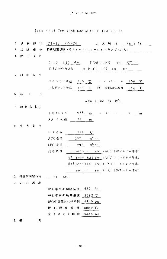
JAERI - M 82 -002
Table 3 3 18 Tes t cond i t i ons of CCTF Ti-st C 1 - 15
1 J. S# # '•; C 1 - 15 i K u n 2 4 - I A *& I I 5 5 2 2 6
3 d.(; K fflt # fflftfll^tS ( ') 7 < a- v - , u - -x .i > ft£ ff x (| \ )
•1 111 'J % ft
- r d i / ; 9 4 0 M w -J- * -j*tSi it: vj .*;i*j i .i i K W
v ••; > /; . -H^y 1 ".r ' "C ' • • ' - • : 'i 1 f>K "C
H 0 6 > „' OH
KCC >K AA 39 6 °C
ACCMtW 23 7 rn'hr
29 8 m ' / h r
- s e c - - sec . A(.'C ! %
4 7 sec — 8 2 5 sf r i A e' C > ^ K u
82 5 s c c - 8 6 4 sec (1.1X1 > -'i- K u
s e c - - sec (I.PC! KST.7 t + / • / I :
9. l*f iti''Km«ti^-f^'1 H I sec
10 tp >u (S If
6 8 9
P t * g fi
g: ? x x + »#
808
348
808
2
5
2
54 6 5
t sec
t sec
- 98 -
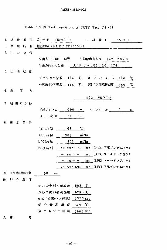
JAERI -M 82-002
Table 3.3. 19 Test conditions of CCTF Test C 1 - 16
1. Ht i S '•} C 1-16 (Run25 ) 2. & f& I] 5 5. 3. 6
3. IS m tffi f- te&V£.f& ( F L E C H T 3 1 0 5 B )
4. It! h % ft
9.88 MW f-fejjjg|ii;jtt;l3; 1,4 7 KW/m
A . B : C ^ 1.06 : 1.0 : 0 79
ffl Iff
u s °C SG • •^ f ly i lWag 2G3 °C_
))
4 2 2 kK/Wa
\:%-}~\s-r u 0.90 m '^ - 7" > - ^ 0 m
SG ._". * §\ 7.4 m
6 7
: 361 mVhr
LPCl eft !ft 40.1 mYhr
49 s e c - 75 sec (ACC
- sec— - sec (ACC n - ;u K U ?'ffi7JO
- sec sec (LPCl 3 - ;u K
75 sec -590 sec (LPCl T
56 sec
593
629.3 °C
13 7.0 sec
'C> ft g iS ffi 629.3 t
i v -y 1$ £i] 196.5 sec
- 9 9 -
JAER! - M 8;-002
4.
4. i
C 1 2 ...?!$ i M ^ ^ % { ' t T - L I 11 , . i t t«ftn . / ; . , Ti iblc 1 1 1 :- (." 1 - 2 ..A|ij i C I 11
M . ,U f; c ,'_ ' . h o
n.'.r. U ' - C M J . - U
. I l l 1 , he I I 2 - . ) . J l - i j ; . l 1 1 I M I U ' l l 'J Ml l i t
/ I 'Klii-]!tf;»-V4 |]i.i !> I K i | i y . 'KI ! i l ( i ; ; i i . ' i 4 i | i t I K f i .
t « i i l f * l l ( , t 2:i H \ A C C -i- - K I M " , | . | \ ' | I - I-
Kt ftll
1- fi n-i - ?-J it- ^ i i C A •*''_ /*: v ••; > '; •• i t i ' .L-L ;>^ tM;K(' r! i . C 1 2 , C I - 11 W M.j-iCt* i~
H. I I 1 ; : i , ^ 1 - ' L + / . ' / ^ l t K 5 ' ^ ^ - i ' I I T U , L 1 2 i c l t
Llc-Ttfr C 1 2 . C ! I 1 T I J i i l . . ] -X3,
t L / : • ' , « t K x. O n «
I M « 1 l r. : : K W i ' ^ - V i f i i t - u - v r c i h - ? " - c o i l - y j t U ^ ^ J t K ' W ^ ^ - ' j W - 2nn ttUijii
t l i C I - 2 i C I I 1 J^Wtzm^fSX:W.i'i^\ 2 0 0 » W ( « I C i i l ^ T C 1 2 I C l t - ^ C l 11
- v^HWjUi- ' ^ i iS ' j 20 » . f t i v +• > 7 S H T u
c i - 2 (cJtKL r e
' J-^l^it jf , C 1
I 11
2 i C l - I I i«l!i ' ! i ;(
- 100 -
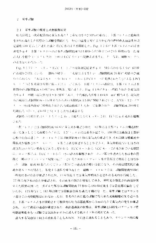
J A E R I - M 8 2 - 0 0 2
2 1 V.
H : / j V r S i - a - ^ r t t l f v l ' - K ; fe'<i « - * . ' : i : * l f : ) ) * • 0 2 M I ' . J c H i ? H , 1- M ' i- <
r A 1,1 A . ; • ' ] ( ' ; i c . •-:. M i ' d - i f i i ' - ' r • • , / t M ; : . ; : i •.>; ( i • . . . t W I i l l V n * 7fi ( I r ^ l i l o r - A i
/ ,> ' • . .•,< i.-:, ',• ' ^ ; ; , i ' K t • /;. . u i ' i /<>.' . l . l ' C I i i - r ftl*.'-^/::. ,'_•".!. 7~> I . I V I
i. ! - " ' i , : ' M i . M : m ' i i i i | : ' ( / v . " . . ! : ! . ! . i 1 , • > , - : , 1 - 3 : ' t t - ' . ' U f H ' / . M . l - f f i ' i / - ' . , ( / ) <
H i | | : ! | ' l ^ ' ) , A ' W l l i l « i i v ( i : U i - ; - - i j ' . i . ' f f i i ! \ , Y . I « r i t ! /•, l ' ' u ; -1 1 « '" -'-»'-i • • - ( U t t A < i / - f - U U l l i
' J ' . . | . . | M I I V l . ' i . l , ' - ' ! ! 1 , ' j : t ' • :fi. M W - , t , : j , t t ' j S f l l ^; i l ' . ' i« . M i i k W m r H T " i J o i U ' - U I :
W P I i l i 'J 1 7 i ; ' . - i n i i H- ; u \ * i e n ; ' j ; : A i w ..' •:,
. . i t l fc i lV i . ' t t ' ; V-•!•'.:!. '• - ^ 'J ' ' i l i ; . ! J | i ; ^ ; : 1. 0 i - v - \ i \ . n I - ; : ,j
^ i i /:
I f a / 1 L. * . • • • r : i , ^ ! S « l M 1 ] 4 f i ( * i ' i n i l - i - - ; A ' < i . i ! : ! ' j - ( « » ! . ' . ^ n / ; K I H - ; : : i I a ; - - ' i. •' . ' - y ) f f i i a -
Z n . i ^ f t 'Kc r , ' ; i | r V j ^ ' J i i L "C>•* ^ . I '"11 ' ! •K.WffifA.Z * i i * i r f r i A \ ' M
7 7 » / 5 > . j 1 8 0 f i ' i i u i * i T l i R K S R l c f t j / / " L T
- 101 -
JAERt- M 82-002
CCTF
•I'^'M .'.'.'.It•'".;.-<i-l,'."]y'i 'in i f tc i(••]#... L/:f«"'rT!-")/T.l l .?--cn :c UA,<>1 "Ct "o t'M'-jr j ) ,* 11.
I t hum I- X -VJ - f i l Z t i ' l . i W i -<X;ut'f ' Ml*-jtt-ft W) i ! j . ' . a r c i >£ ; £ fy.iUi<Z> *><
•r.'^.iL.'i Fffi ' u i -•.*••'. ACC .'K/JVI. 'K raftf; znz ' : . ' js f* • ; L . ' .' ') tCf/jir-i -:• t»¥1H>vi
» a ; l-«,;. ',;•;, _ ' - : H I . ' j ^ S R i f i i / j ^ " ^ 1 m r . t , ? . 'k-'-ftto.hlid * <l - : . i : j n mAq^-'Kwft..1; /J ;
' j V f S i a i i i i i f t » f f l : i - j ; « i / - > i : : i A < f i a n i ' ( < ' C ( A / : ^ n / : . ^ u . c t f r ' i J -:, K I I I I - . L C . - R . W : ^ n . ^
i ' l , ' , 1 ^ : - !. ;) tt.«ini; l - t t 1: ') I- / j . ' IM l . l ' K r .1. 0 A / : M i . ! f !- c'i,IV ^'^UlU1.1 '. i'.i iaVUX'C
'.". : ,'. .Vd!IVj-y).",il i/- ii3 y\irA\''.W '<t®\% hiZi'ii I /• a t t r A t "C • ' ) / ! 'Kii-V-'i: t. 1-
1 1 . ' .JJ•••.(« ' t •! ''••> i ' ' cc I- 1 i - ' t l ^ o - i i / • 1. / : 7<; w ; - A I V 1 •• ^••". I . I H M
' • ; - O * '••!!. , | \ ' K l i l / j i * ' j 1 ' ) , ' _ ' i .'• •L",|-..,.-),'f i | - 4 ( | ; ; i I „,'. i , | f t M - : ' . ; . U 1
l ; i « . I 1 ' ! . : . . I ' j I i ^ f i / i W E . ' - J i S J ' j ^ f ^ - " l ' ' r . ' i l i i c ^ i H i a i i . - r ^ - i - ) i I ' l l H i - . ' . ' . , -^ i
i " j • i W ' ' ; - : . iu,:':i (f,iltLljr-jKnn C'C.v.O, v i > -r n; f ';i|!.irj :<(in H 'C ,^ r, •> , -y i ;
> !• : t T i M j - ' l - ' i l l ' j ' ;>0 i r . : t j : . ' , . ) : i : i • * n l f t ' j i i j l i n L C ^ / ; t /i-b >.L.' I . ' j t i i i- • '
H. I . , ) ' £ ^ . - , . I , . , L , - C . - ) « I * / ;-r" i( i%.' i . ' i . ' i - * 'L i 1 ! H S i L
I M « . I 1 \2 ;z '•••••: •r--lii?A:± i|. ' j t f S f t . X i ^ t f i f i t - j . f
V-,%. 1 1. 12 T ? •'; > •f.^-''Kafi^n.1fi:H-S;ft:t*!:jil;-^<1 J;T :C ECC 'ky)* l . 'k*- -« ' 5 : f l : i
-*j -?;t)Wrt,Vi ']<;c4; 0 ffi/jn-4- .. 63 » i : rft{,V.(J'bi-L-o«t«Si: K« i : i* L •ti'.L.'T«^'<ift't-. A*
W;^ n -o i . ' iUiU o, 67 f'X; ECC 'k^ ' l - \4Jnliii ^ - ^ H ^'CUJtft^. ' j l l / : t /; 76 ft'
!iH:'k'-- i-MACC't-K/).. ' )LPCH:- K.cUJJfix. '>U. F.CC'kO^f|I^tt;i*'j 1 9£
- > ^ c ' - 'i- K u *' ^CD?1:^K*i L P C I t - Kirtfljftx. i j t l i : i l l ct 0 . S C I * > ' " J « * ' < ; M : ^
ic «t \-T o J; -i i : ' i 'oo filfclSf 3 - -u K u /-^^tHJ-t Z fctifi. Rlli LPCI * - K ir t i i 'o i I") B.'f
- 102 -
JAERI- M 82-002
>.'• ; '." £ i n n f m
U ^ 6 ' d f l ] i ' ' x ' i - i l f c ' 4 f i d m A q ' C .*> O t ' j l l fi m A q (IV L> d f r C J j o
f 'K / j ? ' - f t ' j ( r i l l ; - i "J ; i " S V J < ^ x . . • , ) ! ' : / ^ j L '. • * # « > ' ; t f l i K i ^ - c : . t ; i : ^ '
. L I c o r , c s c ( f V i a ^ i ' K . , ' , , ! I V / T ' j / > : , ; - . ! v .'„• r . . | ' ^ , ( , . /, •1-M t f i! l iM ldi C , , | W H i
f V K l <•" , , ! [ 1 , 1 , / ) A f l " ^ i i > ' V l A, A i l / ' ' » • ' . , ' ( . v . 7 ; '., . - ; > f , ; i . H / l / ' , i ; ! | i - : i ; . ! 'k C«% /• .'• ? l . •; o>
' K i t . i i ' ' . • i ' l j n » A < i - : i ^ > , l o o f t ' l ' i I • . • 1 ) | ! i i . " ' •' ' i i k y - : . 1 - , ' ) . I ' , ) • ' ; r, v ••> i> .• ' R i n ' i
A - M ' K : ' 1 •:> d ( 5 ' ; •• ' ' ' • > | I K « ; I W , I I I | k ^
J -1 I X ' V I / . ^ r ' K ^ ' l
I-" 1K". 1 1 i s r . I ;".<:•' t- -»- i.yvKin'i. P u ^ - j - 4 I 3 ; ' L •) 7.1
f, s i ^ j t u i ' i i o , 0 , -b i ,L ' \ i I,-I!LIIU') F. • ,JJ>.', ir> r+ fvia.i; tn" i J o iil
1; I; n y r -j fU1i;-r i . l£t t«W)!/ . ( ! i ' l ; : , i ; o *'<tfC'l-.hi5.-11'.49";:,,t« c > ' ; iH. ' rc tn ,C-i l ' , i
^ r f a ^ ^ f t i l i i c . t ' o '* '<v^ ' ) - : ! i l ; i . i ' i 'L^M^dlil 'L'Wi;^- n . i - , , t l l L .':?,', '4lc i n i i . 300
i n n HV)!!!]-c*'j I k)> s W r ' f : 101IA5/fit '"C I . , * ' / u .' .'• "C !• •> ' ' n i t i f l S
s i ' o i B 5(1 f. fr \.1ft-' u- -t A - 1- •; • -' j n « : i i : i j f c L C t - o .
\;%Vi i- / . -Co ' )^ /K m n . l.ffi v 1. <- . ' . t i l l . IjUlk I'n . 'tW 1 •?•(.'"' Eq. 171 ICi< I fi
Fig. J 1. MI ;M1V-~ - ra i l : Wil'k \P , iWlfi"--VODH^JJU-X .P , ,S - I^ - fa^ ^ - v
3 't---'({-(i:.tzt>\ ^ I t f J W ' i - yz^llJ]liy><n!.liz?, I ^ Kip. 4 1 I 5 i : ; j SG.'li
I T u+ A j) KnKicM-ttfA: t h -•?? 1; J; ^^flftGWI'^.V^S-'h t ( a t " - - ' ?-Min5«'4
t " - - v - 3 ' t - r i t,izizim -(Dttw.&i, ,xts>), a t " - - -' 3 • i - 7 i ; i ) r « - 7
Fig. •) 1 1 5 c V^ru t /*i&Q.t>i*>i-L<%m?$ Yl$L^i$1-Z r,3 ®fr>', 01!
- 103 -
JAERI-M 82-002
A P , £ © K ? ^ - r o E / : i f 0 * A P
Jf>5. A P B i A P , O l l i , Eq
£ fcic, ©«?=> - ^ K u ?V xn>\ctsttZR1M'kl±ti!MtZ>o 58»T=> - ^ Ku ' / / x
±& L T(JIJT.ilSHE03* - ^TT* 5O «?lfr ^ - ^ K u ' / / x
m,, £ { 0 ! ^ ^ - r^iffi -> Titan hifcU\ m , ffl-,«;i|ft^'S
Fig. 'I I. 16 \C SG Al )?\s± AiiUi 17'u-J- y , i •.ftfflijnftAifllia'S-'.i^",, SG Al I V i / t
l I 7 u ->- AcOy^jHlffii lili' -ft L ^., J; A: SG (111 I W->
Al I •/ ^ ')• AOfi'dfll^lft: J: 0 t'i> L H W J ^ I H ' C C * ? . ^ , •c«;i;':ffl
C- * «f ¥:/{f-C* -» fc,, S G ©(f 11J 7 u 11. ic te (•/ 5 MWM If (i ^ki *U!W?H.V 4'i| 63 fi)> ic Jb
L,*, 120fJ»Jil|!$r-(*li!i'220 •CliJiiftlC^L, r « m i i l J -'^T*>7oo SG *
L r«'xUP-ffl^©.«\fe;a*^fe)i: I it * r 'HCi 5 SG HIM 7 u t Acofflffiii 216
L fc*< ••> T
Fig. 4. 1. i7lcfi£t:3-^Ku-^lcfcW5 ECCffi*i$l£- SG
ECC •+-- h5•(i^^-e«[E/)J^;£•']"^•ro 76&IC^;)<* - KA« A C C t - KA>t) LPCI * - Kit
S£^$n/-:^feic, ECCa7KiiHE(± j 1 ^ ' i i t , ACC-e- Ktrfi,
s t i twLrje^sf t£af-f t i^<saz-r5 £ SG*>h<r>
- 104 -
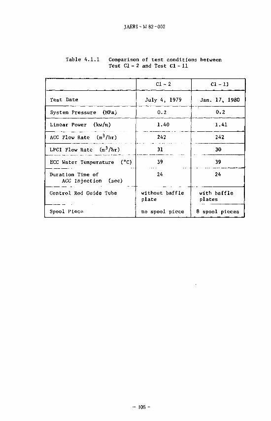
JAERI-M 82-002
Table 4 .1 .1 Comparison of t e s t condit ions between Test Cl - 2 and Test Cl - 11
Test Date
System Pressure (MPa)
Linear Power (kw/m)
ACC Flow Rate (n\3/hr)
LPCI Flow Rate (m3/hr)
ECC Water Temperature (°C)
Duration Time of ACC Injection (sec)
Control Rod Guide Tube
Spool Piece
Cl - 2
July 4, 1979
0.2
1.40
242
31
39
24
without baffle plate
no spool piece
Cl-11
Jan. 17, 1980
0.2
1.41
242
30
39
24
with baffle plates
8 spool pieces
- 105 -
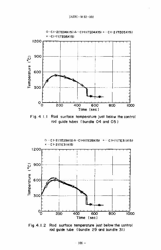
JAERI-M 82-002
O- C1-2(TEO4XI5) A CI-1KTE04XI5) + C 1-2 (TEO5XI5) X-CI-1KTEO5X15)
1200
900
600 a> a. E
300
°~ 200 400 600 800 1000 Time (sec)
Fig. 4 I.I Rod surface temperature just below the control rod guide tubes (bundle 04 and 05 )
O CI-2(TE29X15)A -CHKTE29XI5) x C1-2(TE31X15>
CHKTE3IX15)
1200
200 400 600 Time (sec)
800 1000
Fig .4.1.2 Rod surface temperature just below the control rod guide tube (bundle 29 and bundle 31)
- 106 -
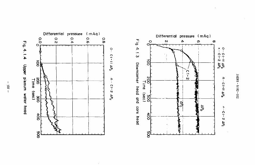
Differential
C
o
I
_ •s c 3 S a ? 3-a a.
pressure p
( mAq ) O in
o o
t>
o
to
OJ
O o
i
Q CL
a a. o o
3-(D a a.
O O
ro
(D
Differential pressure (mAq) ro ji o a>
-
; i
•
r
0
11
1
---
x O
o
+
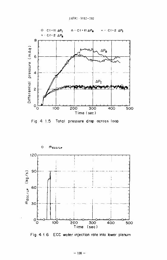
JAERI - M 82 -002
O CI-I IAP, A ' C t - l l i P , + CI-2
x CI-2 AP8
Q .
S 2
•
-
L—^^r^
APj
-
100 200 300 Time (sec)
400 500
Fig 4 15 Total pressure drop across loop
o ^ECC/LP
(20
°0 100 200 300 400 500 Time (sec)
Fig. 4.1.6 ECC water injection rate into bwer plenum
- 108
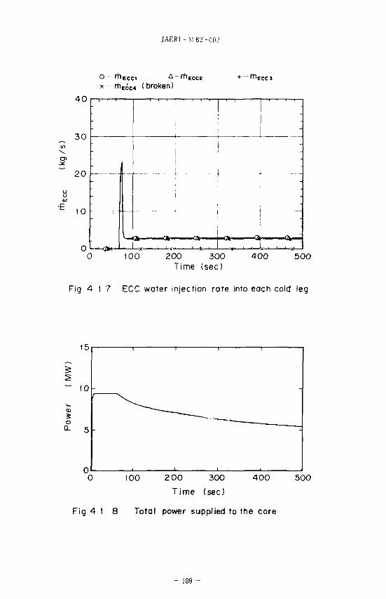
JAERI - M 82-002
o • r h c c c 1 + ••• r ru
(broken)
4 0
30
20
10
0 1 - ->o • • L 100 200 300 400 500
Time (sec)
Fig 4 1 7 ECC water injection rate into each cold leg
0 100 2 00 300 Time (sec)
400 500
Fig.4 I 8 Total power supplied to the core
- 109 -
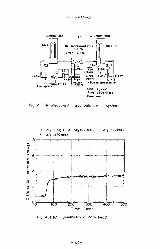
JAERI-M8C-002
- Broktn loop
S 6 4 D«-«ntralrm»nt rate 9. I I %
Error : 6.4%
I 484 (St»am) 9.701 I 3401
(Wat»r) L l ~ 3 " Due to condantotion
Unit kg / i tc Tim* 35O±IOt»c 8a** rot*
2.967
Fig 4 1.9 Measured mass balance in system
o APC (Odeg.) A AP c (90deg) + &PC (ISOdeg
* APc(270deg)
100 200 300 Time (sec)
400 500
Fig. 4.1.10 Symmetry of core head
- no -
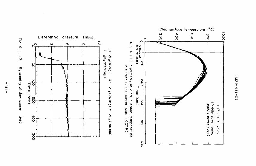
Clod surfoce temperature (°C)
IV)
CO
3
a. o 3 O
o CD
3 (D Q
a.
Differential pressure (mAq)
O"
d o 3 at
en x O
1 ro o
a. C » —
-
-
\
o &
00
o
f
31
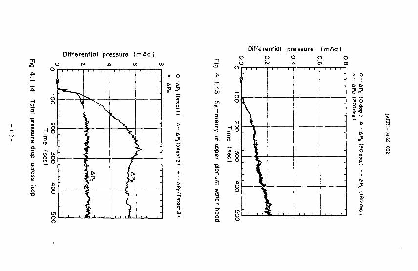
Differential pressure (mAq)
i
sure
Q. rop aci
5 (A in
> l00|
o o
w H8 ^ o 3
300 (sec)
400
8 1 1 1 1
I 1 is
} r
-
-
t>
O o
> >
I
OJ
3 3 a>
>< o
•s 1 3 CD
3
a
Differential pressure (mAq) p p o p p b ro *•& o> a>
z!8 CD
o o
k - ) 1
I ,,,,
----
[ ; I i
X O
N O
2
3 o a. a a
CD O
0 0
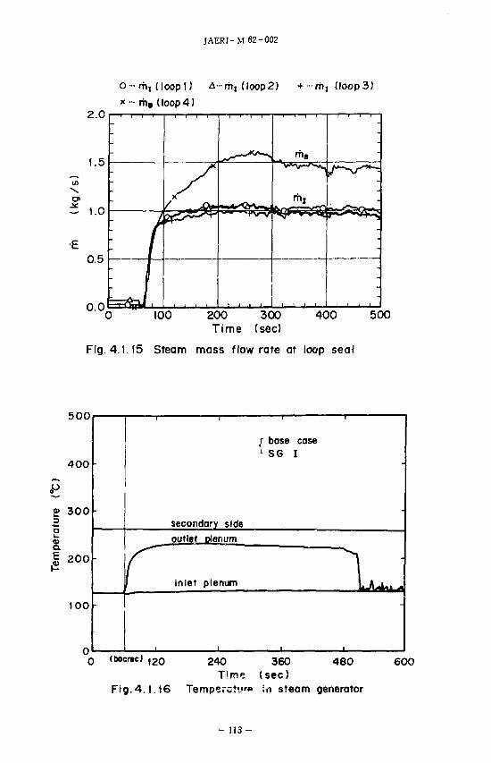
JAERI-M 82-002
o - mt (loop() -a-rhj (Ioop2) + -rhi (loop3)
* ••• rh» (loop4) 2 . 0 i . i i .
'0 100 200 300 400 500 Time (sec)
Fig. 4.1.15 Steam mass flow rate at loop seal
500
400
p
£ 300 3
2 &
£
100
secondary side
outlet plenum
|| inlet plenum
r base case ^ SG I
1
(bocrtc) 120 480 240 360 Time (sec)
Fig.4.1.16 Tempera?•_"•» in steam generator
6 0 0
- 1 1 3 -
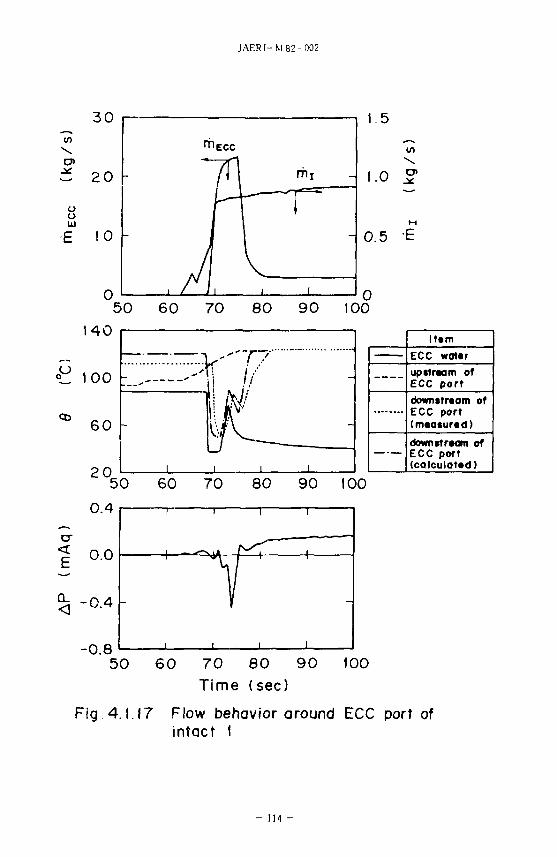
JAERI-M82-002
3 0
O>
o o 111
E 10 -
140
C 100 - .
60 -
2 0
1.5
1.0 51
- 0.5 E
lt«m
ECC wot«r
upttraam of ECC port
downstream of ECC port (mtaturtd)
downstream of ECC port (calculated)
50 60 70 80 90 100
-0.8 50 60 70 80 90 100
Time (sec)
Fig.4.1.17 Flow behavior around ECC port of intact I
- 114 -
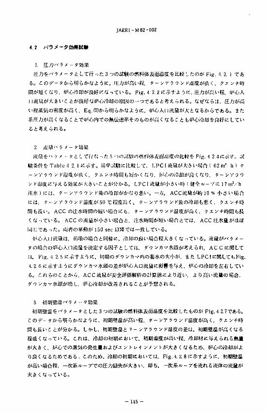
JAERI-M82-002
4.2
iF\g. 4. 2. 1 X h
§l>gi, 9-yT y V y KSffi fS < , ?xy*ttf
f\$\i>m<t£iQ, &<b<fat$t>SMlifr-t£-,X^Z>o Fig. 4. 2. 2 i c ^ - f i - j It, E ^ K ^ H . *P<£>A
*£&*£%If,
2.
-5 X - * <!: L Tf f « -^ ; 5 '3<?).i.C*«in*»rK+AifiH.l/Q:tf)lt«f«- Fig. 1 2. -) iC j i to .it :1& Table >1. 2. ] IC/j*<tu M:(Vi«)tB!lcitWL 'C. LPC I MtlftA<A;LU>Jyrj ( 62 ms. h ) 9
yyy^y h'iLVQWiH. <, >j x y-f 0.VIII] t.hb'j> < y 0 , •J}i'C>tf)?ftii|IA<m < If 0, V - >r v •>
Kfflffiic '5-x. S5E()Mi*s A * l> C i **i>/J>So LPC I «£H*>''J^^ ^11,', ( | i | ^ ^ - r i c 1 7 m'/ 'h
, 9 - v r 7 ^ ^ K»(O?ft£|]*«A>« Office - / ) ' ,
vTyQv KiSffiA*50 t ISfflW < . ^ - ^ T ^
ACC
iso sec ja
£ L t l i , ? ' ^ > * T * R i i A J % i t > n , A C C
(i, Fig. 4. 2. 5
4. 2. 6<c
8 L,
y* v Ytf-kk < UZtztb, )p<L>
CtDiztb. ^S|l©ffi^ltfcl>Tli. Fig. 4. 2. 8 ic^-^J;^ ic
- 115-
JAERI- M 82-002
4. 9'0 V *-7§|S^-7 * -9%1'M;
?"<? y+i vBgig£^*7 * - * i L / : 2 oaagjOft^WMnSljES- Fig. 4. 2. 9
KBStS£^;l, Fig. 4.2. 10f£/fv
* fc Fig. 4. 2. n ic^-t-J; -5 ic,
L, tolMicfciPTIi, [iTfl#ffl?' vAT^Kifflliliia'^L <. f3*^, Ift?"^
^ T Fig. 4 2. 12 fe<fct>'Fig. 4.2. I3 ic^ t .> CtX
T ' - 'y ( i , •Jj>-C.«^K>(OflS5<tfiti(ili&.eiI*-i"5 t f l T , Fig. 4 2. 12 ic,j';t.t; -j
.«e!T-(i80 sec tftic Fig. 'I 2. 13 IC,j<t'/'^ y *
. 'Jji'L'-ewftM;ic j ; 70siiit>\:.w\:.•$ z t y>t?n y i *> i i n s * n *>„
5.
Fig. 4 2. 14ic,j::tc o « f - ? ^ ^ , [.Tiifi'li, *>« f3lPJfc^£H^fj5-,]< L, Mi
«tH5: Fig.4. 2. 15fcJ;O' Fig. 4. 2.
; tat, - » : * ^ -
:*^oA>5o 6t->T, ffi
-OAriJitEi mfl: FL, •bi.L' £|]/5\t;< ' i 5 i ? i i n 5 .
Fig. 4. 2. 17 ICfx Lfc iS^Wii lSSlSdl tK*^^*^ <t TlCtP-D h^TTW^a^'lK , Fig. 4.
2. 18 ic,f; L/: J;-5 ic
l i . •*P'
-So
6. ECC &•&><? S
ECC /KS«"*7 ^ - 9 t Lfcatg8O«81sK**iSiSffiS-»«^aeiJtt2Lr Fig. 4. 2. 19
< . ECC
1 141 sec
, ECCKM, ^-v^mtizm'
KlCjJiLTl>5a
- 116-
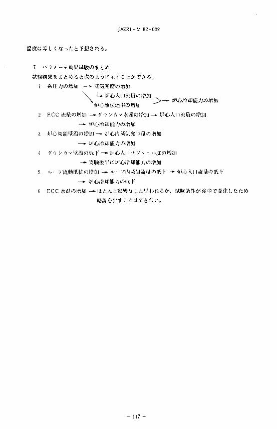
JAERI-M 82-002
7. '<??< -*%}$>M%ti<Dt Lib
2. ECC MtfilotW/JD —•• 'Z<1 v ft
(i ECC
- 117 -
c V
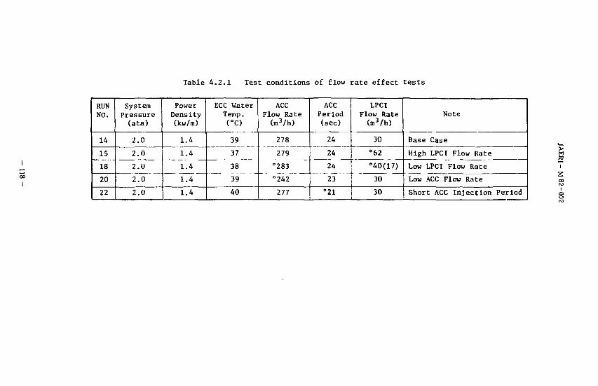
Table 4.2.1 Test conditions of flow rate effect tests
00
I
RUN NO.
14
15
18
20
22
System Pressure (ata)
2.0
2.0
2.0
2.0
2.0
Power Density (kw/m)
1.4
1.4
1.4
1.4
1.4
ECC Water Temp.
(°c)
39
37
38
39
40
ACC Flow Rate (ni3/h)
278
279
"283
°242
277
ACC Period (sec)
24
24
24
23
°21
LPCI Flow Rate (m3/h)
30
"62
°40(17)
30
30
Note
Base Case
High LPCI Flow Rate
Low LPCI Flow Rate
Low ACC Flow Rate
Short ACC Injection Period
PI 2
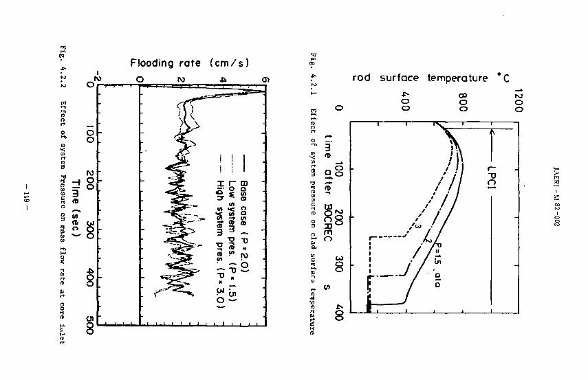
00
3 n m
Flooding rate ( c m / s ) o ro *
oi
8
-
•
•
• ^ "
*y^
•
1 1
igh
w
tem
3
*^ TJ H
OJ
b
i
r~ o
>< c ^ <B
3 pre
*—» TJ H
-
-
ase
o o (A (0
"D H
!
o
-
"3
00
rod surface temperature *C
33
i 2
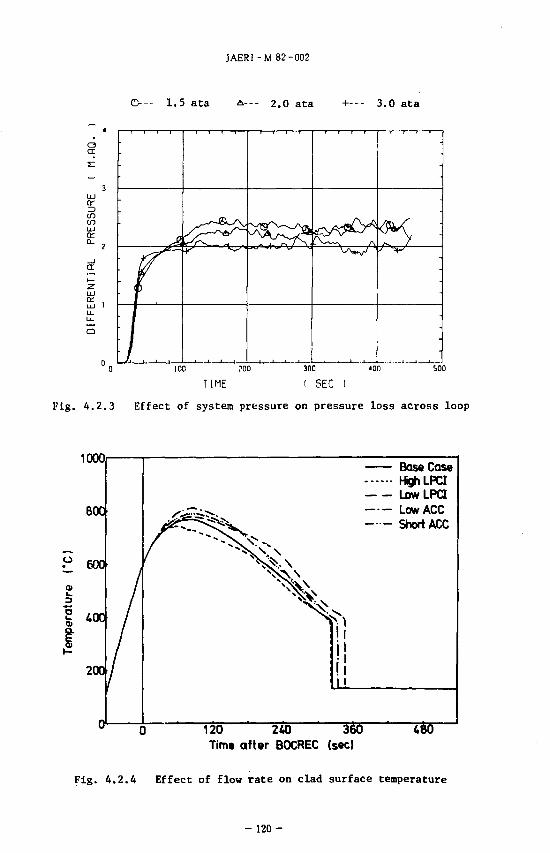
C3
ID to
cr
01
JAER1-M 82-002
©~- 1.5 ata A--- 2.0 ata +--- 3.0 ata
100 ?D0
T I M E 300 400
( SEC I 500
Fig. 4.2.3 Effect of system pressure on pressure loss across loop
1000
•° 600
3
"5
200
Base Case HghLPCI LowLPCI Low ACC Short ACC
"120" ' 240 Time after BOCREC (sec)
Fig. 4.2.4 Effect of flow rate on clad surface temperature
- 120-
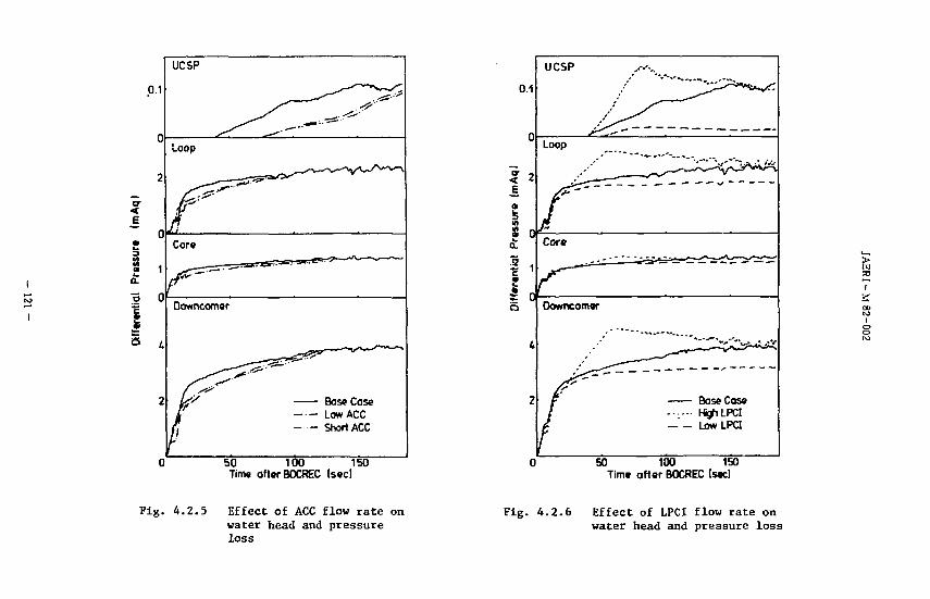
P 1
0
2
e o
1 ' o 0
UCSP
Loop
Core
Downcomer
Base Case Low ACC Short ACC
50 100 150 Time after BOCREC (sec)
Fig. 4 .2 .5 Effect of ACC flow rate on water head and pressure loss
01
Base Case HghLPCI LowLPCI
50 100 150 Time after BOCREC (sec)
Fig. 4 .2 .6 Effect of LPCI flow rate on water head and pressure lo s s
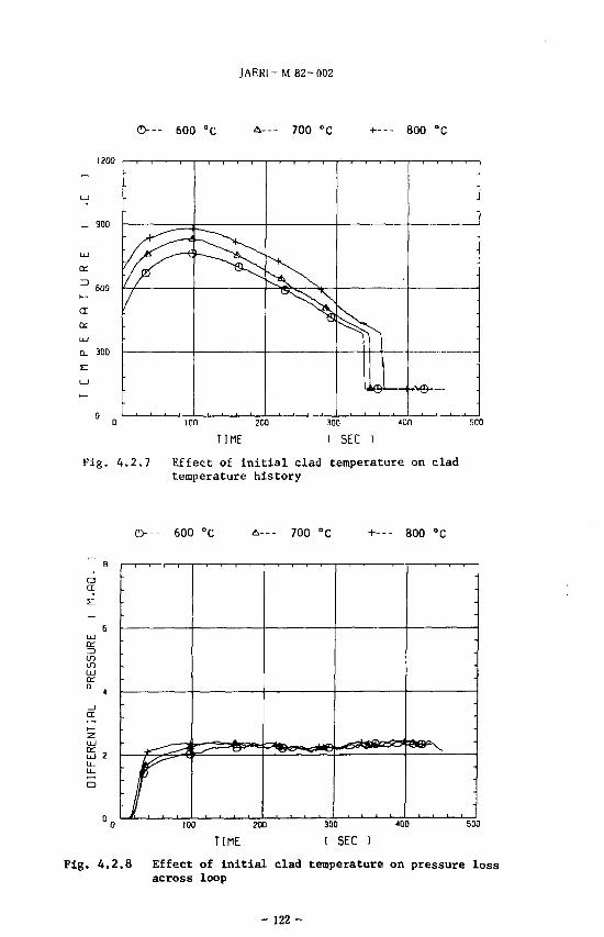
JAER1- M 82-002
©--- 600 °C 700 °C +- - - 800 °C
l?00
100 200
TIME
Fig. 4.2.7 Effect of initial clad temperature on clad temperature history
O-- 600 °C 700 °C +--- 800 °C
o a;
if) in
or
D f
•
•
•
-
100 200
TIME 300 '00
1 SEC ) SD0
Fig. 4.2.8 Effect of initial clad temperature on pressure loss across loop
- 122-
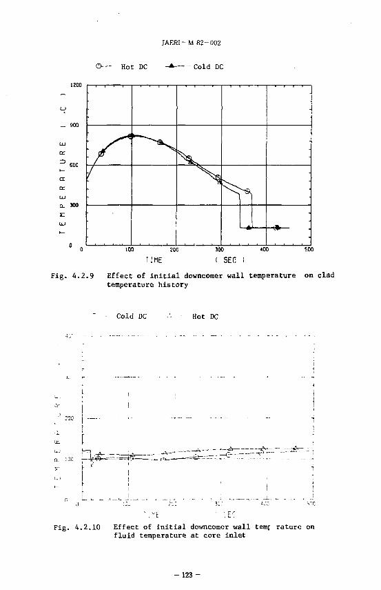
JAERI- M 82-002
©-- - Hot DC -*• Cold DC
UJ or
= > 600 t—
a oc UJ Q_ 300
71
I • 1 1—-T —
-
•
•
100 200
TIME 300 <00
SEC soo
Fig. 4 .2 .9 Effect of i n i t i a l downcomer wall temperature on clad temperature h i s tory
Cold DC Hot DC
200
o_ i ac |—!i;< ll——6 r *"
Fig. 4.2.10 Effect of ini t ial dovmcomer wall temf rature on fluid temperature at core inlet
- 1 2 3 -
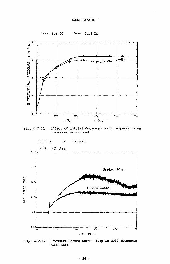
JAERI-M82-002
Q— Hot DC -— Cold DC
o CE
Z3 CO to LU cc CL
2 UJ
•
*
1 / •
A o ~
•
•
100 200
TIME
300 400
I SEC )
500
Fig. 4.2.11 Effect of initial downcomer wall temperature on downcomer water head
Tf-:coi NO 12 i-9.07., 31
CHART NO 265
5 1. CiQj
Fig. 4.2.12 Pressure losses across loop in cold downcomer wall test
- 124 -
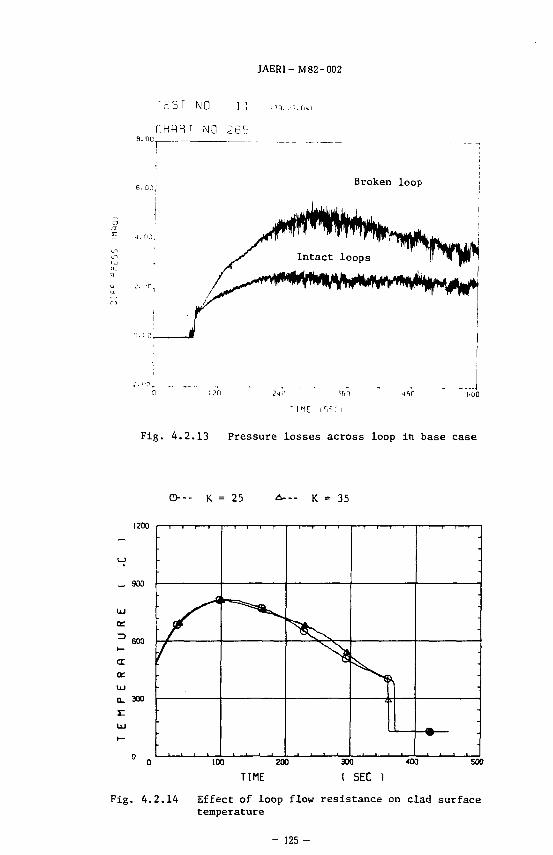
JAERI- M82-002
TEST NO
CHflRT NO
Fig. 4.2.13 Pressure losses across loop in base case
O-- K = 25 K = 35
1200
_ 900
600
UJ O_ 300
f i.
•
•
•
100 200
TIME
300 400
( SEC ) 500
Fig. 4.2.14 Effect of loop flow resistance on clad surface temperature
- 125-
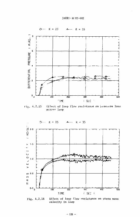
JAERI-M 82-002
O--- K = 25 A--- 35
3 1/3 ID UJ
100 ?00 T IME
300
I SEC 400 500
Fig. 4.2.15 Effect of loop flow resistance on ^jessure loss acros« loop
Q--- K = 25 K - 35
100 ZOO
TIME SD0
Fig. 4.2.16 Effect of loop flow resistance on steam mass velocity in loop
- 126 -
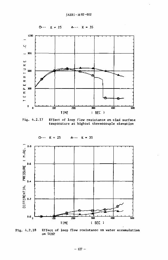
JAERI-M 82-002
O— K = 25 - - K - 35
1200
CJ
_ 900
LU
or
3 BOO i—
cc
oc
LU
Q. 300
•
— * -A
k
100 zoo TIME
300 400
1 SEC ) 600
Fig. 4.2.17 Effect of loop flow resistance on clad surface temperature at highest thermocouple elevation
O — K = 25 A--- K - 35
0.8
o en
0.6
en to
(X 0.4
0-2
0.0. D V>
h—e e — * -*
•
D 300 400 500
TIME ( SEC )
Fig. 4.2.18 Effect of loop flow resistance on water accumulation on UCSP
- 127 -

JAERI-M82-002
1000
120 240 360 Time (sec)
480 600
Fig. 4.2.19 Effect of ECC water temperature on clad surface temperature
- 128-
JAERI-M 82-002
4 .3
LT FLECHT*££&i8<i PKLJg£Sti$£ff->fce Table 4. 3. 1 It FLECHT
-16 £ FLECHT
Fig. 4.3.1
t'-*Vf/7 7 V t -it 1.67 i 1.49 T?£3O FiR. 4. 3. 2. ID
LPCI
ilfi'lffifASo FLECHT
•> > * v^o/Wlff^- Vic * - '< 7 o - J-U-^i .fi{tc LPCI MtWl- A/i
o Fig. 4.3.3
i .ccTFO/J*J FLE
CHT l e t t e r <t^CiA^A>5o Fig. 4 3. A ic ? x v-fx y < n -7<©Jt$2fe:5R£v;f<!h, i1^
, CCTFOf-)i]IIi FLECHT
Table 4. 3. 2 ic PKL K7Aagl i PKLiS&aei C 1-SH4 H v S PWR
- 129 -
JAERI-M82-002
Table 4.3.1 Comparison of test conditions between FLECHT 3105B and CCTF Test Cl-16
RUN NO.
COMMENTS
Containment
Pressure (MPa)
Peak Power
(kw/m)
Averaged Power
(kw/m)
Axial peaking
factor ( — )
(*°ACC flow
rate (kg/m2s)
(*1}LPCI flow
rate (kg/m2s)
ACC injection
time (sec)
ECC water
temperature (°C)
SG secondary
water level (m)
SG secondary
temperature (°C)
Initial clad
temperature (°C)
FLECHT
31O5B
0.407
2.76
1.37
1.67
392
valiable
14
66.7
7.3
267
593
CCTF
Cl-16
0.415
2.78
1.47
1.49
386
42.8
17
67
7.4
263
593
Note: (*i) ; Flow rate is determined based on core flow area.
- 130 -
JAERI-M 82-002
Table 4.3.2 Comparison of test conditions
between PKL K7A and CCTF Test C1-SH5
di ft (MW)
m » * it (-) » (-)
» SIS £ * (m)
it) ft» *
ft'lff (KW/tn)
3j .6 M10) U IS. CC)
PKL K 7 A
1. 4 22
337
0
3.9
1. 1 7 : 1 0 : 0. 9 2
1 19
1. 0 8
7 2 0/650/630
CCTF C1-SH5
7. 0 9
1824
224
3.6 6
1. 02 : 1 0 : 1 0 1
I 49
I 0 6
6 20
ECC rt A C C Tr- K l A C C * - I-J; I") LP " I
ECC ;K
S HE ft
CO
(MPa)
35
0.4 3
43
0.4 3
single intact 3 8
double intact 3 7
broken 7 2
intact 1
i ntact 2
intact 3
broken
- 35
- 3 5
- 3 5
- 3 5
- 131 -
JAERI-,VI 82-002
2.0
1.0 -
o 0.
-1.83
Fig. 4 .3 .1 Axial power profi le
o
FLECHT 3105 B
CCTF C1-16
o o
101
•£ 5
I 50 100 ISO
time after flood (sec)
Fig. A.3.2 Core inlet velocity
200
-132-
elevation
Clad surface temperature (°C) 00
8
n
o. 01 e Ml » n m rr ( I 3 •o ID
r t
e n>
1 I" tn
o
loo
Q .
at CD o
IV) o
rv> O
o» Ok
o
CM
o
! 1 1 i
rn -n
1 1 1 1
1 1
rn -t x"" ~* 3 CJI pL
0) S"
CC
TF C
FLEC
HT
C
oupling
Is5 5 CD
o — —
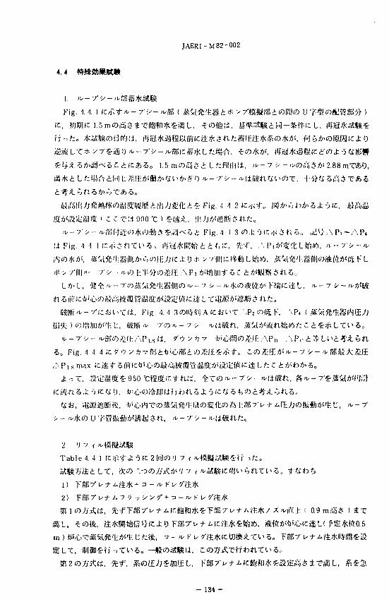
JAERI-M82-002
4.4
Fig. I A.
1.5 mmf i i e i Lfcfflliili, ^ - 7 •> -
ft 5 iO>
Mlffi ' C e r a 900 "C ) ^-ax., Hl J*M!ffiWr j n / : o
Fig. .1 <! 1 (C-jiSn-Cl**, ft'n£fc\\iiibtt<,tt. 'k'i\ ,W\i)<mt LSf?*i. / t - r - > - ^
.«C<1 JE'l;8S(l|iJA'^toj);Jjic J; 0 :)•• •• •/(||i)icfi;*Jj LWiM), .-K'*l 'l-.aSfl|i|«rft(4*<(«: KL
- - T •>• - >KO h"ii^co^ll A P, Asti¥(/j|| 1' 5 C t KW& * ft Z> o
. Fig. A. 4. 3cDD>H"il AKfcl^r. ' .Pz CMS K, . \P
5O Fig. 4 1 4 IC y"O y A vg)5,flj'.i:>a5i«^/.r:«:/pt-o C « £-ffi t<>^- 7 •> - JU Ss Ai
AP,. smax lcii
-?(c« D, ¥'b(Di$£l)lZisteftZ X t lets. 5
2. 'J 7 <
T a b l e 4. 4. ! K,-f<f- J; o IC 2 OHCT> 'I 7
1) T9!7" u j - Aft;J< 4 n - ;u K u /
2) T S R 7 " u + A 7-5 y - > y / + n - ^ K i
a9mss > ttr
- 134 -
JAERI-M82-002
c i 4, c i - i 5 i c o ^ - c , 5 C I J , C 1 5 Fig. 4. 4 5 , Fig. 4. 4. 6
Fig. 4. 4. 7 ICC1 4, Cl 2 Ofr'^AU/KfflOlt^^/jl-to 'J 7
T ^ a C i j O ^ ^ S o Fie 4 4. 8ic^'5
i ^ r i l l , hiWv ( Fig. 4 4. 9 ]*>^(>K
') 7
, u 7
Table 4.4.1 Test conditions of Refill simulation tests
Items
System pressure
Average linear power
Radial power ratio
Initial peak temp.
Downcomer wall temp.
Lower pleaum water hight
Total ACC coolant volume
ACC flow rate
ACC injection period
ACC coolant temp.
N2 injection
LPCI flow rate
LPCI coolant temp.
Units
( kg/cm2a )
( kw/m )
( - )
( °C )
( °C )
( m )
( m3 )
( m3/h )
( sec )
( °C )
( m3/h )
( °C )
Cl-4
<
<
< 1.17
198
0.9
240
14
35
w/o
<
<
RUN NO.
Cl-15
6 + 2 >
1.4 >
: 1.10 : 0.90 >
600
198
0.9
1.6
240
14 + 10*
35
4sec*
30 >
35 >
N2 gas injection was intended to continue 10 sec, however it continued only about 4 sec.
- 135-
Clad surface temperature (°C3
Power (Arbitrary unit)
xn o
I a
a.
sr 09 B 3
O O •o
2 i
JAERI-M 82-002
Liquid Itvtl of contalnmtnt tank I
Liquid Itvtl of containmtnt tank 2
60 120 180 240 300 Time (sec)
Fig. 4.4.3 Differential pressure and liquid level transient
in loop seal water filling test
e
cr
E 6
I4
£
Powtr shutdown -,„
[)owncomtf jT
\
^, -Timt whtn AFb-AF^ would txcttd " APLSBWI, if powtr did not shutdown
1 t 1
100 200 300 Time (sec)
4OO 500
Fig. 4 .4 .4 Collapsed leve l of core and downcomer
- 137 --
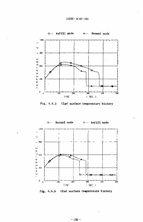
JAER1-M 82-C02
O-— Ref i l l mode A — Normal mode
a a:
a. 300 -
•
a-—;~-e-
. in
-
*
-
100 200
TIME 300 400
I SEC ) soo
Fig. 4.4.5 Clad surface temperature history
©--- Normal mode A--- Refill mode
cr a:
Q. 300
I0D ?00
T I M E 300 «i)0
( SEC I soo
Fig. 4.4,6 Clad surface temperature history
- 1 3 8 -
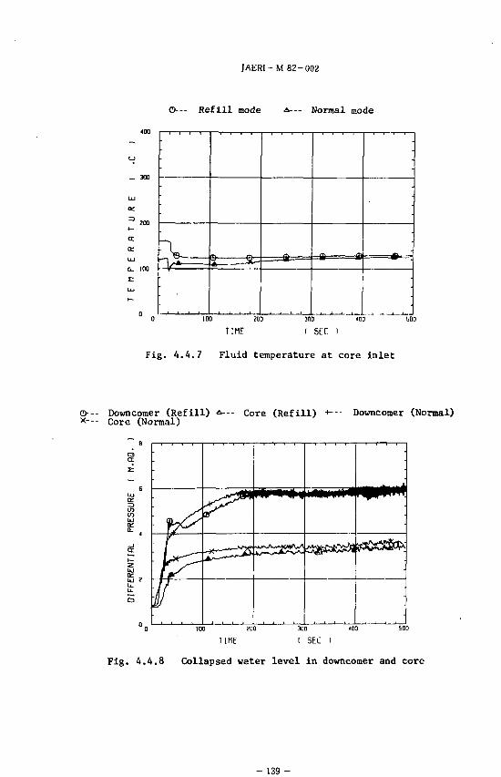
JAERl-M 82-002
©— R e f i l l mode •*--- Normal mode
UJ
G_ 100
•
. a— •• a
•
100 ?00
TIME
300 '00
I SEC I
Fig. 4.4.7 Fluid temperature at core inlet
O-- Downcomer (Refill) x--- Core (Normal)
Core ( R e f i l l ) H — Downcomer (Normal)
er z UJ
u. u_ o
1 1 t 1
•
100 200
TIME
300 '03
SEC
Fig. 4.4.8 Collapsed water level in downcomer and core
- 139 -
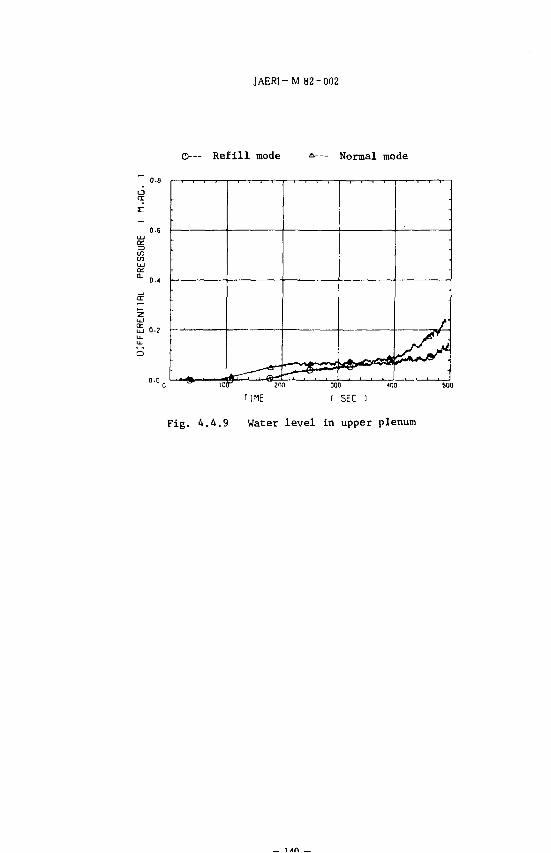
JAERI-M 82-002
O ~ Ref i l l mode Normal mode
z: •
-
-
J
) «no son TIME ( SEC
Fig. 4.4.9 Water level in upper plenum
JAERI- M 82-002
4.5
I. t t 46
Table 4 5. 1
y
l»r(i, W'stf?\H ECC'M ">-x
^c i/ji, '/0 >Avffl
' m,. * m,->«0
5 ~ ]5 ^-CftO. l:!51l7'ix^/xE^[l*APu*<*3'i:>- y''V A-?^-t£ At',, AP,.(O5 - 15
ET. 0, 55 1 M:« Eq. (IW^^mi, !ft2.5 - 7.5 ^iS^iiiffi^ EM* f n> £ 0 (fi»U*
X, E C C * - hT-
, Eq.(7)J; 0 A > 5 i -j ic
- 141 -
JAERI- M 82-002
tS&ffl&IC&^-ai, C C T F i F L E C H T SET, PKL ©fctifii II, $Sf«W:A>'£ '3,CCTF
-9 ic— $?£
'J 7 <
2. ff
(i) rk/mm^k'kmmvrizts^rzmznzimtra (2) tyfccaW&LfcMil
(3) '•Iaa;i>ffil«rM!*^C>/ilrtJMlO:,1tt' fi««-(!"{irtf:/J?^iL>^Wlc')6Yi!,tl!c')A:yj« ' " - r > - ' i^f f i* .^^
c n ^c/XtjtSSJIJ, C C T F 5fi 1 * , -^ 2 r*;^' -ll- C'A! «!i S *1 -5. WC tit,,,
% A11 * « p w R T S /u * n T s 3 - 'f K f '/tn * f J !•: c c s w n « j j A «sit w < j . ,t 13 ,v,'i
t ' l : i i ' i ECCS //AfcRUft I , J; O'i-^-CA'-a^rJTW^ PWR 0,15,1 )• & j j T ; tolCk;-^T*>5,,
( CCTF35 2 C'lji'iL-Tn-itSSjOMf^^So 1
r I t f c l ' T ( i , f'fki*ISate8*ffl^.C-«*i|:->W;aiWi'3ti3ffl.'a:(i. ft870"Ci,H'»-
sil, CCTFXB10°CCSg.m^'ii^\ 890
©
L, ^©iifitfci'© J: -5 ^ i*^ f*^ - i5^T CCTF
- 1 4 2 -
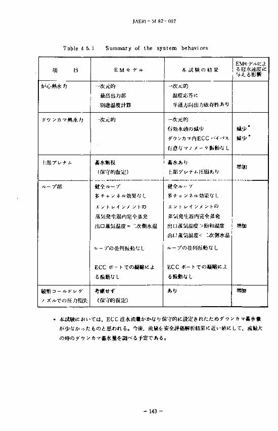
JAERI-M 82-002
Table 4. 5. 1 Summary of the system behaviors
m H EMtf*
BX{ti) | j j 75 SI*
ECC # - h- T'OSlttlCj:
4^ aS 1^ ro J6 5K
ECC if— Is T'W)S)Sf^<t
SfiftAfL
EMfcr'HCj;
man
- 143-
JAERI- M 82-002
5.
2 1 0 < ^m
(1) 'i:yfeii¥ffi
LTIi,
(2)
fc A>', C tlli ECC
(3) / i / - V • > -
(4) fco c«')'T,
LT,
, H,
- X * 4 ^ ' # F. Mayineer
Herdtle, R. K. Fujita fticfc
54
iife,
> 9 -i
. S.
fc C . K . L e w e . H . G .
- 144-
JAERI-M 82-002
G
GACC
GLPCI
mg
me mp
mECC mECC/LP
K
Q
P
APg
APn
Tinit Tsat
P
volume flow rate (m3/hr)
ACC volume flow rate (m3/hr)
LPCI volume flow rate (m /hr)
total mass flow rate through the broken loop (kg/s)
water accumulation rate in the core (kg/s)
water accumulation rate in the downcomer (kg/s)
liquid mass flow rate from three intact cold legs to downcomer
(kg/s)
steam mass flow rate from three intact cold legs to downcomer
(kg/s)
^ C water injection rate into a cold leg (kg/s)
ECC water injection rate into lower plenum (kg/s)
total mass flow rate through a intact loop (kg/s)
total mass flow rate through four loop,- See Eq. (2) (kg/s)
water mass flow rate through broken cold leg nozzle (kg/s)
water accumulation rate in upper plenum (kg/s)
loop K factor ( - )
average linear power (kW/m)
pressure (MPa)
pressure drop across broken loop (mAq)
pressure drop across broken cold leg nozzle (mAq)
core head i.e. core collapsed level (mAq)
downcomer head i.e. downcomer collapsed level (mAq)
pressure drop across a intact loop (mAq)
upper plenum water head (mAq)
flow area of loop piping (m2)
initial clad surface temperature (°C)
saturation temperature (°C)
steam density in a intact loop (kg/m3)
steam density in a broken loop (kg/m3)
- 145 -
Top Related
Copyright © 2022 FDOKUMEN

