


Bahasa
Halaman
Hukum


http://pii.sagepub.com/Control Engineering
Engineers, Part I: Journal of Systems and Proceedings of the Institution of Mechanical
http://pii.sagepub.com/content/222/8/757The online version of this article can be found at:
DOI: 10.1243/09596518JSCE588
2008 222: 757Proceedings of the Institution of Mechanical Engineers, Part I: Journal of Systems and Control EngineeringG Di Rito and R Galatolo
primary flight actuatorsExperimental and theoretical study of the electrical failures in a fault-tolerant direct-drive servovalve for
Published by:
http://www.sagepublications.com
On behalf of:
Institution of Mechanical Engineers
can be found at:EngineeringProceedings of the Institution of Mechanical Engineers, Part I: Journal of Systems and ControlAdditional services and information for
http://pii.sagepub.com/cgi/alertsEmail Alerts:
http://pii.sagepub.com/subscriptionsSubscriptions:
http://www.sagepub.com/journalsReprints.navReprints:
http://www.sagepub.com/journalsPermissions.navPermissions:
http://pii.sagepub.com/content/222/8/757.refs.htmlCitations:
at Unipi / Celdes on July 15, 2011pii.sagepub.comDownloaded from
Experimental and theoretical study of the electricalfailures in a fault-tolerant direct-drive servovalve forprimary flight actuatorsG Di Rito* and R Galatolo
Department of Aerospace Engineering, University of Pisa, Pisa, Italy
The manuscript was received on 4 March 2008 and was accepted after revision for publication on 8 April 2008.
DOI: 10.1243/09596518JSCE588
Abstract: The current paper deals with the study of the electrical failures in fault-tolerantflight actuators, with particular reference to the short circuits of the servovalve coils. A high-fidelity model of the servovalve of a modern fly-by-wire actuator is developed and validatedthrough experiments, focusing attention on the characterization of the component dynamics incase of partial and total short circuits of the direct-drive motor coils. The servovalve model isthen used to simulate a typical on-ground built-in-test procedure to determine the limitcondition for the detection of a partial short circuit. Finally, once different possiblecombinations of short circuits are injected, the degradation of performances of the wholeactuator is characterized through experiments, and the servovalve model is used to justify thetest results, highlighting and discussing the effects of the failures on the system dynamics.
Keywords: flight control, fault-tolerant actuators, direct-drive servovalve, failure analysis,testing, modelling and simulation
1 INTRODUCTION
Full-authority fly-by-wire flight control systems are
nowadays a standard technology solution for ad-
vanced military aircraft and for civil transport
airliners. To provide the adequate level of safety,
the primary flight actuators are designed to be fault-
tolerant components, so that they must be able
appropriately to operate in the event of one or more
failures. The capability of the system to tolerate the
actuator failures also depends on the flight control
computers, which must be able to detect the
malfunctions by means of both on-ground and in-
flight built-in tests [1]. However, as a result of
inadequate or impracticable monitoring procedures,
a flight actuator can operate with dormant failures,
implying an unexpected degradation of the perfor-
mance and the safety of the aircraft.
When hydraulic flight actuators with direct-drive
servovalve [2, 3] are concerned, dormant failures can
be caused by the short circuits in the servovalve
coils. Actually, as these faults can involve only a part
of the windings, the on-ground built-in-tests cannot
detect the malfunction, causing the aircraft to take
off with a damaged actuator. The problem is that a
partial short circuit could extend to the rest of the
coil during the flight, implying a significant degrada-
tion of the actuator performances.
Although many authors have focused their atten-
tion on the study, the modelling, and the dynamic
characterization of electrical motors in faulty condi-
tions [4–6], scarce information is available about the
modelling and the failure analysis of direct-drive
electrical motors for aerospace servovalves.
In the current paper, a high-fidelity model of the
direct-drive servovalve of a modern fly-by-wire
actuator is developed and validated through experi-
ments, focusing attention on the characterization of
the component dynamics in short circuits of the
motor coils.
*Corresponding author: Department of Aerospace Engineering,
University of Pisa, via Caruso, Pisa, Italy. email: g.dirito@ing.
unipi.it
757
JSCE588 F IMechE 2008 Proc. IMechE Vol. 222 Part I: J. Systems and Control Engineering
at Unipi / Celdes on July 15, 2011pii.sagepub.comDownloaded from
2 SYSTEM DESCRIPTION
2.1 Architecture of the fault-tolerant flightactuator
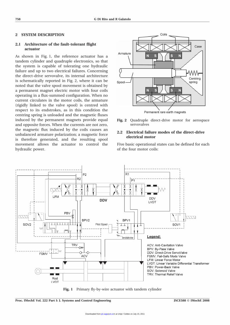
As shown in Fig. 1, the reference actuator has a
tandem cylinder and quadruple electronics, so that
the system is capable of tolerating one hydraulic
failure and up to two electrical failures. Concerning
the direct-drive servovalve, its internal architecture
is schematically reported in Fig. 2, where it can be
noted that the valve spool movement is obtained by
a permanent magnet electric motor with four coils
operating in a flux-summed configuration. When no
current circulates in the motor coils, the armature
(rigidly linked to the valve spool) is centred with
respect to its endstrokes, as in this condition the
centring spring is unloaded and the magnetic fluxes
induced by the permanent magnets provide equal
and opposite forces. When the currents are not zero,
the magnetic flux induced by the coils causes an
unbalanced armature polarization; a magnetic force
is therefore generated, and the resulting spool
movement allows the actuator to control the
hydraulic power.
2.2 Electrical failure modes of the direct-driveelectrical motor
Five basic operational states can be defined for each
of the four motor coils:
Fig. 1 Primary fly-by-wire actuator with tandem cylinder
Fig. 2 Quadruple direct-drive motor for aerospaceservovalves
758 G Di Rito and R Galatolo
Proc. IMechE Vol. 222 Part I: J. Systems and Control Engineering JSCE588 F IMechE 2008
at Unipi / Celdes on July 15, 2011pii.sagepub.comDownloaded from
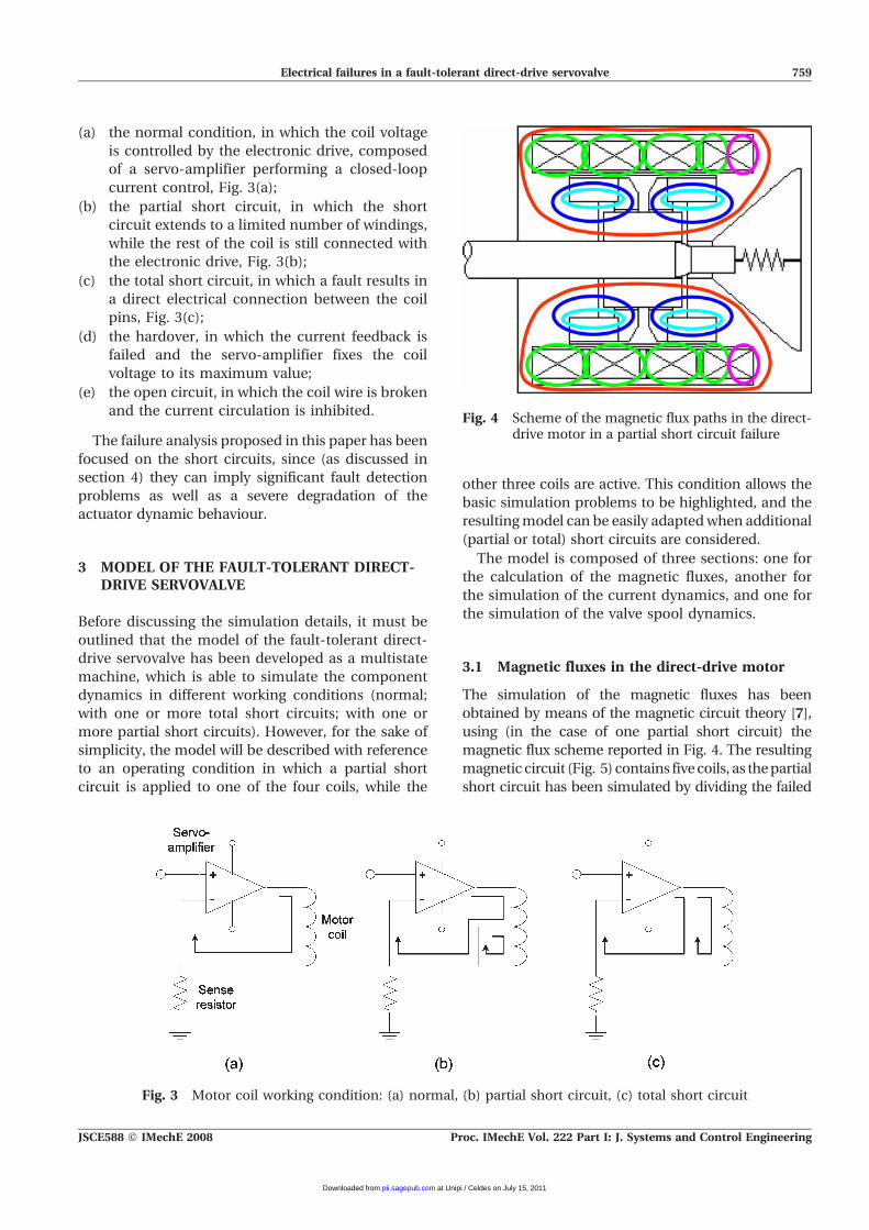
(a) the normal condition, in which the coil voltage
is controlled by the electronic drive, composed
of a servo-amplifier performing a closed-loop
current control, Fig. 3(a);
(b) the partial short circuit, in which the short
circuit extends to a limited number of windings,
while the rest of the coil is still connected with
the electronic drive, Fig. 3(b);
(c) the total short circuit, in which a fault results in
a direct electrical connection between the coil
pins, Fig. 3(c);
(d) the hardover, in which the current feedback is
failed and the servo-amplifier fixes the coil
voltage to its maximum value;
(e) the open circuit, in which the coil wire is broken
and the current circulation is inhibited.
The failure analysis proposed in this paper has been
focused on the short circuits, since (as discussed in
section 4) they can imply significant fault detection
problems as well as a severe degradation of the
actuator dynamic behaviour.
3 MODEL OF THE FAULT-TOLERANT DIRECT-DRIVE SERVOVALVE
Before discussing the simulation details, it must be
outlined that the model of the fault-tolerant direct-
drive servovalve has been developed as a multistate
machine, which is able to simulate the component
dynamics in different working conditions (normal;
with one or more total short circuits; with one or
more partial short circuits). However, for the sake of
simplicity, the model will be described with reference
to an operating condition in which a partial short
circuit is applied to one of the four coils, while the
other three coils are active. This condition allows the
basic simulation problems to be highlighted, and the
resulting model can be easily adapted when additional
(partial or total) short circuits are considered.
The model is composed of three sections: one for
the calculation of the magnetic fluxes, another for
the simulation of the current dynamics, and one for
the simulation of the valve spool dynamics.
3.1 Magnetic fluxes in the direct-drive motor
The simulation of the magnetic fluxes has been
obtained by means of the magnetic circuit theory [7],
using (in the case of one partial short circuit) the
magnetic flux scheme reported in Fig. 4. The resulting
magnetic circuit (Fig. 5) contains five coils, as the partial
short circuit has been simulated by dividing the failed
Fig. 3 Motor coil working condition: (a) normal, (b) partial short circuit, (c) total short circuit
Fig. 4 Scheme of the magnetic flux paths in the direct-drive motor in a partial short circuit failure
Electrical failures in a fault-tolerant direct-drive servovalve 759
JSCE588 F IMechE 2008 Proc. IMechE Vol. 222 Part I: J. Systems and Control Engineering
at Unipi / Celdes on July 15, 2011pii.sagepub.comDownloaded from
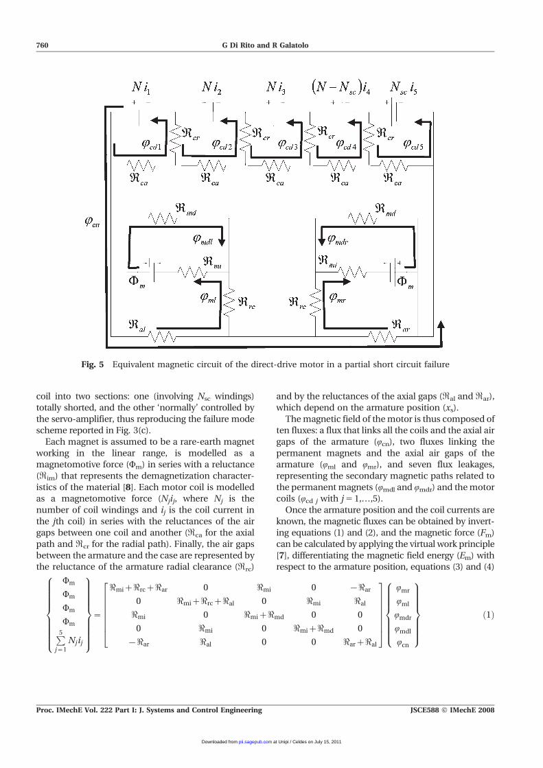
coil into two sections: one (involving Nsc windings)
totally shorted, and the other ‘normally’ controlled by
the servo-amplifier, thus reproducing the failure mode
scheme reported in Fig. 3(c).
Each magnet is assumed to be a rare-earth magnet
working in the linear range, is modelled as a
magnetomotive force (Wm) in series with a reluctance
(Rim) that represents the demagnetization character-
istics of the material [8]. Each motor coil is modelled
as a magnetomotive force (Njij, where Nj is the
number of coil windings and ij is the coil current in
the jth coil) in series with the reluctances of the air
gaps between one coil and another (Rca for the axial
path and Rcr for the radial path). Finally, the air gaps
between the armature and the case are represented by
the reluctance of the armature radial clearance (Rrc)
and by the reluctances of the axial gaps (Ral and Rar),
which depend on the armature position (xs).
The magnetic field of the motor is thus composed of
ten fluxes: a flux that links all the coils and the axial air
gaps of the armature (Qcn), two fluxes linking the
permanent magnets and the axial air gaps of the
armature (Qml and Qmr), and seven flux leakages,
representing the secondary magnetic paths related to
the permanent magnets (Qmdl and Qmdr) and the motor
coils (Qcd j with j 5 1,…,5).
Once the armature position and the coil currents are
known, the magnetic fluxes can be obtained by invert-
ing equations (1) and (2), and the magnetic force (Fm)
can be calculated by applying the virtual work principle
[7], differentiating the magnetic field energy (Em) with
respect to the armature position, equations (3) and (4)
Wm
Wm
Wm
WmP5j~1
Njij
8>>>>>>>><>>>>>>>>:
9>>>>>>>>=>>>>>>>>;
~
<miz<rcz<ar 0 <mi 0 {<ar
0 <miz<rcz<al 0 <mi <al
<mi 0 <miz<md 0 0
0 <mi 0 <miz<md 0
{<ar <al 0 0 <arz<al
26666664
37777775
Qmr
Qml
Qmdr
Qmdl
Qcn
8>>>>>><>>>>>>:
9>>>>>>=>>>>>>;
ð1Þ
Fig. 5 Equivalent magnetic circuit of the direct-drive motor in a partial short circuit failure
760 G Di Rito and R Galatolo
Proc. IMechE Vol. 222 Part I: J. Systems and Control Engineering JSCE588 F IMechE 2008
at Unipi / Celdes on July 15, 2011pii.sagepub.comDownloaded from
Ni1
Ni2
Ni3
N{Nscð Þi4
Nsci5
8>>>>>><>>>>>>:
9>>>>>>=>>>>>>;
~
<caz<cr {<cr 0 0 0
{<cr <caz2<cr {<cr 0 0
0 {<cr <caz2<cr {<cr 0
0 0 {<cr <caz2<cr {<cr
0 0 0 {<cr <caz<cr
26666664
37777775
Qcd1
Qcd2
Qcd3
Qcd4
Qcd5
8>>>>>><>>>>>>:
9>>>>>>=>>>>>>;
ð2Þ
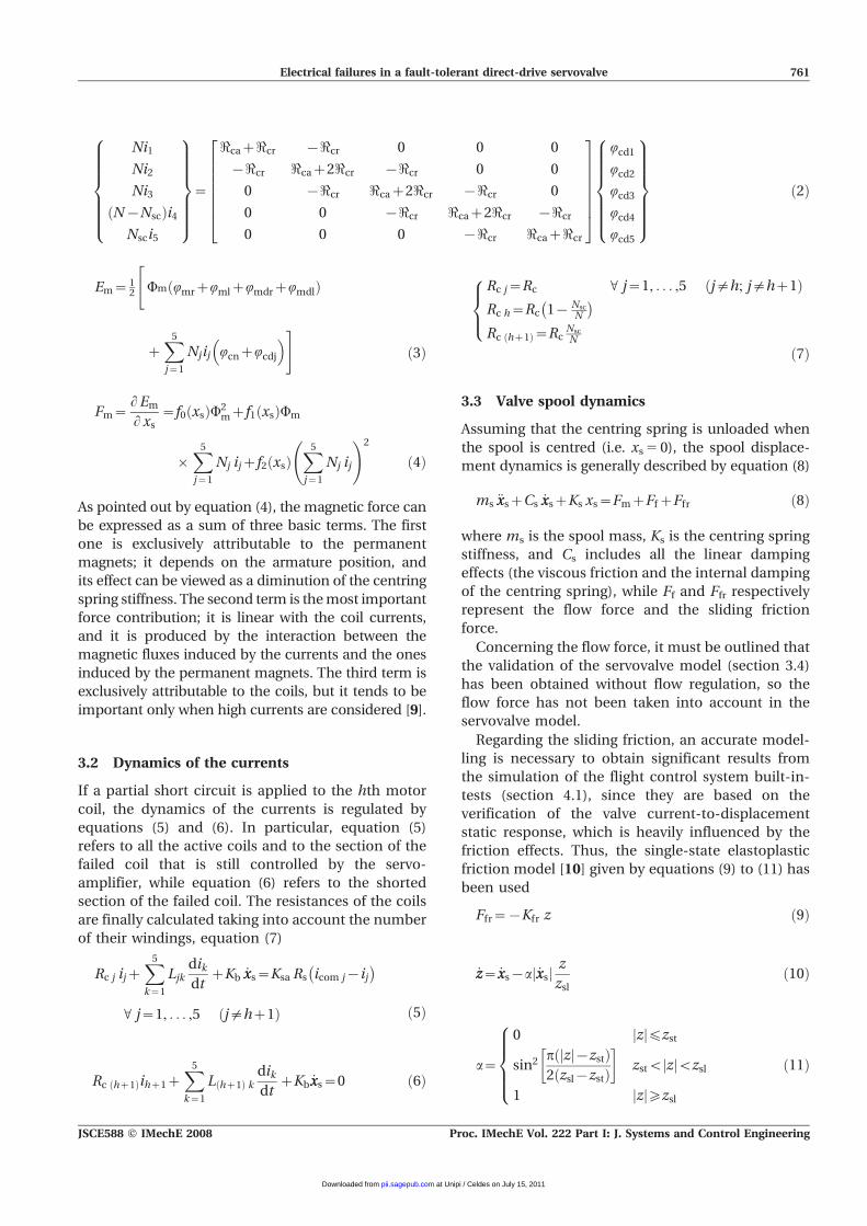
Em~ Wm QmrzQmlzQmdrzQmdlð Þ
zX5
j~1
Njij QcnzQcdj
� �#ð3Þ
Fm~L Em
L xs~f0 xsð ÞW2
mzf1 xsð ÞWm
|X5
j~1
Nj ijzf2 xsð ÞX5
j~1
Nj ij
!2
ð4Þ
As pointed out by equation (4), the magnetic force can
be expressed as a sum of three basic terms. The first
one is exclusively attributable to the permanent
magnets; it depends on the armature position, and
its effect can be viewed as a diminution of the centring
spring stiffness. The second term is the most important
force contribution; it is linear with the coil currents,
and it is produced by the interaction between the
magnetic fluxes induced by the currents and the ones
induced by the permanent magnets. The third term is
exclusively attributable to the coils, but it tends to be
important only when high currents are considered [9].
3.2 Dynamics of the currents
If a partial short circuit is applied to the hth motor
coil, the dynamics of the currents is regulated by
equations (5) and (6). In particular, equation (5)
refers to all the active coils and to the section of the
failed coil that is still controlled by the servo-
amplifier, while equation (6) refers to the shorted
section of the failed coil. The resistances of the coils
are finally calculated taking into account the number
of their windings, equation (7)
Rc j ijzX5
k~1
Ljkdik
dtzKb _xxs~Ksa Rs icom j{ij
� �V j~1, . . . ,5 j=hz1ð Þ ð5Þ
Rc hz1ð Þihz1zX5
k~1
L hz1ð Þ kdik
dtzKb _xxs~0 ð6Þ
Rc j~Rc V j~1, . . . ,5 j=h; j=hz1ð ÞRc h~Rc 1{ Nsc
N
� �Rc hz1ð Þ~Rc
Nsc
N
8><>:
ð7Þ
3.3 Valve spool dynamics
Assuming that the centring spring is unloaded when
the spool is centred (i.e. xs 5 0), the spool displace-
ment dynamics is generally described by equation (8)
ms €xxszCs _xxszKs xs~FmzFfzFfr ð8Þ
where ms is the spool mass, Ks is the centring spring
stiffness, and Cs includes all the linear damping
effects (the viscous friction and the internal damping
of the centring spring), while Ff and Ffr respectively
represent the flow force and the sliding friction
force.
Concerning the flow force, it must be outlined that
the validation of the servovalve model (section 3.4)
has been obtained without flow regulation, so the
flow force has not been taken into account in the
servovalve model.
Regarding the sliding friction, an accurate model-
ling is necessary to obtain significant results from
the simulation of the flight control system built-in-
tests (section 4.1), since they are based on the
verification of the valve current-to-displacement
static response, which is heavily influenced by the
friction effects. Thus, the single-state elastoplastic
friction model [10] given by equations (9) to (11) has
been used
Ffr~{Kfr z ð9Þ
_zz~ _xxs{a _xxsj jz
zslð10Þ
a~
0 zj j¡zst
sin2 p zj j{zstð Þ2 zsl{zstð Þ
� �zstv zj jvzsl
1 zj j¢zsl
8>>><>>>:
ð11Þ
12 #
Electrical failures in a fault-tolerant direct-drive servovalve 761
JSCE588 F IMechE 2008 Proc. IMechE Vol. 222 Part I: J. Systems and Control Engineering
at Unipi / Celdes on July 15, 2011pii.sagepub.comDownloaded from
where z is the local deformation of the spool contact
area, Kfr is the contact stiffness, a is the stick-slip
factor, zsl is the local deformation during the slipping
motion (assumed to be constant), and zst is the
maximum local deformation during the sticking
motion (assumed to be zsl/2).
3.4 Experimental validation
The basic problem in the study of the short circuit
failure is attributable to the fact that the fault can
involve a limited part of the coil, and it is very complex
experimentally to reproduce this condition. This leads
to the necessity of modelling and simulation for
estimating the effects of the failure on the actuator
dynamics, but it also implies some kind of uncertainty
about the verification of the simulation results. On the
other hand, the experimental study of the total short
circuits is rather simple to realize, as the faults can be
reproduced without performing invasive tests on the
component. This aspect was important for the
research because parallel experimental activities were
carried out on the flight actuator, and others were
planned for the future.
For these reasons, the validation of the model has
been obtained only with reference to the total short
circuits, by testing an actual aircraft servovalve with
an electronic control unit specifically designed for
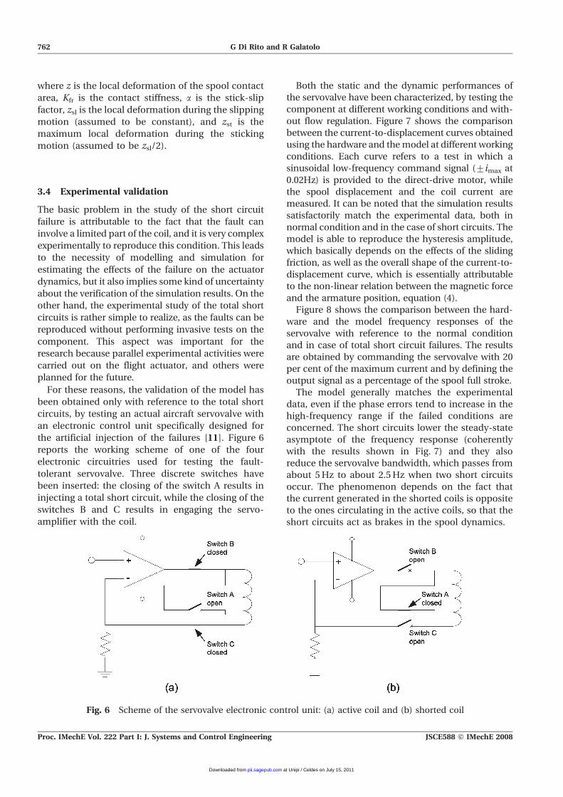
the artificial injection of the failures [11]. Figure 6
reports the working scheme of one of the four
electronic circuitries used for testing the fault-
tolerant servovalve. Three discrete switches have
been inserted: the closing of the switch A results in
injecting a total short circuit, while the closing of the
switches B and C results in engaging the servo-
amplifier with the coil.
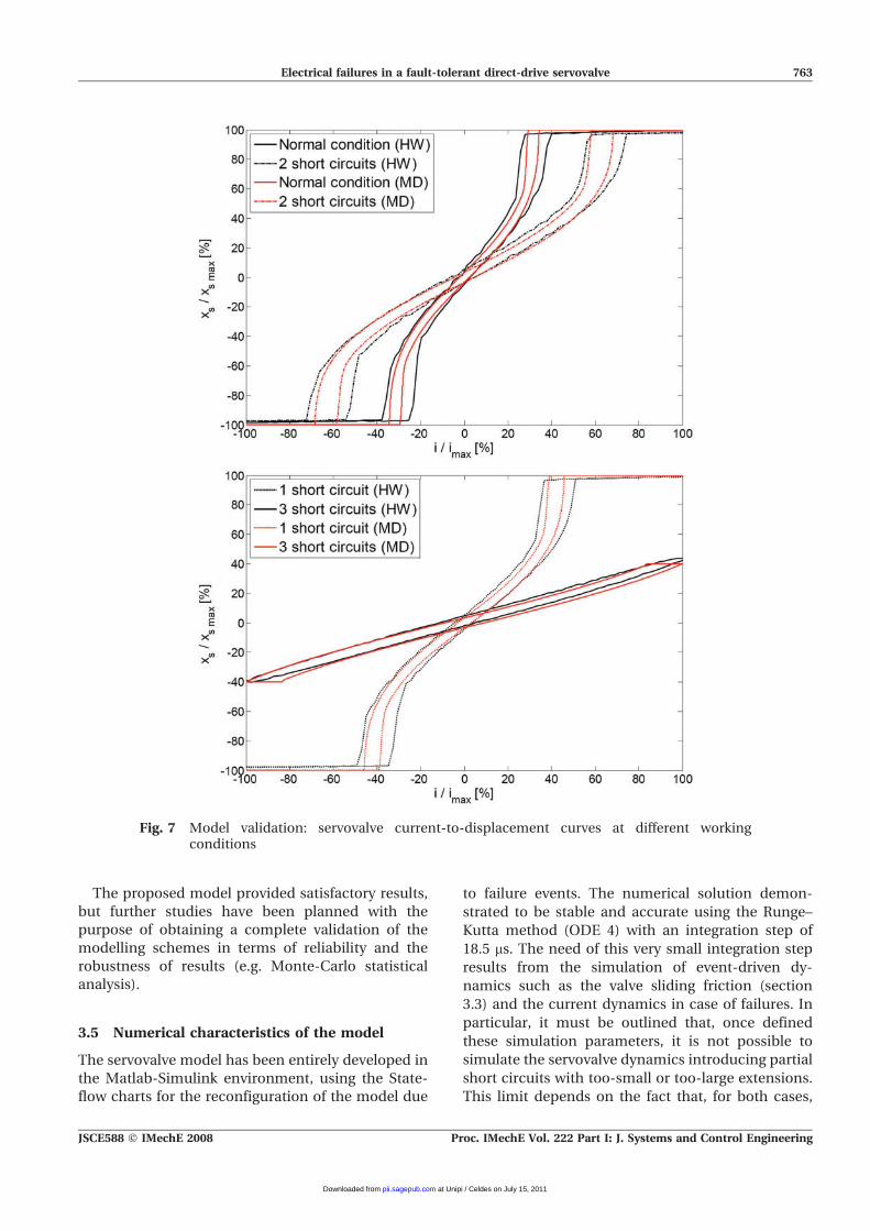
Both the static and the dynamic performances of
the servovalve have been characterized, by testing the
component at different working conditions and with-
out flow regulation. Figure 7 shows the comparison
between the current-to-displacement curves obtained
using the hardware and the model at different working
conditions. Each curve refers to a test in which a
sinusoidal low-frequency command signal (¡imax at
0.02Hz) is provided to the direct-drive motor, while
the spool displacement and the coil current are
measured. It can be noted that the simulation results
satisfactorily match the experimental data, both in
normal condition and in the case of short circuits. The
model is able to reproduce the hysteresis amplitude,
which basically depends on the effects of the sliding
friction, as well as the overall shape of the current-to-
displacement curve, which is essentially attributable
to the non-linear relation between the magnetic force
and the armature position, equation (4).
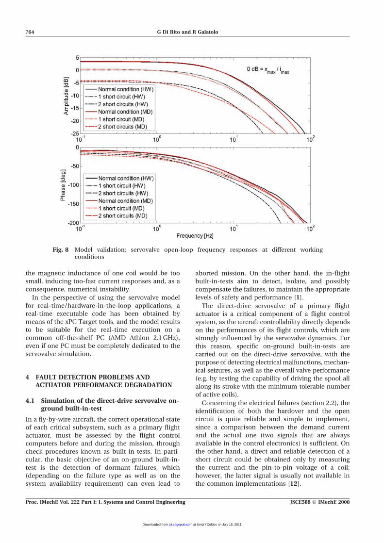
Figure 8 shows the comparison between the hard-
ware and the model frequency responses of the
servovalve with reference to the normal condition
and in case of total short circuit failures. The results
are obtained by commanding the servovalve with 20
per cent of the maximum current and by defining the
output signal as a percentage of the spool full stroke.
The model generally matches the experimental
data, even if the phase errors tend to increase in the
high-frequency range if the failed conditions are
concerned. The short circuits lower the steady-state
asymptote of the frequency response (coherently
with the results shown in Fig. 7) and they also
reduce the servovalve bandwidth, which passes from
about 5 Hz to about 2.5 Hz when two short circuits
occur. The phenomenon depends on the fact that
the current generated in the shorted coils is opposite
to the ones circulating in the active coils, so that the
short circuits act as brakes in the spool dynamics.
Fig. 6 Scheme of the servovalve electronic control unit: (a) active coil and (b) shorted coil
762 G Di Rito and R Galatolo
Proc. IMechE Vol. 222 Part I: J. Systems and Control Engineering JSCE588 F IMechE 2008
at Unipi / Celdes on July 15, 2011pii.sagepub.comDownloaded from
The proposed model provided satisfactory results,
but further studies have been planned with the
purpose of obtaining a complete validation of the
modelling schemes in terms of reliability and the
robustness of results (e.g. Monte-Carlo statistical
analysis).
3.5 Numerical characteristics of the model
The servovalve model has been entirely developed in
the Matlab-Simulink environment, using the State-
flow charts for the reconfiguration of the model due
to failure events. The numerical solution demon-
strated to be stable and accurate using the Runge–
Kutta method (ODE 4) with an integration step of
18.5 ms. The need of this very small integration step
results from the simulation of event-driven dy-
namics such as the valve sliding friction (section
3.3) and the current dynamics in case of failures. In
particular, it must be outlined that, once defined
these simulation parameters, it is not possible to
simulate the servovalve dynamics introducing partial
short circuits with too-small or too-large extensions.
This limit depends on the fact that, for both cases,
Fig. 7 Model validation: servovalve current-to-displacement curves at different workingconditions
Electrical failures in a fault-tolerant direct-drive servovalve 763
JSCE588 F IMechE 2008 Proc. IMechE Vol. 222 Part I: J. Systems and Control Engineering
at Unipi / Celdes on July 15, 2011pii.sagepub.comDownloaded from
the magnetic inductance of one coil would be too
small, inducing too-fast current responses and, as a
consequence, numerical instability.
In the perspective of using the servovalve model
for real-time/hardware-in-the-loop applications, a
real-time executable code has been obtained by
means of the xPC Target tools, and the model results
to be suitable for the real-time execution on a
common off-the-shelf PC (AMD Athlon 2.1 GHz),
even if one PC must be completely dedicated to the
servovalve simulation.
4 FAULT DETECTION PROBLEMS ANDACTUATOR PERFORMANCE DEGRADATION
4.1 Simulation of the direct-drive servovalve on-ground built-in-test
In a fly-by-wire aircraft, the correct operational state
of each critical subsystem, such as a primary flight
actuator, must be assessed by the flight control
computers before and during the mission, through
check procedures known as built-in-tests. In parti-
cular, the basic objective of an on-ground built-in-
test is the detection of dormant failures, which
(depending on the failure type as well as on the
system availability requirement) can even lead to
aborted mission. On the other hand, the in-flight
built-in-tests aim to detect, isolate, and possibly
compensate the failures, to maintain the appropriate
levels of safety and performance [1].
The direct-drive servovalve of a primary flight
actuator is a critical component of a flight control
system, as the aircraft controllability directly depends
on the performances of its flight controls, which are
strongly influenced by the servovalve dynamics. For
this reason, specific on-ground built-in-tests are
carried out on the direct-drive servovalve, with the
purpose of detecting electrical malfunctions, mechan-
ical seizures, as well as the overall valve performance
(e.g. by testing the capability of driving the spool all
along its stroke with the minimum tolerable number
of active coils).
Concerning the electrical failures (section 2.2), the
identification of both the hardover and the open
circuit is quite reliable and simple to implement,
since a comparison between the demand current
and the actual one (two signals that are always
available in the control electronics) is sufficient. On
the other hand, a direct and reliable detection of a
short circuit could be obtained only by measuring
the current and the pin-to-pin voltage of a coil;
however, the latter signal is usually not available in
the common implementations [12].
Fig. 8 Model validation: servovalve open-loop frequency responses at different workingconditions
764 G Di Rito and R Galatolo
Proc. IMechE Vol. 222 Part I: J. Systems and Control Engineering JSCE588 F IMechE 2008
at Unipi / Celdes on July 15, 2011pii.sagepub.comDownloaded from
An alternative approach could be based on the
evaluation of the servovalve current-to-displacement
response related to the single coils (Fig. 7(b)), but
this procedure could imply the possibility of having
dormant failures owing to partial faults. This
problem has been pointed out by means of the
validated model of the servovalve, simulating an on-
ground built-in-test composed of the following
steps.
Step 1: all the coil currents are set to zero; after
that, a test current (iBIT) is sent to the coil 1 and a
static measurement of the spool position (xs1 BIT) is
recorded;
Step(s) 2 (3 and 4): step 1 is repeated commanding
the coil 2 (3 and 4);
Step 5: if the jth spool position measurement
(where j 5 1,…,4) is outside a fixed threshold (i.e.
|xs j BIT 2 xs nom| .Dxth), a malfunction is detected
in the jth coil; otherwise the servovalve passes the
check.
The failure coverage provided by this test clearly
depends on the position threshold (Dxth): in parti-
cular, the larger is the threshold, the bigger is the
undetected partial short circuit. Nevertheless, too-
small thresholds cannot be used, because the
current-to-displacement response of a direct-drive
motor depends on the temperature (the air gaps vary
with the thermal dilatation and the magnet proper-
ties are temperature dependent [8]), and the com-
ponent temperature during the built-in-test is not
predictable.
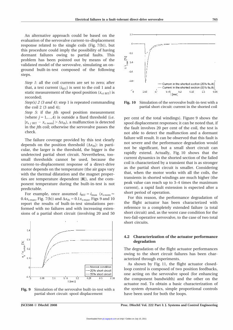
For example, once assumed iBIT 5 imax (xs nom <0.4xs max, Fig. 7(b)) and Dxth 5 0.1xs max, Figs 9 and 10
report the results of built-in-test simulations per-
formed with no failures and with increasing exten-
sions of a partial short circuit (involving 20 and 50
per cent of the total windings). Figure 9 shows the
spool displacement responses; it can be noted that, if
the fault involves 20 per cent of the coil, the test is
not able to detect the malfunction and a dormant
failure will result. It can be observed that this fault is
not severe and the performance degradation would
not be significant, but a small short circuit can
rapidly extend. Actually, Fig. 10 shows that the
current dynamics in the shorted section of the failed
coil is characterized by a transient that is as stronger
as the partial short circuit is smaller. Considering
that, when the motor works with all the coils, the
transients in shorted windings are much higher (the
peak value can reach up to 3–4 times the maximum
current), a rapid fault extension is expected after a
short period of operation.
For this reason, the performance degradation of
the flight actuator has been characterized with
reference to a completely extended failure (a total
short circuit) and, as the worst case condition for the
two-fail-operative servovalve, to the case of two total
short circuits.
4.2 Characterization of the actuator performancedegradation
The degradation of the flight actuator performances
owing to the short circuit failures has been char-
acterized through experiments.
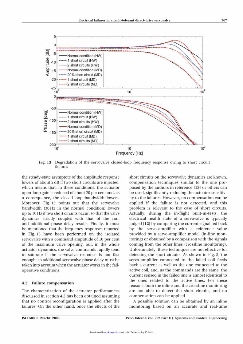
As shown by Fig. 11, the flight actuator closed-
loop control is composed of two position feedbacks,
one acting on the servovalve spool (for enhancing
the component bandwidth) and the other on the
actuator rod. To obtain a basic characterization of
the system dynamics, simple proportional controls
have been used for both the loops.Fig. 9 Simulation of the servovalve built-in-test with a
partial short circuit: spool displacement
Fig. 10 Simulation of the servovalve built-in-test with apartial short circuit: current in the shorted coil
Electrical failures in a fault-tolerant direct-drive servovalve 765
JSCE588 F IMechE 2008 Proc. IMechE Vol. 222 Part I: J. Systems and Control Engineering
at Unipi / Celdes on July 15, 2011pii.sagepub.comDownloaded from
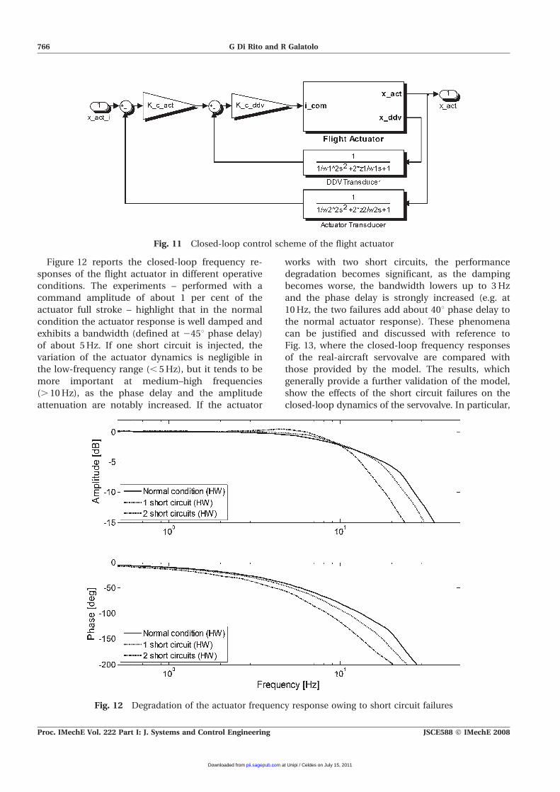
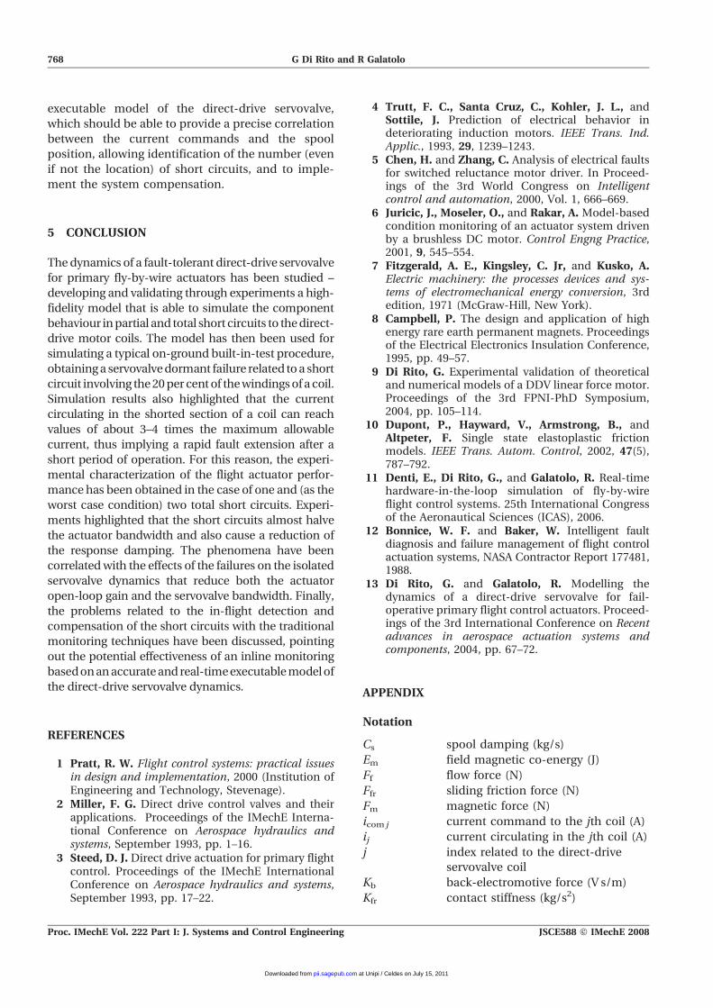
Figure 12 reports the closed-loop frequency re-
sponses of the flight actuator in different operative
conditions. The experiments – performed with a
command amplitude of about 1 per cent of the
actuator full stroke – highlight that in the normal
condition the actuator response is well damped and
exhibits a bandwidth (defined at 245u phase delay)
of about 5 Hz. If one short circuit is injected, the
variation of the actuator dynamics is negligible in
the low-frequency range (, 5 Hz), but it tends to be
more important at medium–high frequencies
(. 10 Hz), as the phase delay and the amplitude
attenuation are notably increased. If the actuator
works with two short circuits, the performance
degradation becomes significant, as the damping
becomes worse, the bandwidth lowers up to 3 Hz
and the phase delay is strongly increased (e.g. at
10 Hz, the two failures add about 40u phase delay to
the normal actuator response). These phenomena
can be justified and discussed with reference to
Fig. 13, where the closed-loop frequency responses
of the real-aircraft servovalve are compared with
those provided by the model. The results, which
generally provide a further validation of the model,
show the effects of the short circuit failures on the
closed-loop dynamics of the servovalve. In particular,
Fig. 11 Closed-loop control scheme of the flight actuator
Fig. 12 Degradation of the actuator frequency response owing to short circuit failures
766 G Di Rito and R Galatolo
Proc. IMechE Vol. 222 Part I: J. Systems and Control Engineering JSCE588 F IMechE 2008
at Unipi / Celdes on July 15, 2011pii.sagepub.comDownloaded from
the steady-state asymptote of the amplitude response
lowers of about 2 dB if two short circuits are injected,
which means that, in these conditions, the actuator
open-loop gain is reduced of about 20 per cent and, as
a consequence, the closed-loop bandwidth lowers.
Moreover, Fig. 13 points out that the servovalve
bandwidth (30 Hz in the normal condition) lowers
up to 10 Hz if two short circuits occur, so that the valve
dynamics strictly couples with that of the rod,
and additional phase delay results. Finally, it must
be mentioned that the frequency responses reported
in Fig. 13 have been performed on the isolated
servovalve with a command amplitude of 10 per cent
of the maximum valve opening, but, in the whole
actuator dynamics, the valve commands rapidly tend
to saturate if the servovalve response is not fast
enough; so additional servovalve phase delay must be
taken into account when the actuator works in the fail-
operative conditions.
4.3 Failure compensation
The characterization of the actuator performances
discussed in section 4.2 has been obtained assuming
that no control reconfiguration is applied after the
failures. On the other hand, once the effects of the
short circuits on the servovalve dynamics are known,
compensation techniques similar to the one pro-
posed by the authors in reference [13] or others can
be used, significantly reducing the actuator sensitiv-
ity to the failures. However, no compensation can be
applied if the failure is not detected, and this
problem is relevant to the case of short circuits.
Actually, during the in-flight built-in-tests, the
electrical health state of a servovalve is typically
judged [12] by comparing the current signal fed back
by the servo-amplifier with a reference value
provided by a servo-amplifier model (in-line mon-
itoring) or obtained by a comparison with the signals
coming from the other lines (crossline monitoring).
Unfortunately, these techniques are not effective for
detecting the short circuits. As shown in Fig. 3, the
servo-amplifier connected to the failed coil feeds
back a current as well as the one connected to the
active coil, and, as the commands are the same, the
current sensed in the failed line is almost identical to
the ones related to the active lines. For these
reasons, both the inline and the crossline monitoring
are not able to detect the short circuits, and no
compensation can be applied.
A possible solution can be obtained by an inline
monitoring based on an accurate and real-time
Fig. 13 Degradation of the servovalve closed-loop frequency response owing to short circuitfailures
Electrical failures in a fault-tolerant direct-drive servovalve 767
JSCE588 F IMechE 2008 Proc. IMechE Vol. 222 Part I: J. Systems and Control Engineering
at Unipi / Celdes on July 15, 2011pii.sagepub.comDownloaded from
executable model of the direct-drive servovalve,
which should be able to provide a precise correlation
between the current commands and the spool
position, allowing identification of the number (even
if not the location) of short circuits, and to imple-
ment the system compensation.
5 CONCLUSION
The dynamics of a fault-tolerant direct-drive servovalve
for primary fly-by-wire actuators has been studied –
developing and validating through experiments a high-
fidelity model that is able to simulate the component
behaviour in partial and total short circuits to the direct-
drive motor coils. The model has then been used for
simulating a typical on-ground built-in-test procedure,
obtaining a servovalve dormant failure related to a short
circuit involving the 20 per cent of the windings of a coil.
Simulation results also highlighted that the current
circulating in the shorted section of a coil can reach
values of about 3–4 times the maximum allowable
current, thus implying a rapid fault extension after a
short period of operation. For this reason, the experi-
mental characterization of the flight actuator perfor-
mance has been obtained in the case of one and (as the
worst case condition) two total short circuits. Experi-
ments highlighted that the short circuits almost halve
the actuator bandwidth and also cause a reduction of
the response damping. The phenomena have been
correlated with the effects of the failures on the isolated
servovalve dynamics that reduce both the actuator
open-loop gain and the servovalve bandwidth. Finally,
the problems related to the in-flight detection and
compensation of the short circuits with the traditional
monitoring techniques have been discussed, pointing
out the potential effectiveness of an inline monitoring
based on an accurate and real-time executable model of
the direct-drive servovalve dynamics.
REFERENCES
1 Pratt, R. W. Flight control systems: practical issuesin design and implementation, 2000 (Institution ofEngineering and Technology, Stevenage).
2 Miller, F. G. Direct drive control valves and theirapplications. Proceedings of the IMechE Interna-tional Conference on Aerospace hydraulics andsystems, September 1993, pp. 1–16.
3 Steed, D. J. Direct drive actuation for primary flightcontrol. Proceedings of the IMechE InternationalConference on Aerospace hydraulics and systems,September 1993, pp. 17–22.
4 Trutt, F. C., Santa Cruz, C., Kohler, J. L., andSottile, J. Prediction of electrical behavior indeteriorating induction motors. IEEE Trans. Ind.Applic., 1993, 29, 1239–1243.
5 Chen, H. and Zhang, C. Analysis of electrical faultsfor switched reluctance motor driver. In Proceed-ings of the 3rd World Congress on Intelligentcontrol and automation, 2000, Vol. 1, 666–669.
6 Juricic, J., Moseler, O., and Rakar, A. Model-basedcondition monitoring of an actuator system drivenby a brushless DC motor. Control Engng Practice,2001, 9, 545–554.
7 Fitzgerald, A. E., Kingsley, C. Jr, and Kusko, A.Electric machinery: the processes devices and sys-tems of electromechanical energy conversion, 3rdedition, 1971 (McGraw-Hill, New York).
8 Campbell, P. The design and application of highenergy rare earth permanent magnets. Proceedingsof the Electrical Electronics Insulation Conference,1995, pp. 49–57.
9 Di Rito, G. Experimental validation of theoreticaland numerical models of a DDV linear force motor.Proceedings of the 3rd FPNI-PhD Symposium,2004, pp. 105–114.
10 Dupont, P., Hayward, V., Armstrong, B., andAltpeter, F. Single state elastoplastic frictionmodels. IEEE Trans. Autom. Control, 2002, 47(5),787–792.
11 Denti, E., Di Rito, G., and Galatolo, R. Real-timehardware-in-the-loop simulation of fly-by-wireflight control systems. 25th International Congressof the Aeronautical Sciences (ICAS), 2006.
12 Bonnice, W. F. and Baker, W. Intelligent faultdiagnosis and failure management of flight controlactuation systems, NASA Contractor Report 177481,1988.
13 Di Rito, G. and Galatolo, R. Modelling thedynamics of a direct-drive servovalve for fail-operative primary flight control actuators. Proceed-ings of the 3rd International Conference on Recentadvances in aerospace actuation systems andcomponents, 2004, pp. 67–72.
APPENDIX
Notation
Cs spool damping (kg/s)
Em field magnetic co-energy (J)
Ff flow force (N)
Ffr sliding friction force (N)
Fm magnetic force (N)
icom j current command to the jth coil (A)
ij current circulating in the jth coil (A)
j index related to the direct-drive
servovalve coil
Kb back-electromotive force (V s/m)
Kfr contact stiffness (kg/s2)
768 G Di Rito and R Galatolo
Proc. IMechE Vol. 222 Part I: J. Systems and Control Engineering JSCE588 F IMechE 2008
at Unipi / Celdes on July 15, 2011pii.sagepub.comDownloaded from

Ks centring spring stiffness (kg/s2)
Ksa servo-amplifier gain
Ljk magnetic inductance of the jth coil
related to the current circulation in
the kth coil (H)
ms spool mass (kg)
N total number of coil windings
Nsc number of shorted coil windings
Rc j resistance of the jth coil (Ohm)
Rs sense resistance (Ohm)
xs spool displacement (m)
z local deformation of the contact area
(m)
zsl local deformation during the slipping
motion (m)
zst maximum local deformation during
the sticking motion (m)
a stick-slip factor
Qcdj dispersed magnetic flux linked to the
jth coil (Wb)
Qcn net magnetic flux linked to armature
and coils (Wb)
Qmdl dispersed magnetic flux linked to the
left permanent magnet (Wb)
Qmdr dispersed magnetic flux linked to the
right permanent magnet (Wb)
Qml magnetic flux linked to the left
permanent magnet (Wb)
Qmr magnetic flux linked to the right
permanent magnet (Wb)
Wm magnetomotive force of the perma-
nent magnet (A)
Ral magnetic reluctance of the armature
axial gap (left side) (A/Wb)
Rar magnetic reluctance of the armature
axial gap (right side) (A/Wb)
Rca magnetic reluctance of the axial
dispersion path of a coil (A/Wb)
Rcr magnetic reluctance of the
radial dispersion path of a coil
(A/Wb)
Rmd magnetic reluctance of the disper-
sion path of the permanent magnet
(A/Wb)
Rmi internal magnetic reluctance of the
permanent magnet (A/Wb)
Rrc magnetic reluctance of the armature
radial clearance (A/Wb)
Electrical failures in a fault-tolerant direct-drive servovalve 769
JSCE588 F IMechE 2008 Proc. IMechE Vol. 222 Part I: J. Systems and Control Engineering
at Unipi / Celdes on July 15, 2011pii.sagepub.comDownloaded from
Top Related
Copyright © 2022 FDOKUMEN

