Zynq UltraScale+ MPSoC: Software Developers Guide
269
Zynq UltraScale+ MPSoC Soſtware Developer Guide UG1137 (v2021.2) October 27, 2021 See all versions of this document Xilinx is creating an environment where employees, customers, and partners feel welcome and included. To that end, we’re removing non- inclusive language from our products and related collateral. We’ve launched an internal initiative to remove language that could exclude people or reinforce historical biases, including terms embedded in our software and IPs. You may still find examples of non-inclusive language in our older products as we work to make these changes and align with evolving industry standards. Follow this link for more information.
-
Upload
khangminh22 -
Category
Documents
-
view
2 -
download
0
Transcript of Zynq UltraScale+ MPSoC: Software Developers Guide

Zynq UltraScale+ MPSoCSoftware Developer Guide
UG1137 (v2021.2) October 27, 2021
See all versionsof this document
Xilinx is creating an environment where employees, customers, andpartners feel welcome and included. To that end, we’re removing non-inclusive language from our products and related collateral. We’velaunched an internal initiative to remove language that could excludepeople or reinforce historical biases, including terms embedded in oursoftware and IPs. You may still find examples of non-inclusivelanguage in our older products as we work to make these changes andalign with evolving industry standards. Follow this link for moreinformation.

Revision HistoryThe following table shows the revision history for this document.
Section Revision Summary10/27/2021 Version 2021.2
General updates Updated a few technical details
Revision History
UG1137 (v2021.2) October 27, 2021 www.xilinx.comZynq UltraScale+ MPSoC: Software Developers Guide 2Send Feedback

Table of ContentsRevision History...............................................................................................................2
Chapter 1: About This Guide.....................................................................................7Introduction................................................................................................................................. 7Intended Audience and Scope of this Document....................................................................8Prerequisites................................................................................................................................ 8
Chapter 2: Programming View of Zynq UltraScale+ MPSoCDevices........................................................................................................................... 10Hardware Architecture Overview............................................................................................ 10Boot Process.............................................................................................................................. 13Virtualization..............................................................................................................................16System Level Reset Requirements.......................................................................................... 16Security....................................................................................................................................... 17Safety and Reliability.................................................................................................................20Memory Overview for APU and RPU Executables................................................................. 23
Chapter 3: Development Tools.............................................................................. 25Vivado Design Suite.................................................................................................................. 25Vitis Unified Software Platform............................................................................................... 27Arm GNU Tools.......................................................................................................................... 29Device Tree Generator..............................................................................................................30PetaLinux Tools..........................................................................................................................30Linux Software Development using Yocto............................................................................. 31
Chapter 4: Software Stack....................................................................................... 34Bare Metal Software Stack....................................................................................................... 34Linux Software Stack.................................................................................................................37Third-Party Software Stack.......................................................................................................42
Chapter 5: Software Development Flow.......................................................... 43Bare Metal Application Development.....................................................................................44Application Development Using PetaLinux Tools................................................................. 46
UG1137 (v2021.2) October 27, 2021 www.xilinx.comZynq UltraScale+ MPSoC: Software Developers Guide 3Send Feedback

Linux Application Development Using Vitis........................................................................... 46
Chapter 6: Software Design Paradigms........................................................... 51Frameworks for Multiprocessor Development......................................................................51Symmetric Multiprocessing (SMP).......................................................................................... 52Asymmetric Multiprocessing (AMP)........................................................................................53
Chapter 7: System Boot and Configuration................................................... 57Boot Process Overview............................................................................................................. 57Boot Flow....................................................................................................................................57Boot Image Creation.................................................................................................................59Boot Modes................................................................................................................................ 61Detailed Boot Flow.................................................................................................................... 67Disabling FPD in Boot Sequence............................................................................................. 70Setting FSBL Compilation Flags............................................................................................... 70FSBL Build Process.................................................................................................................... 74Using the Ethernet-Based Recovery Tool...............................................................................99
Chapter 8: Security Features................................................................................ 101Boot Time Security.................................................................................................................. 101Bitstream Authentication Using External Memory............................................................. 112Run-Time Security................................................................................................................... 115Trusted Firmware-A................................................................................................................ 115FPGA Manager Solution......................................................................................................... 118Xilinx Memory Protection Unit...............................................................................................120Xilinx Peripheral Protection Unit........................................................................................... 121System Memory Management Unit......................................................................................121A53 Memory Management Unit............................................................................................ 122R5 Memory Protection Unit....................................................................................................122TrustZone................................................................................................................................. 122
Chapter 9: Platform Management.................................................................... 123Platform Management in PS..................................................................................................123Wake Up Mechanisms............................................................................................................ 126Platform Management for Memory......................................................................................127DDR Controller.........................................................................................................................127Platform Management for Interconnects............................................................................ 127PMU Firmware......................................................................................................................... 128
UG1137 (v2021.2) October 27, 2021 www.xilinx.comZynq UltraScale+ MPSoC: Software Developers Guide 4Send Feedback

Chapter 10: Platform Management Unit Firmware................................ 129Features....................................................................................................................................129PMU Firmware Architecture...................................................................................................130Execution Flow.........................................................................................................................131Handling Inter-Process Interrupts in PMU firmware......................................................... 133PMU Firmware Modules......................................................................................................... 137Error Management (EM) Module.......................................................................................... 140Power Management (PM) Module........................................................................................146Scheduler..................................................................................................................................147Safety Test Library...................................................................................................................147CSU/PMU Register Access......................................................................................................148Timers....................................................................................................................................... 149Configuration Object.............................................................................................................. 152PMU Firmware Loading Options........................................................................................... 154PMU Firmware Usage............................................................................................................. 160PMU Firmware Memory Layout and Footprint....................................................................166Dependencies.......................................................................................................................... 168
Chapter 11: Power Management Framework.............................................169Introduction............................................................................................................................. 169Zynq UltraScale+ MPSoC Power Management Overview...................................................171Power Management Framework Overview......................................................................... 175Using the API for Power Management.................................................................................188XilPM Implementation Details............................................................................................... 195Linux......................................................................................................................................... 198Trusted Firmware-A (TF-A)..................................................................................................... 215PMU Firmware......................................................................................................................... 218
Chapter 12: Reset........................................................................................................ 221System-Level Reset................................................................................................................. 221Block-Level Resets...................................................................................................................221Application Processing Unit Reset........................................................................................ 222Real Time Processing Unit Reset...........................................................................................223Full Power Domain Reset....................................................................................................... 223Warm Restart...........................................................................................................................223Supported Use Cases..............................................................................................................227
Chapter 13: High-Speed Bus Interfaces......................................................... 250
UG1137 (v2021.2) October 27, 2021 www.xilinx.comZynq UltraScale+ MPSoC: Software Developers Guide 5Send Feedback

USB 3.0......................................................................................................................................250Gigabit Ethernet Controller....................................................................................................253PCI Express...............................................................................................................................256
Chapter 14: Clock and Frequency Management....................................... 261Changing the Peripheral Frequency..................................................................................... 261
Chapter 15: Target Development Platforms................................................263QEMU........................................................................................................................................263Boards and Kits........................................................................................................................263
Chapter 16: Boot Image Creation...................................................................... 264
Appendix A: Libraries............................................................................................... 265
Appendix B: Additional Resources and Legal Notices........................... 266Xilinx Resources.......................................................................................................................266Documentation Navigator and Design Hubs...................................................................... 266References................................................................................................................................266Please Read: Important Legal Notices................................................................................. 269
UG1137 (v2021.2) October 27, 2021 www.xilinx.comZynq UltraScale+ MPSoC: Software Developers Guide 6Send Feedback

Chapter 1
About This Guide
IntroductionThis document provides the software-centric information required for designing and developingsystem software and applications for the Xilinx® Zynq® UltraScale+™ MPSoCs. TheZynq UltraScale+ MPSoC family has different products, based upon the following systemfeatures:
• Application processing unit (APU):
○ Dual or Quad-core Arm® Cortex®-A53 MPCore
○ CPU frequency up to 1.5 GHz
• Real-time processing unit (RPU):
○ Dual-core Arm Cortex®-R5F MPCore
○ CPU frequency up to 600 MHz
• Graphics processing unit (GPU):
○ Arm Mali-400 MP2
○ GPU frequency up to 667 MHz
• Video codec unit (VCU):
○ Simultaneous Encode and Decode through separate cores
○ H.264 high profile level 5.2 (4Kx2K-60)
○ H.265 (HEVC) main, main10 profile, level 5.1, high Tier, up to 4Kx2K-60 rate
○ 8 and 10-bit encoding
○ 4:2:0 and 4:2:2 chroma sampling
For more details, see the Zynq UltraScale+ MPSoC Product Table and the Product Advantages.
Chapter 1: About This Guide
UG1137 (v2021.2) October 27, 2021 www.xilinx.comZynq UltraScale+ MPSoC: Software Developers Guide 7Send Feedback

Intended Audience and Scope of thisDocument
The purpose of this guide is to enable software developers and system architects to becomefamiliar with:
• Xilinx software development tools.
• Available programming options.
• Xilinx software components that include device drivers, middleware stacks, frameworks, andexample applications.
• Platform management unit firmware (PMU firmware), Trusted Firmware-A (TF-A), OpenAMP,PetaLinux tools, Xen Hypervisor, and other tools developed for the Zynq UltraScale+ MPSoCdevice.
PrerequisitesThis document assumes that you are:
• Experienced with embedded software development
• Familiar with Armv7 and Armv8 architecture
• Familiar with Xilinx development tools such as the Vivado® Integrated Design Environment(IDE), the Vitis™ unified software platform, compilers, debuggers, and operating systems.
This document includes the following chapters:
• Chapter 2: Programming View of Zynq UltraScale+ MPSoC Devices: Briefly explains thearchitecture of the Zynq UltraScale+ MPSoC hardware. Xilinx recommends you to go throughand understand each feature of this chapter.
• Chapter 3: Development Tools: Provides a brief description about the Xilinx softwaredevelopment tools. This chapter helps you to understand all the available features in thesoftware development tools. It is recommended for software developers to go through thischapter and understand the procedure involved in building and debugging softwareapplications.
• Chapter 4: Software Stack: Provides a description of various software stacks such as baremetal software, RTOS-based software and the full-fledged Linux stack provided by Xilinx fordeveloping systems with the Zynq UltraScale+ MPSoC device.
• Chapter 5: Software Development Flow: Walks you through the software developmentprocess. It also provides a brief description of the APIs and drivers supported in the Linux OSand bare metal.
Chapter 1: About This Guide
UG1137 (v2021.2) October 27, 2021 www.xilinx.comZynq UltraScale+ MPSoC: Software Developers Guide 8Send Feedback

• Chapter 6: Software Design Paradigms: Helps you understand different approaches to developsoftware on the heterogeneous processing systems. After reading this chapter, you will have abetter understanding of programming in different processor modes like symmetric multi-processing (SMP), asymmetric multi-processing (AMP), virtualization, and a hybrid mode thatcombines SMP and AMP.
• Chapter 7: System Boot and Configuration: Describes the booting process using differentbooting devices in both secure and non-secure modes.
• Chapter 8: Security Features: Describes the Zynq UltraScale+ MPSoC devices features youcan leverage to enhance security during application boot- and run-time.
• Chapter 9: Platform Management: Describes the features available to manage powerconsumption, and how to control the various power modes using software.
• Chapter 10: Platform Management Unit Firmware: Describes the features and functionality ofPMU firmware developed for Zynq UltraScale+ MPSoC device.
• Chapter 11: Power Management Framework: Describes the functionality of the Xilinx PowerManagement Framework (PMF) that supports a flexible power management control throughthe platform management unit (PMU).
• Chapter 12: Reset: Explains the system and module-level resets.
• Chapter 13: High-Speed Bus Interfaces: Explains the configuration flow of the high-speedinterface protocols.
• Chapter 14: Clock and Frequency Management: Briefly explains the clock and frequencymanagement of peripherals in Zynq UltraScale+ MPSoC devices.
• Chapter 15: Target Development Platforms: Explains about the different developmentplatforms available for the Zynq UltraScale+ MPSoC device, such as quick emulators (QEMU),and the Zynq UltraScale+ MPSoC boards and kits.
• Chapter 16: Boot Image Creation: Describes Bootgen, a standalone tool for creating abootable image forZynq UltraScale+ MPSoC devices. Bootgen is included in the Vitis softwareplatform.
• Appendix A - Appendix K: Describe the available libraries and board support packages to helpyou develop a software platform.
• Appendix B: Additional Resources and Legal Notices: Provides links to additional informationthat is cited throughout the document.
Chapter 1: About This Guide
UG1137 (v2021.2) October 27, 2021 www.xilinx.comZynq UltraScale+ MPSoC: Software Developers Guide 9Send Feedback
Chapter 2
Programming View of ZynqUltraScale+ MPSoC Devices
The Zynq® UltraScale+™ MPSoC supports a wide range of applications that requireheterogeneous multiprocessing. Heterogeneous multiprocessing system consists of multiplesingle and multi-core processors of differing types. It supports the following features:
• Multiple levels of security
• Increased safety
• Advanced power management
• Superior processing, I/O, and memory bandwidth
• A design approach, based on heterogeneous multiprocessing presents design challenges,which includes:
○ Meeting application performance requirements within a specified power envelope
○ Optimizing memory access within heterogeneous multiprocessing system
○ Providing low-latency, coherent communications between various processing engines
○ Managing and optimizing system power consumption in all operational modes
Xilinx® provides comprehensive tools for hardware and software development on theZynq UltraScale+ MPSoC, and various software modules such as operating systems,heterogeneous system software, and security management modules.
The Zynq UltraScale+ MPSoC is a heterogeneous device that includes the Arm® Cortex®-A53,high-performance, energy-efficient, 64-bit application processor, and also the 32-bit ArmCortex®-R5F dual-core real-time processor.
Hardware Architecture OverviewThe Zynq UltraScale+ MPSoCs provide power savings, programmable acceleration, I/O, andmemory bandwidth. These features are ideal for applications that require heterogeneousmultiprocessing.
Chapter 2: Programming View of Zynq UltraScale+ MPSoC Devices
UG1137 (v2021.2) October 27, 2021 www.xilinx.comZynq UltraScale+ MPSoC: Software Developers Guide 10Send Feedback
The following figure shows the Zynq UltraScale+ MPSoC architecture with next-generationprogrammable engines for security, safety, reliability, and scalability.
Chapter 2: Programming View of Zynq UltraScale+ MPSoC Devices
UG1137 (v2021.2) October 27, 2021 www.xilinx.comZynq UltraScale+ MPSoC: Software Developers Guide 11Send Feedback

Figure 1: Zynq UltraScale+ MPSoC Device Hardware Architecture
RPU
256 KBOCM
LPD-DMA
CSUPMU
Processing System
Cortex-R5F32 KB I/D
128 KB TCM
Cortex-R5F32 KB I/D
128 KB TCM
4 x 1GE
APU
Cortex-A5332 KB I/D
Cortex-A5332 KB I/D
Cortex-A5332 KB I/D
Cortex-A5332 KB I/D
GIC
SCU
ACP 1 MB L2
GPUMali-400 MP2
64 KB L2
2 x USB 3.0
NAND x8ONFI 3.1
2 x SD3.0/eMMC4.51
Quad-SPIx 8
2 x SPI
2 x CAN
2 x I2C
2 x UART
GPIOs
SYSMON
MIO Central
Switch
FPD-DMA
VCU H.264/H.265
PCIe Gen4
DisplayPort v1.2 x1, x2
2 x SATAv3.0
PCIe Gen2x1, x2, or x4
SHA3AES-GCMRSA
Processor System BPU
DDRC (DDR4/3/3L, LPDDR3/4)
Programmable Logic
128 KB RAM
PL_L
PDH
P
GIC
LLLP
LLLP
RGMII
ULPI PS-G
TR
SMMU/CCI
GFC
USB 3.0
SGMII
Low Power Switch
To ACP
Low Power Full PowerBattery Power
32-bit/64-bit
64-bitM S
128-bitM S
LPD_
PLH
PCH
PM
GTY Quad
GTH Quad
Interlaken 100G Ethernet
ACE DisplayPort
Video and Audio Interface
M => AXI Master S => AXI Slave X23704-021320
Chapter 2: Programming View of Zynq UltraScale+ MPSoC Devices
UG1137 (v2021.2) October 27, 2021 www.xilinx.comZynq UltraScale+ MPSoC: Software Developers Guide 12Send Feedback

The Zynq UltraScale+ MPSoC features are as follows:
• Cortex-R5F dual-core real-time processor unit (RPU)
• Arm Cortex-A53 64-bit quad/dual-core processor unit (APU)
• Mali-400 MP2 graphic processing unit (GPU)
• External memory interfaces: DDR4, LPDDR4, DDR3, DDR3L, LPDDR3, 2x Quad-SPI, andNAND
• General connectivity: 2x USB 3.0, 2x SD/SDIO, 2x UART, 2x CAN 2.0B, 2x I2C, 2x SPI, 4x1GE, and GPIO
• Security: Advanced Encryption Standard (AES), RSA public key encryption algorithm, andSecure Hash Algorithm-3 (SHA-3)
• AMS system monitor: 10-bit, 1 MSPS ADC, temperature, voltage, and current monitor
• The processor subsystem (PS) has five high-speed serial I/O (HSSIO) interfaces supporting theprotocols:
○ PCIe®: base specification, version 2.1 compliant, and Gen2x4
○ SATA 3.0
○ DisplayPort: Implements a DisplayPort source-only interface with video resolution up to 4kx 2k
○ USB 3.0: Compliant to USB 3.0 specification implementing a 5 Gb/s line rate
○ Serial GMII: Supports a 1 Gb/s SGMII interface
• Platform Management Unit (PMU) for functions that include power sequencing, safety,security, and debug.
For more details, see the following sections of the Zynq UltraScale+ Device Technical ReferenceManual (UG1085): APU, RPU, PMU, GPU, and inter-processor interrupt (IPI).
Boot ProcessThe platform management unit (PMU) and configuration security unit (CSU) manage and performthe multi-staged booting process. You can boot the device in either secure or non-secure mode.See Boot Process Overview or, see the Boot and Configuration chapter of the Zynq UltraScale+Device Technical Reference Manual (UG1085).
Boot ModesYou can use any of the following as the boot mode for booting from external devices:
Chapter 2: Programming View of Zynq UltraScale+ MPSoC Devices
UG1137 (v2021.2) October 27, 2021 www.xilinx.comZynq UltraScale+ MPSoC: Software Developers Guide 13Send Feedback

• Quad SPI flash memory (QSPI24, QSPI32)
• eMMC18
• NAND
• Secure Digital Interface Memory (SD0, SD1)
• JTAG
• USB
The bootROM does not directly support booting from SATA, Ethernet, or PCI Express (PCIe). Theboot security does not rely on, and is largely orthogonal to TrustZone (TZ). The bootROM(running on the Platform Management Unit) performs the security resources management (forexample, key management) and establishes root-of-trust. It authenticates FSBL, locks bootsecurity resources, and transfers chain-of-trust control to FSBL (either on APU or RPU).
To understand more about the boot process in the different boot modes, see the ‘Boot andConfiguration’ chapter of the Zynq UltraScale+ Device Technical Reference Manual (UG1085).
QSPI24 and QSPI32
The QSPI boot mode supports the following:
• x1, x2, and x4 read modes for single Quad SPI flash memory (QSPI24) and x8 for dual QSPI
• Image search for MultiBoot
• I/O mode is not supported in FSBL
Note: Single Quad-SPI memory (x1, x2 and x4) is the only boot mode that supports execute-in-place (XIP).
For additional information, see QSPI24 and QSPI32 Boot Modes.
eMMC18
The eMMC18 boot mode supports:
• FAT 16 and FAT 32 file systems for reading the boot images.
• Image search for MultiBoot. The maximum number of searchable files as part of an imagesearch for MultiBoot is 8,191.
For additional information, see eMMC18 Boot Mode.
NAND
The NAND boot supports the following:
• 8-bit widths for reading the boot images
• Image search for MultiBoot
Chapter 2: Programming View of Zynq UltraScale+ MPSoC Devices
UG1137 (v2021.2) October 27, 2021 www.xilinx.comZynq UltraScale+ MPSoC: Software Developers Guide 14Send Feedback

For additional information, see NAND Boot Mode.
SD
The SD boot supported version is 3.0. This version supports:
• FAT 16/32 file systems for reading the boot images.
• Image search for MultiBoot. The maximum number of searchable files as part of an imagesearch for MultiBoot is 8,191.
For additional information, see SD Boot Mode.
JTAG
You can download any software images needed for the PS and hardware images needed for thePL using JTAG.
IMPORTANT! In JTAG mode, you can boot the Zynq UltraScale+ MPSoC in non-secure mode only.
For additional information, see JTAG Boot Mode.
Zynq UltraScale+ devices do not support JTAG accesses while the CPU cores are powered downrandomly by the software running on the device.
In case of PetaLinux, these kernel configuration options are known to be incompatible with theJTAG debugger:
• CONFIG_PERF_EVENTS
• CONFIG_FREEZER
• CONFIG_SUSPEND
• CONFIG_PM
• CONFIG_CPU_IDLE
USB
USB boot mode supports USB 3.0. It does not support MultiBoot, image fallback, or XIP. Itsupports both secure and non-secure boot mode. It is not supported for systems without DDR.USB boot mode is disabled by default. For additional information, see USB Boot Mode.
Chapter 2: Programming View of Zynq UltraScale+ MPSoC Devices
UG1137 (v2021.2) October 27, 2021 www.xilinx.comZynq UltraScale+ MPSoC: Software Developers Guide 15Send Feedback

VirtualizationVirtualization allows multiple software stacks to run simultaneously on the same processor,which enhances the productivity of the Zynq UltraScale+ MPSoC. The role of virtualization variesfrom system to system. For some designers, virtualization allows the processor to be kept fullyloaded at all times, saving power and maximizing performance. For others systems, virtualizationprovides the means to partition the various software stacks for isolation or redundancy.
For more information, see System Virtualization in the Zynq UltraScale+ Device Technical ReferenceManual (UG1085).
The support for virtualization applies only to an implementation that includes Arm exceptionlevel-2 (EL2). Armv8 supports virtualization extension to achieve full virtualization with nearnative guest operating systems performance. There are three key hardware components forvirtualization:
• CPU virtualization
• Interrupt virtualization
• System MMU for I/O virtualization
System Level Reset RequirementsThe system-level reset term is used to describe the system or subsystem level resets. ‘System’reset (different from system-level resets) is a specific type of system-level reset. The followingtable provides summary of system-level resets, which are described in details in subsequentsections.
Table 1: System-Level Resets
Reset Type DescriptionExternal POR The external POR reset is triggered by external pin assertion. There are a
number of software only registers which are not reset by the POR resets. At firstPOR boot, a safety system (requiring HFT1 by PS & PL) can be configured suchthat a subsequent POR only resets PS (and not PL).
Internal POR Internal POR reset can be triggered by software register write, or by safetyerrors. With the exception of error status register (which are reset by externalPOR, but not by internal POR), internal POR resets the same thing as externalreset does. Internal-POR cannot be guaranteed without silicon validation (dueto in-rush power concern), so internal-POR is for internal purpose unlessvalidated.
System Reset System reset is to be able to reset system excluding debug logic. To simplifysystem reset, there are few other things (xBIST, scan clear, power gating) whichare not reset by this reset. Also, boot mode information is not reset by systemreset. The system reset can be triggered by external pin (SRST), or softwareregister write, or by safety errors.
Chapter 2: Programming View of Zynq UltraScale+ MPSoC Devices
UG1137 (v2021.2) October 27, 2021 www.xilinx.comZynq UltraScale+ MPSoC: Software Developers Guide 16Send Feedback

Table 1: System-Level Resets (cont'd)
Reset Type DescriptionPS Only Reset The PS only reset is to reset the PS while the PL remains active. This reset can be
triggered by hardware error signals or by software register write. This reset is asubset of system reset (excluding the PL reset). If the PS reset is triggered by anerror signal, then the error is also transmitted to the PL.
FPD Reset The FPD reset resets all of the FPD power domain. It can be triggered by errorsor software register write. If the FPD reset is triggered by an error signal, thenthe error is also transmitted to LPD & PL.
RPU Reset The RPU Reset is to reset the RPU in case of errors. While each of the R5 corecan be independently reset, but in lockstep, only R5_0 needs to be reset to resetboth the R5 cores. This reset can be triggered by errors or software registerwrite.
SecurityThe increasing ubiquity of Xilinx devices makes protecting the intellectual property (IP) withinthem as important as protecting the data processed by the device. As security threats haveincreased, the range of security threats or potential weaknesses that must be considered todeploy secure products has grown as well.
The Zynq UltraScale+ MPSoC provides the following features to help secure applications runningon the SoC:
• Encryption and authentication of boot images.
• Hardened crypto accelerators for use by the user application.
• Secure methods of storing cryptographic keys.
Methods for detecting and responding to tamper events. See the Security chapter of the ZynqUltraScale+ Device Technical Reference Manual (UG1085) for more information.
Configuration Security UnitThe following are some of the important responsibilities of the configuration security unit (CSU):
• Secure boot.
• Tamper monitoring and response.
• Secure key storage and management.
• Cryptographic hardware acceleration.
Chapter 2: Programming View of Zynq UltraScale+ MPSoC Devices
UG1137 (v2021.2) October 27, 2021 www.xilinx.comZynq UltraScale+ MPSoC: Software Developers Guide 17Send Feedback

The CSU comprises two main blocks as shown in the following figure. On the left is the secureprocessor block that contains a triple redundant processor for controlling boot operation. It alsocontains an associated ROM, a small private RAM, and the necessary control/status registersrequired to support all secure operations. The block on the right is the crypto interface block(CIB) and contains the AES-GCM, DMA, SHA, RSA, and PCAP interfaces.
Figure 2: Configuration and Security Unit Architecture
CSU PMU Switch
ROMValidation
ROM(128 KB)
RAM(32 KB)
TripleRedundantMicroBlaze
SHA-3384
AES-GCM256
Secure Stream Switch
PCAP
CSU DMA
CSURegisters
KeyManagement
To PL Configuration
PMU ROMValidation
To/From LPD Main Switch
TamperSources INTC
ECC
BBRAMeFUSEPUFOperationKUP Family
CSU Local
Registers
PUF RSA Multiplier
PSTP
Security Processor Block Crypto Interface BlockX15318-032817
After boot, the CSU provides tamper response monitoring. These crypto interfaces are availableduring runtime. To understand how to use these features, seethe XilFPGA Library v5.3 in the OSand Libraries Document Collection (UG643). See the Security chapter of the Zynq UltraScale+Device Technical Reference Manual (UG1085) for more information.
• Secure Processor Block: The triple-redundant processor architecture enhances the CSUoperations during single event upset (SEU) conditions.
• Crypto Interface Block (CIB): Consists of AES-GCM, DMA, SHA-3/384, RSA, and PCAPinterfaces.
Chapter 2: Programming View of Zynq UltraScale+ MPSoC Devices
UG1137 (v2021.2) October 27, 2021 www.xilinx.comZynq UltraScale+ MPSoC: Software Developers Guide 18Send Feedback

• AES-GCM: The AES-GCM core has a 32-bit word-based data interface, with 256-bits of keysupport.
• Key Management: To use the AES, a key must be loaded into the AES block. The key isselected by CSU bootROM.
• SHA-3/384: The SHA-3/384 engine is used to calculate a hash value of the input image forauthentication.
• RSA-4096 Accelerator: Facilitates RSA authentication.
To understand boot image encryption or authentication, refer to the following:
• Chapter 7: System Boot and Configuration
• Chapter 16: Boot Image Creation
• The Security chapter of the Zynq UltraScale+ Device Technical Reference Manual (UG1085).
• Boot and Configuration information in the Zynq UltraScale+ Device Technical Reference Manual(UG1085).
System-Level ProtectionsThe system-level protection mechanism involves the following areas:
• Zynq UltraScale+ MPSoC Linux software stack relies on the Trusted Firmware-A (TF-A).Protection can be enhanced even further by configuring the XMPU and XPPU to provide thesystem-level run-time security.
○ Protection against buggy or malicious software (erroneous software) from corruptingsystem memory or causing a system failure.
○ Protection against incorrect programming, or malicious devices (erroneous hardware) fromcorrupting system memory or causing a system failure.
○ Memory (DDR, OCM) and peripherals (peripheral control, SLCRs) are protected from illegalaccesses by erroneous software or hardware to protect the system.
• The Xilinx memory protection unit (XMPU) enforces memory partitioning and TrustZone (TZ)protection for memory and FPD slaves. The XMPU can be configured to isolate a master or agiven set of masters to a developer-defined set of address ranges.
• The Xilinx peripheral protection unit (XPPU) provides LPD peripheral isolation and inter-processor interrupt (IPI) protection. The XPPU can be configured to permit one or moremasters to access an LPD peripheral. For more information, see the XPPU Protection of Slavessection of the Zynq UltraScale+ Device Technical Reference Manual (UG1085).
Chapter 2: Programming View of Zynq UltraScale+ MPSoC Devices
UG1137 (v2021.2) October 27, 2021 www.xilinx.comZynq UltraScale+ MPSoC: Software Developers Guide 19Send Feedback

Safety and ReliabilityThe Zynq UltraScale+ MPSoC architecture includes features that enhance the reliability of safetycritical applications to give users and designers increased confidence in their systems. The keyfeatures are as follows:
• Memory and cache error detection and correction
• RPU safety features
• System-wide safety features
To understand how to use these features, see Chapter 8: Security Features.
Safety FeaturesThe Cortex-A53 MPCore processor supports cache protection in the form of ECC on all RAMinstances in the processor using the following separate protection elements:
• SCU-L2 cache protection
• CPU cache protection
These elements enable the Cortex-A53 MPCore processor to detect and correct a 1-bit error inany RAM, and to detect 2-bit errors.
Cortex-A53 MPCore RAMs are protected against single-event-upset (SEU) such that theprocessor system can detect and then, take specific action to continue making progress withoutdata corruption. Some RAMs have parity single-error detect (SED) capability, while others haveECC single-error correct, double-error detect (SECDED) capability.
The RPU includes two major safety features:
• Lock-step operation, shown in the following figure.
• Error checking and correction, described further in Error Checking and Correction.
Lock-Step OperationCortex-R5F processors support lock-step operation mode, which operates both RPU CPU coresas a redundant CPU configuration called safety mode.
The Cortex-R5F processor set to operate in the lock-step configuration exposes only one CPUinterface. Because Cortex-R5F processor only supports the static split and lock configuration,switching between these modes is permitted only while the processor group is held in power-onreset (POR). The input signals SLCLAMP and SLSPLIT control the mode of the processorgroup.
Chapter 2: Programming View of Zynq UltraScale+ MPSoC Devices
UG1137 (v2021.2) October 27, 2021 www.xilinx.comZynq UltraScale+ MPSoC: Software Developers Guide 20Send Feedback

These signals control the multiplex and clamp logic in the lock-step configuration. When theCortex-R5F processors are in the lock-step mode (shown in the following figure), there must becode in the reset handler to manage that the distributor within the GIC dispatches interrupts onlyto CPU0. The RPU includes a dedicated interrupt controller for Cortex-R5F MPCore processors.This Arm PL390 generic interrupt controller (GIC) is based on the GICv1 specification.
Figure 3: RPU Lock-Step Operation
X14824-062717
TCMs Associatedwith CPU1
TCM A
TCM B
TCMs Associatedwith CPU0
TCM A
TCM B
ShimShim
Cortex-R5F CPU0
Cortex-R5F CPU0
Comparison and Synchronization Logic
Caches Associatedwith CPU0
D-Cache
I-Cache
GIC
Tightly coupled memories (TCMs) are mapped in the local address space of each Cortex-R5Fprocessor; however, they are also mapped in the global address space where any master canaccess them provided that the XPPU is configured to allow such accesses.
The following table lists the address maps from the RPU point of view:
Table 2: RPU Address Maps
Operation Mode Memory R5_0 View (StartAddress)
R5_1 View (StartAddress)
Global AddressView (Start
Address)Split Mode R5_0 ATCM (64 KB) 0x0000_0000 N/A 0xFFE0_0000
R5_0 BTCM (64 KB) 0x0002_0000 N/A 0xFFE2_0000
R5_0 instruction cache I-Cache N/A 0xFFE4_0000
R5_0 data cache D-Cache N/A 0xFFE5_0000
Split Mode R5_1 ATCM (64 KB) N/A 0x0000_0000 0xFFE9_0000
R5_1 BTCM (64 KB) N/A 0x0002_0000 0xFFEB_0000
R5_1 instruction cache I-Cache N/A 0xFFEC_0000
R5_1 data cache D-Cache N/A 0xFFED_0000
Lock-step Mode R5_0 ATCM (128 KB) 0x0000_0000 N/A 0xFFE0_0000
R5_0 BTCM (128 KB) 0x0002_0000 N/A 0xFFE2_0000
R5_0 instruction cache I-Cache N/A 0xFFE4_0000
R5_0 data cache D-Cache N/A 0xFFE5_0000
Chapter 2: Programming View of Zynq UltraScale+ MPSoC Devices
UG1137 (v2021.2) October 27, 2021 www.xilinx.comZynq UltraScale+ MPSoC: Software Developers Guide 21Send Feedback

Error Checking and CorrectionThe Cortex-R5F processor supports error checking and correction (ECC) schemes of data. Thedata has similar properties although the size of the data chunk to which the ECC scheme appliesis different.
For each aligned data chunk, the processor computes and stores a number of redundant codebits with the data. This enables the processor to detect up to two errors in the data chunk or itscode bits, and correct any single error in the data chunk or its associated code bits. This is alsoreferred to as a single-error correction, double-error detection (SEC-DED) ECC scheme.
System-Wide Safety FeaturesThe system-wide safety features are designed to address error-free operation of theZynq UltraScale+ MPSoC.
These features include the following:
Platform Management Unit
The platform management unit (PMU) in the Zynq UltraScale+ MPSoC executes the code loadedfrom ROM and RAM within a flat memory space, implements power safety routines to preventtampering of PS voltage rails, performs logic built-in self-test (LBIST), and responds to a user-driven power management sequence.
The PMU also includes some registers to control the functions that are typically very critical tothe operation and safety of the device. Some of the registers related to safety are as follows:
• GLOBAL_RESET: Contains reset for safety-related blocks.
• SAFETY_GATE: Gates hardware features from accidental enablement.
• SAFETY_CHK: Checks the integrity of the interconnect data lines by using target registers forsafety applications by periodically writing to and reading from these registers.
PMU Triple-Redundancy
The power management unit (PMU) contains triple-redundant MicroBlaze™ processors for ahigh-level of system reliability and strong SEU resilience. PMU controls the power-up, reset, andmonitoring of resources within the entire system. The PMU performs multiple tasks including thefollowing tasks:
• Initializing the system during boot
• Managing power gating and retention states for different power domains and islands
• Communicating the supply voltage settings to the external power control devices
• Managing sleep states including the deep-sleep mode and processing of wake functions
Chapter 2: Programming View of Zynq UltraScale+ MPSoC Devices
UG1137 (v2021.2) October 27, 2021 www.xilinx.comZynq UltraScale+ MPSoC: Software Developers Guide 22Send Feedback

More details about PMU are available in Chapter 9: Platform Management.
Interrupts
The generic interrupt controller (GIC) handles interrupts. Both the APU and the RPU have aseparate dedicated GIC for interrupt handling. The RPU includes an Arm PL390 GIC, which isbased upon the GICv1 specification due to its flexibility and protection. The APU includes aGICv2 controller. The GICv2 is a centralized resource for supporting and managing interrupts inmulti-processor systems. It aids the GIC virtualization extensions that support theimplementation of the GIC in systems supporting processor virtualization.
The Zynq UltraScale+ MPSoC embeds an inter-processor interrupt (IPI) block that aids incommunication between the heterogeneous processors. Because PMUs can communicate withdifferent processors simultaneously, the PMU has four IPIs connected to the GIC of the PMU.
For more information on IPI routing to different processors, see the “Interrupts” chapter in theZynq UltraScale+ Device Technical Reference Manual (UG1085).
Memory Overview for APU and RPUExecutables
The following tables give the configurable memory regions for APUs and RPUs.
Note:
• In RPU lock-step mode (Lock-Step Operation), R5_0_ATCM_MEM_0 and R5_0_BTCM_MEM_0 memoryaddress are mapped to R5_0_ATCM_LSTEP and R5_0_BTCM_LSTEP memory ranges respectively in thesystem address map.
• In RPU split mode, R5_x_ATCM_MEM_0 and R5_x_BTCM_MEM_0 memory address are mapped toR5_x_ATCM_SPLIT and R5_x_BTCM_SPLIT memory ranges respectively in the system address map.
• QSPI memory is accessible when QSPI controller is in linear mode.
See the System Addresses chapter of the Zynq UltraScale+ Device Technical Reference Manual(UG1085) for more information.
See Real-time Processing Unit (RPU) and On-Chip Memory (OCM) sections of the Zynq UltraScale+ Device Technical Reference Manual (UG1085) for more information on RPU, R5 and OCM.
Table 3: Configurable Memory Regions for APUs
Memory Type Start Address SizeDDR Low 0x00000000 2 GB
DDR High 0x800000000 2 GB
Chapter 2: Programming View of Zynq UltraScale+ MPSoC Devices
UG1137 (v2021.2) October 27, 2021 www.xilinx.comZynq UltraScale+ MPSoC: Software Developers Guide 23Send Feedback

Table 3: Configurable Memory Regions for APUs (cont'd)
Memory Type Start Address SizeOCM 0xFFFC0000 256 KB
QSPI 0xC0000000 512 MB
Table 4: Configurable Memory Regions for RPU Lock-Step Mode
Memory Type Start Address SizeDDR Low 0x100000 2047 MB
OCM 0xFFFC0000 256 KB
QSPI 0xC0000000 512 MB
R5_0_ATCM_MEM_0 0x00000 64 KB
R5_0_BTCM_MEM_0 0x20000 64 KB
R5_TCM_RAM_0_MEM 0x00000 256 KB
Table 5: Configurable Memory Regions for RPU Split Mode
Memory Type Start Address SizeR5_0
DDR Low 0x100000 2047 MB
OCM 0xFFFC0000 256 KB
QSPI 0xC0000000 512 MB
R5_0_ATCM_MEM_0 0x00000 64 KB
R5_0_BTCM_MEM_0 0x20000 64 KB
R5_1
DDR Low 0x100000 2047 MB
OCM 0xFFFC0000 256 KB
QSPI 0xC0000000 512 MB
R5_1_ATCM_MEM_0 0x00000 64 KB
R5_1_BTCM_MEM_0 0x20000 64 KB
Note: BootROM always copies First Stage Boot Loader (FSBL) from 0xFFFC0000 and it is not configurable.If FSBL is compiled for a different load address, Bootgen may refuse it as CSU bootROM (CBR) does notparse partition headers in the boot image but merely copies the FSBL code at a fixed OCM memorylocation (0xfffc0000). See Chapter 7: System Boot and Configuration for more information on Bootgen.
Chapter 2: Programming View of Zynq UltraScale+ MPSoC Devices
UG1137 (v2021.2) October 27, 2021 www.xilinx.comZynq UltraScale+ MPSoC: Software Developers Guide 24Send Feedback

Chapter 3
Development ToolsThis chapter focuses on Xilinx® tools and flows available for programming software forZynq® UltraScale+™ MPSoCs. However, the concepts are generally applicable to third-party toolsas the Xilinx tools incorporate familiar components such as an
Eclipse-based integrated development environment (IDE) and the GNU compiler tool chain.
This chapter also provides a brief description about the open source tools available that you canuse for open source development on different processors of the Zynq UltraScale+ MPSoC.
A comprehensive set of tools for developing and debugging software applications onZynq UltraScale+ MPSoC devices includes:
• Hardware IDE
• Software IDEs
• Compiler toolchain
• Debug and trace tools
• Embedded OS and software libraries
• Simulators (for example: QEMU)
• Models and virtual prototyping tools (for example: emulation board platforms)
Third-party tool solutions vary in the level of integration and direct support forZynq UltraScale+ MPSoC devices.
The following sections provide a summary of the available Xilinx development tools.
Vivado Design SuiteThe Xilinx Vivado® Design Suite contains tools that are encapsulated in the Vivado integrateddesign environment (IDE). The IDE provides an intuitive graphical user interface (GUI) withpowerful features.
Chapter 3: Development Tools
UG1137 (v2021.2) October 27, 2021 www.xilinx.comZynq UltraScale+ MPSoC: Software Developers Guide 25Send Feedback

The Vivado Design Suite supersedes the Xilinx ISE software with additional features for system-on-a-chip development and high-level synthesis. It delivers a SoC-strength, IP- and system-centric, next generation development environment built exclusively by Xilinx to address theproductivity bottlenecks in system-level integration and implementation.
All of the tools and tool options in Vivado Design Suite are written in native Tool CommandLanguage (Tcl) format, which enables use both in the Vivado IDE or the Vivado Design Suite Tclshell. Analysis and constraint assignment is enabled throughout the entire design process. Forexample, you can run timing or power estimations after synthesis, placement, or routing. Becausethe database is accessible through Tcl, changes to constraints, design configuration, or toolsettings happen in real time, often without forcing re-implementation.
The Vivado IDE uses a concept of opening designs in memory. Opening a design loads the designnetlist at that particular stage of the design flow, assigns the constraints to the design, and thenapplies the design to the target device. This provides the ability to visualize and interact with thedesign at each design stage.
IMPORTANT! The Vivado IDE supports designs that target 7 series and newer devices only.
You can improve design performance and ease of use through the features delivered by theVivado Design Suite, including:
• The Processor Configuration Wizard (PCW) within the IP integrator with graphical userinterfaces to let you create and modify the PS within the IP integrator block design.
VIDEO: For a better understanding of the PCW, see the Quick Take Video: Vivado ProcessorConfiguration Wizard Overview.
• Register transfer level (RTL) design in VHDL, Verilog, and SystemVerilog.
• Quick integration and configuration of IP cores from the Xilinx IP catalog to create blockdesigns through the Vivado IP integrator.
• Vivado synthesis.
• C-based sources in C, C++, and SystemC.
• Vivado implementation for place and route.
• Vivado serial I/O and logic analyzer for debugging.
• Vivado power analysis.
• SDC-based Xilinx Design Constraints (XDC) for timing constraints entry.
• Static timing analysis.
• Flexible floorplanning.
• Detailed placement and routing modification.
• Bitstream generation.
Chapter 3: Development Tools
UG1137 (v2021.2) October 27, 2021 www.xilinx.comZynq UltraScale+ MPSoC: Software Developers Guide 26Send Feedback

• Vivado Tcl Store, which you can use to add to and modify the capabilities in Vivado.
You can download the Vivado Design Suite from the Xilinx Vivado Design Suite – ML Editions.
Vitis Unified Software PlatformThe Vitis™ unified software platform is an integrated development environment (IDE) for thedevelopment of embedded software applications targeted towards Xilinx embedded processors.The Vitis software platform works with hardware designs created with Vivado Design Suite. TheVitis software platform is based on the Eclipse open source standard and the features forsoftware developers include:
• Feature-rich C/C++ code editor and compilation environment
• Project management
• Application build configuration and automatic Makefile generation
• Error navigation
• Integrated environment for seamless debugging and profiling of embedded targets
• Source code version control
• System-level performance analysis
• Focused special tools to configure FPGA
• Bootable image creation
• Flash programming
• Script-based command-line tool
The Vitis IDE lets you create software applications using a unified set of Xilinx tools for the Arm®
Cortex®-A53 and Cortex®-R5F processors as well as for Xilinx MicroBlaze™ processors. Itprovides various methods to create applications, as follows:
• Bare metal and FreeRTOS applications for MicroBlaze
• Bare metal, Linux, and FreeRTOS applications for APU
• Bare metal and FreeRTOS applications for RPU
• User customization of PMU firmware
• Library examples are provided with the Vitis tool (ready to load sources and build), as follows:
○ OpenCV
○ OpenAMP RPC
○ FreeRTOS “HelloWorld”
Chapter 3: Development Tools
UG1137 (v2021.2) October 27, 2021 www.xilinx.comZynq UltraScale+ MPSoC: Software Developers Guide 27Send Feedback

○ lwIP
○ Performance tests (Dhrystone, memory tests, peripheral tests)
○ RSA authentication for preventing tampering or modification of images and bitstream
○ First stage boot loader (FSBL) for APU or RPU.
You can export a block design, hardware design files, and bitstream files to the export directorydirectly from the Vivado Project Navigator. For more information regarding the Vivado DesignSuite, see the Vivado Design Suite Documentation.
All processes necessary to successfully complete this export process are run automatically. TheVitis IDE creates a new hardware platform project within the workspace containing the followingfiles:
• .project: Project file
• psu_init.tcl: PS initialization script
• psu_init.c, psu_init.h: PS initialization code
• psu_init.html: Register summary viewer
• system.hdf: Hardware definition file
The compiler can be switched as follows:
• 32-bit or 64-bit (applications that are targeted to Cortex-A53)
• 32-bit only (applications targeted to Cortex-R5F, and Xilinx MicroBlaze devices)
For the list of build procedures, see the Vitis Unified Software Platform Documentation: EmbeddedSoftware Development (UG1400), where built-in help content lets you explore further after youlaunch the Vitis IDE.
The Vitis software platform has the following IDE extensions.
• XSCT Console: Xilinx Software Command-line Tool (XSCT) is an interactive and scriptablecommand-line interface to the Vitis software platform. As with other Xilinx tools, the scriptinglanguage for XSCT is based on Tools Command Language (Tcl). You can run XSCT commandsinteractively or script the commands for automation. XSCT supports the following actions.
• Creating platform projects and application projects
• Manage repositories
• Manage domain settings and add libraries to domains
• Set toolchain preferences
• Configure and build applications
• Download and run applications on hardware targets
Chapter 3: Development Tools
UG1137 (v2021.2) October 27, 2021 www.xilinx.comZynq UltraScale+ MPSoC: Software Developers Guide 28Send Feedback

• Create and flash boot images by running Bootgen and program_flash tools
• Bootgen Utility: Bootgen is a Xilinx tool that lets you stitch binary files together and generatedevice boot images. Bootgen defines multiple properties, attributes and parameters that areinput while creating boot images for use in a Xilinx device. Bootgen comes with both agraphical user interface and a command line option. The tool is integrated into the Vitissoftware platform for generating basic boot images using a GUI, but the majority of Bootgenoptions are command line-driven. For more information on the Bootgen utility, see theBootgen User Guide (UG1283).
• Program Flash: Program Flash is a tool used to program the flash memories in the design.Various types of flash types are supported by the Vitis software platform for programming.
• Repositories: A software repository is a directory where you can install third-party softwarecomponents, as well as custom copies of drivers, libraries, and operating systems. When youadd a software repository, the Vitis software platform automatically infers all the componentscontained with the repository and makes them available for use in its environment. Yourworkspace can point to multiple software repositories.
• Program FPGA: You can use the Program FPGA feature to program FPGA using bitstream.
• Device Tree Generation: Device tree (DT) is a data structure that describes hardware. Thisdescribes hardware that is readable by an operating system like Linux so that it does not needto hard code details of the machine. Linux uses the DT basically for platform identification,runtime configuration like bootargs, and device node population.
For a detailed explanation on the Vitis IDE features, and to understand the embedded softwaredesign flow, see the Vitis Unified Software Platform Documentation: Embedded SoftwareDevelopment (UG1400).
You can download the Vitis tool from the Embedded Design Tools Download.
Arm GNU ToolsThe Arm GNU open source toolchain is adopted for the Xilinx software development platform.The GNU tools for Linux hosts are available as part of Vitis software platform. This section detailsthe open source GNU tools and Linux tools available for the processing clusters in theZynq UltraScale+ MPSoC.
The following table lists some of the Xilinx Arm GNU tools available for programming the APU,RPU, and embedded MicroBlaze processors.
Chapter 3: Development Tools
UG1137 (v2021.2) October 27, 2021 www.xilinx.comZynq UltraScale+ MPSoC: Software Developers Guide 29Send Feedback

Table 6: Xilinx Arm GNU Tools
Tool Descriptionaarch64-none-elf-gccaarch64-none-elf-g++
GNU C/C++ compiler.
aarch64-none-elf-as GNU assembler.
aarch64-none-elf-ld GNU linker.
aarch64-none-elf-ar A utility for creating, modifying, and extracting fromarchives.
aarch64-none-elf-objcopy Copies and translates object files.
aarch64-none-elf-objdump Displays information from object files.
aarch64-none-elf-size Lists the section sizes of an object or archive file.
aarch64-none-elf-gprof Displays profiling information.
aarch64-none-elf-gdb The GNU debugger.
Device Tree GeneratorThe device tree (DT) data structure consists of nodes with properties that describe a hardware.The Linux kernel uses the device tree to support a wide range of hardware configurations.
In FPGAs, it is possible to have different combinations of peripheral logics, each using a differentconfiguration. For all the different combinations, the device tree generator (DTG) generatesthe .dts/.dtsi device tree files.
The following is a list of the .dts/.dtsi files generated by the device tree generator:
• pl.dtsi: Contains all the memory mapped peripheral logic (PL) IPs.
• pcw.dtsi: Contains the dynamic properties for the PS IPs.
• system-top.dts: Contains the memory, boot arguments, and command line parameters.
• zynqmp.dtsi: Contains all the PS specific and the CPU information.
• zynqmp-clk-ccf.dtsi: Contains all the clock information for the PS peripheral IPs.
For more information, see the Build Device Tree Blob page on the Xilinx Wiki.
PetaLinux ToolsThe PetaLinux tools offer everything necessary to customize, build, and deploy open sourceLinux software to devices.
Chapter 3: Development Tools
UG1137 (v2021.2) October 27, 2021 www.xilinx.comZynq UltraScale+ MPSoC: Software Developers Guide 30Send Feedback

PetaLinux tools include the following:
• Build tools such as GNU, petalinux-build, and make to build the kernel images and theapplication software.
• Debug tools such as GDB, petalinux-boot, and oprofile for profiling.
The following table shows the supported PetaLinux tools.
Table 7: PetaLinux Supported Tools
Tools DescriptionGNU Arm GNU tools.
petalinux-build Used to build software image files.
Make Make build for compiling the applications.
GDB GDB tools for debugging.
petalinux-boot Used to boot Linux.
QEMU Emulator platform for the Zynq UltraScale+ MPSoC device.
OProfile Used for profiling.
See the following documentation for more details:
• PetaLinux Tools documentation
• Zynq UltraScale+ MPSoC: Embedded Design Tutorial (UG1209)
• Libmetal and OpenAMP for Zynq Devices User Guide (UG1186)
Linux Software Development using YoctoXilinx offers the meta-xilinx Yocto/OpenEmbedded recipes to enable those customers within-house Yocto build systems to configure, build, and deploy Linux for Zynq® UltraScale+™MPSoCs.
The meta-xilinx layer also provides a number of BSPs for common boards which use Xilinxdevices.
The meta-xilinx layer provides additional support for Yocto/OE, adding recipes for variouscomponents. See meta-xilinx for more information.
You can develop Linux software on Cortex-A53 using open source Linux tools. This sectionexplains the Linux Yocto tools and its project development environment.
The following table lists the Yocto tools.
Chapter 3: Development Tools
UG1137 (v2021.2) October 27, 2021 www.xilinx.comZynq UltraScale+ MPSoC: Software Developers Guide 31Send Feedback

Table 8: Yocto Tools
Tool Type Name DescriptionYocto build tools Bitbake Generic task execution engine that
allows shell and Python tasks to be runefficiently, and in parallel, whileworking within complex inter-taskdependency constraints.
Yocto profile and trace tools Perf Profiling and tracing tool that comesbundled with the Linux Kernel.
Ftrace Refers to the ftrace function tracer butencompasses a number of relatedtracers along with the infrastructureused by all the related tracers.
Oprofile System-wide profiler that runs on thetarget system as a command-lineapplication.
Sysprof System-wide profiler that consists of asingle window with three panes, andbuttons, which allow you to start, stop,and view the profile from one place.
Blktrace A tool for tracing and reporting low-level disk I/O.
Yocto Project Development EnvironmentDevelopers can configure the Yocto project development environment to support developingLinux software for Zynq UltraScale+ MPSoCs through Yocto recipes provided from the Xilinx GITserver. You can use components from the Yocto project to design, develop, and build a Linux-based software stack.
The following figure shows the complete Yocto project development environment. The Yoctoproject has wide range of tools which can be configured to download the latest Xilinx kernel andbuild with some enhancements made locally in the form of local projects.
You can also change the build and hardware configuration through BSP.
Yocto combines a compiler and other tools to build and test images. After the images pass thequality tests and package feeds required for SDK generation are received, the Yocto toollaunches the Vitis IDE for application development.
The important features of the Yocto project are, as follows:
• Provides a recent Linux kernel along with a set of system commands and libraries suitable forthe embedded environment.
• Makes available system components such as X11, GTK+, Qt, Clutter, and SDL (among others)so you can create a rich user experience on devices that have display hardware. For devicesthat do not have a display or where you wish to use alternative UI frameworks, thesecomponents need not be installed.
Chapter 3: Development Tools
UG1137 (v2021.2) October 27, 2021 www.xilinx.comZynq UltraScale+ MPSoC: Software Developers Guide 32Send Feedback

• Creates a focused and stable core compatible with the OpenEmbedded project with whichyou can easily and reliably build and develop Linux software.
• Supports a wide range of hardware and device emulation through the quick emulator (QEMU).See the Xilinx Quick Emulator User Guide: QEMU for more information.
IMPORTANT! Enabling full Yocto of Xilinx QEMU is not available.
Figure 4: Yocto Project Development Environment
User Configuration
Metadata(.bb+patches)
Machine(BSP)Configuration
Policy Configuration
SourceFetching
PatchApplication
Configuration / Compile /
Autoreconf as needed
OutputAnalysis for
package splitting plus
Packagerelationships
.rpmGeneration
.debGeneration
.ipkGeneration
QATests
imageGeneration
ImagesApplication
DevelopmentSDK
Package Feeds
Source Mirror(s)
Upstream Project
Releases
LocalProjects
SCMs(optional)
Upstram SourceMetadata/InputsBuild System
Output PackagesProcess steps (Tasks)Output Image Data
SDKGeneration
X14841-021317
You can download the Yocto tools and the Yocto project development environment from the Yocto Project Organization.
For more information about Xilinx-provided Yocto features, see Yocto Features in the PetaLinuxTools Documentation: Reference Guide (UG1144).
Chapter 3: Development Tools
UG1137 (v2021.2) October 27, 2021 www.xilinx.comZynq UltraScale+ MPSoC: Software Developers Guide 33Send Feedback

Chapter 4
Software StackThis chapter provides an overview of the various software stacks available for the Zynq®
UltraScale+™ MPSoC devices.
For more information about the various software development tools used with this device, see Chapter 3: Development Tools. For more information about bare metal and Linux softwareapplication development, see Chapter 5: Software Development Flow.
Bare Metal Software StackXilinx® provides a bare metal software stack called the standalone board support package (BSP)as part of the Vitis™ software platform. The Standalone BSP gives you a simple, single-threadedenvironment that provides basic features such as standard input/output and access to processorhardware features. The BSP and included libraries are configurable to provide the necessaryfunctionality with the least overhead. You can locate the standalone drivers at the following path:
<Xilinx Installation Directory>\Vitis\<version>\data\embeddedsw\XilinxProcessorIPLib\drivers
You can locate libraries at the following path:
<Xilinx Installation Directory>\Vitis\<version>\data\embeddedsw\lib\sw_services
The following figure illustrates the bare metal software stack in the APU.
Chapter 4: Software Stack
UG1137 (v2021.2) October 27, 2021 www.xilinx.comZynq UltraScale+ MPSoC: Software Developers Guide 34Send Feedback

Figure 5: Bare-Metal Software Development Stack
User Applications
Zynq UltraScale+ MPSoC Hardware
lwIP 211
XilFlash
XilSecure
XilFFS
Xilpm
XilSkey
DisplayDriver
ZDMAdrivers
EthernetDriver
USBDriver
SD cardDriver
FlashDrivers
SPI, I2C, UARTDrivers
SYSMONDrivers
Libraries
Standalone Drivers
XilFPGA
X17169-062121
Note: The software stack of libraries and drivers layer for bare metal in RPU is same as that of APU.
The key components of this bare metal stack are:
• Software drivers for peripherals including core routines needed for using the Arm® Cortex®-A53, Arm® Cortex®-R5F processors in the PS as well as the Xilinx® MicroBlaze™ processors inthe PL.
• Bare metal drivers for PS peripherals and optional PL peripherals.
• Standard C libraries: libc and libm, based upon the open source Newlib library, ported to theArm Cortex-A53, Arm Cortex-R5F, and the MicroBlaze processors.
• Additional middleware libraries that provide networking, file system, and encryption support.
• Application examples including the first stage boot loader (FSBL) and test applications.
The C Standard Library (libc)libc library contains standard functions that all C programs can use. The following table lists thelibc modules:
Table 9: Libc.a Functions and Descriptions
Header File Descriptionalloca.h Allocates space in the stack
assert.h Diagnostics code
ctype.h Character operations
errno.h System errors
inttypes.h Integer type conversions
Chapter 4: Software Stack
UG1137 (v2021.2) October 27, 2021 www.xilinx.comZynq UltraScale+ MPSoC: Software Developers Guide 35Send Feedback

Table 9: Libc.a Functions and Descriptions (cont'd)
Header File Descriptionmath.h Mathematics
setjmp.h Non-local goto code
stdint.h Standard integer types
stdio.h Standard I/O facilities
stdlib.h General utilities functions
time.h Time function
The C Standard Library Mathematical Functions(libm)The following table lists the libm mathematical C modules:
Table 10: libm.a Function Types and Function Listing
Function Type Supported FunctionsAlgebraic cbrt, hypot, sqrt
Elementary transcendental asin, acos, atan, atan2, asinh, acosh, atanh, exp, expm1, pow, log,log1p, log10, sin, cos, tan, sinh, cosh, tanh
Higher transcendentals j0, j1, jn, y0, y1, yn, erf, erfc, gamma, lgamma, and gamma_ramma_r
Integral rounding eil, floor, rint
IEEE standard recommended copysign, fmod, ilogb, nextafter, remainder, scalbn, and fabs
IEEE classification isnan
Floating point logb, scalb, significand
User-defined error handling routine matherr
Standalone BSPThe libraries available with the standalone BSP are as follows:
• XilFatFS: A LibXil FATFile system and provides read/write access to files stored on a Xilinxsystem ACE compact flash.
• XilFFS: Generic Fat File System Library.
• XilFlash: Xilinx flash library for Intel/AMD CFI compliant parallel flash.
• XilSecure: Xilinx Secure library provides an interface to access secure hardware (AES, RSA andSHA) engines.
• XilSkey: Xilinx secure key library.
Chapter 4: Software Stack
UG1137 (v2021.2) October 27, 2021 www.xilinx.comZynq UltraScale+ MPSoC: Software Developers Guide 36Send Feedback

• XilFPGA: A library that provides an interface to the Linux or bare-metal users for configuringthe programmable logic (PL) over PCAP from PS.
• XilPM: Xilinx Power Management (XilPM) provides Embedded Energy Management Interface(EEMI) APIs for power management on Zynq UltraScale+ MPSoC.
• XilMailbox: The XilMailbox library provides the top-level hooks for sending or receiving aninter-processor interrupt (IPI) message using the Zynq UltraScale+ MPSoC IPI hardware
• lwIP Library: An open source TCP/IP protocol suite that provides access to the core lwIP stackand BSD (Berkeley Software Distribution) sockets style interface to the stack.
These libraries are documented in The C Standard Library (libc).
.
Linux Software StackThe Linux OS supports the Zynq UltraScale+ MPSoC. With the sole exception of the Arm GPU,Xilinx provides open source drivers for all peripherals in the PS as well as key peripherals in thePL. The following figure illustrates the full software stack in APU, including Linux and an optionalhypervisor.
Chapter 4: Software Stack
UG1137 (v2021.2) October 27, 2021 www.xilinx.comZynq UltraScale+ MPSoC: Software Developers Guide 37Send Feedback

Figure 6: Linux Software Development Stack
Trusted App1
Third Party Secure OS
ARM Trusted Firmware
EL0
EL1
EL2
EL3
Secure World
App1 App2 App3
Linux SMP
U-Boot/Hypervisor
Non-secure World
PMU Firmware
X18968-062121
The Armv8 exception model defines exception levels EL0–EL3, where:
• EL0 has the lowest software execution privilege. Execution at EL0 is called unprivilegedexecution.
• Increased exception levels, from 1 to 3, indicate an increased software execution privilege.
• EL1 runs the non-secure operating system in the non-secure world or a secure operatingsystem in the secure world when using a TEE architecture.
• EL2 provides support for processor virtualization. You may optionally include an open sourceor commercial hypervisor in the software stack.
• EL3 provides support for secure monitor software. The Cortex-A53 MPCore processorimplements all the exception levels (EL0-EL3) and supports both execution states (AArch64and AArch32) at each exception level.
You can leverage the Linux software stack for the Zynq UltraScale+ MPSoC in multiple ways. Thefollowing are some of your options:
• PetaLinux Tools: The PetaLinux tools include a branch of the Linux source tree, U-Boot as wellas Yocto-based tools to make it easy to build complete Linux images including the kernel, theroot file system, device tree, and applications for Xilinx devices. See the PetaLinux ProductPage for more information. The PetaLinux tools work with the same open source Linuxcomponents described immediately below.
Chapter 4: Software Stack
UG1137 (v2021.2) October 27, 2021 www.xilinx.comZynq UltraScale+ MPSoC: Software Developers Guide 38Send Feedback

• Open Source Linux and U-Boot: The Linux Kernel sources including drivers, boardconfigurations, and U-Boot updates for the Zynq UltraScale+ MPSoC are available from the Xilinx Github link, and on a continuing basis from the main Linux kernel and U-Boot trees aswell. Yocto board support packages are also available from the main Yocto tree.
• Commercial Linux Distributions: Some commercial distributions also include support for XilinxUltraScale+ MPSoC devices and they include advanced tools for Linux configuration,optimization, and debug. You can find more information about these from the XilinxEmbedded Computing page.
Multimedia Stack OverviewThis section describes the multimedia software stack in the Zynq UltraScale+ MPSoC.
The GPU and a high performance DisplayPort accelerate the graphics application. The GPUprovides hardware acceleration for 2D and 3D graphics by including one geometry processor(GP) and two pixel processors (PP0 and PP1), each having a dedicated memory management unit(MMU). The cache coherency between the APU and the GPU is achieved by cache-coherentinterconnect (CCI), which supports the AXI coherency extension (ACE) only.
CCI in-turn connects the APU and the GPU to the DDR controller, which arbitrates the DDRaccess.
The following figure shows the multimedia stack.
Chapter 4: Software Stack
UG1137 (v2021.2) October 27, 2021 www.xilinx.comZynq UltraScale+ MPSoC: Software Developers Guide 39Send Feedback

Figure 7: Multimedia Stack
Graphics Application
Display ServerEx: XII, Wayland Mali common
Libraries
Video Codecs
Graphic LibrariesEx: Open GLES1,
Open GLES 2, Open VG
Gstreamer
Frame Buffer Driver Display DriversVideo Drivers
Ex: V4L2Mali Graphic
DriversDRM
APU
Linux Kernel Drivers
DDR Controller
Memory
GPO PPO PP1Display Port
ARM MALI GPUCache Coherent
Interconnect
Ffmpeg pipeline
X14795-110320
The Linux kernel drivers for multimedia enables the hardware access by the applications runningon the processors.
The following table lists the multimedia drivers through the middleware stack that consists of thelibraries and framework components the applications use.
Table 11: Libraries and Framework Components
Component DescriptionDisplay server Coordinates the input and output from the applications to
the operating system.
Chapter 4: Software Stack
UG1137 (v2021.2) October 27, 2021 www.xilinx.comZynq UltraScale+ MPSoC: Software Developers Guide 40Send Feedback

Table 11: Libraries and Framework Components (cont'd)
Component DescriptionGraphics library The Zynq UltraScale+ MPSoC architecture supports OpenGL
ES 1.1 and 2.2, and Open VG 1.1.
Mali™-400 MP2 common libraries Mali-400 MP2 graphic libraries. For more details on how toswitch between different EGL backends, refer to Xilinx MALIDriver.
Gstreamer A freeware multimedia framework that allows aprogrammer to create a variety of media handlingcomponents.
Video codecs Video encoders and decoders.
The following table lists the Linux kernel graphics drivers.
Table 12: Linux Kernel Drivers
Drivers DescriptionFrame buffer driver Kernel graphics driver exposing its interface through /dev/
fb*. This interface implements limited functionality(allowing you to set a video mode and drawing to a linearframe buffer).
Direct rendering manager (DRM) Serves in rendering the hardware between multiple userspace components.
Mali-400 MP2 graphics drivers Provides the hardware access to the GPU hardware.
Video drivers Video capture and output device pipeline drivers based onthe V4L2 framework. The Xilinx Linux V4L2 pipeline driverrepresents the whole pipeline with multiple sub-devices.You can configure the pipeline through the media node, andyou can perform control operations, such as stream on/off,through the video node.Device nodes are created be the pipeline driver. Thepipeline driver also includes the wrapper layer of the DMAengine API, and this enables it to read/write frames fromRAM.
Display port drivers Enables the hardware access to the display port, based onDRM framework.
FreeRTOS Software StackXilinx provides a FreeRTOS board support package (BSP) as a part of the Vitis™ softwareplatform. The FreeRTOS BSP provides you a simple, multi-threading environment with basicfeatures such as, standard input/output and access to processor hardware features. The BSP andthe included libraries are highly configurable to provide you the necessary functionality with theleast overhead. The FreeRTOS software stack is similar to the bare metal software stack, exceptthat it contains the FreeRTOS library. Xilinx device drivers included with the standalone libraries
Chapter 4: Software Stack
UG1137 (v2021.2) October 27, 2021 www.xilinx.comZynq UltraScale+ MPSoC: Software Developers Guide 41Send Feedback

can typically be used within FreeRTOS provided that only a single thread requires access to thedevice. Xilinx bare metal drivers are not aware of Operating Systems. They do not provide anysupport for mutexes to protect critical sections, nor do they provide any mechanism forsemaphores to be used for synchronization. While using the driver API with FreeRTOS kernel,you must take care of this aspect.
The following figure illustrates the FreeRTOS software stack for RPU.
Figure 8: FreeRTOS Software Stack
X16911-062121
User Applications
Lwip Networking File system (xilffs)
Secure Key (xilkey)
Standard ‘C’Library(libxil.a)
DisplayDriver
ZDMAdrivers
EthernetDriver
USBDriver
SD cardDriver
FlashDrivers
SPI, I2C, UARTDrivers
SYSMONDrivers
Libraries
Drivers
Secure(xilsecure)
Power Mgr API(xilpm)
OpenAmp(xilopenamp)
Parallel Flash(xilflash)
ARM Cortex-R5 Core 0
RPU
FreeRTOS
ARM Cortex-R5 Core 1
Note: The FreeRTOS software stack for APU is same as that for RPU except that the libraries support both32-bit and 64-bit for APU.
Third-Party Software StackMany other embedded software solutions are also available from the Xilinx partner ecosystem.More information is available from the Xilinx website, Embedded Computing and the website, Xilinx Third Party Tools.
Chapter 4: Software Stack
UG1137 (v2021.2) October 27, 2021 www.xilinx.comZynq UltraScale+ MPSoC: Software Developers Guide 42Send Feedback

Chapter 5
Software Development FlowThis chapter explains the bare metal software development for RPU and APU using the Vitis™unified software platform as well as Linux software development for APU using PetaLinux toolsand the Vitis software platform.
The following figure depicts the top-level software architecture of theZynq® UltraScale+™ MPSoC.
Chapter 5: Software Development Flow
UG1137 (v2021.2) October 27, 2021 www.xilinx.comZynq UltraScale+ MPSoC: Software Developers Guide 43Send Feedback

Figure 9: Software Development Architecture
Software DevelopmentTools
IDE
Boot LoaderEx: U-Boot
Power Management Firmware
HardwareHandoff
Build Tools
Compiler Assembler
Linker
Zynq UltraScale+ MPSoC Hardware
Quad core ARM-A53 APU
ARM Mali400 GPU
Dual core ARM Cortex-R5F RPU
Enhanced DSP and AXI
Platform Management
Unit
System Configuration
and Security Unit
DDR Memory Controller
Debugger Profiler
Simulator Flash Writer
Debug Tools
· Configure PS· Integrate IP· Export Hardware to SDK
Vivado
Software
HardwareOS Kernel
Applications
Middleware Stack(Ex: Graphics, File system)
System Software (Ex: Hypervisor, OpenAMP)
Security ManagementSoftware
Software Stack
Programmable Logic
Peripherals
OS Kernel
Drivers
X14793-051519
Bare Metal Application DevelopmentThis section assists you in understanding the design flow of bare metal application developmentfor APU and RPU using the Vitis software platform. The following figure shows the top-leveldesign flow in the Vitis software platform. You can create a C or C++ standalone applicationproject by using the New Application Project wizard.
Chapter 5: Software Development Flow
UG1137 (v2021.2) October 27, 2021 www.xilinx.comZynq UltraScale+ MPSoC: Software Developers Guide 44Send Feedback

To create a project, follow these steps:
1. Click File → New → Application Project. The New Application Project dialog box appears.
Note: This is equivalent to clicking on File → New → Project to open the New Project wizard, selectingXilinx → Application Project, and clicking Next.
2. Type a project name into the Project Name field.
3. Select the location for the project. You can use the default location as displayed in theLocation field by leaving the Use default location check box selected. Otherwise, click thecheck box and type or browse to the directory location.
4. Select Create a new platform from hardware (XSA). The Vitis IDE lists the all the availablepre-defined hardware designs.
5. Select any one hardware design from the list and click Next.
6. From the CPU drop-down list, select the processor for which you want to build theapplication. This is an important step when there are multiple processors in your design. Inthis case you can either select psu_cortexa53_0 or psu_cortexr5_0.
7. Select your preferred language: C or C++.
8. Select an OS for the targeted application.
9. Click Next to advance to the Templates screen.
The Vitis software platform provides useful sample applications listed in Templates dialog boxthat you can use to create your project. The Description box displays a brief description ofthe selected sample application. When you use a sample application for your project, theVitis software platform creates the required source and header files and linker script.
10. Select the desired template. If you want to create a blank project, select Empty Application.You can then add C files to the project, after the project is created.
11. Click Finish to create your application project and board support package (if it does not exist).
Note:
1. Xilinx recommends that you use the Managed Make flow rather than Standard Make C/C++ unless youare comfortable working with make files.For more details on QEMU, see the Xilinx Quick Emulator UserGuide: QEMU.
2. Cortex®-R5F and Cortex®-A53 32-bit bare metal software do not support 64-bit addressed datatransfer using device DMA.
3. By default, all standalone applications will run only on APU0. The other APU cores will be off.
Chapter 5: Software Development Flow
UG1137 (v2021.2) October 27, 2021 www.xilinx.comZynq UltraScale+ MPSoC: Software Developers Guide 45Send Feedback
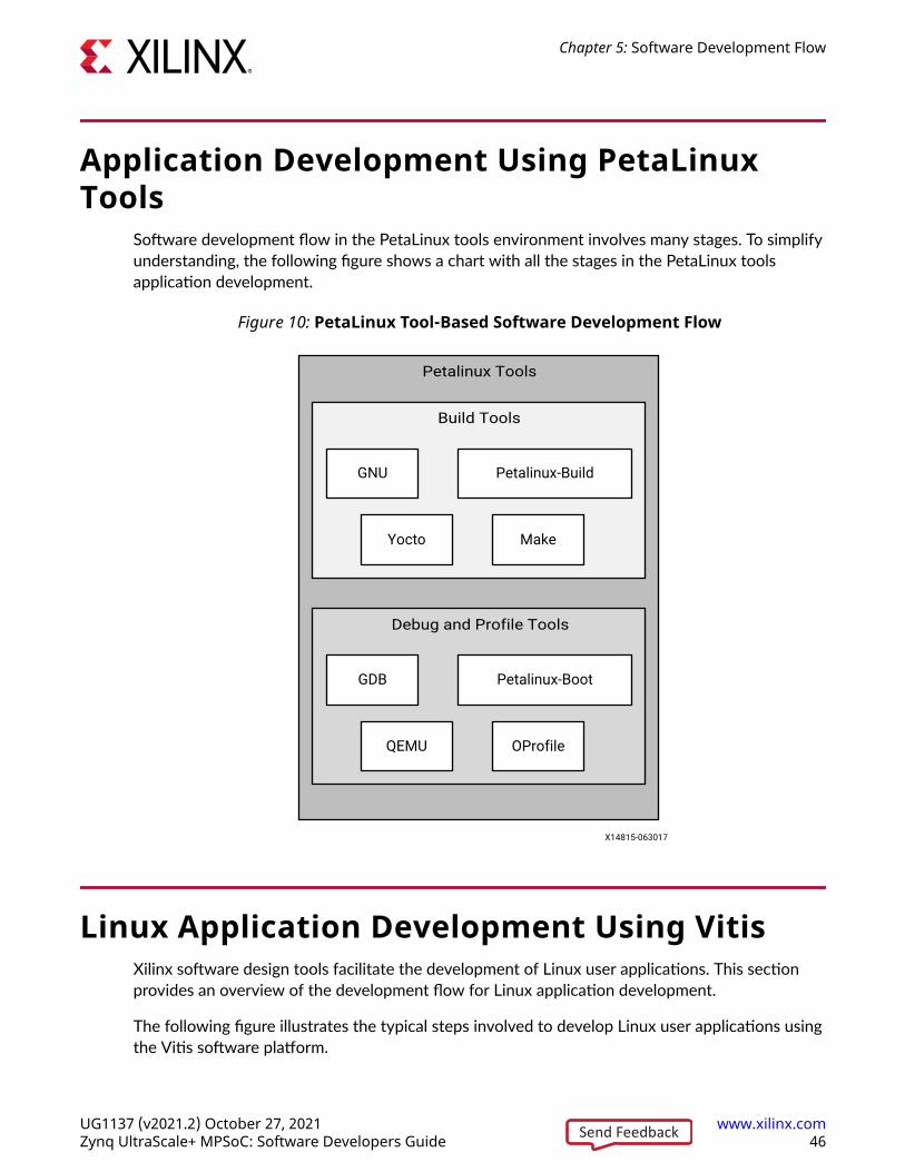
Application Development Using PetaLinuxTools
Software development flow in the PetaLinux tools environment involves many stages. To simplifyunderstanding, the following figure shows a chart with all the stages in the PetaLinux toolsapplication development.
Figure 10: PetaLinux Tool-Based Software Development Flow
Petalinux Tools
Build Tools
Debug and Profile Tools
GNU Petalinux-Build
Yocto Make
GDB Petalinux-Boot
QEMU OProfile
X14815-063017
Linux Application Development Using VitisXilinx software design tools facilitate the development of Linux user applications. This sectionprovides an overview of the development flow for Linux application development.
The following figure illustrates the typical steps involved to develop Linux user applications usingthe Vitis software platform.
Chapter 5: Software Development Flow
UG1137 (v2021.2) October 27, 2021 www.xilinx.comZynq UltraScale+ MPSoC: Software Developers Guide 46Send Feedback

Figure 11: Linux Application Development Flow
Invoke SDK
Create a Linux application project
Build the Linux application project
Software Application DevelopmentProfiling
Performance met?
Download Hardware Bitstream to FPGA
Debug
Functionality achieved?
Open / CreateSDK workspace
Adding an Application to Linux file system
Yes Yes
No No
Boot Linux & set up target connection
X14816-063017
Creating a Linux Application ProjectYou can create a C or C++ Linux application project by using the New Application Project wizard.
Chapter 5: Software Development Flow
UG1137 (v2021.2) October 27, 2021 www.xilinx.comZynq UltraScale+ MPSoC: Software Developers Guide 47Send Feedback

To create a project:
1. Click File → New → Application Project. The New Application Project dialog box appears.
2. Type a project name into the Project Name field.
3. Select the location for the project. You can use the default location as displayed in theLocation field by leaving the Use default location check box selected. Otherwise, click thecheck box and type or browse to the directory location.
4. Select Next.
5. On the Select platform tab, select the Platform that has a Linux domain and click Next.
6. On the Domain window, select the domain from the Domain drop-down.
7. Select your preferred language: C or C++.
8. Optionally, select Linux System Root to specify the Linux sysroot path and select LinuxToolchain to specify the Linux toolchain path.
9. Click Next to move to the Templates screen.
10. The Vitis software platform provides useful sample applications listed in the Templates dialogbox that you can use to create your project. The Description box displays a brief descriptionof the selected sample application. When you use a sample application for your project, theVitis software platform creates the required source and header files and linker script.
11. Select the desired template. If you want to create a blank project, select Empty Application.You can then add C files to the project, after the project is created.
12. Click Finish to create your Linux application project.
13. Click the icon to generate or build the application project.
Create a Hello World ApplicationAfter installing the Vitis™ software platform, the next step is to create a software applicationproject. Software application projects are the final application containers. The project directorythat is created contains (or links to) your C/C++ source files, executable output file, andassociated utility files, such as the Makefiles used to build the project.
Note: The Vitis software platform automatically creates a system project for you. A system project is a top-level container project that holds all of the applications that can run in a system at the same time. This isuseful if you have many processors in your system, especially if they communicate with one another,because you can debug, launch, and profile applications as a set instead of as individual items.
Build a Sample Application
This section describes how to create a sample Hello World application using an existing template.
1. Launch the Vitis software platform.
2. Select a workspace directory for your first project.
Chapter 5: Software Development Flow
UG1137 (v2021.2) October 27, 2021 www.xilinx.comZynq UltraScale+ MPSoC: Software Developers Guide 48Send Feedback

3. Click Launch. The welcome page appears.
4. Close the welcome page. The development perspective opens.
5. Select File → New → Application Project.
6. Enter a name in the Project name field and click Next. The Select platform tab opens. Youshould choose a platform for your project. You can either use a pre-supplied platform (fromXilinx or another vendor), a previously created custom platform, or you can create oneautomatically from an exported Vivado® hardware project.
7. On the Select platform tab, click the platform you just created and click Next. To use your
own hardware platform, click the icon and add your platform to the list.
8. Select the system configuration for your project and click Next. The Templates windowopens.
9. Select Hello World and click Next. Your workspace opens with the Explorer pane showingthe hello_world_system system project and the zcu102 platform project.
10. Right-click the system project and select Build Project. You have now built your applicationand the Console tab shows the details of the file and application size.
Debug and Run the Application
Now that you have generated the executable binary, you can test it on a board. To run theapplication on the board, perform the following preliminary steps:
• Connect a JTAG cable to the computer.
• Set the Boot Mode switch of the board to JTAG mode.
• Connect a USB UART cable and setup your UART console.
• Power up the board.
1. Expand the system project and choose the application project you want to debug. Right-clickthe application and select Debug As → Launch on Hardware (Single Application Debug).
2. On the Confirm Perspective Switch dialog, click Yes. The Vitis IDE switches to the Debugperspective and the debugger stops at the entry to your main() function.
3. Using the commands in the toolbar, step through the application. After you step through theprint() function, Hello World appears in the UART console.
Adding Driver Support for Custom IP in the PLThe Vitis software platform supports Linux BSP generation for peripherals in the PS as well ascustom IP in the PL. When generating a Linux BSP, the Vitis software platform produces a devicetree, which is a data structure describing the hardware system that passes to the kernel whenyou boot.
Chapter 5: Software Development Flow
UG1137 (v2021.2) October 27, 2021 www.xilinx.comZynq UltraScale+ MPSoC: Software Developers Guide 49Send Feedback

Device drivers are available as part of the kernel or as separate modules, and the device treedefines the set of hardware functions available and features enabled.
Additionally, you can add dynamic, loadable drivers. The Linux kernel supports these drivers.Custom IP in the PL are highly configurable, and the device tree parameters define both the setof IP available in the system and the hardware features enabled in each IP.
See Chapter 3: Development Tools for additional overview information on the Linux Kernel andboot sequence.
Chapter 5: Software Development Flow
UG1137 (v2021.2) October 27, 2021 www.xilinx.comZynq UltraScale+ MPSoC: Software Developers Guide 50Send Feedback
Chapter 6
Software Design ParadigmsThe Xilinx® Zynq® UltraScale+™ MPSoC architecture supports heterogeneous multiprocessorengines targeted at different tasks. The main approaches for developing software to target theseprocessors are by using the following:
• Frameworks for Multiprocessor Development: Describes the frameworks available fordevelopment on the Zynq UltraScale+ MPSoC.
• Symmetric Multiprocessing (SMP): Using SMP with PetaLinux is the most simple flow fordeveloping an SMP with a Linux platform for the Zynq UltraScale+ MPSoC.
• Asymmetric Multiprocessing (AMP): AMP is a powerful mode to use multiple processorengines with precise control over what runs on each processor. Unlike SMP, there are manydifferent ways to use AMP. This section describes two ways of using AMP with varying levelsof complexity.
The following sections describe these development methods in more detail.
Frameworks for Multiprocessor DevelopmentXilinx provides multiple frameworks for Zynq UltraScale+ MPSoCs to facilitate the applicationdevelopment on the heterogeneous processors and Xilinx 7 series FPGAs. These frameworks aredescribed as follows:
• Hypervisor Framework: Xilinx provides the Xen hypervisor, a critical item needed to supportvirtualization on APU of Zynq UltraScale+ MPSoC. The Use of Hypervisors section coversmore details.
• Authentication Framework: The Zynq UltraScale+ MPSoC supports authentication andencryption features as a part of authentication framework. To understand more about theauthentication framework, see Boot Time Security.
• TrustZone Framework: The TrustZone technology allows and maintains isolation betweensecure and non-secure processes within the same system. See this whitepaper for moreinformation.
Xilinx provides the trustzone support through the Trusted Firmware-A (TF-A) to maintain theisolation between secure and non-secure worlds. To understand more about TF-A, see TrustedFirmware-A.
Chapter 6: Software Design Paradigms
UG1137 (v2021.2) October 27, 2021 www.xilinx.comZynq UltraScale+ MPSoC: Software Developers Guide 51Send Feedback

• Multiprocessor Communication Framework: Xilinx provides the OpenAMP framework forZynq UltraScale+ MPSoCs to allow communication between the different processing units.For more details, see the Xilinx Quick Emulator User Guide: QEMU
• Power Management Framework: The power management framework allows softwarecomponents running across different processing units to communicate with the powermanagement unit.
Symmetric Multiprocessing (SMP)SMP enables the use of multiple processors through a single operating system instance. Theoperating system handles most of the complexity of managing multiple processors, caches,peripheral interrupts, and load balancing.
The APU in the Zynq UltraScale+ MPSoCs contains four homogeneous cache coherent Arm®
Cortex®-A53 processors that support SMP mode of operation using an OS (Linux or VxWorks).Xilinx and its partners provide operating systems that make it easy to leverage SMP in the APU.The following diagram shows an example of Linux SMP with multiple applications running on asingle OS.
Figure 12: Example SMP Using Linux
APU
ArmCortex-A53
ArmCortex-A53
ArmCortex-A53
ArmCortex-A53
Linux Kernel in SMP
Application n
Thre
ad 1
Thre
ad 2
Thre
ad n
Application 1
Thre
ad 1
Thre
ad 2
Thre
ad n
X14837-063017
Chapter 6: Software Design Paradigms
UG1137 (v2021.2) October 27, 2021 www.xilinx.comZynq UltraScale+ MPSoC: Software Developers Guide 52Send Feedback

This would not be the best mode of operation when there are hard, real-time requirements as itignores Linux application core affinity which should be available to developers with the existingXilinx software.
Asymmetric Multiprocessing (AMP)AMP uses multiple processors with precise control over what runs on each processor. UnlikeSMP, there are many different ways to use AMP. This section describes two ways of using AMPwith varying levels of complexity.
In AMP, a software developer must decide what code has to run on each processor beforecompiling and creating a boot image that includes the software executable for each CPU. UsingAMP with the Arm Cortex-R5F processors (SMP is not supported in Cortex-R5F) in the RPUenables developers to meet highly demanding, hard real-time requirements as opposed to softreal-time requirements.
You can develop the applications independently, and program those applications to communicatewith each other using inter-processing communication (IPC) options. See this link to the“Interrupts” chapter of the Zynq UltraScale+ Device Technical Reference Manual (UG1085) forfurther description of this feature.
You can also apply this AMP method to applications running on MicroBlaze™ processors in thePL or even in the APU. The following diagram shows an AMP example with applications runningon the RPU and the PL without any communication with each other.
Figure 13: AMP Example using Bare-Metal Applications Running on RPU and PL
MicroBlaze
Bare-metalApplication
Bare-metalApplication
Bare-metalApplication
RPUPL
ArmCortex-R5F
ArmCortex-R5F
MicroBlaze
MicroBlaze
X19225-071317
OpenAMPThe OpenAMP framework provides mechanisms to do the following:
Chapter 6: Software Design Paradigms
UG1137 (v2021.2) October 27, 2021 www.xilinx.comZynq UltraScale+ MPSoC: Software Developers Guide 53Send Feedback

• Load and unload firmware
• Communicate between applications using a standard API
The following diagram shows an example of an OpenAMP and the hard real-time capabilities ofthe RPU using the OpenAMP framework.
In this case, Linux applications running on the APU perform the loading and unloading of RPUapplications. This allows developers to load different processing dedicated algorithms to the RPUprocessing engines as needed with very deterministic performance.
Figure 14: Example with SMP and AMP using OpenAMP Framework
X14839-063017
APU
ArmCortex-A53
Arm Cortex-A53
Arm Cortex-A53
Arm Cortex-A53
Linux Kernel in SMP mode RTOSKernel
BaremetalApplication
Application 1
Thre
ad 1
Thre
ad 2
Thre
ad n
RPU
ArmCortex-R5F
Arm Cortex-R5F
PL
MicroBlaze
MicroBlaze
RTOSKernel
BaremetalApplication
BaremetalApplication
Application n
Thre
ad 1
Thre
ad 2
Thre
ad n
RPMsg
Open AMP(APIs for loading/ Unloading firmware, Message Passing)
RPMsg
See the Libmetal and OpenAMP for Zynq Devices User Guide (UG1186) for more information aboutthe OpenAMP Framework.
Virtualization with HypervisorThe Zynq UltraScale+ MPSoCs include a hardware virtualization extension on the Arm Cortex-A53 processors, interrupt controller, and Arm System MMU (SMMU) that provides flexibility tocombine various operating system combinations, including SMP and AMP, within the APU.
The following diagram shows an example of an SMP-capable OS, like Linux working along withReal-Time Operating System (RTOS) as well as a bare metal application using a single hypervisor.
This enables independent development of applications in their respective mode of operation.
Chapter 6: Software Design Paradigms
UG1137 (v2021.2) October 27, 2021 www.xilinx.comZynq UltraScale+ MPSoC: Software Developers Guide 54Send Feedback

Figure 15: Example with Hypervisor
X14840-063017
Hypervisor
APU
ArmCortex-A53
Arm Cortex-A53
Arm Cortex-A53
Arm Cortex-A53
Linux Kernel inSMP mode
RTOSKernel
BaremetalApplication
Application 1
Thre
ad 1
Thre
ad 2
Thre
ad n
Appl
icat
ion
n
Task
1
Task
2
Task
n
Although the hardware virtualization included within Zynq UltraScale+ MPSoC and itshypervisors allow the standard operating systems and their applications to function with low tomoderate effort, the addition of a hypervisor does bring design complexity to low-level systemfunctions such as power management, FPGA bitstream management,
OpenAMP software stack, and security accelerator access which must use additional underlyinglayers of system firmware. Hence, Xilinx recommends that the developers must initiate earlyeffort into these aspects of system architecture and implementation.
For more details on using Hypervisor like the Xen Hypervisor, see the MPSoC Xen Hypervisorwebsite.
Chapter 6: Software Design Paradigms
UG1137 (v2021.2) October 27, 2021 www.xilinx.comZynq UltraScale+ MPSoC: Software Developers Guide 55Send Feedback

Use of HypervisorsXilinx distributes a port for the Xen open source hypervisor in the XilinxZynq UltraScale+ MPSoC. Xen hypervisor provides the ability to run multiple operating systemson the same computing platform. Xen hypervisor, which runs directly on the hardware, isresponsible for managing CPU, memory, and interrupts. Multiple numbers of OS can run on topof the hypervisor. These operating systems are called domains (also called as virtual machines(VMs)).
The Xen hypervisor provides the ability to concurrently run multiple operating systems and theirstandard applications with relative ease. However, Xen does not provide a generic interfacewhich gives the guest an operating system access to system functions. Hence, you need to followthe cautions mentioned in this section.
Xen hypervisor controls one domain, which is domain 0, and one or more guest domains. Thecontrol domain has special privileges, such as the following:
• Capability to access the hardware directly
• Ability to handle access to the I/O functions of the system
• Interaction with other virtual machines.
It also exposes a control interface to the outside world, through which the system is controlled.Each guest domain runs its own OS and application. Guest domains are completely isolated fromthe hardware.
Running multiple Operating Systems using Xen hypervisor involves setting up the host OS andadding one or more guest OS.
Note: Xen hypervisor is available as a selectable component within the PetaLinux tools; Xen hypervisor canalso be downloaded from Xilinx GIT. With Linux and Xen software that is made available by Xilinx, it ispossible to build custom Linux guest configurations. Guest OS other than Linux require additional softwareand effort from third-parties. See the PetaLinux Product Page for more information.
Chapter 6: Software Design Paradigms
UG1137 (v2021.2) October 27, 2021 www.xilinx.comZynq UltraScale+ MPSoC: Software Developers Guide 56Send Feedback

Chapter 7
System Boot and ConfigurationZynq® UltraScale+™ MPSoCs support the ability to boot from different devices such as a QSPIflash, an SD card, a host with Device Firmware Upgrade utility installed on it, or a NAND flash inplace. This chapter details the booting process using different booting devices in both secure andnon-secure modes.
Boot Process OverviewThe platform management unit (PMU) and configuration security unit (CSU) manage and performthe multi-staged booting. You can boot the device in either secure (using authenticated bootimage) or non-secure (using an unauthenticated boot image) mode. The boot stages are asfollows:
• Pre-configuration stage: The PMU primarily controls pre-configuration stage that executesPMU ROM to setup the system. The PMU handles all of the processes related to reset andwake-up.
• Configuration stage: This stage is responsible for loading the first-stage boot loader (FSBL)code for the PS into the on-chip RAM (OCM). It supports both secure and non-secure bootmodes. Through the boot header, you can execute FSBL on the Cortex®-R5F-0 / R5-1processor or the Cortex®-A53 processor. The Cortex-R5F-0 processor also supports lock stepmode.
• Post-configuration stage: After FSBL execution starts, the Zynq UltraScale+ MPSoC entersthe post configuration stage.
Boot FlowThere are two boot flows in the Zynq UltraScale+ MPSoC architecture: secure and non-secure.The following sections describe some of the example boot sequences in which you bring upvarious processors and execute the required boot tasks.
Note: The figures in these sections show the complete boot flow, including all mandatory and optionalcomponents.
Chapter 7: System Boot and Configuration
UG1137 (v2021.2) October 27, 2021 www.xilinx.comZynq UltraScale+ MPSoC: Software Developers Guide 57Send Feedback

Figure 16: Boot Flow Example
Time
Release CSU
Power Monitoring
LoadFSBL
Tamper Monitoring
PMU
CSU
RPU FSBL
APU U-Boot LinuxATF
X18969-062421
Non-Secure Boot Flow
In non-secure boot mode, the PMU releases the reset of the configuration security unit (CSU),and enters the PMU server mode where it monitors power. After the PMU releases the CSUfrom reset, it loads the FSBL into OCM. PMU firmware runs from PMU RAM in parallel to FSBLin OCM. FSBL is run on APU or RPU. FSBL runs from APU/RPU and TF-A; U-Boot and Linux runon APU. Other boot configurations allow the RPU to start and operate wholly independent ofthe APU and vice-versa.
• On APU, TF-A will be executed after the FSBL hands off to TF-A. TF-A hands off to a secondstage boot loader like U-Boot which executes and loads an operating system such as Linux.
• On RPU, FSBL hands off to a software application.
• Linux, in turn, loads the executable software.
Note: The operating system manages the multiple Cortex-A53 processors in symmetric multi-processing(SMP) mode.
Secure Boot Flow
In the secure boot mode, the PMU releases the reset of the configuration security unit (CSU) andenters the PMU server mode where it monitors power. After the PMU releases the CSU fromreset, the CSU checks to determine if authentication is required by the FSBL or the userapplication.
The CSU does the following:
• Performs an authentication check and proceeds only if the authentication check passes. Thenchecks the image for any encrypted partitions.
• If the CSU detects partitions that are encrypted, the CSU performs decryption and loads theFSBL into the OCM.
Chapter 7: System Boot and Configuration
UG1137 (v2021.2) October 27, 2021 www.xilinx.comZynq UltraScale+ MPSoC: Software Developers Guide 58Send Feedback

For more information on CSU, see the Configuration Security Unit section.
FSBL running on APU hands off to TF-A. FSBL running on RPU loads TF-A. In both the cases, TF-A loads U-Boot which loads the OS. TF-A then executes the U-Boot and loads an OS such asLinux. Then Linux, in turn, loads the executable software. Similarly, FSBL checks forauthentication and encryption of each partition it tries to load. The partitions are only loaded byFSBL on successful authentication and decryption (if previously encrypted).
Note: In the secure boot mode, psu_coresight_0 is not supported as a stdout port.
Boot Image CreationBootgen is a tool that lets you stitch binary files together and generate device boot images.Bootgen defines multiple properties, attributes and parameters that are input while creating bootimages for use in a device.
The secure boot feature for devices uses public and private key cryptographic algorithms.Bootgen provides assignment of specific destination memory addresses and alignmentrequirements for each partition. It also supports encryption and authentication, described in theBootgen User Guide (UG1283). More advanced authentication flows and key management optionsare discussed in the Using HSM Mode section of Bootgen User Guide (UG1283), where Bootgencan output intermediate hash files that can be signed offline using private keys to sign theauthentication certificates included in the boot image. The program assembles a boot image byadding header blocks to a list of partitions.
Optionally, each partition can be encrypted and authenticated with Bootgen. The output is asingle file that can be directly programmed into the boot flash memory of the system.
Various input files can be generated by the tool to support authentication and encryption as well.
Bootgen comes with both a GUI interface and a command line option. The tool is integrated intothe software development toolkit, Integrated Development Environment (IDE), for generatingbasic boot images using a GUI, but the majority of Bootgen options are command line-driven.Command line options can be scripted. The Bootgen tool is driven by a boot image format (BIF)configuration file, with a file extension of *.bif. Along with SoC, Bootgen has the ability toencrypt and authenticate partitions for and later FPGAs, as described in FPGA Support. Alongwith SoC and ACAP devices, Bootgen has the ability to encrypt and authenticate partitions forand later FPGAs, as described in FPGA Support. In addition to the supported command andattributes that define the behavior of a Boot Image, there are utilities that help you work withBootgen. Bootgen code is now available on Github.
Chapter 7: System Boot and Configuration
UG1137 (v2021.2) October 27, 2021 www.xilinx.comZynq UltraScale+ MPSoC: Software Developers Guide 59Send Feedback

Creating a Bootable ImageWhen a system project is selected, by running build, the Vitis software platform builds allapplications in the system project and creates a bootable image according to a pre-defined BIF oran auto-generated BIF.
You can create bootable images using Bootgen. In the Vitis™ IDE, the Create Boot Image menuoption is used to create the boot image.
To create a bootable image, follow these steps:
1. Select the Application Project in the Project Explorer view.
2. Right-click the application and select Create Boot Image to open the Create Boot Imagedialog box.
3. Specify the boot loader and the partitions.
Chapter 7: System Boot and Configuration
UG1137 (v2021.2) October 27, 2021 www.xilinx.comZynq UltraScale+ MPSoC: Software Developers Guide 60Send Feedback

4. Click Create Image to create the image and generate the BOOT.bin in the<Application_project_name>/_ide/bootimage folder.
Boot ModesRefer to this link to the “Boot and Configuration” chapter of the Zynq UltraScale+ Device TechnicalReference Manual (UG1085) for a comprehensive table of the available boot modes.
Chapter 7: System Boot and Configuration
UG1137 (v2021.2) October 27, 2021 www.xilinx.comZynq UltraScale+ MPSoC: Software Developers Guide 61Send Feedback

QSPI24 and QSPI32 Boot ModesThe QSPI24 and QSPI32 boot modes support the following:
• x1, x2, and x4 read modes for single Quad SPI flash memory 24 (QSPI24) and single Quad SPIflash memory 32 (QSPI32)
• x8 read mode for dual QSPI.
• Image search for MultiBoot
• I/O mode for BSP drivers (no support in FSBL)
The bootROM searches the first 256 Mb in x8 mode. In QSPI24 and QSPI32 boot modes (wherethe QSPI24/32 device is < 128 Mb), to use MultiBoot, place the multiple images so that they fitin memory locations less than 128 Mb. The pin configuration for QSPI24 boot mode is 0x1.
Note: QSPI dual stacked (x8) boot is not supported. Only QSPI Single Transmission Rate (STR) is supported.Single Quad-SPI memory (x1, x2, and x4) is the only boot mode that supports execute-in-place (XIP).
To create a QSPI24/QSPI32 boot image, provide the following files to the Bootgen tool:
• An FSBL ELF
• A secondary boot loader (SBL), such as U-Boot, or a Cortex-R5F-0/R5-1 and/or a Cortex-A53application ELF
• Authentication and encryption key (optional)
For more information on Authentication and Encryption, see Chapter 8: Security Features.
Bootgen generates the boot.mcs and a boot.bin binary file that you can write into the QSPIflash using the flash writer. MCS is an Intel hex-formatted file that includes a checksum forreliability.
Note: The pin configuration for QSPI24 boot mode is 0x1 for qspi 24 and 0x2 for qspi32.
SD Boot ModeSD boot (version 3.0) supports the following:
• FAT 16/32 file systems for reading the boot images.
• Image search for MultiBoot with a maximum number 8,192 files are supported.
Note: exFAT is not supported for SD boot in FSBL and U-Boot.
The following figure shows an example for booting Linux in SD mode.
Chapter 7: System Boot and Configuration
UG1137 (v2021.2) October 27, 2021 www.xilinx.comZynq UltraScale+ MPSoC: Software Developers Guide 62Send Feedback

Figure 17: Booting in SD Mode
Bootgen Tool
Boot.bin
FAT 32Kernel Image
Device tree file
Root file systemEXT 3
File system
ZynqUltraScale+
MPSoc
0 1 0 1
Petalinux SDK
SDKFSBL
U-Boot
A53 Image
KEY
.bif
SD card Boot Mode pins
KEY
Board
X14933-063017
To create an SD boot image, provide the following files to Bootgen:
• An FSBL ELF
• A Cortex-R5F-0/R5-1 and/or an Cortex-A53 application ELF
• Optional authentication and encryption keys
The Bootgen tool generates the boot.bin binary file. You can write the boot.bin file into an SDcard using a SD card reader.
In PetaLinux, do the following:
1. Build the Linux kernel image, device tree file, and the root file system.
2. Copy the files into the SD card.
The formatted SD card then contains the boot.bin, the kernel image, and the device tree file inthe FAT32 partition; the root file system resides in the EXT 4 partition.
IMPORTANT! To boot from SD1, configure the boot pins to 0x5. To boot from SD0, configure the bootpins to 0x3.To boot from SD with a level shifter, configure the boot pins to 0xE.
eMMC18 Boot ModeeMMC18 boot (version 4.5) supports the following:
• FAT 16/32 file systems for reading the boot images.
• Image search for MultiBoot with a maximum number of 8,192 files being supported.
Chapter 7: System Boot and Configuration
UG1137 (v2021.2) October 27, 2021 www.xilinx.comZynq UltraScale+ MPSoC: Software Developers Guide 63Send Feedback
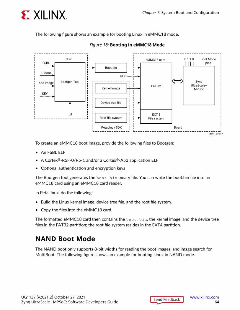
The following figure shows an example for booting Linux in eMMC18 mode.
Figure 18: Booting in eMMC18 Mode
Bootgen Tool
Boot.bin
FAT 32Kernel Image
Device tree file
Root file systemEXT 3
File system
ZynqUltraScale+
MPSoc
0 1 1 0
PetaLinux SDK
SDKFSBL
U-Boot
A53 Image
KEY
.bif
eMMC18 card Boot Mode pins
KEY
Board
X18971-071317
To create an eMMC18 boot image, provide the following files to Bootgen:
• An FSBL ELF
• A Cortex®-R5F-0/R5-1 and/or a Cortex®-A53 application ELF
• Optional authentication and encryption keys
The Bootgen tool generates the boot.bin binary file. You can write the boot.bin file into aneMMC18 card using an eMMC18 card reader.
In PetaLinux, do the following:
• Build the Linux kernel image, device tree file, and the root file system.
• Copy the files into the eMMC18 card.
The formatted eMMC18 card then contains the boot.bin, the kernel image, and the device treefiles in the FAT32 partition; the root file system resides in the EXT4 partition.
NAND Boot ModeThe NAND boot only supports 8-bit widths for reading the boot images, and image search forMultiBoot. The following figure shows an example for booting Linux in NAND mode.
Chapter 7: System Boot and Configuration
UG1137 (v2021.2) October 27, 2021 www.xilinx.comZynq UltraScale+ MPSoC: Software Developers Guide 64Send Feedback

Figure 19: Booting in NAND Mode
Boot Header
FSBL
SBL
R5 Image
A53 Image
BootgenTool Flash
Writer
Flash
Boot.bin
eFuse
FSBL
R5 Image
A53 Image
.bif
SDK
JTAG
Key
QSPI
Board
NANDConverter
NANDimage
Key
FSBL
Boot Pins
ZynqUltraScale+
MPSoC
0100
X14934-071317
To create a NAND boot image, provide the following files to Bootgen:
• An FSBL ELF
• A Cortex-R5F-0/R5-1 application ELF and/or an Cortex-A53 application ELF
• Optional authentication/encryption keys
The Bootgen tool generates the boot.bin binary file. You can then write the NAND bootableimage into the NAND flash using the flash writer
IMPORTANT! To boot from NAND, configure boot pins to 0x4.
JTAG Boot ModeYou can manually download any software image needed for the PS and any hardware image onthe PL using JTAG. For JTAG boot mode settings, see this link in the Zynq UltraScale+ DeviceTechnical Reference Manual (UG1085).
IMPORTANT! Secure boot is not supported in the JTAG mode.
USB Boot ModeThe USB boot mode supports only USB 2.0. In USB boot mode, both the secure and non-secureboot modes are supported. USB boot mode is not supported for DDR-less systems. Features likeMultiboot, fallback image, and XIP are not supported.
Note: USB boot mode is disabled by default in FSBL. To enable the USB boot mode, configure theFSBL_USB_EXCLUDE_VAL to 0 in xfsbl_config.h file.
Chapter 7: System Boot and Configuration
UG1137 (v2021.2) October 27, 2021 www.xilinx.comZynq UltraScale+ MPSoC: Software Developers Guide 65Send Feedback

Table 13: USB Boot Mode Details
Pin FunctionalityMode pins 0x7
MIO pins MIO[63:52]
Non-secure Yes
Secure Yes
Signed Yes
Mode Slave
USB boot mode requires a host PC with dfu-utils installed on it. The host and device need to beconnected through a USB 2.0 or USB 3.0 cable. The host must contain one boot.bin to be loadedby bootROM, which contains only fsbl.elf and another boot_all.bin to be loaded byFSBL. On powering up the board in USB boot mode, issue the following commands:
• On Linux host:
• dfu-util -D boot.bin: This downloads the file to the device, which is processed bybootROM.
• dfu-util -D boot_all.bin: This downloads the file to the device, which is processed by FSBL.
• On Windows host:
• dfu-util.exe -D boot.bin: This downloads the file to the device, which is processed bybootROM.
• dfu-util.exe -D boot_all.bin: This downloads the file to the device, which is then processedby FSBL.
The size limit of boot.bin and boot_all.bin are the sizes of OCM and DDR. The size ofOCM is 256 KB.
Secondary Boot ModeThere is a provision to have two boot devices in the Zynq UltraScale+ MPSoC architecture. Theprimary boot mode is the boot mode used by bootROM to load FSBL and optionally PMU FW.The secondary boot mode is the boot device used by FSBL to load all the other partitions. Thesupported secondary boot modes are QSPI24, QSPI32, SD0, eMMC, SD1, SD1-LS, NAND andUSB.
When using PS-PCIe® on ZU+ in Endpoint mode, running FSBL is enough to set up the block forendpoint mode operation. FSBL should be able to program the PS/PS-PCIe® and GTR within 100ms. However, this doesn’t include PL-bitstream programming as including that would make thisgreater than 100 ms.
Chapter 7: System Boot and Configuration
UG1137 (v2021.2) October 27, 2021 www.xilinx.comZynq UltraScale+ MPSoC: Software Developers Guide 66Send Feedback

IMPORTANT! If secondary boot mode is specified, it should be different from the primary boot device. Forexample, if QSPI32 is the primary boot mode, QSPI24 cannot be the secondary boot mode. Instead, youcan have SD0, eMMC, SD1, SD1-LS, NAND, USB as secondary boot modes. All combinations of bootdevices are supported as primary and secondary boot devices.
Note: By default, the secondary boot mode is the same as primary boot mode and there will be only oneboot image.
See What is Secondary Boot Mode in FSBL wiki page for more information.
Detailed Boot FlowThe platform management unit (PMU) in the Zynq UltraScale+ MPSoC is responsible for handlingthe primary pre-boot tasks.
PMU ROM will execute from a ROM during boot to configure a default power state for thedevice, initialize RAMs, and test memories and registers. After the PMU performs these tasks andrelinquishes system control to the configuration security unit (CSU), it enters a service mode. Inthis mode, the PMU responds to interrupt requests made by system software through theregister interface or by hardware through the dedicated I/O to perform platform managementservices.
Pre-Boot SequenceThe following table lists the tasks performed by the PMU in the pre-Boot sequence.
Table 14: Pre-Boot Sequence
Pre-Boot Task Description0 Initialize MicroBlaze™ processor. Capture key states.
1 Scan, and clear LPD and FPD.
2 Initialize the System Monitor.
3 Initialize the PLL used for MBIST clocks.
4 Zero out the PMU RAM.
5 Validate the PLL. Configure the MBIST clock.
6 Validate the power supply.
7 Repair FPD memory (if required).
8 Zeroize the LPD and FPD and initialize memory self-test.
9 Power-down any disabled IPs.
10 Either release CSU or enter error state.
11 Enter service mode.
Chapter 7: System Boot and Configuration
UG1137 (v2021.2) October 27, 2021 www.xilinx.comZynq UltraScale+ MPSoC: Software Developers Guide 67Send Feedback

As soon as the CSU reset is released, it executes the CSU bootROM and performs the followingsequence:
1. Initializes the OCM.
2. Determines the boot mode by reading the boot mode register, which captures the boot-modepin strapping at the POR.
3. The CSU continues with the FSBL load and the optional PMU firmware load. PMU firmwareis the software that can be executed by the PMU unit. The code executes from the RAM ofthe PMU. See Chapter 9: Platform Management for more information.
The following figure shows the detailed boot flow diagram.
Chapter 7: System Boot and Configuration
UG1137 (v2021.2) October 27, 2021 www.xilinx.comZynq UltraScale+ MPSoC: Software Developers Guide 68Send Feedback

Figure 20: Detailed Boot Flow Example
Power ON
PMU releases CSU Reset
Read Boot Mode Pins
Read Boot Header from the Boot image
Check for Authentication
Fallback bootDecrypt FSBL
Load FSBL to OCM
FSBL configures the PS
FSBL configures PL with the bitstream
FSBL loads the RPU software
FSBL loads the APU software
FSBL Handoff to APU software
Is FSBLAuthenticated?
YES
YES NOYES
NO
Is FSBLEncrypted?
Authentication Test passed?
Decryption Fails?
NO
Fallback boot
YES
APU/RPU
CSU
PMU
X14935-070717
Chapter 7: System Boot and Configuration
UG1137 (v2021.2) October 27, 2021 www.xilinx.comZynq UltraScale+ MPSoC: Software Developers Guide 69Send Feedback

Disabling FPD in Boot SequencePerform the following to avoid an FPD lockout, where FPD Power is applied momentarily:
• Apply the power until the completion of bootROM execution.
• To power down the FP during FSBL execution, set FPD bit '22' of PMU_GLOBALREQ_PWRDWN_STATUS register.
• To bring the FP domain up in a later stage of the boot process, set the PMU_GLOBALREQ_PWRUP_STATUS bit to '22’.
Perform the following in cases where the FPD power is not applied before the FSBL boots
1. Power up the R5.
2. A register is set indicating the FPD is locked pending POR as the reset or clear sequencecannot execute on the FPD.
3. R5 can read the FP locked status from PMU_GLOBAL REQ_ISO_STATUS register bit ‘4’.
4. At this stage, PMU_GLOBAL REQ_PWRUP_STATUS bit '22' will not be set.
5. To bring the FPD node back up, power must be supplied to the node and a POR needs to beissued.
Setting FSBL Compilation FlagsYou can set compilation flags using the C/C++ settings in the Vitis FSBL project, as shown in thefollowing figure:
Note: There is no need to change any of the FSBL source files or header files to include these flags.
Chapter 7: System Boot and Configuration
UG1137 (v2021.2) October 27, 2021 www.xilinx.comZynq UltraScale+ MPSoC: Software Developers Guide 70Send Feedback

Figure 21: FSBL Debug Flags
The following table lists the FSBL compilation flags.
Table 15: FSBL Compilation Flags
Flag DescriptionFSBL_DEBUG Prints basic information and error prints, if any.
FSBL_DEBUG_INFO Enables debug information in addition to the basic information.
FSBL_DEBUG_DETAILED Prints information with all data exchanged.
FSBL_NAND_EXCLUDE Excludes NAND support code.
FSBL_QSPI_EXCLUDE Excludes QSPI support code.
FSBL_SD_EXCLUDE Excludes SD support code.
SBL_SECURE_EXCLUDE Excludes authentication code and encryption code but not checksumcode.
FSBL_BS_EXCLUDE Excludes bitstream code.
FSBL_EARLY_HANDOFF_EXCLUDE Excludes early handoff related code.
FSBL_WDT_EXCLUDE Excludes WDT support code.
FSBL_PERF_EXCLUDE_VAL Excludes performance prints.
FSBL_A53_TCM_ECC_EXCLUDE_VAL Excludes TCM ECC Init for A53.
FSBL_PL_CLEAR_EXCLUDE_VAL Excludes PL clear unless boot.bin contains bitstream.
FSBL_PROT_BYPASS_EXCLUDE_VAL Excludes isolation configurations.
Chapter 7: System Boot and Configuration
UG1137 (v2021.2) October 27, 2021 www.xilinx.comZynq UltraScale+ MPSoC: Software Developers Guide 71Send Feedback

Table 15: FSBL Compilation Flags (cont'd)
Flag Description8FSBL_PARTITION_LOAD_EXCLUDE_VAL Excluded partition loading.
FSBL_USB_EXCLUDE_VAL Excludes USB code.This is set to 1 by default.Set this value to 0 to enable USB boot mode.
FSBL_FORCE_ENC_EXCLUDE_VAL Excludes forcing encryption of all partitions when ENC_ONLY fuse isprogrammed. By default, this is set to 0.FSBL forces to enable encryption for all the partitions when ENC_ONLYis programmed.
FSBL_DDR_SR_EXCLUDE_VAL DDR Excludes self refresh code.
FSBL_TPM_EXCLUDE_VAL Excludes TPM related code.
FSBL_PL_LOAD_FROM_OCM_EXCLUDE_VAL Excludes the code to load bitstream in chunks from OCM.
FSBL_UNPROVISIONED_AUTH_SIGN_EXCLUDE_VAL
Excludes the code to load authenticated partitions as non-secure whenEFUSEs are not programmed and when boot header is notauthenticated.
See "I’m unable to build FSBL due to size issues, how can I reduce its footprint?" section in FSBLwiki page for more information.
Enabling Debug Prints
See FSBL wiki page for more information on debugging FSBL.
Fallback and MultiBoot FlowIn the Zynq® UltraScale+™ MPSoC, the CSU bootROM supports MultiBoot and fallback bootimage search where the configuration security unit CSU ROM or bootROM searches through theboot device looking for a valid image to load. The sequence is as follows:
• BootROM searches for a valid image identification string (XLNX as image ID) at offsets of 32KB in the flash.
• After finding a valid identification value, validates the checksum for the header.
• If the checksum is valid, the bootROM loads the image. This allows for more than one image inthe flash.
In MultiBoot:
• CSU ROM or FSBL or the user application must initiate the boot image search to choose adifferent image from which to boot.
• To initiate this image search, CSU ROM or FSBL updates the MultiBoot offset to point to theintended boot image, and generates a soft reset by writing into the CRL_APB register.
The following figure shows an example of the fallback using the MultiBoot flow.
Chapter 7: System Boot and Configuration
UG1137 (v2021.2) October 27, 2021 www.xilinx.comZynq UltraScale+ MPSoC: Software Developers Guide 72Send Feedback

Figure 22: Fallback using the MultiBoot Flow
Boot Header
Image 1
.
.
.
.
Boot Header
Image 2
0x100_0000
0x002_0000
0x000_0000Boot Header 1
Image 1
.
.
.
.
.
Boot Header 2
Image 2
0x100_0000
0x002_0000
0x000_0000
.
.
.
.
0x001_0000
0x000_8000
0x001_8000
Multi-Boot Offset=1
Multi-Boot Offset=2
Multi-Boot Offset=3
Multi-Boot Offset=4
X14936-071217
Note: The same flow is applicable to both Secure and Non-secure boot methods.
In the example fallback boot flow figure, the following sequence occurs:
• Initially, the CSU bootROM loads the boot image found at 0x000_0000.
• If this image is found to be corrupted or the decryption and authentication fails, CSUbootROM increments the MultiBoot offset by one and searches for a valid boot image at0x000_8000 (32 KB offset).
• If the CSU bootROM does not find the valid identification value, it again increments theMultiBoot offset by 1, and searches for a valid boot image at the next 32 KB aligned address.
• The CSU bootROM repeats this until a valid boot image is found or the image search limit isreached. In this example flow, the next image is shown at 0x002_0000 corresponding to aMultiBoot offset value of four.
• In the example MultiBoot flow, to load the second image that is at the address 0x002_0000,MutiBoot offset is updated to four by FSBL/CSU-ROM. When the MultiBoot offset isupdated, soft reset the system.
The following table shows the MultiBoot image search range for different booting devices.
Chapter 7: System Boot and Configuration
UG1137 (v2021.2) October 27, 2021 www.xilinx.comZynq UltraScale+ MPSoC: Software Developers Guide 73Send Feedback

Table 16: Boot Devices and MultiBoot Image Search Range
Boot Device MultiBoot Image Search RangeQSPI Single (24-bit) 16 MB
QSPI Dual (24-bit) 32 MB
QSPI Single (32-bit) 256 MB
QSPI Dual (32-bit) 512 MB
NAND 128 MB
SD/EMMC 8,191 boot files
USB Not applicable
FSBL Build ProcessAfter authenticating and/or decrypting, the FSBL is loaded into OCM and handed off by the CSUbootROM. First Stage Boot Loader configures the FPGA with a bitstream (if it exists) and loadsthe Standalone (SA) Image or Second Stage Boot Loader image from the non-volatile memory(NAND/SD/eMMC/QSPI) to RAM(DDR/TCM/OCM). It takes the Cortex-R5F-0/R5F-1 processoror the Cortex-A53 processor unit out of reset. It supports multiple partitions. Each partition canbe a code image or a bitstream. Each of these partitions, if required, will be authenticated and/ordecrypted.
Note: If you are creating a custom FSBL, you should be aware that the OCM size is 256 KB and is availableto CSU bootROM. The FSBL size is close to 170 KB and it would fit in the OCM. While using the USB bootmode, you should make sure that the PMU firmware is loaded by the FSBL and not by the CSU bootROM.This is because the size of boot.bin loaded by the CSU bootROM should be less than 256 KB.
Note: Users can load bitstream from OCM for non-encrypted cases even if DDR is present in the design.By default, the FSBL_PL_LOAD_FROM_OCM_EXCLUDE_VAL value is set to 0 in xfsbl_config.h,making the bitstream copy and load from DDR in the non-encrypted cases. By setting theFSBL_PL_LOAD_FROM_OCM_EXCLUDE_VAL value to 1, the user can ensure that bitstream is loadedfrom OCM in chunks and not from DDR. Also, if DDR is not present in the design, the bitstream is loadedfrom OCM irrespective of the FSBL_PL_LOAD_FROM_OCM_EXCLUDE_VAL value.
Creating a New Zynq UltraScale+ MPSoC FSBLApplication ProjectTo create a new Zynq UltraScale+ MPSoC FSBL application in the Vitis software platform, do thefollowing:
1. Click File → New → Application Project.
The New Application Project dialog box appears.
2. In the Project Name field, type a name for the new project.
Chapter 7: System Boot and Configuration
UG1137 (v2021.2) October 27, 2021 www.xilinx.comZynq UltraScale+ MPSoC: Software Developers Guide 74Send Feedback

3. Select the location for the project. To use the default location as displayed in the Locationfield, leave the Use default location check box selected. Otherwise, click to deselect thecheck box, then type or browse to the directory location.
4. Select Create a new platform from hardware (XSA). The Vitis IDE lists the all the availablepre-defined hardware designs.
5. Select any one hardware design from the list and click Next.
6. From the CPU drop-down list, select the processor for which you want to build theapplication. This is an important step when there are multiple processors in your design. Inthis case you can either select psu_cortexa53_0 or psu_cortexr5_0.
7. Select your preferred language: C.
8. Select an OS for the targeted application.
9. Click Next.
10. In the Templates dialog box, select the Zynq UltraScale+ MPSoC FSBL template.
11. Click Finish to create your application project and board support package (if it does not exist).
Phases of FSBL OperationFSBL operation includes the following four stages:
• Initialization
• Boot device initialization
• Partition loading
• Handoff
The following figure shows the stages of FSBL operation:
Chapter 7: System Boot and Configuration
UG1137 (v2021.2) October 27, 2021 www.xilinx.comZynq UltraScale+ MPSoC: Software Developers Guide 75Send Feedback

Figure 23: Stages of FSBL
CSUROM
1. Initializatio
n
2. Boot Device
Initialization
3. Partition Copy,
Validation4. HandoffApplic
ation
wfe
PDR/RST Handoff to FSBL
Success
wfe
ErrorError
Error
JTAG Boot
Error
SLCR RST(FallBack)
Handoff
Jtag Boot/No Image
Partition Completed
Partition Not Completed
FallbackNot Supported
FSBL Stage Diagram
FSBL Block Diagram
1. Initialization1a. Get Reset Reason1b. System Initialization1c. Processor Initialization1d. DDR Initialization1e. Board Initialization1f. Reset Validation
2. Boot Device Installation and Header Validation
2a. Primary Boot Device Initialization2b. Header Validation2c. Secondary Boot Device Initialization
XFsbl Initialize()
XFsbl_BootDeviceInitAnd:Validate()
3. Partition Copy Validation3a. Partition Header Validation3b. Partition Copy
XFsbl_PartitionLoad()
4. Handoff4a. PM Init4b. Protection Config4c. Handoff to CPUs
XFsbl_Handoff()
X19962-101917
Initialization
Initialization consists of the following four internal stages:
XFsbl_SystemInit
This function powers up PL for 1.0 and 2.0 silicon and removes PS-PL isolation. It initializesclocks and peripherals as specified in psu-init. This function is not called in APU only reset.
Chapter 7: System Boot and Configuration
UG1137 (v2021.2) October 27, 2021 www.xilinx.comZynq UltraScale+ MPSoC: Software Developers Guide 76Send Feedback

Figure 24: FSBL System Initialization
Stage 1a
xFsbl_SystemInit()
SystemInitialization
Home
XFsbl_PowerUpIsland()XFsbl_IsolationRestore()
PowerupPL(Remove Isolation, For 1.0 & 2.0 silicon)
psu_init()*DDR, MIO, CLK, PLL Settings, Peripheral, SERDES Initialization
ConfigurationSuccessful? no
Error Lock Down
yes
In MMUtable for A53 mask DDR regions “memory”
Stage1c
X19952-101917
XFsbl_ProcessorInit
Processor initialization will start in this stage. It will set up the Instruction and Data caches, L2caches, MMU settings, stack pointers in case of A53 and I/D caches, MPU settings, memoryregions, stack pointers, and TCM settings for R5-0. Most of these settings will be performed inBSP code initialization. IVT vector is changed to the start of OCM for A53 and to start of TCM(0x0 in lowvec and 0xffff0000 in highvec) in case of R5-0.
Chapter 7: System Boot and Configuration
UG1137 (v2021.2) October 27, 2021 www.xilinx.comZynq UltraScale+ MPSoC: Software Developers Guide 77Send Feedback

Figure 25: Processor Initialization
Stage 1c
Stage 1b
Partition Initialization
Home
xFsbl_ProcessorInit()
Handoff from CSUROM main()
· Configure Memory Regions, SP, TCM (in BSP)· Enable MPU I/D Cache (In BSP)· Copy IVT to TCM (0x0)· Change reset address to TCM (0x0)
Read Cluster ID
A9? no
yes
· Configure SP· Enable MMU, I/D Cache, L2 Cache· Change IVT to start of OCM
XFsbl_RegisterHandlers() Enable ExceptionsRegister Exception Handlers
Stage 1d
X19954-101917
Initialize DDR
DDR would be initialized in this stage. This function is not called in Master only reset.
Chapter 7: System Boot and Configuration
UG1137 (v2021.2) October 27, 2021 www.xilinx.comZynq UltraScale+ MPSoC: Software Developers Guide 78Send Feedback

Figure 26: DDR Initialization
Stage 1d
Stage 1c
Stage 1e
DDR Initialization
DDR has ECC? no
yes
ECC Initialization of DDR
yes
Higher DDR Preset!
Stage 1eno
ECC Initialization of higher DDR
Stage 1e
X19957-101917
XFsbl_BoardInit
This function performs required board specific initializations. Most importantly, it configures GTlanes and IIC.
Chapter 7: System Boot and Configuration
UG1137 (v2021.2) October 27, 2021 www.xilinx.comZynq UltraScale+ MPSoC: Software Developers Guide 79Send Feedback

Figure 27: Board Initialization
Stage 1e
Stage 1d
Board Init
no Stage 1f
Initiate I2C driver
Board is 2cu102 or
2cu100
yes
Stage 1f
Configuration programming I2C
USBxxxxx
PCIE Reset for2CU102
X19960-101917
Boot Device Initialization
XFsbl_PrimaryBootDeviceInit
This stage involves reading boot mode register to identify the primary boot device and initializethe corresponding device. Each boot device driver provides init, copy and release functions whichare initialized to DevOps function pointers in this stage.
Chapter 7: System Boot and Configuration
UG1137 (v2021.2) October 27, 2021 www.xilinx.comZynq UltraScale+ MPSoC: Software Developers Guide 80Send Feedback

Figure 28: Primary Boot Device Initialization
Stage 2a Stage
1c
xFsbl_PrimaryBootDeviceInit()
yes
HomePrimary Boot Device
Initialization
XFsbl_InitWdt()XFsbl_CsuDmainit()
InitializeWDT,CSUDMA
drivers
BootMode==(JTAG || PJTAG0 ||
PJTAG1)yes
BootMode == (QSP124 || QSP132 || SD0
||EMMC||NAND||SD1 ||SD1 with level shifter)
no Wfe;
QSPI ?
no
ErrorLockDown
yesConfigure QSPIIn Single/Dual/Stacked mode
ConfigurationSuccess? no
ErrorLockDown
NAND ? yes ConfigurationSuccess?
no
no
ErrorLockDown
SD/eMMC yes ConfigurationSuccess?
no
no
Create bootimage name
yes
yes
no
no
Stage 2b
X19958-101917
Chapter 7: System Boot and Configuration
UG1137 (v2021.2) October 27, 2021 www.xilinx.comZynq UltraScale+ MPSoC: Software Developers Guide 81Send Feedback

XFsbl_ValidateHeader
Using the copy functions provided, the FSBL reads the boot header attributes and image offsetaddress. It reads the EFUSE bit to check for authentication. It reads the image header andvalidates the image header table. It then reads the Partition Present Device attribute of imageheader. A non-zero value indicates a secondary boot device. A zero value indicates that thesecondary boot device is the same as the primary boot device.
Figure 29: Validating Header
Stage 2b Stage
2a
xFsbl_ValidateHeader()
HomeHeader
Validation
XFsbl_ReadImageHeader() Read
Image Header
noErrorLockDown
Validate Image header
Populate handoff parameter to ATF
Success?
noImage Header
Table Validation Successful?
yes
yes
Stage 3a
Image Header Validation Checks* No partitions present* Num of partitions supported* Start of Partition Header offset Address check* Image Header Table Checksum
X19959-101917
Chapter 7: System Boot and Configuration
UG1137 (v2021.2) October 27, 2021 www.xilinx.comZynq UltraScale+ MPSoC: Software Developers Guide 82Send Feedback

XFsbl_SecondaryBootDeviceInit
This function is called in case of a non-zero value of Partition Present Device attribute of imageheader table. It initializes the secondary boot device driver and the secondary boot device wouldbe used to load all partitions by FSBL.
XFsbl_SetATFHandoffParams
TF-A is assumed to be the next loadable partition after FSBL. It is capable of loading U-Boot andsecure OS and hence, it is passed a handoff structure.
The first partition of an application will have a non-zero execution address. All the remainingpartitions of that application will have 0 as execution address. Hence look for the non-zeroexecution address for partition which is not the first one and ensure the CPU is A53.
This function sets the handoff parameters to the Trusted Firmware-A (TFA). The first argument istaken from the FSBL partition header. A pointer to the handoff structure containing theseparameters is stored in the PMU_GLOBAL.GLOBAL_GEN_STORAGE6 register, which the TF-Areads. The structure is filled with magic characters 'X', 'L', 'N', and 'X' followed by the total numberof partitions and execution address of each partition.
Partition Loading
XFsbl_PartitionHeaderValidation
Partition header is validated against various checks. All the required partition variables areupdated at this stage. If the partition owner is not FSBL, partition will be ignored and FSBL willcontinue loading the other partitions.
Chapter 7: System Boot and Configuration
UG1137 (v2021.2) October 27, 2021 www.xilinx.comZynq UltraScale+ MPSoC: Software Developers Guide 83Send Feedback

Figure 30: Partition Header Validation
Stage 3a Stage
2b
xFsbl_PartitionHeaderValidation()
Partition Header Validation
XFsbl_ValidateChecksum()Validate Partition Header
Checksum ?
Partition Parsing done
yes
Partition Owner ==
FSBL
yes
Stage 3b
Home
Stage 4
Update Partition Variables
ErrorLockDown
no
no Stage 3a
Check partition word lengths for Plain Encrypted
and Autheticated
yes
XFsbl_thecheckvalidMemoryAddress()Destination Load Address/Eexcuable address Checkt
* No DDR and address in DDR* Address not in TCM, DRR, PL DDR
ErrorLockDown
no
yes
Checksum word offset, Image header
offset, Data word offset check
yes
* Checksum type not supported* Destination Cpu not supported
* Running in lockstep mode and destination cpu is r5-0/r5-1* Destination Cpu same for 2 Images
* XIP Image and length
no
no
no
yesxFsbl_ValidatePartitionHeader()
X19951-101917
Chapter 7: System Boot and Configuration
UG1137 (v2021.2) October 27, 2021 www.xilinx.comZynq UltraScale+ MPSoC: Software Developers Guide 84Send Feedback

XFsbl_PartitionCopy
Partition will be copied to the DDR or TCM or OCM or PMU RAM.
Chapter 7: System Boot and Configuration
UG1137 (v2021.2) October 27, 2021 www.xilinx.comZynq UltraScale+ MPSoC: Software Developers Guide 85Send Feedback

Figure 31: Partition Copy
Stage 3b
Stage 3a
xFsbl_PartitionCopy()
yes
Home
PartitionCopy
If no Load address specified, else Adress = Load
adress
PS DDRPresent
SkipCopying(DDRLess)no
DestinationCPU == R5 && Load address is in
TCM
DestinationDevice == PL
no
· Update Load address Map it to high TCM· Power up the TCMs and initialize TCM & CC
yes
Running CPU is R5 AND Partition is
Non secure Partition AND Application address overlaps
with IVT
Copy overlapping Part of Partition to a
local buffer
yes
Trigger PMU0 IPI and wait until PMU Microblaze goes to sleep before PMU
FW download
Destn Dev = PMU
CopySuccessful?
yes
Stage 3a
PSOnly Reset no
yes
Stage 3a
no
no
yes
X19950-101917
Chapter 7: System Boot and Configuration
UG1137 (v2021.2) October 27, 2021 www.xilinx.comZynq UltraScale+ MPSoC: Software Developers Guide 86Send Feedback
XFsbl_PartitionValidation
Partition will be validated based on the partition attributes. If checksum bit is enabled, then thepartition will be validated first for checksum correctness and then, based on the authenticationflag, it would be authenticated. If encryption flag is set, then the partition will be decrypted andthen copied to the destination.
Chapter 7: System Boot and Configuration
UG1137 (v2021.2) October 27, 2021 www.xilinx.comZynq UltraScale+ MPSoC: Software Developers Guide 87Send Feedback

Figure 32: Partition Validation Function
Xsecure_AesDecrypt()Decrypt Image from DDR/
TCMP/PMU_RAMTo DDR/TCM/PMU_RAM
Stage 3c
Stage 3b
Checksum enabled?
Stage xFsbl_PartitionValidation()
Checksum Validation Sucessful?
yes no
Home
Authenticaion Enabled?
yes noXFabl_Authentication()
Authentication Validation Successful?
yesno
PartitionValidation
(PS Image II PMU firmware) &&
(Encrypted) ?yes
noyes
Decryption Successful ?
ErrorXxxxxxx
no
FsblHookBeforeBitstreamDownload
yes
Initialize PCAP Interface
For 3.0 Ps version & above Powerup PL
Encrypted bitstream?
Xsecure_AesDecrypt()Send bitstream via
CSUDMA_AES_to PCAPyes
Send bitstream to PCAP through
CSUDMA
PL Done Successful?
Wait until PL Done noErrorXxxxxxx
Remove the Isolation for PS-PL
Provide PS-PL reset
FSBL Hook after Bitstream download
Stage 4
PL Image?
yes
no
no
X19949-101917
Chapter 7: System Boot and Configuration
UG1137 (v2021.2) October 27, 2021 www.xilinx.comZynq UltraScale+ MPSoC: Software Developers Guide 88Send Feedback

Handoff
In this stage, protection_config functions from psu_init will be executed and then, anyhandoff functionality is executed. Also PS-PL isolation is removed unconditionally. R5 will bebrought out of reset if there is any partition supposed to run on its cores. R5-0/R5-1 will beconfigured to boot in lowvec mode or highvec mode as per the settings provided by you whilebuilding the boot image. The handoff address in lowvec mode is 0x0 and 0xffff0000 inhighvec mode. Lowvec/Highvec information should be specified by you while building the bootimage. After all the other PS images are done, then the running CPU will be handed off with anupdate of the PC value. If there is no image to hand off for the running the CPU, FSBL will be inwfe loop.
Any running processor cannot pass any parameters to any other processor. Any communicationbetween various partitions can happen by reading from (or writing to) the PMU global registers.
Handoff on the running processor involves updating Program Counter (PC) of the runningprocessor, as is done in the case of APU Reset. Handoff to other processors involves updatingtheir PCs and bringing the processors out of reset.
XFsbl_PmInit
This function initializes and configures the Inter Processor Interrupts (IPI). It then writes the PMconfiguration object address to an IPI buffer and triggers an IPI to the target. The PMU firmwarethen reads and configures the device nodes as specified in the configuration object.
Chapter 7: System Boot and Configuration
UG1137 (v2021.2) October 27, 2021 www.xilinx.comZynq UltraScale+ MPSoC: Software Developers Guide 89Send Feedback

Figure 33: PM Initialization
4a
Stage 3c
PM_INIT
Is PS-only Reset
Remove PS-PL isolation
Is APV-only Reset
PM Init
4b
4c
yes
no
no
yes
X19946-101917
Protection Configuration
In this stage, protection_config functions from psu_init will be executed. The applicationof protection happens in this stage.
Chapter 7: System Boot and Configuration
UG1137 (v2021.2) October 27, 2021 www.xilinx.comZynq UltraScale+ MPSoC: Software Developers Guide 90Send Feedback

Figure 34: Protection Configuration
Disable tamper responses
4b
4a
Protection Config
Is protection byte met
psu-apply xxxxx3psu-ocm-protection
4c
Stage
psu-protectionpsu-protection mode
Enable tamper response
yes
no
X19947-101917
Chapter 7: System Boot and Configuration
UG1137 (v2021.2) October 27, 2021 www.xilinx.comZynq UltraScale+ MPSoC: Software Developers Guide 91Send Feedback

Handoff
Handoff on the running processor involves updating Program Counter (PC) of the runningprocessor, as is done in the case of APU Reset. Handoff to other processors involves updatingtheir PCs and bringing the processors out of reset. A53 FSBL will bring R5 out of reset if there isany partition to run on it. R5 will be configured to boot in lowvec mode or highvec mode as perthe settings provided by you while building the boot image. The handoff address in lowvec modeis 0x0 and 0xffff0000 in highvec mode.
You must specify Lowvec/Highvec information while building the boot image. After all the otherPS images are done, then running the CPU image will be handed off to that cpu with an updateon the PC value. If there no image for the running CPU, it will be in wfe loop.
Figure 35: Handoff
Stage 4c
Stage4b
xFsbl_Handoff()
Home
Handoff
Copy Arm predefined code
to 0xffff0000
PS Image present? yes
· Update Reset vector address at 0xFFFFFF00· Take CPU out of reset
Running CPU handoff image
present ?
no wfe
Disable exceptions
yes
R5 ? no Update PC
yes
HANDOFF
· Copy the original vector table to TCM if required· Update PC
X19948-101917
Chapter 7: System Boot and Configuration
UG1137 (v2021.2) October 27, 2021 www.xilinx.comZynq UltraScale+ MPSoC: Software Developers Guide 92Send Feedback

Supported Handoffs
The following table shows the various combinations of handoffs that are supported in FSBL.
Table 17: Supported Handoffs
FSBL Application Processor Cores Execution Address64-bit 64-bit All (i.e. A53-0, A53-1, A53-2, A53-3) Any Address
64-bit 32-bit A53-1, A53-2, A53-3 0x0
32-bit 32-bit A53-0 Any Address
32-bit 32-bit A53-1, A53-2, A53-3 0x0
32-bit 64-bit A53-1, A53-2, A53-3 Any Address
Error Lock Down
XFsbl_ErrorLockDown function handles errors in FSBL. This function is called whenever thereturn value of a function is unsuccessful. This function updates error status register and thenloops indefinitely, if fallback is not supported.
In case the boot mode supports fallback, MultiBoot offset register is updated and then waits for aWDT reset to occur. On reboot, bootROM and FSBL read the image from the new addresscalculated from MultiBoot offset, thus loading a new image.
Chapter 7: System Boot and Configuration
UG1137 (v2021.2) October 27, 2021 www.xilinx.comZynq UltraScale+ MPSoC: Software Developers Guide 93Send Feedback

Figure 36: Error Lock Down Function
XFsbl_ErrorLockDown()
Home
Update ErrorStatus Register
BootMode == ( QSP124 || QSP132 || SD0
||EMMC|NAND|SD1 ||SD1 with level shifter)
no
yes
Fallback not supported by this
bootmode
XFsbl_HookBeforeFallback() FSBL
Hook Before Fallback
yes
Update Multiboot Address register
wfe
SLCR ResetX19953-101917
Miscellaneous Functions
The following functions are available in FSBL:
XFsbl_PrintArray
This function prints entire array in bytes as specified by the debug type.
void XFsbl_PrintArray (u32 DebugType, const u8 Buf[], u32 Len, const char *Str);
Table 18: XFsbl_PrintArray Parameters in FSBL
Parameters DescriptionDebugType Printing of the array is performed as defined by the debug
type.
Buf Pointer to the buffer to be printed
Len Length of the bytes to be printed
Str Pointer to the data that is printed
Chapter 7: System Boot and Configuration
UG1137 (v2021.2) October 27, 2021 www.xilinx.comZynq UltraScale+ MPSoC: Software Developers Guide 94Send Feedback

XFsbl_Strcpy
This function to copy the source string to the destination string.
char *XFsbl_Strcpy(char *DestPtr, const char *SrcPtr)
Table 19: XFsbl_Strcpy Parameters in FSBL
Parameters DescriptionDestPtr Pointer to the buffer to be printed
SrcPtr Pointer to the buffer containing the source string
XFsbl_Strcat
This function to append the second string to the first string.
char* XFsbl_Strcat(char* Str1Ptr, const char* Str2Ptr)
Table 20: XFsbl_Strcat Parameters in FSBL
Parameters DescriptionStr1Ptr Pointer to the original string to which string pointed to by
Str2Ptr would be appended
Str2Ptr Pointer to the second string
XFsbl_Strcmp
This function compares strings.
s32 XFsbl_Strcmp( const char* Str1Ptr, const char* Str2Ptr)
Table 21: XFsbl_Strcmp Parameters in FSBL
Parameters DescriptionStr1Ptr Pointer to the first string
Str2Ptr Pointer to the second string
XFsbl_MemCpy
This function copies the memory contents pointed to by SrcPtr to the memory pointed to byDestPtr. Len is number of bytes to be copied.
void* XFsbl_MemCpy(void * DestPtr, const void * SrcPtr, u32 Len)
Chapter 7: System Boot and Configuration
UG1137 (v2021.2) October 27, 2021 www.xilinx.comZynq UltraScale+ MPSoC: Software Developers Guide 95Send Feedback

Table 22: XFsbl_MemCpy Parameters in FSBL
Parameters DescriptionSrcPtr Pointer to the memory contents to be copied
DestPtr Pointer to the destination
Len Length of the bytes to be printed
XFsbl_PowerUpIsland
This function checks the power state of one or more power islands and powers them up ifrequired.
u32 XFsbl_PowerUpIsland(u32 PwrIslandMask)
Table 23: XFsbl_PowerUpIsland Parameters in FSBL
Parameters DescriptionPwrIslandMask Mask of island that needs to be powered up
XFsbl_IsolationRestore
This function requests isolation restore through the PMU firmware.
u32 XFsbl_IsolationRestore(u32 IsolationMask);
Table 24: XFsbl_IsolationRestore Parameters in FSBL
Parameters DescriptionIsolationMask Mask of the entries for which isolation is to be restored
XFsbl_SetTlbAttributes
This function sets the memory attributes for a section in the translation table.
void XFsbl_SetTlbAttributes(INTPTR Addr, UINTPTR attrib);
Table 25: XFsbl_SetTlbAttributes Parameters in FSBL
Parameters DescriptionAddr Address for which the attributes are to be set
Attrib Attributes for the memory region
Chapter 7: System Boot and Configuration
UG1137 (v2021.2) October 27, 2021 www.xilinx.comZynq UltraScale+ MPSoC: Software Developers Guide 96Send Feedback

XFsbl_GetSiliconIdName
This function reads the CSU_ID_CODE register and calculates the SvdId of the device. It returnsthe corresponding deviceID name.
const char *XFsbl_GetSiliconIdName(void);
XFsbl_GetProcEng
This function determines and returns the engine type. Currently only CG, EG, and EV enginetypes are supported.
const char *XFsbl_GetProcEng(void);
XFsbl_CheckSupportedCpu
This function checks if a given CPU is supported by this variant of Silicon. Currently it checks if itis CG part and disallows handoff to A53_2/3 cores.
u32 XFsbl_CheckSupportedCpu(u32 CpuId);
Table 26: XFsbl_CheckSupportedCpu Parameters in FSBL
Parameters DescriptionCpuld Checks if the processor is A53_2 or A53_3 or not.
XFsbl_AdmaCopy
This function copies data memory to memory using ADMA. You must take care of cacheinvalidation and flushing. ADMA also should be configured to simple DMA before calling thisfunction.
u32 XFsbl_AdmaCopy(void * DestPtr, void * SrcPtr, u32 Size);
Table 27: XFsbl_AdmaCopy Parameters in FSBL
Parameters DescriptionDestPtr Pointer to the destination buffer to which data needs to be
copied
SrcPtr Pointer to the source buffer from which data needs to becopied
Size Number of bytes of data that needs to be copied
XFsbl_GetDrvNumSD
This function is used to obtain drive number based on design and boot mode.
u32 XFsbl_GetDrvNumSD(u32 DeviceFlags);
Chapter 7: System Boot and Configuration
UG1137 (v2021.2) October 27, 2021 www.xilinx.comZynq UltraScale+ MPSoC: Software Developers Guide 97Send Feedback

Table 28: XFsbl_GetDrvNumSD Parameters in FSBL
Parameters DescriptionDevice flags Contains the boot mode information, that is, one of SD0,
SD1, eMMC, or SD1-LS boot modes
XFsbl_MakeSdFileName
This function returns the file name of the boot image. The name is deduced from the parameters.
void XFsbl_MakeSdFileName(char*XFsbl_SdEmmcFileName, u32 MultiBootReg, u32 DrvNum);
Table 29: XFsbl_MakeSdFileName Parameters in FSBL
Parameters DescriptionXFsbl_SdEmmcFileName Contains the final file name
Multiboot reg The value of the MultiBoot register gets appended to the filename, if its value is non zero
DrvNum Differentiates between SD0 and SD1 logical drives
Hooks in FSBL
Hooks are the functions that can be defined by you. FSBL provides blank functions and executesthem from certain strategic locations. The following table shows the currently available hooks.
Table 30: Hooks in FSBL
Hook Purpose/Location Hook Function NameBefore PL bitstream loading XFsbl_HookBeforeBSDownload()
After PL bitstream loading XFsbl_HookAfterBSDownload()
Before (the first) Handoff (to any application) XFsbl_HookBeforeHandoff()
Before fallback XFsbl_HookBeforeFallback()
To add more initialization code, in addition to that in psu_initor to replace psu_init with custom initialization
XFsbl_HookPsuInit(()
See FSBL wiki page for more information on FSBL.
Chapter 7: System Boot and Configuration
UG1137 (v2021.2) October 27, 2021 www.xilinx.comZynq UltraScale+ MPSoC: Software Developers Guide 98Send Feedback

Using the Ethernet-Based Recovery ToolThe SOM solution stack includes an Ethernet-based recovery mode that can be used with anapplication on a host PC to provide a full factory QSPI image reset/reload mechanism. Therecovery tool will be maintained in a reserved section of the QSPI memory. Ethernet-basedrecovery was selected over USB as many security minded customers prefer to disable the USBbut are using Ethernet in their applications. The Ethernet recovery application is an applicationthat runs a simplified Ethernet stack for interacting with a customer/engineer’s host machine (forexample, a laptop) to allow a manual update/overwrite of Image A and Image B on QSPI on SOM.
Ethernet-based recovery requires no incremental tools on your PC besides a web browser. YourPC must have the new firmware binary file in its local file-system. You should be able to handledownloading the associated Xilinx factory boot file updates from a Xilinx repository, and the on-target firmware will handle the mapping of a given file to physical address and the act of writingto flash. Image recovery utility uses a fixed IP address of 192.168.0.111.
The Ethernet-based recovery tool is capable of reading the sideband control EEPROMs to verifythe make and model of the SOM. The Ethernet factory fallback/recovery process is initiated byholding the FWUEN button during a power on reset sequence. The tool requires the firmwareupdate button to be depressed to over-write any firmware contents. It updates thecorresponding A/B persistent registers to an appropriate state.
To use the Ethernet-based recovery tool, follow these steps:
1. Hold the firmware update enable (FWUEN) button when powering on the device.
2. Connect the PC to the KV260 Starter Kit via Ethernet as shown in the following figure.
3. Set the PC to a static IP that is on the same subnet as the recovery tool (192.168.0.xyz), butnot the same IP address.
4. Use a web-browser (for example, Chrome or Firefox) to enter the URL http://192.168.0.111for access to the Ethernet-based recovery tool.
Chapter 7: System Boot and Configuration
UG1137 (v2021.2) October 27, 2021 www.xilinx.comZynq UltraScale+ MPSoC: Software Developers Guide 99Send Feedback

5. Use the GUI to update either the A or B boot firmware partitions with a boot.bin file fromthe file system on the PC.
The Ethernet recovery tool interface is shown in the following figure.
Figure 37: Ethernet Recovery Tool
Chapter 7: System Boot and Configuration
UG1137 (v2021.2) October 27, 2021 www.xilinx.comZynq UltraScale+ MPSoC: Software Developers Guide 100Send Feedback
Chapter 8
Security FeaturesThis chapter details the Zynq® UltraScale+™ MPSoC features that you can leverage to addresssecurity during boot time and run time of an application. The Secure Boot mechanism isdescribed in detail in this link to the Security chapter of the Zynq UltraScale+ Device TechnicalReference Manual (UG1085).
The system protection units (SPU) provide the following hardware features for run-time securityof an application running on Zynq UltraScale+ MPSoCs:
• Xilinx Memory Protection Unit
• Xilinx Peripheral Protection Unit
• System Memory Management Unit
• A53 Memory Management Unit
• R5 Memory Protection Unit
One of the runtime security features is access controls on the PMU and CSU global registersfrom Linux. These registers are classified into two lists: The white list (accessible all the time bydefault) and the black list (accessible only when a compile time flag is set). For more details, see CSU/PMU Register Access.
Boot Time SecurityThis section details the various boot image formats for authentication and encryption.
IMPORTANT! For Zynq MPSoC, when RSA_EN eFUSE is not programmed and BOOT.BIN does not haveBH_AUTH enabled, FSBL can load bin as non-secure even if the partitions are authenticated. It is a newfeature in 2021.1, which is disabled by default. To enable it, setFSBL_UNPROVISIONED_AUTH_SIGN_EXCLUDE_VAL to 0 in xfsbl_config.h
EncryptionZynq UltraScale+ MPSoCs has a 256-bit AES-GCM hardware engine that supports confidentialityof your boot images, and can also be used post-boot to encrypt and decrypt data.
Chapter 8: Security Features
UG1137 (v2021.2) October 27, 2021 www.xilinx.comZynq UltraScale+ MPSoC: Software Developers Guide 101Send Feedback

The AES cryptographic engine has access to a diverse set of key sources. For more informationon the key sources, see Zynq UltraScale+ Device Technical Reference Manual (UG1085).
The red key is used to encrypt the image. During the generation of the boot file (BOOT.bin), thered key, and the initialization vector (IV) must be provided to the Bootgen tool in .nky fileformat.
PMU firmware can be loaded by CSU bootROM or FSBL.
IMPORTANT! If both the FSBL and PMU firmware are encrypted, the PMU firmware must be loaded bythe FSBL (and not the CSU bootROM) to avoid reusing the AES Key/IV pair. For more information, seeXilinx Answer 70622.
The following BIF file is an example encrypted image, where PMU firmware is loaded by FSBL:
the_ROM_image:{[aeskeyfile] bbram.nky [keysrc_encryption] bbram_red_key[bootloader, encryption=aes, destination_cpu=a53-0] ZynqMP_Fsbl.elf [destination_cpu = pmu, encryption=aes] pmufw.elf}
BIF File with BBRAM Red Key
The following BIF file sample shows the red key stored in BBRAM:
the_ROM_image: { [aeskeyfile] bbram.nky[keysrc_encryption] bbram_red_key[bootloader, encryption=aes, destination_cpu=a53-0] ZynqMP_Fsbl.elf[destination_cpu = a53-0, encryption=aes] App_A53_0.elf}
BIF File with eFUSE Red Key
The following BIF file sample shows the red key stored in eFUSE.
the_ROM_image: { [aeskeyfile] efuse.nky[keysrc_encryption] efuse_red_key[bootloader, encryption=aes, destination_cpu=a53-0] ZynqMP_Fsbl.elf [destination_cpu = a53-0, encryption=aes] App_A53_0.elf}
Chapter 8: Security Features
UG1137 (v2021.2) October 27, 2021 www.xilinx.comZynq UltraScale+ MPSoC: Software Developers Guide 102Send Feedback

BIF File with an Operational Key
For creating a boot image using Bootgen with an operational key (op key), you must provide thetool with the operational key, along with the red key and IV in an .nky file. Bootgen places thisoperational key in a header and encrypts it with the device red key. The result is what is called anencrypted secure header. The main advantage of this is that it minimizes the use of the devicekey, thus limiting its exposure. For more details, refer to “Minimizing Use of the AES Boot Key(OP Key Option)” in the Zynq UltraScale+ Device Technical Reference Manual (UG1085).
the_ROM_image:{[aeskeyfile] bbram.nky [fsbl_config] opt_key [keysrc_encryption] bbram_red_key[bootloader, encryption=aes, destination_cpu=a53-0] ZynqMP_Fsbl.elf [destination_cpu = a53-0, encryption=aes] App_A53_0.elf}
Using Op Key to Protect the Device Key in a Development Environment
The following steps provide a solution in a scenario where two development teams Team-A(secure team), which manages the secret red key and Team-B (non-secure team) workcollaboratively to build an encrypted image without sharing the secret red key. Team-A managesthe secret red key. Team-B builds encrypted images for development and test. However, it doesnot have access to the secret red key.
Team-A encrypts the boot loader with the device key (using the Op Key option) and delivers theencrypted bootloader to Team-B. Team-B encrypts all the other partitions using the Op Key.
Team-B takes the encrypted partitions that they created and the encrypted boot loader theyreceived from the Team-A and uses Bootgen to ‘stitch’ everything together into a singleboot.bin.
The following procedures describe the steps to build an image:
Procedure 1
In the initial step, Team-A encrypts the boot loader with the device key using the opt_key option,delivers the encrypted boot loader to Team-B. Now, Team-B can create the complete image at ago with all the partitions and the encrypted boot loader using the operational key as device key.
1. Encrypt boot loader with device key:
bootgen -arch zynqmp -image stage1.bif -o fsbl_e.bin -w on -log error
Chapter 8: Security Features
UG1137 (v2021.2) October 27, 2021 www.xilinx.comZynq UltraScale+ MPSoC: Software Developers Guide 103Send Feedback

Example stage1.bif:
stage1:{[aeskeyfile] aes.nky [fsbl_config] opt_key [keysrc_encryption] bbram_red_key[bootloader,destination_cpu=a53-0,encryption=aes]fsbl.elf}
Example aes.nky for stage1:
Device xc7z020clg484;Key 0 AD00C023E238AC9039EA984D49AA8C819456A98C124AE890ACEF002100128932;IV 0 F7F8FDE08674A28DC6ED8E37;Key Opt 229C993D1310DD27B6713749B6D07FCF8D3DCA01EC9C64778CBAF457D613508F;
2. Attach the encrypted boot loader and rest of the partitions with the operational key as devicekey to form a complete image:
bootgen -arch zynqmp -image stage2a.bif -o final.bin -w on -log error
Example of stage2.bif:
stage2:{[aeskeyfile] aes-opt.nky [bootimage]fsbl_e.bin[destination_cpu=a53-0,encryption=aes]hello.elf [destination_cpu=a53-1,encryption=aes]hello1.elf}
Example aes-opt.nky for stage2:
Device xc7z020clg484;Key 0 229C993D1310DD27B6713749B6D07FCF8D3DCA01EC9C64778CBAF457D613508F;IV 0 F7F8FDE08674A28DC6ED8E37;
Procedure 2
In the initial step, Team-A encrypts the boot loader with the device key using the opt_key optionand delivers the encrypted boot loader to Team-B. Now, Team-B can create encrypted images foreach partition independently, using the operational key as the device key. Finally, Team-B can useBootgen to stitch all the encrypted partitions and the encrypted boot loader, to get the completeimage.
1. Encrypt boot loader with device key:
bootgen -arch zynqmp -image stage1.bif -o fsbl_e.bin -w on -log error
Chapter 8: Security Features
UG1137 (v2021.2) October 27, 2021 www.xilinx.comZynq UltraScale+ MPSoC: Software Developers Guide 104Send Feedback

Example stage1.bif:
stage1:{[aeskeyfile] aes.nky [fsbl_config] opt_key [keysrc_encryption] bbram_red_key[bootloader,destination_cpu=a53-0,encryption=aes]fsbl.elf}
Example aes.nky for stage1:
Device xc7z020clg484;Key 0 AD00C023E238AC9039EA984D49AA8C819456A98C124AE890ACEF002100128932;IV 0 F7F8FDE08674A28DC6ED8E37;Key Opt 229C993D1310DD27B6713749B6D07FCF8D3DCA01EC9C64778CBAF457D613508F;
2. Encrypt the rest of the partitions with operational key as device key:
bootgen -arch zynqmp -image stage2a.bif -o hello_e.bin -w on -log error
Example of stage2a.bif:
stage2a:{[aeskeyfile] aes-opt.nky[destination_cpu=a53-0,encryption=aes]hello.elf}bootgen -arch zynqmp -image stage2b.bif -o hello1_e.bin -w on -log error
Example of stage2b.bif:
stage2b:{[aeskeyfile] aes-opt.nky[destination_cpu=a53-1,encryption=aes]hello1.elf
Example of aes-opt.nky for stage2a and stage2b:
Device xc7z020clg484;Key 0 229C993D1310DD27B6713749B6D07FCF8D3DCA01EC9C64778CBAF457D613508F;IV 0 F7F8FDE08674A28DC6ED8E37;
3. Use Bootgen to stitch the above to form a complete image:
Example of stage3.bif:
stage3:{[bootimage]fsbl_e.bin [bootimage]hello_e.bin [bootimage]hello1_e.bin}
Note: Key Opt of aes.nky is same as Key 0 in aes-opt.nky and IV 0 must be same in both nky files.
Chapter 8: Security Features
UG1137 (v2021.2) October 27, 2021 www.xilinx.comZynq UltraScale+ MPSoC: Software Developers Guide 105Send Feedback

BIF File for Black Key Stored in eFUSE
For customers who would like to have the device key stored encrypted when not in use, thephysical unclonable function (PUF) can be used. Here, the actual red key is encrypted with thePUF key encryption key (KEK), which is an encryption key that is generated by the PUF. Thedevice will decrypt the black key to get the actual red key, so you need to provide the KEK detailsin BIF, such as shutter value, KEK IV to Bootgen. The black key can be stored in either eFUSE orthe Boot Header. Shutter value indicates the time for which the oscillator values can be capturedfor PUF. This value must always be 0x100005E.
For more details, refer to “Storing Keys in Encrypted Form (Black)” in the Zynq UltraScale+ DeviceTechnical Reference Manual (UG1085).
The following BIF example shows storage of the black key in eFUSE.
the_ROM_image:{[pskfile]PSK.pem [sskfile]SSK.pem [aeskeyfile]red.nky[keysrc_encryption] efuse_blk_key [fsbl_config] shutter=0x0100005E [auth_params] ppk_select=0[bootloader, encryption = aes, authentication = rsa, destination_cpu=a53-0]fsbl.elf[bh_key_iv] black_key_iv.txt}
BIF File for Black Key Stored in Boot Header
The following BIF file sample shows boot header black key encryption:
the_ROM_image:{[aeskeyfile] redkey.nky [keysrc_encryption] bh_blk_key [bh_keyfile] blackkey.txt [bh_key_iv] black_key_iv.txt[fsbl_config] pufhd_bh , puf4kmode , shutter=0x0100005E, bh_auth_enable [pskfile] PSK.pem[sskfile] SSK.pem[bootloader,authentication=rsa , encryption=aes, destination_cpu=a53-0]fsbl.elf [puf_file]hlprdata4k.txt}
Note: Authentication of boot image is compulsory for using black key encryption.
To generate or program the eFUSEs with the back key, see Programming BBRAM and eFUSEs(XAPP1319).
Chapter 8: Security Features
UG1137 (v2021.2) October 27, 2021 www.xilinx.comZynq UltraScale+ MPSoC: Software Developers Guide 106Send Feedback

BIF File for Obfuscated Form (Gray) Key Stored in eFUSE
If you would like to have the device key store in obfuscated form, you can encrypt the actual redkey with the family key which is an encryption key. Device will decrypt the obfuscated key to getthe actual red key. Hence, you need to provide the required inputs to Bootgen. The obfuscatedkey can be stored in either eFUSE or the Boot Header.
For more details, see Storing Keys in Obfuscated Form (Gray) section in the Zynq UltraScale+Device Technical Reference Manual (UG1085).
Note: The family key is the same for all devices within a given Zynq UltraScale+ MPSoCs family. Thissolution allows you to distribute the obfuscated key to contract manufacturer's without disclosing theactual user key.
The following example shows storage of the obfuscated key in eFUSE:
the_ROM_image:{[aeskeyfile] red.nky [keysrc_encryption] efuse_gry_key [bh_key_iv] bhkeyiv.txt[bootloader, encryption=aes, destination_cpu=a53-0] fsbl.elf}
The following example shows storage of the obfuscated form (gray) key in boot header:
the_ROM_image:{[aeskeyfile] red.nky [keysrc_encryption] bh_gry_key [bh_key_iv] bhkeyiv.txt[bh_keyfile] bhkey.txt[bootloader, encryption=aes, destination_cpu=a53-0] fsbl.elf}
To Generate Obfuscated Key with Family Key:
Use Xilinx tools (Bootgen) to create the Obfuscated key. However, the family key is notdistributed with the Xilinx development tools. It is provided separately. The family key receivedfrom Xilinx should be provided in the bif as shown in the example below.
IMPORTANT! To receive the family key, please contact [email protected].
Sample bif to generate Obfuscated key:
all:{[aeskeyfile] aes.nky [familykey] familyKey.cfg [bh_key_iv] bhiv.txt}
For more information, see Bootgen User Guide (UG1283)
Chapter 8: Security Features
UG1137 (v2021.2) October 27, 2021 www.xilinx.comZynq UltraScale+ MPSoC: Software Developers Guide 107Send Feedback

Using Bootgen to Generate Keys
If you are using Bootgen to create keys, NIST approved KDF is used, which is Counter Mode KDFwith CMAC as the PRF.
With a Single Key/IV pair:
• If seed is specified - Key Generation is based on Seed.
• If seed is NOT specified - Key Generation is based on Key0.
IMPORTANT! For production devices, make sure that the Seed or Key0 has been generated by acryptographically strong generator such as a true random number generator.
If an empty file is mentioned, Bootgen generates a seed with time based randomization. This isnot a standard like the KDF. This seed will in turn be the input for KDF to generate the Key/IVpairs.
BIF File with Multiple AESKEY Files
The following BIF file samples show the encryptions using aeskey files:
One AES Key / Partition
You may specify multiple .nky files, one for each partition in the image. The partitions areencrypted using the key that is specified before the partition.
sample_bif:{[aeskeyfile] test1.nky[bootloader, encryption=aes] fsbl.elf [aeskeyfile] test2.nky [encryption=aes] hello.elf [aeskeyfile] test3.nky [encryption=aes] app.elf}
The fsbl.elf partition is encrypted using the keys from test1.nky file. If we assume that thehello.elf file has two partitions since it has two loadable sections, then both the partitionsare encrypted using keys from test2.nky file. The app.elf partition is encrypted using keysfrom test3.nky file.
Chapter 8: Security Features
UG1137 (v2021.2) October 27, 2021 www.xilinx.comZynq UltraScale+ MPSoC: Software Developers Guide 108Send Feedback

One AES Key / Each Partition (Multiple Loadable Sections Scenario)
You may specify multiple .nky files, one for each partition in the image. The partitions areencrypted using the key that is specified before the partition. You are allowed to have unique keyfiles for each of the partition created due to multiple loadable sections by having key file namesappended with ‘.1’, ‘.2’...’.n’ in the same directory of the key file meant for that partition.
sample_bif:{[aeskeyfile] test1.nky[bootloader, encryption=aes] fsbl.elf [aeskeyfile] test2.nky [encryption=aes] hello.elf [aeskeyfile] test3.nky [encryption=aes] app.elf}
The fsbl.elf partition is encrypted using the keys from test1.nky file. Assume that thehello.elf file has three partitions since it has three loadable sections, and hello.elf.0 isencrypted using the keys from test2.nky file, hello.elf.1 is encrypted using the keys fromtest2.1.nky, and hello.elf.2 is encrypted using the keys from test2.2.nky file. Theapp.elf partition is encrypted using keys from test3.nky file.
Using the same .nky file across multiple partitions, reuses the AES Key and AES Key/IV Pair ineach partition. Using the AES key across multiple partitions increases the exposure of the keyand violates NIST. 800-38D. To avoid the re-use of AES Key/IV pair, Bootgen increments the IVwith the partition number. To avoid the re-use of both AES Key and AES Key/IV pair, Bootgenallows you to provide multiple .nky files, one for each partition.
IMPORTANT! To avoid key re-use, support for single nky file across multiple partitions will be deprecated.
CAUTION! Using a single .nky file with multiple partitions means that the same key is being used ineach partition, which violates NIST. 800-38D. A warning is issued in the current release with the plan togenerate an error in future releases.
Note: Key0/IV0 - should be the same in all the nky files.
If you specify multiple keys and if the number of keys are less than the number of blocks to beencrypted, the Bootgen is ERRORED OUT.
If you need to specify multiple Key/IV pairs, you must specify (number-of-blocks+1) pairs. Theextra Key/IV pair is for SH. Ex: If blocks=4;8;16 - you have to specify 4+1=5 Key/IV pairs.
Chapter 8: Security Features
UG1137 (v2021.2) October 27, 2021 www.xilinx.comZynq UltraScale+ MPSoC: Software Developers Guide 109Send Feedback

AuthenticationThe SHA hardware accelerator included in the Zynq UltraScale+ MPSoC implements the SHA-3algorithm and produces a 384-bit digest. It is used together with the RSA-4096 accelerator toprovide image authentication These blocks (SHA-3/384, and RSA) are hardened and part ofcrypto interface block (CIB). You can use authentication by itself or in conjunction withencryption.
Authentication flow treats the FSBL as raw data, where it makes no difference whether theimage is encrypted or not. There are two level of keys: primary key (PK) and secondary Key (SK).
Each key has two complementary parts: secret key and public key:
• PK contains primary public key (PPK) and primary secret key (PSK).
• SK contains secondary public key (SPK) and secondary secret key (SSK).
The hardened RSA block in the CIB is a Montgomery multiplier for acceleration of the mathrequired for RSA. The hardware accelerator can be used for signature generation or verification.The ROM code only supports signature verification. Secret keys are only used in the signaturegeneration stage when the certificate is generated by Bootgen.
IMPORTANT! Signature generation is not done on the device, but in software during preparation of theboot image.
To better understand the format of the authentication certificate, see Bootgen User Guide(UG1283).
As with all asymmetric algorithms, the private (secret) keys (PSK and SSK) are used to sign whilethe public versions (PPK and SPK) are used to verify (authenticate). The equations for eachsignature (SPK, boot header, and boot image) are listed here:
• SPK signature. The 512 bytes of the SPK signature is generated by the following calculation:
SPK signature = RSA(PSK, padding || SHA(SPK+ auth_header)).
• Boot header signature. The 512 bytes of the boot header signature is generated by thefollowing calculation:
Boot header signature = RSA(SSK, padding || SHA(boot header)).
• Boot image signature. The 512 bytes of the boot image signature is generated by thefollowing calculation:
BI signature = RSA(SSK, padding || SHA(PFW + FSBL + authentication certificate)).
Note: For SHA-3 authentication, Xilinx uses Keccak SHA3 to calculate hash on boot header, PPK hash andboot image. NIST-SHA3 is used for all other partitions which are not loaded by ROM. The differencebetween the two is padding (10*1 vs 0110*1). Request XPT475 from your Xilinx representative for detailson the NIST variances.
Chapter 8: Security Features
UG1137 (v2021.2) October 27, 2021 www.xilinx.comZynq UltraScale+ MPSoC: Software Developers Guide 110Send Feedback

Bootgen supports RSA-4096 signature generation only. The modulus, exponentiation andprecalculated R^2 Mod N are required. Software is supported only for RSA public key encryption,for encrypting the signature RSA engine requires modulus, exponentiation and pre-calculatedR^2 Mod N, all these are extracted from keys.
BIF File with SHA-3 Boot Header Authentication and PPK0
The following BIF file sample supports the BH RSA option. This option supports integration andtest prior to the system being fielded. For more details, see “Integration and Test Support (BHRSA Option)” in the Zynq UltraScale+ Device Technical Reference Manual (UG1085).
The BIF file is for SHA-3 boot header authentication, where actual PPK hash is not comparedwith the eFUSE stored value.
the_ROM_image: { [fsbl_config] bh_auth_enable[auth_params] ppk_select=0; spk_id=0x00000000 [pskfile] primary_4096.pem[sskfile] secondary_4096.pem[bootloader, authentication=rsa, destination_cpu=a53-0] fsbl.elf [pmufw_image, authentication=rsa] xpfw.elf}
BIF File with SHA-3 eFUSE RSA Authentication and PPK0
The following BIF file sample shows eFUSE RSA authentication using PPK0 and SHA-3.
the_ROM_image:{[auth_params]ppk_select=0;spk_id=0x00000001[pskfile]psk.pem[sskfile]ssk.pem[bootloader, authentication = rsa, destination_cpu=a53-0]zynqmp_fsbl.elf[destination_cpu = a53-0, authentication = rsa]Application.elf}
Enhanced RSA Key Revocation SupportThe RSA key provides the ability to revoke the secondary keys of one partition without revokingthem for all partitions.
Note: Primary key should be the same across all partitions.
This is achieved by using USER_FUSE0 to USER_FUSE7 eFuses (one can revoke up to 256 keys, ifall are not required for their usage) with the new BIF parameter spk_select.
The following BIF file sample shows enhanced user fuse revocation:
Chapter 8: Security Features
UG1137 (v2021.2) October 27, 2021 www.xilinx.comZynq UltraScale+ MPSoC: Software Developers Guide 111Send Feedback

Image header and FSBL uses different SSK's for authentication (ssk1.pem and ssk2.pemrespectively) with the following bif input.
the_ROM_image: {[auth_params]ppk_select = 0[pskfile]psk.pem[sskfile]ssk1.pem[bootloader, authentication = rsa, spk_select = spk-efuse, spk_id = x00000001, sskfile = ssk2.pem]zynqmp_fsbl.elf[destination_cpu =a53-0, authentication = rsa, spk_select = user-efuse,spk_id = 0x1, sskfile = ssk3.pem]Application1.elf[destination_cpu =a53-0, authentication = rsa, spk_select = spk-efuse, spk_id = 0x00000001, sskfile = ssk4.pem]Application2.elf}
Same SSK will be used for both Image header and FSBL (ssk2.pem), if separate SSK is notmentioned.
the_ROM_image: {[auth_params]ppk_select = 0 [pskfile]psk.pem[bootloader, authentication = rsa, spk_select = spk-efuse, spk_id = 0x00000001, sskfile = ssk2.pem]zynqmp_fsbl.elf[destination_cpu =a53-0, authentication = rsa, spk_select = user-efuse, spk_id = 1, sskfile = ssk3.pem]Application1.elf[destination_cpu =a53-0, authentication = rsa, spk_select = spk-efuse, spk_id = 0x00000001, sskfile = ssk4.pem]Application2.elf}
spk_select = spk-efuse indicates that spk_id eFuse will be used for that partition.
spk_select = user-efuse indicates that user eFuse will be used for that partition.Partitions loaded by CSU ROM will always use spk_efuse.
Note: The spk_id eFuse specifies which key is valid. Hence, the ROM checks the entire field of spk_ideFuse against the SPK ID to make sure it is a bit for bit match.
Valid range of spk_id for spk_select user-efuse is 0x1 to 0x100 (in decimal 1 to 256). Theuser eFuse specifies which key ID is not valid (has been revoked). Hence, the firmware (non-ROM) checks to see if a given user eFuse that represents the SPK ID has been programmed.
Bitstream Authentication Using ExternalMemory
Authentication of a bitstream is different from all other partitions. The FSBL can be whollycontained within the OCM, and therefore authenticated and decrypted inside of the device. Forthe bitstream, the size of the file is so large that it cannot be wholly contained inside the deviceand external memory must be used. The use of external memory creates a challenge to maintainsecurity because an adversary may have access to this external memory.
Chapter 8: Security Features
UG1137 (v2021.2) October 27, 2021 www.xilinx.comZynq UltraScale+ MPSoC: Software Developers Guide 112Send Feedback

The following section describes how the bitstream is authenticated securely using externalmemory.
BootgenWhen bitstream is requested for authentication, Bootgen divides the whole bitstream into 8 MBblocks and has an authentication certificate for each block.
If a bitstream is not in multiples of 8 MB, the last block contains the remaining bitstream data.
Figure 38: Bitstream Blocks
Boot Header
FSBL
FSBL AC
8MB block 1
8MB block 2
.PL Bitstream Data
.
.
LastBlock(remaining)
Block1 AC
Block2 AC...
Last Block AC
WholeBitstream
Authenticationcertificates of bitstream
X19220-110320
When authentication and encryption are both enabled, encryption is first done on the bitstream.Then Bootgen divides the encrypted data into blocks and places an authentication certificate foreach block.
Chapter 8: Security Features
UG1137 (v2021.2) October 27, 2021 www.xilinx.comZynq UltraScale+ MPSoC: Software Developers Guide 113Send Feedback

SoftwareTo securely authenticate the bitstream partition, FSBL uses the TF-A section's OCM memory tocopy the bitstream in chunks from FLASH or DDR.
IMPORTANT! While creating a boot image, the bitstream partition should be before the TF-A partition.Otherwise, TF-A memory is over-written while processing the bitstream partition.
The workflow for the DDR and DDR-less systems is nearly identical. The only difference is thatfor systems with the DDR, FSBL copies the entire bitstream partition (bitstream andauthentication certificates) to the DDR from the FLASH devices, because DDR is faster toaccess. FSBL then, each time, copies a chunk of bitstream from the DDR. For the DDR-lesssystems, FSBL copies a chunk of bitstream directly from the FLASH devices.
The following is the software workflow for authenticating the bitstream:
1. FSBL identifies the availability of the DDR on the system based on the XFSBL_PS_DDRmacro. FSBL has two buffers in OCM, ReadBuffer buffer of size 56 KB and HashsOfChunks[]to store intermediate hashs calculated for each 56 KB of 8 MB blocks.
2. FSBL copies a 56 KB chunk from the first 8 MB block to ReadBuffer.
3. FSBL calculates hash on 56 KB and stores in HashsOfChunks.
4. FSBL repeats the previous steps until the entire 8 MB of block is completed.
Note: 56 KB is taken for performance; it can be of any size.
5. FSBL authenticates the bitstream.
6. Once the authentication is successful, FSBL starts copying 56 KB starting from the first blockwhich is located in DDR/FLASH to ReadBuffer, calculates the hash, and then compares itwith the hash stored at HashsOfChunks.
7. If hash comparison is successful, FSBL transmits data to PCAP through DMA (forunencrypted bitstream) or AES (if encryption is enabled).
8. FSBL repeats the previous two steps until the entire 8 MB block is completed.
9. Repeats the entire process for all the blocks of bitstream.
Note: If there is any failure at any stage, PL is reset and FSBL is exited.
The bitstream is directly routed to PCAP through CSU DMA by configuring secure stream switch.
For a DDR system, the whole encrypted bitstream is copied to DDR. For DDR-less system,decryption is copied to OCM(TF-A section) in chunks.
Note: Xilinx recommends that you have a bitstream partition immediately after the FSBL partition in theboot image.
Chapter 8: Security Features
UG1137 (v2021.2) October 27, 2021 www.xilinx.comZynq UltraScale+ MPSoC: Software Developers Guide 114Send Feedback
Run-Time SecurityRun-time security involves protecting the system against incorrectly programmed or maliciousdevices corrupting the system memory or causing a system failure.
To protect the system, it is important to secure memory and the peripherals during a softwareexecution. The Zynq UltraScale+ MPSoCs provide memory and peripheral protection through thefollowing blocks:
• Trusted Firmware-A
• Xilinx Memory Protection Unit
• Xilinx Peripheral Protection Unit
• System Memory Management Unit
• A53 Memory Management Unit
• R5 Memory Protection Unit
One of the runtime security features is access controls on the PMU and CSU global registersfrom Linux. These registers are classified into two lists:
• The white list which is accessible all the time by default.
• The black list which is accessible only when a compile time flag is set.
Trusted Firmware-AThe Zynq UltraScale+ MPSoC incorporates the standard execution model advocated for Armv8cores. This model runs the normal operating system at a less privileged level, requiring it torequest access to security-sensitive hardware or registers using a proxy software called a securemonitor. The specific secure monitor provided by Xilinx for the Zynq UltraScale+ MPSoC deviceis a part of Linaro Trusted Firmware-A (TF-A). Xilinx neither requires nor provides a Trusted OSHowever, the TF-A provided by Xilinx does include hooks that allow customers to add their ownTrusted OS and Trusted applications in order to implement a Trusted Execution Environment. TF-A is the secure monitor that provides switching between the secure and the non-secure world.See this whitepaper for more information.
The primary purpose of TF-A is to ensure that the system modules (drivers, applications) areisolated from security resources. For example, Linux should be prevented from accessing theregion where a private key is stored in the SoC. Likewise, the driver for a crypto block does notneed to know the current session key; the session key could be programmed by the keynegotiation algorithm and stored in a secure location within the crypto block.
Chapter 8: Security Features
UG1137 (v2021.2) October 27, 2021 www.xilinx.comZynq UltraScale+ MPSoC: Software Developers Guide 115Send Feedback

Another usage of TF-A is to prevent any user space application from directly accessing thehardware cryptographic engine. Instead, a user space application can make a call to the kernelwhere the data to be processed is copied to kernel space. Afterwards, the driver will copy thedata from the kernel's virtual memory to physical address. Later, the driver will make a call to TF-A and then to the PMU/CSU to perform cryptographic operations on the physical address. Formore information, see WP512.
PSCI is the interface from non-secure software to firmware implementing power managementuse-cases (for example, secondary CPU boot, hotplug, and idle). It might be necessary forsupervisory systems to perform actions, such as restoring context and switches to the powerstate of core. Non-secure software can call TF-A runtime services using the Arm secure monitorcall (SMC) instruction.
In the Arm architecture, synchronous control transfers between the non-secure state to a securestate are handled through SMC exceptions, which are generated by the SMC instruction. Theseare handled by the secure monitor. The operation of the secure monitor is determined by theparameters passed in through registers.
Two types of calls are defined:
• Fast calls to execute atomic secure operations
• Standard calls to start preemptive secure operations
Two calling conventions for the SMC instruction defines two function identifiers for the SMCinstruction define two calling conventions:
• SMC32: A 32-bit interface that either 32-bit or 64-bit client code can use. SMC32 passes upto six 32-bit arguments.
• SMC64: A 64-bit interface used only by 64-bit client code that passes up to six 64-bitarguments.
You define the SMC function identifiers based upon the calling convention. When you define theSMC function identifier, you pass that identifier into every SMC call in register R0 or W0, whichdetermines the following:
• Call type
• Calling convention
• Secure function to invoke
TF-A implements a framework for configuring and managing interrupts generated in eithersecurity state. It implements a subset of the trusted board boot requirements (TBBR) and theplatform design document (PDD) for Arm reference platforms.
The cold boot path is where the TBBR sequence starts when the platform is powered on, andruns up to the stage where it hands-off control to firmware running in the non-secure world inDRAM. The cold boot path starts when you physically turn on the platform.
Chapter 8: Security Features
UG1137 (v2021.2) October 27, 2021 www.xilinx.comZynq UltraScale+ MPSoC: Software Developers Guide 116Send Feedback

• You chose one of the CPUs released from reset as the primary CPU, and the remaining CPUsare considered secondary CPUs.
• The primary CPU is chosen through platform-specific means. The cold boot path is mainlyexecuted by the primary CPU, other than essential CPU initialization executed by all CPUs.
• The secondary CPUs are kept in a safe platform-specific state until the primary CPU hasperformed enough initialization to boot them.
For a warm boot, the CPU jumps to a platform-specific address in the same processor mode as itwas when released from reset.
TF-A FunctionsThe following table lists the TF-A functions:
Note: bl31 is equivalent to the TF-A, which in this case is the secure monitor.
Table 31: TF-A Functions
TF-A Functions Descriptionbl31_arch_setup(); Generic architectural setup from EL3.
bl31_platform_setup(); Platform setup in BL1.
bl31_lib_init(); Simple function to initialize all BL31 helper libraries.
cm_init(); Context management library initialization routine.
dcsw_op_all(DCCSW); Cleans caches before re-entering the non-secure softwareworld.
(*bl32_init)(); Function pointer to initialize the BL32 image.
runtime_svc_init(); Calls the initialization routine in the descriptor exported by aruntime service. After a descriptor is validated, its start andend owning entity numbers and the call type are combinedto form a unique oen. The unique oen is an index into thert_svc_descs_indices array. This index stores the index of theruntime service descriptor.
validate_rt_svc_desc(); Simple routine to sanity check a runtime service descriptorbefore it is used.
get_unique_oen(); Gets a unique oen.
bl31_prepare_next_image_entry(); Programs EL3 registers and performs other setup to enableentry into the next image after BL31 at the next ERET.
bl31_get_next_image_type(); Returns the next_image_type.
bl31_plat_get_next_image_ep_info (image_type); Returns a reference to the entry_point_info structurecorresponding to the image that runs in the specifiedsecurity state.
get_security_state () Gets the security state.
cm_init_context() Initializes a cpu_context for the first use by the current CPU,and sets the initial entry point state as specified by theentry_point_info structure.
get_scr_el3_from_routing_model() Returns the cached copy of the SCR_EL3 which contains therouting model (expressed through the IRQ and FIQ bits) fora security state that is stored through a previous call toset_routing_model().
Chapter 8: Security Features
UG1137 (v2021.2) October 27, 2021 www.xilinx.comZynq UltraScale+ MPSoC: Software Developers Guide 117Send Feedback

Table 31: TF-A Functions (cont'd)
TF-A Functions Descriptioncm_prepare_el3_exit() Prepares the CPU system registers for first entry into the
secure or the non-secure software world.• If execution is requested to EL2 or hyp mode SCTLR_EL2
is initialized.• If execution is requested to the non-secure EL1 or svc
mode, and the CPU supports EL2; then EL2 is disabled byconfiguring all necessary EL2 registers.
For all entries, the EL1 registers are initialized from thecpu_context.
cm_get_context(security_state); Gets the context of the security state.
el1_sysregs_context_restore Restores the context of the system registers.
cm_set_next_context Programs the context used for exception return. Thisinitializes the SP_EL3 to a pointer to a cpu_context set for therequired security state.
bl31_register_bl32_init Initializes the pointer to BL32 init function.
bl31_set_next_image_type Accessor function to help runtime services determine whichimage to execute after BL31.
For more information about TF-A, see Trusted Firmware-A documentation.
FPGA Manager SolutionThe FPGA Manager in the Zynq UltraScale+ MPSoC provides an interface to download differenttypes of bitstreams (full, partial, authenticated, encrypted and so on) during runtime from Linuxenvironment. The key features of the FPGA Manager are as follows:
• Full bitstream loading
• Partial Reconfiguration (partial bitstream loading)
• Encrypted full/partial bitsream loading
• Authenticated full/partial bitstream loading
• Authenticated and encrypted full/partial bitstream loading
• Readback of configuration registers
• Readback of bitstream (configuration data)
FPGA Manager ArchitectureThe following figure shows the architecture of the FPGA Manager.
Chapter 8: Security Features
UG1137 (v2021.2) October 27, 2021 www.xilinx.comZynq UltraScale+ MPSoC: Software Developers Guide 118Send Feedback

Figure 39: FPGA Manager Architecture Block Diagram
Linux FPGA Manager (kernel)
ATF
EEMI/SCMI/SVC
PMUFW
IPI
xilfpga
xilfpga APIs
FPGA/PL
X22151-121818
Execution Flow
FPGA manager provides an abstraction for the user to load bitstream using Linux. The xilfpgalibrary initializes the PCAP, CSUDMA and other hardware. For more details about xilfpga, see theXilFPGA section in the OS and Libraries Document Collection (UG643).
To load a bitstream, the FPGA manager allocates the required memory and invokes the EEMI APIusing the FPGA LOAD API ID. This request is a blocking call. The FPGA Manger waits forresponse from the TF-A and response is provided to the fpga core layer which passes it to theapplication. This is described in the following figure:
Chapter 8: Security Features
UG1137 (v2021.2) October 27, 2021 www.xilinx.comZynq UltraScale+ MPSoC: Software Developers Guide 119Send Feedback

Figure 40: FPGA Manager Flow
fpgautil -b system.bitApplication Layer
FPGA Manager Core Framework Linux Kernel — EL1 NS
ZYNQMP FPGA Manager driver
ZYNQMP Firmware driver
ATF
PMUFW
Xilfpga Library
ATF (BL31) — EL3
PMUFW and XILFPGA
Write Request
SMC CALL
IPI
EEMI Request
X22152-110320
Xilinx Memory Protection UnitThe Xilinx memory protection unit (XMPU) is a region-based memory protection unit. For moredetails, see “System Protection Unit” chapter in the Zynq UltraScale+ Device Technical ReferenceManual (UG1085).
Protecting Memory with XMPUIsolation of memory is fundamental to any secure or functionally safe system. The XMPU givesusers the ability to partition user-defined regions of memory and allocate them to specificisolated subsystems.
To understand more about XMPU features and functionality, refer to “System Protection Unit”chapter in the Zynq UltraScale+ Device Technical Reference Manual (UG1085).
Chapter 8: Security Features
UG1137 (v2021.2) October 27, 2021 www.xilinx.comZynq UltraScale+ MPSoC: Software Developers Guide 120Send Feedback

Configuring XMPU RegistersThe XMPU is configurable either one-time or through TrustZone access from a secure master(PMU, APU TrustZone secure master, or RPU when configured as secure master). At boot time,the FSBL configures the XMPU and its configuration can be locked such that it can only bereconfigured at next power-on reset. If the configuration is not locked, then XMPU can bereconfigured any number of times by secure master accesses. If you choose to configure theXMPU dynamically, you must also consider many aspects including the idling of active devicesand the AXI bus.
For more information on using the XMPU please see Isolation Methods in Zynq UltraScale+MPSoCs (XAPP1320).
Xilinx Peripheral Protection UnitThe XPPU allows protecting peripherals, message buffers, inter-processor interrupts (IPI),communications, and Quad SPI flash memory. To understand more about Xilinx peripheralprotection unit (XPPU) features and functionality, see this link to the “Xilinx Peripheral ProtectionUnit” section of the Zynq UltraScale+ Device Technical Reference Manual (UG1085).
For more information on using the XMPU please see Isolation Methods in Zynq UltraScale+MPSoCs (XAPP1320).
System Memory Management UnitThe system memory management unit (SMMU) provides isolation to I/O and DMA capabledevices by virtualizing their address space.. The SMMU provides address translation for an I/Odevice to identify more than its actual addressing capability. In absence of memory isolation, I/Odevices can corrupt system memory. The SMMU provides device isolation to prevent DMAattacks. To offer isolation and memory protection, it restricts device access for DMA-capable I/Oto a pre-assigned physical space.
To understand more about SMMU features and functionality, see this link to the “SystemMemory Management Unit” section of the Zynq UltraScale+ Device Technical Reference Manual(UG1085).
Chapter 8: Security Features
UG1137 (v2021.2) October 27, 2021 www.xilinx.comZynq UltraScale+ MPSoC: Software Developers Guide 121Send Feedback

A53 Memory Management UnitThe memory management unit (MMU) controls table-walk hardware that accesses translationtables in main memory. The MMU translates virtual addresses to physical addresses and providesconfigurable 1-stage or 2-stage address translation. The MMU provides fine-grained memorysystem control through a set of virtual-to-physical address mappings and memory attributes heldin page tables. These are loaded into the translation lookaside buffer (TLB) when a location isaccessed.
To understand more about MMU features and functionality, see this link to the “MemoryManagement Unit” section of the Zynq UltraScale+ Device Technical Reference Manual (UG1085).
R5 Memory Protection UnitThe memory protection unit (MPU) enables you to partition memory into regions and setindividual protection attributes for each region. When the MPU is disabled, no access permissionchecks are performed, and memory attributes are assigned according to the default memory map.The MPU has a maximum of 16 regions.
To understand more about MPU features and functionality, see this link to the “MemoryProtection Unit” section of the Zynq UltraScale+ Device Technical Reference Manual (UG1085).
TrustZoneTrustZone provides state isolation, which can divide peripherals, memory, and applications into asecure and non-secure world. See Isolation Methods in Zynq UltraScale+ MPSoCs (XAPP1320) fordetails and the TRM.
Chapter 8: Security Features
UG1137 (v2021.2) October 27, 2021 www.xilinx.comZynq UltraScale+ MPSoC: Software Developers Guide 122Send Feedback
Chapter 9
Platform ManagementZynq® UltraScale+™ MPSoCs are designed for high performance and power-sensitiveapplications in a wide range of markets. The system power consumption depends on howintelligently software manages the various subsystems – turning them on and off only when theyare needed and, also at a finer level, trading off performance for power. This chapter describesthe features available to manage power consumption, and how to control the various powermodes using software.
Platform Management in PSTo increase the scalability in the platform management unit (PMU), the Zynq UltraScale+ MPSoCsupports multiple power domains such as:
• Full Power Domain
• Low Power Domain
• Battery Power Domain
• PL Power Domain
For details on the PMU and the optional PMU firmware (PMU firmware) functionality, see theZynq UltraScale+ Device Technical Reference Manual (UG1085).
For more information on dynamically changing the PS clocks, see Chapter 14: Clock andFrequency Management.
The PS block offers high levels of functionality and performance. At the same time, there is astrong need to optimize the power consumption of this block with respect to the functionalityand performance that is necessary at each stage of the operation.
The Zynq UltraScale+ MPSoC has multiple power rails. Each rail can be turned off independently,or can use a different voltage. Many of the blocks on a specific power rail implement power-gating, which allows blocks to be gated off independently.
Examples of these power-gated domains are the: Arm® Cortex®-A53 and the Cortex®-R5Fprocessors, GPU pixel processors (PP), large RAMs, and individual USBs.
The following figure shows a block diagram of the platform management at the PS level.
Chapter 9: Platform Management
UG1137 (v2021.2) October 27, 2021 www.xilinx.comZynq UltraScale+ MPSoC: Software Developers Guide 123Send Feedback

Figure 41: Platform Management at the PS Level
SoC Debug
Quadcore APU L2RAM
GPU
Interconnect IPI
IOU CSU PMU
eFuseAMS
BBRAM RTC
ADMA
SLCR
PLLs
DualR5
TCM
GIC RPU
OCM
USB
OSCPS
PL
DAP, RPU Debug
BPU
Low power domain
Battery power domain
Full power domain
X19226-071317
From the power perspective, Zynq UltraScale+ MPSoCs offers the following modes of operationat the PS level:
• Full-power operation mode
• Low-power operation mode
• Deep-sleep mode
• Shutdown mode
• Battery-power mode
The following sections describe these modes.
Chapter 9: Platform Management
UG1137 (v2021.2) October 27, 2021 www.xilinx.comZynq UltraScale+ MPSoC: Software Developers Guide 124Send Feedback

Full-Power Operation ModeIn the full-power operation mode (shown as full power domain in the figure above), the entiresystem is up and running. Total power dissipation depends on the number of components thatare running: their states and their frequencies. In this mode, dynamic power will likely dominatethe total power dissipation.
To optimize static and dynamic power in full-power mode, all large modules have their ownpower islands to allow them to be shut down when they are not being used. To understand aboutfull-power operation mode, see this link to the “Platform Management Unit” chapter in the ZynqUltraScale+ Device Technical Reference Manual (UG1085).
Low-Power Operation ModeIn the low-power operation mode, a subset of the PS (shown as low-power domain in the figureabove) is powered up that includes: the PMU, RPU, CSU, and the IOU.
In this mode, the ability to change system frequency allows power dissipation to be tuned. TheCSU must be running continuously to monitor the system security against SEU and tampering. Inthis mode, the ability to change system frequency allows power dissipation to be tuned.
The low-power mode includes all lower-domain peripherals. Among the blocks within the low-power mode, PLLs, dual Cortex-R5F, USBs, and the TCM and OCM block RAMs offer powergating.
Note: SATA, PCIe®, and DisplayPort blocks are within the full power domain (FPD).
You can control power gating to different blocks through software by configuring the LPD_SLCRregisters. See the SLCR_Registers link in the Zynq UltraScale+ Device Register Reference (UG1087)for more information on LPD_SLCR register.
Deep-Sleep Operation ModeDeep-Sleep is a special mode in which the PS is suspended and waiting a wake-up signal. Thewake can be triggered by the MIO, the USB, or the RTC.
Upon wake, the PS does not have to go through the boot process, and the security state of thesystem is preserved. The device consumes the lowest power during this mode while stillmaintaining its boot and security state.
In this mode, all the blocks outside the low-power domain, such as the system monitor and PLLs,are powered down. In LPD, Cortex-R5F is powered down. Because this mode has to preserve thecontext, TCM and OCM are in a retention state.
Chapter 9: Platform Management
UG1137 (v2021.2) October 27, 2021 www.xilinx.comZynq UltraScale+ MPSoC: Software Developers Guide 125Send Feedback

Shutdown ModeShutdown mode powers down the entire APU core. This mode is applicable to APU only. Duringshutdown, the entire processor state, including its caches, is completely lost; therefore, softwareis required to save all states before requesting the PMU to power down the APU core.
When a CPU is shutdown, it is expected that any interrupt from a peripheral that is associatedwith that CPU to initiate its power up; therefore, the interrupt lines to an APU core are alsorouted to the PMU interrupt controller, and are enabled when the APU core is powered down.
The Embedded Energy Management Interface EEMI API Reference Guide (UG1200) describe theAPIs to invoke shutdown.
For more details, see this link to the “Platform Management Unit Programming Model” section inthe Zynq UltraScale+ Device Technical Reference Manual (UG1085).
Battery-Powered ModeWhen the system is OFF, limited functionality within the PS must stay ON by operating on abattery. The following features operate within the battery-powered domain PS:
• Battery-backed RAM (BBRAM) to hold key for secure configuration
• Real-time clock (RTC) including the crystal I/O
The Zynq UltraScale+ MPSoC includes only one battery-powered domain and only the functionsthose are implemented in the PS can be battery backed-up. The required I/O for the battery-powered domain includes the battery power pads and the I/O pads for the RTC crystal.
Power Management FrameworkThe Embedded Energy Management Interface EEMI API Reference Guide (UG1200) describes how touse the power API functions.
Note: There is no difference between bare metal, FreeRTOS, or Linux-specific power management XilinxEEMI API offerings.
Wake Up MechanismsTo understand about wake up mechanisms, see this link to the “Platform Management UnitOperation” section of “Chapter 6, Platform Management Unit” of theZynq UltraScale+ DeviceTechnical Reference Manual (UG1085).
Chapter 9: Platform Management
UG1137 (v2021.2) October 27, 2021 www.xilinx.comZynq UltraScale+ MPSoC: Software Developers Guide 126Send Feedback

Platform Management for MemoryThe Zynq UltraScale+ MPSoCs include large RAMs like L2 cache, OCM, and TCM. These RAMssupport various power management features such as: clock gating, power gating, and memoryretention modes.
• TCM and OCM support independent power gating and retention modes.
• The L2 cache controller supports dynamic clock gating, retention, and shutdown modes toreduce power consumption at a finer granularity.
DDR ControllerThe DDR controller implements the following mechanisms to reduce its power consumption:
• Clock Stop: When enabled, the DDR PHY can stop the clocks to the DRAM.
• For DDR2 and DDR3, this feature is only effective in self-refresh mode.
• For LPDDR2, this feature becomes effective during idle periods, power-down mode, self-refresh mode, and deep power-down mode.
• Pre-Charge Power Down: When enabled, the DDRC dynamically uses pre-charge powerdown mode to reduce power consumption during idle periods. Normal operation continueswhen a new request is received by the controller.
• Self-Refresh: The DDR controller can dynamically put the DRAM into self-refresh modeduring idle periods. Normal operation continues when a new request is received by thecontroller.
In this mode, DRAM contents are maintained even when the DDRC core logic is fully powereddown; this allows stopping the DDR3X clock and the DCI clock that controls the DDRtermination.
Platform Management for InterconnectsThe Interconnect lays across multiple power rails and power islands which can be on or off atdifferent times. To ease the implementation, in most cases, the clocks for two power domainsthat communicate with one another must be asynchronous; consequently, requiringsynchronizers on their interconnection.
Chapter 9: Platform Management
UG1137 (v2021.2) October 27, 2021 www.xilinx.comZynq UltraScale+ MPSoC: Software Developers Guide 127Send Feedback

To ease timing, the power domain is placed exactly at the clock crossing. The synchronizer mustbe implemented as two separate pieces with each placed in one of the two domains that areconnected through the synchronizer, creating a bridge.
The bridge consists of a slave interface and a master interface with each lying entirely within asingle power and clock domain. The clock frequencies at the interfaces can vary independent ofeach other, and each half can be reset independent of the other half.
Level shifters or clamping, or both, must be implemented between the two halves of the bridgefor multi-voltage implementation or power-off.
Also, the bridge keeps track of open transactions, as follows:
• When the bridge receives a power-down request from the PMU, it logs that request.
• All new transactions return an error while the previously open transactions are beingprocessed as usual until the transaction counter becomes 0. At that point, the bridgeacknowledges to the PMU that it is safe to shut down the master or slave connected to thebridge.
• The entire Interconnect shuts down only when all bridges within that interconnect are idle.
For more details, see this link to the “PMU Interconnect” sub-section in the “PlatformManagement Unit” chapter of the Zynq UltraScale+ Device Technical Reference Manual (UG1085).
PMU FirmwareEvery system configuration that is supported by Xilinx includes PMU firmware in addition to thefunctions of power-up and sleep management. The PMU can execute user programs thatimplement advanced system monitoring and power management algorithms. In this mode, anapplication or a real-time processor copies the power management program into the PMUinternal RAM through an inbound LPD switch. The PMU executes software that implements therequired reset, power management, system monitoring, and interrupt controls within all Xilinxsupported system configurations.
For more details, see this link to the “Platform Management Unit Programming Model” section in“Chapter 6” of the Zynq UltraScale+ Device Technical Reference Manual (UG1085).
You can use the Vitis software platform to create custom PMU firmware. It provides the sourcecode for the PMU firmware template and the necessary library support. For details on how tocreate a Vitis project, see Chapter 5: Software Development Flow.
Chapter 9: Platform Management
UG1137 (v2021.2) October 27, 2021 www.xilinx.comZynq UltraScale+ MPSoC: Software Developers Guide 128Send Feedback

Chapter 10
Platform Management UnitFirmware
The Platform Management Unit (PMU) in Zynq® UltraScale+™ MPSoCs is located within theLow-power sub-system. The PMU consists of a MicroBlaze™ processor which loads executablecode from 32 KB ROM and 128 KB RAM into flat memory space. The PMU controls the power-up, reset, and monitoring of resources within the system including inter-processor interrupts andpower management registers. The ROM is preloaded with PMU bootROM (PBR) which performspre-boot tasks and enters a service mode. PMU_FW must be loaded to provide advanced systemfunctionality for each of the Xilinx® supported use-cases. This chapter explains the features andfunctionality of PMU firmware developed for Zynq UltraScale+ MPSoC.
FeaturesThe following are the key features of PMU firmware:
• Provides modular functionality: PMU firmware is designed to be modular. It enables you toadd a new functionality in the form of a module
• Provides easy customization of modules
• Easily configurable to include only the required functionality for a user application
• Support communication with other components in the system over IPI (Inter-ProcessorInterrupt)
• Run time configurability for EM module
• Support for various Power Management features
Chapter 10: Platform Management Unit Firmware
UG1137 (v2021.2) October 27, 2021 www.xilinx.comZynq UltraScale+ MPSoC: Software Developers Guide 129Send Feedback

PMU Firmware ArchitectureThe following figure shows the architecture block diagram of PMU firmware. PMU firmware isdesigned to be modular and enables adding new functionality in the form of modules. Eachfunctionally distinct feature is designed as a module so that the PMU firmware can be configuredto include only the required functionality for a user application. This type of modular designallows easy addition of new features and optimizes memory footprint by disabling unusedmodules.
PMU firmware can be divided into base firmware and modules. PMU Base Firmware doesinitialization of modules, registering events for the modules, and provides all the commonfunctions that may be required by the modules. These common functions can be categorized intothe following APIs:
1. PMU firmware Core APIs
a. Scheduler
b. Event Manager
c. IPI Manager
2. PMU firmware General APIs
a. BSP/Utility APIs
b. Reset Services APIs
c. ROM Services APIs
These APIs can be used by the modules in PMU firmware to perform the specified actions asrequired.
Chapter 10: Platform Management Unit Firmware
UG1137 (v2021.2) October 27, 2021 www.xilinx.comZynq UltraScale+ MPSoC: Software Developers Guide 130Send Feedback

Figure 42: PMU firmware Architecture Block diagram
Execution FlowThe initialization in PMU firmware takes place in a normal context. Interrupts are disabled toavoid unintended interruptions and prevent usage of the system resources before they areproperly initialized. After initialization completes, interrupts are enabled and the required tasksare scheduled to be executed. The system enters in to a sleep state. The system wakes up onlywhen an event occurs or the scheduled tasks are triggered and the corresponding handlers areexecuted. The following figure shows the state transitions for PMU firmware.
Chapter 10: Platform Management Unit Firmware
UG1137 (v2021.2) October 27, 2021 www.xilinx.comZynq UltraScale+ MPSoC: Software Developers Guide 131Send Feedback

Figure 43: State Transitions for PMU firmware in Main Loop
Main Loop
[Active]Execute TriggeredTasks
[Active]Execute InterruptHandlers
Wake on Interrupt
Other Wakes
[Sleep]
Main Loop
[Active]Execute TriggeredTasks
[Active]Execute InterruptHandlers
[Sleep]
X24857-120120
PMU firmware execution flow consists of the following three phases:
• Initialization phase: This phase consists of PMU firmware starting up, performing self-testsand validations, initializing the hardware, creating and initializing modules. Interrupts aredisabled during this phase and are enabled at the end.
• Post initialization: In this phase, PMU firmware enters service mode, wherein it enters intosleep and waits for an interrupt.
• Waking up: PMU firmware enters the interrupt context and services the interrupt. Aftercompleting this task, it goes back to sleep.
The following figure shows the execution flow for PMU firmware.
Chapter 10: Platform Management Unit Firmware
UG1137 (v2021.2) October 27, 2021 www.xilinx.comZynq UltraScale+ MPSoC: Software Developers Guide 132Send Feedback

Figure 44: Execution Context View for PMU firmware
Interrupt ContextMain Loop
Start Up
Create Modules
Initialize Modules
Enable Interrupts
Sleep
Execute Triggered Tasks
Interrupt Handler
-Dispatch Events to registered modules-Modules execute the handlers
-Dispatch IPI to registered modules-Modules execute IPI handlers
PIT:-Flag tasks for execution
interrupt
reti
interrupt
reti
X24856-120120
Handling Inter-Process Interrupts in PMUfirmware
IPI is a key interface between PMU firmware and non-PMU entities on the SoC. PMU includesfour Inter-Processor Interrupts (IPI) assigned to it and one set of buffers. PMU firmware usesIPI-0 and associated buffers for communication by default, which is initiated by other masters onSoC to PMU. PMU firmware uses IPI-1 and associated buffers for callbacks from PMU to othermasters and for communication initiated by PMU firmware.
The following figure shows the IPI handling stack with interfaces between different componentsinvolved in this process. PMU firmware uses IPI driver to send and receive the messages. An IPImanager layer in Base Firmware is implemented over the driver and it takes care of dispatchingthe IPI message to the registered module handlers based on IPI ID in the first word of themessage. The following table displays the message format for IPI.
Table 32: IPI Message Format
Word Content Description0 Header <target_module_id, api_id>
Chapter 10: Platform Management Unit Firmware
UG1137 (v2021.2) October 27, 2021 www.xilinx.comZynq UltraScale+ MPSoC: Software Developers Guide 133Send Feedback

Table 32: IPI Message Format (cont'd)
Word Content Description1 Payload Module dependent payload
2
3
4
5
6 Reserved Reserved - for future use
7 Checksum
IPI-1 is used for the callbacks from PMU to other masters and for communication initiated byPMU firmware. Currently, PM and EM modules use IPIs and this can be taken as reference forimplementing custom modules which require IPI messaging.
Figure 45: IPI Handler Stack with Interfaces
Core Framework
IPI Manager
IPI Driver
Module
GetSource
Write BufferTriggerIPI
Read BufferGetIpiMask
GetMsgSendMsg
Dispatch IPI
X22155-121818
PMU firmware provides wrapper APIs around IPI driver functions to send and receive IPImessages. During initialization, PMU firmware initializes the IPI driver and enables IPI interruptfrom the masters which are IPI assigned.
Send IPI MessageXPfw_IpiWriteMessage() API is used to send IPI message to target. This function internallycalls the IPI driver write API with buffer type as Message buffer.
Chapter 10: Platform Management Unit Firmware
UG1137 (v2021.2) October 27, 2021 www.xilinx.comZynq UltraScale+ MPSoC: Software Developers Guide 134Send Feedback

Parameters
Table 33: Send IPI Message
Parameter DescriptionModPtr Module pointer from where the IPI message is being sent. In IPI
message, target_module_id field will be updated with the Module IPI IDinformation which is present in Module pointer.
DestCpuMask Destination target IPI ID
MsgPtr Message Pointer
MsgLen Message Length
Return
XST_SUCCESS: If message is sent successfully.
XST_FAILURE: If message fails.
Send IPI ResponseXPfw_IpiWriteResponse() API is used to send the response to the master which sent an IPImessage. This function internally calls the IPI driver write API with buffer type as Responsebuffer.
Parameters
Table 34: Send IPI Response
Parameter DescriptionModPtr Module pointer to check which module received this IPI response
SrcCpuMask Source IPI ID to read IPI response
MsgPtr Response Message Pointer
MsgLen Response Message Length
Return
XST_SUCCESS: If IPI response is read successfully.
XST_FAILURE: If response fails.
Read IPI MessageXPfw_IpiReadMessage() is used to read the IPI message received when IPI interrupt comes.This function internally calls the IPI driver read API with buffer type as Message buffer.
Chapter 10: Platform Management Unit Firmware
UG1137 (v2021.2) October 27, 2021 www.xilinx.comZynq UltraScale+ MPSoC: Software Developers Guide 135Send Feedback

Parameters
Table 35: Read IPI Message
Parameter DescriptionSrcCpuMask Source IPI ID to read the IPI message
MsgPtr Message Pointer
MsgLen Message Length
Return
XST_SUCCESS: If IPI message is read successfully.
XST_FAILURE: If message fails.
Read IPI ResponseXPfw_IpiReadResponse() is used to read the IPI response for the message sent. Thisfunction internally calls the IPI driver read API with buffer type as response buffer.
Parameters
Table 36: Read IPI Response
Parameter DescriptionModPtr Module pointer to check which module received this IPI response
SrcCpuMask Source IPI ID to read IPI response
MsgPtr Response Message Pointer
MsgLen Response Message Length
Return
XST_SUCCESS: If IPI response is read successfully.
XST_FAILURE: If response fails.
Triggering an IPIXPfw_IpiTrigger() is used to trigger an IPI to the destination. This function internally callsthe IPI driver trigger. This function should be called after the IPI message writes IPI buffer.
Chapter 10: Platform Management Unit Firmware
UG1137 (v2021.2) October 27, 2021 www.xilinx.comZynq UltraScale+ MPSoC: Software Developers Guide 136Send Feedback

Parameters
Table 37: Triggering an IPI
Parameter DescriptionDestCpuMask Destination target IPI ID
Return
XST_SUCCESS: If IPI is triggered successfully.
XST_FAILURE: If trigger fails.
Note: Vivado® allows you to enable or disable the IPI. To do so, select MPSoC IP → Re-customize IP → Switch To Advanced Mode → Advanced Configuration → Inter Processor Interrupt (IPI) Configuration → IPI-Master Mapping. However, it is not recommended that you disable IPI channels for APU or RPU for thePMU firmware PM module to work as expected because in the default configuration, PM assumes thatboth APU and RPU IPI channels are enabled.
PMU Firmware ModulesPMU firmware consists of the following modules:
1. Error Management (EM)
2. Power Management (PM)
3. Scheduler
4. Safety Test Library (STL)
PMU firmware has a module data structure (XPfw_Module_t) which contains the informationabout the module. This data structure is defined for each module when the module is created.The following table shows its members.
Table 38: Module Data Structure Members
Member Range Additional InformationModId 0.. 31
CfgInitHandler Init handler function pointer Default to NULL
IpiHandler Handler for IPI manager Default to NULL
EventHandler Handler for registered events of themodule
Default to NULL
IpiId 16-bit IPI ID Unique to each module
Chapter 10: Platform Management Unit Firmware
UG1137 (v2021.2) October 27, 2021 www.xilinx.comZynq UltraScale+ MPSoC: Software Developers Guide 137Send Feedback

PMU firmware also has a core data structure which contains the list and the details of allmodules. The following table shows its members.
Table 39: Core Data Structure Members
Member Range Additional InformationModList array 0.. 31 Module list array (of 32 elements) of
Module structure
Scheduler Scheduler structure Scheduler task owned by the module
ModCount 0.. 31
IsReady Core is ready/dead
Mode Safety Diagnostics mode/Normal mode
Base PMU firmware supports a few APIs that are used by these modules. Also, if you want tocreate a custom module, these APIs can be used from xpfw_core.h.
Creating a ModuleXPfw_CoreCreateMod() API is called during the startup to create a module. PMU firmwarecan have maximum of 32 modules. This function checks if the module count reached themaximum count. If not, it fills in the details to core structure ModList and returns this moduledata structure to the caller. Otherwise, it returns NULL.
Setting up Handlers for the ModuleEach module can be provided with three handlers which are called during the respective phasesas described below:
Table 40: Module Handlers
ModuleHandler Purpose API for Registering the Handler Execution
contextInit Called during the init of the core to
configure the module, register forevents or add scheduler tasks. Thiscan be used to load theconfiguration data into the moduleif required.
XPfw_CoreSetCfgHandler(const XPfw_Module_t*ModPtr,XPfwModCfgInitHandler_tCfgHandler);
StartUp
Event Handler Called when an event occurs(module should have registered forthis event, preferably during the initphase
XPfw_CoreSetEventHandler(constXPfw_Module_t *ModPtr,XPfwModEventHandler_t EventHandler);
Interrupt
IPI Handler Called when an IPI message withrespective module-id arrives
XPfw_CoreSetIpiHandler(const XPfw_Module_t*ModPtr, XPfwModIpiHandler_t IpiHandler,u16 IpiId);
Interrupt
Chapter 10: Platform Management Unit Firmware
UG1137 (v2021.2) October 27, 2021 www.xilinx.comZynq UltraScale+ MPSoC: Software Developers Guide 138Send Feedback

PMU Firmware Build FlagsIn PMU firmware, each module can be enabled/disabled based on your requirement. This isachieved by using build flags. The following table describes the important build flags in PMUfirmware and its usage. Please see xpfw_config.h file in PMU firmware sources for a completelist of build flags.
Table 41: PMU Firmware Build Flags
Flag Description Prerequisites DefaultSetting
XPFW_DEBUG_DETAILED Enables detailed debug prints in PMUfirmware.This feature is supported in 2017.3 releaseand above.
Disabled
PM_LOG_LEVEL Enables print based debug functions forPM module. Possible values are:• Alerts• Errors• Warnings• InformationHigher numbers include the debug scopeof lower number, i.e. enabling 3(warnings) also enables 1 (alerts) and 2(errors).
Disabled
ENABLE_EM Enables Error Management Module. ENABLE_SCHEDULER Disabled
ENABLE_ESCALATION Enables escalation of sub-system restart toSRST/PS-Only if the first restart attemptfails.
ENABLE_RECOVERY,ENABLE_EM,ENABLE_SCHEDULER
Disabled
ENABLE_RECOVERY Enables WDT based restart of APU sub-system.
ENABLE_EM, ENABLE_PM,EMABLE_SCHEDULER
Disabled
ENABLE_PM Enables Power Management Module Enabled
ENABLE_NODE_IDLING Enables idling and reset of nodes beforeforce shutdown of a sub-system.
Disabled
ENABLE_SCHEDULER Enables Scheduler module Enabled
ENABLE_WDT Enables CSU WDT based restart of systemused by PMU.
ENABLE_SCHEDULER,ENABLE_EM
Disabled
ENABLE_STL Enables STL Module. None Disabled
ENABLE_RTC_TEST Enables RTC event handler test module. None Disabled
ENABLE_SAFETY Enables CRC calculation for IPI messages. None Disabled
ENABLE_FPGA_LOAD Enables FPGA bit stream loading feature. ENABLE PM Enabled
ENABLE_SECURE Enables security features. ENABLE PM Enabled
IDLE_PERIPHERALS Enables idling peripherals before PS-onlyor System reset.
ENABLE PM Disabled
ENABLE_POS Enables Power Off Suspend feature. ENABLE PM Disabled
EFUSE_ACCESS Enables efuse access feature. ENABLE PM Disabled
ENABLE_UNUSED_RPU_PWR_DWN
Powers down RPU(s) and slaves if they arenot running after receiving PmInitFinalize.
Enabled
Chapter 10: Platform Management Unit Firmware
UG1137 (v2021.2) October 27, 2021 www.xilinx.comZynq UltraScale+ MPSoC: Software Developers Guide 139Send Feedback

Table 41: PMU Firmware Build Flags (cont'd)
Flag Description Prerequisites DefaultSetting
USE_DDR_FOR_APU_RESTART Enables handling of APU restart gracefullyby storing FSBL to DDR during boot andrestoring it back to OCM beforeperforming APU restart.
ENABLE_SECURE Enabled
Error Management (EM) ModuleError Management HardwareZynq UltraScale+ MPSoC has a dedicated error handler to aggregate and handle fatal errorsacross the SoC. See the TRM/Arch Spec for more information.
All fatal errors routed to Error Manager can either set to be handled by HW (and trigger aSRST/PoR/PS error out) or trigger an interrupt to PMU.
Error Management in PMU firmwareError management module initializes and handles the errors that are generated by hardware andprovides an option for you to customize these handlers. In hardware, there are two error statusregisters which hold the type of error that occurred. Also any error can be enabled/disabled frominterrupting the PMU MicroBlaze. For each of the errors, you can decide what action should betaken when the error occurs. The possible scenarios would be one or a combination of thefollowing choices:
1. Asserting of PS_ERROR_OUT signal on the device
2. Generation of an interrupt to the PMU processor
3. Generation of a system reset (SRST)
4. Generation of a power-on-reset (POR)
PMU firmware provides APIs to register custom error handlers or assign a default (SRST/PoR/PSerror out) action in response to an Error. When PMU firmware starts, it sets an error action asinterrupt to PMU for some of the errors and PS error out for others as per the ErrorTable[]structure defined in xpfw_error_manager.c.
Error Management API Calls
This section describes the APIs supported by Error Management module in PMU firmware.
Chapter 10: Platform Management Unit Firmware
UG1137 (v2021.2) October 27, 2021 www.xilinx.comZynq UltraScale+ MPSoC: Software Developers Guide 140Send Feedback

Setting up Error Action
XPfw_EmSetAction() API is used to setup an action for the specified error.
Parameters
Table 42: XPfw_EmSetAction
Parameter DescriptionErrorId ErrorId is ID for error as defined in EM Error ID Table.
ActionId ActionId is one of the actions defined in EM Error ActionTable.
ErrorHandler ErrorHandler is the handler to be called in case where actionis interrupt to PMU
Return
XST_SUCCESS: If error action is set properly.
XST_FAILURE: If error action fails.
Removing Error Action
XPfw_EmDisable() API is used to remove error action for the specified error.
Parameters
Table 43: XPfw_EmDisable
Parameter DescriptionErrorId ErrorId is ID for error to remove error action
Return
XST_SUCCESS: If successful.
XST_FAILURE: If action fails.
Processing an Error
XPfw_EmProcessError() API processes the errors that occur. If the respective error isregistered with an error handler, then this function will call the respective handler to takeappropriate action.
Chapter 10: Platform Management Unit Firmware
UG1137 (v2021.2) October 27, 2021 www.xilinx.comZynq UltraScale+ MPSoC: Software Developers Guide 141Send Feedback

Parameters
Table 44: XPfw_EmProcessError
Parameter DescriptionErrorType Type of error received
(EM_ERR_TYPE_1: For errors in PMU GLOBALERROR_STATUS_1EM_ERR_TYPE_2: For errors in PMU GLOBALERROR_STATUS_2)
Return
XST_SUCCESS: If successful.
XST_FAILURE: If action fails.
IPI Handling by EM Module
Along with the PM module, error management module also uses IPI-0 channel for messageexchange. APU and RPU 0/1 masters can communicate to this module using IPI. Thetarget_module_id in IPI message differentiates which module needs to take an action basedon the message received. The target_module_id for IPI handler registered for EM module is0xE. Currently, PMU firmware supports only the messages shown in the following table using IPI.
Table 45: IPI Messages Supported by PMU firmware
S.No IPI Message IPI Message ID/API ID1 Set error action 0x1
2 Remove error action 0x2
3 Send errors occurred 0x3
Set Error Action
When this IPI message is received from any target to PMU firmware, PMU firmware sets theerror action for the error ID received in the message. If processing of the message is successful, itsends SUCCESS (0x0) response to the target. Otherwise FAILURE (0x1) response will be sent.The message format for the same is as below:
Table 46: Message Format for Error Action
Word Description0 <target_module_id, api_id>
1 Error ID. See EM Error ID Table for the Error IDs supported.
2 Error Action. See EM Error Action Table for the Error Actions supported.
Chapter 10: Platform Management Unit Firmware
UG1137 (v2021.2) October 27, 2021 www.xilinx.comZynq UltraScale+ MPSoC: Software Developers Guide 142Send Feedback

Remove Error Action
When this IPI message is received from any target to PMU firmware, EM module IPI handler willremove the error action for the error ID received. And after processing the message, it will sendSUCCESS/FAILURE response to the target respectively. The message format for the same is asbelow:
Table 47: Message Format for Removing Error Action
Word Description0 <target_module_id, api_id>
1 Error ID. See EM Error ID Table for the Error IDs supported.
Send Errors Occurred
PMU firmware saves the errors that occur in the system and sends to the target upon request.The message format is as below:
Table 48: Message Format for Sending Errors Occurred
Word Description0 <target_module_id, api_id>
The following table shows the response message sent by PMU firmware.
Table 49: Response Message by PMU Firmware
Word Description0 <target_module_id, Success/Failure>
1 Error_1 (Bit description is as ERROR_STATUS_1 register in PMU Global registers. If a bit isset to 1, then it means the respective error as described in ERROR_STATUS_1 hasoccurred)
2 Error_2 (Bit description is as ERROR_STATUS_2 register in PMU Global registers. If a bit isset to 1, then it means the respective error as described in ERROR_STATUS_2 hasoccurred)
3 PMU RAM Correctable ECC Count
EM Error ID TableTable 50: EM Error ID Table
Error ID ErrorNumber Error Description Default Error
ActionEM_ERR_ID_CSU_ROM 1 Errors logged by CSU bootROM (CBR) PS Error Out
EM_ERR_ID_PMU_PB 2 Errors logged by PMU bootROM (PBR)in the pre-boot stage
PS Error Out
Chapter 10: Platform Management Unit Firmware
UG1137 (v2021.2) October 27, 2021 www.xilinx.comZynq UltraScale+ MPSoC: Software Developers Guide 143Send Feedback

Table 50: EM Error ID Table (cont'd)
Error ID ErrorNumber Error Description Default Error
ActionEM_ERR_ID_PMU_SERVICE 3 Errors logged by PBR in service mode PS Error Out
EM_ERR_ID_PMU_FW 4 Errors logged by PMU firmware PS Error Out
EM_ERR_ID_PMU_UC 5 Un-Correctable errors logged by PMUHW. This includes PMU ROM validationError, PMU TMR Error, uncorrectablePMU RAM ECC Error, and PMU LocalRegister Address Error
PS Error Out
EM_ERR_ID_CSU 6 CSU HW related Errors PS Error Out
EM_ERR_ID_PLL_LOCK 7 Errors set when a PLL looses lock (Theseneed to be enabled only after the PLLlocks-up)
PS Error Out
EM_ERR_ID_PL 8 PL Generic Errors passed to PS PS Error Out
EM_ERR_ID_TO 9 All Time-out Errors [FPS_TO, LPS_TO] PS Error Out
EM_ERR_ID_AUX3 10 Auxiliary Error 3 PS Error Out
EM_ERR_ID_AUX2 11 Auxiliary Error 2 PS Error Out
EM_ERR_ID_AUX1 12 Auxiliary Error 1 PS Error Out
EM_ERR_ID_AUX0 13 Auxiliary Error 0 PS Error Out
EM_ERR_ID_DFT 14 CSU System Watch-Dog Timer Error System Reset
EM_ERR_ID_CLK_MON 15 Clock Monitor Error PS Error Out
EM_ERR_ID_XMPU 16 XPMU Errors [LPS XMPU, FPS XPMU] Interrupt to PMU
EM_ERR_ID_PWR_SUPPLY 17 Supply Detection Failure Errors PS Error Out
EM_ERR_ID_FPD_SWDT 18 FPD System Watch-Dog Timer Error Interrupt to PMU ifENABLE_RECOVERY flag is definedand FSBL runs on APU.Otherwise, SystemReset
EM_ERR_ID_LPD_SWDT 19 LPD System Watch-Dog Timer Error Interrupt to PMU ifENABLE_RECOVERY flag is definedand FSBL runs on RPU.Otherwise, SystemReset
EM_ERR_ID_RPU_CCF 20 Asserted if any of the RPU CCF errorsare generated
PS Error Out
EM_ERR_ID_RPU_LS 21 Asserted if any of the RPU CCF errorsare generated
Interrupt to PMU
EM_ERR_ID_FPD_TEMP 22 FPD Temperature Shutdown Alert PS Error Out
EM_ERR_ID_LPD_TEMP 23 LPD Temperature Shutdown Alert PS Error Out
EM_ERR_ID_RPU1 24 RPU1 Error including both Correctableand Uncorrectable Errors
PS Error Out
EM_ERR_ID_RPU0 25 RPU0 Error including both Correctableand Uncorrectable Errors
PS Error Out
EM_ERR_ID_OCM_ECC 26 OCM Uncorrectable ECC Error PS Error Out
EM_ERR_ID_DDR_ECC 27 DDR Uncorrectable ECC Error PS Error Out
Chapter 10: Platform Management Unit Firmware
UG1137 (v2021.2) October 27, 2021 www.xilinx.comZynq UltraScale+ MPSoC: Software Developers Guide 144Send Feedback

EM Error Action TableTable 51: EM Error Action Table
Error Action Error ActionNumber Error Action Description
EM_ACTION_POR 1 Trigger a Power-On-Reset
EM_ACTION_SRST 2 Trigger a System Reset
EM_ACTION_CUSTOM 3 Call the custom handler registered as ErrorHandlerparameter
EM_ACTION_PSERR 4 Trigger a PS-Error Out action
PMU Firmware Signals PLL Lock Errors onPS_ERROR_OUTWhen EM module is enabled, it is recommended to enable SCHEDULER also. During FSBLexecution of psu_init, it is expected to get the PLL lock errors. To avoid these errors duringEM module initialization, PMU firmware will not enable PLL Lock errors. It waits for psu_initcompletion by FSBL using a scheduler task. After FSBL completes execution of psu_init, PMUfirmware will enable all PLL Lock errors.
In xpfw_error_management.c, you can see the following default behavior of the PMUfirmware for PLL Lock Errors:
[EM_ERR_ID_PLL_LOCK] = { .Type = EM_ERR_TYPE_2, .RegMask =PMU_GLOBAL_ERROR_STATUS_2_PLL_LOCK_MASK, .Action = EM_ACTION_NONE, .Handler =NullHandler},
where, PMU_GLOBAL_ERROR_STATUS_2_PLL_LOCK_MASK is #defined with 0X00001F00value, which means that all the PLL Lock Errors are enabled. Hence, if the design do not use anyPLL/PLLs that are not locked, this triggers the PS_ERROR_OUT signal. It means that thePMU_GLOBAL.ERROR_STATUS_2 register (bits [12:8]) signals that one or more PLLs are NOTlocked and that triggers the PS_ERROR_OUT signal.
To analyze further and see if this is really an issue is to fully understand the status of the PLL inthe design. For example, if the design only uses IO_PLL and DDR_PLL andPMU_GLOBAL.ERROR_STATUS_2 register signals 0x1600 value, it means that the RPU_PLL,APU_PLL, and Video_PLL Lock errors have occurred. Looking at a few more registers, you canreally understand the status of the PLLs.
PLL_STATUS
• PLL_STATUS (CRL_APB) = FF5E0040: 00000019
• PLL_STATUS (CRF_APB) = FD1A0044: 0000003A
Chapter 10: Platform Management Unit Firmware
UG1137 (v2021.2) October 27, 2021 www.xilinx.comZynq UltraScale+ MPSoC: Software Developers Guide 145Send Feedback

Table 52: PLL_STATUS
PLL STATUS ERROR_STATUS_2IOPLL is locked and stable Bit [8] is for IO_PLL = 0
RPLL is stabled and NOT locked (which means bypassed) Bit [9] is for RPU_PLL = 1
APPL is stabled and NOT locked (which means bypassed) Bit [10] is for APU_PLL = 1
DPLL is locked and stable Bit [11] is for DDR_PLL = 0
VPLL is stabled and NOT locked (which means bypassed) Bit [12] is for Video_PLL = 1
Hence, if the design only uses IO_PLL and DDR_PLL, then it is not really an error to haveRPU_PLL, APU_PLL and Video_PLL in NOT locked status.
Xilinx recommends you to customize the PMU_GLOBAL_ERROR_STATUS_2_PLL_LOCK_MASKto cover only the PLL of interest so that you can have a meaningful PS_ERROR_OUT signal.
Example:
#define PMU_GLOBAL_ERROR_STATUS_2_PLL_LOCK_MASK ((u32)0X00000900U) will onlysignal on PS_ERROR_OUT IO_PLL and DDR_PLL errors.
Power Management (PM) ModuleZynq UltraScale+ MPSoC Power Management framework is based on an implementation of theEmbedded Energy Management Interface (EEMI). This framework allows software componentsrunning across different processing units (PUs) on a chip or device to issue or respond to requestsfor power management.
The Power Management module is implemented within the PMU firmware as an event-drivenmodule. Events processed by the Power Management module are called power managementevents. All power management events are triggered via interrupts.
When handling an interrupt the PMU firmware determines whether the associated event shall beprocessed by the Power Management module. Accordingly, if the PMU firmware determines thatan event is power management related and if the Power Management module is enabled, thePMU firmware triggers it to process the event.
For example, all the PS and PL interrupts can be routed to the PMU via the GIC Proxy. When theapplication processors (APU or RPU) are temporarily suspended, the PMU handles the GIC Proxyinterrupt and wakes up the application processors to service the original interrupts. The PMUfirmware does not actually service these interrupts, although you are free to customize the PMUfirmware so that these interrupts are serviced by the PMU instead of by the applicationprocessors. For more information, see the ‘Interrupts’ chapter of the Zynq UltraScale+ DeviceTechnical Reference Manual (UG1085).
Chapter 10: Platform Management Unit Firmware
UG1137 (v2021.2) October 27, 2021 www.xilinx.comZynq UltraScale+ MPSoC: Software Developers Guide 146Send Feedback

When processing a power management event the Power Management controller may exploit thePMU ROM handlers for particular operations regarding the state control of hardware resources.Warm restart and FPGA configuration manager are part of Power Management module. PMUfirmware includes XilFPGA and XilSecure libraries to support the functionalities of PL FPGAconfiguration and to access secure features respectively. See Chapter 11: Power ManagementFramework for more information.
Note: Since the Power Management module uses base firmware APIs such as IPI manager/event manager,it is not possible to run standalone power management features without PMU firmware. See PM Exampleswiki page for XilPM based design examples.
SchedulerA scheduler is required by modules like STL in order to support periodic tasks like registercoverage, scrubbing, etc. PMU firmware also uses scheduler for LPD WDT functionality. This willbe explained in the following section. PMU MicroBlaze has 4 PITs (0-3) and Scheduler uses PIT1.The scheduler supports up to 10 tasks. The following table shows the Scheduler’s task list datastructure with members.
Table 53: Scheduler Data Structure Members
Member Values/Range Additional informationTask ID 0 0.. 9 0 - Highest priority
Interval Task interval in Milliseconds
OwnerId 0.. 9 Modules that owns this task
Status Enabled/Disabled
Callback Function pointer Default to NULL
Note: By default, scheduler functionality is disabled. To enable the same, ENABLE_SCHEDULER build flagneeds to be defined.
Safety Test LibrarySafety Test Library (STL) is a collection of software safety mechanisms complementing hardwaresafety features for the detection of random hardware (HW) faults. PMU firmware has aplaceholder for STL initialization during PMU firmware startup. This is enabled whenENABLE_STL build flag is defined. The software library and the safety documentation can beseen at the Safety Lounge.
Chapter 10: Platform Management Unit Firmware
UG1137 (v2021.2) October 27, 2021 www.xilinx.comZynq UltraScale+ MPSoC: Software Developers Guide 147Send Feedback

CSU/PMU Register AccessThe following section discusses how to Read/Write the CSU and PMU global registers andprovides a list of White and Black registers.
Register Write
$ echo > /sys/firmware/zynqmp/config_reg
Register Read
$ echo > /sys/firmware/zynqmp/config_reg $ cat /sys/firmware/zynqmp/config_reg
CSU and PMU global registers are categorized into two lists:
• By default, the White list registers can be accessed all the time. The following is a list of whiteregisters.
○ CSU Module:
- Csu_status
- Csu_multi_boot
- Csu_tamper_trig
- Csu_ft_status
- Jtag_chain_status
- Idcode
- Version
- Csu_rom_digest(0:11)
- Aes_status
- Pcap_status
○ PMU Global Module:
- Global_control
- Global_Gen_Storage0 - 6
- Pers_Glob_Gen_Storage0-6
- Req_Iso_Status
- Req_SwRst_Status
- Csu_Br_Error
Chapter 10: Platform Management Unit Firmware
UG1137 (v2021.2) October 27, 2021 www.xilinx.comZynq UltraScale+ MPSoC: Software Developers Guide 148Send Feedback

- Safety_Chk
• The Black list registers can accessed when a compile time flag is set.
Every other register in both the CSU Module and the PMU_GLOBAL Module that is not coveredin the above white list will be a black register. RSA and RSA_CORE module registers are blackregisters.
The #define option (SECURE_ACCESS_VAL) provides access to the black list. To access blacklist registers, build the PMU firmware with SECURE_ACCESS_VAL flag set.
TimersZynq UltraScale+ MPSoCs have two system watchdog timers, one each for full-power domain(FPD) and low-power domain (LPD). Each of these WDT provides error condition information tothe error manager. EM module can be configured to set a specific error action when FPD or LPDWDT expires. This section describes the usage of these watchdog timers and the PMU firmwarefunctionality when these watchdog timers expire.
FPD WDTFPD WDT can be used to reset the APU or the FPD. PMU firmware error management modulecan configure the error action to be taken when the FPD WDT error occurs. PMU firmwareimplemented a recovery mechanism for FPD WDT error. This mechanism is disabled by default.The same can be enabled by defining ENABLE_RECOVERY build flag.
The EM module in PMU firmware sets FPD WDT error action as ‘system reset’ when recoverymechanism is not enabled. In this case, PMU firmware doesn't initialize and configure the FPDWDT. It is left for Linux driver to initialize and start the WDT if required. When WDT expires,system restart happens.
When ENABLE_RECOVERY flag is defined and FSBL runs on APU, PMU firmware sets FPD WDTerror action as ‘interrupt to PMU’ and registers a handler to be called when this error occurs. Inthis case, when PMU firmware comes up, it initializes and starts the WDT. It also initializes andsets the timer mode of TTC to interval mode.
PMU firmware configures FPD WDT expiry time to 60 seconds. And if WDT error occurs, PMUfirmware gets an interrupt and it calls the registered handler. PMU firmware has a restart trackerstructure to track the restart phase and other information for a master. APU and RPU are themasters currently using this structure. Following are its members:
Chapter 10: Platform Management Unit Firmware
UG1137 (v2021.2) October 27, 2021 www.xilinx.comZynq UltraScale+ MPSoC: Software Developers Guide 149Send Feedback

Table 54: Restart Tracker Structure Members
Member DescriptionMaster Master whose restart cycle is to be tracked
RestartState Track different phases in restart cycle
RestartScope Restart scope upon FPD WDT error interrupt
WdtBaseAddress Base address for WDT assigned to this master
WdtTimeout Timeout value for WDT
ErrorId Error Id corresponding to the WDT
WdtPtr Pointer to WDT for this master
WdtResetId Wdt reset ID
TtcDeviceId TTC timer device ID
TtcPtr Pointer to TTC for this master
TtcTimeout Timeout to notify master for event
TtcResetId Reset line ID for TTC
When WDT error occurs, WDT error handler is called and PMU firmware performs the following:
1. It checks if master is APU and error ID is FPD WDT. Then, it checks if restart state is inprogress or not. If restart state is not in progress, then it changes the restart state to inprogress.
2. Later, it restarts the WDT so that the PMU firmware knows when the WDT error is not dueto APU application.
3. Then, it idles APU by sending an IPI to TF-A through timer interrupt TTC3_0.
Note: This is only true for Linux, and not for bare metal where there is no TF-A.
4. If the first restart attempt fails, then PMU firmware escalates restart to either system-reset orPS-only reset if ENABLE_ESCALATION flag is defined. If ENABLE_ESCALATION is notdefined, PMU firmware restarts the APU. Otherwise, PMU firmware performs the following:
• First, PMU firmware checks if PL is configured or not.
• If PL is configured, PMU firmware initiates PS-only restart. Otherwise, it initiates system-reset.
Note: Ensure that the WDT heartbeat application is running in Linux.
LPD WDTLPD WDT can be used to reset the RPU. PMU firmware error management module can configurethe error action to be taken when the LPD WDT error occurs. PMU firmware implements arecovery mechanism for LPD WDT error. This mechanism is disabled by default. The same can beenabled by defining the ENABLE_RECOVERY build flag.
Chapter 10: Platform Management Unit Firmware
UG1137 (v2021.2) October 27, 2021 www.xilinx.comZynq UltraScale+ MPSoC: Software Developers Guide 150Send Feedback

The EM module in the PMU firmware sets LPD WDT error action as "system reset' whenrecovery mechanism is not enabled. In this case, PMU firmware doesn't initialize and configurethe LPD WDT. It is left to the RPU user application to initialize and start the WDT, if required.When WDT expires, the system restarts.
When ENABLE_RECOVERY flag is defined and FSBL is running on RPU, PMU firmware sets FPDWDT error action as "interrupt to PMU" and registers a handler to be called when this erroroccurs. In this case, when PMU firmware comes up, it initializes and starts the WDT.
PMU firmware configures LPD WDT expiry time to 60s. And if WDT error occurs, PMU firmwaregets an interrupt and it calls the registered handler. PMU firmware maintains a restart trackerstructure for LPD WDT. Refer to Table 10-23 for more information.
When WDT error occurs, the WDT error handler is called and PMU firmware performs thefollowing actions:
1. It checks if master is RPU and error ID is LPD WDT. Then, it checks if restart state is inprogress or not. If restart state is not in progress, then it changes the restart state to inprogress and restarts the WDT to track the next WDT expiry.
2. It applies AIB isolation for RPU and removes it.
3. If restart scope is set as a subsystem, then it will restart RPU subsystem.
4. If restart scope is set as PS only restart, then PMU firmware will restart PS subsystem.
5. If restart scope is set as system, then it will perform the system restart.
CSU WDTThe CSU WDT is configured to be used by PMU firmware that if PMU firmware applicationhangs for some reason, then the system would restart. This functionality is enabled only whenENABLE_WDT flag is defined.
EM modules sets CSU WDT error action as ‘System Reset’ Initialization of CSU WDT depends onbringing WDT out of reset which is performed by psu_init from FSBL. FSBL writes the statusof psu_init completion to PMU Global general storage register 5, so that PMU firmware cancheck for its completion before initializing CSU WDT. When ENABLE_WDT flag is defined duringPMU firmware initialization, it adds a task to scheduler to be triggered for every 100 milli-seconds until psu_init completion status is updated by FSBL. After psu_init is completed,this task will be removed from scheduler tasks list and PMU firmware initializes CSU WDT andconfigures it to 90 milli-seconds. It also starts a scheduler task to restart the WDT for every 50milli-seconds. Whenever CSU WDT error occurs due to PMU firmware code hanging, this error ishandled in hardware to trigger ‘System Reset’ and the system will restart.
Following are the dependencies to use this WDT functionality:
1. EM module needs to be enabled by defining ENABLE_EM flag.
Chapter 10: Platform Management Unit Firmware
UG1137 (v2021.2) October 27, 2021 www.xilinx.comZynq UltraScale+ MPSoC: Software Developers Guide 151Send Feedback

2. ENABLE_WDT flag needs to be defined to use CSU WDT.
3. Scheduler module needs to be enabled by defining ENABLE_SCHEDULER to add a task toscheduler to check for psu_init completion and to restart WDT periodically.
Configuration ObjectThe configuration object is a binary data object used to allow updating data structures in thePMU firmware power management module at boot time. The configuration object must becopied into memory by a processing unit on the Zynq UltraScale+ MPSoC. The memory regioncontaining the configuration object must be accessible by the PMU.
The PMU is triggered to load the configuration object via the following API call:
XPm_SetConfiguration(address);
The address argument represents the start address of the memory where the configurationobject is located. The PMU determines the size of the configuration object based on its content.
Once the PMU loads the configuration object it updates its data structures which are used tomanage the states of hardware resources (nodes). Partial configurations are not possible. If theconfiguration object does not provide information as defined in this document or provides partialinformation, the consistency of PMU firmware power management data cannot be guaranteed.The creator of the configuration object must ensure the consistency of the information providedin the configuration object. The PMU does not change the state of nodes once the configurationobject is loaded. The PMU also does not check whether the information about current states ofnodes provided in the configuration object really matches the current state of the hardware.Current state is a state of a hardware resource at the moment of processing the configurationobject by the PMU.
The configuration object specifies the following:
• List of masters available in the system
• All the slave nodes the master is currently using and current requirement of the master for theslave configuration
• All the slave nodes the master is allowed to use and default requirement of the master for theslave configuration
• For each power node, which masters are allowed to request/release/power down
• For each reset line, which masters are allowed to request the change of a reset line value
• Which shutdown mode the master is allowed to request and shutdown timeout value for themaster
Chapter 10: Platform Management Unit Firmware
UG1137 (v2021.2) October 27, 2021 www.xilinx.comZynq UltraScale+ MPSoC: Software Developers Guide 152Send Feedback

• Which masters are allowed to set configuration after the configuration is already set upon thesystem boot by the FSBL
PM Configuration Object GenerationPM Configuration Object is generated as follows:
1. Specify the custom PM framework Configuration using the PCW tool
2. PCW generates the HDF file
3. At build time, the XSA Parser parses the XSA file and insert the configuration object into theFSBL code
Figure 46: Configuration Object Generation
PCW HDF Parser FSBL
HDF Config Object
Initial Configuration at BootThe configuration object shall be loaded prior to calling any EEMI API, except the following APIs:
• Get API version
• Set configuration
• Get Chip ID
Until the first configuration object is loaded the PM controller is configured to initially expect theEEMI API calls from the APU or RPU master, via IPI_APU or IPI_RPU_0 IPI channels, respectively.In other words, the first configuration object has to be loaded by APU or RPU.
After the first configuration object is loaded, the next loading of the configuration object can betriggered by a privileged master. Privileged masters are defined in the configuration object thatwas loaded the last.
Following are the steps at boot level:
1. FSBL sends the configuration object to PMU with the Set Configuration API
2. PMU parses the configuration object and configures
Chapter 10: Platform Management Unit Firmware
UG1137 (v2021.2) October 27, 2021 www.xilinx.comZynq UltraScale+ MPSoC: Software Developers Guide 153Send Feedback

3. PMU powers off all the nodes which are unused after all the masters have completed theinitialization
All other requests prior to the first Set Configuration API call will be rejected by PMU firmware.
Figure 47: Initial Configuration at Boot
FSBL PMU
PM Init
Set Configuration (ConfigObj)
PMU Firmware Loading OptionsPMU firmware can be loaded by either FSBL or CSU BootROM (CBR). Both these flows aresupported by Xilinx. Loading PMU firmware using FSBL has the following benefits:
• Possible quick boot time, when PMU firmware is loaded after bitstream.
• In use cases where you want two BIN files - stable and upgradable, PMU firmware can be partof the upgradable (by FSBL) image.
IMPORTANT! CBR loads FSBL. If CBR also loads PMU firmware, it means that the secure headers forboth FSBL and PMU firmware are decrypted with same Key-IV pair, which is a security vulnerability(security rule is: no two partitions should use the same Key-IV pair). This is addressed in FSBL, not in CBR.Hence, you should avoid CBR loading PMU firmware in secure (decryption) cases.
For DDR self-refresh over Warm restart, FSBL and PMU firmware must be loaded first (in any order) beforeall other images (e.g. bitstream).
For Power Off Suspend, PMU firmware must be loaded first (i.e. by CSU) before FSBL.
Chapter 10: Platform Management Unit Firmware
UG1137 (v2021.2) October 27, 2021 www.xilinx.comZynq UltraScale+ MPSoC: Software Developers Guide 154Send Feedback

Loading PMU Firmware in JTAG Boot ModePM operations depend on the configuration object loaded by FSBL from 2017.1 release onwards.Hence, In JTAG boot mode, it is mandatory to load PMU FW before loading FSBL. In device bootmodes, loading of configuration object to PMU firmware by FSBL is handled both in CBR loadingPMU firmware and FSBL loading PMU firmware options. Use the following steps to boot in JTAGmode:
1. Disable security gates to view PMU MicroBlaze. PMU MicroBlaze is not visible in xsdb forSilicon v3.0 and above.
2. Load PMU firmware and run.
3. Load FSBL and run.
4. Continue with U-Boot/Linux/user specific application.
Following is a complete Tcl script:
#Disable Security gates to view PMU MB targettargets -set -filter {name =~ "PSU"}
#By default, JTAGsecurity gates are enabled#This disables security gates for DAP, PLTAP and PMU.mwr 0xffca0038 0x1ffafter 500
#Load and run PMU FWtargets -set -filter {name =~ "MicroBlaze PMU"}dow xpfw.elfconafter 500
#Reset A53, load and run FSBLtargets -set -filter {name =~ "Cortex-A53 #0"}rst -processordow fsbl_a53.elfcon
#Give FSBL time to runafter 5000stop
#Other SW...dow u-boot.elfdow bl31.elfcon
#Loading bitstream to PLTargets -set -nocase -filter {name =~ "*PL*"}fpga download.bit
Chapter 10: Platform Management Unit Firmware
UG1137 (v2021.2) October 27, 2021 www.xilinx.comZynq UltraScale+ MPSoC: Software Developers Guide 155Send Feedback

Loading PMU Firmware in NON-JTAG Boot ModeWhen PMU firmware is loaded in a non-JTAG Boot mode on a 1.0 Silicon, an error message‘Error: Unhandled IPI received’ may be logged by PMU firmware at startup, which can be safelyignored. This is due to the IPI0 ISR not being cleared by PMU ROM. This is fixed in 2.0 and laterversions of silicon.
Using FSBL to Load PMU Firmware
1. Build PMU firmware application in the Vitis IDE.
2. Build an FSBL in the Vitis IDE for A53. (R5F can also be used).
3. Create a hello_world example for A53.
4. Select Xilinx → Create Boot Image.
5. Create a new bif file. Choose:
a. Architecture: ZynqMP
b. You will see A53 fsbl and hello_world example by default in partitions. Also, we needPMU firmware.
c. Click on Add, then provide pmufw.elf path. Also select Partition type as datafile,Destination device as PS, and Destination CPU as PMU.
d. Click OK.
Chapter 10: Platform Management Unit Firmware
UG1137 (v2021.2) October 27, 2021 www.xilinx.comZynq UltraScale+ MPSoC: Software Developers Guide 156Send Feedback

6. After adding pmufw as partition. Click on pmufw partition and then, click UP.
7. Make sure to select the following partition order:
a. A53 FSBL
b. PMU firmware
c. Hello World application
8. Click on Create Image. You will see BOOT.bin created in a new bootimage folder in yourexample project.
9. View the .BIF file to confirm the partition order.
Chapter 10: Platform Management Unit Firmware
UG1137 (v2021.2) October 27, 2021 www.xilinx.comZynq UltraScale+ MPSoC: Software Developers Guide 157Send Feedback

10. Now copy this BOOT.bin into SD card.
11. Boot the ZCU102 board in SD boot mode. You can see the fsbl → pmufw → hello_worldexample prints in a sequence.
Using CBR to load PMU Firmware
When PMU firmware is loaded by CBR, it is executed prior to FSBL. So the MIOs, Clocks andother initializations are not done at this point. Consequently, the PMU firmware banner andother prints may not be seen prior to FSBL. Post FSBL execution, the PMU firmware prints canbe seen as usual.
To make the CBR load PMU firmware, follow these steps:
1. Change the BOOT.bin boot partitions.
2. Perform the steps listed in Loading PMU Firmware in NON-JTAG Boot Mode.
3. Create a new bif file. Choose the following:
a. Architecture: ZynqMP.
Chapter 10: Platform Management Unit Firmware
UG1137 (v2021.2) October 27, 2021 www.xilinx.comZynq UltraScale+ MPSoC: Software Developers Guide 158Send Feedback

b. You will see A53 fsbl and hello_world example by default in partitions. Also, we needpmufw.
c. Click Add and then provide the pmufw.elf path. Select the Partition type as pmu(loaded by bootrom).
d. Click OK.
e. Click on Create Image. You will see BOOT.bin created in a new folder named bootimagein your example project.
f. You can also view .BIF to confirm the partition order.
Chapter 10: Platform Management Unit Firmware
UG1137 (v2021.2) October 27, 2021 www.xilinx.comZynq UltraScale+ MPSoC: Software Developers Guide 159Send Feedback

g. Now copy this BOOT.bin into SD card.
h. Boot the ZCU102 board in SD boot mode. You can see the pmufw → fsbl → hello_worldexample prints in a sequence.
PMU Firmware UsageThis section describes the usage of PMU firmware with examples.
Enable/Disable ModulesThis section describes how to enable/disable PMU firmware build flags both in the Vitis softwareplatform and PetaLinux.
In PetaLinux
1. Create a PetaLinux project.
Chapter 10: Platform Management Unit Firmware
UG1137 (v2021.2) October 27, 2021 www.xilinx.comZynq UltraScale+ MPSoC: Software Developers Guide 160Send Feedback

2. Open <plnx-project-root>/project-spec/meta-user/recipes-bsp/pmu/pmu-f irmware_%.bbappend file and add the following line:
YAML_COMPILER_FLAGS_append = -DENABLE_EM
The above line enables EM module. To enable any flag, it should be prefixed with '-D'.
3. After any change to the YAML compiler flags, force a clean state before rebuilding theapplication.
Custom Module UsageEach set of user defined routines performing a specific functionality should be designed to be amodule in PMU firmware. These files must be self-contained. However, these files can usedeclarations from xpfw_core.h. Each module can register with the following interfaces. If anyof the handler is not needed by the module, it can be skipped from being registered.
• Config Handler: Called during initialization.
• Event Handler: Called when a registered event is triggered.
• IPI Handler: Called when an IPI message arrives with the registered IPI ID
Creating a Custom Module
To create a custom module, add the following code to PMU firmware:
/* IPI Handler */static void CustomIpiHandler(const XPfw_Module_t *ModPtr, u32 IpiNum, u32 SrcMask,const u32* Payload, u8 Len){ /*** Code to handle the IPI message received*/}
/* CfgInit Handler */static void CustomCfgInit(const XPfw_Module_t *ModPtr, const u32 *CfgData,u32 Len){ /*** Code to configure the module, register for events or add scheduler tasks*/}
/* Event Handler */static void CustomEventHandler(const XPfw_Module_t *ModPtr, u32 EventId){ /*** Code to handle the events received*/}
/** Create a Mod and assign the Handlers. We will call this function
Chapter 10: Platform Management Unit Firmware
UG1137 (v2021.2) October 27, 2021 www.xilinx.comZynq UltraScale+ MPSoC: Software Developers Guide 161Send Feedback

* from XPfw_UserStartup()*/void ModCustomInit(void){ const XPfw_Module_t *CustomModPtr = XPfw_CoreCreateMod(); (void) XPfw_CoreSetCfgHandler(CustomModPtr, CustomCfgInit); (void) XPfw_CoreSetEventHandler(CustomModPtr, CustomEventHandler); (void) XPfw_CoreSetIpiHandler(CustomModPtr, CustomIpiHandler, (u16)IPI_ID);}
Registering for an Event
All interrupts that come into PMU are exposed to user as Events with specific EVENTIDs definedin xpfw_events.h. Any module can register for an event (usually in CfgHandler) and the module'sEventHandler will be called when an event is triggered.
To register for an RTC Event:
Status = XPfw_CoreRegisterEvent(ModPtr,XPFW_EV_RTC_SECONDS);
Example of an EventHandler:
void RtcEventHandler(const XPfw_Module_t *ModPtr, u32 EventId){ xil_printf("MOD%d:EVENTID: %d\r\n", ModPtr->ModId, EventId); if(XPFW_EV_RTC_SECONDS == EventId){ /* Ack the Int in RTC Module */ Xil_Out32(RTC_RTC_INT_STATUS,1U); xil_printf("RTC: %d \r\n", Xil_In32(RTC_CURRENT_TIME)); }}
Error Management UsageThis sections describes the usage of the EM module to configure the error action to be taken forthe errors that comes to PMU firmware (the errors generated in the system which are mapped toPMU MB).
Example for Error Management (Custom Handler)
For this example, OCM uncorrectable error (EM_ERR_ID_OCM_ECC) is considered. The defaulterror action for this error is set to PS Error Out. In the following example, a custom handler isregistered for this error in PMU firmware and the handler in this case just prints out the errormessage. In a more realistic case, the corrupted memory may be reloaded, but this example isjust limited to clearing the error and printing a message.
Chapter 10: Platform Management Unit Firmware
UG1137 (v2021.2) October 27, 2021 www.xilinx.comZynq UltraScale+ MPSoC: Software Developers Guide 162Send Feedback

Adding the Error Handler for OCM Uncorrectable ECC in PMU firmware:
+++ b/lib/sw_apps/zynqmp_pmufw/src/xpfw_mod_em.c@@ -140,6 +140,14 @@ void FpdSwdtHandler(u8 ErrorId) XPfw_RecoveryHandler(ErrorId); }+/* OCM Uncorrectable Error Handler */+static void OcmErrHandler(u8 ErrorId)+{+ XPfw_Printf(DEBUG_DETAILED, "EM: OCM ECC error detected\n");+ /* Clear the Error Status in OCM registers */+ XPfw_Write32(0xFF960004, 0x80);+}+ /* CfgInit Handler */ static void EmCfgInit(const XPfw_Module_t *ModPtr, const u32 *CfgData, u32 Len)@@ -162,6 +170,8 @@ static void EmCfgInit(const XPfw_Module_t *ModPtr, const u32*CfgData, } }+ XPfw_EmSetAction(EM_ERR_ID_OCM_ECC, EM_ACTION_CUSTOM, OcmErrHandler);+ if (XPfw_RecoveryInit() == XST_SUCCESS) { /* This is to enable FPD WDT and enable recovery mechanism when
To inject OCM Uncorrectable ECC error using debugger (xsdb):
;# Enable ECC UE interrupt in OCM_IENmwr -force 0xFF96000C [expr 1<<7]
;# Write to Fault Injection Data 0 Register OCM_FI_D0;# Errors will be injected in the bits which are set, here its bit0, bit1mwr -force 0xFF96004C 3
;# Enable ECC and Fault Injectionmwr -force 0xFF960014 1;# Clear the Count Register : OCM_FI_CNTRmwr -force 0xFF960074 0;# Now write data to OCM for the fault to be injected# Since OCM does a RMW for 32-bit transactions, it should trigger error heremwr -force 0xFFFE0000 0x1234
;# Read back to trigger error againmrd -force 0xFFFE0000
Example for Error Management (PoR as a Response to Error)
Some error may be too fatal and the system recovery from those errors may not be feasiblewithout doing a Reset of entire system. In such cases PoR or SRST can be used as actions. In thisexample we use PoR reset as a response to the OCM ECC double-bit error.
Chapter 10: Platform Management Unit Firmware
UG1137 (v2021.2) October 27, 2021 www.xilinx.comZynq UltraScale+ MPSoC: Software Developers Guide 163Send Feedback

Here is the code that adds the PoR as action:
@@ -162,6 +162,8 @@ static void EmCfgInit(const XPfw_Module_t *ModPtr, const u32*CfgData, } }+ XPfw_EmSetAction(EM_ERR_ID_OCM_ECC, EM_ACTION_POR, NULL);+ if (XPfw_RecoveryInit() == XST_SUCCESS) { /* This is to enable FPD WDT and enable recovery mechanism when
The Tcl script to inject OCM ECC error is same as the one for above example. Once you triggerthe error, a PoR occurs and you may see that all processors are in reset state similar to how theywould be in a fresh power-on state. PMU RAM also gets cleared off during a PoR. Hence, PMUfirmware needs to be reloaded.
Example for Error Management (PS Error out as a Response toError)
If you need to communicate outside of system when any error occurs, PS ERROR OUT responsecan be set for that respective error. So, when that error occurs, error will be propagated outsideand PS_ERROUT signal LED will glow. In this example we use PS ERROR OUT as a response tothe OCM ECC double-bit error.
Following is the code that adds the PS ERROR OUT as action:
@@ -162,6 +162,8 @@ static void EmCfgInit(const XPfw_Module_t *ModPtr, const u32*CfgData, } }+ XPfw_EmSetAction(EM_ERR_ID_OCM_ECC, EM_ACTION_PSERR, NULL);+ if (XPfw_RecoveryInit() == XST_SUCCESS) { /* This is to enable FPD WDT and enable recovery mechanism when
The Tcl script to inject OCM ECC error is same as the one for above example. Once you triggerthe error, a PS_ERROUT LED will glow on board.
IPI Messaging UsageThis section describes the usage of IPI messaging from PMU firmware to RPU0 and RPU0 toPMU firmware. PMU firmware, while initializing IPI driver, also enables IPI interrupt from the IPIchannel assigned master.
From PMU Firmware to RPU0
See Zynq UltraScale Plus MPSoC - IPI Messaging Example for more information.
Note: You need to enable EM module in PMU firmware to run this example.
Chapter 10: Platform Management Unit Firmware
UG1137 (v2021.2) October 27, 2021 www.xilinx.comZynq UltraScale+ MPSoC: Software Developers Guide 164Send Feedback

From RPU0 to PMU Firmware
See Zynq UltraScale Plus MPSoC - IPI Messaging Example for IPI messaging example from RPUto PMU.
IMPORTANT! Since the example in the wiki page shows how to trigger IPI from PMU to RPU0 and viceversa, to trigger an IPI to/from APU or RPU1, you need to change the destination CPU mask to theintended master.
Adding a Task to SchedulerTasks are functions which take void arguments and return void. Currently PMU firmware has noway to check that the task returns in a pre-determined time, so this needs to be ensured by thetask design. Let us consider a task which prints out a message:
void TaskPrintMsg(void){xil_printf("Task has been triggered\r\n");}
If we want to schedule the above task to occur every 500ms, the following code can be used.The TaskModPtr is a pointer for module which is scheduling the task.
Status = XPfw_CoreScheduleTask(TaskModPtr, 500U, TaskPrintMsg);if(XST_SUCCESS == Status) {xil_printf("Task has been added successfully !\r\n");}else {xil_printf(Ërror: Failed to add Task !\r\n");}
Reading FPD Locked Status from RPURegister 0xFFD600F0 is a local register to PMU firmware, in which bit 31 displays whether FPDis locked or not locked. (If bit 31 is set to 1, then FPD is locked. It remains isolated until POR isasserted). You can verify the FPD locked status by reading this register through PMU firmware.This can be achieved by an MMIO read call to PMU firmware. Use the following steps to readFPD locked status from R5:
1. Create an empty application for R5 processor. Enable xilpm library in BSP settings.
2. Create a new.c file in the project and add the following code:
#include "xipipsu.h"#include "pm_api_sys.h"#define IPI_DEVICE_IDXPAR_XIPIPSU_0_DEVICE_ID#define IPI_PMU_PM_INT_MASKXPAR_XIPIPS_TARGET_PSU_PMU_0_CH0_MASK
#define MMIO_READ_API_ID20U#define FPD_LOCK_STATUS_REG0xFFD600F0
int main(void)
Chapter 10: Platform Management Unit Firmware
UG1137 (v2021.2) October 27, 2021 www.xilinx.comZynq UltraScale+ MPSoC: Software Developers Guide 165Send Feedback

{XIpiPsu IpiInstance; XIpiPsu_Config *Config; s32 Status;u32 Value;
/* Initialize IPI peripheral */Config = XIpiPsu_LookupConfig(IPI_DEVICE_ID); if (Config == NULL) {xil_printf("Config Null\r\n"); goto END;}
Status = XIpiPsu_CfgInitialize(&IpiInstance, Config, Config->BaseAddress);if (0x0U != Status) { xil_printf("Config init failed\r\n"); goto END;}
/* Initialize the XilPM library */ Status = XPm_InitXilpm(&IpiInstance); if (0x0U != Status) {xil_printf("XilPM init failed\r\n"); goto END;}/* Read using XPm_MmioRead() */Status = XPm_MmioRead(FPD_LOCK_STATUS_REG, &Value); if (0x0U != Status){xil_printf("XilPM MMIO Read failed\r\n"); goto END;}xil_printf("Value read from 0x%x: 0x%x\r\n",FPD_LOCK_STATUS_REG, Value);
END:xil_printf("Exit from main\r\n");}
Note: This application must be run after FSBL is successfully executed. This application cannot runsuccessfully, if FSBL fails to send configuration object to PMU firmware.
PMU Firmware Memory Layout and FootprintThis section contains the approximate details of PMU firmware Memory Layout and also theMemory Footprint with various modules enabled.
In PMU RAM, some part is reserved for PBR leaving around 125.7 KB for PMU firmware. Thefollowing figure shows the memory layout of PMU RAM.
Chapter 10: Platform Management Unit Firmware
UG1137 (v2021.2) October 27, 2021 www.xilinx.comZynq UltraScale+ MPSoC: Software Developers Guide 166Send Feedback

Figure 48: PMU Firmware Memory Layout
128K PMU RAM
32'hFFDC_0000
xxxxxxxxx
Reserved: Never Cleared
Stack
xxx
ROM Extension table_XpbrServExtTbl
Reserved for Firmware
MicroBlaze Reserved
__fw_hw_exception_vector
__fw_interrupt_vector
__fw_sw_exception_vector
__fw_start_vector0xffdc_0000
fw_start: 0xffdc_0050
0x00
0x08
0x10
0x20
128656 Bytes
1024 Bytes
32 Bytes
244 Bytes
0xffdd_f6e0
0xffdd_fae00xffdd_fb00
0xffdd_ff00
0xffdd_fff40xffdd_fff80xffdd_fffc
0xffdd_0000
X22156-092820
In PMU firmware, only PM module is enabled by default along with Base Firmware and all theother modules are disabled. See the PMU Firmware Build Flags section to know about thedefault setting of a module.
Note: All the metrics are with compilation optimized for size -Os. This optimization setting is enabled bydefault in the Vitis IDE. To disable the same, follow the steps mentioned in Enable/Disable Modulessection.
Chapter 10: Platform Management Unit Firmware
UG1137 (v2021.2) October 27, 2021 www.xilinx.comZynq UltraScale+ MPSoC: Software Developers Guide 167Send Feedback

Table 55: PMU Firmware Metrics
S.No Feature/ComponentSize
Occupied(KB)
FreeSpace(KB)
Additional Notes Remarks
1 PMU firmware withoutdetailed debug printsenabled
111.4 16.6 This is with base PMU firmware andPM module.
2 PMU firmware with detaileddebug prints enabled
115.4 12.6 Detailed debug prints are enabledwhen XPFW_DEBUG_DETAILED flag isdefined.
This estimationis withcombination of(1) and (2)
3 PMU firmware with ErrorManagement Moduleenabled
114.4 13.6 Error Management module is enabledwhen ENABLE_EM andENABLE_SCHEDULER flags are defined.
This estimationis withcombination of(1) and (3)
4 PMU firmware with Restartfunctionality enabled
117.1 10.9 Restart functionality is enabled whenENABLE_RECOVERY,ENABLE_ESCALATION andCHECK_HEALTHY_BOOT flags aredefined along with EMABLE_EM andENABLE_SCHEDULER flags.
This estimationis withcombination of(1) and (4)
DependenciesRECOMMENDED: It is recommended to have all the software components (FSBL, PMU firmware, TF-A,U-Boot and Linux) of the same release tag (e.g.: 2017.3).
Chapter 10: Platform Management Unit Firmware
UG1137 (v2021.2) October 27, 2021 www.xilinx.comZynq UltraScale+ MPSoC: Software Developers Guide 168Send Feedback

Chapter 11
Power Management Framework
IntroductionThe Zynq® UltraScale+™ MPSoC is the industry's first heterogeneous multiprocessor SoC(MPSoC) that combines multiple user programmable processors, FPGA, and advanced powermanagement capabilities.
Modern power efficient designs requires usage of complex system architectures with severalhardware options to reduce power consumption as well as usage of a specialized CPU to handleall power management requests coming from multiple masters to power on, power off resourcesand handle power state transitions. The challenge is to provide an intelligent software frameworkthat complies to industry standard (IEEEP2415) and is able to handle all requests coming frommultiple CPUs running different operating systems.
Xilinx has created the Power Management Framework (PMF) to support a flexible powermanagement control through the platform management unit (PMU).
This Power Management Framework handles several use case scenarios. For example, Linuxprovides basic power management capabilities such as idle, hotplug, suspend, resume, andwakeup. The kernel relies on the underlining APIs to execute power management decisions, butmost RTOSes do not have this capability. Therefore they rely on user implementation, which ismade easier with use of the Power Management Framework.
Industrial applications such as embedded vision, Advanced Driver Assistance, surveillance,portable medical, and Internet of Things (IoT) are ramping up their demand for
high-performance heterogeneous SoCs, but they have a tight power budget. Some of theapplications are battery operated, and battery life is a concern. Some others such as cloud anddata center have demanding cooling and energy cost, not including their need to reduceenvironmental cost. All of these applications benefit from a flexible power management solution.
Key FeaturesThe following are the key features of the Power Management Framework.
• Provides centralized power state information through use of a Platform Management Unit(PMU)
Chapter 11: Power Management Framework
UG1137 (v2021.2) October 27, 2021 www.xilinx.comZynq UltraScale+ MPSoC: Software Developers Guide 169Send Feedback
• Supports Embedded Energy Management Interface (EEMI) APIs (IEEE P2415)
• Manages power state of all devices
• Provides support for Linux power management, including:
○ Linux device tree power management
○ TF-A/PSCI power management support
○ Idle
○ Hotplug
○ Suspend
○ Resume
○ Wakeup process management
• Provides direct control of the following power management features with more than 24 APIs:
○ Processor unit suspend and wake up management
○ Memories and peripherals management
Power Management Software ArchitectureThe Zynq UltraScale+ MPSoC architecture employs a dedicated programmable unit (PMU) thatcontrols the power-up, power-down, monitor, and wakeup mechanisms of all system resources.The customer benefits from a system that is better equipped on handling power managementadministration for a multiprocessor heterogeneous system. However, it is inherently morecomplex. The goal of the Power Management Framework is to abstract this complexity, exposingonly the APIs you need to be aware of to meet your power budget goal.
Chapter 11: Power Management Framework
UG1137 (v2021.2) October 27, 2021 www.xilinx.comZynq UltraScale+ MPSoC: Software Developers Guide 170Send Feedback

Figure 49: Power Management Framework
Power Management Framework (PMF)
RPU User Application
RTOS & Bare Metal
XilPM APIs
EEMI APIs
PMU Firmware Bare-Metal
PM firmwareEEMI APIs
APU User Application
Linux
ATF/PSCI
Bare Metal & OSes
XilPM APIs
RPU PMU APU
EEMI APIs
PMrequest
PM state
PMrequest
PM state
X19504-100620
The intention of the EEMI is to provide a common API that allows all software components topower manage cores and peripherals. At a high level, EEMI allows you to specify a high-levelpower management goal such as suspending a complex processor cluster or just a single core.The underlying implementation is then free to autonomously implement an optimal power-savingapproach.
The Linux device tree provides a common description format for each device and its powercharacteristics. Linux also provides basic power management capabilities such as idle, hotplug,suspend, resume, and wakeup. The kernel relies on the underlining APIs to execute powermanagement decisions.
You can also create your own power management applications using the XilPM library, whichprovides access to more than 24 APIs.
Zynq UltraScale+ MPSoC Power ManagementOverview
The Zynq UltraScale+ MPSoC power management framework is a set of power managementoptions, based upon an implementation of the Embedded Energy Management Interface (EEMI).The power management framework allows software components running across differentprocessing units (PUs) on a chip or device to issue or respond to requests for powermanagement.
Chapter 11: Power Management Framework
UG1137 (v2021.2) October 27, 2021 www.xilinx.comZynq UltraScale+ MPSoC: Software Developers Guide 171Send Feedback

Zynq UltraScale+ MPSoC Power ManagementHardware ArchitectureThe Zynq UltraScale+ MPSoC is divided into four major power domains:
• Full power domain (FPD): Contains the Arm® Cortex®-A53 application processor unit (APU) aswell as a number of peripherals typically used by the APU.
• Low power domain (LPD): Contains the Arm Cortex®-R5F real-time processor unit (RPU), theplatform management unit (PMU), and the configuration security unit (CSU), as well as theremaining on-chip peripherals.
• Programmable logic (PL) power domain: Contains the PL.
• Battery-power domain: Contains the real-time clock (RTC) as well as battery-backed RAM(BBRAM).
Other power domains listed in the following figure are not actively managed by the powerframework. Designs that want to take advantage of the Power Management switching of powerdomains must keep some power rails discrete. This allows individual rails to be powered off withthe power domain switching logic. For more details, see the “PCB Power Distribution andMigration in UltraScale+ FPGAs” in the UltraScale Architecture PCB Design User Guide (UG583).
The following diagram illustrates the Zynq UltraScale+ MPSoC power domains and islands.
Chapter 11: Power Management Framework
UG1137 (v2021.2) October 27, 2021 www.xilinx.comZynq UltraScale+ MPSoC: Software Developers Guide 172Send Feedback

Figure 50: Zynq UltraScale+ MPSoC Power Domain and Islands
Chapter 11: Power Management Framework
UG1137 (v2021.2) October 27, 2021 www.xilinx.comZynq UltraScale+ MPSoC: Software Developers Guide 173Send Feedback

Because of the heterogeneous multi-core architecture of the Zynq UltraScale+ MPSoC, no singleprocessor can make autonomous decisions about power states of individual components orsubsystems.
Instead, a collaborative approach is taken, where a power management API delegates all powermanagement control to the platform management unit (PMU). It is the key componentcoordinating the power management requests received from the other processing units (PUs),such as the APU or the RPU, and the coordination and execution from other processing unitsthrough the power management API.
IMPORTANT! In the EEMI implementation for Zynq UltraScale+ MPSoC, the platform management unit(PMU) serves as the power management controller for the different processor units (PUs), such as the APUand the RPU. These APU/RPU act as a power management (PM) master node and make powermanagement requests. Based on those requests, the PMU controls the power states of all PM slave nodesas well as the PM masters. Unless otherwise specified, the terms "PMU" and "power managementcontroller" are interchangeable.
The Zynq UltraScale+ MPSoC also supports inter-processor interrupts (IPIs), which are used asthe basis for power-management related communication between the different processors. Seethis link to the “Interrupts” chapter of the Zynq UltraScale+ Device Technical Reference Manual(UG1085) for more detail on this topic.
Zynq UltraScale+ MPSoC Power ManagementSoftware ArchitectureTo enable multiple processing units to cooperate in terms of power management, the softwareframework for the Zynq UltraScale+ MPSoC provides an implementation of the powermanagement API for managing heterogeneous multiprocessing systems.
The following figure illustrates the API-based power management software architecture.
Chapter 11: Power Management Framework
UG1137 (v2021.2) October 27, 2021 www.xilinx.comZynq UltraScale+ MPSoC: Software Developers Guide 174Send Feedback

Figure 51: API-Based Power Management Software Architecture
PMU PMM
APU
OS/Application(s)
PM-API
RPU
RTOS/Application(s)
PM-API
MicroBlaze
Application(s)
PM-API
PM Masters
PM-APIPM Controller
PM Slaves Memory_A Memory_B Peripheral_A Peripheral_B
IPI - communication IPI - communication
Power state
control
Power state control
Power state control
X19503-071317
Power Management Framework OverviewThe Zynq UltraScale+ MPSoC power management framework (PMF) is based on animplementation of EEMI, see the Embedded Energy Management Interface EEMI API ReferenceGuide (UG1200). It includes APIs that consist of functions available to the processor units (PUs)to send messages to the power management controller, as well as callback functions in for thepower management controller to send messages to the PUs. The APIs can be grouped into thefollowing functional categories:
• Suspending and waking up PUs
• Slave device power management, such as memories and peripherals
• Miscellaneous
• Direct-access
Chapter 11: Power Management Framework
UG1137 (v2021.2) October 27, 2021 www.xilinx.comZynq UltraScale+ MPSoC: Software Developers Guide 175Send Feedback

API Calls and ResponsesPower Management Communication using IPIs
In the Zynq UltraScale+ MPSoC, the power management communication layer is implementedusing inter-processor interrupts (IPIs), provided by the IPI block. See this link to the “Interrupts”chapter of the Zynq UltraScale+ Device Technical Reference Manual (UG1085) for more details onIPIs.
Each PU has a dedicated IPI channel with the power management controller, consisting of aninterrupt and a payload buffer. The buffer passes the API ID and up to five arguments. The IPIinterrupt to the target triggers the processing of the API, as follows:
• When calling an API function, a PU generates an IPI to the power management unit (PMU),prompting the execution of necessary power management action.
• The PMU performs each PM action atomically, meaning that the action cannot be interrupted.
• To support PM callbacks, which are used for notifications from the PMU to a PU, each PUimplements handling of these callback IPIs.
Acknowledge MechanismThe Zynq UltraScale+ MPSoC power management framework (PMF) supports blocking and non-blocking acknowledges. In most API calls that offer an acknowledge argument, the caller canchoose one of the following three acknowledge options:
• REQUEST_ACK_NO: No acknowledge requested
• REQUEST_ACK_BLOCKING: Blocking acknowledge requested
• REQUEST_ACK_NON_BLOCKING: Non-blocking acknowledge using callback requested
Multiple power management API calls are serialized because each processor unit (PU) uses asingle IPI channel for the API calls. After one request is sent to the power managementcontroller, the next one can be issued only after the power management controller hascompleted servicing the first one. Therefore, no matter which acknowledge mechanism is used,the caller can be blocked when issuing subsequent requests.
No Acknowledge
If no acknowledge is requested (REQUEST_ACK_NO), the power management controllerprocesses the request without returning an acknowledge to the caller, otherwise anacknowledgment is sent.
Chapter 11: Power Management Framework
UG1137 (v2021.2) October 27, 2021 www.xilinx.comZynq UltraScale+ MPSoC: Software Developers Guide 176Send Feedback

Blocking Acknowledge
After initiating a PM request with the (REQUEST_ACK_BLOCKING) specified, a caller remainsblocked as long as the power management controller does not provide the acknowledgment.
The platform management unit (PMU) writes the acknowledge values into the response portionof the IPI buffer before it clears the IPI interrupt. The caller reads the acknowledge values fromthe IPI buffer after the IPI observation register shows that the interrupt is cleared, which is whenPMU has completed servicing the issued IPI. The IPI for the PU is disabled until the PMU is readyto handle the next request.
Non-Blocking Acknowledge
After initiating a PM request with the (REQUEST_ACK_NON_BLOCKING) specified, a caller doesnot wait for the platform management unit (PMU) to process that request. Moreover, the caller isfree to perform some other activities while waiting for the acknowledge from the PMU.
After the PMU completes servicing the request, it writes the acknowledge values into the IPIbuffer. Next, the PMU triggers the IPI to the caller PU to interrupt its activities, and to inform itabout the sent acknowledge.
Non-blocking acknowledges are implemented using a callback function that is implemented bythe calling PU, see XPm_NotifyCb Callback.
For more information about XPm_NotifyCb, see XilPM Library in the OS and Libraries DocumentCollection (UG643).
Power Management Framework LayersThere are different API layers in the power management framework (PMF) implementation forZynq UltraScale+ MPSoCs, which are, as follows:
• Xilpm: This is a library layer used for standalone applications in the different processing units,such as the APU and RPU.
• TF-A: The Trusted Firmware-A (TF-A) contains its own implementation of the client-side PMframework. It is currently used by Linux operating systems.
• PMU firmware: The power management unit firmware (PMUFW) runs on the powermanagement unit (PMU) and implements of the power management API.
For more details, see this link in the Zynq UltraScale+ Device Technical Reference Manual (UG1085).
The following figure shows the interaction between the APU, the RPU, and the PMF APIs.
Chapter 11: Power Management Framework
UG1137 (v2021.2) October 27, 2021 www.xilinx.comZynq UltraScale+ MPSoC: Software Developers Guide 177Send Feedback

Figure 52: API Layers Used with Bare-Metal Applications Only
RPU
Bare metal application
xilpm
PM-API
PMU
PM-API
APU
Bare metal application
xilpm
PM-API
IPI
X19094-071317
If the APU is running a complete software stack with an operating system, the Xilpm library is notused. Instead, the TF-A running on EL3 implements the client-side power management API, andprovides a secure monitor call (SMC)-based interface to the upper layers.
The following figure illustrates this behavior. See the Armv8 manuals for more details on theArmv8 architecture and its different execution modes. It illustrates the PMF layers that areinvolved when running a full software stack on the APU.
Chapter 11: Power Management Framework
UG1137 (v2021.2) October 27, 2021 www.xilinx.comZynq UltraScale+ MPSoC: Software Developers Guide 178Send Feedback

Figure 53: PM Framework Layers Involved When Running a Full Software Stack on theAPU
APU
RPU
OS
ATF
PM-API
EL0/1
EL3
SMC
Bare metal application
xilpm
PM-API
PMU
PM-API
IPI
X19093-071317
Typical Power Management API Call FlowAny entity involved in power management is referred to as a node. The following sectionsdescribe how the power management framework (PMF) works with slave nodes allocated to theAPU and the RPU.
Generally, the APU or the RPU inform the power management controller about their usage of aslave node, by requesting for it. They then inform the power management controller about thecapability requirement needed from the slave node. At this point, the power managementcontroller powers up the slave node so that it can be initialized by the APU or the RPU.
Requesting and Releasing Slave Nodes
When a PU requires a slave node, either peripheral or memory, it must request that slave nodeusing the power management API. After the slave node has performed its function and is nolonger required, it may be released, allowing the slave node to be powered off.
Chapter 11: Power Management Framework
UG1137 (v2021.2) October 27, 2021 www.xilinx.comZynq UltraScale+ MPSoC: Software Developers Guide 179Send Feedback

The following figure shows the call flow for a use-case in which the APU and the RPU are sharingan OCM memory bank, ocm0.
Figure 54: PM Framework Call Sequence for APU and RPU Sharing an OCM MemoryBank
APU
pm_request_node(nodelD=ocm0,cap=full, ack=1)
PMC + PSM RPU ocm0
pm_release_node(node=ocm0, latency=0)
pm_self_suspend(nodelD=APU 0, latency=MAX)
WFI interrupt
pm_request_node(nodeID=ocm0, cap=full, ack=1)
pm_release_node(node=ocm0, latency=0)
RUN
POWER DOWN
RUN RUN OFF
ON
OFF
X20022-111020
Note: The ocm0 memory remains powered on after the APU calls XStatus XPm_ReleaseNode, becausethe RPU has also requested the same slave node. It is after the RPU also releases the ocm0 node that thePMU powers off the ocm0 memory.
Chapter 11: Power Management Framework
UG1137 (v2021.2) October 27, 2021 www.xilinx.comZynq UltraScale+ MPSoC: Software Developers Guide 180Send Feedback

Processor Unit Suspend and Resume
To allow a processor unit (PU) to be powered off, as opposed to just entering an idle state, anexternal entity is required to take care of the power-down and power-up transitions. For theZynq UltraScale+ MPSoC, the platform management unit (PMU) is the responsible entity forperforming all power state changes.
The processor unit (PU) notifies the PMU that a power state transition is being requested. Thefollowing figure illustrates the process.
Figure 55: APU Suspend and Resume Procedure
PMU OCM DDR L2$
RUN ON
APU_0 APU_1/2/3 Peripheral
ON ON RUN POWER DOWN
ON
save contextsave context
self_suspend(nodeID-APU_0, latency=MAX)
configure
set_wakeup_source(targetID=APU, nodeID=Periheral, enable=true)
set_requirement(nodeID=OCM, capabilities=context, ack=0)
WFI Interrupt
Interrupt
restore context
restore context
serve interrupt
ON ON RUN
Retention Power Down
Power Down
X20023-110217
Chapter 11: Power Management Framework
UG1137 (v2021.2) October 27, 2021 www.xilinx.comZynq UltraScale+ MPSoC: Software Developers Guide 181Send Feedback

The Self-Suspending a CPU/PU section in Implementing Power Management on a Processor Unitprovides more details on the suspend or resume procedure. Each PU usually depends on anumber of slave nodes to be able to operate.
Sub-system Power ManagementIsolation Configuration
The Zynq UltraScale+ MPSoC can be partitioned into sub-systems, so that they can be managedindependently by the power management framework. For example, you can define a Linux sub-system and a Real-time sub-system. The Linux sub-system may include the APU (as the PMmaster) and a number of peripherals (as the PM slaves). The Real-time sub-system may includethe RPU and a number of other peripherals. Each sub-system can be powered up, powereddown, restarted or suspended without affecting the other sub-systems. A sub-system has onlyone PM Master, and may include both FPD and LPD peripherals.
You can create your own sub-systems using the Vivado® PCW tool. The following figure showsthe PCW screen shots of a valid configuration, which contains only an APU sub-system and noRPU sub-systems.
Chapter 11: Power Management Framework
UG1137 (v2021.2) October 27, 2021 www.xilinx.comZynq UltraScale+ MPSoC: Software Developers Guide 182Send Feedback

Figure 56: PCW Configuration
Chapter 11: Power Management Framework
UG1137 (v2021.2) October 27, 2021 www.xilinx.comZynq UltraScale+ MPSoC: Software Developers Guide 183Send Feedback

Figure 57: PCW Configuration Contd
Chapter 11: Power Management Framework
UG1137 (v2021.2) October 27, 2021 www.xilinx.comZynq UltraScale+ MPSoC: Software Developers Guide 184Send Feedback

Figure 58: PCW Configuration Contd
Note: The PCW tool is also used to isolate some peripherals from each other for security purposes. SeeZynq UltraScale+ MPSoC: Embedded Design Tutorial (UG1209) and Zynq UltraScale+ MPSoC Processing SystemLogiCORE IP Product Guide (PG201) for details on how to set up isolation between peripherals.
Configuration Object
The sub-system configuration is captured in a Configuration Object, which is generated by theVivado and PetaLinux toolchain. The Configuration Object contains:
• The PM Masters that are present in the system (APU and/or RPU). Any PM Master notspecified in the Configuration Object will be powered down by the PMU.
• Configurable permissions for each PM Master, such as:
○ Which PM Master can use which PM Slave (A PM Master can use all the PM Slaves thatbelong in the same sub-system.)
○ Access to MMIO address regions.
○ Access to peripheral reset lines.
Chapter 11: Power Management Framework
UG1137 (v2021.2) October 27, 2021 www.xilinx.comZynq UltraScale+ MPSoC: Software Developers Guide 185Send Feedback

• Pre-allocated PM Slaves. The PM Master can use these PM Slaves without requesting forthem first. These PM Slaves are needed by the PM Master in order to boot. The toolchainmakes sure that the APU can access the L2 cache and DDR banks without first requesting forthem. The same is true for the RPU accessing all the TCM banks.
During boot, the Configuration Object is passed from the FSBL to the PMU firmware. For moredetails, see the Configuration Object.
Note: Isolation is not required for the Configuration Object to be created. You can create subsystems tocustomize the Configuration Object and then uncheck the isolation checkbox.
Power Management Initialization
Power management is disabled during boot and all the peripherals are powered up at this time.That is because it is often necessary to allow for possible, and temporary, inter-dependenciesbetween peripherals during boot and initialization. When FSBL is finished with initializing theperipherals and loading the application binaries, it passes the Configuration Object to the PMU.The PMU is now aware of all the sub-systems and their associated PM Masters and PM Slaves.PM Masters and PM Slaves that are not included in the Configuration Object are never used, andare powered down by the PMU.
A PM Master is not likely to use all the PM Slaves at all times. Therefore, a PM Slave should bepowered up only when it is being used. The PM Master must notify the PMU before and afterusing a PM Slave. This functionality is implemented in the PetaLinux kernel. This requirementhinders developers starting with a new RPU application, when the focus is on functionality andnot power optimization. Therefore, it is convenient for the PMU to also support PM-incapableMasters that do not provide notifications when they are using the PM Slaves. This is done bykeeping all the PM Slaves in the sub-system powered up until the PM Master sends thePmInitFinalize request to the PMU. A PM-incapable Master will never send this request,which means that its PM Slaves will remain powered up at all times or until this PM Master itselfis powered down.
A PM-capable Master sends this request after initializing the sub-system. The PMU then beginspowering down the PM Slaves in this sub-system whenever they are not being used.
As a result, when there is an RPU master present in the system but it is not running anyapplication, the PMU firmware will consider it as a PM incapable master and hence will neverpower down the RPU and its slaves. From the 2018.3 release and onwards, this behavior is fixedand allows you to power down unused RPUs. This change is protected by the compilation flagENABLE_UNUSED_RPU_PWR_DWN and is enabled by default. When this flag is enabled, theunused RPU and allocated slaves will be powered down if not in use.
Chapter 11: Power Management Framework
UG1137 (v2021.2) October 27, 2021 www.xilinx.comZynq UltraScale+ MPSoC: Software Developers Guide 186Send Feedback
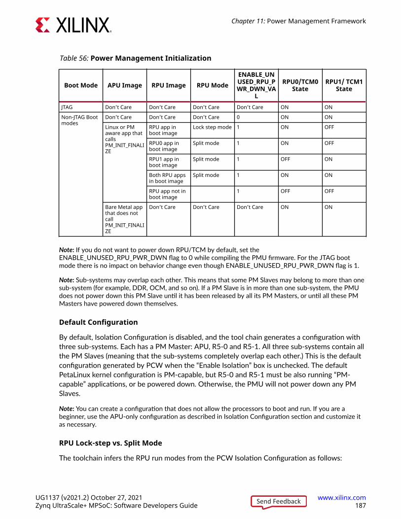
Table 56: Power Management Initialization
Boot Mode APU Image RPU Image RPU ModeENABLE_UNUSED_RPU_PWR_DWN_VA
L
RPU0/TCM0State
RPU1/ TCM1State
JTAG Don’t Care Don’t Care Don’t Care Don’t Care ON ON
Non-JTAG Bootmodes
Don’t Care Don’t Care Don’t Care 0 ON ON
Linux or PMaware app thatcallsPM_INIT_FINALIZE
RPU app inboot image
Lock step mode 1 ON OFF
RPU0 app inboot image
Split mode 1 ON OFF
RPU1 app inboot image
Split mode 1 OFF ON
Both RPU appsin boot image
Split mode 1 ON ON
RPU app not inboot image
1 OFF OFF
Bare Metal appthat does notcallPM_INIT_FINALIZE
Don’t Care Don’t Care Don’t Care ON ON
Note: If you do not want to power down RPU/TCM by default, set theENABLE_UNUSED_RPU_PWR_DWN flag to 0 while compiling the PMU firmware. For the JTAG bootmode there is no impact on behavior change even though ENABLE_UNUSED_RPU_PWR_DWN flag is 1.
Note: Sub-systems may overlap each other. This means that some PM Slaves may belong to more than onesub-system (for example, DDR, OCM, and so on). If a PM Slave is in more than one sub-system, the PMUdoes not power down this PM Slave until it has been released by all its PM Masters, or until all these PMMasters have powered down themselves.
Default Configuration
By default, Isolation Configuration is disabled, and the tool chain generates a configuration withthree sub-systems. Each has a PM Master: APU, R5-0 and R5-1. All three sub-systems contain allthe PM Slaves (meaning that the sub-systems completely overlap each other.) This is the defaultconfiguration generated by PCW when the “Enable Isolation” box is unchecked. The defaultPetaLinux kernel configuration is PM-capable, but R5-0 and R5-1 must be also running “PM-capable” applications, or be powered down. Otherwise, the PMU will not power down any PMSlaves.
Note: You can create a configuration that does not allow the processors to boot and run. If you are abeginner, use the APU-only configuration as described in Isolation Configuration section and customize itas necessary.
RPU Lock-step vs. Split Mode
The toolchain infers the RPU run modes from the PCW Isolation Configuration as follows:
Chapter 11: Power Management Framework
UG1137 (v2021.2) October 27, 2021 www.xilinx.comZynq UltraScale+ MPSoC: Software Developers Guide 187Send Feedback

• No RPU present in any subsystem: Configuration Object contains no RPU.
• Only R5-0 present in subsystem(s): Configuration Object contains R5-0 running in lock-stepmode.
• Both R5-0 and R5-1 in subsystems: Configuration Object contains R5-0 and R5-1 running insplit mode.
• Only R5-1 present in subsystem(s): Configuration Object contains R5-1 running in split mode.
The default Configuration Object contains two RPU PM Masters: R5-0 and R5-1, and the PMUassumes that the R5-0 and R5-1 are running in split mode. However, the boot image actuallydetermines whether the RPU runs in lock-step or split mode at boot time. The RPU run modefrom the boot image must match the number of RPU PM Masters in the Configuration Object.Otherwise, the power management framework will not work properly.
Note: If you intend to use the R5 in lock-step mode, you need to ensure that the Isolation Configuration isenabled in PCW, and only R5-0 (not R5-1) is present in a subsystem.
Sharing DevicesSharing access to devices between APU and RPU is possible but must always be done with greatcare. The access and operation of a device depend on its clock (if applicable), its configurationand its power state (on, off, retention, and so on.) The PMU makes sure the device is in thelowest power state that will satisfy the requirement of all the PM Masters, but it is up to the APUand RPU to set up the clock and configuration of the device.
Extra care must be taken when a device is shared between the APU running Linux and the RPU.Linux is not aware that another entity might be using one of its devices, and will clock-gate,power-gate and disable the device whenever it is not being used. The options available are:
• Disable Linux runtime power management of the device. See https://www.kernel.org/doc/Documentation/ABI/testing/sysfs-devices-power. This will keep the device running evenwhen Linux is not using it, but the device will still be clock-gated and disabled when Linuxgoes to sleep.
• Implement a special driver for the device.
Any devices not used by the APU should be removed from the device tree.
Using the API for Power ManagementThis chapter contains detailed instructions on how to use the Xilinx® power managementframework (PMF) APIs to carry out common power management tasks.
Chapter 11: Power Management Framework
UG1137 (v2021.2) October 27, 2021 www.xilinx.comZynq UltraScale+ MPSoC: Software Developers Guide 188Send Feedback

Implementing Power Management on a ProcessorUnitThe Xilpm library provides the functions that the standalone applications executing on aprocessor can use to initiate the power management API calls.
See the SDK Online Help (UG782) for information on how to include the Xilpm library in a project.
Initializing the Xilpm Library
Before initiating any power management API calls, you must initialize the Xilpm library by callingXPm_InitXilpm, and passing a pointer to a properly initialized inter-processor interrupt (IPI)driver instance.
See this link to the “Interrupts” chapter of the Zynq UltraScale+ Device Technical Reference Manual(UG1085). for more information regarding IPIs.
Working with Slave Devices
The Zynq UltraScale+ MPSoC power management framework (PMF) contains functionsdedicated to managing slave devices (also referred to as PM slaves), such as memories andperipherals. Processor units (PUs) use these functions to inform the power managementcontroller about the requirements (such as capabilities and wake-up latencies) for those devices.The power management controller manages the system so that each device resides in the lowestpossible power state, meeting the requirements from all eligible PUs.
Requesting and Releasing a Node
A PU uses the XPm_RequestNode API to request the access to a slave device and assert itsrequirements on that device. The power management controller manages the requested device'spower-on and active state, provided the PU and the slave belong to the same sub-system.
After a device is no longer used, the PU typically calls the XPm_ReleaseNode function to allowthe PM controller to re-evaluate the power state of that device, and potentially place it into alow-power state. It also then allows other PUs to request that device.
Changing Requirements
When a PU is using a PM slave, its requirement on the slave's capability may change. Forexample, an interface port may go into a low power state, or even be completely powered off, ifthe interface is not being used. The PU may use XPm_SetRequirement to change thecapability requirement of the PM slave. Typically, the PU would not release the PM slave if it willbe changing the requirement again in the future.
Chapter 11: Power Management Framework
UG1137 (v2021.2) October 27, 2021 www.xilinx.comZynq UltraScale+ MPSoC: Software Developers Guide 189Send Feedback

The following example call changes the requirement for the node argument to require wake-interrupts only:
XPm_SetRequirement(node, PM_CAP_WAKEUP, 0, REQUEST_ACK_NO);
IMPORTANT! Setting requirements of a node to zero is not equivalent to releasing the PM slave. Byreleasing the PM slave, a PU may be allowing other PUs to use the device exclusively.
When multiple PUs share a PM slave (this applies mostly to memories), the power managementcontroller selects a power state of the PM slave that satisfies all requirements of the requestingPUs.
The requirements on a PM slave include capability as well as latency requirements. Capabilityrequirements may include a top capability state, some intermediate capability states, an inactivestate (but with the configuration retained), and the off state. Latency requirement specifies themaximum time allowed for the PM slave to switch to the top capability state from any otherstate. If this time limit cannot be met, the power management controller will leave the PM slavein the top capability state regardless of other capability requirements.
Self-Suspending a CPU/PU
A PU can be a cluster of CPUs. The APU is a PU, that has four CPUs. An RPU has two CPUs, butit is considered as two PUs when running in the split mode, and one PU when it is running in thelock-step mode.
To suspend itself, a CPU must inform the power management controller about its intent by callingthe XPM_SelfSuspend function. The following actions then occur:
• After the XPm_SelfSuspend() call is processed, none of the future interrupts can preventthe CPU from entering a sleep state. To manage such behavior in the case of the APU andRPU, after the XPm_SelfSuspend() call has completed, all of the interrupts to a CPU aredirected to the power management controller as GIC wake interrupts.
• The power management controller then waits for the CPU to finalize the suspend procedure.The PU informs the power management controller that it is ready to enter a sleep state bycalling XPm_SuspendFinalize.
• The XPm_SuspendFinalize() function is architecture-dependent. It ensures that anyoutstanding power management API call is processed, then executes the architecture-specificsuspend sequence, which also signals the suspend completion to the power managementcontroller.
• For Arm® processors such as the APU and RPU, the XPm_SuspendFinalize() functionuses the wait for interrupt (WFI) instruction, which suspends the CPU and triggers aninterrupt to the power management controller.
• When the suspend completion is signaled to the power management controller, the powermanagement controller places the CPU into reset, and may power down the power island ofthe CPU, provided that no other component within the island is currently active.
Chapter 11: Power Management Framework
UG1137 (v2021.2) October 27, 2021 www.xilinx.comZynq UltraScale+ MPSoC: Software Developers Guide 190Send Feedback

• Interrupts enabled through the GIC interface of the CPU are redirected to the powermanagement controller (PMC) as a GIC wake interrupt assigned to that particular CPU.Because the interrupts are redirected, the CPU can only be woken up using the powermanagement controller.
• Suspending a PU requires suspending all of its CPUs individually.
Resuming Execution
A CPU can be woken up either by a wake interrupt triggered by a hardware resource or by anexplicit wake request using the XPM_RequestWakeup API.
The CPU starts executing from the resume address provided with the XPm_SelfSuspend call.
Setting up a Wake-up Source
The power management controller can power down the entire FPD if none of the FPD devicesare in use and existing latency requirements allow this action. If the FPD is powered off and theAPU is to be woken up by an interrupt triggered by a device in the LPD, the GIC Proxy must beconfigured to allow propagation of FPD wake events. The APU can ensure this by callingXPM_SetWakeUpSource for all devices that might need to issue wake interrupts.
Hence, prior to suspending, the APU must call XPm_SetWakeupSource(NODE_APU, node,1) to add the required slaves as a wake-up source. The APU can then set the requirements tozero for all slaves it is using. After the APU finalizes its suspend procedure, and provided that noother PU is using any resource in the FPD, the PM controller powers off the entire FPD andconfigures the GIC proxy to enable propagation of the wake event of the LPD slaves.
Aborting a Suspend Procedure
If a PU decides to abort the suspend procedure after calling the XPM_SetSelfSuspendfunction, it must inform the power management controller about the aborted suspend by callingthe XPm_AbortSuspend function.
Handling PM Slaves During the Suspend Procedure
A PU that suspends itself must inform the power management controller about its changedrequirements on the peripherals and memories in use. If a PU fails inform the power managementcontroller, all of the used devices remain powered on. Typically, for memories you must ensurethat their context is preserved by using the following function:
XPm_SetRequirement(node, PM_CAP_CONTEXT, 0, REQUEST_ACK_NO);
When setting requirements for a PM slave during the suspend procedure; after callingXPM_SelfSuspend, the setting is deferred until the CPU finishes the suspend. This deferenceensures that devices that are needed for completing the suspend procedure can enter a lowpower state after the calling CPU finishes suspend.
Chapter 11: Power Management Framework
UG1137 (v2021.2) October 27, 2021 www.xilinx.comZynq UltraScale+ MPSoC: Software Developers Guide 191Send Feedback

A common example is instruction memory, which a CPU can access until the end of a suspend.After the CPU suspends a memory, that memory can be placed into retention. All deferredrequirements reverse automatically before the respective CPU is woken up.
When an entire PU suspends, the last awake CPU within the PU must manage the changes to thedevices.
Example Code for Suspending an APU/RPU
There the following is an example of source code for suspending the APU or RPU:
/* Base address of vector table (reset-vector) */ extern void *_vector_table;/* Inform PM controller that APU_0 intends to suspend */ XPm_SelfSuspend(NODE_APU_0, MAX_LATENCY, 0, (u64)&_vector_table);/*** Set requirements for OCM banks to preserve their context.* The PM controller will defer putting OCMs into retention until the suspend is finalized*/XPm_SetRequirement(NODE_OCM_BANK_0, PM_CAP_CONTEXT, 0, REQUEST_ACK_NO);XPm_SetRequirement(NODE_OCM_BANK_1, PM_CAP_CONTEXT, 0, REQUEST_ACK_NO);XPm_SetRequirement(NODE_OCM_BANK_2, PM_CAP_CONTEXT, 0, REQUEST_ACK_NO);XPm_SetRequirement(NODE_OCM_BANK_3, PM_CAP_CONTEXT, 0, REQUEST_ACK_NO);
/* Flush data cache */ Xil_DCacheFlush();/* Inform PM controller that suspend procedure is completed */ XPm_SuspendFinalize();
Suspending the Entire FPD Domain
To power-down the entire full power domain, the power management controller must suspendthe APU at a time when none of the FPD devices is in use. After this condition is met, the powermanagement controller can power-down the FPD automatically. The power managementcontroller powers down the FPD if no latency requirements constrain this action, otherwise theFPD remains powered on.
Forcefully Powering Down the FPD
There is the option to force the FPD to power-down by calling the functionXPM_ForcePowerdown. This requires that the requesting PU has proper privileges configured inthe power management controller. The power management controller releases all PM Slavesused by the APU automatically.
Note: This force method is typically not recommended, especially when running complex operating systemson the APU because it could result in loss of data or system corruption, due to the OS not suspending itselfgracefully.
IMPORTANT! Use the XPm_RequestSuspend API.
Chapter 11: Power Management Framework
UG1137 (v2021.2) October 27, 2021 www.xilinx.comZynq UltraScale+ MPSoC: Software Developers Guide 192Send Feedback

Interacting with Other Processing UnitsSuspending a PU
A PU can request that another PU be suspended by calling XPm_RequestSuspend, and passingthe targeted node name as an argument.
This causes the power management controller to call XPm_InitSuspendCb(), which is acallback function implemented in the target PU. The target PU then initiates its own suspendprocedure, or call XPm_AbortSuspend and specify the abort reason. For example, you canrequest an APU to suspend with the following command:
XPm_RequestSuspend(NODE_APU, REQUEST_ACK_NON_BLOCKING, MAX_LATENCY, 0);
The following diagram shows the general sequence triggered by a call to theXPM_RequestSuspend.
For more information about XPm_RequestSuspend, XPm_InitSuspendCb, andXPm_AbortSuspend, see XilPM Library in the OS and Libraries Document Collection (UG643).
Figure 59: APU initiating suspend for the RPU by calling XPm_RequestSuspend
APU
XPm_RequestSuspend(nodeID=RPU, latency=MAX)
PMU RPU TCM
RUN RUN RUN ON
XPm_InitSuspendCb(reason=PU REQ,
latency=MAX)
XPm_SelfSuspend(nodeID=RPU, latency=MAX)
XPm_SetRequirement(nodeID=TCM,
cap=context, ack=0)
XPm_SuspendFinalize
Power Down Retention
save context
X20024-110217
Chapter 11: Power Management Framework
UG1137 (v2021.2) October 27, 2021 www.xilinx.comZynq UltraScale+ MPSoC: Software Developers Guide 193Send Feedback

Waking a PU
Additionally, a PU can request the wake-up of one of its CPUs or of another PU by callingXPm_RequestWakeup.
• When processing the call, the power management controller causes a target CPU or PU to beawakened.
• If a PU is the target, only one of its CPUs is woken-up by this request.
• The CPU chosen by the power management controller is considered the primary CPU withinthe PU.
The following is an example of a wake-up request:
XPm_RequestWakeup(NODE_APU_1, REQUEST_ACK_NO);
For more information about XPm_RequestWakeup, see XilPM Library in the OS and LibrariesDocument Collection (UG643).
DDR Self-refresh over Warm RestartIn most systems, the RAM of a computing system is cleared when the system resets or powersdown. Any data that needs to be retained, such as settings and logs, are usually stored in a non-volatile memory such as flash and battery backed-up RAM. These non-volatile memories areslower, especially when the amount of data is huge. For some systems, a more preferred solutionis to retain the data in the DRAM, thus effectively using it as a non-volatile memory.
The Zynq UltraScale+ MPSoC software solution supports a feature to put DDR into self-refreshmode during warm restart (system reset, or PS only reset). This makes the DDR a non-volatilememory and its contents remain as it is even after a reset.
By default, this feature is disabled. You can enable this feature by enabling the following buildflags during PMUFW and FSBL compilation:
• PMUFW: ENABLE_DDR_SR_WR
• FSBL: XFSBL_ENABLE_DDR_SR
After these build flags are enabled, the PMUFW puts the DDR in self-refresh mode during awarm restart (PS only or System restart).
Chapter 11: Power Management Framework
UG1137 (v2021.2) October 27, 2021 www.xilinx.comZynq UltraScale+ MPSoC: Software Developers Guide 194Send Feedback

XilPM Implementation DetailsThe system layer of the PM framework is implemented on the Zynq UltraScale+ MPSoC usinginter-processor interrupts (IPIs). To issue an EEMI API call, a PU will write the API data (API IDand arguments) into the IPI request buffer and then trigger the IPI to the PMU.
After the PM controller processes the request it will send the acknowledge depending on theparticular EEMI API and provided arguments.
Payload Mapping for API Calls to PMUEach EEMI API call is uniquely identified by the following data:
• EEMI API identifier (ID)
• EEMI API arguments
Please see Appendix A for a list of all API identifiers as well as API argument values.
Prior to initiating an IPI to the PMU, the PU shall write the information about the call into the IPIrequest buffer. Each data written into the IPI buffer is a 32-bit word. Total size of the payload issix 32-bit words - one word is reserved for the EEMI API identifier, while the remaining wordsare used for the arguments. Writing to the IPI buffer starts from offset zero. The information ismapped as follows:
• Word [0] EEMI API ID
• Word [1:5] EEMI API arguments
The IPI response buffer is used to return the status of the operation as well as up to 3 values.
• Word [0] success or error code
• Word [1:3] value 1..3
Payload Mapping for API Callbacks from the PMUThe EEMI API includes callback functions, invoked by the PM controller, sent to a PU.
• Word [0]EEMI API Callback ID
• Word [1:5]EEMI API arguments
Refer to the XilPM Library in the OS and Libraries Document Collection (UG643) for a list of all APIidentifiers as well as API argument values.
Chapter 11: Power Management Framework
UG1137 (v2021.2) October 27, 2021 www.xilinx.comZynq UltraScale+ MPSoC: Software Developers Guide 195Send Feedback

Issuing EEMI API calls to the PMUBefore issuing an API call to the PMU, a PU must wait until its previous API call is processed bythe PMU. A check for completion of a PMU action can be implemented by reading thecorresponding IPI observation register.
An API call is issued by populating the IPI payload buffer with API data and triggering an IPIinterrupt to the PMU. In case of a blocking API call, the PMU will respond by populating theresponse buffer with the status of the operation and up to 3 values. See Appendix B: AdditionalResources and Legal Notices for a list of all the errors that can be sent by the PMU if a PMoperation was unsuccessful. The PU must wait until the PMU has finished processing the API callprior to reading the response buffer, to ensure that the data in the response buffer is valid.
Chapter 11: Power Management Framework
UG1137 (v2021.2) October 27, 2021 www.xilinx.comZynq UltraScale+ MPSoC: Software Developers Guide 196Send Feedback

Figure 60: Example Flow of Issuing API Call to the PMU
XEMI API Call
Previous API call
processed by the PMU?
Copy API data into IPI request buffer
Trigger IPI interrupt
Blocking API call?
API call processed by
the PMU?
Read response from the PMU
Return
No
No
Yes
Yes
Yes
X19506-071017
Handling API callbacks from the PMUThe PMU invokes callback functions to the PU by populating the IPI buffers with the API callbackdata and triggering an IPI interrupt to the PU. In order to receive such interrupts, the PU mustproperly initialize the IPI block and interrupt controller. A single interrupt is dedicated to allcallbacks. For this reason, element 0 of the payload buffer contains the API ID, which the PUshould use to identify the API callback. The PU should then call the respective API callbackfunction, passing in the arguments obtained from locations 1 to 4 of the IPI request buffer.
An implementation of this behavior can be found in the XilPM library.
Chapter 11: Power Management Framework
UG1137 (v2021.2) October 27, 2021 www.xilinx.comZynq UltraScale+ MPSoC: Software Developers Guide 197Send Feedback

LinuxLinux executes on the EL1 level, and the communication between Linux and the TF-A softwarelayer is realized using SMC calls.
Power management features based on the EEMI API have been ported to the Linux kernel,ensuring that the Linux-centric power management features utilize the EEMI services providedby the PMU.
Additionally, the EEMI API can be access directly through debugfs for debugging purposes. Notethat direct access to the EEMI API through debugfs will interfere with the kernel powermanagement operations and may cause unexpected problems.
All the Linux power management features presented in this chapter are available in the PetaLinuxdefault configuration.
User Space PM Interface
System Power States
You may request to change the power state of a system or the entire system. The PMU facilitatesthe switching of the system or sub-system to the new power state.
Shutdown
You may shutdown the APU sub-system with the standard 'shutdown' command.
To shut down the entire system, the user must shut down all the other sub-systems prior toshutting down the APU sub-system. For example, use the following command to power downthe PL.
echo pm_release_node 69 > /sys/kernel/debug/zynqmp-firmware/pm
Use this command to power up the PL again:
echo pm_request_node 69 > /sys/kernel/debug/zynqmp-firmware/pm
For information about how to shut down the PL sub-system, see the Libmetal and OpenAMP forZynq Devices User Guide (UG1186).
Chapter 11: Power Management Framework
UG1137 (v2021.2) October 27, 2021 www.xilinx.comZynq UltraScale+ MPSoC: Software Developers Guide 198Send Feedback

Reboot
You can use the reboot command to reset the APU, the PS or the System. By default, the rebootcommand resets the system. You can change the scope of the reboot command to APU or PS ifrequired. To change the reboot scope to APU:
echo subsystem > /sys/firmware/zynqmp/shutdown_scope
To change the reboot scope to PS:
echo ps_only > /sys/firmware/zynqmp/shutdown_scope
To change the reboot scope to System:
echo system > /sys/firmware/zynqmp/shutdown_scope
The reboot scope is set to System again after the reset.
Suspend
The kernel is suspended when the CPU and most of the peripherals are powered down. Thesystem run states needed to resume from suspend is stored in the DRAM, which is put into self-refresh mode.
Kernel configurations required:
• Power management options
○ [*] Suspend to RAM and standby
○ [*] User space wakeup sources interface
○ [*] Device power management core functionality
• Device Drivers
○ SoC (System On Chip) specific Drivers
- Xilinx® SoC drivers
- Zynq MPSoC SoC
- [*] Enable Xilinx Zynq MPSoC Power Management driver
- [*] Enable Zynq MPSoC generic PM domains
• Firmware Drivers
○ Zynq MPSoC Firmware Drivers
- -*- Enable Xilinx Zynq MPSoC firmware interface
Note: Any device can prevent the kernel from suspending.
Chapter 11: Power Management Framework
UG1137 (v2021.2) October 27, 2021 www.xilinx.comZynq UltraScale+ MPSoC: Software Developers Guide 199Send Feedback
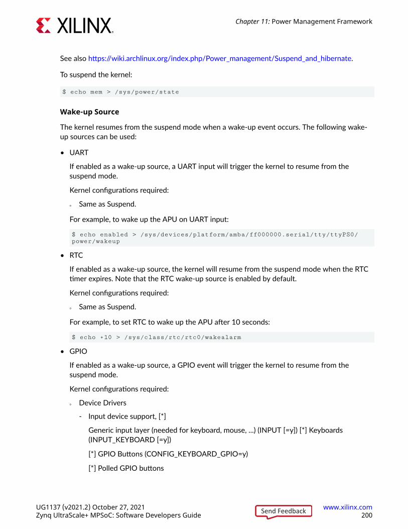
See also https://wiki.archlinux.org/index.php/Power_management/Suspend_and_hibernate.
To suspend the kernel:
$ echo mem > /sys/power/state
Wake-up Source
The kernel resumes from the suspend mode when a wake-up event occurs. The following wake-up sources can be used:
• UART
If enabled as a wake-up source, a UART input will trigger the kernel to resume from thesuspend mode.
Kernel configurations required:
○ Same as Suspend.
For example, to wake up the APU on UART input:
$ echo enabled > /sys/devices/platform/amba/ff000000.serial/tty/ttyPS0/power/wakeup
• RTC
If enabled as a wake-up source, the kernel will resume from the suspend mode when the RTCtimer expires. Note that the RTC wake-up source is enabled by default.
Kernel configurations required:
○ Same as Suspend.
For example, to set RTC to wake up the APU after 10 seconds:
$ echo +10 > /sys/class/rtc/rtc0/wakealarm
• GPIO
If enabled as a wake-up source, a GPIO event will trigger the kernel to resume from thesuspend mode.
Kernel configurations required:
○ Device Drivers
- Input device support, [*]
Generic input layer (needed for keyboard, mouse, ...) (INPUT [=y]) [*] Keyboards(INPUT_KEYBOARD [=y])
[*] GPIO Buttons (CONFIG_KEYBOARD_GPIO=y)
[*] Polled GPIO buttons
Chapter 11: Power Management Framework
UG1137 (v2021.2) October 27, 2021 www.xilinx.comZynq UltraScale+ MPSoC: Software Developers Guide 200Send Feedback

For example, to wake up the APU on the GPIO pin:
$ echo enabled > /sys/devices/platform/gpio-keys/power/wakeup
Power Management for the CPU
CPU Hotplug
The user may take one or more APU cores on-line and off-line as needed through the CPUHotplug control interface.
Kernel configurations required:
• Kernel Features
○ [*] Support for hot-pluggable CPUs
See also:
• https://www.kernel.org/doc/Documentation/cpu-hotplug.txt
• http://lxr.free-electrons.com/source/Documentation/devicetree/bindings/arm/idle-states.txt
For example, to take CPU3 off-line:
$ echo 0 > /sys/devices/system/cpu/cpu3/online
CPU Idle
If enabled, the kernel may cut power to individual APU cores when they are idling. The kernelconfigurations required are:
• CPU Power Management
○ CPU Idle
- [*] CPU idle PM support
- Arm CPU Idle Drivers
- [*] Generic Arm/Arm64 CPU idle Driver
See also:
• https://www.kernel.org/doc/Documentation/cpuidle/core.txt
• https://www.kernel.org/doc/Documentation/cpuidle/driver.txt
• https://www.kernel.org/doc/Documentation/cpuidle/governor.txt
• https://www.kernel.org/doc/Documentation/cpuidle/sysfs.txt
Chapter 11: Power Management Framework
UG1137 (v2021.2) October 27, 2021 www.xilinx.comZynq UltraScale+ MPSoC: Software Developers Guide 201Send Feedback

Below is the sysfs interface for cpuidle.
$ ls -lR /sys/devices/system/cpu/cpu0/cpuidle/
/sys/devices/system/cpu/cpu0/cpuidle/:drwxr-xr-x 2 root root 0 Jun 10 21:55 state0drwxr-xr-x 2 root root 0 Jun 10 21:55 state1
/sys/devices/system/cpu/cpu0/cpuidle/state0:-r--r--r-- 1 root root 4096 Jun 10 21:55 desc-rw-r--r-- 1 root root 4096 Jun 10 21:55 disable-r--r--r-- 1 root root 4096 Jun 10 21:55 latency-r--r--r-- 1 root root 4096 Jun 10 21:55 name-r--r--r-- 1 root root 4096 Jun 10 21:55 power-r--r--r-- 1 root root 4096 Jun 10 21:55 residency-r--r--r-- 1 root root 4096 Jun 10 21:55 time-r--r--r-- 1 root root 4096 Jun 10 21:55 usage
/sys/devices/system/cpu/cpu0/cpuidle/state1:-r--r--r-- 1 root root 4096 Jun 10 21:55 desc-rw-r--r-- 1 root root 4096 Jun 10 21:55 disable-r--r--r-- 1 root root 4096 Jun 10 21:55 latency-r--r--r-- 1 root root 4096 Jun 10 21:55 name-r--r--r-- 1 root root 4096 Jun 10 21:55 power-r--r--r-- 1 root root 4096 Jun 10 21:55 residency-r--r--r-- 1 root root 4096 Jun 10 21:55 time-r--r--r-- 1 root root 4096 Jun 10 21:55 usage
where:
• desc: Small description about the idle state (string)
• disable: Option to disable this idle state (bool)
• latency: Latency to exit out of this idle state (in microseconds)
• name: Name of the idle state (string)
• power: Power consumed while in this idle state (in milliwatts)
• time: Total time spent in this idle state (in microseconds)
• usage: Number of times this state was entered (count)
Below is the sysfs interface for cpuidle governors.
$ ls -lR /sys/devices/system/cpu/cpuidle//sys/devices/system/cpu/cpuidle/:-r--r--r-- 1 root root 4096 Jun 10 21:55 current_driver-r--r--r-- 1 root root 4096 Jun 10 21:55 current_governor_ro
CPU Frequency
If enabled, the CPU cores may switch between different operation clock frequencies. The kernelconfigurations required are:
Chapter 11: Power Management Framework
UG1137 (v2021.2) October 27, 2021 www.xilinx.comZynq UltraScale+ MPSoC: Software Developers Guide 202Send Feedback

• CPU Frequency scaling
○ [*] CPU Frequency scaling
○ Default CPUFreq governor
- Userspace
• CPU Power Management
○ [*] CPU Frequency scaling
○ Default CPUFreq governor
- Userspace
- <*> Generic DT based cpufreq driver
Look up the available CPU speeds:
$ cat /sys/devices/system/cpu/cpu*/cpufreq/scaling_cpu_freq
Select the 'userspace' governor for CPU frequency control:
$ echo userspace > /sys/devices/system/cpu/cpu0/cpufreq/scaling_governor
Look up the current CPU speed (same for all cores):
$ cat /sys/devices/system/cpu/cpu*/cpufreq/scaling_cpu_freq
Change the CPU speed (same for all cores):
$ echo <freq> > /sys/devices/system/cpu/cpu0/cpufreq/scaling_setspeed
For details on adding and changing CPU frequencies, see the Linux kernel documentation onGeneric Operating Points.
Power Management for the Devices
Clock Gating
Stop device clocks when they are not being used (also called Common Clock Framework.) Thekernel configurations required are:
• Common Clock Framework
○ [*] Support for Xilinx ZynqMP Ultrascale+ clock controllers
Runtime PM
Power off devices when they are not being used. Note that individual drivers may or may notsupport run-time power management. The kernel configurations required are:
Chapter 11: Power Management Framework
UG1137 (v2021.2) October 27, 2021 www.xilinx.comZynq UltraScale+ MPSoC: Software Developers Guide 203Send Feedback
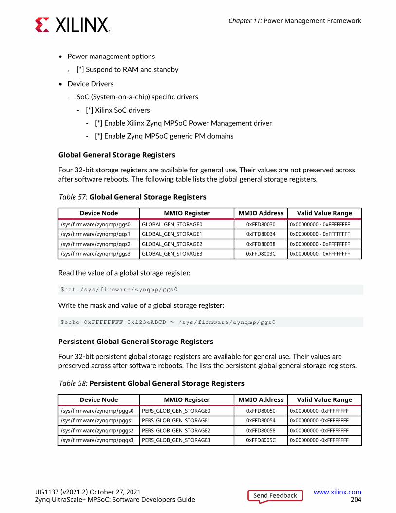
• Power management options
○ [*] Suspend to RAM and standby
• Device Drivers
○ SoC (System-on-a-chip) specific drivers
- [*] Xilinx SoC drivers
- [*] Enable Xilinx Zynq MPSoC Power Management driver
- [*] Enable Zynq MPSoC generic PM domains
Global General Storage Registers
Four 32-bit storage registers are available for general use. Their values are not preserved acrossafter software reboots. The following table lists the global general storage registers.
Table 57: Global General Storage Registers
Device Node MMIO Register MMIO Address Valid Value Range/sys/firmware/zynqmp/ggs0 GLOBAL_GEN_STORAGE0 0xFFD80030 0x00000000 - 0xFFFFFFFF
/sys/firmware/zynqmp/ggs1 GLOBAL_GEN_STORAGE1 0xFFD80034 0x00000000 - 0xFFFFFFFF
/sys/firmware/zynqmp/ggs2 GLOBAL_GEN_STORAGE2 0xFFD80038 0x00000000 - 0xFFFFFFFF
/sys/firmware/zynqmp/ggs3 GLOBAL_GEN_STORAGE3 0xFFD8003C 0x00000000 - 0xFFFFFFFF
Read the value of a global storage register:
$cat /sys/firmware/zynqmp/ggs0
Write the mask and value of a global storage register:
$echo 0xFFFFFFFF 0x1234ABCD > /sys/firmware/zynqmp/ggs0
Persistent Global General Storage Registers
Four 32-bit persistent global storage registers are available for general use. Their values arepreserved across after software reboots. The lists the persistent global general storage registers.
Table 58: Persistent Global General Storage Registers
Device Node MMIO Register MMIO Address Valid Value Range/sys/firmware/zynqmp/pggs0 PERS_GLOB_GEN_STORAGE0 0xFFD80050 0x00000000 -0xFFFFFFFF
/sys/firmware/zynqmp/pggs1 PERS_GLOB_GEN_STORAGE1 0xFFD80054 0x00000000 -0xFFFFFFFF
/sys/firmware/zynqmp/pggs2 PERS_GLOB_GEN_STORAGE2 0xFFD80058 0x00000000 -0xFFFFFFFF
/sys/firmware/zynqmp/pggs3 PERS_GLOB_GEN_STORAGE3 0xFFD8005C 0x00000000 -0xFFFFFFFF
Chapter 11: Power Management Framework
UG1137 (v2021.2) October 27, 2021 www.xilinx.comZynq UltraScale+ MPSoC: Software Developers Guide 204Send Feedback

Read the value of a persistent global storage register:
$cat /sys/firmware/zynqmp/pggs0
Write the mask and value of a persistent global storage register:
$echo 0xFFFFFFFF 0x1234ABCD > /sys/firmware/zynqmp/pggs0
DemoA demo script is included with the PetaLinux pre-built images, which performs a few simplepower management tasks:
• System Suspend
• CPU Hotplug
• CPU Freq
• System Reboot
• System Shutdown
To start the demo, type the following command:
$ hellopm
Debug InterfaceThe PM platform driver exports a standard debugfs interface to access all EEMI services. Theinterface is intended for testing only and does not contain any checking regarding improperusage, and the number, type and valid ranges of the arguments. The user should be aware thatinvoking EEMI services directly via this interface can very easily interfere with the kernel powermanagement operations, resulting in unexpected behavior or system crash. Zynq MPSoC debugfsinterface is disabled by default in defconfig. It needs to be enabled explicitly as mentioned below.
Kernel configurations required (in this order):
• Kernel hacking
○ Compile-time checks and compiler options
- [*] Debug File system
• Firmware Drivers
○ Zynq MPSoC Firmware Drivers
- [*] Enable Xilinx Zynq MPSoC firmware interface
- [*] Enable Xilinx Zynq MPSoC firmware debug APIs
Chapter 11: Power Management Framework
UG1137 (v2021.2) October 27, 2021 www.xilinx.comZynq UltraScale+ MPSoC: Software Developers Guide 205Send Feedback

You may invoke any EEMI API except for:
• Self Suspend
• System Shutdown
• Force Power Down the APU
• Request Wake-up the APU
Command-line Input
The user may invoke an EEMI service by writing the EEMI API ID, followed by up to fourarguments, to the debugfs interface node.
API ID
Function ID can be EEMI API function name or ID number, type string or type integer,respectively.
Arguments
The number and type of the arguments directly depend on the selected API function. Allarguments must be provided as integer types and represent the ordinal number for that specificargument type from the EEMI argument list. For more information about function descriptions,type and number of arguments see the EEMI API Specification.
Example
The following example shows how to invoke a request_node API call for NODE_USB_0.
$ echo "pm_request_node 22 1 100 1" > /sys/kernel/debug/zynqmp-firmware/pm
Command List
Get API Version
Get the API version.
$ echo pm_get_api_version > /sys/kernel/debug/zynqmp-firmware/pm
Request Suspend
Request another PU to suspend itself.
$ echo pm_request_suspend <node> > /sys/kernel/debug/zynqmp-firmware/pm
Chapter 11: Power Management Framework
UG1137 (v2021.2) October 27, 2021 www.xilinx.comZynq UltraScale+ MPSoC: Software Developers Guide 206Send Feedback

Self Suspend
Notify PMU that this PU is about to suspend itself.
$ echo pm_self_suspend <node> > /sys/kernel/debug/zynqmp-firmware/pm
Force Power Down
Force another PU to power down.
$ echo pm_force_powerdown <node> > /sys/kernel/debug/zynqmp-firmware/pm
Abort Suspend
Notify PMU that the attempt to suspend has been aborted.
$ echo pm_abort_suspend > /sys/kernel/debug/zynqmp-firmware/pm
Request Wake-up
Request another PU to wake up from suspend state.
$ echo pm_request_wakeup <node> <set_address> <address> > /sys/kernel/debug/zynqmp-firmware/pm
Set Wake-up Source
Set up a node as the wake-up source.
$ echo pm_set_wakeup_source <target> <wkup_node> <enable> > /sys/kernel/debug/zynqmp-firmware/pm
Request Node
Request to use a node.
$ echo pm_request_node <node> > /sys/kernel/debug/zynqmp-firmware/pm
Release Node
Free a node that is no longer being used.
$ echo pm_release_node <node> > /sys/kernel/debug/zynqmp-firmware/pm
Chapter 11: Power Management Framework
UG1137 (v2021.2) October 27, 2021 www.xilinx.comZynq UltraScale+ MPSoC: Software Developers Guide 207Send Feedback

Set Requirement
Set the power requirement on the node.
$ echo pm_set_requirement <node> <capabilities> > /sys/kernel/debug/zynqmp-firmware/pm
Set Max Latency
Set the maximum wake-up latency requirement for a node.
$ echo pm_set_max_latency <node> <latency> > /sys/kernel/debug/zynqmp-firmware/pm
Get Node Status
Get status information of a node. (Any PU can check the status of any node, regardless of thenode assignment.)
$ echo pm_get_node_status <node> > /sys/kernel/debug/zynqmp-firmware/pm
Get Operating Characteristic
Get operating characteristic information of a node.
$ echo pm_get_operating_characteristic <node> > /sys/kernel/debug/zynqmp-firmware/pm
Reset Assert
Assert/de-assert on specific reset lines.
$ echo pm_reset_assert <reset> <action> > /sys/kernel/debug/zynqmp-firmware/pm
Reset Get Status
Get the status of the reset line.
$ echo pm_reset_get_status <reset> > /sys/kernel/debug/zynqmp-firmware/pm
Get Chip ID
Get the chip ID.
$ echo pm_get_chipid > /sys/kernel/debug/zynqmp-firmware/pm
Chapter 11: Power Management Framework
UG1137 (v2021.2) October 27, 2021 www.xilinx.comZynq UltraScale+ MPSoC: Software Developers Guide 208Send Feedback

Get Pin Control Functions
Get current selected function for given pin.
$ echo pm_pinctrl_get_function <pin-number> > /sys/kernel/debug/zynqmp-firmware/pm
Set Pin Control Functions
Set requested function for given pin.
$ echo pm_pinctrl_set_function <pin-number> <function-id> > /sys/kernel/debug/zynqmp-firmware/pm
Get Configuration Parameters for the Pin
Get value of requested configuration parameter for given pin.
$ echo pm_pinctrl_config_param_get <pin-number> <parameter to get> > /sys/kernel/debug/zynqmp-firmware/pm
Set Configuration Parameters for the Pin
Set value of requested configuration parameter for given pin.
$ echo pm_pinctrl_config_param_set <pin-number> <parameter to set> <param value> > /sys/kernel/debug/zynqmp-firmware/pm
Control Device and Configurations
Control device and configurations and get configurations values.
$ echo pm_ioctl <node id> <ioctl id> <arg1> <arg2> > /sys/kernel/debug/zynqmp-firmware/pm
Table 59: IOCTLs in SDG
IOCTL_ID Name Description0 IOCTL_GET_RPU_OPER_MODE returns current RPU operating mode (lockstep/split).
1 IOCTL_SET_RPU_OPER_MODE configures RPU operating mode (lockstep/split).
2 IOCTL_RPU_BOOT_ADDR_CONFIG configures RPU boot address
3 IOCTL_TCM_COMB_CONFIG configures TCM to be in split mode or combinedmode
4 IOCTL_SET_TAPDELAY_BYPASS enable/disable tap delay bypass
5 IOCTL_SET_SGMII_MODE enable/disable SGMII mode for the GEM device
6 IOCTL_SD_DLL_RESET resets DLL logic for the SD device
7 IOCTL_SET_SD_TAPDELAY sets input/output tap delay for the SD device
8 IOCTL_SET_PLL_FRAC_MODE sets PLL mode
Chapter 11: Power Management Framework
UG1137 (v2021.2) October 27, 2021 www.xilinx.comZynq UltraScale+ MPSoC: Software Developers Guide 209Send Feedback

Table 59: IOCTLs in SDG (cont'd)
IOCTL_ID Name Description9 IOCTL_GET_PLL_FRAC_MODE returns current PLL mode
10 IOCTL_SET_PLL_FRAC_DATA sets PLL fraction data
11 IOCTL_GET_PLL_FRAC_DATA returns PLL fraction data value
12 IOCTL_WRITE_GGS writes value to GGS register
13 IOCTL_READ_GGS returns GGS register value
14 IOCTL_WRITE_PGGS writes value to PGGS register
15 IOCTL_READ_PGGS returns PGGS register value
16 IOCTL_ULPI_RESET performs the ULPI reset sequence for resetting theULPI transceiver
17 IOCTL_SET_BOOT_HEALTH_STATUS sets healthy bit value to indicate boot health status tofirmware.
18 IOCTL_AFI writes the afi values at given index
Table 60: Description of IOCTLs
IOCTL_ID Name Descript
ionArguments
Node_ID Arg1 Arg2 Return Value0 IOCTL_GET_RPU_OPER_MO
DEreturnscurrentRPUoperatingmode(lockstep/split)
unused unused unused Operatingmode
0:LOCKSTEP1: SPLIT
1 IOCTL_SET_RPU_OPER_MODE
configures RPUoperatingmode(lockstep/split)
unused Value of operatingmode
0: LOCKSTEP1: SPLIT
unused unused
2 IOCTL_RPU_BOOT_ADDR_CONFIG
configures RPUbootaddress
NODE_RPU_0NODE_RPU_1
Value to set forboot address
0: LOVEC/TCM1: HIVEC/OCM
unused unused
3 IOCTL_TCM_COMB_CONFIG
configures TCM tobe in splitmode orcombinedmode
unused Value to set (Split/Combined)
0: SPLIT1: COMB
unused unused
Chapter 11: Power Management Framework
UG1137 (v2021.2) October 27, 2021 www.xilinx.comZynq UltraScale+ MPSoC: Software Developers Guide 210Send Feedback

Table 60: Description of IOCTLs (cont'd)
IOCTL_ID Name Descript
ionArguments
Node_ID Arg1 Arg2 Return Value4 IOCTL_SET_TAPDELAY_BYP
ASSenables/disablestap delaybypass
unused Type of tap delay
0:NAND_DQS_IN1:NAND_DQS_OUT- 2: QSPI
Tap-delayEnable/ Disable
0: DISABLE1: ENABLE
unused
5 IOCTL_SET_SGMII_MO DE enables/disablesSGMIImode forthe GEMdevice
NODE_ETH_0,NODE_ETH_1,NODE_ETH_2,NODE_ETH_3
"GMII modeEnable/ Disable
0: DISABLE1: ENABLE
unused unused
6 IOCTL_SD_DLL_RESET resets DLLlogic forthe SDdevice
NODE_SD_0,NODE_SD_1
SD DLL Reset type
0: ASSERT1: RELEASE2: PULSE
unused unused
7 IOCTL_SET_SD_TAPDE LAY setsinput/output tapdelay forthe SDdevice
NODE_SD_0,NODE_SD_1
Type of tap delay toset
0: INPUT1: OUTPUT
Value to set forthe tap delay
unused
8 IOCTL_SET_PLL_FRAC_MODE
sets PLLmode
unused PLL clock ID PLL Mode
0:FRAC_MODE1:INT_MODE
unused
9 IOCTL_GET_PLL_FRAC_MODE
returnscurrentPLL mode
unused PLL clock ID unused PLL Mode
0:FRAC_MODE1:INT_MODE
10 IOCTL_SET_PLL_FRAC_DATA
sets PLLfractiondata
unused PLL clock ID PLL fractiondata
unused
11 IOCTL_GET_PLL_FRAC_DATA
returnsPLLfractiondata value
unused PLL clock ID unused PLL fractiondata
Chapter 11: Power Management Framework
UG1137 (v2021.2) October 27, 2021 www.xilinx.comZynq UltraScale+ MPSoC: Software Developers Guide 211Send Feedback

Table 60: Description of IOCTLs (cont'd)
IOCTL_ID Name Descript
ionArguments
Node_ID Arg1 Arg2 Return Value12 IOCTL_WRITE_GGS writes
value toGGSregister
unused GGS register index(0/1/2/3)
Register valueto be written
unused
13 IOCTL_READ_GGS returnsGGSregistervalue
unused GGS register index(0/1/2/3)
unused Register value
14 IOCTL_WRITE_PGGS writesvalue toPGGSregister
unused PGGS registerindex (0/1/2/3)
Register valueto be written
unused
15 IOCTL_READ_PGGS returnsPGGSregistervalue
unused PGGS registerindex (0/1/2/3)
unused Register value
16 IOCTL_ULPI_RESET performsthe ULPIresetsequenceforresettingthe ULPItransceiver
unused unused unused unused
17 IOCTL_SET_BOOT_HEALTH_STATUS
setshealthybit valueto indicateboothealthstatus tofirmware
unused healthy bit value unused unused
18 IOCTL_AFI writes theafi valuesat givenindex
unused AFI register index(0 to 15)
Register valueto be written
unused
Query Data
Request data from firmware.
$ echo pm_query_data <query id> <arg1> <arg2> <arg3> > /sys/kernel/debug/zynqmp-firmware/pm
Enable Clock
Enable the clock for a given clock node_id.
$ echo pm_clock_enable <clock id> > /sys/kernel/debug/zynqmp-firmware/pm
Chapter 11: Power Management Framework
UG1137 (v2021.2) October 27, 2021 www.xilinx.comZynq UltraScale+ MPSoC: Software Developers Guide 212Send Feedback

Disable Clock
Disable the clock for a given clock node_id.
$ echo pm_clock_disable <clock id> > /sys/kernel/debug/zynqmp-firmware/pm
Get Clock State
Get the state of clock for a given clock node_id.
$ echo pm_clock_getstate <clock id> > /sys/kernel/debug/zynqmp-firmware/pm
Set Clock Divider
Set the divider value of clock for a given clock node id.
$ echo pm_clock_setdivider <clock id> <divider value> > /sys/kernel/debug/zynqmp-firmware/pm
Get Clock Divider
Get the divider value of clock for a given clock node_id.
$ echo pm_clock_getdivider <clock id> > /sys/kernel/debug/zynqmp-firmware/pm
Set Clock Rate
Set the clock rate for a given clock node_id.
$ echo pm_clock_setrate <clock id> <clock rate> > /sys/kernel/debug/zynqmp-firmware/pm
Get Clock Rate
Get the clock rate for a given clock node_id.
$ echo pm_clock_getrate <clock id> > /sys/kernel/debug/zynqmp-firmware/pm
Set Clock Parent
Set the parent clock for a given clock node_id.
$ echo pm_clock_setparent <clock id> <parent clock id> > /sys/kernel/debug/zynqmp-firmware/pm
Chapter 11: Power Management Framework
UG1137 (v2021.2) October 27, 2021 www.xilinx.comZynq UltraScale+ MPSoC: Software Developers Guide 213Send Feedback

Get Clock Parent
Get the parent clock for a given clock node id.
$ echo pm_clock_getparent <clock id> > /sys/kernel/debug/zynqmp-firmware/pm
Note: Clock id definitions are available in the following file of the clock bindings documentation:Documentation/devicetree/bindings/clock/xlnx,zynqmp-clk.txt
PM Platform DriverThe Zynq UltraScale+ MPSoC power management for Linux is encapsulated in a powermanagement driver, power domain driver and platform firmware driver. The system-level APIfunctions are exported and as such, can be called by other Linux modules with GPL compatiblelicense. The function declarations are available in the following location:
include/linux/firmware/xilinx/zynqmp/firmware.h
The function implementations are available in the following location:
drivers/firmware/xilinx/zynqmp/firmware*.c
Provide the correct node in the Linux device tree for proper driver initialization. The firmwaredriver relies on the 'firmware' node to detect the presence of PMU firmware, determine thecalling method (either 'smc' or 'hvc') to the PM-Framework firmware layer and to register thecallback interrupt number.
The ‘firmware’ node contains following properties:
• Compatible: Must contain ‘xlnx,zynqmp-firmware’.
• Method: The method of calling the PM framework firmware. It should be ‘smc’.
Note: Additional information is available in the following txt file of Linux Documentation:Documentation/devicetree/bindings/firmware/xilinx/xlnx,zynqmp-firmware.txt.
Example:
firmware {zynqmp_firmware: zynqmp-firmware { compatible = "xlnx,zynqmp-firmware"; method = "smc";};};
Note: Power domain driver and power management driver binding details are available in the following filesof Linux Documentation:
• Documentation/devicetree/bindings/soc/xilinx/xlnx,zynqmp-power.txt
• Documentation/devicetree/bindings/power/zynqmp-genpd.txt
Chapter 11: Power Management Framework
UG1137 (v2021.2) October 27, 2021 www.xilinx.comZynq UltraScale+ MPSoC: Software Developers Guide 214Send Feedback

Note: xilPM do not support the following EEMI APIs. For current release, they are only supported for Linuxthrough TF-A.
• query_data
• ioctl
• clock_enable
• clock_disable
• clock_getstate
• clock_setdivider
• clock_getdivider
• clock_setrate
• clock_getrate
• clock_setparent
• clock_getparent
• pinctrl_request
• pinctrl_release
• pinctrl_set_function
• pinctrl_get_function
• pinctrl_set_config
• pinctrl_get_config
Trusted Firmware-A (TF-A)The Trusted Firmware-A (TF-A) executes in EL3. It supports the EEMI API for managing thepower state of the slave nodes, by sending PM requests through the IPI-based communication tothe PMU.
TF-A Application Binary InterfaceAll APU executable layers below EL3 may indirectly communicate with the PMU via the TF-A.The TF-A receives all calls made from the lower ELs, consolidates all requests and send therequests to the PMU.
Following Arm's SMC Calling Convention, the PM communication from the non-secure world tothe TF-A is organized as SiP Service Calls, using a predefined SMC function identifier and SMCsub-range ownership as specified by the calling convention.
Chapter 11: Power Management Framework
UG1137 (v2021.2) October 27, 2021 www.xilinx.comZynq UltraScale+ MPSoC: Software Developers Guide 215Send Feedback

Note that the EEMI API implementation for the APU is compliant with the SMC64 callingconvention only.
EEMI API calls made from the OS or hypervisor software level pass the 32-bit API ID as the SMCFunction Identifier, and up to four 32-bit arguments as well. As all PM arguments are 32-bitvalues, pairs of two are combined into one 64-bit value.
The TF-A returns up to five 32-bit return values:
• Return status, either success or error and reason
• Additional information from the PM controller
Checking the API Version
Before using the EEMI API to manage the slave nodes, the user must check that EEMI APIversion implemented in the TF-A matches the version implemented in the PMU firmware. EEMIAPI version is a 32-bit value separated in higher 16 bits of MAJOR and lower 16 bits of MINORpart. Both fields must be the same between the TF-A and the PMU firmware.
The EEMI version implemented in the TF-A is defined in the local EEMI_API_VERSON flag. Therich OS may invoke the PM_GET_API_VERSION function to retrieve the EEMI API version fromthe PMU. If the versions are different, this call will report an error.
Note: This EEMI API call is version independent; every EEMI version implements it.
Checking the Chip ID
Linux or other rich OS can invoke the PM_GET_CHIPID function via SMC to retrieve the chip IDinformation from the PMU.
The return values are:
• CSU idcode register (see TRM).
• CSU version register (see TRM).
For more details, see the Zynq UltraScale+ Device Technical Reference Manual (UG1085).
Power State Coordination Interface (PSCI)Power State Coordination Interface is a standard interface for controlling the system power stateof Arm processors, such as suspend, shutdown, and reboot. For the PSCI specifications, see http://infocenter.arm.com/help/index.jsp?topic=/com.arm.doc.den0022c/index.html.
TF-A handles the PSCI requests from Linux. TF-A supports PSCI v0.2 only (with no backwardcompatible support for v0.1).
Chapter 11: Power Management Framework
UG1137 (v2021.2) October 27, 2021 www.xilinx.comZynq UltraScale+ MPSoC: Software Developers Guide 216Send Feedback

The Linux kernel comes with standard support for PSCI. For information regarding the bindingbetween the kernel and the TF-A/PSCI, see https://www.kernel.org/doc/Documentation/devicetree/bindings/arm/psci.txt.
Table 61: PSCI v0.2 Functions Supported by the TF-A
Functions Description SupportedPSCI Version Return the version of PSCI implemented. Yes
CPU Suspend Suspend execution on a core or higher level topology node. This call isintended for use in idle subsystems where the core is expected to return toexecution through a wakeup event.
Yes
CPU On Power up a core. This call is used to power up cores that either:
• Have not yet been booted into the calling supervisory software.
• Have been previously powered down with a CPU_OFF call.
Yes
CPU Off Power down the calling core. This call is intended for use in hotplug. A corethat is powered down by CPU_OFF can only be powered up again inresponse to a CPU_ON.
Yes
Affinity Info Enable the caller to request status of an affinity instance. Yes
Migrate (Optional) This is used to ask a uniprocessor Trusted OS to migrate its context to aspecific core.
Yes
Migrate Info Type(Optional)
This function allows a caller to identify the level of multicore supportpresent in the Trusted OS.
Yes
Migrate Info Up CPU(Optional)
For a uniprocessor Trusted OS, this function returns the current residentcore.
Yes
System Off Shut down the system. Yes
System Reset Reset the system. Yes
PSCI Features Introduced in PSCI v1.0.Query API that allows discovering whether a specific PSCI function isimplemented and its features.
Yes
CPU Freeze (Optional) Introduced in PSCI v1.0.Places the core into an IMPLEMENTATION DEFINED low-power state.Unlike CPU_OFF it is still valid for interrupts to be targeted to the core.However, the core must remain in the low power state until it a CPU_ONcommand is issued for it.
No
CPU Default Suspend(Optional)
Introduced in PSCI v1.0.Will place a core into an IMPLEMENTATION DEFINED low-power state.Unlike CPU_SUSPEND the caller need not specify a power state parameter.
No
Node HW State(Optional)
Introduced in PSCI v1.0.This function is intended to return the true HW state of a node in thepower domain topology of the system.
Yes
System Suspend(Optional)
Introduced in PSCI v1.0.Used to implement suspend to RAM. The semantics are equivalent to aCPU_SUSPEND to the deepest low-power state.
Yes
PSCI Set Suspend Mode(Optional)
Introduced in PSCI v1.0.This function allows setting the mode used by CPU_SUSPEND to coordinatepower states.
No
PSCI Stat Residency(Optional)
Introduced in PSCI v1.0.Returns the amount of time the platform has spent in the given powerstate since cold boot.
Yes
Chapter 11: Power Management Framework
UG1137 (v2021.2) October 27, 2021 www.xilinx.comZynq UltraScale+ MPSoC: Software Developers Guide 217Send Feedback

Table 61: PSCI v0.2 Functions Supported by the TF-A (cont'd)
Functions Description SupportedPSCI Stat Count(Optional)
Introduced in PSCI v1.0.Return the number of times the platform has used the given power statesince cold boot.
Yes
PMU FirmwareThe EEMI service handlers are implemented in the PMU firmware, as one of the modules calledPM Controller (There are other modules running in the PMU firmware to handle other types ofservices). For more details, see the Chapter 10: Platform Management Unit Firmware.
Power Management EventsThe PM Controller is event-driven, and all of the operations are triggered by one of the followingevents:
• EEMI API events triggered via IPI0 interrupt.
• Wake events triggered via GPI1 interrupt.
• Sleep events triggered via GPI2 interrupt.
• Timer event triggered via PIT2 interrupt.
EEMI API Events
EEMI API events are software-generated events. The events are triggered via IPI interrupt whena PM master initiates an EEMI API call to the PMU. The PM Controller handles the EEMI requestand may send back an acknowledgment (if one is requested.) An EEMI request often triggers achange in the power state of a node or a master, with some exceptions.
Wake Events
Wake events are hardware-generated events. They are triggered by a peripheral signaling that aPM master should be woken-up. All wake events are triggered via the GPI1 interrupt.
The following wake events are supported by the PM controller:
• GIC wake events which signal that a CPU shall be woken up due to an interrupt triggered by ahardware resource to the associated GIC interface. The following GIC wake events aresupported:
○ APU[3:0]An event for each APU processor
○ RPU[1:0]An event for each RPU processor
Chapter 11: Power Management Framework
UG1137 (v2021.2) October 27, 2021 www.xilinx.comZynq UltraScale+ MPSoC: Software Developers Guide 218Send Feedback

• FPD wake event directed by the GIC Proxy. This wake event is triggered when any of thewake sources enabled prior to suspending. The purpose of this event is to trigger a wake-up ofAPU master when FPD is powered down. If FPD is not powered down, none of the wakesignals would propagate through FPD wake. Instead, the wake would propagate through GICwake if the associated interrupt at the GIC is properly enabled. All wake events targeted tothe RPU propagate via the associated GIC wake.
Sleep Events
Sleep events are software-generated events. The events are triggered by a CPU after it finalizesthe suspend procedure with the aim to signal to the PMU that it is ready to be put in a low powerstate. All sleep events are triggered via GPI2 interrupt.
The following sleep events are supported:
• APU[3:0]An event for each APU processor
• RPU[1:0]An event for each RPU processor
When the PM controller PM Controller receives the sleep event for a particular CPU, the CPU isput into a low power state.
Timer Event
Timer event is hardware-generated event. It is triggered by a hardware timer when a period oftime expires. The event is used for power management timeout accounting and it is triggered viaPIT2 interrupt.
General flow of an EEMI API CallThe following diagram illustrates the sequence diagram of a typical API call, starting with the callinitiated by a PM Master (such as another PU):
Chapter 11: Power Management Framework
UG1137 (v2021.2) October 27, 2021 www.xilinx.comZynq UltraScale+ MPSoC: Software Developers Guide 219Send Feedback

Figure 61: EEMI API Call Sequence Diagram
PM Master PMU Firmware PM Controller PMU ROM
IPI
XEMI API event
handler()
return
acknowledge
return
XEMI API call
X20021-110217
The previous diagram shows four actors, where the first one represents the PM Master, i.e. eitherthe RPU, APU, or a MicroBlaze™ processor core. The remaining 3 actors are the differentsoftware layers of the PMU.
First the PMU firmware receives the IPI interrupt. Once the interrupt has been identified as apower management related interrupt, the IPI arguments are passed to the Power ManagementModule. The PM controller then processes the API call. If necessary it may call the PMU ROM inorder to perform power management actions, such as power on or off a power island, or a powerdomain.
Chapter 11: Power Management Framework
UG1137 (v2021.2) October 27, 2021 www.xilinx.comZynq UltraScale+ MPSoC: Software Developers Guide 220Send Feedback

Chapter 12
ResetThe Zynq® UltraScale+™ MPSoC reset block is responsible for handling both internal andexternal reset inputs to the system, and to meet the reset requirements for all the peripheralsand the APU and RPU. The reset block generates resets for the programmable logic part of thedevice, and allows independent reset assertion for PS and PL blocks.
This chapter explains the reset mechanisms involved in the system reset and the individualmodule resets.
System-Level ResetThe Zynq UltraScale+ MPSoCs let you reset individual blocks such as the APU, RPU, or evenindividual power domains like the FPD and LPD. There are multiple, system-level reset options,as follows:
• Power-on reset (POR)
• System reset (SRST_B)
• Debug system reset
For more details on the system-level reset flow, see this link to the “Reset System” chapter in theZynq UltraScale+ Device Technical Reference Manual (UG1085).
Block-Level ResetsThe PS-only reset can be implemented as a subset of system-reset; however, the user mustprovide software that ensures PS-to-PS AXI transactions are gracefully terminated beforeinitiating a PS-only reset.
Chapter 12: Reset
UG1137 (v2021.2) October 27, 2021 www.xilinx.comZynq UltraScale+ MPSoC: Software Developers Guide 221Send Feedback

PS-Only ResetThe PS-only reset re-boots the PS while that PL remains active. You can trigger the PS-only resetby hardware error signal(s) or a software register write. If the PS-only reset is due to an errorsignal, then the error can be indicated to the PL also, so that the PL can prepare for the PRrestart.
The PS-only reset sequence can be implemented as follows:
• [ErrorLogic] Error interrupt is asserted whose action requires PS-only reset. This request issent to PMU as an interrupt.
• [PMU-FW] Set PMU Error (=>PS-only reset) to indicate to PL.
See the PS Only Reset section in the “Reset System” chapter of the Zynq UltraScale+ DeviceTechnical Reference Manual (UG1085) describes the PS-only reset sequence.
Note: PS-only reset is not supported in qspi24 mode on systems with a flash size that is greater than 16MB.
Application Processing Unit ResetYou can independently reset each of the APU CPU core in the software.
The APU MPCore reset can be triggered by FPD, WDT, or a software register write; however,APU MPCore is reset without gracefully terminating requests to and from the APU. The intent isthat you use the LPD in case of catastrophic failures in the FPD. The APU reset is primarily forsoftware debug.
The Zynq UltraScale+ Device Technical Reference Manual (UG1085) describes the APU resetsequence.
APU-Only ResetAPU-only reset is supported in QSPI24, QSPI32, SD0, SD1, SD1-LS, and eMMC boot modes.
Note: The QSPI24 boot mode is not supported by the APU-only restart on systems with flashes greaterthan 16 MB in the QSPI single mode and greater than 32 MB in the dual parallel mode.
Chapter 12: Reset
UG1137 (v2021.2) October 27, 2021 www.xilinx.comZynq UltraScale+ MPSoC: Software Developers Guide 222Send Feedback

Real Time Processing Unit ResetEach Cortex®-R5F core can be independently reset. In lockstep mode, only the Cortex-R5F_0needs to be reset to reset both Cortex-R5F cores. It can be triggered by errors or a softwareregister write. The Cortex-R5F reset can be triggered due to a lockstep error to be able to resetand restart the RPU. It needs to gracefully terminate Cortex-R5F ingress and egress transactionsbefore initiating reset of corresponding Cortex-R5F.
Full Power Domain ResetThe FPD-reset resets all of the FPD power domain and can be triggered by errors or a softwareregister write. If the FPD reset is due to error signal, then the error must be indicated to both theLPD and the PL.
The FPD reset can be implemented by leveraging the FPD power-up sequence; however, it needsto gracefully terminate FPD ingress and egress AXI transactions before initiating reset of FPD.FPD reset sequence can be PL Reset.
The Zynq UltraScale+ MPSoCs has general-purpose output pins from the PMU block that can beused to reset the blocks in PL. Additionally, GPIO using the EMIO interface can also be used toreset PL logic blocks. For a detailed description of the reset flow, see the this link to the “ResetSystem” chapter in the Zynq UltraScale+ Device Technical Reference Manual (UG1085).
For more information on the software APIs for reset, see the PMU firmware in Chapter 9:Platform Management.
Warm RestartThe Zynq UltraScale+ MPSoC is a highly complex piece of silicon, capable of running multiplesubsystems on the chip simultaneously. As such, Zynq UltraScale+ supports various types ofreset. This varies from the simplest system reset to the much more complicated subsystemrestart. In any system or subsystem that has a processor component and a programmable logiccomponent, reset must entail both reset to the hardware as well as software. Reset to thehardware includes the following:
• Resetting of the processor and all peripherals associated with the system/subsystem
• Cleaning up of the memory as needed
• Making sure that the interconnect is in a clean state that is capable of routing traffic.
Chapter 12: Reset
UG1137 (v2021.2) October 27, 2021 www.xilinx.comZynq UltraScale+ MPSoC: Software Developers Guide 223Send Feedback

Reset to the software results in the processor starting from the reset vector. However, designermust make sure that a valid and clean code for the system/subsystem is located at the resetvector in order to bring the system back to a clean running state.
Resets for Zynq UltraScale+ are broadly divided into two categories. They are:
• Full system resets
• Subsystem restarts
Full system resets include the following:
• Power-On-Reset (POR)
• System-reset
• PS-only-reset
Subsystem restarts include APU subsystems and RPU subsystem restarts.
Full system resets are quite straight forward. Hardware is brought back to the reset state andsoftware starts executing ROM code, with a minor behavior difference between the reset types.There are subtleties to PS-only reset which will be discussed in later sections.
Subsystem restart is more complicated. A subsystem in Zynq UltraScale+ is composed of all thecomponents of a particular operating system. The following figure shows both Vivado's view ofthe PS as well as example subsystems as defined by the OS. The default IP configuration menu inVivado provides a flattened view, consisting of all available PS components. In the example, thesecomponents are partitioned into three separate subsystems, each running an independentoperating system. Each subsystem consists of a processor, list of peripherals and memory. Theexample shows the following subsystems:
• RPU based subsystem running uC/OS-II
• RPU based subsystem running FreeRTOS
• APU based subsystem running Linux
Subsystems can be configured in the Isolation Configuration view that is inside the Vivado PCW(PS Configuration Wizard), when the Advanced Mode check box is enabled.
Chapter 12: Reset
UG1137 (v2021.2) October 27, 2021 www.xilinx.comZynq UltraScale+ MPSoC: Software Developers Guide 224Send Feedback

Figure 62: Vivado IP Configuration Menu
During subsystem restart, the entire subsystem is restarted from a clean state without affectingthe running of the other active subsystems defined in MPSoC. For example, during an APUsubsystem restart, an APU subsystem running Linux is restarted as far back as FSBL, while theRPU subsystem running FreeRTOS and uC/OS-II continues to function undisturbed. Similarly fora RPU subsystem restart, an APU subsystem continues to function undisturbed.
Subsystem restarts are managed by the platform management unit (PMU). To restart eachsubsystem, PMU must first ensure that all on-going AXI-transactions are terminated and that nonew transactions are issued. In the subsystems shown in the following figure, the interconnectsthat connects the components of the subsystem, are not explicitly shown. However, eachsubsystem includes multiple interconnects and the same interconnects are used by all threesubsystems. If the PMU firmware resets all the components in a subsystem while leavingunfinished transactions in the interconnect, the AXI master and slave might both be in the resetstate. However, the unfinished AXI transactions will remain in the interconnect, thus blocking allsubsequent traffic. Stuck transactions in the interconnect causes the system to freeze as theseconnections are shared. It is therefore imperative that the PMU ensures all transactions arecompletely finished before resetting each and every components in the subsystem, including theprocessor.
Chapter 12: Reset
UG1137 (v2021.2) October 27, 2021 www.xilinx.comZynq UltraScale+ MPSoC: Software Developers Guide 225Send Feedback

Figure 63: Subsystem Components for Various Operating Systems
Before releasing the processor from reset, the PMU must ensure that the code in the reset vectorwill result in a clean system restart. In the case of the RPU subsystem running standaloneapplications, this means either loading a clean copy of the application elf or making sure that theapplication code is re-entrant. In the case of the APU subsystem running Linux, this meansstarting from a re-entrant copy of FSBL.
Note: The on-chip memory (OCM) module contains 256 KB of RAM starting at 0xFFFC0000. The OCM ismainly used by the FSBL and TF-A components. The FSBL uses the OCM region from 0xFFFC0000 to0xFFFE9FFF. The last 512B of this region is used by the FSBL to share the handoff parameterscorresponding to applications that the TF-A hands off. The TF-A uses the rest of the OCM i.e. from0xFFFEA000 to 0xFFFFFFFF.
The current implementation of a warm reset requires the FSBL to be in the OCM to support the PMUfirmware hand off to (already existing) the FSBL without actually restarting. Hence, the OCM is completelyused and no other application is allowed to use it when a warm restart is enabled.
Chapter 12: Reset
UG1137 (v2021.2) October 27, 2021 www.xilinx.comZynq UltraScale+ MPSoC: Software Developers Guide 226Send Feedback

Supported Use CasesAPU Subsystem RestartFor an APU subsystem only restart, you must define the APU subsystem using PCW in theVivado design tools. The PMU executes the function to restart the APU subsystem. First, thePMU idles all components in the APU subsystem. When all is quiet, the PMU will reset eachcomponent, including the APU processors. When the reset is released, it will re-execute the FSBLcode in the OCM. The task carried out by the FSBL for restart differs only slightly than that ofthe POR.
Note: The FSBL is re-entrant. Hence, the APU can simply re-execute the FSBL without having to reload aclean copy.
The following figure shows the APU subsystem restart process.
Figure 64: APU Subsystem Restart Process
The start of this flow diagram represents a clean running state. Linux, RPU, PMU, and CSUsubsystems are in running status. The health of the APU subsystem is monitored by an APUWDT (watchdog timer). Linux runs a background application which periodically boosts thewatchdog to prevent it from timing out. If an APU subsystem hangs, the WDT times out. Thetimeout interrupts the PMU and results in an APU subsystem restart. Alternatively, you caninvoke the APU subsystem restart by directly calling for it in Linux.
Chapter 12: Reset
UG1137 (v2021.2) October 27, 2021 www.xilinx.comZynq UltraScale+ MPSoC: Software Developers Guide 227Send Feedback

Implementation
To support any subsystem restart, a subsystem must first be defined in the Vivado design toolsusing the Isolation Configuration view. For an APU subsystem running Linux, the following APUsubsystem are required in addition to the default PMU subsystem:
• A secure APU system for running the FSBL and TF-A
• A non-secure APU subsystem for running Linux.
See Sub-system Power Management for more information on subsystem configuration and anexample of the APU only subsystem.
IMPORTANT! While APU subsystem consists solely of PS components, it is often the case that APUsubsystem also includes IP peripherals implemented in PL. Unfortunately, isolation configuration menudoes not include features to assign PL IPs to different subsystems. As a result, all IPs instantiated in Vivadoare added to the generated device tree source (DTS) file. In order to properly define the APU subsystem, allPL IPs that do not belong in the APU subsystem need to be manually removed from the DTS file.Otherwise, drivers for all the soft IPs will be enabled for Linux, and APU will attempt to manage all the softIPs even when the APU is going through a warm restart.
IMPORTANT! During a subsystem restart, all components in the subsystem must be in the idle state,followed by reset. This is implemented for supported components in the PS. For all IPs in PL of a subsystemthat are AXI slaves, no additional tasks are required to idle them. You may supply code to reset these slavesif desired. For PL IPs that are AXI masters, you must provide the necessary code to stop and complete allAXI transactions from the master as well as to reset it. See Idle and Reset of Peripherals for details onadding the idle and reset code.
See GPIO Reset to PL for design issue and guidelines pertaining to using resetn signal from PSto PL (ps_resetn). You can optionally enable the recovery and escalation features as desired.Building Software for detailed instructions on building the software.
RPU Subsystem RestartRPU as Master
For an RPU subsystem only restart, you must define the RPU subsystem using PCW in the XilinxVivado® Design Suite. The PMU executes the function to restart the RPU subsystem. First, thePMU checks if master is RPU and FSBL was initially running on RPU. Then PMU will idle allcomponents in the RPU subsystem. When all is quiet, the PMU will reset each component,including the RPU processors. When the reset is released, it will re-execute the FSBL code. FSBLfor subsystem restart loads only RPU partitions without interrupting other subsystems.
Note: RPU only subsystem restart is supported only with FSBL running on RPU just as APU only restart.Here the FSBL is re-entrant. Hence, the RPU can simply re-execute the FSBL without having to reload aclean copy.
Chapter 12: Reset
UG1137 (v2021.2) October 27, 2021 www.xilinx.comZynq UltraScale+ MPSoC: Software Developers Guide 228Send Feedback

Once all the subsystems have started and represent a clean running state, the health of the RPUsubsystem can be monitored using an LPD WDT (watchdog timer) by an application running onRPU. This application must take care of boosting the watchdog to prevent it from timing out. Ifan RPU subsystem hangs, this WDT times out and interrupts the PMU which results in RPUsubsystem restart. For more information, see the LPD WDT section.
Alternatively, you can invoke the RPU subsystem restart by directly calling for it in RPUapplication.
Implementation
The implementation is same as APU only subsystem restart except that RPU subsystem must bedefined in the Vivado® Design Suite using the Isolation Configuration view.
Note: To support any subsystem restart, a subsystem must first be defined in the Vivado design tools usingthe Isolation Configuration view.
The RPU subsystem requires RPU running an FSBL and RPU application in addition to PMUsubsystem. See Sub-system Power Management for more information on subsystemconfiguration and an example of the APU only subsystem.
IMPORTANT! During a subsystem restart, all components in the subsystem must be in the idle state,followed by reset. This is implemented for supported components in the PS. For all IPs in PL of a subsystemthat are AXI slaves, no additional tasks are required to idle them. You may supply code to reset these slavesif desired. For PL IPs that are AXI masters, you must provide the necessary code to stop and complete allAXI transactions from the master as well as to reset it. See Idle and Reset of Peripherals for details onadding the idle and reset code.
See GPIO Reset to PL for design issue and guidelines pertaining to using resetn signal from PSto PL (ps_resetn). You can optionally enable the recovery and escalation features as desired.See Building Software for detailed instructions on building the software.
APU as Master
RPU subsystem restart requires the APU subsystem and one or more RPU subsystems running inlock-step or split mode. The APU subsystem running Linux is the master of the RPU subsystemsand manages the life cycle of the subsystem using the remoteproc feature of OpenAMP. APUuses remoteproc to load, start, and stop the RPU application. It also re-syncs the APU subsystemwith RPU subsystem after the restart. APU subsystem can trigger a RPU restart by followingsequence:
1. First, it stops the RPU
2. Loads the new firmware
3. Then, it starts the RPU again.
Chapter 12: Reset
UG1137 (v2021.2) October 27, 2021 www.xilinx.comZynq UltraScale+ MPSoC: Software Developers Guide 229Send Feedback

Many events including user command, RPU watchdog timeout or message from the RPU to APUvia message pipe may trigger the RPU subsystem restart. Then, APU issues remoteproccommand to PMU to start or stop the RPU, and the PMU changes the state of the RPUsubsystem.
The following figure shows the RPU subsystem restart process.
Figure 65: RPU Subsystem Restart
The start of the above diagram represents a clean running state for all subsystems, Linux, RPU,PMU and CSU. In the flowchart, APU receives a RPU subsystem restart request. When APUreceives the restart request, it uses remoteproc features to stop the RPU subsystem, load newfirmware code, and then starts the RPU subsystem again. The flow chart shows the use of a RPUWDT. The RPU periodically boosts the watch dog. If the RPU hangs, WDT times out. Linux willreceive the timeout and restarts the RPU subsystem.
Implementation
You must define the RPU subsystem using the Isolation Configuration view in Vivado PCW, andboth PMU and APU subsystems are required. In addition, two configurations are possible for theRPU subsystem: RPUs in lock step mode or in split mode. See the Isolation ConfigurationConsideration wiki page for more information on subsystem configuration. Sharing of peripheralsbetween subsystems are not supported. Make sure that the peripherals in all subsystems aremutually exclusive.
Chapter 12: Reset
UG1137 (v2021.2) October 27, 2021 www.xilinx.comZynq UltraScale+ MPSoC: Software Developers Guide 230Send Feedback

IMPORTANT! In the process of subsystem restart, all components in the subsystem must be in the idlestate, followed by reset. This is implemented for supported components in the PS. For all IPs in PL of asubsystem that are AXI slaves, no additional tasks are required to idle them. User may supply code to resetthe slaves if desired. For PL IPs that are AXI masters, user must provide the necessary code to stop andcomplete all AXI transactions from the master as well as to reset it. See Idle and Reset of Peripherals fordetails on adding the idle and reset code.
RPU subsystem restart is supported with Linux kernel implementation of remoteproc on APU inconjunction with OpenAMP library on RPU. It is currently not supported with Linux userspaceOpenAMP library on APU. RPU application must be written in accordance with the OpenAMPapplication requirements. See Libmetal and OpenAMP for Zynq Devices User Guide (UG1186) formore information. Note that the rpmsg is not required for remoteproc. You can employ rpmsgfeature to provide a communication pipe between the two processors. However, remoteproc isindependent of rpmsg. To make remoteproc function properly with subsystem restart, RPUapplication needs to include a resource table with static shared memory allocation. Dynamicshared memory allocation is not supported for subsystem restart. You must implement the stepsoutlined in How to Write a Simple OpenAMP Application in Libmetal and OpenAMP for ZynqDevices User Guide (UG1186) to satisfy the remoteproc requirement, but not beyond that. Afterinitialization, the RPU application needs to signal to the PMU that it is Power Management (PM)aware by calling XPm_InitFinalize().
Note: If you call XPm_InitFinalize() too early, then the slaves that are not yet initialized are poweredoff. They will be powered up again when the RPU application comes around to initialize them, which willincur some additional power-up latency. See ZU+ Example - PM Hello World wiki page for moreinformation on how to write a PM aware RPU application.
Finally, you must ensure that the address of the reserved memory for RPU code is synchronizedacross all layers. It must be defined under memory for both APU and RPU subsystems in theisolation configuration of Vivado. The same address region should be used in the DTS file forOpenAMP overlay in Linux and again, in resource table and linker script for the RPU application.
See GPIO Reset to PL for design issue and guidelines pertaining to using resetn signal from PSto PL (ps_resetn). You can optionally enable the recovery and escalation features as desired.Building Software for detailed instructions on building the software.
PS-Only ResetFor a PS-only restart, the entire processor system is reset while PL continues to function. Prior toinvoking PS-only reset, PMU turns on isolation between PS and PL, thus clamping the signalsbetween them in well-defined states. After PS-only reset is released, PS executes the standardboot process starting from the PMU ROM, followed by CSU ROM, then FSBL and so on. DuringFSBL, the isolation between PS and PL is removed.
IMPORTANT! As the software has gone through a reset cycle, the state of the hardware IPs in PL whichcontinue to run during the PS-only reset may become out of sync with the state of the software whichinterfaces or controls the IPs. It is your responsibility to make sure that the software and hardware statesare properly re-synchronized. In a PS-only reset, you cannot download the bitstream again.
Chapter 12: Reset
UG1137 (v2021.2) October 27, 2021 www.xilinx.comZynq UltraScale+ MPSoC: Software Developers Guide 231Send Feedback

PS-only reset can be initiated by Linux command or watchdog timeout or PMU errormanagement block. If you are interested in PS-only reset without APU/RPU subsystem restart,subsystem/isolation configuration is not required. Linux commands for setting reboot type andreboot will work without additional modifications.
System ResetIn a system-reset, the entire hardware, both PS and PL are reset. After system reset is released,PS executes the standard boot process starting from the PMU ROM, followed by CSU ROM,then FSBL and so on. The following table shows the differences between system reset and POR:
Table 62: Differences between POR and System Reset
POR System ResetReset persistent registers Preserves persistent registers
Resamples boot mode pins Does not resample boot mode pins
Reset debug states Preserves debug states
Resample eFuse values Requires explicit software action to refresh
Security state determined Security state locked
Clear tamper response Preserves tamper response
Select security key source Security key source locked
Optional LBIST and/or SCAN/CLEAR Does not run LBIST or SCAN/CLEAR
Run MBIST Explicit software action needed to run MBIST
System reset can be initiated by Linux command or watchdog timeout or PMU errormanagement block. If you are interested in only System reset without APU/RPU subsystemrestart, subsystem/isolation configuration is not required.
Note: System reset is not supported in qspi24 mode on systems with a flash size that is greater than 16MB.
Idle and Reset of PeripheralsIt is necessary to stop/complete any ongoing transaction by any IP or processor of the subsystembefore resetting them. Otherwise, it may lead to hanging of the interconnect and eventuallyhanging of the entire system. Also, to ensure proper operation by the IP after reboot, it is best toreset them and bring them to post bootROM state.
PMU firmware implements peripheral idling and resetting for the PS IPs that can be idled / resetduring the subsystem reset. The IPs that will be attempted to idled/reset is based on isolationconfiguration of the Vivado.
Build PMU firmware with the following idling flags to enable subsystem node idling and resetting:
• ENABLE_NODE_IDLING
Chapter 12: Reset
UG1137 (v2021.2) October 27, 2021 www.xilinx.comZynq UltraScale+ MPSoC: Software Developers Guide 232Send Feedback

• IDLE_PERIPHERALS
Node Reset and Idle
During a subsystem restart, the PMU firmware makes sure that the associated PS peripheralnodes are idled and brought to reset state. Following is the list of currently supported PSperipherals that will undergo idle/reset, if they are part of the subsystem that is undergoing reset:
• TTC
• Ethernet/EMAC
• I2C
• SD
• eMMC
• QSPI
• USB
• DP
• SATA
See GPIO reset to PL to understand the implication of GPIO reset.
Note: PS peripherals are idled prior to invoking resets for user invoked reboot of PS-only and system-resetcommand.
Custom HooksPMU firmware does not keep track of PL peripherals. Hence, there is no idle/reset functionimplementation available in the PMU firmware. However, it is necessary to treat thoseperipherals in the same the PS peripherals are treated. You can add a custom hook in theidle_hooks.c file to idle the PL peripherals and reset them. These hooks can be called fromthe PmMasterIdleSlaves function in the pm_master.c file of the PMU firmware.
lib/sw_apps/zynqmp_pmufw/src/pm_master.c:dir:dir -769,6 +769,12 :dir:dir static void PmMasterIdleSlaves(PmMaster* const master)
PmDbg(DEBUG_DETAILED,"%s\r\n", PmStrNode(master->nid));
+ /*+ * Custom hook to idle PL peripheral before PS peripheral idle+ */++ Xpfw_PL_Idle_HookBeforeSlaveIdle(master);+while (NULL != req) {u32 usage = PmSlaveGetUsageStatus(req->slave, master); Node = &req->slave->node;:dir:dir -783,6 +789,11 :dir:dir static void PmMasterIdleSlaves(PmMaster*
Chapter 12: Reset
UG1137 (v2021.2) October 27, 2021 www.xilinx.comZynq UltraScale+ MPSoC: Software Developers Guide 233Send Feedback

const master)}req = req->nextSlave;}++ /*+ * Custom hook to idle PL peripheral after PS peripheral idle+ */+ Xpfw_PL_Idle_HookAfterSlaveIdle(master);#endif}
The Xpfw_PL_Idle_HookBeforeSlaveIdle and Xpfw_PL_Idle_HookAfterSlaveIdlecan contain the code to idle the PL peripherals and reset them if necessary. The implementationcan be either of the following:
• Write AXI registers of PL IPs to bring them to idle state and reset. This is the preferred and agraceful way to idle PL peripherals.
• Implement a signal based handshake where PMU firmware signals PL to idle all PL IPs. Thisimplementation should be used when there is no direct control to gracefully stop traffic. Forexample, you can use this implementation if there are non DMA PL IPs, which does not havereset control but are connected through a firewall IP. This implementation also allows stoppingall traffic passing through it unlike the other where each IP needs to be idled individually.
Note: Implementation for these custom hooks is not provided by Xilinx.
GPIO Reset to PLVivado configuration allows you to enable fabric resets from PS to PL. The following figure showsthat the Zynq UltraScale+ block outputs pl_resetn0 and pl_resetn1 signals with FabricReset Enabled and the Number of Fabric Resets set to 2, can be used to drive reset pins of PLcomponents.
Chapter 12: Reset
UG1137 (v2021.2) October 27, 2021 www.xilinx.comZynq UltraScale+ MPSoC: Software Developers Guide 234Send Feedback

Figure 66: Resets from PS to PL
The pl_resetn signals are implemented with PS GPIOs. Pl_resetn pins are released afterbitstream configuration in software using the psu_ps_pl_reset_config_data function. Inthe case where a subsystem also uses GPIO for purpose other than reset, the GPIO block isincluded in the subsystem definition. The image below shows an example of an APU subsystemwith GPIO as a slave peripheral.
Chapter 12: Reset
UG1137 (v2021.2) October 27, 2021 www.xilinx.comZynq UltraScale+ MPSoC: Software Developers Guide 235Send Feedback

Figure 67: APU Subsystem with GPIO
In the case where GPIO is a subsystem slave peripheral, the entire GPIO component will be resetas part of the restart process when the subsystem is being restarted. Since pl_resetn areimplemented with GPIOs, pl_resetn will be forced low during subsystem restart. This behaviormay be undesirable if the pl_resent signals are being used to drive PL IPs in subsystems otherthan the one being reset. For example, if pl_resetn0 drives resets to PL IP for APU subsystemand pl_resetn1 drives PL IPs for RPU subsystem.
During APU subsystem restart, both pl_resetn0 and pl_resent1 will be forced into thereset state. Consequently, PL IPs in RPU subsystem will be reset. This is the wrong behavior sinceAPU-restart should not affect the RPU subsystem as the GPIO is implicitly shared between theAPU and RPU subsystem via pl_resetn signals. Since sharing of peripherals is not supportedfor subsystem restart, pl_resetn causes problems during subsystem reset. The work-around isto skip idling and resetting GPIO peripheral during any subsystem restart even if the componentis assigned in the subsystem/isolation configuration.
To skip the GPIO reset during the node Idling and reset, build the PMU firmware with followingflag:
REMOVE_GPIO_FROM_NODE_RESET_INFO
Note: GPIO component goes through a reset cycle also during PS-only reset. PMU firmware enables PS-PLisolation prior to calling PS only reset which locks pl_resetn to High. However, as soon as FSBL removesthe PS-PL isolation, the reset goes Low. FSBL then calls psu_ps_pl_reset_config_data toreconfigure pl_resetn back to High. This is needed since resetting the PL components allows propersynchronization of software and hardware states after reset.
Chapter 12: Reset
UG1137 (v2021.2) October 27, 2021 www.xilinx.comZynq UltraScale+ MPSoC: Software Developers Guide 236Send Feedback

Recovering from a Hang SystemIn an event of system hang, as indicated by FPT WDT timeout, PMU can be used to carry out asequence of events to try and recover from the unresponsive condition. By default, when FPDWDT times out, PMU firmware will not invoke any type of restart. This is so that user can specifythe exact desired behavior. However, Xilinx provides a typical recovery scheme in which PMUfirmware monitors the state of APU subsystem using FPD WDT and restart APU (Linux)subsystem if the timer expires, indicating problem with Linux.
Since RPU subsystem is managed by Linux using remoteproc, the life-cycle of the RPU subsystemis completely up to Linux. PMU is not involved in deciding when to restart RPU subsystem(s).RPU hang recovery can also be implemented with help of either software or hardware watchdogbetween APU and RPU subsystems. In that case, the watchdog is configured and handled byLinux but the heartbeats is provided by RPU application(s). The exact method of deciding whento restart RPU is up to the user, watchdog is simply one of many possibilities. To enable recovery,PMU firmware should be built with enabling error management and recovery. Following macrosenable the Recovery feature:
• ENABLE_EM
• ENABLE_RECOVERY
It is also necessary to build TF-A with following flags (see APU Idling for details):
ZYNQMP_WARM_RESTART=1
IMPORTANT! One TTC timer (timer 9) will be reserved for PMU's use when these compile flags areenabled.
Watchdog ManagementThe FPD WDT is used for monitoring APU state. Software running on APU periodically touchFPD WDT to keep it from timing out. The occurrence of WDT timeout indicates an unexpectedcondition on the APU which prevents the software from running properly and an APU restart isinvoked. FPD WDT is configured by PMU firmware at initialization stage, but is periodicallyserviced by software running on APU.
The default timeout configured for WDT is 60 seconds and can be changed byRECOVERY_TIMEOUT flag in PMU firmware. When APU subsystem goes into a restart cycle,FPD WDT is kept running to ensure that the restart lands in a clean running state where softwarerunning on APU is able to touch the WDT again. Therefore, the timeout for the WDT must belong enough to cover the entire APU subsystem restart cycle to prevent the WDT from timingout in the middle of restart process. It is advisable to start providing the heartbeat as soon as is
Chapter 12: Reset
UG1137 (v2021.2) October 27, 2021 www.xilinx.comZynq UltraScale+ MPSoC: Software Developers Guide 237Send Feedback

feasible in Linux. PetaLinux BSP includes recipe to add the watchdog management service ininit.d. As FPD WDT is owned by PMU firmware, it would be unsafe to use full fledged Linuxdriver for handling WDT. It is advisable to just pump the heartbeats by writing restart key(0x1999) to restart register (WDT base + 0x8) of the WDT. It can be done through C programdaemon or it can be part of bash script daemon.
It is recommended to be part of idle thread or similar low priority thread, which if hangs weshould consider the subsystem hang.
The following is the snippet of the single heartbeat stroke to the FPD WDT from commandprompt. This can be included in the bash script which runs periodically.
# devmem 0xFD4D0008 32 0x1999
The following wdt-heartbeat application periodically provides the heartbeat to FPD WDT. Fordemo purpose this application is launched as daemon. The code from this application can beimplemented in appropriate location such as an idle thread of Linux.
#include <stdio.h>#include <sys/mman.h>#include <fcntl.h>#include <unistd.h>
#define WDT_BASE 0xFD4D0000#define WDT_RESET_OFFSET 0x8#define WDT_RESET_KEY 0x1999
#define REG_WRITE(addr, off, val) (*(volatile unsigned int*)(addr+off)=(val))#define REG_READ(addr,off) (*(volatile unsigned int*)(addr+off))
void wdt_heartbeat(void){char *virt_addr; int fd;int map_len = getpagesize();fd = open("/dev/mem", (O_RDWR | O_SYNC)); virt_addr = mmap(NULL,map_len, PROT_READ|PROT_WRITE,MAP_SHARED,fd, WDT_BASE);
if (virt_addr == MAP_FAILED) perror("mmap failed");
close(fd);
REG_WRITE(virt_addr,WDT_RESET_OFFSET, WDT_RESET_KEY);
munmap((void *)virt_addr, map_len);}int main(){while(1){wdt_heartbeat(); sleep(2);}return 0;}
Chapter 12: Reset
UG1137 (v2021.2) October 27, 2021 www.xilinx.comZynq UltraScale+ MPSoC: Software Developers Guide 238Send Feedback

On the expiry of watchdog, PMU firmware receives and handles the WDT interrupt. PMUfirmware idles the subsystem's master CPU i.e., all A53 cores (see APU Idling), and then carriesout APU only restart flow which includes CPU reset and idling and resetting peripherals (seePeripheral Idling) associated to the subsystem reset.
Note: If ESCALATION is enabled PMU firmware will trigger the appropriate restart flow (which can beother than APU only restart) as explained in Escalation section.
APU IdlingEach A53 is idled by taking them to the WFI state. This is done through Trusted Firmware-A (TF-A). For idling CPU, the PMU firmware raises TTC interrupt (timer 9) to TF-A, which issuessoftware interrupt to each alive A53 core. The respective cores then clears the pending SGI onitself and put itself into WFI.
The last core just before going into WFI issues pm_system_shutdown (PMU firmware API) toPMU firmware, which then performs APU only restart flow.
This feature must be enabled in TF-A for recovery to work properly. It can be enabled by buildingTF-A with ZYNQMP_WARM_RESTART=1 flag.
Modifying Recovery Scheme
When ENABLE_RECOVERY is turned on, Xilinx provides a recovery implementation in which aFPD WDT timeout results in the invocation of APU subsystem restart. You can easily modify therecovery behavior by modifying the code. Alternatively, an example of PMU firmware invokingsystem-reset on FPD WDT timeout is detailed in Xilinx Answer: 69423.
EscalationIf current recovery cannot bring the system back to the working state, the system must escalateto a more severe type of reset on the next WDT expiry in order to try and recover fully. It is up toyou to decide on the escalation scheme. A commonly used scheme starts with APU-restart onthe first watchdog expiration, followed by PS-only reset on the next watchdog expiration, thenfinally system-reset.
To enable escalation, PMU firmware must be built with following flags:
ENABLE_ESCALATIONEscalation Scheme
Chapter 12: Reset
UG1137 (v2021.2) October 27, 2021 www.xilinx.comZynq UltraScale+ MPSoC: Software Developers Guide 239Send Feedback

Default Scheme
Default escalation scheme checks for the successful pm_system_shutdown call from TF-A forAPU-only restart which happens when the TF-A is able to successfully idle all active CPUs. If TF-A is not successful in idling the active cores, WDT will time out again with the WDT_in_Progessflag set, resulting in do escalation.
Escalation will trigger System level reset. System level reset is defined as PS only reset if PL ispresent or System restart if PL is not present.
The following figure shows the flow of the control in case of default escalation scheme.
Figure 68: Flow of Control for Default Escalation Scheme
Is WDT_In_ProgressRaise Interrupt to PMU Firmware
NoDo
Escalation
Restart WDT
Set WDT_in_Progress flag
Raise IPI request to ATF for Clearing APUSleep and
wait for event
Restart WDT
Clear WDT_in_Progress flagDo APU only restart
Clear all the pending interrupts on this core
ATF Raises Sw interrupts for all Active cores
Is Last Active Core?
Call Pm System shutdowncall for APU only reset
WFI
Each Active core invoked runs same codeIPI to ATF
IPI to PMU-firmware
Legends
AM Trusted Firmware
Hardware
PMU Firmware
Yes
FPDWDT
Expired
X21016-060618
Chapter 12: Reset
UG1137 (v2021.2) October 27, 2021 www.xilinx.comZynq UltraScale+ MPSoC: Software Developers Guide 240Send Feedback

Healthy Bit Scheme
Default scheme for escalation does not guarantee the successful reboot of the system. It onlyguarantees the successful role of TF-A to idle the CPU during the recovery. Consider the scenarioin which the FPD_WDT has timed out and APU subsystem restart is called in which TF-A is ableto successfully make the pm_system_shutdown call. However, APU subsystem restart is farfrom finished after pm_system_shutdown is called. The restart process can be stuckelsewhere, such as fsbl, u-boot or Linux init state. If the restart process is stuck in one of theaforementioned tasks, FPD_WDT will expire again, causing the same cycle to be repeated as longas TF-A is loaded and functioning. This cycle can continue indefinitely without the systembooting back into a clean running state.
The Healthy Bit scheme solves this problem. In addition to default scheme, the PMU firmwarechecks for a Healthy Bit, which is set by Linux on successful booting. On WDT expiry, if HealthyBit is set, it indicates that Linux is able to boot into a clean running state, then no escalation isneeded. However, if Healthy Bit is not set, that means the last restart attempt did notsuccessfully boot into Linux and escalation is needed. There is no need to repeat the same typeof restart. PMU firmware will escalate and call a system level reset.
Healthy Bit scheme is implemented using the bit-29 of PMU global general storage register(PMU_GLOBAL_GLOBAL_GEN_STORAGE0[29]). PMU firmware clears the bit before starting therecovery or normal reboot and Linux must set this bit to flag a healthy boot.
PMU global registers are accessed through sysfs interface from Linux. Hence, to set the healthybit from the Linux, execute the following command (or include in the code):
# echo "0x20000000 0x20000000" > "/sys/devices/platform/firmware/ggs0"
To enable the healthy bit based escalation scheme, build the PMU firmware with the followingflag:
CHECK_HEALTHY_BOOT
The following figure shows the flow of the control in case of the healthy bit escalation scheme.
Chapter 12: Reset
UG1137 (v2021.2) October 27, 2021 www.xilinx.comZynq UltraScale+ MPSoC: Software Developers Guide 241Send Feedback

Figure 69: Healthy Bit Escalation Scheme
Is WDT_In_Progress
Healthy Bit Set?FPDWDT
Expired
Raise Interrupt to PMU Firmware
No Do EscalationNo
Restart WDT
Yes
Set WDT_in_Progress flag
Raise IPI request to ATF for Clearing APUSleep and
wait for event
Restart WDT
Clear WDT_in_Progress flagDo APU only restart
Clear all the pending interrupts on this core
ATF Raises Sw interrupts for all Active cores
Is Last Active Core?
Call Pm System shutdowncall for APU only reset
WFI
Each Active core invoked runs same codeIPI to ATF
IPI to PMU-firmware
Legends
AM Trusted Firmware
Hardware
PMU Firmware
Yes
X21015-060618
Customizing Recovery and Escalation Scheme
By default, when FPD WDT times out, PMU FW will not invoke any type of restart. While Xilinxhas provided predefined RECOVERY and ESCALATION behaviors, users can easily customizedifferent desired schemes.
When FPD _WDT times out, it calls FpdSwdtHandler. If ENABLE_EM is defined,FpdSwdtHandler calls XPfw_recoveryHandler. It is otherwise an empty function.
Chapter 12: Reset
UG1137 (v2021.2) October 27, 2021 www.xilinx.comZynq UltraScale+ MPSoC: Software Developers Guide 242Send Feedback

In xpfw_mod_em.c,
#ifdef ENABLE_EMoid FpdSwdtHandler(u8 ErrorId){XPfw_Printf(DEBUG_ERROR,"EM: FPD Watchdog Timer Error (Error ID: %d)\r\n", ErrorId);XPfw_RecoveryHandler(ErrorId);}
#elsevoid FpdSwdtHandler(u8 ErrorId) { }
Without ENABLE_EM, you can simply update FpdSwdtHandler which will be called at FPDTimeout. With ENABLE_EM turned on, you need to update XPfw_recoveryHandler.
Similarly, turning on RECOVERY defines the XPfw_RecoveryHandler (seexpfw_restart.c). Unless RECOVERY is turned on, XPfw_ RecoveryHandler is an emptyfunction and nothing will happen when FPD_WDT times out.
RecoveryHandler basically follows the flow chart detailed in the Escalation Scheme section.When FPD_WDT times out, the code follows the progression of orange boxes. If WDT is notalready in progress, Restart WDT, Set WDT_In_Progress flag, Raise TTC (timer 9) interrupt to TF-A. Then TF-A takes over. It Raises SW interrupt for all active cores, clear pending interrupts, etc.(see blue boxes). Essentially, PMU restarts and boosts the WDT, then sends a request to TF-A.TF-A cleanly idles all four APUs and when they all get to WFI (Last Active Core is true), TF-Aissues PMU System Shutdown with APU subsystem as argument back to PMU. When PMU getsthis command, it invokes APU subsystem restart.
If ENABLE_ESCALATION is not set, the code never takes the Do Escalation path. If theRecoveryHandler hangs for some reason (for example, something went wrong and APUcannot put all four CPU cores to WFI), it keeps retrying APU restart or hang forever. WhenENABLE_ESCLATION is on and if anything goes wrong during execution of the flowchart, it willlook like WDT is still in progress (since clear WDT_in_progress flag happens only as the last step),Do Escalation will call SYSTEM_RESET instead of trying APU-restart again and again.
To customize recovery and escalation behavior, use the provided XPfw_recoveryHandler as atemplate to provide a customized XPfw_recoveryHandler function.
Building SoftwareAll the software components are built and packaged by Xilinx PetaLinux tool. See PetaLinux wikipage for more information on how to build and package software components.
Build Flag for Restart Solution
Following build time flags are not set by default and can alter the behavior of the restart inZynq UltraScale+ MPSoC:
Chapter 12: Reset
UG1137 (v2021.2) October 27, 2021 www.xilinx.comZynq UltraScale+ MPSoC: Software Developers Guide 243Send Feedback

Table 63: Build Time Flags
Component Flag Name Description
PMU firmware
ENABLE_EM Enable error management andprovide WDT interrupt handling.This is not directly related torestart solution but needed forrecovery.
ENABLE_RECOVERY Enable Recovery during WDTexpiry
ENABLE_ESCALATION Allow escalation on failure of bootor recovery
CHECK_HEALTHY_BOOT Use Healthy bit to determineescalation
IDLE_PERIPHERALS ENABLE_NODE_IDLING Both the flags must be usedtogether to allow PMU firmware toattempt peripherals node idling(and reset).
REMOVE_GPIO_FROM_NODE_RESET_INFO Skips GPIO from the node idlingand resetting list.This is needed when the system isusing GPIO to provide reset (orsimilar) signals to PL or otherperipherals outside currentsubsystem.If this flag is set, GPIO is not reset.
TF-A ZYNQMP_WARM_RESTART=1 Enable WARM RESTART recoveryfeature in TF-A that allow the CPUidling triggered from PMUfirmware.
FSBL FSBL_PROT_BYPASS Skip XMPU/XPPU basedconfiguration for system exceptfor DDR and OCM.
Linux CONFIG_SRAM Needed for Remoteproc to workfor load RPU images in the TCM.
Modifying Component RecipesEach component's recipe can be changed to either include the build time compilation flags or toinclude patches for custom code modification/addition. PetaLinux provides meta-user Yoctobased layer for user specific modifications. The layer can be found in project directory project-spec/meta-user/ location.
PMU Firmware
User specific recipe for PMU firmware can be found in the following location:
dir:project-spec/meta-user/recipes-bsp/pmu/pmu-firmware_%.bbappend (ifdoesn't exist please create this file at this path).
Chapter 12: Reset
UG1137 (v2021.2) October 27, 2021 www.xilinx.comZynq UltraScale+ MPSoC: Software Developers Guide 244Send Feedback

The PMU firmware code can be modified by patches against embeddedsw GitHub repo. Locationfor the source code is embeddedsw/tree/master/lib/sw_apps/zynqmp_pmufw. Thepatches should be copied to project-spec/meta-user/recipes-bsp/pmu/filesdirectory and the same patch names should be added pmu-firmware_%.bbappend file.
Example:
If my_changes.patch (against PMU firmware source) is to be added and all the flags explainedin the Build Time Flags in Building Software are to be enabled (set), then project-spec/meta-user/recipes-bsp/pmu/pmu-firmware_%.bbappend may look like the followingfile:
YAML_COMPILER_FLAGS_append = " -O2 -DENABLE_EM -DENABLE_RECOVERY-DENABLE_ESCALATION -DENABLE_NODE_IDLING -DREMOVE_GPIO_FROM_NODE_RESET_INFO-DCHECK_HEALTHY_BOOT -DIDLE_PERIPHERALS"
FILESEXTRAPATHS_prepend := "${THISDIR}/files:" SRC_URI_append = " file://my_changes.patch"
FSBL
User specific recipe for the FSBL can be found in the following location:
dir:project-spec/meta-user/recipes-bsp/fsbl/fsbl_%.bbappend (if does notexist, please create this file at this path). The FSBL code can be modified by patches against embeddedsw GitHub repo. Location for the source code is as follows:
embeddedsw/tree/master/lib/sw_apps/zynqmp_fsbl
The patches should be copied to project-spec/meta-user/recipes-bsp/fsbl/filesdirectory and the same patch names should be added to fsbl_%.bbappend file.
Example:
If my_changes.patch (against the FSBL source) is to be added and all the flags explained in theBuild Time Flags in Building Software are to be enabled (set), then the modified project-spec/meta-user/recipes-bsp/fsbl/fsbl_%.bbappend file will look like the followingfile (XPS_BOARD_ZCU102 flag was already existing):
YAML_COMPILER_FLAGS_append = " -DXPS_BOARD_ZCU102 -DFSBL_PROT_BYPASS"FILESEXTRAPATHS_prepend := "${THISDIR}/files:" SRC_URI_append = " file://my_changes.patch"
TF-A
User specific recipe for TF-A can be found in the following location:
dirproject-spec/meta-user/recipes-bsp/arm-trusted-firmware/arm-trusted-firmware_%.bbappend file (if it doesn't exist, create this file in this path). You canfind the ATF files in Git repository for arm trusted firmware.
Chapter 12: Reset
UG1137 (v2021.2) October 27, 2021 www.xilinx.comZynq UltraScale+ MPSoC: Software Developers Guide 245Send Feedback

Example:
To add warm restart flag to TF-A, project-spec/meta-user/recipes-bsp/arm-trusted-firmware/arm-trusted-firmware_%.bbappend will look like the following file:
## Enabling warm restart feature#EXTRA_OEMAKE_append = " ZYNQMP_WARM_RESTART=1"
Linux
There are many ways to add /modify Linux configuration. See PetaLinux Tools Documentation:Reference Guide (UG1144) for the same.
User specific recipe for Linux kernel can be found in the following location:
project-spec/meta-user/recipes-kernel/linux/linux-xlnx_%.bbappend (if itdoesn't exist, create this file at this path).
You can find the Linux files at Git Repository for Linux Example:
To add SRAM config to Linux, create the following bsp.cfg file:
project-spec/meta-user/recipes-kernel/linux/linux-xlnx/bsp.cfg
CONFIG_SRAM=y
Add this file in the following bbapend file of Linux:
project-spec/meta-user/recipes-kernel/linux/linux-xlnx_%.bbappend
SRC_URI += "file://bsp.cfg" FILESEXTRAPATHS_prepend := "${THISDIR}/${PN}:"
Modifying Device Tree
User specific recipe for device tree can be found in the following location:
project-spec/meta-user/recipes-bsp/device-tree/device-tree-generation_%.bbappend. This file contains the following contents:
SRC_URI_append ="\ file://system-user.dtsi \"FILESEXTRAPATHS_prepend := "${THISDIR}/files:"
Chapter 12: Reset
UG1137 (v2021.2) October 27, 2021 www.xilinx.comZynq UltraScale+ MPSoC: Software Developers Guide 246Send Feedback

The content of system-user.dtsi in project-spec/meta-user/recipes-bsp/device-tree/files directory is as follows:
/include/ "system-conf.dtsi"/ {};
This file can be modified to extend the device tree functionality by adding, removing, ormodifying the DTS nodes.
Example: Adding DT node(s) [ remoteproc RPU split mode]
The overlay dtsi(s) can be added in files/ directory (remember to update bbappend fileaccordingly) and included in system-user.dtsi. For adding remoteproc related entries toenable RPU subsystem to load, unload, or restart, add a new overlay file calledremoteproc.dtsi.
Note: This is for split mode. Check open amp documentation for lockstep and other possibleconfigurations.
File: remoteproc.dtsi
/ {
reserved-memory {
#address-cells = <2>;
#size-cells = <2>; ranges;rproc_0_reserved: rproc:dir3ed000000 { no-map;reg = <0x0 0x3ed00000 0x0 0x1000000>;
};
};
power-domains {
pd_r5_0: pd_r5_0 {
#power-domain-cells = <0x0>; pd-id = <0x7>;};
pd_r5_1: pd_r5_1 {
#power-domain-cells = <0x0>; pd-id = <0x8>;};
pd_tcm_0_a: pd_tcm_0_a {
#power-domain-cells = <0x0>; pd-id = <0xf>;};
pd_tcm_0_b: pd_tcm_0_b {
#power-domain-cells = <0x0>; pd-id = <0x10>;};
Chapter 12: Reset
UG1137 (v2021.2) October 27, 2021 www.xilinx.comZynq UltraScale+ MPSoC: Software Developers Guide 247Send Feedback

pd_tcm_1_a: pd_tcm_1_a {
#power-domain-cells = <0x0>;
pd-id = <0x11>;};
pd_tcm_1_b: pd_tcm_1_b {
#power-domain-cells = <0x0>; pd-id = <0x12>;};};amba {
r5_0_tcm_a: tcm:dirffe00000 { compatible = "mmio-sram";reg = <0x0 0xFFE00000 0x0 0x10000>;
pd-handle = <&pd_tcm_0_a>;
};
r5_0_tcm_b: tcm:dirffe20000 { compatible = "mmio-sram";reg = <0x0 0xFFE20000 0x0 0x10000>;
pd-handle = <&pd_tcm_0_b>;
};
r5_1_tcm_a: tcm:dirffe90000 { compatible = "mmio-sram";reg = <0x0 0xFFE90000 0x0 0x10000>;
pd-handle = <&pd_tcm_1_a>;
};
r5_1_tcm_b: tcm:dirffeb0000 { compatible = "mmio-sram";reg = <0x0 0xFFEB0000 0x0 0x10000>;
pd-handle = <&pd_tcm_1_b>;
};
elf_ddr_0: ddr:dir3ed00000 { compatible = "mmio-sram";reg = <0x0 0x3ed00000 0x0 0x40000>;
};
elf_ddr_1: ddr:dir3ed40000 { compatible = "mmio-sram";reg = <0x0 0x3ed40000 0x0 0x40000>;
};
test_r50: zynqmp_r5_rproc:dir0 {
compatible = "xlnx,zynqmp-r5-remoteproc-1.0";
reg = <0x0 0xff9a0100 0x0 0x100>, <0x0 0xff340000 0x0 0x100>, <0x0 0xff9a0000 0x0 0x100>;
Chapter 12: Reset
UG1137 (v2021.2) October 27, 2021 www.xilinx.comZynq UltraScale+ MPSoC: Software Developers Guide 248Send Feedback

reg-names = "rpu_base", "ipi", "rpu_glbl_base"; dma-ranges;
core_conf = "split0"; sram_0 = <&r5_0_tcm_a>; sram_1 = <&r5_0_tcm_b>; sram_2 = <&elf_ddr_0>; pd-handle = <&pd_r5_0>;interrupt-parent = <&gic>; interrupts = <0 29 4>;} ;test_r51: zynqmp_r5_rproc:dir1 {compatible = "xlnx,zynqmp-r5-remoteproc-1.0";reg =<0x0 0xff9a0200 0x0 0x100>, <0x0 0xff340000 0x0 0x100>, <0x0 0xff9a0000 0x0 0x100>;
reg-names = "rpu_base", "ipi", "rpu_glbl_base"; dma-ranges;core_conf = "split1"; sram_0 = <&r5_1_tcm_a>; sram_1 = <&r5_1_tcm_b>; sram_2 = <&elf_ddr_1>; pd-handle = <&pd_r5_1>;interrupt-parent = <&gic>; interrupts = <0 29 4>;} ;};};
Now include this node in system-user.dtsi:
/include/ "system-conf.dtsi"/include/ "remoteproc.dtsi"/ {};
For information on OpenAMP and remoteproc, see the OpenAmp wiki page.
Example: Removing DT node(s) [ PL node]
It is necessary to remove PL nodes, which are not accessed or dependent on APU subsystem,from the device tree. Again, you can modify system-user.dtsi in project-spec/meta-user/recipes-bsp/device-tree/files to remove specific node or property.
For example, you can modify the system-user.dtsi as following, if you are willing to removeAXI DMA node from the dts:
/include/ "system-conf.dtsi"/include/ "remoteproc.dtsi"/ {/delete-node/axi-dma;};
Chapter 12: Reset
UG1137 (v2021.2) October 27, 2021 www.xilinx.comZynq UltraScale+ MPSoC: Software Developers Guide 249Send Feedback

Chapter 13
High-Speed Bus InterfacesThe Zynq® UltraScale+™ MPSoC has a serial input/output unit (SIOU) for a high-speed serialinterface. It supports protocols such as PCIe®, USD 3.0, DisplayPort, SATA, and Ethernetprotocols.
• The SIOU block is part of the full-power domain (FPD) in the PS.
• The USB and Ethernet controller blocks that are part of the low-power domain (LPD) in theZynq UltraScale+ MPSoC also share the PS-GTR transceivers.
• The interconnect matrix enables multiplexing of four PS-GTR transceivers in variouscombinations across multiple controller blocks.
• A register block controls or monitors signals within the SIOU.
This chapter explains the configuration flow of the high-speed interface protocols.
See this link to the “High-Speed PS-GTR Transceiver Interface” of the Zynq UltraScale+ DeviceTechnical Reference Manual (UG1085) for more information.
USB 3.0The Zynq UltraScale+ MPSoC USB 3.0 controller consists of two independent dual-role device(DRD) controllers. Both can be individually configured to work as host or device at any giventime. The USB 3.0 DRD controller provides an eXtensible host controller interface (xHCI) to thesystem software through the advanced eXtensible interface (AXI) slave interface.
• An internal DMA engine is present in the controller and it uses the AXI master interface totransfer data.
• The three dual-port RAM configurations implement the RX data FIFO, TX data FIFO, and thedescriptor/register cache.
The following flow diagrams illustrate how to configure USB as mass storage device.
Chapter 13: High-Speed Bus Interfaces
UG1137 (v2021.2) October 27, 2021 www.xilinx.comZynq UltraScale+ MPSoC: Software Developers Guide 250Send Feedback

Figure 70: USB Example Flow: USB Initialization
USB config initialize
Start
Call a function to hook up the handler for control packets
Is Req type==Std dev req?
Stall on endpoint 0
Call a function to hook up the handler for mass storage
Stall the endpoint 0
Handle standard device request
Is Req type==class req? Handle the class request
Is Req type==vendor req? Do nothing
Is Req ==Mass storage
reset?
Do nothing(Status phase is handled by driver)
Is Req ==Get_Maz_LUN Prepare a URB with number of LUNs
Yes
Yes
Yes
Yes
Yes
No
No
No
No
No
A
X15463-111020
Chapter 13: High-Speed Bus Interfaces
UG1137 (v2021.2) October 27, 2021 www.xilinx.comZynq UltraScale+ MPSoC: Software Developers Guide 251Send Feedback

Figure 71: Example USB Flow: Hookup Bulk in and Bulk out Handlers and InitializeInterrupt Controller
Prepare device descriptors
Prepare configuration descriptors
Call a function to hook up the bulkout handler
Is phase ==Data?
Send command status wrapper (CSW)
Call a function to hook up the bulk In handler
Read the packet data into Receive BufferIs phase ==Status?
Initialize the driver interrupt controller
Config initialize for GIC
Connect the interrupt controller
Is phase ==Command? Parse CBW
Send reduced block command (RBC) Write operation
Is phase ==Data?
IsRBC
Mode sense ==1?
Send CSW with mode
Yes
Yes
No
No
Yes
No
Yes Yes
Send CSW with modeNo
No
B
A
X15477-071017
Chapter 13: High-Speed Bus Interfaces
UG1137 (v2021.2) October 27, 2021 www.xilinx.comZynq UltraScale+ MPSoC: Software Developers Guide 252Send Feedback

Figure 72: Enable Interrupts and Start the USB Controller
Enable all the required interrupts
Connect the interrupt controller to the interrupt handling logic in ARM
Enable interrupts in the ARM
Wait for interrupts
Start USB Controller
B
X15478-021317
For more information on USB controller, see this link to the “USB 2.0/3.0 Host, Device, andController,” chapter of the Zynq UltraScale+ Device Technical Reference Manual (UG1085).
Gigabit Ethernet ControllerThe gigabit Ethernet controller (GEM) implements a 10/100/1000 Mb/s Ethernet MACcompatible with IEEE Standard for Ethernet (IEEE Std 802.3-2008) and is capable of operating ineither half or full-duplex mode in 10/100 mode and full-duplex in 1000 mode.
The processor system (PS) is equipped with four gigabit Ethernet controllers. Registers are usedto configure the features of the MAC, and select different modes of operation. The DMAcontroller connects to memory through the advanced eXtensible interface (AXI). It is attached tothe FIFO interface of the controller of the MAC to provide a scatter-gather type capability forpacket data storage in an embedded processing system.
The following figures illustrate an example for configuring an Ethernet controller to send a singlepacket of data in RGMII mode.
Chapter 13: High-Speed Bus Interfaces
UG1137 (v2021.2) October 27, 2021 www.xilinx.comZynq UltraScale+ MPSoC: Software Developers Guide 253Send Feedback

Figure 73: Example Ethernet Flow: Initialize Ethernet Controller
Start
Setup UART
Get the Configuration of Ethernet Hardware
Get Cache Coherence Selection
Initialize Ethernet hardware, setup interrupts and callbacks
Error in initializing? Return error and exit
Set the MAC address
Set the loopback speed to 1G
Get the PHY interface
Detect the PHY address
Read the PHY Model
Yes
No
A
X15462-071017
Chapter 13: High-Speed Bus Interfaces
UG1137 (v2021.2) October 27, 2021 www.xilinx.comZynq UltraScale+ MPSoC: Software Developers Guide 254Send Feedback

Figure 74: Example Ethernet Flow: Configure the Ethernet Parameters & Initiate theTransmit
Clear the PHY of any existing bits
RGMII mode PHY specific register initialization
Configure the Interface modes
Set the speed and put the PHY in reset
Put the PHY in loopback
Return Error and ExitError Setting the PHY loopback?
Set PHY <-> MAC Data clock
Delay
Setup BD space
Setup attributes of BD space
Set up the packet to be transmitted
Clear out the receive packet memory area
Calculate the frame length (not including FCS)
Setup BD Rings and push the Frame
Start the Ethernet Device and Initiate Transmit
Wait for status of the transmitted packet
No
Yes
A
BX15479-071017
Chapter 13: High-Speed Bus Interfaces
UG1137 (v2021.2) October 27, 2021 www.xilinx.comZynq UltraScale+ MPSoC: Software Developers Guide 255Send Feedback
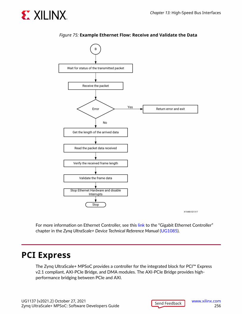
Figure 75: Example Ethernet Flow: Receive and Validate the Data
Wait for status of the transmitted packet
Receive the packet
Return error and exitError
Get the length of the arrived data
Read the packet data received
Verify the received frame length
Validate the frame data
Stop Ethernet Hardware and disable Interrupts
No
Yes
Stop
B
X15480-021317
For more information on Ethernet Controller, see this link to the “Gigabit Ethernet Controller”chapter in the Zynq UltraScale+ Device Technical Reference Manual (UG1085).
PCI ExpressThe Zynq UltraScale+ MPSoC provides a controller for the integrated block for PCI™ Expressv2.1 compliant, AXI-PCIe Bridge, and DMA modules. The AXI-PCIe Bridge provides high-performance bridging between PCIe and AXI.
Chapter 13: High-Speed Bus Interfaces
UG1137 (v2021.2) October 27, 2021 www.xilinx.comZynq UltraScale+ MPSoC: Software Developers Guide 256Send Feedback

The following flow diagrams illustrate an example for configuring PCIe root complex for a datatransfer.
Figure 76: Example PCIe Flow: Enable the Legacy Interrupts and Create PCIe Root Bus
Map the register memory space for PCIe bridge and controller
Start
Map the memory space for ECAM
Write the bridge offset in the bridge register base
Enable the bridge in the bridge control register
Disable the DMA channel registers
Enable the bridge configuration interrupt
Enable Ingress Subtractive decode translation
Enable message filtering
Get the PCIe link up
ECAMBit==1
?Return error and exit
Enable ECAM in ECAM control register
Yes
No
AX15481-071217
Chapter 13: High-Speed Bus Interfaces
UG1137 (v2021.2) October 27, 2021 www.xilinx.comZynq UltraScale+ MPSoC: Software Developers Guide 257Send Feedback

Figure 77: Example PCIe Flow: Enable the Legacy Interrupts and Create PCIe Root Bus
Get the legacy interrupt number
Return error and exitInvalid interrupt
number
Register the legacy interrupt handler
Return error and exitFailed to
register handle?
Enable all legacy interrupts
Get the bridge resources
Error getting resources?
Create PCIe root bus
Return error and exit
Return error and exitError creating
root bus? Yes
Yes
Yes
Yes
No
No
No
No
A
B
X15483-043021
Chapter 13: High-Speed Bus Interfaces
UG1137 (v2021.2) October 27, 2021 www.xilinx.comZynq UltraScale+ MPSoC: Software Developers Guide 258Send Feedback

Figure 78: Example PCIe Flow: Enable MSI Interrupts and Wait for Interrupts
Assign MSI chip hooks
No
Create the IRQ domain
Enable MSII and MSII status
Error creating IRQ domain? Return error and exit
Yes
No
MSII bit Present?No
Write the MSII low and high addresses
Disable and clear all high range MSI interrupts
Get the MSI_1 IRQ number
Disable and clear all low range MSI interrupts
Get the MSI_0 IRQ number
Enable all low range interrupts
Enable all high range interrupts
Remove the Interrupt Domain
Error Registering MSI_0 handle?
No
Yes
Register the MSI_0 handle
Error getting the IRQ number?
No
Error Registering MSI_1 handle?
Yes
Yes
Register the MSI_1 handle
Error getting the IRQ number? Yes
Yes
No
No
Is MSI bit set?
Yes
B
Scan the PCIe child bus
Assign unassigned bus resoources
Add PCIe bus devices
Set the platform driver data
Wait for interrupts
X15484-043021X15484-071217
Note: For endpoint operation, refer to this link to “Controller for PCI Express” in the Zynq UltraScale+ DeviceTechnical Reference Manual (UG1085).
After the memory space for PCIe bridge and ECAM is mapped, ECAM is enabled for ECAMtranslations. You then acquire the bus range to set up the bus numbers, and write the primary,secondary, and subordinate bus numbers. The interrupt system must be set up by enabling all themiscellaneous and legacy interrupts. You can parse the ranges property of a PCI host bridgedevice node, and setup the resource mapping based on its content.
Chapter 13: High-Speed Bus Interfaces
UG1137 (v2021.2) October 27, 2021 www.xilinx.comZynq UltraScale+ MPSoC: Software Developers Guide 259Send Feedback

To create a root bus, allocate the PCIe root bus and add initial resources to the bus. If the MSI bitis set, you must enable the message signaling interrupt (MSI). After configuring the MSIinterrupts, scan the PCIe slot and enumerate the entire PCIe bus and allocate bus resources toscanned buses. Now, you can add PCIe devices to the system.
For more information on PCI Express, see this link to the “DMA Controller” section and this linkto “Controller for PCI Express” in the Zynq UltraScale+ Device Technical Reference Manual(UG1085).
Chapter 13: High-Speed Bus Interfaces
UG1137 (v2021.2) October 27, 2021 www.xilinx.comZynq UltraScale+ MPSoC: Software Developers Guide 260Send Feedback

Chapter 14
Clock and Frequency ManagementThe Zynq® UltraScale+™ MPSoC architecture includes a programmable clock generator thattakes a clock of a definite input frequency and generates multiple-derived clocks using thephase-locked loop (PLL) blocks in the PS. The output clock from each of the PLLs is used as areference clock for the different PS peripherals.
Unlike the USB and Ethernet peripherals, some peripherals like the UART and SD allow you todynamically change the device frequency setting.
This chapter provides information about changing the operating frequency of these peripheralsdynamically. See Chapter 11: Power Management Framework for more information on reducingor adjusting the clock frequencies.
Changing the Peripheral FrequencyYou can change the peripheral operation frequency by directly setting the frequency in thecorresponding peripheral clock configuration register. The Zynq UltraScale+ MPSoC BSPprovides APIs that aid in changing the peripheral clock frequency dynamically according to yourrequirements.
The following table shows the standalone APIs that can be used to change the frequency of theperipherals
Table 64: Standalone APIs
APIs DescriptionXSDPS_change_clkfreq Change the clock frequency of SD.
XSPIPS_setclkprescaler XSPIPS_getclkprescaler Pre-scale the SPI frequency.
XRtcPSu_calculatecalibration Change the oscillator frequency.
XQSPIPSU_setclkprescaler Change the clock frequency of QSPI.
Chapter 14: Clock and Frequency Management
UG1137 (v2021.2) October 27, 2021 www.xilinx.comZynq UltraScale+ MPSoC: Software Developers Guide 261Send Feedback

In case of a Linux application, the frequency of all the peripherals is set in the device tree file. Thefollowing code snippet shows the setting of peripheral clock.
ps7_qspi_0: ps7-qspi:dir0xFF0F0000 {#address-cells = <0x1>;#size-cells = <0x0>;#bus-cells = <0x1>;clock-names = “ref_clk”, “pclk”;compatible = “xlnx,usmp-gqspi”, “cdns,spi-r1p6”; stream-connected-dma = <0x26>;clocks = <0x1e 0x1e>; dma = <0xb>; interrupts = <0xf>;num-chip-select = <0x2>;reg = <0x0 0xff0f0000 0x1000 0x0 0xc0000000 0x8000000>;speed-hz = <0xbebc200>; xlnx,fb-clk = <0x1>;xlnx,qspi-clk-freq-hz = <0xbebc200>; xlnx,qspi-mode = <0x2>;
To avoid any error condition, the peripheral needs to be stopped before changing thecorresponding clock frequency.
The steps to follow before changing the clock frequency for any peripheral are as follows:
1. Stop the transition pertaining to the peripheral (IP) and make it idle.
2. Stop the IP by appropriately configuring the registers.
3. Change the clock frequency of the peripheral.
4. Issue soft reset to the IP.
5. Restart the IP.
For more information on Zynq UltraScale+ MPSoC clock generator, see this link in the “Clocking”chapter in the in the Zynq UltraScale+ Device Technical Reference Manual (UG1085).
Chapter 14: Clock and Frequency Management
UG1137 (v2021.2) October 27, 2021 www.xilinx.comZynq UltraScale+ MPSoC: Software Developers Guide 262Send Feedback

Chapter 15
Target Development PlatformsThis chapter describes various development platforms available for theZynq® UltraScale+™ MPSoC, such as Quick Emulators (QEMU) and the Zynq UltraScale+ MPSoCboards and kits.
QEMUQEMU is a system emulation model that functions on an Intel-compatible Linux host system.Xilinx® QEMU implements a framework for generating custom machine models based on adevice tree passed to it using the command line. See the Xilinx Quick Emulator User Guide: QEMUfor more information about QEMU.
Boards and KitsXilinx provides the Zynq UltraScale+ MPSoC ZCU102, ZCU106, and ZCU111 Evaluation Kits fordevelopers. To understand more about the evaluation kits, see the following documentationpages:
• ZCU102
• ZCU106
• ZCU111
To know the different Zynq UltraScale+ MPSoCs, see the Zynq UltraScale+ MPSoC ProductsPage.
Chapter 15: Target Development Platforms
UG1137 (v2021.2) October 27, 2021 www.xilinx.comZynq UltraScale+ MPSoC: Software Developers Guide 263Send Feedback

Chapter 16
Boot Image CreationZynq® UltraScale+™ MPSoC supports both secure and non-secure booting. While deploying thedevices in field, it is important to prevent unauthorized or modified code from being run on thesedevices. Zynq UltraScale+ MPSoC provides the required confidentiality, integrity, andauthentication to host applications securely. For more information on security features, see ZynqUltraScale+ Device Technical Reference Manual (UG1085).
Zynq UltraScale+ MPSoCs typically have many hardware and software binaries that are used toboot them to function as designed and expected. These binaries includes FPGA bitstreams,Firmware, boot loaders, operating system, and applications that you select. For example: FPGAbitstream files, first stage boot loader (FSBL), PMU firmware, TF-A, U-Boot, Linux kernel, Rootfs,device tree, standalone or RTOS applications and so on). Xilinx provides a standalone tool,Bootgen, to stitch all these binary images together and generate a device bootable image in aspecific format that Xilinx loader programs can interpret while loading.
Bootgen has multiple attributes and commands that define its behavior while generating bootimages. They are secure boot image generation, non-secure boot image generation, Secure keygeneration, HMI Mode and so on. For complete details of how to get the Bootgen tool, theinstallation procedure, and details of Zynq Ultrascale+ Boot Image format, Bootgen commands,attributes, and boot image generation procedure with examples, see Bootgen User Guide(UG1283).
Chapter 16: Boot Image Creation
UG1137 (v2021.2) October 27, 2021 www.xilinx.comZynq UltraScale+ MPSoC: Software Developers Guide 264Send Feedback

Appendix A
LibrariesSee OS and Libraries Document Collection (UG643) for information on API reference for thefollowing libraries.
• Standalone Library
• LwIP 2.1.1 Library
• XilIFS
• XilFFS
• XilSecure
• XilSkey
• XilPM
• XilFPGA
• XilMailbox
Appendix A: Libraries
UG1137 (v2021.2) October 27, 2021 www.xilinx.comZynq UltraScale+ MPSoC: Software Developers Guide 265Send Feedback

Appendix B
Additional Resources and LegalNotices
Xilinx ResourcesFor support resources such as Answers, Documentation, Downloads, and Forums, see XilinxSupport.
Documentation Navigator and Design HubsXilinx® Documentation Navigator (DocNav) provides access to Xilinx documents, videos, andsupport resources, which you can filter and search to find information. To open DocNav:
• From the Vivado® IDE, select Help → Documentation and Tutorials.
• On Windows, select Start → All Programs → Xilinx Design Tools → DocNav.
• At the Linux command prompt, enter docnav.
Xilinx Design Hubs provide links to documentation organized by design tasks and other topics,which you can use to learn key concepts and address frequently asked questions. To access theDesign Hubs:
• In DocNav, click the Design Hubs View tab.
• On the Xilinx website, see the Design Hubs page.
Note: For more information on DocNav, see the Documentation Navigator page on the Xilinx website.
References
Appendix B: Additional Resources and Legal Notices
UG1137 (v2021.2) October 27, 2021 www.xilinx.comZynq UltraScale+ MPSoC: Software Developers Guide 266Send Feedback

Xilinx References
1. Xilinx Third-Party Licensing Solution Center
2. PetaLinux Product Page
3. Xilinx Vivado Design Suite – HLx Editions
4. Xilinx Third-Party Tools
5. Zynq UltraScale+ MPSoC Product Table
6. Zynq UltraScale+ MPSoC Product Advantages
7. Zynq UltraScale+ MPSoC Products Page
Zynq Devices Documentation
1. Xilinx Quick Emulator User Guide: QEMU
2. UltraScale Architecture and Product Data Sheet: Overview (DS890)
3. Isolation Methods in Zynq UltraScale+ MPSoCs (XAPP1320)
4. Zynq UltraScale+ Device Technical Reference Manual (UG1085)
5. Zynq UltraScale+ Device Register Reference (UG1087)
6. Zynq UltraScale+ MPSoC: Embedded Design Tutorial (UG1209)
7. Zynq UltraScale+ MPSoC Processing System LogiCORE IP Product Guide (PG201)
8. UltraScale Architecture System Monitor User Guide (UG580)
9. Libmetal and OpenAMP for Zynq Devices User Guide (UG1186)
10. Embedded Energy Management Interface Specification (UG1200)
11. UltraFast Embedded Design Methodology Guide (UG1046)
12. Zynq-7000 SoC: Embedded Design Tutorial (UG1165)
13. Zynq-7000 SoC Software Developers Guide (UG821)
14. UltraScale Architecture PCB Design User Guide (UG583)
15. Vivado Design Suite Documentation
16. Bootgen User Guide (UG1283)
Vitis software platform and PetaLinux Documents
1. Vitis Unified Software Platform Documentation
Appendix B: Additional Resources and Legal Notices
UG1137 (v2021.2) October 27, 2021 www.xilinx.comZynq UltraScale+ MPSoC: Software Developers Guide 267Send Feedback

2. OS and Libraries Document Collection (UG643)
3. Embedded Design Tools Download
4. PetaLinux Tools Documentation: Reference Guide (UG1144)
5. Xilinx Software Development Kit: System Performance (UG1145)
Xilinx IP Documents
1. AXI Central Direct Memory Access LogiCORE IP Product Guide (PG034)
2. AXI Video Direct Memory Access LogiCORE IP Product Guide (PG020)
Miscellaneous Links
1. Xilinx Github
2. Embedded Development
3. Yocto
4. PetaLinux Software Development
5. Zynq UltraScale+ Silicon Devices Page
6. Xilinx Answer: 66249
7. Vivado Quick Take Video: Vivado PS Configuration Wizard Overview
8. Xilinx Wiki
9. Kria SOM
Third-Party References
1. Lauterbach Technologies
2. Arm Trusted Firmware
3. Xen Hypervisor
4. Arm Developer Center
5. Arm Cortex-A53 MPCore Processor Technical Reference Manual
6. Yocto Product Development
7. GNU FTP
8. Power State Coordination Interface – Arm DEN 0022B.b, 6/25/2013
Appendix B: Additional Resources and Legal Notices
UG1137 (v2021.2) October 27, 2021 www.xilinx.comZynq UltraScale+ MPSoC: Software Developers Guide 268Send Feedback
Please Read: Important Legal NoticesThe information disclosed to you hereunder (the "Materials") is provided solely for the selectionand use of Xilinx products. To the maximum extent permitted by applicable law: (1) Materials aremade available "AS IS" and with all faults, Xilinx hereby DISCLAIMS ALL WARRANTIES ANDCONDITIONS, EXPRESS, IMPLIED, OR STATUTORY, INCLUDING BUT NOT LIMITED TOWARRANTIES OF MERCHANTABILITY, NON-INFRINGEMENT, OR FITNESS FOR ANYPARTICULAR PURPOSE; and (2) Xilinx shall not be liable (whether in contract or tort, includingnegligence, or under any other theory of liability) for any loss or damage of any kind or naturerelated to, arising under, or in connection with, the Materials (including your use of theMaterials), including for any direct, indirect, special, incidental, or consequential loss or damage(including loss of data, profits, goodwill, or any type of loss or damage suffered as a result of anyaction brought by a third party) even if such damage or loss was reasonably foreseeable or Xilinxhad been advised of the possibility of the same. Xilinx assumes no obligation to correct anyerrors contained in the Materials or to notify you of updates to the Materials or to productspecifications. You may not reproduce, modify, distribute, or publicly display the Materialswithout prior written consent. Certain products are subject to the terms and conditions ofXilinx's limited warranty, please refer to Xilinx's Terms of Sale which can be viewed at https://www.xilinx.com/legal.htm#tos; IP cores may be subject to warranty and support terms containedin a license issued to you by Xilinx. Xilinx products are not designed or intended to be fail-safe orfor use in any application requiring fail-safe performance; you assume sole risk and liability foruse of Xilinx products in such critical applications, please refer to Xilinx's Terms of Sale which canbe viewed at https://www.xilinx.com/legal.htm#tos.
AUTOMOTIVE APPLICATIONS DISCLAIMER
AUTOMOTIVE PRODUCTS (IDENTIFIED AS "XA" IN THE PART NUMBER) ARE NOTWARRANTED FOR USE IN THE DEPLOYMENT OF AIRBAGS OR FOR USE IN APPLICATIONSTHAT AFFECT CONTROL OF A VEHICLE ("SAFETY APPLICATION") UNLESS THERE IS ASAFETY CONCEPT OR REDUNDANCY FEATURE CONSISTENT WITH THE ISO 26262AUTOMOTIVE SAFETY STANDARD ("SAFETY DESIGN"). CUSTOMER SHALL, PRIOR TO USINGOR DISTRIBUTING ANY SYSTEMS THAT INCORPORATE PRODUCTS, THOROUGHLY TESTSUCH SYSTEMS FOR SAFETY PURPOSES. USE OF PRODUCTS IN A SAFETY APPLICATIONWITHOUT A SAFETY DESIGN IS FULLY AT THE RISK OF CUSTOMER, SUBJECT ONLY TOAPPLICABLE LAWS AND REGULATIONS GOVERNING LIMITATIONS ON PRODUCTLIABILITY.
Copyright
© Copyright 2015-2021 Xilinx, Inc. Xilinx, the Xilinx logo, Alveo, Artix, Kintex, Kria, Spartan,Versal, Vitis, Virtex, Vivado, Zynq, and other designated brands included herein are trademarks ofXilinx in the United States and other countries. All other trademarks are the property of theirrespective owners.
Appendix B: Additional Resources and Legal Notices
UG1137 (v2021.2) October 27, 2021 www.xilinx.comZynq UltraScale+ MPSoC: Software Developers Guide 269Send Feedback