
Communication Developers Handbook
141
NComm, Inc. Communication Developers Handbook Top Gotchas and Shortcuts for WAN Access Developers Framer Management, Line Testing, Signaling and Performance Monitoring Software Updated content includes: Sync Status Messaging Ethernet OAM 2011 Edition
-
Upload
khangminh22 -
Category
Documents
-
view
0 -
download
0
Transcript of Communication Developers Handbook

NComm, Inc.
Communication Developers Handbook
Top Gotchas and Shortcuts for WAN Access Developers Framer Management, Line Testing, Signaling and
Performance Monitoring Software
Updated content includes:
Sync Status Messaging Ethernet OAM
2011 Edition

NComm, Inc.
NOTICE
The information contained herein is the property of NComm and shall not, in whole or inpart, be reproduced, translated, or converted to any electronic or machine readable formwithout NComm’s prior written approval.
NComm, Inc. assumes no liability for losses incurred as a result of out-of-date or incorrectinformation contained in the document.
Communication Developers Handbook
Current Edition October 2010
Printed in the USACopyright © 2001-2010 by NComm, Inc.Hampstead, NH
All rights reserved.

Communication Developers Handbook
NComm, Inc. i
Contents
Contributors ................................................................................................... 1Introduction.................................................................................................... 2Main Components of an Ethernet/WAN Access Project ................................. 4
Hardware ......................................................................................................................... 5Processor ..................................................................................................................... 5Memory ........................................................................................................................ 6WAN Framer ................................................................................................................ 7Vendor Equipment Application ................................................................................... 11
Software ........................................................................................................................ 12Operating System ...................................................................................................... 13Management of your WAN Access Trunks................................................................. 14
The Industry Standards, and the “Real World” ............................................. 16What is Trunk Management Software? ........................................................ 18
Main Components of Trunk Management Software ...................................................... 20Configuration Manager............................................................................................... 20Alarm Manager........................................................................................................... 21Maintenance Manager ............................................................................................... 21Signaling Manager for T1/E1...................................................................................... 22
Sync Status Messages and Clock Distribution Management......................................... 23Trunk Management and SNMP ..................................................................................... 26Automatic Protection Switching ..................................................................................... 28
History ........................................................................................................................ 28Description ................................................................................................................. 29
WarmStart Capability..................................................................................................... 30System Behavior with WarmStart............................................................................... 31WarmStart Implementation Objectives....................................................................... 32Framer and Transceiver Devices ............................................................................... 33

Communication Developers Handbook
NComm, Inc. ii
Designing for High Availability.................................................................................... 34
Ethernet in the Wide Area Network .............................................................. 35Ethernet OAM Design Considerations ....................................................................... 37
Specific Issues of Ethernet OAM for IEEE 802.1ag...................................... 39Specific Issues of Ethernet OAM for ITU Y.1731.......................................... 41Specific Issues of T1/E1 .............................................................................. 44
Overview of T1 .............................................................................................................. 44Alarms........................................................................................................................ 45Framing...................................................................................................................... 46In-band Loopback Activation and De-Activation......................................................... 50Signaling .................................................................................................................... 50
Overview of E1 .............................................................................................................. 53Framing...................................................................................................................... 54Alarms........................................................................................................................ 59Signaling .................................................................................................................... 60
Standards Requirements ............................................................................................... 61Software Architecture .................................................................................................... 62
Specific Issues of T3/E3 .............................................................................. 63Overview of T3 .............................................................................................................. 63
G.747 ......................................................................................................................... 72Overview of E3 .............................................................................................................. 74
G.751 Framing ........................................................................................................... 74G.832 Framing ........................................................................................................... 77
Standards Requirements ............................................................................................... 81Alarms and Configuration .............................................................................................. 81Performance Monitoring ................................................................................................ 82Software Architecture .................................................................................................... 83
Specific Issues of SONET/SDH ................................................................... 84Overview of SONET ...................................................................................................... 84

Communication Developers Handbook
NComm, Inc. iii
Section Overhead ...................................................................................................... 86Line Overhead............................................................................................................ 86Path Overhead ........................................................................................................... 87
Overview of SDH ........................................................................................................... 88Standards Requirements ............................................................................................... 94Alarms and Configuration .............................................................................................. 95Performance Monitoring ................................................................................................ 95Japanese SDH .............................................................................................................. 96
Handling Groups ........................................................................................................ 98Automatic Protection Switching ..................................................................................... 99
Interoperability and NComm's TMS.......................................................................... 101Software Architecture .................................................................................................. 102
Testing Issues and Gotcha’s...................................................................... 103Estimating the Development Time for a WAN Access Project.................... 109
Best Options for Development..................................................................................... 111Using NComm’s TMS for SNMP Management ........................................................ 112
The history of bus architecture .................................................................................... 112PMC/PTMC ................................................................................................................. 115COMPACTPCI............................................................................................................. 117The Future: PCI Express, ATCA, AMC… .................................................................... 119Growing Demand for VoIP........................................................................................... 120The evolution of telecom equipment ............................................................................ 122Outsourcing solutions that make “cents”...................................................................... 122Completing the System Design ................................................................................... 123Go to the experts ......................................................................................................... 124
Glossary .................................................................................................... 125About NCOMM .......................................................................................... 133About LSI Corporation ............................................................................... 134

Communication Developers Handbook
NComm, Inc. iv
This page is intentionally left blank

Communication Developers Handbook
NComm, Inc. 1
Contributors
NComm gives its sincere thanks to the following companies that have provided support forthis book.
LSI Corporation
Network Systems Design e-zine

Communication Developers Handbook
NComm, Inc. 2
Introduction
With the ever-increasing options for accessing the Wide Area Network (WAN), designingcommunications interfaces has become a more challenging task. New developments, newplatforms, new applications of Ethernet and increasing customer requirements make thedesign of access interfaces a never-ending challenge. If you are designing equipment thatrequires T1/E1/T3/E3/SONET/SDH or Ethernet interfaces, you need to read the rest of thisbook. If you are not, you will still find a wealth of knowledge but you might find a goodnovel more interesting.
You made it to the second paragraph, which means you have such a project to complete.As a manager or senior developer, you are charged with developing a product thatincludes a WAN or LAN interface, but the project has many other items for you to consider.You have circuit boards to design, a microprocessor to choose, complier and developmentsystems to select, an operating system to select, debuggers/emulators to select, changecontrol systems to choose and implement, etc. etc. You have many items on your plate tomake your project, and company, successful.
Fortunately, even with all of these issues to consider, meeting a schedule is never aproblem. But wait. Schedule is a problem! Since you aren’t doing basic research that maynever lead to results, you must deliver products that will pay the bills, including your ownsalary. So, you need to figure out the best way to get the job done. You have a product tocomplete on time.
Adding value to the traffic that traverses your product is core to the value of your company.Getting the traffic into and out of your product is probably not a focus; you need to do it,you need to do it correctly, but no one will purchase your product because of it. The mostimportant objective is to get the interface completed and released so that it works well andsupports the value added of your particular company.

Communication Developers Handbook
NComm, Inc. 3
This handbook will review the major components that need to go into an Ethernet/WANaccess project. It will answer the question “What is Trunk Management Software?” Inaddition it will go thru some specialized issues such as clock management, automaticprotection switching and warm start. There is a section devoted to Ethernet and to thespecifics for that interface. Also, there is an overview of each of the WAN interfaces suchas T1 and the specific issues that you might encounter there. Trends in embeddedhardware have their own section. An area that NComm has lots of experience with istesting. Once you get your design produced, you will need to test it. There is a sectioncalled “Testing Issues and Gotcha’s”, which go thru many of the issues that NComm hasseen with testing. How to estimate this type of project is also covered as well as glossaryof terms.
To summarize, it will discuss the technical issues that are essential components of yourdesign. It will outline how to make the proper decisions, and present you with options. Itwill also discuss make vs. buy decisions, and some of the tools and components availablefor purchase. While all the sections probably won’t apply to everyone, we hope you findwhat you are looking for.

Communication Developers Handbook
NComm, Inc. 4
Main Components of an Ethernet/WAN Access Project
First, why do you have an access interface? Unless you are in the CSU/DSU1 or NIC2
business, the value-add in your product relies on traffic being carried over the publicnetwork, and the access interface is the mechanism to get that traffic into and out of yourproduct. The traffic can be voice or data, but the traffic still must traverse the interface. Andif it is data, it could be ATM, Frame Relay, Multi-Link PPP, etc.
At the Customer Premise Equipment (CPE) or Remote Terminal (RT) side of the network,Ethernet/WAN interfaces are found on equipment including:
PBXs Routers PRI (ISDN) Terminal Adapters Remote Access Servers M13 and SONET Multiplexers Voice Over IP Devices Terrestrial bases for wireless systems Edge Switches
On the Central Office (CO) side of the network, it is fair to say that most of the equipmentwill have one of these interfaces. Among these will include:
Class 5 Switch Cards Office Channel Units (OCU) including those with Data Ports (OCU/DP)
1 CSU = Channel Service Unit. DSU = Data Service Unit
2 NIC = Network Interface Card

Communication Developers Handbook
NComm, Inc. 5
Digital Loop Carrier (DLC) equipment Repeaters/Regenerators
So, what do you do to complete your project? You start by determining what maincomponent pieces need to be scheduled, and then determine how to best accomplisheach of them. Real design means setting priorities. For example, you have probablydecided to not write your own complier and linker, right? So, why is that? BECAUSE IT ISNOT SOMETHING THAT ADDS VALUE TO YOUR PRODUCT. It is not a corecompetency that enhances your company’s success (let alone your own career). Whenwas the last time you didn’t purchase a product because the vendor did not write his or herown complier? So, to get your project completed, you need to purchase the tools that willhelp you advance most efficiently and then make what you must to complete your project.
Before we move forward, I’ll give you a little advice originally from a top Xerox manager.He said that, “There are three parameters that need to be managed: cost, quality, andschedule. Cost and schedule are performance issues. Quality is an employment issue.”Shipping product that doesn’t work properly isn’t just expensive to fix; it can do yourcompany’s reputation irreparable harm and damage your career.
So, what do you need to do to get the interface going?
Hardware
Assuming you have already determined the physical circuit board parameters --connectors, bus structure, power, form factor etc., the remaining decisions will focus on thecomponents that are required to make your Ethernet/WAN access design operational.
Processor
One of the most important considerations in the choice of processor is the amount ofprocessing power, usually expressed in MIPS (Millions of Instructions Per Second). The

Communication Developers Handbook
NComm, Inc. 6
old rule of thumb still applies that your processor should be roughly twice the capacity thatyour system requires under normal operating conditions. You need to establish a MIPSbudget that considers the current and follow-on demands of the project.
As many of you have already experienced, thereal MIPS requirement can easily beunderestimated because of estimationerrors and omissions, real world differences fromthe theoretical, changes in productdefinition and “feature creep”, softwareinefficiencies and follow-on releases on theoriginal product platform. The market hasa nasty habit of needing new features and exposing feature holes that usually consumesignificantly more processing power. While cost is an important consideration, it isprobably more costly to cut the processor too close and find yourself mining for MIPS.Eventually the Laws of Physics take over and you are in the middle of a redesign.
Other considerations include the processor track record in telecom/datacom applications,obtainability of board support packages, third party software and source code availability,vendor design assistance and availability. A significant consideration is staff experiencewith the device. If your engineering staff has used a specific processor in prior projects, thelearning curve is substantially reduced when using the same processor in follow-onprojects.
Memory
The basic rule: you have to make sure that you have enough! Memory will be consumedby operating system, and application data. Be very careful to fully accommodatedynamically allocated memory. It may seem obvious, but it is a requirement oftenunderestimated.
You need to establish aMIPS budget that
considers the current andfollow-on demands of the
project.

Communication Developers Handbook
NComm, Inc. 7
WAN Framer
The framer is the hardware component that takes your data stream and maps it to theWAN service (T1, SONET, etc.). Framer choice involves a number of considerations.Many come down to cost; this is best looked at as “total” cost. You first need to determinethe number of trunks or circuits that your interface will handle. Will the product offer bothUS and European flavors of transmission? If there will be multiple flavors, will a singleproduct offering contain all capabilities or will the base be built with different hardwarepopulations and different software to become different models in a line of offerings. Yourresponse to these questions might be a single framer that does T1 and E1, or it might betwo different yet pin-compatible devices.
Other considerations include the framer’s impact on the MIPS budget, part availability,framer standards compliance, expected part longevity, vendor support and, of course,price. The following table lists the most popular framers in our experience.
Popular Framers for WAN Access Projects
T1T1/E1-
LIUE1 T3/E3-
LIU T3 E3 HDLC SONET/SDH
Supermapper(tmxf28155)
Ultramapper(tmxf84622)
Hypermapper(tmxf33625)
Ultraframer(TFRA84J13)
Supermapper(tmxf28155)
Ultramapper(tmxf84622)
Hypermapper(tmxf33625)
Supermapper(tmxf28155)
Ultramapper(tmxf84622)
Hypermapper(tmxf33625)
Ultraframer(TFRA84J13)
Ultramapper(tmxf84622)
Hypermapper(tmxf33625)
Supermapper(tmxf28155)
Ultramapper(tmxf84622)
Hypermapper(tmxf33625)
MARS10G(TSOT1610G)
TSOT16106A
TADM042G5

Communication Developers Handbook
NComm, Inc. 8
T1T1/E1-
LIUE1 T3/E3-
LIU T3 E3 HDLC SONET/SDH
OrinocoS1204 .
T1T1/E1-
LIUE1 T3/E3-
LIU T3 E3 HDLC SONET/SDH
XRT72L71 . .
T1T1/E1-
LIUE1 T3/E3-
LIU T3 E3 HDLC SONET/SDH
DS2151DS2152
DS21352/DS21552
DS21Q352/DS21Q552DS21Q48DS2155
DS21Q55DS21455DS21458DS26502DS26503DS26528DS26519DS3100
DS21Q48 DS2153DS2154
DS21354/DS21554
DS21Q354/DS21Q554DS21Q48DS2155
DS21Q55DS21455DS21458DS26502DS26503DS26528DS26519DS3100
DS315x DS3112DS314XDS316XDS317X*DS318X
DS3112DS314XDS316XDS317X*DS318X
DS2155DS21Q352/DS21Q552
..
T1T1/E1-
LIUE1 T3/E3-
LIU T3 E3 HDLC SONET/SDH
..MPC82XX
PowerQUICC II MCC..

Communication Developers Handbook
NComm, Inc. 9
T1T1/E1-
LIUE1 T3/E3-
LIU T3 E3 HDLC SONET/SDH
82P228882P228482P228282P2281
82P228882P228482P228282P2281
.. ..
(formerly Infineon devices)
T1T1/E1-
LIUE1 T3/E3-
LIU T3 E3 HDLC SONET/SDH
FALC54PEF2254
FALC-LH PEF2255
FALC56 PEF2256
Quad FALCPEF 22554
Quad LIUPEF 22504
Quad LIUPEF
22504
FALC54 PEF2254
FALC-LH PEF 2255
FALC56 PEF 2256
Quad FALC PEF 22554
Quad LIU PEF 22504
Octal-FALCPEF22558
QuadLIU PEF22504
TE3-MUX(M13FX
)PEF 3445
TE3-FALCPEF 3460
..TE3-FALCPEF 3460 FALC56 PEF 2256 ..
(formerly Intel devices)
T1T1/E1-
LIUE1 T3/E3-
LIU T3 E3 HDLC SONET/SDH
IXF3208IXF3208
IXF19301

Communication Developers Handbook
NComm, Inc. 10
T1T1/E1-
LIUE1 T3/E3-
LIU T3 E3 HDLC SONET/SDH
.
PHAST®-12NTXC06312b
PHAST®-12PTXC06412b
T1T1/E1-
LIUE1 T3/E3-
LIU T3 E3 HDLC SONET/SDH
COMETPM4351
TOCTLPM4388
COMET-QuadPM4354
TEMUXPM8315
TEMUX84PM8316
TECT3PM4328
TEMUX84E3PM8320
PM8321
TEMUX-336PM8310
COMET PM4351
COMET-Quad PM4354
TEMUX PM8315
TEMUX84 PM8316
EOCTLPM6388
TEMUX84E3 PM8320
PM8321
TEMUX-336PM8310
S/UNI QJETPM7346
TEMUXPM8315
TEMUX84PM8316
TECT3PM4328
TEMUX84E3PM8320
S/UNI QJET PM7346
Spectra-2488PM5315
TUPP+622PM5363
PM5319
PM5360
TEMUX84 PM8316
Spectra-4x155PM5316
S/UNI MultiPM5354
Arrow 155PM5320
TEMUX84E3PM8320
TEMUX-336PM8310

Communication Developers Handbook
NComm, Inc. 11
T1T1/E1-
LIUE1 T3/E3-
LIU T3 E3 HDLC SONET/SDH
VSC9675 VSC9675 . .
Vendor Equipment Application
Ethernet/WAN interfaces are showing up more and more frequently in more and moreproducts. Many people don’t realize that even with technologies like Frame Relay andPrimary Rate ISDN, physical level access is still required. Often it is T1 or E1, but can beT3, E3, SONET, SDH or even MetroEthernet. These interfaces will be at both ends of thetransmission. Each segment must be terminated properly for correct operation andsegmentation for fault location.
Also, T1, E1 and T3 will often be found beingcarried inside SONET streams. Multiplexing ofthese lower speed interfaces into SONET orSDH will result in multiple layers of alarmand performance information that requiresmonitoring at various places.
Bottom-line, you need to get the physical layer interface working and to be able to interfaceto any other system. Your hardware designers may have some suggestions, but you stillhave to fit your software architecture with the standards that are required. For example, allhardware framers are not created equal. Some devices do very well implementing somefeatures, but require external hardware (e.g. FPGAs) to implement other features. Youneed to ensure that your choice of framer can implement the features your productrequires, and can also handle the other constraints of your system.
Bottom-line, you need toget the physical layer
interface working and tobe able to interface to any
other system.

Communication Developers Handbook
NComm, Inc. 12
Software
Many software decisions are interdependent on hardware decisions; and, a cool headneeds to be kept. Too often you see hardware designers dumping responsibility on thesoftware team, or the software group trying to drive the hardware decisions to make theirjobs easier. The real consideration is the impact on the company; this requires a look atthe total cost, quality and that schedule thing again. Any addition in hardware cost, meansextra dollars ship out the door with every unit sold. On the other hand, adding a capabilityin hardware might prove more reliable than the same feature in software. Both of theseconsiderations need to be taken against the schedule backdrop. All else being equal, youcan never recover lost time to market. So, these decisions become an optimization, not amaximization issue. The software component is block diagrammed into basic parts inFigure 1:
Figure 1. Basic Software Components

Communication Developers Handbook
NComm, Inc. 13
Now let’s look at two of the most important software pieces and some key considerations:
Operating System
The operating system used for most (if not all) telecom/datacom systems needs to be aReal Time Operating System (RTOS). To properly implement standards, you need to beable to count on processing that is very deterministic. Things need to happen when theymust happen, and cannot be held up because some extraordinary event occurred. It is truethat some improved OS's that are not, strictly speaking, real-time have included someprioritization that tends to overcome some of our concerns. But, be careful. There areinstances where you have less than 10 ms to react and your system better be there toknow it!
It used to be that most development groupsdesigned or “rolled” their own OS. We are seeingless of this every year and now there are high-quality, off-the-shelf alternatives. Unless youhave some extraordinary requirements, which wehaven’t seen yet, you should probably bespending your time adding unique value toyour offering. What is the payback of successfully reinventing the wheel?!?
There are a small number of operating systems that once dominated a majority of theWAN access development projects. VxWorks (Wind River), pSOS (Wind River), OSE, andNucleus (Accelerated Technology) are the real-time operating systems that we saw themost. They all support the top hardware platforms. Each system has its strengths andweaknesses. It is a good idea to gather information from each vendor, and then decide ifthere are significant design reasons to choose one over the other.
Now, we see a major interest in using Linux OS in communications applications. Originally,Linux was not a real-time OS. In 2003, extensions were available to affect a more real-time
To properly implementstandards, you need to be
able to count onprocessing that is very
deterministic.

Communication Developers Handbook
NComm, Inc. 14
performance. With version 2.6, these extensions were integrated even more closely withinthe OS. Almost all the new developments we see are based on Linux.
Although growing popularity cannot be denied, it should be recognized that while it is “free”there are still significant support costs. Many of our Trunk Management Software usershave successfully based their systems on Linux. NComm has now added the Linuxoperating system as one of our standard pre-ports.
Many design decisions are, and should be, based on the experience of your developmentteam. Having developers already experienced with one OS will reduce your learning curve,and improve problem solving. This is a good rule as long as the OS delivers the real-timefeatures required by your application.
Management of your WAN Access Trunks
The most important items that separate a WAN interface from a traditional LAN interfaceare that the WAN interface is “expected” to be available 100% of the time, and the WANinterface is more likely to have multiple equipment manufacturers and service providersend-to-end. If your house is burning, you expect that when you dial 9113, you will alwaysconnect to the fire department. To provide high levels of service, the standards for WANinterfaces have been developed so that problems can be located, isolated, and in somecases, fixed before an outage occurs.
3 911 is the number to call in most United States locations for emergency services such as fire, police, andmedical.

Communication Developers Handbook
NComm, Inc. 15
Trunk management software is software that manages the WAN (or LAN see the EthernetOAM section) interface in your product. It sits ontop of your framer control code and below yourvalue added application. It permits the properconfiguration of the framer, alerts yourapplication to important things that arehappening on the line, controls the overheadfunctions of the WAN circuits, and providesstandard compliant operation of your T1, E1,T3, E3, SONET, or SDH interface.
Prime considerations, or design goals, for this trunk management software should includecompliance to the applicable standards, code efficiency, and a well-defined ApplicationProgrammer Interface (API) that will promote application code reuse, hardware flexibility,and future product growth plans. As will be discussed later, trunk management software isthe component that controls the actual WAN interface and is essential for the properoperation of your product. It covers the specialized set of controls and signaling, thatmakes operation and interaction on the public network possible, standard compliant andinteroperable with multi-vendors equipment.
The specialization of trunk management software means that software developers, withoutthe experience of having written trunk management software previously, have a high initiallearning curve. After designing and writing the code, they will experience an unusually longtest and debug phase as the variations in what the published standards versus the trueoperational realities become apparent. Lack of real world experience in this area greatlyincreases the risk that the WAN interface released to your customers will not perform asexpected and required.
To provide high levels ofservice, the standards forWAN interfaces have been
developed so thatproblems can be located,
isolated, and in somecases, fixed before an
outage occurs.

Communication Developers Handbook
NComm, Inc. 16
The Industry Standards, and the “Real World”
The first thing you need to determine is which standards cover your product. There are anumber of standards that may apply; from regulatory standards (FCC and EU), to tradeorganizations (ANSI, EIA, TIA, and ITU), and carrier standards (AT&T, WorldCom,Telcordia). If your marketing organization has done their job, they should have providedthe list of standards for you to implement. You still need to figure out to what extent theyapply to your product, and if you really need to implement them. To make your job moredifficult, there are different interpretations to many of the standards as well as industry-accepted practices. Here is where you need to start depending on the WAN interface thatyou are adding to your product. The following matrix shows the most essential standards,for each type of WAN interface:
T1 E1 T3 E3 SONET SDH
Alarms T1.231
I.431
G.731
ETSI 300-233
T1.231
G.747
G.751
G.832
T1.231
T1.105
GR-253
G.783
G.784
Maintenance &PerformanceMonitoring
T1.403
T1.231
TR54016
G.826
SA bitprocessing
will conformto G.704
T1.231
G.704
G.826
G.751
G.832
T1.231
T1.105
GR-253
G.783
G.784
G.826

Communication Developers Handbook
NComm, Inc. 17
T1 E1 T3 E3 SONET SDH
Signaling
T1.403
TR-08
GR-303(Tables 12-3
& 12-4)
GR-506
ATT Pub43801
Q.421
Q.422N/A N/A N/A N/A
AutomaticProtectionSwitching
N/A N/A N/A N/A
GR-253
T1.105
G.841
The way standards are written often makes it difficult to understand what the standard’sbody intended. There are sometimes interpretations of the standard that the developer isrequired to make. On the other hand, subtle changes have been made to the formalstandards that have resulted from some field test, experience, and best practice. This addsto the confusion as to what has to be implemented.
A well thought-out design – both hardware and software greatly improves the situation. Agood example of this occurred when we went through EU certification for E1. Smallchanges had to be made to the software to pass the testing criteria. A good softwarearchitecture allowed for such adjustments with ease.
Communication Developers Handbook
NComm, Inc. 18
What is Trunk Management Software?
Trunk management software is the software required to put a WAN interface e.g.,T1/E1/T3/E3/SONET/SDH or Ethernet interface into the network (Ethernet will bediscussed later). It provides the ability to integrate hardware devices such as framers into acomplete software system.
Most framer silicon vendors provide “drivers” that are geared toward performing devicedesign validation. In other words, they verify that the framer is performing the way it wasdesigned.
Trunk management software addresses adifferent need. The end- user equipment designerdoes not need to validate the design of the framermanufacturer, but instead needs to put theframer into their product and make sure that itimplements the applicable standardscorrectly.
Application Programmer Interfaces (APIs) help to modularize the design and developmentof any sizable software project by providing a layered model and are widely used. Thefollowing figure shows the layered approach to the software architecture design that usesAPIs.
Trunk managementsoftware is the softwarerequired to put a WAN
interface e.g.,T1/E1/T3/E3/SONET/SDH
or Ethernet interface intothe network.
Communication Developers Handbook
NComm, Inc. 19
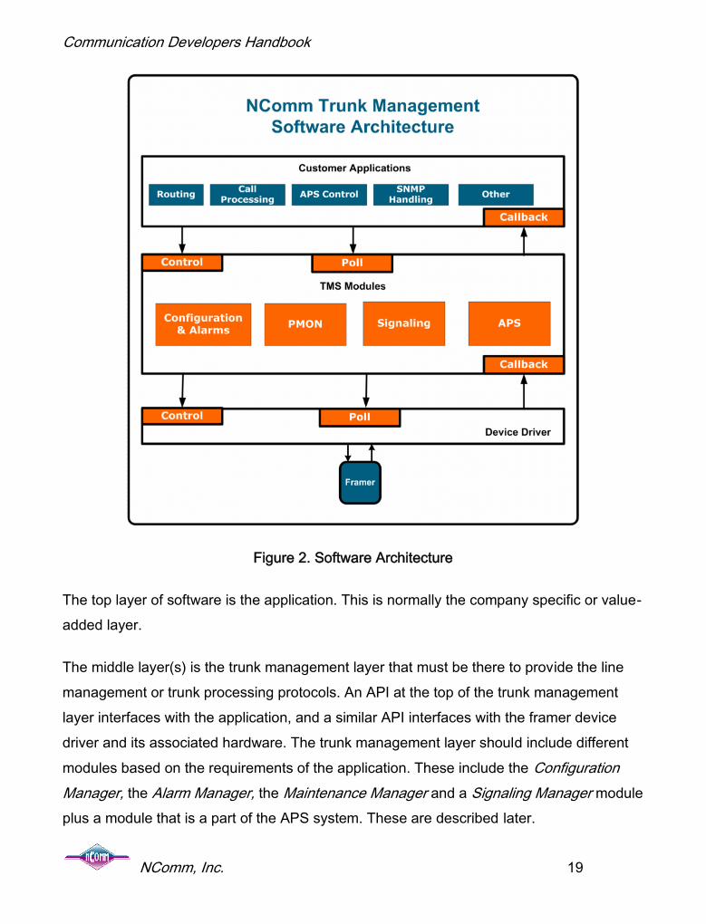
Figure 2. Software Architecture
The top layer of software is the application. This is normally the company specific or value-added layer.
The middle layer(s) is the trunk management layer that must be there to provide the linemanagement or trunk processing protocols. An API at the top of the trunk managementlayer interfaces with the application, and a similar API interfaces with the framer devicedriver and its associated hardware. The trunk management layer should include differentmodules based on the requirements of the application. These include the ConfigurationManager, the Alarm Manager, the Maintenance Manager and a Signaling Manager moduleplus a module that is a part of the APS system. These are described later.

Communication Developers Handbook
NComm, Inc. 20
The bottom layer is the driver layer that interfaces directly with the hardware and providesan autonomous interface so that it is possible to develop the application independent of thehardware.
Device drivers provide a portable interface to assist the application development on theindustry standard devices. The device driver should be implemented so that it does notrequire operating system services and thus is portable across different operating systemsand platforms.
Main Components of Trunk Management Software
From here on out, we will regularly refer to examples of functionality from NComm’s TrunkManagement Software. Whether or not you are using this specific software, the capabilitiesand standards are exactly those that you will need to duplicate in your product.
Configuration Manager
Configuration management sets the proper parameters that match the line service to theWAN interface. It also sets user configurable parameters that regulate the kinds ofinformation that will be reported and the rules of reporting. For example, the defaultintegration time per T1.231 for declaring a red alarm is 2.5 seconds. If an applicationdesires this declaration to happen in 1 second, it can be reconfigured as such. Majorparameters that may need to be configured include:
Line Encoding Line Framing Format Line Build-Out (Short haul/Long haul w/ distance parameters) Alarm integration including programmable integration timers Selection of clear channel, idle channel, and/or signaling model. This needs to be
selectable on a per voice channel basis. Selection of user side or network side for the interface Configuration of addresses for maintenance protocols

Communication Developers Handbook
NComm, Inc. 21
Selection of remote, local, payload, and diagnostic loopbacks under application control
Alarm Manager
WAN interfaces use the terminology of “Alarm” to signify any failure of the interface. Forinstance, three different alarms (red, yellow, and blue) are used to indicate differentproblems in the transmission or reception of data in a T1 system. Other functions includedin alarm management include:
Standards compliant detection, declaration, and clearing of all alarm conditions perT1.231
Programmable alarm integration timers for OOF, LOS, AIS, and RAI. Standardscompliant responses to far-end alarm conditions as per T1.231
For E1 and E3, the alarm capabilities must meet standards per I.431, G.732, ETSI 300-233
For SONET and SDH, handling Enhanced RDI, TIM defect detection, PLM defectdetection and PTI strings.
Maintenance Manager
The Maintenance Manager handles the gathering, processing and communication ofperformance data, initiating and responding to loop back signals, monitoring and providingthreshold crossing alerts, establishing/managing special links like the FDL (Facility DataLink) and PMDL (Path Maintenance Data Link), and passing BOC/BOM messages (BitOriented Code/Bit Oriented Message). Other functions contained in the maintenancemanager may include:
Manages and responds to the Facility Data Link (FDL) per TR-54016 Bit Oriented Message/ Bit Oriented Code (BOM/BOC) handling per T1.403 Programmable Loop Back codes In band and out of band Loop Up and Loop Down code reception and transmission 1 second performance report collection and transmission per T1.403

Communication Developers Handbook
NComm, Inc. 22
96 (or 192), 15-minute performance data bucket collection and transmission for theNear End per TR-54016 and T1.231.
Responding to and transmitting 15-minute performance data buckets over the FDL forthe Near End per TR-54016
Far end performance data collection in 96, 15-minute buckets and 24-hour summarybased upon receipt of T1.403 PRMs from the far end per T1.231.
For E1, E3 and SDH, performance monitoring must meet the standards per G.826 andprovide a 15-min/24-hour data performance database as well. SA bit processing mustconform to G.704
For E1, control of Sa, Si, and X bits. Threshold Crossing Alerts
Signaling Manager for T1/E1
The Signaling Manager sends, receives and interprets Robbed-Bit and ChannelAssociated Signaling for T1 and E1, respectively. Along with Signaling System 7 (SS7)and the D Channel in ISDN, Robbed-Bit Signaling and CAS are the only ways to placeconventional telephone calls. This signaling tends to be used at the edge of the network asopposed to the core.
Common Channel Signaling (CCS) (Not to be confused with Channel AssociatedSignaling) is used by either T1 or E1 and refers to a system that does not use a specific bitstructure for signaling. Instead, all or part of a channel is used to pass messages betweentwo systems to indicate how a channel is being used. This type of system is commonlyfound in ISDN, which uses a D channel to pass messages.
Functions that need to be supported in the module include:
Robbed-Bit or Channel Associated Signaling (CAS) communication that willaccommodate a different signaling model per timeslot

Communication Developers Handbook
NComm, Inc. 23
T1 Robbed-bit signaling allows customer choice of signaling models per T1.403 – 1999,TR-08, or GR-303-CORE-Rev3 (Tables 12-3 & 12-4). Choice may be done on a perDS0 basis
E1 CAS signaling models as defined in Q.421, Q.422 and including on a per E0 basis Processes bit freezing and debouncing Provides call state information such as wink, flash, on-hook, loop open, etc. to the
application layer per the selected signaling model Transmission and reception of dial pulse digits. Timers associated with signaling such as wink, hook flash, and digit on/off ratios, must
be programmable on a per timeslot basis TR-08/SLC-96 and T1.403 Tri-level signaling supported with external hardware support
for generation and detection of the toggling state. Publication 43801
Sync Status Messages and Clock Distribution Management
The telecom network functions as a synchronous finite state machine where the timing issourced from a common source. The timing is then distributed throughout the network fromone central office to the next via the equipment located in each central office. Since timingcan be distributed across many cites and geographical locations, designing the timingdistribution throughout the network becomes an engineering task – the synchronizationplan.
The synchronization plan is critical to the network design to prevent timing relatedproblems. In networks where timing is NOT properly designed, issues can result with:
Pointer justifications in SONET and SDH networks Slips in T1 and E1 networks. Uncontrolled slips in channel banks

Communication Developers Handbook
NComm, Inc. 24
All of these problems will result in lower quality services being provided by the network. Anetwork designed with a properly synchronization plan will eliminate these problems andwill have a higher quality level provided to the customers of the network.
So, we design a valid synchronization plan and we are all done? Well, not really. How doyou know the synchronization plan is implemented correctly? What happens whenequipment fails or facilities between offices fail? These items will cause even a validsynchronization plan to fail. That is, unless there are some automatic recoverymechanisms in place to automatically address these problems and let the network recoverfrom these types of failures. Automatic Clock management via Synchronization StatusMessages (SSM) is the mechanism design to manage the distribution of clockingthroughout the network.
Clock Management in the Network
Clock management and clock traceability have always been important in the network. SyncStatus Messages (SSM) provide clock traceability information that is used to makedecisions about which available clock to use. SSMs are nothing new, and specificationswere standardized and implemented decades ago. SSM messages can be carried over:
T1: SSMs are carried via Bit Oriented Code words (BOCs, also known as Bit OrientedMessages, BOMs).
E1: SSMs are carried via the national bits on a CRC4 formatted E1.
E3: SSMs are carried via the Timing Mark or SSM field in the E3 frame.
SONET/SDH: SSMs are carried via the S1 Byte in bits 5-8.
T3: T3 cannot be used as a timing reference and has no SSM capabilities.
Each type of facility listed above can transmit and receive SSMs. The goal of clockmanagement is to examine the quality of the clocks being received by the system, select

Communication Developers Handbook
NComm, Inc. 25
the best quality clock, and then propagate the selected clock to downstream networkelements. In addition to the facilities listed above, a system can be synchronized to a BITS(Building Integrated Timing Supply) source. Some common sources of BITS clock areGPS (Global Positioning System) satellites.
The SSM Mechanism
An SSM system sends and receives Sync Status Messages and performs algorithms tooptimize the choice of available clocks and propagate timing to downstream elements.Although its implementation requires complying with standards (GR-253, GR-1244, ETSI300-417-6-1 and G.781), the standards provide the objective without the correspondingimplementation details. Thus, a successful implementation of the standards relies on adetailed understanding of networks and their pit falls.
Standards issues aside, the successful SSM system must meet a number of requirementsand provide certain functions. These include:
Maintaining traceability to an identifiable primary clock reference source. Ensuring that higher stratum (accuracy) clocks are selected over lower stratum
clocks. Ensuring that all Network Elements have both a primary source and a secondary
source in case of a primary failure. Ensuring that timing loops are avoided.
To meet these objectives, the system must do the following:
Determine the proper source from which to generate timing by processing the SSMs Interface to a Timing Device Driver (i.e. DS3100 chip's timing functions). Process the timing inputs from external Line cards (e.g. S1 bytes, TM, BOCs, SA
bits). Provide support for redundant Timing Card control and switching between them to
meet equipment redundancy requirements.

Communication Developers Handbook
NComm, Inc. 26
Provide transmission relay of the proper SSM messages. Execute algorithms for controlling the timing per GR-253 for SONET/T1, and ETSI
300-417-6-1 and G.781 for E1/E3/SDH. The algorithms should default to the standards, but permit selectability and
configurability by the user. Provide a well-defined API to enable portability across software and hardware
implementations.
There is one last thought to keep in mind whenimplementing some of the less specific areas of thestandards. Meeting carrier SLAs (Service LevelAgreements) will be partially dependent on theeffective functioning of your SSM system. Networkavailability is important to all users of the network.In the final analysis, design decisions must meetthese real-world needs.
Trunk Management and SNMP
Not that many years ago, Simple Network Management Protocol (SNMP) wasimplemented primarily for LAN applications and within that, mostly at the customer end ofthe network. As newer WAN technologies like frame relay were deployed, SNMP wasextended to control the network end to end. The underlying transport layers continued touse various Operations Administration Maintenance and Provisioning (OAMP) and thisinformation is used to fill some SNMP data requirements. SNMP has been receiving widerand wider acceptance as the protocol of choice to manage WAN products.
SNMP, created in 1988, provides a UDP/IP based protocol for managing devices over anetwork. At the core of the SNMP protocol is the Management Information Base (MIB) thatdescribes the items of a device that can be managed by the SNMP protocol. Each MIB isdefined in a Request for Comments (RFC) Document as managed by the Internet
Meeting carrier SLAs(Service Level
Agreements) will bepartially dependent on the
effective functioning ofyour SSM system.

Communication Developers Handbook
NComm, Inc. 27
Engineering Task Force (IETF) and the Internet Engineering Steering Group (IESG). MIBscan cover many items such as printers, protocols, etc. as well as WANs.
The SNMP protocol implements three basic primitives: SET, GET, and TRAP. Theseprimitives allow the SNMP management station to modify and/or retrieve the behavior ofthe device managed by SNMP. The MIB describes the “objects” that can be managed bythe SNMP protocol. SET allows new values to be assigned to the objects, GET allows theobjects values to be retrieved and TRAP allows the device to inform the manager about“important” events.
SNMP is being selected as a replacement to Operational Support System (OSS) protocolssuch as TABS and/or TBOS. Increased focus in the network for data transport of voicetraffic (such as VOIP) has also increased the demand for SNMP management of WANproducts. SNMP and Trunk Management Software are not substitutes for each other. TheSNMP MIBs map into the information that the trunk management software provides. ForWide Area Networks, the RFCs that are currently in force are listed below:
DS0/Voice Channels – RFC 2494 T1/E1 – RFC 3895 T3/E3 – RFC 3896 SONET/SDH – RFC 3592 Automatic Protection Switching for SONET/SDH – RFC 3498
Implementing the SNMP management for a WAN device is not as complex as it seemsbecause lots of the work is already done for you. It should be an exercise in mappingexisting information provided by the TMS interface to the MIB objects. In a typical productdevelopment environment, you will want to select a SNMP development system such asthat available from SNMP research (http://www.snmp.com/).
The SNMP development system will contain the software that understands the SNMPprotocol and has the software interface routines required for the networking software, suchas Ethernet. The development system will also contain other tools that make developing

Communication Developers Handbook
NComm, Inc. 28
an SNMP Agent (the software that will run in your device) easier to build and debug. Oneof these tools is the MIB complier, which will read the RFC4 that contains the MIB andgenerate a set of “stub” routines. The stub routines will already work with the networkingsoftware so that your equipment will execute the SNMP protocol correctly. However, theseare just stubs that have the SET and GET functions and they will need to be filled out sothat they actually implement the correct SET and GET functionality.
Automatic Protection Switching
Protection switching addresses the network aspect of availability rather than reliability.Reliability can be looked at as Mean Time Between Failures (MTBF). Availability is MeanDuration Of Failure (MDOF) or once a failureoccurs, how quickly is network connectivityrestored. Simply put, it is uptime. Availability is alsodescribed by “5 9's” or 99.999% up time. Themotivation of implementing AutomaticProtection Switching (APS) is that no matter thereliability of a circuit, even a short duration outage is very expensive and painful.
History
Backing up mission critical circuits or those with service agreements attached has alwaysbeen a key network design consideration. Automatic fail-over to alternate facilities hasbeen available for decades. Low speed (1200Kbps – 19.2 Kbps) lease-line analog modemcircuits were backed up with switched (dial-up) analog circuits. The digital circuits (2,400Kbps – 64 Kbps) were backed up first by switched analog circuits, by switched 4-wire, andthen 2-wire digital service. Rarely, the backup was an idle leased line. As services like T1
4 Literally use the RFC as the input to the MIB complier. MIBs are defined in a standardized ASN.1 formatthat may be read by a program.
Protection switchingaddresses the networkaspect of availabilityrather than reliability.

Communication Developers Handbook
NComm, Inc. 29
became more common, the idle leased line method became more prevalent. Thesemethods were often referred to as dial-restoral and hot stand-by, respectively.
Protection methods like these often met the needs of the customers served. The downside is that they were all proprietary to a single equipment provider. Mixing of differentmanufacturer’s equipment was impossible. Changing vendors meant not only forkliftchanges of hardware, but also “forklift” changes in operations manuals and retraining ofentire staffs. This situation still exists today when considering technologies like T1, E1, T3and E3. The problem is that there are no open standards available to encourage uniformapproaches to protection switching to achieve interoperability and compatibility betweenequipment vendors.
The newest physical layer WAN technologies are beginning to change that. Both SONETand SDH have specific standards for the operation of protection. These are broadly calledAutomatic Protection Switching (APS), and sometimes Multiplexed Protection Switching(MPS) for SDH. Since SONET/SDH (OCs or Optical Carriers) can be configured in point-to-point and ring network architectures with different needs, different standards andtechniques are applied to each.
Description
APS is often used to describe two different kinds of protection switching. One is equipmentprotection. In the event of a piece of hardware failing, another piece is switched in torestore service.
A second type of protection switchingprotects from facility or fiber/coax/copper failure.Should the transport medium become severedor otherwise compromised, amechanism is put in place to supply analternate physical path. This is what the
The methods to achieveequipment and facility
protection are different…Itis VERY important for the
marketing and engineeringteams to keep these two
objectives clear anddistinct.

Communication Developers Handbook
NComm, Inc. 30
standards define.
The methods to achieve equipment and facility protection are different. The standards onlyaddress facility APS. It is VERY important for the marketing and engineering teams tokeep these two objectives clear and distinct. We often see them confused and mixed witheach other during design discussions.
WarmStart Capability
Before you finalize your design specification, or better yet, your Statement of MarketRequirements, the ability to upgrade software running on the host processor or to rebootthe processor without bringing the entire system down should be considered. Sometimesreferred to as “warm restart,” NComm calls this function WarmStart. This capabilitysignificantly improves equipment uptime, because user traffic continues to be processedeven when the host or the host software is not running. Until fairly recently, this was not arequirement in traditional telephony equipment.
One common practice in place of WarmStart is the use of dual memory banks. Theequipment runs in one bank while the second was being loaded with the new software.Once the new software is resident locally, the equipment would be brought down and thenre-initialized with the new code. Dual banks can also be used as backup in the case ofsoftware corruption. Both in cases of software upgrades and unexpected corruption, thismethod reduces downtime, but still results in service disruptions, including the abrupttermination of any calls in progress. Further, depending on the size of the memory banks,duplicating them may add significant additional cost to the product.
A second method for addressing the problem is to use redundant equipment. In thisscenario, an active system carries the traffic while an inactive protection system standsready to take over for the active system if it fails. When a software upgrade is required, theprotection system is upgraded to the new software first. After that upgrade is complete, theswitch occurs and the protection system takes over for the active system. The previously

Communication Developers Handbook
NComm, Inc. 31
active system is then upgraded. Using redundant equipment can be expensive, since itrequires twice as much hardware. In addition, the new software must be designed so that itcan interact properly with the older version in terms of the protection switch. If, for somereason, the older version either is not compatible with, or cannot be made compatible withthe new version, this method may fail to accomplish the restart goals.
WarmStart takes the software reloading process to a new level. There are parts of asystem (processing user traffic) that can continue autonomously without the operatingsystem and embedded software running. WarmStart creates an environment where thiscan take place and provides the process necessary to execute the software reload andbring up in a way that is transparent to existing calls and traffic. It is important to note thatduring Warm Start, overhead functions such as alarms and performance messages will notbe processed, nor will new calls be set up. However, established calls and data traffic willnot be disrupted.
System Behavior with WarmStart
When considering the overall availability or “uptime” of a communication system within anetwork, that you must take into consideration the anticipated failure rate of the hostprocessor software. This is in addition to the failure rates of the host processor hardwareand the devices processing the user traffic (framers, mappers, transceivers, networkprocessors, etc.).
In typical WAN systems, the host processor is an off-the-shelf microprocessor that isresponsible for configuration and control of the network processor. The host processor istypically loaded with an operating system that runs a program containing an API thatcontrols the data traffic processing elements such as framers, transceivers, mappers,network processors, switching devices, and application software.
Given that software failure rates tend to be higher than hardware failure rates, systemsdesigned for high availability must be able to recover from host processor software failures(unplanned host processor outages caused, for example, by divide by zero traps or

Communication Developers Handbook
NComm, Inc. 32
watchdog timer expirations) without having to reset or otherwise interrupt the flow of usertraffic through the data processing elements.
Similarly, it also important to eliminate or minimize user traffic disruption during plannedhost software upgrades. In other words, it is imperative to be able to reboot the hostprocessor without having to reset the line card or network interface card or any device onit. The following figure depicts the system behavior before, during and after the host reset.LSI semiconductors are used as an example.
Figure 3. System Behavior during WarmStart
WarmStart Implementation Objectives
WarmStart is not specified in any standard. It is up to the equipment vendors to designspecific implementations. However, there are general objectives that suggest where thedesign work needs to be done. Depending on the hardware and software architectures,there may be more or less of the system capable of taking advantage of WarmStart. Theobjectives of any WarmStart-enabled product include:
Maintain user traffic flowing through the equipment Keep established calls
Host P
Dataout
Host P
Wire-speed transmission
Host PControl Path
Software Ver NPlanned or
Unplanned Reset
Data in Dataout
Wire-speed transmissionData
in
Dataout
Wire-speed transmission
Control PathSoftware Ver N
Or Ver N+1Phase 1: Normal
operation of systemPhase 2: Host Reset
Data Path S/W Ver N Data Path S/W Ver NData Path S/W Ver N
Phase 3: Load same ornew version of software
SupermapperTM UltramapperTMAgere Network Processors

Communication Developers Handbook
NComm, Inc. 33
Re-establish the state of the system prior to the initiation of the WarmStartsequence
Adjust the state of the system for any changes that took place during the WarmStartsequence
Several hardware and software design considerations need to be examined to insure thatthe WarmStart function can be implemented. Not looking at these prior to design can makeit difficult or impossible to retrofit the feature. Most importantly, the portion of the hardwareprocessing user traffic needs to be able to run autonomously. If the data processinghardware cannot run on its own, WarmStart cannot be implemented. Most, if not all,framers and transceivers should be able to support WarmStart. Similarly, some networkprocessors employed for protocol processing and traffic management can also supportWarmStart. The entire hardware architecture needs to be planned to function correctly. Inthe following sections we address WarmStart for framer and transceiver devices, as wellas for network processors.
Framer and Transceiver Devices
In the case of WAN interfaces, this involves the framer or transceiver device. We believethat most framers can be used in a WarmStart system. However, it is best to either verifyin-house that your choice of devices is WarmStart-capable, or have NComm verify it foryou. Early verification mitigates the risk and costs associated with surprises late in thedevelopment cycle.
Generally, once you assemble the appropriate hardware and software, the operation, seenat a high level, is simple. A snapshot is taken of the configuration and state of the framerdevice(s). Then, the framer is isolated (or disconnected) from the normal initializationsequence that would reset the device. New software is loaded and brought on-line withouttouching the framer operation and assumes that the configuration and state informationhave not changed. Then, the assumed and actual configuration and state are compared

Communication Developers Handbook
NComm, Inc. 34
and reconciled to current. The software is fully interfaced to the framer device and asuccessful WarmStart has been achieved.
Designing for High Availability
Systems designed for high availability typically require software that enables theWarmStart capability. Some device vendors and third party software providers supportinga device provide software that the system developer can use to implement the capability inthe application layer software. The software usually will have some sort of an API to makeintegration easier.
Vendors like LSI provide such software for their network processors (NP) that includesupport for the WarmStart feature. A key element ofthe design includes the ability to recover theconfiguration state that is lost when the hostprocessor is reset. In the case of LSI, the NPWarmStart design uses non-volatile host memory(NVM), where NVM is defined as a block of hostDRAM whose contents are preserved across ahost processor reset and/or reboot.
Assuming that DRAM contents are unchanged when the host processor is reset, NVM cansimply be a block of reserved host DRAM, not included in the general memory pool. Notethat the NVM must be reserved so that it is not cleared or allocated for other purposeswhen the operating system reboots. This principle holds in most, if not all WarmStartimplementations. For further details regarding the LSI API, please refer to the RTE/APIReference Guide for the specific LSI network processor.
There is a definite trend towards making WarmStart a requirement in both data andtelephony equipment. For companies that do not currently provide this feature, it is time tostart planning to include this critical feature in next releases of product.
There is a definite trendtowards making
WarmStart arequirement in both data
and telephonyequipment.

Communication Developers Handbook
NComm, Inc. 35
Ethernet in the Wide Area Network
Consider the availability of your typical land line telephone system. It's always there,always functioning, apparently always available. Today, we take our telephones forgranted.
The telephone system has been around for over a hundred years. The phone companyhas measured and monitored the quality and integrity of telephone communicationsystems for most of that hundred-year span. Their methods have matured, and theirtechniques have been refined via decades of detailed research and science.
One of the methods that they use is generically called OA&M, which means Operations,Administration, and Maintenance. Using OA&M techniques, the phone company is able todetermine not only already-failed phone service, but they can accurately signaldegradation, predict failures, and affect repairs beforehand.
OA&M is of great value, and it runs 24/7 within the telephone systems of today. If a trainsuddenly derails and digs up and cuts a telephone communication line, the phonecompany immediately knows when and where the damage occurred, even before thelocomotive has come to rest. Your telephone communication is automatically rerouted,mid-conversation, and you are never aware of the event.
In fact, Wide Area Network telecommunications, which include the telephone networks andthe Internet, routinely use OA&M methods to monitor the delivery and quality of theirservices.
Enter the new age of high-speed digital communications where all sorts of paid-forservices are now carried over a single fiber all the way into the home. Most of theseservices are quickly becoming Ethernet-based, and service providers have recognized thematurity and value that OA&M provides to WAN systems. Digital service providers are now

Communication Developers Handbook
NComm, Inc. 36
applying these same WAN OA&M concepts to modern Ethernet-based delivery systems.They simply call it OAM.
What is Ethernet OAM?OAM in Ethernet is associated with layer 2 of the OSI model, the Data Link Layer. Thegoal of Ethernet OAM is to measure and monitor performance of the transmission path,from one endpoint to another. Ethernet OAM works on the principle of injecting OAMpackets into the normal stream of data packets at layer 2, and having the end pointsprocess those packets to determine performance parameters such as misconfigurednodes, unidentified and out-of-place nodes, disconnected or failed nodes, frame loss,frame delay, end-to-end path identification, bit error rates, etc.
To fully understand Ethernet OAM, nothing can substitute for a detailed read of theappropriate standards documents. They are easy reads.
The standards documents that define and specify OAM in Ethernet are:
IEEE 802.3ah – Ethernet link OAMo Applies to the connectivity of point-to-point connections
IEEE 802.1ag – Connectivity Fault Managemento Applies to the connectivity of bridges and paths that pass through bridgeso Handles both multipoint connections and point-to-point connections
ITU-T Y.1731 – OAM Functions and Mechanismso Applies to both multipoint and point-to-point connectionso Relies on the 802.1AG protocol for transport, and is more of an extension to
the 802.1AG standard.

Communication Developers Handbook
NComm, Inc. 37
Ethernet OAM Design Considerations
The following diagram illustrates NComm’s Ethernet OAM package for a Linux platform. AllOAM processing resides within kernel space because it needs to be as real time aspossible. The less critical reporting, control, and management functions are placed in userspace. The Linux-dependent portion of the software is isolated to the driver, which is just atap into the existing Linux network stack. A high-level API provides a clean and conciseinterface to the Application software in user space. This is the same architecture as allother NComm TMS offerings, so integration is seamless with NComm WAN packages.

Communication Developers Handbook
NComm, Inc. 38
Figure 4. NComm Ethernet OAM Software

Communication Developers Handbook
NComm, Inc. 39
Specific Issues of Ethernet OAM for IEEE 802.1ag
802.1AG is a soup-to-nuts standard that focuses specifically on the end-to-endconnectivity and continuity of nodes within an Ethernet network. It is because of this focuson connectivity that 802.1AG refers to its specifications as Connectivity FaultManagement, or CFM, instead of as OAM.
The 802.1AG standard is specific to bridges and bridge applications, and it therefore itspecifies a lot of multicast packets in addition to unicast packets. The use of multicastpackets permits the auto-discovery of each node, or hop, within the path from near end tofar end.
In fact, 802.1AG defines and explains, in great detail, the how and why of CFM. In additionto the low-level specification and format of individual OAM packets, 802.1AG also specifiesa higher level, managed object MIB-style (Management Information Base) of control andstatus methodology to properly manage the OAM topology.
The packet-types specific to 802.1AG are the following:
CCM – Continuity Check Messages. This is used to verify the continuous connectivity of allEthernet nodes. The loss of the reception of CCM messages from a node represents theloss of connectivity to that node. On the flip side, the reception of a CCM message from anunknown node represents a possible incorrect configuration of nodes.
LBM/LBR – Loopback Message and Response. These packet-types are used to verifyconnectivity to another end point. The packets are also sequence-numbered so that theorder of delivery can be verified.

Communication Developers Handbook
NComm, Inc. 40
LTM/LTR – Link Trace Message and Response. These packet-types are used toenumerate and identify all hops between two end points. This reveals the distance androuting between the two end points.

Communication Developers Handbook
NComm, Inc. 41
Specific Issues of Ethernet OAM for ITU Y.1731
Whereas 802.1AG focuses on the end-to-end connectivity and continuity of nodes withinan Ethernet network, Y.1731 focuses on the performance of that network.
Y.1731 provides a specification of algorithms and additional packet-types to measure theperformance of an Ethernet path, end to end, and of each node within the path. It also re-specifies the same packets as 802.1AG, but there are some trivial algorithmic differencesin how they are handled. However, note that all re-specified packets remain compatiblewith 802.1AG.
Y.1731 does not provide the full, all-encompassing, system-wide usage details containedin 802.1AG, nor does it supply any of the MIB values or controls for management. Y.1731simply specifies the additional tools of performance measurement. You can think of Y.1731packets as being a superset of the packets already specified in 802.1AG.
Y.1731 does not have its own protocol identifier byte. It uses use the 802.1AG protocolidentifier. From a system standpoint, it is important that all OAM nodes are configured tosupport the same protocol-set end to end.
Y.1731 uses different terminology from 802.1AG, but the terminology references similarpositions within the OAM hierarchy. The following table is a simple list:
802.1AG Y.1731
Maintenance Domain (MD) No similar object
Maintenance Association (MA) Maintenance Entity Group (MEG)
Maintenance Association ID (MAID) Maintenance Entity Group ID (MEGID)
Maintenance Domain Level (MD Level) Maintenance Entity Group Level (MEG Level)

Communication Developers Handbook
NComm, Inc. 42
The packet-types specified by Y.1731 that are in addition to those already specified by802.1AG, are:
AIS – Alarm Indication Signal Message. This packet is sent to the far end when the nearend detects an alarm condition. An alarm condition can be a combination of one or morevarious defects usually detected via the CCM packets, and it tells the far end that the nearend is experiencing a problem. The AIS packet is transmitted periodically, typically onceper second, until the fault condition clears.
LCK – Lock Message. This is used to communicate an administrative lock to the far end,and implies an interruption in data traffic. It tells the far end that the near end is present butnot available for use. Like the AIS packets, LCK packets are also transmitted periodicallyuntil the Admin clears the lock.
LMM/LMR – Loss Measurement Message and Response. This packet-pair is used tocollect a couple of transmit and receive packet-counter values for both inbound andoutbound packets. Packet loss is determined from this information.
1DM/DMM/DMR – Delay Measurement Message and Response. These packets are usedto measure the propagation delay, and any variation of that delay, between two end points.They rely on high-precision timestamp information. The timestamps are specified downinto the nanosecond region.
TST – Test Message. This packet is used for Bit Error Rate measurement, and/orthroughput measurement. There are many different types of Bit Error Rate measurementsand the choice is left up to the vendor. The payload of the packet is generated by whatevertest signal generator the vendor desires.
The rest of the following packet-types are defined, but Y.1731 does not specify theirusage. They are non-specific and somewhat open-ended, and further details are declaredas being outside the scope of Y.1731:

Communication Developers Handbook
NComm, Inc. 43
MCC – Maintenance Communication Channel Message. Specified for remotemanagement, but the packet contents are vendor-specified.
VSM/VSR – Vendor Specific Message and Response. Specified for use across common-vender equipment with the packet contents being vendor-specified.
EXM/EXR – Experimental Message and Response. Defined, but its application and usageis unspecified.
APS – Automatic Protection Switching Message. Defined by Y.1731, but its applicationand usage is specified elsewhere.

Communication Developers Handbook
NComm, Inc. 44
Specific Issues of T1/E1
Overview of T1
T1 provides a 1.544 MHz electrical interface. The T1 signal can carry channelized traffic orunchannelized traffic. The T1 signal consists of payload bits that are used to carry the dataover the T1 line, and framing bits that are used to determine where the payload is located.In unchannelized applications, the payload bits carry data traffic such as frame relay orATM. In channelized traffic, the payload is partitioned into timeslots and is used to carryvoice traffic or call control such as ISDN or SS7.
The T1 signal consists of a time-multiplexed frame with one framing bit and 192 payloadbits as shown in the following diagram. In unchannelized applications, the payload willconsist of a stream of bits. In channelized T1 applications, the payload will be divided into24, 8-bit timeslots.
Figure 5. Basic T1 Frame
The T1 frame is repeated every 125 microseconds, which leads to the frequency of1.544Mhz (193/0.000125). There are three main types of framing which are present on T1:
1. Super Frame format – also known as D42. Extended Super Frame – also known as ESF

Communication Developers Handbook
NComm, Inc. 45
3. SLC-96 or TR-008 Framing format
These different framing formats all use the same basic T1 frame, but the definition of theframing bit is different and will be described later.
Alarms
Alarms are used to detect and notify maintenance personnel of problems on the T1. Thereare three types of alarms:
1. RED alarms2. BLUE alarms also known as Alarm Indication Signal (AIS)3. YELLOW alarms also known as Remote Alarm Indication (RAI)
Alarms are created from defects. Defects are momentary impairments present on the trunkor line. If a defect is present for a sufficient amount of time (the integration time), then analarm is declared. Once an alarm is declared, the alarm is present until after the defectclears for a sufficient period of time. The time it takes to clear is called the de-integrationtime. The table below shows the defects, the alarms and the typical integration and de-integration times for T1 per ANSI T1.231.
Defect Alarm Integration Time De-Integration Time
Loss of SignalRED 2.5 Seconds 10 Seconds
Loss of FrameRemote AlarmIndication (RAI)
YELLOW 0.5 Seconds 0.5 Seconds
Alarm IndicationSignal (AIS)
BLUE 2.5 Seconds 10 Seconds

Communication Developers Handbook
NComm, Inc. 46
Framing
The different framing formats carry the alarm information differently. To understand this,we need to look at the details of the framing formats. As indicated before, the Framing bitin a T1 frame repeated every 125 microseconds in the 193rd bit. The framing bit positionconsists of two types of bits, the Terminal Framing (Ft) and Signaling Framing (Fs) bits. InSF and SLC-96, the Ft bits are the same – a repeating 0, 1, 0, 1, 0, 1 pattern while the Fsbits are different.
Super Frame Framing
In Super Frame Framing, the framing pattern is as follows:
Frame
1 2 3 4 5 6 7 8 9 10 11 12
Fs 0 0 1 1 1 0Ft 1 0 1 0 1 0
Figure 6. T1 Super Frame
In Super Frame Framing, frame number 6 and frame number 12 are signaling frames. Inchannelized T1 applications using robbed-bit signaling, these frames are used to containthe signaling information. In frame numbers 6 and 12, the least significant bit of all 24timeslots is “robbed” to carry call state information. The bit in frame 6 is called the A bit andthe bit in frame 12 is called the B bit. The combination of AB defines the state of the call forthe timeslot that these two bits are located in.
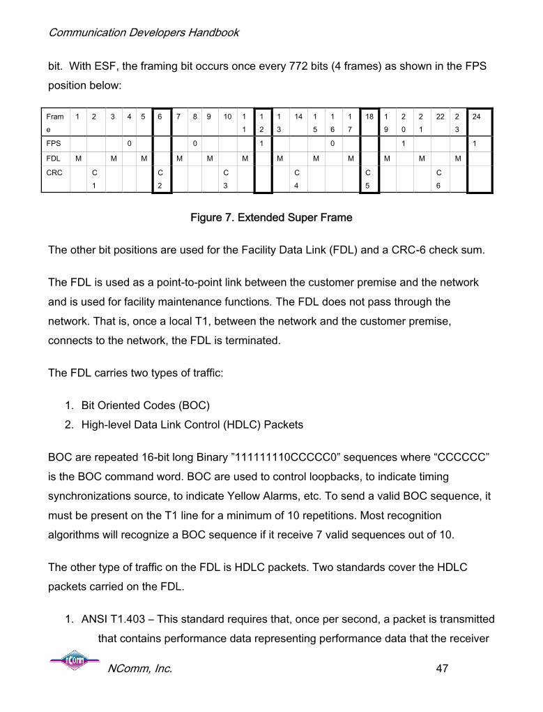
Extended Super Frame Framing
Extended Super Frame (ESF) framing is similar to Super Frame except that the superframe has been “extended” to 24 frames instead of 12 frames. In addition, theadvancements in technology have eliminated the need to have a framing bit every 193rd
Communication Developers Handbook
NComm, Inc. 47
bit. With ESF, the framing bit occurs once every 772 bits (4 frames) as shown in the FPSposition below:
Frame
1 2 3 4 5 6 7 8 9 10 11
12
13
14 15
16
17
18 19
20
21
22 23
24
FPS 0 0 1 0 1 1
FDL M M M M M M M M M M M M
CRC C1
C2
C3
C4
C5
C6
Figure 7. Extended Super Frame
The other bit positions are used for the Facility Data Link (FDL) and a CRC-6 check sum.
The FDL is used as a point-to-point link between the customer premise and the networkand is used for facility maintenance functions. The FDL does not pass through thenetwork. That is, once a local T1, between the network and the customer premise,connects to the network, the FDL is terminated.
The FDL carries two types of traffic:
1. Bit Oriented Codes (BOC)2. High-level Data Link Control (HDLC) Packets
BOC are repeated 16-bit long Binary ”111111110CCCCC0” sequences where “CCCCCC”is the BOC command word. BOC are used to control loopbacks, to indicate timingsynchronizations source, to indicate Yellow Alarms, etc. To send a valid BOC sequence, itmust be present on the T1 line for a minimum of 10 repetitions. Most recognitionalgorithms will recognize a BOC sequence if it receive 7 valid sequences out of 10.
The other type of traffic on the FDL is HDLC packets. Two standards cover the HDLCpackets carried on the FDL.
1. ANSI T1.403 – This standard requires that, once per second, a packet is transmittedthat contains performance data representing performance data that the receiver

Communication Developers Handbook
NComm, Inc. 48
is detecting. Four seconds of information is transmitted so that recoveryoperations may be initiated in case an error corrupts a packet.
2. AT&T TR-54016 – This standard contains requirements for monitoring theperformance of the T1. Once the performance data is collected, it can beretrieved via the FDL from the far end via a command-response protocol.
The last item carried in the framing bit position is the CRC-6 checksum. The CRC-6pattern contains the checksum over the previous frame. It allows bit errors on the T1 to bedetected.
In Extended Super Frame framing, frame number 6, 12, 18 and 24 are signaling frames. Inchannelized T1 applications using robbed-bit signaling, these frames are used to containthe signaling information. In frame numbers 6, 12, 18 and 24, the least significant bit of all24 timeslots is “robbed” to carry call state information. The bit in frame 6 is called the A bitand the bit in frame 12 is called the B bit, the bit in frame 18 is called the C bit, and the bitin the 24 frame is called the D bit. The combination of ABCD defines the state of the callfor the timeslot that these four bits are located in.
SLC-96 Framing
AT&T invented SLC-96 framing for their SLC-96 product. SLC-96 is also generally knownas TR008. We will use the term TR008 to describe our product features. The detaileddescription of SLC-96 can be found in the Telcordia Document GR-8-CORE. The purposeof the SLC-96 product was to provide standard telephone service (POTS e.g., Plain OldTelephone Service) in areas of high subscriber density, but back-haul the traffic over T1facilities. To support the equipment, which is likely in an underground location, the T1sneeded methods to provide:
1. Indications of equipment failure to maintenance personnel2. Indications of failures of the POTS lines3. Testing the POTS lines4. Redundancy on the T1s

Communication Developers Handbook
NComm, Inc. 49
The manner that SLC-96 framing supports these features is using the framing bit positionin the SLC-96 frame. The SLC-96 Super Frame, which is 72 frames long follows:
Frame
1 2 3 4 5 6 7 8 9 10 11 12 13 14 15 16 17 18 19 20 21 22 23 24
Fs 0 0 0 1 1 1 0 0 0 1 1 1
Ft 1 0 1 0 1 0 1 0 1 0 1 0
Frame
25 26 27 28 29 30 31 32 33 34 35 36 37 38 39 40 41 42 43 44 45 46 47 48
Fs C1 C2 C3 C4 C5 C6 C7 C8 C9 C10
C11
0
Ft 1 0 1 0 1 0 1 0 1 0 1 0
Frame
49 50 51 52 53 54 55 56 57 58 59 60 61 62 63 64 65 66 67 68 69 70 71 72
Fs 1 0 M1 M2 M3 A1 A2 S1 S2 S3 S4 1
Ft 1 0 1 0 1 0 1 0 1 0 1 0
Figure 8. SLC-96 Frame
The C1-C11 bits are the concentration bits. These bits are used to map POTS lines totimeslots on the T1 especially in oversubscribed conditions. That is, when more POTSlines are provided than can be carried on the T1s.
The M1-M3 bits are used for maintenance activities.
The A1-A2 bits are used for conveying alarm information from the remote device.
The S1-S4 bits are used for controlling protection switching.
In SLC-96 framing, frame number 6 and frame number 12 are signaling frames and everyset of 12 frames thereafter. In channelized T1 applications using robbed-bit signaling,these frames are used to contain the signaling information. In frame numbers 6 and 12, the

Communication Developers Handbook
NComm, Inc. 50
least significant bit of all 24 timeslots is “robbed” to carry call state information. The bit inframe 6 is called the A bit and the bit in frame 12 is called the B bit. The combination of ABdefines the state of the call for timeslot that these two bits are located.
In-band Loopback Activation and De-Activation
Loopbacks are used to test T1 lines. To support testing, an in-band loopback is used toplace the T1 in remote, also known as line loopback. A remote loopback causes the bitsreceived on the T1 to be looped, un-modified, back to its source.
Sending the loopback pattern activates an in-band loopback. The pattern must be sent forat least 5 seconds. The pattern overwrites the entire payload in the T1, thus corrupting anycalls or data traffic. The framing bit may or may not still be present. The loopback isinvoked when the pattern is removed.
The loopback is torn down when an in-band loop down pattern is transmitted for a periodof 5 seconds. Of course, the times mentioned in this section are the nominal times perANSI T1.403 but may be changed in different installations.
Signaling
Signaling is how calls are passed on the T1 facility via the signaling bits. There aresignaling bits in both the receive and transmit direction. These bits described the state of acall on the timeslot.
In ESF framing, the ABCD bits are used, while in SF and SLC-96 framing the AB bits areused. So, how many different call states can you potentially have with two bits, AB? Theobvious answer is 4. However, this is not correct. As it turns out, there are potentially 9different call states. The way this is done is using the concept of tri-level signaling. If welook just at the A bit, it can be a 0 or a 1 but it can also be a toggle. A toggle is when in onesuper frame the bit is a 0 while in the next it is a 1 and it toggles every other super frame.Thus, the A bit can have 3 different states, which is termed tri-level signaling. In SF and

Communication Developers Handbook
NComm, Inc. 51
SLC-96, a call can have 9 different states in each direction. ESF framing does not use tri-level signaling and has 16 possible states.
The method to determine how to interpret the signaling bits depends upon the call modelbeing used. ANSI T1.403, AT&T PUB 43601, GR-303, and GR-8 all define different callmodels to interpret the signaling bits. The call models defined by these standards includethe following
Loop start Loop start with RLCF Ground Start Ground Start with RLCF Loop-Reverse Battery Signaling Network provided reverse battery signaling E & M Signaling Customer-installation-provided loop-start supervision (FXS/FXO) Private line auto ring Ring down Superimposed Ringing Multiparty Direct Inward Dialing Dial Pulse Terminating Frequency Selective Ringing Multiparty Single Party Superimposed Ringing Multiparty Universal Voice Grade Coin CF/DTF Multiparty Signaling
Channel Associated Signaling (CAS) is the original signaling system used by E1 andprovides 4 signaling bits for every channel. In CAS, channel 16 is reserved for signalingand the A/B/C/D bits for each channel are divided among 16 frames. Frame 0 contains thealignment signal, alarm, and spare bits. Frame 1 contains the A/B/C/D bits for channel 1 in

Communication Developers Handbook
NComm, Inc. 52
the upper half of the channel and the A/B/C/D bits for channel 16 in the lower half. Theremaining 14 frames follow the frame 1 format accordingly. In recent years, the termRobbed-Bit Signaling (RBS) has been replaced by CAS, which is now often used to referto bits that are associated with a specific channel whether it is in the T1 or E1 format.

Communication Developers Handbook
NComm, Inc. 53
Overview of E1
E1 provides a 2.048 MHz electrical interface. The E1 signal can carry channelized traffic orunchannelized traffic. The E1 signal consists of payload bits that are used to carry the dataover the E1 line, and framing bits that are used to determine where the payload is located.In unchannelized applications, the payload bits are used to carry data traffic such as framerelay or ATM. In channelized traffic, the payload is partitioned into timeslots and is used tocarry voice traffic or call control such as ISDN or SS7.
The E1 signal consists of a time-multiplexed frame with 8 framing bits and up to 248payload bits as shown in the following diagram. In unchannelized applications, the payloadwill consist of a stream of bits. In channelized E1 applications, the payload will be dividedinto up to 31, 8-bit time slots and one framing time slot.
Figure 9. Basic E1 Frame
The E1 frame is repeated every 125 microseconds, which leads to the frequency of 2.048MHz (256/0.000125). Four types of framing are present on E1:
1. Basic E1 Framing2. E1 Framing with Signaling Multi-Frame Alignment.3. E1 Framing with CRC4 Multi-Frame Alignment.4. E1 Framing with CRC4 Multi-Frame Alignment and Signaling Multi-Frame
Alignment.

Communication Developers Handbook
NComm, Inc. 54
These different framing formats all use the same basic E1 frame, however the differencesin the framing sequence are described below.
Framing
E1 framing consists of a dual frame pattern. The first frame pattern, shown below as frame0, contains the Frame Align Signal (FAS). The FAS is what is used to find the remainingparts of the E1 frame. The second frame pattern contains the Non-Frame Align Signal
(NFAS).
Figure 10. E1 Frame Pattern
The first time slot in each frame is used to provide frame detection. In E1, an entire timeslot is dedicated to framing information as well as other information. In the FAS frame, timeslot 0 contains the Si (international) bit and the bit pattern 0011011. An E1 framer will lookfor this bit pattern to establish basic frame alignment.
In addition to the FAS pattern, the NFAS will be checked to detect the Non-FrameAlignment Signal. The “1” in the NFAS is used to validate the NFAS signal. The NFAS alsocontains the Si bit, the A-bit and five Sa bits. The A bit is used to indicate the RemoteAlarm Indication (RAI) to the far end. When the A-bit is a 1, the RAI is asserted and when

Communication Developers Handbook
NComm, Inc. 55
the A-bit is a 0 the RAI is not asserted. The Si bit is the international bit. Its use is reservedfor crossing international boundaries. In most cases, the Si bit will be set to a one. Thereare five Sa bits, Sa4 through Sa8. The Sa bits are the national bits and are nominally set toall 1s when not used. When used, the Sa bits are for synchronization status messages,loop back requests, and other uses.
E1 Framing with Signaling Multi-Frame Framing
The E1 Framing with Signaling Multi-Frame framing extends the E1 frame from a two-frame sequence to a 16-frame sequence as shown in the following diagram.
Figure 11. E1 Multi-Frame
The E1 frame is extended to 16 frames by the use of time slot 16 to carry the CASsignaling information. The first frame, named “Frame 0” above, is used to indicate the startof the 16-frame sequence. In this frame, time slot 16 contains the Multi-Frame Alignment

Communication Developers Handbook
NComm, Inc. 56
Signal (MFAS) that consists of a 4-bit pattern of all zeros in the first four bits of the timeslot. The second 4 bits contain the three Extra Bits (X-bits) and the Multi-Frame RemoteAlarm Indicator bit (Y-bit). When E1 is used to carry Channel Associated Signaling, it mustuse one of the E1 frame formats that contain the MFAS. Because of the use of all zeros asthe Multi-Frame Alignment Signal, no other entry in time slot 16 can contain all zeros.
In addition to carrying the MFAS, time slot 16 also carries the Channel AssociatedSignaling bits for call processing. There are 4 bits for each voice channel and are groupedtwo sets of 4 bits in each timeslot. The 8 bits continued in Frame 1 correspond to thesignaling bits for timeslot 1 and timeslot 17. The 8 bits contained in Frame 2 correspond tothe signaling bits for timeslot 2 and timeslot 18. This pattern continues for all 30-voicechannels.

Communication Developers Handbook
NComm, Inc. 57
E1 Framing with CRC Multi-Frame Framing
In the E1 Framing with CRC Multi-Frame the Si bits are re-defined and are used to carry aCRC-4 checksum pattern. The 16-frame Multi-Frame is divided into two Sub Multi-Frames(I and II) and the alignment is done via the CRC frame alignment sequence in the first bit.In Sub Multi-Frame I, this sequence is the pattern B”0001” and in Sub Multi-Frame II, thesequence is B”011”, with both patterns located in the Si bit position of the frame. Inaddition to the CRC alignment bits, the first bit position contains a CRC-4 checksum andE-bits. This is shown in the chart below:
Sub
Multi-Frame
FrameNumber
Bits 1 to 8 of the Frame
1 2 3 4 5 6 7 8
Multi-Frame I 0 C1 0 0 1 1 0 1 11 0 1 A Sa4 Sa5 Sa61 Sa7 Sa8
2 C2 0 0 1 1 0 1 13 0 1 A Sa4 Sa5 Sa62 Sa7 Sa8
4 C3 0 0 1 1 0 1 15 1 1 A Sa4 Sa5 Sa63 Sa7 Sa8
6 C4 0 0 1 1 0 1 17 0 1 A Sa4 Sa5 Sa64 Sa7 Sa8
II 8 C1 0 0 1 1 0 1 19 1 1 A Sa4 Sa5 Sa61 Sa7 Sa8
10 C2 0 0 1 1 0 1 111 1 1 A Sa4 Sa5 Sa62 Sa7 Sa8
12 C3 0 0 1 1 0 1 113 E* 1 A Sa4 Sa5 Sa63 Sa7 Sa8
14 C4 0 0 1 1 0 1 115 E* 1 A Sa4 Sa5 Sa64 Sa7 Sa8
Figure 12. E1 Framing with CRC-4 Multi-Frame

Communication Developers Handbook
NComm, Inc. 58
The CRC-4 checksum bit contains the CRC-4 checksum of the previous CRC-4 Sub Multi-Frame. The E-bits are used to inform the far end of received CRC-4 errors. When a badCRC-4 Sub Multi-Frame is received, an E-bit in the reverse direction is set to indicate theerror. If both CRC-4 Sub Multi-Frames are in error, both E-bits are set. Using the CRC-4errors and E-bits, both ends can determine which direction has difficulties in passing trafficerror free.
When using the CRC-4 Multi-Frame, the Sa bits also have expanded functionality. Insteadof being only one bit, each Sa bit becomes 8 bits in the CRC-4 Multi-Frame. One use ofthe expanded Sa bits is to carry the Synchronization Status Message. Since the SSM isonly 4-bits long, the Four Sa bits are repeated in each Sub Multi-Frame. This is shown inthe chart below:
San1, San2, San3, San4n = Sub-Frame
a = 4, 5, 6, 7, 8Depending upon the
networkSynchronization Quality Level (QL) description
0000 Quality unknown (existing synchronization network)0001 Reserved0010 See ITU G.8110011 Reserved0100 SSU-A - See G.8120101 Reserved0110 Reserved0111 Reserved1000 SSU-B – See G.8121001 Reserved1010 Reserved1011 Synchronous Equipment Timing Source (SETS)1100 Reserved1101 Reserved1110 Reserved1111 Do not use for synchronization

Communication Developers Handbook
NComm, Inc. 59
E1 Framing with CRC Multi-Frame and Signaling Multi-Frame Framing
The E1 Framing with CRC Multi-Frame and Signaling Multi-Frame combine both the CRC-4 multi-frame as well as the Signaling Multi-Frame. Although both Multi-Frame signalingare 16 frames long, they are not necessarily aligned with each other. When both framingschemes are present, the features associated with each are available.
Alarms
Alarms are used to detect and notify maintenance personnel of problems on the E1. Thealarms present in E1 are very similar to those of T1. These alarms are defined below:
1. Loss of Signal (LOS) alarms2. Loss of Frame (LOF) alarms3. Alarm Indication Signal (AIS) alarms4. Remote Alarm Indication (RAI) alarms
Alarms are created from defects. Defects are momentary impairments present on the trunkor line. If a defect is present for a sufficient amount of time (the integration time), then thedefect produces an alarm. Once an alarm is declared, the alarm is present until after thedefect clears for a sufficient period of time. The time it takes to clear is called the de-integration time. The table below shows the defects, the alarms and the default integrationand de-integration times for E1. The times selected for E1 are the same as the times forT1 since there is no specific time specified for E1 integration and de-integration timers.
Defect Alarm Integration Time De-Integration Time
Loss of Signal LOS 2.5 Seconds 10 SecondsLoss of Frame LOF 2.5 Seconds 10 SecondsRemote AlarmIndication (RAI)
RAI 0.5 Seconds 0.5 Seconds
Alarm IndicationSignal (AIS)
AIS 2.5 Seconds 10 Seconds

Communication Developers Handbook
NComm, Inc. 60
A note should be made about the Loss of Frame defect in E1. With the four different typesof framing in E1, the Loss of Frame defect is a composite of the defects associated witheach framing component as shown in the following table:
Basic E1Frame
E1 withSignaling
Multi-Frame
E1 with CRC-4Multi-Frame
E1 with CRC-4Multi-Frame andSignaling Multi-
Frame
Loss of BasicFrameAlignment
Used todetect LOF
defect
Used to detectLOF defect
Used to detectLOF defect
Used to detectLOF defect
Loss of CRC-4FrameAlignment
Used to detectLOF defect
Used to detectLOF defect
Loss ofSignalingFrameAlignment
Used to detectLOF defect
Used to detectLOF defect
Signaling
Signaling is how calls are passed on the E1 facility. This is done via the signaling bitsindicated in the two E1 framing formats that have Signaling Multi-Frame. Signaling bits aretransferred in both the receive direction and the transmit direction. Unlike T1 where the

Communication Developers Handbook
NComm, Inc. 61
signaling bits describe the state of the call, interpreting the signaling bits in E1 dependsupon the previous state of both the receive and transmit directions.
The method to determine how to interpret the signaling bits depends upon the call modelbeing used. ITU specification Q.422 defines the call model to interpret the signaling bits inE1. As an alternative to CAS signaling, ISDN and SS7 may be used to place phone callsover an E1 facility. Typically, the timeslot used for carrying ISDN or SS7 is also time slot16. Consequently, basic E1 or E1 with CRC-4 Multi-Frame framing schemes must be usedif ISDN or SS7 is to be carried.
Standards Requirements
The software must handle the requirements of:
ANSI T1.231, Telecommunications - Digital Hierarchy - Layer 1 In-ServiceDigital Transmission Performance Monitoring
ANSI T1.403, Telecommunications - Network and Customer InstallationInterfaces - DS1 Electrical Interface
ANSI T1.408/T1.403.01, Telecommunications - Network and CustomerInstallation Interfaces - ISDN Primary Rate Layer 1 Electrical InterfaceSpecification
ATT TR-54016, Technical Reference Requirements For Interfacing DigitalTerminal Equipment To Services Employing The Extended SuperframeFormat
ITU-T G.703, Series G: Transmission System And Media, Digital Systems AndNetworks; Digital Transmission Systems - Terminal Equipment - General;Physical/Electrical Characteristics Of Hierarchical Digital Interfaces
ITU-T G.704, Series G: Transmission Systems And Media, Digital Systems AndNetworks; Digital Transmission Systems - Terminal Equipment- General;Synchronous Frame Structures And Used At 1544, 6312, 2048 and 44736 Kbit/S Hierarchical Levels

Communication Developers Handbook
NComm, Inc. 62
ITU-T G.826, Series G: Transmission And Media, Digital Systems AndNetworks; Digital Transmission Systems - Digital Networks - Quality AndAvailability Targets; Error Performance Parameters And Objectives ForInternational, Constant Bit Rate Digital Paths At Or Above The …
ITU-T Q.422, Clauses For Exchange Line Signaling Equipment
In addition, there are the robbed-bit signaling requirements of:
o ANSI T1.403, Telecommunications - Network and Customer InstallationInterfaces - DS1 Electrical Interface
o AT&T TR-008, Digital Interface Between The SLC-96 Digital Loop CarrierSystem And A Local Digital Switch
o BELLCORE/Telcordia GR-303, Integrated Digital Loop Carrier System GenericRequirements Objectives And Interface, Tables 12-3 and 12-4.
o ATT PUB 43801, Digital Channel Bank Requirements and Objectives,November 1982.
Software Architecture
Products requiring T1/E1 interfaces face the daunting task of providing many low-levelfunctions so that the applications conform to the different T1/E1 standards. At the sametime, for ease of development, internally they must supply a set of function calls that permithigh-level application software development independent of the hardware implementationthat conforms to the appropriate standards. Using the layered architecture shown in theprevious section will provide the necessary base to develop a T1/E1 project.

Communication Developers Handbook
NComm, Inc. 63
Specific Issues of T3/E3
Overview of T3
T3 also known as DS3 provides a 44.736 MHz electrical interface. The T3 electricalinterface consists of two coaxial cables, one for transmit and one for receive, at a lineimpedance of 75 Ohm. The electrical T3 signal looks as shown below:
Figure 13. Basic T3 Interface
As shown above, the T3 interface consists of the Customer Interface (CI) at one end andthe Network Interface (NI) at the other. A nominal DS3 signal is a Bi-Polar signal withamplitude of about 0.6V. Each “one” (or Mark) on the line is a positive or negative polaritypulse and each “zero” is no pulse. Each Mark must alternate in polarity – that is, if the first

Communication Developers Handbook
NComm, Inc. 64
1 is a positive pulse, then the next pulse is negative. This requirement gives rise to theterm “Alternate Mark Inversion” or AMI line encoding.
However, there is an issue with AMI encoding. When the T3 signal contains long strings ofzeros, there are no transitions in the signal that the electronics can look for to determinewhere the bits are. And after too many zero (175 plus/minus 25), the electronics willdetermine that the signal has entered a failure condition known as Loss of Signal. Toprevent this problem, a line encoding scheme known as B3ZS - bipolar with three-zerosubstitution – was created. The B3ZS encoding scheme will substitute a string of 3consecutive zeros with the special pattern. The encoding schemes use bi-polar violation(s)as a method to send long strings of zeros as listed below:
000 will be substituted with 00V where V is a positive violation pulse if the previous 1was also a positive pulse
or
000 will be substituted with 10v where v is a negative violation pulse if the next bit is apositive pulse.
The bi-polar violations that are sent and received as part of a B3ZS encoded string ofzeros are not counted as part of the performance errors on the line.
The T3 signal can either be channelized or unchannelized. A T3 signal consists of payloadbits, used to carry the data over the T3 trunk, and overhead bits, used to determine wherethe payload is located (i.e. framing bits) and other overhead bits used for performancemonitoring.
The T3 frame looks as follows:

Communication Developers Handbook
NComm, Inc. 65
Figure 14. Basic T3 Frame
The T3 frame consists of a 4760 bits per frame. This translates into a frame rate of44.736M/4760 = 9,398.32 frames per second. The T3 frame is constructed from 7 M-subframes of 680 bits each. Each M-sub frame is the same with the exception of the first bit.
The overhead bits in the first M-sub frame consists of X1, F1, C1, F3, C2, F3, C3, and F4.The four F bits are used for establishing T3 frame alignment. The three C-bits are used forstuffing or other overhead purposes depending upon the framing format.
In the first bit position of the M-sub frame, the bits are used as follows:
X1, X2 – This is the remote alarm indication bit. When X1 and X2 are 0, the remotealarm is asserted and when they are 1, the remote alarm is cleared.

Communication Developers Handbook
NComm, Inc. 66
P1, P2 – These bits should always be the same and represent the EVEN parity of allthe information bits of the previous T3 frame. NOTE: The overhead bits are excludedfrom the parity calculation.
M1, M2, M3 – These are the multi-frame alignment bits. The M-bits are used todetermine which M-sub frame is the first M-sub frame. The M1, M2, and M3 bits arealways the value 010.
In each M-sub frame, the bits are used as follows:
F1, F2, F3, F3 – These are frame alignment bits. The F-bits are used to identify wherean M-sub frame is in the signal. The F1, F2, F3, and F4 bits are always the value 1001.
C1, C2, C3 – The stuff bits are used differently depending upon the frame format. InM23 framing they are used as stuff indicator bits. In C-bit parity, the C-bits are used tocarry other overhead information. The use of the C-bits will be described later.
A T3 interface can be used in two manners: unchannelized or channelized. Inunchannelized applications, the payload bits are used to carry data traffic such as framerelay. All T3 related parameters such as alarms, configuration, loopbacks, FEAC channel,performance monitoring are still applicable in unchannelized applications.
In channelized applications, the T3 payload consists of seven multiplexed T2 signals.There are two methods to multiplex the T2 signals:
M23 Framing C-bit parity Framing
These two methods differ substantially in how the multiplexing is done. In M23 framing,which is called M13 framing by most people and is used throughout this document,assumes the T2 signals are asynchronous to each other. The overhead bits, called C-bits,are used to control stuffing of the T2 signals. Stuffing is a method that allows the T2 signalto be adapted to a higher frequency clock by adding additional bits. Slower T2 signals will

Communication Developers Handbook
NComm, Inc. 67
have more bits added while faster T2 will have less bits added. The C-bits indicate howmany bits have been added to the T2. After the stuffing operation, the resulting T2 signalsare synchronized to each other and are multiplexed into the T3 signal. Additional overheadbits are used to provide framing for the resulting signal.
The stuffing bits in M13 framing are also used to control loopbacks. Normally, the three C-bits are the pattern 000 or 111 and the receiver uses a majority vote to determine what thevalue is to prevent errors from causing incorrect operation. However, when the far endwants to request that the near end goes into loopback, the third C-bits will be inverted.Thus, when the near end receives 001 or 110, the far-end is requesting that a loopback beinvoked. The loopback control by the inverted 3rd C-bit is a T2 Line loopback. The C-bits inthe first M-sub frame control the loopback of the first T2, the C-bits in the second M-subframe control the loopback of the second T2 and so forth. In C-bit parity format, loopbacksare requested via the FEAC channel. However, via the FEAC channel, only T3 level andT1 level loopbacks can be requested. The FEAC channel cannot request a loopback at theT2 level.
As the Public Switched Telephone Network (PSTN) has evolved, the network has becomemore closely synchronized. Also, although T2s can be deployed as standalone interfaces,they are almost never used this way. Thus, the T2s can be required to be synchronous.When the T2s are synchronized, the C-bits used for stuffing are no long required and canbe used for other purposes. The C-bit parity format defines how these C-bits are used.
The C-bits are used for:
FEAC Channel – The Far End Alarm and Control (FEAC) channel is used to informthe far-end piece of equipment of alarm and fault conditions as well as requestloopbacks.
PMDL Channel – The Path Maintenance Data Link (PMDL) is a 28.8 Kbits/secchannel that provides a communications channel to the far-end piece of equipment.

Communication Developers Handbook
NComm, Inc. 68
Packets carried over the PMDL channel are HDLC (High Level Data Link Control)formatted.
FEBE bits – The FEBE (Far-End Block Error) bits are used to inform the far end thatyou have received a T3 frame that contained parity errors. The received FEBE bitsare used to accumulate far-end performance information.
For both the M13 and C-bit parity format, each T2 contains 4 T1s. The T1s are multiplexedtogether in a similar fashion that the T2s are multiplexed together in M13 framing. Theframing at the T2 level is shown in the following diagram:
Figure 15. T2 Frame Structure
The T2s are built from 4 M-sub frames in a similar fashion that the T3s are built form 7 M-sub frames. Please be careful of the terminology. The T2 frame and the T3 frame use thesame nomenclature, but they mean different things – very confusing.
The T2 frames have the following overhead bits:
F1, F2 – These are the T3 frame alignment bits – The F1, F2 bits are set to 01.

Communication Developers Handbook
NComm, Inc. 69
M1, M2, M3 – These are the multi-frame alignment bits – The M1, M2, M3 bits are setto 011.
X – The X-bit is used as the remote alarm indication bit. When X is a 0, the remotealarm is asserted and when X is a 1, the remote alarm is cleared.
C1, C2, C3 – These are the stuffing bits. The stuffing bits are used in similar mannerthat the stuff bits in the T3 frame are used. Stuffing is a method that allows the T1signal to be adapted to a higher frequency clock by adding additional bits. Slower T1signals will have more bits added while faster T1 will have less bits added. The C-bitsindicate how many bits have been added to the T1. After the stuffing operation, theresulting T1 signals are synchronized to each other and are multiplexed into the T2signal. Additional overhead bits are used to provide framing for the resulting signal.
The algorithm used to multiplex 4 T1s to a T2 is the same in C-bit parity framing and M13framing. Normally, the three C-bits are the pattern 000 or 111 and the receiver uses amajority vote to determine what the value is to prevent errors from causing incorrectoperation. However, when the far end wants to request you to go into loopback, the thirdC-bits will be inverted. Thus, when you receive 001 or 110 the far-end is requesting that aloopback be invoked. The loopback control by the inverted 3rd C-bit is a T1 Line loopback.The C-bits in the first M-sub frame control the loopback of the first T1, the C-bits in thesecond M-sub frame control the loopback of the second T1 and so forth. In C-bit parityformat, loopbacks of the T1s are requested via the FEAC channel and inversion of the 3rd
C-bit is not used.
Note: These C-bits are in the T2 frame format and should not be confused with the C-bitsused in the T3 frame format; they are different C-bits that are used to stuff the T1 signalsinto the T2. The algorithm used to multiplex the T1s into the T2 is the same for C-bit parityand M13 formatted T3 signals. The following table summarizes some of the majordifferences between M13 and C-bit parity formats.

Communication Developers Handbook
NComm, Inc. 70
M13 Format C – Bit parity format
Loopbacks No loopback at the T3 level isdefined.
Loopbacks at the T2 level arerequested by inverting the third C-bit in the T3 frame associated withthe T2.
Loopbacks at the T1 level arerequested by inverting the third C-bit in the T2 Frame associatedwith the T1.
Loopback of the T3 isrequested by sending a FEACcommand.
No T2 loopbacks are defined.
T1 loopbacks are requestedby sending a FEACcommand.
Near End performance Near end performance data isaccumulated for performancemeasures such as bi-polarviolations, errors in the framingbits, parity errors, etc.
Near end performanceparameters are extendedfrom the parameters availablefrom the M13 Frame format.
Far End performance The only far end performance dataaccumulated for M13 format is theFCCP-PFE parameter.
The Far End performancedata is accumulated viaprocessing information fromthe far end. The FEBE bits,RAI, etc. are used toaccumulate the far-endperformance information.

Communication Developers Handbook
NComm, Inc. 71
M13 Format C – Bit parity format
FEAC Not Applicable The FEAC channel containstwo types of traffic: Signalsand Commands.
Signals consist of acontinuous stream of thefollowing pattern:
11111111 0SSSSSS0
Where ‘SSSSSS’ is the signalcode. Signals are sent for avariety of reasons such as inresponse to alarmsconditions.
The other type of traffic iscommands. Commandsconsist of 10 repetitions of aloop back activate or loopback deactivate patternfollowed by 10 repetitions ofthe type of loopbackrequested. The T3, a specificT1 or all T1s can berequested.

Communication Developers Handbook
NComm, Inc. 72
M13 Format C – Bit parity format
PMDL Not Applicable The ANSI T1.107 standarddefines three standardmessages for the PMDL link.These are:
Test Signal Identification
T3 Path Signal Identification
Idle Signal Identification
Nominally, these signals aresent once per second.
G.747
G.747 is an ITU standard that defines a method of how to multiplex 3 E1s into a T2. This istypically encountered in M13 Multiplexers where the resulting T2s are multiplexed into aT3.
We have been seeing increasing use of G.747 in non-North American applicationsbecause, using G.747, a T3 can carry 21 E1s. This compares to E3 where an E3 can onlycarry 16 E1s. Since the physical cable, 75-Ohm Coaxial Cable, is the same for both T3and E3, T3 becomes more efficient for large numbers of E1s.

Communication Developers Handbook
NComm, Inc. 73
The T2 frame for carrying E1s is shown below:
Figure 16. T2 Frame Structure for G.747
In the T2 frame structure for G.747, the first 9 bits are used as the frame alignmentsequence. This allows the start of the T2 frame to be identified. The other bits are asfollows:
159 bits, 165 bits, 162 bits – This are the bits from the E1 tributaries.X – The remote alarm bit. When 1, the remote alarm is asserted and is cleared whenthe X-bit is 0P – is the even parity calculation over the previous frameRES – is reserved for future use. Set to 1 when not used.
Cji = stuffing bits. Where i = the E1 tributary the stuffing bit is associated with and j = thestuffing bit. A majority-voting scheme is used to determine if stuffing is required or not.

Communication Developers Handbook
NComm, Inc. 74
Overview of E3
E3 provides a 34.368 MHz electrical signal that can be either channelized orunchannelized. The E3 signal consists of payload bits, used to carry the voice or data,overhead bits that are used to locate the payload information (i.e. framing patterns), andother overhead bits used for clock justifications and alarming. E3 has two types of framingformats, which we will cover in the following sections:
G.751 – See the ITU-T specification G.751
G.832 – See the ITU-T specification G.832
G.751 Framing
G.751 framing is used for multiplexing lower speed signal, E1s, into the E3. In G.751framing, the E1 signals are first multiplexed into E2 signals as shown in the followingdiagram.
Figure 17. G.751 Frame

Communication Developers Handbook
NComm, Inc. 75
As shown in the diagram, the E2 frame consists of four sub-frames of 212 bits each. Eachsub-frame consists of some overhead bits and some tributary bits.
In the first sub-frame, the first 10 bits are the Frame Alignment Sequence (FAS) bits.These bits provide information required to locate the tributary bits in the signal. Bit 11 is theRemote Alarm Indication (RAI) bit. The RAI bit is used to convey to the equipment at thefar end that the receiver is having problems recovering the signal. For example, if you arein an Out Of Frame (OOF) condition, you will inform the far end via the RAI bit. Bit 12 is theNational bit and may be defined by the country where the equipment is provided. Whencrossing a national boundary, the National Bit must be a 1.
In the 3 other sub-frames, the C1n, C2n, C3n and C4n bits are used as justificationindicators. A value of 000 indicates a negative justification while a 111 indicates a positivejustification. A majority vote of the three bits is used to prevent bit errors from creatingincorrect justifications moves. The J1, J2, J3, J4 bits are the justification bits for each oneof the E1 tributaries. The E2 frame uses an all ones pattern to indicate an Alarm IndicationSignal (AIS).
The E3 frame is very similar to the E2 frame. Instead of containing 4 E1s, the E3 framecontains 4 E2s. The frame structure for the E3 is shown below.

Communication Developers Handbook
NComm, Inc. 76
Figure 18. E3 Frame
As shown in the diagram, the E3 frame consists of four sub-frames of 384 bits each. Eachsub-frame consists of some overhead bits and some tributary bits.
In the first sub-frame, the first 10 bits are the Frame Alignment Sequence (FAS) bits.These bits provide information required to locate the tributary bits in the signal. Bit 11 is theRemote Alarm Indication (RAI) bit. The RAI bit is used to convey to the equipment at thefar end that the receiver is having problems recovering the signal. For example, if you arein an Out Of Frame (OOF) condition, you will inform the far end via the RAI bit. Bit 12 is theNational bit and may be defined by the country where the equipment is provided. Whencrossing a national boundary, the National Bit must be a 1.
In the 3 other sub-frames, the C1n, C2n, C3n and C4n bits are used as justificationindicators. A value of 000 indicates a negative justification while a 111 indicates a positivejustification. A majority vote of the three bits is used to prevent bit errors from creatingincorrect justifications moves. The J1, J2, J3, J4 bits are the justification bits for each oneof the E2 tributaries. The E3 frame uses an all ones pattern to indicate an Alarm IndicationSignal (AIS).

Communication Developers Handbook
NComm, Inc. 77
G.832 Framing
G.832 E3 framing is very dissimilar than G.751 E3 framing. Where G.751 is designed totransport E1s in a multiplex manner, G.832 is designed to transport ATM traffic.Consequently, the framing is very different as shown below:
Figure 19. G.833 E3 Frame
If you are familiar with SDH (Synchronous Digital Hierarchy) optical framing, the G.832framing for E3 has a number of similarities.
The FA1, FA2 pattern provides the framing of the signal and consists of the pattern:
FA1: 11110110
FA2: 00101000
This is the same framing bit pattern that is used in the SDH optical signal.

Communication Developers Handbook
NComm, Inc. 78
The next overhead byte is the Error Monitoring (EM) byte. The EM byte provides the abilityto detect errors in the E3 frame via a BIP-8 error-checking scheme. The BIP-8 does abyte-by-byte even parity calculation over the previous frame and places the value in thecurrent frame’s EM location. Thus, the number of BIP-8 errors that are possible in oneframe ranges from 0 to 8.
The Trail Trace (TR) byte location contains the trail access point identifier. The TR bytecontains a 16-byte long string that is sent over 16 frames. The string allows the destinationto determine if it is connected to the proper source. The 16-byte string is structured asfollows:
Byte
Number1 2 3 4 5 6 7 8 9 10 11 12 13 14 15 16
Bit 1 1 0 0 0 0 0 0 0 0 0 0 0 0 0 0 0Bit 2 C1 T T T T T T T T T T T T T T TBit 3 C2 T T T T T T T T T T T T T T TBit 4 C3 T T T T T T T T T T T T T T TBit 5 C4 T T T T T T T T T T T T T T TBit 6 C5 T T T T T T T T T T T T T T TBit 7 C6 T T T T T T T T T T T T T T TBit 8 C7 T T T T T T T T T T T T T T T
The first byte consists of a 1 in the first bit followed by seven CRC bits. These CRC bitsrepresent a CRC-7 code over the other 15-byte locations. The polynomial for the CRC-7code is X7 + X3 + 1.
The 15 other bytes have a 0 as the first bit position, followed by a 7-bit character from theITU-T specification T.50. ITU-T T.50 specification is very similar to the ASCII character set.

Communication Developers Handbook
NComm, Inc. 79
The Maintenance and Adaptation Byte (MA) contains the following bit fields:
Bit 1 2 3 4 5 6 7 8RDI REI Payload Type Multi-Frame
IndicatorSSM
Figure 19. MA Byte
The Remote Defect Indication (RDI) is similar to the RAI used in G.751 E3 framing. TheRDI bit is used to indicate to the far end that the equipment is receiving an impairment ofsome kind.
The Remote Error Indication (REI) is used to inform the far end that one or more errorswhere received in the EM byte location. The REI indication can be used by equipment todetermine that there is a problem with the E3 being transmitted.
The Payload type field indicates the type of traffic that is being carried on the E3 trunk. Thevalues that are defined in ITU-T G.832 are:
Code Payload Type
000 Unequipped001 Equipped, non-specific010 ATM011 SDH TU-12s
The Multi-Frame indicator and the SSM bit are used in conjunction with each other. TheSMM bit is a four-bit Synchronization Status Message (SMM) with one bit being providedeach frame. The Multi-Frame bit provides a binary count from 00 to 11 such that when theMF is a 00, the most significant SMM bit is present and when the MF is a 11, the leastsignificant SMM is present. From ITU-T G.707, the values of the SSM message is asfollows:

Communication Developers Handbook
NComm, Inc. 80
SSM BitsMSB - LSB Synchronization quality level description
0000 Quality unknown0001 Reserved0010 Rec. G.8110011 Reserved0100 Rec. G.812 transit0101 Reserved0110 Reserved0111 Reserved
1000 Rec. G.812 local1001 Reserved1010 Reserved1011 Synchronous Equipment Timing Source (SETS)1100 Reserved1101 Reserved1110 Reserved1111 Do not use for synchronization
Some older equipment does not use the SSM scheme for indicating the source ofsynchronization. For these pieces of equipment, an all 0 pattern indicates that the sourceis traceable to a primary timing source while a 1 indicates that it should not be used as atiming source.
The Network Operator byte (NR) can be used in one or two manners. The NR byte may beused for maintenance activities or for a communications link in Tandem applications.
The final byte, the General Purpose byte (GC), can be used by maintenance personal for avoice/data link.

Communication Developers Handbook
NComm, Inc. 81
Products requiring T3/E3 interfaces face the daunting task of providing many low-levelfunctions so that the applications conform to the different T3 or E3 standards.
Standards Requirements
The software must handle the following requirements:
ANSI T1.107 and ANSI T1.107a, Telecommunications - Digital Hierarchy – FormatSpecifications
ANSI T1.404, Telecommunications – Network-to-Customer Installation – DS3Metallic Interface
ANSI T1.231, Telecommunications – Layer 1 In-Service Digital TransmissionPerformance Monitoring
Alarms and Configuration
The alarm and configuration module includes processing of the following T3/E3 functions:
1. Transmission and reception of alarms. The alarm and configuration module willprocess line defects, such as loss of frame, into alarm conditions. Theintegration times for T3 will default to the times defined in ANSI T1.231 but canbe changed via an API call. The module also handles G.826 for E3.
2. Configuration. The alarm and configuration module will allow the application to setframe format (C-bit/M13 or HDB3), line encoding, line build-out, andchannelized/un-channelized application.
3. User versus Network Side. As with most telecommunications interfaces, the T3/E3protocol is not symmetrical. Either user side (also known as Customer Interface– CI) or Network Side (NI) can be selected.
4. FEAC channel – The FEAC channel is only defined for the C-bit parity frame format.The FEAC channel is used to communicate alarm and failure information, calledFEAC signals, as well as request loopbacks be put up or taken down, called

Communication Developers Handbook
NComm, Inc. 82
FEAC commands. For FEAC signals, the T3 alarm and configuration managerwill perform prioritization of the FEAC code per T1.107 before the code istransmitted. On the receive size, the configuration and alarm module can beconfigured to alert the application software after a valid FEAC signal has beenrecognized. FEAC commands can be transmitted or receive by the alarm andconfiguration module. When transmitting a FEAC command, the applicationsoftware will be notified by a callback after the FEAC command has been sent.On the receive side, the alarm and configuration manager will detect a properlyformatted command request and, if configured to, notify the application and/orimplement the command.
5. PMDL channel – The PMDL channel is only defined for the C-bit parity frameformat. The PMDL transfers HDLC based packets between the CI and NI sides.The application can transmit as well as receive PMDL packets.
6. Loopbacks – In C-bit parity format, loopbacks are requested via the FEAC channel(See above), but in M13 format, loopbacks are done by inverting C-bits. C-bits atthe M13 frame level control loopbacks of the T2s while C-bits at the T2 framinglevel control T1 loopbacks. The alarm and configuration module will implementas well as transmit loopback requests of the appropriate C-bits. Inunchannelized T3, this feature is not applicable.
7. E3 Messages – Handle the National Bit, Status Synch message, Payload Typemessage and Trail Trace message.
Performance Monitoring
The performance monitoring module provides the following features:
1. Performance Monitoring – The performance monitoring software records theperformance parameters specified in for both T3 and E3. The T3 performanceparameters for ANSI T1.231 are stored in 15-minute buckets for a total of 192buckets (representing 48 hour information). When configured in C-bit parity format,

Communication Developers Handbook
NComm, Inc. 83
the performance monitoring includes the far-end information. For E3, performancemonitoring uses G.826 with 96 15-minute buckets.
2. Time-of-day-processing – T1.231 specifies that performance information be trackedaccording to the time of day starting at 12:00 midnight and proceeding every 15minutes. However, there are reasons that the time of day may need to be changed– daylight savings time for example. The performance monitoring will manage thechange to the time of day and maintain the correct information in the buckets perT1.231.
3. Threshold crossing alerts – The performance monitoring module provides the abilityfor the application to set thresholds on the performance parameters. Duringprocessing, when the performance monitoring module determines that the thresholdhas been crossed, it will notify the application via a call back.
Software Architecture
Products requiring T3/E3 interfaces face the daunting task of providing many low-levelfunctions so that the applications conform to the different DS3 standards. At the sametime, for ease of development, internally they must supply a set of function calls that permithigh-level application software development independent of the hardware implementationthat conforms to the appropriate standards. Using a similar design to that of the T1 wouldyield a layered approach with the APIs to handle the interface.

Communication Developers Handbook
NComm, Inc. 84
Specific Issues of SONET/SDH
Overview of SONET
SONET is an acronym for Synchronous Optical Network, which is a method for carryingdata and voice traffic over optical or electrical interfaces, usually for long distances.SONET is a framed signal that uses the basic building block of a Synchronous TransportSignal – Level 1 (STS-1). Scaling upwards, several STS-1s can be multiplexed together toform OC-Ns. Scaling downwards, an STS-1 can contain up to 7 VT Groups (VTGs) witheach group containing four VT1.5s per VTG, three VT2s per VTG, two VT3s per VTG, orone VT6 per VTG.
VT1.5s are used for multiplexing T1s onto a SONET signal. Four T1s are combinedinto one VTG allowing a total of 28 T1s to be carried in a STS-1 – the same as a T3.
VT2s are used for multiplexing E1s onto a SONET signal. Three E1s are combinedinto one VTG allowing a total of 21 E1s to be carried in a STS-1 – the same as a T3using the G.747 mapping scheme.
VT3s are used for multiplexing T1-Cs onto a SONET signal. Two T1-Cs arecombined into one VTG allowing a total of 14 T1-Cs to be carried in a STS-1.Although defined by the standards, T1-Cs are not commonly found in the network.
VT6s are used for multiplexing T2s onto a SONET signal. One T2 is mapped intoone VTG allowing a total of 7 T2s to be carried in a STS-1. Although defined by thestandards, T2s are not commonly found in the network.
The Virtual Tributary (VT) contains the facility being transported as well as additionaloverhead information. The VT can contain the Alarm Indication Signal (AIS). In addition toAIS, the V5 byte can contain the signal-label. If the signal label is 0, then the VT is

Communication Developers Handbook
NComm, Inc. 85
unequipped. If the VT is unequipped when it is expected to be equipped the UnequippedAlarm will be raised. In addition, if the signal label byte does not match its expected value,then the Trace Identifier Mismatch alarm is raised.
Each SONET signal is made up of Line, Section, and Path overhead in addition to thepayload. The OC-N signal can contain up to N STS-1 signals. If the OC-N signal containsN STS-1s, then there is one copy of the Line overhead, one copy of the Section overhead,and N copies of the Path overhead, one for each STS-1.
The Section Overhead passes from one connection to the next; the Line Overhead passesfrom one cross connect to the next cross connect, and the Path Overhead passes fromone end to the next. The following diagram shows how this is organized.
Figure 20. SONET Signal
In addition to STS-1s, the SONET signal can contain higher bit rate signals for carryinghigher bandwidth signals. These are called concatenated signals such as STS-3C, STS-12C, and STS-48C. The number in OC-XC indicates the equivalent number of STS-1 inthe signal (e.g. STS-12C uses the same bandwidth as 12 STS-1s). The overall bandwidthof the OC-N signal can contain combinations of STS-1s and concatenated signals up tothe full bandwidth of the signal.

Communication Developers Handbook
NComm, Inc. 86
Section Overhead
The Section Overhead is used for the following purposes:
SONET Byte Purpose
A1, A2 Framing – Used to acquire framing so that the payloadcan be extracted
J0 Section Trace MessageZ0 Section GrowthB1 Section Performance Monitoring – Contains the BIP-8
patternE1 Order wire – point to point voice linkF1 User DefinedD1-D3 192k bits/second Data Communication Channel (DCC)
Line Overhead
The Line Overhead is used for the following purposes:
SONET Byte Purpose
B2 Line Error Monitoring – Contains the BIP-8 patternK1, K2 All 8 bits in K1 and 5 bits in K2 are used for the
protection switching protocols defined for SONET. Theremaining three bits in K2 (b6-b8) is used for carryingthe Line AIS and Line Remote Defect Indication.
D4-D1 576k bits/second Data Communication Channel (DCC)S1 Synchronization status message.Z1 Reserved for future growthM0 Used to carry the Line Remote Error Indication – The
REI informs the far end that you are receiving BIP-8errors.
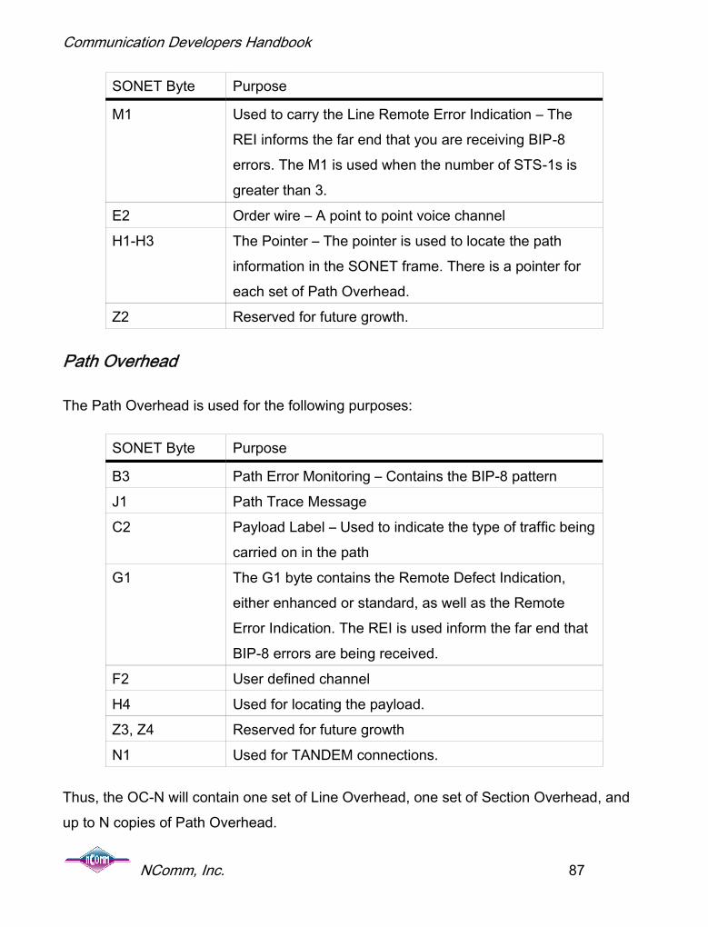
Communication Developers Handbook
NComm, Inc. 87
SONET Byte Purpose
M1 Used to carry the Line Remote Error Indication – TheREI informs the far end that you are receiving BIP-8errors. The M1 is used when the number of STS-1s isgreater than 3.
E2 Order wire – A point to point voice channelH1-H3 The Pointer – The pointer is used to locate the path
information in the SONET frame. There is a pointer foreach set of Path Overhead.
Z2 Reserved for future growth.
Path Overhead
The Path Overhead is used for the following purposes:
SONET Byte Purpose
B3 Path Error Monitoring – Contains the BIP-8 patternJ1 Path Trace MessageC2 Payload Label – Used to indicate the type of traffic being
carried on in the pathG1 The G1 byte contains the Remote Defect Indication,
either enhanced or standard, as well as the RemoteError Indication. The REI is used inform the far end thatBIP-8 errors are being received.
F2 User defined channelH4 Used for locating the payload.Z3, Z4 Reserved for future growthN1 Used for TANDEM connections.
Thus, the OC-N will contain one set of Line Overhead, one set of Section Overhead, andup to N copies of Path Overhead.

Communication Developers Handbook
NComm, Inc. 88
Hardware implementations of OC-N systems may involve various and mixed devices thataccess different sub-levels of an OC or STS signal. To accommodate this expectedhardware architecture, the NComm SONET/SDH TMS Package has a polymorphic devicedriver mapping methodology. This methodology permits potentially many device drivers toappear as one virtual device to the NComm SONET/SDH TMS Package. This alsomaintains a commonality in general device driver development.
Overview of SDH
SDH, which stands for Synchronous Digital Hierarchy, is used primarily outside of NorthAmerica and was derived from the initial SONET standards. Therefore, instead ofdescribing SDH, this section will describe the differences from SONET. In SDH, the namesof the different pieces have different names. Specifically:
SONET SDHPath PathLine Multiplex SectionSection Regenerator Section
The SDH view of the network then follows as:
Figure 21. SDH Signal

Communication Developers Handbook
NComm, Inc. 89
The line rates for the SDH signal are called Synchronous Transport Module (STM) insteadof STS. They are similar to the SONET standards as shown in the following table:
Rate (in MHz) SONET Terminology SDH Terminology
51.84 STS-1 -NONE-155.52 STS-3 STM-1622.08 STS-12 STM-4
2488.32 STS-48 STM-169953.28 STS-192 STM-64
One notable difference between SDH and SONET is the lack of a 51.84 MHz line rate orOC-1. In some SDH discussions the term STM-0 is used to indicate a 51.84 MHz link.However, this does not physically exist.
SDH, like SONET, is used to carry slower speed interfaces such as E1, E3, T1, etc over ahigh-speed optical interface. The methods used by SDH to multiplex these lower speedsignals onto the optical fiber to create the STM-N optical signal are shown in the followingdiagram:
Figure 22. SDH Breakout

Communication Developers Handbook
NComm, Inc. 90
T1 Inputs – To carry T1 traffic over an STM-N interface, the T1 circuits can be mapped intoa TU-11 or a TU-12. If mapped into a TU-11, 4 TU-11’s are multiplexed into a TUG-2. TheSONET version of this is mapping a T1 into a VT1.5 and 4 VT1.5’s are multiplex into a VT-G. Alternatively, a T1 can be mapped into a TU-12 and three TU-12s mapped into a TUG-2.
E1 Inputs – To carry E1 traffic over a STM-N interface, the E1 circuit can be mapped into aTU-12. Subsequently, 3 TU-12’s are multiplexed into a TUG-2. The SONET version of thisis mapping an E1 into a VT2 and 3 VT2’s are multiplex into a VT-G.
T2 Inputs – To carry T2 traffic over a STM-N interface, the T2 can be mapped into a TU-2and, subsequently, into a TUG-2.
E3 Input – The basic unit of SDH is the VC-3 and a VC-3 can carry one E3 signal. Analternative to the VC-3, an E3 can be mapped into a TU-3.
T3 Input – A T3 like the E3 can be mapped into either a VC-3 or a TU-3.
The SDH frame is repeated every 125us. Now that you have a basic understand on howthe multiplexing signal work, let’s examine the SDH frame as shown in the next diagram:

Communication Developers Handbook
NComm, Inc. 91
Figure 23. SDH Frame
NU – National Use – These bytes are reserved for definition at the discretion of the countrythat the equipment is deployed in.
R – Reserved- These bytes are reserved for future use.
Regenerator Section Transport Overhead
A1/A2 – Framing bytes – The framing bytes consist of the pattern:
A1: 11110110
A2: 00101000
These bytes are used to recover the basic frame alignment of the SDH signal

Communication Developers Handbook
NComm, Inc. 92
J0 – Regenerator Section Trace Message – The Trace Message is used to validate thatthe two endpoints of the SDH facility are connected correctly. The J0 byte locationcontains the trail access point identifier. The TR byte contains a 16-byte long string that issent over 16 frames. The string allows the destination to determine if it is connected to theproper source. The 16-byte string is structured as follows:
ByteNumber
1 2 3 4 5 6 7 8 9 10 11 12 13 14 15 16
Bit 1 1 0 0 0 0 0 0 0 0 0 0 0 0 0 0 0Bit 2 C1 T T T T T T T T T T T T T T TBit 3 C2 T T T T T T T T T T T T T T TBit 4 C3 T T T T T T T T T T T T T T TBit 5 C4 T T T T T T T T T T T T T T TBit 6 C5 T T T T T T T T T T T T T T TBit 7 C6 T T T T T T T T T T T T T T TBit 8 C7 T T T T T T T T T T T T T T T
The first byte consists of a 1 in the first bit followed by seven CRC bits. These CRC bitsrepresent a CRC-7 code over the other 15-byte locations. The polynomial for the CRC-7code is X7 + X3 + 1.
The 15 other bytes have a 0 as the first bit position, followed by a 7-bit character from theITU-T specification T.50. ITU-T T.50 specification is very similar to the ASCII character set.
B1 - BIP–8-parity byte – The B1 byte is used for monitoring performance of theRegenerator Section component of the SDH connection. Specifically, the B1 byte providesthe ability to detect errors in the SDH Regenerator Section via a BIP-8 error-checkingscheme. The BIP-8 does a byte-by-byte even parity calculation over the previous frameand places the value in the current frame’s B1 location. The parity is calculated after thescrambling operation. Thus, the number of BIP-8 errors that are possible in one frameranges from 0 to 8.

Communication Developers Handbook
NComm, Inc. 93
MD – Media Dependant Byte
D1 – D3 – Data communications channel – The data communications channel (DCC)provides a 196K bit per second communications channel which is used to administer theSDH network.
E1 – Orderwire – The order wire is a 64K bits/sec voice channel that provides a point-to-point voice communications channel that is used by maintenance personnel.
Multiplex Section Overhead
H1-H3 – Pointer Bytes – The Pointer bytes are used to locate the path information in theSDH frame. Although the SDH network is nearly synchronous, there exist different clockingsources. Just like the SONET network, the pointer bytes are used to account for timingdifferences between different nodes in the SDH network.
D4 – D12 –Data communications channel – The data communications channel (DCC)provides a 576K bit per second communications channel which is used to administer theSDH network.
S1 – Synchronization Status Message – The S1 byte is used to carry synchronization traceinformation. The low order 4 bits (Bits 5-8) carry the message as shown in the followingtable.
S1 Bitsb5-b8 Synchronization quality level description
0000 Quality unknown
0001 Reserved0010 Rec. G.8110011 Reserved0100 Rec. G.812 transit0101 Reserved

Communication Developers Handbook
NComm, Inc. 94
S1 Bitsb5-b8 Synchronization quality level description
0110 Reserved0111 Reserved1000 Rec. G.812 local1001 Reserved1010 Reserved1011 Synchronous Equipment Timing Source (SETS)1100 Reserved1101 Reserved
1110 Reserved1111 Do not use for synchronization
Z1 – Z2 – Growth Bytes – Reserved for future growth.
M1 – Far End Block Error Byte – The M1 byte carries information to tell the far end thaterrors exist in the receive link. This allows for network maintenance personal to isolate andcorrect impaired networks.
K1 – K2 - Protection Switching Byte – The K1/K2 bytes are used for controlling protectionswitching of SDH facilities. A protocol between the two endpoints negotiates how traffic willbe placed over the normal and protection SDH networks. Multiple protocols existdepending upon the network topology.
E2 – Order wire - The order wire is a 64K bits/sec voice channel that provides a point-to-point voice communications channel that is used by maintenance personnel.
Standards Requirements
The software must handle the requirements of:
ANSI T1.105 and ANSI T1.231

Communication Developers Handbook
NComm, Inc. 95
ITU-T G.783 and ITU-T Q.921 Telcordia GR.253
Alarms and Configuration
The alarm and configuration module includes processing of the following SONET/SDHfunctions:
1. Transmission and reception of alarms. The alarm and configuration module willprocess line defects, such as loss of frame or AIS, into alarm conditions. Theintegration times will default to the times defined in ANSI T1.231 or ITU G.826but can be changed via an API call.
2. Configuration. The alarm and configuration module will allow the application to setthe various operating parameters of the different SONET/SDH signal levels.
3. User vs. Network Side. As with most telecommunications interfaces, theSONET/SDH protocol is not symmetrical. Either user side (also known asCustomer Interface – CI) or network side (NI) can be selected.
Performance Monitoring
The performance monitoring module includes the following features:
1. Performance Monitoring – The performance monitoring records the performanceparameters specified in ANSI T1.231 or ITU G.826 whichever is appropriate. Theperformance parameters are stored in 15-minute buckets for a total of 192 buckets(representing 48 hours of information).
2. Time-of-day-processing – T1.231 specifies that performance information be trackedaccording to the time of day starting at 12:00 midnight and proceeding every 15minutes. However, there are reasons that the time of day may need to be changed –daylight savings time for example. The performance monitoring will manage the change

Communication Developers Handbook
NComm, Inc. 96
of the time of day and maintain the correct information in the buckets per T1.231. ITUG.826 has similar properties.
3. Threshold crossing alerts – The performance monitoring module provides the ability forthe application to set thresholds on the performance parameters. During processing,when the performance monitoring module determines that the threshold has beencrossed, it will notify the application via a call back.
Japanese SDH
Most of the world can be accommodated by either standard SONET or SDH. The onlyimportant exception that we are aware of is Japan. The Japanese standards JT-G707 andJT-G783 are very similar to the standards, ITU-T G.707 and ITU-T G783. However, theyare not identical and the differences must be implemented to insure standard complianceand interoperability. Japanese SDH makes some tweaks to standard SDH and adds theconcept of the JHG or the Japanese Handling Group. The following goes into a little moredetail of what these differences are.
STM-0: The STM-0 rate defined in JT-G707 is equivalent to the STS-1 rate definedby Bellcore.
There are two options for mapping the VC-11/TU-11 bytes.
1. STM-0 supports 28 VC-11/TU-11
2. STM-1 support 3*STM-0 (i.e. 28*3 VC-11/TU-11).
There are three alarms that are maintained separately for each handling group:
LOS – loss of HG alignment
AIS – detection of AIS in the HG
RDI – presence of three consecutive 0s in the Sp/BAIS bit.

Communication Developers Handbook
NComm, Inc. 97
VT Group Structure: The Japanese Handling Group (JHG) implementation of SDHmaps and demaps 1.544 Mbits/s using VC-11/TU-11 in byte synchronous modeonly. For signaling information, it uses a handling group concept. This combines thesignaling information for six DS0s into a handling group. There are four handlinggroups for each DS1 line. The figure below shows the details of how the individualtime slots are grouped together. Only two of the four time slots are shown in thefigure.
Figure 24. Time Slot Grouping
In the JHG implementation, the byte following the V5-byte in the VT SPE is calledthe W-byte. In byte synchronous mode, signaling bits (S1, S2, S3, & S4) for eachhandling group get mapped into dedicated ST-bits. These bits are placed in the W-byte in the VT mapper frame as shown below.
Figure 25. W-Byte Contents

Communication Developers Handbook
NComm, Inc. 98
Handling Groups
Each handling group consists of a framing bit (F), six signaling bits (As) and an alarm bit(Sp), which is also called Backward AIS (BAIS). The JHG implementation uses the STframe format that consists of eight VT frames (1 ms). The signaling bits of the eight W-bytes from the ST frame format (ST1 – ST4) are shown below (See Figure 26). The Flocations are arbitrary with respect to one another.
Figure 26. W-Byte Signaling Bits
The F-bit is an ST framing bit, which toggles between 0 and 1 every ST multiframe. Thisframing bit might not be aligned between the handling groups.

Communication Developers Handbook
NComm, Inc. 99
Automatic Protection Switching
There are four standards that define APS for SONET and SDH transport. The general setis T1.105 (there are a number of sub-documents). GR-253 addresses Linear APS whileGR-1400 and GR-1230 specify Unidirectional Path Switched Ring (UPSR) and Bi-directional Line Switched Ring (BLSR), respectively. For SDH, G.841 defines LinearProtection Switching and Ring Protection Switching.
There are three models of Linear APS. They are 1 + 1, 1:1 and 1:n. Linear APS is usedprimarily in applications linked to the core network and by definition are point to point. AllLinear APS solutions have the drawback of asymmetric delay. Additional buffering at thenodes is required to overcome this. Buffering raises the cost of the equipment
1 + 1 provides two fiber links. Each link carries identical traffic. The receivers at each endmonitor the bit streams and choose the “best” one. 1 + 1 is the most expensive but alsooffers the fastest recovery often without any data loss. It is expensive because tworeceivers are required at each end point, twice as much fiber is needed, and no additionalcapacity is gained.
1:n including the special case of 1:1, as its name implies, provides one backup fiber for upto 14 primary fibers. The back-up fiber can carry low priority traffic when not used for backup. There is a time to detect and time to switch traffic from the primary to the back up, andsome loss will be experienced. As the detect plus switching times must be kept to 60 mSecor less, conventional phone calls should not be dropped (The network is architected forcalls to withstand up to 2.5 seconds of disruption). This method is much less expensivebecause one fiber provides coverage for multiple primary fibers.
Ring APS comes in two flavors. That is UPSR (Unidirectional Path Switched Ring) andBLSR (Bidirectional Line Switched Ring).
Of the Ring APS methods, UPSR is relatively simple. There are two, counter-rotating fiberlinks. Each fiber carries the identical traffic. Each “node” monitors both fibers and picks the

Communication Developers Handbook
NComm, Inc. 100
“best” one based on several criteria. These criteria include bit error rate, AIS (AlarmIndication Signal) and a couple of others. Some of the positive aspects of UPSR includethat the receiver makes all decisions with no interaction with either the local or remotetransmitter, no communications channel is needed, and it provides virtually un-interruptedservice. The down side includes the need for redundant transceivers as well as introducingasymmetric delay (More information can be found in GR-1400).
BLSR is a bit more complicated. This method uses the K1/K2 bytes as well as other localindications to raise a flag to switch. Once the flag is raised, an independent “controller”then communicates with the local back-up facility (through the back-up SONET/SDHtransceiver) via the K1/K2 bytes that communicates to a far end transceiver to prepare forthe transfer of the traffic from the failed facility to the back-up facility. Together the switch issynchronized and executed.
Once a switch is executed by any of the methods (linear or ring), its next action isdependent on whether it has been configured as revertive or non-revertive. If it is revertive,the traffic will be automatically switched back to the original facility once it is recognized asgood. In non-revertive, the traffic will stay switched until it is manually switched back.
Usually, these switches will be configured as non-revertive. The reason that APS has beenimplemented in the first place is that the traffic being carried is very large and a serviceoutage is very costly. It is not uncommon for a bad line to appear as fixed for short periodsof time while the carrier is determining and fixing the line problems. Automatically switchingback could create repeated switches further disrupting service. In 1:1 or 1+1 modes, non-revertive is the norm. After a switch is performed and the faulty facility is repaired, thatfacility becomes that back-up line.
All APS must meet certain performance thresholds to be standard complaint. The budgetfor detecting a failure and initiating a switchover must be within 10 mS. Completion of theswitchover must be within 50 mS of the initiation. Thus, the maximum time from detectionof the failure to complete restoral is 60 mS.

Communication Developers Handbook
NComm, Inc. 101
There are several different criteria for making the switching decision. These include:
AIS (Alarm Indication Signal)
LOP (Loss Of Pointer)
Unequipped (indicated in the C2 byte)
RDI (Remote Defect Indication)
Bit Error Ratio (Severely Errored Seconds/Errored Seconds)
Bi-directional or 1:n APS uses the K1 and K2 bytes to also pass information.
Where these various indications are used depends on the type of APS being implemented.Line level indicators are used for Linear Models and Line and Path level for Ring models.K1/K2 are used only when there is a sharing of the back-up facility or when communicationwith the far end is required for coordination. An examination of the relevant standards willprovide the details for your implementation.
Interoperability and NComm's TMS
While there are standards for SONET and SDH APS, interoperability is still an issue. Therehave been groups that have tried to remedy this situation but to date have not beensuccessful. In discussions with carriers, this reality has forced them to use a singleequipment provider within a network being protected. Carriers typically do not like to betied to a single source and NComm expects this to change. One of the benefits ofNComm's Trunk Management Software generally and the APS modules in particular isthat their use goes a long way towards achieving interoperability.

Communication Developers Handbook
NComm, Inc. 102
Software Architecture
Products requiring SONET/SDH interfaces face the daunting task of providing many low-level functions so that the applications conform to the different SONET/SDH standards.Hardware implementations of OC-N systems may involve various and mixed devices thataccess different sub-levels of an OC or STS signal. The Trunk Management Softwaremust supply a set of function calls that permit development of high-level applicationsoftware independent of the hardware implementation. One way to do this is to use apolymorphic device driver mapping methodology. This methodology permits potentiallymany device drivers to appear as one virtual device to the upper level application software.This also maintains a commonality in general device driver development.

Communication Developers Handbook
NComm, Inc. 103
Testing Issues and Gotcha’s
Now that you have built your product, you need to make sure it works properly. You havehardware to test as well as software and are not sure which is working yet. Make sure yoursoftware can talk to you hardware. If this does not work, you can’t even start testing thesoftware.
The first step is to make sure you can read and write theregisters in your framer. This can typically be done withouthaving your system software running, but by using adebugger or emulator. Make sure all bits can be written andread back. The test patterns 0x00, 0xAA, 0x55 and 0xff arecommon patterns to use.
Although most communications devices are byte-aligned, newer devices have 16-bitand/or 32-bit interfaces. In these cases, your processor must be able to talk to devices thathave different byte alignments. Some 16-bit or 32-bit devices can only be accessed with a16-bit or 32-bit bus cycle. Your software and the device driver will have to be written toconsider the device width. For example, you can get into trouble if you have a 16-bit deviceas shown below:
1) You want to read a status register.2) The status register is 16 bits long and the register clears the bits after you read
them.3) You read only 1 byte (8 bits) of data.4) The processor will run a 16-bit cycle to the device.
Gotcha
Don’t try to get yoursoftware working until youcan read from and write tothe framer.
eed to be able tocount on processing
that is verydeterministic.

Communication Developers Handbook
NComm, Inc. 104
5) So, even though you only wanted 8 bits, the hardware will read 16 bits and clearthem all, even the ones that you did not intend to read. You have lostinformation that can result in your system being in an incorrect state.
Another area that 16-bit and 32-bit devices can get you introuble is if the device has the ability to read and writebytes and has a bus interface that is 16 or 32 bits wide.Your hardware must provide byte accessibility. However, ifthe hardware only provides access at 16-bit or 32-bitmodularity, then when a one-byte register is written, otherregisters will changed that the software engineer did notintended to change.
Once you can talk to the device correctly, you need to get a signal from your board to theoutside world. You will typically have a Line Interface Unit (LIU) or optical module (OM)between your framer and the physical cable attached to your system. The LIU or OM iswhere the signal from the framer is converted from a string of bits to the appropriateanalog signal for the physical medium. You might think that it’s a digital interface and thatis true, but all digital signals are actually analog. The signal from the framer mustpropagate through this interface and make it on the cable. There are transformers,protection circuits, clock recovery chips as well as other items that must be traversedbefore reaching the cable.
So, how do you know the signal made it on the cable correctly?You connect the signal to a test set. You might think that youcan use a loopback cable, but if you cannot be sure the signalis making it to the cable, how can you be sure that the signalwill be received correctly and your freshly built, untestedhardware can detect it? The bottom line is you need a test set.
Gotcha
If your framer supportsbyte accesses, makesure your hardwaredoes also.
eed to be able tocount on
processing that isvery deterministic.
Gotcha
Don’t use a loopbackcable for initial testing.
eed to be able tocount on
processing that isvery
deterministic.

Communication Developers Handbook
NComm, Inc. 105
Without one, you will be guessing because some design problems affect both thetransmitter and receiver and will go undetected without a test set. If you cannot afford atest set - the right tool to do the job - why are you doing the project at all?
Now that you have a test set connected to your board, you need to tell your framer to senda signal that is easy for a test set to see. Usually, this is an Alarm Indication Signal (AIS).AIS will typically override other settings in the framer, so that you do not need to get all thebits in possibly hundreds of registers correct. Once you are sending AIS to the test set,verify on the test set that you are receiving the AIS. If you are not, get your hardwaredesigner to verify that the clocks and the data from the framer to the interface circuitry arecorrect.
If you are not getting AIS at the test set, and the hardware checks out, verify that you havethe cables attached to the test set properly. One easy way to test this is to look at thepower level being received on the signal. If the signal is –40db from nominal, then you aregetting cross talk between your transmit cables and receive cables, or noise out of yoursystem. You are not getting a good signal. You need to get to a signal level that is nearnominal levels.
Once you get the AIS to the test set, you need to verifythat the frequency of the signal is correct. Telecom signalfrequencies are VERY accurate. If the clock frequencythat your test set is receiving is off, then you have aclocking problem in your hardware or a configurationproblem in your software.
The table below shows the typical timing tolerances you should be seeing:
Gotcha
Transmit clocks that don’tmeet the specificationsindicate hardware or
configuration problems.

Communication Developers Handbook
NComm, Inc. 106
Interface Type Clock Accuracy
T15 1.544Mhz +- 50Hz (32ppm)E16 2.048Mhz +- 102Hz (50ppm)T37 44.736Mhz +- 895Hz (20ppm)SONET8 OC1: 51.84Mhz +-238Hz (4.6ppm)
OC3: 155.52Mhz +-715Hz (4.6ppm)
OC12: 622.08Mhz +- 2861Hz (4.6ppm)
OC48: 2.48832Ghz +- 11,446Hz(4.6ppm)
Again, if your clocks are off by more than this, you have a clocking issue that needs to besolved before proceeding.
Once you get the AIS to your test set, then your transmit hardware path is likely operatingcorrectly. You still have to verify all the functionalities of the interface in the transmitdirection.
However, it is now time to go on to the receive direction andverify that you can get traffic from your test set into yourboard. Start by sending AIS from your test set to the board.All interfaces have a loss-of-signal (LOS) detector and, if the
5 ANSI T1.403 – 1999 Section 5.2.3
6 ITU G.703 – 10/98, Section 9.1.
7 ANSI T1.404 – 1994, Section 5.2
8 ANSI T1.105.09 – 1996, Section 6.1
Gotcha
Verify that the Loss ofSignal detector indicatesthat a signal is present.

Communication Developers Handbook
NComm, Inc. 107
board is receiving AIS, should cause the LOS detector to indicate that a signal is present.On some interfaces, AIS is an unframed signal (T1/E1) while on others it is a framed signal(T3/SONET) so make sure that you are not looking at the loss-of-frame (LOF) indication.
After you get a good signal into the board, you want to verify that you can detect theframing pattern contained in the signal. Change your test set to start sending a valid signalthat is, typically, a pseudo-random test pattern. Check your framer device so that you candetermine if you are getting a valid, framed signal. If you are getting a valid frame signal,your receiver is getting traffic. The next step is to check out both the transmitter andreceiver at the same time.
Place your framer into line or remote loopback as shown in the following diagram:
Figure 31. Loopback setup
Using your test set, send a pseudo-random test pattern. Verify thatthe test set can see the test pattern and the test pattern operateserror free. Yes, that is error free. You are in a laboratory environmentand you should operate with zero bit errors. If you are havingproblems seeing a signal, make sure your test set is setup togenerate the transmit clock. Whenever you are running a test, you
Gotcha
Make sure youhave a clocksource.

Communication Developers Handbook
NComm, Inc. 108
need to be able to trace the clock back to an oscillator somewhere. The oscillator could beon your board, in the test set or available from a system clock source. One source ofmeasurement errors, as well as system problems, is having a facility hooked up wherethere is no clock source. For example, if your system is in loop timing9 AND your test set isin loop timing; the interface will sort of work, but will not function properly. In ourexperience, this is a very common source of problems.
9 Loop timing is when the receive clock is used as the transmit clock.

Communication Developers Handbook
NComm, Inc. 109
Estimating the Development Time for a WAN AccessProject
As you know, estimating development times for any project of this magnitude is never anexact science. One major assumption, that most projects make, is that the hardware andsoftware components can be started at roughly the same time. Based on our experience,which now spans three decades, for typical telecom/datacom equipment development, theWAN access card or subsystem project can be expected to look something like the chartbelow.
Figure 32. Schedule for Telecom Module
Obviously, any of these components can take longer based on staffing and projectmagnitude, but if you are starting a project “from scratch”, these are reasonable estimates.
What if you didn’t have to start from scratch on the software side? Suppose the framerdriver and the trunk management software components were off-the-shelf? If so, then you

Communication Developers Handbook
NComm, Inc. 110
could concentrate all your development effort on your application – the value-added part.Using NComm TMS™, or Trunk Management Software, you can do exactly that and yourschedule for the WAN access device would change to look closer to the table below.
Figure 33. Schedule with TMS
NComm TMS™ is a completely functional suite of Ethernet, T1, E1, T3, E3, SONET (VT-n,STS-n, OC-n) and SDH software providing configuration, alarm, maintenance/performancemonitoring, loop back activation, Robbed-Bit Signaling (T1) and Channel-AssociatedSignaling (E1) functionality. The TMS resides between your telecom application andproduct above and the framer device driver below. It does not manage the data payload,but does manage the control, monitoring and reporting required to keep the trunk operatingas effectively as possible and allows it to function in a standard compliant manner.NComm also has a T1/E1 Line Interface Unit (LIU) package, which when combined withthe T3 TMS provides full functionality for an M13 multiplexer application.

Communication Developers Handbook
NComm, Inc. 111
Best Options for Development
There are three major reasons why you should consider using NComm TMS™ – time,money, and quality.
1. You collapse your Ethernet, T1, E1, T3, E3, SONET or SDH development schedulefrom the better part of a year to just a few days, thus gaining time-to-market. Firsttime development of standards compliant programming in-house takes about 2staff-years and 9-12 months of elapsed time.
2. You spend less money and conserve scarce development resources. Engineeringexpenses could have been applied to adding value to your product, not developingstandards compliant and pre-tested transmission software. Further, such in-housedevelopment adds another branch of development activity. This will delay yourproduct release and add risk to whether the software is fully functional.
3. By deploying software that has been used in many applications, widely deployed,tested and retested, and fully debugged, you gain the immediate quality that canonly come from years of field deployment. Quality you gain on day one. Savings insupport costs you gain every year.
Engineers who have developed trunk management software in the past are quickest torealize the value proposition of not developing it in-house again.
NComm’s portfolio of products includes Ethernet, T1, E1, T3, E3, SONET and SDHtechnologies as well as Primary Rate ISDN and Sync Status Message management. Ascompanies are becoming more global in nature, they are developing product platforms torun on different types of wide area networks. NComm offerings co-exist with each other sothat all the combinations may be enabled at either build or run time, increasing themanufacturer’s flexibility. NComm TMS™ is framer independent and drivers have alreadybeen developed for a variety of devices.

Communication Developers Handbook
NComm, Inc. 112
Likewise, TMS™ is designed to be portable to any processor and real time operatingsystem. Pre-defined ports to industry popular real-time operating systems VxWorks ((WindRiver), OSE, Nucleus, and Linux (2.4/2.6) are standard with each NComm TMS™ suite.
Using NComm’s TMS for SNMP Management
NComm provides a set of documents, called MIB Mapping Documents, which will describehow to fill in the functionality of the stub file that is created by the SNMP developmentenvironment. These MIB mapping documents will describe which API calls to make toimplement the set and get functions that will be required for your device. Since the MIBmapping document is independent from the SNMP protocol, your job implementing theSNMP Agent should be simple regardless of the SNMP development environment chosen.Thus, SNMP management of your device will be greatly simplified by selecting NComm’sTMS products for implementing your WAN or Ethernet interface.
The history of bus architecture
It’s important to go back in time to the days of the non-intelligent buses such as VESALocal bus, EISA, ISA. These bus structures were in a word, “slow.” As CPU speedsincreased with Moore’s Law, the need for a faster, more intelligent bus emerged. In theearly 1990’s, Intel invented the Peripheral Component Interconnect (PCI) bus, which had asweeping effect on the bus structures of the day. The PCI bus began as a 32-bit/ 33 MHzbus capable of 1 Gb/sec of data transfers. But most important was the fact that, unlike itspredecessors, it was an intelligent bus. Soon, all servers, workstations and personnelcomputers were equipped with a PCI bus.
Intel, knowing they had a good thing with the PCI bus, decided to share the technologywith the world. This enabled others to build the bridge chips and drove the cost ofimplementing such a sophisticated bus down dramatically. Now with this low cost, highspeed bus, new designs were emerging that solved old dilemmas.

Communication Developers Handbook
NComm, Inc. 113
With the PCI bus specification now in the community, one of the dilemmas in the VMEworld was about to be solved. The VME industry was strapped to a maximum of 21 slotsand no way to expand. System designers needed more functionality, especially in the areaof I/O. The perfect solution would take the form of a daughter or mezzanine card but notprotrude past a single slot mechanical envelope. Such a card would add the neededfunctionality without expanding the chassis. Now, with inexpensive PCI bridges available,the VME world solved this problem by developing single slot daughter cards we know nowas the PCI Mezzanine Card or PMC card. The PMC card combines the electricalcharacteristics of the PCI bus with the mechanical dimensions of the Common MezzanineCard or CMC format. The dimensions are similar to one credit card wide and three creditcards long.
VME was the defacto standard for those in need of an industrial, rugged form factor.Despite the adoption of PMCs for additional functionality, the VME lacked a number offeatures that were quickly becoming very important. Of those, hot swap, more user I/Opins, increased bus bandwidth, and most of all a cost reduction, emerged as the mostimportant criteria for a new design. The solution took the form of a 6U Euro form factorcard (just like VME) and was called CompactPCI.
So, with Intel’s support, the PCI bus was born and has spawned many new designs andsolved many existing challenges. The future is bright with new technology and busstructures as well. The PCI bus continues to increase in speed, a new serial bus coinedPCI Express promises data transfer speeds of greater than 80 Gb/s, and the CompactPCIand PMC form factors are expanding with a new form factor called ATCA (AdvancedTelecom Computing Architecture) to meet greater power and cooling needs.
The remainder of this section will concentrate on describing in more detail the PCI bus andsubsequent busses derived from it.
PCI Bus

Communication Developers Handbook
NComm, Inc. 114
First introduced in the early 1990s, the PCI bus had a sweeping effect on the current busstructures. The PCI bus, with initial data transfer speeds of 1 Gb/sec, was not only muchfaster than existing buses, but was designed to be more intelligent. Several cards cancoexist on the bus simultaneously. Each PCI card contains a set of registers that allowsthe host processor to identify and properly configure resources at boot up. These registersalso facilitate true Plug and Play capability in a PCI environment.
As shown below in the figure, PCI cards can take on several different forms, from short tolong and regular to low profile. The bus structures also have several permutations from 32-bit/ 33 MHz to 64-bit/ 66 MHz. Refer to the following table for PCI bus architectureperformance capabilities. A standard PCI bus can be up to four slots. Each slot can be anycombination listed on the chart below. Electrical signaling is an important part of the PCIspecification. The PCI signal is a “reflective” signal meaning that the signal travels to theend of the bus, and as the reflection travels back the other direction, the information isconsidered valid. The signal voltage levels can be 3.3V, 5V, or Universal. The PCIspecification is governed by the PCI-Sig group (http://www.pcisig.com).
Figure 27. Sample PCI Bus Cards

Communication Developers Handbook
NComm, Inc. 115
The PCI bus has had an incredibly good run and shown great success in the past.However, even at 64-bit/133 MHz, the PCI is running out of gas for some applications.These applications will be much better served by evolving to PCI Express. However, manyless demanding interfaces such as T1/E1 and T3/E3 will continue to use the standard PCIbus for years to come.
PMC/PTMC
The PCI Mezzanine Card or PMC evolved from the PCI specification and was developedto solve the need to add more functionality to already overburdened VME systems. AnIEEE specification (IEEE1386) governs the electrical and mechanical characteristics of thePMC card. The card measures 3” X 5” and is designed as a mezzanine or daughter cardintended to fit between two adjacent boards without extending past a single slot. Alongwith adding more functionality to a system, PMCs can also serve to make a single baseplatform more flexible. As an example, the SBE HW400c/M can serve as a TDM switchwhen equipped with a T1 PMC card. Add a DSP resource card and you immediately havea VOIP Gateway.

Communication Developers Handbook
NComm, Inc. 116
Figure 28. Sample PMC card
Where IEEE1386 defines the electrical and mechanical nature of the PMC card, PICMG2.3 defines the pin out scheme as it pertains to the CompactPCI platform. PICMG 2.3defines a 32 or 64-bit interface at 33 MHz along with user definable I/O pins available.
Another PICMG specification, PICMG 2.15 was developed to meet the special needs ofthe Telecom market. This member of the PMC family is referred to as PCI TelecomMezzanine Card (PTMC) and retains the mechanical as well as the PCI 32-bit electricalspecification. Where it differs is in the pin out assignments. The PTMC was designed toallow for at least two planes of data. The PCI is always there at 32 bits and intended as thecontrol plane. In addition, the specification allows for a combination of the following highbandwidth data plane technologies:
RMII (10/100 Mb Ethernet) Gbit Ethernet TDM Utopia POS/PHY

Communication Developers Handbook
NComm, Inc. 117
Much like PCI cards, PMC/PTMC cards have had a good success on VME, CompactPCIand custom motherboard platforms. PMC/PTMC cards will be in demand for many years tocome.
COMPACTPCI
CompactPCI is yet another design spawned from the PCI specification and is alsogoverned by the PICMG organization (www.picmg.com). In the mid 1990’s the CompactPCIspecification was emerging to meet the needs of those disgruntled with what wasperceived to be missing features in VME platforms. Hot swap capability, high-speed bus,more user I/O pins, and lower cost were the most important design criteria. TheCompactPCI specification retained the 6U Eurocard form factor with 2 mm pin and socketconnectors yielding up to 220 pins. The pins are arranged in groups labeled J1 – J5. J1

Communication Developers Handbook
NComm, Inc. 118
and J2 are used exclusively for 32-64 bit/33-66 MHz PCI bus transfers enabling up to 4 Gbof data transfer capability. J3 – J5 are used for user I/O or specifically assigned to anotherbus structure.
The blade architecture along with pin and socket design makes CompactPCI a veryrugged, robust architecture suitable for military, industrial, or telecommunicationrequirements. CompactPCI boards are inserted from the front of the chassis, and I/O canbreak out either to the front or through the rear.
Unlike PCI, which only supports up to four cards, the CompactPCI can support eight slotsin a chassis. More slots can be enabled with the use of PCI bridging technology. Stagedpower and ground pins are used to provide true hot swap capability.
The PICMG organization has amassed a plethora of specifications intended to enhancethe CompactPCI platform. Without a doubt, the two that standout the most are PICMG 2.5and 2.16, Computer Telephony Specification and Packet Switching Backplanerespectively. The Computer Telephony Specification, more often referred to as H.110,takes the user I/O pins on J4 and assigns them to carry up to 32 lanes of bi-directionalTDM data. A CompactPCI board equipped with an H.110 bus can easily be made tofunction as a TDM switch.
The Packet Switching Backplane, often referred to as 2.16 or PSB, is simply “Ethernet onthe backplane”. Much like the H.110 above, 2.16 reassigns user I/O pins on J3 to supporttwo sets of 19 full duplex 10/100/1000 Mb/s Ethernet channels. Two CompactPCI cardsequipped with PSB could communicate out of band from the PCI bus via Ethernet. Theadded bonus is due to the fact there are two sets of Ethernet lines, the two boards nowhave a failover channel. Add an Ethernet switch into the system and now up to 19 boardscan communicate in a non-blocking fashion all over Ethernet.

Communication Developers Handbook
NComm, Inc. 119
Figure 29. Sample CompactPCI card
The Future: PCI Express, ATCA, AMC…
As CPU speeds and physical access technologies continue to increase, dual 2 GHzservers have become commonplace, and 10 Gb Ethernet is just around the corner. Thesefacts demand that bus structures also keep up. PCI, a parallel style bus structure isessentially exhausted at 64-bit/133 MHz, yielding 8 Gb of bandwidth. With 10 Gb Etherneton the forefront, however, this clearly won’t be enough bandwidth to process the data. Toaddress this emerging “need for speed,” Intel has developed a serial bus structure,capable of 80 Gb/sec…that’s a 10X increase over traditional PCI. Intel coined this new busstructure PCI Express. To date, there are a small number of servers supporting this newtechnology, but the future is clear that PCI Express will, like PCI, be deployed in everyserver on the market.
Embedded form factors are also evolving with the recent PICMG (www.PICMG.com)ratification of the Advanced Telecom Computing Architecture (AdvancedTCA®). This newblade style form factor boasts larger board size to accommodate more components,increased power, and better cooling characteristics. In addition, AdvancedTCA will alsoadapt to several different high-speed switch fabrics allowing for data bandwidth from 10 Gbto greater than 100 Gb. In the early stage, AdvancedTCA will fully embrace the standard

Communication Developers Handbook
NComm, Inc. 120
PMC daughter card technology. However, in the future we will see the adoption of yetanother form factor, AdvancedTCA Mezzanine Card (AMC). The AMC card will act muchlike its PMC brother, but will provide more board space and hot swap features.
Growing Demand for VoIP
Voice over Internet Protocol (VoIP) first emerged in the early 1990s as a way to conductvoice conversations over the Internet without incurring telephone charges. Today, thecapacity, speed and reach of data networks are expanding much faster than traditionalcircuit-switched voice networks. Voice over packet solutions (such as VoIP) leverage thosedata network resources and contemporary packet-switching technologies to generate newrevenue opportunities and cost savings for both startup voice service providers (e.g.Vonage), and existing telecom carriers. The result is that telecom companies are franticallyinvesting in VoIP infrastructure equipment more than any other technology. And whileproprietary VoIP systems initially helped establish the market, the trend is clearly towardopen and interoperable VoIP platforms that easily permit equipment makers and carriercustomers to add differentiable value.
Many VoIP gateway vendors are moving in this direction, opting to differentiate throughsoftware hosted on VoIP optimized hardware platforms. SBE, for example, has developeda high-density VoIP gateway engine using Texas Instruments’ DSPs with Telogy Softwareand Wintegra’s WinPath network processor to enable integration of voice, data, and fax.This standards-based PTMC module is scalable in density to over 2000 carrier-grade voicechannels on a single daughterboard. System designers can now integrate complexgateway blades entirely using off-the-shelf, open-architecture board products in order toprovide telecom carriers and service providers with a selection of programmable voiceplatforms featuring the industry-leading Telogy voice processing software in addition toSBE’s line of channelized WAN interface cards.
There are additional benefits to designing with standards-based hardware. Modular VoIP“blades” based around standard, interoperable modules like PMC and AdvancedMC

Communication Developers Handbook
NComm, Inc. 121
reduce costs by limiting the number of unique blades that telecom OEMs and carriers haveto purchase and stock. In a VoIP gateway equipped with transcoding modules, the systemcould be deployed in a minimal configuration and scaled up later without replacing thewhole blade and without taking it off line.
Building VoIP gateways in the context of required interoperability and standards ultimatelyminimizes network infrastructure costs by facilitating seamless, multi-vendor environmentsfor both media gateways and softswitch/media gateway controllers (see Figure 30). Thistranslates directly to a carrier’s ability to generate more revenue per customer byinteroperating with leading softswitch, PBX and IP PBX vendors, supporting diverse callcontrol protocols and offering transport-layer-agnostic solutions. As a result, open standardplatforms allow seamless support for third-party software applications and services, whichis a fundamental driver for VoIP market growth.
Figure 30. VoIP in the Network

Communication Developers Handbook
NComm, Inc. 122
The evolution of telecom equipment
Early on, telecom equipment was very specialized as well as localized. Each companycontributed a product based on their core competency. As an example, Company X wouldbuild an excellent router and company Y built the physical interface to the outside world.These two disparate appliances would be physically connected to yield a core router.
From there, a form of integration began to take shape. Company X and Y now joinedforces to allow one or both to integrate into a single appliance, which was in the past twoor more. Of course, the challenge with this arrangement is having enough margins to goaround. This spawned the move for Company X to attempt to “do it all.” Except thatCompany X, although expert in routing, had no competence in physical interfaces. Thisresulted in sub-par appliances and caused the user of the product much consternation.
Outsourcing solutions that make “cents”
There is no doubt that undergoing a new system design or even a system upgrade can bean intimidating task. So, it is not surprising that there is much talk these days about“outsourcing.” Be it near or off shore, outsourcing almost always implies farming out somepiece of design work to another firm. The motivation is simple; reduce the cost of aparticular design, minimize the fixed overhead of personnel and accelerate time to market.
The allure of outsourcing is quite understandable, as most firms in the Telco space havelost 50% or better of their staff. To remain viable concerns, these firms must continue toproduce competitive products within understaffed environments. Thus, outsourcing is animmediate form of engineer replacement and a way to complete their designs.
The cost of outsourcing must always be taken into consideration and is often understated.Typically, a given project has three cost parameters: direct cost, schedule and quality.Direct cost and schedule are both performance issues and can typically be kept undercontrol via an on-site project manager. However, quality is a much more fickle beast, one

Communication Developers Handbook
NComm, Inc. 123
that has short and long term effects which can be both good and bad. An on-site projectmanager may have a difficult time managing quality control at disparate sites.
There exists an alternative to custom outsourcing that can minimize these costs andactually produce a better result than total internal development. This is the selectiveutilization of off-the-shelf hardware and software specifically designed for seamlessintegration into a variety of networking applications.
Completing the System Design
So, how does one harness this rich resource of embedded level products, developedspecifically by folks who are experts in their field? The likely place to start is with theclassic embedded system architecture. Whether you’re building an intelligent brakecontroller for the auto industry or a Telco grade Class 5 Softswitch, four key componentsare necessary for your system: First and foremost is your application, followed by theenclosure, CPU resource, and finally the I/O.
Your application code is clearly the most important piece of the design. This is where yourcore competency lies and where most of your attention should be focused. Not handlingthis in-house is likely to reduce your competitive advantage and your ability to maintainthat advantage.
The enclosure will most certainly dictate the form factor of the commercially availableproducts used in the system. Selecting a CompactPCI chassis implies the use ofCompactPCI cards and gives you the additional option of using PMC cards for extraprocessing power or I/O. For more cost sensitive products, a PCI platform may be chosen,and PCI cards can be used for the I/O. For future designs requiring much higherbandwidth, an AdvancedTCA platform, with its daughter card technology, AMC, may beyour choice.
CPUs have converged into four likely choices: X86, PowerPC, MIPPS and SPARC. Theirassociated operating systems include: Linux, Windows, and Solaris. Your choice of CPU

Communication Developers Handbook
NComm, Inc. 124
and OS is largely dependent on history, processing power requirements, powerconsumption, and real-time requirements. Very likely, your enclosure, CPU selection andOS choice will be made from commercially available products.
That brings us to the I/O. Earlier in the book, wetook a deep dive into the most classic of WANtechnology, T1/E1, T3/E3, SONET/SDH. Thesesix physical interfaces, along withGigabit Ethernet are the staples of WAN andBroadband technology. Build a networkaccess device, VoIP Gateway, or router and youwill surely be tapping into one or more of these technologies. But just as the CPU andenclosure are likely not in your core competency, and therefore sourced from commerciallyavailable products, the I/O is a necessary component that is best left to the experts toproduce.
Go to the experts
Today, the solution is to go to the expert for your non-core competency requirements. When Ciscorequired a Token Ring interface to enable its AGS router to communicate with IBM gear, they didn’thesitate to outsource. Same story applies with HP when they required a synchronous serialinterface to enable frame relay in their cellular base station. These large companies realized thephysical interfaces their end solutions required were not in their core competency, but wereabsolutely critical in making their product successful. So they went to the leader in WAN devicesand allowed the best in class to provide the products they required. A carefully thought out mix ofinternally developed and out sourced assets can optimize your project and maximize the profit toyour company.
A carefully thought out mixof internally developed andout sourced assets canoptimize your project andmaximize the profit to yourcompany.

Communication Developers Handbook
NComm, Inc. 125
Glossary
The terminology found in this document is based on the definitions found in variousstandards and other ANSI documents. The most commonly used terms are noted below.
Alarm Indication Signal (AIS) A signal transmitted in lieu of the normal signal to maintaintransmission continuity and to indicate to the receiving equipment that there is atransmission interruption located either at the equipment originating the AIS signalor upstream of that equipment.
Alternate Mark Inversion (AMI) A line code that employs a ternary signal to convey binarydigits, in which successive binary ones are represented by signal elements thatare normally of alternating positive and negative polarity and of equal amplitude,and in which binary zeros are represented by signal elements that have zeroamplitude. North American implementations use signal elements representingbinary ones that are non-zero for only half the unit interval (50% duty cycle).
Asynchronous Transfer Mode (ATM) A multiplexing/switching technique in whichinformation is organized in fixed-length cells with each cell consisting of anidentification header field and an information field; the transfer mode isasynchronous in the sense that the recurrence of cells depends on the required orinstantaneous bit rate.
B3ZS (Bipolar with 3-zero substitution) A method of encoding a string of 3 zeros byinserting bipolar violations. This is usually used in T3.
B8ZS (Bipolar with 8-zero substitution) An AMI line code with the substitution of a uniquecode to replace occurrences of eight consecutive zero signal elements. 000VB0VBreplaces each block of eight successive zeros, where B represents an inserted

Communication Developers Handbook
NComm, Inc. 126
non-zero signal element conforming to the AMI rule, and V represents an insertednon-zero signal element that is a bipolar violation.
Bipolar Violation A non-zero signal element in an AMI signal that has the same polarity asthe previous non-zero signal element.
BIP-8 An error-checking scheme used by E3. This does a byte-by-byte even paritycalculation over the previous frame and places the value in the current frame’s EMlocation.
Bit Interleaved Parity N (BIP-N) A method of error monitoring. If even parity is used, an N-bit code is generated by the transmitting equipment over a specified portion of thesignal such as a manner that the first bit of the code provides even parity over thefirst bits of all N-bit sequences in the covered portion of the signal, the second bitprovides even parity over the second bits of all N-bit sequences within thespecified portion and so on.
Bit Oriented Code (BOC) A message sent over the FDL of an ESF formatted T1 thatcontrols maintenance operations on the T1.
Blue Alarm An AIS signal.
Bursty Errored Seconds (BES) See Severely Errored Sections (SES).
Channel Associated Signal (CAS) A method of signaling that assigns signaling bits thatcorrespond to their timeslot.
Channelized, Channel, Channel Timeslot A frame is said to be channelized if the payloadtimeslots are assigned in a fixed pattern to signal elements from more than onesource, each operating at a slower digital rate. T1: the 192 payload bits represent24, 8-bit channel time slots, making up 24 individual 64kbits/s (DS0) bit streams;each DS0 is referred to as a channel. The eight contiguous digit timeslotsassociated with a DS0 channel are referred to as a channel time slot. T3: Typically

Communication Developers Handbook
NComm, Inc. 127
a T3 will consist of 7 T2 signals with each T2 containing 4 T1 interfaces. For E3,the payload is up to 4 E2s and each E2 can have 4 E1s.
Concatenated Synchronous Transport Signal level N (STS-Nc) A signal constructed byconcatenating the envelope capacities of N STS-1s to carry an STS-Nc SPE thattransports a super-rate signal. These STS-1s shall be transported as a singleentity.
Connectivity Fault Management (CFM) This is a term used in 802.1AG to generically referto its flavor of Ethernet OAM.
Cyclic Redundancy Check (CRC) A method of detecting the existence of errors in thetransmission of a digital signal using polynomial division.
D4 Frame The fourth generation digital channel bank.
DS1 (Digital Signal 1, T1) A digital signal transmitted at the nominal rate of 1.544 Mbits/s.
E1 A digital signal transmitted at the nominal rate of 2.048 Mbits/sec
Elastic Store/Slip Buffer Used to adjust for differences in timing between the T1/E1interface and the system timing.
Errored Second (ES) A one second interval with an error. See AT&T standard TR 54016(T1), ANSI standard T1.231 or ITU-T standard G.826 (E1/E3)
Excessive Zeros (EXZ) The occurrence of more too many contiguous zeros. For an AMIcoded signal, the occurrence of more than 15 contiguous zeros. For a B8ZS codedsignal, when more than 7 contiguous zeros occur.
Extended Super Frame (ESF) A DS1/T1 framing format of 24 frames. In this format, 2Kbps are used for framing pattern sequence, 4 Kbps are used for the Facility Data

Communication Developers Handbook
NComm, Inc. 128
Link, and the remaining 2 Kbps are used for CRC. A one second interval with anerror. See TR 54016.
Facility Data Link (FDL) An embedded overhead channel within the ESF format for T1.
FEAC Far End Alarm and Control Channel that is used in T3.
Frame T1: A set of 192 timeslots for the information payload, preceded by a one-digittimeslot containing the framing (F) bit, for a total of 193 timeslots. The payload isoften DS0-channelized into 24 channel timeslots. E1: A set of 256 bits organizedinto 32 timeslots numbered 1 to 32. Timeslot 1 contains the framing pattern, CRC-4, Si bits, Sa Bits, and A bit. When CAS signaling is used, timeslot 17 is used tocarry the signaling bits for each channel. T3: A set of 192 timeslots for theinformation payload, preceded by a one-digit timeslot containing the framing (F)bit, for a total of 193 timeslots. The payload is often DS0-channelized into 24channel timeslots. E3: A set of 32 timeslots.
Framer Loopback An internal (within the framer) loopback that tests the path up to whereframing is introduced. Used for diagnostics.
HDB3 A zero substitution code used in E1 signaling.
High-Level Data Link Control (HDLC) A very common bit-oriented data link protocol (OSIlayer 2), standardized by ISO.
In-Band Using or involving the information digit timeslots of a frame; i.e., bit assignments ofa frame exclusive of the framing bit.
Line In SONET/SDH, a transmission medium, together with the associated equipment,required to provide the means of transporting information between twoconsecutive Network Elements (NEs), one of which originates the signal and theother terminates it.

Communication Developers Handbook
NComm, Inc. 129
Line Build-Out (LBO) An electrical network used to increase the electrical length of a cablesection used in T1.
Line Coding Violation (LCV) The occurrence of either a Bipolar Violation or ExcessiveZeros.
Line Loopback A loopback in which the signal returned toward the source of the loopbackcommand consists of the full signal with (1) bit sequence integrity maintained, (2)no change in framing, and (3) no removal of bipolar violations.
Local Loopback An internal (within the framer) diagnostic loopback in which the signalreturned towards the source is framed.
Loop Down Code Code sent to disable loopback.
Loop Up Code Code sent to set up loopback.
Loopback A state of a transmission facility in which the received signal is returned towardsthe sender.
Loss Of Frame (LOF) or Out Of Frame (OOF) A framing error occurred; for SONET/SDHthe network element is unable to frame align on an incoming signal.
Loss Of Signal (LOS) When no pulses are detected of either positive or negative polarity.
M13 Frame A T3 framing standard that supports Asynchronous T2 and T1 signals.
Media Access Control address (MAC) Generally, every piece of hardware or equipmentthat resides on an Ethernet connection will contain its own unique MAC address. Thisaddress typically never changes. Unlike an IP address, a MAC address is non-routableand is used by Layer 2 of the OSI model.
Multicast To broadcast an Ethernet packet without having any specific target node. Thepacket uses a special MAC address that is nonspecific to any particular hardware, i.e. a

Communication Developers Handbook
NComm, Inc. 130
group-MAC address. 802.1AG and Y.1731 Ethernet OAM use multicast packetsextensively to perform much of their work.
Multi-Frame A method used in E1 to provide CAS signaling.
Operations, Administration, and Maintenance (OAM) OA&M is a general term born out ofthe WAN telecommunications industry that applies to the configuration, control,and performance monitoring of WAN communications. When applied to Ethernet,the term OA&M is usually shortened to simply OAM.
Out Of Frame (OOF) A framing error occurred.
Path In SONET/SDH, A logical connection between the point at which a standard frameformat for the signal at the given rate is assembled and the point at which thestandard frame format for the signal is disassembled.
Path Coding Violation (PCV) See Bipolar Violation.
Path Overhead (POH) Overhead assigned to and transported with the payload until thepayload is demultiplexed. It is used for functions that are necessary to transportthe payload.
Payload The information bits of a frame.
Payload Loopback For T1, a loopback in which the signal returned toward the source ofthe loopback command consists of the payload of the received signal (with bitsequence integrity retained) and newly generated ESF framing (not necessarilymaintaining the integrity of the channel timeslots, frames, or superframes of thereceived signal.). The newly generated ESF data link contains a valid performancereport message with a value of one in every LB-labeled bit position for the durationof the loopback indicating the signal is the result of a payload loopback.

Communication Developers Handbook
NComm, Inc. 131
Revertive In APS, the traffic on a facility will switch back to the original facility once it isrecognized as good.
Section For SONET/SDH, the portion of a transmission facility, including terminatingpoints, between a line terminating equipment (LTE) and Section TerminatingEquipment (STE) OR between two Section Terminating Equipments.
Severely Errored Seconds (SES) This is a performance measure. See TR-54016 or G.826for detailed information.
Signal Bits Special bits on the T1/E1 used for placing calls.
SLC-96 (Subscriber loop carrier) Another T1 framing format.
Stuffing A method used in communications to multiplex low-level signals into higher-levelsignals so that the clock rate and data are preserved across the interface such asin T3 to multiplex T2’s into the T3 and multiplex T1’s into the T2.
Super Frame (SF) A DS1/T1 framing format of 12 frames.
Super Frame vs. Extended Super Frame While both formats contain the same number ofchannel time slots, the SF format is a 12-frame structure while ESF contains 24frames. Both use the 8th bit of each channel time slot in every 6th frame forsignaling, thus providing the SF format with A/B signaling bits and the ESF formatwith A/B/C/D signaling bits every multi-frame. In addition, the ESF format uses the Fbits to provide frame alignment, CRC-6 check bits, and a 4 kbit/s data link. The SFformat divides the F bits into Ft and Fs bits. The Ft bits are terminal framing bits thatidentify frame boundaries and the Fs bits are signaling framing bits that identifysignaling frames.
Synchronous Transport Signal Level 1 (STS-1) The basic logical building block signal witha rate of 51.840 Mbits/s.

Communication Developers Handbook
NComm, Inc. 132
Synchronous Transport Signal Level N (STS-N) This signal is obtained by byte interleavingN STS-1 signals together. The rate of the STS-N is N times 51.480 Mbits/s.
T1 vs. E1 The main differences in T1 and E1 are the operating frequency, the number oftime slots, the pulse shape, the characteristic line impedance, and the signalingmethod. The T1 system operates at 1.544 MHz with a total of 24 time slots. TheT1 pulse shape contains over and under shoot and is driven on a line impedanceof 100 . Finally, digital messages to signal on and off hook or other conditions aresent using robbed bit signaling. The E1 system operates at 2.048 MHz with a totalof 32 time slots. The E1 pulse shape is a perfectly rectangular pulse shape and isdriven on a line impedance of 120 or 75 . Finally, digital messages to signal onand off hook or other conditions are sent using channel associated signaling.
Unicast To send a packet to a specific piece of Ethernet hardware. The packet uses theMAC address of the target node. This is used by all Ethernet OAM protocols.
Yellow Alarm A Remote Alarm Indication signal. The indication from the far end equipmentthat it is having difficulties receiving the near end signal.
Zero Destuffing Used in HDLC packets; remove the zero following 5 consecutive ones.

Communication Developers Handbook
NComm, Inc. 133
About NCOMM
NComm, based in Hampstead, NH, provides turnkey embedded software solutions andhardware platforms that are used by equipment vendors to add Ethernet and WANinterfaces to their products. Developed by NComm’s team of engineering and businessprofessionals, our products are designed using the experience obtained by decades ofexperience in communications software & hardware design and bringing complex productsto market.
NComm Trunk Management Software is the Ethernet & WAN de facto standard,embedded by equipment vendors from 3COM to ADC to Sonus Networks and is the mostwidely used and tested software for Ethernet and WAN OAM. NComm delivers theunderpinning, drop-in software technology necessary to build interoperable, standards-compliant WAN access devices including framer configuration, alarming & faultmanagement, PMON, line testing, and signaling. NComm’s mission is to reduce theirclient’s time-to-market through turnkey Ethernet, T1, E1, T3, E3, SONET, SDH, APS,Primary Rate ISDN and Sync Status Message telecommunications source code
For more information, call us at (603) 329-5221, or visit www.ncomm.com

Communication Developers Handbook
NComm, Inc. 134
About LSI Corporation
LSI Corporation is a leading provider of innovative silicon, systems and softwaretechnologies that enable products which seamlessly bring people, information and digitalcontent together. We offer a broad portfolio of capabilities and services including customand standard product ICs, adapters, systems and software that are trusted by the world'sbest known brands to power leading solutions in the Storage and Networking markets. Foradditional information, please visit lsi.com.

Communication Developers Handbook
NComm, Inc. 135
This page is intentionally left blank