
z/VSE V4R3.0 Administration
723
IBM z/VSE Administration Version 4 Release 3 SC33-8304-04
-
Upload
khangminh22 -
Category
Documents
-
view
0 -
download
0
Transcript of z/VSE V4R3.0 Administration

IBM z/VSE
AdministrationVersion 4 Release 3
SC33-8304-04
���


IBM z/VSE
AdministrationVersion 4 Release 3
SC33-8304-04
���

Note!
Before using this information and the product it supports, be sure to read the general information under “Notices” on pagexix.
This edition applies to Version 4 Release 3 of IBM z/Virtual Storage Extended (z/VSE), Program Number 5609-ZV4,and to all subsequent releases and modifications until otherwise indicated in new editions.
This edition replaces SC33–8304–03.
Order publications through your IBM representative or the IBM branch office serving your locality. Publications arenot stocked at the addresses given below.
A form for readers' comments is provided at the back of this publication. If the form has been removed, addressyour comments to:IBM Deutschland Research & Development GmbHDepartment 3248Schoenaicher Strasse 220D-71032 BoeblingenFederal Republic of Germany
You may also send your comments by FAX or via the Internet:Internet: [email protected] (Germany): 07031-16-3456FAX (other countries): (+49)+7031-16-3456
When you send information to IBM, you grant IBM a non-exclusive right to use or distribute the information in anyway it believes appropriate without incurring any obligation to you.
© Copyright IBM Corporation 1984, 2010.US Government Users Restricted Rights – Use, duplication or disclosure restricted by GSA ADP Schedule Contractwith IBM Corp.

Contents
Figures . . . . . . . . . . . . . . xiii
Tables . . . . . . . . . . . . . . xvii
Notices . . . . . . . . . . . . . . xixProgramming Interface Information . . . . . . xixTrademarks . . . . . . . . . . . . . . xx
Accessibility . . . . . . . . . . . . xxiUsing Assistive Technologies . . . . . . . . xxiz/VSE Information . . . . . . . . . . . xxi
About This Book. . . . . . . . . . xxiiiWho Should Use This Book . . . . . . . . xxiiiHow to Use This Book . . . . . . . . . . xxiiiWhere to Find More Information . . . . . . xxiii
Summary of changes . . . . . . . . xxv
Part 1. System Customization . . . . 1
Chapter 1. Using the InteractiveInterface and Skeletons . . . . . . . . 5z/VSE Profiles . . . . . . . . . . . . . . 5Types of Interactive Interface Panels . . . . . . 6
Selection Panels . . . . . . . . . . . . 6Data Entry Panels . . . . . . . . . . . 6Function Lists . . . . . . . . . . . . . 7Help Panels. . . . . . . . . . . . . . 7
Using the Fast Path Facility . . . . . . . . . 7Using the Synonym Function . . . . . . . . . 8Signing on to the Interactive Interface . . . . . . 8Using Program Function (PF) Keys . . . . . . . 9Using Skeletons . . . . . . . . . . . . . 10
Overview . . . . . . . . . . . . . . 10Copying Skeletons . . . . . . . . . . . 10
Chapter 2. Tailoring IPL and SystemStartup. . . . . . . . . . . . . . . 13Initiating System Startup . . . . . . . . . . 13
Using a $ASIPROC Procedure . . . . . . . 14Tailoring the IPL Procedure . . . . . . . . . 14
Adding or Altering an IPL Procedure . . . . . 15IPL Parameters You Can Modify . . . . . . 15How to Add an IPL Procedure . . . . . . . 16
Overview of Startup Processing . . . . . . . 18JCL Startup Procedures and Jobs . . . . . . 21Procedures CPUVARn and $COMVAR . . . . 22
Considerations for Tailoring System Startup . . . 23Procedures and Jobs You Should Not Change . . 23Considerations for BASIC and MINI Startup . . 23Job Control Language Used . . . . . . . . 24Considerations for Naming Conventions. . . . 24
CPUVARn and Related Startup Processing . . . . 26Startup Program DTRISTRT . . . . . . . . 30Security Initialization During Startup . . . . . 31Other Startup Programs . . . . . . . . . 31Tracing Startup Processing . . . . . . . . 32Modifying Startup Processing Using CPUVARnInformation . . . . . . . . . . . . . 33Modifying Startup When Installing an AdditionalProgram . . . . . . . . . . . . . . 33Using Synchronization Points . . . . . . . 34Synchronizing Partition Startup Using IESWAITRProcedure . . . . . . . . . . . . . . 34Changing Startup for DASD Sharing . . . . . 34Changing Startup When Lock File Is Stored OnSCSI DASD . . . . . . . . . . . . . 34
Using Skeletons for Tailoring System Startup . . . 36Skeleton for Cataloging Startup Changes(SKENVSEL) . . . . . . . . . . . . . 37Skeletons for Static Partition Allocations . . . . 38Skeletons for Starting Up BG Partition . . . . 42Skeletons for Starting Up VSE/POWER . . . . 50Skeleton for Defining Library Search Chains(SKLIBCHN) . . . . . . . . . . . . . 58Skeleton for Starting Up the CICS TransactionServer and VSE/ICCF (SKCICS) . . . . . . 60Skeleton for Starting Up VTAM (SKVTAM). . . 64Skeleton for Starting Up TCP/IP (SKTCPSTR) . . 66Skeleton for Loading User Jobs During a COLDStartup (SKCOLD) . . . . . . . . . . . 67Skeleton for Loading a Job (SKLOAD) . . . . 68Skeleton for Tailoring $COMVAR Procedure(SKCOMVAR) . . . . . . . . . . . . 68Skeleton for Starting Up the Virtual Tape Server(SKVTASTJ) . . . . . . . . . . . . . 69Skeleton for Starting Up VSE Connector Server(SKVCSSTJ) . . . . . . . . . . . . . 70
Chapter 3. Modifying PredefinedEnvironments. . . . . . . . . . . . 73Modifying Library Search Chains . . . . . . . 73Changing Use of Static Partitions . . . . . . . 73Modifying Static Partition Allocations . . . . . 74Moving to Another Environment . . . . . . . 74
Moving from Predefined Environment A to B/C,or from B to C . . . . . . . . . . . . 75Moving to an Environment of Your Own Design 75
Modifying the Dynamic Partition Support . . . . 76Tailoring the IPL Procedure . . . . . . . . 76Cataloging JCL Startup Procedures . . . . . 76Tailoring VSE/POWER Startup Procedure . . . 77Defining Dynamic Class Tables . . . . . . . 77
Chapter 4. ConfiguringNon-Communication Devices . . . . . 81Introduction . . . . . . . . . . . . . . 81
© Copyright IBM Corp. 1984, 2010 iii

Using the Configure Hardware Dialog . . . . . 82Adding a Non-Communication Device . . . . . 83
Device Considerations . . . . . . . . . . 84Changing or Deleting a Non-Communication DeviceSpecification . . . . . . . . . . . . . . 87
Chapter 5. Configuring Your System toUse SCSI Disks . . . . . . . . . . . 89Overview of the z/VSE Support for SCSI Disks . . 90Prerequisites for Using SCSI Disk Support . . . . 90Restrictions When Using SCSI Disk Support . . . 91Restrictions When Using VSAM Files On SCSI Disks 91Limitations When Defining SCSI Disks During IPL 92Storage Requirements When Using SCSI Disks . . 92Space Requirements When SCSI Is Used As aSystem Disk . . . . . . . . . . . . . . 92Characteristics of a SCSI Disk . . . . . . . . 92Migration Considerations for SCSI Disks . . . . 93Configuring FCP Adapters, SCSI Disks, andConnection Paths . . . . . . . . . . . . 93
Example of a SCSI Environment That Uses aSwitch . . . . . . . . . . . . . . . 93Example of a SCSI Environment That UsesPoint-to-Point Connections . . . . . . . . 95Configuring FCP Adapters Using IOCP . . . . 96Configuring SCSI Disks in the Disk Controller. . 97Defining FCP Devices, SCSI Disks andConnection Paths to z/VSE . . . . . . . . 99Using JCL Statements to Define or DeleteConnection Paths . . . . . . . . . . . 103Checking Which SCSI Devices Are Available 104
Using Multipathing to Access SCSI Disks . . . . 104Using Shared SCSI Disks . . . . . . . . . 105Using the Attention Routine OFFLINE / ONLINECommands . . . . . . . . . . . . . . 107Performing an IPL of z/VSE From a SCSI Disk . . 107
Prerequisites. . . . . . . . . . . . . 107Initiating an IPL of z/VSE From a VM Guest 107Initiating an IPL of z/VSE From an LPAR . . . 108Understanding IPL Messages Relating to SCSIDisks . . . . . . . . . . . . . . . 109
Errors That Might Occur During Configuration . . 110
Chapter 6. Configuring Your System toUse PAV. . . . . . . . . . . . . . 111Overview of PAV Support . . . . . . . . . 112Prerequisites for Using PAV Support. . . . . . 112Restrictions/Considerations When Using PAVSupport . . . . . . . . . . . . . . . 113Configuring PAV Volumes Using IOCP . . . . . 114Defining PAV Volumes to z/VSE . . . . . . . 115Activating PAV Using AR Commands or JCLStatements . . . . . . . . . . . . . . 115Checking Which PAV Volumes Are Available . . . 116
Chapter 7. Tailoring the InteractiveInterface . . . . . . . . . . . . . 117Planning Considerations for Using the InteractiveInterface . . . . . . . . . . . . . . . 117
VSE CONTROL FILE . . . . . . . . . . 118
Maintaining Selection Panels . . . . . . . . 119Maintaining Selection Panels without VSE/ICCF 119Introduction . . . . . . . . . . . . . 119Add or Change a Panel . . . . . . . . . 121Delete a Panel . . . . . . . . . . . . 122Update HELP . . . . . . . . . . . . 122Delete HELP . . . . . . . . . . . . 122Rebuild Default Selection Panels . . . . . . 122Migrating Selection Panel Definitions to aSecond z/VSE System . . . . . . . . . 123Creating HELP Panels . . . . . . . . . 124Additional Considerations . . . . . . . . 124
Maintaining Application Profiles . . . . . . . 125Maintaining Application Profiles withoutVSE/ICCF . . . . . . . . . . . . . 125Add or Change an Application Profile . . . . 127Delete an Application Profile . . . . . . . 128Rebuild Default Application Profiles. . . . . 128Migrating Your Application Profile Definitionsto a Second z/VSE System . . . . . . . . 128Additional Considerations . . . . . . . . 129
Creating a User-Defined Selection Panel . . . . 131Creating the User Profile . . . . . . . . 131Creating the Selection Panel . . . . . . . 134Creating the Application Profile . . . . . . 135Accessing the Newly Created Selection Panel 135
Maintaining Synonyms . . . . . . . . . . 135Adding, Changing, or Deleting a Synonym . . 136Additional Considerations . . . . . . . . 136
Password Expiration . . . . . . . . . . . 136How the Password History Is Stored . . . . . 137Resetting a Revoked User-ID . . . . . . . . 137
Chapter 8. Installing a SecondPredefined CICS Transaction Server . 139Installation Tasks for a Second CICS TransactionServer . . . . . . . . . . . . . . . . 139
Task 1: Modify Predefined Environment . . . 139Task 2: Modify Skeletons Provided by z/VSE 141Task 3: Modify CICS Control Tables . . . . . 141Task 4: Submit the Modified Skeletons . . . . 142Task 5: Definitions for MRO . . . . . . . 143Using Traces for Problem Solving . . . . . 145
Skeletons for Second CICS Transaction Server . . 145Skeleton SKCICS2 . . . . . . . . . . . 145Skeleton SKPREPC2 . . . . . . . . . . 149
Chapter 9. Maintaining VTAMApplication Names and StartupOptions . . . . . . . . . . . . . . 157Maintaining VTAM Application Names . . . . 157Maintaining VTAM Startup Options . . . . . . 158
Chapter 10. Maintaining andCataloging Printer Information . . . . 161Maintaining Printer FCB. . . . . . . . . . 161
Add or Change an FCB . . . . . . . . . 161Additional Considerations . . . . . . . . 163
Cataloging Printer UCB . . . . . . . . . . 163
iv z/VSE V4R3.0 Administration

Standard UCB . . . . . . . . . . . . 164Non-Standard UCB . . . . . . . . . . 164Additional Considerations . . . . . . . . 165
Cataloging Your Own Print Control Buffer Phases 165
Chapter 11. Extending and TailoringSystem Files. . . . . . . . . . . . 167Extending the VSE/ICCF DTSFILE . . . . . . 167
Estimating Used Space . . . . . . . . . 167Using Skeleton SKDTSEXT . . . . . . . . 167
Reformatting the VSE/ICCF DTSFILE . . . . . 170Extending VSE/POWER Files . . . . . . . . 173
Extending the Queue File and Data File by aVSE/POWER Cold Start. . . . . . . . . 173Extending the Data File during a VSE/POWERWarm Start . . . . . . . . . . . . . 176
Chapter 12. Tailoring TerminalFunctions and Console Definitions . . 181Using Skeleton IESxLOGO . . . . . . . . . 181
Changing the LOGO Design . . . . . . . 183Setting a Limit for Invalid Sign-On Attempts 184Controlling the Escape Facility . . . . . . 184Specifying cuu in Netname . . . . . . . . 185Configure 'Logon Here' . . . . . . . . . 185
Recovering Terminal Connections . . . . . . 186Implementing Program IESCLEAN . . . . . 187
Signing On to Different CICS System . . . . . 188Tailoring Console Definitions . . . . . . . . 189
Using Macro IJBDEF . . . . . . . . . . 190Member IJBEDEF.Z . . . . . . . . . . 192
Chapter 13. ZONE Specifications andDaylight Saving Time . . . . . . . . 197ZONEDEF Specification . . . . . . . . . . 199ZONEBDY Specification . . . . . . . . . . 200
Part 2. Files and Tapes . . . . . . 201
Chapter 14. Managing VSE/VSAMFiles and Catalogs . . . . . . . . . 203Overview of File and Catalog Management Dialogs 203Displaying or Processing a VSE/VSAM File . . . 204Defining a New VSE/VSAM File . . . . . . . 205Defining a VSE/VSAM Library . . . . . . . 208Defining a VSE/VSAM Alternate Index or Name 209
Alternate Index. . . . . . . . . . . . 209Alternate Name . . . . . . . . . . . 210
Displaying or Processing a VSE/VSAM Catalog orSpace . . . . . . . . . . . . . . . . 210
Show Space . . . . . . . . . . . . . 210Define Alternate Name . . . . . . . . . 211Print Catalog Contents . . . . . . . . . 212Define Space . . . . . . . . . . . . 212Delete Catalog . . . . . . . . . . . . 213Delete Space. . . . . . . . . . . . . 214
Defining a New VSE/VSAM User Catalog . . . 214
Chapter 15. Performing a FlashCopy 217Installing FlashCopy . . . . . . . . . . . 218
Hardware Prerequisite . . . . . . . . . 218Shipment and Installation . . . . . . . . 218
Issuing IXFP Commands From a Batch Job . . . 218Using IXFP SNAP Function With VM Minidisks 219Using the FlashCopy Space Efficient (SE) Feature 219
Overview of the FlashCopy SE Feature . . . . 219Dealing With an Out-of-Space Condition . . . 220Recognizing a Space-Efficient Volume . . . . 220Verifying the Status of a Space-Efficient TargetVolume . . . . . . . . . . . . . . 220Additional Messages That Might Occur WhenRunning With DEBUG ON . . . . . . . . 220
Using the FlashCopy Consistency Group Support 221VSE/Fast Copy (FCOPY) Exploitation ofFlashCopy . . . . . . . . . . . . . . 223
Job Stream Examples . . . . . . . . . . 223
Chapter 16. Managing Non-VSE/VSAMLibraries and User File Labels . . . . 225Defining a VSE User Library in Non-VSE/VSAMSpace . . . . . . . . . . . . . . . . 225Extending a VSE User Library in Non-VSE/VSAMSpace . . . . . . . . . . . . . . . . 227Deleting a VSE User Library in Non-VSE/VSAMSpace . . . . . . . . . . . . . . . . 229Creating Standard Labels for Non-VSE/VSAMUser Files . . . . . . . . . . . . . . 230
Chapter 17. Implementing Virtual TapeSupport . . . . . . . . . . . . . . 235Overview of Virtual Tape Support . . . . . . 236Prerequisites for Using Virtual Tape Support . . . 236
Ensuring there is Sufficient PFIXed Space in theSystem GETVIS . . . . . . . . . . . 236Installing the Java Development Kit (JDK) . . . 237
Restrictions When Using Virtual Tapes . . . . . 237File Names and Other Considerations When UsingVirtual Tapes . . . . . . . . . . . . . 238Installing the Virtual Tape Server . . . . . . . 240
Obtaining a Copy of the Virtual Tape Server . . 240Performing the Virtual Tape Server Installation 241Starting the Virtual Tape Server . . . . . . 241
Defining the Tape Device . . . . . . . . . 242Starting, Stopping, and Cancelling Virtual Tapes 242Starting and Stopping the Virtual Tape DataHandler . . . . . . . . . . . . . . . 242Working with VSE/VSAM Virtual Tapes . . . . 243
VSE/VSAM ESDS File Definition (SkeletonSKVTAPE) . . . . . . . . . . . . . 244Writing to VSE/VSAM Virtual Tapes . . . . 246
Working with Remote Virtual Tapes . . . . . . 247Entering a File Name Under Linux, UNIX, orWindows . . . . . . . . . . . . . . 247Case Sensitivity Under Linux and UNIX . . . 247Using Forward or Backward Slashes UnderWindows . . . . . . . . . . . . . . 247Further Documentation . . . . . . . . . 248
Examples of Using Virtual Tapes . . . . . . . 248
Contents v

Backing Up and Restoring Data . . . . . . 248Transferring Virtual Tape Files. . . . . . . 249Backing Up Data Using the Tivoli StorageManager . . . . . . . . . . . . . . 249
Chapter 18. Implementing TapeLibrary Support . . . . . . . . . . 251Overview of Tape Library Support . . . . . . 252How Tape Libraries are Configured . . . . . . 252Migrating/Configuring Your z/VSE System forTLS. . . . . . . . . . . . . . . . . 253Understanding the Format of Inventory Data. . . 255
Output File Produced by a Query InventoryRequest . . . . . . . . . . . . . . 255Input File Submitted by a Manage InventoryRequest . . . . . . . . . . . . . . 256Output Produced by a Manage InventoryRequest . . . . . . . . . . . . . . 256Naming Conventions for Inventory Files . . . 256
Performing Tape Library Functions . . . . . . 257
Part 3. BSM and LDAP Security 259
Chapter 19. Roadmap/Overview ofBSM-Based Security . . . . . . . . 263Roadmap for Using BSM-Based Security . . . . 263General Aspects . . . . . . . . . . . . 265
Security Considerations . . . . . . . . . 265The Security Administrator . . . . . . . . 265
Overview Diagram of BSM-Based Security . . . 266General Concept of Access Control . . . . . . 269
Chapter 20. Implementing z/VSESecurity Support . . . . . . . . . . 271Tasks Required to Implement Security Support . . 271Using the Tailor-IPL-Procedure Dialog to TailorSecurity Parameters . . . . . . . . . . . 273Applying Security to VSE/ICCF Libraries . . . . 274
Dummy Resource IJSYSRS.SYSLIB.DTSUTILA 275Passwords For VSE/ICCF and the InteractiveInterface . . . . . . . . . . . . . . 275
Chapter 21. Migrating CICSTransaction Security Definitions . . . 277Overview of Migration Steps . . . . . . . . 277Performing the Migration . . . . . . . . . 281Recreating Your BSM Control File . . . . . . 285
Chapter 22. Maintaining User Profilesvia BSM Dialogs . . . . . . . . . . 287Introduction . . . . . . . . . . . . . . 288Adding/Changing a User-ID and ProfileDefinitions . . . . . . . . . . . . . . 289
Entering z/VSE User Profile Information . . . 289Adding/Changing CICS Profile and DTSECTABInformation . . . . . . . . . . . . . 293Adding/Changing VSE/ICCF ProfileInformation . . . . . . . . . . . . . 295
Adding an LDAP User-ID to Correspond to theVSE User-ID. . . . . . . . . . . . . 298Adding/Changing the Group Connects for aVSE User-ID. . . . . . . . . . . . . 301
Deleting a User-ID and Profile Definitions . . . . 303Generating a Job to Create BSM Groups . . . . 303Creating a Status of User-IDs Using the Dialog . . 304Maintaining CICS User Profiles without VSE/ICCF 304Generating BSM Cross Reference Reports . . . . 304
Using the BSTXREF Service . . . . . . . 304Using the BSM Cross Reference Report Dialog 306
Additional Considerations . . . . . . . . . 307Creating a Status Report of User-IDs UsingIESBLDUP . . . . . . . . . . . . . 307Dialog Considerations . . . . . . . . . 307VSE/ICCF Library Considerations . . . . . 308VSE/ICCF Interactive Partitions . . . . . . 309VSE/ICCF DTSFILE Considerations . . . . . 309
Chapter 23. Maintaining User Profilesvia Batch Program IESUPDCF . . . . 311Preparing to Use Batch Program IESUPDCF . . . 311
Planning for User Profiles . . . . . . . . 311Preparing Skeleton IESUPDCF. . . . . . . 312Setting the ICCF Parameter in SkeletonIESUPDCF . . . . . . . . . . . . . 312Adding a User-ID in Skeleton IESUPDCF . . . 314Altering a User-ID in Skeleton IESUPDCF . . . 317Deleting a User-ID in Skeleton IESUPDCF. . . 318Skeleton IESUPDCF . . . . . . . . . . 318
Using Batch Program IESUPDCF to Maintain UserProfiles . . . . . . . . . . . . . . . 321
Return Codes Issued by IESUPDCF . . . . . 321Example of Completed Skeleton IESUPDCF . . 323
Chapter 24. Maintaining User Profilesin an LDAP Environment . . . . . . 325Overview of LDAP Sign-On Processing. . . . . 326LDAP Sign-On: Prerequisites and Getting Started 330Deciding if Strict-User-Mappings Are to be Used 331Deciding if Password-Caching is to be Used . . . 331Choosing an LDAP Authentication Method . . . 332Tailoring the LDAP Configuration MemberSKLDCFG . . . . . . . . . . . . . . 333Example of an LDAP Configuration Member . . . 335Rules for Using LDAP-Enabled User-IDs . . . . 338Choosing a Method for Maintaining LDAP UserMappings . . . . . . . . . . . . . . 339Using Dialogs to Maintain LDAP User Mappings 339Using the LDAP Mapping Tool to Maintain LDAPUser Mappings . . . . . . . . . . . . . 343
ID Command . . . . . . . . . . . . 343ADD Command . . . . . . . . . . . 344CHANGE Command . . . . . . . . . . 345DELETE Command . . . . . . . . . . 346LIST Command . . . . . . . . . . . 346EXPORT Command . . . . . . . . . . 347Example of How to Specify Control Statements 347
Using Your Own LDAP Sign-On Program . . . . 348
vi z/VSE V4R3.0 Administration

Return/Feedback Codes Generated During LDAPSign-On . . . . . . . . . . . . . . . 349
Chapter 25. Resources Classes Storedin the BSM Control File . . . . . . . 351Syntax Rules For Resources Defined in the BSMControl File . . . . . . . . . . . . . . 352Resource Class ACICSPCT . . . . . . . . . 352Resource Class APPL . . . . . . . . . . . 352Resource Class DCICSDCT . . . . . . . . . 353Resource Class FACILITY . . . . . . . . . 353Resource Class FCICSFCT . . . . . . . . . 354Resource Class JCICSJCT . . . . . . . . . 354Resource Class MCICSPPT . . . . . . . . . 355Resource Class SCICSTST . . . . . . . . . 355Resource Class TCICSTRN . . . . . . . . . 356WebSphere MQ for z/VSE Resource Classes . . . 357Additional Resource Classes . . . . . . . . 357
Chapter 26. Protecting Resources viaBSTADMIN Commands . . . . . . . 359Overview of BSM BSTADMIN Commands andTheir Syntax. . . . . . . . . . . . . . 361
How You Enter a Command Continuation. . . 362How You Enter Generic Names . . . . . . 362How You Enter Comment Lines . . . . . . 363
ADD | AD Command . . . . . . . . . . 363CHANGE | CH Command. . . . . . . . . 364DELETE | DE Command . . . . . . . . . 366PERMIT | PE Command . . . . . . . . . 366ADDGROUP | AG Command. . . . . . . . 367CHNGROUP | CG Command. . . . . . . . 367DELGROUP | DG Command . . . . . . . . 367CONNECT | CO Command . . . . . . . . 367REMOVE | RE Command . . . . . . . . . 368LIST | LI Command . . . . . . . . . . . 368LISTG | LG Command . . . . . . . . . . 369LISTU | LU Command . . . . . . . . . . 369PERFORM | PF Command. . . . . . . . . 369USERID | ID Command . . . . . . . . . 372STATUS | ST Command . . . . . . . . . 372Return Codes That Might Occur When UsingBSTADMIN . . . . . . . . . . . . . . 373
Chapter 27. Protecting Resources viaBSM Dialogs. . . . . . . . . . . . 375Scenario to Demonstrate the Use of BSM Dialogs 376
Security Environment to be Created in theScenario . . . . . . . . . . . . . . 376Step 1: Add Group Profiles . . . . . . . . 376Step 2: Add Users to Groups . . . . . . . 378Step 3: Add Resource Profiles and Give AccessRights . . . . . . . . . . . . . . . 379Step 4: Activate the Security Setup . . . . . 381Connecting a User to Groups via Option 8 . . 382Removing User Connects to Groups via Option9 . . . . . . . . . . . . . . . . 382Removing User Connects to All Groups viaPF10 . . . . . . . . . . . . . . . 383
Using BSM Dialogs to Protect JCL Operands . . . 385
Chapter 28. Overview ofDTSECTAB-Based VSE Security . . . 389How Security Checking Is Performed . . . . . 389How User Profile Information Is Used . . . . . 390Which Resources Can Be Protected in DTSECTAB? 390Defining Resources in DTSECTAB . . . . . . 391Using the IBM-Provided DTSECTAB . . . . . 391How Users Are Identified and Authenticated . . . 392
Security Information in the JECL Statement * $$JOB. . . . . . . . . . . . . . . . 392Security Information in the JCL Statement // ID 392
How VSE/POWER Jobs are Authenticated . . . 393
Chapter 29. Customizing/ActivatingDTSECTAB-Based Security . . . . . 395Activating Security for Batch Resources . . . . 395Tasks to be Done after Initial Installation . . . . 396
Considerations for User-IDs FORSEC andDUMMY . . . . . . . . . . . . . . 396
Pregenerated Access Control Table DTSECTAB . . 397Predefined Member DTSECTRC (ContainingDTSECTAB) . . . . . . . . . . . . . 397
Maintaining the Access Control Table DTSECTAB 398Scenario 1. Predefined Security Support Only 398Scenario 2. Add Resources Using the UACCParameter Only . . . . . . . . . . . 398Scenario 3. Add Resources Using the ACCParameter . . . . . . . . . . . . . 399
Applying IBM Service to DTSECTRC . . . . . 399Protecting the Access Control Table DTSECTABItself . . . . . . . . . . . . . . . . 399Content of Pregenerated DTSECTAB (DTSECTRCin VSE/ICCF Library 59) . . . . . . . . . 400
Chapter 30. Access Rights/Checkingin DTSECTAB . . . . . . . . . . . 407How Access Rights Are Used . . . . . . . . 407
Two Kinds of Access Rights . . . . . . . 408An Example of Using Access Rights . . . . . 409Diagram of Access-Checking Flow . . . . . 410
Access Control for Libraries . . . . . . . . 411The Access Right of CON . . . . . . . . 412Hierarchical Access Checking . . . . . . . 412Impact on Logging . . . . . . . . . . 413Access Control for LIBDEF Statements . . . . 413Access Checking for Source Library Inclusion(SLI) . . . . . . . . . . . . . . . 414Special Access Checking for LibrarianCommands . . . . . . . . . . . . . 414Protection of the System Library and SystemSublibrary . . . . . . . . . . . . . 415Protection of PRIMARY Library and Sublibraries 415
Access Control for Startup Procedures . . . . . 416Startup Procedures with Access Rights of aParticular User . . . . . . . . . . . . 416Access Control and CICS Region Prefix. . . . 416
System Phases, B-Transients, Link Area, SVA andLTA . . . . . . . . . . . . . . . . 417
Considerations for B-Transients . . . . . . 417Considerations for Link Area, SVA, and LTA 417
Contents vii

Chapter 31. DTSECTAB Macro: Syntaxand Examples . . . . . . . . . . . 419Format of DTSECTAB Macro for DefiningResources . . . . . . . . . . . . . . 419Generic Protection of Resources . . . . . . . 421Examples of DTSECTAB Resource Entries . . . . 422
File Entries: . . . . . . . . . . . . . 422Library Entries: . . . . . . . . . . . . 423Sublibrary Entries:. . . . . . . . . . . 423Member Entries: . . . . . . . . . . . 424Example of DTSECTAB Entries for LibraryControl . . . . . . . . . . . . . . 424
Chapter 32. Propagation ofVSE/POWER Security Identification . . 427VSE/POWER Authenticated Jobs . . . . . . . 427Propagating Security Identification betweenVSE/POWER Subsystems . . . . . . . . . 428
Security Zone . . . . . . . . . . . . 428General Rules for VSE/POWER Subsystems . . 429Security Checking under VSE/POWER SharedSpooling . . . . . . . . . . . . . . 429Transfer of Jobs or Files/Members betweenSystems . . . . . . . . . . . . . . 429
Chapter 33. Operating aDTSECTAB-Based Security System . . 431Some General Rules . . . . . . . . . . . 431Avoiding Startup Problems . . . . . . . . . 431Performance Considerations . . . . . . . . 432Tape Handling . . . . . . . . . . . . . 432Controlling the Security Server Partition . . . . 432
Chapter 34. Additional z/VSE DataProtection Facilities . . . . . . . . 435Using the IPL Exit to Check After IPL . . . . . 435Using the Job Control Exit to Check Job ControlStatements . . . . . . . . . . . . . . 435Using Labeling to Identify/Date Files . . . . . 436Using Data Secured Files to Protect Files on Disk 436Using DASD File Protection to Protect Files onDisk . . . . . . . . . . . . . . . . 437Using the Track Hold Option to PreventConcurrent Updates . . . . . . . . . . . 437Using Lock Management to Lock Resources UsingAssembler Macros . . . . . . . . . . . . 437Protecting VSE/VSAM Files via Passwords . . . 438
Chapter 35. Logging/ReportingSecurity Events . . . . . . . . . . 439Logging and Creating Reports Of Security-RelatedSMF Records . . . . . . . . . . . . . 439
Using SMF/DMF to Log Access Attempts toDTSECTAB Resources . . . . . . . . . 439Configuring Your System to Use the DMF . . . 440Overview of the DMF Logging and ReportingProcess . . . . . . . . . . . . . . 441Activating the Logging of SMF Records . . . 442
Using the BSM Report Writer to ProcessDFHDFOU Output . . . . . . . . . . 442
Using VSE/ACLR to Log/Report Access Attemptsto DTSECTAB . . . . . . . . . . . . . 445
Using VSE/ACLR to Log Access Attempts toLibraries . . . . . . . . . . . . . . 445Using VSE/ACLR to Audit Access Attempts toControlled Resources . . . . . . . . . . 448Using VSE/ACLR to Obtain an Audit Trail . . 448
Hints for Auditing. . . . . . . . . . . . 449
Chapter 36. Protecting CICSTransactions with Access ControlTable DTSECTXN . . . . . . . . . . 451Using the Define Transaction Security Dialog . . . 451
Generic Transaction Names. . . . . . . . 453Explanation of INCLUDE MEMBER Field . . . 453Merging, Processing and Activating DTSECTXN 453
Using the Macro DTSECTXN . . . . . . . . 455Example of the CICS Transaction Security TableDTSECTXM . . . . . . . . . . . . . 456Example of the CICS Transaction Security TableDTSECTXN . . . . . . . . . . . . . 456
Chapter 37. Migrating CICS/VSESecurity Information to the CICS TS . 457Overview of Migration Tasks . . . . . . . . 457Migrating USER Definitions Stored in IESCNTL 458Migrating USER Definitions Stored in DFHSNTand DTSFILE . . . . . . . . . . . . . 458Migrating TRANSEC Definitions Using theMigration Aid . . . . . . . . . . . . . 458
Step 1: Prepare Input Using the CICS SecurityMigration Aid . . . . . . . . . . . . 458Step 2: Migrate TRANSEC Definitions to a CICSTS System . . . . . . . . . . . . . 460
Migrating DFHPCT.A TRANSEC Definitions . . . 463DTSECTXS Parameters . . . . . . . . . 463Invoking DTSECTXS . . . . . . . . . . 464DTSECTXS Return Codes: . . . . . . . . 464
Migrating DFHCSDUP TRANSEC Definitions . . 465DTSECTX3 Parameters . . . . . . . . . 465Invoking DTSECTX3 . . . . . . . . . . 466DTSECTX3 Return Codes . . . . . . . . 466
Part 4. Encryption . . . . . . . . 467
Chapter 38. Implementing HardwareCryptographic Support . . . . . . . 471Background . . . . . . . . . . . . . . 471Assigning Crypto Cards to a Specific LPAR . . . 472How Crypto Cards Are Used . . . . . . . . 473Using Crypto Support with a z/VSE Guest underz/VM . . . . . . . . . . . . . . . . 474Displaying Hardware Crypto Status InformationUnder z/VSE . . . . . . . . . . . . . 475Using Hardware Crypto Commands. . . . . . 477
Using the APADD Command to DynamicallyAdd/Enable a Crypto Card . . . . . . . 477
viii z/VSE V4R3.0 Administration

Using the APBUSY Command to Set theWait-On-Busy Time Interval . . . . . . . 477Using the APEAI Command to EnableAP-Queue Interrupts . . . . . . . . . . 477Using the APDAI command to disableAP-queue interrupts . . . . . . . . . . 478Using the APHIST Command to Obtain anOverview of Processed Crypto Requests . . . 478Using the APQUE Command to DisplayCurrent Requests . . . . . . . . . . . 478Using the APREM Command to DynamicallyRemove/Disable a Crypto Card . . . . . . 479Using the APRETRY Command to Set theNumber of Retry Attempts . . . . . . . . 480Using the APSENSE Command to Refresh YourHardware Crypto Configuration . . . . . . 480Using the APTERM Command to TerminateCrypto Subtask IJBCRYPT . . . . . . . . 480Using the APTRACE Command to Enable theHardware Crypto Trace . . . . . . . . . 481Using the APWAIT Command to Set the APPolling Time Interval . . . . . . . . . . 481
Using Crypto Support and an External SecurityManager . . . . . . . . . . . . . . . 482
Chapter 39. Preparing Your System toUse SSL . . . . . . . . . . . . . 483Step 1: Activate TCP/IP for VSE/ESA . . . . . 484Step 2: Create a Client Keyring File (KeyRing.pfx) 484Step 3: Download and Customize theKeyman/VSE Tool . . . . . . . . . . . 485
Obtaining a Copy of Keyman/VSE . . . . . 485Performing the Installation of Keyman/VSE . . 485Customize the Keyman/VSE Settings . . . . 485
Step 4: Ensure That Your VSE Keyring LibraryMembers Are Secure . . . . . . . . . . . 489Getting Started Using the IBM-Supplied KeyringSet . . . . . . . . . . . . . . . . . 490Currently-Supported SSL Cipher Suites. . . . . 492Obtaining Unlimited-Strength Jurisdiction PolicyFiles . . . . . . . . . . . . . . . . 492Differences in SSL Support Provided by IBM/SunJDKs . . . . . . . . . . . . . . . . 494SSL Examples Provided With the OnlineDocumentation . . . . . . . . . . . . . 496
Chapter 40. Configuring for ServerAuthentication . . . . . . . . . . . 497Configuring for Server Authentication UsingSelf-Signed Certificates . . . . . . . . . . 497Configuring for Server Authentication UsingCA-Signed Certificates . . . . . . . . . . 502Configuring the VSE Connector Server for ServerAuthentication . . . . . . . . . . . . . 507
Step 1: Configure and Catalog the VSEConnector Server's SSL Profile . . . . . . . 507Step 2: Activate SSL Profile in MainConfiguration File . . . . . . . . . . . 508
Configuring Self-Written Clients for ServerAuthentication . . . . . . . . . . . . . 509
Step 1: Set SSL Flag in ClassVSEConnectionSpec . . . . . . . . . . 509Step 2: Configure SSL Profile . . . . . . . 510Step 3: Copy a Server Certificate Into the ClientKeyring File . . . . . . . . . . . . . 511
Summary of Server Authentication Tasks for theJava-Based Connector . . . . . . . . . . 512
Chapter 41. Configuring for ClientAuthentication . . . . . . . . . . . 513Configuring for Client Authentication UsingSelf-Signed Certificates . . . . . . . . . . 514Configuring for Client Authentication UsingCA-Signed Certificates . . . . . . . . . . 517Configuring the VSE Connector Server for ClientAuthentication . . . . . . . . . . . . . 522Summary of Client Authentication Tasks for theJava-Based Connector . . . . . . . . . . 523
Chapter 42. Implementing ClientAuthentication with VSE User-IDMapping . . . . . . . . . . . . . 525Prerequisites. . . . . . . . . . . . . . 525Using the Batch Service Function BSSDCERT . . . 525Changing the Defaults (Optional). . . . . . . 527Using the Client-Certificates/User-IDs Dialog . . 527
Step 1: Starting the Dialog . . . . . . . . 527Step 2: Selecting an Option . . . . . . . . 528Step 3: Creating the Output Job . . . . . . 529Step 4: Submitting or Storing the Output Job 530
Chapter 43. ImplementingHardware-Based Tape Encryption. . . 531Overview of Hardware-Based Tape Encryption . . 532Prerequisites for Using Hardware-Based TapeEncryption . . . . . . . . . . . . . . 532Restrictions When Using Hardware-Based TapeEncryption . . . . . . . . . . . . . . 533Tape Encryption When Running z/VSE as a GuestUnder z/VM . . . . . . . . . . . . . 533Obtaining and Installing the Encryption KeyManager . . . . . . . . . . . . . . . 534Using a Job to Backup Data With Encryption . . . 534
Example of a LIBR Job to Backup/Encrypt theContents of a Library. . . . . . . . . . 534
Using a POFFLOAD Command to Backup DataWith Encryption . . . . . . . . . . . . 534Specifying KEKL Statements . . . . . . . . 535Specifying ASSGN Statements . . . . . . . . 536Using the Query Tape (QT) Command to DisplayTape Information . . . . . . . . . . . . 537Reading the Contents of an Encrypted Tape . . . 538Understanding Message 0P68I KEYXCHG ER . . 538Hints and Tips . . . . . . . . . . . . . 539
Assigning System Logical Units . . . . . . 539Positioning of the Tape When Using the ASSGNStatement . . . . . . . . . . . . . 539Handling Situations Where the EKM is notAvailable . . . . . . . . . . . . . . 539
Contents ix

Running Stand-Alone Utilities (FCOPY, ICKDSF,DITTO, LIBR) . . . . . . . . . . . . 540Additional Considerations When Using LIBRUtility . . . . . . . . . . . . . . . 540Overwriting Encrypted Volumes . . . . . . 540Multivolume File Processing . . . . . . . 540
Chapter 44. Implementing theEncryption Facility for z/VSE. . . . . 541Overview of the EF for z/VSE. . . . . . . . 542Prerequisites for Using the IJBEFVSE (or IJBEFPGP)Utility . . . . . . . . . . . . . . . . 545Restrictions When Using the IJBEFVSE (orIJBEFPGP) Utility . . . . . . . . . . . . 546Installing the EF for z/VSE. . . . . . . . . 546
Installation Steps . . . . . . . . . . . 546Fast Service Upgrade (FSU) Considerations . . 547
Installing the z/OS Java Client . . . . . . . 547Performance considerations For Using theIJBEFVSE Utility . . . . . . . . . . . . 547Setting Up to Use Passphrase-Based Encryption(PBE) . . . . . . . . . . . . . . . . 548Setting Up to Use Public-Key Encryption (PKE) 549
Overview of How Keys/Certificates are Used 549Define Properties of Host and Generate/Uploada Key Pair to the Host . . . . . . . . . 550Export a Public Key for Use with the z/OS JavaClient . . . . . . . . . . . . . . . 551Export a Public Key for Use on z/OS or a JavaPlatform . . . . . . . . . . . . . . 552Import a Public Key into z/VSE from z/OS or aJava Platform . . . . . . . . . . . . 553
Invoking the IJBEFVSE Utility . . . . . . . . 554Deciding Whether or Not to Use DataCompression . . . . . . . . . . . . . 558Specifying File Names for CLRFILE and ENCFILE 558Specifying File Attributes and Record Formats . . 559Encrypting and Exchanging Record-Based Data 560
Types of Data That Might Need to be Encrypted 560Layout of Header-Record of Encrypted Dataset . . 560Tape Format Used by the IJBEFVSE Utility . . . 562Situations Where an Encrypted Dataset Does NotFit on a Tape . . . . . . . . . . . . . 563Using Virtual Tapes as Intermediate Storage . . . 563Messages Generated by the IJBEFVSE Utility . . . 563Examples of Using the IJBEFVSE Utility . . . . 564
Example: Encrypt a VSE Library Member into aVSAM File . . . . . . . . . . . . . 564Example: Create an Encrypted VSAM File . . . 564Example: Encrypt a VSE Library Member andStore on Virtual Tape . . . . . . . . . . 565Example: Create an Encrypted IDCAMS Backupon Tape . . . . . . . . . . . . . . 566Example: Restore/Decrypt an EncryptedIDCAMS Backup from Tape . . . . . . . 567Example: Restore/Decrypt an EncryptedIDCAMS Backup to a Dataset . . . . . . . 568Example: Encrypt a Library Member UsingPublic-Key Encryption . . . . . . . . . 568Example: Decrypt a Tape That was EncryptedUsing Public-Key Encryption . . . . . . . 569
Example: Use Multiple RSA Control Statementsfor Multiple Remote Systems . . . . . . . 569Example: Encrypt a VSE/POWER POFFLOADTape . . . . . . . . . . . . . . . 570Example: Restore/Decrypt an EncryptedPOFFLOAD Tape . . . . . . . . . . . 571Example: Encrypt a LIBR Backup Tape . . . . 571Example: Restore/Decrypt an Encrypted LIBRBackup . . . . . . . . . . . . . . 572Example: Write an Encrypted SAM Dataset toVTAPE . . . . . . . . . . . . . . 573Example: Restore/Decrypt an Encrypted SAMDataset From VTAPE . . . . . . . . . . 573Example: Write an Encrypted SAM Dataset toDisk . . . . . . . . . . . . . . . 574Example: Encrypt a Tape or VTAPE Using theDynamT Utility . . . . . . . . . . . 574Example: Decrypt a Tape or VTAPE Using theDynamT Utility . . . . . . . . . . . 575Example: Encrypt a Binary File Using the z/OSJava Client . . . . . . . . . . . . . 575Example: Use z/OS Java Client with Public-KeyEncryption . . . . . . . . . . . . . 576
Known Problems When Encrypting andExchanging Data . . . . . . . . . . . . 577
Looping When Using CA DynamT to Open aClear Tape or Virtual Tape . . . . . . . . 577
Chapter 45. Implementing theEncryption Facility for z/VSEOpenPGP . . . . . . . . . . . . . 579Overview of PGP and the EF for z/VSE OpenPGP 581
Differences to the IJBEFVSE utility . . . . . 581Differences to GnuPG and the EF for z/OS . . 582
Prerequisites for Using the IJBEFPGP Utility . . . 582Restrictions When Using the IJBEFPGP Utility . . 583Installing the Prerequisite and Optional Programs 583Summary of Commands Available With theIJBEFPGP Utility . . . . . . . . . . . . 584Invoking the IJBEFPGP Utility. . . . . . . . 584Setting Up to Use Passphrase-Based Encryption(PBE) . . . . . . . . . . . . . . . . 588
OpenPGP PBE With the Encryption Done onz/VSE. . . . . . . . . . . . . . . 588OpenPGP PBE With the Decryption Done onz/VSE. . . . . . . . . . . . . . . 590
Setting Up to Use OpenPGP Public-Key Encryption(PKE) . . . . . . . . . . . . . . . . 591
OpenPGP PKE With the Encryption Done onz/VSE. . . . . . . . . . . . . . . 592OpenPGP PKE With the Decryption Done onz/VSE. . . . . . . . . . . . . . . 596
Valid Record Formats. . . . . . . . . . . 601Algorithms Supported by the IJBEFPGP Utility onSystem z . . . . . . . . . . . . . . . 602Examples of Using the IJBEFPGP Utility . . . . 603
OpenPGP Example: Obtain Help Information 603OpenPGP Example: Obtain a List of AvailableAlgorithms . . . . . . . . . . . . . 603
x z/VSE V4R3.0 Administration

OpenPGP Example: Obtain Information Aboutthe Original Input File . . . . . . . . . 603OpenPGP Example: Encrypt a Library MemberUsing PBE . . . . . . . . . . . . . 604OpenPGP Example: Encrypt a Library MemberUsing PKE . . . . . . . . . . . . . 604OpenPGP Example: Decrypt a PGP Message 604OpenPGP Example: Encrypt a Library Memberto Virtual Tape . . . . . . . . . . . . 605OpenPGP Example: Decrypt a Library MemberContained on Virtual Tape . . . . . . . . 605OpenPGP Example: Encrypt a Library Memberto a Remote Virtual Tape . . . . . . . . 606
Known Problems When Using the IJBEFPGPUtility . . . . . . . . . . . . . . . . 606
Access to PRVK failed . . . . . . . . . 606RSA decryption failed . . . . . . . . . 607The text file cannot be decrypted on aworkstation . . . . . . . . . . . . . 607The decrypted file contains garbage . . . . . 607The MDC cannot be found in the encrypteddataset . . . . . . . . . . . . . . 607Duplicate key during decryption of a VSAM file 608
Part 5. Miscellaneous . . . . . . . 609
Chapter 46. Supporting ApplicationDevelopment. . . . . . . . . . . . 611Tailoring Compile Skeletons . . . . . . . . 611
Example: Skeletons C$$ASBAT and C$$ASONL 612Compile Example (Part 1) . . . . . . . . 616Compile Example (Part 2) . . . . . . . . 617
Creating an Application Job Stream . . . . . . 618Printer Specifications . . . . . . . . . . 620Reader or Punch Specifications . . . . . . 620Tape Specifications . . . . . . . . . . 620Data Specifications . . . . . . . . . . 621Job Information Specifications . . . . . . . 621
Chapter 47. Regenerating theSupervisor, VSE/POWER, or VSE/ICCF 623Installing the Generation Feature . . . . . . . 623Regenerating the Supervisor . . . . . . . . 623Regenerating VSE/POWER. . . . . . . . . 624Regenerating VSE/ICCF. . . . . . . . . . 628
VSE/ICCF DTSFILE Generation Parameters . . 630
Chapter 48. Using RPG II With theCICS Transaction Server . . . . . . 633
Running Job RPGINST . . . . . . . . . . 633Running Job RPGSAMPL . . . . . . . . . 634
Chapter 49. Displaying System Statusand Storage Information. . . . . . . 635Dialogs Available . . . . . . . . . . . . 635
Display System Activity or Channel and DeviceActivity . . . . . . . . . . . . . . 635Display CICS TS Storage . . . . . . . . 636
Using the Display Storage Layout Dialog . . . . 637Accessing the Dialog . . . . . . . . . . 637Static Partition Layout Panel . . . . . . . 638Dynamic Partition Layout Panel . . . . . . 639SVA Layout Panel . . . . . . . . . . . 640
Changing the Dialog Interval Time . . . . . . 641
Chapter 50. Collecting Additionalz/VSE Activity Data . . . . . . . . . 643Taking Measurements . . . . . . . . . . 644
Format of Input Parameters for TransactionIEXM . . . . . . . . . . . . . . . 645Transactions IEXA and IEXS . . . . . . . 646
User Exit Description . . . . . . . . . . . 646User Exit Linkage Definition . . . . . . . 647Sample User Exit Program Provided by SkeletonSKEXITDA . . . . . . . . . . . . . 647Flow of Events . . . . . . . . . . . . 650Error Processing . . . . . . . . . . . 650
Format of Measurement Data . . . . . . . . 651Format of System Activity Data . . . . . . 651Format of Channel and Device Activity Data 656
Examples of Measurement Data . . . . . . . 656Example 1: Data of Two Static Partitions andOne Dynamic Class . . . . . . . . . . 656Example 2: Data of One Dynamic Class/OneDynamic Partition . . . . . . . . . . . 660Example 3: Channel and Device Activity Data 662
Chapter 51. Fast Paths and Synonymsfor Dialogs . . . . . . . . . . . . 663
Glossary . . . . . . . . . . . . . 671
Index . . . . . . . . . . . . . . . 679
Contents xi

xii z/VSE V4R3.0 Administration
Figures
1. z/VSE Online Panel . . . . . . . . . . 92. Panel for Modifying Supervisor Parameters 173. z/VSE Startup Sequence for an Unmodified
System (Part 1) . . . . . . . . . . . 194. z/VSE Startup Sequence for an Unmodified
System (Part 2) . . . . . . . . . . . 205. Example of a CPUVAR1 Procedure. . . . . 266. Portion of a Startup Trace . . . . . . . . 327. Skeleton SKENVSEL for Cataloging Startup
Changes . . . . . . . . . . . . . 378. Skeleton SKALLOCA (Static Partition
Allocations) . . . . . . . . . . . . 399. Skeleton SKALLOCB (Static Partition
Allocations) . . . . . . . . . . . . 4010. Skeleton SKALLOCC (Static Partition
Allocations) . . . . . . . . . . . . 4111. Skeleton SKJCL0 (Startup Procedure for BG
Partition) . . . . . . . . . . . . . 4212. Skeleton SKUSERBG (Startup Procedure for
BG Partition) . . . . . . . . . . . . 4813. Skeleton SKJCL1 (Startup Procedure for
VSE/POWER Partition) . . . . . . . . 5014. Skeleton SKPWSTRT (VSE/POWER Warm and
Cold Starts) . . . . . . . . . . . . 5315. Skeleton SKLIBCHN (Defining Library Search
Chains) . . . . . . . . . . . . . . 5916. Skeleton SKCICS, Part 1 of 2 (Starting Up the
CICS Transaction Server and VSE/ICCF) . . . 6117. Skeleton SKCICS, Part 2 of 2 (Starting Up the
CICS Transaction Server and VSE/ICCF) . . . 6318. Skeleton SKVTAM, Part 1 of 2 (Starting Up
VTAM) . . . . . . . . . . . . . . 6419. Skeleton SKVTAM, Part 2 of 2 (Starting Up
VTAM) . . . . . . . . . . . . . . 6520. Skeleton SKTCPSTR (Starting Up TCP/IP) 6621. Skeleton SKCOLD (Loading Jobs into Reader
Queue) . . . . . . . . . . . . . . 6722. Skeleton SKLOAD (Cataloging and Loading a
Job) . . . . . . . . . . . . . . . 6823. Skeleton SKCOMVAR (DASD Sharing
Environment) . . . . . . . . . . . . 6924. Skeleton SKVTASTJ (Starting Up Virtual Tape
Server) . . . . . . . . . . . . . . 7025. Skeleton SKVCSSTJ (Starting Up VSE
Connector Server) . . . . . . . . . . 7126. Skeleton SKJCLDYN . . . . . . . . . 7727. Maintain Dynamic Partitions (TAS$DYN1) 7828. Maintain Dynamic Partitions (TAS$DYN2) 7929. Unit Address List of Hardware Configuration
Dialog . . . . . . . . . . . . . . 8230. Panel for Cataloging Startup Members
(Hardware Configuration). . . . . . . . 8431. Example of a SCSI Environment Using a
Switch . . . . . . . . . . . . . . 9432. Example of a SCSI Environment Using
Point-to-Point Connections . . . . . . . 95
33. IOCP Statements Used For Configuring FCPAdapters . . . . . . . . . . . . . 97
34. Basic IOCP Configuration for PAV Volumes 11435. IOCP Configuration for PAV Volumes With
Additional Information . . . . . . . . 11436. CICS Command Level Coding Example for
Code 1 (Start) . . . . . . . . . . . 13037. First Panel of Defining a User Profile 13238. Second Panel of Defining a User Profile for a
Type 2 User . . . . . . . . . . . . 13239. Third Panel of Defining a User Profile for a
Type 2 User . . . . . . . . . . . . 13340. Fourth Panel of Defining a User Profile 13341. Panel for Defining Primary Library in User
Profile . . . . . . . . . . . . . . 13442. First Panel of Defining a Selection Panel 13443. Second Panel of Defining a Selection Panel 13444. First Panel of Defining an Application Profile 13545. Second Panel of Defining an Application
Profile . . . . . . . . . . . . . . 13546. Skeleton SKCICS2 (Starting Up Second CICS
in Partition F8) . . . . . . . . . . . 14747. Skeleton SKPREPC2 . . . . . . . . . 14948. Panel for VTAM APPLID Maintenance 15749. Extending the VSE/ICCF DTSFILE (Skeleton
SKDTSEXT) . . . . . . . . . . . . 16950. Skeleton SKICFFMT, Part 1 of 2 (Formatting
the VSE/ICCF DTSFILE) . . . . . . . . 17151. Skeleton SKICFFMT, Part 2 of 2 (Formatting
the VSE/ICCF DTSFILE) . . . . . . . . 17252. Skeleton SKPWREXT . . . . . . . . . 17453. Skeleton SKPWRDAT . . . . . . . . . 17854. IESELOGO Skeleton, Part 1 of 3 . . . . . 18255. IESELOGO Skeleton, Part 2 of 3 . . . . . 18356. IESELOGO Skeleton, Part 3 of 3 . . . . . 18457. Logon Here Panel . . . . . . . . . . 18658. Contents of Member IJBEDEF.Z . . . . . 19359. Tailor IPL Procedure Dialog. . . . . . . 19760. Panel for Modifying Zone Specifications 19861. ZONEDEF Specification Panel . . . . . . 19962. ZONEBDY Specification Panel . . . . . . 20063. Define VSE User Library in Non-VSE/VSAM
Space (SKLIBDEF Skeleton) . . . . . . . 22664. SKLIBEXT Skeleton, Part 1 of 3 (Extend VSE
User Library in Non-VSE/VSAM Space) . . 22765. SKLIBEXT Skeleton, Part 2 of 3 (Extend VSE
User Library in Non-VSE/VSAM Space) . . 22866. SKLIBEXT Skeleton, Part 3 of 3 (Extend VSE
User Library in Non-VSE/VSAM Space) . . 22967. Delete VSE User Library in Non-VSE/VSAM
Space (SKLIBDEL Skeleton) . . . . . . . 23068. DTRLABUS Skeleton, Part 1 of 3 (Create
Standard Labels) . . . . . . . . . . 23269. DTRLABUS Skeleton, Part 2 of 3 (Create
Standard Labels) . . . . . . . . . . 233
© Copyright IBM Corp. 1984, 2010 xiii

70. DTRLABUS Skeleton, Part 3 of 3 (CreateStandard Labels) . . . . . . . . . . 234
71. Skeleton SKVTASTJ (for Starting the VirtualTape Data Handler) . . . . . . . . . 243
72. Skeleton SKVTAPE. . . . . . . . . . 24573. Job Stream Example for Backing Up a z/VSE
Library. . . . . . . . . . . . . . 24974. Backup Job That Uses the Tivoli Storage
Manager and Virtual Tapes . . . . . . . 25075. Restore Job That Uses the Tivoli Storage
Manager and Virtual Tapes . . . . . . . 25076. Overview of z/VSE and CICS Security
Processing . . . . . . . . . . . . 26777. Tailor IPL Procedure Dialog. . . . . . . 27378. Panel for Mapping All Transaction Security
Keys to Groups Profiles . . . . . . . . 28179. Job for Building Group Profiles and
Connecting User-IDs . . . . . . . . . 28280. Panel for Migrating DTSECTXN Entries to the
BSM Control File . . . . . . . . . . 28381. Job to Map DTSECTXN Entries to BSM
Groups . . . . . . . . . . . . . 28382. Maintain User Profiles Panel . . . . . . 28883. Add or Change User Profile Panel . . . . 28984. User Authorization Panel for Type 2 User 29185. Add or Change CICS Profile Panel . . . . 29386. Add or Change Resource Access Rights Panel 29487. Adding an LDAP User-ID in the Maintain
LDAP User Profiles Panel . . . . . . . 29888. Panel Used for Updating an LDAP User
Profile . . . . . . . . . . . . . . 29989. Adding Group Connect Information for a
New VSE User-ID . . . . . . . . . . 30190. Changing Group Connect Information for an
Existing VSE User-ID . . . . . . . . . 30291. Skeleton IESUPDCF . . . . . . . . . 31992. Example of a Completed Skeleton IESUPDCF 32393. Overview of LDAP Sign-On Processing 32694. LDAP Sign-On Panel . . . . . . . . . 32795. Panel Used for Maintaining User Profiles in
the LDAP Mapping File . . . . . . . . 33996. Panel Used for Adding/Updating an LDAP
User Profile . . . . . . . . . . . . 34097. Panel Used for Displaying Details of an
LDAP User Profile . . . . . . . . . . 34298. Summary of Basic Security Manager
BSTADMIN Commands . . . . . . . . 36199. Pregenerated DTSECTAB (DTSECTRC in
VSE/ICCF Library 59) . . . . . . . . 400100. Access Authorization Checking with Access
Control Classes Defined in DTSECTAB . . . 411101. How DMF Is Used to Log Records and
Create Reports . . . . . . . . . . . 441102. Example of DFHDFOU Dump Utility 442103. Example of Job Used to Start the BSM Report
Writer . . . . . . . . . . . . . . 442104. Example of Output Created by the BSM
Report Writer . . . . . . . . . . . 444105. Access Logging when Accessing a Library
Member . . . . . . . . . . . . . 447106. Define Transaction Security Dialog . . . . 452
107. Define Transaction Security Dialog . . . . 453108. Extract of Table DTSECTXM . . . . . . 456109. Extract of Table DTSECTXN (Source Format
DTSECTXS) . . . . . . . . . . . . 456110. CICS/VSE Security Migration Aid Screen
(XSM01) . . . . . . . . . . . . . 460111. CICS/VSE Security Migration Aid Screen
(XSM02) . . . . . . . . . . . . . 460112. Using the Cryptos Option of the Service
Element Program . . . . . . . . . . 472113. Example of the Crypto Service Operations
Window . . . . . . . . . . . . . 473114. VSE Host Properties icon on Keyman/VSE
Toolbar . . . . . . . . . . . . . 486115. Using Keyman/VSE to Specify the Properties
of the z/VSE Host . . . . . . . . . . 486116. Local File Properties icon on Keyman/VSE
Toolbar . . . . . . . . . . . . . 487117. Entering the Properties of the Client Keyring
File . . . . . . . . . . . . . . . 488118. Job SKSSLKEY to Catalog a Sample Keyring
Set into the VSE Keyring Library . . . . . 490119. Generate RSA Key Pair icon on Keyman/VSE
Toolbar . . . . . . . . . . . . . 498120. Generate ROOT Certificate icon on
Keyman/VSE Toolbar. . . . . . . . . 498121. A Thawte Signed Server Certificate . . . . 503122. Skeleton SKVCSSSL (Configure SSL for the
VSE Connector Server) . . . . . . . . 507123. Skeleton SKVCSCFG (Activate SSL Profile for
the VSE Connector Server) . . . . . . . 508124. Set SSL Parameters Using a Properties Object 510125. Example of Java Properties File for the VSE
Connector Client and VSE Navigator. . . . 511126. Open New Input File icon on Keyman/VSE
Toolbar . . . . . . . . . . . . . 514127. Create CA-Signed Keyring icon on
Keyman/VSE Toolbar. . . . . . . . . 517128. Job to Configure the VSE Connector Server
for Client Authentication. . . . . . . . 522129. Listing All Client-Certificate/User-ID Pairs 528130. Adding a Client-Certificate/User-ID Pair 529131. Overview of Hardware-Based Tape
Encryption . . . . . . . . . . . . 532132. Using the QT Command to Display the
Details of an Encrypted Tape . . . . . . 537133. Using a LIBR Job to Read the Contents of an
Encrypted Tape . . . . . . . . . . . 538134. Overview of How Passphrase-Based
Encryption (PBE) is Used . . . . . . . 543135. Overview of How Public-Key Encryption
(PKE) is Used . . . . . . . . . . . 544136. Local File Properties icon on Keyman/VSE
Toolbar . . . . . . . . . . . . . 551137. Selecting JKS Option in Keyman/VSE 552138. Save icon on Keyman/VSE Toolbar . . . . 552139. Decrypt a File on Windows Using GPGee 589140. Entering a Decryption Passphrase in GPGee 590141. Encrypt a File on Windows Using GPGee 590142. Entering an Encryption Passphrase in GPGee 591
xiv z/VSE V4R3.0 Administration

143. Export a Public Key From the GnuPGKeystore . . . . . . . . . . . . . 593
144. Specify a Filename for the File to Contain thePublic Key . . . . . . . . . . . . 594
145. Import a PGP Public Key into Keyman/VSE 594146. Upload PGP Public Key from Keyman/VSE
to z/VSE host . . . . . . . . . . . 595147. Select the Encrypted z/VSE Dataset Stored on
a Workstation . . . . . . . . . . . 596148. Create an RSA Key Pair Using Keyman/VSE 597149. Upload RSA Key Pair to z/VSE . . . . . 597150. Export a PGP Public Key . . . . . . . 598151. Display Public Key Part in the GNU Privacy
Assistant window . . . . . . . . . . 599152. Select File to be Encrypted by the GPGee Tool 599153. Select Public-Key to be Used for the
Encryption . . . . . . . . . . . . 600154. Compile Skeleton (C$$ASBAT) for Batch High
Level Assembler Programs . . . . . . . 613155. Compile Skeleton (C$$ASONL) for Online
High Level Assembler Programs . . . . . 615156. Compile Skeleton (C$QASONL) for Online
High Level Assembler Programs for DB2 . . 616157. Jobs Generated by Compile Skeleton
C$QASONL . . . . . . . . . . . . 617158. Skeleton SKPWRGEN (VSE/POWER
Generation) . . . . . . . . . . . . 625
159. VSE/ICCF Generation (SKICFGEN Skeleton) 629160. Code Example for Formatting the DTSFILE 631161. Display CICS TS Storage Dialog . . . . . 636162. Dialog Entry Panel. . . . . . . . . . 637163. Static Partition Layout Panel . . . . . . 638164. Dynamic Partition Layout Panel . . . . . 639165. SVA Layout Panel . . . . . . . . . . 640166. COMMAREA Layout for Linkage to User Exit
Program . . . . . . . . . . . . . 647167. IESDAOUT Display in Character
Representation . . . . . . . . . . . 648168. IESDAOUT Display in Hexadecimal
Representation . . . . . . . . . . . 649169. IESCHOUT Display in Character
Representation . . . . . . . . . . . 649170. IESCHOUT Display in Hexadecimal
Representation . . . . . . . . . . . 650171. Error Codes Passed to the User Exit Program 651172. Format of Static Partitions Data . . . . . 652173. Format of Dynamic Classes Data . . . . . 654174. Format of Dynamic Partitions Data . . . . 655175. Format of Channel/Device Data . . . . . 656176. Example 1: Data of Two Static Partitions and
One Dynamic Class . . . . . . . . . 656177. Example 2: Data of One Dynamic Class 660178. Example 2: Data of One Dynamic Partition 661179. Example 3: Channel and Device Activity Data 662
Figures xv

xvi z/VSE V4R3.0 Administration

Tables
1. Model User Profiles of z/VSE . . . . . . . 52. Standard PF Key Usage . . . . . . . . 103. Relationship Between VSE/VSAM
Authorization in User Profile and DialogSelections . . . . . . . . . . . . . 204
4. Overview of Tape Library ConfigurationPossibilities . . . . . . . . . . . . 252
5. Naming Conventions for Inventory Files 2566. Overview of LIBSERV Commands Used With
an IBM Tape Library Data Server . . . . . 2577. Overview of Steps to Follow When Migrating
Your CICS Transaction Security Definitions . 2788. Fields Contained in the LDAP Configuration
Member SKLDCFG . . . . . . . . . 3339. COMMAREA Used When Calling Sign-On
Module IESLDSOC . . . . . . . . . 34810. WebSphere MQ for z/VSE Resource Classes
Supported by the BSM . . . . . . . . 35711. Additional Resource Classes Supported by
the BSM . . . . . . . . . . . . . 35712. BSM Resource Profiles Used in the Scenario 37613. Access Rights for Libraries, Sublibraries and
Members . . . . . . . . . . . . . 40714. Access Rights Required for ACB or DTF
Open Processing . . . . . . . . . . 40815. Currently Supported SSL Cipher Suites 49216. SSL Certificate-Support Provided by IBM's
JSSE Packages . . . . . . . . . . . 49417. SSL Certificate-Support Provided by Sun's
JSSE Packages . . . . . . . . . . . 494
18. PKCS12 Encryption-Support Provided byIBM's JDKs . . . . . . . . . . . . 495
19. PKCS12 Encryption-Support Provided bySun's JDKs . . . . . . . . . . . . 495
20. Tasks Involved in Configuring the Java-BasedConnector for Server Authentication . . . . 512
21. Tasks Involved in Configuring the Java-BasedConnector for Client Authentication . . . . 523
22. Encryption/Decryption Possibilities WhenUsing Public-Key Encryption (PKE) . . . . 550
23. Control Statements Used With the IJBEFVSEUtility . . . . . . . . . . . . . . 554
24. Layout of Header Record That is Included inEncrypted Data . . . . . . . . . . . 561
25. Differences Between the IJBEFVSE andIJBEFPGP Utilities . . . . . . . . . . 581
26. Commands Available With the IJBEFPGPUtility . . . . . . . . . . . . . . 584
27. Control Statements Used With the IJBEFPGPUtility . . . . . . . . . . . . . . 585
28. Valid Combinations When ExchangingEncrypted Datasets Between Platforms . . . 601
29. Algorithms Supported by the IJBEFPGPUtility . . . . . . . . . . . . . . 602
30. Equivalent algorithm strength for various keysizes . . . . . . . . . . . . . . 602
31. Fast Paths and Synonyms for Dialogs 663
© Copyright IBM Corp. 1984, 2010 xvii

xviii z/VSE V4R3.0 Administration

Notices
References in this publication to IBM products, programs, or services do not implythat IBM intends to make these available in all countries in which IBM operates.Any reference to an IBM product, program, or service is not intended to state orimply that only that IBM product, program, or service may be used. Anyfunctionally equivalent product, program, or service that does not infringe any ofthe intellectual property rights of IBM may be used instead of the IBM product,program, or service. The evaluation and verification of operation in conjunctionwith other products, except those expressly designated by IBM, are theresponsibility of the user.
IBM may have patents or pending patent applications covering subject matter inthis document. The furnishing of this document does not give you any license tothese patents. You can send license inquiries, in writing, to the IBM Director ofLicensing, IBM Corporation, North Castle Drive, Armonk, NY 10504-1785, U.S.A.
Any pointers in this publication to non-IBM Web sites are provided forconvenience only and do not in any manner serve as an endorsement. IBM acceptsno responsibility for the content or use of non-IBM Web sites specificallymentioned in this publication or accessed through an IBM Web site that ismentioned in this publication.
Licensees of this program who wish to have information about it for the purposeof enabling: (i) the exchange of information between independently createdprograms and other programs (including this one) and (ii) the mutual use of theinformation which has been exchanged, should contact:IBM Deutschland GmbHDept. M358IBM-Allee 171139 EhningenGermany
Such information may be available, subject to appropriate terms and conditions,including in some cases payment of a fee.
Programming Interface InformationThis manual also documents intended Programming Interfaces that allow thecustomer to write programs to obtain the services of z/VSE. This information isidentified where it occurs, either by an introductory statement to a chapter orsection or by the following marking:
Programming Interface information
End of Programming Interface information
© Copyright IBM Corp. 1984, 2010 xix

TrademarksIBM, the IBM logo, ibm.com, Lotus, and Notes are trademarks or registeredtrademarks of International Business Machines Corporation in the United States,other countries, or both. If these and other IBM trademarked terms are marked ontheir first occurrence in this information with a trademark symbol (® or ™), thesesymbols indicate U.S. registered or common law trademarks owned by IBM at thetime this information was published. Such trademarks may also be registered orcommon law trademarks in other countries. A current list of IBM trademarks isavailable on the Web at "Copyright and trademark information" atwww.ibm.com/legal/copytrade.shtml
Linux is registered trademark of Linus Torvalds in the United States, othercountries, or both.
Microsoft and Windows are trademarks of Microsoft Corporation in the UnitedStates, other countries, or both.
UNIX is a registered trademark of The Open Group in the United States and othercountries.
Java is a trademark of Sun Microsystems, Inc. in the United States, other countries,or both.
Other company, product, or service names may be trademarks or service marks ofothers.
xx z/VSE V4R3.0 Administration

Accessibility
Accessibility features help a user who has a physical disability, such as restrictedmobility or limited vision, to use software products successfully. The majoraccessibility features in z/VSE enable users to:v Use assistive technologies such as screen readers and screen magnifier softwarev Operate specific or equivalent features using only the keyboardv Customize display attributes such as color, contrast, and font size
Using Assistive TechnologiesAssistive technology products, such as screen readers, function with the userinterfaces found in z/VSE. Consult the assistive technology documentation forspecific information when using such products to access z/VSE interfaces.
z/VSE Informationz/VSE information is accessible using screen readers with the BookServer/LibraryServer versions of z/VSE books in the Internet library at:http://www.ibm.com/systems/z/os/zos/bkserv/vse.html
One exception is command syntax that is published in railroad track format. Ifrequired, screen-readable copies of z/VSE books with that syntax information areseparately available in HTML zipped file form upon request to [email protected].
© Copyright IBM Corp. 1984, 2010 xxi

xxii z/VSE V4R3.0 Administration

About This Book
This manual mainly describes how to perform resource definition tasks for IBM®
z/VSE 4.3.
Resource definition tasks are tasks which define the characteristics of your z/VSEsystem. System resources include items such as startup procedures, user profiles,files, libraries, and devices installed. This manual describes how to define andmodify such resources.
Who Should Use This BookThis manual is mainly intended for the system administrator or personsperforming resource definition tasks. Some of the information provided concernsprogrammers as well.
How to Use This BookFor many resource definition tasks, z/VSE provides dialogs via the InteractiveInterface. The manual shows for the model system administrator (SYSA) how toaccess a dialog for a particular task. It shows (in boxes) the Fast Path and thedefault synonym, if available. In the synonym box, space is left to allow you toadd your own synonym. For those tasks for which z/VSE provides skeletons, themanual describes the skeletons and shows when and how to use them.
Where to Find More InformationAn overview of z/VSE 4.3 enhancements and changes is provided in the z/VSERelease Guide.
z/VSE Home Pagez/VSE has a home page on the World Wide Web, which offers up-to-dateinformation about VSE-related products and services, new z/VSE functions,and other items of interest to VSE users.
You can find the z/VSE home page at
http://www.ibm.com/systems/z/os/zvse/
You can also find VSE User Examples (in zipped format) at
http://www.ibm.com/systems/z/os/zvse/downloads/samples.html
© Copyright IBM Corp. 1984, 2010 xxiii

xxiv z/VSE V4R3.0 Administration

Summary of changesv A new parameter IODEV has been added to the Tailor IPL Procedure dialog. It
enables various Input/Output (I/O) control blocks to be allocated in the 31-bitshared addressing area instead of in the previous 24-bit shared addressing area.See “IODEV Considerations” on page 18.
v Support is included for physical device addresses of up to X'FFFF'. See “Usingthe Configure Hardware Dialog” on page 82 and “Configuring FCP Adapters,SCSI Disks, and Connection Paths” on page 93.
v There is a limitation that you should consider when defining SCSI disks. See“Limitations When Defining SCSI Disks During IPL” on page 92.
v You can now implement Parallel Access Volume (PAV)1 support, which is anoptional licensed feature on the IBM System Storage® DS6000/DS8000 series. SeeChapter 6, “Configuring Your System to Use PAV,” on page 111.
v You can now use the FlashCopy® Consistency Group support to take a FlashCopyacross multiple volumes. See “Using the FlashCopy Consistency Group Support”on page 221.
v The Copy a Volume or File dialog now provides a selection to remove an existingFast Copy relation to a target disk. See “VSE/Fast Copy (FCOPY) Exploitation ofFlashCopy” on page 223.
v z/VSE now supports the TS7680 ProtecTIER® Deduplication Gateway forSystem z, which provides users with an optimal disk-based solution for Systemsz applications that traditionally use tape. See Chapter 18, “Implementing TapeLibrary Support,” on page 251.
v The dialogs for adding or changing a user profile have been modified so thatz/VSE automatically links to LDAP-related panels. See “Adding/Changing aUser-ID and Profile Definitions” on page 289.
v You can now generate BSM Cross Reference reports. When deleting a user-ID,these reports help administrators identify and delete the related profiledefinitions in the BSM control file (BSTCNTL). See “Generating BSM CrossReference Reports” on page 304.
v The previous restriction, that z/VSE did not support the use of an LDAPlong-user-ID and long password in the ID statement of batch jobs, has beenremoved. For details, see “Overview of LDAP Sign-On Processing” on page 326.
v A dialog has been provided that simplifies the maintenance of LDAP user-IDs inthe LDAP mapping file. See “Rules for Using LDAP-Enabled User-IDs” on page338.
v The Basic Security Manager now supports resource classes for use withWebSphere MQ for z/VSE. See “WebSphere MQ for z/VSE Resource Classes” onpage 357.
v Dialog enhancement have been made that simplify the connecting of a user-IDto one or more user groups, as well as removing the connects of a user-ID to oneor more user groups. See “Connecting a User to Groups via Option 8” on page382, “Removing User Connects to Groups via Option 9” on page 382, and“Removing User Connects to All Groups via PF10” on page 383.
v You can now use five resource profiles (for the FACILITY resource class) toprotect operands contained in JCL statements. See “Using the
1. Introduced with z/VSE 4.2.1, but listed in the “Summary of changes” in case you did not install z/VSE 4.2.1.
© Copyright IBM Corp. 1984, 2010 xxv

Tailor-IPL-Procedure Dialog to Tailor Security Parameters” on page 273 and“Using BSM Dialogs to Protect JCL Operands” on page 385.
v You can now use SMF (System Management Facility) records together with theDMF (Data Management Facility) to log access attempts to resources protectedby DTSECTAB. See “Logging and Creating Reports Of Security-Related SMFRecords” on page 439.
v Two new commands are described that you can use to manage your hardwarecryptography. See “Using the APEAI Command to Enable AP-Queue Interrupts”on page 477 and “Using the APDAI command to disable AP-queue interrupts”on page 478.
v The Encryption Facility for z/VSE now provides support for PGP1 (“Pretty GoodPrivacy”) via the IJBEFPGP utility. See Chapter 45, “Implementing theEncryption Facility for z/VSE OpenPGP,” on page 579.
v DOS/VS RPG II support is now available with the CICS Transaction Server forVSE/ESA online programs. See Chapter 48, “Using RPG II With the CICSTransaction Server,” on page 633.
v CICS/VSE (Program Number 5686-026) is no longer be shipped on the ExtendedBase Tape of z/VSE. Therefore, references to CICS/VSE have been removedfrom this manual except for the topics that describe how to migrate yourCICS/VSE security information to the CICS Transaction Server for VSE/ESA.
What is New With z/VSE 4.3?For a summary of all the items that have been introduced with z/VSE 4.3,refer to z/VSE Release Guide, SC33-8300.
xxvi z/VSE V4R3.0 Administration

Part 1. System Customization
Chapter 1. Using the Interactive Interface andSkeletons . . . . . . . . . . . . . . . 5z/VSE Profiles . . . . . . . . . . . . . . 5Types of Interactive Interface Panels . . . . . . 6
Selection Panels . . . . . . . . . . . . 6Data Entry Panels . . . . . . . . . . . 6Function Lists . . . . . . . . . . . . . 7Help Panels. . . . . . . . . . . . . . 7
Using the Fast Path Facility . . . . . . . . . 7Using the Synonym Function . . . . . . . . . 8Signing on to the Interactive Interface . . . . . . 8Using Program Function (PF) Keys . . . . . . . 9Using Skeletons . . . . . . . . . . . . . 10
Overview . . . . . . . . . . . . . . 10Copying Skeletons . . . . . . . . . . . 10
Chapter 2. Tailoring IPL and System Startup . . 13Initiating System Startup . . . . . . . . . . 13
Using a $ASIPROC Procedure . . . . . . . 14Tailoring the IPL Procedure . . . . . . . . . 14
Adding or Altering an IPL Procedure . . . . . 15IPL Parameters You Can Modify . . . . . . 15How to Add an IPL Procedure . . . . . . . 16
Page Data Set Considerations . . . . . . 17IODEV Considerations . . . . . . . . 18
Overview of Startup Processing . . . . . . . 18JCL Startup Procedures and Jobs . . . . . . 21Procedures CPUVARn and $COMVAR . . . . 22
Considerations for Tailoring System Startup . . . 23Procedures and Jobs You Should Not Change . . 23Considerations for BASIC and MINI Startup . . 23Job Control Language Used . . . . . . . . 24Considerations for Naming Conventions. . . . 24
Using the Same Names as z/VSE . . . . . 24Using Your Own Naming Convention . . . 24
CPUVARn and Related Startup Processing . . . . 26Startup Program DTRISTRT . . . . . . . . 30Security Initialization During Startup . . . . . 31
Return Codes from BSSINIT . . . . . . . 31Other Startup Programs . . . . . . . . . 31Tracing Startup Processing . . . . . . . . 32Modifying Startup Processing Using CPUVARnInformation . . . . . . . . . . . . . 33Modifying Startup When Installing an AdditionalProgram . . . . . . . . . . . . . . 33Using Synchronization Points . . . . . . . 34Synchronizing Partition Startup Using IESWAITRProcedure . . . . . . . . . . . . . . 34Changing Startup for DASD Sharing . . . . . 34Changing Startup When Lock File Is Stored OnSCSI DASD . . . . . . . . . . . . . 34
Using Skeletons for Tailoring System Startup . . . 36Skeleton for Cataloging Startup Changes(SKENVSEL) . . . . . . . . . . . . . 37Skeletons for Static Partition Allocations . . . . 38
Skeleton SKALLOCA . . . . . . . . . 39
Skeleton SKALLOCB . . . . . . . . . 40Skeleton SKALLOCC . . . . . . . . . 41
Skeletons for Starting Up BG Partition . . . . 42Skeleton SKJCL0. . . . . . . . . . . 42Including AR Commands. . . . . . . . 47Skeleton SKUSERBG . . . . . . . . . 48Enabling the DB2 Server for VSE . . . . . 49
Skeletons for Starting Up VSE/POWER . . . . 50Skeleton SKJCL1. . . . . . . . . . . 50Skeleton SKPWSTRT . . . . . . . . . 51
Skeleton for Defining Library Search Chains(SKLIBCHN) . . . . . . . . . . . . . 58Skeleton for Starting Up the CICS TransactionServer and VSE/ICCF (SKCICS) . . . . . . 60Skeleton for Starting Up VTAM (SKVTAM). . . 64Skeleton for Starting Up TCP/IP (SKTCPSTR) . . 66Skeleton for Loading User Jobs During a COLDStartup (SKCOLD) . . . . . . . . . . . 67Skeleton for Loading a Job (SKLOAD) . . . . 68Skeleton for Tailoring $COMVAR Procedure(SKCOMVAR) . . . . . . . . . . . . 68Skeleton for Starting Up the Virtual Tape Server(SKVTASTJ) . . . . . . . . . . . . . 69Skeleton for Starting Up VSE Connector Server(SKVCSSTJ) . . . . . . . . . . . . . 70
Chapter 3. Modifying Predefined Environments 73Modifying Library Search Chains . . . . . . . 73Changing Use of Static Partitions . . . . . . . 73Modifying Static Partition Allocations . . . . . 74Moving to Another Environment . . . . . . . 74
Moving from Predefined Environment A to B/C,or from B to C . . . . . . . . . . . . 75Moving to an Environment of Your Own Design 75
Modifying the Dynamic Partition Support . . . . 76Tailoring the IPL Procedure . . . . . . . . 76Cataloging JCL Startup Procedures . . . . . 76Tailoring VSE/POWER Startup Procedure . . . 77
Activating a Dynamic Class Table . . . . . 77Defining Dynamic Class Tables . . . . . . . 77
Chapter 4. Configuring Non-CommunicationDevices . . . . . . . . . . . . . . . 81Introduction . . . . . . . . . . . . . . 81Using the Configure Hardware Dialog . . . . . 82Adding a Non-Communication Device . . . . . 83
Device Considerations . . . . . . . . . . 84Disk Devices (Including FBA-SCSI Disks) . . 85Tape Devices . . . . . . . . . . . . 85Automated Tape Library Support . . . . . 86IBM 3820 Printer . . . . . . . . . . 86Support of AFP Printers . . . . . . . . 86Virtual Disk for Label Area . . . . . . . 86Considerations for Dummy Devices . . . . 86
Changing or Deleting a Non-Communication DeviceSpecification . . . . . . . . . . . . . . 87
© Copyright IBM Corp. 1984, 2010 1

Chapter 5. Configuring Your System to Use SCSIDisks . . . . . . . . . . . . . . . . 89Overview of the z/VSE Support for SCSI Disks . . 90Prerequisites for Using SCSI Disk Support . . . . 90Restrictions When Using SCSI Disk Support . . . 91Restrictions When Using VSAM Files On SCSI Disks 91Limitations When Defining SCSI Disks During IPL 92Storage Requirements When Using SCSI Disks . . 92Space Requirements When SCSI Is Used As aSystem Disk . . . . . . . . . . . . . . 92Characteristics of a SCSI Disk . . . . . . . . 92Migration Considerations for SCSI Disks . . . . 93Configuring FCP Adapters, SCSI Disks, andConnection Paths . . . . . . . . . . . . 93
Example of a SCSI Environment That Uses aSwitch . . . . . . . . . . . . . . . 93Example of a SCSI Environment That UsesPoint-to-Point Connections . . . . . . . . 95Configuring FCP Adapters Using IOCP . . . . 96Configuring SCSI Disks in the Disk Controller. . 97Defining FCP Devices, SCSI Disks andConnection Paths to z/VSE . . . . . . . . 99Using JCL Statements to Define or DeleteConnection Paths . . . . . . . . . . . 103Checking Which SCSI Devices Are Available 104
Using Multipathing to Access SCSI Disks . . . . 104Using Shared SCSI Disks . . . . . . . . . 105Using the Attention Routine OFFLINE / ONLINECommands . . . . . . . . . . . . . . 107Performing an IPL of z/VSE From a SCSI Disk . . 107
Prerequisites. . . . . . . . . . . . . 107Initiating an IPL of z/VSE From a VM Guest 107Initiating an IPL of z/VSE From an LPAR . . . 108Understanding IPL Messages Relating to SCSIDisks . . . . . . . . . . . . . . . 109
Errors That Might Occur During Configuration . . 110
Chapter 6. Configuring Your System to Use PAV 111Overview of PAV Support . . . . . . . . . 112Prerequisites for Using PAV Support. . . . . . 112Restrictions/Considerations When Using PAVSupport . . . . . . . . . . . . . . . 113Configuring PAV Volumes Using IOCP . . . . . 114Defining PAV Volumes to z/VSE . . . . . . . 115Activating PAV Using AR Commands or JCLStatements . . . . . . . . . . . . . . 115Checking Which PAV Volumes Are Available . . . 116
Chapter 7. Tailoring the Interactive Interface 117Planning Considerations for Using the InteractiveInterface . . . . . . . . . . . . . . . 117
VSE CONTROL FILE . . . . . . . . . . 118Maintaining Selection Panels . . . . . . . . 119
Maintaining Selection Panels without VSE/ICCF 119Introduction . . . . . . . . . . . . . 119Add or Change a Panel . . . . . . . . . 121Delete a Panel . . . . . . . . . . . . 122Update HELP . . . . . . . . . . . . 122Delete HELP . . . . . . . . . . . . 122Rebuild Default Selection Panels . . . . . . 122
Migrating Selection Panel Definitions to aSecond z/VSE System . . . . . . . . . 123Creating HELP Panels . . . . . . . . . 124Additional Considerations . . . . . . . . 124
Maintaining Application Profiles . . . . . . . 125Maintaining Application Profiles withoutVSE/ICCF . . . . . . . . . . . . . 125
System Provided Application Profiles . . . 127Add or Change an Application Profile . . . . 127Delete an Application Profile . . . . . . . 128Rebuild Default Application Profiles. . . . . 128Migrating Your Application Profile Definitionsto a Second z/VSE System . . . . . . . . 128Additional Considerations . . . . . . . . 129
Function Selection Within an Application . . 129Example of Application Coding for theInteractive Interface . . . . . . . . . 130
Creating a User-Defined Selection Panel . . . . 131Creating the User Profile . . . . . . . . 131
First Panel . . . . . . . . . . . . 132Second Panel . . . . . . . . . . . 132Third Panel . . . . . . . . . . . . 133Fourth Panel . . . . . . . . . . . 133Panel for Specifying VSE/ICCF PrimaryLibrary . . . . . . . . . . . . . 134
Creating the Selection Panel . . . . . . . 134Creating the Application Profile . . . . . . 135Accessing the Newly Created Selection Panel 135
Maintaining Synonyms . . . . . . . . . . 135Adding, Changing, or Deleting a Synonym . . 136Additional Considerations . . . . . . . . 136
Password Expiration . . . . . . . . . . . 136How the Password History Is Stored . . . . . 137Resetting a Revoked User-ID . . . . . . . . 137
Chapter 8. Installing a Second Predefined CICSTransaction Server . . . . . . . . . . . 139Installation Tasks for a Second CICS TransactionServer . . . . . . . . . . . . . . . . 139
Task 1: Modify Predefined Environment . . . 139Task 2: Modify Skeletons Provided by z/VSE 141Task 3: Modify CICS Control Tables . . . . . 141
System Initialization Table . . . . . . . 141Destination Control Table . . . . . . . 142File Control Table . . . . . . . . . . 142
Task 4: Submit the Modified Skeletons . . . . 142Task 5: Definitions for MRO . . . . . . . 143
Tailoring Autoinstall Terminals . . . . . 145Using Traces for Problem Solving . . . . . 145
Skeletons for Second CICS Transaction Server . . 145Skeleton SKCICS2 . . . . . . . . . . . 145Skeleton SKPREPC2 . . . . . . . . . . 149
Chapter 9. Maintaining VTAM ApplicationNames and Startup Options . . . . . . . . 157Maintaining VTAM Application Names . . . . 157Maintaining VTAM Startup Options . . . . . . 158
Chapter 10. Maintaining and Cataloging PrinterInformation. . . . . . . . . . . . . . 161Maintaining Printer FCB. . . . . . . . . . 161
2 z/VSE V4R3.0 Administration

Add or Change an FCB . . . . . . . . . 161Additional Considerations . . . . . . . . 163
Cataloging Printer UCB . . . . . . . . . . 163Standard UCB . . . . . . . . . . . . 164Non-Standard UCB . . . . . . . . . . 164Additional Considerations . . . . . . . . 165
Cataloging Your Own Print Control Buffer Phases 165
Chapter 11. Extending and Tailoring SystemFiles . . . . . . . . . . . . . . . . 167Extending the VSE/ICCF DTSFILE . . . . . . 167
Estimating Used Space . . . . . . . . . 167Using Skeleton SKDTSEXT . . . . . . . . 167
Reformatting the VSE/ICCF DTSFILE . . . . . 170Extending VSE/POWER Files . . . . . . . . 173
Extending the Queue File and Data File by aVSE/POWER Cold Start. . . . . . . . . 173Extending the Data File during a VSE/POWERWarm Start . . . . . . . . . . . . . 176
Chapter 12. Tailoring Terminal Functions andConsole Definitions. . . . . . . . . . . 181Using Skeleton IESxLOGO . . . . . . . . . 181
Changing the LOGO Design . . . . . . . 183Setting a Limit for Invalid Sign-On Attempts 184Controlling the Escape Facility . . . . . . 184Specifying cuu in Netname . . . . . . . . 185Configure 'Logon Here' . . . . . . . . . 185
Recovering Terminal Connections . . . . . . 186Implementing Program IESCLEAN . . . . . 187
Signing On to Different CICS System . . . . . 188Tailoring Console Definitions . . . . . . . . 189
Using Macro IJBDEF . . . . . . . . . . 190Defining Panel Data . . . . . . . . . 190Defining PF Key Settings . . . . . . . 191Defining a Local Message Text . . . . . 191Starting Table Generation . . . . . . . 192
Member IJBEDEF.Z . . . . . . . . . . 192
Chapter 13. ZONE Specifications and DaylightSaving Time . . . . . . . . . . . . . 197ZONEDEF Specification . . . . . . . . . . 199ZONEBDY Specification . . . . . . . . . . 200
Part 1. System Customization 3

4 z/VSE V4R3.0 Administration

Chapter 1. Using the Interactive Interface and Skeletons
The z/VSE Interactive Interface makes it easier for you to interactively use thefacilities of z/VSE and its components. You select the task you want to performfrom selection panels. A dialog requests input from you to complete the specifictask. Some functions are not supported by dialogs but by skeletons. To perform atask with a skeleton, you edit (change) the skeleton and submit it for processing.
z/VSE Profilesz/VSE provides model user profiles. A user profile defines a user to the z/VSESystem. It includes a user-ID and password which you use to sign on to thesystem. The profile defines what is invoked after you sign on. The model profilesreflect different levels of authorization. The user-IDs and corresponding passwordsprovided with z/VSE are shown below.
Table 1. Model User Profiles of z/VSE
User-ID Password Function
SYSA SYSA Model system administrator
PROG PROG Model programmer
OPER OPER Model operator
POST BASE User to complete initial installation
CICSUSER CICSUS CICS® default User
DBDCCICS DBDCCI CICS partition user (F2)
PRODCICS PRODCI CICS partition user (F8)
CNSL CNSL Default CICS user with administrator authority for theinternal master console and other internal consoles
FORSEC FORSEC Model system administrator (without VSE/ICCF)
$SRV $SRV Model for problem determination
VCSRV VCSRV Connector Server/Virtual Tape Data Handler partitionuser
You can use the first three profiles as models to define your own user-IDs for anadministrator, programmer, or operator. It is recommended that you do not changeor delete the authorizations of SYSA, PROG, OPER, or FORSEC. They can beaffected when you perform a Fast Service Upgrade.
After initial installation, you should define and use your own user-IDs usingeither:v the Maintain User Profiles dialog.v batch utility IESUPDCF.
CICSUSER is a default user-ID required for CICS Transaction Server startup. Itperforms security checks for terminal users that are not signed-on. DBDCCICS andPRODCICS are partition user-IDs required for CICS Transaction Server startup.CNSL is the default user used with the master console and other internal consoles(such as REXX consoles). These user-IDs do not have initial selection panels andcan therefore not be used for sign-on.
© Copyright IBM Corp. 1984, 2010 5

Note: Do NOT delete the CICSUSER or CNSL user-IDs.
FORSEC is a model user-ID and password for system startup with security (accesscontrol) active. This user-ID is relevant only, if you have selected SECURITY=YESduring initial installation of z/VSE or if you want to activate it later. For furtherdetails, refer to Chapter 29, “Customizing/Activating DTSECTAB-Based Security,”on page 395.
$SRV identifies a default panel hierarchy which provides access to a set ofstandard dialogs for problem determination. This panel hierarchy is mainlyintended for IBM personnel doing remote problem determination for a user site viaa data link connecting the user installation with an IBM Support Center, forexample. But the $SRV panel hierarchy can also be used for local problemdetermination. For details about the dialogs available with $SRV, refer to themanual z/VSE Guide for Solving Problems under “Model User Profile for ProblemDetermination”.
VCSRV is the partition user required for the Connector Server and the Virtual TapeData Handler startup. It does not have an initial selection panel and can thereforenot be used for sign-on.
Chapter 51, “Fast Paths and Synonyms for Dialogs,” on page 663 provides anoverview of the dialogs available and shows which model user-ID can accesswhich dialog.
The panel hierarchies for SYSA, PROG, and OPER are shown in the foldouts at theback of the manual.
After initial installation you must change the passwords of SYSA, PROG, OPER, and$SRV during the first logon.
Types of Interactive Interface PanelsThe Interactive Interface uses several types of panels:
Selection PanelsA selection panel displays up to nine options which you can select. The selectionsare numbered. You make your selection by entering the appropriate number at thebottom of the panel.
After you have entered the selection, either another selection panel is displayed oran application is invoked. This application may offer you a:v Selection panelv Data entry panelv Function listv Application sign-on panel
Data Entry PanelsThe dialogs use data entry panels to obtain input about the task you areperforming. You enter information in particular fields on the panel. For example, ifyou define a library, you must enter the library file name in the LIBRARY NAMEfield.
Using the Interactive Interface
6 z/VSE V4R3.0 Administration

Function ListsA Function List (FULIST) displays a list of items which you can process. The itemscan be, for example:v Devicesv VSE/VSAM filesv VSE/ICCF library membersv VSE/POWER queue entries
Such a panel also displays options you can use to process these items. Optionscould be:v Alterv Showv Printv Copyv Delete
Each option corresponds to a particular number. When using a FULIST, you simplyenter the number of the option next to the item you want to process.
Help PanelsOn most panels you can press PF1 to display a HELP panel. This providesadditional information about the FULIST, selection panel, or data entry panel andthe task you are performing.
Sometimes the system displays a message on your panel for which specific helpinformation is available. For example, if you have entered incorrect data, themessage informs you of the error. If you then press PF1 in the case of CICS panels,the HELP panel explains the error and how you can correct it. Some HELP panelsdisplay a list of topics which you can select for more information.
Using the Fast Path FacilityThe Interactive Interface has a “Fast Path” facility which allows you to go directlyto a dialog without going through the entire panel hierarchy to reach the dialog.You will use the Fast Path facility after having some experience and knowing theselection numbers required for a task.
To use a Fast Path, you enter all the numbers (on one selection panel) of theselections you would enter on the individual panels in the hierarchy. An exampleis given below to show you how a Fast Path works. After signing on with anadministrator user-ID, the system displays the z/VSE Function Selection panel.Suppose you want to access the Maintain User Profiles dialog. To reach the dialogby going through the entire hierarchy, you would do the following:
In the z/VSE Function Selection panel, select:2 (Resource Definition)In the Resource Definition panel, select:1 (User Interface Tailoring)In the User Interface Tailoring panel, select:1 (Maintain User Profiles)
By using the Fast Path, you can go directly to the Maintain User Profiles dialog. Inthe z/VSE Function Selection panel, enter:
Using the Interactive Interface
Chapter 1. Using the Interactive Interface and Skeletons 7

211
A Fast Path may be entered on any selection panel. It represents the selectionsstarting from the current panel. If a Fast Path is preceded by the character '=',selection begins at the z/VSE Function Selection panel. Note that if you use the FastPath facility to access a dialog, PF3 returns to the point where the Fast Pathstarted.
Chapter 51, “Fast Paths and Synonyms for Dialogs,” on page 663 shows the FastPaths that can be used to access dialogs.
Using the Synonym FunctionThis function allows you to use a private synonym for selecting a panel. Forexample, instead of specifying the Fast Path 211 for the Maintain User Profilesdialog you can also enter a word which you may remember better. upm is thedefault synonym provided by z/VSE for the Maintain User Profiles dialog.
Synonym models are shipped for the model users SYSA, PROG, and OPER. Referto Chapter 51, “Fast Paths and Synonyms for Dialogs,” on page 663 for thesynonyms provided for these users. With the Maintain Synonym dialog, users canchange their synonyms and create new ones. Refer to “Maintaining Synonyms” onpage 135 for a description of the dialog. Note that if you use a synonym to accessa dialog, PF3 returns to the initial function selection panel.
Note: For the dialogs described in this book, you will find two boxes showing therelated Fast Path and the default synonym, if available. The synonym boxhas space left to allow you to add the synonym you created for yourself.
Signing on to the Interactive InterfaceIn order to use the Interactive Interface, you have to sign on. The sign-on procedureidentifies you to the system and accesses the Interactive Interface. Before you cansign on, you need a user-ID and password. The system administrator is responsiblefor creating user-IDs.
If LDAP-authentication is not enabled, the user-ID is a 4 - 8 character name thatidentifies a user to the system. The password is a 3 - 8 character confidential codeassociated with the user-ID. You sign on to the Interactive Interface from the z/VSEOnline panel by entering your user-ID and password. An example of the panel isshown in Figure 1 on page 9. The password is not displayed on the panel.
USER-ID.... xxxxxxxxPASSWORD... yyyyyyyy
The system checks the user-ID and password. If they are correct, it accesses theselection panel or application which is defined for that particular user-ID.“Password Expiration” on page 136 gives details on how to change a password.
If LDAP-authentication is enabled, an LDAP sign-on panel (a z/VSE LDAP panelcontaining a long-user-ID and a long-password field) is displayed:
Using the Interactive Interface
8 z/VSE V4R3.0 Administration

IESADMSO3 z/VSE SIGN ON5609-ZV4 and Other Materials (C) Copyright IBM Corp. 2010 and other dates
++++ VV VV SSSSS EEEEEEE
++ VV VV SSSSSSS EEEEEEEzzzzzz ++ VV VV SS EEzzzzz ++ VV VV SSSSSS EEEEEE
zz ++ VV VV SSSSSS EEEEEEzz ++ VV VV SS EEzzzzzz ++ VVVV SSSSSSS EEEEEEEzzzzzzz ++ VV SSSSS EEEEEEE
Your terminal is and its name in the network is D3000001Today is 10/22/2010 To sign on to DBDCCICS -- enter your:
USER-ID. ________________________________________________________________PASSWORD
PF1=HELP 2=TUTORIAL 3=TO VM 4=REMOTE APPLICATIONS 6=ESCAPE(U)9=Escape(m) 10=NEW PASSWORD 12=LOGON HERE
For details of how LDAP sign-on is used, see Chapter 24, “Maintaining UserProfiles in an LDAP Environment,” on page 325.
Using Program Function (PF) KeysThe Interactive Interface supports Program Function (PF) keys to perform variousfunctions. PF keys and the function they represent are displayed at the bottom ofeach panel.
Note: Some keyboards use 'F keys' (for example, F9) instead of PF keys. Thefunction, however, is the same. This book uses the name 'PF' key.
Your terminal has either 10, 12 or 24 PF keys depending on the model of theterminal. If you have 24 keys, PF13 - PF24 correspond to the same functions asPF1 - PF12 within a VSE environment. This may not be true for some applicationswhich may use all 24 PF keys.
IESADMSO1 z/VSE ONLINE5609-ZV4 and Other Materials (C) Copyright IBM Corp. 2010 and other dates
++++ VV VV SSSSS EEEEEEE
zzzzzz ++ VV VV SSSSSSS EEEEEEEzzzzz ++ VV VV SS EE
zz ++ VV VV SSSSSS EEEEEEzz ++ VV VV SSSSSS EEEEEEzzzzzz ++ VV VV SS EEzzzzzzz ++ VVVV SSSSSSS EEEEEEE
VV SSSSS EEEEEEE
Your terminal is A000 and its name in the network is D3000001Today is 10/22/2010 To sign on to DBDCCICS -- enter your:
USER-ID........ ________ The name by which the system knows you.PASSWORD....... Your personal access code.
PF1=HELP 2=TUTORIAL 3=TO VM 4=REMOTE APPLICATIONS 6=ESCAPE(U)9=Escape(m) 10=NEW PASSWORD
Figure 1. z/VSE Online Panel
Using the Interactive Interface
Chapter 1. Using the Interactive Interface and Skeletons 9

On a PC keyboard with only 10 PF keys, the following applies:v PF9 corresponds to the PF11 key when pressed simultaneously with the shift
key.v PF10 corresponds to the PF12 key when pressed simultaneously with the shift
key.
Some PF keys used by the Interactive Interface have the same function from everypanel that uses them. Other PF key functions differ for different dialogs. Eachpanel shows the PF keys you can use and the functions to which they correspond.When you use a PF key, review the panel you are working with to know whichfunction the PF key represents.
The following table shows the PF keys that have the same meaning on all panelsof the Interactive Interface:
Table 2. Standard PF Key Usage
PF KEY NAME ACTION
1 HELP Help information.
3 END Quit and go back one level.
4 RETURN Quit and go to top panel.
7 BACKWARD Scroll (move) to previous page.
8 FORWARD Scroll (move) to next page.
PF keys 2, 5, 6, 9, 10, 11, and 12 are used for different functions, but not for afunction shown in Table 2.
Using Skeletons
Overviewz/VSE provides skeletons to help you complete a number of tasks. A skeleton is amember in a VSE/ICCF library. You use it to create a job which completes a task.It contains variables and parameters which you change to reflect yourrequirements. After you make the changes, you submit the completed skeleton(job) to the system for processing.
z/VSE ships most skeletons in VSE/ICCF library 59. They are intended to be usedmore than once. Therefore, you should copy them to another library (usually yourVSE/ICCF primary library) before you edit and change them. Keep the originalskeleton in its library for future use.
A skeleton is replaced if it is affected by service such as FSU (Fast ServiceUpgrade) or when applying a PTF. Therefore, you should make sure you copy it toanother library and only change the copied member.
Copying SkeletonsThe Interactive Interface provides the Program Development Library dialog whichyou can use to copy VSE/ICCF members between libraries. This topic describeshow you use the dialog to copy skeletons from the library in which they reside toyour primary library.
Using the Interactive Interface
10 z/VSE V4R3.0 Administration

When you access the Program Development Library dialog, the panel displays yourdefault primary library in the PRIMARY field. This is the library to which youcopy a skeleton. Access the library where the skeleton resides as the secondarylibrary.SECONDARY .... 59__ (Enter library number; 59, for example)PREFIX ....... _______ (Optionally, enter a prefix for skeleton
names)OPTION ....... 2 (Enter 2 for secondary library)
Note: Library member names (as for skeletons) consist of up to eight characters.The PREFIX field accepts up to seven characters.
The Secondary Library panel is displayed after pressing ENTER. Locate the skeletonname. Copy the skeleton to your primary library by entering 4 in the OPT column.You must specify a member name in the NEW NAME column. Enter the character“=” if the new name is to be the same as the original name.
Press PF3 to return to the Program Development Library panel. Access yourVSE/ICCF primary library to edit the copied skeleton.
Using Skeletons
Chapter 1. Using the Interactive Interface and Skeletons 11

12 z/VSE V4R3.0 Administration

Chapter 2. Tailoring IPL and System Startup
This chapter contains these main topicsv “Initiating System Startup”v “Tailoring the IPL Procedure” on page 14v “Overview of Startup Processing” on page 18v “Considerations for Tailoring System Startup” on page 23v “CPUVARn and Related Startup Processing” on page 26v “Using Skeletons for Tailoring System Startup” on page 36
Note: From z/VSE 4.3 onwards, CICS/VSE (Program Number 5686-026) is nolonger shipped on the Extended Base Tape. Therefore, all references toCICS/VSE have been removed from this chapter.
Related Topics:
Before you modify the procedures for IPL (initial program load) and systemstartup, you should be familiar with the information provided in the chapter“System Organization and Concepts” of the z/VSE Planning manual.
You should also be familiar with the IPL and startup information provided in themanual z/VSE Guide to System Functions under “Starting the System” whichprovides details on topics such as the following:v The ASI master procedure ($ASIPROC).v Establishing the communication device for IPL.v Interrupt IPL processing for modifications.v Loading phases into the SVA.
The description of IPL and system startup in this chapter follows the sequence(and uses the names) of a z/VSE system as shipped by IBM.
Note on TerminologyThe process of IPL and system startup is also referred to as ASI (automatedsystem initialization). In this context, startup procedures and functions arealso referred to as ASI procedures and functions. This chapter uses the termASI only if technical or terminology reasons make it advisable to do so.
Initiating System StartupBefore starting up z/VSE, the operator has to perform IML (Initial MicroprogramLoad) for hardware (processor) initialization.
The operator can then initiate startup for z/VSE by performing IPL. After theprograms required for IPL have been loaded the appropriate IPL procedure will beprocessed. An IPL procedure defines specific system parameters needed during IPLprocessing.
© Copyright IBM Corp. 1984, 2010 13
The name of the IPL procedure used during initial installation depends on the diskdevice type on which z/VSE is to reside (DOSRES). For example, for a systemresiding on an:v IBM 3390 disk device, z/VSE selects IPL procedure $IPLE90 for initial
installation.v IBM FCP-attached FBA-SCSI disk device, z/VSE selects IPL procedure $IPLEGF
for initial installation.
“Appendix A” of the z/VSE Planning manual shows the contents of such an IPLprocedure and the names of the IPL procedures shipped with z/VSE.
During initial installation, the IPL procedure is modified according to thecustomer's environment and is renamed to $IPLESA. In a running system (afterinstallation), the IPL procedure appears under this name, for example, whenworking with the Tailor IPL Procedure dialog. You can use this dialog to add ordelete an IPL procedure or modify its values.
Using a $ASIPROC ProcedureWhen the operator initiates IPL, z/VSE does one of the following to get the correctIPL and JCL procedure names for startup:1. Retrieves the names from $ASIPROC, if a $ASIPROC master procedure exists.
For a detailed description of creating a $ASIPROC master procedure refer tothe manual z/VSE Guide to System Functions under “The ASI Master Procedure”.As shipped, z/VSE includes a $ASIPROC for initial installation only.
2. Uses the default names: $IPLESA and $$JCL.3. In addition, z/VSE allows the operator to interrupt startup processing. The
operator can then enter the procedure names to be used by the system. This isdescribed in detail in the manual z/VSE Guide to System Functions under“Interrupt and Restart the IPL Process”.
Tailoring the IPL ProcedureWhen you tailor an IPL procedure, be aware of the predefined disk layouts usedby z/VSE and shown in the manual z/VSE Planning under “z/VSE™ DiskLayouts”. There you can find the location of all the system files and libraries usedby z/VSE and the free space still available on DOSRES and SYSWK1. Do not usethe areas defined as reserved.
Be aware that:v Predefined environment B (a medium environment) contains an enlarged page
data set of 264 MB (compared to 150 MB for predefined small environment A).The free space is reduced accordingly.
v Predefined environment C (a large environment) contains an enlarged page dataset of 2 GB. The free space is reduced accordingly.
To access the Tailor IPL Procedure dialog, start with the z/VSE Function Selectionpanel and select:
2 (Resource Definition)4 (Hardware Configuration and IPL)2 (Tailor IPL Procedure)
Initiating System Startup
14 z/VSE V4R3.0 Administration

The panel displayed lists the IPL procedures defined for your system. ADD,ALTER, and DELETE are the options you can select. Enter the option number inthe OPT column next to the procedure you want to process.
Adding or Altering an IPL ProcedureIf you add a procedure, the procedure you select is used as a model. The valuesdefined for the model are used as defaults for the new procedure. You arerequested for a name of the new IPL procedure. This is the name you must includein $ASIPROC or the operator must enter it during IPL.
IPL Parameters You Can ModifyIf you add or alter an IPL procedure, you can modify the IPL parameters listedbelow. Refer to the manual z/VSE System Control Statements for a detaileddescription of the IPL commands and parameters or use the help text provided bythe dialog via PF1.v Supervisor
Used to modify parameters such as the physical address of the IPL console andvirtual storage options (VSIZE, VIO, VPOOL, IODEV). Figure 2 on page 17shows the panel layout and the parameters that can be specified.
v SYS
Used to modify various system parameters displayed on two panels:Panel TAS$ICM1BUFLDCHANQDASDFPSUBLIBVMCFSECESMSERVPARTTRKHLD
For details of the security parameters SEC, ESM, and SERVPART, refer to “Usingthe Tailor-IPL-Procedure Dialog to Tailor Security Parameters” on page 273.Panel TAS$ICMABUFSIZENPARTSPASIZERSIZESDSIZESPSIZEATLQUIESCE
For details of the “signal shutdown” parameter QUIESCE, refer to the chapter“Initial Program Load” in the z/VSE System Control Statements, SC33-8305.If your processor allows automatic timer-controlled IPL, set the BUFLDparameter to IGNORE if you use this function. Refer to the description of theSYS command in the manual z/VSE System Control Statements under “SYS” forfurther details.
Tailoring the IPL Procedure
Chapter 2. Tailoring IPL and System Startup 15

The automatic IPL function is closely related to the automatic timer-controlledpower-on function of a processor. If these hardware functions are available, yourprocessor provides panels for using them.
v DLA
Included for compatibility reasons only. If you attempt to use this parameter,you will be prompted to delete it.
v DPD
Used to modify page data set definitions. Be aware that:– Predefined environment A contains a page data set of 150 MB.– Predefined environment B contains a page data set of 264 MB.– Predefined environment C contains a page data set of 2 GB.Note that:– A DPD specification is not allowed if you define a system without a page
data set. Refer to “Page Data Set Considerations” on page 17 for furtherdetails.
– You must ensure that no overlap occurs with other files when enlarging orrelocating the page data set extents.
Refer to “Page Data Set Considerations” on page 17 for further page data setdetails.
v DLF
Used to modify the lock file (also known as cross-system communication file)definition. This file is required when sharing disk devices (DASD sharing)among VSE systems.
v DEF
Used to modify the definition of the physical device for the system recorder fileand the hardcopy file (SYSREC) and the VSE/VSAM master catalog (SYSCAT).
v ZONE
Used to modify the ZONE specifications (time difference between local time andGreenwich Mean Time).For further details about ZONE specifications, refer to Chapter 13, “ZONESpecifications and Daylight Saving Time,” on page 197.
v APPC/VM
Used to modify VSE APPC/VM resource definitions. Such definitions arerequired if you run z/VSE under VM and want to enable DB2 Server for VSE &VM applications to share one or more DB2® data bases.
v SVA
Used to modify parameters of the Shared Virtual Area (SVA):SDL ENTRIES (max. number is 32765)Additional PSIZE (24-bit, 31-bit)Additional GETVIS (24-bit, 31-bit)
How to Add an IPL ProcedureThe following steps are required if you want to create and add a new IPLprocedure:1. In the panel that lists the IPL procedures for your system enter 1 next to an
existing IPL procedure. This procedure is used as a model. The values of themodel are used as defaults for the new procedure.
2. The next panel requests you to enter the name of the new procedure (the firstcharacter must be $).
Tailoring the IPL Procedure
16 z/VSE V4R3.0 Administration

3. The subsequent panel shows the parameters that can be modified. They arelisted under “IPL Parameters You Can Modify” on page 15. Enter 1 to the leftof the parameter(s) you want to change. Figure 2 shows, as an example, thepanel for changing SUPERVISOR parameters.
4. A panel will be displayed for each parameter you select. Press PF5 to save yourchanges.
5. On the panel displayed next, press PF5 to create a jobstream to catalog yournew or updated IPL procedure.
6. The Job Disposition panel is displayed. With it, you can submit the job to batch,file it in your VSE/ICCF primary library, or both.
Page Data Set ConsiderationsThe page data set option allows to define a system without a page data set whichis possible if enough real (processor) storage is available or if, in a VMenvironment, the VM virtual storage size is large enough to accommodate allz/VSE storage requirements.
If you specify 2 (no) for PAGE DATA SET, you get a system without a page dataset. This system status is also referred to as NOPDS. For a NOPDS-system, aspecification of VSIZE and the DPD parameter in the IPL procedure are notallowed.
The manual z/VSE Planning provides further details about NOPDS.
You may move the page data set from the system reserved space to anotherlocation and use the reserved space for your own definitions. You can release thereserved space by using the FREE key (PF6) on the DPD panel of the Tailor IPLProcedure dialog.
Note that starting with VSE/ESA 2.6, z/VSE checks automatically during initialinstallation whether the processor storage size is sufficient for a NOPDS system. IfYES, no page data set is created and a NOPDS system is established.
TAS$SUP1 TAILOR IPL PROCEDURE: SUPERVISOR PARAMETERS
Enter the required data and press PF5=PROCESS
IPL CONSOLE.................. ____ Console address used during IPL. Forvalid console addresses enter a "?".
PAGE DATA SET................ _ Do you want to use a page data set?1=yes, 2 =no.
VSIZE........................ _______ Virtual address space; in M or G.
VIO.......................... _______ Virtual I/O work space; in K or M.
VPOOL........................ ______ V-pool size; in K or M.
IODEV........................ ____ Number of I/O devices
IPL LOG OPTION............... _ Logging of IPL commands on the IPLconsole required? 1=yes, 2=no.
PF1=HELP 2=REDISPLAY 3=END 5=PROCESS
Figure 2. Panel for Modifying Supervisor Parameters
Tailoring the IPL Procedure
Chapter 2. Tailoring IPL and System Startup 17

IODEV ConsiderationsThe IODEV parameter specifies the number of Input/Output (I/O) devices thez/VSE supervisor will support. The IODEV parameter also determines the sharedaddressing area in which various I/O control blocks will be allocated by thez/VSE supervisor.
You can set IODEV to either:v 1023, which means:
– The z/VSE supervisor supports 1023 I/O devices.– The z/VSE supervisor will allocate the I/O control blocks in the 24-bit shared
area, under the 16 MB line.v 1024, which means:
– The z/VSE supervisor supports 1024 I/O devices.– The z/VSE supervisor will allocate the I/O control blocks in the 31-bit shared
area (instead of in the 24-bit shared area), under the 2 GB line.
Overview of Startup ProcessingWhen the operator initiates system startup, first the IPL procedure, then the JCLstartup procedures and jobs are processed. As shipped, z/VSE uses the defaultprocedure names for startup.
The JCL startup procedure for the BG partition calls, right at the beginning, thestartup program DTRISTRT. DTRISTRT uses as input the following:v System variables stored in procedure CPUVARn (CPUVAR1 procedure shipped
with z/VSE and used in this description).v The startup mode entered by the operator (BASIC, COLD, or MINI).
Entering a startup mode is optional.
As output, DTRISTRT generates values for system variables and updates thosevariables in procedure CPUVAR1.
The JCL startup procedures retrieve the updated system variables from CPUVAR1.These variables control the subsequent startup process and determine the startupmode used. Refer to “JCL Startup Procedures and Jobs” on page 21 for furtherdetails.
Figure 3 on page 19 and Figure 4 on page 20 show the flow of main events duringstartup processing for predefined environments A, B, and C. Note that procedurePOWSTRTn (where n identifies the predefined environment) also activates thedynamic partition support which is not shown in the figure.
Removed Support and z/VSE Environment CNote that:1. From z/VSE 3.1 onwards, Environment C is introduced and is a large
environment using a maximum page data set size of 2 GB. ThisEnvironment C is not related to the previous Environment C that wasused for Unattended Node Support.
2. For details of this Environment C, refer to the manual z/VSE Planning,SC33-8301.
Tailoring the IPL Procedure
18 z/VSE V4R3.0 Administration

Identify and start
security partition
ALLOCBSX. Proc
STDLABEL.Proc
STDLABUP.Proc
STDLABUS.Proc
SETSDL.Proc
$COMVAR.Proc
CPUVAR1.Proc
BG Partition
FB Partition
$ASIPROC.Proc(optional)
System-Labels (on virtual disk)
VSAM Labels (on real and virtual disk)
User Labels (on real and virtual disk)
Loading phasesinto SVA
Identify CPU-ID
Determinestartup mode
$$A$SUPI Supervisor$IPLxxx.Proc
Loadingof phases
into SVA
$0JCL.Proc
DTRISTRTOperator:
MINIBASICCOLD
System:WARM
CPUVAR1.Proc
Partitionallocations
Update
BASIC orMINIstartup
ALLOC. Proc
BSSINIT
LIBSDL. ProcLoading phasesinto SVA
$COMVAR.ProcCPUVAR1.Proc
IdentifyCPU-IDDeterminestartup mode
BSSINIT Start securitypartition
BSTPSTS Securityserver
$BJCL.Proc
Note: As shipped, z/VSE includes a $ASIPROC for initial installation only. If you want to use $ASIPROC, you mustcreate your own. Refer also to “Using a $ASIPROC Procedure” on page 14.
Figure 3. z/VSE Startup Sequence for an Unmodified System (Part 1)
Overview of Startup Processing
Chapter 2. Tailoring IPL and System Startup 19

Note: The sequence of events shown in the F1 partition is for WARM startup and continues at entry point 1. ACOLD or BASIC startup continues at entry point 2, a MINI startup at entry point 3, after the correspondingsequence in F1 has completed.
Figure 4. z/VSE Startup Sequence for an Unmodified System (Part 2)
Overview of Startup Processing
20 z/VSE V4R3.0 Administration

JCL Startup Procedures and JobsAfter the successful processing of the IPL procedure, the JCL startup procedure forthe BG partition $0JCL is called. The 0 in the second position indicates the BGpartition. For the naming convention of JCL startup procedures refer to “AppendixA” in the z/VSE Planning manual.
Following is a list of actions performed after $0JCL gets control. The list describesthe flow of events (for WARM and RECOVERY startup) as shown in Figure 3 onpage 19 and Figure 4 on page 20.1. $0JCL calls procedure STDLABEL to write system file labels into the label
information area on the virtual disk. STDLABEL calls label proceduresSTDLABUP (VSE/VSAM labels) and STDLABUS (user labels).The dialogs for VSE/VSAM objects automatically update STDLABUP.STDLABUS, however, must be updated for user files created in space notmanaged by VSE/VSAM by using skeleton STDLABUS.
2. Once standard labels are written, $0JCL calls procedure SETSDL. Thisprocedure writes phase names into the system directory list (SDL) andoptionally loads selected phases into the SVA.
3. After SETSDL completes, $0JCL calls procedure $COMVAR to identify theCPU where startup is to be performed and the SETPARM procedure to beused. For a single CPU system, the name of the SETPARM procedure shippedwith z/VSE is CPUVAR1.
4. $0JCL then calls the startup program DTRISTRT. DTRISTRT decides whichstartup mode is to be used. It bases its decision on the information stored inCPUVAR1 and the startup mode requested by the operator (if any). DTRISTRTalso decides about BASIC ($$JCLBSX) and MINI ($$JCLMIN) startup. You canmodify the startup only, if DTRISTRT is included in $0JCL.
5. When DTRISTRT completes, $0JCL calls procedure LIBSDL to load phases forVTAM, CICS, REXX, High Level Assembler, LE/VSE, the VSE C LanguageRun-Time Support, as well as connector-related programs into the SVA.
6. Next, $0JCL calls procedure ALLOC for allocating static partitions.If startup mode is BASIC or MINI, procedure ALLOCBSX is called instead.
7. The security server partition is started by job SECSERV according to thereturn code of program BSSINIT. The related variable in CPUVARn is set. Asshipped, the security server runs in the FB partition. The security server mustrun in a partition that is not under the control of VSE/POWER. BSSINIT isexecuted again to identify the security server partition. Based on the result,program BSTPSTS is executed, which is the actual security server program.The security server is stopped after VSE/POWER is terminated with thePEND command.
8. Once the partitions are allocated, partition F1 is started and $1JCL activatesVSE/POWER.
9. $1JCL calls the following procedures:a. DTRICCF for assigning the VSE/ICCF DTSFILE.b. DTRPOWER for assigning VSE/POWER files.c. $COMVAR to identify the CPU where startup is to be performed and the
SETPARM procedure to be used.d. CPUVAR1 for retrieving environment information.e. LIBDEF for defining standard LIBDEF search chains for libraries and
sublibraries.f. LIBDUMP for assigning the dump library for VSE/POWER.
Overview of Startup Processing
Chapter 2. Tailoring IPL and System Startup 21

g. POWSTRTn to start all VSE/POWER-controlled partitions allocated(except F1, which is already running). The following VSE/POWER startupprocedures are provided:
POWSTRTA (predefined environment A)POWSTRTB (predefined environment B)POWSTRTC (predefined environment C)
When a partition has been started via POWSTRTn, the JCL ASI procedurefor that partition is processed: $2JCL, $3JCL, and so on.Note the following:
v If startup mode is COLD, the VSE/POWER queues are also formatted.v If startup mode is BASIC, partitions FB and F1 are started. The
procedure $1JCLBSX:– formats temporary VSE/POWER queues on SYSWK1– brings up the F1 partition– starts partitions BG, F2, F3, F4, and F5.
v If startup mode is MINI, $1JCLMIN initializes a two-partition system(BG and F1).
10. After partition startup completes, $0JCL resumes processing. The BG partitionis now under control of VSE/POWER.Depending on the startup mode, the following procedures are called:Mode: Procedure(s) called:
WARM USERBGCOLD COLDJOBS, USERBGBASIC COLDJOBS, BASICBGMINI MINIBG
These procedures determine the remaining startup activities.
USERBG
USERBG is processed if startup mode is WARM or COLD. It calls theprocedures SPLEVEL, LIBDEF, $COMVAR, and CPUVAR1, and releases thestartup jobs VTAMSTRT and CICSICCF.
COLDJOBS
COLDJOBS is processed if startup mode is COLD or BASIC. The procedurereloads jobs provided by z/VSE into the VSE/POWER reader queue.
BASICBG
BASICBG is processed if startup mode is BASIC. It loads the startup jobsVTAMBSX and CICSBSX into the VSE/POWER reader queue.
Together with COLDJOBS, BASICBG completes the building of a basicsystem without user modifications. A basic system helps you recover froma problem caused, for example, by your own modifications.
MINIBG
MINIBG is processed if startup mode is MINI. It completes the building ofa two partition system, BG and F1 (VSE/POWER). You can use such asystem for library maintenance, for example.
Procedures CPUVARn and $COMVAROne or more CPUVARn procedures are the memory of the startup process. ACPUVARn procedure consists of JCL SETPARM statements which contain system
Overview of Startup Processing
22 z/VSE V4R3.0 Administration

variables. These variables describe each partition's status. Each CPU requires itsown CPUVARn procedure, where n identifies the CPU. For a single CPU system,z/VSE provides procedure CPUVAR1.
Procedure $COMVAR identifies the CPU number and the related CPUVARnprocedure of the CPU on which the startup is to be performed.
Refer to “CPUVARn and Related Startup Processing” on page 26 for an example ofa CPUVARn procedure.
Considerations for Tailoring System Startup
Procedures and Jobs You Should Not ChangeThere are a number of startup procedures and jobs which you should not change.These procedures and jobs control the startup modes BASIC and MINI. Bothstartup modes enable you to bring up z/VSE even in case of problems. It is,therefore, essential that you can always perform a BASIC or MINI startup. Thefollowing procedures and jobs are used for a BASIC or MINI startup and shouldnot be changed:v $1JCLBSXv $1JCLMINv $BJCLMINv BASICBGv MINIBGv ALLOCBSXv CICSBSXv VTAMBSX
Considerations for BASIC and MINI StartupYou should be aware of the following problems that may arise when you are usinga MINI or a BASIC startup in a modified environment.v BASIC startup
A BASIC startup uses for partition allocations the procedure ALLOCBSX asshipped with z/VSE. If you change the virtual storage values in your IPLprocedure or generate a supervisor which requires considerably more storage,the storage required by BASIC startup for partition allocation may not beavailable. You may then get a system with only a limited number of partitionsactive.
v MINI startupIn an environment with VSE/POWER shared spooling, you have regeneratedand modified the VSE/POWER phase IPWPOWER and probably given it aname of your own. If you select a MINI startup, the system uses the originalIPWPOWER phase in which shared spooling is defined as SHARED=NO. Toavoid a possible damage of your VSE/POWER files, you must first shutdown allthe other involved VSE systems before you select a MINI startup.
Plan for extensive testing if you modify the system startup. Before you implementyour changes, ensure that they are error free and that system startup still workscorrectly.
Overview of Startup Processing
Chapter 2. Tailoring IPL and System Startup 23
Note: The VSE/POWER queue file resides in the partition GETVIS area. Thepartition allocation for VSE/POWER in case of a MINI startup is based onthe default size of the VSE/POWER queue file. If you have increased thesize of the queue file, it does no longer fit into the partition GETVIS areaand the MINI startup does not work. If this is the case, perform a BASICstartup to get a system with the BG and F1 partition active.
Job Control Language UsedThe startup procedures and jobs are written in the job control language (JCL). JCLfunctions such as conditional job control, symbolic parameters, and nestedprocedures can be used. When modifying system startup, you must adhere to therules valid for these functions. For a detailed description of these functions, refer tothe manual z/VSE Guide to System Functions under “Controlling Jobs”.
A CPUVARn procedure consists of JCL SETPARM statements. The SETPARMstatement is discussed in the manual z/VSE System Control Statements under“SETPARM”.
Considerations for Naming ConventionsWhen tailoring system startup, you must plan for the names you are going to usefor the changed startup procedures and jobs. The skeletons provided for startuptailoring reflect the original startup members and show the names used by z/VSE.These names reveal to you the logical structure and relationship of the startupprocedures and jobs.
Using the Same Names as z/VSEYou can use the same names as z/VSE. That is, you do not change the namesgiven in the skeletons. As a result, the changed member replaces the originalmember in libraries IJSYSRS.SYSLIB (and in PRD2.SAVE). This means that theoriginal startup member is lost. Consequently, if your changes are incorrect, youwill get startup problems. Although the manual z/VSE Guide for Solving Problemsprovides hints to overcome such a situation, try to avoid such a problemaltogether. Use one of the following methods:v Create backup copies of those startup members you are going to change. Create
new ones as required but assign different names to them. After successfultesting, rename them to the original z/VSE-supplied name.
v Change the skeletons (if necessary) so that your changed version is not stored inPRD2.SAVE, but only in IJSYSRS.SYSLIB. The original member is then stillavailable in PRD2.SAVE. After successful testing, save the changed version inPRD2.SAVE as well.
Note: z/VSE uses PRD2.SAVE to save members. This is to ensure that the latestversion of a member is not lost when performing an FSU (Fast ServiceUpgrade).
Using Your Own Naming ConventionIf you want to use your own names, invent names that allow you easyidentification of your own startup procedures and jobs.
For the JCL startup procedures $nJCLnnn, you must observe the following namingrules:v The procedure name must always start with $n (where n is the partition
number).
Tailoring System Startup (Considerations)
24 z/VSE V4R3.0 Administration

v The characters (maximum of six) following the first two ($n) characters must bethe same for all JCL procedures.
So, if you choose your own eight character procedure names, you can change thelast six characters. But these six characters must be the same for all JCL proceduresrequired for a single startup.
The names chosen by you are not known to the system; you have two ways todefine them to z/VSE:v The operator enters them during IPL.v You specify the names in a $ASIPROC master procedure. Refer to “Using a
$ASIPROC Procedure” on page 14 for details.
Tailoring System Startup (Considerations)
Chapter 2. Tailoring IPL and System Startup 25

CPUVARn and Related Startup ProcessingSETPARM procedure CPUVARn controls startup processing together with startupprogram DTRISTRT and others. CPUVAR1.PROC is the default CPUVARnprocedure shipped with z/VSE and shown in Figure 5.
// SETPARM XSPINIT=FIRST * SYSTEM VARIABLES *// SETPARM XENVNR=A// SETPARM DASD=’’// SETPARM XDOSRES=’’// SETPARM TPMODE=’’// SETPARM TAPECUU=’’// SETPARM TAPEMD1=’’// SETPARM TAPEMD2=’’// SETPARM CPUMODE=’’// SETPARM XS=’’// SETPARM XPWCNTL=ALL// SETPARM XCUST=NOAUTO// SETPARM XUSEBG=B0 * PROGRAM RUNNING IN PARTITION *// SETPARM XUSEF1=PW// SETPARM XUSEF2=CI// SETPARM XUSEF3=VT// SETPARM XUSEF4=B4// SETPARM XUSEF5=B5// SETPARM XUSEF6=NONE// SETPARM XUSEF7=NONE// SETPARM XUSEF8=NONE// SETPARM XUSEF9=NONE// SETPARM XUSEFA=NONE// SETPARM XUSEFB=NONE// SETPARM XSTATBG=INACTIVE * STATUS OF PARTITION *// SETPARM XSTATF1=INACTIVE// SETPARM XSTATF2=INACTIVE// SETPARM XSTATF3=INACTIVE// SETPARM XSTATF4=INACTIVE// SETPARM XSTATF5=INACTIVE// SETPARM XSTATF6=’’// SETPARM XSTATF7=’’// SETPARM XSTATF8=’’// SETPARM XSTATF9=’’// SETPARM XSTATFA=’’// SETPARM XSTATFB=’’// SETPARM XPARTB0=BG * PARTITION PROGRAM IS RUNNING IN *// SETPARM XPARTPW=F1// SETPARM XPARTCI=F2// SETPARM XPARTVT=F3// SETPARM XPARTB4=F4// SETPARM XPARTB5=F5// SETPARM XSECP=FB// SETPARM XPWMODE=COLD * STARTUP MODE FOR KEY PROGRAMS *// SETPARM XSTRTPW=WARM// SETPARM XSTRTCI=’’// SETPARM XSTRTVT=’’// SETPARM XBASIC=NONE// SETPARM XCOLD=NONE// SETPARM XMODEBG=COLD * PARTITION STARTUP MODE *// SETPARM XMODEF1=COLD// SETPARM XMODEF2=COLD
Figure 5. Example of a CPUVAR1 Procedure (Part 1 of 2)
Startup Procedures and Programs
26 z/VSE V4R3.0 Administration

PARAMETERS:
CPUMODE (reflects the supervisor mode; X stands for ESA)
DASD (disk device type of DOSRES)
DISTRIB (distribution medium)
TAPECUU (tape address of installation tape)
TAPEMD1 (tape mode is streaming)
TAPEMD2 (tape mode is non-streaming)
TPMODE (VTAM)
XDOSRES (disk address of DOSRES)
XS (subarea number if z/VSE is an unattended node; it is included forcompatibility reasons only since unattended node environments areno longer supported)
XSECP (security server partition)
VARIABLES:
Note: From z/VSE 4.3 onwards, CICS/VSE (Program Number 5686-026) is nolonger shipped on the Extended Base Tape. Therefore, all references toCICS/VSE have been removed from this topic.
v XAPPLyy (where yy is the partition ID: F2 or F8)
Use: Identifies the application names of the CICS systems running perdefault in F2 and F8 (CICS TS). Must be changed if otherpartitions are used.
Value: DBDCCICS | PRODCICS
Set: For F2 during initial installation (DBDCCICS). For F8(PRODCICS) by user when installing the corresponding CICSsystem.
v XBASIC
Use: Keeps request for a system BASIC startup from a z/VSEcomponent program. This request will be processed at the nextstartup.
Value: BASIC | NONE
Initial: Program DTRISTRT sets it to NONE after processing of firststartup after initial installation.
// SETPARM XMODEF3=COLD// SETPARM XMODEF4=COLD// SETPARM XMODEF5=COLD// SETPARM XMODEF6=’’// SETPARM XMODEF7=’’// SETPARM XMODEF8=COLD// SETPARM XMODEF9=’’// SETPARM XMODEFA=’’// SETPARM XMODEFB=’’// SETPARM XAPPLF2=DBDCCICS * CICS APPLICATION NAMES *// SETPARM XAPPLF8=PRODCICS// SETPARM SSLCAUT=NO * SSL CLIENT AUTHENTICATION *// SETPARM XFATD=’N’ * FAT-3390 *
Figure 5. Example of a CPUVAR1 Procedure (Part 2 of 2)
Startup Procedures and Programs
Chapter 2. Tailoring IPL and System Startup 27

Set: By z/VSE program or user application.
If a job or procedure requests the next startup to be a systemBASIC start, the following JCL statement has to be used(assuming a CPU number of 2):// EXEC DTRSETP,SIZE=AUTO,PARM=’CPUVAR2;;SET XBASIC=BASIC’
v XCOLD
Use: Keeps request for a system COLD start. This request will beprocessed at the next startup.
Value: COLD | NONE
Initial: Program DTRISTRT sets it to NONE after processing the request.
Set: By z/VSE program or user application. For example, whenextending VSE/POWER queues or installing VSE/POWERPNET.
v XCUST
Use: Keeps request for automatic customization of an unattendednode (it is included for compatibility reasons only sinceunattended nodes are no longer supported).
Value: AUTO | NOAUTO
Initial: NOAUTO
Set: Via DTRSETP program during installation of the unattendednode system at the service node.
v XENVNR
Use: Contains the character of the predefined environment selectedduring initial installation. This number determines thePOWSTRTn procedure to be called by the JCL procedure of theVSE/POWER partition ($1JCL).
Value: A, B, or C.
Set: During initial installation.v XMODEyy (where yy is a partition ID: BG, F1 to FB)
Use: Contains the startup mode to be performed for a particularpartition.
Value: MINI | BASIC | COLD | RECOV | WARM
Set: Program DTRISTRT decides on the startup mode for eachpartition and sets all variables XMODEyy accordingly.
v XPARTzz (where zz is the symbolic partition ID as defined in XUSEyy)
Use: Keeps partition ID of symbolic partition. Necessary for mappingto actual partitions. For example, statement START &XPARTPWin the BG ASI procedure will be changed (if this variablecontains the value F1), into the statement START F1 to start theVSE/POWER partition.
Value: BG | F1 through FB
Set: By program DTRISTRT, but not for a BASIC startup. For aBASIC startup, the use of the partitions is predetermined.
v XPWCNTL
Use: Keeps status of partition control during installation of an
Startup Procedures and Programs
28 z/VSE V4R3.0 Administration

unattended node system (it is included for compatibility reasonsonly since unattended nodes are no longer supported).
Value: ALL | NET
Initial: ALL
Set: By the system during initial installation of an unattended nodesystem at the service node.
v XPWMODE
Use: Contains the startup mode to be executed for the VSE/POWERpartition.
Value: Same as for XMODEyy above.
Set: By program DTRISTRT. DTRISTRT decides on the startup modefor each partition and sets this variable accordingly.
v XSECP
Use: Server partition as specified in the IPL SYS command.
Value: FB | PARTITION ID
Initial: FB
Set: By the system during startup of BG partition.v XSPINIT
Use: Used by program DTRISTRT to keep track of how theinstallation of z/VSE is progressing.
Value: FIRST | INSTALL | FINISHED
Initial: FIRST
Set: Is reset to INSTALL at initial installation time and set toFINISHED when initial installation is complete.
v XSTATyy (where yy is a partition ID: BG, F1 to FB)
Use: Keeps status of each partition. This is used by the startupprogram DTRISTRT to decide between a WARM or RECOV(recovery) startup.
Value: ACTIVE | INACTIVE | blank
Set: By program DTRSETP: to ACTIVE when startup job begins, toINACTIVE when startup job ends.
v XSTRTzz (where zz is the symbolic partition ID as defined in XUSEyy)
Use: Keeps request for a COLD startup from a z/VSE program oruser application. This request will be processed at the nextstartup.
Value: COLD | NONE
Set: By z/VSE programs or user applications. Program DTRISTRTsets it to NONE after processing the request.
v XUSEyy (where yy is a partition ID: BG, F1 to FB)
Use: Indicates use of partition. The value is used to construct thename of related variables. For example, VT to build the namesXSTRTVT and XPARTVT.
Startup Procedures and Programs
Chapter 2. Tailoring IPL and System Startup 29

Value: NONE, or two alphanumeric characters that represent asymbolic partition ID. For example: B0, PW, CI, VT, C2, B4, andso on.
Note: If you want to exclude a partition from startupprocessing, you must specify a value of NONE.
The following values are reserved:
B0 = Background partition
PW = VSE/POWER
CI = CICS with VSE/ICCF
VT = VTAM
Initial: Standard use of partitions:
XUSEBG = B0
XUSEF1 = PW
XUSEF2 = CI
XUSEF3 = VT
XUSEF4 = B4
XUSEF5 = B5
Set: By customer when the use of a partition changes.
Note that it is permitted to set several XUSEyy variables to thesame value. For example, to B4 for a batch partition. TheXUSEyy variables must be present for each partition generatedin the supervisor.
v SSLCAUT
YES Implement client authentication. For details, see Chapter 41,“Configuring for Client Authentication,” on page 513.
NO Do not implement client authentication.v XFATD
YES A FAT-3390 disk is used with VSE/VSAM. For details, see“Define Space” on page 212.
NO A FAT-3390 disk is not used with VSE/VSAM.
Startup Program DTRISTRTDTRISTRT is activated by the JCL startup procedure for the BG partition: $0JCL. Atthat time, the system variables of CPUVARn still reflect the status of the latestshutdown or startup (if shutdown was not performed or not successful).
DTRISTRT analyzes the information stored in CPUVARn for each partition beforemaking a decision about the startup mode. The JCL startup procedures retrieve thevariables from CPUVARn to initiate startup with the proper startup mode.
In addition, DTRISTRT issues messages that allow the operator to intervene andrequest startup modes MINI, BASIC, or COLD, but not WARM or RECOV(recovery). Intervention is possible if it was requested using the:v The IPL load parameter.
Startup Procedures and Programs
30 z/VSE V4R3.0 Administration

v Command MSG BG within a three-second time limit, after message IESI0211was issued by z/VSE during the startup of partition BG.
Refer to the manual z/VSE Guide to System Functions under “Interrupt IPLProcessing for Modifications” for details.
For the parameters and the syntax to be used when calling DTRISTRT, refer to“Tracing Startup Processing” on page 32. There, you also find the return codesissued by DTRISTRT.
Security Initialization During StartupThe z/VSE predefined environments use FB as security server partition. It isrecommended not to switch to another partition for running the security server.
The name of the Basic Security Manager (BSM) server routine is BSTPSTS. If anExternal Security Manager (ESM) also requires a server partition like the BSM, thename BSTPSTS must be replaced by the name of the ESM server routine in theserver partition startup procedure $BJCLxxx, which is the default.
BSSINIT is the common security initialization routine for the BSM or an ESM. Theparameter setting in the IPL SYS command controls the initialization process. Ifneither an ESM initialization phase (SYS ESM=phase) nor recovery mode (SYSSEC=RECOVER) has been specified, BSSINIT will start BSM initialization. BSSINITinitializes and starts partition FB as BSM server partition unless another partitionthan FB has been specified in the IPL SYS command (SYS SERVPART=xx).
If the IPL SYS command includes SEC=YES, a minimum protection of libraries andfiles is active during startup. This protection is based on DTSECTAB definitionsand is in effect until the BSM or an ESM is active and takes over protection. TheBSM requires the security server.
Return Codes from BSSINITThe return codes of the common security initialization routine BSSINIT providestatus information for conditional processing during startup in the $xJCLxxxprocedure. Note that these return codes are no error indicators.0 Do nothing for security (security may be inactive)1 to 11 Identifies the server partition (11, for example, is the FB partition)99 Indicates that the current partition is the server partition
Other Startup ProgramsBesides startup program DTRISTRT, the following programs are also involved instartup processing. For tailoring startup, you should know what they are used for:
DTRIBASE Identifies system characteristics such as teleprocessing accessmethod and environment number.
DTRIINIT Loads jobs into the VSE/POWER reader queue.
This program is a general utility program. The manual z/VSESystem Utilities describes the program in detail under “DTRIINITUtility”.
DTRISCPU Compares the CPU ID given as input parameter with the actualCPU ID. Called by $COMVAR if more than one CPU involved.
DTRSETP Updates startup procedure CPUVARn.PROC.
IESWAITT Waits an unlimited time until VTAM is active.
Startup Procedures and Programs
Chapter 2. Tailoring IPL and System Startup 31

IESWAIT Waits the specified number of seconds to allow the operator torequest a startup mode. The number of seconds is passed asparameter with the PARM operand. See also parameter 6 under“Tracing Startup Processing.”
Tracing Startup Processingz/VSE provides a parameter (TEST1) that allows you to trace the input processedand the output created by the startup program DTRISTRT. You can use thisparameter to test your startup modifications. You call DTRISTRT with thefollowing statement:// EXEC DTRISTRT,SIZE=AUTO,PARM=’CPUVAR2;;;;TEST1’
The parameters that can be specified are positional and must be enclosed in singlequotes (')and separated by semicolons (;). The following parameters (PARM=) aresupported:
Parameter 1: Name of SETPARM procedure (CPUVAR2).
Parameter 2: Used by z/VSE for BASIC startup.
Parameter 3: Used by z/VSE for MINI startup.
Parameter 4: Reserved.
Parameter 5: Trace request (TEST1).
Parameter 6: Number of seconds (two digits) for operator to request startupmode (IESWAIT). The default is 10 seconds.
The parameters of interest here are 1 (CPUVAR2) and 5 (TEST1). Specifying TEST1for parameter 5 causes the trace to be activated. The trace information is shown onSYSLOG and printed on SYSLIST. Figure 6 shows a sample portion of a startuptrace.
DTRISTRT issues the following return codes:
00 Successful processing (not MINI startup).
01 Successful processing (MINI startup).
08 Function partially executed (not MINI startup). Processing continues.Possible errors:
Maximum number of variables exceeded.Syntax error in SETPARM statement.
IESI0216I LOG DTRISTRT USING MEMBER CPUVAR2.PROC IN IJSYSRS.SYSLIB.IESI0231I SYNTAX ERROR IN STATEMENT "SETPARM ... ". STATEMENT WILL BE IGNORED.IESI0211I ALL PARTITIONS WILL BE INITIALIZED IN xxxxxx START MODE. IF YOU
WANT TO INTERRUPT ENTER "MSG BG".IESI0217I LOG DTRISTRT INPUT FROM MEMBER : XUSEBG =B0.IESI0217I LOG DTRISTRT INPUT FROM MEMBER : XBASIC =NONE.IESI0217I LOG DTRISTRT INPUT FROM MEMBER : XCOLD =NONE.IESI0218I LOG DTRISTRT PROCESSING BG DECIDES ON RECOV STARTUP MODE.IESI0219I LOG DTRISTRT OUTPUT INTO MEMBER : XMODEBG=RECOV.IESI0219I LOG DTRISTRT OUTPUT INTO MEMBER : XPARTB0=BG.IESI0217I LOG DTRISTRT INPUT FROM MEMBER : XUSEFB =NONE.IESI0219I LOG DTRISTRT OUTPUT INTO MEMBER : XMODEFB DELETED.IESI0217I LOG DTRISTRT INPUT FROM MEMBER : XUSEFA =NONE.IESI0219I LOG DTRISTRT OUTPUT INTO MEMBER : XMODEFA DELETED....
Figure 6. Portion of a Startup Trace
Startup Procedures and Programs
32 z/VSE V4R3.0 Administration

09 Function partially executed (MINI startup). Processing continues. Forpossible errors see return code 08.
12 Error occurred. Processing is terminated. Possible errors:Parameter syntax incorrect.Library full on output.
16 Severe error occurred. Processing is terminated. Possible errors:Phase not found.GETVIS space exhausted.
Modifying Startup Processing Using CPUVARn InformationFor example, you may want to process a user-written procedure in case of aspecific partition startup condition. The following is assumed:
Partition: F8CPU: CPU1Procedure: $8JCL.PROCSETPARM procedure: CPUVAR1Condition: COLD startup
To identify a COLD startup, you have to retrieve the corresponding systemvariable from CPUVAR1. Your statements in $8JCL may look as follows:
// EXEC PROC=CPUVAR1,XMODEF8// IF &XMODEF8 = COLD THEN// GO TO USRPROC
.
.
./. USRPROC// EXEC PROC=MYPROC
.
.
.
Modifying Startup When Installing an Additional ProgramMost likely you want to install additional programs on top of your z/VSE system.For example, z/VSE optional programs or your own application programs.
For startup, the following changes are required:1. Update system variables XUSEyy and XSTATyy (set to INACTIVE) in
CPUVARn.PROC for the partition used with the utility program DTRSETP.Refer to the manual z/VSE System Utilities under “DTRSETP Utility” for detailsabout how to use this utility.
2. Catalog the startup job into a VSE sublibrary and load it into the VSE/POWERreader queue by using skeleton SKLOAD described under “Skeleton forLoading a Job (SKLOAD)” on page 68. Add the startup job also to theCOLDJOBS load list for a COLD startup by using skeleton SKCOLD describedunder “Skeleton for Loading User Jobs During a COLD Startup (SKCOLD)” onpage 67.
3. Update USERBG.PROC by including the name of the startup job by usingskeleton SKUSERBG.
4. Update the LIBDEF chain if necessary.
Startup Procedures and Programs
Chapter 2. Tailoring IPL and System Startup 33

Using Synchronization PointsProgram DTRSETP provides a WAIT function that allows you to synchronizepartitions at the JCL level. For example, partition F5 waits for partition F4 to reacha certain point in processing. To use this function, you must add a variable to thestartup procedure CPUVARn. For example, USYNC01. Use program DTRSETP toadd such a variable.
During system startup USYNC01 must be reset; to the value NO, for example. Todo this, you must insert in the BG ASI procedure ($0JCL) an EXEC statement forprogram DTRSETP. Insert the statement after the JOB statement and before theEXEC DTRISTRT statement. Use skeleton SKJCL0 for that purpose.
The program running in F5 must use operation WAIT of program DTRSETP toinitiate a wait loop for checking repeatedly the status of USYNC01. If the programrunning in F4 has reached its particular point of processing, it must use operationSET of program DTRSETP to set USYNC01 to an agreed value. This value will berecognized by the program running in F5 and synchronization can occur.
Refer to the manual z/VSE System Utilities under “DTRSETP Utility” for a detaileddescription of program DTRSETP.
Synchronizing Partition Startup Using IESWAITR ProcedureIESWAITR may be used to synchronize startup of:v TCP/IP and CICS, for example, if the CICS TS Web Support (CWS) is to be
used. If IESWAITR is coded in the CICS startup (see also skeletons SKCICS andSKCICS2), it ensures that TCP/IP is up and running when CICS is started.
v TCP/IP and the VSE Connector Server.v Other applications and the DB2 Server.
IESWAIT is also used to check that DMF jobname DMFSTART has successfullyinitialized.
Changing Startup for DASD SharingFor an environment with DASD sharing (sharing any disk devices among two ormore CPUs, for example SCSI disks), you must create procedures CPUVAR2through CPUVARn by tailoring procedure $COMVAR accordingly. SkeletonSKCOMVAR can be used to tailor procedure $COMVAR. Refer to “Skeleton forTailoring $COMVAR Procedure (SKCOMVAR)” on page 68 for details.
For general guidelines for DASD sharing, refer to the manual z/VSE Guide toSystem Functions under “DASD Sharing with Multiple VSE Systems”.
Changing Startup When Lock File Is Stored On SCSI DASD
Related Topic:v “Using Shared SCSI Disks” on page 105
In an environment with DASD sharing where the lock file is stored on a SCSIDASD (sharing disk devices among two or more CPUs) and the FCP adapter is notconfigured for NPIV mode, you must use the dialog Tailor IPL Procedure (Fast Path242) to define a physical FCP adapter for the lock file.
To define a lock file on a SCSI disk, you must:
Startup Procedures and Programs
34 z/VSE V4R3.0 Administration

1. In the Tailor IPL Procedure dialog, enter '2' (= ALTER) next to the IPL procedureyou wish to change, and press Enter.
2. Enter a '1' next to DLF (“Modify Lock File Definition”) and press Enter. TheLock File Definition panel is then displayed:
TAS$ICM4 TAILOR IPL PROCEDURE: LOCK FILE DEFINITION
Enter the required data and press ENTER.
The DLF command must be used if DASD sharing is specified in the supervisor.If DASD sharing is not specified, any DLF command must be deleted.
VOLUME SERIAL................ WORK01 Volume Serial of lock file DASD(Enter blanks to delete command)
NUMBER OF CPUS............... 9 Number of CPUs to be sharedSTART ADDRESS................ 200 Starting cylinder or block numberLOCK FILE SIZE............... 80 Number of cylinders or blocks (leave
blank for VSE defaults)SECURED DATA SET ?........... 1 2 = no, 1 = yesFORMAT....................... 2 Formatting required (2 = no, 1
= yes)FCP.......................... ___ cuu of the FCP adapter,if lock file
on SCSIWARNING: If the lock file was previously defined by another system, specifyonly the volume serial number and leave the other parameters blank.PF1=HELP 2=REDISPLAY 3=END
3. In the field “FCP” you enter the address of the FCP adapter you wish to use. Ifyou are not using NPIV mode (see the note below), you specify the address ofthe FCP adapter used for connecting this SCSI DASD.
Notes:
a. If you want to allocate a lock file on a SCSI disk, you have to have a uniqueFCP adapter installed for each VSE system sharing the lock file, and accessthe lock file via this unique FCP. The reason is, that the hardware does notreserve the SCSI disk (RESERVE command) per FCP cuu, but only per FCPadapter. This restriction does not apply if the FCP adapter has beenconfigured in NPIV mode. In this case you may leave the FCP parameter blank.
b. This operand will be ignored for non-SCSI disks (for example, ECKD™ orany other FBA device).
4. After you press Enter, the IPL procedure (for example, $IPLESA) will beupdated with the above details. It is catalogued in the IJSYSRS library.
For further details about implementing SCSI support, see Chapter 5, “ConfiguringYour System to Use SCSI Disks,” on page 89.
Startup Procedures and Programs
Chapter 2. Tailoring IPL and System Startup 35

Using Skeletons for Tailoring System Startupz/VSE provides skeletons that help you tailor startup procedures and jobs. Theskeletons are provided in VSE/ICCF library 59 and reflect the original startupmembers as provided by z/VSE for the predefined environments.
Notes:
1. From z/VSE 4.3 onwards, CICS/VSE (Program Number 5686-026) is no longershipped on the Extended Base Tape. Therefore, all references to CICS/VSE havebeen removed from this topic.
2. Before you change a skeleton, copy it to your primary VSE/ICCF library. Makeyour changes to that copy, not to the original. For details refer to “CopyingSkeletons” on page 10.
On the following pages you find the statements of each startup skeleton listed.Those variables and names that have to be changed or that are likely candidatesfor changes are described and printed in bold. In general, you can change anystatement of a skeleton (except for those mentioned under “Procedures and JobsYou Should Not Change” on page 23). You must then find out, however, how suchchanges impact the statements of other skeletons and change them accordingly.Following is a list of skeletons available for tailoring system startup.v Skeletons for static partition allocations:
– SKALLOCA = Environment A (entry system)– SKALLOCB = Environment B (medium system)– SKALLOCC = Environment C (large system)
v Skeletons for starting up partitions:– SKJCL0 = BG partition– SKJCL1 = F1 partition (VSE/POWER)– SKJCL2-SKJCL9 = F2-F9 partitions– SKJCLA = FA partition– SKJCLB = FB partition– SKJCLDYN = Dynamic partitions
v Skeletons for called procedures and jobs:– SKUSERBG = Job release and LIBDEF processing– SKPWSTRT = VSE/POWER autostart– SKLIBCHN = Define library search chains (LIBDEFs)– SKCICS = Startup job CICS Transaction Server and VSE/ICCF (F2)– SKVTAM = Startup job VTAM (F3)– SKTCPSTR = Startup job TCP/IP (F7)– SKCOLD = Adding jobs for COLD startup– SKLOAD = Load job into VSE/POWER reader queue– SKCOMVAR = DASD sharing– SKVTASTJ = Startup of the Virtual Tape Server partition– SKVCSSTJ = Startup of the Connector Server partition
v Skeletons for environments B and C
– SKCICS2 = Startup job second CICS Transaction Server (without VSE/ICCF).For details, see Chapter 8, “Installing a Second Predefined CICS TransactionServer,” on page 139.
Tailoring System Startup (Skeletons)
36 z/VSE V4R3.0 Administration
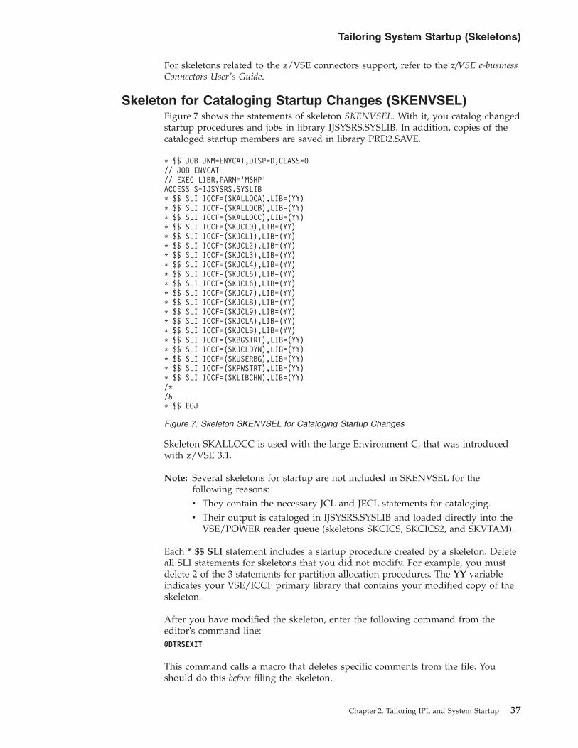
For skeletons related to the z/VSE connectors support, refer to the z/VSE e-businessConnectors User's Guide.
Skeleton for Cataloging Startup Changes (SKENVSEL)Figure 7 shows the statements of skeleton SKENVSEL. With it, you catalog changedstartup procedures and jobs in library IJSYSRS.SYSLIB. In addition, copies of thecataloged startup members are saved in library PRD2.SAVE.
Skeleton SKALLOCC is used with the large Environment C, that was introducedwith z/VSE 3.1.
Note: Several skeletons for startup are not included in SKENVSEL for thefollowing reasons:v They contain the necessary JCL and JECL statements for cataloging.v Their output is cataloged in IJSYSRS.SYSLIB and loaded directly into the
VSE/POWER reader queue (skeletons SKCICS, SKCICS2, and SKVTAM).
Each * $$ SLI statement includes a startup procedure created by a skeleton. Deleteall SLI statements for skeletons that you did not modify. For example, you mustdelete 2 of the 3 statements for partition allocation procedures. The YY variableindicates your VSE/ICCF primary library that contains your modified copy of theskeleton.
After you have modified the skeleton, enter the following command from theeditor's command line:@DTRSEXIT
This command calls a macro that deletes specific comments from the file. Youshould do this before filing the skeleton.
* $$ JOB JNM=ENVCAT,DISP=D,CLASS=0// JOB ENVCAT// EXEC LIBR,PARM=’MSHP’ACCESS S=IJSYSRS.SYSLIB* $$ SLI ICCF=(SKALLOCA),LIB=(YY)* $$ SLI ICCF=(SKALLOCB),LIB=(YY)* $$ SLI ICCF=(SKALLOCC),LIB=(YY)* $$ SLI ICCF=(SKJCL0),LIB=(YY)* $$ SLI ICCF=(SKJCL1),LIB=(YY)* $$ SLI ICCF=(SKJCL2),LIB=(YY)* $$ SLI ICCF=(SKJCL3),LIB=(YY)* $$ SLI ICCF=(SKJCL4),LIB=(YY)* $$ SLI ICCF=(SKJCL5),LIB=(YY)* $$ SLI ICCF=(SKJCL6),LIB=(YY)* $$ SLI ICCF=(SKJCL7),LIB=(YY)* $$ SLI ICCF=(SKJCL8),LIB=(YY)* $$ SLI ICCF=(SKJCL9),LIB=(YY)* $$ SLI ICCF=(SKJCLA),LIB=(YY)* $$ SLI ICCF=(SKJCLB),LIB=(YY)* $$ SLI ICCF=(SKBGSTRT),LIB=(YY)* $$ SLI ICCF=(SKJCLDYN),LIB=(YY)* $$ SLI ICCF=(SKUSERBG),LIB=(YY)* $$ SLI ICCF=(SKPWSTRT),LIB=(YY)* $$ SLI ICCF=(SKLIBCHN),LIB=(YY)/*/&* $$ EOJ
Figure 7. Skeleton SKENVSEL for Cataloging Startup Changes
Tailoring System Startup (Skeletons)
Chapter 2. Tailoring IPL and System Startup 37

Finally, submit job ENVCAT for processing.
Skeletons for Static Partition AllocationsFigure 8 on page 39, Figure 9 on page 40, Figure 10 on page 41 show thestatements of the skeletons provided for static partition allocations. The commentsincluded in the skeletons are not shown.
Note on ALLOC R and SETPFIXIn releases prior to VSE/ESA 1.3, the skeletons for static partition allocationsincluded ALLOC R definitions. Since VSE/ESA 1.3, the ALLOC R definitionhas been replaced by the JCL command SETPFIX. SETPFIX and ALLOC R areto be used as follows:v SETPFIX command is to be used to set limits per partition for fixing pages
(PFIX).v An ALLOC R definition is to be used only to define storage per partition
available for programs to be executed in real mode.
SETPFIX definitions are included in the startup procedures $1JCL (forVSE/POWER), VTAMSTRT (for VTAM), and CICSICCF (for CICS); theassociated skeletons are SKJCL1, SKVTAM, and SKCICS. For TCP/IP theskeleton used is SKTCPSTR. For the second predefined CICS, the name of thestartup procedure is CICS2, the name of the skeleton is SKCICS2.
Each skeleton's CATALOG statement shows the procedure name ALLOC. z/VSEuses this name for the allocation procedures provided, however, you may use yourown name instead. To help you make a decision, read first “Considerations forNaming Conventions” on page 24. If you decide to use your own name, you mustreplace ALLOC (in skeletons SKALLOCx and SKJCL0) with the name you havechosen.
TCP/IP using OSAX-links require approximately 1 MB PFIX storage (above 16 MB)per link. For further details, refer to the skeleton SKTCPSTR.
After you have modified the skeleton, enter the following command from theeditor's command line:@DTRSEXIT
This command calls a macro that deletes specific comments from the skeleton. Youshould do this before filing the skeleton.
Use skeleton SKENVSEL for cataloging your changes. Refer to “Skeleton forCataloging Startup Changes (SKENVSEL)” on page 37 for details.
Tailoring System Startup (Skeletons)
38 z/VSE V4R3.0 Administration

Skeleton SKALLOCAThis skeleton applies to predefined environment A including 12 static partitions(one crossing the 16 MB line).
Note: The SYSDEF command defines the VTAM® and VTAM applicationrequirements for data spaces. This includes the VTAM requirements forVSE/POWER and CICS. This is also reflected in the // EXECIPWPOWER,... statements of the VSE/POWER startup procedure (skeletonSKPWSTRT), the // EXEC DFHSIP,... statements of the CICS startupprocedure (skeleton SKCICS), and the // EXEC ISTINCVT,... statement ofthe VTAM startup procedure (skeleton SKVTAM).
The value defined for DSIZE is a minimum value which must not be reduced. Addyour own requirements for data spaces to this predefined value. The DSIZE valuegiven here reflects the status at the time the manual was printed. The actual valueshipped with z/VSE may be higher.
CATALOG ALLOC.PROC DATA=YES REPLACE=YESALLOC F1=4MSIZE F1=1350KALLOC BG=6MSIZE BG=1280KALLOC F2=30MSIZE F2=2048KALLOC F3=15MSIZE F3=600KALLOC F4=1MSIZE F4=768KALLOC F5=1MSIZE F5=768KALLOC F6=512KSIZE F6=256KALLOC F7=16MSIZE F7=1MALLOC F8=6MSIZE F8=3584KALLOC F9=512KSIZE F9=256KALLOC FA=512KSIZE FA=256KALLOC FB=1MSIZE FB=512KSYSDEF DSPACE,DSIZE=15MNPGR BG=255,F2=255,F3=100,F4=100,F5=50,F6=50,F7=50,F8=200NPGR F9=50,FA=50,FB=50/+CONN S=IJSYSRS.SYSLIB:PRD2.SAVECOPY ALLOC.PROC REPLACE=YES
Figure 8. Skeleton SKALLOCA (Static Partition Allocations)
Tailoring System Startup (Skeletons)
Chapter 2. Tailoring IPL and System Startup 39

Skeleton SKALLOCBThis skeleton applies to predefined environment B prepared for a second CICS TS.It includes 12 static partitions (four crossing the 16 MB line).
The SYSDEF command defines the VTAM and VTAM application requirements fordata spaces. This includes the requirements for VSE/POWER and CICS. This isalso reflected in the:v // EXEC IPWPOWER,... statements of the VSE/POWER startup procedure
(skeleton SKPWSTRT).v // EXEC DFHSIP,... statements of the CICS startup procedures (skeletons
SKCICS and SKCICS2).v // EXEC ISTINCVT,... statement of the VTAM startup procedure (skeleton
SKVTAM).
The value defined for DSIZE is an average size covering most application needs. Itleaves about 4 MB for non-VTAM applications like TCP/IP for VSE/ESA or CICSshared data tables. The actual value shipped with z/VSE may be higher.
CATALOG ALLOC.PROC DATA=YES REPLACE=YESALLOC BG=6MSIZE BG=1280KALLOC F1=5MSIZE F1=1400KALLOC F2=50MSIZE F2=2MALLOC F3=15MSIZE F3=600KALLOC F4=20MSIZE F4=2MALLOC F5=1MSIZE F5=768KALLOC F6=512KSIZE F6=256KALLOC F7=20MSIZE F7=1MALLOC F8=50MSIZE F8=2MALLOC F9=512KSIZE F9=256KALLOC FA=512KSIZE FA=256KALLOC FB=1MSIZE FB=512KSYSDEF DSPACE,DSIZE=20M,COMMAX=20NPGR BG=255,F2=255,F3=100,F4=200,F5=50,F6=50,F7=100,F8=200NPGR F9=50,FA=50,FB=50/+CONN S=IJSYSRS.SYSLIB:PRD2.SAVECOPY ALLOC.PROC REPLACE=YES
Figure 9. Skeleton SKALLOCB (Static Partition Allocations)
Tailoring System Startup (Skeletons)
40 z/VSE V4R3.0 Administration

Skeleton SKALLOCCThis skeleton applies to predefined environment C prepared for a largeenvironment. It includes 12 static partitions (eleven crossing the 16 MB line).
The SYSDEF command defines the VTAM and VTAM application requirements fordata spaces. This includes the requirements for VSE/POWER and CICS. This isalso reflected in the:v // EXEC IPWPOWER,... statements of the VSE/POWER startup procedure
(skeleton SKPWSTRT).v // EXEC DFHSIP,... statements of the CICS startup procedures (skeletons
SKCICS and SKCICS2).v // EXEC ISTINCVT,... statement of the VTAM startup procedure (skeleton
SKVTAM).
The value defined for DSIZE is an average size covering most application needs. Itleaves about 240 MB for non-VTAM applications like TCP/IP for VSE/ESA orCICS shared data tables. The actual value shipped with z/VSE may be higher.
CATALOG ALLOC.PROC DATA=YES REPLACE=YESALLOC BG=32MSIZE BG=1280KALLOC F1=32MSIZE F1=1500KALLOC F2=256MSIZE F2=2MALLOC F3=15MSIZE F3=600KALLOC F4=32MSIZE F4=2MALLOC F5=32MSIZE F5=1MALLOC F6=32MSIZE F6=1MALLOC F7=32MSIZE F7=1MALLOC F8=512MSIZE F8=2MALLOC F9=32MSIZE F9=1MALLOC FA=32MSIZE FA=1MALLOC FB=2MSIZE FB=512KSYSDEF DSPACE,DSIZE=256M,COMMAX=20NPGR BG=255,F2=255,F3=100,F4=200,F5=50,F6=50,F7=100,F8=200NPGR F9=50,FA=50,FB=50/+CONN S=IJSYSRS.SYSLIB:PRD2.SAVECOPY ALLOC.PROC REPLACE=YES
Figure 10. Skeleton SKALLOCC (Static Partition Allocations)
Tailoring System Startup (Skeletons)
Chapter 2. Tailoring IPL and System Startup 41

Skeletons for Starting Up BG PartitionYou can use the skeletons SKJCL0 and SKUSERBG to tailor startup for the BGpartition. The comments included in the skeletons are not shown in the followingfigures. To understand the functions included in the startup for the BG partition,refer to “Overview of Startup Processing” on page 18.
Both skeletons are shipped in VSE/ICCF library 59. Figure 11 shows the contentsof skeleton SKJCL0 and Figure 12 on page 48 the contents of skeletons SKUSERBG.Certain AR commands can be included or are recommended for inclusion in the$0JCL procedure. They are listed under “Including AR Commands” on page 47.
Skeleton SKJCL0$0JCL is the procedure name used by z/VSE but you may use your own nameinstead. To help you make a decision, read first “Considerations for NamingConventions” on page 24.
Note: The name for this procedure must always start with $0 and the following sixcharacters must be equal for all related JCL startup procedures.
If you decide to use your own name, you must update $ASIPROC (if used) or theoperator must interrupt IPL processing to enter the correct name.
CATALOG $0JCL.PROC DATA=YES REPLACE=YESSTDOPT ACANCEL=NO,DECK=NO,DUMP=PART,SYSDUMP=YES,SXREF=YESSYSDEF DSPACE,DSIZE=15MSYSDEF SYSTEM,NTASKS=255,TASKS=OLD// VDISK UNIT=FDF,BLKS=2880,VOLID=VDIDLA,USAGE=DLA* VDISK UNIT=CUU,BLKS=81920,VOLID=VDIWRK// EXEC PROC=STDLABEL CALLS ALSO STDLABUP AND STDLABUS LOAD VDISK// EXEC PROC=SETSDL SET SDLPRTY BG,FA,F9,F8,F6,F5,F4,F2,F7,FB,F3,F1ASSGN SYSLST,IGN// JOB BGINIT// LIBDEF DUMP,CATALOG=SYSDUMP.BG,PERM// SETPARM XNCPU=’ ’// EXEC PROC=$COMVAR,XNCPU// EXEC DTRISTRT,SIZE=AUTO,PARM=’CPUVAR&XNCPU;$$JCLBSX;$$JCLMIN’/*// SETPARM RETCODE=$RC// SETPARM XSPINIT=’FINISHED ’// SETPARM XMODEBG=’MINI’// SETPARM XPARTPW=’F1’// SETPARM XPWMODE=’WARM’// IF RETCODE=1 OR RETCODE=9 THEN// GOTO ALLOCBSX// EXEC PROC=CPUVAR&XNCPU,XMODEBG,XPARTPW,XPWMODE,XSPINIT// IF XSPINIT ¬= FINISHED THEN// GOTO NOSDL
Workfiles on Virtual Disk:
If you want to place workfiles on a virtual disk, you must activate the following statementsin the skeleton:
* VDISK UNIT=CUU,BLKS=81920,VOLID=VDIWRK* EXEC PROC=IESWORK DEFINE WORK FILES ON VIRTUAL DISK (on next page)
Figure 11. Skeleton SKJCL0 (Startup Procedure for BG Partition) (Part 1 of 5)
Tailoring System Startup (Skeletons)
42 z/VSE V4R3.0 Administration

// EXEC PROC=LIBSDL PROVIDE CORRECT LIBDEF FOR SET SDLSET SDLLIST=$SVAVTAMLIST=$SVACICSLIST=$SVAREXXLIST=$SVAASMALIST=$SVACONNLIST=$SVACEELIST=$SVAEDCM/** ------------------------------------------------------------------* DEPENDING ON THE SVA SIZE AND ON THE LANGUAGES USED IN LE/VSE* YOU MAY ADDITIONALLY LOAD RUNTIME SUPPORT FOR PL/I AND/OR COBOL.* MOVE THE APPROPRIATE LIST STATEMENT ABOVE.* ADDITIONAL AMOUNT OF STORAGE AS OF GA TIME:** R-MODE 24 RMODE=ANY* LIST=$SVAIGZM LE COBOL 0KB 160KB* LIST=$SVAIBMM LE PL/I 36KB 208KB* * ------------------------------------------------------------------// LIBDROP PHASE/. NOSDLEXPLAIN ON// IF XMODEBG=BASIC THEN// GOTO ALLOCBSX// EXEC PROC=ALLOC CHANGE TO PROCNAME DEFINED IN SKALLOCx x=A,B,C* EXEC PROC=IESWORK DEFINE WORK FILES ON VIRTUAL DISK// GOTO SECSTRT/. ALLOCBSX// EXEC PROC=ALLOCBSX ALLOCs FOR BASIC START// SETPARM XPARTPW=F1* IF YOU CHANGED THE PRIORITY IN YOUR NORMAL SYSTEM* YOU HAVE TO RESET IT FOR BASIC START TO:* PRTY BG,FA,F9,F8,F6,F5,F4,F2,F7,FB,F3,F1
EXPLAIN ON// PAUSE/. SECSTRT// ON $RC=99 GOTO ERROR// EXEC BSSINIT/*// SETPARM RETCODE=$RC// IF RETCODE¬=0 THEN// GOTO PARTFB// EXEC DTRSETP,PARM=’CPUVAR&XNCPU;;’
SET XSECP=RECOVERY/*
Figure 11. Skeleton SKJCL0 (Startup Procedure for BG Partition) (Part 2 of 5)
Tailoring System Startup (Skeletons)
Chapter 2. Tailoring IPL and System Startup 43

// GOTO PWRSTRT/. PARTFB// IF RETCODE¬=11 THEN// GOTO PARTFA// IF XPARTPW = FB THEN// GOTO ERROR// EXEC DTRSETP,PARM=’CPUVAR&XNCPU;;’
SET XSECP=FB/*// GOTO PWRSTRT/. PARTFA// IF RETCODE¬=10 THEN// GOTO PARTF9// IF XPARTPW = FA THEN// GOTO ERROR// EXEC DTRSETP,PARM=’CPUVAR&XNCPU;;’
SET XSECP=FA/*// GOTO PWRSTRT/. PARTF9// IF RETCODE¬=9 THEN// GOTO PARTF8// IF XPARTPW = F9 THEN// GOTO ERROR// EXEC DTRSETP,PARM=’CPUVAR&XNCPU;;’
SET XSECP=F9/*// GOTO PWRSTRT/. PARTF8// IF RETCODE¬=8 THEN// GOTO PARTF7// IF XPARTPW = F8 THEN// GOTO ERROR// EXEC DTRSETP,PARM=’CPUVAR&XNCPU;;’
SET XSECP=F8../*// GOTO PWRSTRT/. PARTF7// IF RETCODE¬=7 THEN// GOTO PARTF6// IF XPARTPW = F7 THEN// GOTO ERROR// EXEC DTRSETP,PARM=’CPUVAR&XNCPU;;’
SET XSECP=F7/*// GOTO PWRSTRT/. PARTF6// IF RETCODE¬=6 THEN// GOTO PARTF5// IF XPARTPW = F6 THEN// GOTO ERROR// EXEC DTRSETP,PARM=’CPUVAR&XNCPU;;’
SET XSECP=F6/*
Figure 11. Skeleton SKJCL0 (Startup Procedure for BG Partition) (Part 3 of 5)
Tailoring System Startup (Skeletons)
44 z/VSE V4R3.0 Administration

// GOTO PWRSTRT/. PARTF5// IF RETCODE¬=5 THEN// GOTO PARTF4// IF XPARTPW = F5 THEN// GOTO ERROR// EXEC DTRSETP,PARM=’CPUVAR&XNCPU;;’
SET XSECP=F5/*// GOTO PWRSTRT/. PARTF4// IF RETCODE¬=4 THEN// GOTO PARTF3// IF XPARTPW = F4 THEN// GOTO ERROR// EXEC DTRSETP,PARM=’CPUVAR&XNCPU;;’
SET XSECP=F4/*// GOTO PWRSTRT/. PARTF3// IF RETCODE¬=3 THEN// GOTO PARTF2// IF XPARTPW = F3 THEN// GOTO ERROR// EXEC DTRSETP,PARM=’CPUVAR&XNCPU;;’
SET XSECP=F3/*// GOTO PWRSTRT/. PARTF2// IF RETCODE¬=2 THEN// GOTO PARTF1// IF XPARTPW = F2 THEN// GOTO ERROR// EXEC DTRSETP,PARM=’CPUVAR&XNCPU;;’
SET XSECP=F2/*/. PARTF1// IF RETCODE¬=1 THEN// GOTO ERROR// IF XPARTPW = F1 THEN// GOTO ERROR// EXEC DTRSETP,PARM=’CPUVAR&XNCPU;;’
SET XSECP=F1/*
Figure 11. Skeleton SKJCL0 (Startup Procedure for BG Partition) (Part 4 of 5)
Tailoring System Startup (Skeletons)
Chapter 2. Tailoring IPL and System Startup 45

/. PWRSTRTSET MRCZEROSTART &XPARTPWSTOPASSGN SYSIN,FEC,PERMASSGN SYSPCH,FEDASSGN SYSLST,FEEASSGN SYSLNK,DISK,VOL=DOSRES,SHR SYSTEM LINK FILEASSGN SYS001,DISK,VOL=SYSWK1,SHR SYSTEM WORK FILE 1ASSGN SYS002,DISK,VOL=SYSWK1,SHR SYSTEM WORK FILE 2ASSGN SYS003,DISK,VOL=SYSWK1,SHR SYSTEM WORK FILE 3ASSGN SYS004,DISK,VOL=SYSWK1,SHR SYSTEM WORK FILE 4// IF XSPINIT ¬= FIRST THEN// GOTO SKIP* ===================================== ** ** INSTALLATION OF *// EXEC PROC=SPLEVEL* ** ===================================== *// EXEC PROC=LOADINST// EXEC DTRSETP,PARM=’CPUVAR1;;’
SET XSPINIT=INSTALL/*// PWR PRELEASE RDR,INSTALL// GOTO EXIT/. SKIP// IF XPWMODE=COLD OR XPWMODE=BASIC THEN// GOTO COLDPART// GOTO ENDCOLD/. COLDPART// ID USER=FORSEC !! NO PWD REQUIRED !!// EXEC PROC=COLDJOBS/. ENDCOLD// IF XMODEBG ¬= MINI THEN// GOTO NOTMINI// EXEC PROC=MINIBG// GOTO EXIT/. NOTMINI// IF XMODEBG ¬= BASIC THEN// GOTO USER// ID USER=FORSEC !! NO PWD REQUIRED !!// EXEC PROC=BASICBG// GOTO EXIT/. USER// ID USER=FORSEC !! NO PWD REQUIRED !!// EXEC PROC=USERBG CHANGE TO YOUR PROCNAME AS USED IN SKUSERBG// GOTO EXIT/. ERROR* ERROR IN THE PARTITION SETUP FOR SECURITY SERVER. SERVER PARTITION* MAY NOT BE &XPARTPW/. EXIT/&/+CONN S=IJSYSRS.SYSLIB:PRD2.SAVECOPY $0JCL.PROC REPLACE=YES
Figure 11. Skeleton SKJCL0 (Startup Procedure for BG Partition) (Part 5 of 5)
Tailoring System Startup (Skeletons)
46 z/VSE V4R3.0 Administration

In a system with security (access control) active, the // ID statements for userFORSEC ensure that startup procedures COLDJOBS and BASICBG have theappropriate access rights. In an ASI procedure no password is required for the IDstatement.
Refer to chapter Chapter 30, “Access Rights/Checking in DTSECTAB,” on page 407for details about the z/VSE access control support.
If you modified procedure USERBG and specified a different procedure name, youmust change the procedure name here as well. Use the name entered in theCATALOG statement of skeleton SKUSERBG. Use skeleton SKENVSEL forcataloging your changes. Refer to “Skeleton for Cataloging Startup Changes(SKENVSEL)” on page 37 for details.
Including AR CommandsAR (attention routine) commands such as the following can be included in the$0JCL startup procedure for the BG partition:BANDIDCACHEDEBUGEXPLAINFREELFCBLUCBOFFLINEONLINEOPERATEPRTYIORESERVSETDFSYSECHOTPBAL
You find a detailed description of these commands in the manual z/VSE SystemControl Statements.
Tailoring System Startup (Skeletons)
Chapter 2. Tailoring IPL and System Startup 47

Skeleton SKUSERBG
USERBG is the procedure name used by z/VSE. If you modify the procedure, youmay want to change the procedure name as well. To help you make a decision,read first “Considerations for Naming Conventions” on page 24.
If you decide to use your own name, you must also update procedure $0JCL. Useskeleton SKJCL0 and modify the corresponding EXEC PROC statement.
Procedure USERBG calls procedure LIBDEF and releases the startup jobsVTAMSTRT and CICSICCF (and CICS2 if installed). If you modified any of theseand specified your own names, replace these names accordingly:v LIBDEFv VTAMSTRTv CICSICCFv CEEWARCv CICS2v STARTVCS
Use the name you entered in the CATALOG statement of the procedure or jobchanged. The names of the skeletons are:
CATALOG USERBG.PROC DATA=YES REPLACE=YES* START MODE FOR BG-PARTITION IS NORMAL* ******************************************** YOUR SYSTEM IS *// EXEC PROC=SPLEVEL* *******************************************STDOPT DATE=MDY CHANGE STANDARD OPTIONS IF WANTED// EXEC PROC=LIBDEF CHANGE TO YOUR OWN LIBDEF PROC// EXEC ARXLINK INITIALIZE REXX/VSE// LIBDEF DUMP,CATALOG=SYSDUMP.BG,PERM* TO ENABLE DB2, ENTER KEY AND CUSTOMER INFO, REMOVE ASTERISKS TO* ACTIVATE, CONTINUATION LINE START COLUMN 16.* BELOW KEY IS THE TRIAL KEY VALID FOR THE TRIAL PERIOD.* EXEC IVALPKEY,PARM=’PRODUCT=DB2 KEY=0000-1111-2222-3333-4444 CUSTINF** O=C111-111-1111’** TO START CAPACITY MEASUREMENT, REMOVE ASTERISK BELOW.* // EXEC PROC=CMTSTART// SETPARM XNCPU=’’// EXEC PROC=$COMVAR,XNCPU GET CPU NUMBER// SETPARM XENVNR=’’// SETPARM SSLCAUT=’’// EXEC PROC=CPUVAR&XNCPU,XENVNR,SSLCAUT// PWR PRELEASE RDR,VTAMSTRT OR YOUR VTAM (SKVTAM)// EXEC IESWAIT,PARM=’03’/*// IF SSLCAUT NE YES THEN// GOTO NOCAUT// EXEC BSSDCERT,PARM=’ACT’/*/. NOCAUT// PWR PRELEASE RDR,CICSICCF OR YOUR CICS (SKCICS)// PWR PRELEASE RDR,CEEWARC LE - AR INTERFACE* // PWR PRELEASE RDR,CICS2 OR YOUR CICS2 (SKCICS2)* // PWR PRELEASE RDR,TCPIP00 OR YOUR TCP/IP STARTUP* // PWR PRELEASE RDR,STARTVCS OR YOUR CONNECTOR SERVER/+CONN S=IJSYSRS.SYSLIB:PRD2.SAVECOPY USERBG.PROC REPLACE=YES
Figure 12. Skeleton SKUSERBG (Startup Procedure for BG Partition)
Tailoring System Startup (Skeletons)
48 z/VSE V4R3.0 Administration

v SKLIBCHNv SKVTAMv SKCICSv SKCICS2v SKTCPSTRv SKVCSSTJ
Use skeleton SKENVSEL for cataloging your changes. Refer to “Skeleton forCataloging Startup Changes (SKENVSEL)” on page 37 for details.
Enabling the DB2 Server for VSETo enable the DB2 Server for VSE you must activate the EXEC IVALPKEYstatement. Refer also to “System Provided Application Profiles” on page 127.
Tailoring System Startup (Skeletons)
Chapter 2. Tailoring IPL and System Startup 49

Skeletons for Starting Up VSE/POWERYou can use skeletons SKJCL1 and SKPWSTRT to modify the startup ofVSE/POWER in partition F1.
Both skeletons are shipped in VSE/ICCF library 59. Figure 13 and Figure 14 onpage 53 show the contents of the skeletons. Comments included in the skeletonsare not shown.
Skeleton SKJCL1
If you modify this procedure, you may also change the procedure name $1JCL. Tohelp you make a decision, read first “Considerations for Naming Conventions” onpage 24. Note that the name for this procedure must always start with $1 and thefollowing six characters must be equal for all related JCL startup procedures.
In a system with security (access control) active, the // ID statement for userFORSEC ensures the appropriate access rights for procedure POWSTRTn. The //
CATALOG $1JCL.PROC DATA=YES REPL=YES// JOB POWSTART// OPTION SADUMP=5// EXEC PROC=DTRICCF ASSIGNMENTS FOR DTSFILE// EXEC PROC=DTRPOWR ASSIGNMENTS FOR VSE/POWER// SETPARM DASD=’’// SETPARM XNCPU=’’// SETPARM XENVNR=’’// SETPARM XPWMODE=’’// SETPARM XPARTPW=’’// SETPARM XSECP=’’// SETPARM XSPINIT=’’// EXEC PROC=$COMVAR,XNCPU// EXEC PROC=CPUVAR&XNCPU,DASD,XENVNR,XPWMODE,XPARTPW,XSECP,XSPINIT// EXEC DTRSETP,PARM=’CPUVAR&XNCPU;;SET XSTAT&XPARTPW=ACTIVE’/*// EXEC PROC=LIBDEF// EXEC PROC=LIBDUMP// SETPFIX LIMIT=300K// ID USER=FORSEC !! NO PWD REQUIRED !!// EXEC PROC=POWSTRT&XENVNR,XPWMODE,XSECP// ID USER=DUMMY !! NO PWD REQUIRED !!/*// EXEC DTRSETP,PARM=’CPUVAR&XNCPU;;SET XSTAT&XPARTPW=INACTIVE’/*// IF XSPINIT = FIRST OR XSPINIT = INSTALL THEN// GOTO NOSEC* ------------------------------------------------------------* SECURITY SERVER PARTITION WILL BE STOPPED* YOU MAY ENTER A PAUSE STATEMENT HERE IN CASE YOU DON’T WANT* TO ALWAYS STOP. YOU WOULD HAVE TO ENTER // GOTO NOSEC IN* CASE YOU DON’T WANT TO STOP.* ------------------------------------------------------------// EXEC DTRIATTN,PARM=’MSG &XSECP,DATA=STOPNOREP’/*// EXEC DTRSETP,PARM=’CPUVAR&XNCPU;SET XSECP=RECOVER’/*/. NOSEC/&/+CONN S=IJSYSRS.SYSLIB:PRD2.SAVECOPY $1JCL.PROC REPLACE=YES
Figure 13. Skeleton SKJCL1 (Startup Procedure for VSE/POWER Partition)
Tailoring System Startup (Skeletons)
50 z/VSE V4R3.0 Administration

ID statement for user DUMMY turns off these access rights. In an ASI procedureno password is required for the ID statement.
Refer to Chapter 30, “Access Rights/Checking in DTSECTAB,” on page 407 fordetails about the z/VSE access control support.
If you decide to use your own name, you must update $ASIPROC (if used) or theoperator must interrupt IPL processing to enter the correct name.
For an explanation of the SETPFIX definition, refer to “Skeletons for Static PartitionAllocations” on page 38. The EXEC PROC statement for LIBDEF calls theprocedure that defines library search chains and assignments for the partitionswhich are controlled by VSE/POWER. If you modified the LIBDEF procedure(skeleton SKLIBCHN) and specified your own procedure name, change thisstatement accordingly. Use the name you entered in the CATALOG statement ofSKLIBCHN.
The EXEC PROC statement for POWSTRT calls the procedure that defines warmand cold starts. &XENVNR identifies the predefined environment chosen (A, B, orC). If you modified this procedure (skeleton SKPWSTRT) and specified your ownprocedure name, change this statement accordingly. Use the name you entered inthe CATALOG statement of SKPWSTRT.
After you have modified the skeleton, enter the following command from theeditor's command line to delete specific comments from the skeleton:@DTRSEXIT
Use skeleton SKENVSEL for cataloging your changes. Refer to “Skeleton forCataloging Startup Changes (SKENVSEL)” on page 37 for details.
Skeleton SKPWSTRTThis skeleton is in two parts; one for a COLD, the other for a WARM startup. Then in POWSTRTn.PROC reflects the predefined environment selected during initialinstallation: A, B, or C.
If you modify this procedure, you may also change the procedure namePOWSTRTn (n identifies the environment selected during initial installation). Referalso to “Considerations for Naming Conventions” on page 24. If you decide to useyour own name, you must update the corresponding EXEC PROC statement inprocedure $1JCL (skeleton SKJCL1).
The statementsSET SYSID=YSET PNET=YYYYYYYY
for shared spooling and networking are optional. Delete them if you do not usethese functions.
The statementSET SECNODE=AAAA
is for a multiple-node environment with security (access control) active. It isrequired to distinguish the nodes for security processing.
The statementSET SECAC=NO
Tailoring System Startup (Skeletons)
Chapter 2. Tailoring IPL and System Startup 51

indicates that the job and its output are not Spool Access Protected. NO is thedefault value.
The statement:SET SJECL=YES
supports the cataloging of VSE/POWER jobs into a VSE library.
The statement:SET WORKUNIT=PA
allows VSE/POWER to run on multiple CPUs in parallel.
A statement:SET RBF=nnnnn
will cause VSE/POWER to cancel a job when the limit nnnnn for the number ofoutput records (99999 in the skeleton) has been reached.
Do not change the following statement:DEFINE L,CICSDATA,3F00,1,255,*
It specifies for the CICS Report Controller a Resource Security Level (RSL) valuefor reports generated by batch programs. Refer to “DEFINE: SpecifyingUser-Defined Output Operands” in the manual VSE/POWER Administration andOperation for a detailed description of the DEFINE command.
The other DEFINE statements are for PSF/VSE (Print Services Facility/VSE), az/VSE optional program which provides advanced printing support for certaintypes of IBM printers.
The VSE/POWERPLOAD DYNC,ID=n,FORCE
command (shown on the following page) is optional and loads the dynamic classtable DTR$DYNn (DTR$DYNC is the name of the table shipped with z/VSE)defining the parameters required for activating dynamic partitions. Dynamicpartitions are supported for all predefined environments.
Note: This skeleton assumes that the Security Server runs in partition FB. If youhave selected another partition for the Security Server, which is notrecommended, you need to modify the skeleton accordingly. If there is aneed to select another partition, you must select a static partition which isnot controlled by VSE/POWER.
Tailoring System Startup (Skeletons)
52 z/VSE V4R3.0 Administration

CATALOG POWSTRTn.PROC REPL=YES DATA=YES// EXEC DTRWAITP// IF XPWMODE ¬= COLD THEN// GOTO WARM// IF XSECP = FB THEN// GOTO COLDFB// ASSGN SYSLST,UA// EXEC IPWPOWER,DSPACE=2MSET SYSID=YSET PNET=YYYYYYYYSET SECNODE=AAAASET SECAC=NOSET SJECL=YESSET WORKUNIT=PADEFINE L,CICSDATA,3F00,1,255,*DEFINE L,CKPTPAGE,4,1,2,B,1,32767DEFINE L,FORMDEF,1D,1,6,CDEFINE L,PAGEDEF,1F,1,6,CDEFINE L,PIMSG,21,2,3,CDEFINE L,DATACK,2022,1,8,CDEFINE L,FORMS,10,1,4,CDEFINE L,PRMODE,18,1,8,CDEFINE L,TRC,1A,1,3,CFORMAT=D,APSTART BG,A0IREADER=FECPRINTERS=FEEPUNCHES=FEDPSTART F2,L2READER=FECPRINTERS=FEE,FEFPUNCHES=FEDPSTART F3,K3READER=FECPRINTERS=FEEPUNCHES=FEDPSTART F4,J4READER=FECPRINTERS=FEEPUNCHES=FEDPSTART F5,H5READER=FECPRINTERS=FEEPUNCHES=FEDPSTART F6,M6READER=FECPRINTERS=FEEPUNCHES=FEDPSTART F7,N7READER=FECPRINTERS=FEEPUNCHES=FEDPSTART F8,P8READER=FEC
Figure 14. Skeleton SKPWSTRT (VSE/POWER Warm and Cold Starts) (Part 1 of 5)
Tailoring System Startup (Skeletons)
Chapter 2. Tailoring IPL and System Startup 53

PRINTERS=FEEPUNCHES=FEDPSTART F9,Q9READER=FECPRINTERS=FEEPUNCHES=FEDPSTART FA,TVREADER=FECPRINTERS=FEEPUNCHES=FEDPSTART FB,BUREADER=FECPRINTERS=FEEPUNCHES=FEDPSTART DEV,YYYYYYYY,SYSPSFXX,PPSTART TASKTR,ENAB,10* PLOAD DYNC,ID=n,FORCE/*// GOTO EXIT/. COLDFB COLD START, SECURITY SERVER IS FB// ASSGN SYSLST,UA// EXEC IPWPOWER,DSPACE=2MSET SYSID=YSET PNET=YYYYYYYYSET SECNODE=AAAASET SECAC=NOSET SJECL=YESSET WORKUNIT=PADEFINE L,CICSDATA,3F00,1,255,*DEFINE L,CKPTPAGE,4,1,2,B,1,32767DEFINE L,FORMDEF,1D,1,6,CDEFINE L,PAGEDEF,1F,1,6,CDEFINE L,PIMSG,21,2,3,CDEFINE L,DATACK,2022,1,8,CDEFINE L,FORMS,10,1,4,CDEFINE L,PRMODE,18,1,8,CDEFINE L,TRC,1A,1,3,CFORMAT=D,APSTART BG,A0IREADER=FECPRINTERS=FEEPUNCHES=FEDPSTART F2,L2READER=FECPRINTERS=FEE,FEFPUNCHES=FEDPSTART F3,K3READER=FECPRINTERS=FEEPUNCHES=FEDPSTART F4,J4READER=FECPRINTERS=FEEPUNCHES=FED
Figure 14. Skeleton SKPWSTRT (VSE/POWER Warm and Cold Starts) (Part 2 of 5)
Tailoring System Startup (Skeletons)
54 z/VSE V4R3.0 Administration

PSTART F5,H5READER=FECPRINTERS=FEEPUNCHES=FEDPSTART F6,M6READER=FECPRINTERS=FEEPUNCHES=FEDPSTART F7,N7READER=FECPRINTERS=FEEPUNCHES=FEDPSTART F8,P8READER=FECPRINTERS=FEEPUNCHES=FEDPSTART F9,Q9READER=FECPRINTERS=FEEPUNCHES=FEDPSTART FA,TVREADER=FECPRINTERS=FEEPUNCHES=FEDPSTART DEV,YYYYYYYY,SYSPSFXX,PPSTART TASKTR,ENAB,10* PLOAD DYNC,ID=n,FORCE/*// GOTO EXIT/. WARM POWER WARM START// IF XSECP = FB THEN// GOTO WARMFB// EXEC IPWPOWER,DSPACE=2MSET SYSID=YSET PNET=YYYYYYYYSET SECNODE=AAAASET SECAC=NOSET SJECL=YESSET WORKUNIT=PADEFINE L,CICSDATA,3F00,1,255,*DEFINE L,CKPTPAGE,4,1,2,B,1,32767DEFINE L,FORMDEF,1D,1,6,CDEFINE L,PAGEDEF,1F,1,6,CDEFINE L,PIMSG,21,2,3,CDEFINE L,DATACK,2022,1,8,CDEFINE L,FORMS,10,1,4,CDEFINE L,PRMODE,18,1,8,CDEFINE L,TRC,1A,1,3,CFORMAT=NOPSTART BG,A0IREADER=FECPRINTERS=FEEPUNCHES=FEDPSTART F2,L2READER=FEC
Figure 14. Skeleton SKPWSTRT (VSE/POWER Warm and Cold Starts) (Part 3 of 5)
Tailoring System Startup (Skeletons)
Chapter 2. Tailoring IPL and System Startup 55

PRINTERS=FEE,FEFPUNCHES=FEDPSTART F3,K3READER=FECPRINTERS=FEEPUNCHES=FEDPSTART F4,J4READER=FECPRINTERS=FEEPUNCHES=FEDPSTART F5,H5READER=FECPRINTERS=FEEPUNCHES=FEDPSTART F6,M6READER=FECPRINTERS=FEEPUNCHES=FEDPSTART F7,N7READER=FECPRINTERS=FEEPUNCHES=FEDPSTART F8,P8READER=FECPRINTERS=FEEPUNCHES=FEDPSTART F9,Q9READER=FECPRINTERS=FEEPUNCHES=FEDPSTART FA,TVREADER=FECPRINTERS=FEEPUNCHES=FEDPSTART FB,BUREADER=FECPRINTERS=FEEPUNCHES=FEDPSTART DEV,YYYYYYYY,SYSPSFXX,PPSTART TASKTR,ENAB,10* PLOAD DYNC,ID=N,FORCE/*// GOTO EXIT/. WARMFB WARM START, SECURITY SERVER IS FB// EXEC IPWPOWER,DSPACE=2MSET SYSID=YSET PNET=YYYYYYYYSET SECNODE=AAAASET SECAC=NOSET SJECL=YESSET WORKUNIT=PADEFINE L,CICSDATA,3F00,1,255,*DEFINE L,CKPTPAGE,4,1,2,B,1,32767DEFINE L,FORMDEF,1D,1,6,CDEFINE L,PAGEDEF,1F,1,6,CDEFINE L,PIMSG,21,2,3,C
Figure 14. Skeleton SKPWSTRT (VSE/POWER Warm and Cold Starts) (Part 4 of 5)
Tailoring System Startup (Skeletons)
56 z/VSE V4R3.0 Administration

DEFINE L,DATACK,2022,1,8,CDEFINE L,FORMS,10,1,4,CDEFINE L,PRMODE,18,1,8,CDEFINE L,TRC,1A,1,3,CFORMAT=NOPSTART BG,A0IREADER=FECRINTERS=FEEPUNCHES=FEDPSTART F2,L2READER=FECPRINTERS=FEE,FEFPUNCHES=FEDPSTART F3,K3READER=FECPRINTERS=FEEPUNCHES=FEDPSTART F4,J4READER=FECPRINTERS=FEEPUNCHES=FEDPSTART F5,H5READER=FECPRINTERS=FEEPUNCHES=FEDPSTART F6,M6READER=FECPRINTERS=FEEPUNCHES=FEDPSTART F7,N7READER=FECPRINTERS=FEEPUNCHES=FEDPSTART F8,P8READER=FECPRINTERS=FEEPUNCHES=FEDPSTART F9,Q9READER=FECPRINTERS=FEEPUNCHES=FEDPSTART FA,TVREADER=FECPRINTERS=FEEPUNCHES=FEDPSTART DEV,YYYYYYYY,SYSPSFXX,PPSTART TASKTR,ENAB,10* PLOAD DYNC,ID=N,FORCE/*/. EXIT/+CONNECT S=IJSYSRS.SYSLIB:PRD2.SAVECOPY POWSTRTn.PROC REPLACE=YES
Figure 14. Skeleton SKPWSTRT (VSE/POWER Warm and Cold Starts) (Part 5 of 5)
Tailoring System Startup (Skeletons)
Chapter 2. Tailoring IPL and System Startup 57

There are four commands for each of the twelve partitions named in the skeleton.For example:PSTART BG,A0IREADER=FECPRINTERS=FEEPUNCHES=FED
These four commands are required for each partition. They define some of thepartition's operating characteristics and its device configuration for spooling. Themanual VSE/POWER Administration and Operation describes these commands indetail.
z/VSE uses the first PRINTERS/PUNCHES as default device. For that reason, yourreal device should precede FEE or FED, respectively.
If more than one device is specified for PRINTERS or PUNCHES, it isrecommended to code the POWER® * $$ LST and the * $$ PUN statements fordevice selection. Otherwise, the LST and PUN parameters are associated with thefirst device and the system will take VSE/POWER default values when spooling toa device other than the first device.
Be sure to delete the commands for the partition(s) that you do not want to haveautostarted. Do this for both the cold and the warm start definitions.
You can use any device address. However, the device must be defined in thehardware configuration table. This is done either during initial installation bydevice sensing or by using the Configure Hardware dialog.
After you have modified the skeleton, enter the following command from theeditor's command line:@DTRSEXIT
This command calls a macro that deletes specific comments from the skeleton. Youshould do this before filing the skeleton.
Use skeleton SKENVSEL for cataloging your changes. Refer to “Skeleton forCataloging Startup Changes (SKENVSEL)” on page 37 for details.
Skeleton for Defining Library Search Chains (SKLIBCHN)You can use the skeleton SKLIBCHN to define search chains and assignments forthe batch partitions controlled by VSE/POWER. Figure 15 on page 59 shows thecontents of the skeleton. Comments included in the skeleton are not shown. Thename of the procedure created by this skeleton is LIBDEF.
Tailoring System Startup (Skeletons)
58 z/VSE V4R3.0 Administration

Note: The second part of skeleton SKLIBCHN, called LIBDEFS, includes inaddition libraries PRD1.BASED, PRD2.SCEEBASD, and PRD1.MACLIBD.These libraries are required only when applying service (PTFs) indirectly.Further details about these libraries are provided in the manual z/VSESystem Upgrade and Service under “Job Sequence for PTF Application”.
If you replace the procedure name LIBDEF by a name of your own, you must alsochange the name in skeletons such as SKJCL1, SKUSERBG, and SKINITNN.
Replace the Y strings in the three LIBDEF statements to define your permanentsublibrary search chains for phase, object, and source members. Note that youshould also include the system sublibraries as defined in the skeleton. If you donot, the Interactive Interface may not function correctly. In the LIBDEF statementfor member type PHASE, the Y string of the CATALOG operand defines thesublibrary that the linkage editor uses to catalog phases.
CATALOG LIBDEF.PROC DATA=YES REPLACE=YES// LIBDEF PHASE,SEARCH=(PRD2.CONFIG,
YYYYYYY.YYYYYYYY,YYYYYYY.YYYYYYYY,YYYYYYY.YYYYYYYY,YYYYYYY.YYYYYYYY,YYYYYYY.YYYYYYYY,YYYYYYY.YYYYYYYY,PRD1.BASE,PRD2.SCEEBASE,PRD2.PROD,PRD2.DBASE,PRD2.COMM,PRD2.COMM2,PRD2.AFP,PRIMARY.$$C),CATALOG=YYYYYYY.YYYYYYYY,PERM
// LIBDEF OBJ,SEARCH=(PRD2.CONFIG,YYYYYYY.YYYYYYYY,YYYYYYY.YYYYYYYY,YYYYYYY.YYYYYYYY,YYYYYYY.YYYYYYYY,YYYYYYY.YYYYYYYY,YYYYYYY.YYYYYYYY,PRD1.BASE,PRD2.SCEEBASE,PRD2.PROD,PRD2.DBASE,PRD2.COMM,PRD2.COMM2,PRD2.AFP,PRIMARY.$$C),PERM
// LIBDEF SOURCE,SEARCH=(PRD2.CONFIG,YYYYYYY.YYYYYYYY,YYYYYYY.YYYYYYYY,YYYYYYY.YYYYYYYY,YYYYYYY.YYYYYYYY,YYYYYYY.YYYYYYYY,PRD1.BASE,PRD2.SCEEBASE,PRD2.PROD,PRD2.DBASE,PRD2.COMM,PRD2.COMM2,PRD2.AFP,PRIMARY.$$C,PRD1.MACLIB),PERM
/*/+CATALOG LIBDEFS.PROC DATA=YES REPLACE=YES// LIBDEF PHASE,SEARCH=(PRD2.CONFIG,
YYYYYYY.YYYYYYYY,YYYYYYY.YYYYYYYY,YYYYYYY.YYYYYYYY,YYYYYYY.YYYYYYYY,YYYYYYY.YYYYYYYY,PRD1.BASED,PRD1.BASE,PRD2.SCEEBASD,PRD2.SCEEBASE,PRD2.PROD,PRD2.DBASE,PRD2.COMM,PRD2.COMM2,PRD2.AFP,PRIMARY.$$C),CATALOG=YYYYYYY.YYYYYYYY,PERM
// LIBDEF OBJ,SEARCH=(PRD2.CONFIG,YYYYYYY.YYYYYYYY,YYYYYYY.YYYYYYYY,YYYYYYY.YYYYYYYY,YYYYYYY.YYYYYYYY,YYYYYYY.YYYYYYYY,PRD1.BASED,PRD1.BASE,PRD2.SCEEBASD,PRD2.SCEEBASE,PRD2.PROD,PRD2.DBASE,PRD2.COMM,PRD2.COMM2,PRD2.AFP,PRIMARY.$$C),PERM
// LIBDEF SOURCE,SEARCH=(PRD2.CONFIG,YYYYYYY.YYYYYYYY,YYYYYYY.YYYYYYYY,YYYYYYY.YYYYYYYY,PRD1.BASED,PRD1.BASE,PRD2.SCEEBASD,PRD2.SCEEBASE,PRD2.PROD,PRD2.DBASE,PRD2.COMM,PRD2.COMM2,PRD2.AFP,PRIMARY.$$C,PRD1.MACLIBD,PRD1.MACLIB),PERM
/*/+CONNECT S=IJSYSRS.SYSLIB:PRD2.SAVECOPY LIBDEF.PROC REPLACE=YESCOPY LIBDEFS.PROC REPLACE=YES
Figure 15. Skeleton SKLIBCHN (Defining Library Search Chains)
Tailoring System Startup (Skeletons)
Chapter 2. Tailoring IPL and System Startup 59

The skeleton reflects the search chains established after initial installation. Ifyou do not install optional programs or if you install them in your own userlibraries, some of the sublibraries remain empty and may be deleted. After initialinstallation the following sublibraries are empty:v PRD2.COMMv PRD2.COMM2v PRD2.DBASEv PRD2.PRODv PRD2.AFPv PRD2.DB2750v PRD2.DB2750Cv PRD2.DFHDOCv PRD2.DB2STPv PRD2.OSASFv PRIMARY.$$Cv PRIMARY.SUF
The sublibrary PRD2.AFP is for the z/VSE optional program PSF/VSE and therelated z/VSE optional programs OGL/370 and PPFA/370.
After you have modified skeleton SKLIBCHN, enter the following command fromthe editor's command line:@DTRSEXIT
This command calls a macro that deletes specific comments from the file. Youshould do this before filing the skeleton. Use skeleton SKENVSEL for catalogingyour changes. Refer to “Skeleton for Cataloging Startup Changes (SKENVSEL)” onpage 37 for details.
Skeleton for Starting Up the CICS Transaction Server andVSE/ICCF (SKCICS)
Skeleton SKCICS creates a startup job for the CICS Transaction Server andVSE/ICCF in default partition F2. If you want to create your own startupprocedure for these components, use skeleton SKCICS. The job stream created withSKCICS catalogs the startup job CICSICCF into IJSYSRS.SYSLIB and loads itdirectly into the VSE/POWER reader queue.
If you have to perform a BASIC startup (because of CICS startup problems, forexample) perform the following steps:v Perform BASIC startup.v Use skeleton SKCICS to create and catalog members CICSICCF.Z and
LDCICS.PROC into IJSYSRS.SYSLIB.v Perform a normal startup.v Run procedure LDCICS.PROC to load the startup job CICSICCF into the
VSE/POWER reader queue.v Release startup job CICSICCF to continue normal startup.
Tailoring System Startup (Skeletons)
60 z/VSE V4R3.0 Administration

In a system with security (access control) active, the // ID statement for userDBDCCICS ensures that CICSICCF has the appropriate access rights to the controlfile. If you submit the job, your access rights are inherited by the CICSICCF startupjob in the VSE/POWER reader queue. If your access rights as a user are adequate,it is recommended to delete the ID statement from the skeleton to avoid anexposure of the password. Chapter 30, “Access Rights/Checking in DTSECTAB,”on page 407 describes the access control support in detail.
Instead of CICSICCF, you may use a name of your own for the startup job. To helpyou make a decision, read first “Considerations for Naming Conventions” on page24. If you use your own name, you must also update procedures USERBG andCOLDJOBS (skeletons SKUSERBG and SKCOLD) with the name you have chosensince they also call CICSICCF. With skeleton SKCOLD you can add your own jobsto the load list of procedure COLDJOBS. Note that these jobs must be cataloged ina VSE library.
* $$ JOB JNM=CATCICS,DISP=D,CLASS=0// JOB CATCICS CATALOG CICSICCF AND LDCICS, LOAD CICSICCF// EXEC LIBR,PARM=’MSHP’ACC S=IJSYSRS.SYSLIBCATALOG CICSICCF.Z REPLACE=YES$$$$ JOB JNM=CICSICCF,DISP=L,CLASS=2,EOJMSG=YES$$$$ LST CLASS=A,DISP=D,RBS=100// JOB CICSICCF CICS/ICCF STARTUP// OPTION SADUMP=5// OPTION SYSDUMPC// UPSI 11100000// LIBDEF *,SEARCH=(PRD2.CONFIG,PRD1.BASED,PRD1.BASE,PRD2.PROD, X
PRD2.SCEEBASD,PRD2.SCEEBASE,PRD2.DBASE,PRD1.MACLIBD, XPRD1.MACLIB,PRD2.DFHDOC)
// LIBDEF DUMP,CATALOG=SYSDUMP.F2// SETPARM XNCPU=’’// SETPARM XMODEF2=AUTO// SETPARM XAPPLF2=’’// SETPARM XSPINIT=’’// SETPARM XENVNR=’’// SETPARM XSECP=’’// EXEC PROC=$COMVAR,XNCPU// EXEC DTRSETP,PARM=’CPUVAR&XNCPU;;SET XSTATF2=ACTIVE’$$/*// EXEC DTRSETP,PARM=’CPUVAR&XNCPU;;SET XAPPLF2=DBDCCICS’$$/*// EXEC DTRSETP,PARM=’CPUVAR&XNCPU;;SET XPARTCI=F2’$$/*// EXEC PROC=CPUVAR&XNCPU,XMODEF2,XAPPLF2,XSPINIT,XENVNR,XSECP// SETPFIX LIMIT=144K// EXEC PROC=DTRCICST ASSGNS FOR CICS FILES// EXEC PROC=DTRINFOA ASSGNS FOR INFO ANAL FILES// EXEC PROC=DTRICCF ASSGN FOR DTSFILE// OPTION SYSPARM=’00’// ASSGN SYS006,UA// ASSGN SYS007,UA// ASSGN SYS008,UA// ASSGN SYS009,SYSLOGLOG// ID USER=DBDCCICSNOLOG// EXEC DTSANALS RECOVER IF DTSFILE DESTROYEDRECOVER OPT$$/*
Figure 16. Skeleton SKCICS, Part 1 of 2 (Starting Up the CICS Transaction Server andVSE/ICCF)
Tailoring System Startup (Skeletons)
Chapter 2. Tailoring IPL and System Startup 61

For an explanation of the SETPFIX definition, refer to “Skeletons for Static PartitionAllocations” on page 38.
For CLASS (in the $$$$ JOB statement) specify the identifier of the partition inwhich CICS is running. The skeleton assumes F2.
EOJMSG=YES is needed for an unattended node environment (it is included forcompatibility reasons only since unattended nodes are no longer supported). Atend-of-job (EOJ), VSE/POWER issues a message which initiates automatedshutdown or the processing of other command lists.
Replace F2 with the identifier of the partition if you run CICS with VSE/ICCF inanother partition than F2.
Tailoring System Startup (Skeletons)
62 z/VSE V4R3.0 Administration

The application IESWAITT (called with // EXEC IESWAITT) must be defined toz/VSE as a VTAM application. This definition exists if you are using z/VSE asshipped by IBM. If this definition is removed because of modifications, you mustuse the Maintain VTAM Application Names dialog and redefine IESWAITT asapplication name (APPLID) to VTAM.
If there is a need to wait until TCP/IP is up, activate statement* // EXEC REXX=IESWAITR,PARM=’TCPIP00’
by removing the preceding asterisk and blank character provided that the TCP/IPstartup job is TCPIP00.
* WAITING FOR VTAM TO COME UP// EXEC IESWAITT$$/** WAITING FOR TCP/IP TO COME UP* // EXEC REXX=IESWAITR,PARM=’TCPIP00’$$/*// OPTION SYSPARM=’00’// ASSGN SYS020,SYSLST// SETPARM ELIM=14M// IF XENVNR = B THEN// SETPARM ELIM=25M// IF XENVNR = C THEN// SETPARM ELIM=200M// IF XMODEF2 = COLD THEN// GOTO COLDST// SETPARM XMODEF2=AUTO// GOTO STARTCIC/. COLDST// SETPARM XMODEF2=COLD/. STARTCIC// IF XSECP = RECOVERY THEN// GOTO RECO// EXEC DFHSIP,SIZE=DFHSIP,PARM=’APPLID=&XAPPLF2.,START=&XMODEF2.,EDSAL*
IM=&ELIM.,SI’,DSPACE=2M,OS390SIT=SP,STATRCD=OFF,NEWSIT=YES,$$$$ SLI MEM=IESVAEXC.Z,S=IJSYSRS.SYSLIB$$/*// GOTO STAT/. RECO// EXEC DFHSIP,SIZE=DFHSIP,PARM=’APPLID=&XAPPLF2.,START=&XMODEF2.,EDSAL*
IM=&ELIM.,SI’,DSPACE=2M,OS390SEC=NO,SIT=SP,STATRCD=OFF,NEWSIT=YES,$$$$ SLI MEM=IESVAEXC.Z,S=IJSYSRS.SYSLIB$$/*/. STAT// EXEC DTRSETP,PARM=’CPUVAR&XNCPU;;SET XSTATF2=INACTIVE’$$/*$$/&$$$$ EOJ/+CATALOG LDCICS.PROC REPLACE=YES DATA=YES// EXEC DTRIINIT
LOAD CICSICCF.Z/*/+/*// EXEC PROC=LDCICS TO LOAD CICSICCF INTO RDR QUEUE/&* $$ EOJ
Figure 17. Skeleton SKCICS, Part 2 of 2 (Starting Up the CICS Transaction Server andVSE/ICCF)
Tailoring System Startup (Skeletons)
Chapter 2. Tailoring IPL and System Startup 63

Note that the default setting for SVA in the DFHSIT is YES.
After you have modified the skeleton, enter the following command from theeditor's command line:@DTRSEXIT
This command calls a macro that deletes specific comments from the skeleton. Youshould do this before filing the skeleton.
The skeleton includes additional $$ characters. They are needed to mask offVSE/POWER JECL statements. Program DTRIINIT, described in the manual z/VSESystem Utilities under “DTRIINIT Utility”, replaces the $$ characters withVSE/POWER JECL statements for cataloging.
Skeleton for Starting Up VTAM (SKVTAM)The SKVTAM skeleton creates a startup job for VTAM running in default partitionF3. The job stream created with SKVTAM catalogs the startup job (VTAMSTRT)into IJSYSRS.SYSLIB and loads it directly into the VSE/POWER reader queue.
If you have to perform a BASIC startup (because of VTAM startup problems, forexample), perform the following steps:v Perform BASIC startup.v Use skeleton SKVTAM to create and catalog members VTAMSTRT.Z and
LDVTAM.PROC into IJSYSRS.SYSLIB.v Perform a normal startup.v Run procedure LDVTAM.PROC to load the startup job VTAMSTRT into the
VSE/POWER reader queue.v Release startup job VTAMSTRT to continue normal startup.
VTAMSTRT is the name of the job used by z/VSE for VTAM startup in defaultpartition F3. You may use your own name instead. To help you make a decision,read first “Considerations for Naming Conventions” on page 24. If you use yourown name, you must also update procedures USERBG and COLDJOBS (skeletonsSKUSERBG and SKCOLD) with the name you have chosen since they also callVTAMSTRT. With skeleton SKCOLD you can add your own jobs to the load list ofprocedure COLDJOBS. Note that these jobs must be cataloged in a VSE library.
* $$ JOB JNM=CATVTAM,DISP=D,CLASS=0// JOB CATVTAM CATALOG VTAMSTRT AND LDVTAM, LOAD VTAMSTRT// EXEC LIBR,PARM=’MSHP’ACC S=IJSYSRS.SYSLIBCATALOG VTAMSTRT.Z REPLACE=YES$$$$ JOB JNM=VTAMSTRT,DISP=L,CLASS=3// JOB VTAMSTRT START VTAM// OPTION DUMP,SADUMP=5// SETPARM XNCPU=’’// EXEC PROC=$COMVAR,XNCPU// EXEC DTRSETP,PARM=’CPUVAR&XNCPU;;SET XSTATF3=ACTIVE’$$/*// SETPFIX LIMIT=424K* // SETPFIX LIMIT=(,300K)// ASSGN SYS000,UA// ASSGN SYS001,DISK,VOL=SYSWK1,SHR TRACE FILE ASSIGNMENT// ASSGN SYS004,DISK,VOL=SYSWK1,SHR TRACE FILE ASSIGNMENT// ASSGN SYS005,DISK,VOL=SYSWK1,SHR NCP LOAD/DIAGNOSIS FILE ASSIGNMENT
Figure 18. Skeleton SKVTAM, Part 1 of 2 (Starting Up VTAM)
Tailoring System Startup (Skeletons)
64 z/VSE V4R3.0 Administration

For an explanation of the SETPFIX definition, refer to “Skeletons for Static PartitionAllocations” on page 38.
For CLASS (in the $$$$ JOB statement), specify the identifier of the partition inwhich VTAM is running. The skeleton assumes F3.
For the // ASSGN statements, specify the VOLIDs of the disk devices where eachfile resides. SYS000 must be unassigned (UA) because VTAM uses it internally. TheTRACE program addresses the TRACE file as SYS001. The TPRINT programaddresses it as SYS004.
Replace the Y strings in each SEARCH chain. The LIBDEF statements define thepermanent sublibrary search chains for phase, object, source, and dump librarymembers.
Replace F3 with the identifier of the partition if VTAM runs in another partitionthan F3.
After you make the changes, run the DTRSEXIT macro. This macro deletes specificcomments from the file. You should do this before you file the skeleton. On thecommand line, enter:
@DTRSEXIT
The skeleton includes additional $$ characters. They are needed to mask offVSE/POWER JECL statements. Program DTRIINIT, described in the manual z/VSESystem Utilities under “DTRIINIT Utility”, replaces $$ characters withVSE/POWER JECL statements for cataloging.
// LIBDEF PHASE,SEARCH=(PRD2.COMM,YYYYYYY.YYYYYYYY,YYYYYYY.YYYYYYYY,YYYYYYY.YYYYYYYY,PRD2.COMM2,PRD2.CONFIG,PRD1.BASED,PRD1.BASE,PRD2.SCEEBASD,PRD2.SCEEBASE,PRD2.PROD),PERM
// LIBDEF OBJ,SEARCH=(PRD2.COMM,YYYYYYY.YYYYYYYY,YYYYYYY.YYYYYYYY,YYYYYYY.YYYYYYYY,PRD2.COMM2,PRD2.CONFIG,PRD1.BASED,PRD1.BASE),PERM
// LIBDEF SOURCE,SEARCH=(PRD2.COMM,YYYYYYY.YYYYYYYY,YYYYYYY.YYYYYYYY,YYYYYYY.YYYYYYYY,PRD2.COMM2,PRD2.CONFIG,PRD1.BASED,PRD1.BASE),PERM
// LIBDEF DUMP,CATALOG=SYSDUMP.F3,PERM// EXEC ISTINCVT,SIZE=ISTINCVT,PARM=’CUSTNO=C555-555-5555,VTAMPW=5979-4*
015-4627-6185-9388’,DSPACE=2M// EXEC DTRSETP,PARM=’CPUVAR&XNCPU;;SET XSTATF3=INACTIVE’$$/*$$/&$$$$ EOJ/+CATALOG LDVTAM.PROC REPLACE=YES DATA=YES// EXEC DTRIINIT
LOAD VTAMSTRT.Z/*/+/*// EXEC PROC=LDVTAM TO LOAD VTAM STARTUP INTO RDR QUEUE/&* $$ EOJ
Figure 19. Skeleton SKVTAM, Part 2 of 2 (Starting Up VTAM)
Tailoring System Startup (Skeletons)
Chapter 2. Tailoring IPL and System Startup 65

Skeleton for Starting Up TCP/IP (SKTCPSTR)The job shown in Figure 20 uses the “special task user-ID” VCSRV. It must besubmitted from an administrator user-ID (for example, SYSA) when batch securityis active (during IPL, SYS SEC=YES). For further details about “special taskuser-IDs”, see “Access Control and CICS Region Prefix” on page 416.
The SKTCPSTR skeleton creates a startup job for TCP/IP running in defaultpartition F7. The job stream created with SKTCPSTR catalogs the procedureLDTCPIP into IJSYSRS.SYSLIB, which loads the startup job (TCPIP00) intoVSE/POWER.
You should increase the SETPFIX value above 16 MB by 1 MB per OSAX link.Therefore, a default value of 2100 KB would allow for two OSAX links.
Replace F7 with the identifier of the partition if TCP/IP runs in another partitionthan F7.
After you make the changes, run the DTRSEXIT macro. This macro deletes specificcomments from the file. You should do this before you file the skeleton. On thecommand line, enter:
@DTRSEXIT
The skeleton includes additional $$ characters. They are needed to mask offVSE/POWER JECL statements. Program DTRIINIT, described in the manual z/VSESystem Utilities under “DTRIINIT Utility”, replaces $$ characters withVSE/POWER JECL statements for cataloging.
You might also need to update the following procedures:
* $$ JOB JNM=CATTCPIP,DISP=D,CLASS=0// JOB CATTCPIP CATALOG TCPIP00 AND LDTCPIP PROCEDURE LOAD TCPIP00// EXEC LIBR,PARM=’MSHP’ACC S=IJSYSRS.SYSLIBCATALOG TCPIP00.Z REPLACE=YES$$$$ JOB JNM=TCPIP00,DISP=L,CLASS=7,EOJMSG=YES$$$$ LST CLASS=A,DISP=D,RBS=100// JOB TCPIP00 TCP/IP STARTUP// ID USER=VCSRV// OPTION SADUMP=5// LIBDEF *,SEARCH=(PRD2.CONFIG,PRD1.BASE,PRD2.SCEEBASE)// SETPFIX LIMIT=(400K)// SETPFIX LIMIT=(,2100K)// EXEC PROC=DTRICCF// EXEC IPNET,SIZE=IPNET,PARM=’ID=00,INIT=IPINIT00’,DSPACE=4M$$/*$$/&$$$$ EOJ/+CATALOG LDTCPIP.PROC REPLACE=YES DATA=YES// EXEC DTRIINIT
LOAD TCPIP00.Z/*/+CONNECT S=IJSYSRS.SYSLIB:PRD2.SAVECOPY TCPIP00.Z REP=YES/*// EXEC PROC=LDTCPIP TO LOAD TCP/IP INTO RDR QUEUE/&* $$ EOJ
Figure 20. Skeleton SKTCPSTR (Starting Up TCP/IP)
Tailoring System Startup (Skeletons)
66 z/VSE V4R3.0 Administration

v USERBG (SKUSERBG)v COLDJOBS (SKCOLD)v STARTVCS (SKVCSSTJ)
Skeleton for Loading User Jobs During a COLD Startup(SKCOLD)
During a COLD startup z/VSE processes procedure COLDJOBS. This procedureactivates program DTRIINIT and provides a list of jobs to be loaded into theVSE/POWER reader queue. The loading of the jobs is done by program DTRIINIT.Refer to the manual z/VSE System Utilities under “DTRIINIT Utility” for furtherdetails about program DTRIINIT. This manual also points out what must beconsidered when loading jobs in a system with security (access control) active.
With skeleton SKCOLD you can add your own jobs to the load list of procedureCOLDJOBS. Note that these jobs must be cataloged in a VSE library.
STARTVCS is the startup job for the Connector Server. TAPESRVR is the startupjob for the Virtual Tape Data Handler.
* $$ JOB JNM=CATALOG,CLASS=0,DISP=D// JOB CATALOG// EXEC LIBR,PARM=’MSHP’ACC S=IJSYSRS.SYSLIBCATALOG COLDJOBS.PROC R=Y DATA=YES// EXEC DTRIINIT
LOAD CICSICCF.ZLOAD STARTVCS.Z LOAD CONNECTOR SERVER JOBLOAD TAPESRVR.Z LOAD TAPE SERVER JOBLOAD TCPIP00.Z LOAD TCP/IP STARTUP JOBLOAD CICS2.Z LOAD CICS2; IF YOU DO NOT USE CICS2 DELETE IT
/*// EXEC DTRIINIT
ACCESS PRD2.SCEEBASELOAD CEEWOPTJ.ZLOAD CEEWARC.Z
/*// ID USER=DUMMY,PWD=DUMMY// EXEC DTRIINIT
LOAD VTAMSTRT.ZLOAD PAUSEBG.ZLOAD PAUSEFA.ZLOAD PAUSEFB.ZLOAD PAUSEF1.ZLOAD PAUSEF2.ZLOAD PAUSEF3.ZLOAD PAUSEF4.ZLOAD PAUSEF5.ZLOAD PAUSEF6.ZLOAD PAUSEF7.ZLOAD PAUSEF8.ZLOAD PAUSEF9.ZLOAD PRTDUMPA.ZLOAD PRTDUMPB.ZLOAD PRTDUC2A.Z LOADED FOR CICS2; IF YOU DO NOT USE CICS2 DELETE ITLOAD PRTDUC2B.Z LOADED FOR CICS2; IF YOU DO NOT USE CICS2 DELETE IT
/*/+/*/&* $$ EOJ
Figure 21. Skeleton SKCOLD (Loading Jobs into Reader Queue)
Tailoring System Startup (Skeletons)
Chapter 2. Tailoring IPL and System Startup 67

In a system with security (access control) active, procedure COLDJOBS must becalled with the appropriate access rights to load startup jobs CICSICCF and CICS2into the VSE/POWER reader queue. The access rights are inherited by the jobsloaded. The // ID statement for user DUMMY turns off these access rights.
Refer to Chapter 30, “Access Rights/Checking in DTSECTAB,” on page 407 for adetailed description of the z/VSE access control support.
After you made the changes, run the DTRSEXIT macro. This macro deletes specificcomments from the skeleton. You should do this before you file the skeleton. Onthe command line, enter:
@DTRSEXIT
Skeleton for Loading a Job (SKLOAD)Skeleton SKLOAD catalogs a job into IJSYSRS.SYSLIB and loads the job (viaprocedure LDPAUSEC) into the VSE/POWER reader queue. Job PAUSEC is usedas an example.
Before you file the skeleton, run the DTRSEXIT macro. This macro deletes specificcomments from the skeleton. On the command line, enter:
@DTRSEXIT
The skeleton includes additional $$ characters. They are needed to mask offVSE/POWER JECL statements. Program DTRIINIT, described in the manual z/VSESystem Utilities under “DTRIINIT Utility”, replaces the $$ characters withVSE/POWER JECL statements for cataloging.
Skeleton for Tailoring $COMVAR Procedure (SKCOMVAR)You must complete this skeleton if your environment includes at least two CPUswhich share disk devices (DASD sharing). Procedure $COMVAR serves to identifythe currently active CPU. The default $COMVAR is set to a single CPUenvironment (XNCPU=1).
* $$ JOB JNM=CATPAUSE,DISP=D,CLASS=0// JOB CATPAUSE CATALOG PAUSEC.Z AND LDPAUSEC, LOAD PAUSEC// EXEC LIBR,PARM=’MSHP’ACC S=IJSYSRS.SYSLIBCATALOG PAUSEC.Z REPLACE=YES$$$$ JOB JNM=PAUSEC,DISP=L,CLASS=C,EOJMSG=YES$$$$ LST CLASS=A,DISP=D// JOB PAUSEC// PAUSE$$/&$$$$ EOJ/+CATALOG LDPAUSEC.PROC REPLACE=YES DATA=YES// EXEC DTRIINIT
ACCESS IJSYSRS.SYSLIBLOAD PAUSEC.Z
/*/+/*// EXEC PROC=LDPAUSEC TO LOAD PAUSEC INTO RDR QUEUE/&* $$ EOJ
Figure 22. Skeleton SKLOAD (Cataloging and Loading a Job)
Tailoring System Startup (Skeletons)
68 z/VSE V4R3.0 Administration
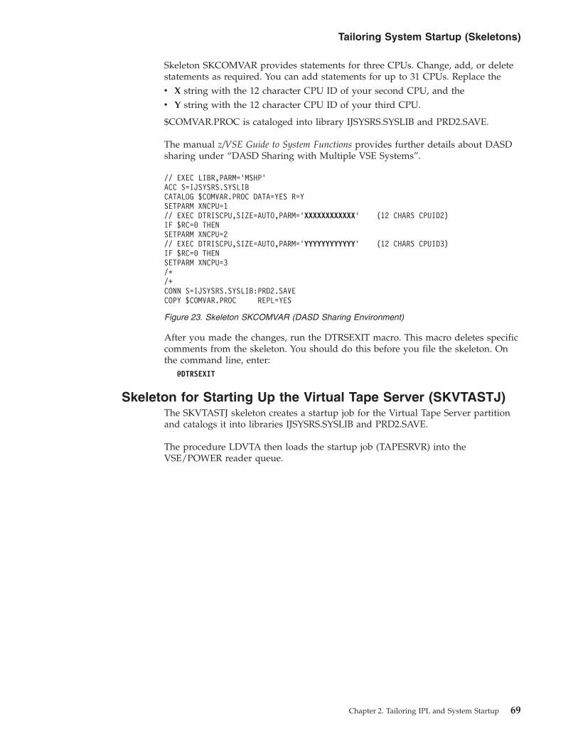
Skeleton SKCOMVAR provides statements for three CPUs. Change, add, or deletestatements as required. You can add statements for up to 31 CPUs. Replace thev X string with the 12 character CPU ID of your second CPU, and thev Y string with the 12 character CPU ID of your third CPU.
$COMVAR.PROC is cataloged into library IJSYSRS.SYSLIB and PRD2.SAVE.
The manual z/VSE Guide to System Functions provides further details about DASDsharing under “DASD Sharing with Multiple VSE Systems”.
After you made the changes, run the DTRSEXIT macro. This macro deletes specificcomments from the skeleton. You should do this before you file the skeleton. Onthe command line, enter:
@DTRSEXIT
Skeleton for Starting Up the Virtual Tape Server (SKVTASTJ)The SKVTASTJ skeleton creates a startup job for the Virtual Tape Server partitionand catalogs it into libraries IJSYSRS.SYSLIB and PRD2.SAVE.
The procedure LDVTA then loads the startup job (TAPESRVR) into theVSE/POWER reader queue.
// EXEC LIBR,PARM=’MSHP’ACC S=IJSYSRS.SYSLIBCATALOG $COMVAR.PROC DATA=YES R=YSETPARM XNCPU=1// EXEC DTRISCPU,SIZE=AUTO,PARM=’XXXXXXXXXXXX’ (12 CHARS CPUID2)IF $RC=0 THENSETPARM XNCPU=2// EXEC DTRISCPU,SIZE=AUTO,PARM=’YYYYYYYYYYYY’ (12 CHARS CPUID3)IF $RC=0 THENSETPARM XNCPU=3/*/+CONN S=IJSYSRS.SYSLIB:PRD2.SAVECOPY $COMVAR.PROC REPL=YES
Figure 23. Skeleton SKCOMVAR (DASD Sharing Environment)
Tailoring System Startup (Skeletons)
Chapter 2. Tailoring IPL and System Startup 69

If you wish, you can replace CLASS=R with another class.
After you make the changes, run the DTRSEXIT macro. This macro deletes specificcomments from the file. You should do this before you file the skeleton. On thecommand line, enter:
@DTRSEXIT
The skeleton includes additional $$ characters. They are needed to mask offVSE/POWER JECL statements. Program DTRIINIT, described in the manual z/VSESystem Utilities under “DTRIINIT Utility”, replaces $$ characters withVSE/POWER JECL statements for cataloging.
Skeleton for Starting Up VSE Connector Server (SKVCSSTJ)The SKVCSSTJ skeleton creates a startup job for the VSE Connector Serverpartition and catalogs it into libraries IJSYSRS.SYSLIB and PRD2.SAVE.
The procedure LDVCS then loads the startup job (STARTVCS) into theVSE/POWER reader queue.
* $$ JOB JNM=CATSTVTA,DISP=D,CLASS=0// JOB CATSTVTA CATALOG TAPESRVR AND LDVTA, LOAD TAPESRVR// EXEC LIBR,PARM=’MSHP’ACC S=IJSYSRS.SYSLIBCATALOG TAPESRVR.Z REPLACE=YES$$$$ JOB JNM=TAPESRVR,DISP=L,CLASS=R,LOG=NO$$$$ LST CLASS=A,DISP=D,PURGE=0004,RBS=500// JOB TAPESRVR START UP VSE TAPE SERVER// ID USER=VCSRV// OPTION SYSPARM=’00’// LIBDEF *,SEARCH=(PRD2.CONFIG,PRD1.BASE,PRD2.SCEEBASE)// EXEC $VTMAIN,SIZE=$VTMAIN$$/*$$/&$$$$ EOJ/+CATALOG LDVTA.PROC REPLACE=YES DATA=YES// EXEC DTRIINIT
LOAD TAPESRVR.Z/*/+CONNECT S=IJSYSRS.SYSLIB:PRD2.SAVECOPY TAPESRVR.Z REP=YES/*// EXEC PROC=LDVTA TO LOAD TAPE SERVER INTO RDR QUEUE/&* $$ EOJ
Figure 24. Skeleton SKVTASTJ (Starting Up Virtual Tape Server)
Tailoring System Startup (Skeletons)
70 z/VSE V4R3.0 Administration

If you wish, you can replace CLASS=R with another class.
After you make the changes, run the DTRSEXIT macro. This macro deletes specificcomments from the file. You should do this before you file the skeleton. On thecommand line, enter:
@DTRSEXIT
The skeleton includes additional $$ characters. They are needed to mask offVSE/POWER JECL statements. Program DTRIINIT, described in the manual z/VSESystem Utilities under “DTRIINIT Utility”, replaces $$ characters withVSE/POWER JECL statements for cataloging.
* $$ JOB JNM=CATSTVCS,DISP=D,CLASS=0// JOB CATSTVCS CATALOG STARTVCS AND LDVCS, LOAD STARTVCS// EXEC LIBR,PARM=’MSHP’ACC S=IJSYSRS.SYSLIBCATALOG STARTVCS.Z REPLACE=YES$$$$ JOB JNM=STARTVCS,DISP=L,CLASS=R$$$$ LST CLASS=A,DISP=D// JOB STARTVCS START UP VSE CONNECTOR SERVER// ID USER=VCSRV* WAITING FOR TCP/IP TO COME UP// EXEC REXX=IESWAITR,PARM=’TCPIP00’// LIBDEF *,SEARCH=(PRD2.CONFIG,PRD1.BASE,PRD2.SCEEBASE)// OPTION SYSPARM=’00’// EXEC IESVCSRV,PARM=’DD:PRD2.CONFIG(IESVCSRV.Z)’$$/*$$/&$$$$ EOJ/+CATALOG LDVCS.PROC REPLACE=YES DATA=YES// EXEC DTRIINIT
LOAD STARTVCS.Z/*/+CONNECT S=IJSYSRS.SYSLIB:PRD2.SAVECOPY STARTVCS.Z REP=YES/*// EXEC PROC=LDVCS TO LOAD VCS STARTUP INTO RDR QUEUE/&* $$ EOJ
Figure 25. Skeleton SKVCSSTJ (Starting Up VSE Connector Server)
Tailoring System Startup (Skeletons)
Chapter 2. Tailoring IPL and System Startup 71

72 z/VSE V4R3.0 Administration

Chapter 3. Modifying Predefined Environments
For a detailed description of the predefined environments provided by z/VSE,refer to the manual z/VSE Planning under “Predefined System Environments”.
This chapter discusses:v Modifying library search chainsv Changing use of static partitionsv Modifying static partition allocationsv Moving to another environmentv Modifying dynamic partition support
Modifying Library Search ChainsYou can modify the library search chains for partitions controlled by VSE/POWER:1. Copy skeleton SKLIBCHN to your VSE/ICCF primary library. Refer to
“Skeleton for Defining Library Search Chains (SKLIBCHN)” on page 58 fordetails about the skeleton.
2. In the skeleton, modify the LIBDEF statements by adding your sublibraries inthe correct sequence.
3. Copy skeleton SKENVSEL to your VSE/ICCF primary library. Modify it tocatalog your changes in skeleton SKLIBCHN. Refer to “Skeleton for CatalogingStartup Changes (SKENVSEL)” on page 37 for details about skeletonSKENVSEL.
Changing Use of Static PartitionsTo have a program run in another static partition, proceed as follows:1. In CPUVARn.PROC, set the system variables XUSEyy and XSTATyy as required
for the partitions involved via program DTRSETP. The manual z/VSE SystemUtilities describes program DTRSETP under “DTRSETP Utility” in detail.If you use a different partition for a CICS system, you must also change thevariable XAPPLyy in CPUVARn which defines the application name for a CICSsystem. yy defines the partition used.
2. If necessary, modify the JCL startup procedures and the startup job(s) involved.If possible, use the skeletons provided. Also, if necessary, delete obsoletestartup jobs in the VSE/POWER reader queue and update procedureCOLDJOBS via skeleton SKCOLD.
3. Modify the partition allocations as needed. If possible, use the skeletonsprovided. Refer to “Modifying Static Partition Allocations” on page 74 fordetails.
4. Modify the VSE/POWER autostart statements in the POWSTRTn procedure.Use skeleton SKPWSTRT.
5. If required, put PARSTD labels into the STDLABUS procedure. Use skeletonSTDLABUS. “Creating Standard Labels for Non-VSE/VSAM User Files” onpage 230 describes skeleton STDLABUS.
6. If required, modify or add library search chain. Use skeleton SKLIBCHN whichis described under “Skeleton for Defining Library Search Chains (SKLIBCHN)”on page 58.
© Copyright IBM Corp. 1984, 2010 73

7. You may want to change VSE/POWER job classes. They are defined in thePOWSTRTn procedure and in the startup jobs in the VSE/POWER readerqueue. Use the appropriate skeletons (SKPWSTRT, SKCICS, and SKVTAM).
8. If required, ask the operator to enter a PRTY command or change the JCLprocedures accordingly. This may be necessary since the priorities for theprograms running in the partitions are now different from those specified in$0JCL or your own procedure.
Modifying Static Partition AllocationsDepending on your environment selected during initial installation (A, B, or C),you must use one of the following skeletons:
SKALLOCA = 12 static partitions (small system)SKALLOCB = 12 static partitions (medium system)SKALLOCC = 12 static partitions (large system)
You can vary the partition sizes within the boundaries of the VSIZE specified forthe predefined environment selected. Refer to the manual z/VSE Planning under“Selecting a Predefined Environment” for the VSIZE values of the predefinedenvironments. You can increase the VSIZE via the Tailor IPL Procedure dialog whichmay also mean that a change in the DPD definitions of the IPL procedure isrequired.
To change partition allocations, perform the following steps:1. Copy the corresponding SKALLOCx skeleton to your primary VSE/ICCF
library and modify the copied skeleton as needed. Refer to “Skeletons for StaticPartition Allocations” on page 38 for details about these skeletons.If you change the procedure name ALLOC in the CATALOG statement, youmust use the new name as input for skeleton SKJCL0. In the skeleton, changethe EXEC PROC statement for the allocation procedure accordingly. Refer to“Skeletons for Starting Up BG Partition” on page 42 for details on skeletonSKJCL0.
2. If you change the default procedure name $0JCL in the CATALOG statement ofSKJCL0, you must specify the new name also in the $ASIPROC masterprocedure (if you created one) or the operator must enter it during IPL.
3. Copy skeleton SKENVSEL to your primary VSE/ICCF library and modify it tocatalog your changes.Refer to “Skeleton for Cataloging Startup Changes (SKENVSEL)” on page 37for details on skeleton SKENVSEL.
4. Submit the job stream created for processing.
Notes:
1. You can change the partition size temporarily with the ALLOC command. Referto the manual z/VSE System Control Statements under “ALLOC” for detailsabout this command.
2. For the changes introduced with VSE/ESA 1.3 concerning ALLOC R, refer to“Skeletons for Static Partition Allocations” on page 38.
Moving to Another EnvironmentMoving to another environment involves a number of tailoring tasks. These varyaccording to your special system requirements. Consider the following as aguideline that helps you define the tailoring tasks to be performed for creating aspecific environment.
Modifying Predefined Environments
74 z/VSE V4R3.0 Administration

Moving from Predefined Environment A to B/C, or from B to CThe predefined environments provided are described in detail in the manual z/VSEPlanning under “Predefined System Environments”.
To move from predefined environment A to predefined environment B or C,proceed as follows:v For an environment with a larger VSIZE, use the Tailor IPL Procedure dialog to
also define new DPD extents. The dialog gives you hints for how much spaceyou need. Use the Tailor IPL Procedure dialog (which is described under“Tailoring the IPL Procedure” on page 14) also if you want to change other IPLparameters.
v To change existing startup procedures, use the skeletons provided. Copy theskeletons first to your VSE/ICCF primary library.
v Set environment number XENVNR in CPUVAR1.PROC by running programDTRSETP in the BG partition:// EXEC DTRSETP,SIZE=AUTO,PARM=’CPUVAR1;;SET XENVNR=n’
where n is the environment number: A, B, or C.Refer to z/VSE System Utilities under “DTRSETP Utility” for details about how touse program DTRSETP.
v Change partition allocations as required by using skeleton SKALLOCn.v Change PASIZE to at least the size of the largest partition.v Change NPARTS, if you wish to define further dynamic partitions.
Moving to an Environment of Your Own DesignIf you want to define an environment of your own design, proceed as follows:1. Use the Tailor IPL Procedure dialog to modify IPL parameters such as virtual
storage (VSIZE) and page data set extents (DPD). For details about the dialog,refer to “Tailoring the IPL Procedure” on page 14.
2. Depending on your requirements you may use one or more of the skeletonsprovided by z/VSE to tailor your startup. For partition allocations, considerusing skeleton SKALLOCA as a sample. Refer to “Using Skeletons for TailoringSystem Startup” on page 36 for details about the skeletons provided.
3. If needed, create or change startup jobs for the partitions. A startup job must beavailable as cataloged procedure in a VSE library. Load the startup jobs into theVSE/POWER reader queue. Use program DTRIINIT which is described indetail in the manual z/VSE System Utilities under “DTRIINIT Utility”.
4. Delete obsolete startup jobs in the VSE/POWER reader queue and updateprocedure COLDJOBS (skeleton SKCOLD) if necessary.
Modifying Predefined Environments
Chapter 3. Modifying Predefined Environments 75

Modifying the Dynamic Partition SupportIf you plan to use dynamic partitions, you should first consult the manual z/VSEPlanning under “Planning for Dynamic Partition Support”. It discusses planningaspects to be considered before using this support.
Notes:
1. The maximum number of dynamic classes per table is 23.2. The maximum number of dynamic class tables is 36.
Predefined environments A, B, and C provide dynamic partition support. If youwant to modify this support or create a dynamic partition environment of yourown, follow the steps outlined below. All steps can be performed while yoursystem is running and are described in detail on the following pages.1. Tailor the IPL Procedure via the Tailor IPL Procedure dialog.2. Catalog the JCL startup procedure for a dynamic partition class via skeleton
SKJCLDYN.3. Tailor the VSE/POWER startup procedure via skeleton SKPWSTRT to have a
specific dynamic class table be loaded automatically during startup.4. Define one or more dynamic class tables via the Maintain Dynamic Partitions
dialog according to your requirements.
You can activate a dynamic class table with the PLOAD command of VSE/POWERor have it activated automatically during startup (step 3).
Tailoring the IPL ProcedureUse the Tailor IPL Procedure dialog (as described under “Tailoring the IPLProcedure” on page 14) if you want to change IPL parameters such as:v NPARTS (IPL SYS command)
Defines the total number of partitions (static and dynamic) you want to use. Youcan increase the number of dynamic partitions but not of static partitions (wherethe maximum is 12). The maximum number of dynamic partitions possibledepends on the user environment. A theoretical value is 150 - 200.
v VSIZE (IPL supervisor parameters command)If you want to increase this value, you must also increase the values in the IPLDPD commands for the page data set extents. Consult the manual z/VSEPlanning under “z/VSE Disk Layouts” for the layout of DOSRES and SYSWK1on the various disk device types.
Note: You must ensure that no overlap occurs with other files when enlargingor relocating the page data set extents.
Depending on the number of the dynamic partitions you are going to use, theremay also be a need to increase the GETVIS area. GETVIS is a parameter of the IPLSVA command. To activate your IPL changes, you must re-IPL the system.
Cataloging JCL Startup ProceduresFor each dynamic class defined in the dynamic class table you must also define astartup procedure. This procedure is processed each time a dynamic partition iscreated. You may use the same procedure for more than one dynamic class. Tocatalog such a procedure, use skeleton SKJCLDYN which includes a sampleprofile. The layout of the skeleton SKJCLDYN is shown below.
Modifying Dynamic Partition Support
76 z/VSE V4R3.0 Administration

You find the name of the procedure (STDPROF) under PROFILE in Figure 27 onpage 78. For details about procedure LIBDEF refer to “Skeleton for DefiningLibrary Search Chains (SKLIBCHN)” on page 58.
After you have modified skeleton SKJCLDYN, enter the following command fromthe editor's command line:@DTRSEXIT
This command calls a macro which deletes specific comments from the file. Youshould do this before filing the skeleton. Use skeleton SKENVSEL (shown under“Skeleton for Cataloging Startup Changes (SKENVSEL)” on page 37) for catalogingyour changes.
Tailoring VSE/POWER Startup ProcedureActivate or modify the PLOAD command in skeleton SKPWSTRT to have therequired dynamic class table automatically loaded during startup. For details aboutskeleton SKPWSTRT refer to “Skeleton SKPWSTRT” on page 51.
Activating a Dynamic Class TableThis step is not required if the operator will activate the dynamic class table at theconsole via the VSE/POWER command:PLOAD DYNC,ID=n,FORCE
n identifies the table and FORCE ensures that even in case of wrong classdefinitions those classes which are correctly specified are activated.
Defining Dynamic Class Tablesz/VSE allows you to define up to 36 dynamic class tables. The name of thepredefined table shipped is DTR$DYNC.
To define dynamic class tables, you use the Maintain Dynamic Partitions dialog. Thedialog updates members DTR$DYNn.Z in system library IJSYSRS.SYSLIB whenpressing PF5 on the panels shown later. For a detailed description of memberDTR$DYNn.Z, refer to the manual z/VSE Planning .
CATALOG STDPROF.PROC DATA=YES REPLACE=YES// LIBDEF DUMP,CATALOG=SYSDUMP.DYN,PERM ASSIGN SYSDUMP FOR DYN.PART.// OPTION NODUMP// EXEC PROC=LIBDEF DEFINE THE PERMANENT LIBRARY SEARCH CHAIN// SETPFIX LIMIT=48KASSGN SYSIN,FECASSGN SYSPCH,FEDASSGN SYSLST,FEEASSGN SYSLNK,DISK,VOL=DOSRES,SHR SYSTEM LINK FILEASSGN SYS001,DISK,VOL=SYSWK1,SHR SYSTEM WORK FILE 1ASSGN SYS002,DISK,VOL=SYSWK1,SHR SYSTEM WORK FILE 2ASSGN SYS003,DISK,VOL=SYSWK1,SHR SYSTEM WORK FILE 3ASSGN SYS004,DISK,VOL=SYSWK1,SHR SYSTEM WORK FILE 4
. DEFINE YOUR OWN ASSIGNS IF NEEDED
. ADD DLBL AND EXTENT STATEMENTS HERE IF NEEDED/+CONNECT S=IJSYSRS.SYSLIB:PRD2.SAVECOPY STDPROF.PROC REPLACE=YES
Figure 26. Skeleton SKJCLDYN
Modifying Dynamic Partition Support
Chapter 3. Modifying Predefined Environments 77

To access the dialog, start with the z/VSE Function Selection panel and select:2 (Resource Definition)7 (Maintain Dynamic Partitions)
The dialog identifies invalid entries by displaying 2 or 5 in the OPT column of thepanel shown in Figure 27. This may also happen when the dialog is reactivatedand validity checking on a higher level is possible.
You get first panel TAS$DYNA listing the dynamic class tables defined for thesystem. With this panel you can add, alter or delete dynamic class tables. You candefine up to 36 dynamic class tables with up to 23 dynamic classes per table. Ifyou enter option 1 (to add a new table) next to an existing table, the specificationsof the dynamic classes are used as default for the new table. First, you must definea name (DTR$DYNX in the example) for the new table in panel TAS$DYN3 beforepanel TAS$DYN1 is displayed.
If you enter option 1 (in panel TAS$DYN1) to add a new class definition you getthe panel shown in Figure 28 on page 79. The system displays default values if youselected an empty line. If you selected an already defined class, as in the example,the dialog uses this class and its parameters as a model for the new class.
TAS$DYN1 MAINTAIN DYNAMIC PARTITIONS
Enter option(s) and press enter.
Dynamic class table : DTR$DYNXOPTIONS: 1 = ADD 2 = ALTER 5 = DELETEOPT DYNAMIC ENABLED MAX NO. OF STORAGE MAXIMUM DYNAMIC PROFILE
CLASS 1=YES PARTITIONS ALLOCATION PROGRAM SPACE2=NO SIZE GETVIS
_ C 1 9 1M 500K 128K STDPROF_ P 1 32 1M 512K 128K PWSPROF_ R 1 3 8M 1024K 128K STDPROF_ S 1 2 15M 1024K 128K STDPROF_ Y 1 8 5M 1024K 128K STDPROF_ Z 1 3 5M 1024K 128K STDPROF
PF1=HELP 2=REDISPLAY 3=END 5=PROCESS
Figure 27. Maintain Dynamic Partitions (TAS$DYN1)
Modifying Dynamic Partition Support
78 z/VSE V4R3.0 Administration

Description of parameters:
DYNAMIC CLASSSpecifies the class to which a dynamic partition belongs. Except for theletters A, B, and F you can use all letters of the alphabet.
NUMBER OF PARTITIONSSpecifies the maximum number of partitions belonging to the same class.
STORAGE ALLOCATIONSpecifies the virtual storage available for a dynamic partition. Theallocation includes the dynamic space GETVIS area:storage allocation = partition allocation + dynamic space GETVIS area
The maximum partition allocation calculates as follows:2GB - size of shared areas - size of dynamic space GETVIS area
2GB is the maximum address space size possible. The shared areas includeshared partitions, system GETVIS area, and the area in which thesupervisor resides.
MAXIMUM PROGRAM SIZESpecifies the amount of contiguous virtual storage in a dynamic partitionreserved for program execution.
DYNAMIC SPACE GETVISSpecifies the size of the dynamic space GETVIS area of a partition. Thisarea can be considered as an extension of the system GETVIS area. In thechapter “Storage Management” of the manual z/VSE Guide to SystemFunctions you find details about the layout of dynamic partitions includingGETVIS areas.
ENABLEDSpecifies whether the dynamic class is to be enabled when a PLOADcommand for activating the dynamic class table is processed byVSE/POWER.
PROFILESpecifies the name of the JCL startup procedure which is to be processedeach time VSE/POWER activates (creates) a dynamic partition of this class.
TAS$DYN2 MAINTAIN DYNAMIC PARTITIONS
Enter the required data and press ENTER.
DYNAMIC CLASS.......... Enter one of the classes C - E, G - ZNUMBER OF PARTITIONS... 8 Enter a number between 1 and 32STORAGE ALLOCATION..... 2M Specify in M bytesMAXIMUM PROGRAM SIZE... 1024K Specify in K or M bytesDYNAMIC SPACE GETVIS... 128K Specify in K bytesENABLED................ 1 1=YES, 2=NOPROFILE................ STDPROF Name of the JCL procedureNUMBER OF LOGICAL UNITS 50 Enter a number between 10 - 255
READER DEVICE.......... FECLIST OF PRINTER DEVICES FEE ___ ___ ___ ___ ___ ___
___ ___ ___ ___ ___ ___ ___
LIST OF PUNCH DEVICES.. FED ___ ___ ___ ___ ___ ______ ___ ___ ___ ___ ___ ___
PF1=HELP 2=REDISPLAY 3=END
Figure 28. Maintain Dynamic Partitions (TAS$DYN2)
Modifying Dynamic Partition Support
Chapter 3. Modifying Predefined Environments 79

NUMBER OF LOGICAL UNITSSpecifies the maximum number of programmer logical units which can beallocated to each dynamic partition of this class.
READER DEVICESpecifies the address of the spooled reader device for the dynamicpartitions of this class.
LIST OF PRINTER DEVICESSpecifies the address(es) of the spooled printer device(s) for the dynamicpartitions of this class.
LIST OF PUNCH DEVICESSpecifies the address(es) of the spooled punch device(s) for the dynamicpartitions of this class.
Modifying Dynamic Partition Support
80 z/VSE V4R3.0 Administration

Chapter 4. Configuring Non-Communication Devices
This chapter describes how to use the Configure Hardware dialog for configuringnon-communication devices such as:v disk devices,v tape devices,v printers.
It contains these main topics:v “Introduction”v “Using the Configure Hardware Dialog” on page 82v “Adding a Non-Communication Device” on page 83v “Changing or Deleting a Non-Communication Device Specification” on page 87
Related Topic:
For details of how to ... Refer to ...
configure communication devices such as OpenSystems Adapters devices (OSA Express, OSA-2),communication controllers, display stations, andpersonal computers
z/VSE Networking Support, SC33-8311
configure tape libraries using z/VSE's Tape LibrarySupport (TLS)
Chapter 18, “Implementing TapeLibrary Support,” on page 251.
IntroductionDuring initial installation, you completed hardware configuration after signing onwith the POST user-ID. This is described in detail in the manual z/VSE Installationunder “Installation Part 3 - Native and VM”.
However, you can add, change, or delete devices on your system at any time. Usethe Configure Hardware dialog to add or delete hardware addresses and to specifydevice characteristics.
By using the dialog as described in this topic, you can create a list that shows allthe devices (and addresses) which are part of your system. Such a configurationlist helps you control the hardware attached to your system. You should create anew list whenever a hardware change is implemented. To create a configurationlist for your installation, perform the following steps:1. Start with the z/VSE Function Selection panel and select Fast Path 241. You get
the panel Hardware Configuration: Unit Address List.2. Press PF9 (PRINT). On the panel displayed you can select the type of
configuration list you want; SNA or non-SNA terminal list, for example. Afterselecting one or more lists, press ENTER.
3. The configuration list(s) created are stored as library member CONFLIST inyour VSE/ICCF primary library.
4. You can print the library member by selecting option 3 (PRINT) in the FULISTdisplay of your primary library. The output is placed in the VSE/POWER listqueue for printing.
© Copyright IBM Corp. 1984, 2010 81

Using the Configure Hardware DialogStart with the z/VSE Function Selection panel and select Fast Path 241. The HardwareConfiguration: Unit Address List panel is displayed. It is shown in Figure 29.
The unit address list consists of one or more panels. It shows all VSE and physicaldevice addresses, and the related devices as defined for your z/VSE system.v The VSE ADDR column contains a list of the VSE addresses (cuu). By default,
the displayed information is based upon a sort of this VSE address list.v The PHYSICAL ADDR column contains a list of the physical addresses (pcuu)
that were defined in the IOCDS or z/VM configuration. If the address is FFF orless, a zero is automatically inserted at the start of the address.
v An 'X' in the column DEVICE DOWN indicates for a tape or disk device thatthis device is not available. By selecting 3 (SELECT FOR FURTHERPROCESSING), this status can be changed.
v An 'X' in the column DEF INCOMPL (definition incomplete) indicates that youshould specify additional details for that particular device address.
Note: To change the VSE address of a device, you must first delete the device(using 5 = DELETE A DEVICE), and then re-add it with a new VSE addressbut with the same physical address (using PF6=ADD ADDR).
Various options and PF-key functions allow you to maintain your hardwareconfiguration. They are listed below.
OPTIONS:
2 = ALTER DEVICE TYPE CODE/MODESelect option 2 if you want to change the Device Type Code, or the DeviceSpecification Mode.
3 = SELECT FOR FURTHER PROCESSINGSelect option 3 if you want to change or add device characteristics other thanDevice Type Code or Device Specification Mode.
ADM$HDWB HARDWARE CONFIGURATION: UNIT ADDRESS LIST
OPTIONS: 2 = ALTER DEVICE TYPE CODE/MODE 3 = SELECT FOR FURTHER PROCESSING4 = LIST SIMILAR DEVICES 5 = DELETE A DEVICE
OPT VSE PHYSICAL DEVICE DTYPE DEVICE DEVICE DEFADDR ADDR CODE MODE DOWN INCOMPL
_ 009 0009 3270CONS 3277_ 00C 000C 2540-R 2540R_ A11 1A11 3390-X ECKD_ A12 1A12 3390-X ECKD_ D01 3D01 3592-E06 TPA11K 08_ D02 3D02 3592-E06 TPA11K 08_ D03 3D03 3592-E06 TPA11K 08_ D10 1D10 3390-X ECKD_ D11 1D11 3390-X ECKD_ D12 1D12 3390-X ECKD_ D14 1D14 3390-X ECKD
POSITION NEAR ADDR == > ___PF1=HELP 2=REDISPLAY 3=END 5=PROCESS 6=ADD ADDR
8=FORWARD 9=PRINT 10=SORT PHY
Figure 29. Unit Address List of Hardware Configuration Dialog
Non-Communication Devices
82 z/VSE V4R3.0 Administration
4 = LIST SIMILAR DEVICESSelect option 4 if you want only devices displayed that belong to a particulargroup. All disk devices or tapes for example.
5 = DELETE A DEVICESelect option 5 if you want to delete a device (including both the physicaladdress and VSE address) from the device address list.
POSITION NEAR ADDR:
This selection allows you to position FULIST close to an address. This address canbe either a VSE address (when the list is sorted by the VSE address), or a physicaladdress (when the list is sorted by the physical address). To skip to the top or tothe bottom of the fulist, you can use either:v 0 or FFF (where list is sorted by the VSE address).v 0 or FFFF (where list is sorted by the physical address).
The input in this field is ignored when you press a PF key.
PF Keys:
5=PROCESSPress PF5 if you have done all your changes using the options 2, 3, 5 or 6, orPF6.
6=ADD ADDRWith PF6 you add a new address (device) to your hardware configuration.Depending on the type of device, several panels are displayed. You have toselect the device you want to add to your installation and enter all devicespecific information required.
9=PRINTUse PF9 to get a printout of the device address list. If you then enter an 'X' nextto an entry in the list, a library member CONFLIST is created in yourVSE/ICCF primary library containing the appropriate listing.
10=SORT PHY or 10=SORT VSEUse PF10 to display the information based upon a sort of the physical addresslist, or based upon the VSE address list.
Adding a Non-Communication DeviceFor most device parameters the system creates and uses defaults. But you must atleast know the device type and device address before you can add a new device.
Let us assume that an IBM tape device of type 3592 Model E06 is to be added thathas:v “Physical” device addresses (pcuu) that are defined in the IOCDS, in the range
X'3D01' to X'3D03'.v Corresponding z/VSE addresses (cuu) in the range X'D01' to X'D03'.
The following steps are required:1. Use Fast Path 241 from the z/VSE Function Selection panel. This gives you the
first page of Hardware Configuration: Unit Address List. Figure 29 on page 82shows this panel.
2. Press PF6. You get the panel Hardware Configuration: Add a Device. Now entera. The (physical) starting address 3D01.
Non-Communication Devices
Chapter 4. Configuring Non-Communication Devices 83

b. The (physical) end address 3D03.c. The VSE starting address D01.d. The VSE end address will be automatically calculated by z/VSE. Leave this
field blank.e. The device name (3592-E06). Instead of entering the device name, you can
enter a '?' to display the selection panel for the Device Groups. In this panel,enter:
7 (Tape Units)Press ENTER.
3. You get the Selection List: Devices panel showing all tape devices supported byz/VSE. Select the correct device type:
1 (3592-E06)Press ENTER.The system redisplays panel Hardware Configuration: Unit Address List with thenewly added device.
4. Press PF5 to process (catalog) the updated hardware configuration. You get thepanel Hardware Configuration: Catalog Startup Members shown in Figure 30. Inthis panel, those startup members are marked by an 'X' which are affected bythe change. In our example: IPL Procedures.Press ENTER.
5. You get the Job Disposition panel to submit the job to batch, file it in yourVSE/ICCF primary library, or both.
For the example user here, the following statements will now be included in theIPL procedure:ADD 3D01:3D03 AS D01:D03,TPA11K,08
Device ConsiderationsFor most non-communication devices you only have to select the device type andenter the cuu address. The other device characteristics are known to the system.
ADM$CRE1 HARDWARE CONFIGURATION: CATALOG STARTUP MEMBERS
Press ENTER to catalog the objects marked by an X. You may add or deletean X as needed.
X IPL Procedures_ VTAM Book with Startup Options_ VTAM Books for Model Terminal Support_ VTAM Book for Local Non-SNA Terminals_ VTAM Book Local SNA Terminals_ VTAM Books for OSA or 3172 attached Terminals_ CICS CSD Group for terminals - VSETERM1_ CICS CSD Group for terminals - VSETERM2_ CICS CSD Group for terminals - VSETERM3
PF1=HELP 2=REDISPLAY 3=END
IPLPROC SOURCE CREATED.
Figure 30. Panel for Cataloging Startup Members (Hardware Configuration)
Non-Communication Devices
84 z/VSE V4R3.0 Administration

For disk devices and the IBM 3820 printer further panels prompt you foradditional device characteristics. For tape devices, you can change and defineadditional characteristics with the SETMOD attention command.
You can also change the mode using option 2 (ALTER DEVICE TYPECODE/MODE) on the Hardware Configuration: Unit Address List panel.
Disk Devices (Including FBA-SCSI Disks)It is recommended that you initialize a disk device before you add it to yoursystem. Under “Initializing Disks and Placing the VTOC”, the manual z/VSEInstallation has details on how to initialize disk devices.
When you enter a disk device type, you get the panel Hardware Configuration: DiskList showing the disk devices specified and two columns with the optionsSHARED and DEVICE DOWN.v SHARED
Enter an X for those disk devices you want to share across systems. Thefollowing types of IBM disk devices can be used for (DASD) sharing:
33803390FBAFBA-SCSI
v DEVICE DOWNEnter an X for those disk devices that are not available (or should not beavailable) for operation.In a shared environment in which the volume labels are not unique, DEVICEDOWN may be required to prevent the system from accessing the wrong devicewhen being addressed by volume label (VOLID).
Configuring FBA-SCSI DisksThe procedure for configuring FCP-attached SCSI disks (FBA-SCSI disks) isdescribed in Chapter 5, “Configuring Your System to Use SCSI Disks,” onpage 89. This procedure is based upon a practical example that covers allaspects of configuring for SCSI use.
Tape DevicesFor the IBM 3480 and IBM 3490 the Configure Hardware dialog offers two choicesfor device definition: one with data compaction, one without. For details aboutdata compaction, refer to the ADD command in the manual z/VSE System ControlStatements under “ADD”.
For the IBM 3590 the Configure Hardware dialog offers three choices for devicedefinition: with 128, 256, or 384 track capacity.
For the IBM 3592 the Configure Hardware dialog offers the:v 512 track capacity for Model J1A.v 896 track capacity for Model E05 (also called the IBM System Storage TS1120).v 1152 track capacity for Model E06 (also called the IBM System Storage TS1130).
With option 2 (ALTER DEVICE TYPE CODE/MODE) the default mode setting canbe changed. With option 3 (SELECT FOR FURTHER PROCESSING) the status of atape device can be set to DEVICE DOWN (and reset).
Non-Communication Devices
Chapter 4. Configuring Non-Communication Devices 85

Automated Tape Library SupportWhen using an IBM 3494 or 3584 tape library, it is necessary to request theautomated tape library support in the IPL SYS command with the parameter ATL.
You can use the Tailor IPL Procedure dialog for setting ATL. You must also changethe sample job TLSDEF to meet your own system requirements.
For details, see Chapter 18, “Implementing Tape Library Support,” on page 251.
IBM 3820 PrinterWhen you specify an IBM 3820 printer you have to define VTAM parametersassociated with the printer. You define such parameters via the HardwareConfiguration: SNA Logical Unit List panel.
You must provide the VTAM parameter LOGAPPL; for the parameters LOCALADDRESS, VTAM PARM TABLE, and LUNAME the system provides defaults.
Support of AFP PrintersYou define printers for Advanced Function Printing (AFP) as any other printer viathe Configure Hardware dialog. The IBM 3800-3, IBM 3825, and IBM 3827 areexamples of such printers. To make use of their advanced functions, these printersrequire in addition the optional program PSF/VSE (Print Services Facility/VSE).z/VSE provides procedures and skeletons which support the installation and useof PSF/VSE. An example is the VSE/POWER startup procedure POWSTRTn whichyou can modify via skeleton SKPWSTRT. For details refer to “SkeletonSKPWSTRT” on page 51.
Virtual Disk for Label Areaz/VSE provides a virtual disk with address FDF for holding the label area.
Considerations for Dummy DevicesYou can change but not delete the following VSE/POWER and VSE/ICCF dummydevices: FED, FEE, FEF, FFD, FFE.
You cannot change or delete the following VSE/POWER and VSE/ICCF dummydevices: FEC, FFA, FFC.
You cannot change or delete the dummy device FFF which is a place holder for adedicated system console.
Non-Communication Devices
86 z/VSE V4R3.0 Administration

Changing or Deleting a Non-Communication Device SpecificationUse panel Hardware Configuration: Unit Address List. You get to it by selecting FastPath 241 from the z/VSE Function Selection panel.
Enter 2 (Alter Device Type Code/Mode) in the option column if you want tochange the device type code or mode of a device. Enter 5 (Delete a Device) if youwant to delete a device.
Enter 3 (Select for Further Processing) in the option column if you want to changeother device characteristics. Note that the following non-communication deviceshave characteristics that can be changed with option 3:v Disk devices.v Tape devicesv IBM 3820 printer.
After you have changed device characteristics or selected deletion, proceed asshown in steps 4 and 5 for “Adding a Non-Communication Device” on page 83.
Non-Communication Devices
Chapter 4. Configuring Non-Communication Devices 87

88 z/VSE V4R3.0 Administration

Chapter 5. Configuring Your System to Use SCSI Disks
This chapter describes how you configure your z/VSE system to useFibre-Channel-attached SCSI (Small Computer System Interface) disks.
It contains these main topics:v “Overview of the z/VSE Support for SCSI Disks” on page 90v “Prerequisites for Using SCSI Disk Support” on page 90v “Restrictions When Using SCSI Disk Support” on page 91v “Restrictions When Using VSAM Files On SCSI Disks” on page 91v “Limitations When Defining SCSI Disks During IPL” on page 92v “Storage Requirements When Using SCSI Disks” on page 92v “Space Requirements When SCSI Is Used As a System Disk” on page 92v “Characteristics of a SCSI Disk” on page 92v “Migration Considerations for SCSI Disks” on page 93v “Configuring FCP Adapters, SCSI Disks, and Connection Paths” on page 93v “Using Multipathing to Access SCSI Disks” on page 104v “Using Shared SCSI Disks” on page 105v “Using the Attention Routine OFFLINE / ONLINE Commands” on page 107v “Performing an IPL of z/VSE From a SCSI Disk” on page 107v “Errors That Might Occur During Configuration” on page 110
Related Topics:
For details of ... Refer to ...
the disk layouts of DOSRES SCSI andSYSWK1 SCSI disks
“z/VSE Disk Layouts (DOSRES, SYSWK1)”in the z/VSE Planning, SC33-8301.
v how to use SCSI disks under z/VMv how to IPL from a SCSI disk when
running z/VSE under VM
“Running z/VSE Under VM” in the z/VSEPlanning, SC33-8301.
how to define a lock file on a SCSI disk. “Changing Startup When Lock File Is StoredOn SCSI DASD” on page 34.
Please Note That!The term FBA-SCSI disk is also used to refer to a SCSI disk.
© Copyright IBM Corp. 1984, 2010 89

Overview of the z/VSE Support for SCSI DisksThe objective of z/VSE Small Computer System Interface (SCSI) disk support is tooffer clients more storage choices as well as help lower Total Cost of Ownership(TCO). Therefore from z/VSE 3.1 onwards, z/VSE has been developed to enableselected SCSI disks to be attached, in addition to Extended Count-Key-Data(ECKD) and Fixed Block Architecture (FBA) disks.
These disk controllers are qualified to be used with z/VSE SCSI support:v IBM System Storage DS8000® and DS6000™.v IBM TotalStorage® Enterprise Storage Server® (ESS) Model F20, 800, and 800
Turbo.
The IBM System Storage SAN Volume Controller (SVC) is also qualified to be usedwith z/VSE's SCSI support.
VSE host programs running on IBM System z10™ (z10) and zEnterprise™ 196 (z196)platforms can access Fibre-Channel-attached SCSI disks. Your application programsdo not need to be modified in order to access the SCSI disk devices providingthese programs are either:v Device independent.v Support FBA devices.
Using the appropriate features and service applied to the IBM System z server, it ispossible to IPL z/VSE from a SCSI disk. Therefore, it is possible to build a“SCSI-only” z/VSE system.
SCSI disk devices use Fixed Block (512-bytes) sectors and are defined in z/VSE asFBA devices. They appear to the user as if they were FBA devices. User-writtenprograms use VSE's existing Fixed Block Architecture (FBA) support (512-byteblocks) to access SCSI disks.
z/VSE FCP-attached SCSI disk support complements SCSI support in z/VM®
Version 5 and Linux on System z. When operating as a guest under z/VM (usingthe VM-emulated FBA support), z/VM presents SCSI disks as 9336-20 FBA disks.In this situation, z/VSE “views” them as FBA, not SCSI disks.
z/VSE is designed to support SCSI disk volume sizes from 8 MB to 24 GB. Becausez/VSE itself uses the first 4 MB for internal purposes, the available user space isequal to the defined size of the disk, minus 4 MB.
The z/VSE SCSI disk support includes support for:v Multipathing, which is a method of increasing the availability of the device.v DASD (disk) sharing using the z/VSE lock file on a SCSI device (or any other
supported device).
Note: z/VSE does not support FlashCopy for SCSI-FCP disks.
Prerequisites for Using SCSI Disk SupportIf you wish to attach SCSI disk devices to a z10 or z196 server and access thesedisk devices from z/VSE, you require:v A z10 or z196 server with at least 32 MB of real storage.v An IBM System z FCP adapter with the following microcode levels:
– For z800 and z900 servers, J11233.015 or later
SCSI Disks
90 z/VSE V4R3.0 Administration

– For z890 and z990 servers, J13471.004 or laterv An IBM System z9® or later FCP adapter.v A disk controller. Either:
– an IBM System Storage DS8000 disk controller,– an IBM System Storage DS6000 disk controller,– an Enterprise Storage Server (ESS) disk controller (such as the IBM 2105), or– a SAN Volume Controller (SVC).
- IBM System Storage disk subsystems and OEM SCSI disk devicessupported by the SVC.
v z/VSE Version 3 Release 1 or later.v z/VM 5.2 or later.v If you are not using a point-to-point connection to attach your SCSI disks to the
z/VSE host, you require an FCP switch (such as an IBM 2109).v If you wish to perform an IPL from a SCSI disk:
– CPU Feature Code 9904 must be installed.– For z800 and z900 servers, your microcode level must be EC-Number J12811
or later.– For z890 and z990 servers, your microcode level must be EC-Number J12221
or later.
Restrictions When Using SCSI Disk SupportThere are some restrictions that apply to a SCSI-only system. For example:v A stand-alone dump cannot be created on a SCSI disk. If you wish to create a
stand-alone dump, you must create this dump using a tape or another type ofdisk.
v Your applications running under z/VSE cannot use SCSI commands directly.SCSI support is only available through FBA channel commands.
Special migration restrictions also apply:v VSE/VSAM Backup/Restore is not possible from ECKD to SCSI. You must use
the Import/Export utility to move VSE/VSAM data from ECKD to SCSI disks.v Similar restrictions (as above) apply when migrating from FBA to SCSI.
Restrictions When Using VSAM Files On SCSI Disksv From z/VSE 3.1 onwards, the minimum number of FBA blocks for a VSAM file
is 512 blocks compared with 64 blocks for an FBA device (for example, a z/VMFBA minidisk or a virtual FBA device).
v The maximum size of a VSAM file is 4 GB.v VSAM can use the first 16 GB of a SCSI disk. If a SCSI disk is larger than 16 GB,
the remaining space is not available to VSAM.
Important!For a list of the restrictions that apply when using VSAM structures on SCSIdisks, refer to the manual VSE/VSAM User's Guide and ApplicationProgramming, SC33-8316.
SCSI Disks
Chapter 5. Configuring Your System to Use SCSI Disks 91

Limitations When Defining SCSI Disks During IPLYou can define SCSI disks using either IPL DEF SCSI commands or AR/JCLSYSDEF SCSI statements:v You must use IPL DEF SCSI commands to define SCSI system disks to be used
during IPL (DOSRES, SYSWK1, and disks containing the PDS and lock file).v You can define all other SCSI disks using either IPL DEF SCSI commands or
AR/JCL SYSDEF SCSI statements.
The number of SCSI disks that can be defined using IPL DEF SCSI commands islimited to approximately 100 SCSI disks. However, this number might be lessdepending upon your configuration.
IBM recommends that you define all SCSI disks that are not required during IPLusing AR/JCL SYSDEF SCSI statements.
For further details on how to remove definitions of SCSI disks, refer to the z/VSESystem Upgrade and Service, SC33-8303
Storage Requirements When Using SCSI DisksTo use SCSI with your z/VSE system you require approximately:v 100 KB 31-bit fixed system Getvis storage per FCP device.v 10 KB 31-bit fixed system Getvis storage per SCSI disk device.
Space Requirements When SCSI Is Used As a System DiskThese are the main differences to the DOSRES and SYSWK1 disk layouts whenSCSI is used as a system disk:v The layouts of DOSRES and SYSWK1 are designed to take account of the
minimum number of FBA blocks (512) for a VSAM file. The layouts of FBA-SCSIand FBA disks (for example, a z/VM FBA minidisk or a virtual FBA device) areidentical.
v The space that is available for the master catalog with PRD1 and PRD2 librarieshas been increased.
v The dump library has been increased.
For details of the FBA disk layouts of DOSRES and SYSWK1, refer to the z/VSEPlanning, SC33-8301.
Characteristics of a SCSI DiskSize of SCSI Disks
z/VSE only supports SCSI disks that have a minimum size of 8 MB and amaximum size of approximately 24 GB. 4 MB of a SCSI disk is usedinternally by z/VSE. Therefore, z/VSE restricts your use of each SCSI diskto the actual size minus 4 MB.
Model In z/VSE, SCSI disks are defined as FBA devices and appear to the user asa 9336 Model 20 FBA device.
Block SizeSCSI disks must be configured with a block size of 512 bytes even if thedisk controller allows a larger block size than 512 bytes.
SCSI Disks
92 z/VSE V4R3.0 Administration

ANSI StandardsSCSI disks must support ANSI SCSI Version 3.
FBA CCW Commands Not SupportedThe following CCW commands are not supported by z/VSE, and will beterminated with the “command reject” message (X'80' in sense byte 0):X'02' Read IPLX'14' Unconditional reserveX'C4' Diagnostic sense/read
Migration Considerations for SCSI DisksA VSAM Backup/Restore from FBA to SCSI, or SCSI to FBA, is not possible. Youcan only perform a VSAM Backup/Restore from SCSI to SCSI. To overcome thislimitation, you can use the Import/Export facility to import or export:v FBA to SCSIv SCSI to FBAv CKD/ECKD to SCSIv SCSI to CKD/ECKD
Configuring FCP Adapters, SCSI Disks, and Connection PathsThis topic is based upon the example configurations of Figure 31 on page 94 andFigure 32 on page 95.
The first example in this topic uses a switch, which enables you to create aconfiguration with a high degree of flexibility.
The second example in this topic uses a point-to-point connection, which removes therequirement for a switch. This option is less expensive, but does not provide theflexibility of using a switch.
Example of a SCSI Environment That Uses a SwitchThe example shown in Figure 31 on page 94 and described in “Configuring FCPAdapters, SCSI Disks, and Connection Paths,” provide a practical example of howSCSI disks might be attached to a z/VSE host via a switch.
The SCSI disks can be configured either in an IBM disk controller or an IBM SANVolume Controller (SVC). z/VSE does not distinguish between a SCSI disk that hasbeen configured in the disk controller from a SCSI disk that has been configured inthe SVC.
SCSI Disks
Chapter 5. Configuring Your System to Use SCSI Disks 93

Notes:
1. The configuration shown in Figure 31 includes the physical addresses of the FCPI/O devices. In “Defining FCP Devices, SCSI Disks and Connection Paths toz/VSE” on page 99, the VSE addresses (cuu) that correspond to these physicaladdresses (pcuu) are used by z/VSE.
2. The values used for WWPN and LUN in Figure 31 were taken from a diskcontroller. If an SVC is used instead of a disk controller, the format of thesevalues will be different.
The example configuration shown in Figure 31 consists of:
�1� Two physical System z FCP adapters with CHPIDs (channel path IDs) 9Dand 9E. These physical FCP adapters (CHPIDs) are accessed as devices oftype FCP that have been configured using the IOCP (Input/OutputConfiguration Program). Both physical FCP adapters (CHPIDs) are sharedby the z/VSE systems running in LPAR-1 and LPAR-2. This is shown inthe IOCP statements of Figure 33 on page 97. The physical FCP adapterscan reside on the same FCP card or on different FCP cards (this isdiscussed in “Using Multipathing to Access SCSI Disks” on page 104).
The number of FCP devices that can be defined for each physical FCPadapter depends upon the hardware you are using. In Figure 31:v Sixteen FCP devices have been defined for physical FCP adapter (CHPID
9D) in the range 1FA0 to 1FAF.v Sixteen FCP devices have been defined for physical FCP adapter (CHPID
9E) in the range 1FB0 to 1FBF.
Note: Within one z/VSE system, one FCP device per physical FCP adapteris sufficient for accessing both the FBA-SCSIs DA1 and DA2.
�2� Each physical System z FCP adapter is connected to the FCP switch (which
z/VSE Host
IBM Disk Controller / SVC
FCPSwitch1
23
LPAR-1(ZVSE1)
Adapter
LPAR-2(ZVSE2)
FCP
FCPDevices
(WWPN :see Note 4)
Port-2
Port-1 SCSI Disk
SCSI Disk
(LUN=5600)
(LUN=5601)
1FA0.....
1FAF [DA1]
[DA2]
Notes:
CHPID 9D
AdapterCHPID 9E
FCP
FCPDevices
1FB0.....
1FBF
3. The WWPN is 5005076300CA9A76.
4. The WWPN is 5005076300C29A76.
(WWPN :see Note 3)
(WWPN :see Note 1)
(WWPN :see Note 2)
1. The WWPN is 5005076300C295A5 (required during configuration only).2 The WWPN is 5005076300C695A5 (required during configuration only).
Figure 31. Example of a SCSI Environment Using a Switch
SCSI Disks
94 z/VSE V4R3.0 Administration

might be an IBM 2109 switch) via a physical cable. The advantage of usinga switch is that all ports on the disk controller can be physically accessedfrom FCP devices 1FA0 to 1FAF, and FCP devices 1FB0 to 1FBF.
�3� The first port (Port-1) on the disk controller or SVC has the worldwideport number (WWPN) 5005076300CA9A76. The second port (Port-2) on thedisk controller or SVC has the WWPN 5005076300C29A76. Both ports areconnected to the FCP switch via physical cables. Ports are configured usingthe configuration software provided with the disk controller or SVC. Anexample for a disk controller is provided in “Configuring SCSI Disks in theDisk Controller” on page 97.
A WWPN is a unique 64-bit string (16 hexadecimal numbers) thatrepresents a port.
The disk controller or SVC contains two SCSI disks with the logical unitnumbers (LUN) 5600 and 5601. A LUN represents a SCSI device. TheLUNs have been configured so they can be accessed via both FCPadapters. LUNs are configured using the configuration software providedwith the disk controller or SVC. The cuu addresses DA1 and DA2 are onlyused by z/VSE and are not part of the configuration process for the diskcontroller.
Example of a SCSI Environment That Uses Point-to-PointConnections
The example shown in Figure 32 and described in “Configuring FCP Adapters,SCSI Disks, and Connection Paths” on page 93, provide a practical example of howSCSI disks might be attached to a z/VSE host via point-to-point connections.
Note: The configuration shown in Figure 32 includes the physical addresses of theFCP I/O devices. In “Defining FCP Devices, SCSI Disks and Connection
z/VSE Host
IBM Disk Controller
1
2
LPAR-1(ZVSE1)
Adapter
LPAR-2(ZVSE2)
FCP
FCPDevices
(WWPN :see Note 4)
Port-2
Port-1 SCSI Disk
SCSI Disk
(LUN=5600)
(LUN=5601)
1FA0.....
1FAF [DA1]
[DA2]
Notes:
CHPID 9D
AdapterCHPID 9E
FCP
FCPDevices
1FB0.....
1FBF
3. The WWPN is 5005076300CA9A76.
4. The WWPN is 5005076300C29A76.
(WWPN :see Note 3)
(WWPN :see Note 1)
(WWPN :see Note 2)
1. The WWPN is 5005076300C295A5 (required during ESS configuration only).2. The WWPN is 5005076300C695A5 (required during ESS configuration only).
Figure 32. Example of a SCSI Environment Using Point-to-Point Connections
SCSI Disks
Chapter 5. Configuring Your System to Use SCSI Disks 95

Paths to z/VSE” on page 99, these physical addresses are mapped to VSEaddresses (cuu) that can be used by z/VSE.
The example configuration shown in Figure 32 on page 95 consists of:
�1� Two physical System z FCP adapters with CHPIDs (channel path IDs) 9Dand 9E. These physical FCP adapters (CHPIDs) are accessed as devices oftype FCP that have been configured using the IOCP (Input/OutputConfiguration Program). Both physical FCP adapters (CHPIDs) are sharedby the z/VSE systems running in LPAR-1 and LPAR-2. This is shown inthe IOCP statements of Figure 33 on page 97. The physical FCP adapterscan reside on the same FCP card or on different FCP cards (this isdiscussed in “Using Multipathing to Access SCSI Disks” on page 104).
The number of FCP devices that can be defined for each physical FCPadapter depends upon the hardware you are using. In Figure 32 on page95:v Sixteen FCP devices have been defined for physical FCP adapter (CHPID
9D) in the range 1FA0 to 1FAF.v Sixteen FCP devices have been defined for physical FCP adapter (CHPID
9E) in the range 1FB0 to 1FBF.
Note: Within one z/VSE system, one FCP device per physical FCP adapteris sufficient for accessing both the FBA-SCSIs DA1 and DA2.
�2� The first port (Port-1) on the disk controller has the worldwide portnumber (WWPN) 5005076300CA9A76. The second port (Port-2) on the diskcontroller has the WWPN 5005076300C29A76. Each port is connected to onephysical FCP adapter via a physical cable. Therefore:v FCP devices 1FA0 to 1FAF can only access Port-1.v FCP devices 1FB0 to 1FBF can only access Port-2.
Ports are configured using the configuration software provided with thedisk controller, as described for the example provided in “ConfiguringSCSI Disks in the Disk Controller” on page 97.
A WWPN is a unique 64-bit string (16 hexadecimal numbers) thatrepresents a port.
The disk controller contains two SCSI disks with the logical unit numbers(LUN) 5600 and 5601. A LUN represents a SCSI device. The LUNs havebeen configured so they can be accessed via both FCP adapters. LUNs areconfigured using the configuration software provided with the diskcontroller, as described in “Configuring SCSI Disks in the Disk Controller”on page 97. The cuu addresses DA1 and DA2 are only used by z/VSE andare not part of the configuration process for the disk controller.
Configuring FCP Adapters Using IOCPEach FCP adapter that you plan to use with a System z server must be configuredin the IOCP (Input/Output Configuration Program).
An FCP adapter is identified in the System z I/O configuration by its channel pathidentifier (CHPID). The channel type for an FCP adapter is FCP. For the examplesshown in Figure 31 on page 94 and Figure 32 on page 95, you would use thesetype of statements:
SCSI Disks
96 z/VSE V4R3.0 Administration

Note: SCSI disks are not configured using the IOCP. Instead, the configurationprograms supplied with the disk controller are used.
Configuring SCSI Disks in the Disk ControllerNotes:
1. This topic provides you with an overview of the actions you must performusing the ESS Specialist (the configuration program of the IBM TotalStorage ESScontroller). Other IBM disk controllers will have a different configurationprocess. For full details, refer to the documentation provided with your diskcontroller.
2. If you are using an IBM TotalStorage ESS controller, please be aware that theinformation in this topic may not exactly match the version of the ESSSpecialist you might be currently using.
3. The configuration steps described below assume that you do not have NPIVmode enabled in your FCP adapter.
4. If you do have NPIV mode enabled, you must use the WWPN that is associatedwith an FCP subchannel. You should not use the WWPN associated with thephysical FCP adapter (the CHPID).
Step 1. Define an FCP adapter.For each of the two FCP adapters shown in Figure 31 on page 94 orFigure 32 on page 95, you must:a. From the main menu, select Storage Location, then Open System
Storage, and then Modify Host Systems. Now you can enter aNickname. For Host-Type, you must select RS/6000® or Linux. TheHost-Type will determine the format of the LUN (logical unit number)to be generated.
b. In the Host Attachment selection, select Fibre Channel Attached.c. In the field Worldwide Port Name, you must specify the WWPN of your
FCP adapter (CHPID) (for the example, either 5005076300C295A5 or5005076300C695A5). A WWPN is automatically assigned to eachphysical FCP adapter (CHPID) when it is shipped from the factory.You can obtain the WWPN by displaying the CHPID informationusing the Service Element.
d. In the Fibre Channel Ports selection, select the disk controller's portsthat can be accessed by the FCP adapter. You can either select allinstalled ports, or you can select specific ports. In the exampleprovided, you would select Port-1 and Port-2 of Figure 31 on page 94or Figure 32 on page 95.
e. Perform a configuration update.
...CHPID PATH=(9D),SHARED, *
PARTITION=((ZVSE1,ZVSE2),(=)),TYPE=FCPCHPID PATH=(9E),SHARED, *
PARTITION=((ZVSE1,ZVSE2),(=)),TYPE=FCP...CNTLUNIT CUNUMBR=1FA0,PATH=(9D),UNIT=FCPCNTLUNIT CUNUMBR=1FB0,PATH=(9E),UNIT=FCP...IODEVICE ADDRESS=(1FA0,016),UNITADD=00,CUNUMBR=(1FA0),UNIT=FCPIODEVICE ADDRESS=(1FB0,016),UNITADD=00,CUNUMBR=(1FB0),UNIT=FCP
Figure 33. IOCP Statements Used For Configuring FCP Adapters
SCSI Disks
Chapter 5. Configuring Your System to Use SCSI Disks 97
Step 2. Configure the Disk Controller's Ports.For each of the two ports (Port-1 and Port-2) shown in Figure 31 on page94 or Figure 32 on page 95, you must:a. From the main menu, select Storage Location, Open System Storage,
and then Configure Host Adapter Ports.b. Select the FCP Host Adapter port that you wish to configure.c. From the FC Ports Attributes selection, you select:
1) Fibre Channel Topology, and then Point to Point (SwitchedFabric).
2) Fibre Channel Protocol, and then FCP (Open Systems).d. Perform a configuration update.
Step 3. Define the LUNs.a. From the main menu, select Storage Location, Open System Storage,
and then Add Volumes.b. Select Host and then the Nickname you specified for your physical
FCP adapter (entered in Step 1 above).c. Select Adapter.d. Select a Disk Group that contains free space.e. Select a volume size, and then the number of volumes (SCSI disks)
you wish to define for this size.f. Perform a configuration update.
Step 4. Specify Access to the LUNs.a. From the main menu, select Storage Location, Open System Storage,
and then Modify Volume Assignments.b. Select the volumes you wish to modify. In the example provided, this
would be 5600 and 5601.c. Click Assign selected volumes to target hosts, Use same ID/LUN in
source and target, and then Select Target Hosts. Select the Nicknamesof your physical FCP adapters (entered in Step 1 above). This willallow the FCP adapters to access the LUN.
d. Perform a configuration update.
SCSI Disks
98 z/VSE V4R3.0 Administration

Defining FCP Devices, SCSI Disks and Connection Paths toz/VSE
The IUI Hardware Configuration dialog of z/VSE is used to define the FCP devicesand SCSI disks to z/VSE.
In these examples (shown in Figure 31 on page 94 and Figure 32 on page 95), wedefine to z/VSE:v FCP devices with VSE address (cuu) FA0 that corresponds to physical address
(pcuu) 1FA0, and VSE address (cuu) FB0 that corresponds to physical address(pcuu) 1FB0.
v FBA-SCSI disk with VSE address (cuu) DA1.v The connection path between:
– FBA-SCSI disk with VSE address (cuu) DA1, and– the LUN 5600 via FCP device with VSE address (cuu) FA0 that corresponds to
physical address (pcuu) 1FA0, and– Port-1 with WWPN 5005076300CA9A76.
Note that we cannot use any of the physical addresses that are defined in theIOCDS.
v FBA-SCSI disk with VSE address DA2 (it has no physical address).v The connection path between:
– FBA-SCSI disk with VSE address (cuu) DA2, and– the LUN 5601 via FCP device with VSE address (cuu) FA0 that corresponds to
physical address (pcuu) 1FA0, and– Port-1 with WWPN 5005076300CA9A76.
v A second connection path between:– FBA-SCSI disk with VSE address (cuu) DA1, and– the LUN 5600 via FCP device with VSE address (cuu) FB0 that corresponds to
physical address (pcuu) 1FB0, and– Port-2 with WWPN 5005076300C29A76. This establishes a multipathing
connection.
Finally, the definitions are processed to create the appropriate statements in the IPLprocedure.Step 1. From the main z/VSE Function Selection panel:
a. Select 2 Resource Definition and press Enter.b. The Resource Definition panel is displayed. Select 4 Hardware
Configuration and IPL and press Enter.c. Select 1 Configure Hardware and press Enter.d. The Hardware Configuration: Unit Address List panel is displayed.
Note: You can instead use the Fast Path 241 of the Interactive Interface toreach the Hardware Configuration: Unit Address List panel.
Step 2. Press PF6 (ADD ADDR) and you are prompted to enter the details for thefirst FCP device. Key the physical starting address 1FA0, the correspondingVSE starting address FA0, and Device Name FCP. Press Enter.
SCSI Disks
Chapter 5. Configuring Your System to Use SCSI Disks 99

ADM$ADD2 HARDWARE CONFIGURATION: ADD A DEVICE
Enter the required data and press ENTER.
Specify the following physical addresses.STARTING ADDRESS............ 1FA0 The physical start address of an
address range, or the only address tobe added.
END ADDRESS................. ____ The upper limit of the address rangeto be added.
Specify the following 3-digit VSE address,if needed.VSE STARTING ADDRESS........ FA0 The VSE address which is the mapping
of the physical starting address.VSE END ADDRESS............. ___ The VSE address which is the mapping
of the physical end address.DEVICE NAME................. FCP The device you want to add or a "?"
to get the group selection panel.
PF1=HELP 2=REDISPLAY 3=END
The Hardware Configuration: Unit Address List panel is then displayed,showing the FCP device that has been added.
Step 3. Repeat the Step 2 to add the physical Starting Address 1FB0 of the secondFCP device, the corresponding VSE Starting Address FB0, and DeviceName FCP.
Step 4. Define a SCSI disk:a. Press PF6 (ADD ADDR) to start the procedure of defining a SCSI disk.b. Key the VSE Starting Address DA1 of the first SCSI disk, and Device
Name FBA-SCSI. Press Enter. The Hardware Configuration: Disk List isdisplayed, showing the example SCSI disk with cuu address DA1.
ADM$DSK2 HARDWARE CONFIGURATION: DISK LIST
Options: 2 = Alter device type code/mode 5 = Delete a disk3 = Specify Shared and/or Device Down by an ’X’ in the appr. column8 = Specify DEF SCSI command
OPT VSE DEVICE DEVICE-TYPE DEVICE SPEC SHARED DEVICEADDR CODE MODE DOWN
_ DA1 FBA-SCSI FBA _ __ _ __ _ __ _ __ _ __ _ __ _ __ _ __ _ __ _ _
PF1=HELP 2=REDISPLAY 3=END 5=PROCESS
Note: From this step onwards, the VSE addresses (cuu) only arerequired in this procedure!
Step 5. Define a Connection Path.a. Key an '8' (Specify DEF SCSI Command) next to the FBA-SCSI disk
DA1 and press Enter. The Hardware Configuration and IPL: DEF SCSIpanel is displayed.
SCSI Disks
100 z/VSE V4R3.0 Administration

b. In this example, you now define the connection path between the SCSIdisk with cuu address DA1 and the FCP device with cuu address FA0,via the Port-1 with WWPN 5005076300CA9A76. The SCSI disk has theLUN 5600.
TAS$ICME HARDWARE CONFIGURATION AND IPL: DEF SCSI
Enter the required data and press ENTER.
FBA ........... DA1 cuu of the FBA-SCSI device
FCP ........... FA0 cuu of the FCP device
WWPN .......... 5005076300CA9A76 World wide port name of theremote controller
LUN ........... 5600 Logical unit number of the SCSI
PF1=HELP 2=REDISPLAY 3=END
c. Press Enter and the Hardware Configuration and IPL: DEF SCSI panel isdisplayed, showing all the connection paths that have been created (thefirst entry below is from a previous entry, and is not part of thisexample).
TAS$ICMD HARDWARE CONFIGURATION AND IPL: DEF SCSI
Enter the required data and press ENTER.
OPTIONS: 1 = ADD 2 = ALTER5 = DELETE
OPT FBA FCP WWPN LUN_ 233 C01 5005076300C693CB 5176_ DA1 FA0 5005076300CA9A76 5600________
PF1=HELP 2=REDISPLAY 3=END 5=PROCESS
d. Press PF5 (Process) to process all the entries listed. The HardwareConfiguration: Disk List panel is displayed, showing the SCSI disk youhave added. Again press PF5 (Process) to process the entries listed.The Hardware Configuration: Unit Address List panel is then displayed
Step 6. Now repeat Steps 4 and 5 to:a. Add the second SCSI disk with VSE Starting Address DA2.b. Define the connection path between the SCSI disk with cuu address
DA2 and the FCP device with cuu address FA0, via Port-1 with theWWPN 5005076300CA9A76. The SCSI disk has LUN 5601.
SCSI Disks
Chapter 5. Configuring Your System to Use SCSI Disks 101

When you have repeated Steps 4 and 5, the Hardware Configuration: UnitAddress List panel now includes both SCSI disks DA1 and DA2, and bothFCP devices FA0 and FB0.
Step 7. Create a multipathing connection. Now we will create a connection pathbetween the SCSI disk with cuu address DA1 and the FCP device with cuuaddress FB0, via Port-2 with the WWPN 5005076300C29A76. The SCSI diskhas the LUN 5600.a. From the Hardware Configuration: Unit Address List panel, key a '3'
(Select for Further Processing) next to the FBA-SCSI disk DA1, andpress Enter. The Hardware Configuration: Disk List panel is displayed,showing the SCSI disk with cuu address DA1.
b. Key an '8' (Specify DEF SCSI Command) next to this FBA-SCSI diskand press Enter. The Hardware Configuration and IPL: DEF SCSI panel isagain displayed, showing the two connection paths you have alreadydefined.
c. Key a '1' next to the connection path entry for DA1 and press Enter. TheHardware Configuration and IPL: DEF SCSI panel is displayed with thefields for FBA and LUN already completed.
TAS$ICME HARDWARE CONFIGURATION AND IPL: DEF SCSI
Enter the required data and press ENTER.
FBA ........... DA1 cuu of the FBA-SCSI device
FCP ........... cuu of the FCP device
WWPN .......... World wide port name of theremote controller
LUN ........... 5600 Logical unit number of the SCSI
PF1=HELP 2=REDISPLAY 3=END
d. Key the FCP cuu address FB0 and the WWPN (for Port-2)5005076300C29A76, and press Enter. The Hardware Configuration and IPL:DEF SCSI panel is displayed, showing all the connection paths thathave been created (the first entry below is not part of this example).
SCSI Disks
102 z/VSE V4R3.0 Administration

TAS$ICMD HARDWARE CONFIGURATION AND IPL: DEF SCSI
Enter the required data and press ENTER.
OPTIONS: 1 = ADD 2 = ALTER5 = DELETE
OPT FBA FCP WWPN LUN_ 233 C01 5005076300C693CB 5176_ DA1 FA0 5005076300CA9A76 5600_ DA1 FB0 5005076300C29A76 5600_ DA2 FA0 5005076300CA9A76 5601______
PF1=HELP 2=REDISPLAY 3=END 5=PROCESS
e. Press PF5 (Process) to process all the entries listed.
f. The Hardware Configuration: Unit Address List panel is then displayed.Again press PF5 (Process) to process all the entries listed. TheHardware Configuration: Catalog Startup Members panel is then displayed.Press Enter.
Step 8. The Job Disposition panel is then displayed. You can select:v Option 1. Submit the job to the VSE/POWER queue.v Option 2. File the job in your primary ICCF library.v Option 3. Perform both the above actions.
Press Enter. The following statements will now be included in the IPLprocedure:ADD DA1:DA2,FBAADD 1FA0 AS FA0,FCPADD 1FB0 AS FB0,FCPDEF SCSI,FBA=DA1,FCP=FA0,WWPN=5005076300CA9A76,LUN=5600DEF SCSI,FBA=DA1,FCP=FB0,WWPN=5005076300C29A76,LUN=5600DEF SCSI,FBA=DA2,FCP=FA0,WWPN=5005076300CA9A76,LUN=5601
You can list this procedure using the LIBR LIST member.
For details of the ADD and DEF statements, refer to the z/VSE System ControlStatements, SC33-8305.
Using JCL Statements to Define or Delete Connection PathsYou can use JCL statements to define or delete connection paths between anFBA-SCSI disk and the associated LUN. If you define a connection path, theFBA-SCSI device and the FCP device must have been added during IPL.
Note: in the statements that follow, cuu and cuu2 are VSE addresses.
To define a connection path, you can enter this statement in the attention routine(AR):SYSDEF SCSI,FBA=cuu,FCP=cuu2,WWPN=portname1,LUN=lun
Alternatively, you can define a connection path in the BG partition using thisstatement:// SYSDEF SCSI,FBA=cuu,FCP=cuu2,WWPN=portname1,LUN=lun
SCSI Disks
Chapter 5. Configuring Your System to Use SCSI Disks 103

To delete a connection path, you must:1. Set the FBA-SCSI offline using the attention routine (AR) OFFLINE command.2. Use this statement in the attention routine (AR):
SYSDEF SCSI,DELETE,FBA=cuu,FCP=cuu2,WWPN=portname1,LUN=lun
Note: Any connection paths you define using the SYSDEF statement will onlyexist until the next IPL of your system is made. If you wish to specifypermanent connection paths, you must use the Interactive Interface.
For details of the SYSDEF SCSI command, refer to the z/VSE System ControlStatements, SC33-8305.
Checking Which SCSI Devices Are AvailableTo obtain the configuration of all SCSI devices in the system, you can use the JCLQUERY SCSI command:QUERY SCSI
To obtain the configuration of a single SCSI device in the system, you can also usethe JCL QUERY SCSI command:QUERY SCSI,cuu
Using Multipathing to Access SCSI DisksMultipathing means that one or more alternate connection paths exist to a SCSIdisk. It is used to increase the availability of a SCSI disk.
To implement multipathing, the FCP devices used to access a SCSI disk (LUN)must be on different physical FCP adapters (CHPIDs). If one connection path is nolonger available due to an outage of an FCP adapter, the alternate connection pathis used.
An FCP card can contain more than one physical FCP adapters (CHPIDs). Becausemaintenance activities might affect all physical FCP adapters (CHPIDs) containedon one FCP card, you might wish to use CHPIDs belonging to different FCP cardsin your multipathing configuration. If you also wish to protect against the possibleoutage of a port, you can define an alternate connection path via a different port.
The examples of Figure 31 on page 94 and Figure 32 on page 95 shows amultipathing configuration for the z/VSE system in LPAR-1 and the SCSI diskdevice DA1. In this configuration, you are protected against outages of either thephysical FCP adapter or the port.DEF SCSI,FBA=DA1,FCP=FA0,WWPN=5005076300CA9A76,LUN=5600DEF SCSI,FBA=DA1,FCP=FB0,WWPN=5005076300C29A76,LUN=5600
If you perform a QUERY SCSI command, the information displayed would looklike this:AR 0015 FBA-CUU FCP-CUU WORLDWIDE PORTNAME LOGICAL UNIT NUMBER PORT-STATUSAR 0015 DA1 FA0 5005076300CA9A76 5600000000000000 -AR 0015 DA1MP FB0 5005076300C29A76 5600000000000000 -
The first connection path that is displayed is used by z/VSE to access the LUN.
If you were to use the same WWPN, you would only be protected against anoutage of the physical FCP adapter, as shown below.
SCSI Disks
104 z/VSE V4R3.0 Administration

DEF SCSI,FBA=DA1,FCP=FA0,WWPN=5005076300CA9A76,LUN=5600DEF SCSI,FBA=DA1,FCP=FB0,WWPN=5005076300CA9A76,LUN=5600
Note: The configuration program of your disk controller might allow you to definepreferred paths. The field PORT-STATUS can therefore contain these possibleentries:v PREFERRED (indicating this is a preferred path).v NON-PREF (indicating this is a non-preferred path).v NO-INFO (indicating that the disk controller does allow preferred paths
to be defined, but z/VSE cannot currently retrieve the relevantinformation).
v - (indicating the disk controller does not support the use of preferredpaths).
In the above example, if:v the disk controller had supported preferred paths,v port 5005076300CA9A76 had been configured to be the preferred path,v port 5005076300C29A76 had been configured to be the non-preferred path,
then a QUERY SCSI command would display this information:AR 0015 FBA-CUU FCP-CUU WORLDWIDE PORTNAME LOGICAL UNIT NUMBER PORT-STATUSAR 0015 DA1 FA0 5005076300CA9A76 5600000000000000 PREFERREDAR 0015 DA1MP FB0 5005076300C29A76 5600000000000000 NON-PREF
Using Shared SCSI DisksDASD sharing means that a SCSI disk can be shared between more than one z/VSEsystem.
DASD sharing requires that a lock file is defined on a shared disk. For details ofhow to specify a lock file for use with FCP-attached FBA-SCSI disks, see“Changing Startup When Lock File Is Stored On SCSI DASD” on page 34.
SCSI Disks
Chapter 5. Configuring Your System to Use SCSI Disks 105

Important!v If the lock file resides on a SCSI disk, you must ensure that each z/VSE
system that shares this lock file has its own physical FCP adapter (CHPID).However:– This is not applicable if you have NPIV mode enabled2 in your FCP
adapter.– In NPIV mode, the FCP devices that are used to access the lock file can
reside on the same physical FCP adapter (CHPID).v In each DLF command, you must specify an FCP device that references a
physical FCP adapter. The FCP device used in a DLF command of anotherz/VSE system must reference a different physical FCP adapter. However:– If you have NPIV mode enabled in your FCP adapter, the FCP parameter
is not required.v If the lock file resides on a SCSI disk, you are strongly recommended not
to define other system files on the lock file device.v If the lock file resides on a SCSI disk and the z/VSE system abends, you
must ensure that you IPL your z/VSE system immediately. To do so, youmust use the same IPL procedure that you used to IPL the z/VSE system.This is required in order to free the SCSI disk for use by other z/VSEsystems.
In addition, the use of the lock file device has these restrictions:v The lock file must not reside on the DOSRES or SYSWK1 SCSI disks.v A multipath connection to the lock file device is not allowed (it will be rejected
by z/VSE).
In Figure 31 on page 94 and Figure 32 on page 95, the lock file resides on SCSI diskDA2. This lock file is shared between ZVSE1 (the first z/VSE system) and ZVSE2(the second z/VSE system). ZVSE1 has a connection path to the SCSI disk thatuses the FCP device FA0. ZVSE2 has a connection path to the SCSI disk that uses,for example, the FCP device FB1.
The FCP device FB0 is already used by ZVSE1 for multipathing.
Providing NPIV mode is not enabled in your FCP adapter, the statements for thisshared DASD configuration would be:DEF SCSI,FBA=DA2,FCP=FA0,WWPN=5005076300CA9A76,LUN=5601DLF UNIT=DA2,BLK=...,NBLK=...,FCP=FA0 (configured in ZVSE1)
DEF SCSI,FBA=DA2,FCP=FB1,WWPN=5005076300C29A76,LUN=5601DLF UNIT=DA2,BLK=...,NBLK=...,FCP=FB1 (configured in ZVSE2)
If NPIV mode is enabled in your FCP adapter (for example, CHPID 9D), the FCPdevice in the DEF SCSI statement for system ZVSE2 could reside on CHPID 9D.The statements would be:DEF SCSI,FBA=DA2,FCP=FA1,WWPN=....,LUN=5601DLF UNIT=DA2,BLK=...,NBLK=... (configured in ZVSE2)
The dialog Tailor IPL Procedure supports the use of the DLF command. For details,see “Changing Startup When Lock File Is Stored On SCSI DASD” on page 34.
2. NPIV is an abbreviation for N_Port ID Virtualization. NPIV is available, for example, with the FiconExpress2 card of an IBMSystem z9 server.
SCSI Disks
106 z/VSE V4R3.0 Administration

For further details about:v The DEF and DLF statements, refer to the manual z/VSE System Control
Statements, SC33-8305.v DASD sharing, refer to the manual z/VSE Guide to System Functions, SC33-8312.
Using the Attention Routine OFFLINE / ONLINE CommandsIf you enter the command:OFFLINE cuu
where cuu is the FCP device address, all connection paths containing this FCPdevice address will be terminated. All currently ongoing I/Os against the SCSIdevices will be cancelled.
If you enter the command:ONLINE cuu
where cuu is the FCP device address, all previously-defined connection pathscontaining this FCP device address will be reactivated.
For further details about the OFFLINE and ONLINE commands, refer to themanual z/VSE System Control Statements, SC33-8305.
Performing an IPL of z/VSE From a SCSI Disk
Note: The information provided here is based upon the examples provided inFigure 31 on page 94 and Figure 32 on page 95. For detailed informationabout how to perform an IPL of z/VSE, refer to the manual z/VSE Operation,SC33-8309.
When you perform an IPL from a non-SCSI disk, the IPL process useschannel-attached devices. From z/VSE 3.1 onwards, you can perform an IPL froman FCP-attached SCSI disk.
To perform an IPL of z/VSE from an FCP-attached SCSI disk, you use the machineloader (a platform-independent hardware tool). You can start the IPL from either:v A VM guest (described in “Initiating an IPL of z/VSE From a VM Guest”).v An LPAR (described in “Initiating an IPL of z/VSE From an LPAR” on page
108).
Prerequisitesv To perform an IPL of z/VSE from a SCSI disk, the SCSI IPL hardware feature
must already be installed and enabled on your System z platform.v If your z/VSE system is running under z/VM, the z/VM system must also
support an IPL from SCSI.
Initiating an IPL of z/VSE From a VM GuestThis topic provides an overview of the steps you must follow if z/VSE is to beIPL'd from a SCSI disk, where the IPL is initiated from a VM guest. The VMguest's virtual memory is loaded with the:v machine loader (a platform-independent hardware tool).v parameters required to access the SCSI disk, which you define using the SET
LOADDEV command (described below).
SCSI Disks
Chapter 5. Configuring Your System to Use SCSI Disks 107

Step 1. Use the SET LOADDEV Command to Supply the Required Parameters.You use the SET LOADDEV command to provide the machine loader withthe parameters this program needs in order to access a SCSI disk. Theseare the parameters you must provide to the machine loader:v WWPN used to access the SCSI disk.v LUN of the SCSI disk.Using the examples shown in Figure 31 on page 94 and Figure 32 on page95, to IPL your z/VSE system from the second SCSI disk that is accessedvia the WWPN 5005076300C29A76 and has the LUN 5601000000000000,you would use the command:SET LOADDEV PORTNAME 50050763 00C29A76 LUN 56010000 00000000
(You must pad the LUN with zeros until it reaches 16 characters).You can also use the QUERY LOADDEV command to display theparameters that have been set for the machine loader. In this example, ifyou enter Q LOADDEV, the displayed information would look like this:PORTNAME 50050763 00C29A76 LUN 56010000 00000000 BOOTPROG 0BR_LBA 00000000 00000000
For details of the SET LOADDEV and QUERY LOADDEV commands,refer to the manual z/VM CP Command and Utility Reference, SC24-6008.
Step 2. IPL the FCP Device.z/VM commands are always used together with the physical addresses(pcuu) and not VSE addresses (cuu). Therefore, the syntax of the z/VMcommand is:IPL fcp_device_number (pcuu)
Using the examples shown in Figure 31 on page 94 and Figure 32 on page95, to IPL the FCP device with the physical address 1FA0, you wouldenter:IPL 1FA0
Initiating an IPL of z/VSE From an LPARThis topic provides an overview of the steps you must follow if z/VSE is to beIPL'd from a SCSI disk, where the IPL is initiated from an LPAR. You use theHardware Management Console (HMC) to load the z/VSE operating system into anLPAR. For details of how to navigate to the HMC Load panel, you should refer tothe operating procedure manual for the IBM server you are using.
In the Load panel, first click SCSI from the selection shown. Then you must enterthese values:
Load AddressThis is the physical address of the FCP device. In the examples of Figure 31on page 94 and Figure 32 on page 95, this is 1FA0.
World Wide Port Name (WWPN)This is the WWPN of the port on the disk controller which is used toconnect to the SCSI disk. In the examples of Figure 31 on page 94 andFigure 32 on page 95, this is 5005076300C29A76.
Logical Unit NumberThe LUN number of the SCSI disk from which the z/VSE operatingsystem is to be IPL'd. In the examples of Figure 31 on page 94 andFigure 32 on page 95, this is 5601000000000000.
SCSI Disks
108 z/VSE V4R3.0 Administration

Note: You must not change any of these fields in the Load panel:v Boot program selectorv Boot record logical block addressv OS specific load parameters
(The defaults are correct).
Understanding IPL Messages Relating to SCSI DisksDuring an IPL, the informational message 0I04I displays:v The FBA-SCSI device address (IPLDEV=...).v SCSI parameters you have specified either using LOADDEV (under z/VM) or
using the Load panel: FCP=..., WWPN=..., and LUN=...
Here is an example message:0I04I IPLDEV=X’600’,VOLSER=DOSRES,CPUID=FF0198142064
FCP=X’1D00’,WWPN=5005076300CA9A76,LUN=5606000000000000
Note: The FCP address X'1D00' is the physical address (pcuu) of the FCP device.
The FBA-SCSI device address is always the one that was used during the previousIPL. If the previous device address cannot be determined, z/VSE generates its owndevice address to be used temporarily (X'FF0' in the example below).0I04I IPLDEV=X’FF0’,VOLSER=DOSRES,CPUID=FF0198142064
FCP=X’1D00’,WWPN=5005076300CA9A76,LUN=5606000000000000
z/VSE also expects a DEF SCSI command for the SYSRES SCSI disk in your IPLprocedure. If the DEF SCSI commands for the SYSRES device do not specify thesame parameters that were used for the IPL, they are considered to be additionalconnection paths. z/VSE will always first use the IPL'd path (that was definedusing LOADDEV or the Load panel). In the example shown below, the DEF SCSIstatement for the SYSRES device uses a different path than the one used for theIPL.BG 0000 DEF SCSI,FBA=600,FCP=C01,WWPN=5005076300CA9A76,LUN=5606000000000000BG 0000 DEF SCSI,FBA=601,FCP=D00,WWPN=5005076300C69A76,LUN=5607000000000000
Note: The VSE address (cuu) X'D00' is now assigned to the physical address(pcuu) X'1D00'.
If you perform a QUERY SCSI command, the information displayed would looklike this:AR 0015 FBA-CUU FCP-CUU WORLDWIDE PORTNAME LOGICAL UNIT NUMBER PORT-STATUSAR 0015 600 D00 5005076300CA9A76 5606000000000000 -AR 0015 600MP C01 5005076300CA9A76 5606000000000000 -AR 0015 601 D00 5005076300C69A76 5607000000000000 -
Notes:
1. The IPL path is given by FCP-CUU D00, assigned from the physical address(pcuu) 1D00.
2. For an explanation of the PORT-STATUS field, see “Using Multipathing toAccess SCSI Disks” on page 104.
SCSI Disks
Chapter 5. Configuring Your System to Use SCSI Disks 109

Errors That Might Occur During ConfigurationThis topic describes the errors that might occur when you configure your SCSIdevices for use with z/VSE. Possible solutions are provided.
ErrorMessage
ReasonCode
Cause Remedy
0S40I 0018 The FCP adapter is probably notauthorized to access the portidentified by WWPN.
Select the port (WWPN) in the FibreChannel Ports selection. For details,see “Configuring SCSI Disks in theDisk Controller” on page 97.
0S40I 002F The FCP devices used forestablishing multipathing aredefined for the same physicalFCP adapter.
Use FCP devices defined ondifferent physical FCP adapters. Fordetails, see “Using Multipathing toAccess SCSI Disks” on page 104.
0S40I 0023 The port identified by WWPN isnot registered in theNameserver of your FCP switch.Either:1. The port does not exist (an
incorrect WWPN wasspecified).
2. The port has been set“Offline” in the FCP switch.
3. The physical cable betweenFCP switch and diskcontroller is not properlyconnected.
Either:1. Enter a valid WWPN.2. Set the port to “Online” in the
FCP switch.3. Ensure that the physical cable
between FCP switch and diskcontroller is properly connected.
0S40I 0102,0018
Confirm that FSFCMD=00000005and that FSFSTAT shows BADDEF.In this case, the port identifiedby WWPN is not an Open FCPport.
Correct your settings in the FCPorts Attributes selection. Fordetails, see “Configuring SCSIDisks in the Disk Controller” onpage 97.
0S41I – Your SCSI disk does not supportANSI SCSI Version 3.
You must use a SCSI disk thatsupports ANSI SCSI Version 3.
0S42I – The block size of your SCSI diskis not 512 bytes.
Re-configure your disk controller.
0S43I – The size of your SCSI disk isless than 8 MB, which is theminimum supported size.
Increase your SCSI disk size.
0S44I – The size of your SCSI disk isgreater than 24 MB, which is themaximum supported size.z/VSE will only use the first 24MB of your SCSI disk.
This message is provided forinformation only. It informs youthat you are wasting disk space.
0S46I 0525000B2500
Either:1. The LUN does not exist in
the disk controller.2. The physical FCP adapter is
not authorized to access theLUN.
Either:1. Enter a valid LUN.2. Select the Nickname of your
physical FCP adapter in theAssign selected volumes to targethosts selection. For details, see“Configuring SCSI Disks in theDisk Controller” on page 97.
SCSI Disks
110 z/VSE V4R3.0 Administration

Chapter 6. Configuring Your System to Use PAV
This chapter describes how you configure your z/VSE system to use Parallel AccessVolume (PAV) support that is available with the DS6000 and DS8000 Series.
It contains these main topics:v “Overview of PAV Support” on page 112v “Prerequisites for Using PAV Support” on page 112v “Restrictions/Considerations When Using PAV Support” on page 113v “Configuring PAV Volumes Using IOCP” on page 114v “Defining PAV Volumes to z/VSE” on page 115v “Activating PAV Using AR Commands or JCL Statements” on page 115v “Checking Which PAV Volumes Are Available” on page 116
Related Topic:
For details of how to ... Refer to ...
add an ECKD volume using the InteractiveInterface
“Using the Configure Hardware Dialog” onpage 82
add an ECKD volume using the ADDstatement
z/VSE System Control Statements, SC33-8305
start and stop PAV support using theSYSDEF SYSTEM,PAV=xxxxx command
z/VSE System Control Statements, SC33-8305
© Copyright IBM Corp. 1984, 2010 111

Overview of PAV SupportPAV reduces storage management costs that are associated with maintaining alarge numbers of volumes that would otherwise be required.
The PAV-alias volumes simulate “alternate paths” to a PAV-base volume. Forexample, a 3390 with one PAV-alias represents one “physical” volume, but twopaths can be used for I/O operations.
For S/390® and System z platforms, PAV-support:v Enables simultaneous data-transfer operations, to/from the same volume.v Allows multiple users and jobs to simultaneously access a volume.v Allows read and write operations to be performed simultaneously to/from
different domains (the domain of an I/O operation is the specified extent towhich the I/O operation applies).
A PAV volume has one volume serial number and multiple device addresses. Thedevice addresses are “represented” by subchannels (these terms are sometimesused interchangeably). When accessing a PAV volume in parallel, the I/Ooperations will be executed simultaneously (except for I/O operations that addressthe same extent).
Using an internal algorithm and load-balancing methods, z/VSE distributes theI/O operations between the available PAV-base and PAV-alias volumes.
Prerequisites for Using PAV SupportBefore you can use PAV support, you must have:v Obtained a PAV license. When you order a PAV license, you specify the feature
code that represents the physical capacity allowed for the function. Therefore,only a subset of the physical capacity installed may be assigned to PAV-usage.
v Activated the appropriate PAV feature code.v Purchased the FICON/ESCON attachment feature (for TURBO models).v Configured IOCP so that your configuration reflects and matches the
DS6000/DS8000 configuration.v Configured both your storage unit and operating system to use PAVs. You can
use the logical configuration definition to define PAV-bases, PAV-aliases, andtheir relationship in the storage unit hardware. This unit address relationshipcreates a single logical volume, allowing concurrent I/O operations. The topic“Modifying zSeries® Volumes” in the IBM System Storage DS® Storage Manageralso describes how to configure and maintain base and alias volumes.
v Created a configuration on the ESS that matches the configuration you created inthe IOCP. As each alias volume also has a uniquely subchannel, the IOCP mustalso contain an IODEVICE statement for each alias volume.
v Used an ADD statement to add the PAV-base in the z/VSE IPL procedure, asdescribed in “Defining PAV Volumes to z/VSE” on page 115.
v Activated z/VSE PAV support via the PAV operand of the SYSDEF SYSTEMstatement. This can be issued as:– an attention routine (AR) command from the system console or master
console, or– a JCL command included in the startup procedure ($0JCL) of the BG
partition.
PAV Support
112 z/VSE V4R3.0 Administration

Restrictions/Considerations When Using PAV Supportv z/VSE only supports up to 7 PAV-alias devices per PAV-base volume.v Device addresses that are configured as PAV-alias volumes cannot be added or
used in the z/VSE system.v If a PAV-alias device is specified as IPL device, the system will try to
automatically identify the SYSRES base device and switch to it as IPL device. Ifthe PAV-base device cannot be identified, the system will enter a hardwait.
v PAV-alias device addresses are also subject to the z/VSE 3-digit cuu restriction.v During PAV activation, z/VSE will consider all available PAV-alias devices for a
PAV-base to be usable. z/VSE does not allow you to exclude or only use some ofthe available PAV-aliases.
v z/VSE does not allow you to dynamically add a PAV-alias device. z/VSE ignoresany such device that becomes ACTIVE. However, if a PAV-base device becomesREADY when PAV is support is ACTIVE, all the corresponding PAV-aliases willalso be activated.
v z/VSE will remove from processing any alias devices that becomenon-operational. To notify you that an alias device has been removed fromprocessing, the PAV-alias cuu will be surrounded by parentheses on the outputfrom the VOLUME cuu,DETAIL command.
v Although a PAV-alias might be considered to be a “virtual” device, it does usecopy blocks, channel queue entries, and other I/O-related resources (in the sameway a “real” device does). Therefore when you allocate such resources, you mustconsider alias devices.
v For transparency with earlier releases, the z/VSE system services and messageswill only consider the PAV-base device.
v PAV processing will not improve the performance of a “single application”PAV-base. However if you have many applications running in parallel that issueI/Os against a single device, PAV processing will improve performance.
v The Subsystem Monitoring Facility (SMF) is enabled to collect information fromthe PAV-base device only.
v If you are running under z/VM and have the required licenses and hardware,z/VM allows (per default) a specified control unit to operate with HyperParallelAccess Volume (HyperPAV) devices. HyperPAV devices that are attached toz/VSE cannot be used with z/VSE's PAV support! For details of how to configureyour PAV devices for use with a z/VSE system that runs under z/VM, refer tothe description of the QUERY CU and SET CU commands in the z/VM CPCommands and Utilities Reference (SC24-6081).
PAV Support
Chapter 6. Configuring Your System to Use PAV 113

Configuring PAV Volumes Using IOCPThe configuration that you define on the DS8000 or DS6000 must match your IOCP(Input/Output Configuration Program) volume-device configuration. Twoexamples are provided below of how an IOCP configuration might be defined.
The first example shows a basic IOCP configuration for a PAV-base volume andPAV-alias volumes.
The second example shows how you can use IOCP to maintain an overview ofwhich volumes have been defined as the PAV-base, and which have been definedas PAV-aliases. Although the IOCP configuration is the same as in the previousexample, the use of the UNIT parameter provides additional clarity.
...*********************************************************************** DEFINE 2105-E20 LOGICAL CONTROL UNIT 0 ***********************************************************************
CNTLUNIT CUNUMBR=0700,PATH=(70,71,72,73),UNITADD=((00,256)), *LINK=(24,2D,34,3D),CUADD=0,UNIT=3990
*********************************************************************** DEFINE 3390-9 BASE AND ALIASES ADDRESS ON LOGICAL CONTROL UNIT 0 ** 16 BASE ADDRESS, 3 ALIASES PER BASE ***********************************************************************
IODEVICE ADDRESS=(900,016),CUNUMBR=(0700),STADET=Y,UNIT=3390IODEVICE ADDRESS=(301,048),CUNUMBR=(0700),STADET=Y,UNIT=3390
**********************************************************************...
Figure 34. Basic IOCP Configuration for PAV Volumes
...*********************************************************************** DEFINE 2105-E20 LOGICAL CONTROL UNIT 1 ***********************************************************************
CNTLUNIT CUNUMBR=0701,PATH=(70,71,72,73),UNITADD=((00,128)), *LINK=(24,2D,34,3D),CUADD=1,UNIT=2105
*********************************************************************** DEFINE 3390-9 BASE AND ALIASES ADDRESS ON LOGICAL CONTROL UNIT 1 ** 16 BASE ADDRESS, 3 ALIASES PER BASE ***********************************************************************
IODEVICE ADDRESS=(A00,016),CUNUMBR=(0701),STADET=Y,UNIT=3390BIODEVICE ADDRESS=(B00,048),CUNUMBR=(0701),STADET=Y,UNIT=3390A
**********************************************************************...
Figure 35. IOCP Configuration for PAV Volumes With Additional Information
PAV Support
114 z/VSE V4R3.0 Administration

Defining PAV Volumes to z/VSEThe IUI Hardware Configuration dialog of z/VSE is used to define the PAV-base toz/VSE.
Notes:
1. You must not define your PAV-alias volumes to z/VSE!2. An ADD statement for an alias device will be ignored.
Note:
You define the PAV-base volume to z/VSE in the same way as for any other ECKDvolume (see “Using the Configure Hardware Dialog” on page 82). For details ofhow to use an ADD command to define a volume to z/VSE, refer to z/VSE SystemControl Statements, SC33-8305.
Activating PAV Using AR Commands or JCL StatementsTo activate PAV support, you can enter this command in the attention routine(AR):SYSDEF SYSTEM,PAV=START
During PAV-activation, all PAV-aliases of the PAV-base volume will be included inPAV processing.
To quiesce (stop) PAV support, you can enter this command in the attentionroutine (AR):SYSDEF SYSTEM,PAV=STOP
There might be a delay before the STOP processing finishes. This is because theI/O traffic must first complete for all PAV-aliases that are being used.
Any PAV activation will only exist until the next IPL of your system is made. Ifyou wish to specify permanent PAV activation, you must include an appropriate JCLstatement in your startup procedure for the BG partition ($0JCL). To do so, useskeleton SKJCL0 in ICCF Library 59.
For details of the SYSDEF SYSTEM command, refer to z/VSE System ControlStatements, SC33-8305.
PAV Support
Chapter 6. Configuring Your System to Use PAV 115

Checking Which PAV Volumes Are Availablev You can use the QUERY SYSTEM command to display the current PAV setting
(highlighted below):QUERY SYSTEMAR 0015 NUMBER OF TASKS TOTAL LIMIT: 255AR 0015 OLD SUBTASKS LIMIT: 163 IN USE: 3 MAX. EVER USED: 4AR 0015 NEW SUBTASKS LIMIT: 0 IN USE: 0 MAX. EVER USED: 0AR 0015 PARALLEL ACCESS VOLUME (PAV): ACTIVE
v You can use the VOLUME command to display PAV information about one ormore volumes (the *B extension is highlighted below in the CODE column):VOLUME 777AR 0015 CUU CODE DEV.-TYP VOLID USAGE SHARED STATUS CAPACITYAR 0015 777 6E*B 2105-000 DOSRE1 USED 1200 CYL
v You can use the VOLUME command together with the DETAIL parameter todisplay the relationship between base and alias volumes:VOLUME 777,DETAILAR 0015 CUU CODE DEV.-TYP VOLID USAGE SHARED STATUS CAPACITYAR 0015 777 6E*B 2105-000 DOSRE1 USED 1200 CYLAR 0015 BASE TO 778,xxx,... (up to 7 alias cuu’s)
Note: If a cuu is enclosed in parentheses, this indicates that the PAV-alias deviceis not operational. For example:AR 0015 BASE TO 778,77E,779,(77A),77B
For further details of the QUERY SYSTEM and VOLUME commands, refer to z/VSESystem Control Statements, SC33-8305.
PAV Support
116 z/VSE V4R3.0 Administration

Chapter 7. Tailoring the Interactive Interface
z/VSE provides dialogs for tailoring the Interactive Interface according to theneeds of your installation. You can:v Define user profile information.v Change the selections offered by the Interactive Interface panels.v Include your own CICS applications so that you can access them from the
Interactive Interface.
z/VSE provides four dialogs to help you tailor the Interactive Interface accordingto your needs:
Maintain User ProfilesMaintain Selection PanelsMaintain Application ProfilesMaintain Synonyms
v The Maintain User Profiles is described in Chapter 22, “Maintaining User Profilesvia BSM Dialogs,” on page 287.
v The remaining three dialogs are described in detail in this chapter.
In addition, the panel User Interface Tailoring offers two more dialogs which allowthe system administrator to:v Maintain PRIMARY Sublibraries
This function is for creating, maintaining, and deleting PRIMARY sublibraries. AVSE (not VSE/ICCF) PRIMARY sublibrary is created for any user who isauthorized in the user profile.
v Customize z/VSE Workstation Platform
This dialog supports workstation integration and allows the specification of upto 3 classes for file transfer between a workstation and VSE sublibraries. Refer tothe manual VSE/ESA Programming and Workstation Guide under “The LibrarianTransaction Server” for further details about this dialog.
Related Topic:
For details of how to ... Refer to the ...
use the Interactive Interface to define userentries
Chapter 22, “Maintaining User Profiles viaBSM Dialogs,” on page 287.
Planning Considerations for Using the Interactive InterfaceBefore you change the Interactive Interface provided by z/VSE, you shouldcarefully plan how you want your system to look like. Review the information inthe following topics about the dialogs provided.
You should be aware that:v For each user signing on, about 2 KB of virtual storage are needed in the
associated CICS partition.v VSE/ICCF is available for type 1 and 2 users with a 4-character user-ID.
VSE/ICCF is not available for type 3 users and type 1 and 2 users with a 5 to8-character user-ID.
© Copyright IBM Corp. 1984, 2010 117

VSE CONTROL FILEUser interface tailoring is done by maintaining records in the z/VSE control file.The file is used by each CICS TS and by the BSM (Basic Security Manager). Toclose the file in case of an update or the alteration of VSE/VSAM options, use thefollowing command:CEMT SET FILE=(IESCNTL) CLOSE
Issue the command for each CICS TS. To close the control file for the BSM, issue:MSG FB,DATA=CLOSECNTL
The control file is a VSE/VSAM KSDS file. It contains the following types ofrecords:1. User profile record
A user profile record exists for each system user. The records are defined andmaintained by using the Maintain User Profiles dialog or the batch utilityIESUPDCF (described in Chapter 23, “Maintaining User Profiles via BatchProgram IESUPDCF,” on page 311).User profile records are used by the BSM for security checking.
2. Selection panel recordSelection panel records are used to build selection panels. z/VSE ships recordsfor all the selection panels in the Interactive Interface. You can create andmaintain other records using the Maintain Selection Panels dialog.
3. Application profile recordAn application profile record contains execution information about a CICSapplication. z/VSE ships records for the Interactive Interface dialogs.z/VSE also provides additional application profiles which you can include inthe Interactive Interface. Under “Dialogs of the Interactive Interface”, themanual z/VSE Planning lists the dialogs and additional applications.You can create and maintain other application profile records using theMaintain Application Profiles dialog. This lets you incorporate your own CICSapplications into the Interactive Interface.
4. Synonym recordA synonym record exists for each system user who has defined synonyms foraccessing dialogs. Each user can create and maintain own synonym recordsusing the Maintain Synonyms dialog.
5. News recordA news record contains a news item which is a message that the system displayswhen a user signs on. You define these records using the Enter News dialog.
Note: Items 6, 7, 8, and 9 are defined and maintained by the Customize z/VSEWorkstation Platform dialog.
6. System ID recordThis record exists for each z/VSE system.
7. Class for job submissionDefines in which class the job is to run.
8. Class for librarian transaction serverDefines the class(es) for the execution of the transaction server.
9. Library recordThis record is for VSE libraries and sublibraries that are visible toprogrammable workstation users.
Tailoring the Interactive Interface
118 z/VSE V4R3.0 Administration

Maintaining Selection Panelsz/VSE lets you change the structure of the Interactive Interface. You can createyour own selection panels and corresponding HELP panels. In this way, you canhave many interactive panel hierarchies for different users of your system.
Maintaining Selection Panels without VSE/ICCFYou can also update selection panels in an environment without VSE/ICCF (incase of a second CICS, for example), or if:v VSE/ICCF has been terminated.v The VSE/ICCF DTSFILE has been disconnected.v The system administrator is a non-VSE/ICCF user.
IntroductionThe Maintain Selection Panels dialog helps you create, change, or delete selectionpanels. You define the selections you want on the panel and specify what isinvoked for each selection. Each selection can invoke:1. Another selection panel. It can be a panel shipped by z/VSE or one that you
create.2. An Interactive Interface dialog.3. An additional z/VSE application.
z/VSE provides a number of applications that are not included in the defaultpanel hierarchies of the Interactive Interface. If you wish, you can invoke oneor more of these applications from selection panels that you create.Under “Additional z/VSE Applications”, the manual z/VSE Planning has anappendix that gives an overview of those applications not included in thedefault panel hierarchies.
4. One of your own CICS applications.You must define your application to the system using the Maintain ApplicationProfiles dialog.
Each selection panel is defined by a selection panel record. The system stores therecords in the z/VSE control file.
You can also write your own HELP information for the selection panels you create.You use the Maintain Selection Panels dialog to process the HELP text. The systemstores HELP text in the system's text repository file IESTRFL. You can use thedialog to add, update, or delete HELP information in the text file.
z/VSE automatically manages the display of HELP panels that you create. Itdisplays your HELP text whenever you press PF1 from a selection panel that youhave created. z/VSE automatically handles backward and forward scrolling.“Creating HELP Panels” on page 124 describes how you create HELP panels.
Before you create selection panels, refer to z/VSE Planning under “Planning forTailoring the Interactive Interface” for additional information about user interfacetailoring. To access the dialog, start with the z/VSE Function Selection panel andselect:
2 (Resource Definition)1 (User Interface Tailoring)2 (Maintain Selection Panels)
Maintaining Selection Panels
Chapter 7. Tailoring the Interactive Interface 119

An entry panel of the Maintain Selection Panels dialog appears where you can pressENTER to list all available panel names, or enter the name or the first characters ofthe panel you want to be listed.
IESADMUIFS MAINTAIN SELECTION PANELS
Specify the prefix of the Selection Panels you want to be listed andpress the ENTER key.
SELECTION.......... ________ 1 - 8 prefix characters, e.g.’AB’ for all Selection Panelsstarting with AB.Press ENTER to list all SelectionPanels.
PF1=HELP 3=END 4=RETURN
A FULIST displays the selection panels defined for the system. If you want tolocate a particular entry, enter the selection panel name in the LOCATE NAMEfield.
IESADMSPL MAINTAIN SELECTION PANELS Page 1 of 10
CONTROL FILEOPTIONS: 1 = ADD 2 = CHANGE 5 = DELETE
6 = UPDATE HELP 7 = DELETE HELP
OPT PANEL NAME HELP SELECTION SELECTABLE PANELS OR APPLICATIONS
_ IESEADM * 1-4 IESEINST IESEDEF IESEOPS IESEPROB5-8 IESEGDEV IESNICCF IESECICA
9_ IESEASAV * 1-4 IESEVSAM IESELIBR IESS$BAC IESS$RHS
5-8 IESEBKDT IESERSTD IESECPDD9
_ IESEBKCA * 1-4 IESC$BMT IESC$BMD IESC$BUT IESC$BUD5-8
9_ IESEBKDT * 1-4 IESU$DMV IESU$DMF
5-89
PF1=HELP 2=REFRESH 3=END 4=RETURN8=FORWARD 9=PRINT
LOCATE NAME ==> ________
The options you can choose are shown at the top of the FULIST. Enter an optionnumber in the OPT column to the left of the panel you want to process.
The dialog processes HELP text whenever you select options:v 1 (ADD)v 6 (UPDATE HELP)v 7 (DELETE HELP)
Maintaining Selection Panels
120 z/VSE V4R3.0 Administration

When you select one of these options, the dialog searches the following librariesfor the VSE/ICCF library member which has the same name as your selection panel:v Primary libraryv Connected libraryv Common library
It then either copies the member to the text repository file or deletes it from thetext file, depending on the option you selected.
Selection panel names that begin with the following characters are reserved:v IESv INW
You cannot change or delete them. You can use them as models to define yourown panels.
To create a status report of selection profiles/panels that are stored in the VSEControl File, press PF9. A status report is then created using the reporting toolIESXSPR, and stored in the VSE/POWER List Queue. This List Queue entry hasthe job name IESXSTX.
The skeleton IESXSTX is provided in VSE/ICCF Library 59. This skeleton containsthe source code of the report format. To create your own report layouts, you canmodify this source code.
If you change the skeleton IESXSTX, you must activate the related phase using theCEMT SET PROG(IESXSTX) NEWCOPY command.
To create a status report of user profiles that are stored in the VSE Control File,press PF9. A status report is then created using the reporting tool IESXSPR, andstored in the VSE/POWER List Queue. The job name of this List Queue entry isIESXSUSP.
Add or Change a PanelIf you add a new panel, enter option number 1 next to the panel you want to useas a model. The model provides default values.
If you change a panel, enter option number 2 next to the panel you want tochange.
After you make your selection, the dialog displays an additional panel. You needthe following information:
SELECTION PANEL NAMESpecify a unique name (when adding only) for the selection panel. Thename cannot begin with the characters IES or INW. These prefixes arereserved for z/VSE.
SEQ The sequence numbers of the selections on the panel. You can specify thenumbers 1 - 9, for up to nine options on the panel. The dialogautomatically sorts the sequence numbers and the corresponding selectiontext in ascending order.
NAMEEnter a 1 - 8 character name indicating what is invoked when this selectionis chosen. It can be:v An application profile name.
Maintaining Selection Panels
Chapter 7. Tailoring the Interactive Interface 121

It can be a z/VSE dialog or application or your own CICS applicationwhich you have added using the Maintain Application Profiles dialog.
v The name of another selection panel.It can be a panel shipped with the system or one that you create.
Under “Additional z/VSE Applications”, the manual z/VSE Planning liststhe dialogs and additional application profiles which z/VSE provides.
TYPE This indicates whether you entered an application profile or a selectionpanel name in the NAME field. Enter:
1 - Application profile2 - Selection panel
SELECTION TEXTThis is the explanation text that is shown to the right of the sequencenumber on the selection panel.
After you type in your information, press ENTER. The dialog formats theinformation, checks for editing errors, and redisplays the panel. Check your entriesand make any changes.
When you are done, press PF5 to update the z/VSE control file and store theselection panel record. If you are adding a new panel, the dialog also searches forcorresponding HELP text. If it locates the VSE/ICCF library member, it formats theHELP text and adds it to the text repository file. If you are changing a selectionpanel, the dialog does not process HELP text.
The dialog continues and redisplays the FULIST.
Delete a PanelOption 5 (DELETE) deletes an existing selection panel record from the z/VSEcontrol file. If you have HELP text for the panel, the dialog also deletes it from thetext repository file. However, it does not delete the library member which containsthe HELP text from the VSE/ICCF library.
Use option 7 to delete your HELP text in both the system's text repository file andthe VSE/ICCF library member.
Update HELPOption 6 (UPDATE HELP) replaces the selection panel HELP text in the systemtext file with HELP text from the VSE/ICCF library member.
Delete HELPOption 7 (DELETE HELP) deletes the selection panel HELP text from both thesystem text file and the VSE/ICCF library member that contains the HELPinformation.
The dialog does not check whether the VSE/ICCF member is found. If the correctlibrary is not accessed, the member may not be deleted.
Rebuild Default Selection Panelsz/VSE ships selection panels for three default hierarchies:v System administratorv Programmerv Operator
Maintaining Selection Panels
122 z/VSE V4R3.0 Administration

“z/VSE Profiles” on page 5 describes the default hierarchies.
If the default selection panel records are damaged, you can rebuild them. This canonly be done using the default administrator user-ID SYSA.
When user-ID SYSA accesses the dialog, the FULIST displays PF6=SYSTEM. PF6 isonly displayed for user-ID SYSA. It rebuilds the shipped selection panel records forthe three default hierarchies.
Migrating Selection Panel Definitions to a Second z/VSESystem
The easiest method of migrating your selection panel records is to use theIESBLDUP utility. For details, refer to the chapter “Migrating From EarlierReleases” in the z/VSE Planning, SC33-8301.
Alternatively, you can use the migration facility described below which enablesyou to:v Generate statements containing your selection panel definitions for a z/VSE
system.v Run REXX/VSE procedure UPCNTLSP, which uses these statements to add your
selection panel definitions to the VSE Control File (IESCNTL) of a second z/VSEsystem.
To generate your selection panel definitions, you can use tool IESXSPR to generatea job that calls REXX procedure UPCNTLSP. To do so, you must:1. Define a transaction (for example, XSPR) to reference program IESXSPR.2. Run transaction XSPR with parameter IESXSSPU (provided in ICCF library 59)
to generate the REXX/VSE job to be run on the second z/VSE system.3. The generated job is written to the punch queue. The name of the generated job
in the punch queue will be the same as the job name of your CICS startup job(for example, CICSICCF).
Here is an example of the generated output:* $$ JOB JNM=UPCNTLSP,CLASS=0,DISP=D* $$ PUN DISP=I,CLASS=0,PRI=9// JOB UPCNTLSP* VSE CONTROL FILE DATA AS OF 04/06/06 18:09:44// EXEC REXX=UPCNTLSPTX AMADADM 64 E60 P IESEINST Installation60 P IESEDEF Resource Definition60 P IESEOPS Operations60 P IESEPROB Problem Handling60 P IESEGDEV Program Development60 A IESNICCF Command Mode60 P IESECICA CICS-Supplied Transactions60 A IESDITTO Ditto60TX BQUL 64 E60 A IESBQU BQ6060606060606060
Maintaining Selection Panels
Chapter 7. Tailoring the Interactive Interface 123

...60/** TOTAL OF 51 SELECTION PANELS/&* $$ EOJ
Creating HELP PanelsYou can create your own HELP panels for the selection panels you create. Yousimply create a VSE/ICCF library member with the same name as the name ofyour selection panel. For example, if you create a selection panel named USERSEL,create a VSE/ICCF library member named USERSEL for your HELP text.
You can use the Program Development Library dialog to create VSE/ICCF librarymembers. Under “Handling VSE/ICCF Library Members”, the manual VSE/ESAProgramming and Workstation Guide describes the dialog in detail.
After you create your library member, edit the member and type in your HELPtext.
Do not enter lines longer than 68 characters. Lines which are longer are truncated.You can have blank lines, but trailing blanks are suppressed.
The system formats the HELP text in a way that one panel (page) of HELP textconsists of sixteen lines, including blank lines. The text can have a maximum of4000 characters, not including trailing blanks. This is approximately 6 - 8 panels oftext. Note that you do not need to define how the system should manage the paneldisplay of HELP text or forward and backward paging. The system does thisautomatically for you.
After creating the HELP text, you can incorporate it into the system using theMaintain Selection Panels dialog.
Additional Considerations1. z/VSE ensures that only one user can access the Maintain Selection Panels dialog
at one time.2. Do not use the following prefixes for the name of your selection panels:v IESv INWThese prefixes are reserved by z/VSE.
3. If you create HELP text before you create your selection panel, the dialogautomatically adds the HELP to the system text file when you add (option 1)the new selection panel.If you create the HELP text after you create your selection panel, you can addthe HELP information to the text file using option 6 (UPDATE HELP).
4. When you use the following options, the correct VSE/ICCF libraries must beaccessed for correct HELP text processing:v 1 (ADD)v 6 (UPDATE HELP)v 7 (DELETE HELP)When the dialog searches for the VSE/ICCF library member with the samename as the selection panel, it searches in the following order:v Primary libraryv Connected library
Maintaining Selection Panels
124 z/VSE V4R3.0 Administration

v Common library5. If you specify that one of your own CICS applications is invoked from a
selection panel, the application must be defined by an application profilerecord. You can define your own applications using the Maintain ApplicationProfiles dialog.
Maintaining Application ProfilesYou can include your own CICS applications in the z/VSE system and access themfrom the Interactive Interface. The application can be accessed from a selectionpanel or invoked directly when a user signs on.
Maintaining Application Profiles without VSE/ICCFYou can also update application profiles in an environment without VSE/ICCF (incase of a second CICS, for example), or if:v VSE/ICCF has been terminated.v The VSE/ICCF DTSFILE has been disconnected.v The system administrator is a non-VSE/ICCF user.
The Maintain Application Profiles dialog helps you include your own applications inthe Interactive Interface. Each application is defined by an application profile record.The record defines the name and characteristics of the application. The systemstores application profile records in the z/VSE control file.
Before you include an application, review z/VSE Planning under “Planning forTailoring the Interactive Interface” for information on user interface tailoring. Thereare many things to consider in terms of user profiles and selection panels beforeyou change your system.
To access the dialog, start with the z/VSE Function Selection panel and select:2 (Resource Definition)1 (User Interface Tailoring)3 (Maintain Application Profiles)
An entry panel of the Maintain Application Profiles dialog appears where you canpress ENTER to list all available application profiles, or enter the name or the firstcharacters of the profile you want to be listed.
Maintaining Selection Panels
Chapter 7. Tailoring the Interactive Interface 125

IESADMUIFA MAINTAIN APPLICATION PROFILES
Specify the prefix of the Application Profiles you want to be listedand press the ENTER key.
APPLICATION........ ________ 1 - 8 prefix characters, e.g.’AB’ for all Application Profilesstarting with AB.Press ENTER to list all ApplicationProfiles.
PF1=HELP 3=END 4=RETURN
A FULIST displays the applications defined for the system. If you want to locate aparticular entry, enter the application name in the LOCATE NAME field.
IESADMAPL MAINTAIN APPLICATION PROFILES Page 1 of 14
CONTROL FILEOPTIONS: 1 = ADD 2 = CHANGE 5 = DELETE
EXECUTION UPPER SHOW SYSTEM USEOPT NAME ACTIVATE CODE CASE INPUT ONLY
_ IESA$FST DTRDDMGR 6 1 1 1_ IESA$HDW DTRDDMGR 6 1 1 1_ IESA$LB DTRDDMGR 6 1 1 1_ IESA$NLS DTRDDMGR 6 1 1 1_ IESAPM IETF 1 1 1 0_ IESAPM2 IESA 1 1 1 0_ IESBQU IESQ 1 1 1 0_ IESC$ACT DTRDDMGR 6 1 1 1_ IESC$APP DTRDDMGR 6 1 1 1_ IESC$BMD DTRDDMGR 6 1 1 1_ IESC$BMT DTRDDMGR 6 1 1 1
PF1=HELP 2=REFRESH 3=END 4=RETURN8=FORWARD 9=PRINT
LOCATE NAME ==> ________
The options you can choose are shown at the top of the FULIST. Enter theappropriate option number in the OPT column to the left of the application youwant to process.
To create a status report of application profiles that are stored in the VSE ControlFile, press PF9. A status report is then created using the reporting tool IESXSPR,and stored in the VSE/POWER List Queue. The List Queue entry is calledIESXSAP.
The skeleton IESXSAP is provided in VSE/ICCF Library 59. This skeleton containsthe source code of the report format. To create your own report layouts, you canmodify this source code.
Maintaining Application Profiles
126 z/VSE V4R3.0 Administration

If you change the skeleton IESXSAP, you must activate the related phase using theCEMT SET PROG(IESXSAP) NEWCOPY command.
Here is an example of the use of IESXSAP to print application profiles to theVSE/POWER List Queue.VSE APPLICATION PROFILE LISTVSE CONTROL FILE
PROFILE EXECUTIONNUMBER NAME ACTIVATE CODE PARAMETER (30 CHAR)
1 IESA$FST DTRDDMGR 6 $$$$EASY ADM$FST
2 IESA$HDW DTRDDMGR 6 EZSIZE=400.$$$$EASY ADM$HDW
3 IESA$LB DTRDDMGR 6 $$$$EASY ADM$LB
4 IESA$NLS DTRDDMGR 6 $$$$EASY TES$MSG 27 482
5 IESAPM IETF 1 APM
6 ........
System Provided Application Profilesz/VSE provides a number of application profiles. The names of these profiles beginwith the prefix IES and are reserved by the system. You cannot change or deletethem. You can use them as models when you add your own application. Usefulapplications are, for example:IESDITTO Access DITTO/ESA for VSEIESISQL Access DB2 Server for VSE
Add or Change an Application ProfileIf you add a new application profile, enter option number 1 next to the profile youwant to use as a model. The model provides default values. If you change aprofile, enter option number 2 next to the profile you want to change.
After you make your selection, the dialog displays an additional panel. You needthe following information:
NAMERequired when adding an application profile. Specify a unique applicationname of 1 - 8 characters. It identifies the application to the system.
CODE Specify how the application is initiated.v 1 = Initiate transaction via CICS START.v 2 = LINK to a program. A CICS LINK is performed to a CICS program
using the current TCA.v 3 = ATTACH a non-conversational transaction. The transaction begins as
if a transaction code had been entered from the terminal. Fornon-conversational transactions, END-OF-TASK does not necessarilymean “end of application”. You have two choices:1. You can add a line of code to your last transaction program so that it
transfers control back to the Interactive Interface. (See Figure 36 onpage 130.)
2. The user can press PF3 to return to the Interactive Interface.v 4 = ATTACH a conversational transaction. The transaction begins as if a
transaction code had been entered from the terminal. For conversationaltransactions, z/VSE assumes that END-OF-TASK means “end of theapplication”. The user is automatically returned to the selection panel.
Maintaining Application Profiles
Chapter 7. Tailoring the Interactive Interface 127

It is recommended that you use the CICS START technique (CODE=1) fornot directly connected applications.
You can only use one of these four codes. Some z/VSE application profilesuse different codes besides the four listed above. If you select a z/VSEprofile as a model and it is defined with another code, the dialog sets theCODE field to an underscore (_) when it displays the panel. Enter a code(1 - 4) for your own applications.
Refer also to “Example of Application Coding for the Interactive Interface”on page 130.
ACTIVATESpecify the name to activate the application.
If you enter 2 for CODE, this is a 1 - 8 character program name. If youenter 1, 3, or 4 for CODE, this is a 1 - 4 character transaction ID.
CASE How terminal input is passed to the application:v 1 = Uppercase (CICS performs Upper Case Translation – UCTRAN).v 2 = Upper- and lowercase (CICS does not perform UCTRAN).
DATA Up to 136 characters of data which is passed to the transaction or program.
If CODE=1, data is passed as interval control data. For the other threecodes, data is passed in the TIOA. Note that “Example of ApplicationCoding for the Interactive Interface” on page 130 has coding examples forretrieving data.
SHOWUsed only if you specify input data (DATA). Specify whether the datawhich is passed should be displayed on the user's terminal:v 1 = data displayed on user's terminal.v 2 = data not displayed on user's terminal.
After you type in your information, press ENTER. The dialog formats theinformation and redisplays the panel. Check your entries and make any changes.
When you are done, press PF5 to update the z/VSE control file and store theinformation. The dialog continues and redisplays the FULIST.
Delete an Application ProfileOption 5 deletes an existing application profile record from the z/VSE control file.You cannot delete applications with the prefix IES, INW, and INF.
Rebuild Default Application Profilesz/VSE ships application profile records for each Interactive Interface dialog. If anyapplication profiles for these dialogs are damaged, you can rebuild them. This canonly be done using the default administrator user-ID SYSA. When user-ID SYSAaccesses the dialog, the FULIST displays PF6=SYSTEM. PF6 is only displayed foruser-ID SYSA. It rebuilds the application profile records which z/VSE provides forthe Interactive Interface.
Migrating Your Application Profile Definitions to a Secondz/VSE System
The easiest method of migrating your application profile definitions is to use theIESBLDUP utility. For details, refer to the chapter “Migrating From EarlierReleases” in the z/VSE Planning, SC33-8301.
Maintaining Application Profiles
128 z/VSE V4R3.0 Administration

Alternatively, you can use the migration facility described below which enablesyou to:v Generate statements containing your application profile definitions for a z/VSE
system.v Run REXX/VSE procedure UPCNTLAP, which uses these statements to add
your application profile records to the VSE Control File (IESCNTL) of a secondz/VSE system.
To generate your application profile definitions, you can use tool IESXSPR togenerate a job that calls REXX procedure UPCNTLAP. To do so, you must:1. Define a transaction (for example, XSPR) to reference program IESXSPR.2. Run transaction XSPR with parameter IESXSAPU (provided in ICCF library 59)
to generate the REXX/VSE job to be run on the second z/VSE system.3. The generated job is written to the punch queue. The name of the generated job
in the punch queue will be the same as the job name of your CICS startup job(for example, CICSICCF).
Here is an example of the generated output:* $$ JOB JNM=UPCNTLAP,CLASS=0,DISP=D* $$ PUN DISP=I,CLASS=0,PRI=9// JOB UPCNTLAP* VSE CONTROL FILE DATA AS OF 03/31/06 08:18:23// EXEC REXX=UPCNTLAPIESA$FST 64 E 6 B2 DTRDDMGR 17$$$$EASY ADM$FSTIESA$HDW 64 E 6 B2 DTRDDMGR 28EZSIZE=400.$$$$EASY ADM$HDWIESA$LB 64 E 6 B2 DTRDDMGR 17$$$$EASY ADM$LB...IESU$RSF 64 E 6 B2 DTRDDMGR 43&EZYZ.IAPCLS=B&EZYZ.$$$$EASY UTL$RST RSTFILIESU$RSV 64 E 6 B2 DTRDDMGR 43&EZYZ.IAPCLS=B&EZYZ.$$$$EASY UTL$RST RSTVOL/** TOTAL OF 186 APPLICATION PROFILES/&* $$ EOJ
Additional Considerations1. Do not use the prefixes IES and INW for the names of your application
profiles. These prefixes are reserved for z/VSE.2. If you add your own CICS applications, they can be invoked either from a
selection panel or directly after signing on as specified in the user's profile. Youcan maintain selection panels and user profiles using the following dialogs:v Maintain User Profilesv Maintain Selection Panels
3. After integrating an application, you must define the relevant programs toCICS.
Function Selection Within an ApplicationMany applications present their own menus (selection panels). Some require akeyword along with the initial transaction code to access a subfunction. You cansimplify how end users work with these applications by creating a selection panelthat replaces the application menu. The panel's selections can be the differentsubfunctions of the application. In this way, you have:
Maintaining Application Profiles
Chapter 7. Tailoring the Interactive Interface 129

v Uniform types of selection panels throughout your system.v The ability to create your own HELPs for an application.v A way for users to access new subfunctions. Additional selections on the panel
can be used for new subfunctions.
For applications in which a single transaction code is entered with a key word forthe desired subfunction, you can point to different application profile records in aselection panel record. Each application profile names the same transaction code,but passes the former key word as data. The correct application subfunction is thuspresented to the user.
Example of Application Coding for the Interactive InterfaceThe entry and exit of an application in the Interactive Interface must be prepareddifferently, depending on the CODE value in the application profile record. Referto Figure 45 on page 135 for an example of the Maintain Application Profiles dialog,where the CODE value is defined.
Entry and exit handling is as follows:
Code 1 or 3v Entry – Do a normal RECEIVE of TIOA data.v Exit – Do an XCTL to program IESFPEP.
Codes 2 or 4v Entry – Do a normal RECEIVE of TIOA data.v Exit – Do a normal RETURN to CICS.
Figure 36 is an example of command level coding for Code 1.
When you enter the application, check how it was started:.EXEC CICS HANDLE CONDITION, Set up in case it was not
ENDDATA(NOTVSE), started by the InteractiveNOTFND(NOTVSE) Interface.
EXEC CICS RETRIEVE, Retrieve data passed by theSET(SOMEREG), Interactive Interface. GiveLENGTH(HALFWORD) register for data address and
how long it is.** If START with data is possible by other means, check for character* string that could only have come from the Interactive Interface.*
CLC =C’MY CHAR STRING’,0(SOMEREG)BNE NOTVSE
** Next instruction assumes program started by the Interactive Interface.*NOTVSE DS 0H Come here if not started by Interactive Interface.
.
.END DS 0H Return to Interactive Interface only if we
. came from there.
.EXEC CICS XCTL PROGRAM(’IESFPEP’)
Figure 36. CICS Command Level Coding Example for Code 1 (Start)
Maintaining Application Profiles
130 z/VSE V4R3.0 Administration

Creating a User-Defined Selection PanelThis topic describes the steps necessary for creating a user-defined selection panel.The example used shows how to create a panel with the following selections:
1 User Application A2 Personal Computer Move Utilities3 Program Development4 File Management5 Retrieve Message6 Display Active Users/Send Message7 Maintain Synonyms
Selection 1 gives access to a user-provided application. Selections 2 through 7 arestandard z/VSE dialogs.
Note: The VSE/ESA Programming and Workstation Guide describes selections 2through 7 in detail.
The following steps are required for creating and using the selection panel outlinedabove:1. Create a user profile with the Maintain User Profiles dialog.2. Create the selection panel with the Maintain Selection Panels dialog.3. Create an application profile for User Application A with the Maintain Application
Profiles dialog.
For the example, the following main parameters are used:user-ID: ENDUUser Type: 2 (Programmer)Password: PNV48Initial Name: ENDSEL (Name of selection panel)Catalog Name: IJSYSCTPrimary Library: 16Name: USAPPL (Name of user application)Activate: APIS (Program or transaction to be activated)
The 4-character user-ID (ENDU) allows this programmer to access and useVSE/ICCF.
Creating the User ProfileThe Maintain User Profiles dialog is used to enter the information shown below.There are four panels for entering user profile information and one or more panelsto define the user's VSE/ICCF primary library and VSE/ICCF parameters.
The values you can enter are described in detail under “Adding/Changing aUser-ID and Profile Definitions” on page 289.
Creating a Selection Panel
Chapter 7. Tailoring the Interactive Interface 131

First Panel
After entering the information you must press PF8 (FORWARD) for the next panel.
Second Panel
After entering the information you must press PF8 (FORWARD) for the next panel.
IESADMUPBA ADD OR CHANGE USER PROFILEBase II CICS ResClass ICCF
To CHANGE, alter any of the entries except the userid.
USERID............. ENDU 4 - 8 characters (4 characters for ICCF users)
INITIAL PASSWORD... ________ 3 - 8 characters
DAYS............... 80 0-365 Number of days before password expiresREVOKE DATE........ 12/01/11 Date when Userid will be revoked (mm/dd/yy)
USER TYPE.......... 1 1=Administrator, 2=Programmer, 3=GeneralINITIAL NAME....... ENDSEL Initial function performed at signonNAME TYPE.......... 2 1=Application, 2=Selection PanelSYNONYM MODEL...... ________ Userid to be used as model for synonymsPROGRAMMER NAME.... Supplementary user name
PF1=HELP 3=END 5=UPDATE8=FORWARD
Figure 37. First Panel of Defining a User Profile
IESADMUPII USER AUTHORIZATIONBase II CICS ResClass ICCFAnswer yes or no to the following questions for userid ENDUEnter 1 for yes, 2 for no
NEWS....................... 1 Should user receive news items?ESCAPE..................... 1 Can user escape to CICS?CONFIRM DELETE............. 2 Does user want a confirmation message?VSE PRIMARY SUBLIBRARY..... 1 Does user want a PRIMARY sublibrary?SUBMIT TO BATCH............ 1 Can user submit to Batch?VSAM FILES................. 1 Can user define VSAM files?VSAM CATALOGS.............. 1 Can user manage VSAM catalogs?OLPD....................... 1 Can user delete OLPD incidents?CONSOLE COMMANDS........... 1 Can user enter all commands?CONSOLE OUTPUT............. 1 Can user see all messages?BATCH QUEUES............... 1 Can user manage all POWER jobs?APPLICATION PROFILES....... 1 Can user maintain application profiles?SELECTION PANELS........... 1 Can user maintain selection panels?USER PROFILES.............. 1 Can user maintain user profiles?DEFAULT USER VSAM CATALOG.. IJSYSCT
PF1=HELP 3=END 5=UPDATEPF7=BACKWARD 8=FORWARD
Figure 38. Second Panel of Defining a User Profile for a Type 2 User
Creating a Selection Panel
132 z/VSE V4R3.0 Administration

Third PanelSelect one or more operator class values from 1 to 24, which identify this user tothe CICS Transaction Server system. Class 1 is set per default if you do not specifyother operator classes. For a detailed description of these characteristics consult theCICS Transaction Server documentation.
After entering the information you must press PF8 (FORWARD) for the next panel.
Fourth PanelNote that the transaction security keys and the access rights chosen are examples.When planning security for your installation consult the CICS Transaction Serverdocumentation.
After entering the information you must press PF5 (UPDATE) for processing thedata you entered in the last four panels.
IESADMUPCI ADD OR CHANGE CICS SEGMENTBase II CICS ResClass ICCF
OPERATOR ID............. SYA Enter 3 character id for user ENDUOPERATOR PRIORITY....... 000 Operator priority between 0-255XRF SIGNOFF............. 2 Sign off after XRF takeover (1=yes,2=no)TIMEOUT................. 00 Minutes until sign off between 0-60
PRIMARY LANGUAGE........ National language for CICS messages
Place an ’X’ next to the operator classes for this user
01 X 02 _ 03 _ 04 _ 05 _ 06 _ 07 _ 08 _09 _ 10 _ 11 _ 12 _ 13 _ 14 _ 15 _ 16 _17 _ 18 _ 19 _ 20 _ 21 _ 22 _ 23 _ 24 _
PF1=HELP 3=END 5=UPDATEPF7=BACKWARD 8=FORWARD
Figure 39. Third Panel of Defining a User Profile for a Type 2 User
IESADMUPR1 ADD OR CHANGE RESOURCE ACCESS RIGHTSBase II CICS ResClass ICCF
Place an ’X’ next to the transaction security keys for user ENDU01 X 02 X 03 X 04 X 05 X 06 X 07 X 08 X 09 X 10 X 11 X12 X 13 X 14 X 15 X 16 X 17 X 18 X 19 X 20 X 21 X 22 X23 X 24 X 25 X 26 X 27 X 28 X 29 X 30 X 31 X 32 X 33 X34 X 35 X 36 X 37 X 38 X 39 X 40 X 41 X 42 X 43 X 44 X45 X 46 X 47 X 48 X 49 X 50 X 51 X 52 X 53 X 54 X 55 X56 X 57 X 58 X 59 X 60 X 61 X 62 X 63 X 64 X
Specify the access rights for 1-32 DTSECTAB access control classes( _=No access, 1=Connect, 2=Read, 3=Update, 4=Alter )
01 _ 02 _ 03 _ 04 _ 05 _ 06 _ 07 _ 08 _ 09 _ 10 _ 11 _12 _ 13 _ 14 _ 15 _ 16 _ 17 _ 18 _ 19 _ 20 _ 21 _ 22 _23 _ 24 _ 25 _ 26 _ 27 _ 28 _ 29 _ 30 _ 31 _ 32 _
READ DIRECTORY..... 1 User can read directory with Connect (1=yes, 2=no)B-TRANSIENTS....... 1 User can manipulate B-Transients (1=yes, 2=no)
PF1=HELP 3=END 5=UPDATEPF7=BACKWARD 8=FORWARD
Figure 40. Fourth Panel of Defining a User Profile
Creating a Selection Panel
Chapter 7. Tailoring the Interactive Interface 133

Panel for Specifying VSE/ICCF Primary Library
After entering the information you must press ENTER for processing.
Creating the Selection PanelThe Maintain Selection Panels dialog is used to enter the information shown below.In the first panel, IESEADM is chosen as a model for the selection panel. In thesecond panel, the required selections are defined.
Note: For the name to be specified for an application refer also to the manualz/VSE Planning. In this manual, the appendixes “Dialogs of the InteractiveInterface” and “Additional z/VSE Applications” show the names of theapplication profiles provided and which can be specified for selectionpanels.
After entering the information you must press ENTER.
After entering the information you must press PF5 (UPDATE) for processing.
User Id = ENDU
LIBRARY.................... 16 The primary library for this user.
DEFAULTS................... 1 Do you accept the remaining defaults?Enter 2 = no, 1 = yes.(Do not change defaults, without care-ful consideration)
Figure 41. Panel for Defining Primary Library in User Profile
OPT PANEL NAME HELP SELECTION SELECTABLE PANELS OR APPLICATIONS
1 IESEADM * 1-4 IESEINST IESEDEF IESEOPS IESEPROB5-8 IESEGDEV IESNICCF IESECICA
9_ IESEASAV * 1-4 IESEVSAM IESELIBR IESS$BAC IESS$RHS
5-8 IESEBKDT IESERSTD IESECPDD9
.
.
.
Figure 42. First Panel of Defining a Selection Panel
SELECTION PANEL NAME.... ENDSEL
SEQ NAME TYPE SELECTION TEXT
1 USAPPL 1 User Application A2 IESEIWS 2 Personal Computer Move Utilities3 IESEGDEV 2 Program Development4 IESVSAM 1 File Management5 IESIMSG 1 Retrieve Message6 IESUSER 1 Display Active User/Send Message7 IESSYN 1 Maintain Synonym8 IESISQL 1 Access DB2 Server for VSE9 1
Figure 43. Second Panel of Defining a Selection Panel
Creating a Selection Panel
134 z/VSE V4R3.0 Administration

Creating the Application ProfileThe Maintain Application Profiles dialog is used to enter the information shownbelow. In the first panel, IESAPM is chosen as a model for the application profile.In the second panel, the application related information is entered.
After entering the information you must press ENTER.
After entering the information you must press PF5 (UPDATE) for processing.
Accessing the Newly Created Selection PanelAfter completing the above steps, user ENDU can log on with password PNV48.The z/VSE Function Selection Panel displayed shows the selections defined for userENDU. User ENDU can work with the selections displayed except for selection 1(User Application A). To access User Application A, the application must first beinstalled (define programs, maps, transactions, and so on to CICS). For anoverview on how to install a user-written application, refer to the manual z/VSEPlanning under “Adding a User-Written Application to Your System”.
Maintaining SynonymsWith this function you can define private synonyms for accessing panels. To accessthe dialog, start with the z/VSE Function Selection panel and select:
2 (Resource Definition)1 (User Interface Tailoring)4 (Maintain Synonyms)
APPLICATION EXECUTION UPPER SHOW SYSTEM USEOPT NAME ACTIVATE CODE CASE INPUT ONLY
_ IESA$FST DTRDDMGR 6 1 1 1_ IESA$HDW DTRDDMGR 6 1 1 1_ IESA$LB DTRDDMGR 6 1 1 11 IESAPM IESA 1 1 1 0
.
.
.
Figure 44. First Panel of Defining an Application Profile
NAME......... USAPPL Unique application name, 1-8 characters.
CODE......... 1 1=START trans ID, 2=LINK to program, 3=ATTACH NON-CONVERSATIONAL trans ID with data, 4=ATTACHCONVERSATIONAL trans ID with data.
ACTIVATE..... APIS Name to activate, a 1-8 character program name ora 1-4 character transaction ID.
CASE......... 1 Terminal input passed to application in uppercaseonly(CASE=1) or upper/lowercase(CASE=2).
DATA......... USERDATA
<==
Optional input data to pass to application.
SHOW......... 2 Show input data(SHOW=1) or do not show it(SHOW=2).
Figure 45. Second Panel of Defining an Application Profile
Creating a Selection Panel
Chapter 7. Tailoring the Interactive Interface 135

When selecting this dialog, you get a list of synonyms active for your user-ID. Youcan locate a particular entry by using the LOCATE field.
Adding, Changing, or Deleting a SynonymTo add a synonym, press PF6. You get the Add New Synonyms panel. On this panelyou can enter up to 13 new synonyms and paths. You can view the updated list ofsynonyms by pressing PF6 again. In addition, you can change a synonym (option2) and delete a synonym (option 5).
A synonym must consist of 1-8 alphameric characters, including the characters $, #,and @. The first character cannot be a number.
Additional ConsiderationsUsers can have their own private synonyms or use a synonym model defined intheir user profile by the system administrator. z/VSE provides synonyms for usersSYSA, PROG, and OPER. They can be used as models for other user-IDs.Chapter 51, “Fast Paths and Synonyms for Dialogs,” on page 663 shows thesynonyms for these users.
You assign a synonym model by specifying the user-ID of the synonym modelowner in the SYNONYM MODEL parameter of a user's profile. Specifying PROG,for example, allows a user to use the synonyms defined for user-ID PROG. Youdefine the SYNONYM MODEL parameter with the Maintain User Profiles dialog.Refer to Chapter 22, “Maintaining User Profiles via BSM Dialogs,” on page 287 fora description of the dialog and the SYNONYM MODEL parameter. To changesynonyms, the following applies:v Private synonyms can be changed by each individual user.v The synonyms of a synonym model can only be changed by the owner (user-ID)
of the model.v If a user (but not the owner) wants to change the synonyms of the synonym
model specified in the provided user profile, z/VSE does not allow it. However,z/VSE creates a copy of the model and allows the user to change the copiedsynonyms. The user can then use the private synonyms but no longer those ofthe synonym model. Only if all private synonyms are deleted, the synonyms ofthe synonym model become accessible again.
Assigning synonym models is a useful method if you have many users that accessthe same panels and functions. By allowing only the administrator to maintainsuch models, you can keep control of the synonyms used at your system.
Password Expirationuser-IDs should be defined with an expiration date for the password. If apassword expires in seven days or less and a user signs-on, the system displaysthe following message after sign-on:YOUR PASSWORD EXPIRES IN x DAYS
In the message, x specifies the number of days before the password expires.
Maintaining Synonyms
136 z/VSE V4R3.0 Administration

It is recommended that the user changes the password during the next sign on.
In addition, the person who is responsible for maintaining user profiles, usuallythe system administrator, can change a password using the Maintain User Profilesdialog. The dialog is described under Chapter 22, “Maintaining User Profiles viaBSM Dialogs,” on page 287.
How the Password History Is StoredBy default, z/VSE retains the last twelve passwords for each user and preventsthese passwords from being reused. If a user then reenters a password that waslast used “thirteen passwords previously”, z/VSE will permit this previously-usedpassword.
If the user changes his/her password during the sign-on procedure, z/VSE willcheck the password history. z/VSE does not check the password history:v If the user changes his/her password using the:
– Batch facility IESUPDCF.– User Profile Maintenance dialog.
v If password-history checking has been turned off using theBSTADMIN PERFORM PASSWORD command.
Please note that you cannot change the rules for the number of passwords that arestored in the password history.
Resetting a Revoked User-IDThe z/VSE Basic Security Manager (BSM) revokes a user-ID if the number ofinvalid sign-on attempts exceeds a specified limit. This limit for sign-on attempts isspecified in the skeleton IESELOGO. Refer to “Setting a Limit for Invalid Sign-OnAttempts” on page 184 for detailed information.
Once a user-ID is revoked, only a user with system administrator authority canreset it. To reset a revoked user-ID, use the dialog Maintain User Profiles. SeeFigure 83 on page 289 for details. In the field REVOKE DATE specify theappropriate date, or set it to zero if the user should never be revoked.
To reset a revoked user-ID, you can also use the batch utility program IESUPDCF.You achieve this with the ALTER command and Revoke 0 for the user to be reset.An example now given:
Maintaining Synonyms
Chapter 7. Tailoring the Interactive Interface 137

* $$ JOB JNM=UPDATECF,CLASS=0,DISP=D* $$ PUN DISP=I// JOB UPDATECF// PAUSE DISCONNECT DTSFILE, IESCNTL// EXEC PROC=DTRICCF// DLBL IESCNTL,’VSE.CONTROL.FILE’,,VSAM,CAT=VSESPUC// EXEC IESUPDCF,SIZE=64KICCF=YES
ALT SYSA,PWD=ABCDEF,REVOKE=0/*/&* $$ EOJ
Maintaining Synonyms
138 z/VSE V4R3.0 Administration

Chapter 8. Installing a Second Predefined CICS TransactionServer
z/VSE provides support for installing a second, predefined CICS TransactionServer. The following text uses also the short form CICS for CICS TransactionServer.
Note: From z/VSE 4.3 onwards, CICS/VSE (Program Number 5686-026) is nolonger shipped on the Extended Base Tape. Therefore, all references toCICS/VSE have been removed from this chapter.
The following skeletons are provided:
SKCICS2 (for defining startup)
SKPREPC2 (for defining resources)
The second CICS Transaction Server under z/VSE does not include VSE/ICCF andcan have any of three relationships to the primary CICS:1. No communication with the primary CICS.2. Communication to the primary CICS via Multiregion Operation (MRO). The two
CICS Transaction Servers run in the same server.3. The two CICS Transaction Servers can also communicate via Intersystem
Communication (ISC), running on the same or different servers. With ISC anytype of CICS subsystem can communicate with each other.
z/VSE's support addresses only the first two cases, and so does this chapter. Forinformation on ISC, consult the IBM manual CICS Intercommunication Guide.
Before you begin with the installation process you should consult the manualz/VSE Planning under “Planning for the Second CICS Transaction Server” forplanning information.
The z/VSE Planning manual also provides detailed information about the “CICSTransaction Server Monitoring and Statistics Support”.
Installation Tasks for a Second CICS Transaction ServerThe tasks to be performed are described below. Follow the given sequence.
Task 1: Modify Predefined EnvironmentThe following is assumed:v You selected predefined environment B or C for initial installation.v Your second CICS is to run in partition F8.
This means that you can use skeleton SKALLOCB or SKALLOCC to change thepartition values as shown below.– For environment B, the allocation reserves the following space in F8 for the
second CICS:ALLOC F8=50MSIZE F8=2M
© Copyright IBM Corp. 1984, 2010 139

– For environment C, the allocation reserves the following space in F8 for thesecond CICS:
ALLOC F8=512MSIZE F8=2M
If you decide not to use F8, you must select a partition of the appropriate size andmodify the startup job accordingly.
Note that these are recommended average values. Depending on yourapplications they may not be sufficient.
For the second, predefined CICS the name of the startup job is CICS2, the name ofthe corresponding skeleton is SKCICS2.
Before you edit the skeletons, copy them first from VSE/ICCF library 59 to yourprimary library.
Increasing partition sizes may also mean that to meet your total systemrequirements you have to either:v Increase the VSIZE.v Select the predefined environments B or C.
The predefined page data set size (VSIZE) for:v Predefined environment B is 264 MB.v Predefined environment C is 2 GB.
However, you can change the VIO and VSIZE values using the Tailor IPL Proceduredialog. Refer to “Tailoring the IPL Procedure” on page 14 for details.
In addition to running a CICS Transaction Server in a static partition, you may alsorun it in a dynamic partition of sufficient size:v Predefined environment B allows for 50 MB partitions.v Predefined environment C allows for 512 MB partitions.
However, you should adjust the value of EDSALIM in the DFHSIT table or thestartup override accordingly:v Predefined environment B has a predefined EDSALIM size of 25 MB.v Predefined environment C has a predefined EDSALIM size of 450 MB.
Note also that the partition parameters and values for dynamic partitions aredefined in the active dynamic class table. You can modify this table with theMaintain Dynamic Partitions dialog. For details refer to “Defining Dynamic ClassTables” on page 77.
Running your second CICS in another static partition than F8 (or in a dynamicpartition) requires changes in skeletons SKCICS2 and SKPREPC2. Affected aremainly statements which include partition-related information. Further details areprovided with the skeleton descriptions.
Do not run the CICS Transaction Server in partition F4 because of possible storagekey problems if storage protection is set in DFHSIT.
Note: Before you submit skeletons SKCICS2 and SKPREPC2 later, ensure that youdid run at least once skeleton SKCOLD. It updates procedure COLDJOBSwhich loads jobs into the VSE/POWER reader queue that are important fora COLD startup.
Installing a Second Predefined CICS TS
140 z/VSE V4R3.0 Administration

Task 2: Modify Skeletons Provided by z/VSECopy a skeleton first from VSE/ICCF library 59 to your primary library andmodify the skeleton here. This ensures that you have a backup version of theoriginal skeleton available.
Skeleton SKUSERBG
1. Locate the statement* // PWR PRELEASE RDR,CICS2
2. Delete the asterisk and the blank in the first two columns. Refer also toFigure 12 on page 48.When the modified procedure is processed during system startup, thestatement causes the second CICS subsystem to be started.
Skeletons SKCICS2 and SKPREPC2
Refer to “Skeleton SKCICS2” on page 145 and to “Skeleton SKPREPC2” on page149 where the skeletons are shown in detail. Comments point out what might orshould be modified and why a modification should be considered.
Modify the skeletons but do not submit them now.
Task 3: Modify CICS Control TablesThe control tables that may need to be modified for the second CICS subsystemare the following (their source can be obtained from VSE/ICCF library 59):
System Initialization Table (DFHSITC2)Destination Control Table (DFHDCTC2)File Control Table (DFHFCTC2)
The FCT will be migrated to the CSD file and further modifications should bedone there.
Differences of significance are indicated in subsequent paragraphs that discuss thevarious tables. These paragraphs point out possible modifications. Some changeshave to be made to the tables to include or exclude CICS-to-CICS communicationsupport via MRO. You may also add entries to meet local requirements.
If your modified skeleton SKPREPC2 includes DLBL and EXTENT statements forCICS Journal Files, you must provide the specifications for the correspondingJournal Control Tables (DFHJCTs). You can use skeleton DFHJCTSP, stored inVSE/ICCF library 59, for that purpose. The skeleton reflects the journal controltables for the primary CICS. Your modification consists of changing the suffix 'SP'into 'C2' wherever it occurs. For a description of the DFHJCT macro, refer to theCICS Transaction Server manual CICS Resource Definition Guide.
System Initialization TableThis table, shipped as member DFHSITC2, includes significant differences comparedto DFHSITSP as follows:
– Except for PLTPI and PLTSD, the table suffix is C2. Note that FCT is NO.Affected operands are:
DCT=C2 PLTPI=P2FCT=NO PLTSD=S2
– The application name of the CICS subsystem:APPLID=PRODCICS
Installing a Second Predefined CICS TS
Chapter 8. Installing a Second Predefined CICS Transaction Server 141

PRODCICS is also the user-ID defined in the VSE.CONTROL.FILE andused in the ID statement as user-ID for startup.
– The table activates the spool support of CICS with the specificationSPOOL=(YES,B,A)
– The internal trace function is set to off (the second CICS Transaction Serveris assumed to support applications in production):
TRTABSZ=256TRTRANSZ=128TRTRANTY=TRAN
– As shipped, table DFHSITC2 does not activate CICS-to-CICScommunication via MRO. The related specifications are set as follows:
GRPLIST=VSELST2IRCSTRT=NOISC=YESSYSIDNT=CIC2
SKPREPC2 defines list VSELST2.
If MRO communication is to be used, IRCSTRT=NO has to be changedinto IRCSTRT=YES (in table DFHSITC2). In table DFHSITSP for theprimary CICS system, the settings for MRO must also be changed fromNO to YES:IRCSTRT=YESISC=YES
Destination Control TableThis table is shipped as member DFHDCTC2; it includes no significant differences.Any TYPE=SDSCI entries that you need in addition are to be added immediatelybehind the box labeled
LOCAL ENTRIES FOR TYPE=SDSCI SHOULD BE PLACED BELOW THIS BOX
File Control TableThis table is shipped as member DFHFCTC2; it includes no significant differences.Any entries that you need in addition are to be added immediately behind the boxlabeled
LOCAL ENTRIES SHOULD BE PLACED BELOW THIS BOX
The default FCT (DFHFCTC2) is migrated into the CSD (CICS System Definition)file (as group FCTC2) and FCT=NO is set. Thus modifying DFHFCTC2 does notchange the system unless the FCT is migrated to the CSD after changing it.Migration is done using utility DFHCSDUP:// EXEC DFHCSDUP,SIZE=600K
DELETE GROUP(FCTC2)MIGRATE TABLE(DFHFCTC2)
/*
The initial setup using SKPREPC2 will migrate the DFHFCTC2.
You may also use RDO (CEDA command) for defining FCT entries.
Task 4: Submit the Modified SkeletonsAfter having modified the skeletons as described under “Skeleton SKCICS2” onpage 145 and “Skeleton SKPREPC2” on page 149, submit the skeletons from theFULIST of your primary VSE/ICCF library.
Installing a Second Predefined CICS TS
142 z/VSE V4R3.0 Administration

Ensure to submit them in the sequence shown:1. SKCICS2 – use option 7.
Before you submit the next skeleton, close the Message Routing file. Use theCICS command:
CEMT SET FILE(IESROUT) CLOSE
If you define the Workstation File Transfer Support for your second CICSsubsystem, close also the Host Transfer file. Use the CICS command:
CEMT SET FILE(INWFILE) CLOSE
2. SKPREPC2 – use option 7.3. The CICS control tables that you modified or coded – use option 7.4. When processing of these skeletons is complete, reopen the file(s) that you have
closed. Use the CICS command(s):CEMT SET FILE(IESROUT) OPEN ENACEMT SET FILE(INWFILE) OPEN ENA
There is no need for you to define any terminals to the second CICS. Also, thename of the second CICS (PRODCICS) is already defined to VTAM.
If MRO communication is to be used, however, you should assign unique CICSterminal IDs to the terminals of the second CICS. Refer also to “TailoringAutoinstall Terminals” on page 145.
Task 5: Definitions for MROFor this task use the RDO (Resource Definition Online) function described in theCICS Transaction Server manual CICS Resource Definition Guide. The function is aconvenient means for setting up a communication path to the primary CICSsubsystem and for defining terminals.1. Define CICS-to-CICS MRO communication
This requires the definition of a connection and an associated sessionsdefinition for each of the two CICS subsystems.For a connection definition, enter the RDO command
CEDA DEFINE CONNECTION
and provide specifications as listed below. Accept the defaults for thedata-entry fields not listed here.
Panel Line SpecificationsDBDCCICS Side
SpecificationsPRODCICS Side
Comment
Connection: CIC2 CIC1 SYSID inDFHSITC2
Group: VSEIRC1 VSEIRC2
Netname: PRODCICS DBDCCICS
ACcessmethod: IRc IRc
Protocol: Must be blank
AUToconnect: Yes Yes
For the associated sessions definition, enter the RDO commandCEDA DEFINE SESSIONS
Provide the specifications listed below to have 10 send and receive sessions.Accept the defaults for the data-entry lines not listed here.
Installing a Second Predefined CICS TS
Chapter 8. Installing a Second Predefined CICS Transaction Server 143

Panel Line SpecificationsDBDCCICS Side
SpecificationsPRODCICS Side
Comment
Sessions: CICSS2 CICSS1 arbitrary
Group: VSEIRC1 VSEIRC2
Connection: CIC2 CIC1 SYSID inDFHSITC2
Protocol: LU61 LU61
RECEIVEPfx: TR PR
RECEIVECount: 010 010
SENDPfx: TS PS
SENDCount: 010 010
SENDSize: 4096 4096 See Note abelow
RECEIVESize: 4096 4096 See Note abelow
OPERRsl: 0 0 See Note bbelow
OPERSecurity: 1 1 See Note bbelow
AUToconnect: Yes Yes
INservice: Yes Yes
RELreq: Yes Yes
Discreq: Yes Yes
Notes:
a. A general recommendation: certain CICS applications may require specificvalues to be specified. Check the applicable manuals.
b. This is the default: gives the terminal operator access to unprotectedresources only.
2. Define terminals
Use the autoinstall function of CICS to define the terminals that are to besupported by your second CICS.Enter RDO commands as follows:
CEDA ADD GROUP(VSEIRC2) LIST(VSELST2)
The statements cause all of list VSELIST to be copied into the new CSD list,and the new group VSEIRC2 (which you had defined via CEDA DEFINESESSIONS), to be added to the list.
CEDA ADD GROUP(VSEIRC1) LIST(VSELIST)CEDA INSTALL GROUP(VSEIRC1)
The above statements add and install the new CSD group, VSEIRC1, which youhad defined via CEDA DEFINE SESSIONS for your primary CICS.
After successful completion of the above procedure, the required definitions foryour second CICS are complete:v At the next startup of your z/VSE system, your second CICS will be available.v If you do not want to restart the second CICS Transaction Server, you should run
a CEDA INSTALL GROUP(VSEIRC2) on a terminal that is signed-on to thesecond CICS Transaction Server.
Installing a Second Predefined CICS TS
144 z/VSE V4R3.0 Administration

Tailoring Autoinstall TerminalsFor using unique CICS terminal IDs, you have to perform the following steps:v In the Hardware Configuration dialog select option 3 for logical unit (further
processing) for autoinstall terminals.v If the entry for CICS TERM ID is displayed, use option 6 and delete the entry
for TERM ID (CICS).
The TERM IDs (such as A001, A002 and so on) are used for the first and a secondCICS.
To prevent the use of duplicated CICS TERM IDs for the second CICS, do thefollowing:v Access and copy the autoinstall exit member IESZATDX from VSE/ICCF library
59 to your own VSE/ICCF library.v Locate the field PREFIX DC C’ABCDEFGHIJ*’.v To ensure that different terminal prefixes are used for the CICS TERM ID,
change the prefix vector to a vector containing different characters (for exampleC’KLMNOPQRST*’).
v Submit the changed member IESZATDX.v Ensure that the phase is being cataloged into a sublibrary unique to the second
CICS Transaction Server.
Using Traces for Problem SolvingAs shipped, the startup job stream (skeleton SKCICS2) defines and allocates anAUXTRACE file (trace file A). However, tracing the flow of transactions throughthe system is not activated automatically. For how to use AUXTRACE, refer to theCICS Transaction Server manual CICS Problem Determination Guide.
Skeleton DFHAUXPR, which is stored in VSE/ICCF library 59, provides a jobstream for analyzing AUXTRACE data. You must adapt the label information inthe job stream for the second CICS (PRODCICS).
If you require a second auxiliary trace file, you can use the skeleton DFHAUXB(which is also stored in VSE/ICCF library 59) to define a second trace file.
Skeletons for Second CICS Transaction ServerThis appendix lists and describes skeletons:
SKCICS2SKPREPC2
These skeletons are shipped as members of VSE/ICCF library 59. The skeletons aslisted in this topic include comments that you may find helpful when modifyingthem. Also note that names of resources (such as volumes) that you might want orhave to change are highlighted in bold.
Skeleton SKCICS2This is the startup procedure for the second CICS Transaction Server. You cansubmit this skeleton unchanged if your second CICS Transaction Server is to run inpartition F8. Else, change the highlighted specifications accordingly and ensure thatXAPPLF8 in CPUVAR1 is modified accordingly.
Installing a Second Predefined CICS TS
Chapter 8. Installing a Second Predefined CICS Transaction Server 145

The first loading of CICS2 is done via skeleton SKPREPC2. If there is a need toload CICS2 again, you have to remove the asterisk (*) in front of the commandEXEC PROC=LDCICS2 to activate the loading into the VSE/POWER reader queue.
After you have modified skeleton SKCICS2, enter the following command from theeditor's command line before you file the skeleton @DTRSEXIT. This commandcalls a macro that deletes specific comments from the skeleton.
Installing a Second Predefined CICS TS
146 z/VSE V4R3.0 Administration

* $$ JOB JNM=CATCICS2,DISP=D,CLASS=0// JOB CATCICS2 CATALOG CICS2 AND LDCICS2// EXEC LIBR,PARM=’MSHP’
ACCESS S=IJSYSRS.SYSLIBCATALOG CICS2.Z REPLACE=YES
$$$$ JOB JNM=CICS2,DISP=L,CLASS=8,EOJMSG=YES$$$$ LST CLASS=A,DISP=D,RBS=100// JOB CICS2 STARTUP OF SECOND CICS WITHOUT ICCF// OPTION SADUMP=5// OPTION SYSDUMPC// LIBDEF *,SEARCH=(PRD2.CONFIG,PRD1.BASED,PRD1.BASE,PRD2.PROD, X
PRD2.SCEEBASD,PRD2.SCEEBASE,PRD2.DBASE),PERM// LIBDEF DUMP,CATALOG=SYSDUMP.F8// SETPARM XNCPU=’’// SETPARM XMODEF8=AUTO// SETPARM XAPPLF8=’’// EXEC PROC=$COMVAR,XNCPU// EXEC DTRSETP,PARM=’CPUVAR&XNCPU;;SET XSTATF8=ACTIVE’ **F8 ASSUMED$$/*// EXEC PROC=CPUVAR&XNCPU,XMODEF8,XAPPLF8 **F8 ASSUMED// SETPFIX LIMIT=256KLOG// ID USER=PRODCICSNOLOG// EXEC PROC=DTRCICS2 LABELS FOR CICS FILES* WAITING FOR VTAM TO COME UP// EXEC IESWAITT$$/** WAITING FOR TCP/IP TO COME UP* // EXEC REXX=IESWAITR,PARM=’TCPIP00’$$/*// ASSGN SYS020,SYSLST* // ASSGN SYS023,DISK,VOL=DOSRES,SHR IF JOURNALING// IF XENVNR = B THEN// SETPARM ELIM=25M// IF XENVNR = C THEN// SETPARM ELIM=450M
CommentIn a system with security (access control) active the // ID statement (for userPRODCICS) ensures that CICS2 has the appropriate access rights to the control file.When you submit the job your access rights are inherited by the CICS2 startup job inthe VSE/POWER reader queue, provided that the // ID statement is for PRODCICSor is of the same model type like DBDCCICS or PRODCICS. In this case, no passwordis required. To get inheritence the job must be submitted when security is active.
Chapter 30, “Access Rights/Checking in DTSECTAB,” on page 407 provides detailsabout the z/VSE access control support.
If you use another name than CICS2, you must also update procedures such asUSERBG and COLDJOBS (via skeletons SKUSERBG and SKCOLD).
ELIM is the value of EDSAMIM. For environment C, the specified value requires apartition of at least 480 MB.
Figure 46. Skeleton SKCICS2 (Starting Up Second CICS in Partition F8) (Part 1 of 2)
Installing a Second Predefined CICS TS
Chapter 8. Installing a Second Predefined CICS Transaction Server 147

The skeleton includes additional $$ characters. They are needed to mask offVSE/POWER JECL statements. Program DTRIINIT, described in the manual z/VSESystem Utilities under “DTRIINIT Utility”, replaces the $$ characters withVSE/POWER JECL statements for cataloging.
// IF XMODEF8 = COLD THEN// GOTO COLDST// SETPARM XMODEF8=AUTO// GOTO STARTCIC/. COLDST// SETPARM XMODEF8=COLD/. STARTCIC// EXEC DFHSIP,SIZE=DFHSIP,PARM=’APPLID=&XAPPLF8.,START=&XMODEF8.,SI’, *
DSPACE=2M,OS390SIT=C2,STATRCD=OFF,NEWSIT=YES,$$$$ SLI MEM=IESVAEXC.Z,S=IJSYSRS.SYSLIB$$/*// EXEC DTRSETP,PARM=’CPUVAR&XNCPU;;SET XSTATF8=INACTIVE’$$/*$$/&$$$$ EOJ/+CATALOG LDCICS2.PROC REPLACE=YES DATA=YES// EXEC DTRIINIT
LOAD CICS2.Z/*/+/** // EXEC PROC=LDCICS2 LOAD CICS2 INTO RDR QUEUE/*/&* $$ EOJ
Figure 46. Skeleton SKCICS2 (Starting Up Second CICS in Partition F8) (Part 2 of 2)
Installing a Second Predefined CICS TS
148 z/VSE V4R3.0 Administration

Skeleton SKPREPC2
Note: Before you submit SKPREPC2 for processing, you may have to changeskeleton SKUSERBG in VSE/ICCF library 59. See also the “Comment” onpage 154.
The skeleton defines the resources for a second CICS Transaction Server andcatalogs the required label information.
For space requirements, consult the manual z/VSE Planning.
* $$ JOB JNM=VSAMDEF2,DISP=D,CLASS=0// JOB VSAMDEF2 - DEFINE VSAM CLUSTERS FOR SECOND CICS* ******************************************** DEFINE AND INITIALIZE VSAM FILES FOR CICS2* *******************************************// EXEC IDCAMS,SIZE=AUTO/* *//* DELETE VSAM FILES *//* */
CommentThe delete job below ensures that no catalog entries with identical file IDs exist.
You might have files with an ID identical to the ones specified in the job and alsounder control of the specified user catalog. If you need those files further on (tooperate with three CICS Transaction Servers, for example), rename the IDs in theskeleton. Suggested approach: change CICS2 to CICSB.
If you do not use the default user catalog, do a global change for the catalog name,VSESPUC, and the catalog ID, VSESP.USER.CATALOG. The occurrences of thesespecifications in the skeleton are highlighted.
DELETE (CICS2.GCD) CL NOERASE PURGE -CATALOG(VSESP.USER.CATALOG)DELETE (CICS2.LCD) CL NOERASE PURGE -CATALOG(VSESP.USER.CATALOG)DELETE (CICS2.ONLINE.PROB.DET.FILE) CL NOERASE PURGE -CATALOG(VSESP.USER.CATALOG)DELETE (CICS2.DFHTEMP) CL NOERASE PURGE -CATALOG(VSESP.USER.CATALOG)DELETE (CICS2.TD.INTRA) CL NOERASE PURGE -CATALOG(VSESP.USER.CATALOG)DELETE (CICS2.RSD) CL NOERASE PURGE -CATALOG(VSESP.USER.CATALOG)SET MAXCC = 0
/* *//* DEFINE VSAM FILES *//* */
Figure 47. Skeleton SKPREPC2 (Part 1 of 7)
Installing a Second Predefined CICS TS
Chapter 8. Installing a Second Predefined CICS Transaction Server 149

Comment
The required VSE/VSAM files are defined to reside on the SYSWK1 volume withDOSRES specified as the secondary volume for allocations. If you plan to have thefiles allocated in VSE/VSAM space on different volumes, change the volume namesaccordingly.
DEFINE CLUSTER(NAME(CICS2.GCD) -RECORDSIZE (4089 4089) -RECORDS (2000 200) -KEYS (28 0) -REUSE -INDEXED -FREESPACE (10 10) -SHR(2) -CISZ(8192) -VOL(SYSWK1 DOSRES)) -DATA(NAME(CICS2.GCD.@D@)) -INDEX (NAME (CICS2.GCD.@I@)) -CATALOG(VSESP.USER.CATALOG)
DEFINE CLUSTER(NAME(CICS2.LCD) -INDEXED -RECORDSIZE (45 124) -RECORDS (3000 200) -KEYS (28 0) -REUSE -FREESPACE (10 10) -SHR(2) -CISZ(2048) -VOL(SYSWK1 DOSRES)) -DATA(NAME(CICS2.LCD.@D@)) -INDEX (NAME (CICS2.LCD.@I@)) -CATALOG(VSESP.USER.CATALOG)
DEF CLUSTER(NAME(CICS2.ONLINE.PROB.DET.FILE) -FILE(IESPRB) -VOL(SYSWK1 DOSRES) -RECORDS (300 100) -RECORDSIZE (4000 4089) -INDEXED -KEYS(2 0) -SHR(2)) -DATA (NAME (CICS2.ONLINE.PROB.DET.FILE.@D@) CISZ(4096)) -INDEX (NAME (CICS2.ONLINE.PROB.DET.FILE.@I@) CISZ(512)) -CATALOG(VSESP.USER.CATALOG)
/* */
Figure 47. Skeleton SKPREPC2 (Part 2 of 7)
Installing a Second Predefined CICS TS
150 z/VSE V4R3.0 Administration

DEF CLUSTER(NAME(CICS2.DFHTEMP) -VOL(SYSWK1 DOSRES) -RECORDS (100) -RECORDSIZE (16377 16377) -CISZ (16384) -NONINDEXED -SHR(2)) -DATA(NAME(CICS2.DFHTEMP.ESDS)) -CATALOG(VSESP.USER.CATALOG)
/* */DEF CLUSTER(NAME(CICS2.TD.INTRA) -
VOL(SYSWK1 DOSRES) -RECORDS (100) -RECORDSIZE (4089 4089) -CISZ (4096) -NONINDEXED -SHR(2)) -DATA(NAME(CICS2.TD.INTRA.ESDS)) -CATALOG(VSESP.USER.CATALOG)
/* */DEF CLUSTER(NAME(CICS2.RSD) -
INDEXED -RECORDSIZE (2000 2000) -RECORDS (250 100) -KEYS (22 0) -FREESPACE (20 20) -SHR(2) -VOL(SYSWK1 DOSRES)) -DATA(NAME(CICS2.RSD.@D@)) -INDEX (NAME (CICS2.RSD.@I@)) -CATALOG(VSESP.USER.CATALOG)
/* */
Comment
The following files are shared with CICSICCF, the primary CICS Transaction Serverand need not be defined:
VSE.TEXT.REPOSITORY.FILEVSE.MESSAGE.ROUTING.FILECICS.CSDVSE.CONTROL.FILE
/*// IF $RC > 0 THENCANCEL
Figure 47. Skeleton SKPREPC2 (Part 3 of 7)
Installing a Second Predefined CICS TS
Chapter 8. Installing a Second Predefined CICS Transaction Server 151

** INITIALIZE THE CICS2 RESTART DATA SET*// DLBL DFHRSD,’CICS2.RSD’,0,VSAM,CAT=VSESPUC// DLBL DFHGCD,’CICS2.GCD’,0,VSAM, X
CAT=VSESPUC// EXEC IDCAMS,SIZE=AUTO
REPRO INFILE -(SYSIPT -ENVIRONMENT -(RECORDFORMAT (FIXUNB) -BLOCKSIZE(80) -RECORDSIZE (80))) -
OUTFILE (DFHRSD)ACTL 0001/*// EXEC IDCAMS,SIZE=AUTO INIT GCD FILE
REPRO INFILE -(SYSIPT -ENVIRONMENT -
(RECORDFORMAT(FIXUNB) -BLOCKSIZE(80) -RECORDSIZE(80))) -
OUTFILE(DFHGCD)/*// DLBL DFHLCD,’CICS2.LCD’,0,VSAM, X
CAT=VSESPUC// LIBDEF *,SEARCH=(PRD2.CONFIG,PRD2.SCEEBASE,PRD1.BASE)// EXEC DFHCCUTL,SIZE=300K INITIALIZE CICS CATALOG/*/&* $$ EOJ* $$ JOB JNM=DTRCICS2,DISP=D,CLASS=0// JOB DTRCICS2 - DEFINE LABELS FOR SECOND CICS// EXEC LIBR,PARM=’MSHP’ACC S=IJSYSRS.SYSLIBCATALOG DTRCICS2.PROC D=YES R=YES EOD=/+// ASSGN SYS018,DISK,VOL=SYSWK1,SHR// DLBL DFHDMPA,’CICS2.DUMPA’,0,VSAM,
CAT=VSESPUC,RECSIZE=7200,DISP=(NEW,KEEP),RECORDS=(300,0)
// DLBL DFHDMPB,’CICS2.DUMPB’,0,VSAM,CAT=VSESPUC,RECSIZE=7200,DISP=(NEW,KEEP),RECORDS=(100,0)
// DLBL DFHAUXT,’CICS2.AUXTRACE’,0,VSAM,CAT=VSESPUC,RECSIZE=4096,DISP=(NEW,KEEP),RECORDS=(400,0)
// DLBL DFHTEMP,’CICS2.DFHTEMP’,0,VSAM,CAT=VSESPUC
// DLBL DFHNTRA,’CICS2.TD.INTRA’,0,VSAM,CAT=VSESPUC
// DLBL DFHRSD,’CICS2.RSD’,0,VSAM,CAT=VSESPUC
Figure 47. Skeleton SKPREPC2 (Part 4 of 7)
Installing a Second Predefined CICS TS
152 z/VSE V4R3.0 Administration

// DLBL DFHLCD,’CICS2.LCD’,0,VSAM,CAT=VSESPUC
// DLBL DFHGCD,’CICS2.GCD’,0,VSAM,CAT=VSESPUC
// DLBL IESPRB,’CICS2.ONLINE.PROB.DET.FILE’,,VSAM,CAT=VSESPUC
* ******************************************************************* C* REMOVE COMMENTS AND TRAILING ’C’ IN COLUMN 71 IN CASE JOURNALLING C* IS USED. ADJUST LABELS AS SPECIFIED IN SKJOUR2 - DEPENDING ON YOUR C* DISK TYPE. C* C* DLBL DFHJ01A,’CICS2.SYSTEM.LOG.A’,0,SD C* EXTENT SYS023,DOSRES,1,0,XXXX,60 C* DLBL DFHJ01B,’CICS2.SYSTEM.LOG.B’,0,SD C* EXTENT SYS023,DOSRES,1,0,XXXX,60 C* DLBL DFHJ02A,’CICS2.USER.JOURNAL.A’,0,SD C* EXTENT SYS023,DOSRES,1,0,XXXX,60 C* DLBL DFHJ02B,’CICS2.USER.JOURNAL.B’,0,SD C* EXTENT SYS023,DOSRES,1,0,XXXX,60 C* ******************************************************************* C/+
CONNECT S=IJSYSRS.SYSLIB:PRD2.SAVECOPY DTRCICS2.PROC REPLACE=YES
/*/&* $$ EOJ
CommentIf you plan to define and format one or more CICS journal files, insert the requiredDLBL and EXTENT statements at this point. Member SKJOURN of the VSE/ICCFlibrary 59 includes suitable sample statements for all types of the supported IBM diskdevices. For further details about defining journal files, refer to “Task 3: Modify CICSControl Tables” on page 141.
The SETPARM values specified in the job below assume that your second CICS willrun in partition F8. If this is your intent, no partition-related specifications need bechanged. However, if your second CICS Transaction Server is to run in anotherpartition, F5 for example, change the SETPARM values as shown:
Present Specification Change ToXPARTC2=’F8’ XPARTC2=’F5’XUSEF8=’CI’ XUSEF5=’CI’XAPPLF8=’PRODCICS’ XAPPLF5=’PRODCICS’
Do not use the partition F4 because of possible storage key problems if storageprotection is set in DFHSIT. Also, be aware of the size requirements of the partition.
Modify the job if necessary. If journaling is used, the journal files are located onDOSRES. However, for environment C you should locate the journal files to a disk otherthan DOSRES. Otherwise, the page data set might be overwritten!
* $$ JOB JNM=GLOBVAR,DISP=D,CLASS=0// JOB GLOBVAR - DEFINE GLOBAL VARIABLES// SETPARM XNCPU=’// EXEC PROC=$COMVAR,XNCPU// EXEC DTRSETP,PARM=’CPUVAR&XNCPU’
SET XPARTC2=’F8’SET XUSEF8=’CI’SET XAPPLF8=’PRODCICS’
/*/&* $$ EOJ
Figure 47. Skeleton SKPREPC2 (Part 5 of 7)
Installing a Second Predefined CICS TS
Chapter 8. Installing a Second Predefined CICS Transaction Server 153

CommentThe following job replaces the currently used startup procedure USERBG for the BGpartition. In the SLI statement, replace the library number 59 by the number of yourprimary library (assuming that you had applied the changes to SKUSERBG in yourprimary library). Jobs PRTDUC2A and PRTDUC2B are for printing the dump data setsof CICS.
If your currently used startup procedure includes changes of your own, ensure thatyou include your own member in the SLI statement instead of member SKUSERBG.
* $$ JOB JNM=COPYUBG,DISP=D,CLASS=0// JOB COPYUBG - COPY SKUSERBG FROM ICCF LIBRARY// EXEC LIBR,PARM=’MSHP’
ACCESS S=IJSYSRS.SYSLIB* $$ SLI ICCF=(SKUSERBG),LIB=(59)/*/&* $$ EOJ* $$ JOB JNM=ADDJOBS,CLASS=0,DISP=D// JOB ADDJOBS ADD JOBS TO POWER READER QUEUE// EXEC DTRIINIT
LOAD CICS2.ZLOAD PRTDUC2A.ZLOAD PRTDUC2B.Z
/*/&* $$ EOJ
CommentThe job below changes the share option definition from SHAREOPTIONS(2) toSHAREOPTIONS(4) for the Message Routing and the Host Transfer File.
Replace the ID of the VSE/VSAM user catalog if you do not use the default usercatalog of z/VSE.
* $$ JOB JNM=SHARE4,CLASS=0,DISP=D// JOB SHARE4 CHANGE SHAREOPTIONS* PLEASE CLOSE FILES IESROUT AND INWFILE ON DBDCCICS* AND ALSO ON ALL OTHER CICS PARTITIONS USING THE FILES.* CEMT SET FI(XXXXXXX) CLOSE* A RETURN CODE OF 4 IS OK. IF THE INWFILE DOES NOT EXIST, RETURN* CODE WILL BE 12.* IF OTHER FILES SHOULD ALSO BE SHARED AMONG SYSTEMS CHANGE* THE SHAREOPTIONS ACCORDINGLY.// PAUSE// EXEC IDCAMS
ALTER VSE.MESSAGE.ROUTING.FILE.@I@ -SHAREOPTIONS(4) -CATALOG(VSESP.USER.CATALOG)/**/
Figure 47. Skeleton SKPREPC2 (Part 6 of 7)
Installing a Second Predefined CICS TS
154 z/VSE V4R3.0 Administration

NoteWhen you have completed both skeletons (SKCICS2 and SKPREPC2),continue with “Task 3: Modify CICS Control Tables” on page 141.
CommentDelete the two ALTER statements for the Host Transfer File if the availableWorkstation File Transfer Support is to be used only from your primary CICSTransaction Server or not at all.
If the Workstation File Transfer Support support is to be used from both CICSTransaction Servers, the share option of the Host Transfer File must be changed. Thismay slightly impact file transfer speed.
ALTER VSE.MESSAGE.ROUTING.FILE.@D@ -SHAREOPTIONS(4) -CATALOG(VSESP.USER.CATALOG)/**/ALTER PC.HOST.TRANSFER.FILE.INDEX -SHAREOPTIONS(4) -CATALOG(VSESP.USER.CATALOG)/**/ALTER PC.HOST.TRANSFER.FILE.DATA -SHAREOPTIONS(4) -CATALOG(VSESP.USER.CATALOG)
/** OPEN FILES AGAIN* CEMT SET FI(XXXXXXX) OPEN// PAUSE/&* $$ EOJ
* PLEASE CLOSE DFHCSD IN DBDCCICS// PAUSE// LIBDEF *,SEARCH=(PRD2.CONFIG,PRD1.BASE,PRD2.SCEEBASE)// EXEC DFHCSDUP,SIZE=600K INIT AND LOAD CICS
DELETE GROUP(FCTC2)DELETE LIST(VSELST2)ADD GROUP(VSETYPE) LIST(VSELST2)ADD GROUP(VSETERM) LIST(VSELST2)ADD GROUP(VSETERM1) LIST(VSELST2)APPEND LIST(DFHLIST) TO(VSELST2)ADD GROUP(DFHRCF) LIST(VSELST2)ADD GROUP(DFHCLNT) LIST(VSELST2)ADD GROUP(CICREXX) LIST(VSELST2)ADD GROUP(TCPIP) LIST(VSELST2)ADD GROUP(VSEAI62) LIST(VSELST2)ADD GROUP(EZA) LIST(VSELST2)ADD GROUP(DFH$WBSN) LIST(VSELST2)
* $$ SLI MEM=IESZFCT2.ZADD GROUP(VSESPG) LIST(VSELST2)ADD GROUP(FCTC2) LIST(VSELST2)ADD GROUP(CEE) LIST(VSELST2)LIST ALL
/** PLEASE OPEN DFHCSD AGAIN// PAUSE/&* $$ EOJ
Figure 47. Skeleton SKPREPC2 (Part 7 of 7)
Installing a Second Predefined CICS TS
Chapter 8. Installing a Second Predefined CICS Transaction Server 155

Installing a Second Predefined CICS TS
156 z/VSE V4R3.0 Administration

Chapter 9. Maintaining VTAM Application Names and StartupOptions
Maintaining VTAM Application NamesThe dialog Maintain VTAM Application Names helps you maintain VTAMapplication names: To access the dialog, start with the z/VSE Function Selectionpanel and select:
2 (Resource Definition)5 (Maintain VTAM Application Names)
You get the panel VTAM APPLID Maintenance: APPLID List as shown in Figure 48.
The panel lists the application names (APPLIDs) of the VTAM applicationsinstalled on your system. The APPLIDs listed are defined as minor nodes of theVTAM application major node VTMAPPL. The applications shown are of type:v CICS
for primary CICS Transaction Server (DBDCCICS) or additional CICS systems(PRODCICS, for example).
v RJEfor the standard VSE/POWER RJE (Remote Job Entry) definition.
v PNETfor the VSE/POWER networking support program.
Other possible application types are:
COM$APPA VTAM APPLID MAINTENANCE: APPLID LIST
OPTIONS: 2 = ALTER AN APPLID 5 = DELETE AN APPLID
OPT APPLID APPLICATION APPLICATION DEFAULTTYPE PROPERTY LOGAPPL
_ DBDCCICS CICS LOGAPPL X_ PRODCICS CICS LOGAPPL __ POWER RJE __ PNET PNET __ ________ __ ________ __ ________ __ ________ __ ________ __ ________ __ ________ _
PF1=HELP 2=REDISPLAY 3=END 5=PROCESS 6=ADD APPL
Figure 48. Panel for VTAM APPLID Maintenance
© Copyright IBM Corp. 1984, 2010 157

v TCP/IPif you are using the z/VSE base program TCP/IP for VSE/ESA.
v PSFif you are using the z/VSE optional program PSF/VSE (Print ServicesFacility/VSE).
v SELF-DEFINEDfor user-defined applications.
If you define your own applications (SELF-DEFINED), you have to include theapplication macro definition in a special library member in VSE/ICCF library 2.This member is named E$$VTMAP and included in the VTAM major nodeVTMAPPL during generation. If you have that member in your private VSE/ICCFlibrary, it is retrieved from there and not from library 2. “Application Major Node”in the manual z/VSE Networking Support provides further details about this facility.
Application property LOGAPPL, as shown for application type CICS, indicates thatyou can set up a direct sign on to that application. An 'X' in the last columnindicates that this APPLID is taken as default value for the LOGAPPL parameterfor terminal configuration. The dialog offers the following functions:v Add (PF6)v Alter (Option 2)v Delete (Option 5)
After entering your changes, press PF5. You get the Job Disposition panel to submitthe job created to batch, or file it in your VSE/ICCF primary library, or both.
Maintaining VTAM Startup OptionsWith the dialog Maintain VTAM Startup Options you maintain VTAM parametersfor startup. To access the dialog, start with the z/VSE Function Selection panel andselect:
2 (Resource Definition)6 (Maintain VTAM Startup Options)
You get the panel VTAM Start Options Maintenance that allows you to maintain thefollowing parameters stored in the VTAM startup member ATCSTR00:
HOSTSAThis is the SNA subarea number of this host. The value (in hexadecimal)you can specify depends on the naming convention selected during initialinstallation. The 2-digit subarea naming convention allows a value from 1to 255; the 4-digit subarea naming convention from 1 to 65535. Note,however, that for a value greater 511 each subarea range of 256 requires anadditional 7KB of VTAM buffer.
z/VSE supports per default 511 subareas. This is the default value in thestart option MXSUBNUM.
If you change the HOSTSA value, the system renames on request allVTAM resource names. The suffix of the resource names is changed to theHOSTSA value.
Maintaining VTAM Application Names
158 z/VSE V4R3.0 Administration

PROMPTEnter 1 if you want the operator to be prompted for entering the startupoptions during system startup.
Enter 2 if you want the system to take the values as defined on the panel.This results in an automatic startup of VTAM. No operator intervention isrequired. z/VSE creates VTAM startup member ATCSTR00 and stores it inVSE/ICCF library 51. You can apply permanent changes to the VTAMstartup book(s) (if they were created via dialog) by using memberE$$VTMST in VSE/ICCF library 2. Member E$$VTMST is automaticallyincluded in startup member ATCSTR00. “Values Entered through a Dialog”in the manual z/VSE Networking Support provides further details.
NETIDThis is the 1 to 8 character name of the network this VTAM is part of. Thename should be unique within interconnected networks.
After typing in your changes, press ENTER. You get the Job Disposition panel tosubmit the job created to batch, or file it in your VSE/ICCF primary library, orboth.
Maintaining VTAM Startup Options
Chapter 9. Maintaining VTAM Application Names and Startup Options 159

160 z/VSE V4R3.0 Administration

Chapter 10. Maintaining and Cataloging Printer Information
Maintaining Printer FCBYou use the Maintain Printer FCB dialog to define and maintain printer formscontrol buffers (FCBs). For the FCBs provided by z/VSE, refer to “Creating PrintBuffers for a System Printer” in the manual z/VSE Installation.
To access the dialog, start with the z/VSE Function Selection panel and select:2 (Resource Definition)4 (Hardware Configuration and IPL)3 (Maintain Printer FCB)
The panel you get displays the FCBs currently defined. You can scroll through theentries using PF7 and PF8. The options you can select are at the top of the display.Enter the option number in the OPT column to the left of the FCB name you wantto process.
When you are finished, press PF5. The dialog processes the information andredisplays the selection panel.
The options you can select for maintaining FCBs are:1 (Add)2 (Alter)5 (Delete)7 (Catalog)
The dialog creates a job for cataloging the new or changed FCB in theIJSYSRS.SYSLIB library. After pressing PF5 you get the Job Disposition panel. Withit, you can submit the job to batch, file it in your default VSE/ICCF primarylibrary, or both.
Add or Change an FCBIf you add (ADD) or change (ALTER) an FCB, you need the following informationon the printer's characteristics:
FCB NAMEIf you add an FCB, enter the new FCB name. If you alter an FCB, you canchange the name.
The name identifies the FCB to the Interactive Interface. It is not the phasename. You can use the same name that you use for the phase name. TheFCB name must be unique.
DEVICE TYPEEnter 3203, 3211, 3262, 3289, 4245, 4248, or 6262.
PHASE NAMEThe library phase name. You use this name either in the LFCB commandor in a VSE/POWER LST control statement to load the FCB.
© Copyright IBM Corp. 1984, 2010 161

The system automatically loads one FCB at IPL. The phase name is fixedfor each printer type. Unless an FCB has the standard name for the printertype, it must be loaded by the operator or by VSE/POWER JECL.
LINES PER INCHEnter either 6 or 8 for the number of lines per inch. If you want to changethe lines-per-inch setting anywhere on the form (when using an IBM 4248or IBM 3262 printer for example), leave this field blank.
FORM LENGTHEnter the page length, in inches. For example; 11, 12, and 8.5 areacceptable.
3211 INDEXINGSpecify the following information for IBM 3211 printers with the indexingfeature:v SHIFT DIRECTION
0 - No indexing1 - Right2 - Left
v SHIFT NUMBERThe number of positions to be shifted (1 - 31). For no indexing, enter 0.
CHANNEL POSITIONSEnter the print line position for channels 1 - 12. If the channel is not used,enter 0.
Channel 1 cannot be 0.
VERIFICATION MESSAGEEnter a message that is printed on SYSLST when the FCB is loaded. Themessage is printed after the following header (where xxxxxxxx is the phasename):
xxxxxxxx LOADED
STACKER-LEVEL CONTROLSpecify 1, 2, 3, or 4. The meaning is as follows:
1 = Automatic stacker level control.2 = 25 mm (1 in) below automatic stacker level control.3 = 51 mm (2 in) below automatic stacker level control.4 = 76 mm (3 in) below automatic stacker level control.
HORIZONTAL COPYSpecify 1 (for YES) or 2 (for NO).
PRINT SPEEDSpecify 1, 2, 3, or 4. The meaning is as follows:
1 = No change of the print-speed setting.2 = Low speed (2.200 lines per minute).3 = Medium speed (3.000 lines per minute).4 = High speed (3.600 lines per minute).
The following parameters are only required for IBM 4248 printers.
Maintaining Printer FCB
162 z/VSE V4R3.0 Administration

TRAY DROP RATESpecify 1, 2, 3, or 4. The meaning is as follows:
1 = 7 forms cause a drop.Form thickness: 0.5 mm (0.02 in).
2 = 13 forms cause a drop.Form thickness: 0.2 mm (0.007 in).
3 = 19 forms cause a drop.Form thickness: 0.1 mm (0.005 in).
4 = 25 forms cause a drop.Form thickness: < 0.1 mm (0.003 in).
OFFSET COUNT BYTEIf horizontal copy is on, the offset count byte specifies where the duplicateprint line begins.
The dialog creates a job for cataloging the new or changed FCB in theIJSYSRS.SYSLIB library. After pressing PF5 you get the Job Disposition panel. Withit, you can submit the job to batch, file it in your default VSE/ICCF primarylibrary, or both.
Additional ConsiderationsIf you want to use an FCB that you create, you must load it into the printer. Nore-IPL is necessary. The operator (or VSE/POWER JECL) can load it by using theLFCB command.
Cataloging Printer UCBYou use the Catalog Printer UCB dialog to catalog a universal character set buffer(UCB). For the UCBs provided by z/VSE, refer to the manual z/VSE Installationunder “Creating Print Buffers for a System Printer”.
A UCB converts bit patterns sent to the printer into specific locations on the printtrain. By using a UCB, you can take advantage of options such as different printtrains, and upper- and lowercase printing.
The Catalog Printer UCB dialog creates a job to catalog a standard UCB or toassemble and catalog a non-standard UCB. To access this dialog, start with theinitial z/VSE Function Selection panel and select:
2 (Resource Definition)4 (Hardware Configuration and IPL)4 (Catalog Printer UCB)
Maintaining Printer FCB
Chapter 10. Maintaining and Cataloging Printer Information 163

You get the Catalog Printer UCB: Select Function panel. From this panel you canselect three different catalog dialogs:
1 (Catalog IPL loaded standard train)Select this option to define a new UCB that is automatically loaded at IPL. Thenew UCB replaces the current UCB that is loaded at IPL.2 (Catalog user loaded standard train)Select this option if you want to define a new UCB, but you do not want toreplace the current UCB loaded at IPL. The new UCB is assigned a name thatcan be used when a program is run.3 (Catalog user loaded non-standard train)Select this option if you want to define your own load phase. The source forthe phase is in a VSE/ICCF library member. The dialog helps you assemble andcatalog the non-standard UCB. The current UCB is still loaded at IPL.
After you make your selection, the dialog displays various panels. The input youneed depends on the type of UCB you catalog (standard or non-standard). Reviewthe descriptions below.
Standard UCBIf you select option 1 or 2 (standard train), you need the following information:
PRINTER TYPESelect the printer type you are using.
PRINT TRAINSelect the train type for the printer you are using.
BUFFER NAMEThis is the phase name that is assigned to the UCB in the VSE library. Thename cannot be:v ALLv Sv ROOT
You are asked for the buffer name, only if you are cataloging a user loadedstandard train (option 2 on the selection panel).
After entering the information required, the Job Disposition panel is displayed. Withit, you can submit the job to batch, file it in your VSE/ICCF primary library, orboth.
Non-Standard UCBIf you select option 3 (non-standard train), you need the following information:
MEMBER NAMEThe name of the VSE/ICCF library member that contains the source for theUCB you create.
PASSWORDThe password for the VSE/ICCF member. This is needed, if the member ispassword-protected.
LIBRARY NUMBERThe number of the library that contains the VSE/ICCF member.
Cataloging Printer UCB
164 z/VSE V4R3.0 Administration

BUFFER NAMEThe phase name that is assigned to the UCB in the VSE library. The namecannot be:v ALLv Sv ROOT
After entering the information required, the Job Disposition panel is displayed. Withit, you can submit the job to batch, file it in your VSE/ICCF primary library, orboth.
Additional Considerations1. If you select option 1 (Catalog IPL Loaded Standard Train), the dialog catalogs
the UCB in the system library with a standard name. The system automaticallyloads it into the printer at IPL.
2. If you select option 2 (Catalog User Loaded Standard Train), you define theUCB with a phase name. The operator has to load it into the printer (with theLUCB command) before you can use it.
3. If you select option 3 (Catalog User Loaded Non-Standard Train), you mustcreate a VSE/ICCF library member that contains the source for the UCB phase.The operator has to load the UCB into the printer (with the LUCB command).
Cataloging Your Own Print Control Buffer PhasesThis step applies if the print trains (or belts) used on your location's printers donot match the default FCB and UCB images that are loaded automatically duringIPL. You may catalog your own FCB (forms control buffer) or UCB (universalcharacter set buffer) image phases, if there is a need. For a list of default FCB andUCB image phases, refer to the manual z/VSE System Control Statements under“Buffer Load Phases”; this list includes the names of the UCB-image objectmodules shipped with z/VSE for possible link-editing. The manual describes, inaddition, how to create FCB or UCB image phases and how to catalog them. Yourcontrol statements for cataloging buffer-image phases (assuming that an IBMsupplied UCB-image object module can be used) should be:
// JOB CATALOG BUFFER IMAGE// OPTION CATALLIBDEF *,SEARCH=IJSYSRS.SYSLIB,CATALOG=IJSYSRS.SYSLIB
PHASE $$BUCBxx,*INCLUDE IJBxxxxx...... PHASE and INCLUDE statements for additional... buffer-image phases....
// EXEC LNKEDT,PARM=’MSHP’/*/&
On completion of this job step, you can load any of the newly catalogedbuffer-image phases by entering an LFCB or LUCB command in the format:
LFCB cuu,phasenameLUCB cuu,phasename,NOCHK
Cataloging Printer UCB
Chapter 10. Maintaining and Cataloging Printer Information 165

Cataloging Print Control Buffer Phases
166 z/VSE V4R3.0 Administration

Chapter 11. Extending and Tailoring System Files
Extending the VSE/ICCF DTSFILEIf necessary, you can allocate more space to the VSE/ICCF DTSFILE. You can dothis by defining a larger extent on SYSWK1 or by defining extents on severalvolumes.
Estimating Used SpaceBefore you extend the amount of space reserved for the DTSFILE, you shouldmake sure that you actually need to do so. Space allocated to the DTSFILE cannotbe used for any other purpose.
“z/VSE Disk Layouts” in the manual z/VSE Planning documents the initial spaceallocations for the DTSFILE (ICCF.LIBRARY) on SYSWK1. You can estimate howmuch of that space is currently in use in two ways:1. During system startup, look for the following message:
K088I HI FILE RECORDS=number (nn%)
This message is issued for the F2 (CICS-VSE/ICCF) partition. If nn% is near0%, it may mean that the reserved space is almost used up.
2. Access the DTSUTIL utility of VSE/ICCF. From the z/VSE Function Selectionpanel select the Command Mode. Enter first $DTSUTIL to invoke the utility andthenDISPLAY LIBRARY
to display library information. The resulting display shows the total amount ofDTSFILE space and the amount of free space left. The following example showsthat at least 372,333 records of the space reserved for the libraries are stillavailable:RECORDS IN FILE 432,040HI FILE RECORDS 372,333
It is also recommended that you back up and restore the VSE/ICCF libraries beforeyou allocate more space to the DTSFILE. This may free up some space thatcurrently cannot be used. z/VSE Operation has information about backing up andrestoring the VSE/ICCF libraries under “Backing Up VSE/ICCF Libraries” andunder “Restoring VSE/ICCF Libraries”.
Using Skeleton SKDTSEXTWith the skeleton SKDTSEXT, you create a job that extends the VSE/ICCFDTSFILE to a multivolume, multiextent file. The skeleton is shipped in VSE/ICCFlibrary 59. Figure 49 on page 169 shows the skeletons and the variables you mustspecify.
To extend the DTSFILE, you must perform the following steps:1. Backup the DTSFILE on tape. Use the Backup the ICCF Library on Tape dialog.2. Create a restore job for the DTSFILE using the Restore the ICCF Library from Tape
dialog. Submit the job. Defer its execution by using disposition L.
© Copyright IBM Corp. 1984, 2010 167

Note: The restore job must be in the VSE/POWER reader queue, before yourun the extend job. In this way, it can be released while VSE/ICCF isdown. If the job is not there, you might later have to reinstall yoursystem in order to use VSE/ICCF again.
3. Prepare the extend job by using skeleton SKDTSEXT. Refer to Figure 49 on page169 for details of the skeleton and what needs to be observed when using it.Comments included in the skeleton are not shown.Submit the extend job with disposition L. As a result, the job is stored in theVSE/POWER reader queue but not released for processing.
4. Update the label information in the STDLABEL procedure. The reason is thatthe job you created (via SKDTSEXT) can only update the temporary label areaon disk but not the STDLABEL procedure itself. To update the labelinformation permanently, perform the following steps:a. Copy the STDLABEL procedure from IJSYSRS.SYSLIB to your primary
VSE/ICCF library. For copying, use the VSE/ICCF LIBRP command. Incommand mode, enter:LIBRP IJSYSRS.SYSLIB STDLABEL.PROC STDLABEL
b. Update the DTSFILE label information.c. Ensure that all necessary JCL statements are present and submit procedure
STDLABEL for processing (cataloging).5. Shutdown the system and perform a MINI startup. Release the jobs in the
reader queue. Release first the extend job and after its successful completionthe restore job.
6. To activate the changed characteristics of the DTSFILE, shutdown the systemand perform a normal startup.
Extending VSE/ICCF DTSFILE
168 z/VSE V4R3.0 Administration

Observe the following when using skeleton SKDTSEXT:v First copy skeleton SKDTSEXT to your primary VSE/ICCF library.v Assign a logical unit to every extent that you define. SYS010 must be the logical
unit assigned to the first extent, SYS011 to the second extent, and so on.However, if you define the second extent on the same volume as the first extent,you must use SYS010 also for the second extent. Skeleton SKDTSEXT uses twoextents on different volumes.Ensure that no overlap occurs with the extents of other files.
v SYSXXX and SYSYYY define the disk volume(s). SYSWK1, for example.v NNNNN defines the beginning of an extent.v MMMMM defines the total amount of space to be reserved for the extent.v The disk volume used for the extent must have the SHR (share) option.v In the skeleton, you also have to complete statements that update the system's
standard labels and the procedure DTRICCF. DTRICCF contains the assignmentsfor the DTSFILE. It is processed during startup of VSE/POWER and CICS.
* $$ JOB JNM=ICCFEXT,CLASS=0,DISP=D* $$ LST CLASS=A,DISP=D
.
.// JOB ICCFFORM FORMAT YOUR z/VSE ICCF DTSFILE ON NEW EXTENTS// DLBL DTSFILE,’ICCF.LIBRARY’,99/366,DA// EXTENT SYS010,SYSXXX,1,0,NNNNN,MMMMM// EXTENT SYS011,SYSYYY,1,1,NNNNN,MMMMM// ASSGN SYS010,DISK,VOL=SYSXXX,SHR// ASSGN SYS011,DISK,VOL=SYSYYY,SHR// PAUSE BE SURE ICCF IS NOT OPERATIONAL// EXEC DTSUTILFORMAT LIB(199) USERS(199)/*/&// JOB UPDATE UPDATE STDLABEL AREA AND DTRICCF.PROC// OPTION STDLABEL=DELETEDTSFILE/*// OPTION STDLABEL=ADD// DLBL DTSFILE,’ICCF.LIBRARY’,99/366,DA// EXTENT SYS010,SYSXXX,1,0,NNNNN,MMMMM// EXTENT SYS011,SYSYYY,1,1,NNNNN,MMMMM/*
.
.// EXEC LIBR,PARM=’MSHP’ACC S=IJSYSRS.SYSLIBCATALOG DTRICCF.PROC DATA=YES REPL=YES// ASSGN SYS010,DISK,VOL=SYSXXX,SHR// ASSGN SYS011,DISK,VOL=SYSYYY,SHR/+CONNECT S=IJSYSRS.SYSLIB:PRD2.SAVECOPY DTRICCF.PROC REPLACE=YES/*/&* $$ EOJ
Figure 49. Extending the VSE/ICCF DTSFILE (Skeleton SKDTSEXT)
Extending VSE/ICCF DTSFILE
Chapter 11. Extending and Tailoring System Files 169
After making the changes, run the DTRSEXIT macro. This macro deletes specificcomments from the skeleton. You should do this before you file the skeleton. Onthe command line, enter:
@DTRSEXIT
Reformatting the VSE/ICCF DTSFILEThe DTSFILE generated by z/VSE defines 199 libraries and 199 VSE/ICCF user-IDrecords. You can reformat the DTSFILE to create additional libraries and user-IDrecords.
Notes:
1. Before changing the original definitions for libraries and user-IDs, refer to“Formatting the Library File or Changing its Size” in the manual VSE/ICCFAdministration and Operation. This manual has detailed information aboutformatting the DTSFILE.
2. For z/VSE, you must define VSE/ICCF libraries with the DATE option.
Skeleton SKICCFMT has the values that z/VSE specifies for the file. If you use theskeleton, first copy it from VSE/ICCF library 59 to your primary VSE/ICCFlibrary. Then edit the copied file.
To reformat the DTSFILE, perform the following steps:v Backup the DTSFILE on tape. Use the Backup the ICCF Library on Tape dialog.v Create a restore job for the DTSFILE using the Restore the ICCF Library from Tape
dialog. Replace line "RESTORE ALL" by "RESTORE LIBRARIES(n) USERS(u)ALL", and insert before the changed restore command a format command asfollows:FORMAT LIBRARIES(n) USERS(u),
where "n" is the number of desired libraries and "u" the number of desiredVSE/ICCF users.
v Prepare the job to add new libraries according to skeleton SKICFFMT. Be awarethat no format command is needed and only those libraries must be mentioned,that have not already been added when the DTSFILE backup was done. Insert aPAUSE statement before calling DTSUTIL to be able to disconnect the DTSFILEwhen running the job. Submit the job.
Figure 50 shows the skeleton. Comments included in the skeleton are not shown.
The sample has only one variable, -V001-. You can also change, add, or deleteother statements or parameters.
Extending VSE/ICCF DTSFILE
170 z/VSE V4R3.0 Administration

In the ASSGN statement, replace the variable -V001-. Specify the volume numberof the disk where the DTSFILE resides.
The skeleton adds the following libraries:
1 = For VSE/ICCF administrator2 = Common library3-6 = Public libraries
Libraries 7 - 49 are private libraries that can be assigned to users.
Note: Libraries 8, 9, and 10 are used as primary libraries by the predefined z/VSEusers OPER, PROG, and SYSA.
* $$ JOB JNM=SKICFFMT,DISP=D,CLASS=0// JOB SKICFFMT// ASSGN SYS010,DISK,VOL=-V001-,SHR// ASSGN SYS011,DISK,VOL=-V002-,SHR// EXEC DTSUTILFORMAT LIBRARIES(199) USERS(199)* ADD LIBRARY 1 . . .ADD LIBRARY FREESPACE(40) DATE
* ADD LIBRARY 2 . . .ADD LIBRARY FREESPACE(10) DATE
* ADD LIBRARIES 3,4,5, AND 6 . . .ADD LIBRARY MAXDIR(200) FREESPACE(25) DATE NOCOMMON PUBLICADD LIBRARY MAXDIR(200) FREESPACE(25) DATE NOCOMMON PUBLICADD LIBRARY MAXDIR(200) FREESPACE(25) DATE NOCOMMON PUBLICADD LIBRARY MAXDIR(200) FREESPACE(25) DATE NOCOMMON PUBLIC* ADD LIBRARIES 7 THRU 49 . . .
ADD LIBRARY MAXDIR(200) FREESPACE(25) DATEADD LIBRARY MAXDIR(200) FREESPACE(25) DATE
.
. (Additional ADD LIBRARY statements)
.
ADD LIBRARY MAXDIR(200) FREESPACE(25) DATEADD LIBRARY MAXDIR(200) FREESPACE(25) DATE
Figure 50. Skeleton SKICFFMT, Part 1 of 2 (Formatting the VSE/ICCF DTSFILE)
Reformatting VSE/ICCF DTSFILE
Chapter 11. Extending and Tailoring System Files 171

The skeleton adds libraries 50 - 68 which are reserved for z/VSE and are used bythe Interactive Interface. The skeleton also adds libraries 69 - 99 which are privateand can be assigned to users.
After making the changes, run the DTRSEXIT macro. This macro deletes specificcomments from the skeleton. You should do this before you file the skeleton. Onthe command line, enter:
@DTRSEXIT
After the macro finishes, file the job. You can then submit it to the system forprocessing.
* ADD LIBRARIES 50 THRU 68 . . .
ADD LIBRARY DATE NOCOMMON PUBLICADD LIBRARY DATE NOCOMMON PUBLIC
.
. (Additional ADD LIBRARY statements)
.
ADD LIBRARY DATE NOCOMMON PUBLICADD LIBRARY DATE NOCOMMON PUBLIC* ADD LIBRARIES 69 THROUGH 99
ADD LIBRARY MAXDIR(200) FREESPACE(25) DATEADD LIBRARY MAXDIR(200) FREESPACE(25) DATE
.
. (Additional ADD LIBRARY statements)
.
ADD LIBRARY MAXDIR(200) FREESPACE(25) DATEADD LIBRARY MAXDIR(200) FREESPACE(25) DATE* ADD LIBRARIES 100 THROUGH 199.
ADD LIBRARY MAXDIR(200) FREESPACE(25) DATEADD LIBRARY MAXDIR(200) FREESPACE(25) DATE
.
. (Additional ADD LIBRARY statements)
.ADD LIBRARY MAXDIR(200) FREESPACE(25) DATEADD LIBRARY MAXDIR(200) FREESPACE(25) DATEDSERV ALL COMMON SORTEDEND/*/&* $$ EOJ
Figure 51. Skeleton SKICFFMT, Part 2 of 2 (Formatting the VSE/ICCF DTSFILE)
Reformatting VSE/ICCF DTSFILE
172 z/VSE V4R3.0 Administration

Extending VSE/POWER FilesIf there is a need to extend the VSE/POWER files, do it carefully. Incorrectspecifications are likely to cause startup problems. Two sample job streams(skeletons) are provided, the first one for extending both the data file (IJDFILE)and the queue file (IJQFILE), the second one for extending the data file (IJDFILE)only.
Extending the Queue File and Data File by a VSE/POWER ColdStart
The VSE/POWER IJQFILE is designed for about 500 to 1000 queue file records.Extending it or placing the queue and/or the data file at a different disk locationcan only be done by a VSE/POWER cold start.
Note: If it is necessary to increase the queue file, you must also increase the size ofthe partition GETVIS area (skeleton SKALLOCx). For the values to bespecified, refer to “Planning for VSE/POWER” in the manual VSE/POWERAdministration and Operation.
The following steps are required to extend/move the space for the VSE/POWERdata file and queue file:1. Use the POFFLOAD BACKUP command to save the queue entries on tape.2. Update the file extent information in the label procedure STDLABEL.PROC.
Proceed as follows:a. Copy the label procedure from IJSYSRS.SYSLIB to your primary VSE/ICCF
library. For copying, use the VSE/ICCF command LIBRP. In CommandMode, enter:LIBRP IJSYSRS.SYSLIB STDLABEL.PROC STDLABEL
b. Update the file extent information NNNNN (beginning of extent) andMMMMM (amount of space). Sample statements are shown below:// DLBL IJQFILE,’VSE.POWER.QUEUE.FILE’,99/366,DA// EXTENT SYS001,DOSRES,1,0,NNNNN,MMMMM// DLBL IJDFILE,’VSE.POWER.DATA.FILE’,99/366,DA// EXTENT SYS002,SYSWK1,1,0,NNNNN,MMMMM
For a description of the DLBL and EXTENT statements, see the manualz/VSE System Control Statements under “DLBL” and under “EXTENT”.To extend the queue file or the data file, ensure that enough space isavailable on the disk volume(s) that you use. The queue file can have onlyone extent. The data file can have up to 32 extents, and all of its extentsmust reside on disk volumes of the same device type.
Notes:
1) If you extend the VSE/POWER data file (IJDFILE) over more than onevolume, you have to use consecutive SYSnnn numbers starting withSYS002 and update the label information in STDLABEL.PROCaccordingly.
2) If you define extents on multiple volumes or if you move to a differentvolume than SYSWK1, you must update procedure DTRPOWR inIJSYSRS.SYSLIB. DTRPOWR includes the ASSGN statements for theVSE/POWER account, queue, and data files. Refer also to the skeletonSKPWREXT shown in Figure 52 on page 174.
Extending VSE/POWER Files
Chapter 11. Extending and Tailoring System Files 173

3) If you move the VSE/POWER queue file (IJQFILE) to a different volumethan DOSRES, you must update procedure DTRPOWR inIJSYSRS.SYSLIB.
c. Add to your edited member the control statements listed below. In front ofyour member add:* $$ JOB JNM=RECAT,CLASS=0,PRI=9// JOB RECAT// LIBDEF *,CATALOG=IJSYSRS.SYSLIB// EXEC LIBR,PARM=’MSHP’ACC S=IJSYSRS.SYSLIB
At the end of your member add:/&* $$ EOJ
3. Submit the updated label procedure by selecting option 7 or by entering:SUBMIT STDLABEL. This causes the procedure to be written back intoIJSYSRS.SYSLIB, replacing the original label-information statements.
4. Shut down your system; follow the procedure described in the VSE/ESAOperation manual under "Shutting Down the System".
5. Perform a COLD startup of your sytem.6. Reload the queue entries saved on tape. Use the POFFLOAD LOAD command.
The manual z/VSE Operation describes in detail how to use the POFFLOADcommand under “Offloading and Loading VSE/POWER Queues”. For adetailed description of the LIBRP command, refer to the manual VSE/ICCFUser's Guide under “LIBRP Macro”.
You may replace steps 2 and 3 by using skeleton SKPWREXT provided inVSE/ICCF library 59 and follow its instructions.
* $$ JOB JNM=POWEREXT,CLASS=0,DISP=D* $$ LST CLASS=A,DISP=D// JOB POWEREXT* --------------------------------------------------------------------* STEP 1* --------------------------------------------------------------------* CHANGE THE LABEL PROCEDURE* STDLABEL.PROC IN IJSYSRS.SYSLIB AS FOLLOWS:* 1. COPY THE PROCEDURE INTO YOUR PRIMARY LIBRARY USING LIBRP.* 2. MODIFY THE LABELS FOR POWER DATA AND/OR ACCOUNT* FILE AND SAVE THE MODIFIED FILE.* IF CHANGING THE QUEUE FILE IT MIGHT BE NECESSARY TO* ADJUST THE PARTITION SIZE, REFER ALSO TO THE* ADMINISTRATION GUIDE.* 3. INSERT THE NAME OF THIS ICCF MEMBER IN THE SUBSEQUENT* INCLUDE STATEMENT - VARIABLE --V001--* OR USE DITTO AND CHANGE THE PROCEDURE DIRECTLY, DON’T* FORGET TO CHANGE ALSO IN PRD2.SAVE AND REMOVE FOLLOWING* STEP.// EXEC LIBR,PARM=’MSHP’AC S=IJSYSRS.SYSLIB/INCLUDE --V001--// EXEC LIBR,PARM=’MSHP’CON S=IJSYSRS.SYSLIB:PRD2.SAVECOPY STDLABEL.PROC R=Y/*
Figure 52. Skeleton SKPWREXT (Part 1 of 2)
Extending VSE/POWER Files
174 z/VSE V4R3.0 Administration

After making the changes, run the DTRSEXIT macro. This macro deletes specificcomments from the skeleton. You should do this before you file the skeleton. Onthe command line, enter:
@DTRSEXIT
After the macro finishes, file the job. You can then submit it to the system forprocessing.
* --------------------------------------------------------------------* STEP 2* --------------------------------------------------------------------* CHANGE PROCEDURE DTRPOWR* IF ANY OF THE POWER FILES WAS MOVED TO A DIFFERENT VOLUME* THE ASSIGNMENT MUST ALSO BE CHANGED.* CHANGE THE PROCEDURE AS YOU CHANGED THE LABEL PROCEDURE,* THE NAME OF THE PROCEDURE HAS TO BE CHANGED IN THE SUBSEQUENT* INCLUDE STATEMENT - VARIABLE --V002--* OR USE DITTO AND CHANGE THE PROCEDURE DIRECTLY, DON’T* FORGET TO CHANGE ALSO IN PRD2.SAVE AND REMOVE FOLLOWING* STEP.// EXEC LIBR,PARM=’MSHP’AC S=IJSYSRS.SYSLIB/INCLUDE --V002--// EXEC LIBR,PARM=’MSHP’CON S=IJSYSRS.SYSLIB:PRD2.SAVECOPY DTRPOWR.PROC R=Y/** --------------------------------------------------------------------* STEP 3* --------------------------------------------------------------------* MAKE SURE A POWER COLD START IS PERFORMED* --------------------------------------------------------------// SETPARM XNCPU=’ ’// EXEC PROC=$COMVAR,XNCPU// EXEC DTRSETP,PARM=’CPUVAR&XNCPU;;’
SET XPWMODE=COLD/** --------------------------------------------------------------* STEP 4* --------------------------------------------------------------* FOR THE FOLLOWING COLD START, BACKUP THE DATA FILE AS FOLLOWS:* 1. REPLY "(END/ENTER)" TO FINISH THIS JOB* 2. SHUTDOWN ALL PARTITIONS EXCEPT POWER* 3. POFFLOAD YOUR POWER QUEUES* POFFLOAD BACKUP,ALL,CUU* CUU OF THE TAPE DRIVE* 4. IPL FROM DOSRES, SYSTEM WILL ISSUE A COLD START* 5. WHEN VSE/POWER IS UP AFTER IPLING, LOAD THE DATA* BACK INTO THE SYSTEM:* POFFLOAD LOAD,ALL,CUU* CUU OF THE TAPE DRIVE* --------------------------------------------------------------// PAUSE/&* $$ EOJ
Figure 52. Skeleton SKPWREXT (Part 2 of 2)
Extending VSE/POWER Files
Chapter 11. Extending and Tailoring System Files 175

Extending the Data File during a VSE/POWER Warm StartIf there is only a need for more VSE/POWER data file space, for example to beable to store more LST output, you may increase the data file during aVSE/POWER Warm start. This is possible without reformatting the existing queuefile and data file extents as required in case of a Cold start. Therefore, the Data Fileextension will not affect the already spooled data and cause no longsystem-down-time.
To trigger Data File extension during Warm start, append one extent withascending sequence number to the existing IJDFILE DLBL/EXTENT statements.The new extent must be added as the last extent, because VSE/POWER accessesthe extents as a contigious stream of DBLKs, starting with DBLK #0 and endingwith DBLK #n. DBLKs on existing extents are already referred to by their numberwhich cannot be changed. VSE/POWER will detect the appended extent duringthe next Warm start and will ask the operator to confirm Data File extension by:
1QD2D DATA FILE EXTENT NO. mm FOUND - TO FORMAT REPLY ’YES’ ELSE ’NO’(// EXTENT SYSxxx,volid,1,nnn,start,length)
When the operator replies YES, VSE/POWER verifies the specified location of theappended extent. If the new extent is accepted, formatting of the new extent takesplace after Warm start has been completed. While the additional extent isformatted, spooling is already enabled. More details about this process can befound in the manual VSE/POWER Administration and Operation.
Note: As long as the maximum number of Data File extents is not yet reached,"Data File extension during Warm start" can be repeated during asubsequent VSE/POWER Warm start. Therefore, it is recommended todefine a Queue File larger than needed during a VSE/POWER Cold start toavoid any further VSE/POWER Queue File extensions. The following stepsare required:
1. Update the file extent information in the label procedure STDLABEL.PROC asfollows:a. Copy the label procedure from IJSYSRS.SYSLIB to your primary VSE/ICCF
library. For copying, use the VSE/ICCF command LIBRP. In Command Mode,enter:LIBRP IJSYSRS.SYSLIB STDLABEL.PROC STDLABEL
b. Append another EXTENT statement for the data file (IJDFILE). Samplestatements show DLBL, EXTENT, and ASSGN statements before and afterappending a new EXTENT. The old DLBL/EXTENT and ASSGN statementshave the following values:// DLBL IJDFILE,’VSE.POWER.DATA.FILE’,99/366,DA// EXTENT SYS002,SYSWK1,1,0,start1,length1// EXTENT SYS002,SYSWK1,1,1,start2,length2// EXTENT SYS003,SYSWK4,1,2,start3,length3
// ASSGN SYS002,DISK,VOL=SYSWK1,SHR POWER DATA FILE 1 + 2// ASSGN SYS003,DISK,VOL=SYSWK4,SHR POWER DATA FILE 3
The new DLBL/EXTENT and ASSGN statements have the following values:// DLBL IJDFILE,’VSE.POWER.DATA.FILE’,99/366,DA// EXTENT SYS002,SYSWK1,1,0,start1,length1// EXTENT SYS002,SYSWK1,1,1,start2,length2// EXTENT SYS003,SYSWK4,1,2,start3,length3// EXTENT SYS004,SYSWK2,1,3,start4,length4
Extending VSE/POWER Files
176 z/VSE V4R3.0 Administration

// ASSGN SYS002,DISK,VOL=SYSWK1,SHR POWER DATA FILE 1 + 2// ASSGN SYS003,DISK,VOL=SYSWK4,SHR POWER DATA FILE 3// ASSGN SYS004,DISK,VOL=SYSWK2,SHR POWER DATA FILE 4
For a description of the DLBL and EXTENT statements, see the manualz/VSE System Control Statements under “DLBL” and under “EXTENT”.To extend the Data File, ensure that enough space is available on the diskvolume(s) that you use. The Data File can have up to 32 extents, and allthese extents must reside on disk volumes of the same device type.
Notes:
1) If you extend the VSE/POWER data file (IJDFILE) over more than onevolume, you have to use consecutive SYSnnn numbers starting withSYS002 and update the label information in STDLABEL.PROCaccordingly.
2) If you define extents on multiple volumes or if you move to a differentvolume than SYSWK1, you must update procedure DTRPOWR inIJSYSRS.SYSLIB. DTRPOWR includes the ASSGN statements for theVSE/POWER account, queue, and data files. Refer also to skeletonSKPWRDAT shown in Figure 53 on page 178.
c. Add to your edited member the control statements listed below.In front of your member:
* $$ JOB JNM=RECAT,CLASS=0,PRI=9// JOB RECAT// LIBDEF *,CATALOG=IJSYSRS.SYSLIB// EXEC LIBR,PARM=’MSHP’ACC S=IJSYSRS.SYSLIB
At the end of your member:/&* $$ EOJ
2. Submit the updated label procedure by selecting option 7 or by entering:SUBMIT STDLABEL
This causes the procedure to be written back into IJSYSRS.SYSLIB, replacing theoriginal label-information statements.
3. Shut down your system; follow the procedure described in the z/VSE Operationmanual under “Shutting Down the System”.
4. Re-IPL your system which will prompt you with message 1QD2D.
For a detailed description of the LIBRP command, refer to the manual VSE/ICCFUser's Guide under “LIBRP Macro”.
You may replace steps 1 and 2 by using skeleton SKPWRDAT provided inVSE/ICCF library 59 and follow its instructions.
Extending VSE/POWER Files
Chapter 11. Extending and Tailoring System Files 177

* $$ JOB JNM=POWERDAT,CLASS=0,DISP=D* $$ LST CLASS=A,DISP=D// JOB POWERDAT* --------------------------------------------------------------------* STEP 1* --------------------------------------------------------------------* CHANGE THE LABEL PROCEDURE* STDLABEL.PROC IN IJSYSRS.SYSLIB AS FOLLOWS:* 1. COPY THE PROCEDURE INTO YOUR PRIMARY LIBRARY USING LIBRP.* 2. APPEND ONE EXTENT FOR POWER DATA FILE IJDFILE AND* SAVE THE MODIFIED FILE.* NOTE: THE ADDITIONAL EXTENT MUST EITHER RESIDE ON THE SAME* DISK AS THE LAST EXTENT AND USE THE SAME LOGICAL UNIT* NUMBER (SYSNNN) OR MUST RESIDE ON A DISK* CONTAINING NO DATA FILE EXTENTS SO FAR AND THE LOGICAL* UNIT NUMBER SYSNNN MUST BE INCREMENTED BY ONE.** 3. INSERT THE NAME OF THIS ICCF MEMBER IN THE SUBSEQUENT* INCLUDE STATEMENT - VARIABLE --V001--* OR USE DITTO AND CHANGE THE PROCEDURE DIRECTLY, DON’T* FORGET TO CHANGE ALSO IN PRD2.SAVE AND REMOVE FOLLOWING* STEP.// EXEC LIBR,PARM=’MSHP’AC S=IJSYSRS.SYSLIB/INCLUDE --V001--// EXEC LIBR,PARM=’MSHP’CON S=IJSYSRS.SYSLIB:PRD2.SAVECOPY STDLABEL.PROC R=Y/** --------------------------------------------------------------------* STEP 2* --------------------------------------------------------------------* CHANGE PROCEDURE DTRPOWR* IF THE APPENDED EXTENT OF THE POWER DATA FILE RESIDES ON* A NOT YET ASSIGNED VOLUME, YOU MUST ADD THE ASSIGNMENT.* CHANGE THE PROCEDURE AS YOU CHANGED THE LABEL PROCEDURE,* THE NAME OF THE PROCEDURE HAS TO BE CHANGED IN THE SUBSEQUENT* INCLUDE STATEMENT - VARIABLE --V002--* OR USE DITTO AND CHANGE THE PROCEDURE DIRECTLY, DON’T* FORGET TO CHANGE ALSO IN PRD2.SAVE AND REMOVE FOLLOWING* STEP.// EXEC LIBR,PARM=’MSHP’AC S=IJSYSRS.SYSLIB/INCLUDE --V002--// EXEC LIBR,PARM=’MSHP’CON S=IJSYSRS.SYSLIB:PRD2.SAVECOPY DTRPOWR.PROC R=Y/** --------------------------------------------------------------* STEP 3* --------------------------------------------------------------* DURING THE FOLLOWING WARM START, VSE/POWER WILL EXTEND THE DATA FILE* 1. REPLY "(END/ENTER)" TO FINISH THIS JOB* 2. IPL FROM DOSRES, SYSTEM WILL ISSUE A WARM START* 3. WHEN VSE/POWER REQUESTS CONFIRMATION FOR* DATA FILE EXTENSION BY MESSAGE 1QD2D, REPLY ’YES’* --------------------------------------------------------------// PAUSE/*/&* $$ EOJ
Figure 53. Skeleton SKPWRDAT
Extending VSE/POWER Files
178 z/VSE V4R3.0 Administration

After making the changes, run the DTRSEXIT macro. This macro deletes specificcomments from the skeleton. You should do this before you file the skeleton. Onthe command line, enter:
@DTRSEXIT
After the macro finishes, file the job. You can then submit it to the system forprocessing.
Extending VSE/POWER Files
Chapter 11. Extending and Tailoring System Files 179

180 z/VSE V4R3.0 Administration

Chapter 12. Tailoring Terminal Functions and ConsoleDefinitions
This chapter describes several tasks for tailoring terminal functions. For the task ofchanging z/VSE console definitions, refer directly to “Tailoring ConsoleDefinitions” on page 189.
Using Skeleton IESxLOGOThe IESxLOGO skeleton allows you to modify the z/VSE Online panel and relatedfunctions. With this panel you sign on to z/VSE. The 'x' in the logo name refers tothe language being used:
E English
J Japanese
An example of this panel is shown in Figure 1 on page 9.
Using IESxLOGO (where 'x' refers to the language you are using: E or J) you can:1. Change the logo that is displayed on the panel. The default logo is z/VSE. You
can implement your own logo design for the panel display.2. Set a limit for invalid sign-on attempts. The MAXNUMSO parameter is
retained for compatibility reasons only. To modify the number of invalidsign-on attempts, you must use the BSTADMIN commandPERFORM PASSWORD (for details, see “Overview of BSM BSTADMINCommands and Their Syntax” on page 361).
3. Allow every CICS user to escape to CICS from the panel without signing on tothe Interactive Interface.To implement the escape function, you can either:v Specify that PF6 and PF9 are displayed on the panel. These PF keys are used
for the escape facility.v Specify a 1 - 4 character string for the escape facility. A user can then enter
this character string from the z/VSE Online panel to escape to CICS.
Note: The security functions of the Interactive Interface (user-ID, password) arebypassed when allowing to “escape” to CICS and use it in native mode.
4. Specify the offset or cuu for non-SNA terminals in the netname to use the PF3function key when running under VM.
5. Configure the "logon here" function.
The skeleton is shipped in VSE/ICCF library 59. First copy it to your VSE/ICCFprimary library and edit the copied skeleton. Refer to “Copying Skeletons” onpage 10 for information on copying skeletons.
IESxLOGO modifications become effective for all the terminals defined to a CICSsubsystem.
© Copyright IBM Corp. 1984, 2010 181

Figure 54 through Figure 56 shows the skeleton. A description of the statementsand changes follows each part of the skeleton.
Notes:
1. The statement// EXEC ASMA90....
calls the High Level Assembler. Refer to the manual z/VSE Guide to SystemFunctions under “High Level Assembler Considerations” for further details.
2. Do not change the statements in this part of the skeleton, except for the casedescribed below:You may have a system with multiple CICS partitions and for each of thoseyou want individual logos displayed. The logo created with this skeleton iscataloged in library PRD2.CONFIG. If you want to create a second logo, you
* $$ JOB JNM=IESELOGO,CLASS=A,DISP=D,NTFY=YES* $$ LST CLASS=Q,DISP=H// JOB IESELOGO ASSEMBLE// LIBDEF *,CATALOG=PRD2.CONFIG* IN CASE GENERATION FEATURE IS INSTALLED ACTIVATE THE FIRST LIBDEF* // LIBDEF SOURCE,SEARCH=(PRD2.GEN1,PRD1.BASE,PRD1.MACLIB)// LIBDEF SOURCE,SEARCH=(PRD1.BASE,PRD1.MACLIB)// OPTION CATAL,LIST// EXEC ASMA90,SIZE=(ASMA90,64K),PARM=’EXIT(LIBEXIT(EDECKXIT)),SIZE(MAX*
-200K,ABOVE)’..
GBLB &PUNCH SHALL WE PUNCH A CATALOG STATEMENT?&PUNCH SETB 1 THIS TIME THE ANSWER IS YES
AIF (NOT &PUNCH).BYPUN IF NO CATALOG STATEMENT REQUIREDPUNCH ’ CATALOG IESELOGO.OBJ REP=YES’PUNCH ’ PHASE IESELOGO,S’
.BYPUN ANOP NO CATALOG STATEMENT REQUIREDLOGO TITLE ’z/VSE -- USER CHANGEABLE LOGO PHASE’IESELOGO CSECT
DC CL8’IESLOGO’ MODULE IDENTIFIERDC X’64’ VSE/ESA 2.4.0 AND HIGHERDC AL1(LOGOLINS) NUMBER OF LINES OF LOGO TEXTDC H’0’ ... RESERVED ...DC A(LOGOBA) ADDRESS OF THE LOGO TEXTDC A(ESCAPESW) ADDRESS OF THE ESCAPE SWITCHDC A(MAXNUMSO) ADDRESS MAX. NUMBER SIGNON ATTEMPTSDC A(0) *DC A(UCESCSTR) ADDRESS OF THE UPPER CASE ESCAPE
* CHARACTER STRINGDC A(MCESCSTR) ADDRESS OF THE MIXED CASE ESCAPE
* CHARACTER STRINGDC A(CUUOFFS) ADDRESS OF CUU OFFSET IN NETNAMEDC A(SIGNONH) ADDRESS OF SIGNON-HERE SWITCH
*---------------------------------------------------------------------** THE LINES ABOVE THIS BOX MUST NOT BE CHANGED **---------------------------------------------------------------------*
SPACE 2.
SPACE 2.
EQU 70 FIXED LENGTH OF EACH LINE.
SPACE 2.
SPACE 2
Figure 54. IESELOGO Skeleton, Part 1 of 3
Tailoring Terminal Functions
182 z/VSE V4R3.0 Administration

must change the library definition (PRD2.CONFIG) in the LIBDEF statement.Otherwise, the second logo simply replaces the logo you created first. Choosean appropriate sublibrary of your installation. Change the library search chainof the related CICS so that the sublibrary with the logo is early or first in thesearch chain.
3. To define the maximum number of sign-on attempts, you must use theBSTADMIN command PERFORM PASSWORD. For details, see “Overview ofBSM BSTADMIN Commands and Their Syntax” on page 361.
Changing the LOGO DesignYou use this section of the skeleton to change the logo design.
The LOGOBA label must be before the logo text and should not be changed. In the*DC CL(L) statements:v Replace the question marks (?) with your own logo design.v Replace the asterisks (*) in column 1 with blanks for each DC statement that you
use.
You can replace the question marks with text, block letters, or blank lines. Do notchange the format of the skeleton; that is, the beginning and ending columns of thelines. The format follows the rules of Assembler language coding. If you changethe format, there may be assembly errors or the sign-on program itself may notwork correctly.
The LOGOEND label must follow the logo text. To implement the change, proceedas follows:1. Submit skeleton IESxLOGO (where 'x' refers to the language you are using: E
or J) for processing.2. Restart CICS.
LOGOBA EQU * THIS LABEL MUST PRECEDE YOUR LOGO TEXT*---------------------------------------------------------------------*LOGOSKEL EQU * THE SKELETON LOGO BEGINS HERE*DC CL(L)’?????????????????????????????????????????????????????????????*
?????????’*DC CL(L)’??????????????? YOU CAN REPLACE THE AREA ????????????????????*
?????????’*DC CL(L)’?????????????? FILLED WITH QUESTION MARKS ???????????????????*
?????????’*DC CL(L)’??????????????? WITH YOUR OWN LOGO TEXT ?????????????????????*
?????????’*DC CL(L)’?????????????????????????????????????????????????????????????*
?????????’*DC CL(L)’?????????????????????????????????????????????????????????????*
?????????’*DC CL(L)’?????????????????????????????????????????????????????????????*
?????????’*DC CL(L)’?????????????????????????????????????????????????????????????*
?????????’*DC CL(L)’?????????????????????????????????????????????????????????????*
?????????’*DC CL(L)’?????????????????????????????????????????????????????????????*
?????????’*---------------------------------------------------------------------*LOGOEND EQU * THIS LABEL MUST FOLLOW YOUR LOGO TEXT
Figure 55. IESELOGO Skeleton, Part 2 of 3
Tailoring Terminal Functions
Chapter 12. Tailoring Terminal Functions and Console Definitions 183

Setting a Limit for Invalid Sign-On AttemptsA user without a valid password can try to gain access to the system again andagain. To limit the chances of gaining unauthorized access through thistrial-and-error method, you can restrict the number of unsuccessful sign-onattempts. If the limit is reached, z/VSE revokes the user-ID to prevent further use.System administrator authority is required to use the dialog for resetting a revokeduser-ID. Refer to “Resetting a Revoked User-ID” on page 137 for further details.
You must use the BSTADMIN PERFORM PASSWORD command to set a limit for invalidsign-on attempts. For details, see “PERFORM | PF Command” on page 369.
Note: In Figure 56, the variable MAXNUMSO is retained for compatibility reasonsonly. Any modification of this variable will have no effect!
To implement the change, proceed as follows:1. Submit skeleton IESELOGO for processing.2. Restart CICS.
Controlling the Escape FacilityWith line ESCAPESW in skeleton IESELOGO (shown in Figure 56), you can controlwhether PF6 and PF9 are displayed on the sign-on panel. These two PF keys areused for the CICS escape facility. A user can press PF6 or PF9 to escape to nativeCICS without signing on to the Interactive Interface. In this case, security valuesfor z/VSE and CICS are not established.
LOGOLINS EQU (LOGOEND-LOGOBA)/L NUMBER OF LOGO TEXT LINESSPACE 3
.MAXNUMSO DC H’5’ MAX. NUMBER INVALID SIGNON ATTEMPTS
SPACE 1.
SIGNONH DC C’Y’ SIGNON-HERE CAPABILITYSPACE 1
.SPACE 1
.ESCAPESW DC C’N’ ESCAPE SWITCH
SPACE 2.
UCESCSTR DC CL4’ ’ THIS IS THE CHARACTER STRING THE* TERMINAL OPERATOR SHOULD KEY INTO . . .**
.MCESCSTR DC CL4’ ’ THIS IS THE CHARACTER STRING THE* TERMINAL OPERATOR SHOULD KEY INTO . . .
.SPACE 2
.CUUOFFS DC H’1’ CUU OFFSET (0-5) IN NETNAME
SPACE 2*---------------------------------------------------------------------*
END , NOTE --> NO LABEL ON END CARD/*// EXEC LNKEDT/*/&* $$ EOJ
Figure 56. IESELOGO Skeleton, Part 3 of 3
Tailoring Terminal Functions
184 z/VSE V4R3.0 Administration

If you want to have the escape facility with the PF keys, change the N value in lineESCAPESW to Y.
If you have terminals which do not have PF6 and PF9, you can specify a 1 - 4character string for the escape facility. You would do the following:1. Change the N value in line ESCAPESW to Y.2. In the following statements, insert a 1 - 4 character string between the single
quotes (' '):v UCESCSTR DC CL4' 'v MCESCSTR DC CL4' 'UCESCSTR is for escape with uppercase (equivalent to PF6). MCESCSTR is forescape with mixed case (equivalent to PF9). Transaction IDs are translated inuppercase (UCTRANID).You can use special characters, but you cannot specify lowercase letters. If yourcharacter string is shorter than four characters, it must be padded with blankson the right.
After filing the skeleton, perform the following steps to implement your changes:1. Submit the completed skeleton for processing. The skeleton assembles and
catalogs the logo module.2. Check for any errors in the assembly. Correct any errors before proceeding.3. Restart CICS.
Specifying cuu in NetnameAccording to the naming convention for non-SNA terminals, the generated VTAMnetname contains the cuu (channel and unit number) in position 2-4:
xcuuxxxx
This is needed by z/VSE when running under VM to offer the PF3 function key(RETURN TO VM) on the z/VSE Online panel. If you use your own namingconvention, you can specify the position of cuu using the IESxLOGO (where 'x'refers to the language you are using: E, G, S, or J) skeleton.
Perform the following steps:1. Locate line CUUOFFS in skeleton IESxLOGO (shown in Figure 56 on page 184).
In this line, change the default offset 1 (H'1') to the offset at which cuu starts innetname.
2. Submit skeleton IESxLOGO for processing.3. Restart CICS.
Configure 'Logon Here'If a user wants to sign-on to a z/VSE system but is already signed-on at anotherterminal, the messageUSER ID ’xxxxx ’ IS ALREADY IN USE AT TERMINAL ’nnnn’
is displayed and the entry panel provides a PF key (PF12) with the functionLOGON HERE.
LOGON HERE specifies that if this user-ID is already logged on, it should bedisconnected from its current terminal and reconnected at the terminal where thislogon is requested.
Tailoring Terminal Functions
Chapter 12. Tailoring Terminal Functions and Console Definitions 185

If you want to disable this function, change the statement SIGNONH in skeletonIESxLOGO (where 'x' refers to the language you are using: E or J) to N (No):
...SIGNONH DC C’N’ SIGNON-HERE CAPABILITY...
Recovering Terminal ConnectionsWhen a terminal is switched off without signing off or loses its VTAM connectionto the CPU, the Interactive Interface is unaware of it. The user-ID and the relatedcontrol blocks are not freed. This prevents a signing on with the same user-ID fromanother terminal.
To help avoid such situations, z/VSE provides the program IESCLEAN. Thisprogram frees all the resources related to specific user-ID and performs a sign offfrom the Interactive Interface. A user can then sign on again with the freed user-IDfrom a different terminal but without the reconnect facility available.
IESADMSO1 z/VSE ONLINE5609-ZV4 and Other Materials (C) Copyright IBM Corp. 2010 and other dates
++++ VV VV SSSSS EEEEEEE
zzzzzz ++ VV VV SSSSSSS EEEEEEEzzzzz ++ VV VV SS EE
zz ++ VV VV SSSSSS EEEEEEzz ++ VV VV SSSSSS EEEEEEzzzzzz ++ VV VV SS EEzzzzzzz ++ VVVV SSSSSSS EEEEEEE
VV SSSSS EEEEEEE
Your terminal is A001 and its name in the network is D3010001Today is 10/22/2010 To sign on to DBDCCICS -- enter your:
USER-ID........ ________ The name by which the system knows you.PASSWORD....... Your personal access code.
PF1=HELP 2=TUTORIAL 3=TO VM 4=REMOTE APPLICATIONS 6=ESCAPE(U)9=Escape(m) 10=NEW PASSWORD
Figure 57. Logon Here Panel
Tailoring Terminal Functions
186 z/VSE V4R3.0 Administration

Implementing Program IESCLEAN
Programming Interface information
z/VSE uses the CICS node error program DFHZNEP to provide a link to programIESCLEAN. Refer to the manual CICS Customization Guide for details on node errorprocessing.
In VSE/ICCF library 59, z/VSE provides three sample programs to modifyprogram IESCLEAN:
IESZNEPIESZNEPSIESZNEPX
Program IESCLEAN is invoked if one of the following CICS error codes occur:10 Node not activated49 Node session terminated57 Terminal released by master terminal operator61 (with Sense=0831) POWER OFF at SNA terminals.A7 Bracket errorD1 Node unrecoverable
You can add or remove error codes as needed by your installation.
You can use the sample programs provided as follows:v IESZNEP includes a complete node error program (NEP) DFHZNEP which is
active by default. By changing and submitting skeleton IESZNEP, you canreplace NEP DFHZNEP.
v If you currently operate with a user supplied node error program, you can eitheruse sample IESZNEPS or sample IESZNEPX:– Sample IESZNEPS:
This sample assumes that you use the CICS sample node error program(DFHNEPS macro).IESZNEPS contains an error processor to be included into an existing sampleNEP with the statement: COPY IESZNEPS. When being submitted, thesample creates member IESZNEPS.A and stores it in library PRD2.CONFIG.The group number assigned to the error processor must be unique.
– Sample IESZNEPX:This sample assumes that you use your own user written node errorprogram.IESZNEPX contains an error processor to be included into an existing userwritten NEP with the statement: COPY IESZNEPX. When being submitted,the sample creates member IESZNEPX.A and stores it in libraryPRD2.CONFIG.
Recovering Terminal Connections
Chapter 12. Tailoring Terminal Functions and Console Definitions 187

To modify program IESCLEAN, the following steps are required:1. Select one of the sample programs according to the needs of your installation.2. Submit the sample program for processing.3. Prepare your own node error program (if necessary).4. Assemble your node error program (if necessary).5. Restart CICS.
End of Programming Interface information
Signing On to Different CICS System
Programming Interface information
The sign-on exit IESEXIT (skeleton SKEXIT1) allows a user to sign on to differentCICS subsystems in the same z/VSE system with the same user-ID and passwordand receive different initial selection or application panels.
The initial selection panel or application name is defined for a given user in theuser profile. In a z/VSE system with several CICS subsystems, the users aredefined in the same control file meaning that for all CICS systems the same initialselection panel or application name is selected for a user at sign on. By means ofthis exit, you are able to specify an initial selection panel or application namedepending on different CICS subsystems which use the same control file.
The program needs to be defined in the CICS CSD file (CEDA). Control must begiven back via CICS RETURN.
The following parameters are provided through the CICS communication area(COMMAREA):* PARAMETER LIST FOR SIGNON EXITPARMX DS 0H PARAMETER LIST FOR EXIT1APPLIDX DS CL8 APPLICATION ID (padded with X’40’s)USERIDX DS CL8 USERID (padded with X’00’s)CURRSELX DS CL8 CURRENT SELECTION/APPLICATIONNEWSELX DS CL8 NEW SELECTION/APPLICATIONCURRTYPX DS CL1 CURRENT TYPE SELECTION/APPLICATIONNEWTYPX DS CL1 NEW TYPE SELECTION/APPLICATIONPARMLENX EQU *-PARMX LENGTH OF PARAMETER AREA
Following is an example of how to retrieve a parameter in IESEXIT1:OC EIBCALEN,EIBCALEN COMMUNICATION AREA PROVIDED ?BZ RETURN NO, RETURNL R1,DFHEICAP GET POINTER TO COMMUNICATION AREAUSING PARMX,R1
The parameters have the following meaning:
APPLIDX: ID of CICS as DBDCCICS, PRODCICS or any other.
USERIDX: User-ID as defined for z/VSE.
CURRSELX: Name of initial selection panel or application as defined in the userprofile.
NEWSELX: Name of initial selection panel or application to be used for thissign on. These names must be defined to the system.
CURRTYPX: Current type which can be selection (S) or application (A).
Recovering Terminal Connections
188 z/VSE V4R3.0 Administration

NEWTYPX: New type which can be selection (S) or application (A).
You should catalog program IESEXIT into sublibrary PRD2.CONFIG.
End of Programming Interface information
Tailoring Console Definitions
Programming Interface information
z/VSE uses predefined console definitions which you may modify if required. Notethat these definitions are used for all active consoles at your z/VSE installation.Individual console tailoring is not possible.
Consult also the manual z/VSE Planning under “Console Support” before you starttailoring console definitions. The manual has a chapter which introduces andprovides an overview of the console support provided.
Console definitions define:v Panel data (fixed text displayed on the panel)v PF key settingsv Local messages (related to the Console dialog)
The console definitions are shipped in source format as well as in phase format.The source of the console definitions is available as member IJBxDEF.Z, thecorresponding phase is $IJBxDEF.PHASE. x defines one of the following languages:
E = EnglishJ = Japanese
The basic version of the system contains:IJBEDEF.Z and $IJBEDEF.PHASE (English)
The following multicultural support version (source and phase) is also available:IJBJDEF.Z and $IJBJDEF.PHASE (Japanese)
$IJBEDEF.PHASE is always part of the system independent of the languageordered. Member IJBxDEF.Z contains definitions for:v Panel data (either in English or in a national language).v PF keys (either in English or in a national language).v Local messages consisting of two entries each (the first entry specifies the local
message text in English and the second one in a national language).
In order to modify console definitions, you must proceed as follows:1. Edit the source in corresponding member IJBxDEF.Z.2. Copy the member first from IJSYSRS.SYSLIB to your primary VSE/ICCF
library. Use the VSE/ICCF command LIBRP.3. Assemble the edited member and catalog the resulting object module as phase
$IJBxDEF.PHASE into the system library IJSYSRS.SYSLIB.
The input required to create phase $IJBxDEF consists of multiple invocations of themacro IJBDEF as shown in Figure 58 on page 193.
Signing On to Different CICS Systems
Chapter 12. Tailoring Terminal Functions and Console Definitions 189

Using Macro IJBDEFThe IJBDEF macro can be used to create entries for:v Panel datav PF key settingsv Local messages.
The macro does extensive validity and syntax checking for each macro definition.Every invocation of macro IJBDEF creates one entry.
NoteWhen reading this macro description refer to Figure 58 on page 193 for easierunderstanding. The figure includes coded examples of the different types ofentries.
The IJBDEF macro has the following general format:label IJBDEF parameters
The parameters are positional. Code a comma for any parameter that you omit(except for the last one).
The first parameter determines the type of definition:
PANEL Defines a panel data table entry
PFKEY Defines a PF key table entry
MSG Defines a local message text table entry
GEN Starts the table generation.
Note: The IJBDEF macro has no default for the first parameter.
Defining Panel DataFor defining panel data, the macro has the following format:IJBDEF PANEL,type,,,’edata’,’ndata’
One invocation defines an entry in the panel data table which consists of 30 entriesallocated in IJBxDEF. The meaning of each parameter is as follows:
type Specifies the type of the particular panel data table entry. The constants tobe specified for type are predefined and cannot be changed.
'edata' A string of data in English, enclosed in apostrophes, to be displayed at adefined position on the panel.
'ndata' A string of data in a national language, enclosed in apostrophes, to bedisplayed at a defined position on the panel.
Note: In case 'ndata' is identical with 'edata', the specification of '=' issufficient for 'ndata'.
The maximum data length that can be displayed varies with the paneltype. The following list shows the maximum number of characters allowedfor each panel type:TPANL 10TTITL 20TSYST 8
Tailoring Console Definitions
190 z/VSE V4R3.0 Administration

TAPPL 8TTIME 6TPAGE 8TTIMX 8TACMD 3TCMD 126TDMSG 78TFILT 8TFILTR 8TACTM 8TFILX 17THOLD 8TNOHLD 8TDIRC 6TNUM1 8TPAUSE 6TNUM2 4TIMSG 8TMESG 8TSUSP 8TMODE 6TMODXC 14TMODXCM 14TMODXCD 14TMODXR 14TMODXE 14TMODXH 14
Defining PF Key SettingsFor defining PF key settings, the macro has the following format:
IJBDEF PFKEY,n,m,’etext’,’ntext’,’command’
The meaning of each parameter is as follows:
n PF key number in the range 1-12, or ENTER, or CLEAR
m One of the modes under which the PF key is valid:C console modeR redisplay modeE explain modeH help mode
'etext' The descriptive text in English to be displayed on the panel, with amaximum length of 8 characters, enclosed in apostrophes.
'ntext' The descriptive text in a national language to be displayed on the panel,with a maximum length of 8 characters, enclosed in apostrophes.
Notes:
1. The total length of the descriptive text for the PF keys (1-12) per mode('etext' mode, 'ntext' mode) must not exceed 80 characters. For eachsingle specification one extra space must be counted.
2. In case 'ntext' is identical with 'etext', the specification of '=' is sufficientfor 'ntext'. See also Figure 58 on page 193.
'command'A string of data being a local command, a z/VSE command or any otherdata such as a reply. It must be enclosed in apostrophes and may consist ofup to 10 substrings separated from each other by 2 apostrophes.
Defining a Local Message TextThis function can be used when writing your own console applications. Fordefining the text of a local message, the macro has the following format:
Tailoring Console Definitions
Chapter 12. Tailoring Terminal Functions and Console Definitions 191

Mn IJBDEF MSG,’etext’,’ntext’
The meaning of each parameter is as follows:
Mn n is a number between 1 and 256, each of which specifies a particularmessage table entry. The number cannot be changed for system-suppliedlocal messages. These are the numbers M1 through M80 which arereserved for use by z/VSE.
'etext' Text of local message in English enclosed in apostrophes.
'ntext' Text of local message in a national language enclosed in apostrophes.
Note: In case 'ntext' is identical with 'etext', the specification of '=' issufficient for 'ntext'. See also Figure 58 on page 193.
Starting Table GenerationFor starting the generation of console definition tables, the macro has the followingformat:
IJBDEF GEN,phase
IJBDEF GEN must be the last specification in a sequence of IJBDEF specifications.The variable "phase" specifies the name of the phase to be generated:$IJBEDEF (English, which is the default)$IJBJDEF (Japanese)
Member IJBEDEF.ZFigure 58 on page 193 shows member IJBEDEF.Z stored in system libraryIJSYSRS.SYSLIB. Note that the contents of IJBEDEF.Z as shown reflects the status atthe time the manual was printed. The actual contents shipped may differ from theone shown in Figure 58.
The following job stream example can be used to reassemble member IJBEDEF.Z iftailoring is required:* $$ JOB JNM=IJBEDEF,DISP=D,CLASS=Z,LDEST=(*,user)* $$ LST CLASS=X,DISP=D// JOB CATAL IJBEDEF CONSOLE DEFINITIONS// OPTION NOSYSDUMP// ID USER=FORSEC,PWD=FORSEC// LIBDEF *,CATALOG=IJSYSRS.SYSLIB// OPTION ERRS,SXREF,SYM,NODECK,CATAL// EXEC ASMA90,SIZE=(ASMA90,64K)
.
.member IJBEDEF.Z
.
./*// EXEC LNKEDT,PARM=’MSHP’/&* $$ EOJ
Tailoring Console Definitions
192 z/VSE V4R3.0 Administration

*********************************************************************** PANEL DATA DEFINITIONS ***********************************************************************
IJBDEF PANEL,TSYST,,,’SYSTEM:’,’=’IJBDEF PANEL,TSYSX,,,’ ’,’=’IJBDEF PANEL,TTITL,,,’ z/VSE 4.3 ’,’=’IJBDEF PANEL,TUSER,,,’USER:’,’=’IJBDEF PANEL,TUSEX,,,’ ’,’=’IJBDEF PANEL,TTIME,,,’TIME:’,’=’IJBDEF PANEL,TTIMX,,,’ ’,’=’IJBDEF PANEL,TDISP,,,’TURBO’,’=’IJBDEF PANEL,TDISPX,,,’ ’,’=’IJBDEF PANEL,TACMD,,,’==>’,’=’IJBDEF PANEL,TCMD,,,’ ’,’=’IJBDEF PANEL,TDMSG,,,’ ’,’=’IJBDEF PANEL,TFILT,,,’ ’,’=’IJBDEF PANEL,TFILTR,,,’FILTER:’,’=’IJBDEF PANEL,TACTM,,,’ACT_MSG:’,’=’IJBDEF PANEL,TFILX,,,’ ’,’=’IJBDEF PANEL,THOLD,,,’HOLD’,’=’IJBDEF PANEL,THRUN,,,’HOLDRUN’,’=’IJBDEF PANEL,TNOHLD,,,’NOHOLD’,’=’IJBDEF PANEL,TDIRC,,,’ ’,’=’IJBDEF PANEL,TPAUS,,,’PAUSE:’,’=’IJBDEF PANEL,TPAUSX,,,’ ’,’=’IJBDEF PANEL,TSCRL,,,’SCROLL:’,’=’IJBDEF PANEL,TSCRLX,,,’ ’,’=’IJBDEF PANEL,TIMSG,,,’ ’,’=’IJBDEF PANEL,TMESG,,,’MESSAGE’,’=’IJBDEF PANEL,TSUSP,,,’SUSPEND’,’=’IJBDEF PANEL,TMODE,,,’MODE:’,’=’IJBDEF PANEL,TMODXC,,,’CONSOLE’,’=’IJBDEF PANEL,TMODXCM,,,’CONSOLE ..MORE’,’=’IJBDEF PANEL,TMODXCD,,,’CONSOLE ..HOLD’,’=’IJBDEF PANEL,TMODXR,,,’REDISPLAY’,’=’IJBDEF PANEL,TMODXE,,,’EXPLANATION’,’=’IJBDEF PANEL,TMODXH,,,’HELP’,’=’
*********************************************************************** PF KEY DEFINITIONS ***********************************************************************
IJBDEF PFKEY,1,C,’1=HLP’,’=’,’%HELP’IJBDEF PFKEY,2,C,’2=CPY’,’=’,’%COPY ’’?CL’IJBDEF PFKEY,3,C,’3=END’,’=’,’%END’IJBDEF PFKEY,4,C,’4=RTN’,’=’,’%RETURN’IJBDEF PFKEY,5,C,’5=DEL’,’=’,’%DELETE ’’?CL’’,’’?IN’IJBDEF PFKEY,6,C,’6=DELS’,’=’,’%DELETE ’’?CL’’,’’SYSTEM’IJBDEF PFKEY,7,C,’7=RED’,’=’,’%REDISPLAY ’’?IN’IJBDEF PFKEY,8,C,’8=CONT’,’=’,’%CONTINUE’IJBDEF PFKEY,9,C,’9=EXPL’,’=’,’%EXPLAIN ’’?TK’IJBDEF PFKEY,10,C,’10=HLD’,’=’,’%CHANGE ’’HOLD’IJBDEF PFKEY,11,C,’ ’,’=’,’’IJBDEF PFKEY,12,C,’12=RTRV’,’=’,’%RETRIEVE’IJBDEF PFKEY,ENTER,C,’INPUT’,’=’,’?IN’IJBDEF PFKEY,CLEAR,C,’CLEAR’,’=’,’%CLEAR’
*
Figure 58. Contents of Member IJBEDEF.Z (Part 1 of 4)
Tailoring Console Definitions
Chapter 12. Tailoring Terminal Functions and Console Definitions 193

IJBDEF PFKEY,1,R,’1=HLP’,’=’,’%HELP’IJBDEF PFKEY,2,R,’2=CPY’,’=’,’%COPY ’’?CL’IJBDEF PFKEY,3,R,’3=END’,’=’,’%REDISPLAY E’IJBDEF PFKEY,4,R,’ ’,’=’,’’IJBDEF PFKEY,5,R,’ ’,’=’,’’IJBDEF PFKEY,6,R,’6=CNCL’,’=’,’%REDI C’IJBDEF PFKEY,7,R,’7=BWD’,’=’,’%REDI ’’?CL’’;’’B,’’?IN’IJBDEF PFKEY,8,R,’8=FWD’,’=’,’%REDI ’’?CL’’;’’F,’’?IN’IJBDEF PFKEY,9,R,’9=EXPL’,’=’,’%EXPLAIN ’’?TK’IJBDEF PFKEY,10,R,’10=INP’,’=’,’?IN’IJBDEF PFKEY,11,R,’ ’,’=’,’’IJBDEF PFKEY,12,R,’12=INFO’,’=’,’%CHANGE INFO’IJBDEF PFKEY,ENTER,R,’REDISPLY’,’=’,’%REDI ’’?CL’’;’’?IN’IJBDEF PFKEY,CLEAR,R,’CLEAR’,’=’,’%CLEAR’
*IJBDEF PFKEY,1,E,’1=HLP’,’=’,’%HELP’IJBDEF PFKEY,2,E,’2=CPY’,’=’,’%COPY ’’?CL’IJBDEF PFKEY,3,E,’3=END’,’=’,’%END’IJBDEF PFKEY,4,E,’ ’,’=’,’’IJBDEF PFKEY,5,E,’ ’,’=’,’’IJBDEF PFKEY,6,E,’ ’,’=’,’’IJBDEF PFKEY,7,E,’7=BWD’,’=’,’%BACKWARD’IJBDEF PFKEY,8,E,’8=FWD’,’=’,’%FORWARD’IJBDEF PFKEY,9,E,’9=EXPL’,’=’,’%EXPLAIN ’’?TK’IJBDEF PFKEY,10,E,’10=INP’,’=’,’?IN’IJBDEF PFKEY,ENTER,E,’EXPLAIN’,’=’,’%EXPLAIN ’’?TK’IJBDEF PFKEY,CLEAR,E,’CLEAR’,’=’,’%CLEAR’
*IJBDEF PFKEY,1,H,’1=HLP’,’=’,’%HELP’IJBDEF PFKEY,2,H,’ ’,’=’,’’IJBDEF PFKEY,3,H,’3=END’,’=’,’%END’IJBDEF PFKEY,4,H,’ ’,’=’,’’IJBDEF PFKEY,5,H,’ ’,’=’,’’IJBDEF PFKEY,6,H,’ ’,’=’,’’IJBDEF PFKEY,7,H,’7=BWD’,’=’,’%BACKWARD’IJBDEF PFKEY,8,H,’8=FWD’,’=’,’%FORWARD’IJBDEF PFKEY,9,H,’ ’,’=’,’’IJBDEF PFKEY,10,H,’10=INP’,’=’,’?IN’IJBDEF PFKEY,ENTER,H,’HELP’,’=’,’%HELP’IJBDEF PFKEY,CLEAR,H,’CLEAR’,’=’,’%CLEAR’
************************************************************************ CONSOLE ROUTER LOCAL MESSAGE DEFINITIONS, RANGE M1 - M20 ***********************************************************************M1 IJBDEF MSG,’0D18I INVALID INPUT’,’=’M2 IJBDEF MSG,’0D14I COMMAND IGNORED’,’=’M3 IJBDEF MSG,’0D11I INVALID REPLY-ID’,’=’M4 IJBDEF MSG,’0D10I COMMAND/REPLY NOT AUTHORIZED’,’=’M5 IJBDEF MSG,’0D19I ATTENTION ROUTINE NOT ACTIVE’,’=’M6 IJBDEF MSG,’0D24I REDISPLAY PROCESSOR NOT ACTIVE’,’=’M7 IJBDEF MSG,’0D21I INPUT REJECTED BY EXTERNAL EXIT’,’=’
Figure 58. Contents of Member IJBEDEF.Z (Part 2 of 4)
Tailoring Console Definitions
194 z/VSE V4R3.0 Administration

M8 IJBDEF MSG,’0D91I INPUT NOT ACCEPTED DUE TO REMOTE OPERATING M-ODE’,’=’
M9 IJBDEF MSG,’0D92I REDISPLAY MODE ALREADY ACTIVE FOR OTHER USER-’,’=’
M10 IJBDEF MSG,’0D93I COMMAND NOT ACCEPTED’,’=’*********************************************************************** HARD COPY FILE LOCAL MESSAGE DEFINITIONS, RANGE M21 - M40 ***********************************************************************M21 IJBDEF MSG,’0D26E I/O ERROR ON HARD COPY FILE’,’=’M22 IJBDEF MSG,’0D29E INCORRECT LENGTH DURING I/O FOR HARD COPY FI-
LE’,’=’M23 IJBDEF MSG,’0D51I EXTENT FAILED’,’=’M24 IJBDEF MSG,’0D52I GETVIS FAILED’,’=’M25 IJBDEF MSG,’0D56E INCONSISTENT STATE DURING HARD COPY FILE PRO-
CESSING’,’=’M26 IJBDEF MSG,’0D80I INVALID REDISPLAY COMMAND’,’=’M27 IJBDEF MSG,’0D81I A TRAILING COMMA IS NOT VALID’,’=’M28 IJBDEF MSG,’0D82I FUNCTION HOLD AND A SUBFILTER ARE NOT COMPAT-
IBLE’,’=’M29 IJBDEF MSG,’0D83I REDISPLAY COMMAND IS CANCELLED’,’=’M30 IJBDEF MSG,’0D84I REDISPLAY MODE IS TERMINATED’,’=’M31 IJBDEF MSG,’0D85I ACTION CANCEL DOES NOT ALLOW OTHER OPERANDS’-
,’=’M32 IJBDEF MSG,’0D86I NO REDISPLAY COMMAND/MODE IS ACTIVE, COMMAND-
IGNORED’,’=’M33 IJBDEF MSG,’0D22I INSUFFICIENT GETVIS FOR REQUESTED FUNCTION’,-
’=’************************************************************************ CONSOLE APPLICATION LOCAL MESSAGES, RANGE M41 - M80 ***********************************************************************M41 IJBDEF MSG,’0D61I PRESS CONTINUE TO RESUME’,’=’M42 IJBDEF MSG,’0D62I SCREEN IS FULL WITH HOLD MESSAGES (SET ACT_M-
SG TO NOHOLD)’,’=’M43 IJBDEF MSG,’0D63I PF/PA KEY NOT DEFINED’,’=’M44 IJBDEF MSG,’0D64I COMMAND NOT ALLOWED IN THIS MODE’,’=’M45 IJBDEF MSG,’0D65I COMMAND NOT ALLOWED FROM THE INPUT LINE’,’=’M46 IJBDEF MSG,’0D66I INVALID CURSOR POSITION/LINE NUMBER FOR THIS-
COMMAND’,’=’M47 IJBDEF MSG,’0D67I COMMAND INVALID’,’=’M48 IJBDEF MSG,’0D68I OPERAND INVALID’,’=’M49 IJBDEF MSG,’0D69I PRESS END TO RESUME’,’=’M50 IJBDEF MSG,’0D70I NO MORE EXPLAIN/HELP DATA AVAILABLE’,’=’M51 IJBDEF MSG,’0D71I NO EXPLAIN/HELP DATA FOUND’,’=’M52 IJBDEF MSG,’0D72I TRY AGAIN LATER’,’=’M53 IJBDEF MSG,’0D73I CONSOLE DEACTIVATED, HIT ENTER TO RESUME’,’=-
’M54 IJBDEF MSG,’0D74I EXPLAIN FILE ACCESS FAILURE’,’=’M55 IJBDEF MSG,’0D75I EXPLAIN SUPPORT NOT ACTIVE’,’=’M56 IJBDEF MSG,’0D76I EXPANSION FAILURE’,’=’M57 IJBDEF MSG,’0D77I DICTIONARY COULD NOT BE LOADED’,’=’*
Figure 58. Contents of Member IJBEDEF.Z (Part 3 of 4)
Tailoring Console Definitions
Chapter 12. Tailoring Terminal Functions and Console Definitions 195
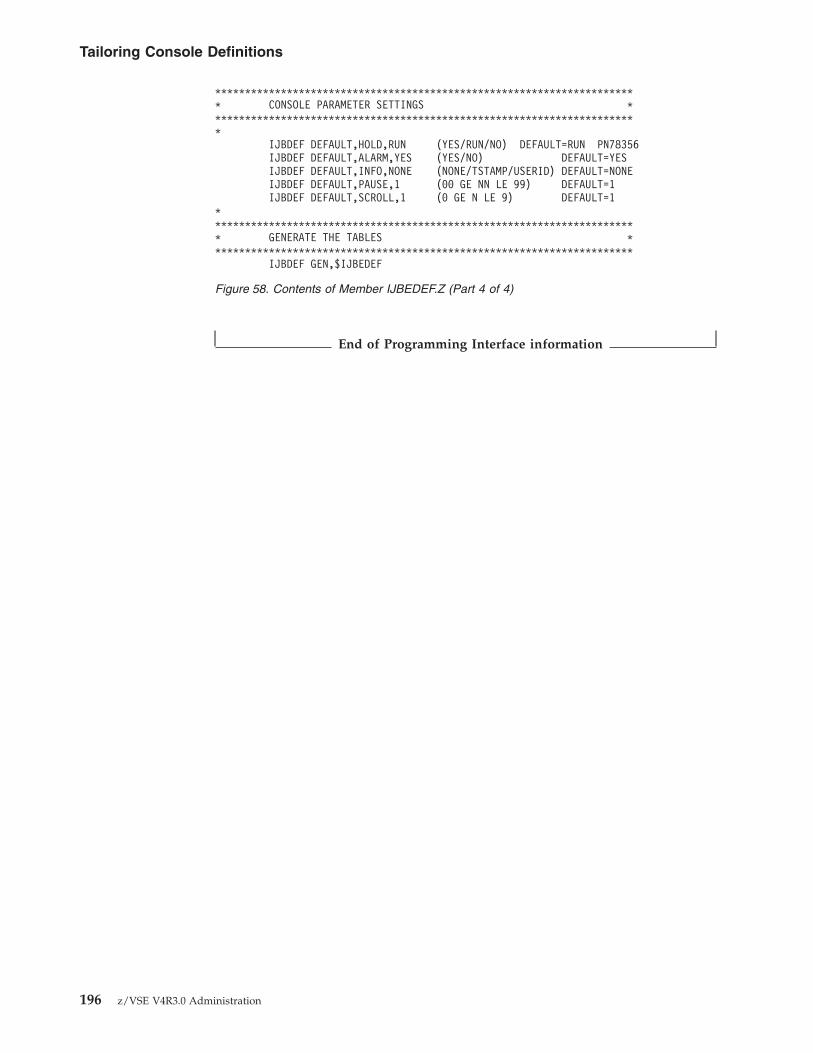
End of Programming Interface information
*********************************************************************** CONSOLE PARAMETER SETTINGS ************************************************************************
IJBDEF DEFAULT,HOLD,RUN (YES/RUN/NO) DEFAULT=RUN PN78356IJBDEF DEFAULT,ALARM,YES (YES/NO) DEFAULT=YESIJBDEF DEFAULT,INFO,NONE (NONE/TSTAMP/USERID) DEFAULT=NONEIJBDEF DEFAULT,PAUSE,1 (00 GE NN LE 99) DEFAULT=1IJBDEF DEFAULT,SCROLL,1 (0 GE N LE 9) DEFAULT=1
************************************************************************ GENERATE THE TABLES ***********************************************************************
IJBDEF GEN,$IJBEDEF
Figure 58. Contents of Member IJBEDEF.Z (Part 4 of 4)
Tailoring Console Definitions
196 z/VSE V4R3.0 Administration

Chapter 13. ZONE Specifications and Daylight Saving Time
With the Tailor IPL Procedure dialog, you can add or modify zone specifications todefine time zones, and to be able to switch between standard and daylight savingtime (summertime) without changing the IPL startup procedure each time.
To access the dialog, start with the z/VSE Function Selection panel and select:2 (Resource Definition)4 (Hardware Configuration and IPL)2 (Tailor IPL Procedure)
You get a list of the IPL parameters that can be modified. Select the ZONEparameter by entering 1 next to it.
On the ZONE SPECIFICATION panel, you can define the zone direction and thezone hours, or you can specify a zone id. These two possibilities define staticvalues in your IPL procedure.
TAS$MAS2 TAILOR IPL PROCEDURE
Enter the required data and press ENTER.
IPL procedure = $
To modify one or more of the following IPL parameters, place a 1 next to it.
_ Supervisor Modify console, supervisor- and storage option_ SYS Modify SYS command parameters_ DLA Delete label area definition_ DPD Modify page data set definition_ DLF Modify lock file definition_ DEF Modify recorder file and catalog assignment1 ZONE Modify ZONE specifications_ APPC/VM Modify VSE APPC/VM specification_ SVA Modify shared virtual area definition
PF1=HELP 2=REDISPLAY 3=END 5=PROCESS
Figure 59. Tailor IPL Procedure Dialog
© Copyright IBM Corp. 1984, 2010 197

NoteIf you want to use the possibility to switch between times, make sure thatyou have no static ZONE definition specified on the panel shown above(TAS$ICM6). The switching will be ignored when the IPL procedure containsa static SET ZONE definition.
To add or change the Time Zone Definition (ZONE ID), delete the values shownon the ZONE DIRECTION and ZONE HOURS lines and press PF8 to define thecharacteristics of the ZONDEF specifications (see Figure 61 on page 199). If yourdefinitions are already completed on this panel, press PF5 to process the enteredvalues.
Note that if you do not want to have a SET ZONE command in your IPLprocedure, (for example, if you are running under VM), you need to delete all thevalues entered on panel TAS$ICM6.
TAS$ICM6 TAILOR IPL PROCEDURE: ZONE SPECIFICATION
Enter the required data and press ENTER.
ZONE DIRECTION............... _ Direction to you from GreenwichEngland (1 = East 2 = West)
ZONE HOURS................... __ Hours to you from Greenwich, England(Two digits between 00 and 23)
ZONE ID...................... CES Time Zone Definition.
PF1=HELP 2=REDISPLAY 3=END 5=PROCESS8=FORWARD
Figure 60. Panel for Modifying Zone Specifications
198 z/VSE V4R3.0 Administration

ZONEDEF SpecificationUse the Zonedef Specification dialog to define system time zones according to theirdifference from Greenwich Mean Time (GMT).
The following values can be specified:
ZONE IDEnter a three character name for this ZONE definition. You can select anyname you want. It refers to a specific zone value. You can define up to 10new ZONE IDs. The examples shown, are the names of the official timezones division. For example:v CES for Central European Summertimev CET for Central European Standard Timev EST for Eastern Standard Timev EDT for Eastern Daylight Saving Timev CST for Central Standard Timev CDT for Central Daylight Saving Time
ZONE DIRECTIONEnter the direction to you from Greenwich, England. 1 = East, 2 = West.For example, define 2 for USA which is to the west of Greenwich.
ZONE HOURSEnter the hours to you from Greenwich, England. Enter two digits between00 and 23. Only zone hours, no zone minutes are supported.
Press PF8 to get the ZONEBDY Specification panel, or press PF5 to process theentered values.
TAS$ICMB TAILOR IPL PROCEDURE: ZONEDEF SPECIFICATION
Enter the required data and press ENTER.
OPTIONS: 1 = ADD 2 = ALTER 5 = DELETE
OPT ZONE ID ZONE DIRECTION ZONE HOURS
_ CES 1 00_ CET 1 01_ EST 2 05_ CST 2 06_ EDT 2 04_ CDT 2 05_ ___ _ ___ ___ _ ___ ___ _ ___ ___ _ __
PF1=HELP 2=REDISPLAY 3=END 5=PROCESSPF7=BACKWARD 8=FORWARD
Figure 61. ZONEDEF Specification Panel
Chapter 13. ZONE Specifications and Daylight Saving Time 199
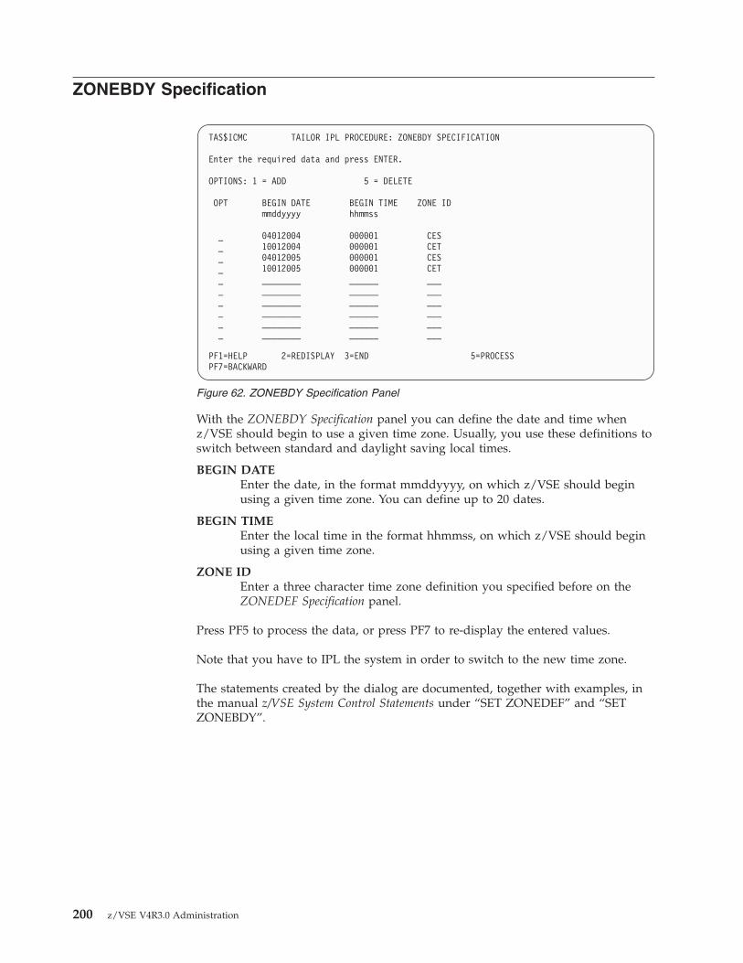
ZONEBDY Specification
With the ZONEBDY Specification panel you can define the date and time whenz/VSE should begin to use a given time zone. Usually, you use these definitions toswitch between standard and daylight saving local times.
BEGIN DATEEnter the date, in the format mmddyyyy, on which z/VSE should beginusing a given time zone. You can define up to 20 dates.
BEGIN TIMEEnter the local time in the format hhmmss, on which z/VSE should beginusing a given time zone.
ZONE IDEnter a three character time zone definition you specified before on theZONEDEF Specification panel.
Press PF5 to process the data, or press PF7 to re-display the entered values.
Note that you have to IPL the system in order to switch to the new time zone.
The statements created by the dialog are documented, together with examples, inthe manual z/VSE System Control Statements under “SET ZONEDEF” and “SETZONEBDY”.
TAS$ICMC TAILOR IPL PROCEDURE: ZONEBDY SPECIFICATION
Enter the required data and press ENTER.
OPTIONS: 1 = ADD 5 = DELETE
OPT BEGIN DATE BEGIN TIME ZONE IDmmddyyyy hhmmss
_ 04012004 000001 CES_ 10012004 000001 CET_ 04012005 000001 CES_ 10012005 000001 CET_ ________ ______ ____ ________ ______ ____ ________ ______ ____ ________ ______ ____ ________ ______ ____ ________ ______ ___
PF1=HELP 2=REDISPLAY 3=END 5=PROCESSPF7=BACKWARD
Figure 62. ZONEBDY Specification Panel
200 z/VSE V4R3.0 Administration

Part 2. Files and Tapes
Chapter 14. Managing VSE/VSAM Files andCatalogs . . . . . . . . . . . . . . 203Overview of File and Catalog Management Dialogs 203Displaying or Processing a VSE/VSAM File . . . 204Defining a New VSE/VSAM File . . . . . . . 205Defining a VSE/VSAM Library . . . . . . . 208Defining a VSE/VSAM Alternate Index or Name 209
Alternate Index. . . . . . . . . . . . 209Alternate Name . . . . . . . . . . . 210
Displaying or Processing a VSE/VSAM Catalog orSpace . . . . . . . . . . . . . . . . 210
Show Space . . . . . . . . . . . . . 210Define Alternate Name . . . . . . . . . 211Print Catalog Contents . . . . . . . . . 212Define Space . . . . . . . . . . . . 212Delete Catalog . . . . . . . . . . . . 213Delete Space. . . . . . . . . . . . . 214
Defining a New VSE/VSAM User Catalog . . . 214
Chapter 15. Performing a FlashCopy. . . . . 217Installing FlashCopy . . . . . . . . . . . 218
Hardware Prerequisite . . . . . . . . . 218Shipment and Installation . . . . . . . . 218
Issuing IXFP Commands From a Batch Job . . . 218Using IXFP SNAP Function With VM Minidisks 219Using the FlashCopy Space Efficient (SE) Feature 219
Overview of the FlashCopy SE Feature . . . . 219Dealing With an Out-of-Space Condition . . . 220Recognizing a Space-Efficient Volume . . . . 220Verifying the Status of a Space-Efficient TargetVolume . . . . . . . . . . . . . . 220Additional Messages That Might Occur WhenRunning With DEBUG ON . . . . . . . . 220
Using the FlashCopy Consistency Group Support 221VSE/Fast Copy (FCOPY) Exploitation ofFlashCopy . . . . . . . . . . . . . . 223
Job Stream Examples . . . . . . . . . . 223
Chapter 16. Managing Non-VSE/VSAM Librariesand User File Labels . . . . . . . . . . 225Defining a VSE User Library in Non-VSE/VSAMSpace . . . . . . . . . . . . . . . . 225Extending a VSE User Library in Non-VSE/VSAMSpace . . . . . . . . . . . . . . . . 227Deleting a VSE User Library in Non-VSE/VSAMSpace . . . . . . . . . . . . . . . . 229Creating Standard Labels for Non-VSE/VSAMUser Files . . . . . . . . . . . . . . 230
Chapter 17. Implementing Virtual Tape Support 235Overview of Virtual Tape Support . . . . . . 236Prerequisites for Using Virtual Tape Support . . . 236
Ensuring there is Sufficient PFIXed Space in theSystem GETVIS . . . . . . . . . . . 236Installing the Java Development Kit (JDK) . . . 237
Restrictions When Using Virtual Tapes . . . . . 237File Names and Other Considerations When UsingVirtual Tapes . . . . . . . . . . . . . 238Installing the Virtual Tape Server . . . . . . . 240
Obtaining a Copy of the Virtual Tape Server . . 240Performing the Virtual Tape Server Installation 241
Uninstalling the Virtual Tape Server . . . . 241Starting the Virtual Tape Server . . . . . . 241
Defining the Tape Device . . . . . . . . . 242Starting, Stopping, and Cancelling Virtual Tapes 242Starting and Stopping the Virtual Tape DataHandler . . . . . . . . . . . . . . . 242Working with VSE/VSAM Virtual Tapes . . . . 243
VSE/VSAM ESDS File Definition (SkeletonSKVTAPE) . . . . . . . . . . . . . 244
File Size . . . . . . . . . . . . . 246File Name . . . . . . . . . . . . 246File Sharing . . . . . . . . . . . . 246
Writing to VSE/VSAM Virtual Tapes . . . . 246Working with Remote Virtual Tapes . . . . . . 247
Entering a File Name Under Linux, UNIX, orWindows . . . . . . . . . . . . . . 247Case Sensitivity Under Linux and UNIX . . . 247Using Forward or Backward Slashes UnderWindows . . . . . . . . . . . . . . 247Further Documentation . . . . . . . . . 248
Examples of Using Virtual Tapes . . . . . . . 248Backing Up and Restoring Data . . . . . . 248Transferring Virtual Tape Files. . . . . . . 249Backing Up Data Using the Tivoli StorageManager . . . . . . . . . . . . . . 249
Chapter 18. Implementing Tape Library Support 251Overview of Tape Library Support . . . . . . 252How Tape Libraries are Configured . . . . . . 252Migrating/Configuring Your z/VSE System forTLS. . . . . . . . . . . . . . . . . 253Understanding the Format of Inventory Data. . . 255
Output File Produced by a Query InventoryRequest . . . . . . . . . . . . . . 255Input File Submitted by a Manage InventoryRequest . . . . . . . . . . . . . . 256Output Produced by a Manage InventoryRequest . . . . . . . . . . . . . . 256Naming Conventions for Inventory Files . . . 256
Performing Tape Library Functions . . . . . . 257
© Copyright IBM Corp. 1984, 2010 201

202 z/VSE V4R3.0 Administration
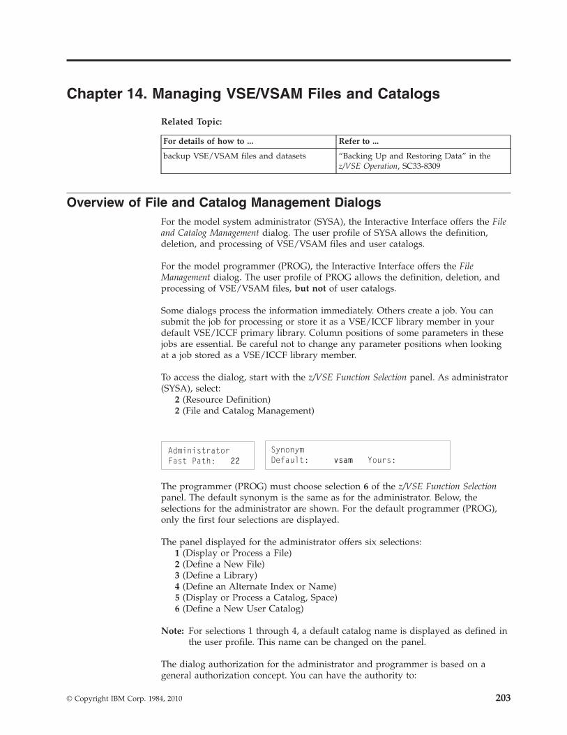
Chapter 14. Managing VSE/VSAM Files and Catalogs
Related Topic:
For details of how to ... Refer to ...
backup VSE/VSAM files and datasets “Backing Up and Restoring Data” in thez/VSE Operation, SC33-8309
Overview of File and Catalog Management DialogsFor the model system administrator (SYSA), the Interactive Interface offers the Fileand Catalog Management dialog. The user profile of SYSA allows the definition,deletion, and processing of VSE/VSAM files and user catalogs.
For the model programmer (PROG), the Interactive Interface offers the FileManagement dialog. The user profile of PROG allows the definition, deletion, andprocessing of VSE/VSAM files, but not of user catalogs.
Some dialogs process the information immediately. Others create a job. You cansubmit the job for processing or store it as a VSE/ICCF library member in yourdefault VSE/ICCF primary library. Column positions of some parameters in thesejobs are essential. Be careful not to change any parameter positions when lookingat a job stored as a VSE/ICCF library member.
To access the dialog, start with the z/VSE Function Selection panel. As administrator(SYSA), select:
2 (Resource Definition)2 (File and Catalog Management)
The programmer (PROG) must choose selection 6 of the z/VSE Function Selectionpanel. The default synonym is the same as for the administrator. Below, theselections for the administrator are shown. For the default programmer (PROG),only the first four selections are displayed.
The panel displayed for the administrator offers six selections:1 (Display or Process a File)2 (Define a New File)3 (Define a Library)4 (Define an Alternate Index or Name)5 (Display or Process a Catalog, Space)6 (Define a New User Catalog)
Note: For selections 1 through 4, a default catalog name is displayed as defined inthe user profile. This name can be changed on the panel.
The dialog authorization for the administrator and programmer is based on ageneral authorization concept. You can have the authority to:
© Copyright IBM Corp. 1984, 2010 203

v Define/delete files.v Process catalogs.
This authorization is part of the user profile. When you define a user profile, youspecify whether the user has the authority to define/delete files and the authorityto process catalogs. This does not depend on whether the user is an administratoror programmer.
Table 3 illustrates the selections which the panel displays and which you can accessbased on the authorization you have. If the panel displays a selection which youcannot access and you enter that selection number, the dialog displays an errormessage.
Table 3. Relationship Between VSE/VSAM Authorization in User Profile and DialogSelections
Define/Delete Files Process Catalogs Selections Displayed and Accessible
YES YES All selections displayed. All selections can beaccessed.
YES NO Selections 1 - 4 displayed. Selections 1 - 4 canbe accessed.
NO YES Selections 1 - 6 displayed. Only selections 1,5, and 6 can be accessed.
NO NO Selections 1 - 4 displayed. Only selection 1can be accessed.
Displaying or Processing a VSE/VSAM FileThe dialog Display or Process a File provides a FULIST that shows the file IDs andfile names of all files in the specified catalog. Use PF7 and PF8 to scroll throughthe list. Use PF9 to list a subset of the files by entering a prefix. With PF2 you canrefresh the panel display. To locate a particular file, enter the file ID in theLOCATE FILE ID field. The FILE TYPE field contains either the letter A or B toshow the type of file.A - Alternate indexB - Base file
The options you can choose are at the top of the FULIST. Enter an option numberin the OPT column to the left of the file ID you want to process. The optionsavailable are listed below. They are described in detail in the manual VSE/ESAProgramming and Workstation Guide under “Display or Process a File”.
1 (Show) Displays details about the characteristics of a VSE/VSAM file oralternate index.
2 (Sort) Sorts a VSE/VSAM file. You must have:v The z/VSE optional program DFSORT/VSE or a compatible
program installed.v Both input and output files already defined in the catalog.
3 (Print) Prints one or more records of a VSE/VSAM file on the systemprinter.
4 (Copy) Copies all or part of a file to another file. You can also copy aVSE/VSAM file to and from tape.
5 (Delete) Deletes a VSE/VSAM file or an alternate index and name. Youcannot delete system files.
VSE/VSAM - Overview of Dialogs
204 z/VSE V4R3.0 Administration

6 (Verify) Compares the end-of-file information in the catalog with theend-of-file indicator(s) in the file. If the information does not agree,the catalog information is corrected. You cannot verify an alternateindex.
7 (Load) Loads data from a VSE/ICCF library member into a base file, orloads an alternate index from a base file.
Defining a New VSE/VSAM FileWith the dialog Define a New File you can create a new VSE/VSAM file in thecatalog specified. To access the dialog, start with the z/VSE Function Selection paneland select:
If you want to specify a catalog and not use the default catalog, select Fast Path 22.
The dialog displays several panels. You need to enter different file characteristics,depending on the type of file you are defining.
The dialog defines the new file and adds a label to the system standard label areawith the file name, file ID, and catalog name of the new file. It also adds labelinformation to the VSE/VSAM label procedure STDLABUP in IJSYSRS.SYSLIB.
You need the following information:
FILE IDEnter up to five segments for the file ID. You cannot enter more than 38characters, including dots.
FILE NAMEEnter 1 - 7 alphameric characters. The first character must be alphabetic.
FILE ORGANIZATION1 - Non-keyed (ESDS)2 - Keyed (KSDS)3 - Numbered (RRDS)4 - Numbered (VRDS)5 - Sequential (SAM ESDS)
FILE ADDRESSABILITY1 - No extended addressing. This is the default.2 - Extended addressing. Define a VSE/VSAM KSDS file larger than 4GB.
FILE ACCESSFor the VSE/VSAM Share option, specify:
1 - Multiple Read OR Single Write2 - Multiple Read AND Single Write3 - Multiple Read AND Write (no integrity)4 - Multiple Read AND Write (with integrity)
FILE USAGE1 - Data file (NOREUSE)2 - Work file (REUSE)
VSE/VSAM - Displaying or Processing a File
Chapter 14. Managing VSE/VSAM Files and Catalogs 205

If the catalog owns space on more than one volume, at this point a list is displayedwhich shows these volumes and their device type. You can then select the volumeyou want the primary space allocated on and the volume(s) you want thesecondary space allocated on.
EXPIRATION DATEEnter four digits for the year, and three digits for the day of the year(YYYYDDD).
ALLOCATION UNITRequired only for CKD disk devices. Specify one of the following:
1 - Cylinder2 - Track
For FBA devices, the allocation unit “Block” is used automatically.
PRIMARY and SECONDARY ALLOCATIONThe number of allocation units for the initial (primary) and subsequent(secondary) allocations.
CONTROL INTERVAL SIZESpecify the Control Interval size of the data component for all file types.For file types that have indexes, the value of the index component iscalculated by VSAM.
AVERAGE and MAXIMUM RECORD SIZEThe average and maximum length of the data record, in bytes. For RRDSfiles, the average and maximum record sizes are the same. If you aredefining a sequential file, you do not need this information.
DATA COMPRESSIONData compression is available for VSE/VSAM files of type ESDS, KSDS,and VRDS. By specifying 1, data compression will be enabled.
The manual z/VSE Planning under “Data Compression Support” providesintroductory information about the data compression support.
Additional information required for specific file types:
Keyed (KSDS) Files
For keyed (KSDS) files, specify KEY LENGTH and POSITION.
Enter the key length from 1 - 255. The key position is the offset of the keyfrom the beginning of the record.
VSE/VSAM - Defining a New File
206 z/VSE V4R3.0 Administration

Sequential Files
If you define a sequential file, specify the following file characteristics:
RECORD FORMAT1 - Fixed, unblocked2 - Fixed, blocked3 - Variable, unblocked4 - Variable, blocked5 - Undefined6 - No control interval format
RECORD SIZEFixed record formats only (RECORD FORMAT options 1 and 2). Enterthe record length.
BLOCK SIZEFixed, blocked format only (RECORD FORMAT option 2). Enter theblock length.
AVERAGE RECORD SIZEVariable length and undefined formats only (RECORD FORMAToptions 3, 4, or 5). Enter the average length of the record.
MAXIMUM RECORD SIZEVariable length and undefined formats only (RECORD FORMAToptions 3, 4, or 5). Enter the maximum length of the record.
On the Job Execution panel, select:
1 - Delayed, Submission is handled by user2 - Immediate, Job is executed
Option 1 stores the job control statements as a VSE/ICCF library member in yourdefault primary library. The default member name is F$xxxx, where xxxx is youruser-ID. You can change the name on the panel.
Option 2 automatically runs the job online. The terminal is locked until the jobfinishes. It also stores the VSE/ICCF member F$xxxx.P (xxxx is your user-ID) inyour default primary library. If there are no errors, the member contains one recordwith an asterisk (*). If errors occurred, the control statements and VSE/VSAM(Access Method Services) error messages are stored in this member. You arenotified if you should review the contents of the library member.
VSE/VSAM - Defining a New File
Chapter 14. Managing VSE/VSAM Files and Catalogs 207

Defining a VSE/VSAM LibraryWith the dialog Define a Library you can create a VSE library in VSE/VSAMmanaged space. To access the dialog, start with the z/VSE Function Selection paneland select:
If you want to specify a catalog and not use the default catalog, select Fast Path 22.
You need the following information:
LIBRARY NAMESpecify the library file name. 'VSE.file name.LIBRARY' is the default for thefile ID created by the dialog.
PRIMARY ALLOCATIONEnter the number of 1K library blocks.
SECONDARY ALLOCATIONEnter the number of 1K library blocks.
EXTENTSEnter either 1 (for a maximum of 16 extents) or 2 (for a maximum of 32extents). You can specify a maximum of 32 extents when the library is amulti-volume file and is defined in space managed by VSE/VSAM. If youspecify a maximum of 32 extents (MAX32), you must also selectSECONDARY ALLOCATION on the next Select Space panel.
If the catalog owns space on more than one volume, a list is displayed that showsthese volumes and their device type code. You can then select the volume youwant the primary space allocated and the volume(s) you want the secondary spaceallocated.
On the Job Execution panel, select:
1 - Delayed, Submission is handled by user2 - Immediate, Job is executed
Option 1 stores the job control statements in a VSE/ICCF library member in yourdefault primary library. The default member name is F$xxxx, where xxxx is youruser-ID. You can change the name on the panel.
Option 2 automatically runs the job online. The terminal is locked until the jobfinishes. It also stores the VSE/ICCF member F$xxxx.P (xxxx is your user-ID) inyour default primary library. If there are no errors, the member contains one recordwith an asterisk (*). If errors occurred, the control statements and VSE/VSAM(Access Method Services) error messages are stored in this member. You arenotified if you should review the contents of the library member.
Note: To access a library you need at least one sublibrary. Use the librarian (LIBR)program to define sublibraries. “Using VSE Libraries” in the manual z/VSEGuide to System Functions describes program LIBR in detail.
VSE/VSAM - Defining a Library
208 z/VSE V4R3.0 Administration

Defining a VSE/VSAM Alternate Index or NameWith the dialog Define an Alternate Index or Name you can create either an alternateindex or an alternate name for an existing VSE/VSAM file. A FULIST displays thefile IDs and names of the files in the catalog. To access the dialog, start with thez/VSE Function Selection panel and select:
If you want to specify a catalog and not use the default catalog, select Fast Path 22.Use PF7 and PF8 to scroll through the list. Use PF9 to list a subset of the files byentering a prefix. With PF2 you can refresh the display. To locate a particular file,enter the file ID in the LOCATE FILE ID field.
Alternate IndexThis task defines an alternate index over an existing base file. When you define analternate index, two things are defined:1. The alternate index cluster.2. The path.
The name and ID you specify become the path name and ID. The system generatesthe name of the alternate index cluster internally. You need the followinginformation:
ALTERNATE INDEX ID and NAMESpecify the ID and the name of the alternate index.
KEY POSITION and LENGTHSpecify the position and length of the alternate key within the base record.The key length can be 1 - 255.
KEYS Specify the maximum number of non-unique keys in the alternate index.The dialog uses this value to calculate the maximum record length of thealternate index file.
The dialog adds a label to the system standard label area with the file name, fileID, and catalog name of the alternate index. It also adds label information to theVSE/VSAM label procedure STDLABUP.
On the Job Execution panel, select:
1 - Delayed, Submission is handled by user2 - Immediate, Job is executed
Option 1 stores the job control statements as a VSE/ICCF library member in yourdefault primary library. The default member name is F$xxxx, where xxxx is youruser-ID. You can change the name on the panel.
Option 2 automatically runs the job online. The terminal is locked until the jobfinishes. It also stores the VSE/ICCF member F$xxxx.P (xxxx is your user-ID) inyour default primary library. If there are no errors, the member contains one recordwith an asterisk (*). If errors occurred, the control statements and VSE/VSAM(Access Method Services) error messages are stored in this member. You arenotified if you should review the contents of the library member.
VSE/VSAM - Defining Alternate Index/Name
Chapter 14. Managing VSE/VSAM Files and Catalogs 209

Alternate NameThis task defines an alternate name for the file. It also adds label information tothe VSE/VSAM label procedure STDLABUP.
If a file does not have a file name (it has no label in the system standard labelarea), you can use this task to define the file name. You should not define alternatenames for libraries.
You only need to specify the alternate file name.
On the Job Execution panel, select:
1 - Delayed, Submission is handled by user2 - Immediate, Job is executed
Option 1 stores the job control statements in a VSE/ICCF library member in yourdefault primary library. The default member name is F$xxxx, where xxxx is youruser-ID. You can change the name on the panel.
Option 2 automatically runs the job online. The terminal is locked until the jobfinishes. It also stores the VSE/ICCF member F$xxxx.P (xxxx is your user-ID) inyour default primary library. If there are no errors, the member contains one recordwith an asterisk (*). If errors occurred, the control statements and VSE/VSAM(Access Method Services) error messages are stored in this member. You arenotified if you should review the contents of the library member.
Displaying or Processing a VSE/VSAM Catalog or SpaceThe dialog Display or Process a Catalog, Space provides a FULIST that shows thecatalog IDs and names in the system. To access the dialog, start with the z/VSEFunction Selection panel and select:
Use PF7 and PF8 to scroll through the list. With PF2 you can refresh the display.
You can select the following options:1 (Show space)2 (Define alternate name)3 (Print catalog contents)4 (Define space)5 (Delete catalog)6 (Delete space)
Show SpaceThis task displays details about the space owned by the catalog selected. A panellists the volumes owned by the catalog. It displays the allocated, used, and freespace on each volume.
VSE/VSAM - Defining Alternate Index/Name
210 z/VSE V4R3.0 Administration

Define Alternate NameThis task defines an alternate name for the catalog. The dialog defines the nameand adds a label to the system standard label area with the alternate name. It alsoadds label information to the VSE/VSAM label procedure STDLABUP.
You should use alternate names for catalogs carefully. On the File and CatalogManagement panel, if you:v Select options 1 or 4
AND
v Specify an alternate catalog name in the CATALOG NAME field
The FULIST only displays file names for files which are defined with the alternatecatalog name. The FULIST displays *NONE* as the file name for files defined inthe same catalog with a different catalog name.
You only need to specify the alternate catalog name.
On the Job Execution panel, select:
1 - Delayed, Submission is handled by user2 - Immediate, Job is executed
Option 1 stores the job control statements in a VSE/ICCF library member in yourdefault primary library. The default member name is F$xxxx, where xxxx is youruser-ID. You can change the name on the panel.
Option 2 automatically runs the job online. The terminal is locked until the jobfinishes. It also stores the VSE/ICCF member F$xxxx.P (xxxx is your user-ID) inyour default primary library. If there are no errors, the member contains one recordwith an asterisk (*). If errors occurred, the control statements and VSE/VSAM(Access Method Services) error messages are stored in this member. You arenotified if you should review the contents of the library member.
VSE/VSAM - Displaying/Processing Catalog/Space
Chapter 14. Managing VSE/VSAM Files and Catalogs 211

Print Catalog ContentsThis task creates a LISTCAT of the selected catalog. You do not have to specify anyinformation. On the Job Execution panel, select:
1 - Delayed, Submission is handled by user2 - Immediate, Job is submitted
Option 1 stores the job control statements as a VSE/ICCF library member in yourdefault primary library.
Option 2 submits the job automatically. It also stores the VSE/ICCF memberF$xxxx.P (xxxx is your user-ID) in your default primary library. If there are noerrors, the member contains one record with an asterisk (*). If errors occurred, thecontrol statements and VSE/VSAM (Access Method Services) error messages arestored in this member. You are notified if you should review the contents of thelibrary member.
Define SpaceThis task defines VSE/VSAM space that is to be used for the allocation of files. Itis recommended that you define space owned by a catalog on the same volume onwhich the catalog resides. You need the following information:
VOLUME NAMEEnter the six character VOLID of the disk where the space should bedefined.
ALL FREE SPACESpecify whether you want all available space on the volume forVSE/VSAM:
1 - YES2 - NO
If you specify 1 (YES), all free space (up to 16 extents) on the volume isdedicated to VSE/VSAM.
If you specify 2 (NO), a panel displays the free extents on the volume.Select one extent. Enter the beginning allocation and the amount of spaceto be allocated.
In some circumstances, VSE/VSAM rounds the specified values to a highernumber. If the rounded extent exceeds the original one, the space definitionfails. To avoid this, choose values which result in a smaller extent than theone shown.
SPACE AVAILABLE TO CURRENT FILESSpecify whether the files currently owned by the catalog can access thenew space for secondary allocation:
1 - YES2 - NO
If you specify 1 (YES), the dialog alters the catalog entries of the currentfiles so new space can be used for secondary allocation. The dialogchanges the catalog entries, if:v The secondary allocation for the file is greater than 0.v You define new space on disk devices with the same device type code as
the primary allocation for the file(s).
VSE/VSAM - Displaying/Processing Catalog/Space
212 z/VSE V4R3.0 Administration

If a current file already accesses space on a volume, it keeps that accesswhen you define new space on the same volume.
If you specify 2 (NO), current files cannot access the new space.
FAT-3390 DISKSpecify extended space on a 3390 disk.
1 - YES2 - NO
If you specify 1 (YES), the dialog defines up to 65520 cylinders of space(3390 ECKD only).
If you specify 2 (NO), the limit of 10017 cylinders is valid. You shouldspecify NO for all other disks.
On the Job Execution panel, select:
1 - Delayed, Submission is handled by user2 - Immediate, Job is executed
Option 1 stores the job control statements in a VSE/ICCF library member in yourdefault primary library. The default member name is F$xxxx, where xxxx is youruser-ID. You can change the name on the panel.
Option 2 automatically runs the job online. The terminal is locked until the jobfinishes. It also stores the VSE/ICCF member F$xxxx.P (xxxx is your user-ID) inyour default primary library. If there are no errors, the member contains one recordwith an asterisk (*). If errors occurred, the control statements and VSE/VSAM(Access Method Services) error messages are stored in this member. You arenotified if you should review the contents of the library member.
Notes:
1. For CKD disk devices, the units of allocation are cylinders and not tracks.2. If you are using emulated FBA disks or virtual FBA disks, VSE/VSAM can use
as VSE/VSAM space the first 4194240 blocks (2 GB) in units of 960 blocks.3. If you are using FBA-SCSI disks, VSE/VSAM can use as VSE/VSAM space the
first 33546240 blocks (16 GB) in units of 30720 blocks. For further details, referto the manual z/VSE Planning, SC33-8301.
Delete CatalogThis task deletes a VSE/VSAM catalog or alternate catalog name. The dialogremoves the user catalog entry from the VSE/VSAM master catalog. Before youdelete a catalog, you should do the following:v Delete all files which the catalog owns.v If the catalog owns space on more than one volume, first delete the space on the
volumes other than the catalog volume.
The dialog deletes the catalog and removes the label from the system standardlabel area and the VSE/VSAM label procedure STDLABUP. If the catalog hasalternate names, specify what you want to delete:
1 - Delete catalog name only2 - Delete actual catalog, including alternate names
Verify that the catalog is the one you want to delete.
VSE/VSAM - Displaying/Processing Catalog/Space
Chapter 14. Managing VSE/VSAM Files and Catalogs 213

On the Job Execution panel, select:
1 - Delayed, Submission is handled by user2 - Immediate, Job is executed
Option 1 stores the job control statements in a VSE/ICCF library member in yourdefault primary library. The default member name is F$xxxx, where xxxx is youruser-ID. You can change the name on the panel.
Option 2 automatically runs the job online. The terminal is locked until the jobfinishes. It also stores the VSE/ICCF member F$xxxx.P (xxxx is your user-ID) inyour default primary library. If there are no errors, the member contains one recordwith an asterisk (*). If errors occurred, the control statements and VSE/VSAM(Access Method Services) error messages are stored in this member. You arenotified if you should review the contents of the library member.
Delete SpaceThis task deletes VSE/VSAM data spaces. A panel displays a list of the volumesowned by the catalog. It shows the allocated, used, and free space on each volume.
Enter 5 in the OPT column next to the volume you want to select. On the JobExecution panel, select:
1 - Delayed, Submission is handled by user2 - Immediate, Job is executed
Option 1 stores the job control statements in a VSE/ICCF library member in yourdefault primary library. The default member name is F$xxxx, where xxxx is youruser-ID. You can change the name on the panel.
Option 2 automatically runs the job online. The terminal is locked until the jobfinishes. It also stores the VSE/ICCF member F$xxxx.P (xxxx is your user-ID) inyour default primary library. If there are no errors, the member contains one recordwith an asterisk (*). If errors occurred, the control statements and VSE/VSAM(Access Method Services) error messages are stored in this member. You arenotified if you should review the contents of the library member.
Defining a New VSE/VSAM User CatalogWith the dialog Define a New User Catalog you can create a new user catalog and,optionally, space for file allocation.
Data Compression Support: The dialog automatically creates for each usercatalog a CCDS (Compression Control Data Set) which is namedVSAM.COMPRESS.CONTROL. This cluster is required to enable data compressionfor ESDS, KSDS, and VRDS files defined in the catalog. Under “Data CompressionSupport”, the manual z/VSE Planningprovides an overview about the datacompression support available.
To access the dialog, start with the z/VSE Function Selection panel and select:
VSE/VSAM - Displaying/Processing Catalog/Space
214 z/VSE V4R3.0 Administration

The dialog adds a label to the system standard label area with the catalog name. Italso adds label information to the VSE/VSAM label procedure STDLABUP.
Space which belongs to a catalog should be on the same volume as the catalogitself. When you define the catalog, you can use only part of a volume and thenuse more of the volume later. However, it is better if you take as much space onthe volume as you will need. Additional space may not be available later. Youneed the following information:
USER CATALOG ID and NAMEFor the new catalog, enter up to five segments for the file ID. You cannotenter more than 38 characters, including dots. For the name, enter 1 - 7alphameric characters.
Note: The catalog name IJSYSUC is reserved for system use.
VOLUME NAMEEnter the six character volume ID of the disk where the catalog will bedefined.
ALL FREE SPACESpecify whether you want all available space on the volume forVSE/VSAM:
1 - YES2 - NO
If you specify 1 (YES), the dialog uses all free space (up to 16 extents) onthe volume for both the catalog and files. VSE/VSAM determines the sizeof the space reserved for the catalog and for the files.
If you specify 2 (NO), you are defining space for the catalog, and space forfile allocation. A panel displays the free extents on the volume. Select oneextent. Enter the beginning allocation and the amount of space to beallocated.
This is how space will be allocated:v For FBA devices (FBA SCSI, or FBA devices under z/VM):
– 3072 blocks will be allocated for the catalog space– the remaining blocks will be allocated for the data space
v For ECKD devices:– 75 tracks will be allocated for the catalog space– the remaining tracks will be allocated for the data space
In some circumstances, VSE/VSAM rounds the specified values to a highernumber. If the rounded extent exceeds the original one, the space definitionfails. To avoid this, choose values which result in a smaller extent than theone shown.
FAT-3390 DISKSpecify extended space on a 3390 disk.
1 - YES2 - NO
If you specify 1 (YES), the dialog defines up to 65520 cylinders of space(3390 ECKD only).
If you specify 2 (NO), the limit of 10017 cylinders is valid. You shouldspecify NO for all other disks.
On the Job Execution panel, select:
VSE/VSAM - Defining New User Catalog
Chapter 14. Managing VSE/VSAM Files and Catalogs 215

1 - Delayed, Submission is handled by user2 - Immediate, Job is executed
Option 1 stores the job control statements in a VSE/ICCF library member in yourdefault primary library. The default member name is F$xxxx, where xxxx is youruser-ID. You can change the name on the panel.
Option 2 automatically runs the job online. The terminal is locked until the jobfinishes. It also stores the VSE/ICCF member F$xxxx.P (xxxx is your user-ID) inyour default primary library. If there are no errors, the member contains one recordwith an asterisk (*). If errors occurred, the control statements and VSE/VSAM(Access Method Services) error messages are stored in this member. You arenotified if you should review the contents of the library member.
VSE/VSAM - Defining New User Catalog
216 z/VSE V4R3.0 Administration

Chapter 15. Performing a FlashCopy
This chapter describes how you can perform a FlashCopy using the AR (AttentionRoutine) IXFP SNAP command. In addition, FlashCopy provides the IXFP DDSRand STATUS functions.
z/VSE provides support for:v FlashCopy Version 1 (volume-based FlashCopy), including the NOCOPY option
which can be used to copy most, or all, of the data directly from the source totape without the need to first copy all of the physical data to an intermediatebackup copy.
v FlashCopy Version 2 (“FlashCopy 2”), which includes the features of FlashCopyVersion 1 plus extensions designed to improve capacity management and diskutilization.
Note: Except for FILE SNAPping (DSN=data-set-name), VSE will not:1. perform VTOC checking on the specified target device.2. provide warning messages of any kind, be it overlapping extents,
secured- or unexpired files, or anything else.
Cylinder or volume copying will be done unconditionally within the specifiedor assumed boundaries.
This chapter contains these main topics:v “Installing FlashCopy” on page 218v “Issuing IXFP Commands From a Batch Job” on page 218v “Using IXFP SNAP Function With VM Minidisks” on page 219v “Using the FlashCopy Space Efficient (SE) Feature” on page 219v “Using the FlashCopy Consistency Group Support” on page 221v “VSE/Fast Copy (FCOPY) Exploitation of FlashCopy” on page 223
Related Topics:
For details of ... Refer to ...
the IXFP SNAP, IXFP DDSR, andIXFP STATUS commands (their syntax andparameters)
z/VSE System Control Statements, SC33-8305.
how to backup VSE/VSAM files anddatasets
“Backing Up and Restoring Data” in thez/VSE Operation, SC33-8309
For a general description of FlashCopy, refer to “Hardware Support” in the z/VSEPlanning, SC33-8301.
© Copyright IBM Corp. 1984, 2010 217

Installing FlashCopy
Hardware PrerequisiteFlashCopy support has the following hardware prerequisites:v IBM TotalStorage DS8000 or DS6000 with the PTC (“point-in-time copy”) feature
installed.v IBM TotalStorage Enterprise Storage Server (ESS) with the FlashCopy Version 1
or Version 2 feature installed.
Shipment and InstallationThe FlashCopy support is part of z/VSE as shipped. The name of the phasecontaining this support is $IJBESFC, which resides in sublibrary IJSYSRS.SYSLIB.
$IJBESFC is automatically loaded into the SVA during startup. The FlashCopysupport is provided via the IXFP command.
Issuing IXFP Commands From a Batch JobA small REXX/VSE procedure can be used to issue IXFP commands from a batchjob. The following example shows such a procedure:* $$ JOB JNM=IXFPREXX,CLASS=0,DISP=D// JOB IXFPREXX// EXEC LIBRACC S=PRD2.CONFIGCAT IXFPREXX.PROC R=Y/* rexx/vse procedure *//* to issue console commands */trace offrc = SENDCMD(’your-console-cmd-1’) /* enter your 1st IXFP cmd here */call sleep 5 /* wait for 5 seconds */rc = SENDCMD(’your-console-cmd-2’) /* enter your 2nd IXFP cmd here */exit rc/+/*// LIBDEF *,SEARCH=(PRD2.CONFIG,PRD1.BASE)// EXEC REXX=IXFPREXX/&* $$ EOJ
More information on the REXX/VSE Console Automation Capability can be foundin the REXX/VSE Reference manual, SC33-6642.
FlashCopy
218 z/VSE V4R3.0 Administration

Using IXFP SNAP Function With VM MinidisksIf used on a z/VSE system running under z/VM, the IXFP SNAP function:v does not allow volume or cylinder relocation for partial minidisks, and
thereforev only works (and will only be accepted as a valid command by z/VM) for
full-pack minidisks or dedicated devices.
Please be aware that for minidisks which use MDC (Mini Disk Caching), the MDCbuffer must be flushed before performing a SNAP or DDSR function. Otherwise,data can be incomplete.
The above MDC problem is solved by VM APAR VM61486, which is included inz/VM Version 4 onwards.
Note: Other host caching products (for example, Cache Magic) will have the samerequirements.
Using the FlashCopy Space Efficient (SE) Feature
Overview of the FlashCopy SE FeatureFlashCopy SE is optimized for use in situations where a small percentage of thesource volume is updated during the life of the relationship.v If much more than 20 per cent of the source is expected to change, there may be
tradeoffs in terms of performance versus space efficiency. In this case,“standard” FlashCopy might be considered a better alternative.
v Since background copy would update the entire target volume, it would not makemuch sense and is therefore not permitted with FlashCopy SE.
v If performance on the source or target volumes is of primary importance,standard FlashCopy is recommended.
The FlashCopy SE feature of the DS8000 series allocates storage space on an “asneeded” basis by only using space on a target volume when it actually copiestracks from the source volume to the target volume. Using FlashCopy SE, diskspace will only be consumed on the target volume when:v a write to the source volume needs to be hardened on disk, orv a write is directed to the target volume.
FlashCopy SE is designed for temporary copies. The duration of the copy shouldgenerally not be longer than 24 hours, unless the source and target volumes havelittle write activity.
Since space is allocated “as needed” on the target volumes, data location on thetarget volumes is independent of data location on the source volumes:v Data is not physically ordered in the same sequence on the target volume as it is
on the source volume.v A mapping structure is created to keep track of where the data on the target
volume is physically located.
Note: FlashCopy SE relations might fail if sufficient space is not available in thestorage that is allocated for the target volumes. However, this relation-failure
IXFP From Batch Job
Chapter 15. Performing a FlashCopy 219

does prevent I/O failures on the source volumes. If the target volumebecomes unusable, standard FlashCopy relations require your interventionto remove the relation.
For details of how you implement FlashCopy SE, refer to the documentation thataccompanies the DS8000 Series.
Dealing With an Out-of-Space ConditionIf the space-efficient (SE) volume encounters an out-of-space condition, theFlashCopy relationship will fail. It will not perform a write-inhibit to the sourcevolume or extent.
Further Host writes will be allowed to the source volume/extent, but Host writeand reads will be rejected on the target volume/extent. As a result:v The volume will appear as if it is offline.v An “Equipment Check Sense” will be displayed.
To clear this condition and remove the relation, you must issue an IXFP DDSRcommand. For details, refer to “Job Control and Attention Routine” in the z/VSESystem Control Statements, SC33-8305.
Recognizing a Space-Efficient VolumeIf you enter the AR (Attention Routine) command VOLUME cuu, if the volume is aSpace Efficient volume then SE (Space Efficient) is included in the display. Forexample, if a volume has a cuu of e59 and is a Space Efficient volume, the displaywould look like this:volume e59
AR 0015 CUU CODE DEV.-TYP VOLID USAGE SHARED STATUS CAPACITYAR 0015 E59 6E 2107-900 *NONE* UNUSED DOWN SE 65520 CYL
For further details, refer to “Job Control and Attention Routine” in the z/VSESystem Control Statements, SC33-8305.
Verifying the Status of a Space-Efficient Target VolumeIf you enter the AR (Attention Routine) command IXFP STATUS when the targetvolume is a Space Efficient (SE) volume, the following additional message isdisplayed:IXFP74I FL/SE QUERY CUU=nnn POOLID=nnn ALLOCATED SPACE=’nnnn’ CYL POOL SIZE=’nnnn’ CYL
The cuu=nnn provided in this message is the currently-defined FlashCopySpace-Efficient TARGET repository. This additional information might also bedisplayed:v Extent Pool ID.v Space that is currently allocated in the Extent Pool's Repository.v Size of the Pool's Extent Repository.
For further details of the IXFP STATUS command, refer to “Job Control andAttention Routine” in the z/VSE System Control Statements,
Additional Messages That Might Occur When Running WithDEBUG ON
These are the messages you might receive if you are running your z/VSE systemusing the Attention Routine (AR) DEBUG ON option:
Space Efficient Feature
220 z/VSE V4R3.0 Administration

v If you are running z/VSE as guest under z/VM 5.4 or earlier, these messages willnot appear. This is because FlashCopy SE is not supported by z/VM 5.4 or earlier.
v If you are running z/VSE as guest under z/VM 6.1 or later (or if you are runningin LPAR mode), these messages will appear.
AR 0024 ATTENTION-MSG read for DEVICE=0E11 Path=80AR 0024 00100601 10000001 000E0000 00000000AR 0024 AOMOS01I POOL=001, SPACE EFFICIENT TARGET REPOSITORY HAS REACHED A WARNING WATERMARK
AR 0024 ATTENTION-MSG read for DEVICE=0E11 Path=80AR 0024 00100602 00000001 000E0000 00000000AR 0024 AOMOS02I POOL=001, SPACE EFFICIENT TARGET REPOSITORY HAS BEEN EXHAUSTED
Using the FlashCopy Consistency Group SupportUsing the FlashCopy Consistency Group support, you can take a FlashCopy acrossmultiple volumes on an ESS, DS6000, or DS8000 storage system. This is useful whenapplications have their data spread over multiple volumes.
If you run z/VSE under z/VM, to use Consistency Group support you must have:v Installed APAR VM64693.v Specified STDEVOPT DASDSYS DATAMOVER in the CP directory.
You can use consistency groups to help create a consistent Point-in-Time copy acrossmultiple volumes, and even across multiple ESS, DS6000, or DS8000 storagesystems, thus managing the consistency of dependent writes:v If the start of one write operation is dependent upon the completion of a
previous write, the writes are dependent. Application examples for dependentwrites are databases with their associated logging files. In addition, updates tocatalogs, VTOCs as well as VSAM indexes and VSAM data components rely ondependent writes. For example, the database logging file will be updated after anew entry has been successfully written to a table space.
v The chronological order of dependent writes to the FlashCopy source volumes isthe basis for providing consistent data at the FlashCopy target volumes.
To ensure that order of dependent writes to the FlashCopy source volume isconsistent with the data on the target volume, you can use the FlashCopy FREEZEparameter. When you invoke an IXFP SNAP with parameter FREEZE, the storagesystem will stop the I/O activity to the source volume for a period-of-time byputting the source volume in an extended long busy state. Therefore, a time slot canbe created during which the dependent write updates will not occur. FlashCopyuses the time slot to establish a consistent point-in-time copy of the relatedvolumes.
I/O activity resumes when either of the following occurs:v You invoke an IXFP DDSR with parameter THAW for the source volume (after
all FlashCopies have been established). THAW indicates that all FlashCopyvolumes in this logical subsystem (specified by one volume in the unitparameter) will be released.
v The extended “long busy” time slot has expired (the default is two minutes).
You can use Consistency Groups to minimize the application impact on yourproduction data. This is because prior to a Consistency Group FlashCopy, you haveto:1. quiesce the application,2. establish their FlashCopy relationships, and3. restart the application,
Space Efficient Feature
Chapter 15. Performing a FlashCopy 221

which is a disruptive process. It might cause application outages or dataunavailability for an unacceptable period of time.
Notes:
1. The FREEZE parameter always affects the complete volume. Therefore, even ifthe IXFP SNAP has been used to specify data sets (rather than completevolumes), the complete volume will nevertheless be “long busy” to hostoperations. The timer is set to a default of two minutes, called the “ConsistencyGroup timer” on the WEB panel that displays server properties. You canchange the timer value to suit your needs.
2. The FlashCopy command and FlashCopy FREEZE are on a volume basis, butthe THAW command is at the LSS (logical subsystem) level. This means, if thereare more than one set of volumes using consistency, the THAW command willaffect all of the Consistency Groups.
3. An I/O request to a source device that is in a FREEZE state will be in a “longbusy” state until either:v The extended long busy time slot (120 seconds) has expired.v A THAW command is issued.
This might cause:v Delays to I/O requests for system files residing on a disk that is in a
FREEZE state.v Delays to AR commands.v Unpredictable results for application programs that use their own error
processing routines.v A THAW command to not be processed until the extended “long busy” time
slot (120 seconds) has expired. This might also be because previous I/Orequests are still in a “long busy” state.
4. If you repeatedly submit a FlashCopy FREEZE request for the same sourcevolume, this request will fail with a PERM I/O error. This is because the sourcevolume is in an extended “long busy” state.
For details of how to use the FREEZE and THAW parameters with the IXFP SNAPand IXFP DDSR commands, refer to the chapter “Job Control and AttentionRoutine” in the z/VSE System Control Statements,
Consistency Groups
222 z/VSE V4R3.0 Administration

VSE/Fast Copy (FCOPY) Exploitation of FlashCopyThe VSE/Fast Copy utility (described in the manual z/VSE System Utilities) exploitsthe FlashCopy function. It supports full volume backup from disk-to-disk.However, it does not support the copying of files or extents.
The following VSE/Fast Copy options are supported:v COPY ALLv COPY VOLUMEv COPY VOLUME NOCOPYv COPY ALL NOCOPYv DDSR
The DDSR option which removes a previously-established NOCOPY relation is alsosupported via the Remove FlashCopy relation IUI dialog:
3 (Operations)7 (Backup/Restore)7 (Copy a Volume or File)3 (Remove FlashCopy relation)
For a description of the Remove FlashCopy relation dialog, refer to the chapter“Backing Up and Restoring Data” in the z/VSE Operation, SC33-8309.
The VSE/Fast Copy (FCOPY) uses a FlashCopy when:v FlashCopy support is available in the disk hardware.v A full-volume backup request is for disk-to-disk (and not disk-to-tape).
If the requested support is not available, a normal VSE/Fast Copy backup will beperformed.
The following VSE/Fast Copy optional parameters are supported:IV (input volume)OV (output volume)NV (new volume)
The following VSE/Fast Copy optional parameters are tolerated:NOPROMPTNOVERIFYLIST
The following VSE/Fast Copy optional parameters force FlashCopy NOT to beused. These parameters apply to COPY VOLUME only:
EXCLUDENOVSAMNOEXPIRED
Job Stream ExamplesThis job stream example applies to the COPY ALL as well as to the COPYVOLUME command:// JOB jobname// ASSGN SYS004,140// ASSGN SYS005,141// EXEC FCOPYCOPY VOLUME IV=SYSRES/*/&
VSE/Fast Copy
Chapter 15. Performing a FlashCopy 223

This job stream example shows how the NOCOPY parameter is used to establish aFlashCopy relation to a target disk whose volume-ID is FRA626:// JOB jobname// ASSGN SYS004,ANYDISK,VOL=DOSRES,SHR// ASSGN SYS005,ANYDISK,VOL=FRA626,SHR// EXEC FCOPYCOPY VOLUME NOCOPY -NOVERIFY NV=FRA626/*/&
This job stream example shows how the DDSR parameter is used to remove aFlashCopy relation to a target disk whose volume-ID is FRA626:// JOB jobname// ASSGN SYS005,ANYDISK,VOL=FRA626,SHR// EXEC FCOPYDDSR/*/&
VSE/Fast Copy
224 z/VSE V4R3.0 Administration

Chapter 16. Managing Non-VSE/VSAM Libraries and User FileLabels
To manage libraries in non-VSE/VSAM space, z/VSE provides the followingskeletons:v SKLIBDEF (for defining libraries)v SKLIBEXT (for extending libraries)v SKLIBDEL (for deleting libraries)
To create standard labels for non-VSE/VSAM user files, z/VSE provides skeletonSTDLABUS.
These skeletons are described on the following pages.
Defining a VSE User Library in Non-VSE/VSAM SpaceThe SKLIBDEF skeleton defines a VSE user library in non-VSE/VSAM space. Theskeleton has two major steps:1. Add standard label for the new library.2. Create the library.
The skeleton is shipped in library 59. First copy it to your primary library and editthe copied file. Refer to “Copying Skeletons” on page 10 for information oncopying skeletons.
Figure 63 on page 226 shows the skeleton. The variables you should change arehighlighted in color. They are described below the figure to help you make thecorrect changes.
After you make the changes, update the standard label skeleton STDLABUS. Addthe label for the library which SKLIBDEF defines. Refer to “Creating StandardLabels for Non-VSE/VSAM User Files” on page 230 for information aboutSTDLABUS.
Note: To access a library you need at least one sublibrary. Use the librarian (LIBR)program to define sublibraries. “Using VSE Libraries” in the manual z/VSEGuide to System Functions describes the librarian program LIBR in detail.
To manage libraries in VSE/VSAM space, z/VSE provides dialogs as described inChapter 14, “Managing VSE/VSAM Files and Catalogs,” on page 203.
© Copyright IBM Corp. 1984, 2010 225

Change the --Vxxx-- variables in the DLBL, EXTENT, and DEFINE LIB statements.
--V001--This is the file name of the library. Specify 1 - 7 alphanumeric characters.
Note: Change --V001-- in both the DLBL and DEFINE LIB statements.
--V002--This is the file identification. Specify 1 - 44 alphanumeric characters. Donot delete the single quotes (' ') around the variable.
--V101--The volume number where the library will reside. It must be 6 characters.The value can be the same or different for each extent.
--V102--This is the extent sequence number (0 - 15). You can have up to sixteenextents defined on several disks. The disks must all be of the same type.
--V103--This is the start location of the library in tracks or blocks. The value can bedifferent for each extent.
--V104--This is the amount of space to be allocated for the library on the firstvolume. The value can be different for each extent. Specify the value intracks or blocks.
After you have modified the skeleton, enter the following command from theeditor's command line:@DTRSEXIT
This command calls a macro that deletes specific comments from the skeleton. Youshould do this before filing the skeleton.
* $$ JOB JNM=DEFLIBR,CLASS=0,DISP=D// JOB DEFLIBR DEFINE LIBRARY IN NON VSAM SPACE// OPTION STDLABEL=ADD// DLBL --V001--,’--V002--’,99/366,SD// EXTENT ,--V101--,1,--V102--,--V103--,--V104--// EXTENT ,--V101--,2,--V102--,--V103--,--V104--/*// EXEC LIBRDEFINE LIB=--V001-- R=Y/*/&* $$ EOJEND OF MEMBER
Figure 63. Define VSE User Library in Non-VSE/VSAM Space (SKLIBDEF Skeleton)
226 z/VSE V4R3.0 Administration

Extending a VSE User Library in Non-VSE/VSAM SpaceThe SKLIBEXT skeleton extends a VSE user library in non-VSE/VSAM space. It isrecommended that you use a MINI startup for extending a library. This is toensure that the library is not in an active LIBDEF chain.
The skeleton has five major steps:1. Back up the library to tape.2. Delete the library.3. Delete standard label for the library.4. Add new standard label for the extended library.5. Create library and restore the library from tape.
The skeleton is shipped in VSE/ICCF library 59. First copy it to your &iccfprimary library and edit the copied skeleton. Refer to “Copying Skeletons” onpage 10 for information on copying skeletons.
Figure 64 shows the skeleton. Each section of the skeleton is shown in separateparts of the figure. The variables you should change are highlighted in color. Adescription of the changes follows each part of the figure.
After you make the changes, update the standard label skeleton STDLABUS.Change the label for the library which SKLIBEXT updates. Refer to “CreatingStandard Labels for Non-VSE/VSAM User Files” on page 230 for informationabout STDLABUS.
* $$ JOB JNM=EXTLIBR,CLASS=0,DISP=D// JOB EXTLIBR EXTEND LIBRARY IN NON VSAM SPACE* THIS FUNCTION USES A TAPE FOR OUTPUT* MOUNT TAPE REEL --V004-- WITH UNLABELED TAPE ON DEVICE --V003--* THEN CONTINUE. IF NOT POSSIBLE CANCEL THIS JOB* WARNING: EXISTING TAPE LABEL WILL BE OVERRIDDEN// PAUSE// ASSGN SYS005,--V003--// MTC REW,SYS005// EXEC LIBR
BACKUP LIB = --V001-- /* LIBRARY IDENTIFICATIONRESTORE = ONLINE /* RESTORE TYPETAPE = SYS005 /* TAPEADRESS
/*// MTC REW,SYS005// IF $RC > 0 THEN// GOTO $EOJ// EXEC LIBRDELETE LIB=--V001--/*// IF $RC > 0 THEN// GOTO $EOJ// OPTION STDLABEL=DELETE--V001--/*
Figure 64. SKLIBEXT Skeleton, Part 1 of 3 (Extend VSE User Library in Non-VSE/VSAMSpace)
Extending Library Non-VSE/VSAM Space
Chapter 16. Managing Non-VSE/VSAM Libraries and User File Labels 227

Change the --Vxxx-- variables in the comments, the ASSGN, BACKUP LIB, andDELETE LIB statements, and in the statement following the OPTION statement.
--V001--This is the file name of the library. Specify 1 - 7 alphanumeric characters.
--V003--The tape address (cuu) used for the backup.
--V004--The volume number of the backup/restore tape. It must be 6 characters.
Change the --Vxxx-- variables in the DLBL and EXTENT statements.
--V001--This is the file name of the library. Specify 1 - 7 alphanumeric characters.
--V002--This is the file identification. Specify 1 - 44 alphanumeric characters. Donot delete the single quotes (' ') around the variable.
--V101--The volume number where the library will reside. It must be 6 characters.The value can be the same or different for each extent.
--V102--This is the extent sequence number (0 - 15). You can have up to sixteenextents defined on several disks. The disks must be all of the same type.
--V103--This is the start location of the library in tracks or blocks. The value can bedifferent for each extent.
--V104--This is the amount of space to be allocated for the library on the firstvolume. The value can be different for each extent. Specify the value intracks or blocks.
// OPTION STDLABEL=ADD// DLBL --V001--,’--V002--’,99/366,SD
// EXTENT ,--V101--,1,--V102--,--V103--,--V104--// EXTENT ,--V101--,2,--V102--,--V103--,--V104--// EXTENT ,--V101--,3,--V102--,--V103--,--V104--/*
Figure 65. SKLIBEXT Skeleton, Part 2 of 3 (Extend VSE User Library in Non-VSE/VSAMSpace)
Extending Library Non-VSE/VSAM Space
228 z/VSE V4R3.0 Administration

Change the --Vxxx-- variables in the comments and the ASSGN, and RESTORE LIBstatements.
--V001--This is the file name. Specify 1 - 7 alphanumeric characters.
--V003--The tape address (cuu) used to restore the library.
--V004--The volume number of the backup/restore tape. It must be 6 characters.
When you run the job, use the same tape and tape device you specify in theskeleton.
After you have modified the skeleton, enter the following command from theeditor's command line:@DTRSEXIT
This command calls a macro that deletes specific comments from the skeleton. Youshould do this before filing the skeleton.
Deleting a VSE User Library in Non-VSE/VSAM SpaceThe SKLIBDEL skeleton deletes a VSE user library in non-VSE/VSAM space. It isrecommended that you use a MINI startup for deleting a library. This is to ensurethat the library is not in an active LIBDEF chain.
The skeleton has two major steps:1. Delete the library.2. Delete the standard label for the library.
The skeleton is shipped in VSE/ICCF library 59. First copy it to your VSE/ICCFprimary library and edit the copied file. Refer to “Copying Skeletons” on page 10for information on copying skeletons.
Figure 67 shows the skeleton. The variable you should change is highlighted incolor. It is described below the figure to help you make the correct changes.
* THIS FUNCTION USES AN EXISTING TAPE FOR INPUT* MOUNT TAPE REEL --V004-- ON DEVICE --V003-- (THE TAPE IS UNLABELED)* THEN CONTINUE. IF NOT POSSIBLE CANCEL THIS JOB* REPLY ’DELETE’ TO MESSAGE ’4433D EQUAL FILE ID IN VTOC ...’
// PAUSE// ASSGN SYS005,--V003--// MTC REW,SYS005// EXEC LIBR
RESTORE LIB = --V001--LIST = YESREPLACE = YESTAPE = SYS005
/*// MTC RUN,SYS005/&* $$ EOJ
Figure 66. SKLIBEXT Skeleton, Part 3 of 3 (Extend VSE User Library in Non-VSE/VSAMSpace)
Extending Library Non-VSE/VSAM Space
Chapter 16. Managing Non-VSE/VSAM Libraries and User File Labels 229

After you make the changes, update the standard label skeleton STDLABUS.Delete the label for the library which SKLIBDEL deletes. Refer to “CreatingStandard Labels for Non-VSE/VSAM User Files” for information aboutSTDLABUS.
Change the --V001-- variable in the DELETE LIB statement and the statementfollowing the OPTION statement. --V001-- is the file name. Specify 1 - 7alphanumeric characters.
After you have modified the skeleton, enter the following command from theeditor's command line:@DTRSEXIT
This command calls a macro that deletes specific comments from the skeleton. Youshould do this before filing the skeleton.
Creating Standard Labels for Non-VSE/VSAM User FilesYou use skeleton STDLABUS to create standard labels for files you created inspace not managed by VSE/VSAM. In addition, you can use STDLABUS to add yourpartition standard labels.
Note: Labels for VSE/VSAM files are automatically created or deleted when usingthe dialogs for file and catalog management. For additional information onz/VSE label processing, consult the manual z/VSE Planning. It describes thestandard label procedures STDLABEL, STDLABUP, and STDLABUS used byz/VSE under “Standard Label Procedures”.
STDLABUS contains VSE/POWER JECL and JCL statements to catalog theprocedure in the system library. It is shipped in VSE/ICCF library 59. First copy itto your VSE/ICCF primary library and edit the copied skeleton. Refer to “CopyingSkeletons” on page 10 for information on copying skeletons.
The name of the member in the CATALOG statement must be STDLABUS becausethe system standard label procedure STDLABEL calls STDLABUS to load yourstandard labels.
* $$ JOB JNM=DELLIBR,CLASS=0,DISP=D// JOB DELLIBR DELETE LIBRARY IN NON VSAM SPACE// EXEC LIBRDELETE LIB=--V001--/*// IF $RC > 0 THEN// GOTO $EOJ// OPTION STDLABEL=DELETE--V001--/*/&* $$ EOJ
Figure 67. Delete VSE User Library in Non-VSE/VSAM Space (SKLIBDEL Skeleton)
Deleting Library Non-VSE/VSAM Space
230 z/VSE V4R3.0 Administration

Figure 68 on page 232 shows the skeleton. Each section of the skeleton is shown inseparate parts of the figure. The values you should change are highlighted. Theskeleton contains samples for defining labels for the following types of disk files:v Sequentialv Direct accessv Index sequential
Each sample is enclosed within asterisks (*) and is noted by a heading. DLBL andEXTENT statements follow each sample. Use these statements to define your labelsfor that particular type of disk file. The DLBL and EXTENT statements containvariables which you replace. The variables are basically the same for each disk filetype. They are described below. Differences for specific types of disk files arenoted.
YYYYYYYThis is the file name. Specify 1 - 7 characters.
FFFFFFFFThis is the file-id. Specify 1 - 44 characters.
YYYY/DDDThe retention period of the file where YYYY is the year and DDD is theday.
YYYYYYThe SYS number of the file.
VVVVVVVolume number of the disk where the file resides.
T File type code. This value differs depending on the type of file. For directaccess files, you must specify 1.
For sequential disk files, specify:1 - Prime data8 - Prime data with split cylinder (not FBA)
For index sequential disk files, specify:1 - Prime data2 - Overflow4 - Index
S The file sequence number. This value starts with 0.
BBBBBBBBStarting track or block for the extent of the file.
NNNNNNNNNumber of tracks or blocks for this extent.
PP You need this value for sequential disk files only. Specify the split cylinderstart track (for split cylinder only).
The variables you should change in the DLBL statements are:
The variables you should change in the EXTENT statements are:
Creating Standard Labels Non-VSE/VSAM User Files
Chapter 16. Managing Non-VSE/VSAM Libraries and User File Labels 231

In the CATALOG statement, the procedure name must be STDLABUS. The systemstandard label procedure STDLABEL calls STDLABUS to load your standard labels.
The three samples are enclosed within asterisks. They are for the following typesof sequential disk files:v Single extent.v Two single extent using split cylinder on an IBM 3390.v Multi-extent.
Use the DLBL and EXTENT statements following the three samples to define thelabels for your sequential disk files. If you do not use these statements, deletethem.
..$$ JOB JNM=CATALOG,DISP=D,CLASS=0// JOB CATALOG
MAKE SURE SYSLST IS ASSIGNED FOR LIBR C// EXEC LIBR,PARM=’MSHP’ACC S=IJSYSRS.SYSLIBCATALOG STDLABUS.PROC DATA=YES REPLACE=YES/. STANDARD LABEL SKELETON FOR YOUR STANDARD LABELS
CSEQUENTIAL DISK FILE SAMPLES. C
C* * * * * * * * * * * * * * * * * * * * * * * * * * * * * * * * * * * C* // DLBL SAMPSD1,’SAMPLE.SEQUENTL.DISK.FILE.ONE’,99/366,SD C* // EXTENT SYS004,SAMP01,1,0,2400,1200 C* * * * * * * * * * * * * * * * * * * * * * * * * * * * * * * * * * * C
SINGLE EXTENT SD FILE. C* * * * * * * * * * * * * * * * * * * * * * * * * * * * * * * * * * * C* // DLBL SAMPSD2,’SAMPLE.SEQUENTL.DISK.FILE.TWO’,99/366,SD C* // EXTENT SYS004,SAMP01,8,0,2400,1200,6 C* // DLBL SAMPSD3,’SAMPLE.SEQUENTL.DISK.FILE.THREE’,99/366,SD C* // EXTENT SYS004,SAMP01,8,0,2407,1200,14 C* * * * * * * * * * * * * * * * * * * * * * * * * * * * * * * * * * * C
TWO SINGLE EXTENT SD FILES USING SPLIT CYLINDER ON 3390. C* * * * * * * * * * * * * * * * * * * * * * * * * * * * * * * * * * * C* // DLBL SAMPSD4,’SAMPLE.SEQUENTL.DISK.FILE.FOUR’,99/366,SD C* // EXTENT SYS004,SAMP01,1,0,2400,600 C* // EXTENT SYS004,SAMP01,1,1,2400,600 C* * * * * * * * * * * * * * * * * * * * * * * * * * * * * * * * * * * C
MULTI-EXTENT SD FILE. CC
SEQUENTIAL DISK FILE SKELETON. CC
// DLBL YYYYYYY,’FFFFFFFF.FFFFFFFF.FFFFFFFF.FFFFFFFF’,YYYY/DDD,SD C// EXTENT YYYYYY,VVVVVV,T,S,BBBBBBBB,NNNNNNNN,PP
Figure 68. DTRLABUS Skeleton, Part 1 of 3 (Create Standard Labels)
Creating Standard Labels Non-VSE/VSAM User Files
232 z/VSE V4R3.0 Administration

One sample is enclosed within asterisks for direct access disk files. Use the DLBLand EXTENT statements following the sample to define the labels for your directaccess files. If you do not use these statements, delete them.
Two samples are enclosed within asterisks for index sequential files (create andextension). Use the DLBL and EXTENT statements following each sample to definethe labels for your index sequential (create or extension) files. If you do not usethese statements, delete them.
DIRECT ACCESS FILE SAMPLE. CC
* * * * * * * * * * * * * * * * * * * * * * * * * * * * * * * * * * * C* // DLBL SAMPDA,’SAMPLE.DIRECT.ACCESS.FILE.A’,99/366,DA C* // EXTENT SYS002,SAMP01,1,0,100,1200 C* // EXTENT SYS002,SAMP01,1,1,1300,1200 C* * * * * * * * * * * * * * * * * * * * * * * * * * * * * * * * * * * C
CDIRECT ACCESS FILE SKELETON. C
C// DLBL YYYYYYY,’FFFFFFFF.FFFFFFFF.FFFFFFFF.FFFFFFFF’,YYYY/DDD,DA// EXTENT YYYYYY,VVVVVV,T,S,BBBBBBBB,NNNNNNNN
INDEX SEQUENTIAL FILE (CREATE) SAMPLE. CC
* * * * * * * * * * * * * * * * * * * * * * * * * * * * * * * * * * * C* // DLBL SAMPISC,’SAMPLE.INDEX.SEQUENTL.FILE.ONE’,99/366,ISC C* // EXTENT SYS005,SAMP01,4,0,3700,1200 C* // EXTENT SYS005,SAMP01,4,1,4900,1200 C* // EXTENT SYS005,SAMP01,1,2,6100,1200 C* // EXTENT SYS005,SAMP01,1,3,7300,1200 C* // EXTENT SYS005,SAMP01,2,4,8500,1200 C* * * * * * * * * * * * * * * * * * * * * * * * * * * * * * * * * * * C
CINDEX SEQUENTIAL FILE (CREATE) SKELETON. C
C// DLBL YYYYYYY,’FFFFFFFF.FFFFFFFF.FFFFFFFF.FFFFFFFF’,YYYY/DDD,DA// EXTENT YYYYYY,VVVVVV,T,S,BBBBBBBB,NNNNNNNN
INDEX SEQUENTIAL (EXTENSION) FILE SAMPLE. CC
* * * * * * * * * * * * * * * * * * * * * * * * * * * * * * * * * * * C* // DLBL SAMPISE,’SAMPLE.INDEX.SEQUENTL.FILE.TWO’,99/366,ISE C* // EXTENT SYS006,SAMP01,4,0,9700,1200 C* // EXTENT SYS006,SAMP01,4,1,10900,1200 C* // EXTENT SYS006,SAMP01,1,2,12100,1200 C* // EXTENT SYS006,SAMP01,1,3,13300,1200 C* // EXTENT SYS006,SAMP01,2,4,14500,1200 C* * * * * * * * * * * * * * * * * * * * * * * * * * * * * * * * * * * C
CINDEX SEQUENTIAL (EXTENSION) FILE SKELETON.
C// DLBL YYYYYYY,’FFFFFFFF.FFFFFFFF.FFFFFFFF.FFFFFFFF’,YYYY/DDD,DA// EXTENT YYYYYY,VVVVVV,T,S,BBBBBBBB,NNNNNNNN
Figure 69. DTRLABUS Skeleton, Part 2 of 3 (Create Standard Labels)
Creating Standard Labels Non-VSE/VSAM User Files
Chapter 16. Managing Non-VSE/VSAM Libraries and User File Labels 233

After each // OPTION statement, add the standard labels for that particularpartition. If you do not specify labels for a partition, the area is cleared.
Note: Do not delete any of the // OPTION statements, even if you have nopartition standard labels to add. If you do, startup problems are likely tooccur.
After making the changes, run the DTRSEXIT macro. This macro deletes specificcomments from the skeleton. You should do this before you file the skeleton. Onthe command line, enter:
@DTRSEXIT
// OPTION PARSTD// OPTION PARSTD=F1 FOR STATIC PARTITIONS// OPTION PARSTD=F2// OPTION PARSTD=F3// OPTION PARSTD=F4// OPTION PARSTD=F5// OPTION PARSTD=F6// OPTION PARSTD=F7// OPTION PARSTD=F8// OPTION PARSTD=F9// OPTION PARSTD=FA// OPTION PARSTD=FB// OPTION CLASSTD=C FOR DYNAMIC PARTITIONS// OPTION CLASSTD=P// OPTION CLASSTD=Y// OPTION CLASSTD=Z/+CONN S=IJSYSRS.SYSLIB:PRD2.SAVECOPY STDLABUS.PROC REPLACE=YES../*../&..$$ EOJ
Figure 70. DTRLABUS Skeleton, Part 3 of 3 (Create Standard Labels)
Creating Standard Labels Non-VSE/VSAM User Files
234 z/VSE V4R3.0 Administration

Chapter 17. Implementing Virtual Tape Support
In z/VSE, a virtual tape is a file (or dataset) containing a tape image. You can readfrom or write to a virtual tape in the same way as if it were a physical tape. Avirtual tape can be:v A VSE/VSAM ESDS file on the z/VSE host side.v A remote file on the server side; for example, a Linux, UNIX, or Windows file.
To access such a remote virtual tape, a TCP/IP connection is required betweenz/VSE and the remote system.
This chapter contains these main topics:v “Overview of Virtual Tape Support” on page 236v “Prerequisites for Using Virtual Tape Support” on page 236v “Restrictions When Using Virtual Tapes” on page 237v “File Names and Other Considerations When Using Virtual Tapes” on page 238v “Installing the Virtual Tape Server” on page 240v “Defining the Tape Device” on page 242v “Starting, Stopping, and Cancelling Virtual Tapes” on page 242v “Starting and Stopping the Virtual Tape Data Handler” on page 242v “Working with VSE/VSAM Virtual Tapes” on page 243v “Working with Remote Virtual Tapes” on page 247v “Examples of Using Virtual Tapes” on page 248
Related Topics:
For details of the ... Refer to ...
v current restrictions when working withvirtual tapes
v hints and tips when working with virtualtapes
URL http://www.ibm.com/systems/z/os/zvse/support/vtape.html
VTAPE-command syntax diagrams andexamples:v VTAPE START (to start the Virtual Tape
Data Handler)v VTAPE STOP (to stop the Virtual Tape
Data Handler)v VTAPE QUERY (to check which virtual
tapes are currently active)
“Job Control and Attention Routine” in thez/VSE System Control Statements, SC33-8305.
installation of optional z/VSE programsusing virtual tapes
z/VSE Installation, SC33-8302.
© Copyright IBM Corp. 1984, 2010 235

Overview of Virtual Tape SupportThe Virtual Tape Support consists of three functional components:v Virtual Tape Simulator
The Virtual Tape Simulator is part of z/VSE and ready for use after z/VSEinstallation. The Virtual Tape Simulator:– Controls virtual tape processing independent of where the virtual tape is
located (VSE/VSAM or remote).– Receives any incoming requests and forwards them to the Virtual Tape Data
Handler for processing.– Provides status information about the function performed.
v Virtual Tape Data Handler
The Virtual Tape Data Handler is part of z/VSE and ready for startup afterz/VSE installation. It is required for handling the read or write access to anyvirtual tape: VSE/VSAM virtual tapes or remote virtual tapes via TCP/IP. WhenVirtual Tape Support is:– activated (VTAPE START command or statement), the Virtual Tape Data
Handler is loaded into a dynamic partition (the default) or into a staticpartition.
– deactivated, the partition is released again.v Virtual Tape Server
The Virtual Tape Server is required for remote virtual tapes only. It is theworkstation counterpart to the Virtual Tape Data Handler on the z/VSE sidewith which it communicates via TCP/IP. The Virtual Tape Server must beinstalled on a workstation with a Java platform.
Prerequisites for Using Virtual Tape SupportThere are two prerequisites for using Virtual Tape Support.
Ensuring there is Sufficient PFIXed Space in the SystemGETVIS
Before you use the Virtual Tape Support, you should be aware that the z/VSE I/OSupervisor will allocate a 1 MB buffer for each virtual tape in the PFIXed SystemGETVIS area of your z/VSE system. This may cause problems if you run virtualtapes in parallel, and where the real storage available is not greater than 16 MB(under z/VM, for example).
The 1 MB buffer is used to buffer the tape data before it is:v Written to the virtual tape.v Read from the virtual tape.
Therefore, before you use the VTAPE START command, you must ensure that thereis sufficient PFIXed space available in the System GETVIS area of your z/VSEsystem.
To check that sufficient PFIXed System GETVIS space is available, you can issuethe AR command:MAP SVA
If the system has insufficient PFIXed System GETVIS storage, when the VTAPESTART command is issued this message will be displayed:"1YN6t Not Enough Pfixed Getvis Storage to Establish Virtual Tape"
Virtual Tapes
236 z/VSE V4R3.0 Administration

Installing the Java Development Kit (JDK)Before you use the Virtual Tape Support, you must install Java Development Kit(JDK) 1.5 or higher on the workstation where you plan to install the Virtual TapeServer.
You can download the Java Development Kit (JDK) from the Internet via thefollowing URLs:http://www.ibm.com/developerworks/java/jdk/index.html(or)http://java.sun.com/downloads/index.html
Restrictions When Using Virtual TapesIn general, the Virtual Tape Support is intended to be transparent to applications,and to provide customers with the ability to read from or write to a virtual tape inthe same way as if it were a physical tape. For technical and performance reasons,the full range of the capabilities of a physical tape has not been implemented andthere are a number of restrictions outlined in this topic. This topic also providesand points to planning information to be considered before you start using virtualtapes at your installation.
The following restrictions apply for virtual tapes:v There is no alternate tape support for virtual tapes. To avoid this restriction:
– For a VSAM virtual tape, you should choose primary and secondaryallocations for the virtual tape file that are large enough to avoid an “end ofvolume” condition.
– For a VSAM virtual tape, the size limits that apply to an ESDS cluster (4 GB)also apply here.
– For a remote virtual tape, the size of the remote virtual tape file is assignedaccording to the PC's file rules. If you receive an “end of volume” conditionfor your remote virtual tape, you should check these PC file rules.
v The SDAID trace program does not support virtual tapes as output device.v The DITTO/ESA for VSE program does not support the ERASE TAPE function
for virtual tapes. An application that issues an ERASE TAPE function will becancelled. Instead of using the ERASE TAPE function, you should use theequivalent VSAM and PC file-system functions.
v Multivolume tape files and alternate tapes (ALT option of the ASSGN statement)are not supported for virtual tapes.
v Virtual Tape Support in a stand-alone environment is not supported.v You are recommended not to run virtual tape job streams in VSE/ICCF
interactive partitions.v For remote virtual tapes, the file you need for containing a virtual tape is created
automatically. However, for a VSE/VSAM virtual tape you must create the fileyourself. For details, see “VSE/VSAM ESDS File Definition (Skeleton SKVTAPE)”on page 244.
v A remote virtual tape behaves like a physical tape with regard toreading/writing. However, a VSE/VSAM virtual tape behaves differently withregard to writing. For details, see “Writing to VSE/VSAM Virtual Tapes” onpage 246.
Virtual Tapes
Chapter 17. Implementing Virtual Tape Support 237

Restrictions Regarding Label Handling:The following job sequence would cause a deadlock between the partition BG andthe Tape Data Handler partition:// OPTION STDLABEL=ADD// DLBL VTAPFIL,’VTAPFIL.TEST.FILE’,,VSAM,CAT=IJSYSCT// VTAPE START,UNIT=181,LOC=VSAM,FILE=’VTAPFIL’
The deadlock is caused by the VTAPE command, since the BG partition isconcurrently updating system standard labels (that is the // OPTION STDLABEL is ineffect). To avoid this type of deadlock, you should terminate the standard labelprocessing (by including an // OPTION USRLABEL statement before the VTAPE STARTstatement).
The correct job control sequence would therefore be:// OPTION STDLABEL=ADD// DLBL VTAPFIL,’VTAPFIL.TEST.FILE’,,VSAM,CAT=IJSYSCT// OPTION USRLABEL// VTAPE START,UNIT=181,LOC=VSAM,FILE=’VTAPFIL’
For the latest information on supported functions and programs, operatingcharacteristics, and possible restrictions refer also to the z/VSE home page (Serviceand Support page) at:http://www.ibm.com/servers/eserver/zseries/zvse/support/
File Names and Other Considerations When Using Virtual TapesIf the required Linux, UNIX, or Windows file for a remote virtual tape does notexist, it will be automatically created after the corresponding VTAPE STARTcommand has been submitted. When assigning file names you must observecertain rules and characteristics as outlined below.
Linux and UNIX ConsiderationsLinux and UNIX are case sensitive, but job streams created on the z/VSEhost (using dialogs of the Interactive Interface) are in capital letters. It maybe therefore necessary to edit such job streams to adapt the filename to theLinux or UNIX conventions.
Windows ConsiderationsWindows file names may contain blanks, therefore the filename must beenclosed in quotes. A quote within a filename must be coded as two singlequotes. For example:FILE=’D:\John’’s\Virtual Tapes\vt001401.001’
Windows file names can have more than 100 characters in length. Since thelimit for remote files is 100 characters, you may specify FILE=’filename’twice or even three times. The filename is concatenated in storage, thusallowing for a file name length of 200 or even 300. The following exampleis equivalent to the previous example:FILE=’D:’,FILE=’\John’’s\Virtual Tapes\’,FILE=’vt001401.001’
Example JobHere is an example of a job that has been generated by the Prepare for Installationdialog:* $$ JOB JNM=INSPRE,DISP=D,PRI=3, C* $$ NTFY=YES, C* $$ LDEST=*, C* $$ CLASS=0// JOB INSPRE SCAN OPTIONAL PRODUCT TAPE
Virtual Tapes
238 z/VSE V4R3.0 Administration

// LIBDEF PHASE,SEARCH=(PRD1.BASE,IJSYSRS.SYSLIB)* ** * PREPARE ADDITIONAL PROGRAM INSTALLATION* * - SCAN PROGRAM TAPE* ** * VIRTUAL TAPE SPECIFIED, NO REAL TAPE DRIVE REQUIRED ON* * 280// EXEC IJBVTDLGUNIT=280,LOC=123.123.123.123,FILE=’DATASET*********************************’FILE=’****************************************’FILE=’****************************************’FILE=’****************************************’FILE=’****************************************’FILE=’****************************************’FILE=’************************’READ/*// ASSGN SYS006,280// MTC REW,SYS006// EXEC DTRIPRE,PARM=’VDDR=280’/*// ASSGN SYS006,UA// VTAPE STOP,UNIT=280/&* $$ EOJ
Before it is submitted, the above job can be stored in a library and edited asrequired. For example, you might need to use the SET CASE MIXED command toproduce the statements shown below:...FILE=’my*TEST.file****************************’FILE=’****************************************’FILE=’****************************************’FILE=’****************************************’FILE=’****************************************’FILE=’****************************************’FILE=’************************’...
When the job is finally submitted, a mixed-case file name will therefore be used.
Virtual Tapes
Chapter 17. Implementing Virtual Tape Support 239

Installing the Virtual Tape Server
Note: The Virtual Tape Server is required for Remote Virtual Tapes only.
It must be installed on a workstation with a Java platform. The following steps arerequired:v Obtain a copy of the Virtual Tape Server.v Perform the Virtual Tape Server installation.
Support for uninstalling the Virtual Tape Server is also available.
The Virtual Tape Server is supplied as file vtapesrv.w (contained in PRD2.PRODafter the VSE Connectors Workstation Code has been installed from the ExtendedBase Tape) and also as file vtape41x.zip (on the z/VSE Home Page). For details ofhow to obtain these files, see “Obtaining a Copy of the Virtual Tape Server.”
Obtaining a Copy of the Virtual Tape ServerTo obtain a copy of the Virtual Tape Server, you must decide if you wish to obtainit:v From the Internet.v By installing the VSE Connectors Workstation Code component from the
Extended Base Tape.
To obtain the Virtual Tape Server from the Internet, you should:1. Start your Web browser and go to the URL
http://www.ibm.com/servers/eserver/zseries/zvse/downloads/
2. From within the Virtual Tape Server section, download the file vtapennn.zip (orvtapennn.zip-APAR_number for the latest APAR level) to the directory whereyou wish to install the Virtual Tape Server. Note: nnn refers to the current VSEversion (for example, vtape430.zip).
To obtain the Virtual Tape Server by installing the VSE Connectors Workstation Codecomponent, you should:1. Install the VSE Connectors Workstation Code component 5686CF8-38
CONN.C/W from the Extended Base Tape. After you have installed thiscomponent, the Virtual Tape Server W-book vtapesrv.w will be stored in z/VSEsublibrary PRD2.PROD.
2. Use the FTP (file transfer program) utility of TCP/IP for VSE/ESA to downloadvtapesrv.w to the directory where you wish to install the Virtual Tape Server.
Notes:
1. You must download vtapesrv.w in binary.2. Make sure that Unix mode is turned off. Otherwise vtapesrv.w will be
downloaded in ASCII mode, even when you specify binary. UNIX mode is oneparameter of your VSE FTP daemon. Some FTP clients might force UNIX modeto be turned on. The example below shows how a successful transfer ofvtapesrv.w was made using a (command line) FTP client. The place where theUNIX mode is set, is shown as bold.c:\temp>ftp n.n.n.n (this is the IP address of the z/VSE system)Connected to n.n.n.n
...220 Service ready for new user.User (n.n.n.n:(none)): user331 User name okay, need password.
Virtual Tapes
240 z/VSE V4R3.0 Administration

Password:230 User logged in, proceed.ftp> cd prd2250 Requested file action okay, completed.ftp> cd prod250 Requested file action okay, completed.ftp> binary200 Command okay.ftp> get vtapesrv.w200 Command okay.150-File: PRD2.PROD.VTAPESRV.W
Type: Binary Recfm: FB Lrecl: 80 Blksize: 80CC=ON UNIX=OFF RECLF=OFF TRCC=OFF CRLF=ON NAT=NO
150 File status okay; about to open data connection226-Bytes sent: 4,756,400
Records sent: 59,455Transfer Seconds: 16.52 ( 290K/Sec)File I/O Seconds: 3.94 ( 1,548K/Sec)
226 Closing data connection.4756400 bytes received in 17,12 seconds (277,91 Kbytes/sec)ftp> bye221 Service closing control connection.c:\temp>ren vtapesrv.w vtape430.zip
Performing the Virtual Tape Server InstallationTo perform the installation of the Virtual Tape Server, you must:1. Open a Command Prompt and change to the directory into which you have
downloaded the vtape410.zip file.2. If you have downloaded the file from the z/VSE host, rename vtapesrv.w to
vtape410.zip.3. Extract vtape410.zip into a temporary directory (for example, c:\temp).4. Execute the file:v setup.bat or setup.cmd (under Windows)v setup.sh (under Linux or Unix)
The installation process now begins. To perform the installation, you are guidedthrough various installation dialogs.
Uninstalling the Virtual Tape ServerThere are two possible ways to uninstall the Virtual Tape Server:v Using the “standard” Windows method, which uses the Add or Remove
Programs function from within the Windows Control Panel.v Using the uninstall program that is supplied with the Virtual Tape Server
(available for all platforms). You can find this program in the _uninstsub-directory that is located under the directory where you installed the VirtualTape Server.
Starting the Virtual Tape ServerTo start the Virtual Tape Server you may either click on the icon Start Server in theProgram Group Virtual Tape (available on Windows only), or execute one of thescript files run.bat or run.cmd (Windows) or run.sh (Linux or UNIX). The runscript adds the VirtualTape.jar to the classpath and starts the Virtual Tape Server:set classpath=.;VirtualTape.jar;%classpath%java com.ibm.vse.vtape.VirtualTapeServer
Virtual Tapes
Chapter 17. Implementing Virtual Tape Support 241

Defining the Tape DeviceA virtual tape is added to the system like a physical tape (unit). It must have atleast one cuu address. For example:ADD cuu,3480
The Virtual Tape Support is available for tape devices with a device type code of3480, 3490, or 3490E.
Note: It is recommended to select for virtual tapes unique cuu numbers that arenot used by physical tape units in order to avoid any tape handling or tapeoperation problems.
Starting, Stopping, and Cancelling Virtual TapesYou start and stop the Virtual Tape Support using the VTAPE START and theVTAPE STOP command. Examples are shown in the following topics.
The commands can be issued from both, a static or a dynamic partition, and alsofrom a REXX procedure via the JCL host command environment (ADDRESS JCL).
Every job that contains a VTAPE START,UNIT=cuu... statement should contain an ON$CANCEL GOTO label statement, where label references the VTAPE STOP,UNIT=cuucommand. By using this convention, you ensure that virtual tapes will always beclosed at the end of the job, even if the job is cancelled.
Starting and Stopping the Virtual Tape Data HandlerThis topic provides some background information on the startup of the VirtualTape Data Handler. The Virtual Tape Data Handler is started automatically whenthe first VTAPE START command or statement is submitted. This causes thestartup job TAPESRVR, stored in the VSE/POWER reader queue, to be released. Bydefault, the Virtual Tape Data Handler runs in a dynamic partition of class R.
Note: You should view the Virtual Tape Data Handler as a subsystem of yourz/VSE system. Therefore, if you wish to terminate virtual tape processing,you should not cancel the Virtual Tape Data Handler.
The Virtual Tape Data Handler requires the C-Runtime Library.
The startup job TAPESRVR is placed in the VSE/POWER reader queue either:v during initial installation of z/VSE.v during a cold startup of z/VSE.
z/VSE provides in VSE/ICCF library 59 skeleton SKVTASTJ which includesstartup job TAPESRVR (Figure 71 on page 243).
Virtual Tapes
242 z/VSE V4R3.0 Administration

The skeleton does the following:1. Catalogs startup job as TAPESRVR.Z into IJSYSRS.SYSLIB.2. Catalogs procedure LDVTA which loads TAPESRVR.Z into the reader queue via
DTRIINIT.3. Executes LDVTA.PROC. If you do not want to load the startup job immediately
into the active reader queue, delete the line // EXEC PROC=LDVTA.
The job stream loads the Virtual Tape Data Handler into a dynamic partition ofclass R which occupies 8 MB. 8 MB is the minimum required.
If you create a new TAPESRVR job, you must ensure that this new job is releasedby the VTAPE START command. To do so, delete the previous TAPESRVR job inthe VSE/POWER reader queue.
Note: You cannot change the job name TAPESRVR.
Here are some guidelines for stopping the Virtual Tape Data Handler:v If you want to terminate the Tape Data Handler subsystem, use the VTAPE STOP
command to close all virtual tapes. The Tape Data Handler will thenautomatically terminate after 30 seconds.
v To check which tape units are defined as virtual, use the VTAPE QUERY command.v If the Tape Data Handler is cancelled because of an error condition (for example,
a program check), to avoid possible inconsistencies in the system you shouldclose all open virtual tapes. To see which virtual tapes are open, use the ARVOLUME command. A tape device type of VTAP-00 in the command outputindicates that the device is a virtual tape.
Working with VSE/VSAM Virtual TapesTo work with VSE/VSAM virtual tapes, you must first define the VSE/VSAMESDS file which is to contain the virtual tape. This can be done via either the:v Dialog Define a New File (Fast Path 222).
* $$ JOB JNM=CATSTVTA,DISP=D,CLASS=0// JOB CATSTVTA CATALOG TAPESRVR AND LDVTA, LOAD TAPESRVR// EXEC LIBR,PARM=’MSHP’ACC S=IJSYSRS.SYSLIBCATALOG TAPESRVR.Z REPLACE=YES// JOB TAPESRVR START UP VSE TAPE SERVER// ID USER=VCSRV// OPTION SYSPARM=’00’// LIBDEF *,SEARCH=(PRD2.CONFIG,PRD1.BASE,PRD2.SCEEBASE)// EXEC $VTMAIN,SIZE=$VTMAIN$$/*$$/&$$$$ EOJ/+CATALOG LDVTA.PROC REPLACE=YES DATA=YES// EXEC DTRIINIT
LOAD TAPESRVR.Z/*/+/*// EXEC PROC=LDVTA TO LOAD TAPE SERVER INTO RDR QUEUE/&* $$ EOJ
Figure 71. Skeleton SKVTASTJ (for Starting the Virtual Tape Data Handler)
Virtual Tapes
Chapter 17. Implementing Virtual Tape Support 243

v VSE/VSAM IDCAMS job stream provided in skeleton SKVTAPE (which isavailable in VSE/ICCF library 59).
You can then use the JCL command VTAPE to open the VSE/VSAM file as avirtual tape which can be accessed via the cuu specified. For example:VTAPE START,UNIT=cuu,LOC=VSAM,FILE=’vsamfilename’,SCRATCH
In the example, the SCRATCH parameter is optional and causes the virtual tape tobe cleared before new data is written to it.VTAPE STOP,UNIT=cuu
closes the virtual tape file and drops the association between the tape unit cuu andthe virtual tape file. If this was the only active VTAPE session, the z/VSE partitionin which the Virtual Tape Data Handler is running is released after 30 seconds.
Please note that from z/VSE 4.1 onwards, you are no longer required to have theDLBL for the VSAM files that are used with z/VSE VTAPE as system standardlabels. Instead, you can specify the DLBLs directly in the job from which theVTAPE START command is issued. The VTAPE START command will thentransfer the label information to the tape server partition.
For example, using this support you can:1. Define a new VSAM file (using the IDCAMS DEFINE CLUSTER command).2. Use the newly-created cluster in the same job that uses with a virtual tape.
You are no longer required to add the DLBL to the system standard labels.
VSE/VSAM ESDS File Definition (Skeleton SKVTAPE)Skeleton SKVTAPE creates a VSE/VSAM ESDS file that is to contain a virtual tape.Figure 72 on page 245 shows the skeleton.
Virtual Tapes
244 z/VSE V4R3.0 Administration
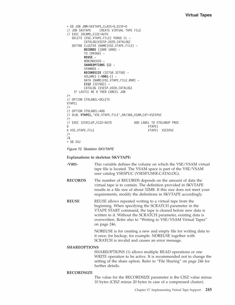
Explanations to skeleton SKVTAPE:
-V001- This variable defines the volume on which the VSE/VSAM virtualtape file is located. The VSAM space is part of the VSE/VSAMuser catalog VSESPUC (VSESP.USER.CATALOG).
RECORDS The number of RECORDS depends on the amount of data thevirtual tape is to contain. The definition provided in SKVTAPEresults in a file size of about 32MB. If this size does not meet yourrequirements, modify the definitions in SKVTAPE accordingly.
REUSE REUSE allows repeated writing to a virtual tape from thebeginning. When specifying the SCRATCH parameter in theVTAPE START command, the tape is cleared before new data iswritten to it. Without the SCRATCH parameter, existing data isoverwritten. Refer also to “Writing to VSE/VSAM Virtual Tapes”on page 246.
NOREUSE is for creating a new and empty file for writing data toit once; for backup, for example. NOREUSE together withSCRATCH is invalid and causes an error message.
SHAREOPTIONSSHAREOPTIONS (1) allows multiple READ operations or oneWRITE operation to be active. It is recommended not to change thesetting of the share option. Refer to “File Sharing” on page 246 forfurther details.
RECORDSIZEThe value for the RECORDSIZE parameter is the CISZ value minus10 bytes (CISZ minus 20 bytes in case of a compressed cluster).
* $$ JOB JNM=SKVTAPE,CLASS=0,DISP=D// JOB SKVTAPE CREATE VIRTUAL TAPE FILE// EXEC IDCAMS,SIZE=AUTO
DELETE (VSE.VTAPE.FILE) PURGE CL -CATALOG(VSESP.USER.CATALOG)
DEFINE CLUSTER (NAME(VSE.VTAPE.FILE) -RECORDS (1000 1000) -TO (99366) -REUSE -NONINDEXED -SHAREOPTIONS (1) -SPANNED -RECORDSIZE (32758 32758) -VOLUMES (-V001-)) -DATA (NAME(VSE.VTAPE.FILE.@D@) -CISZ (32768)) -CATALOG (VSESP.USER.CATALOG)
IF LASTCC NE 0 THEN CANCEL JOB/*// OPTION STDLABEL=DELETEVTAPE1/*// OPTION STDLABEL=ADD// DLBL VTAPE1,’VSE.VTAPE.FILE’,99/366,VSAM,CAT=VSESPUC/*// EXEC IESVCLUP,SIZE=AUTO ADD LABEL TO STDLABUP PROCD VTAPE1A VSE.VTAPE.FILE VTAPE1 VSESPUC/*/&* $$ EOJ
Figure 72. Skeleton SKVTAPE
Virtual Tapes
Chapter 17. Implementing Virtual Tape Support 245

CISZ The recommended value for the Control Interval Size is 32 KB; itshould not be smaller than 8 KB.
File SizeThe 4GB limit for VSE/VSAM files applies also for VSE/VSAM virtual tape files.
File NameIn the skeleton, VTAPE1 in the DLBL statement is the filename to be used in theVTAPE START command.
File SharingWhatever is defined in SHAREOPTIONS, the Virtual Tape Data Handler acceptsonly single WRITE or multiple READ access to a VSE/VSAM virtual tape from asingle z/VSE system. This corresponds to SHAREOPTIONS (1). If you want toaccess a VSE/VSAM virtual tape from more than one z/VSE system, useSHAREOPTIONS (1) which allows single WRITE or multiple READ access only.SHAREOPTIONS (1) avoids unpredictable results where multiple system access isbeing used.
Writing to VSE/VSAM Virtual TapesWRITE can only start at the beginning of a VSE/VSAM virtual tape. No rewrite oroverwrite of existing data is possible except from the beginning a tape. For writingto a VSE/VSAM virtual tape more than once, the file definition (skeletonSKVTAPE) must include the REUSE parameter. Once a VTAPE STOP commandhas been issued, the remaining buffer contents is written to tape, the tape is closed,and an end-of-volume (EOV) indicator is written. This means, no further data canbe appended (added) to this particular virtual tape.
Note that VSAM cluster can be defined as compression, but the compression ratecan vary a large amount (depending on the type of data).
There are three ways of writing to a VSE/VSAM virtual tape:1. The VSE/VSAM file is defined with REUSE.
During OPEN processing the tape is positioned to its beginning before aWRITE operation starts. Existing data is overwritten.
2. The VSE/VSAM file is defined with REUSE and VTAPE START includes theSCRATCH parameter.SCRATCH causes the tape to be cleared before WRITE starts at the beginningof the tape.
3. The VSE/VSAM file is defined with NOREUSE.You can write to the tape only once (for backup, for example).NOREUSE with SCRATCH is invalid and causes an error.
Virtual Tapes
246 z/VSE V4R3.0 Administration

Working with Remote Virtual TapesTo access a remote virtual tape, a TCP/IP connection must be established betweenz/VSE and the remote workstation with the Virtual Tape Server installed. Youstart the VTAPE support for a remote virtual tape with a VTAPE command such asthe following:VTAPE START,UNIT=cuu,LOC=ipaddress:portnumber,FILE=’filename’
(or)VTAPE START,UNIT=cuu,LOC=hostname:portnumber,FILE=’filename’
The ipaddress or hostname identifies the Virtual Tape Server workstation on whichthe remote virtual tape file is located (a Linux, UNIX, or Windows file, forexample). The portnumber is the TCP/IP port number to be used for the connection.If the virtual tape file does not yet exist, the command automatically causes thecreation of the required file (Linux, UNIX, or Windows) using the filenamespecified. The VTAPE command:VTAPE STOP,UNIT=cuu
drops the association between the tape unit cuu and the remote virtual tape file. Ifthis was the only active VTAPE session, the z/VSE partition in which the VirtualTape Data Handler is running is released after 30 seconds.
Note: If a remote virtual tape has been started whose TCP/IP connection is slow,this might have a negative impact on the performance of other virtual tapes.To avoid this problem, you should ensure that the TCP/IP connection to thevirtual tape is reliable and fast enough to be able to process highdata-transfer rates.
Entering a File Name Under Linux, UNIX, or WindowsIf the required Linux, UNIX, or Windows file for a remote virtual tape does notexist yet, it is automatically created when submitting the corresponding VTAPESTART command. When assigning file names you must observe certain rules andcharacteristics.
File names may contain blanks, therefore the filename must be enclosed in quotes.A quote within a filename must be coded as two single quotes; for example:FILE=’D:\John’’s\Virtual Tapes\vt001401.001’
File names can have more than 100 characters in length, therefore you may specifyFILE=’filename’ twice or even three times. However, each file parameter cannot begreater than 100 characters in length. Therefore, the filename is concatenated instorage, allowing for a file name length of 200 or even 300. The following exampleis equivalent to the previous example:FILE=’D:’,FILE=’\John’’s\Virtual Tapes\’,FILE=’vt001401.001’
Case Sensitivity Under Linux and UNIXLinux and UNIX are case sensitive but job streams created on the z/VSE host(dialogs of the Interactive Interface) are in capital letters. It may be thereforenecessary to edit such job streams to adapt the filename to the Linux or UNIXconventions.
Using Forward or Backward Slashes Under WindowsYou can use forward slashes (“/”) instead of backward slashes (“\”) on Windows(as is the case with Linux and UNIX).
Virtual Tapes
Chapter 17. Implementing Virtual Tape Support 247

If you wish to use the VTAPE command with Windows, you will probably usebackward-slashes to separate the directories. An example would be:C:\vtape\tapeiamge.aws
However, the use of backward-slashes might cause code-page errors during thetranslation from EBCDIC to ASCII. Therefore, when using the VTAPE commandwith Windows you are strongly recommended to use forward-slashes. An examplewould be:C:/vtape/tapeiamge.aws
If you use backward-slashes, the filename on Windows might be treated as arelative-path instead of an absolute-path. As a result, the tape image will becreated in the Virtual Tape Server's installation directory! This occurs becauseWindows does not recognize the path as an absolute-path if backward-slashes aretranslated into some incorrect characters.
Forward-slashes do not usually cause code-page translation errors. In addition, theJava runtime environment will automatically convert forward-slashes intobackward-slashes on Windows.
The Virtual Tape Server can accept both forward and backward slashes onWindows.
Further DocumentationThe workstation with the Virtual Tape Server installed provides the documentvtape.html. It includes further details about remote virtual tapes and the relatedenvironment. You reach the document by selecting from the Start Menu first VirtualTape, and then Help.
Examples of Using Virtual Tapes
Backing Up and Restoring DataBackup functions often produce tape output. Thus you may consider whethervirtual tapes are an alternative for such tasks in your data processing environment.For temporary data or short term backups in a z/VSE environment, for example,VSE/VSAM virtual tapes avoid the overhead of mounting and handling physicaltapes.
You can use virtual tapes for all types of backup and restore operations (involvingVSAM objects, library objects, history files, volumes, and files). For details, refer tothe chapter “Backing Up and Restoring Data” in the manual z/VSE Operation,SC33-8309.
Following is a backup example using a remote virtual tape. Data on a remotevirtual tape can be saved on CD-ROM for archiving or for distribution. In theexample, a VSE library backup and a later restore is assumed.1. Create a job stream to backup a VSE library on a remote virtual tape as shown
in the following sample job stream:
Virtual Tapes
248 z/VSE V4R3.0 Administration

2. Use the programs available on your Linux or Windows system to copy (burn)the VSE library from the remote virtual tape to a CD-ROM for archiving.Depending on the CD-ROM software you have installed, you may create thevirtual tape backup of the VSE library directly on the CD-ROM.
3. To restore the VSE library you must create a similar job stream as the oneshown for BACKUP, using the Librarian RESTORE command. You can restorethe VSE library (stored as virtual tape on CD-ROM) directly from the CD-ROMback to z/VSE.
Transferring Virtual Tape FilesIt is possible to transfer virtual tape files between a workstation (remote virtualtape) and the z/VSE host (VSE/VSAM virtual tape) and vice versa with theTCP/IP File Transfer Program (FTP). For a transfer from workstation to host usethe put command, for a host to workstation transfer the get command. Make sureyou are transferring the files in binary mode.
The example below shows the command sequence for a transfer from server tohost:C:\>ftp x.x.x.x <-- enter hostname/IP address of your VSE systemConnected to x.x.x.x.
...220 Service ready for new user.User (9.164.155.2:(none)): user <-- enter your user id here331 User name okay, need password.Password: <-- enter your password here230 User logged in, proceed.ftp> bin <-- switch to binary mode200 Command okay.ftp> quote site lrecl 32758 <-- enter the record size of your VSAM cluster200 Command okay.ftp> quote site recfm v <-- set record format to variable200 Command okay.ftp> put tape.image VSE.VTAPE.FILE <-- enter your filenames
Backing Up Data Using the Tivoli Storage ManagerThe Tivoli® Storage Manager (TSM) is an IBM software product that allows you tobackup and restore data over the network. The TSM:v Manages the storage.v Controls where the backup data is to be stored.
The TSM runs on a wide range of platforms, including Linux on System z®. If theTSM is already used at your site, z/VSE can be integrated into either new orexisting TSM-controlled backup environments.
// JOB BACKUP (Backup a Library to a PC File)// ON $CANCEL OR $ABEND GOTO VTAPSTOPVTAPE START,UNIT=480,LOC=9.164.186.20:2285, C
FILE=’D:\VSE Backup\prd2.001’MTC REW,480// EXEC LIBR
BACKUP LIB=PRD2 TAPE=480/*/. VTAPSTOPVTAPE STOP,UNIT=480/&
Figure 73. Job Stream Example for Backing Up a z/VSE Library
Virtual Tapes
Chapter 17. Implementing Virtual Tape Support 249

The TSM manages several storage pools, which can reside on disk or tape. Theadministrator defines the rules which determine:v How the storage pools are used.v When data should be migrated from one pool to another.
You can use the VTAPE command to back up z/VSE data to the TSM:v Remote VTAPEs only are supported.v You can encrypt data before it is sent over the network to the TSM server.v Your established backup jobs on z/VSE can usually be run almost unchanged.
Here is a typical VSAM backup job that uses the TSM:
Here is a typical VSAM restore job that uses the TSM (which corresponds to thebackup job):
For further details about using the:v Tivoli Storage Manager, see -
http://www.ibm.com/software/tivoli/products/storage-mgr/
v Tivoli Storage Manager together with VTAPE, see -http://www.ibm.com/systems/z/os/zvse/support/vtape.html
* $$ JOB JNM=VSAMBKUP,DISP=L,CLASS=0// JOB VSAMBKUP// ON $CANCEL OR $ABEND GOTO VTAPSTOP* THIS JOB BACKS UP VSAM DATASETS// DLBL IJSYSUC,’ catalog ’,,VSAMVTAPE START,UNIT=181,LOC=ip-addr,FILE=’TSM:VSAM.AWS(BACKUP,VSE)’,SCRATCH// ASSGN SYS005,181// EXEC IDCAMS,SIZE=AUTO
BACKUP ( cluster ) -REW -NOCOMPACT -BUFFERS(3)
/*/. VTAPSTOP// ASSGN SYS005,UAVTAPE STOP,UNIT=181/&* $$ EOJ
Figure 74. Backup Job That Uses the Tivoli Storage Manager and Virtual Tapes
* $$ JOB JNM=VSAMREST,DISP=L,CLASS=0// JOB VSAMREST// ON $CANCEL OR $ABEND GOTO VTAPSTOP* THIS JOB RESTORES VSAM DATASETSVTAPE START,UNIT=181,LOC=ip-addr,FILE=’TSM:VSAM.AWS(BACKUP,VSE)’,READ// ASSGN SYS004,181// EXEC IDCAMS,SIZE=AUTO
RESTORE OBJECTS ( ( cluster ) ) -CATALOG( catalog ) -REW -BUFFERS(3)
/*/. VTAPSTOP// ASSGN SYS004,UAVTAPE STOP,UNIT=181/&* $$ EOJ
Figure 75. Restore Job That Uses the Tivoli Storage Manager and Virtual Tapes
Virtual Tapes
250 z/VSE V4R3.0 Administration
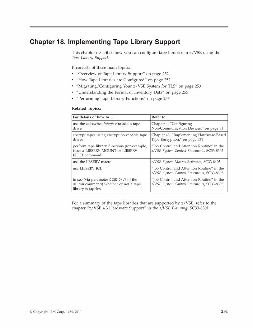
Chapter 18. Implementing Tape Library Support
This chapter describes how you can configure tape libraries in z/VSE using theTape Library Support.
It consists of these main topics:v “Overview of Tape Library Support” on page 252v “How Tape Libraries are Configured” on page 252v “Migrating/Configuring Your z/VSE System for TLS” on page 253v “Understanding the Format of Inventory Data” on page 255v “Performing Tape Library Functions” on page 257
Related Topics:
For details of how to ... Refer to ...
use the Interactive Interface to add a tapedrive
Chapter 4, “ConfiguringNon-Communication Devices,” on page 81
encrypt tapes using encryption-capable tapedrives
Chapter 43, “Implementing Hardware-BasedTape Encryption,” on page 531
perform tape library functions (for example,issue a LIBSERV MOUNT or LIBSERVEJECT command)
“Job Control and Attention Routine” in thez/VSE System Control Statements, SC33-8305
use the LBSERV macro z/VSE System Macros Reference, SC33-8405
use LIBSERV JCL “Job Control and Attention Routine” in thez/VSE System Control Statements, SC33-8305
to see (via parameter DISK-ONLY of theQT cuu command) whether or not a tapelibrary is tapeless
“Job Control and Attention Routine” in thez/VSE System Control Statements, SC33-8305
For a summary of the tape libraries that are supported by z/VSE, refer to thechapter “z/VSE 4.3 Hardware Support” in the z/VSE Planning, SC33-8301.
© Copyright IBM Corp. 1984, 2010 251

Overview of Tape Library SupportThe z/VSE Tape Library Support (TLS) enables z/VSE to access tape libraries via achannel interface. As a result:v The need to use an XPCC or APPC communication protocol is removed.v The need to setup a VTAM LU6.2 connection when using LCCD is removed.
z/VSE supports these tape libraries:v IBM TotalStorage 3494 Tape Libraryv IBM System Storage TS3500/3584 UltraScalable Tape Libraryv IBM System Storage TS7700 Virtualization Engine.v IBM System Storage tapeless (disk-only) TS7720 Virtualization Engine.v IBM TS7680 ProtecTIER Deduplication Gateway for System z.v IBM TotalStorage Virtual Tape Server (VTS)
For the TS3500/3584 Tape Library:
v The attachment of zSeries hosts to the TS3500/3584 Tape Library is done via theEnterprise Library Controller (ELC). This attachment takes advantage of theTS3500/3584 Tape Library’s support for the:– IBM TotalStorage 3592 Tape Drive Model J1A– IBM System Storage TS1120 tape drive (previously called the TotalStorage
3592 Model E05)– IBM System Storage TS1130 tape drive (previously called the TotalStorage
3592 Model E06)v The ELC program (the new Library Manager) provides the zSeries attachment to
the TS3500/3584 Tape Library. This zSeries-attachment is achieved by using theexisting 3494 Library Manager to generate SCSI Medium Changer commands todrive the TS3500/3584.
v For Open system environments, you can use in the same TS3500/3584 TapeLibrary:– IBM TotalStorage LTO (Linear Tape-Open) Tape sub-systems.– IBM System Storage TS1120 tape drives (previously called the TotalStorage
3592 Model E05).– IBM System Storage TS1130 tape drives (previously called the TotalStorage
3592 Model E06).
How Tape Libraries are ConfiguredHere is an overview of how tape libraries can be configured:
Table 4. Overview of Tape Library Configuration Possibilities
IBM 3494 TapeLibrary
IBM TS3500/3584UltraScalable TapeLibrary
IBM TS7700VirtualizationEngine ¹
IBM TS7680ProtecTIERDeduplicationGateway forSystem z ²
Which tape drives canbe defined/used?
v IBM 3490Ev IBM 3590v IBM 3592 Model J1Av IBM TS1120 (3592
Model E05)v IBM TS1130 (3592
Model E06)
v IBM 3592 Model J1Av IBM TS1120 (3592
Model E05)v IBM TS1130 (3592
Model E06)
v IBM 3490E v IBM 3592 ModelJ1A
Tape Library Support
252 z/VSE V4R3.0 Administration

Table 4. Overview of Tape Library Configuration Possibilities (continued)
IBM 3494 TapeLibrary
IBM TS3500/3584UltraScalable TapeLibrary
IBM TS7700VirtualizationEngine ¹
IBM TS7680ProtecTIERDeduplicationGateway forSystem z ²
Run under z/VMusing VGS (VSEGuest Server)?
Yes Yes Yes Yes
Run in VSE LPARmode?
Yes Only with the:v IBM 3592 Model J1Av IBM TS1120 (3592
Model E05)v IBM TS1130 (3592
Model E06)
Yes Yes
Run in VSE LPARmode using TLS (TapeLibrary Support)?
Yes Yes Yes Yes
Notes:
1. The TS7700 1.5 and later support a disk-only configuration of the IBM TS7720Virtualization Engine.
2. The TS7680 provides a disk-only virtual tape solution, and emulates an IBMtape library and 3592 Model J1A tape drives.
3. The TS1120 is also referred to as the 3592 Model E05. The TS1130 is alsoreferred to as the 3592 Model E06.
Migrating/Configuring Your z/VSE System for TLSTo prepare your z/VSE system for use with an IBM tape library, you must performthe steps described below:Step 1. Add a SYS ATL=TLS Command to Your z/VSE Startup Procedure:
You must add a SYS ATL=TLS command to your z/VSE IPL procedure,using the dialog described in “IPL Parameters You Can Modify” on page15. For details of the SYS command, refer to the manual z/VSE SystemControl Statements, SC33-8305.
Step 2. Define Customization Options and Control Statements:You must change the sample job TLSDEF which is provided in ICCFLibrary 59 to meet your own system requirements. Here is an example jobwhich uses logical addresses 460 to 463, and 580 to 582. All variables areshown in italics.* $$ JOB JNM=TLSDEF,CLASS=0,DISP=D* $$ LST CLASS=A// JOB TLSDEF
EXEC LIBR,PARM=’MSHP’ACCESS S=IJSYSRS.SYSLIBCATALOG TLSDEF.PROC REPLACE=YESLIBRARY_ID TAPELIB1 SCRDEF=SCRATCH00 INSERT=SCRATCH00LIBRARY_ID TAPELIB2 * SECOND LIB DEF DUAL LIBDEVICE_LIST TAPELIB1 460:463 * DRIVES 460 TO 463DEVICE_LIST TAPELIB2 580:582 * DRIVES 580 TO 582QUERY_INV_LISTS LIB=TLSINV * MASTER INVENTORY FILES
Tape Library Support
Chapter 18. Implementing Tape Library Support 253

MANAGE_INV_LISTS LIB=TLSMAN * MANAGE FROM MASTER/+/&* $$ EOJ
These are the keywords and parameters used in job TLSDEF:
LIBRARY_IDThe keyword LIBRARY_ID is followed by the eight-character logicalunit name of an attached library. This logical unit name is used as theLibrary Name field in functional requests from users, and as thez/VSE sub-library name used in inventory requests. If the libraryname is less than 8 characters, it will be padded to the right withblanks.v The keyword SCRDEF is followed by the name of the scratch pool
to be used as the default for this z/VSE host on this library. Tapeswill be mounted from this pool for nonspecific MOUNT SCRATCHrequests. If this parameter is not included, SCRATCH00 will beused as the default pool.
v The keyword INSERT allows a target category to be specified forautomatic insert processing of new volumes inserted in the library.The target category must be either SCRATCHnn (where nn is in therange 00 to 31), or PRIVATE. If this parameter is omitted, noautomatic insert processing occurs.
You must define one LIBRARY_ID statement for each attached library.If user requests do not specify a library name, the library associatedwith the first occurrence of this keyword will be used as the default.z/VSE supports a maximum of eight libraries.
DEVICE_LISTDesignates the Library_Id and the corresponding devices. Whenmultiple hosts are attached to the same library, this keyword allowsdevice partitioning. This statement may be repeated as required to listall libraries with devices to be used by this host.
QUERY_INV_LISTSDesignates the name (up to seven characters) for the predefined VSElibrary in which Query Inventory member lists are to be created. Ifthis control card is not found or if it is not coded properly, or if thelibrary and a sub-library for the attached 3494 or 3584 is not defined,Query Inventory requests cannot be processed.
MANAGE_INV_LISTSDesignates the name (up to seven characters) for the predefinedlibrary from which Manage Inventory member lists are to be read. Ifthis control card is not found or if it is not coded properly, or if thelibrary and a sub-library for the attached tape library is not defined,Manage Inventory requests cannot be processed.
For details of how to predefine z/VSE libraries for inventory requests,refer to Step 4 (below).
After you have customized the job TLSDEF, submit this job to catalogTLSDEF.PROC into library IJSYSRS.SYSLIB. Your TLSDEF.PROC will thenbecome active the next time an IPL is made of your z/VSE system.
Step 3. Enter a STDEVOPT Statement in z/VM (Optional)If your z/VSE system is running under z/VM, you must include thisstatement in the user directory entry:STDEVOPT LIBRARY CTL
Tape Library Support
254 z/VSE V4R3.0 Administration

Otherwise, the devices will be controlled by z/VM which will return a“command reject” for each request.
Step 4. Define z/VSE Libraries to Contain Inventory RequestsBefore you can start the inventory application, you must create a libraryinto which host copies of tape-library inventory lists can be written. Youmust create a unique sub-library that has the name of your tape library.The library into which host copies of tape-library inventory lists can bewritten requires disk space assigned using DLBL and EXTENT statements.You can add these labels to either the STANDARD or USER STANDARDLABEL procedure. Here is an example of these statements:* DEFINITION FOR THE VSE TLSINV INVENTORY LIBRARY// DLBL TLSINV,’VSE.TLSINV.QLISTS.LIBRARY’,99/365// EXTENT ,SYSWK1,1,0,9500,100EXEC LIBRDEF L=TLSINVDEF S=TLSINV.TAPELIB1
(Note: the Library and Sublibrary examples are as used in Step 2)
Understanding the Format of Inventory Data
Output File Produced by a Query Inventory RequestAn 80-byte inventory record output file is created by a Query Inventory request.This file applies to a cartridge and contains the following information:v External volume label (six characters)v Media type:
– CST1 or CST2 for 3490 cartridges.– CST3 or CST4 for 3590 cartridges.– CST5 for 3592 300 GB cartridges.– CST6 for 3592 WORM (Write-Once-Read-Many) 300 GB cartridges.– CST7 for 3592 60 GB cartridges.– CST8 for 3592 WORM 60 GB cartridges.– CST9 for 3592 700 GB.– CSTA for 3592 WORM 700 GB.
v Special attribute byte, represented by an EBCDIC bit string (eight characters)Bit 0 If 1, volume is present in library, but inaccessibleBit 1 If 1, volume is mounted or queued for mountBit 2 If 1, volume is in eject-pending stateBit 3 If 1, volume is in process of ejectionBit 4 If 1, volume is misplacedBit 5 If 1, volume has unreadable label or no labelBit 6 If 1, volume was used during manual modeBit 7 If 1, volume was manually ejected
v Category name (ten characters)v Library manager hexadecimal category number, in EBCDIC representation (four
characters)
The fields in each record are separated by a blank character to enhance theirreadability.
A sample file record is:CS0010 CST2 01000000 PRIVATE FFFF
Tape Library Support
Chapter 18. Implementing Tape Library Support 255

A header with the time of list creation is inserted as the first record in the list.
Input File Submitted by a Manage Inventory RequestA file submitted for use in a Manage Inventory request requires that eachsix-character external volume serial number in the list start in column 1 of a filerecord. The remaining space in each 80-character record is ignored as input. Thisallows for returning the Query Inventory output file as input to the ManageInventory function.
A sample record in a Manage Inventory input file is:CS0010 CST2 01000000 PRIVATE FFFF
Or, simplyCS0010
A header record (as described for Query Inventory output) may be optionallypresent in the input list. Any record starting with an asterisk (*) is not considered avalid input data record and is ignored.
Output Produced by a Manage Inventory RequestAfter a Manage Inventory request is completed, a return code (or reason code) issupplied to indicate that processing is complete and to report the overall results forprocessing the request (for example, input was valid, file was found, and so forth).The actual outcome of transferring each volume to a new target category isreflected within the file itself. The file is updated by adding a results message ineach file record, starting in column 38. An example of a successful output filerecord is:CS0010 CST2 01000000 PRIVATE FFFF CATEGORY CHANGED TO EJECT
An example for an unsuccessful output file record is:AB1234 CATEGORY NOT CHANGED, RSN=3340
Naming Conventions for Inventory FilesTable 5 summarizes the naming conventions for inventory files used in the QueryInventory (IQUERY) functions. VSE libraries must be predefined, together with asub-library for each attached 3494 or 3584.
Table 5. Naming Conventions for Inventory Files
Source Category Member Name
(omitted) ALL
PRIVATE PRIVATE
INSERT INSERT
SCRATCHnn SCRnn
SCRATCH SCRnn (see Note 1)
MANEJECT MANEJECT
EJECT EJECT
VOL VOL
Tape Library Support
256 z/VSE V4R3.0 Administration

Notes:
1. In the above table entry for SCRATCH, nn refers to the default scratch pool thatwas specified using the SCRDEF keyword (see Step 2 of “Migrating/Configuring Your z/VSE System for TLS” on page 253).
2. There are no naming conventions for the Manage Inventory (MINVENT)function. You can specify MEMNAME according to your own namingconventions.
Performing Tape Library FunctionsIBM tape library communication is performed using the JCL LIBSERV statementsdescribed in Table 6. For details of these commands , refer to the manual z/VSESystem Control Statements, SC33-8305.
Table 6. Overview of LIBSERV Commands Used With an IBM Tape Library Data Server
Command Description
LIBSERV AQUERY Verify the location of a volume in all known libraries.
LIBSERV CQUERY Return the number of volumes in a source category.
LIBSERV CMOUNT Mount a volume from a source category on a device belonging to atape library. Access will then be given to the device.
LIBSERV DQUERY Verify the status of a device in a tape library.
LIBSERV RELEASE Release a device in a tape library.
LIBSERV EJECT Eject a volume.
LIBSERV IQUERY Request the inventory data of volumes currently assigned to acategory in a tape library. See also “Output File Produced by aQuery Inventory Request” on page 255.
LIBSERV LQUERY Return the operational status of a tape library.
LIBSERV MOUNT Mount a specified volume.
LIBSERV MINVENT Transfer the volumes in a referenced member name and sourcecategory, to a target category.
LIBSERV SETVCAT Assign a volume to a target category.
LIBSERV SQUERY Verify the location of a volume in a library.
Tape Library Support
Chapter 18. Implementing Tape Library Support 257

Tape Library Support
258 z/VSE V4R3.0 Administration

Part 3. BSM and LDAP Security
Chapter 19. Roadmap/Overview of BSM-BasedSecurity . . . . . . . . . . . . . . . 263Roadmap for Using BSM-Based Security . . . . 263General Aspects . . . . . . . . . . . . 265
Security Considerations . . . . . . . . . 265The Security Administrator . . . . . . . . 265
Passwords and User-IDs. . . . . . . . 266Overview Diagram of BSM-Based Security . . . 266General Concept of Access Control . . . . . . 269
Chapter 20. Implementing z/VSE SecuritySupport . . . . . . . . . . . . . . . 271Tasks Required to Implement Security Support . . 271Using the Tailor-IPL-Procedure Dialog to TailorSecurity Parameters . . . . . . . . . . . 273Applying Security to VSE/ICCF Libraries . . . . 274
Dummy Resource IJSYSRS.SYSLIB.DTSUTILA 275Passwords For VSE/ICCF and the InteractiveInterface . . . . . . . . . . . . . . 275
Chapter 21. Migrating CICS TransactionSecurity Definitions. . . . . . . . . . . 277Overview of Migration Steps . . . . . . . . 277Performing the Migration . . . . . . . . . 281Recreating Your BSM Control File . . . . . . 285
Chapter 22. Maintaining User Profiles via BSMDialogs . . . . . . . . . . . . . . . 287Introduction . . . . . . . . . . . . . . 288Adding/Changing a User-ID and ProfileDefinitions . . . . . . . . . . . . . . 289
Entering z/VSE User Profile Information . . . 289Adding/Changing CICS Profile and DTSECTABInformation . . . . . . . . . . . . . 293Adding/Changing VSE/ICCF ProfileInformation . . . . . . . . . . . . . 295Adding an LDAP User-ID to Correspond to theVSE User-ID. . . . . . . . . . . . . 298Adding/Changing the Group Connects for aVSE User-ID. . . . . . . . . . . . . 301
Deleting a User-ID and Profile Definitions . . . . 303Generating a Job to Create BSM Groups . . . . 303Creating a Status of User-IDs Using the Dialog . . 304Maintaining CICS User Profiles without VSE/ICCF 304Generating BSM Cross Reference Reports . . . . 304
Using the BSTXREF Service . . . . . . . 304Using the BSM Cross Reference Report Dialog 306
Additional Considerations . . . . . . . . . 307Creating a Status Report of User-IDs UsingIESBLDUP . . . . . . . . . . . . . 307Dialog Considerations . . . . . . . . . 307VSE/ICCF Library Considerations . . . . . 308VSE/ICCF Interactive Partitions . . . . . . 309VSE/ICCF DTSFILE Considerations . . . . . 309
Chapter 23. Maintaining User Profiles via BatchProgram IESUPDCF. . . . . . . . . . . 311Preparing to Use Batch Program IESUPDCF . . . 311
Planning for User Profiles . . . . . . . . 311Preparing Skeleton IESUPDCF. . . . . . . 312Setting the ICCF Parameter in SkeletonIESUPDCF . . . . . . . . . . . . . 312Adding a User-ID in Skeleton IESUPDCF . . . 314
Mandatory Parameters . . . . . . . . 314Optional Parameters . . . . . . . . . 315
Altering a User-ID in Skeleton IESUPDCF . . . 317Deleting a User-ID in Skeleton IESUPDCF. . . 318Skeleton IESUPDCF . . . . . . . . . . 318
Using Batch Program IESUPDCF to Maintain UserProfiles . . . . . . . . . . . . . . . 321
Return Codes Issued by IESUPDCF . . . . . 321Example of Completed Skeleton IESUPDCF . . 323
Chapter 24. Maintaining User Profiles in anLDAP Environment . . . . . . . . . . . 325Overview of LDAP Sign-On Processing. . . . . 326LDAP Sign-On: Prerequisites and Getting Started 330Deciding if Strict-User-Mappings Are to be Used 331Deciding if Password-Caching is to be Used . . . 331Choosing an LDAP Authentication Method . . . 332Tailoring the LDAP Configuration MemberSKLDCFG . . . . . . . . . . . . . . 333Example of an LDAP Configuration Member . . . 335Rules for Using LDAP-Enabled User-IDs . . . . 338Choosing a Method for Maintaining LDAP UserMappings . . . . . . . . . . . . . . 339Using Dialogs to Maintain LDAP User Mappings 339Using the LDAP Mapping Tool to Maintain LDAPUser Mappings . . . . . . . . . . . . . 343
ID Command . . . . . . . . . . . . 343ADD Command . . . . . . . . . . . 344CHANGE Command . . . . . . . . . . 345DELETE Command . . . . . . . . . . 346LIST Command . . . . . . . . . . . 346EXPORT Command . . . . . . . . . . 347Example of How to Specify Control Statements 347
Using Your Own LDAP Sign-On Program . . . . 348Return/Feedback Codes Generated During LDAPSign-On . . . . . . . . . . . . . . . 349
Chapter 25. Resources Classes Stored in theBSM Control File. . . . . . . . . . . . 351Syntax Rules For Resources Defined in the BSMControl File . . . . . . . . . . . . . . 352Resource Class ACICSPCT . . . . . . . . . 352Resource Class APPL . . . . . . . . . . . 352Resource Class DCICSDCT . . . . . . . . . 353Resource Class FACILITY . . . . . . . . . 353Resource Class FCICSFCT . . . . . . . . . 354Resource Class JCICSJCT . . . . . . . . . 354Resource Class MCICSPPT . . . . . . . . . 355
© Copyright IBM Corp. 1984, 2010 259

Resource Class SCICSTST . . . . . . . . . 355Resource Class TCICSTRN . . . . . . . . . 356WebSphere MQ for z/VSE Resource Classes . . . 357Additional Resource Classes . . . . . . . . 357
Chapter 26. Protecting Resources viaBSTADMIN Commands . . . . . . . . . 359Overview of BSM BSTADMIN Commands andTheir Syntax. . . . . . . . . . . . . . 361
How You Enter a Command Continuation. . . 362How You Enter Generic Names . . . . . . 362How You Enter Comment Lines . . . . . . 363
ADD | AD Command . . . . . . . . . . 363CHANGE | CH Command. . . . . . . . . 364DELETE | DE Command . . . . . . . . . 366PERMIT | PE Command . . . . . . . . . 366ADDGROUP | AG Command. . . . . . . . 367CHNGROUP | CG Command. . . . . . . . 367DELGROUP | DG Command . . . . . . . . 367CONNECT | CO Command . . . . . . . . 367REMOVE | RE Command . . . . . . . . . 368LIST | LI Command . . . . . . . . . . . 368LISTG | LG Command . . . . . . . . . . 369LISTU | LU Command . . . . . . . . . . 369PERFORM | PF Command. . . . . . . . . 369USERID | ID Command . . . . . . . . . 372STATUS | ST Command . . . . . . . . . 372Return Codes That Might Occur When UsingBSTADMIN . . . . . . . . . . . . . . 373
Chapter 27. Protecting Resources via BSMDialogs . . . . . . . . . . . . . . . 375Scenario to Demonstrate the Use of BSM Dialogs 376
Security Environment to be Created in theScenario . . . . . . . . . . . . . . 376Step 1: Add Group Profiles . . . . . . . . 376Step 2: Add Users to Groups . . . . . . . 378Step 3: Add Resource Profiles and Give AccessRights . . . . . . . . . . . . . . . 379Step 4: Activate the Security Setup . . . . . 381Connecting a User to Groups via Option 8 . . 382Removing User Connects to Groups via Option9 . . . . . . . . . . . . . . . . 382Removing User Connects to All Groups viaPF10 . . . . . . . . . . . . . . . 383
Using BSM Dialogs to Protect JCL Operands . . . 385
Chapter 28. Overview of DTSECTAB-Based VSESecurity . . . . . . . . . . . . . . . 389How Security Checking Is Performed . . . . . 389How User Profile Information Is Used . . . . . 390Which Resources Can Be Protected in DTSECTAB? 390Defining Resources in DTSECTAB . . . . . . 391Using the IBM-Provided DTSECTAB . . . . . 391How Users Are Identified and Authenticated . . . 392
Security Information in the JECL Statement * $$JOB. . . . . . . . . . . . . . . . 392Security Information in the JCL Statement // ID 392
How VSE/POWER Jobs are Authenticated . . . 393
Chapter 29. Customizing/ActivatingDTSECTAB-Based Security . . . . . . . . 395Activating Security for Batch Resources . . . . 395Tasks to be Done after Initial Installation . . . . 396
Considerations for User-IDs FORSEC andDUMMY . . . . . . . . . . . . . . 396
Pregenerated Access Control Table DTSECTAB . . 397Predefined Member DTSECTRC (ContainingDTSECTAB) . . . . . . . . . . . . . 397
Maintaining the Access Control Table DTSECTAB 398Scenario 1. Predefined Security Support Only 398Scenario 2. Add Resources Using the UACCParameter Only . . . . . . . . . . . 398Scenario 3. Add Resources Using the ACCParameter . . . . . . . . . . . . . 399
Applying IBM Service to DTSECTRC . . . . . 399Protecting the Access Control Table DTSECTABItself . . . . . . . . . . . . . . . . 399Content of Pregenerated DTSECTAB (DTSECTRCin VSE/ICCF Library 59) . . . . . . . . . 400
Chapter 30. Access Rights/Checking inDTSECTAB . . . . . . . . . . . . . . 407How Access Rights Are Used . . . . . . . . 407
Two Kinds of Access Rights . . . . . . . 408An Example of Using Access Rights . . . . . 409Diagram of Access-Checking Flow . . . . . 410
Access Control for Libraries . . . . . . . . 411The Access Right of CON . . . . . . . . 412Hierarchical Access Checking . . . . . . . 412Impact on Logging . . . . . . . . . . 413Access Control for LIBDEF Statements . . . . 413Access Checking for Source Library Inclusion(SLI) . . . . . . . . . . . . . . . 414
Format 1 (with member name only) . . . . 414Format 2 (member plus sublibrary) . . . . 414
Special Access Checking for LibrarianCommands . . . . . . . . . . . . . 414Protection of the System Library and SystemSublibrary . . . . . . . . . . . . . 415Protection of PRIMARY Library and Sublibraries 415
Accessing PRIMARY Sublibraries. . . . . 415PRIMARY Sublibraries for Predefined UsersSYSA, OPER and PROG . . . . . . . . 416PRIMARY.$$C Common Sublibrary . . . . 416
Access Control for Startup Procedures . . . . . 416Startup Procedures with Access Rights of aParticular User . . . . . . . . . . . . 416Access Control and CICS Region Prefix. . . . 416
System Phases, B-Transients, Link Area, SVA andLTA . . . . . . . . . . . . . . . . 417
Considerations for B-Transients . . . . . . 417Considerations for Link Area, SVA, and LTA 417
Chapter 31. DTSECTAB Macro: Syntax andExamples . . . . . . . . . . . . . . 419Format of DTSECTAB Macro for DefiningResources . . . . . . . . . . . . . . 419Generic Protection of Resources . . . . . . . 421Examples of DTSECTAB Resource Entries . . . . 422
File Entries: . . . . . . . . . . . . . 422
260 z/VSE V4R3.0 Administration

Library Entries: . . . . . . . . . . . . 423Sublibrary Entries:. . . . . . . . . . . 423Member Entries: . . . . . . . . . . . 424Example of DTSECTAB Entries for LibraryControl . . . . . . . . . . . . . . 424
Chapter 32. Propagation of VSE/POWERSecurity Identification . . . . . . . . . . 427VSE/POWER Authenticated Jobs . . . . . . . 427Propagating Security Identification betweenVSE/POWER Subsystems . . . . . . . . . 428
Security Zone . . . . . . . . . . . . 428General Rules for VSE/POWER Subsystems . . 429Security Checking under VSE/POWER SharedSpooling . . . . . . . . . . . . . . 429Transfer of Jobs or Files/Members betweenSystems . . . . . . . . . . . . . . 429
Chapter 33. Operating a DTSECTAB-BasedSecurity System . . . . . . . . . . . . 431Some General Rules . . . . . . . . . . . 431Avoiding Startup Problems . . . . . . . . . 431Performance Considerations . . . . . . . . 432Tape Handling . . . . . . . . . . . . . 432Controlling the Security Server Partition . . . . 432
Chapter 34. Additional z/VSE Data ProtectionFacilities . . . . . . . . . . . . . . 435Using the IPL Exit to Check After IPL . . . . . 435Using the Job Control Exit to Check Job ControlStatements . . . . . . . . . . . . . . 435Using Labeling to Identify/Date Files . . . . . 436Using Data Secured Files to Protect Files on Disk 436Using DASD File Protection to Protect Files onDisk . . . . . . . . . . . . . . . . 437Using the Track Hold Option to PreventConcurrent Updates . . . . . . . . . . . 437Using Lock Management to Lock Resources UsingAssembler Macros . . . . . . . . . . . . 437Protecting VSE/VSAM Files via Passwords . . . 438
Chapter 35. Logging/Reporting Security Events 439Logging and Creating Reports Of Security-RelatedSMF Records . . . . . . . . . . . . . 439
Using SMF/DMF to Log Access Attempts toDTSECTAB Resources . . . . . . . . . 439Configuring Your System to Use the DMF . . . 440Overview of the DMF Logging and ReportingProcess . . . . . . . . . . . . . . 441Activating the Logging of SMF Records . . . 442Using the BSM Report Writer to ProcessDFHDFOU Output . . . . . . . . . . 442
Using VSE/ACLR to Log/Report Access Attemptsto DTSECTAB . . . . . . . . . . . . . 445
Using VSE/ACLR to Log Access Attempts toLibraries . . . . . . . . . . . . . . 445
The Reporting Module . . . . . . . . 446Using VSE/ACLR to Audit Access Attempts toControlled Resources . . . . . . . . . . 448Using VSE/ACLR to Obtain an Audit Trail . . 448
Hints for Auditing. . . . . . . . . . . . 449
Chapter 36. Protecting CICS Transactions withAccess Control Table DTSECTXN . . . . . . 451Using the Define Transaction Security Dialog . . . 451
Generic Transaction Names. . . . . . . . 453Explanation of INCLUDE MEMBER Field . . . 453Merging, Processing and Activating DTSECTXN 453
Using the Macro DTSECTXN . . . . . . . . 455Example of the CICS Transaction Security TableDTSECTXM . . . . . . . . . . . . . 456Example of the CICS Transaction Security TableDTSECTXN . . . . . . . . . . . . . 456
Chapter 37. Migrating CICS/VSE SecurityInformation to the CICS TS . . . . . . . . 457Overview of Migration Tasks . . . . . . . . 457Migrating USER Definitions Stored in IESCNTL 458Migrating USER Definitions Stored in DFHSNTand DTSFILE . . . . . . . . . . . . . 458Migrating TRANSEC Definitions Using theMigration Aid . . . . . . . . . . . . . 458
Step 1: Prepare Input Using the CICS SecurityMigration Aid . . . . . . . . . . . . 458Step 2: Migrate TRANSEC Definitions to a CICSTS System . . . . . . . . . . . . . 460
DTSECTX2 Parameters . . . . . . . . 461Invoking DTSECTX2 . . . . . . . . . 462DTSECTX2 Return Codes . . . . . . . 462
Migrating DFHPCT.A TRANSEC Definitions . . . 463DTSECTXS Parameters . . . . . . . . . 463Invoking DTSECTXS . . . . . . . . . . 464DTSECTXS Return Codes: . . . . . . . . 464
Migrating DFHCSDUP TRANSEC Definitions . . 465DTSECTX3 Parameters . . . . . . . . . 465Invoking DTSECTX3 . . . . . . . . . . 466DTSECTX3 Return Codes . . . . . . . . 466
Part 3. BSM and LDAP Security 261

262 z/VSE V4R3.0 Administration

Chapter 19. Roadmap/Overview of BSM-Based Security
This chapter provides a roadmap and overview of the security that is availablefrom z/VSE V3R1.1 onwards.
It consists of these main topics:v “Roadmap for Using BSM-Based Security”v “General Aspects” on page 265v “Overview Diagram of BSM-Based Security” on page 266v “General Concept of Access Control” on page 269
Roadmap for Using BSM-Based SecurityTo establish an operational security system, you might find it useful to follow this“roadmap”:1. The general aspects which you should consider when setting up security for
your z/VSE system are described below. This chapter also includes an overviewdiagram of the complete BSM-based security (for z/VSE and CICS) which isshown in “Overview Diagram of BSM-Based Security” on page 266.
2. The installation tasks that you must complete are described in the followingtopics:a. The initial tasks you must complete to have security installed on your
z/VSE system are described in Chapter 20, “Implementing z/VSE SecuritySupport,” on page 271.
b. The setting up of security options, such as:v active resource classes,v password rules,v audit options.
are described in “PERFORM | PF Command” on page 369.c. The commands that you use to control the security server are described in
“Controlling the Security Server Partition” on page 432.d. How you migrate CICS transaction security definitions, contained in
security table DTSECTXN, to the latest BSM transaction profiles is describedin Chapter 21, “Migrating CICS Transaction Security Definitions,” on page277.
e. How you migrate the 64 transaction security keys (defined for each user) to64 BSM groups is described in “Performing the Migration” on page 281.This topic also describes how user-IDs can be connected to these 64 BSMgroups.
f. How you recreate and/or backup the BSM control file is described in“Recreating Your BSM Control File” on page 285. This process uses theBSTSAVER program. The commands generated by BSTSAVER can also besaved if you wish to migrate to a later level of BSM.
3. How you setup and maintain your user profiles is described in these topics:a. Chapter 22, “Maintaining User Profiles via BSM Dialogs,” on page 287
describes how you define user profiles using dialogs.b. Chapter 23, “Maintaining User Profiles via Batch Program IESUPDCF,” on
page 311 describes how you define user profiles using a batch job.
© Copyright IBM Corp. 1984, 2010 263

Note: Chapter 24, “Maintaining User Profiles in an LDAP Environment,” onpage 325 describes how you set up your user profiles in an LDAPenvironment (which is not based on the BSM).
4. The resource customization/administration tasks that you must complete aredescribed in the following topics:a. How you group resources (such as CICS transactions, CICS transient data
queues, CICS files, and so on) into resource classes, is described inChapter 25, “Resources Classes Stored in the BSM Control File,” on page351.
b. The syntax rules for the resources you define in the BSM control file aregiven in “Syntax Rules For Resources Defined in the BSM Control File” onpage 352.
c. How you define resources in the BSM control file using the BSTADMINEXEC, is described in Chapter 26, “Protecting Resources via BSTADMINCommands,” on page 359.
d. How you define resources in the BSM control file using dialogs, is describedin Chapter 27, “Protecting Resources via BSM Dialogs,” on page 375.
e. How you protect JCL statements by defining resource profiles for theFACILITY resource class is described in “Using the Tailor-IPL-ProcedureDialog to Tailor Security Parameters” on page 273.
f. An overview of VSE security based upon the use of table DTSECTAB andthe VSE control file is described in Chapter 28, “Overview ofDTSECTAB-Based VSE Security,” on page 389. This chapter also describeshow VSE/POWER jobs are authenticated.
g. How you customize the IBM-supplied sample table DTSECTAB and activatebatch security based on this table, is described in Chapter 29,“Customizing/Activating DTSECTAB-Based Security,” on page 395.
h. How you specify access rights in table DTSECTAB, is described inChapter 30, “Access Rights/Checking in DTSECTAB,” on page 407.
i. The syntax of the DTSECTAB macro (including examples of its use), isdescribed in Chapter 31, “DTSECTAB Macro: Syntax and Examples,” onpage 419.
j. How security information is propagated between one or more VSE/POWERbatch environments, is described in Chapter 32, “Propagation ofVSE/POWER Security Identification,” on page 427.
k. The security items that you should consider in a system where batchsecurity is active (such as avoiding startup problems, performance, tapehandling), is described in Chapter 33, “Operating a DTSECTAB-BasedSecurity System,” on page 431.
l. The standard facilities for protecting data (such as IPL Exit, Job Control Exit,Disk-File Protection, Track Hold Option), are described in Chapter 34,“Additional z/VSE Data Protection Facilities,” on page 435.
5. The logging and reporting of security events is described in the following topics:v How you use the DMF (Data Management Facility) to store SMF (System
Management Facilities) records created by RACROUTE requests, is describedin “Logging and Creating Reports Of Security-Related SMF Records” on page439.
v How you use optional program ACLR (VSE/Access Control-Logging andReporting) to log/report-on access attempts to resources contained in tableDTSECTAB, is described in “Using VSE/ACLR to Log/Report AccessAttempts to DTSECTAB” on page 445.
264 z/VSE V4R3.0 Administration

General AspectsIf you are an experienced z/VSE user, you may skip the following text.
The information stored in a data processing system is often of vital importance tothe organization which uses the system. On one hand, the information is necessaryfor the members of the organization to do their work. On the other hand, thesystem may store confidential information, whose disclosure to unauthorizedpersons could mean considerable damage to an organization.
Corresponding to these two categories of information are two aspects of dataprotection:
Data Security which means protecting information from unauthorized accessand use.Data Integrity which means protecting information from loss or destruction.
The z/VSE Access Control Function, which is the primary topic of this chapter,solely addresses the first aspect: data security. The Access Control Function is partof the Basic Security Manager of z/VSE.
A computer system operating under control of z/VSE offers a number ofprotection functions for hardware and software. This chapter deals with thesoftware protection functions provided by z/VSE. For hardware protectionfunctions, refer to the appropriate manuals of the hardware you are using.
Security ConsiderationsA z/VSE system is designed to protect users' data or applications from interferenceby other users or applications. However, people who deliberately use theirknowledge of the internals of the system can gain unauthorized access to data andresources of the system despite built-in security safeguards. Management isresponsible for introducing administrative and operational safeguards that help toavoid such exploitations and that ensure system security to a great extent.
To achieve an acceptable level of system security for a z/VSE installation a usershould:v Ensure that knowledgeable and skilled members of the installation's staff will
have little or no chance to access certain data or to use or manipulate certainprograms;
v Ensure that resources (mainly programs) that can be used to bypass existingsecurity safeguards are protected properly.
v Ensure that IBM's Diagnosis Reference manuals are given only to a limited set ofpersons.
The Security AdministratorA security administrator must have adequate software protection functionsavailable to meet all security demands. A person appointed to assume theresponsibility of safeguarding installation's assets (data and programs) should,therefore, carefully review the available standard functions. A securityadministrator should do this review in full consideration of the variousresponsibilities that a person in such a position normally must assume, some ofwhich are indicated below:v Together with management, prepare a list of sensitive files and of programs that
process data in these files.
Chapter 19. Roadmap/Overview of BSM-Based Security 265

v Determine who of the installation's staff is authorized to use those programs anddata and establish procedures that ensure that authorized persons only, and noone else, will be able to invoke the programs.
v Protect system libraries adequately.v Minimize the chance that unauthorized access of sensitive data remains
undetected.v Keeping track of the usage of certain protected programs and data (logging and
reporting).v Utilize (in addition to z/VSE Access Control) special security functions of z/VSE
components and programs.
Passwords and User-IDsOne of the responsibilities of the security administrator is to assign passwords tousers and force the users to change them from time to time in order to avoiddamage as a result of inadvertent or intentional disclosure.
The password itself should be composed of a random combination ofalphanumeric characters. It should not contain any information or be mnemonic.
If passwords must be included in the job stream, special protective measures maybe required. For example, the member containing the job stream could be protectedsuch that unauthorized persons are unable to read it.
Overview Diagram of BSM-Based SecurityFigure 76 on page 267 provides an overview of the z/VSE security that is basedupon the use of the Basic Security Manager (BSM). The BSM is always activatedduring z/VSE startup, in order to provide:v sign-on security,v CICS transaction security.
Notes:
1. If the functionality provided by the BSM does not meet your requirements, youmight instead be able to use an External Security Manager (ESM) that issupplied by a vendor.
2. You cannot use both the BSM and an ESM in the same z/VSE system!
266 z/VSE V4R3.0 Administration

�1� When a user signs on to CICS, CICS issues a RACROUTE request to verifythis user-ID, password, and the authorization for this CICS application ID.1. For the user-ID and password, the BSM checks this information against
the entries in the VSE Control File (VSE.CONTROL.FILE), whichcontains all security-related user profile information. The check of theCICS application name is done using the CICS application profilebelonging to resource class APPL. The resources belonging to classAPPL are defined in the BSM control file (VSE.BSTCNTL.FILE).
2. If the user verification was successful, the BSM returns an informationblock that describes this user. CICS retains this user information, anduses it when it checks the authorization to other CICS resources (Step�2�).
�2� If a CICS user wishes to access a CICS resource, CICS issues a RACROUTErequest containing the name and class of the resource, the required accessright, and the user information block for this user. The BSM:1. Checks this information against the information stored in the BSM
control file. The BSM control file contains CICS-specific securityinformation such as CICS transactions, application programs, files,journals, temporary storage queues, transient data queues, transactionsinitiated by a CICS START command, and general information such asapplications, facilities, and user groups.
2. Returns the result of the check to CICS.
�(2)� Up to z/VSE V3R1.1, CICS transaction security was provided for the CICSTS (not CICS/VSE) via access control table DTSECTXN, which was used todefine CICS transactions and their security class. From z/VSE V3R1.1onwards, this method has been succeeded by the use of the BSM concept
Figure 76. Overview of z/VSE and CICS Security Processing
Chapter 19. Roadmap/Overview of BSM-Based Security 267

that includes the use of the BSM control file. Migration programs areprovided for you to migrate CICS security data from DTSECTXN to theBSM control file.
�3� The VSE/ICCF is an application that runs under the CICS TS. VSE/ICCFmanages its own security by checking information about user-IDs and datawith the information stored in the DTSFILE.
�4� From a batch job, a sign-on request might be sent to the BSM for a user.The BSM:1. Checks the user against the user information contained in the
VSE.CONTROL.FILE.2. Returns the result to the batch job.
If the user can be signed-on to z/VSE, the z/VSE system retains the userinformation and uses it when it checks the authorization to z/VSEresources (Step �5�).
�5� From a batch job, system routines might issue a security request to access az/VSE resource (a file, library, sublibrary, or library member) that isdefined in the access control table DTSECTAB. The BSM:1. Checks the information contained in this request against the
corresponding information stored in DTSECTAB.2. Returns the result to the batch job.
�6� From a batch job, a program might issue a RACROUTE request to the BSMto access a general resource (for example, resource profileIBMVSE.JCL.ASSIGN.PERM of the FACILITY resource class) that a user wishesto access. The BSM:1. Checks the request information against the information stored in the
BSM control file.2. Returns the result of the check to the batch job.
268 z/VSE V4R3.0 Administration

General Concept of Access ControlThe z/VSE security support allows you to introduce access control at yourinstallation and to implement an acceptable degree of data security. It helps youmeet requirements of personal accountability and provides support for:v User Identification and Authentication. For details refer to “How Users Are
Identified and Authenticated” on page 392.v Access Authorization. For details refer to
– Chapter 30, “Access Rights/Checking in DTSECTAB,” on page 407– Chapter 26, “Protecting Resources via BSTADMIN Commands,” on page 359
v Logging and Reporting.For Logging and Reporting of VSE, the z/VSE optional program VSE/AccessControl - Logging and Reporting is available. Its functions are briefly described inChapter 35, “Logging/Reporting Security Events,” on page 439. Consolemessages are also used to log violations.BSM security also allows you to log security events from RACROUTE requests:– These events are logged as SMF records using the DMF (Data Management
Facility) provided by the CICS Transaction Server for VSE/ESA (the CICS TS).– You can produce reports from the data using the DMF and the BSM Report
Writer. For details, see “Logging and Creating Reports Of Security-RelatedSMF Records” on page 439.
Chapter 19. Roadmap/Overview of BSM-Based Security 269

270 z/VSE V4R3.0 Administration

Chapter 20. Implementing z/VSE Security Support
This chapter describes the main tasks you must complete in order to implementsecurity support.
Please note that the Basic Security Manager (BSM) is always activated during startupin order to provide sign-on security (signing on via the Interactive Interface) andCICS transaction security. This is independent of how you specify the SEC settingin the IPL SYS command (as explained below).
This chapter contains these main topics:v “Tasks Required to Implement Security Support”v “Using the Tailor-IPL-Procedure Dialog to Tailor Security Parameters” on page
273v “Applying Security to VSE/ICCF Libraries” on page 274
Tasks Required to Implement Security SupportFrom z/VSE 4.1 onwards, your system is automatically set up to use the latest BSMsecurity. This means, during an FSU or initial installation z/VSE will automaticallydefine the:v Security setup for transactions.v System-provided files in resource class FCICSFCT.v Standard facilities for the CICS Report Controller.
However, these are the further tasks you must complete in order to implementsecurity support:v Decide if you wish to use the Basic Security Manager (BSM) or an External
Security Manager (ESM). If the functionality provided by the BSM does not meetyour requirements, you might instead be able to use an External SecurityManager (ESM) that is supplied by a vendor. If you want to use an ESM, youmust:– Define the name of the ESM initialization routine in the ESM parameter of the
IPL SYS command. z/VSE always checks for the ESM parameter setting first.If the parameter is specified then the ESM is activated, otherwise the BSM.
– Define a security server partition (if the ESM requires one) using theSERVPART parameter of the IPL SYS command. The default is the FBpartition.
Note: You cannot use both the BSM and an ESM in the same z/VSE system!v If you are performing a Fast Service Upgrade (FSU), decide if your CICS
transaction security should be based upon:– the latest BSM security (as described in Chapter 26, “Protecting Resources via
BSTADMIN Commands,” on page 359).– the security table DTSECTXN (which is the older method) as described in
Chapter 36, “Protecting CICS Transactions with Access Control TableDTSECTXN,” on page 451.
v Specify your security parameters using the IPL SYS command:SEC=NOSEC=YESSEC=(YES,JCL)
© Copyright IBM Corp. 1984, 2010 271

SEC=(YES,NOTAPE)SEC=(YES,NOTAPE,JCL)ESM=nameSERVPART=partitionSEC=RECOVER– You can modify these parameters using the Tailor IPL Procedure dialog (see
“Using the Tailor-IPL-Procedure Dialog to Tailor Security Parameters” onpage 273 for details).
– During initial installation, you are asked whether you want to run yoursystem with "security on". If you respond with YES, this will set SEC=YES inthe IPL SYS command.
v Specify your security-related user profile information in theVSE.CONTROL.FILE. The Maintain User Profiles dialog is used to define accesscontrol classes and access control rights.– The parameter AUTH for identifying a user as the security administrator is not
available. Instead, when defining a user profile for a type 1 user (systemadministrator), this user automatically has "AUTH authorization" and canaccess all resources with access right ALT (Alter).
– The CICS transaction security keys in the Maintain User Profiles dialog areonly valid if you are still using the DTSECTXN table to protect your CICStransactions (as described in Chapter 36, “Protecting CICS Transactions withAccess Control Table DTSECTXN,” on page 451).
– If you have migrated your CICS transaction definitions to the BSM controlfile, you must maintain BSM groups instead of CICS transaction security keys.For details, see Chapter 26, “Protecting Resources via BSTADMINCommands,” on page 359.
For details of how to use the Maintain User Profiles dialog, see Chapter 22,“Maintaining User Profiles via BSM Dialogs,” on page 287.
v Define your resource definitions in the security table DTSECTAB (except for thepredefined users DUMMY and FORSEC). This is described in Chapter 28,“Overview of DTSECTAB-Based VSE Security,” on page 389.
User Profiles DUMMY and FORSEC!User profiles are stored in the VSE.CONTROL.FILE (and not in tableDTSECTAB) except for the predefined users FORSEC and DUMMY. Thesepredefined users are required by z/VSE, and are the only user definitionsincluded in DTSECTAB. User FORSEC is defined in both DTSECTAB andVSE.CONTROL.FILE. Do not delete these users!
Implementation
272 z/VSE V4R3.0 Administration

Using the Tailor-IPL-Procedure Dialog to Tailor Security ParametersWith the Tailor IPL Procedure dialog you can modify the security parameters SEC,ESM, and SERVPART of the IPL SYS command.
To access the dialog, start with the z/VSE Function Selection panel and select:2 (Resource Definition)4 (Hardware Configuration and IPL)2 (Tailor IPL Procedure)
Select the IPL procedure you want to modify and press enter.
SEC Specifies whether DTSECTAB security is to be activated or not.
The following selections are possible:v If 1 = YES is specified, the system performs access authorization
checking for resources defined in DTSECTAB.v If 2 = NO is specified, access control for resources defined in
DTSECTAB is inactive (job control ID card, for example, isignored). CICS transaction and sign-on security, however, is stillactive.
v If 3 = NOTAPE is specified, access control is restricted to DASDfiles and libraries defined in DTSECTAB.
v 4 = RECOVER prevents activation of a security manager. It shouldbe used for recovery actions only, which cannot be done while asecurity manager is active.
v If 5 = JCL is specified, the system will perform JCL securitychecking and will use these resource names contained inresource class FACILITY:– IBMVSE.JCL.ASSIGN.PERM– IBMVSE.JCL.LIBDEF.PERM– IBMVSE.JCL.LIBDROP.PERM– IBMVSE.JCL.OPTION.PARSTD– IBMVSE.JCL.OPTION.STDLABEL
TAS$ICM1 TAILOR IPL PROCEDURE: SYS COMMAND
Enter the required data and press PF5=PROCESS
BUFLD........................ 1 Load printer buffers? 1=yes, 2=noCHANQ........................ _____ Number of channel queue entriesDASDFP....................... 1 DASD file protection? 1=yes, 2=noSUBLIB....................... ____ Number of sublibraries
VMCF......................... _ CMS-VSE console interface? 1=yes,2=no, or blank for system default
SEC.......................... 6 access control security? 1=yes, 2=no,3=NOTAPE, 4=RECOVER, 5=JCL,6=JCL,NOTAPE
ESM.......................... ________ Name of the ESM initialization phaseSERVPART..................... FB Security server partition (F1,F2, ...
FB)
TRKHLD....................... 12 Number of hold requestsPF1=HELP 2=REDISPLAY 3=END 5=PROCESS
8=FORWARD
Figure 77. Tailor IPL Procedure Dialog
Tailoring IPL Procedure Dialog
Chapter 20. Implementing z/VSE Security Support 273

For details of using JCL security checking, see “Using BSMDialogs to Protect JCL Operands” on page 385.
v If 6 = JCL,NOTAPE is specified, both options 5 = JCL and 3 =NOTAPE will be active.
ESM Specifies the name of an ESM (External Security Manager)initialization phase. If nothing is specified, the BSM (Basic SecurityManager) is activated.
SERVPART Specifies the static partition to be used for the Security Server; thedefault is FB. Be careful when selecting another partition for theSecurity Server, which is not recommended. It must be a staticpartition which is not controlled by VSE/POWER and needs acorresponding priority.
Applying Security to VSE/ICCF LibrariesVSE/ICCF does not use the z/VSE security support to control the logon processand access to VSE/ICCF members.
In VSE/ICCF, access to VSE/ICCF libraries is controlled by defining a library aspublic or as private. In addition to a VSE/ICCF user's primary library, up to 8alternate (private) libraries can be allocated to the user.
If SEC=NO ....
then VSE/ICCF uses tables of its own to control the access to batch resources suchas files and programs in VSE libraries. The tables provided are:v System Program Tablev Load Protection Tablev System File Table
Refer to the IBM manual VSE/ICCF Administration and Operation for details aboutVSE/ICCF libraries and protection tables under “Types of User Libraries” andunder “Access Control Facilities”.
If SEC=YES ....
then VSE/ICCF's protection mechanism is bypassed. z/VSE Access Control checksall accesses from VSE/ICCF interactive partitions in the same way as accesses frombatch partitions via DTSECTAB.
Access checking for jobs running in interactive partitions uses the ID of theVSE/ICCF terminal user. Therefore, the VSE/ICCF terminal user must have a userprofile entry in VSE.CONTROL.FILE. The passwords need not match because theuser's authentication was already done at logon.
LIBDEF definitions in the CICS/ICCF partition startup are valid for interactivepartitions and the terminal user. Therefore, it is recommended to keep thepermanent LIBDEFs that are supplied by the pregenerated DTSECTAB (see also“Access Control for LIBDEF Statements” on page 413). In this way, only theuniversal access rights are granted to interactive partition users.
Tailoring IPL Procedure Dialog
274 z/VSE V4R3.0 Administration

Dummy Resource IJSYSRS.SYSLIB.DTSUTILAThis is a dummy resource which has an entry in DTSECTAB but is not a realmember of any library. Users having READ access to this member are allowed toissue security-relevant DTSUTIL commands, for example ALTER USER. Otherusers may only read or write to VSE/ICCF members.
Passwords For VSE/ICCF and the Interactive InterfaceNormally, a user's password under VSE/ICCF is the same (that is, truncated to 6characters) as the password under the VSE Interactive Interface.
Tailoring IPL Procedure Dialog
Chapter 20. Implementing z/VSE Security Support 275

276 z/VSE V4R3.0 Administration

Chapter 21. Migrating CICS Transaction Security Definitions
The introduction of the BSM control file with z/VSE V3R1.1 allows you to protectCICS and general resources using BSM resource profiles stored in the BSM controlfile. From z/VSE 4.1 onwards, the BSM-based security is the standard securityconcept that is established during the initial installation of z/VSE.
The use of the BSM control file succeeds the previous method of protecting CICStransactions via the table DTSECTXN. From z/VSE V4R1 onwards, IBM-providedtransaction security definitions will only be supplied in the format that is used bythe BSM control file.
If you have performed:v an initial installation of z/VSE 4.3, orv an FSU to z/VSE 4.3 from a VSE system in which you had already migrated your
security definitions to the latest BSM security,
then the DTSECTXN-based security (that uses transaction security keys) is nolonger used. Instead, you must use the TCICSTRN resource class and user groupsto protect your CICS transactions.
If you have performed an FSU from a VSE system where you have not migratedyour security definitions to the latest BSM security, you can further use thesetransaction security keys (1 to 64) to control access to a CICS transaction defined inDTSECTXN.
This chapter therefore describes how you migrate your CICS transactions and theirsecurity keys from DTSECTXN to transaction profiles stored in the BSM control file.Note that for compatibility reasons, DTSECTXN can exist in parallel to transactionprofiles. The BSM authorization procedure first checks DTSECTXN. If an entry fora CICS transaction is not found, it then uses the transaction profiles.
This chapter contains these main topics:v “Overview of Migration Steps”v “Performing the Migration” on page 281.v “Recreating Your BSM Control File” on page 285
Related Topic:v Chapter 37, “Migrating CICS/VSE Security Information to the CICS TS,” on
page 457
Overview of Migration StepsThe steps you can follow partly depends on:v The VSE system level from which you installed z/VSE 4.3.v Whether you performed an FSU (Fast Service Upgrade) or an initial installation.v Whether you wish to retain the use of your previous security definitions.
Table 7 on page 278 provides an overview of the steps you follow in order tomigrate your CICS transaction security definitions to the latest security concept(shown in Figure 76 on page 267):
© Copyright IBM Corp. 1984, 2010 277

Table 7. Overview of Steps to Follow When Migrating Your CICS Transaction Security Definitions
How do you plan toinstall z/VSE 4.3?
Steps You Should Follow On YourSystem (Before Installing z/VSE 4.3)
Steps You Must Follow After Installing z/VSE4.3
Using an InitialInstallation, andcoming from a VSEsystem that is earlierthan VSE/ESA 2.4 thatruns CICS/VSE.
Depending upon the type of CICSdefinitions you are using, perform oneor more of the following:
v Use the LIBR utility to save todisk/tape the PCT from yourprevious system.
v Generate the migration data set (fordetails, see “Migrating TRANSECDefinitions Using the Migration Aid”on page 458).
v Use the LIBR utility to save todisk/tape the CSD updatestatements (to be used withDFHCSDUP) from your previoussystem .
One or more of the following:
v Use the LIBR utility to copy the saved PCTdefinitions to your z/VSE 4.3 system. Next,run DTSECTXS to convert your PCT entriesinto BSTADMIN control statements. Finally,submit the generated output to update theBSM control file. For details, see “MigratingDFHPCT.A TRANSEC Definitions” on page463.
v Use the LIBR utility to copy the savedmigration data set to your z/VSE 4.3 system(for details, see “Migrating TRANSECDefinitions Using the Migration Aid” on page458). Next, run DTSECTX2 to convert yourmigration data set definitions into BSTADMINcontrol statements. Finally, submit thegenerated output to update the BSM controlfile.
v Use the LIBR utility to copy the saved CSDupdate statements to your z/VSE 4.3 system.Next, run DTSECTX3 to convert theDFHCSDUP control statements intoBSTADMIN control statements. Finally, submitthe generated output to update the BSMcontrol file. For details, see “MigratingDFHCSDUP TRANSEC Definitions” on page465.
Using an InitialInstallation, where yoursystem is VSE/ESA 2.4or later in whichDTSECTXN is usedtogether with theInteractive Interfacedialogs.
Save to disk/tape the copy ofDTRISEC.Z (containing the DTSECTXNdefinitions) from your previous system.
1. Copy the saved DTRISEC.Z intoIJSYSRS.SYSLIB.
2. Run:
// EXEC REXX=IPFTABLE,PARM=’IJSYSRS.SYSLIB.DTSECTXS.A
IJSYSRS.SYSLIB.DTRISEC.U’/*
3. Ensure that you have migrated your VSEcontrol file (IESCNTL) using the IESBLDUPutility. Then press PF6 = Groups in FastPath 211 (Maintain User Profiles) to:a. define default groups in the BSM control
file, andb. assign users to these groups.
4. Press PF6= Merge in Fast Path 285 (MigrateSecurity Entries) to merge the newDTRISEC.U definitions with those from yourprevious system (see Figure 78 on page 281).
5. Also use Fast Path 285 to migrate theDTSECTXN definitions (that were merged inthe previous step) to the BSM control file (seeFigure 80 on page 283).
278 z/VSE V4R3.0 Administration
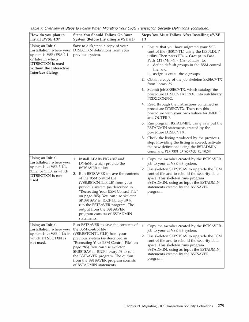
Table 7. Overview of Steps to Follow When Migrating Your CICS Transaction Security Definitions (continued)
How do you plan toinstall z/VSE 4.3?
Steps You Should Follow On YourSystem (Before Installing z/VSE 4.3)
Steps You Must Follow After Installing z/VSE4.3
Using an InitialInstallation, where yoursystem is VSE/ESA 2.4or later in whichDTSECTXN is usedwithout the InteractiveInterface dialogs.
Save to disk/tape a copy of yourDTSECTXN definitions from yourprevious system.
1. Ensure that you have migrated your VSEcontrol file (IESCNTL) using the IESBLDUPutility. Then press PF6 = Groups in FastPath 211 (Maintain User Profiles) to:a. define default groups in the BSM control
file, andb. assign users to these groups.
2. Obtain a copy of the job skeleton SKSECVTXfrom library 59.
3. Submit job SKSECVTX, which catalogs theprocedure DTSECVTX.PROC into sub.libraryPRD2.CONFIG.
4. Read through the instructions contained inprocedure DTSECVTX. Then run thisprocedure with your own values for INFILEand OUTFILE.
5. Run program BSTADMIN, using as input theBSTADMIN statements created by theprocedure DTSECVTX.
6. Check the listing produced by the previousstep. Providing the listing is correct, activatethe new definitions using the BSTADMINcommand PERFORM DATASPACE REFRESH.
Using an InitialInstallation, where yoursystem is z/VSE 3.1.1,3.1.2, or 3.1.3, in whichDTSECTXN is notused.
1. Install APARs PK24287 andDY46510 which provide theBSTSAVER utility.
2. Run BSTSAVER to save the contentsof the BSM control file(VSE.BSTCNTL.FILE) from yourprevious system (as described in“Recreating Your BSM Control File”on page 285). You can use skeletonSKBSTSAV in ICCF library 59 torun the BSTSAVER program. Theoutput from the BSTSAVERprogram consists of BSTADMINstatements.
1. Copy the member created by the BSTSAVERjob to your z/VSE 4.3 system.
2. Use skeleton SKBSTSAV to upgrade the BSMcontrol file and to rebuild the security dataspace. This skeleton runs programBSTADMIN, using as input the BSTADMINstatements created by the BSTSAVERprogram.
Using an InitialInstallation, where yoursystem is z/VSE 4.1.x inwhich DTSECTXN isnot used.
Run BSTSAVER to save the contents ofthe BSM control file(VSE.BSTCNTL.FILE) from yourprevious system (as described in“Recreating Your BSM Control File” onpage 285). You can use skeletonSKBSTSAV in ICCF library 59 to runthe BSTSAVER program. The outputfrom the BSTSAVER program consistsof BSTADMIN statements.
1. Copy the member created by the BSTSAVERjob to your z/VSE 4.3 system.
2. Use skeleton SKBSTSAV to upgrade the BSMcontrol file and to rebuild the security dataspace. This skeleton runs programBSTADMIN, using as input the BSTADMINstatements created by the BSTSAVERprogram.
Chapter 21. Migrating CICS Transaction Security Definitions 279

Table 7. Overview of Steps to Follow When Migrating Your CICS Transaction Security Definitions (continued)
How do you plan toinstall z/VSE 4.3?
Steps You Should Follow On YourSystem (Before Installing z/VSE 4.3)
Steps You Must Follow After Installing z/VSE4.3
Using an FSU, andcoming from z/VSE4.1.0 or later in whichDTSECTXN is used
None 1. Press PF6 = Groups in Fast Path 211(Maintain User Profiles) to:a. define default groups in the BSM control
file, andb. assign users to these groups.
2. Do not migrate your DTSECTXN entriesusing Fast Path 285 (Migrate Security Entries).Instead, press PF6 in Fast Path 285 to mergethe new DTRISEC.U definitions with thosefrom your previous system (see Figure 78 onpage 281).
3. If you do wish to migrate, use Fast Path 285(see Figure 80 on page 283) to migrate yourDTSECTXN definitions, merged in previousstep, to the BSM control file.
Using an FSU fromz/VSE 4.1.1 or later inwhich DTSECTXN isnot used
None None
Note: For details of how to migrate CICS/VSE resources (except for transactionsecurity definitions) to the latest security concept, refer to Chapter 37,“Migrating CICS/VSE Security Information to the CICS TS,” on page 457.The CICS transaction security definitions are migrated using Fast Path 285(see Figure 80 on page 283).
280 z/VSE V4R3.0 Administration

Performing the MigrationTo migrate CICS transactions and their security keys contained in table DTSECTXNto transaction profiles in the BSM control file, you should:Step 1. Ensure that parameter SPOOL has been set to YES (“CICS SPOOLER
ACTIVE”) in the CICS System Initialization Table (SIT).Step 2. Create Group Profiles From All User-ID Definitions, and Connect
User-IDs to Groups.
a. Use Fast Path 211 to display the Maintain User Profiles panel, as shownin Figure 78.
b. Press PF6 to create a job which (when submitted) will:1) Create group profiles from the transaction security keys.2) Connect all user-IDs to their corresponding group profiles.
This job is stored in the VSE/POWER punch queue and has the filename CICSICCF. You can use Fast Path 32 to display the contents.Figure 79 on page 282 shows an extract of such a job:
IESADMUPL2 MAINTAIN USER PROFILESVSE CONTROL FILESTART.... ________OPTIONS: 1 = ADD 2 = CHANGE 5 = DELETE
PASSWORD REVOKE USER INITIAL NAMEOPT USERID VALID UNTIL DATE TYPE NAME TYPE
_ $SRV 08/01/05 2 IESERSUP 2_ AMAD 08/01/05 1 AMADADM 2_ AMA1 08/01/05 1 IESDITTO 1_ AMA2 08/01/05 1 AMADADM 2_ ASTA 10/21/02 * 1 IESEADM 2_ BA01 1 IESEADM 2_ BA02 1 IESEADM 2_ CICSUSER 08/01/05 3 DFLESEL 2_ CNSL 08/01/05 1 DUMMY 1_ DBDCCICS 08/01/05 1 DUMMY 1_ ELKC 02/24/03 * 1 ELKESEL 2_ ELKE 07/14/05 1 ELKESEL 2
PF1=HELP 3=END 6=GROUPSPF7=BACKWARD 8=FORWARD 9=PRINT
Figure 78. Panel for Mapping All Transaction Security Keys to Groups Profiles
Migrating to BSM Control File
Chapter 21. Migrating CICS Transaction Security Definitions 281

c. Select Fast Path 323 (Punch Queue), and then type a '4' (“Copy toPrimary Library”) next to the job name. The job will then be receivedfrom the VSE/POWER punch queue to your Primary Library.
d. Select Fast Path 511 (Primary Library), and then type a '1' (“Edit”) nextto the job name, to check the contents of the job. If the contents arecorrect, use Option '7' (“Submit”) to submit the job to z/VSE. Theuser-IDs will then be connected to their corresponding group profiles.
Step 3. Add New User-IDs to Your System.Now that you have migrated all user-IDs and connected these user-IDs totheir appropriate groups, for new user-IDs you should not repeat Step 1.Instead, you should:a. Use Fast Path 211 to define the new user-IDs.b. Authorize the new user-IDs, by connecting them to the appropriate
group profiles using Fast Path 282 (Security Maintenance).Step 4. Migrate Transaction Security Entries.
a. Select Fast Path 285 (Migrate Security Entries) from the InteractiveInterface.
b. You are now prompted to enter a “1” to migrate your transactionsecurity keys. If you wish to migrate transaction security entries thatare stored in another table, key the name of this table in the field“Migrate Member”. Otherwise, the default table DTSECTXN will beselected for migration.
// JOB IESTBGRI...* ADD TRANSEC CLASS MIGRATION GROUPS IN CASE NOT EXISTADDGROUP GROUP01 DATA(’TRANSEC CLASS MIGRAT’)ADDGROUP GROUP02 DATA(’TRANSEC CLASS MIGRAT’)ADDGROUP GROUP03 DATA(’TRANSEC CLASS MIGRAT’)...ADDGROUP GROUP63 DATA(’TRANSEC CLASS MIGRAT’)ADDGROUP GROUP64 DATA(’TRANSEC CLASS MIGRAT’)...* BA02 IS SYSTEM ADMINISTRATOR. NOT CONNECTED TO ANY GROUPCONNECT GROUP01 CICSUSERCONNECT GROUP60 CICSUSERCONNECT GROUP61 CICSUSERCONNECT GROUP62 CICSUSERCONNECT GROUP63 CICSUSERCONNECT GROUP64 CICSUSER* CNSL IS SYSTEM ADMINISTRATOR. NOT CONNECTED TO ANY GROUP* DBDCCICS IS SYSTEM ADMINISTRATOR. NOT CONNECTED TO ANY GROUP* ELKC IS SYSTEM ADMINISTRATOR. NOT CONNECTED TO ANY GROUP* ELKE IS SYSTEM ADMINISTRATOR. NOT CONNECTED TO ANY GROUPCONNECT GROUP01 EOPECONNECT GROUP60 EOPECONNECT GROUP61 EOPECONNECT GROUP62 EOPECONNECT GROUP63 EOPECONNECT GROUP64 EOPECONNECT GROUP01 EPRGCONNECT GROUP60 EPRGCONNECT GROUP61 EPRG...
Figure 79. Job for Building Group Profiles and Connecting User-IDs
Migrating to BSM Control File
282 z/VSE V4R3.0 Administration

c. After pressing Enter, a job containing BSTADMIN statements is createdsimilar to that shown in Figure 81. Two statements are created for eachtransaction entry in DTSECTXN (an example of the DTSECTXNstructure is shown in Figure 109 on page 456) .
d. The migration job then maps transaction security keys 1 to 64 fromDTSECTXN to the BSM group profiles GROUP01 to GROUP64, by:1) Migrating the definitions from the Maintain Transaction Security
dialog.2) Migrating mixed-case definitions from member DTSECTXM.A.3) Migrating definitions from your own member (if present).4) Renaming the previous definition members.5) Loading the new BSTADMIN definitions.6) Rebuilding the dataspace.7) Deleting the previous DTSECTXN phase (providing the previous
steps completed successfully).To migrate your own transaction security definitions, you can also usethese procedures (that are used in the above steps):
TAS$SEC4 MIGRATE SECURITY ENTRIES
Enter the required data and press ENTER.
The security concept of the Basic Security Manager (BSM) has changed.You are recommended to migrate your entries and use the dialogMaintain Security Profiles.
The DTSECTXN table as used by this dialog can still be used in parallel to thenew BSM control file.
MIGRATE...................... 1 Do you want to migrate the trans-action security entries?Enter 1 for YES.Enter 2 to proceed with the DefineTransaction Security dialog.
Migrate own security definitions in macro format?Migrate Member.......... __________________________________
PF1=HELP 2=REDISPLAY 3=END
TO MIGRATE PRESS PF6 IN MAINTAIN USER PROFILE DIALOG.
Figure 80. Panel for Migrating DTSECTXN Entries to the BSM Control File
// JOB BSTADMINID (PARAMETERS SUPPRESSED)** * This job updates the BSM control file with the initial* * values and activates them via BSTADMIN.*// DLBL BSTCNTL,’VSE.BSTCNTL.FILE’,,VSAM,CAT=VSESPUC// LIBDEF *,SEARCH=(PRD2.CONFIG,PRD1.BASE)// EXEC BSTADMIN
ADD TCICSTRN ’emai’ UACC(NONE)PERMIT TCICSTRN ’emai’ ID(GROUP01) ACCESS(READ)ADD TCICSTRN ’ftp’ UACC(NONE)PERMIT TCICSTRN ’ftp’ ID(GROUP01) ACCESS(READ)
...
Figure 81. Job to Map DTSECTXN Entries to BSM Groups
Migrating to BSM Control File
Chapter 21. Migrating CICS Transaction Security Definitions 283

DTRMIGRM Migrates transaction security definitions that are inMacro format.
DTRMIGRT Migrates transaction security definitions that are inTable format.
Note: After you have migrated your transaction definitions, you arestrongly recommended to use Fast Path 2811 (Maintain SecurityProfiles) to define your transaction security.
Migrating to BSM Control File
284 z/VSE V4R3.0 Administration

Recreating Your BSM Control FileA batch program is available (BSTSAVER) which:1. Builds BSTADMIN commands from the contents of the BSM control file
(VSE.BSTCNTL.FILE).2. Stores these BSTADMIN commands in a librarian member.
You can use program BSTSAVER to:v Create a backup of your BSM control file (that is, for security/backup purposes)
in readable text format.v Migrate the contents of your BSM control file to your current z/VSE release. For
example, when migrating your BSM security to z/VSE 4.3.0 from:– z/VSE 3.1.1 (or a later refresh of z/VSE 3.1)– z/VSE 4.1 (or a later refresh of z/VSE 4.1)
To run the BSTSAVER program, you can either:v Create a batch job that contains this statement:
// EXEC BSTSAVER,PARM=’library.sublibrary.member_name.member_type’
v Run BSTSAVER from the system console, for example using a commandsequence like this:r rdr,pausebg0 // exec bstsaver,parm=’library.sublibrary.member_name.member_type’...0 end
(where library.sublibrary.member_name.member_type is the member containing theBSTADMIN commands that are used for recreating the profiles in your BSMcontrol file).
If you wish to change any commands before restoring memberlibrary.sublibrary.member_name.member_type to your BSM control file, you can editthis member to do so.
To restore the information from the memberlibrary.sublibrary.member_name.member_type to your BSM control file, you can use abatch job like this one:// EXEC BSTADMIN* $$ SLI MEM=member_name.member_type,S=library.sublibrary/*// EXEC BSTADMIN
PERFORM DATASPACE REFRESH/*
Migrating to BSM Control File
Chapter 21. Migrating CICS Transaction Security Definitions 285

Migrating to BSM Control File
286 z/VSE V4R3.0 Administration

Chapter 22. Maintaining User Profiles via BSM Dialogs
This chapter describes how you maintain the security and other informationcontained in user profiles using BSM dialogs.
It contains these main topics:v “Introduction” on page 288v “Adding/Changing a User-ID and Profile Definitions” on page 289v “Deleting a User-ID and Profile Definitions” on page 303v “Generating a Job to Create BSM Groups” on page 303v “Creating a Status of User-IDs Using the Dialog” on page 304v “Maintaining CICS User Profiles without VSE/ICCF” on page 304v “Generating BSM Cross Reference Reports” on page 304v “Additional Considerations” on page 307
Related Topics:
For details of how to ... Refer to ...
use BSM security server commands z/VSE Operation, SC33-8309.
maintain large numbers of user profilesusing batch utility IESUPDCF
Chapter 23, “Maintaining User Profiles viaBatch Program IESUPDCF,” on page 311.
view and change LDAP user profiles Chapter 24, “Maintaining User Profiles in anLDAP Environment,” on page 325.
protect CICS and general resources Chapter 27, “Protecting Resources via BSMDialogs,” on page 375.
© Copyright IBM Corp. 1984, 2010 287

IntroductionEvery user of the Interactive Interface is defined by a user profile. The profileincludes a unique user-ID and password which is used to sign on to the InteractiveInterface. It also determines what is displayed after the user signs on.
The Interactive Interface provides the Maintain User Profiles panel, which is thecentral point for controlling a user's access to the z/VSE system. Starting from thisdialog, you can:v define, update, or delete user profiles.v ensure that each LDAP user profile is consistent with its corresponding VSE user
profile (when LDAP support is active).v manage a user's connects to groups.
To access the dialog, start with the z/VSE Function Selection panel and selectFast Path 211. The panel shown in Figure 82 is then displayed.
A FULIST displays the user-IDs defined to the system. The options you can chooseare shown at the top of the FULIST. Use PF7 or PF8 to scroll through the entries. Ifyou want to locate a particular user-ID, enter the user-ID in the START field. Thedialog searches for the user-ID and displays it at the beginning of the list.
The options that you can select are explained in the topics that follow.
IESADMUPL2 MAINTAIN USER PROFILESVSE CONTROL FILESTART.... ________OPTIONS: 1 = ADD 2 = CHANGE 5 = DELETE
PASSWORD REVOKE USER INITIAL NAMEOPT USERID VALID UNTIL DATE TYPE NAME TYPE
_ $SRV 08/01/10 2 IESERSUP 2_ AMAD 08/01/10 1 AMADADM 2_ AMA1 08/01/10 1 IESDITTO 1_ AMA2 08/01/10 1 AMADADM 2_ ASTA 10/21/10 1 IESEADM 2_ BA01 1 IESEADM 2_ BA02 1 IESEADM 2_ CICSUSER 08/01/10 3 DFLESEL 2_ CNSL 08/01/10 1 DUMMY 1_ DBDCCICS 08/01/10 1 DUMMY 1_ ELKC 12/24/08 * 1 ELKESEL 21 PROG 10/14/15 2 IESEPROG 2
PF1=HELP 3=END 6=GROUPSPF7=BACKWARD 8=FORWARD 9=PRINT
Figure 82. Maintain User Profiles Panel
Maintaining User Profiles via Dialogs
288 z/VSE V4R3.0 Administration

Adding/Changing a User-ID and Profile Definitionsv To add a user-ID, in the Maintain User Profiles panel (shown in Figure 82 on page
288) enter '1' in the OPT column of the user-ID that you wish to use as a model.The model provides default values. “Dialog Considerations” on page 307 hasinformation on the default values.
v To change a user-ID, in the Maintain User Profiles panel (shown in Figure 82 onpage 288) enter '2' in the OPT column of the user-ID whose profile you wish tochange.
The Add or Change User Profile dialog is then displayed which you can use tospecify profile information:v The first two panels of this dialog are used for defining z/VSE user profile
information.v The third and fourth panels of this dialog are used for defining CICS and
DTSECTAB-based security information.v The fifth panel of this dialog is used for defining VSE/ICCF information.
In addition, two further panels might be displayed:v If LDAP support is active, the Maintain LDAP User Profiles panel. This dialog
allows you to add or change an LDAP user profile that corresponds to the VSEuser profile.
v If the user is not an administrator (Type 1 user), the Maintain Security Profilespanel. This dialog allows you to add or change the user's connects to groups.
Entering z/VSE User Profile InformationFor the first two panels, the z/VSE profile information is described on thefollowing pages. The example used in this section has PRG1 as the user-ID to beadded and PROG as the model user-ID.
USERIDThe user-ID which identifies the user to the Interactive Interface. It can be1 to 8 alphanumeric characters long and include the special characters @, #,or $. No blank is allowed.
IESADMUPBA ADD OR CHANGE USER PROFILEBase II CICS ResClass ICCF
To CHANGE, alter any of the entries except the userid.
USERID............. PRG1 1 - 8 characters (4 characters for ICCF users)
INITIAL PASSWORD... ________ 3 - 8 characters
DAYS............... 155 0-365 Number of days before password expiresREVOKE DATE........ 12/31/10 Date when Userid will be revoked (mm/dd/yy)
USER TYPE.......... 2 1=Administrator, 2=Programmer, 3=GeneralINITIAL NAME....... IESEPROG Initial function performed at signonNAME TYPE.......... 2 1=Application, 2=Selection PanelSYNONYM MODEL...... ________ Userid to be used as model for synonymsPROGRAMMER NAME.... Supplementary user name
PF1=HELP 3=END 5=UPDATE8=FORWARD
Figure 83. Add or Change User Profile Panel
Maintaining User Profiles via Dialogs
Chapter 22. Maintaining User Profiles via BSM Dialogs 289

Note that access to VSE/ICCF depends on the length of the user-ID. A 5 -8 character user-ID does not have access to VSE/ICCF. Refer also to“Planning Considerations for Using the Interactive Interface” on page 117.
If you are changing a user profile, you cannot change this field on thepanel.
INITIAL PASSWORDThis is the password associated with the user-ID. Specify 3 - 8alphanumeric characters including the special characters @, #, or $. Noblank is allowed.
The user is forced to change the password during the first sign-on.
DAYS The number of days before the password expires. Specify a numberbetween 0 and 365. If you enter 0, the password will not expire.
Information about password expiration and how you can change yourpassword is given in “Password Expiration” on page 136.
REVOKE DATEEnter the date, when the user-ID will be revoked by the system. After thisdate, a sign-on attempt with this user-ID will be rejected. The valid dateformat is MM/DD/YY. You can also specify 0 if the user-ID has anunlimited validity.
Note: If the User-ID is revoked you must change the revoke date, not thepassword.
USER TYPEEnter one of the following:v 1 (Administrator)
This selection provides VSE/ICCF administrative authority if the userhas a 4-character user-ID and is defined on a CICS subsystem withVSE/ICCF. The SYSA profile supplied by z/VSE defines a type 1 user.If the user is defined for a CICS subsystem without VSE/ICCF, noVSE/ICCF administrative authority is provided.
v 2 (Programmer and Operator)If the user has a 4-character user-ID, this selection provides access toVSE/ICCF, but not VSE/ICCF administrative authority. The PROG andOPER profiles supplied by z/VSE define type 2 users.
v 3 (General)This selection does not provide access to VSE/ICCF. It is intended forapplication end users. z/VSE does not supply a predefined profile fortype 3 users.
INITIAL NAMEName of the selection panel or application invoked when the user signs onto the Interactive Interface.
NAME TYPEThis defines the type of function you specify in the INITIAL NAME field.v 1 - Application
The system invokes the application when the user signs on.v 2 - Selection Panel
The system displays the selection panel when the user signs on.
Maintaining User Profiles via Dialogs
290 z/VSE V4R3.0 Administration

SYNONYM MODELThis defines the user-ID to be used as a model for synonyms. z/VSEprovides synonyms for users SYSA, PROG, and OPER. These can be usedas models for other users. For further details about synonyms refer to“Maintaining Synonyms” on page 135.
PROGRAMMER NAMESupplementary user name consisting of up to 20 characters. This field isoptional.
After entering the required details, press PF8 to proceed to the second panel, asshown in Figure 84.
For the following fields, you can enter:
1 - YES2 - NO
NEWSThe system displays news items to the user.
News items are messages which the system displays when a user signs on.It also displays the messages to users already signed on to the system. Youuse the Enter News dialog to add, change, or delete news items.
ESCAPEThe user can escape to CICS. This lets the user leave the InteractiveInterface and go into native CICS mode. If a user has this authorization,the selection panels show PF6 and PF9. These PF keys are used for theescape facility.
CONFIRM DELETEThis defines whether the user gets a confirmation message when deletingVSE/POWER queue entries, VSE/ICCF library members, or BSM resourcedefinitions.
VSE PRIMARY SUBLIBRARYThis defines whether the user gets assigned a VSE sublibrary named
IESADMUPII USER AUTHORIZATIONBase II CICS ResClass ICCFAnswer yes or no to the following questions for userid PRG1Enter 1 for yes, 2 for no
NEWS....................... 1 Should user receive news items?ESCAPE..................... 2 Can user escape to CICS?CONFIRM DELETE............. 2 Does user want a confirmation message?VSE PRIMARY SUBLIBRARY..... 1 Does user want a PRIMARY sublibrary?SUBMIT TO BATCH............ 1 Can user submit to Batch?VSAM FILES................. 1 Can user define VSAM files?VSAM CATALOGS.............. 2 Can user manage VSAM catalogs?OLPD....................... 1 Can user delete OLPD incidents?CONSOLE COMMANDS........... 2 Can user enter all commands?CONSOLE OUTPUT............. 1 Can user see all messages?BATCH QUEUES............... 2 Can user manage all POWER jobs?
DEFAULT USER VSAM CATALOG.. IJSYSCT
PF1=HELP 3=END 5=UPDATEPF7=BACKWARD 8=FORWARD
Figure 84. User Authorization Panel for Type 2 User
Maintaining User Profiles via Dialogs
Chapter 22. Maintaining User Profiles via BSM Dialogs 291

PRIMARY.userid. The PRIMARY sublibrary will be created by using theMaintain PRIMARY Sublibraries dialog for any user who has this option setin the profile.
SUBMIT TO BATCHThis defines whether the user is authorized to submit jobs to the batchqueues.
VSAM FILESThe user can define and delete VSE/VSAM files, libraries, alternateindexes, and alternate names. This authorization is not available forgeneral user (type 3) profiles.
The user can access selections 1, 2, 3, and 4 from the File and CatalogManagement dialog. These selections are:v Display or Process a Filev Define a New Filev Define a Libraryv Define an Alternate Index or Name
VSAM CATALOGSThe user can process VSE/VSAM catalogs and define and deleteVSE/VSAM space. This authorization is not available for general user(type 3) profiles.
The user can access selections 1, 5, and 6 from the File and CatalogManagement dialog. These selections are:v Display or Process a Filev Display or Process a Catalog, Spacev Define a New User Catalog
OLPD The user can delete Online Problem Determination (OLPD) incidentrecords from the system. This authorization is not available for generaluser (type 3) profiles.
CONSOLE COMMANDSThis allows the user to access a master console and to enter all commands.This is only valid for type 2 users (programmer and operator).
CONSOLE OUTPUTIf this flag is set, the user gets all messages displayed on the console. Thisauthorization is not available for type 3 users.
BATCH QUEUESA type 1 user (administrator) can manage all VSE/POWER jobs of type 1and type 2 users. This includes displaying, changing, printing, or deletinga VSE/POWER job.
As a type 2 user, you can handle only jobs which you submitted or whichare destined for you.
Note: In the dialog, you can set BATCH QUEUES to 1 (yes) also for a type2 user if needed and assign the same authority as for a type 1 user.This requires, however, that bit 2 in the VSE/ICCF option byteOPTB (which is described later) is set to 1. You should consult themanual VSE/ICCF Administration and Operation for the additionalauthorizations given when changing the setting of bit 2 to 1.
Maintaining User Profiles via Dialogs
292 z/VSE V4R3.0 Administration

APPLICATION PROFILESThis is only valid for administrator (type 1) profiles. It allows the user tocreate and maintain application profiles using the Maintain ApplicationProfiles dialog.
SELECTION PANELSThis is only valid for administrator (type 1) profiles. It allows the user tocreate and maintain selection panels using the Maintain Selection Panelsdialog.
USER PROFILESThis is only valid for administrator (type 1) profiles. It allows the user tocreate and maintain user profiles using the Maintain User Profiles dialog.
DEFAULT USER VSAM CATALOGThis defines the name of the user's default catalog. It is not available fortype 3 users.
After entering the required details, press PF8 to proceed to the third and fourthpanels as described in “Adding/Changing CICS Profile and DTSECTABInformation.”
Adding/Changing CICS Profile and DTSECTAB InformationFor the third and fourth panels, the CICS profile and DTSECTAB access rightsinformation is described below. Refer to CICS documentation for more details onthe values you can specify. The DTSECAB access rights are described inChapter 28, “Overview of DTSECTAB-Based VSE Security,” on page 389.
OPERATOR IDCICS three character operator identification. The ID should be unique.
OPERATOR PRIORITYThe value which CICS uses for the dispatching priorities of the user. Entera number from 0 to 255.
XRF SIGNOFF
This defines if the user is signed-off after an XRF takeover. Enter 1 for YES,and 2 for NO.
IESADMUPCI ADD OR CHANGE CICS SEGMENTBase II CICS ResClass ICCF
OPERATOR ID............. PR1 Enter 3 character id for user PRG1OPERATOR PRIORITY....... 000 Operator priority between 0-255XRF SIGNOFF............. 2 Sign off after XRF takeover (1=yes,2=no)TIMEOUT................. 00 Minutes until sign off between 0-60
PRIMARY LANGUAGE........ National language for CICS messages
Place an ’X’ next to the operator classes for this user
01 X 02 _ 03 _ 04 _ 05 _ 06 _ 07 _ 08 _09 _ 10 _ 11 _ 12 _ 13 _ 14 _ 15 _ 16 _17 _ 18 _ 19 _ 20 _ 21 _ 22 _ 23 _ 24 _
PF1=HELP 3=END 5=UPDATEPF7=BACKWARD 8=FORWARD
Figure 85. Add or Change CICS Profile Panel
Maintaining User Profiles via Dialogs
Chapter 22. Maintaining User Profiles via BSM Dialogs 293

TIMEOUTGives the value in minutes used by CICS to initiate sign off after the valuespecified has elapsed since the latest terminal activity. After such a timeout,you get the z/VSE Online panel displayed. You can specify a value from 0to 60. The value you specify is always rounded up to a multiple of 5minutes. A value of 0 means no time out. 0 should be specified forVSE/ICCF users.
If you specify a TIMEOUT value for a VSE/ICCF user, the CICS TIMEOUTvalue for this user should be greater than the sum of all ICCF TIMEOUTvalues. This ensures that in case of a VSE/ICCF timeout, the user affectedis “reset” to a z/VSE panel (from a VSE/ICCF panel) thus enabling acorrect working of a possible CICS timeout as well.
PRIMARY LANGUAGESpecify the language in which CICS messages should be displayed. Specify'E' for US English or 'J' for Japanese. If you leave this field blank, the CICSdefault will be used.
OPERATOR CLASSESChoose the operator classes from 1 to 24. This defines the user to the CICSTransaction Server system. 1 is the default operator class.
After entering the required details, press PF8 to proceed to the fourth panel, asshown in Figure 86.
On the fourth panel, the CICS transaction security keys and DTSECTAB batchaccess rights can be specified.
TRANSACTION SECURITY KEYSIf you have migrated your CICS transaction data to the latest securityconcept that uses the BSM control file, you will not use these security keysto protect your CICS transactions. Instead, you will use user groups asdescribed in Chapter 26, “Protecting Resources via BSTADMINCommands,” on page 359. The migration of security keys to these usergroups is described in “Performing the Migration” on page 281.
IESADMUPR1 ADD OR CHANGE RESOURCE ACCESS RIGHTSBase II CICS ResClass ICCF
Place an ’X’ next to the transaction security keys for user PRG101 X 02 X 03 X 04 X 05 X 06 X 07 X 08 X 09 X 10 X 11 X12 X 13 X 14 X 15 X 16 X 17 X 18 X 19 X 20 X 21 X 22 X23 X 24 X 25 X 26 X 27 X 28 X 29 X 30 X 31 X 32 X 33 X34 X 35 X 36 X 37 X 38 X 39 X 40 X 41 X 42 X 43 X 44 X45 X 46 X 47 X 48 X 49 X 50 X 51 X 52 X 53 X 54 X 55 X56 X 57 X 58 X 59 X 60 X 61 X 62 X 63 X 64 X
Specify the access rights for 1-32 DTSECTAB access control classes( _=No access, 1=Connect, 2=Read, 3=Update, 4=Alter )
01 2 02 3 03 3 04 1 05 _ 06 _ 07 _ 08 4 09 _ 10 4 11 _12 _ 13 _ 14 _ 15 _ 16 _ 17 _ 18 _ 19 _ 20 _ 21 _ 22 _23 _ 24 _ 25 _ 26 _ 27 _ 28 _ 29 _ 30 _ 31 _ 32 _
READ DIRECTORY..... 1 User can read directory with Connect (1=yes, 2=no)B-TRANSIENTS....... 2 User can manipulate B-Transients (1=yes, 2=no)
PF1=HELP 3=END 5=UPDATEPF7=BACKWARD 8=FORWARD
Figure 86. Add or Change Resource Access Rights Panel
Maintaining User Profiles via Dialogs
294 z/VSE V4R3.0 Administration

However, if you have not migrated your CICS transaction data to the BSMcontrol file, you can use these transaction security keys to allow access to aCICS transaction defined in DTSECTXN. You can specify from 1 to 64 keys.The default is 1. The Interactive Interface requires the use of CICS securitykeys 1 and 61. The security keys correspond to the TRANSEC operand inthe DTSECTXN macro and the security class in the Define TransactionSecurity dialog.
ACCESS RIGHTSYou can specify the access right for batch access classes 1 to 32. Enter 1 forconnect, 2 for read, 3 for update, or 4 for alter. If nothing is specified, noaccess to a resource with this access class is allowed.
READ DIRECTORYIf you specify 1, this user can read the directory of a library or sublibrary.
B-TRANSIENTSIf you specify 1, this user can catalog, rename or delete a B-transient in aprotected sublibrary if the user has the required access right to thesublibrary.
After you have entered z/VSE and CICS/batch information on the four panels,press PF5 and the dialog updates the VSE.CONTROL.FILE for the user profile.
If you are adding a profile for a user:v with access to VSE/ICCF, z/VSE displays the VSE/ICCF Maintain User Profiles:
Specify Library panel. Proceed to “Adding/Changing VSE/ICCF ProfileInformation.”
v without access to VSE/ICCF and if LDAP support is active, z/VSE displays theMaintain LDAP User Profiles panel. Proceed to “Adding an LDAP User-ID toCorrespond to the VSE User-ID” on page 298.
v without access to VSE/ICCF and if LDAP support is not active, z/VSE displaysthe Maintain Security Profiles panel in which you can add or change the groupconnects information. Proceed to “Adding/Changing the Group Connects for aVSE User-ID” on page 301.
Adding/Changing VSE/ICCF Profile InformationIf you are adding or changing a user-ID for an administrator (Type 1 user) orprogrammer (Type 2 user), you have now the option of updating VSE/ICCF profileinformation (via the Transfer Control panel when you are changing a user-ID).Press the appropriate PF key:
PF5 - YES (You want to update the VSE/ICCF profile).PF6 - NO (You do not want to update the VSE/ICCF profile).
Note that access to VSE/ICCF is only possible for users with a 4-characteruser-ID.
The VSE/ICCF default values should be acceptable for most users. You should notchange the default values unless you have a specific reason to do so. See also“Additional Considerations” on page 307.
If you press PF6 (NO), the update process is complete. The dialog redisplays theFULIST of user-IDs.
Maintaining User Profiles via Dialogs
Chapter 22. Maintaining User Profiles via BSM Dialogs 295

The dialog displays the Specify Library panel. In the LIBRARY field, enter thelibrary number for the user's VSE/ICCF primary library. For further informationabout VSE/ICCF libraries refer to “VSE/ICCF Library Considerations” on page308. You can accept the remaining z/VSE defaults for VSE/ICCF information orchange the defaults. In the DEFAULTS field, enter one of the following:
1 - YES (You do accept the defaults.)2 - NO (You do not accept the defaults.)
If you enter 2 (NO), you are asked for additional VSE/ICCF information. Ingeneral, the default values should be acceptable for most users. You shouldcarefully consider any VSE/ICCF changes that you make and use therecommended values. This is to ensure that the Interactive Interface operatescorrectly. For more detailed information on VSE/ICCF options, refer to the manualVSE/ICCF Administration and Operation.v VSE/ICCF option bytes: OPTA, OPTB, and OPTC
The default option byte settings depend on the z/VSE user type. Foradministrator (type 1) profiles, the defaults are:
OPTA - 01110001OPTB - 11111010OPTC - 01000000
For programmer and operator (type 2) profiles, the defaults are:OPTA - 00000100OPTB - 10000000OPTC - 01000000
The default settings are usually satisfactory for most users.In the OPTA, OPTB, and OPTC bytes, you can change certain bits identified byan asterisk (*) below.
Note: As a general rule, you should only change bits identified by an *. If youchange any other bits, the Interactive Interface may not work correctly forthat the user. An exception is the following situation:
If you decide to have several type 1 users sharing one common VSE/ICCFlibrary, you should set bit 5 of the OPTA byte to ensure that all functions of theInteractive Interface work correctly.– User Type 1 (Administrator)
OPTA - 011*00*1 (You can only change bits 3,6)OPTB - **111010 (You can only change bits 0,1)OPTC - **000*0* (You can only change bits 0,1,5,7)
– User Type 2 (Operator or Programmer)OPTA - 000*01*0 (You can only change bits 3,6)OPTB - ***00000 (You can only change bits 0,1,2)OPTC - **000*0* (You can only change bits 0,1,5,7)
v VSE/ICCF security keys:1 to 32 keys.
v Alternate VSE/ICCF libraries:
Enter up to eight additional private VSE/ICCF libraries that theuser can access (in addition to the primary library and publiclibraries).
For the remaining panels, the VSE/ICCF profile information is described below.
Maintaining User Profiles via Dialogs
296 z/VSE V4R3.0 Administration

v CLASS: Specify the default interactive partition (alphabetic).
v MAXSTATE: The value must be between 500 and 9999.
v MAXPRINT: The value cannot be greater than 9999.
v MAXPUNCH:The value cannot be greater than 32,767.
v LINESIZE: A value from 1-80.
v TIMELIM: The value cannot be greater than 32,767.
v TIMEMAXEX:The value cannot be greater than 65,535.
v DEL: You should not change the default.
v TAB: You should not change the default.
v BS: You should not change the default.
v ESC: You should not change the default.
v END: You should not change the default.
v HEX: You should not change the default.
v LOGONRTN:You should not change the default.
v TIMEOUT: You should not change the default.If there is a need to change the above settings in full screen editor mode ofVSE/ICCF, for example the HEX or TAB option, you must use the SETcommand of VSE/ICCF. If you have completed editing, you should reset thechanged values to their defaults to ensure that afterwards all functions workcorrectly again.
v If LDAP support is active, after pressing Enter z/VSE displays the MaintainLDAP User Profiles panel. Proceed to “Adding an LDAP User-ID to Correspondto the VSE User-ID” on page 298.
v If the user is not an administrator (Type 1 user), after pressing Enter z/VSEdisplays the Maintain Security Profiles panel in which you can add or change thegroup connects information. Proceed to “Adding/Changing the Group Connectsfor a VSE User-ID” on page 301.
Maintaining User Profiles via Dialogs
Chapter 22. Maintaining User Profiles via BSM Dialogs 297

Adding an LDAP User-ID to Correspond to the VSE User-IDTo use an LDAP logon, you can now define the LDAP user-ID which correspondsto the VSE user-ID added in the previous step. If you wish to update the details ofthe LDAP user-ID at a later time (described in “Using Dialogs to Maintain LDAPUser Mappings” on page 339), press PF3. Otherwise, follow the instructions below.1. To add an LDAP user-ID, type a '1' in the first OPT field as shown in Figure 87,
and press Enter.
If an LDAP user-ID for the VSE user-ID already exists, it is displayed.To change an LDAP user-ID, type a '2' in the OPT field for the LDAP user-IDyou wish to change and press Enter.
2. The Add or Change LDAP User Profile panel is then displayed. Figure 88 on page299 shows an example when adding an LDAP user profile for user-ID PRG1.Make your selections and enter values in the fields shown.
IESADMLUPM MAINTAIN LDAP USER PROFILES
START.... ________________________________________________________________VSE USERID.... PRG1OPTIONS: 1 = ADD
USEROPT LDAP USERID TYPE1
PF1=HELP 3=END9=PRINT 10=EXPORT
MAKE NECESSARY CHANGES TO VSE USER-ID ’PRG1 ’.
Figure 87. Adding an LDAP User-ID in the Maintain LDAP User Profiles Panel
Maintaining User Profiles via Dialogs
298 z/VSE V4R3.0 Administration

Where:
LDAP USERIDThe LDAP user-ID to be added or changed. This can be up to 64characters. This parameter is case-sensitive.
DESCRIPTIONA free-text description. This can be up to 64 characters. This parameteris optional and case-sensitive.
VSE USERIDThe VSE user-ID that is assigned to that user. It can contain between 1and 8 alphanumeric or special characters, where the special characterscan be @, #, or $. This parameter is required when TYPE=LDAP. Thisparameter is automatically translated to upper case.
VSE PASSWORDThe VSE password for the VSE user-ID (between 3 and 8 characters).
For Add LDAP User Profile: You can either:v Leave this field empty - if you specified a '1' in the GENERATE
PASSWORD field. A new VSE password is generated using theparameters defined in the PASSWORD PATTERN field. This VSEpassword is encrypted and stored in the LDAP mapping file.
v Enter a VSE password - if you specified a '2' in the GENERATEPASSWORD field. The entered VSE password is automaticallytranslated to upper case. The VSE password is then encrypted andstored in the LDAP mapping file.
For Change LDAP User Profile: You can either:v Leave this field empty:
– If you specified a '1' in the GENERATE PASSWORD field, a newVSE password is generated using the parameters defined in thePASSWORD PATTERN field. This VSE password is encrypted andstored in the LDAP mapping file.
– If you specified a '2' in the GENERATE PASSWORD field, theexisting (previously saved) VSE password is read from the LDAPmapping file and is used for the operation.
IESADMLUPA ADD OR CHANGE LDAP USER PROFILE
LDAP USERID.. prg1_LDAP_user_ID_______________________________________________
DESCRIPTION.. This is the LDAP User-ID corresponding to VSE User-ID PRG1______
VSE USERID......... PRG1____ Assigned VSE user-ID. 1-8 characters
VSE PASSWORD....... PRG1PWD Specifies VSE password. 3-8 characters
GENERATE PASSWORD.. 2 1 - Forces generation of random VSE password2 - Use current password
PASSWORD PATTERN... ________ Specifies a pattern for password generationRequired if password is generatedd - decimal digit (0-9)c - character (A-Z)a - decimal digit (0-9) or character (A-Z)x - special character (@, # or $)other - place is filled with specified characterblank - place is not filled with a character.
PF1=HELP 3=END 5=PROCESS
Figure 88. Panel Used for Updating an LDAP User Profile
Maintaining User Profiles via Dialogs
Chapter 22. Maintaining User Profiles via BSM Dialogs 299

v Enter your existing or a new VSE password. The password isautomatically translated to upper case. The VSE password is thenencrypted and stored in the LDAP mapping file.
GENERATE PASSWORDEnter either:v 1 which instructs the LDAP service program to generate a random
VSE password (GENPWD). The generated password is stored in theLDAP mapping file. For details of how to specify a pattern forpassword generation, see parameter PASSWORD PATTERN. Note: Ifyou generate a random VSE password, any previous VSE password(that you chose yourself) will be overwritten!
v 2 which means the VSE password (that you entered in the VSEPASSWORD field) will be used for logon.
PASSWORD PATTERNA pattern of between 3 and 8 characters that is used when generating apassword. The following characters can be used:v d – denotes that this place is to be filled with a decimal digit (0-9).v c – denotes that this place is to be filled with a character (AZ).v a – denotes that this place is to be filled with either a decimal digit
(0-9) or with a character (A-Z).v x – denotes that this place is to be filled with special character @, #,
or $.v other – denotes that this place is to be filled with another specified
character.v blank – denotes that this place is not filled with a character.
3. After entering all required information in Figure 88 on page 299, press PF5 toproceed with your request. You are returned to the Maintain LDAP User Profilespanel, and a confirmation message (either “User Profile Was AddedSuccessfully” or “User Profile Was Changed Successfully”) is displayed.
4. Press PF3=END to leave the Maintain LDAP User Profiles panel.v If the user-ID is Type 1, the next step (in which group connects are defined) is
skipped. This is because an administrator automatically has access to all groups.z/VSE now re-displays the Maintain User Profiles panel together with a messagethat the user has been added or changed successfully.
v If the user-ID is not Type 1, the Maintain Security Profiles panel is displayedwhere you can add or change this user-ID's connects to groups. Proceed to“Adding/Changing the Group Connects for a VSE User-ID” on page 301.
Maintaining User Profiles via Dialogs
300 z/VSE V4R3.0 Administration

Adding/Changing the Group Connects for a VSE User-ID
Note: If you wish, you can add or change the details of group connects at a latertime (described in Chapter 27, “Protecting Resources via BSM Dialogs,” onpage 375).
If a user-ID was added the Maintain Security Profiles panel shows the addeduser-ID (in the example, PRG1) in the USERID CONNECTED? column together with allBasic Security Manager groups, as shown in Figure 89:v The groups to which the new user-ID (in the example, PRG1) is already
connected are identified with a '*'.v The groups to which the model user-ID (in the example, PROG) is connected are
identified with an M. The model user-ID was selected in Figure 82 on page 288.
In Figure 89, for all groups you can now:v Press PF6 to build the same connects as used by the model user-ID (marked with
an M).v Press PF10 to remove all existing connects (marked with a '*').v Press PF3 to accept the existing connects (marked with a '*'). The connects
marked with an M will not be built.
In Figure 89, for a single group you can now:v Type 1 (ADD) in the OPT column to add a new group.v Type 2 (CHANGE) in the OPT column to change an existing group.v Type 5 (DELETE) in the OPT column to delete an existing group.v Type 8 (CONNECT) in the OPT column to connect to a group.v Type 9 (REMOVE) in the OPT column to remove the user-ID from a group.
If you press Enter, PF7, or PF8, the options you have entered will be executed andthe results are displayed.
IESADMBSLG MAINTAIN SECURITY PROFILESBSM RESOURCE CLASS: GROUPSTART....OPTIONS: 1 = ADD 2 = CHANGE 5 = DELETE 6 = USER LIST
8 = CONNECT 9 = REMOVE USERIDOPT GROUP NAME DESCRIPTION CONNECTED?
PRG1_ GROUP01 TRANSEC CLASS MIGRAT M_ GROUP02 TRANSEC CLASS MIGRAT_ GROUP03 TRANSEC CLASS MIGRAT *_ GROUP04 TRANSEC CLASS MIGRAT M_ GROUP05 TRANSEC CLASS MIGRAT_ GROUP06 TRANSEC CLASS MIGRAT M_ GROUP07 TRANSEC CLASS MIGRAT *_ GROUP08 TRANSEC CLASS MIGRAT M_ GROUP09 TRANSEC CLASS MIGRAT M_ GROUP10 TRANSEC CLASS MIGRAT M_ GROUP11 TRANSEC CLASS MIGRAT *_ GROUP12 TRANSEC CLASS MIGRAT M
PF1=HELP 3=END 6=CONNECT MODEL8=FORWARD 9=PRINT 10=REMOVE ALL
CHANGE THE SECURITY PROFILE OF USERID ACCORDING TO THE MODEL PROG .
Figure 89. Adding Group Connect Information for a New VSE User-ID
Maintaining User Profiles via Dialogs
Chapter 22. Maintaining User Profiles via BSM Dialogs 301

After completing your changes, press PF3. z/VSE re-displays the Maintain UserProfiles panel together with a message confirming that the user-ID has beensuccessfully updated.
If a user-ID was changed the Maintain Security Profiles panel shows the user-IDwhose connect information is to be changed (in the example, PRG2) in theUSERID CONNECTED? column together with the Basic Security Manager groups towhich the user-ID is currently connected (identified with a '*'), as shown inFigure 90.
In Figure 90, for all groups, you can now press PF10 to remove all existing connects.
In Figure 90, for a single group you can now:v Accept the existing connects (marked with a '*') by pressing PF3.v Type 1 (ADD) in the OPT column to add a new group.v Type 2 (CHANGE) in the OPT column to change an existing group.v Type 5 (DELETE) in the OPT column to delete a group.v Type 8 (CONNECT) in the OPT column to connect to a group.v Type 9 (REMOVE) in the OPT column to remove a connect to a group.
If you press Enter, PF7, or PF8, the options you have entered will be executed andthe results are displayed.
After completing your changes, press PF3. z/VSE re-displays the Maintain UserProfiles panel together with a message confirming that the user-ID has beensuccessfully updated.
IESADMBSLG MAINTAIN SECURITY PROFILESBSM RESOURCE CLASS: GROUPSTART....OPTIONS: 1 = ADD 2 = CHANGE 5 = DELETE 6 = USER LIST
8 = CONNECT 9 = REMOVE USERIDOPT GROUP NAME DESCRIPTION CONNECTED?
PRG2_ GROUP01 TRANSEC CLASS MIGRAT *_ GROUP02 TRANSEC CLASS MIGRAT_ GROUP03 TRANSEC CLASS MIGRAT *_ GROUP04 TRANSEC CLASS MIGRAT *_ GROUP05 TRANSEC CLASS MIGRAT_ GROUP06 TRANSEC CLASS MIGRAT *_ GROUP07 TRANSEC CLASS MIGRAT *_ GROUP08 TRANSEC CLASS MIGRAT *_ GROUP09 TRANSEC CLASS MIGRAT *_ GROUP10 TRANSEC CLASS MIGRAT *_ GROUP11 TRANSEC CLASS MIGRAT *_ GROUP12 TRANSEC CLASS MIGRAT *
PF1=HELP 3=END8=FORWARD 9=PRINT 10=REMOVE ALL
MAKE NECESSARY CHANGES TO THE SECURITY PROFILE OF THE CHANGED USERID.
Figure 90. Changing Group Connect Information for an Existing VSE User-ID
Maintaining User Profiles via Dialogs
302 z/VSE V4R3.0 Administration

Deleting a User-ID and Profile DefinitionsTo delete a user-ID, in the Maintain User Profiles panel (shown in Figure 82 on page288)1. Type '5' in the OPT column for the user-ID and press Enter. The next step
depends upon whether or not the user-ID is LDAP-enabled.2. When deleting a user-ID that is LDAP-enabled z/VSE displays the Maintain
LDAP User Profiles panel containing the LDAP user-ID you wish to delete.a. Type a '5' in the OPT column for this user-ID, and press Enter. z/VSE
displays a message confirming that the LDAP user profile has been deleted.b. On pressing PF3, the Maintain Security Profiles panel is displayed as shown
in Figure 89 on page 301. You can now either:v Remove all existing connects by pressing PF10.v Remove specific group connects by typing a '9' in the OPT column for
one or more groups, and pressing Enter.v Leave all existing group connects unchanged by pressing PF3.
In all other cases z/VSE displays the Maintain Security Profiles panel as shownin Figure 89 on page 301. You can now either:v Remove all existing connects by pressing PF10.v Remove specific group connects by typing a '9' in the OPT column for one or
more groups, and pressing Enter.v Leave all existing group connects unchanged by pressing PF3.
3. After leaving the Maintain Security Profiles panel, z/VSE displays the MaintainUser Profiles panel together with a message confirming that the deletion wassuccessful. z/VSE has now deleted the user profile record from the VSE controlfile (IESCNTL), and the profile definitions from the BSM control file(BSTCNTL). If the user has access to VSE/ICCF:v The VSE/ICCF DTSFILE entry for type 1 and 2 users with a 4-character
user-ID is deleted by a batch job created and submitted by the dialog.v If the VSE/ICCF user owns a PRIMARY sublibrary, the administrator is
asked to confirm the deletion of this user-ID.
Note: After deleting the user-ID, you can use BSM reports to check that you havedeleted all related profile definitions from the BSM control file. See“Generating BSM Cross Reference Reports” on page 304.
Generating a Job to Create BSM GroupsTo create BSM groups, in the Maintain User Profiles panel (shown in Figure 82 onpage 288) press PF6. A job is then generated with the name IESTBGRI. You can usejob IESTBGRI to:v Create BSM groups.v Connect these groups to specific user-IDs.
Job IESTBGRI is stored in the punch queue with the file name CICSICCF. Fordetails, see “Performing the Migration” on page 281.
Maintaining User Profiles via Dialogs
Chapter 22. Maintaining User Profiles via BSM Dialogs 303

Creating a Status of User-IDs Using the DialogTo create a status report of user profiles that are stored in the VSE Control File, inthe Maintain User Profiles panel (shown in Figure 82 on page 288) press PF9. Astatus report is then created using the reporting tool IESXSPR, and stored in theVSE/POWER List Queue. The job name of this List Queue entry is IESXSUSP.
The skeleton IESXSUSP is provided in VSE/ICCF Library 59. This skeletoncontains the source code of the report format. To create your own report layouts,you can modify this source code.
If you change the skeleton IESXSUSP, you must activate the related phase usingthe CEMT SET PROG(IESXSUSP) NEWCOPY command.
Maintaining CICS User Profiles without VSE/ICCFYou can also update user profiles for CICS users in an environment withoutVSE/ICCF (in case of a second CICS, for example), or if:v VSE/ICCF has been terminated.v The VSE/ICCF DTSFILE has been disconnected.v The system administrator is a non-VSE/ICCF user.
Generating BSM Cross Reference ReportsThe BSM Cross Reference reports provide information about:v User-IDsv Groupsv Access control classesv Resources which can be accessed via the UACC definition in the profile.v Undefined user-IDs found in groups and access lists of resource profiles.
Using the BSM Cross Reference reports, you can manage the profile definitions thatare stored in the:v VSE control file (IESCNTL)v Table DTSECTABv BSM control file (BSTCNTL)
BSM Cross Reference reports are especially useful for checking that after youdelete a user-ID, you have also deleted all related profile definitions from accesslists and groups.
You can generate your BSM Cross Reference reports using either the:v BSTXREF service, described in “Using the BSTXREF Service.”v BSM Cross Reference Report panel (Fast Path 286), described in “Using the BSM
Cross Reference Report Dialog” on page 306.
Using the BSTXREF ServiceTo use the BSM cross reference service, start BSTXREF by using this statement:EXEC BSTXREF,PARM=’parameters’
You can call BSTXREF from either a:v Console job (such as PAUSEBG).v Batch job.
Maintaining User Profiles via Dialogs
304 z/VSE V4R3.0 Administration

The generated report (that has the job name BSTXREF) is created in theVSE/POWER list queue.
These are the BSTXREF parameters you can enter (in UPPER CASE only):
PARM='USERID=USER [,L]'The user information for user-ID USER will be listed, which includes:v Whether or not this user-ID is defined in the VSE control file (IESCNTL).v Whether or not this user-ID is an administrator.v The groups to which this user-ID is connected.v The resource profiles that contain this user-ID on their access lists. If you
specify an 'L' (to generate a detailed report), all resource profiles areadditionally listed where this user-ID is authorized via a group.
v All ACCs (access control classes) and access rights of this user-ID.v If batch security is active (SYS SEC=YES), then:
– If you specify an 'L' (to generate a detailed report), all DTSECTABresource entries that have an ACC (access control class) of this user-IDon their list of ACCs.
– If this user-ID is defined in the DTSECTAB, the following DTSECTABinformation will be listed:- Whether or not the user-ID is type “administrator”.- All ACCs (access control classes) and access rights of this user-ID.- All resources where an ACC of this user-ID is contained in the
ACC list.
PARM='USERID=*[,L]'The user information for all user-IDs will be listed.
PARM='GROUP=GROUP_NAME'The group information for group GROUP_NAME will be listed. Thisconsists of:v A description of the group.v The user-IDs that are connected to this group.v The resource profiles whose access lists contain this group.
PARM='GROUP=*'The group information for all groups will be listed.
PARM='ACC=1|...|32'All user-IDs will be listed that have the specified access control class. Ifbatch security is active (SYS SEC=YES), then:v All user-IDs defined in DTSECTAB that have this ACC will be listed.v All resource entries from DTSECTAB that have this ACC contained in
their ACC list will be listed.
PARM='ACC=*'All access control classes will be listed.
PARM='UACC'All resource profiles will be listed that have a UACC which is not NONE.If batch security is active (SYS SEC=YES), all resources defined inDTSECTAB that have a UACC which is neither NONE nor CONNECT willbe listed.
PARM='INCONS[,L]'All user-ID inconsistencies will be listed. These are user-IDs found ingroups or on access lists of resource profiles, but that are not defined in the
Maintaining User Profiles via Dialogs
Chapter 22. Maintaining User Profiles via BSM Dialogs 305

VSE control file (IESCNTL) as a user-ID. If you specified an 'L' (to generatea detailed report), all resource profiles are additionally listed where thisuser-ID is authorized via a group.
Using the BSM Cross Reference Report DialogTo use this dialog, you must:1. Display the main panel of the BSM Cross Reference Report dialog. To so do, start
with the z/VSE Function Selection panel and select Fast Path 286.
IESADMBSXT BSM CROSS REFERENCE REPORT
OPTIONS: 1 = REPORT 2 = DETAILED REPORT
OPT REPORT NAME
_ Information about user-ID *________ Information about group *________ Information about access control class *_ (1..32)_ Information about all user-ID inconsistencies_ Information about UACC that allow resource access
* = ALL
PF1=HELP 3=END
2. For one of the above options, select the level of detail you require (1 = obtain asummary report, 2 = obtain a detailed report).
3. For the options below you must enter additional information.v For Information about user-ID, enter either a specific user-ID, or an asterisk
(the default) to obtain a report of all user-IDs.v For Information about group, enter either a specific group name, or an asterisk
(the default) to obtain a report of all groups.v For Information about access control class, enter the number of an access control
class (ACC) between 1 and 32, or an asterisk (the default) to obtain a reportof all ACCs.
4. Press ENTER, and a member CICSICCF is created in your punch queue. UseFast Path 32 (Manage Batch Queues) and 3 = Punch Queue to locate memberCICSICCF (that contains the job BSTXREF).a. Enter option 4 to copy member CICSICCF to your z/VSE Primary Library.b. Use Fast Path 51 (Program Development Library) to view member CICSICCF.c. Using option 7, you can submit job BSTXREF.d. Job BSTXREF is then created in the z/VSE List Queue. It contains the BSM
Cross Reference Report.e. Use Fast Path 32 (Manage Batch Queues) and 1 = List Queue to view the
display, change, print, or delete the report (BSTXREF).
The contents of the report (BSTXREF) vary according to the selection you made:
Information about user-IDThe generated report provides this information:v Whether or not this user-ID is defined in the VSE control file (IESCNTL).v Whether or not this user-ID is an administrator.
Maintaining User Profiles via Dialogs
306 z/VSE V4R3.0 Administration

v The groups to which this user-ID is connected.v The resource profiles that contain this user-ID on their access lists.v Whether or not this user-ID is defined in the DTSECTAB table. If this user-ID
is defined in the DTSECTAB, this information (taken from DTSECTAB) will belisted:– Whether or not the user-ID is type “administrator”.– All ACCs (access control classes) and access rights of this user-ID.– All resources where an ACC of this user-ID is contained in the ACC list.
v In you request a detailed report, this additional information is provided:– The resource profiles for which this user-ID is authorized via a group.– The DTSECTAB resource entries which have an access control class for
this user on their list of ACCs.
Information about groupThe generated report provides this information:v A description of the group.v The user-IDs that are connected to this group.v The resource profiles whose access lists contain this group.
Information about access control classThe generated report lists all users for whom the specified access control class(ACC) has been defined.
Information about all user-ID inconsistenciesThe generated report lists all user-ID inconsistencies. If you request a detailedreport, the resource profiles in which this user-ID is authorized via a group arealso listed.
Information about UACC that allow resource accessThe generated report lists all resource profiles that have a UACC which is notNONE.
Additional Considerations
Creating a Status Report of User-IDs Using IESBLDUPTo maintain user profiles, you need an up-to-date record of the users defined toyour system. You can print such a status report with the migration utility program(IESBLDUP), as described in Chapter 22, “Maintaining User Profiles via BSMDialogs,” on page 287.
You can also create a status report using the PRINT function of the Maintain UserProfiles panel. For details, see “Creating a Status of User-IDs Using the Dialog” onpage 304.
Also refer to the manual z/VSE System Utilities under “IESBLDUP Utility” for ageneral description of the program and for a job stream example.
Dialog Considerations1. If you change a user profile which is currently being used on the system, any
new options do not immediately take effect. The user must sign off and sign onagain to take advantage of new or changed options.
2. When you add a new user, the user-ID that you enter the option number nextto is used as a model. The values defined for the model are used as defaults forthe new profile you are defining.
Maintaining User Profiles via Dialogs
Chapter 22. Maintaining User Profiles via BSM Dialogs 307

With this, you can add new profiles using existing profiles as models. z/VSEprovides user profiles for type 1 and type 2 users. If you do not need to changethe defaults, you simply have to enter a new user-ID and password.If some z/VSE defaults are not satisfactory, define a new profile and enter yourown values. You can then use the new profile as a model to define other userson the system.
3. Observe the following when you add or change a profile:v When you add a user, select a model profile which has the same profile type
(1, 2, or 3) and the same length of the user-ID (4 characters or 5 to 8characters) that you want for the new user.
v If you change a type 1 profile to a type 2 or 3, the options that do not applyto the new user type (2 or 3) are set to 0.
v If you add or change a profile and you change the user type, you mustupdate the VSE/ICCF information. On the Specify Library panel, specify 2(NO) indicating that you do not accept the defaults.
Notes:
a. Refer to “Planning Considerations for Using the Interactive Interface” onpage 117 for details about VSE/ICCF dependencies.
b. If you do not update the VSE/ICCF information, the defaults for theoriginal user profile types 1 and 2 are used as defaults for the newuser-ID. This could result in incorrect authorization values for the newuser.
4. If you delete a type 1 or 2 user profile, you must disconnect the VSE/ICCFDTSFILE. A message requests you to do so when the job stream created isbeing processed.
5. z/VSE ensures that only one user can access the Maintain User Profiles dialog atone time.
6. Any VSE/ICCF information you enter is saved until you leave the dialog.When you finish the dialog, it makes all updates to the VSE/ICCF DTSFILE atthe same time. Because of this, you can maintain several user profiles at oncewithout waiting for the system to make the DTSFILE updates one at a time.However, when you leave the dialog, you may notice a delay while the dialogupdates the DTSFILE.
VSE/ICCF Library ConsiderationsYou can allocate VSE/ICCF libraries 3 to 7, 11 to 49, and 70 to 199 as user libraries.Other libraries are for use by the system. Further planning details about VSE/ICCFlibraries are provided in the z/VSE Planning manual under “VSE/ICCF Libraries”.Refer also to “Reformatting the VSE/ICCF DTSFILE” on page 170.
Programmer (type 2) profiles cannot access library 1. You should not define theirVSE/ICCF primary library as library 1. By default bit setting, they have readaccess only to public libraries 50 - 69. However, this is only true if a user isworking with the Interactive Interface. When using the command mode ofVSE/ICCF, a user can switch to library 51 and read from as well as write to thatlibrary.
Note also that a FULIST for type 2 users does not display members that have beendefined as shared through the VSE/ICCF utility DTSUTIL. Such members are onlyaccessible for the owner and the system administrator.
Maintaining User Profiles via Dialogs
308 z/VSE V4R3.0 Administration

VSE/ICCF Interactive PartitionsThe manual z/VSE Planning has information about the characteristics and layout ofthe predefined VSE/ICCF interactive partitions under “VSE/ICCF InteractivePartition Layout and Characteristics”. VSE/ICCF interactive partition requirementsand eligibility for concurrent execution are important considerations when youcreate your own panel hierarchy. If you increase the size of existing interactivepartitions or add class A and B partitions, you also should make a correspondingincrease to the size of the CICS/ICCF (F2) partition. Interactive partitions reside inthe partition GETVIS area of the CICS/ICCF partition.
VSE/ICCF DTSFILE ConsiderationsWhen the system updates the DTSFILE in an interactive partition, it uses theVSE/ICCF utility program DTSUTIL. Output from the job is put in VSE/ICCFlibrary member U$xxxx.P (xxxx is your user-ID). The member is in your defaultprimary library. The system replaces the contents of U$xxxx.P each time you runthis task.
If there is a power failure or other system interruptions before the dialog ends andupdates to the DTSFILE are complete, the contents of the z/VSE control file andthe DTSFILE may not match. If you think that this has occurred, do the following:1. Access the Maintain User Profiles dialog again.2. Select the CHANGE option (2) for the user profile(s) you were working with.3. Request an update (PF5) of the VSE/ICCF information. This is necessary to
ensure that all profile information is consistent.
If you do these steps, the information in the DTSFILE and the z/VSE control filewill agree with each other.
Maintaining User Profiles via Dialogs
Chapter 22. Maintaining User Profiles via BSM Dialogs 309

310 z/VSE V4R3.0 Administration

Chapter 23. Maintaining User Profiles via Batch ProgramIESUPDCF
This chapter describes the batch utility program IESUPDCF, which allows thesystem administrator to maintain user profiles in the VSE Control File (IESCNTL)and in the VSE/ICCF DTSFILE. Using this program, you can ADD, ALTer, andDELete user profiles. IESUPDCF helps you save time when configuring userprofiles.
This chapter contains these main topics:v “Preparing to Use Batch Program IESUPDCF”v “Using Batch Program IESUPDCF to Maintain User Profiles” on page 321
Preparing to Use Batch Program IESUPDCFThe following topic describes the procedures you should perform before usingIESUPDCF.
Planning for User ProfilesWith z/VSE you can use three types of user profiles.
A VSE/ICCF (short form: ICCF) user profile is a type 1 or type 2 user profile witha 4 character user-ID. It is defined in the VSE control file (IESCNTL) and also inthe VSE/ICCF DTSFILE.
Model profiles for type 1 and type 2 user profiles are provided:
Type 1 User ProfileValid for the System Administrator. Access to all z/VSE functions,including ICCF.
Type 2 User ProfileValid for Operators and Programmers. Access to most of the z/VSEfunctions, including ICCF.
Type 3 User ProfileValid for general users (and Type 1 and Type 2 users with a user-ID of 4 to8 characters). Access to selected functions, but not to ICCF.
Information for ICCF users is recorded in the IESCNTL and in the DTSFILE.Information for type 3 user profiles is only recorded in the IESCNTL file. For thefollowing discussion you should know that ICCF-related definitions (PASSWORDand LIBRARY) are recorded in two places: in the DTSFILE and in the IESCNTLfile.
Figure 91 on page 319 shows skeleton IESUPDCF. It is shipped in ICCF library 59.You have to change this skeleton to add, alter, or delete user profiles. Before youchange skeleton IESUPDCF, you should carefully plan for the types of users youwant to create.
© Copyright IBM Corp. 1984, 2010 311

Preparing Skeleton IESUPDCFYou have to prepare skeleton IESUPDCF according to your needs. This mayinclude:v Set the ICCF parameter for all users referred to in the job.v Insert ADD statements for adding user profiles.v Insert ALTer statements for altering user profiles.v Insert DELete statements for deleting user profiles.
The following topics have more details.
Setting the ICCF Parameter in Skeleton IESUPDCFWith the setting of the ICCF parameter, you control the generation of job DTRUPD,which updates the DTSFILE. You must enter either Yes, No, or Ignore. There is nodefault.
ICCF=YES IESUPDCF updates user profiles in the control file (IESCNTL). ForICCF users, IESUPDCF updates user profiles in the DTSFILE.Therefore, a new job DTRUPD is generated.
The following describes how specifying ICCF=YES affects theADD, ALTER, and DELete statements:
ADD The new user is added to the IESCNTL control file. Thedefinitions of the model user profile are used as default.
If the model profile is for an ICCF user and the newuser-ID is 4 characters long, then the new user will also bean ICCF user. Thus, the DTSUTIL statement is generatedfor job DTRUPD.
ALTer The user definition is altered in the IESCNTL control file. Ifthe user profile is for an ICCF user, a DTSUTIL statementis generated for job DTRUPD.
DELeteThe user definition in the IESCNTL control file is deleted.If the user profile is an ICCF user, the DTSUTIL statementfor job DTRUPD is generated.
ICCF=No No update of the DTSFILE is performed. This means that youcannot ADD or DELete ICCF users. In addition, you cannot ALTerthe password or the ICCF library of ICCF users.
The following describes how specifying ICCF=NO affects the ADD,ALTer, and DELete statements:
ADD If the model profile is for an ICCF user, then the ADDstatement is ignored, and an error message is inserted intothe listing. If the model profile is not for an ICCF user, thenew user is added to the IESCNTL control file.
ALTer ICCF-related definitions (PASSWORD and LIBRARY) arenot altered in the IESCNTL control file.
�� ICCF= YesNoIgnore
��
Maintaining User Profiles via IESUPDCF
312 z/VSE V4R3.0 Administration

DELeteIf the user profile is an ICCF user, the statement is ignoredand an error message is inserted into the listing. For type 3user profiles, the definition in the control file is deleted.
ICCF=Ignore You can ADD, ALTer, or DELete any user in the control file(IESCNTL). For VSE/ICCF users, however, the DTSFILE is notupdated. IGNORE must be used if the control file is not related toan ICCF subsystem.
The following describes how specifying ICCF=IGNORE affects theADD, ALTer, and DELete statements:
ADD The new user is added to the control file.
ALTer All specified parameters are altered in the control file. Ifspecified, the LIBRARY parameter is ignored, since it isonly relevant for ICCF subsystems.
DELeteThe user definition in the control file is deleted,independent of the user profile type.
Refer also to item 2 in skeleton IESUPDCF, shown in Figure 91 on page 319.
Maintaining User Profiles via IESUPDCF
Chapter 23. Maintaining User Profiles via Batch Program IESUPDCF 313

Adding a User-ID in Skeleton IESUPDCFTo ADD a user-ID, you insert the following statement into skeleton IESUPDCF:
The first three parameters are mandatory; the rest are optional. Do not change theorder of the mandatory parameters.
Mandatory Parameters
Note: Each ADD statement may use one or more physical lines. A continuationline is indicated by the continuation character “–” as the last character in theprevious line. The continuation character must be preceded by a blank or acomma. The required parameters must be specified together with the ADDstatement on one line.
user-idThe user-ID which identifies the user to the system. It must be 4-8alphanumeric characters long and may include the characters @, #, or $.Blanks are not allowed.
Note: For ICCF users, the user-ID can only be 4 characters long.
�� ADD user_id,password,profile,Catalog=catname ,Days=nnn
�
�,Library=libname ,Initial= nnnnnnnn(A)
nnnnnnnn(S),Operator=oper_id
�
�,PGMID=programmer_id ,PRiority=priority ,Synonym=user_id
�
�,Timeout=mm ,APM= Yes
No,BAT= Yes
No,BQA= Yes
No
�
�,CMD= Yes
No,COD= Yes
No,COU= Yes
No,DVF= Yes
No
�
�,ESC= Yes
No,MVC= Yes
No,Natlang= E
J
�
�,NEWS= Yes
No,OLPD= Yes
No,PSL= Yes
No
�
�,Revoke= mm/dd/yy
0,SPM= Yes
No,UPM= Yes
No
�
�,XRF= Yes
No
��
Maintaining User Profiles via IESUPDCF
314 z/VSE V4R3.0 Administration

passwordThis is the password associated with the user-ID. It can be 3 - 8alphanumeric characters long and may include the characters @, #, or $.Blanks are not allowed.
profileThis is the identification (user-ID) of a user already defined to the systemand used as a model for the new user. It must be 4-8 characters long.Using optional parameters you can alter the defaults for the new user-ID.
Optional ParametersThis topic describes the optional parameters you can use with either the ADDstatement, or the ALTer statement (described on page 317).
Catalog=catnameThe name of the user's default VSE/VSAM catalog (IJSYSCT). Thisparameter is not available for type 3 users.
Days=nnnThe number of days before the user's password expires. Specify a numberbetween 0 and 365. If you enter 0, the password will not expire.
Library=libnameThe user's primary ICCF library. This value may be 4 digits in length.When specifying:v ICCF=IGNORE, the LIBRARY parameter is ignored, since it is only
relevant for ICCF subsystems.v ICCF=NO, you cannot change the library for an VSE/ICCF user.
Initial=nnnnnnnn(A)|nnnnnnnn(S)Initial function performed at sign on. You can use up to eightalphanumeric characters. The value must be followed by the typespecification:v (A) - if the initial function is an application, orv (S) - if the initial function is a selection panel.
For example:
INITIAL=FUNCNAME(A) for an application.
Operator=oper-id3-character operator identification for CICS. The ID must be unique.
PGMID=Programmer-idUp to 20-character programmer name.
PWD|PAssword=passwordIt can be 3 - 8 alphanumeric characters long and may include thecharacters @, #, or $. Blanks are not allowed. You cannot change thepassword for an ICCF user when specifying ICCF=NO. This parameter isonly to be used together with the ALTer statement.
PRiority=priorityThe value which CICS uses for the dispatching priorities of the user. Entera number from 0 - 255. 0 is the highest priority; 255 the lowest.
Synonym=user-idThis defines the user-ID to be used as a model for synonyms. z/VSEprovides synonyms for users SYSA, PROG, and OPER. These can be usedas models for other users.
Timeout=mmGives the value in minutes used by CICS to initiate sign off after the value
Maintaining User Profiles via IESUPDCF
Chapter 23. Maintaining User Profiles via Batch Program IESUPDCF 315

specified has elapsed since the latest terminal activity. You can specify avalue from 0 to 60. The value you specify is always rounded up to amultiple of 5 minutes. A value of 0 means no time out. 0 should bespecified for ICCF users.
APM=Yes|NoWhen set to “Yes”, you can create and maintain application profiles. This isonly valid for the administrator (type 1) user profiles.
BAT=Yes|NoWhen set to “Yes”, you can submit jobs for batch processing.
BQA=Yes|NoWhen set to “Yes”, you can manage all VSE/POWER jobs of an ICCF user.
CMD=Yes|NoWhen set to “Yes”, you can enter system console commands from theSystem Console dialog. This authorization is not available for general (type3) user profiles.
COD=Yes|NoWhen set to “Yes”, you will get a confirmation message when deletingVSE/POWER queue entries, VSE/ICCF library members, or BSM resourcedefinitions.
COU=Yes|NoWhen set to “Yes”, all console output is shown.
DVF=Yes|NoWhen set to “Yes”, you can define and delete VSE/VSAM files, libraries,alternate indexes, and alternate names. This authorization is not possiblefor general (type 3) user profiles.
ESC=Yes|NoWhen set to “Yes”, you can escape to CICS. This lets you leave theInteractive Interface and work directly with CICS.
MVC=Yes|NoWhen set to “Yes”, you can process VSE/VSAM catalogs and define anddelete VSE/VSAM space. This authorization is not available for general(type 3) user profiles.
Natlang=E|JNational language indicator for this user.E = English, J = Japanese
NEWS=Yes|NoWhen set to “Yes”, the system displays news items to you. News items aremessages which the system displays when you sign on or when you arealready signed on.
OLPD=Yes|NoWhen set to “Yes”, you can delete Online Problem Determination (OLPD)incident records from the system. This authorization is not available forgeneral (type 3) user profiles.
PSL=Yes|NoWhen set to “Yes”, you will have a private sublibrary (primary user-ID).
Revoke=mm/dd/yy|0Revoke date when the user-ID will be revoked. If zero is specified, theuser-ID will never get revoked.
Maintaining User Profiles via IESUPDCF
316 z/VSE V4R3.0 Administration

SPM=Yes|NoWhen set to “Yes”, you can create and maintain selection panels. This isonly valid for the administrator (type 1) user profiles.
UPM=Yes|NoWhen set to “Yes”, you can create and maintain user profiles. This is onlyvalid for the administrator (type 1) user profiles.
XRF=Yes|NoWhen set to “Yes”, the user gets signed off after XRF takeover. Otherwise,the user stays signed on.
Altering a User-ID in Skeleton IESUPDCFTo ALTer a user-ID, you insert the following statement into skeleton IESUPDCF:
ALTer checks the user types and performs those changes allowed for the specificuser types. For the ALTer statement the first parameter (userid) is mandatory. Theuser-ID identifies the user to the system. It must be 4-8 alphanumeric characterslong and may include the characters @, #, or $. Blanks are not allowed. You alsomust specify at least one additional parameter from the optional parameters shownin the ALTer statement syntax. The optional parameters you can use are describedin detail under “Optional Parameters” on page 315. You may have more than oneALTer statement for the same user profile.
�� ALTer userid,Catalog=catname ,Days=nnn ,Library=libname
�
�,Initial= nnnnnnnn(A)
nnnnnnnn(S),Operator=oper-id ,PWD=password
PAssword=password
�
�,PGMID=programmer-id ,PRiority=priority ,Synonym=user-id
�
�,Timeout=mm ,APM= Yes
No,BAT= Yes
No,BQA= Yes
No
�
�,CMD= Yes
No,COD= Yes
No,COU= Yes
No,DVF= Yes
No
�
�,ESC= Yes
No,MVC= Yes
No,Natlang= E
J
�
�,NEWS= Yes
No,OLPD= Yes
No,PSL= Yes
No
�
�,Revoke= mm/dd/yy
0,SPM= Yes
No,UPM= Yes
No
�
�,XRF= Yes
No
��
Maintaining User Profiles via IESUPDCF
Chapter 23. Maintaining User Profiles via Batch Program IESUPDCF 317

Each ALTer statement may use one or more physical lines. A continuation line isindicated by the continuation character “–” as the last character in the previousline. The continuation character must be preceded by a blank or a comma. Theuser-id must be specified on the same line as the ALTer statement.
Deleting a User-ID in Skeleton IESUPDCFTo DELete a user-ID, you insert the following statement into skeleton IESUPDCF:
For the DELete statement, the user-ID identifies the user which is to be deleted. Itmust be 4-8 alphanumeric characters long and may include the characters @, #, or$. Blanks are not allowed.
Skeleton IESUPDCFThe following figure shows skeleton IESUPDCF, shipped in ICCF library 59. Usethis skeleton to ADD, ALTer, or DELete your user profiles.
�� DELete user_id ��
Maintaining User Profiles via IESUPDCF
318 z/VSE V4R3.0 Administration

* $$ JOB JNM=IESUPDCF,CLASS=0,DISP=D* $$ PUN DISP=I,CLASS=0,PRI=9// JOB IESUPDCF// OPTION NOLOG** THIS SKELETON MAY BE USED BY THE ADMINISTRATOR TO GENERATE A* JOB FOR BATCH USER PROFILE MAINTENANCE.* 1. IF THE CONTROL FILE BELONGS TO A CICS WITHOUT ICCF AND THIS* CICS DOES NOT SHARE THE CONTROL FILE WITH CICS/ICCF,* ADJUST THE ’// DLBL’ STATEMENT TO MAINTAIN* USER PROFILES IN THE RELATED CONTROL FILE.* 2. SUPPLY AN OPERAND FOR THE ICCF PARAMETER, VALID OPERANDS ARE:* Yes ... UPDATE USER PROFILES IN CONTROL FILE (CICS) AND* IN THE DTSFILE (ICCF).* No ... UPDATE USER PROFILES IN CONTROL FILE ONLY.* INHIBIT CHANGES TO ICCF RELATED INFORMATION.* Ignore ... UPDATE USER PROFILES IN CONTROL FILE ONLY.* THIS VALUE MUST BE USED IF THE CONTROL FILE* IS USED IN CICS SUBSYSTEMS RUNNING WITHOUT ICCF.* 3. INSERT THE ADD, ALTER AND DELETE STATEMENTS THAT YOU NEED TO* MAINTAIN USER PROFILES.* SAMPLE STATEMENTS:* ==================* * TEXT ... A COMMENT LINE* ADd USERID,PASSWD,PROFILE(,OPTIONAL PARAMETERS)* ALter USERID(,OPTIONAL PARAMETERS)* Delete USERID* EXPLANATION OF PARAMETERS:* ==========================* 1. REQUIRED AND POSITIONAL PARAMETERS:* --------------------------------------* USERID ... THE ID OF THE USER ( ADD, ALTER, DELETE )* ( 4-8 CHARACTER / 4 CHARACTER FOR ICCF USER )* PASSWD ... THE PASSWORD OF THE USER ( ADD )* ( 3-8 CHARACTERS )* PROFILE ... THE ID OF THE USER USED AS PROFILE FOR* THE NEW USER ( ADD )* ( 4-8 CHARACTER / 4 CHARACTER FOR ICCF USER )** 2. OPTIONAL PARAMETERS IN ADD/ALTER STATEMENT:* ----------------------------------------------* Catalog= ... THE DEFAULT CATALOG OF THE USER* EXAMPLE: CAT=VSESPUC* Days= ... NUMBER OF DAYS IN EXPIRATION INTERVAL* EXAMPLE: DAYS=20 ( RANGE: 0-365)* Library= ... Primary ICCF library ( only ICCF users )* EXAMPLE: LIB=20* Initial= ... Initial function at SIGNON* EXAMPLE: INIT=APPLNAME(A) ... FOR APPLICATION* INIT=SELNAME(S) ... FOR SELECTION P.* Natlang= ... NATIONALLANGUAGE_INDICATOR* EXAMPLE: NAT=E ( for English)* PGMID= ... PROGRAMMER ID (maximum 20 characters)* EXAMPLE: PGMID=G_SMITH* Operator= OPERATOR ID* EXAMPLE: OPER=OPE
Figure 91. Skeleton IESUPDCF (Part 1 of 3)
Maintaining User Profiles via IESUPDCF
Chapter 23. Maintaining User Profiles via Batch Program IESUPDCF 319

* PWD= ... USER PASSWORD* PAssword= EXAMPLE: PWD=PASSWD ( 3-8 Characters )* PRiority= ... OPERATOR PRIORITY* EXAMPLE: PRIOR=5 ( RANGE: 0-255 )* Revoke= ... REVOKE_DATE* EXAMPLE: R=01/31/01 ( Format mm/dd/yy )* Synonym= ... SYNONYMS MODEL* EXAMPLE: SYNONYM=SYNS ( 4-8 CHARACTERS )* Timeout= ... TIMEOUT INTERVAL* EXAMPLE: TIME=20 ( VALUES: 0,5,10,...,60 )* APM=Yes|No ... APPLICATION PROFILE MAINTENANCE* BQA=Yes|No ... MANAGE ALL BATCH QUEUES* CMD=Yes|No ... ENTER CONSOLE COMMANDS* COU=Yes|No ... FULL OUTPUT ON SYSTEM CONSOLE* COD=Yes|No ... CONFIRM ON DELETE* DVF=Yes|No ... DEFINE VSAM FILES* ESC=Yes|No ... ESCAPE TO CICS* MVC=Yes|No ... MANAGE VSAM CATALOGS* NEWS=Yes|No ... DISPLAY NEWS TO USER* OLPD=Yes|No ... DELETE OLPD INCIDENTS* PSL=Yes|No ... OWNS A PRIVATE SUBLIBRARY* BAT=Yes|No ... SUBMIT TO BATCH* SPM=Yes|No ... SELECTION PANEL MAINTENANCE* UPM=Yes|No ... USER PROFILE MAINTENANCE* XRF=Yes|No ... XRF SIGNOFF* - ... CONTINUATION CHARACTER* 4. DELETE BLOCK ’UPDPL’, IF YOU DO NOT WANT TO MAINTAIN* THE PRIMARY LIBRARY.* *************************************************************** IESCNTL MUST BE CLOSED IF UPDATES ARE DONE. PERFORM* CEMT SET FILE(IESCNTL) CLOSE IN EACH CICS WITH THE* INTERACTIVE INTERFACE ACTIVE* MSG FB,DATA=CLOSECNTL TO CLOSE THE FILE IN BSM** IMPORTANT:* IF NEW USERS ARE ADDED, IN ORDER TO DEFINE THIS USERS* TO THE BSTCNTL BASED SECURITY, YOU HAVE TO PRESS PF6 (GROUPS)* ON PANEL ’USER PROFILE MAINTENANCE’ FASTPATH 211.* THE USERS CAN ALSO BE ADDED USING BSTADMIN:* // EXEC BSTADMIN* CONNECT GROUPxx user* /** IF USERS ARE DELETED, THIS USERS SHOULD BE REMOVED FROM THE* GROUP:* // EXEC BSTADMIN* REMOVE GROUPxx user* /*** ******************************************************************* ====> UPDATE NEXT LINE IF NECESSARY (SEE 1.)// DLBL IESCNTL,’VSE.CONTROL.FILE’,,VSAM,CAT=VSESPUC*// EXEC PROC=DTRICCF// EXEC IESUPDCF,SIZE=64K** ====> SUPPLY AN OPERAND FOR THE ICCF PARAMETER (SEE 2.)ICCF=** ====> INSERT STATEMENTS HERE (NO COMMENT ’*’ IN FIRST COLUMN, SEE 3.)
Figure 91. Skeleton IESUPDCF (Part 2 of 3)
Maintaining User Profiles via IESUPDCF
320 z/VSE V4R3.0 Administration

Using Batch Program IESUPDCF to Maintain User ProfilesAfter making changes in skeleton IESUPDCF, submit the job for processing. Oncethe job is processed, check the output listing to see whether the job DTRUPD wascreated. Please note that this job will only be created when you specify ICCF=YES.If so:v Check the system console, since job DTRUPD prompts you to disconnect the
DTSFILE and waits for a response.v Disconnect the DTSFILE (/DISC DTSFILE) and reply to the suspended job.v Reconnect the DTSFILE after the job has terminated (/CON DTSFILE).v If you have specified ICCF=YES, you will have two listings with the name
IESUPDCF. (With ICCF=NO or ICCF=IGNORE you will get one IESUPDCFlisting). Check both of them for flagged statements and return codes.
v After users have been added, run the BSTADMIN statements.
Return Codes Issued by IESUPDCF0 No error. Job DTRUPD was not generated.
2 No error. Job DTRUPD was generated.
User action:v Ensure that job (DTRUPD) is started immediately.v Disconnect the DTSFILE when prompted on the system console.
4 The program has detected one or more invalid user statements in the job.The invalid statements are flagged in the listing. All valid statements areprocessed. Job DTRUPD was not generated.
User action:v Examine the job listing.v Correct the flagged job statements.
* /*// IF $RC=0 THEN// GOTO STEP2// IF $RC=4 THEN// GOTO ERROR// IF $RC>6 THEN// GOTO END// LOG* ===> JOB ’DTRUPD’ CREATED, ENSURE THAT THIS JOB IS EXECUTED NEXT// NOLOG// IF $RC=2 THEN// GOTO STEP2/. ERROR// LOG* ===> ERRORS IN INPUT DATA, STATEMENT(S) FLAGGED IN LISTING// NOLOG/. STEP2** ====> DELETE BLOCK ’UPDPL’, IF REQUIRED (SEE 4.)* ************ BEGIN OF BLOCK ’UPDPL’ ****************************// EXEC PROC=IESUPDPL* /** ************ END OF BLOCK ’UPDPL’ *******************************/. END* /&* $$ EOJ
Figure 91. Skeleton IESUPDCF (Part 3 of 3)
Maintaining User Profiles via IESUPDCF
Chapter 23. Maintaining User Profiles via Batch Program IESUPDCF 321

v Delete statements that are not flagged from the job, because they havebeen processed before.
v Submit the corrected job again.
6 The program has detected one or more invalid user statements in the job.The invalid statements are flagged in the listing. All valid statements areexecuted. Job DTRUPD was generated.
User action:v Submit job DTRUPD.v Examine the job listing.v Correct the flagged job statements.v Delete statements that are not flagged from the job, because they have
been processed before.v Submit the corrected job again.
8 The ICCF statements were ignored. ICCF=NO was specified in the job, butthere was at least one statement that tried to alter an ICCF user definition.This statement was ignored.
User action:
If the erroneous statement is to be processed:v Specify ICCF=YES.v Delete all statements that are not flagged, because they have been
processed before.v Submit the corrected job again.
16 The program has been canceled due to severe errors.
User action:v Examine the listing to determine the reason. The error might have been
caused by one of the following:
CDLOADThe program was unable to load the DTSFILE I/O routineDTSFILRT.
CONTROL FILEA VSE/VSAM macro caused an error.
GETVISThe partition GETVIS area is too small for the job.
Maintaining User Profiles via IESUPDCF
322 z/VSE V4R3.0 Administration

Example of Completed Skeleton IESUPDCFThe following is an example of a completed IESUPDCF skeleton, which showsADDing, ALTering, and DELeting users.
* $$ JOB JNM=IESUPDCF,CLASS=0,DISP=D* $$ PUN DISP=I,CLASS=0,PRI=9// JOB IESUPDCF// OPTION NOLOG** THIS SKELETON MAY BE USED BY THE ADMINISTRATOR TO GENERATE A* JOB FOR BATCH USER PROFILE MAINTENANCE.* ...* ... Description is deleted.* ... (See skeleton IESUPDCF)** ====> UPDATE NEXT LINE IF NECESSARY (SEE 1.)// DLBL IESCNTL,’VSE.CONTROL.FILE’,,VSAM,CAT=VSESPUC*// EXEC PROC=DTRICCF// EXEC IESUPDCF,SIZE=64K** ====> SUPPLY AN OPERAND FOR THE ICCF PARAMETER (SEE 2.)ICCF=YES** ====> INSERT STATEMENTS HERE (NO COMMENT ’*’ IN FIRST COLUMN, SEE 3.)ADD NEWUSR,PASSWD,OLDUSR, -
DAYS=30,TIMEOUT=15, -CPW=YES,PSL=YES
ALT MYUSER, PWD=NEWPWD, -DAYS=30,TIMEOUT=15, -CPW=YES,PSL=YES
DEL OLDUSR/*// IF $RC=0 THEN// GOTO STEP2// IF $RC=4 THEN// GOTO ERROR// IF $RC>6 THEN// GOTO END// LOG* ===> JOB ’DTRUPD’ CREATED, ENSURE THAT THIS JOB IS EXECUTED NEXT// NOLOG// IF $RC=2 THEN// GOTO STEP2/. ERROR// LOG* ===> ERRORS IN INPUT DATA, STATEMENT(S) FLAGGED IN LISTING// NOLOG/. STEP2** ====> DELETE BLOCK ’UPDPL’, IF REQUIRED (SEE 4.)* ************ BEGIN OF BLOCK ’UPDPL’ ****************************// EXEC PROC=IESUPDPL* /** ************ END OF BLOCK ’UPDPL’ **********************************/. END/&* $$ EOJ
Figure 92. Example of a Completed Skeleton IESUPDCF
Maintaining User Profiles via IESUPDCF
Chapter 23. Maintaining User Profiles via Batch Program IESUPDCF 323

Maintaining User Profiles via IESUPDCF
324 z/VSE V4R3.0 Administration

Chapter 24. Maintaining User Profiles in an LDAPEnvironment
This chapter describes how you maintain your z/VSE user profiles in an LDAPenvironment. LDAP is the abbreviation for “Lightweight Directory AccessProtocol”.
It contains these main topics:v “Overview of LDAP Sign-On Processing” on page 326v “LDAP Sign-On: Prerequisites and Getting Started” on page 330v “Deciding if Strict-User-Mappings Are to be Used” on page 331v “Deciding if Password-Caching is to be Used” on page 331v “Choosing an LDAP Authentication Method” on page 332v “Tailoring the LDAP Configuration Member SKLDCFG” on page 333v “Example of an LDAP Configuration Member” on page 335v “Rules for Using LDAP-Enabled User-IDs” on page 338v “Choosing a Method for Maintaining LDAP User Mappings” on page 339v “Using Dialogs to Maintain LDAP User Mappings” on page 339v “Using the LDAP Mapping Tool to Maintain LDAP User Mappings” on page 343v “Using Your Own LDAP Sign-On Program” on page 348v “Return/Feedback Codes Generated During LDAP Sign-On” on page 349
Note!
v The LDAP support described in this chapter can be used together with theBasic Security Manager (BSM). If the functionality provided by the BSM doesnot meet your requirements, you might instead be able to use an ExternalSecurity Manager (ESM) that is supplied by a vendor.
v You cannot enter an LDAP long-user-ID and long-password in aVSE/POWER Job statement. You can only enter a z/VSE short-user-ID andshort-password using this VSE/POWER Job statement:* $$ JOB ... SEC=(userid,password).
Related Topics:
For details of how to ... Refer to ...
define user profiles for use with BSM-basedsecurity
Chapter 22, “Maintaining User Profiles viaBSM Dialogs,” on page 287
define an LDAP user-ID and profile duringthe process of adding a VSE user-ID
“Adding/Changing a User-ID and ProfileDefinitions” on page 289
maintain large numbers of user profiles inbatch, for use with BSM-based security
Chapter 23, “Maintaining User Profiles viaBatch Program IESUPDCF,” on page 311
For a general description of LDAP support and how it can benefit your company,refer to “Security Support” in the z/VSE Planning, SC33-8301.
© Copyright IBM Corp. 1984, 2010 325

Overview of LDAP Sign-On Processing
LDAP sign-on is based upon the use of the LDAP mapping file. This VSAM KSDSfile is used to store the user-ID mappings, and is automatically defined if youperformed an FSU to z/VSE 4.3. An FSU from one modification level of z/VSE 4.3to a later level will keep the LDAP mapping file unchanged.
The LDAP mapping file contains:v Records containing user-IDs that are to be used for LDAP-authentication, in which
a mapping of a long-user-ID (used in the LDAP environment) to a short-user-ID(used in z/VSE) is done. These user-IDs are referred to as being LDAP-enabled.
v Records containing user-IDs that are not used for LDAP-authentication (forexample, the SYSA user-ID). These user-IDs are referred to as being notLDAP-enabled, and these users can sign on to z/VSE even if the LDAP server isnot operational.
z/VSE
z/VSECICSSign-OnProgram(IESIES01)
LDAP DirectoryLDAP Mapping File(VSAM KSDS)
Customer-WrittenCICSSign-OnProgram
(IESLDSOC for CICS)LDAP Sign-On Module LDAP Client
(IESLDAPC)LDAP Server(e.g. IBM Tivoli)
IdentityManagement
Tools
“Company-Wide” Network
Batch Mapping Tool(IESLDUMA)
LDAPConfiguration(IESLDCFG)
TCP/IP
Notes:
3. The LDAP client implements the LDAP protocol (specified by RFC2251) and connectionhandling. It also provides a programming interface in accordance with RFC1823.
4. To manage user mappings in the LDAP mapping file you can either use the IUI dialog"Maintain LDAP User Profiles" or the (batch) LDAP Mapping Tool. For example, you canenable/disable LDAP-authentication for specific users.
1. The CICS or batch sign-on program calls the LDAP sign-on module, providingLDAP-authentication is enabled “system-wide”.
2. The LDAP sign-on module authenticates the user via the LDAP Client API. It also looksup the user in the LDAP mapping file, and returns the short-user-ID (z/VSE user-ID) andshort-password.
[See Note 2][See Note 3]
[See Note 4]
[See Note 1]
IUI Dialog"Maintain LDAPUser Profiles"
[See Note 4]
z/VSEBatchSign-OnProgram(IESLDSOB)
[See Note 1]
(IESLDSO for Batch)
Figure 93. Overview of LDAP Sign-On Processing
User Profiles in LDAP
326 z/VSE V4R3.0 Administration

The processing flow for an LDAP sign-on via the LDAP sign-on panel is asfollows.Step 1. When a user starts his/her terminal session either:
a. The z/VSE sign-on program (IESIES01) is started, orb. A customer-written sign-on program is started.
Step 2. The z/VSE sign-on program (IESIES01) checks if LDAP-authentication isenabled:a. If LDAP-authentication is enabled an LDAP sign-on panel (the z/VSE
LDAP panel is shown in Figure 94) is displayed, containing thelong-user-ID and long-password fields.
b. If LDAP-authentication is not enabled, a non-LDAP sign-on panel isdisplayed. The remainder of this chapter no longer applies.
Note: LDAP-authentication is enabled using the skeleton SKLDCFGdescribed in Table 8 on page 333.
Step 3. The z/VSE sign-on program links (via an EXEC CICS LINK command) tothe LDAP sign-on module IESLDSOC. The sign-on program uses theCOMMAREA (described in Table 9 on page 348) to pass the long-user-IDand long-password to the LDAP sign-on module.
Step 4. The LDAP sign-on module locates the LDAP mapping file. The LDAPsign-on module then searches for the record containing the user-IDmapping. Depending upon whether or not the record is found, one of thefollowing applies:v If the record containing the user-ID mapping is not found and LDAP is
being operated in:– strict mode, the sign-on attempt is rejected.– non-strict mode and the user-ID and password are both less than or
equal to 8 characters, a mapping of user-IDs does not take place. Thesign-on attempt is then sent “unchanged” to the security manager(for example, to the Basic Security Manager in z/VSE), as describedin Step 5 (below).
– non-strict mode and the user-ID and/or password are greater than 8characters, the sign-on attempt is rejected.
IESADMSO3 z/VSE SIGN ON5609-ZV4 and Other Materials (C) Copyright IBM Corp. 2007 and other dates
++++ VV VV SSSSS EEEEEEE
++ VV VV SSSSSSS EEEEEEEzzzzzz ++ VV VV SS EEzzzzz ++ VV VV SSSSSS EEEEEE
zz ++ VV VV SSSSSS EEEEEEzz ++ VV VV SS EEzzzzzz ++ VVVV SSSSSSS EEEEEEEzzzzzzz ++ VV SSSSS EEEEEEE
Your terminal is and its name in the network is D3000001Today is 10/11/2008 To sign on to DBDCCICS -- enter your:
USER-ID. ________________________________________________________________PASSWORD
PF1=HELP 2=TUTORIAL 3=TO VM 4=REMOTE APPLICATIONS 6=ESCAPE(U)9=Escape(m) 10=NEW PASSWORD 12=LOGON HERE
Figure 94. LDAP Sign-On Panel
User Profiles in LDAP
Chapter 24. Maintaining User Profiles in an LDAP Environment 327

Note: strict mode and non-strict mode are described in “Deciding ifStrict-User-Mappings Are to be Used” on page 331.
v If the record containing the user-ID mapping is found and the user-ID isnot LDAP-enabled, a mapping of user-IDs does not take place. Thesign-on attempt is then sent “unchanged” to the security manager (forexample, to the Basic Security Manager in z/VSE), as described in Step5 (below).
v If the record containing the user-ID mapping is found and the user-ID isLDAP-enabled, an LDAP-authentication is performed with the remoteLDAP server:– If the LDAP-authentication is successful, a mapping of user-IDs
occurs. The sign-on attempt is sent to the security manager (forexample, to the Basic Security Manager in z/VSE) as described inStep 5 (below). The sign-on attempt will use the short-user-ID andshort-password obtained from the mapping,
– If the LDAP-authentication is not successful, the sign-on attempt isrejected.
Step 5. Providing the sign-on attempt has not already been rejected, the LDAPsign-on module (IESLDSOC) returns the short-user-ID and short-password(the “z/VSE” user-ID and password) to the z/VSE sign-on program viathe COMMAREA.
Step 6. Depending upon whether the sign-on request was accepted or rejected inthe previous steps, the z/VSE sign-on program (IESIES01) continues toprocess the sign-on request.
The processing flow for an LDAP sign-on via a batch job is as follows.Step 1. The batch job must be modified to include these statements:
// EXEC IESLDSOBUSER=xxx...PWD=xxx.../*
Step 2. The z/VSE sign-on program (IESLDSOB) calls the LDAP sign-on moduleIESLDSO.
Step 3. The LDAP sign-on module locates the LDAP mapping file. The LDAPsign-on module then searches for the record containing the user-IDmapping. Depending upon whether or not the record is found, one of thefollowing applies:v If the record containing the user-ID mapping is not found and LDAP is
being operated in:– strict mode, the sign-on attempt is rejected.– non-strict mode and the user-ID and password are both less than or
equal to 8 characters, a mapping of user-IDs does not take place. Thesign-on attempt is then sent “unchanged” to the security manager(for example, to the Basic Security Manager in z/VSE), as describedin Step 5 (below).
– non-strict mode and the user-ID and/or password are greater than 8characters, the sign-on attempt is rejected.
Note: strict mode and non-strict mode are described in “Deciding ifStrict-User-Mappings Are to be Used” on page 331.
v If the record containing the user-ID mapping is found and the user-ID isnot LDAP-enabled, a mapping of user-IDs does not take place. The
User Profiles in LDAP
328 z/VSE V4R3.0 Administration

sign-on attempt is then sent “unchanged” to the security manager (forexample, to the Basic Security Manager in z/VSE) as described in Step 5(below).
v If the record containing the user-ID mapping is found and the user-ID isLDAP-enabled, an LDAP-authentication is performed with the remoteLDAP server:– If the LDAP-authentication is successful, a mapping of user-IDs
occurs. The sign-on attempt is sent to the security manager (forexample, to the Basic Security Manager in z/VSE) as described inStep 4 (below). The sign-on attempt will use the short-user-ID andshort-password obtained from the mapping,
– If the LDAP-authentication is not successful, the sign-on attempt isrejected.
Step 4. Providing the sign-on attempt has not already been rejected, the LDAPsign-on module (IESLDSO) returns the short-user-ID and short-password(the “z/VSE” user-ID and password) to the z/VSE sign-on program(IESLDSOB).
Step 5. Depending upon whether the sign-on request was accepted or rejected inthe previous steps, the z/VSE sign-on program (IESLDSOB) continues toprocess the sign-on request using the short “z/VSE” user-ID andpassword in the same way as when processing an // ID statement.
User Profiles in LDAP
Chapter 24. Maintaining User Profiles in an LDAP Environment 329
LDAP Sign-On: Prerequisites and Getting StartedTo get started with LDAP sign-on, you must have:v Set up an LDAP environment within your company.v Set up your network so that z/VSE can connect to an LDAP server.v Enabled “system-wide” LDAP sign-on processing within z/VSE. For details, see
field 'FLAGS' in Table 8 on page 333.v Decided whether or not to enable strict-mode and set the field 'FLAGS'
accordingly. For details, see:– “Deciding if Strict-User-Mappings Are to be Used” on page 331.– Field 'FLAGS' in Table 8 on page 333.
v Decided whether or not to use password-hashing and set the field'CACHE_EXPIRATION' accordingly. For details, see:– “Deciding if Password-Caching is to be Used” on page 331.– Field 'CACHE_EXPIRATION' in Table 8 on page 333.
v Decided on which LDAP-authentication method you wish to use and set the field'AUTH_METHOD' accordingly. For details, see:– “Choosing an LDAP Authentication Method” on page 332.– Field 'AUTH_METHOD' in Table 8 on page 333.
v Added an entry in the LDAP mapping file for each user who will be using anLDAP sign-on. For details, see “Rules for Using LDAP-Enabled User-IDs” onpage 338.
v Tailored the remaining fields (to those described above) that are contained inmember SKLDCFG. For details, see “Tailoring the LDAP Configuration MemberSKLDCFG” on page 333.
Notes:
1. IBM does not provide you with an LDAP server that runs under z/VSE!However, you can use any suitable LDAP server that is used within yourcompany (for example, the IBM Tivoli Directory Server or the IBM Tivoli IdentityManager).
2. The LDAP mapping file IESLDUM (a VSE/VSAM KSDS file) is definedautomatically if you performed an FSU to z/VSE 4.3. An FSU from onemodification level of z/VSE 4.3 to a later level will keep the LDAP mappingfile unchanged.
User Profiles in LDAP
330 z/VSE V4R3.0 Administration
Deciding if Strict-User-Mappings Are to be UsedYou can configure the LDAP sign-on support to operate in one of the followingmodes:v Strict mode, in which all users (those using a long-user-ID and those using a
short-user-ID) are defined in the LDAP mapping file.v Non-strict mode, in which only those users using a long-user-ID are defined in the
LDAP mapping file. However, if a user signs on using a short-user-ID, thesign-on request will nevertheless be processed providing this short-user-ID isrecognized by the security manager (for example, by the Basic SecurityManager). The advantage of using non-strict mode is that users who should beable to sign on to z/VSE when the LDAP server is not operational (for example,the SYSA user-ID), do not have to be defined in the LDAP mapping file.
For details of how to set strict mode or non-strict mode, see field 'FLAGS' in Table 8on page 333.
Deciding if Password-Caching is to be UsedPassword-caching is optional. Without the use of password-caching, each LDAPsign-on attempt must communicate with the LDAP server. This can add“overhead” to your z/VSE system. This is especially true if you are using SSL forsecure communication.
To disable password-caching, you must set the field 'CACHE_EXPIRATION' to zero,as described in Table 8 on page 333.
Using password-caching, a cache is used to store a hash of the last LDAP password.The LDAP password can then be verified locally using the LDAP-password hashstored in the LDAP mapping file. This means, to verify the LDAP password there isno need to authenticate with the LDAP server.
This is how password-verification works:1. A SHA-256 hash is generated from the user's password and is stored in the
LDAP mapping file.2. When the user attempts to perform an LDAP sign-on, z/VSE checks if the
password that has been entered is valid or not. To do so, a SHA-256 hash isgenerated from the password that has been entered by the user.
3. z/VSE compares the generated-hash with the hash stored in the LDAPmapping file.
4. If the hash values are the same, the password is valid. If the hash values arenot the same, z/VSE rejects the LDAP sign-on.
Note: There is no way of recovering the password from the hash.
If password-caching is enabled, you must also configure the period of validity for thepassword hash-values stored in the LDAP mapping file. This is also done using thefield 'CACHE_EXPIRATION', as described in Table 8 on page 333.v If a user performs an LDAP sign-on within the time-limit for the password's
validity, an LDAP-authentication with the LDAP server is not performed.Instead, the password is verified locally using the stored password hash.
v If a user performs an LDAP sign-on after the time-limit for the password'svalidity, an LDAP-authentication with the LDAP server is performed. If the
User Profiles in LDAP
Chapter 24. Maintaining User Profiles in an LDAP Environment 331

LDAP-authentication is successful, z/VSE updates the password hash and marksit as valid for the time-limit you have defined.
Choosing an LDAP Authentication MethodYou must choose from one of two possible LDAP-authentication methodsdescribed below, and then set the field 'AUTH_METHOD' in Table 8 on page 333accordingly.
The two LDAP authentication methods described here are well known in thecomputer industry. For example, Unix- and Linux-based systems provide supportfor so called “Pluggable Authentication Modules” (PAM). You can use one of themodules (PAM-LDAP) to authenticate with an LDAP server (since PAM-LDAPuses exactly the same processing that is described here).
The method you choose largely depends upon how LDAP has been set up withinyour installation:v Direct BIND with LDAP user-ID and password. This method uses a pattern to
build a LDAP distinguished name (DN) with the user-ID (for example,cn=%u,dc=ibm,dc=com, where %u is replaced with the user-ID). The distinguishedname is then used to perform a BIND operation with the password. This methodrequires that the user-ID is part of the LDAP distinguished name. To use thismethod, you must set the field 'AUTH_METHOD' to '1'.
v Search for distinguished name using attribute. This method is used when theuser-ID is not part of the distinguished name. Therefore, an LDAP SEARCHoperation is first performed, to search for the associated entry. The search uses afilter such as uid=%u, where uid is the name of an attribute and %u is replacedwith the user-ID. The distinguished name of the search result is used to performthe final BIND operation with the given password. To use this method, youmust set the field 'AUTH_METHOD' to '2'.
User Profiles in LDAP
332 z/VSE V4R3.0 Administration

Tailoring the LDAP Configuration Member SKLDCFGTailor skeleton SKLDCFG (contained in ICCF library 59) according to theconfiguration you wish to implement. These are the fields contained in skeletonSKLDCFG:
Table 8. Fields Contained in the LDAP Configuration Member SKLDCFG
Field Description
FLAGS The following bits are used:
v X'00000001' - LDAP-authentication is enabled (system-wide). When this bit is ON, theLDAP sign-on panel (shown in Figure 94 on page 327) is displayed.
v X'00000002' - SSL is enabled. When this bit is ON, secure communication is used. TheSSL options must also be configured.
v X'00000004' - “Strict” user mapping is to be used:– If this bit is ON, all users must be defined in the LDAP mapping file, including
users that are not LDAP-enabled (for example, SYSA). If a user tries to sign in thatis not defined in the LDAP mapping file, a “User not found” error message will bereturned.
– If this bit is OFF, z/VSE first attempts to locate the user in the LDAP mapping file.If not found, the user is processed as if he/she were not LDAP-enabled. Therefore,the user-ID and password are returned without any mapping taking place.
v X'00000008' - Failure hash support is active. A second password expiration time can beused to control how long a hash is valid if none of the LDAP servers can be reached.
v X'00000010' - uppercase mode is enabled. When enabled, the LDAP user ID will betranslated to uppercase before it is used to perform the signon. The LDAP usermapping administration tool and the LDAP dialogs also process this flag whencreating user mapping records.
v X'80000000' - Tracing is enabled.
USER_MAP_FILE_DLBL DLBL name of the LDAP mapping file (for example, IESLDUM).
EBCDIC_CODEPAGE EBCDIC codepage name (in LE/VSE iconv format). The LDAP protocol uses the UTF-8codepage. Therefore, any textual data has to be translated into EBCDIC. This setting isimportant for special characters such as an '@' that is used in a user-ID or password. Anexample of an EBCDIC codepage is IBM-1047.
CACHE_EXPIRATION Validity period (in minutes) for caching the LDAP password. To disable caching, set thisvalue to zero.
LDAP_SERVERS One or multiple IP addresses or hostnames of LDAP servers, separated by blanks. Theservers are contacted in order of specification. If the first one is not available, the secondone is tried, and so on. The specification can optionally contain the port (hostname:port). Ifno port is specified, the default ports are used (that means, for non-SSL: 389, for SSL:636).
KEYRING_LIBRARY The keyring library and sublibrary used for SSL keys and certificates. This field is onlyused when SSL is enabled (see field 'FLAGS').
KEYNAME Name of the key member used for SSL. This field is only used when SSL is enabled (seefield 'FLAGS').
CIPHER_SPEC The cipher specs used for SSL handshake. The value contains of one or multiple 2character codes: for example, 010208090A62. This field is only used when SSL is enabled(see field FLAGS, above).
SESSION_TIMEOUT The SSL session timeout in seconds. This field is only used when SSL is enabled (seefield 'FLAGS').
User Profiles in LDAP
Chapter 24. Maintaining User Profiles in an LDAP Environment 333

Table 8. Fields Contained in the LDAP Configuration Member SKLDCFG (continued)
Field Description
AUTH_METHOD LDAP-authentication method:
1 Direct: The LDAP user-ID is used directly with the BIND operation. The fieldDN_BIND_PATTERN is used to build the distinguished name for BIND.
2 Search: The LDAP user-ID cannot be used directly for BIND. Instead, aSEARCH is first performed using the attribute that is specified in fieldUSER_ATTRIBUTE. The search result’s “distinguished name” is then used for aBIND.
DN_BIND_PATTERN Pattern used for building the “distinguished name” when using the direct authenticationmethod.
BIND_DN “Distinguished name” used for BIND, when the search authentication method is used.This “distinguished name” is used to BIND before the SEARCH operation is performed.When this field is left blank, an anonymous BIND is performed.
BIND_PWD Password used for BIND when the search authentication method is used. This passwordis used to BIND before the SEARCH operation is performed. When this field is leftblank, an anonymous BIND is performed.
USER_ATTRIBUTE Name of the attribute containing the user-ID used with the search authenticationmethod. An LDAP SEARCH operation is performed using an LDAP filter, such as:
v (%a=%u)
v (&(%f)(%a=%u)) – when field ADD_SEARCH_FILTER is not blank:– “%a” is replaced with the attribute name.– “%u” is replaced with the LDAP user-ID.– “%f” is replaced with the additional search filter specified in field
ADD_SEARCH_FILTER.
BASE_DN The base distinguished name for performing the SEARCH operation. The search resultsare dependent on the search scope (see field 'SEARCH_SCOPE').
SEARCH_DEREF This option specifies how references should be handled when performing the search. Thefollowing values are used:0 Dereference never1 Dereference searching2 Dereference finding3 Dereference always
SEARCH_SCOPE The search scope specifies how the search should be performed. The following values areused:0 Base1 One level2 Sub-tree
ADD_SEARCH_FILTER Additional search filter that is concatenated to the search filter using “AND”. See alsofield 'USER_ATTRIBUTE'.
SEARCH_TIMEOUT This option specifies the time limit in seconds for the SEARCH operation. A value ofzero means no time limit.
FAILURE_CACHE_EXPI The “failure cache expiration” option specifies the validity period in minutes for failurecases. This field has a similar function to the CACHE_EXPIRATION field.
User Profiles in LDAP
334 z/VSE V4R3.0 Administration

Example of an LDAP Configuration MemberThis topic provides you with a practical example that is taken from the IBM BluePages LDAP configuration. The IBM Blue Pages contain records of IBM employees,which can be updated both locally and from a central administrative location, andcan only be accessed from within the IBM internal network.* $$ JOB JNM=LDCONFIG,CLASS=A,DISP=D// JOB LDCONFIG GENERATE LDAP SIGNON CONFIG PHASE* ********************************************************************* ASSEMBLE AND LINK THE LDAP CONFIG PHASE ** ** NOTE: THE CONTENTS OF THIS MEMBER IS CASE SENSITIVE ! ** ********************************************************************// LIBDEF *,CATALOG=PRD2.CONFIG// LIBDEF *,SEARCH=PRD1.BASE// OPTION ERRS,SXREF,SYM,NODECK,CATAL,LISTX
PHASE IESLDCFG,*,SVA// EXEC ASMA90,SIZE=(ASMA90,64K),PARM=’EXIT(LIBEXIT(EDECKXIT)),SIZE(MAXC
-200K,ABOVE)’IESLDCFG CSECTIESLDCFG AMODE ANYIESLDCFG RMODE ANY* ********************************************************************* GENERAL SETTINGS:* ********************************************************************** FLAGS. POSSIBLE VALUES SEE EQUATES BELOW*FLAGS DC XL4’00000001’LDAP_AUTH_ENABLED EQU X’00000001’ LDAP AUTH IS ENABLEDUSE_SSL EQU X’00000002’ SSL IS ENABLEDSTRICT_MODE EQU X’00000004’ STRICT USER MAPPINGFAILURE_HASH EQU X’00000008’ FAILURE PASSWORD HASH USEDUPPERCASE_MODE EQU X’00000010’ UPPERCASE LDAP USERID & PWDTRACE EQU X’80000000’ ENABLE TRACING** USER MAPPING FILE NAME (DLBL)*USER_MAP_FILE_DLBL DC CL8’IESLDUM’** EBCDIC CODEPAGE (IMPORTANT FOR @ CHAR). THE LDAP PROTOCOL USES UTF-8* FOR DATA TRANSFER. THE LDAP CLIENT TRANSLATES THIS TO THE SPECIFIED* EBCDIC CODEPAGE. (DEFAULT IS IBM-1047).*EBCDIC_CODEPAGE DC CL16’IBM-1047’** VALIDITY PERIOD IN MINUTES FOR CACHING THE LDAP PASSWORD.* TO DISABLE CACHING OF LDAP PASSWORDS SET THIS VALUE TO ZERO.*CACHE_EXPIRATION DC F’0’** ********************************************************************* LDAP SERVER SETTINGS* ********************************************************************** LDAP SERVER IP OR HOSTNAME.** SPECIFICATION CONTAINS THE IP ADDRESS OR HOSTNAME OF ONE OR MORE* LDAP SERVERS IN THE FORM <SERVER>:<PORT>. MULTIPLE SERVER ADDRESSES* ARE SEPARATED BY BLANKS. IF THE PORT NUMBER IS OMITED, THE DEFAULT* PORT NUMBERS ARE USED:* 389 - NON-SSL* 636 - SSL* PLEASE NOTE THAT MICROSOFT ACTIVE DIRECTORY MAY USE DIFFERENT PORT* NUMBERS. THE AD GLOBAL CATALOG SERVER USES PORT 3268 PER DEFAULT.*LDAP_SERVERS DC CL256’my.ldap.server:389’** ********************************************************************* SSL SPECIFIC SETTINGS. IF SPECIFIED, A SSL CONNECTION IS USED TO
User Profiles in LDAP
Chapter 24. Maintaining User Profiles in an LDAP Environment 335

* CONNECT TO THE LDAP SERVER.* ********************************************************************** KEYRING LIBRARY*KEYRING_LIBRARY DC CL16’CRYPTO.KEYRING’** NAME OF THE KEY MATERIAL IN THE KEYRING LIBRARY*KEYNAME DC CL8’LDAPKEY’** SSL CIPHER SPECS TO USE*CIPHER_SPEC DC CL64’010208090A62’** SSL SESSION TIMEOUT IN SECONDS*SESSION_TIMEOUT DC F’86440’** ********************************************************************* LDAP AUTHENTICATION SETTINGS* ********************************************************************** AUTHENTICATION METHOD:* 1.) DIRECT: THE LDAP USER ID IS USED DIRECTLY AS THE USER NAME* PASSED TO BIND. THE DN_BIND_PATTERN BELOW IS USED TO* BUILD THE DISTINGUISHED NAME FOR BIND.* 2.) SEARCH: THE LDAP USER ID IS NOT USED DIRECTLY FOR BIND.* INSTEAD A SEARCH IS PERFORMED FOR THE USER ID USING* A SPECIFIC ATTRIBUTE. THE DISTINGUISHED NAME OF THE* SEARCH RESULT IS USED TO PERFORM THE BIND.*AUTH_METHOD DC F’2’AUTH_DIRECT EQU 1 USE DIRECT BIND WITH USER IDAUTH_SEARCH EQU 2 USE SEARCH ON ATTRIBUTE** DISTINGUISHED NAME PATTERN. AN OCCURANCE OF ’%u’ IS REPLACED* WITH THE USER NAME.*DN_BIND_PATTERN DC CL64’cn=%u,dc=mycompany,dc=com’** DISTINGUISHED NAME USED FOR BIND WHEN PERFORMING THE SEARCH.* LEAVE IT BLANK FOR ANONYMOUS BIND*BIND_DN DC CL64’’** PASSWORD USED FORBIND WHEN PERFORMING THE SEARCH.* LEAVE IT BLANK FOR ANONYMOUS BIND*BIND_PWD DC CL64’’** USER ID ATTRIBUTE NAME USED WHEN PERFORMING THE SEARCH.*USER_ATTRIBUTE DC CL64’emailaddress’** BASE DISTINGUISHED NAME USED WHEN PERFORMING THE SEARCH.*BASE_DN DC CL64’ou=myorgunit,o=mycompany.com’** THE DEREFERENCING OPTION USED WHEN DOING THE SEARCH*SEARCH_DEREF DC F’0’DEREF_NEVER EQU 0 DEREF NEVERDEREF_SEARCHING EQU 1 DEREF SEARCHINGDEREF_FINDING EQU 2 DEREF FINDINGDEREF_ALWAYS EQU 3 DEREF_ALWAYS** THE SCOPE USED WHEN DOING THE SEARCH*SEARCH_SCOPE DC F’2’SCOPE_BASE EQU 0 SEARCH THE OBJECT ITSELFSCOPE_ONELEVEL EQU 1 SEARCH THE OBJECT’S IMMEDIATE CHILDREN
User Profiles in LDAP
336 z/VSE V4R3.0 Administration

SCOPE_SUBTREE EQU 2 SEARCH THE OBJECT AND ALL ITS DESCENDENTS** ADDITIONAL SEARCH FILTER USED WHEN PERFORMING THE SEARCH.* LEAVE IT BLANK IF NO ADDITIONAL FILTER IS REQUIRED*ADD_SEARCH_FILTER DC CL128’’** THE TIMEOUT OPTION USED WHEN DOING THE SEARCH. A VALUE* OF 0 MEANS NO TIME LIMIT. THE TIMEOUT IS SPECIFGIED IN SECONDS.*SEARCH_TIMEOUT DC F’0’*** VALIDITY PERIOD IN MINUTES FOR CACHING THE LDAP PASSWORD. THIS* PERIOD IS USED WHEN THE LDAP SERVER CAN NOT BE REACHED.* TO DISABLE FAILURE CACHING OF LDAP PASSWORDS SET THIS VALUE TO ZERO.* TO ENABLE FAILURE CACHEING; YOU ALSO NEED TO SET THE BIT FAILURE_HASH* IN THE FLAGS FIELD.*FAILURE_CACHE_EXPI DC F’0’** ********************************************************************* END OF SETTINGS* ********************************************************************
END/*// IF $MRC GT 4 THEN// GOTO NOLINK// EXEC LNKEDT,PARM=’MSHP’* ********************************************************************* DONT FORGET TO NEWCOPY IESLDCFG IN ORDER TO ACTIVATE IT: ** CEMT SET PROG(IESLDCFG) NEWCOPY ** ********************************************************************/. NOLINK/*/&* $$ EOJ
User Profiles in LDAP
Chapter 24. Maintaining User Profiles in an LDAP Environment 337

Rules for Using LDAP-Enabled User-IDsUser-IDs that are to be used for LDAP-authentication are referred to as beingLDAP-enabled.
User-IDs that are not used for LDAP-authentication are referred to as being notLDAP-enabled. These users can sign on to z/VSE even if the LDAP server is notoperational.v After a user-ID has been LDAP-enabled, this user should not be able to perform
an LDAP sign-on using his/her short-user-ID (used in z/VSE). Doing so wouldbypass the company's security policies that are enforced by theLDAP-authentication.
v When enabling a user-ID for LDAP authentication, a new z/VSE password israndomly generated, and a password-change request is issued (usingRACROUTE).– The randomly-generated password is stored (encrypted) in the LDAP mapping
file.– The user will never know the randomly-generated password. Therefore,
he/she will not be able to perform an LDAP sign-on using the short-user-ID(used in z/VSE).
v You should set short-user-IDs (used in z/VSE) that are LDAP-enabled tonon-expiring (as described in “Password Expiration” on page 136 and “Enteringz/VSE User Profile Information” on page 289). For such short-user-IDs,password expiration should be enforced by the LDAP server based on thelong-user-ID and long-password.
You should add these users as not LDAP-enabled:v Administrators (such as SYSA)v Operatorsv Security administrators
To do so, use the TYPE=VSE setting (described in “ADD Command” on page 344and “CHANGE Command” on page 345).
User Profiles in LDAP
338 z/VSE V4R3.0 Administration

Choosing a Method for Maintaining LDAP User MappingsTo maintain LDAP user mappings in the LDAP mapping file, these tasks areavailable:v add LDAP user mappings,v change LDAP user mappings,v delete LDAP user mappings,v list LDAP user mappings,v export all definitions for migrating LDAP user mappings to a new system.
To perform the above tasks, you can use either:v Interactive User Interface dialogs (described in “Using Dialogs to Maintain
LDAP User Mappings”).v the LDAP mapping tool (described in “Using the LDAP Mapping Tool to
Maintain LDAP User Mappings” on page 343).
You are strongly recommended to use dialogs and not the (batch) LDAP mappingtool, since dialogs are not only easier-to-use but also reduce the possibility of error.
Using Dialogs to Maintain LDAP User MappingsThe Maintain LDAP User Profiles dialog allows you to browse and modify theentries in the LDAP mapping file. Using this dialog, you can perform all of thetasks that can be performed using the LDAP mapping tool. However, the MaintainLDAP User Profiles dialog is easier to use than the LDAP mapping tool.
Note: The dialogs described here are automatically linked-to during the procedureto add, change, or delete a user profile. For details, see “Adding/Changinga User-ID and Profile Definitions” on page 289.
To invoke the Maintain LDAP User Profiles dialog, the administrator usesFast Path 217. The panel shown in Figure 95 is then displayed.
1. You can now optionally enter:v A value in the START field to display all LDAP user-IDs whose values are
greater than or equal to the START value.
IESADMLUPM MAINTAIN LDAP USER PROFILES
START.... ________________________________________________________________VSE USERID.... ________OPTIONS: 1 = ADD 2 = CHANGE 3 = DISPLAY 5 = DELETE
USEROPT LDAP USERID TYPE_ LDAP_User_2 LDAP_ LDAP_User_3 LDAP_ LDAP_User_4 LDAP_ LDAP_User_5 LDAP_ LDAP_User_6 LDAP_ LDAP_User_7 LDAP_ LDAP_User_8 LDAP_ LDAP_User_9 LDAP2 LINE__for__LDAP__User__Name__Case__Sensitive__and__64_chars_long LDAP_ VSEUSER1 VSE_ VSEUSER2 VSE_ VSEUSER3 VSE
PF1=HELP 3=END9=PRINT 10=EXPORT
Figure 95. Panel Used for Maintaining User Profiles in the LDAP Mapping File
User Profiles in LDAP
Chapter 24. Maintaining User Profiles in an LDAP Environment 339

v A value in the VSE USERID field to only display LDAP user-IDs that arelinked to this specific VSE user-ID.
2. After pressing ENTER, Figure 95 on page 339 then lists the:v LDAP user-IDs that you selected, which can be up to 64 characters long and
case-sensitive.v User type of each LDAP user-ID, which can be either:
– LDAP (for LDAP-enabled users).– VSE (for LDAP-disabled users).
If you enter 1 = ADD or 2 = CHANGE against an LDAP user-ID in Figure 95 onpage 339, the Add or Change LDAP User Profile panel is displayed.
Where:
LDAP USERIDThe LDAP user-ID to be added or changed. This can be up to 64characters. This parameter is case-sensitive.
DESCRIPTIONA free-text description. This can be up to 64 characters. This parameter isoptional and case-sensitive.
VSE USERIDThe VSE user-ID that is assigned to that user. It can contain between 1 and8 alphanumeric or special characters, where the special characters can be@, #, or $. This parameter is required when TYPE=LDAP. This parameter isautomatically translated to upper case.
VSE PASSWORDThe VSE password for the VSE user-ID (between 3 and 8 characters).
For Add LDAP User Profile: You can either:v Leave this field empty - if you specified a '1' in the GENERATE
PASSWORD field. A new VSE password is generated using theparameters defined in the PASSWORD PATTERN field. This VSEpassword is encrypted and stored in the LDAP mapping file.
IESADMLUPA ADD OR CHANGE LDAP USER PROFILE
LDAP USERID.. ________________________________________________________________
DESCRIPTION.. ________________________________________________________________
VSE USERID......... ________ Assigned VSE user-id. 1-8 characters
VSE PASSWORD....... ________ Specifies VSE password. 3-8 characters
GENERATE PASSWORD.. _ 1 - Forces generation of random VSE password2 - Use current password
PASSWORD PATTERN... ________ Specifies a pattern for password generationRequired if password is generatedd - decimal digit (0-9)c - character (A-Z)a - decimal digit (0-9) or character (A-Z)x - special character (@, # or $)other - place is filled with specified characterblank - place is not filled with a character.
PF1=HELP 3=END 5=PROCESS
Figure 96. Panel Used for Adding/Updating an LDAP User Profile
User Profiles in LDAP
340 z/VSE V4R3.0 Administration

v Enter a VSE password - if you specified a '2' in the GENERATEPASSWORD field. The entered VSE password is automatically translatedto upper case. The VSE password is then encrypted and stored in theLDAP mapping file.
For Change LDAP User Profile: You can either:v Leave this field empty:
– If you specified a '1' in the GENERATE PASSWORD field, a new VSEpassword is generated using the parameters defined in thePASSWORD PATTERN field. This VSE password is encrypted andstored in the LDAP mapping file.
– If you specified a '2' in the GENERATE PASSWORD field, the existing(previously saved) VSE password is read from the LDAP mapping fileand is used for the operation.
v Enter your existing or a new VSE password. The password is automaticallytranslated to upper case. The VSE password is then encrypted andstored in the LDAP mapping file.
GENERATE PASSWORDEnter either:v 1 which instructs the LDAP service program to generate a random VSE
password (GENPWD). The generated password is stored in the LDAPmapping file. For details of how to specify a pattern for passwordgeneration, see parameter PASSWORD PATTERN. Note: If you generatea random VSE password, any previous VSE password (that you choseyourself) will be overwritten!
v 2 which means the VSE password (that you entered in the VSEPASSWORD field) will be used for logon.
PASSWORD PATTERNA pattern of between 3 and 8 characters that is used when generating apassword. The following characters can be used:v d – denotes that this place is to be filled with a decimal digit (0-9).v c – denotes that this place is to be filled with a character (AZ).v a – denotes that this place is to be filled with either a decimal digit (0-9)
or with a character (A-Z).v x – denotes that this place is to be filled with special character @, #, or $.v other – denotes that this place is to be filled with another specified
character.v blank – denotes that this place is not filled with a character.
After making your selections and entering values in the displayed fields, press PF5to proceed with your request. The message “User Profile Was Added Successfully”is displayed.
If you enter 3 = DISPLAY against an LDAP user-ID in Figure 95 on page 339, theDisplay LDAP User Profile panel is displayed. It shows the information about anLDAP user-ID that is stored in the LDAP mapping file.
User Profiles in LDAP
Chapter 24. Maintaining User Profiles in an LDAP Environment 341

If you enter 5 = DELETE against an LDAP user-ID in Figure 95 on page 339,z/VSE will request that you confirm the deletion of this user-ID providing theCONFIRM DELETE option is set to YES in the profile for this user-ID (usingFast Path 211, Maintain User Profiles). Otherwise, the LDAP user-ID will be deletedwithout a warning message.
If you press PF9=PRINT in Figure 95 on page 339, z/VSE will send a listing to theVSE/POWER list queue. It has the same name as the CICS startup job (defaultCICSICCF) and contains details of all LDAP users.
If you press PF10=EXPORT in Figure 95 on page 339, z/VSE will create a job withthe same name as the CICS startup job (default CICSICCF) in the VSE/POWERpunch queue. Job CICSICCF can be used for migrating LDAP users.
IESADMLUPD DISPLAY LDAP USER PROFILE
LDAP USERID.. LDAP_USER_N1
DESCRIPTION.. This user is system admin
LDAP ENABLED....... 1 1 - LDAP authentication is enabled; 0 - disabled
VSE USERID......... ADN1 Assigned VSE userid
HASH EXPIRATION.... 20090101 Date when password hash expires (yyyymmdd)150000 Time when password hash expires (hhmmss)
LAST LDAP SIGNON... 20081001 Date of last sign-on using online LDAP(yyyymmdd)112043 Time of last sign-on using online LDAP(hhmmss)
LAST HASH SIGNON... 20081002 Date of last sign-on using cached LDAP(yyyymmdd)101533 Time of last sign-on using cached LDAP(hhmmss)
FAILURE HASH EXPIR. 20090101 Date when hash expires in failure case(yyyymmdd)150000 Time when hash expires in failure case(hhmmss)
PF1=HELP 3=END
Figure 97. Panel Used for Displaying Details of an LDAP User Profile
User Profiles in LDAP
342 z/VSE V4R3.0 Administration

Using the LDAP Mapping Tool to Maintain LDAP User MappingsThe LDAP mapping tool is a batch tool that is invoked via an // EXEC IESLDUMAstatement. It reads control statements from SYSIPT. Since this tool providessecurity-sensitive services, it can only be used by administrator type users.v If batch security is active in z/VSE (via the SYS SEC=YES statement), you must
specify an ID statement in the job running IESLDUMA.v If batch security is not active in z/VSE, you must specify the user-ID and
password of an administrator using the ID command (as the first command whenexecuting IESLDUMA).
Syntax of the LDAP Mapping Tool:// ID USER=xxx,PWD=xxx// EXEC IESLDUMA,PARM=’parameters’control statements
.../*
If a command does not fit on one line, it can be continued on the next line(s). Toindicate a continuation, the line must end with a '-' character (minus). Thecontinuation character can be in any position.
These are the parameters you can specify with the LDAP mapping tool:
ParameterDescription
SYSLST=DD:SYSnnnSpecifies an alternative destination for messages printed on SYSLST. Thisparameter is optional.
DEBUGIf specified, DEBUG is turned ON. You should only set DEBUG to be ONif problems exist.
These are the control statements you can specify with the LDAP mapping tool.Note: Some parameters of these control statements are case sensitive! Make sure youswitch to mixed-case mode in your editor (if you are using VSE/ICCF, enter CASE Min the VSE/ICCF command line).
ID CommandThe ID command must be the first command in a sequence of commands, unlessyou are using the ID statement in the job. It authorizes an administrator toperform user mapping modifications:
�� ID USER='user-ID' PWD='password' ��
Where:
USER='user-ID'Specifies an administrator user-ID. This parameter is required when batchsecurity is not active. Parameter PWD has to be specified in conjunctionwith USER.
User Profiles in LDAP
Chapter 24. Maintaining User Profiles in an LDAP Environment 343

PWD='password'Specifies the administrator's password. This parameter is required whenbatch security is not active. Parameter USER has to be specified inconjunction with PWD.
ADD CommandThe ADD command adds a new user mapping to the LDAP mapping file:
�� ADD LDAPUSER='xxx' TYPE=VSEDESC='xxx'
��
�� ADD LDAPUSER='xxx' TYPE=LDAPDESC='xxx'
VSEUSER='xxx' �
� VSEPWD='xxx'GENPWD OLDPWD='xxx'
PWDPATTERN='xxx'
��
Where:
LDAPUSER='xxx'Specifies the LDAP user-ID to be added. This can be up to 64 characters.This parameter is case sensitive.
TYPE=VSE | LDAPSpecifies the type of the user:v VSE: User is not LDAP-enabled.v LDAP: User is LDAP-enabled
DESC='xxx'Specifies a free-text description. This can be up to 64 characters. Thisparameter is optional and case-sensitive.
VSEUSER='xxx'Specifies the VSE user-ID of up to 8 characters that is assigned to that user.This parameter is required when TYPE=LDAP.
VSEPWD='xxx'Specifies the VSE password of up to 8 characters. Either VSEPWD orGENPWD can be specified. If VSEPWD is specified, the user's password isnot changed.
GENPWDForces the VSE password to be generated by random. Either VSEPWD orGENPWD can be specified. If GENPWD is specified, the VSE user'spassword is changed via RACROUTE call. See parameter PWDPATTERNfor details of specifying a pattern for password generation.
PWDPATTERN='xxx'Specifies a pattern that is used when generating a password. The followingcharacters can be used:v d – denotes that this place is to be filled with a decimal digit (0-9).v c – denotes that this place is to be filled with a character (AZ).v a – denotes that this place is to be filled with either a decimal digit (0-9)
or with a character (A-Z).v x – denotes that this place is to be filled with special character @, #, or $.
User Profiles in LDAP
344 z/VSE V4R3.0 Administration

v other – denotes that this place is to be filled with another specifiedcharacter.
v blank – denotes that this place is not filled with a character.
OLDPWD='xxx'Specifies the current password of the VSE user-ID. This parameter isrequired when GENPWD is specified.
CHANGE CommandThe CHANGE command changes a user in the LDAP mapping file:
�� CHANGE LDAPUSER='xxx' TYPE=VSEDESC='xxx'
��
�� CHANGE LDAPUSER='xxx' TYPE=LDAPDESC='xxx' VSEUSER='xxx'
�
�VSEPWD='xxx'GENPWD
OLDPWD='xxx' PWDPATTERN='xxx'
��
Where:
LDAPUSER='xxx'Specifies the LDAP user-ID to be changed. This can be up to 64 characters.This parameter is case sensitive.
TYPE=VSE | LDAPSpecifies the type of the user:v VSE: User is not LDAP-enabled.v LDAP: User is LDAP-enabled
If omitted, the type is not changed.
DESC='xxx'Specifies a free-text description. This can be up to 64 characters. Thisparameter is optional and case-sensitive. If omitted, the description is notchanged.
VSEUSER='xxx'Specifies the VSE user-ID of up to 8 characters that is assigned to that user.If omitted, the VSE user-ID assignment is not changed.
VSEPWD='xxx'Specifies the VSE password of up to 8 characters. Either VSEPWD orGENPWD can be specified.v If VSEPWD is specified, the user's password is not changed.v If both VSEPWD and GENPWD are omitted, the user's password is not
changed.
GENPWDForces the VSE password to be generated by random. Either VSEPWD orGENPWD can be specified, or this parameter can be omitted.v If GENPWD is specified, the VSE user's password is changed via
RACROUTE call. See parameter PWDPATTERN for details of specifyinga pattern for password generation.
User Profiles in LDAP
Chapter 24. Maintaining User Profiles in an LDAP Environment 345

v If both VSEPWD and GENPWD are omitted, the user's password is notchanged.
OLDPWD='xxx'Specifies the current VSE password for the VSE user-ID.v OLDWPD can be specified when GENPWD is specified.v If OLDWPD is not specified, the previous VSE password is read from
the user's entry in the LDAP mapping file.
PWDPATTERN='xxx'Specifies a pattern that is used when generating a password. The followingcharacters can be used:v d – denotes that this place is to be filled with a decimal digit (0-9).v c – denotes that this place is to be filled with a character (AZ).v a – denotes that this place is to be filled with either a decimal digit (0-9)
or with a character (A-Z).v x – denotes that this place is to be filled with special character @, #, or $.v other – denotes that this place is to be filled with another specified
character.v blank – denotes that this place is not filled with a character.
DELETE CommandThe DELETE command deletes a user mapping from the LDAP mapping file:
�� DELETE LDAPUSER='xxx' ��
Where:
LDAPUSER='xxx'Specifies the LDAP user-ID to be deleted. This can be up to 64 characters.This parameter is case-sensitive.
LIST CommandThe LIST command lists all (the default) or specific users contained in the LDAPmapping file:
�� LISTLDAPUSER='xxx' TYPE= VSE
LDAPVSEUSER='xxx'
��
Where:
LDAPUSER='xxx'Specifies the LDAP user-IDs to be listed. They can be up to 64 characters.This parameter is case sensitive. You can use wildcards (* and ?). If thisparameter is omitted, all LDAP users are listed.
TYPE=VSE | LDAPSpecifies the type of the users to be listed:v VSE: List only non-LDAP-enabled users.v LDAP: List only LDAP-enabled users.
VSEUSER='xxx'Specifies the VSE user-ID of up to 8 characters that is assigned to that user.If the parameter is omitted, all VSE users are listed.
User Profiles in LDAP
346 z/VSE V4R3.0 Administration

EXPORT CommandThe EXPORT command exports all or certain users from the LDAP mapping file.The users are exported as control statements so that the output can be directlyused for migration. Note: The output contains the VSE passwords in readableformat.
�� EXPORTLDAPUSER='xxx' TYPE= VSE
LDAPVSEUSER='xxx'
�
�OUTPUT='DD:nnn' GENPWD
PWDPATTERN='xxx'
��
Where:
LDAPUSER='xxx'Specifies the LDAP user-IDs to be exported. They can be up to 64characters. This parameter is case sensitive. You can use wildcards (* and?). If this parameter is omitted, all users are exported.
TYPE=VSE | LDAPSpecifies the type of the users to be exported:v VSE: Export only non-LDAP-enabled users.v LDAP: Export only LDAP-enabled users.
VSEUSER='xxx'Specifies the VSE user-ID of up to 8 characters that is assigned to that user.If the parameter is omitted, all users are exported.
OUTPUT='DD:nnn'Specifies the output device or file. If this parameter is omitted, the usersare exported to SYSPUN.v DD:SYSnnn – denotes a logical unitv DD:lib.slib(member.type) – denotes a library member
GENPWDIf specified, the export function will generate control statements that usethe GENPWD option. Since the exported data contains passwords inclear-text format, these passwords can be treated as compromised. WithGENPWD, the passwords will be changed when importing the exporteddata and the passwords are no longer known.
PWDPATTERN='xxx'Specifies the pattern that is used in the exported control statements. Onlyvalid if the GENPWD option is specified. If not specified, noPWDPATTERN parameter will be used in the exported data.
Example of How to Specify Control StatementsHere is an example of how to specify control statements using the LDAP mappingtool.// JOB RUNLDUMA// EXEC IESLDUMAID USER=’SYSA’ PWD=’password’ADD LDAPUSER=’[email protected]’ VSEUSER=’HUGO’ -TYPE=LDAP GENPWD PWDPATTERN=’aaaaaaaa’ OLDPWD=’INITPWD’ -DESC=’Hugo Maier’ADD LDAPUSER=’HUGO’ TYPE=VSE DESC=’Hugo Schmidt’
User Profiles in LDAP
Chapter 24. Maintaining User Profiles in an LDAP Environment 347

DELETE LDAPUSER=’HUGO’CHANGE LDAPUSER=’[email protected]’ VSEUSER=’FRAN’ -TYPE=LDAP -DESC=’Hugo Maier’LISTEXPORT/*/&
Using Your Own LDAP Sign-On ProgramIf required, you can create your own LDAP sign-on program. Your sign-onprogram's callable interface must use an EXEC CICS LINK command which includesthe CICS Communication Area (COMMAREA) used by the IBM-supplied sign-onmodule IESLDSOC:v The input to sign-on module IESLDSOC is the:
– long LDAP user-ID (up to 64 characters), and– long LDAP password (up to 64 characters).
v The output from sign-on module IESLDSOC is the:– short z/VSE user-ID (between 4 and 8 characters), and– short z/VSE password (up to 8 characters).
To proceed with sign-on processing (for example, using an EXEC CICS SIGNONcommand), your own LDAP sign-on program uses the information returned fromsign-on module IESLDSOC . Table 9 describes the COMMAREA layout (length 152bytes) that is used when calling IESLDSOC:
Table 9. COMMAREA Used When Calling Sign-On Module IESLDSOC
Field Length Description
LDAPUserID 64 chars (Input) The LDAP user-ID
LDAPPassword 64 chars (Input) The LDAP password
ReturnCode 4 bytes (Output) Return code of sign-on processing
FeedbackCode 4 bytes (Output) Applicable for certain return codes (for example, LDAP errorcodes)
VSEUserID 8 chars (Output) The assigned z/VSE user-ID. Only set if sign-on was successful.
VSEPassword 8 chars (Output) The corresponding z/VSE password. Only set if sign-on wassuccessful.
User Profiles in LDAP
348 z/VSE V4R3.0 Administration

Return/Feedback Codes Generated During LDAP Sign-OnIf LDAP-authentication fails, appropriate error messages will be displayed on theInteractive User Interface sign-on screen.
If a severe error occurs, the following message is issued to SYSLST by the LDAPsign-on program:IESC3001E SEVERE ERROR WHILE PERFORMING LDAP AUTHENTICATION
RC=’nn’ FDBK=’nn’ OPERATION=’nnnn’
For details, refer to z/VSE Messages and Codes, Volume 2, SC33-8307.
These are the return codes that might be generated during LDAP sign-onprocessing:
Return Code Explanation0 OK, no error.1 Fetch/CDLOAD of IESLDSO.PHASE has failed.2 Invalid parameter (for example, NULL pointer, or area-too-short).3 A buffer is too small. An internal operation resulted in more data
than buffer space is available.4 Configuration error. Either the configuration IESLDCFG.PHASE is
not available or invalid.5 Error during SHA-256 processing.6 I/O error when accessing the LDAP mapping file.7 Invalid authentication method.8 SSL initialization has failed.9 An LDAP error has occurred. See feedback code for LDAP return
code.10 The connection to an LDAP server has failed.11 An LDAP BIND operation has failed. See feedback code for LDAP
return code.12 The user has not been found in the LDAP mapping file or has not
been found in the LDAP directory.13 The authorization has failed for the specified user and password.14 The specified user-ID is not LDAP-enabled (for example, SYSA).
These are the feedback codes that might be generated during LDAP sign-onprocessing:
Feedback Code ExplanationX'00' (decimal 0) LDAP_SUCCESSX'01' (decimal 1) LDAP_OPERATIONS_ERRORX'02' (decimal 2) LDAP_PROTOCOL_ERRORX'03' (decimal 3) LDAP_TIMELIMIT_EXCEEDEDX'04' (decimal 4) LDAP_SIZELIMIT_EXCEEDEDX'05' (decimal 5) LDAP_COMPARE_FALSEX'06' (decimal 6) LDAP_COMPARE_TRUEX'07' (decimal 7) LDAP_AUTH_METHOD_NOT_SUPPORTEDX'08' (decimal 8) LDAP_STRONG_AUTH_REQUIREDX'09' (decimal 9) LDAP_PARTIAL_RESULTSX'0a' (decimal 10) LDAP_REFERRALX'0b' (decimal 11) LDAP_ADMINLIMIT_EXCEEDEDX'0c' (decimal 12) LDAP_UNAVAILABLE_CRITICAL_EXTENSIONX'0d' (decimal 13) LDAP_CONFIDENTIALITY_REQUIREDX'0e' (decimal 14) LDAP_SASL_BIND_IN_PROGRESSX'10' (decimal 16) LDAP_NO_SUCH_ATTRIBUTE
User Profiles in LDAP
Chapter 24. Maintaining User Profiles in an LDAP Environment 349

X'11' (decimal 17) LDAP_UNDEFINED_TYPEX'12' (decimal 18) LDAP_INAPPROPRIATE_MATCHINGX'13' (decimal 19) LDAP_CONSTRAINT_VIOLATIONX'14' (decimal 20) LDAP_TYPE_OR_VALUE_EXISTSX'15' (decimal 21) LDAP_INVALID_SYNTAXX'20' (decimal 32) LDAP_NO_SUCH_OBJECTX'21' (decimal 33) LDAP_ALIAS_PROBLEMX'22' (decimal 34) LDAP_INVALID_DN_SYNTAXX'23' (decimal 35) LDAP_IS_LEAFX'24' (decimal 36) LDAP_ALIAS_DEREF_PROBLEMX'30' (decimal 48) LDAP_INAPPROPRIATE_AUTHX'31' (decimal 49) LDAP_INVALID_CREDENTIALSX'32' (decimal 50) LDAP_INSUFFICIENT_ACCESSX'33' (decimal 51) LDAP_BUSYX'34' (decimal 52) LDAP_UNAVAILABLEX'35' (decimal 53) LDAP_UNWILLING_TO_PERFORMX'36' (decimal 54) LDAP_LOOP_DETECTX'3c' (decimal 60) LDAP_SORT_CONTROL_MISSINGX'3d' (decimal 61) LDAP_INDEX_RANGE_ERRORX'40' (decimal 64) LDAP_NAMING_VIOLATIONX'41' (decimal 65) LDAP_OBJECT_CLASS_VIOLATIONX'42' (decimal 66) LDAP_NOT_ALLOWED_ON_NONLEAFX'43' (decimal 67) LDAP_NOT_ALLOWED_ON_RDNX'44' (decimal 68) LDAP_ALREADY_EXISTSX'45' (decimal 69) LDAP_NO_OBJECT_CLASS_MODSX'46' (decimal 70) LDAP_RESULTS_TOO_LARGEX'47' (decimal 71) LDAP_AFFECTS_MULTIPLE_DSASX'50' (decimal 80) LDAP_OTHERX'51' (decimal 81) LDAP_SERVER_DOWNX'52' (decimal 82) LDAP_LOCAL_ERRORX'53' (decimal 83) LDAP_ENCODING_ERRORX'54' (decimal 84) LDAP_DECODING_ERRORX'55' (decimal 85) LDAP_TIMEOUTX'56' (decimal 86) LDAP_AUTH_UNKNOWNX'57' (decimal 87) LDAP_FILTER_ERRORX'58' (decimal 88) LDAP_USER_CANCELLEDX'59' (decimal 89) LDAP_PARAM_ERRORX'5a' (decimal 90) LDAP_NO_MEMORYX'5b' (decimal 91) LDAP_CONNECT_ERRORX'5c' (decimal 92) LDAP_NOT_SUPPORTEDX'5d' (decimal 93) LDAP_CONTROL_NOT_FOUNDX'5e' (decimal 94) LDAP_NO_RESULTS_RETURNEDX'5f' (decimal 95) LDAP_MORE_RESULTS_TO_RETURNX'60' (decimal 96) LDAP_CLIENT_LOOPX'61' (decimal 97) LDAP_REFERRAL_LIMIT_EXCEEDEDX'70' (decimal 112) LDAP_SSL_ALREADY_INITIALIZEDX'71' (decimal 113) LDAP_SSL_INITIALIZE_FAILEDX'72' (decimal 114) LDAP_SSL_INITIALIZE_NOT_CALLEDX'73' (decimal 115) LDAP_SSL_PARAM_ERRORX'74' (decimal 116) LDAP_SSL_HANDSHAKE_FAILEDX'75' (decimal 117) LDAP_SSL_GET_CIPHER_FAILEDX'76' (decimal 118) LDAP_SSL_NOT_AVAILABLEX'77' (decimal 119) LDAP_SSL_KEYRING_NOT_FOUNDX'78' (decimal 120) LDAP_SSL_PASSWORD_NOT_SPECIFIED
User Profiles in LDAP
350 z/VSE V4R3.0 Administration

Chapter 25. Resources Classes Stored in the BSM ControlFile
This chapter provides “reference-type of information” describing the resourceclasses used to access resources that are stored in the BSM control file(VSE.BSTCNTL.FILE). The syntax of resource names is based on the RACF® classdescriptor table (CDT), but with a few changes. The maximum length for resourcenames supported by BSM is 246 bytes.
This chapter contains these main topics:v “Syntax Rules For Resources Defined in the BSM Control File” on page 352v “Resource Class ACICSPCT” on page 352v “Resource Class APPL” on page 352v “Resource Class DCICSDCT” on page 353v “Resource Class FACILITY” on page 353v “Resource Class FCICSFCT” on page 354v “Resource Class JCICSJCT” on page 354v “Resource Class MCICSPPT” on page 355v “Resource Class SCICSTST” on page 355v “Resource Class TCICSTRN” on page 356v “WebSphere MQ for z/VSE Resource Classes” on page 357v “Additional Resource Classes” on page 357
Related Topic:
For details of how ... Refer to the ...
the BSM resource classes are used with theCICS TS (including practical examples)
CICS Transaction Server for VSE/ESA, SecurityGuide, SC33-1942-03 (or later).
© Copyright IBM Corp. 1984, 2010 351

Syntax Rules For Resources Defined in the BSM Control FileDuring a resource check the BSM takes the resource name and looks for thematching profile name. These names are case sensitive.
Due to the various rules for the profile names in the different resource classes,there are 3 general rules:1. Profile names, which contain only alphanumeric characters or the characters #
(X'7B'), $ (X'5B'), and @ (X'7C') in their name-parts, can be entered as lower-casecharacters without single quotes. They will be converted to upper case characters.
2. If a profile name contains special characters, the profile name must be enclosed insingle quotes.
3. If the profile name is entered in single quotes, by default a conversion to uppercase will not take place. You are responsible for using upper and lower caseletters as required. You will find details of any exceptions in the resource classdescription.
Resource Class ACICSPCTDescription
Used by the BSM to process CICS-started transactions and EXEC CICScommands. The related CICS parameter is XPCT.
Format<prefix.>transaction
Max. length from CDT13
These are the syntax rules for using the ACICSPCT resource class:
prefix The user-ID which was used in the CICS start job:Length
Between 4 and 8 characters, as is required by the Maintain UserProfiles dialog.
Acceptable CharactersAlphanumeric characters plus # (X'7B'), $ (X'5B'), and @ (X'7C').Like user-IDs, prefixes must be stored as uppercase characters.
transactionThe CICS transaction name:Length
Between 1 and 4 characters.Acceptable Characters
A-Z a-z 0-9 $ @ # . / - _ % & ¢ ? ! : | " = ¬ , ; < and >. For furtherdetails, refer to the manual CICS Transaction Server for VSE/ESA,Resource Definition Guide.
Resource Class APPLDescription
Used by the BSM to control the access to applications.
Formatapplication
Max. length from CDT8
BSM Resource Classes
352 z/VSE V4R3.0 Administration

These are the syntax rules for using the APPL resource class:
applicationThe name of the protected application:Length
Between 1 and 8 characters.Acceptable Characters
Alphanumeric characters plus # (X'7B'), $ (X'5B'), and @ (X'7C').Lowercase characters are converted to uppercase. You might alsorefer to the manual CICS Transaction Server for VSE/ESA, ResourceDefinition Guide, SC33-1653, for relevant information about theCONNECTION resource.
Resource Class DCICSDCTDescription
Used by the BSM to control access to CICS transient data queues. Therelated CICS parameter is XDCT.
Format<prefix.>transdatqueue
Max. length from CDT13
These are the syntax rules for using the DCICSDCT resource class:
prefix The user-ID which was used in the CICS start job:Length
Between 4 and 8 characters, as is required by the Maintain UserProfiles dialog.
Acceptable CharactersAlphanumeric characters plus # (X'7B'), $ (X'5B'), and @ (X'7C').Like user-IDs, prefixes must be stored as uppercase characters.
transdatqueueThe CICS transient data queue name:Length
Between 1 and 4 characters.Acceptable Characters
Alphanumeric characters plus # (X'7B'), $ (X'5B'), and @ (X'7C').You cannot use special characters, lowercase, or mixed casecharacters as is defined for the DESTID= parameter in CICS. Forfurther details, refer to the description of DFHDCT in the manualCICS Transaction Server for VSE/ESA, Resource Definition Guide,SC33-1653-05 or later.
Resource Class FACILITYDescription
Used by the BSM for various purposes.
Formatfacility1<.facility2>...<.facilityn>
Max. length from CDT39
These are the syntax rules for using the FACILITY resource class:
BSM Resource Classes
Chapter 25. Resources Classes Stored in the BSM Control File 353

facilityThe name of the protected resource:Length
Between 1 and 39 characters.Acceptable Characters
A-Z a-z 0-9 $ @ # . / - _ % & ¢ ? ! : | " = ¬ , ; < and >. Thecharacter '.' is used as the separator of the facility name parts.
Resource Class FCICSFCTDescription
Used by the BSM to protect files managed by CICS file control. The relatedCICS parameter is XFCT.
Format<prefix.>filename
Max. length from VSE16
These are the syntax rules for using the FCICSFCT resource class:
prefix The user-ID which was used in the CICS start job:Length
Between 4 and 8 characters, as is required by the Maintain UserProfiles dialog.
Acceptable CharactersAlphanumeric characters plus # (X'7B'), $ (X'5B'), and @ (X'7C').Like user-IDs, prefixes must be stored as uppercase characters.
filenameThe CICS file name.Length
Between 1 and 7 characters from CICS, and between 1 and 8characters from RACF. The BSM supports between 1 and 7characters as for the VSE file name.
Acceptable CharactersThe same as for VSE file names. That is, between 1 and 7alphanumeric characters, plus # (X'7B'), $ (X'5B'), and @ (X'7C').The first character must be alphabetic or #, $, or @.
Resource Class JCICSJCTDescription
Used by the BSM to control access to CICS journals. The related CICSparameter is XJCT.
Format<prefix.>journal
Max. length from BSM15
These are the syntax rules for using the JCICSJCT resource class:
prefix The user-ID which was used in the CICS start job:Length
Between 4 and 8 characters, as is required by the Maintain UserProfiles dialog.
BSM Resource Classes
354 z/VSE V4R3.0 Administration

Acceptable CharactersAlphanumeric characters plus # (X'7B'), $ (X'5B'), and @ (X'7C').Like user-IDs, prefixes must be stored as uppercase characters.
journalThe CICS journal names DFHJ01 to DFHJ99. The BSM uses a length of 6characters, which differs from the length of 7 characters from the RACFCDT.Length
6 characters from CICS.Acceptable Characters
Always DFHJnn, where nn is between 01 and 99.
Resource Class MCICSPPTDescription
Used by the BSM to control access to CICS programs that have beeninvoked by other CICS application programs. The related CICS parameteris XPPT.
Format<prefix.>program
Max. length from CDT17
These are the syntax rules for using the MCICSPPT resource class:
prefix The user-ID which was used in the CICS start job:Length
Between 4 and 8 characters, as is required by the Maintain UserProfiles dialog.
Acceptable CharactersAlphanumeric characters plus # (X'7B'), $ (X'5B'), and @ (X'7C').Like user-IDs, prefixes must be stored as uppercase characters.
programThe CICS program names (also refer to the topic describing BSMenhancements in the CICS Transaction Server for VSE/ESA Security Guide,SC33-1942-03 or later):Length
Between 1 and 8 characters.Acceptable Characters
Alphanumeric characters plus # (X'7B'), $ (X'5B'), and @ (X'7C').
Resource Class SCICSTSTDescription
Used by the BSM to control access to CICS temporary storage queue. Therelated CICS parameter is XTST.
Format<prefix.>tsqueue
Max. length from CDT25
These are the syntax rules for using the SCICSTST resource class:
prefix The user-ID which was used in the CICS start job:
BSM Resource Classes
Chapter 25. Resources Classes Stored in the BSM Control File 355

LengthBetween 4 and 8 characters, as is required by the Maintain UserProfiles dialog.
Acceptable CharactersAlphanumeric characters plus # (X'7B'), $ (X'5B'), and @ (X'7C').Like user-IDs, prefixes must be stored as uppercase characters.
tsqueueThe CICS temporary storage queue name:Length
Between 1 and 16 characters (also refer to the topic describing theWRITE TS command in the CICS Transaction Server for VSE/ESA,Enhancements Guide, GC34-5763-05 or later).
Acceptable CharactersA-Z a-z 0-9 $ @ # . / - _ % & ¢ ? ! : | " = ¬ , ; < and >. For furtherdetails, refer to the manual CICS Transaction Server for VSE/ESA,Resource Definition Guide, SC33-1653-05 or later.
Notes:
1. This is the BSM checking rule: If there is a dot between the fourth and lastcharacter, and the string in front of the dot corresponds to the syntax rules fora VSE user-ID, the entry will be treated as prefixed. That means, if no matchingBSM profile is found, to identify the access right the BSM will search for aprofile that does not have a prefix.
2. If you include a temporary storage queue that contains hexadecimal charactersin its name, unpredictable results may occur.
3. If a temporary storage queue name contains an imbedded blank, an ESM thatyou might be using may truncate the resource name to that blank.
Resource Class TCICSTRNDescription
Used by the BSM to control access to CICS transactions. The related CICSparameter is XTRAN.
Format<prefix.>transaction
Max. length from CDT13
These are the syntax rules for using the TCICSTRN resource class:
prefix The user-ID which was used in the CICS start job:Length
Between 4 and 8 characters, as is required by the Maintain UserProfiles dialog.
Acceptable CharactersAlphanumeric characters plus # (X'7B'), $ (X'5B'), and @ (X'7C').Like user-IDs, prefixes must be stored as uppercase characters.
transactionThe name of the CICS transaction:Length
Between 1 and 4 characters.Acceptable Characters
A-Z a-z 0-9 $ @ # . / - _ % & ¢ ? ! : | " = ¬ , ; < and >. For further
BSM Resource Classes
356 z/VSE V4R3.0 Administration

details, refer to the manual CICS Transaction Server for VSE/ESA,Resource Definition Guide, SC33-1653-05 or later.
WebSphere MQ for z/VSE Resource ClassesThe Basic Security Manager supports the following resource classes that are usedby WebSphere MQ for z/VSE Version 3 onwards:
Table 10. WebSphere MQ for z/VSE Resource Classes Supported by the BSM
Resource Class Max. Length of Resource Name
MQADMIN 62
MQCMDS 22
MQCONN 10
MQQUEUE 53
MQNLIST 53
For details of how to protect WebSphere MQ for z/VSE resources using theBSTADMIN batch program, refer to the WebSphere® MQ for z/VSE V3.0, SystemManagement Guide, GC34-6981.
Additional Resource ClassesThe Basic Security Manager supports these additional resource classes:
Table 11. Additional Resource Classes Supported by the BSM
Resource ClassMax. Length ofResource Name Description
SURROGAT 17 Used by the CICS TransactionServer for VSE/ESA
BSM Resource Classes
Chapter 25. Resources Classes Stored in the BSM Control File 357

BSM Resource Classes
358 z/VSE V4R3.0 Administration

Chapter 26. Protecting Resources via BSTADMIN Commands
This chapter describes how you use BSTADMIN commands to protect CICS andother resources. You can call BSTADMIN from either:v The system console, for example using a command sequence such as:
r rdr,pausebg0 // id user=sysa,pwd=xxxxxxxx0 // exec bstadmin0 li tcicstrn iesn...0 end
v A batch job.
Notes:1. If the functionality provided by the BSM does not meet your requirements, you
might instead be able to use an External Security Manager (ESM) that issupplied by a vendor.
2. You cannot use both the BSM and an ESM with the same z/VSE system.3. The partition in which BSTADMIN is to run must have at least 256K of virtual
storage allocated to it.
This chapter contains these main topics:v “Overview of BSM BSTADMIN Commands and Their Syntax” on page 361v “ADD | AD Command” on page 363v “CHANGE | CH Command” on page 364v “DELETE | DE Command” on page 366v “PERMIT | PE Command” on page 366v “ADDGROUP | AG Command” on page 367v “CHNGROUP | CG Command” on page 367v “DELGROUP | DG Command” on page 367v “CONNECT | CO Command” on page 367v “REMOVE | RE Command” on page 368v “LIST | LI Command” on page 368v “LISTG | LG Command” on page 369v “LISTU | LU Command” on page 369v “PERFORM | PF Command” on page 369v “USERID | ID Command” on page 372v “STATUS | ST Command” on page 372v “Return Codes That Might Occur When Using BSTADMIN” on page 373
Related Topics:
For details of how to ... Refer to ...
use Interactive Interface dialogs to protect CICSand other resources
Chapter 27, “Protecting Resources via BSMDialogs,” on page 375.
use BSM security to protect operands ofspecific JCL statements
“Using BSM Dialogs to Protect JCLOperands” on page 385.
protect CICS resources using BSM resourceclasses, including practical examples
CICS Security Guide, SC33-1942-03 or later.
© Copyright IBM Corp. 1984, 2010 359

For details of how to ... Refer to ...
use BSM resource classes (referenceinformation)
Chapter 25, “Resources Classes Stored in theBSM Control File,” on page 351.
use security server commands z/VSE Operation, SC33-8309.
use batch BSTADMIN commands to protectaccess to the IDCAMS SNAP command
VSE/VSAM User's Guide and ApplicationProgramming, SC33-8316.
Protecting Resources via BSTADMIN Commands
360 z/VSE V4R3.0 Administration

Overview of BSM BSTADMIN Commands and Their SyntaxFor most of the BSTADMIN commands shown in Figure 98, the BSM must beactive. If a command can be used when the BSM is not active (that means, z/VSEhas been IPL'd with SYS SEC=RECOVER), an appropriate comment is provided in thecommand description.
When logging with DMFIf you use logging with DMF, for performance reasons you should specifyparameter OS390 in the EXEC BSTADMIN statement of Figure 98. This is requiredso that BSTADMIN can communicate directly with the DMF partition. Thefirst statement should therefore look like this:EXEC BSTADMIN,OS390
EXEC BSTADMIN
Commands:ADD|AD class-name profile-name [GEN|NOGEN]
[AUDIT(audit-level1[(access-level)][,audit-level2[(access-level)]])]
[UACC(uacc)][DATA(’installation-data’)]
CHANGE|CH class-name profile-name [GEN|NOGEN][AUDIT(audit-level1[(access-level)]
[,audit-level2[(access-level)]])][UACC(uacc)][DATA(’installation-data’)]
DELETE|DE class-name profile-name [GEN|NOGEN]PERMIT|PE class-name profile-name [GEN|NOGEN] ID(name) ACCESS(access)|DELETE
ADDGROUP|AG group [DATA(’installation-data’)]CHNGROUP|CG group [DATA(’installation-data’)]DELGROUP|DG groupCONNECT|CO group user-idREMOVE|RE group user-id
LIST|LI class-name profile-name|* [GEN|NOGEN]LISTG|LG group-name|*LISTU|LU user-id
PERFORM|PF [AUDIT ADMINACC|NOADMINACC] |[CLASS(class-name) ACTIVE|INACTIVE] |
[CMDAUDIT|NOCMDAUDIT]][SETOPT CMDUSERID|NOCMDUSERID][DATASPACE REFRESH|SIZE(nK|nM)] |[PASSWORD [HISTORY|NOHISTORY]
[LENGTH(minimum-pw-length)][REVOKE(number-invalid-pws)|NOREVOKE][WARNING(days-before-pw-expires)|NOWARNING]]
USERID|ID USER(user-id) PASSWORD(password)
STATUS|ST
Figure 98. Summary of Basic Security Manager BSTADMIN Commands
Protecting Resources via BSTADMIN Commands
Chapter 26. Protecting Resources via BSTADMIN Commands 361

How You Enter a Command ContinuationTo continue a command on the next line, you enter a dash (“–”) as the lastnon-blank character in the current line. In the following example, a LIST commandis entered with continuations:0 li -BG-0000 BST902A CONTINUE0 tcicstrn -BG-0000 BST902A CONTINUE0 iesnBG 0000 CLASS NAMEBG 0000 ----- ----BG 0000 TCICSTRN IESNBG 0000BG 0000 UNIVERSAL ACCESSBG 0000 ----------------BG 0000 NONEBG 0000BG 0000 INSTALLATION DATABG 0000 -----------------BG 0000 NONEBG 0000BG 0000 AUDITINGBG 0000 --------BG 0000 FAILURES(READ)BG 0000BG 0000 USER ACCESSBG 0000 ---- ------BG 0000 GROUP61 READBG 0000 JIM READBG 0000BG 0000 BST904I RETURN CODE OF LIST IS 00BG-0000 BST901A ENTER COMMAND OR END
How You Enter Generic NamesA generic profile name will usually be defined when resources of the samev resource class, andv access right
begin with the same characters in their names. This “common part” of the resourcenames can be used as a generic profile name.
For example, the security definition:ADD TCICSTRN ABC GENPERMIT TCICSTRN ABC GEN ID(GROUP03) ACCESS(READ)
would be applied to all transactions with a name beginning with ABC (forexample, ABC1, ABC2, ABCX, ...), if no discrete (non-generic) definition exists. Inthis example, possible generic names could also be AB and A. The BSM uses thisrule: the longest generic profile name which matches the name of the accessedresource is used to identify the access right.
If there is a discrete profile for a resource, it will be used instead of genericprofiles. For example, the security definition:ADD TCICSTRN ABC3PERMIT TCICSTRN ABC3 ID(GROUP04) ACCESS(READ)
would be used for transaction ABC3 instead of the ABC definition.
Protecting Resources via BSTADMIN Commands
362 z/VSE V4R3.0 Administration

Definitions for CICS resources can have prefixes. If a prefix is specified in thegeneric profile name, it must be fully specified. Only the resource-name part canbe truncated.
If a generic profile for all resources of a resource class is required, two singlequotes must be specified instead of the resource name. For example,ADD TCICSTRN ’’ GENPERMIT TCICSTRN ’’ GEN ID(GROUP04) ACCESS(READ)
This can also be defined for a single CICS using the prefix. For example,ADD TCICSTRN DBDCCICS. GENPERMIT TCICSTRN DBDCCICS. GEN ID(GROUP05) ACCESS(READ)
How You Enter Comment LinesComment lines can be inserted between commands. A comment line starts with anasterisk, and is followed by a blank. For example:* **************************************** Define generic transaction ABC* ***************************************ADD TCICSTRN ABC GENPERMIT TCICSTRN ABC GEN ID(GROUP03) ACCESS(READ)* **************************************** Show security status* ***************************************ST
...
ADD | AD CommandUse the ADD command to add to BSM all resources belonging to resource classeswhich are supported by the BSM control file. These are the parameters for use withADD | AD:
class-nameSpecifies the 1 to 8 character name of the class to which the resourcebelongs.
profile-nameSpecifies the name of the discrete or generic profile you want to add to thespecified class. The syntax of the resource names depend on the specifiedresource class (described in Chapter 25, “Resources Classes Stored in theBSM Control File,” on page 351). If the resource name contains specialcharacters and/or is case-sensitive, the profile name must be enclosed insingle quotes. Single quotes as part of the profile name have to be enteredas two single quotes.
GEN Specifies that the profile name is a generic name. For details, see “HowYou Enter Generic Names” on page 362.
NOGENSpecifies that the profile name is fully specified. Usually it stays for adiscrete resource. If nothing is specified, NOGEN will be assumed.
AUDIT(audit-level1[(access-level)][,audit-level2[(access-level)]])Specifies the access attempts that should be logged (for details, see“Logging and Creating Reports Of Security-Related SMF Records” on page439).
Protecting Resources via BSTADMIN Commands
Chapter 26. Protecting Resources via BSTADMIN Commands 363

Note: If you omit the AUDIT parameter, the BSM will use the defaultFAILURES(READ).
The audit-level1 and audit-level2 specify which access attempts should belogged. These are the values you can enter:ALL Specifies that both authorized accesses and detected unauthorized
access-attempts should be logged.FAILURES
Specifies that detected unauthorized access-attempts should belogged (the Default).
NONESpecifies that no logging should be done. An access-level cannot bespecified.
SUCCESSSpecifies that authorized access-attempts should be logged.
Note: If you define the same audit-level twice, the access-level of the mostrecent definition will be used.
The access-level specifies which access levels should be logged. These arethe values you can enter:ALTER
Specifies that only ALTER access-level attempts should be logged.READ Specifies that access-attempts at any level should be logged (the
Default).UPDATE
Specifies that access-attempts at the UPDATE and ALTER levelshould be logged.
UACC(uacc)Specifies the universal access authority to be associated with this resource.The values you can enter for “universal access authorities” (uacc) are:ALTER, UPDATE, READ, or NONE. If you do not enter a value for thisparameter, NONE will be assumed.
DATA('installation-data')You can use this parameter to specify up to 20 characters ofinstallation-defined data that is to be stored in the profile. The data mustbe enclosed in quotes. You can list this information by using the LISTcommand.
Here is an example of using the ADD command to define files in the FCICSFCTresource class:ADD FCICSFCT file1 UACC(NONE)ADD FCICSFCT file2 UACC(NONE)
CHANGE | CH CommandUse the CHANGE command to change the profile of a resource. This resourcemust belong to a class that is used by the BSM control file. These are theparameters for use with CHANGE | CH:
class-nameSpecifies the 1 to 8 character name of the class to which the resourcebelongs. For a list of resource classes supported by BSM, see Chapter 25,“Resources Classes Stored in the BSM Control File,” on page 351.
profile-nameSpecifies the name of the discrete or generic profile you want to change.
Protecting Resources via BSTADMIN Commands
364 z/VSE V4R3.0 Administration

The name you specify must be the name of an existing discrete or genericprofile in the specified class. If the resource name contains specialcharacters and/or is case-sensitive, the profile name must be enclosed insingle quotes. Single quotes as part of the profile name have to be enteredas two single quotes.
GEN Specifies that the profile name is a generic name. For details, see “HowYou Enter Generic Names” on page 362.
NOGENSpecifies that the profile name is fully specified. Usually it stays for adiscrete resource. If nothing is specified, NOGEN will be assumed.
AUDIT(audit-level1[(access-level)][,audit-level2[(access-level)]])Specifies the access attempts that should be logged (for details, see“Logging and Creating Reports Of Security-Related SMF Records” on page439).
The audit-level1 and audit-level2 specify which access attempts should belogged. These are the values you can enter:ALL Specifies that both authorized accesses and detected unauthorized
access-attempts should be logged.FAILURES
Specifies that detected unauthorized access-attempts should belogged (the Default).
NONESpecifies that no logging should be done. An access-level cannot bespecified.
SUCCESSSpecifies that authorized access-attempts should be logged.
Note: If you have defined the same audit-level twice, the access-level ofthe most recent definition will be used.
The access-level specifies which access levels should be logged. These arethe values you can enter:ALTER
Specifies that only ALTER access-level attempts should be logged.READ Specifies that access-attempts at any level should be logged (the
Default).UPDATE
Specifies that access-attempts at the UPDATE and ALTER levelshould be logged.
Note: If you omit the AUDIT parameter, the BSM will use the defaultFAILURES(READ).
UACC(uacc)Specifies the universal access authority to be associated with this resource.The values you can enter for “universal access authorities” (uacc) are:ALTER, UPDATE, READ, or NONE.
DATA('installation-data')You can use this parameter to specify up to 20 characters ofinstallation-defined data that is to be stored in the profile. The data mustbe enclosed in quotes. You can list this information using the LIST command.
Protecting Resources via BSTADMIN Commands
Chapter 26. Protecting Resources via BSTADMIN Commands 365

DELETE | DE CommandUse the DELETE command to delete BSM resource profiles from the BSM controlfile. These are the parameters for use with DELETE | DE:
class-nameSpecifies the 1 to 8 character name of the class to which the resourcebelongs. For a list of resource classes supported by BSM, see Chapter 25,“Resources Classes Stored in the BSM Control File,” on page 351.
profile-nameSpecifies the name of the discrete or generic profile BSM is to delete fromspecified class. The name you specify must be the name of an existingdiscrete or generic profile in the specified class. If the resource namecontains special characters and/or is case-sensitive, the profile name mustbe enclosed in single quotes. Single quotes as part of the profile name haveto be entered as two single quotes.
GEN Specifies that the profile name is a generic name. For details, see “HowYou Enter Generic Names” on page 362.
NOGENSpecifies that the profile name is fully specified. Usually it stays for adiscrete resource. If nothing is specified, NOGEN will be assumed.
PERMIT | PE CommandUse the PERMIT command to maintain the list of user-IDs and groups that areauthorized to access a specific resource that belongs to a resource class. Theresource class must be supported by BSTADMIN. These are the parameters for usewith PERMIT | PE:
class-nameSpecifies the 1 to 8 character name of the class to which the resourcebelongs. For a list of resource classes supported by BSM, see Chapter 25,“Resources Classes Stored in the BSM Control File,” on page 351.
profile-nameSpecifies the name of an existing discrete or generic profile in the specifiedclass whose access list you want to modify. If the resource name containsspecial characters and/or is case-sensitive, the profile name must beenclosed in single quotes. Single quotes as part of the profile name have tobe entered as two single quotes.
GEN Specifies that the profile name is a generic name. For details, see “HowYou Enter Generic Names” on page 362.
NOGENSpecifies that the profile name is fully specified. Usually it stays for adiscrete resource. If nothing is specified, NOGEN will be assumed.
ID(name)Specifies which user-ID or group should have a defined access authority tothis resource.
Note: If a user-ID and a group to which the user-ID is connected are bothcontained in the same access list, only the access right of the user-IDwill be used (and not the access right of the group).
ACCESS(access)Specifies the access authority to this resource for the specified ID. The
Protecting Resources via BSTADMIN Commands
366 z/VSE V4R3.0 Administration

access authorities are ALTER, UPDATE, READ, and NONE. Independentof the PERMIT definition an administrators will always have access to aresource.
DELETEFor the specified ID, specifies that the access authority to this resourceshould be deleted.
Here is an example of using the PERMIT command to authorize users to read-fromor write-to file1 and file2:PERMIT FCICSFCT file1 ID(group1) ACCESS(UPDATE)PERMIT FCICSFCT file2 ID(group1) ACCESS(READ)
ADDGROUP | AG CommandUse the ADDGROUP command to define a new group. These are the parametersfor use with ADDGROUP | AG:
group Specifies the 1 to 8 alphanumeric-character name of the group whoseprofile should be added to the BSM control file.v The characters # (X'7B'), $ (X'5B'), and @ (X'7C') can be part of the group
name. Lower case characters will be converted to upper case.v The name of the group must be unique and must not currently exist as
group name or user-ID in the BSM control file.
DATA('installation-data')You can use this parameter to specify up to 20 characters ofinstallation-defined data that is to be stored in the profile. The data mustbe enclosed in quotes. You can list this information using the LIST command.
CHNGROUP | CG CommandUse the CHNGROUP command to change the installation-defined data associatedwith a group. These are the parameters for use with CHNGROUP | CG:
group Specifies the 1 to 8 alphanumeric-character name of the group whoseprofile should be changed. The characters # (X'7B'), $ (X'5B'), and @ (X'7C')can be part of the group name. Lower case characters will be converted toupper case.
DATA('installation-data')You can use this parameter to specify up to 20 characters ofinstallation-defined data that is to be stored in the profile. The data mustbe enclosed in quotes. You can list this information using the LIST command.
DELGROUP | DG CommandUse the DELGROUP command to delete a group and its connections to user-IDsfrom the BSM control file. This is the parameter for use with DELGROUP | DG:
group Specifies the 1 to 8 alphanumeric-character name of the group whichshould be deleted. The characters # (X'7B'), $ (X'5B'), and @ (X'7C') can bepart of the group name. Lower case characters will be converted to uppercase.
CONNECT | CO CommandUse the CONNECT command to add a user-ID to an existing group. These are theparameters for use with CONNECT | CO:
Protecting Resources via BSTADMIN Commands
Chapter 26. Protecting Resources via BSTADMIN Commands 367

group Specifies the 1 to 8 alphanumeric character name of the group to which theuser-ID should be connected. The characters # (X'7B'), $ (X'5B'), and @(X'7C') can be part of the group name. Lower case characters will beconverted to upper case.
user-id Specifies the user-ID which is to be connected to the group.
REMOVE | RE CommandUse the REMOVE command to remove a user-ID from an existing group. These arethe parameters for use with REMOVE | RE:
group Specifies the 1 to 8 alphanumeric character name of the group from whicha user-ID should be removed. The characters # (X'7B'), $ (X'5B'), and @(X'7C') can be part of the group name. Lower case characters will beconverted to upper case.
user-id Specifies the user-ID which is to be removed from the group.
LIST | LI CommandUse the LIST command to list information about resources that are defined in theBSM control file. These are the parameters for use with LIST | LI:
class-nameSpecifies the 1 to 8 character name of the class to which the resourcebelongs. For a list of resource classes supported by BSM, see Chapter 25,“Resources Classes Stored in the BSM Control File,” on page 351.
profile-nameSpecifies the name of an existing discrete or generic profile in the specifiedclass about which information is to be displayed. If the resource namecontains special characters and/or is case-sensitive, the profile name mustbe enclosed in single quotes. Single quotes as part of the profile name haveto be entered as two single quotes.
* Specifies that all profiles of this resource class should be listed.
GEN Specifies that the profile name is a generic name (see “How You EnterGeneric Names” on page 362). If '*' was entered instead of a profile name,all generic profiles of the specified resource class will be listed.
NOGENSpecifies that the profile name is fully specified. Usually it stays for adiscrete resource.v If nothing is specified, NOGEN will be assumed.v If '*' was entered instead of a profile name and NOGEN was specified,
all non-generic (discrete) resources profiles of the specified class will bedisplayed.
Here is an example of using the LIST command and the output it produces:0 li tcicstrn iesnBG 0000 CLASS NAMEBG 0000 ----- ----BG 0000 TCICSTRN IESNBG 0000BG 0000 UNIVERSAL ACCESSBG 0000 ----------------BG 0000 NONEBG 0000BG 0000 INSTALLATION DATA
Protecting Resources via BSTADMIN Commands
368 z/VSE V4R3.0 Administration

BG 0000 -----------------BG 0000 NONEBG 0000BG 0000 AUDITINGBG 0000 --------BG 0000 SUCCESS(READ),FAILURES(ALTER)BG 0000BG 0000 USER ACCESSBG 0000 ---- ------BG 0000 GROUP61 READBG 0000 JIM READBG 0000BG 0000 BST904I RETURN CODE OF LIST IS 00BG-0000 BST901A ENTER COMMAND OR END
LISTG | LG CommandUse the LISTG command to list the user-IDs which belong to a specified group.These are the parameters for use with LISTG | LG:
group Specifies the group for which the connected user-IDs should be listed.
* Specifies that all groups should be listed together with their connecteduser-IDs.
Here is an example of using the LISTG command and the output it produces:0 lg group61
BG 0000 INFORMATION FOR GROUP GROUP61BG 0000 INSTALLATION DATA = NONEBG 0000 USER(S)=BG 0000 ANNABG 0000 BERTABG 0000 CICSUSERBG 0000 HUGOBG 0000 TONYBG 0000 BST904I RETURN CODE OF LISTG IS 00BG-0000 BST901A ENTER COMMAND OR END
LISTU | LU CommandUse the LISTU command to list the names of the groups to which a specificuser-ID belongs. These is the parameter for use with LISTU | LU:
user-id Specifies the user-ID for which the group information should be listed.
Here is an example of using the LISTU command and the output it produces:0 lu anna
BG 0000 INFORMATION FOR USER ANNABG 0000 GROUP(S)=BG 0000 GROUP61BG 0000 TEST1BG 0000 BST904I RETURN CODE OF LISTU IS 00BG-0000 BST901A ENTER COMMAND OR END
PERFORM | PF CommandUse the PERFORM command to activate or deactivate resources classes in theBSM, or to refresh the contents of the data space. These are the parameters for usewith PERFORM | PF:
Protecting Resources via BSTADMIN Commands
Chapter 26. Protecting Resources via BSTADMIN Commands 369

AUDITSpecifies the system-wide BSM auditing options.ADMINACC
Specifies that the BSM should log all accesses to resources made bythe system administrator (user type 1). For resources that aredefined in DTSECTAB, you should use the program ACLR (fordetails, see Chapter 35, “Logging/Reporting Security Events,” onpage 439).
NOADMINACC (default)Specifies that the BSM should not log accesses to resources madeby the system administrator (user type 1). However, if the resourceprofile specifies AUDIT(ALL) or AUDIT(SUCCESS), accesses by theadministrator will nevertheless be logged.
CLASS(class-name)Specifies the 1 to 8 character name of the class to which the resourcebelongs. The variable class-name can be followed by:ACTIVE
Specifies that the resource class should be set to “active”, and thataccess-authority evaluation should be done for resources of thisclass.
INACTIVESpecifies that the resource class should be set to “inactive”, andthat no access-authority evaluation should be done for resources ofthis class.Warning!: Do not make a resource “inactive” if the resource class isbeing used by an active CICS system. This will probably causethe CICS system to crash!
CMDAUDITSpecifies that command-auditing should be performed for thisresource class. The BSM will then log all changes that are made(using BSTADMIN commands) to resource profiles of this resourceclass.
NOCMDAUDITSpecifies that command-auditing should no longer be performedfor this resource class. The BSM will then not log changes that aremade (using BSTADMIN commands) to resource profiles of thisresource class.
SETOPTSpecifies the general BSM options:CMDUSERID
Specifies that in an environment where batch security is not active(SYS SEC=NO), the user of BSTADMIN has to first identifyhimself/herself via a user-ID and password, before he/she canenter any other BSTADMIN command.
NOCMDUSERIDSpecifies that in an environment where batch security is not active(SYS SEC=NO), the user of BSTADMIN can enter any BSTADMINcommand without having to first identify himself/herself via auser-ID and password. This is the default.
DATASPACESpecifies actions that are related to the data space. The keywordDATASPACE can be followed by:
Protecting Resources via BSTADMIN Commands
370 z/VSE V4R3.0 Administration

REFRESHSpecifies that the contents of the data space should be rebuilt frominformation contained in the BSM control file.
Note: The user issuing the PERFORM DATASPACE REFRESH commandor issuing the RACROUTE REQUEST=LIST macro has theresponsibility to ensure that no multitasking that results inthe issuing of a RACROUTE REQUEST=AUTH, RACROUTEREQUEST=FASTAUTH, RACROUTE REQUEST=VERIFY, RACROUTEREQUEST=LIST macro, or PERFORM DATASPACE REFRESHcommand occurs at the same time as the PERFORM DATASPACEREFRESH command.
SIZE Specifies how large the data space will be allocated. It can bespecified as kilobytes (1K to 99999K) or as megabytes (1M to2048M) . If a SIZE value has never been specified, the system defaultsize for a single data space will be used. For further details ofsystem settings for data spaces, you can use the QUERY DSPACEcommand.
Note: The PERFORM command with the SIZE option can be usedduring recovery when the BSM is not active.
PASSWORDSpecifies actions for the monitoring and checking of passwords. Thekeyword PASSWORD can be followed by:HISTORY
Specifies that for each user-ID, the BSM should save the previouspasswords and compare these with an intended new password. Ifthere is a match with one of these previous passwords, or with thecurrent password, the BSM will reject the intended new password.
NOHISTORYSpecifies that the new password information should only becompared with the current password.
LENGTH(minimum-pw-length)Specifies the minimum password length. The BSM does not permita password that is longer than 8 alphanumeric characters. You canenter a minimum of 3 characters for a password. This is also thedefault.
REVOKE(number-invalid-pws)Specifies the number (1 to 254) of consecutive incorrect passwordattempts that the BSM will allow before it revokes the user-ID onthe next incorrect attempt. The default value is 5.
NOREVOKESpecifies that the BSM should ignore the number of consecutiveinvalid password attempts.
WARNING(days-before-pw-expires)Specifies the number of days (1 to 255) before a password expires,that the signon program should issue a warning message to a user.The default is 7 days.
Note: The signon program of the z/VSE Interactive Interface onlysupports an internal maximum value of 7 days!
NOWARNINGSpecifies that CICS should not issue a warning message forpassword expiration.
Protecting Resources via BSTADMIN Commands
Chapter 26. Protecting Resources via BSTADMIN Commands 371

Note!Ensure that you have removed the // EXEC IESIRCVT statement in theprocedure USERBG.PROC. To do so, use skeleton SKUSERBG (locatedin ICCF library 59). If this statement is contained in USERBG.PROC,the settings specified by the PERFORM PASSWORD ... command will beoverwritten by the IESIRCVT settings!
USERID | ID CommandUse the USERID command to identify yourself to BSTADMIN using a user-ID andpassword. To use all other BSTADMIN commands, the user must be anadministrator (type 1 user-ID). The USERID command is required in anenvironment where no batch security is active (SYS SEC=NO) and the BSM optionCMDUSERID is set. It is ignored in all other cases.
USER(user-ID)Specifies the user-ID that identifies the user who wishes to use BSTADMINcommands.
PASSWORD(password)Specifies the password with which to authenticate the user who wishes touse BSTADMIN commands.
STATUS | ST CommandUse the STATUS command to obtain the status information of the BSM.
Here is an example of using the STATUS command and the output it produces:0 stBG 0000 CLASS ACTIVE CMDAUDITBG 0000 ----- ------ --------BG 0000 USER YES NOBG 0000 GROUP YES NOBG 0000 DATASET NO NOBG 0000 VSELIB NO NOBG 0000 VSESLIB NO NOBG 0000 VSEMEM NO NOBG 0000 TCICSTRN YES NOBG 0000 ACICSPCT YES NOBG 0000 DCICSDCT YES NOBG 0000 FCICSFCT YES NOBG 0000 JCICSJCT YES NOBG 0000 MCICSPPT YES NOBG 0000 SCICSTST YES NOBG 0000 APPL YES NOBG 0000 FACILITY YES NOBG 0000 MQADMIN YES NOBG 0000 MQCMDS YES NOBG 0000 MQCONN YES NOBG 0000 MQNLIST YES NOBG 0000 MQQUEUE YES NOBG 0000 SURROGAT YES NOBG 0000BG 0000 PASSWORD PROCESSING OPTIONS:BG 0000 12 GENERATIONS OF PREVIOUS PASSWORDS BEING MAINTAINED.BG 0000 AFTER 3 CONSECUTIVE UNSUCCESSFUL PASSWORD ATTEMPTS,BG 0000 A USERID WILL BE REVOKED.BG 0000 PASSWORD EXPIRATION WARNING LEVEL IS 7 DAYS.BG 0000 A PASSWORD CAN HAVE 3 TO 8 CHARACTERS.
Protecting Resources via BSTADMIN Commands
372 z/VSE V4R3.0 Administration

BG 0000BG 0000 AUDIT OPTIONS:BG 0000 ADMINISTRATOR ACCESSES TO RESOURCES ARE LOGGEDBG 0000BG 0000 GENERAL OPTIONS:BG 0000 NO USER ID IS REQUIRED TO USE BSTADMIN WITHOUT BATCH SECURITYBG 0000 BSTADMIN IS USING USER ID SYSA FOR AUTHORIZATIONBG 0000BG 0000 LOGGING STATUS:BG 0000 SMF LOGGER FOR DTSECTAB RESOURCES IS INSTALLED AND ACTIVEBG 0000 DMF STATUS IS: ACTIVEBG 0000BG 0000 DATA SPACE STATUS:BG 0000 CURRENT DATA SPACE SIZE IS 960K.BG 0000 USAGE OF DATA SPACE STORAGE IS 16%.BG 0000 DATA PART SIZE IS 159K.BG 0000 SIZE OF PREVIOUS DATA SPACE WAS 960K.BG 0000 USAGE OF PREVIOUS DATA SPACE WAS 16%.BG 0000 DATA PART SIZE WAS 159K.BG 0000BG 0000 BST904I RETURN CODE OF STATUS IS 00BG-0000 BST901A ENTER COMMAND OR END
The above listing of classes shows the names of the classes as they are used inRACROUTE requests. The user profiles that are defined in the VSE.CONTROL.FILEbelong to the class USER.
For the resources defined in table DTSECTAB, the following class names are used:v DATASET (VSE files that have the format volid.fileid)v VSELIB (VSE libraries that have the format volid.fileid.libname)v VSESLIB (VSE sublibraries that have the format libname.sublibname)v VSEMEM (VSE sublibrary members that have the format
libname.sublibname.membername)
Return Codes That Might Occur When Using BSTADMINThese are the return codes that might be generated by the BSTADMIN program.
ReturnCode(Dec)
ReturnCode(Hex)
Description
0 0 The requested operation was successful.
8 8 A user error (that is, syntax error) occurred. BSTADMIN continues withthe next command.
12 C An internal processing error occurred. BSTADMIN terminates processing.
16 10 The required BSM was not active, or another severe problem exists.BSTADMIN terminates processing.
77 4D The phase usage of BSTADMIN or BSTADMII is incorrect, or incorrectrmode objects have been linked. BSTADMIN terminates processing.
87 57 BSTADMIN is already active in this partition. BSTADMIN terminatesprocessing.
88 58 BSTADMIN is not supported for the VSE release you are currentlyrunning. BSTADMIN terminates processing.
89 59 The request is not supported for use with dialogs. BSTADMIN terminatesprocessing.
Protecting Resources via BSTADMIN Commands
Chapter 26. Protecting Resources via BSTADMIN Commands 373

Protecting Resources via BSTADMIN Commands
374 z/VSE V4R3.0 Administration
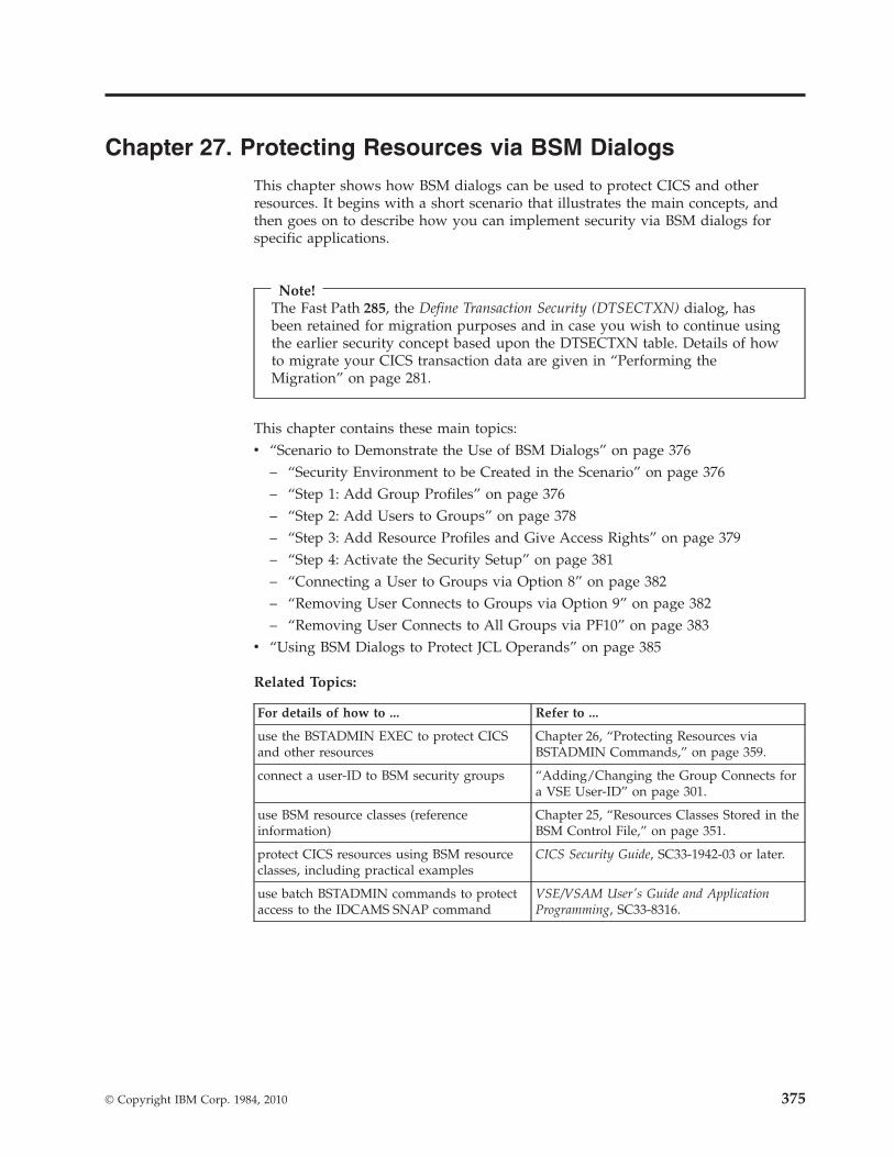
Chapter 27. Protecting Resources via BSM Dialogs
This chapter shows how BSM dialogs can be used to protect CICS and otherresources. It begins with a short scenario that illustrates the main concepts, andthen goes on to describe how you can implement security via BSM dialogs forspecific applications.
Note!The Fast Path 285, the Define Transaction Security (DTSECTXN) dialog, hasbeen retained for migration purposes and in case you wish to continue usingthe earlier security concept based upon the DTSECTXN table. Details of howto migrate your CICS transaction data are given in “Performing theMigration” on page 281.
This chapter contains these main topics:v “Scenario to Demonstrate the Use of BSM Dialogs” on page 376
– “Security Environment to be Created in the Scenario” on page 376– “Step 1: Add Group Profiles” on page 376– “Step 2: Add Users to Groups” on page 378– “Step 3: Add Resource Profiles and Give Access Rights” on page 379– “Step 4: Activate the Security Setup” on page 381– “Connecting a User to Groups via Option 8” on page 382– “Removing User Connects to Groups via Option 9” on page 382– “Removing User Connects to All Groups via PF10” on page 383
v “Using BSM Dialogs to Protect JCL Operands” on page 385
Related Topics:
For details of how to ... Refer to ...
use the BSTADMIN EXEC to protect CICSand other resources
Chapter 26, “Protecting Resources viaBSTADMIN Commands,” on page 359.
connect a user-ID to BSM security groups “Adding/Changing the Group Connects fora VSE User-ID” on page 301.
use BSM resource classes (referenceinformation)
Chapter 25, “Resources Classes Stored in theBSM Control File,” on page 351.
protect CICS resources using BSM resourceclasses, including practical examples
CICS Security Guide, SC33-1942-03 or later.
use batch BSTADMIN commands to protectaccess to the IDCAMS SNAP command
VSE/VSAM User's Guide and ApplicationProgramming, SC33-8316.
© Copyright IBM Corp. 1984, 2010 375

Scenario to Demonstrate the Use of BSM Dialogs
Security Environment to be Created in the ScenarioThis is the security environment that we establish in the scenario:
Table 12. BSM Resource Profiles Used in the Scenario
BSM ResourceClass
Resource Name (and Description) Access/User list with UACC(READ)
GROUP PRODCGRP (the group of userswho can access the ProductionCICS system)
IVAN, APPLUSR1, ...
GROUP DBDCCGRP (the group of userswho can access the DevelopmentCICS system)
DEV1, DEV2, ...
APPL DBDCCICS (the DevelopmentCICS system)
CICSUSER, DBDCCGRP
APPL PRODCICS (the Production CICSsystem)
CICSUSER, PRODCGRP
v CICSUSER is included in the scenario because this user is required as a defaultfor CICS.
v IVAN will be given access to PRODCICS. Afterwards, if IVAN then signs on toz/VSE, the name of the application he wishes to access will be sent to the BSM.Providing the resource class APPL is activated in the BSM and a resource profilefor the subject-application exists, the BSM verifies that IVAN has a minimum ofread-access to the application profile. If not, an appropriate message is sent tohis sign-on panel.
Note: For some resource classes, the resource profile is case-sensitive. Here is anexample of how incorrect information will be generated if you enter aresource profile in the wrong case:1. In the Maintain Security Profiles panel (Fast Path 2811) and for resource
class TCICSTRN, you wish to display a list of CICS transactions startingwith the CEDA transaction.
2. You enter ceda (in lower case) in the field START....3. z/VSE does not display a list of transactions starting with CEDA.
Instead, z/VSE displays a list of transactions starting (for example) withemai, ftp, iccf, and so on (all in lower case).
Step 1: Add Group ProfilesIn the first step of the scenario, we add the group profiles PRODCGRP andDBDCCGRP.1. Use Fast Path 28 to display the Security Maintenance dialog. Next, select Option
'2' (“BSM Group Maintenance”) and press Enter.
Protecting via BSM Dialogs
376 z/VSE V4R3.0 Administration

IESADMSL.IESEBSEC SECURITY MAINTENANCEAPPLID: DBDCCICS
Enter the number of your selection and press the ENTER key:
1 BSM Resource Profile Maintenance2 BSM Group Maintenance3 BSM Security Rebuild4 Maintain Certificate - User ID List5 Define Transaction Security (DTSECTXN)
PF1=HELP 3=END 4=RETURN 6=ESCAPE(U)9=Escape(m)
==> 2 Path: 28
2. The Maintain Security Profiles dialog is displayed for BSM resource classGROUP. (In the example below, “TRANSEC CLASS MIGRAT” indicates thatthese groups were migrated from CICS security-keys). Now enter a '1'anywhere in the OPT column and press Enter.
IESADMBSLG MAINTAIN SECURITY PROFILESBSM RESOURCE CLASS: GROUPSTART.... GROUP01OPTIONS: 1 = ADD 2 = CHANGE 5 = DELETE 6 = USER LIST
8 = CONNECT 9 = REMOVE USERIDOPT GROUP NAME DESCRIPTION CONNECTED?
________1 GROUP01 TRANSEC CLASS MIGRAT_ GROUP02 TRANSEC CLASS MIGRAT_ GROUP03 TRANSEC CLASS MIGRAT_ GROUP04 TRANSEC CLASS MIGRAT_ GROUP05 TRANSEC CLASS MIGRAT_ GROUP06 TRANSEC CLASS MIGRAT_ GROUP07 TRANSEC CLASS MIGRAT_ GROUP08 TRANSEC CLASS MIGRAT_ GROUP09 TRANSEC CLASS MIGRAT_ GROUP10 TRANSEC CLASS MIGRAT_ GROUP11 TRANSEC CLASS MIGRAT_ GROUP12 TRANSEC CLASS MIGRAT
PF1=HELP 3=END8=FORWARD 9=PRINT 10=REMOVE ALL
Note: The Maintain Security Profiles panel is described in detail in“Adding/Changing the Group Connects for a VSE User-ID” on page 301.
3. The Maintain Security Profiles dialog is displayed. Now enter the group-namePRODCGRP and description, and press PF5 (Update). The BSM control file isthen updated with these details. PRODCGRP then becomes an “instance” ofresource class GROUP.
Protecting via BSM Dialogs
Chapter 27. Protecting Resources via BSM Dialogs 377

IESADMBSAG MAINTAIN SECURITY PROFILESBSM CLASS: GROUP
Add Group:
GROUP NAME......... PRODCGRP 1 - 8 characters
DESCRIPTION........ Production Group Optional remark
PF1=HELP 3=END 5=UPDATE
4. Add group DBDCCGRP (with description “Development Group”) by repeatingactions 1, 2, and 3 of this step.
Step 2: Add Users to GroupsIn this second step, we add IVAN and APPLUSR1 to the group PRODCGRP. Thisis required so that IVAN and APPLUSR1 can access PRODCICS (the ProductionCICS system). Then we add user-ID APPLUSR1 to the group PRODCGRP, andfinally user-IDs DEV1 and DEV2 to the group DBDCCGRP.1. In the Maintain Security Profiles dialog, we enter a '6' (User List) next to the
group PRODCGRP and press Enter.
IESADMBSLG MAINTAIN SECURITY PROFILESBSM RESOURCE CLASS: GROUPSTART.... GROUP54OPTIONS: 1 = ADD 2 = CHANGE 5 = DELETE 6 = USER LIST
8 = CONNECT 9 = REMOVE USERIDOPT GROUP NAME DESCRIPTION CONNECTED?
_________ GROUP54 TRANSEC CLASS MIGRAT_ GROUP55 TRANSEC CLASS MIGRAT_ GROUP56 TRANSEC CLASS MIGRAT_ GROUP57 TRANSEC CLASS MIGRAT_ GROUP58 TRANSEC CLASS MIGRAT_ GROUP59 TRANSEC CLASS MIGRAT_ GROUP60 TRANSEC CLASS MIGRAT_ GROUP61 TRANSEC CLASS MIGRAT_ GROUP62 TRANSEC CLASS MIGRAT_ GROUP63 TRANSEC CLASS MIGRAT_ GROUP64 TRANSEC CLASS MIGRAT6 PRODCGRP Production Group
PF1=HELP 3=ENDPF7=BACKWARD 8=FORWARD 9=PRINT 10=REMOVE ALL
2. The Maintain User List dialog is displayed. Now enter a '1' (Add) in the OPTfield and press Enter.
Protecting via BSM Dialogs
378 z/VSE V4R3.0 Administration

IESADMBSLU MAINTAIN USER LISTBSM CLASS: GROUP GROUP: PRODCGRPSTART....OPTIONS: 1 = ADD 5 = DELETE
OPT USERID
1
PF1=HELP 3=ENDPF7=BACKWARD 8=FORWARD
3. The Maintain Security Profiles dialog is displayed. We now add IVAN to thegroup PRODCGRP and press PF5 (Update).
IESADMBSAU MAINTAIN SECURITY PROFILESBSM CLASS: GROUP
Connect Userid to group:
GROUP NAME......... PRODCGRP Group name
USERID............. IVAN 1 - 8 characters
PF1=HELP 3=END 5=UPDATE
4. Add the user-ID APPLUSR1 to the group PRODCGRP. To do so, we repeatactions 2 and 3 of this Step.
5. Add user-IDs DEV1 and DEV2 to the group DBDCCGRP (to complete the firsttwo rows of Table 12 on page 376). To do so, we repeat actions 1, 2, and 3 ofthis Step for group DBDCCGRP.
Note: If the groups in this scenario had already existed, we could have used Option'8' (Connect) to connect the user-IDs to the groups. See “Connecting a Userto Groups via Option 8” on page 382.
Step 3: Add Resource Profiles and Give Access RightsIn this step, we first add APPL resource profiles for application DBDCCICS. Thenwe add user-ID CICSUSER and group DBDCCGRP to the access list forDBDCCICS. Finally, CICSUSER and group DBDCCGRP are given an access-right ofREAD.
Protecting via BSM Dialogs
Chapter 27. Protecting Resources via BSM Dialogs 379

1. Use Fast Path 2818 to display the Maintain Security Profiles dialog for resourceclass APPL. Now we enter a '1' anywhere in the OPT column and press Enter.The Maintain Security Profiles dialog for resource class APPL is displayed. Nowenter details of resource DBDCCICS and press PF5 (Update). DBDCCICS thenbecomes an “instance” of resource class APPL.
IESADMBSAE MAINTAIN SECURITY PROFILESBSM RESOURCE CLASS: APPL
Add Profile:
PREFIX............. ________ CICS region
RESOURCE NAME...... DBDCCICSMaximum length is 8 characters.
GENERIC............ (1=yes, 2=no)
UNIVERSAL ACCESS... _ (_=None, 2=Read, 3=Update, 4=Alter)
AUDIT-LEVEL 1 ..... 1 (_=None, 1=Failure, 2=Success, 3=All)ACCESS-LEVEL 1 .... 2 (2=Read, 3=Update, 4=Alter), _=default
AUDIT-LEVEL 2 ..... (_=None, 1=Failure, 2=Success, 3=All)ACCESS-LEVEL 2 .... (2=Read, 3=Update, 4=Alter), _=defaultDESCRIPTION........ Optional remark
PF1=HELP 3=END 5=UPDATE
2. The Maintain Security Profiles dialog for resource class APPL is re-displayed.Now we must find the entry DBDCCICS in the list of profile names that aredisplayed. Enter option '6' next to DBDCCICS to display the access list for thisresource. The Maintain Access List dialog is displayed. Now enter a '1' (ADD) inthe OPT column to display the “Add Userid or Groupid” function.
3. Enter details of CICSUSER (who is given read-access to resource profileDBDCCICS), and press PF5 (Update).
IESADMBSAA MAINTAIN ACCESS LISTBSM CLASS: APPL PROFILE: DBDCCICS
Add Userid or Groupid:
NAME............... CICSUSER Userid or Groupid
ACCESS............. 2 (_=None,2=Read, 3=Update, 4=Alter)
PF1=HELP 3=END 5=UPDATE
4. Add group DBDCCGRP to the access list for resource DBDCCICS, by repeatingaction 3 of this Step. When completed, the Maintain Access List dialog isdisplayed showing user-ID CICSUSER and group DBDCCGRP. Both haveaccess '2' (read-only) for resource profile DBDCCICS.
Protecting via BSM Dialogs
380 z/VSE V4R3.0 Administration

IESADMBSLA MAINTAIN ACCESS LISTBSM CLASS: APPL PROFILE: DBDCCICSSTART.... NUMBER OF ENTRIES ON LIST: 00002OPTIONS: 1 = ADD 2 = CHANGE 5 = DELETE
OPT NAME ACC
_ CICSUSER 2_ DBDCCGRP 2
PF1=HELP 3=ENDPF7=BACKWARD 8=FORWARD
The next actions in Step 3 consists of:v Adding APPL resource profiles for application PRODCICS.v Adding user-ID CICSUSER and group PRODCGRP to the access list for
application PRODCICS.v Giving CICSUSER and PRODCGRP an access-right of READ.
To perform these actions, we repeat actions 1, 2, 3, and 4 of this Step.
Step 4: Activate the Security SetupIn this last step, we activate:v Application profiles:
– DBDCCICS– PRODCICS
v Group profiles:– DBDCCGRP– PRODCGRP
To do so:1. Use Fast Path 28 to display the Security Maintenance panel.2. Select option '3' (“BSM Security Rebuild”). The activation of the application and
group profiles will now automatically proceed.3. The message “Security Information Was Successfully Rebuilt” is displayed
when the process has completed.
The completion of Steps 1 to 4 means that the BSM security environment shownin Table 12 on page 376 has been successfully created!
Protecting via BSM Dialogs
Chapter 27. Protecting Resources via BSM Dialogs 381

Connecting a User to Groups via Option 8In “Step 2: Add Users to Groups” on page 378, three actions were required toconnect user-ID IVAN to the group PRODCGRP via option ‘6’ (User List). However, forexisting groups you can use a single action to connect a user to one or moregroups. This is done using Option '8' (Connect) of the Maintain Security Profilespanel.
In the example provided here, the user-ID DEV3 is a programmer (Type 2 user) andwill be connected to these groups:v DBDCCGRPv GROUP06v GROUP07v GROUP08v GROUP111. We type an '8' (Connect) in the OPT column for the five groups listed above.
IESADMBSLG MAINTAIN SECURITY PROFILESBSM RESOURCE CLASS: GROUPSTART....OPTIONS: 1 = ADD 2 = CHANGE 5 = DELETE 6 = USER LIST
8 = CONNECT 9 = REMOVE USERIDOPT GROUP NAME DESCRIPTION CONNECTED?
DEV3____8 DBDCCGRP DEVELOPMENT CICS_ GROUP01 TRANSEC CLASS MIGRAT_ GROUP02 TRANSEC CLASS MIGRAT_ GROUP03 TRANSEC CLASS MIGRAT_ GROUP04 TRANSEC CLASS MIGRAT_ GROUP05 TRANSEC CLASS MIGRAT8 GROUP06 TRANSEC CLASS MIGRAT8 GROUP07 TRANSEC CLASS MIGRAT8 GROUP08 TRANSEC CLASS MIGRAT_ GROUP09 TRANSEC CLASS MIGRAT_ GROUP10 TRANSEC CLASS MIGRAT8 GROUP11 TRANSEC CLASS MIGRAT
PF1=HELP 3=ENDPF7=BACKWARD 8=FORWARD 9=PRINT 10=REMOVE ALL
2. After pressing ENTER, the user-ID is connected to the five groups. An asteriskwill be displayed in the USERID CONNECTED? column for each of the five groups.
Removing User Connects to Groups via Option 9The Maintain Security Profiles panel allows you to use Option '9' (Remove) toremove the connects of a user-ID to one or more groups.
In the example provided here, the user-ID DEV3 is a programmer (Type 2 user)whose connects to these groups will be removed:v DBDCCGRPv GROUP081. We type a '9' (Remove) in the OPT column for the two groups listed above.
Protecting via BSM Dialogs
382 z/VSE V4R3.0 Administration

IESADMBSLG MAINTAIN SECURITY PROFILESBSM RESOURCE CLASS: GROUPSTART....OPTIONS: 1 = ADD 2 = CHANGE 5 = DELETE 6 = USER LIST
8 = CONNECT 9 = REMOVE USERIDOPT GROUP NAME DESCRIPTION CONNECTED?
DEV39 DBDCCGRP DEVELOPMENT CICS *_ GROUP01 TRANSEC CLASS MIGRAT_ GROUP02 TRANSEC CLASS MIGRAT_ GROUP03 TRANSEC CLASS MIGRAT_ GROUP04 TRANSEC CLASS MIGRAT_ GROUP05 TRANSEC CLASS MIGRAT_ GROUP06 TRANSEC CLASS MIGRAT *_ GROUP07 TRANSEC CLASS MIGRAT *9 GROUP08 TRANSEC CLASS MIGRAT *_ GROUP09 TRANSEC CLASS MIGRAT_ GROUP10 TRANSEC CLASS MIGRAT_ GROUP11 TRANSEC CLASS MIGRAT *
PF1=HELP 3=ENDPF7=BACKWARD 8=FORWARD 9=PRINT 10=REMOVE ALL
2. After pressing ENTER, the connects are removed. The asterisks will beremoved from the USERID CONNECTED? column for each of the groups.
Removing User Connects to All Groups via PF10The Maintain Security Profiles panel allows you to use PF10 (Remove All) to removethe connects of a user-ID to all groups to which the user-ID is currently connected.
In the example provided here, the user-ID DEV3 is a programmer (Type 2 user) andwill be removed from all groups to which this user-ID is currently connected.These groups are:v GROUP06v GROUP07v GROUP11v GROUP22v GROUP46
(GROUP 22 and GROUP46 would be displayed in the panel below by pressingPF8).1. We press PF10 (Remove All) in the panel below.
IESADMBSLG MAINTAIN SECURITY PROFILESBSM RESOURCE CLASS: GROUPSTART....OPTIONS: 1 = ADD 2 = CHANGE 5 = DELETE 6 = USER LIST
8 = CONNECT 9 = REMOVE USERIDOPT GROUP NAME DESCRIPTION CONNECTED?
DEV3_ DBDCCGRP DEVELOPMENT CICS_ GROUP01 TRANSEC CLASS MIGRAT_ GROUP02 TRANSEC CLASS MIGRAT_ GROUP03 TRANSEC CLASS MIGRAT_ GROUP04 TRANSEC CLASS MIGRAT_ GROUP05 TRANSEC CLASS MIGRAT_ GROUP06 TRANSEC CLASS MIGRAT *_ GROUP07 TRANSEC CLASS MIGRAT *_ GROUP08 TRANSEC CLASS MIGRAT_ GROUP09 TRANSEC CLASS MIGRAT_ GROUP10 TRANSEC CLASS MIGRAT_ GROUP11 TRANSEC CLASS MIGRAT *
PF1=HELP 3=ENDPF7=BACKWARD 8=FORWARD 9=PRINT 10=REMOVE ALL
Protecting via BSM Dialogs
Chapter 27. Protecting Resources via BSM Dialogs 383

2. The connects are removed, and the asterisks will be removed from theUSERID CONNECTED? column for each of the groups.
Protecting via BSM Dialogs
384 z/VSE V4R3.0 Administration

Using BSM Dialogs to Protect JCL OperandsYou can use BSM security to protect operands of specific JCL statements. Forexample, you can protect the PERM operand of the ASSGN and LIBDEFstatements.
IBM provides five resource profiles that are used for JCL statement checking:v IBMVSE.JCL.ASSGN.PERMv IBMVSE.JCL.LIBDEF.PERMv IBMVSE.JCL.LIBDROP.PERMv IBMVSE.JCL.OPTION.PARSTDv IBMVSE.JCL.OPTION.STDLABEL
(In the above resource profiles, the operands are shown as highlighted).
JCL statement checking is activated using the SEC parameter of the z/VSE IPLprocedure. For details, see “Using the Tailor-IPL-Procedure Dialog to TailorSecurity Parameters” on page 273.
Notes:
1. To perform JCL statement checking:v JCL security must be enabled.v The minimum access right for Universal Access or user-IDs/groups must be
READ.2. As an alternative to using resource profiles, you could use generic profiles. For
details, see “How You Enter Generic Names” on page 362.
After JCL security is enabled, each time a user submits a batch job the statementscontained in the batch job (for example, the PERM operand of an ASSIGN orLIBDEF statement) will be checked against access lists. For each resource profile,these user-IDs/groups will be authorized to execute the JCL statement:v User-IDs of type 1 (Administrator).v User-IDs/groups contained in the access list used with the security profile.
If a security profile does not exist, all user-IDs/groups will be authorized toexecute the JCL statement.
An example of setting up JCL statement checking now follows. To give all userscontained in group S1JCLGRP read-access to the resource profiles used for JCLstatement checking, we must:1. Use Fast Path 2819 to display the Maintain Security Profiles panel. Then enter
IBMVSE in the START field and press Enter. The resource profiles used for JCLstatement checking are then displayed.
Protecting via BSM Dialogs
Chapter 27. Protecting Resources via BSM Dialogs 385

IESADMBSLE MAINTAIN SECURITY PROFILESBSM RESOURCE CLASS: FACILITY ACTIVESTART.... IBMVSE (CASE SENSITIVE)OPTIONS: 1 = ADD 2 = CHANGE 5 = DELETE 6 = ACCESS LIST
OPT PROFILE NAME DESCRIPTION UNIVERSAL AUDIT> ACCESS VALUE
_ IBMVSE.JCL.ASSGN.PERM FOR JCL SECURITY 12_ IBMVSE.JCL.LIBDEF.PERM FOR JCL SECURITY 12_ IBMVSE.JCL.LIBDROP.PERM FOR JCL SECURITY 12_ IBMVSE.JCL.OPTION.PARSTD FOR JCL SECURITY 12_ IBMVSE.JCL.OPTION.STDLABEL FOR JCL SECURITY 12
PF1=HELP 3=END8=FORWARD 9=PRINT 11=NAME RIGHT
2. Type 6 (Access List) in the OPT column for the profileIBMVSE.JCL.ASSGN.PERM and press Enter. The Maintain Access List panel isdisplayed.
3. Now enter a '1' (ADD) in the OPT column to display the “Add Userid orGroupid” function. Enter the details for S1JCLGRP as shown below and pressPF5 (Update).
IESADMBSAA MAINTAIN ACCESS LISTBSM CLASS: FACILITY PROFILE: IBMVSE.JCL.ASSGN.PERM
Add Userid or Groupid:
NAME............... S1JCLGRP Userid or Groupid
ACCESS............. 2 (_=None,2=Read, 3=Update, 4=Alter)
PF1=HELP 3=END 5=UPDATE
4. Repeat actions 2 and 3 of this Step for the other four resource profiles to giveS1JCLGRP read-access to these resource profiles.
5. To confirm that read-access has been successfully granted, we useFast Path 2819 and type 6 (Access List) in the OPT column for any of theprofiles (in this example, for IBMVSE.JCL.ASSGN.PERM). Press Enter and theMaintain Access List panel should confirm that access has been successfullydefined.
Protecting via BSM Dialogs
386 z/VSE V4R3.0 Administration
IESADMBSLA MAINTAIN ACCESS LISTBSM CLASS: FACILITY PROFILE: IBMVSE.JCL.ASSGN.PERMSTART.... NUMBER OF ENTRIES ON LIST: 00002OPTIONS: 1 = ADD 2 = CHANGE 5 = DELETE
OPT NAME ACC
_ S1JCLGRP 2
PF1=HELP 3=ENDPF7=BACKWARD 8=FORWARD
Note that instead of using dialogs, you can use batch BSTADMIN commands to setup JCL statement checking (described in Chapter 26, “Protecting Resources viaBSTADMIN Commands,” on page 359).
Protecting via BSM Dialogs
Chapter 27. Protecting Resources via BSM Dialogs 387

388 z/VSE V4R3.0 Administration

Chapter 28. Overview of DTSECTAB-Based VSE Security
This chapter describes how the z/VSE Access Control Function is used together withtable DTSECTAB to control access to files, libraries, sublibraries, and librarymembers. It also describes how access control to batch jobs is done. The z/VSEAccess Control Function is supplied with the Basic Security Manager (BSM).
This chapter contains these main topics:v “How Security Checking Is Performed”v “How User Profile Information Is Used” on page 390v “Which Resources Can Be Protected in DTSECTAB?” on page 390v “Defining Resources in DTSECTAB” on page 391v “Using the IBM-Provided DTSECTAB” on page 391v “How Users Are Identified and Authenticated” on page 392v “How VSE/POWER Jobs are Authenticated” on page 393
Related Topics:
For details of ... Refer to ...
how to activate VSE security based on tableDTSECTAB
Chapter 29, “Customizing/ActivatingDTSECTAB-Based Security,” on page 395.
the contents of DTSECTAB (as delivered byIBM)
“Content of Pregenerated DTSECTAB(DTSECTRC in VSE/ICCF Library 59)” onpage 400.
the syntax of the DTSECTAB macro, andexamples of its use
Chapter 31, “DTSECTAB Macro: Syntax andExamples,” on page 419.
how security information is propagatedbetween one or more VSE/POWER batchenvironments
Chapter 32, “Propagation of VSE/POWERSecurity Identification,” on page 427.
How Security Checking Is PerformedSecurity checking is performed on two distinct levels:1. User identification and authentication:v User identification: this is done by checking the user ID. Is this user-ID
known to the system?v User authentication: is the user really the person that owns this user ID? This
is checked either via an explicit password supplied with a job, or it ischecked via an indication that the password had been validated at someearlier stage. This may have been done during sign-on, for example, beforethe job was submitted. In this case, no further password check is necessary.
2. Access authorization:is the user permitted to access a particular resource such as a file, library,sublibrary, or member?This is done by comparing thev User profile information in the VSE.CONTROL.FILE with thev Resource profile information in DTSECTAB.
© Copyright IBM Corp. 1984, 2010 389

How User Profile Information Is UsedUser profiles are stored in the VSE.CONTROL.FILE. A user profile specifies, for anindividual user, the access rights to resources. You define user profiles via theMaintain User Profile Dialog. See Chapter 22, “Maintaining User Profiles via BSMDialogs,” on page 287 for details.
The ACC parameter defines access control classes together with associated accessrights. A user's access control class can have one of the following access rights:v ALT (Alter)v UPD (Update)v READ (Read-only)v CON (Connect)
These access rights are ordered hierarchically: ALTER implies UPDATE, UPDATEimplies READ, READ implies CONNECT.
The definition of access rights will be discussed in detail in “How Access RightsAre Used” on page 407. Refer also to Figure 86 on page 294 where the "Add orChange Resource Access Rights" panel of the Maintain User Profiles dialog isshown.
A user that is defined as system administrator (type 1 user) in the user profile hasunrestricted access with access right of ALT to all protected resources.
Which Resources Can Be Protected in DTSECTAB?Resources to be protected must be defined in DTSECTAB. The following resourcescan be protected:1. All libraries, sublibraries, and all their members.
Members are protected at member name level. That is, within one sublibrary,members of different types with the same name are protected under the sameresource profile. For example, if a user has an access right to member namePROG1, that right applies to PROG1.A, PROG1.E, PROG1.OBJ, PROG1.PHASE,and PROG1.PROC.
2. Files as outlined below:v All VSE/VSAM KSDS, RRDS, VRDS and ESDS accessed directly via an ACB
macro, and all VSE/VSAM-managed SAM files accessed via either a DTFSDor an ACB macro, or by appropriate file definition statements of the IBMcompiler(s) used at your installation. Note that the file's VOLSER and catalogare not checked.When VSE/VSAM data is accessed via a path, the path name is used foraccess checking.The file's catalog can only be checked if the cluster is defined with theauthorization parameter, and a VSE/VSAM user security verification routine(USVR) is coded. The catalog name can be passed to the USVR exit after theentry point name in the authorization parameter. You find detailedinformation on the USVR exit in the IBM manual VSE/VSAM Commandsunder “User Security-Verification Routine”.
v All non-VSAM disk files and standard-labeled tape files that are defined by afile description macro (DTFxx), or by appropriate file definition statements ofthe IBM compiler(s) used at your installation.
Overview of VSE Security
390 z/VSE V4R3.0 Administration

You cannot protect through DTSECTAB entries:v Unlabeled tapesv Tapes with non-standard labelsv Diskette files
Defining Resources in DTSECTABFor each resource to be protected, the security administrator defines one or moreaccess control classes in the corresponding resource profile. In general, resourceswithout an entry in DTSECTAB are not protected.
Access control classes are numbers between 1 and 32 which are assigned to theresource.
A typical definition might look as follows:DTSECTAB TYPE=SUBLIB,NAME=AUX.PR$302,ACC=(8,9)
Sublibrary AUX.PR$302 is defined as a resource that can be accessed by users whohave access control classes 8 and 9 defined in their user profile.
Authorization of a particular user to access a resource is determined by a match ofthe access control classes. In our example “An Example of Using Access Rights” onpage 409, user ENDU with access control class 1 through 8 is allowed to accesssublibrary AUX.PR$302 due to the match on class 8. The access right is limited toUPDATE. An attempt by ENDU to ALTER (rename or delete) the sublibrary wouldbe an access violation.
Access Control via classes establishes an individual access right for the user. Forresources "library, sublibrary, and member", additionally a universal access right(UACC) can be specified. It grants all users of the system, irrespective of theclasses specified in user profiles (if such profiles exist), the defined access right ofALT, UPD, READ or CON. For a resource with a universal access right, individualaccess rights are meaningful only if they are higher than the universal access right,because at least the UACC will be granted to any user.
You find detailed information about protection of resources in Chapter 30, “AccessRights/Checking in DTSECTAB,” on page 407.
Using the IBM-Provided DTSECTABThe predefined table DTSECTAB contains mainly system-defined resources. It doesnot use any classes, the resources are protected via universal access rights only. Inthis way the pregenerated definitions do not interfere with the user'sinstallation-specific class definitions.
You can build upon this table if you need to tailor the given support. You may, forexample, extend the set of resources to include your own resources. Or, you maywant to establish a set of access control classes to implement your own rules ofdifferentiation between individual users.
More details on the predefined support are given in Chapter 29,“Customizing/Activating DTSECTAB-Based Security,” on page 395.
Overview of VSE Security
Chapter 28. Overview of DTSECTAB-Based VSE Security 391

How Users Are Identified and AuthenticatedIn a secured z/VSE system, batch jobs that are submitted for processing arechecked for identification and authentication (security identification):v User identification: is the user known to the system? That is, does the user have
a user profile in the VSE.CONTROL.FILE?v Authentication: is the user really the person that owns this user ID?
Security identification is supplied in three ways:1. During sign-on to a z/VSE subsystem such as the z/VSE Interactive Interface
or VSE/ICCF. Jobs submitted from here run under the sign-on user ID.2. An explicit security identification in the SEC parameter of the VSE/POWER
JECL statement * $$ JOB of a submitted job.An equivalent identification can be given for jobs submitted via az/VSE-internal interface, the “VSE/POWER Spool Access Support”. It isdescribed in the IBM manual VSE/POWER Application Programming under“Introduction to Spool-Access Support”.
3. An explicit security identification in the // ID job control statement of a jobsubmitted.
If you submit a job, you need not explicitly enter user-ID and password with eachsubmission, as explained in “How VSE/POWER Jobs are Authenticated” on page393.
Security Information in the JECL Statement * $$ JOBThe parameter SEC in the * $$ JOB statement of VSE/POWER specifies user-IDand password of the VSE/POWER job to be submitted:
* $$ JOB ... SEC=(user-ID,password)
The SEC parameter is optional. However, if specified, it must contain both user-IDand password.
The security information in the * $$ JOB statement is valid for the entire sequenceof z/VSE jobs included in a VSE/POWER job stream.
For a complete description of the * $$ JOB statement refer to the manualVSE/POWER Administration and Operation under “* $$ JOB: Marking the Start of aVSE/POWER Job”.
Security Information in the JCL Statement // IDThe job control statement // ID carries the same information as the JECLstatement * $$ JOB, that is: user-ID and password.
The information is valid for one z/VSE job: it covers the job where it is included,but not any other job that might follow.
A // ID statement overrides the VSE/POWER security information for the lengthof the z/VSE job. After that, VSE/POWER's security information becomes effectiveagain.
// ID statements should be avoided because users with access to jobs in theVSE/POWER reader queue can see both, user-ID and password. Specifying the
Overview of VSE Security
392 z/VSE V4R3.0 Administration

user-ID and password in the * $$ JOB statement is the better and recommendedsolution. Retrieving a job from the VSE/POWER reader queue generally does notreveal user-ID and password.
However, there are situations where the statement is needed, for examplev In z/VSE startup procedures. Please refer to “Access Control for Startup
Procedures” on page 416.v In PAUSExx jobs. Please refer to “Tasks to be Done after Initial Installation” on
page 396.v In jobs that accomplish the transferring of jobs and files between systems. z/VSE
dialogs may create a // ID statement if the remote system is at backlevel (z/VSEprior to VSE/ESA 1.3). Please refer to “Transfer of Jobs or Files/Membersbetween Systems” on page 429.
How VSE/POWER Jobs are AuthenticatedThe user-ID, which z/VSE knows (for example from sign-on), is sufficient for userauthentication if a batch job is submitted from one of the five sources:1. z/VSE Interactive Interface2. VSE/ICCF3. A workstation via the SEND/RECEIVE command interface4. A job with explicit user-ID and password specification5. Another authenticated job.
Therefore, a user who submits a job from any of the above sources does not needto care about the user-ID or the password for this job.
A job that is submitted on behalf of a user whose user-ID and password have beenvalidated earlier is called an authenticated job.
Note: If a job is to run with another user profile than the one of the submitter,user-ID and password must be supplied. In this case, not the // IDstatement but the * $$ JOB statement should be used for the reasonsoutlined above.
The subject of user-ID propagation is discussed in more detail in Chapter 32,“Propagation of VSE/POWER Security Identification,” on page 427.
Overview of VSE Security
Chapter 28. Overview of DTSECTAB-Based VSE Security 393

394 z/VSE V4R3.0 Administration

Chapter 29. Customizing/Activating DTSECTAB-BasedSecurity
This chapter describes how you can customize the IBM-supplied table DTSECTAB,and then activate access-control security based on this table.
It also lists the contents of table DTSECTAB, as shipped by IBM.
As shipped, z/VSE provides basic security support for access-control which isready to use. This support includes the following functions and resources:v Activation of the Basic Security Manager (BSM) during initial installation.v Startup procedures adapted for a system with the Basic Security Manager active.v A predefined access control table (DTSECTAB) for resource protection which is
automatically generated during initial installation, if you answered with YESduring initial installation.
v PRIMARY sublibraries for predefined users SYSA, OPER, and PROG.
This chapter contains these main topics:v “Activating Security for Batch Resources”v “Tasks to be Done after Initial Installation” on page 396v “Pregenerated Access Control Table DTSECTAB” on page 397v “Maintaining the Access Control Table DTSECTAB” on page 398v “Applying IBM Service to DTSECTRC” on page 399v “Protecting the Access Control Table DTSECTAB Itself” on page 399v “Content of Pregenerated DTSECTAB (DTSECTRC in VSE/ICCF Library 59)” on
page 400
Related Topics:
For details of ... Refer to ...
how to specify access rights in tableDTSECTAB, and how access checking isused to process these access rights
Chapter 30, “Access Rights/Checking inDTSECTAB,” on page 407.
the syntax of the DTSECTAB macro, andexamples of its use
Chapter 31, “DTSECTAB Macro: Syntax andExamples,” on page 419.
Activating Security for Batch ResourcesYou can activate basic security for batch resources either during initial installation,or later by using the Tailor IPL Procedure dialog as described under “Using theTailor-IPL-Procedure Dialog to Tailor Security Parameters” on page 273.
If the support is activated during initial installation, the installation programupdates the IPL procedure $IPLESA and adds the statement:SYS SEC=(YES,NOTAPE)
where:v NOTAPE - means that files on disk are protected but not files on tape.
© Copyright IBM Corp. 1984, 2010 395

v SEC=YES - activates both the protection of disk and the protection of tape files.
In a system with security on, the predefined access control table DTSECTABbecomes active at the first IPL after initial installation.
This ensures a correct startup for a system with security active. You should use thepredefined DTSECTAB as a base when later adding your own entries. The tableprovides the necessary protection of system libraries. Startup would not work ifsystem libraries were not properly protected.
Tasks to be Done after Initial InstallationDuring initial installation, the system defines the users shown in the table inTable 1 on page 5.
The first IPL after initial installation with SEC=YES activates the predefined basicsecurity support. A system administrator (type 1 user, SYSA) has unlimited accessto all resources and should now do the following:v Change the passwords of user-IDs FORSEC, SYSA, OPER, $SRV, and PROG in
file VSE.CONTROL.FILE.
Note: These user-IDs are explained in Table 1 on page 5.v For the user-ID FORSEC, also change the password in DTSECTAB.v For users FORSEC, PROG, OPER and $SRV, you must perform a logon
immediately after installation, in order to change the password. Afterwards, usethe Maintain Primary Sublibraries dialog to define PRIMARY sublibraries for theusers SYSA, PROG, and OPER. The password for user POST needs to bechanged after the initial installation process has been completed. Change thepassword via the dialog Maintain User Profiles, (for details refer to Chapter 22,“Maintaining User Profiles via BSM Dialogs,” on page 287).
v Change and submit skeleton SKCICS and possibly SKCICS2 in VSE/ICCFlibrary 59. Log on as system administrator, and submit the job. This submissioncatalogs the startup job CICSICCF as member CICSICCF.Z in the systemsublibrary IJSYSRS.SYSLIB and places the job into the VSE/POWER readerqueue. The job "inherits" the security attributes of the submitter and changesthem via the ID statement to the special task user-ID for the CICS region. Makesure this is the only CICS startup job by deleting the original from the readerqueue.
As PAUSExx jobs do not have any access rights, you can provide access rights viathe // ID statement if required.
Considerations for User-IDs FORSEC and DUMMYUsers FORSEC and DUMMY are available for system purposes only. They are theonly users defined in DTSECTAB.
FORSEC
is defined as system administrator in the z/VSE system that is delivered to you.Its purpose is to provide appropriate access rights at system startup.
Activating DTSECTAB-Based Security
396 z/VSE V4R3.0 Administration

ImportantYou should NEVER remove user FORSEC from either DTSECTAB or theVSE.CONTROL.FILE.
If your installation uses the optional program VSE/Access Control - Logging andReporting (VSE/ACLR), you may want to reduce the access rights of this user byspecifying access control classes. This greatly reduces the number of loggingrecords because administrator accesses are always logged (not only violations).Therefore, activate the Logging and Reporting program only after you havereduced the access rights of user FORSEC in DTSECTAB and the VSE control file.Refer also to Chapter 35, “Logging/Reporting Security Events,” on page 439.
The manual VSE/Access Control-Logging and Reporting: Program Reference andOperations Guide provides details about VSE/Access Control - Logging andReporting.
DUMMY
has no special access rights. This user-ID is included in certain startup proceduresbefore certain jobs (such as PAUSEBG, PAUSEF1, ... ) are submitted. User-IDDUMMY serves to inhibit the inheritance of the user FORSEC's access rights(which are administrator rights) to those jobs.
ImportantNever remove user DUMMY from DTSECTAB.
Pregenerated Access Control Table DTSECTABThe z/VSE system that is delivered to you has a predefined access control tableDTSECTAB. The table provides a basic level of security; it does not use any accesscontrol classes. It is automatically generated and ready for use immediately afterinitial installation.
You should never remove or change any of the supplied entries without carefulconsideration. You may, of course, add entries by using the methods describedbelow.
Predefined Member DTSECTRC (Containing DTSECTAB)DTSECTRC contains security information about protected z/VSE system resources(plus definitions of special users: FORSEC and DUMMY). Its content is shownunder “Content of Pregenerated DTSECTAB (DTSECTRC in VSE/ICCF Library59)” on page 400. (The exact content may have changed since this manual wasprinted. Please look at your copy in VSE/ICCF library 59, member DTSECTRC.)
You may add entries for protected z/VSE system resources as needed or changethose provided by adding access control classes. Programs that can potentiallybypass access control, should also be protected at member level. Be sure that noperson other than the security administrator is given an access right to sensitivemembers.
Activating DTSECTAB-Based Security
Chapter 29. Customizing/Activating DTSECTAB-Based Security 397

Note: Except for users FORSEC and DUMMY, users should only be defined inVSE.CONTROL.FILE (user SYSA).
“Maintaining the Access Control Table DTSECTAB” describes how to maintainDTSECTAB.
Maintaining the Access Control Table DTSECTABVSE Access Control offers two major groups of access rights for resources:v Universal access rights via the UACC parameter, and/orv Individual access rights via the ACC parameter.
Three scenarios will be discussed in the following:1. Only the pregenerated security support is used: you do not add resources of
your own to DTSECTAB, just users in the VSE.CONTROL.FILE.2. You add users plus resources of your own. The resources are protected with
universal access rights only. Access control classes are not used.3. You add users plus resources of your own. The resources are protected by
universal access rights as well as by individual access rights via classes.
In each of these three cases, a new DTSECTAB phase must be cataloged. z/VSEactivates the new table when the next user identification and authentication is tobe done. The source version of DTSECTAB is called DTSECTRC.
Note: If you make changes to table DTSECTAB, you are recommended to IPL yourz/VSE to ensure that these changes will be included in z/VSE componentsthat store parts of the z/VSE security data.
Scenario 1. Predefined Security Support OnlyYou confine yourself to the resources defined in the pregenerated DTSECTAB.These resources are defined with UACC only; access control classes are not used.You just add/delete users. To do this, use one of the two methods:v Define a user in the VSE.CONTROL.FILE, with the Maintain User Profiles dialog.v Modify skeleton IESUPDCF (a member in library 59) and submit the job to
batch. This job updates the VSE.CONTROL.FILE.
Scenario 2. Add Resources Using the UACC Parameter OnlyYou add resources in addition of those defined in the pregenerated DTSECTAB.The resources are protected by universal access rights only. This implies that youneed not modify the user profiles in the VSE.CONTROL.FILE.
Proceed as follows:v Get yourself a copy of DTSECTRC from VSE/ICCF library 59 into your private
VSE/ICCF library. Whenever you change DTSECTAB, use the member youcopied into your private VSE/ICCF library.
v Update member DTSECTRC in your private VSE/ICCF library by addingdefinitions for the resources you want to protect.
v Submit DTSECTRC from your private VSE/ICCF library.
Activating DTSECTAB-Based Security
398 z/VSE V4R3.0 Administration

Scenario 3. Add Resources Using the ACC ParameterYou add resources in addition to those defined in the pregenerated DTSECTAB.Some of the resources are protected via access control classes. This forces you tomodify user profiles in the VSE.CONTROL.FILE because the ACC parameter mustbe included.
Proceed as follows for users:v Use the Maintain User Profiles dialog as described under “Adding/Changing a
User-ID and Profile Definitions” on page 289.
For resources, proceed in the same way as described under “Scenario 2. AddResources Using the UACC Parameter Only” on page 398.
Applying IBM Service to DTSECTRCSince DTSECTRC is code supplied by IBM, it can be affected by IBM service.
After a service PTF or FSU (Fast Service Upgrade) has been applied, you will havethe latest IBM-supplied version of DTSECTRC in VSE/ICCF library 59. Considerthat you may have to update your version in sublibrary PRD2.SAVE accordingly.
Protecting the Access Control Table DTSECTAB ItselfTo prevent manipulation and misuse of the information stored in DTSECTAB, theIBM-supplied DTSECTAB has entries which serve to protect the DTSECTAB itself.Please refer to Figure 99 on page 400.
The system encrypts sensitive information in the table to provide additionalprotection.
Activating DTSECTAB-Based Security
Chapter 29. Customizing/Activating DTSECTAB-Based Security 399

Content of Pregenerated DTSECTAB (DTSECTRC in VSE/ICCF Library59)
The supplied DTSECTAB is shown in Figure 99.
****************************************************** ** 5686-CF7 (C) COPYRIGHT IBM CORP. 1984, 2004 ** ******************************************************
TITLE ’DTSECTAB - SECURITY TABLE FOR RESOURCES’********************************************************************
PUNCH ’ CATALOG DTSECTRC.OBJ REP=YES’SPACE 3
*---------------------------------------------------------------------** ** STATIC PART OF DTSECTAB ** **---------------------------------------------------------------------** THIS PART IS SHIPPED AS A-BOOK IN IJSYSRS.SYSLIB.DTSECTRC. ** IF CHANGED, THE USER SHOULD PUT HIS VERSION UNDER THE SAME ** NAME IN PRD2.SAVE, AS IBM SERVICE IS DONE ON THE MEMBERS ** CONTAINED IN IJSYSRS.SYSLIB. ** (THE JOB TO BUILD A DTSECTAB LOOKS FIRST IN PRD2.SAVE FOR ** DTSECTRC). **---------------------------------------------------------------------**---------------------------------------------------------------------** IBM SUPPLIED USERS **---------------------------------------------------------------------**** USER DUMMY HAS NO SPECIAL SECURITY RIGHTS.USED TO RESET INHERITANCE*** IT AVOIDS GETTING TOO MANY RIGHTS WHILE LOADING POWER JOBS DURING*** ASI.*** YOU SHOULD NOT DEFINE AN II USER WITH THE NAME ’DUMMY’.*---------------------------------------------------------------------*
DTSECTAB TYPE=USER, CNAME=DUMMY, CPASSWRD=DUMMY, CAUTH=NO, CSUBTYPE=INITIAL
SPACE 3*---------------------------------------------------------------------**** USER FORSEC HAS ALL ACCESS RIGHTS. THEREFORE, THE PASSWORD NEEDS*** TO BE CHANGED AFTER INITIAL INSTALLATION.*---------------------------------------------------------------------*
DTSECTAB TYPE=USER, CNAME=FORSEC, CPASSWRD=FORSEC, CREADDIR=YES, CMCONS=YES, CAUTH=YES, CRIGHT=BTRANS
*---------------------------------------------------------------------** END OF IBM SUPPLIED USERS **---------------------------------------------------------------------**---------------------------------------------------------------------** ** FOLLOWING IS THE Z/VSE 3.1 SUPPLIED PART OF THE DTSECTAB ** THAT DEFINES A MINIMUM SET OF RESOURCES TO BE PROTECTED. ** **---------------------------------------------------------------------*
Figure 99. Pregenerated DTSECTAB (DTSECTRC in VSE/ICCF Library 59) (Part 1 of 6)
Activating DTSECTAB-Based Security
400 z/VSE V4R3.0 Administration

****** LIBRARIES************************************************************* IJSYSRS
DTSECTAB TYPE=LIB, CNAME=DOSRES.VSE.SYSRES.LIBRARY.IJSYSRS, CUACC=CON
DTSECTAB TYPE=SUBLIB, CNAME=IJSYSRS.SYSLIB, CUACC=CON
DTSECTAB TYPE=MEMBER, CNAME=IJSYSRS.SYSLIB.*, CUACC=READ
****** CPUVAR* IS USED BY VARIOUS JOBSTREAMS TO SAVE PARAMETERSDTSECTAB TYPE=MEMBER, C
NAME=IJSYSRS.SYSLIB.CPUVAR*, CUACC=UPD
****** ALLOW PROGRAMMER TO ADD HIS/HER OWN VSAM FILE VIA II DIALOGSDTSECTAB TYPE=MEMBER, C
NAME=IJSYSRS.SYSLIB.STDLABUP, CUACC=UPD
****** CLRDK DESTROYS THE DATA ON A DISK.DTSECTAB TYPE=MEMBER, C
NAME=IJSYSRS.SYSLIB.CLRDK****** ICKDSF DESTROYS DATA ON A DISK.
DTSECTAB TYPE=MEMBER, CNAME=IJSYSRS.SYSLIB.ICKDSF
****** IKQVDU CHANGES THE FORMAT 1 LABELDTSECTAB TYPE=MEMBER, C
NAME=IJSYSRS.SYSLIB.IKQVDU****** DTSANALS SHOULD BE EXECUTED BY AUTHORIZED PERSONS ONLY
DTSECTAB TYPE=MEMBER, CNAME=IJSYSRS.SYSLIB.DTSANALS
****** DTSUTILA IS A RESOURCE THAT PROTECTS SECURITY SENSITIVE* DTSUTIL COMMANDS FROM BEING EXECUTED BY NON-ADMINISTRATORS
DTSECTAB TYPE=MEMBER, CNAME=IJSYSRS.SYSLIB.DTSUTILA
****** SECURITY PROGRAMS/TABLESDTSECTAB TYPE=MEMBER, C
NAME=IJSYSRS.SYSLIB.DTSEC******* PROGRAMS TO MANIPULATE THE CONTROL FILE
DTSECTAB TYPE=MEMBER, CNAME=IJSYSRS.SYSLIB.IESUPDCF
DTSECTAB TYPE=MEMBER, CNAME=IJSYSRS.SYSLIB.IESBLDUP
****** PROGRAMS TO MANIPULATE THE LDAP USER MAPPING FILEDTSECTAB TYPE=MEMBER, C
NAME=IJSYSRS.SYSLIB.IESLDUMADTSECTAB TAPE=MEMBER, C
NAME=IJSYSRS.SYSLIB.IESLDSODTSECTAB TAPE=MEMBER, C
NAME=IJSYSRS.SYSLIB.IESLDSOC****** PROGRAMS TO ALLOW POWER Q MANIPULATION
DTSECTAB TYPE=MEMBER, CNAME=IJSYSRS.SYSLIB.DTRIJMGR
DTSECTAB TYPE=MEMBER, CNAME=IJSYSRS.SYSLIB.IPW$$DD
DTSECTAB TYPE=MEMBER, CNAME=IJSYSRS.SYSLIB.BSTADMIN
Figure 99. Pregenerated DTSECTAB (DTSECTRC in VSE/ICCF Library 59) (Part 2 of 6)
Activating DTSECTAB-Based Security
Chapter 29. Customizing/Activating DTSECTAB-Based Security 401

****** THE NEXT ENTRIES ARE USED TO PROTECT THE PASSWORDS IN ...* (PROGRAMS THAT ACCES THE VSE.CONTROL.FILE)
DTSECTAB TYPE=MEMBER, CNAME=IJSYSRS.SYSLIB.CICSICCF
DTSECTAB TYPE=MEMBER, CNAME=IJSYSRS.SYSLIB.CICS2
****** IJSYSR2 IS ALIAS NAME OF IJSYSRS, USED BY SERVICE DIALOGS* WHICH CAN ONLY INVOKED BY SYSTEM ADMINISTRATOR
DTSECTAB TYPE=LIB, CNAME=DOSRES.VSE.SYSRES.LIBRARY.IJSYSR2, CUACC=CON
****** IJSYSR1 IS ALIAS NAME OF IJSYSRS, USED BY SERVICE DIALOGS* WHICH CAN ONLY INVOKED BY SYSTEM ADMINISTRATOR
DTSECTAB TYPE=LIB, CNAME=SYSWK1.SYS.NEW.RES.IJSYSR1, CUACC=CON
****** PRD1DTSECTAB TYPE=LIB, C
NAME=*.VSE.PRD1.LIBRARY.PRD1, CUACC=CON
****** PRD1.BASEDTSECTAB TYPE=SUBLIB, C
NAME=PRD1.BASE, CUACC=CON
DTSECTAB TYPE=MEMBER, CNAME=PRD1.BASE.*, CUACC=READ
****** PRD1.BASED SERVICE SUBLIBRARYDTSECTAB TYPE=SUBLIB, C
NAME=PRD1.BASED, CUACC=CON
DTSECTAB TYPE=MEMBER, CNAME=PRD1.BASED.*, CUACC=READ
****** PRD1.MACLIBDTSECTAB TYPE=SUBLIB, C
NAME=PRD1.MACLIB, CUACC=CON
DTSECTAB TYPE=MEMBER, CNAME=PRD1.MACLIB.*, CUACC=READ
****** PRD1.MACLIBD SERVICE SUBLIBRARYDTSECTAB TYPE=SUBLIB, C
NAME=PRD1.MACLIBD, CUACC=CON
DTSECTAB TYPE=MEMBER, CNAME=PRD1.MACLIBD.*, CUACC=READ
****** AVOID THAT ANYONE CAN MANIPULATE FILES USING DITTODTSECTAB TYPE=MEMBER, C
NAME=PRD1.BASE.DITTO****** PRDPRIM IS ALIAS NAME OF PRD1, USED BY SERVICE DIALOGS* WHICH CAN ONLY BE INVOKED BY SYSTEM ADMINISTRATOR
DTSECTAB TYPE=LIB, CNAME=*.VSE.PRD1.LIBRARY.PRDPRIM, CUACC=CON
****** PRD2DTSECTAB TYPE=LIB, C
NAME=*.VSE.PRD2.LIBRARY.PRD2, CUACC=CON
DTSECTAB TYPE=SUBLIB, CNAME=PRD2.*, CUACC=READ
Figure 99. Pregenerated DTSECTAB (DTSECTRC in VSE/ICCF Library 59) (Part 3 of 6)
Activating DTSECTAB-Based Security
402 z/VSE V4R3.0 Administration

****** PRD2.SCEEBASE LE CODE LIBRARYDTSECTAB TYPE=SUBLIB, C
NAME=PRD2.SCEEBASE, CUACC=CON
DTSECTAB TYPE=MEMBER, CNAME=PRD2.SCEEBASE.*, CUACC=READ
****** PRD2.SCEEBASD LE SERVICE LIBRARYDTSECTAB TYPE=SUBLIB, C
NAME=PRD2.SCEEBASD, CUACC=CON
DTSECTAB TYPE=MEMBER, CNAME=PRD2.SCEEBASD.*, CUACC=READ
****** PRD2.DBASE PRODUCT LIBRARY DATABASESDTSECTAB TYPE=SUBLIB, C
NAME=PRD2.DBASE, CUACC=CON
DTSECTAB TYPE=MEMBER, CNAME=PRD2.DBASE.*, CUACC=READ
****** PRD2.PROD PRODUCT LIBRARY IN GENERALDTSECTAB TYPE=SUBLIB, C
NAME=PRD2.PROD, CUACC=CON
DTSECTAB TYPE=MEMBER, CNAME=PRD2.PROD.*, CUACC=READ
****** PRD2.COMM PRODUCT LIBRARY COMMUNICATION PRODUCTS 1DTSECTAB TYPE=SUBLIB, C
NAME=PRD2.COMM, CUACC=CON
DTSECTAB TYPE=MEMBER, CNAME=PRD2.COMM.*, CUACC=READ
****** PRD2.COMM2 PRODUCT LIBRARY COMMUNICATION PRODUCTS 2DTSECTAB TYPE=SUBLIB, C
NAME=PRD2.COMM2, CUACC=CON
DTSECTAB TYPE=MEMBER, CNAME=PRD2.COMM2.*, CUACC=READ
****** PRD2.AFP PRODUCT LIBRARY ADVANCED PRINTERDTSECTAB TYPE=SUBLIB, C
NAME=PRD2.AFP, CUACC=CON
DTSECTAB TYPE=MEMBER, CNAME=PRD2.AFP.*, CUACC=READ
****** PRD2.DB2750 PRODUCT LIBRARY DB2 7.5.0DTSECTAB TYPE=SUBLIB, C
NAME=PRD2.DB2750, CUACC=CON
DTSECTAB TYPE=MEMBER, CNAME=PRD2.DB2750.*, CUACC=READ
Figure 99. Pregenerated DTSECTAB (DTSECTRC in VSE/ICCF Library 59) (Part 4 of 6)
Activating DTSECTAB-Based Security
Chapter 29. Customizing/Activating DTSECTAB-Based Security 403

DTSECTAB TYPE=SUBLIB, CNAME=PRD2.DB2750C, CUACC=CON
DTSECTAB TYPE=SUBLIB, CNAME=PRD2.DB2750C.*, CUACC=READ
****** PRD2.DB2STP PRODUCT LIBRARY DB2 STORED PROCEDURESDTSECTAB TYPE=SUBLIB, C
NAME=PRD2.DB2STP, CUACC=CON
DTSECTAB TYPE=MEMBER, CNAME=PRD2.DB2STP.*, CUACC=READ
****** SRV$SYS IS USED BY BACKUP JOBSTREAMS TO SAVE PARAMETERSDTSECTAB TYPE=MEMBER, C
NAME=PRD2.CONFIG.SRV$SYS, CUACC=UPD
****** BASIC START NEEDS THIS SUBLIBDTSECTAB TYPE=SUBLIB, C
NAME=PRD2.SAVE, CUACC=CON
DTSECTAB TYPE=MEMBER, CNAME=PRD2.SAVE.*, CUACC=UPD
****** ONLY THE SA IS ALLOWED TO READ THE SECURITY RELATED MEMBERSDTSECTAB TYPE=MEMBER, C
NAME=PRD2.SAVE.DTSEC*DTSECTAB TYPE=MEMBER, C
NAME=PRD2.SAVE.DTRI*DTSECTAB TYPE=SUBLIB, C
NAME=PRD2.CONFIG, CUACC=CON
DTSECTAB TYPE=MEMBER, CNAME=PRD2.CONFIG.*, CUACC=UPD
****** ONLY THE SA IS ALLOWED TO READ THE SECURITY RELATED MEMBERSDTSECTAB TYPE=MEMBER, C
NAME=PRD2.CONFIG.DTSEC*DTSECTAB TYPE=SUBLIB, C
NAME=PRD2.BSXCPU*, CUACC=ALT
****** PRIMARY LIBRARYDTSECTAB TYPE=LIB, C
NAME=*.VSE.PRIMARY.LIBRARY.PRIMARY, CUACC=CON
****** THE $$C SUBLIB SHOULD BE USED TO EXCHANGE DATA BETWEEN USERSDTSECTAB TYPE=SUBLIB, C
NAME=PRIMARY.$$C, CUACC=UPD
****** CRYPTO LIBRARY SSL KEYSDTSECTAB TYPE=LIB, C
NAME=*.VSE.CRYPTO.LIBRARY.CRYPTO, CUACC=CON
****** CRYPTO.KEYRINGDTSECTAB TYPE=SUBLIB, C
NAME=CRYPTO.KEYRING, CUACC=CON
DTSECTAB TYPE=MEMBER, CNAME=CRYPTO.KEYRING.*
Figure 99. Pregenerated DTSECTAB (DTSECTRC in VSE/ICCF Library 59) (Part 5 of 6)
Activating DTSECTAB-Based Security
404 z/VSE V4R3.0 Administration

****** FILES *********************************************************DTSECTAB TYPE=FILE, C
NAME=*.VSE.CONTROL.FILEDTSECTAB TYPE=FILE, C
NAME=*.VSE.BSTCNTL.FILEDTSECTAB TYPE=FILE, C
NAME=*.VSE.LDAP.MAPPING.FILEDTSECTAB TYPE=FILE, C
NAME=DOSRES.VSE.POWER.QUEUE.FILEDTSECTAB TYPE=FILE, C
NAME=SYSWK1.VSE.POWER.DATA.FILE, CSUBTYPE=FINAL
EJECT
Figure 99. Pregenerated DTSECTAB (DTSECTRC in VSE/ICCF Library 59) (Part 6 of 6)
Chapter 29. Customizing/Activating DTSECTAB-Based Security 405

406 z/VSE V4R3.0 Administration

Chapter 30. Access Rights/Checking in DTSECTAB
This chapter provides detailed information about:v how you specify access rights in the table DTSECTAB, andv how access checking is used to process these access rights.
It contains these main topics:v “How Access Rights Are Used”v “Access Control for Libraries” on page 411v “Access Control for Startup Procedures” on page 416v “System Phases, B-Transients, Link Area, SVA and LTA” on page 417
Related Topics:
For details of ... Refer to ...
how to activate VSE security based on tableDTSECTAB
Chapter 29, “Customizing/ActivatingDTSECTAB-Based Security,” on page 395.
the contents of DTSECTAB (as delivered byIBM)
“Content of Pregenerated DTSECTAB(DTSECTRC in VSE/ICCF Library 59)” onpage 400.
the syntax of the DTSECTAB macro, andexamples of its use
Chapter 31, “DTSECTAB Macro: Syntax andExamples,” on page 419.
How Access Rights Are UsedTable 13 shows how access rights are used in relation to protected resources.Detailed explanations are provided in the topics that follow.
Access rights are to be defined for a user's access control classes through theMaintain User Profiles dialog.
Table 13. Access Rights for Libraries, Sublibraries and Members
AccessRight Library Sublibrary Member
ALT Create and delete. Create, delete andrename.
Create, delete andrename.
UPD Update contents. Create,delete and rename (ALT)sublibraries in it.
Update contents.Catalog, delete andrename (ALT) membersin it.
Update contents. Add,delete and change lines.
READ Read only for libraryand all sublibraries in it.
Read only for sublibraryand all members in it.
Read only.
CON Access to sublibraries init, if user has accessright for thesesublibraries individually.
Access to members in it,if user has access rightfor these membersindividually.
Not Applicable.
The meaning of the access rights is as follows:
© Copyright IBM Corp. 1984, 2010 407

v ALT = Alterv UPD = Updatev READ = Readv CON = Connect
Please recall that ALT implies UPD, UPD implies READ, READ implies CON(where applicable).
Note: A user must have at least access right CON to a protected sublibrary inorder to access it by a LIBDEF statement.
The above table shows access rights for libraries, sublibraries and members. Accessrights for files are as follows:v Both ALT and UPD provide the right to create, delete, rename a file, and to add,
delete, and change records.v READ means 'read-only'.v CON is not applicable to a file.
For DASD files, the Access Control Function determines during OPEN processingthe required access right depending on the ACB (access control block) of aVSE/VSAM or DTF file. For example, to open a DTFSD file for INPUT, only anaccess right of READ must be defined in DTSECTAB. If the same file is opened forOUTPUT, an access right of UPD is required in DTSECTAB.
The following table lists the access rights required for DASD files. Note that forDTFDI files access checking is already done when the ASSGN statement is beingprocessed.
Table 14. Access Rights Required for ACB or DTF Open Processing
DASD File: Access Right Required
ACB; MACRF defines (..,OUT) UPD
ACB; MACRF does not define (..,OUT) READ
DTFDA (every case) UPD
DTFIS (every case) UPD
DTFPH (every case) UPD
DTFDI DEVADDR=SYSIPT|SYSRDR READ
DTFDI DEVADDR=SYSPCH|SYSLST UPD
DTFSD TYPEFLE=INPUT READ
DTFSD TYPEFLE=OUTPUT UPD
DTFSD UPDATE=YES UPD
DTFSD TYPEFLE=WORK UPD
DTFSD TYPEFLE=WORKIN READ
DTFSD TYPEFLE=WORKUP UPD
DTFSD TYPEFLE=WORKMOD UPD
Two Kinds of Access RightsThe security administrator, who is defined as type 1 user (system administrator) inthe user profile, has the highest access right to all resources.
Access Rights/Checking
408 z/VSE V4R3.0 Administration

The following text refers to a user who is not the security administrator. For suchusers, access to a protected resource is controlled by one of the following accessrights:1. Universal Access Right2. A match of an access control class.
1. Universal Access Right
It grants all users of the system a particular access right to a library, sublibrary ormember (files cannot have a universal access right). A universal access right isdefined in the UACC parameter of LIB, SUBLIB or MEMBER-type calls in theDTSECTAB macro. For example, the macro call
DTSECTAB TYPE=MEMBER, CNAME=IJSYSRS.SYSLIB.STDLABUP, CUACC=UPD
authorizes all users of the system to update the contents of member STDLABUP inthe system sublibrary IJSYSRS.SYSLIB.
Access to a protected resource is allowed if the universal access right of theresource is sufficient for the requested access. In the example above, UACC=UPDis sufficient when a program attempts to read or change member STDLABUP.
2. Access by Access Control Class
In a resource profile, one or more of 32 access control classes can be assigned to aresource (ACC parameter of the DTSECTAB macro).
The user profiles also refer to these classes and are defined with the Maintain UserProfile dialog. In addition, the user profile specifies which access right the user hasfor a particular class: CON, READ, UPD, or ALT. The ACC parameter thus definesthe range of the user's authorization for the specified access class or group ofclasses as long as the universal access right for the resource is not sufficient.
A resource that has neither a UACC nor an access control class defined can only beaccessed by the system administrator (type 1 user).
An Example of Using Access RightsThe example assumes a type 3 user with the following definitions in thecorresponding user profile:
USERID=ENDUPASSWORD=XB3L25ACCESS CLASS=1-8ACCESS RIGHT=UPD
The access request concerns the following resource:DTSECTAB TYPE=SUBLIB,NAME=AUX.PR$302,ACC=(8,9),UACC=READ
The Access Control function first checks whether the resource has a sufficientuniversal access right. If this is not the case, it compares the user profile entry withthe resource profile entry. This check is done in two steps:1. A check for a match of the access control class.
Access Rights/Checking
Chapter 30. Access Rights/Checking in DTSECTAB 409

If there is a match between the access control classes of the user profile entryand the profile entry of the resource to be accessed, processing is allowed tocontinue. Otherwise, a security violation is indicated. This check is done for therequested resources.
2. A check for the user's access right in the user profile and the type of accessattempted by a job or program.If the access right for this class in the user profile is sufficient for the type ofaccess attempted, processing is allowed to continue. Otherwise, a securityviolation is indicated.
In the above example, user ENDU with access control class 1 through 8 is allowedto access sublibrary AUX.PR$302 due to the match on class 8. The access right islimited to UPDATE. An attempt by ENDU to ALTER (rename or delete) thesublibrary would be an access violation.
In case of an access violation, the job or user program is canceled, or execution ofthe function is skipped. The violation is recorded (logged) on the log data set if theoptional program VSE/Access Control-Logging and Reporting is installed.
Access control classes are also used to determine whether allowed accesses toresources defined in DTSECTAB are to be logged. Please refer to the description ofthe LOG parameter on 421.
In case there is more than one match between access control classes, the higheraccess right becomes effective.
Diagram of Access-Checking FlowFigure 100 on page 411 shows the concept of access authorization checking(universal access rights and type 1 user access rights are not taken into account).
Access Rights/Checking
410 z/VSE V4R3.0 Administration

Access Control for LibrariesThe Access Control Function follows the hierarchy of the VSE library structure. If alibrary is protected, all sublibraries and members in it are protected automatically.If a library is not protected, its sublibraries and members cannot be protected.
The possession of any access right (except CON) to a library entity implies at leastthe same access right to the entities below it in the hierarchy. Consider thisexample:Sublibrary REP1.DEV............ access right UPDMember REP1.DEV.PROG1...... access right READ
Figure 100. Access Authorization Checking with Access Control Classes Defined inDTSECTAB
Access Rights/Checking
Chapter 30. Access Rights/Checking in DTSECTAB 411

Member PROG1 automatically inherits the access right of UPD from sublibraryREP1.DEV. Its own specification of READ is overridden.
The Access Right of CONThe access right of CON is valid for libraries and sublibraries only. It determineswhether a user may access the library/sublibrary at all, for example by a LIBDEF.
The access right of CON is not conferred to the next lower level. Therefore, in alibrary protected with CON, a sublibrary that has no entry for itself cannot beaccessed.
Consider the following example:Library PRD1 .............. access right CON
Sublibrary PRD1.BASE....... access right CONSublibrary PRD1.CONFIG..... no access right specified, or
not defined in DTSECTAB at all
The user can do a LIBDEF for sublibrary PRD1.BASE but not for sublibraryPRD1.CONFIG.
CON allows no higher access right such as READ or UPD. In particular, to be ableto read or update members of a sublibrary that is protected with the access right ofCON, you must provide profile entries in the access control table for all itsmembers (be sure to use generic member notation). Otherwise, only the securityadministrator has access to these members.
Hierarchical Access CheckingFor access rights other than CON, library protection is strictly hierarchical. If theuser has an access right for a library, he has the same right for all sublibraries andall members therein.
When a protected resource in the library hierarchy is to be accessed, the accesscontrol checking is done at each level in the hierarchy, until a sufficient access rightis found (see Figure 105 on page 447). For this reason,v Access checking on the lower level is only done if the inherited access right from
the higher level is not sufficient.v Defining access rights at the lower level makes only sense if the lower level's
right is higher than the right inherited from the higher level.
When a member is to be accessed, first the access right to the library is checked,then to the sublibrary. These rights are determined when the library and thesublibrary are accessed (for example by a LIBDEF). If their rights are not sufficient,the member itself will be checked. The user attempting the access must have atleast the access right CON (connect) to the library and the sublibrary. If, forexample, a user is attempting read access to the member, and has the READ accessright to the library in which the member is stored, Access Control allows theaccess, and does no checking at sublibrary or member level.
The same is true if you attempt to access a protected sublibrary. In this case, youmust at least have the access right CON (connect) to the library in which thesublibrary resides, and checking stops if you have a sufficient access right to thatlibrary.
Access Rights/Checking
412 z/VSE V4R3.0 Administration

Impact on LoggingVia the LOG parameter in the resource definition, you can specify for whichclasses successful accesses to a protected resource are to be logged. Accessviolations are always logged. An access granted via a universal access right isnever logged.
The method of hierarchical access checking, as described before, has an impact onlogging. The access to a member is only logged if access checking reaches themember level, that is: if there is no inheriting of a sufficient access right.
Consider the following example.EXEC LIBRACCESS S=IJSYSRS.SYSLIBLIST $IPLESA.PROC
v The access right for library IJSYSRS is established as the maximum of universaland (the job submitter's) individual access rights. This right (if larger than CON)is inherited by sublibrary IJSYSRS.SYSLIB.
v The access right for sublibrary IJSYSRS.SYSLIB is established as the maximumbetween the inherited right and the maximum of universal and individual accessrights.This right (if larger than CON) is inherited by all members in IJSYSRS.SYSLIB.
For theLIST $IPLESA.PROC
statement, an access right of READ is required.v If the inherited access right is READ or higher, then no more access checking is
done and access is allowed. The access is not logged.v Else, the maximum of universal and individual access rights must be READ or
higher to access the member, otherwise an access violation occurs.The access is logged if the UACC is not sufficient and the access class isspecified in the LOG parameter.
Access Control for LIBDEF StatementsFor certain functions (for example FETCH/LOAD, the linkage editor, or jobcontrol), access to sublibraries is requested by LIBDEF job control statements.
The system regards a LIBDEF statement as an attempt to access the sublibrary orsublibraries that it specifies. LIBDEF statements are of two types:v Permanent (PERM), valid for all jobs in the partition in which they are entered;v Temporary (TEMP), valid only within the job in which they are entered.
Access checking and the granting of access rights is done as described in thepreceding topics.
Please note for permanent LIBDEFs:
For any sublibrary (except IJSYSRS.SYSLIB) which you intend to specify in apermanent LIBDEF statement, plus its containing library, you must specify auniversal access right (UACC=CON or higher) in the resource profile.
Access Rights/Checking
Chapter 30. Access Rights/Checking in DTSECTAB 413

Only the universal access right to the sublibrary is granted. This is because apermanent LIBDEF is still effective after completion of the job that established theLIBDEF. Another user's job can use this LIBDEF.
Please note for temporary LIBDEFs:
For a temporary LIBDEF statement, individual access rights of the user oruniversal access rights (whichever are higher) are granted.
When access to a sublibrary is via a temporary LIBDEF, the normal rules forchecking apply. If the universal access right is sufficient, the access is allowed; ifnot, the individual access right is checked, and the access is allowed if this issufficient.
This means, that a user who wants an individual access right to be granted for asublibrary must use a temporary LIBDEF.
Access Checking for Source Library Inclusion (SLI)Checking for the access right of READ (to a member) becomes necessary when aVSE/POWER job contains an * $$ SLI statement which includes a member from aVSE library.
There are two formats of * $$ SLI:1. * $$ SLI MEM=2. * $$ SLI MEM=... ,S=lib.sublib...
The first format specifies only the member name whereas the second format hasalso the sublibrary specified that contains the member.
Format 1 (with member name only)In this case, the VSE/POWER partition (via LIBDEF) must have the access right ofat least CON for the member's library and sublibrary. If the VSE/POWERpartition's access rights are not higher than CON, the job must have an accessright of at least READ to the member.
In the z/VSE system that is shipped to you, the startup procedure for theVSE/POWER partition contains permanent LIBDEFs. Therefore only the universalaccess rights are established.
It is recommended that you retain the permanent LIBDEFs. Keeping theseuniversal rights low allows you to carefully set the higher access rights on memberlevel.
Format 2 (member plus sublibrary)In this case, no access checking against the VSE/POWER partition takes place.Rather, the job containing the SLI statement must provide the proper access right.
Special Access Checking for Librarian CommandsNormally, a user can access a member in a sublibrary if that user has theappropriate access right for the member and the connect (CON) right for thesublibrary.
However,
Access Rights/Checking
414 z/VSE V4R3.0 Administration

v Librarian commands with a generic member specification require the accessright of READ (or higher) for the sublibrary, in addition to the appropriateaccess rights for the members. Alternatively, the access right of CON to a libraryor sublibrary and a user profile entry of READDIR=YES are sufficient forreading the respective directory.
v A Librarian TEST command specifying a sublibrary or member name alwaysrequires the access right of READ for the library in which the sublibrary ormember resides.
v A Librarian SEARCH command with OUTPUT=FULL always requires the accessright of READ for the library to be searched, even if only a sublibrary has beenspecified.
Protection of the System Library and System SublibraryThe system library IJSYSRS and the system sublibrary IJSYSRS.SYSLIB are treatedin a special way because they are accessed for the first time at IPL time beforelabel information is available. z/VSE uses the FORMAT-1 standard disk file labelfor access checking.
By default, the system library, IJSYSRS, has the universal access right of connect(UACC=CON) while the system sublibrary, IJSYSRS.SYSLIB, has the universalaccess right of read (UACC=READ).
The default also applies if the (sub)library has no entry in the access control tableDTSECTAB. If the (sub)library has an entry in DTSECTAB which does notspecifically defines a universal access right, the universal access right is set toCON.
Therefore, regardless of what you specify in your DTSECTAB, IJSYSRS andIJSYSRS.SYSLIB have at least a universal access right of connect (UACC=CON).
The access control table DTSECTAB that is delivered with your z/VSE systemdefines universal access rights of connect (UACC=CON) for all system sublibraries.This allows to exercise selective control over certain programs (for exampleDITTO/ESA for VSE in PRD1.BASE).
Protection of PRIMARY Library and SublibrariesDuring initial installation, a VSE library named PRIMARY is automatically created.This library will later contain PRIMARY.userid sublibraries for all users defined inz/VSE's control file.
PRIMARY sublibraries allow for private user libraries that offer a similar kind ofprotection as the primary libraries in a VSE/ICCF environment.
Accessing PRIMARY SublibrariesThe name of such a sublibrary is always PRIMARY.userid.
No entries in the access control table DTSECTAB are required for PRIMARYsublibraries. An entry for the PRIMARY library is sufficient and is provided in thepregenerated table of your z/VSE system.
Without explicit authorization in the access control table DTSECTAB, only theowner user-ID and a type 1 user (system administrator) can access the data storedin such a sublibrary. Note that such a user can access all resources.
Access Rights/Checking
Chapter 30. Access Rights/Checking in DTSECTAB 415

The owning user automatically has the UPDATE right. The access right can beincreased to ALTER by appropriate entries in DTSECTAB. It is not possible toreduce in DTSECTAB a user's UPDATE right to a sublibrary owned by this user.
For a type 2 user (programmer) and a type 3 user (operator), Access Controlchecks whether the user-ID of the requestor and the name of the PRIMARYsublibrary match. If user-ID and name do not match, no access is possible withoutappropriate DTSECTAB entries.
PRIMARY Sublibraries for Predefined Users SYSA, OPER andPROGThe above users have by default a primary sublibrary when the system is newlyinstalled.
PRIMARY.$$C Common SublibraryA special sublibrary, named PRIMARY.$$C, is also available to allow data exchangeamong different users. Sublibrary PRIMARY.$$C is protected in the pregeneratedDTSECTAB with the universal access right of update (UPD). Therefore, all usershave read/write access to this sublibrary.
Access Control for Startup ProceduresStartup procedures, such as $0JCL, include // ID statements for user FORSEC foraccessing protected resources. The statements are processed if the system hassecurity on SEC=YES. They are ignored if SEC=NO is specified. The password isnot necessary during system startup and is therefore omitted from the // IDstatement.
For each partition, the startup procedure is loaded without access checking.Neither a universal nor an individual access right is necessary.
Startup Procedures with Access Rights of a Particular UserThe following applies to startup processing for static partitions.1. If the // ID statement in an ASI procedure contains no password, then
password verification is skipped.2. All access checks from now on till end-of-job (/&) are done using the
information from the specified user's profile.3. Batch jobs that are submitted to VSE/POWER inherit the user-ID for which
startup is running. If desired, this user-ID propagation can be overridden byincluding a // ID statement with another user-ID and the respective passwordin the job streams or by coding this user information in the * $$ JOB statementof the submitted jobs.
Access Control and CICS Region PrefixIn an environment with more than one CICS region, the CICS prefixing allows aninstallation to prevent users on one CICS region to access resources of a differentCICS region that has a different prefix.
The BSM supports the CICS prefixing of transaction names (see Chapter 36,“Protecting CICS Transactions with Access Control Table DTSECTXN,” on page451).
CICS uses the user-ID under which the CICS region is running as prefix. If thesystem is started with SYS SEC=YES, this user-ID is the ID of the job submitter, the
Access Rights/Checking
416 z/VSE V4R3.0 Administration

POWER job card, or the // ID statement. This may result in short (4 character)prefixes which are normally not very meaningful or it exposes the password. Toavoid this, special task user-IDs are provided by BSM. They should be specified inthe // ID statement without password. Jobs, which have such a user-ID in the IDstatement have to be submitted from an administrator (type 1 user-ID).
IBM ships three special task user-IDs in the VSE control file:v DBDCCICS (for use with CICS)v PRODCICS (for use with CICS)v VCSRV (for use with the VSE Connector Server and TCP/IP)
The initial name that is specified in the Maintain User Profile dialog is DUMMY. Alogon to the Interactive Interface is not possible using any of these user-IDs.
If no DTSECTAB security is active (SYS SEC=NO), the BSM takes the user-ID fromthe // ID statement in the CICS startup job. This // ID statement does not requirea password. If no // ID statement is found, the user-ID FORSEC is used asdefault.
System Phases, B-Transients, Link Area, SVA and LTAIn the pregenerated access control table DTSECTAB, the entries
DTSECTAB TYPE=SUBLIB, CNAME=IJSYSRS.SYSLIB, CUACC=CON
DTSECTAB TYPE=MEMBER, CNAME=IJSYSRS.SYSLIB.*, CUACC=READ
ensure that system phases can be executed at any time and for any user. If forsome reason you lower the UACC in the second call (TYPE=MEMBER), youshould increase the UACC in the first call (TYPE=SUBLIB) to at least READ.
Considerations for B-TransientsB-Transients are a special kind of system phases. In a system with security active,they can be loaded from protected libraries only. The attempt to load a B-transientfrom an unprotected library would cause an access violation.
Likewise, in a system with security active, B-transients can be cataloged only inprotected libraries.
Libraries that contain B-transients of the z/VSE base programs are automaticallyprotected by appropriate entries in the pregenerated access control tableDTSECTAB.
Considerations for Link Area, SVA, and LTAThe Link Area (used when link-editing with OPTION LINK), the Shared VirtualArea (SVA), and the Logical Transient Area (LTA) cannot be protected explicitly byentries in DTSECTAB.
The Link Area is considered as an unprotected library. This means that ifOPTION LINK is used, and a name beginning with $$B... appears in the PHASEstatement, an access violation occurs.
For the execution of phases, the SVA is regarded as a resource with the universalaccess right READ.
Access Rights/Checking
Chapter 30. Access Rights/Checking in DTSECTAB 417

The LTA is activated and used by special phases, the B-transients. The rules forB-transients apply (see the preceding topic). B-transients which do not conform tothese rules cannot be activated, and cause an access violation when called.
Access Rights/Checking
418 z/VSE V4R3.0 Administration

Chapter 31. DTSECTAB Macro: Syntax and Examples
This chapter describes the syntax of the DTSECTAB macro and includes manyexamples of its use.
The DTSECTAB macro is used to build the access control table DTSECTAB and todefine resource entries in it. You must specify one entry for each resource to beprotected. If generic specification of resource names is used, an arbitrary numberof resources can be protected with one table entry.
For each entry to be specified a DTSECTAB macro call is required. The first macrocall must include the SUBTYPE=INITIAL parameter, the last one theSUBTYPE=FINAL parameter.
This chapter contains these main topics:v “Format of DTSECTAB Macro for Defining Resources”v “Generic Protection of Resources” on page 421v “Examples of DTSECTAB Resource Entries” on page 422
Related Topics:
For details of ... Refer to ...
how to activate VSE security based on tableDTSECTAB
Chapter 29, “Customizing/ActivatingDTSECTAB-Based Security,” on page 395.
the contents of DTSECTAB (as delivered byIBM)
“Content of Pregenerated DTSECTAB(DTSECTRC in VSE/ICCF Library 59)” onpage 400.
Format of DTSECTAB Macro for Defining Resources
�� DTSECTAB TYPE= �
� FILE ,NAME= volid.fileidvolid.**.fileid
LIB ,NAME= volid.fileid.libname*.fileid.libname ,UACC=right
SUBLIB ,NAME= libname.sublibnamelibname.* ,UACC=right
MEMBER ,NAME= libname.sublibname.membernamelibname.sublibname.* ,UACC=right
�
�
�
,
,ACC=( class )class-class
�
,
,LOG=( class )class-class
�
© Copyright IBM Corp. 1984, 2010 419

�,SUBTYPE= INITIAL
FINAL
��
Mandatory Parameters:
TYPE Specifies for which type of resource this profile is intended. The possiblevalues are:
FILE for a file profile,
LIB for a library profile,
SUBLIB for a sublibrary profile
MEMBER for a member profile.
NAMESpecifies the name of the resource. The format of the value mustcorrespond to the value of the TYPE parameter, as follows:
TYPE Format of NAME Value
FILE volid.fileid
LIB volid.fileid.libname
SUBLIBlibname.sublibname
MEMBERlibname.sublibname.membername
The elements of the resource names are:
volid The 1 to 6-character volume identifier of the volume on which thefile or library resides. For files on tape, for files or libraries inVSE/VSAM-managed space, and for VSE/VSAM files code anasterisk (*) for volid.
fileid The 1 to 44-character fileid (the second operand of the DLBLstatement) or the 17-byte tape-fileid (TLBL) as defined for the fileor library.
libnameThe library name used in the librarian DEFINE command whichdefined the library.
sublibnameThe sublibrary name used in the librarian DEFINE commandwhich defined the sublibrary.
membernameThe member name under which the member was cataloged. Themember type is not used in the access control table. Members of alltypes having the same name share the same access control profile.
Notes:
1. A library is, in practice, a file which has been put under the control ofthe librarian program using a librarian DEFINE command. Be carefulnot to submit a FILE-type macro in addition to the LIB-type macro fora library.
2. “libname” must be used only once in the system, so that the NAMEparameters for sublibrary entries can be made unique.
DTSECTAB Macro
420 z/VSE V4R3.0 Administration

3. The combination “volid.fileid” must be used only once in the system.4. The “file-id” must be identical to the file-id in the DLBL or TLBL
statement. It may contain periods; the access control function does notconfuse these with the periods delimiting the file-id from the otheroperands.
5. Specification and padding of “volid” and “file-id” are as described forthe “DLBL”, “TLBL” and “EXTENT”. statements in the IBM manualz/VSE System Control Statements.
6. For a multi-extent, multi-volume library residing in non-VSAM space,only one entry with TYPE=LIB is needed. The VOLID must be of thevolume on which the first extent of the library resides.
Optional Parameters:
ACC Specifies the access control class(es) to be assigned to the named resource.For class, specify a decimal number from 1 to 32. You can also specify alist of classes, for example (1,3,5), or a range of classes, for example (1-3).Access is allowed to those users who have one or more of the specifiedclasses in the ACC parameter of their user profile.
UACC For libraries, sublibraries and members only: Specifies an access rightwhich all users of the system are to have to the named resource. This rightis granted irrespective of the classes specified in the users' profiles. Thepossible values for right are:
ALT, UPD, READ and CON.
See Table 13 on page 407 for explanations of the access rights.
LOG Specifies which class(es) of successful accesses are to be logged. Accessviolations are always logged.
The same syntax as for the ACC parameter applies. Only classes thatappear in the ACC parameter are meaningful here.
SUBTYPEThis parameter is required in the first and the last call of the DTSECTABmacro, and is not allowed in the intermediate calls. The value INITIALmust be used in the first call, and the value FINAL in the last call.
Generic Protection of ResourcesThe rules for single resources, as explained above, also apply to groups ofresources. In the DTSECTAB macro, you can make a generic specification in theNAME parameter. To do this, code an asterisk (*) for the last element of theresource name. For example, ...NAME=000111.*... would apply the access controlprofile to all files on the volume with the serial number 000111. Coding...NAME=LIB1.SUBA.*... would apply the profile to all members in sublibrarySUBA of library LIB1.
Note that the asterisk (*) is a reserved character and must not be used in resourcenames. Therefore, do not use the asterisk in a file name or in a volume serialnumber.
To apply an access control profile to, for example, all files on volume 000111 whosefile-ids begin with PAY..., code:NAME=000111.PAY*
DTSECTAB Macro
Chapter 31. DTSECTAB Macro: Syntax and Examples 421

The common part of the resource names can be any length, up to one characterless than the allowed maximum length. In other words, the generic name,including the asterisk, is subject to the same length restrictions as a normalresource name.
Note: You can give a group of members the same access class(es) by genericspecification in the DTSECTAB macro. However, this is not sufficient toaccess these members with a generic specification in a Librarian command.You still need the access right of READ or higher to the sublibrary or, forreading directory information, the access right of CON plus READDIR=YESin the user profile (see “Special Access Checking for Librarian Commands”on page 414).
Generic protection is not available at library level.
A special case arises when there are two or more generic specifications startingwith the same characters. For example, two entries of type FILE might have theparameters:NAME=000999.PAY*,ACC=1
andNAME=000999.PAYR*,ACC=2
If an access to the file PAYROLL on volume 000999 is attempted, the AccessControl Function will check for (and allow) access class 2 and reject access class 1.The rule is that the longest generic name which matches with the name of theaccessed resource is used.
If the full name of the resource to be accessed (in this example, PAYROLL) is foundin an entry, this entry is, of course, used for checking. Or take as another examplethe two specificationsIJSYSRS.SYSLIB.*,UACC=READIJSYSRS.SYSLIB.DITTO
All members of the SYSLIB sublibrary have the universal access right of READ,but the program DITTO is excluded from this rule.
Examples of DTSECTAB Resource Entries
File Entries:DTSECTAB TYPE=FILE, X
NAME=999999.PAYROLL, XACC=(16), XLOG=(16)
This entry can be used to protect non-VSAM disk files. The protected nameconsists of the six-character volume-ID of the storage medium used, followed bythe 44-byte file-id, taken from the DLBL statement.DTSECTAB TYPE=FILE, X
NAME=*.PAYROLL, XACC=(16), XLOG=(16)
DTSECTAB Macro
422 z/VSE V4R3.0 Administration

This entry can be used to protect tape files or SAM files in VSE/VSAM-managedspace. The protected resource name must consist of an asterisk (*) followed by the44-byte (disk) or 17-byte (tape) file-id, taken from the DLBL or TLBL statement,respectively.
In both examples, only users with the access class 16 or AUTH=YES in their accesscontrol profile can access the file PAYROLL. Successful accesses will be logged(LOG parameter).
Library Entries:DTSECTAB TYPE=LIB, X
NAME=888888.P.C.TEST.LIB1, XACC=(1-8,32), XLOG=(1-8)
Library entries are used for protecting libraries. Protecting a library means alsoprotecting the sublibraries and members in it. The name consists of the 6-charactervolume-ID of the storage medium used, followed by the file-id from the DLBLstatement defining the disk file, and the filename from the current DLBL statementassociated with the library.
Users with access classes in the range 1 to 8 and 32 can access this library (ACCparameter), and all entities in it. Accesses made via classes 1 to 8 will be logged.
It is possible to allow users who need to access only some of the sublibraries inthis library to do so. This is done in the following example by using the universalaccess right connect (UACC=CON):DTSECTAB TYPE=LIB, X
NAME=888888.TEST.LIB1, XACC=(1-8,32), XUACC=CON, XLOG=(1-8)
If a sublibrary in this library is given, for example, the access class 10, a user withonly access class 10 in his profile could access that sublibrary (but no othersublibrary in this library).
Note: The examples above are for libraries in non-VSAM space. For libraries inVSE/VSAM-managed space, code an asterisk (*) in place of the volumeidentifier.
Sublibrary Entries:DTSECTAB TYPE=SUBLIB, X
NAME=LIB1.SUBA, XACC=(4-12), XLOG=(4-12)
Sublibrary entries are used for defining access rights to sublibraries. The nameconsists of the name of the library, followed by the name of the sublibrary. Thesublibrary name is the name used in the librarian DEFINE command whichcreated the sublibrary.
Users with access classes in the range 4 to 12 can access this sublibrary (ACCparameter), and all members in it. Accesses made via classes 4 to 12 will belogged.
DTSECTAB Macro
Chapter 31. DTSECTAB Macro: Syntax and Examples 423

It is possible to allow users who need to access only some of the members in thissublibrary to do so. This is done in this example by using the universal accessright connect (UACC=CON):DTSECTAB TYPE=SUBLIB, X
NAME=LIB1.SUBA, XACC=(4-12), XUACC=CON, XLOG=(4-12)
If a member is given the access class, for example, 3, a user with only access class3 in the user profile could access that member.
Member Entries:DTSECTAB TYPE=MEMBER, X
NAME=LIB1.SUBA.PAY*, XACC=(9-15), XLOG=(9-10,15)
DTSECTAB TYPE=MEMBER, XNAME=LIB1.SUBX.DITTO, XSUBTYPE=FINAL
Member entries define access rights to members in sublibraries.
The value in the NAME parameter consists of the library name, sublibrary nameand member name. The member type is not specified. All types of member(phases, object modules, procedures and so on) with the same name have the sameaccess profile. This means, for example, that if a programmer has the “alter” accessright to the source book of a program, he will automatically have the same right tothe object module and the phase form of the program. The programmer can alsocatalog a procedure of the same name to set up the job control statements for theprogram. The first example has a generic name specification. This means that theaccess profile is the same for all source books, object modules, phases andprocedures in this sublibrary whose names begin with PAY.
Note that generic protection does not necessarily allow generic access to membersin Librarian commands (see “Generic Protection of Resources” on page 421).
SUBTYPE=FINAL, as in the second example, must be specified for the last macrocall in the assembler input stream.
Example of DTSECTAB Entries for Library ControlThe following DTSECTAB entries demonstrate the various protection levelsavailable for controlling the access to libraries, sublibraries, and their members.The example is based on sublibrary REP1.BASE, which is located inVSE/VSAM-managed space. This sublibrary is assumed to have stored a phasewith the name PROG1.
Four DTSECTAB entries are shown followed by explanatory text.1. Protect the library:
DTSECTAB TYPE=LIB, XNAME=*.VSE.REP1.LIBRARY.REP1, XUACC=CON
2. Protect the sublibrary:
DTSECTAB Macro
424 z/VSE V4R3.0 Administration

DTSECTAB TYPE=SUBLIB, XNAME=REP1.BASE, XUACC=CON
3. Allow each user to read all members:DTSECTAB TYPE=MEMBER, X
NAME=REP1.BASE.*, XUACC=READ
4. Restrict access to PROG1 to the security administrator:DTSECTAB TYPE=MEMBER, X
NAME=REP1.BASE.PROG1 X
The first two entries protect sublibrary REP1.BASE and give all users the accessright of CON. (By substituting or adding to UACC=CON in the entry for thesublibrary an ACC= statement, you could give selected users higher access rightsto REP1.BASE).
Entry three allows all users read access to all members in sublibrary REP1.BASE.
Entry four restricts access to PROG1 to the security administrator. The member isprotected against any access from other users because neither a universal nor anindividual access right is defined.
Entry four could be expanded to look like this:DTSECTAB TYPE=MEMBER, X
NAME=REP1.BASE.PROG1, XACC=(10,12)
This restricts access to PROG1 to selected users (other than a securityadministrator). These users must have access control classes 10 or 12 defined intheir user profile.
DTSECTAB Macro
Chapter 31. DTSECTAB Macro: Syntax and Examples 425

426 z/VSE V4R3.0 Administration

Chapter 32. Propagation of VSE/POWER SecurityIdentification
This chapter describes how security information is propagated between one ormore VSE/POWER batch environments.
A user who submits a batch job from the z/VSE Interactive Interface (or from aVSE/ICCF terminal or through the SEND command from a workstation) does nothave to pass user-ID and password for the job submitted. The systemautomatically makes sure that the job will run with the user's profile information.Only if the job is to run with another user profile, the submitter must specify theother user's security identification.
This chapter contains these main topics:v “VSE/POWER Authenticated Jobs”v “Propagating Security Identification between VSE/POWER Subsystems” on page
428
VSE/POWER Authenticated JobsA job is considered authenticated if the user-ID and password of the submitterwere checked successfully before the job was submitted. This type of job thus iscalled an authenticated job. Only the user-ID of the submitter is associated withthe job.
An authenticated job retains its status even when being transferred viav A PNET network to another VSE/POWER systemv VSE/POWER shared spooling to another systemv A POFFLOAD tape to another system
under the condition that the originating system and the executing system belong tothe same security zone. (The concept of security zone is described below, under“Propagating Security Identification between VSE/POWER Subsystems” on page428.)
The authenticated job is submitted internally via thev VSE/POWER Spool Access Support or Extended Device Support (XPCC
interface), orv VSE/POWER spooled punch output (* $$ PUN DISP=I).
The user-ID is propagated from the submitting job into the authenticated job.
Examples:v A job that is generated as * $$ PUN DISP=I output inherits the security
identification from the job which generates the punch output.v The utility DTRIINIT (which loads programs into the RDR queue via Spool
Access Support) propagates the security identification of the utility job to thejobs that are being loaded.
If the submitting job contains a // ID statement, the propagated user-ID is takenfrom that statement. Note that when using a VSE/POWER JECL statement * $$
© Copyright IBM Corp. 1984, 2010 427

PUN with DISP=I, the // ID statement must precede the * $$ PUN. Thesubmitting job may override the propagated security identification by punching a *$$ JOB statement which contains user-ID and password for the job being created.
Note that a job runs even if the job's user-ID does not exist in theVSE.CONTROL.FILE, but can access resources with a (sufficient) universal accessright, or which are unprotected.
From a system with security inactive (SEC=NO), propagation of securityidentification is not possible.
Propagating Security Identification between VSE/POWER SubsystemsThe CPU on which a batch job is submitted need not be the same as the CPUwhich is to execute the job. This is the case when a job is submitted viav A PNET network to another VSE/POWER systemv VSE/POWER shared spooling to another systemv A POFFLOAD tape to another system
For the propagation of security information to an authenticated job, it is importantwhether or not the two systems belong to the same security zone. When anauthenticated job runs in a security zone other than the originating zone, it runswithout security authorization.
Security ZoneA security zone consists of a group of systems where a given user-ID that occurson any of these systems identifies the same user.
If all user profiles on the submitting system and the executing system are unique(that is: a user-ID identifies the same person on each system), the submitter needsnot be concerned about passing security identification to the other system becausethe (local) user-ID does not belong to another person on the other system. Thesecurity administrator should define the two systems as belonging to the samesecurity zone.
Within one security zone, authenticated jobs keep their status. The security zone isdefined to VSE/POWER in the SECNODE parameter of eitherv the POWER generation macro:
POWER SECNODE=zonename
or thev VSE/POWER SET statement:
SET SECNODE=zonename
For more details refer to the IBM manual VSE/POWER Administration and Operationunder “POWER Generation Macro” and under “SET: Setting VSE/POWER StartupControl Values”.
Equal SECNODE names on multiple systems mean: each user-ID describes thesame person on those systems where the user-ID is defined in theVSE.CONTROL.FILE.
If, on the other hand, the security administrator cannot guarantee that user profilesare unique on the two systems, different SECNODE names must be defined on thetwo systems. In this case, a submitter must explicitly pass along security
VSE/POWER Security
428 z/VSE V4R3.0 Administration

identification in the * $$ JOB statement in order to access protected resources withinsufficient universal access rights in another security zone. This ensures that thejob does not run with the user profile of a different person.
General Rules for VSE/POWER SubsystemsThe preceding discussion assumed that the submitting system and the executingsystem are both IPLed with security active (SEC=YES).
Consider the following combinations:
Submitting System SEC=YES - Executing System SEC=YES:v If the SECNODE IDs are equal, the submitting system propagates the security
identification to the executing system unless it is explicitly overridden by thesubmitter.
v If the SECNODE IDs are not equal, the submitter should explicitly supplysecurity information in the * $$ JOB statement. The implicitly propagatedsecurity identification is ignored on the executing system, and furtherpropagation cannot take place.
Submitting System SEC=YES - Executing System SEC=NO:
The security information transferred by the submitting system is ignored.
Submitting System SEC=NO - Executing System SEC=YES:
No security information is implicitly propagated with the submitted job. Thesubmitter should explicitly supply security information in the * $$ JOB statement.
Submitting System SEC=NO - Executing System SEC=NO:
No security information is propagated with the submitted job.
The preceding text outlined the general rules that govern security authorizationbetween systems. The following topics deal with two special VSE/POWERenvironments:v Shared Spoolingv Job/File transfer from one system to another.
Security Checking under VSE/POWER Shared SpoolingIn a VSE/POWER shared spooling environment, typically the security zone wouldbe equal for all sharing systems. This allows users to have their jobs run on any ofthese systems. If for some special reason any of the shared systems has its ownsecurity zone, VSE/POWER's job scheduling will take this into account.VSE/POWER attempts to execute authenticated jobs on systems with matchingSECNODE names.
For detailed information (in particular about the SHARED parameter of thePOWER macro) refer to the IBM manual VSE/POWER Administration and Operationunder “POWER Generation Macro”.
Transfer of Jobs or Files/Members between SystemsFor a VSE/POWER PNET network, z/VSE provides dialogs for:v Submitting a job to another system in the networkv Transferring/retrieving VSAM files or VSE/ICCF members.
VSE/POWER Security
Chapter 32. Propagation of VSE/POWER Security Identification 429

When the local system and/or the remote system run with security active, accesscontrol also needs to be considered. The system in which you use the dialog andsubmit the job is called local system. In particular, the propagation of securityinformation is affected by:v Differing security zonesv The possible participation of a backlevel system (this can be a VSE system prior to
VSE/ESA 1.3, or a VSE/SP system).
Under “Submitting Jobs to Other Systems”, the IBM manual z/VSE NetworkingSupport provides details and describes how you work with the dialog.
VSE/POWER Security
430 z/VSE V4R3.0 Administration

Chapter 33. Operating a DTSECTAB-Based Security System
This chapter describes various security items that you should consider in a z/VSEsystem with DTSECTAB-based (batch) security “active”.
It consists of these main topics:v “Some General Rules”v “Avoiding Startup Problems”v “Performance Considerations” on page 432v “Tape Handling” on page 432v “Controlling the Security Server Partition” on page 432
Related Topics:
For details of ... Refer to ...
how to activate VSE security based on tableDTSECTAB
Chapter 29, “Customizing/ActivatingDTSECTAB-Based Security,” on page 395.
the contents of DTSECTAB (as delivered byIBM)
“Content of Pregenerated DTSECTAB(DTSECTRC in VSE/ICCF Library 59)” onpage 400.
the syntax of the DTSECTAB macro, andexamples of its use
Chapter 31, “DTSECTAB Macro: Syntax andExamples,” on page 419.
Some General Rulesv The console must be physically protected as a physical object because anybody
with physical access to the console can IPL the system with SEC=NO.v Do not place jobs that access secured resources into the RDR queue while batch
security is not yet active. Such jobs could fail after you IPL your system withbatch security active. This is because the propagation of security information(user-ID!) does not happen if batch security is not active.To avoid this potential problem, place explicit security information into the job.
v When using VSE/ICCF via the Interactive Interface, passwords may differbetween the z/VSE Interactive Interface and VSE/ICCF without causing anyharm. However, when invoking the VSE/ICCF utility DTSBATCH from theconsole, you must know the VSE/ICCF password.
Avoiding Startup ProblemsYou can start up your system even after a problem came up. Interrupt IPLprocessing with STOP=SVA and specify SEC=NO in the IPL SYS command. Thislets your system work without batch security active.
Refer to the IBM manual z/VSE Guide to System Functions under “Interrupt andRestart the IPL Process” for information on how to interrupt IPL processing.
For recovery reasons it might be necessary to initialize your system withoutsecurity support. In this case specify SEC=RECOVER in the IPL SYS command.
© Copyright IBM Corp. 1984, 2010 431

Performance ConsiderationsThe impact on performance when using the z/VSE security support depends onhow many resources are protected, how frequently they are accessed and by howmany users, and whether all accesses are to be logged, or only the attemptedviolations.
Performance can be improved by efficient use of universal access rights. Forexample, a sublibrary whose members can be read (called for program execution)by anybody suggests itself for being protected only by universal access rights. Inthis case, access checking ends at sublibrary level; no time is wasted by accesschecking for each and every member.
Tape HandlingTapes can be excluded from resource protection by specifying NOTAPE in the IPLSYS parameter SEC:SEC=(YES,NOTAPE)
This is appropriate when, for example, you have a "Tape Manager" programinstalled that provides security checking for tapes.
In a system where tapes are part of the resource protection scheme, onlystandard-labeled tapes can be protected, and only under the following restriction.Specification of REWIND=NORWD in the associated DTFMT is allowed only if thetape is positioned at load point. Therefore, the tapes must be single-file. Otherwisethe system could not verify whether the volume is on the tape.
In a system with batch security active, the following operational rules should beobserved:v The REWIND option must be specified for the particular magnetic tape volumes
in the following VSE/VSAM commands: EXPORT, EXPORTRA, IMPORT,IMPORTRA, PRINT and REPRO. This means that multifile volumes onunlabeled tapes are not supported.
v The operator is not allowed to enter IGNORE as a reply to certain warningmessages that relate to tape processing (these messages have numbers of type41xx).
Controlling the Security Server PartitionThe Security Server uses the VSE.CONTROL.FILE as data repository for userprofiles. The Security Server runs per default in the FB partition.
For controlling the Security Server partition, specific MSG commands are available.These commands can be entered from the system console through:MSG xx,DATA=command
where xx is the partition where your security server runs.
You can display a list of all available commands by entering at the console:msg nn,data=? (or HELP or blank)
For further details of these commands, refer to the manual z/VSE Operation.
Operating a DTSECTAB-Based System
432 z/VSE V4R3.0 Administration

If you have installed an External Security Manager (ESM), refer to thedocumentation shipped with this product.
Operating a DTSECTAB-Based System
Chapter 33. Operating a DTSECTAB-Based Security System 433

434 z/VSE V4R3.0 Administration

Chapter 34. Additional z/VSE Data Protection Facilities
This chapter describes the standard facilities for protecting data that are providedby z/VSE.
It contains these main topics:v “Using the IPL Exit to Check After IPL”v “Using the Job Control Exit to Check Job Control Statements”v “Using Labeling to Identify/Date Files” on page 436v “Using Data Secured Files to Protect Files on Disk” on page 436v “Using DASD File Protection to Protect Files on Disk” on page 437v “Using the Track Hold Option to Prevent Concurrent Updates” on page 437v “Using Lock Management to Lock Resources Using Assembler Macros” on page
437v “Protecting VSE/VSAM Files via Passwords” on page 438
Using the IPL Exit to Check After IPLAfter the IPL procedure has been completed, control is passed to the phase$SYSOPEN. This phase, a dummy phase in the IBM-supplied system sublibrary,can be replaced by a user exit routine to perform various checks that may beimportant for the security and integrity of the system. For more information on theIPL exit refer to the IBM manual z/VSE Guide to System Functions under “Writingan IPL Exit Routine”.
Note: You can use the IPL Exit, for example, to perform integrity and securitychecks. You might wish to check if the correct system and data packs havebeen mounted.
Using the Job Control Exit to Check Job Control StatementsThis standard facility can be used for access control, but it requires a great deal ofprogramming effort. It is better to use the access control table DTSECTAB foroverall data protection in the system. You may, however, want to use the exit inspecial cases.
The job control exit transfers control to the phase $JOBEXIT each time a job controlstatement has been read. $JOBEXIT is a dummy phase in the IBM-supplied systemsublibrary. It is loaded into the SVA automatically at IPL. You can replace thedummy phase by a user exit routine to perform various access control checks.
For example, to check the usage authorization for a program named PRIVLGE, theexit routine could be designed to examine the // EXEC statement for a specificcode in the comment field as shown below:User specification:
// EXEC PRIVLGE (no code specified as a comment)
Replacement by the user exit routine:// EXEC ERROR1
© Copyright IBM Corp. 1984, 2010 435

where program ERROR1 might simply issue a message indicating that the jobcannot be processed due to a missing usage code.
The routine might also be used to examine an installation-defined identificationcode in the JOB statement, and compare this code with an access code associatedwith a file to be accessed.
The exit routine is not allowed to perform any I/O operations, to issue any SVCs,or to cancel the job.
For more information on the job control exit refer to the IBM manual z/VSE Guideto System Functions under “Writing a Job Control Exit Routine”. This topic alsocovers the setup of multiple job control exits.
Using Labeling to Identify/Date FilesLabeling helps to ensure that the correct data is mounted for processing, andassists in protecting data againstv inadvertent destruction, andv unauthorized access and usage.
This protection is provided for files stored on magnetic tape or disk, where eachfile is identified by one or more file labels. In addition, each volume of data isidentified by one volume label.
Volume and file labels are mandatory for disks and diskettes, and optional fortapes. For security reasons, however, it is strongly recommended to label all tapesthat can use standard labels. Note, however, that some IBM programs require tapeswithout standard labels.
The TLBL statement is used for specifying label information for a magnetic tape,the DLBL and EXTENT statements for specifying it for a disk device, or a diskette.The VSE system label processing routines check whether the correct volume ismounted, and whether the retention period or expiration date has been reached.This protects files from being overwritten and destroyed prematurely.
The contents of the label must be specified when a file is created. The same labelinformation must be available when the file is processed, to enable the system tocompare the actual label of the data being processed with the label informationsubmitted by the user. If a mismatch is detected the job is terminated.
For more information on labeling refer to the IBM manual z/VSE Guide to SystemFunctions under “Job Control for Label Information”.
Using Data Secured Files to Protect Files on DiskThe DSF operand in the DLBL statement indicates that a data secured file is to becreated or processed. If a data secured file is to be accessed, a warning message isissued on the console. The operator then has to decide whether this file can beaccessed by the program causing the message, and enter a reply at the console toallow the access. All these warning messages would make up a record of fileaccesses. While this method may have provided sufficient protection of andprivacy for an installation's data in the past, it may not meet the protection andprivacy standards of the future. Using the Access Control Function of VSE is thebetter method.
Additional Facilities
436 z/VSE V4R3.0 Administration

Using DASD File Protection to Protect Files on DiskThe DASD File Protection facility prevents programs from writing data outside thelimits of their disk files. This might happen if, for example, a randomizingalgorithm produces an unexpected disk address which is outside the file limits.Other files on a disk volume are thus protected against unintended destruction.However, if two disk files have been opened in the same partition and use thesame programmer logical unit, these two files are not protected against destroyingeach other's data.
Disk file protection is activated if the DASDFP=YES operand is used in the IPLSYS command. DASDFP=YES is set in the IBM provided setting.
Using the Track Hold Option to Prevent Concurrent UpdatesThis facility is available only for disk volumes not under control of VSE/VSAM. Ina multiprogramming environment, it prevents two or more programs fromconcurrently updating the same record of a track on a CKD-type disk volume, orthe same record within a block on an FBA-type disk volume. In an installation thatmakes effective use of this facility, all of an installation's programs should specifytrack hold in their DTFs.
To specify the TRKHLD parameter:1. Select Fast Path 242 (Tailor IPL Procedure).2. Select Modify SYS command parameters.3. Enter a value in the TRKHLD field.
Using Lock Management to Lock Resources Using Assembler MacrosIn a multitasking environment, a mechanism is needed to prevent a task fromusing the resources of another task in an uncontrolled way, so as to avoid thedestruction and erroneous updating of data. The lock management protectsuser-defined and system resources against concurrent use by different tasks indifferent partitions on one or more servers. Two levels of sharing are availablewhen using the IBM-supplied LOCK and UNLOCK macros:v Exclusive usage of a resource.v Shared usage of a resource.
The following resources may be protected:
Files, libraries, catalogs, disk volumes and control blocks.
The resources are defined by symbolic names. Any symbolic name may be used;however, a naming convention should be established for the installation, andshould be adhered to by all programmers using the LOCK and UNLOCK macros.A file name, a volume-id (VOLID), or a disk file begin address are examples ofsymbolic names.
The DTL and GENDTL macros are available to define a resource for share control.The DTL macro builds a lock control block, which the operating system needs tocontrol the sharing of the particular resource during assembly; the GENDTL macrobuilds this block dynamically during execution.
Additional Facilities
Chapter 34. Additional z/VSE Data Protection Facilities 437

Once the lock control block is defined for a resource, the operating system canefficiently control exclusive or shared access to the resource in accordance with theDTL or GENDTL macro. The MODDTL macro allows a lock control block to bemodified dynamically.
A successful lock request (via the LOCK macro) means that the resource is lockedfor the task or partition issuing the request. With the UNLOCK macro the programcan either release the resource completely, or in conjunction with the MODDTLmacro, weaken the lock control from “exclusive control” to a shared status.
For more information on the various macros refer to the manuals z/VSE SystemMacros Reference and z/VSE System Macros User's Guide.
Protecting VSE/VSAM Files via PasswordsVSE/VSAM allows you to define passwords for accessing VSE/VSAM objects like:
ClustersAlternate IndexesComponents (Data and Index)PathsCatalogs
To gain access to a protected object, a program or the operator must provide thepassword defined for it. You define passwords with the Access Method ServicesDEFINE command. Passwords can be defined for different levels of access:1. Read access2. Update access3. Control-interval access4. Full access
Moreover, you can supply a user security-verification routine to double-check theauthority of a program accessing a file.
Note: The job streams created by the Interactive Interface of z/VSE (for File andCatalog Management) do not include VSE/VSAM data protectionparameters. If you want to define passwords, for example, you must edit thejob streams and add the required password parameter yourself.
For a detailed description of VSE/VSAM data protection, refer to the manualVSE/VSAM User's Guide and Application Programming under “Data Protection andIntegrity Options.” For a description of the DEFINE command refer to the manualVSE/VSAM Commands under “Defining a Catalog.” In a z/VSE user profile youcan assign the default catalog a user is allowed to access. In addition, you canassign authority for managing VSE/VSAM files or catalogs or both. Refer toChapter 22, “Maintaining User Profiles via BSM Dialogs,” on page 287 for detailsabout maintaining user profiles.
Additional Facilities
438 z/VSE V4R3.0 Administration
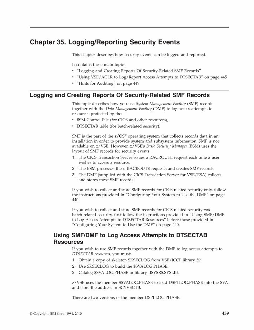
Chapter 35. Logging/Reporting Security Events
This chapter describes how security events can be logged and reported.
It contains these main topics:v “Logging and Creating Reports Of Security-Related SMF Records”v “Using VSE/ACLR to Log/Report Access Attempts to DTSECTAB” on page 445v “Hints for Auditing” on page 449
Logging and Creating Reports Of Security-Related SMF RecordsThis topic describes how you use System Management Facility (SMF) recordstogether with the Data Management Facility (DMF) to log access attempts toresources protected by the:v BSM Control File (for CICS and other resources),v DTSECTAB table (for batch-related security).
SMF is the part of the z/OS® operating system that collects records data in aninstallation in order to provide system and subsystem information. SMF is notavailable on z/VSE. However, z/VSE's Basic Security Manager (BSM) uses thelayout of SMF records for security events:1. The CICS Transaction Server issues a RACROUTE request each time a user
wishes to access a resource.2. The BSM processes these RACROUTE requests and creates SMF records.3. The DMF (supplied with the CICS Transaction Server for VSE/ESA) collects
and stores these SMF records.
If you wish to collect and store SMF records for CICS-related security only, followthe instructions provided in “Configuring Your System to Use the DMF” on page440.
If you wish to collect and store SMF records for CICS-related security andbatch-related security, first follow the instructions provided in “Using SMF/DMFto Log Access Attempts to DTSECTAB Resources” before those provided in“Configuring Your System to Use the DMF” on page 440.
Using SMF/DMF to Log Access Attempts to DTSECTABResources
If you wish to use SMF records together with the DMF to log access attempts toDTSECTAB resources, you must:1. Obtain a copy of skeleton SKSECLOG from VSE/ICCF library 59.2. Use SKSECLOG to build the $SVALOG.PHASE.3. Catalog $SVALOG.PHASE in library IJSYSRS.SYSLIB.
z/VSE uses the member $SVALOG.PHASE to load DSPLLOG.PHASE into the SVAand store the address in SCYVECTB.
There are two versions of the member DSPLLOG.PHASE:
© Copyright IBM Corp. 1984, 2010 439

v One version of DSPLLOG.PHASE is active when the BSM is used to log accessattempts to DTSECTAB resources via SMF records.
v Another version of DSPLLOG.PHASE is distributed with the VSE/ACLRprogram. This version is also used to log access attempts to DTSECTAB resourcevia its own format (as described in “Using VSE/ACLR to Log/Report AccessAttempts to DTSECTAB” on page 445).
Because the same member name ($SVALOG.PHASE) is used for both of the aboveoptions, this ensures that either BSM SMF logging or VSE/ACLR logging can beactive at any one time.
SMF records and the DMF are used in this way:1. Member DSPLLOG.PHASE (that is supplied with the BSM) sends the SMF
records to the BSM Security Server running in partition FB.2. The BSM Security Server transfers the SMF records to the DMF.3. The DMF writes the SMF records to the VSAM data set.
The resource manager can check accesses to DTSECTAB resources using either the:v SECHECK macro.v RACROUTE macro.
If a RACROUTE macro is used, up to four records can be written to the loggingfile. These four entries report on access to the library, sublibrary, member, andRACROUTE processing. You should take this into account when reading reports ofsuch accesses to DTSECTAB resources.
Configuring Your System to Use the DMFTo use the DMF, you must:1. Configure the DMF and its utilities to meet your requirements. The tasks that
you must complete include creating the data sets required by the DMF, andconfiguring the DMF dump utility DFHDFOU. The DMF dump utilityprocesses the data sets used by DMF, and allows you to selectively copyrecords from the DMF data sets to tape/disk for subsequent processing. Fordetails of how to perform these tasks, refer to the manual CICS TransactionServer for VSE/ESA, Operations and Utilities, SC33-1654.
2. Ensure you have specified parameter OS390 in the startup procedure for FB($BJCL.PROC):// EXEC BSTPSTS,DSPACE=3M,OS390
Parameter OS390 is required to allow the security server to communicate withthe DMF partition.
3. Take copies of jobs DFHDMFSP (to prepare the DMF) and SKDMFST (to startthe DMF) from ICCF library 59, and tailor them for your environment.
4. Start the DMF as quickly as possible after VSE/POWER is active, so that the DMFcan begin to collect data. To start DMF, you can add the statement:PWR PRELEASE RDR,DMFSTART
to the USERBG.PROC before CICS or other jobs are started.
Note: If you are collecting SMF records for DTSECTAB, for performancereasons you are recommended to:v Run the DMF in class Z with only one job active in this partition.v Increase the priority of class Z using, for example:
Logging/Reporting Accesses
440 z/VSE V4R3.0 Administration

PRTY BG,FA,F9,F8,F6,F5,F4,F2,F7,FB=Z,F3,F1
Overview of the DMF Logging and Reporting ProcessFigure 101 provides an overview of how the DMF is used to log records and createreports.
�1� The SETDMF FLUSH command is used to write the current contents of thecache to the file CICS.DBDCCICS.DFHDMFA.
�2� Before the dump utility can read CICS.DBDCCICS.DFHDMFA records, this filemust be deactivated. Therefore, CICS.DBDCCICS.DFHDMFA is deactivated, andCICS.DBDCCICS.DFHDMFB (the next file in the group of defined data sets) isactivated. To do so, the SETDMF SWITCH command is used.
�3� The DMF dump utility DFHDFOU is started, which reads all SMF recordsin CICS.DBDCCICS.DFHDMFA.
�4� The utility DFHDFOU dumps the security records (SMF80 records) to thefile CICS.DMF.DATA.
�5� The BSM Report Writer (BSTPRWTR) is started, which reads the SMF80records from file CICS.DMF.DATA.
�6� The BSM Report Writer creates the report.
Figure 101. How DMF Is Used to Log Records and Create Reports
Logging/Reporting Accesses
Chapter 35. Logging/Reporting Security Events 441

Activating the Logging of SMF RecordsTo specify the logging of SMF records for a specific BSM profile, use the AUDITparameter of the BSTADMIN ADD and CHANGE commands. You can also use theInteractive Interface dialog instead of the BSTADMIN command (see page 377).
For the logging of access attempts, you can choose between four audit-levels: ALL,FAILURES, NONE, or SUCCESS. For details, see “ADD | AD Command” on page363 or “CHANGE | CH Command” on page 364.
Note: Use the auditing function with care! It will increase the BSM / DMFprocessing and might degrade z/VSE system performance!
Using the BSM Report Writer to Process DFHDFOU OutputThe SMF records that the DMF dump utility DFHDFOU creates are stored in adata set created by yourself. You can then use the BSM Report Writer to create yourown reports from these SMF records.
Here is an example of a DFHDFOU dump utility job:
Here is an example of a job to start the BSM Report Writer:
The BSM Report Writer reads the output of the DMF dump utility, and builds areport which contains:v A detailed listing of the processed records.v A summary of the user entries.
* $$ JOB JNM=DFHDFOU,CLASS=0,DISP=D// JOB OFFLOAD DMF, DATA SET* Enter ID statement// PAUSE ID stmt or enter// DLBL VSESPUC,’VSESP.USER.CATALOG’,,VSAM// DLBL INFILE,’CICS.DBDCCICS.DFHDMFB’,,VSAM,CAT=VSESPUC// DLBL OUTFILE,’CICS.DMF.DATA’,0,VSAM,CAT=VSESPUC, *DISP=(NEW,KEEP),RECORDS=2000,RECSIZE=5750// LIBDEF *,SEARCH=PRD1.BASE* Option ALL dumps and clears DMF data set// EXEC DFHDFOU,SIZE=DFHDFOUINDD (INFILE, OPTIONS (ALL))OUTDD (OUTFILE, TYPE(80))/*/&* $$ EOJ
Figure 102. Example of DFHDFOU Dump Utility
* $$ JOB JNM=BSTRPWTR,CLASS=0,DISP=D// JOB BSTRPWTR// PAUSE ID statement or enter// DLBL VSESPUC,’VSESP.USER.CATALOG’,,VSAM// DLBL INPUT,’CICS.DMF.DATA’,,VSAM,DISP=(OLD,KEEP),CAT=VSESPUC// EXEC BSTRPWTR,SIZE=BSTRPWTR/*/&* $$ EOJ
Figure 103. Example of Job Used to Start the BSM Report Writer
Logging/Reporting Accesses
442 z/VSE V4R3.0 Administration

v A summary of the resource entries.v A summary of security commands.v A general summary.
Here is an example of the formatted output created by the BSM Report Writer:
Logging/Reporting Accesses
Chapter 35. Logging/Reporting Security Events 443

07.282 12:59:18 BSM Report - Listing of Process RecordsEv Qe u
*Job/User n aDate Time Name t l07.282 12:57:04 SYSA 1 0 Job=(BSTADMIN) - User verification: Successful initiation / logon
AUGUST WONG Auth=(None),Reason=(None)07.282 12:57:07 HUGO 1 1 Job=(CICSICCF) - User verification: Invalid password
HUGO MAYER Auth=(None),Reason=(User verification failure)07.282 12:57:16 HUGO 1 0 Job=(CICSICCF) - User verification: Successful initiation / logon
HUGO MAYER Auth=(None),Reason=(None)07.282 12:57:17 SYSA 24 0 Job=(BSTADMIN) - PERFORM command: No violation detected
AUGUST WONG Auth=(Administrator),Reason=(Command)PERFORM PASSWORD LENGTH(8)
07.282 12:57:20 SYSA 19 0 Job=(BSTADMIN) - PERMIT command: No violation detectedAUGUST WONG Auth=(Administrator),Reason=(Class)
PERMIT APPL MYAPPL2 ID(HUGO) DELETE07.282 12:57:28 SYSA 1 8 Job=(BSTADMIN) - User verification: Successful termination
AUGUST WONG Auth=(None),Reason=(None)07.282 12:57:30 HUGO 2 1 Job=(CICSICCF) - Resource access: Insufficient authority
HUGO MAYER Auth=(Normal),Reason=(Audit options)Resource=CESN,Intent=Read,Allowed=None,Resource class=TCICSTRN,GenProf=CES
07.282 12:57:34 SYSA 1 0 Job=(PAUSEBG ) - User verification: Successful initiation / logonAUGUST WONG Auth=(None),Reason=(None)
07.282 12:57:37 SYSA 2 0 Job=(PAUSEBG ) - Resource access: Successful accessAUGUST WONG Auth=(Administrator),Reason=(Administrator)
Resource=MYAPPL.MYPRINT,Intent=Read,Allowed=Read,Resource class=FACILITY07.282 12:57:38 HUGO 1 8 Job=(CICSICCF) - User verification: Successful termination
HUGO MAYER Auth=(None),Reason=(None)07.282 12:57:44 SYSA 1 8 Job=(PAUSEBG ) - User verification: Successful termination
AUGUST WONG Auth=(None),Reason=(None)
07.282 12:59:18 BSM Report - Listing of User Summary---------- R e s o u r c e S t a t i s t i c s ----------
User/ Name ---- Job/Logon ---- ------- I n t e n t s -------*Job Success Violation Success Violation Alter Update Read TotalHUGO HUGO MAYER 1 1 0 1 0 0 1 1SYSA AUGUST WONG 2 0 1 0 0 0 1 1
07.282 12:59:18 BSM Report - Listing of Resource Summary------- I n t e n t s -------
Resource Name Success Violation Alter Update Read TotalClass = FACILITYMYAPPL.MYPRINT 1 0 0 0 1 1
Class = TCICSTRNCESN 0 1 0 0 1 1
07.282 12:59:18 BSM Report - Listing of Command SummaryQualifier Occurrences
Event = 19 - PERMIT command0 - No violation detected 1
Event = 24 - PERFORM command0 - No violation detected 1
Accumulated totals - 2
07.282 12:59:18 BSM Report - General Summary
Process records: 11
--- Job / Logon Statistics ---Total Job/Logon/Logoff 7Total Job/Logon successes 3Total Job/Logon violations 1Total Job/Logon attempts by undefined users 0Total Job/Logon successful terminations 3
--- Resource Statistics ---Total resource accesses (all events) 2Total resource access successes 1Total resource access violations 1
Figure 104. Example of Output Created by the BSM Report Writer
Logging/Reporting Accesses
444 z/VSE V4R3.0 Administration

Using VSE/ACLR to Log/Report Access Attempts to DTSECTABThe z/VSE optional program VSE/Access Control-Logging and Reporting(VSE/ACLR) can be used if an installation plans to log the usage of certainprotected resources defined in DTSECTAB. The program supports the logging ofattempts to use protected resources without authorization and, optionally, of anyauthorized access to protected resources. It provides formatted reports of theinformation logged.
Note: Instead of using VSE/ACLR to log access attempts to resources protectedvia DTSECTAB, you can use the default BSM support that uses SMF records.For details, see “Using SMF/DMF to Log Access Attempts to DTSECTABResources” on page 439.
For a detailed description of this program, refer to the IBM manual VSE/AccessControl-Logging and Reporting: Program Reference and Operations Guide.
The access control support can be used without the logging and reporting programbeing installed.
For each resource that is defined with access control class(es) in the access controltable DTSECTAB, a logging option can be specified. Depending on the specificationof that option, either all accesses to this resource, or only access violations, arelogged. For further details refer to the description of the LOG parameter of theDTSECTAB macro on page 421.
The VSE/Access Control-Logging and Reporting program enables the securityadministrator to audit the access to system resources. The program logs accesscontrol related events and allows you to print them later for analysis.
Whenever a logging situation occurs the logging and reporting program writes arecord on the log data set, a file on disk, to record the event. (When assemblingand cataloging B-transients, it can happen that two records are written to thelogging file. Take this into account when reading reports of such accesses.) Thedata sets used for logging need not be on dedicated disk volumes, but should beon separate volumes.
Note: You should protect the two log data sets (their file names are IJSYSL1 andIJSYSL2) in the access control table DTSECTAB. Define them without theACC parameter. This ensures that only the VSE/ACLR program and asystem administrator (SYSA) have access to those files.
Using VSE/ACLR to Log Access Attempts to LibrariesTo produce accurate statistics on access to library entities (libraries, sublibrariesand members), the following must be taken into account:
When a member is to be accessed, the access control checking is done at each levelin the hierarchy (see Figure 105 on page 447). First of all, the access rights tolibrary/sublibrary are valid that were established when the sublibrary wasaccessed (for example due to processing of a LIBDEF). When the user is attemptingread access to the member and has the READ access right to the library in whichthe member is stored, access control does no checking at sublibrary or memberlevel (see “Access Control for Libraries” on page 411).
Log Access to DTSECTAB Using VSE/ACLR
Chapter 35. Logging/Reporting Security Events 445

The attempted access is not logged at sublibrary level, because the user was notattempting to read the sublibrary as a whole. It is not logged at member leveleither, because the Access Control Function stopped when it found the neededaccess right at library level. So this access is not logged, no matter what wasspecified in the LOG parameter for the member and sublibrary.
If, however, the user in this example had only the connect right to the library andsublibrary, access control checking would continue down to member level. Theaccess would be logged (if the relevant access class is specified in the LOGparameter for the member; access violations are logged in any case).
In short, if all accesses are to be logged, the entity to be accessed must require ahigher access right than those above it in the hierarchy, and the access rights to theentities above it must be insufficient to allow the attempted access. (It makes nodifference whether the access rights are granted as individual rights in the userprofile entry or as universal access rights in the resource profile entry of the accesscontrol table.)
Here are a few examples:v For all accesses to a member to be logged, the access right to the library and
sublibrary in which it is stored must be limited to connect. There will be anaccess check for each member access.As an example, consider the following generic member entry:
IJSYSRS.SYSLIB.*,ACC=(1),LOG=(1)
The user with ACC=(1,READ) can read all members, and each read is logged.v For update and alter accesses to a member to be logged, the access right to the
library and sublibrary must be read or lower. In this case, read accesses (tomembers) do not cause any access checking and hence no logging.For update/alter of a member, access checking will be done.
Due to the above checking mechanisms, an installation has to make a choicebetween satisfactory performance and detail of logging.
The same principle holds for the logging of accesses to sublibraries.
The security administrator should consider at which level each user should haveaccess to the libraries, and grant only the connect access right to the level(s) aboveit. This will ensure accurate logging of access events.
The Reporting ModuleThe reporting module of the logging and reporting program creates printouts fromthe log data set according to your specifications. For more details on this topic,refer to “Using VSE/ACLR to Audit Access Attempts to Controlled Resources” onpage 448.
The reporting module must run in a batch partition.
Log Access to DTSECTAB Using VSE/ACLR
446 z/VSE V4R3.0 Administration

Note that all accesses to libraries and files performed by the system administrator (SYSA) are logged, regardlesswhether the LOG parameter in the resource access definition was specified or not.
Figure 105. Access Logging when Accessing a Library Member
Log Access to DTSECTAB Using VSE/ACLR
Chapter 35. Logging/Reporting Security Events 447

Using VSE/ACLR to Audit Access Attempts to ControlledResources
A record of unauthorized access attempts and attempts to access sensitive data canhelp the system administrator to identify data security problems. Auditing meansanalyzing these access attempts. The audit trail is the record of critical accessattempts.
Careful analysis of the audit trail helps you to:v Identify access violations and the user responsible for them;v Find security weak points;v Adapt access control measures to changing conditions;v Recognize a need for corrective action by management;v Use the system more efficiently.
VSE/Access Control-Logging and Reporting (VSE/ACLR), a z/VSE optional program,offers all of the above functions.
Using VSE/ACLR to Obtain an Audit TrailThe VSE/ACLR program enables the user, normally the security administrator, toget a printed audit trail from the information stored in the log data set. Thereporting program (DSPRPM) produces printouts of the log data set, according tothe selection criteria defined by the user in the ACCESS control statement ofVSE/ACLR.
Unsuccessful identification and authentication attempts are not subject to loggingby VSE/ACLR.
Log Access to DTSECTAB Using VSE/ACLR
448 z/VSE V4R3.0 Administration

Hints for AuditingMost access violations are the result of errors, and occur with a fairly constantfrequency. Each system develops a characteristic pattern after a certain period ofroutine running. Any drastic change in this pattern in an otherwise unchangedsystem should be investigated.
For example, an unusually low number of violations may mean that someone hasfound a way to circumvent access control routines. The following examples givepossible explanations for other symptoms:v More people are authorized to work with the system and protected resources
than are actually doing so: This may indicate that authorization is too easy toget without apparent necessity, or an anticipated necessity did not materialize.
v Many more authorized people work with the system and the protected resourcesthan was anticipated: Again this may indicate that authorization is too easy toget, or that protection was defined for resources which actually need not beprotected.
v Fewer people are authorized to use the system and protected resources thananticipated: This may indicate that authorization is too difficult to get, or theneed to work with the system is not as high as estimated, or not all of the datathat requires protected status has been defined.
v Some resources have an unexpectedly low access activity: It may indicate thatthe resource can possibly be removed from the system, or that an authorizationis too difficult to get, or that a way has been found to circumvent protection.
v Some resources have an unexpectedly high access activity: In case of a file, itmay indicate that a separation of sensitive and nonsensitive data should beconsidered to increase processing efficiency; for other resources, it may indicatethat authorization is too easy to get.
These examples show that security measures must be reviewed frequently and beadjusted as the need arises.
The audit trail should be made available to the people and departments involved,and a list of violations should be distributed as often as possible to allow for quickreactions. A file owner, for example, should be notified if an unauthorized access tohis file has been recorded.
Hints
Chapter 35. Logging/Reporting Security Events 449

450 z/VSE V4R3.0 Administration

Chapter 36. Protecting CICS Transactions with Access ControlTable DTSECTXN
The method described in this chapter for protecting CICS transactions usingDTSECTXN has been succeeded by the method of protecting CICS resources usingthe BSM control file (VSE.BSTCNTL.FILE). For details, see Chapter 26, “ProtectingResources via BSTADMIN Commands,” on page 359.
Furthermore, if your z/VSE 4.3 system was installed via an:v initial installation, you cannot use the method of protecting CICS transactions
described here.v FSU process from z/VSE 3.1 or a system that still used the old security concept,
you can use the method of protecting CICS transactions described here.
This method of CICS transaction security is part of the basic security support(BSM) and protects CICS transactions from unauthorized access if they arespecified in table DTSECTXN. This check is always active independent of the SECsetting in the IPL SYS command.
If you still wish to use the previous security concept, CICS will not allow accessto transactions which are not defined in DTSECTXN.
The BSM compares the security class of a transaction with the transaction securitykey(s) defined for a particular user in the corresponding user profile. Refer also tothe panel "Add or Change Resource Access Rights" that is shown in Figure 86 onpage 294.
Attempts to invoke CICS transactions by unauthorized users are logged on thesystem console.
You can define entries in DTSECTXN through either the dialog or macro provided.
This chapter contains these main topics:v “Using the Define Transaction Security Dialog”v “Using the Macro DTSECTXN” on page 455
Using the Define Transaction Security DialogYou can add, delete or alter security entries for transactions with the TransactionSecurity Dialog. These entries are contained in table DTRISEC.Z which is located inIJSYSRS.SYSLIB.
To access the dialog, start with the z/VSE Function Selection panel and select:2 (Resource Definition)8 (Security Maintenance)5 (Define Transaction Security)
If you still use the old security concept, you are then asked whether you wish tomigrate your CICS transaction entries to the BSM control file (by selecting Option1) and therefore use the latest BSM security concept.
© Copyright IBM Corp. 1984, 2010 451

However, if you still wish to use the previous security concept that uses tableDTSECTXN, you can select Option 2 “Proceed with the Define Transaction Securitydialog”. The Define Transaction Security dialog then appears where you can pressENTER to list all available security entries, or specify the first characters of theCICS transaction names or the CICS region you want to be listed.
TRANSIDSpecifies the transaction name, or 1 to 3 prefix characters for a group ofCICS transactions that are to be protected and which have the same prefix.
CICS REGIONSpecifies the CICS region for which the security entries are to be listed. Thename of the CICS region is the user-ID under which CICS has been started;for example, DBDCCICS or PRODCICS. This user-ID is provided in the IDstatement of the CICS startup job, independent of the settings of SYS SEC=in the IPL SYS command. The user-ID must be defined in the VSE ControlFile. In a predefined z/VSE system this user-ID is the same as the APPLIDof this CICS system which is defined in the SIT (System InitializationTable). The list of entries will be sorted by transaction name in alphabeticalorder.
Note: To activate the checking of the CICS region, you must specifySECPRFX=YES in the SIT.
Using PF6=MERGE, you can merge the new or changed system entries with thesecurity table DTRISEC.Z in IJSYSRS.SYSLIB. This may be useful if you createdyour own member, or if you applied service, or if you did a Fast Service Upgrade(FSU) to z/VSE 3.1, for example.
After pressing ENTER, the panel Define Transaction Security appears. It is a FULISTthat displays selected security entries where you can add, alter, or delete entries.
You can include your own lower-case transaction security definitions in theIBM-supplied default member DTSECTXM.A (displayed in Figure 107 on page453). These definitions are included in the assembly before the security definitionsof the dialog, but they are not shown in the dialog.
TAS$SECF DEFINE TRANSACTION SECURITY: SPECIFY FILTEREnter the required data and press ENTER.
Press ENTER to list all security entries.
Specify the prefix of the CICS transaction names or the CICS region youwant to be listed and press the ENTER key.
TRANSID.............. ____ Enter the full transaction name or1 - 3 prefix characters, e.g. AB forall transactions starting with AB
CICS REGION.......... ________ Enter the CICS region.
PF1=HELP 2=REDISPLAY 3=END 6=MERGE
Figure 106. Define Transaction Security Dialog
Protecting CICS Transactions with DTSECTXN
452 z/VSE V4R3.0 Administration

Fill in the required data and press ENTER to check the values. PressPF5=PROCESS to process the changes and to submit the batch job to create tableDTSECTXN including the entries defined. The source code is provided inDTSECTXS.A. Do not change this source code.
Generic Transaction NamesAn X in column GENERIC indicates that this transaction name is interpreted as ageneric name. In the example, there exists an explicit definition of security class 30for transaction AB1, and a generic definition of security class 10 for AB. Thismeans that security class 30 is valid for transaction AB1, and security class 10 forall those transactions that start with AB and do not have an explicit securitydefinition like AB1.
Explanation of INCLUDE MEMBER FieldThe job that is created contains an SLI statement for the member name. Themember name is specified using its fully-qualified member name. This membercontains lower-case transaction security definitions. These definitions are includedin the assembly job in front of the security definitions of the dialog. However,these lower-case transaction security definitions are not displayed by the dialog.
The default member is IJSYSRS.SYSLIB.DTSECTXM.A.
Merging, Processing and Activating DTSECTXNThe MERGE function of the dialog can merge member DTRISEC.Z inIJSYSRS.SYSLIB with one or more of the following members:v DTRISEC.U
This member is created by the system in case of FSU or the application ofservice.
v A user-created member, for example, USERMEMB.Z in userlib.usersublib.The member must be of type Z and must have the special table format requiredby the dialog.
Example
TAS$SEC1 DEFINE TRANSACTION SECURITY
Enter the required data and press ENTER.
OPTIONS: 1 = ADD 2 = ALTER 5 = DELETE
OPT TRANSACTION NAME CICS REGION SECURITY CLASS GENERIC_ AADD 1_ ABRW 1_ ACCT 1_ ACEL 1_ ACLG 1_ AC01 1_ AC02 1_ AC03 1_ AC05 1_ AC06 1
LOCATE TRANSACTION NAME == > ____INCLUDE MEMBER == > IJSYSRS.SYSLIB.DTSECTXM.A
PF1=HELP 2=REDISPLAY 3=END 5=PROCESS8=FORWARD
Figure 107. Define Transaction Security Dialog
Protecting CICS Transactions with DTSECTXN
Chapter 36. Protecting CICS Transactions with Access Control Table DTSECTXN 453

You want to create a new DTSECTXN by merging macro member MYMAC.A inuserlib.usersublib with DTRISEC.Z. The following steps are required:1. Run a job stream for MYMAC.A that includes the following command to create
the required table format:EXEC REXX=IPFTABLE,PARM=’ULIB.USUBLIB.MYMAC.A ULIB.USUBLIB.MYTAB.Z’
2. Select the MERGE function of the dialog and enter your parameters (membername and sublibrary name) to merge your table with DTRISEC.Z inIJSYSRES.SYSLIB.
3. Select the PROCESS function of the dialog to catalog the new phaseDTSECTXN into IJSYSRS.SYSLIB and PRD2.SAVE. In addition, macroDTSECTXS.A is cataloged into PRD2.CONFIG. Both, DTSECTXN andDTSECTS.A include the changes of MYTAB.Z.The PROCESS function:v Creates job CATSEC which you must submit for processing.v Updates table DTRISEC.Z which is used when the dialog is called the next
time.4. DTSECTXN is activated with the following command:
CEMT PERFORM SECURITY REBUILD
The command is issued by the job generated. You may issue this commanddirectly if the update did not complete correctly. DTSECTXN is also activatedby stopping/starting the CICS partition.
Protecting CICS Transactions with DTSECTXN
454 z/VSE V4R3.0 Administration

Using the Macro DTSECTXNThe DTSECTXN macro can be used to build the CICS transaction security tableDTSECTXN. For each transaction to be defined, a security class must be assigned.
Syntax Diagram:
�� DTSECTXN NAME=cics_region_prefix.
transid,TRANSEC=(class) �
�,TYPE= GENERIC ,SUBTYPE= INITIAL
FINAL
��
Refer also to the definition of CICS REGION on the preceding page.
Parameter Description:
NAME=cics_region_prefix.transidThe cics_region_prefix is a 1 to 8-character identifier, and transid specifies a 1to 4-character transaction name. Generic transaction names are allowed ifTYPE=GENERIC has been specified. A transaction name may includealphabetic and numeric characters, and the following special characters:$ # @ / % ¢ ? ! : | " = ¬ ; < >
Mixed case transaction names are supported.
The cics_region_prefix can be used to identify a particular CICS subsystem iftwo or more CICS subsystems run under z/VSE.
TRANSEC=(class)Defines the security class (1 to 64) to control the invocation of a transaction.For example, if TRANSEC=(5) is specified, only users defined with securitykey 5 in their profile can start this transaction.
Only one security class can be specified for a transaction.
Security keys for a user profile can only be specified via the Maintain UserProfiles dialog, which is described in Chapter Chapter 22, “Maintaining UserProfiles via BSM Dialogs,” on page 287.
TYPE=GENERICThis parameter is optional and causes a transaction name (transid) to beinterpreted as a generic name. This means that an entry with TYPE=GENERICcovers all transactions whose names start with the characters defined as transid,except such a name is defined explicitly (refer also to “Generic TransactionNames” on page 453). Any abbreviation is accepted: TYPE=G, TYPE=GE, andso on.
SUBTYPE=INITIAL or FINALThe parameter is required in the first and the last call of the DTSECTXNmacro, and is not allowed in the calls between. The first macro call mustinclude SUBTYPE=INITIAL, and the last one SUBTYPE=FINAL.
Examples:DTSECTXN NAME=DBDCCICS.AADD,TRANSEC=(1)DTSECTXN NAME=TR,TRANSEC=(1),TYPE=GENERIC
Protecting CICS Transactions with DTSECTXN
Chapter 36. Protecting CICS Transactions with Access Control Table DTSECTXN 455

Example of the CICS Transaction Security Table DTSECTXMAs shipped, z/VSE provides a predefined DTSECTXM. DTSECTXM includesentries such as the following (it does not include generic entries):
The above table contains transaction security definitions written in lower case. Youcan enter your own transaction security definitions in this table. These definitionsare included in the assembly job in front of the security definitions of the dialog.However, these lower-case transaction security definitions are not displayed by thedialog.
Example of the CICS Transaction Security Table DTSECTXNAs shipped, z/VSE provides a predefined DTSECTXN. DTSECTXN includesentries such as the following (it does not include generic entries).
DTSECTXN NAME=emai,TRANSEC=(1),SUBTYPE=INITIALDTSECTXN NAME=ftp,TRANSEC=(1)DTSECTXN NAME=iccf,TRANSEC=(1)DTSECTXN NAME=lpr,TRANSEC=(1)DTSECTXN NAME=newc,TRANSEC=(1)DTSECTXN NAME=ping,TRANSEC=(1)DTSECTXN NAME=ropc,TRANSEC=(1)DTSECTXN NAME=teln,TRANSEC=(1)
Figure 108. Extract of Table DTSECTXM
DTSECTXN NAME=AADD,TRANSEC=(1)DTSECTXN NAME=ABRW,TRANSEC=(1)DTSECTXN NAME=ACCT,TRANSEC=(1)DTSECTXN NAME=ACEL,TRANSEC=(1)DTSECTXN NAME=ACLG,TRANSEC=(1)DTSECTXN NAME=AC01,TRANSEC=(1)DTSECTXN NAME=AC02,TRANSEC=(1)DTSECTXN NAME=AC03,TRANSEC=(1)DTSECTXN NAME=AC05,TRANSEC=(1)DTSECTXN NAME=AC06,TRANSEC=(1)DTSECTXN NAME=AC2A,TRANSEC=(1)DTSECTXN NAME=AC2C,TRANSEC=(1)DTSECTXN NAME=AC2D,TRANSEC=(1)DTSECTXN NAME=AC2E,TRANSEC=(1)DTSECTXN NAME=AC2F,TRANSEC=(1)DTSECTXN NAME=AC20,TRANSEC=(1)DTSECTXN NAME=AC21,TRANSEC=(1)DTSECTXN NAME=AC22,TRANSEC=(1)DTSECTXN NAME=AC23,TRANSEC=(1)DTSECTXN NAME=AC24,TRANSEC=(1)DTSECTXN NAME=AC25,TRANSEC=(1)
...DTSECTXN NAME=XPLA,DTSECTXN NAME=2RPS,DTSECTXN NAME=8888,DTSECTXN NAME=9999,TRANSEC=(1),SUBTYPE=FINALEND
Figure 109. Extract of Table DTSECTXN (Source Format DTSECTXS)
Protecting CICS Transactions with DTSECTXN
456 z/VSE V4R3.0 Administration

Chapter 37. Migrating CICS/VSE Security Information to theCICS TS
This chapter describes how you can migrate CICS/VSE 2.3 (or older)security-related information to the CICS TS.
Up to z/VSE V3R1.1, CICS transaction security was provided for the CICS TS (notCICS/VSE) via access control table DTSECTXN, which was used to define CICStransactions and their security class. From z/VSE V3R1.1 onwards, this method hasbeen succeeded by the use of the BSM concept that includes the use of the BSMcontrol file.
This chapter contains these main topics:v “Overview of Migration Tasks”v “Migrating USER Definitions Stored in IESCNTL” on page 458v “Migrating USER Definitions Stored in DFHSNT and DTSFILE” on page 458v “Migrating TRANSEC Definitions Using the Migration Aid” on page 458v “Migrating DFHPCT.A TRANSEC Definitions” on page 463v “Migrating DFHCSDUP TRANSEC Definitions” on page 465
Overview of Migration TasksTo migrate the your CICS/VSE 2.3 (or older) security-related information to theCICS TS, you must:1. Migrate your user definitions stored in IESCNTL using utility IESBLDUP.2. Migrate your user definitions stored in DFHSNT using utility IESBLDUP.3. Use the CICS/VSE Security Migration Aid and then skeleton SKSECTX2 of
ICCF library 59 to migrate your TRANSEC definitions to a CICS TS system thatuses either table DTSECTXN or the BSM control file.
4. Use skeleton SKSECTXS of ICCF library 59 to migrate your TRANSECdefinitions stored in macro DFHPCT.A to a CICS TS system that uses eithertable DTSECTXN or the BSM control file.
5. Use skeleton SKSECTX3 of ICCF library 59 to migrate your TRANSECdefinitions that are stored in a library member containing CICS/VSEDFHCSDUP definitions (with formatDEFINE TRANSACTION(xxxx) ... TRANSEC(yy) ...) to a CICS TS system that useseither table DTSECTXN or the BSM control file.
REXX procedures SKSECTX2, SKSECTXS, and SKSECTX3 create as output a librarymember whose name is to be defined in the OUTFILE parameter. Depending onthe FORMAT parameter, the procedures create one of the following:v A table in IPF format.
Select this format if you wish to produce input for the dialog. Afterwards, theMERGE function of the Define Transaction Security dialog can be used. With thisfunction, existing transaction security definitions in DTSECTXN can be mergedwith the migrated security definitions from CICS/VSE. Note that in this case amigrated security definition for a particular transaction overwrites an alreadyexisting definition for that transaction in DTSECTXN.
v A file consisting of DTSECTXN macro definitions.
© Copyright IBM Corp. 1984, 2010 457

Select this format if you wish to produce macro input for the DTSECTXNassembly run.
v A file consisting of BSTADMIN ADD and BSTADMIN PERMIT commands.Select this format if you wish to use the BSM security that is available fromz/VSE V3R1.1 onwards (that uses the BSM control file).
These tasks are described in the topics that follow.
Migrating USER Definitions Stored in IESCNTLFor details of how to use the IESBLDUP utility to migrate your IESCNTL userdefinitions, refer to the chapter describing the IESBLDUP utility in the manualz/VSE System Utilities, SC33-8336.
Also ensure that the control options when using IESBLDUP are set correctly:* CONTROL STATEMENT FOR MIGRATION FROM A VSE/SP OR VSE/ESA SYSTEMCF=YES,DTSRSTR=NO,UPDATE=YES
Migrating USER Definitions Stored in DFHSNT and DTSFILEFor details of how to use the IESBLDUP utility to migrate your DFHSNT andDTSFILE user definitions, refer to the chapter describing the IESBLDUP utility inthe manual z/VSE System Utilities, SC33-8336.
Also ensure that the control options when using IESBLDUP are set correctly:CF=NO,DTSRSTR=NO,SNT=YES,ALT=YES,UPDATE=YESADMN=USRA,PROG=USRB,GENL=USRC
Migrating TRANSEC Definitions Using the Migration Aid
Step 1: Prepare Input Using the CICS Security Migration AidFor details of how to use the CICS security migration aid, refer to the manualCICS/VSE Security Migration Guide, SC33-1406. You can find this manual on theCICS for VSE/ESA V2R3 bookshelf.
You should check that you have APAR PQ50857 installed on your CICS/VSEsystem. If not, some transactions might be missing in the security definition.
If you wish to migrate to VSE/ESA 2.6, APAR PQ61103 will insure that themigration utility generates a compatible IPF table.1. Run job DFHCSDUP (LIBDEF PRD2.CICSOLDP and corresponding CSD-File)
with the statement UPGRADE USING(DFHCU22X) to create the RDO-groupDFHXSM:* $$ JOB JNM=DFHCSDSM,CLASS=0,DISP=D// JOB DFHCSDSM UPGRADE DFHCU22X// LIBDEF *,SEARCH=(PRD2.CONFIG,PRD2.CICSOLDP,PRD2.SCEEBASE,PRD1.BASE)// DLBL DFHCSD,’CICSO.CSD’,0,VSAM, X
CAT=VSESPUC// EXEC DFHCSDUP,SIZE=600K INIT AND LOAD CICS CSD VSAM FILE
UPGRADE USING(DFHCU22X)/*/&* $$ EOJ
2. Use transaction CEDA INSTALL group or transaction CEDA ADD group to addgroup DFHXSM to your GRPLIST of CICS/VSE 2.3.
Migrating CICS/VSE Security
458 z/VSE V4R3.0 Administration

3. Add the DFHFCT entry to your FCT, recompile the FCT, and COLD-Start yourCICS/VSE after defining the DFHXSMA dataset using these statements:DFHXSMA DFHFCT TYPE=DATASET,DATASET=DFHXSMA,ACCMETH=VSAM, X
SERVREQ=(UPDATE,ADD,BROWSE,DELETE),LOG=YES,RECFORM=(VARIABLE,BLOCKED),STRNO=2
Define dataset DFHXSMA as the output file for security migration:* $$ JOB JNM=DEFXSMA,CLASS=0,DISP=D,NTFY=YES// JOB EBER DEFINE FILE// EXEC IDCAMS,SIZE=AUTODEFINE CLUSTER ( -
NAME (VSE15.DFHXSMA ) -CYLINDERS(2 2 ) -SHAREOPTIONS (2) -RECORDSIZE (19 80 ) -VOLUMES (ESA010 ) -NOREUSE -INDEXED -FREESPACE (15 7) -KEYS (18 0 ) -NOCOMPRESSED -TO (99366 )) -DATA (NAME (VSE15.DFHXSMA.¹D¹ ) -CONTROLINTERVALSIZE (4096 )) -INDEX (NAME (VSE15.DFHXSMA.¹I¹ )) -CATALOG (ESCAT10.USER.CATALOG )
IF LASTCC NE 0 THEN CANCEL JOB/*// OPTION STDLABEL=ADD// DLBL DFHXSMA,’VSE15.DFHXSMA’,,VSAM, X
CAT=ESCAT10/*// EXEC IESVCLUP,SIZE=AUTOA VSE15.DFHXSMA DFHXSMA ESCAT10/*/&* $$ EOJ
4. COLD-start your CICS/VSE 2.3 system after adding a DLBL statement to theCICS-startup job. For example:// DLBL DFHXSMA,’VSE15.DFHXSMA’,,VSAM,CAT=ESCAT10
5. Use the CESM transaction to migrate all wanted resources. Please note thatCESM has defined RSCL=YES. If you do not want to define all applicableresources with RSL key values, do the following:a. Use transaction CEDA COPY to copy transaction CESM to a private groupb. Use transaction CEDA ALTER to enter transaction CESM in this new group
to RSLC=NOc. Use transaction CEDA ADD to add this new group to GRPLISTd. Use transaction CEDA INSTALL to install this new group
After entering transaction CESM, the following screen is displayed:
Migrating CICS/VSE Security
Chapter 37. Migrating CICS/VSE Security Information to the CICS TS 459

6. Enter an 'X' next to the option “Perform selective ....”. The following screen isthen displayed:
Entering an 'X' in front of Transactions and in front of REPLACE willa. Collect all of the transaction-related security information of the running
CICS/VSE 2.3 system.b. Store this security information in DFHXSMA.
Step 2: Migrate TRANSEC Definitions to a CICS TS SystemThis step can be followed for VSE/ESA V2R4.0 onwards and a CICS TS 1.1.0 or1.1.1 system.
Skeleton SKSECTX2 executes procedure DTSECTX2, which uses as input theVSE/VSAM output file DFHXSMA created by the Security Migration Aid (SMA) ofCICS/VSE (Step 1 above). The migration aid extracts security information fromCICS/VSE and the VSE.CONTROL.FILE and stores it in file DFHXSMA.DTSECTX2 then reads the security information from DFHXSMA.
DTSECTX2 generates output for table DTSECTXN of a CICS TS system, or for theBSM control file of a CICS TS system.
To migrate your TRANSEC definitions, you should copy SKSECTX2 from ICCFlibrary 59 to your own library, and modify the lines at the end of the skeletonaccording to your installation:
XSM01 CICS/VSE Version 2.3 Security Migration Aid Applid: A0006CI3
_ Perform selective Update/Replace for this CICS system
_ Replace all data for this CICS system
_ Update all data for this CICS system
_ Selectively display the contents of DFHXSMA
PF1=Help PF12=Quit ENTER=Continue
Figure 110. CICS/VSE Security Migration Aid Screen (XSM01)
XSM02 CICS/VSE Version 2.3 Security Migration Aid Applid: A0006CI3
_ Transient Data (DCT) _ Replace_ Files (FCT) _ Update_ Journals (JCT)_ Transactions (PCT)_ Programs (PPT)_ USER Profiles (IUI/SNT/TCT)_ RCF authorized printers (TCT)_ Temporary Storage (TST)
PF1=Help PF4=Main Menu PF12=Quit ENTER=Continue
Figure 111. CICS/VSE Security Migration Aid Screen (XSM02)
Migrating CICS/VSE Security
460 z/VSE V4R3.0 Administration

// LIBDEF *,SEARCH=(PRD2.CONFIG,PRD1.BASE)// EXEC REXX=DTSECTX2,PARM=’INFILE=VSEESA.DFHXSMA X
OUTFILE=PRD2.CONFIG.DTSECTX2.A’REGION=MYREGIONFORMAT=MACROCATALOG=VSESPUC/*
Parameters can be specified in the PARM operand, via SYSIPT, or in a combinationof both. Refer to “DTSECTX2 Parameters” for a description of the parameters andexamples of how to use them. A description of the parameters required can also befound within this REXX procedure.
You then submit the job (skeleton) for processing. The job catalogs first procedureDTSECTX2 into PRD2.CONFIG and invokes it from there. You may change thename of the sublibrary used for cataloging.
Note: Be sure that you have closed the DFHXSMA file in the CICS/VSE 2.3partition before running this REXX procedure.
DTSECTX2 ParametersDTSECTX2 uses the following parameters:
Parameter Description
INFILE Defines the VSE/VSAM file created by the CICS/VSE SecurityMigration Aid (SMA).
FORMAT Defines the format of the output file; either IPF, MACRO, orBSTADMIN.
IPF is the format required when using the MERGEfunction of the Define Transaction Security dialog tomerge existing security entries in DTSECTXN withmigrated entries. This is the default.
MACRO is the format consisting of DTSECTXN macrodefinitions. This output must be assembled tocreate a DTSECTXN.PHASE and activated via theCEMT PERF SECURITY REBUILD command.
BSTADMIN is the format consisting of BSTADMIN ADD andBSTADMIN PERMIT commands. You can use thisformat to migrate your CICS/VSE 2.3 security datato the BSM control file (VSE.BSTCNTL.FILE) that isavailable from z/VSE V3R1.1 onwards. For details,see “Performing the Migration” on page 281.
OUTFILE Defines the library member name of the file to be createdcontaining the definitions for table DTSECTXN or for input to theBSM control file (BSTADMIN format). The default is:v PRD2.CONFIG.DTRISEC.M for the IPF format.v PRD2.CONFIG.DTSECTXS.A for the MACRO format.v PRD2.CONFIG.DTSECTVTX.Z for the BSTADMIN format.
CATALOG Defines the name of the VSE/VSAM catalog which includes theinput file (INFILE). The default is the master catalog IJSYSCT.
REGION Defines the name of the CICS-Region to be included in theDTSECTXN definitions. Default is the region name found in theinput file (INFILE). If region names should not be included in theDTSECTXN definitions, specify REGION= followed by a blank.
Migrating CICS/VSE Security
Chapter 37. Migrating CICS/VSE Security Information to the CICS TS 461

Invoking DTSECTX2The following example invokes DTSECTX2 and uses the PARM operand to providethe parameters INFILE and OUTFILE. The parameters REGION and FORMAT areprovided via SYSIPT.// EXEC REXX=DTSECTX2,PARM=’INFILE=CICS.DFHXSMA XOUTFILE=LIB.SLIB.DTSECTX2.A REGION=DBDCCICS’
The following example invokes DTSECTX2 and uses SYSIPT to provide theparameters.// LIBDEF *,SEARCH=(PRD2.CONFIG,PRD1.BASE)// EXEC REXX=DTSECTX2INFILE=VSEESA.DFHXSMAOUTFILE=PRD2.CONFIG.DTSECTX2.AREGION=MYREGIONFORMAT=MACROCATALOG=VSESPUC/*
DTSECTX2 Return CodesDTSECTX2 may issue the following return codes:0 Processing successful2 Unsupported character in transaction name: <tr-name>4 Syntax error: Invalid keyword <keyword>8 Member <mem.type> already exists in sublibrary <lib.slib>12 IDCAMS PRINT of VSE/VSAM file failed with RC=n16 Transaction name longer than 4 characters: <tr_name>24 No transaction specifications found28 Accessing sublibrary <lib.slib> failed32 Writing member <lib.slib.mem.type> failed with RC=n
After the job has run, you should verify your output file and the printout in theLST queue to ensure correct processing.
Migrating CICS/VSE Security
462 z/VSE V4R3.0 Administration

Migrating DFHPCT.A TRANSEC DefinitionsSkeleton SKSECTXS executes procedure DTSECTXS, which uses as input existinglibrary members that include Program Control Table (PCT) definitions. DTSECTXSgenerates output for table DTSECTXN of a CICS TS system, or the BSM control fileof a CICS TS system. Examples of library members with PCT definitions are theCICS/VSE tables IESZPCT and DFHPCTxx.
To migrate your PCT TRANSEC definitions, you should copy skeleton SKSECTXSfrom ICCF library 59 to your own library and modify the following lines at theend of the skeleton according to your installation. An A-book of your currentDFHPCT needs to be placed into the named INFILE library (in this samplePRD2.CONFIG).// LIBDEF *,SEARCH=(PRD2.CONFIG,PRD1.BASE)// EXEC REXX=DTSECTXS,PARM=’INFILE=IJSYSRS.SYSLIB.IESZPCT.A X
OUTFILE=PRD2.CONFIG.DTSECTXS.A’REGION=DBDCCICSFORMAT=MACRO/*
Parameters can be specified in the PARM operand, via SYSIPT, or in a combinationof both. Refer to “DTSECTXS Parameters” for a description of the parameters andexamples of how to use them. A description of the parameters required can also befound within this REXX procedure.
You then submit the job (skeleton) for processing. The job catalogs first procedureDTSECTXS into PRD2.CONFIG and invokes it from there. You may change thename of the sublibrary used for cataloging.
DTSECTXS ParametersDTSECTXS uses the following parameters:
Parameter Description
INFILE Defines the library member name of the file containing PCTdefinitions with TRANSEC values.
FORMAT Defines the format of the output file; either IPF, MACRO, orBSTADMIN.
IPF is the format required when using the MERGEfunction of the Define Transaction Security dialog tomerge existing security entries in DTSECTXN withmigrated entries. This is the default.
MACRO is the format consisting of DTSECTXN macrodefinitions. This output must be assembled tocreate a DTSECTXN.PHASE and activated via thecommand CEMT PERF SECURITY REBUILD.
BSTADMIN is the format consisting of BSTADMIN ADD andBSTADMIN PERMIT commands. You can use thisformat to migrate your CICS/VSE 2.3 security datato the BSM control file (VSE.BSTCNTL.FILE) that isavailable from z/VSE V3R1.1 onwards. For details,see “Performing the Migration” on page 281.
OUTFILE Defines the library member name of the file to be createdcontaining the definitions for table DTSECTXN or for input to theBSM control file (BSTADMIN format). The default is:
Migrating CICS/VSE Security
Chapter 37. Migrating CICS/VSE Security Information to the CICS TS 463

v PRD2.CONFIG.DTRISEC.M for the IPF format.v PRD2.CONFIG.DTSECTXS.A for the MACRO format.v PRD2.CONFIG.DTSECTVTX.Z for the BSTADMIN format.
REGION Defines the name of the CICS-Region to be included in theDTSECTXN definitions. If region names should not be included inthe DTSECTXN definitions, omit this parameter or specifyREGION= followed by a blank.
Invoking DTSECTXSThe following example invokes DTSECTXS and uses the PARM operand to provideparameters:// EXEC REXX=DTSECTXS,PARM=’INFILE=IJSYSRS.SYSLIB.IESZPCT.A’
For the FORMAT, OUTFILE, and REGION parameters the defaults are effective.
The following example invokes DTSECTXS and uses SYSIPT to provideparameters:// EXEC REXX=DTSECTXSINFILE=IJSYSRS.SYSLIB.IESZPCT.AFORMAT=MACROOUTFILE=LIB.SLIB.DTSECTXS.AREGION=DBDCCICS
DTSECTXS Return Codes:DTSECTXS may issue the following return codes:0 Processing successful2 Unsupported character in transaction name: <tr-name>4 Syntax error: Invalid keyword <keyword>8 Member <mem.type> already exists in sublibrary <lib.slib>12 Reading member <mem.type> failed with RC=n16 Transaction name longer than 4 characters: <tr_name>20 TRANSEC definition is not a number: <tran_sec>24 No transaction specifications found28 Accessing sublibrary <lib.slib> failed32 Writing member <lib.slib.mem.type> failed with RC=n
After the job has run, you should verify your output file and the printout in theLST queue to ensure correct processing.
Migrating CICS/VSE Security
464 z/VSE V4R3.0 Administration

Migrating DFHCSDUP TRANSEC DefinitionsSkeleton SKSECTX3 executes procedure DTSECTX3, which uses as input theCICS/VSE DFHCSDUP definitions of formatDEFINE TRANSACTION(xxxx)... TRANSEC(yy) stored in a library member. DTSECTX3generates output for table DTSECTXN of a CICS TS system, or the BSM control fileof a CICS TS system.
To migrate your DFHCSDUP TRANSEC definitions, you should copy skeletonSKSECTX3 from ICCF library 59 to your own library and modify the followinglines at the end of the skeleton according to your installation. An Z-book of yourcurrent DFHCSDUP needs to be placed into the named INFILE library (in thissample PRD2.PROD).// LIBDEF *,SEARCH=(PRD2.CONFIG,PRD1.BASE)// EXEC REXX=DTSECTX3,PARM=’INFILE=PRD2.PROD.MGJCSD.Z X
OUTFILE=PRD2.CONFIG.DTSECTX3.A’REGION=MYREGIONFORMAT=MACRO/*
Parameters can be specified in the PARM operand, via SYSIPT, or in a combinationof both. Refer to “DTSECTX3 Parameters” for a description of the parameters andexamples of how to use them. A description of the parameters required can also befound within this REXX procedure.
You then submit the job (skeleton) for processing. The job catalogs first procedureDTSECTX3 into PRD2.CONFIG and invokes it from there. You may change thename of the sublibrary used for cataloging.
DTSECTX3 ParametersDTSECTX3 uses the following parameters:
Parameter Description
INFILE Defines the name of the file (name used by Librarian) containingthe DFHCSDUP definitions.
FORMAT Defines the format of the output file; either IPF, MACRO, orBSTADMIN.
IPF is the format required when using the MERGEfunction of the Define Transaction Security dialog tomerge existing security entries in DTSECTXN withmigrated entries. This is the default.
MACRO is the format consisting of DTSECTXN macrodefinitions. This output must be assembled tocreate a DTSECTXN.PHASE and activated via thecommand CEMT PERF SECURITY REBUILD.
BSTADMIN is the format consisting of BSTADMIN ADD andBSTADMIN PERMIT commands. You can use thisformat to migrate your CICS/VSE 2.3 security datato the BSM control file (VSE.BSTCNTL.FILE) that isavailable from z/VSE V3R1.1 onwards. For details,see “Performing the Migration” on page 281.
OUTFILE Defines the library member name of the file to be createdcontaining the definitions for table DTSECTXN or for input to theBSM control file (BSTADMIN format). The default is:
Migrating CICS/VSE Security
Chapter 37. Migrating CICS/VSE Security Information to the CICS TS 465

v PRD2.CONFIG.DTRISEC.M for the IPF format.v PRD2.CONFIG.DTSECTXS.A for the MACRO format.v PRD2.CONFIG.DTSECTVTX.Z for the BSTADMIN format.
REGION Defines the name of the CICS-Region to be included in theDTSECTXN definitions. Default is the region name found in theinput file (INFILE). If region names should not be included in theDTSECTXN definitions, omit this parameter or specify REGION=followed by a blank.
Invoking DTSECTX3The following example invokes DTSECTX3 and uses the PARM operand to provideparameters:// EXEC REXX=DTSECTX3,PARM=’INFILE=LIB.SLIB.MYTRANS.DEFS XOUTFILE=LIB.SLIB.DTSECTX3.A REGION=DBDCCICS’
The following example invokes DTSECTX3 and uses SYSIPT to provideparameters:// EXEC REXX=DTSECTX3INFILE=LIB.SLIB.MYTRANS.DEFSCATALOG=IJSYSCTFORMAT=MACROOUTFILE=LIB.SLIB.DTSECTX3.AREGION=DBDCCICS
DTSECTX3 Return CodesDTSECTX3 may issue the following return codes:0 Processing successful2 Unsupported character in transaction name: <tr-name>4 Syntax error: Invalid keyword <keyword>8 Member <mem.type> already exists in sublibrary <lib.slib>12 Reading member <mem.type> failed with RC=n16 Transaction name longer than 4 characters: <tr_name>20 TRANSEC definition is not a number: <transec>21 Security number greater than 2424 No transaction specifications found28 Accessing sublibrary <lib.slib> failed32 Writing member <lib.slib.mem.type> failed with RC=n
After the job has run, you should verify your output file and the printout in theLST queue to ensure correct processing.
Migrating CICS/VSE Security
466 z/VSE V4R3.0 Administration

Part 4. Encryption
Chapter 38. Implementing HardwareCryptographic Support . . . . . . . . . 471Background . . . . . . . . . . . . . . 471Assigning Crypto Cards to a Specific LPAR . . . 472How Crypto Cards Are Used . . . . . . . . 473Using Crypto Support with a z/VSE Guest underz/VM . . . . . . . . . . . . . . . . 474Displaying Hardware Crypto Status InformationUnder z/VSE . . . . . . . . . . . . . 475Using Hardware Crypto Commands. . . . . . 477
Using the APADD Command to DynamicallyAdd/Enable a Crypto Card . . . . . . . 477Using the APBUSY Command to Set theWait-On-Busy Time Interval . . . . . . . 477Using the APEAI Command to EnableAP-Queue Interrupts . . . . . . . . . . 477Using the APDAI command to disableAP-queue interrupts . . . . . . . . . . 478Using the APHIST Command to Obtain anOverview of Processed Crypto Requests . . . 478Using the APQUE Command to DisplayCurrent Requests . . . . . . . . . . . 478Using the APREM Command to DynamicallyRemove/Disable a Crypto Card . . . . . . 479Using the APRETRY Command to Set theNumber of Retry Attempts . . . . . . . . 480Using the APSENSE Command to Refresh YourHardware Crypto Configuration . . . . . . 480Using the APTERM Command to TerminateCrypto Subtask IJBCRYPT . . . . . . . . 480Using the APTRACE Command to Enable theHardware Crypto Trace . . . . . . . . . 481Using the APWAIT Command to Set the APPolling Time Interval . . . . . . . . . . 481
Using Crypto Support and an External SecurityManager . . . . . . . . . . . . . . . 482
Chapter 39. Preparing Your System to Use SSL 483Step 1: Activate TCP/IP for VSE/ESA . . . . . 484Step 2: Create a Client Keyring File (KeyRing.pfx) 484Step 3: Download and Customize theKeyman/VSE Tool . . . . . . . . . . . 485
Obtaining a Copy of Keyman/VSE . . . . . 485Performing the Installation of Keyman/VSE . . 485Customize the Keyman/VSE Settings . . . . 485
Specify the Properties of Your z/VSE Host 485Specify the Properties of Your Local KeyringFile . . . . . . . . . . . . . . . 487
Step 4: Ensure That Your VSE Keyring LibraryMembers Are Secure . . . . . . . . . . . 489Getting Started Using the IBM-Supplied KeyringSet . . . . . . . . . . . . . . . . . 490Currently-Supported SSL Cipher Suites. . . . . 492Obtaining Unlimited-Strength Jurisdiction PolicyFiles . . . . . . . . . . . . . . . . 492
Differences in SSL Support Provided by IBM/SunJDKs . . . . . . . . . . . . . . . . 494SSL Examples Provided With the OnlineDocumentation . . . . . . . . . . . . . 496
Chapter 40. Configuring for ServerAuthentication . . . . . . . . . . . . 497Configuring for Server Authentication UsingSelf-Signed Certificates . . . . . . . . . . 497Configuring for Server Authentication UsingCA-Signed Certificates . . . . . . . . . . 502Configuring the VSE Connector Server for ServerAuthentication . . . . . . . . . . . . . 507
Step 1: Configure and Catalog the VSEConnector Server's SSL Profile . . . . . . . 507Step 2: Activate SSL Profile in MainConfiguration File . . . . . . . . . . . 508
Configuring Self-Written Clients for ServerAuthentication . . . . . . . . . . . . . 509
Step 1: Set SSL Flag in ClassVSEConnectionSpec . . . . . . . . . . 509Step 2: Configure SSL Profile . . . . . . . 510Step 3: Copy a Server Certificate Into the ClientKeyring File . . . . . . . . . . . . . 511
Summary of Server Authentication Tasks for theJava-Based Connector . . . . . . . . . . 512
Chapter 41. Configuring for ClientAuthentication . . . . . . . . . . . . 513Configuring for Client Authentication UsingSelf-Signed Certificates . . . . . . . . . . 514Configuring for Client Authentication UsingCA-Signed Certificates . . . . . . . . . . 517Configuring the VSE Connector Server for ClientAuthentication . . . . . . . . . . . . . 522Summary of Client Authentication Tasks for theJava-Based Connector . . . . . . . . . . 523
Chapter 42. Implementing Client Authenticationwith VSE User-ID Mapping . . . . . . . . 525Prerequisites. . . . . . . . . . . . . . 525Using the Batch Service Function BSSDCERT . . . 525Changing the Defaults (Optional). . . . . . . 527Using the Client-Certificates/User-IDs Dialog . . 527
Step 1: Starting the Dialog . . . . . . . . 527Step 2: Selecting an Option . . . . . . . . 528Step 3: Creating the Output Job . . . . . . 529Step 4: Submitting or Storing the Output Job 530
Chapter 43. Implementing Hardware-Based TapeEncryption . . . . . . . . . . . . . . 531Overview of Hardware-Based Tape Encryption . . 532Prerequisites for Using Hardware-Based TapeEncryption . . . . . . . . . . . . . . 532
© Copyright IBM Corp. 1984, 2010 467

Restrictions When Using Hardware-Based TapeEncryption . . . . . . . . . . . . . . 533Tape Encryption When Running z/VSE as a GuestUnder z/VM . . . . . . . . . . . . . 533Obtaining and Installing the Encryption KeyManager . . . . . . . . . . . . . . . 534Using a Job to Backup Data With Encryption . . . 534
Example of a LIBR Job to Backup/Encrypt theContents of a Library. . . . . . . . . . 534
Using a POFFLOAD Command to Backup DataWith Encryption . . . . . . . . . . . . 534Specifying KEKL Statements . . . . . . . . 535Specifying ASSGN Statements . . . . . . . . 536Using the Query Tape (QT) Command to DisplayTape Information . . . . . . . . . . . . 537Reading the Contents of an Encrypted Tape . . . 538Understanding Message 0P68I KEYXCHG ER . . 538Hints and Tips . . . . . . . . . . . . . 539
Assigning System Logical Units . . . . . . 539Positioning of the Tape When Using the ASSGNStatement . . . . . . . . . . . . . 539Handling Situations Where the EKM is notAvailable . . . . . . . . . . . . . . 539Running Stand-Alone Utilities (FCOPY, ICKDSF,DITTO, LIBR) . . . . . . . . . . . . 540Additional Considerations When Using LIBRUtility . . . . . . . . . . . . . . . 540Overwriting Encrypted Volumes . . . . . . 540Multivolume File Processing . . . . . . . 540
Chapter 44. Implementing the EncryptionFacility for z/VSE . . . . . . . . . . . 541Overview of the EF for z/VSE. . . . . . . . 542Prerequisites for Using the IJBEFVSE (or IJBEFPGP)Utility . . . . . . . . . . . . . . . . 545Restrictions When Using the IJBEFVSE (orIJBEFPGP) Utility . . . . . . . . . . . . 546Installing the EF for z/VSE. . . . . . . . . 546
Installation Steps . . . . . . . . . . . 546Fast Service Upgrade (FSU) Considerations . . 547
Installing the z/OS Java Client . . . . . . . 547Performance considerations For Using theIJBEFVSE Utility . . . . . . . . . . . . 547Setting Up to Use Passphrase-Based Encryption(PBE) . . . . . . . . . . . . . . . . 548Setting Up to Use Public-Key Encryption (PKE) 549
Overview of How Keys/Certificates are Used 549Define Properties of Host and Generate/Uploada Key Pair to the Host . . . . . . . . . 550Export a Public Key for Use with the z/OS JavaClient . . . . . . . . . . . . . . . 551Export a Public Key for Use on z/OS or a JavaPlatform . . . . . . . . . . . . . . 552Import a Public Key into z/VSE from z/OS or aJava Platform . . . . . . . . . . . . 553
Invoking the IJBEFVSE Utility . . . . . . . . 554Deciding Whether or Not to Use DataCompression . . . . . . . . . . . . . 558Specifying File Names for CLRFILE and ENCFILE 558Specifying File Attributes and Record Formats . . 559Encrypting and Exchanging Record-Based Data 560
Types of Data That Might Need to be Encrypted 560Layout of Header-Record of Encrypted Dataset . . 560Tape Format Used by the IJBEFVSE Utility . . . 562Situations Where an Encrypted Dataset Does NotFit on a Tape . . . . . . . . . . . . . 563Using Virtual Tapes as Intermediate Storage . . . 563Messages Generated by the IJBEFVSE Utility . . . 563Examples of Using the IJBEFVSE Utility . . . . 564
Example: Encrypt a VSE Library Member into aVSAM File . . . . . . . . . . . . . 564Example: Create an Encrypted VSAM File . . . 564Example: Encrypt a VSE Library Member andStore on Virtual Tape . . . . . . . . . . 565Example: Create an Encrypted IDCAMS Backupon Tape . . . . . . . . . . . . . . 566Example: Restore/Decrypt an EncryptedIDCAMS Backup from Tape . . . . . . . 567Example: Restore/Decrypt an EncryptedIDCAMS Backup to a Dataset . . . . . . . 568Example: Encrypt a Library Member UsingPublic-Key Encryption . . . . . . . . . 568Example: Decrypt a Tape That was EncryptedUsing Public-Key Encryption . . . . . . . 569Example: Use Multiple RSA Control Statementsfor Multiple Remote Systems . . . . . . . 569Example: Encrypt a VSE/POWER POFFLOADTape . . . . . . . . . . . . . . . 570Example: Restore/Decrypt an EncryptedPOFFLOAD Tape . . . . . . . . . . . 571Example: Encrypt a LIBR Backup Tape . . . . 571Example: Restore/Decrypt an Encrypted LIBRBackup . . . . . . . . . . . . . . 572Example: Write an Encrypted SAM Dataset toVTAPE . . . . . . . . . . . . . . 573Example: Restore/Decrypt an Encrypted SAMDataset From VTAPE . . . . . . . . . . 573Example: Write an Encrypted SAM Dataset toDisk . . . . . . . . . . . . . . . 574Example: Encrypt a Tape or VTAPE Using theDynamT Utility . . . . . . . . . . . 574Example: Decrypt a Tape or VTAPE Using theDynamT Utility . . . . . . . . . . . 575Example: Encrypt a Binary File Using the z/OSJava Client . . . . . . . . . . . . . 575Example: Use z/OS Java Client with Public-KeyEncryption . . . . . . . . . . . . . 576
Known Problems When Encrypting andExchanging Data . . . . . . . . . . . . 577
Looping When Using CA DynamT to Open aClear Tape or Virtual Tape . . . . . . . . 577
Chapter 45. Implementing the EncryptionFacility for z/VSE OpenPGP . . . . . . . . 579Overview of PGP and the EF for z/VSE OpenPGP 581
Differences to the IJBEFVSE utility . . . . . 581Differences to GnuPG and the EF for z/OS . . 582
Prerequisites for Using the IJBEFPGP Utility . . . 582Restrictions When Using the IJBEFPGP Utility . . 583Installing the Prerequisite and Optional Programs 583Summary of Commands Available With theIJBEFPGP Utility . . . . . . . . . . . . 584
468 z/VSE V4R3.0 Administration

Invoking the IJBEFPGP Utility. . . . . . . . 584Setting Up to Use Passphrase-Based Encryption(PBE) . . . . . . . . . . . . . . . . 588
OpenPGP PBE With the Encryption Done onz/VSE. . . . . . . . . . . . . . . 588OpenPGP PBE With the Decryption Done onz/VSE. . . . . . . . . . . . . . . 590
Setting Up to Use OpenPGP Public-Key Encryption(PKE) . . . . . . . . . . . . . . . . 591
OpenPGP PKE With the Encryption Done onz/VSE. . . . . . . . . . . . . . . 592OpenPGP PKE With the Decryption Done onz/VSE. . . . . . . . . . . . . . . 596
Valid Record Formats. . . . . . . . . . . 601Algorithms Supported by the IJBEFPGP Utility onSystem z . . . . . . . . . . . . . . . 602Examples of Using the IJBEFPGP Utility . . . . 603
OpenPGP Example: Obtain Help Information 603OpenPGP Example: Obtain a List of AvailableAlgorithms . . . . . . . . . . . . . 603OpenPGP Example: Obtain Information Aboutthe Original Input File . . . . . . . . . 603OpenPGP Example: Encrypt a Library MemberUsing PBE . . . . . . . . . . . . . 604OpenPGP Example: Encrypt a Library MemberUsing PKE . . . . . . . . . . . . . 604OpenPGP Example: Decrypt a PGP Message 604OpenPGP Example: Encrypt a Library Memberto Virtual Tape . . . . . . . . . . . . 605OpenPGP Example: Decrypt a Library MemberContained on Virtual Tape . . . . . . . . 605OpenPGP Example: Encrypt a Library Memberto a Remote Virtual Tape . . . . . . . . 606
Known Problems When Using the IJBEFPGPUtility . . . . . . . . . . . . . . . . 606
Access to PRVK failed . . . . . . . . . 606RSA decryption failed . . . . . . . . . 607The text file cannot be decrypted on aworkstation . . . . . . . . . . . . . 607The decrypted file contains garbage . . . . . 607The MDC cannot be found in the encrypteddataset . . . . . . . . . . . . . . 607Duplicate key during decryption of a VSAM file 608
Part 4. Encryption 469

470 z/VSE V4R3.0 Administration

Chapter 38. Implementing Hardware Cryptographic Support
This chapter describes how you can implement hardware cryptographic support inthese main topics:v “Background”v “Assigning Crypto Cards to a Specific LPAR” on page 472v “How Crypto Cards Are Used” on page 473v “Using Crypto Support with a z/VSE Guest under z/VM” on page 474v “Displaying Hardware Crypto Status Information Under z/VSE” on page 475v “Using Hardware Crypto Commands” on page 477v “Using Crypto Support and an External Security Manager” on page 482
Related Topic:
For details of how to ... Refer to the ...
setup cryptographic hardware using theHardware Management Console and theSupport Element
technical article “How to setupcryptographic hardware for VSE”, whichyou can find in the “Documentation” sectionof the z/VSE Homepage (see “Where to FindMore Information” on page xxiii).
BackgroundPCICA, PCIXCC, and Crypto Express2 cards provide RSA encryption-assistsupport and can help to increase the throughput in a TCP/IP network using SSL(Secure Sockets Layer):v SSL uses cryptography both for authentication of clients and servers, and for
data confidentiality. It is a public key cryptography-based extension to TCP/IPnetworking.
v The CP Assist for Cryptographic Function (CPACF) provides hardware support forsymmetric cryptographic algorithms, like AES, DES, Triple-DES, and SHA-1.
v z/VSE supports the IBM Crypto Express2, Crypto Express3, and PCICryptographic Accelerator (PCICA) cards which provide encryption assistsupport for increased SSL throughput. The support is based on functionsprovided by TCP/IP for VSE/ESA 1.5.
v From z/VSE 3.1 onwards, SSL transparently uses Crypto Express2 and PCICAcards (if available).
v From z/VSE 4.1 onwards, SSL transparently uses PCIXCC cards (if available).v VSE/ESA 2.7 also supported PCICA, but did not support CPACF and CEX2.v There is no need to change any applications already using SSL. Existing
applications that use SSL automatically benefit from this transparent use ofCrypto cards. For example, applications such as:– CICS Web Support (CWS),– VSE/POWER PNET,– z/VSE e-business connectors,– Secure FTP,– Secure Telnet.– WebSphere MQ with SSL
© Copyright IBM Corp. 1984, 2010 471

v If Hardware Crypto support is not available, TCP/IP for VSE/ESA 1.5Ftransparently provides software encryption.
Assigning Crypto Cards to a Specific LPAR
Note: This topic provides you with an extract only of the IBM Service Elementprogram. For all further information/inquiries, please refer to thedocumentation supplied with your IBM server.
Installed Crypto cards are assigned to a specific LPAR using the System zplatform’s Service Element. To display the current status or add a Crypto device,you should:1. Open the Primary Support Element Workplace.2. Click on Cryptos using a window similar to Figure 112.
3. The available Crypto devices and their assignment to this specific LPAR arethen displayed.
4. Use the menu choice Crypto Details to display or change the properties of aCrypto device. Use the option Crypto Service Operations to add a Cryptodevice to this LPAR, as shown in Figure 113 on page 473.
Figure 112. Using the Cryptos Option of the Service Element Program
Hardware Crypto Support
472 z/VSE V4R3.0 Administration

How Crypto Cards Are Usedz/VSE uses Crypto cards for RSA acceleration only:v The PCICA card supports RSA1024 and RSA2048. However, RSA2048 is not
exploited by TCP/IP for VSE/ESA.v A key length of 512 is not directly supported by the hardware. Instead, this key
length is internally processed by the hardware using 1024-bit requests.v TCP/IP for VSE/ESA exploits RSA1024 and RSA2048 on PCIXCC and Crypto
Express2 cards.v TCP/IP for VSE/ESA does not provide a software implementation for RSA2048.
The Crypto card is plugged into an Adjunct Processor (AP), which is seen as anextension to the CPU. Once plugged into the system, the Crypto card is identifiedas follows:v An eight-character serial number.v A two-digit Adjunct Processor (AP) number.v A CHPID number.
Since Crypto cards are seen as an extension to the CPU rather than as a newchannel-attached device, the Crypto card requires no configuration, and as a resultv no device typev no ADD statementv no IOCDS definition.
During system initialization (IPL), z/VSE senses the hardware and recognizes theCrypto support, if installed. The following messages are issued on the console bythe Security Server partition (usually FB) which activates the Hardware Cryptosupport via startup job SECSERV:
Crypto support available:FB 0011 // JOB SECSERV
DATE 12/12/2004, CLOCK 13/16/38FB 0011 ID (PARAMETERS SUPPRESSED)FB 0094 1J023I FOUND A CRYPTO EXPRESS2 CARD AT AP 0
Figure 113. Example of the Crypto Service Operations Window
Hardware Crypto Support
Chapter 38. Implementing Hardware Cryptographic Support 473
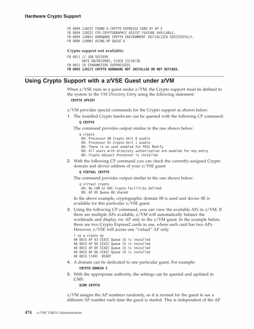
FB 0094 1J023I FOUND A CRYPTO EXPRESS2 CARD AT AP 2FB 0094 1J022I CPU CRYPTOGRAPHIC ASSIST FEATURE AVAILABLE.FB 0094 1J005I HARDWARE CRYPTO ENVIRONMENT INITIALIZED SUCCESSFULLY.FB 0094 1J006I USING AP QUEUE 6
Crypto support not available:FB 0011 // JOB SECSERV
DATE 08/09/2002, CLOCK 13/16/38FB 0011 ID (PARAMETERS SUPPRESSED)FB 0095 1J017I CRYPTO HARDWARE NOT INSTALLED OR NOT DEFINED.
Using Crypto Support with a z/VSE Guest under z/VMWhen z/VSE runs as a guest under z/VM, the Crypto support must be defined tothe system in the VM Directory Entry using the following statement:
CRYPTO APVIRT
z/VM provides special commands for the Crypto support as shown below:1. The installed Crypto hardware can be queried with the following CP command:
Q CRYPTO
The command provides output similar to the one shown below:q crypto00: Processor 00 Crypto Unit 0 usable00: Processor 01 Crypto Unit 1 usable00: There is no user enabled for PKSC Modify00: All users with directory authorization are enabled for key entry00: Crypto Adjunct Processor is installed
2. With the following CP command you can check the currently-assigned Cryptodomain and device address of your z/VSE guest:
Q VIRTUAL CRYPTO
The command provides output similar to the one shown below:q virtual crypto00: No CAM or DAC Crypto Facilities defined00: AP 0E Queue 08 shared
In the above example, cryptographic domain 08 is used and device 0E isavailable for this particular z/VSE guest.
3. Using the following CP command, you can view the available APs in z/VM. Ifthere are multiple APs available, z/VM will automatically balance theworkloads and display one AP only to the z/VM guest. In the example below,there are two Crypto Express2 cards in use, where each card has two APs.However, z/VSE will access one “virtual” AP only.* cp q crypto apAR 0015 AP 03 CEX2C Queue 15 is installedAR 0015 AP 04 CEX2C Queue 15 is installedAR 0015 AP 05 CEX2C Queue 15 is installedAR 0015 AP 06 CEX2C Queue 15 is installedAR 0015 1I40I READY
4. A domain can be dedicated to one particular guest. For example:CRYPTO DOMAIN 5
5. With the appropriate authority, the settings can be queried and updated inCMS:
DIRM CRYPTO
z/VM assigns the AP numbers randomly, so it is normal for the guest to see adifferent AP number each time the guest is started. This is independent of the AP
Hardware Crypto Support
474 z/VSE V4R3.0 Administration

queue number (Cryptographic domain). CP will not provide hardware Cryptosupport for third-level guests (VM2 as a second-level guest of VM1, with z/VSE asa guest on VM2). CP will not provide V=R guest survival support for the Cryptosupport.
Consult the corresponding z/VM manuals for further details about the z/VMCrypto support for guest systems.
Displaying Hardware Crypto Status Information Under z/VSEIf you use the Basic Security Manager (BSM), you can display the status of yourhardware Crypto support on your z/VSE console. To do so, you use the followingconsole command:msg fb,data=status=cr
The output from this command looks like following:msg fb,data=status=crAR 0015 1I40I READYFB 0011 BST223I CURRENT STATUS OF THE SECURITY TRANSACTION SERVER:FB 0011 ADJUNCT PROCESSOR CRYPTO SUBTASK STATUS:FB 0011 AP CRYPTO SUBTASK STARTED .......... : YESFB 0011 MAX REQUEST QUEUE SIZE ............. : 1FB 0011 MAX PENDING QUEUE SIZE ............. : 1FB 0011 TOTAL NO. OF AP REQUESTS ........... : 1234FB 0011 NO. OF POSTED CALLERS .............. : 1234FB 0011 AP CRYPTO POLLING TIME (1/300 SEC).. : 1FB 0011 AP CRYPTO WAIT ON BUSY (1/300 SEC).. : 75FB 0011 AP CRYPTO RETRY COUNT .............. : 5FB 0011 AP CRYPTO TRACE LEVEL .............. : 3FB 0011 TOTAL NO. OF WAITS ON BUSY ......... : 0FB 0011 CURRENT REQUEST QUEUE SIZE ......... : 0FB 0011 CURRENT PENDING QUEUE SIZE ......... : 0FB 0011 ASSIGNED APS : PCICC / PCICA ....... : 0 / 0FB 0011 CEX2C / CEX2A ....... : 1 / 1FB 0011 PCIXCC .............. : 0FB 0011 AP 0 : CEX2C - ONLINEFB 0011 AP 1 : CEX2A - ONLINEFB 0011 ASSIGNED AP QUEUE (CRYPTO DOMAIN)... : 5FB 0011 CPU CRYPTOGRAPHIC ASSIST FEATURE:FB 0011 CPACF AVAILABLE .................... : YESFB 0011 INSTALLED CPACF FUNCTIONS:FB 0011 DES, TDES-128, TDES-192FB 0011 AES-128FB 0011 SHA-1, SHA-256FB 0011 END OF CPACF STATUS
The above output shows the availability of:v Two Crypto Express2 APs, configured in coprocessor mode.v Three Crypto Express2 APs, configured in accelerator mode.v The CPACF feature.v The assigned AP queue (cryptographic domain) is 5.
In addition to the status of Crypto cards, the status output shows the availabilityof the CPACF, which provides symmetric Crypto functions (such as DES,triple-DES, AES, and SHA-1 hashing).
CPACF is not available on all zSeries servers. Where it is available, it is usedtransparently in SSL sessions.
Hardware Crypto Support
Chapter 38. Implementing Hardware Cryptographic Support 475

By displaying the command HELP of the SECSERV job, you can obtain a list of theavailable hardware Crypto commands. The listing below shows:v The general Security Server commands that you can use.v A list of the hardware Crypto commands.msg fb,data=?AR 0015 1I40I READYFB 0011 BST221I POSSIBLE SECURITY SERVER COMMANDS ARE:FB 0011 DBSTARTCACHE ........: STARTS DATABASE CACHINGFB 0011 DBSTOPCACHE .........: STOPS DATABASE CACHINGFB 0011 STATUS ..............: SHOWS TOTAL SERVER STATUSFB 0011 STATUS=ALL ..........: SHOWS TOTAL SERVER STATUSFB 0011 STATUS=MAIN|PS|DB|CR : SHOWS SELECTED STATUSFB 0011 LOGTIME=N ...........: SETS LOGTIME TO N MINUTES (1..9)FB 0011 RESET ...............: CLEANUP EVERYTHINGFB 0011 STOP | SHUTDOWN .....: STOPS THE SERVER (USE WITH CAUTION)FB 0011 SHUTDOWN NOPROMPT ...: STOPS THE SERVER WITHOUT CONFIRM.FB 0011 OPENCNTL ............: OPENS THE II CONTROL FILEFB 0011 CLOSECNTL ...........: CLOSES THE II CONTROL FILEFB 0011 OPENBST .............: OPENS THE BSM CONTROL FILEFB 0011 CLOSEBST ............: CLOSES THE BSM CONTROL FILEFB 0011 HARDWARE CRYPTO COMMANDS:FB 0011 APBUSY=NN ...........: SET AP CRYPTO WAIT ON BUSY (0..99)FB 0011 APRETRY=NN ..........: SET AP CRYPTO RETRY COUNT (0..99)FB 0011 APREM AP=NN .........: REMOVE (DISABLE) A CRYPTO DEVICEFB 0011 APADD AP=NN .........: ADD (ENABLE) A DISABLED DEVICEFB 0011 APQUE ...............: SHOW STATUS OF ASSIGNED AP QUEUEFB 0011 APHIST ..............: SHOW HISTORY OF PROCESSED REQUESTSFB 0011 APWAIT=NN ...........: SET AP CRYPTO POLLING TIME (0..99)FB 0011 APSENSE .............: START SENSING OF CRYPTO HARDWAREFB 0011 APTRACE=N ...........: SET AP CRYPTO TRACE LEVEL (0..3)FB 0011 APEAI ...............: ENABLE AP-QUEUE INTERRUPTSFB 0011 APDAI ...............: DISABLE AP-QUEUE INTERRUPTS
Hardware Crypto Support
476 z/VSE V4R3.0 Administration

Using Hardware Crypto CommandsYou can use the commands described below to manage your hardware Cryptoconfiguration.
Using the APADD Command to Dynamically Add/Enable aCrypto Card
On IBM System z10 (z10) and zEnterprise 196 (z196) platforms, you can use theAPADD command to add/enable an AP (Crypto card) that has beenremoved/disabled from use with z/VSE via the APREM command. The AP(Crypto card) is then flagged as being available for processing Crypto requests inz/VSE.
The AP (Crypto card) is specified using a number between 1 and 63.
You should be aware that:v No “physical” change is made to the Crypto device.v The APADD command is used to control the use of an assigned Crypto device by
z/VSE.
Here is an example of the APADD command:msg fb,data=apadd ap=1AR 0015 1I40I READYFB 0011 1J025I AP 1 ENABLED SUCCESSFULLY.
If you are not using the BSM, for guidance you should refer to “Using CryptoSupport and an External Security Manager” on page 482.
Using the APBUSY Command to Set the Wait-On-Busy TimeInterval
You can use the APBUSY command to set the wait-on-busy time interval. This is thewait-time between attempts to re-queue a request after a:v device-busy condition,v reset-in-progress condition,v queue-full condition.
The default value is 75/300th seconds. Valid values are 0 to 99.
Here is an example of the APBUSY command to set the AP wait-on-busy timeinterval to 50/300th seconds:msg fb,data=apbusy=50AR 0015 1I40I READYFB 0011 1J040I WAIT ON BUSY TIME SET TO 50 * 1/300 SEC.
Using the APEAI Command to Enable AP-Queue InterruptsYou can use the APEAI command to enable AP-queue interrupts. The AP-queueadapter-interruption facility is a function of z10 and z196 platforms. Whenperforming cryptographic operations on Crypto Express2 and Crypto Express3cards, the calling program is notified via a hardware interrupt when a response isready for de-queueing from a card. Previously, the calling program had to use apolling mechanism for this function. In certain situations, using AP-queueinterrupts might result in enhanced performance.
Hardware Crypto Support
Chapter 38. Implementing Hardware Cryptographic Support 477

Note: the AP-queue adapter-interruption facility is not available when runningunder z/VM.
Here is an example of the APEAI command to check if AP-queue interrupts areavailable:msg fb,data=status=crAR 0015 1I40I READYFB 0011 BST223I CURRENT STATUS OF THE SECURITY TRANSACTION SERVER:FB 0011 ADJUNCT PROCESSOR CRYPTO SUBTASK STATUS:FB 0011 AP CRYPTO SUBTASK STARTED .......... : YESFB 0011 MAX REQUEST QUEUE SIZE ............. : 0FB 0011 MAX PENDING QUEUE SIZE ............. : 0FB 0011 TOTAL NO. OF AP REQUESTS ........... : 0FB 0011 NO. OF POSTED CALLERS .............. : 0FB 0011 AP-QUEUE INTERRUPTS AVAILABLE ...... : YESFB 0011 AP-QUEUE INTERRUPTS STATUS ......... : DISABLED...
When the APEAI command is executed, AP-queue interrupts will be enabled for allAPs assigned to the current LPAR, as shown in this example:msg fb,data=apeaiAR 0015 1I40I READYFB 0011 1J048I AP QUEUE ADAPTER INTERRUPTS ENABLED.
Using the APDAI command to disable AP-queue interruptsYou can use the APDAI command to disable AP-queue interrupts for all APsassigned to the current LPAR.
Here is an example of the APEAI command:msg fb,data=apdaiAR 0015 1I40I READYFB 0011 1J049I AP QUEUE ADAPTER INTERRUPTS DISABLED.
Using the APHIST Command to Obtain an Overview ofProcessed Crypto Requests
You can use the APHIST command to obtain an overview of the Crypto requeststhat have been processed since the last IPL or last restart of the Security Server.
The output from APHIST provides statistics that:v show all APs assigned to this LPAR or VM guest.v list the Crypto requests that have been processed.
Here is an example of the APHIST command:msg fb,data=aphistAR 0015 1I40I READYFB 0011 1J046I HISTORY OF AP QUEUE 5:FB 0011 AP : 0 (CEX2C) 1 (CEX2A)FB 0011 ---------- ------------ ------------FB 0011 RSA1024E : 123 456FB 0011 RSA1024D : 78 95FB 0011 RSA2048E : 12 34FB 0011 RSA2048D : 5 6FB 0011 ---------- ------------ ------------
Using the APQUE Command to Display Current RequestsYou can use the APQUE command to display:v The number of requests that are currently being processed.
Hardware Crypto Support
478 z/VSE V4R3.0 Administration

v A list of APs (Crypto cards) that are assigned to this LPAR or VM guest.
The number of currently-processed requests must be zero before you can toggle anAP (Crypto card) to “OFF” using the Support Element. Typically, an administratorwill use:1. APREM command to disable an AP.2. APQUE command to check if the AP can be safely toggled to “OFF” using the
Support Element.
An AP (Crypto card) can be specified using a number between 1 and 63.
Here is an example of the APQUE command that shows that both APs can besafely removed from the LPAR or VM guest:msg fb,data=apqueAR 0015 1I40I READYFB 0011 1J045I NUMBER OF REQUESTS BEING PROCESSED BY AP QUEUE 5:FB 0011 AP 0 : 0FB 0011 AP 1 : 0
Using the APREM Command to Dynamically Remove/Disable aCrypto Card
You can use the APREM command to remove/disable an AP (Crypto card) fromz/VSE without the need to restart the LPAR or VM guest. The AP (Crypto card) isthen flagged as being unavailable for processing Crypto requests in z/VSE.
On z10 and z196 platforms, APREM can be used to:v set an AP (Crypto card) to offline.v dynamically remove an AP (Crypto card) from a z/VSE LPAR via the server's
Support Element.
Typically, you would:1. Use APREM to prevent this AP (Crypto card) from being used to process
further Crypto requests.2. Repeatedly use the APQUE command to check if there are replies pending in
this AP.3. When no replies are pending, use the server's Support Element to set the AP to
offline or remove the AP (Crypto card) from the LPAR .
The AP (Crypto card) is specified using a number between 1 and 63.
You should be aware that:v The APREM command causes an AP to be no longer available for processing
Crypto requests.v The status of the Crypto device is not changed.v The APADD command can be used to re-enable the AP for processing Crypto
requests.
Here is an example of the APREM command:msg fb,data=aprem ap=1AR 0015 1I40I READYFB 0011 1J026I AP 1 DISABLED SUCCESSFULLY.
Hardware Crypto Support
Chapter 38. Implementing Hardware Cryptographic Support 479

Using the APRETRY Command to Set the Number of RetryAttempts
You can use the APRETRY command to set the number of retry attempts on a:v device-busy condition,v reset-in-progress condition,v queue-full condition.
The default value is five retry attempts. Valid values are 0 to 99.
Here is an example of the APRETRY command to set the number of retry attemptsto 10:msg fb,data=apretry=10AR 0015 1I40I READYFB 0011 1J036I RETRY COUNT SET TO 10.
Using the APSENSE Command to Refresh Your HardwareCrypto Configuration
On zSeries z890, z990, and later servers, you can configure an AP online or offlinewithout the need to restart the LPAR or VM guest. Additionally, with the IBMSystem z9 and later servers, you can dynamically change the configuration of aCrypto Express2 and later adapter from co-processor mode into accelerator modeor vice versa.
You can use the APSENSE command to dynamically reflect such configuration changesin your z/VSE system. This command updates the hardware Crypto environmentwithout the need to re-IPL your z/VSE system.
Here is an example of the APSENSE command:msg fb,data=apsenseAR 0015 1I40I READYFB 0095 1J022I CPU CRYPTOGRAPHIC ASSIST FEATURE AVAILABLE.FB 0095 1J031I HARDWARE CRYPTO ENVIRONMENT REFRESHED.
If you are not using the BSM, for guidance you should refer to “Using CryptoSupport and an External Security Manager” on page 482.
Using the APTERM Command to Terminate Crypto SubtaskIJBCRYPT
You can use the APTERM command to terminate the z/VSE Crypto device (subtaskIJBCRYPT). This subtask is part of the SECSERV (Security Server) phase BSTPSTS.
Here is an example of the APTERM command:msg fb,data=aptermAR 0015 1I40I READYFB 0095 1J032I HARDWARE CRYPTO DEVICE DRIVER TERMINATED.
To restart the device driver, you can use the APSENSE command (as described in“Using the APSENSE Command to Refresh Your Hardware CryptoConfiguration”).
Hardware Crypto Support
480 z/VSE V4R3.0 Administration

Using the APTRACE Command to Enable the Hardware CryptoTrace
You can use the APTRACE command to turn on/off the internal trace facilitycontained in z/VSE hardware Crypto support. The trace output is sent to theOperator Console. You can use these four trace settings:0 Full trace including informational messages.1 Show warning and error messages.2 Show error messages only.3 Trace off (the default).
Here is an example of the APTRACE command to activate full trace (by setting thetrace level to zero):msg fb,data=aptrace=0AR 0015 1I40I READYFB 0011 1J034I CRYPTO TRACE LEVEL SET TO 0.
Using the APWAIT Command to Set the AP Polling TimeInterval
Crypto cards process RSA encrypt and decrypt operations via an asynchronousinterface. This means that:1. Requests are enqueued to an Adjunct Processor (AP).2. After a certain time interval, these requests will be dequeued.
You can use the APWAIT command to specify the time interval (in 1/300th seconds)from the time between:1. Enqueuing a request into the internal processing queue of an AP.2. The first attempt to dequeue a response.
Higher values will increase elapsed job time, but also decrease CPU time. Lowervalues will minimize elapsed job time, but might also increase CPU timesignificantly. The default value is 1/300th seconds. Valid values are 0 to 99.
Here is an example of the APWAIT command to set the AP wait-time interval to2/300th seconds:msg fb,data=apwait=2AR 0015 1I40I READYFB 0011 1J038I POLLING TIME SET TO 2 * 1/300 SEC.
Hardware Crypto Support
Chapter 38. Implementing Hardware Cryptographic Support 481

Using Crypto Support and an External Security ManagerIf you use an External Security Manager (and not the Basic Security Manager) thefollowing implementation details of the Hardware Crypto support are importantand must be observed.
The Hardware Crypto support is activated by the startup job SECSERV (SecurityServer) which is part of the Basic Security Manager and which runs in partition FBby default. If SECSERV is not started (because you are using an External SecurityManager), the Hardware Crypto support is not available. However, the HardwareCrypto task can be started manually in any partition with a job stream such as thefollowing:* $$ JOB JNM=HWCRYPTO,DISP=D,CLASS=R// JOB HWCRYPTO// EXEC IJBCRYPT/*/&* $$ EOJ
To activate the Hardware Crypto support, proceed as follows:1. Start the above job stream (or a similar one).2. Shutdown TCP/IP and your TCP/IP applications (TCP/IP runs in partition F7
by default).3. Restart TCP/IP and your TCP/IP applications.
Console Interface Not Available!If you are using an ESM, you should be aware that you cannot use theConsole Interface that is provided by the SECSERV job. As a result, youcannot use BSM commands together with your environment. For example,you cannot issue the APSENSE command to dynamically refresh your Cryptoconfiguration.
Hardware Crypto Support
482 z/VSE V4R3.0 Administration

Chapter 39. Preparing Your System to Use SSL
This chapter describes the steps you should follow to set up your z/VSE system sothat you can implement Secure Sockets Layer (SSL) support. After completing thesteps in this chapter, you can then proceed to implement:v Server authentication (described in Chapter 40, “Configuring for Server
Authentication,” on page 497).v Client authentication (described in Chapter 41, “Configuring for Client
Authentication,” on page 513).
Check Home Page for Latest Information!Before starting to configure your z/VSE system for SSL, you are advised tocheck the z/VSE e-business Connectors and Utilities home page for any newinformation relating to SSL. The URL is:http://www.ibm.com/servers/eserver/zseries/zvse/products/connectors.html
z/VSE provides hardware crypto support which requires a PCI CryptographicAccelerator (PCICA) card or equivalent.
This chapter contains these main topics:v “Step 1: Activate TCP/IP for VSE/ESA” on page 484v “Step 2: Create a Client Keyring File (KeyRing.pfx)” on page 484v “Step 3: Download and Customize the Keyman/VSE Tool” on page 485v “Step 4: Ensure That Your VSE Keyring Library Members Are Secure” on page
489v “Getting Started Using the IBM-Supplied Keyring Set” on page 490v “Currently-Supported SSL Cipher Suites” on page 492v “Differences in SSL Support Provided by IBM/Sun JDKs” on page 494v “SSL Examples Provided With the Online Documentation” on page 496
Related Topics:
For details of how to ... Refer to the ...
setup SSL with:v Secure FTPv Secure Telnetv The VSE LDAP clientv The Java-based connectorv CICS Web Support (CWS)v WebSphere MQ for z/VSEv The VSE Script connector
v IBM Redbook Security on IBM z/VSE,SG24-7691.
v technical articles located in the“Documentation” section of the z/VSEHomepage:
http://www.ibm.com/servers/eserver/zseries/zvse/documentation/
After being implemented, server authentication can be used by:v CICS Web Support,v VSE/POWER networking,v Secure FTP,
© Copyright IBM Corp. 1984, 2010 483

v Secure Telnet,v Any other installed TCP/IP application that runs on z/VSE.
Step 1: Activate TCP/IP for VSE/ESAWhen you activate TCP/IP for VSE/ESA you have access to all TCP/IP functions,including SSL support. Please note that for SSL support, you require the TCP/IPfor VSE/ESA Application Pak.
For details of how to activate TCP/IP for VSE/ESA, refer to the z/VSE TCP/IPSupport, SC34-2604.
The instructions for using SSL with z/VSE are provided in the TCP/IP for VSE 1.5,Optional Features, which you can obtain from either:v The z/VSE Homepage (described in “Where to Find More Information” on page
xxiii).v Disk 3 (PDFs) of the VSE Collection Online Library, SK2T-0060.v The z/VSE Collection on DVD Online Library, SK3T-8348, which contains all
manuals (both PDFs and BOOK files).
Step 2: Create a Client Keyring File (KeyRing.pfx)On the workstation from which you wish to implement server authentication, youmust have installed a copy of the IBM-supplied client keyring file KeyRing.pfx.This file will be used for storing keys and certificates used by serverauthentication.
To obtain a copy of KeyRing.pfx, you must install the VSE Connector Client onyour workstation, as described in the chapter “Installing and Operating theJava-Based Connector” in the z/VSE e-business Connectors User's Guide, SC33-8310.
During the installation of the VSE Connector Client, KeyRing.pfx is automaticallystored in the directory:\vsecon\samples
After being created during the installation, KeyRing.pfx contains a copy of theIBM-supplied sample root certificate, and a sample client certificate which has beensigned by the root certificate. The file is initially protected by the password‘ssltest’.
To:v change the password,v manage the certificates stored in the client keyring file,
you use the IBM-supplied Keyman/VSE tool (described in “Step 3: Download andCustomize the Keyman/VSE Tool” on page 485).
Preparing z/VSE System for SSL
484 z/VSE V4R3.0 Administration
Step 3: Download and Customize the Keyman/VSE Tool
JDK 1.5 or higher is required!Before you begin, you must already have installed the Java Development Kit(JDK) 1.5 or higher on the development platform where you plan to installthe Keyman/VSE. If you do not have JDK 1.5 or higher installed, refer to thechapter “Installing the Common Prerequisite Programs” in the z/VSEe-business Connectors User's Guide, SC33-8310 for details of how to install it.
You can use the Keyman/VSE tool for most of the activities concerning SSL keysand certificates. You install it on a Java-enabled platform.
Obtaining a Copy of Keyman/VSETo obtain a copy of Keyman/VSE, start your Web browser and go to URL:
http://www.ibm.com/servers/eserver/zseries/zvse/downloads/
From within the Keyman/VSE section, select Details and Download, thendownload the keyman zip file to the directory where you wish to installKeyman/VSE. The default is directory c:\vkeyman (for Windows) or /vkeyman(for Linux).
Performing the Installation of Keyman/VSETo perform the installation of Keyman/VSE, you must:1. Unzip the keyman zip file which contains these files:v setup.jar (contains the Keyman/VSE code)v setup.bat (an install batch file for Windows 2000/XP/Vista)v setup.cmd (an install batch file for Windows NT)v setup.sh (an install script for Linux/Unix)
2. Start the batch file (by double-clicking the file) that is applicable to youroperating-system platform.
3. The installation process now begins, and you are guided through variousinstallation menus.
4. To access the HTML-based documentation, you can now use your Web browserto open the file vkeyman.html in the \vkeyman\help\ subdirectory.
Customize the Keyman/VSE SettingsDuring the operation of Keyman/VSE, access is required from the workstationwhere you have installed Keyman/VSE, to the VSE Keyring Library stored on thez/VSE Host. You must customize Keyman/VSE so it can communicate with thez/VSE host, as described below.
Specify the Properties of Your z/VSE HostBefore you can start to create keys and certificates, you must specify the propertiesof your z/VSE host. To begin this action, click VSE Host properties on the toolbar,as shown in Figure 114 on page 486.
Preparing z/VSE System for SSL
Chapter 39. Preparing Your System to Use SSL 485

The VSE Host – Properties window is then displayed. Click New and you can enterthe details of your z/VSE host, as shown in Figure 115:
These are the fields you must complete in Figure 115:Name The name you wish to use for the z/VSE host system that is
specified by IP Address (below).IP Address The IP address of the z/VSE host.Port The port number of the VSE Connector Server running on your
z/VSE host (the default is 2893).VSE User A valid VSE User ID that has been defined using the Interactive
Interface Maintain User Profiles dialog.VSE Job Class
The VSE/POWER Job class which denotes the partition in whichJobs, submitted via Keyman/VSE, will run. These jobs catalogkeyring members in CRYPTO.KEYRING.
VSE PasswordThe password used by VSE User to logon to the z/VSE host. Youmust enter this password twice.
Figure 114. VSE Host Properties icon on Keyman/VSE Toolbar
Figure 115. Using Keyman/VSE to Specify the Properties of the z/VSE Host
Preparing z/VSE System for SSL
486 z/VSE V4R3.0 Administration

VSE Crypto LibraryThe name of the library on the z/VSE host used for storingkeyring members. Library CRYPTO.KEYRING is shown as default,since this library is automatically defined on IJSYSCT (the VSAMmaster catalog) during the installation of z/VSE. However, you canuse your own library names.
Cert. Member NameThe name you wish to assign to each member of the keyring to becreated. For example, if you enter MYNAME here, a keyringconsisting of these members will be created in the VSE CryptoLibrary: MYNAME.PRVK (key pair), MYNAME.CERT (servercertificate) and MYNAME.ROOT (root certificate).
Cert. Mapping MemberThe name of the VSE library member containing the list of clientcertificates and their VSE User-ID mappings. The default isBSSDCUID. For details, see Chapter 42, “Implementing ClientAuthentication with VSE User-ID Mapping,” on page 525.
TCP/IP LibraryThe library where TCP/IP is installed. The default is PRD1.BASE.
TCP/IP System IDThe System ID of the TCP/IP partition you wish to use togetherwith Keyman/VSE. The default is 00.
When you have finished entering the details of your z/VSE host, click either:v OK to store the details and complete this activity.v Add to store the details and then start to add the details for another z/VSE host.
Specify the Properties of Your Local Keyring FileTo customize Keyman/VSE so that it contains the properties of the IBM-suppliedkeyring file Keyring.pfx that is stored on the client, click Local file properties asshown in Figure 116.
The Local Keyring File – Properties window is then displayed as shown in Figure 117on page 488.
Figure 116. Local File Properties icon on Keyman/VSE Toolbar
Preparing z/VSE System for SSL
Chapter 39. Preparing Your System to Use SSL 487

These are the fields you must complete in Figure 117:File Name The name of the client keyring file. The default is Keyring.pfx,
which is the name of the IBM-supplied keyring file. However, youcan enter your own file name which will then be used for creatinga new client keyring file.
Keyring File PasswordThe password you wish to assign to your client keyring file. Later,you will be prompted to enter this password when you:v Open the client keyring file.v Import the client keyring file into a Web browser.
Encryption of public itemsThe algorithm you wish to use for the internal encryption of thepublic Certificate items (items which do not contain a private key).
Encryption of private itemsThe algorithm you wish to use for the internal encryption of theprivate Certificate items (which do contain a private key).
Password protectionThe strength of security with which the password should beencrypted, where 1 is the weakest level and 2000 (therecommended setting) the strongest level of encryption. Note: Ifyou have problems importing the keyring file into your Webbrowser, reduce the password encryption strength to 1.
Figure 117. Entering the Properties of the Client Keyring File
Preparing z/VSE System for SSL
488 z/VSE V4R3.0 Administration

Step 4: Ensure That Your VSE Keyring Library Members Are SecureYou must ensure that the members that will be copied into the VSE KeyringLibrary (private keys, server certificates, and root certificates) are secure. To do so,use the:1. z/VSE Access Control Function, which is part of the Basic Security Manager
(BSM).2. Access control table DTSECTAB. The default VSE Keyring Library
(CRYPTO.KEYRING) is secured with all parts.
For details, refer to Chapter 28, “Overview of DTSECTAB-Based VSE Security,” onpage 389.
In addition, you must:v Ensure that your system is started with SEC=YES in the IPL SYS parameter.v Ensure that your private key and server certificate have full read/write access
protection.v Include an ID statement in the startup job of each application that is to use
certificates for SSL. The application might be a CICS application or the VSEConnector Server, for example.
v Submit the startup job for an application:– when security is active (that is, SEC=YES in the IPL SYS parameter).– using an authorized user (for example, the Administrator).
v Ensure that your VSE Keyring Library (the IBM-default is CRYPTO.KEYRING)cannot be accessed via FTP. For example, you should not specify the name ofyour VSE Keyring Library in any DEFINE FILE statement.
Preparing z/VSE System for SSL
Chapter 39. Preparing Your System to Use SSL 489

Getting Started Using the IBM-Supplied Keyring Set
To get started using SSL, you can use the IBM-supplied keyring set for testing andlearning purposes. To do so, you simply have to run Job SKSSLKEY to catalog theIBM-supplied keyring set into the VSE Keyring Library on the z/VSE host. Thiskeyring set consists of:v A private key SAMPLE.PRVKv A server certificate (which includes the public key) SAMPLE.CERTv A root certificate SAMPLE.ROOT
Note: You can use this keyring set together with CICS Web Support and thez/VSE Java-based connector.
The VSE Keyring Library (CRYPTO.KEYRING) is automatically defined on IJSYSCT(the VSAM Master Catalog) during the installation of z/VSE.
After you have run Job SKSSLKEY, you can start to use this keyring setimmediately. However, the length of the key pair in the IBM-supplied keyring setis 512 bits, which is not secure enough for applications that require high security.
* $$ JOB JNM=SETUPSSL,DISP=D,CLASS=0// JOB SETUPSSL DEFINE SSL SAMPLE ENVIRONMENT* ******************************************************************** STEP 1: CREATE RSA PRIVATE KEY ’SAMPLE.PRVK’** ******************************************************************// OPTION SYSPARM=’00’ SYSID OF MAIN TCP/IP PARTITION// LIBDEF PHASE,SEARCH=(PRD1.BASE)// EXEC CIALPRVK,SIZE=CIALPRVK,PARM=’CRYPTO.KEYRING.SAMPLE’-----BEGIN RSA Private Key-----hXNnvtgWEHuF4rhLWODrmJhG7yNyDYhXjTN1sALJEn2wCYsuaqhnmco5WbJOKdPeg+oFi0o1MrsPQABoDtes/tNfMtTVzS6Vz/5EmpdrO0MlpNdK/QLdzyS5SgSSA0ZNgWhVe3eY4+2FQb3x8D5pnjhGuMc3NzxZynBa2j+dz5ae8+nAH8qfQRsPfcXU715Y
...-----END RSA Private Key-----/*
Figure 118. Job SKSSLKEY to Catalog a Sample Keyring Set into the VSE Keyring Library(Part 1 of 2)
Preparing z/VSE System for SSL
490 z/VSE V4R3.0 Administration

For production purposes, you should use the Keyman/VSE tool to create:v one keyring set to be used by the CICS Transaction Server for VSE/ESA.v one keyring set to be used by the z/VSE Java-based connector. It is
recommended that you use a different keyring set to the keyring set used by theCICS Transaction Server for VSE/ESA.
For details of how to do so, see “Configuring for Server Authentication UsingCA-Signed Certificates” on page 502.
* ******************************************************************** STEP 2: CREATE VSE SERVER CERTIFICATE ’SAMPLE.CERT’** ******************************************************************// OPTION SYSPARM=’00’ SysId of main TCP/IP partition// LIBDEF PHASE,SEARCH=(PRD1.BASE)// EXEC CIALCERT,SIZE=CIALCERT,PARM=’CRYPTO.KEYRING.SAMPLE’-----BEGIN CERTIFICATE-----MIICJTCCAc8CBHiMye4wDQYJKoZIhvcNAQEFBQAwgZYxIDAeBgkqhkiG9w0BCQEWEXZzZWVzYUBkZS5pYm0uY29tMQswCQYDVQQGEwJERTETMBEGA1UEBxMKQm9lYmxpbmdlbjEUMBIGA1UEChMLSUJNIEdlcm1hbnkxGDAWBgNVBAsTD1ZTRSBEZXZlbG9w
...-----END CERTIFICATE-----/** ******************************************************************** STEP 3: CREATE ROOT CERTIFICATE ’SAMPLE.ROOT’** ******************************************************************// OPTION SYSPARM=’00’ SysId of main TCP/IP partition// LIBDEF PHASE,SEARCH=(PRD1.BASE)// EXEC CIALROOT,SIZE=CIALROOT,PARM=’CRYPTO.KEYRING.SAMPLE’-----BEGIN CERTIFICATE-----MIICGzCCAcUCBHiLtz0wDQYJKoZIhvcNAQEFBQAwgZYxIDAeBgkqhkiG9w0BCQEWEXZzZWVzYUBkZS5pYm0uY29tMQswCQYDVQQGEwJERTETMBEGA1UEBxMKQm9lYmxpbmdlbjEUMBIGA1UEChMLSUJNIEdlcm1hbnkxGDAWBgNVBAsTD1ZTRSBEZXZlbG9w
...-----END CERTIFICATE-----/*/&* $$ EOJ
Figure 118. Job SKSSLKEY to Catalog a Sample Keyring Set into the VSE Keyring Library(Part 2 of 2)
Preparing z/VSE System for SSL
Chapter 39. Preparing Your System to Use SSL 491

Currently-Supported SSL Cipher SuitesYou define the SSL Version using SSLVERSION, which is contained in the:v Java properties object of the VSE Connector Client (see Figure 124 on page 510).v Java properties file of the VSE Connector Client (see Figure 125 on page 511).v SSL configuration file of the VSE Connector Server (see Figure 122 on page 507).
Table 15 shows the SSL cipher suites that are currently supported. It represents theformat you use when defining these cipher suites for the VSE Connector Client:v For the format you use when defining these cipher suites for the VSE Connector
Server, see Figure 122 on page 507.
Table 15. Currently Supported SSL Cipher Suites
Hex Code Cipher Suite Encryption See Notes...
01 SSL_RSA_WITH_NULL_MD5 No 1, 2, 3
02 SSL_RSA_WITH_NULL_SHA No 1, 2, 3
08 SSL_RSA_EXPORT_WITH_DES40_CBC_SHA 40-bit 1, 2, 4
09 SSL_RSA_WITH_DES_CBC_SHA 56-bit 1, 4
0A SSL_RSA_WITH_3DES_EDE_CBC_SHA 168-bit 1, 4
62 RSA1024_EXPORT_DESCBC_SHA 56-bit 1, 3, 5
2F TLS_RSA_WITH_AES_128_CBC_SHA 128-bit 1, 6
35 TLS_RSA_WITH_AES_256_CBC_SHA 256-bit 1, 6, 7
Notes:
1. The cipher suites NULL_MD5 (X'01'), NULL_SHA (X'02'), andRSA1024_EXPORT_DESCBC_SHA (X'62') require the SSL 3.0 handshaking. They cannotbe used with TLS 1.0 handshaking.
2. The cipher suites SSL_RSA_EXPORT_WITH_DES40_CBC_SHA (X'08'),SSL_RSA_WITH_DES_CBC_SHA (X'09'), and SSL_RSA_WITH_3DES_EDE_CBC_SHA (X'0A')can be used with both SSL 3.0 and TLS 1.0, handshaking.
3. The cipher suite RSA1024_EXPORT_DESCBC_SHA (X'62') is not supported by the VSEConnector Client. For a detailed description of the SSL V3 protocol andsupported cipher suites, refer to the SSL Protocol Version 3.0.
4. The 2048-bit SSL handshaking additionally requires a Crypto Express2 and latercard and the latest version of TCP/IP for VSE/ESA. On a System z9 server orequivalent, AES-128 can be transparently performed using the CPACF hardwarecrypto feature. For details, refer to the chapter “Hardware Support” of thez/VSE Planning, SC33-8301.
5. See also “Obtaining Unlimited-Strength Jurisdiction Policy Files.”
Obtaining Unlimited-Strength Jurisdiction Policy FilesBy default, your Java installation does not support AES with key sizes that aregreater than 128 bits. However, to use AES-256 you need unlimited strengthcryptography.
Due to import-control restrictions imposed by some countries, the jurisdictionpolicy files shipped with Java only permit strong cryptography to be used. Anunlimited strength version of these files (that is, with no restrictions oncryptographic strength) is available for download on this Web page:http://java.sun.com/products/jce/javase.html
Preparing z/VSE System for SSL
492 z/VSE V4R3.0 Administration

To activate unlimited strength cryptography in Java:1. Replace the files local_policy.jar and US_export_policy.jar in the directory
...\lib\security of your Java installation.2. Restart your Java application.
The same files can also be used to activate unlimited strength cryptography for anIBM Java.
Preparing z/VSE System for SSL
Chapter 39. Preparing Your System to Use SSL 493
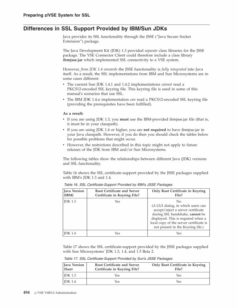
Differences in SSL Support Provided by IBM/Sun JDKsJava provides its SSL functionality through the JSSE (“Java Secure SocketExtension”) package.
The Java Development Kit (JDK) 1.3 provided separate class libraries for the JSSEpackage. The VSE Connector Client could therefore include a class libraryibmjsse.jar which implemented SSL connectivity to a VSE system.
However, from JDK 1.4 onwards the JSSE functionality is fully integrated into Javaitself. As a result, the SSL implementations from IBM and Sun Microsystems are insome cases different:v The current Sun JDK 1.4.1 and 1.4.2 implementations cannot read a
PKCS12-encoded SSL keyring file. This keyring file is used in some of thismanual's scenarios that use SSL.
v The IBM JDK 1.4.n implementation can read a PKCS12-encoded SSL keyring file(providing the prerequisites have been fulfilled).
As a result:
v If you are using JDK 1.3, you must use the IBM-provided ibmjsse.jar file (that is,it must be in your classpath).
v If you are using JDK 1.4 or higher, you are not required to have ibmjsse.jar inyour Java classpath. However, if you do then you should check the tables belowfor possible problems that might occur.
v However, the restrictions described in this topic might not apply to futurereleases of the JDK from IBM and/or Sun Microsystems.
The following tables show the relationships between different Java (JDK) versionsand SSL functionality.
Table 16 shows the SSL certificate-support provided by the JSSE packages suppliedwith IBM's JDK 1.3 and 1.4.
Table 16. SSL Certificate-Support Provided by IBM's JSSE Packages
Java Version(IBM)
Root Certificate and ServerCertificate in Keyring File?
Only Root Certificate in KeyringFile?
JDK 1.3 Yes No(A GUI dialog, in which users can
accept/reject a server certificateduring SSL handshake, cannot be
displayed. This is required when alocal copy of the server certificate is
not present in the Keyring file.)
JDK 1.4 Yes Yes
Table 17 shows the SSL certificate-support provided by the JSSE packages suppliedwith Sun Microsystems' JDK 1.3, 1.4, and 1.5 Beta 2.
Table 17. SSL Certificate-Support Provided by Sun's JSSE Packages
Java Version(Sun)
Root Certificate and ServerCertificate in Keyring File?
Only Root Certificate in KeyringFile?
JDK 1.3 Yes Yes
JDK 1.4 Yes Yes
Preparing z/VSE System for SSL
494 z/VSE V4R3.0 Administration

Table 17. SSL Certificate-Support Provided by Sun's JSSE Packages (continued)
Java Version(Sun)
Root Certificate and ServerCertificate in Keyring File?
Only Root Certificate in KeyringFile?
JDK 1.5 Yes Yes
JDK 1.6 Yes Yes
You normally use a key management tool (such as Keyman/VSE, keytool.exe, orOpenSSL) to define the PKCS12 properties of your local keyring file, including the:v Encryption of public and private items (certificates) in the keyring file.v Strength of the file's password encryption.
Using the Keyman/VSE tool, you define the above properties in the window“Local Keyring File – Properties”.
Table 18 shows the SSL encryption-support provided by the PKCS12 files suppliedwith IBM's JDK 1.3 and 1.4 .
Table 18. PKCS12 Encryption-Support Provided by IBM's JDKs
Encryption of Public and/or Private Items (Certificates)
Java Version(IBM)
None DES (168-bit) RC4 (128-bit or40-bit)
RC2 (128-bit or40-bit)
JDK 1.3 Yes Yes Yes Yes
JDK 1.4 Yes No Yes Yes
Table 19 shows the SSL encryption-support provided by the PKCS12 files suppliedwith Sun Microsystems' JDK 1.3, 1.4, and 1.5 Beta 2.
Table 19. PKCS12 Encryption-Support Provided by Sun's JDKs
Encryption of Public and/or Private Items (Certificates)
Java Version(Sun)
None DES (168-bit) RC4 (128-bit or40-bit)
RC2 (128-bit or40-bit)
JDK 1.3 Yes Yes Yes Yes
JDK 1.4 Yes No No No
JDK 1.5 Yes No No No
JDK 1.6 Yes No No No
Preparing z/VSE System for SSL
Chapter 39. Preparing Your System to Use SSL 495

SSL Examples Provided With the Online DocumentationYou might also refer to the SSL examples provided with the VSE ConnectorClient's online documentation:v SSLApiExample shows how to code a Java application to connect to the VSE
Connector Server via SSL. Note: You can also find a step-by-step description ofthis example in the online documentation (refer to “Using the OnlineDocumentation Option” in the z/VSE e-business Connectors User's Guide,SC33-8310).
v SSLConsoleExample shows how to connect via SSL, to submit a consolecommand, and then obtain the resulting console messages.
Both of these examples are ready-to-run, and use the IBM-provided Client KeyringFile (Keyring.pfx). In addition, you must also have either:v Submitted job SKSSLKEY to catalog the corresponding entries in the VSE
Keyring Library (CRYPTO.KEYRING).v Created your own keyrings.
For details, see “Getting Started Using the IBM-Supplied Keyring Set” on page 490.
You can find the complete Java source code for the above SSL examples in theSamples sub-directory of the directory where you installed the VSE ConnectorClient. For details of how to use the online documentation, refer to “Using theOnline Documentation Option” in the z/VSE e-business Connectors User's Guide,SC33-8310.
Preparing z/VSE System for SSL
496 z/VSE V4R3.0 Administration

Chapter 40. Configuring for Server Authentication
This chapter describes the steps you take to configure your z/VSE system forSecure Sockets Layer (SSL) server authentication. For most applications, serverauthentication provides a sufficient level of SSL security, and means that a servercertificate is provided by the server (in this case, the z/VSE host) to authenticatethe server to clients. However, if you require client authentication in addition toserver authentication, also refer to the instructions provided in Chapter 41,“Configuring for Client Authentication,” on page 513.
Note: Before starting this chapter, you should understand the differences betweenthe SSL support offered by IBM's and Sun Microsystems's Java DevelopmentKits. For details, see “Differences in SSL Support Provided by IBM/SunJDKs” on page 494.
Support for 2048-Bit RSA Key Pairs!The example in this chapter is based upon the use of 1024-bit RSA key pairs.However, you can use 2048-bit RSA key pairs if you are using:v A PCIXCC card.v A Crypto Express2 card or later.v The latest version of TCP/IP for VSE/ESA.
This chapter contains these main topics:v “Configuring for Server Authentication Using Self-Signed Certificates”v “Configuring for Server Authentication Using CA-Signed Certificates” on page
502v “Configuring the VSE Connector Server for Server Authentication” on page 507v “Configuring Self-Written Clients for Server Authentication” on page 509v “Summary of Server Authentication Tasks for the Java-Based Connector” on
page 512
Configuring for Server Authentication Using Self-Signed CertificatesTo configure your z/VSE system for server authentication that uses yourself-signed server certificates, you should follow the steps given below.
Note: Certificates that you sign using your own root certificate are not usableoutside of your own company's test or intranet environment.
Prerequisites:v You must have completed all the steps described in Chapter 39, “Preparing Your
System to Use SSL,” on page 483.v The VSE Connector Server must be running on the z/VSE host in non-SSL
mode (for details, refer to the chapter “Installing and Operating the Java-BasedConnector” in the z/VSE e-business Connectors User's Guide, SC33-8310).
v You must have installed the Java Development Kit (JDK) 1.4 or higher on theplatform where you will use the Keyman/VSE (for details, refer to the chapter“Installing the Common Prerequisite Programs” in the z/VSE e-businessConnectors User's Guide, SC33-8310).
© Copyright IBM Corp. 1984, 2010 497

Step 1. Create an RSA Key Pair
a. On the Keyman/VSE toolbar click Generate new RSA key pair asshown in Figure 119.
b. Select a key length of 1024, and click Generate key (key lengths of512 bits are not secure). The entry is then created and displayed. Youcan examine the properties of this RSA Key Pair entry bydouble-clicking it.
Step 2. Create a Self-Signed Root Certificate
a. On the Keyman/VSE toolbar click Generate ROOT certificate asshown in Figure 120. The Enter Personal Information for ROOT Certwindow is then displayed.
b. Complete the fields in this window (make sure you select a keylength of 1024).
c. Click Generate cert to create your root certificate. The self-signedroot certificate is then created and added to the list of displayedCertificate items. You can examine the properties of this rootcertificate by double-clicking it.
Step 3. Create a Request for a VSE Server CertificateIn this step, a request for a server certificate is created using the RSAkey pair that was previously created in Step 1.
Figure 119. Generate RSA Key Pair icon on Keyman/VSE Toolbar
Figure 120. Generate ROOT Certificate icon on Keyman/VSE Toolbar
Server Authentication Using Self-Signed Certificates
498 z/VSE V4R3.0 Administration

a. Select the entry 1024-bit RSA Key Pair, and then display the pop-upmenu by clicking the entry using the right mouse-button. SelectCreate VSE server cert request.
b. Complete the fields in this window and click Generate to createyour certificate request. The 1024-bit Certificate Request is thencreated and added to the list of displayed Certificate items.
Step 4. Sign the Request for a VSE Server CertificateIn this step, the request for a server certificate is signed using thepreviously-created root certificate (using the Clipboard).a. Select the entry 1024-bit Certificate Request, and then display the
pop-up menu by clicking the entry using the right mouse-button.Select Copy to clipboard.
b. Select your root certificate from the displayed list. Next, display thepop-up menu by clicking the root certificate using the rightmouse-button. Select Sign certificate request. The Sign CertificateRequest window is then displayed.
c. Paste the certificate request from the Clipboard into this window,using the usual keyboard combination (for example, Shift + Insert).
d. Click Generate, and the generated VSE server certificate that hasnow been signed by your root certificate, is added to the list ofdisplayed Certificate items.
e. The 1024-bit Certificate Request entry is no longer required, andyou should delete it by selecting this 1024-bit certificate request andthen pressing the Del key.
Step 5. Upload the 1024-Bit RSA Key Pair to the z/VSE HostIn this step, the RSA key pair is uploaded to the z/VSE host andcataloged into the VSE Keyring Library (CRYPTO.KEYRING), where itwill have the suffix .PRVK.a. Select the 1024-bit RSA Key Pair from the displayed list. Next,
display the pop-up menu by clicking the 1024-bit RSA Key Pairentry using the right mouse-button. Select Upload to VSE. The SendCertificate Item to VSE window is then displayed.
b. The values displayed in this window are taken from your Hostsettings (described in “Specify the Properties of Your z/VSE Host”on page 485). You can change them here if you wish. When you areready, click Upload. The CIALSRVR utility is started on the z/VSEhost, which catalogs the RSA key pair in the VSE Keyring Library.
c. On the Send Certificate Item to VSE window you will now see statusmessages. On the z/VSE console you will see messages similar tothose below:R1 0045 IESC1023I CLIENT CONNECTED FROM IP: 9.164.183.168R1 0045 IESC1028I CLIENT SESSION ESTABLISHED FOR USER: JSCHBG 0001 1Q47I BG CIALSRVR 01148 FROM (JSCH) , TIME=11:35:12BG 0000 // JOB CIALSRVR
DATE 03/04/2006, CLOCK 11/35/12BG 0000 CIALSRVR 01.05 A 12/23/02 12.55BG 0000 Default password phrase will be usedBG 0000 SETPORT 6045BG 0000 Waiting for PC to send rsa private key.BG 0000 1024-bit RSA key written into CRYPTO .KEYRING .JSCH01 .PRVK
Server Authentication Using Self-Signed Certificates
Chapter 40. Configuring for Server Authentication 499

BG 0000 EOJ CIALSRVR MAX.RETURN CODE=0000DATE 03/04/2006, CLOCK 11/35/18, DURATION 00/00/06
BG 0001 1Q34I BG WAITING FOR WORK
Step 6. Upload the Root Certificate to the z/VSE HostIn this step, the self-signed root certificate is uploaded to the z/VSEhost and cataloged into the VSE Keyring Library (CRYPTO.KEYRING),where it will have the suffix .ROOT.a. Select your root certificate from the displayed list. Next, display the
pop-up menu by clicking the root certificate entry using the rightmouse-button. Select Upload to VSE. The Send Certificate Item to VSEwindow is then displayed.
b. The values displayed in this window are taken from your Hostsettings (described in “Specify the Properties of Your z/VSE Host”on page 485). You can change them here if you wish. When you areready, click Upload. The CIALROOT utility is started on the z/VSEhost, which catalogs the root certificate in the VSE Keyring Library.
c. On the Send Certificate Item to VSE window you will now see statusmessages. On the z/VSE console you will see messages similar tothose below:BG 0001 1Q47I BG CIALROOT 01149 FROM (JSCH) , TIME=12:16:32BG 0000 // JOB CIALROOT
DATE 03/04/2006, CLOCK 12/16/32BG 0000 CIALROOT 01.05 A 12/23/02 12.55BG 0000 EOJ CIALROOT MAX.RETURN CODE=0000
Step 7. Upload the Server Certificate to the z/VSE HostIn this step, the self-signed server certificate is uploaded to the z/VSEhost and cataloged into the VSE Keyring Library (CRYPTO.KEYRING),where it will have the suffix .CERT.a. Select your server certificate from the displayed list. Next, display
the pop-up menu by clicking the server certificate entry using theright mouse-button. Select Upload to VSE. The Send Certificate Itemto VSE window is then displayed.
b. The values displayed in this window are taken from your Hostsettings (described in “Specify the Properties of Your z/VSE Host”on page 485). You can change them here if you wish. When you areready, click Upload. The CIALCERT utility is started on the z/VSEhost, which catalogs the server certificate in the VSE Keyring Library.
c. On the Send Certificate Item to VSE window you will now see statusmessages. On the z/VSE console you will see messages similar tothose below:BG 0000 // JOB CIALCERT
DATE 03/04/2006, CLOCK 12/18/22BG 0000 CIALCERT 01.05 A 12/23/02 12.54BG 0000 EOJ CIALCERT MAX.RETURN CODE=0000
DATE 03/04/2006, CLOCK 12/18/22, DURATION 00/00/00BG 0001 1Q34I BG WAITING FOR WORK
Step 8. Save the Client Keyring FileSince the RSA key pair, root certificate, and server certificate have beenuploaded to the z/VSE host and cataloged into the VSE Keyring Library
Server Authentication Using Self-Signed Certificates
500 z/VSE V4R3.0 Administration

(CRYPTO.KEYRING), you can now delete certificates items that are nolonger required from your client keyring file KeyRing.pfx, and thensave this file.v You must keep the self-signed root certificate in the client keyring
file, so that the client can verify server certificates sent to it from thez/VSE host during the SSL handshake.
v You can keep the self-signed server certificate in the client keyringfile, so that this server certificate can be compared with the servercertificate sent to it from the z/VSE host during the SSL handshake.This avoids having to store the server certificate sent from the z/VSEhost at the start of each communications session.
v You can delete the other Certificate items (such as the 1024-bit RSAkey pair, or certificate requests).
After you have deleted the unwanted Certificate items, select File andthen Save keyring file from the Menu bar. Enter your password andclick OK.
Step 9. Import the Client Keyring File into a Web Browser (CICS WebSupport Only)This step is only required when configuring for server authentication inCICS Web Support. In this step you import into each of your CICS clients(Web browsers) the client keyring file that you have saved in Step 8.v For Microsoft Internet Explorer Web browsers, you double-click
KeyRing.pfx and the Internet Explorer is started. The CertificateManager Import Wizard window is then displayed, with generalinformation. Now follow the instructions provided for adding theclient keyring file to your certificate store. During the procedure, youwill be requested to enter the:a. File you wish to import (for example c:\vsecon\samples\
KeyRing.pfx).b. Password that you specified when you saved the client keyring
file in Step 8.c. Certificate store (the system area where certificates are stored). You
can either define your own store, or let the system automaticallyselect a store. This is the recommended option.
v For Netscape and Mozilla Web browsers, you start your Web browser,and then select Edit — Preferences — Certificates. Now follow theinstructions for importing your client keyring file. During theprocedure, you will be requested to enter a password with which youcan protect the client keyring file.
v If you receive the message “The data cannot be decrypted because itwas encrypted using an algorithm or key size which is not allowedby this configuration”, then the options set in the client keyring fileprevent this file from being imported into your Web browser. Checkand amend the PKCS#12 options using the Keyman/VSE tool.
Step 10. Verify Your Certificates in the VSE Keyring LibraryTo verify that your root certificate and server certificate are valid andcorrect, you can submit the job CIALSIGV.JCL on the z/VSE host. In thisjob, you specify the name of the root and server certificates.
Server Authentication Using Self-Signed Certificates
Chapter 40. Configuring for Server Authentication 501

Configuring for Server Authentication Using CA-Signed CertificatesTo configure your z/VSE system for server authentication that uses certificatessigned by a Certificate Authority (CA), you should follow the steps given below.
Note: Certificates that are signed by a CA can be used throughout the internet foruse with customers and business partners.
Prerequisites:v You must have completed all the steps described in Chapter 39, “Preparing Your
System to Use SSL,” on page 483.v The VSE Connector Server must be running on the z/VSE host in non-SSL
mode (for details, refer to the chapter “Installing and Operating the Java-BasedConnector” in the z/VSE e-business Connectors User's Guide, SC33-8310).
v You must have installed the Java Development Kit (JDK) 1.4 or higher on theplatform where you will use the Keyman/VSE (for details, refer to the chapter“Installing the Common Prerequisite Programs” in the z/VSE e-businessConnectors User's Guide, SC33-8310).
Step 1. Create an RSA Key Pair
a. On the Keyman/VSE toolbar click Generate new RSA key pair asshown in Figure 119 on page 498.
b. Select a key length of 1024, and click Generate key (key lengths of512 bits are not secure). The entry is then created and displayed. Youcan examine the properties of this RSA Key Pair entry bydouble-clicking it.
Step 2. Create a Request for a VSE Server CertificateIn this step, a request for a server certificate is created using the RSAkey pair that was previously created in Step 1.a. Select the entry 1024-bit RSA Key Pair, and then display the pop-up
menu by clicking the entry using the right mouse-button. SelectCreate VSE server cert request. The Enter Your Personal Informationwindow is then displayed.
b. Complete the fields in this window and click Generate to createyour certificate request. The 1024-bit Certificate Request is thencreated and added to the list of displayed Certificate items.
Step 3. Request a VSE Server CertificateIn this step, the request for a server certificate is copied to the Clipboardso that it can be signed by a CA. Select the entry 1024-bit CertificateRequest, and then display the pop-up menu by clicking the entry usingthe right mouse-button. Select Copy to clipboard.
Step 4. Proceed To a CA Web Page for Obtaining Free CertificatesYou must now submit your certificate request to any CertificateAuthority to be signed. This example shows you how to obtain a freesigned server certificate from the Thawte Corporation.a. Start your Web browser and proceed to the Thawte Corporation Web
site:https://www.thawte.com/cgi/server/test.exe
Server Authentication Using CA-Signed Certificates
502 z/VSE V4R3.0 Administration

You must firstly register with Thawte. Then, you given instructionson how to proceed to the Web page for obtaining test servercertificates, which are free.
Notes:1) The server certificate is only valid for a limited number of days.2) You also need a root certificate from Thawte that can be used
with the server certificate. You must manually insert this rootcertificate into your Web browser, as described in Step 6.
Step 5. Obtain a Signed Server Certificate and Copy into Your Client KeyringFile
a. Paste your server certificate request from the Clipboard into theappropriate area of the Test Thawte Certificates window. Complete theother details, such as:v For Type of test certificate, select Test X509v3 SSL Cert.v For Format for Chained CA Certs, select "Use the standard format"
(the BASE64 encoding of an X.509v3 certificate).b. Click Generate Test Certificate. The output from this request is a
signed server certificate that is displayed under the heading Here isyour certificate:. An example is shown in Figure 121.
c. Using your mouse, select the server certificate. Include the-----BEGIN CERTIFICATE----- and -----END CERTIFICATE-----.
d. Copy the server certificate to your Clipboard, using the usualkeyboard combination (for example, Control + Insert).
e. Paste the server certificate from your Clipboard into theKeyman/VSE window, by selecting File and then Read clipboardfrom the Keyman/VSE Menu bar. The server certificate is thenadded to the list of displayed Certificate items.
Step 6. Obtain the CA's Public Root Certificate and Copy into Your ClientKeyring FileYou must now obtain a root certificate from the Certificate Authority.This root certificate is a “public” root certificate. This means, you cannotuse it for signing other certificates (as you can for self-signedcertificates). Instead, this “public” root certificate is used during the SSLhandshake to verify certificates that you receive (to check the identity ofthe sender).a. Proceed again to the Thawte Corporation Web site:
https://www.thawte.com/cgi/server/test.exe
-----BEGIN CERTIFICATE-----MIICsDCCAhmgAwIBAgIDBYAlMA0GCSqGSIb3DQEBBAUAMIGHMQswCQYDVQQGEwJaQTEiMCAGA1UECBMZRk9SIFRFU1RJTkcgUFVSUE9TRVMgT05MWTEdMBsGA1UEChMUVGhhd3RlIENlcnRpZmljYXRpb24xFzAVBgNVBAsTDlRFU1QgVEVTVCBURVNUMRww
...-----END CERTIFICATE-----
Figure 121. A Thawte Signed Server Certificate
Server Authentication Using CA-Signed Certificates
Chapter 40. Configuring for Server Authentication 503

and follow the instructions on how to proceed to the Web page forobtaining the Thawte public root certificate, which is free.
b. Using your mouse, select the root certificate. Include the -----BEGINCERTIFICATE----- and -----END CERTIFICATE-----.
c. Copy the root certificate to your Clipboard, using the usual keyboardcombination (for example, Control + Insert).
d. Paste the root certificate from your Clipboard into the Keyman/VSEwindow, by selecting File and then Read clipboard from theKeyman/VSE Menu bar. The root certificate is then added to the listof displayed Certificate items.
Step 7. Upload the 1024-Bit RSA Key Pair to the z/VSE HostIn this step, the RSA key pair is uploaded to the z/VSE host andcataloged into the VSE Keyring Library (CRYPTO.KEYRING), where itwill have the suffix .PRVK.a. Select the 1024-bit RSA Key Pair from the displayed list. Next,
display the pop-up menu by clicking the 1024-bit RSA Key Pairentry using the right mouse-button. Select Upload to VSE. The SendCertificate Item to VSE window is then displayed.
b. The values displayed in this window are taken from your Hostsettings (described in “Specify the Properties of Your z/VSE Host”on page 485). You can change them here if you wish. When you areready, click Upload. The CIALSRVR utility is started on the z/VSEhost, which catalogs the RSA key pair in the VSE Keyring Library.
c. On the Send Certificate Item to VSE window you will now see statusmessages. On the z/VSE console you will see messages similar tothose below:R1 0045 IESC1023I CLIENT CONNECTED FROM IP: 9.164.183.168R1 0045 IESC1028I CLIENT SESSION ESTABLISHED FOR USER: JSCHBG 0001 1Q47I BG CIALSRVR 01148 FROM (JSCH) , TIME=11:35:12BG 0000 // JOB CIALSRVR
DATE 03/04/2006, CLOCK 11/35/12BG 0000 CIALSRVR 01.05 A 12/23/02 12.55BG 0000 Default password phrase will be usedBG 0000 SETPORT 6045BG 0000 Waiting for PC to send rsa private key.BG 0000 1024-bit RSA key written into CRYPTO .KEYRING .JSCH01 .PRVKBG 0000 EOJ CIALSRVR MAX.RETURN CODE=0000
DATE 03/04/2006, CLOCK 11/35/18, DURATION 00/00/06BG 0001 1Q34I BG WAITING FOR WORK
Step 8. Upload the CA's Public Root Certificate to the z/VSE HostIn this step, the public root certificate is uploaded to the z/VSE hostand cataloged into the VSE Keyring Library (CRYPTO.KEYRING),where it will have the suffix .ROOT.a. Select the CA's root certificate from the displayed list. Next, display
the pop-up menu by clicking the root certificate entry using the rightmouse-button. Select Upload to VSE. The Send Certificate Item to VSEwindow is then displayed.
b. The values displayed in this window are taken from your Hostsettings (described in “Specify the Properties of Your z/VSE Host”on page 485). You can change them here if you wish. When you areready, click Upload. The CIALROOT utility is started on the z/VSEhost, which catalogs the root certificate in the VSE Keyring Library.
Server Authentication Using CA-Signed Certificates
504 z/VSE V4R3.0 Administration

c. On the Send Certificate Item to VSE window you will now see statusmessages. On the z/VSE console you will see messages similar tothose below:BG 0001 1Q47I BG CIALROOT 01149 FROM (JSCH) , TIME=12:16:32BG 0000 // JOB CIALROOT
DATE 03/04/2006, CLOCK 12/16/32BG 0000 CIALROOT 01.05 A 12/23/02 12.55BG 0000 EOJ CIALROOT MAX.RETURN CODE=0000
Step 9. Upload the CA-Signed Server Certificate to the z/VSE HostIn this step, the CA-signed server certificate is uploaded to the z/VSEhost and cataloged into the VSE Keyring Library (CRYPTO.KEYRING),where it will have the suffix .CERT.a. Select the CA-signed server certificate from the displayed list. Next,
display the pop-up menu by clicking the server certificate entryusing the right mouse-button. Select Upload to VSE. The SendCertificate Item to VSE window is then displayed.
b. The values displayed in this window are taken from your Hostsettings (described in “Specify the Properties of Your z/VSE Host”on page 485). You can change them here if you wish. When you areready, click Upload. The CIALCERT utility is started on the z/VSEhost, which catalogs the server certificate in the VSE Keyring Library.
c. On the Send Certificate Item to VSE window you will now see statusmessages. On the z/VSE console you will see messages similar tothose below:BG 0000 // JOB CIALCERT
DATE 03/04/2006, CLOCK 12/18/22BG 0000 CIALCERT 01.05 A 12/23/02 12.54BG 0000 EOJ CIALCERT MAX.RETURN CODE=0000
DATE 03/04/2006, CLOCK 12/18/22, DURATION 00/00/00BG 0001 1Q34I BG WAITING FOR WORK
Step 10. Save the Client Keyring FileSince the RSA key pair, root certificate, and server certificate have beenuploaded to the z/VSE host and cataloged in the VSE Keyring Library,you can now delete certificates that are no longer required from yourclient keyring file KeyRing.pfx, and then save this file.v You must keep the CA's public root certificate in the client keyring
file, so that the client can verify certificates sent to it from the z/VSEhost during the SSL handshake.
v You can keep the signed server certificate in the client keyring file, sothat this server certificate can be compared with the server certificatesent to it from the z/VSE host during the SSL handshake. This avoidshaving to store the server certificate sent from the z/VSE host at thestart of each communications session.
v You can delete the other Certificate items (such as the 1024-bit RSAkey pair, or certificate requests).
After you have deleted the unwanted Certificate items, select File andthen Save keyring file from the Menu bar. Enter your password andclick OK.
Step 11. Import the Client Keyring File into a Web Browser (CICS WebSupport Only)This step is only required when configuring for server authentication in
Server Authentication Using CA-Signed Certificates
Chapter 40. Configuring for Server Authentication 505

CICS Web Support. In this step you import into each of your CICS clients(Web browsers) the client keyring file that you have saved in Step 10.v For Microsoft Internet Explorer Web browsers, you double-click
KeyRing.pfx and the Internet Explorer is started. The CertificateManager Import Wizard window is then displayed, with generalinformation. Now follow the instructions provided for adding theclient keyring file to your certificate store. During the procedure, youwill be requested to enter the:a. File you wish to import (for example c:\vsecon\samples\
KeyRing.pfx).b. Password that you specified when you saved the client keyring
file in Step 10.c. Certificate store (the system area where certificates are stored). You
can either define your own store, or let the system automaticallyselect a store.
v For Netscape and Mozilla Web browsers, you start your Web browser,and then select Edit — Preferences — Certificates. Now follow theinstructions for importing your client keyring file. During theprocedure, you will be requested to enter a password with which youcan protect the client keyring file.
v If you receive the message “The data cannot be decrypted because itwas encrypted using an algorithm or key size which is not allowed bythis configuration”, then the options set in the client keyring fileprevent this file from being imported into your Web browser. Checkand amend the PKCS#12 options using the Keyman/VSE tool.
Step 12. Verify Your Certificates in the VSE Keyring LibraryTo verify that your root certificate and server certificate are valid andcorrect, you can submit the job CIALSIGV.JCL on the z/VSE host. In thisjob, you specify the name of the root and server certificates.
Server Authentication Using CA-Signed Certificates
506 z/VSE V4R3.0 Administration

Configuring the VSE Connector Server for Server Authentication
Not Relevant for CICS Web Support!The information in this topic is not relevant for implementing serverauthentication in CICS Web Support.
This topic describes the steps you must follow for each VSE Connector Serverinstallation, in order to implement server authentication.
Prerequisites: You must have completed the steps described in either “Configuringfor Server Authentication Using Self-Signed Certificates” on page 497 or“Configuring for Server Authentication Using CA-Signed Certificates” on page 502.
You can run the VSE Connector Server either in SSL-mode, or in non-SSL-mode.
Note: You cannot have both SSL-mode and non-SSL-mode connections using thesame VSE Connector Server. However you can, of course, run multiple VSEConnector Servers in different partitions on the z/VSE host, and with orwithout SSL.
This topic contains these sub-topics:v “Step 1: Configure and Catalog the VSE Connector Server's SSL Profile”v “Step 2: Activate SSL Profile in Main Configuration File” on page 508
Step 1: Configure and Catalog the VSE Connector Server'sSSL Profile
Use job skeleton SKVCSSSL (in ICCF library 59) to configure and catalog the VSEConnector Server's SSL profile on the z/VSE host. Here is an example of skeletonSKVCSSSL:
; *****************************************************************; SSL CONFIGURATION MEMBER FOR VSE CONNECTOR SERVER; *****************************************************************; SSLVERSION SPECIFIES THE MINIMUM VERSION THAT IS TO BE USED; POSSIBLE VALUES ARE: SSL30 AND TLS31; KEYRING SPECIFIES THE SUBLIBRARY WHERE THE KEY FILES ARE; STORED.; CERTNAME NAME OF THE CERTIFICATE THAT IS USED BY THE SERVER; SESSIONTIMEOUT NUMBER OF SECONDS THAT THE SERVER WILL USE TO; ALLOW A CLIENT TO RECONNECT WITHOUT PERFORMING A; FULL HANDSHAKE. (86440 SEC = 24 HOURS); AUTHENTICATION TYPE OF AUTHENTICATION. POSSIBLE VALUES ARE:; SERVER - SERVER AUTHENTICATION ONLY; CLIENT - SERVER AND CLIENT AUTHENTICATION; LOGON - SERVER AND CLIENT AUTENTICATION WITH LOGON.; THE CLIENT CERTIFICATE IS USED FOR THE LOGON.
Figure 122. Skeleton SKVCSSSL (Configure SSL for the VSE Connector Server) (Part 1 of 2)
VSE Connector Server for Server Authentication
Chapter 40. Configuring for Server Authentication 507

Notes:
1. You specify cipher suites as a list of hex numbers.2. For a complete list of supported cipher suites refer to Table 15 on page 492.3. The cipher suite with hex number 62 (shown above) is currently not supported
by the VSE Connector Client.
Step 2: Activate SSL Profile in Main Configuration FileUse job skeleton SKVCSCFG (in ICCF library 59) to enable SSL and catalog the SSLprofile in the VSE Connector Server's main configuration file. Here is an exampleof skeleton SKVCSCFG:
; *****************************************************************SSLVERSION = SSL30KEYRING = CRYPTO.KEYRINGCERTNAME = SAMPLESESSIONTIMEOUT = 86440AUTHENTICATION = SERVER
; ****************************************************************; CIPHERSUITES SPECIFIES A LIST OF CIPHER SUITES THAT ARE ALLOWED; ****************************************************************CIPHERSUITES = ; COMMA SEPARATED LIST OF NUMERIC VALUES
01, ; RSA512_NULL_MD502, ; RSA512_NULL_SHA08, ; RSA512_DES40CBC_SHA09, ; RSA1024_DESCBC_SHA0A, ; RSA1024_3DESCBC_SHA62, ; RSA1024_EXPORT_DESCBC_SHA2F ; TLS_RSA_WITH_AES_128_CBC_SHA35 ; TLS_RSA_WITH_AES_256_CBC_SHA
Figure 122. Skeleton SKVCSSSL (Configure SSL for the VSE Connector Server) (Part 2 of 2)
...SERVERPORT = 2893MAXCLIENTS = 256SSLENABLE = YES
...LIBRCFGFILE = DD:PRIMARY.TEST(IESLIBDF.Z)USERSCFGFILE = DD:PRIMARY.TEST(IESUSERS.Z)PLUGINCFGFILE = DD:PRIMARY.TEST(IESPLGIN.Z)SSLCFGFILE = DD:PRIMARY.TEST(IESSSLCF.Z)
...
Figure 123. Skeleton SKVCSCFG (Activate SSL Profile for the VSE Connector Server)
VSE Connector Server for Server Authentication
508 z/VSE V4R3.0 Administration

Configuring Self-Written Clients for Server Authentication
Not Relevant for CICS Web Support!The information in this topic is not relevant for implementing serverauthentication in CICS Web Support.
This topic describes the changes for SSL server-authentication support that youmust make to:v Self-written clients installed on either the physical/logical middle-tier of a 3-tier
environment, or on workstations in a 2–tier environment.v The SSL examples supplied with the VSE Connector Client (for details, see “SSL
Examples Provided With the Online Documentation” on page 496).
Prerequisites: You must have completed the steps described in either “Configuringfor Server Authentication Using Self-Signed Certificates” on page 497 or“Configuring for Server Authentication Using CA-Signed Certificates” on page 502.
This topic contains these main sub-topics:v “Step 1: Set SSL Flag in Class VSEConnectionSpec”v “Step 2: Configure SSL Profile” on page 510v “Step 3: Copy a Server Certificate Into the Client Keyring File” on page 511
Step 1: Set SSL Flag in Class VSEConnectionSpecFrom VSE/ESA 2.6 onwards, class VSEConnectionSpec of the VSE ConnectorClient's VSE Java Beans supports an SSL flag, which can be set for your userapplications. When this flag is set, you must also specify additional SSL-relatedparameters. To do so, you can either:v Define a Java properties object.v Create a Java properties file to contain the required SSL parameters.
In the example shown in Figure 124 on page 510, the SSL parameters are set usinga Java properties object.
Self–Written Clients for Server Authentication
Chapter 40. Configuring for Server Authentication 509

Step 2: Configure SSL ProfileTo configure the SSL profile, you must create a Java properties file containing thesepairs of keys / values (an example of which is shown in Figure 125 on page 511:
Key Value
SSLVERSION SSL or TLS
CIPHERSUITESSpecifies a list of symmetric encryption/decryption algorithmswhich the client can use to negotiate the cipher used in the relatedconnection. For an SSL-connection to be established, the client andthe VSE Connector Server must support the same cipher with thesame encryption strength (40-bit, 56-bit, 128-bit, and so on). For alist of the currently-supported cipher suites, see Table 15 on page492.
KEYRINGFILEPathname of a client keyring file which is stored on either each Webclient of a 2-tier environment or on the physical/logical middle-tierof a 3-tier environment, and is protected by a password. See“Specify the Properties of Your Local Keyring File” on page 487 fora description of the keyring file.
...try {
spec = new VSEConnectionSpec(InetAddress.getByName(ipAddr),2893,userID,password);
}catch (UnknownHostException e) { ... }
/* Specify secure SSL connection */spec.setSSL(true);
/* Specify SSL properties */sslProps = new Properties();sslProps.put("SSLVERSION", "SSL");sslProps.put("CIPHERSUITES",
"SSL_RSA_WITH_NULL_MD5," +"SSL_RSA_WITH_NULL_SHA," +"SSL_RSA_EXPORT_WITH_DES40_CBC_SHA," +"SSL_RSA_WITH_DES_CBC_SHA," +"SSL_RSA_WITH_3DES_EDE_CBC_SHA");
sslProps.put("KEYRINGFILE", "c:\\vsecon\\KeyRing.pfx");sslProps.put("KEYRINGPWD", "ssltest");spec.setSSLProperties(sslProps);
/* Create VSE system instance with this connection */system = new VSESystem(spec);
/* Connect to host */system.connect();
...
Figure 124. Set SSL Parameters Using a Properties Object
Self–Written Clients for Server Authentication
510 z/VSE V4R3.0 Administration

Note: The name that you define here must also be used when youcreate your client keyring file for the first time.
KEYRINGPWDPassword to protect the client keyring file. For the client keyringfile automatically created during installation, "ssltest" is the pre-setpassword.
LOGONWITHCERTYES or NO. An implicit logon is possible providing:1. The Client Keyring File contains a client certificate which is also
stored as a .CCERT member in the VSE Keyring Library on thez/VSE host.
2. The .CCERT member in the VSE Keyring Library has beenmapped to a z/VSE User ID.
An implicit logon means that the client does not have to providelogon information (that is, a User ID and password) explicitly. IfLOGONWITHCERT is set to YES, you must also specifyAUTHENTICATION=LOGON in the VSE Connector Server'sconfiguration file (see Figure 122 on page 507 for details).
You can use the hash character ‘#’ as a comment delimiter.
Here is an example of a Java properties file:
Notes:
1. You are not required to define all SSL parameters in your Java properties file.2. If you do not define an SSL parameter in your Java properties file, you must
ensure that your user application requests any missing information from theuser, before connecting to the server.
3. In Figure 125, parameter KEYRINGPWD has not been specified.
Step 3: Copy a Server Certificate Into the Client Keyring FileA server certificate includes a public key, and is provided by the server (the z/VSEhost) to authenticate the server to clients (VSE Connector Clients). If you copy aserver certificate into each client keyring file, this will avoid the user having tostore this certificate on the first occasion when it is sent from the server.
Decide if you wish to use the IBM-supplied sample server certificate with eachVSE Connector Client, or if instead you wish to use your own server certificate.Depending upon your decision, you must copy either:v the IBM-supplied sample server certificate (SAMPLE.CERT),v your own server certificate,
from the VSE Keyring Library on the z/VSE host, into the client keyring file(KeyRing.pfx) located on either:
SSLVERSION=SSL # SSL or TLSCIPHERSUITES=SSL_RSA_EXPORT_WITH_DES40_CBC_SHAKEYRINGFILE=c:\\vsecon\\keyring.pfxLOGONWITHCERT=NO
Figure 125. Example of Java Properties File for the VSE Connector Client and VSENavigator
Self–Written Clients for Server Authentication
Chapter 40. Configuring for Server Authentication 511

v Each Web client of a 2-tier environment.v The physical/logical middle-tier of a 3-tier environment.
For 2-tier environments, if a Web client does not contain a copy of the servercertificate and communicates with the z/VSE host, the user will be prompted todecide if a copy of the server certificate should be stored on the Web client. Youcan therefore either:v Provide each Web client with a copy of the server certificate before starting.v Let each Web client take a copy during the first processing that takes place.
Summary of Server Authentication Tasks for the Java-BasedConnector
Not Relevant for CICS Web Support!The information in this topic is not relevant for implementing serverauthentication in CICS Web Support.
Table 20 provides a summary of the tasks you must carry out to implement serverauthentication for the Java-based connector (that is, for VSE Connector Clients andthe VSE Connector Server).
Table 20. Tasks Involved in Configuring the Java-Based Connector for Server Authentication
Server Authentication
On the z/VSE Host Side Set AUTHENTICATION = SERVER in skeleton SKVCSSSL.
On the Client Side Set LOGONWITHCERT = NO in member ssl.prop.
Certificates Do not use Job SKSSLKEY to catalog the 1024–bit sample privatekey and certificates. Instead, use Keyman/VSE to create yourown 1024-bit or 2048-bit keys and certificates. Note: 512-bit keysare not secure.
Using Keyman/VSE Use the wizard dialog Actions –> Create CA-signed Keyring tocreate the complete keyring. All certificates are therefore signedby an external Certificate Authority (CA) such as Thawte.However, you will be charged by Thawte for these actions.
Client Keyring File Your client keyring file must contain the CA's public rootcertificate. A client certificate is not required.
Self–Written Clients for Server Authentication
512 z/VSE V4R3.0 Administration

Chapter 41. Configuring for Client Authentication
If client authentication is required (in addition to server authentication), a clientcertificate is provided by clients to authenticate the client to the server.
To implement client authentication in your Java-based connector, you mustconfigure for client authentication:v Each VSE Connector Client installed on Web clients of a 2-tier environment.v The VSE Connector Client installed on the physical/logical middle-tier of a 3-tier
environment.v The VSE Connector Server.
To implement client authentication in CICS Web Support, you must configure eachCICS client (Web browser) for client authentication. The procedure for configuringthe VSE Connector Server does not apply to CICS Web Support.
Note: Before starting this chapter, you should understand the differences betweenthe SSL support offered by IBM's and Sun Microsystems's Java DevelopmentKits. For details, see “Differences in SSL Support Provided by IBM/SunJDKs” on page 494.
Support for 2048-Bit RSA Key Pairs!The example in this chapter is based upon the use of 1024-bit RSA key pairs.However, you can use 2048-bit RSA key pairs if you are using:v A Crypto Express2 card or later.v The latest version of TCP/IP for VSE/ESA.
This chapter contains these main topics:v “Configuring for Client Authentication Using Self-Signed Certificates” on page
514v “Configuring for Client Authentication Using CA-Signed Certificates” on page
517v “Configuring the VSE Connector Server for Client Authentication” on page 522v “Summary of Client Authentication Tasks for the Java-Based Connector” on page
523
© Copyright IBM Corp. 1984, 2010 513

Configuring for Client Authentication Using Self-Signed CertificatesTo configure your z/VSE system for client authentication using your self-signedcertificates, you should follow the steps given below.
Note: Certificates that you sign using your own root certificate are not usableoutside of your own company's test or intranet environment.
Prerequisites:v You must have completed all the steps described in Chapter 39, “Preparing Your
System to Use SSL,” on page 483.v The VSE Connector Server must be running on the z/VSE host in non-SSL
mode (for details, refer to the chapter “Installing and Operating the Java-BasedConnector” in the z/VSE e-business Connectors User's Guide, SC33-8310).
v You must have installed the Java Development Kit (JDK) 1.4 or higher on theplatform where you will use Keyman/VSE (for details, refer to the chapter“Installing the Common Prerequisite Programs” in the z/VSE e-businessConnectors User's Guide, SC33-8310).
Step 1. Complete Steps for "Server Authentication Using Self-SignedCertificates"Complete all steps described in “Configuring for Server AuthenticationUsing Self-Signed Certificates” on page 497.
Step 2. Open the Keyring File
a. On the Keyman/VSE toolbar click Open new input file as shown inFigure 126. The Enter Keyring File Password window is then displayed.
b. Enter your password for this keyring file and click OK.
Step 3. Create a Client Certificate That is Signed by the Root Certificate
a. Select your root certificate (that was created during “Configuring forServer Authentication Using Self-Signed Certificates” on page 497)from the displayed Certificate items, and then display the pop-upmenu by clicking it using the right mouse-button. Select Create usercertificate. The Enter Your Personal Information window is thendisplayed.
Figure 126. Open New Input File icon on Keyman/VSE Toolbar
Client Authentication Using Self-Signed Certificates
514 z/VSE V4R3.0 Administration

b. Complete the fields in this window. If you wish the client certificate tobe mapped to a VSE User ID (for details of this process, seeChapter 42, “Implementing Client Authentication with VSE User-IDMapping,” on page 525), you must enter a valid z/VSE User ID in thefield Map to VSE User. When you have completed the fields in thiswindow, click Generate user cert to create your client (user)certificate. The client certificate is then created and added to the list ofdisplayed Certificate items.
Step 4. Upload the Self-Signed Client Certificate to the z/VSE Host
a. Select the client certificate from the displayed list. Next, display thepop-up menu by clicking the client certificate using the rightmouse-button. Select Upload to VSE. The Send Certificate Item to VSEwindow is then displayed. You do not need to change the values inthis window, since you have already set them in “Configuring forServer Authentication Using Self-Signed Certificates” on page 497.Therefore, click Upload. The BSSDCERT utility is started on thez/VSE host, which catalogs the client certificate in the VSE KeyringLibrary where it will have the suffix .CCERT. BSSDCERT alsoperforms the mapping of the client certificate to a VSE User ID.
b. On the Send Certificate Item to VSE window you will now see statusmessages. The progress of job BSSDCERT is displayed on both theSend Certificate Item to VSE window and the z/VSE console.
Step 5. Save the Client Keyring FileSince the properties of the client keyring file are unchanged, you can nowclick Save on the toolbar to save the client keyring file KeyRing.pfx.
Step 6. Import the Client Keyring File into a Web Browser (CICS Web SupportOnly)This step is only required when configuring for client authentication inCICS Web Support. In this step you import into your CICS client (Webbrowser) the client keyring file that you have saved in Step 5.v For Microsoft Internet Explorer Web browsers, you double-click
KeyRing.pfx and the Internet Explorer is started. The CertificateManager Import Wizard window is then displayed, with generalinformation. Now follow the instructions provided for adding theclient keyring file to your certificate store. During the procedure, youwill be requested to enter the:a. File you wish to import (for example c:\vsecon\samples\
KeyRing.pfx).b. Password that you specified when you saved the client keyring file
in Step 5.c. Certificate store (the system area where certificates are stored). You
can either define your own store, or let the system automaticallyselect a store.
v For Netscape and Mozilla Web browsers, you start your Web browser,and then select Edit — Preferences — Certificates. Now follow theinstructions for importing your client keyring file. During theprocedure, you will be requested to enter a password with which youcan protect the client keyring file.
Client Authentication Using Self-Signed Certificates
Chapter 41. Configuring for Client Authentication 515

v If you receive the message “The data cannot be decrypted because itwas encrypted using an algorithm or key size which is not allowed bythis configuration”, then the options set in the client keyring fileprevent this file from being imported into your Web browser. Checkand amend the PKCS#12 options using the Keyman/VSE tool.
Step 7. Verify Your Certificates in the VSE Keyring LibraryTo verify that your root certificate and server certificate are valid andcorrect, you can submit the job CIALSIGV.JCL on the z/VSE host. In thisjob, you specify the name of the root and server certificates.
Client Authentication Using Self-Signed Certificates
516 z/VSE V4R3.0 Administration

Configuring for Client Authentication Using CA-Signed CertificatesTo configure your z/VSE system for client authentication using certificates thathave been signed by an external Certificate Authority (CA), you should follow thesteps given below in which a wizard is used to simplify and shorten the process.
Note: Certificates that are signed by a CA can be used throughout the internet.
Prerequisites:v You must have completed all the steps described in Chapter 39, “Preparing Your
System to Use SSL,” on page 483.v The VSE Connector Server must be running on the z/VSE host in non-SSL
mode (for details, refer to the chapter “Installing and Operating the Java-BasedConnector” in the z/VSE e-business Connectors User's Guide, SC33-8310).
v You must have installed the Java Development Kit (JDK) 1.4 or higher on theplatform where you will use Keyman/VSE (for details, refer to the chapter“Installing the Common Prerequisite Programs” in the z/VSE e-businessConnectors User's Guide, SC33-8310).
Step 1. Get Started and Check Properties
a. On the Keyman/VSE toolbar click Create CA-signed keyring asshown in Figure 127.
b. The VSE Host Properties window is then displayed. Check that thevalues shown are correct (for details of the fields in this window, see“Specify the Properties of Your z/VSE Host” on page 485). Thenclick Next.
c. The Local Keyring File Properties window is then displayed. Checkthat the values shown are correct (for details of the fields in thiswindow, see “Specify the Properties of Your Local Keyring File” onpage 487). Then click Next. The Generate RSA Key Pair window isthen displayed.
Step 2. Create an RSA Key Pair and Server Certificate Request
a. Select a key length of 1024, and click Next (key lengths of 512 bitsare not secure). The key pair entry is then created, and the PersonalInformation for VSE Server Cert window is displayed. Complete thefields in this window, and click Next to create your server certificaterequest.
Figure 127. Create CA-Signed Keyring icon on Keyman/VSE Toolbar
Client Authentication Using CA-Signed Certificates
Chapter 41. Configuring for Client Authentication 517

Step 3. Request a VSE Server CertificateThe certificate request is displayed in the Request VSE Server Certificatefrom a CA window. Click Next, and:a. The request for a server certificate is copied to the Clipboard (so that
it can be later signed by a CA, such as Thawte Inc.).b. The Get VSE Server Certificate from CA window is displayed
containing an area into which you paste the signed certificate, inStep 5.
Step 4. Proceed To a CA Web Page for Obtaining Free CertificatesYou must now submit your certificate request to any CA to be signed.This example shows you how to obtain a free signed server certificatefrom the Thawte Corporation. Start your Web browser and proceed tothe Thawte Corporation Web site:https://www.thawte.com/cgi/server/test.exe
You must firstly register with Thawte. Then, you given instructions onhow to proceed to the Web page for obtaining test server certificates,which are free.
Note: The server certificate is only valid for a limited time period.
Step 5. Obtain a Signed Server Certificate
a. Paste your server certificate request from the Clipboard into theappropriate area of the Test Thawte Certificates window. Complete theother details, such as:v For Type of test certificate, select Test X509v3 SSL Cert.v For Format for Chained CA Certs, select "Use the standard format"
(the BASE64 encoding of an X.509v3 certificate).b. Click Generate Test Certificate. The output from this request is a
signed server certificate that is displayed under the heading Here isyour certificate:.
c. Using your mouse, select the server certificate. Include the-----BEGIN CERTIFICATE----- and -----END CERTIFICATE-----.
d. Copy the server certificate to your Clipboard, using the usualkeyboard combination (for example, Control + Insert).
e. Paste the server certificate from your Clipboard into the Get VSEServer Certificate from CA window, using the usual keyboardcombination (for example, Shift + Insert). Click Next, and:1) The signed server certificate is added to the list of Certificate
items.2) The Personal Information for VSE Client Cert window is displayed.
Step 6. Request a VSE Client CertificateComplete the fields in the Personal Information for VSE Client Certwindow. If you wish the client certificate to be mapped to a VSE UserID (for details of this process, see Chapter 42, “Implementing ClientAuthentication with VSE User-ID Mapping,” on page 525), you mustenter a valid z/VSE User ID in the field Map to VSE User. When youhave completed the fields in this window, click Next to create your
Client Authentication Using CA-Signed Certificates
518 z/VSE V4R3.0 Administration

request for a client (user) certificate. The client certificate request isdisplayed in the Request VSE Client Certificate from CA window. ClickNext, and:a. The request for a client certificate is copied to the Clipboard (so that
it can be later signed by a CA, such as Thawte Inc.).b. The Get VSE Client Certificate from CA window is displayed
containing an area into which you can paste the signed certificate, inStep 8.
Step 7. Proceed To a CA Web Page for Obtaining Free CertificatesYou must now submit your certificate request to any CA to be signed.This example shows you how to obtain a free signed client certificatefrom the Thawte Corporation. Start your Web browser and proceed tothe Thawte Corporation Web site:https://www.thawte.com/cgi/server/test.exe
You must firstly register with Thawte. Then, you given instructions onhow to proceed to the Web page for obtaining test client certificates,which are free.
Note: The client certificate is only valid for a limited time period.
Step 8. Obtain a Signed Client Certificate
a. Paste your client certificate request from the Clipboard into theappropriate area of the Test Thawte Certificates window. Complete theother details, such as:v For Type of test certificate, select Test X509v3 SSL Cert.v For Format for Chained CA Certs, select "Use the standard format"
(the BASE64 encoding of an X.509v3 certificate).b. Click Generate Test Certificate. The output from this request is a
signed client certificate that is displayed under the heading Here isyour certificate:. An example is shown in Step (5. ).
c. Using your mouse, select the client certificate. Include the-----BEGIN CERTIFICATE----- and -----END CERTIFICATE-----.
d. Copy the client certificate to your Clipboard, using the usualkeyboard combination (for example, Control + Insert).
e. Paste the client certificate from your Clipboard into the Get VSEclient certificate from CA window, using the usual keyboardcombination (for example, Shift + Insert). Click Next, and:1) The signed client certificate is added to the list of Certificate
items.2) The Get Root Certificate from CA window is displayed.
Step 9. Obtain the CA's Public Root CertificateYou must now obtain a root certificate from the Certificate Authority.This root certificate is a “public” root certificate. This means, you cannotuse it for signing other certificates (as you can for self-signedcertificates). Instead, this “public” root certificate is used during the SSLhandshake to verify certificates that you receive (to check the identity ofthe sender).a. Proceed again to the Thawte Corporation Web site:
https://www.thawte.com/cgi/server/test.exe
Client Authentication Using CA-Signed Certificates
Chapter 41. Configuring for Client Authentication 519
and follow the instructions on how to proceed to the Web page forobtaining the Thawte public root certificate, which is free.
b. Using your mouse, select the root certificate. Include the -----BEGINCERTIFICATE----- and -----END CERTIFICATE-----.
c. Copy the root certificate to your Clipboard, using the usual keyboardcombination (for example, Control + Insert).
d. Paste the root certificate from your Clipboard into the Get RootCertificate from CA window, using the usual keyboard combination(for example, Shift + Insert). Click Next, and:1) The public root certificate is then added to the list of Certificate
items.2) The Create Client/Server Keyring window is displayed.
Step 10. Upload the Keyring Members to the z/VSE HostWhen you click Finish in the Create Client/Server Keyring window, thesemembers are uploaded to the z/VSE host and cataloged in the VSEKeyring Library (CRYPTO.KEYRING):v The 1024-bit RSA key pair (which will have the suffix .PRVK). Job
CIALSRVR is used to catalog this member in the VSE KeyringLibrary.
v The public root certificate (which will have the suffix .ROOT). JobCIALROOT is used to catalog this member in the VSE KeyringLibrary.
v The signed server certificate (which will have the suffix .CERT). JobCIALCERT is used to catalog this member in the VSE KeyringLibrary.
v The client certificate (which will have the suffix .CCERT). JobBSSDCERT is used to catalog this member in the VSE Keyring Libraryand perform the mapping to a VSE User ID.
The progress of these jobs is displayed on both the Create Client/ServerKeyring window and the z/VSE console.
Step 11. Save the Client Keyring FileSince the RSA key pair, root certificate, server certificate, and clientcertificate have been uploaded to the VSE Keyring Library on the z/VSEhost, you can now delete certificates that are no longer required fromyour client keyring file KeyRing.pfx, and then save this file.v You must keep the CA's public root certificate in the client keyring
file, so that the client can verify certificates sent to it from the z/VSEhost during the SSL handshake.
v You must keep the signed client certificate in the client keyring file, sothat the client send this certificate to the z/VSE host during the SSLhandshake.
v You can keep the signed server certificate in the client keyring file, sothat this server certificate can be compared with the server certificatesent to it from the z/VSE host during the SSL handshake. This avoidshaving to store the server certificate sent from the z/VSE host at thestart of each communications session.
v You can delete the other Certificate items (such as the 1024-bit RSAkey pair, or certificate requests).
Client Authentication Using CA-Signed Certificates
520 z/VSE V4R3.0 Administration

After you have deleted the unwanted Certificate items, select File andthen Save keyring file from the Menu bar. Enter your password andclick OK.
Step 12. Import the Client Keyring File into a Web Browser (CICS WebSupport Only)This step is only required when configuring for server authentication inCICS Web Support. In this step you import into your CICS client (Webbrowser) the client keyring file that you have saved in Step 10.v For Microsoft Internet Explorer Web browsers, you double-click
KeyRing.pfx and the Internet Explorer is started. The CertificateManager Import Wizard window is then displayed, with generalinformation. Now follow the instructions provided for adding theclient keyring file to your certificate store. During the procedure, youwill be requested to enter the:a. File you wish to import (for example c:\vsecon\samples\
KeyRing.pfx).b. Password that you specified when you saved the client keyring
file in Step 10.c. Certificate store (the system area where certificates are stored). You
can either define your own store, or let the system automaticallyselect a store.
v For Netscape and Mozilla Web browsers, you start your Web browser,and then select Edit — Preferences — Certificates. Now follow theinstructions for importing your client keyring file. During theprocedure, you will be requested to enter a password with which youcan protect the client keyring file.
v If you receive the message “The data cannot be decrypted because itwas encrypted using an algorithm or key size which is not allowedby this configuration”, then the options set in the client keyring fileprevent this file from being imported into your Web browser. Checkand amend the PKCS#12 options using the Keyman/VSE tool.
Step 13. Verify Your Certificates in the VSE Keyring LibraryTo verify that your root certificate and server certificate are valid andcorrect, you can submit the job CIALSIGV.JCL on the z/VSE host. In thisjob, you specify the name of the root and server certificates.
Client Authentication Using CA-Signed Certificates
Chapter 41. Configuring for Client Authentication 521

Configuring the VSE Connector Server for Client Authentication
Not Relevant for CICS Web Support!The information in this topic is not relevant for implementing clientauthentication in CICS Web Support.
To configure the VSE Connector Server for client authentication, you use SSLconfiguration member SKVCSSSL contained in ICCF Library 59. An example of therequired settings is shown in Figure 128.
You can set the parameter AUTHENTICATION to specify:
SERVER Server authentication only.
CLIENT Server authentication and client authentication.
LOGON Server authentication and client authentication that uses a clientcertificate to logon.
Note: If you specify that you require client authentication in Figure 128, then eachclient (where a VSE Connector Client is installed) must:v have a valid client certificate stored in the client keyring file.v provide a client certificate when connecting to the VSE Connector Server
(it is not possible to have client authentication for some clients only).
; *****************************************************************; SSL CONFIGURATION MEMBER FOR VSE CONNECTOR SERVER; *****************************************************************
; *****************************************************************; SSLVERSION SPECIFIES THE MINIMUM VERSION THAT IS TO BE USED; POSSIBLE VALUES ARE: SSL30 AND TLS31; KEYRING SPECIFIES THE SUBLIBRARY WHERE THE KEY FILES ARE; STORED.; CERTNAME NAME OF THE CERTIFICATE THAT IS USED BY THE SERVER; SESSIONTIMEOUT NUMBER OF SECONDS THAT THE SERVER WILL USE TO; ALLOW A CLIENT TO RECONNECT WITHOUT PERFORMING A; FULL HANDSHAKE. (86440 SEC = 24 HOURS); AUTHENTICATION TYPE OF AUTHENTICATION. POSSIBLE VALUES ARE:; SERVER - SERVER AUTHENTICATION ONLY; CLIENT - SERVER AND CLIENT AUTENTICATION; LOGON - SERVER AND CLIENT AUTENTICATION WITH LOGON; THE CLIENT CERTIFICATE IS USED TO LOGON.; *****************************************************************SSLVERSION = SSL30KEYRING = CRYPTO.KEYRINGCERTNAME = SAMPLESESSIONTIMEOUT = 86440AUTHENTICATION = CLIENT or LOGON
...
Figure 128. Job to Configure the VSE Connector Server for Client Authentication
VSE Connector Server for Client Authentication
522 z/VSE V4R3.0 Administration

Summary of Client Authentication Tasks for the Java-Based ConnectorTable 21 provides a summary of the tasks you must complete to configure theJava-based connector for client authentication, including mapping client certificatesto VSE User IDs. The table includes the information contained in Chapter 42,“Implementing Client Authentication with VSE User-ID Mapping,” on page 525.
Table 21. Tasks Involved in Configuring the Java-Based Connector for Client Authentication
Client Authentication Client Authentication with VSEUser ID Mapping
On the z/VSE HostSide
Set AUTHENTICATION =CLIENT in skeleton SKVCSSSL.
Set AUTHENTICATION =LOGON in skeleton SKVCSSSL.
On the Client Side Set LOGONWITHCERT = NO inmember ssl.prop.
Set LOGONWITHCERT = YES inmember ssl.prop.
Certificates Do not use Job SKSSLKEY tocatalog the 1024–bit sampleprivate key and certificates.Instead, use Keyman/VSE tocreate your own 1024-bit or2048-bit keys and certificates.Note: 512-bit keys are not secure.
Do not use Jobs SKSSLKEY andSKCCERT to catalog the 1024–bitsample private key andcertificates. Instead, useKeyman/VSE to create your own1024-bit or 2048-bit keys andcertificates. Note: 512-bit keys arenot secure.Client certificates mustbe mapped to VSE User IDs usingeither (a) the VSE InteractiveInterface (Fast Path 2.9) or (b)Keyman/VSE
UsingKeyman/VSE
Use the wizard dialog Actions –>Create CA-signed Keyring tocreate the complete keyring. Allcertificates are therefore signedby an external CertificateAuthority (CA) such as Thawte.However, you will be charged byThawte for these actions.
Use the wizard dialog Actions –>Create CA-signed Keyring tocreate the complete keyring. Allcertificates are therefore signed byan external Certificate Authority(CA) such as Thawte. However,you will be charged by Thawte forthese actions.
Client Keyring File Your client keyring file mustcontain the CA's public rootcertificate, and a client certificatewhich has been signed by thisCA.
Your client keyring file mustcontain the CA's public rootcertificate, and the client certificatewhich you use to signon to theHost without an explicit logon.This certificate must have beensigned by this CA and mapped toa valid VSE User ID.
VSE Connector Server for Client Authentication
Chapter 41. Configuring for Client Authentication 523

VSE Connector Server for Client Authentication
524 z/VSE V4R3.0 Administration

Chapter 42. Implementing Client Authentication with VSEUser-ID Mapping
If client authentication is required in addition to server authentication, a clientcertificate is provided by clients to authenticate the client to the server.
Using the service functions for client authentication described in this chapter, youcan introduce access checking on client certificates via z/VSE User IDs that havebeen assigned to these client certificates.
The client certificates belong to either CICS clients or VSE Connector Clients.Therefore using client certificates, you can control the access rights from:v CICS clients to z/VSE host resources.v VSE Connector Clients to z/VSE host resources.
A client-certificate/User-ID mapping list can be built and maintained using eitherthe batch function BSSDCERT, or using the Client-Certificates/User-IDs dialog.
This chapter contains these main topics:v “Prerequisites”v “Using the Batch Service Function BSSDCERT”v “Changing the Defaults (Optional)” on page 527v “Using the Client-Certificates/User-IDs Dialog” on page 527
Related Topic:v “Summary of Client Authentication Tasks for the Java-Based Connector” on page
523
PrerequisitesBefore you can use the service functions described here, you must have obtainedand stored in the VSE Keyring Library on the z/VSE host (defaultCRYPTO.KEYRING) at least one client certificate. This is a client certificate inBase64 format, to which you wish to assign a z/VSE User ID.
For details of how to obtain and store client certificates , refer to Chapter 41,“Configuring for Client Authentication,” on page 513.
Using the Batch Service Function BSSDCERT
This topic describes how you can use the BSSDCERT service in batch to build andto maintain the mapping list of client-certificate/User-ID pairs.EXEC BSSDCERT,PARM=’options’
options:ADD,<CertMemName>,<Uid>,TRUST|NOTRUSTCHG,<CertMemName>,<Uid>,TRUST|NOTRUSTDEL,<CertMemName>LST[,<ListMemName>[,I]]ACTCML,<CmdListMemName>STA,<ALL>
© Copyright IBM Corp. 1984, 2010 525

where:
ADD Adds a new certificate to the client-certificate/User-ID mappinglist.
CHG Changes the details of an entry in the client-certificate/User-IDmapping list.
DEL Deletes an entry for a given certificate in the client-certificate/User-ID mapping list.
LST Extracts a readable list from the contents of theclient-certificate/User-ID mapping list. The list contains theCertMemName, the assigned userid, the trusted indication, andfrom the certificate information about the subject. This can be thesubject's common name (for example, the certificate owner), andthe subject's organization. However, the information will betruncated to fit on the line. The created mapping list can be eitherdisplayed on the console, or written to a librarian member in plaintext format or IPF format. IPF format is required so that themapping list can be displayed in the Client-Certificates/User-IDsDialog (Figure 129 on page 528).
ACT Builds an incore version of the client-certificate/User-ID mappinglist. It also activates the list so that it can be used by CICS WebSupport (CWS).
CML Specifies a librarian member name that contains a list ofBSSDCERT function calls.
STA Shows the status of the client-certificate/User-ID mapping list. Ifthis list is active, the storage size of this list and the number ofrecords, will be displayed. If you specify parameter ALL, thecurrent name settings of the related z/VSE library members arealso displayed. For further details about name settings, see“Changing the Defaults (Optional)” on page 527.
CertMemName The name of the library member that contains the client certificate.The member suffix is CCERT. The client certificate is a Base64encoded X.509 certificate as returned from a PKCS #10 certificaterequest. The data must include the string ’-----BEGINCERTIFICATE-----’ immediately before the Base64 encoding, andthe string ’-----END CERTIFICATE-----’ immediately following it.
Uid The z/VSE User ID defined using, for example, the Basic SecurityManager (BSM). This User ID will be associated with a clientcertificate. The client (a CICS client or a VSE Connector Client) willthen have the access rights defined for this User ID, during aconnection to the z/VSE host.
TRUST The specified client certificate is trusted.
NOTRUST The specified client certificate is not trusted.
ListMemName The name of librarian member to which the output of the LSTfunction should be written.
I Specifies that the output of the LST function should be written toin IPF format to the librarian member specified usingListMemName. (IPF format is required so that the mapping list canbe displayed in the Client-Certificates/User-IDs Dialog).
Mapping Client Certificates to VSE User IDs
526 z/VSE V4R3.0 Administration

CmdListMemNameThe name of a librarian member that contains a list BSSDCERTfunction calls.
Changing the Defaults (Optional)You might wish to change the library and member-names defaults that are used byBSSDCERT (for example, the name of the VSE Keyring Library). Howevernormally, you should not need to change these defaults.
The SETPARM defaults are shown below. To change any of the defaults, you usethe SETPARM SYSTEM,BSSDC..='value' statement.Certificate/userid mapping file:
BSSDCUI=’l.s[.mn[.mt]]’default: CRYPTO.KEYRING.BSSDCUID.MAPPING
Client certificates:BSSDCCL=’l.s’
default: CRYPTO.KEYRING
List output in files:BSSDCLT=’l.s’
default: IJSYSRS.SYSLIB
Command list input file:BSSDCCS=’l.s’
default: IJSYSRS.SYSLIB
For example, to change the Certificate/Userid mapping file default toMYCRYPTO.KEYRING, you would enter at the system console:SETPARM SYSTEM,BSSDCUI=’MYCRYPTO.KEYRING’
Please Note!If you change the above defaults for List output in files or Command list inputfile, you will no longer be able to use the Client-Certificates/User-IDs Dialog.
For details of how to use the SETPARM command, refer to z/VSE System ControlStatements.
Using the Client-Certificates/User-IDs DialogThe Client-Certificates/User-IDs dialog is provided so that you can more easilymanage your client-certificate/User-ID mapping list. It calls the BSSDCERTfunction, which was described in “Using the Batch Service Function BSSDCERT”on page 525.
Step 1: Starting the DialogTo start the Client-Certificates/User-IDs dialog, you select 29 Maintain Certificate -User ID List on the administrator's Resource Definition Selection panel (IESEDEF).The panel shown in Figure 129 on page 528 is then displayed, which shows the listof all client-certificate/User-ID pairs defined for your z/VSE system.
Mapping Client Certificates to VSE User IDs
Chapter 42. Implementing Client Authentication with VSE User-ID Mapping 527

Here is an explanation of the fields displayed in Figure 129:
OPT In this column you can enter either a 1 (to add a certificate to themapping list), 2 (to change a certificate in the mapping list), or 5(to delete a certificate from the mapping list). Explained in “Step 2:Selecting an Option.”
CERTIFICATE COMMON NAMECommon name contained on the client certificate, and theorganization of the certificate owner.
CERTIFICATE MEMBER NAMEName of the member that contains the client certificate.
USERID z/VSE User ID that the administrator has assigned to the clientcertificate.
TRUSTED If an X is displayed next to a client certificate, then theadministrator has decided that this client's User ID can be used foraccess checking. Otherwise, this client's User ID will not be usedfor access checking. You can use this field to temporarily deactivatethe assignment of a client certificate to a User ID.
The use of the PF5 (Process) and PF6 (Activate) keys are described in “Step 3:Creating the Output Job” on page 529.
Step 2: Selecting an OptionFrom the panel shown in Figure 129, you can enter in the OPT column one of theseoptions:
1 (ADD) If you enter a 1 (in Figure 129) to add a new client-certificate/User-ID pair, you get the panel shown in Figure 130 on page 529. Thesystem displays default values if you select an empty line. If youselected an already-defined client-certificate/User-ID pair, thedialog uses this client-certificate/User-ID pair and its parameters(for USER ID and TRUSTED) as a model for the newclient-certificate/User-ID pair.
TAS$CERS CLIENT CERTIFICATES - USER IDSEnter the required data and press ENTER
OPTIONS: 1 = ADD 2 = CHANGE 5 = DELETE
OPT CERTIFICATE USERID TRUSTEDCOMMON NAME MEMBER NAME
_ John Haeberle, IBM KRL00010 JOHNHB X_ Paul Gallagher, IBM KRL00012 PAULGL X_ Helmut Hellner, IBM KRL00015 HELHELL_ Alexander Schoettle, IBM KRL00017 ASCHOETT X_ TCPIP4VSE, Connectivity Systems KRL00018 473337 X_ TCPIP5VSE, Connectivity Systems KRL00019 460341 X_ TCPIP6VSE, Connectivity Systems KRL00022 155287 X_ Herbert Nass, IBM KRL00024 NASSHER_ Anita Stark, IBM KRL00026 NETTANI_ Elke Schaefer, IBM KRL00027 ELKESCHA X
LOCATE MEMBER NAME == > ________PF1=HELP 2=REDISPLAY 3=END 5=PROCESS 6=ACTIVATE
8=FORWARD
Figure 129. Listing All Client-Certificate/User-ID Pairs
Mapping Client Certificates to VSE User IDs
528 z/VSE V4R3.0 Administration

You must then enter in the field:
Member NameThe name of the member that contains the clientcertificate. By default, this member will be storedin the VSE Keyring Library.
User ID The z/VSE User ID of the client-certificate/User-IDpair to be added.
Trusted Either the value:1 The client certificate should be trusted.2 The client certificate should not be trusted.
After completing the fields above, you press Enter to save yourchanges and return to the Client-Certificates/User-IDs dialog(Figure 129 on page 528).
2 (CHANGE) After entering a 2 next to a client-certificate/User-ID pair, you canthen overtype either the User ID or the Trusted parameter of thepair, Press Enter to save your changes.
5 (DELETE) After entering a 5 next to a client-certificate/User-ID pair, you canthen press Enter to carry out the deletion.
Step 3: Creating the Output JobAfter all your changes have been entered, you can either press PF5 (Process) orPF6 (Activate).
PF5 (Process only)A job is created (shown in “Step 4: Submitting or Storing theOutput Job” on page 530) in which the mapping list ofClient-Certificates/User-IDs is to be updated with a list of yourchanges. These changes might include:v new pairs whose details you have defined using Option 1.v changed pairs whose details you have defined using Option 2.v pairs to be deleted, which you have identified using Option 5.
You can activate these changes at a later time using the PF6function.
TAS$CER CLIENT CERTIFICATES - USER IDS: ADD
Enter the required data and press ENTER.
MEMBER NAME............ ________ Unique name of the library memberthat contains the client certificate
USER ID................ UAX VSE User Id associated tothe certificate.
TRUSTED................ 1 The certificate is trusted.Enter 1 for yes and 2 for no.
PF1=HELP 2=REDISPLAY 3=END
Figure 130. Adding a Client-Certificate/User-ID Pair
Mapping Client Certificates to VSE User IDs
Chapter 42. Implementing Client Authentication with VSE User-ID Mapping 529

PF6 (Process and Activate)As for PF5, a job is created in which the mapping list ofClient-Certificates/User-IDs is to be updated with a list of yourchanges. In addition however:v an incore version of the new mapping list will be built and
activated.v the automatic activation of the new mapping list during all
subsequent system-startups, is prepared.
Step 4: Submitting or Storing the Output JobAfter completing “Step 3: Creating the Output Job” on page 529, the dialog createsa job with the default name CATCERT. On the Job Disposition panel, you cansubmit the job to batch, file it in your default primary library, or both.
Mapping Client Certificates to VSE User IDs
530 z/VSE V4R3.0 Administration

Chapter 43. Implementing Hardware-Based Tape Encryption
This chapter describes how you can encrypt tapes using the hardware-basedencryption facilities provided by an encryption-capable tape drive device. Examplesof encryption-capable tape drives are the IBM System Storage TS1130 and TS11203.
This chapter contains these main topics:v “Overview of Hardware-Based Tape Encryption” on page 532v “Prerequisites for Using Hardware-Based Tape Encryption” on page 532v “Restrictions When Using Hardware-Based Tape Encryption” on page 533v “Tape Encryption When Running z/VSE as a Guest Under z/VM” on page 533v “Obtaining and Installing the Encryption Key Manager” on page 534v “Using a Job to Backup Data With Encryption” on page 534v “Using a POFFLOAD Command to Backup Data With Encryption” on page 534v “Specifying KEKL Statements” on page 535v “Specifying ASSGN Statements” on page 536v “Using the Query Tape (QT) Command to Display Tape Information” on page
537v “Reading the Contents of an Encrypted Tape” on page 538v “Understanding Message 0P68I KEYXCHG ER” on page 538v “Hints and Tips” on page 539
Related Topics:
For details of how to ... Refer to ...
use the Interactive Interface to add a tapedrive
Chapter 4, “ConfiguringNon-Communication Devices,” on page 81
configure tape libraries containingencryption-capable tape drives
Chapter 18, “Implementing Tape LibrarySupport,” on page 251
v display the key encrypted key labels of thetape medium using the Query Tape (QT)command
v specify the mode for an encryption-capabletape drive, using a JCL ASSGN statement
v use a JCL KEKL statement to forceencryption when writing data to a tape
“Job Control and Attention Routine” in thez/VSE System Control Statements, SC33-8305.
backup/export to encrypted tapes using theInteractive Interface
“Backing Up and Restoring Data” in thez/VSE Operation, SC33-8309.
create encrypted tapes using the POFFLOADcommand
“VSE/POWER Operator Commands” in theVSE/POWER Administration and Operation,SC33-8314.
For details of the currently-supported tape drives, tape controllers, and taperecording formats, refer to “Tape Device Support” in the z/VSE Planning,SC33-8301.
3. The TS1130 is also referred to as the 3592 Model E06. The TS1120 is also referred to as the 3592 Model E05.
© Copyright IBM Corp. 1984, 2010 531

Overview of Hardware-Based Tape EncryptionFigure 131 provides a simplified description of hardware-based tape encryption.
Here is an explanation of Figure 131:1. A request is made for data to be backed-up to tape in encrypted format. This
request can originate from a:v LIBR, FCOPY, or VSAM backup job running on the z/VSE host.v VSE/POWER POFFLOAD command entered at the z/VSE console by an
operator.An ASSGN statement (contained in the job or entered at the console) sets theMode for the TS1120 or TS1130 tape drives to encryption.A KEKL statement (contained in the job or entered at the console), whichcontains one or two key-encryption-key labels, informs z/VSE to associate atape unit with one or two key-encryption-key labels.
2. The key-encryption-key labels are passed via the z/VSE Supervisor to theEncryption Key Manager (EKM).
3. “Key negotiation” takes place between the tape drive and the EKM, duringwhich the EKM validates/supplies encryption keys with the tape drive. Thetape drive and EKM communicate via the TCP/IP protocol.
4. If the key-verification process is successful, the data on the tape cartridge willbe encrypted. If not, an error message is returned.
Prerequisites for Using Hardware-Based Tape EncryptionThese are the prerequisites for using hardware-based tape encryption:v The Encryption Key Manager must be running on a Java platform. For details,
see “Obtaining and Installing the Encryption Key Manager” on page 534.v You must have installed and configured an encryption-capable tape drive, such as
the IBM System Storage TS1120 or TS1130, and a tape controller. For a list ofcurrently-supported tape drives, refer to the chapter “Hardware Support” in thez/VSE Planning, SC33-8301
v You must record your data using either the Encrypted Enterprise Format 2(EEFMT2), which is the encrypted form of EFMT2, or the Encrypted EnterpriseFormat 3 (EEFMT3), which is the encrypted form of EFMT3. The
Host
Encryption KeyManager (EKM)
ClearText
Hardware-BasedEncryption
read/write
LPAR
Application(LIBR, FCOPY,VSAM Backup)orOperator (enteringPOFFLOAD cmd)wishes to store dataon tape in encryptedformat
z/VSE
SupervisorI/O
Tape Drive
ClearText
EncryptedText
Hardware-BasedEncryption
read/write read/write
data path
Tape Controller
FICON /ESCON
IP Port
(Java platform)
The Encryption Key Manager can run onany Java-enabled platform (e.g. underLinux on System z, under Linux runningon a Workstation, or under Windows)
Figure 131. Overview of Hardware-Based Tape Encryption
Encrypting Tapes
532 z/VSE V4R3.0 Administration

EEFMT2/EEFMT3 recording formats are supported across all of the 3592 mediatypes (MEDIA5 to MEDIA10). For details, refer to the chapter “HardwareSupport” in the manual z/VSE Planning, SC33-8301.
v If you wish to use the REKEY parameter (explained in “Specifying KEKLStatements” on page 535), you must have either:– TS1120 C06 tape controller, machine code level 1.21.3.xx or later, or– TS1120 J70 tape controller, machine code level 1.19.7.xx or later.
Both machine code levels were generally available on August 31st, 2007.
Restrictions When Using Hardware-Based Tape EncryptionThe following restrictions apply to the use of encrypted tapes:v A tape cartridge cannot contain both encrypted and non-encrypted data.v If the first file written to a tape is encrypted, all subsequent files written to that
same tape cartridge will be encrypted using the same key (except for the volumelabel structure for the first file sequence).
v The DOSVSDMP utility is not supported for encryption. Therefore, a request tocreate an encrypted stand-alone dump tape using the DOSVSDMP utility will berejected!
Tape Encryption When Running z/VSE as a Guest Under z/VMThe z/VSE and z/VM operating systems both support hardware-based tapeencryption.
You are therefore recommended to use hardware-based tape encryption on eitherz/VSE or z/VM (not on both operating systems). Otherwise, there could be errorscaused by different key encryption key labels being used. Below is a summary ofusing encryption with z/VM and z/VSE.
1. z/VM-Based Encryption IS Active (via an ATTACH or SET RDEV Command):
v If encryption has not been enabled in z/VSE via the mode setting of an ASSGNstatement, encryption will be processed according to the encryption-settings inz/VM. However, although z/VSE is not “aware of” encryption, the QT (“QueryTape”) command will display the encryption-indication of the volume.
v If encryption has been enabled in z/VSE via the mode setting of an ASSGNstatement, encryption will be handled according to the encryption-settings inz/VSE.
2. z/VM-Based Encryption IS NOT Active:
v If encryption has been enabled in z/VSE via the mode setting of an ASSGNstatement, encryption will be handled according to the encryption-settings inz/VSE.
For further details about implementing hardware-based tape encryption underz/VM, refer to z/VM CP Planning and Administration, SC24-6083-04 or later.
Encrypting Tapes
Chapter 43. Implementing Hardware-Based Tape Encryption 533

Obtaining and Installing the Encryption Key ManagerThe Encryption Key Manager (EKM) is a common-platform Java application that isused to generate and protect AES (Advanced Encryption Standard) keys. Uponrequest, the EKM generates AES keys to be used for encryption, and protects thesekeys using RSA key pairs.
To obtain a copy of the EKM from the Internet, you should:1. Enter the following URL:
http://www.ibm.com/support/us/
2. Search for “Encryption Key Manager” and locate the zipped file containing theEKM.
3. Download the zipped file containing the EKM to the directory where you wantto install it.
4. Install and customize the EKM by following the instructions provided in theIBM System Storage Tape Encryption Key Manager, Introduction, Planning and UserGuide, GA76-0418.
Using a Job to Backup Data With EncryptionJobs for backing-up to tape with encryption (LIBR, FCOPY, VSAM Backup) mustcontain an ASSGN statement and might contain a KEKL statement. An example fora LIBR job is given below.
Example of a LIBR Job to Backup/Encrypt the Contents of aLibrary
The LIBR job below will backup to tape and encrypt the contents of library PRD2.It specifies two key-encryption-key labels (KEKL1 and KEKL2). The tape drive hasa unit address (cuu) of 480.// JOB ENCRYPT// ID USER=user-ID,PWD=password// ASSGN SYS005,480,03// KEKL UNIT=480,KEKL1=’HUSKEKL1’,KEM1=L,KEKL2=’HUSKEKL2’,KEM2=L// EXEC LIBRBACKUP LIB=PRD2 TAPE=SYS005/*/&
Using a POFFLOAD Command to Backup Data With EncryptionWhen using the POFFLOAD command to backup encrypted data, the operatorenters ASSGN and KEKL statement at the console. However, the syntax of theASSGN and KEKL statements are the same as when they are contained within ajob running a LIBR, FCOPY, or VSAM backup. Here is an example:POFFLOAD BACKUP,RDR,480,KEKL=AR 0015 1C39I COMMAND PASSED TO VSE/POWERF1 0001 1Q7GA SPECIFY POFFLOAD BACKUP KEY ENCRYPTION LABEL KEKL1= AND KEM1= OR
"CANCEL" FOR 480G 480,KEKL1=’MYKEK LABEL1’,KEM1=L,AR 0015 1C39I COMMAND PASSED TO VSE/POWERF1 0001 1Q7HA SPECIFY POFFLOAD BACKUP KEY ENCRYPTION LABEL KEKL2= AND KEM2= OR
"CANCEL" FOR 480G 480,KEKL2=’MYKEK LABEL2’,KEM2=LAR 0015 1C39I COMMAND PASSED TO VSE/POWERAR 0015 1Q7JI POFFLOAD BACKUP TAPE(S) ON 480 WILL BE ENCRYPTEDF1 0001 1Q2AI OFFLOADING BACKUP SUCCESSFULLY COMPLETED ON 480, JOURNAL LST
ENTRY $OFJ0154 CREATED (10/27/06 19:11:31)
Encrypting Tapes
534 z/VSE V4R3.0 Administration

Operator commands for reading encrypted tapes are not affected by VSE/POWER'stape-encryption support. Using an // ASSGN PERM mode statement and by definingdefault KEKL-values in the Encryption Key Manager (EKM), the systemadministrator can remove the need for any special encryption-command operandswhen creating POFFLOAD BACKUP|SAVE|PICKUP tapes.
For further details, refer to the chapter “VSE/POWER Operator Commands” in theVSE/POWER Administration and Operation, SC33-8314.
Specifying KEKL StatementsJobs for backing-up to tape with encryption (LIBR, FCOPY, VSAM backup) mightinclude a KEKL statement.
If your job does not contain a KEKL statement, the EKM will use the defaults thatyou previously generated and stored in the EKM.
The KEKL statement has the following syntax:// KEKL UNIT={cuu|SYSnnn},KEKL1=’KEKL1’,KEM1={L|H},KEKL2=’KEKL2’,KEM2={L|H}[,REKEY]// KEKL UNIT={cuu|SYSnnn},KEKL1=’KEKL1’,KEM1={L|H}[,REKEY]// KEKL UNIT={cuu|SYSnnn},CLEAR
where:
cuu Specifies the tape unit for which the key-encryption-key labels are to beused.
SYSnnnSpecifies the logical unit of the tape unit for which the key-encryption-keylabels are to be used. This logical unit must have been previously assigned. Thevalue of nnn can be:v between 000 and 255v LSTv PUN
KEKL1 Is the label for the first key-encryption-key to be used by the EKM toencrypt the data to be stored on the tape. Must be enclosed in singlequotation marks. If you do not specify a KEKL1, z/VSE uses the defaultKEKL1 and KEKL2 that are stored by the EKM.
KEKL2 Is the label for the second key-encryption-key to be used by the EKM toencrypt the data to be stored on the tape. Must be enclosed in singlequotation marks.v You cannot specify a KEKL2 without having specified a KEKL1.v If you specify a KEKL1 but do not specify a KEKL2 , z/VSE uses the
value of KEKL1 for KEKL2.v If you do not specify a KEKL1 and a KEKL2, z/VSE uses the default
KEKL1 and KEKL2 that are stored by the EKM.
KEM1 Specifies how the label for the first key-encryption-key (KEKL1) is encodedby the EKM and stored on the tape cartridge. The values can be either:L Encoded as the specified label.H Encoded as a hash of the public key.
KEM2 Specifies how the label for the second key-encryption-key (KEKL2) isencoded by the EKM and stored on the tape cartridge. The values can beeither:L Encoded as the specified label.H Encoded as a hash of the public key.
Encrypting Tapes
Chapter 43. Implementing Hardware-Based Tape Encryption 535

REKEYEnables a tape cartridge that has already been encrypted to have its datakey re-encrypted using one or two new key-encryption-keys that arespecified by new KEKL(s): KEKL1/KEM1 and possibly KEKL2/KEM2.This enables a tape cartridge to be “re-keyed” without having to copy thedata to another volume (that is, the same data key will be encrypted usingnew key-encryption-keys) .v The rules when specifying new key-encryption-keys are the same as
when specifying key-encryption-keys without the REKEY parameter.v If a REKEY request is submitted against a volume which is not
positioned at Load Point ( LP), z/VSE will force a rewind of the tapebefore the REKEY is processed.
The prerequisites for using REKEY are given in “Prerequisites for UsingHardware-Based Tape Encryption” on page 532.
CLEARIndicates that the information previously established by a KEKL statementis cleared.
Note: You might need to reset the KEKL (the default KEKL, or the KEKLfrom a previous KEKL statement) on a previously-encryptedvolume. To do so, you must issue a WRITE command (for example,writing a tape mark) from the Beginning-Of-the-Tape (BOT) withencryption mode not active.
For further details about using the KEKL statement, refer to the chapter “JobControl and Attention Routine” in the z/VSE System Control Statements, SC33-8305.
Specifying ASSGN StatementsJobs (LIBR, FCOPY, VSAM backup) that require hardware-based tape encryptionmust include an ASSGN statement as follows:
Method 1: Specify the Device Mode of the Encryption-Capable Tape Drive.
The syntax of the ASSGN statement is as follows:// ASSGN SYSnnn,cuu,mode
where:v cuu is the device address of the encryption-capable tape drive.v mode is a 1-byte field that determines how the data on the tape should be
written.
These are the encryption-related modes you can use:X'03' Encryption Write Mode for the TS1120 (3592 Model E05)X'04' Encryption Write Mode for the TS1130 (3592 Model E06)X'0B' Encryption and IDRC (compression) Write Mode for the TS1120 (3592
Model E05)X'0C' Encryption and IDRC (compression) Write Mode for the TS1130 (3592
Model E06)X'23' Encryption with unbuffered Write Mode for the TS1120 (3592 Model E05)X'24' Encryption with unbuffered Write Mode for the TS1130 (3592 Model E06)X'2B' Encryption and IDRC (compression) and unbuffered Write Mode for the
TS1120 (3592 Model E05)
Encrypting Tapes
536 z/VSE V4R3.0 Administration

X'2C' Encryption and IDRC (compression) and unbuffered Write Mode for theTS1130 (3592 Model E06)
Note: IDRC is an abbreviation for Improved Data Recording Capability.
Method 2: Let z/VSE Find a Suitable Tape Drive
Here, you:1. Specify that you require an encrypted write-format.2. Let z/VSE locate a suitable tape drive.
The syntax of the ASSGN statement is as follows:// ASSGN SYSnnn,device_class,mode
If the tape device_class (recording format) is set to EEFMT2 or EEFMT3, z/VSE willsearch your system for an encryption-capable tape drive. The mode specifies anyencryption mode.
For further details about using the ASSGN statement, refer to the chapter “JobControl and Attention Routine” in the z/VSE System Control Statements, SC33-8305.
Using the Query Tape (QT) Command to Display Tape InformationYou can use the Attention Routine (AR) QT command to display the mode of atape drive that is attached to your z/VSE system.
In the following example:v CODE 5603 indicates:
– A tape drive that uses the TPA is attached to z/VSE (the 56 part of 5603).– This tape drive is assigned to encryption mode (the 03 part of 5603).
v 3592-E05 is the device type for the IBM System Storage TS1120 (IBM 3592 E05)tape drive.
v KEY_LABEL_001 is the label for the first key-encryption-key to be used by theEKM to encrypt the data encryption key.
v KEY_LABEL_002 is the label for the second key-encryption-key to be used by theEKM to encrypt the data encryption key.
For further details, refer to the chapter “Job Control and Attention Routine” in thez/VSE System Control Statements, SC33-8305.
QT A83AR 0015 CUU CODE DEV.-TYP VOLID USAGE MED-TYP STATUS POSITIONAR 0015 A83 5603 3592-E05 PAUL01 BG CST5 /E RESERVED 8 BLKAR 0015 CU 3592-C06 LIB 3494-L10 (GALL88)AR 0015 FAST-ACC.SEG.= 0 MB FILES = 2AR 0015 KEKL1:KEY_LABEL_001AR 0015 KEKL2:KEY_LABEL_002AR 0015 1I40I READY
Figure 132. Using the QT Command to Display the Details of an Encrypted Tape
Encrypting Tapes
Chapter 43. Implementing Hardware-Based Tape Encryption 537

Reading the Contents of an Encrypted TapeFigure 133 is an example of how to read the contents of an encrypted tape using theLIBR utility:v This job does not require KEKL statements to specify the encryption keys to be
used.v If KEKL statements are included in the job, they will be ignored.v To read the encrypted data, the job uses the keys that are already stored on the
tape.
However, these are the prerequisites for running this job:v The z/VSE host where the job is to run must be connected to an EKM.v The tape must have been previously encrypted using keys that are known by the
currently-connected EKM.v The encryption keys must not have been deleted from the currently-connected
EKM.
Understanding Message 0P68I KEYXCHG ERThe EKM generates this message explanation:0P68I Encryption key negotiation with the EKM failed
However, the sense data of the message contains additional useful information. Forexample:804C08C022402751 0001FF0000000000 0005EE3100000092 2004E82061BA2111
CU=00 DRIVE=000000 EKM=EE31
In the above example (which starts at byte 0), bytes 4 and 5 might contains 2240.This is the return code and reason-qualifier code (RC-RQC). It means that therequired encryption-key exchange has failed. Furthermore:1. Byte 8 contains the CU reason code (in the above example, 00).2. Bytes 13 ,14 and 15 contain the sense key from the device (in the above example,
000000).
* $$ JOB JNM=LIBSCAN,DISP=D,PRI=3, C* $$ NTFY=YES, C* $$ LDEST=*, C* $$ CLASS=0// JOB LIBSCAN SCAN VSE LIBRARY BACKUP TAPE* THIS FUNCTION USES A TAPE FOR INPUT* MOUNT TAPE BACKUP ON DEVICE 480* THEN CONTINUE. IF NOT POSSIBLE CANCEL THIS JOB.// PAUSE// MTC REW,480// ASSGN SYS004,480// EXEC LIBR,PARM=’MSHP’
RESTORE * /* LIBRARY IDENTIFICATION */ -SCAN = YES /* SCAN SPECIFICATION */ -TAPE = SYS004 /* TAPEADDRESS */
/*// MTC RUN,480/&* $$ EOJ
Figure 133. Using a LIBR Job to Read the Contents of an Encrypted Tape
Encrypting Tapes
538 z/VSE V4R3.0 Administration

3. Bytes 18 and 19 contain the sense key from the EKM:v A value 0000 would mean that a failure has occurred whilst connecting to
the EKM.v The value EE31 (shown in the above example) means that an encryption
configuration problem has occurred in which the error has something to dowith the key store.
For further details of this and other EKM error messages, refer to the IBM SystemStorage Tape Encryption Key Manager, Introduction Planning and User Guide,GA76-0418.
Hints and TipsThis topic contains various hints and tips that you might find useful.
Assigning System Logical UnitsThis problem-situation might arise:1. The assignment of system logical units results in OPEN processing (during
VOL1 and header-label checking). After OPEN processing:a. The tape (for labeled tapes) is positioned behind the VOL1 label.b. Previously-used KEKLs are still active.
2. A subsequent KEKL statement that is set after the ASSGN statement causes thejob to be cancelled.
To overcome this problem, you can create the following job:// ASSGN SYSnnn,cuu,mode// MTC REW,cuu// KEKL UNIT=cuu,KEKL1=’TEST’,KEM1=L
The mode must be one of the encryption modes (for example, 03).
Positioning of the Tape When Using the ASSGN StatementThe syntax of the ASSGN statement is as follows:
ASSGN SYSnnn,cuu,mode
If the tape specified in the cuu device address is at load point, the new mode settingis immediately effective.
If the tape specified in the cuu device address is not at load point, the new modesetting will be effective the next time a write occurs at load point.
For mode set to encryption mode (for example, X'03'):v If the tape was at load point, the tape will be written as encrypted.v If the tape was not at load point, the tape will continue writing in the current
mode.
If the first file written to a tape is encrypted, all subsequent files written to thatsame tape cartridge will be encrypted using the same data key.
Handling Situations Where the EKM is not AvailableIf a tape contains encrypted data and is rewritten without encryption activated, thejob might fail with a key-exchange error (described in “Understanding Message0P68I KEYXCHG ER” on page 538).
Encrypting Tapes
Chapter 43. Implementing Hardware-Based Tape Encryption 539

This is because certain stand-alone utilities read the VOL1 label before starting theI/O process.
To overcome this problem, before you resubmit the job you should:1. write a tape mark,2. rewind the tape.
Running Stand-Alone Utilities (FCOPY, ICKDSF, DITTO, LIBR)The stand-alone utilities FCOPY, ICKDSF, DITTO, and LIBR can be called from anencrypted stand-alone backup tape.
Backups performed from any of these utilities will be in unencrypted format only.
Additional Considerations When Using LIBR UtilityA LIBR BACKUP job with RESTORE=STANDALONE can be written in encryptedformat.v If an IPL is made from an unlabeled tape, there might be a delay when the
key-exchange occurs. You might be required to re-IPL the tape drive using theIPL cuu command.
v If an IPL is made from a labeled tape, you might have to enter the IPL cuucommand approximately four times, until the tape marks at the beginning of thetape have been skipped. This problem can also occur without encryption.
Overwriting Encrypted VolumesIf an encrypted volume is processed but the key is unknown to the EKM, accessmight fail with the message “0P68I Key Exchange Error” (described in“Understanding Message 0P68I KEYXCHG ER” on page 538).
To overcome this error, you can write a tape mark at the Beginning-Of-the-Tape(BOT).
Multivolume File ProcessingTo process a multivolume file on an alternate volume, you must specify the sameKEKL as was specified for the original volume.
Here is an example of how to process a multivolume file. In this example, thespecified alternate tape must also be assigned to encryption mode. The entry '3'represents encryption mode X'03'.// ASSGN SYS005,cuu1,3// ASSGN SYS006,cuu2,3// ASSGN SYS005,cuu2,ALT// KEKL UNIT=cuu1,KEKL1=’TEST’,KEM1=L// KEKL UNIT=cuu2,KEKL1=’TEST’,KEM1=L
Encrypting Tapes
540 z/VSE V4R3.0 Administration

Chapter 44. Implementing the Encryption Facility for z/VSE
This chapter describes how you can use the Encryption Facility for z/VSE toimplement the software-based encryption of:v SAM files,v VSAM files,v VSE Library members,v tapes and virtual tapesv complete backups that were made using any z/VSE backup utility (such as
IDCAMS, LIBR, POFFLOAD) or a vendor product.
Note!Throughout this chapter, the term:v EF for z/VSE is used as the short-form for the Encryption Facility for z/VSE.v z/OS Java Client V1.2 is used as the short-form for the Encryption Facility for
z/OS Client Version 1 Release 2.v EF for z/OS V1.1 is used as the short-form for the Encryption Facility for
z/OS Version 1 Release 1.
Note!You must have a partition size of at least 8 MB for the partition in which theEF for z/VSE is to run.
You can also use the EF for z/VSE OpenPGP to implement the software-basedencryption of OpenPGP data formats, where the term PGP is an abbreviation for“Pretty Good Privacy”. For details, see Chapter 45, “Implementing the EncryptionFacility for z/VSE OpenPGP,” on page 579.
This chapter contains these main topics:v “Overview of the EF for z/VSE” on page 542v “Prerequisites for Using the IJBEFVSE (or IJBEFPGP) Utility” on page 545v “Restrictions When Using the IJBEFVSE (or IJBEFPGP) Utility” on page 546v “Installing the EF for z/VSE” on page 546v “Installing the z/OS Java Client” on page 547v “Performance considerations For Using the IJBEFVSE Utility” on page 547v “Setting Up to Use Passphrase-Based Encryption (PBE)” on page 548v “Setting Up to Use Public-Key Encryption (PKE)” on page 549v “Invoking the IJBEFVSE Utility” on page 554v “Deciding Whether or Not to Use Data Compression” on page 558v “Specifying File Names for CLRFILE and ENCFILE” on page 558v “Specifying File Attributes and Record Formats” on page 559v “Encrypting and Exchanging Record-Based Data” on page 560v “Layout of Header-Record of Encrypted Dataset” on page 560v “Tape Format Used by the IJBEFVSE Utility” on page 562v “Situations Where an Encrypted Dataset Does Not Fit on a Tape” on page 563
© Copyright IBM Corp. 1984, 2010 541
v “Using Virtual Tapes as Intermediate Storage” on page 563v “Messages Generated by the IJBEFVSE Utility” on page 563v “Examples of Using the IJBEFVSE Utility” on page 564v “Known Problems When Encrypting and Exchanging Data” on page 577
Related Topics:
For details of how to ... Refer to ...
display your current hardware cryptoenvironment
“Using Crypto Support with a z/VSE Guestunder z/VM” on page 474 and “DisplayingHardware Crypto Status Information Underz/VSE” on page 475.
activate crypto support if you are using anExternal Security Manager (ESM)
“Using Crypto Support and an ExternalSecurity Manager” on page 482.
encrypt tapes using an encryption-capable tapedevice
Chapter 43, “Implementing Hardware-BasedTape Encryption,” on page 531.
install and use the EF for z/OS (theEncryption Facility for z/OS)
IBM Encryption Facility for z/OS: User'sGuide, SA23-1349
encrypt using PGP (“Pretty Good Privacy”)tools and features
Chapter 45, “Implementing the EncryptionFacility for z/VSE OpenPGP,” on page 579.
Overview of the EF for z/VSEThe EF for z/VSE (Encryption Facility for z/VSE) provides data protection byoffering the encryption of data for:v data exchange,v archiving, andv backing up.
It is a software-based encryption facility. Depending on the IBM server and the typeof cryptographic hardware that you have installed, the EF for z/VSE useshardware-accelerated crypto support for encryption and decryption.
Encrypted data can be exchanged between different operating systems:v The EF for z/VSE can read encrypted files that were created using:
– the EF for z/OS (Encryption Facility for z/OS),– the z/OS Java Client.
v Encrypted files that were created using the EF for z/VSE can be read by:– the EF for z/OS,– the z/OS Java Client,– z/OS Decryption Client.
The EF for z/VSE provides encryption for:v SAM files,v VSAM files,v VSE Library members,v complete backups made with any z/VSE backup utility (such as IDCAMS, LIBR,
POFFLOAD) or a vendor product.
For single VSAM files or VSE Library members, the filenames are specified directlyin the JCL that is used to invoke the IJBEFVSE utility.
For full backups, you must:
EF for z/VSE
542 z/VSE V4R3.0 Administration

1. backup your data to a physical tape or Virtual Tape,2. encrypt this backup tape to an encrypted dataset,3. write the encrypted dataset to a second tape or DASD.
You can choose between two methods for encrypting data:v Passphrase-based encryption (PBE), which is the simplest method since it does not
require any key-generation or key-handling. On systems without TCP/IP forVSE/ESA or with other TCP/IP stacks, you can only use passphrase-basedencryption. It is described in Figure 134.
v Public-key encryption (PKE), which requires the use of a key management tool (forexample, Keyman/VSE) to either generate private and public keys, or to importpublic keys. It is described in Figure 135 on page 544.
Figure 134 provides a simplified description of passphrase-based encryption.
The number of each list item below describes a step shown in Figure 134:
�1� The Encryption-Site encrypts the data on the dataset using a secretpassword. To do so, it runs a job that executes the IJBEFVSE utility andincludes a secret password together with the dataset. The IJBEFVSE utilityuses the secret password to generate a data key (a symmetric key), which itthen uses to encrypt the data on the dataset. The secret password wouldthen typically be stored using a password-management program.
�2� The Encryption-Site sends the encrypted dataset to the Decryption-Site. Forexample, an encrypted dataset containing sales information is sent to thehead office of the company.
�3� In addition to sending the encrypted dataset, Encryption-Site also sendsthe secret password to Decryption-Site. This might be done by phone, byregistered letter, and so on.
�4� Decryption-Site decrypts the dataset using the secret password. To do so, itruns a job that executes the IJBEFVSE utility and includes the secretpassword together with the encrypted dataset. This job uses:1. the secret password to generate the data key,2. the data key to decrypt the data on the dataset.
4
Encrypt the data usinga secret password
DecryptionSite
EncryptionSite
Send encrypted dataset (e.g. on a tape) to Decryption-Site
Securely transfer the password to Decryption-Site
Decrypt the data (contained inthe encrypted dataset) usingthe password sent fromEncryption-Site
1
3
2
Figure 134. Overview of How Passphrase-Based Encryption (PBE) is Used
EF for z/VSE
Chapter 44. Implementing the Encryption Facility for z/VSE 543

The dataset is therefore made available for use.
Examples of the jobs described here are provided in “Examples of Using theIJBEFVSE Utility” on page 564.
Figure 135 provides a simplified description of public-key encryption.
The number of each list item below describes a step shown in Figure 135:
�1� The Decryption-Site uses a key management tool (for example,Keyman/VSE) to generate an RSA key pair (a public key and a private key).
The public key is contained in a public certificate.
1a
Decrypt the data key (contained inthe encrypted dataset) using theprivate key
7
Encrypt the data usingan internally-generateddata key
5
Export the public key to Encryption-Site (via a public certificate)
4
Generate RSAkey pair :- private key- public key
6
Decryption-SiteEncryption-Site
1
2
3
Encrypt the data keyusing the public keysent from Decryption-Site
Write to a dataset:1.
encrypted data key
encrypted dataplus
2.
Send encrypted dataset (e.g. on a tape) to Decryption-Site
8
Decrypt the data (contained inthe encrypted dataset) using thedecrypted data key
Figure 135. Overview of How Public-Key Encryption (PKE) is Used
EF for z/VSE
544 z/VSE V4R3.0 Administration

�2� The Decryption-Site exports the public key to Encryption-Site using thepublic certificate.
�3� The Encryption-Site generates its own data key and encrypts the data onthe dataset. To do so, it runs a job that executes the IJBEFVSE utility andincludes the data key together with the dataset.
�4� The Encryption-Site encrypts the data key (that was used in �3�) using thepublic key. To do so, it runs a job that executes the IJBEFVSE utility andspecifies the name of the VSE library member that contains the public key(as shown in “Example: Encrypt a Library Member Using Public-KeyEncryption” on page 568).
�5� The encrypted data, together with the encrypted data key, are written to adataset.
�6� The Encryption-Site sends the dataset to the Decryption-Site. For example,an encrypted dataset containing sales information is sent to the head officeof the company.
�7� The Decryption-Site uses its private key to decrypt the data key(Encryption-Site used the corresponding public key to encrypt the datakey). To do so, it runs a job that executes the IJBEFVSE utility and specifiesthe name of the VSE library member that contains the correspondingprivate key (as shown in “Example: Decrypt a Tape That was EncryptedUsing Public-Key Encryption” on page 569).
�8� Using the same job that was started in �7�, the Decryption-Site uses thedata key to decrypt the data contained on the dataset. The job includes thedata key together with the encrypted dataset.
Examples of the jobs described here are provided in “Examples of Using theIJBEFVSE Utility” on page 564.
Prerequisites for Using the IJBEFVSE (or IJBEFPGP) UtilityTo use public-key encryption you must have:v defined a partition size of at least 8 MB for the partition in which the IJBEFVSE
utility is to run.v installed the Java Development Kit (JDK) 1.5 or higher.v activated TCP/IP for VSE/ESA, as described in “Step 1: Activate TCP/IP for
VSE/ESA” on page 484.v set up an IBM Crypto Express2 card or equivalent that will be used to process
2048-bit RSA keys (see Chapter 38, “Implementing Hardware CryptographicSupport,” on page 471).
v installed the TCP/IP for VSE/ESA system-fixes ZP15E214, ZP15F246, andZP15F230 that are supplied by Connectivity Systems Inc. You can obtain these fixesfrom http://www.e-vse.com/csi-support/zaps15e.htm.
v installed either the:– Keyman/VSE, as described in “Step 3: Download and Customize the
Keyman/VSE Tool” on page 485, or– CIAL client, that is provided by Connectivity Systems Inc and can be
downloaded free-of-charge. Using the CIAL client, you can generate an RSAkey pair and upload this key pair to the z/VSE host. You can obtain the CIALclient from www.e-vse.com.
v activated the IBM CPU Assist for Cryptographic Function (CPACF) feature that issupplied with IBM z890 servers and later. To activate the CPACF feature, youmust install the latest relevant microcode updates. To check if the CPACF featurehas been activated, enter this command at the z/VSE console:
EF for z/VSE
Chapter 44. Implementing the Encryption Facility for z/VSE 545

MSG FB,DATA=STATUS=CR
The resulting display shows if algorithms such as DES and TDES are available.In the following example, the CPACF feature has been activated:FB 0011 CPU CRYPTOGRAPHIC ASSIST FEATURE:FB 0011 CPACF AVAILABLE .................... : YESFB 0011 INSTALLED CPACF FUNCTIONS:FB 0011 DES, TDES-128, TDES-192FB 0011 SHA-1
However, if the display shows only SHA-1 being available, this indicates that theCPACF feature has not been activated. For details of the algorithms that availableon IBM servers, see Table 29 on page 602.
The only prerequisite for using passphrase-based encryption is that you must haveactivated the CPACF feature, as described for public-key encryption.
Restrictions When Using the IJBEFVSE (or IJBEFPGP) Utilityv The IJBEFVSE utility is only compatible with V1.1 of the EF for z/OS
(Encryption Facility for z/OS).v You can exchange encrypted data between z/VSE and non-z/VSE platforms
providing the encrypted data was created using:– the IJBEFVSE utility,– the EF for z/OS V1.2,– the z/OS Java Client V1.2.
v The IJBEFVSE utility does not support secure key operations (ENCTDES).v Depending upon the record format, some z/OS clear-data files (such as PDS
members) will not be supported by z/VSE. A z/OS PDS cannot be restored intoa z/VSE LIBR member or VSAM cluster.
v As stated previously, the IJBEFVSE utility supports encryption of complete tapes(CLRTAPE). If this tape is decrypted using the EF for z/OS V1.1 or the z/OSJava Client V1.2, this produces a tape in AWSTAPE format.
v When decrypting data, the CLRFILE file-attributes (LRECL, RECFM, BLKSIZE,and so on) must match the specifications in the header of the encrypted dataset.You can use the INFO option to display these attributes.
v When encrypting binary files, the z/OS Java Client V1.2 uses by default a fixedrecord length of 32760 bytes. Therefore, if you transfer a file to z/VSE which hasbeen encrypted using the z/OS Java Client V1.2, the destination file must bedefined with a maximum record length of at least 32760.
v The z/OS Java Client V1.2 cannot decrypt data that was compressed using eitherthe IJBEFVSE utility or the EF for z/OS V1.1.
Installing the EF for z/VSE
Installation Steps1. Ensure you have met the requirements outlined in “Prerequisites for Using the
IJBEFVSE (or IJBEFPGP) Utility” on page 545.2. When you have ordered EF for z/VSE (Encryption Facility for z/VSE), you will
receive a tape with the product which is included with the other “OptionalProducts” that are available with z/VSE. The procedure how to install anoptional product within z/VSE is described in “Optional Installation Tasks” ofthe z/VSE Installation, SC33-8302.
EF for z/VSE
546 z/VSE V4R3.0 Administration

3. You must install the product in a VSE sublibrary ('lib.sublib'). IBM recommendsthat you use sublibrary PRD2.PROD.
Fast Service Upgrade (FSU) ConsiderationsAfter refreshing your z/VSE system via an FSU, the EF for z/VSE members arestill contained in lib.sublib providing lib.sublib is not one of the following:v IJSYSRS.SYSLIBv PRD1.BASEv PRD2.SCEEBASE
The above libraries are automatically replaced during an FSU. Therefore, the EF forz/VSE members will be deleted if installed there!
Note that IBM always recommends upgrading optional products when upgradingthe base operating system. Therefore the EF for z/VSE members should also beupgraded to the most current service level when performing an FSU.
Installing the z/OS Java Client
IBM Support!The Encryption Facility for z/OS Client (whose short-form is the z/OS JavaClient) is separately licensed IBM Java Client and IBM Decryption Client forz/OS code that is provided "AS IS" (without warranty, without productsupport) and is available as a no-charge, web download. While IBM has noobligation under this license to provide support, IBM does intend to reviewand analyze problems reported. At IBM's discretion, an updated z/OS JavaClient web download (which includes the IBM Java Client and the IBMDecryption Client for z/OS) may be provided.
To report problems with the Java Client or Decryption Client when used toexchange data with the Encryption Facility for z/VSE (5686-CF8), pleasecontact: [email protected].
To install the z/OS Java Client, you must:1. Download the z/OS Java Client from:
http://www.ibm.com/servers/eserver/zseries/zos/downloads/#efclient
2. Follow the instructions for installing the z/OS Java Client that are provided onthe Web site.
Performance considerations For Using the IJBEFVSE UtilityThis topic is also relevant for using the IJBEFPGP utility (described in Chapter 45,“Implementing the Encryption Facility for z/VSE OpenPGP,” on page 579).
The overall performance of an encryption or decryption process depends on theseissues:v Compression. Compressing data prior to encryption usually speeds up the
process, because less data has to be encrypted. The compression speed can bedefined using the parameter COMPRESSION (described in Table 23 on page554). Note that ZIP compression uses host CPU cycles, whereas theSystem z-based compression used with the IJBEFVSE utility does not use hostCPU cycles.
EF for z/VSE
Chapter 44. Implementing the Encryption Facility for z/VSE 547

v Encryption algorithm. There are significant differences in terms of speedbetween the supported encryption algorithms. AES performs much faster thanTDES. Larger key lengths will slow down performance. When using public-keyencryption (PKE), there is no significant difference between the different publickey sizes, because only the data key is encrypted using a public key.
v Hardware support. There are various hardware dependencies:– You can use the IJBEFVSE utility on a z890, because the required hardware
feature CPACF is available on this server.– On a z890 platform, only TDES is supported by CPACF, whereas AES would
have to be performed in software. Therefore you are not recommended to useAES on a z890 server.
– On a z9 platform, only AES-128 is provided by CPACF, whereas AES-256 (forexample) would have to be performed in software.
– On z10 and z196 platforms, all AES key lengths are supported by CPACF.v Physical I/O. When encrypting a file with many small records (for example a
KSDS file), the encrypted dataset usually has a much larger record length, usingthe maximum possible of the underlying ESDS file. Therefore, writing encrypteddata to disk requires much less I/O than writing the decrypted dataset (with itsmany small records) during the decryption process.
Setting Up to Use Passphrase-Based Encryption (PBE)Notes:
1. If you plan to delete your original unencrypted data after encryption, you arestrongly recommended to:v Verify that your data can be decrypted successfully before destroying any
original data.v Keep a copy of the IJBEFVSE utility version you used to encrypt the data, to
ensure you can perform the decryption at any time in future.2. In this description, the term “password” is used instead of “passphrase”.
When you use a password to encrypt the data contained in a dataset, the data keyis never explicitly accessed by the user. You must only ensure that the passwordyou use is stored in a secure location.
Usually, you will store the password together with the associated tape label or filename. At some time in the future, you can then restore the encrypted tape ordataset using the password and tape label or file name.
Using passphrase-based encryption, the data key that is used for encryption isgenerated from:v the password you enter,v the iteration count, andv an 8-byte random number (the “salt”) which varies according to the encryption
process.
In the header of the encrypted dataset are stored:v the iteration count,v the “salt” value.
If the same dataset is encrypted twice using the same password and iteration count,the resulting encrypted datasets will be completely different! This is because arandomly-generated salt value is included in the creation of the data key. For detailsabout the ICOUNT= iteration-count parameter, see Table 23 on page 554.
EF for z/VSE
548 z/VSE V4R3.0 Administration

To manage your passwords, you can use any available tool from vendors, freeware,or shareware. You can find suitable tools by searching the Web for the term“Password Manager”.
Setting Up to Use Public-Key Encryption (PKE)
Note: If you plan to delete your original unencrypted data after encryption, youare strongly recommended to:v Verify that your data can be decrypted successfully before destroying any
original data.v Keep a copy of the IJBEFVSE utility version you used to encrypt the data,
to ensure you can perform the decryption at any time in future.
Overview of How Keys/Certificates are UsedAs described in Figure 135 on page 544, the randomly-generated data key isencrypted using a public key sent from the decryption site. This encrypted data key isstored in the encrypted dataset header. When the decryption site wishes to decryptthe dataset, it will use its corresponding private key. The encryption and decryptionsites can, of course, be the same site.
This process guarantees that although multiple sites can encrypt data, only onesingle site is able to decrypt the data. This is because private keys, which are usedfor decryption, are never (intentionally) distributed between systems. Therefore,public-key encryption is more secure (but also more restrictive) thanpassphrase-based encryption.
However, if you wish to create local backups which do not leave the encryption site,public-key encryption is relatively easy to implement.
The VSE Keyring Library on the z/VSE host has the default nameCRYPTO.KEYRING. It contains these members:v RSA key pairs, which have the suffix .PRVK. Each .PRVK member contains a key
pair (a private key and a public key) which are not stored as certificates. Note:the name “PRVK” might be confusing, since it “sounds” as if it only contains aprivate key.
v Public key certificates, which contain public keys and have the suffix .CERT.v Root certificates which have the suffix .ROOT. These certificates can be either
self-signed, or signed by a Certificate Authority (CA).
Using Keyman/VSE running on the Java platform of a PC or workstation, you can:1. generate an RSA key pair on a PC or workstation (Note: you cannot generate an
RSA key pair on your z/VSE host).2. store the RSA key pair in a password-protected local key store, which can be a:v z/VSE-supplied client keyring file (KeyRing.pfx, described in “Step 2: Create
a Client Keyring File (KeyRing.pfx)” on page 484, orv z/OS-supplied client keyring file Keyring.jks.
3. upload the RSA key pair to a z/VSE system, where the key pair is cataloguedas a .PRVK library member in the VSE Keyring Library (CRYPTO.KEYRING).
When encrypting data, you can specify up to 16 RSA control statements:v Each control statement identifies the label of one RSA public key member (PRVK
or CERT member).
EF for z/VSE
Chapter 44. Implementing the Encryption Facility for z/VSE 549

v Depending on the number of RSA control statements, you can send anencrypted file to up to 16 different recipients.
When decrypting data, you specify one RSA control statement only. This identifies the.PRVK member which contains the corresponding private key to one of the 16possible public keys used that was used to encrypt the data.
Table 22 shows the possibilities for using public-key encryption to encrypt anddecrypt data. The actions listed are described in the topics that follow the table.
Table 22. Encryption/Decryption Possibilities When Using Public-Key Encryption (PKE)
Decrypt on z/VSE UsingIJBEFVSE utility
Decrypt on z/OS Using EFfor z/OS V1.1
Decrypt on Java PlatformUsing z/OS Java Client
Encrypt on z/VSEUsing IJBEFVSEutility
Generate RSA key-pair withKeyman/VSE and upload thiskey pair to z/VSE.
Generate RSA key-pair withKeyman/VSE and export thepublic key “enclosed in acertificate” for further use onz/OS.
Generate RSA key-pair withKeyman/VSE and export thepublic key “enclosed in acertificate” for further use ona Java workstation.
Encrypt on z/OSUsing EF forz/OS V1.1
Import the certificate containingthe z/OS public key intoKeyman/VSE and upload it toz/VSE.
Not applicable to z/VSE Not applicable to z/VSE
Encrypt on JavaPlatform Usingz/OS Java Client
Import the certificate containingthe public key from the JKSkeystore into Keyman/VSE andupload it to z/VSE.
Not applicable to z/VSE Not applicable to z/VSE
Define Properties of Host and Generate/Upload a Key Pair tothe Host
This topic involves the use of the Keyman/VSE tool. To use it, you must haveinstalled the VSE Connector Client. For details, refer to the chapter “Installing andOperating the Java-Based Connector” in the z/VSE e-business Connectors User'sGuide, SC33-8310.
These are the steps you should follow:Step 1. Define the properties of your z/VSE system in the VSE Host Properties
dialog of the Keyman/VSE tool (providing you have not already done so).For details, see “Specify the Properties of Your z/VSE Host” on page 485.If you will decrypt on a z/VSE system that is different to the one used forencryption, repeat this step for the second z/VSE system.
Step 2. Create an RSA key pair and select your required key length. See “Step 1.Create an RSA Key Pair” of “Configuring for Server Authentication UsingSelf-Signed Certificates” on page 497.
Step 3. Upload this key pair to your z/VSE system. See “Step 5. Upload the1024-Bit RSA Key Pair to the z/VSE Host” of “Configuring for ServerAuthentication Using Self-Signed Certificates” on page 497. If you aredecrypting on a different z/VSE system, also upload the key pair to thesecond z/VSE system.
Step 4. If you now wish to follow the procedure described in “Export a PublicKey for Use with the z/OS Java Client” on page 551, you should save thekey pair. Otherwise, you can delete the key pair from Keyman/VSE (orsimply quit Keyman/VSE without saving).
EF for z/VSE
550 z/VSE V4R3.0 Administration

If the same public key is used on different z/VSE systems, you are stronglyrecommended to use the same z/VSE library-member name.
Export a Public Key for Use with the z/OS Java ClientThis topic describes how to export the public key, that was generated in “DefineProperties of Host and Generate/Upload a Key Pair to the Host” on page 550, intoa JKS Keystore. This public key is contained in a signed server certificate.
A z/OS Java Client can then use the public key (the signed server certificate) toencrypt data. This encrypted data can then be later decrypted using a private keystored on the z/VSE host.
These are the steps you should follow:Step 1. Complete these four steps using Keyman/VSE:
a. Create a Self-Signed Root Certificateb. Create a Request for a VSE Server Certificatec. Sign the Request for a VSE Server Certificated. Upload the RSA Key Pair to the z/VSE Host
The above four steps are described in Steps 2 to 5 of “Configuring forServer Authentication Using Self-Signed Certificates” on page 497.
Step 2. The signed VSE server certificate is now stored in Keyman/VSE. Itcontains the public key belonging to the RSA key pair. You can now deletethe other items from Keyman/VSE, since they are no longer required.
Step 3. On the Keyman/VSE toolbar click Local file properties, as shown inFigure 136.
Step 4. Select the JKS option, as shown in Figure 137 on page 552. To protect theJKS Keystore, enter a password. Then click OK.
Figure 136. Local File Properties icon on Keyman/VSE Toolbar
EF for z/VSE
Chapter 44. Implementing the Encryption Facility for z/VSE 551

Step 5. Click the Save icon to “export” the JKS Keystore file for later use, asshown in Figure 138. The JKS Keystore now contains the signed servercertificate with its public key. Please not that you cannot save RSA key pairsin a JKS Keystore, since keys must always be stored on certificates.However, you can save keys in the z/VSE-supplied KeyRing.pfx.
Export a Public Key for Use on z/OS or a Java PlatformThis topic describes how to export the public key, that was generated in “DefineProperties of Host and Generate/Upload a Key Pair to the Host” on page 550, intoa JKS Keystore that can then be used by:v the EF for z/OS (Encryption Facility for z/OS) V1.1 on z/OS, orv a z/OS Java Client on a Java platform.
As explained in “Overview of How Keys/Certificates are Used” on page 549, theVSE Keyring Library on the z/VSE host contains Keyrings. In each Keyring, thepublic key is stored in both the:
Figure 137. Selecting JKS Option in Keyman/VSE
Figure 138. Save icon on Keyman/VSE Toolbar
EF for z/VSE
552 z/VSE V4R3.0 Administration
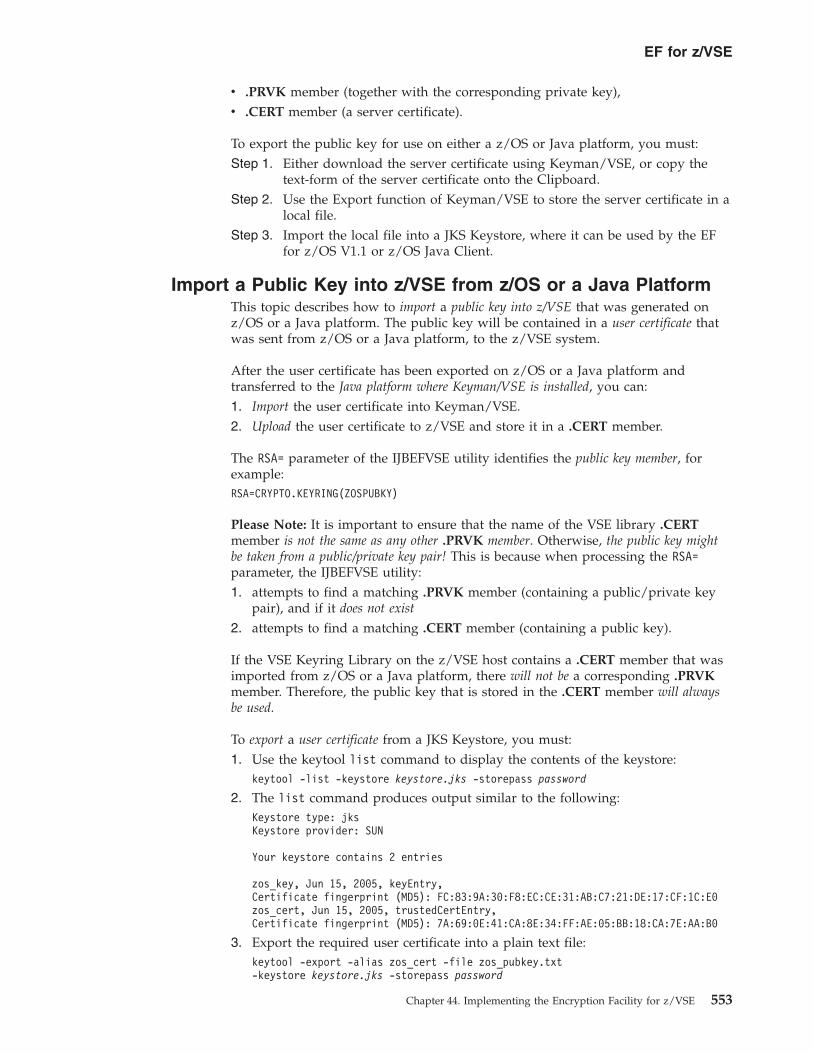
v .PRVK member (together with the corresponding private key),v .CERT member (a server certificate).
To export the public key for use on either a z/OS or Java platform, you must:Step 1. Either download the server certificate using Keyman/VSE, or copy the
text-form of the server certificate onto the Clipboard.Step 2. Use the Export function of Keyman/VSE to store the server certificate in a
local file.Step 3. Import the local file into a JKS Keystore, where it can be used by the EF
for z/OS V1.1 or z/OS Java Client.
Import a Public Key into z/VSE from z/OS or a Java PlatformThis topic describes how to import a public key into z/VSE that was generated onz/OS or a Java platform. The public key will be contained in a user certificate thatwas sent from z/OS or a Java platform, to the z/VSE system.
After the user certificate has been exported on z/OS or a Java platform andtransferred to the Java platform where Keyman/VSE is installed, you can:1. Import the user certificate into Keyman/VSE.2. Upload the user certificate to z/VSE and store it in a .CERT member.
The RSA= parameter of the IJBEFVSE utility identifies the public key member, forexample:RSA=CRYPTO.KEYRING(ZOSPUBKY)
Please Note: It is important to ensure that the name of the VSE library .CERTmember is not the same as any other .PRVK member. Otherwise, the public key mightbe taken from a public/private key pair! This is because when processing the RSA=parameter, the IJBEFVSE utility:1. attempts to find a matching .PRVK member (containing a public/private key
pair), and if it does not exist
2. attempts to find a matching .CERT member (containing a public key).
If the VSE Keyring Library on the z/VSE host contains a .CERT member that wasimported from z/OS or a Java platform, there will not be a corresponding .PRVKmember. Therefore, the public key that is stored in the .CERT member will alwaysbe used.
To export a user certificate from a JKS Keystore, you must:1. Use the keytool list command to display the contents of the keystore:
keytool -list -keystore keystore.jks -storepass password
2. The list command produces output similar to the following:Keystore type: jksKeystore provider: SUN
Your keystore contains 2 entries
zos_key, Jun 15, 2005, keyEntry,Certificate fingerprint (MD5): FC:83:9A:30:F8:EC:CE:31:AB:C7:21:DE:17:CF:1C:E0zos_cert, Jun 15, 2005, trustedCertEntry,Certificate fingerprint (MD5): 7A:69:0E:41:CA:8E:34:FF:AE:05:BB:18:CA:7E:AA:B0
3. Export the required user certificate into a plain text file:keytool -export -alias zos_cert -file zos_pubkey.txt-keystore keystore.jks -storepass password
EF for z/VSE
Chapter 44. Implementing the Encryption Facility for z/VSE 553

4. Import the user certificate into Keyman/VSE, and upload it to your z/VSEsystem.
Invoking the IJBEFVSE UtilityThis topic describes the:v syntax of the IJBEFVSE utility,v control statements that can be used with the IJBEFVSE utility,v rules for specifying file names when using the CLRFILE and ENCFILE control
statements,v rules for specifying record formats.v jobs must include these statements:
// EXEC IJBEFVSE [,PARM=’[SYSLST=DD:SYSnnn] [DEBUG]’]control statements
.../*
where:
SYSLST=DD:SYSnnnOptional. Specifies a logical unit to-which the listing should be written(for example SYSLST=DD:SYS004)
DEBUGOptional. Enables debugging (messages will be sent to SYSLST and tothe console).
control statementsDetails are given in Table 23. Control statements are passed via SYSIPT.
Table 23 lists the control statements you can use with the IJBEFVSE utility. If youspecify the same control statement more than once, only the last specification willbe used. All control statements are passed via SYSIPT.
Table 23. Control Statements Used With the IJBEFVSE Utility
Statement Explanation
DESC='text' Optional, and only used for encryption processing.
Specifies 1 to 64 EBCDIC character bytes of descriptive text to be placed in the headerrecord. IJBEFVSE places the text in the header record. The text is used to assist inidentifying the source of the encrypted data in the output.v You must enclose the text in single quotation marks.v Imbedded blanks are allowed.v All text must be included on one control statement line.
CLRTDES Only used for encryption processing. For decrypting, this information is contained inthe header of the encrypted file.
Specifies that the input file is to be encrypted with a clear TDES triple-length key.
CLRAES128 Only used for encryption processing. For decrypting, this information is contained inthe header of the encrypted file.
Specifies that the input file is to be encrypted with a clear 128-bit AES key.
COMPRESSION=NO|YES Specifies whether you want compression of the clear input before encryption of thedata occurs:v COMPRESSION=NO indicates that compression does not occur.v COMPRESSION=YES causes compression to be performed before encryption.v If you do not specify the COMPRESSION keyword, the default is NO.
EF for z/VSE
554 z/VSE V4R3.0 Administration

Table 23. Control Statements Used With the IJBEFVSE Utility (continued)
Statement Explanation
ENCTDES Not supported by z/VSE. In z/OS, ENCTDES specifies that the input file is to beencrypted with a secure TDES triple-length key. Only used for encryption processing.For decrypting, this information is contained in the header of the encrypted file.
RSA=label Specifies the 64-byte label of an existing RSA private/public key pair that is present inthe VSE Keyring library (for example, CRYPTO.KEYRING). The program uses this keyto encrypt the data encryption key. When you decrypt the data, the RSA key must bepresent at the recovery site.
In z/VSE, this parameter specifies the 8 character name of the private key member inthe keyring library. The member name is specified as follows:v lib.slib(member) – including name of keyring library, wherev member – the default keyring library is used (KEYRING.LIBRARY)
To encrypt data, you can use up to 16 RSA= keywords to specify up to 16 public-keylabels. Depending on the number of multiple RSA labels, you can send the encryptedfile to up to 16 individual recipients.
The RSA keyword is optional when:v you decrypt data that is encrypted with a single RSA= control statement, orv the RSA private key label is the same as the RSA public key label used to protect
the data-encrypting key.
This is because the RSA key label is stored in the header record.
For data encrypted with multiple RSA= control statements, you must specify one singleRSA keyword for decryption. Decryption does not allow multiple RSA keywords. Fordetails, see “Example: Use Multiple RSA Control Statements for Multiple RemoteSystems” on page 569.
PASSWORD=pwd Specifies the 8- to 32- EBCDIC character password to be used to generate:v a clear TDES triple-length key, orv a clear 128-bit AES key.
Leading and trailing blanks and tab characters are removed; imbedded blanks and tabcharacters are allowed. Passwords are case sensitive.
In order to minimize problems caused by code-page differences at the encrypting anddecrypting sites, IBM suggests you use only the upper and lower-case letters Athrough Z, numerals 0 – 9, and the underscore character (_).
ICOUNT=nnnnn Only used for encryption processing. For decrypting, this information is contained inthe header of the encrypted file.
When you specify a password, ICOUNT specifies the number of iterations that theSHA-1 hash algorithm is to be performed in the generation of the data key and theinitial chaining vector (ICV) for encryption. nnnnn is an integer between 1 and 10,000.
If you do not specify ICOUNT, the default is 16.
ICOUNT allows you to strengthen security when you use PASSWORD. If you specifya robust password (specifying 32 random characters), the default is sufficiently secure.
COMPRESSION=NO|YES Compression is not supported by z/VSE. Therefore, only COMPRESSION=NO isaccepted. This parameter can only be used for encryption processing on a z/OS system.
z/VSE cannot decrypt datasets that were compressed prior to encryption!
EF for z/VSE
Chapter 44. Implementing the Encryption Facility for z/VSE 555
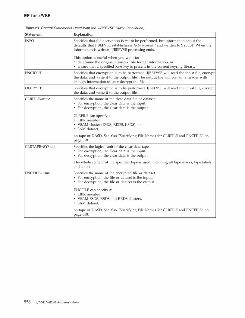
Table 23. Control Statements Used With the IJBEFVSE Utility (continued)
Statement Explanation
INFO Specifies that file decryption is not to be performed, but information about thedefaults that IJBEFVSE establishes is to be recovered and written to SYSLST. When theinformation is written, IJBEFVSE processing ends.
This option is useful when you want to:v determine the original clear-text file format information, orv ensure that a specified RSA key is present in the current keyring library.
ENCRYPT Specifies that encryption is to be performed. IJBEFVSE will read the input file, encryptthe data, and write it to the output file. The output file will contain a header withenough information to later decrypt the file.
DECRYPT Specifies that decryption is to be performed. IJBEFVSE will read the input file, decryptthe data, and write it to the output file.
CLRFILE=name Specifies the name of the clear-data file or dataset:v For encryption, the clear data is the input.v For decryption, the clear data is the output.
CLRFILE can specify a:v LIBR member,v VSAM cluster (ESDS, RRDS, KSDS), orv SAM dataset,
on tape or DASD. See also “Specifying File Names for CLRFILE and ENCFILE” onpage 558.
CLRTAPE=SYSnnn Specifies the logical unit of the clear-data tape.v For encryption, the clear data is the input.v For decryption, the clear data is the output.
The whole content of the specified tape is used, including all tape marks, tape labelsand so on.
ENCFILE=name Specifies the name of the encrypted file or dataset.v For encryption, the file or dataset is the input.v For decryption, the file or dataset is the output.
ENCFILE can specify a:v LIBR member,v VSAM ESDS, KSDS and RRDS clusters,v SAM dataset,
on tape or DASD. See also “Specifying File Names for CLRFILE and ENCFILE” onpage 558.
EF for z/VSE
556 z/VSE V4R3.0 Administration

Table 23. Control Statements Used With the IJBEFVSE Utility (continued)
Statement Explanation
RECFM=n Specifies the record format of the CLRFILE. For VSAM clusters and LIBR membersthis parameter is not required, since the format information is read from the VSAMcatalog or Library. For SAM datasets on tape or DASD this parameter is required.
Valid values are:v F – fixedv V – variablev B – blockedv S – spannedv U – undefinedv FB – fixed blockedv FBS – fixed blocked spannedv VB – variable blockedv VBS – variable blocked spanned
In addition to the above formats, you can add an:v A (ASA print-control characters), orv M (machine print-control characters).
When decrypting, the RECFM information is contained in the header of the encryptedfile. If used with the IGNOREHEADER option, the settings in the header can beoverruled.
For further details about supported records formats and defaults, refer to:v “Record, Block, and Control Interval” in the z/VSE System Macros User's Guide,
SC33-8407, andv “Record Formats” in the LE/VSE C Run-Time Programming Guide, SC33-6688.
LRECL=nnn Specifies the logical record length of the CLRFILE. For VSAM clusters and LIBRmembers this parameter is not required, since the record length information is readfrom the VSAM catalog or Library. For SAM datasets on tape or DASD, thisparameter is required.
When specifying LRECL, you must also specify the RECFM control statement. Whendecrypting, this information is contained in the header of the encrypted file. If usedwith the IGNOREHEADER option, the settings in the header can be overruled.
For further details about supported records formats and defaults, refer to:v “Record, Block, and Control Interval” in the z/VSE System Macros User's Guide,
SC33-8407, andv “Record Formats” in the LE/VSE C Run-Time Programming Guide, SC33-6688.
BLKSIZE=nnn Specifies the bloc size of the CLRFILE. For VSAM clusters and LIBR members thisparameter is not required, since the record length information is read from the VSAMcatalog or Library. For SAM datasets on tape or DASD this parameter is required.
When specifying BLKSIZE, you must also specify the RECFM control statement. Whendecrypting, this information is contained in the header of the encrypted file. If usedwith the IGNOREHEADER option, the settings in the header can be overruled.
For further details about supported records formats and defaults, refer to:v “Record, Block, and Control Interval” in the z/VSE System Macros User's Guide,
SC33-8407, andv “Record Formats” in the LE/VSE C Run-Time Programming Guide, SC33-6688.
IGNOREHEADER Only used for decryption processing. Specifies that the record format, logical recordlength, and block size specifications in the header of ENCFILE should not be used.
Instead, the specifications from the RECFM, LRECL and BLKSIZE control statementsare used. This option is useful when you want to restore an encrypted file into a fileor dataset with different record formats and lengths.
EF for z/VSE
Chapter 44. Implementing the Encryption Facility for z/VSE 557

Table 23. Control Statements Used With the IJBEFVSE Utility (continued)
Statement Explanation
APPEND Only used for decryption processing. Specifies that the CLRFILE is to be opened forappend. Useful for existing VSAM clusters that have not been defined withREUSE=YES.
CODEPAGE=nnnn Specifies the EBCDIC codepage used for SYSIPT input. This codepage is importantwhen specifying the password. Special characters (such as '@') are on different codepoints in different codepages. Default is IBM-1047. The codepage statement mustappear before the PASSWORD=nnn control statement.
Deciding Whether or Not to Use Data CompressionIf you have to archive large amounts of encrypted data, you might wish tocompress the data. For example, compressing the data might help to reduce thenumber of tape volumes you require.
Because encrypted data is not very compressible, you might use theCOMPRESSION option (described in Table 23 on page 554) to compress data beforeencryption is performed.
If you plan to use the z/OS Java Client to decrypt data, please note that the z/OSJava Client cannot decrypt data that was compressed using the IJBEFVSE program.
Specifying File Names for CLRFILE and ENCFILENotes:
1. The CLRFILE parameter is used when decrypting a complete tape.2. The ENCFILE parameter is used when encrypting a complete tape.3. For details of CLRFILE and ENCFILE, see Table 23 on page 554.
The following rules apply for specifying file names with the CLRFILE andENCFILE control statements.
File names for LIBR membersDD:<library>.<sub-library>(<member>.<type>) For example:DD:PRIMARY.SYSA(MYFILE.TXT)
File names for VSAM clustersDD:<dlbl> The specified DLBL must be present in the system standard,class or partition label area and must point to an existing VSAM cluster.Please note that VRDS clusters are not supported. ENCFILE only acceptsVSAM ESDS clusters. CLRFILE accepts ESDS, KSDS and RRDS clusters.For exampleDD:VSAMCLU
File names for SAM datasets on tapeDD:<lu>-<tlbl> or DD:<lu> The LU specifies a logical unit in the formSYSnnn. A tape must be assigned to this LU. If the TLBL (tape label) isspecified (concatenated by a dash), a labeled tape file will be opened. IfTLBL is not specified, an unlabeled tape file is opened. The specified TLBLmust be present in the system standard, class or partition label area.Multivolume files and multiple files on a volume are supported. ForexampleDD:SYS004-TAPEFIL
EF for z/VSE
558 z/VSE V4R3.0 Administration
File names for SAM datasets on DASDThe specified DLBL must be present in the system standard, class orpartition label area. EXTENT information must be also present via a DLBL.For exampleDD:<dlbl>
Specifying File Attributes and Record FormatsWhen encrypting data on z/VSE, you must pass the file attributes of the clear data tothe IJBEFVSE utility. If you are encrypting a VSAM file or a library member, thefile attributes will be known by the VSAM Catalog or the Library.
If you are encrypting datasets on DASD or tape, the file attributes are not known.Therefore, you must specify the file attributes when you invoke the IJBEFVSEutility. To do so, you use the control statements RECFM, LRECL and BLKSIZE(described in Table 23 on page 554 and Table 27 on page 585):v The statements RECFM, LRECL and BLKSIZE might be dependent on each
other: for example, if you are using a blocked format then you must specifyBLKSIZE.
v The IJBEFVSE utility stores the file attributes in the header record of theencrypted dataset.
v If you specify file attributes for VSAM files or library members that do not matchthe attributes in the catalog or Library, a warning message will be written toSYSLST and the file attributes from the catalog or library will be used.
v If you specify incorrect record formats, z/VSE's Basic Access Method might cancelthe IJBEFVSE utility. For further details about record formats, refer to:– “Record, Block, and Control Interval” in the z/VSE System Macros User's Guide,
SC33-8407, and– “Record Formats” in the LE/VSE C Run-Time Programming Guide, SC33-6688.
When decrypting data on z/VSE, the file attributes of the clear data are contained inthe header record (described in “Layout of Header-Record of Encrypted Dataset” onpage 560) of the encrypted dataset:v You can use the INFO option to display the file attributes stored in the header.v When decrypting into a dataset on DASD or tape, the information from the
header is used to create the dataset.v When decrypting into a VSAM file or library member, the file attributes may
conflict with the file attributes that are stored in the catalog or Library. In thiscase, the attributes form the catalog or Library will be used and an appropriatewarning message will be written to SYSLST.
v You can override the attributes stored in the header by using theIGNOREHEADER control statement (described in Table 23 on page 554). Duringthis process, the file attributes from the header will be ignored. You musttherefore specify these attributes using the control statements RECFM, LRECLand BLKSIZE (described in Table 23 on page 554).
v The statements RECFM, LRECL and BLKSIZE may be dependent on each other:for example, you must specify BLKSIZE if you are using a blocked format.
v When decrypting into a VSAM file or library member, no specifications arerequired, since they are taken from the catalog or library.
EF for z/VSE
Chapter 44. Implementing the Encryption Facility for z/VSE 559

Encrypting and Exchanging Record-Based DataThis topic describes how you can:v encrypt/decrypt record-based data.v exchange encrypted record-based data with other operating-system platforms.
You are more likely to need to encrypt record-based data than JPEG data (whichwas described in previous topics, and which does not have a record structure).
See also “Known Problems When Encrypting and Exchanging Data” on page 577.
Types of Data That Might Need to be EncryptedThese are the types of data that you might need to encrypt, and which affect theencryption actions you must take:
Stream-based dataBinary data without any internal structure. Its representation on differentplatforms is exactly the same. However, there might be some difference inthe underlying file systems:v On workstation platforms we have flat files without any record structure.v On z/VSE platforms, we have VSAM files in which a binary stream might
be split into multiple records according to internal VSAM logic.
Line-based dataThe simplest example of line-based data is a plain-text file with line-breakcharacters. On ASCII platforms, there is a CRLF sequence (X'0D0A') at theend of each line. On EBCDIC platforms, lines are split by a new-linecharacter (X'15').
Note: All lines are explicitly separated by line breaks.
Record-based dataRecord-based data is stored in files that contain logical records withoutline-break characters. For example:v A VSAM file consists of record-based data in which each logical data
record is stored in one physical record of the VSAM file.v A CMS file in z/VM contains data records whose lengths are given by
the record length of the CMS file.
You should also be aware that if you use the z/OS Java Client to encrypt anEBCDIC encoded data file on z/OS, when you decrypt on z/VSE the clear-filecontents will be restored in EBCDIC-readable form. However:v If you decrypt the file on an ASCII platform (such as on a Windows PC), the
decrypted data will still be encoded in EBCDIC.v There is no option provided in which you could specify a character set that
might be used when decrypting textual data.
Layout of Header-Record of Encrypted DatasetThe encrypted data that is produced by the IJBEFVSE utility (as well as by the EFfor z/OS) includes a header record. This record contains the information you requirein order to decrypt the data on a:v mainframe, orv workstation running the z/OS Java Client.
EF for z/VSE
560 z/VSE V4R3.0 Administration

Table 24 shows the layout of the header record.
Table 24. Layout of Header Record That is Included in Encrypted Data
Offset(Decimal)
Name of HeaderField
Type ofData
Description
0 HEADER_EYE Character An eye-catcher: “HEADER” in EBCDIC
6 HDR_VERSION Character Version of the header record for Encryption Facility.
8 HDR_DESC Character EBCDIC description (DESC keyword) of encrypted data.
72 HDRLEN Integer Length of entire header record (integer format).
76 HDRSALT Character 8-byte field (salt value) used with password.
84 HDRICNT Integer Iteration count (ICOUNT keyword), integer format from 1 to 10,000to be used with password.
88 HDRKEYLN Character Modulus length (hexadecimal format from 512 ... 2048) in bits of theRSA public/private key taken from the RSA keyword information.
90 HDRRSA Character Pathname of the PRVK or CERT member containing the RSApublic/private key in the format lib.sublib(membername)
154 HDRICV Character Initialization chaining vector to be used with encryption/decryption.
170 Reserved for IBM use.
174 HDAESDES Bit Type of key to be used to encrypt/decrypt data:v X'01' use a clear TDES triple.length key.v X'02' use a clear 128-bit AES key.v X'03' use a secure TDES triple-length key.
175 HDRFLAGS Bit Bit string that indicates type of output, compression options, andformat of encrypted data:v Bit 0 = 1: unused.v Bit 1 = 1: indicates output data compressed .v Bit 2 = 1: indicates compression dictionary is present in the
encrypted data.v Bit 3 = 1: indicates clear data is binary.v Bit 3 = 0: indicates clear data is text (not used by z/VSE).
176 HDR_COMPVER Character Version of Encryption Facility compression used.
178 HDRIRECF Bit Input file record format:v Bit 0 = 1, Bit 1 = 0: Fixed.v Bit 0 = 0, Bit 1 = 1: Variable.v Bit 0 = 1, Bit 1 = 1: Undefined.v Bit 3 = 1: Blocked records.v Bit 5 = 1: ASA control character.v Bit 6 = 1: Machine control character.
179 HDRIRECL Integer Input file logical record length.
181 HDRIBLKS Integer Input file block size.
185 HDRORECF Bit Output file record format:v Bit 0 = 1, Bit 1 = 0: Fixed.v Bit 0 = 0, Bit 1 = 1: Variable.v Bit 0 = 1, Bit 1 = 1: Undefined.v Bit 3 = 1: Blocked records.v Bit 5 = 1: ASA control character.v Bit 6 = 1: Machine control character.
186 HDRORECL Integer Length of output file logical record.
188 HDROBLKS Integer Output file block size.
192 HDR_KEYVAL Integer Encrypted data-encryption key.
448 Reserved for IBM use.
EF for z/VSE
Chapter 44. Implementing the Encryption Facility for z/VSE 561

Table 24. Layout of Header Record That is Included in Encrypted Data (continued)
Offset(Decimal)
Name of HeaderField
Type ofData
Description
464 HDR_RSA_CNT Integer Applies only when the “HEADER” is version X'0002' or greater:Number of RSA= control statements.
468 HDR_RSA Character Applies only when the “HEADER” is version X'0002' or greater:An array consisting of information for multiple RSA= controlstatements. The length is variable based on the number of RSA=control statements, with each entry 344 bytes in length.
HDR_RSA_LAB Character An element of HDR_RSA consisting of a 64-byte label of one of theRSA public/private keys, that is, the pathname of the PRVK orCERT member containing the RSA public/private key in the formatlib.sublib(membername).
532 HDR_KEY_LN Character An element of HDR_RSA consisting of Modulus length (hexadecimalformat from 512 - 2048) in bits of the RSA public/private key in thisentry.
534 Character Two-byte placeholder of HDR_RSA.
536 HDR_KEY_VAL Character An element of HDR_RSA consisting of the hexadecimal encrypteddata-encrypting key. This value is encrypted by the RSA key in thisentry.
792 HDR_RSA_TAG Character An element of HDR_RSA consisting of a hexadecimal value used forvalidation.
812 End of Header record or begin of another HDR_RSA element.
Tape Format Used by the IJBEFVSE UtilityIf you use the IDCAMS utility to backup a dataset to tape, the backup creates:v two or more tape files,v tape marks.
However, a dataset stored on a tape consists of:v one tape file, followed byv one tape mark.
In both of the above cases, a tape label (TLBL) might precede the data on tape.
The IJBEFVSE utility always creates encrypted datasets that consist of:v a header record,v the encrypted data.
These encrypted datasets are BAM (Basic Access Method) datasets that can bestored on either on disk or tape.
The clear data to be encrypted can be either:v a dataset (VSE library member, a VSAM file, a SAM file on DASD or tape), orv a complete tape that was created using any proprietary backup process.
Before the encryption is performed, the IJBEFVSE utility internally converts tapedata into AWSTAPE format. This means that an encrypted tape can be:v decrypted into a dataset.v further processed as a standard AWSTAPE on all platforms.v decrypted into the original tape format on a physical tape or Virtual Tape.
EF for z/VSE
562 z/VSE V4R3.0 Administration

Situations Where an Encrypted Dataset Does Not Fit on a TapeIn general, an encrypted dataset can reside on disk or tape. If using tapes, in somecases an encrypted dataset (for example, an IDCAMS backup) will not fit on onesingle tape. Furthermore, an encrypted dataset is always larger than the originalclear dataset because of the space required for the header structure and someinternal control information.
Although tape devices usually compress data internally, this data-compression willnot work as well for encrypted data as it does for clear data.
If the non-encrypted data does not fit on one tape, you will probably have createdmultiple volumes of non-encrypted data. For example, the IDCAMS backupprocess might have requested a second tape to be mounted because the first tape isfull. As a result, you now have two or more non-encrypted backup tapes:v The IJBEFVSE utility will now encrypt each clear tape in a separate step.v Because each clear tape is full and because of the increase in size, you will
probably need two encrypted tapes per clear tape.
If the non-encrypted data does fit on one tape but the encrypted data exceeds onetape because of its overhead, the encrypted dataset is probably a SAM file:v SAM will ask for a second tape when IJBEFVSE utility reaches the end-of-tape.v This is normal behavior when writing multi-volume datasets.
Using Virtual Tapes as Intermediate StorageYou can use virtual tapes to store the intermediate clear data, before the finalencrypted data is written to physical tapes.
However, when using virtual tapes in VSAM the maximum tape-image size islimited to 4 GB (because of the size limit of a VSAM ESDS cluster).
Alternatively, you can use a VTAPE on a remote platform, such as Linux on Systemz. In this case, the remote AWSTAPE file:v has no size limitation,v can be easily deleted after creating the encrypted backup.
Messages Generated by the IJBEFVSE UtilityThe IJBEFVSE utility writes to SYSLST:v Informational messagesv Warning messagesv Error messagesv Statistics
During the encryption of a clear tape and after reading past theEND_OF_VOLUME of the input tape, this message is sent to the console:F8 0014 0P36I P NO REC FND SYS005=480
CCSW=0200700CA80200FFFF CCB=700C80SNS= 08402031 00002420 00000000 00000000 00000088 04020202
020200F0 000000FF
v This occurs because the IJBEFVSE utility has no other method of determiningthe END_OF_VOLUME.
EF for z/VSE
Chapter 44. Implementing the Encryption Facility for z/VSE 563

v This situation is internally handled and you can ignore it.v It is not relevant whether:
– the tape has been used previously, or– data from a previous write-process is still stored on the tape after the current
data.
Examples of Using the IJBEFVSE UtilityThis topic provides you with practical examples of how to perform the encryptionof tapes, disks, files, and volumes using the IJBEFVSE utility.
For examples of how to perform the encryption of tapes, disks, files, and volumesusing the IJBEFPGP utility, see “Examples of Using the IJBEFPGP Utility” on page603.
Example: Encrypt a VSE Library Member into a VSAM FileThis example uses passphrase-based encryption. The job below encrypts the specifiedVSE library member and creates an encrypted VSAM dataset. You can use ESDS,RRDS, and KSDS clusters for clear datasets. Only ESDS clusters can be used forencrypted datasets. For explanations of the control statements used here, seeTable 23 on page 554.* $$ JOB JNM=ENCMEM,CLASS=0,DISP=D// JOB ENCMEM// LIBDEF *,SEARCH=(PRD2.SCEEBASE,PRD2.PROD,PRD2.DBASE)// EXEC IJBEFVSEENCRYPTDESC=’ENCRYPTION TEST’CLRTDESPASSWORD=MYPASSWDICOUNT=233CLRFILE=DD:PRD2.CONFIG(PICTURE.JPG)ENCFILE=DD:ENCDATA/*/&* $$ EOJ
The job below decrypts the encrypted VSAM dataset. Note that algorithm anditeration count need not to be specified, because they are contained in the headerof the encrypted dataset. Also DESC is applicable only for encryption. Thespecified descriptive text is contained in the header of the encrypted dataset.* $$ JOB JNM=DECMEM,CLASS=0,DISP=D// JOB DECMEM// LIBDEF *,SEARCH=(PRD2.SCEEBASE,PRD2.PROD,PRD2.DBASE)// EXEC IJBEFVSEDECRYPTPASSWORD=MYPASSWDCLRFILE=DD:PRD2.CONFIG(PICTURE.JPG)ENCFILE=DD:ENCDATA/*/&* $$ EOJ
Example: Create an Encrypted VSAM FileThis example uses passphrase-based encryption. The job below encrypts a VSAM file.For explanations of the control statements used here, see Table 23 on page 554.* $$ JOB JNM=ENCVSAM,CLASS=0,DISP=D// JOB ENCVSAM// LIBDEF *,SEARCH=(PRD2.SCEEBASE,PRD2.PROD,PRD2.DBASE)
EF for z/VSE
564 z/VSE V4R3.0 Administration

// EXEC IJBEFVSEENCRYPTDESC=’ENCRYPTION TEST’CLRAES128PASSWORD=MYPASSWDICOUNT=233CLRFILE=DD:CLRDATAENCFILE=DD:ENCDATA/*/&* $$ EOJ
The job below decrypts the encrypted VSAM file:* $$ JOB JNM=DECVSAM,CLASS=4,DISP=D// JOB DECVSAM// LIBDEF *,SEARCH=(PRD2.SCEEBASE,PRD2.PROD,PRD2.DBASE)// EXEC IJBEFVSEDECRYPTPASSWORD=MYPASSWDCLRFILE=DD:CLRDATAENCFILE=DD:ENCDATA/*/&* $$ EOJ
Example: Encrypt a VSE Library Member and Store on VirtualTape
This example uses passphrase-based encryption. The job below encrypts a VSE librarymember, and then stores the encrypted file on a virtual tape. For explanations ofthe control statements used here, see Table 23 on page 554.* $$ JOB JNM=ENCRYPT,CLASS=0,DISP=D// JOB ENCRYPT// LIBDEF *,SEARCH=(PRD2.SCEEBASE,PRD2.PROD,PRD2.DBASE)VTAPE START,UNIT=480,LOC=VSAM,FILE=’VTAPE1’MTC REW,480// ASSGN SYS006,480// TLBL OUTFILE,’ENCRYPTED.DATA’// EXEC IJBEFVSE,PARM=’DEBUG’ENCRYPTDESC=’ENCRYPTION TEST’CLRTDESPASSWORD=MYPASSWDICOUNT=100CLRFILE=DD:PRD2.CONFIG(TEST01.TXT)ENCFILE=DD:SYS006-OUTFILE/*// ASSGN SYS006,UAVTAPE STOP,UNIT=480/&* $$ EOJ
The job below uses a VTAPE which is located on a remote workstation. Thisrequires the Virtual Tape Server running on the workstation. The Virtual TapeServer is a Java application that can be downloaded from the z/VSE Homepage(whose URL is given in “Where to Find More Information” on page xxiii).* $$ JOB JNM=ENCRMV,DISP=D,CLASS=0,USER=FOERY// JOB ENCRMV// LIBDEF *,SEARCH=(PRD2.SCEEBASE,PRD2.PROD,PRD2.DBASE)VTAPE START,UNIT=480,LOC=9.152.216.57,FILE=’ENCRMV’MTC REW,480// ASSGN SYS006,480// TLBL OUTFILE,’ENCRMV.DATA’
EF for z/VSE
Chapter 44. Implementing the Encryption Facility for z/VSE 565

// EXEC IJBEFVSEENCRYPTDESC=’ENCRMV TEST’CLRTDESPASSWORD=MYPASSWDICOUNT=123CLRFILE=DD:PRD2.CONFIG(MYMEMB.Z)ENCFILE=DD:SYS006-OUTFILE/*// ASSGN SYS006,UAVTAPE STOP,UNIT=480/&* $$ EOJ
The job below reads the remote VTAPE and writes the decrypted data back to theoriginal VSE library member.* $$ JOB JNM=DECRMV,DISP=D,CLASS=0,USER=FOERY// JOB DECRMV// LIBDEF *,SEARCH=(PRD2.SCEEBASE,PRD2.PROD,PRD2.DBASE)VTAPE START,UNIT=480,LOC=9.152.216.57,FILE=’ENCRMV’,READMTC REW,480// ASSGN SYS006,480// TLBL INFILE,’ENCRMV.DATA’// EXEC IJBEFVSEDECRYPTPASSWORD=MYPASSWDCLRFILE=DD:PRD2.CONFIG(MYMEMB.Z)ENCFILE=DD:SYS006-INFILE/*// ASSGN SYS006,UAVTAPE STOP,UNIT=480/&* $$ EOJ
Example: Create an Encrypted IDCAMS Backup on TapeThis example uses passphrase-based encryption. For explanations of the controlstatements used here, see Table 23 on page 554. The creation of an encryptedbackup from an IDCAMS backup tape requires three steps:Step 1. Write the IDCAMS backup to a physical tape or Virtual Tape.Step 2. Run the IJBEFVSE utility against the backup tape, and create an encrypted
tape or dataset.Step 3. Erase the clear IDCAMS backup tape, delete the related VSAM file, or
overwrite it with zeros or random data.
The following JCL shows steps 1 and 2.* $$ JOB JNM=BKUPVTAP,CLASS=0,DISP=D* $$ LST DISP=D,CLASS=A,RBS=100* ********************************************************************* STEP 1: CREATE IDCAMS BACKUP TO VTAPE* ********************************************************************// JOB BKUPVTAP BACKUP VSAM TO VTAPEVTAPE START,UNIT=480,LOC=VSAM,FILE=’VTAPE1’MTC REW,480// ASSGN SYS005,480// TLBL INFILE,’BACKUP.FILE’// DLBL IJSYSCT,’VSAM.MASTER.CATALOG’,,VSAM// EXEC IDCAMS,SIZE=AUTO
BACKUP (CALC.KSDS CALC.ESDS -PAYROLL.CONTROL.FILE1/MPWD1 -PAYROLL.FILE.BRANCH01/MPWD2 -
) -BUFFERS(4) -BLOCKSIZE(32758) -
EF for z/VSE
566 z/VSE V4R3.0 Administration

STDLABEL(INFILE) –REWIND
/** ********************************************************************* STEP 2: CREATE ENCRYPTED BACKUP TAPE* ********************************************************************// LIBDEF *,SEARCH=(PRD2.SCEEBASE,PRD2.PROD,PRD2.DBASE)VTAPE START,UNIT=481,LOC=VSAM,FILE=’VTAPE2’MTC REW,480// ASSGN SYS006,481// TLBL OUTFILE,’ENCRYPTED.BACKUP’// EXEC IJBEFVSE,PARM=’DEBUG’ENCRYPTDESC=’ENCRYPTION TEST’CLRTDESPASSWORD=MYPASSWDICOUNT=100CLRTAPE=SYS005ENCFILE=DD:SYS006-OUTFILE/*// ASSGN SYS005,UA// ASSGN SYS006,UAVTAPE STOP,UNIT=480VTAPE STOP,UNIT=481/&* $$ EOJ
Note: if you are using a VSAM Virtual Tape, as shown in this example, its size islimited to 4 GB. This is due to the limitation of the underlying VSAM ESDSfile.
Example: Restore/Decrypt an Encrypted IDCAMS Backup fromTape
This example uses passphrase-based encryption. The restore/decrypt of an encryptedbackup from tape (for example IDCAMS, but also any other proprietary backup)results in the creation of the original tape. This can be used with the relatedproprietary restore function. For explanations of the control statements used here,see Table 23 on page 554.* $$ JOB JNM=RESTVSAM,CLASS=4,DISP=D// JOB RESTVSAM RESTORE ENCRYPTED BACKUP FROM VTAPE* ********************************************************************* STEP 1: DECRYPT BACKUP VTAPE* ********************************************************************// LIBDEF *,SEARCH=(PRD2.SCEEBASE,PRD2.PROD,PRD2.DBASE)VTAPE START,UNIT=480,LOC=VSAM,FILE=’VTAPE1’VTAPE START,UNIT=481,LOC=VSAM,FILE=’VTAPE2’// ASSGN SYS005,480// ASSGN SYS006,481// TLBL OUTFILE,’ENCRYPTED.BACKUP’// EXEC IJBEFVSEDECRYPTPASSWORD=MYPASSWDCLRTAPE=SYS005ENCFILE=DD:SYS006-OUTFILE/** ********************************************************************* STEP 2: RESTORE CLEAR IDCAMS BACKUP FROM VTAPE* ********************************************************************// TLBL INFILE,’BACKUP.FILE’// DLBL IJSYSCT,’VSAM.MASTER.CATALOG’,,VSAMMTC REW,480// EXEC IDCAMS,SIZE=AUTO
RESTORE OBJECTS((AIX.CALC.KSDS) -
EF for z/VSE
Chapter 44. Implementing the Encryption Facility for z/VSE 567

(PAYROLL.CONTROL.FILE1/MPWD1)) -) -BUFFERS(4) -STDLABEL(INFILE)
/*// ASSGN SYS005,UA// ASSGN SYS006,UAVTAPE STOP,UNIT=480VTAPE STOP,UNIT=481/&* $$ EOJ
Example: Restore/Decrypt an Encrypted IDCAMS Backup to aDataset
This example uses passphrase-based encryption. If an encrypted backup tape isrestored/decrypted to a clear dataset, the resulting clear dataset will be in AWSTAPEformat. For explanations of the control statements used here, see Table 23 on page554.* $$ JOB JNM=DECRYPT,CLASS=4,DISP=D// JOB DECRYPT// LIBDEF *,SEARCH=(PRD2.SCEEBASE,PRD2.PROD,PRD2.DBASE)VTAPE START,UNIT=480,LOC=VSAM,FILE=’VTAPE1’MTC REW,480// ASSGN SYS006,480// TLBL OUTFILE,’ENCRYPTED.DATA’// EXEC IJBEFVSE,PARM=’DEBUG’DECRYPTPASSWORD=MYPASSWDCLRFILE=DD:CLRDATAENCFILE=DD:SYS006-OUTFILE/*// ASSGN SYS006,UAVTAPE STOP,UNIT=480/&* $$ EOJ
Example: Encrypt a Library Member Using Public-KeyEncryption
This example uses public-key encryption. In this job, the RSA parameter points to aVSE library member CEX2TEST.PRVK which contains the RSA key pair used towrap the data key. The data key is randomly created, and then used to encrypt thedata. For further information about creating RSA key pairs, see “Configuring forServer Authentication Using Self-Signed Certificates” on page 497. For explanationsof the control statements used here, see Table 23 on page 554.* $$ JOB JNM=ENCMEMB,CLASS=4,DISP=D// JOB ENCMEMB ENCRYPT LIB MEMBER// LIBDEF *,SEARCH=(PRD2.SCEEBASE,PRD2.PROD,PRD2.DBASE)VTAPE START,UNIT=480,LOC=VSAM,FILE=’VTAPE1’MTC REW,480// ASSGN SYS006,480// TLBL OUTFILE,’ENCRYPTED.DATA’// EXEC IJBEFVSE,PARM=’DEBUG’ENCRYPTDESC=’ENCRYPTION TEST’CLRTDESRSA=CRYPTO.KEYRING(CEX2TEST)CLRFILE=DD:PRIMARY.JSCH(IESMODEL.Z)ENCFILE=DD:SYS006-OUTFILE/*
EF for z/VSE
568 z/VSE V4R3.0 Administration

// ASSGN SYS006,UAVTAPE STOP,UNIT=480/&* $$ EOJ
Example: Decrypt a Tape That was Encrypted UsingPublic-Key Encryption
This example uses public-key encryption. If you are decrypting a tape or dataset onthe same z/VSE system, you do not need to specify the location of the RSA keyagain, since this information is stored in the header of the encrypted dataset.However, the matching public RSA key must be available on the z/VSE system inthe specified PRVK member. For explanations of the control statements used here,see Table 23 on page 554.* $$ JOB JNM=DECRSA,CLASS=4,DISP=D// JOB DECRSA// LIBDEF *,SEARCH=(PRD2.SCEEBASE,PRD2.PROD,PRD2.DBASE)VTAPE START,UNIT=480,LOC=VSAM,FILE=’VTAPE1’MTC REW,480// ASSGN SYS006,480// TLBL OUTFILE,’ENCRYPTED.DATA’// EXEC IJBEFVSE,PARM=’DEBUG’DECRYPTRSA=CRYPTO.KEYRING(CEX2TEST)CLRFILE=DD:PRIMARY.JSCH(IESMODEL.CLEAR)ENCFILE=DD:SYS006-OUTFILE/*// ASSGN SYS006,UAVTAPE STOP,UNIT=480/&* $$ EOJ
Example: Use Multiple RSA Control Statements for MultipleRemote Systems
This example uses public-key encryption. The following job uses multiple RSAcontrol statements to encrypt a VSE library member. Each RSA label referenceseither a CERT or a PRVK member. For explanations of the control statements usedhere, see Table 23 on page 554.* $$ JOB JNM=ENCMULT,CLASS=4,DISP=D// JOB ENCMULT ENCRYPT WITH MULTIPLE RSA STMTS// LIBDEF *,SEARCH=(PRD2.SCEEBASE,PRD2.PROD,PRD2.DBASE)// EXEC IJBEFVSEENCRYPTDESC=’ENCRYPTION TEST’CLRAES128RSA=CRYPTO.KEYRING(PUBKEY1)RSA=CRYPTO.KEYRING(PUBKEY2)RSA=CRYPTO.KEYRING(PUBKEY3)RSA=CRYPTO.KEYRING(PRIVKEY1)CLRFILE=DD:PRD2.CONFIG(IPINIT00.L)ENCFILE=DD:ENCDATA/*/&* $$ EOJ
In this example, the data key is encrypted with three RSA public keys and one RSAprivate key. This allows decrypting the output dataset on three remote systemswhere the corresponding private RSA keys are present. The remote systems can bez/OS or z/VSE systems, but also any Java workstations. In addition to this, theencrypted dataset can be decrypted on the same system using the public key thatbelongs to the private key specified in the last RSA control statement.
EF for z/VSE
Chapter 44. Implementing the Encryption Facility for z/VSE 569
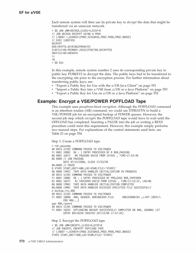
Each remote system will then use its private key to decrypt the data that might betransferred via an unsecure network.* $$ JOB JNM=DECRSA,CLASS=4,DISP=D// JOB DECRSA DECRYPT USING A PRVK// LIBDEF *,SEARCH=(PRD2.SCEEBASE,PRD2.PROD,PRD2.DBASE)// EXEC IJBEFVSEDECRYPTRSA=CRYPTO.KEYRING(PRVKEY2)CLRFILE=DD:PRIMARY.JSCH(IPINIT00.DECRYPTD)ENCFILE=DD:ENCDATA/*/&* $$ EOJ
In this example, remote system number 2 uses its corresponding private key topublic key PUBKEY2 to decrypt the data. The public keys had to be transferred tothe encrypting site prior to the encryption process. For further information abouttransferring public keys, see:v “Export a Public Key for Use with the z/OS Java Client” on page 551v “Import a Public Key into z/VSE from z/OS or a Java Platform” on page 553v “Export a Public Key for Use on z/OS or a Java Platform” on page 552
Example: Encrypt a VSE/POWER POFFLOAD TapeThis example uses passphrase-based encryption. Although the POFFLOAD commandis an attention routine (AR) command, we could use DTRIATTN to build aVSE/POWER job for an encrypted backup of POWER queues. However, thesecond job step which encrypts the POFFLOAD tape would have to wait until theOFFLOAD has completed. Inserting a PAUSE into the job or writing a REXXprocedure could meet this requirement. However, this example simply performstwo manual steps. For explanations of the control statements used here, seeTable 23 on page 554.
Step 1: Create a POFFLOAD taper rdr,pausebgAR 0015 1C39I COMMAND PASSED TO VSE/POWERF1 0001 1R88I OK : 1 ENTRY PROCESSED BY R RDR,PAUSEBGBG 0001 1Q47I BG PAUSEBG 05218 FROM (SYSA) , TIME=17:53:40BG 0000 // JOB PAUSEBG
DATE 07/12/2006, CLOCK 17/53/40BG-0000 // PAUSE0 VTAPE START,UNIT=480,LOC=VSAM,FILE=’VTAPE1’BG 0000 1YM3I TAPE DATA HANDLER INITIALIZATION IN PROGRESSAR 0015 1C39I COMMAND PASSED TO VSE/POWERF1 0001 1R88I OK : 1 ENTRY PROCESSED BY PRELEASE RDR,TAPESRVRR1 0001 1Q47I R1 TAPESRVR 05219 FROM (SYSA) , TIME=17:53:57, LOG=NOBG 0000 1YM4I TAPE DATA HANDLER INITIALIZATION COMPLETEDBG-0000 1YM6I TAPE DATA HANDLER ACCESSED SPECIFIED FILE SUCCESSFULLYo backup,lst,480AR 0015 1C39I COMMAND PASSED TO VSE/POWERF1 0001 1QB9A 480, HEADER: HDR1BACKUP.FILE 006193006193 ,L-OFF (REPLY:
PGO 480...)pgo 480,ignoreAR 0015 1C39I COMMAND PASSED TO VSE/POWERF1 0001 1Q2AI OFFLOADING BACKUP SUCCESSFULLY COMPLETED ON 480, JOURNAL LST
ENTRY $OFJ5220 CREATED (07/12/06 17:57:01)
Step 2: Encrypt the POFFLOAD tape* $$ JOB JNM=ENCOFFL,CLASS=0,DISP=D// JOB ENCOFFL ENCRYPT POFFLOAD TAPE// LIBDEF *,SEARCH=(PRD2.SCEEBASE,PRD2.PROD,PRD2.DBASE)VTAPE START,UNIT=480,LOC=VSAM,FILE=’VTAPE1’
EF for z/VSE
570 z/VSE V4R3.0 Administration

VTAPE START,UNIT=481,LOC=VSAM,FILE=’VTAPE2’// ASSGN SYS005,480// ASSGN SYS006,481// TLBL OUTFILE,’ENCRYPTED.DATA’// EXEC IJBEFVSEENCRYPTDESC=’ENCRYPTED POFFLOAD TAPE’CLRTDESPASSWORD=MYPASSWDICOUNT=100CLRTAPE=SYS005ENCFILE=DD:SYS006-OUTFILE/*// ASSGN SYS005,UA// ASSGN SYS006,UAVTAPE STOP,UNIT=480VTAPE STOP,UNIT=481/&* $$ EOJ
For Step 3, you would erase the clear tape.
Example: Restore/Decrypt an Encrypted POFFLOAD TapeThis example uses passphrase-based encryption. As in “Example: Encrypt aVSE/POWER POFFLOAD Tape” on page 570, the restore/decrypt of an encryptedPOFFLOAD tape consists of two manual steps: firstly restoring the clearPOFFLOAD tape, and secondly issuing a POFFLOAD LOAD command. The jobbelow decrypts the encrypted POFFLOAD tape. For explanations of the controlstatements used here, see Table 23 on page 554.* $$ JOB JNM=DECOFFL,CLASS=0,DISP=D// JOB DECOFFL DECRYPT POFFLOAD TAPE// LIBDEF *,SEARCH=(PRD2.SCEEBASE,PRD2.PROD,PRD2.DBASE)VTAPE START,UNIT=480,LOC=VSAM,FILE=’VTAPE1’VTAPE START,UNIT=481,LOC=VSAM,FILE=’VTAPE2’// ASSGN SYS005,480// ASSGN SYS006,481// TLBL OUTFILE,’ENCRYPTED.DATA’// EXEC IJBEFVSEDECRYPTPASSWORD=MYPASSWDCLRTAPE=SYS005ENCFILE=DD:SYS006-OUTFILE/*// ASSGN SYS005,UA// ASSGN SYS006,UAVTAPE STOP,UNIT=480VTAPE STOP,UNIT=481/&* $$ EOJ
After running this job, tape unit 480 contains the clear offload data and can berestored.
Example: Encrypt a LIBR Backup TapeThis example uses passphrase-based encryption. This job shows how to create anencrypted LIBR backup. For explanations of the control statements used here, seeTable 23 on page 554.* $$ JOB JNM=BKUPLIBR,CLASS=4,DISP=D// JOB BKUPLIBR LIBR BACKUP TO VTAPE* ********************************************************************* STEP 1: CREATE LIBR BACKUP TO VTAPE* ********************************************************************
EF for z/VSE
Chapter 44. Implementing the Encryption Facility for z/VSE 571

VTAPE START,UNIT=480,LOC=VSAM,FILE=’VTAPE1’// ASSGN SYS005,480// TLBL INFILE,’BACKUP.FILE’// EXEC LIBR,SIZE=256K
BACKUP LIB=PRD2 -TAPE=SYS005 -TAPELABEL=INFILE -LIST=YES
/** ********************************************************************* STEP 2: CREATE ENCRYPTED BACKUP TAPE* ********************************************************************// LIBDEF *,SEARCH=(PRD2.SCEEBASE,PRD2.PROD,PRD2.DBASE)VTAPE START,UNIT=481,LOC=VSAM,FILE=’VTAPE2’MTC REW,480// ASSGN SYS006,481// TLBL OUTFILE,’ENCRYPTED.BACKUP’// EXEC IJBEFVSEENCRYPTDESC=’ENCRYPTION TEST’CLRTDESPASSWORD=MYPASSWDICOUNT=100CLRTAPE=SYS005ENCFILE=DD:SYS006-OUTFILE/*// ASSGN SYS005,UA// ASSGN SYS006,UAVTAPE STOP,UNIT=480VTAPE STOP,UNIT=481/&* $$ EOJ
Example: Restore/Decrypt an Encrypted LIBR BackupThis example uses passphrase-based encryption. This job restores/decrypts the VSElibrary that was backed up in “Example: Encrypt a LIBR Backup Tape” on page571. For explanations of the control statements used here, see Table 23 on page 554.* $$ JOB JNM=RESTLIBR,CLASS=8,DISP=D// JOB RESTLIBR RESTORE LIBR BACKUP FROM VTAPE* ********************************************************************* STEP 1: DECRYPT ENCRYPTED BACKUP TAPE* ********************************************************************// LIBDEF *,SEARCH=(PRD2.SCEEBASE,PRD2.PROD,PRD2.DBASE)VTAPE START,UNIT=480,LOC=VSAM,FILE=’VTAPE1’VTAPE START,UNIT=481,LOC=VSAM,FILE=’VTAPE2’// ASSGN SYS005,480// ASSGN SYS006,481// TLBL OUTFILE,’ENCRYPTED.BACKUP’// EXEC IJBEFVSEDECRYPTPASSWORD=MYPASSWDCLRTAPE=SYS005ENCFILE=DD:SYS006-OUTFILE/** ********************************************************************* STEP 2: RESTORE CLEAR BACKUP FROM TAPE* ********************************************************************// TLBL INFILE,’BACKUP.FILE’MTC REW,480// EXEC LIBR,SIZE=256K
RESTORE LIB=PRD2 -TAPE=SYS005 -REPLACE=NO -TAPELABEL=INFILE -LIST=YES
EF for z/VSE
572 z/VSE V4R3.0 Administration

/*// ASSGN SYS005,UA// ASSGN SYS006,UAVTAPE STOP,UNIT=480VTAPE STOP,UNIT=481/&* $$ EOJ
Example: Write an Encrypted SAM Dataset to VTAPEThis example uses passphrase-based encryption. The job below encrypts a SAM file ondisk and writes the encrypted dataset to VTAPE. Note that the RECFM and LRECLparameters must be specified and must match the characteristics of the relatedSAM file. When encrypting VSE library members or VSAM files, the IJBEFVSEutility can get this information from the z/VSE library or VSAM catalog. Forexplanations of the control statements used here, see Table 23 on page 554.* $$ JOB JNM=ENCSAM,CLASS=0,DISP=D// JOB ENCSAM// LIBDEF *,SEARCH=(PRD2.SCEEBASE,PRD2.PROD,PRD2.DBASE)VTAPE START,UNIT=480,LOC=VSAM,FILE=’VTAPE1’MTC REW,480// ASSGN SYS006,480// TLBL ENCDATA,’ENCRYPTED.DATA’// DLBL CLRDATA,’SOME.CLEAR.SAM.DATA’,99/366,SD// EXTENT SYS005,DOSRES,,,19125,10000// ASSGN SYS005,ANYDISK,TEMP,VOL=DOSRES,SHR// EXEC IJBEFVSE,PARM=’DEBUG’ENCRYPTRECFM=FLRECL=80DESC=’ENCRYPTION TEST’CLRAES128PASSWORD=MYPASSWDICOUNT=233CLRFILE=DD:CLRDATAENCFILE=DD:SYS006-ENCDATA/*// ASSGN SYS006,UAVTAPE STOP,UNIT=480/&* $$ EOJ
Example: Restore/Decrypt an Encrypted SAM Dataset FromVTAPE
This example uses passphrase-based encryption. The job below restores/decrypts theencrypted dataset from VTAPE. Note that the LRECL and RECFM parametersmust not be specified since they are contained in the header of the encrypteddataset. For explanations of the control statements used here, see Table 23 on page554.* $$ JOB JNM=DECSAM,CLASS=0,DISP=D// JOB DECSAM// LIBDEF *,SEARCH=(PRD2.SCEEBASE,PRD2.PROD,PRD2.DBASE)VTAPE START,UNIT=480,LOC=VSAM,FILE=’VTAPE1’MTC REW,480// ASSGN SYS006,480// TLBL ENCDATA,’ENCRYPTED.DATA’// DLBL CLRDATA,’SOME.CLEAR.SAM.DATA’,99/366,SD// EXTENT SYS005,DOSRES,,,19125,10000// ASSGN SYS005,ANYDISK,TEMP,VOL=DOSRES,SHR// EXEC IJBEFVSEDECRYPTPASSWORD=MYPASSWDCLRFILE=DD:CLRDATA
EF for z/VSE
Chapter 44. Implementing the Encryption Facility for z/VSE 573

ENCFILE=DD:SYS006-ENCDATA/*// ASSGN SYS006,UAVTAPE STOP,UNIT=480/&* $$ EOJ
Example: Write an Encrypted SAM Dataset to DiskThis example uses passphrase-based encryption. The job below encrypts a SAM dataseton disk and writes the encrypted data into another SAM dataset on disk. Forexplanations of the control statements used here, see Table 23 on page 554.* $$ JOB JNM=ENCSAMD,CLASS=0,DISP=D// JOB ENCSAMD ENCRYPT SAM DATASET ON DISK// LIBDEF *,SEARCH=(PRD2.SCEEBASE,PRD2.PROD,PRD2.DBASE)// DLBL CLRDATA,’SOME.CLEAR.SAM.DATA’,99/366,SD// EXTENT SYS005,DOSRES,,,19125,10000// ASSGN SYS005,ANYDISK,TEMP,VOL=DOSRES,SHR// DLBL ENCDATA,’SOME.ENCRYPTED.SAM.DATA’,99/366,SD// EXTENT SYS006,DOSRES,,,29125,10000// ASSGN SYS006,ANYDISK,TEMP,VOL=DOSRES,SH// EXEC IJBEFVSEENCRYPTRECFM=FLRECL=80DESC=’ENCRYPTION TEST’CLRAES128PASSWORD=MYPASSWDICOUNT=2345CLRFILE=DD:CLRDATAENCFILE=DD:ENCDATA/*/&* $$ EOJ
Example: Encrypt a Tape or VTAPE Using the DynamT UtilityThis example uses public-key encryption. The job below encrypts a physical tape andoutputs the result to a virtual tape. The tape management is performed using theDynamT tape management product.* $$ JOB JNM=ENCRYPT,CLASS=R,DISP=D// JOB ENCRYPT - ENCRYPT FCOPY DUMP VOLUME TO TAPE// TLBL CLRDATA,’RAID23,U,P’// TLBL ENCDATA,’EFVSE003,U’// EXEC TDYNASNOPEN CLRDATA,SYS005,INPUT/*// EXEC IJBEFVSEENCRYPTDESC=’ENCRYPTED DATA’RSA=CRYPTO.KEYRING(KEY01)COMPRESSION=YESRECFM=FLRECL=32758CLRAES128ICOUNT=1234CLRTAPE=SYS005ENCFILE=DD:ENCDATA/*// EXEC TDYNASNVTSTOP SYS005/*/&* $$ EOJ
EF for z/VSE
574 z/VSE V4R3.0 Administration

Example: Decrypt a Tape or VTAPE Using the DynamT UtilityThis example uses public-key encryption. The job below decrypts a virtual tape andoutputs the result to a physical tape. The tape management is performed using theDynamT tape management product.* $$ JOB JNM=DECRYPT,CLASS=R,DISP=D// JOB DECRYPT - DECRYPT FCOPY DUMP VOLUME FROM ENCRYPTED TAPE// TLBL CLRDATA,’RAID23,U,P’// TLBL ENCDATA,’EFVSE003,U’// EXEC TDYNASNOPEN CLRDATA,SYS006,OUTPUT/*// EXEC IJBEFVSEDECRYPTRSA=CRYPTO.KEYRING(KEY01)RECFM=FLRECL=32758CLRTAPE=SYS006ENCFILE=DD:ENCDATA/*// EXEC TDYNASNCLOSE CLRDATA,SYS006,OUTPUTVTSTOP SYS006/*/&* $$ EOJ
Example: Encrypt a Binary File Using the z/OS Java ClientThis example uses passphrase-based encryption. You can use a script similar to thatbelow in order to encrypt a workstation file. Here it is assumed that a Java runtimeenvironment or SDK is installed on the workstation. The following exampleencrypts a JPEG image. For explanations of the control statements used here, refer tothe documentation supplied with the z/OS Java Client.java com.ibm.encryptionfacility.EncryptionFacility-mode encrypt-underlyingKey PBEWithSHA1And3DES-password mypasswd-inputFile mypic.jpg-outputFile mypic.jpg.enc-iterations 233
Next, the encrypted file mypic.jpg.enc could be uploaded to z/VSE (for example,into a VSAM file with a LRECL of at least 32760 bytes) because this value isinternally used by the Java Client. Using a VSAM file with a shorter max recordlength would result in truncated records and thus in an unusable file.
When uploading the encrypted file to z/VSE via FTP, you must specify these FTPparameters:binquote site recfm vquote site lrecl 32760
Decrypting the file on z/VSE returns an exact copy of the original file, which canbe downloaded to the same or another workstation for further processing.* $$ JOB JNM=DECRJPG,CLASS=4,DISP=D// JOB DECRJPG// LIBDEF *,SEARCH=(PRD2.SCEEBASE,PRD2.PROD,PRD2.DBASE)// EXEC IJBEFVSEDECRYPTPASSWORD=MYPASSWDCLRFILE=DD:PRIMARY.JSCH(MYPIC.JPG)
EF for z/VSE
Chapter 44. Implementing the Encryption Facility for z/VSE 575

ENCFILE=DD:ENCDATA/*/&* $$ EOJ
You could now use the VSE Navigator to view the decrypted image in the z/VSElibrary. You can download the VSE Navigator from the z/VSE Homepage (whoseURL is given in “Where to Find More Information” on page xxiii).
Example: Use z/OS Java Client with Public-Key EncryptionThis example uses public-key encryption. You can use this example providing youhave created a JKS keystore (as described in “Export a Public Key for Use with thez/OS Java Client” on page 551).
The example below shows how to encrypt a binary file mypic.jpg using the publicRSA key from a previously-created JKS keystore.
Note: The –keyStoreCertificateAlias parameter must be set to “0”, becauseKeyman/VSE enumerates the keystore items beginning with zero. You must alsospecify the keystore password that was entered when the JKS file was saved inKeyman/VSE. For explanations of the control statements used here, refer to thedocumentation supplied with the z/OS Java Client.java com.ibm.encryptionfacility.EncryptionFacility-mode encrypt-underlyingKey AES16-keyStoreName Keyring.jks-keyStoreType JKS-keyStoreCertificateAlias 0-password mypasswd-inputFile mypic.jpg-outputFile mypic.jpg.enc
Using these FTP commands, the encrypted file is uploaded into a VSE/VSAM fileon z/VSE:binQuote site lrecl 32760Quote site recfm v
Finally, the IJBEFVSE utility is invoked in order to decrypt the VSAM file into aclear VSAM file with the same maximum record length.
The job below references the PRVK member that you created when uploading theRSA key pair to z/VSE. For details, see “Define Properties of Host andGenerate/Upload a Key Pair to the Host” on page 550.* $$ JOB JNM=DECRJPG,CLASS=4,DISP=D// JOB DECRJPG// LIBDEF *,SEARCH=(PRD2.SCEEBASE,PRD2.PROD,PRD2.DBASE)// EXEC IJBEFVSEDECRYPTRSA=CRYPTO.KEYRING(EFVSE01)CLRFILE=DD:PRIMARY.JSCH(MYPIC.JPG)ENCFILE=DD:ENCDATA/*/&* $$ EOJ
EF for z/VSE
576 z/VSE V4R3.0 Administration

Known Problems When Encrypting and Exchanging Data
Looping When Using CA DynamT to Open a Clear Tape orVirtual Tape
Symptom:
When using CA DynamT to open a clear tape or virtual tape, the EF for z/VSEloops endlessly. The TAPESRVR job starts (to load the Virtual Tape DataHandler), but there is no apparent I/O against the VTAPE file after thefile-open sequence has completed.You use JCL similar to this:// EXEC TDYNASNOPEN CLRDATA,SYS005,INPUT/*
Possible Reason / Response:
Add the 'P' option to the TLBL for CLRDATA, which should solve the problem:// TLBL CLRDATA,’RAID23,U,P’
Dynam/T then opens the VTAPE successfully.The cause of the problem was:– Dynam/T performed a dynamic logical unit block (LUB) allocation and did
not assign the VTAPE to SYS005.– As shown in the JCL example above, the EF for z/VSE expected CLRDATA
to be assigned to SYS005
EF for z/VSE
Chapter 44. Implementing the Encryption Facility for z/VSE 577

EF for z/VSE
578 z/VSE V4R3.0 Administration

Chapter 45. Implementing the Encryption Facility for z/VSEOpenPGP
This chapter describes how you can use the Encryption Facility for z/VSE OpenPGPto implement the software-based encryption of:v SAM files,v VSAM files,v VSE Library members,v tapes and virtual tapesv complete backups that were made using any z/VSE backup utility (such as
IDCAMS, LIBR, POFFLOAD) or a vendor product.
Note!Throughout this chapter, the term:v EF for z/VSE OpenPGP is used as the short-form for the Encryption Facility
for z/VSE OpenPGP
v EF for z/VSE is used as the short-form for the Encryption Facility for z/VSE.v EF for z/OS V1.1 is used as the short-form for the Encryption Facility for
z/OS Version 1 Release 1.
This chapter contains these main topics:v “Overview of PGP and the EF for z/VSE OpenPGP” on page 581v “Prerequisites for Using the IJBEFPGP Utility” on page 582v “Restrictions When Using the IJBEFPGP Utility” on page 583v “Installing the Prerequisite and Optional Programs” on page 583v “Summary of Commands Available With the IJBEFPGP Utility” on page 584v “Invoking the IJBEFPGP Utility” on page 584v “Setting Up to Use Passphrase-Based Encryption (PBE)” on page 588v “Setting Up to Use OpenPGP Public-Key Encryption (PKE)” on page 591v “Valid Record Formats” on page 601v “Algorithms Supported by the IJBEFPGP Utility on System z” on page 602v “Examples of Using the IJBEFPGP Utility” on page 603v “Known Problems When Using the IJBEFPGP Utility” on page 606
Related Topics:
For details of ... Refer to ...
OpenPGP v http://en.wikipedia.org/wiki/Openpgpv http://tools.ietf.org/html/rfc4880
(RFC4880)
GnuPG v http://www.gnupg.org/v http://www.gnupg.org/docs.html
(documentation)v http://www.spywarewarrior.com/uiuc/
gpg/gpg-com-0.htm (commands)
the issues that affect overall performance ofan encryption or decryption process
“Performance considerations For Using theIJBEFVSE Utility” on page 547
© Copyright IBM Corp. 1984, 2010 579
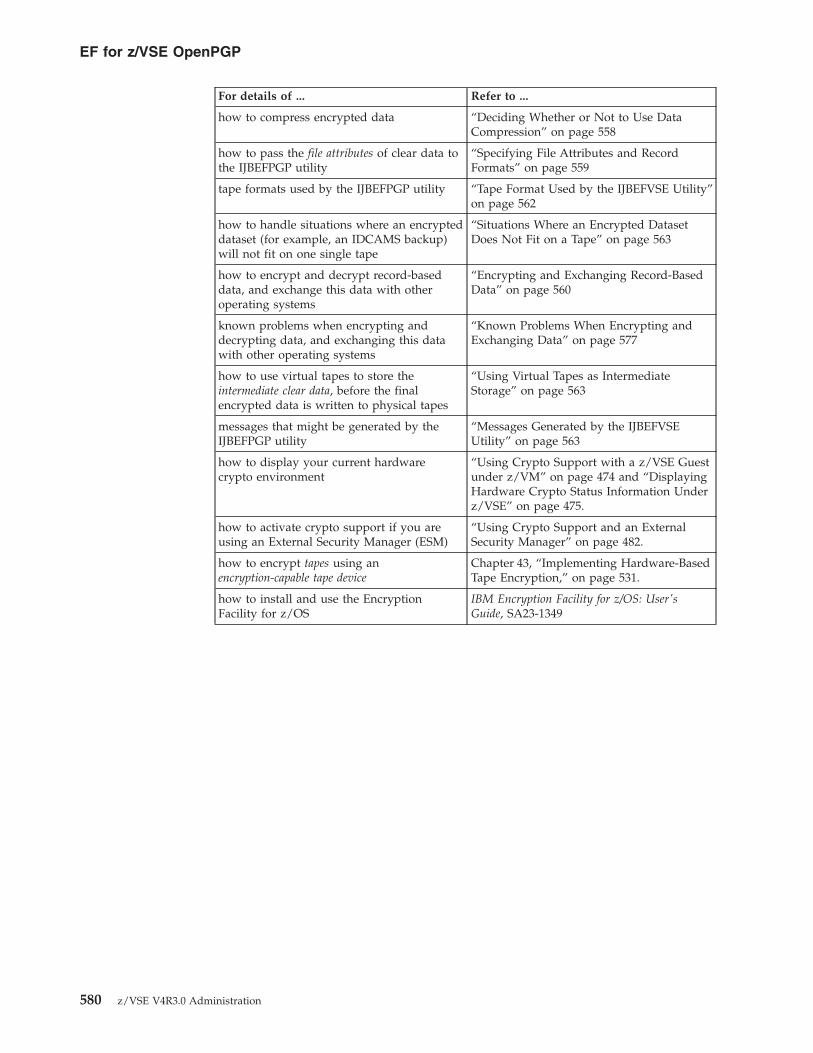
For details of ... Refer to ...
how to compress encrypted data “Deciding Whether or Not to Use DataCompression” on page 558
how to pass the file attributes of clear data tothe IJBEFPGP utility
“Specifying File Attributes and RecordFormats” on page 559
tape formats used by the IJBEFPGP utility “Tape Format Used by the IJBEFVSE Utility”on page 562
how to handle situations where an encrypteddataset (for example, an IDCAMS backup)will not fit on one single tape
“Situations Where an Encrypted DatasetDoes Not Fit on a Tape” on page 563
how to encrypt and decrypt record-baseddata, and exchange this data with otheroperating systems
“Encrypting and Exchanging Record-BasedData” on page 560
known problems when encrypting anddecrypting data, and exchanging this datawith other operating systems
“Known Problems When Encrypting andExchanging Data” on page 577
how to use virtual tapes to store theintermediate clear data, before the finalencrypted data is written to physical tapes
“Using Virtual Tapes as IntermediateStorage” on page 563
messages that might be generated by theIJBEFPGP utility
“Messages Generated by the IJBEFVSEUtility” on page 563
how to display your current hardwarecrypto environment
“Using Crypto Support with a z/VSE Guestunder z/VM” on page 474 and “DisplayingHardware Crypto Status Information Underz/VSE” on page 475.
how to activate crypto support if you areusing an External Security Manager (ESM)
“Using Crypto Support and an ExternalSecurity Manager” on page 482.
how to encrypt tapes using anencryption-capable tape device
Chapter 43, “Implementing Hardware-BasedTape Encryption,” on page 531.
how to install and use the EncryptionFacility for z/OS
IBM Encryption Facility for z/OS: User'sGuide, SA23-1349
EF for z/VSE OpenPGP
580 z/VSE V4R3.0 Administration

Overview of PGP and the EF for z/VSE OpenPGPOpenPGP is a standard protocol for ensuring the integrity of data that can beexchanged between trusted partners. It is designed to help provide data integritythrough:v Data encryption using either a randomly-generated symmetric session key or a
password.v OpenPGP certificates for the exchange of key information that can provide the
data integrity service.
For compatibility with workstation-based PGP tools, IBM has tested the EF forz/VSE OpenPGP together with the OpenPGP implementation GnuPG.
OpenPGP support is designed to offer even more choice and flexibility forexchanging data with business partners. For example, it does not require that yourbusiness partners purchase new storage hardware, have a mainframe, or runz/VSE. PGP (“Pretty Good Privacy”) uses many different encryption and hashalgorithms, so that you can take full advantage of System z hardware features.
The EF for z/VSE OpenPGP offers the same functionality as the EF for z/VSE(described on “Overview of the EF for z/VSE” on page 542), but also offerssupport for OpenPGP. It therefore provides the:v IJBEFVSE utility, which is the same as the utility used by the EF for z/VSE.v IJBEFPGP utility for OpenPGP encryption processing.
Notes:
1. The IJBEFVSE utility uses the System z data format.2. The IJBEFPGP utility supports the OpenPGP data format.3. The support for OpenPGP under z/VSE is compatible with the support for
OpenPGP under z/OS.4. The functions and services supported by the OpenPGP format are not
compatible with the functions and services of the System z format.
As is the case for the IJBEFVSE utility, when using the IJBEFPGP utility you canchoose between two methods for encrypting data:v Passphrase-based encryption, which is described in Figure 134 on page 543.v Public-key encryption, which is described in Figure 135 on page 544.
Differences to the IJBEFVSE utilityThe OpenPGP standard permits all combinations of symmetric algorithms, keylengths, hash algorithms, and compression algorithms. However, the System zformat only supports a restricted number of algorithms and key lengths.
Table 25 summarizes the differences between the IJBEFVSE and IJBEFPGP utilities.
Table 25. Differences Between the IJBEFVSE and IJBEFPGP Utilities
IJBEFVSE IJBEFPGP
Encrypted data format v System z format v OpenPGP format
Compatibility with v EF for z/OS V.1.1v EF for z/OS Java clientv Decryption Client for z/OS
v OpenPGP implementations, such asGnuPG or EF for z/OS V1.2OpenPGP
EF for z/VSE OpenPGP
Chapter 45. Implementing the Encryption Facility for z/VSE OpenPGP 581

Table 25. Differences Between the IJBEFVSE and IJBEFPGP Utilities (continued)
IJBEFVSE IJBEFPGP
Symmetric Algorithms v TDESv AES-128
v DESv TDESv AES-128v AES-192v AES-256
Hash algorithms v SHA1 v MD5v SHA1v SHA224v SHA256v SHA384v SHA512
Compression v System z-provided compression v ZIP-based compressionv ZLIB-based compression
RSA key lengths v 512v 1024v 2048
v 512v 1024v 2048
Public key format v x.509 certificates v PGP certificates
Although z/VSE datasets are encrypted according to the OpenPGP standard andare therefore exchangeable between z/VSE and workstation platforms, not alltypes of z/VSE datasets make sense in a workstation environment. The followingsection discusses the different file and record formats.
Differences to GnuPG and the EF for z/OSThis section describes the differences between the IJBEFPGP utility and the:v IJBEFVSE utilityv GnuPG (if used)v the EF for z/OS (Encryption Facility for z/OS)
The IJBEFPGP utility:v does not maintain keyrings in an OpenPGP environment. Therefore, it does not
provide any commands or options to import or export PGP public keys. In az/VSE environment, this is done using the Keyman/VSE tool.
v allows the specification of single-key DES (DES_SK) as encryption algorithm(GnuPG and z/OS do not allow this). However, these algorithms (described inRFCs 2440 and 4880) cannot be used with z/VSE:– cast5– idea– blowfish– twofish
v always uses an MDC for data integrity when encrypting, but accepts encrypteddatasets that were encrypted without using an MDC.
Prerequisites for Using the IJBEFPGP UtilityThe prerequisites for using the IJBEFPGP utility are the same as those for using theIJBEFVSE utility. Therefore, for a list of the prerequisites refer to “Prerequisites forUsing the IJBEFVSE (or IJBEFPGP) Utility” on page 545.
EF for z/VSE OpenPGP
582 z/VSE V4R3.0 Administration

Restrictions When Using the IJBEFPGP Utilityv For enhanced data integrity, the OpenPGP standard supports DSA signatures and
RSA signatures. However, the IJBEFPGP utility does not support signatures.Furthermore:– RSA signatures will probably be supported in a future release of z/VSE.– DSA signatures are permanently restricted for use with z/VSE.
v The OpenPGP standard defines the use of “key-IDs” to identify an RSA publickey in a keystore. This key-ID is given by 8 bytes derived from the public keybytes. When encrypting using public-key encryption, the key-ID is calculatedand added to the encrypted dataset. The recipient of the encrypted dataset mayuse the key-ID to identify the corresponding private key in order to decrypt thesession key. However:– When decrypting, the IJBEFPGP utility ignores key-IDs and instead uses a
private key that was specified using the RECIPIENT_ALIAS parameter.– When encrypting, the IJBEFPGP utility uses a null key-ID, called the
“speculative key-ID”. This causes other PGP implementations to search theirkey database for a matching private key. For details, refer to the RFC4880.
v The IJBEFPGP utility supports record-based VSAM data by storing extrainformation about record lengths and record formats. However, you cannotdecrypt an encrypted VSAM file using another PGP tool. Only the IJBEFPGP utilitywill process the relevant meta information correctly.
v The following symmetric algorithms are not supported:– cast5– blowfish– twofish– idea
v The following hash algorithm is not supported:– RIPEMD-160
v The following public-key algorithm is not supported:– DSA
Installing the Prerequisite and Optional Programs1. (Required) You require the Keyman/VSE program in order to:v Create RSA key pairs and certificates,v Upload RSA key pairs and certificates to z/VSE,v Import and export PGP certificates.
2. (Optional) To exchange data with non-System z platforms, you can optionallyuse any PGP implementations. “Examples of Using the IJBEFPGP Utility” onpage 603 provides examples of how to exchange data with non-System zplatforms.
3. (Optional) Download and install the Gnu Privacy Guard fromhttp://www.gnupg.org. The install package is contained in one filegnupg-1.4.7.tar.gz. Simply unpack the contents of this file into a new folder.
4. (Optional) Download and install the GPG4Win Windows GUI which includesthe Windows Explorer extension GPGee. Download GPG4Win fromhttp://www.gpg4win.de/. The install file is a Windows file gpg4win-1.1.3.exe.Double-click this file and follow the instructions provided in the install dialogs.
Note: The documentation that accompanies GPG4Win is currently onlyavailable in the German language!
EF for z/VSE OpenPGP
Chapter 45. Implementing the Encryption Facility for z/VSE OpenPGP 583

Summary of Commands Available With the IJBEFPGP UtilityYou can use the following commands with the IJBEFPGP utility:
Table 26. Commands Available With the IJBEFPGP Utility
Command Description
PB_ENCRYPT Password-based encryption.
PK_ENCRYPT Public-key encryption.
DECRYPT Decryption
LIST_ALGO Print available algorithms on SYSLST. Available encryption algorithmsare dependent on the machine. For example, on an IBM z890 we onlyhave TDES. An IBM z9 server also provides AES-128, z10 and z196servers additionally provide AES-192 and AES-256. Available RSA keylengths depend on installed crypto cards.
INFO Specifies that file decryption is not to be performed, but informationabout the encrypted input file is to be recovered and written to SYSLST.When the information is written, processing ends.
This option is useful when you want to:v determine the original clear-text file format information, orv ensure that a specified RSA key is present in the current keyring
library.
HELP Print command help on SYSLST
Invoking the IJBEFPGP UtilityThis topic describes the:v syntax of the IJBEFPGP utility,v control statements that can be used with the IJBEFPGP utility,v rules for specifying file names when using the CLRFILE and ENCFILE control
statements,v rules for specifying record formats.v jobs must include these statements:
// EXEC IJBEFPGP [,PARM=’[SYSLST=DD:SYSnnn] [DEBUG]’]control statements
.../*
where:
SYSLST=DD:SYSnnnOptional. Specifies a logical unit to-which the listing should be written(for example SYSLST=DD:SYS004)
DEBUGOptional. Enables debugging (messages will be sent to SYSLST and tothe console).
control statementsDetails are given in Table 27 on page 585. Control statements are passedvia SYSIPT.
Table 27 on page 585 lists the control statements you can use with the IJBEFPGPutility. If you specify the same control statement more than once, only the last
EF for z/VSE OpenPGP
584 z/VSE V4R3.0 Administration

specification will be used. The availability of some algorithms and key lengthsdepends upon the System z platform, as described in Table 29 on page 602. Allcontrol statements are passed via SYSIPT.
Note: The table uses the abbreviations PBE for passphrase-based encryption, and PKEfor public-key encryption.
Table 27. Control Statements Used With the IJBEFPGP Utility
Option DescriptionApplicablefor Required
CLRFILE=name Dataset containing clear data. For encryption, the cleardata is the input, for decryption it is the output. Validfile types are:v Librarian membersv VSAM ESDS, KSDS and RRDS clustersv SAM dataset on tape or DASD
See also “Specifying File Names for CLRFILE andENCFILE” on page 558.
All Yes ¹
ENCFILE=name Dataset containing encrypted data. For encryption, thisfile is the output, for decryption it is the input. Validfile types are:v Librarian membersv VSAM ESDS clustersv SAM dataset on tape or DASD
See also “Specifying File Names for CLRFILE andENCFILE” on page 558.
All Yes
CLRTAPE=SYSnnn Specifies the logical unit of the clear data tape. Forencryption, the clear data is the input. For decryption,the clear data is the output. The whole content of thespecified tape is used, including all tape marks, tapelabels and so on.
All Yes ²
S2K_PASSPHRASE=pwd 8 to 32 char password. For compatibility with PGP,EBCDIC passwords are internally translated to ASCIIbefore generating the encryption key. Refer toparameters ASCII_CODEPAGE andEBCDIC_CODEPAGE.
PBE,Decrypt
Yes forPBE
S2K_CIPHER_NAME=name Name of encryption algorithm:v DES_SK (single-key DES)v TRIPLE_DES (default)v AES_128v AES_192v AES_256
Use the LIST_ALGO command to list the availableencryption algorithms.
PBE, PKE No
COMPRESSION=n Set compression level (0 ... 9):0 : Do not use compression1 : Use best speed for compression6 : default9 : Use best compression
PBE, PKE No
COMPRESS_NAME=name Name of compression algorithm:v UNCOMPRESSEDv ZIP (default)v ZLIB
PBE, PKE No
EF for z/VSE OpenPGP
Chapter 45. Implementing the Encryption Facility for z/VSE OpenPGP 585

Table 27. Control Statements Used With the IJBEFPGP Utility (continued)
Option DescriptionApplicablefor Required
DIGEST_NAME=name Name of hash algorithm:v MD5v SHA_1 (default)v SHA224v SHA256v SHA384v SHA512
Use the LIST_ALGO command to list the availableencryption algorithms.
PBE, PKE No
RECIPIENT_ALIAS=name Member name of a PRVK or CERT member containingan RSA private or public key. Up to 16RECIPIENT_ALIAS statements can be specified.
PKE,Decrypt
Yes forPKE
CONFIDENTIAL Indicate in the PGP message that input data is verysensitive. PGP implementations usually do not save thistype of data to disk, but instead only display data onthe console.
PBE, PKE No
USE_EMBEDDED_FILENAME Store received data with the original file name asspecified in the PGP message. You can also specify theCLRFILE parameter as a fallback, in case the embeddedfile name is not usable on z/VSE. The IJBEFPGP utilitywill first try to use the embedded file name. If notusable, it will take the dataset name as specified byCLRFILE. Note: while on workstation platforms a newfile with the embedded filename is created during thedecryption process, this is often not possible on z/VSE.For example, when using VSAM data, the relatedcluster must exist before it can be used by theIJBEFPGP utility.
Decrypt No
USE_RECORDINFO Information about LRECL, BLKSIZE, and RECFM isstored in the encrypted dataset. In addition to that, thelength of each plain input record is maintained in orderto be able to restore the original record structure whendecrypting later. This information is z/VSE-specific andis silently skipped by other PGP implementations. Onz/VSE, this information is used when decrypting adataset to restore clear data with its original recordstructure. This parameter should always be used whenencrypting record based datasets, such as SAM, orVSAM files.
PBE, PKE No
LRECL=nnn Specifies the logical record length of the CLRFILE. ForVSAM clusters and LIBR members this parameter is notrequired, since the record length information is readfrom the VSAM catalog or Library. For SAM datasetson tape or DASD it is required. You must also specifythe RECFM control statement when specifying LRECL.
For further details about supported records formats anddefaults, refer to:v “Record, Block, and Control Interval” in the z/VSE
System Macros User's Guide, SC33-8407, andv “Record Formats” in the LE/VSE C Run-Time
Programming Guide, SC33-6688.
PBE, PKE,Decrypt
Yes forSAMdatasets
EF for z/VSE OpenPGP
586 z/VSE V4R3.0 Administration

Table 27. Control Statements Used With the IJBEFPGP Utility (continued)
Option DescriptionApplicablefor Required
RECFM=n Specifies the record format of the CLRFILE. For VSAMclusters and LIBR members this parameter is notrequired, since the format information is read from theVSAM catalog or Library. For SAM datasets on tape orDASD it is required. Valid values are:v F – fixedv V – variablev B – blockedv S – spannedv U – undefinedv FB – fixed blockedv FBS – fixed blocked spannedv VB – variable blockedv VBS – variable blocked spanned
In addition an A (ASA print-control characters) or M(machine print-control characters) can be added toabove formats.
For further details about supported records formats anddefaults, refer to:v “Record, Block, and Control Interval” in the z/VSE
System Macros User's Guide, SC33-8407, andv “Record Formats” in the LE/VSE C Run-Time
Programming Guide, SC33-6688.
PBE, PKE,Decrypt
Yes forSAMdatasets
BLKSIZE=nnn Specifies the bloc size of the CLRFILE. For VSAMclusters and LIBR members this parameter is notrequired, since the record length information is readfrom the VSAM catalog or Library. For SAM datasetson tape or DASD it is required. You must also specifythe RECFM control statement when specifyingBLKSIZE.
For further details about supported records formats anddefaults, refer to:v “Record, Block, and Control Interval” in the z/VSE
System Macros User's Guide, SC33-8407, andv “Record Formats” in the LE/VSE C Run-Time
Programming Guide, SC33-6688.
PBE, PKE,Decrypt
Yes forSAMdatasets
ASCII_CODEPAGE=nnnn Specifies the ASCII codepage used for SYSIPT input.This codepage is important when specifying thepassword. Special characters (such as '@') are ondifferent code points in different codepages. Default isIBM-850. The codepage statement must appear beforethe PASSWORD control statement.
PBE No
EBCDIC_CODEPAGE Specifies the EBCDIC codepage used for SYSIPT input.This codepage is important when specifying thepassword. Special characters (such as '@') are ondifferent code points in different codepages. Default isIBM-1047. The codepage statement must appear beforethe PASSWORD control statement.
PBE No
Notes:
1. Parameter CLRFILE is not required when USE_EMBEDDED_FILENAME isspecified.
EF for z/VSE OpenPGP
Chapter 45. Implementing the Encryption Facility for z/VSE OpenPGP 587
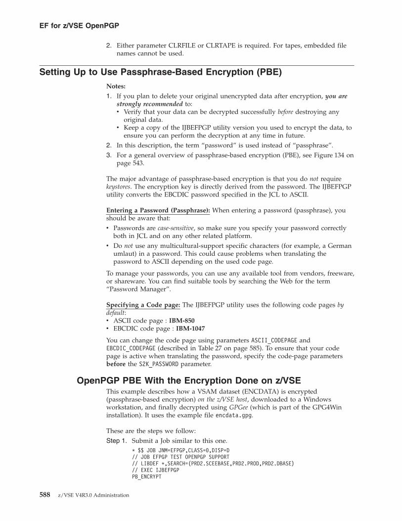
2. Either parameter CLRFILE or CLRTAPE is required. For tapes, embedded filenames cannot be used.
Setting Up to Use Passphrase-Based Encryption (PBE)Notes:
1. If you plan to delete your original unencrypted data after encryption, you arestrongly recommended to:v Verify that your data can be decrypted successfully before destroying any
original data.v Keep a copy of the IJBEFPGP utility version you used to encrypt the data, to
ensure you can perform the decryption at any time in future.2. In this description, the term “password” is used instead of “passphrase”.3. For a general overview of passphrase-based encryption (PBE), see Figure 134 on
page 543.
The major advantage of passphrase-based encryption is that you do not requirekeystores. The encryption key is directly derived from the password. The IJBEFPGPutility converts the EBCDIC password specified in the JCL to ASCII.
Entering a Password (Passphrase): When entering a password (passphrase), youshould be aware that:v Passwords are case-sensitive, so make sure you specify your password correctly
both in JCL and on any other related platform.v Do not use any multicultural-support specific characters (for example, a German
umlaut) in a password. This could cause problems when translating thepassword to ASCII depending on the used code page.
To manage your passwords, you can use any available tool from vendors, freeware,or shareware. You can find suitable tools by searching the Web for the term“Password Manager”.
Specifying a Code page: The IJBEFPGP utility uses the following code pages bydefault:v ASCII code page : IBM-850v EBCDIC code page : IBM-1047
You can change the code page using parameters ASCII_CODEPAGE andEBCDIC_CODEPAGE (described in Table 27 on page 585). To ensure that your codepage is active when translating the password, specify the code-page parametersbefore the S2K_PASSWORD parameter.
OpenPGP PBE With the Encryption Done on z/VSEThis example describes how a VSAM dataset (ENCDATA) is encrypted(passphrase-based encryption) on the z/VSE host, downloaded to a Windowsworkstation, and finally decrypted using GPGee (which is part of the GPG4Wininstallation). It uses the example file encdata.gpg.
These are the steps we follow:Step 1. Submit a Job similar to this one.
* $$ JOB JNM=EFPGP,CLASS=0,DISP=D// JOB EFPGP TEST OPENPGP SUPPORT// LIBDEF *,SEARCH=(PRD2.SCEEBASE,PRD2.PROD,PRD2.DBASE)// EXEC IJBEFPGPPB_ENCRYPT
EF for z/VSE OpenPGP
588 z/VSE V4R3.0 Administration

S2K_PASSPHRASE=BLAHBLAHS2K_CIPHER_NAME=AES_128CLRFILE=DD:CLRDATAENCFILE=DD:ENCDATA/*/&* $$ EOJ
Step 2. Use FTP to download the encrypted dataset (the example usesencdata.gpg) from the z/VSE host to a Windows workstation.ftp> get encdata encdata.gpg200 Command okay150-About to open data connectionFile:EFVSE.ENCDATAType:Binary Recfm:FB Lrecl: 80 Blksize: 80CC=ON UNIX=OFF RECLF=OFF TRCC=OFF CRLF=ON NAT=NO CONT=OFFMODE=Stream STRU=File150 File status okay; about to open data connection226-Bytes sent: 83,736Transfer Seconds: .20 ( 409K per second)File I/O Seconds: .01 ( 8177K per second)226 Closing data connectionftp: 83736 bytes received in 0.81Seconds 103.00Kbytes/sec.ftp>
Step 3. Decrypt the file stored on the Windows workstation using GPGee.
We are now prompted to enter a passphrase.Step 4. Key the passphrase and click OK.
Figure 139. Decrypt a File on Windows Using GPGee
EF for z/VSE OpenPGP
Chapter 45. Implementing the Encryption Facility for z/VSE OpenPGP 589

A confirmation message is then displayed.
OpenPGP PBE With the Decryption Done on z/VSEThis example describes how the file picture.jpg is encrypted (passphrase-basedencryption) using GPGee on a Windows workstation, uploaded to z/VSE, andfinally decrypted on z/VSE. There is no special setup necessary for password-basedencryption.
These are the steps we follow:Step 1. Encrypt a file on a Windows workstation.
Step 2. Enter a password. Here, uppercase is used because in the later z/VSE JCLthe password is also specified in uppercase.
Figure 140. Entering a Decryption Passphrase in GPGee
Figure 141. Encrypt a File on Windows Using GPGee
EF for z/VSE OpenPGP
590 z/VSE V4R3.0 Administration

GPG then creates an encrypted output file picture.jpg.gpg.Step 3. Rename the file to picture.gpg, and upload to the z/VSE host.
ftp> put encdata.gpg encdata200 Command okay150-About to open active data connection
File:EFVSE.ENCDATAType:Binary Recfm:FB Lrecl: 80 Blksize: 80CC=ON UNIX=OFF RECLF=OFF TRCC=OFF CRLF=ON NAT=NO CONT=OFFMODE=Stream STRU=File
150 File status okay; about to open data connection226-Bytes received: 83,556
Records received: 1,045Transfer Seconds: .06 ( 1360K per second)File I/O Seconds: .09 ( 907K per second)
226 Closing data connectionftp: 83556 bytes sent in 0.00Seconds 83556000.00Kbytes/sec.ftp>
Step 4. Decrypt the encrypted dataset.* $$ JOB JNM=EFPGP,CLASS=0,DISP=D// JOB EFPGP TEST OPENPGP SUPPORT// LIBDEF *,SEARCH=(PRD2.SCEEBASE,PRD2.PROD,PRD2.DBASE)// EXEC IJBEFPGPDECRYPTS2K_PASSPHRASE=BLAHBLAHCLRFILE=DD:CLRDATAENCFILE=DD:ENCDATA/*/&* $$ EOJ
The resulting clear data is then written into the clear dataset indicated bythe CLRFILE parameter.
Setting Up to Use OpenPGP Public-Key Encryption (PKE)
Note: If you plan to delete your original unencrypted data after encryption, youare strongly recommended to:v Verify that your data can be decrypted successfully before destroying any
original data.v Keep a copy of the IJBEFPGP utility version you used to encrypt the data,
to ensure you can perform the decryption at any time in future.
As described in Figure 135 on page 544, public-key encryption (PKE) requires thesetup of keystores (such as the VSE Keyring Library or the GnuPG keystore) onboth the:v Encryption-Site's platform,v Decryption-Site's platform.
Figure 142. Entering an Encryption Passphrase in GPGee
EF for z/VSE OpenPGP
Chapter 45. Implementing the Encryption Facility for z/VSE OpenPGP 591

Furthermore, Figure 135 on page 544 also shows how the Encryption-Site requires apublic key, and the Decryption-Site uses the corresponding private key. Both thesekeys were originally generated at the Decryption-Site.
However, there is a problem that arises when setting up the keystores: PGP usesDSA keys by default, whereas z/VSE only supports RSA keys:v The Windows GUI GPG4Win is back-level compared to the GPG command-line
tool and does not allow the creation of RSA keys.v You must therefore use the GPG command-line tool directly in order to setup a
keystore with an RSA key pair.
OpenPGP PKE With the Encryption Done on z/VSEThese are the steps we follow:Step 1. Create an RSA key pair using the GnuPG command-line tool:
C:\Program Files\GNU\GnuPG\pub>gpg --gen-keygpg (GnuPG) 1.4.7; Copyright (C) 2006 Free Software Foundation, Inc.This program comes with ABSOLUTELY NO WARRANTY.This is free software, and you are welcome to redistribute itunder certain conditions. See the file COPYING for details.
Please select what kind of key you want:(1) DSA and Elgamal (default)(2) DSA (sign only)(5) RSA (sign only)
Your selection? 5RSA keys may be between 1024 and 4096 bits long.What keysize do you want? (2048)Requested keysize is 2048 bitsPlease specify how long the key should be valid.
0 = key does not expire<n> = key expires in n days<n>w = key expires in n weeks<n>m = key expires in n months<n>y = key expires in n years
Key is valid for? (0) 1yKey expires at 10/22/08 14:05:18Is this correct? (y/N) y
You need a user ID to identify your key; the software constructs the user IDfrom the Real Name, Comment and Email Address in this form:
"Heinrich Heine (Der Dichter) <[email protected]>"
Real name: Joerg SchmidbauerEmail address: [email protected]: BlahYou selected this USER-ID:
"Joerg Schmidbauer (Bin ich) <[email protected]>"
Change (N)ame, (C)omment, (E)mail or (O)kay/(Q)uit? oYou need a Passphrase to protect your secret key.
We need to generate a lot of random bytes. It is a good idea to performsome other action (type on the keyboard, move the mouse, utilize thedisks) during the prime generation; this gives the random numbergenerator a better chance to gain enough entropy......+++++.....+++++gpg: key E57429F5 marked as ultimately trustedpublic and secret key created and signed.
gpg: checking the trustdbgpg: 3 marginal(s) needed, 1 complete(s) needed, PGP trust modelgpg: depth: 0 valid: 3 signed: 3 trust: 0-, 0q, 0n, 0m, 0f, 3ugpg: depth: 1 valid: 3 signed: 0 trust: 0-, 1q, 0n, 1m, 1f, 0ugpg: next trustdb check due at 2008-10-22pub 2048R/E57429F5 2007-10-23 [expires: 2008-10-22]
Key fingerprint = 7B53 8429 007F BA9B C064 3227 EADE 6428 E574 29F5uid Joerg Schmidbauer (Bin ich) <[email protected]>
EF for z/VSE OpenPGP
592 z/VSE V4R3.0 Administration

Note that this key cannot be used for encryption. You may want to usethe command "--edit-key" to generate a subkey for this purpose.
C:\Program Files\GNU\GnuPG\pub>
Once created, the GPG4Win tool can then display and process thegenerated RSA key.
Step 2. Export the public key from the GnuPG keystore:a. Open the GUI and select Keys – Export Keys.
b. Specify an output filename and click OK.
Figure 143. Export a Public Key From the GnuPG Keystore
EF for z/VSE OpenPGP
Chapter 45. Implementing the Encryption Facility for z/VSE OpenPGP 593

In the example used, the PGP public key is now contained in filejschmidb.pubkey.txt.
Step 3. Import the PGP public key into Keyman/VSE:a. Start Keyman/VSE and click File – Import PGP public key from file.
Step 4. Select the file containing the PGP public key, which was exported in theprevious step, and click Open. The “Select private key for signature”window is displayed, which asks whether or not you will use an existingroot certificate to sign the certificate containing the public key.
Step 5. Select Create new private key for signature and click Continue. The“Specify personal information” window is displayed into which youmust key the certificate's details (name, organization, e-mail address,when the certificate should expire, and so on).
Step 6. Enter the certificate's details and click Continue. The PGP public key willthen be imported into Keyman/VSE.
Step 7. Upload the PGP public key to the VSE Keyring Library on the z/VSEhost:
Figure 144. Specify a Filename for the File to Contain the Public Key
Figure 145. Import a PGP Public Key into Keyman/VSE
EF for z/VSE OpenPGP
594 z/VSE V4R3.0 Administration

a. In Keyman/VSE, right-click the imported PGP public key and selectUpload to VSE.
b. The “Send Certificate Item to VSE” window is displayed. Selectmember type CERT and click Upload.
In this example, the PGP public key has now been stored in VSE KeyringLibrary member JSCHMIDB.CERT. Now we can start to encrypt a z/VSEdataset using OpenPGP public-key encryption.
Step 8. Perform the encryption of a z/VSE dataset on z/VSE (where the publickey to be used must be stored on z/VSE in a .CERT or .PRVK member,and the corresponding private key must be stored in the GnuPG keystoreon the workstation-side). To do so, submit this job to encrypt the z/VSEdataset:* $$ JOB JNM=EFPGP,CLASS=0,DISP=D// JOB EFPGP TEST OPENPGP SUPPORT// LIBDEF *,SEARCH=(PRD2.SCEEBASE,PRD2.PROD,PRD2.DBASE)// EXEC IJBEFPGPPK_ENCRYPTRECIPIENT_ALIAS=CRYPTO.KEYRING(JSCHMIDB)S2K_CIPHER_NAME=AES_128CLRFILE=DD:CLRDATAENCFILE=DD:ENCDATA/*/&$$ EOJ
To allow multiple recipients to decrypt the encrypted dataset, we couldalso specify multiple RECIPIENT_ALIAS parameters. This requires thatthe public key of each recipient is available on z/VSE in a .PRVK or.CERT member. Here is an example job:* $$ JOB JNM=EFPGP,CLASS=S,DISP=D// JOB EFPGP ENCRYPT// LIBDEF *,SEARCH=(PRD2.SCEEBASE,PRD2.PROD,PRD2.DBASE)// EXEC IJBEFPGPPK_ENCRYPTRECIPIENT_ALIAS=CRYPTO.KEYRING(BOBSKEY)RECIPIENT_ALIAS=CRYPTO.KEYRING(JIMSKEY)RECIPIENT_ALIAS=CRYPTO.KEYRING(RODSKEY)RECIPIENT_ALIAS=CRYPTO.KEYRING(ALICEKEY)RECIPIENT_ALIAS=CRYPTO.KEYRING(MYKEY)S2K_CIPHER_NAME=AES_128COMPRESSION=1COMPRESS_NAME=ZIPDIGEST_NAME=SHA_1CLRFILE=DD:CLRDATA
Figure 146. Upload PGP Public Key from Keyman/VSE to z/VSE host
EF for z/VSE OpenPGP
Chapter 45. Implementing the Encryption Facility for z/VSE OpenPGP 595

ENCFILE=DD:ENCDATA/*/&* $$ EOJ
Note: Currently, the maximum number of RECIPIENT_ALIASparameters is 16.
Step 9. Use FTP to download the encrypted dataset (in binary) to a Windowsworkstation:ftp> get encdata encdata.gpg200 Command okay150-About to open data connectionFile:EFVSE.ENCDATAType:Binary Recfm:FB Lrecl: 80 Blksize: 80CC=ON UNIX=OFF RECLF=OFF TRCC=OFF CRLF=ON NAT=NO CONT=OFFMODE=Stream STRU=File150 File status okay; about to open data connection226-Bytes sent: 83,736Transfer Seconds: .20 ( 409K per second)File I/O Seconds: .01 ( 8177K per second)226 Closing data connectionftp: 83736 bytes received in 0.81Seconds 103.00Kbytes/sec.ftp>
Step 10. Decrypt the encrypted file on a Windows workstation.a. Select the encrypted file:
The “Enter passphrase” window is displayed.b. Key the passphrase of the private key and click OK. A confirmation
message "Successfully decrypted and written to file filename" isdisplayed.
OpenPGP PKE With the Decryption Done on z/VSEWhen decrypting on z/VSE, we need a .PRVK member on z/VSE that contains aprivate key. We start the process on the z/VSE-side, and then export the z/VSEpublic key to the GnuPG keystore on the Windows workstation.
These are the steps we follow:
Figure 147. Select the Encrypted z/VSE Dataset Stored on a Workstation
EF for z/VSE OpenPGP
596 z/VSE V4R3.0 Administration

Step 1. Create an RSA key pair using the Keyman/VSE tool:
Step 2. Upload the private key to z/VSE:a. Start the VSE Connector Server on z/VSE in non-SSL mode and upload
the key pair to z/VSE.
b. As the private key will be used for PGP decryption, in this example thelibrary member is given the name PGPDECR.PRVK.
Step 3. Export the public key as a PGP public key file:a. In Keyman/VSE, right-click the RSA key pair and select Export PGP
public key.
Figure 148. Create an RSA Key Pair Using Keyman/VSE
Figure 149. Upload RSA Key Pair to z/VSE
EF for z/VSE OpenPGP
Chapter 45. Implementing the Encryption Facility for z/VSE OpenPGP 597

b. Specify the output file and click Save. In the example, the namepgpdecr.pubkey.txt is used. The “Enter Personal Information for PGPPublic Key” window is displayed.
Step 4. Key the personal information into the relevant fields (name, comment,e-mail address, when the certificate should expire, and so on). Afterentering these details, click OK. The file containing the PGP public keylooks like this:-----BEGIN PGP PUBLIC KEY BLOCK-----Version: IBM Encryption Facility for z/VSE V1.2xo0ESAYBqwEEAIWsS1KT6aM0qdBrBDHat0wiAQljbtyw6GWxcpfO/mL4RYA/37lxxbVlO9BkMJzkW5JNX4MYodUiCZ7B98Wda8kMs90xtyEb6bikVD8W228b1m8K5amg5NRTTztYoH3exwtItq31oIllQHI2AQRCshy57lKGCTARInqf8/DQPtBpABEBAAHCuwQfAQIAJQUCSAYBqwIeAQIbDwULAgkIBwUVAgoJCAMWAQICF4AFCQEDt4AACgkQj0AvFgM5ohcYnQP9GMWdqoRa6rKMI9C7wnKKVHaAE1uCY8dASWTALHrLufR+5Ua10nBE36YcGGxN/NNZu4CO2t551+Lro4Lh3dnU8TtP1kx2w0eMToobDZ2n1ivv8G1T0AqdyW09b8qJ53pa7sZKa1ZVylfAESWUiXBfUPHEz4bJUMP78cmx/Gx8ssrNJVBHUCBEZWNjcnlwdGlvbiA8anNjaG1pZGJAZGUuaWJtLmNvbT7CuwQTAQIAJQUCSAYBrAIeAQIbDwULAgkIBwUVAgoJCAMWAQICF4AFCQEDt4AACgkQj0AvFgM5ohc7aAP9GMg1gDR3z5YNvHwAi3LXzyiOkae/wh1zfE6OmyjzpmPNy2iJ+nVfQXCzuPrWYeA0sWVVLDrseVGJkJqKfaUDCsxoAoEpRUHaFc16JsFa2YCBSIfBzrhMyROmFJwAygTnSuy7rYmr1VouO65mfkvidV1JBXTVHXIwD9bKlO93FOg==zugp-----END PGP PUBLIC KEY BLOCK-----
Step 5. A window is displayed which includes two confirmation lines: 1 publickeys read and 1 public keys imported. Click Close. If the details of thenew public key are displayed in the “GNU Privacy Assistant - KeyringEditor” window, the key only has a public-key (and no private-key) part.
Figure 150. Export a PGP Public Key
EF for z/VSE OpenPGP
598 z/VSE V4R3.0 Administration

Step 6. Encrypt the example file picture.jpg “locally” (on the Windowsworkstation) using the GPGee tool.a. Use the Windows Explorer to select the file to be encrypted:
b. Select the key to be used for the encryption:
Figure 151. Display Public Key Part in the GNU Privacy Assistant window
Figure 152. Select File to be Encrypted by the GPGee Tool
EF for z/VSE OpenPGP
Chapter 45. Implementing the Encryption Facility for z/VSE OpenPGP 599

c. GnuPG creates an encrypted file picture.jpg.gpg. Rename the file topicture.gpg before uploading to z/VSE. Use FTP to perform theupload:ftp> put encdata.gpg encdata200 Command okay150-About to open active data connection
File:EFVSE.ENCDATAType:Binary Recfm:FB Lrecl: 80 Blksize: 80CC=ON UNIX=OFF RECLF=OFF TRCC=OFF CRLF=ON NAT=NO CONT=OFFMODE=Stream STRU=File
150 File status okay; about to open data connection226-Bytes received: 83,556
Records received: 1,045Transfer Seconds: .06 ( 1360K per second)File I/O Seconds: .09 ( 907K per second)
226 Closing data connectionftp: 83556 bytes sent in 0.00Seconds 83556000.00Kbytes/sec.ftp>
Step 7. Perform the decryption of the file encdata.gpg on z/VSE (where theprivate key to be used must be stored on z/VSE in a .PRVK member, andthe corresponding public key must be stored in the GnuPG keystore on theworkstation-side). To do so, submit this job to decrypt the file:* $$ JOB JNM=EFPGP,CLASS=0,DISP=D// JOB EFPGP TEST OPENPGP SUPPORT// LIBDEF *,SEARCH=(PRD2.SCEEBASE,PRD2.PROD,PRD2.DBASE)// EXEC IJBEFPGPDECRYPTRECIPIENT_ALIAS=CRYPTO.KEYRING(PGPDECR)CLRFILE=DD:CLRDATAENCFILE=DD:ENCDATA/*/&* $$ EOJ
Figure 153. Select Public-Key to be Used for the Encryption
EF for z/VSE OpenPGP
600 z/VSE V4R3.0 Administration

Valid Record FormatsWhile workstation files are always byte streams, z/VSE datasets have a record-basedstructure (VSAM KSDS, RRDRS, and so on). If both encryption and decryptiontakes place on a z/VSE system, you can maintain the original record structure of aclear input dataset by specifying the parameter USE_RECORDINFO:v The IJBEFPGP utility uses a private/experimental data packet (described in
RFCs 2440 and 4880) with tag number 60 to store fields LRECL, BLKSIZE, andRECFM of the clear dataset.
v Each plaintext data record is prefixed with its length prior to encryption. Thisinformation is again used when the dataset is decrypted in order to restore theoriginal record structure of the plaintext data.
OpenPGP implementations that ignore the z/VSE-specific RECORDINFO packetduring decryption will not be able to distinguish between record length prefix andrecord data. For example, when decrypting a dataset with record information on anon-z/VSE platform, this prefix will be treated as part of the data. Therefore, theUSE_RECORDINFO option should only be used when encrypting and decrypting onz/VSE.
When encrypted datasets are exchanged between different platforms (such asworkstations using GnuPG) or between z/OS using the EF for z/OS, a limitednumber only of clear-data formats can be exchanged. Table 28 shows thecombinations of clear and encrypted datasets that can be exchanged on variousplatforms.
Table 28. Valid Combinations When Exchanging Encrypted Datasets Between Platforms
z/VSE Workstations z/OS
Tape or VTAPE N/A Tape or VTAPE
SAM dataset Encrypted data contains a6-byte length field in front ofeach data record.
z/OS dataset. However, EFfor z/OS does not retaininformation about thenumber of bytes for eachrecord. The lengthinformation as provided byz/VSE cannot be recognized.
VSAM ESDS Plain binary or text file Not supported
VSAM KSDS (only cleardataset)
Encrypted data contains a6-byte length field in front ofeach data record.
Not supported
VSAM RRDS (only cleardataset)
Encrypted data contains a6-byte length field in front ofeach data record.
Not supported
VSAM VRDS Not supported because ofLE/VSE runtime.
Not supported
VSE Library Member Plain binary or text file Unix System Services file
Note: VRDS clusters are not supported because LE/VSE does not support VRDS.
EF for z/VSE OpenPGP
Chapter 45. Implementing the Encryption Facility for z/VSE OpenPGP 601

Algorithms Supported by the IJBEFPGP Utility on System zThe OpenPGP standard supports many different algorithms. However, only someof these algorithms are supported by the IJBEFPGP utility. Other algorithms areavailable on specific System z platforms only. Table 29 shows a list of supportedalgorithms and their prerequisites.
Table 29. Algorithms Supported by the IJBEFPGP Utility
Algorithm z890/z990 z9 z10 z196
MD5 yes ¹ yes ¹ yes ¹ yes ¹
SHA-1 yes yes Yes Yes
SHA-224 - yes Yes Yes
SHA-256 - yes Yes Yes
SHA-384 - - Yes Yes
SHA-512 - - Yes Yes
DES yes yes Yes Yes
TDES yes yes Yes Yes
AES-128 yes ¹ yes Yes Yes
AES-192 yes ¹ yes ¹ Yes Yes
AES-256 yes ¹ yes ¹ Yes Yes
RSA encrypt/ decrypt
yes ² yes ² yes ² yes ²
DSA - - - -
¹ algorithm available as software implementation in TCP/IP for VSE/ESA.² requires latest version of TCP/IP for VSE/ESA 1.5E or higher. 2048 bit keysrequire a PCIXCC or Crypto Express2.
Notes:
1. When using password-based encryption, parameter DIGEST_NAME onlyaffects the creation of the data key from a given password.
2. When using public-key encryption, symmetric algorithms are used to encryptdata, whereas RSA is used to encrypt the session key.
3. Although it is possible to use any combination of symmetric, asymmetric andhash algorithm, you are recommended to use algorithms and key lengths ofsimilar strength. For example, you should not encrypt an AES-256 key with a512-bit RSA key.
Table 30 is taken from RFC4880 and shows the equivalent algorithm strength fordifferent key sizes.
Table 30. Equivalent algorithm strength for various key sizes
Asymmetric key size (bits) Hash size (bits) Symmetric key size (bits)
1024 160 80
2048 224 112
3072 256 128
7680 384 192
15360 512 256
EF for z/VSE OpenPGP
602 z/VSE V4R3.0 Administration

In a z/VSE environment, a good choice for public-key encryption would be to use:v AES-128 for data encryption.v A 2048-bit RSA key to encrypt the session key.
Examples of Using the IJBEFPGP UtilityThis topic provides you with practical examples of how to perform the encryptionof tapes, disks, files, and volumes using the IJBEFPGP utility.
For examples of how to perform the encryption of tapes, disks, files, and volumesusing the IJBEFVSE utility, see “Examples of Using the IJBEFVSE Utility” on page564.
OpenPGP Example: Obtain Help InformationThis example shows how you can obtain a list of the available commands andoptions.* $$ JOB JNM=EFPGP,CLASS=0,DISP=D// JOB EFPGP TEST OPENPGP SUPPORT// LIBDEF *,SEARCH=(PRD2.SCEEBASE,PRD2.PROD,PRD2.DBASE)// EXEC IJBEFPGPHELP/*/&* $$ EOJ
OpenPGP Example: Obtain a List of Available AlgorithmsThis example prints a list of available algorithms to SYSLST. The list is dependenton the server being used and also the version of TCP/IP that is being used.* $$ JOB JNM=EFPGP,CLASS=0,DISP=D// JOB EFPGP TEST OPENPGP SUPPORT// LIBDEF *,SEARCH=(PRD2.SCEEBASE,PRD2.PROD,PRD2.DBASE)// EXEC IJBEFPGPLIST_ALGO/*/&* $$ EOJ
OpenPGP Example: Obtain Information About the OriginalInput File
The job below specifies that file decryption is not to be performed, but informationabout the original clear-text input file is to be recovered and written to SYSLST.v If you specify a RECIPENT_ALIAS, the IJBEFPGP utility checks if the data key can
be decrypted using this private key.v If you specify a password, the IJBEFPGP utility checks if the length is correct but
does not attempt a decryption.* $$ JOB JNM=EFPGP,CLASS=S,DISP=D// JOB EFPGP SHOW INFO// LIBDEF *,SEARCH=(PRD2.SCEEBASE,PRD2.PROD,PRD2.DBASE)// EXEC IJBEFPGPINFORECIPIENT_ALIAS=CRYPTO.KEYRING(MYKEY)CLRFILE=DD:CLRDATAENCFILE=DD:ENCDATA/*/&* $$ EOJ
EF for z/VSE OpenPGP
Chapter 45. Implementing the Encryption Facility for z/VSE OpenPGP 603

OpenPGP Example: Encrypt a Library Member Using PBEThis example uses passphrase-based encryption (PBE). For explanations of the controlstatements used here, see Table 27 on page 585.* $$ JOB JNM=EFPGP,CLASS=0,DISP=D// JOB EFPGP TEST OPENPGP SUPPORT// LIBDEF *,SEARCH=(PRD2.SCEEBASE,PRD2.PROD,PRD2.DBASE)// EXEC IJBEFPGPPB_ENCRYPTS2K_PASSPHRASE=BLAHBLAHS2K_CIPHER_NAME=AES_256COMPRESSION=1COMPRESS_NAME=ZIPUSE_RECORDINFODIGEST_NAME=SHA256CLRFILE=DD:CLRDATAENCFILE=DD:ENCDATA/*/&* $$ EOJ
OpenPGP Example: Encrypt a Library Member Using PKEThis example uses public-key encryption (PKE). For explanations of the controlstatements used here, see Table 27 on page 585.* $$ JOB JNM=EFPGP,CLASS=0,DISP=D// JOB EFPGP TEST OPENPGP SUPPORT// LIBDEF *,SEARCH=(PRD2.SCEEBASE,PRD2.PROD,PRD2.DBASE)// EXEC IJBEFPGPPK_ENCRYPTRECIPIENT_ALIAS=CRYPTO.KEYRING(BOBSKEY)S2K_CIPHER_NAME=AES_128COMPRESSION=1COMPRESS_NAME=ZIPUSE_RECORDINFODIGEST_NAME=SHA256CLRFILE=DD:CLRDATAENCFILE=DD:ENCDATA/*/&* $$ EOJ
OpenPGP Example: Decrypt a PGP MessageThis example uses public-key encryption. The job below attempts to use threedifferent private keys in the keyring library to decrypt a specified PGP message.You can specify up to 16 RECIPIENT_ALIAS statements. For explanations of thecontrol statements used here, see Table 27 on page 585.* $$ JOB JNM=EFPGP,CLASS=S,DISP=D// JOB EFPGP DECRYPT WITH MULTIPLE PKS// LIBDEF *,SEARCH=(PRD2.SCEEBASE,PRD2.PROD,PRD2.DBASE)// EXEC IJBEFPGPDECRYPTRECIPIENT_ALIAS=CRYPTO.KEYRING(BOBSKEY)RECIPIENT_ALIAS=CRYPTO.KEYRING(JOHNSKEY)RECIPIENT_ALIAS=CRYPTO.KEYRING(MYKEY)CLRFILE=DD:VTAPE1ENCFILE=DD:VTAPE2/*/&* $$ EOJ
EF for z/VSE OpenPGP
604 z/VSE V4R3.0 Administration

When specifying multiple RECIPIENT_ALIAS statements for encryption, the data keyis encrypted multiple times by each specified public key. The resulting PGPmessage then contains multiple “Public-key encrypted session key packets”.
If a recipient is able to decrypt at least one of these packets (that is, has at least oneof the corresponding private keys) the PGP message can be decrypted.
OpenPGP Example: Encrypt a Library Member to Virtual TapeThis example uses passphrase-based encryption. For explanations of the controlstatements used here, see Table 27 on page 585.* $$ JOB JNM=ENCTAPE,CLASS=S,DISP=D// JOB ENCTAPE ENCRYPT TAPE// LIBDEF *,SEARCH=(PRD2.SCEEBASE,PRD2.PROD,PRD2.DBASE)* INPUT FILE IS LIBR MEMBER* OUTPUT FILE ON TAPE 480VTAPE START,UNIT=480,LOC=VSAM,FILE=’VTAPE2’MTC REW,480// ASSGN SYS006,480// TLBL OUTFILE,’ENCRYPTED.DATA’// EXEC IJBEFPGPPB_ENCRYPTS2K_PASSPHRASE=MYPASSWDS2K_CIPHER_NAME=AES_128COMPRESSION=1COMPRESS_NAME=ZIPDIGEST_NAME=SHA256CLRFILE=DD:PRD2.CONFIG(IPINIT00.L)ENCFILE=DD:SYS006-OUTFILE/*// ASSGN SYS006,UAVTAPE STOP,UNIT=480/&* $$ EOJ
OpenPGP Example: Decrypt a Library Member Contained onVirtual Tape
This example uses passphrase-based encryption. For explanations of the controlstatements used here, see Table 27 on page 585.* $$ JOB JNM=DECTAPE,CLASS=S,DISP=D// JOB DECTAPE DECRYPT TAPE// LIBDEF *,SEARCH=(PRD2.SCEEBASE,PRD2.PROD,PRD2.DBASE)* INPUT FILE IS TAPE* OUTPUT FILE IS LIBR MEMBERVTAPE START,UNIT=480,LOC=VSAM,FILE=’VTAPE2’MTC REW,480// ASSGN SYS006,480// TLBL OUTFILE,’ENCRYPTED.DATA’// EXEC IJBEFPGPDECRYPTS2K_PASSPHRASE=MYPASSWDCLRFILE=DD:PRD2.CONFIG(IPINIT00.DECR)ENCFILE=DD:SYS006-OUTFILE/*// ASSGN SYS006,UAVTAPE STOP,UNIT=480/&* $$ EOJ
EF for z/VSE OpenPGP
Chapter 45. Implementing the Encryption Facility for z/VSE OpenPGP 605

OpenPGP Example: Encrypt a Library Member to a RemoteVirtual Tape
This example uses passphrase-based encryption. For explanations of the controlstatements used here, see Table 27 on page 585.* $$ JOB JNM=ENCRYPT,DISP=D,CLASS=0// JOB ENCRYPT// LIBDEF *,SEARCH=(PRD2.SCEEBASE,PRD2.PROD,PRD2.DBASE)VTAPE START,UNIT=480,LOC=9.152.216.57,FILE=’MYTAPE’MTC REW,480// ASSGN SYS006,480// TLBL OUTFILE,’MYTAPE.DATA’// EXEC IJBEFPGPPB_ENCRYPTS2K_PASSPHRASE=MYPASSWDS2K_CIPHER_NAME=AES_128COMPRESSION=1COMPRESS_NAME=ZIPDIGEST_NAME=SHA256CLRFILE=DD:PRD2.CONFIG(IPINIT00.L)ENCFILE=DD:SYS006-OUTFILE/*// ASSGN SYS006,UAVTAPE STOP,UNIT=480/&* $$ EOJ
Known Problems When Using the IJBEFPGP UtilityThis topic describes some known problems when using the IJBEFPGP utility, andprovides troubleshooting hints and tips.
Access to PRVK failedSymptom:T046: SSL303E IPDSCRFI failed RC=00000008(LIBROPIF) reason=00000418 00000008T046: SSL113W IPDSCRFI get for CRYPTO KEYRING BOBSKEY PRVK failedT046: SSL303E IPDSCRFI failed RC=000007E7(LIBRCALL) reason=000005D0
Possible Reason / Response:
You are encrypting or decrypting by using one or more RECIPIENT_ALIASstatements. For example:// EXEC IJBEFPGPPK_ENCRYPTRECIPIENT_ALIAS=CRYPTO.KEYRING(BOBSKEY)RECIPIENT_ALIAS=CRYPTO.KEYRING(MYKEY)
The IJBEFPGP utility attempts to read the specified VSE Keyring Librarymembers with member type .PRVK and .CERT (if .PRVK not found). If a librarymember cannot be found in the specified VSE Keyring Library, The IJBEFPGPutility issues the messages shown above.Check the SYSLST output, which when– decrypting, will contain this type of output:
SUCCESSFULLY DECRYPTED THE SESSION KEY USING CRYPTO.KEYRING(MYKEY)
– encrypting, will contain this type of output:ENCRYPTING SESSION KEY WITH RSA PUBLIC KEY FROM PRVK:CRYPTO.KEYRING(MYKEY)
In both the above cases, the output means that there was at least one memberfound which could be used to encrypt/decrypt the session key.
EF for z/VSE OpenPGP
606 z/VSE V4R3.0 Administration

RSA decryption failedSymptom:SSL203E RSAD failed RC=0000002E(RSADLBD5) reason=00000144SSL203E RSAD failed RC=0000002E(RSADNZFI) reason=00000444SSL203E RSAD failed RC=0000002E(RSADNZFI) reason=00000444SSL203E RSAD failed RC=0000002E(RSADLBAD) reason=00000300
Possible Reason / Response:
You are decrypting using one or more private keys specified via the parameterRECIPIENT_ALIAS. Note that for decryption a private key is required. This means,the VSE Keyring Library members must be .PRVK members containing aprivate key.// EXEC IJBEFPGPDECRYPTRECIPIENT_ALIAS=CRYPTO.KEYRING(MYKEY)RECIPIENT_ALIAS=CRYPTO.KEYRING(MYKEY2)RECIPIENT_ALIAS=CRYPTO.KEYRING(MYKEY3)
The IJBEFPGP utility could read a member specified in the VSE KeyringLibrary, but the private key could not be used to decrypt the session key.Providing there is at least one line in the output job that is similar to the linebelow, one of the specified keys could be used to decrypt the session key.SUCCESSFULLY DECRYPTED THE SESSION KEY USING CRYPTO.KEYRING(MYKEY2)
The text file cannot be decrypted on a workstationSymptom:
After being encrypted on z/VSE, a plain-text file cannot be decrypted on aworkstation.
Possible Reason / Response:
You probably uploaded the plain-text file to z/VSE with character translation (forexample, using the ASCII option with FTP).When downloading the encrypted file to your workstation, you did not changethis option to BINARY.
The decrypted file contains garbageSymptom:
When decrypting on a workstation, the decrypted file contains repeatedgarbage bytes located between clear-text data.
Possible Reason / Response:
You encrypted a file on z/VSE with the USE_RECORDINFO option.Therefore, the encrypted file contains a RECORDINFO packet, which is ignoredwhen decrypting the file on a workstation.In addition, each data record is prefixed with a data structure that contains thelength of the record that follows. This information cannot be interpreted byother PGP implementations, and is therefore treated as being part of the data.To solve the problem, you should not use the USE_RECORDINFO option if thedecryption is not to be performed on z/VSE.
The MDC cannot be found in the encrypted datasetSymptom:
EF for z/VSE OpenPGP
Chapter 45. Implementing the Encryption Facility for z/VSE OpenPGP 607

When decrypting on z/VSE, the MDC could not be found in the encrypteddataset.
Possible Reason / Response:
You encrypted the file on a workstation and then uploaded the file to z/VSE.You probably did not specify a variable record format for the z/VSE targetdataset (you did not specify recfm v when uploading via FTP). This resulted inadditional padding bytes being inserted at the end of the encrypted dataset, upto the record length of the target file.When decrypting, these padding bytes are treated as if they belonged to the filecontents. This causes this error.
Duplicate key during decryption of a VSAM fileSymptom:
When decrypting on z/VSE, the MDC could not be found in the encrypteddataset.You get the following message when decrypting an encrypted dataset, wherethe original input file was a VSAM KSDS file:ERROR: FAILED TO WRITE DATA RECORD.
BYTES TO WRITE : 80BYTES WRITTEN : 0REASON: DUPLICATE KEY.
Possible Reason / Response:
When encrypting the file, you did not use the USE_RECORDINFO option.As a result, the original record structure cannot be restored.Clear output records are simply written using the length of the target VSAMfile, which can result in duplicate keys.You must encrypt the clear file again, using the USE_RECORDINFO option.
EF for z/VSE OpenPGP
608 z/VSE V4R3.0 Administration

Part 5. Miscellaneous
Chapter 46. Supporting ApplicationDevelopment . . . . . . . . . . . . . 611Tailoring Compile Skeletons . . . . . . . . 611
Example: Skeletons C$$ASBAT and C$$ASONL 612Batch and Online Skeleton Information . . . 613Program IESINSRT . . . . . . . . . 614
Compile Example (Part 1) . . . . . . . . 616Compile Example (Part 2) . . . . . . . . 617
Creating an Application Job Stream . . . . . . 618Printer Specifications . . . . . . . . . . 620Reader or Punch Specifications . . . . . . 620Tape Specifications . . . . . . . . . . 620Data Specifications . . . . . . . . . . 621Job Information Specifications . . . . . . . 621
Chapter 47. Regenerating the Supervisor,VSE/POWER, or VSE/ICCF . . . . . . . . 623Installing the Generation Feature . . . . . . . 623Regenerating the Supervisor . . . . . . . . 623Regenerating VSE/POWER. . . . . . . . . 624Regenerating VSE/ICCF. . . . . . . . . . 628
VSE/ICCF DTSFILE Generation Parameters . . 630Pregenerated Libraries and User-IDs . . . 630Skeleton SKICFFMT . . . . . . . . . 630
Chapter 48. Using RPG II With the CICSTransaction Server . . . . . . . . . . . 633Running Job RPGINST . . . . . . . . . . 633Running Job RPGSAMPL . . . . . . . . . 634
Chapter 49. Displaying System Status andStorage Information . . . . . . . . . . 635Dialogs Available . . . . . . . . . . . . 635
Display System Activity or Channel and DeviceActivity . . . . . . . . . . . . . . 635Display CICS TS Storage . . . . . . . . 636
Using the Display Storage Layout Dialog . . . . 637Accessing the Dialog . . . . . . . . . . 637Static Partition Layout Panel . . . . . . . 638Dynamic Partition Layout Panel . . . . . . 639SVA Layout Panel . . . . . . . . . . . 640
Changing the Dialog Interval Time . . . . . . 641
Chapter 50. Collecting Additional z/VSE ActivityData . . . . . . . . . . . . . . . . 643Taking Measurements . . . . . . . . . . 644
Format of Input Parameters for TransactionIEXM . . . . . . . . . . . . . . . 645Transactions IEXA and IEXS . . . . . . . 646
User Exit Description . . . . . . . . . . . 646User Exit Linkage Definition . . . . . . . 647Sample User Exit Program Provided by SkeletonSKEXITDA . . . . . . . . . . . . . 647Flow of Events . . . . . . . . . . . . 650Error Processing . . . . . . . . . . . 650
Format of Measurement Data . . . . . . . . 651Format of System Activity Data . . . . . . 651
Format of Static Partitions Data . . . . . 652Format of Dynamic Classes/DynamicPartitions Data . . . . . . . . . . . 654
Format of Channel and Device Activity Data 656Examples of Measurement Data . . . . . . . 656
Example 1: Data of Two Static Partitions andOne Dynamic Class . . . . . . . . . . 656Example 2: Data of One Dynamic Class/OneDynamic Partition . . . . . . . . . . . 660Example 3: Channel and Device Activity Data 662
Chapter 51. Fast Paths and Synonyms forDialogs . . . . . . . . . . . . . . . 663
© Copyright IBM Corp. 1984, 2010 609

610 z/VSE V4R3.0 Administration

Chapter 46. Supporting Application Development
This chapter describes two administrative tasks for application development:v Tailoring compile skeletons.v Creating application job streams via dialog.
It contains these main topics:v “Tailoring Compile Skeletons”v “Creating an Application Job Stream” on page 618
Tailoring Compile Skeletons“Handling VSE/ICCF Library Members” in the manual VSE/ESA Programming andWorkstation Guide describes the Program Development Library dialog. You use thisdialog to access and work with VSE/ICCF libraries. Various options allow you tocreate, maintain, and process library members. One of the options allows you tocompile library members.
Before using the Compile a Member option, the related compile skeletons must betailored as needed for your installation.
The compile skeletons are available in VSE/ICCF library 2. The skeleton namesare:v C$$xxyyy
v C$Qxxyyy
v C$Dxxyyy
where:v Q identifies the skeletons provided for use with the DB2 Server.v D identifies the skeletons provided for use with DL/I.
For a complete list of the skeletons available refer to the manual z/VSE Planningunder “Tailoring Compile Skeletons”.
xx can be:CN (for C for z/VSE)CV (for COBOL for z/VSE)PV (for PL/I for z/VSE)AS (for High Level Assembler for VSE)RP (for RPG II)FO (for VS FORTRAN)
From z/VSE V4R2.0 onwards, RPG II support is available for CICS TransactionServer for VSE/ESA online programs.
yyy can be:ONL for online program.BAT for batch program.SUB for batch subroutine.
© Copyright IBM Corp. 1984, 2010 611

MAP for BMS map definition. Note: You can also use the TEMPLATEparameter of the Compile Job Generation panel (Fast Path 51) to generate anHTML map definition from a BMS MAP (for details, refer to the VSE/ESAProgramming and Workstation Guide).
Before you tailor the skeletons, you should consider who will use them and howthey will be used.1. You can give the skeletons to all or some application programmers. Copy them
from library 2 to a library to which the programmer has write access. Theprogrammer can then tailor the skeletons.
2. You can tailor the skeletons for the entire system. In this way, you can establishcertain standards for compile jobs and have every programmer use the sameskeletons. For this method, tailor the skeleton files and leave them in library 2.
When a user selects the COMPILE option in the Program Development Librarydialog, the system searches for the compile skeleton in the following order:1. User's primary library2. User's current secondary library (if any)3. Common library (VSE/ICCF library 2)
Example: Skeletons C$$ASBAT and C$$ASONLFigure 154 shows skeleton C$$ASBAT for compiling a High Level Assembler batchprogram. Figure 155 on page 615 shows skeleton C$$ASONL for compiling a HighLevel Assembler online (CICS) program.
You should tailor the skeletons according to the needs of your programdevelopment environment. Use the information provided for the two exampleswhen tailoring other skeletons.
Note: In the skeletons and compile examples on the following pages the statement// EXEC ASMA90,SIZE=(ASMA90,64K)....
calls the High Level Assembler. Note that the 'C' at the end of the first lineis the continuation character. Refer to the manual z/VSE Planning under“Changing from DOS/VSE Assembler to High Level Assembler” for furtherdetails about the High Level Assembler.
Skeleton C$$ASBAT
612 z/VSE V4R3.0 Administration

Batch and Online Skeleton InformationThe following information applies in general to any batch and online compileskeleton. Note that parameters beginning with an & are replaced with informationthe user enters when using the COMPILE option. You must change the LIBDEFstatement and replace the variable lib.sublib with the library and sublibrary nameyou want to use. In addition, review and consider changing the following:v Job class and disposition in the * $$ JOB statement.
DISP=DCLASS=A
v Print class and disposition in the * $$ LST statement.DISP=DCLASS=Q
v Additional LIBDEF statements for your own libraries should be added to thesupplied LIBDEF statements and inserted after each job statement.
v Check all C/VSE skeletons whether the DLBL for the C/370™ message file is thesame you used during the installation of C/VSE.
v COBOL options in the OPTION statements.v For Map Definitions (BMS map) it is possible to also generate HTML templates.
These templates are stored in PRD2.DFHDOC and are used with the CICS WebSupport (CWS).
v CICS preprocessor options (online program).v SLI statement.
VSE/POWER and VSE/ICCF features allow you to include a VSE/ICCFmember at execution time. This reduces submit time and uses disk space moreefficiently. The member does not have to be transferred from the VSE/ICCFlibrary to the VSE/POWER reader queue. Consider the following about thesefeatures:1. You should not change the VSE/ICCF member until the job completes or if
you need to change it, replace the SLI statement with a /INCLUDEstatement. This will put the member in the reader queue at submit time.
* $$ JOB JNM=&JOBNAME,DISP=D,CLASS=A,NTFY=YES* $$ LST DISP=D,CLASS=Q,PRI=3// JOB &JOBNAME COMPILE PROGRAM &PROGNAME// SETPARM CATALOG=&CATALOG// IF CATALOG = 2 THEN// GOTO NOCAT// LIBDEF PHASE,CATALOG=lib.sublib// OPTION ERRS,SXREF,SYM,NODECK,CATAL
PHASE &PROGNAME,*// GOTO ENDCAT/. NOCAT// OPTION ERRS,SXREF,SYM,LIST,NODECK/. ENDCAT// EXEC ASMA90,SIZE=(ASMA90,64K),PARM=’EXIT(LIBEXIT(EDECKXIT)),SIZE(MAXC
-200K,ABOVE)’* $$ SLI ICCF=(&PROGNAME,&PASSWORD),LIB=(&LIBNO)/*// IF CATALOG EQ 2 OR $MRC GT 4 THEN// GOTO NOLNK// EXEC LNKEDT,SIZE=256K/. NOLNK/&* $$ EOJ
Figure 154. Compile Skeleton (C$$ASBAT) for Batch High Level Assembler Programs
Chapter 46. Supporting Application Development 613
2. If the compile job stream runs on another system, a correctly namedVSE/ICCF member must be available at the remote system or if you want amember at your system compiled at another system, replace the SLIstatement with a /INCLUDE statement. An incorrect VSE/ICCF member maycause unpredictable results during execution.
Note that names of CICS tables must start with DFH. When assembling CICStables and this naming convention is not observed, the job stream does not workcorrectly.
Do not change the * $$ PUN and $ $$ PUN statements, otherwise programIESINSRT does not work correctly.
Program IESINSRTProgram IESINSRT supports any nesting level and copies all input from SYSIPT toSYSPCH up to the statement * $$ END. Statement * $$ END itself is not copied,but causes the program to exit. The punched output of IESINSRT is used to build anew entry in the VSE/POWER reader queue since the VSE/POWER JECLstatement * $$ PUN DISP=I,PRI=9,CLASS=A is part of the JCL for IESINSRT.Statement * $$ END may be hidden like a VSE/POWER JECL statement by a $instead of an *. On the highest nesting level:v All statements starting with $ $$ are changed to * $$.v Statements /* and /& may be hidden by a # instead of a /.v All statements starting with # are changed to /. The # is used to avoid a
premature EOF (end-of-file) condition.v All // JOB and /& statements must be hidden by a #. The reason is that all JCL
statements between a GOTO and the target label statement are ignored exceptfor // JOB and /&. If these statements are not hidden by a #, they cause a jobtermination.
v If a complete job is generated by IESINSRT, make sure you also generateVSE/POWER JECL statements. Otherwise, VSE/POWER generates anAUTONAME job.
614 z/VSE V4R3.0 Administration
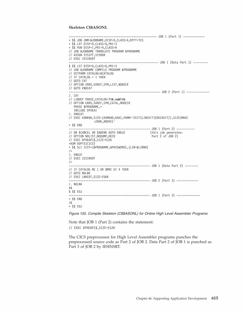
Skeleton C$$ASONL
Note that JOB 1 (Part 2) contains the statement:// EXEC DFHEAP1$,SIZE=512K
The CICS preprocessor for High Level Assembler programs punches thepreprocessed source code as Part 2 of JOB 2. Data Part 2 of JOB 1 is punched asPart 3 of JOB 2 by IESINSRT.
----------------------------------------------------- JOB 1 (Part 1) -------------* $$ JOB JNM=&JOBNAME,DISP=D,CLASS=A,NTFY=YES* $$ LST DISP=D,CLASS=Q,PRI=3* $$ PUN DISP=I,PRI=9,CLASS=A// JOB &JOBNAME TRANSLATE PROGRAM &PROGNAME// ASSGN SYSIPT,SYSRDR// EXEC IESINSRT------------------------------------------------------ JOB 1 (Data Part 1) ---------$ $$ LST DISP=D,CLASS=Q,PRI=3// JOB &JOBNAME COMPILE PROGRAM &PROGNAME// SETPARM CATALOG=&CATALOG// IF CATALOG = 1 THEN// GOTO CAT// OPTION ERRS,SXREF,SYM,LIST,NODECK// GOTO ENDCAT------------------------------------------------------- JOB 2 (Part 1) --------------/. CAT// LIBDEF PHASE,CATALOG=lib.sublib// OPTION ERRS,SXREF,SYM,CATAL,NODECK
PHASE &PROGNAME,*INCLUDE DFHEAI
/. ENDCAT// EXEC ASMA90,SIZE=(ASMA90,64K),PARM=’EXIT(LIBEXIT(EDECKXIT)),SIZE(MAXC
-200K,ABOVE)’* $$ END------------------------------------------------- JOB 1 (Part 2) -----------// ON $CANCEL OR $ABEND GOTO ENDJ2 (this job generates:// OPTION NOLIST,NODUMP,DECK Part 2 of JOB 2)// EXEC DFHEAP1$,SIZE=512K*ASM XOPTS(CICS)* $$ SLI ICCF=(&PROGNAME,&PASSWORD),(LIB=&LIBNO)/*/. ENDJ2// EXEC IESINSRT/*------------------------------------------------- JOB 1 (Data Part 2) --------// IF CATALOG NE 1 OR $MRC GT 4 THEN// GOTO NOLNK// EXEC LNKEDT,SIZE=256K------------------------------------------------- JOB 2 (Part 3) -------------/. NOLNK#&$ $$ EOJ------------------------------------------------- JOB 1 (Part 3) --------------* $$ END/&* $$ EOJ
Figure 155. Compile Skeleton (C$$ASONL) for Online High Level Assembler Programs
Chapter 46. Supporting Application Development 615

Compile Example (Part 1)Skeleton C$QASONL is used as an example for showing a compile skeleton(Figure 156) and the jobs it generates (Figure 157 on page 617).
If the DB2 Server for VSE is not installed in PRD2.DB2740, you must change theLIBDEF statement accordingly.
-------------------------------------------- JOB 1 (Part 1)-----------------------* $$ JOB JNM=&JOBNAME,DISP=D,CLASS=A,NTFY=YES* $$ LST DISP=D,CLASS=Q,PRI=3* $$ PUN DISP=I,DEST=*,PRI=9,CLASS=A// JOB &JOBNAME DB2 PRE PROCESS &PROGNAME// ASSGN SYSIPT,SYSRDR// EXEC IESINSRT-------------------------------------------- JOB 2 (Part 1) ----------------------$ $$ LST DISP=D,CLASS=Q,PRI=3$ $$ PUN DISP=I,DEST=*,PRI=9,CLASS=A// JOB &JOBNAME CICS PRE PROCESS &PROGNAME// ASSGN SYSIPT,SYSRDR// EXEC IESINSRT-------------------------------------------- JOB 3 (Part 1) ----------------------$ $$ LST DISP=D,CLASS=Q,PRI=3// JOB &JOBNAME COMPILE PROGRAM &PROGNAME// LIBDEF *,SEARCH=PRD2.DB2740// SETPARM CATALOG=&CATALOG// IF CATALOG = 1 THEN// GOTO CAT// OPTION ERRS,SXREF,SYM,LIST,NODECK// GOTO ENDCAT/. CAT// LIBDEF PHASE,CATALOG=lib.sublib// OPTION ERRS,SXREF,SYM,CATAL,NODECK
PHASE &PROGNAME,*INCLUDE DFHEAI
/. ENDCAT// EXEC ASMA90,SIZE=(ASMA90,64K),PARM=’EXIT(LIBEXIT(EDECKXIT)),SIZE(MAXC
-200K,ABOVE)’$ $$ END----------------------------------------------- JOB 2 (Part 2) -------------------// ON $CANCEL OR $ABEND GOTO ENDJ3// OPTION NOLIST,NODUMP,DECK// EXEC DFHEAP1$,SIZE=512K*ASM XOPTS(CICS)* $$ END----------------------------------------------- JOB 1 (Part 2) -------------------// ON $CANCEL OR $ABEND GOTO ENDJ2// LIBDEF *,SEARCH=PRD2.DB2740// EXEC PROC=ARIS74DB// EXEC PROC=ARIS74PL// EXEC ARIPRPA,SIZE=AUTO,PARM=’ISOL(&ISOL),&BLOCK,PREP=&PROGNAME,
DBNAME=&DBNAX0&DBNAX1&DBNAX2,USER=&SQLUSERID/&SQLPW’* $$ SLI ICCF=(&PROGNAME,&PASSWORD),LIB=(&LIBNO)/*/* ENDJ2// EXEC IESINSRT----------------------------------------------- JOB 2 (Part 3) -------------------/*/*/. ENDJ3
Figure 156. Compile Skeleton (C$QASONL) for Online High Level Assembler Programs forDB2 (Part 1 of 2)
616 z/VSE V4R3.0 Administration

Compile Example (Part 2)The following 3 jobs are generated by skeleton C$QASONL (shown in Figure 156on page 616).
// EXEC IESINSRT----------------------------------------------- JOB 3 (Part 2) --------------------/*// IF CATALOG NE 1 OR $MRC GT 4 THEN// GOTO NOLNK
INCLUDE ARIRRTED// EXEC LNKEDT,SIZE=256K/. NOLNK#&$ $$ EOJ$ $$ END-------------------------------------------------- JOB 2 (Part 4) -----------------#&$ $$ EOJ* $$ END----------------------------------------------- JOB 1 (Part 3) --------------------/&* $$ EOJ
Figure 156. Compile Skeleton (C$QASONL) for Online High Level Assembler Programs forDB2 (Part 2 of 2)
---------------------------------------------- JOB 1 -------------------------------* $$ JOB JNM=COMUSER,DISP=D,CLASS=A,NTFY=YES* $$ LST DISP=D,CLASS=Q,PRI=3* $$ PUN DISP=I,PRI=9,CLASS=A// JOB COMUSER DB2 PRE PROCESS TEST// ASSGN SYSIPT,SYSRDR// EXEC IESINSRT// ON $CANCEL OR $ABEND GOTO ENDJ2// LIBDEF *,SEARCH=PRD2.DB2740// EXEC PROC=ARIS74DB// EXEC PROC=ARIS74PL// EXEC ARIPRPA,SIZE=AUTO,PARM=’ISOLATION(CS),NOBLK,PREP=TEST *
DBNAME=SQLDB,USERID=SQLDBA/SQLDBAPW’* $$ SLI ICCF=(TEST),LIB=(0099)/*/. ENDJ2// EXEC IESINSRT/&* $$ EOJ------------------------------------------- JOB 2 ----------------------------* $$ LST DISP=D,CLASS=Q,PRI=3* $$ PUN DISP=I,PRI=9,CLASS=A// JOB COMUSER CICS PRE PROCESS TEST// ASSGN SYSIPT,SYSRDR// EXEC IESINSRT
Figure 157. Jobs Generated by Compile Skeleton C$QASONL (Part 1 of 2)
Chapter 46. Supporting Application Development 617

For EXEC CICS batch client programs, skeletons are available in VSE/ICCF library59 as follows:SKEXCIAS High Level Assembler for VSESKEXCICV COBOL for VSE/ESASKEXCIPL PL/I for VSE/ESASKEXCICN C for VSE/ESA
Creating an Application Job StreamThe Create Application Jobstream dialog helps you create job streams. You can savethe input parameters that you specify in a VSE/ICCF library member for futureuse. If you create another job stream with similar parameters, you can use thesaved input for default values.
To access the dialog, start with the z/VSE Function Selection panel and select:5 (Program Development)2 (Create Application Job Stream)
The programmer (PROG) must choose selection 3 on the z/VSE Function Selectionpanel. The dialog displays the Create Application Job Stream: Create or Modify panel.
If you used the dialog before and saved your input parameters, you can use themas defaults. This is helpful if you are creating a job stream with parameters that are
// ON $CANCEL OR $ABEND GOTO ENDJ3// OPTION NOLIST,NODUMP,DECK// EXEC DFHEAP1$,SIZE=512K*ASM XOPTS(CICS)/*/. ENDJ3// EXEC IESINSRT/&* $$ EOJ -------------------------------------------- JOB 3 -----------------------------* $$ LST DISP=D,CLASS=Q,PRI=3// JOB COMUSER COMPILE PROGRAM TEST// SETPARM CATALOG=2// IF CATALOG = 1 THEN// GOTO CAT// OPTION ERRS,SXREF,SYM,LIST,NODECK// GOTO ENDCAT/. CAT// LIBDEF PHASE,CATALOG=lib.sublib// LIBDEF *,SEARCH=PRD2.DB2740// OPTION ERRS,SXREF,SYM,CATAL,NODECK
PHASE TEST,*INCLUDE DFHEAI
/. ENDCAT// EXEC ASMA90,SIZE=(ASMA90,64K),PARM=’EXIT(LIBEXIT(EDECKXIT)),SIZE(MAXC
-200K,ABOVE)’/*// IF CATALOG NE 1 OR $MRC GT 4 THEN// GOTO NOLNK
INCLUDE ARIRRTED// EXEC LNKEDT,SIZE=256K/. NOLNK/&* $$ EOJ
Figure 157. Jobs Generated by Compile Skeleton C$QASONL (Part 2 of 2)
618 z/VSE V4R3.0 Administration

similar to ones in a previous job stream. The input was saved in a VSE/ICCFlibrary member. Specify the name of the member on the panel.
If you are creating a new job stream, simply press ENTER. You are asked to definenew parameters. On the next panel, specify the following:
PROGRAM NAMEEnter the name of the program. The name cannot be:v ALLv ROOTv S
LIBRARY and SUBLIBRARY NAMESpecify the library and sublibrary where the program resides. The dialogsearches for the program in this library and sublibrary.
If the sublibrary is defined in the LIBDEF PHASE,SEARCH= statement forthe partition where the job runs, you can leave these fields blank.
From the Select Functions panel, select any optional functions for your job stream. Ifyour program uses any Input/Output (I/O) devices, other than disk, you canprovide specifications for individual devices. Enter:
1 - YES (Provide specifications)2 - NO (Do not provide specifications)
If you specify 1 (YES), the dialog displays additional panels. The options you canspecify are described in the following topics, beginning with “PrinterSpecifications” on page 620.
When you finish entering your options (or choose not to specify any), you can doone of two things:1. Return to the beginning of the dialog to review and possibly change the
options.The dialog redisplays the Select Functions panel. Again, indicate the options youwant to review or specify.
2. Continue with the dialog.
After you continue, you are asked whether you want to save the parameters. Ifyou want to save them, enter the name of a VSE/ICCF library member. The dialogstores the parameters in the member in your default primary library.
If you do not want to save the values, just press ENTER.
The dialog creates a job with the default name PRGEXE. On the Job Dispositionpanel, you can submit the job to batch, file it in your default primary library, orboth.
Creating Application Job Stream
Chapter 46. Supporting Application Development 619

Printer SpecificationsYou can define the following requirements for up to three printouts:v Printer addressv Logical unit
Specify SYSLST or SYS000 - SYS254.4
v Output classv Number of copiesv Form number
This specifies that a special form is used for the output.v Forms control buffer (FCB)v Train image buffer (UCB)
Reader or Punch SpecificationsYou can specify the following units to be used by your program:v Reader logical unit
If your program has card input from a reader other than SYSRDR, specify thelogical unit (SYS000 - SYS254).4
v Punch or punch to tape– Logical unit
If your program does not write to SYSPCH, specify the logical unit (SYS000 -SYS254).
– Tape addressIf your program punches to tape, enter the physical tape address.
Tape SpecificationsYou can define the following tape I/O specifications for up to four tapes:v Tape addressv Logical unit
Specify the logical unit which your program uses to reference the tape (SYS000 -SYS254).4
v Tape volume IDIf you specify an ID, write down the value you use. You will need to know itlater, if you use the tape for input.You should have comments and a PAUSE statement in the job stream for tapemount instructions.
v File name (name which your program uses to reference the tape file).v File ID
Specify an optional name that is associated with the file on the tape. If you entera file ID, write down the value you specify. You will need to know it later whenyou process the file.
v File dateFor output tapes, this is the expiration date. For input tapes, it is the creationdate.The date format is YYYY/DDD, where YYYY is the year and DDD is the day ofthe year.
4. Please take account of the NPGR value that is set in the ALLOC procedure. This value might be lower than 255.
Creating Application Job Stream
620 z/VSE V4R3.0 Administration

Data SpecificationsYou can choose how data is included in your job stream:1. From a VSE/ICCF library member when the job stream runs.
You are asked for the name of the library member that contains the data.Specify the password, if the member is password-protected.
2. Data entered from the dialog.You can enter up to three lines of data. The dialog includes the data in the jobstream.
Job Information SpecificationsYou can specify the following job options:v UPSI
You can set up to eight user program switches. Positions 0 - 7 of the UPSI byteare set from left to right. For each program switch, specify:
0 - Switch is set off1 - Switch is set onx - Switch is unchanged
v Job dateSpecify a date to override the system date.
In addition, you may include COMMENT and PAUSE statements.
Creating Application Job Stream
Chapter 46. Supporting Application Development 621

Creating Application Job Stream
622 z/VSE V4R3.0 Administration

Chapter 47. Regenerating the Supervisor, VSE/POWER, orVSE/ICCF
This chapter describes various tasks related to the regeneration of z/VSE functions.
The generation of the supervisor should only be performed if you have modifiedany generation macros. For example, you might be using generation macros thatare supplied by a vendor. There are no parameters available that you can modify.
To generate the supervisor it is necessary to first install the Generation Feature. Thiscan be done during the installation of z/VSE or later using the dialog provided forit.
For the regeneration of VSE/POWER and VSE/ICCF, z/VSE provides skeletons.
This chapter contains these main topics:v “Installing the Generation Feature”v “Regenerating the Supervisor”v “Regenerating VSE/POWER” on page 624v “Regenerating VSE/ICCF” on page 628
Installing the Generation FeatureThe z/VSE distribution tape(s) contain source code that provides generationcapability for the supervisor modules. Installation of this code (called the GenerationFeature) is optional. You will normally not need to regenerate the supervisor, unlessyou have modified any generation macros.“Installing z/VSE Generation Feature”in the manual z/VSE Installation provides details for installing the GenerationFeature.
Regenerating the SupervisorFrom z/VSE 4.1 onwards, only one supervisor ($$A$SUPI) is shipped with z/VSE.You should not normally need to change this supervisor.
If, you do wish to change the supervisor and/or generate a listing of thesupervisor, you can use the generation feature to do so. However, you cannotmodify any of the generation options.
The value of the TRKHLD parameter (of the FOPT macro) is specified using theIPL SYS command. This parameter specifies the “number of hold requests” and hasa default value of 12.
To change the value of the TRKHLD parameter in the SYS command, select theInteractive Interface dialog Tailor IPL Procedure (Fast Path 242), and then optionModify SYS command parameters for the procedure you wish to change. Fordetails, see “Tailoring the IPL Procedure” on page 14.
For an example of how to generate the supervisor, refer to the skeleton SKSUPASMprovided in VSE/ICCF library 59.
© Copyright IBM Corp. 1984, 2010 623

Regenerating VSE/POWERSkeleton SKPWRGEN defines the options for VSE/POWER generation. It reflectsthe values which were used to generate the supplied VSE/POWER phaseIPWPOWER (identified by --V100--).
The skeleton is shipped in VSE/ICCF library 59. If you use the skeleton, copy itfirst to your VSE/ICCF primary library and edit the copied skeleton. Figure 158 onpage 625 shows the skeleton. Comments included in the skeleton are not shown.You can change the operands of the POWER macro. Refer to “POWER GenerationMacro” in the manual VSE/POWER Administration and Operation for a descriptionof the POWER macro and operands.
In the skeleton, each operand is on a separate line. When you edit the file, do notdelete the continuation characters (*) in column 72.
In the POWER statement, replace --V100-- with your own VSE/POWER phasename. z/VSE uses the pregenerated VSE/POWER phase IPWPOWER. Do not usethe name IPWPOWER since IPWPOWER is serviced together with VSE/POWER. Ifyou generate your own VSE/POWER, you must also tailor skeleton SKPWSTRTwhich calls IPWPOWER. In SKPWSTRT, change the statement// EXEC IPWPOWER
and replace IPWPOWER with the phase name you specified for --V100--. Fordetails about skeleton SKPWSTRT, see “Skeletons for Starting Up VSE/POWER”on page 50.
Regenerating VSE/POWER
624 z/VSE V4R3.0 Administration

Note: The statement// EXEC ASMA90,SIZE=(ASMA90,64K),PARM=’EXIT(LIBEXIT(EDECKXIT)),SIZE(MAXC
-200K,ABOVE)’
calls the High Level Assembler.
You may add the following parameters to the skeleton (after the line --V100--POWER shown in Figure 158):v If you want to use a master password, add:
MPWD=--V200--, *
The variable --V200-- is the master password.v If you want to activate VSE/POWER PNET, add:
PNET=--V101--, *
* $$ JOB JNM=POWERGEN,CLASS=0,DISP=D* $$ LST CLASS=Q// JOB POWER GENERATION// LIBDEF *,SEARCH=(PRD2.GEN1,PRD1.MACLIB)// LIBDEF PHASE,CATALOG=PRD2.CONFIG// OPTION CATAL// EXEC ASMA90,SIZE=(ASMA90,64K),PARM=’EXIT(LIBEXIT(EDECKXIT)),SIZE(MAXC
-200K,ABOVE)’PWR TITLE ’VSE/POWER - IPWPOWER GENERATION ’
EJECTSPACE 3
--V100-- POWER *ACCOUNT=YES, *CLRPRT=YES, *COPYSEP=YES, *DBLKGP=8, *DBLK=0, *FEED=NO, *JLOG=YES, *JSEP=(0,0), *LTAB=(10,00,05,10,15,20,25,30,35,40,45,50,56), *MEMTYPE=P, *MRKFRM=YES, *MULT12=NO, *NTFYMSG=100, *PAUSE=NO, *PRI=3, *RBS=(0,0), *SECNODE=AAAA, *SHARED=NO, *STDCARD=(0,0), *STDLINE=(0,0), *SPLIM=90, *SPOOL=YES
EJECT*/INCLUDE SKPWRBSC
.
.*/INCLUDE SKPWRSNA
END/*// EXEC LNKEDT,PARM=’MSHP’/&* $$ EOJ
Figure 158. Skeleton SKPWRGEN (VSE/POWER Generation)
Regenerating VSE/POWER
Chapter 47. Regenerating the Supervisor, VSE/POWER, or VSE/ICCF 625

The variable --V101-- is the name of your PNET phase. This is the name of thenetwork definition table as specified for the first PNODE macro withLOCAL=YES.
v If you have SNA workstations attached to your system, add:SNA=YES, *
For the connection between VSE/POWER and VTAM, the VTAM APPLIDPOWER is provided in the VTAM application startup book. The same APPLID isused, if you add SNA=YES to the skeleton.
v If you want to use user-written exit routines, add:JOBEXIT=--V102--, *
orJOBEXIT=(--V102--,--V103--), *
NETEXIT=--V104--, *or
NETEXIT=(--V104--,--V105--), *
OUTEXIT=--V106--, *or
OUTEXIT=(--V106--,--V107--), *
XMTEXIT=--V108--, *or
XMTEXIT=(--V108--,--V109--), *
Where:
--V102-- is the name of the user-written job exit routine.
--V103-- is the number of bytes reserved as work area.
--V104-- is the name of the user-written PNET receiver exit routine.
--V105-- is the number of bytes reserved as work area.
--V106-- is the name of the user-written output exit routine.
--V107-- is the number of bytes reserved as work area.
--V108-- is the name of the user-written PNET transmitter exit routine.
--V109-- is the number of bytes reserved as work area.
If you use the PNET, SNA, or exit parameters, make sure that you have acontinuation character (*) in column 72.
If you have VSE/POWER RJE (Remote Job Entry) definitions for BSC workstations, you should include the skeleton SKPWRBSC. Remove the asterisk (*) infront of the statement:*/INCLUDE SKPWRBSC
You must also tailor the SKPWRBSC skeleton, which you can find in VSE/ICCFLibrary 59.
If you used the remote configuration dialogs to define SNA workstations, youshould include the skeleton SKPWRSNA. Remove the asterisk (*) in front of thestatement:*/INCLUDE SKPWRSNA
SKPWRSNA contains a predefined set of SNA workstations which can beconfigured with the remote configuration dialogs. The dialog generates the VTAM
Regenerating VSE/POWER
626 z/VSE V4R3.0 Administration

line, PU, and LU definitions. Under “VSE/POWER SNA Skeleton SKPWRSNA”,the manual z/VSE Networking Support describes the SKPWRSNA skeleton and theremote configuration dialogs.
After making the changes, run the DTRSEXIT macro. This macro deletes specificcomments from the skeleton. You should do this before you file the skeleton. Onthe command line, enter:
@DTRSEXIT
After the macro finishes, file the job. You can then submit it to the system forprocessing.
Regenerating VSE/POWER
Chapter 47. Regenerating the Supervisor, VSE/POWER, or VSE/ICCF 627

Regenerating VSE/ICCFz/VSE provides two phases for VSE/ICCF: DTSIGEN and DTSIGENM. They canboth be used without regeneration. DTSIGEN is the default VSE/ICCF whileDTSIGENM provides larger interactive partitions.
If you need to regenerate VSE/ICCF because you want different options to be set,proceed as follows:v Define and create new phase via skeleton SKICFGEN.v Shutdown VSE/ICCF.v Restart VSE/ICCF to activate the new phase.
The SKICFGEN skeleton defines the options for VSE/ICCF generation.
The skeleton is shipped in VSE/ICCF library 59. If you use the skeleton, copy itfirst to your VSE/ICCF primary library and edit the copied skeleton.
Figure 159 shows the skeleton. Comments included in the skeleton are not shown.You can edit and change the generation operands for the DTSOPTNS macro.Under “VSE/ICCF Tailoring Options (DTSOPTNS Macro)”, the manual VSE/ICCFAdministration and Operation describes the DTSOPTNS macro and its operands.
In the skeleton, each operand is on a separate line. When you edit the skeleton, donot delete the continuation characters X in column 72.
You can also change, add, or delete statements and operands, if required. Youshould not change the following operands. These are required for z/VSE.v ALTSECv COMLIBv CRJE
Regenerating VSE/ICCF
628 z/VSE V4R3.0 Administration

Note: The statement// EXEC ASMA90,SIZE=(ASMA90,64K),PARM=’EXIT(LIBEXIT(EDECKXIT)),SIZE(MAXC
-200K,ABOVE)’
calls the High Level Assembler.
* $$ JOB JNM=ICCFGEN,CLASS=S,DISP=D* $$ LST CLASS=Q// JOB ICCF GENERATIONLIBDEF PHASE,CATALOG=PRD2.CONFIG// OPTION CATAL
PHASE DTSIGEN,*// EXEC ASMA90,SIZE=(ASMA90,64K),PARM=’EXIT(LIBEXIT(EDECKXIT)),SIZE(MAXC
-200K,ABOVE)’DTSOPTNS ALTSEC=NO, X
ATN2741=YES, XCANKEY=PA2, XCISIZE=2048, XCOMLIB=2, XCRJE=(YES,Q,A,D,A), XDISPKEY=PA3, XDYNSPC=NO, XEDFLAG=73, XEDEND=72, XFILEVER=NO, XHCLINE=132, XINTCOMP=YES, XINTRVAL=1, XKATAKAN=NO, XLOADPRT=YES, XNBUFS=20, XNRECS=22, XNUSRS=30, XNPARTS=5, XNTASKS=4, XPGMRINP=5, XPGMRLST=6, XPGMRPCH=7, XPGMRPIN=8, XPGMRLOG=9, XPSIZE=256, XPARTN=(1,1024,4,I, X2,384,4,A, X3,384,4,A, X4,512,4,BA, X5,512,4,BA), XPARTX=, XRDR=FFC, XRDR2=FFA, XPCH=FFD, XPRT=FFE, XSPOOL=250, XTIOA40=600, XTIOA00=600, XTCTOFS=8
DTSIGENEND
/*// EXEC LNKEDT,PARM=’MSHP’/&* $$ EOJ
Figure 159. VSE/ICCF Generation (SKICFGEN Skeleton)
Regenerating VSE/ICCF
Chapter 47. Regenerating the Supervisor, VSE/POWER, or VSE/ICCF 629

After making the changes, run the DTRSEXIT macro. This macro deletes specificcomments from the skeleton. You should do this before you file the skeleton. Onthe command line, enter:
@DTRSEXIT
After the macro finishes, file the job. You can then submit it to the system forprocessing.
VSE/ICCF DTSFILE Generation Parameters
Pregenerated Libraries and User-IDsThe VSE/ICCF DTSFILE generated by z/VSE defines 199 libraries and 199VSE/ICCF user-ID records. Note that some libraries are reserved for z/VSE. Themembers that z/VSE ships in these libraries take up approximately 20% of thespace reserved for the DTSFILE.
Skeleton SKICFFMTWith the skeleton SKICFFMT, you can reformat the DTSFILE to create up to 99user-ID records and up to 9999 libraries. This skeleton, which is a member ofVSE/ICCF library 59, has the original values that z/VSE specifies for the file.Figure 160 shows the FORMAT and ADD statements used for the DTSFILE. For adetailed description of skeleton SKICCFMT, see “Reformatting the VSE/ICCFDTSFILE” on page 170.
z/VSE requires that you define all VSE/ICCF libraries with the DATE option. Fordetailed information, refer to the manual VSE/ICCF Administration and Operation.
Note: If necessary, you can extend the DTSFILE. You can do this by defining alarger extent on SYSWK1 or by defining extents on several volumes. Forinformation on how to use the skeleton SKDTSEXT to extend the DTSFILE,refer to “Using Skeleton SKDTSEXT” on page 167.
Regenerating VSE/ICCF
630 z/VSE V4R3.0 Administration

FORMAT LIBRARIES(199) USERS(199)* ADD LIBRARY 1 . . .ADD LIBRARY FREESPACE(40) DATE* ADD LIBRARY 2 . . .ADD LIBRARY FREESPACE(10) DATE* ADD LIBRARIES 3,4,5, AND 6 . . .ADD LIBRARY MAXDIR(200) FREESPACE(25) DATE NOCOMMON PUBLICADD LIBRARY MAXDIR(200) FREESPACE(25) DATE NOCOMMON PUBLICADD LIBRARY MAXDIR(200) FREESPACE(25) DATE NOCOMMON PUBLICADD LIBRARY MAXDIR(200) FREESPACE(25) DATE NOCOMMON PUBLIC* ADD LIBRARIES 7 THRU 49 . . .ADD LIBRARY MAXDIR(200) FREESPACE(25) DATEADD LIBRARY MAXDIR(200) FREESPACE(25) DATE...ADD LIBRARY MAXDIR(200) FREESPACE(25) DATEADD LIBRARY MAXDIR(200) FREESPACE(25) DATE* ADD LIBRARIES 50 THRU 68 . . .ADD LIBRARY DATE NOCOMMON PUBLICADD LIBRARY DATE NOCOMMON PUBLIC...ADD LIBRARY DATE NOCOMMON PUBLICADD LIBRARY DATE NOCOMMON PUBLIC* ADD LIBRARIES 69 THROUGH 199ADD LIBRARY MAXDIR(200) FREESPACE(25) DATEADD LIBRARY MAXDIR(200) FREESPACE(25) DATE...ADD LIBRARY MAXDIR(200) FREESPACE(25) DATEADD LIBRARY MAXDIR(200) FREESPACE(25) DATE
Figure 160. Code Example for Formatting the DTSFILE
Regenerating VSE/ICCF
Chapter 47. Regenerating the Supervisor, VSE/POWER, or VSE/ICCF 631

Regenerating VSE/ICCF
632 z/VSE V4R3.0 Administration
Chapter 48. Using RPG II With the CICS Transaction Server
This chapter describes how you can migrate DOS/VS RPG II programs, macros,and samples, so they can be used in a CICS Transaction Server environment (insteadof a CICS/VSE environment). This might be necessary because CICS/VSE is nolonger shipped on the Extended Base Tape of z/VSE.
z/VSE provides the Jobs RPGINST and RPGSAMPL in VSE/ICCF Library 59.These Jobs migrate the parts of CICS/VSE that are required to support RPG II in aCICS Transaction Server environment.
This chapter contains these main topics:v “Running Job RPGINST”v “Running Job RPGSAMPL” on page 634
Running Job RPGINSTThe Job RPGINST performs this processing:1. Defines a new sublibrary called PRD2.RPGII.2. Linkedits the phase DFHERP1$ (the CICS/VSE RPGII translator) into the new
sublibrary (PRD2.RPGII).3. Catalogs these CICS/VSE BMS Map structures (A-books) into sublibrary
PRD2.RPGII:v DFHANRATv DFHANRWCv DFHMDCv DFHMDCLv DFHMDFv DFHMDIv DFHMRPGv DFHMSDv DFHPRMCKv DFHSYS
4. Catalogs these R-type members into sublibrary PRD2.RPGII:v DFHAIDv DFHEIBLKv DFHEIVARv DFHBMSCAv DFHMSRCA
Job RPGINST must have completed successfully before you can add the newsublibrary PRD2.RPGII to the LIBDEFs of member C$$RPONL.
You can find the member C$$RPONL in VSE/ICCF Library 2.
© Copyright IBM Corp. 1984, 2010 633

Running Job RPGSAMPLJob RPGSAMPL catalogs CICS/VSE-supplied RPG Sample applications intosublibrary PRD2.RPGII.
These are the RPG Sample applications that job RPGSAMPL will catalog (as R-typemembers):v DFHXFILEv DFHXLOGAv DFHXL86Ov DFHXRALLv DFHXRBRWv DFHXRCOMv DFHXRMAv DHFXRMBv DFHXRMCv DFHXRMDv DFHXRMKv DFHXRMLv DFHXRMNUv DHFXRRENv DFHXRREPv DFH29080
634 z/VSE V4R3.0 Administration

Chapter 49. Displaying System Status and StorageInformation
This chapter describes the functionality that is available to you for displayingstatus and storage information of the z/VSE and CICS systems.
It contains these main topics:v “Dialogs Available”v “Using the Display Storage Layout Dialog” on page 637v “Changing the Dialog Interval Time” on page 641
Related Topics:
For details of the ... Refer to ...
VSE Navigator, which uses Java classes tocollect data and report-on system activity
“Using VSE Java Beans to Implement JavaPrograms” in the z/VSE e-business ConnectorsUser's Guide, SC33-8310.
VSE Monitoring Agent, which allows you tocollect data from your z/VSE systems
“Collecting Data via the VSE MonitoringAgent” in the z/VSE e-business ConnectorsUser's Guide, SC33-8310.
Dialogs Availablez/VSE provides three dialogs for system status and storage display:v Display System Activityv Display Channel and Device Activityv Display CICS TS Storagev Display Storage Layout
Display System Activity or Channel and Device ActivityThe two dialogs, Display System Activity and Display Channel and Device Activity,provide system status information for daily operation. For this reason, these twodialogs are described in detail in the manual z/VSE Operation under “DisplayingSystem Activity” and under “Displaying Channel and Device Activity”.
The system administrator can access these dialogs from the z/VSE Function SelectionPanel as follows:1. The Display System Activity dialog with Fast Path 361.2. The Display Channel and Device Activity dialog with Fast Path 362.
The display of the first dialog is updated automatically in intervals. This interval,10 seconds for example, can be changed by the system administrator. How tochange the interval time for this dialog is described under “Changing the DialogInterval Time” on page 641.
For the second dialog, press ENTER to get an updated display.
© Copyright IBM Corp. 1984, 2010 635

Display CICS TS StorageFor tuning and debugging purposes, a detailed display of the CICS TS partitionlayout may be required. z/VSE provides such a display via Fast Path 364. Thedisplay provides detailed information about storage allocation and usage as shownin Figure 161. The help text (PF1) provides a description of the information shown.
For a detailed discussion of CICS TS virtual storage refer to the CICS PerformanceGuide.
Instead of using the dialog, it may be sometimes more convenient entering thecommand IEDC on the CICS TS command line to get the same display.
IESADMDCST DISPLAY CICS TS STORAGE Time: 09:40:19Applid: DBDCCICS Sysid: CIC1 Jobname: CICSICCF CICS TS Level: 111
Storage Protection ...... INACTIVE Reentrant Programs ..... PROTECTCICS Trace Table size.. 80
Extended DSA: (All sizes in kbyte) LIMIT 25600ECDSA EUDSA ESDSA ERDSA Totals
Current DSA Size ............. 2048 1024 1024 6144 10240Current DSA used ............. 1876 64 8 5220 7168*Peak DSA used ................ 1884 64 8 5220Peak DSA Size ................ 2048 1024 1024 6144 10240Largest free area/Free Storage 0.95 1.00 1.00 0.94Times short-on-storage (SOS).. 0 0 0 0 0
DSA: LIMIT 5120CDSA UDSA SDSA RDSA Totals
Current DSA Size .............. 512 256 512 512 1792Current DSA used .............. 344 8 456 344 1152*Peak DSA used ................. 352 28 456 344Peak DSA Size ................. 512 256 512 512 1792Largest free area/Free Storage. 0.88 1.00 0.86 0.86Times short-on-storage (SOS)... 0 0 0 0 0
PF1=HELP 2=REFRESH 3=END 4=RETURN
Figure 161. Display CICS TS Storage Dialog
Displaying System Status Information
636 z/VSE V4R3.0 Administration

Using the Display Storage Layout DialogThe data displayed by the Display Storage Layout dialog helps the systemadministrator optimize storage layout, particularly the partition layout. This is ofinterest especially for partitions which host permanently running programs, suchas VSE/POWER or VTAM or applications installed by the user.
The values displayed may indicate that changes like the following need to beconsidered:v A reduction or increase of the partition size.v A reduction or increase of the GETVIS area of a partition.
Accessing the DialogTo access the Display Storage Layout dialog, start with the z/VSE Function SelectionPanel and select:
3 (Operation)6 (System Status)3 (Display Storage Layout)
Figure 162 shows the initial display.
The panel is divided into a left part for static partitions and a right part fordynamic classes.
Address space IDs connected by -- indicate that the corresponding partitions sharetheir address space.
The 16M line symbolically marks the transition to 31-bit addresses (only shown forsystems with an address space > 16MB). An X above the 16M line indicates thatspace beyond 16M has been allocated for the corresponding partition. A | indicates
IESADMDSS1 DISPLAY STORAGE LAYOUT
------------------------------------------------------------------------------| Total SVA (31 bit): 14M PFIX (31 bit) Used: 2372K Limit: 47M |-----------------------------------------------------------------------| Data| X X X X X | | Space:| 16M - - - - - - - - - - - - - - - - | - - - - - - - - - - - - - - - | 9472K| X X X X X | || X X X X X X | || X X X X X X | || X X X X X X X X X X X X | || BG F1 F2 F3 F4 F5 F6 F7 F8 F9 FA FB | C J P R S Y Z || 0 1 2 3 4 5 6 7 8 9 A B | |-----------------------------------------------------------------------|| | SHARED PARTITIONS: none | Avail-| 5120K | Total SVA (24 bit): 3628K Unused: 768K | able:| | SUPERVISOR: 724K PFIX (24) Used: 336K Lim: 12M | 70M------------------------------------------------------------------------------Private space size: 70M Total virtual storage: 264MPARTITION ID / DYNAMIC CLASS: __ Specify for more information
PF1=HELP 2=REFRESH 3=END 4=RETURN 6=SVA
Figure 162. Dialog Entry Panel
Displaying Storage Layout
Chapter 49. Displaying System Status and Storage Information 637

that this space is used by another static partition in the same address space. Theaddress space IDs are shown below the partition IDs.
The size of the private area in each address space is shown at the bottom of thedisplay.
The allocations of the dynamic classes are shown on the right part with thecorresponding dynamic class IDs.
The panel allows you to specify the ID of a static partition or the class of adynamic partition or even a dynamic partition ID directly you want to display.After pressing ENTER, either the storage values of the partition selected are showntogether with the name of the job currently running in the partition or a table withthe active dynamic partitions of this class. Pressing PF6 on any panel gives you anadditional display showing the storage values for the SVA (shared virtual area).
Static Partition Layout PanelFigure 163 shows the static partition layout for an F8 (CICS2) partition. You get thisdisplay by entering F8 in the initial panel shown in Figure 162 on page 637.
The panel is divided into the GETVIS part and the program part. The left part ofthe GETVIS part shows GETVIS BELOW (<16M) information, whereas the rightpart shows information about GETVIS ANY.
Notes:
1. The GETVIS ANY area may reach into the GETVIS BELOW area, that means,the USED area (31 bit) and the FREE area (31 bit) include the corresponding24-bit areas, whereas the largest free block can include the 24-bit area.
2. Any GETVIS area not initialized appears as * on the panel together with amessage.
3. High Water Mark is the largest partition GETVIS size used in the current jobstep.
4. PFIX is the size of the fixed storage pages used by the operating system.
IESADMDSPL STATIC PARTITION LAYOUT
PARTITION: F8 JOB NAME: CICS2PHASE: DFHSIP
------------------------------------------------------------------------------’036FFFFF’X | GETVIS ANY |
| USED: 34M || FREE: 16M |
- -(16M)- - - - - - - - - - - - - - - - -| HIGH WATER MARK: 40M |A GETVIS BELOW | LARGEST FREE BLOCK: 16M || USED: 5560K | PFIX (31 BIT) USED: 0B || FREE: 5700K | PFIX (31 BIT) LIM.: 0B | 50M| HIGH WATER MARK: 11M | |
’00501000’X | LARGEST FREE BLOCK: 5632K V |------------------------------------------------------------------------------
PROGRAM AREA (EXEC SIZE) LOADED PHASE: 582B |’00500000’X PFIX (24) USED: 0B LIM.: 256K AVAILABLE: 3514B | 4096B------------------------------------------------------------------------------
PARTITION: 50M
PF1=HELP 2=REFRESH 3=END 4=RETURN 6=SVA
Figure 163. Static Partition Layout Panel
Displaying Storage Layout
638 z/VSE V4R3.0 Administration

The addresses shown in Figure 163 on page 638 have the following meaning:036FFFFF = end address of partition00501000 = start address of partition GETVIS00500000 = start address of partition
You may enter the ID of any static or dynamic partition directly on this panel. Youcan also enter the ID of a dynamic class to get the list of the active dynamicpartitions of that class displayed.
Dynamic Partition Layout PanelFigure 164 shows the layout of dynamic partition Y1 which is used as example.You get this display by entering in the initial panel ( Figure 162 on page 637) classZ and selecting on the subsequent panel Y1.
The GETVIS information shown is the same as for static partitions. In addition, thedynamic space GETVIS area is shown. The meaning of the addresses shown is asfollows:007FFFFF = end address of partition00620000 = start address of partition GETVIS00520000 = start address of partition00500000 = start address of dynamic space GETVIS
Notes:
1. The value 0 in GETVIS ANY means that the total GETVIS area is below 16MB.2. High Water Mark is the largest dynamic space GETVIS area size used in the
current VSE/POWER job.
If the value for FREE is frequently very low you should consider a larger size forthe dynamic space GETVIS area by decreasing the partition size. If the value forFREE is frequently very high, consider an increase of the partition size. Foradditional information, you may also refer to the chapter “Storage Management”in the manual z/VSE Guide to System Functions.
The panel allows you to specify for display the ID of a static partition, or the classof a dynamic partition, or a dynamic partition ID.
IESADMDDPL DYNAMIC PARTITION LAYOUTPARTITION: Y1 JOB NAME: PAUSEF7 PHASE: LIBR
------------------------------------------------------------------------------| GETVIS ANY || USED: 24K || FREE: 1896K |
- - - - - - - - - - - - - - - - - - - - -| HIGH WATER MARK: 24K |’007FFFFF’X A GETVIS BELOW | LARGEST FREE BLOCK: 1896K |
| USED: 24K | PFIX (31 BIT) USED: 0B || FREE: 1896K | PFIX (31 BIT) LIM.: 0B | 1920K| HIGH WATER MARK: 24K | |
’00620000’X | LARGEST FREE BLOCK: 1896K V |------------------------------------------------------------------------------
PROGRAM AREA (EXEC SIZE) LOADED PHASE: 80K |’00520000’X PFIX (24) USED: 0B LIM.: 48K AVAILABLE: 944K | 1024K------------------------------------------------------------------------------
DYNAMIC SPACE GETVIS USED: 24K |FREE: 104K | 128K
’00500000’X HIGH WATER MARK: 44K |------------------------------------------------------------------------------
PARTITION: 3072KPF1=HELP 2=REFRESH 3=END 4=RETURN 6=SVA
Figure 164. Dynamic Partition Layout Panel
Displaying Storage Layout
Chapter 49. Displaying System Status and Storage Information 639

SVA Layout PanelBy pressing PF6 on one of the previous panels you get the SVA layout of yoursystem; Figure 165 shows an example.
By pressing PF6 on this panel, you get back to the partition layout panel.
High Water Mark (HWM) is the largest size used since the last IPL. The meaningof the SVA addresses and size values is as follows:ADDRESSES:
058FFFFF = End address of SVA05269000 = Start address of system GETVIS area (31 bit)04B00000 = Start address of system program area (31 bit)0043FFFF = End address of virtual pool (V-POOL)00415000 = Start address of system label area (SLA)00288000 = Start address of system GETVIS area (24 bit)000C5000 = Start address of system program area (24 bit)000B5000 = Start address of SVA (system directory list, SDL)
GETVIS SIZE VALUES:6748K = Size of the system GETVIS area 31 bit (used and free,
including GETVIS control area).1588K = Size of the system GETVIS area 24 bit (used and free,
including GETVIS control area).SVA SIZE VALUES:
64K = Size of the virtual pool area (V-POOL)108K = Size of the system label area (SLA)64K = Size of the system directory list (SDL)
7588K = Size of the system program area (31 bit, used and free)172K = Sum of the size of the virtual pool area (V-POOL) and
size of the system label area (SLA)1868K = Size of the system program area (24 bit, used and free,
plus the size of the system directory list, SDL)
In the rightmost column the display shows;14M = Size of SVA (31 bit)
3628K = Size of SVA (24 bit)
IESADMDSV1 SHARED VIRTUAL AREA LAYOUT
------------------------------------------------------------------------------’058FFFFF’X SYSTEM GETVIS(31) USED: (HWM: 2788K ) | 1796K | |’05269000’X FREE: | 4952K | 6748K |----------------------------------------------------------------------| 14M
PROGRAM AREA(31) USED: | 6615K | |’04B00000’X AVAILABLE: | 973K | 7588K |==============================================================================’0043FFFF’X V-POOL | 64K | |’00415000’X SYSTEM LABEL AREA (SLA) | 108K | 172K |----------------------------------------------------------------------|
SYSTEM GETVIS(24) USED: (HWM: 984K ) | 868K | |’00288000’X FREE: | 720K | 1588K |----------------------------------------------------------------------| 3628K
PROGRAM AREA(24) USED: | 1482K | |’000C5000’X AVAILABLE: | 322K | |-------------------------------------------------------------| 1868K |
SYSTEM DIRECTORY LIST (SDL) | 64K | |’000B5000’X | | |------------------------------------------------------------------------------PF1=HELP 2=REFRESH 3=END 4=RETURN 6=PARTITION
Figure 165. SVA Layout Panel
Displaying Storage Layout
640 z/VSE V4R3.0 Administration

Changing the Dialog Interval TimeThe Display System Activity dialog automatically redisplays current system activityevery 15 seconds. You can change the interval time or have the display updatedonly when the user presses ENTER. The information below outlines what youmust do to make such changes.1. Use the Maintain Application Profiles dialog and locate the application profile
IESLA.2. Create a new application profile. Use profile IESLA as a model. You cannot
change the IESLA application profile itself.3. In the DATA field, enter the value you want for the time interval:
0 Use ENTER key to refresh the display.
10-59 Number of seconds for time interval.If you do not enter a value or you enter an incorrect one, the dialog does notdisplay an error message. It uses 15 as the default.
4. You must include the new profile either in a user profile, a selection panel, orboth. You can use the following dialogs:v Maintain User Profilesv Maintain Selection Panels
The dialog calculates information using VSE job accounting tables and othersystem control blocks. Therefore, VSE job accounting must be active in the system(SYS JA=YES at IPL time). If job accounting is not active, you cannot access thedialog. In this case, if you try to access the dialog, the system displays aninformation message on the selection panel.
All jobs should include // JOB and /& statements for correct job accounting and amore accurate display of system activity. This includes startup jobs and jobs thatare initiated during startup.
Changing Dialog Interval Time
Chapter 49. Displaying System Status and Storage Information 641

642 z/VSE V4R3.0 Administration

Chapter 50. Collecting Additional z/VSE Activity Data
This chapter describes how you can collect z/VSE activity in a CICS environment.
Related Topics:
For details of the ... Refer to ...
VSE Navigator, which uses Java classes tocollect data and report-on system activity
“Using VSE Java Beans to Implement JavaPrograms” in the z/VSE e-business ConnectorsUser's Guide, SC33-8310.
VSE Monitoring Agent, which allows you tocollect data from your z/VSE systems
“Collecting Data via the VSE MonitoringAgent” in the z/VSE e-business ConnectorsUser's Guide, SC33-8310.
The CICS-based enhancement takes measurements of the system andchannel/device activity of a z/VSE system. It stores the resulting data intemporary storage queues of the CICS Transaction Server (CICS TS) and activates auser exit program for further processing and analysis of the data. Note that thedata provided is almost identical to the data collected by the Display SystemActivity and the Display Channel and Device Activity dialogs. Both dialogs aredescribed in detail in the z/VSE Operation manual. You are recommended tofamiliarize yourself with these dialogs before working with the enhancementsdescribed in this chapter.
The advantage of the enhanced support is that activity data can be collected over alonger period of time, and can be saved for later analysis. Compared to thedialogs, the support is terminal-independent, because it communicates with theuser exit program only.
Notes:
1. The enhancement applies to data collection, but not to the interpretation of thedata collected. It is not a replacement for any kind of performance tool.
2. The activity measurements require the Job Accounting parameter in the IPLSYS command to be set (JA=YES). This is the z/VSE default in a newlyinstalled system.
The enhanced support includes CICS TS transactions, programs, queues, and askeleton as follows:
IEXM This is the main transaction used to start a measurement cycle.IEXM requires measurement parameters as input.
IEXA IEXM invokes this transaction if system activity is to be measured.IEXA stores the measurement data in the temporary storage queueIESAIEXA and activates a user exit program; either IESDALOG,which is the default, or the one specified as input parameter forIEXM.
IEXS IEXM invokes this transaction if channel/device activity is to bemeasured. IEXS stores the measurement data in the temporarystorage queue IEDSIEXS and activates a user exit program; eitherIESCHLOG, which is the default, or the one specified as inputparameter for IEXM.
© Copyright IBM Corp. 1984, 2010 643

IESAIEXA This is the CICS TS temporary storage queue in which transactionIEXA saves the current system activity data of a singlemeasurement sample for further processing by a user exit program.The data is overwritten when the next sample is taken.
IEDSIEXS This is the CICS TS temporary storage queue in which transactionIEXS saves the current channel/device activity data of a singlemeasurement sample for further processing by a user exit program.The data is overwritten when the next sample is taken.
IESDAOUT This is the default name of the temporary storage queue in whichthe sample user exit program in skeleton SKEXITDA saves thecontents of the temporary storage queue IESAIEXA (whichcontains system activity data of a single measurement sampleonly).
IESCHOUT This is the default name of the temporary storage queue intowhich the sample user exit program in skeleton SKEXITDA savesthe contents of the temporary storage queue IEDSIEXS (whichcontains channel/device activity data of a single measurementsample only).
IESDALOG IESDALOG is the default name of the user exit program to beactivated in case of system activity measurements.
IESCHLOG IESCHLOG is the default name of the user exit program to beactivated in case of channel/device activity measurements.
SKEXITDA This skeleton provides a sample user exit program for savingmeasurement data. You can use the skeleton to modify the userexit program provided to meet the specific needs of yourenvironment. The skeleton is available in VSE/ICCF library 59.
IESX This is the CICS TS abend code, which is set if a link to a user exitprogram is not possible.
Taking MeasurementsMain transaction IEXM is used to start a measurement cycle and requires thefollowing input parameters:v Name of user exit program (EXIT)v Activity to be measured (MEASURE)v Device range for channel/device (DEVRANGE)v Start time for measurement (STARTTIME)v Stop time for measurement (STOPTIME)v Interval for measurement (INTERVAL)v Cancel request (optional) (FORCE)
To start a measurement cycle, you must call transaction IEXM and provide theinput parameters needed for the measurement. You can enter the informationstring at the system console or at any other console of your z/VSE system. Accessis also possible from a native CICS TS subsystem. An example is given below:
IEXM E(IESDALOG) M(S) STA(070000) STO(073000) I(000100)
The input requests transaction IEXM to initiate a measurement cycle for systemactivity starting at 7:00 and ending at 7:30 and take these measurements inintervals of 60 seconds. The example uses the short forms of the input parameterswhich are described in detail below.
Activity Data
644 z/VSE V4R3.0 Administration

Format of Input Parameters for Transaction IEXMAn input parameter consists of a keyword plus its value surrounded inparentheses. If the value is not specified, the defaults become effective. Parametersare separated by one or more blanks. The maximum length allowed for the stringof input parameters is 100 characters.
If an error occurs in the parameter specifications, the user exit program is notifiedand no measurement transaction is activated.
Following is a description of the keywords allowed and the values that can bespecified for them. The characters shown in uppercase are required, those inlowercase are optional:
Exit(cccccccc)This parameter defines the name of the user exit program invoked bytransactions IEXM, IEXA, and IEXS.
The default name is IESDALOG for measuring system activity, andIESCHLOG for measuring channel and device activity.
Measure(Sa|Cda|All)This parameter defines the type of measurement to be taken:
Sa – System ActivityCda – Channel and Device ActivityAll – Both activities
The default is "All".
Devrange(ccc[-ccc])This parameter is only meaningful if Channel and Device activity is to bemeasured. The maximum range is from 000 to FFF, which is also thedefault.
STArttime(hhmmss)This parameter defines the measurement starting time. Allowed ranges are:v hh – from 00 to 99
A value greater 23 specifies a time on a day following the current one.v mm – from 00 to 59v ss – from 00 to 59
Note that the CICS TS rules for expiration times apply here. This meansthat if STArttime is smaller than the current time, two cases are possible:v If STArttime + 6 hours is greater than the current time, the task is
started immediately.v Otherwise the task is started on the next day.
The default is to start measurements immediately.
Example:
If the STArtime is specified as 100000 (10am) and the current time is 5pm(7 hours greater), the task will be started the next day. With the sameSTArtime and a current time of 3pm, the task would be startedimmediately.
STOptime(hhmmss)This parameter defines the stop time of measurement. Allowed ranges are:v hh – from 00 to 99
A value greater 23 specifies a time on a day following the current one.v mm – from 00 to 59
Activity Data - Measuring
Chapter 50. Collecting Additional z/VSE Activity Data 645

v ss – from 00 to 59
The STOptime has to be larger than the STArttime. A STOptime on a dayfollowing the STArtime day is possible with one exception: the crossing ofa year boundary is not allowed.
If the STArttime given causes the task to be started on the next day, 24hours are added to the given STOptime automatically. If the STOptime issmaller than the current time, measurement is not started.
The default is not to stop measurements, which means that the task maybe stopped by the user exit program or the operator, for example.
Interval(hhmmss)This parameter defines the interval from one measurement sample to thenext. Allowed ranges are:v hh – from 00 to 99v mm – from 00 to 59v ss – from 00 to 59
The lower limit is 10 seconds; the default is 15 seconds.
Force(Yes|No)This parameter allows you to cancel a running measurement to enforce, forexample, the start of a new measurement.v Yes – Cancel running measurement and start new measurement.v No – Start new measurement only if no previously defined measurement
is still scheduled. This is also the default.
Transactions IEXA and IEXSTransactions IEXA and IEXS are called by transaction IEXM to perform the actualactivity measurements.
IEXM invokes IEXA for system activity measurements, IEXS for channel and deviceactivity measurements. Both transactions store the measurement data in a CICS TStemporary storage queue, either in IESAIEXA or in IEDSIEXS, and activate thecorresponding user exit program.
The transactions activate the user exit program each time a measurement sample istaken and written to the CICS TS temporary storage. The exit program should saveall or important performance data stored in IESAIEXA or IEDSIEXS since the datais overwritten when the next measurement sample is taken.
The user exit program specifies a return code for the transaction by which it wasinvoked. This return code indicates either to continue measurements or toterminate them, even if ending time has not been reached yet. When the specifiedending time is reached, the exit program is invoked a last time to signal end ofmeasurements.
User Exit Description
Note: User-written exit programs with a name other than IESDALOG orIESCHLOG must be added to the CICS TS table PPT as follows:
DFHPPT TYPE=ENTRY,PROGRAM=name,RSL=PUBLIC
Activity Data - Measuring
646 z/VSE V4R3.0 Administration

User Exit Linkage DefinitionWhen transactions IEXM, IEXA, or IEXS establish linkage to a user exit program,they provide linkage information in the CICS TS COMMAREA. The layout of theCOMMAREA used to link to a user exit program is as follows:
Sample User Exit Program Provided by Skeleton SKEXITDASkeleton SKEXITDA in VSE/ICCF library 59 provides a sample user exit programfor both types of measurement data: system activity and channel/device activity.The primary purpose of the program is to save the data collected before a newmeasurement takes place. You can use SKEXITDA to tailor the exit programaccording to the needs of your installation.
You may activate the user exit program provided to see how it works. Proceed asfollows:1. Copy skeleton SKEXITDA from VSE/ICCF library 59 to your primary
VSE/ICCF library.2. Rename SKEXITDA to IESDALOG.3. Compile the sample program (without modifying it) by using the compile
option (8) of the Program Development Library dialog for online assemblerprograms.z/VSE creates a phase named IESDALOG.PHASE and catalogs it into thesublibrary specified in compile skeleton C$$ASONL. This skeleton is stored inVSE/ICCF library 2. The sublibrary should be defined in the active LIBDEFPHASE chain for the CICSICCF partition (as shipped, this is partition F2).
4. Activate the new CICS TS phase by calling transaction CEMT as follows:CEMT SET PROG(IESDALOG) NEW
5. Invoke transaction IEXM as shown under “Taking Measurements” on page 644.For channel and device activity data you must specify EXIT(IESDALOG) as forsystem activity. This is because IESDALOG, as provided in skeleton
Name Length Type Contents________________________________________________________________________________
UXPL 0 B IntroducerUXPLNAME 8 C ’IESUXPL ’, name of areaUXPLLENG 2 B Length of areaUXPLEC 1 B Event code, event which invoked exit program
UXECFITI X’01’ first time invocationUXECLATI X’02’ last time invocationUXECSYST X’11’ measurement data of system activityUXECCHDE X’21’ measurement data of channels and devices
UXPLRC 1 B Return code of the exit routineX’00’ ok - continue with measurement
anything else - stop measurementsUXPLERRC 1 B Error code
X’00’ ok - no error to reportanything else - refer to
Figure 171 on page 651UXPLERRI 8 C Further error informationUXPLSTAR 6 C Input parameter: start time (hhmmss)UXPLSTOP 6 C Input parameter: stop time (hhmmss)UXPLINTE 6 C Input parameter: interval (hhmmss)UXPLDEVR 7 C Input parameter: device range (ccc-ccc)UXPLTSQU 8 C Name of TS-Queue containing measurement data
(IESAIEXA or IEDSIEXS)
Figure 166. COMMAREA Layout for Linkage to User Exit Program
Activity Data - User Exit
Chapter 50. Collecting Additional z/VSE Activity Data 647

SKEXITDA, can handle both: system activity and channel/device activity data.If you do not specify IESDALOG explicitly, IEXM tries to invoke the defaultuser exit program IESCHLOG.
Transactions IEXA and IEXS save the measurement data of a single measurementsample in a temporary storage queue. The name of this queue is IESAIEXA forsystem activity data, and IEDSIEXS for channel and device activity data. Thetemporary storage queues IESDAOUT and IESCHOUT are used to save the CICSTS COMMAREA and the measurement records of a complete measurement cycle.Therefore, program IESDALOG moves the data of a single measurement samplefrom IESAIEXA into IESDAOUT and from IEDSIEXS into IESCHOUT.
Program IESDALOG communicates with IEXM and IEXA via the CICS TSCOMMAREA by receiving event codes and possibly error codes. IESDALOGresponds by providing a return code.
When modifying the user exit program, it is helpful to analyze the content ofIESDAOUT and IESCHOUT by using the CICS TS transaction CEBR. Examples ofCEBR displays for IESDAOUT and IESCHOUT are shown in Figure 167 throughFigure 170 on page 650. Figure 167 shows a sample CEBR IESDAOUT display incharacter representation:
Figure 168 on page 649 shows a sample CEBR IESDAOUT display in hexadecimalrepresentation:
CEBR TS QUEUE IESDAOUT RECORD 1 OF 10 COL 1 OF 2052ENTER COMMAND ===>
************************** TOP OF QUEUE *******************************00001 IESUXPL ..... 143740000015000-FFFIESAIEXA00002 IESUXPL ..... .........................IESAIEXA00003 IESAIEXA01/12/0014:37:12...3........................................r....00004 ....... C................................... .... ..........C.......... P00005 ....... Y100DITESYSADITTO ................ .... .....N.................00006 IESUXPL ..... .........................IESAIEXA00007 IESAIEXA01/12/0014:37:27............................................r....00008 ....... C................................... .... ..........C.......... P00009 ....... Y100DITESYSADITTO ................ .... .....N.................00010 IESUXPL ..... .........................IESAIEXA
************************* BOTTOM OF QUEUE *****************************
PF1 : HELP PF2 : SWITCH HEX/CHAR PF3 : TERMINATE BROWSEPF4 : VIEW TOP PF5 : VIEW BOTTOM PF6 : REPEAT LAST FINDPF7 : SCROLL BACK HALF PF8 : SCROLL FORWARD HALF PF9 : VIEW RIGHTPF10: SCROLL BACK FULL PF11: SCROLL FORWARD FULL PF12: UNDEFINED
Figure 167. IESDAOUT Display in Character Representation
Activity Data - User Exit
648 z/VSE V4R3.0 Administration

Figure 169 shows a sample CEBR IESCHOUT display in character representation:
Figure 170 on page 650 shows a sample CEBR IESCHOUT display in hexadecimalrepresentation:
CEBR TS QUEUE IESDAOUT RECORD 1 OF 10 COL 1 OF 2052ENTER COMMAND ===>
************************** TOP OF QUEUE *******************************00001 C9C5E2E4E7D7D34000360100004040404040404040404040404040F1F4F3F7F4F0F0F0F000002 C9C5E2E4E7D7D3400036110000404040404040404000000000000000000000000000000000003 C9C5E2C1C9C5E7C1F0F161F1F261F9F6F1F47AF3F77AF1F2AC42CBF359B2BA010000000000004 0004000000000040C3FF000000000000000000000000000000000000000000000000000000005 0001000000000040E8F1F0F0C4C9E3C5E2E8E2C1C4C9E3E3D6404040000000000000000000006 C9C5E2E4E7D7D3400036110000404040404040404000000000000000000000000000000000007 C9C5E2C1C9C5E7C1F0F161F1F261F9F6F1F47AF3F77AF2F7AC42CC01AFFA3E000000000F00008 0004000000000040C3FF000000000000000000000000000000000000000000000000000000009 0001000000000040E8F1F0F0C4C9E3C5E2E8E2C1C4C9E3E3D6404040000000000000000000010 C9C5E2E4E7D7D34000360200004040404040404040000000000000000000000000000000
************************* BOTTOM OF QUEUE *****************************
PF1 : HELP PF2 : SWITCH HEX/CHAR PF3 : TERMINATE BROWSEPF4 : VIEW TOP PF5 : VIEW BOTTOM PF6 : REPEAT LAST FINDPF7 : SCROLL BACK HALF PF8 : SCROLL FORWARD HALF PF9 : VIEW RIGHTPF10: SCROLL BACK FULL PF11: SCROLL FORWARD FULL PF12: UNDEFINED
Figure 168. IESDAOUT Display in Hexadecimal Representation
CEBR TS QUEUE IESCHOUT RECORD 1 OF 12 COL 1 OF 348ENTER COMMAND ===>
************************** TOP OF QUEUE *******************************00001 IESUXPL ..... 144420000015100-400IEDSIEXS00002 IESUXPL ..... .........................IEDSIEXS00003 14:43:54....130 F1..POWSTART.......*....130 F3..VTAMSTRT.......*....130 F00004 14:43:54....170 F3..VTAMSTRT............170 F2..CICSICCF...2........170 F00005 14:43:54....220 F3..VTAMSTRT...........!220 F2..CICSICCF...........!220 F00006 14:43:54....387 F3..VTAMSTRT.......U...U388 F3..VTAMSTRT.......U...U389 F00007 IESUXPL ..... .........................IEDSIEXS00008 14:44:09....130 F1..POWSTART.......*....130 F3..VTAMSTRT.......*....130 F00009 14:44:09....170 F3..VTAMSTRT............170 F2..CICSICCF...2........170 F00010 14:44:09....220 F3..VTAMSTRT...........!220 F2..CICSICCF...........!220 F00011 14:44:09....387 F3..VTAMSTRT.......U...U388 F3..VTAMSTRT.......U...U389 F00012 IESUXPL ..... .........................IEDSIEXS
************************* BOTTOM OF QUEUE *****************************
PF1 : HELP PF2 : SWITCH HEX/CHAR PF3 : TERMINATE BROWSEPF4 : VIEW TOP PF5 : VIEW BOTTOM PF6 : REPEAT LAST FINDPF7 : SCROLL BACK HALF PF8 : SCROLL FORWARD HALF PF9 : VIEW RIGHTPF10: SCROLL BACK FULL PF11: SCROLL FORWARD FULL PF12: UNDEFINED
Figure 169. IESCHOUT Display in Character Representation
Activity Data - User Exit
Chapter 50. Collecting Additional z/VSE Activity Data 649

Flow of EventsThe flow of events for a system activity measurement cycle, for example, is asfollows:1. A first time invocation of IESDALOG (start of measurement cycle) is initiated
by transaction IEXM and indicated by X'01' in field UXPLEC of the CICS TSCOMMAREA. IESDALOG responds by writing message "IESDALOG first" tothe console and by passing return code X'00' to IEXM: continue measurementcycle.
2. Transaction IEXM calls transaction IEXA for measuring the system activity.After the measurement, IEXA calls exit program IESDALOG. X'11' in fieldUXPLEC in the CICS TS COMMAREA indicates that the call is from IEXA.IESDALOG saves the current measurement data (stored in IESAIEXA) intemporary storage queue IESDAOUT. Exit program IESDALOG writes message"IESDALOG measure" to the console and passes return code X'00' to IEXA:continue taking measurements.
3. A last time invocation of IESDALOG (end of measurement cycle) is indicatedby X'02' in field UXPLEC of the CICS TS COMMAREA. IESDALOG respondsby writing message "IESDALOG last" to the console.
Error ProcessingErrors recognized by the starting transaction IEXM are, for example, syntax errorsof the input parameters and CICS TS GETMAIN problems. Error information ispassed to one or both user exit programs (IESDALOG and IESCHLOG) dependingon the measurements currently being taken.
Error codes (in decimal) are passed in field UXPLERRC of the CICS TSCOMMAREA to the user exit program. If necessary, additional information iscontained in UXPLERRI. In the following error code list, the kind of additionalinformation is appended in parentheses.
CEBR TS QUEUE IESCHOUT RECORD 1 OF 12 COL 1 OF 348ENTER COMMAND ===>
************************** TOP OF QUEUE *******************************00001 C9C5E2E4E7D7D34000360100004040404040404040404040404040F1F4F4F4F2F0F0F0F000002 C9C5E2E4E7D7D3400036210000404040404040404000000000000000000000000000000000003 F1F47AF4F37AF5F400000000F1F3F040C6F10000D7D6E6E2E3C1D9E3000001350000035C00004 F1F47AF4F37AF5F400000000F1F7F040C6F30000E5E3C1D4E2E3D9E3000003FA0000086800005 F1F47AF4F37AF5F400000000F2F2F040C6F30000E5E3C1D4E2E3D9E30000000B0000382300006 F1F47AF4F37AF5F400000000F3F8F740C6F30000E5E3C1D4E2E3D9E300000003000014E400007 C9C5E2E4E7D7D3400036210000404040404040404000000000000000000000000000000000008 F1F47AF4F47AF0F90000000FF1F3F040C6F10000D7D6E6E2E3C1D9E3000001350000035C00009 F1F47AF4F47AF0F90000000FF1F7F040C6F30000E5E3C1D4E2E3D9E3000003FA0000086800010 F1F47AF4F47AF0F90000000FF2F2F040C6F30000E5E3C1D4E2E3D9E30000000B0000382300011 F1F47AF4F47AF0F90000000FF3F8F740C6F30000E5E3C1D4E2E3D9E300000003000014E400012 C9C5E2E4E7D7D34000360200004040404040404040000000000000000000000000000000
************************* BOTTOM OF QUEUE *****************************
PF1 : HELP PF2 : SWITCH HEX/CHAR PF3 : TERMINATE BROWSEPF4 : VIEW TOP PF5 : VIEW BOTTOM PF6 : REPEAT LAST FINDPF7 : SCROLL BACK HALF PF8 : SCROLL FORWARD HALF PF9 : VIEW RIGHTPF10: SCROLL BACK FULL PF11: SCROLL FORWARD FULL PF12: UNDEFINED
Figure 170. IESCHOUT Display in Hexadecimal Representation
Activity Data - User Exit
650 z/VSE V4R3.0 Administration

If a link to a user exit program is not possible, the task abends with the CICS TSabend code IESX.
Format of Measurement DataThe following topics show the layout and the format of the logging records as theyare stored in the CICS TS temporary storage queues.
Format of System Activity DataAt least one record is available in the CICS TS temporary storage queue IESAIEXAfor each single measurement sample. This record contains the measurement datafor the whole system and the data for static partitions.
If dynamic classes are defined for a z/VSE system, another record followscontaining measurement data for dynamic classes. If dynamic partitions are active,more records are created. They provide performance details about dynamicpartitions (one record for each dynamic class with active dynamic partitions).
Error Code Explanation0 Function completed successfully1 Unexpected CICS TS error (EIBFN, EIBRCODE)4 Input data is longer than 100 bytes5 Input data not found8 Syntax error (invalid string)9 Invalid keyword (invalid keyword)10 Invalid DEVRANGE specification (invalid DEVRANGE)11 Invalid time specification (invalid time)12 Duplicate parameter (parameter)13 Invalid EXIT specification16 The range limits must be from low to high (invalid DEVRANGE)17 STARTTIME must be lower than STOPTIME18 Interval smaller than 10 seconds (invalid INTERVAL)20 Measure system activity attempted to start twice21 Measure channel/device activity attempted to start twice22 Measure system activity canceled23 Measure channel/device activity canceled24 Job accounting is not active25 Internal error, unable to continue, dump taken (dump name)48 Measure channel/device activity: no SIOs found for range49 Measure channel/device activity: given range too large, device list
incomplete
Figure 171. Error Codes Passed to the User Exit Program
Activity Data - User Exit
Chapter 50. Collecting Additional z/VSE Activity Data 651

Format of Static Partitions DataThis record format provides:v Data about overall system performance.v Detailed performance data about static partitions.v A summary of data about dynamic classes.
The record format reserves space for 12 static partitions and 23 dynamic classes. Ifthere are fewer static partitions or dynamic classes defined, the rest of the record isfilled with binary zeroes and blanks.
Notes:
1. In the following figures, "d" in the Display column indicates that thisinformation is also provided by the activity dialogs described in the z/VSEOperation manual.
2. In the following figures, the first byte of LDPARTID is the reply indicator. It isusually blank, but contains an asterisk, if there is an open reply at the consolefor the corresponding partition.
Name Type Display Offset Explanation________________________________________________________________________________
* DATE/TIME INFORMATION*LOGREC DS 0D BEGINNING OF THE LOG RECORDLQID DS CL8 000 LOG RECORD QID (EBCDIC)LDATE DS CL8 008 DATE IN FORMAT: MM/DD/YY (EBCDIC)LTIME DS CL8 d 010 DISPLAY TIME: HH:MM:SS (EBCDIC)LTIME2 DS XL8 018 BEGIN THIS INTERVAL (STCK BINARY)LSECS DS XL4 d 020 ACTUAL INTERVAL IN SECS (BINARY)
SPACE 2** CPU UTILIZATION*LCPUNUM DS XL2 d 024 NUMBER OF CPUS IN CEC (BINARY)LCPUACT DS XL2 d 026 NUMBER OF ACTIVE CPUS (BINARY)LCPUQUI DS XL2 d 028 NUMBER OF QUIESCED CPUS (BINARY)
DS 0F FORCE ALIGNMENTLCPU DS XL2 d 02C SYSTEM CPU TIME IN % (BINARY)LWAIT DS XL2 02E SYSTEM WAIT TIME IN % (BINARY)LIORATE DS XL4 d 030 SYSTEM SIO RATE (BINARY)
SPACE 2** SYSTEM PAGING ACTIVITY*LPAGEOUT DS XL4 d 034 SYSTEM PAGE OUTS (BINARY)LOUTRATE DS XL4 d 038 PAGE-OUT RATE PER SEC (BINARY)LPAGEIN DS XL4 d 03C SYSTEM PAGE INS (BINARY)LINRATE DS XL4 d 040 PAGE-IN RATE PER SEC (BINARY)
SPACE 2** CICS TASK/STORAGE CONTROL DATA*LMAXTASK DS CL4 044 CURRENT MAXTASKS (MXT) LIMIT* * (XMGMXT) (BINARY)LPEAKACT DS CL4 d 048 PEAK # ACTIVE USER TRANSACTIONS* (XMGPAT) (BINARY)
Figure 172. Format of Static Partitions Data (Part 1 of 2)
Activity Data - Format
652 z/VSE V4R3.0 Administration

LMXTLIMI DS CL4 d 04C TIMES MXT LIMIT REACHED* * (XMGTAMXT)(BINARY)LMXTLIM2 DS CL4 050 # USER TRANSACTIONS AT MXT LIMIT* (XMGTDT) (BINARY)LTASKCNT DS CL2 054 CURR. TASK COUNT (DSGCNT )* * (BINARY)LTASKMAX DS CL2 056 MAX. TASK ACCUM. (DSGPNT )* * (BINARY)LTASKNUM DS CL4 d 058 NO. ACTIVE USER TRANSACTIONS* * (XMGTAT) (BINARY)LTASKRAT DS CL4 d 05C CICS TASKS PER SEC(TENTHS) (BINARY)LDISPTCH DS CL4 d 060 CICS TASKS DISPATCHABLE (BINARY)LSUSPEND DS CL4 d 064 CICS TASKS SUSPENDED (BINARY)
SPACE 2** CICS VSAM FCT STATISTICS (removed during CICS/ESA adaptions)*
DS CL10 068 unusedSPACE 2
** VSE PARTITION/DYN CLASS DATA PER JOB ACCOUNTING TABLE*LNPART DS XL2 072 SAVE NUMBER OF PARTITIONS + CLASSES
SPACE 1* LOCAL STATISTICS TABLE FOR 12 PARTITIONS AND 23 CLASSES
DS 0F 074 FORCE WORD ALIGNMENTLPARTAB EQU * PARTITION STATISTICS TABLE
DS CL2 074 dummy for alignmentLDPARTID DS CL3 d 076 PARTITION/CLASS ID + REPLY INDLSPACEID DS CL1 d 079 ADDRESS SPACE IDLPIBFLAG DS CL2 07A PIB FLAGLJOBNAME DS CL8 d 07C JOB NAMELPHANAME DS CL8 d 084 PHASE NAMELPERCENT DS XL4 d 08C CPU UTILIZATION IN %LSIORATE DS XL4 090 SIO RATE/SECONDLCPUOVHT DS XL4 d 094 CPU OVERHEAD TIMELCPUTIME DS XL4 d 098 CPU TIME IN 1/300 SECONDSLCPUFLAG DS CL1 09C unusedLIOCOUNT DS XL4 d 09D I/O COUNTLIOCFLAG DS CL1 0A1 unusedLELAPSET DS CL6 0A2 JOB START TIME FOR ELAPSE CALCLELAPTIM DS XL4 d 0A8 JOB ELAPSED TIME IN SECONDS
DS 0F 0AC FORCE WORD ALIGNMENTLTABSIZE EQU *-LPARTAB 38 STATISTICS TABLE SIZE
DS CL(34*LTABSIZE) BUILD DISPLAY STATISTICSLOGEND EQU *-LOGREC 544* END OF LOG RECORD
Figure 172. Format of Static Partitions Data (Part 2 of 2)
Activity Data - Format
Chapter 50. Collecting Additional z/VSE Activity Data 653

Format of Dynamic Classes/Dynamic Partitions DataThere are two record layouts, one is used for data on dynamic classes, the other fordata on dynamic partitions of a specific dynamic class.
The following figure shows the record layout for data on dynamic classes.
Name Type Display Offset Explanation________________________________________________________________________________
* LOCAL STATISTICS TABLE FOR 35 ENTRIES (PARTITIONS/CLASSES),* SERVES AS REPOSITORY FOR JOB ACCOUNTING DATA/DISPLAY DATA________________________________________________________________________________
LNDATA DS XL2 000 NUMBER OF ENTRIES** VSE PARTITION DATA PER JOB ACCOUNTING TABLE
DS 0F 004 FORCE WORD ALIGNMENTLPARTAB EQU * PARTITION STATISTICS TABLE
DS CL3 004 dummy for alignmentLDPARTID DS CL3 007 PARTITION ID here: CLASS IDLPIBFLAG DS CL2 00A unusedLJOBNAME DS CL8 00C unusedLPHANAME DS CL8 014 unusedLPERCENT DS XL4 d 01C CPU UTILIZATION IN %LSIORATE DS XL4 020 SIO rate/secondLCPUOVHT DS XL4 d 024 CPU OVERHEAD TIMELCPUTIME DS XL4 d 028 CPU TIME IN 1/300 SECONDSLCPUFLAG DS CL1 02C unusedLIOCOUNT DS XL4 d 02D I/O COUNTLIOCFLAG DS CL1 031 unusedLELAPSET DS CL6 032 unusedLELAPTIM DS XL4 038 unused*LCLASS DS CL1 d 03C DYNAMIC CLASS IDLCLSFLG DS CL1 03D DYNAMIC CLASS FLAGLACTIV DS XL2 d 03E ACTIVE PARTITIONS/CLASSLMAXDP DS XL2 d 040 MAX ALLOCATED PARTITIONS/CLASS
DS 0F 044 FORCE WORD ALIGNMENTLTABSIZE EQU *-LPARTAB 040 STATISTICS TABLE SIZE
DS CL(34*LTABSIZE) BUILD DISPLAY STATISTICS
Figure 173. Format of Dynamic Classes Data
Activity Data - Format
654 z/VSE V4R3.0 Administration

The following figure shows the record layout for data on all dynamic partitions ofone dynamic class.
Name Type Display Offset Explanation________________________________________________________________________________
* LOCAL STATISTICS TABLE FOR 35 ENTRIES (PARTITIONS/CLASSES),* SERVES AS REPOSITORY FOR JOB ACCOUNTING DATA/DISPLAY DATA________________________________________________________________________________
LNDATA DS XL2 000 NUMBER OF ENTRIES** VSE PARTITION DATA PER JOB ACCOUNTING TABLE
DS 0F 004 FORCE WORD ALIGNMENTLPARTAB EQU * PARTITION STATISTICS TABLE
DS CL3 004 dummy for alignmentLDPARTID DS CL3 d 007 PARTITION IDLPIBFLAG DS CL2 00A PIB FLAGLJOBNAME DS CL8 d 00C JOB NAMELPHANAME DS CL8 d 014 PHASE NAMELPERCENT DS XL4 d 01C CPU UTILIZATION IN %LSIORATE DS XL4 020 SIO rate/secondLCPUOVHT DS XL4 024 CPU OVERHEAD TIMELCPUTIME DS XL4 028 CPU TIME IN 1/300 SECONDSLCPUFLAG DS CL1 02C unusedLIOCOUNT DS XL4 d 02D I/O COUNTLIOCFLAG DS CL1 031 unusedLELAPSET DS CL6 032 JOB START TIME FOR ELAPSE CALCLELAPTIM DS XL4 038 JOB ELAPSED TIME IN SECONDS*LCLASS DS CL1 03C unusedLCLSFLG DS CL1 03D unusedLACTIV DS XL2 03E unusedLMAXDP DS XL2 040 unused
DS 0F 044 FORCE WORD ALIGNMENTLTABSIZE EQU *-LPARTAB 040 STATISTICS TABLE SIZE
DS CL(34*LTABSIZE) BUILD DISPLAY STATISTICS804
Figure 174. Format of Dynamic Partitions Data
Activity Data - Format
Chapter 50. Collecting Additional z/VSE Activity Data 655

Format of Channel and Device Activity DataCICS TS QUEUE IEDSIEXS contains for every measurement point as many recordsas necessary for the given device range. Device activity information is given forevery device in the device range and for every job using this device. 12 device-jobentries fit into 1 TSQUEUE record.
The following figure shows record layout for data on channel and device activity.
Examples of Measurement Data
Example 1: Data of Two Static Partitions and One DynamicClass
The following figure shows overall system activity data and specific data for twostatic partitions and one dynamic class.
Name Type Display Offset Explanation________________________________________________________________________________
TSREC DS 0F 000 START OF TSQUEUE RECORDTSDTTIME DS CL8 000 MEASUREMENT TIMETSDFTIME DS F 008 MEASUREMENT INTERVALTSLINE DS 0F 00CTSDCUUU DS CL3 00C DEVICE NUMBERTSDSPOOL DS CL1 00F DEVICE SPOOLEDTSDPART DS CL2 010 PARTITION ID* DS CL2 012 FILLERTSDJOBN DS CL8 014 JOBNAMETSDSCUU DS F 01C SIO PER DEVICETSDSCUX DS F 020 SIO PER CONTROL UNITTSDSCXX DS F 024 SIO PER CHANNEL
DS 0F 028 FORCE WORD ALIGNMENTTSLISIZE EQU *-TSLINE TSLINE SIZE
DS CL(11*TSLISIZE) STORAGE FOR NEXT 11 ENTRIES15C
Figure 175. Format of Channel/Device Data
Name Contents Contents Explanation(hexadec) (char/dec)
________________________________________________________________________________
LQID C9C5E2C1C9C5E7C1 IESAIEXA Name of the logging CICS TS queueLDATE F0F261F1F061F9F5 02/10/00 Date in format MM/DD/YYLTIME F0F87AF5F17AF1F5 08:51:15 Begin of the next interval
(readable form)LTIME2 AABCDBF43D6C7102 Begin of the next interval
(internal STCK format)LSECS 00000000F 15 Length of interval between
2 measurement points in seconds*
Figure 176. Example 1: Data of Two Static Partitions and One Dynamic Class (Part 1 of 4)
Activity Data - Format
656 z/VSE V4R3.0 Administration

* CPU UTILIZATION*LCPUNUM 0006 6 Number of CPUs in CECLCPUACT 0006 6 Number of active CPUsLCPUQUI 0000 0 Number of quiesced CPUs
0000 ... force alignment ...LCPU 000D 13 CPU utilization in % (CPU time):
sum of all LPERCENT values ofall partitions and classes
LWAIT 024B 587 CPU utilization in % (WAIT time):100 × LCPUACT - LCPU
LIORATE 0000003A 58 SIO rate:(SUM.current-SUM.previous) / LSECS
where SUM =sum of all LIOCOUNT valuesof all paritions and classes
** SYSTEM PAGING ACTIVITY*LPAGEOUT 00000003 3 Number of pages put on secondary
storageLOUTRATE 00000000 0 LPAGEOUT.current - LPAGEOUT.previous
devided by LSECSLPAGEIN 00000001 1 Number of pages put into main
storageLINRATE 00000000 0 (LPAGEIN.current - LAPGEIN.previous)
devided by LSECS** CICS TASK/STORAGE CONTROL DATA*LMAXTASK 00000014 20 CURRENT MAXTASKS (MXT) LIMIT* * (XMGMXT) (BINARY)LPEAKACT 00000006 6 PEAK # ACTIVE USER TRANSACTIONS* (XMGPAT) (BINARY)LMXTLIMI 00000000 0 TIMES MXT LIMIT REACHED* * (XMGTAMXT)(BINARY)LMXTLIM2 00000000 0 # USER TRANSACTIONS AT MXT LIMIT* (XMGTDT) (BINARY)LTASKCNT 000E 14 CURR. TASK COUNT (DSGCNT )* * (BINARY)LTASKMAX 000E 14 MAX. TASK ACCUM. (DSGPNT )* * (BINARY)LTASKNUM 0000003A 58 NO. ACTIVE USER TRANSACTIONS* * (XMGTAT) (BINARY)LTASKRAT 0000000A 10 CICS TASKS PER SEC(TENTHS) (BINARY)LDISPTCH 00000002 2 CICS TASKS DISPATCHABLE (BINARY)LSUSPEND 00000003 3 CICS TASKS SUSPENDED (BINARY)
SPACE 2*
Figure 176. Example 1: Data of Two Static Partitions and One Dynamic Class (Part 2 of 4)
Activity Data - Examples
Chapter 50. Collecting Additional z/VSE Activity Data 657

** CICS VSAM FCT STATISTICS (removed during CICS/ESA adaptions)*
00000000000000000000 unusedSPACE 2
* VSE PARTITION/DYN CLASS DATA PER JOB ACCOUNTING TABLE*LNPART 0010 16 Number of entries in job accounting
tableLPARTAB EQU * Partition statistics table
First Example of Static Partition Statistics:0000 ... dummy for alignment ...
LDPARTID 40C6F4 F4 First byte: blank or asteriskSecond and third byte: partition id
or class id + ’FF’LSPACEID F4 4 Address space IDLPIBFLAG F9F0 90 Partition’s PIB flag in characters
82: stopped80: unbatched00: active
LJOBNAME D5D640D5C1D4C540 NO NAME Job nameLPHANAME 4040404040404040 Phase nameLPERCENT 00000000 0 CPU utilization in %:
(CPUDIFF × 100) / (LSECS × 300)where CPUDIFF =
(LCPUTIME+LCPUOVHT).current -(LCPUTIME+LCPUOVHT).previous
LSIORATE 00000000 0 SIO rate:LIOCOUNT.current-LIOCOUNT.previous
divided by LSECSLCPUOVHT 00000014 20 CPU overhead time in 1/300 secondsLCPUTIME 0000002B 43 CPU time in 1/300 secondsLCPUFLAG 40 unusedLIOCOUNT 00000058 88 Number of start I/OsLIOCFLAG 40 unusedLELAPSET 000000000000 Job start timeLELAPTIM 00000000 0 Job elapsed time in seconds
Second Example of Static Partition Statistics:0000 ... dummy for alignment ...
LDPARTID 40C2C7 BG First byte: blank or asteriskSecond and third byte: partition id
or class id + ’FF’LSPACEID F0 0 Address space IDLPIBFLAG F0F0 00 Partition’s PIB flag in characters
82: stopped80: unbatched00: active
Figure 176. Example 1: Data of Two Static Partitions and One Dynamic Class (Part 3 of 4)
Activity Data - Examples
658 z/VSE V4R3.0 Administration

LJOBNAME C9C5E2E7C4C1C340 IESXDAC Job nameLPHANAME C1E2D4C1F9F04040 ASMA90 Phase nameLPERCENT 00000009 9 CPU utilization in %:
(CPUDIFF×100) / (LSECS×*300)where CPUDIFF =
(LCPUTIME+LCPUOVHT).current -(LCPUTIME+LCPUOVHT).previous
LSIORATE 0000001F 31 SIO rate:LIOCOUNT.current-LIOCOUNT.previous
devided by LSECSLCPUOVHT 00000116 278 CPU overhead time in 1/300 secondsLCPUTIME 000003E5 997 CPU time in 1/300 secondsLCPUFLAG 40 unusedLIOCOUNT 00000497 1175 Number of start I/OsLIOCFLAG 40 unusedLELAPSET AA9C09C400C0 Job start timeLELAPTIM 00000025 37 Job elapsed time in seconds
Example of Dynamic Class Statistics:0000 ... dummy for alignment ....
LDPARTID 40E8FF Y First byte: blank or asteriskSecond and third byte: partition id
or class id + ’FF’LSPACEID 00 Address space IDLPIBFLAG F0F0 00 Partition’s PIB flag in characters
82: stopped80: unbatched00: active
LJOBNAME 0000000000000000 Job nameLPHANAME 0000000000000000 Phase nameLPERCENT 00000003 3 CPU utilization in %:
(CPUDIFF×100) / (LSECS×300)where CPUDIFF =
(LCPUTIME+LCPUOVHT).current -(LCPUTIME+LCPUOVHT).previous
LSIORATE 00000019 25 SIO rate:LIOCOUNT.current-LIOCOUNT.previous
devided by LSECSLCPUOVHT 00000078 120 CPU overhead time in 1/300 secondsLCPUTIME 000000BC 188 CPU time in 1/300 secondsLCPUFLAG 40 unusedLIOCOUNT 0000036B 875 Number of start I/OsLIOCFLAG 40 unusedLELAPSET 000000000000 Job start timeLELAPTIM 00000000 Job elapsed time in seconds
Figure 176. Example 1: Data of Two Static Partitions and One Dynamic Class (Part 4 of 4)
Activity Data - Examples
Chapter 50. Collecting Additional z/VSE Activity Data 659

Example 2: Data of One Dynamic Class/One Dynamic PartitionThe following figure shows data of one dynamic class.
Name Content Content Explanation(hexadec) (char/dec)
________________________________________________________________________________
LNDATA 0004 4 Number of entries** VSE PARTITION DATA PER JOB ACCOUNTING TABLE
0000 ... dummy for alignment ...LDPARTID 40E8FF Y First byte: blank
Second and third byte:class id + ’FF’
LPIBFLAG 0000 unusedLJOBNAME 0000000000000000 unusedLPHANAME 0000000000000000 unusedLPERCENT 00000003 3 CPU utilization in %:
(CPUDIFF×100) / (LSECS×300)where CPUDIFF =
(LCPUTIME+LCPUOVHT).current -(LCPUTIME+LCPUOVHT).previous
LSIORATE 00000019 25 SIO rate:LIOCOUNT.current-LIOCOUNT.previous
devided by LSECSLCPUOVHT 00000078 120 CPU overhead time in 1/300 secondsLCPUTIME 000000BC 188 CPU time in 1/300 secondsLCPUFLAG 40 unusedLIOCOUNT 0000036B 875 Number of start I/OsLIOCFLAG 40 unusedLELAPSET 000000000000 unusedLELAPTIM 00000000 unused*LCLASS E8 Y Dynamic class idLCLSFLG 80 Class table entry flag:
x’80’ - dynamic class enabledx’40’ - class table entry in error
LACTIV 0001 1 Active partitions/classLMAXDP 0008 8 Max. allocated partitions/class
Figure 177. Example 2: Data of One Dynamic Class
Activity Data - Examples
660 z/VSE V4R3.0 Administration

The following figure shows data of a single dynamic partition.
Name Content Content Explanation(hexadec) (char/dec)
________________________________________________________________________________
* LOCAL STATISTICS TABLE FOR 35 ENTRIES (PARTITIONS/CLASSES),* SERVES AS REPOSITORY FOR JOB ACCOUNTING DATA/DISPLAY DATALNDATA 0001 1 Number of active partitions/class* VSE PARTITION DATA PER JOB ACCOUNTING TABLE
0000 ... dummy for alignment ...LDPARTID 40E8F2 Y2 First byte: blank or asterisk
Second and third byte: partition idLPIBFLAG F0F0 00 PIB flag
82: stopped80: unbatched00: active
LJOBNAME C9C5E2E7C4C4C340 IESXDDC Job nameLPHANAME C1E2D4C1F9F04040 ASMA90 Phase nameLPERCENT 00000003 3 CPU utilization in %:
(CPUDIFF×100) / (LSECS×300)where CPUDIFF =
(LCPUTIME+LCPUOVHT).current -(LCPUTIME+LCPUOVHT).previous
LSIORATE 00000019 25 SIO rate:LIOCOUNT.current-LIOCOUNT.previous
devided by LSECSLCPUOVHT 00000078 120 CPU overhead time in 1/300 secondsLCPUTIME 000000BC 188 CPU time in 1/300 secondsLCPUFLAG 40 unusedLIOCOUNT 0000036B 875 Number of start I/OsLIOCFLAG 40 unusedLELAPSET AAA079330140 Job start timeLELAPTIM 00000020 32 Job elapsed time in seconds*LCLASS 00 unusedLCLSFLG 00 unusedLACTIV 0000 unusedLMAXDP 0000 unused
Figure 178. Example 2: Data of One Dynamic Partition
Activity Data - Examples
Chapter 50. Collecting Additional z/VSE Activity Data 661

Example 3: Channel and Device Activity DataThe following figure shows channel and device activity data of one device and onejob using this device.
Name Content Content Explanation(hexadec) (char/dec)
________________________________________________________________________________
TSDTTIME F0F67AF5F67AF5F4 06:56:54 Measurement timeTSDFTIME 0000000F 15 Measurement intervalTSLINETSDCUUU F2F3F0 230 Device number (cuu)TSDSPOOL 40 Device spooled
x’40’ - nox’5C’ - yes
TSDPART E8F2 Y2 Partition ID0000 ... filler ...
TSDJOBN C9C5E2D7C4C4C340 IESXDDC Job nameTSDSCUU 00000151 337 SIO per deviceTSDSCUX 00005131 20785 SIO per control unitTSDSCXX 00005131 20785 SIO per channel
Figure 179. Example 3: Channel and Device Activity Data
Activity Data - Examples
662 z/VSE V4R3.0 Administration

Chapter 51. Fast Paths and Synonyms for Dialogs
Related Topic:
v “Dialogs of the Interactive Interface” in the manual z/VSE Planning, SC33-8301.
This appendix lists the Fast Paths and synonyms that can be used to access dialogsof the Interactive Interface. For information about creating your own synonyms,refer to “Maintaining Synonyms” on page 135.
In Table 31:v z/VSE Selection is the name used for a dialog in a selection panel of the
Interactive Interface (Analyze and Apply PTFs, for example).v Default For shows where the dialog appears in the default panel hierarchies
supplied by z/VSE:– A = hierarchy for SYSA (type 1 user)– O = hierarchy for OPER (type 2 user)– P = hierarchy for PROG (type 2 user)– S = hierarchy for $SRV (type 2 user)
A, O, and P identify the default panel hierarchies available for a systemadministrator (SYSA), an operator (OPER), and a programmer (PROG).S, which stands for service ($SRV), identifies a default panel hierarchy whichprovides access to a selected set of standard dialogs for problemdetermination. This panel hierarchy is mainly intended for IBM personneldoing remote problem determination for a user site via a data link connectingthe user installation with an IBM Support Center, for example. But the $SRVpanel hierarchy can also be used for local problem determination.
v Fast Path shows the number string that can be used to access the dialog from auser's initial selection panel.
v Default Synonym shows the character string (if any) that is predefined for thedialog. Users can enter the synonym from any selection panel of the InteractiveInterface to access the dialog.Note that predefined synonyms for groups of dialogs (such as the dialogs forbacking up data) are also listed in the figure.
Table 31. Fast Paths and Synonyms for Dialogs
z/VSE SelectionDefaultFor Fast Path Default Synonym
Analyze and Apply PTFs A 1422 ---
Apply PTFs A 1423 ---
Archive All ICCF Libraries on Tape APO
3724256525242
---------
Backup APO
37565
BACKUPBACKUPBACKUP
Backup a File APO
37525672552
---------
© Copyright IBM Corp. 1984, 2010 663

Table 31. Fast Paths and Synonyms for Dialogs (continued)
z/VSE SelectionDefaultFor Fast Path Default Synonym
Backup a User Catalog to Disk AO
371845184
------
Backup a User Catalog to Tape AO
371835183
------
Backup a Volume APO
37515671551
---------
Backup History File AO
37353
------
Backup the DTSFILE (All ICCF Libraries) APO
3724156515241
---------
Backup the Master Catalog to Disk AO
371825182
------
Backup the Master Catalog to Tape AO
371815181
------
Backup VSAM File APO
3713563513
---------
Backup VSE Library on Tape AO
3721521
------
BSM Cross Reference Report A 286 ---
BSM Group Maintenance A 282 ---
BSM Resource Profile Maintenance A 281 ---
BSM Security Rebuild A 283 ---
Catalog Printer UCB A 244 UCB
Change Nicknames A 146 ---
Configure Hardware A 241 ---
Console APOS
315122
CONSOLECONSOLECONSOLE---
Copy a File APO
37725692572
---------
Copy a Volume APO
37715691571
---------
Create Application Job Stream AP
523
------
Create Standalone Dump Program on Tape APS
461461161
---------
Create Standalone Dump Program on Disk APS
462462162
---------
Customize z/VSE Workstation Platform A 216 ---
Fast Paths and Synonyms
664 z/VSE V4R3.0 Administration

Table 31. Fast Paths and Synonyms for Dialogs (continued)
z/VSE SelectionDefaultFor Fast Path Default Synonym
Define a Library AP
22363
------
Define a New File AP
22262
------
Define a New User Catalog A 226 ---
Define an Alternate Index or Name AP
22464
------
Define Transaction Security A 285 ---
Defragmentation of History File A 147 ---
Display Active Users/Send Message APOS
3352414
USERSorMESSAGE---
Display Channel and Device Activity AO
36272
SIOSIO
Display CICS TS Storage AO
36474
------
Display or Process a Catalog, Space A 225 ---
Display or Process a File AP
22161
------
Display Storage Layout AO
36373
------
Display System Activity APO
3615571
DADADA
Display VTOC A 23 VTOC
Down-Level Check A 1431 ---
Dump Program Utilities APS
464616
---------
Enter News APO
345342
NEWSNEWSNEWS
Export-Disconnect a User Catalog AO
3715515
------
Export ICCF Library Members to Tape APO
3724356535243
---------
Export VSAM File APO
3711561511
---------
Fast Service Upgrade A 143 ---
File and Catalog Management Dialogs AP
226
VSAMVSAM
FlashCopy VSAM Catalog/Files AO
3719519
------
Fast Paths and Synonyms
Chapter 51. Fast Paths and Synonyms for Dialogs 665

Table 31. Fast Paths and Synonyms for Dialogs (continued)
z/VSE SelectionDefaultFor Fast Path Default Synonym
Format ICCF Dump Data APS
467467167
---------
FSU Installation A 1433 ---
FSU Preparation A 1432 ---
IBM Service A 14 SERVICE
Import-Connect a User Catalog AO
3716516
------
Import ICCF Library Member APO
3725456645254
---------
Import VSAM File APO
3712562512
---------
Inspect Dump Management Output APS
444414
---------
Inspect Message Log APS
424212
LOGLOG---
Install Generation Feature A 13 ---
Install Program(s) from Tape A 112 ---
Install Programs - V1 Format A 12 ---
Install Programs - V2 Format A 11 ---
Invoke CEDA A 72 RDO
Invoke CEMS A 73 CEMS
Invoke CEOS PO
8262
CEOSCEOS
Invoke CEMT APO
718161
MTMTMT
List and Process User Files in Host TransferFile
AP
381581
------
Look Up PTF/APAR APS
1448458158
---------
Maintain Application Profiles A 213 APM
Maintain Certificate–User ID List A 284 ---
Maintain Dynamic Partitions A 27 ---
Maintain LDAP User Profiles A 217 LUPM
Maintain PRIMARY Sublibraries A 215 ---
Maintain Printer FCB A 243 FCB
Maintain Printer UCB A 244 UCB
Maintain Security Profiles: Resource ClassACICSPCT
A 2812 ---
Fast Paths and Synonyms
666 z/VSE V4R3.0 Administration

Table 31. Fast Paths and Synonyms for Dialogs (continued)
z/VSE SelectionDefaultFor Fast Path Default Synonym
Maintain Security Profiles: Resource ClassAPPL
A 2818 ---
Maintain Security Profiles: Resource ClassDCICSDCT
A 2813 ---
Maintain Security Profiles: Resource ClassFACILITY
A 2819 ---
Maintain Security Profiles: Resource ClassFCICSFCT
A 2814 ---
Maintain Security Profiles: Resource ClassJCICSJCT
A 2815 ---
Maintain Security Profiles: Resource ClassMCICSPPT
A 2816 ---
Maintain Security Profiles: Resource ClassSCICSTST
A 2817 ---
Maintain Security Profiles: Resource ClassTCICSTRN
A 2811 ---
Maintain Selection Panels A 212 SPM
Maintain Synonyms APO
214578
SYNONYMSSYNONYMSSYNONYMS
Maintain User Profiles A 211 UPM
Maintain VTAM Application Names A 25 ---
Maintain VTAM Startup Options A 26 ---
Manage Batch Queues APOS
32233
POWERPOWERPOWER---
Manage List Queue APOS
321213131
LSTLSTLST---
Manage Punch Queue APOS
323233333
PUNPUNPUN---
Manage Reader Queue APOS
322223232
RDRRDRRDR---
Manage Transmit Queue APOS
324243434
XMTXMTXMT---
Manage Wait for Run Subqueue APOS
325253535
------------
Fast Paths and Synonyms
Chapter 51. Fast Paths and Synonyms for Dialogs 667

Table 31. Fast Paths and Synonyms for Dialogs (continued)
z/VSE SelectionDefaultFor Fast Path Default Synonym
Manage In-Creation Queue APOS
326263636
------------
Move Files from Host Transfer File to ICCF AP
385585
------
Move Files from Host Transfer File toVSAM
AP
383583
------
Move ICCF Members to Host Transfer File AP
384584
------
Move VSAM Files to Host Transfer File AP
382582
------
Online Problem Determination APS
41441111
OLPDOLPD---
PC File Transfer AP
386586
------
Personal Computer Move Utilities AP
3858
IWS---
Personalize History File A 145 ---
Prepare for Installation A 111 ---
Print IPL Diagnostics APS
466466166
---------
Print SDAID Tape APS
468468168
---------
Print Service Document A 1421 ---
Print Stand-Alone Dump APO
469469169
---------
Program Development Library APO
5111
ICCFSICCFSICCFS
Program Development Library (PrimaryLibrary)
APO
5111111
ICCFICCFICCF
Remove FlashCopy Relation A 3773 ---
Remove PTF Records from History File A 1424 ---
Remove Standalone Dump Program from aSYSRES Disk
APO
463463163
---------
Restore APO
37565
RESTORERESTORERESTORE
Fast Paths and Synonyms
668 z/VSE V4R3.0 Administration

Table 31. Fast Paths and Synonyms for Dialogs (continued)
z/VSE SelectionDefaultFor Fast Path Default Synonym
Restore a File APO
37625682562
---------
Restore a Member of an ICCF Library APO
3725356635253
---------
Restore a User Catalog from Disk AO
371745174
------
Restore a User Catalog from Tape AO
371735173
------
Restore a Volume APO
37615681561
---------
Restore History File AO
37454
------
Restore One ICCF Library APO
3725256625252
---------
Restore the DTSFILE (All ICCF Libraries) APO
3725156615251
---------
Restore the Master Catalog from Disk AO
371725172
------
Restore the Master Catalog from Tape AO
371715171
------
Restore VSAM File APO
3714564514
---------
Restore VSE Library from Tape AO
3722522
------
Retrace History File APS
1441451151
---------
Retrace APARs APS
1445455155
---------
Retrace Component ID APS
1447457157
---------
Retrace Components APS
1443453153
---------
Retrace Members APS
1446456156
---------
Retrace Products APS
1442452152
---------
Fast Paths and Synonyms
Chapter 51. Fast Paths and Synonyms for Dialogs 669

Table 31. Fast Paths and Synonyms for Dialogs (continued)
z/VSE SelectionDefaultFor Fast Path Default Synonym
Retrace PTFs APS
1444454154
---------
Retrieve Message APOS
3554435
RETRIEVERETRIEVERETRIEVE---
Scan Dump Files on Tape APO
464464164
---------
Scan Dump Files on Disk APO
465465165
---------
Scan VSE Library Backup Tape AO
3723523
------
Storage Dump Management APS
434313
---------
Tailor IPL Procedure A 242 ---
TCP/IP Configuration A 245 ---
Verify Location of Involved Serviced Files A 141 ---
FlashCopy VSAM Catalog / Files A 3719 ---
Fast Paths and Synonyms
670 z/VSE V4R3.0 Administration

Glossary
If you do not find the term you are looking for,refer to the index of this book or to the IBMGlossary of Computing Terms at:http://www.ibm.com/ibm/terminology
The glossary includes definitions with:v Symbol * where there is a one-to-one copy from
the IBM Dictionary of Computing.v Symbol (A) from the American National
Dictionary for Information Processing Systems ,copyright 1982 by the Computer and BusinessEquipment Manufacturers Association(CBEMA). Copies may be purchased from theAmerican National Standards Institute, 1430Broadway, New York, New York 10018.Definitions are identified by the symbol (A)after the definition.
v Symbols (I) or (T) from the ISO Vocabulary -Information Processing and the ISO Vocabulary -Office Machines, developed by the InternationalOrganization for Standardization, TechnicalCommittee 97, Subcommittee 1. Definitions ofpublished segments of the vocabularies areidentified by the symbol (I) after the definition;definitions from draft international standards,draft proposals, and working papers indevelopment by the ISO/TC97/SC1 vocabularysubcommittee are identified by the symbol (T)after the definition, indicating final agreementhas not yet been reached among participatingmembers.
access control. A function of VSE that ensures that thesystem and the data and programs stored in it can beaccessed only by authorized users in authorized ways.
access control table (DTSECTAB). A table used by thesystem to verify a user's right to access a certainresource.
access method. A program, that is, a set of commands(macros), to define files or addresses and to move datato and from them; for example VSE/VSAM orVSE/VTAM.
ACF/VTAM. See VTAM.
address space. A range of up to two gigabytes ofcontiguous virtual storage addresses that the systemcreates for a user. Unlike a data space, an address spacecontains user data and programs, as well as systemdata and programs, some of which are common to all
address spaces. Instructions execute in an address space(not a data space). Contrast with data space.
Advanced Function Printing (AFP). A group of IBMlicensed programs that support APA printers.
* alternate index. In systems with VSE/VSAM, acollection of index entries related to a given basecluster and organized by an alternate key, that is, a keyother than the prime key of the base cluster datarecords; it gives an alternate directory for findingrecords in the data component of a base cluster. Seealso path.
* alternate library. An interactively accessible librarythat can be accessed from a terminal when the user ofthat terminal issues a connect or switch library request.Synonymous with public library.
* application profile. A control block in which thesystem stores the characteristics of one or moreapplication programs.
ASI (automated system initialization) procedure. Aset of control statements which specifies values for anautomatic system initialization.
* assemble. To translate an assembly languageprogram into an object program. (T)
* assembler. A computer program that convertsassembly language instructions into object code.
assembler language. A programming language whoseinstructions are usually in one-to-one correspondencewith machine instructions and allows to write macros.
* automated system initialization (ASI). A functionthat allows control information for system startup to becataloged for automatic retrieval during system startup.
* autostart. A facility that starts up VSE/POWER withlittle or no operator involvement.
background partition. An area of virtual storage inwhich programs are executed under control of thesystem. By default, the partition has a processingpriority lower than any of the existing foregroundpartitions.
block. Usually, a block consists of several records of afile that are transmitted as a unit. But if records arevery large, a block can also be part of a record only. Onan FBA disk, a block is a string of 512 bytes of data.See also control block.
* catalog. 1. A directory of files and libraries, withreference to their locations. A catalog may contain other
© Copyright IBM Corp. 1984, 2010 671

information such as the types of devices in which thefiles are stored, passwords, blocking factors. (I) (A) 2.To store a library member such as a phase, module, orbook in a sublibrary.
See also VSAM master catalog, VSAM user catalog.
* cataloged procedure. A set of control statementsplaced in a library and retrievable by name.
CICS Transaction Server for VSE/ESA. This is thesuccessor system to CICS/VSE.
* CICS/VSE. Customer Information ControlSystem/VSE. No longer shipped on the Extended BaseTape.
* common library. An interactively accessible librarythat can be accessed by any user of the system orsubsystem that owns the library.
* compaction. In SNA, the transformation of data bypacking two characters in a byte so as to takeadvantage of the fact that only a subset of theallowable 256 characters is used; the most frequentlysent characters are compacted.
* compile. To translate a source program into anexecutable program (an object program). See alsoassembler.
conditional job control. The capability of the jobcontrol program to process or to skip one or morestatements based on a condition that is tested by theprogram.
* configuration. The devices and programs that makeup a system, subsystem, or network.
connect. To authorize library access on the lowestlevel. A modifier such as "read" or "write" is requiredfor the specified use of a sublibrary.
* control area (CA). In VSE/VSAM, a group of controlintervals used as a unit for formatting a data set beforeadding records to it. Also, in a key-sequenced data set,the set of control intervals, pointed to by a sequence-setindex record, that is used by VSAM for distributingfree space and for placing a sequence-set index recordadjacent to its data.
control block. An area within a program or a routinedefined for the purpose of storing and maintainingcontrol information.
* control interval (CI). A fixed-length area of diskstorage where VSE/VSAM stores records anddistributes free space. It is the unit of information thatVSE/VSAM transfers to or from disk storage. For FBA,it must be an integral multiple, to be defined at clusterdefinition, of the block size.
DASD sharing. An option that lets independentcomputer systems use common data on shared diskdevices.
* data entry panel. A panel in which the usercommunicates with the system by filling in one ormore fields. See also panel and selection panel.
data file. See file.
Data Interfile Transfer, Testing and Operations(DITTO) utility. An IBM program that providesfile-to-file services for card I/O, tape, and disk devices.The latest version is called DITTO/ESA for VSE.
data set. See file.
default value. A value assumed by the program whenno value has been specified by the user.
* device address. 1. The identification of aninput/output device by its channel and unit number. 2.In data communication, the identification of any deviceto which data can be sent or from which data can bereceived.
* device type code. The four- or five-digit code to beused for defining an I/O device to a computer system.
* dialog. 1. In an interactive system, a series of relatedinquiries and responses similar to a conversationbetween two people. 2. For z/VSE, a set of panels thatcan be used to complete a specific task; for example,defining a file.
direct access. Accessing data on a storage device usingtheir address and not their sequence. This is the typicalaccess on disk devices as opposed to magnetic tapes.Contrast with sequential access.
directory. 1. A table of identifiers and references to thecorresponding items of data. (I) (A) 2. In VSE,specifically, the index for the program libraries. See alsolibrary directory and sublibrary directory.
disk operating system residence volume (DOSRES).The disk volume on which the system sublibraryIJSYSRS.SYSLIB is located including the programs andprocedures required for system startup.
disposition. A means of indicating to VSE/POWERhow job input and output is to be handled. A job may,for example, be deleted or kept after processing.
DOSRES. Disk operating system residence volume.
dummy device. A device address with no real I/Odevice behind it. Input and output for that deviceaddress are spooled on disk.
* dump. 1. Data that has been dumped. (T) 2. Torecord, at a particular instant, the contents of all or partof one storage device in another storage device.Dumping is usually for the purpose of debugging. (T)
672 z/VSE V4R3.0 Administration

dynamic class table. Defines the characteristics ofdynamic partitions.
dynamic partition. A partition created and activatedon an 'as needed' basis that does not use fixed staticallocations. After processing, the occupied space isreleased. Contrast with static partition.
Enterprise Systems Architecture (ESA). See ESA/390.
ESA/390. IBM Enterprise Systems Architecture/390.The latest extension to the IBM System/370 architecturewhich includes the advanced addressability feature andadvanced channel architecture.
* escape. To return to the original level of a userinterface.
extent. Continuous space on a disk or disketteoccupied by or reserved for a particular file or VSAMdata space.
fast service upgrade (FSU). A service function ofz/VSE for the installation of a refresh release withoutregenerating control information such as library controltables.
FBA disk device. Fixed-block architecture disk device.
* FCP. See Fibre Channel Protocol.
*fibre-channel connection (FICON®). A fibre-channelcommunication protocol designed for IBM mainframecomputers and peripherals.
*Fibre Channel Protocol (FCP). The serial SCSIcommand protocol used on fibre-channel networks.
*FICON. See fibre-channel connection.
* file. A named set of records stored or processed as aunit. (T) Synonymous with data set.
* fragmentation (of storage). In virtual system,inability to assign real storage locations to virtualstorage addresses because the available spaces aresmaller than the page size.
FULIST (FUnction LIST). A type of selection panelthat displays a set of files and/or functions for thechoice of the user.
* generate. To produce a computer program byselecting subsets of skeletal code under the control ofparameters. (A)
generation. See macro generation.
* GETVIS space. Storage space within a partition orthe shared virtual area, available for dynamic allocationto programs.
hardcopy file. A system file on disk, used to log alllines of communication between the system and theoperator at the system console, to be printed onrequest.
* hardware. All or part of the physical components ofan information processing system, such as computersor peripheral devices. (T) (A) Contrast with software.
* help panel. A display of information provided bythe system in response to a user's help request.
host transfer file (HTF). Used by the Workstation FileTransfer Support of z/VSE as an intermediate storagearea for files that are sent to and from IBM PersonalComputers.
* initial program load (IPL). The process of loadingsystem programs and preparing the system to run jobs.
interactive. A characteristic of a program or systemthat alternately accepts input and then responds. Aninteractive system is conversational, that is, acontinuous dialog exists between user and system.Contrast with batch.
interactive interface. A system facility which controlshow different users see and work with the system bymeans of user profiles. When signing on, the interactiveinterface makes available those parts of the systemauthorized by the profile. The interactive interface hassets of selection- and data-entry panels through whichusers communicate with the system.
interactive partition. An area of virtual storage for thepurpose of processing a job that was submittedinteractively via VSE/ICCF.
interface. A shared boundary between two hardwareor software units, defined by common functional orphysical characteristics. It might be a hardwarecomponent or a portion of storage or registers accessedby several computer programs.
job accounting. A system function that lists howmuch every job step uses of the different systemresources.
* job catalog. A catalog made available for a job bymeans of the filename IJSYSUC in the respective DLBLjob control statement.
job control language (JCL). A language that serves toprepare a job or each job step of a job to be run. Someof its functions are: to identify the job, to determine theI/O devices to be used, set switches for program use,log (or print) its own statements, and fetch the firstphase of each job step.
job step. One of a group of related programs completewith the JCL statements necessary for a particular run.
Glossary 673

Every job step is identified in the job stream by anEXEC statement under one JOB statement for the wholejob.
job stream. The sequence of jobs as submitted to anoperating system.
label information area. An area on a disk to storelabel information read from job control statements orcommands. Synonymous with label area.
* librarian. The set of programs that maintains,services, and organizes the system and private libraries.
library. See VSE library and VSE/ICCF library.
* library directory. The index that enables the systemto locate a certain sublibrary of the accessed library.
* library member. The smallest unit of data that canbe stored in and retrieved from a sublibrary.
* licensed program. A separately priced program andits associated materials that bear an IBM copyright andare offered to customers under the terms andconditions of the IBM Customer Agreement (ICA).
* linkage editor. A program used to create a phase(executable code) from one or more independentlytranslated object modules, from one or more existingphases, or from both. In creating the phase, the linkageeditor resolves cross references among the modules andphases available as input. The program can catalog thenewly built phases.
* local address. In SNA, an address used in aperipheral node in place of a network address andtransformed to or from a network address by theboundary function in a subarea node.
* lock file. In a shared disk environment under VSE, asystem file on disk used by the sharing systems tocontrol their access to shared data.
* logging. The recording of data about specific events.
logical record. A user record, normally pertaining to asingle subject and processed by data management as aunit. Contrast with physical record which may be largeror smaller.
logical unit (LU). 1. A name used in programming torepresent an I/O device address. 2. In SNA, a portthrough which a user accesses the SNA network, tocommunicate with another user.
master console. In z/VSE, one or more consoles thatreceive all system messages, except for those that aredirected to a particular console. The operator of amaster console can reply to all outstanding messagesand enter all system commands.
major node. In VTAM, a set of minor nodes that canbe activated as a group. See node and minor node.
* member. The smallest unit of data that can be storedin and retrieved from a sublibrary. See also librarymember.
message. 1. In VSE, a communication sent from aprogram to the operator or user. It can appear on aconsole, a display terminal or on a printout. 2. Intelecommunication, a logical set of data beingtransmitted from one node to another.
* minor node. In VTAM programs, a uniquely-definedresource within a major node. See node and major node.
* module. A program unit that is discrete andidentifiable with respect to compiling, combining withother units, and loading; for example, the input to, oroutput from an assembler, compiler, linkage editor, orexecutive routine. (A)
* network address. In SNA, an address, consisting ofsubarea and element fields, that identifies a link, linkstation, or NAU. Subarea nodes use network addresses;peripheral nodes use local addresses. The boundaryfunction in the subarea node to which a peripheralnode is attached transforms local addresses to networkaddresses and vice versa. See local address. See alsonetwork name.
network addressable unit (NAU). In SNA, a logicalunit, a physical unit, or a system services control point.It is the origin or the destination of informationtransmitted by the path control network. Each NAUhas a network address that represents it to the pathcontrol network. See also network name, network address.
networking. Making use of the services of a networkprogram.
network name. 1. In SNA, the symbolic identifier bywhich users refer to a NAU, link, or link station. Seealso network address. 2. In a multiple-domain network,the name of the APPL statement defining a VTAMapplication program. This is its network name whichmust be unique across domains.
* node. 1. In SNA, an end point of a link or junctioncommon to two or more links in a network. Nodes canbe distributed to host processors, communicationcontrollers, cluster controllers, or terminals. Nodes canvary in routing and other functional capabilities. 2. InVTAM programs, a point in a network defined by asymbolic name. Synonymous with network node. Seemajor node and minor node.
nonprogrammable workstation (NPWS). Aworkstation that does not have processing capabilityand that does not allow the user to change itsfunctions. Contrast with programmable workstation.
object module (program). A program unit that is theoutput of an assembler or compiler and is input to alinkage editor.
674 z/VSE V4R3.0 Administration

optional program. An IBM licensed program that auser can install on VSE by way of availableinstallation-assist support.
page data set (PDS). One or more extents of diskstorage in which pages are stored when they are notneeded in processor storage.
page frame. An area of processor storage that cancontain a page.
panel. The complete set of information shown in asingle display on a terminal screen. Scrolling back andforth through panels is like turning manual pages. Seealso selection panel and data entry panel.
partition. A division of the virtual address areaavailable for running programs. See also dynamicpartition, static partition.
* path. 1. In VTAM, the intervening nodes and datalinks connecting a terminal and an application programin the host processor. 2. In VSAM, a named logicalentity providing access to the records of a base clustereither directly or through an alternate index.
personal computer (PC). A microcomputer forindividuals or small businesses.
* physical record. The amount of data transferred toor from auxiliary storage. Synonymous with block.
* physical unit (PU). In SNA, the component thatmanages and monitors the resources of a node.
* primary library. A VSE library owned and directlyaccessible by a certain terminal user.
priority. A rank assigned to a partition or a task thatdetermines its precedence in receiving systemresources.
private area. The part of an address space that isavailable for the allocation of private partitions. Itsmaximum size can be defined during IPL. Contrastwith shared area.
procedure. See cataloged procedure.
* processing. The performance of logical operationsand calculations on data, including the temporaryretention of data in processor storage while this data isbeing operated upon.
* processor. In a computer, a functional unit thatinterprets and executes instructions. A processorconsists of at least an instruction control unit and anarithmetic and logic unit. (T)
profile. A description of the characteristics of a user ora computer resource.
* programmable workstation. A workstation that hassome degree of processing capability and that allows
the user to change its functions. Contrast withnonprogrammable workstation.
prompt. To issue messages to a terminal or consoleuser, requesting information necessary to continueprocessing.
protocol. In SNA, the set of rules for requests andresponses between communicating nodes that want toexchange data.
* queue file. A direct access file maintained byVSE/POWER that holds control information for thespooling of job input and job output.
record. A set of related data or words, treated as aunit. See logical record, physical record.
* remote job entry (RJE). Submission of jobs throughan input unit that has access to a computer through adata link.
* restore. To write back onto disk data that waspreviously written from disk onto an intermediatestorage medium such as tape.
* routing. The assignment of the path by which amessage will reach its destination.
SAM ESDS file. A SAM file managed in VSE/VSAMspace, so it can be accessed by both SAM andVSE/VSAM macros.
* search chain. The order in which chainedsublibraries are searched for the retrieval of a certainlibrary member of a specified type.
security. See access control.
* selection panel. A displayed list of items fromwhich a user can make a selection. Synonymous withmenu.
sequential access. The serial retrieval of records intheir entry sequence or serial storage of records with orwithout a premeditated order. Contrast with directaccess.
* sequential file. A file in which records are processedin the order in which they are entered and stored.
* service program. A computer program that performsfunctions in support of the system. Synonymous withutility program.
shared area. An area of storage that is common to alladdress spaces in the system. z/VSE has two sharedareas:1. The shared area (24 bit) is allocated at the start of
the address space and contains the supervisor, theSVA (for system programs and the system GETVISarea), and the shared partitions.
Glossary 675

2. The shared area (31 bit) is allocated at the end ofthe address space and contains the SVA (31 bit) forsystem programs and the system GETVIS area.
* shared virtual area (SVA). A high address area thatcontains a system directory list (SDL) of frequentlyused phases, resident programs that can be sharedbetween partitions, and an area for system support.
* skeleton. A set of control statements, instructions, orboth, that requires user-specific information to beinserted before it can be submitted for processing.
* software. All or part of the programs, procedures,rules, and associated documentation of a dataprocessing system. Software is an intellectual creationthat is independent of the medium on which it isrecorded. (T)
* spooling. The use of disk storage as buffer storageto reduce processing delays when transferring databetween peripheral equipment and the processors of acomputer. In VSE, this is done under the control ofVSE/POWER.
* standard label. A fixed-format record that identifiesa volume of data such as a tape reel or a file that ispart of a volume of data.
startup. The process of performing IPL of theoperating system and of getting all subsystems andapplication programs ready for operation.
static partition. A partition, defined at IPL time andoccupying a defined amount of virtual storage thatremains constant. Contrast with dynamic partition.
storage dump. See dump.
* subarea. A portion of the SNA network consisting ofa subarea node, attached peripheral nodes, andassociated resources. Within a subarea node, all links,and adjacent link stations in attached peripheral orsubarea nodes that are addressable within the subareashare a common subarea address and have distinctelement addresses.
sublibrary. A subdivision of a library. Members canonly be accessed in a sublibrary.
sublibrary directory. An index for the system to locatea member in the accessed sublibrary.
submit. A VSE/POWER function that passes a job tothe system for processing.
* subsystem. A secondary or subordinate system,usually capable of operating independently of, orasynchronously with, a controlling system. (T)
* supervisor. The part of a control program thatcoordinates the use of resources and maintains the flowof processor operations.
supervisor mode. See ESA mode.
SYSRES. System residence file.
* system console. A console, usually equipped with akeyboard and display screen for control andcommunication with the system.
system directory list (SDL). A list containing directoryentries of frequently-used phases and of all phasesresident in the SVA. The list resides in the SVA.
* system file. A file used by the operating system, forexample, the hardcopy file, the recorder file, the pagedata set.
* system recorder file. The file used to recordhardware reliability data. Synonymous with recorder file.
system residence file (SYSRES). The z/VSE systemsublibrary IJSYSRS.SYSLIB that contains the operatingsystem. It is stored on the system residence volumeDOSRES.
* tailor. A process that defines or modifies thecharacteristics of the system.
* terminal. A point in a system or network at whichdata can either enter or leave. (A) Usually a displayscreen with a keyboard.
terminal control table (TCT). A control block inwhich the system stores information about thecharacteristics and modes of operation of the terminalsdefined to the system.
* transaction. 1. In a batch or remote batch entry, a jobor job step. 2. In CICS/VSE, one or more applicationprograms that can be used by a display stationoperator. A given transaction can be used concurrentlyfrom one or more display stations. The execution of atransaction for a certain operator is also referred to as atask. A given task can relate only to one operator.
* transmit. To send data from one place for receptionelsewhere. (A)
* utility program. 1. A computer program in generalsupport of computer processes; for example, adiagnostic program, a trace program, or a sort program.(T) Synonymous with service program. 2. A programdesigned to perform an everyday task such as copyingdata from one storage device to another. (A)
virtual address. An address that refers to a location invirtual storage. It is translated by the system to aprocessor storage address when the information storedat the virtual address is to be used.
* virtual address space. A subdivision of the virtualaddress area available to the user for the allocation ofprivate, nonshared partitions.
676 z/VSE V4R3.0 Administration

Virtual Machine/Enterprise Systems Architecture(VM/ESA®). The most advanced VM system currentlyavailable.
virtual storage. Addressable space image for the userfrom which instructions and data are mapped intoprocessor (real) storage locations.
volume. A data carrier that is mounted anddemounted as a unit, for example, a reel of tape or adisk pack. (I) Some disk units have no demountablepacks. In that case, a volume is the portion available toone read/write mechanism.
volume ID. The volume serial number, which is anumber in a volume label assigned when a volume isprepared for use by the system.
VSE (Virtual Storage Extended). A system thatconsists of a basic operating system and any IBMsupplied and user-written programs required to meetthe data processing needs of a user. VSE and thehardware it controls form a complete computingsystem. Its current version is called z/VSE.
VSE/ICCF (VSE/Interactive Computing and ControlFacility). An IBM program that serves as interface, ona time-slice basis, to authorized users of terminalslinked to the system's processor.
VSE/ICCF library. A file composed of smaller files(libraries) including system and user data which can beaccessed under the control of VSE/ICCF.
VSE library. A collection of programs in various formsand storage dumps stored on disk. The form of aprogram is indicated by its member type such as sourcecode, object module, phase, or procedure. A VSE libraryconsists of at least one sublibrary which can containany type of member.
VSE/POWER. An IBM program primarily used tospool input and output. The program's networkingfunctions enable a VSE system to exchange files with orrun jobs on another remote processor.
VSE/VSAM (VSE/Virtual Storage Access Method).An IBM access method for direct or sequentialprocessing of fixed and variable length records on diskdevices.
VSE/VSAM catalog. A file containing extensive fileand volume information that VSE/VSAM requires tolocate files, to allocate and deallocate storage space, toverify the authorization of a program or an operator togain access to a file, and to accumulate use statistics forfiles.
VTAM (Virtual Telecommunications Access Method).An IBM program which controls communication andthe flow of data in an SNA network. It providessingle-domain, multiple-domain, and interconnected
network capability; it supports application programsand subsystems (VSE/POWER, for example).
workstation. See programmable and nonprogrammableworkstation.
Workstation File Transfer Support. Enables theexchange of data between IBM Personal Computers(PCs) linked to a z/VSE host system where the data iskept in intermediate storage. PC users can retrieve thatdata and work with it independently of z/VSE.
z/VM. z/Virtual Machine.
z/VSE (z/Virtual Storage Extended). The mostadvanced VSE system currently available.
31-bit addressing. Provides addressability for addressspaces of up to 2 gigabytes.
Glossary 677

678 z/VSE V4R3.0 Administration
Index
Special characters$$A$SUPI supervisor 623$0JCL startup procedure 42$1JCL startup procedure 50$ASIPROC startup procedure 14$COMVAR procedure 22$IJBIXFP, phasename FlashCopy
support 218$IPLEGF 14$IPLESA 14$JOBEXIT dummy phase 435$SRV model user profile 5$SRV user 663$SVALOG phase 439$SYSOPEN dummy phase 435
Numerics3380 disk device 853390 disk device 853480 tape device 853490 cartridges 2553490 tape device 853494 tape library support
See tape library support3590 cartridges 2553590 tape device 853592 cartridges 2553592 tape device 853820 printer 86
AACC parameter (DTSECTAB)
resource profile 391, 421user profile 390
access control 117access control class 409
in resource profile 391, 419in user profile 390, 419
access control functionauditing access to resources 448avoiding startup problems 431B-transients 417DASD file protection 408DTSECTAB macro, description and
format 419for libraries 411generic protection 424hierarchical checking 412LIBDEF definitions 413librarian commands 414Link Area 417logging access attempts to
libraries 445logging accesses to resources 448logging and reporting 445LTA 418operation with 431performance considerations 432
access control function (continued)predefined security support 391, 395propagating security
identification 427, 428resources and access rights 407resources that can be protected 390security identification 392security zone 428SLI 414startup procedures 416summary of access rights 407SVA 417system (sub)library 415system phases 417tape handling 432transfer of jobs of files/members 429user authentication 389, 392user identification 389, 392
Access Control function (VSEsystem) 269
Access Control Function of BSM 489access control table (DTSECTAB)
affected by service 399description and format 419maintaining 398pregenerated 397protecting itself 399resource definitions 391resource profile, coding 419resource profile, examples 422static part (DTSECTRC) 397user profile 390user profile, coding 419
access right 390ALT 390and resources 407by access control class 391, 409CON 390, 412impact on logging 413PRIMARY sublibrary 415READ 390summary 407system (sub)library 415universal 391, 409universal, specifying 421UPD 390
access violation 391accessibility xxiaccessing selection panels (newly
created) 135ACICSPCT resource class 352activity measurement parameters 644ADD command (BSM) 363ADD statement (in IESUPDCF) 314ADDGROUP command (BSM) 367adding
alternate index, VSE/VSAM 209APPC/VM resource 16application profiles 125application programs 125disk devices 83
adding (continued)dynamic partitions 77FCB 161help panels 124IPL procedure 15library in non-VSE/VSAM space 225library in VSE/VSAM space 208local non-communication devices 83panel 121partition standard labels 230, 234printers 83selection panel 131selection panels 119synonyms 135tape devices 83user profile 289user profiles 288user-ID 289VSE/VSAM file 205z/VSE applications 119
adding a user ID (in IESUPDCF) 312,314
Additional GETVIS 16Additional PSIZE 16AFP printers 86ALT access right 390ALTer statement (in IESUPDCF) 317altering
a user ID (in IESUPDCF) 312, 317altering IPL procedure 15alternate
index 209name 209
APADD command 477APBUSY command 477APHIST command 478APPC/VM parameter, IPL 16APPL resource class 352application
profile record 118profiles 117profiles, maintaining 125types, VTAM 158
application coding for InteractiveInterface 130
application ID 143application job stream 618
data specifications 621job information specifications 621printer specifications 620punch specifications 620reader specifications 620tape specifications 620
application profile definitionsmigrating to a second z/VSE 128
application programsadd application profile 127add to the Interactive Interface 127change application profile 127delete 128how to invoke 121
© Copyright IBM Corp. 1984, 2010 679
APQUE command 478APREM command 479APRETRY command 480APSENSE command 480APTERM command 480APTRACE command 481APWAIT command 481AR commands
IXFP SNAP 217ASI procedures and jobs 21ASI, definition of 13assembler 611ASSGN statement for tape
encryption 536ATL parameter 15attention routine OFFLINE / ONLINE
commands 107audit trail
how to get 448AUTH parameter (DTSECTAB) 390AUTH parameter (user profile) 272authenticated job 393, 427authentication of user 389, 392authentication, client
See client authenticationautoinstall terminal (tailoring) 145automated system initialization (ASI) 13automatic IPL (via processor) 15automatic power-on (via processor) 15
BB-transients, access control 417basic security concept 269Basic Security Manager 489BASIC startup considerations 23BASICBG procedure 22batch compile skeletons 613BG partition, skeletons for starting 42BSM commands
ADD 363ADDGROUP 367CHANGE 364CHNGROUP 367CONNECT 367DELETE 366DELGROUP 367LIST 368LISTG 369LISTU 369PERFORM 369PERMIT 366REMOVE 368STATUS 372USERID 372
BSM control file, recreating 285BSM Cross Reference Report dialog 306BSM Cross Reference reports 304BSM dialogs 375BSM Report Writer (BSTPRWTR) 441BSM resource classes
ACICSPCT 352APPL 352DCICSDCT 353FACILITY 353FCICSFCT 354JCICSJCT 354
BSM resource classes (continued)MCICSPPT 355SCICSTST 355SURROGAT 357syntax rules for 352TCICSTRN 356used to process DTSECTAB
entries 351WebSphere MQ for z/VSE 357
BSM securityBSM Cross Reference Report
dialog 306BSM Cross Reference reports 304BSM Report Writer 442BSTXREF (BSM Cross Reference
service) 304CICS transactions, protecting via
DTSECTXN 451creating reports using the DMF 441DFHDFOU (DMF dump utility) 439DMF (data management facility) 439generic names 362migrating CICS TS security data 281overview diagram 266overview of BSTADMIN
commands 361protecting CICS resources using
BSTADMIN 359protecting CICS/General resources
using dialogs 375return codes ( BSTADMIN) 373
BSSDCERT service functionand Client-Certificates/User-IDs
dialog 527building mapping list of
client-certificate/User-ID pairs 525change library and member-names
defaults 527BSTADMIN commands 359BSTADMIN, return codes 373BSTPRWTR (BSM Report Writer) 441BSTPSTS phase (Crypto subtask
IJBCRYPT) 480BSTSAVER program 285BSTXREF (BSM Cross Reference
service) 304BUFLD parameter 15BUFSIZE parameter 15
CC for z/VSE 611C$$xxyyy, compile skeletons 611C$QASONL, compile skeleton for
DB2 617C$Qxxyyy, compile skeletons 611CA
See Certificate Authority (CA)catalog management, VSE/VSAM 203cataloging
FCB 161print control buffer phases 165startup changes 37UCB 163
CCDS (compression control dataset) 214
Certificate Authority (CA)Thawte Corporation 502
certificate, clientSee client certificate
certificate, serverSee server certificate
certificatescataloging server and root 490cataloging server certificate 490root 503verifying 501, 506
CEX2A support 471CEX2C support 471CHANGE command (BSM) 364changing
dialog interval time 641dynamic class tables 77FCB 161IPL procedure 14local non-communication device
specification 87panel 121password 137profile definitions for a user-ID 289startup for DASD sharing 34startup for SCSI DASD sharing with
lock file on SCSI 34use of static partitions 73user-ID 289user-ID and its profile
definitions 289VTAM application names 157VTAM startup options 158z/VSE logo 183z/VSE sign-on panel 181
channel and device activity display 635CHANQ parameter 15CHNGROUP command (BSM) 367CHPID (channel path id) 94CIALCERT utility 500CIALROOT utility 500CIALSIGV utility 501, 506CIALSRVR utility 499CICS
CICSICCF startup job 60escape facility 184installation tasks for a second
CICS 139report controller, DEFINE
statement 52security keys 295signing on to different CICS
systems 188skeleton for startup 60user profile information 293
CICS startupremove ID statement 396
CICS Transaction Server 60, 139obtaining root certificate 503
CICS transactions, protecting viaDTSECTXN 451
CICS/VSE Security Migration Aid 460CICS/VSE security, migrating to CICS
TS 457CICSICCF punch file 281CICSICCF startup job 60CICSUSER model user profile 5
680 z/VSE V4R3.0 Administration

CIPHERSUITES 510class (access control) 409
defining in resource profile 421in resource profile 391, 419in user profile 390, 419
class for job submission 118class for librarian transaction server 118client authentication 30
and Client-Certificates/User-IDsdialog 527
batch service functionBSSDCERT 525
configuring for 513configuring VSE Connector
Server 522service functions for 525using CA-signed certificates 517using self-signed certificates 514
client certificatesigning using a Certificate
Authority 519signing using own root
certificate 514client-certificate/User-ID pairs, mapping
list 525Client-Certificates/User-IDs dialog
creating the output job 529selecting an option 528starting 527submitting/ storing the output
job 530CLRFILE (file names for) 558COLD startup 67COLDJOBS procedure 22commands
ADD (BSM command) 363ADDGROUP (BSM command) 367CHANGE (BSM command) 364CHNGROUP (BSM command) 367CONNECT (BSM command) 367DELETE (BSM command) 366DELGROUP (BSM command) 367LIBRP 168LIST (BSM command) 368LISTG (BSM command) 369LISTU (BSM command) 369PERFORM (BSM command) 369PERMIT (BSM command) 366POFFLOAD 173REMOVE (BSM command) 368STATUS (BSM command) 372USERID (BSM command) 372
communication, CICS to CICS 143compile skeletons
batch High Level Assemblerprogram 612
library search order 612names of 611online High Level Assembler
program 615online High Level Assembler program
for DB/2 616tailor 611
compression control data set(CCDS) 214
CON access right 390, 412configuration list (CONFLIST) 81
configurez/VSE system for Tape Library
Support 253configure hardware dialog 82configuring
CIALSIGV utility 501, 506hardware 81installing the Keyman/VSE tool 485SCSI devices, errors that can
occur 110self-written clients for SSL 509SKSSLKEY Job 490VSE Connector Server for server
authentication 507CONFLIST (configuration list) 81CONNECT command (BSM) 367connection definition 143connector server partition 5considerations for BASIC and MINI
startup 23Consistency Group support
(FlashCopy) 221console definitions 189control file information in
DTSECTAB 398control file, VSE 118copying skeletons to primary library 10CPUVAR1 procedure 26CPUVARn procedure 22creating
alternate index, VSE/VSAM 209application job stream 618application profiles 125, 135dynamic class tables 77help panels 124help text 124library in non-VSE/VSAM space 225library in VSE/VSAM space 208new user catalog, VSE/VSAM 214selection panels 119, 134standard labels, non-VSE/VSAM 230status report of user-IDs 307synonyms 135user profile 131, 289user-defined selection panel 131VSE/VSAM file 205
Cross Reference Report dialog(BSM) 306
Cross Reference reports (BSM) 304Crypto express2 support 471Crypto status (displaying) under
z/VSE 475crypto support
and External Security Manager 482assigning Crypto cards to an
LPAR 472displaying status under z/VSE 475PCICA Card 473under z/VM 474using APADD command 477using APBUSY command 477using APHIST command 478using APQUE command 478using APREM command 479using APRETRY command 480using APSENSE command 480using APTERM command 480
crypto support (continued)using APTRACE command 481using APWAIT command 481
CRYPTO.KEYRING library 490customize z/VSE workstation
platform 117cuu in netname 185
DDASD files, access control 408DASD sharing 68DASD sharing with lock file on SCSI,
startup considerations 34DASD sharing, startup
considerations 34DASDFP 437DASDFP parameter 15data compression, VSE/VSAM files 206,
214data entry panels 6data protection features (VSE
system) 435basic concepts 269data secured files 436disk file protection 437IPL exit 435job control exit 435resource protection through
macros 437track hold option 437
data secured files 436data space definition 39, 40, 41daylight saving time 197DB2 Server for VSE, enabling 49DBDCCICS model user profile 5DCICSDCT resource class 353DDSR
syntax 217DEF parameter, IPL 16default
passwords 5synonyms 8user profiles 5user-IDs 5
default synonyms 663defining
alternate catalog name 211alternate file name, VSE/VSAM 209alternate index, VSE/VSAM 209cuu in netname 185dynamic partitions 77library in non-VSE/VSAM space 225library in VSE/VSAM space 208library search chains 58selection panel 131user profile 289VSE/VSAM file 205VSE/VSAM space 212VSE/VSAM space on emulated or
virtual FBA disk 213VSE/VSAM space on FBA-SCSI
disk 213VSE/VSAM user catalog 214
DELETE command (BSM) 366DELETE statement (in IESUPDCF) 318
Index 681

deletingFCB 161library in non-VSE/VSAM space 229local non-communication device 87panel 122profile definitions for a user-ID 303user-ID and its profile
definitions 303VSE/VSAM catalog 213VSE/VSAM file 204VSE/VSAM space 214
deleting a user ID (in IESUPDCF) 312,318
DELGROUP command (BSM) 367destination control table, second
CICS 142DFHDFOU (DMF dump utility) 439DFHSNT, migrating user definitions 458dialog interval time 641dialogs 5
catalog printer UCB 163configure hardware 82create application job stream 618customize z/VSE workstation
platform 117define a library 208define a new file 205define a new user catalog 214define an alternate index or
name 209display channel and device
activity 635Display CICS TS Storage 636display or process a catalog,
space 210display or process a file 204display storage layout 637display system activity 635file and catalog management 203maintain application profiles 125maintain dynamic partitions 77maintain primary sublibraries and
security table 117maintain printer FCB 161maintain selection panels 119maintain synonyms 135maintain user profiles 288maintain VTAM application
names 157maintain VTAM startup options 158overview of 663tailor IPL procedure 14
digital signature 503disability xxidisk devices, adding to the system 83disk file protection 437Display CICS TS Storage dialog 636displaying
catalog or space 210channel and device activity 635file 204storage layout 637system activity 635system status 635VSE/VSAM space 210
DLA parameter, IPL 16DLBL statement 436
DLF parameter, IPL 16DMF (data management facility) 439DMF, creating reports using 441DPD parameter, IPL 16DSF operand 436DTL macro 437DTRIBASE startup program 31DTRIINIT startup program 31DTRISCPU startup program 31DTRISTRT startup program 30DTRPOWR procedure 177DTRSETP startup program 31DTSECTAB macro
ACC parameter 421affected by service 399AUTH parameter 390description and format 419LOG parameter 421maintaining 398NAME parameter (resource) 420pregenerated 397protecting itself 399resource definitions 391resource profile, coding 419resource profile, examples 422static part (DTSECTRC) 397SUBTYPE parameter 421TYPE parameter (resource) 420UACC parameter 421user profile 390user profile, coding 419
DTSECTAB table 489DTSECTAB, access control table 389DTSECTAB, resources, collecting SMF
records for 439DTSECTRC (static part of
DTSECTAB) 397DTSECTX2 parameters 461DTSECTX2 return codes 462DTSECTX3 parameters 465DTSECTX3 return codes 466DTSECTXM, example of 456DTSECTXN macro
description and format 455DTSECTXN table, protecting CICS
transactions 451DTSECTXN, example of 456DTSECTXS parameters 463DTSECTXS return codes 464DTSECVTX procedure 279DTSFILE 630DTSFILE, extending 167DTSFILE, migrating user definitions 458DTSUTILA, dummy resource 275dummy devices 86DUMMY user (access control) 397
access rights in PAUSExx jobs 396in pregenerated DTSECTAB 397
DyanmT utility, to manage tapedecryption 575
DyanmT utility, to manage tapeencryption 574
dynamic class tables 77activating 77defining 77maintain with dynamic partitions
dialog 78
dynamic partition layout panel 639dynamic partition support
activate during startup 52maintain dynamic partitions
dialog 78startup tailoring 76
dynamic partition support,modifying 76
DynamT, to open a clear tape or virtualtape 577
EE$$VTMAP library member, VTAM
definition 158E$$VTMST library member, VTAM
definition 159ENCFILE (file names for) 558encryption (hardware-based)
ASSGN job statement 536implementation 531job for a POFFLOAD backup 534job for LIBR backup to tape 534KEK labels 535KEKL statements 535overview 532prerequisites 532restrictions for 533support 531
encryption (software-based) usingEncryption Facility for z/VSE
See Encryption Facility for z/VSEEncryption Facility for z/OS
and EF for z/VSE 542Encryption Facility for z/OS Client
See z/OS Java ClientEncryption Facility for z/OS V1.1 542Encryption Facility for z/VSE
and Encryption Facility for z/OSV1.1 542
and z/OS Java Client 542clear data (file attributes, record
formats) 559encrypted-data header record 560encrypting/exchanging record-based
data 560export public key for use on z/OS or
a Java platform 552export public key for use with z/OS
Java Client 551generate/upload a key pair 550header record (layout) 561import public key from z/OS or Java
platform 553installing 546invoking 554, 584job examples 564messages generated 563overview 542passphrase-based encryption 543passphrase-based encryption (PBE)
setting up to use 548prerequisites 545public-key encryption 544
encryption/decryptionpossibilities 550
682 z/VSE V4R3.0 Administration

Encryption Facility for z/VSE (continued)public-key encryption (continued)
export public key for use on z/OSor Java platform 552
export public key for use withz/OS Java Client 551
generate/upload a key pair 550import public key from z/OS or
Java platform 553public-key encryption (PKE)
setting up for 549restrictions for 546tape format used by 562using virtual tapes 563
Encryption Key Managerobtaining/ installing 534
encryption supportCEX2A 471CEX2C 471PCICA 471PCIXCC 471
Enterprise Storage Server (ESS)SCSI implementation 89
entry to application program 130escape facility, CICS 184ESM parameter 15estimating space 167example
of LDAP configuration file 335examples
completed skeleton IESUPDCF 323of using Encryption Facility for z/VSE
OpenPGP 603of using IJBEFVSE utility 564
exit from application program 130exit parameters, VSE/POWER 626expiration of password 136explicit password 389, 392explicit security identification 392extending
DTSFILE in non-VSAM managedspace 630
DTSFILE, VSE/ICCF 167library in non-VSE/VSAM space 227space for VSE/ICCF libraries 167VSE/POWER data file 173VSE/POWER queue file 173
FFACILITY resource class 353Fast Path for dialog selection 7Fast Paths to dialogs 663FAT-3390 disks (for VSE/VSAM) 30FBA disk device 85FBA-SCSI disk device 85FBA-SCSI disks, configuring 85FCB phases, cataloging 165FCB, printer forms control buffer 161
add 161alter 161catalog 161delete 161
FCICSFCT resource class 354FCP (Fibre Channel Protocol)
adapter 94switch 94
FCP adapters, configuring 96FCP devices, configuring 99feedback codes, LDAP 349file control table, second CICS 142file entry (DTSECTAB), example 422file label 436file management, VSE/VSAM 203FILE resource type (DTSECTAB) 420file transfer, access control 429FlashCopy
Consistency Group support 221installing 218IXFP command 217Space Efficient (SE) feature 219
out-of-space condition 220recognizing an SE volume 220verifying status of SE volume 220
FlashCopy SE feature 219formatting DTSFILE 630formatting VSE/ICCF DTSFILE 170FORSEC model user profile 5FORSEC user (access control) 396
lowering access rights forlogging 396
FORTRAN 611FSU, affecting DTSECTAB 399function lists 7function selection within an
application 129
GGENDTL macro 437generating
supervisor 623VSE/ICCF 628VSE/POWER 624
Generation Featureinstalling 623
generic member specification(Librarian) 414, 424
generic names in BSTADMINcommands 362
generic, name of protected resource 421
Hhardware and software prerequisites for
SCSI disk support 90hardware configuration
adding local non-communicationdevices 83
changing local non-communicationdevice specification 87
Crypto support 471deleting local non-communication
device 87dialog 82disk devices 83list (CONFLIST) 81printers 83tape devices 83
hardware Crypto support 471header record (layout) of encrypted
data 561help panels 7
help panels (continued)add to text file 121create for selection panels 124delete from text file 121update in text file 121
help text, creating 124High Level Assembler 611history of user passwords, storing 137homepage
for downloading Keyman/VSE 485Thawte Corporation 502
HOSTSA parameter, VTAM 158
IICCF
parameter for user profiles (inIESUPDCF) 312
ID statement 392remove from CICS startup 396startup procedure 416
identification of user 389, 392IESBLDUP facility 123IESCLEAN program 187IESDITTO 127IESELOGO skeleton
control escape facility 184limit sign-on attempts 184modify sign-on panel 181signon—here facility 186specifying cuu position in
netname 185IESEXIT program 188IESINSRT program 614IESISQL 127IESLDSOC (IBM-supplied sign-on
module) 348IESTBGRI job 281IESUPDCF batch program
adding a user ID (ADDstatement) 314
mandatory parameters for 314optional parameters for 315statement syntax for 314
altering a user ID (ALTerstatement) 317
statement syntax for 317deleting a user ID (DELete
statement) 318description 311example of completed skeleton
IESUPDCF 323planning for user profiles 311preparing skeleton IESUPDCF 312return codes 321setting the ICCF parameter 312skeleton IESUPDCF 318using 318, 321
IESUPDCF batch utility 398IESUPDCF batch utility program 311IESWAIT startup program 32IESWAITR procedure 34IESWAITT startup program 31IESXSAPU, generate job for application
profiles 127IESXSSPU, generate job for selection
panels 121
Index 683

IESXSUSP job 304IESZATDX program 145IESZNEP sample program 187IESZNEPS sample program 187IESZNEPX sample program 187IEXM parameters 645IJBCRYPT Crypto subtask 480IJBDEF macro 190IJBEDEF.Z member 192IJBEFPGP utility, syntax 584IJBEFVSE utility, syntax 554IJBxDEF, console definitions 189IJDFILE, VSE/POWER data file 173IJQFILE, VSE/POWER queue file 173IJSYSL1/2 445initial installation, security-related tasks
after 396initial program load (IPL) procedure 14installing
FlashCopy 218Generation Feature 623
installing a second predefined CICSauxiliary trace facility 145communication to primary CICS 142,
143environment characteristics 139installation tasks for 139problem solving 145RDO definitions 143skeleton jobs 145skeleton modifications 141subsystem-name, define the 143table modification 141terminal definitions 144terminal, define a 143
installing an additional program, startupconsiderations 33
interactive interface 5data entry panels 6Fast Path facility 7Fast Paths for dialogs 663function lists 7help panels 7including applications 125panel types 6PF key usage 9selection panels 6signing on 8synonym function 8synonyms for dialogs 663using the 5
interactive interface tailoring 117adding synonyms 135application profiles 125including CICS applications 125selection panels 119synonym model parameter 136user profiles 288
interactive partition, access controlconsiderations 274
interrupt IPL when batch securityproblems 431
inventory files, naming conventionsfor 256
IODEV (input/output devices) 18IPL (initial program load) procedure 14
from a SCSI Disk 107
IPL (initial program load) procedure(continued)
how to add procedure 16interrupt when batch security
problems 431parameters 15tailoring 14
IPL of z/VSE from a SCSI Disk 107IPL parameters
APPC/VM 16automatic IPL (via processor) 15automatic power-on (via
processor) 15DEF 16DLA 16DLF 16DPD 16supervisor 15SVA 16SYS 15, 273ZONE 16
IPL sys command, dialog 273IPWPOWER phase 624IXFP command
issuing from batch job 218syntax and parameters 217
JJA parameter 15Java Development Kit
prerequisite 237Java Development Kit (JDK)
differences between IBM andSun 494
JCICSJCT resource class 354JCL ASI procedures and jobs 21JCL startup procedures and jobs 21job control exit 435job submission class 118job transfer, access control 429job, authenticated 393, 427JOBEXIT, VSE/POWER 626journal control table, second CICS 141JSSE (“Java Secure Socket Extension”)
package 494
KKEK labels 535KEKL statements 535key pair, generating 498Keyman/VSE tool (for SSL keys)
obtaining via the internet 485performing the installation 485prerequisites for installing 485
keymanvse.zip, obtaining 485keyring file (KeyRing.pfx)
importing into a Web browser 521storing client certificate in 515used with VSE Connector
Clients 484KeyRing.pfx file 484KEYRINGFILE 510KEYRINGPWD 511
Llabels, using for protecting data 436LDAP sign-on support
authentication method 332deciding if strict-user-mappings are to
be used 331example of configuration
member 335feedback codes generated 349mapping tool (batch) to add/maintain
user mappingsinteractive dialog to add/maintain
user mappings 338overview description 326overview diagram 326password-caching 331prerequisites 330return codes 349using your own sign-on
program 348LIB resource type (DTSECTAB) 420LIBDEF, permanent
impact on access control 413keep for CICS/ICCF partition 274
LIBDEF, temporaryimpact on access control 414
LIBR backup to tape withencryption 534
LIBR, librarian program 208librarian commands
access control 414backup with encryption 534
librarian program, LIBR 208librarian transaction server 118libraries
access control 411example of protection via
DTSECTAB 424hierarchical access checking 412logging access attempts 445PRIMARY, access control 415system, access control 415
libraryalternate, VSE/ICCF 296default primary library,
VSE/ICCF 296define in non-VSE/VSAM space 225define in VSE/VSAM space 208search chains, modifying them 73
library entry (DTSECTAB), example 423LIBRP command 168Link Area, access control 417LIST command (BSM) 368LISTG command (BSM) 369LISTU command (BSM) 369local message, console definitions 191lock file stored on SCSI DASD, changing
startup IPL 34LOCK macro 437log data set 410, 445LOG parameter (DTSECTAB) 421logging
access attempts to libraries 445access violations 421impact of access rights 413successful accesses (LOG= ) 421
Logging and Reporting program 445
684 z/VSE V4R3.0 Administration

Logging and Reporting program(continued)
access attempts to libraries 445activating 397log data sets 445reporting module 446
logging SMF records 439logon here 185lost connection, terminal 186LTA, access control 418LUN (used by SCSI) 95
Mmacro IJBDEF 190maintain dynamic partitions dialog 78Maintain Primary Sublibraries and
Security Table dialog 398maintaining
application profiles 125dynamic partitions 78printer FCB 161selection panels 119synonyms 135user profiles 288VTAM application names 157VTAM startup options 158
maintaining the access control tableDTSECTAB 398
maintaining user profilesvia IESUPDCF batch program 311
managinglibraries in non-VSE/VSAM
space 225VSE/VSAM files and catalogs 203
mapping list, of client-certificate/User-IDpairs 525
MCICSPPT resource class 355member entry (DTSECTAB),
example 424MEMBER resource type
(DTSECTAB) 420messages relating to SCSI disks 109migrating
application profile definitions to asecond z/VSE 128
CICS TS security data to BSM controlfile 281
CICS/VSE security information to theCICS TS 457
CICS/VSE TRANSEC definitionsusing the CICS security migrationaid 458
DFHCSDUP TRANSECdefinitions 465
DFHPCT.A TRANSECdefinitions 463
DFHSNT, user definitions 458DTSFILE, user definitions 458selection panel definitions to a 2nd
z/VSE using IESBLDUP 123selection panel definitions to a 2nd
z/VSE using UPCNTLSP 123using CICS/VSE Security Migration
Aid 460MINI startup considerations 23, 24MINIBG procedure 22
MODDTL macro 438models
operator 5problem determination 5programmer 5synonyms 136system administrator 5system administrator (without
VSE/ICCF) 5user profiles 5
modifyingconsole definitions 189dynamic partition support 76escape facility 184IPL procedure 14library search chains 73predefined environments 73sign-on panel 181startup 33static partition allocations 74VSE/ICCF generation 628VSE/POWER generation 624
MQSeries resource classes 357multipathing to SCSI disks 104
NNAME parameter (DTSECTAB) 420name, generic of protected resource 421naming / case conventions when using
virtual tapes 238naming conventions for system
startup 24native mode 5NETEXIT, VSE/POWER 626NETID parameter, VTAM 159networking, PNET parameter 51news record 118non-standard UCB 164NOPDS (no page data set) system 17NOTAPE in SYS parameter SEC 432NPARTS parameter 15
OOFFLINE command (AR) 107ONLINE command (AR) 107online compile skeletons 613OpenPGP encryption
algorithms supported onSystem z 602
EF for z/VSE, differences to GnuPGand Encryption Facility forz/OS 582
installing required/optionalprograms 583
job examples 603overview 581passphrase-based encryption
encryption done on VSE 588passphrase-based encryption (PBE)
setting up to use 588passphrase-based encryption with
decryption on VSE 590prerequisites 582
OpenPGP encryption (continued)public-key encryption
decryption done on VSE 596encryption done on VSE 592
public-key encryption (PKE)setting up for 591
restrictions for using 583OPER model user profile 5OPER user 663operating a system with
DTSECTAB-Based security active 431OPTx bytes 296OSAX-links, TCP/IP PFIX storage 38OUTEXIT, VSE/POWER 626
Ppage data set, supervisor parameter 17panel data, console definitions 190panel types
data entry panels 6function lists 7help panels 7selection panels 6
Parallel Access VolumeSee PAV (Parallel Access Volume)
supportpartition
allocations, modifying 74allocations, skeletons for 38changing use of static partitions 73layout display 637modifying dynamic partitions 76standard labels 230, 234startup, access control 416synchronization 34VSE/POWER, SLI access control 414
partition GETVIS area 24PASIZE parameter 15passphrase-based encryption 543
decryption done on VSE 590encryption done on VSE 588
password 266change 137expiration 136explicit 389, 392for signing on 8of predefined users, changing 396storing password history 137VSE/ICCF considerations 274
password history 137password-caching, used for LDAP
sign-on 331PAUSExx jobs, access rights 396PAV (Parallel Access Volume) support
activating using AR commands 115configuring volume devices via
IOCP 114defining PAV volumes to z/VSE 115getting started 112implementation 111prerequisites 112quiescing (stopping) using AR
commands 115restrictions 113
PAV volumes 111PAV volumes, defining to z/VSE 115
Index 685

PCICA support 471PCIXCC support 471PERFORM command (BSM) 369performance considerations for access
control 432permanent LIBDEF
impact on access control 413permanent sublibrary definition
impact on access control 413PERMIT command (BSM) 366PF key settings, console definitions 191PF keys 9PGP (Pretty Good Privacy)
See OpenPGP encryptionplanning for
VSE/POWER generation 624planning for a second predefined
CICS 139PNET parameter, VSE/POWER 625POFFLOAD backup with
encryption 534POFFLOAD command 173POWSTRTn startup procedure 51predefined environments 73predefined security support 391, 395
activating for batch resources 395pregenerated DTSECTAB 397SLI access checking 414system (sub)library 415
preferred path to SCSI disks 105preparing skeleton IESUPDCF 312PRIMARY (sub)library, access
control 415primary library, VSE/ICCF 296print control buffer phases, catalog 165print services facility (PSF) 158printer forms control buffer, FCB 161printers, adding to the system 83printing
LISTCAT of VSE/VSAM catalog 212VSE/VSAM file 204
private keycataloging 490generating 498
problem determination, remote 5procedure DTSECVTX 279PRODCICS model user profile 5PROG model user profile 5PROG user 663program function (PF) keys 9program IESINSRT 614PROMPT parameter, VTAM 159propagation of security identification
between systems 428in startup procedures 416
propagation of VSE/POWER securityidentification 427
protecting the access control table 399PSF (print services facility) 158PSF parameters, startup
VSE/POWER 52PSF, start printer 54public key
cataloging on a certificate 490public-key encryption 544
decryption done on VSE 596encryption done on VSE 592
QQUIESCE parameter 15
RRDO definitions, second CICS 143READ access right 390record-based data, encrypting/
exchanging 560recovering terminal connections 186reformatting the VSE/ICCF
DTSFILE 170regenerating components 623remote problem determination 5Remote Virtual Tape 247REMOVE command (BSM) 368report controller, DEFINE statement 52Report Writer (for use with BSM) 442reporting module 446REQTEXT
FORSEC user-ID 396logging (LOG= parameter) 421startup procedures 416tasks to be done after initial
installation 396VSE/VSAM files 438
resourceaccess control 390and access rights 407dummy DTSUTIL 275generic protection 421
resource classes (BSM)ACICSPCT 352APPL 352DCICSDCT 353FACILITY 353FCICSFCT 354for processing DTSECTAB
entries 351JCICSJCT 354MCICSPPT 355SCICSTST 355SURROGAT 357syntax rules for 352TCICSTRN 356WebSphere MQ for z/VSE 357
resource definitions (DTSECTAB) 391resource profile (DTSECTAB)
ACC parameter 421coding 419examples 422LOG parameter 421NAME parameter 420SUBTYPE parameter 421TYPE parameter 420UACC parameter 421
resource protection through macros 437return codes
BSTADMIN 373for IESUPDCF batch program 321LDAP 349
return to VM 185right (access control) 390, 391, 409
summary 407RJE definitions, VSE/POWER 626
root certificatedescription 503obtaining 503
RPG 611RPG II, using with CICS Transaction
Server 633RPGINST, Job for using RPG II with
CICS TS 633RPGSAMPL, Job 634RSA key pair
generating 498RSIZE parameter 15
SSCICSTST resource class 355SCSI disk, characteristics of 92SCSI disks 89SCSI disks, configuring 85SCSI disks, configuring in the Disk
Controller 97SCSI support
adding devices to IPL procedure 103ADDing SCSI disks 99attention routine OFFLINE / ONLINE
commands 107characteristics of a SCSI disk 92configuring FCP adapters 96configuring SCSI disks in the Disk
Controller 97deleting devices from IPL
procedure 103errors during configuration 110example of disk attachment under
z/VSE using a switch 93example of disk attachment under
z/VSE using point-to-pointconnections 95
hardware and softwareprerequisites 90
IPL of z/VSE from a SCSI Disk 107IPL procedure $IPLEGF 14LUN 95, 96messages relating to SCSI disks 109migration considerations 93multipathing 104overview 90preferred paths 105restrictions 91SCSI disks, implementation 89shared SCSI disks 105space requirements 92storage requirements 92VSAM files on SCSI disks 91WWPN (worldwide port name) 94
SDL ENTRIES 16SDSIZE parameter 15SEC parameter 15SEC parameter in * $$ JOB 392SEC parameter in IPL SYS 432SECNODE parameter
(VSE/POWER) 428Secure Sockets Layer (SSL)
activate SSL profile for VSE ConnectorServer 508
and Java properties file 510
686 z/VSE V4R3.0 Administration

Secure Sockets Layer (SSL) (continued)client keyring file on Web clients or
middle-tier 484configuring self-written clients 509configuring VSE Connector Server for
server authentication 507differences between IBM's and Sun's
JDK 494flag in VSEConnectionSpec class 509installing / activating 484profile for VSE Connector Server 507root certificate 503
securityBSM Report Writer 442CICS transactions, protecting via
DTSECTXN 451concept 269considerations 265creating reports using the DMF 441DFHDFOU (DMF dump utility) 439DMF (data management facility) 439implementation 271migrating CICS TS security data 281overview diagram of LDAP sign-on
processing 326overview diagram of z/VSE
processing 266using BSM dialogs 375using BSTADMIN commands 359VSE/POWER 427
security administrator 265defining (AUTH=) 390
security auditingaccess to control resources 448auditing 445hints for 449
security identification 392propagation 427propagation between systems 428
security keys for CICS 295security table 117security zone 428selection panel
accessing 135adding 121changing 121create help text 124create user-defined 131delete 122delete help text 122rebuild default hierarchies 122record 118reserved prefixes for panel
names 121, 124update help text 122
selection panel definitionsmigrating to a second z/VSE 123
server authenticationand server certificates 511
server certificatecopying to client keyring file on Web
client or physical/logicalmiddle-tier 511
signing using a CertificateAuthority 503, 518
used with VSE Connector Client'sclient keyring file 511
server certificate, cataloging 490server certificate, signing 503, 518Service Element software 472service functions for client
authentication 525service, affecting DTSECTAB 399SERVPART parameter 15sessions definition 143SET XPCC IPL command 16SETPARM procedure
CPUVAR1.PROC 26setting ICCF parameter (in
IESUPDCF) 312shared addressing area, IODEV 18shared SCSI disks 105Shared Spooling, security checking 429shared spooling, SYSID parameter 51sign-on attempts, setting a limit 184sign-on panel 181signing on to the interactive interface 8SKALLOCA skeleton, partition
allocations 39SKALLOCB skeleton, partition
allocations 40SKALLOCC skeleton, partition
allocations 41SKCICS skeleton, starting up CICS and
VSE/ICCF 60SKCICS, remove ID statement 396SKCICS2 skeleton 141, 145SKCOLD skeleton, loading jobs during
COLD startup 67SKCOMVAR skeleton, tailoring
$COMVAR procedure 69SKDTSEXT skeleton, extend VSE/ICCF
DTSFILE 167SKDTSEXT, skeleton for extending
DTSFILE 630skeleton
IESUPDCF 311example of 318preparing 311
skeletonsC$$xxyyy, for compile 611C$Qxxyyy, for compile 611CIALSIGV.JCL 501, 506control tables, second CICS 141copying to primary library 10IESxLOGO, control escape
facility 184IESxLOGO, limit sign-on
attempts 184IESxLOGO, modify the sign-on
panel 181SKALLOCA, partition allocations 39SKALLOCB, partition allocations 40SKALLOCC, partition allocations 41SKCICS, starting up CICS and
VSE/ICCF 60SKCICS2, second CICS 141, 145SKCOLD, loading jobs during a
COLD startup 67SKCOMVAR, tailoring $COMVAR
procedure 69SKDTSEXT, extend VSE/ICCF
DTSFILE 167SKDTSEXT, extending DTSFILE 630
skeletons (continued)SKENVSEL, cataloging startup
changes 37SKICFFMT, formatting DTSFILE 630SKICFFMT, reformat VSE/ICCF
DTSFILE 170SKICFGEN, modify VSE/ICCF
generation 628SKJCL0, BG partition startup 42SKJCL1, VSE/POWER partition
startup 50SKJCLDYN 77SKJOURN, second CICS 153SKLIBCHN, defining library search
chains 58SKLOAD, loading a job 68SKPREPC2, second CICS 141, 149SKPWRGEN, modify VSE/POWER
generation 624SKPWSTRT, VSE/POWER partition
startup 51SKSECVTX 279SKSSLKEY.JCL 490SKTCPSTR 38SKTCPSTR, starting up TCP/IP 66SKUSERBG, BG partition startup 48SKVCSSSL (configure VSE Connector
Server for client authentication) 522SKVCSSTJ, starting up VSE Connector
Server 70SKVTAM, starting up VTAM 64SKVTASTJ, starting up Virtual Tape
Server 69SKVTMSAN, activate ACF/VTAM
subareas 158STDLABUS, create standard labels
non-VSE/VSAM 230skeletons for
compilation 611defining library search chains 58dynamic partition startup 77libraries in non-VSE/VSAM
space 225loading a job 68loading jobs during COLD
startup 67partition allocations 38starting up BG partition 42starting up CICS and VSE/ICCF 60starting up VSE/POWER
partition 50starting-up TCP/IP 66starting-up Virtual Tape Server 69starting-up VSE Connector Server 70starting-up VTAM 64tailoring $COMVAR procedure 68tailoring system startup 36
SKENVSEL skeleton, cataloging startupchanges 37
SKEXITDA 647SKICFFMT skeleton, reformat VSE/ICCF
DTSFILE 170SKICFFMT, skeleton for formatting
DTSFILE 630SKICFGEN skeleton, modify VSE/ICCF
generation 628
Index 687

SKJCL0 skeleton, BG partitionstartup 42
SKJCL1 skeleton, VSE/POWER partitionstartup 50
SKJCLDYN skeleton 76SKLIBCHN skeleton, defining library
search chains 58SKLIBDEF skeleton 225SKLIBDEL skeleton 225SKLIBEXT skeleton 225SKLOAD skeleton, loading a job 68SKPREPC2 skeleton 141, 149SKPWRGEN skeleton, modify
VSE/POWER generation 624SKPWSTRT skeleton, VSE/POWER
partition startup 51SKSECVTX, to catalog DTSECVTX
procedure 279SKSSLKEY, job to catalog a keyring
set 490SKTCPSTR skeleton 38SKTCPSTR skeleton, starting up
TCP/IP 66SKUSERBG skeleton, BG partition
startup 48SKVCSCFG skeleton 508SKVCSSL skeleton 507SKVCSSSL skeleton (configure VSE
Connector Server for clientauthentication) 522
SKVCSSTJ skeleton, starting up VSEConnector Server 70
SKVTAM skeleton, starting upVTAM 64
SKVTASTJ skeleton, starting up VirtualTape Server 69
SKVTMSAN skeleton, activateACF/VTAM subareas 158
SLI statement 613SLI, access control 414SMF (System Management Facility) 439SMF records for DTSECTAB
resources 439SNA parameter, VSE/POWER 626SNAP
syntax 217SNAP command 217source code for VSE/Advanced Functions
and CICS 623special task user-IDs 417specifying cuu in netname 185spooling, device configuration 58SPSIZE parameter 15SQL/DS program 16SSL
See Secure Sockets Layer (SSL)SSLVERSION 510standard labels, non-VSE/VSAM 230standard UCB 164starting
BG partition, skeletons for 42VSE/POWER partition, skeletons
for 50startup
ASI procedures and jobs 21considerations for tailoring 23JCL ASI procedures and jobs 21
startup (continued)JCL startup procedures and jobs 21job CICSICCF 60job STARTVCS 70job TAPESRVR 69job TCPIP00 66job VTAMSTRT 64naming conventions 24procedures and jobs not to be
changed 23processing overview 18programs 30skeletons 36startup modes 18startup procedures and jobs 21tracing startup processing 32
startup procedure, second CICS 141startup procedures, access control 416startup sequence of unmodified z/VSE
system 19STARTVCS startup job 70static part (DTSECTRC) of
DTSECTAB 397static partition layout panel 638STATUS command (BSM) 372status report of user profiles 307status report of user-IDs 307STDLABUS skeleton, create standard
labels non-VSE/VSAM 230storage layout display 637subarea naming convention, VTAM 158SUBLIB parameter 15SUBLIB resource type (DTSECTAB) 420sublibrary 208, 225sublibrary definition, permanent
impact on access control 413sublibrary definition, temporary
impact on access control 414sublibrary entry (DTSECTAB),
example 423, 424SUBTYPE parameter (DTSECTAB) 421supervisor
$$A$SUPI 623generation example 623generation parameters 623regenerating 623SKSUPASM skeleton for 623
supervisor parameter, IPL 15SURROGAT resource classes 357SVA (shared virtual area)
layout display 637SVA layout panel 640SVA parameter, IPL 16SVA, access control 417switch
FCP (Fibre Channel Protocol) 94synchronization points 34synonym
creation of 135function 8model 136record 118
synonyms for accessing dialogs 663SYS parameter, IPL 15SYS parameter, SEC=RECOVER 431SYSA model user profile 5SYSA user 663
systemactivity display 635status display 635
system (sub)library, access control 415system activity data
channel data 656data format 651device data 656dynamic classes 654dynamic partitions 654error codes 651error processing 650examples 656flow of events 650IESCHOUT display 649IESDAOUT display 648IEXA 646IEXM parameters 645IEXS 646input parameters 644overview 643SKEXITDA 647static partitions 652transactions 643user exit 646user exit skeleton 647
system console, dedicated 86system ID record 118system initialization table, second
CICS 141system phases, access control 417system startup 14system startup procedures
$0JCL 42$1JCL 50$ASIPROC 14$COMVAR 22, 69$IPLEGF 14$IPLESA 14BASICBG 22COLDJOBS 22, 67CPUVAR1 26CPUVARn 22LIBDEF 58MINIBG 22POWSTRTA 22POWSTRTB 22POWSTRTC 22POWSTRTn 51USERBG 22, 42
system startup programsDTRIBASE 31DTRISCPU 31DTRISTRT 30DTRSETP 31IESWAIT 32IESWAITT 31
system startup skeletons 36system startup tailoring
changing startup for DASDsharing 34
changing startup for DASD sharingwith lock file on SCSI 34
changing use of static partitions 73installing an additional program 33modifying library search chains 73modifying partition allocations 74
688 z/VSE V4R3.0 Administration

system startup tailoring (continued)modifying startup processing using
CPUVARn information 33using skeletons 36using synchronization points 34
system without page data set 17
Ttable modification, second CICS 141tailoring
$COMVAR procedure 68application profiles 125autoinstall terminals 145compile skeletons 611console definitions 189dynamic partitions 76interactive interface 117IPL procedure 14selection panels 119user profiles 288
tape devices, adding to the system 83tape encryption using hardware 531tape handling with access control 432tape library functions, performing 257tape library support
configure z/VSE system for 253inventory data, format of 255naming conventions for inventory
files 256overview 251tape library functions,
performing 257Tape Library Support 251TAPESRVR job 242TAPESRVR startup job 69TCICSTRN resource class 356TCP/IP
skeleton for startup 66TCPIP00 startup job 66
TCPIP00 startup job 66temporary LIBDEF
impact on access control 414temporary sublibrary definition
impact on access control 414terminal connections, recovering 186terminal definitions, second CICS 144terminal functions, tailoring 181Thawte Corporation 502time zone 197Tivoli Storage Manager 249TLBL statement 436tracing startup processing 32track hold option 437transactions 643
IEDSIEXS 644IESAIEXA 644IESCHLOG 644IESCHOUT 644IESDALOG 644IESDAOUT 644IESX 644IEXA 643, 646IEXM 643IEXS 643, 646SKEXITDA 644
transfer of files/members, accesscontrol 429
transfer of jobs, access control 429TRKHLD parameter 15, 437type 1 user 290type 1/2/3 user profiles 311type 2 user 290type 3 user 290TYPE parameter (DTSECTAB) 420
UUACC (universal access right) 391, 409UACC parameter (DTSECTAB) 421UCB phases, cataloging 165UCB, universal character set buffer 163UCTRAN (Upper Case Translation) 128universal access right 391, 409
CON for system library 415defining in DTSECTAB 421example of specification 423, 424for interactive partition users 274in pregenerated DTSECTAB 391performance considerations 432permanent LIBDEF 414READ for system sublibrary 415
UNLOCK macro 437UPCNTLAP, REXX/VSE procedure 128UPCNTLSP, REXX/VSE procedure 123UPD access right 390user
interface tailoring 117profile record 118
user authentication 389, 392user definition, second CICS 143user exit skeleton 647user exit, activity data 646
IESCHOUT display 649IESDAOUT display 648
user ID$SRV 663change password 137for signing on 8OPER 663PROG 663SYSA 663
user identification 389, 392propagation 427
user profile (VSE.CONTROL.FILE) 390AUTH parameter 390coding 419
user profile types 311user profiles 117
$SRV model user profile 5adding a user ID 314adding a user-ID 289altering a user ID 317changing a user-ID 289changing password 290CICSUSER model user profile 5creating a status report of 307DBDCCICS model user profile 5deleting a user ID 318deleting a user-ID 303DTSFILE considerations 309FORSEC model user profile 5library considerations 308
user profiles (continued)maintaining 288OPER model user profile 5planning 311PRODCICS model user profile 5PROG model user profile 5skeleton IESUPDCF 318SYSA model user profile 5types of 311using a profile as a model 308VCSRV model user profile 5z/VSE defaults 5z/VSE models 5
user type 1 290user type 2 290user type 3 290user-ID revoked 137USERBG startup procedure 22, 42USERID command (BSM) 372using
$ASIPROC procedure for startup 14Fast Path facility of interactive
interface 7IESUPDCF batch program 321interactive interface 5skeletons 10skeletons for tailoring system
startup 36synchronization points 34synonym function of interactive
interface 8
VVCSRV model user profile 5VCSRV special task user-ID 417violation, access 391virtual tape
file naming / case conventions whenusing 238
Virtual Tape Data Handler 236Virtual Tape Server 236
skeleton for startup 69TAPESRVR startup job 69
Virtual Tape Simulator 236Virtual Tape support 235
installing the Virtual Tape Server 241installing Virtual Tape Server 240obtaining the Virtual Tape Server 240prerequisites 236starting, stopping, and cancelling
Virtual Tapes 242uninstalling the Virtual Tape
Server 241virtual tapes
backing up and restoring data 248backing up data via the Tivoli Storage
Manager 249examples of using 248implementation 235installing Virtual Tape Server 240overview 235remote virtual tape 247starting, stopping, and cancelling 242startup of Virtual Tape Data
Handler 242support 235
Index 689

virtual tapes (continued)transferring virtual tape files 249VSE/VSAM virtual tape 243
VMCF parameter 15volume label 436VSAM files, access control 390VSE Connector Client
and copy of server certificate 511and Java properties file for SSL
profile 510SSL flag in VSEConnectionSpec 509using client keyring file 484
VSE Connector Serveractivate & cataloging SSL profile 508configuration file 508configuring for client
authentication 522configuring for SSL 507configuring SSL profile 507obtaining root certificate 503skeleton for startup 70STARTVCS startup job 70
VSE Keyring Library, installing 490VSE Keyring Library, securing via
BSM 489VSE system protection facilities 435VSE/ACLR program 445VSE/Fast Copy utility (exploiting
FlashCopy) 223VSE/ICCF
alternate library 296CICSICCF startup job 60default primary library 296dummy devices 86extend DTSFILE 167formatting DTSFILE 170, 630generation, skeleton SKICFGEN 628regenerating VSE/ICCF 628security considerations 274skeleton for startup 60
VSE/POWERdevice configuration for spooling 58dummy devices 86extend data file, IJDFILE 173extend queue file, IJQFILE 173generation, skeleton
SKPWRGEN 624IPWPOWER phase 624JOBEXIT 626NETEXIT 626OUTEXIT 626PNET parameter 51, 625regenerating VSE/POWER 624RJE definitions 626SECAC parameter 52SECNODE parameter 428Shared Spooling, security
checking 429skeletons for starting 50SLI, access control 414SNA parameter 626SYSID parameter 51user-written exit routines 626XMTEXIT 626
VSE/POWER security 427
VSE/VSAMcompression control data set
(CCDS) 214data compression 206define alternate catalog name 211define alternate file name 209define alternate index 209define new user catalog 214define space 212define space on FBA-SCSI disk 213delete catalog 213delete space 214print catalog contents 212space owned by catalog 210
VSE/VSAM access control 438VSE/VSAM catalogs 203, 210
authorization to use 204define 203define alternate catalog name 211define new user catalog 214define space 212delete catalog 213delete space 214display catalog space 210print contents 212
VSE/VSAM files 203alternate file name 210alternate index 209authorization to use 204copy 204define 203, 205delete 204display 204load 204on SCSI disks 91print 204show 204sort 204verify 204
VSE/VSAM Virtual Tape 243VSE.CONTROL file information in
DTSECTAB 398VSEConnectionSpec class 509VTAM
application names 157E$$VTMAP library member 158E$$VTMST library member 159HOSTSA parameter 158NETID parameter 159PROMPT parameter 159skeleton for startup 64startup options 158subarea naming convention 158VTAMSTRT startup job 64
VTAMSTRT startup job 64
WWebSphere MQ for z/VSE resource
classes 357workstation platform 117WORM (Write-Once-Read-Many)
cartridges 255WWPN (worldwide port name) 94
XXMTEXIT, VSE/POWER 626
Zz/OS Java Client 542
and EF for z/VSE 542installing 547
z/VM Crypto support 474z/VSE
applications 119ASI procedures and jobs 21control file 118dynamic class tables 77dynamic partition support 76Fast Paths to dialogs 663logo 183online panel 9profiles 5sign-on panel 181skeletons 10startup modes 18, 30startup procedures and jobs 21synonyms for accessing dialogs 663user profiles 5
z/VSE security, overview diagram 266zone direction 199zone hours 199zone id 199zone parameter 197ZONE parameter, IPL 16ZONE Specifications
zone specification dialog 198zone, security 428zonebdy specification 200
690 z/VSE V4R3.0 Administration

Readers’ Comments — We'd Like to Hear from You
IBM z/VSEAdministrationVersion 4 Release 3
Publication No. SC33-8304-04
We appreciate your comments about this publication. Please comment on specific errors or omissions, accuracy,organization, subject matter, or completeness of this book. The comments you send should pertain to only theinformation in this manual or product and the way in which the information is presented.
For technical questions and information about products and prices, please contact your IBM branch office, yourIBM business partner, or your authorized remarketer.
When you send comments to IBM, you grant IBM a nonexclusive right to use or distribute your comments in anyway it believes appropriate without incurring any obligation to you. IBM or any other organizations will only usethe personal information that you supply to contact you about the issues that you state on this form.
Comments:
Thank you for your support.
Submit your comments using one of these channels:v Send your comments to the address on the reverse side of this form.v Send a fax to the following number: FAX (Germany): 07031+16-3456
FAX (Other Countries): (+49) +7031-16-3456v Send your comments via e-mail to: [email protected]
If you would like a response from IBM, please fill in the following information:
Name Address
Company or Organization
Phone No. E-mail address

Readers’ Comments — We'd Like to Hear from YouSC33-8304-04
SC33-8304-04
����Cut or FoldAlong Line
Cut or FoldAlong Line
Fold and Tape Please do not staple Fold and Tape
Fold and Tape Please do not staple Fold and Tape
PLACE
POSTAGE
STAMP
HERE
IBM Deutschland Research & Development GmbHDepartment 3248Schoenaicher Strasse 220D-71032 BoeblingenFederal Republic of Germany
_ _ _ _ _ _ _ _ _ _ _ _ _ _ _ _ _ _ _ _ _ _ _ _ _ _ _ _ _ _ _ _ _ _ _ _ _ _ _ _ _ _ _ _ _ _ _ _ _ _ _ _ _ _ _ _ _ _ _ _ _ _ _ _ _ _ _ _ _ _ _ _ _ _ _ _ _ _ _ _ _ _ _ _ _ _ _ _
_ _ _ _ _ _ _ _ _ _ _ _ _ _ _ _ _ _ _ _ _ _ _ _ _ _ _ _ _ _ _ _ _ _ _ _ _ _ _ _ _ _ _ _ _ _ _ _ _ _ _ _ _ _ _ _ _ _ _ _ _ _ _ _ _ _ _ _ _ _ _ _ _ _ _ _ _ _ _ _ _ _ _ _ _ _ _ _
__
__
__
__
__
__
__
__
__
__
__
__
__
__
__
__
__
__
__
__
__
__
__
__
__
__
__
__
__
__
__
__
__
__
__
__
__
__
__
__
__
__
__
__
__
__
__
__
__
_


����
File Number: S370/S390-34Program Number: 5609-ZV4
SC33-8304-04

Spineinformation:
��
�IB
Mz/
VSE
z/V
SEV
4R3.
0Ad
min
istr
atio
nVe
rsio
n4
Rel
ease
3SC
33-8
304-
04
![Á¯Y ÖfyZÀŒ¿YÁ cZ»|y Ä»Z¿€] {€] Z¯ ÖˆÀm ¾Ë ÁZnf» ½Z»](https://static.fdokumen.com/doc/165x107/631be1ecc2fddc481907bd33/aay-oefyzaoeya-czy-aez-z-oeam-e-aznf-z.jpg)