zettler controls front page and table of contents.qxp - Relay ...
65
HVAC/R PRODUCTS
-
Upload
khangminh22 -
Category
Documents
-
view
0 -
download
0
Transcript of zettler controls front page and table of contents.qxp - Relay ...

HVAC/R PRODUCTS

1
Through tradit ional craftsmanship and engineering excellence, the Zett ler name has
symbolized quality and reliabil i ty in relays for over 100 years in demanding applicationssuch as telecommunication systems, computer peripherals, off ice automation equip-ment, home appliances, security systems, test and measurement devices, and industri-al controls.
We also bring that same commitment to the HVAC/R market with an offering of relays,
contactors, heat sequencers, temperature sensors, transformers, and fan center con-t ro ls .
This group of products is used by the HVAC/R industry in both residential and commer-
cial applications.
Zett ler controls welcomes application challenges, stocks over one mil l ion units, deliv-
ers quick turnaround, and understands demanding service requirements. Our uniquecombination of 100% quali ty testing, f irst-class sales and technical support, cost-effec-tive product design, and outstanding product availabil i ty offer a highly dependable andresponsive resource for fulf i l l ing all your HVAC/R needs.
Visit our website for addit ional product information and new product announcements.www.zet t lercontro ls.com
Rev 05/09

INFORMATIONPAGE
· AZ9401 Series 16 AMP Power Relay.........................
· AZ2900 Series 25 AMP Power Relay..........................
· ZC9034 Series 2-pole HVAC/R Relays.......................
· ZCPR Series Motor Start Potential Relay...................
· AZ2280 Series 30 AMP Miniature Power Relay..........
· AZ2700 Series 30 AMP Power Relay.........................
· AZ2800 Series 30 AMP Miniature Power Relay.........
· AZ29001 Series 25 AMP Power Relay........................
· XMC0 Series Definite Purpose Contactors................
· XMCK Series Definite Purpose Contactors.................
· AHR Series Transformers (30 VA through 50 VA).....
· ZC24A34 Series Electric Heat Sequencers................
· ZC9011 Series Fan Centers........................................
· Make and Break Timer Boards...................................
· Thermistors/ Temperature Sensors.............................
2
Table of Contents
3
5
7
9
13
15
17
19
21
30
34
41
48
50
52

GENERAL DATA
Life Expectancy Minimum operat ions
Mechanical 1 x 10⁷
Electrical 1 x 10⁵ at 16 A 240 VAC Res.
Operate Time (typical) 25 ms at nominal coi l voltage
Release Time (typical) 25 ms at nominal coi l voltage
Dielectric Strength 2500 Vrms coi l to contact(at sea level for 1 min.) 1000 Vrms between open contacts
Insulation Resistance 500 megohms min. at 500 VDC, 20°C50% RH
Dropout Greater than 20% of nominal coil volt-age
Ambient Temperature At nominal coi l voltageOperating -20°C (-4°F) to 40°C (104°F) Storage -20°C (-4°F) to 105°C (221°F)
Vibration 0.062" DA at 10–55 Hz
Shock Operating 15 g, 11 ms 1/ 2 sine
(no false operation)
Enclosure Phenol ic
Terminals Quick-connect
Weight 75 grams
CONTACTS
Arrangement SPST (1 Form A)SPST (1 Form B)SPDT (1 Form C)
Ratings Resistive load:
Max. switched power: 4000 VAMax. switched current : 16 AMax. switched voltage: 250 VAC
UL, CUR All models8 FLA, 25 LRA at 250 VAC, 30k cycles8 A at 250 VAC, General Purpose, 30k cycles
1 Form A16 A at 250 VAC, resist ive, 100k cycles
1 Form C16 A at 250 VAC, resist ive, 100k cycles
Material Silver cerium
Resistance < 50 mil l iohms init ial ly(24 V, 1 A voltage drop method)
NOTES
1 . All values at 20°C (68°F).
2 . Relay may pull in with less than “Must Operate” value.
3 . Specif icat ions subject to change without notice.
COIL
Power
At Nominal Voltage 3.5 VA(typical)
Temperature Rise 60°C (108°F) at nominal coil voltage
Temperature Max. 105°C (221°F)
AZ9401
16 AMP POWER RELAYFEATURES
• Universal mounting bracket with break-away tabs• Panel Mount• 16 Amp switching• 55 Amp inrush curre n t• Quick-connect terminals• UL, CUR file E44211
3

RELAY ORDERING DATA
COIL SPECIFICATIONS ORDER NUMBER*
Nominal Coil Must Operate Max. Continuous Coil Resistance Coil Current 1 Form CVAC VAC VAC ±10% A2 4 20 .4 31 .2 9 0 0 .146 AZ9401–1C–24A
1 2 0 1 0 2 1 3 2 2 0 0 0 0 .029 AZ9401–1C–120A
2 4 0 2 0 4 2 6 4 7 2 0 0 0 .015 AZ9401–1C–240A
*For 1 Form A or 1 Form B, substi tute “-1A” or “-1B” in place of “-1C”.
AZ9401
MECHANICAL DATA
1A 1B
Wiring Diagram
Quick Disconnect
1C
4
23
5 54
3 3
4
1 1 1
2- Ø0.169 [4.3] 4- Ø0.15
[3.8]
0.063[1.6]
1.112max[28.25]
1.860max[47.25]
Ø0.075[1.9]0.142
[4.0]0.315[8.0]
0.250[6.35]
0.386[9.8]
0.031[0.8]
0.374[9.5]
1.270max[32.25]
2.626[66.7]
2.157[54.8]8
3.031[77.0]
1.811[46.0]
1.563[39.7]
2
0.930[23.7]
2
11
5
3
4 0.635[16.13]
Dimensions in inches with metric equivalents in parentheses. Tolerance: ± .010"
4
GENERAL DATA
Life Expectancy Minimum operat ions
Mechanical 1 x 10⁶
Electrical 1 x 10⁵ at 25 A 277 VAC Res.
Operate Time (typical) 25 ms at nominal coi l voltage
Release Time (typical) 25 ms at nominal coi l voltage
Dielectric Strength 2500 Vrms coi l to contact(at sea level for 1 min.) 1000 Vrms between open contacts
Insulation Resistance 500 megohms min. at 500 VDC, 20°C50% RH
Dropout Greater than 20% of nominal coil voltage
Ambient Temperature At nominal coi l voltageOperating -20°C (-4°F) to 40°C (104°F) Storage -20°C (-4°F) to 105°C (221°F)
Vibration 0.062" DA at 10–55 Hz
Shock Operating 10 g, 11 ms 1/ 2 s ine
(no false operation)
Enclosure Phenol ic
Terminals Quick-connect
Weight 85 grams
CONTACTS
Arrangement SPST (1 Form A)SPST (1 Form B)SPST (1 Form A and 1 Form B)SPDT (1 Form C)
Ratings Resistive load:
Max. switched power: 6925 VAMax. switched current : 25 AMax. switched voltage: 277 VAC
UL, CUR 1 Form A12 FLA, 60 LRA at 125 VAC, 30k cycles8 FLA, 48 LRA at 250 VAC, 30k cycles7 FLA, 42 LRA at 277 VAC, 30k cycles25 A at 277 VAC, resist ive, 50k cycles
1 Form C14 FLA, 84 LRA at 125 VAC, 30k cycles8 FLA, 48 LRA at 250 VAC, 30k cycles7 FLA, 42 LRA at 277 VAC, 30k cycles25 A at 277 VAC, resist ive, 50k cycles3 A at 277 VAC, 30k cycles ( Pilot duty )277 VA at 277 VAC, 30k cycles ( Pilot duty )
1 Form A & B12 FLA, 60 LRA at 120 VAC, 30k cycles8 FLA, 48 LRA at 250 VAC, 30k cycles7 FLA, 42 LRA at 277 VAC, 30k cycles18 A at 277 VAC, resist ive, 100k cycles
Material Silver cadmium oxide, Silver Cerium (Pilot)
Resistance < 200 mil l iohms init ial ly(24 V, 1 A voltage drop method)
NOTES
1 . All values at 20°C (68°F).
2 . Relay may pull in with less than “Must Operate” value.
3 . Specif icat ions subject to change without notice.
COIL
Power
At Nominal Voltage 4.0 VA(typical)
Temperature Rise 60°C (108°F) at nominal coil voltage
Temperature Max. 105°C (221°F)
AZ2900
25 AMP POWER RELAYFEATURES
• Panel mount• Universal mounting bracket with break-away tabs• 25 Amp switching• Quick-connect terminals• UL, CUR file E44211
5

RELAY ORDERING DATA
COIL SPECIFICATIONS ORDER NUMBER*
Nominal Coil Must Operate Max. Continuous Coil Resistance Coil Current 1 Form C**VAC VAC VAC ±10% A2 4 20 .4 31 .2 7 7 0 .167 AZ2900–1C–24A
1 2 0 1 0 2 1 3 2 2 0 0 0 0 .033 AZ2900–1C–120A
2 4 0 2 0 4 2 6 4 6 0 0 0 0 .017 AZ2900–1C–240A
2 7 7 2 3 5 3 0 5 7 2 5 0 0 .014 AZ2900–1C–277A
*For 1 Form A, 1 Form B, or 1 Form A & B, substitute “-1A”, “-1B” or “-1AB” in place of “-1C”. For Silver Cerium (AgCe) contactmaterial add suff ix “E”. For permanant plastic mounting tabs on 2.15” (hole diameter .150”) centers add suff ix “P” or for 2.62”centers (hole diameter .189”) add “P1”.
AZ2900
MECHANICAL DATA
1 2
3 4
56
31 5
6 42
31 5
6 42
3.031[77.00]
2.626[66.7]
2.157[54.80]
1.811[46.00]
1.563[39.70]
MAX 1.270[MAX 32.25]
2-Ø0.169[ Ø4.30] 4-Ø0.150
[ Ø3.80]
MAX 1.860[MAX 47.25]
MAX 1.112[MAX 28.25]
0.059[1.50]
MAX 1.270[MAX 32.25]
2.669[67.80]
2.157[54.80]
MAX 1.860[MAX 47.25]
0.500[12.70]
2-Ø0.150[ Ø3.80]
MAX 1.132[MAX 28.75]
3.000[76.20]
2.626[66.70]
MAX 1.860[MAX 47.25]
MAX 1.270[MAX 32.25]
0.622[15.80]
MAX 1.132[MAX 28.75]
2-Ø0.189[ Ø4.80]
0.374[9.50]
0.158[4.00]
Ø0.075[ Ø1.90]
0.031[0.80]
0.252[6.40]
0.315[8.00]
0.386[9.80]
1
3
2
4 6
5
3
1
4
2
3
1 5 1
3
5
6 4
2
Terminals Type
QC
Wiring Diagram
1A 1B
1C 1A+1B
AZ2900 Suffix "P" Suffix "P1"
2-R0.250[R6.35]
Dimensions in inches with metric equivalents in parentheses. Tolerance: ± .010"
6
CONTACT RATING – (POWER/PILOT MAX.)125VAC 208VAC 250VAC 277VAC 480VAC 600VAC
Full Load Amps (FLA) 13 .8 7 . 6 6 . 9 6 . 0 3 . 0 3 . 0
General Use Amps 15 .0 15 .0 15 .0 15 .0 10 .0 —
Locked Rotor Amps (LRA) 82 .8 45 .6 41 .4 36 .0 18 .0 15 .0
Horsepower 3 / 4 3 / 4 3 / 4 3 / 4 3 / 4 —
Pilot Duty — — — 831 VA 125 VA —
Resistive — — — — 12.5 —
*Up to LRA rating for 36A @ 277VAC
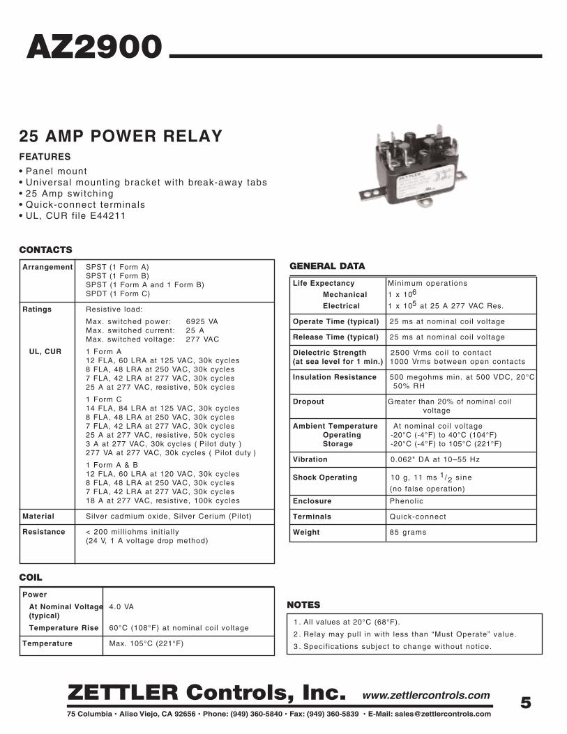
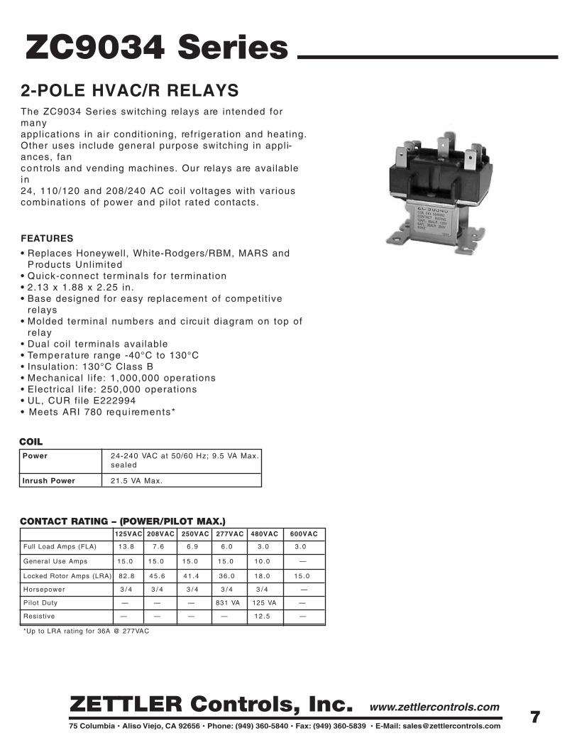
ZC9034 Series2-POLE HVAC/R RELAYSThe ZC9034 Series switching relays are intended formany applications in air condit ioning, refr igeration and heating.Other uses include general purpose switching in appli-ances, fan con t rols and vending machines. Our relays are availablein 24, 110/120 and 208/240 AC coi l voltages with various combinations of power and pi lot rated contacts.
FEATURES
• Replaces Honeywell, White-Rodgers/RBM, MARS andP roducts Unl imited
• Quick-connect terminals for terminat ion• 2.13 x 1.88 x 2.25 in.• Base designed for easy replacement of competi t ive
relays• Molded terminal numbers and circuit diagram on top of
relay• Dual coil terminals available• Temperature range -40°C to 130°C• Insulation: 130°C Class B• Mechanical l i fe: 1,000,000 operations• Electr ical l i fe: 250,000 operations• UL, CUR fi le E222994• Meets ARI 780 requ i rements*
COILPower 24-240 VAC at 50/60 Hz; 9.5 VA Max.
sealed
Inrush Power 21.5 VA Max.
7

RELAY ORDERING INFORMATION
ZC9034 Series
MECHANICAL DATA
ELECTRICAL SCHEMATIC
RELAY MODEL
COIL VOLTAGE (CONTACTS)
POLE CONFIGURATION FORM
ZC9034 0 - 24 VAC (Pwr/Pwr) Blank - DP (double pole) Double Pole1 - 120 VAC (Pwr/Pwr) SP - SP (single pole) Blank - DPDT - N.O., N.C.2 - 240 VAC (Pwr/Pwr) 2A - DPST - N.O.3 - 24 VAC (Pwr/Pilot)* 2B - DPST - N.C.4 - 120 VAC (Pwr/Pilot)* 2AB - DPST - Pole 1-2-3 N.O5 - 240 VAC (Pwr/Pilot)* - Pole 4-5-6 N.C6 - 24 VAC (Pilot/Pilot)7 - 120 VAC (Pilot/Pilot) Single Pole (1-2-3)8 - 240 VAC (Pilot/Pilot) Blank - SPDT - N.O., N.C.
1A - SPST - N.O.1B - SPST - N.C.
ZC9034 3 SP - 1A
*Power Terminals 1-2-3, Pilot Terminals 4-5-6
Single coil terminals are standard. For dual coil terminals add suff i x “ -01”
8

WIRING DIAGRAM
GENERAL DATA
Life Expectancy Minimum operat ions
Mechanical 7.5 x 10⁵
Electrical 5 x 10⁵ at 16A 400VAC
2 x 10⁵ at 35A 400VAC (break only)
1 x 10⁵ at 50A 400VAC (break only)
Dimensions (mm) 51.2 x 46.6 x 36.5
Construction Unsealed
Weight approx. 110 grams
COILCoil Consumption 5VA
Coil Voltage See table A & B
Coil Resistance See table A & B
Insulation System Class B (130oC)
FEATURES• 50A switching capabi l i ty• SPST-NC configurations• .250” quick connect terminat ion• ISO 9001 cert i f ied• Variety of mounting posit ions• UL, CUR SA11095• Non-posit ion sensit ive design*
ZCPR SeriesMOTOR START POTENTIAL RELAY
ZCPRA6AM6
*Except in posit ion #3
9
CONTACTS
Arrangement SPST-NC
Ratings 16A (make and break), 400 VAC, cos k = 0.7 to 0.835A (break only), 400 VAC cos k = 0.7 to 0.850A (break only), 400 VAC cos k = 0.7 to 0.8
Material Silver cadmium oxide
Resistance < 50 mill iohms at 1A 24VDC

ZCPR SeriesMECHANICAL DATATAB MOUNT ZCPRZ6AM6 Shown
2.0
16.0
9.6
36.5
3.0
51.2
46.6
23.3 10.4
28.7
5.2
5.0
5.0
5.2
28.7
10.423.3
46.6
51.2
51.2
46.6
23.3 10.4
28.7
5.2
5.0
7.6
36.5
3.0
45.2
4.0
6.4
10.0
5.0
7.6
36.5
3.0
8.08.0
17.48.0
9.4
5-Ø3.6
3.2
3.7
7.6
PLASTIC MOUNT (Unit: mm)
PANEL MOUNT (Unit: mm)
METAL TAB MOUNT ( Unit: mm)
UNIVERSAL BRACKET MOUNT ( Unit: mm)
50.7
0
45.24.
0
6.4
10.0 46.6
23.3 10.4
28.7
5.2
7.6
Outl ine Dimensions
10

ZCPR Series
MOUNTING TYPE/TERMINAL CONFIGURATION
MOTOR START POTENTIAL RELAY
Part number ordering information.
ZCPR
PART NUMBERING SYSTEM
D
Coil Type/P.U. & D.O. - See Table A & B
6AM
Mounting Posit ion - See Below
XXX
Optional Customer Assign (XXX)
6
MOUNTING POSITION
Basic Series Designation
Mounting Type/Terminal Configurat ion
*
* Posit ion sensit ive
A
B
C
D
L
M
N
P
Panel Mount, 5 screws (2 on #4)
Panel Mount, 5 dual QD (2 on #4)
Panel Mount, 3 screws (#1, 2 and 5)
Panel Mount, 3 dual QD (#1, 2 and 5)
Plastic Tab and Panel Mount, 5 screws (2 on #4)
Plastic Tab and Panel Mount, 3 dual QD (#1, 2 and 5)
Plastic Tab and Panel Mount, 3 screws (2 on #4)
Plastic Tab and Panel Mount, 5 dual QD (2 on #4) W
X
Y
Z
Metal Tab Mount, 5 screws (2 on #4)
Metal Tab Mount, 3 dual QD (#1, 2 and 5)
Metal Tab Mount, 3 screws (#1, 2 and 5)
Metal Tab Mount, 5 dual QD (2 on #4)
U Universal Metal Bracket Mount, 5 dual QD (2 on #4)
*Universal Metal Bracket Mount not available in posit ion 3
11

ZCPR Series
TABLE A - OPERATING CHARACTERISTICS AT 50 Hz
MOTOR START POTENTIAL RELAY
Coil number 2 3 4 5 6 7 8 9Vmax at
40¡ £ ¤V£ '299 338 378 356 452 151 530 228
Resistance¡ 10% at25¡ (ƒ ‚)
5600 7500 10700 10000 13800 1500 19500 3900
H.P.U. P.U. D.O. P.U. D.O. P.U. D.O. P.U. D.O. P.U. D.O. P.U. D.O. P.U. D.O. P.U. D.O.A 120-130 111-124 20-45 111-124 35-77B 130-140 120-134 20-45 120-134 35-77C 150-160 140-153 40-90 130-144 20-45 130-144 35-77D 160-170 150-163 40-90 150-163 40-90 140-153 20-45 140-153 35-77E 170-180 162-175 40-90 162-175 40-90 149-163 35-77F 180-190 171-184 40-90 171-184 40-90 180-195 40-105 157-172 35-77G 190-200 180-193 40-90 180-195 40-105 180-195 40-105 189-205 40-105 168-182 35-77H 200-220 186-215 40-90 190-215 40-105 195-224 50-110 186-214 60-133 178-192 35-77I 220-240 205-234 40-105 208-239 50-110 204-233 50-110 204-233 60-133 183-213 35-77L 240-260 224-252 40-105 224-252 50-110 223-259 50-110 223-252 60-133 223-252 60-130 203-231 35-77M 260-280 243-271 40-105 239-270 50-110 242-272 50-110 242-272 60-133 239-268 60-135 239-268 75-170N 280-300 260-289 50-110 262-290 60-121 262-290 60-133 258-287 60-135 258-287 75-170O 300-320 280-310 60-121 280-310 60-133 277-305 60-135 277-305 75-170P 320-340 300-328 60-121 300-328 60-154 295-324 60-135 295-324 75-170Q 340-360 318-347 60-121 314-342 60-135 314-342 75-180R 350-370 323-352 75-180S 360-380 332-361 75-180
H.P.U. = Approximate pick up at 90o C, P.U. and D.O. values at 25o C.
40o C (V)
+10% at25oC (e)
Coil number 2 3 4 5 6 7 8 9Vmax at
40¡ £ ¤V£ '332 375 420 395 502 168 588 253
Resistance¡ 10% at25¡ (ƒ ‚)
5600 7500 10700 10000 13800 1500 19500 3900
H.P.U. P.U. D.O. P.U. D.O. P.U. D.O. P.U. D.O. P.U. D.O. P.U. D.O. P.U. D.O. P.U. D.O.AA 120-130 111-124 20-45 111-124 35-77AB 130-140 120-134 20-45 120-134 35-77AC 150-160 130-144 20-45 130-144 35-77AD 160-170 150-163 40-90 140-153 20-45 140-153 35-77AE 170-180 162-175 40-90 149-163 20-45 149-163 35-77AF 180-190 171-184 40-90 180-195 40-105 157-172 35-77AG 190-200 180-193 40-90 180-195 40-105 189-205 40-105 168-182 35-77AH 200-220 186-215 40-90 190-215 40-105 195-224 60-121 186-214 60-130 178-192 35-77AI 220-240 205-234 40-90 208-239 50-110 204-233 60-121 204-233 60-130 183-213 35-77AL 240-260 224-252 40-105 224-252 50-110 223-259 60-121 223-252 60-130 203-231 35-77AM 260-280 243-271 40-105 239-270 50-110 242-272 60-121 242-272 60-140 239-268 60-135 221-250 35-77AN 280-300 260-289 50-110 262-290 60-121 262-290 60-140 258-287 60-135 258-287 75-170AO 300-320 280-310 60-121 280-310 60-140 277-305 60-135 277-305 75-170AP 320-340 300-328 60-121 300-328 60-140 295-324 60-135 295-324 75-170AQ 340-360 318-347 60-121 314-342 60-135 314-342 75-180AR 350-370 323-352 75-180AS 360-380 332-361 75-180
H.P.U. = Approximate pick up at 90o C, P.U. and D.O. values at 25o C.
40o C (V)
+10% at25o C (e)
TABLE B - OPERATING CHARACTERISTICS AT 60 Hz
12
CONTACTS
Arrangement SPST (1 Form A, or B)SPDT (1 Form C)
Ratings Resistive load:
Max. switched power: 840 W or 8310 VAMax. switched current: 30 A (Form A)15 A (Form B)Max. switched voltage: 277 VAC, 28 VDC
UL, CUR 1 Form A30 A at 277 VAC, General Use [1][2]2 Hp at 250 VAC [1] [2 ]1 HP at 125 VAC [1] [2 ]3 0 A at 28 VDC [1]20/60 (FLA/LRA) at 277 VAC 30k cycles [1]
1 Form B15 A at 277 VAC, General Use [1]10 A at 28 VDC [1]0.5 HP at 250 VAC [1]0.25 HP at 125 VAC [1]10/33 (FLA/LRA) at 277 VAC 30k cycles [1]
1 Form C30/20 A (N.O./N.C.) at 277 VAC, General Use[ 1 ] [ 2 ]20/10 A (N.O./N.C.) at 28 VDC[1]2/0.5 HP (N.O./N.C.) at 250 VAC[1 ] [2 ]1/0.25 HP (N.O./N.C.) at 125 VAC[1 ] [2 ]20/60 (FLA/LRA) at 277 VAC 30k cycles N.O. [1]10/33 (FLA/LRA) at 277 VAC 30k cycles N.C. [1]
Material Silver cadmium oxide [1], si lver t in oxide [2]
Resistance < 50 mil l iohms init ial ly(24 V, 1 A voltage drop method)
GENERAL DATA
Life Expectancy Minimum operat ions
Mechanical 1 x 10⁷
Electrical 1 x 10⁵ at 30 A 120 VAC Res. N.O.
Operate Time 15 ms at nominal coi l voltage
Release Time 10 ms at nominal coi l voltage(with no coi l suppression)
Dielectric Strength 1500 Vrms contact to contact(at sea level for 1 min.) 2500 Vrms contact to coi l
Insulation Resistance 1000 megohms min. at 500 VDC, 20°C50% RH
Dropout DC: Greater than 1 0% of nominal coi l voltageAC: Greater than 2 0% of nominal co il voltage
Ambient Temperature At nominal coi l voltageOperating -55°C (-67°F) to 85°C (185°F)Storage -55°C (-67°F) to 155°C (311°F)
Vibration 0.062" DA at 10–55 Hz
Shock 10 g
Enclosure P.B.T. polyester
Terminals Tinned copper al loy, Quick ConnectsNote: Allow suitable slack on leads when wir ing, and do not subject the terminals to excessive force .
Max. Solder Temp. 270°C (518°F)
Max. Solder Time 5 seconds
Max. Solvent Temp. 80°C (176°F)
Max. Immersion Time 30 seconds
Weight 36 grams
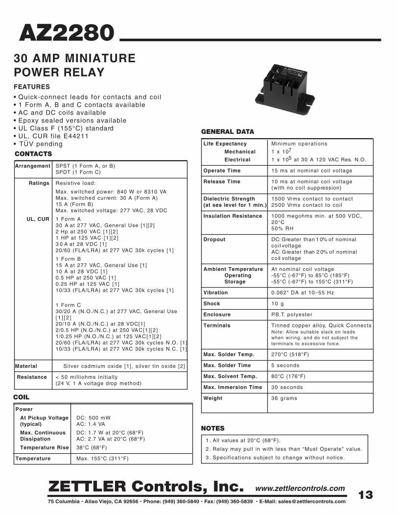
AZ228030 AMP MINIATURE POWER RELAYFEATURES
• Quick-connect leads for contacts and coi l• 1 Form A, B and C contacts available• AC and DC coils available• Epoxy sealed versions available• UL Class F (155°C) standard• UL, CUR file E44211• TÜV pending
COIL
Power
At Pickup Voltage DC: 500 mW(typical) AC: 1.4 VA
Max. Continuous DC: 1.7 W at 20°C (68°F)Dissipation AC: 2.7 VA at 20°C (68°F)
Temperature Rise 38°C (68°F)
Temperature Max. 155°C (311°F)
NOTES
1 . All values at 20°C (68°F).
2 . Relay may pull in with less than “Must Operate” value.
3 . Specif icat ions subject to change without notice.
13

RELAY ORDERING DATA
COIL SPECIFICATIONS – DC CoilNominal Coil Must Operate Max. Continuous Nominal Current Coil Resistance ORDER NUMBER*
VDC VDC VDC mA ± 10% ± 10%5 3 .75 6 . 4 1 8 5 2 7 AZ2280–1A–5DF
6 4 .50 7 . 8 1 5 0 4 0 AZ2280–1A–6DF
9 6 .75 12 .2 9 3 9 7 AZ2280–1A–9DF
1 2 9 .00 15 .4 7 7 1 5 5 AZ2280–1A–12DF
1 5 11 .25 19 .8 5 9 2 5 6 AZ2280–1A–15DF
1 8 13 .5 24 .1 4 7 3 8 0 AZ2280–1A–18DF
2 4 18 .00 32 .0 3 6 6 6 0 AZ2280–1A–24DF
4 8 36 .00 62 .6 1 9 2 5 6 0 AZ2280–1A–48DF
1 1 0 82 .5 146 .6 8 . 2 1 3 4 5 0 AZ2280-1A-110DF
COIL SPECIFICATIONS – AC Coil 50/60 HzNominal Coil Must Operate Max. Continuous Nominal Coil Coil Resistance ORDER NUMBER*
VAC VAC VAC Power VA ± 10%1 2 10 .2 13 .8 2 . 3 2 5 AZ2280–1A–12AF
2 4 20 .4 27 .6 2 . 1 1 0 0 AZ2280–1A–24AF
1 2 0 102 .0 138 .0 2 . 3 2 ,500 AZ2280–1A–120AF
2 0 8 176.8 239 .0 2 . 2 11 ,000 AZ2280–1A–208AF
220 /240 187 .0 276 .0 2 .2 /2 .6 13,490 AZ2280–1A–240AF
2 7 7 235.4 318 .5 2 . 2 15 ,000 AZ2280–1A–277AF
*Substi tute “-1B” or “-1C” in place of “-1A” for 1 Form B or 1 Form C respectively. For si lver t in oxide contacts substi tute “-1AE” or “-1CE” in place of “-1A” or “-1C.” Add “T” to “-1A”, “-1AE”, “-1B”, “-1C” or “-1CE” for extended l i fe contacts. Substi tute “DEF” or “AEF”in place of “DF” or “AF” for epoxy sealed version. For 0.110 coil terminals change “F” to “KF. ”
AZ2280
MECHANICAL DATA1.08
(27.5)
1.27(32.4)
1.71(43.5)
1.98(50.2)
0.14(3.5)
1.09(27.8)
WIRING DIAGRAM (Top View)
0.25 x 0.032±0.003
3 places
0.187 x 0.02*±0.003
2 places
* "K" = 0.110 x .02
1 FORM A 1 FORM B 1 FORM C
2 4
1 5
3
2
1 5
2
3
4
1 5
Dimensions in inches with metric equivalents in parentheses. Tolerance: ± .010"
14
GENERAL DATA
Life Expectancy Minimum operat ions
Mechanical 1 x 10⁶
Electrical 1 x 10⁵ at 30 A 120 VAC Res.
Operate Time (max) 30 ms at nominal coi l voltage
Release Time (max) 30 ms at nominal coi l voltage(with no coi l suppression)
Dielectric Strength 4000 Vrms coi l to contact(at sea level for 1 min.) 2000 Vrms between open contacts
Insulation 1000 megohms min. at 20°C, 500 VDC,Resistance 50% RH
Dropout Greater than 5% of nominal coi l voltage (DC)Greater than 15% of nominal coi l voltage (AC)
Ambient Temperature At nominal coi l voltageOperating -40°C (-40°F) to 85°C (185°F) - Class BStorage -40°C (-40°F) to 105°C (221°F) - Class F
-40°C (-40°F) to 130°C (266°F) - Class B-40°C (-40°F) to 155°C (311°F) - Class F
Vibration 0.062" DA at 10–55 Hz
Shock Operating 10 g, 11 ms, 1 / 2 s ine
(no false operation)
Non-Operating 100 g, 11 ms, 1 / 2 sine (no damage)
Enclosure P.B .T. polyester
Terminals Tinned copper al loy, Quick connecttabsNote: Allow suitable slack on leads when wir ing, and do not subject the terminals to excessive force .
Weight 120 grams
COIL
Power
At Pickup Voltage(typical) 1.2 VA (AC)
Max. Continuous 3.8 W at 20°C (68°F) ambientDissipation
Temperature Rise 50°C (90°F) at nominal coil voltage
Temperature Max. 130°C (266°F) - Class BMax. 155°C (311°F) - Class F
AZ2700
NOTES
1 . All values at 20°C (68°F).
2 . Relay may pull in with less than “Must Operate” value.
3 . Specif icat ions subject to change without notice.
CONTACTS
Arrangement SPST (1 Form X)DPST (2 Form X)
Ratings Resistive load:
Max. switched power: 840 W or 8310 VAMax. switched current: 30 AMax. switched voltage: 150* VDC or 400 VAC
*Note: If switching voltage is greater than 30 VDC,special p recautions must be taken. Please contact the facto-ry.
Rated Load 30 A at 277 VAC res. 30k cycles [1]UL, CUR 1.5 HP at 120 VAC [1]
3 HP at 240 VAC [1]TV-10 at 120 VAC [1]30 A at 277 VAC res. 70k cycles [2]3 HP at 240 VAC 100k cycles [2]10 A at 120 VAC tungsten load, 10k cycles [2]
TÜV 27 A at 240 VAC, cos phi = .8, 100k cycles [1]
Material [1]Si lver cadmium oxide,[2] si lver t in oxide
Resistance < 100 mil l iohms init ial ly(24 V, 1 A voltage drop method)
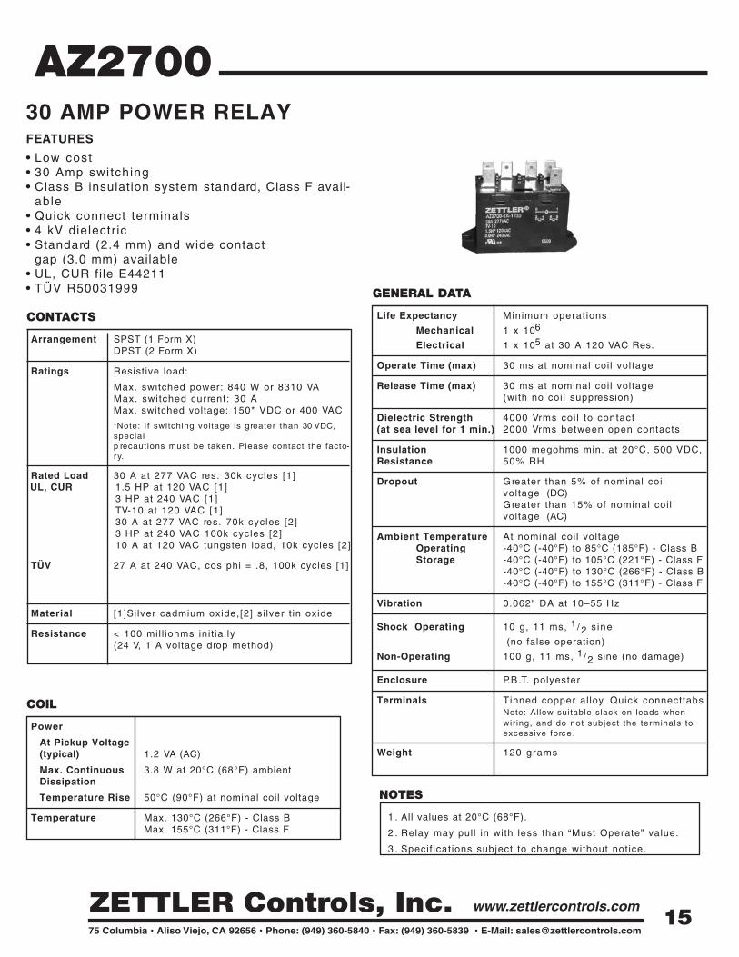
30 AMP POWER RELAYFEATURES
• Low cost• 30 Amp switching• Class B insulation system standard, Class F avail-
able• Quick connect terminals• 4 kV dielectr ic• Standard (2.4 mm) and wide contact
gap (3.0 mm) available• UL, CUR file E44211• TÜV R50031999
15

COIL SPECIFICATIONS – AC COIL ORDER NUMBER*Nominal Coil Must Operate Max. Continuous Coil Current 1 Form X 2 Form XVAC VAC VAC mA ± 10%
6 4 .80 6 . 6 3 1 9 AZ2700–1A–6A AZ2700–2A–6A1 2 9 .60 13 .2 1 6 0 AZ2700–1A–12A AZ2700–2A–12A2 4 19 .2 26 .4 8 0 AZ2700–1A–24A AZ2700–2A–24A4 8 38 .4 52 .8 4 0 AZ2700–1A–48A AZ2700–2A–48A
1 2 0 96 .0 132 .0 2 3 AZ2700–1A–120A AZ2700–2A–120A2 2 0 176 .0 242 .0 1 0 AZ2700–1A–220A AZ2700–2A–220A2 4 0 192 .0 264 .0 9 . 2 AZ2700–1A–240A AZ2700–2A–240A
*For si lver t in oxide add suffix “T” (UL approved for 1 Form X version only). For wide contact gap add “W”. ForClass F add suff ix “F” .
RELAY ORDERING DATA
COIL SPECIFICATIONS – DC COIL ORDER NUMBER*Nominal Coil Must Operate Max. Continuous Coil Resistance 1 Form X 2 Form XVDC VDC VDC ± 10%
3 2 .25 4 . 2 4 . 7 AZ2700–1A–3D AZ2700–2A–3D6 4 .50 8 . 4 18 .8 AZ2700–1A–6D AZ2700–2A–6D
1 2 9 .00 16 .8 7 5 AZ2700–1A–12D AZ2700–2A–12D2 4 18 .00 33 .7 3 0 0 AZ2700–1A–24D AZ2700–2A–24D4 8 36 .0 67 .5 1 2 0 0 AZ2700–1A–48D AZ2700–2A–48D
1 0 0 75 .0 140 .5 5 2 0 0 AZ2700–1A–100D AZ2700–2A–100D1 1 0 82 .5 154 .7 6 3 0 0 AZ2700–1A–110D AZ2700–2A–110D2 0 0 150 .0 282 .4 2 1 0 0 0 AZ2700–1A–200D AZ2700–2A–200D
AZ2700
MECHANICAL DATA
2.362 [60.0]
[ø4.5]2 x ø.177
[47.0]1.850
[11.0].433
[6.3 x 0.81].250 x .032
[ø1.8]ø.071
[68.0]2.677
1.989 [50.5]2.362
[60.0]
1.320 [33.5]
.177 [4.5]
1 FORM X
64
10
864
1
2
2 FORM X
1
8
0
WIRING DIAGRAMS
MOUNTING HOLE LAYOUT
0
2 64
Dimensions in inches with metric equivalents in parentheses. Tolerance: ±. 010 "
16
GENERAL DATA
Life Expectancy Minimum operat ions
Mechanical 5 x 10⁷
Electrical 1 x 10⁵ at 30 A 120 VAC Res. N.O.
Operate Time 15 ms typical25 ms maximum with bounce
Release Time 10 ms typical25 ms maximum with bounce(with no coi l suppression)
Dielectric Strength 1500 Vrms contact to contact(at sea level for 1 min.) 4000 Vrms contact to coi l
2000 Vrms between contact sets
Insulation Resistance 1 09 ohms minimum at 500 VDC
Dropout DC: Greater than 1 0% of nominal coilvoltageAC: Greater than 2 0% of nominal coilvoltage
Ambient Temperature At nominal coi l voltageOperating DC: -40°C (-40°F) to 95°C (203°F)
AC: -40°C (-40°F) to 75°C (167°F)Storage -40°C (-40°F) to 155°C (311°F)
Vibration 0.062" DA at 10–55 Hz
Shock Operational,10 g for 11 ms 1/ 2 sine
pulse(no contact opening > 100usec)
Non-destructive, 100 g for 11 ms 1/ 2sine pulse
Enclosure P.B.T. polyester
Terminals Quick connect tabsNote: Allow suitable slack on leads when wir ing, and do not subject the terminals to excessive force .
Max. Solvent Temp. 80°C (176°F)
Max. Immersion Time 30 seconds
Weight 86 grams
CONTACTS
Arrangement DPST-N.O.DPDT
Ratings Resistive load:
Max. switched power: 560 W or 8310 VAMax. switched current : 30 A N.O, 3 A N.C.Max. switched voltage: 600 VAC or 30 VDC*
UL, CUR 30 A at 277 VAC General Use, 100k cyclesN.O. 1 Hp at 120 VAC, 100k cycles
2 . 5 Hp at 240 VAC, 100k cycles110 LRA/25.3 FLA at 240 VAC (DC coils only), 30k cycles
UL, CUR 3 A at 277 VAC General Use, 100k cycles N.C.
VDE N.O. 20A 250VAC, N.C. 3A 250VAC
*Note: If switching voltage is greater than 30VDC, special precautions must be taken. Please contact the factory.
Material Silver cadmium oxide, si lver t in oxide
Resistance <50 mil l iohms ini t ial ly(6 V, 1 A voltage drop method)
AZ2800
COIL
Power
At Pickup Voltage DC: 0.925 W(typical) AC: 2.6 VA
Max. Continuous DC: 5.0 W at 20°C (68°F)Dissipation AC: 7.0 VA at 20°C (68°F)
Temperature Rise DC: 48°C (86°F) at nominalcoil voltage
AC: 68° C (122°F) at nominal coil volt-age
Temperature Max. 155°C (311°F)
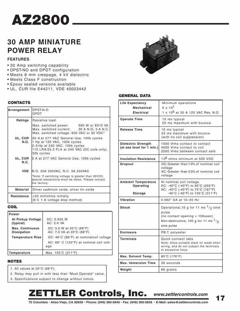
30 AMP MINIATURE POWER RELAYFEATURES
• 30 Amp switching capabi l i ty• DPST-NO and DPDT configuration• Meets 8 mm creepage, 4 kV dielectric• Meets Class F construction• Epoxy sealed versions available• UL, CUR fi le E44211, VDE 40023442
NOTES
1 . All values at 20°C (68°F).
2 . Relay may pull in with less than “Must Operate” value.
3 . Specif icat ions subject to change without notice.
17

COIL SPECIFICATIONS – AC Coil60 Hz [1]Nominal Coil Must Operate Max. Continuous Nominal Current Coil Resistance ORDER NUMBER*
VAC VAC VAC mA ± 10% ± 10%1 2 9 . 6 15 .6 3 2 5 9 . 5 AZ2800–2C–12A
2 4 19 .2 31 .2 154 35 .7 AZ2800–2C–24A
1 2 0 96 .0 156 .0 33 .5 8 3 0 AZ2800–2C–120A
2 0 8 166 .4 270 .4 19 .3 2 6 0 0 AZ2800–2C–208A
2 2 0 176 .0 2 8 6 18 .1 2 8 7 0 AZ2800–2C–220A
2 4 0 192 .0 312 .0 17 .3 3 8 0 0 AZ2800–2C–240A
2 7 7 221 .6 360 .1 14 .5 4 7 0 0 AZ2800–2C–277A
*Add suffix “E” for epoxy sealed version. Add suff ix “K” for 0.187x.020 or “J” for 0.187x.032 QC coi l terminals. Substi tute'2A” for “2C” to indicate DPST (N.O.) contacts. Add suff ix “E” to “2A” or “2C” to indicate AgSNO2 contacts.
[1] For 50 Hz coil replace “A” with “A5” (example: “A2280-2C-24A5”).
AZ2800RELAY ORDERING DATA
COIL SPECIFICATIONS – DC CoilNominal Coil Must Operate Max. Continuous Coil Resistance ORDER NUMBER*
VDC VDC VDC ± 10%6 4 . 5 10 .5 2 2 AZ2800–2C–6D
1 2 9 . 0 20 .7 8 6 AZ2800–2C–12D
2 4 18 .0 41 .8 3 5 0 AZ2800–2C–24D
4 8 36 .0 83 .4 1 3 9 0 AZ2800–2C–48D
1 1 0 82 .5 190 .5 7 2 5 5 AZ2800–2C–110D
MECHANICAL DATA
.58
0
1
34
78
2
6
0
4
8
2
6
2 FORM C
1
VIEWED TOWARD TERMINALS
2 FORM A
1.36 [34.5]
1.04 [26.4]
[8.0]
2.35
8 x.032 [.81]
2.69 [68.4]
[41.1]
[59.7]
WIRING DIAGRAM [14.8].31
1.62 [3.8].15
.63 [16.0]
8 x.45 [11.4]
2 x DIM "A"DIM. "A" = .250 [6.35] x .032 [.81] THK - STANDARD
DIM. "A" = .187 [4.75] x .020 [.51] THK - "K" SUFFIX
[3.3].13
[4.6].18
[6.35]6 x.250
[25.4]1.00
Dimensions in inches with metric equivalents in parentheses. Tolerance: ± .010"
18

GENERAL DATA
Life Expectancy Minimum operat ions
Mechanical 1 x 10⁶
Electrical 1 x 10⁵ at 25 A 277 VAC Res.
Operate Time (typical) 25 ms at nominal coi l voltage
Release Time (typical) 25 ms at nominal coi l voltage
Dielectric Strength 2500 Vrms coi l to contact(at sea level for 1 min.) 1000 Vrms between open contacts
Insulation Resistance 500 megohms min. at 500 VDC, 20°C50% RH
Dropout Greater than 20% of nominal coilvoltage
Ambient Temperature At nominal coi l voltageOperating -20°C (-4°F) to 40°C (104°F) Storage -20°C (-4°F) to 105°C (221°F)
Vibration 0.062" DA at 10–55 Hz
Shock Operating 10 g, 11 ms 1/ 2 sine
(no false operation)
Enclosure Phenol ic
Terminals Quick-connect
Weight 78 grams
CONTACTS
Arrangement SPST (1 Form A)SPST (1 Form B)SPST (1 Form A and 1 Form B)SPDT (1 Form C)
Ratings Resistive load:
Max. switched power: 6925 VAMax. switched current : 25 AMax. switched voltage: 277 VAC
UL, CUR 1 Form A7 FLA, 42 LRA at 277 VAC, 30k cycles25 A at 277 VAC, resist ive, 30k cycles
1 Form B14 FLA, 84 LRA at 125 VAC, 30k cycles12 FLA, 60 LRA at 120 VAC, 30k cycles8 FLA, 48 LRA at 250 VAC, 30k cycles25 A at 277 VAC, resist ive, 30k cycles
1 Form C12 FLA, 60 LRA at 120 VAC, 30k cycles8 FLA, 48 LRA at 250 VAC, 30k cycles7 FLA, 42 LRA at 277 VAC, 30k cycles
Material Silver cadmium oxide
Resistance < 200 mil l iohms init ial ly(24 V, 1 A voltage drop method)
NOTES
1 . All values at 20°C (68°F).
2 . Relay may pull in with less than “Must Operate” value.
3 . Specif icat ions subject to change without notice.
COIL
Power
At Nominal Voltage 4.0 VA(typical)
Temperature Rise 60°C (108°F) at nominal coil voltage
Temperature Max. 105°C (221°F)
AZ29001
25 AMP POWER RELAYFEATURES
• Panel mount• Universal mounting bracket with break-away tabs• 25 Amp switching• Quick-connect terminals• UL, CUR 44211
19

RELAY ORDERING DATA
COIL SPECIFICATIONS ORDER NUMBER*
Nominal Coil Must Operate Max. Continuous Coil Resistance Coil Current 1 Form C**VAC VAC VAC ±10% A2 4 20 .4 31 .2 7 7 0 .167 AZ29001–1C–24A
1 2 0 1 0 2 1 3 2 2 0 0 0 0 .033 AZ29001–1C–120A
2 4 0 2 0 4 2 6 4 6 0 0 0 0 .017 AZ29001–1C–240A
2 7 7 2 3 5 3 0 5 7 2 5 0 0 .014 AZ29001–1C–277A
*For 1 Form A, 1 Form B, or 1 Form A & B, substitute “-1A”, “-1B” or “-1AB” in place of “-1C”. For permanant plastic mountingtabs on 2.15” (hole diameter .150”) centers add suff ix “P” or for 2.62” centers (hole diameter .189”) add “P1”. **There is no terminal “6” on 1 Form C relays.
AZ29001
MECHANICAL DATA
1 2
3 4
56
31 5
6 42
31 5
6 42
3.031[77.00]
2.626[66.7]
2.157[54.80]
1.811[46.00]
1.563[39.70]
MAX 1.270[MAX 32.25]
2-Ø0.169[ Ø4.30] 4-Ø0.150
[ Ø3.80]
MAX 1.860[MAX 47.25]
MAX 1.112[MAX 28.25]
0.059[1.50]
MAX 1.270[MAX 32.25]
2.669[67.80]
2.157[54.80]
MAX 1.860[MAX 47.25]
0.500[12.70]
2-Ø0.150[ Ø3.80]
MAX 1.132[MAX 28.75]
3.000[76.20]
2.626[66.70]
MAX 1.860[MAX 47.25]
MAX 1.270[MAX 32.25]
0.622[15.80]
MAX 1.132[MAX 28.75]
2-Ø0.189[ Ø4.80]
0.374[9.50]
0.158[4.00]
Ø0.075[ Ø1.90]
0.031[0.80]
0.252[6.40]
0.315[8.00]
0.386[9.80]
1
3
2
4 6
5
3
1
4
2
3
1 5 1
3
5
6 4
2
Terminals Type
QC
Wiring Diagram
1A 1B
1C 1A+1B
AZ2900 Suffix "P" Suffix "P1"
2-R0.250[R6.35]
Dimensions in inches with metric equivalents in parentheses. Tolerance: ± .010"
20

Description
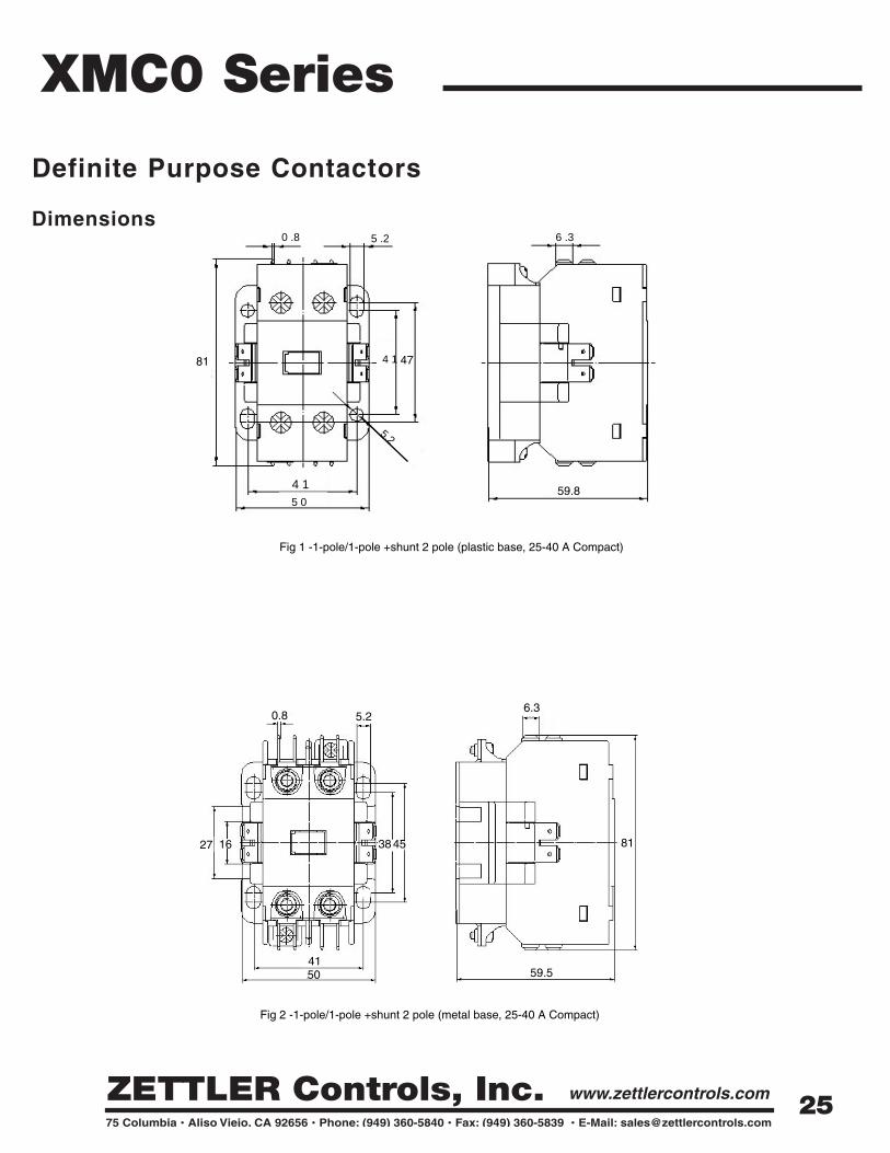
XMC0 Series
Definite Purpose Contactors
ZETTLER Controls XMC0 series of Definite Purpose
Contactors are electromechanical switching devices designed
ideally for the HVAC industry. The most common applica-
t ions of our contactors are found in refr igerat ion, air condi-
t ioning and heating. Other applications include elevators,
food service equipment, cranes, hoists, welding machines,
power supplies, vending machines, l ighting, pumps and com-
p ressors. XMC0 contactors are bui l t to the ARI 780/790 stan-
da rd in our ISO 9001 manufacturing faci l i ty for high perform-
ance and great rel iabi l i ty. XMC0 is available in various pole
configurations and load ratings up to 90 amps.
Features
• A variety of termination options for specif ic application requ i rements
• Universal mounting plate: Easy replacement of competi tor 's contactors
• Heavy-duty contacts ensure long electr ical l i fe
• EE lamination (magnetic assembly) provides optimum performance
whi le reducing power consumption
• Performance unaffected by posit ion mounting
• Dust- f ree internal construct ion
• UL, CUR fi le no. E222994
21

Aux Switch Block Left
Aux Switch Block Right
Coil Terminals
-5 0 -•
XMC0 Series
25 25 FLA
32 32 FLA
40 40 FLA
50 50 FLA
63 63 FLA
75 75 FLA90 90 FLA
Full Load Amp
1 1-pole + 1 shunt - Compact
2 2-pole - Compact
7 1-pole - Compact
3 3-pole* - Standard
3A 2-pole - Standard
Number of Poles
* 3P is only opt ion for 50/63/75/90 Ampmodels
D 12V 12V
E 24V 24V
F 110-120V 110-120V
I 208-220V 208-240V
L 277V
N 380-415 440-480V
U 550-600V 550-600V
A Plastic Base
B Metal Plate
CMetal Plate with
DIN rail mounting*
Mounting Plate
A Long cover
B Short cover
Cover
A Screw
B Sems clamp
C Slotted & Hex head washer
D Box lug
EBox lug (Line) Slotted &
Hex head washer
F Slotted & Hex head
washer (Line) Box lug
Terminal with QuickConnects
Nil AgSnO2
H AgCdO
Contact Material
PART NUMBERING SYSTEM
Full Load Amps
Number of Poles
Coil Voltage
B
Cover
Mounting Plate
B
Terminal
B C
Contact Material
Custom Special Code
XMC0 XXX- 3 H
* Available for 50 &63 Ampversions only
0 0 F G
Power Q.C. Terminals
Nil
1
3
4
5
6
1P3P
4P
5P
6P
2NO, pressure plate screws w/ Q.C.
2NO, pressure plate screws
1NO, pressure plate screws
1NC, pressure plate scerws1NC+1NO, pressure plate screws
2NC, pressure plate screws
None ( standard type)
1NC+1NO, pressure plate screws w/ Q.C.
1NC,pressure plate screws w/ Q.C.
1NO, pressure plate screws w/ Q.C.
2NC, pressure plate screws w/ Q.C.
Auxiliary Contact Options ( Right and Left)
Nil
F Dual Terminals w/ screws in 3 pole
Dual Terminals w/o screws in 1 & 2 pole and single terminals w/ screw in 3 pole
Coil Terminals
NilGD
Q
Quad Terminals 1&2 poles Dual Terminals 3 poleWithout any terminals
Dual terminals in 1&2 polesDual terminals at the side near coil terminal
and quad terminals on opposite side in 3 pole
Power Terminals
*Contact option available in
40A version only.
22

Rated insulation voltage 690 Vrms
Di-electric strength 2500Vrms (coil to contact & contact to contact)
Designs/conforms to IEC 60947-4-1, GB14048.4, EN60947-4, ARI780 / 790, CE
Agency approvals UL,CUR file E220475
Operating position ± 15° possible, relative to normal vertical mounting plane
Operating altitude 2000 meters without derating
-20°C to 70°C
-40°C to 70°C
Shock resistance
(1/2 ~ wave) = 11ms Contact Open: 6g ; Contact Closed: 15g
Vibration resistance (5-300Hz) Contact Open: 2g ; Contact Closed: 4g
Ambient temperature
XMC0 SeriesDefinite Purpose Contactors
General Data
Electrical
Rated Operating voltage 12V-600V max.
12 x FLA
10 x FLA
Switching frequency 360 operations/hour
Electrical endurance (ARI 780/790) 250,000 cycles
Mechanical endurance (ARI 780/790) 3,000,000 cycles
Make capacity (230V, cos Ø=0.45)
Break capacity (230V, cos Ø=0.45)
10690
AC600 (AC-15) 230/380V 3/1.9
N600(DC-13) 110/230V 2.2/1.1
Conventional thermal current ( A)Rated Insulation Voltage ( V )
Rated Operational
Current (A)
Auxiliary Contact Block Data
23

XMC0 Series
Definite Purpose Contactors
Electrical Ratings
Pole FormInrush
VASealed
VASealed
(W)Pickup Voltage
Dropout Voltage
1 pole, 1 pole + 1 shunt 32 5.0 1.5 - 3 2 pole 40 6.0 2.5 - 4.5 3 pole, 2 pole standard (3A) 60 8.0 3.6 - 6 3 pole -503 & 633 120 17.0 3.5 - 8 3 pole -753 & 903 235 32.0 6.0 - 17
¡Â 0. 8 Us ¡Ã 0. 2 Us
Coil Data
*Us = nominal coil voltage
< 0.8 Us* > 0.2 Us*
240VAC 480VAC 600VAC1P XMC0-257
1P+1shunt XMC0-2512P XMC0-2521P XMC0-327
1P+1shunt XMC0-3212P XMC0-3221P XMC0-407
1P+1shunt XMC0-4012P XMC0-4022P XMC0-253A3P XMC0-2532P XMC0-323A3P XMC0-3232P XMC0-403A3P XMC0-403
75 95 450 375 300 3P XMC0-753
90 120 540 450 360 3P XMC0-903
125 100
32 40 180 150 120Compact
25 32 150
40 50 240 200 160
25 32 150 125 100
40 50 240
Standard
32 40 180
50 63 300
150 120
200 160
XMC0-633
Order Number
63 80 360 300
250 200 3P XMC0-503
SizeFull Load
Amps (FLA)
Resistive Load Amps
(RLA)Pole Form
Locked Rotor Amps (LRA)
240 3P
24
XMC0 Series
Definite Purpose Contactors
0 .8 5 .2
81
4 15 0
5.2
6 .3
59.8
4 1 47
59.550
41
27 16
0.8 5.2
38 45 81
6.3
6.3
Fig 1 -1-pole/1-pole +shunt 2 pole (plastic base, 25-40 A Compact)
Fig 2 -1-pole/1-pole +shunt 2 pole (metal base, 25-40 A Compact)
Dimensions
25

XMC0 Series
Definite Purpose Contactors
5.2
50
61
0.12
380.
1245
0.1241
Fig 3 -2-pole (metal base, 25-40 A Compact)
-0.1+0.40.8
47
1616
1
0+
0.5
35
0+
0.2
5.3
0.5
96
-0.03+0.136.3
0.581.5
0.361
0.2380.250.4
3 pole plastic base (standard version)
Fig 4 -3-pole (plastic base, 25-40 A Standard)
0.3
81.9
26

XMC0 Series
Definite Purpose Contactors
0.8
92.5
61
6.3
5.2
78
0.8
47
1616
1
6.3
3 pole plastic base (standard version)
Fig 5 -3-pole (plastic base, 25-40 A Standard)
Fig 6 -3-pole (metal base, 25-40 A Standard)
81.5 ± 0.5
81.9
± 0
.396
± 0
.5
38 ± 0.250.4 ± 0.261 ± 0.3
5.3
± 0
.20
35 ±
0.5
0
50 0.1
10
79.5
0.2
82
0.2
5.210
50.4 0.23
38 0.195
5.2
27

XMCO Series
Fig 7 -3-pole (metal base, 50-63 A Standard)
Fig 8 -3-pole (metal base, 75-90 A Standard)
0.8
84 ± 0.5
102.
6 ±
0.4
83 ± 0.5
6.36.3
38 ± 0.257 ± 0.2
73 ± 0.3
82.5
± 0
.380
± 0
.3
5.2
± 0
.2
0.8
127
± 0
.4
94 ± 0.4
6.3
6.3
112 ± 0.4
5.2
5.2
63 ± 0.3
73 ± 0.3
112.
5 ±
0.4
117.
5 ±
0.4
28

XMCO Series
61
71
63.8
0.8
6.4
10.8
29

Description
XMCK SeriesDefinite Purpose Contactors
Zett ler Controls XMCK series of Definite Purpose Contactors
a re electro-mecahnical switching devices designed ideally for
the HVAC industry. The most common applications of our con-
tactors are found in refrigeration, ARI condit ioning, and heat-
ing. Other applications include elevators, food serv ice
equipment, cranes, hoists, welding machines, power supplies,
vending machines, l ighting, pumps and compressors. XMCK
contactors are bui l t to the ARI 780/790 standard in our ISO
9001 manufacturing faci l i ty for high performance and grea t
rel iabi l i l ty. XMCK is a aff o rdable solut ion with 1 to 2 pole con-
f igurations and ratings up to 50 amps.
Features
• A variety of termination options for specif ic application requ i rements
• Universal mounting plate: Easy replacement of competi tor 's contactors
• Convenient non-posit ion sensit ive mounting
• Performance unaffected by posit ion mounting
• Dust- f ree internal construct ion
• UL, CUR fi le no. E222994
30

5 0
Coil Voltage
XMCK Series
30 25 FLA
40 30 FLA
50 40 FLA
Contact Ratings
D 1-pole
DN 1-pole + 1 shunt
2 2-pole
Number of Poles
24 24 24120 110-120 110-120240 208-240 208-240277 --- 277
50Hz 60Hz
AB
CD
E
F
Slotted & Hex head washer w/ quick connectBox Lug w/ quick connect
Box Lug w/ quick connect ( Line) Slotted Hex head washer w/ quick connect (Load)
Slotted & Hex head washer w/ quick connect (Line) Box Lug w/ quick connect (Load)
Screw w/ quick connectSems clamp w/ quick connect
Terminal with Quick Connects
PART NUMBERING SYSTEM
Contact Ratings
Number of Poles
Coil Voltage
0 2 4
Terminal
CXMCK - D - XXX
Custom Special Code
31

Rated insulation voltage 690 VrmsAgency approvals UL,CUR file E222994Operating position ± 15° possible, relative to normal vertical mounting plane
-20°C to 70°C -40°C to 70°C
Ambient temperature
XMCK SeriesDefinite Purpose Contactors
General Data
Electrical
Rated Operating voltage 12V-600V max.
Switching frequency 360 operations/hourElectrical endurance (ARI 780/790) 100,000 cyclesMechanical endurance (ARI 780/790) 500,000 cycles
240/277V 480V 600V
1P XMCK- 30D1P+1shunt XMCK- 30DN
150 125 - 2P XMCK - 3021P XMCK -40D
1P+1shunt XMCK -40DN180 150 - 2P XMCK - 402
1P XMCK - 50D1P+1shunt XMCK - 50DN
240 150 - 2P XMCK - 502
100
150
150 75 50
240 160
Pole Form Order Number
100125
40 50
32 40
Locked Rotor Amps (LRA)
25 30
Full Load Amps (FLA)
Resistive Load Amps
(RLA)
Electrical Ratings
Pole FormInrush
VASealed
VASealed
(W)Pickup Voltage
Dropout Voltage
1 pole (D) 1 pole + 1 shunt (DN) 2 pole (2) 40 8.0 2.5-4.5
¡Â 0. 8 Us ¡Ã 0. 2 Us32 7.0 2.0-4.0
*Us = nominal coil voltage
> 0.2 Us*< 0.8 Us*
Coil Data
32
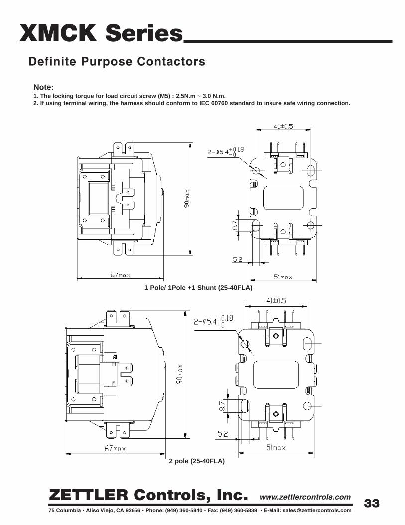
XMCK SeriesDefinite Purpose Contactors
1 Pole/ 1Pole +1 Shunt (25-40FLA)
Note:1. The locking torque for load circuit screw (M5) : 2.5N.m ~ 3.0 N.m.2. If using terminal wiring, the harness should conform to IEC 60760 standard to insure safe wiring connection.
2 pole (25-40FLA)
33
ZC AHR Series
VA RATINGS
NOTES
PRIMARY AND SECONDARY VOLTAGES
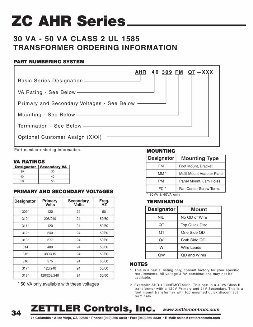
30 VA - 50 VA CLASS 2 UL 1585 TRANSFORMER ORDERING INFORMATION
Part number ordering information.
AHR
PART NUMBERING SYSTEM
Basic Series Designation
VA Rating - See Below
4 0
Primary and Secondary Voltages - See Below
3 0 9
Termination - See Below
Mounting - See Below
QT
Optional Customer Assign (XXX)
FM XXX
TERMINATION
MOUNTING
1. This is a partial l ist ing only, consult factory for your specif ic requ i rements. All voltage & VA combinations may not be available.
2. Example: AHR-40309FMQT-5555. This part is a 40VA Class II transformer with a 120V Primary and 24V Secondary. This is a foot mount transformer with top mounted quick disconnect terminals.
Designator Secondary VA30 30
40 40
Designator MountNIL
QT
Q1
Q2
W
QW
No QD or Wire
Top Quick Disc.
One Side QD
Both Side QD
Wire Leads
QD and Wires
Designator Mounting TypeFM
MM
PM
FC
Foot Mount, Bracket
Multi Mount Adapter Plate
Panel Mount, Lam Holes
Fan Center Screw Term.
*
*
Designator Primary Volts
Secondary Volts
Freq.HZ
309*
310*
311*
312*
313*
314
315
316
317*
318*
120
208/240
120
240
277
480
380/415
575
120/240
120/208/240
24
24
24
24
24
24
24
24
24
24
60
50/60
50/60
50/60
50/60
50/60
50/60
50/60
50/60
50/60
* 50 VA only available with these voltages
50 50
* 30VA & 40VA only
34

ZC AHR Series
STANDARD MODELS AVAILABLE
NOTES
30 VA - 50 VA QUICK CONNECTCLASS 2 UL 1585 TRANSFORMER
FEATURES• 30VA - 50 VA Inherently energy l imited• Compact frame size• No secondary fusing requ i re d• Low heat r ise• 50/60 Hz• Input voltages 120-575 V, output 24 V• Terminations with quick-connect top, one side, or both sides• Panel mount, foot-mount, adapter plate• Customizat ion for wire length, color, terminations and
other customer requ i rements• Spli t bobbin design• Class B insulation system 130°C rated• UL/CUR File E214561
Foot Mount, BracketMulti Mount Adapter Plate (4 x 4)Panel Mount, Lam Holes
GENERAL DATA
MountingOptions
Quick Connect Options
Quick ConnectSize
Frequency
InsulationSystem
Weight
QT - Top mounted QD terminalsQ1 - One side QD terminalsQ2 - Both side QD terminals
Standard male quick connectterminals are .250 x .032.
60 Hz, 50/60 Hz
130°C Class B
30 VA mult i mount 1.86 lbs.30 VA foot mount 1 .50 lbs.40 VA mult i mount 2.14 lbs.40 VA foot mount 1.78 lbs.50 VA foot mount 2 .48 lbs.
Zett ler Controls, Inc. can custom build transformers to many diff e re n tspecif icat ions.Contact Zett ler Controls, Inc. direct ly for more information.
US
Prim./Sec.Voltage
30 VA Standard Model Designation
120 - 24
208/240 - 24
120 - 24
240 - 24
277 - 24
480 - 24
AHR30309
AHR30310
AHR30311
AHR30312
AHR30313
AHR30314
AHR30315
AHR30316
AHR30317
AHR30318
380/415 - 24
575 - 24
120/240 - 24
120/208/240 - 24
40 VA Standard Model Designation
AHR40309
AHR40310
AHR40311
AHR40312
AHR40313
AHR40314
AHR40315
AHR40316
AHR40317
AHR40318
35

ZC AHR Series30 VA - 40 VA QUICK CONNECTCLASS 2 UL 1585 TRANSFORMER
MECHANICAL DATA
All dimensions are shown in mil l imeters.
57.0
32.0
Y
C
WG
R
ZE
TT
LER
CO
NT
RO
LS
48.7
32.0MAX
5.56
1.2
C
US
R
76.0MAX
6.35 x 0.8 (TYP) QUICK CONNECT
67.0
2xØ4.75
82.4
71.4
MAX
Type Q1 One Side Termination
94.5MAX
75.0
2xØ4.75
71.4
82.4
57.0
RC
WGY
48.7
5.56
1.2
32.0 32.0
QUICK CONNECT6.35 x 0.8 (TYP)
32.0MAX
LABEL:45x14
ZE
TT
LE
R C
ON
TR
OLS
C
US
R
Type Q2 Both Side Termination
57.0
RC
WGY
71.4
82.4
QUICK CONNECT 6.35 x 0.8 (TYP)
19.05 47.5
2xØ4,75
1.20
36.0
32.0
82.5MAX
LABEL:45x14
32.0MAX
R
ZE
TT
LE
R C
ON
TR
OLS
C
US
Type QT Top Mount Termination
36

ZC AHR Series
MECHANICAL DATA
Y W
C
ZETTLER CONTROLSAHR50311FMQ1 50VA 50/60HzINPUT: COM 120V Y WOUTPUT: 24V 50VA C-R
MADE IN CHINA C US
R
Y W
C
ZETTLER CONTROLSAHR50311FMQ1 50VA 50/60HzINPUT: COM 120V Y WOUTPUT: 24V 50VA C-R
MADE IN CHINA C US
R
Y W
C
ZETTLER CONTROLSAHR50311FMQ1 50VA 50/60HzINPUT: COM 120V Y WOUTPUT: 24V 50VA C-R
MADE IN CHINA C US
R
36,0
1.20
1,2
56.0 MAX
67.0 MAX
4xØ4.0±0.5
2xØ4.8±0.2
44.5±0.5
55.6±0.5
79.5±0.5
90.5±0.5
82.5 MAX
31.5±1.0
79.5±0.5
90.5±0.5
R3
2xØ4.8±0.2
76.0 MAX
1,2
56.0 MAX
67.0 MAX
4XØ4.0±0.5
44.5±0.5
5.56±0.1
55.6±0.5
31.5±1.0
31.5±1.0
4xØ4.0±0.5
44.5±0.5
67.0 MAX
5.56±0.1
56.0 MAX
55.6±0.51,2
90.5±0.5
79.5±0.5
R3
2xØ4.8±0.2
65.0 MAX
Type Q1 One Side Termination
Type Q2 Both Side Termination
Type QT Top Mount Termination
All dimensions are shown in mil l imeters.
50 VA QUICK CONNECTCLASS 2 UL 1585 TRANSFORMER
37

ZC AHR Series
NOTES
FEATURES
WIRE LEAD DETAILS
GENERAL DATA
• 30 VA - 50 VA Inherently energy l imited• Compact frame size• No secondary fusing requ i re d• Low heat r ise• 50/60 Hz• Input voltages 120-575 V, output 24 V• Terminat ions with scre w, quick-connect orw i re s• Panel mount, foot-mount, adapter plate• Customizat ion for wire length, color, termina-t ions
and other customer requ i rements• Spli t bobbin design• Class B insulation systems 130° C rated• UL/CUR File E214561
STANDARD MODELS AVAILABLE
30 VA - 50 VA WIRE LEAD CONNECTCLASS 2 UL 1585 TRANSFORMER
Foot Mount, BracketMult i Mount Adapter PlatePanel Mount, Lam HolesFan Center Screw Term.
MountingOptions
Wire Size
Frequency
InsulationSystem
Weight
Box Quantity
All leads are 18 AWG strandedUL 1015Stranded wires have 300 mmtotal length, with 10 mm str ip.
60 Hz, 50/60 Hz
130° C Class B
Zett ler Controls, Inc. can custom buildtransformers to many diff e rent specif icat ions. ContactZett ler Controls, Inc. direct ly for more infor-mat ion.
Voltage Color
COM
120
208
240
277
Black
White
Red
Orange
Brown
Black/Red
Grey
Blue
480
575
24
COM
Length(mm)
StripLength (mm)
Yellow
300
300
300
300
300
300
300
300
300
10
10
10
10
10
10
10
10
10
Primary
Secondary
C US
*
* Suggested wire colors: consult factory for speci f ic wire colorrequ i rements.
30 VA mult i mount 18 per box30 VA foot mount 30 per box40 VA mult i mount 18 per box40 VA foot mount 30 per box50 VA foot mount
30 VA mult i mount 1.86 lbs.30 VA foot mount 1.50 lbs.40 VA mult i mount 2.14 lbs.40 VA foot mount 1.78 lbs.50 VA foot mount 2.16 lbs.
Prim./Sec.Voltage
30 VA Standard Model Designation
120 - 24
208/240 - 24
120 - 24
240 - 24
277 - 24
480 - 24
AHR30309
AHR30310
AHR30311
AHR30312
AHR30313
AHR30314
AHR30315
AHR30316
AHR30317
AHR30318
380/415 - 24
575 - 24
120/240 - 24
120/208/240 - 24
40 VA Standard Model Designation
AHR40309
AHR40310
AHR40311
AHR40312
AHR40313
AHR40314
AHR40315
AHR40316
AHR40317
AHR40318
50 VA Standard Model Designation
AHR50309
AHR50310
AHR50311
AHR50312
AHR50313
N/A
N/A
N/A
AHR50317
AHR50318
38

ZC AHR Series30 VA - 40 VA WIRE LEAD CONNECTCLASS 2 UL 1585 TRANSFORMER
MECHANICAL DATA
All dimensions are shown in mil l imeters except as noted.
57
48.7
BLKWHT
5.56
1.2
ZE
TT
LE
R C
ON
TR
OL
S
32.0
300±10
LABEL:45x14300±10
C
US
R
32.0MAX
WH
TB
LKBLU
YE
L
60.6MAX
82.4 71.4
2xØ4.75
10.0±2
Type FM Foot Mount Bracket
57.0
47.5
BLKWHT
5.56
MA
DE
IN C
HIN
A
OU
TPU
T:24
V 4
0VA
YE
L-B
LU
ZE
TT
LE
R C
ON
TR
OLS
INP
UT:
480
V 5
0/60
Hz
BLK
-WH
TA
HR
4031
4FM
W
4
0VA
50/
60H
z
32.0
300±10
10.0±2
LABEL:45x14300±10
C
US
R
CLA
SS
2 X
FMR
32.0MAX
WH
TB
LKBLU
YE
L
60.6MAX
47.75
38.1
4 x 4.6
Type PM Panel Mount
57.0
47.5
BLKWHT
RC
WGY
5 x #6 x 1/4" long SCREWTERMINAL
WH
TB
LK
250±10
15±2
32.0
ZE
TT
LE
R C
ON
TR
OLS
R
CU
S
32.0MAX
67.0MAX
5.56
LABEL:45x14
Type FC Screw Termination (Fan Center)
39

ZC AHR Series
MECHANICAL DATA
BLK WHT
INPUT: COM
120V
OUTPUT: 24V 50VA YEL-BLU
AHR50311FMW
50VA 50/60HzZ
ET
TL
ER
CO
NT
RO
LS
MADE IN CHINA
10.0±2
WHT BLK
YEL BLUE
56.0 MAX
C U
S
R
10.0±2
BLK WHT
INPUT: COM
120V
OUTPUT: 24V 50VA YEL-BLU
AHR50311PMW
50VA 50/60HzZ
ET
TLE
R C
ON
TR
OLS
MADE IN CHINA
10.0±2
WHT BLK
YEL BLUE
C U
S
R
10.0±2
10.0±2
67.0 MAX
4xØ4.0±0.55.56±0.1
44.5±0.5
55.6±0.51,2
31.5±1.0
10.0±2
Strip Only
300±10
300±10LABEL: 45x14
R3
2xØ4.8±0.265.0 MAX
79.5±0.5
90.5±0.5
65.0 MAX
10.0±2
Strip Only
300±10
31.5±1.0
300±10LABEL:45x14
10.0±2
4xØ4.0±0.5
44.5±0.5
55.6±0.5
56.0 MAX
5.56±0.1
67.0 MAX
Type FM Foot Mount Bracket
50 VA WIRE LEAD CONNECTCLASS 2 UL 1585 TRANSFORMER
Type PM Panel Mount
40

ZC24A34 Series
ZC24A34-3
Electric Heat Sequencers
Description:The posit ive temperature coefficient (PTC) heater element provides voltagecompensation over a wide voltage range without danger of over-heating athigh voltage. It is self-current l imit ing, and assures device actuation underlow voltage conditions. The PTC has a unique feature of always stabil izingtemperature, regardless of ambient temperature or voltage range.
Key Features:1. Solid State PTC Heaters
2. Replaces most Klixon & TOD Brands
3. Quick-Connect Terminals
4. Shock and Vibrat ion Resistant
5. Mounts in any posit ion
6. Contact Ratings - to 25 Amps at 120 or 240 Volts, and 12.5A at 480 Vo l ts
7. Full-Load Rated Auxiliary Contacts
8. Standard Operating Ambience Between - 50° F (-45.5° C) and 165° F (73.8° C)
9. Custom Timing's Available
10. UL File E237660, CSA approved
Applications:Sequencing of heater banks in:
1. Electr ic Furnaces
2. Baseboard Heaters
3. Duct Heaters
4. Suspension Heaters
5. Recreational vehicle blower and element contro l
6. Heat pump blower and heating element contro l
7. Motor speed switching in air conditioning (high speed) / heating systems
( low speed) where a single set of contacts handle combination motor and heater eletment
loading in the heating function.
8. Contro l c i rcu i ts requir ing definite sequence on both start up and shut down.
41

ZC24A34 SeriesElectric Heat SequencersApplications:Through Air: 6.35 mmOver Surface: 9.52 mm
With suff ix “x ” Th rough Air: 9.53 mmOver Surface: 12.70
(1) M1-M2 and M3-M4 are always the f i rst switches to turn ON and last to turn OFF. All otherswitches are random ON and random OFF.
(2) 24A34-14 Switch contacts designated F1-F2 instead of M1-M2.
ON TIME - Elapsed time to make contacts after heater is energized (Min. to Max.)OFF TIME - Elapsed time to make contacts after heater is de-energized (Min. to Max.)OFF Timings determined after PTC heater has been electrif ied for a total of 5 minutes.Standard Timings determined at 25° C . Timing's at temperatures above or below 25° wil l vary.Canadian timings with CSA approval only.
M1-M2 M3-M4 M5-M6 M7-M8 M9-M10 M1-M2 M3-M4 M5-M6 M7-M8 M9-M10
ZC24A34-1 1 1 1-20 - - - - 40-110 - - - -
ZC24A34-2 1 1 - - 30-90 - - - - 1-30 - -
ZC24A34-3 (1) 1 2 1-20 1-20 - - - 40-110 40-110 - - -
ZC24A34-4 1 2 - - 30-90 30-90 - - - 1-30 1-30 -
ZC24A34-5 (1) 2 3 1-110 1-110 1-110 - - 1-110 1-110 1-110 - -
ZC24A34-6 (1) 2 4 1-110 1-110 1-110 1-110 - 1-110 1-110 1-110 1-110 -
ZC24A34-14 (1)(2) 4 5 1-160 1-160 1-160 1-160 1-160 1-160 1-160 1-160 1-160 1-160
Timings - OFFTimings - ON
Model Number Timings Switches
Standard Timings:
Table Notes
These contacts switch simultaneously
Optional Customer 4 Digit SuffixCustom ON and OFF Timings are available. A four digit suff ix code wil l be added to model numberwith the closest Timings. i .e DPDT sequencer with ON time of 1-60 and OFF time of 1-45 wil l bedesignated ZC24A34-3 XXXX. Please consult factory for further detai ls.
M1-M2 M3-M4 M5-M6 M7-M8 M9-M10 M1-M2 M3-M4 M5-M6 M7-M8 M9-M10ZC24A34-3-021 1 1 1--20 - - - - 1--60 - - - -ZC24A34-3-022 1 1 15-45 - - - - 1--30 - - - -ZC24A34-3-023 1 1 25-60 - - - - 15-45 - - - -ZC24A34-3-024 1 1 30-90 - - - - 1--40 - - - -ZC24A34-3-025 1 1 30-90 - - - - 1--30 - - - -ZC24A34-3-026 2 2 1--20 30-90 - - - 40--90 1--30 - - -ZC24A34-6-027 2 2 1-160 1-160 - - - 1-160 1-160 - - -ZC24A34-2-029 1 1 15-35 - - - - 25-55 - - - -ZC24A34-3-036 2 2 1--20 30-90 - - - 45-110 1--30 - - -ZC24A34-5-037 1 1 1-110 - - - - 1-110 - - - -
Timings - ON Timings - OFFModel Number Timings Switches
Canadian Timings:
42

ZC24A34 Series
3
H1 C
Figure 1
Figure 2
Figure 3 Single Pole Single Throw (SPST)
Electric Heat Sequencers
Heater-Switch Actions and Configurations:The ZC24A34-1 (re fe rence Figure 1), ZC24A34-2 (re fe rence Figure 2)uti l izes one bi-metal disc to achieve single-timing operation. They are available inSPST (re fe rence Figure 3) switch actions. This configuration can be automaticallyreset and buil t to close a set of contacts on temperature r ise within a specif iedt ime range.
Electrical Ratings:Single Load Contact Ratings (All Models):
RESISTIVE(NON-INDUCTIVE)
MOTOR RATINGS(INDUCTIVE)
VACWATTS AMPS
FULLLOAD
LOCKED ROTORPILOTDUTY
120 3000 25.0 10.0A 60.0A 125VA240 6000 25.0 5.0A 30.0A 125VA
480 6000 12.5 3.0A 18.0A 480VA
Combined Load Ratings (All Models):30A @ 240 VAC - Total: 23 A non-inductive + 7 FLA/ 42 LRAInduct ive.Li fe at rated current: 100,000 cycles
Heater Pole24 Vac 0.18A (Anticipator)0.75 A Max Inrush0.16 to 0.20 Amps Steady StateAmbient Rating: -50° to 165°F
43

ZC24A34 Series
41
H
5
3
H
Figure 4
Figure 5
Figure 6 Double Pole Single Throw (DPST)
Electric Heat Sequencers
Heater-Switch Actions and Configurations:The ZC24A34-3 (re fe rence Figure 4), ZC24A34-4 (re fe rence Figure 5)uti l izes one bi-metal disc to achieve single-timing operation. They are available inDPST (re fe rence Figure 6) switch actions. This configuration can be automaticallyreset and bui l t to close a set of contacts on temperature r ise within a specif ied t imerange.
44

ZC24A34 SeriesElectric Heat Sequencers
Figure 7
Figure 8
Heater-Switch Actions and Configurations:The ZC24A34-5 (re fe rence Figure 7),ut i l izes two bi-metal discs in conjunction withone SPST and one DPST switch action to achieve two independent Timings. TheZC24A34-6 (re fe rence Figure 8) ut i l izes two bi-metal discs in conjunction with twoDPST switch actions to also achieve two independent Timings. This configurationcan be automatical ly reset, and buil t to close three or four sets of contacts on tem-perature r ise within a specif ied t ime range.
45

ZC24A34 SeriesElectric Heat Sequencers
Figure 9
Heater-Switch Actions and Configurations:The ZC24A34-14 (re fe rence Figure 9), ut i l izes four bi-metal discs in conjunction withone SPST and two DPST switch actions to achieve four independent Timings. This con-f iguration can be automatical ly reset, and buil t to close f ive sets of contacts on tem-perature r ise within a specif ied t ime range.
Terminals:Standard terminal types are l isted below. Special switch terminals such as doublequick connects and female quick connects may be available for a specif ic switch ter-minal. Consult sales for details.
Switch Terminals1. Solder type
2. Screw type - 0.250” x 0.032” (6.35 x 0.81mm) Q.C.
Heater-Switch Actions and Configurations:
Standard heater terminals are 15° 0.250” x 0.032 (6.35 x 0.81mm), double brassmale quick connects.The stage terminals are t in-plated brass.
1.Solder type
2. Screw type-0.250” x 0.0.32” Q.C (Double Q.C terminals available at additionalcost)
Use 12 gauge or larger wire for loads greater then 15 amperes.
46

Electrical Ratings
ZC24A34 Series
Watts Amps FLA LRA120 3000 25.0 14 72 125240 6000 25.0 7 42 125480 6000 25.0 3 18 480
NO contacts - Terminals 1-3
VACPilot Duty
(VA)Inductive (Motor)Non-Inductive (Resistive, Amps)
Standard Timings:
Model Timing Switches Heat Cool
ZC24A34-15 1 1 1-25 65-115
4.57
5.56
5.16Hole
2.44
Tab Inserted in Ø2.92 Hole
30.1
65.1
60.9
12.2
45.3
27.6
13.715°
1
2
3
41.9
42.0
50.8
41.3
Heater-Switch Action and Configuration:The ZC24A34-15 (Figure10) uti l izes a single bi-metal disc in a single pole double throw con-figuration. The SPDT switch action allows for a single set of t imings. Mainly used in heatpump air handlers by providing a delay to the blower motor in cooling mode.
Figure 10
ZC24A34-15
Watts Amps120 1200 10.0 125240 1200 5.0 125
Non-Inductive (Resistive, Amps)VAC
Pilot Duty (VA)
NC contacts - Terminals 1-2
47
ZC9011 Series
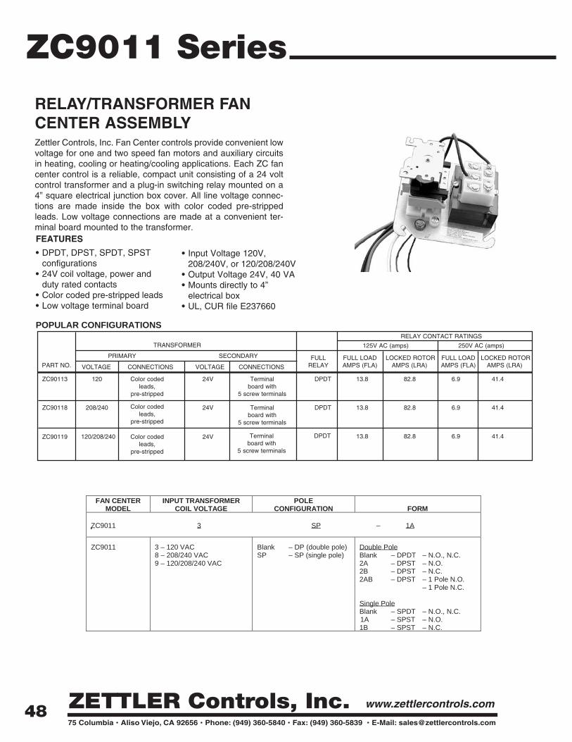
RELAY/TRANSFORMER FANCENTER ASSEMBLYZettler Controls, Inc. Fan Center controls provide convenient lowvoltage for one and two speed fan motors and auxiliary circuitsin heating, cooling or heating/cooling applications. Each ZC fan center control is a reliable, compact unit consisting of a 24 voltcontrol transformer and a plug-in switching relay mounted on a4” square electrical junction box cover. All line voltage connec-tions are made inside the box with color coded pre-strippedleads. Low voltage connections are made at a convenient ter-minal board mounted to the transformer.FEATURES
• DPDT, DPST, SPDT, SPSTconfigurations
• 24V coil voltage, power andduty rated contacts
• Color coded pre-stripped leads• Low voltage terminal board
• Input Voltage 120V, 208/240V, or 120/208/240V
• Output Voltage 24V, 40 VA• Mounts directly to 4”
electrical box• UL, CUR file E237660
RELAY CONTACT RATINGSTRANSFORMER 125V AC (amps) 250V AC (amps)
PRIMARY SECONDARY FULL FULL LOAD LOCKED ROTOR FULL LOAD LOCKED ROTORPART NO. VOLTAGE CONNECTIONS VOLTAGE CONNECTIONS RELAY AMPS (FLA) AMPS (LRA) AMPS (FLA) AMPS (LRA)
ZC90113 120 Color coded 24V Terminal DPDT 13.8 82.8 6.9 41.4leads, board with
pre-stripped 5 screw terminals
ZC90118 208/240 Color coded 24V Terminal DPDT 13.8 82.8 6.9 41.4leads, board with
pre-stripped 5 screw terminals
Terminal DPDTboard with
5 screw terminals
13.8 82.8 6.9 41.4ZC90119 120/208/240 Color coded 24Vleads,
pre-stripped
POPULAR CONFIGURATIONS
FAN CENTERMODEL
INPUT TRANSFORMERCOIL VOLTAGE
POLECONFIGURATION FORM
ZC9011 3 SP – 1A
ZC9011 3 – 120 VAC8 – 208/240 VAC9 – 120/208/240 VAC
Blank – DP (double pole)SP – SP (single pole)
Double PoleBlank – DPDT – N.O., N.C.2A – DPST – N.O.2B – DPST – N.C.2AB – DPST – 1 Pole N.O.
– 1 Pole N.C.
Single PoleBlank – SPDT – N.O., N.C.1A – SPST – N.O.1B – SPST – N.C.
48

ZC90118
ZC90113
DPDT Relay
DPDT Relay
ZC90119
DPDT Relay
MECHANICAL DATA
ZC9011 Series
49

ZC2 SeriesDelay on Make and Break Timer Boards
• Compressor lockout/ant i-short cycle t imer• B rownout protect ion• Helps prevent scrol l compressor reversal• Fixed or adjustable t iming• UL 873 Pending
FEATURES
SPECIFICATIONS
Voltage 18 ~ 30 VAC
Current 1.5 A
Inrush 15 A
Input:
TypeBreak 30 sec. FixedBreak 3 min. fixedBreak 5 min. fixedBreak 3 ~ 10 min. adjustableMake 30 sec. FixedMake 3 min. fixedMake 5 min. fixedMake 3 ~ 10 min. adjustable
ZC211ZC214ZC215ZC216
ZC201ZC204ZC205ZC206
Model TimeTime Dleays
PRODUCT OUTLINE
Dimensions in mm
ZC "delay on make" t imer is ideal for compressor stagingand start ing mult iple motors. This relay also helps reducepower surges in that i t applies the load only after the delayperiod has ended.The ZC "delay on break" t imer helps top rotect air condit ioning, refr igerat ion and other equipmentf rom damage which may be caused by the short cycling ofcompressors. When power is lost, the load is de-energizedand the delay period begins. The system wil l restart onlyafter the delay period has ended
Description
50

ZC2 SeriesDelay on Make and Break Multi-input
FEATURES
• Compressor lockout/ant i-short cycle t imer• Helps to protect compressors from damage
caused by rapid short cycl ing• Simple, 2 wire hook-up• Adjustable t iming• Universal input voltage: 24 VAC, cut jumper for
120/240 VAC• UL 873 Pending
SPECIFICATIONS
Voltage 18 ~ 240 VAC
Current 1.5 A
Inrush 15 A
Input:
TypeTime Dleays
Model Time
ZC207Knob-adjustable 0.3 ~ 10 minutes ( 1.8 ~ 600
seconds )
Break
MakeZC218
PRODUCT OUTLINE
Dimensions in mm
51

NTC Thermistors
DescriptionThrough traditional craftsmanship and engineering excellence, the Zettler name has symbolized qualityand reliability in electrical components for over 100 years in demanding applications such as telecommu-nications systems, computer peripherals, office automation equipment, home appliances, security sys-tems, test and measurement devices, and industrial controls.
We also bring that same commitment to the HVAC/R market with an offering of relays, transformers, con-tactors, heat sequencers, temperature sensors, and fan centers. This group of products is used by theHVAC/R industry in both residential and commercial applications.
We welcome application challenges, stock over one million units, deliver quick turnaround, and under-stand demanding service requirements. Our unique combination of 100% quality testing, first-class salesand technical support, cost-effective product design, and outstanding product availability offer a highlydependable and responsive resource for fulfilling all your HVAC/R Components needs.
52

NTC ThermistorsCharacteristics
Zettler NTC Thermistor Sensors offer economical, accurate and reliable solutions to those applica-tions requiring more extensive sensing than one or two temperature points. NTC thermistor sen-sors provide a change in resistance with temperature when combined with an electronic circuitand provide a means of continuously measuring temperature over a wide range.
NTC Thermistor Sensor Features• Economical• Long-term stability• Custom sensors to fit customer requirements• Custom sensor housings to fit customer requirements• A wide variety of packaging options available
An NTC thermistor is a ceramic semiconductor made with various metal oxides. Their electricalresistance decreases with increasing temperature. This resistance is processed by an electroniccircuit to provide temperature measurement. The thermistor itself does not provide any controlover heating elements, relays, etc. The thermistor is strictly a sensor and any electrical controlwould need to be implemented by the circuit utilizing the thermistor.
Operating Principles of NTC Thermistor Sensor
Continous Temperature Sensing
53

Terminology
An NTC thermistor is one in which the zero-power resistance decreases with an increase in bodytemperature.
Negative Temperature Coefficient (NTC)
Zero-Power Resistance (RT)The zero-power resistance is the DC resistance value of a thermistor measured at a specified temperature with power dissipated by the thermistor low enough that any further decrease inpower will result in not more than 0.1 % (or one-tenth of the specified measurement tolerance,whichever is smaller) change in resistance.
Rated zero power resistance (R25)The zero power resistance is measured under the standard temperature of 25°C.
B Value ( unit: K )B value is a constant describing the physical characteristic of the NTC thermistor material, alsocalled thermistor coefficient.That is: = ln(R1/R2)/(1/T1-1/T2)R1-Resistance at Temperature T1R2-Resistance at Temperature T2B value is usually determined by zero-power resistance at 25°C / 85°C in American market and25°C / 50°C in Asia market.
NTC Thermistors
54

Maximum Operating TemperatureThe maximum operating temperature of a thermistor is the maximum body temperature atwhich the thermistor will operate for an extended period of time with acceptable stability ofits characteristics. This temperature can be the result of internal or external heating, or both,and should not exceed the maximum value specified.
Maximum Power Rating
The maximum power rating of a thermistor is the maximum power which a thermistor willdissipate for an extended period of time with acceptable stability of its characteristics.
Dissipation Constant
The dissipation constant is the ratio, (expressed in milliwatts per degree C) at a specifiedambient temperature, of a change in power dissipation in a thermistor to the resultant bodytemperature change.
Thermal Time Constant
The thermal time constant is the time required for a thermistor to change 63.2 % of the totaldifference between its initial and final body temperature when subjected to a step functionchange in temperature under zero-power conditions.
NTC Thermistors
55
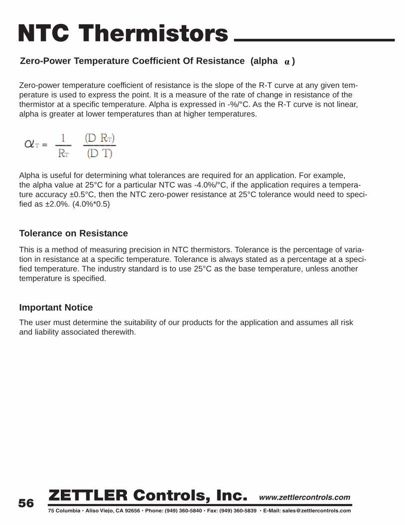
Zero-Power Temperature Coefficient Of Resistance (alpha )
Zero-power temperature coefficient of resistance is the slope of the R-T curve at any given tem-perature is used to express the point. It is a measure of the rate of change in resistance of thethermistor at a specific temperature. Alpha is expressed in -%/°C. As the R-T curve is not linear,alpha is greater at lower temperatures than at higher temperatures.
Alpha is useful for determining what tolerances are required for an application. For example,the alpha value at 25°C for a particular NTC was -4.0%/°C, if the application requires a tempera-ture accuracy ±0.5°C, then the NTC zero-power resistance at 25°C tolerance would need to speci-fied as ±2.0%. (4.0%*0.5)
Tolerance on Resistance This is a method of measuring precision in NTC thermistors. Tolerance is the percentage of varia-tion in resistance at a specific temperature. Tolerance is always stated as a percentage at a speci-fied temperature. The industry standard is to use 25°C as the base temperature, unless anothertemperature is specified.
Important Notice The user must determine the suitability of our products for the application and assumes all riskand liability associated therewith.
NTC Thermistors
56
α
HVAC/R appliance
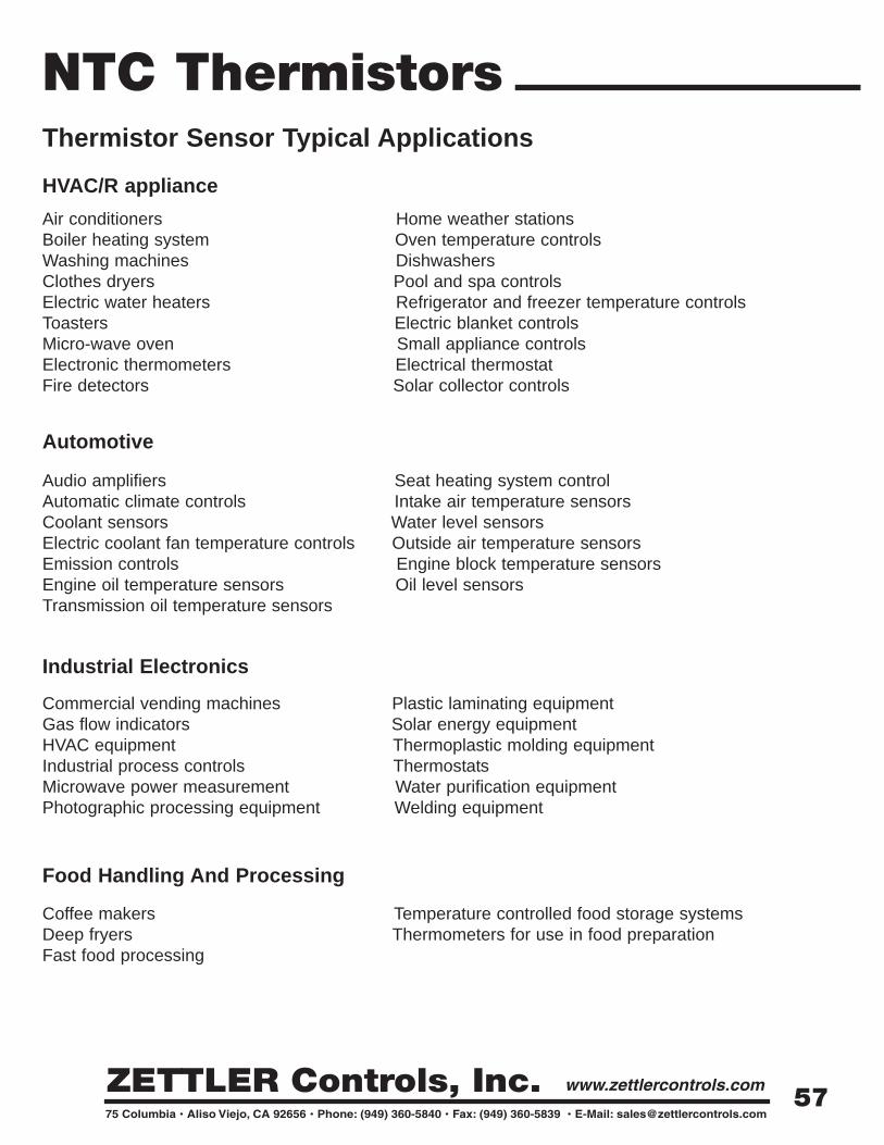
Thermistor Sensor Typical Applications
Air conditioners Home weather stations Boiler heating system Oven temperature controls Washing machines DishwashersClothes dryers Pool and spa controls Electric water heaters Refrigerator and freezer temperature controls Toasters Electric blanket controlsMicro-wave oven Small appliance controls Electronic thermometers Electrical thermostatFire detectors Solar collector controls
Industrial Electronics
Commercial vending machines Plastic laminating equipmentGas flow indicators Solar energy equipmentHVAC equipment Thermoplastic molding equipmentIndustrial process controls ThermostatsMicrowave power measurement Water purification equipmentPhotographic processing equipment Welding equipment
Automotive
Audio amplifiers Seat heating system controlAutomatic climate controls Intake air temperature sensors Coolant sensors Water level sensorsElectric coolant fan temperature controls Outside air temperature sensorsEmission controls Engine block temperature sensorsEngine oil temperature sensors Oil level sensorsTransmission oil temperature sensors
Food Handling And Processing
Coffee makers Temperature controlled food storage systemsDeep fryers Thermometers for use in food preparationFast food processing
NTC Thermistors
57

Zettler Controls Thermistor Sensor part numbering system
Features and Benefits
Zettler NTS Thermistor sensor is designed according to UL 1434 or customer custom require-ments. All components have excellent reliability and are RoHS compliant. Precision range term1%, 2%, 3% and 5%.
Thermistor sensor benefits include:• Engineered to specific application requirements• Thermally responsive.• Increased performance of the overall system in terms of energy consumption and ease of
use.• Reduced assembly cost and increased reliability.• Rugged performance and long-term stability.
Plastic over-molded sensor features and benefits include:• Plastic provides a much higher protection against moisture over time.• Plastic probes can be made into more application-specific shapes.• Plastic probes can eliminate multiple-part assemblies for customers and reduce their labor
and combined material cost.• Lower weight content than metal probes can benefit transportation costs.
NTC Thermistors
58

Sensor VarietiesZettler designed thermistor sensors use a variety of sensor types to further enhance their use in applica-tions. The most common sensor is the axial glass encapsulated NTC thermistor which can be suppliedwith tight tolerances at multiple temperatures.
Standard Plastic Materials
Standard plastic materials selections are based on use, probe shape, response time and cost. Themost commonly used plastics are General Electric's Valox and Chevron Phillips Chemical'sRyton. The advantages of plastic are low cost, design shape flexibility and excellent moistureprotection. Other protection methods are epoxy potted-metal housings and shrink tubing. Metalhousings are typically brass, stainless steel or aluminum.The following are the most commonly used plastics. Customer-specified plastics can also be used.
• Valox - inexpensive, acceptable for use with food products• Polypropylene - very inexpensive, low temperature rating• Ryton - high temperature rating, good thermal conductivity, relatively expensive, harder but also
more brittle than Valox or polypropylene.
Zettler can use all major brands of wire terminals and connector housings.The photos show just a small sampling of our capabilities. Please contact aZettler Controls Applications Engineer for assistance in selecting the wire ter-minations and housings for your application.
Temperature sensor typical package types : Plastic housing sealed, Metal housing sealed, Combinedhousing sealed, Simple housing packaged.
Plastic housing sealed temperature sensor housing materials include Valox PBT, Ryton PPS, PP, Nylon, Ultem.Use proper plastic material according to customer differentshape, thermal time constant, cost and application require-ments etc. Economical, shape complexity, moisture resistance,performance stability and light weight are the advantages ofthis kind of sensors. Normal material sealed sensors can beused in -40°C to +125°C environment, special plastic sealedsensors can be used up to +200°C.
NTC Thermistors
59

The NTC can be sealed completely in a plastic housing or can be exposed, this will be determined bycustomer's applications thermal response and dielectric strength requirement.
Metal housing sealed temperature sensor housing material options include Brass (copper), StainlessSteel, Aluminium etc. quick thermal response?strong construction, easy to fasten and high applicationenvironment temperature are the advantages. Some types can be used at -40°C to +250°C environment.
Combined housing sealed temperature sensor is normally housed by metal and plastic material together.It has the advantage of plastic housing sealed and metal housing sealed sensors, quick thermalresponse, strong construction, easy to have complex shape, easy to fasten, etc. to +250°C environment.
NTC Thermistors
60

Simple housing packaged temperature sensor, the NTC normally is packaged by Teflon or PVC heatshrink sleeve or sealed by epoxy. This kind of sensor has simple construction, is economical and hasgood thermal response. They normally can be used in a clean application environment without strictenvironment conditions.
NTC Thermistors
61

Widely Used Temperature Sensing Technologies performance Comparison
NTC Thermistors
THERMO-COUPLE
Fast Time Response High Stability Simple InexpensiveHigh Resistance Eliminates the Need for Four Wire Measurement
Wide Operating Temperature Range
Inexpensive
Small Size Interchangeable Over Wide Temperature Range
Rugged
Inexpensive No External Power Supply Required
High StabilityInterchangeable to Tight Tolerance
Operating Temperature Limited to Approximately -60 to +300 Degrees Celsius
Relatively Slow Time response
Relatively Low Stability Current Source Required
Interchangeable Over Relatively Narrow Temperature Ranges
Low Resistance Requires Three or Four Wire Measurement
Low Sensitivity Subject to Self-Heating
Current Source Required Sensitive to Shock and Vibration
Low Voltage Output Can Be Affected By RFI and EMI
Limited Configurations
Current Source Required
Reference Junction Compensation Required
Expensive
I.C. SENSOR
PARAMETERResistance vs. Temperature
Resistance vs. Temperature
Voltage vs. Temperature Voltage or Current vs. Temperature
Large Change in Resistance vs. Temperature
Linear Wide Operating Temperature Range
SENSOR TYPE NTC THERMISTORPLATINUM RESISTOR
Limited Operating Temperature Range
DISADVANTAGES
ADVANTAGES
Non-Linear Small Change in Resistance vs. Temperature
Non-Linear
Linear High Output vs. Temperature
62
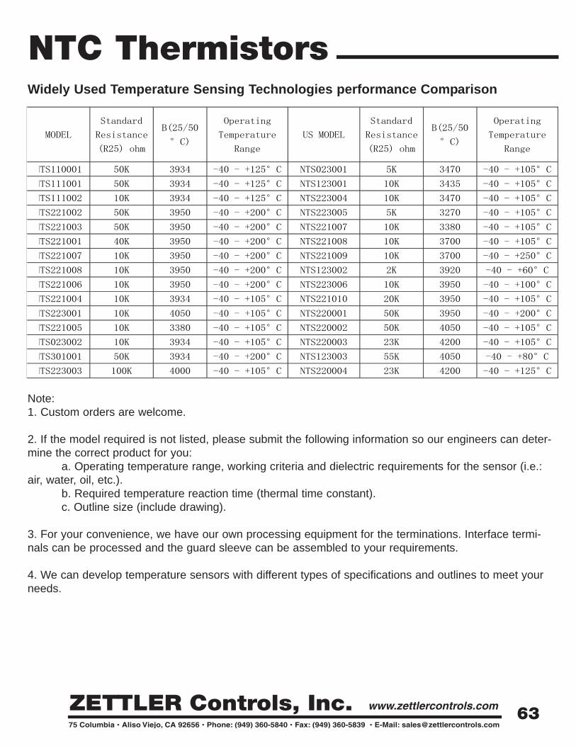
Widely Used Temperature Sensing Technologies performance Comparison
Note:1. Custom orders are welcome.
2. If the model required is not listed, please submit the following information so our engineers can deter-mine the correct product for you:
a. Operating temperature range, working criteria and dielectric requirements for the sensor (i.e.:air, water, oil, etc.).
b. Required temperature reaction time (thermal time constant).c. Outline size (include drawing).
3. For your convenience, we have our own processing equipment for the terminations. Interface termi-nals can be processed and the guard sleeve can be assembled to your requirements.
4. We can develop temperature sensors with different types of specifications and outlines to meet yourneeds.
NTC Thermistors
63

Rev. 05/15/09
ZETTLER COMPONENTS USA75 ColumbiaAliso Viejo, CA 92656TEL: 949-831-5000FAX: 949-831-8548E-Mail: [email protected]: www.zettlercomp.com
AMERICAN ZETTLER, INC.75 ColumbiaAliso Viejo, CA 92656TEL: 949-831-5000FAX: 949-831-8642E-Mail: [email protected]: www.azettler.com
ZETTLER CONTROLS, INC.75 ColumbiaAliso Viejo, CA 92656TEL: 949-360-5840FAX: 949-360-5839E-Mail: [email protected]: www.zettlercontrols.com
ZETTLER MAGNETICS, INC.75 ColumbiaAliso Viejo, CA 92656TEL: 949-360-5838FAX: 949-360-5839E-Mail: [email protected]: www.zettlermagnetics.com
AZ DISPLAYS, INC.75 ColumbiaAliso Viejo, CA 92656TEL: 949-360-5830FAX: 949-360-5839E-Mail: [email protected]: www.azdisplays.com
ZETTLER ELECTRONICS BELGIUMLeuvenselaan, 1723300 Tienen-TirlemontBelgiumTEL: +32 16 825 183FAX: +32 16 822 437WEB: www.zettlerelectronics.be
ZETTLER ELECTRONICSGmbH - GERMANYJunkersstrasse 3 82178 PuchheimGermanyTEL: +49 89 800 97 0FAX: +49 89 800 97 200WEB: www.zettlerelectronics.com
ZETTLER ELECTRONICSNEDERLAND BVDorpsstraat 512761 AA ZevenhuizenThe NetherlandsTEL: +31 180 310 663FAX: +31 180 311 048WEB: www.zettlerelectronics.nl
ZETTLER ELECTRONICSPOLAND sp.z.o.o.Osadnikow Wojskowych 4068-200 ZaryPolandTEL: +48 68 47 91 437FAX: +48 68 47 91 439WEB: www.zettlerelectronics.pl
ZETTLER ELECTRONICS (HK) LTD.Rm. 211 Hewlett Centre52-54 Hoi Yuen RoadKwun TongHong KongTEL: +852 2375 1288FAX: +852 2375 7433WEB: www.zettlerhk.com
XIAMEN ZETTLER ELECTRONICS CO., LTD6-7/F Yinfeng Building, No. 48-50 Huli AveHuli DistrictXiamen 361006ChinaTEL: +86 592 2650 988FAX: +86 592 2650 900WEB: www.zettlercn.com
NINGBO ZETTLER ELECTRONICS CO., LTDNo. 5 Shuntai RoadYangming Technological ParkYuyao City ChinaTEL: +86 574 6250 2178FAX: +86 574 6250 2177WEB: www.zettlernb.com
ZETTLER ELECTRONICS SHANGHAI14/F , New Hongqiao Jieyun Building No.2Lane 600, Tianshan Rd. Changning DistrictShanghai 200051ChinaTEL: +86 21 5100 1736FAX: +86 21 5206 6921WEB: www.zettlercn.com
ZETTLER ELECTRONICS DONGGUANRm A , 4F Yingzhan BuildingNo. 18 Lianfeng Road, Changan TownDongguan 523848ChinaTEL: +86 769 8532 0703FAX: +86 769 8532 0403WEB: www.zettlercn.com