
Xerox Control Program-Five (CP-V)
402
Xerox Control Program-Five (CP-V) Xerox 560 and Sigma 5/617/9 Computers © Xerox Corporation 1974, 1975 goneywell Information Systems Inc. Data Base Technical MCIlual 90 19 95D 90 19 95D-1 90 19 95D-2 90 19 95D-3 September 1978 XEROX File No.: 1 X33 Printed In USA
-
Upload
khangminh22 -
Category
Documents
-
view
0 -
download
0
Transcript of Xerox Control Program-Five (CP-V)

Xerox Control Program-Five (CP-V)
Xerox 560 and Sigma 5/617/9 Computers
© Xerox Corporation 1974, 1975
~197d, goneywell Information Systems Inc.
Data Base
Technical MCIlual
90 19 95D 90 19 95D-1 90 19 95D-2 90 19 95D-3
September 1978
XEROX
File No.: 1 X33
Printed In USA

REVISION
This publication documents the FOO version of Control Program-Five
(CP-V). Pages dated 9/1/78, denote changes that reflect the FOO version.
ii

TAB L E o F CON TEN T S
JIT - Job Inform.ation Table ••• ; •••••••••••••••••••.••••••••••••••• Usage ••••••••• Description .... . JIT Picture .... . Label Definitions. JIT Usage by Processors ..
Scheduler ••••••••....•••.••• Scheduler Queues ••..••.• Event Transition Tables ••...••
~ Resource Su~ ••..••••••• Situational Priority Increments .•••••••••• Scheduler States ••••••••• Scheduler Events ••.•.•••.• Scheduler/Swapper Tables •••• Scheduler/State Tables/Queues •• Scheduler Priority and Real-Time Data •••••••
User Tab les ............................... . Common Multiprocessor Control Tables •••
Shared Processor Tables •.•••••..••••••••••••.•.••.•••.•••.•••••••• Tables Displaced by Processor Number ••••••••••••••••••••••••.• Processor Table Layout •••• Ghost Job Tables ••••••....
Memory Allocation •••.••.•••.•••..• On-Line Memory Pointers .•••••• Batch Memory Pointers ••••••.•.•. Physical Memory Allocation ••••.••••.•.•. CP-V Buffer Linking •••••.••••••••••. Swap Storage Layout •••••••••• Swapping RAD Granule Table ••• Memory and Stolen Page Data
Input/Output Tables ....••••••.•.• DCT - Device Control .•••.•••• RAD/PACK Characteristics ••... IOQ I/O Enqueueing .•.••. DOT CIT DTT AVR
Devoce Operations .• Channel Information. Device Type - Class Tables ••••
Tables ............... . AVR Table Bit Definitions. Table Contents and Bit Settings •••••••• coe Tab les .......................... .
iii
Section Page
VA 1 VA 1 VA 2 VA 3 I VA 17 VA.Ol 19
VC 20 VC 20 VC 20 VC 20 VC 20 vc 21 vc 21 VC 22 VC 22 VC 23
VD 24 VD.Ol 27
VE 35 VE 35 VE 36 VE 37
VF 38 VF .01 38 VF.Ol 38 VF .01 39 VF .01 40 VF .02 41 VF .02 42 , VF.02 44a
VG 45 VG.Ol 45 VG.Ol 48 VG.02 49 VG.02 50 VG.02 50 VG.03 51 VG.04 57 VG.04 58 VG.04 59 VG.05 62

I
File Tab les ...................................................... . Master Index Format for Level 0 ••..••......•.•. ' ••.••••••.••.•• Master Index Format for a Higher Level Index ••••..••.••••••.•• Accoun t Direc tory ............................................ . Master Index Format for the Public File Account Directory .... . Entry Format for Public File Account Directory ............... . Entry Format for a Private Volume Set Account Directory ...... . File Directory ........ 0 •••••••••••••••••••••••••••••••••••••••
Master Index Format for Public and Private File Directories ••• Free Granule Pool (FSP) Format •••••••••••••••••••.•••••••••••• File Information Table (FIT) Format ••.••.•••.•.••••.••..•.•••• Private Volume Set Tables ••••••••••••••..•••••.•••••••••.••••• VTOC - Volume Table of Contents •••••.•••••••••••••••••••••.••• HGP - Allocation Tables ••.•.•••••••••••••..••••.•••••••••••••• CFU - Current File Usage Tables ••••••.••••.•.•.••.•••••••••.•• ACNCFU - Account Directory CFU •••••••••••••••••••••••••••••••• FILCFU - File Directory CFU •••.•••.••••••••••••••••••••••••••• User File CFU ••••.... 0 ••••••••••••••••••••••••••••••••••••••••
File DeB •••..•••••••••••••••••••••••.•••••••••••••••••••••••••
Labe led Tape DCB •......•.••.•••.....•..•••.•••.......•..••••••
ANS Labeled Tape DeB ••.••••••••••••••••••••••••••••.•••.••••••
Device DeB •••••••.•.•••••••••••.••••••••••••••••••••••••••••••
cP-V Labe led Tape .......................................•..... General Format of Sentinels ••••.•••••.••••••.•••••••••••..•.•• Record Format .••...••......••••..•......•••.•...•....••...•••.•
ANS Labe led Tape •.•..• 0 •••••••••••••••••••••••••••••••••••••••
General Format and Sentinels ••••••.•.....••••••••••.••••.••••• Generalized Disk Address ••.•••••••.•••••••••.••.•••••••.•••.•• Consecutive File Format ••••..••.•••.•••.•.•••••.•.•.••••..•.•• Schema for Locating and Referencing Public Files ••••••.•..•••• Schema for Locating and Referencing Private Files ••.•.••..•••• Read-Ahead Tables ...... 0 ••••••••••••••••••••••••••••••••••••••
Symbionts and Cooperatives .••••.••••••••••••••••.••.•••.•••••••••• Symbiont/Cooperative File Block ••••.•••••••••••••••••••••••••• Symbiont Tables .............................................. . Linkage Between Logical Device Tables •.•.••••••••••••••••••••• Input Symbiont Context Block ••.•••••••••••.•••.••••••••••••••• Cooperative Context Block ••••••••••••••••••••••••••••••••••••• Output Symbiont Context Block •.•.••.•.••.•.•••.••.•.••..•••••• Symbiont/Cooperative Context Block Displacement Symbols ••••••• RBBAT Communication Buffers •••.•..••••..•.•.•.••••••••••••••••
Multi-Batch Scheduler Tables •••.....••••••.•••.••••••.•••••.•••••• MBS Tab les in RBBAT .........•...................•.......•..••.
Priority Tables ........................................... . S-ymbiont File Tables ...................................... . Serial Number Tables •••••••••••••.•••••••••••••••••••••••.•
iv
Section Page
VH 66 VH.Ol 66 VH.Ol 69 VH.02 70 VH.02 70 VH.02 70 VH.02 71 VH .. 03 72 VH.03 73 VH.03 75 VH.04 76 VH.06 80 VR.06 81 VR.07 83 VH.08 85 VH.08 86 VR.08 89 VH.08 91 VH.09 93 VR.lO 104 VH.ll 112 VH.12 119
VH.16.0l 126 VR.16.0l 127 VH.16.0l 129 VH.16.02 132 VH.16.02 132
VH.17 135 VH.18 136 VR.19 139 VH.20 140 VH.21 141
VI.Ol 144 VI.Ol 144 VI.Ol 146 VI.Ol 149 VI.Ol 152 VI.Ol 153 VI.Ol 154 VI.Ol 156 VI.Ol 161 VI.02 171 VI.02 171 VI.02 171 VI.02 172 VI.02 173

MBS Tab les in Core ......... It ••••••••••••••••••••••••••••••••••
Resource Allocation Tables .•••••.•••...•.•••••••••••••••••• Serial Number Tables for Running Jobs •••..••• e •••••••••••••
Partition Tables ••..••••.••.....••••..•• Partition Table Layout ••••••••••.•.•.•..
GI Tables •........ '!' ••••••••••••••••••••••••••••••••••••••
Service Limit Tables •.•..••••.•••.••••••••••• Peripheral Authorization Tables ••••.••••.••••••.•..••.••••••••
Error Log ......................•.........•...............•....•.•. Error Log Format •••.•.•••.••••••••. File Control Pointers •.•••...••••.• Error Log Core Structure •••.•••.•••.••••••••..•.••••••••.••••• Overview .• Glossary .. Error Log Codes •.•.••....•••••.•••.••••••••••••••••••••••••••• Error Log Entry Formats •••....••.•.•• CSE STOP Tables .•..•.••.•...•••••••.••••
Assign/Merge Table ••••.. Function ...••.•..•. Structure .....•••... Format of Assign/Merge Table .••..•••.••••••••.•. Format of RUN Table ••.••••.••.•••••.•••••..•.•••
Error Codes and Error Messages •••••••••.•..••••••.••.•••••••••••• ~ Error Message File Format •••••..••.••••••••.•••••••••••.•••••• Error Messages ................•...............................
: USERS - Logon File ..••.......••...••.•..•••..•...........•....••• Structure .................................................... . Contents ............. ct •••••••••••••••••••••• II •••••••••••••••••
:ACCTLG - Accounting Log Format •••..•...••.. Structure .................................................. ~ .. Contents ...............•......................................
RATE Record ••..•. Structure .•••
:RBLOG - Remote Batch Logon File .•••••••••••••.•••••••••••••••...• Purpose •........................•••...••...•..• 0 ••••••••••••••
Contents ........................................••.........•.. Structure of the RBID Record •...•.•••.•...•••••••..••..•••••••
:PROCS - Restricted Processor List •••••..••••.•..•.•.•.•••••...•••
v
Section .;page
VI.02 174 VI.02 174 VI.02 175 VI.02 176 VI.02 178 VI.02 179 VI.02 180 VI.02 181
VK 182 VK 182 VK 183 VK 18,+ VK 186 VIZ 190 VK 200 VK 208 VK.Ol 236
VL 238 VL 238 VL 238 VL 238 VL.Ol 241
VM 247 VM 247 VM 249
VN.Ol 261 VN.Ol 262 VN.Ol 264 VN.02 268 VN.02 269 VN.02 270 VN.03 273 VN.03 273 VN.04 274 VN.04 274 VN.04 275 VN.04 280 VN.05 281

Loader Tab les •••••.••••.••••••••.•• 0 ••••••••••••••••••••••••••••••
Task Control Block (TCB) ••••.••••••••.•••••••••••••.•••• ~ ••••• DCB Name Table (DCBTAB) ••••••••••••••••••••••••••••••••••••••• Load Module Layout •••••••••••••••••••••••••••••••••••••••••••• HEAD Record •••••••••••••••••••••••••••••••••••••••••••••••••••
TREE Record •••••••••••••••••••••••••••••••••••••••••••••••••••
Segm.ent Components •••••••••••••••••••••••••••••••••••••••••••• Libraries •••••••••••••••••••••.••.•••••••••••••••••••••••••••• REF /BREF Tab les •••••••••••••••••••••••••••••••••••••••••••••••
REF/DEF and Expression Stack •••••••••.•••••••••••••••••••••••• Relocation Dictionary •••.••••••••••••••••••••••••••••••••••••• LOCCT Tab Ie 0 ••••••••••••••••••••••••••••••••••••••••••••••••••
Real TiIne •••.•••••• 0 ••••••••••• ., .................................. .
Interrupt Control Block Formats ••••••••••••••••••••••••••••••• ICB for User Task •••••••••••••••••••••••••••••••••••••••••• reB for Ghost Job •••••••••••••••••••••••••••••••••••••••••• reB for CLOCK3 ••••••••••••••••••••••••••••••••••••••••••••• ICB Field Descriptions ••••••••••••••••••••••••••••••••••••• reB Chain Headers •••••••••.••••••••••••••••••••••••••••••••
Da List Block Formats ••••••••••••••.•••.•.•••••••••••••••••••• WAIT List Block Format •••••••.•• " ••••••••••••••••••••••••••••• M:FRGD Module •••••••••••••••••••••••••••••••••••••••••••••••••
M:!Me Modifications •••••••••..••••••••••••••••••••••••••••••••
ENQ/DEQ ••••••••••••••••••••••••••••••••••••••••••••••••••••••••••• Description ••.••••••••••.••••••••••••••••.•••••••••••••••••••• Queue Head Entries •••••••••••••••••••••••••••••••••••••••••••• SQ Entries ••••••••••••••.••..••••••••••••••••••••••••••••••••• QECB Entries •••••••••••••••••••••••••••••••••••••••••••••••••• QNAl1E Entries •••••••••••••••••••••••••••••••••••••••• 0 ~ •••••••
Remote Processing .•••••••••.•.•.•••••••••••••••••••••••••••••••••• Remote Processing Tables in Core •••••••••••••••••••••••••••••• Remote Processing Tables in RBBAT ••••••••••••••••••••••••••••• RB : FlAG Structure ••••••••••••••••••••••••••••••••••••••••••••• IRBT and 2780 Context ••••••••••••••••••••••••••••••••••••••••• Remote Processing Handler Structure ••••••••••.••••••••••••••.•
Screech Codes ••••••••••••••••••• 0 •••••••••••••••••••••••••••••••••
vi
Section Page
va 283 va 283 va 283 va 284 va 285 va 287 va 288 va 289 va 291 va 292 vo 294 va 297
VP 299 VP 299 VP 299 VP 300 VP 301 VP 302 VP 306 VP 306 VP 308 VP 309 VP 311
VQ 313 VQ 313 VQ 313 VQ 315 VQ 316 VQ 316
VR 318 VR 318 VR 319 VR 320 VR 321 VR 324
VS 325

Transaction Processing ••.•••••.••••••••••.•••••••••••.•••••••••••• Physical Work Pages (PWPTABLE) ••••.••••••••••••••••••••••••••• TTP Resident Table - Queue Management •.•••••..•.•.••••.••••.••
Recovery Tables ............................•...................... Core Dump Fonnat... . .••••.•......•••.• It •••••••••••••••••••
Dump Tape Fo-rtn..at.... . •••••..••..•......•..... 0 ••••••••
Recovery Buffer..... . .•••.•.••••••••. Power Fail-Safe Interrupt Status •••..••.•.••
Ind ex .......•..•...........•.•••...•••.•..•..............••.......
vii
Section Page
VT 347 VT 347 VT 348
VU 351 VU 351 VU 351 VU 352 VU 353
354

NAME: USAGE:
CP-V TECHNICAL MANUAL
JIT THE LABELS OF THE ITEMS IN JIT ARE CONSTRUCTED using the following conventions. These conventions allow the user to determine from the label itself whether it is an address or a displacement within JIT and whether it has byte, halfword or ~~rd resolution. items in jit should always be referenced by label rather than absolutely because the internal structure of JIT may change.
JIT LABELING CONVENTIONS: All the labels defined in JIT are constructed using the following conventions. These conventions allow the user to determine whether the label is an address or a displacement from J:JIT and its resolution from the label itself.
1.) A colon (:) indicates that the label is an address. Example: J:TCB, JH:PC, JB:VLH
2.) No colon indicates that the label is a displacement from J:JIT. Example: JTCB, PR DC RM , JBVLII
3.) If the label starts with JH:, JH or HA, it has JB or BA, it has byte resolution. If it starts with JX: or JX, it may be either byte or halfword, depending on vclue assigned by :BIG during sysgen. Any other characters indicate word resolution. . Examples: Word - J:UNAME, JUNAME, UNAME
Halfword - JH: PC, JHDA Byt e - JB: VLH , JB VLH , BAABC
4.) In some cases several labels will reference the same item giving address and displacement with different resolution for the same item. Example: The I/O abort code - word 17, byte 0 -
J:ABC, JABC, ABC and BAABC DESCRIPTION: Each user receives an initialized JIT when the
job or terminal session begins. This JIT stays with the job until it is logged off.
1
Section VA Page 1 9/1/78

CP-V TECHNICAL MANUAL Section VA Page 2 9/1/78
A user's JIT contains his accounting deta, resource usage limitations, various flags describing the status of his job, some loader data, the M:UC and ~:XX DCBs, memory management data, a temp stack for mcnitor use, pointers and addresses of data in his context block, his map and access code images and swapper data, as well as many other items too numerous to mention. The JIT is 512 words long (1 page) and is always loaded at .BCOO (virtual).
The seek addresses (JH:DA) and the command list (J:CL) used by the swapper to swap a user in or out are contained in JIT. There is enough space in JIT to contain this data for a user whose size is no greater than 20 pages on Sigma 7 and small memory Sigma 9/560 systems. If a user's size exceeds 20 pages, he is allocated an AJIT, "additional JIT", and the swapper command list is .moved into AJIT. The space in JIT that was formerly used for the command list is then used for the seek addresses, i.e., JH:DA spills over INTO J:CL. ON LARGE NEMORY SYSTEMS (GREATER than 128K) , all users receive an AJIT at the time they receive the JIT. The AJIT contains both the swapper command list and the seek address table, JH: DA.
2

J:JIT, JIT J:UN
J:ACCN
J:UNAME
J:CTIME
J:OVHTIM
J : CALC NT
J: PTIME
J:UTIME
)
o 1 234 16 31
I I I I I I I I I I I I I I I I I I I I I I I I
SYSID : SYSID I I
--~--------~-----~~-----~~---------~-----~~--I I 1 I I '1 I I
: : : : - COMMAND PROC. EXEC. : : : --- SUB TASK : : ---- REMmE ASSIST : ----- GHOST --------- ON-LINE
I ,.
ACCOUNT NUMBER-- 2 WORDS
USER NAMF- 3 WORDS
JACCN ACCN
JUNAMF UNAMF
: /I OF 1/0 OPS * SL: larA IN CURRENT QUANTUM: CEXT
CURRENT OVERHEAD TIME OVHTIMF
COUNT OF CAL 1 CALLS IOTIMF
PROCESSOR ExECUTION TIME TPEXT
PROCESSOR OVERHEAD TIME TPOVf
PROCESSOR PAGE * TIME MEMORY USE FACTOR TPIaf
--~------~------~~-~-----~-------------------USER EXECUTION TIME TUEXT
------------~--------------------------------
JIT JIT JIT JIT JIT JIT JIT JIT JIT JIT JIT JIT JIT JIT JIT JIT JIT JIT JIT JIT JIT JIT JIT JIT JIT JIT JIT JIT JIT JIT JIT JIT JIT JIT JIT JIT JIT JIT JIT JIT JIT JIT
JIT JIT
8COO 8COO 8eoo 8COO BCOO 8eoo 8COO 8eoo Beoo 8eoo 8eoo Be01 8COl 8eOl BCOl BCOl 8C03 8e03 BC03 8e03 8C03 BC03 8C03 8e06 8C06 8C06 BC07 BC07 8C07 8C08 8C08 8C08 BC09 8c09 Beog 8COA 8COA 8COA 8eoB 8COB 8COB 8COC
8COC 8eoc
\O."C/l 'DJ(1) - C1Q (.) '(1)C+ -.J ..... ex> 0
w:s
< >

J:DELTAT
J:MRT
J:ABC
+= J:RNST
USER OVERHEAD TIME TUOvr
--------------~--------~~-~-----~-------~----
USER PAGE * TIME MEMORY USE FACTOR TUIOT
I -- TIME CXJANTllM LEFT (INC BY CLOCK4) TIMTMP -------~-------------~-----------------------
MAX RUN TIME. IF ZERO, NO MAX MRT
o
: ABORT CODE
o
I RUN I STATUS
8 11 23 26 31
: JOB :PRIOR
: : : SENSE: JABC,PRT : : :SWITCHS: SS,BAABC
I I
-FNQ'S OUTSTANDING 8 9 10 14 161718 20 24 31
I : RUN : : : FLAG: I I I I
: I : IX : LINK : : ::S : : : :: L : COUNTF. R
I I I I I I I I
: RUNFLAG :. JRNST, PUF : CCBEF, RNST
BARNST
: :: - EXEC. SEVe LEVEL : : - RETURN M:EXIT AFTER M:LINK : - RETURN M:F.RR/M:XXX AFTER M:LINK
I - SAVE/RES J:CCBUF ON M:LINK/M:LDTRC I -------------COMMAND IN J:CCBUF ----------------CONTROL CMND BUF FULL
JIT 8COD JIT 8COD JIT 8COD JIT 8COF JIT 8COF JIT 8COF. JIT 8COF JIT 8COF JIT ReOF JIT 8C10 JIT 8C10 JIT 8C10 JIT 8C11 JIT 8C11 JIT 8C11 JIT 8C11 JIT 8C11 (')
""0 JIT 8C11 I
JIT 8e11 <:
JIT 8C12 t-;'I L11
JIT 8C12 (')
JIT 8C12 :..:r.: z
JIT BC12 .... n
JIT 8C12 :]:::1
JIT 8C12 ~
JIT 8C12 ...s: ;:c.
JIT 8C12 :Z .-JIT 8C12 '-
~
JIT 8C12 L'
JIT 8C12 JIT 8C12 JIT 8C12
\.O""O(/.) ., ru (l) -OQ ()
'('()c1" --.1 ..... .:,0 0
..t=' :::3
<: :x;.
'u1
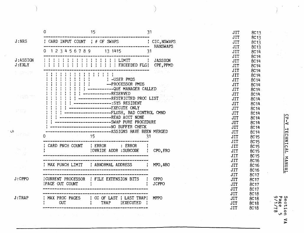
J:NRS
J:ASSIGN J:EXLY
J:CPPO
J:TRAP
)
a 15 31
: CARD INPUT COUNT : # OF SWAPS : CIC,NSWAPS --------------------------------------------- HANSWAPS a 1 2 3 4 5 6 7 8 9 13 1415 31
: : : : : : : : : : : : : : I : LIMIT : : : : : : : : : : : : : : : : : EXCEEDED FLGI
I I I I I I I I I I I I
: : : -USER PMDS : : --PROCESSOR PMDS
JASSIGN CPE,PPMD
: -----------QUE MANAGER CALLED : ~-----------RESERVED
: --------------RESTRICTED PROC LIST ----------------:SYS RESIDENT
------------------EXECUTE ONLY I --------------------FLUSH, BAD CONTROL CMND ----------------------READ ACCT NONE
: ------------------------SWAP PURE PROCEDURE : --------------------------NO BUFFER CHECK ----------------------------ASSIGNS HAVE BEEN MERGED
a 15 31
: CARD PNCH COUNT : ERROR : ERROR :OVRIDE ADDR :SUBCODE
: MAX PUNCH LIMIT : ABNORMAL ADDRESS
: CURRENT PROCESSOR : FILE EXTENSION BITS : PAGE our COUNT
CPO,ERO
MPO,ABO
CPPO JCPPO
: MAX PROC PAGES OlIT
: cc Of LAST : LAST TRAP: MPPO TRAP :EXECUfED:
JIT JIT JIT JIT JIT JIT JIT JIT JIT JIT JIT JIT JIT JIT JIT JIT JIT JIT JIT JIT JIT JIT JIT JIT JIT JIT JIT JIT JIT JIT JIT JIT JIT JIT JIT JIT JIT JIT
8C13 8C13 8C13 8C13 8C14 8C14 8C14 8C14 8C14 8C14 8C14 8C14 8C14 8C14 8C14 8C14 8C14 8C14 8C14 8C14 8C14 8C14 8C15 8C15 8C15 8C15 8C15 8C16 8C16 8C16 8C17 8C17 8C17 8C17 8C18 8C18 8C18 8C18
\..O""OC/l ........ Q) (D -OQ Q ........ (D cT ......:I ..... <::x> 0
U'I:;S
< >

J:JlP
J:lNTER
J:RWECB
JB:STEP JB:ORG
J:ASPlN
J:ALB
J:TELFLGS
J:CASSIN
IUSER PAGE COUNT IAOORESS OF CCl'S LOADER: ALOCCT : COMMAND TABLE CUPO
lMAX USER LP PAGES : JOB IN PROGRESS FLAG I MUPO
:OIAGNOSTIC PAGE CNT: n OF INTERACTIONS CDPO
I MAX DO PAGES OUT : ECB ADDRESS MDPO
:n OF STEPSIJOB ORIGIN:n TAPE READ & WRITES: TPACCESS
ACTIVE SPINDLES
: UNUSED CAL3 *J:ALB
CCI AND TEL FLAGS (SEE DEF)
o 8
: REMOTE : REMOTE : UNUSED :BATCH FLAG: BATCH ID :
25
: FLAGS
31
CCLTFLGS CCLFLAGS MJCFLG JTELFLGS
ERIFLAGS ERRLFLGS JRBID
JlT JlT JlT JlT JlT JIT JIT JIT JIT JIT JIT JIT JIT JIT JIT JIT JIT JIT JIT JIT JIT JIT JIT JIT JIT JIT JIT JIT JIT JIT JIT JIT JIT JIT
8C19 8C19 8C19 8C19 8C1A 8C1A 8C1A 8C1B 8C1B 8C1B 8C1C 8C1C 8C1C 8C1D 8C1D 8C10 8C1D 8C1E 8C1E 8C1E 8C1E 8C1E 8C20 8C20 8C20 8C21 8C21 8C21 8C21 8C22 8C22 8C22 8C22 8C22
\O'"'OC/l ........ Q) -CD -.. CJIQ () ........ CDci" -...J ..... CD 0
O\::s
< »

J: INTENT
J:TIMFNT
J: UTIMER
J:USENT
J:TCB
J:TREE
)
o 15 31
: :0--------------0 : USER CONSOLE INTERUPT: INTENT : : : FNTRY ADDRESS , I
l-- COMMAND PROCESSOR BREAK CONTROL
:0-----------------0: ENTRY ADDRESS FOR M:STIMER
INTERVAL SET BY M:STIMER
7 8 910 1112 14 15
TRAP FLAGS I I
, I I I , I I I I I I I I I I I I I I I , I I , I I , I I I I I I I I I
I I , I I I I I
ADD. OF USER TRAP ROUTINES BY M:TRAP
I : : : --BAD CAL TRAP CONTROL : : : ----FIXED POINT TRAP CONTROL : : ------DECIMAL TRAP CONTROL
TIMENT
lTTIMER
31
TRPFLAGS
: --------FLOATING POINT TRAP CONTROL ----------STACK TRAP CONTROL
------------UNIMPLEMENTED INSTR TRAP CONTROL --------------NON-ALLOWED OPERATION TRAP CNTRL
----------------RSVRD. - TRAP CONTROL
: 0---------------0 : TCB ADDRESS TCBADR
: 0---------------0 : TREE TABLE ADDRESS JITREE
: MIN TEMP PACK SPACE REMAINING TMPDPPK
JIT JIT JIT JIT JIT JIT JIT JIT JIT JIT JIT JIT JIT JIT JIT JIT JIT JIT JIT JIT JIT JIT JIT JIT JIT JIT JIT JIT JIT JIT JIT JIT JIT JIT JIT JIT JIT JIT
8C23 8C23 8C23 8C23 8C23 8C23 8C23 8C24 8C24 8C24 8C24 8C25 8C25' 8C25 8C26 8C26 8C26 8C26 8C26 8C26 8C26 8C26 8C26 8C26 8C26 8C26 8C26 8C26 8C26 8C27 8C27 8C27 8C28 8C28 8C28 8C29 8C29 8C29
n ""0 I < ~ rr1 n :c z H n » r 3: > Z c:: > r
\O"'tICIl ,Q)Cl) -OQ ()
'CDc1" .....:3 ..... ex> 0
.....:3::3
<: »
co
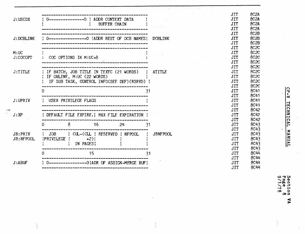
J:USCDX : 0---------------0 : ADDR CONTEXT DATA BUFFER CHAIN
J:DCBLINK : 0----------------0 IADDR REST OF DCB NAMFS: DCBLINK
M:UC J:caeOPT
, I
: cae OPT IONS IN M: UC+8
J:TITLE : IF BATCH, JOB TITLE IN TEXTC (21 WORDS) ATITLE : IF ONLINE, M:UC (22 WORDS) I
IF SUB TASK, CONTROL INFO(SEE DEF)(RSRVD) :
o 31
J:UPRIV : USER PRIVILEGE FLAGS
J:XP : DEFAULT FILE FXPIRE.: MAX FILE EXPIRATION:
o 8 16 24 31
JB:PRIV : JOB : CUL-(ClL : RESERVED NFPOOL JBNFPOOL JB: NFPOOL : PRIVILEGE : +2) :
IN PAGES:
o 15 31
J:ABUF : O----------------OIADR Of ASSIGN-MERGE BUF:
JIT JIT JIT JIT JIT JIT JIT JIT JIT JIT JIT JIT JIT JIT JIT JIT JIT JIT JIT JIT JIT JIT JIT JIT JIT JIT JIT JIT JIT JIT JIT JIT JIT
8C2A BC2A BC2A 8C2A 8C2B BC2B BC2B BC2C BC2C 8C2C 8C2C 8C2C 8C2C 8C2C 8C2C BC2C n 8C41 "0
8C41 • < BC41
~ 8C41 ['11
8C42 n :c
BC42 2'! ......
BC42 n BC43 >
~
8C43 x BC43 > BC43 Z!
c: 8C43 >
~ 8C43 8C44 8C44 8C44 8C44
\O"Ot/l ,Q)tI) ..... OQ () ,t'DC"f' -.:a ..... <:Xl 0
QI)::S
< >

\
J:SIMSP
JB:CCARS JB:DISP JB:CUN JB:arEL JB:LPP JB:LC
\0 JB: PCW JB: PR(}IIPT
J:IDELTAT
J : EXTENT
012 789
I I I , I I I I I ,
14 15
I I
31
ADDR Of TRAPPED RF.G ZERO IN TSTACK
'OR' OF INHIBIT BITS FROM TRAPPED : PSD ------ BITS 10-15 FROM TRAPPED PSD
: (ARITHMFfIC & DECIMAL FAULT MASKS) ------------ MAP BIT (BIT 9) FROM TRAPPED PSD
-------------- MODE ALTERED BIT (BIT 40) OR'D WITH SLAVE BIT (BIT 8) OF TRAPPED PSD
o 8 16 24 31
lRECORD SZ I DISPLACE. : CURRENT :SPEC SHRD : : C.C. : IN C.C. : USER II IPROC. /I
:n OF LINES:CURRENT # : PLATEN :PER PAGE :OF LINES I WIDTH : DEF=O : DEF=O : DEF=O
INITIAL VALUE OF J:DELTAT
PROMPT : BYTE : DEF=O
-------- -------.~------~--------------------o 1 2 3 4 5 6 7 8 15
I , I I I I I I
I • I I I I
I I I I I I I I
: : ADDR OF EXIT CONTROL
: : : : --'LAST' OP ON EXIT CNTRL : : I ----STEP CON INC : I ------EXIT CNTRL;C-Y AND QUIT : --------UNUSED
31
----------M:LINK OR M:LDTRC EXIT CONDITION ------------EXIT CNTRL BY CMND PROC
I --------------EXIT CNTRL IN PROGRESS ----------------SOME LIMIT EXCEEDED
------------------OPERATOR ABORT OR LINE HNGUP
JIT JIT JIT JIT JIT JIT JIT JIT JIT JIT JIT JIT JIT JIT JIT JIT JIT JIT JIT JIT JIT JIT JIT JIT JIT JIT JIT JIT JIT JIT JIT JIT JIT JIT JIT JIT JIT JIT JIT JIT JIT
8C44 8C44 [,·:44 8C44 8C44 8C44 8C44 8C44 8C44 8C44 8C44 8C44 8C44 8C44 8C45 8C45 8C45 8C45 8C45 8C46 8C46 8C46 8C46 8C46 8C47 8C47 8C47 8C48 8C48 8C48 8C48 8C48 8C48 8C48 8C48 8C48 8C48 8C48 8C48 8C48 8C48
\.O""OCJ) 'Q}ro ~(jQ (.)
........ ro(1--.J ..... ' co 0
\.0:5
< :>

J :XPSD
TSTACK urs
.....\ J:OVRLY o
J:CPROCS
J:CFLGS
: MIN TEMP RAD SPACE REMAINING
OLD PSD
CAL3 HANDLER PSD
: TEMPORARY STACK DOUBLEWORD (BOUND 8)
TEMPORARY STACK OF SIZE=JTSTACKSZ=121
I OVERLAY ENTRY POINT ADDRESS
o 8 16 24
: UB:APR : UB:APO : UB:ASP l UB:DB
o 16
: GARBAGE : UH:FLG AT SAVE
TMPDCPK
31
31
JIT JIT JIT JIT JIT JIT JIT JIT JIT JIT JIT JIT JIT JIT JIT
·JIT JIT JIT JIT JIT JIT JIT JIT JIT JIT JIT JIT JIT JIT JIT
8C49 8C49 8C49 8C49 8C49 8C49 8C49 8C49 8C49 8C49 8C4E 8C4E 8C4E 8C4F 8C4E 8C4E 8C4F 8C4E 8C4E 8CC9 8CC9 BCC9 8CCA BCCA 8CCA 8CCA 8CCB 8CCB BCCS BCCS
I..O"'OC/.l .......... 00(1) .....\OQ (;) .......... (ocT --.:J ...... (.0 ...... 0
o:::s <: ::x>
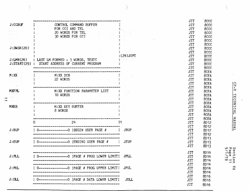
J:CCBUF
J:IJ.olSK(20)
CONTROL Ca.1MAND BUFFER FOR CCI AND TEL 20 WORDS FOR TEL 30 WOROO FOR CC I
J:LMN(26) : LAST LM FORMED - 3 WORDS, TEXTC J:START(29): START ADDRESS Of CURRENT PROGRAM
M:XX
MXFPL
MXKB
J:BUP
J:EUP
o
M:XX DCB 22 WORDS
M:XX FUNCTION PARAMETER LIST 10 WORDS
M : XX KEY BUFFER 8 WORDS
24
: 0---------------0 :BEGIN USER PAGE #
: 0---------------0 lENDING USER PAGE #
)
. : (24)JOPT
31
JBUP
JEUP
J:PLL : 0---------------0 IPAGE # PROG LOWER LIMIT: JPLL
J:PUL I 0---------------0 :PAGE # PROG UPPER LIMIT: JPUL
---~~------------------------~----------~----J:DLL : 0---------------0 lPAGE # DATA LOWER LIMIT: JDLL
JIT JIT JIT JIT JIT JIT JIT JIT JIT JIT JIT JIT JIT JIT JIT JIT JIT JIT JIT JIT JIT JIT JIT JIT JIT JIT JIT JIT JIT JIT JIT JIT JIT
JIT JIT JIT JIT JIT JIT JIT JIT JIT
8cee 8cee 8eee 8eee 8cee 8cee 8cee 8cee 8eee 8eee 8eee 8eee 8cee BeEA 8CEA 8CEA 8CEA 8CEA 8eEA 8CFA 8CEA 8CEA 8CEA 8CEA 8eEA 8CEA 8D12 8D12 8D12 8D12 8D13 8D13 8D13
8D14 8D14 8D14 8014 8D14 8014 8016 8D16 8D16
\.O""OC/.l '00<1> ~OQ (.) '<1>c-t -..:I ..... CO~O
~::::l
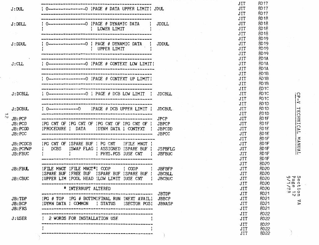
J:DUL
J:DDLL
J:DDUL
J:Cu.
J:OCBlL
J:OCBUL
i\) JB: pcp JB: PCD JB: PCOD JB:PCC
JB: PCOCB JB:PC~P JB:FBUC
JB:FBLL
JB:CBUC
JB:TDP JB:BCP JB:FRS
J: USER
: 0---------------0 \PAGE # DATA UPPER LIMIT: JDUL
: 0---------------0 IPAGE # DYNAMIC DATA : LOWER LIMIT
: 0---------------0 : PAGE # DYNAMIC DATA : UPPER LIMIT
: 0---------------0 :PAGE # CONTEXT LOW LIMIT:
: 0---------------0 :PAGE # CONTFXT UP LIMIT:
: 0---------------0 I PAGE # DCB LOW LIMIT
JDDLL
JDDUL
JDCBLL
: 0------------0 :PAGE # DCB UPPER LIMIT: JDCBUL
--------------------------------------------- JPCP : PG CN! OF : PG CN! Of : PG CNT OF : PG CNT OF: JBPCP :PROCEDURE: OATA :OYNM OATA : CONTFXT JBPCDD --------------------------------------------- JBPCC
: PG CN! OF : SPARE BUF : PG CNT : FILE MNGf : oeBS ISWAP FLAG : ASSIGNED :SPARE BUF: JSPBFLG
: PHYS.PGS :USE CNT JBFBUC
\FILE MNGf ~Fn..E MNGT*! COOP : COOP : :SPARE BUF IFREE BUF :SPARF BUF :SPARE BUF : :UPPER LIM IPOOL HEAD \LOW LIMIT :USE CNT
* INTERRUPT ALTERED
JBFBFP JBCBLL JBCBUC
--------------------------------------------- JBTOP :PG # TOP ~PG # BOTTM:FINAL RUN ~NEXT AVAIL: JBBCP :OYMN DATA: COMMON : STATUS :SECTOR POS: JBNASP
: 2 WORDS FOR INSTALLATION USE --~-~---~-----~---~--~~-----------------~--~~
~--------------------~----------------------
JIT JIT JIT JIT JIT JIT JIT JIT JIT JIT JIT JIT JIT JIT JIT JIT JIT JIT JIT JIT JIT JIT JIT JIT JIT JIT JIT JIT JIT JIT JIT JIT JIT JIT JIT JIT JIT JIT JIT JIT JIT JIT JIT JIT JIT JIT JIT
8D17 8D17 8D17 8D18 8D18 8D18 8018 8019 8019 8019 8D1q 8D1A 8D1A 801A 8018 8D18 8018 801C 801C R01C 8010 BD1D 8010 8D1F 801F B01F 801E 8D1F 8D1F 8D1F 8D1F 801F 8020 8D20 8020 8D20 8020 8020 8021 8021 8D21 8D21 8022 8022 8D22 8D22 8022
1..0""'0(.1) ,rum .-. OQ ()
">-(1)(1" -.J ....,:~~ 0
r\):S
c:::: :x>

J :CLS
JB:MAX
JB:MNPA
~ JX: PPH w
JX:PPT JB:SLNK JB:XLNK
JB:PPC JB:NRG JB: PNR
JB:VL.H JB:PEAK JH:PC JB:STEPCC JB:VLT JB:PMTS JB:TMTS
I CLOSE STATUS INFO
: NUMBER OF PACK READS AND WRITES
I NUMBER OF DISC READS AND WRITES
o 8 16 24
: MAXIMUM RESOURCES ALLOWED TO USER
4 WORD BITE TABLE
o
: PHYSICAL PAGE : CHAIN HEAD
o
: PHYSICAL PAGE CHAIN TAIL
o 8
16
: UNUSED
16
I SLNK
16
24
: XLNK
24
:PHYS PAGE IPARTITION In REMAIN I UNUSED :CHAIN CNT: n I GRANULES I
)
DPACCESS
DCACCESS
31
IJBMNPA
31
31
31
JXPPH JPPH
JPPT JXPPT
JPPC JBPPC JBNRG
:VIRT. PG IPEAK CORE: ON-LINE PAGE JBVLH ILINK HEAD : COUNT JVLH
:VIRT PG ISTEP COND.:n DISC :n TAPES JVLT ILINK TAIL : CODES :PACK MOUNT: MOUNTS
JIT JIT JIT JIT JIT JIT JIT JIT JIT JIT JIT JIT JIT JIT JIT JIT JIT JIT JIT JIT JIT JIT JIT JIT JIT JIT JIT JIT JIT JIT JIT JIT JIT JIT JIT JIT JIT JIT JIT JIT JIT JIT
8D24 8024 8D24 8025 8D25 8D25 8D26 8D26 8D26 8D27 8D27 8D27 8D27 8D27 8D27 8D27 8D27 8D27 8D27 8D2B 8D2B 8D2B 8D28 8D28 8D2C 8D2C 8D2C 8D2C 8D2C 8D2D 8D2D 8D2D 8D2D 8D2D 8D2E 8D2E 8D2E 8D2E 8D2F 8D2F 8D2F 8D2F
(')
""0 I < ~ trl n :t: :z H (')
> r-3: > :.z: c > r-
\O""Ocn ,QJ(I) ~OQ 0 ,(I)('i' -.l .oo~o
w:s
< >

: PERMANENT HAD SPACF REMAINING PROCRM
: PERMANENT PACK SPACE REMAINING PRDPHM
: TEMPORARY HAD SPACE REMAINING TMDCRM
: TEMPORARY PACK SPACE REMAINING TMDPRM
J:VLCS VIRTUAL LINK CHAIN STOP JVLCS
J:AJ AOOITIONAL JIT PHYSICAL PAGE NUMBER JAJ
J:CLPA COMMAND LIST PHYSICAL ADDRESS JCLPA
~ J:CLE NUMBER Of WORDS IN COMMAND LIST JCLF
I POINTER TO TRANSFER IN CHANNEL IN J:CL JCLP
I SAVED WORD OF COMMAND LIST WHERE TIC WENT: JCLT
J:FDDA FILE DIRECTORY DISC ADDRESS
o 16 31
J:T IREAD COMP TIME : READ CURRENT TIME
J:JAC ACCF.sS CODES FOR USER JJAC 2 BITS PER PAGE - 12 WORDS
JIT JIT JIT JIT JIT JIT JIT JIT JIT JIT JIT JIT JIT JIT JIT JIT JIT JIT JIT JIT JIT JIT JIT JIT JIT JIT JIT JIT JIT JIT JIT JIT JIT JIT JIT JIT JIT JIT JIT JIT JIT JIT
8D30 8D30 8D30 8D31 BD31 8031 BD32 BD32 BD32 BD33 BD33 BD33 8D34 BD34 SD34 BD35 BD35 BD35 BD36 8D36 BD36 BD37 BD37 BD37 BD3B BD3B 8D3B BD39 BD39 8D39 BD3A BD3A BD3A BD3B BD3B BD3B BD3B 8D3C BD3C 8D3C BD3C BD3C
n ." I < ~ CTJ n ::r: :z H n > L'
3: > Z C :l> r
I..O"'OCIl ,0)(1) -OQ (.)
'('!)("t' -.J ,.....
00-0
\ ;
.:=:s
< :l>

J:STAR
J:BASE
J:TIC
V1
J:AMR
J:ICBHDR
J: PPRIV
JB:LMAP
FDA OF *B
*D
*G
*L
*T -----------~-~--~~--------~-----------~---~--
*N (LNKTRC)
: SPILL BUFFER FOR INDEX BUFFERS. : ALSO USED BY OTHER MONITOR ROUTINES : AS TEMPORARY STORAGE. 12 WORDS
o 16 '11
lRFSPONSE TIME,2MS OR O:TURNAROUND TIME OR 0:
: OISC ADDRESS Of ASSIGN-MERGE RECORD
o 15 31
, I I I I I lHEAD OF ACTIVE ICB CHAIN!
I , I ,
l --M:IOEX CAL ISSUED ---REAL TIME CAL ISSUED
PROCESSOR PRIVILEGE FLAGS
VIRTUAL PAGE # CHAIN BYTE TABLE BY VIRTUAL PAGE # 53 WORDS
JBLMAP JLMAP
JIT JIT JIT JIT JIT JIT JIT JIT JIT JIT JIT JIT JIT JIT JIT JIT JIT JIT JIT JIT JIT JIT JIT JIT JIT JIT JIT JIT JIT JIT JIT JIT JIT JIT JIT JIT JIT JIT JIT JIT
8048 8048 8048 8048 8048 8048 8048 8048 8048 8048 8048 8048 8048 804E 804E 804E· 804E 804E BD5A 805A 8D5A 8D5A 8058 805B 805B B05C BD5C BD5C 805C 805C 8D5C 805C 8050 8050 8050 B05F. 805E 805E 805E 805E
\ I
\.O'"OUl '0)(1) ....a.OQ Q
'(Dei" .......J ...... (X)....a.o
U1::S
< ;J:Io

JB:CUR
JX:CMAP
J:LDCF JH:LDCF
JH:DA
J:CL
J:AJIT
: CURRENT RESOURCES ALLOCATED TO USER
4 WORD BYTE TABLE
I I .
--- ... -------------------------~.~.;.. .•. ; .. .;;;.;;.,;.-;.;,;.;;,;.--.--.---- .. /: .•.. ~ .. - ............... " ..•......
PHYSICAL PAGE II CHAIN ~_.JXCMAP
o
HALF -WORD OR BYTE JCMAP INDEXED BY VIRTUAL PAGE II 53 WORDS OR 106 ON BIG 9
31
PERIPHERAL FLAGS
SEEK ADDRESS USED BY J:CL JDA (SIGMA 7 AND SMALL SIGMA 9) LOCATED AT END OF AJIT IF BIG SYSTEM:
COMMAND LIST USED BY SWAPPER
SEEK IOCD BA(JH:DA(O)) READIWRITE IOCD READ/WRITE IOCD READ/WRITE IOCD
_ READ/WRITE IOCD SEEK BA(JH:DA(1)) READ/WRITE IOCD
..
JCL
:ADDR OF AJIT IF J:CL TOO BIG FOR JIT
JIT 8D63 JIT 8063 JIT 8063 JIT 8063 JIT 8063 JIT 8063 JIT 8063 JIT 8063 JIT 8063
········~-:rr-···· .. -·-8D9j JIT 8093 JIT 8D93 JIT 8093 JIT 8D93 JIT 8D93 JIT 8093 JIT 8093 JIT 8D93 JIT 8093 JIT 8093 JIT 8093 JIT 8093 JIT 8093 JIT 8D93 JIT 8093 JIT 8093 JIT 8D93 JIT 8D93 JIT 8093 JIT 8D93 JIT 8093 JIT 8093 JIT 8093 JIT 8093 JIT 8D93
.............. __ ._.-.................................................. --·-__ ... JJT 8093 J ir-"--'" "\8EOO" JIT 8Eoo JIT 8Foo
\.O'"OUl ......... 0)('1) ..... O'Q () ......... (!)c1" -.J t-H ex> ..... 0
\ I
o\::::s
< >

:AMHED :LOGSZ ABO ACCN ALOCCT ATITLE BAABC BARNST CCBEF CC[FLAGS CCLTFLGS CDPO CEXT CIC COCLN CPE CPO CPPO CUPO OCACCESS OCBLINK DPACCESS ERLFLAGS ERa ERRLFLGS FPMC HANSWAPS INTENT IOTIME J:ABC J:AEUF J:ACCN J:AJ J:AJIT J:ALB J:AMR J:ASPIN J:ASSIGN J:BASE
CP-V TECHNICAL MANUAL
JIT LABEL DEFINITIONS
ASSIGN/MERGE RECORD HEAD :USERS RECORD SIZE I/O ABNORMAL OVERRIDE ADDR. (SEE J:ACCN) ADDR OF LOCCT TABLE BUILT BY CCI. (SEE J:TITLE) (SEE J:ABC) (SEE J:RNST) (SEE J:RNST) (SEE J:TELFLGS) (SEE J:TELFLGS) (SEE J:INTER) (SEE J:CTIME) (SEE J: NRS) DISPLACEt-1ENT IN M:UC TO LINE If (SEE J:ASSIGN) TOTAL # OF CARDS PUNCHED FOR JOB.
(SEE J:CPPO) CURRENT # OF USER PAGES OUT. TOTAL # OF DISC READS AND WRITES FOR JOB. (SEE J:L'CBLINK) TOTAL # OF PACK READS AND WRITES FOR THE JOB. (SEE J:CASSIN) I/O ERROR OVERRIDE ADDR. (SEE J:CASSIN) FREE PAGE MAP CONSTANT HALFWORD ADDR OF # OF SWAPS PRIOR TO A TRAP (SEE J:INTENT) (SEE J:CALCNT) BITS 0-7: I/O ABORT CODE LOCATION OF ASSIGN-MERGE BUFFER IF IN CORE, ACCOUNT # FOR THIS JOB (EBCDIC-2 WORDS). PHYS PAGE # OF AJIT (ADDITIONAL JIT) ADDR OF ADDITIONAL JIT. AJIT NEEDED IF J:CL ADDR OF LAST BRANCH (FOR 560 ONLY). DISC ADDR OF THE ASSIGN-MERGE RECQRD. TWO WORD BIT TABLE USED TO MARK THE DCT BIT 0: ASSIGNS HAVE BEEN MERGED. SCRATCH STORAGE (12 WORDS)
17
Section VA Page 17 9/1/78

J:BUP J:CALCNT J:CASSIN JB:CCARS J:CCBUF JB:CCDISP J:CFLGS J:CL J:CLE J:CLL J:CLPA J:CLS J:COGOPT J:CPPO J:CPRCCS J:CTIME J:CUL JB:CUN J:OCBLINK J:OCBLL J:OCBUL J:DDLL J:DDUL J:IELTAT J:Il.L J:DUL J:IlISK J:EUP J:EXLY J:EXTENT J:FDDA J:ICBHDR J: IDELTAT J:INTENT J:INTER J:JAC J:JIP J:JIT J:LOCF
CP-V TECHNICAL MANUAL
PAGE # OF LOWER LIMIT OF USER AREA (1ST PAGE D). COUNT OF CALl CALLS EXECUTED. BITS 8-15: WORK-STATION OF ORIGIN. ACTUAL RECORED SIZE OF CONTROL CMND. CONTROL CMND BUFFER USED BY TEL AND CCI DISPLACEMENT INTO CONTROL CMND. THIS FIELD IS SET UP BY THE SAVE CAL. START OF SWAPPER CMND LIST IF NO AJIT. # OF WORDS IN SWAP.PER CMND LIST. PAGE # OF LOWER LIMIT OF JOB CONTEXT AREA PHYS ADDR OF SWAPPER CMND LIST. CLOSE STATUS INFORMATION. COG OPTIONS (M:UC+8) BITS 0-14: CURRENT PROCESSOR PAGES OUT. PROCESSCRS ASSOCIATED AT TIME OF SAVE CAL. # OF I/O OPERATIONS IN CURRENT QUANTUM * SL:IOTA. PAGE II OF UPPER LIMIT OF JOB CONTEXT AREA. CURRENT USER NUMBER ADDR OF OCB TABLE. PAGE # OF OCB LOWER LIMIT. PAGE # OF DCB UPPER LIMIT. PAGE # OF LOWER LIMIT OF DYNAMIC DATA AREA. PAGE # OF UPPER LIMIT OF DYNAMIC DATA AREA NEGATIV VALUE OF QUANTUM REMAINING, INC BY CLOCK4. PAGE # OF LOWER LIMIT OF PROGRAM DATA AREA. PAGE # OF UPPER LIMIT OF PROGRAM DATA AREA. RESERVED FOR DOD. PAGE # OF UPPER LIMIT OF USER AREA CURRENTLY EXEClfI'ING AN EXECUTE-ONLY LOAD MODULE .. BIT 0: OPERATOR ABORT OR LINE HANGUP. FILE DIRECTORY DISC ADDR FOR THIS ACCOUNT. BIT 0: USER HAS ISSUED REAL-TIME CALl. INITIAL VALUE OF J:DELTAT (NEGATIVE QUANTUM). BIT 0: CMND PROCESSOR BREAK CONTROL FLAG. BITS 0-14: CURRENT DIAGNOSTIC PAGES OUT. TABLE OF THE TWO BIT ACCESS PROTECTION CODES BITS 0-14: MAXIMLM USER PAGES OUT. JIT START ADDR, CURRENTLY X'BCOO'. PERIPHERAL AUTHORIZATION FLAGS, PARELLEL TO
18
Section VA Page 1 8 9/1118
J:LMN J:MRT J:NRS J:OPT J:OVHTIM J:OVRLY J:PLL J:PPRIV J:PTIME J: PUL J:RNST J:RWECB J: SIMSP J:STAR J:START J:T J:TCB J:TELFLGS J:TIC J:TIMENT J:TITLE J:TRAP J:TREE J:UN J:-UNAME J:UPRIV J:lBCDX J:USENT J:USER J: lffIME J:UTIMER J:VLCS J:XP J:XPSD JABC JACCN JAJ JAJITVP JASSIGN
CP-V TECHNICAL MANUAL
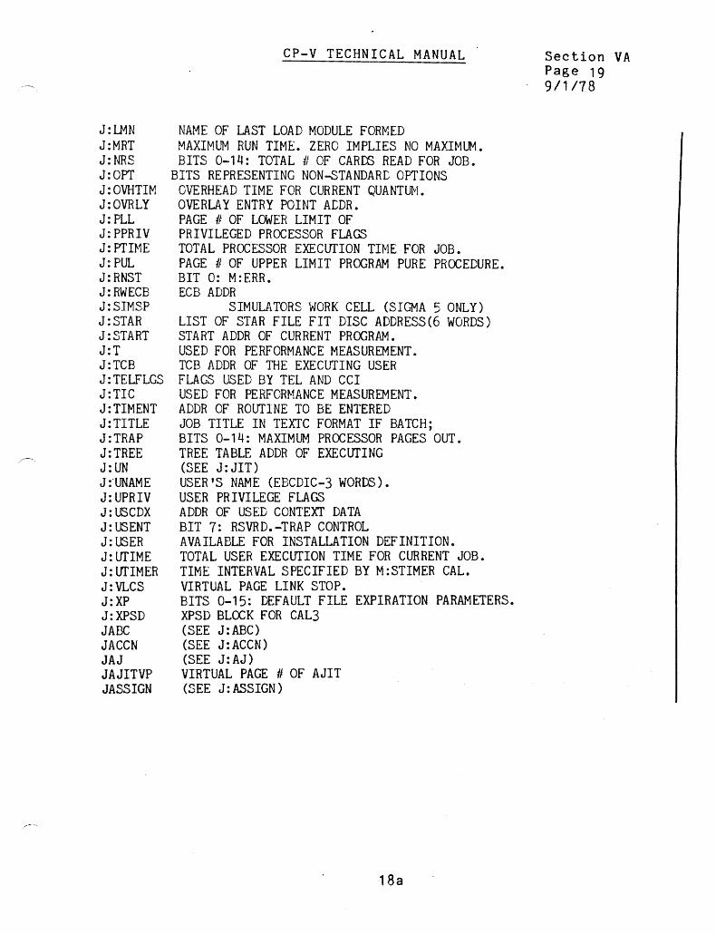
NAME OF LAST LOAD MODULE FORMED MAXIMUM RUN TIME. ZERO IMPLIES NO MAJ~MUM. BITS 0-1~: TOTAL # OF CARDS READ FOR JOB.
BITS REPRESENTING NON-STANDARL OPTIONS OVERHEAD TIME FOR CURRENT QUANTUIvI. OVERLAY ENTRY POINT ACDR. PAGE # OF LOWER LIMIT OF PRIVILEGED PROCESSOR FLAGS TOTAL PROCESSOR EXEClIfION TINE FOR JOB. PAGE # OF UPPER LIMIT PROGRAM PURE PROCEDURE. BIT 0: M:ERR. ECB ADDR
SIMULATORS WORK CELL (SIGMA 5 ONLY) LIST OF STAR FILE FIT DISC ADDRESS(6 WORDS) START ADDR OF CURRENT PROGRAM. USED FOR PERFORMANCE MEASUREMENT. TCB ADDR OF THE EXECUTING USER FLAGS USED BY TEL AND CCI USED FOR PERFORMANCE MEASUREMENT. ADDR OF ROUTINE TO BE ENTERED JOB TITLE IN TEXTC FORMAT IF BATCH; BITS 0-1~: MAXIMUM PROCESSOR PAGES OUT. TREE TABLE ADDR OF EXECUTING (SEE J:JIT) USER'S NAME (EBCDIC-3 WORDS). USER PRIVILEGE FLAGS ADDR OF USED CONTEXT DATA BIT 7: RSVRD. -TRAP CONTROL AVAILABLE FOR INSTALLATION DEFINITION. TOTAL USER EXECUTION TIME FOR CURRENT JOB. TIME INTERVAL SPECIFIED BY M:STIMER CAL. VIRTUAL PAGE LINK STOP. BITS 0-15: DEFAULT FILE EXPIRATION PARAMETERS. XPSD BLOCK FOR CAL3 (SEE J:ABC) (SEE J:ACCN) (SEE J:AJ) VIRTUAL PAGE # OF AJIT (SEE J:ASSIGN)
18a
Section VA Page 19 9/1118
CP-V TECHNICAL MANUAL
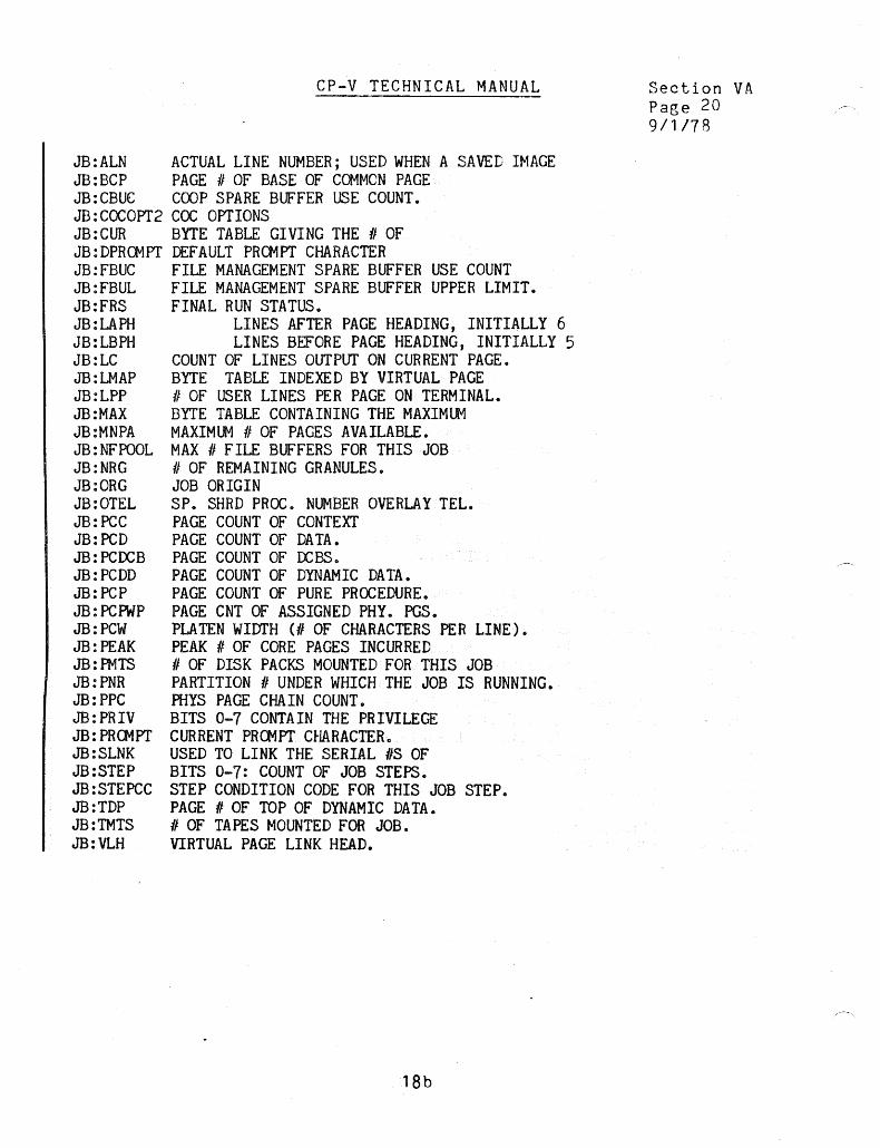
JB:ALN ACTUAL LINE NUMBER; USED WHEN A SAVED IMAGE JB:BCP PAGE # OF BASE OF COMMON PAGE JB: CBUC COOP SPARE BUFFER USE COUNT. JB : CaeOPT2 cae OPTIONS JB:CUR BYTE TABLE GIVING THE 1/ OF JB:DPROMPT DEFAULT PROMPT CHARACTER JB:FBUC FILE MANAGEMENT SPARE BUFFER USE COUNT JB:FBUL FILE MANAGEMENT SPARE BUFFER UPPER LIMIT. JB:FRS FINAL RUN STATUS. JB:LAPH LINES AFTER PAGE HEADING, INITIALLY 6 JB:LBPH LINES BEFORE PAGE HEADING, INITIALLY 5 JB:LC COUNT OF LINES OUTPUT ON CURRENT PAGE. JB:LMAP BYTE TABLE INDEXED BY VIRTUAL PAGE JB:LPP II OF USER LINES PER PAGE ON TERMINAL. JB :MAX BYTE TABLE CONTAINING THE MAXIMlt1 JB:MNPA MAXIMUM 1/ OF PAGES AVAILABLE. JB:NFPOOL MAX 1/ FILE BUFFERS FOR THIS JOB JB:NRG 1/ OF REMAINING GRANULES. JB:ORG JOB ORIGIN JB:OTEL SP. SHRD PROC. NUMBER OVERLAY TEL. JB: PCC PAGE COUNT OF CONTEXT JB:PCD PAGE COUNT OF DATA. JB:PCOCB PAGE COUNT OF OCBS. JB:PCDD PAGE COUNT OF DYNAMIC DATA. JB: PCP PAGE COUNT OF PURE PROCEDURE. JB:PCPWP PAGE CNT OF ASSIGNED PHY. PGS. JB: PeW PLA TEN WIDTH (II OF CHARACTERS PER LINE). JB:PEAK PEAK # OF CORE PAGES INCURRED JB: PMTS II OF DISK PACKS MOUNTED FOR THIS JOB JB:PNR PARTITION 1/ UNDER WHICH THE JOB IS RUNNING. JB: PPC PHYS PAGE CHA IN COUNT. JB:PRIV BITS 0-7 CONTAIN THE PRIVILEGE JB: PRG1PT CURRENT PROMPT CHARACTERc JB:SLNK USED TO LINK THE SERIAL OS OF JB:STEP BITS 0-7: COUNT OF JOB STEPS. JB:STEPCC STEP CONDITION CODE FOR THIS JOB STEP. JB: TOP PAGE II OF TOP OF DYNAMIC DATA. JB:TMTS II OF TAPES MOUNTED FOR JOB. JB:VLH VIRTUAL PAGE LINK HEAD.
18b
Section VA Page 20 9/1118
JB:VLT JB:XLNK J8BCP JBCBLL JBCBUC J8FBFP JBFBUC JBLMAP JBMNPA JBNASP J8NFPOOL JBNRG J8PCC JB PC DD J8PCP J8PPC J8TDP JBUP JBUPVP JBUPVPA JBVLH JCCL JCL JCLE JCLP JCLPA JCLT JCMAP JCOVP JCOVPA JC02VPA JCPPO JDA JOCBLL JOCBUL JDDLL JDDUL JDLL JDUL
CP-V TECHNICAL MANUAL
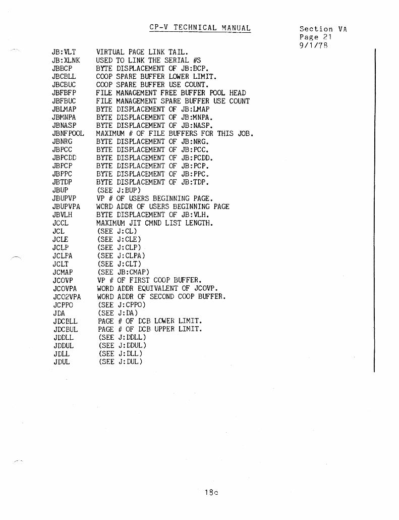
VIRTUAL PAGE LINK TAIL. USED TO LINK THE SERIAL #S BYTE DISPLACEMENT OF JB:BCP. COOP SPARE BUFFER LOWER LIMIT. COOP SPARE BUFFER USE COUNT. FILE MANAGEMENT FREE BUFFER POOL HEAD FILE MANAGEMENT SPARE BUFFER USE COUNT BYTE DISPLACEMENT OF JB:LMAP BYTE DISPLACEMENT OF J8:MNPA. BYTE DISPLACEMENT OF JB:NASP. MAXIMUM # OF FILE BUFFERS FOR THIS JOB. BYTE DISPLACEMENT OF J8:NRG. BYTE DISPLACEMENT OF JB:PCC. BYTE DISPLACEMENT OF JB:PCDD. BYTE DISPLACEMENT OF JB:PCP. BYTE DISPLACEHENT OF JB: PPC 0
BYTE DISPLACEMENT OF JB:TDP. (SEE J:BUP) VP # OF USERS BEGINNING PAGE. WORD ADDR OF USERS BEGINNING PAGE BYTE DISPLACEMENT OF JB:VLH. MAXIMUM JIT CMND LIST LENGTH. (SEE J:CL) (SEE J: CLE) (SEE J:CLP) (SEE J:CLPA) (SEE J:CLT) (SEE JB: Cf-'lAP) VP # OF FIRST COOP BUFFER. WORD ADDR EQUIVALENT OF JCOVP. WORD ADDR OF SECOND COOP BUFFER. (SEE J:CPPO) (SEE J:DA) PAGE # OF DCB LOWER LIMIT. PAGE # OF DCB UPPER LIMIT. (SEE J:DDLL) (SEE J:DDUL) (SEE J: DLL) (SEE J:DUL)
Section VA Page 21 9/1/7R

JEUP JEUPVP JH:DA JH:LDCF JH:PC JIT JITREE JJAC JJITVP JLMAP JOPT JOVVP JOVVPA JPCP JPLL JPPC JPPH JPPT JPUL JRBID JRNST JSBUF1VP JSBUF2VP JSPBFLG JSPVP JTELFLGS JTSTACKSZ JUNAME JVLCS JVLH JVLT JX:CMAP JX: PPH JX:PPT JXBUFVP JXCMAP JXPPH JXPPT M:UC
CP-V TECHNICAL MANUAL
(SEE J:EUP) VP h OF END USERS PAGE HALFWORD TABLE OF SEEK ADDRESSES PERIPHERAL AUTHORIZATION FLAGS, PARALLEL TO ON-LINE PAGE COUNT. (SEE J: JIT) TREE TABLE ADDRES OF EXECUTING (SEE J:JAC) VP II OF JIT. (SEE JB:LMAP) BITS REPRESENTING NON-STANDARD OPTIONS(SEE J:OPT) VP # START OF MAP IMAGE WHICH WOR~ ADDR EQUIVALENT OF JOVVP. (SEE JB:PCP) (SEE J: PLL) (SEE JB:PPC) (SEE JX: PPH ) (SEE JX: PPT) (SEE J:PUL) REMOTE BATCH JOB ID. (SEE J:RNST) VP # OF FIRST SPECIAL BUFFER VP # OF SECOND SPECIAL BUFFER. SPARE BUFFER SWAP FLAG. VP # OF SPECIAL SHARED PROCESSOR. (SEE J: TELFLGS ) LENGTH OF TSTACK. USER'S NAME (EBC~IC - 3 WORDS). (SEE J:VLCS) (SEE JB: VLH) (SEE JB: VLT ) BYTE/HALFWORD TABLE INDEXED BY PHYSICAL PAGE CHAIN HEAD PHYSICAL PAGE CHAIN TAIL VP # START OF JIT MAP IMAGE. BYTE DISPLACEMENT (SEE JX: CfviAP) • BYTE DISPLACEMENT OF JX: PPH. BYTE DISPLACEMENT OF JX:PPT. M: UC DeB IF ONLINE (JOB TITLE IF
18d
Section VA Page 22 9/1/78
M:XX MDPO MJCFLG MPO MPPO MRT MUPO MXFPL MXKB NSWAPS OVHTIME PPMD PROCRM PRDPRM PRT PUF RNST RUNFLAG SBUF1VPA SBUF2VPA SEED SPDBASE SPPBASE SS SYSID TCBADR TIMENT TIM'IMP TMOCRt-1 TMDPRM TMPDCPK TMPDPPK TPACCESS TPEXT TPIOT TPOVf TRPFLAGS TSTACK TUEXT
CP-V TECHNICAL MANUAL
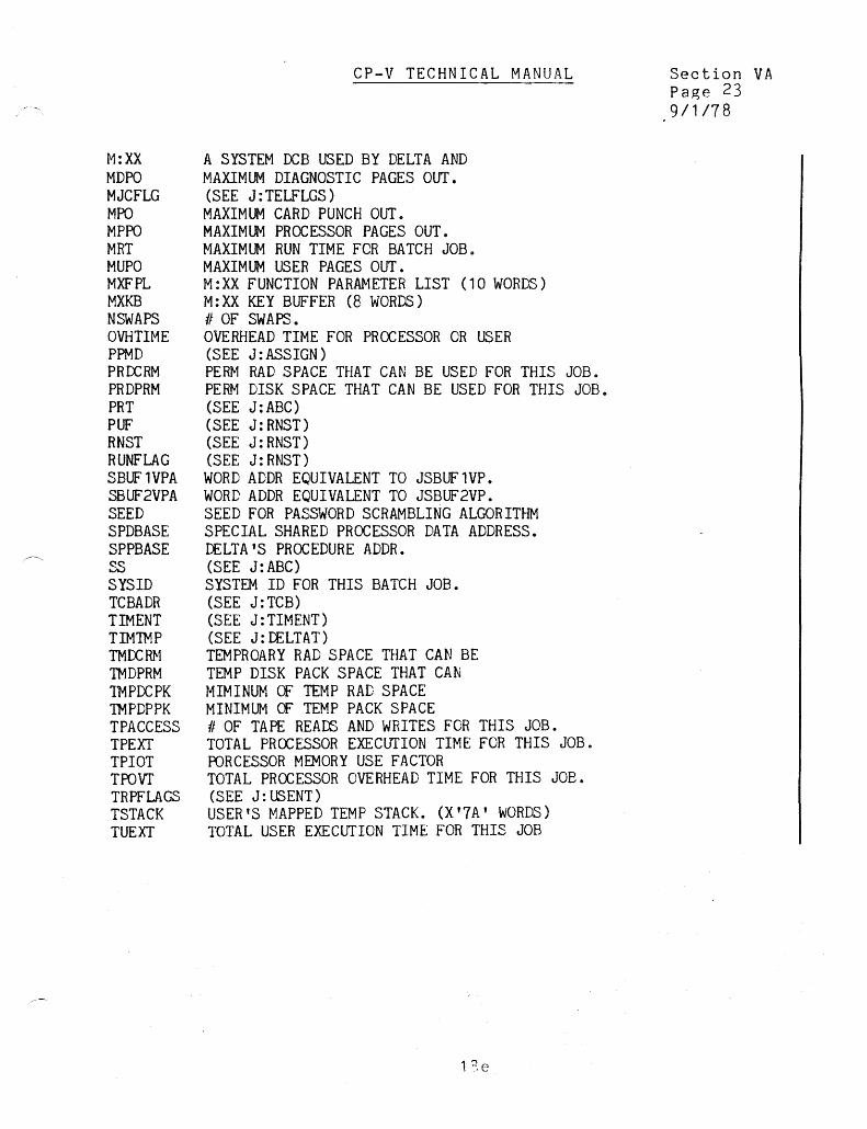
A SYSTEM DeB USED BY DELTA AND MAXIMUM DIAGNOSTIC PAGES OUT. (SEE J:TELFLGS) MAXIMUM CARD PUNCH OUT. MAXIMUM PROCESSOR PAGES OUT. MAXIMUM RUN TIME FOR BATCH JOB. MAXIMUM USER PAGES OUT. M:XX FUNCTION PARAMETER LIST (10 WORDS) M:XX KEY BUFFER (8 WORDS) 1/ OF SWAPS. OVERHEAD TIME FOR PROCESSOR OR USER (SEE J:ASSIGN) PERM RAD SPACE THAT CAN BE USED FOR THIS JOB. PERM DISK SPACE THAT CAN BE USED FOR THIS JOB. (SEE J:ABC) (SEE J:RNST) (SEE J:RNST) (SEE J: RNST)
WORD ADDR EQUIVALENT TO JSBUF1VP. WORD ADDR EQUIVALENT TO JSBUF2VP. SEED FOR PASSWORD SCRAMBLING ALGORITHM SPECIAL SHARED PROCESSOR DATA ADDRESS. DELTA'S PROCEDURE ADDR. (SEE J:ABC) SYSTEM ID FOR THIS BATCH JOB. (SEE J:TCB) (SEE J:TIMENT) (SEE J: LELTAT) TEMPROARY RAD SPACE THAT CAN BE TEMP DISK PACK SPACE THAT CAN MIMINUM CF TEMP RAD SPACE MINIMUM CF TEMP PACK SPACE II OF TAPE READS AND WRITES FOR THIS JOB. TOTAL PROCESSOR EXECUTION TIME FOR THIS JOB. PORCESSOR MEMORY USE FACTOR TOTAL PROCESSOR OVERHEAD TIME FOR THIS JOB. (SEE J:USENT) USER'S MAPPED TEMP STACK. (X'1A' WORDS) TOTAL USER EXECUTION TIME FOR THIS JOB
l~e
Section VA Page 23 9/1118

TUIOT TUOVI' UNAME USRENT UTIMER UTS
Note:
CP-V TECHNICAL MANUAL
USER MEMORY USE FACTOR (USER PAGES*TIME). TOTAL USER OVERHEAD TIME FOR THIS JOB (SEE J:UNAME) (SEE J:USENT) TIME INTERVAL SPECIFIED BY M:STIMER CAL. (SEE TSTACK)
Section VA Page 24· 9/1/78
Pages l8g through 180 were deleted by the FOG release.
18f

ABSOLUTE
DDRESSES
X'2B'
X 14F'
JOPT
CCBUF J:ACCN
J:CTIME
J:DELTAT
J:JIT
J:OPT
J:PTIME
J:UTIME
J:UNAME
J:UTIME
JB:LC
JCPPO
M:UC
MRT
J:CPROCS
J:IDELTAT
J:OVHTIME
J:RNST
J:TCB
J:TELFLGS
APL BASIC EASY
X
X
X X
X X X
X X X
X X
X
X X
X X X
FLAG FORIV GPDS LIB META
X
X X X X
X
X
X
X X
·X
LANGUAGE PROCESSOR CHART
J1T USAGE BY PROCESSORS
SL/l TEXT SORT EDMS EDMS Re-structuri ng
X X
X )( X
X
X
X
X
)(
lOP MANAGE COBOL RPG MERGE
X

SCHEDULER QUEUES
SB:SWP
Ordered I ist of queues to be searched by swap
scheduler
0 7
SW SClO STI STOB SQR SQFI SQA SC9 se8 se7 SC6 se5 SC4 SC3 se2 sel seo SRT
SITUATIONAL PRIORITY INCREMENTS
SH:PINC 0 15
Not Used
3
2
CP-V TECHNICAL MANUAL SECTION VC PAGE 1
o 1
2/10/76
EVENT TRANSITION TABLES
Word Table of State Event Transitions Size is a Function of Number of Final States (Displaced by Event)
R E S o U R C E
I N o E X
o
SB:SET
Destination State (in parallel with
S:SET)
31
7
RESOURCE SUB-QUEUES FOR SQR/SQRO
o 1 2 3 4 5 6
SB:RQ
HEAQ HEAD HEAD HEAD HEAD HEAD HEAD
R:SYMF R:SYMD R:OCR R:CBA R:DPA R:QFAC R:NQW
SYMFILE or SGCBUF SYMBIONT DISC OPEN/CLOSE COC BUFFER SWAPPER PAGE QUEUE FOR ALLOCAT ENQ WAIT
6
Special Compute
I/O Complete
Interactive Chains for sub-states in SQR/SQRO are linked using U:MISC and UB:PRIO as shown.
4 Terminal Output Cont
3 Resource Unblock
Subtracted from user base priority (UB:PRIOB) to compute current priority (UB:PRIO) •.
o 78 2324
Resource Index O-------------·---------~-O FLINK
(SB:RQ)
SB:IOTA - Cell containing I/O time allowance. Remaining quantum is decremented by this vo,lue for each I/O.
SL:OPC - Word containing monitor overlay protection counter value.
31
S:OPC - Word containing working value for overlay protection counter, decremented when unsuccessful at swap schedul ing. Refreshed by Sl:OPC when successful swap schedule.
")(l

SCHEDULER STATES
STATE #
SRT 1 SCO 2 SCI 3 SC2 4 SC3 5 SC4 6 SC5 7 SC6 8 SC7 9 SC8 A SC9 B SClO C SCU D STOB E STOBO F SlOW 10 SIOMF 11 SW 12 SQA 13 SQR 14 SQRO 15 STI 16 STIO 17 SQFI 18 SNULL 19
SCHEDULER EVENTS
STATE #
E :IlP 0 E:QMF, E:IP 1 E:CRD 2 E:CIC 3 E:CBL 5 E:CUB 6 E:CBK 8 E:CEC A E:ERR C E:ABRT, E:OFF E E:WU 10 E:SL 12 E:QA 13 E:ART 14 E:UQA 16 E:KO 18 E:AP, E:NC 1A E:QE 1B E:IC 1C E:QFI lD E:NSYMF 1E E:SYMF 1F E:NSYMD 20 E:SYMD 21 E:OCR 22 E:NOCR 23 E:CFB 24 E:CBA 25 E:ND 26 E:DPA 27 E:QFAC 28 E:UQFAC 29 E:NQW 30 E:NQR 31
CP-V TECHNICAL MANUAL
MEANING
Real Time Compute Background Compute X'CO' < UB:PRIO< X'F5' Background Compute Priority-= X'F6' -
II X'F7' X'F8' X'F9' X'FA' X'FB' X'FC' X'FD' X'FE' X'FF'
Current User Terminal Output Blocked Terminal Output Blocked Out of Core I/O Wait tv\aster I/O Function Count Too High Wait (Asleep) Queued for Access (To RBBA n Queued for Dynamic Resource Queued for Dynamic Resource Out of Core Terminal Inputting Terminal Inputting Out of Core Queued for Real Time Interrupt Empty User Slot
MEANING
I/O in Progress Queue for tv\aster Function Count Too High Terminal Read Terminal Input Complete Terminal Output Block Terminal Output Unblock User H it Break User Hit Control-Y User to be Errored User to be Aborted Wake Up Sleeping User Begin Wait (Sleep) Queue for Access to RBBA T Activate Real Time User Unqueue for Access Kick Out of Core Associate Shared Processor, Need Core Page Quantum End I/O Complete Queue for Real Time Interrupt No Symbiont File Entries OR RBBA T comm. Buffers Symbiont File Entries or RBBAT Comm. Buffers Available No Symbiont Disc Space Symbiont Disc Space Available Open/Close Request Open/Close Available Need COC Buffer COC Buffer Available Need Swapper Page Swapper Page Available Queue for ALLOCA T Unqueue for ALLOCA T ENQ Wait ENQ Release
21
SECTION VC PAGE 2 9/1;78

SB:OSUl
Out-Swap user Numbers
o 7
First BYTE Contains number of Users in list length SMAXOUT
o length Smaxout
length Smaxout
CP-V TECHNICAL MANUAL
SCHEDULER/SWAPPER TABLES
SB:F Pl SH:EDA
r--;::essor Numbers of I .. [RETO Processors Ending Disc Addresses for Swapout
o 7
First BYTE Contains number of Procs in list length co 2 ·SMAXOUT
S:BDA
o
length co SMAXOUT
Beginning disc addresses for Swap Out
S:BCl
Pointers to Beginnings of Users' Command - - lists for Swap Out
S:ECl
Pointers to Ends of Users' Command lists for Swap Out
Section Page 3 1/4/74
15
31
o 31 Length Smaxout
S'SCl
Seek Order BA(SH:SDA} DISP
X'2EI COUNT 2 BYTES
! Read Order ({PROCESSOR'S}). .
I BA JlTS PhYSIcal Page Address; for Swap Out
r X'2C' Count 1 PAGE
0 31 4-'lIord 10CD Pair for Reading Processor Pages length 2 *PPROCS
SH:SDA
I Processors' Disc Addresses I 0
lenqth 2 PPROCS
S8:HO
User· of First U\ef in Queue
Oueues i1~pl()ced hI' ·.t"te f lumber. The, ore ,em if no lher in Oueue.
7 o
15
SCHEDUlER/~TATE TABLES/QUEUES
S8:TQ
User 1/ of lost User in Queue
7 U8:Fl ond U8:BL ore used to linl- Users in Queue.
SB:PNl
In-Swap Processor Number
o 15 length 4 First BYTE contains number of Processors in List
22
vc

CP-V TECHNICAL MANUAL
Section VC Page 4 2/7/77
S:BADF LG is a one-word cell designed to indicate it any real-time activity has occurred. This will be displayed permanently by ANLZ.
o 123 31 S:BADFLG
S:IRPINC
S:IOPINC
S:CPINC
SB:RQ
s:cup S:PRIODEC
S:RTIR
SB :HQ/SB: TQ
a---- Single user abort has occurred ------ Real-time lock-in-core abort has occurred
Jo------ Real-time lock-in-core has occurred "--------- Real-time activity has occurred
Cell containing I/O complete priority increment. Default = 4.
Cell containing I/O complete priority increment. Default = 3.
Cell containing special compute priority increment. Default = l.
Byte table containing user number for head of resourse subqueue -indexed by resource number which is the integer part of {E:BLK or E:REL}/2. Users in a subqueue are linked through U:MISC. Major queue for a user in any dynamic resource subqueue will be SQR or SQRO.
Cell, current user's priority. Set to X'FF ' when idle.
Cell, priority decrement to be applied when interrupting a user for a high-priority user. Applied to UB:PRIO.
Cell, real-time user in and ready flag.
Initial ized to have SNULL point to chain of empty user slots.
23
I
o
o
UB :PRIO-*IA
UB:NECB
UB:SWAPI
Index to Swap device for user
Resource No. I 7
7
CP- V TECHNICAL MANUAL
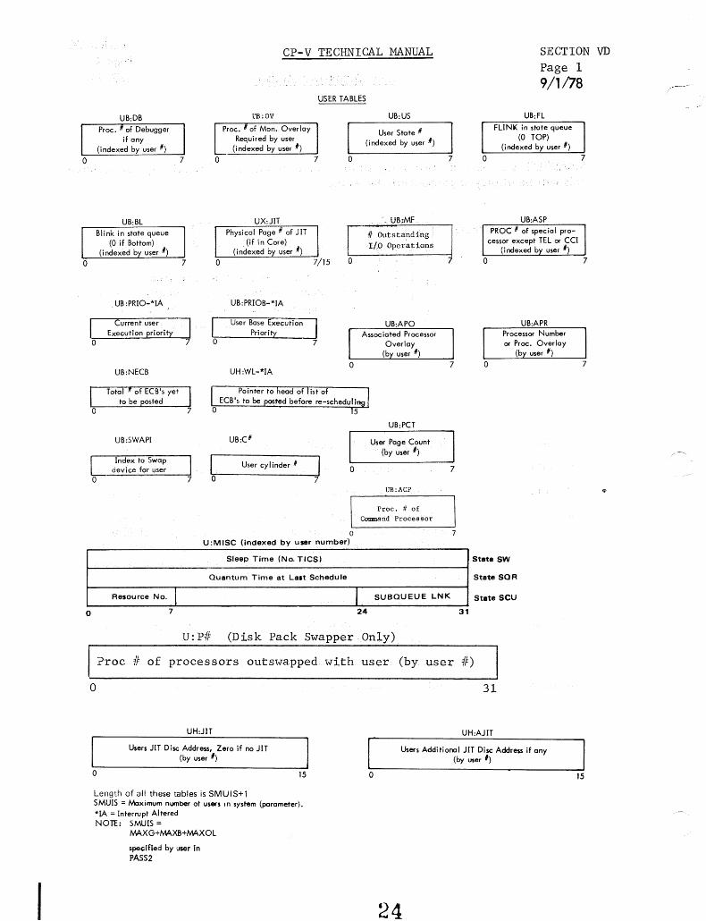
USER TABLES
l13 :OV
7 o
o
UB:PRIOB-*IA
UH:WL-*IA
UB:C(l
I User cyl inder (I o o 7
o U:MISC (indexed by user number)
Sleep Time (No. TICS)
Quantum Time at Last Schedule
UB:US
User State (I
(indexed by user (I)
. UB:MF
if Outstanding 1/0 Operations
UB:PCT
User Page Count (by user I)
UB:ACP
Proc. It of Cotmnand Processor
7
7
7
I SUBQUEUE LNK
24
u:pif (Disk Pack Swapper Only)
31
SECTION VD
Page 1 9/1/78
UB:FL FLlNl< in state queue
(0 TOP) (indexed by user #)
7
Stat. SW
State SOR
State SCU
?roc if of processors out swapped with user (by user if)
o 31
o
UH:JIT
Users JIT Disc Address, Zero if no JlT (by user I)
Length of all these tables is SMUIS+1 SMUlS = tv\aximum number ot users 10 system (parameter). *lA = Interrupt Altered NOn:: SMUIS =
MAXG+MAXB+MAXOL
spe<:ified by user in PASS2
o
UH:AJIT
Users Additional JIT Disc Address if any (by user I)
24

CP-v TECHNICAL MANUAL
Added User Tables
UB:MPFLG - exists only if NSCPU ) 0
012 7
SECTION VD Page 2 2/10/76
~---------Slave suitable CAL rate
---------------Permanent master only
~--------Master CPU only
(length SMUIS)
UB: CALR - exists only if NSCPU,'> 0
o 31
TICS/CAL
U: CALC - exi~ts if NSCPU> 0
o
CAL COUNT DURING QUANTUM
Average compute/cal during recent quantum

CP-V TECHNICAL MANUAL
UH:FLG
Bit Meaning if Set
o Bypass, available core too.lmall now 1 STEP in progress or unblock received before block 2· -Initial DCBs being swapped in
mrl Special JIT access __ .~~ ... ~~*~-:..""",. 4 Initialization must be done 5 DEL TA is associated 6 JIT is in core
. ______________ ~7--______ --~J~obr7is~ba~tc~h~~~q_~--~~----~ 8 TEL in control (or CCI, other CP) 9 DELTA in control 10 Interactive user 11 Pure procedure must be swapped 12 OPNCLS user 13 :ACCTLG or :USERS open 14 Intentry inhibit (real time) 15 -Ready to run
------------------------~------------------~
UH:F LG2 .,; *IA
Bit
o 1 2 3 4 5 6 7
9 10 11 12 13 14 15
UH:Dl- *IA
o
Bit
o 1 2 3 4 - 15
Real time lock in core (abso ute) System ghost locked out (real time lock in core) Interrupted during a CAL Transaction rocessin function
oncurrent output mode eyin - Special Systems Suspended for reconnection - Special Systems COC line hang-up Just swapped in
-Swap Quantum not satisfied User swap error Context swap error JIT swap error
Meaning if Set
Job is to be aborted Job is to be errored Control-Y received Break received Doubleword address of DO list
SECTION VD Page 3 10/31/74

CP-V TECHNICAL MANUAL Common Multiprocessor Control Tables
SB;INIT - prcsc~cd over recovery
o 567
II II
SB:PFLC
Started (sot by keyin or aysgen) Stop (set by kcy1n)
SB:RCVA
o 7
SB:HINT -k
o 7 SI.A VE - !'t.\STER I:-''TERRUPT NO.
SB:RCVR
SB:HPSW
SB:SFLC
o
SECTION VD.Ol Page 1 2/10/76
o 7 I POST FLAG I RECOVERY ACKNOl-lLEDGE I RECOVERY
REQUEST
7 I POST SQUAN FLAG
7
SB:STATE
sx:SPP
o EXECUTION
STATE
7
o - not active • stopped 1 - INIT+lDLE 2 - user in progress
SH:HINQ
o HINIQUMI VALUE
2 lIIS units
S:ADP.
o
15
SH:MAXQ
o L MAX QUAN VALUE 2 ms units
o 7/15 SLAVE PROCESSOR PRIVATE PAGE #
I CPU HARDWARE ADDRESS
Byte if :BIG-O.
S:CLAIH
f CLAIM US SWITCH FOR STARTUP
o c:. C1.A tilED O?':.AVA Iv\nLE
S:PCUN
31 o
* }tPIPl - value def specifying presence of i.ntcq)roccssor !nterrupt pair. Controls interpretation of SB:~tlNT.
NSCPU - value def declaring number of CPUs which exist other than IIlI1ster.
1. All tables are NSCPU+l long.
2. Entry 0 1. master CPU.
3. Index by processor no. (software).
CL~~T USER NO.
15
:31
31
~'/

n:FLT
o rFAULT TYPE
INDEX
1
CP-V·TECHNICAL MANUAL
n:EFLG
r:EADDI
.. al address of error log buffer for lave CPU fault
Special Multi-Processing Cells
SL:BSTIlT
o AUTO START INHIBIT
o .> permit auto start at boot/reboot. 1 .) inhibit auto start at boot/roboot.
I:ISCRCH • o I SLAVE INITIATED SCREECH CODE
lon-zero .> SCREECH
r
o
S:STOD'l'
o
HOOS£ RE-£NTRA1lC'l COUNTER . (inc by KEYlN)
FLAG SET BY KEYIN TO TRIGGER .100S£ DISMY
TIME our VALUE WIlEN "AlTUm FOR RECOVERY '\CKN~'LEDGE
28
rH:SCICH
o r
31
31
31
31
31
31
SCIlEECH COOl
SECTION VD.01 Page 2 2/10/76

CP-V TECHNICAL MANUAL
Special Cells - Processor Private
XPSD receivers for the following traps and interrupts are contained
in each processors' private page:
NOPPSD Trap X'40'. non-allowed operation
UNlMPSD Trap X'41', unimplemented instruction
STKLPSD Trap X'42'. stack limit trap
FlXOVPSD Trap X'43'. fixed point arithmetic
FLTFPSD Trap X'44'. floating pOint arithmetic
])ECPSl) Trap X'45', dedC\ill fault
CALlpsD Trap X'48'. Call I
CAL2PSD TTap X'49' , Call 2
CAL3PSD Trap X'4A' , Call 3
The following XPSD receivers for miscellaneous purposes arc also
·located in the private page:
CTRAPSD
RCVPSD
BLKPSD
S:PNO
o
Transfer to central trap handler
Entry to recovcry/T:SCREECHS
Block uscr on slave CPU
( PROCESSOR NO. (SOFTWARE)
31
This cell exists in VPXPSDT. the CPU private page, and hence is unique for each processor, Master is processor O. Slave Ilumbers are set by 1'IOOS£.
S:CLOCK4
o 31
CAlAPSD
IPT47
PSD$T46
PSD$T4C
PSD$T4D
PSD$I.57
PFSAA6PSD
PGlROFF
Clock 4. the subjective countor, vill tick indirect this" cell.
SRECS
i ·16 vords
Trap handler temp for register save
Trap X'4B'.
Trap X'41'.
AUP X'46',
Trap X'4C't
Trap X'4D'.
SECTION VD.01 Page 3 2/10/76
Call 4
intcrproccssor trap (X560)
va t chd og t irnc r
parity error
instruction exception
Interrupt X'57'
Trap X'46'. roceiver during power faU uf.
Interrupt/Trap X'51' power off

TEKP
TEMPI
UMP2
CP-V TECHNICAL MANUAL
1:IH'1'BIT
o 31
WD lIT FOR SB:MI~~
GROUP NUMBER SB:MINT
o n J:D'f SAVED VALUE OF J:DELTA'r
J:IDr SAVED VALL'E OF J:IDEL'rAT
8:CUN
o cuaRE:a USER N .... MBER
f DoUblevord temp for T:PULLE and entry_
TmP$BREG
o
31
3j Temp cell for use while acquiring last branch register.
0 31
1 ·1 Doubleword aligned t~p b~ock for goneral aiac.llaneous use.
ft'SRSW
2
L 31
I Sense witch .ettingll at povor fAil •• ia.
IALANCE
0 :41
I I . Balaaco counter for powor fall .afe.
Doubleword A.l1&ned
SECTION VD.01 Page 4 2/10/76
30
CP-V TECHNICAL MANUAL
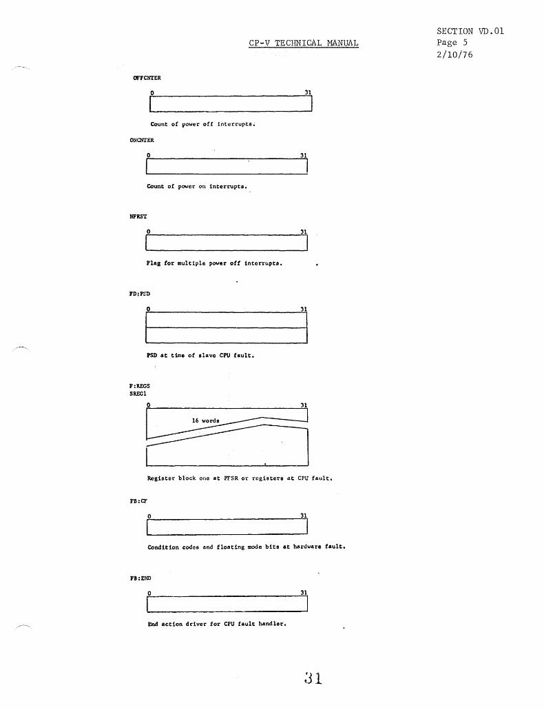
OFFCNTER
o
Count of power off interrupts.
ONClfIER
o
Count of power on interrupts.
NFRST
o
Flag for multiple power off interrupts.
FD:PSD
r PSD at time of .lava CPU fault.
F:RECS SRECI
:n
31
31
Register block one at PFSR or registers at CPU fault.
n:CF
o
I Condition codes and floating mode bits at hardware fault.
n:END
o :n
End Action driver for CPU fault handler.
SECTION VD.01 Page 5 2/10/76

CP-V TECHNICAL MANUAL
rault haDdler ttllllP ceU.
o 31
I 'ault handlor temp cell.
D 31
Fs!l.OGB 0 CODE
1 TIME
rD:EPSD 2 rsD
3 rsD
4
, rulInG 6 CCS AND rLACS
J'llltEAL ., I£hL ADDIt OF TAAPPED INST
I'IINst • TRAPPED'INST
'al:V1RT , ANLZ CC AND VIRTUAL ADDR
':-IREAL A REAL EFFECTIVE ADDR
Inor. lOS buffer for alaft fault ha~l.ra.
32
SECTION VD.01 Page 6 2/10/76
CP-V TECHNICAL MANUAL
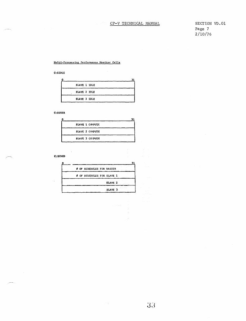
Multi-Processing Performance ~~nitor Cells
C:SIDLE
o 31
SLAVE I IDLE
SLAVE 2 IDLE
SLAVE 3 IDLE
C:SUSER
o 31
SLAVE 1 ccriPtm:
Sl~ VE 2 (;(y'{ptrrE
SLAVE 3 CO:lPtrrE
C:SCHED
L- 31
f OF SCHEDULES FOR MASTER
, Of SCHEDULES FOR SLAVE 1
SLAVE 2
SLAVE 3
SECTION VD. 01
Page 7 2/10/76

CP-V TECHNICAL MANUAL
Multiprocessing Sysgen Built Tables
If no :SCPO command 18 detactad. .ASS2 bulld. a dummy ca.eaftd.
from th18 cOUIIIAnd the load module STABLES 18 bullt. Thl. lIOdule
contalns tha followtaa table. and ab.olute DEF ••
Abaolut. DB •
• SCPU • , of alave CPUa (f~08 NSCPU)·
MP!PI .. 1 if HPIPl .pecified
.. «» if HPIPI DOt apee if ted
* Tho.e are the only entrle. In S~LES if • ftOD~ultl-proc.~aine
• y.ta. t •••• NSCrU. O. MP1.1 • O. s:ADa i •• word 10Ql •
Iable.
J!!!!!!. In~a .11151 ~ contentl
I:PCUM tid IISCPU+l «» n:HPS" byte IISCPU+l 0 n:l'FLG byte ISC,.,.1 «» IX:S.P byto/hv ISCPU+l 0
"epandlne 011 :lIe n:lTATE byte MSCPU+l 0 D:INl'!' byte IISCl'U+l bit 7 • 1 tf AutO
.,aclfled for .nt~ S:CLADI votnl .SCPU+I «» D:HINr byte RSCPUtl . INtS valua .pecltied
for ent~ SH:HINQ W RSCPU+l IIINQ/2 tor entry IH:MAXQ hv IISCPU+l IlAXQ/2 for elltry ':ADR votnl nSCPU+I 0 IB:SFLG byte IfSCPU+I 0 SB:acva byt:e IISCPU+l 0 'B:ltCVA byte IISCPU+l 0 SL:ISTRT tid 1 1 if NOAUTO .,acIUed S:HPKYH toNI 1 «» .:tu'DlSP vd 1 «» SL:HPCALR tid 1 10 ':STour vd 1 3000 I'I:FLT byte iSCPUtI 0 J'tEADDR word .SCrUtl 0 I'I:ULC byte .SCPUtl 0 r:PFSR word 1 0
. J'U:SCRCH hal!.fword III.CPU+l 0
34
SECTION VD.Ol Page 8 2/10/76

±
CP-V TECHNICAL MANUAL
Tables Displaced by Processor Number (Located in M:SPROCS)
P:NAl'fE
PROCESSOR ROOT OR OVERLAY NAl'fE IN TEXTC FORMAT
o
PB: LNK1<
I Proc. # of next overlay I o
o
o
PB: PSZ
No. of pages of pure procedure
4 5 6 7 8
31 32
PX: HPPfr"< PX: TPP
Head of physical Tail of physical page chain page chain
o 7/15 o
PB:DSZ PB:DCBSZ
No. of pages of Data No. of pages of DCBs
o 7 o
P:SA 15 31 PB:REP
7/15
i Processol;" startl ! No. of users associated I
I Address with Processor I ~~-.~~-r~~~~~~~---------------------- 0 7
Processor was loaded with CORELIB option. '-------- Processor is allowed maximum memory.
Processor is a publ ic library. PB: Cifo"dd< '---~--------Processor is a debugger.
'--.!:::-------------Processor is special shared Cylinder Number of processor. Procedure
,'< Zero is none. Allowed to 01 ter JIT o 7 -- Zero if not in core. #1<1< Disk Pack Swapping Systems only.
PH:PDA PH:DDA
o
0
0
0
Section VE Page 1
10/31/74
63
PB:UC
No. of users in core using processor
PB:PVA
Virtual page No. of first proc. page
PB:HVA
Virtual page No. of first page not used
PB:DC#1dd;
Cylinder Number of Data
\ Disk address of first page of procedure Disk address of first page
of data & DCBs
o
o
o
o
15 o 15
PH:FRQ
P:TCB o
Processors TCB address (zero implies none) PB:LCT
31 I of users associated that are real-time I locked in core O~----~~~~~--------------~7
P:AC
Access codes for top 16 virtual pages (special processor area)
31 32
PBT:LOCK
Processor locked in core bit table - length
31 32
bit/processor - indexed (from left) by processor number.
± T - Teletype Command Processor B - Batch Command Processor G - Ghost Command Processor
63
(PNAMEND + 31)/32 words
63
7
7

Monitor Overlays
Shared Processor Roots
Standard Processor Roots
MAXOLVY
SPSIZE
PNAMEND
PPROCS
-r ~
\.. ,,--
I
<
( "..
~
'"
CP-V TECHNICAL MANUAL
0 ~ ~ ~ 0 ~ ~ ~ ~ 0 ~ 0 ~ ~ ~ ~ ~ ~ ~
Section VE Page 2
10/31/74
i MAXOVLY {index}
.ill PNAMtEND {index} ...
PR OC S {i ndexll
number of monitor overlays plus one {plus one because entry 0 in processor tables is not used}
total number of spare pages required for one shared processor (a PASS2 parameter)
index number plus one of last shared processor root entry
index number plus one of last shared processor overlay entry
36

CP-V TECHNICAL MANUAL
GHOST JOB TABLES-Interrupt Altered
MAXG - Maximum number of Ghost Jobs
S:GJOBTBL o r-·-·--I
Names of Ghost Jobs (Indexed by Ghost Job Number) (TEXTC)
= 0 if in active slot with index ~ MING
SB:GJOBUN o 7
IGhost Job User # 1 (Indexed by Ghost Job #)
Length = MAXG+ 1 = index jf under < MING = 0 if inactive slot with index ~ MING
S:GJOBACN
Account for Ghost (Indexed by Ghost Job Number)
--------_.-------------o
SECTION VE PAGE 3
4/1/74
Length = MAXG+ 1
63
Length = MAX G+ 1
63

o
o
Monitor Area
Monitor Area
35K
lI- -- ....., ....., «
Cll (JJITVP)
lI- -- ....., ....., «
Cll (JJITVP)
Buffers
Buffers
ON~lINE MEMORY POINTERS
40K
Data Dynamic
Data
CUl BUP DUl DDll Dll
40K BATCH MEMORY POINTERS
Data Program Dynamic
Pages
CUL BUP DUL PLl DlL
PUL DDLL
DDUL Pll PUl
TDP
112K 128K
EUP
Special Area
Common Pages
EUP DDUL
o
CP-V TECHNICAL MANUAL
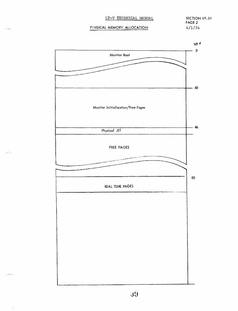
PYHSICAL MEMORY ALLOCATION
SECTION VF. 01 PAGE 2 4/1/74
L Monitor Root -;;;J -~
Vp #
o
r--__ .~.---------~--
~---------------------------------------------------+--~
Monitor Initialization/Free Pages
Physical JIT
FREE PAGES
~ . .-b_-.----........ ---- ... ----... _ ....... y ~----
-----80
REAL TIME PAGES I _____________________ ,........_· __ .. ~<_"··J .. ·~·~""·~·
,j9

Ct! W U. u. :::> co w -I co
:5 « ~ I-Vl Ct! -U.
U.
0 Vl
-I Vl
0 W Ct!
0 C 0- C
~ <
...
CP-V TECHNICAL MANUAL
CP-V Buffer Linking
FIRST AVAILABLE MONITOR BUFFER
GMBSIZ Words
SECTION VF. 01 PAGE J
2/10/76
....... ----------~-.---.----------.-~-~------.. -
-----------------------------------------------"--------------~
I .. -----, I I I I
I I I
r - - - - - - - - - - - - - - - - - - - - - - - - - - - - - - - - --J I , L __
LAST AVAILABLE MONITOR BUFFER
SYSTEM LAYOUT ON RAD
PSA
BOOT, ABSOLUTE COPY OF MONITOR, MONITOR OVERLAYS, AND SHARED PROCESSORS
SWAP STORAGE
PER
PERIPHERAL STORAGE AREA (SYMBIONT)
PFA
FILE STORAGE AREA
)
J I T
DATA
) I
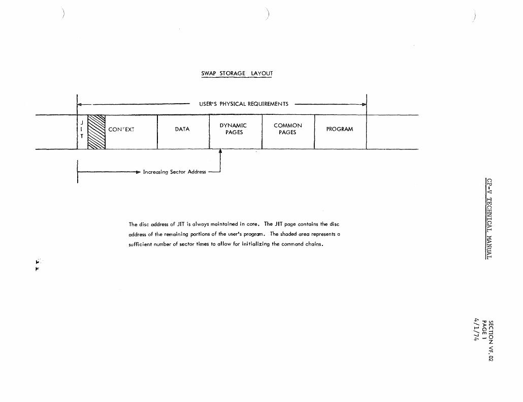
SWAP STORAGE LAYOUT
USER'S PHYSICAL REQUIREMENTS
DYNAMIC PAGES
COMMON PAGES
PROGRAM
I---------ID> ... Increasing Sector Address
The disc address of JIT is always maintained in core. The JIT page contains the disc
address of the remaining portions of the user's program. The shaded area represents a
sufficient number of sector times to allow for initializing the command chains.

CP-v TECHNICAL MANUAL Section VF.02 Page 2
10/31/74 SWAPPING RAD GRANULE TABLE
M: SGP is a word table containing pointers to the swapping granule table for each RAD swap device.
There are four types of granule tables:
~ RAD PSA ~Hexl 721'1 0 SA 40
1 - 7232- 0 PSA 80 2 7232 81 PSA 100 3 7232 ]01 PSA 200 4 3214 0 PSA 80 5 3214 81 PSA 100
Vertical words are granule positions. In each word tracks go from R to L.
Horizontal is track or band number.
Band Band 31 0 63
Swapping Granule Table
PSA RAD TYPE 0
wds 2
fWd 0 E Granule 0 wd2 _ ~ _
db1 wds41 - ....... __
lWd ad -GranUle 40
PSA RAD TYPE 1 4
!:!1j jWd 2
Gra~:.
Granu e : PSD RAD TYPE 2
t 6 ,
PSA RAD TYPE 3
t 6
! PSA RAD TYPE 4
~ 4
I Granule 0
6
1 Granule 5
PSA RAD TY PE 5
~ 8
J J
16
1 I
Granule li
6
1 Granule 5
If bit is set, this granule is available.
32
Type 0
Type 1
. Type 2
Type 3
Type 4
Type 5

Name Value Description
PSA Type 0 2 3 4 5
MB:GAMl 63 7 7 7 7 7 Granule address mask.
MB:GAM2 3 7 15 3 7 Mask to extract #S GP words/granule.
MB:GAM3 -1 -2 -3 -4 -2 -3 Shift count to convert SGP index to granuleR.
MB:GAM4 6 3 3 3 3 3 Sh i ft count to form track address.
MB:GAM5 7 -4 -4 -4 -4 -4 Shift count to obtain track address. C.l I-d
MB:GAM6 127 15 15 15 15 15 Sector address mask. I <:::
MB:GAM7 0 0 0 0 16 16 low order track bit. 1-3 t:r:l CJ
MB:GPT 41 6 6 6 6 6 #Granules per track. ~ H
MB:SPT 82 12 12 12 12 12 #Sectors per track. &;
~ t-I
t- - ~ "-'"- MB:SWAPS 0 2 3 2 Shift count to obtain SGP index from granule#. ~
MB:DWT 41 12 24 48 12 24 SGP size in doublewords. t-I
MB:SPACEJIT 7 Granule increment to space JITs around RAD.
M:GATLIM 63 127 255 511 127 255 Highest valid track number.
M:GASLIM 80 10 10 10 10 10 Highest valid sector number.
M:ADRINCR 46 4 4 4 5 5 Increment to add to last sector to get first sector on next track.
tn-oV1 "OCD --" co (')
Note: l. Swapper related tables contain an entry for each swap device. The total number of entries is defined "'-. CD ~.
"" w 0 tn ::J
by LSWAP+1. < -n 2. The user table, UB:SWAPI, contains the index into the swap tables.
. 0
'"

M:CLBGN
M:FREE#GRAN
M:HLTIC
-M:JITPAGE
M:SGP
M:SNSDA
M:SWAPD
M:SWPEND
M:WCKBCL
M:WCKECL
MB:SDI
MB:SFC
MB:#RTRY
MH:CLEND
CP-V TECHNICAL MANUAL
Beg inn ing of swap command list.
Number of available granules.
TIC to be inserted at end of command list.
Granule position for next JIT.
Address of SGP table.
Buffer for sense infonnation.
Device address.
Highest possible PSA seek address.
Beginning of command list for write check.
End of command list for write check.
Swapper DCT index.
Swapper function code.
Number of remaining retries.
End of swap command list.
44
Section VF. 02 Page 4 5/1/75

;'
/'
MONITOR ROOT
MONITOR JIT
UNMAPPED SEGMENT (UMOV)
XDELTA
REAL TIME
USER JIT
MONITOR OVERLAY
AVAILABLE FOR USERS
RESERVED FOR STEALING BY RBBAT
,
"if
I.
SECTION VF.02 PAGE 5 9/1/78
CP-V TECHNICAL MANUAL
MEMORY AND STOLEN PAGE DATA
• I 1 PAGE HELD BACK FOR USER JIT
t PAGES HELD BACK FOR USER OVERLAY , ~
S:PCORE /I PHYSI CAL PAGES AVAI LABLE, CONSTANT
1 S:ACORE /I
I PHYSICAL PAGES CURRENTLY AVAILABLE FOR SWAPPING. NEVER EXCEEDS S:PCORE + 7
SL:CORE /I PAGES A USER MAY SWAP (SL:CORE = MIN ( 1B4, S:PCORE)) , l S:~TLM ABSOLUTE LIMIT ON STOLEN PAGES
S:STLC CURRENT LIMIT ON STOLEN PAGES. I ~~~IND'CATES STOLEN PAGES MUST BE RETURNED ~YMBIONT
S:STL# /I PAGES CURRENTLY STOLEN
SL:RSVP # PAGES RESERVED FOR STEALING BY RBBAT
440

CP-V TECHNICAL MANUAL
(This page intentionally left blank.)
44b

RADIST o use normal algorithm 1 = allocate on RAD, if available
locn _o'A I " ,OCT2 CIT INDEX , . Device Ph)'$ical Addr. .'
~O----------4~5--------------------~15 0 I 7
DCT7
o
DA (Commcnd List Space)
DCTl9 -*IA
15100, AIO Cond";on Code, I o 7
DCT20 - *IA
I TDV Condo Codes
o DCT21- *IA
DCT22
DCT23
=0 if not disk type device =d(isplacement il4. words from HGP
dep) to the incore HGP for I spec if ic device .
DCTlP 1.
DCTIA 1.
15
1. Generated as discrete table if dua 1 access on aya tem; if not dual access then labels are equated to OCTI.
*IA Interrupt Altered
DCTlO DCTll-*lA
RE Entrancy Counter Device Activity (Count)
~O------------~~~------------~15 0
o
o
See Page 2
Retry Function Code
Channel FINK in 100 Tobles
7
7
5 C
DCT1S
Access control key for dual access
00 both subchannels used 01 subchannel 1 only 10 = subchannel 2 only 11 = dual access, use eithrr Bubchannel
QUEUE HEAD INDEX
7
WA (I/O Cleanup post processing) Entry
1415
Device in Diagnostic Mode Don't ignore random interrupts
31
PA-1 Alternate path of dual access controller partitioned P!'>al Pr1roary path of dunl ncccss controller partitioned PAC If PAzl, this is set to oricinn1 value of OCT) bit 6 PPC If ppel, this 1. set to original value of DCTJ bit 7 I>I'-l Device partitioned by itself and not when controller
partitioned. Upon controller recurn, this de ... ~ce not returned.
Device I/O Interrupt Overdue Timeout Time
31
4 0 4 0 for Remote Batch devices*
TIme Out Increments I:::. (See OCT 11)
o 7

CP-V TECHNICAL MANUAL SECTION VG.01 Page 2
DCT Tables
DCT15 - *IA
o
Channel BLINK in IOQ Tables - see DCT14 -
o
7
7
o implies monitor I/O permissible
10/31/74
if DCT5 indicates "DEVICE BUSY II
it DCT5 does not indicate IIDEVICE BUSY II
10 implies this is the user number of real-time user who may issue M:IOEX requests
DCT12 - *IA
Last AIO Status
o 31
Real-Time I 0 End Action Addr
31
if DCT15 =0
if DCT15 f 0
I L set if device was pre-empted via a DCB call to STOPIO L set if real-time I/O is currently active {i. e. interrupt pending}
46

CP-V TECHNICAL MANUAL
SECTION VG.01 PAGE 3
DCT24 - *IA - RMA TABLE 9/1/78
DCT25
t
- Byte table
- Parallel to DCTl
- Entry contains:
Bit # o 2 3 4 5 7
If Bit = 1,
"--r-'--..t.----L..-~-...L-..L--L__'. NOPARTD - Device /b..../
not partitionable
DCT28
o·
t 1'_ PERDWND - Device ~ does not exist {perm. down}
SIO Counter
DCT29
7 0
DEFERRED SIO COUNTER
f 31
15
MPCDEV - Device is accessed via an MPC controller
PERDWNC - Controller does not exist
01 = Primary 10 = Alternate 11 = Both
NOPARTC .. Controller not partitionable
DOWN .. Device is down as used in previous C P-V (UTS), only then it was in DCT3 as IIDown" flag
STOP allocation
DCT26 (RESERVED)
BYTE 0 OF DCT27 HOLDS DCTX OF LAST SIO ISSUED. DCT28 BIT 7 DETERMINES IF DEFERRED 10 ALLOWED. D(T28 BIT 6 DETERMINES IF ABNORMAL HIO ALLOWED"
I
I

CP-V TECHNICAL MANUAL
Section VG.01 Page 4· 4/1/74
The following tables are idexed by DCT22
Disci ims
,0 a..-.. _____ 3_1-J1 Largest valid SECTOR ADDRESS + 1
NCYL
I 0
NTPC
I 0
NSPT
I 0
CYL$SHFT
I 0
TRK$SHFT
o
SEC$SHFT
o
Number of cyl inders on device. 0 for RADs. 31
Number of tracks/cylinder.' For RAD, 1 31 cylinder assumed.
Number of sectors/track 31
Sh ift instruction to position CYL porti on 31 of seek address of the form S LS, 9 XX
or NOP if not present
Same as above except for track SLS,8 XX 31
Same as above except for SEC S LS, 7 31

I /
10Q
100 - I/o ENQUEUING TABLES
[}J_~]~T o 7 ~~_~ __ ~_"_:jlQUEUE SIZE
000 001 010 100
Both subchannelll required Restricted to subchannel 1 Restricted to subchannel 2 Dual-access. subchanne1 una •• igned ""-
-*IA ,.....:>-.... I001-*IA 10Q2-*IA IOQ3 - Status 5 6 7
Q Chain Bock Link 0 Head
o 1006-.*IA
Old Software Function Code
7 o
Q Chain Fwd Link 0 ---III>
Toil
7
WA(Caliing DCB) 0 DCB Not Used
o 1 2~===- (lOQ8) ~(BUFF)
1007
-*I:a I,dex I o 1415 31 o 7 Codes: TY: 0 - Read with editing
1 - Write 2 - Write with device nome 3 - Read without editing 4 - Read with editing recover
1009-*IA
Ii CDW's
TIME OUT A
BA (BUFFER SIZE)
o Codes (continued):
CP: 0 - Punch EBCDIC 1 - Punch binary
DC: 0 - Read 1 - Write 2 - Sense 3 - Check write 4 - Write with check-write
7T, 9T: 0 - Read 9T(7T read pocked} 1 - Write 9T (7T write pocked) 2 - Read 7T binary 3 • Write 7T binary 4 - Back space record
Codes: TY: 5 - Write new/line characters Codes: LP: 3 - Write with format
CR: 0 - Read binary 2 - Read automatic
LP: 1 .. Write without formaT IOQ10-*IA 10Qll-*IA
Number of retry requests Number of retries remaining
15
o 7 o
7T,9T: 5 - Fore space record 6 - Bock space file 7 - Fore space fi Ie 8 - Write tope mark 9 - Rewind A - Rewind off-line B - 9T sense C - Read 7T decimal D - Write 7T decimal E - Reod recovery 9T (7T pocked) F - Write recovery 9T, (7T pocked)
10 - Read backward 9T 11 - Read backward 9T recovery 12 - 7T read binary recovery 13 - 7T write binary recovery 14 - 7T read decimal recovery
7
-*IA IOQ4 - Software Function Codes
Calling Function Code Current Function Code
o 7 o 7 IOQ8-*IA
1 0 I : , DA (D9ta Chain CLIST)
0 1 xl : ! I DA (CLlST+Time Out)
0 0 - I BA (BUFFER) o 12 13 14 15 16
x = 1 if channel is to be left "not busy" following SIO
IOQ12 -*IA
t--_T_RA_C_K __ +-'_....LI_s...,;.E...,;.CT.:...,:O:...R-j1 7231/32, 120 1/02/04/05, 7211/12
BAND , SECTOR I
o RAD Seek Address & DCTX for Device or OCior SYMX
789 11 12 15
7T,9T: 15 - 7T write decimal recovery 16 - Reod backward 7T pocked 17 - Read backward 7T binary 18 - Read backward 7T decimal
31
31
. o .....,

U1 C
10Q - I/O ENQUEUING TABLES (continued)
WA (End-!-ction : return) :
31 0
Count of Number of Background I/O Requests Queued
End Action Infonnation
31 o
Operator's Console Flag -=1= 0 => Keyin In Progress
IOQI5-"'IA IOQI6
I User Number
7 o 7
[ feB Add~. I ~o~--------------~31
DOT - DEVICE OPERATIONS; CIT - CHANEL QUEUING INFO
DOT 0 7B
P ~~ ...,,"'0 VlO m_ -tz
0 1 ~I ;:;:I
~I 01 '" ):1 ~, QI 81 CLIST POINTERS ~I ~I 0 7 ~I
I VII .- -I
L
CHANNel INFORMATION TABLES o 7 0
r---------------~
Q - Chain Tai I Index
CIT 2
1516 2324
~::l R! -t ~ ~~ n..." ~m
m O OC: zC: oZ ~-t mn
-t (5 Z
DOUBLEWORD DISPLACEMENTS
o
'---_ .. Subchannel 2 busy ~ '--------Subchannel 1 bu.y
31
..." c: Z nn ::l0 OZ Z::! nZ 0C: ~m
laat selected) bat selected)
r 1- FUNCTION CODE (PER IOQ5) = INDEX <Ot--
81 <Ot--
VI
~I <Ot--
f;1 I/o HANDLER DEVICE TABLES +-:-~I Zl ~I ~,
21 0 1 01 "11
1 I
I L
C!T5
<Ot--
-- -1 ~~~: I ADD
14 15
CIT 4
o => None, =lo=> NA (Queueing Optimization Routine This Channel)
Holding request index if subchanne1 1
in hold state o
31
31 0 7 8 15 16 23 24 31
[ flAGS [I F:~~~-I I o - Use CDW as is (without'function byte) I - Seek, seek address in IOQI2 2 - BA(BUFF) => IOQ8, BC(BUFSIZ) =:> IOQ9 3 - Message for OC device (DCTX for device
in IOQI2) 4 - Special handler function branch 10 "ADD"
CIT6 1.
Holding request index if subchanne1 !1 in hold state
1. Generated for dual access system only; otherwise labe 1 is reques ted to cns.
t-O til Pl I::tj
OQ (") (T) 1-3
H N~
a o N

CP-V TECHNICAL MANUAL
Device Type-Class Tables (DTT)
The directing label table exists in three parts.
SECTION VG.03 PAGE 1 10/31/74'
The first part consists of the device type or mnemonic table, the parallel assignment
tables, OB:{g} TX, and the descriptor ta~les. If the device appears in the Resource
Allocation Table (SH :RNM), then, OB: {g} TX contains the index into SH :RNM.
If not, the entries will contain either the appropriate DCT index or the logical stream index into SH:LNM. The TB:SZ, TB:MAX, TB:FLGS, and TB:FLGSl tables contain descriptors of the physical device attributes. The information is developed from the :DEVICE card in SYSGEN.
The second part consists of operational labels and the assignment table. This information is developed from the :OPLBLT card in SYSGEN.
The third part consists of logical stream names and the default device type to which they apply. This information comes from :LDEV in SYSGEN.

'+ N
~ Z
~
OH:NM
NO TV PR PP CR CP LP DC 9T 7T MT DP SP PL RB XP ME MO
", ... J.iC " ...
jin- 'j tandard
Device I emo~cs
OB:BTX
CP-V TECl:!l:ilCAL MANUAL
OB:OTX OB:GTX l'B:SZ TB:tMX TB:FLGS
SH:OPNM OB:BOPTX OB:OOPTX OB:GOPTX
OC LO LL DO PO BO LI SI Bl SL SO CI CO AL EJ EO UC
Pseudo OP Slots
SH:LNM
ser Defined Logical Device Names
+ 01 (TV) 2 + ** 2 + ** 2+-3 + ** 3 + ** 1 + ** 1 + ** 1 + ** 2 + ** 3 + ** 1 + ** 3+ ** 3 + ** 1 + **
ME ME ME ME 00 00 00 ME 00 ME 00 00 00 00 ME 00 ME
01 (lY) 2 + ** 2 +** 2 + ** 3 + ** 3 + ** 01 (TV) 01 (lY) 01 (TV) 2 + ** 3 + ** 01 (TV) 3 + ** 3+-01 (TV) 3+ ** 01
uuu SB:LTV
DCT4X User I Specified Logic~1 Devic~ T
** = LDVCONST = ~EVICES + 1 + SV:RSIZ + 1
* Default to 6, if no punch on system.
SECTION VG.03 PAGE 2
10/31/74
TB:FLGSI

'+ N Vi a::: >-V'l
"E III
~ Qj 0 -0 6 E r::: o II> 0 cn&!Z
CP-V TECHNICAL MANUAL
SH:RNM x SB:RTY Q)
;!;: CO UI- FF 9T o Q) 08 7T -0 .~ 09 L. > SP
o Q)
-go OB MC* o L. 12 ..... 0
V) .....
User DCT4X Specified For User Resource Specified Names
*
Resource Device Type
If MC is present as a device, it is automatically included in the group of standard resources.
User Specified Value For Resource Type
User Specified Value For Resource Type
SECTION VG. 03 PAGE 3
10/31/74
\. ~ ---------------'1~-------------
These tables are repeated for on-line and ghost with the 'B' replaced by '0' or 'G' in each of the table names.
Standard Defaults for these Resource Tables
S d d
~ SP
Resource (private Table ame· CO 9T 7T disk MC Name (core) (tapes) (tapes) packs)
SH:RTOT X'7FFF' #1 # # 1
SH:RBSUM X'7FFF' # # # 1
SB:RBMX X'lO' # # # 1
SB:RBDF X'C' a a a a SH:RBCU 0 0 0 0 0
SH:ROSUM X'7FFF' # # # 1
SB:ROMX X'lO' #_1 2 #-1 #-1 1
SB:RODF X'C' 0 0 0 0
SH:ROCU 0 0 0 0 0
SH:RGSUM X'7FFF' # # # 1
SB:RGMX X'FF' #_1 2 #-1 #-1 1
SB:RBDF X'FF' #-1 2 #-1 #-1 1
SH:RCU 0 a 0 0 0
# is the total number of this type of device specified on :DEVICE commands.
2 If #-1 =0, then the value is set to 1.

TYPMNSZ
OV:SIZ
_ OV:NM
SH:OPNM
OB:BTX
OB:BOPTX
OB:OTX
OB:OOPTX
OB:GTX
OB:GODTX
m:sz TB:MAX
TB:FLGS
OTHER
LISTING
TAPE
PA9K (SP)
RAD (DC)
CP-V TECHNICAL MANUAL SECTION VG.03 PAGE 4 ItJ/31/74
Value definition that specifies number of device type mnemonics and empty slots.
Value definition which specifies number of operational labels defined.
TEXT of label as specified on :OPLBLT or type mnemonic as specified on the :DEVICE.
Default OP label table and OP label assignments.
*Index into DCT, RAT or LDEV (Batch).
*Index into DCT or LDEV (Batch).
*Index into DCT, RAT, or LDEV (On-I ine).
*Index into DCT or LDEV (On-line).
*Index into DCT, RAT or LDEV (Ghost).
*Index into DCT or LDEV (Ghost).
Form size or minimum record length.
Iv\aximum record size.
w V)
0::
~ 0:: 0-
W I- 0 ~ U Q.. :::> ~~ 0 ~ ~ ~ 0 al~ U ~
0 1 2 3 4 5 6 7
0 0 - ... - -0 1 0 1 - 1 1
1 0 1 ... - - - .
1 1 1 1
1 1 0 0
* A DCT index appears as the DCT index into the DCT tables.
A RAT index appears as #DEVICES+l+RAT index; RAT index = index into SH:RNM
An LDEV index appears as #DEVICES+l+SV:RSIZ+l+LDEV index; LDEV index = index into SH:LNM; #DEV1CES =-DCTSIZE
54

CP-V TECHNICAL MANUAL
SECTION VG.03 PAGE 5 10/31/74
If TB:FLGS Type = 10(TAPE), then
TB:FLGS 1
where
SV:LSIZ
SV:LSIZP
SV:LSIZPA
OV:NMSZ
SH:LNM
SB:LTY
012 7
D C P D C 0
unused T T
DD is the Dual Density indicator o = device does not have dual density capability 1 = device has dual density capability
CC is the Code Conversion indicator o = device does not have code conversion capability 1 = device has code conversion capabil ity
POTT is the Potter tape drive indicator 1 = 9T device for which sense and set correction orders are invalid
Value definition defining the number of logical devices defined, 15 maximum.
Value definition determined as follows:
#LDEV SV:LSIZP
0-3 2 4-5 3 6 4 7-8 5 9-10 6 11 7 12-13 8 14-15 9
Value definition equal to SV:LSIZ P*9.
Value definition equal to TYPMNSZ+OV:SIZ+l+SV:LSIZ+1.
TEXT of label as specified on :LDEV at SYSGEN time.
Default device type.
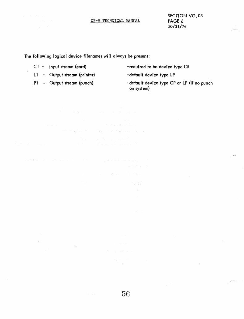
Cp .. V TECHNICAL MANUAL SECTION VG.03 PAGE 6 10/31/74
The following logical device filenames will always be present:
C 1 .. Input stream (card)
L 1 .. Output stream (printer)
P 1 ... Output stream (punch)
-required to be device type CR
-default device type LP
-default device type CP or LP (if no punch on system)

U"1 ....,j
AVRTBL (Double)
0 31 32
Serial # Bits
Tape
Disc/Pack
VALUES
BATAPE - first tape DCT index AVRTBLSIZ - # tape entries AVRTBLNE - # tape + # packs
AVRID (/2)
63
)
AVR TABLES
SOLICIT AVRNOU (Byte) (1/2)
TAB LE S (i ndexed by DC T# minus BA TAPE)
AVRTBL - See bits
DCT Tables -,
BATAPE
AVRTBLSIZ L AVRTBLNE
1
AVRID - User # /SID s-l = Lock SOLICIT - 0 = No, 10= Yes AVRNOU .. # DCBs + # users for packs
# tape spacing operations in progress for tapes
-P-"t.n ........ »m .t.G')(') ....... m-t
-P- --0 Z < G') .

Cp-'v . TECHNICAL MANUAL Section Page 2
9/1/78
VG.04
AVR Table Bit Definitions
AVRTBL (AVRTBLSIZ=number of tapes, AVRTBLNE=tapes + private packs, BATAPE=first tape DCT index) (EQUed in PASS2)
Entry Format for Labeled Tapes ... Q)
{/)
::J ~
-r-! o 31 32 39 40
Serial Number
Serial Number POS AVR SCR HLD PTL UPL OPN NOU TPOS
in use
Four-byte EBCDIC serial number of volume mounted. Tape at beginning, Yes' (0) or.no (1). Volume serial number verified, yes (1) or No (0) Scratch tape mounted, yes (1) or no (0). Volume can be dismounted, yes (1) or no (0) PTL option specified in last M;CLOSE, yes (1) or no (0). Labeled tape - out or Qutin, yes (1) or no (0). Tape position known by system, yes (1) or no (0). Number of DCBs open to files on the volume. Number of tape marks between load point and present position of tape. Set when drive is allocated.
Entry Format for Direct Access Devices
o 31 3 40 47 48 63
~ ________ S_e_r_ia __ l_N_um __ b_e_r ____________ ~~~~~~~~~~a-____ N_OU ______ ~_H_G_P_D_I_S_P~[] Serial Number
PUB
AVR
INIT VER MTD PRIM
NOU HGPDISP
EBCDIC serial of current volume. This field and all other flags are reset to zero when system dismounts volume. Device public (1) or private (0).
Volume serial verified and cylinder BIT MAPS moved to allocation table, yes (1) or no (0).
Private volume being initia1ized~ yes (1) or no (0). Verification in progress (1) or not active (0). Mount requested (pending), yes (1) or no (0). Volume mounted is primary volume in a private volume set, yes (1) orono (0). Number of DCBs open to files on this volume. Word displacement from HGP to FWA of allocation table for device.
r--u ilo

CP-V TECHNICAL .}1ANUAL
AVR TABLES
Table Content and Bit Settings
L
I • TAPE OR PACK AVR STATUS PUB SERIAL NOU AVR
! Premount Publ ic ;
1 # 1 0 j 1
I i! Premount ~ 0 # 0 0 I i
r 0 ! Avai lable (Empty) 0 0 0 I --
# # ! Sol icited 1 0 0 I --- --~-.--
t Being Verified 1-0 # 1 0
Dismount (lock) 1 # # 1
Private non
# # shareable 0 1
Share PRIVATE 0 # # 1 -- .-.
Public (operator) 1 # # 1 - -
System 1 0 0 0
Scratch 0 # 0 1
Premount SCRATCH 0 # 0 0
Sol icited SCRATCH 0 -1 0 0
AVR ID
0
#
0
#
#
-1
#
0
0
0
#
01
#
#
Section VG.04 Page 3 4/1/74
SOLICIT VER
0 0
0 0
0 0
1 0 1
0 1
0 0
0 0
0 0
0 0
0 0
0 0
0 0
1 0
SCR
0
0
0
0
0
0
0
0
0
0
1
1
0

CP-V TECHNICAL MANUAL
AVRSID
o 7 16 31
TYC I RBC
Used between end-action and user M:CHECK (or equiv.) for M:PRECORD operations.
TYC - I/O opmp1etion type I RBC - Remaining record count
AVRFI'..JMT - Six Words
o 17 18 19
from register 12 on user end action
23 I FILENAME I ~ I EXPIRA TI ON
Section VG.04 Page 4 2/10/76
FILENAME
VSN
EXPIRATION
name of the first file on the tape volume (TEXTC).
volume sequence number (binary)
Jul ian expiration date (five bytes representing YYDDD in EBCDIC.
ANSFLGS - One Byte
o 123 456 7
AT tape is ANS (0 = no, 1 = yes).
TO type of DCB (0 = NON-ANS, 1 = ANS)
ERR error flags (00 = no error, 01 = NOT ANS, 10 = NOT EXPIRED, 11 = ANS VOL).
AK ANSSCRATCH key-in processed (O=no, l=yes).
RO Access protection {O = unrestricted, 1 = read only}.
BLP BLP option specified (0 = no, 1 = yes). If CPV labeled tape bit set implies no un-blocked records can be written.
MS' MOUNT OR SCRATCH (0 = Mount, 1 = Scratch)
so

AVRFLGS
where
CP-V TECHNICAL MANUAL Section VG.04 Page 5 10/31/74
o 12 3 7
D C R A R D C E T D S S W 0 K
DDS is the Dual Density Status indicator
o = density is 1600 bpi (PE) 1 = density is 800 bpi (NRZI) DDS is only meaningful for output tapes where DD in TB:FLGS 1 is 1.
CCS is the Code Conversion Status indicator
o = no code conversion is performed 1 = code conversion is performed between EBCDIC (in core) and
ASCII (on tape). CCS is only meaningful for tapes where CC in TB:F LGS 1 is 1.
REW is the rewinding bit, indicating a REW was initiated but the end action has not yet occurred.
o = not rewinding 1 = rewinding - no other operations may start on this drive.
ATO is the Asynchronous Tape Operation flag.
1 = a tape spacing operation is in progress and data transfers are not to be initiated - AVRNOU contains the number of operations in progress.
o -= data transfers are OK.
RDK is the READ keyin flag.
1 = a ··READ keyin has previously been received for th is user for this tape.

o
COCOC LB:UN CPOS
Caunt of remaining characters to be output
User No. Carriage Position
o 7 o 7 o o inactive 1 last character
COC TABLES {indexed by Line Number} Length LNOL 'All are Interrupt Altered
7 o
CPI
Initial Carriage Position for a read
RSZ
User requested message size if a read is pending
o 7
BUFCNT
COCTERM
I T_',o' Typ. I o 7 o = 33 teletype 1 35 teletype
being output & this COCIO & COCOR are meaningless.
InJicates the current column number of the
carriage. o 7 2 = 37 teletype
3 '" XDS Model 7015
4 5 6, 7
Break count Restricted code set
Tab simulation Read pending
Transparent Mode Escape sequence, (EOA pending for 2741)
E!=hoplel<
MODE5
Activation char. set , Check parity mode I L Restri ct code set to lower case ~ 2741 line
Space insertion mode Full Duplex Paper Tape Mode
Logging off
MODE6 o 1 2 3
Current number of buffen ,in use by the line
Number of lines upspaced during input Lost input
2741 leyboard Loebd (TTY output - ipore lIIOde)
Backspace edit mode Half Duplex Paper Tape
Relative Tabbing
4 5 6 7
4-11 = IBM 2741 1,2-16 "" Installation-defined
17 = ASCII APL
I I I COB: CTI
Master} Sysgen Defllult Slave Line Type Read Complete Break Pend ing
______ • LiDe DeB Open if slave, else DEFER SEND I
if Master (DOO) _________ Master \. Currettt Lin!!
. Slave j (OO=either) Ty~
TL (HW) 15 EOMTIME (HW)
lS' i. l~ HardWired L;. Unused ~ Half-duplex tUnQ around phase '2
, Half-duplex turn around phase I ~ Out?ut halt mOde
L ~--------------~) Read with user timeout '------------------~) Half-duplex input
Half-duplex
TrE* 15
link to the buffer for input tab simulation while 0 read is pending
Time activation was received. If read is pending, number of 1. 2 second intervals till timeout. LI1~ ~ COUPLED TO
o
o 2 3 4 5 6 7
....... -----Initial value for COCTERM
'-----------.,---There is no initial value
A value of 8000 indicates no tabs in e:fect for the read. * Significant only if COUPLE option specified in PASS2
If no read pending, the input buffer ajdress where activation took place.
COCOl
.Byte pOinter to current ::13e~tic::t po1nt inta the output atream i r:: the Ulla.
COCOR
l\yta pointer to th~ curr<':lt z.:<m('val potnt frOt!! the output str~<ll:l for the 1 tr.e. o '" no buffers.
cocn pointer to cl::"rent i:lsert ion point
in~ . ., tha input stream for t1-.<l lbe. 0,. no buffers.
COC!R
Byt~ pointer to current rerno':al point from the input stream for the line. o '" no buffers.

MODE 4 o
MODE 4 INIT 0 I 2
Line Speed Indicator
o 1 2 3 4 5 6 7
Algorithm
o 1 2 3 4 5 6 7
2 3
3
CP-V TECHNICAL MANUAL
5
14 5
Characters Per Second
10 15 30 60
120 240 480 960
6
6
I
7
7
Baud
110 134/150
300 600
1200 2400 4800 9600
Applicable Terminals
Section VG.05 Page 1.1 9/1/78
Current tim ing algorithm (see MOD E41 NIT) Unused Insert mode Couple reiected Currently coupled, couple ok
Line speed indicator Initial- timin..Q algorithm (see MODE4) Unused
TTY 33, 35, 37, Most CRT's 2741-Types, Texas Instruments 733 Execuport, Datapoint Memorex All (Combination of 2 and 3) Texas Instruments 725 Teletype Model 40 Hardcopy Printer Unused
62a

CP-V TECHNICAL MANUAL
(This page intentionally left blank.)
I 62b
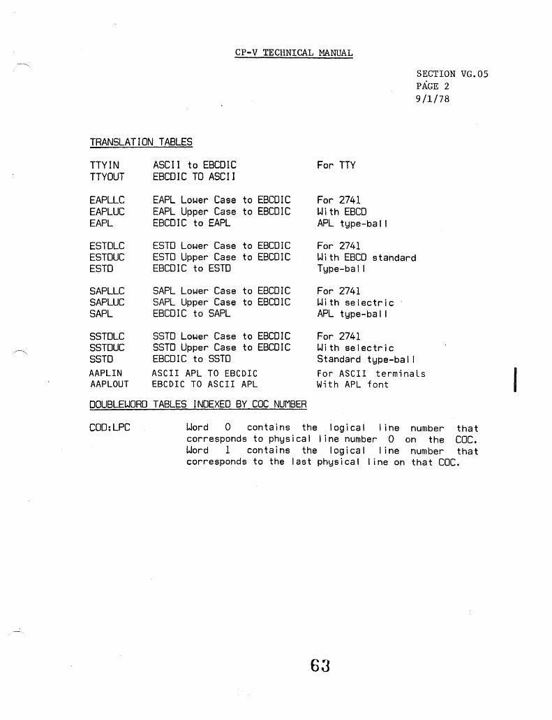
~,
CP-V TECHNICAL MANUAL
SECTION VG.05 PAGE 2 9/1/78
TRANSLATION TABLES
TTYIN ASCII to EBCDIC For TTY TTY OUT EBCDIC TO ASCI I
EAPLLC EAPL Lower Case to EBCDIC For 2741 EAPLUC EAPL Upper Case to EBCDIC Wi th EBCD EAPl EBCDIC to EAPL APL type-ba I I
ESTDLC ESTD Lower Case to EBCDIC For 2741 ESTDUC ESTD Upper Case to EBCDIC Wi th EBCD standard ESTD EBCDIC to ESTD Type-ball
SAPLLC SAPL Lower Case to EBCDIC For 2741 SAPLUC SAPL Upper Case to EBCDIC With selectric SAPL EBCDIC to SAPL APL type-ba I I
SSTDLC SSTD Lower Case to EBCDIC For 2741 SSTDUC SSTD Upper Case to EBCDIC With selectric SSTD EBCDIC to SSrD Standard type-bal I AAPLIN ASCII APL TO EBCDIC For ASCII terminaLs AAPLOUT EBCDIC TO ASCII APL With APL font
DOUBLEWORD TABLES INDEXED BY cac NUMBER
COD:LPC Word 0 contains the logical I ine number that corresponds to physical line number 0 on the CDC. Word 1 contains the logical line number that corresponds to the last physical line on that COCo
63
I

CP-V TECHNICAL MANUAL SECTION VG.05 Page 3 2/10/76
WORD TABLES INDEXED BY COC NUMBER
CO:CMND
CO: IlL
CO:LNM
CO:LST
CO:OIL
CO: OUT
CO: RINGE
CO:XPSDO
DA (command list)
Input interrupt level select bit for WRITE DIRECT instructions
Mask for obtaining line number; X'3F' for a COC, X'7F' for an FECP
BA (next character in ring buffer) - BA (first byte after end of ring buffer)
Output interrupt level select bit for WRITE DIRECT instructions.
WA (4 word output interrupt PSD block)
WA (first word after the end of the ring buffer)
Output interrupt XPSD instruction
HALFWORD TABLES INDEXED BY COC NUMBER
COH:DN COC device address
COR:II Input interrupt location
COH:IO Output interrupt location
COH:RBS Byte size of ring buffer
BYTE TABLES INDEXED BY COC NUMBER
COB:SIOS Condition codes from the SIO instruction in COCINIT
64

I
o
CP-V TECHNICAL MANUAL SECTION VG.OS Page 4 9/1/78
READ/WRITE DIRECT INSTRUCTIONS INDEXED BY COC NUMBER
Table Instruction Descriptton Cd = DIO address)
CO:OUTRS
CO: STAT
CO: RCVOFF
CO: RCVON
CO: RCVDOFF
CO:XDATA
CO: TSTAT
CO:XSTOP
COC BUFFER LINKAGES
Free Chain:
RD,7 .30dO Output response
WD,IO .30dO Sense receiver status
WD,7 .30d2 Turn receiver off
WD,7 .30dl Turn receiver on
WD,7 .30d3 Turn receiver data set off
WD,6 .30d5 Transmit 'data
WD,7 .30d4 Sense transmitter status
WD,7 .30dE Stop transmit
COCHPB is the head pointer. FLINKs occupy word 0 of the buffer, and are word displacements from COCBUF to the next buffer.
Input, Output, and Tab Buffer Chains: COCIR, COCOR, and TL are the
COCGFLG
respective head pointers. FLINKs occupy halfword 0 of the buffer, and are the byte displacement from COCBUF to byte 2 of the next buffer in the chain.
(COC GHOST REQUEST FLAGS)
1516 23 24 31
'- 'V ./ ~ \"", ~
I
v-
I Unused Power fai I-safe init request Clock 3/T :COCHC init request CSECOM init request Online user max increesea Unused Ghost id/boot COC init request Ghost id/recovery COC init request
-----------------------------------Unused
65

I
I
I
~ I
CP-V TECHNICAL MANUAL SECTION VG.05 Page 5 9/1/78
Additional Data Cells for CP-V L6 Front-end:
L6LIMS Doubleword containing first L6 logical line number and last L6 logical line number; contains 1 and 0 if no front-end.
Additional ADEF for .the CP-V L6 Front end:
L6i1FIRST ADEF giving the first L6 front-end COC number EQU'ed to LCOC+l if no L6 front-end
Changes to the RD/wn Instruction Tables for the CP-V L6 Front-end:
Table Name Contents
CO:DUTRS NOP
co: STAT XPSD,O Rcur status routine
CO: RCYOFF NOP
CO: RCVON XPSD,O Turn Rcur on routine
CO: RCVDOFF XPSD,O Turn data set off routine
CO:XDATA XPSD,O Transmit character routine
CO: TSTAT LCI 3
CO:XSTOP NOP
65a

CP-V TECHNICAL MANUAL
(This page intentionally left blank.)
65b
SECTION VG.05 Page 6 9/1/78
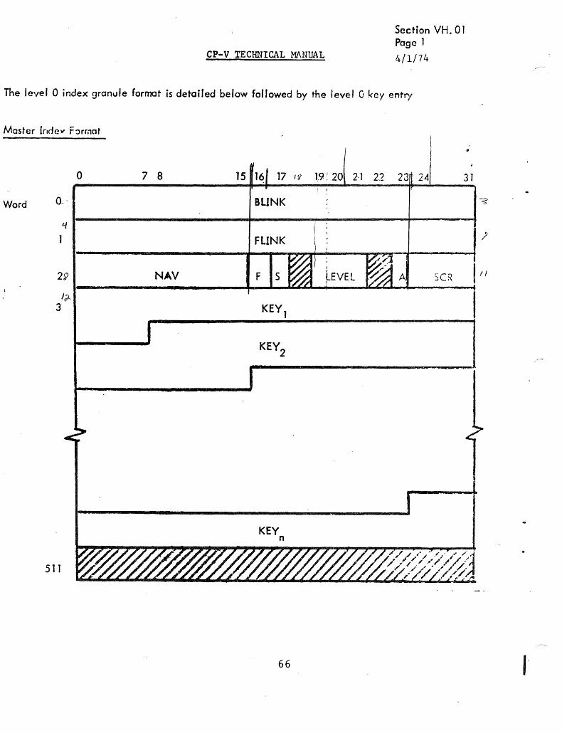
CP-V TECHNICAL MANUAL
Section VH. 01 Page 1
4/1/74
The level 0 index granule format is detailed below followed by the level G key entry
Master Incley F ~rmot
0 7 8 15 16 17 J 1t 19 ,: 20 2-1 22 31
Word 0-- BLINK
LI
1 FLINK
29 NAV F S SCR
JJ.-3
KEY n
511
66
"

CP-V TECHNICAL MANUAL
Section VH. 01
where:
S =
BLINK
FLINK
NAV
LEVEL
A
KEY
Page 2
4/1/74
1 if full-granule size; 0 if half-granule size
contains the disk address of the preceding index granule, or. zero, if none.
contains the disk address of the next index granule, or zero, if none.
contains the number of significant bytes in the index granule 0. e., points to the next available byte in the index granule).
contains the level of the index entries (i. e., contains 0).
is the added flag and ind icates whether or not th is index half~granule has been added since the current higher level index structure was created (0 means no, 1 means yes).
is the key entry, shown below
SCR 1 + KEYM (see description on 14-38)
F = 1 if FIT is in this granule; 0, otherwise. The FIT will occupy the final 80 words, if present.
KEY ENTRY SCR
Byte o 1 ••.•. +0 SCR +2
SCR +4
SCR SCR SCR +8 +10 +12
5 6 7 F E
K L contai ns the number of bytes in the key
KEY contains the character string that indentifjes the record
BLDISP contains the byte displacement of the record segment associated with this key entry within the data granule pointed to by DABLK
bO/
A 0 C K F

BLKSIZ
DABLK
BLK
FAK
EOF
c
CP-V TECHNICAL MANUAL :t _
Section VH.01 Page 3 4/1/74
contains the byte count of the initial size of the record segment associated with this key entry. BLKSIZ is never updated.
contains the disk address of the data granule that contains the record segment associated with this key entry.
contains the count of the number of bytes of data currently in the record segment associated with this key entry (BLK < BLKSIZ). -
indicates whether or not th is entry is the first appearance of this key (0 means no, 1 means yes).
indicates whether or not this entry is the last undeleted entry in the file (0 means no, 1 means yes).
indicates whether or not this record segment is the final segment of the record (0 means yes, 1 means no).
68

CP-V TECHNICAL MANUAL
SECTION VH.01 PAGE 4
MASTER INDEX FORMAT FOR A HIGHER LEVEL INDEX 10/31/74
The formats of the higher-level granule and the higher-level key entry are detailed below.
Master Index
o 7 8 31
Word 0
2 NAV SCR
3
KEY n
511
Key Entry
Byte {O SCR SCR +0 +3
IIK-lrl---K-E-Y----~--u-n-us-~--~I~D-A-B-l~K~
----- SCR bytes -----
where
Kl contains the number of bytes in the key. If the key entry in the level 0 half granule pointed to by DABlK is not the first appearance of that key at tevel 0, the high order bit of KL (at level 1) is set.
KEY contains the key from the first key entry in an index granule on the lower level.
SCR is a field in the DCB and equals the maximum key length + 1.
DABLK
BLINK
FLINK
NAV
LEVEL
contains the disk address of the index granule on the lower level.
contains the disk address of the preceding index.granule at this level, or zero, if none.
contains the disk address of the next index granule at this level or zero, if none.
contains the number of significant bytes in the index granule.
contains the level of the index entries (the lowest is level 0, the next is level 1, and so forth).
A only meaningful at level Oi always 0 on higher levels.
69

I
I
CP-V TECHNICAL MANUAL
ACCOUNT DIRECTORY
SECTION VH.02 PAGE 1 9/1;78
An account directory consists of a master index. An account directory index granule consists of entries that
contain an account number and the disk addresses of the file directory associated with the account. There is
one account directory for all public files in the system. Each private volume set has its own account directory
which is limited to 96 entries. Tile permanent information about the public file account directory is contained
in the ACNCFU. ACNCFU is not used for private account directories. A private account directory is always located on Granu Ie 1 of the primary volume in the set.
FORMAT FOR THE PUBLIC FILE ACCOUNT DIRECTORY
Master Index
Word 0
2
3
6
7
to
509
510
511
0
Entry Format for Public
o 8
78
NAV
ACN
1 16171
BLINK
FLINK
ENTRY 1
ENTRY 2
ENTRY n
DUAL
DBLINK
DFLINK
89
70
2 24 31
seR
1112
DABLK DUBLK
7

where
S
ACN
DABLK
DUBLK
FAK
C
BLINK, FLINK and NAV
DUAL
DFLINK, DBLINK
SCR
CP-V TECHNICAL MANUAL SECTION VH.02 PAGE 2 9/1/78
= 1 for full-granule size; S = 0 for half-granule size.
contains an eight-byte EBCDIC account number.
contains the disk address of the file directory associated with this account.
contains the disk address of the dual of the first granule of the file directory in question.
~
= 1; indicates that this entry is the first appearance of this key.
= 0; has no meaning for an account directory.
have the same meaning as in the Master Index for Level O. Both BLINK and FLINK are zero for a private volume set account directory.
disk address of the dual location for current granule.
same as FLINK and BLINK except that these disk addresses apply to the dual structure for the directory.
9 for public account directories, X'C' for private account directories.
Entry Format for Private
o 7 a 1516 23 24 3T
KL = X'OB' X'40' X'40' X'40'
ACN contains a-byte EBCDIC account number.
DABLK
FAK
71
I
I

I
CP-V TECHNICAL MANUAL
FILE DIRECTORY
Section VH.03 Page 1 9/1/78
A file directory consists of a Master Index (MI) and a set of File Information Tables {FITs}. A file directory index granule consists of key e.ntries that contain the name of a file in the associated account and the disk address of the filels FIT. A FIT is located on a granule aJ located to the file and contains all the information necessary to open a file. Information about the file directory itself (its mini ... FIn is contained in the last three words of the first block of its master index. The information from the mini-FIT is maintained in the FILCFU when the file directory is being updated. Publ ic and private file directories have the same formats. .
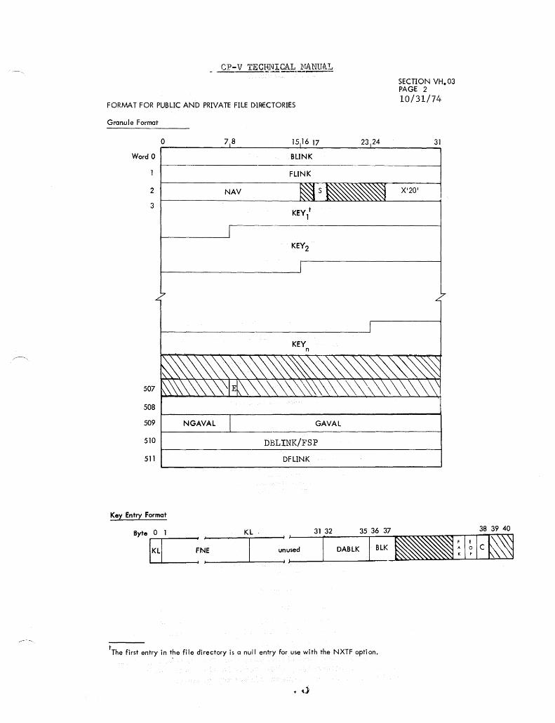
cP-v TECljNlCAb.1!~
FORMAT FOR PUBLIC AND PRIVATE FILE [)1~CTORIES
Granule Format
Word 0
2
3
507
508
509
510
511
o
Key Entry Format
NGAVAL
78 1516 17
BLINK
FLINK
NAV
KEY n
GAVAL
DBLINK/FSP
DFLINK
23 24
tThe first entry in the file directory is a null entry for use with the NXTF option.
... ,\j
SECTION VH.03 PAGE 2 10/31/74
31
X'20'

CP-V TECHNICAL MANUAL
E set if directory is empty.
Section VH.03 Page ~
2/10/76
FSP disk address of free granule pool (only in first directory granule).
where:
S == 1
KL
FNE
DABLK
BLK
for full-granule size; =0, for half-granule size.
contains the number of bytes in the key.
contains an EBCDIC file name.
contains the disk address of the file's FIT.
Descriptors.
dynamic descriptors
bit 0 is 1 bit 1 is 0 in file directory; but set to 1 in DCB field if we are creating a
new synonymous file. bit 2 is 0 in file directory; but set to 1 in DCB field if a synonymous file
is being processed bit 3 is unused bit 4 is 1 if the file has been modified since it was backed up by FILL bit 5 is 1 if the file ahs been modified since it was last backed up by
an Increment bit 6 is 1 if the file has been modified since it was last backed up by a
Saveall bit 7 is 1 if the file has been modified since the last Fill
static descriptors
bit 0 is I if the file has a password bit 1 is I if the file is a SYNON file bit 2 is I if the file organization is random bit 3 is reserved for expansion bit 4 if 1 if the file is not to be automatically backed up bit 5 is 1 if the access date is not to be updated bit 6 is 1 if the file is not to be semi-automatically deleted bit 7 is unassigned, but see the X'II' VLP, below
entry descriptors (unchanged) bits 0-4 are not used bit 5 is 1 (FAK) bit 6 is 1 if this is the last FD entry for the account (EOF) bit 7 is 0 (C) FAK == 1; indicates that this entry is the first appearance of this key.
EOF indicates whether or not this key entry is the last in the file (0 means no, 1 means yes).
C == 0; has no meaning for a file directory.
DBLINK, DfLINK, BLINK, FLINK, and NAV have the same meaning as is previous Account Directory formats. NGVAL,GAVAL, have the same meanings as in the FILCFU (see File Directory CFU (FILCFU) later in this chapter).
Words 509 and 510 as specified only for the initial granule of a directory; otherwise, they contain the same dual information as does an account directory granule.

CP-V TECHNICAL MANUAL
(Material on this page has been deleted.)
75
SECTION VH.03 Page 4 9/1/78
I

CP-v TECHNICAL MANUAL
FILE INFORMATION TABLE (FIT) FORMAT FOR AN ORIGINAL FILE
o 1 2 1 4 5 6 7 3 9 1011 12 13 It. 15 n 1718 )9 ')0 2' 'J;> !23 24 2'1 26 27 28 29 30 31 ~ ~ ~R _ I
i~--------·----~--·---~·---- -
(9 ... .'ords) FNE (in l'EXTC format)
X'03' I LE = 0 I-~DHO= 2-- I NAW = 2
PASSIWl(1) (? \,'onls) .-1 I I X'05' LE '" 0 NDW NAW
Read ACNs (2 \vords each)
X'OG' I LE == 0 I NDH I NAH
Write ACNs (2 words each)
X'14' I LE = 0 I NDi.,T I NAW
Execute A CNs (2 words each)
X'15' I LE = 0 I NDW l NAW
Execute Vehicles (3 words each, TEXTC)
I I ._-
I X 'Otf' LE '" 0 r..'DI.J ;: 2 ~W"~ . Expiration DutE'
X'Op' I LE= 0 I NDW;: 2 1 NAW = 2
Last Access Date
X'lO' I LE = 0 I NDW = 2 I NAI.,T == 2
Backup Date ---r
I I X'OE' I LE = 0 NDW= 2 NAW= 2
Creation Date
X'OA ' I LE = 0 I NDH= 3 I NAW= 3
~IDdification Date
X'OD' I LE = 0 I NDW = ) J NAW = 1
File Size
X'OC' I LE =0 I NDI.,1 = 7 I NAW = 7
EI FDA
TDA
I NGAW_L I GAVAL
com 0 SLIDES /
, /
)
(///// /11/1/11 II I I I I I II I / II I~ I~~~ /II II III I II II I I I~ SREC
LDA
X'09' I LE = 1 I NOW = 3 I NAW = 3
SECTION VH.04 PAGE 1 2/10/76
These coded entries are optional; presence of the entry is indicated by the byte 0 hex code.
See CFU format for meaning of fields
See DCB for meaning of fields.
The maximum size of the FIT is 80 words. The only limit on the number of read, write, execute accounts and execute vehicles is the 80 word maximum FIT size.
7~he FIT starts in word 4 for consecutive files and in the 80th word from the end for keyed or random files.
7t5

Field
ACN
CCSD
CYl
Date
E = 1
FDA
File size
FNE
GAVAL
KEYM
lOA
LRDLO
LSLIDES
NAW
NDW
CP-V TECHNICAL MANUAL
Description
is an account number. Each ACN is an eight-byte EI\(l)1C entry with trailing blanks. IE there is no Read ACN entry. and ACN can read the file. If there is no Hrlte ACN, no one can write in the file except the ACN that C'reated the file
contains, for keyed tiles, either the byte displacement to the next available byte in the last data granule of the file (SREC), which means that the blocking buffer was truncated; or 0, which means that the last data granule in the file (SREC) contains 5J2 words.
specifies whether the file assigned to the DCB is to be allocated by granules or cylinders (0 = granule allocation, 1 = cyl inder allocation). It is only meaningful for public files.
is of the form MMDpHHYY, where
MM is numerical month DD is day of month HH is hour of day YY is last two digits of the year, all in ESCDIC bytes
Expiration date may contain the word NEVER followed by three blanks, which indicates that the file does not have an expiration date.
The modificat.ion date contains three words. 'The third word is of the form HHMM, where
HH is a repeat of the hour MM is the minute
file contains no record
contains the disk address of the file's first index granule at level O.
contains the current number of index and data granules allocated to keyed and consecutive files; or the number of data granules allocated for random files.
is the EBCDIC name of the file in TEXTC format.
contains the disk address of the next available granule in the fast cylinder allocated to the filei zero if none.
contains
I. the maximum length, in bytes, of the keys in the file. Applicable to keyed files. Maximum value is 31.
2. the type of device that the random file is to be allocated on (0 = allocate on either RAD or DP, X'?' = allocate on RAD, X'B' = allocate on DP). Applicable to random files.
contains the disk address of the file's last index granule at level O.
contains the limiting number of contiguous index granules that can be allocated in level 0 and not be reflected in level 1 before the flag, which signals CLOSE to reconstruct the higher level index structure, is set (i. e., before SLIDES in the CFU is set equal to 255).
has meaning only if a multilevel index exists and contains
1. the limiting number of index granules that can be allocated in level 0 and nof be reflected in level 1 before the flag, which signah CLOSE to reconstruct the higher level index structure, is set.
2. the value 255, which means that once a higher level index structure exists, it is not to be reconstructed.
LSLlDES is only used for keyed files.
is the number of available words in the entry (not inel uding the control word).
is the number of significant data words in the entry (not including the control word).
77
SECTION VH.04 Page 2 2/10/76
NGAVAL
NOSEP
NSF
o
ORG
PASSWORD
SLIDES
CP-V TECHNICAL MANUAL
is, the nurrJ}cr of, 8\'a;l.1I.1b1,-, grallules in t:hc
lll£t,cylinder nllocated to the file
spcc:l.flcs \!hcthcr or not p'anules an' 1:0
be allocated on a specif:Lc, d,',vicc type. This flag!J;:\s no mcanjflg for p;:ivate or
-random [lIes.
is the number of files synonymous with this file.
is a level 1 flag indicating whether or not a level 1 index exists in a keyed file (0 == no, 1 == yes). ,
is the file organization indicator (0 == non spec'ified and is treated as consecutive, 1 == consecutive, 2 == keyed, 3 == random).
is an eight-byte EBCDIC entry with trailing blanks.
contains, for keyed files, either
1. a tally of the number of index granules allocated at level 0 since the current multilevel index structure was created, or if non exists, since the file was first opened,
2. a tally of the number of index granules allocated at the current level while the multilevel index structure is being (re) created.
3. the value 255, which means that a new multilevel index structure should be built when the file is closed (unless LSLIDES in the DCB equals 255 and a level-l index exists).
Field Description
LE is the last entry flag and indicates whether or not this parameter is the last entry in the FIT (0 means no,' J means yes).
SPARE contains the number of spare byte positions to be left unused
SREC
TDA
So == 0 51 == 0 52 == 1 53 == 0 S4 == I S5 == I S6 == I S7 == 0
in the end of the current index granule in the event that the key to be added is the last key in the file.
SPARE is only used for keyed files.
contains the disk address of the last data granule in the file. It is only used in the output mode.
contains, for keyed files, either
I. the disk address of the first index granule at the top of the multilevel structure, if one exists.
2. the disk address of the middle index there are three level-O index file is ,keyed.
granule, if granules and the
3. 0, which means that either the file is consecutive, or that the file is keyed and there are at the most two index half-granules.
For consecutive files, TDA contains the number of records in the file.
if file organization is random
if file is not to be automatically backed up if access date is not to be updated if file is not to be semi-automatically deleted
78
SECTION VH.04 Page 3 9/1/78

CP-V TECHNICAL MANUAL
Secti on VH. 04 Page 4 4/1/74
FILE INFOKf\I\ATION TABLE (FIT) FORMAT FOR A SYNONYMOUS FILE
o 7 8 15 16 23 24 31 01 I LE = 1 I NDW=8 I NAW=8
F NE (TEXTC Format)
OB 1 LE I NDW I NAW
SYNON FILE NAME (TEXTC Format)
A synonymous file does not have a FIT, but if a synonymous Hie is accessed on a NXTF open with FPARAM, an X'08 1 error return is made with the above information passed as the FPARAM.
* This entry replaces the optional entries on the original file.
7U
*

CP-V TECHNICAL MANUAL
PRIVATE VOLUME SET TABLES
SECTION VH.06 Page 1 9/1/78
A private volume set is a collection of disk pack volumes that the user has grouped together, containing any number of riles with any type of organization. A private volume set is a self-contained entity and contains its own account directory and file directories (which contain information about all files on the private volume set). The account directory for a private volume set is located on granule 1 of the primary volume. The first file directory begins on granule 2; each file directory thereafter begins on a successive logical cylinder boundary. Because volumes can be mounted serially for consecutive files, file directories cannot extend beyond the primary volume. The format for the private file directories is the same as for the public directories. Every private volume has a Volume Table of Contents (VTOC) which is built by the VOLINIT processor and is located on granule 0 of the volume. The format of the VTOC is shown on the following page.
. 80

CP-V TECHNICAL MANUAL SECTION VH.06 PAGE 2 9/1;78
VOLUME TABLE OF CONTENTS (VTOC) FORMAT
o
2
3
4
5
6
MAPWL+7
n
VTOCFields
Field Name
Bit Map
o
--
First Sector Number
MAPWD
MAPWL
NSN
NGC
Word
7+n
6
6
4
4
7 8 15 16 23 24 31 I I I
: LBL (in EBCDIC)
VSN
SNTD
NGC 1 MAPWL
NVAT
MAPWD I First Sector f\Jumber
BIT MAP (1 bit per cylinder)
NSN
SNT (serial no. table)
Meaning
contains the cylinder bit map for the volume. If the bit is set, the cylinder is unallocated. If the bit is reset, the cylinder is allocated. For devjces where the nu.mber of cylinders is not an even multiple of 32, VOLlNIT re<:ets the bits in the last word which do not represent cyl inders.
contains the sector number for the first sector on the device (i. e., sector 0).
contains the word displacement from the start of an allocation table to the bit map. MAPWD is set to X '01' by the VOLINIT processor.
contains the number of words in the bit map.
contains the number of serial numbers in the Serial Number Table.
contains the number of granules per logical cylinder.
81
,

Field Name
NVAT
SNT
SNTD
VSN
Word
5
3
(1 &2)
CP-V TECHNICAL MANUAL
Meaning
SECTION VH. 06 PAGE 3 4/1/74
contains the next volume1s cylinder 0 allocation table. Each bit represents a granule. If the bit is set, the granule is unallocated. If the bit is reset, the granule is allocated. The first bit, which represents granule 0 is always set allocated. NVAT is only used when a consecutive file extends beyond volume boundaries.
contains the serial numbers of all the volumes in the private volume set for the primary volume. The position of a serial number represents its volume number. (The primary volume is always volume 1.) The order of the serial numbers never changes, but new volumes can be added to the set, and will be added at the end. For other volumes, this table contains only the serial number of the primary volume. Only the first four bytes of the serial number are carried in the serial number table.
contains the word displacement from the start of the VTOC to the start of the Serial Number Table.
contains the volume serial number (left-justified and blank-filled to eight bytes.)
82

CP-V TECHNICAL MANUAL
SECTION YH.07 PAGE 1 2/10/76
ALLOCATION TABLES (HGP)
SYSGEN creates an allocation table {called HGP - Heading Granule Pool for each disk device (RAD or disk pack) defined at SYSGEN time. The HGPs are located in ALLOCA T's data (See Section GB) - ALLOCA n and in CORE starting at the location HGP. (The bit maps for public devices are not in the CORE HGP Tables.) Allocation tables are used to allocate and release granule/cylinder units from symbiont storage areas of a device and the file. An allocation table contains (1) information about the file and symbiont storage areas of a device, (2) the relationship between the device's physical (sector and track) and logical {granule or cylinder} units, and {3} the maps which control the allocation of the granule/cylinder units in the file and in the symbiont storage areas of the device. The system device's allocation table is always the first one and beyins at the location HGP •. The allocation table format (HGP) is shown below.
Allocation Table Format (HGP)
where
o
2
3
4
6
7
n
o
0
f-
E
E
7 8 I
01
O/LBP
PER MAPWL
- - -- -PER MAPWD
PFA MAPWD
/51617 1\ 2324 31
FLINK
DCT rlJI TYPE I NGC
NST/SFLNK
NSG/LBD
PFA MAPWL
NVAT - - ,- - -- - - ---
PER 1st SECTOR NO.
I PFA 1st SECTOR NO. -
PER BIT MAP
PFA BIT MAP
CYL indicates whether the device is allocated by cylinder or granule (0 means granule, 1 means cylinder). All private devices are allocated by cylinder. Disks can only be allocated by granule. Symbiont storage only exists on devices allocated by granule.
~ :: ... O'G.)

DCT
E
FLINK
LBP, LBO
NGC
NSG
NST
NVAT"
PER bit map
PERMAPWD
PER MAPWL
CP-V TECHNICAL MANUAL
contains the DCT index of the device the allocation table is associated with.
if set, indicates that this portion of the bit map (PER or PFA) is all zeroes (ALLOCAT data).
contains the address of the next allocation table, or zero if none. HGP equals the address of the first allocation table in the chain.
SECTION VH.07 PAGE 2
10/31/74
contains the bit position and word displacement of the last single granule allocated from the bit map (ALLOCAT data only).
contains the number of granules per cylinder, but only has meaning if CYL is set.
contains the number of sectors per 512 - word granule for this device (CORE headers only).
contains the number of sectors per track for the device (CORE headers only).
contains the next volume's cylinder 0 allocation table (if PRIV is set). Each bit represents a granule. If the bit is set, the granule is unallocated. If the bit is reset, the granule is allocated.
is a map in which each bit represents a granule in the symbiont storage area. (Symbiontsare only allocated on devices with granule allocation units). The bits are ordered left to right within a word so that bit 0 of the first word represents the first granule in the symbiont storage area, bit 0 of the second word represents the 32nd granule in the storage area, and so forth. If the bit is set, the granule is unallocated, if the bit is reset, the granule is allocated.
contains the word d splacement from the start of this allocation table to the first word of the bit map for the symbiont storage area.
contains the nurmer of words in the bit map for the symbiont storage area.
PER first sector number contains the sector number of the first track in the symbiont storage area.
PFA bit map
PER MAPWD
PER MAPWL
(Sectors are numbered starting with 0.)
is a map in which each bit represents a granule or cylinder (depending upon the CYL flag) in the file storage area. The bits are ordered left to right within a word so that bit 0 of the first word represents the first granule/cylinder in the file storage area, but 0 of the second word represents the 32nd granule/cylinder in the storage area, and so forth. If the bit is set, the granule/cylinder is unallocated/ if the bit is reset, the granule/cylinder is allocated.
contains the word displacement from the start of this allocotlon table to the first word of the bit map for the symbiont storage area.
contains the number of words in the bit map for the symbiont storage area.
PER first sector number contains the sector number of the first track in the symbiont storage area. (Sectors are numbered starting with 0.)
PFA bit map
PFA MAPWD
PFA MAPWL
is a map in which each bit represents a granule or cylinder (depending upon the CYL flag) in the file storage area: The bits are ordered left to right within a word so that bit 0 of the first word represents the first granule/cylinder in the file storage area, but o of the second word represents the 32nd granule/cylinder in the storage.area, and so forth. If the bit is set, the granule/cylinder is unallocated; if the bit is reset, the granule/cylinder is allocated.
contains the word displacement from the start of this allocation table to the first word of the bit map for the file storage area.
contains the number of words in the bit map for the file storage area.
PFA first sector number contains the sector number of the first track in the fi Ie storage area. (Sectors are numbered starting with 0).
PRIV
SFLNK
TYPE
indicates whether the device is public or private (0 means public, 1 means private).
contains the address of the ne~t allocation table in the circular chain of similar usage devices (ALLOCAT data only).
contains the device type (7 means disk; B means disk pack).

CP-V TECHNICAL MANUAL
CURRENT FILE USAGE (CFU) TABLES
SECTION VH.08 PAGE 1 4/1/74
The CFU tables contain information about the currently open disk fi les. Each open file, whether public or private, has a CFU table. In the case where an old version of a file exists and a new version is being created, the two versions are considered as different files until the new version is closed, at which time it replaces the old version. If the old version is opened in the input mode at the same time the new version is opened in the OUT or OUTIN mode, each wi II have a different CFU, but the CFUs are linked together and each is called the secondary CFU of the other. SYSGEN creates a pool of user CFU buffers from the number specified in the CFU option of the Monitor's command. In addition, SYSGEN creates two SYSGEN CFUs called ACNCFU and FILCFU, which immediately precede the user CFU pool. ACNCFU contains information about the public fi Ie account directory. FILCFU contains information about the currently referenced public or private fi Ie directory. The CFU tables are core-resident in the data area of the Monitor1s root. The constants ACNCFU and FILCFU equa I the addresses of the account and fi Ie directory CFUs respectively. The constant BGRCFU equals the address of the first user CFU buffer, and the constant LASTCFU equals the address of the last user CFU buffer.
85

CP-V TECHNICAL MANUAL
The Account CFU (ACNCFU)
SECTION VH.08 PAGE 2 9/1/78
Word/Bit o 1 2 3 4 5 6 7 8 9 10 11 12 13 14 15 16 17 18 19 20 21 22 23 24 25 26 27 28 29 30 31
0 NEh1fD
1 FDA
2 eDAM
3 GAVAL
4 DCDAM
5 TDA
6 RDA
7 DRDA
8 DFDA
lj DrGRA~
10
11
12 CC2
13
14 ACCTCNT
15 NAMTBL
16 NAMTBLE
I 17 FREE G.FU
18 I REDFLGS
86

FIELD WORD
ACCTTBL 13
ACCTCNT 14
CDAM 2
DCDAM 4
DB UFF 3 10
DFDA 8
DIGRAN 9
DRDA 7
E 1
CC1 11
CC2 12
FDA 1
GAVAL 3
FREECFU 17
CP-V TECHNICAL MANUAL
MEANING
SECTION VH.08 Page 3 9/1/78
is the word address of the start of the account name entries in the user CFU area.
is a count of the number of account name entries current1y in the user CFU area.
disc address of the granule of the account directory current1y beihg processed.
disc address of the dual of the granule of the account directory cur ently being processed.
disc address of the dual of the granule currently being processE~d in BUFF3 in the INST routines in WRTF.
disc address of the dual of the FDA (see below).
disc address of the dual supplied by the GETIGRAN rou tine in WRTF.
disc address of the dual of the RDA (see below).
is the empty directory flag and is only one for a short period at the start of a cold boot of a PO tape.
set by a STCF in the FINDFIL routines in OPN and CLS after determining whether (equal) or not (not equal) the FILCFU iH set up for the directory required.
set by a STCF in the FI1~FIL routines in OPN and CLS indicating wh(~ther (equal) or not (not equal) the directory to be processed is that of :SYS.
disc address of the start (1st granule) in the account direc ory.
disc address of the next granule available from the cylinder most recently 2llocated to the account directory. Unless the system contains public cylinder devices, this field and ~GAVAL are always zero.
address of the last 8-word block set up by CLOSE. Whenever a disk file is closed, the address in FREECFU is decremented by 8. If the CFU to which it now points is not active, the CFU for the file being closed is moved to this CFU and the original CFU is clobbered. If the CFU being pointed to is active, FREECFU is reset to the address of the last 8-word block.
87
,
FIELD WORD
NGAVAL 3
NAMTBL 15
NAMTBLE 16
NEWFD o
RDA 6
REDFLGS 18
SIGCLS 12
TDA 5
CP~ V TECHNIcAL MANUAL
MEANING
SECTION VH.08 PAGE 4 10/31/74
the number of granules still unallocated from the cylinder most recently allocated to the account directory.
word address of the start of the file name entries in the user CPU area.
word address o"F the next available word in the user CFU area into which a file name can be placed.
is a flag used in CLS to indicate whether or not a new file directory is being created.
disc address of the granule requested to be read by the REDSEC routines in RDF.
control flags used by the REDSEC routines in RDF.
flag indicatint whether (not zero) or not (zero) a CFU with a name has been released since the last restructuring Qf the user CFU area.
always zero indicating that no multi-level structure exists.
88

CP-V TECHNICAL MANUAL
SECTION VH.08 PAGE 5 2/10/76
The File CFU (FILCFU)
~vord/Bit o 1 2 3 4 5 6 7 8 9 10 11 12 13 14 15 16 17 18 19 20 21 22 23 24 25 26 27 28 29 30 31
0 CMD
1
2
3 NGAVAL GAVAL
4 DCDAM
5 TDA
6 FITDA
7 FSP
~ 8 DFDA
9 ACN
10
11
12
13
14 .,,. .1..'
16
17
18
where:
FIELD
ACN 9,10
CBLINK 16
CDfu~ 2
CMD o
DCDAM 4
DFDA a
FDA 1
GAVAL 3
NGAVAL :3
FITDA 6
FSP 7
NFD 17
l\'FIT 17
NFSP 18
p o
TDA 5
CP-V TECHNICAL MANUAL
SECTION VII.OB Page 6 2/10/76
MEANING
the eight characters of the account name of the current file directory.
the blink of l:.he granule· indicated by CDAN.
disc address of the granule of the file directory currently being processed.
displacement i.n the appropriate account directory granule of th~ entry for the current file directory.This field is only used when a new file directory is being created;.
dual disk address of the granule pointed to by CDAM.
disc address 6£ the dual of the FDA (see below):
disc addi:ess 6f the start (1st granule) of the file directory.
disc address 6f the next granule available from the cylinder most recently allocated to the file directory •
. This field contains zeros if there are none left from the last cylinder or if the directory is being allocated on a granule device.
the number of granules still unallocated from the cylinder most recently allocated to the file directory.
disc address df the file information table during - OPN and CLS.
disc address 6f the start of the free sector pool or zero.
number of granules in the file directory.
number of random files in the current account.
number of granules in the free -sector pool.
is the privat~ f12g indicati.'1g whethe! (one) or not (::ero) the current file 2~rectory is from a privete pack set.
always zero indicating that no multi-level structure exists.
80

User CFU
o
Field Name
A
ACCT
CCBD
D
DCTX
E
FDA
Word
o
2
4
o
2
CP-V TECHNICAL :MANUAL
Meaning
SECTION VH.08 PAGE 7 9/1/78
Active flag, indicating whether or not a DCB is associated with this CFU (0 means no, 1 yes).
For non-star publ ic files, this is a doubleword index to a table of account names. The base address of the table is in ACNCFU+ 13.
For keyed files only, either the byte displacement to the next available byte in the last data granule (SREC) which means that the blocking buffer was truncated, or O.
Indicating whether (=1) or not (=0) to release the granules of the file during close.
For private pack files, the DCT index of the primary volume as mounted.
For keyed and consecutive files, =1 if file contains no records, 0, otherwise.
For keyed files, the disk address of the first level 0 Master index granule. For random and consecutive files, the disk address of the first granule of the file.
~l

I
FNE 2
FITLOC 6
FUN 0
G 3
GAVAL 3
GZAP 3
LDA 7
NGAVAL 3
NOU 0
a 0
P 0
PAX 2
R 0
RD 0
S 0
SCFU 4
SIZE 5
SLIDES 0
SREC 6
SW 0
TDA 5
W o
U o
CP-V TEClli~ICAL MANUAL
SECTION VH.08 PAGE 8 9/1/78
For non-star files, this is a word address to a table of file names in TEXTC form.
For random files, the disk address of the file information table (FIT).
The funGtion of the DCBs associated with this CFU (1 = In, 2 = OUT, 4 = IN OUT, 8 = OUTIN).
For random files, if set indicates a newly allocated file being cleaned.
The disk address of the next avai lable granule in the cyt inder most recently allocated to this file or zero.
For random files, the address of the monitor buffer in which the cleaning data is kept. Only meaningful if G is set.
For keyed files, the disk address of the final level zero master index granule. For consecutive files, the disk address of the final granule of the file.
Tally of the number of available granules in the cylinder most recently allocated to this file.
Tally of the number of DCBs currently associated with this CFU.
For keyed files, a flag indicating whether (= 1) or not (= 0) a level above the level 0 master index exists.
Private flag, indicating whether (= 1) or not (= 0) the file associated with this CFU is on a private pack.
For private fi les, the index of the account in the private volume set account directory.
Random flag, indicating whether (= 1) or not (= 0) the file associated with this CFU has random organization.
Read has occurred flag, indicating whether (= 1) or not (= 0) a read CAL has been executed for the file associated with this CFU during this open.
Shared flag, indicating whether (= 1) or not (= 0) the DCB (s) associated with this CFU have the share specification.
Word address of the secondary CFU ( if any) associated with the current CFU.
For consecutive Hies, a tally of the number of records currently existing in the file. For random files, a tally of the number of granules in the file.
For keyed files only, a tally of the number of master index granules at level 0 which are not reflected in a higher level index. If this value is 255, it indicates that a threshold has been exceeded which indicates that the upper level indices should be (re) built.
For keyed files only, the disk address of the final data granule in the file.
Shared write flag, indicating whether (= 1) or not (= 0) a modification to the file is currently in progress.
For keyed files only either the disk address of the top of the upper level index structure if the upper exists,. or zero.
Write flag, indicating whether (= 1) or not (= 0) the file contents have been modified during this open.
Update FIT flag, set by open if the FIT needs to be updated at close.

CP-V TECHNICAL MANUAL
Section VH.09 Page 1 4/1/74
This appendix contains the formats for the three kinds of DeBs created by the monitor: files, devices, and labeled tClpe. Following each format, the parameter fields of the DeB are described in alphabetical sequence by their mnemonic. All referenced addresses have word resol ,~tion unless otherwise specified.
FILE DCB
Figure A-J shows the format of. the DeB for consecutive[ keyed, and random files. All single fields are applicable to the three kinds of files. Fields shown with a heavy border depict differences between consecutive, keyed, and random. Shaded fields are not lJsed by the DeB.
Word 0
ASN = 1
28 29 30 31
Word 1 I
NRT FUN CFUA
. . 0 1 2 31 4 5 6 7 8 9 10 11112 13 14 15116 17 18 19120 21 22 23 I 24 25 26 271 28 29 30 31
Word 2 I . . NRA lYC BUF
... -,.. ..
0 1 2 3 14 5 6 7 8 9 10 11112 13 14 15116 17 18 19120 21 22 23124 25 26 271 28 29 30 31
Word 3 I
RSZ ERA
. . . o 1 2 3 14 5 6 718 9 10 11r12 13 14 15116 17 18 19120 21 22 23T24 25 26 27128 29 30 31
Word 4 T
ARS ABA I I
o 1 2 314 5 6 718 9 10 11112 13 14 15116 17 18 19120212223124 25 26 27128293031
Word 5 I
0 N E N T N N x A
X ORG ACS FIll W T C R RAX RNDEV W R U T N P K K 0 N F
0 1 2 3 4 5 6 7 8 9 10 11112 13 14 15 16 17 18 19120 21 22 23 24 25 26 27 28 29 30 31
Fi!=lure A-I. Format of File DeB

Word 6
BlK .
CP-V TECHHlCAL MANUAL
FLP
Section VH. 09 Page 2 4/1/74
o 1 2 3145 6 718 9 10111121314151161718·19120212223124252627128293031
Word 8 . I T
CDA I . I
0 1 2 314 5 6 718 9 10 11112 13 14 15116 17 18 19120 21 22 231 24 25 26 271 28 29 30 31
Word 9 · I I
VSND AGE BUFX 1
I I I
, i I "'01" 2 3 14 5 6 7 8 9 10 11112 13 14 15116 17 18 19120 21 22 23124 25 26 27128 29 30 31
29 30 31
Word 11 , ·
VNO ove FPARAM
I
0 1 2 314 5 6 7 8 9 10 11112 13 14 15116 17 18 19120 21 22 23124 25 26 27128 29 30 31
Word 12 · I
KEYM CLK
. . o 1 2 3 I 4 5 6 7 8 9 10 11112 13 14 15116 17 18 19120 21 22 23124 25 26 27128 29 30 31
Word 13 I
RWS or TCFU
" . 01231456718 9 101111213141511617181912021'2223124.252627128293031
Figure A-l. Format of File DeB (cant.)
94

CP-v TECHNICAL MANUAL Section YH. 09 Page 3 2/7/77
--------------------------------------------------------------------~ Word 14
CRECNO or ADDER
23:24 I 151 i6 17 18 19 T 20 13 14 21 22 25 26 27128 29 30 31 o 1 2
Word 15
BCDA
012 30 31
Word 16
R B M T B N N B B I R
X L CRPT B U U B T I D D T S A R
0 1 2 3 14 5 6 7 8 9 10 11 12 13 14 15 I 16 17 18 19 I 20 21 22 23124 25 26 27 I 28 29 30 31
Word 17
DESC
I (for private files) PAT SCR
DESC I
0 1 2 3 14 5 6 7 8 9 10 11112 13 14 15116 17 18 19120 21 22 231 24 25 26 27 1 28 29 30 31
Word 19
7~B PREINO 23 ~ 24 25
I
RDLO LSLIDES LRDLO SPARE
~ 3 14 11112 13 18 19120 21 26 27128 0 1 2 5 6 9 10 14 15116 17 22 29 30 31
Word 20 I
CMD PBD or RSTORE
o 1.2 3 I 4 5 6 7 I 8 9 10 11112 13 14 15 16 17 18 19120 21 22 23124 25 26 27128 29 30 31
Word 21
ACD I FLD
DCBCDAM or RUM
0 1 2 3 14 5 6 7 I 8 9 10 11112 1314 15116 17 18 19 I 20 21 22 23124 25 26 27 I 28 29 30 31
Words 22 -.. n are used for variable length parameters.
Figure A-l. Format of Fi Ie DCB (cant.) 95

Field
ABA
ACD
ACS
ADDER
AGE
ARS
ASN
BBUD
BCDA
BLK
BRS
CP-V TECHNICAL MANUAL
Section VH. 09 Page 4 4/1/74
Dc~c_r~~tio~
Conluins the aJdre5s of the user's routine thot will handle abnormal conditions resulting from insufficient or confiictin8 information. (The monilor returns to ABA in the FPT if the abnormal condition is the r(;sult of a device abnormality.)
contains the Vlord displacement to the user's account number in the DCB relative to the start of the variable length parameters. (FLP-I ACD 07 FWA of the EBCDIC account number.)
is the file access indicator (0 co none specified and is treated as sequential, 1 ::::: sequential, 2 ::- direct). ACS is only meaningful when a file is first written in the OUT or OUTIN mode. If a file has consecutive organization, OPEN always sets ACS to sequential (regardless of the access specified). If a file has keyed organization and access is not specified, OPEN leaves ACS unchanfled and the residual ACS value applies. If (1 fi Ie has keyed organization and sequential access is specified, the keys written must be in ascending order. However r if the organization is keyed and direct access is specified, the keys can be written in any order (the monitor sorts them into ascending order). -
ACS is not used by random fi les.
contains the size of a single entry in the master index structure or directory for operations on
keyed fj le5 or di rectori es.
is used to measure the most recent activity on the DCB so that buffer truncation can be made more efficiently.
contains
1. the actual number of data bytes transferred to or from the user following a read or write.
2. the number of records remaining to be skipped following a PRECORD operation that has terminated due to an end-of-fi Ie or a beginning-of-file condition.
indicates the assignment type currently in effect for the DCB (0 =- null, 1 = file, 2 = Xerox labeled tape, 3 = device, X'A' = ANS labeled tape).
indicates whether or not the blocking buffer (BUF1) has been changed since it was last read or initialized (0 = unchanged r 1 = changed). This flag is used to determine whether or not BUFl needs to be written out to the data granule specified in BCDA before truncating the buffer.
BBUD is not used by random files.
contains the disk address of the data granule currently in the blocking buffer (BUF1).
BCDA is not used by random files.
contains
Word
4
21
5
14
9
4
o
16
15
6
1. the byte count of the record segment point8d to by either CBD or PBD, depending upon 6 the point in time. Not applicable to random files.
2. the number of bytes to be transferred by the I/o routines whenever called.
indicates whether or not the record segment pointed to be CBD or PBD, depending upon the point in time, is blocked (0 = unblockedr 1 = blocked).
BRS is not used by random fi les.
During an open BRS, indicates whether the 'TEST' option was indicated in the open FPT (0 == not test, 1 = test). .
16
96

Field
BUF
SUFX
CBD
CP-V TECHNICAL MANUAL VH.09 Page 5
2/7/77
Description Word
contains the address of the user's buffer where the data record is to be read or written. 2
contains three 5-bit subfields used to index into the lable of pooled buffers available to the 9 file management system. These indexes have varying significance depending on the current operation being performed.
contains the current byte displacement v. :n the blocking buffer (BUFI). CSD specifies where 18 the record segment associat~d with the ke) Jointed to by CMD begins. When writing on the file, CBD = 0 if a d?ta granule other than Ine last is being updated.
CSD is not used by random files.
CDA contains
CFUA
ClK
CMD
1. the disk address to be used by the Vo routines whenever called.
2. a counter indicating the number of recards to skip. Not applicable to random files.
contains the address of the CFU associated with the file. During open or close operations, CFUA contains the address of the ACNCFU and FIlCFU.
contains 12
1. the net number of data and Master Index granules allocated to or released from the file during this OPEN. Applicable to keyed and consecutive files. The field is a 23-bit signed integer with a guard bit in bit 8 that is used to prevent overflow into the KEYM field.
2. the number of granules allocated to the file. Applicable to random files.
contains
1. the byte displacement to the current key entry in the Master Index Buffer (BUF2) for keyed fi les. CMD, along wi th TRN and DCBCDAM, points to the current position in the file. For consecutive files, CMD contains a word position in the granule pointed to by DCBCDAM. None of this is applicable to random files.
2. the byte displacement to the current entry in the Account Directory or File Directory index buffer (BUF2) when the file is being opened or closed.
20
CRECNO contains the current record number. It is set to \4
CRPT
CYL
1. 0 if at the b\ginning of the file.
2. the number of records in the file (obtained from TDA in the CFU) if at the end of the file.
3. the sequential record number of the record most recently read or written.
CRECNO is only used for consecutive files.
for keyed and consecutive files. Specifies the address of the seed for a data encryption process.
specifies whether the file assigned to the DCB is to be allocated by granules or cylinders (0 =- granule allocation, 1 = cylinder allocation). Only meaningful for public files.
16
o
97

CP-V TECHNICAL MANUAL
Section VH. 09 Page 6
2/7/77
Field Description Word
DCBCDAM is used when CrUA points to a user CFU for keyed or random files and contains the disk 21 address of the current index hulf-granule in the Moster Index Buffer (BUF2). If CFUA points to the Account or File Directory CFU, CDAM in FILCFU or ACNCFU contains Ihe disk address of the current index half-granule in BUF2. For consecutive files, DCBCDAM contains a disk address of a granule, reflecting (in coniunction with CMD) the location in the file at which the most recent data transfer operation took place.
DESC is used as temporary storage for fi Ie descriptors during open and close. For private fi les, 17 DESC resides in bits 8-14.
DIR indicates the direction of the read operation {O ;: forward, 1- reverse}. 0
DIR is not used by random files.
EGV
EOP
ERA
EXT
EXTRND
FCD
FCI
FCN
FIll
FLO
FLP
FPARAM
is the event-given flag and indicates whether or not the completion code posted in the TYC field has been communicated to the user's program by the CHECK routine (0 = no, 1 = yes).
The CHECK routine is called either directly· by the user or indirectly by the monitor, depending upon the WAIT, ERR, and ABN options in the FPT.
is the ending operation indicator (0 l!: other, e. g., rewind, 1 =: read, 2 == write). Specifies the type of I/o operation currentl}, or last performed.
EOP is not used by random files.
contains the address of the user's routine that will handle error conditions resulting from insufficient or conflicting information. (The monitor leturns to the ERA in the FPT if the error condition is the result of a device failure.)
is the file extension flag and indicates whether OPEN is to position to the beginning or end of a specified file (0:= beginning-of-file, 1 = end-of-file).
is set to one if the NLR field,is to be logically appended to the RSTORE field (NLR being the most significant field) for a random fi Ie. Otherwise, it is set to zero.
indicates whether the DCB is opened or closed (0 =-closed, 1 = opened).
indicates whether the DCB has ever been closed. This flag is set when the DCB is first closed and then never reset (0 ;== DCB has never been closed, 1 =- DCB has been previously opened and closed).
indicates the current number of 1/0 operations that have been initiated but not completed, for this DCB.
indicates the file option last specified (0 == none specified and is treated as release, 1 0: release, 2 =:: save, 3=JOB).
contains the word displacement to the file nome in the DCB relative to the start of the variable length parameters (FLD + FLP == FWA of the EBCDIC file name).
contains the address of the start of the variable length parameters in the DCB (coiled the file list-pointer).
contains the receiving address of the user's 90-word buffer to which the variable length parameters from the file'S FIT are to be passed.
FUN indicates the file mode function (0 -= null, 1 == IN, 2= OUT, 4 == INOUT, 8 = OUTIN).
HBTD
Since the monitor does not distinguish between INOUT and OUTlN on random files, OUTlN is set the some as I NOUT for random fi I es.
is the I/O handler's byte displacement indicator and is used whenever the I/o routines are called to specify the byte displacement within QBUF into which the dato transfer is to begin.
o
o
3
0
5
0
0
7
5
21
6
11
o
~---.....-
98
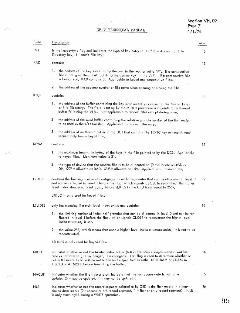
Field
IMT
KAD
KBUF
KEYM
LRDLO
LSLIDES
MIUD
NACUP
NLR
Section YH. 09 Page 7
CP-V TECHNICAL MANUAL 4/1/74
is the image-type flag and indicates the type of key entry in BUF2 (0:::: Account or Fi Ie Directory key, 4 = user's file key).
contains
1. the address of the key specified by the user in the read or write FPT. If a consecutive file is being written, KAD points to the dummy key (in the VLP). If a consecutive file is being read, KAD contains O. Applicable to keyed and consecutive files.
2, the address of the account number or file nome when opening or closing the fi Ie.
contains
1. the address of the buffer containing the key most recently accessed in the Moster Index or File Directory. The field is set up by the M:DCB procedure and points to an 8-word buffer following the VLPs. Not applicable to random files except during open.
2. the address of the word buffer containing the relative granule number of the first sector to be used in the I/o transfer. Applicable to random files only.
3. the address of an 8-word buffer in the DCB that contains the TEXTC key or· records read sequentially from a keyed file.
contains
1. the maximum length, in bytes, of the keys in the file pointed to by the DCB. Applicable to keyed files. Maximum value is 31.
2. the type of device that the random fi Ie is to .be allocated on (0 = allocate on RAD or DP, X'7' = allocate on RAD, XIB' = allocate on DP). Applicable to random files.
contains the limiting number of contiguous index half-granules that can be allocated in level 0 and not be reflected in level 1 before the flag, which signals CLOSE to reconstruct the higher level index strucl"ure, is set (i. e, T before SLIDES in the CFU is set equal to 255).
LRDLO is only used for keyed files.
only has meaning if a multilevel index exists and contains
1. the limiting number of index half granules that can be allocated in level 0 and not be reflected in level 1 before the flag, which signals CLOSE to reconstruct the higher level index structure, is set.
2. the value 255, which means that once a higher level index structure exists, it is not to be reconstruc ted.
LSLIDES is only used for keyed files •.
indicates whether or not the Master Index Buffer (BUF2) has been changed since it was last read or initial ized (0 = unchanged, 1 = changed), This flag is used to determine whether or not BUF2 needs to be written out to the sector specified in either DCBCDAM or CDAM in FILCFU or ACNCFU before truncating the buffer.
indicates whether the filels descriptors indicate that the last access date is not to be updated (0 = may be updated, 1 = may not be updated),
indicates whether or not the record segment pointed to by CBD is the first record in a continued data record (0 = second or nth record segment, 1 = first or only record segment). NLR is only meaningful during a WRITE operation.
Word
16
18
10
12
19
19
16
5
16

CP-V TECHNICAL MANUAL Section VH. 09 Page 8 4/1/74
Field Description Word
NOSEP specifies whether or not index granules are to be allocated like data granules (O = no, 1 = yes). 0 Normally, index granules are allocated on DP. However,.if all the devices of the normally allocated type are saturated, the system attempts to allocate on an alternate device. The
NRA
order of allocation for data granules is DP and RAD regardless of the NOSEP flag. The order " of allocation far index granules also is DP and RAD if the NOSEP flag is reset. If the NOSEP " flag is setl index granules are allocated like data granu"les. This flog has no meaning for pri
vate fi les.
NOSEP is not used by random fi les.
indicates the number of recovery tries that may be attempted before a device error message is to be logged.
NRT indicates the number of recovery tries remaining before a device error message is to be logged.
NWK
NXTA
NXTF
ONWK
ORG
ove
PAT
indicates whether or not NEWKEY was specified in the M:WRITE FPT (0 = replace an existing keYI if the key does not exist, take an abnormal return; 1 = write a new key, if the key already exists, take an abnormal return). If ONWK is set, the NWK flag is ignored.
NWK is only used for keyed files.
is the next account indicator and specifies whether this account (i. e., the account number in the DeB/JIT) or the next account in the Accaunt Directory (i. e., the one following the account named in the DeB) is to be assigned to the DeB atOPEN (0 = this account, 1 = the next account). If an account number is not specified in the DeB and the NXTA indicator is set, the first account in the Account Directory is put in the DCB and nothing more is done unless NXTF is also set. The previous is not applicable for private volumes. After a file is open, the bit is set to 1 if the DCB is open to a star file (see Glossary); otherwise, it is set to O.
is the next file indicator and specifies whether this file (i. e. I the fi Ie named in the DeB/FPT) or the next file in the File Directory {i.e. , the one following the file named in the DeB) is to be assigned to the DeB at OPEN. If a file name is not specified (in either the DeB or FPT)I the first name in the File Directory is put in the DeB and assigned (0 = this file, 1 = next fi Ie).
indicates whether or not ONEKEY was specified in the M:WRlTE FPT (0 = check NWK flag, 1 = if the key already exists, replace the corresponding record, otherwise write a new record),
ONWK is only used for keyed files.
is the fi Ie organization indicator (0 = none specified and is treated as consecutive, 1 == consecutive, 2 = keyed, 3 = random).
is the open volume count and only has meaning for private files.
1. for consecutive private fi les, ove indicates whether or not the volume pointed to by VNO is opened or not (0 = no, 1 = yes),
" 2. for keyed or random private files, ove contains a COUl'1t of the numbers of volumes that have been opened.
contains the allocation table address of the private volume pointed to by VNO. Only has meaning for private files.
2
5
16
5
5
5
11
17
100

Field
PBD
CP-V TECHNICAL MANUAL
Description
Section VH. 09 Page 9 4/1/74
Word
is the previous buffer displacement indicator, specifying at which byte in the blocking buffer . (BUF1) the previous record segment begins.
20
PBD is not used by random fi les.
PRECNO contains the direction (+ or -) and the n;:mber of records that must be skipped from the posi- 19 tion indicated in CRECNO prior to a dal ' transfer operation (read, write, or delete),
PRIV
QBUF
RAX
RBBI
RDLO
RUM
RNDEV
RSTORE
RSZ
RWS
PRECNO is only used for c;onsecutive fi,'
indicates whether ~he file assigned to the DCB is public or private (0 == public, 1 = private). Public files reside on public devices and private files reside on private volume sets.
contains
1. the buffer address to be used by the I/O routines whenever called.
2. 'the address within the user's buffer where the next record segment begins.
QBUF, 2 is not applicable to random files.
controls read ahead. If set to X'FP, no read ahead is possible. If set to zero, no read ahead is in progress. Otherwise, RAX contains an index into read ahead tables.
is the release blocking buffer inhibit flag and indicates whether or not the blocking buffer (BUF1) should be released during end-action after the data granule has been read into (BUF1) and the record segment has been transferred to the user's buffer. (0 = release BUF1, 1 = do not release BUFl.)
RBBI is not used by random files.
contains a tally (up to 255) of the number of index half-granules that are read or inserted at level 0 to locate the position of a user-specified key entry at level O. If RDLO is greater than LRDLO, the flag, which signals CLOSE to reconstruct the higher level index structure, is set.
RDLO is only used for keyed files •.
temporarily contains the number of granules specified in the RSTORE option on the ASSIGN control command during the ASSIGN/DCB merge. The first halfword contains X16E4C' which is used as a flag to indicate that RSTORE was specified.
RUM is used by random files only.
contains the type of device requested for file allocation (0 = none specified and for private files gets changed to XIB', 7 = RAD, and XIB 1 = DP).
contains the number of granules to be allocated to the file.
RSTORE is used by random files only. If RSTORE value is zero when a random file is created, an abnorma I return is made wi th a code of X '14'. Bi ts 8- 15 of word 5 are used by random fi I es as a high order extension of this field if the EXTRAND bit is set.
indicates the default record size, in bytes.
indicates
I. the requested number of bytes to be read or written from the user's buffer (BUF). During the I/O operation, RWS is decremented by the value in BLK each time that a record segment is either output or blocked. At the termination of the I/O operation, RWS is set equal to ARS.' Applicable to keyed and consecutive files.
2. the requested number of bytes to be read or written from the user's buffer (BUF). At the termination of the I/O operation, RWS.is set equal to ARS. Applicable to random files.
o
7
5
16
19
21
5
20
3
13
101

Field
S
SCR
SPARE
SWXV
TBT
TCFU
TRN
TYC
USTD
Section VH. 09 Page 10
CP-V TECHNICAL MANUAL 4/1/74
Description
contains the value of the S field from the mode specification in the Open Cal FPT. S = 1 means SHARE; S = 0 means EXCLUSIVE.
indicates
1. the byte length of the key portion of the entries in the Master Index currently referenced by the DCB. This can be the Master Index for the Account Directory, the File Directory, or the user's file.
2. this field is used to temporarily contain the contents of KEYM field. Applicable to random files only.
contains the number of spare byte positions to be left unused in the end of the current index half-granule in the event that the key to be added is the last okey in the file.
SPARE is only used for keyed files.
is the switch volume flag and indicates whether or not the current volume is to be switched to the next volume after all updated buffers have been output to the current volume (O = no, 1 = yes). Only used for consecutive private files.
not meaningfully used for fi les; however, the flag does get set and reset.
contains the address of the user CFU during CLOSE.
indicates, for keyed filest whether the fj Ie is positioned before or after the data record whose key entry is pointed to by CMD (0 = after, 1 = before). For consecutive files, this bit is set only if the most recently executed operation on the file was a read backwards.
indicates the type of completion of an I/o operation.
TYC Code
o
2
3
4
5
6
7
8
9
A
B
Corresponding Error/ Abnormal Code
o
o
7
10
4
IC
5
6
41
45
57
o
Meaning
normal without device I/o transfer
normal with a device I/o transfer
lost data
beOg i nn i ng -of-tape
beginning-of-fi Ie
end-of-reel
end-oF-data
end-of-fi Ie
read error
write error
public devices/private volume-set saturated
SLIDES is 255
C 0 partial higher level index built
is the byte displacement indicator, specifying at which byte in the user's buffer (BUF) the data record be!=lins.
Word
7
17
19
o
16
13
5
2
o

Field
USR
CP-V. TECHNICAL MANUAL
Section VH.09 Page 11 2/10/76
Descripl ion Word
indicates whether the JOB account number is the same as the account number specified in 0 the DeB (0 :=. yes, 1 = no).
VDCT contains the DCT index of the device on which the volume (in a private volume set) pointed 10 to by VNO is mounted. Only meaningful for private files.
VNO contains the volume number of the private volume currently being referenced via the DCB. 11 Volume number is the position (starting with one) of a volume within the DCB's SN list. The SN list in the DCB has a fixed order and comes from the serial number table on the primary volume of a private volume set. Only meaningful for private files.
VSND contains the word displacement to the serial number table of the private volume set (i. e., the 9
WAT
XUP
SN list) in the DCB relative to the start of the Variable Length Parameters (FLP + VSND = the control word of the SN list).
is the wait flag and indicates whether or not WAlT was specified in the FPT (0 = no, 1 = yes). 0
indicates whether or not a higher level index structure is in the process of being reconstructed 0 or constructed (0 = either that there is no higher level index or that the higher level index is complete, 1 = that the higher level index is being built). Only meaningful for keyed files.
VARIABLE LENGTH PARAMETERS 22- n
Each variable length parameter entry is preceded by a control word of the following form:
Byte 0 = a code number (see TobIe A-l) identifying the parameter which follows,
Byte 1 = code for the entry position (00 = more parameter entries to follow, 01 = last parameter entry).
Byte 2 = number of significant data words in the parameter entry.
Byte 3 = total number of words reserved for the entry, not including the control word (that is, maximum entry length).
Table A-l. Variable Length Parameter Codes
Code Parameter Type
01 File name (the first byte of which contains the number of characters
02 Account number. 03 Password. 04 Expiration date. 05 READ account numbers. 06 WRITE account numbers. 07 SN/INSN serial numbers. 08 OUTSN serial numbers. 09 File information (see Figure·A-2).
OA Modification date. OB SYNON name. OC File information (see Figure A-2). OD File size. OE Creation date. OF Last access date. 10 Backup date. n Descriptors. 12 Search open mask. 13 Reserved for later use. i4 Execute account numbers.
15 Execute vehicle 16 Account list
17 Permission bits corresponding to 16 above~
18 For use by installation. 19 For inclusion of device open prime PLIST.
. .103
til the name).

Word 1
NRT
0 1 2 3 14 5 6 7 8 9
Word 2
NRA .
0 1 2 314 5 6 7 8 9
Word 3
RSZ
I
0 1 2 3 14 5 6 7 18 9
Word 4 . . ARS
0 1 2 3 14 5 6 718 9
Word 6
BlK
..
CP-V TECHNICAL MANUAL
0
FUN 0 E 0 TYPE V
F
10 11112 13 14 15 16 17 18 19120 21
TYC . .
10 11112 13 14 15116 17 18 19120 21
-1
10 111 12 13 14 15116 17 18 191 20 21
I
I
. 10 111 12 13 14 15116 17 18 19120 21
.
U B T o
Section VH. 10 Page 1
4/1/74
ASN = 2
25 26 27 28 29 30 31
DEV
22 23 24 25 26 27128 29 30 31
BUF J
22 23124 25 26 27128 29 30 31
ERA
, 22 23124 25 26 271 28 29 30 31
ABA
. 22 23124 25 26 27128 29 30 31
ACS
29 30 31
.1 I
FLP
o 1 2 3 I 4 5 6 7 I 8 9 10 11112 13 14 15116 17 18 19120 21 22 23124 25 26 27128 29 30 31
Wora 7
Figure A-4. Format of Xerox labeled Tape DCB
lU4
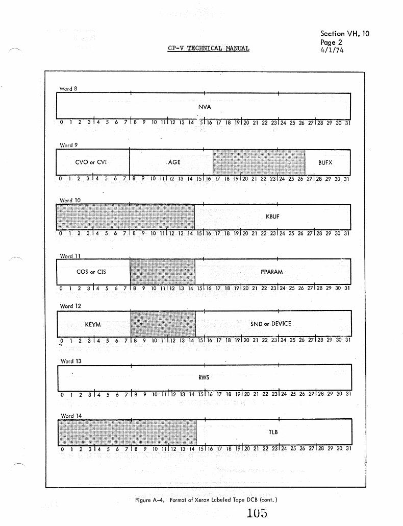
CP-V TECHNICAL MANUAL
Word 8
NVA
I " I
Section VH. 10 Page 2 4/1/74
o 1 2 3 I 4 5 6 7 I 8 9 10 11112 13 145116 17 18 19120 21 22 23124 25 26 27128 29 30 31
Word 9
CVO or CVI BUFX
o 1 2 345 6 7 8 28 29 30 31
COS or CIS FPARAM
o 1 28 29 30 31
Word 12
KEYM SND or DEVICE
o 1 'l
Word 13 . RWS
. . o 1 2 3 1 4 5 6 7 I 8 9 10· 1111213 14 15116 17 18 19120 21 22 23124 25 26 27128 29 30 31
Figure A-4. Format of Xerox Labeled Tape DCB (cont. )
1U5

Section VH. 10 Page 3
CP-V TECHNICAL MANUAL 4/1/74
Word 15 ,
BCDA
o 1 2 314 5 6 718 9 10 11112 13 14 15116 17 18 19120212223124252627128293031
Word 20 . . CMD PBD
o 1 2 314 5 6 718 9 10 11112 13 14 1516171819120 212223124252627128293031
Word 21
ACD FLD •• I
o 1 2 314 5 6 718 9 10111121314 1516171819120212223124252627128293031
Words 22 - n are used for variable length parameters.
Figure A-4. Format of Xerox Labeled Tape DCB (cant.) ,
lU-o
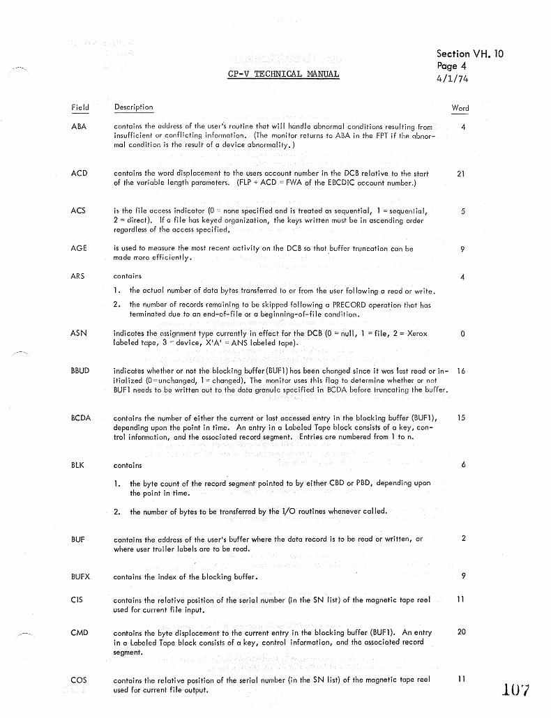
Field
ABA
ACD
ACS
AGE
ARS
ASN
BBUD
BCDA
BLK
BUF
BUFX
CIS
CMD
COS
CP-V TECHNICAL MANUAL
Section VH. 10 Page 4
Description
contains the address of the user"s routine that will handle abnormal conditions resulting from insufficient or conflicting information. (The monitor returns to ABA in the FPT if the clbnormal condition is the result of a device abnormality.)
contains the word displacement to the users account number in the DCB relative to the start of the variable length parameters. (FLP + ACD ,= FWA of the EBCDIC account number.)
is the file access indicator (0 ::-.: none specified and is treated as sequential r 1 = sequential, 2 == direct). If a file has keyed organization, the keys written must be in ascending order regardless of the access specified.
is used to measure the most recent activity on the DCB so that buffer truncation can be made more efficiently.
contains
1. the actual number of data bytes transferred to or from the user following a read or write.
2. the number of records remaining to be skipped following a PRECORD operation that has terminated due to an end-of-file or a beginning-of-file condition. .
indicates the assignment type currently in effect for the DCB (0 ;:: null, = file, 2 = Xerox labeled tape, 3 == device, XlA' = ANS labeled tape).
4/1/74
Word
4
21
5
9
4
o
indicates whether or not the blocking buffer{BUF1) has been changed since it was last read orin- 16 itialized (O=unchanged, 1::: changed). The monitor uses this flag to determine whether or not BUFl needs to be written out to the data granule specified in BCDA before truncating the buffer.
contains the number of either the current or last accessed entry in the blocking buffer (BUFl), 15 depending upon the point in time. An entry in a Labeled Tape block consists of a key, con-trol information, and the associated record segment. Entries are numbered from 1 to n.
contains 6
1. the byte count of the record segment pointed to by either CBD or PBD, depending upon the point in time.
2. the number of bytes to be transferred by the I/O routines whenever called.
contains the address of the user's buffer where the data record is to be read or written, or where user trai ler lobe Is are to be read.
contains the index of the blocking buffer.
contains the relative position of the serial number (in the SN list) of the magnetic tape reel used for current fi Ie input.
contains the byte displacement to the current entry in the blocking buffer (BUF1). An entry in a Labeled Tape block consists of a key I control information, and the associated record segment.
contains the relative position of the serial number (in the SN list) of the magnetic tape reel used for current fi Ie output.
2
9
11
20
11
1U7
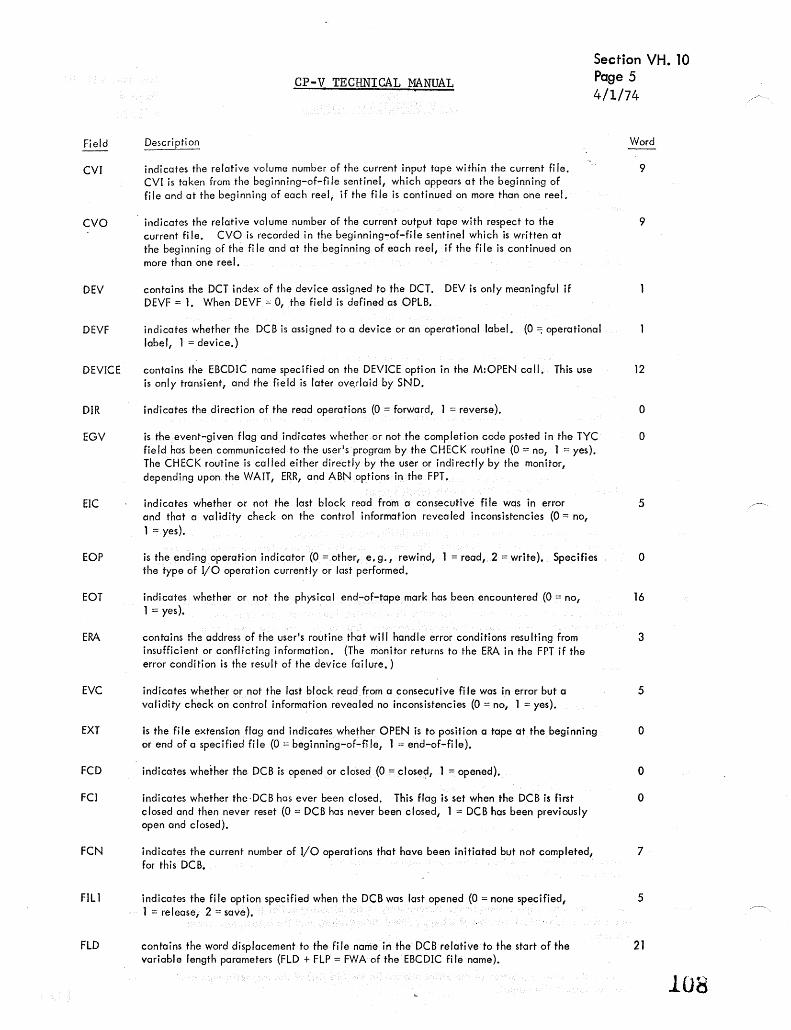
CP-V TECHNICAL MANUAL
Section VH. 10 Page 5 4/1/74
Field
CVI
CVO
Description
indicates the relative volume number of the current input tape within the current fi Ie. CVI is taken from the beginning-of-fi Ie sentinel, which appears at the beginning of file and at the beginning of each reel, if the file is continued on more than one reel.
indicates the relative volume number of the current output tape with respect to the current file. CVO is recorded in the beginning~of-file sentinel which is written at the beginning of the file and at the beginning of each reel, if the file is continued on more than one reel.
DEV contains the DCT index of the device assigned to the DCT. DEV is only meaningful if DEVF == 1. When DEVF = 0, the field is defined as OPLB.
DEVF indicates whether the DCB is assigned to a device or an operational label. (0 =; operational label, 1 = device.)
DEVICE
DIR
EGV
EIC
EOP
EaT
ERA
EVC
EXT
FCD
FCI
FCN
FIll
FLO
contains the EBCDIC name specified on the DEVICE option in the M:OPEN call. This use is only transient, and the field is later ove.rlaid by SND.
indicates the direction of the read operations (O = forward, 1 = reverse).
is the event-given flag and indicates whether or not the completion code posted in the TYC field has been communicated to the user's program by the CHECK routine (0 == no, 1 = yes). The CHECK routine is called either directly by the user or indirectly by the monitor, depending upon the WAIT, ERR, and ABN options in the FPT.
indicates whether or not the last block read from a consecutive file was in error and that a validity check on the control information revealed inconsistencies (0 = no, 1 = yes).
is the ending operation indicator (0 = other, e. g., rewind, 1 = read, 2 = write). Specifies the type of I/O operation currently or last performed.
indicates whether or not the physical end-of-tape mark has been encountered (0 = no, 1 == yes).
contains the address of the user's routine that will handle error conditions resulting from insufficient or conflicting information. (The monitor returns to the ERA in the FPT if the error condition is the result of the device failure.)
indicates whether or not the last block read from a consecutive file was in error but a validity check on control information revealed no inconsistencies (0 = no, 1 = yes).
is the file extension flag and indicates whether OPEN is to position a tape at the beginning or end of a specified file (0 = beginning-of-fi Ie, 1 = end-of-file).
indicates whether the DCB is opened or c lased (0 = closed, 1 = opened).
indicates whether the-DCB has ever been closed. This flag is set when the DCB is first closed and then never reset (0 = DCB has never been closed, 1 = DCB has been previously open and closed).
indicates the current number of I/O operations that have been initiated but not completed, for this DCB.
indicates the file option specified when the DCB was last opened (0 = none specified, 1 = release, 2 == save).
contains the word displacement to the file nanie in the DeB relative to the start of the variable length parameters (FLD + FLP = FWA of the EBCDIC file name).
Word
9
9
12
o
o
5
o
16
3
5
o
o
o
7·
5
21
108
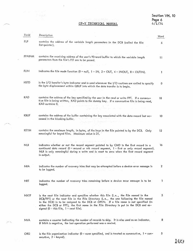
Section YH. 10 Page 6
CP-V TECHNICAL MANUAL 4/1/74
Field
FLP
FPARAM
Description
contains the address of the variable length parameters in the DCB (called the fi Ie list-pointer).
contains the receiving address of the user's 90-word buffer to which the variable length parameters from the fi leIs FIT are to be passed.
FUN indicates the file mode function (0 = null, 1 = IN{ 2 = OUT, 4 = INOUT, 8:::: OUTIN).
HBTD
KAD
KBUF
KEYM
NLR
NRA
is the I/o handler's byte indi cator and is used whenever the I/o routines are called to specify the byte displacement within QBUF into which the data transfer is to begin.
contains the address of the key specified by the user in the read or write FPT. If a consecutive file is being written, KAD points to the dummy key. If a consecutive file is being read, KAD confai ns O.
contains I-he address of the buffer containing the key associated with the data record last accessed in the blocking buffer.
contains the maximum length, in bytes, of the keys in the fi Ie pointed to by the DCB. Only meaningful for keyed files. Maximum value is 31. -
indicates whether or not the record segment pointed to by CMD is the first record in a continued data record (O = second or nth record segment, 1 = first or only record segment). NLR is only meaningful during a write and is reset to zero when the first record segment is output.
indicates the number of recovery tries that may be attempted before a device error message is to be logged.
NRT indicates the number of recovery tries remaining before a device error message is to be logged.
NXTF
NVA
ORG
is the next file indicator and specifies whether this file (i.e., the file named in the DCB/FPT) or the next file in the -File Directory (i.e., the one following the file named in the DCB) is to be assigned to the DCB at OPEN. If a fi Ie name is not specified (in either the DCB or FPT), the first name in the Fi Ie Directory is put in the DCB and assigned (0:::: this file, 1 = next file).
contains a counter indicating the number of records to skip. It is also used as an indicator. If NVA is negative, the last operation performed was a rewind.
is the file organization indicator (0 = none specified, and is treated as consecutive, 1 = consecutive, 2 = keyed).
Word
6
11
o
18
10
12
16
2
5
8
5
,1UU

Field
PBD
PUN
QBUF
RBBI
REV
RNDEV
RNR
RSZ
RWS
SCR
SND
TBT
TlB
TRN
Section VH. 10 Page 7
CP-V TECHNICAL MANUAL 4/1/74
Description
contains
1. a counter used by M:OPEN to determine how many volumes remain to be searched for the specified fi Ie.
2. the number of bytes in the previous labeled tape block. PBD is only meaningful on a read operation and is taken from the PBS field of a labeled block.
indicates whether a 7-track tope is to be read/written in the packed or unpacked mode (0 = unpacked, 1 = packed).
contains
1. the buffer address to be used by the Vo routines whenever called.
2. the address within the user's buffer where the next record segment begins.
indicates whether or not the blocking buffer should be released at end-action (0 = release blocking buffer, 1 = do not release blocking buffer because the buffer will be reused to read in the next block). RBBI is set during a read operation when a data record is continued and more than one read request wi II be initiated.
indicates whether the labeled Tape block currently in the blocking buffer (BUF1) was read in the forward or reverse direction (0 = forward, 1 = reverse).
contains the type of device specified (0 = nane specified, 8 = 9T, 9 = 7T, X'A' =MT).
is a transient flag used by the system to defer error reporting for a tape block read by the monitor in anticipation of a read not yet requested by the user (0 = user requested read, 1 = user read not requested).
indicates the default record size, in bytes.
indicates the requested number of bytes to be read or written from the user's buffer (BUF). At the termination of the I/O operation, RWS is set equal to ARS.
indicates the byte 'ength of the key portion of the entries in the labeled Tape block.
contains the word displacement to the tape serial number (SN list) in the DCB relative to the start of the variable length parameters (FlP + SND = FWA of .the EBCDIC serial numbers).
indicates whether or not the labeled Tape blocking buffer has been truncated (0 = no, 1 := yes). Truncation means that monitor has taken the blocking buffer and, if necessary, written the block on tape. .
contains the address of a user's label that is to be written on a tap~ fj Ie when the file is output.
indicates whether the fi Ie is positioned before or after'the data record whose key entry is pointed to by CMD (0 = after, 1 :::: before).
Word
20
o
7
16
16
5
16
3
13
17
12
16
14
5
.ll()

Section VH. 10 Page 8
Field
TYC
CP-V TECHNICAL MANUAL
indicates the type of completion of an I/o operation.
TYC Code
o
2
3
4
5
6
7
8
9
Corresponding Error/ Abnormal Code
o
o
7
1D
4
lC
5
6
41
45
Meaning
normal without devi ce I/o transfer
normal with a device I/o transfer
lost data
beg inn ing-of-tape
beginning-of"':file
end-of-reel
end-of-data
end-of-file
read error
write error
4/1/74
TYPE contains the device-type code for the tape assigned to this DCB.
UBTD
ULBL
WAT
is the byte displacement indicator, specifying at which byte in the user1s buffer (BUF) the data record begins.
indicates whether or not the ULBL option was specified in the FPT of M:READ (0 = no, 1 = yes).
indi2ates whether or not the job account number is the same as the account number specified . in the DCB (0 = yes, 1 = no).
is the wait flag and indicates whether or not WAIT was specified in the FPT (0 = no, 1 = yes).
VARIABLE LENGTH PARAMETERS
Word
2
o
5
o
o
22-...n
Each variabl e· I ength parameter entry is preceded by a control word of the form shown for Fite DC B and in T obI e A-l.
111

Section VH. 11 Page 1
CP-v TECHNICAL MANUAL 4/1/74
Word 0
-_: :':0:°:_:::'::., :+::::::_::::::::! N:::"o R :::::: R D D o 1 2 3 14 5 6 7 8 9 10 11 12 13 14 15116 17 18 19 2021 22 23 24 25 26 27 28 29 30 31
Word 1
D
NRT FUN 0 E
0 TYPE DEV V F
0 1 2 3 14 5 6 7 8 9 10 11112 13 14 15 16 17 18 19120 21 22 23 24 25 26 27128 29 30 31
Word 2
NRA Tye BUF
. 0 1 2 3 14 5 6 7 8 9 10 111 12 13 14 15116 17 18 19120 21 22 23 I 24 25 26 27128 29 30 31
Word 3 I .
BLKSZ ERA
I I
0 1 2 3 14 5 6 7 18 9 10 11112 13 14 15/16 17 18 19120 21 22 231 24 25 26 27 I 28 29 30 31
Word 4
ARS ABA '")
I
0 1 2 314 5 6 718 9 10 11112 13 14- 15116 17 18 19120 21 22 231 24 25 26 27 I 28 29 30 31
21
Word 6
BlK FlP
o 1 2 3 I 4 5 6 7 1 8 9 10 11 I 12 13 14 151 16 17 18 191 20 21 22 231 24 25 26 271 28 29 30 31
Word 7
Figure A-5. Format of ANS Labeled Tape DeB
112

Word 8
Word 9
CVO or CVI
o 1
1
COS or CIS
o 1
Word 12
o 1
Word 14
CONCAT
012
CP-V TECHNICAL MANUAL
17 18, 19 20 2
SND or DEVICE
Figure A-5. Format of ANS Labeled Tape DeB (cont.)
Section VH. 11 Page 2 4/1/74
28 29 30 31
29 30 31
113

Word 15
Word 19
5 6 7: 8 9 10 314 0 1 2
Word 20 ,
CMD
CP-V TECHNICAL MANUAL
11112
SE~lD 13 14 15: 16 17 18 19120 21
.
22 23: 24 25 26
PBD
Section VH. 11 Page 3
4/1/74
2930 31
27: 28 29 I 30 31
o 1 2 3 I 4 5 6 7 I 8 9 10 11112 13 14 15 16 17 18 19120 21 22 23124 25 26 27128 29 30 31
Word 21
Words 22 - n are used for variahle length parameters.
Figure A-5. Format of ANS labeled Tape DeB (cont.)
114

Field
ABA
ABCERR
APF
ARS
ASN
BCERR
BLK
CP-V TECHNICAL MANUAL
Section VH. 11 Page 4 4/1/74
contains the address of the user'~ routine that will handle abnormal conditions resulting from insufficient or conf! icing informotion. (The monitor returns to ABA in the FPT if the abnormal condition is lhe result of a device abnormal ity.)
indicates whether or not block count errors are to be accepted; i. e., whether or not processing is to continue in the case of inconsistency between the tape-specified and systemaccumulated block counts (0 = no, 1 == yes).
contains the ANS post flag. If set to 1, it indicates that ANS post-processing of an I/O operation has not yet been done.
contains
1. the actual number of data bytes transferred to or from the user following a read or write.
2. ,the number of records remaining to be skipped following a PRECORD operation that has terminated due to an end-of-file or a beginning-of-file condition.
indicates the assignment type currently in effect for the DCB (0 = null/ 1 = fj Ie, 2 = Xerox labeled tape/ 3 = device l X'A' = ANS labeled tape).
indicates whether or not a block count error has been detected during EOF/EOT processing (0 = no, 1 = yes). Always cleared before returning to user.
contains
1. the byte count of the record segment pointed to by either CBD or PBD/ depending upon the point in time.
2. the number of bytes to be transferred by the I/O routines whenever called.
Word
4
o
16
4
o
o
6
BLKCNT specifies the number of blocks in the file. 17
BLKSZ specifies the block size in bytes. 3
BUF contains the address of the user's buffer where the data record is to be read or written, or 2 where user trailer labels are to be read.
CIS contains the relative position of the serial number (in the SN list) of t~e magnetic tape reel 11 used for current file input.
CMD contains the number of tape marks that may be passed during an OPEN while searching the 20 last tape of a set.
CONCAT specifies the number of identically named files that are to be read as one logical file 14
COS
(concatenation).
contains the relative position of the serial number (in the SN list) of the magnetic tape reel used for current fi Ie output.
11
IlJ

Field
CVI
CVO
CP .. V TJliCHNlCAL N!WAL
Descri pti on
indicates the relative volume number of the current input tape within the current file. .CVI is taken from the beginning-of-file sentinel, which appears at the beginning of file and at the beginning of each reel, if the file is cont.inued on more than one reel.
indicates the relative volume number of the current output tape with respect to the current file. CVO is recorded in the beginning-of-file sentinel which is written at the beginning of the file and at the beginning of each reel, if the file is continued on more than one reel.
Section VH. 11 Page 5 4/1/74
Word
9
9
DEV contains the DCT index of the device assigned to the DCT. DEV is only meaningful if DEVF = 1. When DEVF = 0, the field is defined as OPLB.
DEVF
DEVICE
DIR
EGV
EOP
EOT
ERA
FCD
FeI
FCN
FIll
FLD
i~dicates whether the DCB is assigned to a pevice or an operational label. (0 label, 1 = device.)
opera ti on a I
contains the EBCDIC name specified on the DEVICE option in the M:OPEN call. This use is only transient, and the field is later overlaid by SND.
indicates the direction of the read operations (0 = forward, 1 = reverse),
is the event-given flag and indicates whether or not the completion code posted in the TYC field has been communicated to the user's program by the CHECK routine (0 = no, 1 = yes). The CHECK routine is called either directly by the user or indirectly by the monitor, depending upon the WAIT, ERR, and ABN options in the FPT.
is the ending operation indicator (0 = other, e. g. I rewind, 1 = read, 2 = write). Specifies the type of I/o operation currently or last performed.
i ndi cates whether or not the physi co I end-of-tape mark has been encountered (0 = no, 1 = yes),
contains the address of the user's routine that will handle error conditions resulting from insufficient or conflicting information. (The monitor returns to the ERA in the FPT if the error condition is the result of the device failure.)
indicates whether the DCB is opened or closed (0 = closed, 1 = opened).
indicates whether the DCB has ever been closed. This flag is set when the DCB is first closed and then never reset (0 = DCB has never been closed, 1 = DCB has been previously open and closed),
indicates the current number of I/O operations that have been initiated but not completed, for this DCB.
indicates the fi Ie option specified when the DCB was last opened (0 = none specified, 1 = release, 2 = save). .
contains the word displacement to the file name in the DCB relative to the start of the variable length parameters (FLD + FLP = FWA of the EBCDIC file name).
12
o
o
o
16
3
o
o
.7
5
21
Ill)

Field
FLP
FMT
FSN
FUN
HBTD
LRCSZ
NRA
~-
NRT
PBD
QBUF
RNDEV
RWS
SETID_
SND
SNfN
TLB
CP-V TECHNICAL MANUAL Section VH. 11 Page 6 4/1/74
Description
contains the address of the variable length parameters in the DeB (called the file list-pointer).
indicates the record format, where
1 = F (fixed length)
2 = D (variable, expressed in decimal)
3 = V (variable, expressed in binary)
4 = U (undefined)
speci fi es the fi Ie sequence number.
indicates the fj Ie mode function (0 = null, 1 = IN, 2 = OUT, 4 = INOUT, 8 = OUTIN).
Word
6
5
16
is the I/o handler's byte indicator and is used whenever the I/o routines are called to specify 0 the byte displacement within QBUF into which the data transfer is to begin.
specifies the logical record size in bytes.
indicates the number of recovery tries that may be attempted before a device error message 2 is to be logged.
indicates the number of recovery tries remaining before a device error message is to be logged.
contains
1. a counter used by M:OPEN to determine how many volumes remain to be searched for the specified file.
2. the number of bytes in the previous labeled tape block. PBD is only meaningful on a read operation and is taken from the PBS field of a labeled block.
contains
1. the buffer address to be used by the I/O routines whenever called.
2. the address within the user's buffer where the next record segment begins.
contains the type of device specified (0 = none specified, 8 = 9T, 9 = 7T, X'A' = MT).
indicates the requested number of bytes to be read or written from the user's buffer (BUF). At the termination of the I/o operation, RWS is set equal to ARS.
specifies the file set identification.
contains the word displacement to the tape serial number (SN list) in the DeB relative to the start of the variable length parameters (FLP + SND := PNA of the EBCDIC serial numbers).
indicates the access method (0 = serial number, 1 = filename).
contains the address of a user's label that is to be written on a tape file when the file is output.
20
7
5
13
19
12
o
14 117

CP-V TECHNICAL MANUAL
Section VH. 11 Page 7 4/1/74
Field Description
TYC indicates the type of completion of an I/O operation.
Corresponding Error/ Tye Code Abnormal Code Meaning
a a normal without device I/O transfer
1 a normal with a device I/o transfer
2 7 lost data
3 1D beginning-of-tape
4 4 beg i nn i ng-of-fi I e
5 1C end-of-reel
6 5 end-of-data
7 6 end-of-fi I e
8 41 read error
9 45 write error
TYPE contains the device-type code for the tape assigned to this DCB.
UBTD
ULBL
WAT
is the byte displacement indicator I specifying at which byte in the user1s buffer (BUF) the data record begins.
indicates whether or not the ULBL option was specified in the FPT of M:READ (0 = no, 1 -= yes).
is the wait flag and indicates whether or not WAIT was specified in the FPT (0 = no, 1 = yes).
VARIABLE LENGTH PARAMETERS
Word
2
a
5
a
22-n
Each variable length parameter entry for ANS labeled tapes is preceded by a control word of the following form:
Byte a = a code number (see Table A-2) identifying the parameter which follows.
Byte 1 = code for the entry position (00 = more parameter entries to follow, 01 = last parameter entry).
Byte 2 = number of significant data words in the parameter entry.
Byte 3 = total number of words reserved for the entry I not including the control word (that is, maximum entry length).
Table A':'2. Variable Length Parameter Codes for ANS Labeled Tapes
Code Parameter Type
01 File name (the first byte of which contains the number of characters in the name).
04 Expiration date.
07 SN/INSN serial numbers. (ANS serial numbers are encoded to fit in 32 bits. )
08 OUTSN serial numbers. (ANS serial numb~rs are encoded to fit in 32 bits. )
118

/~
Word 0
CP-V TECHNICAL MANUAL
M F F W M Bee A Eap a G I D T D
D F A E L R ~ G G N e D V V
D I R
o 1 2 3 I 4 5 6 7 8 9 10 11 12 13 14 15 16 17 18 19 20 21
Word 1
T D NRT FUN a E l TYPE l V
F F
0 1 2 3 14 5 6 7 8 9 10 11112 13 14 15 16 17 18 19-r 20 21
Word 2
NRA lye I
0 1 2 3 14 5 6 7 8 9 10 11112 13 14 15116 17 18 19120 21
Word 3
RSZ
0 1 2 3 14 5 6 7 18 9 10 11112 13 14 15116 17 18 19120 21
Word 4 I
ARS .
0 1 2 3 14 5 6 7 18 9 10 111 12 13 14 15116 17 18 19120 21
Word 6 I. .
BlK
P V H
U F B T
N e D
22 23 24 25
U B T D
26 27
Section VH. 12 Page 1 4/1/74
ASN = 3
28 29 30 31
DEV
22 23 24 25 26 27128 29 30 31
I
BUF
22 23124 25 26 271 28 29 30 31
ERA
22 23124 25 26 27128 29 30 31
ABA
~.1.
22 23124 25 26 27128 29 30 31
I
FlP
o 1 2 314 5 6 718 9 10 11112 13 14 15116 17 18 19T20 2122 2312425262712829 30 31
Figure A-3. Format of Device DeB 11!J
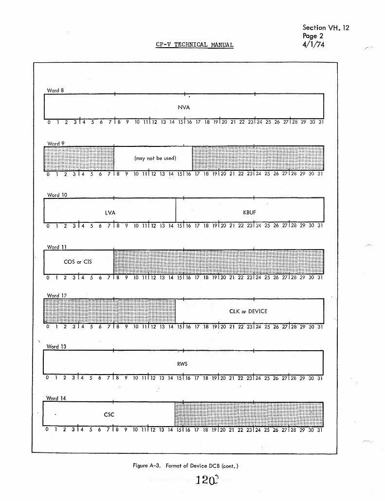
CP-V TECHNICAL MANUAL
Word 8 . . . NVA
I I I I
Section VH. 12 Page 2 4/1/74
o 1 2 314 5 6 718 9 10111121314 15116 17 1819120 2122231242526 27128 2930 31
(may not be used)
Word 10 · lVA KBUF
· . o 1 2 314 5 6 718 9 10 11112 13 14 15116 17 18 191202122231242526 27128 29 30 31
COS or CIS
012
CLK or DEVICE
Word 13 . . · . RWS
. o 1 2 314 5 6 718 9 10 111121314 15116 17 18 1912021222312425262712829 30 31
Figure A-3. Format of Device DCB (cant.)
120:

Word 15
"J:ABI
0 1 2 3 14 5 6 7 8 9
Word 16
TAB5
I
0 1 2 3 14 5 6 7 8 9
Word 17
TAB9
0 1 2 3 14 5 6 7 8 9
Word 18
TAB13
0 1 2 3 14 5 6 7 8 9
Word 19
DSC
1 2 3 14 5 6 7 8 9
Word 20
HSC
0 1 2 3 14 5 6 7 8 9
Word 21
CP-v TECHNICAL. ~NUAL
Section VH. 12 Page 3 4/1/74
TAB2 TAB3 TAM
10 11112 13 14 15 16 17 18 19120 21 22 23 24 25 26 27\28 29 30 31
TAB6 TAB7 TAB8
. I
10 11112 13 14 15 16 17 18 19120 21 22 23 24 25 26 27128 29 30 31
TABlO TAB1I TAB12
10 11112 13 14 _ 15 16 17 18 19120 21 22 23 24 25 26 27128 29 30 31
TAB14 TAB15 TAB16
10 11112 13 14 15 16 17 18 19 I 20 21 22 23 24 25 26 27 1 28 29 30 3i
I
SVA HLC
. I .
10 11112 13 14 15116 17 18 19120 21 22 23124 25 26 27128 29 30 31
I . . FVA CVA or SQS
10 11112 13 14 15( 16 17 18 19120 21 22 23124 25 26 27\2r
B-'29 30 31
I I
SID
o 1 2 3 14 5 6 7 18 9 10 11112 13 14 15116 17 18-19120 21 22 23124 25 26 27128 29 30 31
Words 22 - n are used for variabl e 1 ength parameters
Figure A-3. Format of Device DCB (cont.) r 121
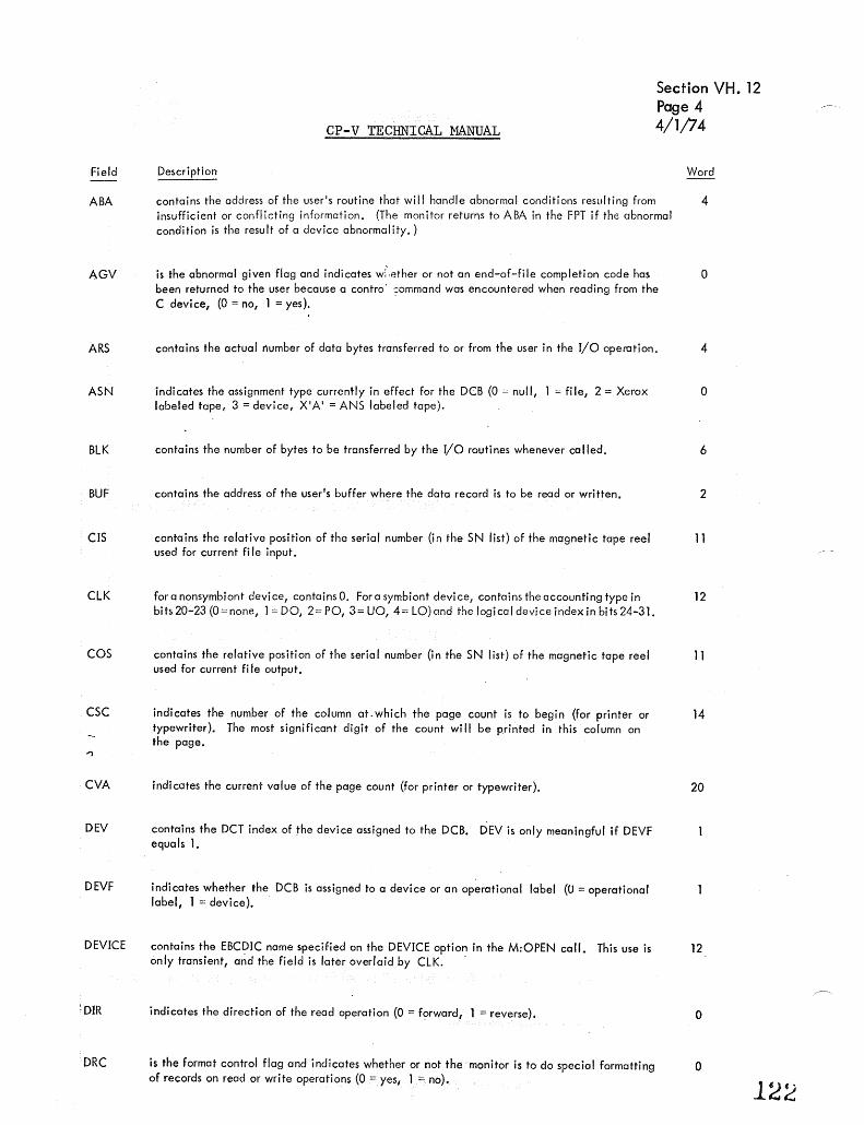
Field
ABA
AGV
ARS
ASN
BlK
BUF
CIS
ClK
COS
CSC
CVA
DEV
DEVF
DEVICE
~ DIR
DRC
Section VH. 12 Page 4
CP-v TECHNICAL MANUAL 4/1/74
Description Word
contains the address of the user's routine that will handle abnormal conditions resulting from 4 insufficient or conflicting information. (The monitor returns to ABA in the FPT if the abnormal condition is the result of a device abnormality,)
is the abnormal given flag and indicates w[,ether or not an end-of-file completion code has 0 been returned to the user because a contro' ::ommand was encountered when reading from the C device, (0 = no, 1 = yes). .
contains the actual number of data bytes transferred to or from the user in the I/O operation. 4
indicates the assignment type currently in effect for the DeB (0 = null, 1 = file, 2 = Xerox 0 labeled tape, 3 = device, X'A' = ANS labeled tape).
contains the number of bytes to be transferred by the I/O routines whenever called. 6
contains the address of the user IS buffer where the data record is to be read or written. 2
contains the relative position of the serial number (in the SN list) of the magnetic tape reel 11 used for current fi Ie input.
for a nonsymbiont de vi ce, contains O. For a symbiont device, contains the accounting type in 12 bits 20-23 (O=none, 1 = DO, 2= PO, 3= UO, 4= lO)and the logical device index in bits 24-31.
contains the relative position of the serial number (in the SN list) of the magnetic tape reel 11 used for current fi Ie output.
indicates the number of the column at. which the page count is to begin (for printer or 14 typewriter). The most significant digit of the count wi II be printed in this column on the page.
indicates the current value of the page count (for prin.ter or typewriter).
contains the DCT index of the device assigned to the DCB. DEV is only meaningful if DEVF equals 1.
indicates whether the DCB is assigned to a device or an operational label (0 = operational label, 1 = device).
contains the EBC,?IC name specified on the DEVICE option in the M:OPEN call. This use is only transient, and the field is later overlaid by ClK. .
indicates the direction of the read operation (0 = forward, 1 = reverse).
is the format control flag and indicates whether or not the monitor is to do special formatting of records on read or write operations (0 = yes, 1 = no),
20
12
o
o
1~2

Field
DSC
EGV
EOP
ERA
FBCD
FCD
FCI
FCN
FLP
::'ection VH. 12 Page 5
CP-V TECHNICAL MANUAL 4/1/74
De$~ription Word
indicates the column number at which the output record is to begin (tor a card punch, type- 19 writer, or printer).
is the event-given flag and indi cates whether or not the completion code posted in the TYC 0 fjeld ha$ been ccmmunicated to the user's program by M:CHECK (1 = yes, 0 = no). M:CHECK is called either directl), by the user or indirectly'by monitor, depending upon the WAIT, ERR, and ABN options in the FPT.
is the ending operation indicator (0 = other, e. g., rewind, 1 = read, 2 = write), Specifies 0 the type of I/o operation currently or last performed.
contains the address of the user's routine that will handle error conditions resulting from in- 3 sufficient or conflicting information. {The monitor returns to the ERA in the FPT if the error condition is the result of a device fai lure.}
is the FORTRAN BCD flag and indicates whether or not BCD is to be converted. to EBCDIC 0 on input, or EBCDIC is to be converted to BCD on output. (O=no conversion, 1 =conversion.)
indicates whether the DCB is opened or dosed (0 = closed, 1 = opened). 0
indicates whether the DCB has ever been closed. This ffag is set when the DCB is first closed, and 0 then never reset (0 = DCBhas never been closed, 1 =DCBhas been previouslyopened andclosed).
indicates the current number of I/o operations that have been initiated but not completed, 7 for this DCB.
contains the address of thevariable length parameters in the DCB{called the file list-pointer). 6
ruN contains the file mode function (O=null, 1 =IN, 2=OUT, 3=IN and OUT, 4= INOUT, 8=OUTIN). 1
FVA
HBTD
HLC
HSC
KBUF
indicates the first line on which printing is to begin (for printer or typewriter),
is the I/o handler's byte indicator and is used whenever the I/O routines are called to specif)' the byte displacement within QBUF into which the data transfer is to begin,
contains the address of the user's page header that is to be output at the beginning of each listing page (the first byteof the page beader contains the byte count).
indicates the column number at which the user's page header is to begin (for printer or t)'pewr iter).
not used for devices but because of common program logic, the field contains a meaningless address.
L indicates whether or not the user specified that the DCB was assigned to a listing type device. (0 = no, 1 = yes.) This flag is only used by the FORTRAN I/o routines. The monitor automatically sets this flag when the DCB is assigr}ed to a listing type device (such as the line printer).
LN used in conjunction with ASN to determine that the DCB is a Transaction Processing slave line DCB.
123
20
o
19
20
10
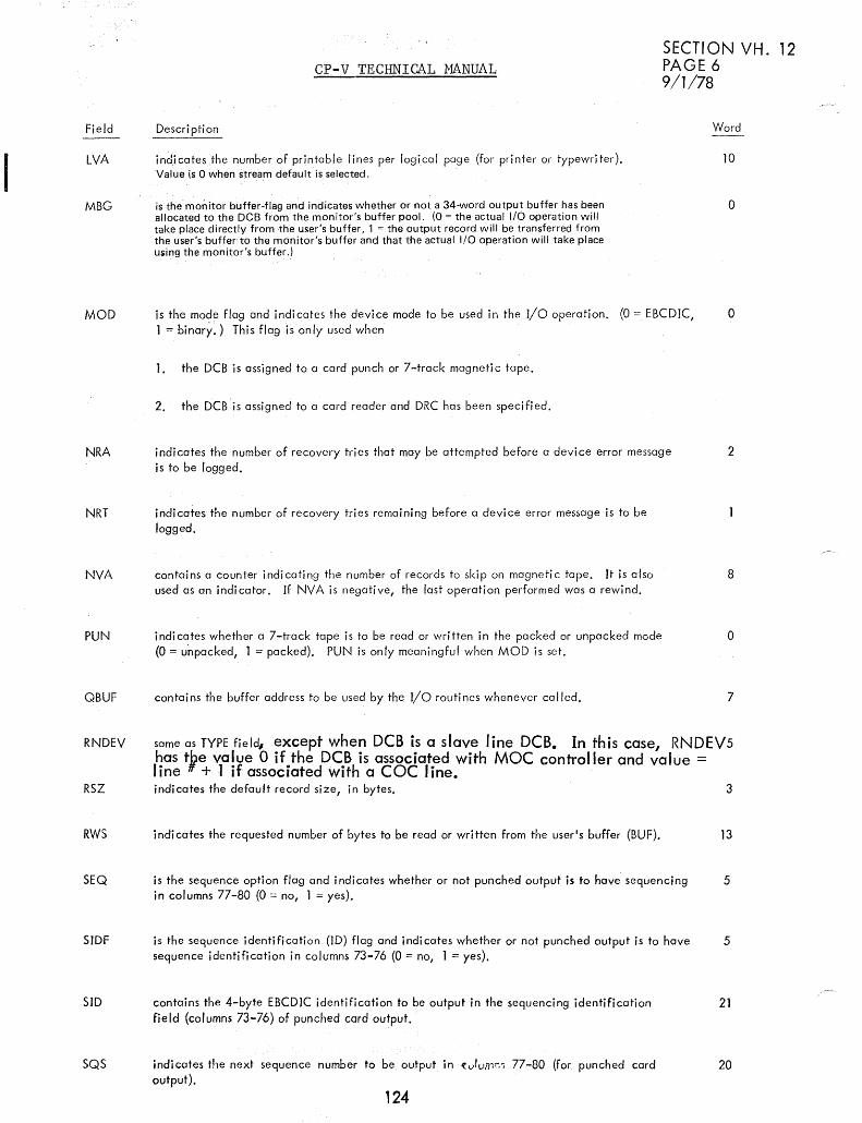
I Field
LVA
MBG
MOD
NRA
CP-V TECHNICAL MANUAL SECTION VH. 12 PAGE 6 9/1/78
Descri pti on
indicatesthe number of printable lines per logical page (for printer or typewriter), Value is 0 when stream default is selected.
is the'mOilitor buffer-flag and indicates whether or not a 34-word output buffer has been allocated to the DeB from the monitor's buffer pool. (0 = the actual I/O operation will take place directly from the user's buffer, 1 = the output record will be transferred from the user's buffer to the monitor's buffer and that the actual I/O operation will take place using the monitor's buffer.l
is the mode flag and indi cates the d·evice mode to be used in the I/O operation. (0 = EBCDIC, 1 = binary.) This flag is only used when
1. the DCB is assigned to a card punch or 7-track magnetic tape,
2, the DCB is assigned to a card reader and DRC has been specified,
indicates the number of recovery tries that may be attempted before a device error message is to be logged.
Word
10
o
o
2
NRT indicates the number of recovery tries remaining before a device error message is to be logged,
NVA
PUN
QBUF
RNDEV
RSZ
RWS
SEQ
SIDF
SID
5QS
contains a counter indicating the number of records to skip on magnetic tape. It is also used as an indicator, If NVA is negative, the last operation performed was a rewind.
indi cates whether a 7-track tape is to be read or written in the packed or unpacked mode (O = unpacked, 1 = packed), PUN is only meaningful when MOD is set,
contains the buffer address to be used by the I/O routines whenever called.
8
o
7
same as TYPE field# except when DCB is a slave line DCB. In this case, RNDEV5 has tpe value 0 if the DeB is associated with MOC controller and value = line + 1 if associated with a cac line. indicates the default record size, in bytes.
indicates the requested number of bytes to be read or written from the user's buffer (BUF).
is the sequence option flag and indicates whether or not punched output is to have sequencing in columns 77-80 (0 = no, 1 = yes).
is the sequence identification (lD) flog and indicates whether or not punched output is to have sequence identification in columns 73-76 (0 = no, 1 = yes),
contains the 4-byte EBCDIC identification to be output in the sequencing identification field (columns 73-76) of punched card output.
indicates the next sequence number to be output in It.)umr:, 77-80 (for punched card output),
124
3
13
5
5
21
20

Field
SVA
TABl-16
CP-v TECHNICAL MANUAL
Description
indicates the number of lines to be spaced between printed lines (for typewriter or printer). A 0 means SPACE was not specified; the output will be single spaced.
indicates the column numbers for the tab-stop settings (for output devices).
TOlF if 1, bits 16-31 of DCB are TEXT OPLABEL. If 0, DEVF is meaningful.
TYC indicates the type of completion of an I/o operation.
TYC Code Corresponding Error/
Abnorma I Code Meaning
Section VH. 12 Page 7 4/1/74
Word
19
15-18
o o normal without device I/o transfer
o normal with device I/o transfer
2 7 lost data
3 1D begi nni ng-of-tape
4 4 beginning-of-fi Ie
5 lC end-of-reel
6 5 end-of-data
7 6 end-of-file
8 41 read error
9 45 write error
1YPE contains the device-type code assigned to the DCB. This field is set whether the DCB is assigned directly to a device or indirectly through an operational label.
USTD
VFC
WAT
is the type displacement indicator, specifying at which byte ir:'! the user's buffer (BUF) the data record begins.
is the vertical format control-flag and indicates whether or not the first byte of the output is a format control character (O = nOt 1 = yes). This flag is only used for printer output.
is the wait flag and indicates whether or not WAIT was specified in the FPT (0 = no, 1 = yes).
o
o
o
VARIABLE LENGTH PARAMETERS 22 n
Each variable length parameter entry is preceded by a control word of the form shown for File DeB and in Table A-l.
1~5
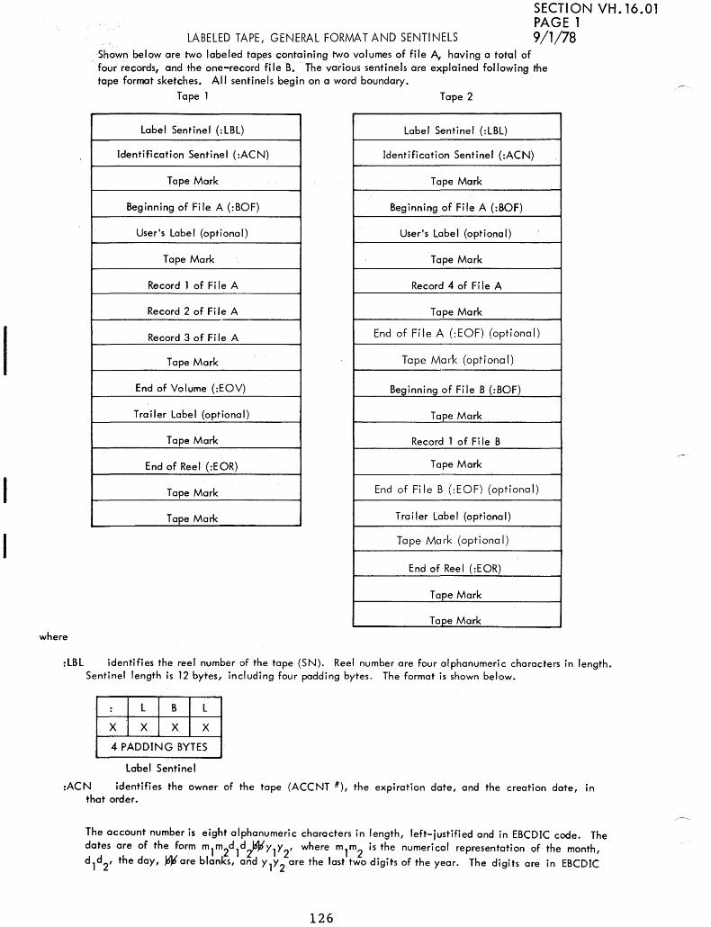
I
where
LABELED TAPE, GENERAL FORMAT AND SENTINELS
SECTION VH. 16.01 PAGE 1 9/1/78
Shown below are two labeled tapes containing two volumes of file A, having a total of . four records, and the one-record fi Ie B. The various sentinels are explained following the tape format sketches. All sentinels begin on a word boundary.
Tape 1 Tape 2
label Sentinel (: lBl) Label Sentinel (:LBL)
Identification Sentinel (:ACN) Identification Sentinel (:ACN)
Tape Mark Tape Mark
Beginning of File A (:BOF) Beginning of File A (:BOF)
User's label (optional) User's Label (optional)
Tape Mark Tape Mark
Record 1 of Fi Ie A Record 4 of Fi Ie A
Record 2 of Fi Ie A Tape Mark
Record 3 of Fi Ie A End of File A (:EOF) (optional)
Tape Mark Tape Mark (optional)
End of Volume (:EOV) Beginning of File B (:BOF)
Trailer label (optional) Tape Mark
Tape Mark Record 1 of Fi Ie B
End of Reel (:EOR) Tape Mark
Tape Mark End of File B (:EOF) (optional)
Tape Mark Trailer label (optional)
Tape Mark (optional)
End of Reel (:EOR)
Tape Mark
Tape Mark
:lBl identifies the reel number of the tape (SN). Reef number are four alphanumeric characters in length. Sentinel length is 12 bytes, including four padding bytes. The format is shown below.
: l B l
X X X X
4 PADDING BYTES
label Sentinel
:ACN identifies the owner of the tape (ACCNT II), the expiration date, and the creation date, in that order.
The account number is eight alphanumeric characters in length, left-justified and in EBCDIC code. The dates are of the form mlm2dld~Y1Y2' where m
1m
2 is the numerical representation of the month,
d ld2, the day, Ware blanKs, and y l Y 2 are the last two digits of the year. The digits are in EBCDIC
126

CP-V TECHNICAL MANUAL Section VH.16. 01 P..:Jge 2 4/1/74
and the blanks must appear. Sentinel length is 28 bytes followed by a physical end-of-file (tape mark record). The format of the ACN Sentinel, also referred to as the identification sentinel, is shown below.
: A C N
01
O2 03
04
05
06
0 7 08
m1
m2 d1
d2
11 11 Yl Y2
m1
m2 d
1 d
2
11 11 Yl Y2
Inter-record Gap
T ape Mark Record
:BOF is the beginning-of-file sentinel consisting of the file-information record, the user's label (if specified), and a physical end of file (tape mark record). The format of the :BOF Sentinel is shown below.
: I B 1 0\ F (Code) 01 Length·
No. char. in I File name file name I
Fi Ie Information 03 00 Length
Password
Inter-record Gap 05 Length
U Read Account Nos.
06 00 Length
User's Label Write Account Nos.
09
Inter-record Gap ORG
Tape Mark Record HDL
Beginning-of-File Sentinel 0 7 8 15 16
The file-information record, as shown, contains several control words and the information associated with each of these. The control words have the following form:
Code LEI Length
where
Code identifies the type of information following the control word. The codes are:
01 - file name. The file name may be a maximum of 31 characters. An additional byte is used to state the length of the file name.

CP-V TECHNICAL MANUAL Section VH 16.01 Page ,3 4/1;74
03 - password (2 words, left-iustified).
05 - Read account numbers.
06 - Write account numbers.
Each account number is left-justified, blank-filled, and two words long. The total number of Read and Write accounts must not exceed 16. Read accounts identify those who may have only read access to the file. Write accounts identify those who may read and write the file. None or All are also allowed.
09 - miscellaneous information, such as:
ORG - gives file organization, i. e., keyed or consecutive.
KEYM - specifies maximum length of the keys. Keys may not be greater than 31 bytes. An additional byte is used to specify the length of the key. On consecutive files, the length of the dummy key is assumed to be three; therefore, KEYM is ignored. On keyed files, if KEYM=O, maximum length is assumed to be 11.
VOL - on multi-reel files, this entry specifies the position of this tape in the file. For example, VOL=2 implies this is the second tape of the multi-reel file. VOL=l indicates the beginning of the file. Every file begins with VOL=l (including single-reel files).
HDL - specifies the length of user's label. If HDL=O, then no user's label exists and the following record must be a physical end-of-file.,
LEI is the last-entry indicator; this entry in the control word indicates the end of the file information. The control words, along with the information they define, do not have to be in a particular order, but LEI must equal 0 if the file information entry is not the last one and must equal 1 if the entry is the last.
Length specifies the length, in words, of the information associated with a particular entry (i. e., follow-ing the code word).
:EOV is the End-of-Volume sentinel:
I
: I E 0 I V
PBS
Inter-record Gap
Tape Mark Record
:EOR is the End-of-Reel sentinel: I I
I E 0 I R ... ..".
PBS
Inter-record Gap
. Tape Mark Record

CP-V TECHNICAL MANUAL
:EOF is the End-of-File sentinel:
I I
T ape Mark Record
Inter-record Gap
: I E 0
Inter-record Gap
Tape Mark Record
where
PBS is the previous block'size, in bytes.
RECORD fORMAT
.
I PBS
F
Section VH 16.01 Page 4 4/1/74
The labeled-tape record format for blocked records is shown below. The truth table following the diagrom shows the possible combinations, of blocked/unblocked continued/not continued records. Figure 16-1 shows a number of examples of various types of records.
PBS
SKEY 1
PBS
where
N KY is number of entries in block.
PBS is previous block size.
t Must start on word boundary.
RECORDl
RECORD2
etc.
Inter-record gap
RECORD3
(unblocked)
NKY
NKY

512
t 3
!
>512 ~8K
CP-V TECHNICAL MANUAL
PBS NKY PBS NKY PBS NKY 0 2 -1 2048 2
KEY (Rl) KEY (R4) KEY (Rl)
RWS 2028
512 RECORD 510 RECORD
3
IRG· IRG IRG
t PBS NKY
t PBS NKY
2048 1 2040 _. 1
KEY (R5) KEY (RS)
I l 7
IRG
1 8K RECORD
8K
1 ,. '7
RECORD
PBS NKY IRG
SECTION VH. 16.01 PAGE 5
t PBS NKY
2048 1
3 KEY (R9)
! 5 RWS 4000
IRG
1 1000
I,- RECORD
IRG
t 3
l IRG
8K RECORD
2048 1 7 KEY (R3) t
PBS NKY 1 1
4 RWS 3 KEY (R8)
32 764
l 6
IRG IRG
PBS NKY
1 PBS NKY
-1 2 -I 2
RECORD KEY (R5)
8K RECORD 512 KEY (RIO)
RWS
'7 512 . IRG
I 512
IRG IRG ! Notes: l. All numbers are decimal.
2. A new record will nat be started in a block unless there is room for at least one full data word. 3. PBS - -1 whenever prior block is unblocked. 4. All keys are assumed to be three bytes long.
Figure 16. 1 Examples of Different Types of Records
IJO
,

cP-v TECHNICAL 1:1ANUAL Section VH 16.01 Page 6
SKEY is size of key. 4/1/74
RWS is size of record in block.
P3
is 1 if record is unblocked, 0 if blocked.
P 2 is 1 if record is continued into next block, 0 if record is not continued.
P 1 is 1 if this is first part of record, 0 if it is not first part.
Truth Table. Combinations of Record Types
Unblocked Continued 1 st. Segment P3 P2 Pl Meaning of Contol Bits
0 0 1 Record is wholly contained within this 512 word block.
0 1 1 1 st record segment of N segments. Continued next block.
0 1 0 Not possible.
0 0 0 Nth record segment (N > 1) of N. If N >2, :. N-l was unblocked.
1 0 0 Physical record following is Nth segment of N (N > 1).
1 0 1 Physical record following is complete.
1 1 1 Physical record following is not complete. Size = 8K words.
1 1 0 Physical record following is not complete. Size = 8K words. This
is ith segment of N (1 > i < N).
131

Cp ... V TECHNICAL MANUAL
ANS TAPE, GEI'!ERAl FORMAT AND SENTINELS
SECTIO"J YH. 16.02 PAGE 1 9/1/78
TIlE! overall structure for ANS tapes u:ld the sentind format are shown bel )w.
Single file, single volume
V all - H DR 1 - H D R2 - UH l 1 * fi I e A * EO F 1 - EOF 2 - U T l 1 * *
Single file, multi-volume
, Vall - HDRl - HDR2 - UHll * file A * EOVl - EDV2 - UTL1**
VOll- HDR1- HDR2 - UHLl * file A * EOF1- Et>F2 - UTLl **
Multi-file, single volume
VOL 1 - HDR 1 - HDR2 - UHL 1 * file A * EOF 1 - EDF2 - UTL 1 *
HDR1- HDR2 - UHLl * file B * EOFl - EOF2- UTLl **
Multi-file, mul ti-vol ume
, VOLl - HDRI - HDR2 - UHLl * file A * EOVI - fi!lV2 -'UTU**
VOL 1 - HDR 1 - HDR2 - UHL 1 * file A * EOF 1 - EOF2 - UTL 1 *
HDR 1 - HDR2 - UHL 1 * fife B * ECF 1 - EOF2- UTL] **
Note: An asterisk denote.s a physical tape mark. A dash denotes an inter-record gap.
132
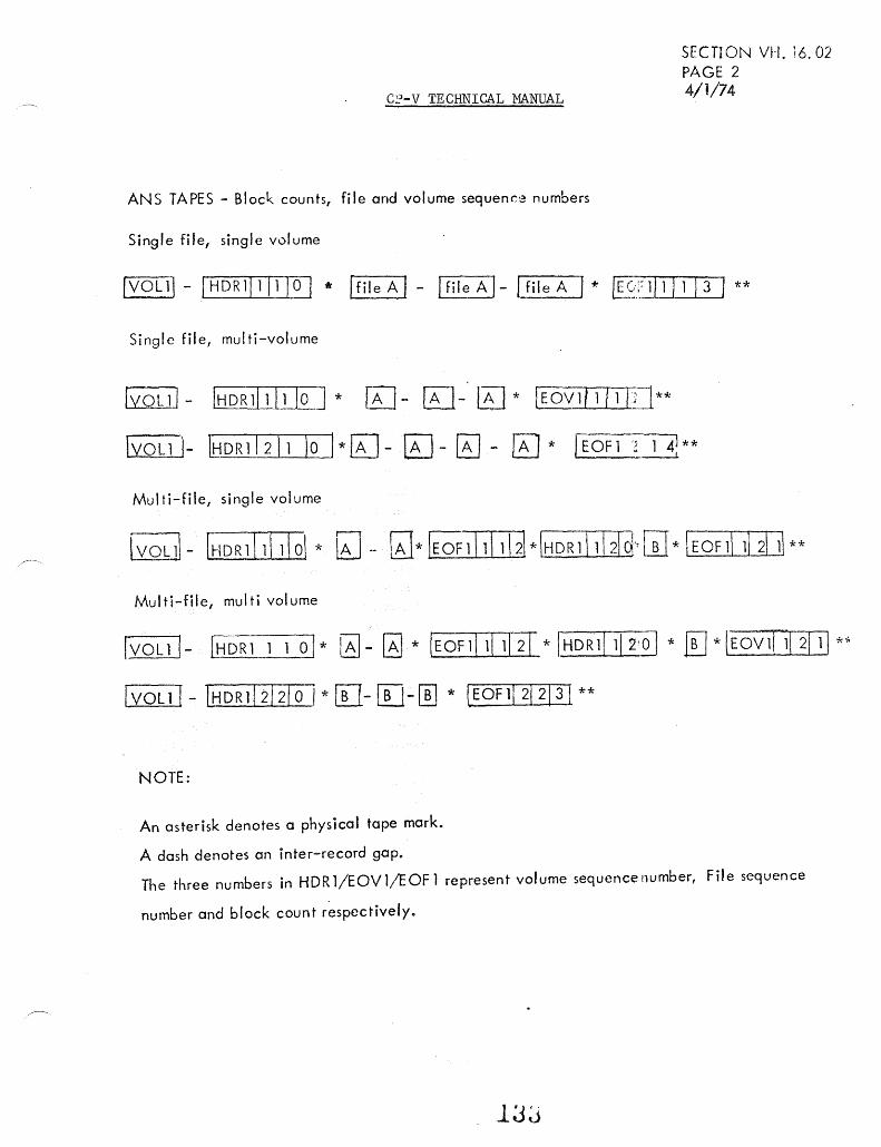
C~-V TECHNICAL MANUAL
ANS TAPES - Block countsr file and volume sequence numbers
Single filer single volume
Single file, multi-volume
GLQUJ- IHDR1/lI1Io 1* lAJ- [TI-'lEJ* [Eovlllll/3]**
SECTION VH. 16.02 PAGE 2 4/1/74
I yo L 1 1- IH D R 1 I 2 11 10 ) * g] - EJ - g] - ~ * I E OF 1 .. ~, 1 4: * *
Mul ti-file, single volume
Mul ti-file, mul ti vol ume
IVOL11- LtiQRl 1 1 01* ~- [;J * IEOF1\111121 * IHDRllllil * [J *IEOV111! 2111 *~
IVOL11- t!;DRlI212/0 I*[}-[[l-[[] * !EOFlI21213! **
NOTE:
An asterisk denotes a physical tape mark.
A dash denotes an inter-record gap.
The three numbers in HDRl/EOV1/EOFl represent volume sequence number, File sequence
number and block count r~spectively.
lJJ

Cp-v TECHNICAL MANUAL
ANS TAPE LABELS FORMAT
SECTION VH. 16.02 PAGE 3 4/1/74
HEADER CHARACTER POSITION DESCRIPTION SOURCE/VALUE
VOLl 1-4 VOLl 5-10 Volume serial number AVRTBL
11 Security 0 12-80 Not used Blanks
:-tDR l/EOV1/EOF 1 1-4 HDR1/EOF l!EOVl 5-21 Filename DCB:FN (VLP=Ol)
22-27 Serial number first volume -AVRSID
28-31 Volume sequence number. DCB:CVO 32-35 Fi Ie sequence number DCB:FSN 36-41 Not used Blank 42-47 Jul ian creation date date 48-53 Jul ian expiration date DCB:EXPR (VlP;:;Q4) 54 Security 0 55-60 Block count DCB:BLKCNT 61-73 CP-V version nUmber Core address X '28 I 74-80 Not used Blanks
H D R2/E OF 2/E OV2 1-4 HDR2/E OF2/E OV2 5 Format DCB:FMT 6-10 Block size DCB:BLKSZ
11-15 Logical record size DCB:LRCSZ 16 Recording density 2(800 BPI) 17 System use 0 18-50 Not used Blanks 51-52 Buffer offset 0(4 if format =N) 53-80 Not used Blanks
134

CP-V TECHNICAL MANUAL
GENERALIZED DISK ADDRESS
SECTION VH .. 17 PAGE 1 2/10/76
Fi Ie Management routines work with generalized disk addresses which are the addresses of granules on disk or DP. IOQ is responsible for correctly converting the disk address to seek address for the specific device.
GENERALIZED DISK ADDRESS FORMAT
o 789
DCTor VNO I 3]
Sector Number
where
DCT is the DCT index of the device (DCT indexes start with 1). Used for public files at all times, but for private files only when IOQ is called.
VNO the volume number within a private volume set, if the file is private. VNO is converted to a OCT index immediately before IOQ is called.
Sector number is the relative sector number (starting with 0) of the sector on the device. SX is the sector extension field. Bit 9 is the most significant bit of the sector number, and bit 8 is the next most significant bit.
]

CP-V TECHNICAL-MANUAL
Consecutive File Format
SECTION VH.18 PAGE 1 4/1/74-
All information in the consecutive file format is contained in full granule sized records. There are no master index half granules used. Many files consist only of control granules which are flinked and blinked and contain all record data and control information. Each record is broken into segments with length less than or equal to 2048 bytes. Record segments which are shorter than 2033 bytes are blocked into the control granules in monitor blocking buffers for input or output: but record segments of greater length are written from, or read to, the user's buffer directly.
Zero length records are treated as no record on output. Records which are less than 2049 bytes long appear as one segment, unless the record is shorter than 2033 bytes but longer than the amount of space available in the final granule of the file at the time it was written. If such is the case, the record is broken into two segments, the first filling out the current granule and the second starting a new final granule. Records with length greater than 2048 bytes are broken into a sufficient number of 2048 byte segments to reduce the remainder to less than 2049 bytes. This remainder is treated as described above.
Record Segments - Each record is broken into segments ~ 2048 bytes.
Case 1. Record Segment < 2033 bytes
Control Word:
bit 0 0 (for blocked)
bit 1 FAK = 1 for initial segment of record, 0 if not initial.
bit 2 C = 0 for last segment of record, 1 if otherwise
bit 3 0
bit 4-15 = II of data bytes in segment (call it m)
bit 16-31 = word position of previous record segment control word in this granule; or if this is the first segment in the granule, O.
h . f m+3 , • h f h T e next -4-1 words contain t e data 0 t e segment.
Case 2. 2033 bytes ~ Record Segment ~ 2048 bytes
Control Word:
bi t 0 1 (for unblocked)
bit 1 FAK
bit 2 C
bit 3 1 if preceding word in the granule is a backspace control word (see below). o if this is the first record segment of the granule or if the preceding record segment in the granule is also unblocked.
bits 4-7 ::= II of data bytes in the segment less 2033.
bits 8-31 generalized disk address of the granule containing the data starting at byte O.
la6

Case 3.
CP-V TECHNICAL MANUAL SectionVH. 18 Page 2 4/1/74
Backspace Control Word. (This word is used only when a granule contains a blocked segment followed by an unblocked segment whose control word is in the same granule. The word is inserted followi1g the data of the blocked segment and preceding the control word of the unblocked segment.)
bits 0-15 = 0
bits 16-31 = word position of previous record segment control word in this granule.
Control Information for Control Granules
Word 0 Blink Word 1 Flink Word 2
bit 0
bit 1
bits 2-15
bits 16-31
= 0 if no case entries appear in the granule, 1 otherwise.
= 0 for granule not full, 1 otherwise.
=0
= If bit 1=0, the word position of the next available word in the granule. If bit 1=1, the word position of the last segment control word in the granule.
The initial granule of a file contains the FIT for that file in words 4 ... 83 of the granule. Word 3 contains a dummy segment control word of type described in Case 1 above with FAK = 0, C = 0, and M = 320. If a record is deleted from a consecutive file, the FAK bit in the first (or only) segment control word for the record is reset to O.
1:J;
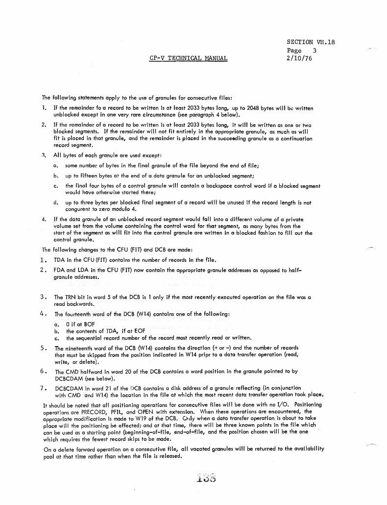
CP-V TECHNICAL MANUAL
The following statements apply to the use of granules for consecutive files:
SECTION VII .18 Page 3 2/10/76
1. If the remainder fo a record to be written is at least 2033 bytes long, up to 2048 bytes will be written unblocked except in one very rare circumstance (see paragraph 4 below).
2. If the remainder of a record to be written is at least 2033 bytes long, it will be written as one or two blocked segments. If the remainder will not fit entirely in the appropriate granule, as much as will fit is placed in that granule, and the remainder is placed in the succeeding granule as a continuation record segment.
~. All bytes of each granu Ie are used except:
a. some number of bytes in the final granule of the file beyond the end of file;
b. up to fifteen bytes at the end of a data granule for an unblocked segment;
c. the final fOl,lr bytes of a control granule will contain a backspace control word if a blocked segment would have otherwise started there;
d. up to three bytes per blocked final segment of a record will be unused if the record length is not congurent to zero modu 10 4.
4. If the data granule of an unblocked record segment would fall into a different volume of a private volume set from the volume containing the control word for that segment, as many bytes from the start of the segment as will fit into the control granule are written in a blocked fash ion to fill out the control granule.
The following changes to the CFU (FIn and DCB are made:
1. TDA in the CFU (FIT) contains the number of records in the file.
2. FDA and LDA in the CFU (FIT) now contain the appropriate granule addresses as opposed to halfgranule addresses.
30 The TRN bit in word 5 of the DCB is 1 only if the most recently executed operation on the file was a read backwards.
4. The fourteenth word of the DCB (W14) contains one of the following:
a. 0 if at BOF b. the contents of TDA, if at EOF c. the sequential record number of the record most recently read or written.
5. The nineteenth word of the DCB (W14) contains the direction (+ or -) and the number of records that must be skipped from the position indicated in W14 pripr to a data transfer operation (read, write, or delete).
6. The CMD halfword in word 20 of the DCB contains a word position in the granule pointed to by DCBCDAM (see below).
7.. DCBCDAM in word 21 of the DCB contains a disk address of a granule reflecting (in conjunction with CMD and W14) the location in the file at which the most recent data transfer operation took place.
It should be noted that all positioning operations for consecutive files will be done with no I/O. Positioning operations are PRECORD, PFIL, and OPEN with extension. When these operations are encountered, the appropriate modification is made to W19 of the DCB. Only when a data transfer operation is about to take place will the positioning be effected; and at that time, there will be three known points in the file which can be used as a starting point (beginning-of-fiIe, end-of-fiIe, and the position chosen will be the one . which requires the fewest record skips to be made.
On a delete forward operation on a consecutive file, all vacated granules will be returned to the availability pool at that time rather than when the file is released. .

D ACNCFU
PUBLIC FILES
Account Directory lAD)
[-
FLINK ! A~!i! DA
ACN DA NO. !
t
f "N.; "J NO
BLINK
ACN NO OA
I. F i",1 block of AD t('ad into indeJC
buffet
2. If de",e-d ACN no' !h.,., ... cond block of AO teod into indeJC buff~r, ttc.
3. When ACN •• found, di.k oddr .... IDA) of occoun"1 FO if, o ... oilable.
F ,I. Dir.c.ooy IFD) for ACNT X
lh
FLINK
NAM'I " ABC DA .. -_.-
-" ...
BCD OA
I
I
:
BLINK ._-0
1-- . . --NAME DA
NAME DA
F,I. Di,ec,ory IFDI for ACNT Y
NAME DA
I I
I J
---
.4. Fir,t block of FD read into some index
buffer.
5. If de,ired file no~ there, \t'cond block of FD reord into inde?C buffer, etc.
File Information Tobie IFITI r.,r Fil. ABC
ABC
ACN'IXI 1-_"""'-
SECURITY
ATTRIBUTE 5
MI DA
FIT lor File BCD
!!CD
ACN' (X)
SECURITY
ATTRIBUTES
MI DA
CFU fo' Open Fa. ABC
ABC
ACN'IX)
MI DA
8. Security check'lt ore mode,
9, File', attributes initialize DeB.
6. When file is found, di'Sk address of file's
fiT is ovoiloble.
10. FIT less \t'curity information and file attributes transferred to CFU and index buffer released.
7 FIT i" rerxf into t.OI'TIt!' inde"" buffer,
PUBLIC KEYED FILES
Motter Inde .. fa, F,le A8C
FLINK
KEY .-
t DA
~ISPL
DA KEY-
t ~~SPL T ----T;;A
RST DISPL
BLINK
. DISPL
KEY I DISPL
BLINK
DA KEY
DISPL
1. First bloc k of MI read into index
buffer.
2. If de"ired key not there, second block uf MI reod into indel( buffer, etc,
3. When key is found, DA of do.o block in which record is contained it available,
•. Obto;n blocking buff.r IBBI ond reod data block.
5, Transfer record to user's buffer.
Do.o 810ck fo, Fil. A8C (512 Wo,d,)
SUBSEQUENT READS
6. Requested key searched in current MI block.
7. If not there, reod next adjacent MI block.
8. When key;" found; determine if 88 contoins required data block.
9. If no', ,eod requ;red dato block into BB.
Transfer record to us.er·s buffer .
. VH. 19. ··Schema for Locati n9 and Referenci n9 Publ ic Files
',~.'~' .. ,
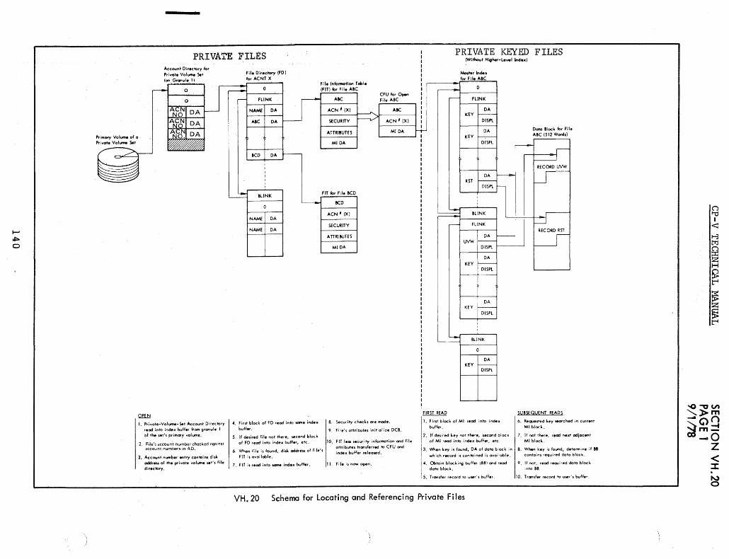
..... ~ 0
P';M"'Y Vol ...... of a P,i""te Vol.- S.I
PRIVATE FILES
1. Privote .. Volvme-Set Account Directory read into inde)( buHer ftom granule 1 of the ,et'~ primary volume.
2. File's account number checked against account numbers in AD.
3. Aceounl number ~Iry Can "'in, di,k oddr~ of the private vollJlf'ne seY" File directory.
4. Firsl block of FD r.ad into some index buffer.
5. If desired file nol rhere, second block of FD read into index buffer, etc.
6. When fil. is found, di,k oddre .. of fil.', FIT i, ovailable.
7. FIT i, read inlo _ index buff.r.
8. Secur ity checks ore mode.
9, File's attributes initialize DCB.
10. FIT I ... security informalion and fil. allribules Ironsferred '" CFU and index buffer released.
PRIVATE KEYED FILES (Wi thou I Hig ..... Le""1 Indo,,)
Mas"" Index
FIRST READ
1. Firsl block of MI read into index buff",.
2. If desired key not lhere, second block of MI read into index buff ..... elc.
3. ~.n key is found, DA of dole block in
whict, recOfd is contained is available.
~. Obtain blocking buffer (881 and r.od dole block.
5. Trcwufer record to vwr~s buffer.
D_ Block for Fila A8C (512 Word.)
RECORD RST
SU8SCQUENT READS
6. Requested key _rehed in currenl MI block.
7. If not there, read next adjacent MI block.
8. When key is found, dele""in~ if B8 contains required dota block.
9. If not, reod requited data block into 88.
Transfer record t'o user~J buffer,
VH.20 Schema for Locating and Referencing Private Fi les
CJ '"d I
<:l
t-3 t:t::I g Z H S; t""l
~ Z ~ t""l

CP-V TECHNICAL MANUAL
SECTION VH.21 PAGE 1 10/31/74
READ-AHEAD TABLES
Paral lei Tables - Length RASIZE
RA:DA
I I I I I I Disc Address
0111 \ \ ~:!~y i!O w~~ t~~~ e~~~d 110 camp let ion 31
I L AIR entry ! - 110 in progress i__ active entry
RAH: DCB i'(
o 15
RAH:TIME
o 15
RAX:PAGE
0 15
RAB: USER it,
I 0 7
RA8:FLINK
I 0 7
Most significant 16 bits of DCB address
Time at which this entry was gotten (32 msec un its)
Physical page address of buffer for this entry
User number of user associated with this ENTRY
Index of next oldest active entry
141
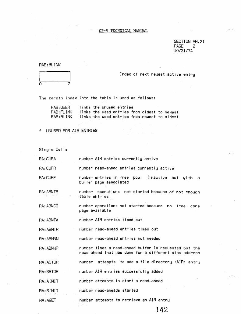
CP-V TECHNICAL MANUAL
SECTION VH.21 PAGE 2 10/31/74
RAB:BLINK
Index of next newest active entry
o 7
The zeroth index into the table is used as fol lows:
RAB:USER RAB:FLINK RAB:·BLINK
I inks the unused entries I inks the used entries from oldest to newest links ·the used entr i es from newest to a I dest
* UNUSED FOR AIR ENTRIES
Sing I e Ce I I s
RA:CURA
RA:CURR
RA:CURF
RA:ABNTB
RA:ABNCO
RA:ABNTA
RA:ABNTR
RA:ABNNN
RA:ABNWP
RA:ASTOR
RA:SSTOR
RA:AINIT
RA:SINIT
RA:AGET
number AIR entries currently active
number read-ahead entries currently active
number entries in free pool (inactive but ~ith a buffer page associated
number operations not started because of not enough table entries
number operations not started because no free core page ava i I ab I e
number AIR entries timed out
number read-ahead entries timed out
number read-ahead entries not needed
number times a read-ahead buffer is requested but the . read-ahead that was done for a different disc address
number attempts to add a file directory (AIR) entry
number AIR entries successfully added
number attempts to start a read-ahead
number read-aheads started
number attempts to retrieve an AIR entry
142

CP-V TECHNICAL MANUAL
SECTION VH.21 PAGE 3 10/31/74
RA:SGET number AIR entries successfully retrieved
SL:RAMR maximum number simultaneous read-aheads al lowed
SL:AIRM maximum number simultaneous AIR entries al lowed
SL:RAMF maximum number pages al towed in free pool
SL:RATOR time-out for read-ahead entries
SL:AIRTO time-out for AIR entries
143

CP-V TECHNICAL MANUAL SECTION VI.Ol Page 1 2/10/76
SYMBIONT COOPERATIVE DATA BASES
Symbiont File Block Format - In CP-V both input and output symbiont file blocks have the same format.· Each such block contains 256 words, and two blocks reside in a granule of file storage. Word 0 of the block is used for forward link address that is inserted by the system when the file is created. A value of zero implies no forward address (i.e., end of file). Word 255 is used for the backward link address again inserted when the file is created. A value of zero implies no backward address (i.e., beginning of file). Each record in the block is preceded by four bytes of control information. Neither the record nor the control information need start on a word boundary except the first control string. Each control string must ~ediately follow the preceding record. The first two bytes of a control string are the byte count (BC) of ~he following record. BC must be greater than zero and less than 1008. No record may be split between blocks. If a block does not have space remaining for a block end control string, a record control string and a record, the next record must begin in a new block. The third byte of a control string is the record control character (RCC) which defines the record.
RCC = ,
o a BCD record (e.g., ca~d)
1 an EOD record (e.g., !EOD)
2 a binary record (BIN)
4 or 5
6 or 7
x'40'
X'86'
X'88'
a PRINT record without a VFC character
a PRINT record, the first byte of which is a VFC character
a block ending control string (i.e., no more records this block)
header line for on-line outpUt.
header line for output repackaged by recovery.
SK=3 at least for header lines; the first two skipped bytes are the number of times the line is to be printed and the VFC character to be used each not-first time the line is printed.
Other values for RCC are reserved for future enhancements and should not be used. The fourth byte of a control string is the skip byte (SK) defined for the convenience of the block encoder. SK may have the values 1 through 4 inclusive.
The next SK-l bytes following the control sequence have no significance and are skipped before the start of data. The skipped bytes are provided to allow a byte aligned MBS instruction (the most efficient execution) to move the bytes into the symbiont block, or to allow placement of the record on a word boundary for record construction ease. The final control string of a block must have RCC = x'40'. BC and SK are not relevant in the final control string.
144
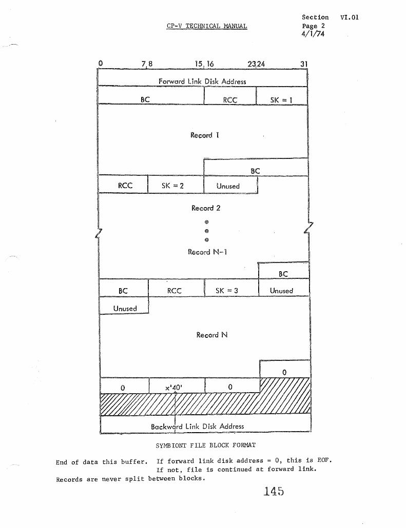
o 78
Be
RCC
Be
Unused
CP-V TECHNICAL MANUAL
15 16 2324
forward link Disk Address
RCC
Record 1
Be SK =2 Unused
Record 2
~
• •
Record N-l
RCC SK == 3
Record N
SYMBIONT FILE BLOCK FORMAT
SK == 1
Be
Unused
Section VI.OI Page 2 4/1/74
31
End of data this buffer. If forward link disk address = 0, this is EOF. If not, file is continued at forward linko
Records are never split between blocks.
145

Section VI.Ol Page 3
CP-V TECHNICAL MANUAL 2/7/77
/--~., .~
SYMTAB ... SYMBIONT TABLES
R s L 5 F E T o T I M R C R L D 0 E A E L E T A L A ,/' L E M M ,5 E
S S P T I E
STB:Q ( Symbiont lOa Entry L L 5
Y 5 M
STH:SUS FCS SusEend Bit for IRBT y B M I B 0 I N
STH:FlG Re mote F I a~s ] 0 T N CD
:> T E Q)
N :;) Q) OJ
E T 0 :> :>
I Q) OJ
STB:lNK I F I Remote Che ins N R Q) :> :> 00 •• MXSTRM+l ., T Y
.~ Q) C
R 0 0 ...J .... '- Vl Y :c I- o 0
STB:TYP Device T 0 0 <{u 0 e V) V)
SQUE S mbiont Queue Chain
~
0
SCNTXT '--" S btiont Context Block Doubleword Address H
< r.J) H (1j CJ:l
,..r::CJ:l
SSIG twJ Symbiont Signal Character :>., '" !-l t::!
6 ,w..-f - t::! >. ~ Q) Q)
Z .!>::
3-Partit. I - ,.0
SSTAT fB 1 Symbiont Status: O-Inactive I-Active .e. ....I o ~ . ....,~ X co 0 0 I- Q) j:!:l
0 V') t::! 0 ..-f _.
~ Z c. ... .-I V') I >.
0 p ,.0
.r:, ... ...c 0
U "'0
Symb iont Return Point .... 4-l Q)
SRET CD Q) ..-f ~ C. QJ Q.) '- O...-l
LA.. ~.-I co ..... Q) (1j
« 0 N U)
13 1 2 1 I ..-f
SYMX ~ Sz:mbiont Index: 1 = INSyt-A, 2 = OU1SYM I-""0 t::! "'0
~ 0 0
>- (I) P t::! :r:: Q)
V) U) Q)
.~ ." ..-f,.o
li 1 1010 I ....
SNDDX DeT Index ...J LA.. j:!:l
146 0- .. ...J
SNDDXSIZ+l ..
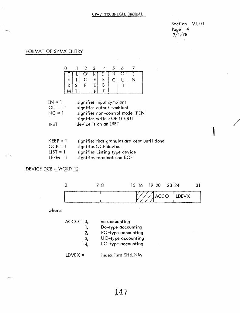
CP-V TECHNICAL MANUAL
FORMAT OF SYMX ENTRY
o T E R M
IN = 1 OUT = 1 NC = 1
IRBT
KEEP = 1 OCP=l LIST = 1 TERM = 1
2 3 4 5 6 7 L 0 K I I N
RiC 0 I
I C E U N S P E B I T T pI T I
signifies input symbiont signifies output symbiont signifies non-control mode if IN signifies write EOF if OUT device is on an IRBT
signifies that granules are kept until done signifies OC P device signifies Listing type device signifies terminate on EOF
DEVICE DCB - WORD 12
Secti on VI. 01 Page 4 9/1/78
o 7 8 15 16 19 20 23 24 31
where:
ACCO = 0, 1, 2, 3, 4,
LDVEX =
~ ACCO : LDEVX
no accounting Do-type accounting PO-type accounting UO-type accounting LO-type accounting
index into SH :LNM
/ I

CP-V TECHNICAL MANUAL Section VI. 01 Page 5 10/31/74
SYMBIONT TABLES IN RBBAT
SlW:FORM
STH:CMDV
STH:NM
STB:DPD.
Form Name Mounted on Device
0= Standard Form
Concurrent output mode ID for device. ~ = not in concurrent mode. bit ~ set = device is printing last chunk
of concurrent output
Text Device Name
for Remote Streams
. Direct Passing Device
Type for Remote Streams
f"fo .. ------SNDDXSlZ-----.... ~1 I+--MXSTRM,--~.I
FORMAT OF STH:FlG ENTRY
IN Input
o
A E B lOU N F T
W S F T Q P
B K S
B U
F F M l S K
S R
l C o B C C
au J OC Operator console ·BKS Suspend control BUT
SRCB type of device STP
S' R C P 0 P C
SRCBP} SRCPC Output ready LOC Device locked if set WFQ Waiting for symbiont start
FLK} CP-V to CP-V EOF EOF pending FMS Forms control ALN RBAlI GN pending
148
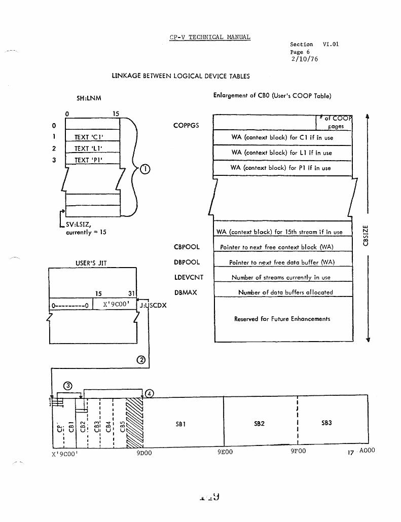
~
CP-V TECHNICAL MANUAL Section VI.ot Page 6 2/10/76
LINKAGE BETWEEN LOGICAL DEVICE TABLES
o
2
3
SH:LNM
o
TEXT IL l'
TEXT 'Pl'
[SV:LSIZ, currently = 15
USER'S JIT
15
15
31
0---------0 I X'9COO' It-
J:l SCDX
1 ~
Q)
® !(4) ~ J ..,1
~:±t . I
~I I I I
=d I I
I
I I I I I
\ - ~. ("')' -.:tl c.... dl dll dl. UI U u! UI U
I , I I u~ I I I
t I I I I
I I
X'9COO' 9DOO
Enlargement of CBO (User's COOP Table)
COPPGS
WA (context block) for C 1 if in use
WA (context block) for L 1 if in use
WA (context block) for Pl if in use
WA (context block) for 15th stream if in use
CBPOOL Pointer to next free context block 0NA)
DBPOOL Pointer to next free data buffer 0NA)
lDEVCNT Number of streams currently in use
DBMAX Number of data buffers allocated
Reserved for Future Enhancements
I
• J I
SBl 582 I 583 I I I
9EOO 9FOO
w ~ V')
co U
17 . AOOO

CP-V TECHNICAL MANUAL
Notes on diagram "LINKAGE BETWEEN LOGICAL DEVICE TABLES"
Section VI.Ol Page 7 2/10/76
1. Given a stream name in text, find index into SH:LNM (e.g., LI has index 2).
2. Fetch J:USCDX which points to base of user's COOP table (X' 9COO' in examp Ie) •
3. Use index from Step 1 to fetch context block pointer for this stream (e.g., Ll has context block CB2).
4. Fetch stream's data buffer address from context block using displacement symbol SCFBUF (e.g., Ll has data buffer SBI as indicated in CB2).
l~U

CP-V TECHNICAL MANUAL
Section VI.Ol Page 7A 10/31/74
Symbiont/Cooperative Context Block - The context block for symbiont/cooperative operations has been totally redefined for CP-V. The salient features of the new context block format include:
1. Definition of new displacement symbols, conforming to more rigorous conventions than previously (i.e., all start with "SC"; "SCF" signifies a file-related value; "SCD" signifies a device-related value). All current symbols (e.g., SCBINFOX, SCJOBX) have been discarded.
2. Space is provided in the new context block for NEWQ arguments used in performing disc and device I/O operations (SCFQARGS, SCDQARGS). Notice that there is not a DCB in the CP-V context block.
3. Space is provided for "stream attribute" values which are modifiable by the user via the LDEV command (e.g., SCSEQ, SCFORM, SCMISC). All stream attribute fields are used in the cooperative context block; some of them are free for different use by INSYM and OUTSYM (since LDEVacts directly on the COOP's context block only).
4. Space is provided for values maintained internally by the symbiont/ cooperative system, including values related to symbiont file construction (SCBLDA, SCFLDA, SCSVDGI) and values used for accounting purposes (SCRCO, SCPCO, SCGCO).
151.

Section VI.Ol Page 8
CP-V TECHNICAL MANUAL 10/31/74 ~
W ORD 0123456 7 8 9 10 11 12 13 14 15 16 17 18 19 20 21 22 23 24 25 26 27 28 29 30 3.1.
0 fo SYMTABX SYMBIONT BASE ADDRESS
1 { o t DEVICE TYPE i
2
3 BLINK DISC ADDRESS
4 FIRST DISC ADDRESS OF FILE
5 WRITE DISC I/O PRIORITY I NRT I 0-------------------0 FUNCTION CODE
6 BLOCKING BUFFER BYTE ADDRESS
7 I BLOCK BYTE COUNT
8 FILE CURRENT DISC ADDRESS
9 FILE SIDE:END ACTION ADDRESS
10 READ I/O PRIORITY J NRT 1 DEVICE DCTX FUNCTION CODE
11 CURRENT BLOCK POINTER (BYTES)
12 MAXIMUM RECORD BYTE COUNT
13 I SYMTABX
14 DEVICE SIDE:END ACTION ADDRESS
15 DISC WRITE FOLLOWON: o READ A CARD, 1 ADD INPUT FILE
16 4 WORD TEMPORARY SAVE AREA
17
18 ,
19
20
21 BLOCKING MODE: 1 RB CC's, o NORMAL
22 (COUNT OF RECORDS READ) - 1
23 COUNT OF JOB CARDS
24 # OF GRANULES
25 BASE OF 3 WORD IINO COMM BUFF" TEMP AREA
26
27
28 FI I oN FIN = 1 IF FIN CARD HAS BEEN READ
29 , SYMX BYTE FOR THIS STREAM
30 NAME FROM! INCTL CMD -
INSYM CONTEXT BLOCK
152

CP-V TECHNICAL MANUAL
wo\o 0
Section VI.Ol Page 9 4/1/74
1 2 3 4 5 6 7 8 9 10 11 12 13 14 15 16 17 18 19 20 21 22 23 24 25 26 27 ~8 29 30 31
STREAM NUHBER
1
2
3
4
5
6
7
8
9
10
11
12
13
14
15
16
17
18
19
20
21
22
23
24
25
26
27
28
29
I~ ~ I~ 16lfJ ~ rq ~ I ~ W I:)· I :~' I 1~~vl\-.I\·t.1 0 I 13
I ~ I b r i-' ,-; ~ I\J Y STREAM TYPE I
BLINK DISC ADDRESS
FILE STARTING DISC ADDRESS READ OR WRITE I/O PRIORITY I NRT 0---------------------0 DISC FUNC. CODE 0 CORE BLOCK ADDRESS
FCN.t 10 IN PROGRESS I BLOCK BYTE COUNT
FILE CURRENT DISC ADDRESS
0 10---------0 I FILE SIDE END ACTION ADDRESS
CURRENT BLOCK POINTER BYTES
RBID I MINIMUM RECORD SIZE OR LINES PER PAGE MAXIMUM RECORD SIZE OR WIDTH
COUNT SPACE I JDE I COPIES
SEQUENCE ID
BLOCKS PROCESSED THIS FILE RECORDS PROCESSED THIS FILE PAGES PROCESSED THIS FILE
FORM PROJECTOR CONTROL
FORM NAME (OR ZERO FOR NONE)
FUTURE FORM NAME (OR ZERO FOR NONE)
RELEASE PREVIOUS DISC ADDRESS
I CURRENT USER NUMBER
CURRENT LINE COUNT THIS PAGE.
COOP CONTEXT BLOCK

. Section VI.Ol . -
- - t
Page )0 CP-V TECHNICAL MANUAL 10/31 74
wo rd o 1 23456 789 10 11 12 13 14 15 16 17 18 19 20 21 22 23 24 25 26 27 28 29 30 31
0 f 01 SYMTABX SYMBIONT BASE ADDRESS
1 I Flags (Bit descriEtion next pa~e) I DEVICE TYPE 1
2 FLINK DISC ADDRESS
3 BLINK DISC ADDRESS
4 COpy COUNT FILE OLDEST DISC ADDRESS READ DISC I I 0---------------------0 5 FUNCTION CODE 1/0 PRIORI~ NRT
6 0 CORE BLOCK ADDRESS
7 J BLOCK EYTE COUNT
8 FILE CURRENT DISC ADDRESS
9 ~l FILE SIDE:END ACTION ADDRESS
10 RECORD 1/0 PRIORITY I NRT I DEVICE DCTX FUNCTION CODE
11 CURRENT BLOCK POINTER (BYTES)
12 CURRENT RECORD BYTE COUNT
13 SYMTABX OR RESTORE DISC ADDRESS
14 01 DEVICE SIDE:END ACTION ADDRESS
15 SYMBIONT PRIORITY REID I FILE SYSID
16 VARIOUS TEMP. USES (SCTYC)
17 I/O CALL ADDRESS
18 -- LAST TOP Of FORM DISP.
19 LAST TOP Of fORM DISK ADDRESS -20 IRBT BACKUP DISP.
21 IRBT BACKUP DISK ADDRESS
22 IRBT TEMP. BACKUP DISP.
23 IRBT TEMP. BAcKUP DISK ADDRESS -
24 # OF GRANULES REMAINING IN FILE - -
25 RETRY COUNTER FOR BLINK fAILURE
26 KEVIN BACK UP DISK
27 BACKUP LIST
28 ~ ! ~ 39 -I ------------------J~
OUTPUT SYMBIONT CONTEXT BLOCK

CP-V TECHNICAL MANUAL Section VI. 01 Page 11 4/1/74
Flags - Word 1 of OUTSYM context block
o 1 234 5 6 7
I I
IRBT B DELET WROT COPI AUG
ACKUP TOGGLEJ E GRANS E EOF
ES COUNTED-N IN PROGRESS
8 9 10 11
CHECK BEFORE DELETE - ..
12 13 14 ] 5 16 17 18 19 20 21 22 23
:
OCp~ I IMAGE -J OPERATIONS
TERM. ON EOF---EXTRA BUFFERS __ _
(OCP)
lJ:)

CP-V TECHNICAL MANUAL Section VI. 01 Page 12 4/1/74
Symbi0!1t/Cooperative Context Block Displace",!e~t Symbo!s
SCAlF
SCBESTDA
SCBLDA
SCBSIZ
SCBUDA
SCBUPPT
SCBUPPTS
SCCDA
SCGUN
ADD input file flag Used by INSYM at Disc write end action to decide to read a cQrd (SCAlF = 0) or ADD input file (SCAlF = 1).
Best Disk Address File starting disk address used by INSYM to AIF, SYMFILS to delete partial input file, COOP to AOF, SYMFILS to add output, OUTSYM to AOFP. When OUTSYM is deleting or outputing with catchup delete this is the oldest notdeleted granule.
Backward Link Disc Address Contains SCCDAfs predecessor except while updating disk addresses.
Block Size Used as the file side size argument to NEWQ and as the boundary during block construction.
Backup Disk Address Is the Backup point for OUTSYM for the 'R' Keyin {and IQI
in 'DELETE I mode}.
Backup Point Used by OUTSYM when IRBT routines request symbiont to backup because of line block reconstruction. This 2 word area contains an appropriate SCDBI and SCCDA.
Backup Point Save Used by OUTSYM to define point of last record output. When IRBT routines send a block down the line this 2 word qrea is copied over SCBUPPT.
Current Disk Address NEWQ argument defining source or destination of current block on file; used by SYMFILS in output closing_
Current User Number Used by COOP to pass to the end-action routine the number of the user whose I/O is completing so the event may be reported.
156
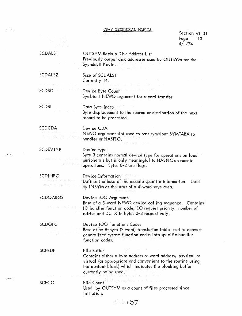
SCDALST
SCDALSZ
SCDBC
SCDBI
SCDCDA
SCDEVTYP
SCDINFO
SCDQARGS
SCDQFC
SCFBUF
SCFCO
CP-V TECHNICAL MANUAL Secti on VI. 01 Page 13 4/1/74
OUTSYM Backup Disk Address List Previously output disk addresses used by OUTSYM for the Syyndd, R Keyin.
Size of SCDALST Currently 14.
Device Byte Count Symbiont NEWQ argument for record transfer
Da ta Byte Index Byte displacement to the source or destination of the next record to be processed.
Device CDA NEWQ argument slot used to pass symbiont SYMTABX to handler or HASPIO.
Device type Byte 3 contains normal device type for operations on local peripherals but is only meaningful to HASPIO on remote operations. Bytes O-L are flags.
Device Information Defines the base of the module specific information. Used by INSYM as the start of a 4-word save area.
Device IOQ Arguments Base of a 5-word NEWQ device calling sequence. Contains 10 handler function code, 10 request priority, number of retries and DCTX in bytes 0-3 respectively.
Device IOQ Functions Codes Base of an a-byte (2 word) translation table used to convert generalized system function codes into specific handler function codes.
File Buffer Contains either a byte address or word address, physical or virtual (as appropriate and convenient to the routine using the context block) which indicates the blocking buffer currently being used ..
File Count Used by OUTSY!-·}. as a count of files processed since in itiation.
• t'-.Lv l
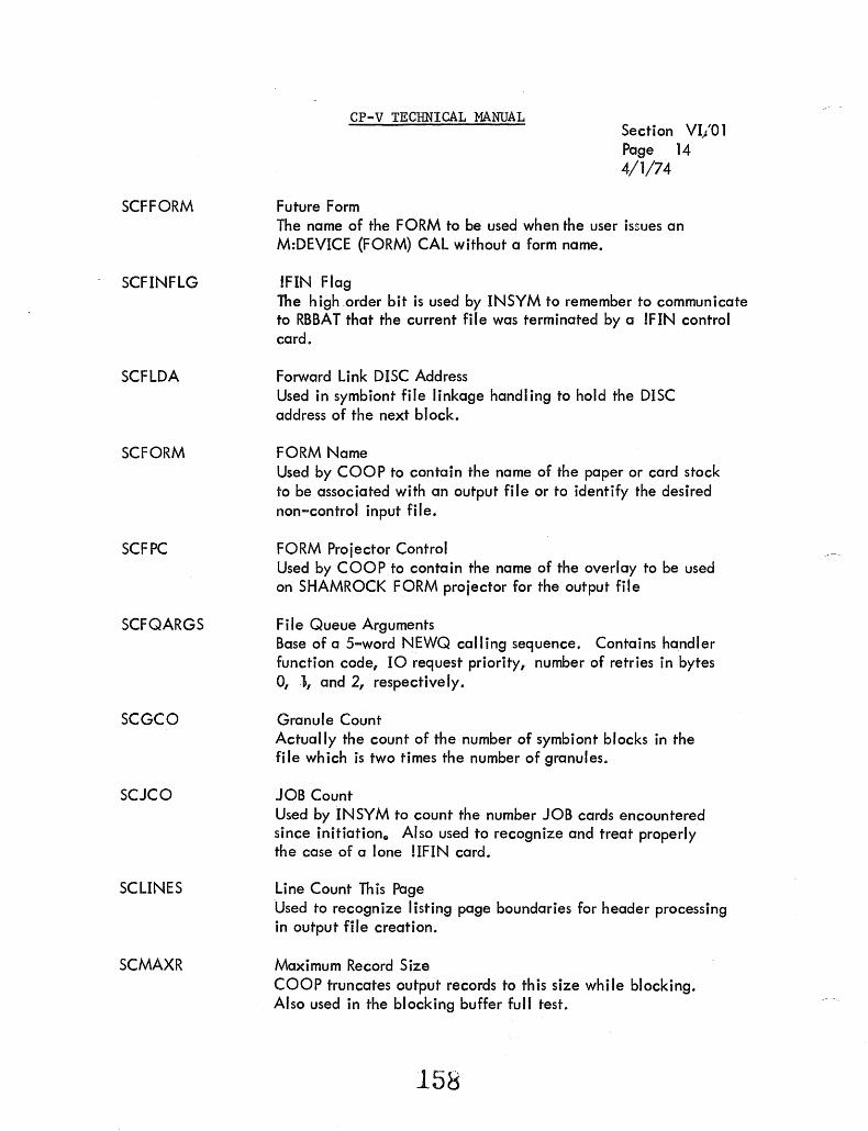
SCFFORM
SCFINFLG
SCFLDA
SCFORM
SCFPC
SCFQARGS
SCGCO
SCJCO
SCLINES
SCMAXR
CP-V TECHNICAL MANUAL
Future Form
Section VI/Ol Page 14 4/1/74
The name of the FORM to be used when the user issues an M:DEVICE (FORM) CAL without a form name.
!FIN Flag The high .order bit is used by INSYM to remember to communicate to RBBAT that the current file was terminated by a IFIN control card.
Forward Link DISC Address Used in symbiont file linkage handling to hold the DISC address of the next block.
FORM Name Used by COOP to contain the name of the paper or card stock to be associated with an output file or to identify the desired non-control input file.
FORM Projector Control Used by COOP to contain the name of the overlay to be used on SHAMROCK FORM projector for the output file
File Queue Arguments Base of a 5-word NEWQ calling sequence. Contains handler function code, 10 request priority, number of retries in bytes 0, .\, and 2, respectively.
Granule Count Actually the count of the number of symbiont blocks in the file which is two times the number of granules.
JOB Count Used by INSYM to count the number JOB cards encountered since initiationo Also used to recognize and treat properly the case of a lone !IFIN card.
Line Count This Page Used to recognize listing page boundaries for header processing in output file creation.
Maximum Record Size COOP truncates output records to this size while blocking. Also used in the blocking buffer full test.
158

SCMINR
SCMISC
SCMODE
SCNCBT
SCPCO
SCRCO
SCRCVLST
SCRPDA
SCSEQ
SCSVDGI
CP-V TECHNICAL MANUAL
Minimum Record Size
Section VI. 01 Page 15 4/1/74
Used in output fi Ie creation to pad short records to an acceptable width. On a listing type device, this cell contains the number of I ines per page.
Miscellaneous Contains miscellaneous output file attributes such as col umn of stream heading page count, default line spacing, job descriptor entry and number of copies.
Blocking Mode U~,ed by INSYM to control file terminations. SCMODE:;:: 1 implies !JOB or !IFIN terminates this file, SCMODE = 0 implies !JOB or !IFIN or !RB terminates. Thus, SCMODE = 1 while blocking RB CCs into a file.
No Communication Buffer Temp. Defines a 4-word area to hold RBBAT communication arguments while a symbiont is waiting in the activate queue for an RBBAT commun ication buffer.
Page Count Contains number of print pages processed for the current file.
Record Count Contains the number of records processed for the current file.
Recovery List A pointer to and control word for the list of prior disc addresses not released in catchup deletion mode in OUTSYM.
Release Previous Disc Addresses If nonzero, contains a disc address not released by cooperative end-action because ALLOCATs core stacks were full.
Sequence ID Contains the sequence ID to be used in stream card sequencing.
Saved Ghost Information Contains the file priority, RBID and SYSID of the current fj Ie to be used to ADD partial output in the event of a IQ I signal or system crash during OUTSYM processing.

SCSYMX
SCTOFDA
SCTYC
SCXTRAB
CP-V TECHNICAL MANUAL
SYMX Table Contents
Section VI. 01 Page 16. 4/1/74
Contains for INSYM the contents of the appropriate entry in the SYMTAB table SYMX.
Top of Form Disc Address Disc address of the granule containing the record belonging on the tope of the current form.
Type of 10 Completion Temporary holding place for TYC at OUTSYM end-action for later examinations.
Extra Buffer list A pointer to and control word for the I ist of buffers used by OUTSYM in multi-core buffer operation.
loU

CP-V TECHNICAL MANUAL
SECTION VI. 01 PAGE 17 10/31/74
RBBAT COMMUNICATION BUFFERS
In the fol lowing descriptions, the numbers in the diagram below are used to describe the fields in a particular RBBAT communication buffer.
LINK 2 3
5 6 7
9 10 11
13 14 15
GFC
8
12
16
Byte 1 is always the I ink to the next buffer. The buffers are linked to SGCHD as in the diagram below.
Byte 4 is always the Ghost Function Code (GFC) Which tel Is RBBAT what operation to perform.
161

etc.
CP-V TECHNICAL MANUAL
SGCHO
head waiting for RBBAT tai I of free buffers
'--------- tail waiting for RBBAT L.------------head of free buffer
SECTION VI.Ol PAGE 18 2/7/77
The 15 RBBAT communication buffers are assembled in the module COMBAT.
162

Section VI.01 Page 18a' 2/7/77
Normally RBBAT communication buffers are obtained from the head of the free chain and released to the tail. However the monitor cell S:QUI ET, when nonzero, also indicates that an abnormal situation exists per below:
S:QUIETt-I ___ l :0 normal operation ..
<;0 queues of communication buffers have been modified ..
> 0 queues are modified and RBBAT data is to be discarded in favor of : R BBRVR data ..
Modification of the queues consists of placing the heads of the free and waiting-for-RBBAT queues in the cell S:SGCSAV and zeroing those bytes in SGCHD"
~HD~HDI
These cells are manipulated by user-generated special GFC codes submitted to RBBAT.
1620.


GFC:
OPERATION:
CALLED BY:
NOTE:
CP-V TECHNICAL MANUAL
NOPGFC
None - release buffer only
Those who use two (2) buffers
See the two-buffer-cal Is below.
SECT ION V I. 01 PAGE 19 10/31/74
--------------------------------------------------------------------------GFC:
OPERATION:
CALLED BY:
B~te 2: Byte 3: B~te5 5 - 8: Bytes 15 - 16:
AIF
Add Symbiont Control Input Fi Ie
I NSYM
SYMBX DCTX Starting disk address Number of granules
--------------------------------------------------------------------------
GFC:
OPERATION:
CALLED BY:
Bytes 5 - 8: Bytes 9 - 12:
GFC:
OPERATION:
CALLED BY:
Bytes 2 - 3: Bytes 5 - 8: B~tes 9 - 12: Bytes 13 - 16:
AIFJE
Add JOBENT Control Input Fi Ie
T:JOBENT
Starting disc address SYSID
AIFNC
Add Symbiont Non-control Input Fi Ie
INSYM
SYMBX,OCTX Starting disc address Name from ;;NCTL Number of granules
163

GFC:
OPERATION:
CALLED BY:
Byte 2: Byte 3: Byte 5: Bytes 6 - 8: Byte 9: Byte 10: Bytes 11 - 12: Bytes 13 - 16:
SECOND BUFFER
Byte 3: Bytes 5 - 8: Bytes 9 - 12:
CP-V TECHNICAL MANUAL
f \0
AOF, AOFL, AOFNB
Add Output Fi Ie (Last, Non-Batch)
SUPCLS, T:JOBENT
Link to second buffer if any Device type Number of copies Starting disc address Priori ty RBID SYSID Number of granules
JOE Form name Forms overlay name
SECTION VI. 01 PAGE 20 10/31/74
----------------------------------------------~-----~---------------------
GFC:
OPERATION:
CALLED BY:
Byte 2: Byte 3: Byte 5: Bytes 6 - 8: Byte 9: Byte 10: Bytes 11 - 12: Bytes 13 - 16:
Add Partial Output Fi Ie
OUTSYM
SYMBX DCTX Number of copies Starting disc address RBSW I TCHED, HASP, PARTIAL, Priority (1,1,I,S) RBID SYSID Number of granules
----------------------------------------~-~------------~-~----------------
GFC: MBSGFC /
OPERATION: Perform Multi-Batch Schedule
CALLED BY: CLOCK I
---~----------------------------------~------~---~----~-------------------
164

GFC:
OPERATION:
CALLED BY:
Byte 2: Byte 3: Byte 5: Bytes 6 - 8: Byte 9: Byte 10: Bytes 11 - 12: Bytes 13 - 16:
SECOND BUFFER
Byte 3: Byte 3 (bits 1 - 7):
Bytes 5 - 8: Bytes 9 - 12:
Note:
CP-V TECHNICAL MANUAL
AOF, AOFL, AOFNB
Add Output File (Last, Non-Batch)
SUPCLS, T:JOBENT
Link to second buffer if any Device type
SECTION VI.01 Page 20
2/10/76
Number of copies or 1st byte of COMID (see SECOND BUFFER) Starting disc address Priority RBID SYSID Number of granules
2nd byte of COMID JDE, bit 0 of byte 3: if set, byte 5 of 1st buffer is 1st byte of COMID Form name Forms overlay name
If a COMID is being passed and bit 0 of the first byte of the COMID is set, this indicates the last "chunk" of concurrent mode output.
--------------------------------------------------------------------------------------GFC:
OPERATION:
CALLED BY:
Byte 2: Byte 3: Byte 5: Bytes 6 - 8: Byte 9: Byte 10: Bytes 11 - 12: Bytes 13 - 16:
GFC:
OPERATION:
CALLED BY:
AOFP
Add Partial Output File
OUTSYM
SYMBX DCTX Number of copies Starting disc address RBSWITCHED, HASP, PARTIAL, Priority (1,1,1,5) RBID SYSID Number of granules
MBSGFC i Perform Multi-Batch Schedule
CLOCK1
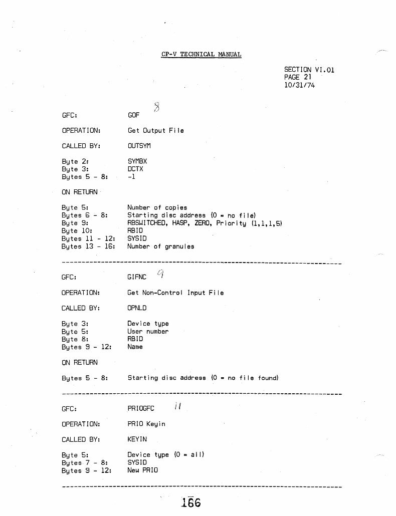
GFC:
OPERATION:
CALLED BY:
Byte 2: Byte 3: Bytes 5 - 8:
ON RETURN·
Byte 5: Bytes 6 - 8: Byte 9: Byte 10: Bytes 11 - 12: Bytes 13 - 16:
CP-V TECHNICAL MANUAL
GOF
Get Output Fi Ie
OUTSYM
SYMBX OCT X -1
Number of copies Starting disc address (O = nofi I~) RBSWITCHED, HASP, ZERO, Priori ty (1,1,1,5) RBID SYSID Number of granules
SECTION VI. 01 PAGE 21 10/31/74
----------------------------------~-------~-~----~--~---------------------
GFC:
OPERATION:
CALLED BY:
Byte 3: Byte 5: Byte 8: Bytes 8 - 12:
ON RETURN
Bytes 5 - 8:
GIFNC
Get Non-Control Input Fi Ie
OPNLD
Device type User number RSID Name
Starting disc address (0 - no fi Ie found)
---------------------------------------~----------------------------------
GFC:
OPERATION:
CALLED BY:
Byte 5: Bytes 7 - 8: Bytes 9 - 12:
pRIOGFC
PRIO Keyin
KEYIN
Device type (0 = al I) SYSIo New PRlO
----------------------------------------~--------~-----~------------------
1S6

GFC:
OPERATION:
CALLED BY:
Byte 5: Bytes 7 - 8:
CP-V TECHNICAL MANUAL
KDELGFC
DELE Keyin
KEYIN
Device type (0 = al I) SYSID
SECTION VI. 01 PAGE 22 10/31/74
--------------------------------------------------------------------------GFC:
OF)E~1A T ION:
CALLED BY:
B~j te 2: 8Uto 3: ,Bytes 5 - 8: 8ytes 9 - 12:
GFe:
OPERATION:
CALLED BY:
Byte 5: Bytes 7 - 8: Bytes 9 - 12:
KFRMGFC
(SYYndd,F'XXXX') Type Form Keyin
KEYIN
SYMBX of SYYndd JOE (-1 not changed) Form name (-1 not changed) Forms overlay name (-1 not changed)
KFCGFC
(Form 3B) Type Form Keyln
KEYIN
Device type SYSID New form name
--------------------------------------------------------------------------
GFC:
OPER!\ T I ON:
CALLED BY:
Bytes 5 - 8:
Bytes 9 - 12:
KDISPGFC
Display Keyins
KEYIN
A o 1
-1 -2 -3 SYSID =0 on LP 1:0 on DC
no option or DC SYSID NORUN SYMB output
167

GFC:
OPERATION:
CALLED BY:
Byte 3: Bytes 5 - 8:
CP-V TECHNICAL MANUAL
KCOMGFC, SNDGFC, BCSTGFC I <l. <7-0
RBCOM, RBSEND, RBBCST Keyins
KEYIN
DCTX to send to MPOOL word address of TEXTC message
SECTION VI. 01 PAGE 23 10/31/74
--~-----------------------------------------------------------------------
GFC:
OPERATION:
CALLED BY:
Byte 5: Bytes 7 - 8:
ON RETURN
Bytes 5 - 8:
Bytes 9 - 12:
JESTAT
JOBENT Status Request
T:JOBENT
Requesting user number SYSID for status
1 running 2 waiting to run 4 waiting to output o completed number waiting to run if bytes 5 through 8 = 2
--------------------------------------------------------------------------
GFC:
OPERATION:
CALLED BY:
Byte 2: Byte 3: Bytes 7 - 8: Bytes 9 - 12:
SECOND BUFFER
Bytes 5 - 8: Bytes 9 - 12:
SWITGFC
RBSWITCH Keyin
KEVIN
Link to second buffer Byte count of WSN $YSID Device type (TEXT)
'TO' workstation name, word 1 WSN, word 2
--------------------------------------------------------------------------
168

~,
GFC:
OPERATION:
CALLED BY:
Byte 2: Byte 4: Bytes 7 - 8:
SECO>~D BUFFER
Bytes 5 - 8: Bytes 8 - 12:
ON RETURN {BUFFl}
Bytes 5 - 8:
CP-V TECHNICAL MANUAL
JEDEL
Cancel Command
T:JOBENT
Link to second buffer Requesting user number SYSID to delete
Word 1 of account Word 2 of account
X'3A' no such fi Ie X'39' wrong account o AOK
SECTION VI. 01 PAGE 24 10/31/74
--------------------------------------------------------------------------
GFC:
OPERATION:
CALLED BY:
Byte 3:
'2 ~)
DUP, HUP
RB Dial Up, RB Hang Up
BSCID, RBSSS, DSCID
DCTX
----------------------------------------------------~---------------------
GFC: LDRR
OPERATION: RB Logon Record Received
CALLED BY: BSCI0, DSCIO, RBSSS
Byte 3: DCTX Bytes 8 - 12: MPDDL word address of logon record
------------------------------------------------------------~------~------
GFC: OCMGFC
OPERi\ T I Or\!: IRBT DC Input Message
CALLED BY: HASPIO
Byte 3: DCTX Bytes 8 - 12: MPOOL word address of message .1b~J

GFC:
OPERATION:
CALLED.BY:
CP-V TECHNICAL MANUAL
RCVR1GFC
Marks Point of Recovery in COMBUFS
RECOVER
SECTION VI. 01 PAGE 25 10/31/74
--------------------------------------------------~------------------------GFC:
OPERATION:
CALLED BY:
Bytes 5 - 8: Bytes 9 Bytes 10 - 12:
RCVRGFC
Perform RBBAT Recovery
RECOVER
Size of dynamic data (-1 says recovery doesn't know) S:CUN at time of crash Flags 1 operator recovery
2 data zapped 4 = COMBUFS zapped 8 = RBBAT wasn't running
-----------------------------~-------------~---~-------~----------~-------
GFC:
OPERATION:
CALLED BY:
Byte 2:
GFC:
OPERATION:
CALLED BY:
Byte 2: Byte 3: Bytes 7 - 8:
KOSTOP
OUTPUT STOP keyin
KEY IN
SYMBX
KFLUSH
FLUSH keyin
KEY IN
SYMBX Device Type SYSID
l'IU

MBS TABLES
Name
OIPRI
FIPRI
RUNPRI
OOPRI
FOPRI
MFPRI
/-, NCIPRI
DELPRI
FREI
FREO
CP-V TECHNICAL MANUAL
IN RBBAT: PRIORITY TABLE
Section VI.02 Pa~e 1 4/1/74
Table Name
Index Head
0
F Head
10 Head
11 Head
"/~ ~.t.- •
20 Head
Head 21
Head 22
23 Head
24 Head
Head 25
BH:HPRI BH:TPRI
of PRIO 0 Input Tail of PRIO 0 Input
..--,.-v'--
of PRIO F Input Tail of PRIO F Input
of Running Jobs Tail of Running Jobs
of PRIO o Jutput Tail of PRIO 0 Output
of PRIO F Output Tail of PRIO F Output
of Message File Tail of Message File OutEut OutEut
of Non-Control Tail of Non-Control Input Input
of Files to be Tail of Files to be Deleted Deleted
of Free Input Tail of Free Input Slots Slots
of Free Output Tail of Free Output Slots Slots
- Both are halfword tables - Displacements are hexidecimal
1~..., .. 1.1
'.~ .<\.,.,..!.I c.."..
4 •• ••

BH:GRAN
BB:COPY
BH:COMID
BW:FORM
BH:XLNK
BH: SLNK
BH:PART
B4W:RES
BH:TIME
BD:ACCT
BB: RID
BB:PI/BB:DEV
BW: SDA
BH:SID
BH:LINK
index
I
1
CP-V TECHNICAL MANUAL
INPUT ----I,.... ... ~-.- OUTPUT
I # of GRANULES
Bit ~ set for I COpy COUNT
last chunk of ---f rONCUR. OUTPUT MODE iD concurrent outpU4:------------.
j
~-'.---~----' .' ".-.-.--.~.------
J HEAD OF EXCLUSIVE CHAIN IN ~ S#H:LNK
l FORM NAME TEXT
---_--II RW
~: HEAD OF SHARED CHAIN IN ,I
[~ S#_H_:L_NK ____________ ~ HW
Section VI.02 Page 2 10/31/74
BYTE
HALF WORD
WORD
I·~ BITS'iMpU~-r.m-IDATE-.. ··-··--..... ·"-1
.' PARTITIQN ! HW Sytv\BIONT FILE TABLES IN RBBAT
f2J -~"--
II, RESOURCE VALUES . . -Ordered like SH:RNM . I -X'80' implies default
j.
---_ .. 'j
I I
I
Four Words ! I 1
t.~.~,;;..-.-::-.-........ ::,,-~.:.:-.....,;;..--.-_:.--.-.;.....--~7....;...,::.:::'..,;;;...:. ~_--~"';----';"--:"------A' ____ ,~ ___ _
r - I t~·; __ J_OB __ R_UN __ -T_I_ME ___ M_INU __ T_E_S _____ ~ HW r JOB ACCOUNT:EXT Jl L-._ .. DW r--··-"--·'~--'"'--·------·----··--·~· --- .. -.-~-------<.
Bit
0 1 2
3 4
5 6
7 /. JOB OR OUTPUT RBID (0 IMPLIES LOCAL) _u_~ ____ ~ ______ · __ ·___ ,-------[ ___ -.!~~-I-?~~TI~. - .. ~-.~~-:'~~~~_" ___ ._~l. __ D~E-V_I_C_E_TY_P_E __ _
i ..... f_~_F~_· ·_"G_S...aI ___ F_~_L_·E __ ·~_·-.T_-~_:_T_~~~_"' _D_I~<_,~~~<~_S_S __ . __ _
; i .
!
zeroeth entry net used
* job priority
17~
FLAGS
Out In
Order Account
Delete output When Added
Hold Hold Using Special Message File
Rerun request
HASP & Switched Seeond rerun RBSWITCHED JOSENT sumbitted

Section VI.02
CP-V TECHNICAL MANUAL Page 3 4/1/74
MES TABLES IN RBBAT: SERIAL NUMBER TABLES
Table Name
s1IH:LNK s1lw: SER s11B: TYP Head of
0 Free Chain
I Link By Serial Number Input File
Index or Free
into SB:RTY & RES Tables Length
(0= > TAIL)
(HW) (WORD) (BYTE)
-Heads of serial number chains are in BH:SLNK or BH:XLNK.
-Length = «INFILE*AVGSER+3)/4)+1
1 ,·,,· I'd

CP-V TECHNICAL MANUAL
MBS TABLES IN CORE:
Resource Allocation Tables (RAn
~ Z 0::::
:I: V')
t ..c ..- 0 + -N Q) - E
V') 0 0:::: c:
-> Q) 0
til L.. ::> 0 In
~ Q)
e::::
SH:RNM
SB:RTY
SH:RTOT
~ ~
co V)
Q) 0.. >-l-
Q) 0
> Q)
0
~ ~ ~ t- ::> Xu-::> :J Xu-::> ::> 0 V') ~ou V')
V') ~ou 0 0 l- cc co co co 000 ~ 0:::
~ ~ c:: ~ 0:: e:::: 0:: ~ .. .. .. .. .. . . :r: t;; co co:c :r: com:c :c V') V') Vl V) Vl Vl V1 V') Vl
Q) 0 L.. ::> 0 V)
Q) 0::::
-0
I
E J ::> -E ::> c:; Q)i
E x ~ L-' L..l
::> 0 (l) =>! Vl E -u U'
..c: ..c: ..c: ,..1 -I u U u u,
..... ~~ ./. ~'-" -- - -_#.,
E ::> --E :::>
c: Q)
E x ~ L-L-a (l,) ::> ::> E V) -0 U
(l) Q) CD Q)
c: c c c .-- - - -I I I I
E ::> In -Vl
0 -a I- - - - _I
0 0 a ~I co co co C C C c:
0 0 0 0 ..c: 0
Resource namet table in TEXT {halfword}
Device type {Byte} (entries are unique)
T ota I system resou rce
Section VI.02 Page Q. 4/1/74
U-u..::> ~ou 0'-'0 0:::: 0:::: 0::::
cOcOI V') Vl V) th o entry not used
E ::> --E - c ::> Q)
x ~ L.. L.. a Q) ::>
E -u u -- -V) V) VI
0 0 0 ..c ..c ..c
'-' <..') <..')
SH:{~} SUM I batch} Total resources available for the ~on-line load
\ ghost
SB:R {g}MX
SB:R{g}DF
9i:R {~} CU
{batch}
Maximum allocation per on-line user ghost
{batch}
Defau It a lIocation per on-line user ghost
{batch}
Currently a Ilocated for the on-I i ne load ghost
Note: SH:RNM and the value definition SV:RSIZ < 15 are in the SYSGEN produced lood module SG:RNT. (The-value tobles ore mo~tor resident, having been initially incorporated into the monitor from the SYSGEN module SG:Rc;T.) fhe first four entries are CO, 9T,7T,
and SP.

CP-V TECHNICAL MANUAL
Section VI.02 Page 5 4/~1!74
MBS TABLES IN CORE: SERIAL NUMBER TABLES FOR RUNNING JOBS
o
1
Table Name
LSERIAL
Head of Free
Link by job or free
(0= '> TAIL)
(BYTE)
TSERIAL
Serial Numbers
(WORD)
RSERIAL
.. .. ///",'/' -'
/'
Device Type from SB:RTY
(BYTE)
1-i
LENGTH
-Heads of serial number chains are in users JIT. -Length = 255 or «(16*AVGSER)+3)/4)+1+16
(whichever is less)
l · ... ~'· l \)

CP-V TECHNICAL MANUAL
MBS TABLES IN CORE: PARTITION TABLES
SYSTEM NAME
PL:LK
PL: CHG
DEFINITION
Partition table lock control word set if tables currently being altered or used.
Control - altered partition status word which flags an occurring change in partition tables and signals which partitions definition has been altered.
Section Page 6 4/1/74
VI.02
ENTRY SIZE
1 word
1 word
Each of the tables below is of length LPART (number of partitions defined).
PLH:TL
PLH:TU
PLH:QN
PLD:ACT
PLH: CUR
PLH:TOL
PLB:USR
PLH:SID
PLH:FLG
Lower time limit of partition n.
Upper time limit of partition n.
Quantum time of partition n.
Current running account of parti-tion n.
Current number of jobs which have been selected under current partition definition.
Total number of jobs run under this partition.
User number of user currently using partition.
SYSID of job currently using partition.
Partition control flags.
PLH:FLG ;
Q H § ...J ~ ~
H u u 0 u U e:::: cc 0 ::t:: < e:::: ...J l- e:::: H
-' o 1 2 "' 1 5 !
1 = legal ORFGON
176
halfword
halfword
halfword
doubleword
halfword
halfword
byte
halfword
halfword

CP-V TECHNICAL MANUAL
Section VI.02 Page 7 4/1/74
The following two tables of length LPART are (number of defined resources) bytes wide.
SYSTEM NAME
PLB:MAX
PLB:MIN
DEFINITION
Upper resource limits of partition n.
Lower resource limits of partition n.
.................. .~. SV:RSIZ+l ~
: j i
I 9T I
7T ISP :;~ CO t ! i i
ENTRY SIZE
# resources bytes
# resources bytes
Resource order corresponds to order in SH:RNM.
Byte 0 of PLB:MIN for a partition contains the head of the exclusive serial number chain into LSERIAL for the job running in that partition.
17'/

CP-V TECHNICAL MANUAL
Section VI.02 Page 8 4/1/74
MES TABLES IN CORE: PARTITION TABLE LAYOUT (PLD:ACT TO PLB:MAX)
*
PLB:MAX
~ ~ MAXIMUM RESOURCES THIS PARTITION -'./ /:>'/'7777-;;)/;/ 7"r,·:::r,7:~-r/.::.· ... ·.,r :7~:'~~7/"TT77
f SV:RSIZ+l bytes
* ** f
PLB:MIN SV:RSIZ+l bytes
* ** PLH:QN r1
, j QUANTUM THIS PARTITION HW
PLH:TU UPPER TIME LIMIT HW
PLH:TL LOWER TIME LIMIT HW
PLH:FLG PART CONTROL FLAGS HW
PLH:TOL TOTALRPN IN THIS PARTITION HW
PLH: SID SYSID OF JOB HW
PLH:CUR JOBS RUN SINCE PART CHANGE HW
PLB:USR USER NUMBER BYTE
PLD:ACT t ~1~1 __ A_C_CO_U_NT ___ OF __ J_O_B ____________ ~1 DW
//oOII.t------ LPART+l ---------l,.~1 * zeroeth entry not used. ** zeroeth sub-entry not used.
178

CP-V TECHNICAL MANUAL
GI Tables
Section VI.02 Page 9 4/1/74
These tables (assembled into the module COMBAT) are the communication path
from the Multibatch Scheduler to CCI via the input cooperative through the
routine GETI. Each table has three entries allowing theMBS to supp,ly
three jobs in one scheduling pass by finding furee iobs and fill ing in the
infonnation from its internal tables (the Batch Tables) into the GI tables.
GET!, when called in response to a CCI read, finds the proper GI entry by
matching the current user number, S:CUN, against the table GIB:UN.
Information from other GI tables is moved to JIT as indicated in the table below,
the file indicated in GI:SDA is read, and the GI table entry is freed by placing
its entry number on the free list GI:FRE.
GIB:UN
GIH:TIIv\ .
GI:ASPN
- User number
- maximum run time minutes {stored in J:MRT
- 3 words containing the shareable Drives/Spindles Bit Map (stored in J:AS PIN)
GI:RES - 4 word list of required resources {store in JB:MAX)iparalles RAT.
GIB:SLN, GIB:XLN - shared and exclusive serial number table linkages (stored
in JB:SLN K, JB:XLN K)
GIB:RID
GI:SDA
GIB:PRT
GI:FRE
GIB:PRI
- remote identification (stored in JRBID)
- starting disk address, input file
- partition number {stored in JB:PNRi SYSID from PLH:SID
store in J:Jln
- A word which lists fue free GI enrries.
- PRIO from job card or PRIO keyini stored in JIT+PRT

Service Limit Tables (SLT)
SL:NAME
CP~V TECHNICAL MANUAL
Section VI.02 Page 10 4/1/74
Sl:BDF SL:BMX SL:ODF SL:OMX Sl:GDF SL:GMX
Sl:NAME Word table containing the first four characters of the limit nome (left iustified blank fi lIed).
S'L: {g} DF Word tabl es conta i n i n9 the defa ul t limit va lues for any {o;2!;e} job.
{ B} {batch} Sl: 0 MXWord tables containing the maximum limit values for anyon-line job.
- G ghost
SV:lIM Value definition defining the number of entries in the SL:NAME table.
Sl:NAME and the value definition SV:LIM are in the SYSGEN produced load module
SG:lNT. A value definition is produced for each limit nome. The value definition is
made up of SV: and the first two characters of the limit nome. These value definitions are
also included in the SYSGE~ module SG :LNT. The value tables are monitor-resident,
having been initially incorporated into tre monitor from the SYSGEN module SG :DLNT.
180

~ >-I-u..
> u")
CP-V TECHNICAL MANUAL
Secti on VI. 02 Page 11 4/1/74
Peripheral Authorization Tables (PAT)
co 0 0 0 0 0
SH:SYMT ~ ~ ~
1" >- >- >-V1 V) V) .. + V) V) V)
~ 0 >- 1 l-
> V1
-1.
31
SH:SYMT A table in TEXT containing those device types to be associated with symbionts. The table consists of halfword entries in TEXT format left justified and blank filled. The bottom of the table contains FAUTH values as above.
S:5YMD
Note:
SV:TYM
SV:FTYM
Words contain ing B it tables wh ich are the defaul t authorization flags. Bit 1 corresponds to the 1st entry.
Is a value defining the table length, for SYMBIONT DEVICES.
Is a value defining the table length including FAUTHs, 15 max.
SH:SYMT and the value definition SV:TYM and SV:FTYM are in the SYSGEN produced load module SG:PNT. S:SYMD B! are core resident. jO
G
Ibl

CP-V TECHNICAL MANUAL
SECTION VK PAGE 1 10/31/74
ERROR LOG FORMAT
The Error Log Fi Ie is a special consecutive fi Ie on the RAD written by ERRLOG. The fi Ie is not accessed by name, but by a special pointer in memory which contains the disk address of the first record in the fi Ie. Each record is 64 words long and contains a backward and forward I ink. The backward link is the disk address of the previous record and the forward I ink is the disk address of the next record in the fi Ie. The backward link is never zero since the fi Ie is considered as open and the next record to be written is being constructed in a core buffer as the errors occur. The forward I ink in the last record written contains the disk address where the next record is to be written.
The record format in the fi Ie is as fol lows:
o Backward Link
1 Forward Link
2 Number of Words in this Buffer
3 Message 1
Message 2
. .
Message N
63
lel2

CP-V TECHNICAL MANUAL
SECTION VK PAGE 2 10/31/74
Each record may contain several unused words at the end of the record since r,iessages may vary in size, from one to eighteen words each. Therefore, up to nine words may be unused. The maximum number of useful words in a record is 61. The format of the backward and forward I ink disk address is as fol lows:
o 1516 31
OCT Index for Disk Relative Sector No.
Disk granules for writing the fi Ie are obtained by cal I ing the GBG {Get Background Granule} routine. This routine gets one granule at a time. Each granule contains one record of the fi Ie.
FILE CONTROL POINTERS
Several pointers in memory provide the necessary control information for constructirlg and accessing the fi Ie. The following is a I ist of pointers, all of word length, and their definitions:
SGRA~~
BGRAN
CURGRAN
FGRAN1
CURBUF
contains the disk address of the first record in the f i Ie.
contains the disk address of the last record written.
contains the disk address of the next record to be written.
contains the disk address of the record to be written fol lowing the current record.
contains address of buffer which is currently being used to pack the messages.
Two 54-word buffers are used for packing the messages. The labels for the two buffers are BUF1 and BUF2. Each buffer is preceded by two control words. The first control word contains the memory address of where the next message wi I I be stored in the buffer. The second control word contains the number of words of space remaining in the buffer. The first three words of the buffer are the same as the first three words of the record on disk. The backward and forward I ink addresses are put in the buffer before any messages are packed in the buf felr.
If one of the buffers is in the process of being written to the disk and tha second buffer fi I Is up before the writing of the first is completed, then al I error m~ssages for the errors which occur whi Ie this condition exists wi I I be lost. The error logging routine just exits when there is no sp~ce avai lable in either of the buffers.
1 ).( ~~

CP-V TECHNICAL MANUAL
Error Log Core Structure
ERRLGTAB
o 1415
CURSUF Current Buffer
SGRAN ERRORLOG Starting Disk Address
BGRAN Previous Disk Address
CURGRAN Current Disk Address
FGRANI Next Disk Address
FGRAN2 Next IDi sk Address
FGRAN3 Next 2Disk Address
184
31
SECTION VK PAGE 3 9/1/78
SUFI
{
This buffer is being fi I led, and
~ wi I I be written to here when fu I I •
} PFA GETGRAN

CP-V TECHNICAL MANUAL
SECTION VK PAGE 4 9/1/78
BUF 1/BUF2 Description
o 31 -.. ~
-1 WA (Nex t En try)
BUFl 0 Back-I ink Disk Address
1 Forward-link Disk Address
2 Number Words Used 680)
-z.J i.-
255 T 80 Avai lable (Maximum)
J
185

OVERVIEW
CP-V TECHNICAL MANUAL SECTION VK Pl'GF 5 10/31/74
The system error log is a standard file 'Of the operating system in question. It may be organized in any access method convenient to the individual operating system but must be accessible sequentially. The name of the file is to be ERRFILE and the account shall be :SYS. Logical records within the file are variable length but may be carried in a fixed length record if convenient. Logical records will never be longer than 20 words.
Each logical record of ERRFILE begins with a byte containing the error log entry code and a byte containing the total number of words in the record.
If a keyed file organization is used to facilitate analysis, the keys will be formatted as follows:
The key contains the Julian date in packed decimal, the time of the error in EBCDIC, and a sequence number for errors with the same time. This sequence number is reset to zero for each entry with a new time. The format of the key is
OEl yy ad dd
h h m m
n
where:
08 is the number of bytes in the key.
yyoddd is the Julian date in packed decimal e
hhmm is the time in hours and minutes (EBCDIC) •
n is the sequence number.
CP-V Error Log Mechanism
In CP-V, the mechansim for creating the error log utilizes a monitor resident recording routine ERRLOG which blocks individual error entries into 64-word blocks using a standard double buffering technique. When full, these blocks may be written into a chain of sectors obtained from the permanent file area (PFA). Only the first 64 words of each 256-word sector is used in order to minimize the core requirement for buffering. Blocks are chained by links carried in the first words of each block and are not part of the standard file system. The core resident head of chain is carried across recoveries by the recovery routines.
186

Sf'CTIflP 'vr CP-V TECHNICAL MANUAL
Each time six errors are recorded by ERRLOG, the ghost job, ERR:FIL, is triggered. This program uses the privileged error log reading CAL to obtain the blocks of er~or log entries from the chained file. The read is destructive and secondary storage granules are returned to the system (PFA) as the information is read from them. ERR:FIL deblocks the individual entries, creates a key for the record indicating date and time of the entry, and writes the record into the file, ERRFILE, in account :SYS using the keyed file organization. Each time ERR:FIL is awakened, it continues copying until no more error log entries remain to be copied.
This process is outlined in Figure 1.

64 word double core buffer
. non-
STANDARD FilE
ERRlOG ROUTINE
ENTRIES FROM VARIOUS MONITOR RECORDING POINTS
. Cp..;. V TECHNICAL MANUAL
READ I ERROR lOG CAL , ; I
RESIDENT USER MONITOR JOB
SF.CTIf)N ~.rK
pAGF. 7 10/31/74
STANDARD KEYED FILE ERRFIlE. :SYS
STANDARD WRITE CAL
GHOST JOB
ERR:FIL
FIGURE 1 - CP-V ERROR LOGGING SCHErm
l~b

CP-V TECHNICAL MANUAL
SUMMARY OF ERROR LOG ENTRIES
Error Codes
o 10 11 12 13 14 15 16 18 lA lB lC IE IF 20 21 22 23 24 25 26 27 28 29-2C 2D 2E 2F 30 31 32 33-40 41 42 43 45-48 49 4A-4F 50 51 52
Null Entry Copy Error (several subtypes) SIO Failure Device Time Out Unexpected Interrupt Reserved Device Error Secondary Device Error System Startup/Recovery File Inconsistency Entry Software-detected Symbiont Inconsistency Reserved Lost Entries' Duplicate Entries Power On Configuration System Identification Time Stamp Bad Granule Release Reserved Remote Processing Error Record Operator Message I/O Activity Count Reserved Hardware Error Watchdog Timer Instruction Exception PFI Primary Record MFI Primary Record Secondary Record for Poll Information Reserved 560 Processor Configuration 560 Memory Parity Secondary Record Sigma 9 Memory Parity Secondary Record Reserved Memory Parity Secondary Record Reserved ENQUEUE Table Overflow Partitioned Resource Returned Resource
Reserved for Future Enhancements
53 - SF For CP-V 60 - 6F ¥or CP-R 70 - BF New Features
189
SECTION VK Page 8
9/1/78

CP-V TECHNICAL MANUAL
GLOSSARY OF TERMS
SECTION VK PAGE 9 10/31/74
The following pages detail the terms used in the error log formats for each operating system.
CP-R GLOSSARY OF TERMS
AIO CC
AIO Status
Alternate I/O Address
Bad Location (Sigma 7 only)
Code
Core Size (in -SK word blocks)
Count
Current Command Doubleword
OCT Index
Effective Address of Trapped Instruction
A 4-bit value (bits 0-3 of designated byte) representing the condition codes as returned by the hardware in response to an AIO instruction.
A 16-bit value representing the status as returned by the hardware in response to an AIO instruction.
A 16-bit value representing an alternate physical I/O address by which a dual-access device can be referenced.
A 32-bit value representing the real memory address which caused a memory parity interrupt.
An 8-bit value in the first byte of an error log message indicating message type.
An 8-bit value representing the number of 8K (8192) blocks of words.
An a-bit value in the second byte of the er~or log message representing the number of useful 32-bit words contained in the error log recorde Includes the first word in the count.
A 64-bit value representing the command doubleword currently being processed for a device (as indicated by the TDV status OW).
An a-bit value indicating the order in which the device is configured into the system (at SYSGEN) $ The index value for the first device is 10
A 32-bit value representing the final address computed for the instruction pointed to by the instruction address (IA) in the PSD.

HIO CC
HIO Status
I/O Address
I/O Count
,::ulian Day
Memory Status Words (only Sigma 9 and 560 series)
MFI (Sigma 6 or 7 only)
Model Number
Number of Parity Errors
Poll CC
Poll Status (identical to POLR Resul ts)
CP-V TECHNICAL MANUAL SrCTIf)IJ VK Pl'c::r. 1') 10/31/74
A 4-bit value (bits 0-3 of designated byte) representing the condition- codes as returned by the hardware in response to an HIO instruction.
A 16-bit value representing the status as returned by the hardware in response to an HIO instruction.
A 16-bit value representing the physical I/O address.
A 32-bit value representing the pumber of start input/output (SID) instructions executed for a device. This value is reset at system boot time.
A 16-bit value representing the julian day of year (e.g., March 1 would be represented as X'3D').
Each word is a 32-bit value representing data returned by the hardware in response to a LMS instruction.
A 4-bit value representing the current . state of the memory fault indicators re
turned by the hardware in response to a RD instruction. All memory fault indicators will be reset.
A 16-b~t value representing the conversion of a number (assigned by Field Engineering to uniquely identify peripheral devices) to a binary value (e.g., 7242 would be represented as X B 1C4A') •
A 16-bit value representing the number of bad locations causing memory parity errors (only the first '14 bad locations are entered in the log if the number of errors errors is greater than 14).
A 4-bit value (bits 0-3 of designated byte) representing the condition codes as returned by the hardware in response to a POLP or POLR instruction.
A 16-bit value representing the processor fault status as returned by the hardware in response to a POLP or POLR Instruction.
l~Ll

Primary I/O Address
- PSD
Real Address
Real Time Resolution
Recovery Count
Relative Time
Retries Remaining
Retry Request
SIO CC
SIO Status
Site Identification
Startup Type
CP-V TECHNICAL MANUAL SECTION VK P}\GE 11 10/31/74
A 16-bit value representing the physical I/O address by which a device can be referenced.
A 64-bit value representing the program status doubleword.
A 32-bit value representing the actual memory address. (In an unmapped system, this is the same as the address in the IA field of the PSD.)
An a-bit value, n, such that actual rela·tive time resolution = 2 milliseconds (e.g., N=1 for a resolution of 500HZ or 2 milliseconds).
Currently not applicable. Will be O.
A 32-bit value representing milliseconds since midnight. Resolution is 2 milliseconds.
An a-bit value representing Retry Request minus the number of retries attempted. The range is between Retry Request and -1. A value of -1 indicates the operation was terminated due to retry count rundown.
An a-bit value representing the maximum number of retries after which device error ie returned to the requestor. This value is obtained from the requestor's DCB.
A 4-bit value (bits 0-3 of designated byte) representing the condition codes as returned by the hardware in response to a SIO instruction.
A 16-bit value representing the status .as returned by the hardware in response toa SIO instruction.
A 64-bit field. The first 32 bits will contain the EBCDIC representation of the SYSGEN input parameter for version. The second 32 bits will be blanks (X 1140' ) •
An a-bit field indicating type system initialization. Will be 3 System device boot.
of for
192

TDV CC
TDV Status Doubleword
TIO CC
TIO Status
Trap CC
Trapped Instruction "
Unit Address
Unit Type
Version
Year
CP-V TECHNICAL MANUAL s :r.cr~PI fin VI( Pi\GI' 1:2 10/ 31 /7l~
A 4-bit value (bits 0-3 of designated byte) representing the condition codes as returned by the hardware in response to a TDV instruction.
A 64-bit value representing the subchannel status as current command doubleword, device status, and byte count as returned by the hardware in response to a TDV instruction ..
A 4-bit value (bits 0-3 of designated byte) representing the condition codes as returned by the hardware in response to a TIO instruction ..
A 16-bit value representing the status as returned by the hardware in response to a TIO instruction.
A 4-bit value (bits 0-3 of designated byte) representing the condition codes as returned by the hardware when
" certain traps occur.
A 32-bit value representing the contents of the location pointed to by the instruction address (IA) in the PSD.
A 6-bit value (bits 2-7 of designated byte) representing the address by which a processor can be referenced. The value is composed of a 3-bit cluster number followed by a 3-bit unit number.
An a-bit value specifying the type of processor. Bit 0 of the designated byte indicates the presence of the processor in the current operational configuration (0 = present, 1 = not present) ..
Not currently applicable. will be o. A 16-bit binary value representing the current year minus 1900 (e.g., 1973 will be represented as X'49').
193

CP-V GLOSSARY OF TERMS
Account
-AIO CC
AIO Status
Alternate I/O Address
Bytes Remaining
Code
Consecutive, Keyed, Random
Core Size
Count
Count of Entries Identical to Previous Entry
Count of Entries Lost
Current Command Doubleword
Caller's Address
CP-V TECHNICAL MANUAL SECTION VI< PAGF 13 10j31/7Q
The doubleword used to identify user's collection of files.
a
A 4-bit field (bits 0-3 of designated byte) representing the condition codes as returned by the hardware in response to an Ala instruction.
A 16-bit field representing the status as returned by the hardware in response to an Ala instruction.
A 16-bit value representing an alternate physical I/O address by which a dualaccess device can be referenced.
A 16-bit field representing the Remaining Byte Count (RBC) field as returned by the hardware in response to a TDV instruction.
An a-bit value in the first byte of the error log message indicating message type.
Methods of organizing user files in CP-V (refer to the CP-V Batch Reference r.1anual)
I
An a-bit value representingithe number of ax (8192) word blocks. I
An a-bit value in the second byte of the error log message representing the number of usefu~ 32-bit words contained in the error log record. Includes the first word in the count.
The number of error log records which are identical to one previously logged for identical reasons (excludes time records).
, , The number of error log records lost when
" logging becomes temporarily impossible for any reason.
A 64-bit value representing the command doubleword currently being processed for a device (indicated by the TDV status DW).
The address or EBeD.Ie name of routine back to which the error logging routine will return when logging is complete; used in isolating software faults.
l!i4

DCT Index
OCT Index of Symbiont Device
Effective Address
Error Subcode
File Name
Granule
Generalized Disk Address
HIO CC
HIO Status
I/O Address
I/O Count
Julian Day
CP-V TECHNICAL MANUAL SECTI0n '\1I< PJ..GB 14 10/31/74
The 8-bit value indicating the order in which the device is configured into the system (at SYSGEN).
The a-bit value indicating the order in which the device associated with the symbiont is configured into the system (at SYSGEN).
A 32-bit value representing the final address computed for the instruction pointed to by the instruction address (IA) in the PSD.
An a-bit field indicating which of several types of file inconsistencies has occurred (see CP-V Batch Reference Manual).
The TEXTC collection storage.
name used to identify a of user data on secondary
The unit of secondary storage allocation equal to 2048 bytes (usually 2 sectors).
See Section 6.0.
A 4-bit value (bits 0-3 of designated byte) representing the condition codes as returned by the hardware in response to an HtO instruction.
A 16-bit value representing the status as returned by the hardware in response to an HIO instruction.
A 16-bit value representing the physical I/O address.
A 32-bit value representing the of SID instructions executed device. This field is reset at boot and recovery time.
number for a system
A 16-bit value representing the julian day of the year (e.g., March 1 would be represented as x'3D') when the error was logged.
1~5
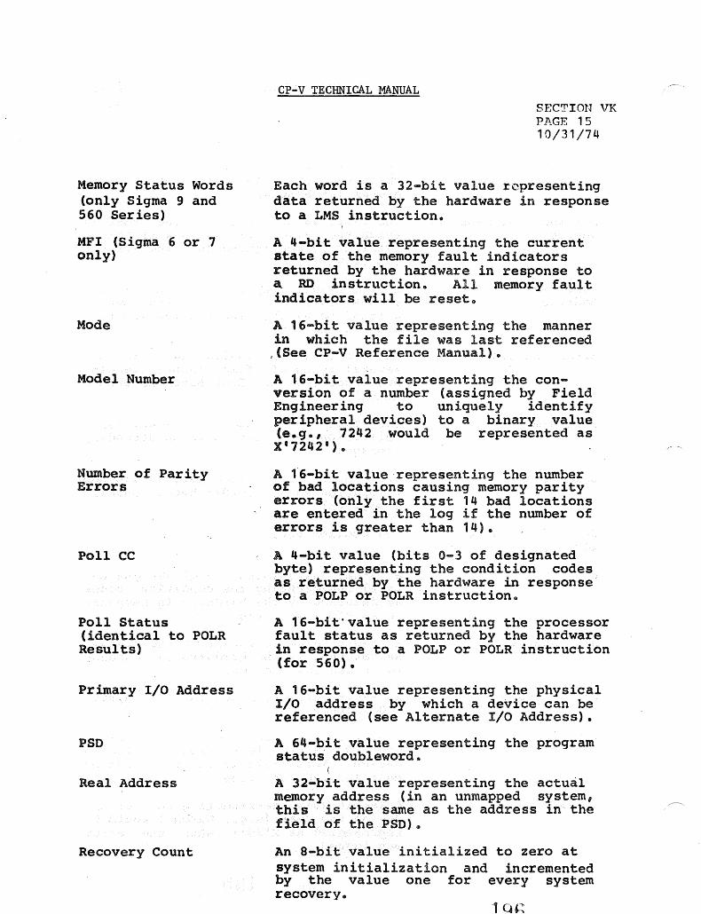
Memory Status Words (only Sigma 9 and 560 Series)
MFI (Sigma 6 or 7 only)
Mode
Model Number
Number of Parity Errors
Poll CC
Poll Status (identical to POLR Results)
Primary I/O Address
PSD
Real Address
Recovery Count
CP-V TECHNICAL MANUAL SECTIon VK Pl\_GE 15 10/31/74
Each word is a 32-bit value representing data returned by the hardware in response to a LMS instruction.
A 4-bit value representing the current state of the memory fault indicators returned by the hardware in response to ~ RD instruction. All memory fault indicators will be reset.
A 16-bit value representing the manner in which the file was last referenced
,(See CP-V Reference Manual).
A 16-bit value representing the conversion of a number (assigned by Field Engineering to uniquely identify peripheral devices) to a binary value (e.g., 7242 would be represented as X'7242').
A 16-bit value'representing the number of bad locations causing memory parity errors (only the first 14 bad locations are entered in the log if the number of errors is greater than 14).
A 4-bit value (bits 0-3 of designated byte) representing the condition codes as returned by the hardware in response to a POLP or POLR instruction.
A 16-bit'value representing the processor fault status as returned by the hardware
.in response to a POLP or POLR instruction (for 560).
A 16-bit value representing the physical I/O address by which a device can be referenced (see Alternate I/O Address).
A 64-bit value representing the program status doubleword.
A 32-bit value representing the actual memory address (in an unmapped system, this is the same as the address in the field of the PSD).
An a-bit value initialized to zero at system initialization and incremented by the value one for every system recovery.

Relative Time
Relative Time Resolution
Retries Remaining
Retry Request
Screech Code
Screech Subcode
Seek Address
Sense Information
S10 CC
SIO Status
Site Identification
Startup Type
CP-V TECHNICAL MANUAL Sr.CTIOI'T VK Pl\C:r. 16 10/31/7 l l
A 32-bit value representing milleseconds since midnight. Resolution is 2 msec.
An a-bit value, n, such that actual relative time resolution = 2 msec. (e.g., n=1 for a resolution of 500HZ or 2 msec.)
An a-bit value representing Retry Request minus the number of entries attempted. The range is between Retry Request and -1. A value of -1 indicates the operation was terminated due to retry count rundown.
An a-bit value representing the maximum number of retries after which device error is returned "to the requestor. This value is obtained from the requestor's DCB.
The code used by CP-V to identify the system failure which has occurred.
An a-bit field identifying which type of a specific and similar set of system failures has occurred (see CP-V Systems Management Reference Manual).
The physical disc address last used to access this device.
The diagnostic information returned from the device as a result of sending a ·sense" order to the device.
A 4-bit value (bits 0-3 of designated (byte) representing the condition codes as returned by the hardware in response to a S10 instruction.
A 16-bit value representing the status as returned by the hardware in response to a SIO instruction.
A 64-bit field which contains the EBCDIC representation of the SYSGEN input parameter for site identification from the :MON command.
An a-bit field indicating which of several types of system initialization was used.

Subchannel Status
-Symbiont File
'rDV CC
TDV Current Command DA
'lDV Status Doubleword
'1'10 CC
'1'10 -Status
Trap CC
Trapped Instruction
Unit Address
CP-V TECHNICAL MANUAL SECTlf)N VK PAGE 17 10/31/74
The status of the I/O subchannel received from the hardware as a resul'c of a TDV instruction.
A CP-V system special file for buffering data between the CPU and slower speed line printers, card punchers, etc.
A 4-bit value" (bits 0-3 of designated byte) representing the condition codes .s returned by the hardware in response to a 'lDV instruction.
A 24-bit field representing the current command doubleword address used in obtaining the device status with a TDV instruction.
A 64-bit field representing the subchannel status, as current command doubleword, device status, and byte count as returned by the hardware in response to a TDV instruction.
A 4-bit value (bits 0-3 of designated byte) representing the condition codes as returned by the hardware in response to a '1'10 instruction.
A 16-bit value representing the status as returned<by the hardware in response to a '1'10 instruction.
A 4-bit value (bits 0-3 of designated byte) representing the condition codes as returned by the hardware when
" certain traps occur.
A 32-bit value representing the contents of the location pointed to by" the instruction address (IA) in the PSD.
A 6-bit value (bits 2-7 of designated byte) representing the address by which ~ processor can be referenced. The value is composed of a 3-bit cluster number followed by a 3-bit unit number.
188

Unit Type
User ID
User Number
Version
Volume Serial Number
Year
CP-V TECHNICAL MANUAL
SEeTInn ~.n~
PJ\GF 1 8 10/31 /7 L~
An a-bit value specifying the type of processor. Bit 0 of the designated byte indicates the presence of the processor in the current operational configuration (0 = present, 1 = not present).
A 16-bit value which is a unique number assigned by the system to the particular job or session.
An a-bit value which is the index into internal system tables used to access user-specific information.
The version identifier of the system running (i.e., AOO, BOO, etc.).
A 4- or 6-byte field supplied by a user to identify either a tape or private pack.
A 16-bit binary value representing the current year minus 1900 (e.g., 1973 will be represented as X'49 B
).

CP-V TECHNICAL MANUAL
ERROR LOG FORMATS
SF.CTION VI< PAGE 19 10/31/74
The following charts detail formats for the error log. Some of the entries will be followed by secondary entries.
All relative times are in milliseconds since midnight. The count is zeroed at miqnight, initialized at system startup, and carried over recovery. An operator-initiated time change will also re-establish the correct count. For CP-V and CP-R, the units are 1 millisecond, however, the clock resolution reduces the relative time resolution to 2 milliseconds.
Hachured fields are unused and may have arbitrary contents.
All condition code fields are the result of use of the STCF instruction, that is, a byte with the condition codes in bits 0-3 and the floating controls in bits 5-1.
All error log entries have a code in byte 0 identifying the entry type, a word count in byte 1. The second word contains relative time. Error Log listing and analysis programs which encounter an illegal or unrecognized entry type must be prepared to display that entry in hexadecimal. The code of zero is reserved for null entries1 error list and analysis programs are expected to skip these entries.
560 specific formats are noted on the formats involved and are logged only when CP-V or CP-R is running on the 560 machine. Basically, the 560 error reporting consists of two secondary detail records which record the status of each processor with valid status as reported by a POLR instruction and the status of each memory with a set error bit as reported by aLMS instruction. These records are produced by routine which are called from several places in the monitor following a primary error record:
PFI J4FI I/O With Memory Fault Watchdog Timer Hardware Fault Trap (4C) Instruction Exception
Details of the mechanism are given in Reference 6.
200

CP-V TECHNICAL MANUAL
(Material on this page has been deleted.)
201
SECTION VK Page 20 9/1/78
I

CP-V TECHNICAL MANUAL
(Material on this page has been deleted.)
202
I
SECTION VK Page 21 9/1/78

CP-V TECHNICAL MANUAL SECTION VK PA.GE 22 10/31/74
The following codes and causes are utilized by CP-V:
CODE DESCRIPTION CAUSE
10 Copy Error Recorded as a result of several possible error conditions in the error logging mechanism. If the record subtypes as 03, 05, or 06, the record is followed by the 64-word buffer in which the error occurred.
11 SIO Failure Recorded when condition codes returned by an SIO instruction are such that CC1 or CC2 are set.
12
13
15
16
Device Timeout Recorded when the timeout value specified by DCT11 has been exceeded. The operating system monitors the length of time operations take for a device to perform. If the device exceeds this time, the operating system assumes faulty operation, records this entry and warns the operator.
Unexpected Interrupt
Recorded when no match can be found between the I/O address returned in the status register by an AIO instruction and only DCT1 I/O address of a device known to be busy.
Device Error
Secondary Record for Pack, RAD, Tape
Recorded as a result of exam1n1ng the status returned in the status register by an AIO, TIO, or TDV instruction and finding an error condition. This record may be followed by 0 to n Memory Parity Secondary Records (42, 43, or 44), 0 to n Secondary Records for Poll Information (32), and Secondary Records for Pack, RAD, and Tape (16), depending on error and machine types.
Recorded to log specific information returned in response to a sense order issued to a device which has indicated an error. This record is preceded (not necessarily contiguously) by the Device Error record (15).
2Ud

CODE
18
lA
lB
IE
IF
20
21
DESCRIPTION
System Startup
File Inconsistency Entry
Software Detected Symbiont Inconsistency
Lost Entry Indicator
Duplicate Entries
Power On
Configuration Recovery
CP-V TECHNICAL MANUAL
CAUSE
SECTION VK Page 23 9/1/78
Recorded when the system is booted and at every recovery. This record is followed by System Identification (22), Time Stamp (23), 1 to n Configuration Records (21), or 1 ton Processor Configuration Records (41) depending on machine type.
Recorded when the operating system finds it cannot, for whatever reason, access a file in the File Management System. Displayed code is described in the BF Reference Manual for CP-V.
Recorded when the operating system finds it cannot, for whatever reason, access a symbiont file in the Symbiont File Management System.
Recorded when error log buffering constraints, timing considerations, and error detection rates force error logging to be temporarily suspended or otherwise impossible.
Recorded when the error logging mechanism detects identical consecutive errors. This prevents the error log from becoming saturated with redundant information.
Recorded when the hardware power monitor forces program execution to trap the location X'Sl' as a result of detecting a restoration of power condition. This normally occurs as a result of a power outage of 500 milliseconds or more in duration.
Recorded when the system is booted and at every recovery as part of the set of secondary records associated with System Startup record (18) and as part of the set of secondary records associated with System Identification record (22).
204

CODE
22
23
24
26
27
28
2D
DESCRIPTION
Syste~
Identification
Time Stamp
Bad Granule Release
Remote Processing Error Record
Operator Message
I/O Activity Count
Hardware Error
CP-V TECHNICAL MANUAL
CAUSE
SECTION VK Page 24
.9/1/78
Recorded when the system is booted and at every recovery as part of the set of secondary records associated with System Startup record (18). It is also recorded when the error log file ERRFILE is empty and the first records transferred to the file were not System Startup (18) and System Identification (22). When this record is the first record in the ERRFILE file, it is followed by Time Stamp (23), 1 to n Configuration Records (21), 1 to n I/O Activity Count (28), or 1 to n Processor Configuration Records (41) depending on machine types.
Recorded when the system is booted at every recovery as part of the set of secondary records associated with System Startup record (18) and part of the set of secondary records associated 'with System Identification (22). It is also recorded each and every hour on the hour.
Recorded when either a bad disk address has "been detected or when the granule to be released is already free (dual allocation).
Recorded when an error is detected in the transmission of data from a remote processing workstation.
Recorded when there is an unsolicited ERRSEND key-in made by the system operator.
Recorded at every recovery and evey hour on the hour following the Time Stamp (23) and as part of the set of secondary records associated with System Identification (22). I/O activity counts will be reset after this record is logged after recovery.
Recorded when program execution is interrupted to location X'56' on Sigma 7 or is trapped to location x'4C' on Sigma 9 or Zerox 560. This record may be followed by 0 to n Memory Secondary Records (42, 43, or 44) and 0 to n Secondary Records for Poll Information (32) depending on error and machine type.
205

CODE
2E
2F
30
31
32
DESCRIPTION
Watchdog Timer
Instruction Exception
PFI Primary Record
MFI Primary Record
Secondary Record for Poll Information
CP-V TECHNICAL MANUAL
CAUSE
Recorded when program execution traps to
SECTION VK Page 25 9/1/78
location X'46' due to a hardware watchdog timer runout condition. This record may be followed by o to n Memory Secondary Records (42, 43, or 44), and o to n Secondary Records for Poll Information (32) depending on error and machine type.
Recorded when program execution traps to location X'4D'on Sigma 9 or Xerox 560 due to an instruction exception condition~ This record may be followed by 0 to n Memory Secondary Records (42, 43, or 44), and 0 to n Secondary Records for Poll Information (32) depending on error and machine type.
Recorded when program execution is interrupted to location X'56' on the Xerox 560 due to a processor fault interrupt condition. This record may be followed by 0 to n Memory Parity Secondary Record (42), and 0 to n Secondary Records for Poll Information (32) depending on error type.
Recorded when program execution is interrupted to location X'57' on the Sigma 9 or Xerox 560 due to a memory fault interrupt condition. This record may be followed by 0 to n Memory Parity Secondary Records (42 or 43), and 0 to n Secondary Records for Poll Information (32) depending on error and machine type.
Recorded to log information obtained by issuing a POLL instruction subsequent to a Device Error (15), Watchdog Timer (19) Hardware Error (17), Instruction Exception (lD), Processor Fault Interrupt (30), and Memory Fault Interrupt (31), only if useful information has been received from the POLL instruction.
206

CODE
41
42
43
49
50
51
52
DESCRIPTION
Processor Configuration
560 Memory Parity Secondary Record
Sigma 9 Memory Parity Secondary Record
Sigma 5-7 Memory Parity Secondary Record
Enqueue Table Overflow
Partitioned Resource
Returned Resource
CP-V TECHNICAL MANUAL
CAUSE
SECTION '.11< PAGE 26 9/1/78
Recorded when system is booted-as part of the set of seconda~y records associated with System Startup Record (18), and as part of the set of secondary records associated with System Identification Record (22).
Recorded to log specific information returned in response to an LMS instruction subsequent to a Device Error (15), Hardware Error (17), Watchdog Timer (19), Instruction Exception (1D), PFI (30), or MFI (31).
Recorded to log specific information returned in response to an LMS instruction subsequent to a Device Error (15), Hardware Error (17), Watchdog Timer (19), Instruction Exception (lD), or
MFI (31).
Recorded to log specific information obtained by scanning memory to attempt to isolate locations which cannot sustain correct parity subsequent to a Device Error (15), Hardware Error (17), Watchdog Timer (19), or Instruction Exception (1D).
Recorded to log specific information after the operating system has detected an enqueue table overflow condition.
Recorded when a resource has been partitioned from the system.
Recorded when a resource, previously partitioried, has been returned to the system.
207
I

CP-V TECHNICAL MANUAL
10 - COpy ERROR (Several Subtypes)
Read Error (CP-V) subtype
10 02 01
Relative Time
Read Error End (C P-V)
10 02 02
Relative Time
Error log Record length Error (C P-V)
10 03 03
Relative Time
Index to Bad En try
Incorrect Time (CP-V)
10 03 05
Relative Time
Index to Bad Entry
Illegal Entry Type (CP-V)
10 03 06
Relative Time
Index to Bad En try
SECTI0N 'TK PAGE 27 10/31/74
The above entries occur as a result of an error condit·ion arising in the error log recording mechanism.
" .....

CP-V TECHNICAL MANUAL
11 - SIO fAILURE (Cp-R,!CP-Y)
COUNT 11 7 6 Model'
Relative Time
SIO STATUS I/o Address
MFI if SIO TOV .,. I.6 or ':£7 CC CC
subchan ~ TOV CURRENT status ~ COMMANO OA
TOV Status Bytes Remaining -
iI
The I/o sequence is SIO, TOV.
II'
S}!CTICIJ 'VIZ Pj\.GE 2& 10/31/74
The SIO Failure is emitted when the following SIO CC are returned
5-7
01xx 10xx ** l1xx
OCT21, OCTl
-OCT19, OCT20
OCT13
8-9 &. 560
010x lOOx ** 110x
** The CC responses which indicate lOP busy mayor may not be considered an error condition due to Operating System dependency.
20~j

CP-V TECHNICAL MANUAL
12 ~ DEVICE TIME OUr (CP~R/CP-V) .
12 COUNT == 0
Relative Time
Modell
HIO Status 1/0 Address
MFI if I6 or "£7
,HIO CC
TOV .CC
subchan TOV Current, status Command DA
TIO CC
OCT12
SECTION VK PAGE 29 10/31/74
-, OCT19, OCT20, DCT20,t.
I OCT13
TOV Status
TIO Status
I Bytes Remal nj n9
Current Command
Ooubleword
Retry Request
Vo Count
Retries Remaining
Volume Serial Number I (6 characters for CP-V I Qrtdinul Curre;nt ANS Tape) function function
-
Code '" Co~e ~ .. ---------....--~!--~------.-.---:..
.. , -,.:--"'*>'
Seek Address
210
OCT21, IOQ 10, IOQ 11
OCT 25
IOQ12.
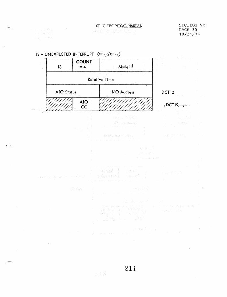
CP-V TECHNICAL MANUAL
13 ~ UNEXPECTED INTERRUPT :<CP-,R/CP,-V)
COUNT 13 == 4 Modell
Ala Status
AIO CC
Relative Time
Va Address
211
OCT12
SECrrrOlT ~.ry
Pl\,GE 30 10/31/74
-, OCT19, -, -

Cp·v TECHNICAL MANUAL
15 - DEVICE ERROR (CP-R/CP-V)
D 15 COUNT
Model' (
D.D
Relative Time
AIO Status I/o Address
MFlif A10 TOV TIO 1:6 or 17 CC ~CC CC
subchan -, ~ '-' <; TDV Current status Command OA
.--. TOV Status Bytes Remaining
Current ~ Command -
Ooubleword -..
TIO Status Retry Retries Request Remaining
I/o Count
-Volume Serial Number. ..
(6 characters for C p .. V Ort;inal Current ANS Tape) .:, Fur.ction Function :
.. I
Code L..i,..., Code r---~- -J • ......, ... ~~
• '1'" ·r .-,. . !, ~ ; .. ,
Seek Address ............. _ ... .....".~ ...............
212
OCT12
SECTION VK PAGE 31 10/31/74
-, OCT19, DCT20, DCT20A
OCT13
OCT21, 10Q 10, 10Q 11
OCT 25
IOQ12
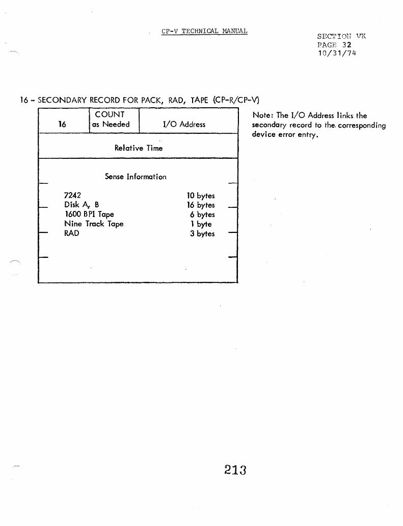
CP-V TECHNICAL MANUAL SECTION ,;rK PAGE 32 10/31/74
16 - SECONDARY RECORD FOR PACK, RAD, TApE (CP-R/CP-V)
COUNT 16 as Needed I/O Address
Relative Time
Sense Information I-
7242 10 bytes I--- Disk A, B 16 bytes
1600 BPI Tape 6 bytes Nine Track Tape 1 byte
t-- RAD 3 bytes
i--
-
-
-
-
213
Note: The I/O Address links the secondary record to the, corresponding device error entry.
CP-V TECHNICAL MANUAL
(Material on this page has been deleted.)
, 214
SECTION VK Page 33 9/1/78
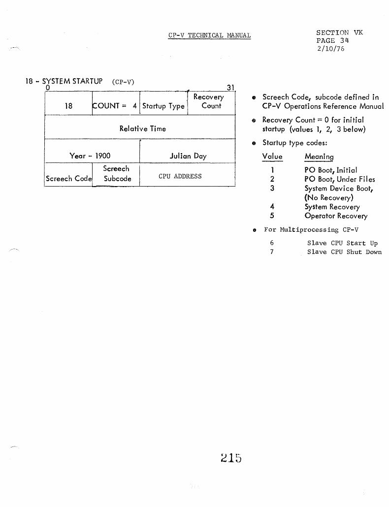
18 - SYSTEM STARTUP (CP-V) o
18 COUNT = 4
CP-V TECHNICAL MANUAL
31 Recovery
Startup Type Count
Relative Time
Year - 1900 Julian Day
Screech Screech Code Subcode CPU ADDRESS
SECTION VK PAGE 34 2/10/76
• Screech Code, subcode defi ned in CP-V Operations Reference Manual
• Recovery Count = 0 for initial startup (values 1, 2, 3 below)
CD Startup type codes:
Value
1 2 3
4 5
Meaning
PO Boot, Initial PO Boott Under Files System Device Boot, {No Recovery} System Recovery Operator Recovery
• For Multiprocessing CP-V
6 7
Slave CPU Start Up Slave CPU Shut Down

CP-V TECHNICAL MANUAL
(Material on this page has been deleted.)
I 216
SECTION VK Page 35 9/1/78

CP-V TECHNICAL MANUAL
lA - FILE INCONSISTENCY ENTRY ( CP-V)
lA COUNT = 14 75 Error
Subcode
Relative Time
file Name
- (8 words) -
- Account -
Generalized Disk Address
Consecutive = 1 t in = 1 ORG Keyed = 2 Mode out = 2 Random = 3 inout = 4
outin = 8
217
From DCB
From DCB
SECTION VK PAGE 36 9/1/78
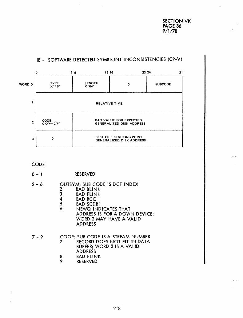
SECTION VK PAGE 36 9/1178
IB - SOFTWARE DETECTED SYMBIONT INCONSISTENCIES (CP-V)
o 7 8 15 16 2324
WORD 0 TYPE LENGTH 0 X' 18' X '04'
RELATIVE TIME
CODE BAD VALUE FOR EXPECTED C'O'-C'F' GENERALIZED DISK ADDRESS 2
0 BEST FILE STARTING POINT GENERALIZED DISK ADDRESS 3
CODE
o - 1 RESERVED
2 - 6 OUTSYM; SUB CODE IS OCT INDEX 2 BAD BLINK 3 BAD FLINK 4 BAD RCC 5 BAD SCDBI 6 NEWQ INDICATES THAT
ADDRESS IS FOR A DOWN DEVICE; WORD 2 MAY HAVE A VALID ADDRESS
7 - 9 COOP; SUB CODE IS A STREAM NUMBER 7 RECORD DOES NOT FIT IN DATA
BUFFER; WORD 2 IS A VALID ADDRESS
8 BAD FLINK 9 RESERVED
218
31
SU8CODE

CP-V TECHNICAL MANUAL
lE - LOST ENTRY INDICATOR (CP-V)
SECTION VK PAGE 38 10/31/74
lE COUNT = 2 Count of entri es lost
Relative time of last lost entry
The above entry is logged when buffering constraints make error logging temporarily impossible. The newest entries are lost.
IF ... DUPLICATE ENTRIES (CP-V)
Count of entri es If COUNT=2 identical to previous
-Relative Time of last duplicate
20 .. POWER ON (CP-V)
20
Relative Time
21~
,
Errorlog routine compares current ent:ry with previous and maintains a count as r ong as entrt es are identical, except time. If current and previous are different and count is non-zero, then<o duplicate entries entry is made. .

CP-V TiCHNlCAL MANUAL
21 - CONFIGURATION RECORD (CP-R/CP-V)
COUNT 21 as needed
Relative Time
Model , OCT Index
Alternate I/O Address Primary I/o Address
22 - SYSTEM IDENTIFICATION (CP-R/cp-V)
22 CQUNT=5
Core size in 8K word blocks
Relative Time
version flags
Site Identification
Relatiye Time
Resolution
SEC':I:'ION vK PAGE 39 10/31/74
Entered at system STARTUP or RECOVERY
One parr of words per device in OCT order; mul tipl e records may occur -maxi mum 5 devi ces per record
Recorded 'at system STIR ltJp and RECOVERY
Relative Time Resolution is expressed as a value of n such that actual relative time resolution = 2n
msec. The value of n for the most likely resolutions are
n = 0 when the timing source Is supplied by a frequency ~1 KHZ
n = 1 500HZ
n = 4 60HZ
For CP-V and CP-R, n-::.1.

CP-V TECHNICAL MANUAL
System, Version, Flags
SECTION VK Page 40 2/10/76
The format of system, version, flags and of site identification is operating system specific. System, version, and flags are formatted as location X'2B'.
2B Imonito~ version I o 34 7 8 15 16
, CPU I Parameters
21 22 25 26 31
Location 2B contains three items:
1. Monitor - this field contains the code number of the Monitor. The codes are:
Code Monitor
0 None or indeterminate 1 BCM 2 RBM 3 RBM .. 2 4 BPM 5 BTM/BPM 6 UTS 7 CP-V 8 CP-R 9-F Reserved for future use
2. Version - this is the version code of the Monitor and is coded to correspond to the common designation for versions. The alphabetic count of the version designation is the high-order part of the code and the version number is the low-order part. For example, AOO is coded X'lO' and D02 is coded X'42'.
3. Parameters - the bits in this field are used to indicate suboptions of the Monitor. They are meaningful only in relation to a particular Monitor. However, the following assignments have been made for BPM, BTM, and CP-V.
Bit 31 30 29 28 27 26 22-25 18 17 16
Bit 22
Meaning if Set Symbiont routines included Remote Batch routines included Real-time routines included Unused Reserved for Data Management System Reserved Field defining CPU Multiprocessing Transaction Processing On-line
Bit 23 Bit 24 Bit 25 0 0 0 0 0 1 0 1 0 0 1 1
Meaning Sigma 5 Sigma 6/Sigma 7 Sigma 9 550/560
221
(for CP-R 01 defines Sigma 5/7)

CP-V TECHNICAL MANUAL
23 ... TIME STAMP (CP-R/cP-.V) ----~~~~~~~~_M
23 COUNT = 3
Relative Time
Year - 1900 Julian Day
24 - BAD GRANULE RELEASE (CP-Y)
24 - COUNT =4 lYPE CODE
Relative Time
Generalized Disk Address
Address of Routine Calling ERRLOG or 'ACAT'
Number of Granules Be i n9 Re I eased
or
SECTION VK PAGE 41 10/31/74
for C P-V, th is record entered by ERR:FIL once each hour on the hour
as binary integers
TYPE CODE
o Bad Address 1 Dual Allocation
If lYPE CODE = 0
If TYPE CODE = 1
'ACAT'is substituted for the address of routine call ing ERRLOG ,when ALL YCA T detects the error.
222

CP-V TECHNICAL MANUAL
26 ... REMOTE PROCESSING ERROR RECORD (CP-V)
SECTION VK PAGE 42 10/31/74
This record is logged when an error has occurred in the transmission of data from a remote processing workstation.
26 COUNT=8 I/O Address
Relative Time
RB:FLAGS
Woskstatron r-- Name -
Current Command F>-
Doubleword ~
RPl RP2 RP3 RP4 I
RP1, RP2, RP3, and RP4 have specific meaning for the type of remote workstation associated· with the record as defined by the follow-ing tables. Refer to the Remote Processing Reference Manual for definition of terms and codes.
223

CP~V TECHNICAL MANUAL SECTION VK PAGE 43 10/31/74
• Xerox 7670 Workstation
RPI Definition RP3 RP4
1 first character in record not SOH Current character position Offending character
2 Incorrect parity on SE l .. .. 3 Incorrect block protect It II
4 Third character in record not STX .. .. 5 RBBAT combuf or MPOOl
unavailable for logon J.J.ean i ng less h1eani ng less
6 Incorrect character parity Current character position Offending character
7 Record trailer character not ETX .. .. 8 Incorrect block check parity .. .. 9 Incorrect block check .. II
A Communication line time-out Mean ingress Meaning less
B NAK received Response received reading for ACK
C Garbled ACK or NAK Response received reading for ACK
224

CP-V TECHNICAL MANUAL
r~p2 represents the current function code associated with the workstation.
RP2 Definition
0 Write card punch
1 Write line printer
2 Send ACK
3 Write rOF (Block protect = 0)
4 Write rOF (Block protect = 1)
5 Write SPACE (Block protect = 0)
6 Write SPACE (Block protect = 1)
7 Read card reader
8 Write rOF 0090n)
9 Read card reader (special)
A Read ACK card punch
B Read ACK line printer •
C Read ACK rOF (Block protect = 0)
D Read ACK rOF (Block protect = 1)
E Read ACK SPACE (Block protect = 0)
F Read ACK SPACE (Block protect = 1)
10 Write EOT .
11 Write DC 1
12 Write ACK (special)
13 Write NAK
14 Write NAK (special)
15 Write BEL (on error)
SECTION HI" pjlcr (~ll
10/31/74
For Xerox 7670 workstations, the current command doubleword in the error log record contains the second command doubleword used to write the text of an output message and is meaningful only for RPI = 0, 1, A, or B.
225

CP-V TECHNICAL MANUAL SECTION VI< Page 45 10/31/74
Intell igent Remote Batch Terminal (IRST)
RPl Definition RP4 Definition
0 Recoverabl e block check error Expected SCB count (s ign extended)
1 Catastrophic block check error (NAK sent in case of I ine error) Expected SCB count (sign extended)
2 Communication line time-out Same as RP2
3 Read for ENQ timed-out (logon) Same as RP2
4 Received ACKO instead of SIGNON at logon ACKO
5 Inappropriate I ine bid (not ENQ"'master, not ACK O-slave) line bid received.
6 NAK received NAK
7 Read timed out Same as RP2
8 Incorrect CRC last character C RCed
9 Trailer character not ETB Offending character
A leader character not STX Offending character
B lost data First character after D lE .
C Garbled ACKO-NAK First character of message
FF RPl is 0 or 1 with RP4 = ... 1 (result appears as X'FFFFFFFF I)
226

CP-V TECHNICAL MANUAL SECTION V1~
PAGE 46 10/31/74
For lRBT, RP2 is the current function code and RP3 is the calling function code. The following table defines RP2 and RP3.
Value RP2 RP3
0 Disconnect Software error - should not occur
1 Write block Write block - read block
2 Write ACK Write ACK .. read block
3 Write block Write block (Walt-a-bit) - Read special
4 Write Wait-a-bit Write Wait-a-bit - Read special
5 Read Block Software error - should not occur
6 Send NAK Software error - should not occur
7 Send ENQ logon as Slave
8 Read for ENQ logon as M.aster
9 ACKO to ENQ Logon as Iv\aster after ENQ Read " A Read Logon Record Software error- should not occur
B NAK logon Record Software 'error - should not occur .
2~7

IBM 2780
RPl
1
2
3
4
5
6
8
9
A
C
CP-V TECHNICAL MANUAL SECTION VK PAGE 47 10/31/74
Definition RP4 Defini tion
Disconnect due to;
a) EOT on read EOT b) Use of 2780 on IRBT only system ENQ
line timeout Same as RP2
ENQ not received on logon read Character received
No EOT after EOF sent Character rece ived
a) ENQ in text mode Character received b) No ENQ answering WACK Character received c) E NQ answer to ACK of E OF Character received
NAK received Character received
CRC failed on input last character CRCed
Unknown response reading for ACK Character rece ived
Trailer character not ETB or ETX Character received
" Header character not STX Character rece ived
228

CP-V TECHNICAL MANUAL SECTION VK PAGE 48 1J/31/7 1!,
For IBM 2780, RP2 is the 'current function code and RP3 is the calling function code. The following table defines RP2 and RP3.
Value RP2 RP3
0 Disconnect Software error' - should not occur y
1 Write Data Write
2 Send ENQ Send ENQ (Wait)
3 Send ACKO Read
.4 Send WACK Send WACK ('Nait)
5 Write Data Write EOF
6 Send ENQ Request to Output
7 Read for ACK, ENQ, EOT (depends on RP3) POL for Input
8 Read for ENQ logon
9 Read Software error - sh~uld not occur
A Send NAK Software error" should not occur
8 Send ACK 1 Software error - should not occur
C Send EOT Software error - should not occur

CP-V TECHNICAL MANUAL
27 - OPERATOR MESSAGE (Cp .. R/Cp.;..V)
27
lEXTC COUNT
COUNT as needed
Relative Time
rEXTC Message Iv\ax Size = 71 characters (CP-V) Max Size = 56 characters CP-R)
28 aD I/O ACTIVITY COUNT (CP-V)
COUNT 28 as needed OCT Index of First Device
-Relative Time
I/O Address, OCT Index,
I/O COUNT I
I/O Address 2. OCT Index a
I/O COUNT,
• " -
SECTION VK PAGE 49 10/31/74
A facility wiil be provided to iniect messages from the operator (or diagnostic program) into the error log. These messages might be used to describe unusual conditions surrounding a particular error. The operator <may enter' ire Ja~ -m-=:ssogp.s from toe opertJfror console vi'.) th~ keyin command IERKSEND1.
Recorded once per hour and at recovery~.' Maximum of 10 ".-entries per" record. Counts are reset to zero after recording them at recovery.
230

CP-V TECHNICAL MANUAL SECTION VK PA,GL 49. 1 9/1/78
2D - HARDWARE ERROR (CP-V)
Generated Sy INTERRUPT 56 (£7)
o CODE=X'2D'1 COUNT=OB CPU ADDRESS TRAP 4C (E9-X560)
TIME
PSDl
PSD2
RESERVED
RESERVED
TRAP CC I: I: I! 0 0 0 0
REAL ADDRESS OF TRAPPED INSTRUCTION
TRAP INSTRUCTION
ANLZ CC EFFECTIVE ADDRESS
If:) REAL EFFECTIVE ADDRESS
FIP - When set indicates that a PE occurred while fetchin3 the instruction (causing T4C) or this is on 156 on Sigma 7. l.n either case, words 4 ... 9 will be zero.
lAP - \\'hen set indicates that a PE occurred due to an indirect address fetch. Words 8 .... 9 will be zero.
RBP - \Vhen set indicates that a PE is present in the associated R-block r~gisters (Xerox 560 only).
The Effective Address and the Real Effective Address will be of the addressing type indicated by the ANLZ CC (br h\Vr VIr dw, i).
2300

I
CP-V TECHNICAL MANUAL
2E - WATCHDOG TIMER (CP-V)
CODE =X'2E'1 COUNT=OB CPU ADDRESS
TIME
PSDl
PSD2
RESERVED
RESERVED
TRAP CC I I ~ I~ II 0 0 0 0
REAL ADDRESS OF TRAPPED INSTRUCTION
TRAP INSTRUCTION
ANLZ CC I EFFECTIVE ADDRESS
REAL EFFECTIVE ADDRESS
SECTION V'K Pl\GL 49.2 9/1/78
~cnerated Sy TRAP 46
FIP - 'Nhen set indicates that a PE occurred while fetchin~ the instruction (causing T4C) or this is c..lJ) 156 on Sigma 7. In either case, words 4 - 9 wi II be zero.
'lAP - When set indicates that a PE occurred due to an indirect address fetch. Words 8 - 9 will be zero.
RBP - Wnen set indicates that a PE is present in the associated R-Slock r~gisters (Xerox 500 only).
The Effective Address and the Real Effective Address viiI! be of the addressing type indicated by the ANLZ CC (b, h,v, Wf dw, i).

CP-V TECHNICAL MANUAL
2F - INSTRUCTION EXECUTION (CP-V)
CODE X'2F'1 COUNT=OB I CPU ADDRESS
TIME
PSDl
PSD2
RESERVED
RESERVED
TRAP CC I ~I~ I! I 0 0 0 0
REAL ADDRESS OF TRAPPED INSTRUCTION
TRAP INSTRUCTION
ANLZ CC EFFECTIVE ADDRESS
REAL EFFECTIVE ADDRESS
SECTION VI( Pl\GI- 49.3 9/1/78
~cr.erated Sy TRAP 4D
FIP - 'Nhen set indicates that a PE occurred 'Nhite fetching the instruction (causing T4C) or this is un 156 on SigmlJ 7. I.n either case, words 4 - 9 will be zero.
IAP - When set indicates that a PE occurred due to an indirect addrzss fetch. Words 8 - 9 wi II be zero.
RBP - Wnen set indicates that a PE is present in the associated R-block registers (Xerox 5~O only).
The Effective Address and the Real Effective Address will be of the addressing type indicated by the AN LZ CC (b, hWt Wt dw, i).
230c

CP-V TECHNICAL MANUAL
(This page intentionally left blank.)
I 230d

CP-V TECHNICAL MANUAL
30 - PFI PRIMARY RECORD (CP-R/CP-V) (560)
30 COUNT = 2
Relative Time
31 - MFI PRIMARY RECORD (CP-R/CP-V) (56Q/Sigma 9)
31 COUNT=2 ~ Relative Time
SECTION VI< PAGE 50 10/31/74
32 ... SECONDARY RECORD FOR POLL INFORMATION (CP-R/CP-V) (560)
32
012
COUNT=3
Relative Time
Unit Type
7 8 11 12 15 16
} 77~ ~ ./////
,I'
Poll Status
231
One record produced per valid poll status received.

CP-V TECHNICAL MANUAL
41 - 560 PROCESSOR CONFIGURATION (CP-R/CP~y) ,(560)
COUNT ~~ 41 as needed !~0///~ ~//;
SECrl ' I0JJ VK Pl\.GE 51 9/1/78
Relative Time One record per cluster defined in sysgen.
l~ 3 3
TYPE CODEl~ Cl UN POLR Results
7 ~7
One entry for each unit in the cl uster. Al&ax.imum 8
42 - 560 MemOlY Perrity Secondary Record (CP-R/CP-V) (560)
This record is logged to record specific information that is returned in response to an LMS instruction subsequent to detectj ng hardware errors.
o 7 8 15 16
CL = UN = TYPE =
TYPE CODE
1 2 3 4 5 6 7
cluster # unit # unit type, high bit set if unit does not respond duri ng Initialization
UNIT NAfv\E
CPU MI PI MIOP RMP CT SU
31
word 0 Type Length CPU address X'42' X'04'
Relative time
2 Rea I add ress
3 Memory status word 0
4 Memory status word 1
232

CP-V TECHNICAL MANUAL
43 - SIGMA 9 Memory Parity Secondary Record (CP-R/CP-V)
This record is logged as a result of the memory fault interrupt associated with location XI 57' or the memory parity trap associated with location X'4C' on the Sigma 9 Qr Xerox 560. This record follows record type X'17' and record type X'31'
o 7 8 15 16 word
o Type X'43'
Length CPU Address X'06'
Relative Time
Rea I Add ress
Memory Status Word 0
Memory Status Word 1
Memory Status Word 2
44 - SIGMA 5-7 Memory Pal)1ty Secondary Record (Cp.R/cp-V)
r----- ----- --------1------ .. -.~~~~--------.--'.
I " COUNT 44 as-needed Number of Parity Errors
------.. __ . ---'---"-'-'---'--Relative Time
1st Bad Location "
..::~ -< ~ "
14th Bad Location
31
SECTION '11\ PAGE 52 10/31/74

49 - MEMORY PARITY SECONDARY RECORD
word 0
word 1
word 2
word 3
word 4
word 5
word 6
word 7
word 8
word 9
word 10
This record is logged to record specific information that is obtained by scanning memory to attempt to isolate locations that cannot sustain correct parity.
o 7 8 15 16
Type Length CPU address X'49' X'OB'
Relative time
Number of bad locations in memory
Logical AN D of addresses of the bad locations
Logical OR addresses of the bad locations
Logical AND of contents of the bad locations
Logical OR of contents of 1he bad locations
LMS Address of lowest location with bad parity CC
Contents of lowest location with bad parity
LMS Address of highest location with bad parity CC
Contents of highest location with bad parity
234
SECTION VK PAGE 53 9/1/78
31

I
CP-V TECHNICAL MANUAL
50 - Enqueue Table Overflow (CP-V)
50 COUNT = 3
Relative Time
User ID Entry Count
SECTION VK PAGE 53.1
9/1/78
- Binary integers
Entry count is the number of entries in the enqueue table belonging to the specified user at the time the error log entry was made.
51 - Partitioned Resource (Cp .... V)
51 COUNT =3 Iv\odel /I
Relative Time
F 0-------------------0 I/O Address
o 1
F = 0 for device entry F = 1 for controller entry
This entry will be logged when a resource has been partitioned.
52 - Returned Resource (CP-V)
52 COUNT=3 Iv\odel /I
Relative Ti me
F p-------------------O liD Address
F = 0 for Device Entry F = 1 for Controller entry
This entry will be fogged whe.n a resource is returned from being partitioned.
2340

CP-V TECHNICAL MANUAL
(This page intentionally left blank.)
I 234b
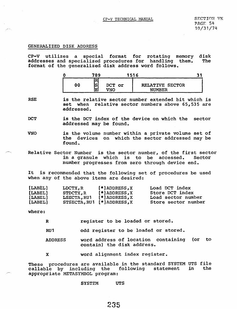
CP-V TECHNICAL MANUAL SECTION VK PAGr. 54 10/31/74
GENERALIZED DISK ADDRESS
CP-v utilizes a special format for rotating memory disk addresses and specialized procedures for handling them. The format of the generalized disk address word follows.
RSE
OCT
VNO
o 789
00 I~ DCT or VNO
1516
RELATIVE SECTOR NUMBER
is the relative sector number extended bit which is set when relative sector numbers above 65,535 are addressed.
is the OCT index of the device on which the sector addressed may be found.
is the volume number within a private volume set of the devices on which the sector addressed may be found.
~, Relative Sector Number is the sector number, of the first sector in a granule which is to be accessed. Sector number progresses from zero through device end.
It is recommended that the following set of procedures be used when any of the above items are desired:
[LABEL 1 [LABEL] (LABEL] [LABEL]
where:
R
RU1
LDCTX,R (*)ADDRESS,X STDCTX,R [*)ADORESS,X LSECTA,RU1 (*]ADDRESS,X STSECTA,RU1 [*]ADDRESS,X
Load nCT index Store OCT index Load sector number Stor~ sector number
register to be loaded or stored.
odd register to be loaded or stored.
ADDRESS word address of location containing (or to contain) the disk address.
x word alignment index register.
These procedures are available in the standard SYSTEM UTS file callable by including the following statement in the appropriate METASYMBOL program:
SYSTEM UTS
235

CP-V -TECHNICAL MANUAL
SECTION VK.Ol PAGE 1 9/1/78
CSE STOP Tables
In the event of a catastrophic hardware fai lure in the central system components (CPU, _ memory, -lOPs, and data busses), tne fau I t hand ling system attempts to log the faJlts in the In-c6re error log buffers at BUFI and - BUF2, and-in addition, collects additional information into tables in memory_ These tables are col lectivel~ cal led the - CSE STOP tab I e s . I nth e eve n t 0 f a II CSE STOP II me s sage be 1 n g ou t put 0 nth e OC, the ~perator should record the contenti of these tables before attempting an operator recovery or turning the machine over to customer engineerso
The fol lowing items are contiguous in memory:
LABEL
R7-.CSED$CF
CSED$REGS CSED$WHY CSED$PSO CSED$MSTAT$ADR
CSED$PSTAT$ADR
CSED$3STAT$ADR CSED$MSG
SIZE
1 word
16 words 1 word 2 words 1 word
1 word
1 word 7 words
MEANING OF CONTENTS
High order byte contains trap condition code Register at time of last CSE trap Internal code for cause of trap Current PSO at time of trap o for Sigma 6/7, address of CSED$MSTAT table on Sigma 9 and Xerox 560 o for Sigma 6/7/9, address of CSED$PSTAT table on Xerox 560 (CSED & 3STAT). Address of memory content polling table Buffer containing CSE STOP message (reason for stopping)
The following items are contiguous in memory:
LABEL SIZE MEANING OF CONTENTS
CSED$3STAT 2 Words XI 490BOOOO' + CPU address, relative time CSED$3COUNT I word Number of bad locations in memory CSED$4ANDADO I word Logical AND of addresses of bad locations CSED$30RADO I word Logical OR of addresses of bad locations CSED$3ANDCONT I word Logical AND of contents of bad locations CSED$30RCONT 1 word Logical OR of contents of bad locations CSED$3FIRST 1 word Address of lowest ce I I with bad contents CSED$3FIRSTC 1 word Contents of lowest cell with bad contents CSED$3LAST 1 word Address of highest cel I with bad contents CSED$3LASTC 1 word Contents of highest cel I with bad contents
236

OPTIONAL TABLE FOR MOS MEMORY SYSTEMS ONLY
SECTION VK.Ol Page 1.1 9/1/78
The MOSTAB table contains data pertaining to the manner in which each bank of MOS Memory reports Single Bit Correctable Errors (SBCEs) via the memory's built-in Error Detection and Correction (EDAC) mechanism. The SBCEs are reported via Interrupt 57, and the 157 handler decodes and checks the Memory Status Words from the affected bank. If the interrupt was of SBCE nature, and the threshold for that bank has not been reached, the error is passed via the standard logging mechanism to ERRFILE. Once the threshold is reached, the SBCE flip-flop is reset for that bank, and no more SBCEs are reported. (Invoking ELLA then gives the user a graphic report of the failing components.)
The table contains eight entries of the form:
o 1 15 16 31
I * I THRESHOLD VALUE CURRENT VALUE
where:
* Bit 0 is the REPORT flag. When set, it indicates that NO SBCE are to be reported on this bank.
THRESHOLD is the maximum number of single bit correctable errors to be reported for this bank.
CURRENT is the current number of single bit correctable errors that have been reported for this bank.
2360

SECTION VIC 01 Page 1·.2 9/1/78
The table is indexed by a computation of the unit number and bank number, and contains values as follows:
NOTE A:
NOTE B:
NOTE C:
o UNIT 0 BANK A
1 UNIT 0 BANK B
2 UNIT 0 BANK C
3 UNIT 0 BANK D
4 UNIT 1 BANK A
5 UNIT 1 BANK B
6 UNIT 1 BANK C
7 UNIT 1 BANK D
The mechanism for error logging sets bit 0 of the associated entry when the threshold is reached. At system initialization, any MOS-genned system automatically scans its memory banks and initializes SBCE reporting for each MOS bank in the system. Non-MCS banks have their entry in the table initialized with only the sign bit set. CONTROL can be used to examine and set the REPORT, THRESHOLD, and CURRENT values from a X'OO' privilege account.
236b

CP-V TECHNICAL MANUAL
SECTION VK.01 PAGE 2 10/31/74
Optional Table for Sigma 9, Xerox 5S0 Only
CSEO$MSTAT table (Memory Fault Status Register Pol ling Table)
This table contains up to 5 entries of the form:
Internal Poll ing Real Address Causing Fault Word 0 Flags
Memory Fault Status Word 0 Word 1
Memory Fault Status Word 1 Word 2
Memory<Fault Status Word 2 (S i gma 9 On I y) Word 3 // (S i gma 9 on I y)
O~tional Table for Xerox 5S0 Only (ref. 5S0 DPS Manual)
CSEO$PSTAT table {Processor Fault Status Register Pol ling Table}
Each entry is one word long of the format:
Proc Addr POLR CC Type Code
Status
Status
Bit 0, when set indicates presence of val id status Processor's cluster/unit address Condition codes from POLR instruction Processor type: 1 - BP, 2 - MI, 3 - PI, 4 - MIOP, 5 - RMI, 6 - CI, 7 - SU lS-bit contents of fault status registers (result of POLR instruction)
237

ill
ASSIGN/MERGE Table
FUNCTION
CP-V TECHNICAL MANUAL SECTION VL PAGE 1 2/7/77
An Assign/Merge Table is the place where information is kept which must be merged into the DCBs that go into the user's context at load or execute time.
An Assign/Merge Table is associated with each job in the system (whether batch or on-line) as a result of a ;JOB command in batch or as a result of logging on.
Modifications to the user's Assign/Merge Table result from the ASSIGN command in batch and from the SET command and various other commands in batch and TEL. The Assign/Merge Table is merged into the DeBs placed in the user's context when the user loads or executes a program. The merging results from the monitor calling File Management to do the actual merging.
Assign/Merge Tables bui It by TEL are never modified by Cel and vice versa.
STRUCTURE
An Assign/Merge Table is one page ,long. It normally consists of a 22-word header, followed by a number of linked entries. However, if in command file mode, the header consists of 30 words.
o
1
2
3
4
5
6
7
BATCH Index to First Avai lable Area Index to First Entry or 0
Unused
Load Module Name for ~RUN (3 words)
Load Module Password for ; RUN (2 words)
Assign/Merge Table
ON-LINE Index to First Ava i I ab I eArea Index to First Entry or 0
Unused (4 words)
Image of J:CPPO from User JIT Image of J:ASSIGN from User JIT 238

CP-V TECHNICAL MANUAL
SECTION VL PAGE 2 9/1;78
8
9
10
11
12
13
14
15
16
17
18
19
20
21
22
23
24
25
26
27
28
29
DATE: YEAR Binary I DAY Julian
Saved Image of User's STDOPT at Job Step (Online)
Maximum Authorized Privi leges (From :USERS)
Saved Image of J:UPRIV
LOGON Time Seconds from Midnight
Billing Rate I System 10
Extended Accounting Field
6 words
Permanent Remaining RAD Space Allocated
Permanent Remaining Disk Space Allocated
Command File Name 3 Words
Command File Account 2 Words
Command File Password 2 Words
Command File Record Number
Assign/Merge Table entries consist of a forward I ink to the next entry, the DCB name in TEXTC format, and an Adjust DCB (open prime) PLIST whose format is described in the CP-V BP Reference Manual.
DC8 names are up to 3 words long for TEL and up to 8 words CCI. The Adjust DCB PLIST may be up to 100 words long. length for TEL entries is constrained only by the buffer size by TEL to construct the entry. For this reason, TEL entries CP-V may have:
.. ~lax i mum of 8 read accounts
• ~1ax i mum of 8 write accounts 81 Maximum of 8 execute accounts
• Maximum of 3 SNs
long for The PLIST reserved for~ COO

CP";VTECHNlCAL· MANUAL
SECTION VL PAGE 3 10/31/74
word 1
FLINK or 0
TEXTC DCB Name (zero f i I led) (Maximum 8 words for CCI) Maximum 3 words for TEL
~djust DCB PLIST
FLINK or 0
24(J

~-,
CP-V TECHNICAL MANUAL
Section Vl. 01 Page 1 5/1/75
Format of RUN Table
Word 0 1 7 8 15 16 . 23 24 31
o I Nl I N2 I XSL
0 1~115 0 BIAS 31 2 F2
t
3 LOAD MODULE NAME ----~-------------~-----------
4 (LMN) IN ------------------------------
5 TEXTC FORMAT
6 ACCOUNT ------------------------------
7 NUMBER
8 PASSWORD ------------------------------
9
A SYMBOLIC START ADDRESS IN ) TEXTC FORMAT ~)
~ (1 to 19 WORDS) ~
lA ± HEX START ADDRESS ADDEND OR ZERO -
}
zero if no password
where
Nl is number of SNAP, SNAPC, IF, AND, OR, and COUNT records in System Debug File.
N2 is number of MODIFY records in System Debug File.
XSL is value of XSL parameter.
BIAS is value of BIAS parameter.
241

Form~t of Modify Table
CP-V TECHNICAL MANUAL Section Vl. 01 Page 2 5/1/75
The Modify Table is written into the system debug file for the current job.
1 byte
2
count I 0"""-------0 res
1 location to
modify
± hex value or 0
byte count' I I modify value 1 value
where res == 0 if byte resolution; == 1 if halfword resolution; = 2 if word resolution; =3 if\ doubleword resolution. The resolution applies to the name specified with the modify value. .
value is value to be given to the location to be modified. It has the form value + res (name) name is the name of an external definition and value is al-digit to a-digit hexadecimal number.
24~

CP-V TECHNICAL MANUAL
Format of PMD, PMDE, PMDI Table
Section VL. 01 Page 3 5/1/75
The PMD, PMDE, PMDI Table is written into the system debug file for the current job.
Code 0 o Ip) 1'2 j '3 Byte Count C1 I o • •
""'" ~~ ""'" ± hex value or 0
} from location
Byte Count C 1 I . . . ~~ ,. .. l~~~~~~~~-±-h-e-x~va-I-u-e-o-r-o~~~~~~~~~ } to locaHon
where Code is 3 for PMD command, 4 for PMDE command, and 5 for PMDI
command. PI = 1 for dump protection type 00. P2 = 1 for dump protec.tion type 01. P3 = 1 for dump protection type 10. from location is beginning dump location to location is ending dump location
24J
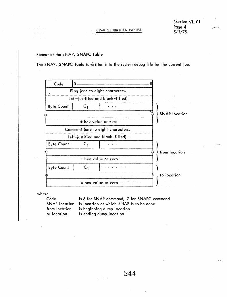
CP-V TECHNICAL MANUAL
Format of the SNAP, S NAPC Table
Section VL. 01 Page 4 5/1/75
The SNAP, SNAPC Table is written into the system debug file for the current iob.
Code to 0
Flag {one to eight characters, ------------------------left-justified and blank-filled}
Byte Count , C 1 I . . . 1,..., ~ I SNAP location
± hex value or zero
Comment {one to eight characters, ~-----------------------
left-iustified and blank-fi lied}
Byte Count I C 1 I . . .
Byte Count I f )
l~L_~~~~~~~~~~~~~~~~~~~~1 (10 locotion _ ± hex value or zero . ,
where Code SNAP location from location to location
is 6 for SNAP command, 7 for SNAPC command is location at which SNAP is to be done is beginning dump location is ending dump location
244
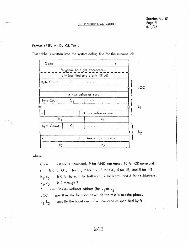
CP-V TECHNICAL MANUAL
Format of IF, AND, OR Table
This table is written into the system debug file for the current job.
Code f ! r
Flag(one to eight characters, ------------------------
Byte Count
1 Byte Count
'""
* I
I eft- ius t i fi ed and blank fj II ed)
j C 1 T ...
± hex va I ue or zero
: C 1 i . . .
I ± hex value or zero
bl xl
~;:; I J }
;",J
~yte Count 1 C 1 ... '"
,L.. 1!-b2-~± h-ex V-Olu:-;-r z-ero -----41 I where
LOC
Section VL. 01 Page 5 5/1/75
Code is 8 for IF command, 9 for AND command, 10 for OR command.
r is 0 for GT, 1 for LT, 2 for EQ, 3 for GE, 4 for LE, and 5 for NE.
is 0 for byte, 1 for haffword, 2 for word, and 3 for doubleword.
x1,x
2 is 0 through 7.
* specifies an indirect address (for Ll or L2).
LOC specifies the location at which the test is to take place.
L l' L2 spec ify the locations to be compared as spec ified by Ir'.

Format of Count Table
CP-V TECHNICAL MANUAL
Section Vl. 01 Page 6 5/1/75
The Count Table is written into the system debug file for the current job.
11 10 -~--- 0 Flag (one to eight characters,
-------------~---------------left-iustified and blank filled)
Byte Count I C1 1 · . ~~---~~1 COUNT location
J ~----------------------------------------I
± hex value or zero
start
end
step
246

CP-V TECHNICAL MANUAL
ID
Error Codes and Error Messages
SEC7iON VM PAGE 1 4/1/74
This section ::Iescribes the error c~""';es and error message handlling in CP-V Subsequ-=nt subsections cover 1) the format (,~ the error message file, and! the general assignment of codes, 2) the meanings of eoc .... , ?f the currently assigned endes, and 3) Ci ! is:- or :he messages on file in the current CP-V system.
Codes for various detected error c..-:.nditions ar~ recorded in JIT. The error code is placed in J:ABC (high order byte/ ':tOO the subcode in ERO (right-justified). When PMD, in the case of batch jobs, or TEL, in the case of on-line iobsis entered, a message IS printed to correspond to the code -::nd subcode. This message is obtained from the error fi I e via a keyed read usi ng a key t:onstruc ted from the code and subcode. If either the fil e or the message record '111< ch corresponds to the code iis missi ng, then a message including the error code itself i$?rinted. Processors also use the error message file and are assigned IIgroup codesll f-:..r their messages.
For I/O errors the user may gain c0ntrol in error situations anD handle the error himself, by specifying error or abnormal addresses either in the DCB v~a M:SETDCB or in the M:READ or M:WRITE procs which is described in the UTS Reference Manual, Appendb-. B.
ERROR MESSAG E FILE FORfM T
The fi I e ERRf\.~SG i fi the account ;SYS contai ns the error messIlges of the system, both for t-Aoni tor and processor error condi tions. The fil e contai ns Iteyed records wi th keys in the form used by EDIT so .that the file may be conveniently changed to suit the individual installation. The record contains the EBCDIC text CDf t,he error message.
Keys are one word long and have the form:
The first byte always contains 03, the couDt of bytes in the ken, the second byte is the group code, the thi rd, error code, and the fourth is the e1nor subcode.
Group codes presently assigned are:
o - t-Aonitor 1 - PCl 2 - LOADER 3 - TEL
4 - RUNNER 5 - CCI 6 - DRSP 7 - BATCH 8;'" ANLZ
247

CP-V TECHNICAL MANUAL
SECTION VM PAG~2 4/1/:t-4
Messages in the file with group codes other than zero are rut handled in any way by the W\onitor itself.
Error codes currently assigned within the Monitor group are:
0-7F I/O error and abnormal clDdes BO-9F COBOL error codes AO-BF Monitor codes CO-FF Unused
Contents of the error message fi Ie for each of the assigned cerles are given in the following pages. The codes follow the format indicated ab~e (with leading zeros su ppressed.)
248

GRP ERR 00 01 00 01 00 02 00 02 00 03 00 04 00 O!:> 00 Ob 00 07 00 08 00 Oq 00 oq 00 Oq 00 Oq 00 Oq 00 Oq 00 OC)
rv 00 Oq .t:::
.. .0 00 Oq 00 Oq 00 oc, 00 Oq 00 Oq 00 Oq 00 Oq 00 09 00 Oq 00 Oq 00 OA 00 Oil 00 OA 00 OA 00 OA 00 OA 00 Ob 00 OC 00 00 00 00
SUA MODULE 00 npfN OB OPEN 00 OPEt'J 01 OPFN no OPEN no OPFN/READ/PRECORO no PRECORO/READ Ou READ 00 READ 00 OPEN 00 RDERLOG 01 ROERLOG 02 RDERLOG 03 ROERLOG OLi RDERLOG O~ RDERLOG 00 RDERLOG 07 RDERLOG 08 RDERLoG Oq RDERLOG 10 RDERLOG 11 RDERLOG OA RDFRLOG 06 RDERLOG Oc RDERLOG 00 ROERLOG OE RDERLOG of RDERLOG 00 CLOSE 01 CLOSE 02 CLOSE 08 CLOSE oq CLOSE OA CLOSE 00 OPEN/READ/CVOL 00 OPEN 00 OPEN 01 pv
)
MESSAGE' INSUFFICIENT INFOR~ATION TO OPEN DeB. REQUESTED NUMBER OF CONTIGUOUS GRANULES NOT AVAILABLE CAN'T OPEN NE~T FILE BECAUSE THERE AREN~T ANY MORE. CAN'T OPEN NEXT ACCOUNT BECAUSE THERE AREN'T ANY ~ORE. FILE DOES NOT FXIST. AEGINNING OF FILE RtACHED. END OF DATA REACHED. END OF FILE OR MONITOR CONTROL CARD REACHED. DATA HAS BEEN LOST. (BECAUSE YOUR BUFFER IS TOO SMALL.) 'NEXT' FILE WON'T OPEN BECAUSE IT'S SYNONYMOUS TO SOME OTHER DIAGNOSTIC CLOSE ERROR
FILE.
NONEXISTENT DEVICE DEVICE BUSY SYMBIONT DEVICE BUSY NO eLIST IN OCR COMMAND LIST DESTROYED BY SWAP lOCO'S EXCEED LIMIT INVALID COMMAND LIST INVALID ADDRESS BUFFER CANNOT CROSS PAGE BOUNDARY A TIO,TDV, OR HID WAS REQUESTED WITH AN INVALID FPT CHAN OPTION ON MtOPEN TO A DEVICE TYPE OR OPLABEL IS ILLEGAL AUTHORIZATION NOT GRANTED OR < AO PRIVILEGE INSUFFICIENT CORE TO PERMIT LOCK CONTROLLER NOT PARTITIONED DEVICE REQUESTED NOT PARTITIONED INVALID ADDRESS INSUFFICIENT SPACE TO PROCESS COMMAND LIST THAT DCB IS ALREADY CLOSED. ILLEGAL VLP CODE ON M:CLOS~ CAL NOT ENOUGH ROOM IN FIT FOR REQUESTED CHANGE ILLEGAL FILE NAME NEW FILE NAME ALREADY EXISTS CAN-T MODIFY A SYNbNYMQUS FILE UNRECOGNIZED SENTINEL ON LABELED TAPf. ILLEGAL SYNON OPERATION. NOT ENOUGH ROOM IN VLP OF DeB FOR PRIVATE PACK SN. 110 ERROR READING VTOC OF A PRIVATE SET
'...0 ""0 Ul "'" OJ (I) ..... OQ n "'" (!) c1" -..:J 1-'-ex:> 0
W::S

GRP ERR 00 OE 00 13 00 14 00 14 00 14 00 14 00 14 00 14 00 1" 00 14 00 t" 00 14 00 14 00 14 00 14 00 15 00 15 00 16
f\.) 00 17 V1 00 18 '.:>' 00 1 q
00 1 A 00 lA 00 lA 00 lA 00 1 A 00 1A 00 lA 00 lA 00 1e 00 Ie 00 10 00 IF 00 20 00 20 00 20 00 20 00 20
SUR MODULE 00 OPEN 00 DELREC/WRITE 00 OPNF 01 OPEN 02 OPEN 03 OPNL 04 MOVECAL(RDL) 05 OPNO Ob OPNF 07 OPNF 08 OPEN 11 LBLT 12 LBlT 13 OPNL 14 OPNF 00 DELREC/WRITE 01 READ/PRECORD 00 WRITE 00 WRITE 00 WRITE 00 OPEN/CLOSE 00 MQVECALCROL) 01 MQVECALCRDL) 02 MOVECAL(RDL) 03 MQVECALCROL) 04 MDVECAL(RDL) 05 MOVECAL(RDL) 42 MOVECAL(RDl) 4A MOVECAL(RDL) 00 REAO/WRITE/PRECORD 01 WRITE 00 REAO/PRECORO 00 WRT/IOD/IORT 01 READ 02 READ 03 READ 04 ROF 05 PV
MESSAGE 127 Dce-s OPEN TO FILE • ACCESS DENIED. YOU MUST SPECIFY NEWKEY WHEN WRITING A NEW RECORD. ACCESS DENIED • PASSWORO, READ/WRITE ACCOUNT OR WRONG ACCOUNT FILE IS BUSY. BAD FPARAM LOCATION. BREAK OR CONTROL-Y DURING MOUNT REQUEST. OPEN NOT PERFORMED. INTERRUPTED MIMOVE OF UNCLEAN RANDOM FILE INVALID OP LABEL IN DeB CONFLICTING OR MISSING DeB INFORMATION CAN·T OPEN DCHOUT wITH REL ILLEGAL PRIVATE PACK DEVICE TYPE CODE CONVERSION SPECIFIED ON DEVICE NOT HAVING FEATURE 800BPI SPECIFIED ON DEVICE NOT HAVING DUAL DENSITY ILLEGAL CODE CONVERSION CHANGE REQUESTED EXECUTE ONLY FILE. THE FILE IS IN OPEN STATUS. ILLEGAL OPERATION SEQUENCE ON UPDATE FILE IMPROPER OPERATION SEQUENCE ON SHARED KEYED FILE CAN'T SAY NEWKEY BECAUSE THE RECORD EXISTS. MUST USE NEWKEV ON OUTPUT FILES
()
""0 I <
KEYS MUST BE GIVEN IN O~OER WHEN WRITING KEYED FILES SEQUENTIALLY. H
ILLEGAL OPERATION ON M:UC DCB e ~ NO ERROR OR AHNORMAL ADDRESS SPECIFIED IN MOVECAL FPT r SECOND DCB IS MISSING ONE OR 80TH DeBS ARE NOT OPEN DCBt NOT OPEN IN OR DCB2 NOT OPEN OUT MOVE CAL NOT ALLOWED FOR DEVICE OR ANS DCBS THE MOVE CAL WAS ABORTED BY BREAK, CONTROL Y, OR oPERATOR KMAX OF INPUT DCB GREATER THAN KMAX OF OUTPUT DCB SPECIFIED BUFFER DOES NOT BELONG TO USER END OF TAPE REACHED. ENO OF TAPE ON COMMON JOURNAL BEGINNING OF TAPE, 0 BYTE COC REAO, OR BAD COMMAND TO TERMINAL BIN (OR VFC) NOT VALID FOR THIS DEVICE PRIVATE PACK IS LUCKED OUT. EXCLUSIVE USE OF PRIVATE PAC~, NOT THIS USER, PRIVATE PACK NOT ON lLIMIT COMMAND ONLINE USER REQUEST FOR PARTITIONED PRIV. PACK PACK SET HAS TWO,PRIMARY VOLUMES
\.0 '1l en ,OJ (1) -' O'Q C')
'fl> ("t' -...:J ~ ex> 0
.s:::::s
3: > z c: > r

GRP ERR 00 21 00 22 00 23 00 24 00 2E 00 30 00 30 00 30 00 30 00 31 00 31 00 31 00 31 00 31 00 32 00 32 00 32 00 32
~ 00 32 -a 00 32
00 32 00 32 00 32 00 32 00 32
00 33
00 3F 00 3F 00 3F 00 3F 00 3' 00 3F 00 3F 00 3F 00 3F 00 3F
SUB MODULE 00 OPEN/CLOSE 00 OPEN 00 cae 00 COC 00 OPEN 01 L.BlT 03 lBLT 0'6 lBlT 05 LBLT 00 ENQ/ENQO 01 ENQ/ENQO 02 ENQ/ENQO 03 ENQ/ENQO 04 ENQ/ENQO 00 MOCIOP 01 MOCIOP 02 MQCrOp 03 OPND 04 OPND/MOCIOP or:, OPNO 06 OPND 07 MOCIO? 08 MQCIOP 09 OPND 70 MOCtOP
00 IOCHEK
35 JORENT 3& JOBENT 37 JOBENT 38 JOAENT 39 J08ENT 3A JOSE NT 38 JOSENT :';C JOBENT '30 JOSENT ~E JOSE NT
MESSAGE PRIVATE PACK CONSISTENCY CHECK FAILURE. PRIVATE PACK ERROR TRYING TO OPEN EXISTING FILE. ON-LINE TERMINAL REAO TIMED OUT. ON-LINE CONDITIONAL READ ISSUED wITH NO TVPE-AHEAD. THAT DCB IS ALREADV OPEN! BAD USER LABEL ON ANS TAPE. INVALID FILE NAME LENGTH. CAN-T SPECIFY EXPIRE,NEVfR. ILLEGAL FORMAT CODE. DEQUEUE ATTEMPTED ON A RESOURCE/ELEMENT NOT QUEUED ENQUEUE ATTEMPTED ON A RESOURCE/ELEMENT ALREADY QUEUED ENQUEUECSHARE) ATTEMPTED ON ELEMENT ALREADY QUEUEDCEXCll 0
ENQUEUE ATTEMPTEO ON RESOURCE/ELEMENT NOT PRESENTLY AVAILABLE ~ ENQUEUE ABORTED BY CONTROL-Y OR BREAK OR OPERATOR ~ MULTI-POINT LINE HUFFER SIZE EXCEEDS 204Q BYTES ~ UNABLE TO ASSIGN PHYSICAL WORK PAGE, LIMIT REACHED ~ UNABLE TO ASSIGN PHYSICAL WORK PAGE, PAGE NOT OWNED BV USER ~ POLLING/SELECTION LIST ALREADY IN USE ~ BAD POLLING/SELECTION LIST ADDRESS 0
UNABLE" TO INITIALIZE SLAVE LINE, BAD SLAVE LINE ID ~ ATTEMPTED TO OPEN Dce TO UNOWNED SLAVE LINE 3
NUMBER OF POL/BEL LIST COMPONENTS EXCEEDS 254 > END OF LIST HIT ON OPEN LIST DURING AUTOMATIC POLLING OPERATIUN ~ MOCIOP MODULE OR COC SLAVE ~INE CODE NOT IN THIS SYSTEM I~ STATUS INSTEAD OF DATA IN BUFFER ON MULTI-POINT, LINE READ READ OR WRITE ON BI-POINT LINE TERMINATED , BY PURGE CAL. ILLEGAL ACCOUNT OR PRIORITY JOB ENTRV DISALLOWED BV OPERATOR USE,R NOT ALL.OWED T a USE J08 E. NTRY SERV ICE. FUNCTION INCONSISTENCY. INVALID to FOR DELETION. TOO LATE TO DELETE JOB. NO MORE SYMBIONT SPACE IS AVAILABLE OR THE QUEUE IS FULL USER NOT ALLOWED TO USE JOB ENTRY SERVICE. SYSTEM OR LL DEVICE NOT SVMBIUNT. THE SPECIFIED DeB IS ALREADY OPEN.
~..." UJ ,Q) ('~ -a (jq () ,(1) ("1" --.J 1-'.
'::x:> 0 U1:::$

GRP ERR SU8 MODULE MESSAGE 00 IF "5F JOBENT THE SPECIFIED BUFFER ADDRESS OR CONTENTS IS INVALID. 00 40 00 READ CAN-T REAO AN OUTPUT FIL.E. 00 41 00 READ IRRECOVERABLE DEVICE READ ·ERROR. 00 41 01 COOP INPUT SYMBIONT FILE LOST BAD RAD. 00 41 02 READ LABELED TAPE READ ERROR. 00 41 03 REAO LABELED TAPE REAO ERROR-RECORD NOT TRANSMITTED. 00 41 OLl READ PARTIAL RECORD TRANSMITTED FOLLOWING ERROR 4103. 00 42 00 READ/WRITE/RANDOM BAD ~EY: lENGTH IS ZERO OR GREATER THAN MAX. 00 42 01 STPNR ILLEGAL BUFFER SIZE ON ASSIGN/MERGE READ OR WRITE 00 43 00 READ CAN-T FIND A RECORD WITH THAT KEY. 00 44 00 t4RITE CAN-T WRITE AN INPUT FILE, 00 45 00 WRITE IRRECOVERABLE DEVICE WRIT~ ERROR, 00 45 01 WRITE WRITE ERROR ON COMMON JOURNAL 00 46 00 READ CAN'T OPEN FOR READ. 00 lib 01 READ CAN'T OPEN FOR REAO, DeB HASN'T ENOUGH INFORMATION. 00 40 03 READ CAN·T OPEN FOR READ, FILE DOESN'T EXIST. 00 Ab 14 OPNF CAN-T OPEN FOR REAO, FILE BUSY, MISSING FILE NAME, ACCOUNT OR PASSWORD
I\) 00 46 21 READ/WRITE PRIVATE PACK LOGIC INCONSISTENCY. ~ 00 40 22 READ PRIVATE PACK ERROR TRYING TO OPEN EXISTING FILE.
00 46 48 READ ONLINE USER CANNOT ACCESS CARD READER. 00 t4b ~q READ CAN·T OPEN FOR READ, NO DISMOUNTABLE RESOURCES AVAILABLE. 00 41 00 WRITE CAN-T OPEN FOR WRITE. 00 41 01 WRITE CAN'T OPEN FOR wRITE: DeB HASN'T ENOUGH INFORMATION. 00 47 03 WRITE CAN-T OPEN FOR WRITEI FI~E DOESN'T EXIST. 00 41 14 OPNF CAN'T OPEN FOR WRITES FILE BUSY, MISSING FILE NAME, ACCOUNT OR PASSWORD 00 47 2B OPEN INVALID OP LABEL IN OCB. 00 47 48 WRITE SYM8IONT USE FLAG NOT SET FOR ONLINE USER. 00 48 00 OPNLD PERIPHERAL USE FLAG NOT SET FOR THIS DEVICE 00 48 01 OPEN ONLINE USER CANNOT ACCESS CARD READER. 00 4q 00 PV YOUR FILE IS wRITf PROTECTED. 00 I.Iq 01 OPE.N REQUESTED REMOVABLE DEVICE IS NOT AVAILABLE 00 4q 02 PV/OPNTP USER DISMOUNTAB~E RESOURCE LIMIT EXCEEDED 00 4<1 03 OPEN INSUFFICIENT DCB SPACE FOR SERIAL NUMBERS '-.O'"'OUl
'OJ([)
00 4A 00 READ/WRITE/ENQ SPECIFIED BUFFER DOES NOT BELONG TO THE USER. ..... OQ (.)
'([)c-f"
00 4A 01 IOCHEK TIME PARAMETER ON M:CHECKECB TOO BIG --..J 1-'-
00 4A 02 IOCHEK EeB IN wRONG STATE ON MaCHECKEC8 OR M:CHECK W/ECB :::0 0 O'\::s
00 4A 03 IOCHEK INFINITE WAIT CONDITION ON MICHECKECB OR M:CHECK W/ECB c:::: 00 4A 04 IOCHEK NO MONITOR WORt< 'SPACE TO HONOR MICHECKECB OR MICHECK W/ECB 3:

I\)
U1 • .,.A)
GRP ERR 00 UtA 00 tiS 00 tiC 00 14D 00 aE 00 4E 00 4E 00 4E 00 4E 00 4F 00 51 00 52 00 54 00 5S 00 50 00" 57 00 57 00 58 00 58 00 58 00 58 00 Sq 00 Sq 00 5q 00 Sq 00 Sq 00 Sq 00 Sq
00 5q 00 '5Q 00 Sq 00 Sq 00 Sq
00 5q 00 Sq 00 Sq
SUA MODULE OS IOCHEK 00 READ/WRITE 00 READ/wRITE 00 CLOSE 00 ARDL 01 READ/CVOL 04 LSLT OS READ/CVOL 07 RfAO/CVOL 00 MAGTAPE 00 CLOSE 00 OPNF 00 REAO 00 OPfN 00 CLOSE/CVOL 00 READ/WRITE iU", RANDOM 00 ENQ/ENQO 01 ENQ/ENQO 02 ENeJ/ENQO 03 ENQ/ENQO 00 IORT 01 MOCIOP 02 MQCIOP 03 MOCIOP 04 MOtIOP O~ f\40CIOP 06 MOCIOP
07 MOClOP 08 MOCtOP Oq MOCIO? OA MOCIOP 08 MQCIOP
ot MOCIOP 00 MQCIOP Of MOCIOP
)
MESSAGE WRONG ACCESS CODE FOR fCB ADDRfSS ON MICH~CKECB OR MzCHECK WiECH A T T E tJI P T TOO PEN A F I L E" T HAT YOU H A V E OPE N A L REA D V • ATTEMPT TO OPEN A FILE THAT SOMEONE ELSE HAS OPEN. ATTEMPT TO CLOSE AND RELEASE A FILE THAT SOMFQNE ELSE IS READING. ANS RLOCK COUNT ERROR AND NO AaCERR SPECIFIED. VOLUME SEQ NUMBER ERROR ON ANS TAPE REGINNING OF FILE ON ANS TAPE ANS BLOCK COUNT ERROR PLUS END OF TAPE. A~S BLOCK COUNT ERROR PLUS END OF FILE. UNRECOVERABLE FRROR AFTER REFLECTOR ON TAPE. YOU STILL HAVE THIS FILE OPEN IN THROUGH ANOTHER DCB. INSUFFICIENT PRIVILEGE FOR THIS CAL YOU MUST NOT READ MONITOR CONTROL CARDS MORE THAN ONCE. TOO MANY FILES OPEN SIMULTANEOUSLY. NO MORE ROOM ON THIS TAPE OR IN THIS TAPE SET GRANULE LIMIT EXCEEDED OR SPACE EXHAUSTED NOT ENOUGH GRANULES FOR WRITE OR COUNT ON READ EXTENDS BEYOND EOF. ENQUEUE REQUEST WOULD RESULT IN A DEADLOCK ENQUEUE TABLES FULL ENQUEUE RE(~UEST FOR ALL WITH OTHER ELEMENTS ALREADY QUEUED UNAUTHORIZED USER ATTEMPTED AN ENQUEUE ATTEMPTED READ ON BI-POINT LINE WITH A READ OUTSTANDING INVALID POLISEl LIST INDEX VALUE POL/SEL LIST INDEX VALUE POINTS TO EXCLUDED OR DUMMY COMPONENT AUTO READ REQUEST CONFLICTS WITH OUTSTANDING 1/0 REQUESTS MULTI-POINT LINE CONTROLLER DOWN NO RESPONSE FROM MULTI.POINT LINE TERMINAL(READ)
H (J ,
:J> r
MULTI-POINT LINE TERMINAL NOT IN TRANSMIT STATE ON SINGLE TERMI~AL READ, REQUEST OR HALT SPECIFIED OR END OF OPEN LIST HIT. BAD TRAILER RECORD ON MULTI-POINT TERMINAL READ PARITY ERROR IN RECORD RECEIVED FROM MULTI-POINT LINE TERMINAL BAD HEADER RECORD ON MULTI-POINT TERMINAL READ NO RESPONSE FROM MULTI-POINT LINE TERMINAL (WRITE) ILLEGAL tST CHARACTER IN WRITE SELECTION RESPONSE HEADER FROM, MULTI-POINT LINE TERMINAL MULTI-POINT LINE TERMINAL NOT IN RECEIVE STATE ON WRITE REQUEST INTERNAL TERMINAL ERROR ON MULTI-POINT READ MULTI-POINT LINE TERMINAL NAK RECORD (WRITE DATA RESPONSE)
1...0 '"tI C/l ,rum ...... CiQ () '(1)<:""1" --.,J 1-'-J:) 0
.....:J::s

GRP ERR SUR 00 5q OF 00 59 10 00 SA 00 00 5A 01 00 58 00 00 SC 00 00 15 0.0 00 75 01 00 75 02 00 75 03 00 75 04 00 15 05 00 15 0& 00 75 07 00 15 ao 00 15 41 00 75 42
.)00 15 l.l3 ~oo 15 "4
00 15 45 00 15 4t" 00 1S a? 00 75 7D 00 15 7£ 00 15 1F 00 1F 10 00 7F 21 00 7F 22 00 1F ~1 00 7F 32 00 1F 4q 00 1F bO 00 1F 61 00 7F bA 00 1F 1<l 00 7F 1C 00 7F 7£ 00 AO 00
MODlILE MOCIOP MOCIOP IORT IOCHEK IOCHEK IOCHEK CLOSE READ READ OPEN CLS/OPEN OPEN OPEN
OPEN RDF RDF INITRCVR INtTRCVR INITRCVR INITRCVR INITRCVR INITRCVR TEL INITRCVR INITRCVR INITRCVR INITRCVR INITRCVR STEPCASP)
WfESSAGE LOST DATA ON MULTI-POINT LINE TERMINAL WRITE ILLEGAL RESPONSE ON MULTI-POINT LINE READ NO ECB ADDRESS SUPPLIED WITH SLAVE LINE 1/0 REQUEST NO ECB ADDRESS SUPPLIED WITH SLAVE LINE MICHECK LINE HUNG UP ON READ PENDING CSI-POINT LINE) LINE HUNG UP ON INCOMPLETE WRITE CSI-POINT LINE) BAD DISC ADDRESS IN FREE SECTOR POOL (OIRECTORIES ONLY). -ERRLOG ONLYOATA RECORDS LOST. FILE INDEx (AND THE ASSOCIATED DATA RECORDS) LOST. ENTIRE FILE LOST. ERROR IN FILE DIRECTORY. ONE OR MORE FILES AP£ INACCESSIBLE. ENTIRE ACCOUNT LOST. ACCOUNT DIRECTORY (AND THE ASSOCIATED ACCOUNTS) lOST. n ERROR tN PYRAMID. (ERRlOG ONLY) ~ HARDWARE ERRORI FREE SECTOR POOL CONTAINS ERRONEOUS INFORMATION.< HARDWARE ERRORs DATA RECORDS LOST DUE TO BAD DISK ADDRESS. ~ HARDWARE ERROR! MASTER INDEX ANO ASSOCIATED OATA RECORDS LOST. ~ HARDWARE ERRORs ENTIRE FILE LOST. ~ HARDWARE ERRORs ONE OR MORE FILES LOST. H
HARDWARE ERROR: ALL FILES IN ACCOUNT HAVE BEEN LOST. ~ HARDWARE ERROR~ ONE OR MORE ACCOUNTS HAVE BEEN LOST. ~ HARDWARE ERROR. ERROR IN PYRAMID. ~ ERROR DURING FAST OPEN (ERRLOG ONLY). II_~~ ERROR IN MAIN DIRECTORY GRANULE DUAL READ (ERRLOG ONLY). _ FILE INCONSISTENCY CORRECTED BY SOFTWARE (ERRLOG ONLY). SINGLE USER ABORT. se 10. SINGLE USER ABORT. Be 21. SINGLE USER ABORT. se 22. SINGLE USER ABORT. se 31. SINGLE USER ABORT. Be 32. SINGLE USER ABORT. se 49.
TEL ISSUED SINGLE USER ABORT ON YOU SINGLE USER ABORT. SC cl. SINGLE USER ABORT. Be cA. SINGL£ USER ASORT. ae 79. SINGLE USER ABORT. se 1C. SINGLE USER ABORT. se 7E. THAT·S NO DEBUGGER!
\.Q'"Ol/.l ,mCD
. -'UCI Q
'CDM" -.J ..... -:::.0 0
-:X:>:::5

f\) U1 '01
GRP 00 00 00 00 00 00 00 00 00 00 00 00 00 00 00 00 00 00 00 00 00 00 00 00 00 00 00 00 00 00 00 00 00 00 00
ERR SUR A1 00 Al 01 A 1 02 A2 00 A2 01 A2 02 43 00 A3 01 43 02 A4 00 44 01 A4 02 A4 03 AIJ n4 A4 05 A4 06 A4 07 A4 08 A4 Oq A4 OA A4 O~
A4 00 A5 0'0 A5 02 AS 04 A5 06 A5 07 AS 08 A5 Oq A5 . 51 A6 03 At> 14 Ab 30 Ab :31 Ab 32
MODULE STE"P(ASP) STPNR STPNR STEP(ASP) SlPNR STPNR TRAP TRAPC TRAPe
TRAP TRAP TRAP TRAP TRAP TRAP TRAP TRAP TRAP TRAP TRAP
CSEHANO STPNR STPNR STPNR STPNR STPNR STPNR STPNR STPI\IR STPNR STPNR STPNR STPNR STPNR
)
MESSAGE DON'T TRY TO DEBUG A SHARED PROCESSOR DON'T TRY TO DEBUG AN EXECUTE ONLY LOAD MODULE LIBRARY CONFLICTS WITH DEeUGGER ATTEMPT TO ACCESS UNAUTORIZEO PROCESSOR(EG. eel ON-LINE). ACCESS TO NON-SYSTEM PROCESSOR DENIED BY INSTALLATION ACCESS TO PROCeSSOR DENIED 8Y INSTALLATION CAN·T GIVE YOU THIS TRAP. YOUR STACK IS FULL OR NOT THERE. NO ENVIRONMENT PRESENT FOR RETURN. DON·T SIMULATE THAT TRAP YOU TRAPPED NONEXISTENT INSTRUCTION NONEXISTENT MEMORY REFERENCE PRIVILEGED INSTRUCTION MEMORY PROTECT VIOLATION UNIMPLEMENTED INSTRUCTION STACK OVERFLOW FIXED POINT OVERFLOW FLUATING POINr FAULT DECIMAL ARITHMETIC FAULT WATCHDOG TIMER RUNOUT. STEP ABORTED. TRAP 47 PROGRAMMED TRAP INSTRUCTION EXCEPTION TRAP - ILLEGAL REGISTER DESIGNATION LOAD MODULE SIZE EXCEEDS USER LIMIT OR AVAILABLE CORE. VIRTUAL CORE NOT AVAILABLE SPECIAL SHARED PROCESSOR EXTENDED MEMORY MODE-CURRENT JOB STEP ABORTED CURRENT SPECIAL SHARED PROCESSOR ABORTED FOR TEL PROGRAM OVERLAPS CURRENTLY ALLOCATED COMMON PAGES PHYSICAL CORE NOT AVAILABLE FOR SHARED PROCESSOR CORE NOT AVAILABLE FOR CONTEXT BUFFER BAD DATA BIAS FOR CORE LIBRARY LOAD MODULE' DOES NOT EXIST LOAD MODULE ACCESS DENtED BAD DCBS OR DeB TABLE BAD HEAD RECORD LOAD MODULE BIAS NOT ON PAGE BOUNDARY
\,Q'""OC/l ........ ;l)(t)
- O'Q () ........ (I) c"1" .......J ...... co 0
'..D ::s
< ..s::

GRP ERR 00 Ac 00 Ab 00 A6 00 At> 00 At;, 00 Ab 00 Ab 00 A6 00 Ab 00 Ab 00 A6 00 Ab 00 Ab 00 A8 00 Aq 00 AA 00 At 00 AD 00 AE 00 AF 00 BO 00 BO 00 80 00 80 00 81 00 81 00 81 00 B1 00 81 00 B1 00 81 00 81 00 81 00 82 00 83 00 83 00 83 00 83
SUA MODULE 33 STPNR 34 STPNR !s STPNR ~b STPNR 37 STPNR 38 STPNR :;q STPNR '3A STPNR 36 STPNR a2 STPNR 43 STPNR '50 STPNR 51 STPNR 00 STPNR 00 UCAL 00 STPNR 00 00 STPNR 00 CALPROC/ALTCP 00 CAlPRQC 00 DUMP 01 DUMP 02 DUMP 03 DUMP 00 SEGLOAD 01 SEGL..OAO 02 SEGLOAD 03 SEGLOAD 04 SEGLOAD 05 SEGLOAD Ob SEGLD 07 SEGLOAO 08 SEGLOAD 00 ENTRY 00 WRTD 01 WRTO 02 WRTD 03 WRTD
MESSAGE PURE PROCEDURE NOT ON PAGE BOUNDARY DeBS NOT ON PAGE BOUNDARY HEAD RECORD IS INCOMPLETE TREE RECORD IS I~COMPLETE NO DEBUGS ARE ALLOWED wITH LINK-SUlLO LMNS PROGRAM TOO BIG OR 8IASED INCORRECTLV FOR ALLOWEO USER AREA FILE NOT KEYED, NOT A LOAD MODUbE YOUR DeB CHAIN IS UNLINKED OR CIRCULAR TCB ADDRESS NOT WITHIN DATA AREA THAT-S NO LOAD MODULE THAT~S NO LOAD MODULE LOAD MODULE IS PRE-aoo (") PMD/SNAP/MODIFY NOT ALLOWED WITH EXECUTE ONLY LOAD MODULES ~ YOU ISSUED AN ERROR OR ABORT CAL ~ ERROR ON READ OR WRITE OF AIM RECORD WHAT PUBLIC LIBRARY? DON#T TRY TO READ THE CARD READER EXTENDED PROCESSING LIMITS WERE. EXCEEDED. THAT CAL HAS AN ILLEGAL OP CODE. YOUR CALI REFERENCES A.NON-EXISTENT DeB. NO M:DO DCB FOR SNAPSHOT ATTEMPT TO DUMP AN INACCESSABLE LOCATION INACCESSIBLE FLAG ADDRESS GIVEN ON CONDITIONAL DEBUG ILLEGAL PARAMETER IN DEBUG CAL. CAN'T FIND THAT OVERLAY SEGMENT. TREE RECORD IS INCOMPLETE TREE RECORD IS CIRCULAR DATA AREA IS LARGER THAN RESERVED BY HEAO pp AREA IS LARGER THAN RESERVED By HEAD
H ("')
» r 3: » :z.: c » r
OVERLAY LIMITS DEFINED BY TREE ARE OUTSIDE THOSE DEFINED BY HEAD INSUFFICIENT MEMORY (SYSTEM ERROR) PAGE ACQUIRED BY M:CVM ENCOUNTERED PAGED LOAD MODULE GREATER THAN 255 SEGMENTS. DON~T USE CAL2,CAL3,DR CALa INSTRUCTIONS LIMIT EXCEEDED. PUNCH LIMIT (PO) PRINTER PAGE LIMIT FOR PROCESSORS (LO) PRINTER PAGE LIMIT FOR USER (UO)
\O""OCIl ,!l)(() ..... OQ C)
'(I) ('1" ......:J .....
CD"'" 0 o::s

GRP ERR 00 83 00 A3 00 B4 00 84 00 84 00 84 00 B4 00 A,:> 00 8S 00 BS 00 85 00 85 00 85 00 85 00 BS 00 BS 00 85 00 RS 00 as 00 as 00 B5
00 85 00 85
00 8S 00 B5 00 85 00 B5 00 B5 00 85 00 85 00 A5 00 85 00 AS 00 85 00 85 00 Bb 00 Bb 00 8b 00 Bb 00 Bb 00 R6
) "JA MonULE 04 WRTD 08 WRTO 00 STPNR 01 STPNR 02 STPNR 03 STPNR ott STPNR 00 STPNR 01 LDLNK 02 STPNR 03 LDLNK 07 STPNR 08 STPNR Oq STPf~R
14 LOLNK LJb . LDLNK /JA LNKTRC 50 STPNR '51 STPNR 57 LOLNK 62 LDLNK
63 LDLrJK 61t LDLN K
6S LNKTRC 66 LNI<TRC b7 LDLNK 68 lDLNK bq LDLNK 6A '.NKTRC 6B STPNR be STPNR 60 LNKTRC bE LNKTRC 6F LNKTRC 70 LNKTRC 00 LDLNK 01 STPNR 02 STPNR 03 STPNR 04 STPNR 05 STPNR
MESSAGE' PRINTER PAGE LIMIT FOR DEBUG (DO) EXECUTION TI~E LIMIT. FXJT YOU ISSUED A M:ERR YOU ISSUED A MtXXX OPERATOR ERRORED YOU. JOB ABORTED BY OPERATOR OR USER. LOAD MODULE SIZE eXCEEDS USER LIMIT OR AVAILARLE CORE LOAD AND LINK CAN'T OPEN YOUR FILE VIRTUAL CORE NOT AVAILABLE FOR SPECIAL SHARED PROCESSOR LOAD AND LINK CAN'T FINO YOUR FILE PROGRAM OVERLAPS CURRENTLY ALLOCATED COMMON PAGES PHYSICAL CORE NOT AVAILABLE FOR SHARED PROCESSOR CORE NOT AVAILABLE FOR CONTEXT BUFFER LOAD ANO LINK IS DENIED ACCESS TO YOUR FILE LOAD AND LINK HAS INSUFFICIENT INFORMATION TO OPEN YOUR FILE. COMMAND STRING ADDRESS DOESN'T BELONG TO YOU LOAD MODULE IS PRE-eoO BAD DATA BIAS FOR CORE LIBRARY RAD SATURATED DURING M:LINK CAL LOAD AND LINK IS NOT PERMITTED WHE~ A SPECIAL PROCESSOR OTHER THAN A CORE LIBRARY IS ASSOCIATED LOAD AND LINK IS PERMITTED ONLY WITI! PROGRAMS CREATED BY OVERLAY LOADER LOAD AND LINK IS NOT PERMITTED ON PROGRAMS NOT OWNING ALL VIRTUAL ME:-10RY FRor~ DATA THROUGH DYNAMIC DATA PAGE ACQUIRED BY CVM ENCOUNTERED OUT OF PAGES (SYSTEM ERROR) INVALID ATTEMPT TO PERFORM LOAD AND LINK EXIT AT JOB STEP LOAD AND LINK OPF,RATION IS ILLEGAL AS SPECIFIED LDlNK CLEANUP WITHOUT PREVIOUS LDLNK OPERATION. LOAD AND LINK TO COMMAND PROCESSOR NOT ALLOWED LOAD AND LINK TO LINKED PROGRAM NOT ALLOWED LOAD AND LINK TO SPECIAL SHARED PROCESSOR NOT ALLOWED PHYSICAL CORE FOR LIBRARY NOT AVAILABLE FOLLO~ING LNKTRC M:LINK/LDTRC ILLEGAL FOR PROGRAMS WITH TP CALS OUTSTANDING LDTRC TO PREVIOUSLY EXECUTED FILE LOAD AND LINK IS ILLEGAL WITH REAL-TIME ICBS PRESENT THAT'S NO SEGLD OCR THE DeB NAME CHAIN IS NOT IN THE DeB RECORD THE DCB NAME CHAIN MAY NOT BE LINKED THE DCB NAME CHAIN IS IRREGULAR THE DCB HAS NO NA~E USER HAS MORE THAN 50Q DCBS
\..O""tIu:> '\))(1) ...... CQ Q
'(,()c'1" --.:J 1-'-00 ...... 0
...... ::::!

GRP ERR 00 Bb 00 Bb 00 Bb 00 Bo 00 St-00 Bb 00 Bb 00 81 00 87 00 87 00 87 00 87 00 81 00 87 00 B7 00 88 00 88 00 as 00 88 00 B8 0,0 B8
~ 00 88 J 00 B8
00 eq 00 Sq 00 8q
00 Bq 00 Bq 00 BC 00 Be 00 BC 00 BC 00 BC 00 Be 00 8e 00 Be
SUB MODULE 0& STPNR 01 STPNR 08 STPNR Oq STPNR OA STPNR OB STEP Oc STE'P 00 OPNLD 01 OPNL,.O 02 OPNLD 03 OPNl.O 04 OPNLO OS OPNLD 00 OPNLD 07 OPNLO 00 RTROOT 01 RTRonT 02 RTROOT 03 RTROOT OIJ RTNR OS RTNR O() RTNR 07 TaJOBENT/GRAN
00 RTRQOT 01 ALTCP/RTROOT 02 RTROOT
04 ALTCP 05 ALTCP 01 TQ 02 TQ 03 TQ 07 TQ 08 TQ oq TQ OA TGI 10 TQ
MESSAGE THE DeB IS OUTSIDE THE BUFFER THE DeB MAY NOT CROSS PAGE BOUNDARIES THE DCB MUST 8E AT LEAST 22 WORDS LONG KBUF MUST LIE WITHIN THE DCB FLP MUST LIE WITHIN THE DCB BAD DeB3 FLP OVERLAPS INTO KBUF ~ISEGLD DeB NEEDS 10 ~ORDS FOR VLPS UNRECOGNIZED STREAM ID UNRECOGNIZED DEV SPECIFICATION FUNCTION NOT LEGAL FOR DEVICE UNRECOGNIZED Vl/SN PERIPHERAL USE FLAG NOT SET FOR THIS DEVICE MULTIPLE COPIES NOT ALLOWED IN CONCURRENT OUTPUT MODE CONCURRENT DUPUT MODE ILLEGAL FOR IRaT YOU ARE NOT AUTHORIZED TO USE CONCURRENT OUTPUT MoDE THIS ERROR CODf IS RESERVED FOR REAL-TIME PURPOSES QFI ATTTEMPED WITH NO ICS·S ASSOCIATED INTRTN ISSUED WHEN NO ICB-S WERE ACTIVE RESTRICTED CAll ISSUED FOLLOWING M:HOlD (ON) USER PROVIDED AN ILLEGAL OR NON-EXISTANT INTERRUPT ADDRESS OR TEXT L~8EI ILLEGAL FPT OR MISSING REQUIRED PARAMETER ZERO TIMER UNITS SPECIFIED VIA MaClOCK CAL1 USER REQUESTED A SERVICE FROM A SYSTEM GHOST AFTER HAVING BLOCKED, THAT GHOST VIA MtHOLD (ON) THIS ERROR CODE IS RESERVED FOR REAL-TIME PURPOSES USER HAS INSUFFICIENT PRIVILEGE TO ISSUE THIS CALt,S INVALID DEVICE AOR, DEVICE NOT PRE-EMPTED, OR SPECIFIED DCB J
IS NOT OPENED PROPERLY (M:IOEX) EFFECTIVE ADDRESS of M:EXU Is IN PROTECTED MEMORY INSTRUCTION TO BE EXECUTED VIA MaEXU HAD INVALID OP.CODE TP SERVICE REQUESTED IS ILLEGAL FOR THIS USER AN EVENT ASSOCIATED WITH THE USER HAS OCCURRED (E.G., M.INT, ABORT, ESC ERROR RETURN FROM GET PHYSICAL WOR~ PAGE QUEUE SATURATED (INDEX CORE SPACE OR SECONDARy STORAGE UNAVAILA8LE) QUEUE LOCK/UN~OCK CALLER DOES NOT HAVE THE REQUIRED PRIVILEGE DeB NOT OPEN FOR A LOCK/UNLOCK REQUEST SPACE IS NOT AVAILABLE TO DEFINE A ~IST ERROR IN SPECIFIED ADDRESS, SIZE, OR QUEUE MSG FORMAT
\,Q."Ul ...... Q)~ ..... (JQ 0 ...... (1)('1" .....;a .... 0) ..... 0
N::S
< x
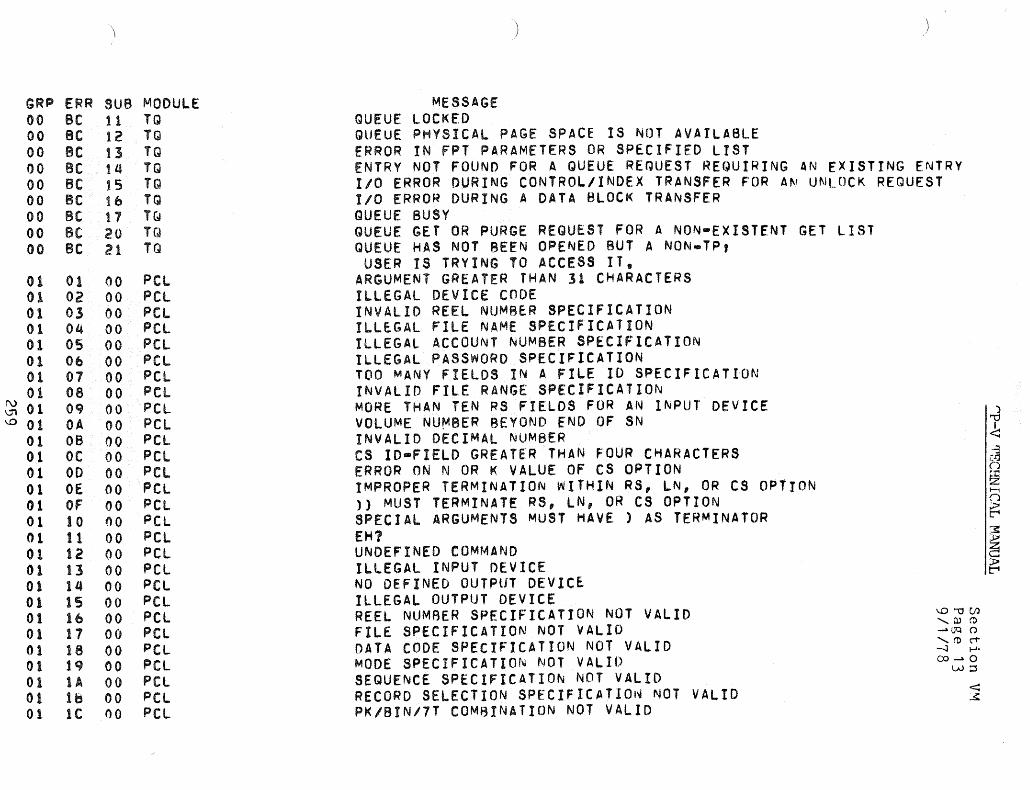
GRP 00 00 00 00 00 00 00 00 00
01 01 01 01 01 01 01 01
~ 01 ~ 01
01 01 01 01 Ot 01 01 01 01 01 01 01 01 01 01 01 01 01
ERR SUB MODULE Be 11 TQ Be t 2 TQ Be t:3 TQ Be 14 TQ Be t 5 TQ Be 1 b TQ Be 17 Ttl Bt 20 T(~ Be 21 TQ
01 00 peL 02 00 pel 03 00 PCl 04 00 pel 05 00 PCl Ob 00 pel 07 00 pel os 00 pel Oq 00 pel OA 00 pel OB 00 pel OC 00 PCl 00 00 pel OE 00 pel OF 00 pel 10 00 pel 11 00 PCl 12 00 pel 13 00 pel 14 00 pel 15 00 pel 16 00 pel 17 00 peL 18 00 pel lq 00 pel lA 00 peL 18 00 pel Ie 00 pel
MESSAGE QUEUE LOCKED
)
QUEUE PHYSICAL PAGE SPACE IS NOT AVAILABLE ERROR IN FPT PARAMETERS OR SPECIFIED LIST ENTRY NOT FOUND FOR A QUEUE REQUEST REQUIRING AN EXISTING ENTRY 1/0 ERROR DURING CONTROL/INDEX TRANSFER FOR AN UNLOCK REQUEST 110 ERROR DURING A DATA BLOCK TRANSFER QUEUE BUSY QUEUE GET OR PURGE REQUEST FOR A NON-EXISTENT GET LIST QUEUE HAS NOT BEEN OPENED BUT A NON.TP,
USER IS TRYING TO ACCESS IT. ARGUMENT GREATER THAN 31 CHARACTERS ILLEGAL DEVICE CODE INVALID REEL NUMBER SPECIFICATION ILLEGAL FILE NAME SPECIFICATION ILLEGAL ACCOUNT NUMBER SPECIFICATION ILLEGAL PASSWORD SPECIFICATION TOO MANY FIELDS IN A FILE ID SPECIFICATION INVALID FILE RANGE SPECIFICATION MORE THAN TEN RS FIELDS FOR AN INPUT DEVICE VOLUME NU~BER BEYOND fND OF SN INVALID DECIMAL NUMBER CS IO-FIELD GREATER THAN FOUR CHARACTERS ERROR ON N OR K VALUE OF CS OPTION IMPROPER TERMINATION WITHIN RS, LN, OR CS OPTION ) MUST TERMINATE RS, LN, OR CS OPTION SPECIAL ARGUMENTS MUST HAVE ) AS TERMINATOR EM? UNDEFINED COMMAND ILLEGAL INPUT DEVICE NO DEFINED OUTPUT DEVIC~ ILLEGAL OUTPUT DEVICE REEL NUM8ER SPECIFICATION NOT VALID FILE SPECIFICATION NOT VALID DATA CODE SPECIFICATION NOT VALID MODE SPECIFICATION NOT VALID SEQUENCE SPECIFICATION NOT VALID R E COR 0 S E LEe T ION S PEe I FIe A T I a I~ NOT V A LtD PK/BIN/7T COMBINATION NOT VALID
~""Ul ,Q.)~
- (]Q () '(t)("'t" -.J ...... 0:>-0
W::J

GRP ERR SUB MODULE MESSAGE 01 10 00 peL NULL ARGUMENT (TWO DELIMITERS IN A ROW) 01 1E 00 pel IMPROPER TERMINATION OF THE COMMAND 01 iF 00 pel ONE REEL NUMBER MUST BE SPECIFIED ON THIS COMM A (\lD
01 20 00 pel TO, INTO, OR OVER NOT SPECIFIED 01 21 00 pel RECORD SIZE EXCEEDS AVAILABLE MEMORY 01 22 00 pel INVALID DEVICE TYPE FOR THIS COMMAND 01 23 00 peL. TOO MANY REEL NUMBERS SPECIFIED 01 24 00 pel 'TO' FILE EXISTS 01 25 00 pel INVALID DIRECTION INDICATOR ON 'SPF" COMMAND' 01 2b 00 pel INPUT RECORD SIZE LARGER THAN 321b7 BYTES 01 27 00 peL INVALID OPTION FOR THIS COMMAND 01 28 00 pel TOO MANY SN,RD,WR,EX,UN SPECIFICATIONS 01 2q 00 peL. RS SPECIFICATION BEYOND END OF FILE (')
01 2A 00 pel ERROR IN COMPRESSED INPUT ""0 I
01 2B 00 pel PCl NEEDS AT LEAST TWO DATA PAGES TO RUN <
01 2C 00 pel TOO MANY ERRORS • PROCESS ABORTED I-]
01 20 00 peL INVALID TA~ SPECIFICATIO~ [T] (J
01 2E 00 PCl OVERFLOW ON EDIT LINE NUMBER :I::
I\J 01 2F 00 pel ZERO INCREMENT ON CS OR LN OPTION z
~ H
0 01 30 00 PCL TX OPTION USED WITHOUT TABS COMMAND (J
:.t>
01 31 00 pel M4q RES r-
01 32 00 PCl CONFLICTING OR DUPLICATE OPTION ::s::
01 33 00 pel MORE THAN Ie TAB VALUES :.t> z
01 34 00 pel INVALID HEXADECI~AL NUMBER c
01 35 00 peL TOO MANY CHARACTERS IN THE COMMANO :.t> r-
01 30 00 pel INVALID VALUE FOR ANS OPTION 01 37 00 PCl TOO MANV BLANKS IN A DELETE COMMAND 01 38 00 PCL ERROR WRITING LISTING OUTPUT 01 39 00 peL TAPE DENSITY SPECIFICATION IS IN ERROR 02 00 01 LOADER UNEXPECTED EOF 02 00 02 lOADER ILLEGAL RECORD 1.0. 02 00 03 LOADER SEQUENCE ERROR 02 00 Ot4 LOADER ILLEGAL RECORD SIZE I..O""Oc.n
':l)(1)
02 00 OS LOADER CHECKSUM ERROR ~OQ (.) '(1)("1"
02 00 0& LOADER ABNORMAL 110 -..J 1-'-
02 00 07 LOADER CANNOT OPEN E.F. 0) ~ 0
..r:=::s
02 00 08 LOADER STACK .OVERflOW < 02 00 09 LOADER BIAS TOO LARGE :.s:

GRP ERR 02 00 02 00 02 00 02 00 02 00 02 00 02 00 02 00 02 00 02 00 02 00 02 00 02 00 02 00 02 00 02 . 00 02 00 02 00 02 00 02 00 02 00 02 00 02 00 02 00 02 00 02 00 02 00 02 00 02 00 02 00 02 00 02 00 02 00 02 00 02 00 02 00 02 00 02 00
SUB MODULE OA LOADER 0.., LOADER ot LOADER OD LOADER Of LOADER OF LOADER 10 LOADER 11 LOADER 12 LOADER 13 LOADER 14 LOADER 15 LOADER 16 LOADER 17 LOADER 18 LOADER 1<1 LOADER tA LOADER tB LOADER IC LOADER to LOADER if LOADER iF LOADER 20 LOADER 21 LOADER 22 LOADER 23 LOADER ?4 LOADER 25 LOADER 26 LOADER 27 LOADER 28 LOADER 2q LOADER 2A LOADER 28 LOADER 2e LOADER 20 LOADER 2E LOADER 2F LOADER
MESSAGE ILL. ROM LANGUAGE BAD START ADDRESS UNEXPECTED ROM END REPEAT LOAD IS ZERO IMPROPER BOUND ILLEGAL ORG
)
BAD I/O RETURN FROM ~zLM DeB SEVe LEV. EXCEEDED ILL. LIB. LOAD ~OD. NO ROOM TO ROUND DeBS To PAGE BOUNDARIES. TRy FORCING XMEM ILL. DSEeT ROOT SEGMENT TOO LARGE TO LOAD IN2 TOO MANY CORE LIBRARIES ASSOCIATED IN2 CANNOT ENTER XMEM. STAC~S TOO LARGE. IN2 NOT ENOUGH ROOM TO CONCATENATE XMEM PAGES IN2 NO ROOM TO READ LIBRARY CORE IMAGE EVL NO ~OOM TO READ LIBRARY RELOCATIO~ DICTIONARy EVl NO ROOM FOR NE~ EXPRESSION WRT NO ROOM TO BUILD DCB TABLE. TRY FORCING XMEM WRT NO ROOM TO RUllO DeB TABLE. WRT LIBRARY LOAD MODULE REF/DfF STACK TOO LARGE TO UPDATE WRT INSUFFICIENT PHYSICAL MEMORY BAD ASSIGN/MERGE RECORD NO ROOM TO ADD LIBRARY LOAD MODULE TO ROM TARLE NO ROOM TO READ LIBRARY REF/DEF STACK NO ROOM TO UPDATE lIBRARY INVALID KEY SUPPLIED FOR DELETE RECORD ON ~:OIC I/O ERROR ON MtDIC IN wRITESEG ILLEGAL LIBRARY LOAD MODULE NAME ABNORMAL 1/0 ON OPEN OR READ TO CORE LIBRARY INVALID DECLARATION NUMBER REFERENCE (BAD ROM). INVALID KEY SUPPLIED FOR WRITE RECORD ON M:DIC ILLEGAL LOADER TRAP ABNORMAL 1/0 IN wRITELIB CANNOT FIND REF/OEF NAME IN STACK LIB LOAD MODULE TOO BIG • CANNOT USE EXTENDED MEMORY LIB LMN IS NOT ALLOWED ON A PRIVATE VOLUME ABNORMAL I/O READING LIB LMN EVL
\.O'"'OC/l ........ Q.) ('() .-OQ ()
........ roC"1" -...J 1-';::x)-o
\J1:S

I\) 0\ o r::r
GRP ERR 02 00 02 00 02 00 Ot! 00 02 00 03 01 0] 01 03 01 03 01 03 01 03 01 03 01 OJ 01 03 01 03 01 03 01 03 01 03 01 03 01 03 01 03 01 03 01 03 01 03 01 0] 01 03 01 03 01 03 01 03 02 03 02 03 02 03 02 03 02 OJ 02 03 03 03 04 OJ 04 03 04
SUB MODULE ~O LOADER 31 LOADER 32 LOADER 33 LOADER 34 LOADER 00 TEL 01 Tf.l 02 TEL 03 TEL 04 TEL 05 TEL Ob TEL 07 TEL OS TEL Oq TEL OA TEL 06 TEL Oc TEL 00 TEL Ot: TEL OF TEL 10 TEL 11 TEL 12 TEL. 13 TEL 14 TEL 15 TEL 1& TEL 00 TEl. 01 TEL 02 TEL 03 TEL 04 TEL 05 TEL 00 TEL 00 TEL 01 TEL 02 TEL
MESSAGE PAGED LMN MUST NOT HAVE MORE THAN 2Sb SEGMENTS
lMN'S SIZE TOO BIG THAT#S NOT A (MAPPABLE) LOAD MODULE BAD ENTRY IN LI~RARV kEF/OfF STACK
EVL
SAL TO AN OVERLAY ON REGISTER ZERO DETECTED WHILE IN 8REF MODE COMMAND LEGAL ONLY AT JOB STEP • QUIT OR GO IMPROPER FORMAT FOR SET COMMAND ILLEGAL OR INCONSISTENT ~ESOURCE NAME DCB NOT ASSIGNED • CAN#T UPDATE FILENAME: ME IS ILLEGAL CAN~T CREATE OR MODIFY DCB • AIM RECORD FULL BAD AIM ENTRY • RESPECIFY SET FOR THIS DeB
OPTION ILLEGAL FOR UNKNOWN FILE TYPE OPTION ILLEGAL FOR FILES OPTION ILLEGAL FOR XEROX LABELED TAPE OPTION ILLEGAL FOR DEVICES OPTION ILLEGAL FOR JOURNAL TAPE OPTION ILLEGAL FOR ANS LABELED TAPE OPTION lEGAL ONLY FOR DEVICES
READ ACCOUNTS EXCEED e ENTRIES WRITE ACCOUNTS EXCEED 8 ENTRIES EXECUTE ACCOUNTS EXCEED 8 ENTRIES MAXIMUM NUMBER OF SN~S EXCEEOEO ON FILE ILLEGAL START WHAT? CONTINUE WHAT? ILLEGAL. OC8 NAME DONT WHAT? eAC~UP RECORD FULL, CAN~T AOD MORE UNABLE TO GET PAGE FOR BACKUP RECORD FILE DOES NOT EXIST BACKUP FILE BUSY, TRY AGAIN LATER FILE INELIGIBLE FOR ~ACKUP BACKUP OF FILE ALREADY EXISTS UNABLE TO GET COMMON PAGE FOR SHOW NOTHING TO .SAVE CAN~T SAVE EXECUTE-ONLY PRGM, QUIT OR GO NO SAVE FILE NAMED
CJ .." I <
\.O'i:7Ul '"'W(() -.DQ () ,",(()c1" -.J ..... (X)-O
"'::s

GRP ERR 03 o~
03 04 03 04 03 04 03 04 03 04 03 04 03 04 03 05 03 OS 03 OS 03 OS 03 OS 03 os 03 OS 03 OS 03 06 03 07 03 08 03 08 03 Oq 03 Oq 03 Oq 03 Oq 03 Oq 03 OA 03 OA 03 OA 03 08 03 OC 03 OC 03 OC 03 00 03 OE. 03 OF 03 OF 03 Of 03 OF
SUR MODULE 03 TEL OQ TEL 0«; TEL 06 TEL 07 TEL 08 TEL Oq TEL OA TEL 00 TEL 01 TEL 02 TEL 03 TEL OLl TEL 05 TEL Ob TEL 07 TEL 00 TEL 00 TEL 00 TEL 01 TE.l 00 TEL 01 TEL 02 TEL 03 TEL 04 TEL 00 TEL 01 TEL 02 TEL 00 TEL 01 TEL 02 TEL 03 TEL 00 TEL 00 TEL 00 TE.L 01 TEL 02 TEL 03 TEL
MESSAGE GET FILE DOES NOT MATCH THIS SYSTEM VERSION BAD GET FILE • INVALID LIMITS HAD GET FILE • INVALID JIT GET CAL FAILED. PROBABLY BAD DeBS GE.T WHAT? ERROR WRITING SAVE FILE - SAVE ABORTED BAD GET FILE • M:CVM FAILURE DURING RESTORE CAN'T GET PAGE FOR RESTORE • GET ABORTED :USERS FILE BUSY, TRY AGAIN LATER UNABLE TO OPEN :USERS FILE, COMMAND ABORTED ERROR READING :USERS FILE, COMMAND ABORTED ERROR WRITING :USERS RECORD, COMMAND ABORTED PASSWORD CHANGE SUCCESSFUL PASSWORD SUPPLIED DOESN'T MATCH CURRENT PASSWORD PASSwORD > 8 CHARS ILLEGAL PASSwORD CHANGE REQUIRES ,OLD,NE~ PASSWORDS CAN'T DEBUG EXECUTE-ONLY PRGM, QUIT OR GO TERMINAL TYPE NOT VALID EXPANDED INPUT EXCEEDS 80 CHARS ERROR, COMMAND EXCEEDS 80 CHARACTERS COMPLETED RUNNING DOESN"r EXIST
WAITING: TO RUN WAITING TO oUTPUT
ID CANCELfD NOT YOUR JOB COMPLETED OR NOT INPUT CAN'T CHANGE MORE lHAN 6 PSEUDO SWITCHES TP NOT IN THIS SYSTEM TP IS NOT CURRENTLY ACTIVE LOGGING OFF TO FREE YOUR LINE FOR TP MESSAGE DISALLOWED BY DONT SEND COUPLE REJECTED FROM •
NO ROOM IN AIM FOR COMMANO FILE INFO, 1/0 ERR ON COMMAND Fl~E
***XEQ TERMINATED*** ***XEQ FILE INTERRUPT***
\..O""OUJ ,ruC1> ...... aq ('.) '(1)c-t' -..:J ~.
c:o-o -..:J:::S
< ..s:

I\.) 0\ o a.
GRP ERR 03 OF 04 03 04 03 04 03 04 03 04 03 04 03 04 03 04 03 04 03 04 03 04 03 04 03 04 03 04 03 04 03 04 03 04 03 04 03 04 03 04 03 04 03 04 03 04 03 Ob 00 Ob 00 Ob 00 Ob 00 Ob 00 Ob 00 Ob 00 Ob 00 Ob 00 Ob 00 Ob 00 Ob 00 Ob 00 Ob 00
SUB MODULE 04 TEL 58 RUNNER 5q RUNNER 5A RUNNER 58 RUNNER rsc RUNNER "50 RUNNER Sf RUNNER r;F RUNNER 60 RUNNER 61 RUNNER 62 RUNNER 63 RUNNER 64 RUNNER 65 RUNNER 66 RUNNER 61 RUNNER 68 RUNNER 6q RUNNER bA RUNNER 68 RUNNER bC RUNNER bD RUNNER bE RUNNER 00 ORSP 01 ORSP 02 DRSP 03 DRSP 04 DRSP O~ DRSP Ob ORSP 07 DRSP 08 DRSP 09 DRSP OA DRSP 08 ORSP OC ORSP OD DRSP
o
1
B
MESSAGE COMMANDS FROM FILE MUST BEGIN WITH A BANG (1) BAD DEBUG LOCATION NAME • BAD IF/AND/OR TEST NAME • BAD SNAP FROM/TO NAME • BAD PMD FROM/TO NAME • BAD MODIFY NAME •
TOO MANY DEBUG COMMANDS INVALID DEBUG RECORD TYPE RUNNER RECEIVED ABOVE 1/0 ERROR READING LOAD MODULE WITH KEYs
RUNNER RECEIVED ABOVE 110 ERROR READING DEBUG FILE BAD START ADDRESS NAME • MODIFY LOCATION NOT WITHIN PROGRAM. START ADDRESS NOT WITHIN PROGRAM • 8AO SEGMENT NAME IN DEBUG COMMAND • CAN-T GET PAGE AFTER PURE-PROCEDURE FOR DEBUG AND CLOBBER TABLE PMD FROM/TO ADDRESS NOT WITHIN USER AREA • DEBUG LOCATION NOT WITHIN PROGRAM • SNAP FROM/TO ADDRESS NOT WITHIN USER AREA •
PMDS AND DEBUGS NOT ALLOWED FOR LOAD MODULES BUILT BY LINK NOT ENOUGH CORE TO PROCESS DEBUG COMMANDS MALFORMED LOAD MODULE HEAD OR TREE RECORD NO ERRORS INSUFFICIENT PRIVILEGE LEVEL TO PROCESS THIS COMMAND INSUFFICIENT MEMORY TO READ TREE DRSP PROGRAM ERROR (SHOULDN'T HAPPEN) PRONAME REQUIRED NO SUCH OVERLAY/PROCESSOR ILLEGAL COMMAND OPTION ILLEGAL FLAG COMBINATION DON·T SET FLAGS WITH MONITOR OVERLAY PROCESSOR/OVERLAY ALREADY EXISTS OON$T USE COMMAND ON TELlceI ILLEGAL PRONAME, NOT tPNN FORMAT CANNOT OPEN THE FlO FlO IS Nor A LOAD MODULE
\.O""tJCIl 'DJ(1) -OQ (".)
'(1)(1" ~ ..... 00-0
oo:::s
< x
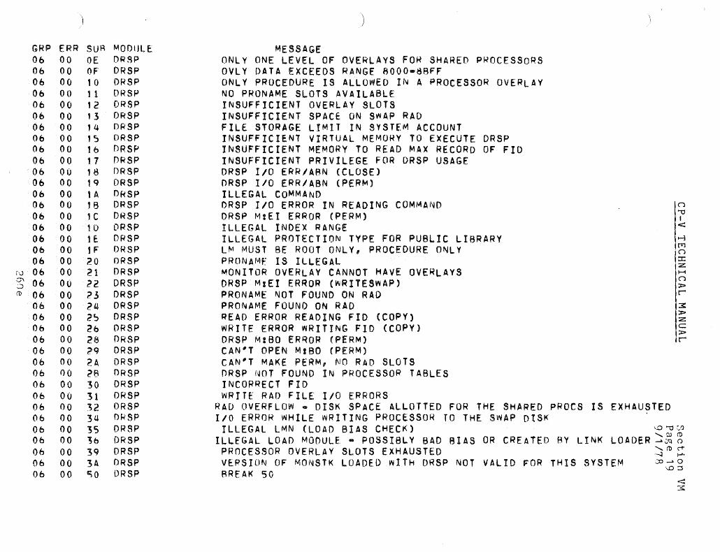
GRP ERR 06 00 06 00 06 00 Ob 00 Ob 00 06 00 06 00 06 00 06 00 06 00 06 00 06 00 Ob 00 06 00 Ob 00 06 00 06 00 06 00 06 00
r'..) 06 00 S 06 00 (D 06 00
Ob 00 06 00 Ob 00 06 00 06 00 06 00 06 00 06 00 Ob 00 06 00 06 00 06 00 Ob 00 06 00 06 00 06 00
SUR MODIJLE OE DRSP OF' DRSP 10 DRSP 1 1 DR SP 12 DRSP 13 DRSP 14 DRSP ,~ DRSP t6 DRSP 1.7 DRSP 18 ORSP 1q DRSP lA DkSP 1B DRSP 1C DRSP 1D ORSP If. DRSP 1F ORSP 20 DRSP 21 DR SP 22 DRSP ?3 DRSP 24 DRSP 2~ DRSP 26 DRSP 28 DRSP ?q ORSP 2A DRSP ?B DRSP 30 DRSP 31 DRSP 32 ORSP 34 nkSP 35 DRSP 36 ORSP 3q DRSP 3A ORSP '50 DRSP
)
MESSAGE ONLY ONE LEVEL OF OVERLAYS FOR SHARED P~OCESSORS OVlY DATA EXCEEDS RANGE 8000-8RFF ONLY PROCEDURE IS ALLOWED IN A PROCESSOR OVERLAY NO PRONAME SLOTS AVAILABLE INSUFFICIENT OVERLAY SLOTS INSUFFICIENT SPACE ON SWAP RAO FILE STORAGE LIMIT IN SYSTEM ACCOUNT INSUFFICIENT VIRTUAL MEMO~Y TO EXECUTE DRSP INSUFFICIENT MEMORY TO READ MAX RECORD OF FlO INSUFFICIENT PRIVILEGE FOR DRSP USAGE DRSP 110 ERR/ABN (CLOSE) ORSP 1/0 ERR/ASN (PERM) ILLEGAL COMMAND ORSP 1/0 ERROR IN READING COMMAND ORSP M:EI ERROR (PERM) ILLEGAL INDEX RANGE ILLEGAL PROTECTION TYPE FOR PUBLIC LIBRARY LM MUST BE ROOT ONLY, PROCEDURE ONLY PRONAMf IS ILLEGAL MONITOR OVERLAY CANNOT HAVE OVERLAYS ORSP M:EI ERROR (WRITESWAP) PRONAME NOT FOUND ON RAD PRONAME FOUND ON RAO READ ERROR READING FlO (COPY) WRITE ERROR WRITING FlO (COpy) DRSP MIBO ERROR (PERM) CAN'T OPEN MIBO (PERM) CAN'T MAKE PERM, NO RAD SLOTS ORSP NOT FOUND IN PROCESSOR TABLES INCORRECT FID WRITE RAD FILE 1/0 ERRORS
RAD OVERFLOW • DISK SPACE ALLOTTED FOR THE SHARED PROCS IS EXHAUSTED 1/0 ERROR WHILE wRITING PROCESSOR TO THE SWAP DISK
ILLEGAL LMN (LOAD BIAS CHECK) ILLEGAL LOAD MODULE • POSSIBLY BAD BIAS
PROCESSOR OVERLAY SLOTS EXHAUSTED VERSION OF MONSTK LOADED wITH DRSP NOT VALID FOR THIS SYSTEM BREAK SO

GRP ERR SUB MODULE MESSAGE 0& 00 51 DRSP BREAK 51 Of> 00 52 DRSP BREAK S2 0& 00 53 DRSP BREAK 53 06 00 154 ORSP BREAK 51.i 08 FF 00 AOOTSUBR OPERATOR INITIATED RECOVERY 08 01 00 SCHED/MM USERS PAGE CHAIN INCONSISTENT 08 02 00 SCHED REPORTED EVENT INCONSIST~NT WITH USER"S CURRENT STATE 08 04 04 seMED OPERATOR INITIATED SHUTDOWN 08 OA 00 TSIC/OPSIO OPCODE IN SWAP COMMAND LIST IS INVALID 08 08 00 TSIOIOPSIO INCORRECT ORDER CODE IN SWAP COMMANO LIST 08 OC 00 TSIO/OPSIO ATTEMPT MADE TO SWAP MONITORS MEMORY 08 OD 00 TSIO HALT FLAGS MISSING IN SWAP COMMAND LIST 08 OE. 00 TSIO 1/0 REQUEST WITH NUll COMMAND LIST 08 OF 00 TSIO/OPSIO INPUT FUNCTION CODE IS INVALID 08 10 00 CQC/ECBBLK coe-BAD coc aUF POOL, OR BAD aUF AOR ON RELEASE REQUEST 08 11 00 coc coe-INVALID INTERNAL CONTROL CODE TRANSLATE REQUEST 08 12 00 CDC CDC-SAD INPUT aUF LINKAGE ON RELEASE REQUEST 08 13 00 CDC CDC-OUTPUT aUF LINKAGE OR CHARACTER COUNT BAD
.) 08 1~ 00 THEUNCOC CDC ROUTINE WAS CALLED IN .A NON-coe SYSTEM t'\ • , 08 14 01 THEUNCOC COCIO CALLED IN A NON-coe SYSTEM ')
08 14 02 THEUNCOC coeOFF CALLED IN A NON.coe SYSTEM 08 14 03 THEUNCOC coeSENDX CALLED IN A NON-coe SYSTEM 08 14 04 THEUNcoe ECHOCR2 CALLED IN A NON.COC SYSTEM 08 17 00 IOQ INVALID DISC ADDRESS PASSED FOR AN 1/0 OPERATION ("")
as lq 00 BUFF INVALID BUFFER ADDRESS PASSED FOR RELEASE ""0
• 08 19 01 OPEN/CLOSE TOO MANY CLIST ENTRIES IN MPQOl < 08 lA 00 CLS ACCOUNT DIRECTORV IS INACCESSIBLE ~
08 1~ 00 SWAPPER USERS PAGE CHAIN NON-ZERO AT SwAP COMPLETION tTl ("")
08 Ie 00 SWAPPER INSWAP PROCESSOR SIZE EXCEEDS elIST SPACE ::I:
08 to 00 TaOV REQUESTED OVERLAY NUMBER IS OUT OF RANGE z H
08 tE 00 SCHED SySTEM REBOOTED ~ITHOUT A PROPER SHUTDOWN ("")
):>
08 1F 00 SWAPPER NOT ENOUGH PAGES TO PERFORM THIS SWAP r 08 21 00 MM ATTEMPT TO SET ACCESS ON AN NON.EXISTENT VIRTUAL PAGE \.O"'OCIl
3: '0)<1)
08 22 00 TYPR PRIVATE VOLUME ALLOCATION ERROR - OQ (') ):>
08 23 CSEHANO INVALID ENTRY TO (Sf HANDLERS '('1)<1" z 00 ~ ..... c:
08 24 00 CSEHAND INSTRUCTION EXCEPTION TRAP IN MASTER MODE corvo ):>
O::J r 08 25 00 CSEHANO UNRECOVERABLE WATCHDOG TIMER TRAP 08 2tt 00 CSEHAND CSE TRAP DURIN~ MFI, PFI HANDLING <
3:
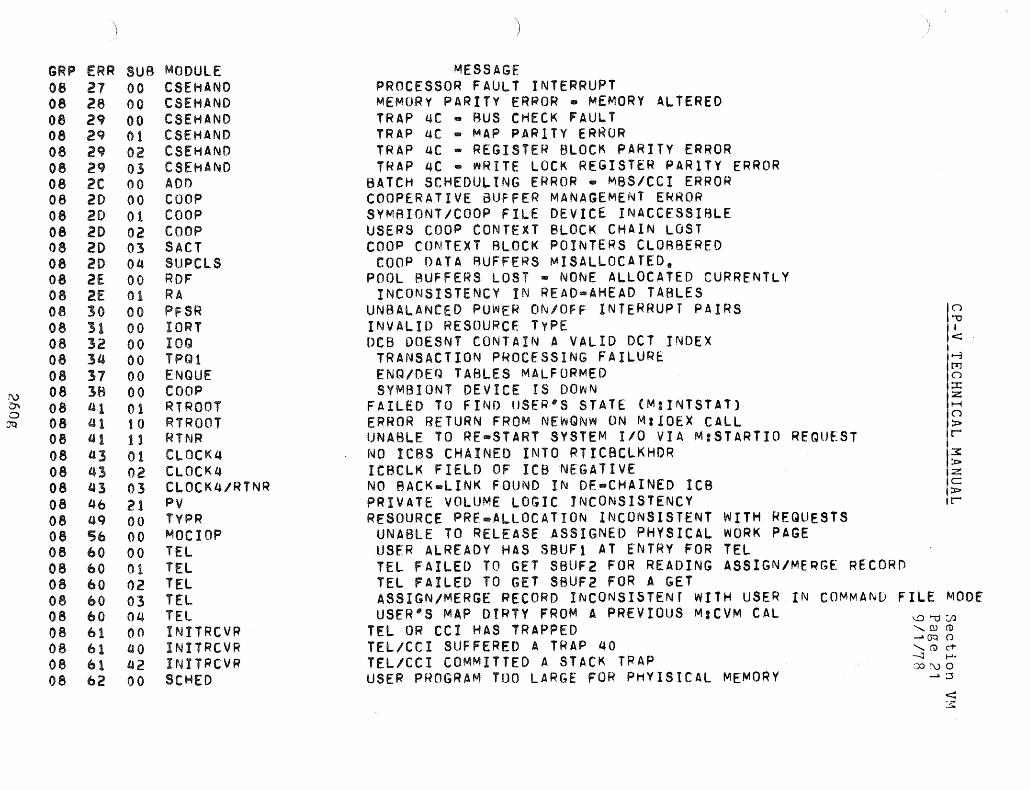
GRP ERR OS 27 08 28 08 29 08 2q 08 29 08 2<:J 08 2C 06 20 08 20 08 20 08 20 08 20 08 2E 08 2.E 08 30 08 31 08 32 08 34 08 37 08 3B 08 41 08 41 08 41 08 tt3 08 43 08 43 06 46 06 4Q 08 5b 08 60 08 60 08 60 08 60 08 60 08 61 08 61 08 61 08 62
SUB MODULE 00 CSEHANO 00 CSEHAND 00 CSEHAND 01 CSEHAND 02 CSEHAND 03 CSEHAND 00 ADD 00 COOP 01 COOP 02 COOP 03 SACT 04 SUPClS 00 RDF 01 RA 00 PFSR 00 tORT 00 IOQ 00 TPQl 00 ENQUE 00 COOP 01 RTROOT 10 RTRQOT 11 RlNR 01 CLOCK4 02 CLOCK4 03 CLOCK4/RTNR 21 pv 00 TYPR 00 MOCIOP 00 TEL 01 TEL 02 TEL 03 TEL 04 TEL 00 INITRCVR ao INITRCVR t42 INITRCVR 00 SCHED
MESSAGE PROCESSOR FAULT INTERRUPT MEMORY PARITY ERROR. MEMORV ALTERED TRAP QC • BUS CHECK FAU~T TRAP 4C • MAP PARITY ERROR TRAP 4C - REGISTER BLOCK PARITY ERROR TRAP 4C - ~RITE LOCK REGISTER PARlTY ERROR
BATCH SCHEDULING ERROR • MBs/tel ERROR COOPERATIVE BUFFER MANAGEMENT ERROR SYMBIONT/COOP FILE DEVICE INACCESSIBLE USERS COOP CONTEXT BLOCK CHAIN LOST COOP CONTEXT BLOCK POINTERS CLOBBERED
COOP DATA BUFFERS MISALLOCATED. POOL BUFFERS LOST .. NONE ALLOCATED CURRENTLY
INCONSISTENCY IN READ-AHEAD TABLES UNBALANCED PUWEH O~/OFF INTERRUPT PAIRS INVALID RESOURCE TvPE DeB DOESNT CONTAIN A VALID OCT INDEX
TRANSACTION PROCESSING FAILURE ENQ/DEQ TABLES MALFORMED SYMBIONT DEVICE IS DOWN
FAILED TO FIND USER'S STATE (M:INTSTAT) ERROR RETURN FROM NEwQNw ON M:IOEX CALL UNABLE TO RE-START SYSTEM 1/0 VIA M:STARTIO REQUEST NO ICSS CHAINED INTO RTICBCLKHDR ICBCLK FIELD OF Ica NEGATIVE NO BACK-LINK F'OUND IN DE-CHAINED leB PRIVATE VOLUME LOGIC INCONSISTENCY RESOURCE PRE-ALLOCATION INCONSISTENT WITH REQUESTS
UNABLE TO RELEASE ASSIGNED PHYSICAL WORK PAGE USER ALREADY HAS SBUFt AT ENTRY FOR TEL TEL FAILED TO GET SBUF2 FOR READING ASSIGN/MERGE RECORD TEL FAILED TO GET SBUF2 FOR A GET
I~ I .~
tTl (J
::r: z H (J
~ r'
3: :.cz
Ie I:x:> Ir'
ASSIGN/MERGE RECORD INCONSISTENT WITH USER IN COMMAND FILE MODE USER'S MAP DIRTY FROM A PREVIOUS M:CVM CAL
TEL OR eCI HAS TRAPPED TELlceI SUFFERED A TRAP 40 TEL/ceI COMMITTED A STACK TRAP USER PROGRAM TOO LARGE FOR PHYISICAL MEMORY
\.O'1:I:::Jl "ru(D ....:. (jq (.)
"rDc-t' --J ...... :X) :\) 0
....:.:,:s
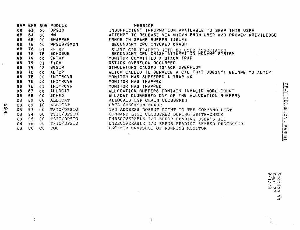
GRP ERR SUB MODULE 08 63 00 OPSIO 08 6A 00 MM 08 68 00 SWAPPER 08 78 00 MPSUB/SMON 08 78 01 ENTRY 08 78 7F SCHOSUB 08 79 00 ENTRY 08 79 01 TaO\l 08 79 02 S5SIM 08 1C 00 ALTCP 08 7E 00 TNITRCVR 08 7E 40 INITRCVR 08 7E 41 INITRCVR 08 81 00 AlLOCAT 08 88 00 SCHED 08 89 00 ALLOCAT
I\) 08 89 10 ALLOCAT 0\ 08 93 00 TSIO/DPSIO 0 :::r 08 94 00 TSIO/DPSIO
08 95 00 TSIO/DPSIO 08 96 00 TSIO/DPSIO 08 CO CO COC
MESSAGE INSUFFICIENT INFORMATION AVAILABLE TO SWAP THIS USER ATTEMPT TO RELEASE VIA MaCVM FROM USER W/O PROPER PRIVILEDGE ERROR IN SPARE BUFFER TABLES
SECONDARY CPU INVOKED CRASH SLAVE CPU TRAPPED WITH NO ¥Si R SECONDARY CPU CRASH ATTEMP N A~~~~~A§V~TEM
MONITOR COMMITTED A STACK TRAP OSTACK OVERFLOW OCCURRED SIMULATORS CAUSED TSTACK OVERFLOW ALTCP CALLED TO SERVICE A CAL THAT DOESN"T BELONG TO ALTCP MONITOR HAS SUFFERED A TRAP 40 MONITOR HAS TRAPPED MONITOR HAS TRAPPED ALLOCATION BUFFERS CONTAIN INVALID WORD COUNT ALLOCAT CLOBBERED ONE OF THE ALLOCATION BUFFERS ALLOCATS HGP CHAIN CLOBBERED DATA CHECKSUM ERROR TVD ADDRESS DOESNT POINT TO THE COMMAND LIST COMMAND LIST CLOBBERED DURING WRITE-CHECK UNRECOVERABLE I/O ERROR READING USER'S JIT UNRECOVERABLE I/O ERROR READING SHARED PROCESSOR ESC-ETB SNAPSHOT OF RUNNING MONITOR
1..0 '·0 Ul ,Wel> ..... O'Q () 'el>C1" ......;J 1-'. CONO
N::S
(")
.." I <:
~ [T) (")
::x: z H (")
:t:» r 3: :t:» z C :t:» r

CP-V TECHNICAL MANUAL
DATA BASES
:USER File Record Format
Section VN.Dl Page 1 4/1/74
Each 126 word record in the logon file, called :USERS, corresponds to an
authorized user. 'lYhenever an on-line or batch user attempts to use the system,
the :USERS file is checked to determine if there is a corresponding record. If not,
he is denied access to the system, if there is a record associated with that user
and if he has logged on with the correct password (if any), he may access the
system.
Each record in the :USERS file contains a profile of a user authorization for use
of various system resources - such as number of spindles, tape drives, core space
RAD and DISK space, etc. At log on time, these various items are placed into
corresponding fields in JIT and/or Assign-Merg.e Table so that information about
the user is readily accessible. Controls can then be duly exerted by the monitor.
The :USERS file is accessed by SUPER, TEL, eel, and LOGON.
26,'· .1.

Word 0
1
2
-3
4
5-
6
7
-8
9
10
11
'12
13 •• !.~
14
UB:BILL 15
UB:PRIV 16
17
18
19
20
21
22
23
24
25
26-
27
28
29 *Updated by LOG-OFF
CP-V TECHNICAL MANUAL
---------------------------- }
} 01
---------------------------- l
----------------------------
--------------.......... ------------ } Count t I I ------ ------~-----_r------
------I------~------t------ }
~ _________ ~!~j~~~~~o~~~~g------Information
-------------~-~~~~---------
Section VN.Ol Page 2 4/1/74/
Account
Name
Flag Bits
Password
Password
Account Auto-Call
Processor
Name
(TEXTC
format)

CP-V TECHNICAL MANUAL
Section VN.Ol Page 3 4/1/74
:UNML
:UBML
16 words
:UOML
16 words
:UGML
:UNMR 16 hal fwords Names
:UBMR Resource Max. 16 bytes
:UOMR Resource Max. 16 bytes
:UGMR Resource Max. 16 bytes
:UNMP 16 halfwords Limit Names
:UPFLGS Flags 16 bytes
263

Name
Account
Name
MC
XO
RP
SE
Password
CP-V TECHNICAL MANUAL
Contents of Users File Record
Description
Section VN. 01 Page 4 10/3-1;74
EBCDIC. Account under which the user is authorized to log in. Value may be 1 to 8 characters in length and is left-justified with trail ing blanks.
EBCDIC. Name under which the user is authorized to log in. Value may be 1 to 12 characters in length and is left-justified with trailing blanks.
Bit 0 Default read access for user, 0 indicates ALL; 1 indicates NONE.
Word 5, bit 27. Set if user has the Me {lv\aintenance Console} specified as a resource. Used for inte-rnal use by SUPER.
Word 5, bit 28. Set if user may execute processors: from :SYS account only. Default = O.
Word 5, bit 29. Set if user has one or more entries in the :PROCS file specifying this user is allowed/ disallowed to execute.
Word 5, bit 30. Set if security check of granule and core cleaning is required.
EBCDIC. Password assigned to this name-account. The contents of the field is the latest value entered by the user himself with a TEL PASSWORD command, or by SUPER via the PASSWORD option of a CREATE or MODIFY command. Value may be 1 to 8 characters in length and is left-justified with trail ing blanks. If no password has been specified, these words contain zeroes. 264

Section VN .. Ol
cP-V TEClI.ijIC:AL MANUAL Page 5 4/1/74
I----------~--.-----------------------------------------~.-Auto-Call
Auto-Call account
~uto"'call name
Billing
Privilege
EBCDIC. Password of LMN to be automatically connected to the user's job when he logs on. Value may be 1 to 8 characters in length and is left"iustified~ with trail ing blanks. If no auto-call LMN has been specified, auto-call password contains zeroes.
EBCDIC. Account in which resides the LMN to be automatically connected to the user's job when he logs in. Value may be 1 to 8 characters in length and is left-justified with trail ing blanks. The value for system processors is II :SYS ". If no autocall LMN has been specified, these words contain zeroes.
EBCDIC. Name of LMN to be automatically connected to the user's job when he logs in. The value is in TEXTC format, may be 1 to 11 characters in length, and is left-iustified with trail ing blanks; the first byte contains a count. If no auto-call LMN has been specified, these words contain ~eroes,.
Binary. Charge class level referencing a charge class table in the RATE file which is used in account processing. The halfword value must lie in the range:
o .s.. charge class < Z
Binary. Privilege level granted the user. The higher privilege codes include the lower privilege. The range of the privilege codes is X'O' to X'FF'. The currently meaningful codes are as follows:
hex code typical use faciJ ities allowed
systems Issue M:SYS CAL programmer Bypass file security
checks. BO systems Access and change
programmer monitor AO diagnostic Read and write' error
programs file; request devices; invoke diagnostics.
80 performance Examine monitor displays
40 normal Default privilege programs level (online and batch)
265

Maximum Retention
IAccumulated Permanent DISK Space
!Accumulated Permanent RAD Space
'Extended Accounting Information
Service Limit
13atch, ani ine and ~host Service Maximum
Resou rce Li mit Names
Batch, ani ine and Ghost Resource Maximum
CP-V TECHNICAL MANUAL i
Section VN. 01 Page 6 4/1/74
Binary. Hours of maximum retention period for files created by the user. A zero means the system default value and X'FFFF' means the files are to be retained indefinitely.
Binary. Permanent DISK storage accumulated by the user. This field is not modified by SUPER.
Binary. Permanent RAD storage accumulated by the user. This field is not modified by SUPER.
EBCDIC. This field specifies installation specific accounting information. A mmximum of 24 characters is allowed. The character; is not allowed.
0 ... 15 four character service limit names. This table gives the serivces for which the maximum values are given in the next three tables.
Three parallel tables of 9 .. 15 full word binary values associated with the service limit names. One table each for batch, onl ine and ghost operation in th is account.
0 ... 15 two character resource limit names. Th is table gives the resources for which maximum usage values are given in the next three tables.
Three parallel tables of 0 ... 15 byte binary values associated with the resource I imit names. One table each for batch, onl ine and ghost operation.
266

Default Retention Period
Peripheral Limit Names
Peripheral Flags
CP-V TECHNICAL MANUAL
Section VN. 01 Page 7 4/1/74
Binary. Hours of retention period for files created by the user. A zero means the system default value and XIFFFF' means the files are to be retained indefinitely.
0-15 two character peripheral device limit names. This table contains the peripheral device names for which use authorization flags are given in the next table.
A table of 0-15 bytes parallel to peripheral limit names each byte has the form:
I 0 11 121 314 Is 16 17 I lJLL9?ost
onlme batch
A bit value of one means that authorization to use the device is granted.
26'1'

CP-V TECHNICAL MANUAL
Job Accounting Record
Section VN.02 Page 1 4/1/74
The following Figure shows the additional structure of the job accounting record. Words 0-37 remain unchanged with respect to previous versions except that the field marked "scratch tapes" in word 32. is now unused.
Four words have been appended to the record, words 38-41 and contain the resource allocation values: the number allocated for batch jobs (regardless of whether or not they were actually used), and, for on-line and ghost jobs it is the number in use at time of logoff. Byte zero of word 38 contains flags which indicate the condition under which the accounting record was generated. The start and end time may be optionally expressed in seconds from midnight by the installat'ion' s setting of bits 31 of S: OPTION in the Monitor Root.
268

Word.
0
2
5
11
12
13
14
15
16
17
18
19
20 /~-"
21 22
23
24
25
26
27
28
29
30
31
32
33
34
35
36
~7
. 38 .~
39
40
41
CP-V TECHNICAL MANUAL
Account
Name
Extended Accounting
Charge Units
line Number Priority Final Run Status
Job Origin System Version
Start Date
Start Time
End Time
Console Interactions
Finish Date
SYSID Pack Mounts
Section VN.02 Page 2 4/1/74
Job Steps
Spindles
Cards Read Ccards Punched
Processor Poges User PaQes
Diagnostic Pages Tope Mounts Tape Drives
T ope Accesses
RAD Accesses
Disk Accesses
1/0 CALS
Permanent RAD Granu les
Permanent Disk Granules
Core Usage
Processor Execution Time
Processor Service Time
Maximum Core Size Partition Save Topes iylIM~/$ffi User Execution Time
'<
User Service Time
Peak Temporary RAD Granu les
Peak Temporary Disk Granules
Billing Rate ~%~ Flags Resource Allocotion (Values
268

Name
Account
Name
Extended Accounting
-Charge Units
Line Number
Priority
Final Run Status
Job Steps
Job Origin
System Version
Start Date
Start Time
End Time
Console Interactions
CP-V TECHNICAL MANUAL
Contents ot Accounting Record
Descri pti on
SECTION VN.02 PAGE 3 4/1/74
Account number of the user as specified on the job card or log-on message.
Name of the user as specified on the job card or log-on message.
Installation-defined accounting information as specified on the job card or log-on message.
Accumulated charge units calculated for the user through use of the rates table.
Line number (Data Set Controller Subchannel) to which the user connected. Line Number is set to XI FF' if entry is for a batch job.
Priority specified on the job card. Unused if entry is for a terminal session.
Run status at the completion of the job {an eight bit field}.
XIOO I - Job exited normally.
X'01 1 - Job aborted, illegal trap.
X'02 1 - Job aborted, I/o error.
X'04 1 - Job aborted, limit exceeded.
X'08 1 - Reserved for CHKPT.
X' l0 ' - Job aborted, I XI key-in.
X'20 ' - Last job step errored, 1 E' key-in.
X'40' - Job -aborted, M:xxx.
X'80 ' - Last job step errored, M:ERR.
Total number of job steps if batch; total number of subsystem operations if on-line.
Origin of batch job.
o - From local card reader
1 - From on-line terminal
2 - Reserved for remote batch
Version of operating system (from cell X'2B') in EBCDIC.
Date at job or terminal session start, where the left halfword is the year and the right halfword is the day. Year is a binary value; e. g., 1970 is represented as X'7B21. Day is the Julian day of the year represented in binary; e. g. , September 14 is represented as XI 101 I •
~ Time of day at start of job of terminal session in minutes from midnight. The value is expressed in binary.
Time of day at end of job or terminal session. Expressed in the same format as start time.
Number of interactions during the course of a terminal session (zero for batch).
:ACCTLG - Accounting Log Format
f'-'-'- '-,
t! 'i.l
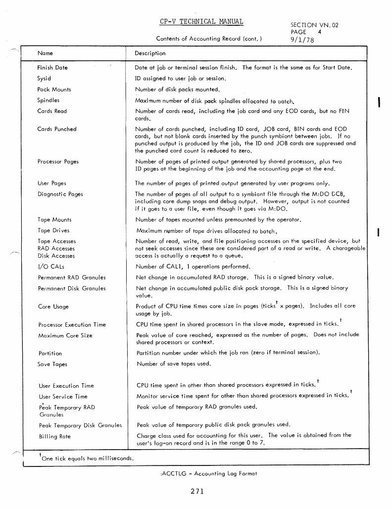
Name
Finish Date
Sysid
Pack Mounts
Spindles
Cards Read
Cards Punched
Processor Pages
User Pages
Diagnosti c Pages
Tape Mounts
Tape Drives
Tape Accesses RAD Accesses Disk Accesses
I/o CALs
Permanent RAD Granules
Permanent Disk Granules
Core Usage
Processor Execution Time
Maximum Core Size
Parti ti on
Save Tapes
User Execution Time
User Servi ce Ti me
P~ak Temporary RAD Granules
Peak Temporary Disk Granu les
Bi II ing Rate
tOne tick equals two milliseconds.
CP-V TECHNICAL MANUAL SECTION VN. 02 PAGE 4
Contents of Accounting Record (cont. ) 9/1/78
Descri pti on
Date at job or terminal session finish. The format is the same as for Start Date.
ID assigned to user job or session.
Number of disk packs mounted.
Maximum number of disk pack spindles allocated to batch.
Number of cards read, including the job card and any EOD cards, but no FIN cards.
Number of cards punched, including ID card, JOB card, BIN cards and EOD cards, but not blank cards inserted by the punch symbiont between jobs. If no punched output is produced by the job, the ID and JOB cards are suppressed and the punched card count is reduced to zero.
Number of pages of printed output generated by shared processors, plus two ID pages at the beginning of the job and the accounting page at the end.
The number of pages of printed output generated by user programs only.
The number of pages of all output to a symbiont fi Ie through the M:DO DCB, including core dump snaps and debug output. However, output is not counted if it goes to a user fi Ie, even though it goes via M: DO.
Number of tapes mounted unless premounted by the operator.
Maximum nt(lmber of tape drives allocated to batch.
Number of read, write, and fi Ie positioning accesses on the specified device, but not seek accesses si nce these are consi dered part of a read or wri te. A charageable ~ccess is actually a request to a queue.
Number of CAll, 1 operations performed.
Net change in accumulated RAD storage. This is a signed binary value.
Net change in accumulated public disk pack storage. This is a signed binary value.
Product of CPU time times core size in pages (tickst
x pages). Includes all core usage by job.
t CPU time spent in shared processors in the slave mode, expressed in ticks.
Peak value of core reached, expressed as the number of pages. Does not include shared processors or context.
Partition number under which the job ran (zero if terminal session).
Number of save tapes used.
t CPU time spent in other than shared processors expressed in ticks.
t Monitor service time spent for other than shared processors expressed in ticks.
Peak value of temporary RAD granules used.
Peak value of temporary public disk pack granules used.
Charge class used for accounting for this user. The value is obtained from the user's log-on record and is in the range 0 to 7.
:ACCTLG - Accounting Log Format
271
I

Name
Flags
Resource Allocation
CP-V TECHNIcAL MANUAL
Contents of Accounting Record (cont.)
Description
Section VN.02 Page 5 4/1/74
Indicate condition under which accounting record was generated
0= Normal 1 = Recovery condition 2 = Assign-Merge record error 3 = Recovery-but missing or bad A/M record
15 byte table containing the number of resources of each type allocated.. For batch jobs it is the number allocated (regardless of whether or not they were actually used). For online or ghost jobs it is the number of resources in use at time of log off.
272
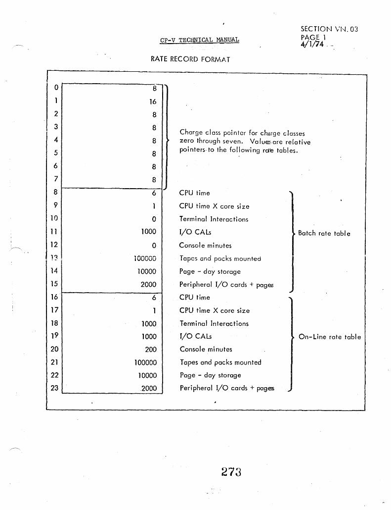
0
1
2
3
4
5
6
7
8
9
10
11
12 ~,
1~ i
14
15
16
17
18
19
20
21
22
23
CP-V TECHNICAL MANUAL
SECTlOt'J vr'-J. 03 PAGE 1 4/1/74 - -
RATE RECORD FORN\,i),T
8 ,""
16
8
8
8
8
8
8
6
1
0
1000
0
100000
10000
2000
6
1
1000
1000
200
100000
10000
2000
~
Charge class pointer for charge classes zero through seven. Valuffi.-are relative pointers· to the following rctle tables.
CPU time
CPU time X core size
Terminal Interactions
I/O CAls
Console minutes
Tapes and packs mounted
Page - day storage
Peripheral I/O cards + pag~
CPU time
CPU time X core size
Terminal Interactions
I/O CALs
Console minutes
Topes and pocks mounted
Page - doy storage
Peripheral I/O cards + pagES
273
Batch rate tabl e
J
On-Line rate table

CP-V TECHNICAL MANlJAL
Section VN.04 Page 1 4/1/74
:RBLOG - Remote Batch Logon File
PURPOSE
Each record except the ID record in the remote batch logon file, called :RBLOG, corresponds to an authorized work station. Whenever a user tries to log a work station onto the system via the IRBID command, or uses a work station name on a JOB card, the :RBLOG file is checked to determine if there is a corresponding record. If not, access to the system is denied; if there is a record associated with that work station name, the system may be accessed. The :RBLOG file is accessed by SUPER, RBBAT, and LDEV.
:RBLOG File Record Format
The remote batch ID record (RBID), which is written with the key I ••• ',
a chain of used RBIDs and a chain of free RBIDs. contains
The record written with a key of '///' contains the list of WSNs indexed by RBIDs.
The records keyed by WSN are described in three formats:
1. Record layout with associated SUPER internal labels.
2. Record elements keyed to the SUPER internal labels.
3. A bit by bit breakdown of the three flag word formats used in the :RBLOG record.
274.

INTERNAL LABEL
RB:RBID
R:FLAG
RD:W'SN
RB:RP
R:BUF
RD:RWSN
RB:DSMl R:RMT \
R:INRCB
R:HSX
R:OUTRCB
RH:DEV
RB:RCB
RH:Fl
RH:F2
RH:SUS
RB:MAX
RB:MIN
RB:PRIV
RB:TYPX
RD:GHOST
RECORD INDEX
o 1
2 3
4
5
6 7
8
9
10
11
12 19
20 23
24 31
32 39
40 47
48 51
52 55
56 59
60 63
64 65.· I
66 79
CP~V TECHNICAL MANUAL
Section VN.04 Page 2 4/1/74
FORMAT/CONTENT
,J ,8 ~ 6 -?£ ~ ______ ~ _________ 1 ______ ~1-__ ' ____ ~
( 8 words
RBID I Flag Bits
Work station name in text 1.-8 characters
Max. Priorif
Buff
Remote work station name in text (1-8 characters)
DSM 1 RMT Number (slave) ~IOC Input J RC B .
Highest device (stream index)
1S/V\D output IRCB
Device name tabl e 16 H W Text
,~-------------~----------------~ 4 wort RCB table - 16 bytes
~~--------------------------~ 8 word:
FLAG 1 Table .. 16 HW
,P-----------------------------~ (' 8 words
FLAG 2 Table - 16 HW
,~--------------------------~ 8 words SUSBIT Table - 16 HW
,~--------------------------~ ./ Maximum Record Count Tobie 4 words
\ 16 bytes ,~--------------------------I / Minimum record Count Table
4 words
/ 4 words
16 bytes
Privi.l ege Tabl e 16 Bytes
~~------------------------------I 4 words
\... ~ wor s
\
14 words
Type Index Table for DC Option 16 Byte ..
TEXT GHOST NAME
Reserved for future use
*These are nine parallel table of 16 elements each, indexed by device.
:RBLOG RECORD (80 WORDS LONG)

Internal Mino Value Max. Value DefaUlt Data Type Associated Note· Label Value Super Option
\ \
R:RBID 0 X'FF' hex Assigned by Super
R:FLAG Type description of Master/Slave R:FlAG follows Xl/N/ X2/N2 SYS/NSYS
RD:VVSN Text 1-8 char. W Specified by user when
creating new work station
RB:RP 0 X'F' X'7' hex RP
R:BUFF 1 FF 1 flag -. MRS MRS-ifF NMRS ..... 1
RD:WSN text RWSN 1-8 char.
RS:DSM 0 X'FF' 0 hex DSM
R:RMT text RMT 2 char
R:INRCB 0 X'FF' 0 hex IReB
R:HSX 0 X'F' DEY MQintained by SUPER. DO .. lndicates the number ot
devices in record minus 1.
R:OUTRCB SMD/NSMD Only one allowed per work station
RH:DEV Text. DEV 2 char. DD
RB:RCB 1 X'FF' must be hex RCB ' .
specified

) )
Max. Value Default Data Type Associated Notf --- --j Internal Min. Value label Value Su per a pti on I
--1
RH:Fl CTl/NCTl description of SRCB
RH :Fl foil ows I
IN/OUT Dt.:'i:OC
RH:F2 DEV=OC description of DIR/NDIR RH:F2 follows lIST SRCB IN/OUT
~ lHN/NBIN
RH:SUS 0 X'FFFF' 0 hex SUS
RB:MAX 1 255 80 * decimal MAX, CP2, lP2
RB:MIN 1 255 1 decimal MIN, LPP
RB:PRIV 0 X'FP 40 hex PRIV
RB:TYPX 0 TYPMNES2 0 DC - Only symb. device types legal
RD:GHOS' 0 Text C GHOST
* For I isting devices, defaults are: IV\ax 132 Min 38 (I ines per page)

FLAG NAME
R:FLAG
(word)
RH:Fl
RH:F2 (HW)
CP-V.TECHNICAL MANUAL
BIT NUMB~R SET (0 - 31 )
6 TYPE= IRBT
7 SIGMA is in SLAVE mode
9 Xl specified 10 TVP = 2780 19 SYS specified
~~ oa specjRed speCI led (remaining bits currently unspeci.fied)
IN and NCTL 0 or OUT and
DEVloc 12 SRCB=C
13 SRCB=P
14 DEV=OC
15 IN
0 DEV=OC
1 DIR
2 LIST=P
3 LIST= S
5 SRCB = U
6 SRCB = t * 7 SRCB = P
9 LIST = Y
LIST = S
10 IN
11 OUT
12 BIN 15 LIST =Y
LIST = S
Section VN.04 Page 5 4/1;74
RESET
TYPE=7670 or 2780
in MASTER mode
not Xl TYPE = IRBT or 7670 NSYS
NotX2 NEM
IN and CTL or OUT
and DEV = OC not C
not P
DEVloc.
OUT
DEV/oc
NDIR
LISTI P
Is Iu Ic *C+P=X
I P
OUT
IN NBIN
I I
DESCRIPTION OF :RBLOG FLAG \VORDS
2'78

CP-V TECHNICAL MANUAL
Note regarding bit values relative to LIST option in RH:F2
BIT 2 3 9 15
lIST= N 0 0 0 0 P 1 0 0 0 y 0 0 1 1 S 0 1 1 1
279
Section VN.04 Page 6 4/1/74_

Word 0
1
2,
3
CP-V TECHNICAL MANUAL
Structure of the RBID Record
HOF 0 TaU HOU
1 2 3 4
5 6 7 8
~c;;; 255 o
HOF =
TaU =
HOU =
Head of Free (initially, 1)
Tail of Used (initially 0)
Head of Used (initiaHy 0)
-
l
Section VN.04 Pa~e 7 4/1/74
Values in words 1 - 64 are changed as work stations are authorized or deleted.
28U

CP-V TECHNICAL MANUAL
:PROCS File
SECTION VN.05 PAGE 1 10/31/74
The setting of the RP bit in the :USERS record {word 5, bitt7} indicates the presence of a record for that user in the :PROCS file. The :PROCSfile is a keyed file, keyed by the concatenated user account and name identically to the :USERS file.
The data record will be of variable size up to a full granule (512 words). The first word of the record is reserved for flag bits and a count. The count is in the high order halfword's bits 1 - 7. The low order halfword contains an index to the next free byte in the record.
Bit 0, called PM, indicates the mode of the processor list. PM = 1 indicates that the list is a list of processors which are not allowed for this user. All processors not listed are allowed. When the PM bit is reset, each entry indicates a processor which is allowed in the specified mode (s), all others being disallowed.
(NOTE: The effectiveness of the :PROCS restrictions on executing processors is dependent upon execute only access on these processors so that the user cannot copy them.)
The remainder of the :PROCS record contains variable length items of the form:
Word 0 o 1 67 15 16 31
p Unassigned
Number of Record Byte Count M Items in Record
~ PM bit = 1 record contains names, of disallowed process ors ~ =0 record contains names of allowed p rocessors
201

CP-V TECHNICAL MANUAL
The remainder of the :PROCS record contains variable length items of the form:
8 Bytes Flag Byte 2 - 12 Bytes if Present
lsloJGIA I p I xl xl X TEXTC Processor Names Account I
SECTION VN.05 PAGE 2 4/1/74
left-iustifled, blank filled
unassigned bits
1 partial processor name
0 fu II processor name
1 account fieJd present in item
0 account :SYS assumed and not present
1 controlled for user in GHOST mode
0 uncontrolled
1 controlled for user in ON-LINE mode
0 uncontroll ed
1 controlled for user in BATCH mode
0 uncontrolled
The minimum item size is 3 bytes, the maximum, 21 .bytes.. There is
room in the reco~d for 97 maximum size or 200 'ordinary' sized items.
282
L

TASK CONTROL BLOCK (OCB)
o 0 0 TSTACK POINTER -, ~SPD
1 P TEMP STACK SIZE (TSS) 10 o 1
2 lA, ),/ ~///// / /, //, '/ //~/~~//> /,' /, /. /' / /, / ,///',/< 2
3 FOR USE BY GL - 1 (Graphics Language)
4 THESE WORDS FOR USE BY PROCESSOR
5
6 0 o LIBRARY ERROR TEMP STACK (TSA)
7 TSASIZ 10
8 ERROR TABLE SIZE (ERTSIZ) LIBRARY ERROR TABLE (ERT)
9
10 0
II 0
12 0
13
14
15
TSAr ~ERT
ACKI TSA
EP
TST If
ERTSIZ-2 TSA 1
0 DCBTAB
0 OVERLAY TREE TABLE POINTER
01 ~~~~Hi~NSE FOR USE BY PROCESSOR
XSL SPECIFIED ON IRUN CARD
FOR USE BY MONITOR
LIBRARY ERROR TEMP STACK
LIBRARY ERROR TABLE
USER'S TEMP STACK 14115116 1 25126
DCB NAME-TABLE (DCBT AB)
0 15 I UNK ADDRESS
DCBI
NAME (TEXTC)
DCB, ADDRESS
-:;~ DCB2 NAME (TEXTC)
DCB2 ADDRESS
--tao1 ~ O~NK TO NEXT DCB NAME - TABLE
3
4
5
6 I
o 7
8
9 A - i"'-B
C
D
E
F
f I 3T
31
....-
:::~
. L RELATIve ADDRESS
TREE TABLES
.1 ';IT I n
I TABLE 0
1:0 n WORDS
~ I TABLE 1 111
I TABLE ri-I I II
J;TCB
J:TREE
J:DCBUNK
.,,'"" ~a m_ ... 0
Z < o
n I-d I
<l
t-3 J::!:j n ~ H
&; t"'"
~ Z $! t"'"

Overlay Loader-Built Load Module Layout at Run Time
Data (00)
Root(OO) Overlay (00)
Background Lower'Limit X'AOOO·
Data (00)
~ore Library~ Blank context areia*
t Background Lower Limit
XIAOOO·
common TCB
t Next doubleword or LOAD BIAS
I
DCB(10)
User's DCBs
.... Page Boundary
Control sections
LIN K-Built Load Module Layout at Run Time
Procedure (01)
Root(Ol) Overlay (01) TEL, DELTA, Core Library Procedure'" or Dvnanlic Data
Page BOundary X'lCOOO' X'1 FFFfI
Detail of Root
DCB(10)
DCB name table DCBs
Procedure (01)
REF/BREF Control Tree table tables sections
Data (00) DCB (10) Procedure (01 ) ~------~~------~ ~------P---------~~~~----------------~----------------. ~ore library's PrC?Qram ~ontext area Data
Batkground Lower Limit XI AOOO'
DCBs
X'16COO·
DCB name table
Program Global Interna Pure Symbol Symbol Procedure Table Table
TEL, DELTA, Core Library Pro
cedure or Dynamic Data
X'lCOOO'
*Allocated by loader and initial ized at run time by core I ibrary procedure routines.

~,
CP-V TECHNICAL MANUAL
Load Modules, Overall Format
Section VO Page 3 4/1/74
A load module is a keyed file whose name was supplied to the Overlay Loader or LIN K
(default = idL). The keys and records are as follows:
Record
Key = 0
HEAD
8X 00 FF f n
ArB I 5L ~r lfifH I 5T ART address
2 TCB* Module Bias*
3 DATA 5ize* DA T A (00) Base*
4 PROCEDURE SIZE * PROCEDURE (01) Base*
5 MAX RF /DF 5i ze TREE 5i ze
6 DCB 5ize* DCB Base (10)*
7 0 0 **
8 0 0 *** 9 0 0
A 0 0 ***w
B 0 0
(Footnotes are on next page.)
~85

CP-V TECHNICAL MANUAL
Section VO Page 4 4/1/74
Footnotes to keys and records shown on previous page:
*Doubl eword address
In byte 0, word 0 x = 0, load module produced by Loader
= 1, load module produced by SYSGEN.
= 2, library load module produced by Loader.
= 3, load module produced by DEFC OM (con-sists of HEAD, lREE, and REF/DEF (Stack).
= 4, load module produced by LIN K.
= 5, paged load module produced by Loader.
n = number of bytes in the HEAD record. For CP-V, n = X 1301•
A = 1, abs module
S = 1, NOTCS
SL= Final Severity Level
** Word 7
*** Word 8
**** Words 9, A, B
If DEFCOM output, this word = byte size of DATA area.
If the LMN contains global symbol table (GST) information,
Word 7 contains the size in words of the GST in
bits 0-14 and location of the GST in bits 15-31.
If the LMN internal symbol table (1ST) information,
Word 8 contains size in words of the 1ST in bits 0-14
and location of the 1ST in bits 15-31.
If the LMN is associated with a core library, these words are
:Pnnn in TEXTC format. If the CORELIB option was specified for
a loader-built load module and no core I ibrary was associated,
bit 0 of word 9 = 1..

CP-V TECHNICAL MANUAL
Seen on VO Page 5 4/1/74
Key = TREE Record is the Tree Tables
Tree Tables
avera It ~)icture for M segments (SO, ... SM)
TREE
S 0-tJ
.
S 1-.
n -1 o 1 2
10 11
20
n = total size of the tabl~s
Tree Table Format (one 11-word Table per Segment)
Displacement
from the beginn of the ROM Tab to the fi rst ROM Table for thi s
.~
les
segment
Tree Size Segment Name in
~------------------------------TEXTC Format -------------------------------ROM Poi nter Back Li nk ** Forward Link** Overlay Link** 00 Size * 00 Loc* REF/DEF Size REF/DEF Loc* 01 Size* 01 Loc* Expr. Size Expr. Loc* 10 Size* 10 Loc*
Tree Tables
-1 o 1 2 3 4 5 6 7 8 9
10
Init ia.lly Clear'"
ed
Segment name is determined by the name of the first file in the segment. (If the load
module has only one segment, i. e., the root, the keys begin with load module name. If
no load module name was supplied, the name is idL.)
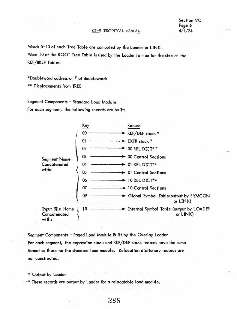
CP-V TECHNICAL :MANUAL
Words 5-10 of each Tree Table are computed by the Loader or LINK.
Section VO Page 6 4/1/74
Word 10 of the ROOT Tree Table is used by the Loader to monitor the size of the
REF/BREF Tables.
-*Ooubleword address or # of doublewords
** Displacements from TREE
Segment Components - Standard Load Module
For each segment, the following records are built:
Segment Name Concatenated with:
Key Record
00 ------•• REF/OEF stack *
01 • EX PR stack *
02 .. 00 REL OICT* *
03 • 00 Control Sections
04 ... 01 REL OICT**
05 .. 01 Control Sections
06 ... 10 REL OICT**
07 - .. 10 Control Sections
09 .. Global Symbol Table(output by SYMCON
Input RIle Name { 10 Concatenated with:
or LINK)
-----...... IJIIto .. Internal Symbol Table (output by LOADER or LINK)
Segment Components - Paged Load Module Built by the Overlay Loader
For each segment, the e~pression stack and REF/OEF stack records have the same
format as those for the standard load module. Relocation dictionary records are
not constructed"
* Output by Loader
** These records are output by Loader for a relocatable load module.
288

CP-V TECHNICAL MANUAL
Section VO Page 7 4/1/74
The core images are partitioned into records of at most 512 words in length with
3-byte keys of the following format:
SEG 00 PAGE
where SEG = the TREE segment number of the segment containing the core image.
PAGE = the page number of the virtual page that will contain this record at
execution time.
All core imag~ records are one page in length except for the first record of an overlay
segment IS 00, 01, and 10 areas. The length of this record satisfies the following: at
execution time, the record begins at the execution bias for this protection type and
ends at the next page boundary.
Library Load Modu les Built by the Overlay Loader
A library constructed by the Overlay Loader consists of two keyed files, :L1B and :DIC.
The library load modules actually reside in one file (:L1B). :DIC is a dictionary whose
keys are the text names of DEFs. The record associated with a dictionary key is the text
name of the load module (within :L1B) in which thar DEF is defined. Thus, in order to lo
cate the unique group of records within :L1B which pertain to a given PREF, the Loader
does a keyed READ to :DIC, the key being the PREF which is being satisfied. This keyed
READ returns the library load module name within :L1B. With this information the Loader
can then read the library load module records into core and merge them with the target
load module.
The keys and records in :L1B are identical to those of non-library load modules (see above)
except that the keys "HEAD" and "TREE" are concatenated with the TEXT load module
name (to keep them unique). Each individual library load module name is "synonymous"
(in a file sense) with the name :LlB.
A slight difference also exists in the REF/DEF and expression stack formats. The VALUE
word of an entry in the REF/DEF stack is actually the head of a chain through the expres
sion stack of all those entries which involve that REF/DEF. (This expedites subsequent
merging of the stacks when the library is included in a us'er program.)
2b9

o
r-- 51
1
- ·S3
2
~ - 55
3
0
4 ,
0
5
0
6
0
Section VO Page 8
cP-v TECHNICAL MANUAL 4/1/74
Tree Tables Tree Structure
0
0
50 ---.J
S2 ---,
----50 f-------J
0
51 ~
54 f--
51 -0
52
56 f--
52
0
0 -
- -
3
1 4
5
2
6
Tree Table link Pointers
back
sub (fwd) overlay
3
4
TREE Table Linking - in Relation to the Overlay Structure
2~JO
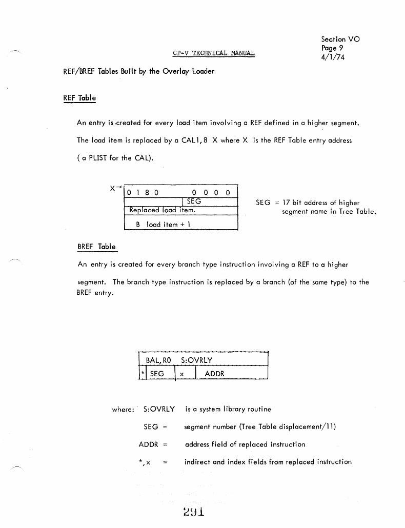
CP-V TECHNICAL MANUAL
Section VO Page 9 4/1/74
REF/BREF Tables Built by the Overlay Loader
REF Table
An entry is ,created for every load item involving a REF defined in a higher segment.
The load item is replaced by a CAL1,8 X where X is the REF Table entry address'
( a PLIST for the CAL).
X-+ o 1 8 0 0 l SEG
Replaced load item.
S load item + 1
BREF Table
0 0 0 SEG = 17 bit address of higher
segment name in Tree Table.
An entry is created for every branch type instruction involving a REF to a higher
segment. The branch type instruction is replaced by a branch (of the same type) to the
BREF entry.
BAL, RO S:OVRLY
* I SEG \ x I ADDR
where:' S:OVRLY is a system library routine
SEG segment number (Tree Table displacement/11)
ADDR = address field of replaced instruction
*,x = indirect and index fields from replaced instruction

o
CP-V TECHNICAL MANUAL
GENERAL REF/DEF STACK FORMAT
USED BY THE OVERLAY LOADER
7 1112' 15 31
n I IE /TYPEI
VALUE
RESOLUTION
Section VO Page 10 4/1/74
-,/ ,...-
where:
n = number of words in thi sentry. E = 1, if the entry has a VAL UE
TYPE = o or 8 DEF 1 SREF 2 PREF 3 or B Dummy Section 4 or 6 Control Section 5 or 7 Forwqrd ReferelJ..ce C or E Page tsoundary Lontrol Section
VALUE constant or address if the load module is not a library or
head of a chain in the expression stack if the load module is a library .
RESOLUTION = the resolution in which the VALUE is expressed. Resolution is of the form:
o 16 31
( byte half 1 word f double .1
If the VALUE is a constant, the RESOLUTION word is O.
If the VALUE is an address, one and only one' byte of the RESOLUTION word is nonzero (viz., the appropriate byte = X'Ol').
If the RESOLUTION assumes a form different from either of the above j
the VALUE is or mi xed resol ution. (In this case the load modul e cannot be relocated and is forced ASS.)
282

CP~V TECHNICAL MANUAL
Section VO Page 11
4/1/74
GENERAL EXPRESSION STACK ENTRY USED BY THE OVERLAY LOADER
If C = 0
If C = 1
o 7 89 10 15 24 31
n Elel DISP CB 1 I CB2
2 CB3
CB4
...
Desti nation
Resolution Word
1 . Word
2 . . Word
m n
where:
n = number of words in entry
E = 1, this entry has been evaluated. = 0, this entrl has not been eval uated.
C = 0, this entry's Destination is a pointer to the REF/DEF stack. = 1, this entry's Destination is a core expression.
DISP = number of words to Word 1.
Destination: (where the value of the entry is to be deposited) =
one of the following forms, depending upon the value of C.
o REF /DEF Poi nter
15 16 31 Segment's Displ acement
in Tree Tabl e
Displacement within segment's REF/DEF stack
o 7 8
Field Size
Resol ution:
C8. = I
Word. I
Core Expression
14 15 31 Terminal Bit Posi tion
Word Address
Same as REF/DEF stack.
a control byte of the expression.
is referenced by a control byte and is a constant or pointer to the segment's REF/DEF stack (same form as Destination where C=O).
f)Q3 Ci. .. J

CP-V TECHNICAL MANUAL
Section VO Page 12 4/1/74
RELOCATION DICTIONARY
If ABS is not specified on the I LOAD card each segment of Loader-buil t load modules
will have records of relocation dictionaries (one per protection type). One relocation
digit is developed for each word in the protection area.
o 1 2 3 8 9 A E
Relocation Dictionary Digits
Type of Relocation
rei ocate the word at byte resol uti on. relocate the word at halfword resolution. relocate the word at word resolution. relocate the word at doubleword resolution. relocate the left half of the word at doubleword resolution. relocate the right half of the word at doubleword resolution. relocate both halves of the word at doubleword resolution. absolute.
Notice that relocation digits exist only for items that terminate on hal fword boundaries.
A load module which ras an item not amenable to one of these digits is set to ASS. Example:
SOUND 4 ZAP EQU DA($)
GEN,8, 16,8 0, ZAP, 0
or SOUND 4
ZAP EQU $ GEN,3, 17, 12 0, ZAP, 0
Either of these would cause the module to be set ASS since ZAP does not terminate on
a halfword boundary.
294

Symbol Tables
Global Symbols:
CP-V TECHNICAL MANUAL Section VO
Page 13 4/1/74
A global symbol table is constructed by LIN K or by SYMCON. This table is a list
of correspondences between symbolic identi fiers {labels) used in the original source
program and the values of virtual core addresses which have been assigned to them
at load time. The global symbols identify obiect (DEFs) within a module which may
be referred to (REFed) in other modules. This table is available to DELTA, for use in
debugging.
Internal Symbols:
An internal symbol table is a list of correspondences similar to the global but which
applies solely within the module. It is built by LINK or the Loader for each input
ROM which contains 1ST load items. Each internal symbol table is associated with
that specific input file (ROM) and identified by its name. The internal as well as
the global symbol tables are created for use by the debug processors, such as DELTA.
The user has the ability under DELTA to define which set of internal symbols is to be
used for specific debugging activities.
Symbol Table Format:
Both global and internal symbol tables consist of three word entries. Symbolic identi
fiers (labels) are limited to seven (7) characters plus count. Symbols originally longer
than seven are truncated leaving the initial characters, although the original character
count is retained. Symbols which are identical in. their first seven characters and are of
equal length occupy one position in the symbol table. The value or definition for such
multiply defined symbols is the first one encountered during the linking process. Each
symbol entered into the table has a type and internal resolution classification. The
internal resolution types are: byte, halfword, word, doubleword, and constant. The
following are the symbol types which are suppl ied by the obiect language and maintained
in the symbol table: instruction, integer, EBCDIC text, short floating point, long floating
point, decimal, packed decimal, and hexadecimal.
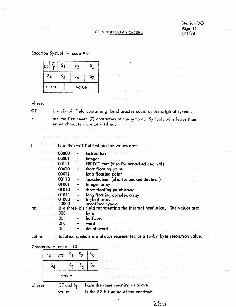
Location Symbol .. code = 01
011 ~ 51 52 53
54 55 56 57~
t I res I value
where:
CP-V TECHNICAL MANUAL
Section VO Page 14 4/1/74
CT is a six-bit field containing the . character count of the original sy-mbol .
. S i are the first seven (7) characters of the symbol. Symbols with fewer than seven characters are zero filled.
t is a five -bit field where the values are:
00000 instruction 00001 integer 00111 EBCDIC test (also for unpacked decimal) 0001 a short floating point 00011 long floating point 00110 hexadecimal (also for packed decimal) 01 001 integer array 01010 short floating point array 01011 long floating complex array a 1000 logical array 10000 - undefined symbol is a three-bit field representing the internal resolution. The values are: res 000 byte 001 hal fword 010 word all doubleword
value location symbols are always represented as a 19-bit byte resolution value.
Constants - code = 1 a
10 I CT 51 152 53
I· 57 54 55 I S6
value
where: CT and 51 value
. have the same meaning as above
is the 32-bit v.alue of the constant.
28b

CP-V TECHNICAL MANUAL SECTION VO PAGE 15
9/1/78
Loader Control Command Table (LOCCT)
Size of the three tables to follow (CP-Vonly)
o 1 2 3 4 5 6 7 8 9 10 11 12 15 16 17 18 19 20 21 22 23 24 25 26 27 28 29 30 31*
Locer 0 R IQ S X nl'2:F3-rF4j T Iy I U I V I SL P IOINIMILIKIJII IHIGIF IElolCIBIA Fl - do not build internal
symbol tables
n~p2 P3 1'4 I SYSid 2 Displacement from LOCCT to TREET
3 Displacement from LOCCT to ROMT 4 REF or BREF count (default = 0) T LOAD BIAS (WA) **
5 Number of Execute Accounts (default = 1) **
6 FCOM Size FCOM (OA) ***'
7 ERSTACK Size (default, X'A') ERTABLE Size (default, X'A')
TSS Size (default = X'40') Number of UNSAT accounts
(default = 0 if NOSYSLIB; = 1 (:SYS) if not) 8
9 Number of READ accounts (default = 1) Number of WRITE accounts (default = 1)
10
11 Load Module Name, TEXTC followed by blanks. (default = three characters SYSid L)
12
13 User Account Number
14
15 Load Module Password (default = 0,0)
16
17 EXPIRE date; 'mrnddWyy' or 'NEVER' (BPM) 0,0 (Cp-V) .
18
19 Library Password i.e., (PERM, LIB, password) (default ~ 0, 0)
20
8 max. 4 REAO Account Numbers - 2 words per account If, (default ;::'ALL~')
8 max. { WRITE Account Numbers - 2 words per account If, (default = 'NONEJ6)$',IS}S")
8 max. { UNSA T A«oon. Nombe~ ond "'~wo"" - • w~d, P'" (0«' ',,,,,,,). {default password = O,O}
8 max. { EXECUTE Account Numbers - 2 words per acct. H
1 max. ~ .
EXECuTE Vehicle - 3 words per vehicle, (default = FETCH~')
TREET--.f- Total Number of words in TREE Tables ,. ~
,!',
TREE Tables - 1 Table per Segment - II words per table ( See Figure 12 for format)
ROMT --..
f ROM Tables - I Table per ROM - 7 words per table (See Figure 11 for format)
297
{
F2 • build global symbol tables
F3 • inhibit output of segment size summary
F4 e DREF specified
PI • "P" option for privileged processors specified
P2 .... s .. option for privileged processors specified
P3 - 'OW' option for privileged processors specified
P4 • "X" option for privileged processors specified
{ {
I
{ {
?

* NOTE: A B C D E F G H I J K L M N 0 P Q
R S T
= = = = = = = = = = = = = = = = = = = =
CP-V TECHNICAL MANUAL
1, UDEF specified 1, NOSYSLIB specified 1, REF specified 1, PERM specified 1, LIB specified 1, M 10 specified 1, M 100 specified
SECTION VO PAGE 16 2/10/76
1, FCOM specified if BPM. If CP-V, the OSP specified.
1, ABS specified 1, Assigns Read 1, GO specified 1, BI specified 1, CSEC 1 specified 1, NOTCB specified 1, XMEM in effect (set by the Loader in IN2), or PAGE specified 1, LDEF specified 1, BREF specified 1, EF specified 1, CORE LIB specified 1, RDEF specified
bits 10 - 11 0 = no map 1 = map by NAME 2 = map by VALUE 3 = map by NAME and VALUE
X = 1, Execute Vehicle specified y = 1, MAPONL Y specified
SL =. Severity ,level (default = 4)
** BPM-CP-V differences in the LOCCT Tables:
Word
4
5
*** 6
BPM
LOAD BIAS field, default = 0
Background lower limit
Passed to the Loader in Register 04 {D4} = FCOM size
298
cP-V
LOAD BIAS, Default = background lower limit WA
Number of Execute Accounts, Default =1

CP-V TECHNICAL MANUAL
REAL TIME
ICB TABLE FORMATS
Type I: ICB Connected to Interrupt Associated with User Task
o 14 15
0* ICBSTAT I ICBXPSD 15
2 3
4 5
ICPRIO
ICBUN
o t O~
1 , ICIlPSD1
.J; 1 1 I
ICBPSDi I
~ 0 1
16
6
7
8
9
ICBPRI ICBDLFLG I 0 ~
10
11 ~
* doubleword boundary
0
ICBENTPSDO
ICBDLDATA
~I 14 15
ICBLNK
ICBINT
ICBICBADR
Section VP Page 1 4/1/74
31
~ 0
~o ICBDL

CP-V TECHNICAL MANUAL
Type II: ICB Connected To Interrupt Associated With Ghost Job
0*
2 3
4 5
o ICBSTAT
ICBGJPR 0
14 15
I ICBXPSD
ICBP~D 1 r I I
T I
ICBP~~~ 16
1 1
6
7
8 9
ICBUN ICBGUN 0"
10 11
* doubl eword boundary
ICBGJNME
ICBGJACN
300
ICBLNK
ICBINT
.
Section Page 4/1;74
,
0
VP 2

CP-V TECHNICAL MANUAL
ICB Connected to CLOCK-3 Interrupt
.0 14 15
0* ICBSTAT
ICBTUN
2 ICBCLK
3 01 . "'0
4 04 ' 1111101 "0
5 o 4.
6 ICBPRIO 04 ~ 0 I I 7 ICBUN 0
8 ICBPRI ,ICBDFLG fo. 9 ICBENTPSDO
10 ICBDLDATA
/~ 11 •• O· • ICBICBADR
* doubleword boundary
3U1
ICBLNK
ICBSYSEP
ICBBLNK
ICBlNT
Section VP Page 3 4/1/74
31
• 0
0
• 0 ICBDL

WORD
-0
CP-V TECHNICAL MANUAL
ICB Field Descriptions
NAME
ICBSTAT Status Flags:
BIT POSITION
4-6
7-8
0 1
2
3
4
5 6
9
NAME
ICBSTATA ICBSTATC
ICBSTATDL
ICBSTATO
ICBSTATINT
ICBSTATYP
ICBSTATSY
, I
Section VP Page 4 4/1/74
DESCRIPTION
DESC RI PTI ON
set if ICB is active set if CLEAR was specified via M:CONNECT. set if ICBDL is already chained into UH :Dl set if ONE SHOT was specified via M:CLOCK
associated interrupt status:
Bit Position
Meaning if set
if pseudo interrupt: trigger pending if real interrupt: has been triggered
(interrupt is active) enabled armed
defines ICB type:
00:: user task (Type 1) 01:: ghost job (Type II) 10:: clock (Type III)
set if ICB is a SYSTEM ICB, in wh i ch case, the ICB is only five words in length.

WORD ·NAME
o ICBlNK
ICBXPSD
ICBTUN
CP-V TECHNICAL MANUAL
Chain link address
DESCRIPTION
Section VP Page 4A 4/1/74
(Types I and II only) this word contains an XPSD instruction; this location is the effective address of the new PSD at location ICBPSD2 which is looded as a result of the hardware interrupt occurring (in the case of a real interrupt) or the result of an XPSD instruction {in the case of a pseudo-interrupt}. This technique allows the interrupt handling routine to determine which IeB is associated with the interrupt that just occurred.
(Type III only) value (in two- millisecond units)' from M:ClOCK CALl.
3U3

CP-V TECHNICAL MANUAL Section VP Page 5 4/1/74
2 .. 3 ICBPSD 1 (Types I and II only) storage area for old (interrupted) PSD upon the occurrence of an interrupt; this location is the effective address of the XPSD instruction in the hardware interrupt location associated with the ICB.
2 ICBCLK (Type III only) number of clock ticks remaining before an interrupt will occur for the user associated with the ICB.
3 ICBSYSEP (Type III only) if the ICBSTA"TS'l bit of ICBSTAi is set, then this is a SYSTEM ICB and is only five words in length (0-4); ICBSYSEP contains the address of the system entry point which will be entered upon the expiration of the elapsed time specified in ICBTUN.
4 ICBBLNK (Type III only) Back link for ICBs currently chained into ICBCLKHDR.
4-5 ICBPSD2 (Types I and II only) contains the new PSD which will be loaded as a result of the execution of the XPSD instruction in the hardware interrupt location associated with the ICB; the instruction address of this PSD will cause the XPSD instruction at ICBXPSD to be executed.
6 ICBPRIO (Types I and III only) used to save the associated user's priority (his old priority) at the time of the interrupt associated with this ICB.
6 ICBGJPRI (Type II only) contains the execution priority of the ghost job to be scheduled as the result of the rnterrupt associated with the ICB*
6 ICBINT Contains the hardware or pseudo-interrupt location associated with this ICB.
7 ICBUN The internal number of the user associated with this ICB (the owner).
7 ICBGUN (Type II only) the internal number of the ghost job itself (user number).
8 ICBPRI (Types I and III only) contains the execution priority of the task to be scheduled as a result of the interrupt associated with this ICB.
3U4

CP-V TECHNICAL MANUAL Section VP Page 6 4/1/74
8 ICBDLFLG (Types I and III only) contains the value X'821 which is a code within the DO-LIST table which, in th is case, is a subtable of the ICB.
8-9 ICBGJNME (Type II only) contains the TEXTC-formatted name of the ghost job to be placed into execution as a result of the interrupt associated with th is ICB.
9 ICBENTPSDO (Types I and III only) contains an image of word 0 of the PSD to be loaded prior to going to the user upon the occurrence of the interrupt as follows:
where:
address
o 8 9 10 15 31
I entry I o address
MS n. reset if MASTER was specified via J M:CONNECT/M:CLOCK.
is the virtual address at which the user is to be given control upon the occurrence of the interrupt; specified via M:CONNECT/M:CLOCK.
10-11 ICBGJACN (Type II only) contains the TEXT-formatted home O-eftiustified, trailing Iolanks} of the eJccount in whose directory may be found th~ ghost" job to. be plQced -into e~ecution as a resuit of the interrupt QssQciated with this ICB.
10 ICBDLDATA (Type I) contains the interrupt location associated with this ICB {i. e., same as ICBINn. (fype III) same as ICBTUN (if e., reque.sted elapsed time in twomillisecond units).
11 ICBICBADR (Types I and III) contains the address of word 0 of this ICB.
#JU r-u V

CP-V TECHNICAL MANUAL Section VP Page 7 4/1/74
ICB Chain Headers
ICB Chain Headers are of the form
o 14 15 31
address
where address is the word address of word zero of an ICB which in turn points to the next ICB in the chain (ICBLNK). The last ICB in the chain has an ICBLNK of zero.
RTICBHDR
This header is built and DEFed by SYSGEN-PASS2 and contained in the M:FRGD module; if this is a real-time system, RTICBHDR will point to the first of a userspecified number of available ICBs. If this is a non-real-time system, RTICBHDR will be set to -1.
RTICBCLKHDR
This header is assembled into, and DEFed in the TABLES module; this chain header always points to the five-word SYSTEM ICB associated with the 1. 2-second time-of-day routine. RTICBCLKHDR also contains a back I ink which points to the last I€B chained into RTICBCLKHDR.
DO LIST BLOCK FORMATS
o
PRIORITY
7 8 9 10 11 'I R O~O E L
15 16
CODE FORWARD LINK
IREL Do not release block to free chain when done. Set when block is contained in an ICB.
*Header **Data Words dependent on code value
306
31
*
**

CP-V TECHNICAL MANUAL Section VP Page 8 4/1/74
Do List Format for Interrupt Entry
o 7 8 9 10 11 15 16 31 I
PRIORITY R O~O 2 FORWARD E LINK· L
o ~ ~ 0 ENTRY ADDRESS
o ~ ~ 0 INTERRUPT
ICB ADDRESS
IREL )- Inhibit release of block. Set if block contained in ICB.
Do List Format for Post-ECB Entry
o
O~
o ~
O-E
*{unused}
8 9 10 11 15
0101 ~ 0 I 1
~ 0
Content to be stored in ECB
o :;::WORD 1 =DW 2 =HW 3 = BYTE
F = posted entry or wait list
FORWARD LINK
ECB Address
~ 0 *

Wait List Block Format
o
O~
CP-V TEqHNlCAL MANUAL
7 8 9 I
~O R E
o~
L
15 16
Section VP Page 9 10/31/74
31
10 FORWARD LINK
ECB Address
IREL Inhibits release of block. Used when block is contained within a larger block.
30~

M:FRGD MODULE
CP-V TECHNICAL MANUAL Section VP Page 10 10/31/74
For a real-time system, one having a :FRGD command present, the following. tables will be generated:
RT:GINTP
RT:UINTP
ICBSIZE
ICB
I
LASTICB
RTICBHDR
BOUND 8 DATA 0,0 GEN, 12,20 0, RT:GINT GEN,8, 1,6, 16 XI 17', :9,0, :9,0
DATA ,0,0 GEN, 12,20 0, RT:UINT GEN,8, 1,6, 1, 16 X117' :9,0, :9,0
DEF RT :GINTP, RT :UINTP REF RT:GIN1, RT:UINT
DEF ICBSIZE, ICB, LASTICB, NINTS EQU 12
EQU $
DO NINTS No. of interrupts
tDO I=NINTS
DATA 0,0 ELSE DATA $+12,0 FIN DATA,8 0,0,0,0,0 FIN EQU $
EQU $ DO O=NINTS DATA 0 ELSE DATA ICB
DEF RTICBHDR, RESDF
309

DEF
RESDF DATA
CRESDF DATA
RESDFP DATA
DYNRESDF DATA
MDYNRESDF DATA
DEF
PPTABlE EQU
DOl
DATA
PPTABlSZ EQU
DEF
PP:UPPH DATA
PP:UPPT DATA
PP:UPPC DATA
DEF
PPTABDSK2 DATA
CP-V TECHNICAL :MANUAL
RESDf., CRESDF, RESDFP, DYNRESDF,
SIZE (number of RESDF pages)
SIZE (number of RESDF pages)
ADDRESS (RESDF address)
0
Section VP Page 11 10/31/74
MDYNRESDF
PAGES (maximum number DYNRESDF pages)
PPTABlE, PPTABLSZ
$
2+(#SEGMENTS-l)
0
$-PPTABLE
PP: UPPH, PP: UPPT, PP: UPPC
0
0
0
PPTABDSK2
0
31U

CP-V TECHNICAL MANUAL Section VP Page 12 10/31/74
INTLB 1 DEF DATA, 2 DATA, 2 DATA,2
INTLB 1, INTLB2, INTLBSIZ, INTLB3 o
. , 'LA' IBBI } text interrupt labels
INTLBSIZ
INTLB2
INTLB3
EQU
DATA, 2 DATA, 2 DATA, 2
HA ($) - HA(INTLB 1)
o X'65' \ X'1022' ., interrupt addresses
)
DATA, 1 DATA, 1 DATA, 1
default (SYSGEN-specified) execution priority
Defaults:
NINTS SIZE
= 0 = 0
Address = XI 10000' PAGES = a
# SEGMENTS = 1
For a non-real-time system, the following subset wi II be generated:
RTICBHDR
M:IMC MODULE
DEF DATA
RTICBADR -1
a. Initialize all entries in UB:US to 31
b. Delete UH :TS.
c. ADD UH :DL, a halfword table parallel to other user tables and initiated to zero.
d. Add UH :WL, a hal fword table initial ized to zero.
e. Add UP:PRIO, a byte table initialized to X'FF'.
f. Add UB:PRIOB, a byte table initialized to zero.
g. Add UB:NECB, a byte table initialized to zero.
311
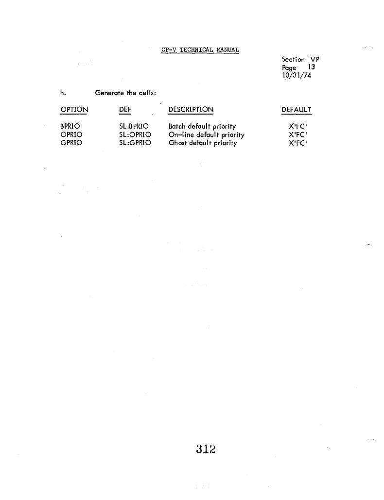
CP-V TECHNICAL MANUAL Section VP Page 13 1.0/31/74
h. Generate the cells:
OPTION DEF DESCRIPTION DEFAULT
SPRIO SL:BPRIO Batch default priority X'FC' OPRIO SL:OPRIO On ... line default priority X'FC' GPRIO SL:GPRIO Ghost default priority X'FC'
31~

CP-V TECHNICAL MANUAL
ENQ/DEQ TABLES
Section VQ Page 1 4/1/74
ENQ/DEG uses the new Queue Table (QT), U:MISC, and the JIT flag ENQ (J :ABC bit 23). U :MISC is set with sleep time whenever a user is put into the sleep state, and JIT :ENQ is set when a user request ENQ and checked by STEP and SSS. The QT is a pool of double words that can be used to contain various kinds of data.
The hierarchy of the Queue Tables is as follows:
a. The first level of entries is the pool of empty entries.
b. The second level of entries is the names of all the queues (qnames) for resources. These are referred to as Q entries.
c. The th ird level of entries is the user numbers of all the users of a queue (qname). These are referred to as U entries, and the first one is Uhead.
d. The fourth level of entries is the names of all the sub-queues (snames) for elements. The order of the sub-queues is first, NULL, if present then ALL, if present, then those with regular names. These are referred to as Sentries.
e. The fifth level is the queues of users for the various resource/ elements. These may be referred to as SQ or user entries, depending on their context of an S chain or a U chain.
The th ird and fourth levels might be more appropriately thought of as two dimensions at the same level, i. e., a queue can be looked upon as the users of sub-queues or sub-queues of users. Both the third and fourth levels contain the heads of threads through the fifth level.
Double words, or contiguous blocks of double words, are also used as appendages to second and fourth level entries to contain names (qname or sname) that _exceed three characters in length. Double words are also used as fifth level appendages to contain the ECB address for pending requests.
The formats of the various types of entries are as follows.
QHEAD ENTRIES
The Q, U, or S entries consist of three fields - the half-word AHVP and OHH P, and the full word QHNAME.
313

o I QHHP
QHHP
QHVP
CP-V TECHNICAL MANUAL
15 16 31 32 I QHVP
Queue Head Horizontal Pointer
Section VQ Page 2 4/1/74
63
QHNAME
Entry 0 contains the double word index in QT of the first empty entry. Other first level entries contain the double word index of the next empty entry (zero is terminator).
Level 2 (Q) entries contain the double word index in the QT of the next qname (Q) entry (zero is terminator).
Level 3 (U) entries contain the double word index in the QT of the next user number (U) entry for this queue name (zero is terminator).
Level 4 (S) entries contain the double word index in QT of the next sub-queue name (sname) entry for this queue (zero is terminator).
Queue Head Vertical Pointer
Entry 0 contains the double word index in QT of the first queue name (qname) entry, i.e., the first entry in level 2.
Level 2 (Q) entries contain the double word index in Q T of the first QHEAD level 3 (U) entry, that is, the head of the user I ists for this queue (qname).
Level 3 (U) first entry contains the double wrod index in QT of the first sub-queue name (sname) entry. Other level 3 entries contain the double word index in QT of the first SQ entry for each user (user chain).
Level 4 (S) entries contain the double word index in Q T of the head of the sub-queue (5) entry -(SQ chain).
:314
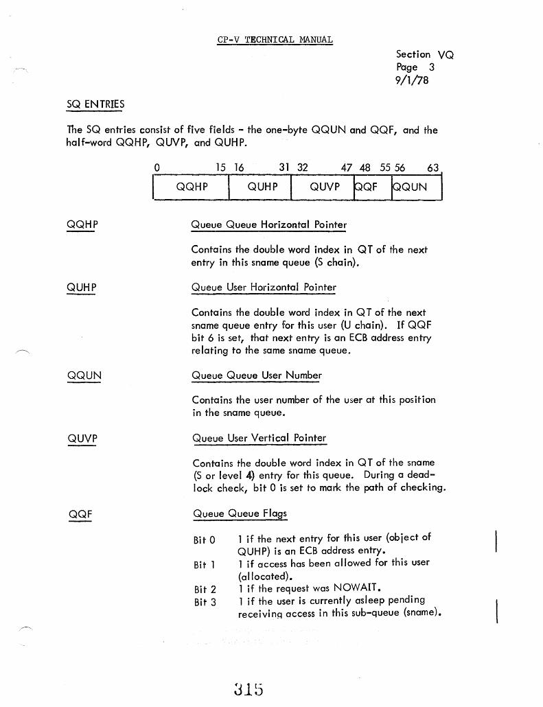
CP-V TECHNICAL MANUAL
SQ ENTRIES
Section VQ Page 3 9/1/78
The SQ entries consist of five fields - the one-byte QQUN and QQF, and the half-word QQHP, QUVP, and QUHP.
QQHP
QUHP
QQUN
QUVP
QQF
o 15 16 31 32 47 48 55 56 63
I ___ Q_Q __ HP ___ I~_Q_U_H_P~I ___ Q_UV __ P~P_Q_F~E~Q_U_N~
Queue Queue Horizontal Pointer
Contains the double word index in QT of the next entry in this sname queue {S chain}.
Queue User Horizontal Pointer
Contains the double word index in Q T of the next sname queue entry for this user {U chain}. If QQF bit 6 is set, that next entry is an ECB address entry relating to the same sname queue.
Queue Queue User Number
Contains the user number of the user at this position in the sname queue.
Queue User Vertical Pointer
Contains the double word index in Q T of the sname (S or level 4) entry for this queue. During a deadlock check, bit 0 is set to mark the path of checking.
Queue Queue Flags
Bi t 0 1 if the next entry for fh is user {object of QUHP} is an ECB address entry.
Bit 1 1 if access has been a Ilowed for this user (allocated).
Bit 2 1 if the request was NOWAIT. Bit 3 1 if the user is currently asleep pending
receivinq access in this sub-queue (sname).
:315

QECB ENTRIES
CP-V TECHNICAL MANUAL Section va Page 4 9/1/78
Bit 4
Bit 5 Bit 6 Bit 7
NOTE:
1 if this user is temporarily blocked from access because he was not a user of this queue (qname) when an EXCL or ALL user was denied immediate access. 1 if a JOB entry. 1 if request was for SHARE. 1 is this is a SHARE entry and there is also an EXCL entry pending upgrade on this subqueue for th is user.
If bit 1 is set the queue entry is "allocated "; "if bit 4 is set the queue entry is "blocked "; and if neither is set the queue entry is "pending ".
The QECB entries consist of three fields, the half-word QUPP andQUHP, and the 17 bit QUEA.
QUPP
QUHP
QUEA
QNAME ENTRIES
o 15 16 31 32 46 47 63 I QUPP I QUHP I QUEA I Queue User's Primary Entry Pointer
Contains the double word index in Qt of the primary portion of this entry - points back to the entry whose QUH P points to it.
Queue User Horizontal Pointer
Same as under SQ entries above.
Queue User ECB Address
Contains the ECB address for user QQUN for subqueue QUVP.
The QNAME entries consist of a single, variable length field. One to four consecutive QT entries are used to contain queue (qname) or sub-queue {sname} names when the names do not fit in the QHNAME field of the Q or
Jlb

CP-V TECHNICAL MANUAL Section va Page 5 4/1/74
Sentry. One double word is used for names of four to seven characters, two double words for names of eight to fifteen characters, three double words for names of sixteen to twenty three characters, and four double words for names of twenty four to the maximum thirty one characters.
317
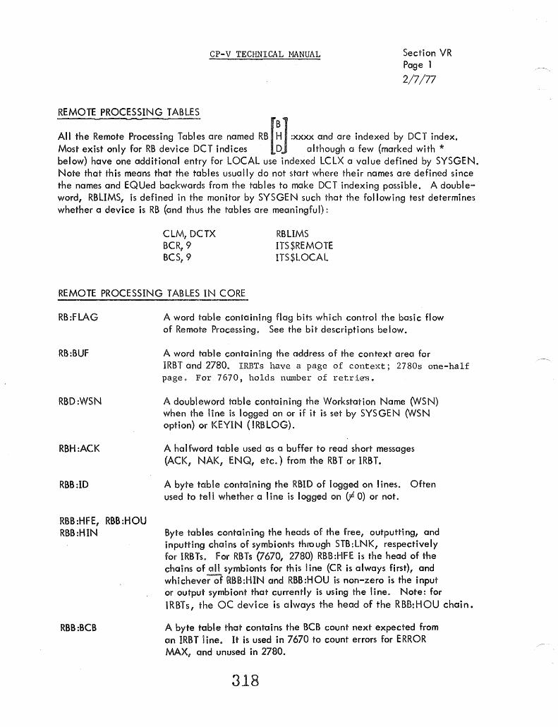
CP-V TECHNICAL MANUAL Section VR Page 1
2/7/77
REMOTE PROCESSING TABLES
All the Remote Processing Tables are named RB [~1 :xxxx and are indexed by DCT index. Most exist only for RB device DCT indices ~J although a few (marked with * below) have one additional entry for LOCAL use indexed LCLX a value defined by SYSGEN. Note that this means that the tables usually do not start where their names are defined since the names and EQUed backwards from the tables to make DCT indexing possible. A doubleword, RBLIMS, is defined in the monitor by SYSGEN such that the following test determines whether a device is RB (and thus the tables are meaningful):
ClM, DCTX BCR, 9 BCS, 9
RBLIMS ITS$REMOTE ITS$LOCAl
REMOTE PROCESSING TABLES IN CORE
RB:FLAG
RB:BUF
RBD:WSN
RBH:ACK
RBB:ID
RBB:HFE, RBB:HOU RBB:HIN
RBB:BCB
A word table containing flag bits which control the basic flow of Remote Processing. See the bit descriptions below.
A word table containing the address of the context area for IRBT and 2780. IRBTs have a page of context; 2780s one-half pages For 7670, holds number of retries.
A doubleword table containing the Workstation Name (WSN) when the line is logged on or if it is set by SYSGEN (WSN option) or KEVIN (!RBLOG).
A halfword table used as a buffer to read short messages (ACK, NAK, ENQ, etc.) from the RBT or IRBT.
A byte table containing the RBID of logged on I ines. Often used to tell whether a line is logged on (f 0) or not.
Byte tables containing the heads of the free, outputting, and inputting chains of symbionts through STB:LNK, respectively for IRBTs. For RBTs 0670, 2780) RBB:HFE is the head of the chains of all symbionts for th is line (CR is always first), and whichever of RBB:HIN and RBB :HOU is non-zero is the input or output symbiont that currently is using the line. Note: for IRBTs, the OC device is always the head of the RBB:HOU chain.
A byte table that contains the BCB count next expected from an IRBT line. It is used in 7670 to count errors for ERROR MAX, and unused in 2780.
318

RBB:LPZ, RBB:CPZ
RBB :SPC
RBB:SFC
CP-V TECHNICAL MANUAL Section VR Page 2 4/1;74
Byte tables used in 7670 and 2780 to keep the current max printer and puch record length. Unused in IRBT.
A byte table used in 7670 to help keep track of the number of formats to be performed before a print. Unused in 2780 and IRBI.
A byte table used in 7670 to preserve the current function when a warning BE lL is being sent. Unused in 2780 and IRBI.
REMOTE PROCESSING TABLES IN RBBAT
*RB:MFAD
*RB:SPMF
*RBH:MFX
RBB:MXP
RBB:DSM
RBB:SMD
A word table containing the address of the current message file buffer. Zero if none.
A word table containing the used byte count of space in I the message file buffer.
A halfword table containing the BH :LINK entry index for the message fi Ie under construction.
A byte table containing the maximum priority for jobs submitted from this WSN. Also used as the priority for any direct passed output.
A byte table containing the device selector mask for this
WSN.
A byte table containing the symbiont index of the system
message device for this WSN.

RB:FLAG STRUCTURE
Bit Name
0 BPBn 1 IGBIT 2 MORBIT 3 HUBIT 4 PUNBIT 5 DCBIT 6 HASPSIT 7 SLYBIT 8 ALBIT 9 XP1BIT 10 2780BIT 11 3780 BIT 11 11MB~~. 12 D IALB IT 13 EDISBIT 14 OFFBIT
15 RBXBIT 16 DUPBIT 17 DISCBIT 18 LOFBIT 19 SYSBIT 20 HALSIT 21 eLKSIT 22 ACTBIT 23 CTRBIT 24 XP2SIT 25 OADBIT 26 FIABIT 27 SSSBIT 28 LIPSIT 29 FINBIT 30 EMSIT 31 0881T
CP-VTECHNICAL MANUAL Section VR Page 3 2/7/77
7670 2780/3780 IRBT Meaning
x x Block protect toggle x x x Cards after !FIN were ignored x x Waiting for next chunk of deck x x x Line hung up x Punching is allowed x x x WSN specified at SYSGEN x x x IRBT line
x We are slave x x x RBLOG keyin done
x X 1 spec ified in SU PER x x x 2780 line (may be changed to IRST at logon)
x 3780 line (2780BIT must also be set) x N3 sEecified in SUPER
x x x Dial specified at SYSGEN x x x ERROR MAX on line x x x Do not connect line (RBX)-Set except at
logon for IRBT x x x Disconnect line now x x x FUll-c~I~~---"··-r~-.-1 = Fu dup ex . x x x Disconnect when output done x x x RBD ISC sent (TEMP) x x x . :SYS jobs .Iegal x x x HOLD all flag
x Wait before ACKO-idle x x x Line logged on x x RBBAT disables RBSSS
x X2 specified in SUPER x x x Set OFFSIT after disconnect x x x RBCC altered stream status x . Inputtins with output suseende~ x x x logging on x FIN has been read x x 1 = NOEM specified
x Old sca was read read of file
320

CP-V TECHNICAL MANUAL
IRBT C()NTEXT PAGE
o LINKI
Cuntext (see descriptions)
LINK} Input Buffer
73
LINK I Input Buffer
183
293 V..INK I OU'~put Buffer
403 Output Buffer
2780 (3780' CONTEXT 1/2 (FULL) PACE
o
38 (38)
148 (178) ~INK I
rtINI{j
Context (see Descriptions)
Buffer
Buffer
-
321
Section VR Page 4 2/7/77 '

T.RBT
CP-V TECHNICAL MANUAL Section VR Page 5 2/10/76
•••••••••••••• CONTEXT POINTERS ••••••••••••••••••• •• F~~SV EGilJ HPB EOU H:BB EO:J HRB EOU HI,I.IB EIJU CPB EOU eBB EGtU eRE: EGiU CI,.JB EG!U POP EC!U POE EOU PIP EOU CBCE: EOU DCRCB EOU RE:C EOU ceRC EOU CUR::':: EO:J BIP EG!U FBF EOU CIP EG!U FeSI EC!U eFC EOU BUT EOU BIN EOU CURF ~I)U LTve EOU F.:S:T EOU SAB EOU PSP EG!U EDF EOU CDNT EG!U COtiTCK EOU CONTCNT EG!U seRe EC!U HIP EG!U B~~D EG!U TT'y'P EG!U RTRY EQU SPB EQU
I)
1 2
4
7
10 11 1 ::: 13 14 15 16 17 13 1q .A. _'
20 21 22
24 25 26
.-.,-, c.'-:. 29 30 31
34
37
38
322
PREV INSYMX FOR FIN READ HEAD PARSE BUFFS HEAD BUILD BUFFS HEAD PEAII BUFFS: HEAD I.dhi'I TE BUFF:~:
CURRENT BSCSPRS BUFF CURRENT BSCSBLD BUF~
CURRENT READ BUFF CURRENT WRITE BUFF POINTER OF BSCIPRS POINTER OF BSCIBLD B2CtPRS IN PROGRESS cu~· D OUTPUT BeB It'iPUT J;;~CB FOR DC REMAINING BYTE COUNT (OUT) CiJR m eRC .:: OUT) CURn USER (OUT) BSCSBLD IN PROGRESS FORCE BUFFER FULL CONTROL IN PROGRESS COt'1B q I t'~PUT FC:S: CUR. FUNCTION CODE BACKUP TDEiGLE B I NAP .... ' PEe Pc'.,,'II .. LAST FAILING USER (OUT) LINE T .... 'C SUSPENDED USERS TO PESTART SUSCK ABORTS BSCSBLD FUNC PERM POINTER EOF(S) IN THIS BLOCK (OUT) CONTINUATION BUFF ADDR COt-iT S''i'MB I NIlE::':: CDt'1T B'lTE COUNT FUr'K: PERM eF.:c HANG UP IN PROGRESS SYMBIONT ACTUALLY BACKED UP 0= I F.::E:T!I 1 =278 0
NUMBER OF RETRIES
SPECIAL BUFFER W·HEN WAB SENT

/~.
Cf ... V TECHNICAL MANUAL -Section VR Page 6 2/7/77
.......................... , ................... ~~ • CONTEXT POINTERS •••• FNS ... ·' EOU (I
HPB EOU 1 HERII PAPSE 'BUFFS HRB EG!U -=. HEAD BUILD :BUFFS L...
H~:B EG!U :~: HEAD PEAD -:BUFFS: HI .. .IB EOU 4 HEAD 1.1.lF.~ I TE :BUFFS CPIt EOU t::' CUF.~PENT PAPSE :BUFF -_I
eBB EOU 6 CUPPEt-iT BUILD :BUFF CF.:B EO:J ? CUPPEt'1T PEAII :BUFF , CI. •. IB EO:J :=: CUPPEt"1T I .. .IPITE BUFF POP EC!U 9 PO It'1TE~~ OF PAF.~:S:E
POE EOU 10 PO It·iTEF.' OF BUILII PIP EOU 11 PAM;::S:E It·~ P POI:; F,' E S: :S: CECE EOU 1--' C *Ut'iUSED In 27::: O. OeRCE: EG!U 1-:' '_,f 0=2780; 11 E I =3780 REC EC!U 14 F.: E t'l A I t'1 I t'iI:; B'lTE CDUt'~T (OUT) ceRe EO:-' 15 CUj:;;~ I::PC (OUT :) CUF.:>:: EOU 16 HOLD:S: ODS D Ur'1T I L PEAII'r' BIP EOU 17 BUILD P'i PPOGPE-S:S FBF EOU 1-:' 1_.' FOPCE BUFFEF.~ FULL elP EOU 1'3 f::DNTPDL H'i PPO(:;F.:ES:S: F~::S: I EOU 20 TEt'1P HOlII TO C""IT 1",1 Fe CFe EI]U 21 '::UP. FUt'~CT IOt'1 CODE BUT EOU -"~-I *UNU:S:ED* c.c. BIN EOU '="-:1 *ur-il...I5:ED* L"._I
CURF EC!U 24 ~r OF ~:EC:S: It,~ CU~: BLI< L T'y'C EG,U ·-te-
C-_l L Ir-iE T'lC RST EOU 2E. SYMB RESTART - ABORT FIRST LINE 'S:AB EOU '-1-' TUPt'1:S: OFF' OUTPUT TIL F:EAD'y' C-(
PS:P EG!U 2:=: +Ut'1USEII* EDF EG!U 21~ '=:':OF IN CU~~ Bll< (OUT) CDt'iT EOU :30 :S:\'t'1B DF'EPATION It,~ PR06 CDNTCK EOU .:::: 1 .. OF PEC ALlOI.t.lED ..... E:LI< SPB=lMRB==F~
CONTeNT EOU ':'':' • Ut-~U:S:ED* "_'L
SCRC EOU ::::::! .Uj-~U-S:EII*
HIP EOU 34 HAt'1(3 UP B'1 PROG~:E:S::S:
JBKD EOU .:::5 .Ut'~U:S:ED.
rTYP EOU 36 2780/3780 = 1 , IRBT=O RTRY EQU 37 NUMBER OF RETRIES SPB EQU 38 ;'(UNUSED~(
323

cr-V TECHNICAL MANUAL Section VR Page 7 2/7/77
REMOTE PROCESSING MODULE STRUCTURE
DSCIO
7670
--' ,
!{BSSS 7670, 2780/3780 I
IRBT
324
BSCI()
2780/3780 I IRB T
27801 C)
2780/3780 ~'-------......I
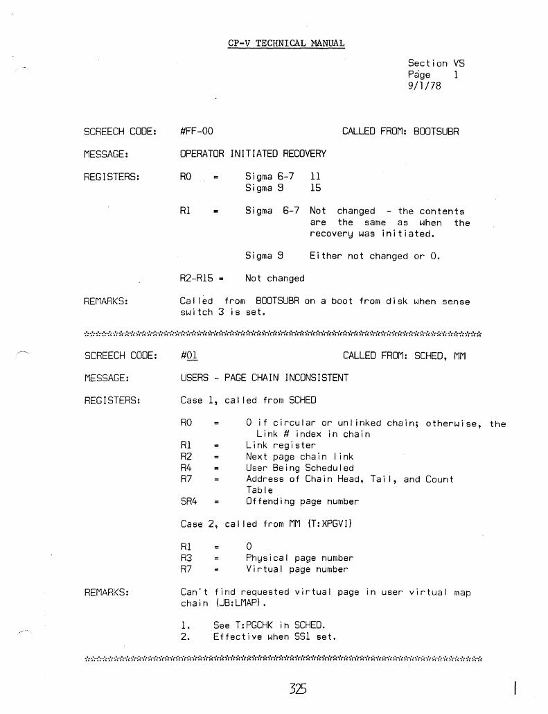
SCREECH CODE:
MESSAGE:
REGISTERS:
REMARKS:
SCREECH CODE:
MESSAGE:
REGISTERS:
REMARKS:
CP-V TECHNICAL MANUAL
Section VS Page 1 9/1/78
#FF-OO CALLED FROM: BOOTSUBR
OPERATOR INITIATED RECOVERY
RD =
Rl
R2-R15
Sigma 6-7 11 Si gma 8 15
Sigma 6-7 Not changed - the contents are the same as when the recovery was initiated.
Sigma 8 Either not changed or o.
Not changed
Cal led from BOOTSUBR on a boot from disk when sense sw itch 3 is set.
#01 CALLED FROM: SCHED, MM
USERS - PAGE CHAIN INCONSISTENT
Case 1, cal led from SCHED
RO
RI R2 R4 R7
SR4 =
o if circular or unl inked chain; otherwise, the Link # index in chain
Link register Next page chain I ink User Being Scheduled Address of Chain Head, Tai I, and Count Table Offending page number
Case 2, cal led from MM (T:XPGVI)
Rl R3 R7
= o Physical page number Virtual page number
Can't find requested virtual page in user virtual map chain (JB:LMAP).
1. See T:PGCHK in SCHEO. 2. Effective when S5l set.
************************************************************************
325

CP-V TECHNICAL MANUAL Section VS Page 2 9/1/78
****************************************************************************
SCREECH CODE:
MESSAGE:
REGISTERS:
REMARKS:
REGISTERS:
REMARI<S:
#02 CALLED FROM: SCHED
REPORTED EVENT INCONSISTENT WITH USER'S CURRENT STATE
"(R3 = Previous state "cR4 User number (T: RE, T: RCE) ,"RS = User number (T: RUE) -;'cR6 = Event number -;"R7 Line number (T: RCE)
SR4 = Rtn. Addr. for reschedule
*Contents dependent upon cal led entry point; if R4 S:CU, cal I was T:RE; if R7 is I ine number of user in R4, cal I was T:RCE; if R4 = RS, entry is T:RUE.
#04-04
NQt Displayed.
Cal led by SSS after the fol lowing a ZAP key-in. system tables, but does restoration phases. No written.
326
CALLED BY: SCHEO
system has quieted down Recovery then saves some
not enter the system recovery dump fi Ie is

SCREECH CODE:
MESSAGE:
REGISTERS:
SCREECH CODE:
MESSAGE:
REGISTERS:
REMARKS:
SCREECH CODE:
MESSAGE:
REGISTERS:
REMARKS:
CP-V TECHNICAL MANUAL
Section VS Page 3 9/1/78
#OA CALLED FROM: DPSIO, TSIO
OPCOoE IN SWAP COMMAND CHAIN IS INVALID
Case 1, command list security checks - SS4 set.
Rl Incorrect command list order code if equal R3
R2 Incorrect command I ist entry address R3 Order code of first lOCO in command R4 Swap device index R6 Command list beginning address R7 Swapper function code
Case 2, Unrecoverable read error during inswap
Inswap user number OCT index
not
(lOCO) list
Rl R7 SRI 01
Incorrect command I ist entry address (lOCO) Order code
#OB CALLED FROM: DPSIO, TSIO
INCORRECT ORDER CODE IN SWAP COMMAND LIST
Rl R2-R7
Incorrect order code, not seek See case 1, SIC #OA above.
SS4 must be on for check,
CALLED FROM: DPSIO, TSIO
ATTEMPT TO SWAP MONITOR'S MEMORY
Rl R2-R7 =
Buffer address See case 1, SIC #OA above.
55-4 must be on for check.
************************************************************************
3Zl

MESSAGE:
REGISTERS:
REMARKS:
SCREECH CODE:
MESSAGE:
REGISTERS:
REMARKS:
SCREECH CODE:
MESSAGE:
REGISTERS:
REMARKS:
CP-V TECHNICAL MANUAL
Sect ion VS Paae 4 9/1/78
SCREECH CODE #00 CALLED FROM:
HALT FLAGS MISSING IN SWAP COMMAND LIST
RO Rl R2-R7
FLAGS byte from TIC command TIC order code See case 1, SIC #OA above.
TSIO
SS-4 must be set to check. FLAGS must not have command chaining set and must have interrupt on zero byte count or channel end set.
#OE CALLED FROM: TSIO
1/0 REQUEST WITH NULL COMMAND LIST
R4 R6 R7
=
=
Swap device index Command list beginning address Swapper function code
Not checked for pack-only swappers.
#OF CALLED FROM: DPSIO, TSIO
INPUT FUNCTION CODE IS INVALID
R2 04
Swapper function code X'OF
SS-4 must be on to check. Function code not between one and five exclusively.
328
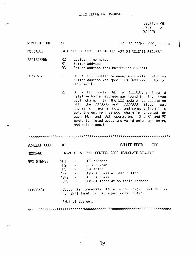
SCREECH CODE:
MESSAGE:
REGISTERS:
REMARKS:
CP-V TECHNICAL MANUAL
Section VS Page 5 9/1/78
#10 CALLED FROM: CDC, ECBBLK
BAD COC BUF POOL, OR BAD BUF ADR ON RELEASE REQUEST
R2 R4 R6
1.
2.
Logical line number Buffer address Return address from buffer return cal I
On a CDC buffer release, an inval id relative buffer address was specified (address 15 or HRBA~'(4+15) .
On a CDC buffer GET or RELEASE, an inval id relative buffer address was found in the free pool chain. If the CDC module was assembled with the COCGBUG and COCPBUG flags set (normally they're not), and sense switch 4 is set, the entire free pool chain is checked on each PUT and GET opera t i on. (The R4 and R6 contents listed above are val id only at entry and exit times.)
************************************************************************
.sCREECH CODE:
MESSAGE:
REGISTERS:
REMARKS:
#11 CALLED FROM: CDC
INVALID INTERNAL CONTROL CODE TRANSLATE REQUEST
,':R1 R2 R5
,;':R7 1(SR2
SR3
DCB address Line number Character Byte address of user buffer Rtrn address Output translation table address
Cause is translate table error (e.g., 2741 NIL on non-2741 line), or bad ihPut buff~r chain.
~'(Not a I ways set.
329
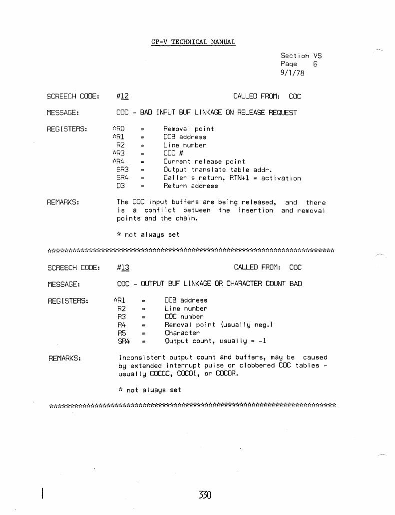
SCREECH CODE:
MESSAGE:
REGISTERS:
REMARKS:
SCREECH CODE:
MESSAGE:
REGISTERS:
REMARKS:
#12
CP-V TECHNICAL MANUAL
Section VS Paqe 5 9/1/78
CALLED FROM: CDC
CDC - BAD INPUT BUF LINKAGE ON RELEASE REQUEST
,":RO '"(Rl
R2 ~:R3
i':R4 SR3 SR4 03
Removal point DCB address Line number CDC # Current release point Output translate table addr. Caller's return, RTN+l = activation Return address
The CDC input buffers are being released, and there is a conflict between the insertion and removal points and the chain.
* not always set
#13 CALLED FROM: CDC
CDC - OUTPUT BUF LINKAGE OR CHARACTER COUNT BAD
j"Rl = R2 R3 R4 RS SR4
DCB address Line number CDC number Removal point (usually neg.) Character Output count, usually = -1
Inconsistent output count and buffers, may be caused by extended interrupt pulse or clobbered CDC tables -usually COCOC, COCOI, or COCOR.
i"C not always set
************************************************************************
330

SCREECH CODE:
MESSAGE:
REGISTERS:
REMARKS:
SCREECH CODE:
MESSAGE:
REGISTERS:
REMARKS:
SCREECH CODE:
MESSAGE:
REGISTERS:
REMARKS:
CP-V TECHNICAL MANUAL
Section VS Page 7 9/1/78
CALLED FROM: THEUNCOC
CDC ROUTINE CALLED IN NON-C~C SYSTEM
SR2 SR4 = 04
BAL adr if 14-03 BAL adr if 14-01 or 14-02 BAL adr if 14-04
The subcode indicates which routine was cal led:
#17
14-01 COCIO 14-02 COCOFF 14-03 COCSENDX 14-04 ECHOCR2
CALLED FROM: IOQ
INVALID DISK ADDRESS PASSED FOR AN I/O OPERATION
Rl ~':R2
R3 ~':SRI
SR4 04
IOQ7,3 = DCTX=O DCB address Queue index Seek address from CDA,R2 IOQ +.175 X'17'
Caused by inval id OCT index. If on a RAD/disk, OSCVT wi I I have been cal led indicating SRI setup.
#19 CALLED FROM: BUFF
INVALID BUFFER ADDRESS PASSED FOR RELEASE
Rl R2 R5 SR4 03 04
Index to BUFLIMS Head of respective buffer pool JIT address LINK Return address Buffer address X'19'
Occurs both on releasing and acquiring buffers of most types (CPOOL, SPOOL, and MPOOL) .
************************************************************************
331

CP-V TECHNICAL MANUAL
Section VS Page 8 9/1/78
**************************************************************************** SCREECH CODE:
MESSAGE:
REGISTERS:
REMARKS:
#19- 01
TOO MANY COWs in MPOOL
R1 R2
= OCT index = CIT index = lOG index
CALLED FROM: MPCDIO
R3 R12 = Actua 1 number of ClJIJs in reques t
An I/O request passed to the MPC disk handler may contain at most 5 command doublewords.
***************************************************************************
SCREECH CODE:
MESSAGE:
REGISTERS:
REMARKS:
SCREECH CODE:
MESSAGE:
REGISTERS:
REMARKS:
lA CALLED FROM: CLS
ACCOUNT DIRECTORY .INACCESSIBLE
No registers significant.
Account directory is bad, and Monitor is unable to reconstruct it. AI I fi les are lost.
#18 CALLED FROM: SWAPPER
USERS PAGE CHAIN NON ZERO AT SWAP COMPLETION
Rl R2 R3 R4 RS R6 SR4
Inswap user number (S:ISUN) Physical byte address of JIT UB: US, 1 (user state) Physical page head Physical page tai I Physical page count Count of swapper free page chain (S:FPPC)
Swappers' free page pool must be nonzero at end of inswap. S:FPPH, S:FPPT contain head and tai I of pages just al located to the inswap user.
332

~--
CP-V TECHNICAL MANUAL Section VS Page 9 9/1/78
****************************************************************************
SCREECH CODE:
MESSAGE:
REGISTERS:
REMARKS:
#lC-OO CALLED FROM:
INSWAP PROCESSOR SIZE EXCEEDS SIZE OF CLIST
Rl = Index into processor inswap list R3 = Inswap processor number
SWAPPER
R4 # of pages by which processor size exceeds available CLIST space.
A shared processor (possibly with an overlay) cannot be inswapped because its size exceeds the size of the command list space used for processor swapping.
****************************************************************************
SCREECH CODE:
MESSAGE:
REGISTERS:
REMARKS:
SCREECH CODE:
MESSAGE:
REGISTERS:
#10 CALLED FROM: T:OV
REQUESTED OVERLAY NUMBER IS OUT OF RANGE
R2 Overlay name R3 Overlay name R4 0 04 X'ID'
Requested monitor overlay not in shared processor table.
#IF CALLED FROM: SWAPPER
NOT ENOUGH PAGES TO PERFORM THIS SWAP
R3 count
Page to release SRI
333
Deficient page

SCREECH CODE:
MESSAGE:
REGISTERS:
SCREECH CODE:
MESSAGE:
REGISTERS:
REMARKS:
CP-V TECHNICAL MANUAL
Section VS Page 10 9/1/78
#21 CALLED FROM: MM
ATTEMPT TO SET ACCESS CONTROLS ON NON-EXISTENT VIRTUAL PAGE
R6 Number of pages to set R7 Virtual page number SR4 = Link register
#22 CALLED FROM: TYPR
PRIVATE VOLUME ALLOCATION ERROR
R2 = SN Count R3 DCB volume no. R4 SYSID (0 :3 EXCL. use) R6 DCB address SR4 RTN. adr. 02 DC8:SNT 04 X'22'
Error in al location; specified entry in AVRTAB not found or with bad flags.
*****~****************************************************************** SCREECH CODE:
MESSAGE:
REGISTERS:
REMARKS:
#23
INVALID ENTRY TO CSE HANDLERS
None significant
CALLED FROM: CSES7, CSES9, CSEX560,CSECOM
Entry was made to an unused slot of the CSE branch vector for this machine.
************************************************************************************
SCREECH CODE:
MESSAGE:
REGISTERS:
REMARKS:
CALLED FROM: CSEHANO
INSTRUCTION EXCEPTION TRAP IN MASTER MODE
AI I relevant information in in-core error log buffers.
Trap X'4D' whi Ie in master mode. Slave mode trap causes normal user job step abort.
334 -

SCREECH CODE:
MESSAGE:
REGISTERS:
REMARKS:
SCREECH CODE:
MESSAGE:
REGISTERS:
REMARKS:
SCREECH CODE:
MESSAGE:
REGISTERS:
REMARKS:
SCREECH CODE:
MESSAGE:
REGISTERS:
REMARKS:
CP-V TECHNICAL MANUAL
#25
UNRECOVERABLE WATCHDOG TIMER TRAP
Section VS Page 11 9/1/78
CALLED FROM: CSEHAND
AI I relevant information in in-core error log buffers.
Sigma 9 and Xerox 560 systems wi I I attempt recovery from watchdog timer traps from 110 instructions without SCREECHing.
#26 CALLED FROM: CSEHAND
CSE TRAP DURING MFI,PFI HANDLING
AI I relevant information is in in-core error log buffers.
On Sigma 9 during MFI handling, or on Xerox 580 during MFI or PFI handling, a CSE trap (X'48', X'4C', X' 40 I) occurred.
#27 CALLED FROM: CSEHAND
PROCESSOR FAULT INTERRUPT
AI I relevant information is in in-core error log buffers.
For Xerox interrupt un like I y.
#28
560 systems only, a processor fault occurred for which continued operation is
CALLED FROM: CSEHAND
MEMORY PARITY ERROR - MEMORY ALTERED
AI I relevant information is in in-core error log buffers.
Memory parity error correction caused memory to be altered, continuation without recovery not possible. Caused by 156 (Sigma 6/7) or T4C (Sigma 9, Xerox 560) .
335
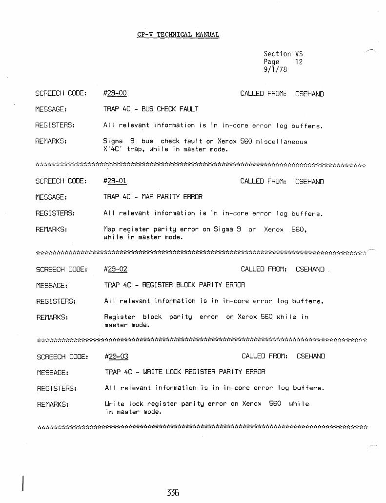
SCREECH CODE:
MESSAGE:
REGISTERS:
REMARKS:
CP-V TECHNICAL MANUAL
#29-00
TRAP 4C - BUS CHECK FAULT
Section VS Page 12 9/1/78
CALLED FROM: CSEHAND
AI I relevant information is in in-core error log buffers.
Sigma 9 bus check fault or Xerox 550 miscellaneous X'4C' trap, whi Ie in master mode.
***********************************************************************************~
SCREECH CODE:
MESSAGE:
REGISTERS:
REMARKS:
SCREECH CODE:
MESSAGE:
REGISTERS:
REMARKS:
SCREECH CODE:
MESSAGE:
REGISTERS:
REMARKS:
#29-01 CALLED FROM: CSEHAND
TRAP 4C - MAP PARITY ERROR
AI I relevant information is in in-core error log buffers.
Map register parity error on Sigma 9 or Xerox 550, whi Ie in master mode.
#29-02 CALLED FROM: CSEHAND.
TRAP 4C - REGISTER BLOCK PARITY ERROR
AI I relevant information is in in-core error log buffers.
Register block parity error or Xerox 560 whi Ie in master mode.
#29-03 CALLED FROM: CSEHAND
TRAP 4C - WRITE LOCK REGISTER PARITY ERROR
AI I relevant information is in in-core error log buffers.
Write lock register parity error on Xerox 560 whi Ie in master mode.
336

SCREECH CODE:
MESSAGE:
REGISTERS:
REr1ARKS:
SCREECH CODE:
I"IESSAGE:
REGISTERS:
REMARKS:
#2C-OO
CP-V TECHNICAL MANUAL
Section VS Page 13 9/1/78
CALLED FROM: ADO
BATCH SCHEDULING ERROR - MBS/CCI ERROR
Rl R2 R3 R5 R8 SR2 SR3 SR4 01 02 03
(S:CUN) current user # Device type Context block address o User's oCB addr (M:C) OPNLD + .14 Context block address OPNLD + .40 BA(OPNLo+ .lE7)+.28 BA(CONTXT BLK+SCFQARGS) +.28 Device type mnemonic text
Register contents significantly different frorll above indicate the moni tor wandered into GETI in ADO. Otherwise, a batch user has been created and has read a card before MBS selected him to be run. Actually al I recorded 2C's have been CCI attempting to start a second job. Problem is either CCI read past FIN or MBS/GETI communication (e.g., GIB:UN clobbered).
#20-00 CALLED FROM: COOP
COOPERATIVE BUFFER MANAGEMENT ERROR
Rl R2 R3 SR4 03
BUFLIMS index for SIC 19 .BCll Context block COOP+ .180 o
At context block initial ization a buffer was al located for the context block. This buffer has been lost through core clobbering or mismanagement of a buffer chain. The particular user cannot continue.
337
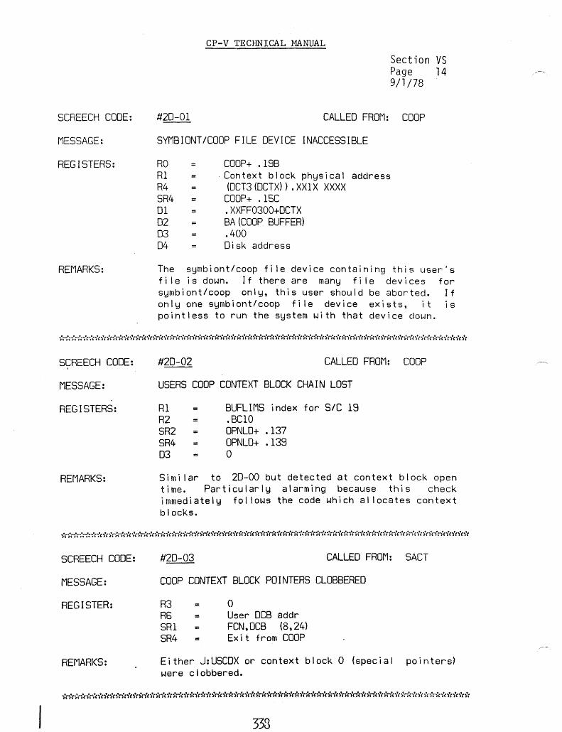
SCREECH CODE:
MESSAGE:
REGISTERS:
REMARKS:
SCREECH CODE:
MESSAGE:
REGISTERS:
REMARKS:
SCREECH CODE:
MESSAGE:
REGISTER:
REMARKS:
#20-01
CP-V TECHNICAL MANUAL
Section VS Page 14 9/1/78
CALLED FROM: COOP
SYMBIONT/COOP FILE DEVICE INACCESSIBLE
RO Rl R4 SR4 01 02 03 04
=
COOP+ .19B . Context block physical address
(DCT3(OCTX)) .XXIX XXXX COOP+ .1SC .XXFF0300+DCTX BA (COOP BUFFER) .400 Disk address
The symbiont/coop fi Ie device containing this user's fi Ie is down. If there are many fi Ie devices for symbiont/coop only, this user should be aborted. If on I y one symb i on t I coop f i I e dev i ce ex i s t s , i tis pointless to run the system with that device down.
#20-02 CALLED FROM: COOP
USERS COOP CONTEXT BLOCK CHAIN LOST
R1 R2 SR2 SR4 03
BUFLIMS index for SIC 19 .BClO OPNLO+ .137 OPNLO+ .139 o
Simi Jar to 20-00 but detected at context block open time. Particularly alarming because this check immediately fol lows the code which al locates context blocks.
#20-03 CALLED FROM: SACT
COOP CONTEXT BLOCK POINTERS CLOBBERED
R3 R6 SRI SR4
o User DCB addr FCN,DCB (8,24) Exit from COOP
Either J:USCDX or context block 0 (special pointers) were clobbered.
333

SCREECH CODE:
MESSAGE:
REGISTERS:
REMARKS:
SCREECH CODE:
MESSAGE:
REGISTERS:
REMARKS:
SCRC:ECH CODE:
MESSAGE:
REGISTERS:
REMAR:<S:
CP-V TECHNICAL MANUAL
Section VS Page 15
'9/1/78
CALLED FROM: SUPCLS
COOP DATA BUFFERS MISALLOCATED
03
RS
R2 SR4
Buffer being released, including spare buffer index in byte O. Context block 0 address and DBPOOL which is the address of the free context buffer list. SV:LSIZ Return address of caller of RCBUFF.
An attempt was made to release a COOP data buffer when the free data buffer pool was ful I. Either the free data buffer pool has been clobbered or too many buffers have been al located meaning some other COOP data area has been clobbered.
#2E CALLED FROM: RDF
POOL BUFFERS LOST - NONE ALLOCATED CURRENTLY
SR3 04
DCB for Which buffer is needed. X'2E'
An attempt was made to get an IPOOL or FPOOL buffer, but none were in free pool and no open DCB had any. Probably either DCB chain has been clobbered or one or more DCBs have been clobbered.
#2E-Ol CALLED FROM: RA
INCONSISTENCY IN READ-AHEAD TABLES
R12 Disc address
An attempt was made to add an AIR block to the tables when it was already there.
339
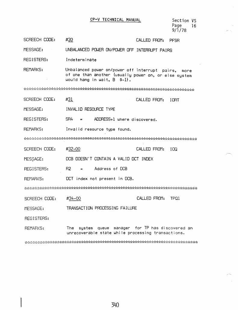
SCREECH CODE:
MESSAGE:
REGISTERS:
REMARKS:
CP-V TECHNICAL MANUAL Section VS Page l6 9/l/78
#30 CALLED FROM: PFSR
UNBALANCED POWER ON/POWER OFF INTERRUPT PAIRS
Indeterminate
Unbalanced power on/power off interrupt pairs, more of one than another (usually power on, or else system would hang in wait, B $-1).
***********************************************************************
SCREECH CODE:
MESSAGE:
REGISTERS:
REMARKS:
SCREECH CODE:
MES$AGE:
REGISTERS:
REMAR;<S:
SCREECH CODE:
MESS~,GE:
REGISTERS:
REMARI<S:
#31 CALLED FROM: IORT
INVALID RESOURCE TYPE
SR4 ADDRESS+1 where discovered.
Inval id resource type found.
#32-00 CALLED FROM: IOQ
DCB DOESN'T CONTAIN A VALID OCT INDEX
R2 = Address of DCB
OCT index not present in DCB.
#34-00 CALLED FROM: TPQl
TRANSACTION PROCESSING FAILURE
The system queue manager for TP has discovered an unrecoverable state whi Ie processing transactions.
340
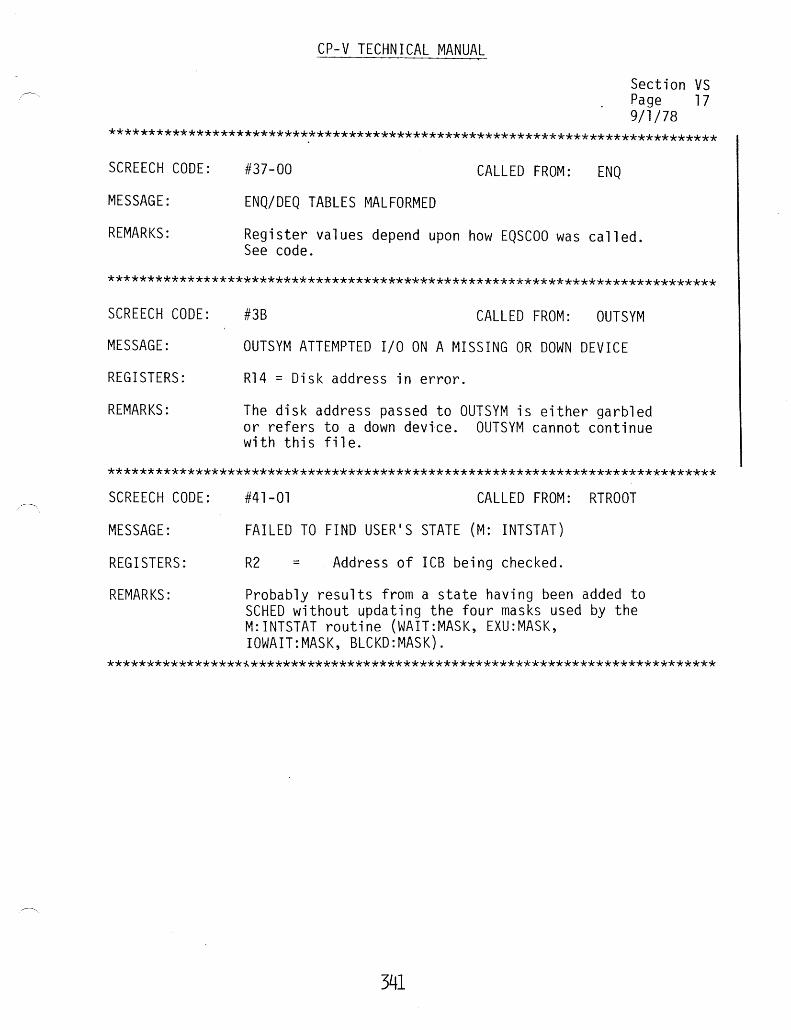
CP-V TECHNICAL MANUAL
Section VS Page 17 9/1/78
****************************************************************************
SCREECH CODE:
MESSAGE:
REMARKS:
#37-00 CALLED FROM: ENQ
ENQ/DEQ TABLES MALFORMED
Register values depend upon how EQSCOO was called. See code.
****************************************************************************
SCREECH CODE:
MESSAGE:
REGISTERS:
REMARKS:
#3B CALLED FROM: OUTSYM
OUTSYM ATTEMPTED I/O ON A MISSING OR DOWN DEVICE
R14 = Disk address in error.
The disk address passed to OUTSYM is either garbled or refers to a down device. OUTSYM cannot continue with this file.
****************************************************************************
SCREECH CODE:
MESSAGE:
REGISTERS:
REMARKS:
#41-01 CALLED FROM: RTROOT
FAILED TO FIND USER'S STATE (M: INTSTAT)
R2 = Address of ICB being checked.
Probably results from a state having been added to SCHED without updating the four masks used by the M:INTSTAT routine (WAIT:MASK, EXU:MASK, IOWAIT:MASK, BLCKD:MASK).
*****************~**********************************************************
341
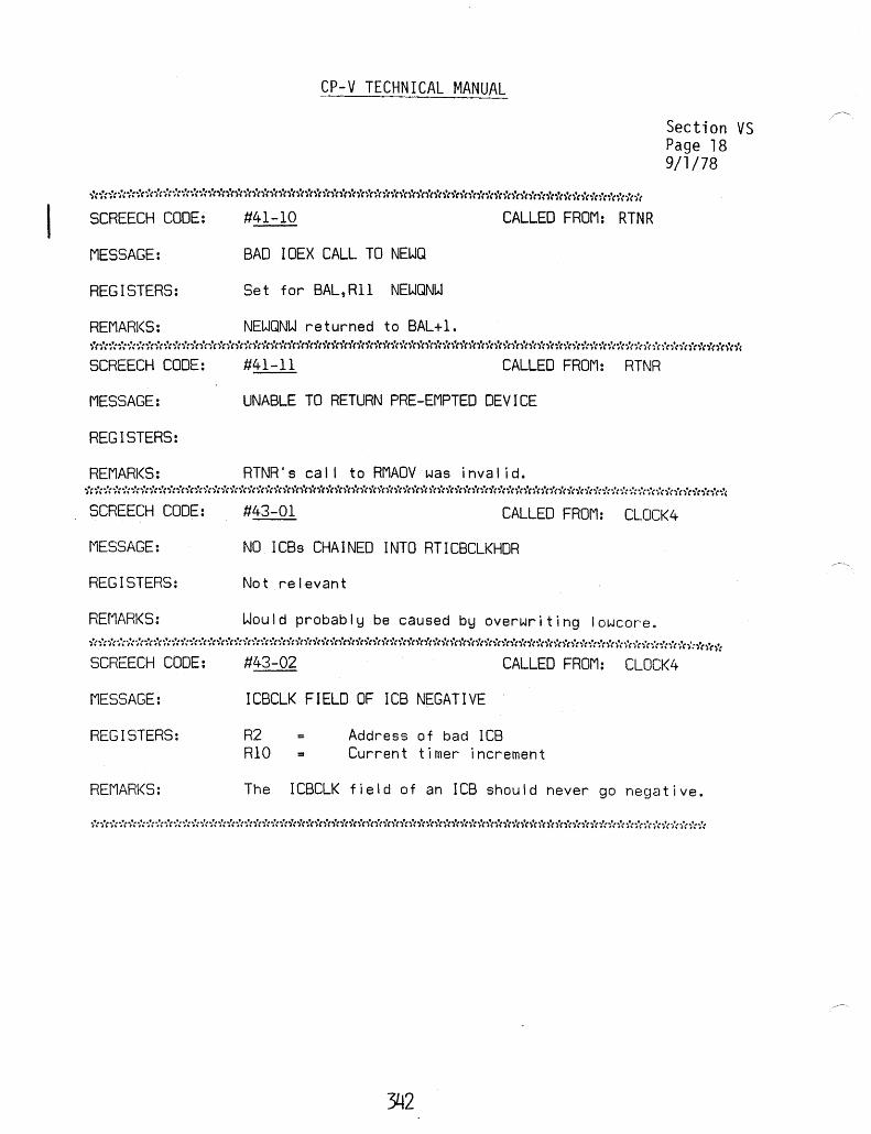
SCREECH CODE:
MESSAGE:
REGISTERS:
REMARKS:
SCREECH CODE:
MESSAGE:
REGISTERS:
REMARKS:
SCREECH CODE:
MESSAGE:
REGISTERS:
REr1ARKS:
SCREECH CODE:
MESSAGE:
REGISTERS:
REMARKS:
CP-V TECHNICAL MANUAL
#41-10 CALLED FROM: RTNR
BAD IOEX CALL TO NEWQ
Set for BAL,Rll NEWQNW
NEWQNW returned to BAL+l.
#41-11 CALLED FROM: RTNR
UNABLE TO RETURN PRE-EMPTED DEVICE
RTNR's cal I to RMAOV was inval ide
Section VS Page 18 9/1/78
CALLED FROM: CLOCK4
NO lCBs CHAINED INTO RTICBCLKHDR
Not relevant
Would probably be caused by overwriting lowcore.
#43-02 CALLED FROM: CLOCK4
ICBCLK FIELD OF ICB NEGATIVE
R2 Address of bad ICB RIO Current timer increment
The ICBCLK field of an ICB should never go negative.
**********************************************************************
342
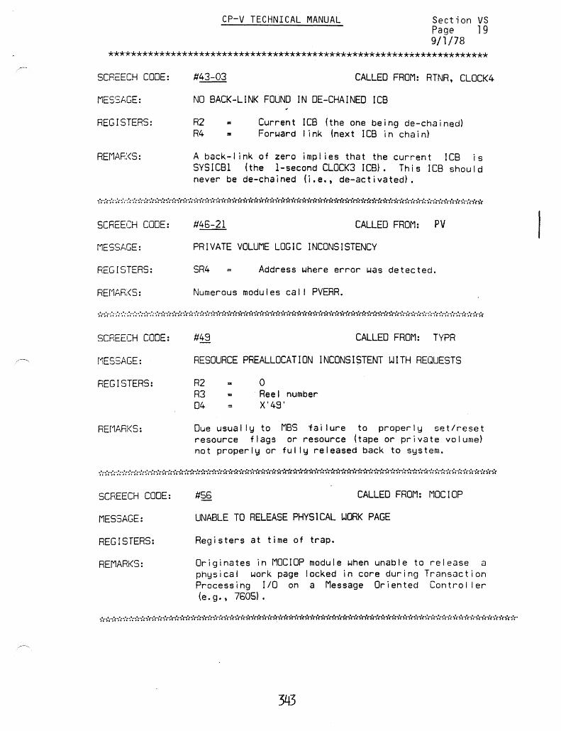
CP-V TECHNICAL MANUAL Section VS Page 19 9/1/78
*******************************************************************
SCRC:ECH CODE:
MESSAGE:
REGISTERS:
REMAF.:<S:
SCREECH CODE:
MESSAGE:
REGISTERS:
SCREECH CODE:
r1ESSAGE:
REGISTERS:
REf1ARKS:
SCREECH CODE:
MESSAGE:
REGISTERS:
REMARKS:
CALLED FROM: RTNR, CLOCK4
NO BACK-LINK FOUND IN DE-CHAINED ICB
R2 R4
Current ICB (the one being de-chained) Forward link (next lCB in chain)
A back-I ink of zero impl ies that the current ICa is SYSICBI (the I-second CLOCK3 ICB}. This ICB should never be de-chained (i.e., de-activated).
#45-21 CALLED FROM: PV
PRIVATE VOLUME LOGIC INCONSISTENCY
SR4 Address where error was detected.
Numerous modules cal I PVERR.
#49 CALLED FROM: TYPR
RESOURCE PREALLOCATION INCONSI$TENT WITH REQUESTS
R2 R3 04
o Reel number X'4S'
Due usually to MBS failure to properly setlreset resource flags or resource (tape or private volume) not properly or fully released back to system.
#56 CALLED FROM: MOCIOP
UNABLE TO RELEASE PHYSICAL WORK PAGE
Registers at time of trap_
Originates in MOCIOP module when unable to release a physical work page locked in core during Transaction Processing 110 on a Message Oriented Controller (e. g., 7505).
343

CP-V TECHNICAL MANUAL Section VS Page 20 9/1/78
********************************************************************
SCReECH CODE:
MESSAGE:
REGISTERS:
REMARKS:
SCREECH CODE:
MESSAGE:
REGISTERS:
REMARKS:
SCREECH CODE:
MESSAGE:
REGISTERS:
REMARKS:
#81- (Trap Cell) CALLED FROM: INITRCVR
TEL OR CCI HAS TRAPPED
Registers at time of trap.
Trap occurred whi Ie operating mapped, slave, and with TEL-in-control set. Subcode is trap location.
#52 CALLED FROM: SCHED
USER PROGRAM TOO LARGE FOR PHYSICAL MEMORY
RO R4
Pages freed Inswap user (S:ISUN)
RO greater than SL:CORE, user got swapped out but now can't fit back in; pages may be released but not reported; JIT-in-core flag = 0 (UH:FLG X'200').
#53 CALLED FROM: DPSIO
INSUFFICIENT INFORMATION AVAILABLE TO SWAP THIS USER
R2 R6 R7 04
= lOCO Command list address Function code X'63'
Insufficient data to complete function, follow-on function code inval id, or flags not set properly; disk pack-only swappers.
************************************************************************
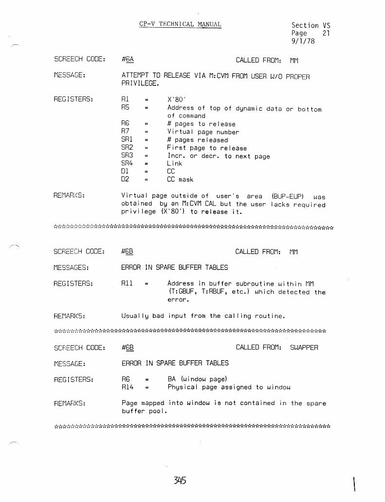
SCREECH CODE:
MESSAGE:
REGISTERS:
REMARl<S:
CP-V TECHNICAL MANUAL
fl5A
Section VS Page 21 9/1/78
CALLED FROM: MM
ATTEMPT TO RELEASE VIA M:CVM FROM USER WID PROPER PRIVILEGE.
Rl R5
R5 R7 SRI SR2 SR3 SR4 01 02
X'80' Address of top of dynamic data or bottom of command fI pages to release Virtual page number II pages released First page to release Incr. or decr. to next page Link CC CC mask
Virtual page outside of user's area (SUP-EUP) was obtained by an M:CVM CAL but the user lacks required pr i v i I ege (X' 80') to re I ease i t.
************************************************************************
SCREECH CODE:
MESSAGES:
REGISTERS:
REMARKS:
SCF~EECH CODE:
MESSAGE:
REGISTERS:
REf1ARI<S:
fl5B CALLED FROM: MM
ERROR IN SPARE BUFFER TABLES
Rll = Address in buffer subroutine within MM (T:GBUF, T:RBUF, etc.) which detected the error.
Usually bad input from the cal I ing routine.
fl5S CALLED FROM: SWAPPER
ERROR IN SPARE BUFFER TABLES
BA (window page) R6 R14 Physical page assigned to window
Page mapped into window is not contained in the spare buf fer poo I.
345 \

CP-V TECHNICAL MANUAL
Section VS Page 22 9/1/78
****************************************************************************
SCREECH CODE:
MESSAGE:
REGISTERS:
REMARKS:
#78-00 CALLED FROM: MPSCHED
SLAVE CPU INVOKED CRASH
R15, left halfword: Screech code passed by slave CPU. R15, right halfword: Slave CPU's processor number.
A slave CPU encountered a condition that requires a full system recovery.
****************************************************************************
SCREECH CODE:
MESSAGE:
REMARKS:
#78-01 CALLED FROM: ENTRY
SLAVE CPU TRAPPED WITH NO USER ASSOCIATED
A slave CPU suffered a trap (or issued a CAL) with no user associated.
If this situation occurs, the system will screech with a code of 78-00. The value X'780l00nn ' will appear in the master CPU's R15 at the time of the crash ('Inn" being the slave CPUls processor number.)
****************************************************************************
SCREECH CODE:
MESSAGE:
REMARKS:
78-7F CALLED FROM: MPSUB
MASTER CPU WANDERED INTO SLAVE CPUIS CODE
The master CPU somehow began executing code reserved for the slave CPU(s) in a multiprocessor system.
****************************************************************************
SCREECH CODE:
MESSAGE:
REGISTERS:
REMARKS:
#78 CALLED FROM: ENTRY
MONITOR COMMITTED A STACK TRAP
Registers at time of trap.
Master bit on in PSD, overflow, underflow, or pointer to stack lost.
346

CP-V TECHNICAL MANUAL
Section VS Page 23 9/1/78
****************************************************************************
SCREECH CODE: #79-01 CALLED FROM T:OV
MESSAGE: MONITOR STACK TRAP
REGISTERS: Registers at time of trap
REMARKS: OSTACK overflow
****************************************************************************
SCREECH CODE:
MESSAGE:
REGISTERS:
REMARKS:
#79-02 CALLED FROM: S5SIM
SIMULATORS OVERFLOWED TSTACK
User (or monitor) resisters when simulated instruction encountered.
The Sisma 5 byte-string/decimal instruction simulators require scratch space in the user's (or monitor's) TSTACK. Possibly due to multiple interrupts or traps, that space is not available.
****************************************************************************
SCREECH CODE:
MESSAGE:
REGISTERS:
REf1AR:<S:
CALLED FROM: ALTCP
ALTCP CALLED TO SERVICE A CAL THAT DOESN'T BELONG TO ALTCP
R3 R6 R7 SRI SR4
R field of CAL First word PLIST Addr. PLIST+1 Code Exit addr (usually TRAPEXIT)
A CALl,l or CALl,2 was passed to ALTCP but should have been handled by CALPROC.
************************************************************************
SCREECH CODE:
MESSAGE:
REGISTERS:
REf1AR;(S:
fi7E-(Trap Cell)
f10N I TOR HAS TRAPPED
Registers at time of trap.
CALLED FROM: INITRCVR
Subcode is trap location. For traps that occur at locations less than X'8000' (JOVVPA), the 15 cells preceding the trap location and the trap location are stored in the monitor JIT AT X'8DFO'-X'8DFF'.
346A

SCREECH CODE:
MESSAGE:
REGISTERS:
REMARKS:
SCREECH CODE:
MESSAGE:
REGISTERS:
REMARKS:
SCREECH CODE:
MESSAGE:
REGISTERS:
REMARKS:
CP-V TECHNICAL MANUAL Section VS Page 24 9/1/78
#87 CALLED FROM: ALLOCAT
ALLOCATION BUFFERS CONTAIN INVALID WORD COUNT
R2 Rl
Stack count Stack number
Either low core has been clobbered or some one has changed ALLOCAT's in-core data.
#88 CALLED FROM: SCHEO
ALLOCAT CLOBBERED ONE OF THE ALLOCATION BUFFERS
Rl R3
Stack index Stack count
ALLOCAT end-action has discovered discrepancy in granule/cylinder stacks.
#89-00 CALLED BY: ALLOCAT
ALLOCAT'S HGP CHAIN CLOBBERED
R7 R9 =
Invalid HGP chain address ALLOCAT internal link register
ALLOCAT data (HGPs and TABLES) has been destroyed.
***************************************.*********************************
SCREECH CODE: CALLED FROM: ALLOCAT
MESSAGE: DATA CHECKSUM ERROR
REGISTERS: None
REMARKS: ALLOCAT data (HGPs and TABLES) has been destroyed.
***********************************************************************
346B

SCREECH CODE:
MESSAGE:
REGISTERS:
REMARKS:
SCREECH CODE:
MESSAGE:
REGISTERS:
REMARKS:
SCR:::ECH CODE:
r'IESSAGE:
REGISTERS:
SCREECH CODE:
MESSAGE:
REGISTERS:
CP-V TECHNICAL MANUAL Section VS Page 25 9/1/78
CALLED FROM: DPSIO, TSIO
TDV COMMAND ADDRESS DOESNT POINT TO COMMAND LIST
RI SRI SR2 02
o Command I ist address from TDV ToV status Cmd. list pointer (S:BECL,RI)
lOP/memory failure; extraneous entry to TSIO/DPSIO not generated within CLIST.
#84 CALLED FROM: DPSIO, TSIO
COMMAND LIST CLOBBERED DURING WRITE CHECK
SRl SR2 Rl2
Incorrect command list entry address TDV status Order code from incorrect command list entry
Can't find seek or TIC within next five command list entries fol lowing error entry, on write or write check.
CALl.Eo FROM: OPSIO, TSIO
UNRECOVERABLE I/O ERROR READING USER'S JIT
RI R7 SRI SR2
t/96
Inswap user number (S: ISUN) OCT Index Command I ist address from TOY status TOY status
CALLED FROM: DSPIo, TSIO
UNRECOVj::RABLE liD ERROR READING SHARED PROCESSOR
Rl R7 SRI SR2
Inswap user number (S:ISUN) OCT index Command I ist address from TOV status TDV status
************************************************************************
346c

CP-v TECHNICAL MANUAL
(This page intentionally left blank.)
346d

~',
~"
CP-V TECHNICAL MANUAL
SECTION VT PAGE 1 10/31/74
PWPTABLE - Physical Work Pages for TP
8i t
0-15 18-23 24 25 28
27
28 29 30 31
Bi t
0-31
o
~
Count Page or Flags
User
15 16 23 24 31
Length PWPENO - PWPTABLE+l
Physical page number {left-justified} If bit 26 is 0 - assign count; if bit 26 is 1 ~ user number Reserved Reserved Release is being accompl ished by clock processing due to unavai labi lity of work space Virtual window is being established in user in order to assign a .page Reserved Page has been acquired by cal ling GPWP (Get Physic~1 Work Page) Page has been acquired by APWP (Assign Physical Work Page) o - this word in PWPTABLE is free for use· 1 - this word in PWPTABLE is currently in use
SL:PWP
I I 0 31
Current I imit of physical work pages
S:PWP#
I 0 31
81 t
0-31 Current count of physical work pages
347

CP-V TECHNICAL MANUAL
SECTION VT PAGE 2 10/31/74
TTP RESIDENT TABLE - QUEUE MANAGEMENT ELEMENTS
o 78 1518 2324 31
Q:MAP 0
Q:CC Q:CFU 1
Q:NSN Q:SN 2
Q:MAX Q:INXCONTROL ·3
Q:DEF 4
5
Q:GET 8 "~
7
Q:LID I Q:MIN I Q: I NXNAV 8
Q:QHEAD 9
Q:QTAIL 10
QINX 11
Q: INXTAIL 12
Q:MPOOL 13
Q:TIO 14
Q:USR Q:SAT I Q:PAGES I Q:OWN 15
Q:TPPP 16
Q:TPPTAIL 17
Q:CONT 18
Q:CONTTAIL 19
Q:OATA 20
Q:OATATAIL 21
Q:PAUSE 22 348

CP-V TECHNICAL MANUAL
SECTION VT PAGE 3 10/31/74
TTP Table Item Descriptions
Item Name
Q:BACK
Q:CC
Q:CFU
Q:CONT
Q:CONTTAIL
Q:DATA
Q:DATATAIL
Q:DEF
Q:GET
Q: INXNAV
Q: INX
Q:INXTAIL
Q: I NXCONTROL
Q:LID
Q:LOCK
(B i t/Byte) Word ~ Description
o (6)
1 (0)
1
18 - 19
20 - 21
4
6
8 {3}
11 - 12
3
8 (0)
o (2)
Byte
Bit Backup option requested during unlock, 1 = yes
110 camp 1 e t i on code; se t by end-action
Address Real address of the queue CFU table
Word Chain header, queue control blocks
Word Chain head/tai I, queue data blocks
Doubleword Chain headltai I, inactive criteria control (points to U: QLIST)
Doubleword Chain headltai I, act i ve entries
Word
criteria control (po i nts to U: QLIST)
Byte Maximum number of keys in an index block
Chain header, queue index blocks
Address . Address of the index control block
Bi t
Halfword Identification number to be
349
assigned to the next GET lis t ; in i t i a I i zed dur i ng queue unlock processing
Queue status, 1 = unlocked

Item Name
Q:MAP
Q:MAX
Q:MIN
Q:MPOOL
Q:NSN
Q:OWN
Q:PAUSE
Q:PAGES
Q:QHEAD
Q:QTAIL
Q:RCV
Q:SAT
Q:SN
Q:TID
Q:TPPP
Q:TPPPTAIL
Q:USR
CP-V TECHNICAL MANUAL
(Bi t/Byte) Word ~
o Address
3 (0) Byte
SECTION VT PAGE 4 10/31/74
Description
Address of the Queue A I I oca t i on Map
Maximum number of queue index blocks retained in core
8 {2} Byte Minimum number of pages
13
2 {O}
15 (3)
22
15
9
10
(2)
o (7)
15 (1)
2
14
16 - 17
15 (0)
Address
Byte
Byte
Bi t
Byte
Address
Address
Bi t
Byte
Address
Word
Word
Byte
required for queue blocks
Mon i tor (MPDDL)
Buffer Address
Number of volumes if queue is on private storage
User number, queue owner
Queue in lock, pause mode
Current number pages al located usage
of physical for queue
Word address, head of chain of users queued for access or space (U: QUES)
Word address, tai I of chain of users queued for access or space (U: QUES)
Recovery in progress, 1 = yes
Queue saturation percentage to accept high priority PUTs only
Address of the queue serial numbers for private storage
Highest TID
Chain header, queue physical pages
User number, current queue lID operation

RECOVERY TABLES
Core Dump Format
CP-V TECHNICAL MANUAL
SECTION VU PAGE 1 10/31/74
CORE is converted to a page number and the space required is compared' with the RAD space avai lable (RCVRDSZ). If space needed exceeds space avai lable, TAPDMP is cal led. Otherwise, RCVRAD+2 is entered into the RECOVERY buffer.
CORE is dumped with an SID and command chain in RCVDMP.
Fol lowing system reboot and core initialization, but before swapping RAD initial ization, the dump space on RAD is written as a keyed fi Ie on the f i Ie RAD.
The keys for core pages are
The user JITs are added to the keyed fi Ie with keys of I 03 I user#1 00 I 00 I .
Dump Tape Format
The dump tape is a labeled tape and each logical record is one page of core memory.
The label sentinel is :LBL RCVT.
The identification sentinel is :ACN :SYSbbbb Date of the crash in format from DATE and DATE+l.

.CP-V TECHNICAL MANUAL
SECTION VU PAGE 2 10/31/74
The tape mark record is:
tape mark
tape mark :EOF 3*4 previous block size
end of reel sentinel terminates the dump tape mark
tape mark tape mark
:EOR NULL
Recover!1 Buffer
Each item of information within the Recovery buffer is fol lowed by an identification word. The identification consists of an id code in byte 0 and th~ word count of the information item in bytes 2 and 3. The items are not necessari Iy in the buffer in id order.
10 CODE
01
02 03
04 05 06 07
08
09 OA OB OC 00
OE OF 10 11
PROBABLE COUNT
IS 3
size 1 value value
logged on users 149
1
4 SI (SGCBUFSZ)
1
ITEM
SGRAN, BGRAN, CURGRAN, FGRANl, CUR8UF and contents of CURBUF and 2 preceding words Administrative message (COCMESS) Initial and final RCVRAD from RCVDMP and RCVRCNT Size of RECOVERY buffer Dump tape identification Down device number Number of locked symbiont devices + 1, RCVRCNT, and 5GB User #, swap index, seek address (8, 8, IS} Partition limits, system limits Unused HGP reconstruction required Unused First disc address of granule stack for release Unused Write symbiont ghost recovery fi les Symbiont ghost communication buffer Symbiont ghost error word
352
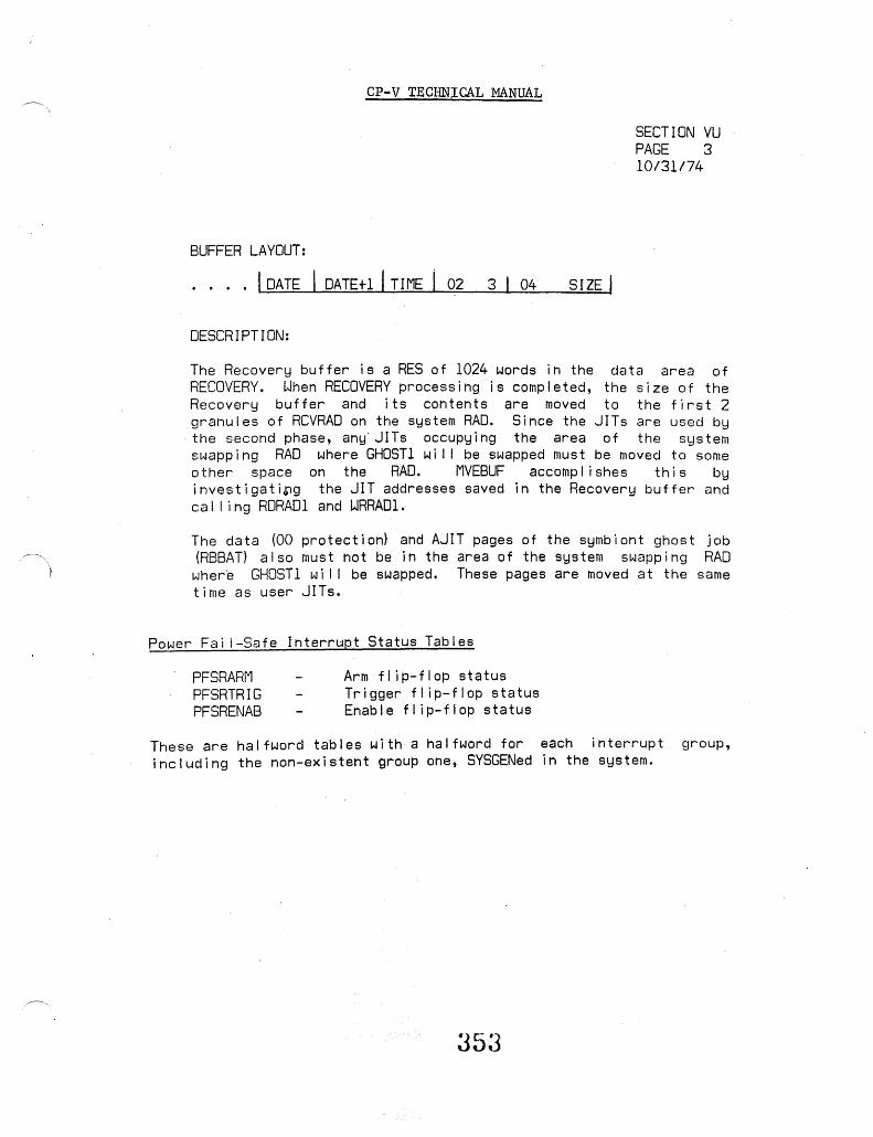
CP-V TECHNICAL MANUAL
SECTION VU PAGE 3 10/31/74
BUFFER LAYOUT:
I DATE DATEtl I TIME I 02 3 04 SIZE I
DESCRIPTION:
The Recovery buffer is a RES of 1024 words in the data area of RECOVERY. When RECOVERY processing is completed, the size of the Recovery buffer and its contents are moved to the first 2 granules of RCVRAD on the system RAD. Since the JITs are used by the second phase, any'JITs occupying the area of the system swapping RAD where GHOST 1 wi I I be swapped must be moved to some other space on the RAD. MVEBUF accompl ishes this by investigati~g the JIT addresses saved in the Recovery buffer and cal ling RDRADI and WRRAD1.
The data (00 protection) and AJIT pages of the symbiont ghost job (RBBAT) also must not be in the area of the system swapping RAD where GHOSTI wi I I be swapped. These pages are moved at the same time as user JITs.
Power Fa; I-Safe Interrupt Status Tables
PFSRARM PFSRTRIG PFSRENAB
Arm flip-flop status Trigger fl ip-flop status Enable flip-flop status
These are halfword tables with a halfword for each interrupt group, including the non-existent group one, SYSGENed in the system.
353

*RB:MFAD, VR-2 *RB:SPMF, VR-2 *RBH :MFX, VR-2 :ACCTlG, VN.02-1 :AMHED, VA.01-1 :lQGSZ, VA,Ol-1 :PROCS, VN.05-1 :RATES, VN.03-1 :RBlOG, VN.04-1 :UBMl, VN.01-3 :UBMR, VN. 01-3 :UGML, VN.01-3 :UGMR, VN.01-3 :UNML, VN.01-3 :UNMP, VN.01-3 :UNMR, VN.01-3 :UOMl, VN.01-3 :UOMR, VN.01-3 :UPFlGS, VN.Ol-3 :USER, VN.Ol-1 2780, VR-4,-7 3COUNT, VK.01-1
A ABO, VA-4 ACCN, VA-3 ACCO, VI.01-4 ACCOUNT DIRECTORY, VH.02-1 ACCOUNTING RECORD, VN.02-1 ACNCFU, VH.08-2 AIR, VH.21-2 ALLOCATION, VH.07-1 ALOCCT, V A-5 ANS, VHf 16.01-2 ANS DCB, VHf 11-1 ANSFLGS, VG.04-4 ARSZ, VG.05-1 ASSIGN/MERGE, VA-ll, VL-l A TIT lE, V A-6 AVR, VG.04-1 AVRFLGS, VG.04-5 AVRFNMT, VG.04-4 AVRID, VG.04-J AVRNOU, VG.04-1 AVRTBL, VG. 04-1, -2 AVRTBLNE, VG.04-1 AVRTBLSIZ, VG.04-1
B B4W:RES, VI. 02-2 BAABC, VA-4 BARNST, VA-4
INDEX
BATAPE, VG.04-l,-2 BB: ... VI. 02-2 BC P, V F. 01 - 1 BD:ACCT, V 1.02-2 BGRAN, VK-2 BH : .•. , VI. 02-1, -2 BPRIO, VP-13 BREF, VO-9 BSCIO, VR-7 BUFCNT, VG.05-1 BUFFER, VF.01-3 BUP, VF.01-1 BW:FORM, V 1.02-2 BW:SDA, VI. 02-2
c Cl, VG.03-6 CBPOOL, VI. 01-6 CCBEF, VA-4 CCLFLAGS, V A-5 CCLTFlAGS, VA-5 CDPO, VA-5 CEXT, VA-3 CFU, VH.08-1 CFU, USER, VH.08-7 CIC, VA-4 CIT, VG.01-1,VG.02-2 Cll, VF.Ol-1 CO: ... , VG. 05-3,-4 COB:SIOS, VG.05-3 COC, VG.05 CQCBUF, VG.05-4 COCHPB, VG.05-4 COCIl, VG.05-1 COCIR, VG.05-1,-4 COC01, VG.05-1 COCOC, VG.05-1 COCOR, VG. 05-1,-4 COCTERM, VG.05-1 COD:HWL, VG.05-2 COD:LPC, VG.05-2 COH: ••• , VG.05-3 CONSECUTIVE, VHf 18-1 CONTEXT BLOCK, V1.01-7A CONTEXT BLOCK DISPLACEMENT SYMBOLS, VI.02-12 COOP CONTEXT, VI. 01-9 COOPERATIVE, VI.Ol-1 COPPGS, VI. 01-6 CPE, VA-4 CPI, VG.05-1 CPO, VA-4 CPOS, VG.05-1 CPPO, VA-4
354

CRESDF, VP-11 EVEN TS, VC-2 CSE STOP, V K. 01-1 EXPRESSION STACK, VO-l1 CSED$, VK.01-1 CUL, VF.Ol-1 CUPO, VA-5 CURBUF, V K-2 F CURGRAN, VK-2
FGRAN1, VK-2 FILCFU, VH.08-5
II FILE DCB, VH.09-1 FILE DESCRIPTORS, VH.03-3 FILE DIRECTORY, VH.03-1
DBMAX, V I. 01-6 FIT, VH.04-1 DBPOOL, VI. 01-6 FSP, VH.03-4 DCACCESS, V A-9 DCBUN K, V A-6 DCBTAB, VO-1
G OCT, VG. 01-1, VG. 03-4 DCW, V G. 01 -1 DOLL, VF.01-1 GENERALIZED DISK ADD., V K-54 DDUL, VF.01-1 GFC, VI. 02-17 DEO, VO-l GHOST, VE-3 DEVICE DCB, VH. 12-1 GI TABLES, VI. 02-9 DISK ADDRESS, VH. 17-1 GI: ... , VI.02-9 DLL, VF.01-1 GIB: ..• , VI. 02-9 DO, VA-5 GIH:IIM, VI. 02-9 DO LIST, VP-7 GLOBAL, VO-13 DOT, VG.02-2 GLOSSARY, VK-9 DPACCESS, V A-9 GPRIO, VP-13
,~ DSCIO, VR-7 GROUP CODE, VM-l OTT, VG.03-1 DU L, V F. 01 -1 DUMP, VU-l DYNRESDF, VP-ll H
HANSWAPS, VA-4
E HASPIO, VR-7 HEAD, VO-3
E: .•. , VC-2 HGP, VH.07-1
EAPL, VG.05-2 HIGHER INDEX, VH.01-4
EAPLLC, VG.05-2 EAPLOC, VG.05-2 ECB, VA-5 ENO, VO-1 EOMTIME, VG.05-1 ERLFLAGS, V A-5 lA, VD-1 ERO, VA-4 IC B, V P - 1 , - 10 ERRLFLGS, V A-5 ICBSIZE, V P-lO ERROR CODE, VM-1 INSYM CONTEXT, VI.01-8 ERROR LOG, V K-1 INTENT, V A-5 ERROR LOG CODES, V K-20 , INTERNAL SYMBOL, VO-13 ERROR LOG ENTRIES, V K-8 lNTLB1, VP-12 ERROR MESSAGES, VM-1 INTLB2, VP-12 ERROR SUBCODE, VM-1 INTLB3, VP-12 ESTD, VG.05-2 INTLBSIZ, VP-12 ESTDlC, VG.05-2 100, VG.02-1 ESTDUC, VG.05-2 IOTIME, V A-3
~ EUP, VF.Ol-l IRBT, VR-4 EVENT TRANSITION, VC-1 IREL, VP-7
355

J
J:ABC, VA-4 J:ABUF, V A-6 J:ACCN, V A-3 J:AJ, VA-lO J:AJIT, V A-12 J:ALB, VA-5 J:AMR, VA-l1 J:ASPIN, v A-5 J:ASSIGN, V A-4 J:BASE, V A-ll J:BUP, VA-8 J:CALCNT, V A-3 J:CASSIN, VA-5 J :CCBUF, V A-4 J:CCBUF, V A-8 J:CFLAGS, V A-7 J:CL, VA-12 J:CLE, VA-ll J:CLL, VA-9 J:CLM, VA-8 J:CLPA, VA-lO J:CLS, VA-9 J:CPPO, V A-4 J :CPROCS, V A-7 J :CTIME, V A-3 J:CUP, VA-9 J:DCBLlNK, VA-6 J:DCBLlNK, VO-l J:DCBLL, V A-9 J:DCBUL, VA-9 J:DDLL, V A-8 J:DDUL, VA-8 J:DELTAT, V A-3,-7 J:DLL, VA-8 J:DUL, VA-8 J:DWSK, VA-8 . J:EUP, VA-8 J:EXLY, VA-4 J:EXTENT, V A-7 J:FDDA, V A-l1 J:ICBHDR, VA-ll J:IDELT AT, V A-7 J:INTENT, VA-S J:INTER, V A-5 J:JAC, V A-ll J:JIP, VA-S J:JIT, VA-3 J:LMN, VA-8 J:MRT, VA-3 J:NRS, VA-4 J:OVHTIM, VA-3 J:OVRLY, V A-7 J:PLL, V A-8 J:PTIME, V A-3 J:PUF, VA-7 J:PUL, VA-8 J:RNST, V A-4 J:RWECB, V A-5
J:STAR, V A-ll J:START, VA-8 J:T, V A-ll J:TCB, VA-6,VO-l J:TELBUF, V A-7 J:TELFLGS, V A-5 J:TIC, VA-ll J:TIMENT, VA-5 J:TITLE, V A-6 J:TRAP, V A-4 J:TREE, VA-6, VO-l J:UN, VA-3 J:UNAME, VA-3 J:USCDX, V A-6 J:USENT, V A-6 J :USER, V A-9 J:UTIME, V A-3 J :UTIMER, V A-5 J:VLCS, VA-lO J:XP, VA-6 JACB, VA-4 JACCN, VA-3 JAJ, VA-lO JASSIGN, V A-4 JB:BCP, V A-9 JB:CBUC, V A-9 JB:COR, V A-lO JB:FBUC, VA-9 JB:FBUL, VA-9 JB:FRS, V A-9 JB:LC, VA-7 JB:LMAP, V A-ll JB:LPP, V A-7 JB:MAX, VA-9 JB:MNPA, VA-9 JB:NFPOOL, VA-6 JB:NRG, V A-lO JB:ORG, V A-5 JB:PCC, VA-9 JB:PCD, V A-9 JB:PCDCB, V A-9 JB:PCDD, VA-9 JB:PCP, V A-9 JB:PCW, V A-7 JB:PEC K, V A-lO JB:PMTS, VA-lO JB:PNR, VA-lO JB:PPC, V A-lO JB:PRIV, V A-6 JB:PROMPT, V A-7 JB:SLN K, V A-lO JB:STEP, V A-5 JB:STEPCC, V A-lO JB: TDP, V A-9 JB:TMTS, VA-lO JB:V LH, V A-lO JB:VLT, VA-10 JB:XLN K, V A-lO JBBCP, VA-9 JBCBLL, V A-9
356

JBCBUC, V A-9 JBFBFP, V A-9 JBFBUC, V A-9 JBLMAP, V A-11 JBMNPA, VA-9 JBN ASP, V A-9 JBNFPOOL, VA-6 JBNRG, V A-lO JBPCC, VA-9 JBPCDD, V A-9 JBPCP, VA-9 JBPPC, V A-lO JBTDP, VA-9 JBUP, VA-8 JBVLH, VA-lO JCL, VA-12 JCLE, V A-l1 JCLP, VA-ll JCLPA, VA-lO JClT, VA-l1 JCMAP, VA-12 JCPPO, VA-4 JDA,VA-12 JDCBLl, V A-9 JDCBUL, V A-9 JDDLl, VA-8 JDDUL, VA-8 JDLL, VA-8 JDUL, VA-8 JEUP, VA-8 JH:DA, VA-12 JH:LDCF, V A-lO JH:PC, VA-6 JIT, V A-I, -3 J ITREE, V A-6 JJAC, V A-l1 J J lTV P, V F. 01-1 JLMAP, VA-ll JOPT, VA-8 JPCP, V A-9 JPll, V A-8 JPPC, V A-10 JPPH, V A-lO JPPT, VA-lO JPUF, V A-7 JPUL, V A-8 JRBID, V A-5 JRESOPT, V A-8 JRNST, VA-4 JSPBFLG, V A-9 JSTDOPT, V A-8 JTELFLGS, V A-5 JUN AME, V A-3 JVLCS, VA-H) JVLH, V A-lO JVLT, VA-10 JX:, V A-I JX:CMAP, V A-l2
/~ JX:PPH, VA-lO JX:PPT, V A-10
JXCMAP, V A-12 JXPPH, V A-lO JXPPT, V A-lO
L 11, VG.03-6 L6l1MS, VG.05-5 LG# FIRST, VG .05-5 LABELED TAPE DCB, VH. 10-1 LABELED TAPE RECORD FORMAT, VH. 16.01-4 LABELED TAPE SENTINELS, VH.16.01-1 LASTlCB, VP-IO LB:UN, VG.05-1 LDEV, VG.03-4 LDEVCNT, VI.01-6 LDVCONST, VG.03-2 LDV E X, V I. 01 -4 LIBRARY, V 0-7 LINK, VO-2 LNOL, VG.05-1 LOAD, VO-2 LOCCT, VO-15 LP, V A-5 LPART, VI. 02-7 LSERIAL, V I. 02-5
M M:FRGD, VP-10 M:IMC, VP-12 M:SGP, VF.02-2 M:SPROCS, VE-l M:UC, VA-6 M:X~, VA-8 MASTER INDEX, VH. 01-l, -4 MAXG, VE-3 MAXOVLY, VE-2 MBS, V I. 02-1, -4 MDPO, VA-5 MDYNRESDF, VP-ll MEMORY, VF.Ol-l MEMORY ALLOCATION, VF.01-2 MEMORY AND STOLEN PAGE .DATA, VF.02-5 MJCFLG, V A-5 MODE, VG.05-1 MPO, VA-4 MPOOL, VF.01-3 MPPO, VA-4 MRT, VA-3 MUPO, VA-5 MXFPL, VA-8 MXSTRM, VI. 01-3
N NFPOOL, V A-6 N SWAPS, V A-4
357

o OB: ... , VG.03-1 OB:BOPTX, VG. 03-2, -4 OB:BTX, VG. 03-2,-4 OB:GODTX, VG. 03-4, -2 OB:G TX, VG. 03-2, -4 OB:OOPTX, VG.03-2,-4 OB:OTX, VG. 03-2, -4 OH:NM, VG.01-1,VG.03-2 OPRIO, VP-13 OV:NM, VG.03-4 OV:NMSZ, VG. 03-2, -5 OV:SIZ, VG. 03-2,-4 OVHTlME, VA-3
p
P:AC, VE-2 P:NAME, VE-l,-2 P:SA, VE-1,-2 P:TCB, VE-2 P1, VG.03-6 PACK, VG.04-3 PARTITION, VI. 02-6 PAT, VI.02-11 PB: •.. , VE-l,-2 PBT:LOCK, VE-2 PER, VF.0l-3 PFA, VF.01-3 PFSRARM, V U-3 PFSRENAB, VU-3 PFSRTRIG, VU-3 PI-i:DDA, VE-2 PH :FRQ, VE-2 PH:PDA, VE-2 PL: •.. , VI. 02-6 PLB: ... , VI. 02-6 PLB:MAX, VI. 02-7 PLB:MIN, VI. 02-7 PLD:ACT, VI. 02-6 PLH: .•. , VI. 02-6 P L L, V F • 01 -1 PNAMEND, VE-2 POWER FAIL-SAFE,VU-3 PP:UPPC, VP-l1 PP:UPPH, VP-l1 PP:UPPT, VP-ll PPMD, VA-4 PPROCS, VE-2 PPT ABDS K2, V P-11 PPTABLE, VP-ll PPTABLSZ, VP-ll PRDCRM, V A-lO PRDPRM, V A-lO PRN ATE, VH. 06-1, VH. 20-1 PRT, V A-4 PSA, VF.01-3
358
PUBLIC, VH.19-1 PUF, VA-4 PUL, VF.Ol-1 PWPENO, VT-1 PWPTABlE, VT-1 PX: •.• , VE-l PX:HPP, VE-2 PX:TPP, VE-2
Q Q: ••• , VT-3 QECB, VQ-4 QFREE, VG.02-1 QHEAD, VQ-l QHHP, VQ-2 QHNAME, VQ-2 QHVP, VQ-2 QQF, VQ-2 QQHP, VQ-2 QQUN, VQ-2 QT, VQ-2 QUEA, VQ-4 QUEUE, VQ -2, VT-2 QUEUE HEAD, VG.Ol-1 QUHP, VQ-2 QUPP, VQ-4 QUVP, VQ-2
R R: .•• , VC-1 RA: ... , VH.21-2 RA:DA, VH.21-1 RA:SGET, VH.21-3 RAB:BLlN K, VH.21-2 RAB:FLlNK, VH.21-1 RAB:USER, VH.21-1 RAH:DCB, VH.21-1 RAH:T1ME, VH.21-1 RASIZE, VH.21-1 RAT, VG. 03-4, VI. 02-4 RATE VN. 03-1 RAX:PAGE, VH.21-1 RB:BUF, VR-l RB:FlAG, VR-1,-3 RBB:BCB, VR-l RBB:CPZ, VR-2 RBB:DSM, VR-2 RBB:HFE, VR-1 RBB:HIN, VR-J RBB:HOU, VR-l RBB:ID, VR-J RBB:LPZ, VR-2 RBB:MXP, VR-2 RBB:SFC, VR-2

RBB:SMD, VR-2 RBB:SPC, VR-2 RBBAT, VI.01-5,VI.02-1 RBBATCOMBUF, VI.02-17 RBD:WSN, VR-1 RBH:ACK, VR-1 RBID, VN.04-1 RBLIMS, VR-l RBSSS, VR-7 RCVDMP, VU-l READ-AHEAD, VH.21-1 REAL TIME, V P-l RECOVERY, VU-l REF, VO-9 REF/DEF, VO-lO RELOCATION DICTIONARY, VO-12 REMOTE PROCESSING ERROR RECORD, VK-42 RESDF, V P-ll RESDFP, VP-ll RNST, VA-4 RPl, V K-42 RP2, V K-42 RP3, VK-42 RP4, VK-42 RSERIAL, V 1.02-5 RSZ, VG.05-1 RT:GINTP, VP-lO RT:UINTP, VP-lO RTICBCLKHDR, VP-7 RTICBHDR, VP-lO,-7 RUN STATUS, V A-4 RUN FLAG, V A-4
s S:BADFLG, VC-4 S:BCL, VC-3 S:BDA, VC-3 S:CPINC, VC-4 S:CUT, VC-4 S:ECL, VC-3 S:GJOBACN, VE-3 S:GJOBTBL, VE-3 S:IOPINC, VC-4 S:IRPINC, VC-4 S:OPC, VC-l S:PRIODEC, VC-4 S:PWP#, VT-1 S:RTIR, VC-4 S:SCl, VC-3 S:SET, VC-1 S:SYMDB, VI.02-11 S:SYMDG, VI. 02-11 S:SYMDO, VI. 02-11 S#B:TYP, VI. 02-3 S#H:LNK, VI. 02-3 S#W:SER, VI. 02-3 SAPL, VG.05-2
SAPLlC, VG.05-2 SAPLUC, VG.05-2 SB:FPL, VC-3 SB:GJOBUN, VE-3 SB:HQ, VE-3,-4 SB:IOTA, VC-1 SB:lTY, VG. 03-2,-5 SB:OSUL, VC-3 SB:PN L, VC-3 SB:RBDF, VG. 03-3, VI. 02-4 SB:RBMX, VG. 03-3, VI. 02-4 SB:RGDF, VI. 02-4 SB:RGMF, VI. 02-4 SB:RGMX, VG.03-3 SB:RODF, VG. 03-3, VI. 02-4 SB:ROMX, VG. 03-3, VI. 02-4 SB:RQ, VC-1,-4 SB:RTY, VG. 03-3, VI. 02-4 SB:SET, VC-1 SB:SWP, VC-1 SB:TQ, VC-3,-4 SCHEDULER QUEUES, VC-1 SCNTXT, VI. 01-3 SCO-lO, VC-l,-2 SCREECH, VS-l SCREECH CODE, VS-l SCU, VC-2 SERVICE LIMIT, VI. 02-10 SGCHD, VI. 02-18 SGRAN, VK-2 SH:RTOT, VI. 02-4 SH:EDA, VC-3 SH:LNM, VG.03-2,-5,VI.01-6 SH:OPNM, VG. 03-2,-4 SH:RBCU, VG. 03-3, VI. 02-4 SH:RBSUM, VG. 03-3, VI. 02-4 SH :RGCU, V I. 02-4 SH:RGSUM, VG. 03-3, VI. 02-4 SH:RNM, VG. 03-3, VI. 02-4 SH:ROCU, VG. 03-3, VI. 02-4 SH:ROSUM, VG. 03-3, VI. 02-4 SH:RTOT, VG.03-3 SH:SDA, VC-3 SH:SYMT, VI. 02-11 SIO, VG.01-1 SIOMF, VC-2 SlOW, VC-2 Sl:AIRM, VH.21-3 SL:AIRTO, VH.21-3 SL:BDF, VI.01-10 SL:BMX, VI.Ol-lO SL:BPRIO, VP-13 SL:GDF, VJ.02-1O SL:GMX, VI. 02-10 SL:GPRIO, VP-13 SL:NAME, VJ.02-1O SL:ODF, VJ.02-1O SL:OMX, VI. 02-10 SL:OPC, VC-l SL:OPRIO, VP-13
359

SL:PWP, VT-l SL:RAMF, VH.21-3 Sl:RAMR, VH.21-3 Sl:RATOR, VH.21-3 SMAXOUT, VC-3 SMUIS, VD-1 SNDDX, VI. 01-3 SN DDXSIZ, VI. 01-3 SNUll, VC-2 SOFTWARE CHECK, VS-l SOLICIT, VG.04-1 SPSIZE, VE-2 SQ, VQ-2 SQA, VC-1,-2 SQFI, VC-1,-2 SQHD, VI. 01-3 SQR, VC-1,-2 SQRO, VC-1,-2 SQTL, VI. 01-3 SQUE, VI. 01-3 SRET, VI.01-3 SRT, VC-l,-2 SS, VA-4 SSIG, VI. 01-3 SSTAT, VI.01-3 SSTD, VG.05-2 SSTDlC, VG.05-2 SSTDUC, VG.05-2 STAR FILES, V A-II STATES, VC-2 STB:DPD, VI. 01-5 STB:lNK, VI. 01-3 STB:Q, VI. 01-3 STB:TYP, VI. 01-3 STH:FlG, VI.01-3 i -5 STH:NM, VI. 01-5 STH:SUS, VI.01-3 STI, VC-1,-2 STlO, VC-2 STOB, VC-l,-2 STOBO, VC-2 STORAGE, VF.01-3 STW:FORM, VI.01-5 SUPER, VN.01-1 SV:FTYM, VI. 02-11 SV:LIM, VI.02-1O SV:lSIZ, VG.03-5 SV:LSIZP, VG.03-5 SV:LSIZPA, VG.03-5 SV:RSIZ, VG.03-3 SV:RSIZ, VI. 02-4 SV : TYM, V I. 02-11 SW, VC-1,-2 SWAP STORAGE, VF.02-1 SWAPPER, VC-3 SWAPPER LAYOUT, VF.02-2 SYMBIONT, VI. 01-1 SYMBOL, VO-J3 SYMTAB, VI. 01-3 SYMX, VI. 01-3
SYNONYMOUS, VH.04-4 SYSID, YA-3
T TAPE, VG.04-3 TB:FlGS, VG. 03-2, -4, -5 TB:FLGS1, VG.03-2 TB:MAX, VG. 03-2, -4 TB:SZ, VG. 03-2,-4 TCB, VA-6, VO-1 . TCBADR, V A-6 TDP, YF.01-1 TDY, VG.01-1 T1MENT, VA-5 T1MTMP, V A-3 T10, VG.01-1 Tl, VG.05-1,-4 TMDCRM, V A-lO TMDPRM, VA-lO TMPDCPK, V A-7 TMPDPPK, V A-6 TP, VT-1 TPACCESS, VA-5 TPEXT, VA-3 TPIOT, VA-3 TPOVT, VA-3 TRANSLATION, VG.05-2 TREE, VO-5 TREE TABLES, VO-1 TRPFLAGS, V A-6 TSERIAl, VI. 02-5 TSTAC K, V A-7 TTP, VT-2 TTYIN, VG.05-2 TTYOUT, VG.05-2 TUEXT, VA-3 TUIOT, VA-3 TUOVT, VA-3 TYC, YH. 09-10, VH. 12-7 TYPMNSZ, VG.03-4
u U: ... , VD-l UB:"" VD-l UB:APO, VA. 01-2, V A-7 UB:APR, VA. 01-2, V A-7 UB:ASP, V A. 01-2, V A.,.7 UB:BL, VC-3
3bO
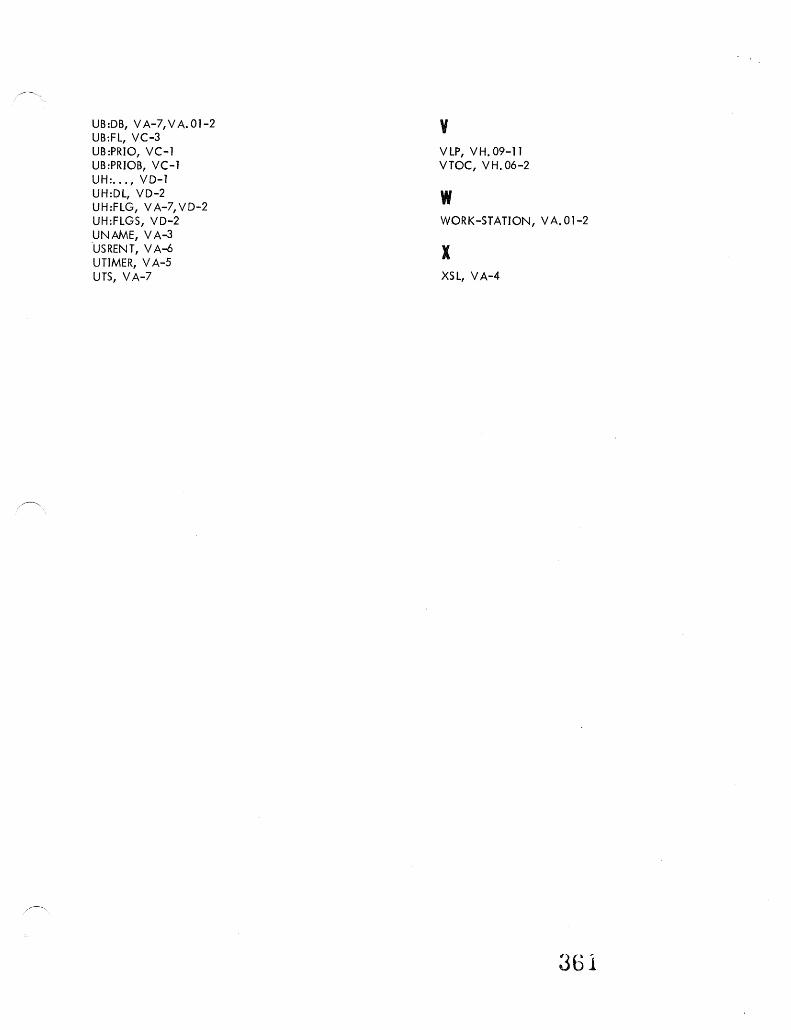
UB:DB, V A-7, V A. 01-2 UB:FL, VC-3 UB:PRIO, VC-l UB:PRIOB, VC-l UH: .•• , VD-l UH:DL, VD-2 UH:FLG, VA-7, VD-2 UH:FLGS, VD-2 UNAME, VA-3 -USRENT, V A-6 UTIMER, V A-5 UTS, VA-7
v VLP, VH.09-11 VTOC, VH.06-2
w WORK-STATION, VA.01-2
x XSL, VA-4
361