
X-STREAM Instruction Manual - 11th Ed. - Emerson
436
www.EmersonProcess.com Instruction Manual HASX2E-IM-HS 10/2012 Gas Analyzers X-STREAM X2 Series Instruction Manual
-
Upload
khangminh22 -
Category
Documents
-
view
0 -
download
0
Transcript of X-STREAM Instruction Manual - 11th Ed. - Emerson

www.EmersonProcess.com
Instruction ManualHASX2E-IM-HS10/2012
Gas Analyzers X-STREAM X2 Series
Instruction Manual

ESSENTIAL INSTRUCTIONSREAD THIS PAGE BEFORE PROCEEDING!
Emerson Process Management (Rosemount Analytical) designs, manufactures and tests its products to meet many national and international standards. Because these instruments are sophisticated technical products, you MUST properly install, use, and maintain them to ensure they continue to operate within their normal specifications. The following instructions MUST be adhered to and integrated into your safety program when installing, using and maintaining Emerson Process Management (Rosemount Analytical) products. Failure to follow the proper instructions may cause any one of the following situations to occur: Loss of life; personal injury; property damage; damage to this instrument; and warranty invalidation.
• Read all instructions prior to installing, operating, and servicing the product.
• If you do not understand any of the instructions, contact your Emerson Process Management (Rosemount Analytical) representative for clarification.
• Follow all warnings, cautions, and instructions marked on and supplied with the product.
• Inform and educate your personnel in the proper installation, operation, and maintenance of the product.
• Install your equipment as specified in the Installation Instructions of the appropriate Instruction Manual and per applicable local and national codes. Connect all products to the proper electrical and pressure sources.
• To ensure proper performance, use qualified personnel to install, operate, update, program, and maintain the product.
• When replacement parts are required, ensure that qualified people use replacement parts specified by Emerson Process Management (Rosemount Analytical). Unauthorized parts and procedures can affect the product’s performance, place the safe operation of your process at risk, and VOID YOUR WARRANTY. Look-alike substitutions may result in fire, electrical hazards, or improper operation.
• Ensure that all equipment doors are closed and protective covers are in place, except when maintenance is being performed by qualified persons, to prevent electrical shock and personal injury.
The information contained in this document is subject to change without notice.
11th edition, 10/2012 X-STREAM and IntrinzX are marks of one of the Emerson group of companies.
All other marks are property of their respective owners.
Rosemount Analytical Process Gas Analyzer Center of Excellence Emerson Process Management GmbH & Co. OHGIndustriestrasse 1D-63594 Hasselroth DeutschlandT +49 (0) 6055 884-0F +49 (0) 6055 884-209www.emersonprocess.de

Emerson Process Management GmbH & Co. OHG TOC-1
X-STREAM X2Instruction ManualHASX2E-IM-HS10/2012
TOC
Tabl
e of
con
tent
s
SHORT FORM GUIDE FOR THIS MANUAL
To find information about see chapter
Safety instructions ..................................................... S
The different instruments designs .............................1
The instruments technical data ..................................2
Measuring principles characteristics ........................3
How to install the instruments ...................................4
1st startup procedures, checking the instrument´s setup ..............................5
Software menu structure, how to navigate and menu entries descriptions ..................................6
Basic procedures (e.g. calibration) ............................7
Maintenance procedures ............................................7
Status messages and troubleshooting .....................8
Modbus parameters ...................................................9
Service information ....................................................10
Block diagrams, terminals & connectors ................. A
Index of phrases ........................................................IDX

Emerson Process Management GmbH & Co. OHGTOC-2
X-STREAM X2Instruction Manual
HASX2E-IM-HS10/2012
Table of ConTenTs
Introduction S-1Definitions S-1Terms Used in This Instruction Manual . . . . . . . . . . . . . . . . . . . . . . . . . . . . . . . . . . . . . . . . . S-2Symbols Used on and Inside the Unit . . . . . . . . . . . . . . . . . . . . . . . . . . . . . . . . . . . . . . . . . . S-3Symbols Used in This Manual . . . . . . . . . . . . . . . . . . . . . . . . . . . . . . . . . . . . . . . . . . . . . . . . S-4
Safety Instructions S-5Intended Use Statement. . . . . . . . . . . . . . . . . . . . . . . . . . . . . . . . . . . . . . . . . . . . . . . . . . . . . S-5General Safety Notice / Residual Risk . . . . . . . . . . . . . . . . . . . . . . . . . . . . . . . . . . . . . . . . . . S-5Authorized Personnel . . . . . . . . . . . . . . . . . . . . . . . . . . . . . . . . . . . . . . . . . . . . . . . . . . . . . . . S-6Additional Literature . . . . . . . . . . . . . . . . . . . . . . . . . . . . . . . . . . . . . . . . . . . . . . . . . . . . . . . . S-6Installing and Connecting the Unit . . . . . . . . . . . . . . . . . . . . . . . . . . . . . . . . . . . . . . . . . . . . . S-7Operating and Maintaining This Unit . . . . . . . . . . . . . . . . . . . . . . . . . . . . . . . . . . . . . . . . . . . S-7
Chapter 1 Technical Description 1-11.1 Overview . . . . . . . . . . . . . . . . . . . . . . . . . . . . . . . . . . . . . . . . . . . . . . . . . . . . . . . . . . . . .1-31.1.1 The Front Panel. . . . . . . . . . . . . . . . . . . . . . . . . . . . . . . . . . . . . . . . . . . . . . . . . . . . . . .1-31.2 Configuration of Gas Lines . . . . . . . . . . . . . . . . . . . . . . . . . . . . . . . . . . . . . . . . . . . . . . .1-41.2.1 Materials Used . . . . . . . . . . . . . . . . . . . . . . . . . . . . . . . . . . . . . . . . . . . . . . . . . . . . . . .1-41.2.2 Safety Filter . . . . . . . . . . . . . . . . . . . . . . . . . . . . . . . . . . . . . . . . . . . . . . . . . . . . . . . . . .1-41.2.3 Inlets and Outlets . . . . . . . . . . . . . . . . . . . . . . . . . . . . . . . . . . . . . . . . . . . . . . . . . . . . .1-41.2.4 Pipework . . . . . . . . . . . . . . . . . . . . . . . . . . . . . . . . . . . . . . . . . . . . . . . . . . . . . . . . . . . .1-41.2.5 Infallible Containments . . . . . . . . . . . . . . . . . . . . . . . . . . . . . . . . . . . . . . . . . . . . . . . . .1-41.2.6 Optional Components for Gas Lines . . . . . . . . . . . . . . . . . . . . . . . . . . . . . . . . . . . . . . .1-51.2.7 Configurations . . . . . . . . . . . . . . . . . . . . . . . . . . . . . . . . . . . . . . . . . . . . . . . . . . . . . . . .1-81.3 Interfaces . . . . . . . . . . . . . . . . . . . . . . . . . . . . . . . . . . . . . . . . . . . . . . . . . . . . . . . . . . . . .1-91.3.1 Analog Outputs . . . . . . . . . . . . . . . . . . . . . . . . . . . . . . . . . . . . . . . . . . . . . . . . . . . . . . .1-91.3.2 Status Relays . . . . . . . . . . . . . . . . . . . . . . . . . . . . . . . . . . . . . . . . . . . . . . . . . . . . . . . .1-91.3.3 Optional Interfaces . . . . . . . . . . . . . . . . . . . . . . . . . . . . . . . . . . . . . . . . . . . . . . . . . . .1-101.4 Comparison of the Various X-STREAM X2 Analyzer Models . . . . . . . . . . . . . . . . . . . .1-121.5 X-STREAM X2GK: ½19 Inch Table-Top Unit . . . . . . . . . . . . . . . . . . . . . . . . . . . . . . . . .1-141.6 X-STREAM X2GP: 19 Inch Table-Top or Rackmount Design . . . . . . . . . . . . . . . . . . . .1-171.7 X-STREAM X2XF: Field Housing With (XLF) Single Or (XXF) Dual Compartment. . . .1-201.7.1 Field Housing for Installation in Hazardous Areas (Ex-Zones / Divisons) . . . . . . . . . .1-261.8 X-STREAM X2FD: Cast Aluminum Flameproof Housing. . . . . . . . . . . . . . . . . . . . . . . .1-27
Chapter 2 Technical Data 2-12.1 Common Technical Data . . . . . . . . . . . . . . . . . . . . . . . . . . . . . . . . . . . . . . . . . . . . . . . . .2-22.2 Model-Specific Technical Data. . . . . . . . . . . . . . . . . . . . . . . . . . . . . . . . . . . . . . . . . . . . .2-5

Emerson Process Management GmbH & Co. OHG TOC-3
X-STREAM X2Instruction ManualHASX2E-IM-HS10/2012
TOC
Tabl
e of
con
tent
s
Table of Contents
2.2.1 X-STREAM X2GK: ½19 Inch Table-Top Unit. . . . . . . . . . . . . . . . . . . . . . . . . . . . . . . . .2-52.2.2 X-STREAM X2GP: 19 Inch Table-Top and Rack-Mount Models . . . . . . . . . . . . . . . .2-122.2.3 X-STREAM X2XF: Single (XLF) or Dual (XXF) Compartment Field Housing . . . . . . .2-152.2.4 X-STREAM X2FD: Flameproof Housing . . . . . . . . . . . . . . . . . . . . . . . . . . . . . . . . . . .2-192.3 Information on Name Plate . . . . . . . . . . . . . . . . . . . . . . . . . . . . . . . . . . . . . . . . . . . . . .2-22
Chapter 3 Measuring Principles 3-13.1 Infrared Measurement (IR), Ultraviolet Measurement (UV) . . . . . . . . . . . . . . . . . . . . . . .3-13.1.1 IntrinzX Technology . . . . . . . . . . . . . . . . . . . . . . . . . . . . . . . . . . . . . . . . . . . . . . . . . . . .3-13.1.2 NDIR Detector . . . . . . . . . . . . . . . . . . . . . . . . . . . . . . . . . . . . . . . . . . . . . . . . . . . . . . . .3-33.1.3 Technical Implementation . . . . . . . . . . . . . . . . . . . . . . . . . . . . . . . . . . . . . . . . . . . . . . .3-43.2 Oxygen Measurement . . . . . . . . . . . . . . . . . . . . . . . . . . . . . . . . . . . . . . . . . . . . . . . . . . .3-53.2.1 Paramagnetic Measurement . . . . . . . . . . . . . . . . . . . . . . . . . . . . . . . . . . . . . . . . . . . . .3-53.2.2 Electrochemical Measurement . . . . . . . . . . . . . . . . . . . . . . . . . . . . . . . . . . . . . . . . . . .3-83.2.3 Electrochemical Trace Oxygen Measurement. . . . . . . . . . . . . . . . . . . . . . . . . . . . . . .3-113.3 Thermal Conductivity Measurement . . . . . . . . . . . . . . . . . . . . . . . . . . . . . . . . . . . . . . .3-133.3.1 Principle of Operation . . . . . . . . . . . . . . . . . . . . . . . . . . . . . . . . . . . . . . . . . . . . . . . . .3-133.3.2 Technical Implementation . . . . . . . . . . . . . . . . . . . . . . . . . . . . . . . . . . . . . . . . . . . . . .3-143.4 Trace Moisture Measurement . . . . . . . . . . . . . . . . . . . . . . . . . . . . . . . . . . . . . . . . . . . .3-153.4.1 Special Operating Conditions . . . . . . . . . . . . . . . . . . . . . . . . . . . . . . . . . . . . . . . . . . .3-163.4.2 Accompanying Gases . . . . . . . . . . . . . . . . . . . . . . . . . . . . . . . . . . . . . . . . . . . . . . . . .3-173.5 Measurement Specifications . . . . . . . . . . . . . . . . . . . . . . . . . . . . . . . . . . . . . . . . . . . . .3-19
Chapter 4 Installation 4-14.1 Scope of Supply. . . . . . . . . . . . . . . . . . . . . . . . . . . . . . . . . . . . . . . . . . . . . . . . . . . . . . . .4-14.2 Introduction . . . . . . . . . . . . . . . . . . . . . . . . . . . . . . . . . . . . . . . . . . . . . . . . . . . . . . . . . . .4-24.3 Gas Conditioning . . . . . . . . . . . . . . . . . . . . . . . . . . . . . . . . . . . . . . . . . . . . . . . . . . . . . . .4-34.4 Gas Connections . . . . . . . . . . . . . . . . . . . . . . . . . . . . . . . . . . . . . . . . . . . . . . . . . . . . . . .4-54.5 Electrical Connections . . . . . . . . . . . . . . . . . . . . . . . . . . . . . . . . . . . . . . . . . . . . . . . . . . .4-74.6 Analyzer Specific Instructions for Installation. . . . . . . . . . . . . . . . . . . . . . . . . . . . . . . . . .4-84.6.1 X-STREAM X2GK . . . . . . . . . . . . . . . . . . . . . . . . . . . . . . . . . . . . . . . . . . . . . . . . . . . . .4-94.6.2 X-STREAM X2GP . . . . . . . . . . . . . . . . . . . . . . . . . . . . . . . . . . . . . . . . . . . . . . . . . . . .4-154.6.3 X-STREAM X2XF Field Housings (single XLF; Dual XXF) . . . . . . . . . . . . . . . . . . . . .4-234.7 Notes On Wiring Signal Inputs and Outputs . . . . . . . . . . . . . . . . . . . . . . . . . . . . . . . . .4-344.7.1 Electrical Shielding of Cables . . . . . . . . . . . . . . . . . . . . . . . . . . . . . . . . . . . . . . . . . . .4-344.7.2 Wiring Inductive Loads . . . . . . . . . . . . . . . . . . . . . . . . . . . . . . . . . . . . . . . . . . . . . . . .4-374.7.3 Driving High-Current Loads. . . . . . . . . . . . . . . . . . . . . . . . . . . . . . . . . . . . . . . . . . . . .4-374.7.4 Driving Multiple Loads . . . . . . . . . . . . . . . . . . . . . . . . . . . . . . . . . . . . . . . . . . . . . . . . .4-38
Chapter 5 Startup 5-15.1 Introduction . . . . . . . . . . . . . . . . . . . . . . . . . . . . . . . . . . . . . . . . . . . . . . . . . . . . . . . . . . .5-1

Emerson Process Management GmbH & Co. OHGTOC-4
X-STREAM X2Instruction Manual
HASX2E-IM-HS10/2012
Table of Contents
5.2 Front Panel Elements . . . . . . . . . . . . . . . . . . . . . . . . . . . . . . . . . . . . . . . . . . . . . . . . . . .5-25.2.1 Display. . . . . . . . . . . . . . . . . . . . . . . . . . . . . . . . . . . . . . . . . . . . . . . . . . . . . . . . . . . . . .5-35.2.2 Status LED . . . . . . . . . . . . . . . . . . . . . . . . . . . . . . . . . . . . . . . . . . . . . . . . . . . . . . . . . .5-35.2.3 Keys . . . . . . . . . . . . . . . . . . . . . . . . . . . . . . . . . . . . . . . . . . . . . . . . . . . . . . . . . . . . . .5-45.3 Symbols Used . . . . . . . . . . . . . . . . . . . . . . . . . . . . . . . . . . . . . . . . . . . . . . . . . . . . . . . . .5-65.4 Software. . . . . . . . . . . . . . . . . . . . . . . . . . . . . . . . . . . . . . . . . . . . . . . . . . . . . . . . . . . . . .5-75.4.1 Navigating and Editing . . . . . . . . . . . . . . . . . . . . . . . . . . . . . . . . . . . . . . . . . . . . . . . . .5-75.4.2 Access Levels . . . . . . . . . . . . . . . . . . . . . . . . . . . . . . . . . . . . . . . . . . . . . . . . . . . . . . . .5-95.4.3 Special Messages . . . . . . . . . . . . . . . . . . . . . . . . . . . . . . . . . . . . . . . . . . . . . . . . . . . .5-105.5 Powering Up . . . . . . . . . . . . . . . . . . . . . . . . . . . . . . . . . . . . . . . . . . . . . . . . . . . . . . . . .5-115.5.1 Boot Sequence . . . . . . . . . . . . . . . . . . . . . . . . . . . . . . . . . . . . . . . . . . . . . . . . . . . . . .5-115.5.2 Measurement Display . . . . . . . . . . . . . . . . . . . . . . . . . . . . . . . . . . . . . . . . . . . . . . . . .5-115.6 Selecting the Language . . . . . . . . . . . . . . . . . . . . . . . . . . . . . . . . . . . . . . . . . . . . . . . . .5-125.7 Checking the Settings . . . . . . . . . . . . . . . . . . . . . . . . . . . . . . . . . . . . . . . . . . . . . . . . . .5-135.7.1 Installed Options . . . . . . . . . . . . . . . . . . . . . . . . . . . . . . . . . . . . . . . . . . . . . . . . . . . . .5-145.7.2 Configuring the Display . . . . . . . . . . . . . . . . . . . . . . . . . . . . . . . . . . . . . . . . . . . . . . . .5-165.7.3 Calibration Setup. . . . . . . . . . . . . . . . . . . . . . . . . . . . . . . . . . . . . . . . . . . . . . . . . . . . .5-175.7.4 Setting the Analog Outputs . . . . . . . . . . . . . . . . . . . . . . . . . . . . . . . . . . . . . . . . . . . . .5-205.7.5 Setting Concentration Alarms . . . . . . . . . . . . . . . . . . . . . . . . . . . . . . . . . . . . . . . . . . .5-285.7.6 Backing Up the Settings . . . . . . . . . . . . . . . . . . . . . . . . . . . . . . . . . . . . . . . . . . . . . . .5-34
Chapter 6 User Interface and Software Menus 6-16.1 Symbols Used . . . . . . . . . . . . . . . . . . . . . . . . . . . . . . . . . . . . . . . . . . . . . . . . . . . . . . . . .6-26.2 Menu System. . . . . . . . . . . . . . . . . . . . . . . . . . . . . . . . . . . . . . . . . . . . . . . . . . . . . . . . . .6-36.2.1 Startup. . . . . . . . . . . . . . . . . . . . . . . . . . . . . . . . . . . . . . . . . . . . . . . . . . . . . . . . . . . . . .6-46.2.2 Control Menu. . . . . . . . . . . . . . . . . . . . . . . . . . . . . . . . . . . . . . . . . . . . . . . . . . . . . . . . .6-56.2.3 Setup Menu . . . . . . . . . . . . . . . . . . . . . . . . . . . . . . . . . . . . . . . . . . . . . . . . . . . . . . . . .6-146.2.4 Status Menu . . . . . . . . . . . . . . . . . . . . . . . . . . . . . . . . . . . . . . . . . . . . . . . . . . . . . . . .6-506.2.5 Info Menu . . . . . . . . . . . . . . . . . . . . . . . . . . . . . . . . . . . . . . . . . . . . . . . . . . . . . . . . . .6-61
Chapter 7 Maintenance and Other Procedures 7-17.1 Introduction . . . . . . . . . . . . . . . . . . . . . . . . . . . . . . . . . . . . . . . . . . . . . . . . . . . . . . . . . . .7-17.2 General Maintenance Information . . . . . . . . . . . . . . . . . . . . . . . . . . . . . . . . . . . . . . . . . .7-27.3 Performing a Leak Test . . . . . . . . . . . . . . . . . . . . . . . . . . . . . . . . . . . . . . . . . . . . . . . . . .7-47.4 Calibration Procedures . . . . . . . . . . . . . . . . . . . . . . . . . . . . . . . . . . . . . . . . . . . . . . . . . .7-57.4.1 Preparing Calibrations . . . . . . . . . . . . . . . . . . . . . . . . . . . . . . . . . . . . . . . . . . . . . . . . . .7-67.4.2 Manual Calibration . . . . . . . . . . . . . . . . . . . . . . . . . . . . . . . . . . . . . . . . . . . . . . . . . . .7-187.4.3 Advanced Calibration . . . . . . . . . . . . . . . . . . . . . . . . . . . . . . . . . . . . . . . . . . . . . . . . .7-217.4.4 Remote Calibration . . . . . . . . . . . . . . . . . . . . . . . . . . . . . . . . . . . . . . . . . . . . . . . . . . .7-327.4.5 Unattended Automatic Calibration . . . . . . . . . . . . . . . . . . . . . . . . . . . . . . . . . . . . . . . .7-37

Emerson Process Management GmbH & Co. OHG TOC-5
X-STREAM X2Instruction ManualHASX2E-IM-HS10/2012
TOC
Tabl
e of
con
tent
s
Table of Contents
7.4.6 Resetting a Calibration . . . . . . . . . . . . . . . . . . . . . . . . . . . . . . . . . . . . . . . . . . . . . . . .7-407.4.8 Cancelling an Ongoing Calibration . . . . . . . . . . . . . . . . . . . . . . . . . . . . . . . . . . . . . . .7-417.5 Replacing Worn Out Sensors . . . . . . . . . . . . . . . . . . . . . . . . . . . . . . . . . . . . . . . . . . . .7-437.5.1 Safety Instructions. . . . . . . . . . . . . . . . . . . . . . . . . . . . . . . . . . . . . . . . . . . . . . . . . . . .7-437.5.2 Opening X-STREAM Analyzers. . . . . . . . . . . . . . . . . . . . . . . . . . . . . . . . . . . . . . . . . .7-447.5.3 Replacing the Electrochemical Oxygen Sensor . . . . . . . . . . . . . . . . . . . . . . . . . . . . .7-477.5.4 Replacing the Trace Oxygen Sensor. . . . . . . . . . . . . . . . . . . . . . . . . . . . . . . . . . . . . .7-547.5.5 Replacing the Trace Moisture Sensor . . . . . . . . . . . . . . . . . . . . . . . . . . . . . . . . . . . . .7-557.6 Cleaning the Instrument´s Outside . . . . . . . . . . . . . . . . . . . . . . . . . . . . . . . . . . . . . . . .7-567.7 Save / Restore Configuration Data Sets . . . . . . . . . . . . . . . . . . . . . . . . . . . . . . . . . . . .7-577.7.1 Save CfgData to UserData . . . . . . . . . . . . . . . . . . . . . . . . . . . . . . . . . . . . . . . . . . . . .7-597.7.2 Restore UserData to CfgData . . . . . . . . . . . . . . . . . . . . . . . . . . . . . . . . . . . . . . . . . . .7-607.7.3 Copy FactData to CfgData . . . . . . . . . . . . . . . . . . . . . . . . . . . . . . . . . . . . . . . . . . . . .7-617.7.4 Save / Restore CfgData to External Device . . . . . . . . . . . . . . . . . . . . . . . . . . . . . . . .7-62
Chapter 8 Troubleshooting 8-18.1 Abstract . . . . . . . . . . . . . . . . . . . . . . . . . . . . . . . . . . . . . . . . . . . . . . . . . . . . . . . . . . . . . .8-18.2 Solving Problems Indicated by Status Messages . . . . . . . . . . . . . . . . . . . . . . . . . . . . . .8-28.2.1 Analyzer Related Messages . . . . . . . . . . . . . . . . . . . . . . . . . . . . . . . . . . . . . . . . . . . . .8-38.2.2 Channel Related Messages (preceded by Channel Tag, e.g. CO2.1) . . . . . . . . . . . . .8-68.3 Solving Problems Not Indicated by Status Messages . . . . . . . . . . . . . . . . . . . . . . . . . .8-118.4 Troubleshooting on Components . . . . . . . . . . . . . . . . . . . . . . . . . . . . . . . . . . . . . . . . . .8-178.4.1 Opening X-STREAM Analyzers . . . . . . . . . . . . . . . . . . . . . . . . . . . . . . . . . . . . . . . . .8-198.4.2 Signal Connectors on XSP Board . . . . . . . . . . . . . . . . . . . . . . . . . . . . . . . . . . . . . . . .8-218.4.3 Sample Pump: Replacement of Diaphragm . . . . . . . . . . . . . . . . . . . . . . . . . . . . . . . .8-228.4.4 Paramagnetic Oxygen Cell: Adjustment of Physical Zero . . . . . . . . . . . . . . . . . . . . . .8-338.4.5 Thermal Conductivity Cell: Adjustment of Output Signal . . . . . . . . . . . . . . . . . . . . . . .8-36
Chapter 9 Modbus Functions 9-19.1 Abstract . . . . . . . . . . . . . . . . . . . . . . . . . . . . . . . . . . . . . . . . . . . . . . . . . . . . . . . . . . . . . .9-19.1.1 Modbus TCP/IP . . . . . . . . . . . . . . . . . . . . . . . . . . . . . . . . . . . . . . . . . . . . . . . . . . . . . . .9-19.2 Supported Functions . . . . . . . . . . . . . . . . . . . . . . . . . . . . . . . . . . . . . . . . . . . . . . . . . . . .9-29.3 List of Parameters and Registers - Sorted by Tag Name. . . . . . . . . . . . . . . . . . . . . . . . .9-29.4 List of Parameters and Registers - Sorted by Daniel Registers. . . . . . . . . . . . . . . . . . .9-22
Chapter 10 Service Information 10-110.1 Return of Material . . . . . . . . . . . . . . . . . . . . . . . . . . . . . . . . . . . . . . . . . . . . . . . . . . . . .10-110.2 Customer Service . . . . . . . . . . . . . . . . . . . . . . . . . . . . . . . . . . . . . . . . . . . . . . . . . . . . .10-210.3 Training . . . . . . . . . . . . . . . . . . . . . . . . . . . . . . . . . . . . . . . . . . . . . . . . . . . . . . . . . . . . .10-2

Emerson Process Management GmbH & Co. OHGTOC-6
X-STREAM X2Instruction Manual
HASX2E-IM-HS10/2012
Table of Contents
Chapter 11 Dismounting and Disposal 11-111.1 Dismounting and Diposal of the Analyzer . . . . . . . . . . . . . . . . . . . . . . . . . . . . . . . . . . .11-1
Appendix A-1A.1 Modbus Specification. . . . . . . . . . . . . . . . . . . . . . . . . . . . . . . . . . . . . . . . . . . . . . . . . . . A-2A.2 EC Declaration of Conformity . . . . . . . . . . . . . . . . . . . . . . . . . . . . . . . . . . . . . . . . . . . A-12A.3 CSA Certificate of Compliance. . . . . . . . . . . . . . . . . . . . . . . . . . . . . . . . . . . . . . . . . . . A-14A.4 Block Diagram . . . . . . . . . . . . . . . . . . . . . . . . . . . . . . . . . . . . . . . . . . . . . . . . . . . . . . . A-21A.5 Water Vapor: Relationship of Dewpoint, Vol.-% and g/Nm³ . . . . . . . . . . . . . . . . . . . . . A-34A.6 Declaration of Decontamination. . . . . . . . . . . . . . . . . . . . . . . . . . . . . . . . . . . . . . . . . . A-35A.7 Assignment of Terminals and Sockets . . . . . . . . . . . . . . . . . . . . . . . . . . . . . . . . . . . . . A-37A.7.1 Tabletop & Rack Mount Analyzers. . . . . . . . . . . . . . . . . . . . . . . . . . . . . . . . . . . . . . . A-37A.7.2 Field Housings. . . . . . . . . . . . . . . . . . . . . . . . . . . . . . . . . . . . . . . . . . . . . . . . . . . . . . A-38
Index I-1

Emerson Process Management GmbH & Co. OHG TOC-7
X-STREAM X2Instruction ManualHASX2E-IM-HS10/2012
TOC
Tabl
e of
con
tent
s
Table of figuresFig. 1-1: X-STREAM Front Panel (here the X-STREAM X2GP) ...........................................1-3Fig. 1-2: Optional Heated Area .............................................................................................1-7Fig. 1-3: Gas Flow Diagram: Single Channel or in Series ....................................................1-8Fig. 1-4: Serial Interface Marking ........................................................................................1-10Fig. 1-5: X-STREAM X2GK - Views ....................................................................................1-16Fig. 1-6: X-STREAM X2GP - Views ....................................................................................1-19Fig. 1-7: X-STREAM X2XF Field Housings - Front Views ..................................................1-22Fig. 1-8: X-STREAM X2XF Field Housings - Front Panel ..................................................1-23Fig. 1-9: X-STREAM XLF - Bottom and Side View .............................................................1-24Fig. 1-10: X-STREAM XLF - Power Supply and Signal Terminals ........................................1-25Fig. 1-11: X-STREAM X2FD - Front View ............................................................................1-29Fig. 1-12: X-STREAM X2FD - Front Panel ...........................................................................1-30Fig. 1-13: X-STREAM X2FD - Bottom View ..........................................................................1-30Fig. 1-14: X-STREAM X2FD - Terminals ..............................................................................1-31
Fig. 2-1: X-STREAM X2GK - Dimensions ............................................................................2-5Fig. 2-2: X-STREAM X2GK - Rear Panel and Handle Variations .........................................2-6Fig. 2-3: UPS 01 T Power Supply Unit ..................................................................................2-9Fig. 2-4: 10 A Table-Top PSU ..............................................................................................2-10Fig. 2-5: X-STREAM X2GP - Dimensions ...........................................................................2-12Fig. 2-6: X-STREAM X2GP - Power Supply and Signal Connections ................................2-14Fig. 2-7: X-STREAM X2GP - Signal Connections With Screw-Type Terminal Adapters ....2-14Fig. 2-8: X-STREAM XLF - Dimensions .............................................................................2-15Fig. 2-9: X-STREAM XXF - Dimensions .............................................................................2-16Fig. 2-10: X-STREAM X2XF Field Housings - Power Supply Terminals / Fuse Holders ......2-18Fig. 2-11: X-STREAM X2XF Field Housings - Signal Terminals .........................................2-18Fig. 2-12: X-STREAM X2FD - Dimensions ...........................................................................2-19Fig. 2-13: X-STREAM X2FD - Power Supply Terminals / Fuse Holders ...............................2-20Fig. 2-14: X-STREAM X2FD - Signal Terminals ...................................................................2-21Fig. 2-15: Analyzer Name Plate (examples) .........................................................................2-22
Fig. 3-1: IntrinzX Signal Forms .............................................................................................3-2Fig. 3-2: Gas Detector Design Principle ...............................................................................3-3Fig. 3-3: Photometer Assembly Principle ..............................................................................3-4Fig. 3-4: Paramagnetic Oxygen Sensor - Assembly Principle ..............................................3-5Fig. 3-5: Electrochemical Sensor - Internal Assembly Principle ...........................................3-8Fig. 3-6: Electrochemical O2 Sensor - Assembly ..................................................................3-8Fig. 3-7: Electrochemical Reaction of Oxygen Sensor .........................................................3-9

Emerson Process Management GmbH & Co. OHGTOC-8
X-STREAM X2Instruction Manual
HASX2E-IM-HS10/2012
Index of Figures
Fig. 3.8 Cover for EO2 Sensor Block At Rear Panel .........................................................3-10Fig. 3.9 Trace Oxygen Sensor Design Principle ................................................................3-11Fig. 3.10 Cover for TO2 Sensor Block At Rear Panel ..........................................................3-12Fig. 3-11: Wheatstone Bridge ...............................................................................................3-13Fig. 3-12: TC Cell, Exterior View, Thermal Isolation Removed .............................................3-14Fig. 3-13: TC Cell, Sectional View ........................................................................................3-14Fig. 3-14: Trace Moisture Sensor Assembly .........................................................................3-15
Fig. 4-1: X-STREAM X2 Analyzers - Scope of Supply ..........................................................4-1Fig. 4-2: Labelling of Gas Connectors (example) .................................................................4-6Fig. 4-3: Installation in Bypass Mode ....................................................................................4-6 Fig. 4-4: X-STREAM X2GK - Front Panel .............................................................................4-9Fig. 4-5: X-STREAM X2GK - Rear Panel ...........................................................................4-10Fig. 4-6: Socket X1 - Pin Configuration ..............................................................................4-11Fig. 4-7: Plug X2 - Modbus Interface ..................................................................................4-12Fig. 4-8: Socket X4 - Pin Configuration .............................................................................4-13Fig. 4-9: Power In Connectors ............................................................................................4-14Fig. 4-10: X-STREAM X2GP - Front View ............................................................................4-15Fig. 4-11: X-STREAM X2GP - Rear Panel, Model With Signal Plugs and Sockets..............4-16Fig. 4-12: X-STREAM X2GP - Rear Panel, With Terminal Adapters and Brackets ..............4-17Fig. 4-13: Socket X1 - Analog & Digital Outputs 1–4 ...........................................................4-18Fig. 4-14: Plug X2 - Modbus Interface ..................................................................................4-19Fig. 4-15: Configuration of XSTA Terminal Adapter ..............................................................4-20Fig. 4-16: Sockets X4.1 and X4.2 - Pin Configuration .........................................................4-21Fig. 4-17: Configuration of XSTD Terminal Adapter ..............................................................4-22Fig. 4-18: X-STREAM XLF ..................................................................................................4-23Fig. 4-19: X-STREAM XXF ..................................................................................................4-24Fig. 4-20: X-STREAM X2XF Field Housings - Terminals, Cable Glands and Gas Fittings ...4-25Fig. 4-21: Terminal Block X1 - Analog Signals and Relay Outputs 1–4 ...............................4-28Fig. 4-22: Terminal Block X1 - Modbus Interface ..................................................................4-29Fig. 4-23: X-STREAM X2XF Field Housings - Ethernet Connector ......................................4-30Fig. 4-24: Terminal Blocks for Digital Inputs and Outputs .....................................................4-31Fig. 4-25: Power Supply Connections ..................................................................................4-32Fig. 4-26: Shielded Signal Cable, Shielding Connected At Both Ends. ................................4-34Fig. 4-27: Shielded Signal Cable, Shielding Connected At One end. ...................................4-35Fig. 4-28: Signal Cable With Double Shielding, Shieldings Connected At Alternate Ends. ..4-35Fig. 4-29: Shield Connector Terminal With Cable .................................................................4-36Fig. 4-30: Suppressor Diode for Inductive Loads. ................................................................4-37Fig. 4-31: Driving High-Current Loads ..................................................................................4-37

Emerson Process Management GmbH & Co. OHG TOC-9
X-STREAM X2Instruction ManualHASX2E-IM-HS10/2012
TOC
Tabl
e of
con
tent
s
Index of Figures
Fig. 4-32: Loads in Series .....................................................................................................4-38Fig. 4-33: Loads in Parallel ...................................................................................................4-38
Fig. 5-1: X-STREAM Front Panel .........................................................................................5-2Fig. 5-2: Limits Defining a Window for Valid Concentrations ..............................................5-31Fig. 5-3: High Pre-Alarm and Main Alarm ...........................................................................5-32Fig. 5-4: Low Pre-Alarm and Main Alarm ............................................................................5-33Fig. 6-1: X-STREAM Software Menu Structure ....................................................................6-3
Fig. 7-1: Leak Testing With U-Turn Manometer ....................................................................7-4Fig. 7-2: Calibration Improvement by Variable Valve Assignments .....................................7-10Fig. 7-3: Internal Valves Assignments .................................................................................7-13Fig. 7-4: Zero All Calibration Procedure Flow Chart ...........................................................7-23Fig. 7-5: Span All Calibration Procedure Flow Diagram .....................................................7-26Fig. 7-6: Zero Span All Calibration Procedure Flow Diagram .............................................7-29Fig. 7-7: Digital Inputs - Initializing Calibrations ..................................................................7-34Fig. 7-8: Graphical Explanation of Interval Time Settings ...................................................7-38Fig. 7-9: X-STREAM X2GP .................................................................................................7-44 Fig. 7-10: X-STREAM X2GK ................................................................................................7-44Fig. 7-11: X-STREAM X2 Field Housings and X2FD - How to Open ...................................7-45Fig. 7-12: Location of the EO2 Sensor Unit ..........................................................................7-50Fig. 7-13: Sensor Unit Design ...............................................................................................7-51Fig. 7-14: Sensor At Rear Panel ...........................................................................................7-52Fig. 7-15: OXS Board, Top View ...........................................................................................7-52Fig. 7-16: Trace Moisture Sensor Assembly Separated .......................................................7-55Fig. 7-17: Relationship of Supported Data Sets and Where to Find Further Information .....7-58Fig. 7-18: Service Port Connector - Serial RS 232 Interface ................................................7-62
Fig. 8-1: X-STREAM X2GP .................................................................................................8-19Fig. 8-2: X-STREAM X2GK ................................................................................................8-19Fig. 8-3: X-STREAM X2 Field Housings and X2FD - How to Open ...................................8-20Fig. 8-4: XSP - Allocation of Signal Connectors..................................................................8-21

Emerson Process Management GmbH & Co. OHGTOC-10
X-STREAM X2Instruction Manual
HASX2E-IM-HS10/2012
index of TablesTab. 3-1: Paramagnetic Sensor - Cross Interferences (examples) . . . . . . . . . . . . . . . . . . . . . 3-6Tab. 3-2: Solvent Resistant Paramagnetic Sensor - Approved Solvents . . . . . . . . . . . . . . . 3-7Tab. 3-3: Solvent Resistant Paramagnetic Sensor - Medium Affected Materials . . . . . . . . 3-7Tab. 3-4: Electrochemical Oxygen Measurement - Cross Interferences . . . . . . . . . . . . . . .3-10Tab. 3-5: Examples of Specific Thermal Conductivities . . . . . . . . . . . . . . . . . . . . . . . . . . . 3-13Tab. 3-6: Dew Points and Water Content (at 1013 hPa) . . . . . . . . . . . . . . . . . . . . . . . . . . 3-16Tab. 3-7: Limitations on Gases . . . . . . . . . . . . . . . . . . . . . . . . . . . . . . . . . . . . . . . . . . . . . . 3-17Tab. 3-8: Gas Components and Measuring Ranges, Examples . . . . . . . . . . . . . . . . . . . . 3-19Tab. 3-9: IR, UV, VIS, TCD - Measurement Performance Specifications . . . . . . . . . . . . . . 3-20Tab. 3-10: Oxygen - Standard Measurement Performance Specifications . . . . . . . . . . . . . 3-21Tab. 3-11: Trace Moisture - Standard Measurement Performance Specifications . . . . . . . . 3-22Tab. 3-12: Special Performance Specifications for Gas Purity Measurements . . . . . . . . . . 3-22
Tab. 5-1: Analog Output Signals: Settings and Operational Modes . . . . . . . . . . . . . . . . . . 5-21Tab. 5-2: Analog Outputs - Scaling (examples) . . . . . . . . . . . . . . . . . . . . . . . . . . . . . . . . . 5-27Tab. 5-3: Influence of “SpanRange” Parameter on Concentration Alarm Limits . . . . . . . . 5-29
Tab. 6-1: Analog Output Signals - Settings and Operational Modes . . . . . . . . . . . . . . . . . 6-32Tab. 6-2: Options for Digital Outputs . . . . . . . . . . . . . . . . . . . . . . . . . . . . . . . . . . . . . . . . . 6-38Tab. 6-3: Options for Digital Inputs . . . . . . . . . . . . . . . . . . . . . . . . . . . . . . . . . . . . . . . . . . . 6-40Tab. 6-4: Parameter IntSHS Options . . . . . . . . . . . . . . . . . . . . . . . . . . . . . . . . . . . . . . . . . 6-42
Tab. 7-1: Digital Inputs Priorities . . . . . . . . . . . . . . . . . . . . . . . . . . . . . . . . . . . . . . . . . . . . 7-33

Emerson Process Management GmbH & Co. OHG S-1
X-STREAM X2 Instruction ManualHASX2E-IM-HS10/2012
SS
afet
y In
stru
ctio
ns
The instruction manual contains information about the component assembly, function, installation, operation and maintenance of the X-STREAM® X2 series gas analyzers.The manual covers several X-STREAM analyzer models and so many contain information about configurations and/or options not appliccable to your analyzer.The installation and operation of units for use in explosive environments is not covered in this manual. Analyzers intended to be used in such environments are supplied with further instruction manuals, which should be consulted in addition to this.
INTRODUCTION
The following definitions explain the use of the terms WARNING, CAUTION and NOTE in this manual.
DEFINITIONS
Indicates an operational or maintenance procedure, a process, a condition, an instruction, etc. Failure to comply may result in injury, death or permanent health risk.
NOTE!Indicates an imperative operational procedure,
or an important condition or instruction.
Indicates an operational or maintenance procedure, a process, a condition, an instruction, etc.Failure to comply may result in damage to or destruction of the instrument, or impaired performance.

Emerson Process Management GmbH & Co. OHGS-2
X-STREAM X2Instruction Manual
HASX2E-IM-HS10/2012
TERMS USED IN THIS INSTRUCTION MANUAL
Lower Explosion Limit (LEL)Volume ratio of flammable gas in air below which an explosive gas atmosphere will not be formed: the mixture of gas and air lacks sufficient fuel (gas) to burn.
Upper Explosion Limit (UEL)Volume ratio of flammable gas in air above which an explosive gas atmosphere will not be formed: the mixture of gas and air is too rich in fuel (deficient in oxygen) to burn.
Flammable Gas(es)Gases and gas mixtures are assigned to be flammable if they might become ignitable when in a mixture with air.
Explosive Gas(es)Flammable Gases and gas mixtures in a mix-ture with air within the explosive limits.
Intrinsically Safe Cell (IS Cell)Cells supplied with an intrinsically safe power signal, approved by a Test Institute, to operate with explosive gases.The design ensures the IS cells remains safe even in case of failure and explosive gases are not ignited.
Infallible ContainmentThis term is derived from the standards of explosion protection especially from the re-quirements for pressurized housings: thus an infallible containment can be characterized by no intended leakage into the gas paths enabling gas to enter the inner compartment of the analyzer housing.
NAMURNAMUR is an international user association of automation technology in process industries. This organisation has issued experience re-ports and working documents, called recom-mendations (NE) and worksheets (NA).
Protection Class IP66 / NEMA 4XBoth terms are used to specify conditions for equipment to be installed outdoor.IP stands for Ingress Protection, the first num-ber specifies protection against solid objects (6. = dust tight) while the second number specifies the degree of protection against liquids (.6 = heavy seas).NEMA stands for National Electrical Manuf-acturers Association. 4X specifies a degree of protection to personnel against incidental contact with the enclosed equipment; to pro-vide a degree of protection against falling dirt, rain, sleet, snow, windblown dust, splashing water, and hose-directed water; and that will be undamaged by the external formation of ice on the enclosure

Emerson Process Management GmbH & Co. OHG S-3
X-STREAM X2 Instruction ManualHASX2E-IM-HS10/2012
SS
afet
y In
stru
ctio
ns
SYMBOLS USED ON AND INSIDE THE UNIT
This symbol at the instrument ... ... means
dangerous voltages may be accessible. Remo-ving covers is permitted only, if the instrument is disconnected from power - and even in this case by qualified personnel only!hot surfaces may be accessible. Removing covers by qualified personnel is permitted only, if the instrument is disconnected from power. Nevertheless several surfaces may remain hot for a limited time.
more detailled information available: see in-struction manual before proceeding!
more detailled information available: see in-struction manual before proceeding!
Wherever one or more of the following symbols appear on or inside the instrument, be careful and read the instructions given in the accompanying manuals!Strictly observe the given warnings, instructions and information to minimize hazards!

Emerson Process Management GmbH & Co. OHGS-4
X-STREAM X2Instruction Manual
HASX2E-IM-HS10/2012
This symbol used in the manual ... ... means
dangerous voltages may be exposed
hot surfaces may be exposed
possible danger of explosion
toxic substances may be present
substances harmful to health may be present
indicates notes relating to heavy instruments
electrical components may be destroyed by electrostatic discharges
units must be disconnected from the power source
indicates special instructions or information for operation at low temperatures.
indicates basic conditions or procedures are being described.This symbol may also indicate information impor-tant for achieving accurate measurements.
SYMBOLS USED IN THIS MANUAL
Wherever one or more of the following symbols are used in this instruction manual, read the accompanying information and instructions carefully.
Follow these warnings and notes carefully to minimize risk.

Emerson Process Management GmbH & Co. OHG S-5
X-STREAM X2 Instruction ManualHASX2E-IM-HS10/2012
SS
afet
y In
stru
ctio
nsINTENDED USE STATEMENTX-STREAM series gas analyzers are intended to be used as analyzers for industrial pur-poses. They must not be used in medical, diagnostic or life support applications nor as safety devices. Using X-STREAM XE analyzers as safety devices, requiring redundant design or SIL clas-sification, is also not permitted.No independent agency certifications or approvals are to be implied as covering such applications!
GENERAL SAFETY NOTICE / RESIDUAL RISKIf this equipment is used in a manner not specified in these instructions, protective sy-stems may be impaired. Despite of incoming goods inspections, production control, routine tests and application of state-of-the-art measuring and test methods, an element of risk remains when operating a gas analyzer! Even when operated as intended and observing all applicable safety instructions some residual risks remain, including, but not limited to, the following:• An interruption of the protective earth line, e.g. in an extension cable, may result in risk
to the user.• Live parts are accessible when operating the instrument with doors open or covers
removed.• The emission of gases hazardous to health may even be possible when all gas connec-
tions have been correctly made.Avoid exposure to the dangers of these residual risks by taking particular care when ins-talling, operating, maintaining and servicing the analyzer.
SAFETY INSTRUCTIONS

Emerson Process Management GmbH & Co. OHGS-6
X-STREAM X2Instruction Manual
HASX2E-IM-HS10/2012
AUTHORIZED PERSONNEL
In-depth specialist knowledge is an absolutely necessary condition for working with and on the analyzer.
Authorized personnel for installing, operating, servicing and maintaining the analyzer are instructed and trained qualified personnel of the operating company and the manufac-turer.
It is the responsibility of the operating company to• train staff,• observe safety regulations,• follow the instruction manual.
Operators must• have been trained,• have read and understood all relevant sections of the instruction manual before
commencing work,• know the safety mechanisms and regulations.
To avoid personal injury and loss of property, do not install, operate, maintain or service this instrument before reading and understanding this instruction manual and receiving appropriate training.
Safety Instructions
ADDITIONAL LITERATUREThis manual covers aspects important for installation and startup of X-STREAM X2 gas analyzers.For comprehensive information on operating and maintain/service the instrument in a safe manner it is MANDATORY to read all additional instruction manuals! If not provided as printed version, check for a accompanying USB stick with an electronic version (PDF)!The following additional instruction manuals are available or referenced within this manual:• HASX2E-SFM-HS X-STREAM X2 short form manual• HASICx-IM-H Infallible containment instruction manual• Separate manuals for Hazardous Area applications
Contact your local service center or sales office when missing documents. SAVE ALL INSTRUCTIONS FOR FUTURE USE!

Emerson Process Management GmbH & Co. OHG S-7
X-STREAM X2 Instruction ManualHASX2E-IM-HS10/2012
SS
afet
y In
stru
ctio
nsINSTALLING AND CONNECTING THE UNIT
The following notices should be carefollowed to ensure compliance with the low voltage directive.1. Suitable grounding connections should be made at all connectors provided for this purpose.2. All safety covers and grounding connections must be properly reinstated after maintenance
work or troubleshooting. 3. A fuse should be provided at the installation site which will completely disconnect the unit
in case of failure. Installing an isolating switch may also be beneficial. In either case, these components must be constructed to conform to recognised norms.
OPERATING AND MAINTAINING THIS UNITOn leaving our factory, this instrument confor-med to all applicable safety directives.In order to preserve this state of affairs, the operator must take care to follow all the in-structions and notes given in this manual and on the unit.
Before switching on the unit, ensure that the local nominal mains voltage corresponds to the factory-set operational voltage of this unit.
Any interruption of the protective earth con-nections, whether inside or outside of the unit, may result in exposure to the risk of electricity. Deliberately disconnected the protective earth is therefore strictly forbidden.
Removing covers may expose components conducting electric current. Connectors may also be energised. The unit should therefore be disconnected from the power supply before any kind of maintenance, repair or calibration work requiring access to the inside of the unit.
Only trained personnel who are aware of the risk involved may work on an open and energized unit.
Fuses may only be replaced by fuses of an identical type and with identical ratings. It is forbidden to use repair fuses or to bypass fuses.Take note of all applicable regulations when using this unit with an autotransformer or a variable transformer.
Substances hazardous to health may escape from the unit’s gas outlet. This may require additional steps to be taken to guarantee the safety of operating staff.
Safety Instructions

Emerson Process Management GmbH & Co. OHGS-8
X-STREAM X2Instruction Manual
HASX2E-IM-HS10/2012
Safety Instructions
EXPLOSION HAZARDThe units described in this manual may not be used in explosive atmospheres without additional safety measures.
ELECTRICAL SHOCK HAZARD Do not operate without covers secure. Do not open while energized. Installation requires access to live parts which can cause death or serious injury.For safety and proper performace this instrument must be connected to a properly grounded three-wire source of power.

Emerson Process Management GmbH & Co. OHG S-9
X-STREAM X2 Instruction ManualHASX2E-IM-HS10/2012
SS
afet
y In
stru
ctio
ns
TOXIC GASESThis unit’s exhaust may contain toxic gases such as (but not limited to) e.g. sulfur dioxide. These gases can cause serious injuries. Avoid inhaling exhaust gases.Connect the exhaust pipe to a suitable flue and inspect the pipes regularly for leaks. All connections must be airtight to avoid leaks. See section 7.2, page 7-2 for instructions on performing a leak test.
HIGH TEMPERATURESHot parts may be exposed when working on photometers and/or heated components in the unit.
Safety Instructions
HEAVY INSTRUMENTThe models intended for outside and wall mounted use (X-STREAM XLF, XXF and X2FD) weigh between 26 kg (57 lb) and 63 kg (139 lb), depending on version and options installed.Two people and/or lifting equipment is required to lift and carry these units.Take care to use anchors and bolts specified to be used for the weight of the units!Take care the wall or stand the unit is intended to be installed at is solid and stable to support the weight!
Emerson Process Management GmbH & Co. OHGS-10
X-STREAM X2Instruction Manual
HASX2E-IM-HS10/2012
Safety Instructions
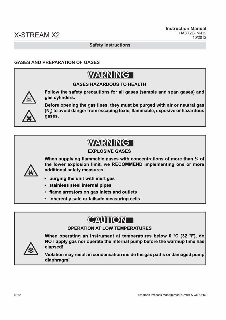
GASES AND PREPARATION OF GASES
GASES HAZARDOUS TO HEALTHFollow the safety precautions for all gases (sample and span gases) and gas cylinders.Before opening the gas lines, they must be purged with air or neutral gas (N2) to avoid danger from escaping toxic, flammable, exposive or hazardous gases.
EXPLOSIVE GASES When supplying flammable gases with concentrations of more than ¼ of the lower explosion limit, we RECOMMEND implementing one or more additional safety measures:
• purging the unit with inert gas• stainless steel internal pipes• flame arrestors on gas inlets and outlets• inherently safe or failsafe measuring cells
OPERATION AT LOW TEMPERATURESWhen operating an instrument at temperatures below 0 °C (32 °F), do NOT apply gas nor operate the internal pump before the warmup time has elapsed!Violation may result in condensation inside the gas paths or damaged pump diaphragm!

Emerson Process Management GmbH & Co. OHG S-11
X-STREAM X2 Instruction ManualHASX2E-IM-HS10/2012
SS
afet
y In
stru
ctio
ns
Safety Instructions
Power supply
ADDITIONAL NOTES FOR UNITS WITH SCREW-TYPE TERMINALSCables for external data processing must be double-insulated against mains power.If this is not possible, cables must be laid in such a way as to guarantee a clearance of at least 5 mm from power cables. This clearance must be permanently secured (e.g. with cable ties)
CONNECTING UNITS FOR PERMANENT INSTALLATIONOnly qualified personnel following all applicable and legal regulations may install the unit and connect it to power and signal cables. Failure to comply may invalidate the unit’s warranty and cause exposure to the risk of damage, injury or death.This unit may only be installed by qualified personnel familiar with the possible risks.Working on units equipped with screw-type terminals for electrical connections may require the exposure of energized components.Wall-mounted units have no power switch and are operational when connected to a power supply. The operating company is therefore required to have a power switch or circuit breaker (as per IEC 60947-1/-3) available on the premises. This must be installed near the unit, easily accessible to operators and labelled as a power cut-off for the analyzer.
Ensure that the local power voltage where the unit is to be installed, corresponds to the unit’s nominal voltage as given on the name plate label.

Emerson Process Management GmbH & Co. OHGS-12
X-STREAM X2Instruction Manual
HASX2E-IM-HS10/2012
• The unit must be installed in a clean and dry area protected from strong vibrations and frost.
• The unit must not be exposed to direct sunlight and sources of heat. Admissable ambient temperatures (see technical details) must be adhered to.
• Gas inlets and outlets must not be interchanged.All gases must be supplied to the unit already processed. When using this unit with corrosive sample gases, ensure that these gases do not contain components harmful to the gas lines.
• Admissable gas pressure for sample and test gases is 1500 hPa.
• Exhaust lines must be laid inclined downwards, depressurized, protected from frost and according to applicable regulations.
• If it is necessary to disconnect the gas lines, the unit’s gas connectors must be sealed with PVC caps to avoid polluting the internal gas lines with condensate, dust, etc.
• To ensure electromagnetic compatibility (EMC), only shielded cables (supplied by us on request, or of equivalent standard) may be used. The customer must ensure that the shiel-ding is correctly fitted ( section 4.5, page 4-31). Shielding and terminal housing must be electrically connected; submin-D plugs and sockets must be screwed to the unit.
• When using optional external adapters (submin-D to screw-type terminal), protection from electromagnetic interference can no longer be guaranteed (CE compliance pursuant to EMC guidelines). In this case the customer or operating company functions as a maker of a system and must therefore ensure and declare compliance with EMC guidelines.
EXPLOSION HAZARDExhaust gases may contain hydrocarbons and other toxic gases such as carbon monoxide. Carbon monoxide is toxic.Faulty gas connections may lead to explosion and death.Ensure that all gas connections are connected as labelled and airtight.
General Operating Notes
General operating notes

Emerson Process Management GmbH & Co. OHG 1-1
X-STREAM X2Instruction ManualHASX2E-IM-HS10/2012
Chapter 1 Technical description
The following are the main features of the new Emerson Process Management X-STREAM gas analyzers in brief:• compact design with easily accessible
internal components• customizable for a wide range of ap-
plications: different housings are avail-able while internal construction remains largely identical
• multilingual microprocessor-controlled user interface with liquid crystal (LCD) or vacuum flourescent display (VFD) to indicate measurement value and status messages
• units for outdoor use are optionally sup-plied with an impact tested front panel
• widerange power supply unit for worldwi-de use without modification (1⁄2 19in units with internal or external PSUs)
X-STREAM X2 gas analyzers can measure up to four different gas components by mul-tiple combinations of the following analyzing techniques (restrictions apply to ½19in units):IR = non-dispersive infrared analysisUV = ultraviolet analysispO2 = paramagnetic oxygen analysiseO2 = electrochemical oxygen analysistO2 = electrochemical trace oxygen analysisTC = thermal conductivity analysistH2O = trace moisture measurementModified resistant measuring cells are avai-lable for use with corrosive gases and/or gases containing solvents.
Special configurations (e.g. intrinsically safe or infallible measuring cells) for the analysis of combustible gases are also available.
Chapter 3 contains a detailed descrip-tion of the various measuring techniques.Standard applicationsThe use of different housings allow X-STREAM analyzers to be tailored to the many different applications:• Tabletop units in ½19in modular design,
with IP 20 protection class• Tabletop and rackmountable units in 19
in modular design, with IP 20 protection class
• Stainless steel wallmountable field housing with IP 66 / NEMA 4X protection class for outdoor use (operating tempe-rature -20°C to +50°C).
• Cast aluminium wallmountable field housing with IP 66 / NEMA 4X protection class for outdoor use (operating tempe-rature -20°C to +50°C).
The various analyzer types are described in more detail in section 1.4, page 1-12ff.
Installation in hazardous areasX-STREAM analyzers in field housings, when fitted with various protective devices, can also be installed and operated in hazardous environments. Available options are:• Non-incendive assembly (Ex nA nC) for
installation in Zone 2 and Division 2 for the measurement of non-flammable gases.
• Pressurized enclosure conforming to ATEX directive 94/9/EC, for installation in zone 2.
1Te
chni
cal D
escr
iptio
n

Emerson Process Management GmbH & Co. OHG1-2
X-STREAM X2Instruction Manual
HASX2E-IM-HS10/2012
1 Technical Description
• Simplified purge system (Z-purge) for installation in North American Div 2 envi-ronments.
The cast aluminium field housing (Ex d) is designed to withstand an explosion and intended to be used in hazardous areas of Zone 1. Its robust design with NEMA 4X / IP 66 protection also enables the installation in rough environments outside hazardous areas.
More information about analy-zers for hazardous areas can be obtained from your Emerson Process Management sales office.
Note!These instructions do not detail the installa-tion or operation of X-STREAM analyzers in hazardous areas. If you intend to use your analyzer for such purposes, we would draw your attention to the separate in-struction manuals supplied with analyzers for use in hazardous areas.
Further features (in parts options):• Configurable measurement display
• gas values and/or secondary measure-ments (e. g. flow)
• single or dual pages• Configurable measurement units
• supports conversion factors from ppm to several other, even user specific units
• 3 independent software access levels• protection against unauthorized chan-
ging of configurations• password protected• to be separately activated
• Unattended zero and span calibrations• calibrations without user interaction
• Backup and restore analyzer configura-tions to/from protected internal memory.

Emerson Process Management GmbH & Co. OHG 1-3
X-STREAM X2Instruction ManualHASX2E-IM-HS10/2012
1.1 OverviewAll X-STREAM gas analyzers feature an easy-to-use alphanumeric user interface, which displays measurement values, status and error messages, and menus for the input of parameters.
For ease of use, the operator can select one of five languages for the display (currently available: English, French, German, Italian and Spanish).
Fig. 1-1: X-STREAM Front Panel (here the X-STREAM X2GP)
1.1.1 The Front Panel
All X-STREAM gas analyzers feature an alphanumeric LCD display with 4x20 cha-racters, showing measurement and status information. Wall-mounted units can, as an alternative, be fitted with a vacuum fluorescent display, incre-asing legibility in brighter environments. The display can also be protected with an impact tested glass panel.All analyzer types also feature three LEDs on the front panel which display status informati-on in addition to the plain text messages.
The colors of the LEDs are based on the NAMUR NE 44 specifications. The LEDs are activated in accordance with the NE 107 standards, and indicate “Failure”, “Function check”, “Out of specification” and “Maintenance request”. For further information, see chapter 8, page 8-1.The analyzer software is operated by means of only six keys.
1.1 Overview
1 4x20 character alphanumeric display 2 LED (red) 3 LED (red) 4 LED (green)
5 “Measure“ key 6 “Enter” key 7 4 keys for settings and menu navigation
1 3 4 5 6 72
1Te
chni
cal D
escr
iptio
n

Emerson Process Management GmbH & Co. OHG1-4
X-STREAM X2Instruction Manual
HASX2E-IM-HS10/2012
1.2 Configuration of Gas Lines
1.2 Configuration of Gas LinesVarious materials are available to allow the analyzer to be customized to your needs. The materials used are selected based on the characteristics of the sample gas, e.g. diffusion rate, corrosiveness, temperature and pressure.1.2.1 Materials UsedThe physical and chemical properties of the sample gas as well as the conditions under which measurement takes place influence the choice of materials. Among those available are Viton®, PFA and stainless steel.1.2.2 Safety FilterThe analyzers are generally fitted with an internal stainless-steel filter. This filter is not a replacement for any dust filter in the prepa-ration of the gas, but represents a last line of defence.1.2.3 Inlets and OutletsRackmounted and tabletop devices are fitted with PVDF inlets and outlets (ø 6/4 mm) as standard. Alternatively, Swagelok™ or stain-less steel fittings (ø 6/4 mm or ¼ in can be fitted.Wall-mounted field housings are supplied with Swagelok™ or stainless steel fittings (ø 6/4 mm or ¼ in) ausgestattet.Other materials available on request.X-STREAM X2FD units are always supplied with flame arrestors and stainless steel fittings (ø 6/4 mm or ¼ in).1.2.4 PipeworkUnless otherwise specified, the analyzers are supplied with Viton® or PVDF piping (ø 6/4 mm or ¼ in). Other materials (e.g. stain-less steel) can be used, depending on the application.
Infallible containments are gas lines which, due to their design, can be regarded as per-manently technically tight. This is achieved by, for example, welded joints, or metallically sealing joints (e.g. tap connectors and bin-ders), providing they are seldom disconnec-ted. Gas lines configured in this manner can be used for measuring noxious, flammable and explosive gases. At the time of going to press, infallible containments for thermal conductivity analysis (TC) are available; other analysis methods are projected. Further in-formation about infallible containments can be found in the separate instruction manual supplied with these units.
Infallible containments do not render it unnecessary to test for leaks regularly, e.g. following lengthy breaks in service, sub-stantial alterations, repairs and modifications. Read the separate instruction manual giving detailed instruc-tions on the configuration, ope-ration and maintenance of units fitted with infallible contain-ments.
1.2.5 Infallible Containments

Emerson Process Management GmbH & Co. OHG 1-5
X-STREAM X2Instruction ManualHASX2E-IM-HS10/2012
1.2 Configuration of Gas Lines
1.2.6 Optional Components for Gas Lines
The analyzers can, as an option, be fitted with further components. Not all components are available for all analyzer types:• internal sample gas pump• internal valve block• internal flow sensors• internal flow monitor switch• internal barometric pressure meters• internal temperature sensors.
1.2.6.1 Internal Sample Gas PumpAn internal sample gas pump is used when the sample gas is under insufficient pressure. It ensures a constant flow of sample gas (max. 2.5 l/min through the analyzer).When in internal pump is fitted, the relevant parameter in the software setup dialog is set to Yes ( 6.2.3.5, page 6-43). The pump can be controlled either manually through a software menu or optionally by a digital input.
1.2.6.2 Internal Valve BlockThe use of an internal valve block allows all necessary gas lines (zero gas, span gas, sample gas) to remain permanently connec-ted to the analyzer. Valves are then activated automatically when required (e.g. during au-tomatic calibration).When an internal valve block is fitted, this is shown in the relevant software setup dialog as either Internal or Int+Ext ( 6.2.3.5, page 6-43). The valves are controlled by either a software menu, optionally by digital input, or automatically during autocalibration.Depending on the model, up to two valve bocks can be fitted.
1.2.6.3 Internal Flow SensorUp to two internal flow sensors can measure the flow of gas and can activate an alarm si-gnal in the event of a failure. The alarm level for flow sensors is operator adjustable to up to 2000 ml/min. Depending on the model, up to two sensors can be fitted and evaluated separately.When a sensor is fitted, the relevant parame-ter in the software setup dialog is set to Yes ( 6.2.3.5, page 6-43). If the current flow rate is too low, a status message is displayed and the parameter under CHECK REQUESTS.. is set to Yes ( Chapter 8 “Troubleshooting”).
1.2.6.4 Internal Flow Monitor SwitchAn internal flow switch monitors the gas flow and activates an alarm signal in case it is not sufficient. The alarm level for the internal flow switch is fixed and not operator adjustable. Additional external switches may used and connected via digital inputs. All fitted flow switches are evaluated to share a common alarm.When an internal flow switch is fitted, the re-levant parameter in the software setup dialog is set to Yes ( 6.2.3.5, page 6-43). If the current flow rate is too low, a status message is displayed and the parameter under CHECK REQUESTS.. is set to Yes ( Chapter 8 “Troubleshooting”).
1Te
chni
cal D
escr
iptio
n

Emerson Process Management GmbH & Co. OHG1-6
X-STREAM X2Instruction Manual
HASX2E-IM-HS10/2012
1.2 Configuration of Gas Lines
1.2.6.6 Internal Temperature SensorsThe influence of varying temperatures can be compensated for by the use of internal temperature sensors ( measurement specification, page 3-17 ).Depending on the configuration of the unit or the demands of the application, temperature sensors can measure the unit’s internal tem-perature or selected measurement channel components.If such sensors are installed in the unit, this is indicated in the installed options menu ( 6.2.3.5, page 6-43).
1.2.6.5 Internal Barometric Pressure SensorThe influence of varying atmospheric pres-sure can be compensated for by the use of an internal barometric pressure sensor ( measurement specification, page 3-17).If such a sensor is installed in the unit, the related menu shows the entry Internal ( 6.2.3.5, page 6-43).

Emerson Process Management GmbH & Co. OHG 1-7
X-STREAM X2Instruction ManualHASX2E-IM-HS10/2012
1.2.6.7 Optional Heated Area
The physical components can be optionally separated from the electrical components by means of a special box (not an option for ½ 19 in units). This can be done for one or both of the following purposes:Firstly, the box allows the physical compon-ents to be regulated to a temperature of ap-prox. 60°C, avoiding condensation of gases or the influence of varying environmental temperatures. Secondly, the box can be purged with, for example, inert gas. The purge gas is first fed through a separate fitting, purges the elec-tronic components, then floods the box and leaves the instrument via another fitting. Purging in this manner can be useful when measuring very low concentrations (e.g. of
CO or CO2): the expulsion of ambient air avoids adulterant outside influences.Alternatively, purging can be used to secure enhanced protection for electronic parts and operators from corrosive or toxic gases: any leaking gas is expelled from the housing and does not escape into the vicinity of the unit or come into contact with any electronic compo-nents located outside the box.In either case, the purge gas outlet should be connected to an exhaust gas line.
Fig. 1-2: Optional Heated Area
The figure shows the heated area with the insulating cover removed.
Insulating cover
Physical components
(example)
Heated moun-ting panelCable support for signal wires
1.2 Configuration of Gas Lines
1Te
chni
cal D
escr
iptio
n

Emerson Process Management GmbH & Co. OHG1-8
X-STREAM X2Instruction Manual
HASX2E-IM-HS10/2012
1.2 Configuration of Gas Lines
Depending on the application and the selected analyzer options, several gas line configurati-ons are available, exemplified in the following diagram of a dual-channel analyzer:
1.2.7 Configurations
Fig. 1-3: Gas Flow Diagram: Single Channel or in Series

Emerson Process Management GmbH & Co. OHG 1-9
X-STREAM X2Instruction ManualHASX2E-IM-HS10/2012
1.3 Interfaces
1.3.1 Analog OutputsEach X-STREAM analyzer is fitted with one output per channel as standard, which can transmit data on concentration levels to an external data acquisition system.The mode of operation (e.g. 4-20 mA, 0-20 mA) and support for NAMUR NE 43 specifications (incl. Live Zero) can be set in a software menu ( 5.7.4, page 5-20).The factory setting for analog outputs is 4-20 mA.
X-STREAM analyzers support up to four ana-log outputs, which, however, do not always need to be assigned to measurement chan-nels which are physically present: if a unit has less than four channels, the remaining analog outputs can be used to transmit concentration levels with a different resolution; for example, a single-channel analyzer could be set up as follows:Output 1: 0…100 % CO2 = 4…20 mAOutput 2: 0…25 % CO2 = 4…20 mA
1.3 InterfacesAll analyzer types are fitted with one analog electrical output for each channel and four status relays as standard.As an option, further interfaces can be ad-ded.
Depending on the unit configuration, all in-terfaces are accessible via either SubminD connectors or screw terminals.
1.3.2 Status RelaysBy default, the four relays are configured to signal the current status of the unit according to the NAMUR NE 44 recommendations (“Failure”, “Maintenance request”, “Out of specification” and “Function check”). Howe-ver, the operator can assign different functions to the relays via software menus. For more information, see 6.2.3.4.2, page 6-37 ff.Note!The NE 44 status is also indicated by the LEDs on the front panel. These LEDs remain conformant to NE 44 even when the status relays are assigned different functions by the software.
The contacts, which can take a maximum load of 30 V at 1 A and 30 W, can be operated as normally open or normally closed.
Further information on the status relays is provided in the chapter “Technical Data”
2.1, pages 2-2 ff!
1Te
chni
cal D
escr
iptio
n

Emerson Process Management GmbH & Co. OHG1-10
X-STREAM X2Instruction Manual
HASX2E-IM-HS10/2012
1.3.3.1 Modbus Interface, SerialA serial interface with the Modbus protocol allows communication with external data ac-quisition systems. The interface enables the exchange and modification of measurement and analyzer signals as well as the remote activation of procedures.The RS 485 interface is electrically isolated from the unit’s electronic components and facilitates the construction of a network of several analyzers.Optionally, an RS 232 interface can also be used (and is also electrically isolated from the unit’s electronic components; however, it only allows communication between two end devices.
All supported Modbus parameters are listed in chapter 9.
1.3.3 Optional Interfaces
1.3.3.2 Modbus Interface, EthernetThe Ethernet Modbus interface offers the same form of comunication with a data ac-quisition system as does a serial interface. The most obvious difference is the plug-and-socket connection: the Ethernet interface uses an RJ45 socket.This interface is also electrically isolated from the unit’s electronic components and enab-les the construction of a network of several analyzers.
All supported Modbus parameters are listed in chapter 9.
Note!The Ethernet Modbus interface cannot be combined with the serial Modbus interface ( 1.3.3.1).
1.3 Interfaces
Fig. 1-4: Serial Interface Marking
A table nearby the connector shows the interface configuration(here: MODBUS)
X

Emerson Process Management GmbH & Co. OHG 1-11
X-STREAM X2Instruction ManualHASX2E-IM-HS10/2012
1.3 Interfaces
1.3.3.3 Digital OutputsDigital outputs can be used for various pur-poses:• Issuing concentration alarms: Process
control systems can detect when limits are exceeded and trigger appropriate actions.
• Switching external components: For ex-ample, during automatic calibration, the necessary valves can be activated directly by the analyzer.
Digital outputs can be integrated into the units in groups of 9 or 18 ( 1.4, page 1-12).The relay contacts, which can take a maxi-mum load of 30 V at 1 A and 30 W, can be operated as normally open (NO) or normally closed (NC).
1.3.3.4 Digital InputsDigital inputs can: • trigger calibration procedures, for example
by a process control system• remotely control valves and the optional
sample gas pump (in concert with correctly configured digital outputs).
Digital inputs can be integrated into the units in groups of 7 or 14 ( 1.4, page 1-12).
Electrical detailsLOW: Uin ≤ 1,5 V HI2GC: Uin ≥ 4,5 VInput impedence: 57,5 kΩ Common ground for all outputs (“IN-GND”)
The inputs are protected against excess voltages of up to approx. 40 V. An open (not wired) input has LOW potential.
1Te
chni
cal D
escr
iptio
n

Emerson Process Management GmbH & Co. OHG1-12
X-STREAM X2Instruction Manual
HASX2E-IM-HS10/2012
1.4 Overview of Analyzer Types
1.4 Comparison of the Various X-STREAM X2 Analyzer Models
1⁄219 in housing, table-top or rackmountable, optional with carrying handleprotection type: IP 20
1⁄119 in housing, table-top or rackmountable, protection type: IP 20
Stainless steel wallmountable fieldhousing, pro-tection type: IP66 / NEMA 4XSingle (XLF) or dual (XXF) compartment design
Cast aluminium wallmountable field housing, protection type: IP66 / NEMA 4X
Internal wide range power supply, or 24V input with external power supply unit
Internal wide range power supply unit Internal wide range power supply unit Internal wide range power supply unit
Max. 3 channels in many combinations max. 8 gas connections, including 1 optional purge gas connection
Max. 4 channels in any combination max. 8 gas connections, 1 optional extra connection for purge gas
Max. 4 channels in any combination max. 8 gas connections, 1 optional extra connection for purge gas
Max. 4 channels in any combination max. 8 gas connections, including 1 optional purge gas connection
Options for gas lines: Valve block, sample gas pump, flow sensor, pressure sensor, infallible gas lines
Options for gas lines: Flow sensor, pressu-re sensor, heating for physical components, sample gas pump, 1 or 2 valve blocks, infalli-ble gas lines
Options for gas lines: Flow sensor, pressure sensor, heating for physical components, sample gas pump, 1 or 2 valve blocks, infalli-ble gas lines
Options for gas lines: Flow sensor, pressu-re sensor, heating for physical components, sample gas pump, 1 or 2 valve blocks, infalli-ble gas lines
1–4 analog outputs, 4 relay outputsoptional: 1 interface card with 7 digital inputs and 9 digital outputs 1 Modbus interface (serial or Ethernet)electrical interfaces accessible via sockets on back of unit)
1–4 analog outputs, 4 relay outputs optional: 1 or 2 interface cards, each with 7 digital inputs and 9 digital outputs 1 Modbus interface (serial or Ethernet)electrical interfaces accessible via sockets on back of unit, optionally: screw-type terminal adapters (except for Ethernet)
1–4 analog outputs, 4 relay outputs optional: 1 or 2 interface cards, each with 7 digital inputs and 9 digital outputs 1 Modbus interface (serial or Ethernet)electrical interfaces on internal screw-type ter-minal adapters (except for Ethernet)
1–4 analog outputs, 4 relay outputs optional: 1 or 2 interface cards, each with 7 digital inputs and 9 digital outputs 1 Modbus interface (serial or Ethernet)electrical interfaces on internal screw-type ter-minal adapters (except for Ethernet)
LCD LCD LCD, optionally: vacuum fluorescent display, impact tested front panel
LCD, impact tested front panel optionally: vacuum fluorescent display
Operational ambient temperature*): 0 °C to +50 °C (32 °F to 122 °F)
Operational ambient temperature*): 0 °C to +50 °C (32 °F to 122 °F)
operational ambient temperature*): -20 °C to +50 °C (-4 °F to 122 °F)
operational ambient temperature*): -20 °C to +50 °C (-4 °F to 122 °F)
Available w/o front plate controls as module XCC
Available w/o front plate controls as module XCA
Models available for use in explosive environ-ments
Flameproof enclosure: approved for use in ex-plosive areas
Size: (DxHxW): max. ca. 460x128.7x213 mm Weight: ca. 8–12 kg (17.6–26.5 lb)
Size: (DxHxW): max. ca. 411x133x482 mm Weight: ca. 11–16 kg (24–35 lb)
Size: (DxHxW): max. ca. 222x460x520 mm Weight: max. ca. 26 kg (57 lb)
Size: (DxHxW): max. ca. 222x512x578 mm Weight: max. ca. 63 kg (138.5 lb)
For more detailed information: section 1.5, page 1-14
For more detailed information: section 1.6, page 1-16
For more detailed information: section 1.7, page 1-19
For more detailed information: section 1.8, page 1-26
*): Limitations apply to selected measurement principles and ranges, Measurement specifications!
X-STREAM X2GK X-STREAM X2GP

Emerson Process Management GmbH & Co. OHG 1-13
X-STREAM X2Instruction ManualHASX2E-IM-HS10/2012
1⁄219 in housing, table-top or rackmountable, optional with carrying handleprotection type: IP 20
1⁄119 in housing, table-top or rackmountable, protection type: IP 20
Stainless steel wallmountable fieldhousing, pro-tection type: IP66 / NEMA 4XSingle (XLF) or dual (XXF) compartment design
Cast aluminium wallmountable field housing, protection type: IP66 / NEMA 4X
Internal wide range power supply, or 24V input with external power supply unit
Internal wide range power supply unit Internal wide range power supply unit Internal wide range power supply unit
Max. 3 channels in many combinations max. 8 gas connections, including 1 optional purge gas connection
Max. 4 channels in any combination max. 8 gas connections, 1 optional extra connection for purge gas
Max. 4 channels in any combination max. 8 gas connections, 1 optional extra connection for purge gas
Max. 4 channels in any combination max. 8 gas connections, including 1 optional purge gas connection
Options for gas lines: Valve block, sample gas pump, flow sensor, pressure sensor, infallible gas lines
Options for gas lines: Flow sensor, pressu-re sensor, heating for physical components, sample gas pump, 1 or 2 valve blocks, infalli-ble gas lines
Options for gas lines: Flow sensor, pressure sensor, heating for physical components, sample gas pump, 1 or 2 valve blocks, infalli-ble gas lines
Options for gas lines: Flow sensor, pressu-re sensor, heating for physical components, sample gas pump, 1 or 2 valve blocks, infalli-ble gas lines
1–4 analog outputs, 4 relay outputsoptional: 1 interface card with 7 digital inputs and 9 digital outputs 1 Modbus interface (serial or Ethernet)electrical interfaces accessible via sockets on back of unit)
1–4 analog outputs, 4 relay outputs optional: 1 or 2 interface cards, each with 7 digital inputs and 9 digital outputs 1 Modbus interface (serial or Ethernet)electrical interfaces accessible via sockets on back of unit, optionally: screw-type terminal adapters (except for Ethernet)
1–4 analog outputs, 4 relay outputs optional: 1 or 2 interface cards, each with 7 digital inputs and 9 digital outputs 1 Modbus interface (serial or Ethernet)electrical interfaces on internal screw-type ter-minal adapters (except for Ethernet)
1–4 analog outputs, 4 relay outputs optional: 1 or 2 interface cards, each with 7 digital inputs and 9 digital outputs 1 Modbus interface (serial or Ethernet)electrical interfaces on internal screw-type ter-minal adapters (except for Ethernet)
LCD LCD LCD, optionally: vacuum fluorescent display, impact tested front panel
LCD, impact tested front panel optionally: vacuum fluorescent display
Operational ambient temperature*): 0 °C to +50 °C (32 °F to 122 °F)
Operational ambient temperature*): 0 °C to +50 °C (32 °F to 122 °F)
operational ambient temperature*): -20 °C to +50 °C (-4 °F to 122 °F)
operational ambient temperature*): -20 °C to +50 °C (-4 °F to 122 °F)
Available w/o front plate controls as module XCC
Available w/o front plate controls as module XCA
Models available for use in explosive environ-ments
Flameproof enclosure: approved for use in ex-plosive areas
Size: (DxHxW): max. ca. 460x128.7x213 mm Weight: ca. 8–12 kg (17.6–26.5 lb)
Size: (DxHxW): max. ca. 411x133x482 mm Weight: ca. 11–16 kg (24–35 lb)
Size: (DxHxW): max. ca. 222x460x520 mm Weight: max. ca. 26 kg (57 lb)
Size: (DxHxW): max. ca. 222x512x578 mm Weight: max. ca. 63 kg (138.5 lb)
For more detailed information: section 1.5, page 1-14
For more detailed information: section 1.6, page 1-16
For more detailed information: section 1.7, page 1-19
For more detailed information: section 1.8, page 1-26
*): Limitations apply to selected measurement principles and ranges, Measurement specifications!
1.4 Overview of Analyzer Types
X-STREAM X2XF X-STREAM X2FD
1Te
chni
cal D
escr
iptio
n

Emerson Process Management GmbH & Co. OHG1-14
X-STREAM X2Instruction Manual
HASX2E-IM-HS10/2012
1.5 X-STREAM X2GK: ½19 Inch Table-Top Unit
1.5 X-STREAM X2GK
This compact model for general purposes can be fitted with up to three measurement channels in various combinations. Power is supplied by an internal wide range power sup-ply or a separate external power supply unit.By default the units are configured for tabletop use. A carrying handle is optional available which makes it easy to take the instrument to varying sampling points. For rack mounting a X2GK is fixed by screws located at the front panel.Front panelThe analyzer’s front panel consists of one 4x20-character alphanumeric LCD display, a membrane keyboard and three status LEDs (Fig. 1-4). The colors of the LEDs are based on the NAMUR NE 44 specifications. The LEDs are activated according to the NE 107 stan-dards and correspond to the following status messages: “Failure”, “Function check”, “Out of specification” and “Maintenance request”. Connection to power supplyAC is supplied by an IEC chassis plug with power switch and fuse holders. The internal wide range power supply unit enables the analyzers to be used worldwide. DC 24 V power is supplied via a 3-pin socket at the rear of the unit.InterfacesThe electrical connections for interface sig-nals are provided via submin-D connectors, also mounted at the back of the unit (Fig. 1-4).For applications where screw-type terminals are preferred for connecting signal wires, op-tional adapters are available, which are moun-ted directly onto the submin-D connectors.
Interface signalsThe number of connections varies according to the number of interfaces installed: a 25-
pin submin-D socket terminal strip is always included, providing one analog output (4-20 or 0-20 mA) and the contacts for the four NAMUR status relays. Further analog outputs can also be provided, e.g. to provide a measurement signal at dif-ferent resolutions. A maximum of four analog outputs are possible.A serial Modbus interface can also be installed on request (RS 232 or RS 485 with Modbus RTU protocol, via 9-pin submin-D male con-nector); alternatively an RJ45 socket can also give access to Ethernet-Modbus-TCP.Digital inputs and outputs can be used to control analyzer functions and external components. The 7 inputs and 9 outputs are connected to peripheral devices via a 37-pole submin-D socket terminal strip.Detailed technical details on the various inter-faces can be found in 1.3, page 1-9. The configuration of the connectors are described in chapter 4 “Installation” and the soft-ware settings in chapter 6 “Software”.A further submin-D socket, which is not in detail described in this manual, is also located at the rear of the unit, and is designated as a Service Interface.
The Service Interface is elec-trically connected to the unit’s electronic components. If it is incorrectly handled, damage to the unit may result. The Service Interface may only be used by EMERSON service personnel or specially trained staff.

Emerson Process Management GmbH & Co. OHG 1-15
X-STREAM X2Instruction ManualHASX2E-IM-HS10/2012
Gas connectionsDepending on the configuration of the unit (number of measurement channels and serial or parallel connection), sample and calibra-tion gases are fed into the unit via up to 8 tube fittings mounted on the rear panel. The configuration of the fittings is indicated on an adhesive label located near the tube fittings.Any free tube fittings can be used for purging the device with • inert gas to minimize interference from the
ambient atmosphere when measuring small concentrations (e.g. of CO2)
or• air or inert gas when measuring corrosive
and/or flammable gases.For further information, see page 1-5.
1.5 X-STREAM X2GK
Special components For the analysis of aggressive and/or flam-mable gases, infallible components (WLD; photometer under development) can be used. The risk of an uncontrolled release of gases due to a leak can be minimized by the use of stainless steel piping and clamping rings. Further details about the infallible contain-ment are in the separate manual supplied with units containing such parts.Furthermore, intrinsically safe measuring cells, which prevent the ignition of gas mix-tures in the case of a failure, can also be used.Modul variation XCCThe ½19-in unit is also available as an ana-½19-in unit is also available as an ana-lyzer module without the front control panel, which can, for example, be integrated into a measuring system in which control and ana-lysis of data is performed via interface by an external data acquisition system.
1Te
chni
cal D
escr
iptio
n

Emerson Process Management GmbH & Co. OHG1-16
X-STREAM X2Instruction Manual
HASX2E-IM-HS10/2012
1.5 X-STREAM X2GK
Fig. 1-5: X-STREAM X2GK - Views
1 4x20 character alphanumeric display 2 LED (red) 3 LED (red) 4 LED (green) 5 “Measure” key 6 “Enter” key 7 4 keys for adjustment and menu selection
8 Signal connectors (some optional) 9 Gas fittings 10 DC power input fuse 11 DC power input 12 Valve block 13 AC power input with integral fuses and switch 14 Carrying handle
1 3 4 5 6 72
8 141110 98
1213Note!Figures show optional components!

Emerson Process Management GmbH & Co. OHG 1-17
X-STREAM X2Instruction ManualHASX2E-IM-HS10/2012
1.6 X-STREAM X2GP: 19 Inch Table-Top or Rackmount Design
1.6 X-STREAM X2GP
This model can be fitted with up to four measurement channels in any combination. The physical components can optionally be encased in a cover. This area can be held at a specific temperature of up to 60 °C to mi-nimize interference from changes in external temperature.Units configured for rack mounting can be converted for tabletop use by removing the lateral mounting brackets and attaching the four feet supplied as accessories.Front panel The analyzer’s front panel consists of one 4x20-character alphanumeric LC display, a membrane keyboard and three status LEDs (Fig. 1-5). The colors of the LEDs are based on the NAMUR NE 44 specifications. The LEDs are activated according to the NE 107 stan-dards and correspond to the following ststus messages: “Failure”, “Function check”, “Out of specification” and “Maintenance request”. Connection to power supply Main power is supplied via the IEC chassis plug mounted on the rear panel, with inte-grated power switch and fuse holders. The internal wide range power supply unit enables the analyzers to be used worldwide.
InterfacesElectrical connections for interface signals are provided via the submin-D connectors also mounted on the rear panel of the device (Fig.1-5). For applications where screw-type terminals are preferred for connecting signal wires, op-tional adapters are available, which are moun-ted directly onto the submin-D connectors.
Interface signalsThe number of connections varies according to the number of interfaces installed: a 25-pin submin-D socket terminal strip is always included, providing one analog output (4-20 or 0-20 mA) and the contacts for the four (NAMUR) status relays. Further analog out-puts can also be provided, e.g. to provide a measurement signal at different resolutions. A maximum of four analog outputs is possible.A serial Modbus interface can also be installed on request (RS 232 or RS 485 with Modbus RTU protocol, via 9-pin submin-D male conec-tor); alternatively an RJ45 socket can also give access to Ethernet-Modbus-TCP.Digital inputs and outputs can be used to control analyzer functions and external components. The 7 inputs and 9 outputs are connected to peripheral devices via a 37-pole sumbin-D socket terminal strip. The number of digital inputs and outputs can be doubled (to 14 inputs and 18 outputs) by adding a second card. The first digital I/O card is marked "X4.1" while the second is "X4.2" on the rear panel, right above the connector (Fig. 1-5, rear view).Detailed technical details on the various in-terfaces can be found in 1.3, page 1-9. The configuration of the connectors and the optional screw-type terminal adapters is de-scribed in chapter 4 “Installation” and the software settings in chapter 6 “Software”.A further submin-D socket, which is not de-scribed in this manual, is also located at the rear of the unit, and is designated as a Service Interface.
1Te
chni
cal D
escr
iptio
n

Emerson Process Management GmbH & Co. OHG1-18
X-STREAM X2Instruction Manual
HASX2E-IM-HS10/2012
1.6 X-STREAM X2GP
The Service Interface is elec-trically connected to the unit’s electronic components. If it is incorrectly handled, damage to the unit may result. The Service Interface may only be used by EMERSON service personnel or specially trained staff.
Gas connectionsDepending on the configuration of the unit (number of measurement channels and serial or parallel connection), sample and calibra-tion gases are fed into the unit via up to 8 threaded connectors mounted on the rear panel. The configuration of the connectors is indicated on an adhesive label located near the connectors.An additional, optional connection can be used for purging the device with • inert gas to minimize interference from the
ambient atmosphere when measuring small concentrations (e.g. of CO2)
or• air or inert gas when measuring corrosive
and/or flammable gases.For further information, see section 1.2.6, page 1-5.
Special components For the analysis of aggressive and/or flam-mable gases, infallible components (WLD; photometer under development) can be used. The risk of an uncontrolled release of gases due to a leak can be minimized by the use of stainless steel piping and clamping rings. Further details about the infallible contain-ment are in the separate manual supplied with units containing such parts.
Furthermore, intrinsically safe measuring cells, which prevent the ignition of gas mixtu-res in the case of a failure, can also be used.Module type XCAThe full 19-in unit is also available as an ana-full 19-in unit is also available as an ana-lyzer module without the front control panel, which can, for example, be integrated into a measuring system in which control and ana-lysis of data is performed via interface by an external data acquisition system.

Emerson Process Management GmbH & Co. OHG 1-19
X-STREAM X2Instruction ManualHASX2E-IM-HS10/2012
Fig. 1-6: X-STREAM X2GP - Views
1.6 X-STREAM X2GP
1 4x20 character alphanumeric display 2 LED (red) 3 LED (red) 4 LED (green)
5 “Measure” key 6 “Enter” key 7 4 keys for adjustment and menu selection 8 Brackets for rack mounting
1 Gas connectors 2 Space for additional tube fittings 3 Optional purge gas inlet
4 Power inlet with filter, fuses & switch 5 Signal input/output connectors (some optional) 6 Cover for eO2 or tO2 sensor
Rea
r vie
wO
ptio
nal
scre
w-ty
pe te
rmin
alad
apte
rFr
ont v
iew
15 2 4 3
1 3 4 5 6 72 8
1 Screw-type terminal adapters 2 Strain-reliefs
1 2
1
Strain-reliefs, top view details
6
1Te
chni
cal D
escr
iptio
n

Emerson Process Management GmbH & Co. OHG1-20
X-STREAM X2Instruction Manual
HASX2E-IM-HS10/2012
1.7 X-STREAM X2XF Field Housings
1.7 X-STREAM X2XF: Field Housing With (XLF) Single Or (XXF) Dual CompartmentField housings are conceived for outdoor use and wall-mounting. The coated stainless steel housing has a protection class rated at IP66 / NEMA 4X, offering protection against water and dust entering the device: IPx6: In case of occasional flooding, e.g. heavy seas, water shall not enter in harmful quantitiesIP6x: Protection against penetration by dust. Live or internal moving parts are completely protected.An X-STREAM field housing can be fitted with up to four measurement channels in any com-bination. The physical components can op-tionally be encased in a cover. This separate volume can be held at a specific temperature of up to 60 °C to minimize interference from changes in external temperature.Front panelThe analyzer’s front panel consists of one 4x20-character alphanumeric LC display, a membrane keyboard and three status LEDs (Fig. 1-6). The colors of the LEDs are based on the NAMUR NE 44 specifications. The LEDs are activated according to the NE 107 stan-dards and correspond to the following status messages: “Failure”, “Function check”, “Out of specification” and “Maintenance request”. A vacuum fluorescent display can be fitted instead of the LCD, making the information displayed more easily readable in low light-levels. The display is covered by an impact te-sted glass to protect it in harsh environments.
Electrical connectionsElectrical connections are provided via inter-nal tube fittings, the cables being fed through cable glands at the right side of the unit (Fig. 1-8). The front cover of the housing swings
open to the left once the fasteners have been released.Connection to power supplyMains power is supplied via the screw-type terminals with integrated fuse holders at the right of the housing, near the front. The wide range power supply unit mounted internally enables the analyzers to be used worldwi-de.Interface signalsIn the basic configuration, the unit has 36 inter-nal screw-type terminals for interface signals, providing one analog output (4[0]-20 mA) and the contacts for the four (NAMUR) sta-tus relays. Further analog outputs can also be provided, e.g. to provide a measurement signal at different resolutions. A maximum of four analog outputs is possible.A serial Modbus interface can also be installed on request (RS 232 or RS 485 with Modbus RTU protocol); alternatively an RJ45 socket gives access to Ethernet-Modbus-TCP. Digital inputs and outputs can be used to control analyzer functions and external components. The 7 inputs and 9 outputs are connected to peripheral devices via a further 36-terminal strip. The number of digital inputs and outputs can be doubled (to 14 inputs and 18 outputs) by adding a second card and an additional 36-terminal strip.Detailed technical information on the various interfaces can be found in 1.3, page1-9 The configuration of the terminals is described in chapter 4 “Installation” and the software settings in chapter 6 “Software”.A further submin-D socket, which is not in detail described in this manual, is also located inside the unit, and is designated as a Service Interface.
Emerson Process Management GmbH & Co. OHG 1-21
X-STREAM X2Instruction ManualHASX2E-IM-HS10/2012
The service interface is elec-trically connected to the unit’s electronic components. If it is incorrectly handled, damage to the unit may result. The service Interface may only be used by EMERSON service personnel or specially trained staff.
Gas connectionsDepending on the configuration of the unit (number of channels, series or parallel pi-ping), up to eight tube fittings are provided for the supply of sample and calibration gases. The assignments of the fittings is given on an adhesive label situated near the fittings.A further optional tube fitting enables the housing to be purged with either • Inert gas to minimize interference from
ambient atmospheres when measuring very small concentrations (e.g. CO2)
or:• air or inert gas whe measuring aggressive
and/or flammable gases.For further information, see section 1.2.6, page 1-5.
Special components For the analysis of aggressive and/or flam-mable gases, infallible components (TCD) can be used. The risk of an uncontrolled release of gases due to a leak can be mi-nimized by the use of stainless steel piping and clamping rings. Further details about the infallible containment are in the separate ma-nual supplied with units containing such parts.Furthermore, intrinsically safe measuring cells, which prevent the ignition of gas mixtu-res in the case of a failure, can also be used.
1.7 X-STREAM X2XF Field Housings
Dual compartment variation XXFThe dual compartment variation XXF sup-ports separating electronics and physics, e.g. for measurement of corrosive or solvent gases. For such applications the electronics are installed in the upper compartment, while measurement physics are in the lower com-partment. This separation is also available as gastight version.XXF also provides more space e.g. for instal-lation of optional signal converter elements for system integrators.
1Te
chni
cal D
escr
iptio
n

Emerson Process Management GmbH & Co. OHG1-22
X-STREAM X2Instruction Manual
HASX2E-IM-HS10/2012
Fig. 1-7: X-STREAM X2XF Field Housings - Front Views
1.7 X-STREAM X2XF Field Housings
HEAVY INSTRUMENTX-STREAM field housings, intended for outside and wall mounted use, weigh approx. (XLF) 26 kg (57 lb) or (XXF) 45 kg (99 lb), depending on options installed.Two people and/or lifting equipment is required to lift and carry these units.Take care to use anchors and bolts specified to be used for the weight of the units!Take care the wall or stand the unit is intended to be installed at is solid and stable to support the weight!
XLF
XXF

Emerson Process Management GmbH & Co. OHG 1-23
X-STREAM X2Instruction ManualHASX2E-IM-HS10/2012
1.7 X-STREAM X2XF Field Housings
Fig. 1-8: X-STREAM X2XF Field Housings - Front Panel
1 4x20 character alphanumeric display 2 LED (red) 3 LED (red) 4 LED (green)
5 “Measure” key 6 “Enter” key 7 4 keys for adjustment and menu selection
1 3 4 5 6 72
1Te
chni
cal D
escr
iptio
n

Emerson Process Management GmbH & Co. OHG1-24
X-STREAM X2Instruction Manual
HASX2E-IM-HS10/2012
1.7 X-STREAM X2XF Field Housings
Fig. 1-9: X-STREAM XLF - Bottom and Side View
1 Cable gland for power cable 2 Cable glands for signal cables 3 4 brackets for wall-mounting 4 Gas in- & outlets (max. 8) 5 Cutouts, to combine 2 housings (here closed)
21 3 5 4 5
Note! In case of XXF, the cable glands are lo-cated at the upper compartment, while the gas in- & outlets are at the bottom side of the lower compartment. Also only 2 brackets are at each com-partment.

Emerson Process Management GmbH & Co. OHG 1-25
X-STREAM X2Instruction ManualHASX2E-IM-HS10/2012
1.7 X-STREAM X2XF Field Housings
Fig. 1-10: X-STREAM XLF - Power Supply and Signal Terminals
1 Screw-type terminals for signal cables 2 Power line filter 3 Cable glands 4 Power supply terminals with integrated fuses 5 Ethernet connector
(shown with front panel removed) 1 32 45
Note! In case of XXF, the terminals and connectors are located at the upper compartment, while physical compo-nents and gas fittings are in the lower compartment.
1Te
chni
cal D
escr
iptio
n

Emerson Process Management GmbH & Co. OHG1-26
X-STREAM X2Instruction Manual
HASX2E-IM-HS10/2012
1.7.1 Field Housing for Installation in Hazardous Areas (Ex-Zones / Divisons)
Special X-STREAM field housing analyzer mo-dels can be used in Ex-zones 2 or Division 2:X-STREAM XLFN/XXFN:Analyzer with non-sparking protection for measuring non-flammable gases in European Ex-zone 2 and North-American Division 2 areas: the customized configuration of this instrument ensures that, when used correctly, no sparks, hot surfaces etc. which could ignite an explosive ambient atmosphere are generated. No further measures, such as a supply of protective gas, are necessary.X-STREAM XLFS/XXFS:Equipped with a simplified pressurized enclos-ure, these models can be used to measure non-flammable gases in European Ex-zone 2. A protective gas (e.g. pressurized air) must be supplied when operating this model.
X-STREAM XLFZ/XXFZ:Equipped with a simplified pressurized enclos-ure, these models can be used to measure non-flammable gases in American zone Div 2. A protective gas (e.g. pressurized air) must be supplied when operating this model.
Please contact your local EMERSON Process Management office if you require analyzers for use in explosive areas.
1.7 X-STREAM X2XF Field Housings
DANGER OF EXPLOSIONThe standard X-STREAM X2XF field housings CAN NOT be used in explosive environments without additional security features.This instruction manual does NOT describe the special conditions necessary to operate gas analyzers in explosive areas.Please refer to the separate instruction manual supplied with units for use in explosive areas.

Emerson Process Management GmbH & Co. OHG 1-27
X-STREAM X2Instruction ManualHASX2E-IM-HS10/2012
1.8 X-STREAM X2FD
1.8 X-STREAM X2FD: Cast Aluminum Flameproof HousingThe most obvious X-STREAM 2FD analyzer feature is its flameproof housing (Fig. 1-10). This enables its use in Ex-zone 1 hazardous environments. With its protection type of IP66/NEMA 4X and sturdy cast aluminum housing designed for wall-mounting, it can also be used in other tough environments.IPx6: In case of occasional flooding, e.g. heavy seas, water shall not enter in harmful quantitiesIP6x: Protection against penetration by dust. Live or internal moving parts are completely protected.Up to four measuring channels in any com-bination can be installed in the X-STREAM X2FD. Optionally, a cover can be installed over the physical components. This separa-te volume can be heated up to a maximum temperature of 60 °C to minimize the effects of changes in external temperature.A description of the different piping options is given in section 1.2.6, page 1-5.
Front panelThe front panel is physically protected with a safety glass panel and consists of a 4x20-character alphanumeric LC display, a keypad and 3 status LEDs (Fig. 1-11). The colors of the LEDs are based on the NAMUR NE 44
specifications. The LEDs are activated in line with NE 107 standards and indicate “Failure”, “Function check”, “Out of specification” and “Maintenance request”. Instead of the LCD display, a vacuum fluorescent display can be fitted.
Electrical connectionsElectrical connections are made via internal screw-type terminals; the corresponding cables are fed through cable inlets on the underside of the unit into the housing (Fig. 1-12). The front of the unit opens downwards once the screws located on the surrounding flange are removed.
Power supply Mains power is connected via screw-type terminals with integrated fuses, located in the front right-hand area of the housing. The internally mounted wide range power sup-ply unit ensures the analyzers can be used worldwide.
Interface signalsIn the basic configuration, the unit has 36 internal screw-type terminals for interface signals, providing one analog output (4–20 or 0–20 mA) for each channel and the contacts for the four NAMUR status relays. Further
DANGER OF EXPLOSIONThe special conditions for installing and operating analyzers in hazardous areas are not covered by this manual!Read the separate instruction manuals shipped together with instrument intended to be installed in hazardous area!
1Te
chni
cal D
escr
iptio
n

Emerson Process Management GmbH & Co. OHG1-28
X-STREAM X2Instruction Manual
HASX2E-IM-HS10/2012
analog outputs can also be provided, e.g. to provide a measurement signal at different re-solutions. A maximum of four analog outputs is possible.A serial Modbus interface can also be installed on request (RS 232 or RS 485 with Modbus RTU protocol); alternatively also access to Ethernet-Modbus-TCP. In this case the RS interface signals are routed to the appropriate number (up to 5) of the 36 terminals. Digital inputs and outputs can be used to control analyzer functions and external components. The 7 inputs and 9 outputs are connected to peripheral devices via a further 36-terminal strip. The number of digital inputs and outputs can be doubled (to 14 inputs and 18 outputs) by adding a second card and an additional 36-terminal strip.Detailed technical information on the various interfaces can be found in 1.3, page 1-9 The configuration of the terminals is described in chapter 4 “Installation” and the software settings in chapter 6 “Software”.A further submin-D socket, which is not in detail described in this manual, is also located at the rear of the unit, and is designated as a Service Interface.
The Service Interface is elec-trically connected to the unit’s electronic components. If it is incorrectly handled, damage to the unit may result. The Service Interface may only be used by EMERSON service personnel or specially trained staff
Gas connections Depending on the configuration of the unit (number of channels, series or parallel pi-ping), up to eight flame arresters are provi-
1.8 X-STREAM X2FD
ded for the supply of sample and calibration gases. The assignments of the connectors is given on an adhesive label situated near the connectors.Optional two of the fittings may be used to purge the housing with either • inert gas to minimize interference from
ambient atmospheres when measuring very small concentrations (e.g. CO2)
or:• air or inert gas when measuring aggres-
sive and/or flammable gases.For further information, see section 1.2.6, page 1-5.Special componentsFor the analysis of aggressive and/or flam-mable gases, and depending on the analysis method used (photometer or TC), infallible components can be used. The risk of an uncontrolled release of gases due to a leak can be minimized by the use of stainless steel piping and clamping rings. Furthermore, for measuring oxygen in flammable atmosphe-res, intrinsically safe measuring cells, which prevent the ignition of gas mixtures in the case of a failure, can also be used.

Emerson Process Management GmbH & Co. OHG 1-29
X-STREAM X2Instruction ManualHASX2E-IM-HS10/2012
Fig. 1-11: X-STREAM X2FD - Front View
1.8 X-STREAM X2FD
transport lug
hinges
transport lug
screws for housing
HEAVY INSTRUMENTThe model X-STREAM X2FD intended for outside and wall mounted use weighs approx. 63 kg (139 lb), depending on options installed.Two people and/or lifting equipment is required to lift and carry these units. Use the lugs located on the sides of the instrument.Take care to use anchors and bolts specified to be used for the weight of the units!Take care the wall or stand the unit is intended to be installed at is solid and stable to support the weight!
1Te
chni
cal D
escr
iptio
n

Emerson Process Management GmbH & Co. OHG1-30
X-STREAM X2Instruction Manual
HASX2E-IM-HS10/2012
1.8 X-STREAM X2FD
Fig. 1-12: X-STREAM X2FD - Front Panel
1 4x20 character alphanumeric display 2 LED (red) 3 LED (red) 4 LED (green)
5 “Measure” key 6 “Enter” key 7 4 keys for adjustment and menu selection
1 3 4 5 6 72
Fig. 1-13: X-STREAM X2FD - Bottom View
1 Cable inlets for power and signal cables 2 Gas tube fittings and purge gas outlet 3 4 brackets for wall mounting
123 3

Emerson Process Management GmbH & Co. OHG 1-31
X-STREAM X2Instruction ManualHASX2E-IM-HS10/2012
1.8 X-STREAM X2FD
1 Terminals for signal cables (shown fully populated) 2 Power line filter 3 Cable inlets for power and signal cables
Fig. 1-14: X-STREAM X2FD - Terminals
(shown with front panel removed)
1 42 35 4 Power supply terminals with integrated fuses 5 Optional Ethernet connection
1Te
chni
cal D
escr
iptio
n

Emerson Process Management GmbH & Co. OHG1-32
X-STREAM X2Instruction Manual
HASX2E-IM-HS10/2012

Emerson Process Management GmbH & Co. OHG 2-1
X-STREAM X2Instruction ManualHASX2E-IM-HS10/2012
2Te
chni
cal d
ata
Chapter 2 Technical data
This chapter contains all the technical details of the analyzers, divided into common and model-specific data.
Common technical data page 2-2
X-STREAM X2GK page 2-5
X-STREAM X2GP page 2-11
X-STREAM X2XF (XLF, XXF) page 2-15
X-STREAM X2FD page 2-18

Emerson Process Management GmbH & Co. OHG2-2
X-STREAM X2Instruction Manual
HASX2E-IM-HS10/2012
2.1 Common Technical Data
2.1 Common Technical DataInstallation siteHumidity (non-condensing) < 90 % RH at +20 °C (68 °F) < 70 % RH at +40 °C (104 °F)Degree of pollution 2 Installation category IIElevation 0 to 2000 m (6560 ft) above sea levelAmbient atmosphere Units may not be operated in corrosive, flammable or explosive (not applicable to X-STREAM X2FD) environments without additional safety measures.
CertificationElectrical safety CAN / USA CSA-C/US, based on CAN/CSA-C22.2 No. 61010-1-04 / UL 61010-1, 2nd edition Europe CE, based on EN 61010-1 Electromagnetic compatitiblity Europe CE, based on EN 61326 Australia C-Tick others NAMUR
Gas parameters Chapter 3 “Measuring principles”
Purging options 4.3 "Gas Conditioning"

Emerson Process Management GmbH & Co. OHG 2-3
X-STREAM X2Instruction ManualHASX2E-IM-HS10/2012
2Te
chni
cal d
ata
Interfaces, signal inputs and outputsInterface signals are accessed in different ways depending on the analyzer model. (This does not apply to Ethernet, which always uses RJ45):X-STREAM X2GK, X2GP: standard: subminD plugs and sockets optional: screw-type terminal adaptersX-STREAM X2XF, X2FD: internal screw-type terminals
All models are supplied with up to 4 analog outputs 4 (0)–20 mA (RB ≤ 500 Ω) (Standard: 1 analog output per channel) electrically isolated from each other and from other electronic components; user-configurable activation and deactivation concentration levels; support for NAMUR NE 43 operation modes, configurable via keypad and Modbus
4 relay outputs dry contacts, max. load. 30 V; 1 A; 30 W resistive
Each output can be configured to one of the following functions: NAMUR NE 107 status signal “Failure” “Maintenance request” “Out of specification” “Function check” 1 of 2 concentration limits per channel, Control signals for external valve V1…V8, external sample gas valve external pump Zoom status for analog outputs
2.1 Common Technical Data

Emerson Process Management GmbH & Co. OHG2-4
X-STREAM X2Instruction Manual
HASX2E-IM-HS10/2012
2.1 Common Technical Data
Optional interfaces for all models
1 Modbus interface RS 485 (2 or 4 wire) optional: RS 232 Ethernet (RJ45 socket)
Digital inputs and outputs
7 or 14 digital inputs max. 30 V, internally limited to 2.3 mA (X-STREAM X2GK: max. 7 inputs) HIGH: min. 4 V; LOW: max. 3 V (common GND)
Each input can be configured to one of the following functions: Open valve V1…V8 Open sample gas valve Activate sample gas pump Zero calibrate all channels Span calibrate all channels Zero and span calibrate all channels Abort calibration Zoom analog output 1 Zoom analog output 2 Zoom analog output 3 Zoom analog output 4
9 or 18 additional relay outputs dry contacts, (X-STREAM X2GK: max. 9 addtn. outputs) max. load. 30 V; 1 A; 30 W resistive Each output can be configured to one of the following functions: NAMUR NE 107 status signal “Failure” “Maintenance request” “Out of specification” “Function check” 1 of 2 concentration limits per channel, Control signals for external valve V1…V8, external sample gas valve external pump Zoom status display for analog outputs

Emerson Process Management GmbH & Co. OHG 2-5
X-STREAM X2Instruction ManualHASX2E-IM-HS10/2012
2Te
chni
cal d
ata
2.2.1 X-STREAM X2GK: ½19 Inch Table-Top Unit
2.2.1 Model-Specific Technical Data: X-STREAM X2GK
Fig. 2-1: X-STREAM X2GK - Dimensions
2.2 Model-Specific Technical Data
All dimensions in mm [inches in brackets]

Emerson Process Management GmbH & Co. OHG2-6
X-STREAM X2Instruction Manual
HASX2E-IM-HS10/2012
2.2.1 Model-Specific Technical Data: X-STREAM X2GK
Front panel detail
6 screws (M 2.5) for rack mounting or affixing frame & handle
Frame and handle detail
Note!All shown variable options are interchangable!
Fig. 2-2: X-STREAM X2GK - Rear Panel and Handle Variations
standard I/O Ethernet digital
I/O DC supply standard gas fittings
Portable with handle
standard I/O Ethernet digital
I/O AC supply valve block

Emerson Process Management GmbH & Co. OHG 2-7
X-STREAM X2Instruction ManualHASX2E-IM-HS10/2012
2Te
chni
cal d
ata
2.2.1 Model-Specific Technical Data: X-STREAM X2GK
HousingMax. operational ambient temperature range*): 0 °C to +50 °C (32 to 122 °F)Max. ambient temperature range for storage: -20 °C to +70 °C (-4 to 158 °F)
Weight (dependent on configuration) approx. 8–12 kg (17.6–26.4 lb)
EN 60529 housing protection type: IP 20 for indoor use. Units must be protected against dripping water and splashes, and direct sunlight.Gas connections: quantity: max. 6 of which optional: 1 or 2 for purge gas material: PVDF 6/4 mm optionally stainless steel 6/4 mm or 1⁄4", other options on requestPower Supply
Instrument data
Nominal input voltage 24 V 100–240 V 50/60 HzInput voltage range 10–30 V 85–264 V, 47–63 HzNominal input current 2.5 A max. 1.3–0.7 A max.
Connection via 3-pin XLR connector on rear panel
Connection via IEC appliance on rear pa-nel
Power Input fuse
Data for fuse link: AC 230 V / T 3.15 A / 5x20 mm (1 pcs)
AC 230 V / T 4 A / 5x20 mm (2 pcs)
Signal inputs and outputsAs standard, signal cables are connected using Submin-D plugs or sockets on the unit’s rear panel (except Ethernet: RJ45 socket) ( Fig. 2-2)Detailed terminal configuration 4.4.1 Installation, page 4-7.
*): Limitations apply to selected measurement principles and ranges, Measurement specifications!

Emerson Process Management GmbH & Co. OHG2-8
X-STREAM X2Instruction Manual
HASX2E-IM-HS10/2012
2.2.1 Model-Specific Technical Data: X-STREAM X2GK
2.2.1.1 Data for Optional External Power Supply Units
Model UPS 01 TThis PSU can be ordered as an option for supplying power to one table-top unit.
Nominal input voltage 120 / 230 V 50/60 HzInput voltage range 95–138 V / 187–264 V , 47–63 HzPower consumption max. 240 VAConnection via rubber connector (IEC plug; Fig. 2-2).
Power input fusesThe PSU does not include user-replaceable fuses.Nominal output voltage 24 V (± 5 %)Nominal output current 5 AOutput 3-pin XLR socketSurge protection current limiting typ. 110% Inom, straight response curve, short-circuit-proofExcess temperature protection reduction of output voltage to disconnection. Resets after cooling. Weight approx. 2.5 kg (4.8 lb)CertificationSafety EN 60950, UL1950, CSA22.2 NO 950-95EMC EN 50081-1 (emitted interference) EN 50082-2 (interference resistance), et al.

Emerson Process Management GmbH & Co. OHG 2-9
X-STREAM X2Instruction ManualHASX2E-IM-HS10/2012
2Te
chni
cal d
ata
2.2.1 Model-Specific Technical Data: X-STREAM X2GK
275.3
105.954
.2
57.7
Fig. 2-3: UPS 01 T Power Supply Unit
IEC power input socket
PE
Dimensions (approx. values in [mm])
Pin 1: MEPin 2: + 24 V Pin 3: 0 V (⊥)shield: housing flange
Pin configuration for 24 V DC output socket
2 13
(shielding)

Emerson Process Management GmbH & Co. OHG2-10
X-STREAM X2Instruction Manual
HASX2E-IM-HS10/2012
This PSU can be optionally ordered for powering 2 table-top units with a single common power supply.
Model: 5 A or 10 A table-top PSU
Recommended clearance for cooling 15 mm (0.6 in) in front and behindWeight: approx. 2 kg (4.4 lb) Nominal input voltage 100–120 / 220-240 V 50/60 Hz (Configured by manufacturer as per order. Manually switching voltage requires opening the housing.)Input voltage range 85–132 / 176–264 V , 47–63 HzNominal input current < 6 A (input voltage set to 115V) < 2,8 A (input voltage set to 230V) Connection via rubber connector (IEC connector) with fuse holder ( Fig. 2-4).
dimensions (approx. [mm])
front
internal view (cover removed)
rear
Fig. 2-4: 10 A Table-Top PSU
2
1
3
(shielding)
Pin 1: MEPin 2: +24 V Pin 3: 0 V (⊥)Shield: housing flange
Pin configuration for 24 V DC output socket
2.2.1 Model-Specific Technical Data: X-STREAM X2GK
IEC power input connector with fuse-holder
PE

Emerson Process Management GmbH & Co. OHG 2-11
X-STREAM X2Instruction ManualHASX2E-IM-HS10/2012
2Te
chni
cal d
ata
Power input fusesData for fuse link: AC 230 V / T 6.3 A / 5x20 mm
Nominal output voltage 24 V (+ 5 %, -1 %)Power consumption max. 5 A or 10 AOutput two 3-pin XLR sockets
Efficiency typ. 89 % (230 VAC, 24 V / 10 A) Power loss typ. 29 W (230 VAC, 24 V / 10 A)
Surge protection protection against short-circuits, power surges and no-load runningExcess temperature protection derating from 60° C (140 °F)
Certification (for internal power supply module only)Safety EN 60950, EN 50178, UL1950, CUL/CSA-22.2 No 950-M90EMC EN 50081-1, class B (emitted interference) EN 50082-2, class A (interf. resistance), et al.
2.2.1 Model-Specific Technical Data: X-STREAM X2GK

Emerson Process Management GmbH & Co. OHG2-12
X-STREAM X2Instruction Manual
HASX2E-IM-HS10/2012
2.2.2 Model-Specific Technical Data: X-STREAM X2GP
2.2.2 X-STREAM X2GP: 19 Inch Table-Top and Rack-Mount Models
Fig. 2-5: X-STREAM X2GP - Dimensions
approx. values in mm [ins]
Strain relief bracket, detail (model with clamping adapt-ers)
X: Height of rear panel cover for tO2 cell: 10 mm [0.39]eO2 cell: 36 mm [1.42]
X

Emerson Process Management GmbH & Co. OHG 2-13
X-STREAM X2Instruction ManualHASX2E-IM-HS10/2012
2Te
chni
cal d
ata
HousingMax. operational ambient temperature range*) : 0 °C to +50 °C (32 °F to 122 °F)Max. ambient temperature range for storage: -20 °C to +70 °C (-4 °F to 158 °F)
Weight: approx. 12–16 kg (26.4–35.2 lb) (dependent on configuration)EN 60529 housing protection type: IP 20 for indoor use. Units must be protected against dripping water and splashes, and direct sunlight. Gas connections: quantity: max. 8 optional 1 addit. purge gas connector material: PVDF 6/4 mm optionally stainless steel 6/4 mm or 1⁄4", other options on request
Power supplyNominal input voltage 100–240 V 50/60 Hz, global power supply unit Input voltage range 85–264 V , 47–63 Hz Nominal input current standard 1.3–0.7 A max. with temperature control 3–1.5 A max.Connection via rubber connector (IEC connector) with power switch at rear of unit ( figs. 2-5 & 2-6).
Power input fusesThe IEC connector incorporates holders for two fuses. Data for fuse links: AC 230 V / T 4 A / 5x20 mm
2.2.2 Model-Specific Technical Data: X-STREAM X2GP
*): Limitations apply to selected measurement principles and ranges, Measurement specifications!

Emerson Process Management GmbH & Co. OHG2-14
X-STREAM X2Instruction Manual
HASX2E-IM-HS10/2012
Fig. 2-6: X-STREAM X2GP - Power Supply and Signal Connections
Signal inputs and outputsAs standard, signal cables are connected using Submin-D plugs or sockets on the unit’s rear panel (except Ethernet: RJ45 so-cket)( Fig. 2-6)
Detailed terminal configuration Instal-lation, page 4-15.
1 Power connector 2 Fuse holder 3 Power switch 4 Signal connectors (some optional)
31 24
2.2.2 Model-Specific Technical Data: X-STREAM X2GP
Optionally, adapters can be plugged onto the Submin-D connectors to enable signal cables to be connected via screw-type terminals. In this case, an additional strain relief bracket for the signal cables is mounted on the rear panel ( Fig. 2-7):
Fig. 2-7: X-STREAM X2GP - Signal Connections With Screw-Type Terminal Adapters (top View)
1 Strain relief with cable shield grounding clamps (quantity varies depending on installed options) 2 Terminal adapters
1 2
Terminal adapters (detail)

Emerson Process Management GmbH & Co. OHG 2-15
X-STREAM X2Instruction ManualHASX2E-IM-HS10/2012
2Te
chni
cal d
ata
2.2.3 Model-Specific Technical Data: X-STREAM X2XF Field Housings
2.2.3 X-STREAM X2XF: Single (XLF) or Dual (XXF) Compartment Field Housing
Fig. 2-8: X-STREAM XLF - Dimensions
All dimensions in mm [inches in bra-ckets]
Cable glands
Gas fittings
Connector for potentialequalization

Emerson Process Management GmbH & Co. OHG2-16
X-STREAM X2Instruction Manual
HASX2E-IM-HS10/2012
2.2.3 Model-Specific Technical Data: X-STREAM X2XF Field Housings
Fig. 2-9: X-STREAM XXF - Dimensions
All dimensions in mm [inches in brackets]
Cable glands
Connector for potentialequalization
Gas fittings

Emerson Process Management GmbH & Co. OHG 2-17
X-STREAM X2Instruction ManualHASX2E-IM-HS10/2012
2Te
chni
cal d
ata
Power supplyNominal input voltage 100–240 V 50/60 Hz, wide range power supply unit
Input voltage range 85–264 V , 47–63 Hz Nominal input current XLF standard 1.3–0.7 A max. with temperature control 3–1.5 A max. XXF standard 1.5–0.8 A max. with temperature control 5.5–3 A max. Connection via touch proof screw-type terminals internally mounted near the cable glands (Fig. 2-9).Wire cross-section: max. 4 mm2, end sleeves not required.Cable entry via one IP 68 cable gland Permissible cable outer diameter: 7–12 mmPower supply fusesFuse holders are integrated within power supply terminals Data for fuse links: AC 230 V / T 6.3 A / 5x20 mm
2.2.3 Model-Specific Technical Data: X-STREAM X2XF Field Housings
HousingMax. operational ambient temperature range*): -20 °C to +50 °C (-4 °F to 122 °F)Max. ambient temperature range for storage: -20 °C to +70 °C (-4 °F to 158 °F) Weight: XLF max. approx. 25 kg (57.2 lb) XXF max. approx. 45 kg / 99.2 lbProtection class: IP 66 (EN 60529) / NEMA 4X for outdoor use to be protected against direct sunlightGas connections: quantity: max. 8 optional 1 additional purge gas connector material: stainless steel 6/4 mm or 1⁄4", other options on request
*): Limitations apply to selected measurement principles and ranges, Measurement specifications!

Emerson Process Management GmbH & Co. OHG2-18
X-STREAM X2Instruction Manual
HASX2E-IM-HS10/2012
Fig. 2-10: X-STREAM X2XF Field Housings - Power Supply Terminals / Fuse Holders
Signal inputs and outputsAll signal cables are connected to internal screw-type terminals located in the front area of the opened housing (Fig. 2-11).Cable cross-section: max. 1.5 mm2, end sleeves not required.Cable entry via three IP 68 cable glandsPermissible cable outer diameter: 7–12 mmDetailed terminal configuration 4.4.3 Installation, page 4-21.
Fig. 2-11: X-STREAM X2XF Field Housings - Signal Terminals
2.2.3 Model-Specific Technical Data: X-STREAM X2XF Field Housings
Note!Depending on the actual analyzer configuration not all shown terminals may be installed!
1 Ethernet 2 Analog & digital I/O terminal strips 3 Max. 4 signal cables entries
1 2 3
1 Power supply terminals with fuse holders 2 Grounded conductor clamp (PE) 3 Power supply cable entry
3
2
1

Emerson Process Management GmbH & Co. OHG 2-19
X-STREAM X2Instruction ManualHASX2E-IM-HS10/2012
2Te
chni
cal d
ata
2.2.4 X-STREAM X2FD: Flameproof Housing
HousingMax. operational ambient temperature range*) -20 °C to +50 °C (-4 °F to 122 °F) Max. ambient temperature range for storage -20 °C to +70 °C (-4 °F to 158 °F)Weight: max. approx. 63 kg (138.6 lb) (dependent on configuration)Protection class: IP 66 (EN 60529) / NEMA 4X for outdoor use to be protected against direct sunlightGas connections: quantity: max. 8 specification: flame arresters w. fittings connections: 6/4 mm or 1⁄4“, stainless steel
Fig. 2-12: X-STREAM X2FD - Dimensions
2.2.4 Model-Specific Technical Data: X-STREAM X2FD
Cable inlets (enclosure threads; M20 x 1.5)
Flame arrestors with gas fittings (enclosure threads: M18 x 1.5)
Eyebolt detail
All dimensions in mm [inches in brackets]
Transport lugs to be removed after installation
*): Limitations apply to selected measurement principles and ranges, Measurement specifications!

Emerson Process Management GmbH & Co. OHG2-20
X-STREAM X2Instruction Manual
HASX2E-IM-HS10/2012
Fig. 2-13: X-STREAM X2FD - Power Supply Terminals / Fuse Holders
3
2
41
Power supplyNominal input voltage 100–240 V 50/60 Hz, global power supply unit
Input voltage range 85–264 V , 47–63 Hz Nominal input current standard 1.3–0.7 A max. with temperature control 3–1.5 A max. Connection via touch proof screw-type terminals located inside the unit near cable glands (Fig. 2-13).Cable cross-section: max. 4 mm2 (10 AWG), end sleeves not required.Cable entry via 1 cable gland, classified IP 68 or suitable conduit with metric-to-NPT adaptorPermissible cable outer diameter: 3–13 mm (0.11–0.5 inch), dependent on inset used in cable glandPower supply fusesFuse holders are integrated within power supply terminals. Fuse ratings: AC 230 V / T 4 A / 5x20 mm
2.2.4 Model-Specific Technical Data: X-STREAM X2FD
1 Power terminals with integrated fuse holders 2 Protective earth terminal (PE) 3 Power cable entry 4 EMI power supply filter

Emerson Process Management GmbH & Co. OHG 2-21
X-STREAM X2Instruction ManualHASX2E-IM-HS10/2012
2Te
chni
cal d
ata
Signal inputs and outputsAll signal cables are connected to internal screw-type terminals (Fig. 2-14), except the optional RJ45 ethernet connector.
Cable cross-section: max. 1.5 mm2, end sleeves not required.Cable entry via three IP 68 cable glands or conduitsPermissible cable outer diameter: 3–13 mm (0.11–0.5 inch), dependent on inset used in cable gland or conduit specification
Detailed terminal configuration separate model X-STREAM X2FD instruction manual ad-dendum.
Fig. 2-14: X-STREAM X2FD - Signal Terminals
2.2.4 Model-Specific Technical Data: X-STREAM X2FD
Note!Depending on the actual analyzer configuration not all shown terminals may be installed!

Emerson Process Management GmbH & Co. OHG2-22
X-STREAM X2Instruction Manual
HASX2E-IM-HS10/2012
2.3 Information on Name Plate
2.3 Information on Name Plate
Fig. 2-15: Analyzer Name Plate (examples)
The name plate provides details on the confi-guration of the unit, installed measuring tech-niques, sample gases and measuring ranges. It also indicates the unit’s serial number.The plate is located on either the side or the rear of the unit.
Note!Analyzers configured to be installed in explo-sive areas have special name plates, descri-bed in the associated manuals.
NO:FS 150 … 5000 ppm
X2GP - IR UV UV eO2 11812345678
NO2:FS 100 … 5000 ppm
SO2:FS 100 … 5000 ppm O2:FS 5 … 25 %
NO:FS 150 … 5000 ppm
IR UV UV eO211912345678
NO2:FS 100 … 5000 ppmSO2:FS 100 … 5000 ppm
O2:FS 5 … 25 %
1 Model and installed measuring techniques (here: IR & 2x UV & electrochemical O2)2 Serial number3 Channel 1: Gas and full scale ranges (here: NO, 150 to 5000 ppm)4 Channel 2: Gas and full scale ranges (here:SO2, 100 to 5000 ppm)5 Channel 3: Gas and full scale ranges (here: NO2, 100 to 5000 ppm)6 Channel 4: Gas and full scale ranges (here:O2, 5 to 25 %)7 Manufacturer´s address8 Certification marks (XEGK, XEGP: on a separate label)9 Electrical data (XEGK, XEGP: on rear panel)
3
9
3 … 6
5
4 6
2
8
7
7
1
1
2
X2GK, X2GP
Field housings
XMA11812345678

Emerson Process Management GmbH & Co. OHG 3-1
X-STREAM X2Instruction ManualHASX2E-IM-HS10/2012
3M
easu
ring
Prin
cipl
es
Chapter 3 Measuring Principles
3.1 Infrared Measurement (IR) Ultraviolet Measurement (UV)
3.1.1 IntrinzX Technology
X-STREAM series analyzers support several measuring principles depending on the gas component of interest. This provides best possible results, as the measurement can be chosen to optimally fit the characteristics of the gas to be measured with respect to the ap-plication. The following sections introduce the available measuring principles highlighting their specific characteristics.
The non-dispersive measurement methods described in this section utilize gas specific light absorption in order to discriminate bet-ween different gases. This is possible, as any gas possesses distinct absorption cha-racteristics. Selective measurement of these so called absorption lines can be used to identify gas components: The amount of light absorpted by the absorption lines, is a direct measure of the gas concentration.One can distinguish between two different types of non-dispersive measurements, dif-fering in the way, wavelength selectivity is accomplished. It is essential for gas specific concentration measurements, to selectively detect only light of the absorption line wave-lengths of the gas of interest. Typically a gas selective detector is used for NDIR measure-ments, 3-3. For NDUV the selectivity is achieved by an additional optical filter, as the detector itself is broadband sensitive. In some applications, a pyrodetector is used for NDIR measurements. This type of detectors is not wavelength selective, hence these se-tups also use an optical filter to narrow their wavelength response function.The assembly of a NDIR and NDUV channel is shown in Fig. 3-3. For NDIR a broad-
band IR light source is used to generate the light, while NDUV measurements utilize a UV narrowband fluorescence source or an EDL (Electrodeless Discharge Lamp), already adopted for the absorption lines of the gas of interest. Part of this adoption is done by a specially selected optical filter in the adaptor cell. The diameter of the light beam emitted from the sources is adjusted to completely fill the opening of the split analysis cell. After traver-sing the analysis cell, the light passes through a filter cell which adjusts the beam diameter to the chopper opening and the diameter of the active detector area. The chopper wheel used is designed to allow an intrinsically referenced measurement. The details of this new method are described in section 3.1.1.The decision, which measurement (UV / IR) to be used for a specific application depends on the gas component to be measured, and the required measurement performance.
The IntrinzX technology is an enhancement of the well established “proof peak” technology with automatic sensitivity control, known from the MLT gas analyzer series. While the “proof peak” provided one reference measurement per chopper wheel revolution only, the IntrinzX technology provides four reference measure-ments per revolution. This IntrinzX technology has been introduced into the market with the launch of the X-STREAM X2 gas analyzers.Using the new IntrinzX chopper wheel, the reference and the measurement signal are modulated with 4 and 5 times the basic revo-lution frequency. As a result, the proof peak

Emerson Process Management GmbH & Co. OHG3-2
X-STREAM X2Instruction Manual
HASX2E-IM-HS10/2012
3.1 Infrared (IR) and Ultraviolet (UV) Measurement
process is integrated into the measurement information, in contrast to being artificially inserted in the measurement signal. Frequency filtering separates the sum signal into measurement and reference signal (
Fig. 3-1). This results in a permanently referenced signal by dividing the integrated reference level by the integrated measure-ment level for each revolution. Therefore the IntrinzX technology provides many outstanding features:• High dynamic measurement ranges (e.g.
0-200 to 50,000 ppm CO), which cannot be obtained with standard photometric technologies
• Reduced temperature dependency• High sensitivity for lowest measuring
rangesThis leads to cost saving effects for the cu-stomer:• Fewer number of benches & cells• Easier field repair and replacement of
parts• Easy adjustment of low measuring ranges
in the field• Reduced maintenance• Extended span calibration intervals• Minimized demand for test gasesDue to the inherent correlation between refe-rence and measurement side, span calibrati-on can often be achieved by zero calibration.The above listed IntrinzX features offer a high degree of flexibility with regards to ap-plications:• One bench enables measurements of low
& high ranges• Low & high concentration in raw and clean
gases
• Low and high ranges before and after scrubbers
• Measurement of carbon bed breakthrough / catalyst efficiency
• Mobile measurements at different samp-ling points / locations
• Easy adaption to different applications (universities, laboratories)
• Supports automotive engine testing• Benches to be used in TOC applications
for measurements of low and high carbon content
Fig. 3-1: IntrinzX signal forms
0 %
abs
orpt
ion
50 %
abs
orpt
ion
100
% a
bsor
ptio
n

Emerson Process Management GmbH & Co. OHG 3-3
X-STREAM X2Instruction ManualHASX2E-IM-HS10/2012
3M
easu
ring
Prin
cipl
es
3.1 Infrared (IR) and Ultraviolet (UV) Measurement
3.1.2 NDIR Detector
Fig. 3-2: Gas detector design principle
Compensation chamber
Fill nozzle
Absorption chamber
Connecting channel with
micro flow detector
Window
The standard detector used for NDIR measurements is an opto pneumatic detector. It consists of two chambers, filled with gas and connected via a small channel ( Fig. 3-2). The gas filling is chosen to provide maximum overlap with the gas to be measured. Usually the gas to be measured itself is used.A micro flow sensor, placed in the connecting channel, measures the flow between both chambers. As light is absorbed by the gas in the absorption chamber, the gas temperature changes. This results in an increase of volume of the heated gas: The gas expands and flows towards the compensation chamber. When the chopper closes, no light is absorbed and thus temperature and volume of the gas in the absorption chamber decrease. Gas flows back from the (now) hotter compensation chamber into the absorption chamber. The
absolute flow, detected by the micro flow sen-sor, in both cases is therefore a measure for the light absorbed while the chopper is open. This directly correlates to the amount of light not absorbed in the analysis cell and therefore to the concentration of the measurement gas inside the analysis cell. Using the divided analysis cell and the IntrinzX chopper wheel, this enables simultaneous de-tection of measurement and reference signal.

Emerson Process Management GmbH & Co. OHG3-4
X-STREAM X2Instruction Manual
HASX2E-IM-HS10/2012
3.1 Infrared (IR) and Ultraviolet (UV) Measurement
Fig. 3-3: Photometer assembly principle
3.1.3 Technical Implementation
1 UV source2 Adaptor cell3 Analysis cell (internal view)4 Filter cell5 UV detector6 Gas detector
7 IR detector electronics8 Pyro detector (alternatively)9 Temperature sensor10 Filter for pyro detector assembly11 Chopper12 Chopper electronics13 IR source14 EDL
The radiation emitted by an IR or UV/EDL source passes an adaptor cell, widening the beam to completely fill out the analysis cell´s diameter. At the opposite side of the cell, another adaptor cell is installed to reduce the beam to the diameter of the opening in the chopper. The detectors are installed at the rear side of the chopper. As pyrodetectors are not as frequency selective as gas detectors, an ad-
ditional filter has to be installed when using pyrodetectors, limiting the bandwidth of radi-ation passing the chopper.
12
3
45
67
8
911 1013
14
12

Emerson Process Management GmbH & Co. OHG 3-5
X-STREAM X2Instruction ManualHASX2E-IM-HS10/2012
3M
easu
ring
Prin
cipl
es
3.2 Oxygen Measurement
3.2 Oxygen MeasurementTwo different principles are used for mea-suring oxygen concentrations. The currently used principle is given by the channel code (sample gas designator) on the nameplate label ( see figure on page 2-21):
pO2 = paramagnetical sensoreO2 = electrochemical sensor
Oxygen measurement is based on the para-magnetical characteristics of oxygen mole-cules:Two nitrogen filled quartz spheres (N2 is not paramagnetic) are arranged in a dumbbell configuration and, hinged to a platinum wire, placed inside a cell. Fixed to the wire a small mirror reflects a light beam to a photo detector (fig. 3-7).The measuring cell is placed inside an in-homogeneous magnetical field generated by a strong permanent magnet of specific design.Oxygen molecules within the sample gas now due to their paramagnetical characteristics are deflected into the area of highest field strength. This generates different forces on both spheres and the resulting torque turns dumbbell and mirror out of the rest position. This generates a photodetector signal becau-se the beam is deflected, too.Initiated by the photodetector signal a pre-amplifier drives a compensation current through a loop surrounding the dumbbell to turn back the dumbbell into the rest position by effect of a magnetic fieldSo the current compensating the torque affec-ting the dumbbell is a direct measure for the oxygen concentration within the sample gas.
3.2.1 Paramagnetic Measurement
In addition to measuring cell, permanent magnet, electronics and enclosure the para-magnetic oxygen detector contains a tempe-rature sensor and a heating element to hold the detector at approx. 55 °C.Several variations are available including corrosion resistant, solvent resistant and/or intrinsically safe (for measuring flammable gases) versions.
Fig. 3-4: Paramagnetic oxygen sensor - Assembly principle
1 Permanent magnet2 Platinum wire3 Mirror4 Glass ball5 Loop
6 Photodetector7 Light source8 Preamplifier9 Display10 Gas inlet11 Gas outlet
4 1 5 3 6 8
11 7 9
2
10

Emerson Process Management GmbH & Co. OHG3-6
X-STREAM X2Instruction Manual
HASX2E-IM-HS10/2012
3.2 Oxygen Measurement
Cross Interferences By Accompanying GasesThe Table below by selected gases shows, how accompanying gases interfere the pa-ramagnetic oxygen measurement. A more comprehensive list of gases and their cross interferences for example is given in the stan-dard IEC 61207-3. If the concentration of such gases is already given at time of enquiry, this interference may be taken into account during factory startup and thus minimized (option)
Tab. 3-1: Paramagnetic sensor - cross interferences (examples)
100 % Gas Zero-level effect % O2
Acetylene C2H2 -0.29Ammonia NH3 -0.20Argon Ar -0.25Bromine Br2 -2.021.2-Butadiene C4H6 -0.491.3-Butadiene C4H6 -0.49n-Butane C4H10 -1.26i-Butene C4H8 -1.30cis 2-Butene C4H8 -0.89trans 2-Butene C4H8 -0.92Carbon dioxide CO2 -0.30Carbon monoxide CO +0.07Chlorine Cl2 -0.94Cyclohexane C6H12 -1.84Ethane C2H6 -0.49Ethylene C2H4 -0.22Helium He +0.33n-Heptane C7H16 -2.40n-Hexane C6H14 -2.02Hydrogen H2 +0.26Hydrogen bromide HBr -0.76
100 % Gas Zero-level effect % O2
Hydrogen chloride HCl -0.35Hydrogen flouride HF +0.10Hydrogen iodide HI -1.19Hydrogen sulphide H2S -0.44Iodine I -2.40Isobutane C4H10 -1.30Krypton Kr -0.55Laughing gas N2O -0.23Methane CH4 -0.18Neon Ne +0.17Nitric acid HNO3 +0.43Nitrogen N2 ±0.00Nitrogen dioxide NO2 +20.00Nitrous oxide NO +42.94n-Octane C8H18 -2.78n-Pentane C5H12 -1.68Oxygen O2 100Propane C3H8 -0.87Propylene C3H6 -0.64Vinyl chloride C2H3Cl -0.77Water H2O -0.03Xenon Xe -1.05
Note!This data is based on a temperature of 60 °C (140 °F).

Emerson Process Management GmbH & Co. OHG 3-7
X-STREAM X2Instruction ManualHASX2E-IM-HS10/2012
3M
easu
ring
Prin
cipl
es
3.2 Oxygen Measurement
Tab. 3-2: Solvent resistant paramagnetic sensor - approved solvents
Tab. 3-3: Solvent resistant paramagnetic sensor - medium affected materials
Applications With Corrosive Or Solvent Components
Special paramagnetic oxygen sensors are available to measure gases, containing cor-rosive or solvent components. See below tables for further information on approved solvents, and medium affected materials.
Approved solvents(inclusive accompanying disturbing components)
Acetic acid HeptaneAcetone HexaneAcrolein Isopropanol
Aromatics MethanolButadiene Methyl acetate
Butadiene-1 MethylethylketoneButadiene-2 Methylmercaptane
C2H2 PropadieneC4H8 Propene
C5 Propylen oxideC6H12 Propylene
CH3COOH TolueneCyclohexane Vinyl acetate
Cyclohexanon Vinyl acetyleneDimethyl sulfide Xylene
Ethanol i-Butyr acidEthene i-Butyr aldehyd
Ethylene i-PropylformiatEthylene oxid n-Butane
Conditions• Single or summarized concentrations
do not exceed 20 %• Gas passes gas cooler prior to entering
the analyzer• Gas dew point at max. 5 °C
Solvent resistant sensors have limited lifetime and are consumables!
ComponentMeasuring cell type
Solvent resistant Corrosion resistant (Chlorine, dry)
Case SS 1.4572 SS 1.4573Pole nucleus Tantalum
Mirror Glass, RhodiumTension band Platinum alloy
Loop wire Platinum alloySupporting
wire Platinum alloyCylinder GlassCylinder bushing Ceramics
Dumbbell GlassTaring Epoxy Epoxy
Compound material Plumb bob, Epoxy Epoxy
Seals Kalrez Kalrez
Another variation of measuring cell has the following materials in contact with the sample:A316 stainless steel, viton ‘O’ ring, boro-silicate glass, electroless nickel, platinum, platinum/iridium alloy.For the solvent resistant version of this cell, the ‘O’ ring made of viton is replaced by a chemraz® model.

Emerson Process Management GmbH & Co. OHG3-8
X-STREAM X2Instruction Manual
HASX2E-IM-HS10/2012
3.2 Oxygen Measurement
3.2.2 Electrochemical MeasurementThis sensor utilizes the principle of galvanic cells, fig. 3-5 shows the design.For storage and handling instructions, and safety data Chapter 7 "Maintenance".
Fig. 3-5: Electrochemical Sensor Internal Assembly Principle
1 Anode (lead)2 Kathode (Gold)3 Electrolyte solution 4 Membrane5 Thermistor 6 Resistance7 Titanum wire8 O-Ring9 Pressure compensating volumes10 Lid11 Electrical connections12 Lids13 Current collector
12
9
84
10
1
6
5
7
3
11
2
12
11
13
The electrochemical oxygen sensor‘s key components are a lead anode (1) and a gold cathode (2) surrounded by a special acid electrolyte (3).The gold electrode is integrated solid with the membrane,which is a non-porous fluororesin membrane. Oxygen which barely diffuses through the membrane is electrochemically reduced on the gold electrode.The temperature compensating thermistor and adjusting resistance are connected bet-ween the cathode and anode. The current generated by oxygen reduction is converted into a voltage by these resistances.The value of the current flowing to the thermi-stor and resistance varies in proportion to the oxygen concentration of the measuring gases which contact the membrane. Therefore, the voltage at the terminal of the resistances is used for the sensor output to measure the oxygen concentration.
Fig. 3-6: Electrochemical O2 Sensor - assembly
Sensor inserted into holder

Emerson Process Management GmbH & Co. OHG 3-9
X-STREAM X2Instruction ManualHASX2E-IM-HS10/2012
3M
easu
ring
Prin
cipl
es
3.2 Oxygen Measurement
Fig. 3-7: Electrochemical reaction of Oxygen Sensor
Resistance (6)Thermistor (5)
(11)(red) (black)
(+)Lead
anode (1)
(-)Gold
cathode (2)
Electrochemical reaction:
Electrolyte (3)
In consequence of its design the sensor‘s lifetime is limited and depends on theoretical designed life and oxygen concentration. The sensor output can be taken as a rough cri-terion for end of lifetime: The sensor is weared when the output in atmosphere is below 70 % of the initial output. The period till this can be calculated by
The sensor‘s designed lifetime under constant conditions of ambient temperature 20 °C is approx. 900,000 % hrs.The lifetime at 21 % oxygen is then calculated to approx. 42,857 hrs, corresponding to approx. 5 years.An indicator for end of lifetime is a reduced output signal. In this case the sensor must be replaced to ensure accurate measurements ( Chapter 7 "Maintenance").
designed life (% hours)O2 concentration (%)
Lifetime =
Note!The given values are for reference only! The expected lifetime is greatly affected by the temperature of the environment in which the sensor is used or stored (operation at 40 °C halves lifetime). Increases or decreases in atmospheric pres-sure have the same effect as increasing or decreasing oxygen concentrations.

Emerson Process Management GmbH & Co. OHG3-10
X-STREAM X2Instruction Manual
HASX2E-IM-HS10/2012
3.2 Oxygen Measurement
3.2.2.1 Special Hints
Due to the measuring principle the electro-chemical oxygen cell requires a minimum internal consumption of oxygen (residual humidity avoids drying of the cell). Supplying cells continuously with dry sample gas of low grade oxygen concentration or with sample gas free of oxygen could result in a reversible detuning of O2 sensitivity. The output signal will become unstable, but response time re-mains constant.For correct measurement the cell needs con-tinuously to be supplied with concentrations of at least 0.1 Vol.-% O2 . We recommend to use the cells if need be in alternating mode, means to purge cells with conditioned (not dried, but dust removed) ambient air when measurement pauses.If it is necessary to interrupt oxygen supply for several hours or days, the cell has to re-generate (supply cell for about one day with ambient air). Temporary flushing with nitrogen (N2) for less than 1 h (e.g. for analyzer zero-
Gas Concen-tration
Interference Level
Carbon monoxide CO 0-100 % no effectCarbon dioxide CO2 0-100 % no effectNitric monoxide NO 0-1 % no effectNitrogen dioxide NO2 0-1 % no effectSulfur dioxide SO2 0-3 % 3 %Hydrogen sulfide H2S 0-3 % no effectAmmonia NH3 0-3 % 1 %Hydrogen H2 0-100 % no effectHydrogen chloride HCl 0-3 % 1 %Benzene C6H6 0-100ppm 1 %Methane CH4 0-100 % no effect
Tab. 3-4: Electrochemical oxygen measurement - Cross interference by accompanying gases
ing purpose) has no influence on measuring characteristics.This sensor is not suitable for anorganic gases containing chlorene or flourene!In addition it is not suitable for sample ga-ses containing ozone, H2S (> 100 ppm) or NH3 (> 20 ppm). For a number of other interfering gases see Tab. 3-4.
Note for X2GP analyzers!If the X2GP analyzer features a thermostate control, the eO2 sensor block is installed at the X2GP rear panel.
Fig. 3.8 Cover for eO2 sensor block at rear panel
Cover

Emerson Process Management GmbH & Co. OHG 3-11
X-STREAM X2Instruction ManualHASX2E-IM-HS10/2012
3M
easu
ring
Prin
cipl
es
3.2.3.1 Special Hints
For trace oxygen measurements (tO2)another electrochemical sensor technology is used, see Fig. 3-9. The sensor is a self contained disposable unit which requires no mainte-nance. The sensor utilizes the principle of electrochemical reaction to generate a signal proportional to the oxygen concentration in the sample.
This flow of electrons constitutes an electric current which is directly proportional to the concentration of oxygen present in the sam-ple. In the absence of oxygen, no oxidation/ reduction reaction occurs and therefore no current is generated. This allows the sensor to have an absolute zero.
3.2.3 Electrochemical Trace Oxygen Measurement
Fig. 3.9 Trace Oxygen sensor design principle
The sensor consists of a cathode and anode which are in contact via a suitable electrolyte. The sensor has a gas permeable membrane which covers the cathode allowing gas to pass into the sensor while preventing liquid electrolyte from leaking out.As the sample diffuses into the sensor, any oxygen present will dissolve in the electro-lyte solution and migrate to the surface of the cathode. The oxygen is reduced at the cathode. Simultaneously, an oxidation reac-tion is occurring at the anode generating four electrons. These electrons flow to the cathode to reduce the oxygen.The representative half cell reactions are:
anode:
cathode:
in total:
4OH−+2Pb → 2PbO+2H2O+4e−
4e− + 2H2O + O2 → 4OH−
2Pb + O2 → 2PbO
INTRODUCTION
2 August 2000 Rosemount Analytical 748375-CROX GT/ROX GP Oxygen Analyzers
CathodeGas Permeable Membrane
Thin Electrolyte Layer
Anode
Oxygen
OH - e -Electrolyte
Current Signal Contact Plates
1.3 THEORY OF TECHNOLOGYThe ROX GT / GP uses an electrochemical sensor technology to achieve themeasurement of oxygen. See Figure 1-1. The sensor is a self contained disposableunit which requires no maintenance. The sensor utilizes the principle ofelectrochemical reaction to generate a signal proportional to the oxygen concentrationin the sample.
The sensor consists of a cathode and anode which are in contact via a suitableelectrolyte. The sensor has a gas permeable membrane which covers the cathodeallowing gas to pass into the sensor while preventing liquid electrolyte from leakingout.
As the sample diffuses into the sensor, any oxygen present will dissolve in theelectrolyte solution and migrate to the surface of the cathode. The oxygen is reducedat the cathode. Simultaneously, an oxidation reaction is occurring at the anodegenerating four electrons. These electrons flow to the cathode to reduce the oxygen.
The representative half cell reactions are:
Cathode:
4e- + 2H2O + O2 → 4OH-
Anode:
4OH- + 2Pb → 2PbO + 2H2O + 4e-
The resultant overall cell reaction is:
2Pb + O2 → 2PbO
This flow of electrons constitutes an electric current which is directly proportional tothe concentration of oxygen present in the sample. In the absence of oxygen, nooxidation / reduction reaction occurs and therefore no current is generated. Thisallows the sensor to have an absolute zero.
FIGURE 1-1. ELECTROCHEMICAL SENSOR TECHNOLOGYThis sensor is a consumable and requires replacement pe-riodically. (To determine if the sensor requires replacement, see the troubleshooting section of this manual)Remaining lifetime counts down when the sensor is in contact with oxygen.For above reasons, the analyzer is shipped with the sensor as extra item in a sealed bag! The sensor must be installed before analyzer startup, accor-ding the instructions shipped with the sensor!Always consult the separate instructions, shipped with the sensor, before intending to start calibrations! Violation may re-sult in a damaged sensor!
Prolonged exposure of the sensor to air can cause extended start up time, reduction of
3.2 Oxygen Measurement

Emerson Process Management GmbH & Co. OHG3-12
X-STREAM X2Instruction Manual
HASX2E-IM-HS10/2012
performance or damage to the sensor. Do not remove the sealing caps until all associated sample handling components are installed and the instrument is fully ready for installa-tion.After replacement purge gas paths with inert gas (nitrogen (N2) or sample gas as soon as possible to avoid prolonged exposure of the sensor to high concentrations of oxygen. The longer the sensor is exposed to air, the longer it will take for the sensor to recover to low ppm levels. When installing a new sensor or starting the instrument for the first time, it may take as long as eight hours for the analyzer to purge down to the lowest operating range.
After initial startup or startup following a pro-longed shutdown, the analyzer may require extended time to recover to the range of measurement. Commonly, this is caused by the introduction of ambient air into the sample and/or vent lines to the sensor. The presence
3.2 Oxygen Measurement
of higher than normal levels of oxygen at the sensor will cause the sensor electrolyte to be-come saturated with dissolved oxygen. When the instrument is placed in operation, the sen-sor must now consume all excess dissolved oxygen above the desired measuring level.All analyzers with electrochemical tO2 cell have to be purged with inert gas (Nitrogen, N2) prior to disconnecting the gas lines! Then the gas line fittings have to be closed for transport or depositing the analyzer.
While handling the sensor, always consider the documen-tation provided together with the sensor, especially the infor-mation on the included material (safety data) in the attachment of the documentation!
Note for X2GP analyzers!If the X2GP analyzer features a thermostate control, the tO2 sensor block is installed at the X2GP rear panel.
Fig. 3.10 Cover for tO2 sensor block at rear panel
Cover

Emerson Process Management GmbH & Co. OHG 3-13
X-STREAM X2Instruction ManualHASX2E-IM-HS10/2012
3M
easu
ring
Prin
cipl
es
3.3 Thermal Conductivity Measurement
3.3 Thermal Conductivity Measurement
Thermal conductivity is the property of a ma-terial that indicates its ability to conduct heat.Thermal conductivity measurement prima-rily is used for measuring concentrations of hydrogen (H2) and helium (He). These gases are characterized by a specific thermal con-ducitivity, differing clearly from that of other gases ( table 3-5).
3.3.1 Principle of Operation
Tab. 3-5: Examples of specific thermal conductivi-ties
The bridge output signal (UBr) is adjusted to zero when in rest position (no gas flow). By default the reference gas path is closed (not flown through by gas). When sample gas is supplied, the sensors in the sample gas path are cooled due to the thermal conductivity ef-fect: The gas absorbs heat and carries it away from the sensors. This tunes the Wheatstone bridge and generates a signal proportional to the thermal conductivity. Additional electronics linearizes and conditi-ons this signal to provide usefull measuring values.Depending on application, it is possib-le to supply a reference gas to the bridge‘s reference side. The output signal in this case is proportional to the difference of the thermal conductivities of sample and reference gas.
Fig. 3-11: Wheatstone Bridge
UBr
RS
RSRR
RR
SampleReference
A Wheatstone bridge, made of 4 temperature sensitive resistors (PT 100 sensors), is sur-rounded by gas in a way, that each 2 sensors are located in the sample gas stream (RS) and in a reference gas stream (RR), Fig. 3-11.
Gaslin mW / cm K
50 °CAir N2/O2 276Ammonia NH3 270Argon Ar 189Butane C4H10 102Carbon Dioxide CO2 184Carbon Monoxide CO 267Chlorine Cl2 371Helium He 1580Hydrochloric Acid HCl 151Hydrogen H2 1910Krypton Kr 185Methane CH4 96,8Neon Ne 516Nitrogen N2 277Oxygen O2 283Radon Rn 26Sulfur Dioxide SO2 113Xenon Xe 60

Emerson Process Management GmbH & Co. OHG3-14
X-STREAM X2Instruction Manual
HASX2E-IM-HS10/2012
3.3.2 Technical ImplementationA block made either of aluminum, stainless steel or hastelloy contains two gas paths. Both, the volume of the block and the mass of the sensors have been minimized in order to obtain short response times. To suppress influences by changing ambient tempera-ture the block is thermostatted and isolated against ambience.The sensors are fully glass packaged to with-stand aggressive gases.
Fig. 3-12: TC cell, exterior view , thermal isolation removed
1 Sensor2 Sample gas inlet and output3 Reference side inlet and output4 Metal block5 Heater for thermostatting
Fig. 3-13: TC cell, sectional view
1 Internnal gas path2 Sample gas inlet and output3 PT 100 sensors4 Metal block5 Lid
3.3 Thermal Conductivity Measurement
1
2
3
4 5 1 3 4 52

Emerson Process Management GmbH & Co. OHG 3-15
X-STREAM X2Instruction ManualHASX2E-IM-HS10/2012
3M
easu
ring
Prin
cipl
es
3.4 Trace Moisture Measurement
Fig. 3-14: Trace Moisture Sensor Assembly
1 Sensor2 Sensor block3 Gas connections
3.4 Trace Moisture Measurement
1
2
3
The Trace Moisture sensor is a robust 2-wire-transmitter, using dew point impe-dance measurement for continuous moisture measurements in gases and gas mixtures. It makes dew point measurement as ac-cessible as temperature and pressure.
Some definitions:
The dew point is the temperature in Deg C to which a given parcel of humid air must be cooled, at constant barometric pressure, for water vapor to condense into water. The con-densed water is called dew. The dew point is the saturation temperature.The dew point is associated with relative humidity. A high relative humidity indicates that the dew point is closer to the current air temperature. Relative humidity of 100 % in-dicates the dew point is equal to the current temperature and the air is maximally satu-rated with water. If the dew point remains constant and temperature increases, relative humidity will decrease.
Humidity is the amount of water vapor in the air. Relative humidity is defined as the ratio of the partial pressure of water vapor (in a gaseous mixture of air and water vapor) to the saturated vapor pressure of water at a given temperature.
This type of sensor is used, if dew point measurements are required.

Emerson Process Management GmbH & Co. OHG3-16
X-STREAM X2Instruction Manual
HASX2E-IM-HS10/2012
3.4 Trace Moisture Measurement
3.4.1 Special Operating ConditionsThe sensor is completely calibrated with all calibration data stored in its flash memory and does not require recalibration:• If the sensor is included into a calibra-
tion procedure, it might end up with a wrong calibration and unusable sensor. Therefore the analyzer's trace moisture measurement channel is configured to be excluded from autocalibration procedures, by default calibrating all channels. This exclusion is done by factory setup and cannot be changed.
• For proper measurement results we re-commend to exchange the sensor regu-larly after 12 months of operation.
How does dew point measurement connect with trace moisture measurement?The lower the dew point of a gas, the less is the content of moisture within that gas.
dp / °C Water / ppm-100 0.025-98 0.038-96 0.057-94 0.084-92 0.123-90 0.179-88 0.258-86 0.368-84 0.520-82 0.729-80 1.01-78 1.40-76 1.91-74 2.59-72 3.49-70 4.68-68 6.22-66 8.22-64 10.8-62 14.1-60 18.3-58 23.5-56 30.2-54 38.5-52 48.9-50 61.8-48 77.6-46 97.1
dp / °C Water / ppm-44 121
-42 150-40 185-38 228-36 279-34 340-32 413-30 501-28 604-26 726-24 870-22 1039-20 1237-18 1468-16 1737-14 2048-12 2409-10 2826-8 3306-6 3856-4 4487-2 52080 60302 69644 80256 92268 10 583
10 12 113
Tab. 3-6: Dew Points and Water Content (at 1013 hPa)

Emerson Process Management GmbH & Co. OHG 3-17
X-STREAM X2Instruction ManualHASX2E-IM-HS10/2012
3M
easu
ring
Prin
cipl
es
3.4 Trace Moisture Measurement
3.4.2 Accompanying Gases
Component Maximum Permitted Concentration / ppm
Maximum Permitted Dew-point / °C
Acetylene (Ethyne) C2H2 1 -20
Ammonia NH3 1000 -20 Aromatic alcohols no limit no limitBenzene C6H6 no limit no limit Bromine Br2 no limit -20 Carbon dioxide CO2 no limit no limit Carbon disulphide CS2 no limit no limit Carbon monoxide CO no limit no limit Carbon tetrachloride CCl4 no limit no limit Carbon tetrafluoride CF4 no limit -20 Chlorine Cl2 not permitted – Dichlorodifluoromethane CCl2F2 no limit -20 Ethane C2H6 no limit no limit Ethylene (Ethene) C2H4 no limit no limit Ethylene oxide CH4O not permitted – Exhaust gases no limit no limit Fluorine F2 10 -20 Glycol (Ethane-1,2-diol) HOCH2CH2OH no limit no limit Halogenated hydrocarbons Consult with Emerson Hydrobromic acid HBr not permitted –Hydrochloric acid HCl not permitted 2 –Hydrofluoric acid HF 500 -20 Hydrogen peroxide H2O2 not permitted –Hydrogen sulphide H2S no limit 3 no limit Mercury Hg not permitted 4 -Methane CH4 no limit no limit Methanoic acid HCOOH not permitted –Methanol CH3OH 5 no limit Methylethyl glycol C4H11O no limit no limit Natural gas no limit no limit Nitric acid HNO3 10 -20 Nitrogen dioxide NO2 no limit -20 Nitrous oxide N2O no limit -20
Tab. 3-7: Limitations on Gases
Several gases may affect the sensor, so consider the following limits:
(I)

Emerson Process Management GmbH & Co. OHG3-18
X-STREAM X2Instruction Manual
HASX2E-IM-HS10/2012
3.4 Trace Moisture Measurement
Component Maximum Permitted Concentration / ppm
Maximum Permitted Dew-point / °C
Oxygen O2 no limit no limit Ozone O3 not permitted –Perchloric acid HClO4 not permitted –Phosgene COCl2 no limit -20 Propane C3H8 no limit no limit Sodium hydroxide NaOH not permitted –Sulphur dioxide SO2 no limit 6 no limit Sulphur hexafluoride SF6 no limit no limit Sulphur trioxide SO3 no limit -20 Sulphuric acid H2SO4 10 -20 Toluene C6H5CH3 no limit no limit Xylene C8H10 no limit no limit
1 Recommended sensor exchange after 6 months.2 For refinery catalytic reformer applications, consult with EMERSON.3 Consult with EMERSON for extremely sour natural gas, >1 % H2S4 Consider sacrificial gold filter to remove mercury vapour – Consult with EMERSON.
5 Consult with EMERSON - for impedance type sensors, recommended concentration limit of Methanol <10% of moisture concentration to be measured to ensure negligible interference effects.
6 At temperatures exceeding 50 °C (122 °F), the maximum concentration is 50 ppm.
Tab. 3-7: Limitation on Gases (II)
The sensor should also be resistant to most organic acids, alcohols, ketones, aldehydes, esters and halogenated hydrocarbons, but will not be resistant to very strong alkalis. If in doubt, consult with EMERSON.

Emerson Process Management GmbH & Co. OHG 3-19
X-STREAM X2Instruction ManualHASX2E-IM-HS10/2012
3M
easu
ring
Prin
cipl
es
3.5 Measurement Specifications
3.5 Measurement Specifications
Tab. 3-8: Gas Components and Measuring Ranges, Examples
Sample gas components and measuring ranges (standard configurations)In total, more than 60 gases are detectable, so the following table gives an overview only. Consult with Emerson for gases / configurations not listed. Not all data is applicable to all analyzer variations. The sample gas(es) and measuring ranges for your specific analyzer are given by the order acknowledgement and on the analyzer's name plate label. Special Specs
or ConditionsStandard Specs
(see Tab. 3-9 – 3-11)
Gas component Principle LowestRange
LowestRange
Highest Range
Acetone 1 CH3COCH3 UV 0–400 ppm 0–3 %Acetone 1 CH3COCH3 IR 0–500 ppm 0–3 %Acetylene C2H2 IR 0–3 % 0–100 %Ammonia NH3 IR 0–100 ppm 0–100 %Argon Ar TCD 0–50 % 0–100 %Carbon dioxide CO2 IR 0–5 ppm 5 0–50 ppm 0–100 %Carbon monoxide CO IR 0–10 ppm 5 0–50 ppm 0–100 %Chlorine Cl2 UV 0–300 ppm 0–100 %Ethane C2H6 IR 0–1000 ppm 0–100 %Ethanol 1 C2H5OH IR 0–1000 ppm 0–10 %Ethylene C2H4 IR 0–400 ppm 0–100 %Helium He TCD 0–10 % 0–100 %Hexane 1 C6H14 IR 0–100 ppm 0–10 %Hydrogen 4 H2 TCD 0–1 % 0–100 %Hydrogen Sulfide H2S UV 0–2 % 0–10 %Hydrogen Sulfide H2S IR 0–10 % 0–100 %Methane CH4 IR 0–100 ppm 0–100 %Methanol 1 CH3OH IR 0–1000 ppm 0–10 %n–Butane C4H10 IR 0–800 ppm 0–100 %Nitrogen dioxide 1 NO2 UV 0–25 ppm 3 0–50 ppm 0–10 % Nitrogen monoxide NO IR 0–100 ppm 0–100 %Nitrous oxide N2O IR 0–100 ppm 0–100 %Oxygen O2 electrochem. 0–5 % 0–25 % 2
Oxygen O2 paramagn. 0–1 % 0–100 %Oxygen, Trace O2 electrochem. 0–10 ppm 0–10 000 ppmPropane C3H8 IR 0–1000 ppm 0–100 %Propylene C3H6 IR 0–400 ppm 0–100 %Sulfur dioxide SO2 UV 0–25 ppm 3 0–50 ppm 0–1 % Sulfur dioxide SO2 IR 0–1 % 0–100 % Sulfur hexafluoride SF6 IR 0–5 ppm 3 0–20 ppm 0–2 %Toluene 1 C7H8 UV 0–300 ppm 0–5 %Vinyl chloride C2H3Cl IR 0–1000 ppm 0–2 %Water vapor 1 H2O IR 0–1000 ppm 0–8 % Water vapor, Trace 1 H2O capacitive 0–100 ppm 0–3000 ppm
1 Dew point below ambient temperature
2 Higher concentrations decrease sensor lifetime
3 Daily zero calibration required for ranges below lowest standard spec range
4 Special "refinery" applica-tion with 0–1% H2 in N2 available
5 see Tab. 3-12

Emerson Process Management GmbH & Co. OHG3-20
X-STREAM X2Instruction Manual
HASX2E-IM-HS10/2012
3.5 Measurement Specifications
Tab. 3-9: IR, UV, VIS, TCD - Measurement Performance Specifications
The specifications given in these tables al-ways apply to the physical measuring ranges, as listed e.g. in the INFO-RANGES.. menu (parameters „MinRange“ and „MaxRange“).
Scaling or zooming ( page 5-20) cannot improve analog ) cannot improve analog output specifications to values better than specified by the phy-sical measuring ranges
Important Notes Concerning Measurement Specification Data
All performance data is verified during the manufacturing process for each unit by the following tests:
• Linearization and sensitivity test• Long term drift stability test• Climate chamber test• Cross interference test (if applicable)
Measurement Performance SpecificationsNDIR/UV/VIS Thermal Conductivity (TCD)
Detection limit (4 σ) 1 4 ≤ 1 % ≤ 1 % Linearity 1 4 ≤ 1 % ≤ 1 % Zero-point drift 1 4 ≤ 2 % per week ≤ 2 % per weekSpan (sensitivity) drift 1 4 ≤ 0.5 % per week ≤ 1 % per week Repeatability 1 4 ≤ 1 % ≤ 1 % Response time (t90) 3 4 s ≤ t90 ≤ 7 s 5 15 s ≤ t90 ≤ 30 s 6
Permissible gas flow 0.2–1.5 l/min. 0.2–1.5 l/min. (+ 0.1 l/min)Influence of gas flow 1 4 ≤ 0.5 % ≤ 1 % 11
Maximum gas pressure 8 14 ≤ 1500 hPa abs. (≤ 7 psig) ≤ 1500 hPa abs. (≤ 7 psig) Influence of pressure 2
– At constant temperature ≤ 0.10 % per hPa ≤ 0.10 % per hPa – With pressure compensation 7 ≤ 0.01 % per hPa ≤ 0.01 % per hPa
Permissible ambient temperature 9 0 (-20) to +50 °C (32 (-4) to 122 °F) 0 (-20) to +50 °C (32 (-4) to 122 °F) Influence of temperature 1 13
(at constant pressure)– On zero point ≤ 1 % per 10 K ≤ 1 % per 10 K– On span (sensitivity) ≤ 5 % (0 to +50 °C / 32 to 122 °F) ≤ 1 % per 10 K
Thermostat control 6 12 none / 60 °C (140 °F) 5 none / 60 °C (140 °F) 10 Warm-up time 6 15 to 50 minutes 5 approx. 50 minutes
Note! 1 psi = 68.95 hPa1 Related to full scale2 Related to measuring value3 From gas analyzer inlet at gas flow of 1.0 l/min
(electronic damping = 0 s)4 Constant pressure and temperature5 Dependent on integrated photometer bench
6 Depending on measuring range7 Pressure sensor is required8 Limited to atmospheric if internal sample pump9 Temperatures below 0 °C (-4 °F) with thermo-
stat control only10 Thermost. controlled sensor: 75 °C (167 °F)
11 Flow variation within ± 0.1 l/min12 Optional thermostatically controlled box with
temperature 60 °C (140 °F), not X2GK13 Temperature variation: ≤ 10 K per hour14 Special conditions apply to model X2FD

Emerson Process Management GmbH & Co. OHG 3-21
X-STREAM X2Instruction ManualHASX2E-IM-HS10/2012
3M
easu
ring
Prin
cipl
es
3.5 Measurement Specifications
Note 1!Not all data listed are applicable to all analyzer versions (e.g. 60 °C thermostatically controlled box is not available for electrochemical and trace oxygen nor for 1⁄219 in instruments).
Note 2!For NDIR/UV/VIS measurements, take into account that • sample gas may diffuse or be released by leakages into the analyzer enclosure• if existent in the analyzer surroundings, the component to be measured may enter the enclosure. Concentrations then may increase inside the enclosure. High concentrations of the component to be measured inside the enclosure may influence the measurement by unintended absorption, which could cause drift of the measurement. A remedy for this issue is to purge the housing with gas not containing the component of interest.
Tab. 3-10: Oxygen - Standard Measurement Performance Specifications
1 Related to full scale2 Related to measuring value3 From gas analyzer inlet at gas flow of 1.0 l/min
(electronic damping = 0 s)4 Constant pressure and temperature5 Range 0–10…200 ppm: ≤ 5 % (5 to 45 °C /
41 to 113 °F)
6 Pressure sensor is required7 Limited to atmospheric if internal sample pump8 Temperatures below 0 °C (-4 °F) with thermo-
stat control only9 Thermost. controlled sensor: 35 °C (95 °F)
10 For ranges 0–5…100 % and flow 0.5…1.5 l/min
11 Optional thermostatically controlled sensor with temperature 60 °C (140 °F)
12 Temperature variation: ≤ 10 K per hour13 No sudden pressure surge allowed14 Special conditions apply to model X2FD
Oxygen SensorsParamagnetic (pO2) Electrochemical (eO2) Trace (tO2)
Detection limit (4 σ) 1 4 ≤ 1 % ≤ 1 % ≤ 1 % Linearity 1 4 ≤ 1 % ≤ 1 % ≤ 1 % Zero-point drift 1 4 ≤ 2 % per week ≤ 2 % per week ≤ 1 % per week Span (sensitivity) drift 1 4 ≤ 1 % per week ≤ 1 % per week ≤ 1 % per weekRepeatability 1 4 ≤ 1 % ≤ 1 % ≤ 1 % Response time (t90)
3 < 5 s approx. 12 s 20 to 80 sPermissible gas flow 0.2–1.5 l/min 0.2–1.5 l/min. 0.2–1.5 l/min.Influence of gas flow 1 4 ≤ 2 % 10 ≤ 2 % ≤ 2 %Maximum gas pressure 7 14 ≤ 1500 hPa abs. (≤ 7 psig) 13 ≤ 1500 hPa abs. (≤ 7 psig) ≤ 1500 hPa abs. (≤ 7 psig)Influence of pressure 2
– At constant temperature ≤ 0.10 % per hPa ≤ 0.10 % per hPa ≤ 0.10 % per hPa– With pressure compensation 6 ≤ 0.01 % per hPa ≤ 0.01 % per hPa ≤ 0.01 % per hPaPermissible ambient temperature 8 0(-20) to +50 °C (32 (4) to 122 °F) 5 to +45 °C (41 to 113 °F) 5 to +45 °C (41 to 113 °F)Influence of temperature 1 12 (at constant pressure)– On zero point ≤ 1 % per 10 K ≤ 1 % per 10 K ≤ 1 % per 10 K 5
– On span (sensitivity) ≤ 1 % per 10 K ≤ 1 % per 10 K ≤ 1 % per 10 K 5
Thermostat control 60 °C (140 °F) 11 none none 9
Warm-up time Approx. 50 minutes - Approx. 50 minutesNote! 1 psi = 68.95 hPa
Note! Take care of the tO2 sensor‘s documentation, providing important calibration instructions!

Emerson Process Management GmbH & Co. OHG3-22
X-STREAM X2Instruction Manual
HASX2E-IM-HS10/2012
3.5 Measurement Specifications
Tab. 3-12: Special Performance Specifications for Gas Purity Measurements
Special Performance Specifications for Gas Purity Measurements (ULCO & ULCO2)
1 Related to full scale2 Constant pressure and temperature3 Within 24 h; daily zero calibration requested
4 Within 24 h; daily span calibration recommended5 Related to measuring value6 Temperature variation: ≤ 10 K per hour7 From gas analyzer inlet at gas flow of 1.0 l/min
8 Barometric pressure sensor is required9 Whichever value is higher
10 Limited to atmospheric if internal sample pump11 Special conditions apply to model X2FD
0–10…< 50 ppm CO0–5…< 50 ppm CO2
Detection limit (4 σ) 1 2 < 2 %Linearity 1 2 < 1 %Zero-point drift 1 2 3 < 2 % resp. < 0.2 ppm 9
Span (sensitivity) drift 1 2 4 < 2 % resp. < 0.2 ppm 9
Repeatability 1 2 < 2 % resp. < 0.2 ppm 9 Response time (t90) 7 < 10 sPermissible gas flow 0.2–1.5 l/min.Influence of gas flow 1 2 < 2%Maximum gas pressure 10 11 ≤ 1500 hPa abs. (≤ 7 psig)Influence of pressure 5
– At constant temperature ≤ 0.1 % per hPa– With pressure compensation 8 ≤ 0.01 % per hPa
Permissible ambient temperature +15 to +35 °C (59 to 95 °F) +5 to +40 °C (41 to 104 °F)Influence of temperature 6 (at constant pressure)
– On zero point < 2 % per 10 K resp. < 0.2 ppm per 10 K 9
– On span (sensitivity) < 2 % per 10 K resp. < 0.2 ppm per 10 K 9
Thermostat control none 60 °C (140 °F)Note! 1 psi = 68.95 hPa
Tab. 3-11: Trace Moisture - Standard Measurement Performance Specifications
Note! 1 psi = 68.95 hPa
Trace Moisture (tH2O)Measurement range -100 to -10 °C dew point (0…100–3000 ppm)Measurement accuracy ±2 °C dew pointRepeatability 0.5 °C dew point Response time (t95) 5 min (dry to wet)Operating humidity 0 to 100 % r.h.Sensor operating temperature -40 to +60 °CTemperature coefficient Temperature compensated across operating temperature range
Operating pressure Depending on sequential measurement system, see analyzer specification 1
max. 1500 hPa abs / 7 psig 2
Flow rate Depending on sequential measurement system, see analyzer specification 1
0.2 to 1.5 Nl/min1 If installed in series to another measurement system, e. g. IR channel2 Special conditions apply to model X2FD
Note! Do not calibrate, see special calibration notes in the measurement description!

Emerson Process Management GmbH & Co. OHG 4-1
X-STREAM X2 Instruction ManualHASX2E-IM-HS10/2012
4In
stal
latio
n
Chapter 4 Installation
This chapter describes the correct installation procedure for the various X-STREAM analyzer versions.On receipt, check the packaging and its contents thoroughly for damage. Inform the carrier immediately of any damage to packaging or contents. Store the instrument at a dry and clean place, considering the acceptable environmental con-ditions. We recommend to keep the packaging available for returning the instrument in case of failure, because only the original packaging ensures proper protection during transportation!4.1 Scope of Supply
HAZARDS FROM MISSING INFORMATIONCompare the contents of your package with the pictures below. Analyzers for hazardous areas need additional parts, described in the accompanying documentation refering to hazardous area installations.Call your local sales office if something is missing, and DO NOT continue to install your analyzer, until all parts are at hand!
Analyzer
external power supply unit with DC power cable
(X2GK, option)
USB stick
Fig. 4-1: X-STREAM X2 Analyzers - scope of supply
Manuals, some of which either as paper or electronic version on USB stick:• short form manual for general purpose
instruments • X-STREAM X2 series manualIf applicable to your instrument• special addendum manual for hazardous
area installations• infallible containment instruction manual
Trace oxygen cell (if applicable)

Emerson Process Management GmbH & Co. OHG4-2
X-STREAM X2Instruction Manual
HASX2E-IM-HS10/2012
4.2 Installation - Introduction
In order to comply with regulations on elec-tromagnetic compatibility, it is recommended to use only shielded cables which can be supplied by Emerson Process Management. The customer must ensure that the shielding is correctly connected to the signal cable plug housing. Submin-d plugs and sockets must be screwed to the analyzer.
The use of external submin-d to screw-type terminal adapters affects electromagnetic compatibility. In such a case the customer must take appropriate measures to comply with the regulations, and must declare con-formity when this is legally required (e.g. European EMC guidelines).
ELECTRICAL SHOCK HAZARDBefore connecting the analyzer to mains power, please read the chapter on safety warnings and the following instructions carefully.
The place of installation must be clean, dry and protected against strong vibrations and frost. Please observe the admissable operating temperatures given in the technical data.Units must not be subjected to direct sunlight or sources of heat.For outdoor installation it is recommended to install the unit in a cabinet. It should at least be protected against rainfall.
4.2 Introduction

Emerson Process Management GmbH & Co. OHG 4-3
X-STREAM X2 Instruction ManualHASX2E-IM-HS10/2012
4In
stal
latio
n
4.3 Installation - Gas Conditioning
4.3 Gas Conditioning
If moisture cannot be avoided, it is necessary to ensure that the dew point of the gases is at least 10 °C (18 °F) below the ambient tempe-rature to avoid condensate in the gas lines.The X-STREAM field housings can optionally be fitted with heated piping to enable the use of gases with a maximum dew point of 25 °C (77 °F).
Pressure and gas flow must remain within the values given in the „Measurement Specifications“ section within this manual.
In order to ensure trouble-free operation, spe-cial attention must be paid to the preparation of the gases:
All gases must be conditioned before supplying to the analyzer, to ensure they are• dry, • free of dust and • free of any aggressive com-
ponents which may damage the gas lines (e.g. by corrosi-on or solvents) .
Flammable gases must not be supplied without suitable pro-tective measures.
Hints for selected gases• Calibration gases for CO and NO need
to be moistured by supplying them via a cooler.

Emerson Process Management GmbH & Co. OHG4-4
X-STREAM X2Instruction Manual
HASX2E-IM-HS10/2012
Enclosure purge optionThe purge medium (e.g. to minimize CO2 interference or for enhanced safety while measuring corrosive or poisonous gases) • must be dry, clean and free of corro-
sives or components containing sol-vents.
• has to be free of components to be measured, to minimize cross interfe-rences.
Its temperature must correspond to the am-bient temperature of the analyzer, but be at least within the range 20…35 °C (68…95 °F).For information about values for pressure and flow, please contact your nearest EMERSON Process Management sales office.
We recomment to always purge the analyzer enclosure, if gases are supplied, which may harm analyzer components, if due to a leak released into the analyzer enclosure!
Open reference optionIn some cases, the measuring cell has an open reference side, to be supplied with nitrogen. This nitrogen • at least should be of quality 5.0, which
means nitrogen of purity ≥ 99.999 %.If such gas is not available, the substitute • must be dry, clean and free of corrosi-
ves or components containing solvents. • has to be free of components to be
measured, to minimize cross interfe-rences.
In any case, the gas temperature must cor-respond to the ambient temperature of the analyzer, but at least be within the range 20…35 °C (68…95 °F).Pressure and gas flow must remain wi-thin the values given in „Chapter 3 Measuring Principles“ within this manual.
Perform a calibration each time the source of this gas (e. g. bottle) has changed!
4.3 Installation - Gas Conditioning

Emerson Process Management GmbH & Co. OHG 4-5
X-STREAM X2 Instruction ManualHASX2E-IM-HS10/2012
4In
stal
latio
n
4.4 Installation - Gas Connections
TOXIC GAS HAZARDSTake care that all external gas pipes are connected in the described way and that they are gastight to avoid leakages! Faulty connected gas pipes lead to explosion hazard or even to mortal danger!Don‘t take a breath of the emissions! Emissions may contain hydrocarbons or other toxic components (e.g. carbon monoxide)! Carbon monoxide may cause headache, sickness, unconsciousness and death.
Do not confuse gas inlets and outlets. All gases supplied must be prepared beforehand. When supplying aggressive gases, ensure that the gas lines are not damaged.Max. admissable pressure: 150 kPa / 7 psig; atmospheric with internal pump!Exhaust lines must be installed to incline downwards and be unpressurized and protected against frost, and conform to legal requirements.
4.4 Gas Connections
TRACE OXYGEN MEASUREMENTS
The sensor for trace oxygen measurements is a consumable. Remaining lifetime counts down when the sensor is in contact with oxygen.For above reasons, the analyzer is shipped with the sensor as extra item in a sealed bag! The sensor must be installed before analyzer startup, according the instructions shipped with the sensor!Do not use plastic tubing for trace oxygen measurements as it can permeate oxygen from the ambient air and cause higher than expected oxygen readings.

Emerson Process Management GmbH & Co. OHG4-6
X-STREAM X2Instruction Manual
HASX2E-IM-HS10/2012
The number of gas connections and their configuration may vary according to analyzer version and installed options.All gas connectors are labelled and can be found on the
• analyzer’s rear panel (X-STREAM X2GP, X-STREAM X2GK)
• underside of the analyzer (X-STREAM field housings)
Should it be necessary to open the gas lines, the gas connectors should be sealed with PVC caps to prevent pollution by moisture, dust, etc.
Fig. 4-2: Labelling of gas connectors (example)
Pressure control valve
Flow sensor
Exhaust
ExhaustAnalyzer
Sample gas pump
Filter
Fig. 4-3: Installation in bypass mode
The analyzer should be mounted close to the sample gas source to minimize transport time. A sample gas pump can be used to reduce the reaction time; this requires that the analyzer be operated in bypass mode or fitted with
a pressure control valve to protect against excessive gas flow and pressure (Fig. 4-3).
4.4 Installation - Gas Connections

Emerson Process Management GmbH & Co. OHG 4-7
X-STREAM X2 Instruction ManualHASX2E-IM-HS10/2012
4In
stal
latio
n
4.5 Electrical Connections
4.5 Installation - Electrical Connections
ELECTRICAL SHOCK HAZARDOnly qualified personnel, observing all applicable technical and legal requirements, may install these devices and connect power and signal cables.Failure to comply may render the guarantee void and cause exposure to risk of damage, injury or death.The devices may only be installed by personnel who are aware of the possible risks. Working on units with screw-type terminals for electrical connections may require exposure to energized components.Wall-mounted X-STREAM analyzers are not fitted with power switches and are operational as soon as they are connected to a power supply.For these analyzers a switch or circuit breaker (IEC 60947-1/-3) must be installed on the premises. The switch or breaker must be located near the analyzer, easily accessible and labelled as a power supply cut-off for the analyzer.Units with screw-type terminals must be de-energized by unplugging it or operating the separate cut-off switch or circuit breaker when working on the power connections.To avoid the risk of electrocution, all units must be earthed. For this reason, the power cable with a protective earth wire must be used.Any break in the earth wire inside or outside the unit may cause exposure to the risk of electrocution and is therefore prohibited.

Emerson Process Management GmbH & Co. OHG4-8
X-STREAM X2Instruction Manual
HASX2E-IM-HS10/2012
4.6 Analyzer Specific Instructions for Installation
4.6 Analyzer Specific Instructions for Installation
Important note for X-STREAM X2FD!Due to the special conditions which must be observed when installing units in EX zones, the installation of the flameproof X-STREAM X2FD version is described in a separate instruction manual HASXMDE-IM-EX.Even if you do not install your X-STREAM X2FD in an EX zone, please install the unit according to the instructions in the separate manual.
Installation instructions: X-STREAM X2GK page 4-8 X-STREAM X2GP page 4-14 X-STREAM X2XF Field housings page 4-22Notes for wiring signal inputs and outputs page 4-33

Emerson Process Management GmbH & Co. OHG 4-9
X-STREAM X2 Instruction ManualHASX2E-IM-HS10/2012
4In
stal
latio
n
Plugs and sockets required for the electrical connections are on the rear panel of the unit (Fig. 4-5).X-STREAM X2GK analyzers are powered by an internal wide range power supply for worldwide use, or by an external DC 24 V power supply unit, optionally supplied with the unit. If an external PSU is not included in delivery, another unit can be used instead, provided it conforms to the specifications in section 2.2.1.1 page 2-8.X-STREAM X2GK analyzers should be ope-rated in a horizontal position.Six screws at the front panel enable to install X2GK models into a rack. The external PSU is optionally available for rack mounting, too.
4.6.1 X-STREAM X2GK
4.6.1 Installation - X-STREAM X2GK
Fig. 4-4: X-STREAM X2GK - front panel

Emerson Process Management GmbH & Co. OHG4-10
X-STREAM X2Instruction Manual
HASX2E-IM-HS10/2012
The number and configuration of the gas inlets and outlets vary from model to model and are indicated on the notice on the rear of the instrument.To simplify installation, we recommend labelling the gas lines as in Fig. 4-5 (1, 2, 3, ...). This avoids confusion in case the analyzer ever has to be disconnected.
Gas connections: Quantity: max. 8 of which optional 1 or 2 as purge gas connections Material: PVDF 6/4 mm optional Stainless steel 6/4 mm or 1⁄4", others on request
Fig. 4-5: X-STREAM X2GK - rear panel
4.6.1 Installation - X-STREAM X2GK
Gas
inle
ts
Gas
out
lets
Ana
log
outp
uts
/ rel
ay
outp
uts
Mod
bus
inte
rface
(RS
485
/ R
S 2
32 /
M
odbu
s 48
5)
Dig
ital i
n- /
outp
uts
RJ4
5 et
hern
et-
inte
rface
(opt
ion)
Ser
vice
inte
rface
AC
Pow
er in
let
with
fuse
s
Alternative DC Power inlet and separate
fuse

Emerson Process Management GmbH & Co. OHG 4-11
X-STREAM X2 Instruction ManualHASX2E-IM-HS10/2012
4In
stal
latio
n
4.6.1 Installation - X-STREAM X2GK
Signal inputs and outputs
The number of signal outputs actually available varies according to the unit’s configuration.
Analog signals Relay outputs Analog signals and relay outputs are on a shared 25-pin submin socket (X1; Fig. 4-6).
Specification of analog signal outputs: 4 (0)–20 mA; load: RB ≤ 500 Ω
Specification of relay outputs 1-4: dry relay change-over ontacts, can be used as normally open (NO) or normally closed (NC) Electrical specification: max. 30 VDC, 1 A, 30 W
Note!Consider the installation notes in section 4.5.
Fig. 4-6: Socket X1 - Pin configuration
Note!Configuration of relay contacts as per standard factory setting (NAMUR status signals)
Signal Pin
Ana
log
outp
uts
Channel 1, (+) 4 (0)–20 mA 1Channel 2, (+) 4 (0)–20 mA 2Channel 3, (+) 4 (0)–20 mA 3Channel 4, (+) 4 (0)–20 mA 4unused 5unused 6unused 7
Rel
ay c
onta
cts
(Sta
tus
sign
als)
Output1 (Failure) NC 8Output1 (Failure) NO 9Output1 (Failure) COM 10Output3 (Off spec) NC 11Output3 (Off spec) NO 12Output3 (Off spec) COM 13
Pin Signal14 Channel 1, GND
Ana
log
outp
uts15 Channel 2, GND
16 Channel 3, GND17 Channel 4, GND18 unused19 unused20 Output2 (Maintenance request) NC
Rel
ay c
onta
cts
(Sta
tus
sign
als)21 Output2 (Maintenance request) NO
22 Output2 (Maintenance request) COM23 Output4 (Function check) NC24 Output4 (Function check) NO25 Output4 (Function check) COM

Emerson Process Management GmbH & Co. OHG4-12
X-STREAM X2Instruction Manual
HASX2E-IM-HS10/2012
Fig. 4-7: Plug X2 - Modbus interface
Modbus interfaceFor specifications and notes on control, see
chapter 7
4.6.1 Installation - X-STREAM X2GK
Pin 1
Pin 8
Ethernet connector
Notes!Consider the installation notes in section 4.5.
X-STREAM analyzers are classified as DTE (Data Terminal Equipment).
Pin6789
Pin12345
Pin no.MOD 485/
2 wireMOD 485/
4 wireRS 232
1 Common Common Common2 not used not used RXD3 not used not used TXD4 not used RXD1(+) not used
5 D1(+) TXD1(+) Common6 not used not used not used
7 not used not used not used
8 not used RXD0(-) not used
9 D0(-) TXD0(-) not used
Pin no. Signal
1 TX+2 TX-3 RX+6 RX-
other not used
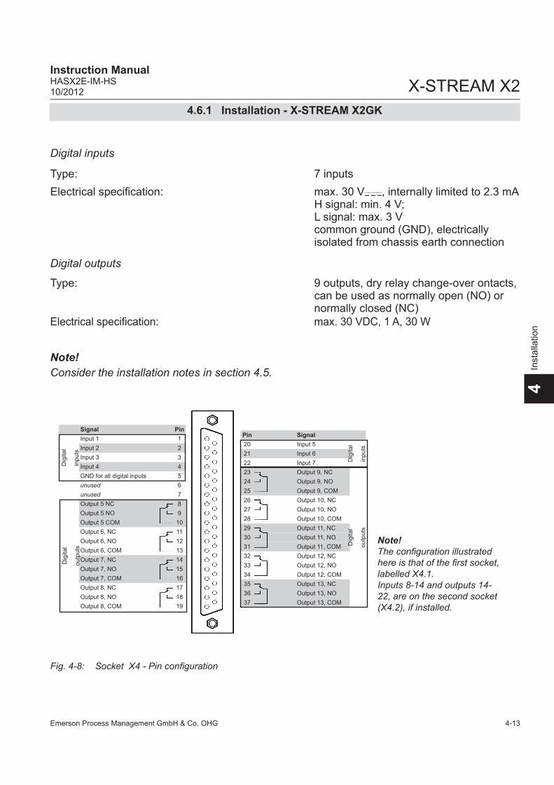
Emerson Process Management GmbH & Co. OHG 4-13
X-STREAM X2 Instruction ManualHASX2E-IM-HS10/2012
4In
stal
latio
n
4.6.1 Installation - X-STREAM X2GK
Fig. 4-8: Socket X4 - Pin configuration
Digital inputs
Type: 9 outputs, dry relay change-over ontacts, can be used as normally open (NO) or normally closed (NC) Electrical specification: max. 30 VDC, 1 A, 30 W
Note!Consider the installation notes in section 4.5.
Type: 7 inputs Electrical specification: max. 30 V , internally limited to 2.3 mA H signal: min. 4 V; L signal: max. 3 V common ground (GND), electrically isolated from chassis earth connection
Digital outputs
Signal PinInput 1 1Input 2 2Input 3 3Input 4 4GND for all digital inputs 5unused 6unused 7Output 5 NC 8Output 5 NO 9Output 5 COM 10Output 6, NC 11Output 6, NO 12Output 6, COM 13Output 7, NC 14Output 7, NO 15Output 7, COM 16Output 8, NC 17Output 8, NO 18Output 8, COM 19
Dig
ital
outp
uts
Dig
ital
inpu
ts
Pin Signal20 Input 521 Input 622 Input 723 Output 9, NC24 Output 9, NO25 Output 9, COM26 Output 10, NC27 Output 10, NO28 Output 10, COM29 Output 11, NC30 Output 11, NO31 Output 11, COM32 Output 12, NC33 Output 12, NO34 Output 12, COM35 Output 13, NC36 Output 13, NO37 Output 13, COM
Dig
ital
outp
uts
Dig
ital
inpu
ts
Note!The configuration illustrated here is that of the first socket, labelled X4.1. Inputs 8-14 and outputs 14-22, are on the second socket (X4.2), if installed.

Emerson Process Management GmbH & Co. OHG4-14
X-STREAM X2Instruction Manual
HASX2E-IM-HS10/2012
4.6.1 Installation - X-STREAM X2GK
Power supply24 VDC is supplied to the unit by means of a three-pin XLR connector on the rear panel of the instrument.Depending on the order, the following is sup-plied as an accessory: either • an external power supply unit which can
be connected directly to the analyzer using the supplied cable
or• a connector which can be used with a
cable and PSU as specified by the cu-stomer.
Note the configuration of the pins on the con-nector ( Fig. 4-9, upper image).
Fig. 4-9: Power In Connectors
1: ME 2: + 24 V3: 0 V (⊥)
2 3 1
Details of any PSUs supplied with the unit are given in section 2.2.1.1, page 2-8ff.
AC power is supplied to the unit by means of a three-pin IEC connector on the rear panel of the instrument.
DC supply
AC supply

Emerson Process Management GmbH & Co. OHG 4-15
X-STREAM X2 Instruction ManualHASX2E-IM-HS10/2012
4In
stal
latio
n
The brackets either side of the front panel enable the unit to be mounted in a rack; this is accomplished by means of four screws (Fig. 4-10).X-STREAM X2GP analyzers should be ope-rated in a horizontal position.
4.6.2 X-STREAM X2GPThis model is fitted with plugs and sockets as standard for electrical connections. They are located at the rear of the instrument (Fig. 4-11).Optionally, adapters are available which can be mounted on the signal connectors to enable signal cables to be connected using screw-type terminals (Fig. 4-12).
4.6.2 Installation - X-STREAM X2GP
Fig. 4-10: X-STREAM X2GP - front view
Screw holes for rack mounting (7.5 x 10.5 mm)

Emerson Process Management GmbH & Co. OHG4-16
X-STREAM X2Instruction Manual
HASX2E-IM-HS10/2012
The number and configuration of the gas inlets and outlets vary from model to model and are indicated on the notice on the rear of the instrument.To simplify installation, we recommend labelling the gas lines as in Fig. 4-11 (1, 2, 3, 4, ...). This avoids confusion in case the analyzer ever has to be disconnected.
Gas inlets and outletsQuantity: max. 8 (plus. 1 purge gas inlet (optional)) Specification: 6/4 mm PVDF optional 6/4 mm or 1⁄4", stainless steel, others on request
Fig. 4-11: X-STREAM X2GP - Rear panel, model with signal plugs and sockets
Gas
inle
ts
Gas
out
lets
Pur
ge g
as in
let
(opt
iona
l)
Mai
ns p
ower
in
Fuse
s
Pow
er s
witc
h
Ana
log
outp
uts
/ NA
-M
UR
sta
tus
rela
ys
Mod
bus
inte
rface
(RS
485
/ R
S 2
32 /
M
odbu
s 48
5)
Dig
ital i
nput
s /
outp
uts
RJ4
5 E
ther
net
conn
ectio
n (o
ptio
nal)
Ser
vice
s in
terfa
ce
4.6.2 Installation - X-STREAM X2GP
Cov
er fo
r tO
2-Sen
sor

Emerson Process Management GmbH & Co. OHG 4-17
X-STREAM X2 Instruction ManualHASX2E-IM-HS10/2012
4In
stal
latio
n
4.6.2 Installation - X-STREAM X2GP
Fig. 4-12: X-STREAM X2GP - Rear panel, with terminal adapters and brackets for rack mounting
Gas
inle
ts
Gas
out
lets
Pur
ge g
as in
let
(opt
iona
l)
Ana
log
outp
uts
/ NA
-M
UR
sta
tus
rela
ys
Mod
bus
inte
rface
(RS
485
/ R
S 2
32 /
M
odbu
s 48
5)
Dig
ital i
nput
s /
outp
uts
Net
zspa
nnun
gs-
eing
ang
Sic
heru
ngen
RJ4
5 E
ther
net
conn
ectio
n (o
ptio
nal)
Net
zsch
alte
r
Ser
vice
s in
terfa
ce
Stra
in re
lief a
nd
shie
ldin
g co
ntac
ts
for s
igna
l cab
les
Cov
er fo
r eO
2-Sen
sor

Emerson Process Management GmbH & Co. OHG4-18
X-STREAM X2Instruction Manual
HASX2E-IM-HS10/2012
4.6.2 Installation - X-STREAM X2GP
Fig. 4-13: Socket X1 - Analog & Digital Outputs 1-4
Signal inputs and outputs
The number of signal outputs actually available varies according to the unit’s configuration.
Analog signals Relay outputs Analog signals and relay outputs are on a shared 25-pin submin socket (X1; Fig. 4-13). Specification of analog signal outputs: 4 (0)–20 mA; burden: RB ≤ 500 Ω
Specification of relay outputs 1-4: Dry relay change-over contacts can be used as NO or NC. Electrical specification: max. 30 VDC, 1 A, 30 W
Note!Consider the installation notes in section 4.5.
Note!Configuration of relay contacts as per standard factory setting (NAMUR status signals)
Signal Pin
Ana
log
outp
uts
Channel 1, (+) 4 (0)–20 mA 1Channel 2, (+) 4 (0)–20 mA 2Channel 3, (+) 4 (0)–20 mA 3Channel 4, (+) 4 (0)–20 mA 4unused 5unused 6unused 7
Rel
ay c
onta
cts
(Sta
tus
sign
als)
Output1 (Failure) NC 8Output1 (Failure) NO 9Output1 (Failure) COM 10Output3 (Off spec) NC 11Output3 (Off spec) NO 12Output3 (Off spec) COM 13
Pin Signal14 Channel 1, GND
Ana
log
outp
uts15 Channel 2, GND
16 Channel 3, GND17 Channel 4, GND18 unused19 unused20 Output2 (Maintenance request) NC
Rel
ay c
onta
cts
(Sta
tus
sign
als)21 Output2 (Maintenance request) NO
22 Output2 (Maintenance request) COM23 Output4 (Function check) NC24 Output4 (Function check) NO25 Output4 (Function check) COM

Emerson Process Management GmbH & Co. OHG 4-19
X-STREAM X2 Instruction ManualHASX2E-IM-HS10/2012
4In
stal
latio
n
4.6.2 Installation - X-STREAM X2GP
Fig. 4-14: Plug X2 - Modbus interface
Modbus interfaceFor specifications and notes on control, see
chapter 7
Notes!Consider the installation notes in section 4.5.When terminal adapters are used, the Mod-bus interface terminals are located on the same adapter as those for the analog signal outputs ( Fig. 4-15, page 4-20).Then a flat flexible cable attached to the ter-minal adapter is used for connecting to the illustrated 9-pole plug.
X-STREAM analyzers are classified as DTE (Data Terminal Equipment).
Pin6789
Pin12345
Pin 1
Pin 8
Ethernet connector
Pin no. Signal
1 TX+2 TX-3 RX+6 RX-
other not used
Pin no.MOD 485/
2 wireMOD 485/
4 wireRS 232
1 Common Common Common2 not used not used RXD3 not used not used TXD4 not used RXD1(+) not used
5 D1(+) TXD1(+) Common6 not used not used not used
7 not used not used not used
8 not used RXD0(-) not used
9 D0(-) TXD0(-) not used

Emerson Process Management GmbH & Co. OHG4-20
X-STREAM X2Instruction Manual
HASX2E-IM-HS10/2012
Pin SignalP2.1 Channel 1, (+) 4 (0)–20 mAP2.2 Channel 1, GNDP2.3 Channel 2, (+) 4 (0)–20 mAP2.4 Channel 2, GNDP2.5 Channel 3, (+) 4 (0)–20 mAP2.6 Channel 3, GNDP2.7 Channel 4, (+) 4 (0)–20 mAP2.8 Channel 4, GNDP2.9 not usedP2.10 not usedP2.11 not usedP2.12 not usedP3.1 not usedP3.2 not usedP3.3 Output 1 (Failure), NCP3.4 Output 1 (Failure), NOP3.5 Output 1 (Failure), COMP3.6 Output 2 (Maintenance Request), NCP3.7 Output 2 (Maintenance Request), NOP3.8 Output 2 (Maintenance Request), COMP3.9 Output 3 (Out of Spec), NCP3.10 Output 3 (Out of Spec), NOP3.11 Output 3 (Out of Spec), COMP3.12 Output 4 (Function check), NCP4.1 Output 4 (Function check), NOP4.2 Output 4 (Function check), COMP4.3 not usedP4.4P4.5P4.6P4.7P4.8P4.9P4.10P4.11P4.12
Rel
ay O
utpu
ts**
)A
nalo
g O
utpu
tsS
eria
l Int
erfa
ce*)
4.6.2 Installation - X-STREAM X2GP
Fig. 4-15: Configuration of XSTA terminal adapter
To connect any serial interface, the adapter is equipped with a flat flexible cable ending in a 9-pin Submin-D plug, which should be plugged onto the unit’s X2 connector.
1 Connector for plug X1 (on reverse side)2 Connection for flat cable to plug X2 (cable not illustrated)3 Screw-type terminals
Note! Consider the installation notes in section 4.5.
Recommended wire gauge: 0.14…1.5 mm2 (AWG 26…AWG 16), end sleeves not requiredSkinning length: 5 mmThread: M2 min. tightening torque: 0.25 Nm
The XSTA adapter can optionally be used to connect signal cables to screw-type terminals instead of Submin-D plugs and sockets: it is plugged onto the X1 Submin-D connector on the unit.
1 2 3
Assignment of serial interface terminals
*) See table below
**) Configuration of relay output termi-nals as per standard factory setting (NAMUR status signals)
TerminalMOD 485/
2 wireMOD 485/
4 wireRS 232
P4.4 SER1 Common Common CommonP4.5 SER2 not used not used RXDP4.6 SER3 not used not used TXDP4.7 SER4 not used RXD1(+) not usedP4.8 SER5 D1(+) TXD1(+) CommonP4.9 SER6 not used not used not used
P4.10 7 not used not used not usedP4.11 8 not used RXD0(-) not usedP4.12 9 D0(-) TXD0(-) not used

Emerson Process Management GmbH & Co. OHG 4-21
X-STREAM X2 Instruction ManualHASX2E-IM-HS10/2012
4In
stal
latio
n
4.6.2 Installation - X-STREAM X2GP
Fig. 4-16: Sockets X4.1 and X4.2 - Pin configuration
Digital inputs
Type: 9 outputs, dry relay change-over ontacts, can be used as normally open (NO) or normally closed (NC) Electrical specification: max. 30 VDC, 1 A, 30 W
Type: 7 inputs Electrical specification: max. 30 V , internally limited to 2.3 mA H Signal: min. 4 V; L Signal: max. 3 V common ground (GND), electrically isolated from chassis earth connection
Digital outputs
Notes! Depending on the configuration, an ana-lyzer may be fitted with up to 2 of these sockets (the unit is thus equipped with 14 digital inputs and 18 digital outputs). To aid
identification, the sockets are labelled X4.1 and X4.2. Consider the installation notes in section 4.5.
Signal PinInput 1 1Input 2 2Input 3 3Input 4 4GND for all digital inputs 5unused 6unused 7Output 5 NC 8Output 5 NO 9Output 5 COM 10Output 6, NC 11Output 6, NO 12Output 6, COM 13Output 7, NC 14Output 7, NO 15Output 7, COM 16Output 8, NC 17Output 8, NO 18Output 8, COM 19
Dig
ital
outp
uts
Dig
ital
inpu
ts
Pin Signal20 Input 521 Input 622 Input 723 Output 9, NC24 Output 9, NO25 Output 9, COM26 Output 10, NC27 Output 10, NO28 Output 10, COM29 Output 11, NC30 Output 11, NO31 Output 11, COM32 Output 12, NC33 Output 12, NO34 Output 12, COM35 Output 13, NC36 Output 13, NO37 Output 13, COM
Dig
ital
outp
uts
Dig
ital
inpu
ts
Note!The configuration illustrated here is that of the first socket, labelled X4.1. Inputs 8-14 and outputs 14-23, are on the second socket (X4.2), if installed.

Emerson Process Management GmbH & Co. OHG4-22
X-STREAM X2Instruction Manual
HASX2E-IM-HS10/2012
Pin SignalP3.1 Input 1P3.2 Input 2P3.3 Input 3P3.4 Input 4P3.5 Input 5P3.6 Input 6P3.7 Input 7P3.8 GND for inputs 1-7P3.9 unusedP3.10 Output 5, NCP3.11 Output 5, NOP3.12 Output 5, COMP4.1 Output 6, NCP4.2 Output 6, NOP4.3 Output 6, COMP4.4 Output 7, NCP4.5 Output 7, NOP4.6 Output 7, COMP4.7 Output 8, NCP4.8 Output 8, NOP4.9 Output 8, COMP4.10 Output 9, NCP4.11 Output 9, NOP4.12 Output 9, COMP2.1 Output 10, NCP2.2 Output 10, NOP2.3 Output 10, COMP2.4 Output 11, NCP2.5 Output 11, NOP2.6 Output 11, COMP2.7 Output 12, NCP2.8 Output 12, NOP2.9 Output 12, COMP2.10 Output 13, NCP2.11 Output 13, NOP2.12 Output 13, COM
Dig
ital i
nput
sD
igita
l out
puts
4.6.2 Installation - X-STREAM X2GP
Fig. 4-17: Configuration of XSTD terminal adapter
An XSTD adapter can optionally be used to connect digital I/O cables to screw-type termi-nals instead of Submin-D plugs and sockets: it is plugged onto the X4.1 and X4.2 (if fitted) Submin-D connectors on the unit.
1 Connector for socket X4.1 / X4.2 (on reverse side)2 Screw-type terminals
Note! Consider the installation notes in section 4.5.
1 2
Recommended wire gauge: 0.14…1.5 mm2, end sleeves not requiredSkinning length: 5 mmThread: M2 Min. tightening torque: 0.25 Nm
Note!The configuration illustrated here is that of the first adapter (on socket X4.1). Inputs 8-14 and outputs 14-23 are on the se-cond adapter (on socket X4.2), if installed.

Emerson Process Management GmbH & Co. OHG 4-23
X-STREAM X2 Instruction ManualHASX2E-IM-HS10/2012
4In
stal
latio
n
4.6.3 Installation - X-STREAM X2XF Field Housings
4.6.3 X-STREAM X2XF Field Housings (Single XLF; Dual XXF)Fitted with four eyebolts and featuring IP66 / Type 4X protection, the X-STREAM X2XF
Fig. 4-18: X-STREAM XLF
field housings can be mounted in the open air on a wall or frame with no extra work.
Dimensions: mm [inch]
HEAVY INSTRUMENT X-STREAM X2XF field housing analyzers intended to be wall mounted and/or outdoor installed, weigh up to 45 kg (99 lbs), depending on the chosen options!Use two persons and/or suitable tools for transportation and lifting these instruments!Take care to use anchors and bolts specified to be used for the weight of the instruments!Assure that the wall/device for installation is sufficiently attached and stable to carry the instrument!
Cable glands
Gas fittings
Connector for potentialequalization
Note!Take care to re-serve space at the right side of the instrument for laying the ca-bles!

Emerson Process Management GmbH & Co. OHG4-24
X-STREAM X2Instruction Manual
HASX2E-IM-HS10/2012
4.6.3 Installation - X-STREAM X2XF Field Housings
All dimensions in mm [inches in brackets]
Cable glands
Connector for potentialequalization
Gas fittings
Note!Take care to reserve space at the right side of the instru-ment for laying the cables!
Fig. 4-19: X-STREAM XXF

Emerson Process Management GmbH & Co. OHG 4-25
X-STREAM X2 Instruction ManualHASX2E-IM-HS10/2012
4In
stal
latio
n
Fig. 4-20: X-STREAM X2XF Field Housings - Arrangement of Terminals, Cable Glands and Gas Fittings
4.6.3 Installation - X-STREAM X2XF Field Housings
Power and signal cables are connected using internal screw-type terminals. This requires opening the unit by releasing the fasteners on the housing.Gas connectors are accessible from the un-derside of the instrument.The number and configuration of the gas inlets and outlets depends on the analytical application, and is noted on a sticker on the underside of the instrument next to the con-nectors.
To simplify installation, we recommend label-ling the gas lines in accordance with these markings. This avoids confusion should the analyzer need to be disconnectedfor main-tenance.
5 Glands for signal cables6 Gas inlets and outlets7 Plugs for openings to connect housings8 Ethernet connector (optional)
1 Terminals for signal cables2 Mains filter3 Power connections with integrated fuses4 Gland for power cable
657
Gas
inle
tsG
as o
utle
ts
18 423
Note on variation XXF!In case of the dual compartment version XXF, the electrical connections are established in the upper compartment, and the gas connections to fittings at the lower compartment.Besides this, the design and layout of terminals and fittings are the same as with the single com-partment version XLF.
GASKETS AT LOW TEMPERATURESConsider that enclosure gas-kets may be frozen when the instrument is installed outdoors. Carefully open the enclosure at temperatures below -10 °C (14 °F) to not damage the gaskets. Damaged gaskets void the ingress protection, possibly causing property damage, personal injury or death.

Emerson Process Management GmbH & Co. OHG4-26
X-STREAM X2Instruction Manual
HASX2E-IM-HS10/2012
All signal cables are connected to screw-type terminals located inside the housing. Access to the internal components is gained by relea-
Preparation of signal cables
Recommended wire gauge: 0.14…1.5 mm2 (AWG 26…AWG 16), end sleeves not requiredSkinning length: 5 mm (0.2")Thread: M2 Min. tightening torque: 0.25 Nm (2.21 in.lb)
4.6.3 Installation - X-STREAM X2XF Field Housings
All cables must be fed through cable glands and secured with a gland nut.
When correctly installed, the glands act as a strain relief and guarantee EMC (electroma-gnetic compatibility):
sing the two fasteners at the front door and opening it to the left.
Gas inlets and outletsQuantity: max. 8 (+ 1 purge gas inlet (optional)) Specification: 6/4 mm PVDF optional 6/4 mm or 1⁄4", stainless steel, others on request
Installing cable glands with shielded cables
3. Feed cable through
dome nut and clam-ping insert
4. Fold braided shield over clamping insert
5. Make sure that brai-ded shield overlaps the O-ring by 3⁄32“ (2 mm)
1. Strip the cabel 2. Expose braided
shield
6. Push clamping insert into body and tighten dome nut
7. Assemble into housing and you´re done!

Emerson Process Management GmbH & Co. OHG 4-27
X-STREAM X2 Instruction ManualHASX2E-IM-HS10/2012
4In
stal
latio
n
Signal inputs and outputs
4.6.3 Installation - X-STREAM X2XF Field Housings
The number of actually available signal out-puts, and also the number of built-in modules with screw-type terminals, varies according to the configuration of the unit.
A maximum of three modules with 36 termi-nals each can be fitted. The terminals can be accessed by opening the front panel of the instrument.
Characteristics of terminals:Recommended wire gauge: 0.14…1.5 mm2 (AWG 26…AWG 16), end sleeves not requiredSkinning length: 5 mm (0.2")Thread: M2 Min. tightening torque: 0.25 Nm (2.21 in.lb)
ELECTRICAL SHOCK HAZARDVerify the power supply at installation site meets the specification given on the analyzer´s nameplate label, before installing the instrument!Verify power cables are disconnected and/or instrument is de-energized prior to working at the terminals!Verify the power cord is layed with a distance of at least 1 cm (0.4 in) to any signal cable to ensure proper insulation from signal circuits!

Emerson Process Management GmbH & Co. OHG4-28
X-STREAM X2Instruction Manual
HASX2E-IM-HS10/2012
4.6.3 Installation - X-STREAM X2XF Field Housings
Fig. 4-21: Terminal block X1 - Analog signals and relay outputs 1-4
Note!Consider the installation notes in section 4.5 and the notes on installing cable glands on page 4-24.
Analog signals Relay outputs Terminals for analog signals and relais outputs 1 - 4 are located on the outer left module (terminal block X1; Fig. 4-21). Analog signal output specification: 4 (0)–20 mA; load: RB ≤ 500 Ω
Specification of relay outputs 1-4: dry relay change-over ontacts, can be used as normally open (NO) or normally closed (NC) Electrical specification: max. 30 VDC, 1 A, 30 W
PinSignal
P2.1
Channel 1, (+) 4 (0)–20 m
AP
2.2C
hannel 1, GN
DP
2.3C
hannel 2, (+) 4 (0)–20 mA
P2.4
Channel 2, G
ND
P2.5
Channel 3, (+) 4 (0)–20 m
AP
2.6C
hannel 3, GN
DP
2.7C
hannel 4, (+) 4 (0)–20 mA
P2.8
Channel 4, G
ND
P2.9
not usedP
2.10not used
P2.11
not usedP
2.12not used
P3.1
not usedP
3.2not used
P3.3
Output 1 (Failure), N
CP
3.4O
utput 1 (Failure), NO
P3.5
Output 1 (Failure), C
OM
P3.6
Output 2 (M
aintenance Request), N
CP
3.7O
utput 2 (Maintenance R
equest), NO
P3.8
Output 2 (M
aintenance Request), C
OM
P3.9
Output 3 (O
ut of Spec), N
CP
3.10O
utput 3 (Out of S
pec), NO
P3.11
Output 3 (O
ut of Spec), C
OM
P3.12
Output 4 (Function check), N
CP
4.1O
utput 4 (Function check), NO
P4.2
Output 4 (Function check), C
OM
P4.3
not usedP
4.4P
4.5P
4.6P
4.7P
4.8P
4.9P
4.10P
4.11P
4.12
Relay Outputs**) Analog OutputsSerial Interface*)
**) Configuration of relay output termi-nals as per standard factory setting (NAMUR status signals)

Emerson Process Management GmbH & Co. OHG 4-29
X-STREAM X2 Instruction ManualHASX2E-IM-HS10/2012
4In
stal
latio
n
4.6.3 Installation - X-STREAM X2XF Field Housings
Modbus interfaceSpecification and interface control:
Chapter 9
Fig. 4-22: Terminal block X1 - Modbus interface
Notes!Consider the installation notes in section 4.5 and the notes on instal-ling cable glands on page 4-24.
X-STREAM analyzers are classified as DTE (Data Terminal Equipment).
The type of serial interface is mar-ked on a label nearby the terminals (see sample above)
The 9 terminals on the left (28 - 36) of the right most strip carry the Modbus interface signals.
PinSignal
P2.1
Channel 1, (+) 4 (0) - 20 m
AP
2.2C
hannel 1, GN
DP
2.3C
hannel 2, (+) 4 (0) - 20 mA
P2.4
Channel 2, G
ND
P2.5
Channel 3, (+) 4 (0) - 20 m
AP
2.6C
hannel 3, GN
DP
2.7C
hannel 4, (+) 4 (0) - 20 mA
P2.8
Channel 4, G
ND
P2.9
not usedP
2.10not used
P2.11
not usedP
2.12not used
P3.1
not usedP
3.2not used
P3.3
Output 1 (Failure), N
CP
3.4O
utput 1 (Failure), NO
P3.5
Output 1 (Failure), C
OM
P3.6
Output 2 (M
aintenance Request), N
CP
3.7O
utput 2 (Maintenance R
equest), NO
P3.8
Output 2 (M
aintenance Request), C
OM
P3.9
Output 3 (Function C
ontro), NC
P3.10
Output 3 (Function C
ontro), NO
P3.11
Output 3 (Function C
ontro), CO
MP
3.12O
utput 4 (Out of S
pec), NC
P4.1
Output 4 (O
ut of Spec), N
OP
4.2O
utput 4 (Out of S
pec), CO
MP
4.3not used
P4.4
P4.5
P4.6
P4.7
P4.8
P4.9
P4.10
P4.11
P4.12
Relay Outputs**) Analog OutputsSerial Interface*)
*) See table below
X
TerminalMOD 485/
2 wireMOD 485/
4 wireRS 232
P4.4 SER1 Common Common CommonP4.5 SER2 not used not used RXDP4.6 SER3 not used not used TXDP4.7 SER4 not used RXD1(+) not usedP4.8 SER5 D1(+) TXD1(+) CommonP4.9 SER6 not used not used not used
P4.10 7 not used not used not usedP4.11 8 not used RXD0(-) not usedP4.12 9 D0(-) TXD0(-) not used

Emerson Process Management GmbH & Co. OHG4-30
X-STREAM X2Instruction Manual
HASX2E-IM-HS10/2012
4.6.3 Installation - X-STREAM X2XF Field Housings
If fitted, the optional RJ45 connection is loca-ted on an electronics board in the card cage section of the unit (Fig. 4-9, pg. 4-23).To install this connection, a cable must be fed through the cable entry without a con-nector.
The connector can be wired on when the free end has been fed into the instrument: We recommend the VARIOSUB RJ45 QUICK-ON connector (PHOENIX CONTACT), which is supplied with the unit and requires no spe-cial tools. Wiring instructions can be found in the separate manual supplied with the connector.
Optional Modbus RJ45 connection
Fig. 4-23: X-STREAM X2XF Field Housings - Ethernet connector
Note!Please note that although the Modbus termi-nals ( previous page) are still installed, they are not connected!
Pin 1 Pin 8
Pin no. Signal
1 TX+2 TX-3 RX+6 RX-
othernot
used

Emerson Process Management GmbH & Co. OHG 4-31
X-STREAM X2 Instruction ManualHASX2E-IM-HS10/2012
4In
stal
latio
n
4.6.3 Installation - X-STREAM X2XF Field Housings
Fig. 4-24: Terminal blocks for digital inputs and outputs
Digital inputs
Quantity: 9 (1 terminal block) or 18 (2 terminal blocks), dry relay change-over ontacts, can be used as normally open (NO) or normally closed (NC) Electrical specification: max. 30 VDC, 1 A, 30 W
Quantity: 7 (1 terminal block) or 14 (2 terminal blocks)Electrical specification: max. 30 V , internally limited to 2.3 mA H Signal: min. 4 V; L Signal: max. 3 V common ground (GND), electrically isolated from chassis earthDigital outputs
Notes!Depending on configuration, an analyzer can be fitted with up to two of these ter-minal blocks (the unit will then feature 14 digital inputs and 18 digital outputs). To aid identification, the sockets are labelled X4.1 and X4.2 (see sample of label to the right).
Consider the installation notes in section 4.5. and the notes on installing cable glands on page 4-24.
Note!The configuration illustra-ted here is that of the first adapter. Inputs 8-14 and outputs 14-23, if available, are on the second adapter.
PinSignal
P3.1
Output 1
P3.2
Output 2
P3.3
Output 3
P3.4
Output 4
P3.5
Output 5
P3.6
Output 6
P3.7
Output 7
P3.8
GN
D for inputs 1-7
P3.9
unusedP
3.10O
utput 5, NC
P3.11
Output 5, N
OP
3.12O
utput 5, CO
MP
4.1O
utput 6, NC
P4.2
Output 6, N
OP
4.3O
utput 6, CO
MP
4.4O
utput 7, NC
P4.5
Output 7, N
OP
4.6O
utput 7, CO
MP
4.7O
utput 8, NC
P4.8
Output 8, N
OP
4.9O
utput 8, CO
MP
4.10O
utput 9, NC
P4.11
Output 9, N
OP
4.12O
utput 9, CO
MP
2.1O
utput 10, NC
P2.2
Output 10, N
OP
2.3O
utput 10, CO
MP
2.4O
utput 11, NC
P2.5
Output 11, N
OP
2.6O
utput 11, CO
MP
2.7O
utput 12, NC
P2.8
Output 12, N
OP
2.9O
utput 12, CO
MP
2.10O
utput 13, NC
P2.11
Output 13, N
OP
2.12O
utput 13, CO
M
Digital inputsDigital outputs

Emerson Process Management GmbH & Co. OHG4-32
X-STREAM X2Instruction Manual
HASX2E-IM-HS10/2012
Connecting the power cordThe power cord is connected to screw-type terminals located inside the housing.Supported wire cross sections: 0.2…4 mm2 (24…12 AWG), no need to use wire end sleevesCable skinning length: 8 mm (0.315 inch)Hole diameter: 1.2 mm (0.05 inch)Screw thread: M 3 Tightening torque, min: 0.5 Nm (4.4 in.lb)
Fig. 4-25: Power supply connections
4.6.3 Installation - X-STREAM X2XF Field Housings
ELECTRICAL SHOCK HAZARDVerify the power supply at installation site meets the specification given on the analyzer´s nameplate label, before installing the instrument!Verify power cables are disconnected and/or instrument is de-energized prior to working at the terminals!Verify the power cord is layed with a distance of at least 1 cm (0.5“) to any signal cable to ensure proper insulation from signal circuits!
Feed the power cable through the cable gland at the instrument´s right side and strip the outer insulation. Strip the individual wires and connect to the terminals (a label is loca-ted next to the terminals on the mains filter housing).Finally, tighten the outer dome nut to secure the power cable.
Live L
Earth PENeutral N
Power supply cable gland

Emerson Process Management GmbH & Co. OHG 4-33
X-STREAM X2 Instruction ManualHASX2E-IM-HS10/2012
4In
stal
latio
n
4.6.3 Installation - X-STREAM X2XF Field Housings
ELECTRICAL SHOCK HAZARD BY MISSING EARTHING CONDUCTORBefore completing the electrical connection of the instrument, verify cables are inserted and connected in correct manner!Ensure the earthing conductor (protective earth; PE) is connected!
After all connections are correctly made and checked, • close the front panel and secure with the
two fasteners.
To achieve best and proper measuring results you must ensure the gas path system does not have leaks. For this reason we recom-mend to carry out a leak test, as it is described within Chapter 7 "Maintenance and other Procedures".
Completing the installation process

Emerson Process Management GmbH & Co. OHG4-34
X-STREAM X2Instruction Manual
HASX2E-IM-HS10/2012
4.7 Notes On Wiring Signal Inputs and Outputs
4.7 Installation - Notes on Wiring
Emerson Process Managament has made every effort during the development process to ensure that the X-STREAM analyzer series ensures electromagnetic compatibility (EMC) with respect to emission and interference resi-stance, as confirmed by EMC measurements.
However, EMC is not wholly influenced by the design of the instrument, but to a large degree by the on-site installation process. Please observe the following sections and precauti-ons to guarantee the safe and problem-free operation of this analyzer.
4.7.1 Electrical Shielding Of CablesIn order to minimise ambient electromagne-tic interference, it is necessary to take care making all electrical connections between the analyzer and any other devices:
• We recommend using only shielded signal cables. The shielding must be connected at both ends to the housing (Fig. 4-26).
Fig. 4-26: Shielded signal cable, shielding connected at both ends.

Emerson Process Management GmbH & Co. OHG 4-35
X-STREAM X2 Instruction ManualHASX2E-IM-HS10/2012
4In
stal
latio
n
On-site conditions often differ from test environments and may require special pre-cautions. Such a case arises when strong electromagnetic fields which could induce an interference current in the shielding. This type of current creates a potential difference between the connected housings.Two possible methods of eliminating this are described here. Fitters familiar with EMC problems must decide which method should be emplyed.
• The shielding is connected only at one end (connecting to the analyzer is re-commended): this gives better protection against external interference, and inter-ference currents are prevented because the ground loop is interrupted.
• Cables with double shielding are used: in this case, one shielding is connected to the analyzer housing, the other shielding to the external device. This is advan-tageous when both units are supplied from different grids (e.g. when installed in different buildings).
This method is more expensive, but gi-ves the best protection against external interference and against interference currents.
Fig. 4-27: Shielded signal cable, shielding connected at one end.
Fig. 4-28: Signal cable with double shielding, shieldings connected at alternate ends.
4.7 Installation - Notes on Wiring

Emerson Process Management GmbH & Co. OHG4-36
X-STREAM X2Instruction Manual
HASX2E-IM-HS10/2012
X-STREAM X2GP with screw-type terminal adaptersIn order to avoid measured values being influ-enced by external interference signals when terminal adapters are in use, the signal cable shieldings must be connected to the analy-zer housing by means of shield connector terminals:• Strip the signal cable to a length of 20 cm
(8"). Take care to not damage the braided shield!
• Pull up the contact part of the shield con-nector terminal,
• feed through the cable as illustrated in fig. 4-30,
• release the contact part down onto the braided shield.
This results in a secure contact with the cable shielding and improves the unit’s interference resistance.The individual wires are then connected as described in section 4.5.2.
The shield connector must be ordered to fit the cable diameter, and can be retrofitted: Ø 1.5 - 6.5 mm: part # ETC02019 Ø 5 - 11 mm: part # ETC02020Ø 10 - 17 mm: part # ETC02021Ø 16 - 24 mm: part # ETC02022
Fig. 4-29: Shield connector terminal with cable
4.7 Installation - Notes on Wiring

Emerson Process Management GmbH & Co. OHG 4-37
X-STREAM X2 Instruction ManualHASX2E-IM-HS10/2012
4In
stal
latio
n
4.7.2 Wiring Inductive LoadsSwitching inductive loads creates electroma-gnetic interference: When an inductive load (e.g. relay, valve) is switched off, the magnetic field resists the change in current; this induces a high volta-ge across the coil contacts (several hundred volts). This impulse propogates through the connected cables and can influence any electrical devices nearby or destroy signal inputs and outputs. This can be avoided with a simple precaution:
• A silicon diode is connected in parallel to the load’s contacts. The induced impul-se is thus short-circuited at its source. The cathode must be connected to the positive end of the coil, the anode to the negative end (Fig. 4-30).
Compatible filter components for standard valves are available on request.
4.7 Installation - Notes on Wiring
Fig. 4-30: Suppressor diode for inductive loads.
4.7.3 Driving High-current LoadsLoads which draw a current in excess of the specifications for X-STREAM series analyzer outputs (>30 mA / >1 A) may not be directly driven from digital or relay outputs.Such loads require external relays serving as de-coupling modules: the X-STREAM output drives the external relay, which in turn drives the load.In order to avoid interference, we recommend supplying the analyzer and the high-current loads from different sources (Fig. 4-31).As previously described, the use of sup-pressor diodes for inductive loads is highly recommended.
Last
Fig. 4-31: Driving high-current loads
External relay
Analyzer output

Emerson Process Management GmbH & Co. OHG4-38
X-STREAM X2Instruction Manual
HASX2E-IM-HS10/2012
Frequently, several loads in one system are controlled by several analyzer outputs, whe-reby the power for the loads derives from a common source. Special care is needed when wiring the loads to minimize interference from switching these loads:
• avoid connected the loads in series:
4.7.4 Driving Multiple Loads
Fig. 4-32: Loads in series
• It is recommended that the loads be wired in parallel, and each load is separately connected to the power supply. Beginning at the distribution point, both the + and the - wires of each load are laid together to the load (Fig. 4-33). Interference is further reduced if a twisted multi-core cable is used.
Distribution point
Lay cables to the loads together as far as possible (using twisted-pair cables if possible)
Fig. 4-33: Loads in parallel
4.7 Installation - Notes on Wiring

Emerson Process Management GmbH & Co. OHG 5-1
X-STREAM X2Instruction ManualHASX2E-IM-HS10/2012
5S
tartu
p
Chapter 5 Startup
Once the unit has been unpacked and in-stalled, it is recommended to first check the settings and if necessary adjust them to the user’s needs. e.g:• What hardware is installed?• Is the unit configured to your needs
(alarms, inputs, outputs, etc.)In order for the information in this chapter to be of any relevence, the unit must have been installed according to the instructions in chapter 4.
5.1 IntroductionThe following pages describe how to navigate through the menus and what is to be observed when configuring the unit. For the first startup after installation, follow the step-by-step in-structions for navigating the menus, allowing you to familiarise yourself with the unit and its software, and if necessary adjust the settings to your own requirements.
OPERATION AT LOW TEMPERATURESWhen operating an instrument at temperatures below 0 °C (32 °F), do NOT apply gas nor operate the internal pump before the warmup time has elapsed!Violation may result in condensation inside the gas paths or damaged pump diaphragm!

Emerson Process Management GmbH & Co. OHG5-2
X-STREAM X2Instruction Manual
HASX2E-IM-HS10/2012
All X-STREAM X2 gas analyzers have an alphanumeric display with four lines of 20 characters to display measuring and status information and the easy-to-use menu-based user interface for entering parameters. For ease of understanding, the user can at any time select one of three languages stored in the unit (currently available: English, French, German, Italian, Portuguese and Spanish in various combinations).
Fig. 5-1: X-STREAM Front Panel
5.2 Front Panel Elements
5.2 Front Panel Elements
Units are operated using six keys on the front panel.Three LEDs on the front panel enable the operating status to be recognised instantly.

Emerson Process Management GmbH & Co. OHG 5-3
X-STREAM X2Instruction ManualHASX2E-IM-HS10/2012
5S
tartu
p
5.2.1 Display
The display has 4x20 characters, either li-quid crystal or vacuum fluorescent (LCD or VFD).What information is displayed depends on the currently displayed menu.
5.2.2 Status LED
5.2 Front Panel Elements
Three status LED indicate the unit’s status, recognisable from a distance. Status is indicated in accordance with the German NAMUR NE 44 recommendations.
“Failure” is indicated when this red LED is lit.
A flashing red LED in the middle indicates “Maintenance request”, “Function check” or “Off-spec operation”.
The third, green LED indicates the power supply status:on: power supply OKoff: power supply interrupted

Emerson Process Management GmbH & Co. OHG5-4
X-STREAM X2Instruction Manual
HASX2E-IM-HS10/2012
5.2.3 Keys
Six keys enable the use of the menu system. Depending on the operational mode (measu-ring, browsing menus, editing) they have the following functions:
ENTER key:
Mode Function
Measuring Leaves the measurement dis-play
Browsing Accesses submenu (..) or exe-cutes command (!)
Editing Confirms new entry
MEASURE key:
Mode FunctionMeasuring (no function)
Browsing Returns to measurement dis-play
Editing Cancels entry
UP / DOWN keys:
Mode Function
Measuring Leaves the measurement dis-play
Browsing
Selects menu lineGoes to previous/next page, when currently in a line begin-ning with /
Editing Changes current parameter
5.2 Front Panel Elements

Emerson Process Management GmbH & Co. OHG 5-5
X-STREAM X2Instruction ManualHASX2E-IM-HS10/2012
5S
tartu
p
LEFT key:
Mode Function
Measuring Leaves the measurement display
Browsing Goes up 1 level or page in menu system
Editing
Moves cursor 1 space Leaves channel selectionCancels editing of given pa-rameterGoes to previous page, when showing in first line
RIGHT key:
Mode FunctionMeasuring Leaves the measurement
displayBrowsing Accesses submenu (..)
EditingGoes to next page, when showing in fourth lineMoves cursor 1 space
5.2 Front Panel Elements

Emerson Process Management GmbH & Co. OHG5-6
X-STREAM X2Instruction Manual
HASX2E-IM-HS10/2012
5.3 Symbols Used
5.3 Symbols Used
Symbol Description
Within Process Descriptions
Setup.. Menu title
Setup.. Analog outputs..
Parent (Setup) and current Menu (Analog outputs)
Analog outputs.. Output1 (2...4)
As an example, the menu for Output1 is displayed; the menus for outputs 2 to 4 are identical
Zero calibration..Span calibration..Adv. Calibration..Apply gas..
DisplayNote!Menus or lines on a grey background are optional or context-dependent, and are not always displayedAccess levels:
Access level 1 (user)
Access level 2 (expert)
Access level 3 (administrator)
Access level 4 (service level)
In the following sections, the symbols and typographical conventions described below are used to describe the software menus and navigation.
OthersSymbols used in this section
Convention Description
Within Text
(MENU TITLE) 6.2.2, page 6-12
For a detailed description of the Menu, see section 6.2.2 on page 6-12.
CONTROL.. - ZOOM..From within the CONTROL menu select the ZOOM menu.
“Valves” Parameter nameNever, 1 min Values to be selected
0 ... 2000 Value to be entered

Emerson Process Management GmbH & Co. OHG 5-7
X-STREAM X2Instruction ManualHASX2E-IM-HS10/2012
5S
tartu
p
5.4 Software
The analyzer software displays measure-ment results and status messages, allows parameters to be set and edited and allows maintenance functions (e.g. calibration) to be carried out. To make it possible to perform all these func-tions on a 4x20 display, the software is orga-nised hierarchically: measurement display is
5.4 Software
on the topmost level, while menus and sub-menus are below ( fig. 6-1, page 6-3).The following methods are used to distinguish between various functions, e.g. executing commands:
5.4.1 Navigating and EditingSelecting a line Lines are selected using the (UP/DOWN) keys. The cursor is displayed over the first character of the selected line. It is moved down with the DOWN key and up with the UP key. If the cursor is in the first line, pressing the key will move it to the last line.
If the cursor is in the last line, pressing the key will move it to the first line.An action in the selected line is initiated by pressing the 8 key, i.e. opening a new menu, starting a procedure or entering edit mode.If a selected parameter has been changed, the “function check” status is set, with the following consequences:
Function Description
Displaying TEXT
Simple text (not selectable with cursor)
Editing VARIABLES
A variable description ends with a colon and the line can be made up of up to 3 elements:1. description2. value: number or text3. unit (optional)Examples:
Span gas: 2000 ppmTol.Check: Off
Variables without a colon can-not be edited.
Function Description
Executing COM-MANDS
A command line text ends in a colon; when this line is selec-ted and ENTER pressed, a command is executed, e.g. a calibration procedure.Example:
Start calibration !
Selecting a MENU
A menu line text ends in two dots; when this line is selected and ENTER pressed, a sub-menu is opened.Example:
Setup..

Emerson Process Management GmbH & Co. OHG5-8
X-STREAM X2Instruction Manual
HASX2E-IM-HS10/2012
EditingEditing mode enables the setting of a parame-ter. It is initiated by pressing the 8 key. The cursor is now placed over the last cha-racter of the current value. Pressing the keys change the selected character; if it is a list of possible values, the entire value is changed. The and keys are used to select a spe-cific character for editing.Which characters are available depends on the position of the cursor: • It is not possible to select the minus sign or
decimal point as the last character. • It is not possible to select the decimal point
in integer values.
• For decimal numbers, the decimal point can be placed anywhere within certain limits.
There are two ways to leave editing mode:8 key: the value is verified (e.g. min/max).
If the value is possible, it is saved and the new value displayed; if not, an error message is displayed.
key: Cancel: all settings and changes are reset to their former values.
BrowsingSome menus have more than four entries, and these cannot all be displayed at once. In these menus, an indicator in the last () or first () line indicates the direction the menu continues in.
To show the following page, the cursor is placed in the line with the indicator and the UP or DOWN key pressed. Alternatively, the LEFT or RIGHT key can be used, irrespective of where the cursor is located.
Line 1 Line 2..Line 3Line 4
Menu continues upwards and downwards..
Line 1 Line 2..Line 3Line 4
Menu continues downwards..
Line 1 Line 2..Line 3Line 4
Menu continues upwards.
• the middle LED lights• the NAMUR relay is activated.The status can be reset by acknowledging it in the “Acknowledgements” menu ( 6.2.2.5, page 6-12).
A “function check” message set off by editing a parameter is automatically reset upon re-turning to the measurement display.
5.4 Software

Emerson Process Management GmbH & Co. OHG 5-9
X-STREAM X2Instruction ManualHASX2E-IM-HS10/2012
5S
tartu
p
5.4.2 Access LevelsAccess levels can be used to prevent changes to parameters by unauthorised personnel. The X-STREAM menu system supports four prioritized access levels which can be acti-vated and deactivated separately, and should be supplied with their own access codes.Level four has the highest priority and is used for factory settings — only qualified EMERSON service personnel have access to this level.Level three allows access to system admin parameters, e.g. for data capture and proces-sing systems.Level two covers the expert settings, e.g. basic settings for calibration.Level one is the user level and includes parameters which should be set by trained personnel.Any menus not assigned to one of these levels are not editable or are of minor relevance.In this chapter, the descriptions of the indi-vidual menus also indicate which level the menus are in. These assignments cannot be changed.
Access codes for levels 1 to 3 can be defi-ned, activated and deactivated by the client. The analyzer is delivered with the following settings:Level Access code Status 1 00000001 Off 2 00000002 Off 3 00000003 Off
Note!If a lower level is locked (i.e. its code acti-vated), all higher levels will also be locked.If a higher level is unlocked (i.e. its code deactivated), all lower levels will also be au-tomatically unlocked.
Component selection menuA single channel analyzer has only one measurement channel (component): editing any parameter will only effect this one chan-nel.A multi-channel analyzer requires that a channel must be selected before its parame-ters can be changed. When this selection is necessary, a menu is automatically displayed;
Select component
Component: CO2.1 Back -
it is not displayed on single-channel units.
5.4 Software
It is recommended to set new access codes if they are to be activated ( 6.2.3.1.2, page 6-18).

Emerson Process Management GmbH & Co. OHG5-10
X-STREAM X2Instruction Manual
HASX2E-IM-HS10/2012
5.4.3 Special MessagesDepending on the last action performed by the user, one of the following messages may be displayed to assist or inform the user (the two confirmation messages are displayed only for a few seconds):
Confirmation of cancellation:Confirms that a procedure (e.g. calibration) has been aborted.
(i)
CANCELLED
Confirmation of execution of command:Confirms that a procedure (e.g. calibration) has been started.
5.4 Software
Use:• the UP/DOWN keys to change the cur-
rently selected digit,
Access Code 1
Code 00000001 Back - Press
Entering access codesIf an access code is required for a menu, the following message is displayed:
Information on incorrect entry:The value entered by the user is outside valid limits. The display indicates what limits apply.Pressing 8 returns the display to the previous screen to allow a valid setting to be entered.
Wrong InputMin: 500Max: 10.000 Press 8
• the LEFT/RIGHT keys to select a different digit,
• the ENTER key to submit the codeor• the MEASURE key to leave edit mode
and return to the previous display.
(i)
-COMMAND EXECUTED-

Emerson Process Management GmbH & Co. OHG 5-11
X-STREAM X2Instruction ManualHASX2E-IM-HS10/2012
5S
tartu
p
5.5 Powering Up
When the unit is powered up, a series of in-ternal tests is automatically performed. During this time the front panel keys are disabled,
The measurement display is shown • automaticaly on completion of the boot
sequence• when the MEASURE key is pressed• automatically after a set period of time
of inactivity (i.e. with no keys being pressed).
The information displayed in the four lines of the measurement display can be determined by the operator:• Sample gas components, measuring
results and measuring units for each channel
• additional measurements, e.g. pressu-re, gas flow, temperature
• nothing (empty line)The factory settings are as follows:
Line 1: measured value of channel 1Line 2: measured value of channel 2Line 3: measured value of channel 3Line 4: measured value of channel 4
Note!If less than four channels are installed in the unit, only the values of the available channels will be shown.Line 4 is also used to display plain text status information (errors, maintenance requests, function checks or off-spec performance).If such messages are active, line 4 alternates between the messages and the parameter selected for line 4.
Active messages are stored in an internal buf-fer. If there is more than one message in the buffer, the display will cycle through them.Each message is not just shown in the display as text, but also indicated by the appropriate LED on the front panel and the activation of the appropriate NAMUR relay (if a relay has been assigned to that NAMUR function; page 6-37).Note!There are also functions, that do activate a relay or LED, but are not shown on the display (e.g. concentration alarms). In such cases, check the status menu for more information.Note!Beginning with software rev. 1.1, X-STREAM X2 supports 2 measurement display pages, to show up to 8 measuring results ( page 6-15 ). Use the LEFT/RIGHT keys to switch between both pages.
CO2.1 135.1 ppmO2.2 201952 ppmCO.3 58.8 ppmH2.4 1.5 %
MEASUREMENT DISPLAY
5.5 Powering Up
5.5.1 Boot Sequencewhile the time remaining for the boot se-quence counts down in the display.
5.5.2 Measurement Display

Emerson Process Management GmbH & Co. OHG5-12
X-STREAM X2Instruction Manual
HASX2E-IM-HS10/2012
If the analyzer is operational and it becomes clear that the incorrect language has been set, which is unintelligible to the operator, the
5.6 Selecting the Language
The DOWN key changes the language. Pres-sing ENTER will set this language and the display is updated accordingly.If the selected language is not the intended one, the previous three steps can be repeated until the intended language is set.
Note!The fourth press of the ENTER key in this sequence access the “Language” parameter line.
5.6 Selecting the Language
following sequence of keypresses (starting at the measurement display) can be used to set the language.
If the system has been set up accordingly, the code for access level 1 must be entered at this point to enable access to the following menu. Note!The factory setting for this unit is “no code required”. For ease of operation, it is recom-mended to use the factory settings for access codes while setting up the unit for the first time. In the following sections, therefore, no more reference will be made to any need for entering a code.

Emerson Process Management GmbH & Co. OHG 5-13
X-STREAM X2Instruction ManualHASX2E-IM-HS10/2012
5S
tartu
p
5.7 Checking the Settings
Language..
Setup..
Display..
Starting with the measurement display (5.5.2, page 5-11), pressing any key except the MEASURE key will access the MAIN MENU; from here, the following steps are to be follo-wed: (If the display is showing anything other than the measurement display, pressing the MEASURE key will return to the measurement display).
5.7 Checking the Settings
Set the preferred language for the software; each analyzer shipped with 3 out of below list of available languages.Currently available (may be extended by future software versions.): EN: English, FR: French, DE: German, IT: Italian, ES: Spanish, PT: Portuguese
Note!If you are unfamiliar with the language set:
page 5-12 shows the sequence to be used to set a different language.
( )
Language
Language: EN
If the system has been set up accordingly, the code for access level 1 must be entered at this point to enable access to the following menu. Note!The factory setting for this unit is “no code required”. For ease of operation, it is recom-mended to use the factory settings for access codes while setting up the unit for the first time. In the following sections, therefore, no more reference will be made to any need for entering a code.
The following sections are structured so that the user can work through them one by one after powering up the unit. After completing these steps, the unit will be configured to the
user’s needs and functioning correctly.

Emerson Process Management GmbH & Co. OHG5-14
X-STREAM X2Instruction Manual
HASX2E-IM-HS10/2012
5.7 Checking the Settings
The cursor is now in the “In/Outputs” line over an arrowhead. Press the DOWN key to display the next menu page and open the INSTALLED OPTIONS submenu.
InstalledOptions..Communikation..Alarms..Save-Load..
Press the LEFT key several times to return to the SETUP menu.
This menu is in two columns and indicates which of the possible optional components are installed in the unit. The values displayed on your unit may differ from those illustrated here.
Do not edit any entries in these menus without special know-ledge.Incorrect entries may result in incorrect results or impair the performance of the unit.This initial access to this menu is intended to gain information on the configuration of the unit.
5.7.1 Installed Options
All X-STREAM gas analyzers can be fitted with a variety of optional components: follow these steps to see which options are installed on your analyzer.
Valves: InternalCOM-Interf: YesPump: YesFlow monitor: Yes
Page 1
Page 2
DigitalIO: 1Pressure: InternalAnalog outputs 4More..

Emerson Process Management GmbH & Co. OHG 5-15
X-STREAM X2Instruction ManualHASX2E-IM-HS10/2012
5S
tartu
p
5.7 Checking the Settings
Protocol: MODB RTUMODB Mode: 32BitID number: 2Interface: RS485/2w
Baud rate: 19200Parity: No
In the two pages of the COMMUNICATION menu, you can verify the parameters of the serial interface, and if necessary select the protocol to be used for data transfer.
Pressing the LEFT key twice will return you to the SETUP menu.

Emerson Process Management GmbH & Co. OHG5-16
X-STREAM X2Instruction Manual
HASX2E-IM-HS10/2012
5.7 Checking the Settings
Check the settings for the measurement dis-play, temperature and pressure units, and for menu access: use the DOWN and ETER keys to access the submenus.
If a setting is not in accordance with your requirements, access that menu ad adjust the parameter.
Press the LEFT key to return to the display setup menu.
5.7.2 Configuring the Display
Line 1: Comp-1Line 2: Comp-2Line 3: Comp-3Line 4: Comp-4
Page 2
Select the value to be displayed in each line of the measurement display. The following options are available: Comp-1 ... Comp-4, Temp-1 ... Temp-4, Press-1 ... Press-4, Flow-1 ... Flow-4 Blank (nothing)
Note!X-STREAM currently supports only one pres-sure sensor. Values Press-1 to Press-4 thus refer to the same sensor .
Setup.. Display..
Component..Temperature..Pressure..Gasflow..
Page 3
The measurement units for the displayed values can be changed in the submenus on page 3.
For example, here are the options for the display of temperature values:
TemperatureUnit: °CDecimalPlaces: 1Temp-1 63.7 °C
Current temperature; here: sensor 1.
Set temperature unit Options available: °C, °F
Set number of decimal places for temperature display: 0 to 4

Emerson Process Management GmbH & Co. OHG 5-17
X-STREAM X2Instruction ManualHASX2E-IM-HS10/2012
5S
tartu
p
Multi-channel unit:Select the component to be set in the gas component selection menu.
Once the display settings have been checked, press the LEFT key to return to the SETUP menu, then open the CALIBRATION menu where e.g. the calibration gas concentrations can be entered..
Calibration.. Calibration gases..
In the CALIBRATION GASES menu, the values for zero and span gas should be en-tered: these values should be taken from the gas supplier’s certification. Values must be correctly set for results to be accurate. In multi-channel units, the values for each channel must be entered separately.
Calibration gases
ZeroGas: 0.0 ppmSpanGas: 500.0 ppm
5.7.3 Calibration Setup
5.7 Checking the Settings
Press the LEFT key to return to the CALI-BRATION menu, and check the entry for “Tol.Check”.The “Tol.Check” (tolerance check) option is set to inactive (Off) by default. When the tolerance check is active (10 %), the analyzer checks during calibration whether the values set for zero and span gas conform to the concentration of the gas currently being supplied. If the concentration varies by more than 10% of the range from the value set, the calibration is aborted.
Note!For more detailed information about the ca-libration procedure, see 7.3, page 7-3.

Emerson Process Management GmbH & Co. OHG5-18
X-STREAM X2Instruction Manual
HASX2E-IM-HS10/2012
5.7 Checking the Settings
This prevents calibration from being perfor-med when the incorrect gas is supplied (e.g. span gas calibration using zero gas), which would result in an incorrectly configured unit.
"Hold on Cal": Specifies behaviour of analog outputs and concentration limits alarms during calibrations (follow measured value or not).. Note!This parameter may also be set in the menu SETUP - IN-/OUTPUTS - ANALOG OUTPUTS. For more information page 5-20.
“Purge time”: When gas flow is controlled by internal or external valves, these allow the appropriate calibration gas to flow into the unit as soon as the calibration procedure is started. Due to the limited gas flow and the distance between valves and measuring cell, some time is required before the measuring cell is filled with the calibration gas: this is the purge time, which is to be entered here. If the calibration is started earlier, the gas lines will still contain other components and the calibration will be inaccurate.
"Valve assignment": This line is to assign internal and/or external valves the function of either zero or span gas valve. Instruments with internal valves are already factory se-tup.
If any of these parameters need to be changed, section 7.3 at page 7-3 for more information.
Note!The line “Purge time” and the second menu page are only displayed if the “Valves” para-meter in the INSTALLED OPTIONS menu is not set to none.
Calibration gases..Tol.Check: OffHold on Cal: YesPurge time: 12 s
Page 1
Valve assignment..Interval time..
Page 2

Emerson Process Management GmbH & Co. OHG 5-19
X-STREAM X2Instruction ManualHASX2E-IM-HS10/2012
5S
tartu
p
The first line allows the user to enter the cur-rent air pressure manually when no pressure sensor is installed, or to read the current pressure when a sensor is installed ( INSTALLED OPTIONS menu). The measu-rement unit is set in the DISPLAY SETUP menu.If no pressure sensor is installed, enter the current air pressure here and adjust it when significant changes take place: this improves the accuracy of the instrument.Signal damping (set in the DAMPING menu) allows the smoothing of the measuring signal, but also affects the reactio time of outputs and display. The factory setting is 0 seconds. and any value between 0 and 28 seconds can be set. In multi-channel units, the value for each channel must be entered separately.
Pressure: 1014.0 hPaDamping..
Press the LEFT key to return to the SETUP menu and from there open the MEASURE-MENT MENU.
Setup.. Measurement..
5.7 Checking the Settings

Emerson Process Management GmbH & Co. OHG5-20
X-STREAM X2Instruction Manual
HASX2E-IM-HS10/2012
5.7 Checking the Settings
Press the LEFT key to return to the SETUP menu, and then open the IN/OUTPUTS menu. and from there the ANALOG OUTPUTS menu.
5.7.4 Setting the Analog Outputs
Analog outputs
SignalRange: 0-20mAHold on cal: Yes
Setup..In/Outputs..Analog outputs..
Page 1
Page 1 shows settings which are relevant for all available analog outputs: The “SignalRange” parameter sets the signal range for the analog outputs. This entry also allows the analog outputs to be set according to the NAMUR NE43 recommendations:The 0-20 mA operational mode generates a 20 mA signal when the concentration is measured at the upper limit of the signal range. A 0 mA signal is generated when the sample gas concentration is at 0 (dead zero).However, a severed cable would also result in a signal of 0, and so an external data capture system would not be able to recognise such a failure, instead registering a gas concen-tration of 0. The usual method to detect a severed cable is to use an offset current: when the concen-tration reaches the lower limit of the range, an analog signal of 4 mA is sent. This allows the detection of a severed cable.This (life zero) mode is activated by setting the “SignalRange” parameter to 4-20 mA.

Emerson Process Management GmbH & Co. OHG 5-21
X-STREAM X2Instruction ManualHASX2E-IM-HS10/2012
5S
tartu
p
5.7 Checking the Settings
Operational modes conforming to NAMUR 43 recommendations (NE 43)The modes described so far do not generate any signal which would allow the detection of a failure in the measurement system. In such a case, the behaviour of the output signal is undefined: either the last value is held, or a random value is sent. System failures cannot then be detected by an external data capture system.NE43 includes recommendations for such cases, but also for the configuration of analog outputs to detect other measurement states. X-STREAM analyzers incorporate these re-commendations as follows:Setting the “SignalRange” parameter to a value other than 0-20 mA or 4-20 mA defi-nes specific analog output signal levels for system failures. Since these values are not
sent during normal operation, a data capture system is able to distinguish between the following situations:• valid measured value (signal within range as per Table 5-1) • signal out of range (signal slowly rises or
falls towards the limits given in table 5-1, and holds that value until the concentration returns to within the measuring range).
• failure (signal out of range as per table 5-1, but not 0) • severed cable (no signal (0 mA)),
Table 5-1 shows an overview of all available operational modes.
Tab. 5-1: Analog Output Signals: Settings and Operational Modes
Output signal, if
"Signal- Range“ Operation Mode
Failure Signal Level acc. NE 43
Measured value is
valid
Measured value is below lower range
limit
Measured value is above upper range
limit
An internal failure
occured
Cable is broken
0-20 mA Dead-Zero - 0 ... 20 mA < -19 mA > 21.7 mA undefined 0 mA
4-20 mA Live-Zero - 4 ... 20 mA < -19 mA > 21.7 mA undefined 0 mA
0-20 mAL similar Dead-Zero below 0 ... 20 mA -0.2 mA*
(-1.8 … -0.01 mA)**20.5 mA*
(20.01 ... 21.5 mA)** -2 mA 0 mA
4-20 mAL similar Live-Zero below 4 ... 20 mA 3.8 mA* (2.2 ...3.9 mA)**
20.5 mA* (20.01 ... 21.5 mA)** 2 mA 0 mA
0-20 mAH similar Dead-Zero above 0 ... 20 mA -0.2 mA*
(-1.8 … -0.01 mA)**20.5 mA*
(20.01 ... 21.5 mA)** > 21.7 mA 0 mA
4-20 mAH similar Live-Zero above 4 ... 20 mA 3.8 mA* (2.2 ...3.9 mA)**
20.5 mA* (20.01 ... 21.5 mA)** > 21.7 mA 0 mA
Note!The application of values marked * or ** depends on the setting of "SignalRange" ( Analog outputs menu, page 6-31).

Emerson Process Management GmbH & Co. OHG5-22
X-STREAM X2Instruction Manual
HASX2E-IM-HS10/2012
5.7 Checking the Settings
Analog outputs
SignalRange: 0-20mAHold on cal: Yes
Page 1
The behaviour of the outputs during calibrati-on can also be set on page 1 of the ANALOG OUTPUTS menu (“Hold on cal” parameter): When the parameter is set to Yes, the follo-wing occurs during calibration:• the analog outputs are “frozen”; i.e., the
output signals remain constant, irrespec-tive of the actual measured concentrati-ons;
• concentration alarms, which may other-wise be set off by the concentrations of the calibration gases, are supressed.
When No is set, the analog output signal always corresponds to the actual measured value during calibration; this may mean that alarms are triggered when limits are exceeded.
Note!This behaviour may be undesireable if for example the unit is connected to a data cap-ture system.
The submenus on page 2 allow further analog output parameters to be set. The number of lines displayed will depend on the number of available anaogue outputs. All these subme-nus are identical:
Page 2
Output1..Output2..Output3..Output4..

Emerson Process Management GmbH & Co. OHG 5-23
X-STREAM X2Instruction ManualHASX2E-IM-HS10/2012
5S
tartu
p
Signal: Comp-1LowScale: 0 ppmHighScale: 1000 ppmZoom..
The “Signal” parameter defines the value to be sent to the selected output. The following options (partly dependent on the number of measuring channels and sensors installed) are available:
Value DescriptionNone The analog signal is deactivated
0/4 mA
Either a 0 mA or 4 mA signal is generated, for example to be used to test the processing in a subsequent system. The actual type of generated signal is setup in the previous menu in the “Si-gnalRange” line ( previous page).
20 mA A 20 mA signal is generated, with which, for exa-mple, the processing of a signal can be tested.
Comp-1, Comp-2, Comp-3, Comp-4 Gas component of channel 1 to 4Temp-1, Temp-2, Temp-3, Temp-4 Measured value from temperature sensorPress-1, Press-2, Press-3, Press-4 Measured value from pressure sensor
Flow-1, Flow-2, Flow-3, Flow-4 Measured value from flow sensor
Zoom-C1, Zoom-C2, Zoom-C3, Zoom-C4
A “zoomed” signal is sent from the selected mea-suring channel (C1 to C4). If one of these options is selected, the “Zoom..” line appears in the menu (see above), which allows a zoom to be set.
5.7 Checking the Settings

Emerson Process Management GmbH & Co. OHG5-24
X-STREAM X2Instruction Manual
HASX2E-IM-HS10/2012
The last line on this menu allows the zoom function of the analog output to be set when that output has been assigned the Zoom signal.This function allows a part of the signal range, specified by “LowScale” and “HighScale”, to be “magnified” on the analog output. Unlike the scaling function, here the output is swit-ched automatically, the moment the switching point concentration is reached.
The “LowScale” and “HighScale” parameters allow a concentration value to be set to corre-spond to the lower (0 or 4 mA) or upper signal value (20 mA). The limis for these parameters are given by the "MinRange" and "MaxRange" parameters, specifying the physical measu-ring ranges of each instrument ( 5.7.4.1, page 5-27).Concentrations outside the range defined by "LowScale" and "HighScale" are not suppor-ted by an analog output.Note!Scaling may affect the analog outputs accuracy! Carefully read the information, given in (5.7.4.1, page 5-27 before scaling analog outputs!
Signal: Comp-1LowScale: 0 ppmHighScale: 1000 ppmZoom..
5.7 Checking the Settings
Out
put s
igna
l
MaxRangeLowScale = 0 HighScale
<> MaxRange
scale
d ou
tput
default output
HighScale =
MaxRangeLowScale
<> 0
0
Out
put s
igna
l
scale
d ou
tput
default output

Emerson Process Management GmbH & Co. OHG 5-25
X-STREAM X2Instruction ManualHASX2E-IM-HS10/2012
5S
tartu
p
5.7 Checking the Settings
Switching: ManualZoom: 50 %Position: LowScaleStatus: Off
This allows to increase the resolution (concen-tration/mA) for a selected range of the entire measuring range.Note!Zooming may affect the analog outputs accuracy! Carefully read the information, given in 5.7.4.1, page 5-27 before scaling analog outputs!
X-STREAM analyzers support the zooming of analog outputs with the following options:The zoom function can be activated in different ways; this is set in the “Switching” line:
• Manual: The operator must activate the zoom function manually, with either • the “Status” parameter in the last line
of this menuor • a parameter in the CONTROL - ZOOM..
menu ( 6.2.2.6 page 6-13)• Auto: The analog output is switched de-
pending on the measured concentration.• Inputs: This requires setting a digital input
( page 6-39). If an external signal is present at that input, the analog output is switched.
In the second line of the menu the zoomed area can be set to between 1 and 99 % of the range previously set in the “LowScale” and “HighScale” functions.
Additionally, the “Position” parameter allows the X-STREAM analyzer to zoom either the
Out
put s
igna
l
Concentration
Switching point (Parameter "Zoom")
Zoom rangeHighscaleLowScale
standard
zoom
ed

Emerson Process Management GmbH & Co. OHG5-26
X-STREAM X2Instruction Manual
HASX2E-IM-HS10/2012
5.7 Checking the Settings
lower or the higher end of the range.
Position: LowScale
Out
put s
igna
l
Concentration
Concentration
Switch point (“Zoom” parameter applied
from LowScale)
Switch point (“Zoom” parameter applied
from HighScale )
Zoomed areaHighScaleLowScale
normal
zoom
ed
If the parameter is set to LowScale, the zoo-med area is at the lower end of the measu-rement range.When switching is set to automatic, a hy-steresis of 10 % of the output signal range is applied to the switch point:
Switch point in mA, measured in zoomed area
Output signal range
rising con-centration
falling con-centration
0 ... 20 mA 20 mA 18 mA4 ... 20 mA 20 mA 18.4 mA
Position: HighScale
Out
put s
igna
l
Zoomed areaHighScaleLowScale
normal zoom
ed
If the parameter is set to HighScale, the zoo-med area is at the upper end of the measu-rement range.When switching is set to automatic, a hy-steresis of 10 % of the output signal range is applied to the switch point:
Switch point in mA, measured in zoomed area
Output signal range
rising con-centration
falling con-centration
0 ... 20 mA 2 mA 0 mA4 ... 20 mA 5,6 mA 4 mA
"Zoom" parameter value
"Zoom" parameter value
Note!For both figures given below, the "Zoom" parameter is set to the same value (here: about 37 %), but, depending on parameter "Position", is once applied from the LowScale end, and once from the HighScale end!

Emerson Process Management GmbH & Co. OHG 5-27
X-STREAM X2Instruction ManualHASX2E-IM-HS10/2012
5S
tartu
p
5.7 Checking the Settings
5.7.4.1 References to the Accuracy of the Analog Outputs
Scaling or zooming relates to the analog outputs only and does not affect front panel display nor serial (Modbus) interface output of measuring results!X-STREAM analyzers are shipped with pre-defined physical measuring ranges, as listed e.g. in the INFO-RANGES.. menu (parame-ters „MinRange“ and „MaxRange“):
All specifications like repeatabi-lity, drift, etc. ( tables 3-7 and 3-8, page 3-18) are related to these physical measuring ranges only! Scaling or zooming cannot im-prove analog output specifica-tions to values better than spe-cified by the physical measuring ranges!
Furthermore the tables apply only to analog output scaling meeting the form „0 ... MinRan-ge“ to „0... MaxRange“ (means always 0 as "LowScale" value)!If "LowScale" is set to a value other than 0, specifications are not longer applicable to analog outputs! The same applies to the zoom parameter "Position" ( previous page), if set to HighScale!
ExampleAnalyzer data:MinRange: 500 ppmMaxRange: 5000 ppm
Low Scale
High Scale Statement
Scaling settings,
where tables are applicable
0 500 Parameter "LowScale" is 0 and "HighScale" within the limits of "MinRange" and "MaxRange"
0 1000
0 2375
0 5000
Scaling settings,
where tables are NOT
applicable
100 500Parameter "LowScale" different 0
500 1000375 2500
4000 5000
0 300 Parameter "HighScale" lower than "MinRange"
0 5100 Parameter "HighScale" higher than "MinRange"
Tab. 5-2: Analog Outputs - Scaling (examples)

Emerson Process Management GmbH & Co. OHG5-28
X-STREAM X2Instruction Manual
HASX2E-IM-HS10/2012
5.7 Checking the Settings
Level1: 100 ppm Function: LowLevel2: 500 ppm Function: High
Press the LEFT key until the SETUP menu is displayed, then select “Alarms” and open the submenu. If you are using a multi-channel analyzer, select the channel to be modified.
5.7.5 Setting Concentration Alarms
Two concentration limits can be set for each channel. Valid settings for limit levels depend on the measuring range and the value of the “SpanRange” parameter ( next page):An error message is displayed if an invalid setting is input.
Note!If concentration alarms are not being used,go straight to page 5-34.
Should the measured concentration go bey-ond one of the limits, a message is displayed in the fourth line of the measurement display and the corresponding digital output is acti-vated if programmed to do so.

Emerson Process Management GmbH & Co. OHG 5-29
X-STREAM X2Instruction ManualHASX2E-IM-HS10/2012
5S
tartu
p
5.7 Checking the Settings
The “SpanRange” parameter is displayed in the INFO - RANGE menu ( 6.2.5.1, page 6-62) and is always given as the percentage of the upper range limit of the selected channel. The “SpanRange” parameter is preset and cannot be modified by the operator. It is used for various functions:Firstly, this parameter determines the maxi-mum possible value of the span gas:A SpanRange of e.g. 220 % means that the greatest permitted value of the span gas for the selected channel is 220 % of the maxi-mum measuring range.Example 1:The oxygen measuring range is 10 %. If the SpanRange is set to 220 %, the maximum permissable span gas concentration is 22 %, enabling to use ambient air (21 % O2) as a span gas.Furthermore, the “SpanRange” parameter determines the range for concentration limits. 100 percentage points are subtracted from the value of this parameter: The result determines by how much above or below the measuring range limits may be set.
Example 2:Range upper limit: 1000 ppm,SpanRange: 100 %.This means that the span gas range coincides with the measuring range. Limits may not lie outside this range: only limits betweeb 0 ppm and 1000 ppm are admissable.Example 4:Range upper limit: 1000 ppm,SpanRange: 110 %.This means that the span gas range exceeds the upper measuring range limit by 10 %. The lower limit may therefore be 10 % below the lower range limit: limits of between -100 ppm and +1100 ppm are admissable.Example 4:Range upper limit: 1000 ppm,SpanRange: 220 %.This means that the span gas range exceeds the measuring range by 120 % in both di-rections (220 % - 100 % = 120 %): the limits may be set between -1200 ppm (-120 % of 1000 ppm) and +2200 ppm (+220 % of 1000 ppm).
Tab. 5-3: Influence of “SpanRange” Parameter on Concentration Alarm Limits
Range: 0 ... 1000 ppm
Parameter "Span range"
Span range exceeds measuring range by
Permissible concentration limits
relative value
absolute value lower limit upper limit
Example 2 (see text) 100 % 0 % 0 ppm 0 ppm 1000 ppmExample 3 (see text) 110 % 10 % 100 ppm -100 ppm 1100 ppmExample 4 (see text) 220 % 120 % 1200 ppm -1200 ppm 2200 ppm

Emerson Process Management GmbH & Co. OHG5-30
X-STREAM X2Instruction Manual
HASX2E-IM-HS10/2012
5.7 Checking the Settings
Note!Off FS is preset by default unless otherwise specified on time of order.
• Low pre-alarm and main alarm: A pre-alarm and a main alarm are set for falling concentraions.
For more detailed information on alarm set-tings, please see the following instructions and illustrations.
The function of each limit can be set in the “Function” parameter:Low: An alarm is triggered if the measured
value drops below the set limit. The alarm relay is activated.High: An alarm is triggered if the measured
value exceeds the set limit. The alarm relay is activated.Off: The alarm function is deactivated and
the corresponding relay is not activa-ted (remains dead).
The “Function” parameter also supports the “Failsafe” operational mode: Failsafe (FS) means that the alarm relay is activated during normal operation. This is the reverse of the usual function in which a relay is activated when an alarm is triggered.In FS mode, if an alarm is triggered, the relay is switched off. In this way, an alarm is also triggered if, for example, the analyzer loses power. Cable breaks can also be detected in this way. Options are:Low FS: An alarm is triggered if the measured
value drops below the set limit. The alarm relay is deactivated.High FS: An alarm is triggered if the measu-
red value exceeds the set limit. The alarm relay is deactivated.Off FS: The alarm function is deactivated and
the corresponding relay is activated.Various different behaviours can be program-med using combinations of operational modes and limit settings:• Window mode: An alarm is triggered, if
the concentration drops below or exceeds the limits of a concentration window, .
• High pre-alarm and main alarm: A pre-alarm and a main alarm are set for rising concentrations.

Emerson Process Management GmbH & Co. OHG 5-31
X-STREAM X2Instruction ManualHASX2E-IM-HS10/2012
5S
tartu
p
Standard mode:An alarm results in the assigned relay being activated.Settings: • Level 1 > Level 2 • Level 1-Function: High • Level 2-Function: Low
If an alarm is active, a corresponding mes-sage is displayed in line 4 of the measurement display.
Failsafe mode:An alarm results in the assigned relay being deactivated.Settings: • Level 1 > Level 2 • Level 1-Function: High FS• Level 2-Function: Low FS
Fig. 5-2: Limits Defining a Window for valid Concentrations
• Defining a windowIf a window between an upper and a lower limit is defined (fig. 5-2), an alarm is issued when the concentration exceeds the upper level (area D) or drops below the lower limit (area B). Only one alarm can be active per channel at any one time.
5.7 Checking the Settings
Con
cent
ratio
n
Activated
Time
Concentration level
Lower limit
Upper limit
Deactivated
Activated
Deactivated
Activated
Deactivated
Activated
Deactivated
A B C D
On
Off
Relay condition
Standard mode
Failsafe mode
Status message on front panel

Emerson Process Management GmbH & Co. OHG5-32
X-STREAM X2Instruction Manual
HASX2E-IM-HS10/2012
• Defining high pre-alarm and main alarm
Standard mode:An alarm results in the assigned relay being activated.Settings: • Level 1 > Level 2 • Level 1-Function: High • Level 2-Function: High
If an alarm is active, a corresponding mes-sage is displayed in line 4 of the measurement display.
Failsafe mode:An alarm results in the assigned relay being deactivated.Settings: • Level 1 > Level 2 • Level 1-Function: High FS• Level 2-Function: High FS
Fig. 5-3: High Pre-Alarm and Main Alarm
5.7 Checking the Settings
If two upper limits are set with one limit hig-her than the other (fig. 5-3), a pre-alarm is triggered when the measured concentration exceeds the first limit (area B). If no corrrecti-ve measures are taken and the concentration exceeds the second limit (area C), a main alarm is triggered.Up to two alarms may be active per channel at any one time.
Con
cent
ratio
nActivated
Time
Concentration level
Pre-alarm limit
Main alarm limit
Deactivated
Activated
Deactivated
Activated
Deactivated
Activated
Deactivated
A B C
On
Off
Relay condition
Standard mode
Failsafe mode
Status message on front panel
Main alarm rising
Pre-alarm rising
Main alarm rising
Pre-alarm rising

Emerson Process Management GmbH & Co. OHG 5-33
X-STREAM X2Instruction ManualHASX2E-IM-HS10/2012
5S
tartu
p
• Defining low pre-alarm and main alarm
Standard mode:An alarm results in the assigned relay being activated.Settings: • Level 1 > Level 2 • Level 1-Function: Low • Level 2-Function: Low
Failsafe mode:An alarm results in the assigned relay being deactivated.Settings: • Level 1 > Level 2 • Level 1-Function: Low FS• Level 2-Function: Low FS
If an alarm is active, a corresponding mes-sage is displayed in line 4 of the measurement display. Fig. 5-4: Low Pre-Alarm and Main Alarm
5.7 Checking the Settings
If two lower limits are set with one limit lower than the other (fig. 5-4), a pre-alarm is trigge-red when the measured concentration falls below the first limit (area B). If no corrective measures are taken and the concentration falls below the second level (area C), a main alarm is triggered.Up to two alarms may be active per channel at any one time.
Con
cent
ratio
n
Activated
Zeit
Concentration level
Pre-alarm limit
Main alarm limit
Deactivated
Activated
Deactivated
Activated
Deactivated
Activated
Dectivated
A B C
On
Off
Relay condition
Failsafe mode
Status message on front panel
Standard mode
Main alarm falling
Pre-alarm falling
Main alarm falling
Pre-alarm falling

Emerson Process Management GmbH & Co. OHG5-34
X-STREAM X2Instruction Manual
HASX2E-IM-HS10/2012
The most important parameters have now been checked and the unit’s settings adjusted to your needs.A backup copy of these configuration data can now be made and saved.
5.7 Checking the Settings
Press the LEFT key until the SETUP menu is displayed, and from there open the SAVE-LOAD menu.
Installed options..Communication..Alarms..Save-Load..
Save-LoadCfgData > SvcPort!SvcPort > CfgData..Verify!
Page 1
Page 2
FactData > CfgData..CfgData > UserData..UserData > CfgData..
Now select the “CfgData > UserData” line and press ENTER.
Press the DOWN key to reach page 2.
5.7.6 Backing Up the Settings
Page 2

Emerson Process Management GmbH & Co. OHG 5-35
X-STREAM X2Instruction ManualHASX2E-IM-HS10/2012
5S
tartu
p
5.7 Checking the Settings
The unit is now saving a copy of the current configuration data (the so-called CfgData dataset) in a special area of memory labelled UserData. This dataset can be used to reset the unit later if, for example, later incorrect settings render the unit unusable.If, during the analyzer startup up, the Cfg-Data checksum is found to be incorrect, the UserData dataset is loaded, to ensure the instrument remains usable.Further changes to the configuration will only be stored in the CfgData dataset until manu-ally saved to UserData.
Upon completion of the saving process a confirmation message will be displayed.
Note!For more detailed descriptions of all the ope-rations in this menu: 7.6, page 7-51.
You have now completed checking the analyzer setup: Press the MEASURE key to return to the measurement display.
CfgData>UserData Are you sure?No!Yes!
(i)
-COMMAND EXECUTED-
Copying data - PLEASE WAIT -
Procedure X:E000
A new window comes up to confirm the action: Select the line Yes! and press the ENTER key: Another windows shows the current status.

Emerson Process Management GmbH & Co. OHG5-36
X-STREAM X2Instruction Manual
HASX2E-IM-HS10/2012

Emerson Process Management GmbH & Co. OHG 6-1
X-STREAM X2Instruction ManualHASX2E-IM-HS10/2012
6S
oftw
are
Men
us
Chapter 6 User Interface and Software Menus
This chapter describes the structure and contents of the X-STREAM X2 gas analyzer software menus.While all the software menues are described in this chapter, chapters 5 and 7 explain by use of examples how to navigate through the menus to perform certain basic setup opera-tions or other functions.

Emerson Process Management GmbH & Co. OHG6-2
X-STREAM X2Instruction Manual
HASX2E-IM-HS10/2012
6.1 Symbols used
6.1 Symbols used
OthersSymbols used in this section
Symbol Description
Within Process Descriptions
Setup.. Menu title
Setup.. Analog outputs..
Upper level (Setup) and current menu (Analog out-puts)
Analog outputs.. Output1 (2...4)
The menu illustrated here for Output1 is the same as for Output2 through Out-put4
Zero calibration..Span calibration..Adv. calibration..Apply gas..
DisplayNote!Menus or lines on grey back-ground are optional or de-pendent on context, and so may not always be displayed.Menu access:
Level 1 (User)
Level 2 (Expert)
Level 3 (Administrator)
Level 4 (Service level)
Convention Description
Within Text
(MENU TITLE) 6.2.2, page 6-12
For a detailed description of the Menu, see section 6.2.2 on page 6-12.
CONTROL.. - ZOOM..From within the CONTROL menu select the ZOOM menu.
“Valves” Parameter nameNever, 1 min Values to be selected
0 ... 2000 Value to be entered
In the following sections, the symbols and typographical conventions described below are used to describe the software menus and navigation.

Emerson Process Management GmbH & Co. OHG 6-3
X-STREAM X2Instruction ManualHASX2E-IM-HS10/2012
6S
oftw
are
Men
us
6.2 Menu System
Fig. 6-1: X-STREAM Software menu structure
6.2 Menu System
Notes!This figure applies to software revision 1.x and later.Numbers are page numbers of this manual, where the associated menu is explained.
Note!This overview does only show menu branches up to the 3rd menu level, not functions nor parameter lines! E.g. the line "Pump" of CON-Pump" of CON- of CON-TROL is not shown.
The analyzer´s menu system has a dynamic behavior in that it does not show entries not supported by the current analyzer configu-ration. Therefore this overview might show entries hidden in your specific instrument!

Emerson Process Management GmbH & Co. OHG6-4
X-STREAM X2Instruction Manual
HASX2E-IM-HS10/2012
6.2 Menu System
CO2.1 135.1 ppmO2.2 201952 ppmTemp-1 58.8 °C (Messages)
Measurement Display
Control..Setup..Status..Info..
Setup menu 6.2.3, page 6-14
Status menu 6.2.4, page 6-50
Info menu 6.2.5, page 6-61MAIN Menu
Control menu 6.2.2, page 6-5
When the unit is powered up, a self-test (POST) is initiated, after which the unit swit-ches to the MEASUREMENT DISPLAY. Pressing any key (except MEASURE) will switch to the main menu. The following submenus are available from here:
6.2.1 Startup
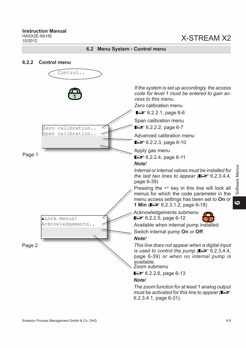
Emerson Process Management GmbH & Co. OHG 6-5
X-STREAM X2Instruction ManualHASX2E-IM-HS10/2012
6S
oftw
are
Men
us
6.2 Menu System - Control menu
6.2.2 Control menu
Control..
If the system is set up accordingly, the access code for level 1 must be entered to gain ac-cess to this menu.
Lock menus!Acknowledgements..Pump: OffZoom..
Available when internal pump installed: Switch internal pump On or Off.Note!This line does not appear when a digital input is used to control the pump ( 6.2.3.4.4, page 6-39) or when no internal pump is available.
Pressing the 8 key in this line will lock all menus for which the code parameter in the menu access settings has been set to On or 1 Min ( 6.2.3.1.2, page 6-18)
Page 2
Zoom submenu 6.2.2.6, page 6-13
Note!The zoom function for at least 1 analog output must be activated for this line to appear ( 6.2.3.4.1, page 6-31).
Acknowledgements submenu 6.2.2.5, page 6-12
Zero calibration menu 6.2.2.1, page 6-6Span calibration menu
6.2.2.2, page 6-7
Apply gas menu 6.2.2.4, page 6-11
Advanced calibration menu 6.2.2.3, page 6-10
Zero calibration..Span calibration..Adv. calibration..Apply gas..
Page 1
Note!Internal or internal valves must be installed for the last two lines to appear ( 6.2.3.4.4, page 6-39)

Emerson Process Management GmbH & Co. OHG6-6
X-STREAM X2Instruction Manual
HASX2E-IM-HS10/2012
Cancel calibration!Start calibration!Zero gas 0.0 ppmCO2.1 134.1 ppm
6.2.2.1 Zero calibration menu
6.2 Menu System - Control menu
Page 2
RESET..Status..
CO2.1 134.1 ppm
Current measured gas concentration.
Note!For further details on calibration procedures, see chapter 7 Maintenance.
Pressing the 8 key in this line will abort the zero calibration and cancel any changes.
Pressing the 8 key in this line will start the zero calibration.
Current nominal zero gas concentration (zero gas concentration can be set in the SETUP menu 6.2.3.2.1, page 6-24)
Current measured gas concentration.
Page 1
Press the 8 key in this line to view the current calibration status ( 6.2.2.2.2, page 6-9)
Control.. Zero calibration..
Multi-channel unit: Select the channel to be calibrated in the SELECT COMPONENT menu.
Multi-channel unit:Press the key to enter the SELECT COM-PONENT menu to change the settings for a different channel.
Press the 8 key in this line to enter a subme-nu to reset the calibration parameters ( 6.2.2.2.1, page 6-8)

Emerson Process Management GmbH & Co. OHG 6-7
X-STREAM X2Instruction ManualHASX2E-IM-HS10/2012
6S
oftw
are
Men
us
Cancel calibration!Start calibration!Span gas 2000.0 ppmCO2.1 134.1 ppm
6.2.2.2 Span calibration menu
6.2 Menu System - Control menu
Note!For further details on calibration procedures, see chapter 7 Maintenance.
Control.. Span calibration..
Multi-channel unit: Select the channel to be calibrated in the SELECT COMPONENT menu.
Pressing the 8 key in this line will abort the span calibration and cancel any changes.
Pressing the 8 key in this line will start the span calibration.Current nominal span gas concentration (span gas concentration can be set in the SETUP menu 6.2.3.2.1, page 6-24)
Current measured gas concentration.
Page 1
Page 2
RESET..Status..
CO2.1 134.1 ppm
Current measured gas concentration.
Press the 8 key in this line to view the current calibration status ( 6.2.2.2.2, page 6-9)
Multi-channel unit:Press the key to enter the SELECT COM-PONENT menu to change the settings for a different channel.
Press the 8 key in this line to enter a subme-nu to reset the calibration parameters ( 6.2.2.2.1, page 6-8)

Emerson Process Management GmbH & Co. OHG6-8
X-STREAM X2Instruction Manual
HASX2E-IM-HS10/2012
6.2.2.2.1 RESET Calibration Menu
6.2 Menu System - Control menu
RESET Are you sure?No!Yes!
This menu appears if the user selected the menu line "Reset.." in either the ZERO CA-LIBRATION or SPAN CALIBRATION menu.To reset the current calibration data to the va-lues saved in UserData ( 6.2.3.8 SAVE-LOAD menu on page 6-48), select "Yes!" and press the 8 key. "No!" returns to the previous menu without applying changes to the calibration data.
Note!Unless altered by the user, UserData settings are the same as the factory settings.
Note 2!Once the reset procedure is started, a mes-sage is displayed indicating how to abort the procedure.

Emerson Process Management GmbH & Co. OHG 6-9
X-STREAM X2Instruction ManualHASX2E-IM-HS10/2012
6S
oftw
are
Men
us
6.2.2.2.2 Calibration Status Menu
6.2 Menu System - Control menu
Gasflow SpangasCO.1 13.304 ppmProcedure NoneTime 0 s
The first line indicates the currently used gas.
This line shows the concentration currently measured.
Indicates which procedure is active (None, Purging, Zeroing, Spaning).
Time remaining for completion of active pro-cedure.
The calibration status menu is accessible from the ZERO CALIBRATION ( 6.2.2.1, page 6-6) and SPAN CALIBRATION ( 6.2.2.2, page 6-7) menus and is for information pur-pose only.

Emerson Process Management GmbH & Co. OHG6-10
X-STREAM X2Instruction Manual
HASX2E-IM-HS10/2012
Cancel calibration!ZeroAll!SpanAll!ZSCalAll!
Control.. Adv. calibration..
6.2.2.3 Advanced Calibration Menu
6.2 Menu System - Advanced Calibration Menu
Pressing the 8 key in this line will abort the current calibration procedure and cancel any changes.
Pressing the 8 key in this line will start the zero calibration for all channels.
Pressing the 8 key in this line will start the span calibration for all channels.
Pressing the 8 key in this line will start the zero & span calibrations for all channels.
Note!For further details on calibration procedures, see chapter 7 Maintenance.
Note!This menu is also available in single-channel units. In this case, the 2nd and 3rd lines will start a zero or span calibration, while the 4th line will allow the operator to start a zero and a span calibration with a single keypress.
Note!This menu is only available when the “Val-ves” parameter in the INSTALLED OPTIONS Menu is set to a parameter other than none.

Emerson Process Management GmbH & Co. OHG 6-11
X-STREAM X2Instruction ManualHASX2E-IM-HS10/2012
6S
oftw
are
Men
us
6.2.2.4 Apply Gas Menu
Use the and keys to switch between Sample, Zero, Span and None.When the selected value is confirmed with the 8 key, the corresponding valve will be opened and all others closed (with the exception of None, which closes all valves).
Note!This menu is only available when the “Val-ves” parameter in the INSTALLED OPTIONS menu is set to a parameter other than none.
6.2 Menu System - Apply Gas Menu
Multi-channel unit:Press the key to enter the SELECT COMPONENT menu to change the settings for a different channel.
Multi-channel unit: Select the component to be set in the SELECT COMPONENT menu.
Control.. Apply gas..
Apply gas: Sample
CO2.1 134.1 ppmTime 0 s

Emerson Process Management GmbH & Co. OHG6-12
X-STREAM X2Instruction Manual
HASX2E-IM-HS10/2012
6.2.2.5 Acknowledgements Menu
6.2 Menu System - Acknowledgements Menu
Control.. Acknowledgements..
All status messages are acknowledged and reset here: simlpy press the 8 key, to ack-nowledge messages.
(i)
-COMMAND EXECUTED-A short confirmation is displayed after this procedure.
Acknowledgements
Status!
If the system is set up accordingly, the access code for level 3 must be entered to gain ac-cess to this menu.

Emerson Process Management GmbH & Co. OHG 6-13
X-STREAM X2Instruction ManualHASX2E-IM-HS10/2012
6S
oftw
are
Men
us
6.2.2.6 zoom menu
6.2 Menu System - Zoom Menu
Control.. Zoom..
This menu allows the operator to determine which analog outputs are "zoomed”, if any:Off: Output is not zoomed.On: Output is zoomed.
Zoom1: OnZoom2: OffZoom3: OffZoom4: Off
Setting for output 1
Setting for output 2
Setting for output 3
Setting for output 4
Note!These settings merely switch the zoom func-tion for each channel on or off.To edit the zoom function settings (e.g. zoom factor, etc.), use the corresponding menu for analog output settings ( 6.2.3.4.1.2.1, page 6-36).

Emerson Process Management GmbH & Co. OHG6-14
X-STREAM X2Instruction Manual
HASX2E-IM-HS10/2012
6.2 Menu System - Setup menu
6.2.3 Setup menu
Setup..
Display..Calibration..Measurement..In/Outputs..
Display setup 6.2.3.1, page 6-15
Calibration setup 6.2.3.2, page 6-22
In/Output setup 6.2.3.4, page 6-30
Measurement setup 6.2.3.3, page 6-28
Page 1
Installed options.Communication..Alarms..Save-Load..
Installed options 6.2.3.5, page 6-43
Communication setup 6.2.3.6, page 6-45
Save-Load 6.2.3.8, Seite 6-48
Alarms setup 6.2.3.7, Seite 6-46
Page 2

Emerson Process Management GmbH & Co. OHG 6-15
X-STREAM X2Instruction ManualHASX2E-IM-HS10/2012
6S
oftw
are
Men
us
6.2 Menu System - Display setup menu
6.2.3.1 Display setup
If the system is set up accordingly, the access code for level 2 must be entered to gain ac-cess to this menu.
If the system is set up accordingly, the access code for level 1 must be entered to gain ac-cess to this menu.
Setup..Display..
Line 1: Comp-1Line 2: Comp-2Line 3: Comp-3Line 4: Comp-4
Page 2
Selection of measurement values to be displayed in each line of the measurement display. Available options: Comp-1 ... Comp-4, Temp-1 ... Temp-4, Press-1 ... Press-4, Flow-1 ... Flow-4 Blank (nothing)
Auto-Home: NeverLanguage..Menu access..
Page 1
This parameter determines how long the software waits without user activity before switching to the measurement display. Available options: Never, 1 min, 10 min
Display language options 6.2.3.1.1, page 6-17
Menu access settings 6.2.3.1.2, page 6-18
Note!X-STREAM currently only supports one pres-sure sensor. The values Press-1...Press-4 therefore all relate to the same sensor.

Emerson Process Management GmbH & Co. OHG6-16
X-STREAM X2Instruction Manual
HASX2E-IM-HS10/2012
6.2 Menu System - Display setup menu
Component display setup 6.2.3.1.3, Page 6-19
Component..Temperature..Pressure..Gasflow...
Page 3
Temperature display setup 6.2.3.1.4, Page 6-20
Gasflow display setup 6.2.3.1.6, Page 6-21
Pressure display setup 6.2.3.1.5, Page 6-20
Line 5: Comp-1Line 6: Comp-2Line 7: Comp-3Line 8: Comp-4
Page 4
Beginning with rev. 1.1, X-STREAM X2 supports 2 measurement display pages, to show addi-tional measuring results. To configure this 2nd page, enter menu page 4 of the current menu.
Selection of measurement values to be displayed in each line of the measurement display. Available options: Comp-1 ... Comp-4, Temp-1 ... Temp-4, Press-1 ... Press-4, Flow-1 ... Flow-4 Blank (nothing)Note!X-STREAM currently only supports one pres-sure sensor. The values Press-1...Press-4 therefore all relate to the same sensor.Note!If a 2nd measurement display page has been configured, use the LEFT/RIGHT keys to switch between both pages.

Emerson Process Management GmbH & Co. OHG 6-17
X-STREAM X2Instruction ManualHASX2E-IM-HS10/2012
6S
oftw
are
Men
us
Language
Language: EN
6.2.3.1.1 Display language setup
6.2 Menu System - Display setup menu
Selects the preferred language for the ana-lyzer software. Available options may vary according to the software version.Currently available:EN: English, FR: French DE: GermanIT: Italian ES: SpanishPT: PortuguesePL: Polish
Note!Each analyzer is shipped with 3 out of above listed available languages. This list may be extended by future software versions.:
If the system is set up accordingly, the access code for level 1 must be entered to gain ac-cess to this menu.
Setup..Display..Language..
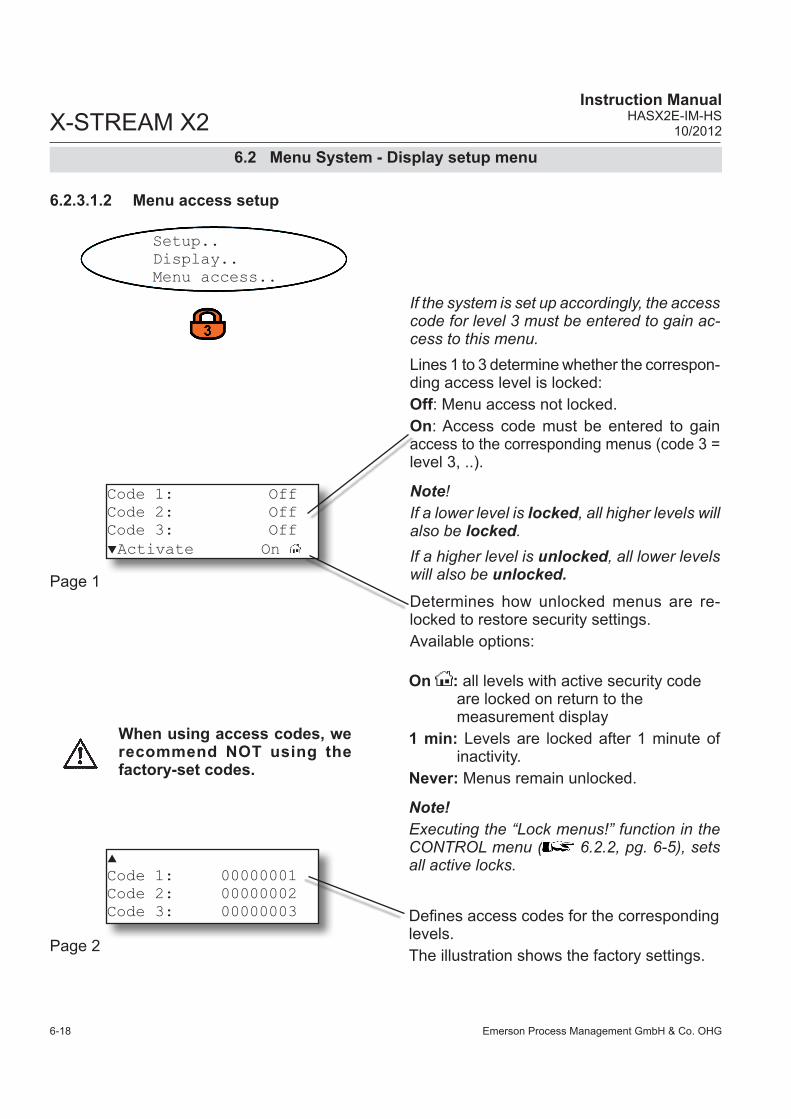
Emerson Process Management GmbH & Co. OHG6-18
X-STREAM X2Instruction Manual
HASX2E-IM-HS10/2012
Code 1: OffCode 2: OffCode 3: OffActivate On
Code 1: 00000001Code 2: 00000002Code 3: 00000003
6.2.3.1.2 Menu access setup
Lines 1 to 3 determine whether the correspon-ding access level is locked:Off: Menu access not locked.On: Access code must be entered to gain access to the corresponding menus (code 3 = level 3, ..).
Note!If a lower level is locked, all higher levels will also be locked.If a higher level is unlocked, all lower levels will also be unlocked.
If the system is set up accordingly, the access code for level 3 must be entered to gain ac-cess to this menu.
6.2 Menu System - Display setup menu
Determines how unlocked menus are re-locked to restore security settings. Available options:
On : all levels with active security code are locked on return to the measurement display1 min: Levels are locked after 1 minute of inactivity.Never: Menus remain unlocked.
Note!Executing the “Lock menus!” function in the CONTROL menu ( 6.2.2, pg. 6-5), sets all active locks.
Defines access codes for the corresponding levels. The illustration shows the factory settings.
Setup..Display..Menu access..
Page 2
Page 1
When using access codes, we recommend NOT using the factory-set codes.

Emerson Process Management GmbH & Co. OHG 6-19
X-STREAM X2Instruction ManualHASX2E-IM-HS10/2012
6S
oftw
are
Men
us
UnitText: ppmFactor: 1.0000Offset: 0.0000
ComponentTag: CO2.1DecimalPlaces: 1CO2.1 134.1 ppm
6.2 Menu System - Display setup menu
6.2.3.1.3 Component menu
Multi-channel unit:Select the component to be set in the SELECT COMPONENT menu.
The tag for the gas component is entered here: each character must be selected and set separately.Note!The “1” in this example indicates that CO2 is the first measurement channel (may be useful for multi-channel units, but not necessary).
Current sample gas concentration using settings described above. Display format is refreshed immediately.
Multi-channel unit:Press the key to enter the SELECT COM-PONENT menu to change the settings for a different channel.
Set number of places after the decimal point: 0 to 4
Set text for the measuring unit of the gas component: each character must be selected and set separately.Gas concentrations are internally calculated in ppm. To use other units, the corresponding factor must be entered, e.g. 0.0001 for %.
If necessary, an offset to be added to the measured value can be set here.
Setup..Display..Component..
Page 1
Page 2
Note!Texts for tags and units, and values for factor and offset are not checked for plausibility. Any arbitrary value can be set..

Emerson Process Management GmbH & Co. OHG6-20
X-STREAM X2Instruction Manual
HASX2E-IM-HS10/2012
6.2 Menu System - Display setup menu
6.2.3.1.4 Temperature menu
Setup..Display..Temperature..
TemperatureUnit: °CDecimalPlaces: 1Temp-1 63.7 °C
Current temperature, here: Sensor 1 value
Set temperature unit Available options: °C, °F
Set number of places after decimal point for temperature value: 0 to 4
PressureUnit: hPaDecimalPlaces: 1Pressure 998.1 hPa
Current presssure value
Set pressure value Available options: Pa, hPa, mbar, Bar, psi
Set number of places after decimal point for pressure value: 0 to 4
6.2.3.1.5 Pressure menu
Setup..Display..Pressure..

Emerson Process Management GmbH & Co. OHG 6-21
X-STREAM X2Instruction ManualHASX2E-IM-HS10/2012
6S
oftw
are
Men
us
6.2 Menu System - Display setup menu
6.2.3.1.6 Gasflow menu
Setup..Display..Gasflow..
GasflowUnit: l/hDecimalPlaces: 1Flow-1 63.7 l/h
Current gas flow, here: Sensor 1 value
Set gas flow unitAvailable options: l/h, l/min, mlmin
Set number of places after decimal point for gas flow value: 0 to 4

Emerson Process Management GmbH & Co. OHG6-22
X-STREAM X2Instruction Manual
HASX2E-IM-HS10/2012
6.2 Menu system - Calibration setup
6.2.3.2 Calibration menu
This parameter determines whether the to-lerance check is active during calibration. Available options: 10%: Tolerance check is active, the limit is
set to 10% (not changeable). A system message must be manually acknow-ledged ( 6.2.2.5, page 6-12)
AutoClr: As 10 %, except that a system mes-sage is automatically acknowledged after 2 or 3 minutes.
Off: Tolerance check is deactivated
Sets calibration gas concentrations 6.2.3.2.1, page 6-24
Specifies analog outputs behaviour during calibrations. Available options: Yes: analog outputs are “frozen” & concen-
tration alarms are surpressedNo: the analog outputs follow the concentra-
tion. This may cause trouble if connec-ted to a data acquisition system.
The time required when switching to zero or span gas so that the gas lines are completely filled with the new gas is entered here.Possible values: 0 .. 600 seconds
If the system is set up accordingly, the access code for level 2 must be entered to gain ac-cess to this menu.
Note!For further details on calibration procedures, see chapter 7 Maintenance.
Setup..Calibration..
Calibration gases..Tol.Check: AusHold on Cal: YesPurge time: 12 s
Page 1
Note!The following lines are only available when the “Valves” parameter in the INSTALLED OPTIONS”menu is set to a parameter other than none.

Emerson Process Management GmbH & Co. OHG 6-23
X-STREAM X2Instruction ManualHASX2E-IM-HS10/2012
6S
oftw
are
Men
us
6.2 Menu system - Calibration setup
Valve assignment..Interval time..
Page 2
Assign valves 6.2.3.2.2, page 6-26
Set interval time for calibration 6.2.3.2.3, page 6-26
Note!This second page is available only if the para-meter "valves" in the INSTALLED OPTIONS menu is set to other than none.

Emerson Process Management GmbH & Co. OHG6-24
X-STREAM X2Instruction Manual
HASX2E-IM-HS10/2012
Calibration gases
ZeroGas: 0.0 ppmSpanGas: 500.0 ppm
6.2 Menu System - Calibration setup
6.2.3.2.1 Calibration gases menu
Setup..Calibration..Calibration gases..
The concentration of the zero gas used for calibration is entered here.
The concentration of the span gas used for calibration is entered here.
Note!Units for calibration gas concentrations are take from the corresponding entry in the dis-play setup menu.
Multi-channel unit:Select the component to be set in the SELECT COMPONENT menu.
Multi-channel unit:Press the key to enter the SELECT COM-PONENT menu to change the settings for a different channel.

Emerson Process Management GmbH & Co. OHG 6-25
X-STREAM X2Instruction ManualHASX2E-IM-HS10/2012
6S
oftw
are
Men
us
6.2 Menu System - Valve Assignment Menu
6.2.3.2.2 Valve Assignment Menu
Setup..In/Output..Valve assignment..
Multi-channel unit:Select the component to be set in the SELECT COMPONENT menu.
If the system is set up accordingly, the access code for level 3 must be entered to gain ac-cess to this menu.
The internal and/or external valves are assi-gned to zero or span gas in this menu ( "7.3 Calibration Procedures" at page 7-5).
Available options:V1 ... V8
Valve assignment
Zerogas: V1Spangas: V2
Multi-channel unit:Press the key to enter the SELECT COM-PONENT menu to change the settings for a different channel.
Note for multi-channel units:Valves can be freely assigned to channels. This includes among others the following variations:• identical combinations (of zero and span
gas valves) for several channels • Combinations in which one valve has the
same function for several channels
• Combinations in which one valve has a dif-ferent function depending on the channel; e.g. a zero gas valve for channel 1 is also the span gas valve for channel 2.
Depending on the gases use, the calibration procedure can be optimised for time or effici-ency using such combinations.( "7.3 Calibration Procedures" at page 7-5).

Emerson Process Management GmbH & Co. OHG6-26
X-STREAM X2Instruction Manual
HASX2E-IM-HS10/2012
Interval timeZeroAll: 2 hZSCalAll: 10 hAutoCal in..
6.2 Menu system - Calibration setup
6.2.3.2.3 Interval time menu
If the system is set up accordingly, the access code for level 3 must be entered to gain ac-cess to this menu.
Sets the time between two zero calibrations in autocal mode.
Sets the time between two combined zero & span calibrations in autocal mode.Possible values for both parameters: 0 .. 999 h
Note!This line appears if at least one interval time has been set.
Specify a time interval to elapse from the current time until the first autocal starts
6.2.3.2.3.1, page 6-27
Note!The following lines are only available when the “Valves” parameter in the INSTALLED OPTIONS menu is set to a value other than none.
Setup..Calibration..Interval time..
Note!For further details on calibration procedures, see chapter 7 Maintenance.

Emerson Process Management GmbH & Co. OHG 6-27
X-STREAM X2Instruction ManualHASX2E-IM-HS10/2012
6S
oftw
are
Men
us
6.2 Menu system - Calibration setup
6.2.3.2.3.1 6.2.3.2.3.1 AutoCal in menu
Setup..Calibration..Interval time..AutoCal in.. Note!
This menu appears only, if at least one interval time has been set.
ZeroAll: 1 hZeroAll: 15 minZSCalAll: 1 hZSCalAll: 15 min
Note!In case there is an interval time specified for one procedure only (ZeroAll or ZSCalAll;
6.2.3.2.3, page 6-26), the related lines for the other procedure will be hidden in this menu!.
The first two lines allow to enter a time to elapse from the current moment, before the next zero calibration for all channels is started. Preset is the remaining time until the next zero calibration starts. Possible values: Any value up to the preset time interval.
Lines 3 & 4 allow to enter similar data for a combined zero & span calibration.Possible values: Any value up to the preset time interval.

Emerson Process Management GmbH & Co. OHG6-28
X-STREAM X2Instruction Manual
HASX2E-IM-HS10/2012
Pressure: 1014.0 hPaDamping..
6.2 Menu system - Measurement setup
6.2.3.3 Measurement menu
If no pressure sensor is installed (INSTALLED OPTIONS - PRESSURE.. set to Manual), the current ambient pressure must be set here.Possible values: 500 .. 2000 hPaOtherwise this line is not editable and shows the currently measured pressure.
Setup signal damping 6.2.3.3.1, page 6-29
Note 1The unit for pressure values is taken from the relevant entry in the display setup.
Note 2As the pressure value is used for pressure compensation, it should, when set to Manu-al, be regularly updated to ensure accurate results.
Setup..Measurement..
If the system is set up accordingly, the access code for level 2 must be entered to gain ac-cess to this menu.

Emerson Process Management GmbH & Co. OHG 6-29
X-STREAM X2Instruction ManualHASX2E-IM-HS10/2012
6S
oftw
are
Men
us
Damping: 5 s
6.2.3.3.1 Signal damping settings
The time for the electronic signal damping is entered here.Lower values give results which are updated more quickly, higher values supress noise from varying gas concentrations.Possible values: 0 .. 28 seconds
6.2 Menu System - Measurement setup
Multi-channel unit:Select the component to be set in the SELECT COMPONENT menu.
Setup..Measurement..Damping..
Note!The analyzer’s total delay time (t90 time) is the sum of the signal damping time and the physical time lag caused e.g. by the properties of the gas flow and the sensors.
Multi-channel unit:Press the key to enter the SELECT COM-PONENT menu to change the settings for a different channel..

Emerson Process Management GmbH & Co. OHG6-30
X-STREAM X2Instruction Manual
HASX2E-IM-HS10/2012
Analog outputs..DigitalOutputs..DigitalInputs..IntSHS..
6.2.3.4 In/Outputs setup
6.2 Menu System - In/Outputs setup
Setup..In/Outputs..
Analog outputs menu 6.2.3.4.1, page 6-31
If the system is set up accordingly, the access code for level 2 must be entered to gain ac-cess to this menu.
Digital outputs menu 6.2.3.4.2, page 6-37
Digital inputs menu 6.2.3.4.3, page 6-39
IntSHS menu 6.2.3.4.4, page 6-39
Note!This menu line appears only when the para-meter in the INSTALLED OPTIONS - DIGITAL IO menu is set to 1 or 1+2 ( 6.2.3.5,page 6-43)
Note!This menu line appears only if the parameter in the INSTALLED OPTIONS - VALVES menu is set to Internal or Int+Ext ( 6.2.3.5, page 6-43

Emerson Process Management GmbH & Co. OHG 6-31
X-STREAM X2Instruction ManualHASX2E-IM-HS10/2012
6S
oftw
are
Men
us
Analog outputs
SignalRange: 0-20mAHold on cal: No
6.2 Menu System - Analog outputs menu
6.2.3.4.1 Analog outputs menu
This line sets the output signal range for all outputs.Available options: 0-20mA, 4-20mA, 0-20mAL, 4-20mAL, 0-20mAH, 4-20mAH
6.2.3.4.1.1, page 6-33
If the system is set up accordingly, the access code for level 3 must be entered to gain ac-cess to this menu.
Setup..In/Outputs..Analog Outputs..
Page 1This entry determines whether the analog output signal and concentration alarm status are held during calibration.
When Yes is set, then during calibration:• analog outputs are “frozen”; i.e., the ana-
log signals remain constant irrespective of the actual measured concentration.
• concentration alarms, which would other-wise be triggered by the calibration gas concentrations, are surpressed.
When No is set, the analog output signal at any given moment reflects the actual measured value during calibration; this may trigger alarms when set limits are exceeded or underrun. Note!This behaviour may be problematic if, for ex-ample, the instrument is connected to a data acquisition system.

Emerson Process Management GmbH & Co. OHG6-32
X-STREAM X2Instruction Manual
HASX2E-IM-HS10/2012
6.2 Menu System - Analog outputs menu
Page 2
Page 3
Available analog outputs (min. 1, max. 4) can be set in greater detail via these submenus.
6.2.3.4.1.2, page 6-34
The lines on this page enable to configure the behaviour of the analog outputs in case the measured values are beyond the range limits:Options: Standard: The outputs are set to the values marked * in table 6-1 below Config: The outputs can be adjusted to the values marked ** in table 6-1 below.
Output1..Output2..Output3..Output4..
Cut mode: StandardLow cut: 3.80High cut: 20.50
Output signal, if
"Signal- Range“ Operation Mode
Failure Signal Level acc. NE 43
Measured value is
valid
Measured value is below lower range
limit
Measured value is above upper range
limit
An internal failure
occured
Cable is broken
0-20 mA Dead-Zero - 0 ... 20 mA < -19 mA > 21.7 mA undefined 0 mA
4-20 mA Live-Zero - 4 ... 20 mA < -19 mA > 21.7 mA undefined 0 mA
0-20 mAL similar Dead-Zero below 0 ... 20 mA -0.2 mA*
(-1.8 … -0.01 mA)**20.5 mA*
(20.01 ... 21.5 mA)** -2 mA 0 mA
4-20 mAL similar Live-Zero below 4 ... 20 mA 3.8 mA* (2.2 ...3.9 mA)**
20.5 mA* (20.01 ... 21.5 mA)** 2 mA 0 mA
0-20 mAH similar Dead-Zero above 0 ... 20 mA -0.2 mA*
(-1.8 … -0.01 mA)**20.5 mA*
(20.01 ... 21.5 mA)** > 21.7 mA 0 mA
4-20 mAH similar Live-Zero above 4 ... 20 mA 3.8 mA* (2.2 ...3.9 mA)**
20.5 mA* (20.01 ... 21.5 mA)** > 21.7 mA 0 mA
These two lines are editable only, if "Cut mode" is set to Config:Low Cut: Configure the "below lower range limit" output signalHigh Cut: Configure the "above upper range limit" output signalAccepted values depend on the setting of "SignalRange" and are marked ** in table 6-1.
Note!These settings apply to ALL analog outputs!
Tab. 6-1: Analog output signals - settings and operational modes

Emerson Process Management GmbH & Co. OHG 6-33
X-STREAM X2Instruction ManualHASX2E-IM-HS10/2012
6S
oftw
are
Men
us
6.2 Menu System - Signal Range
The signal range for the analog outputs is set via the signal "Range" parameter. When set to 0-20 mA, a 20 mA signal is ge-nerated when the measured concentration is equal to the upper range value. A 0 mA signal is generated when the sample gas concentra-tion is 0 (dead zero).However, a severed cable also results in a signal value of 0. An external data acquisition system thus cannot detect such an error and simply registers a gas concentration of 0. The usual method of detecting a severed cable is to use an offset: a concentration correspon-ding to the lower range value is assigned an analog signal of 4 mA, allowing the detection of a severed or disconnected cable.This live zero mode is activated by setting the “SignalRange” parameter to 4-20 mA.
Operation modes conforming to NAMUR 43 (NE 43) recommendationsThe operation modes described above do not generate a signal which would allow detection of a failure in the measurement system. In such cases the behaviour of the output signal is undefined: either the last value is held, or a random value is sent. System failures thus cannot be detected by am external data acqui-sition system.
NE 43 contains recommendations for setting analog outputs in order to avoid these situa-
6.2.3.4.1.1 Signal range menu
tions, and are implemented by X-STREAM analyzers as follows:Setting range parameters to values other than 0-20 mA or 4-20 mA defines specific analog output signals in the case of a failure. Since the-se values do not occur when there is no error, a data acquisition system is able to distinguish between the following conditions:• severed cable (no signal (0 mA)), • failure (signal outside of valid range as in table 6-1, but not 0) • valid signal (signal within valid range as in table 6-1) • signal out of range (signal rises or falls slowly
to the limit given in table 6-1 and holds this value until the concentration returns to a valid level).
Setup..In/Outputs..Analog outputs..SignalRange:

Emerson Process Management GmbH & Co. OHG6-34
X-STREAM X2Instruction Manual
HASX2E-IM-HS10/2012
6.2 Menu System - Analog Outputs Menu
6.2.3.4.1.2 Output1 (2 ... 4) Menu
Selects the parameter to be displayed in the corresponding line in the measurement dis-play. Depending on the number of measuring channels and sensors installed in the unit, the following values are available:Gas components: Comp-1 ... Comp-4Temperature: Temp-1 ... Temp-4, Pressure: Press-1 ... Press-4,Flow: Flow-1 ... Flow-4Zoom: Zoom-C1 ... Zoom-C4(nothing): NoneA constant signal of either 0/4 mA or 20 mA can be generated to check the output settings. The options are labelled accordingly (0/4 mA and 20 mA).
Setup..In/Outputs..Analog outputs..Output1(2...4)..
Signal: Comp-1LowScale: 10 ppmHighScale: 1000 ppmZoom..
This line determines which concentration value corresponds to the lower signal limit (0 or 4 mA).
This line determines which concentration value corresponds to the upper signal limit (20 mA).
This submenu sets the zoom function for the analog output; 6.2.3.4.1.2.1, page 6-36
Note!The last line only appears when "signal" is set to a zoom value (e.g. Zoom-C1).
Page 1

Emerson Process Management GmbH & Co. OHG 6-35
X-STREAM X2Instruction ManualHASX2E-IM-HS10/2012
6S
oftw
are
Men
us
Enter this second menu page to trim the se-lected analog output signal: Thus, if the signal differs from the selected value (0/4 or 20 mA) it can be adjusted to compensate the offset.Depending on the selected signal, vary the related parameter to trim the output signal (higher values increase the output signal, and vice versa). Repeat this procedure until the output signal matches.
Select the analog signal to be trimmed. The analog output will supply this signal.Selectable options: 0/4mA or 20mA
Note!Other options are selectable, to e.g. trim a concentration related output signal!
If "signal" was set to 0/4mA select this line to trim (finetune) the analog output to ex-actly provide 0 or 4 mA. ( 6.2.3.4.1.1, page 6-33 for information about how to select either life-zero or dead zero).Accepted values: -2000 ... +2000(corresponding to appr. -2 ... +2 mA)
If "signal" was set to 20mA select the 4th line to trim (finetune) the analog output to exactly provide 20 mA.Accepted values: -1000 ... +1000(corresponding to appr. -1 ... +1 mA)
Page 2
Trim outputSignal: 0/4mA0/4mA: 10020mA: -50
6.2 Menu System - Analog Outputs Menu

Emerson Process Management GmbH & Co. OHG6-36
X-STREAM X2Instruction Manual
HASX2E-IM-HS10/2012
6.2 Menu System - Analog outputs menu
6.2.3.4.1.2.1 Zoom Output Menu
Setup..In/Outputs..Analog outputs..Output1(2...4)..Zoom..
Switching: ManualZoom: 50 %Position: LowScaleStatus: Off
Determines how the zoom function is to be activated.Available options: Manual, Auto, Inputs
Gives the percentage of the whole measuring range to be zoomed.Accepted values: 1 ... 99 (%)
Determines which end of the range is to be zoomed.Available options: LowScale, HighScale
Current zoom function status.Available options: On, Off
Note!Further details on the function and setting up of the zoom function can be found in Chapter 5 Startup.

Emerson Process Management GmbH & Co. OHG 6-37
X-STREAM X2Instruction ManualHASX2E-IM-HS10/2012
6S
oftw
are
Men
us
6.2 Menu System - Digital Outputs Menu
6.2.3.4.2 Digital Outputs Menu
Setup..In/Outputs..DigitalOutputs..
Outputs are assigned functions in these lines.Avalable options: next page.
This menu enables the assignment of any digital output available to a function.Note!Every unit has, as standard, 4 digital outputs (relays). Depending on the model, 1 or 2 additional cards can be used to increase this number to 9 or 18.Depending on the number of actually avai-lable outputs, this menu consists of 1, 4 or 7 similar pages, of which only the first four are illustrated here.
Output5: SampleOutput6: V1Output7: V2Output8: V3
Page 2
Output9: V4Output10: V5Output11: PumpOutput12: Lim1Cmp1
Page 3
Output13: Lim2Cmp1
Page 4
"Outputs 1-4" are available in every unit. Further pages are indicated by a down arrow ( ) only when at least one extension card (outputs 5 - 13) is installed
"Outputs 5 - 13" are present on the first ex-tension card..
Further pages are indicated by a down arrow ( ) only when a second extension card (out-puts 14 - 22) is installed.
Output1: FailureOutput2: MaintReqOutput3: OffSpecOutput4: FctCheck
Page 1

Emerson Process Management GmbH & Co. OHG6-38
X-STREAM X2Instruction Manual
HASX2E-IM-HS10/2012
6.2 Menu System - Digital Outputs Menu
The following functions can be assigned to each of the digital outputs (max. 22).
Label DescriptionOff Digital output unusedOn Digital output constantly onTest Switches the output on and off every secondV1 Switches external valve V1 on autocalibrationV2 Switches external valve V2 on autocalibrationV3 Switches external valve V3 on autocalibrationV4 Switches external valve V4 on autocalibrationV5 Switches external valve V5 on autocalibrationV6 Switches external valve V6 on autocalibrationV7 Switches external valve V7 on autocalibrationV8 Switches external valve V8 on autocalibrationSample Switches external sample gas valve on autocalibrationPump Switches an external pumpFailure NAMUR NE 107 “Failure” signalMaintReq NAMUR NE 107 “Maintenance request” signalOffSpec NAMUR NE 107 “Out of specification” signalFctCheck NAMUR NE 107 “Function check” signalLim1Cmp1 Concentration alarm 1, component (channel) 1Lim2Cmp1 Concentration alarm 2, component (channel) 1Lim1Cmp2 Concentration alarm 1, component (channel) 2Lim2Cmp2 Concentration alarm 2, component (channel) 2Lim1Cmp3 Concentration alarm 1, component (channel) 3Lim2Cmp3 Concentration alarm 2, component (channel) 3Lim1Cmp4 Concentration alarm 1, component (channel) 4Lim2Cmp4 Concentration alarm 2, component (channel) 4Zoom1 Component (channel) 1 analog signal is zoomedZoom2 Component (channel) 2 analog signal is zoomedZoom3 Component (channel) 3 analog signal is zoomedZoom4 Component (channel) 4 analog signal is zoomedFlowAlm Alarm by flow sensorFLimAlm1 Alarm by flow monitor 1FLimAlm2 Alarm by flow monitor 2
Functions can also be assigned to several outputs simultaneously.
Tab. 6-2: Options for Digital Outputs

Emerson Process Management GmbH & Co. OHG 6-39
X-STREAM X2Instruction ManualHASX2E-IM-HS10/2012
6S
oftw
are
Men
us
6.2 Menu System - Digital Inputs Menu
6.2.3.4.3 Digital Inputs Menu
Setup..In/Outputs..DigitalInputs..
Inputs are assigned to signals in these lines., Available options: next page.
This menu enables the assignment of any digital input available to a signal.Note!Different models can be installed with 1 or 2 cards with 7 or 14 digital inputs. This menu has 2 or 4 pages depending on the number of available inputs.
Input5: V5Input6: V6Input7: V7
Input8: V8Input9: SampleInput10: PumpInput11: ZeroAll
Input12: SpanAllInput13: Zoom1Input14: Zoom2
Page 4
Page 3
Page 2
Input1: V1Input2: V2Input3: V3Input4: V4
Page 1Inputs 1-7 are available on the first extensi-on card. Further menu pages are indicated by the down arrow ( ) only when a second extension card is installed (inputs 8 - 14).
Inputs 8 - 14 are available on the second extension card.
Note!This menu line appears only when the parameter "DigitalIO" in the INSTALLED OPTIONS menu is set to 1 or 1+2 ( 6.2.3.5,page 6-43).

Emerson Process Management GmbH & Co. OHG6-40
X-STREAM X2Instruction Manual
HASX2E-IM-HS10/2012
6.2 Menu System - Digital Inputs Menu
The following signals can be assigned to any of the 14 available digital inputs.
Label DescriptionNone Digital input not used
V1 Activate valve V1V2 Activate valve V2V3 Activate valve V3V4 Activate valve V4V5 Activate valve V5V6 Activate valve V6V7 Activate valve V7V8 Activate valve V8
Sample Activate sample gas valvePump Activate pumpZeroAll Initiate zero calibration of all channelsSpanAll Initiate span calibration of all channelsZSCalAll Initiate zero and span calibration of all channelsCalCancl Abort all currently running calibrationsZoom1 Activate zoom for component (channel) 1 analog signalZoom2 Activate zoom for component (channel) 2 analog signalZoom3 Activate zoom for component (channel) 3 analog signalZoom4 Activate zoom for component (channel) 4 analog signal
FlowAlm Enables connection and use of an external digital gas flow alarm
Functions can also be assigned to several inputs simultaneously.
Chapter 7 includes detailed descriptions of the configuration and execution of calibra-tions with valves.
Tab. 6-3: Options for Digital Inputs

Emerson Process Management GmbH & Co. OHG 6-41
X-STREAM X2Instruction ManualHASX2E-IM-HS10/2012
6S
oftw
are
Men
us
6.2 Menu System - IntSHS Menu
6.2.3.4.4 IntSHS Menu
Setup..In/Outputs..IntSHS..
Gas5: SampleGas6: V5Gas7: V6Gas8: V7
Page 2
Gas1: V1Gas2: V2Gas3: V3Gas4: V4
Page 1
For an overview of all available options: next page.
This menu configures the optional internal components for routing gas (valves and pumps) to be used in autocalibration proce-dures.
Each available gas inlet ("Gas 1 ... Gas 8") with a valve connected is assigned a virtual valve label (V1...V8, Sample). (If the compo-ents were installed in the factory, the basic settings will already have been set). These valves are then assigned a channel and function (zero or span gas) in the VALVE ASSIGNMENT MENU ( 6.2.3.2.2, page 6-26).Note!Depending on the model, 1 or 2 valve blocks with up to 4 or 8 valves can be installed.
Note!This menu appears only when the parameter in the “Installed Options - Valves” is set to Internal or IntExt ( 6.2.3.5, page 6-43)
Pump1: PumpPump2: Off
Page 3
Additionally, the method used to control any installed pumps can be set.Note Depending on the model, up to 2 pumps may be installed.

Emerson Process Management GmbH & Co. OHG6-42
X-STREAM X2Instruction Manual
HASX2E-IM-HS10/2012
6.2 Menu System - IntSHS Menu
Note!Each virtual valve V1 to V8 is normally only assigned to one gas inlet, “Gas1” to “Gas8”. Double assignments are possible, but only meaningful if the unit is configured accordin-gly.
Label DescriptionOff Switches the assigned component (valve or pump) off.On Switches the assigned component (valve or pump) on.Test Switches the assigned component (valve or pump) on and off every second.V1 Valve at selected gas inlet is assigned the value “V1”V2 Valve at selected gas inlet is assigned the value “V2”V3 Valve at selected gas inlet is assigned the value “V3”V4 Valve at selected gas inlet is assigned the value “V4”V5 Valve at selected gas inlet is assigned the value “V5”V6 Valve at selected gas inlet is assigned the value “V6”V7 Valve at selected gas inlet is assigned the value “V7”V8 Valve at selected gas inlet is assigned the value “V8”
Sample
The gas inlet is a sample gas inlet. The valve assigned to it is controlled via the Sample software option.Note!There is only one option Sample . This means that in order to control two sam-. This means that in order to control two sam-ple gas valves during autocalibration, the value Sample must be assigned to two inlets. During calibration, both valves are then controlled synchronously.
Pump
The pump is controlled by the Pump software option. Note!There is only one option Pump. This means that in order to control two pumps during autocalibration, the lines “Pump1” and “Pump2” must be assigned the value Pump. During calibration, both pumps are then controlled synchronously.
Chapter 7 includes detailed descriptions of the configuration and execution of calibra-tions with valves.
Tab. 6-4: Parameter IntSHS options

Emerson Process Management GmbH & Co. OHG 6-43
X-STREAM X2Instruction ManualHASX2E-IM-HS10/2012
6S
oftw
are
Men
us
6.2.3.5 Installed Options Menu
6.2 Menu System - Installed Options Menu
Setup..Installed Options..
If the system is set up accordingly, the access code for level 3 must be entered to gain ac-cess to this menu.
Valves: InternalCOM-Interf: YesPump: YesFlowAlm: Yes
Page 1
Indicates whether valves are installed.Available options:Internal, External, Int(ernal)+Ext(ernal), None.
Indicates whether a serial interface is installed (Yes) or not (No)
Indicates whether an internal pump is installed (Yes) or not (No).
Page 2
DigitalIO: 1Pressure: InternalAnalog outputs 4More..
Indicates how many analog outputs are in-stalled. Accepted values: 1 ... 4
Indicates whether digital I/O cards are in-stalled (1, 1+2) or not (None)
Determines whether a barometric pressure sensor is installed.Available options:Manual: No sensor available. Ambient at-mospheric pressure must be entered manu-ally ( 6.2.3.3 page 6-28)Internal: Internal pressure sensor installed.External: Pressure sent via network (e.g. DeltaV)
More sensors ( 6.2.3.5.1 page 6-44).
Indicates whether flow switches are installed (Yes) or not (No).

Emerson Process Management GmbH & Co. OHG6-44
X-STREAM X2Instruction Manual
HASX2E-IM-HS10/2012
6.2 Menu System - Installed Options Menu
6.2.3.5.1 Installed options, More menu
TempSensor: Temp-1FlowSensor: Flow-1
Setup..Installed Options..More..
Multi-channel unit:Select the component in the SELECT COM-PONENT menu.
Indicates whether and if so, which possibly in-stalled temperature sensor is to be assigned to the selected channel.Available options:None, Temp-1, Temp-2, Temp-3, Temp-4
Indicates whether and if so, which possibly installed flow sensor is to be assigned to the selected channel.Available options:None, Flow-1, Flow-2
Multi-channel unit:Press the key to enter the SELECT COM-PONENT menu to select a different channel.

Emerson Process Management GmbH & Co. OHG 6-45
X-STREAM X2Instruction ManualHASX2E-IM-HS10/2012
6S
oftw
are
Men
us
Protocol: MODB RTUMODB-Mode: 32BitID-Number: 2Interface: RS485
6.2.3.6 Communications settings
If the system is set up accordingly, the access code for level 3 must be entered to gain ac-cess to this menu.
Page 1
Selects Modbus protocol for the serial inter-face.Available options:MODB RTU, SensorNote!The Sensor option is for maintenance pur-poses only.Sets Modbus mode of operation.Available options: 32Bit (=Daniel mode),16BitLow (=Modicon mode, LOW word first) 16BitHi(g)h (=Modicon mode, HIGH word first)Enter instrument ID for network.Possible values: 1 .. 254
MAC ID of the Ethernet port (visible only if "Interface" is set to Ether)
6.2 Menu System - Communications settings
Selects installed RS interface.Available options: RS232, RS485, Ether(net)
Setup..Communication..
Page 2
Baud rate: 19200Parity: NoneMAC: AB234CDE56
Select baud rate of the serial interface.Available options: 2400, 4800, 9600, 19200Sets whether a parity bit is used.Available options: None, Even, OddNote!To view first 2 lines, set "Interface" to other than Ether
Note 1 Chapter 9 includes a detailed descrip-
tion of the Modbus parameters. A general description of Modbus is also to be found in the appendix.
Note 2To be able to use the optional Ethernet in-terface, enable MODB RTU and Ether.

Emerson Process Management GmbH & Co. OHG6-46
X-STREAM X2Instruction Manual
HASX2E-IM-HS10/2012
6.2 Menu System - Alarm Setup Menu
6.2.3.7 Alarm Setup Menu
Note!The unit for concentration values (here: ppm) is taken from the corresponding line in the DISPLAY SETUP menu ( 6.2.3.1.3, page 6-19).
Multi-channel unit:Select the component to be set in the SELECT COMPONENT menu.
Level1: 100 ppm Function: LowLevel2: 500 ppmFunction: High
Sets first concentration alarm level.
Selects alarm output mode for level 1.Available options:Off, Low, High, Off FS, Low FS, High FS( Chapter 5 includes more details about these options are alarm settings)
Sets second concentration alarm level.
Selects alarm output mode for level 2.Available options:Off, Low, High, Off FS, Low FS, High FS( Chapter 5 includes more details about these options and alarm settings)
Setup..Alarms..
If the system is set up accordingly, the access code for level 3 must be entered to gain ac-cess to this menu.
Page 1

Emerson Process Management GmbH & Co. OHG 6-47
X-STREAM X2Instruction ManualHASX2E-IM-HS10/2012
6S
oftw
are
Men
us
6.2 Menu System - Alarm Setup Menu
Multi-channel unit:Press the key to enter the SELECT COM-PONENT menu to change the settings for a different channel.
Hysteresis: 5.00 %
FlowLimit: 1 l/minFlowLimAlm: Low FS
A hysteresis level for the switchpoints can be entered here (as % of upper range value). Permissible values: 0 ... 50 %.
Enter this line to specify whether an installed flow sensor is used to only measure the flow (Off FS) or to measure the flow and activate alarms (Low FS).Available options: Off FS, Low FSOff FS: Alarm functionality is switched off, an assigned output is set to FailSafe mode (relay is activated).Low FS: Alarm functionality is switched on, output is set to FailSafe mode (alarm deac-tivates relay). Relay is de-energized if flow is below given limit.
Page 2
If a flow sensor is assigned to the selected channel ( 6.2.3.5.1, page 6-44) enter this line to specify a flow limit, to activate an alarm as a function of flow dropping below this limit (see next menu line).Permissible values: equivalent to 0 ... 2000 ml/minNote!The unit for flow measurement is taken from the corresponding line in the DISPLAY SE-TUP menu ( 6.2.3.1.6, page 6-21).

Emerson Process Management GmbH & Co. OHG6-48
X-STREAM X2Instruction Manual
HASX2E-IM-HS10/2012
Save-LoadCfgData > SvcPort!SvcPort > CfgData..Verify!
6.2.3.8 Save-Load Menu
This line initiates the procedure for saving configuration data to an external device: the data are sent to the service interface (service port X2).
This line initiates the procedure for restoring configuration data: the data are loaded from the service port.CAUTION! This overwrites all configuration data. Any changes made since the last backup will be undone.Note!This procedure requires a further confirmation to start.
This line initiates the procedure for an online comparison of the current configuration data with the data stored via the service port. The current configuration is not overwritten. Downloaded data are deleted on completion of this procedure.
6.2 Menu System - Save-Load Menu
Page 1
Note 1Some of the following procedures require the installation of terminal software on external hardware (e.g. a PC connected to the service interface) to store the data.
Note 2During these procedures a message is dis-played indicating how to abort the procedure.
Setup..Save-Load..
If the system is set up accordingly, the access code for level 3 must be entered to gain ac-cess to this menu.

Emerson Process Management GmbH & Co. OHG 6-49
X-STREAM X2Instruction ManualHASX2E-IM-HS10/2012
6S
oftw
are
Men
us
Page 2
FactData > CfgData..CfgData > UserData..UserData > CfgData..
6.2 Menu System - Save-Load Menu
Comments:FactData This represents the factory
settings. The data are stored in FRAM memory. The user can copy and change these data in RAM, but these changes cannot be saved as FactData.
UserData A user’s own configuration can be saved to FRAM memory and loaded from FRAM.
CfgData The configuration used at run-time and stored in RAM.At startup, the checksum of the configu-ration is calculated. If an error occurs, the user data are loaded into RAM, overwri-ting the CfgData configuration. This ensures that the instrument is always ready for use.
This function replaces the current configura-tion with factory settings.
This function stores the current configuration as a user dataset in the FRAM memory.
This function replaces the current configura-tion with the user dataset.
CAUTION!All 3 functions overwrite internal data. Any changes made since the last backup will be undone.Note!These procedures require a further confirma-tion to start.
Chapter 7 includes further details of the Save-Load functions.

Emerson Process Management GmbH & Co. OHG6-50
X-STREAM X2Instruction Manual
HASX2E-IM-HS10/2012
6.2 Menu System - Status Menu
6.2.4 Status Menu
Status.. Note!All entries in this menu and its submenus are not editable and provide information only.
Note!The numbers at the start of each line on page 1 indicate how many messages of the corre-sponding type are currently active.
1 Failures..0 Check requests..1 Function checks..0 Off-specs..
Pump OffCalibration.. Measurement..Alarms.. Measurement status
6.2.4.6, page 6-58
Alarm status 6.2.4.7, page 6-60
Calibration status 6.2.4.5, page 6-55
Status of optional internal pump: On or Off
Page 2
Maintenance requests 6.2.4.2, page 6-52
Page 1
Failure messages 6.2.4.1, page 6-51
Function checks 6.2.4.3, page 6-53
Off-specs 6.2.4.4, page 6-54
Indicates whether zoom is active for the ana-log outputs. ( 6.2.3.4.1.2.1, page 6-36)
Page 3
Zoom1 OffZoom2 OffZoom3 OffZoom4 Off

Emerson Process Management GmbH & Co. OHG 6-51
X-STREAM X2Instruction ManualHASX2E-IM-HS10/2012
6S
oftw
are
Men
us
6.2 Menu System - Status Menu
6.2.4.1 Failures
Status..1 Failures..
The number in the “Failures” line in the pre-vious menu indicates how many errors are currently active (here: 1). In the following menus, Yes is displayed in the correspondung number of lines.For more details on troubleshooting, Chapter 8 Troubleshooting.Note!If one or more failures are active, the left-hand LED on the front panel flashes red. The corre-sponding relay is also activated, if configured for NAMUR error messages.
Multi-channel unit:Select the component in the SELECT COM-PONENT menu.
Multi-channel unit:Press the key to enter the SELECT COM-PONENT menu to select a different channel.
ROMmemory YesSensTimeout NoSensCmdFail No
ADC-Error NoChopper NoDetector NoSource No
Page 2
(e.g.: a ROM memory error is indicated)
Page 1

Emerson Process Management GmbH & Co. OHG6-52
X-STREAM X2Instruction Manual
HASX2E-IM-HS10/2012
6.2.4.2 Maintenance requests
Status..0 Check requests..
6.2 Menu System - Status Menu
The number in the “Check requests” line in the previous menu indicates how many errors are currently active (here: 0). In the following menus, Yes is displayed in the corresponding number of lines.For more details on checking maintenance requests, Chapter 8 Troubleshooting.Note!If maintenance is requested, the middle LED on the front panel flashes red. The correspon-ding relay is also activated, if configured for NAMUR error messages.
Multi-channel unit:Select the component in the SELECT COM-PONENT menu.
Multi-channel unit:Press the key to enter the SELECT COM-PONENT menu to select a different channel.
ZCalTolChk NoSCalTolCh NoZCalRefused NoSCalRefused No
FlowMonAlm No
Page 2
Page 3
FlowAlm NoNVRAM fail No
Page 1

Emerson Process Management GmbH & Co. OHG 6-53
X-STREAM X2Instruction ManualHASX2E-IM-HS10/2012
6S
oftw
are
Men
us
6.2.4.3 Function checks
Status..1 Function checks..
6.2 Menu System - Status Menu
The number in the “Function checks” line in the previous menu indicates how many errors are currently active (here: 1). In the following menus, Yes is displayed in the correspondung number of lines.For more details on function checks, Chapter 8 Troubleshooting.Note!If one or more function check messages are active, the middle LED on the front panel flashes red. The corresponding relay is also activated, if configured for NAMUR error messages.
(e.g.: a calibration is currently in progress)
LocalAccess NoSimulation No
Page 2
Calibration YesSvcPort > Cf NoNotSampleGas NoWarm-up No
Page 1

Emerson Process Management GmbH & Co. OHG6-54
X-STREAM X2Instruction Manual
HASX2E-IM-HS10/2012
Status..0 Off-specs..
6.2.4.4 Off-specs
6.2 Menu System - Status Menu
The number in the “Off-specs” line in the previous menu indicates how many errors are currently active (here: 1). In the following menus, Yes is displayed in the correspondung number of lines.For more details on troubleshooting, Chapter 8 Troubleshooting.Note!If one or more off-spec messages are active, the middle LED on the front panel flashes red. The corresponding relay is also activated, if configured for NAMUR error messages.
Multi-channel unit:Press the key to enter the SELECT COM-PONENT menu to select a different channel.
Note!The “Pressure” line is only displayed when the parameter in the INSTALLED OPTIONS menu is set to a value other than Manual.
Multi-channel unit:Select the component in the SELECT COM-PONENT menu.
TempRange NoRangeOverflo NoTempSensor No
Page 2
Pressure NoUnlinear No
Page 1

Emerson Process Management GmbH & Co. OHG 6-55
X-STREAM X2Instruction ManualHASX2E-IM-HS10/2012
6S
oftw
are
Men
us
Gasflow V2Procedure PurgingTime 10 sAutoCal in..
6.2 Menu System - Status Menu
6.2.4.5 Calibration status
Status..Calibration..
If the unit is currently being calibrated, this menu provides information on the current status. Unlike the CONTROL - ZERO/SPAN CALIBRATION menus, for which a channel must be selected for multi-channel units, the data displayed here are not channel depen-dent; i.e., the general status is displayed here.
Shows the current calibration statusPossible values:None: no calibration in progressZeroing: zeroing a channelSpanning: spanning a channelPurging: purging gas lines
The third line indicates the time remaining for the currently active procedure.
This submenu displays information about the next autocalibration ( 6.2.4.5.1, page 6-57)
Page 1
Gasflow:Possible values: Sample, V1...V8, NoneThese values represent the internal and/or external valves used for autocalibration. All valves except the sample valve are user configurable: As each can be assigned either zero or span gas, not the type of gas is listed here but only the valve designator.

Emerson Process Management GmbH & Co. OHG6-56
X-STREAM X2Instruction Manual
HASX2E-IM-HS10/2012
Note!For more detailed information about calibrati-on status, Chapter 7 Maintenance.
CalibrationOffset 0.000000 Factory settingsOffset 0.000000
These two lines show a comparison of the offsets calculated during the latest calibration and during factory startup. The values may be used for diagnostics if e.g. measurement results are not as expected.
Page 2
Multi-channel unit:Press the key to enter the SELECT COM-PONENT menu to select a different channel.
Multi-channel unit:Select the component in the SELECT COM-PONENT menu.
6.2 Menu System - Status Menu

Emerson Process Management GmbH & Co. OHG 6-57
X-STREAM X2Instruction ManualHASX2E-IM-HS10/2012
6S
oftw
are
Men
us
6.2.4.5.1 Auto calibration
Status..Calibration..AutoCal in..
6.2 Menu System - Status Menu
ZeroAll 1 hZeroAll 15 minZSCalAll 1 hZSCalAll 15 min
The first two lines show the remaining time until the next zero calibration for all channels is started, Lines 3 & 4 give the similar information for a combined zero & span calibration.
Note!This menu is available only if autocalibration intervals have been specified ( 6.2.3.2.3, page 6-26).
Note!In case there is an interval specified for one procedure only (ZeroAll or ZSCalAll; 6.2.3.2.3, page 6-26), the related lines for the other procedure will be hidden!.

Emerson Process Management GmbH & Co. OHG6-58
X-STREAM X2Instruction Manual
HASX2E-IM-HS10/2012
Temp-1 54 °CTemp-2 44 °CTemp-3 44 °CTemp-4 44 °C
6.2.4.6 Measurement status
Page 1
Displays the current pressure, either from an internal or external sensor or manually entered.
6.2.3.5, page 6-43 for more information on how pressure is measured.
6.2 Menu System - Status Menu
Status..Measurement..
Pressure 1014 hPa
Page 2
The first menu page shows the temperatures measured by the installed sensors.Note!The number of displayed lines varies depen-ding on the number of installed sensors in your specific instrument.In any case this menu page shows the measuring values of ALL installed sensors, including such assigned to channels ( 6.2.3.5.1, page 6-44). If there are channel assigned sensors, they are once more listed on the related channel specific menu page ( next page).

Emerson Process Management GmbH & Co. OHG 6-59
X-STREAM X2Instruction ManualHASX2E-IM-HS10/2012
6S
oftw
are
Men
us
6.2 Menu System - Status Menu
Multi-channel unit:Select the component in the SELECT COM-PONENT menu.
Multi-channel unit:Press the key to enter the SELECT COM-PONENT menu to select a different channel.
Displays the raw reference value of the de-tector (for selected measurement principles only).
RawRef 2.000000RawMeas 1.000000Ref/Meas 2.000000CO2.1 134.1 ppm
Page 3
Displays the raw measuring value of the de-tector. This is the signal without linearisation, compensation or conversion.
Ratio of RawRef to RawMeas. This value can be used for diagnostic purposes.
Current measurement value in the user-defined measurement unit.
Note!A value of 0 in one or both of the first two lines of page 4 is not necessarily an error. Depending on the measuring procedure used, a value of 0 may be valid.At maximum 8 secondary values (pressure, temperature, flow, source current) can be shown. Source current values are shown only if this limit is not yet reached.
If a temperature sensor is assigned to the selected channel, this line shows the current temperature.
If a flow sensor is assigned to the selected channel, this line shows the current gas flow.
TempSensor 50 °CFlowSensor 1 l/minSrcCurrent 1000 mA
Page 4If the selected channel is an IR channel, this line shows the IR source current.

Emerson Process Management GmbH & Co. OHG6-60
X-STREAM X2Instruction Manual
HASX2E-IM-HS10/2012
Alarms
Level1 OffLevel2 Off
6.2.4.7 Alarm status
Multi-channel unit:Press the key to enter the SELECT COM-PONENT menu to open the same menu for a different channel.
Multi-channel unit:Select the component in the SELECT COM-PONENT menu.
Displays the current status of the concentra-tion alarms for the selected channel. If an alarm is active, the corresponding line dis-plays the value On, otherwise Off.An active concentration alarm also generates a corresponding message in the status line of the measurement display (e.g.. CO.1 Alarm Level1).
6.2 Menu System - Status Menu
Status..Alarms..

Emerson Process Management GmbH & Co. OHG 6-61
X-STREAM X2Instruction ManualHASX2E-IM-HS10/2012
6S
oftw
are
Men
us
6.2.5 Info menu
X-STREAM-2M Revision 1.0Sensor 1077XCA05812345678
Page 1
Page 1b (optional)
6.2 Menu System - Info menu
Installed software version
Analyzer model
Analyzer serial number
Europe..North America..Latin America.. Asia-Pacific..
Page 3
Addresses for customer services: select a line to obtain contact information for the region.
Info..
Installed options 6.2.5.2, page 6-63
Page 2
Range..Installed Options..Pumpcontrol MenuFactory settings..
MAC AB234CDE56
Factory settings 6.2.5.3, page 6-64
Information on measurement range 6.2.5.1, page 6-62
Software version of DSP processor (“0” indi-cates no DSP installed)
Indicates how the pump (either internal or connected to an digital output) is controlled.Note!This line only appears if a pump is available!
Note!This page is shown only, if "Interface" is set to Ether, otherwise it is skipped while scrolling.

Emerson Process Management GmbH & Co. OHG6-62
X-STREAM X2Instruction Manual
HASX2E-IM-HS10/2012
6.2 Menu System - Info menu
6.2.5.1 Information on measurement range
This menu displays information on the range for the selected channel.
Info..Range..
These two lines display the measuring ranges to be used for output zooming without opera-ting the unit outside its specifications ( 6.2.3.4.1.2, page 6-34).
Displays the maximum permitted span gas factor for the upper range value ( chap-ter 7, Calibration procedures).
MinRange 400 ppmMaxRange 1000 ppmSpanRange 110 %
Multi-channel unit:Press the key to enter the SELECT COM-PONENT menu to select a different channel.
Multi-channel unit:Select the component in the SELECT COM-PONENT menu.

Emerson Process Management GmbH & Co. OHG 6-63
X-STREAM X2Instruction ManualHASX2E-IM-HS10/2012
6S
oftw
are
Men
us
6.2 Menu System - Info menu
6.2.5.2 Installed options
Installed OptionsValves Int+ExtCOM-Interf YesPump Yes
Page 1
DigitalIO NoPressure InternalMore..
Page 2
These pages display information about the options installed in the unit.To edit the parameters, the entries in the SETUP menus must be used ( 6.2.3.5, page 6-43).
Info..Installed Options..
6.2.5.2.1 Installed options, more information
FlowSensor 1+2TempSensor Temp-1
Info..Installed Options..More..
Multi-channel unit:Select another component in the SELECT COMPONENT menu to see the options for this channel.
More information 6.2.5.2.1 below

Emerson Process Management GmbH & Co. OHG6-64
X-STREAM X2Instruction Manual
HASX2E-IM-HS10/2012
6.2 Menu System - Info menu
6.2.5.3 Factory settings
The code for access level 4 must be entered to gain access to this menu.
Info..Factory settings..
This menu is not for users’ information, but enables basic settings to be edited. Changing any of the parameters in this menu can result in incor-rect results being displayed; in the worst case, the unit may cease to function.For this reason, access to this level is protected with a level 4 code and granted only to spe-cially trained personnel.

Emerson Process Management GmbH & Co. OHG 7-1
X-STREAM X2Instruction ManualHASX2E-IM-HS10/2012
7M
aint
enan
ce &
Pro
cedu
res
Chapter 7 Maintenance and other Procedures
Maintenance carried out on a regular basis ensures long-term efficiency of your EMER-SON Process Management gas analyzer!
7.1 Introduction
For more detailled information about how to:
General maintenance information 7.2, page 7-2
Perform a leak test 7.3, page 7-4
Perform a calibration 7.4, page 7-5
Replacing Worn Out sensors 7.5, page 7-43
Clean the instrument´s outside 7.6, page 7-54
Backup / restore configuration data sets 7.7, page 7-55
This chapter gives instructions not only for maintenance procedures, but also covers se-veral procedures useful for proper operating the instruments.

Emerson Process Management GmbH & Co. OHG7-2
X-STREAM X2Instruction Manual
HASX2E-IM-HS10/2012
7.2 General Maintenance Information
7.2 General Maintenance Information
Visual InspectionsComponent Interval
Tubing, flexible Leakage, embrittlement, contamination
Once a year
Tubing, stainless steel (SS) Corrosion, contaminationPressure sensor, pressure switch, Flowmeter Corrosion, leakage
Pump Fixed screws, swing free to moveValve block Corrosion, leakageFlame arrestors Corrosion, damages, firmly seated
Field housings (IP 66 / NEMA 4X) Corrosion, damages on enclosure and gaskets
Field housings stopping plugs Firmly seatedField housings cable glands Firmly seated
Intervals given in the following tables are based on standard operating conditions (ambient temperatures +10 ... +40 °C / +50 ... +104 °F; temperature changes < 10 K /hr). Try cleaning contaminated components. Replace components showing corrosion, or not passing inspections or tests!
Maintenance intervals must be shortened for differing opera-ting conditions, and if aggres-sive gases are supplied.Take care of special mainte-nance instructions in separate manuals for accessories or safety equipment, e.g. flame ar-restors, infallible containments, etc.If applicable, consider the ma-nual addendums for instru-ments for hazardous areas!

Emerson Process Management GmbH & Co. OHG 7-3
X-STREAM X2Instruction ManualHASX2E-IM-HS10/2012
7M
aint
enan
ce &
Pro
cedu
res
7.2 General Maintenance Information
TestsComponent Interval
Tubing, flexibleLeak Test Once a yearPressure sensor, pressure switch
Valve block
Pump diaphragm Leak TestAfter 5,000 hrs of operation (=208 days, if continuously opera-ting)
Capillars Pressure drop Once a year
Flame arrestors Pressure drop See instructions in separate ma-nual
Infallible containments Several See instructions in separate ma-nual
RAW measuring values
Verify counts for zero gases (decreasing counts may indicate conta-mination of optical components)
Monthly, then quarterly Acceptable values:photometer quotient: 1.0 ± 0.1 NO, N2O quotient: 1.0 ± 0.2pO2, eO2, TC: 0 ± 100,000 counts (for zero gas N2)
Replace Components Regularly Component Interval
Electrochemical oxygen cell Depending on output signal (see details later in this sec-tion)
Filter, internal Once a year, at least when contaminatedFilter, external Several times a year, depending on process conditions

Emerson Process Management GmbH & Co. OHG7-4
X-STREAM X2Instruction Manual
HASX2E-IM-HS10/2012
Max. pressure 7.25 psig (500 mbar)!Multi channel instruments:Analyzers with parallel tubing require separate leak tests for each gas path !
7.3 Performing a Leak Test
To achieve best and proper measuring results you must ensure the gas path system does not have leaks. The following procedure describes how to perform a leak test with focus on the instru-ment. The gas path system should be leak tested at least on a bimonthly basis and after main-tenance, replacement or repair of gas path parts.Note!It is recommended to include external equip-ment (e.g. cooler, dust filters, etc.) into a leak test!
7.3 Performing a Leak Test
Required tools• U-turn manometer for max. 1.45 psi
(100 mbar)• Stop valveProcedure• Connect the water filled u-turn manome-
ter to the analyzer‘s sample gas output (disconnect external gas lines).
• Install the stop valve between gas input fitting and a Nitrogen (N2) supply.
• Open the stop valve until the internal gas path is under pressure of approx. 0.725 psi/50 mbar (corresponding to 19.7 inch/500 mm water column)
• Close the stop valve. After a short time for the water to balance, the water level must not change over a time period of approx. 5 minutes!
Analyzer
overpressure approx. 0.725 psi / 50 mbar
stop valve
Water
Fig. 7-1: Leak Testing With U-Turn Manometer
HAZARD FROM GASESBefore opening gas paths they must be purged with ambient air or neutral gas (N2) to avoid hazards caused by toxic, flammable, explosive or harmful to health sample gas compo-nents!

Emerson Process Management GmbH & Co. OHG 7-5
X-STREAM X2Instruction ManualHASX2E-IM-HS10/2012
7M
aint
enan
ce &
Pro
cedu
res
7.4 Calibration Procedures
7.4 Calibration ProceduresNote!To achieve best and proper measuring results it is recommended to perform zero and span calibrations on a regular weekly basis. Also a zero calibration must always precede a span calibration!
Zero calibrationTo perform a zero calibration supply either Nitrogen (N2) or another suitable zero gas [conditioned ambient air or industrial air (NOT for Oxygen measurement!)] to the gas path.
Span calibrationSupply span gases with concentrations of 80 % to 110 % of the upper measuring range limit to the gas path. Using lower concentra-tions may decrease accuracy when measu-ring above the span gas concentration! If the Oxygen concentration is known, ambient air may be used for an Oxygen channel span calibration.
X-STREAM gas analyzers support several calibration procedures:Manual calibrationTypically a calibration procedure is carried out manually by supplying the gases sequentially by hand and activating the procedures via front panel keys.The operator has to take care to consider purge times and supply the proper gases in correct order.It is the operators responsibility to not perform a span calibration without a preceding zero calibration!
Advanced calibrationAdvanced calibration is a more comfortable variation of manual calibration, providing ONE KEY calibrations supported by internal and/
or external valves. The analyzer automatically supplies the right gas and considers purge times.
Remote calibrationRemote calibrations may be activated by means of digital inputs or Modbus commands. Calibrations activated via digital inputs re-quire either internal or external valves to be installed. Modbus supports both calibrations with or without valves as well as calibration sequences.
Unattended automatic calibrationUnattended automatic calibrations are activa-ted utilizing the analyzer software time interval setting:After a specified time interval has elapsed, the analyzer automatically carries out valve supported zero or span calibrations.The main advantage is that no user interaction is required to start a calibration or during cali-brations: The analyzer automatically supplies the right gas, considers purge times and, that a span calibration has to be preceded by a zero calibration.

Emerson Process Management GmbH & Co. OHG7-6
X-STREAM X2Instruction Manual
HASX2E-IM-HS10/2012
Before performing any actions, make sure the required calibration gas is applied and flowing!Supply all calibration gases with the same flow and pressure as the sample gas (re-commended: approx. 1 l/min), and utilizing the correct gas fitting.Ensure the warm-up time after switching on has elapsed! Warm-up time depends on installed measuring system and configuration, measurement specifications in chapter 3!
Do NOT calibrate the TRACE OXYGEN sensor (tO2) without prior reading the instructions!Together with each sensor an installation manual is shipped, also giving comprehensive calibration information. Read these information prior intending to activate calibration procedures!
7.4.1 Preparing Calibrations
7.4.1 Preparing Calibrations
OPERATION AT LOW TEMPERATURESWhen operating an instrument at temperatures below 0 °C (32 °F), do NOT apply gas nor operate the internal pump before the warmup time has elapsed!Violation may result in condensation inside the gas paths or damaged pump diaphragm!
Do NOT calibrate the TRACE MOISTURE sensor!The sensor is completely calibrated with all calibration data stored in its flash memory and does not require recalibration:If the sensor is included into a calibration procedure, it might end up with a wrong ca-libration and unusable sensor. Therefore the analyzer's trace moisture measurement channel has to be excluded from any autocalibration procedures! You have to care for not calibrating the trace moisture sensor each time a calibration is performed!For proper measurement results we recommend to exchange the sensor regularly after 12 months of operation. For instructions on how to exchange, X-STREAM X2 instruction manual

Emerson Process Management GmbH & Co. OHG 7-7
X-STREAM X2Instruction ManualHASX2E-IM-HS10/2012
7M
aint
enan
ce &
Pro
cedu
res
Calibration gases
ZeroGas: 0.0 ppmSpanGas: 500.0 ppm
7.4.1 Preparing Calibrations
Before starting calibrations it is required to tell the instrument the calibration gas concen-trations.
Starting from the measurement screen press the DOWN key to open the MAIN MENU, enter the SETUP-CALIBRATION.. menu and directly enter the CALIBRATION GASES.. menu.
Enter the concentration value for the zero gas to be used during zero calibration.
Enter the concentration value for the span gas to be used during span calibration.
Note!The units for the calibration gases are taken from the related entry in the display setup menu.
When done, press the key to return to the CALIBRATION menu.
Setup..Calibration..Calibration gases..
Multi-channel unit: Select the channel to be calibrated in the SELECT COMPONENT menu.
Multi-channel unit:Press the key to enter the SELECT COM-PONENT menu to change the settings for a different channel.

Emerson Process Management GmbH & Co. OHG7-8
X-STREAM X2Instruction Manual
HASX2E-IM-HS10/2012
Calibration gases...Tol.Check: OffHold on cal: OnPurge time: 15 s
7.4.1 Preparing Calibrations
Example:Measuring range: 0 ... 50 % Zero gas: 0 % Span gas: 50 %Situation:Due to a fault zero gas is supplied to carry out a span calibration, instead of span gas.Tolerance check disabled (Off):The analyzer calibrates the span with the wrong gas resulting in an analyzer out of tune. Tolerance check enabled (10%; AutoOff):Starting a span calibration with zero gas connected instead of span gas, the analyzer gives an error message and stops calibrating because the measured (expected span gas) value differs more than 10 % from the upper measuring range limit.
By default the option "Tol.Check" (tolerance check) is disabled (Off). So tolerance check helps avoiding calibrating with a wrong gas applied (e.g. starting a span calibration while zero gas is flowing) resulting in an instrument out of tune (see example to the left side).
With tolerance check enabled (10%) during calibration the analyzer checks that the en-tered (setpoint) values for zero gas and span gas are reasonable compared to the currently flowing calibration gas. If this gas concen-tration differs more than 10 % of measuring range from zero gas (during zero calibration) or span gas setup (during span calibration), calibration is aborted and a maintenance request alarm is set (LED and optional relay output). Resetting the alarm requires to per-form a valid calibration or to confirm it within the CONTROL - ACKNOWLEDGEMENTS.. screen.The 3rd option (AutoOff) has the same func-tionality as 10% except that the maintenance request is reset after 2-3 minutes.
There are still situations when tolerance check must be disabled, e.g. when calibrating after changing the span gas concentration. In this cases select Off.
Note!Unacknowledged maintenance requests are stored even if the instrument is switched off and on again!In addition: If, for example, a calibration was aborted because of a tolerance check, the maintenance request is active. If the operator
does not acknowledge the request and per-forms a new calibration, now with disabled tolerance check, the earlier maintenance re-quest is stored and re-activated again, when the tolerance check is enabled somewhere in the future!

Emerson Process Management GmbH & Co. OHG 7-9
X-STREAM X2Instruction ManualHASX2E-IM-HS10/2012
7M
aint
enan
ce &
Pro
cedu
res
Calibration gases...Tol.Check: OffHold on cal: OnPurge time: 15 s
7.4.1 Preparing Calibrations
Note!The last line ("purge time") shows up only if the valve option is other than none (see IN-STALLED OPTIONS menu) and is used for advanced, remote and unattended calibrati-ons only ( 7.3.1.1.4, page 7-14).
If you do not intend to carry out valve sup-ported calibrations, continue with 7.3.2, page 7-15.

Emerson Process Management GmbH & Co. OHG7-10
X-STREAM X2Instruction Manual
HASX2E-IM-HS10/2012
Fig. 7-2: Calibration Improvement by Variable Valve Assignments
7.4.1.1 Valve Assignment for Valve Supported Calibrations
7.4.1 Preparing Calibrations
As described earlier, several calibration procedures require installed internal and/or external valves.In addition this requires all requested cali-bration gases to be connected to the valves and the valves to be software assigned to the gases.
Why is assigning valves required?For such calibrations the analyzer controls the gas flow and therefore needs to "know" about the different valve functions - this is done by valve assignment. In addition variable valve assignment allows to use one valve for different functions.
Example:• Dual channel analyzer for measuring CO
and CO2.• Spangases are CO and CO2, zero gas
for both channels is N2.
Without variable assignment one would need to zero span channel 1 separately from channel 2. Taking into account the purge times before a calibration calculation starts, to ensure the measuring cells are filled with calibration gas, the whole procedure would take a quite long time.
With variable valve assignment the operator can specify e.g. the valve V1 to be the zero gas valve for channel 1 AND channel 2. Now, when starting a zero calibration, the analyzer calculates the zero values for both channels at a time!
Zero spanning with fixed assignment
Zero spanning with variable assignment
purge times calibration
ch1 ch1 ch1 ch2 ch2 ch2
ch1 &
ch2
ch1 & ch2
ch1&
ch2
improvement in time
timeline

Emerson Process Management GmbH & Co. OHG 7-11
X-STREAM X2Instruction ManualHASX2E-IM-HS10/2012
7M
aint
enan
ce &
Pro
cedu
res
Before starting to assign valves to gases and channels, you need to check what type of valves is used (external or internal):
Setup..Installed Options..
Open the SETUP - INSTALLED OPTIONS.. menu and check the first line ("Valves:")
Valves: InternalCOM-Interf: YesPump: YesFlow monitor: Yes
If this menu (as the example to the left) shows there are internal valves installed, open the INTSHS menu ( 7.3.1.1.1, page 7-10) to assign valves.
Valves: ExternalCOM-Interf: YesPump: YesFlow monitor: Yes
If the menu (as the example to the left) shows there are external valves installed, open the DIGITAL OUTPUTS menu ( 7.3.1.1.2 page 7-12) to assign valves.
Valves: Int+ExtCOM-Interf: YesPump: YesFlow monitor: Yes
If the menu (as the example to the left) shows there are internal and external valves in-stalled, valve assignment has to be done utilizing both, the INTSHS ( 7.3.1.1.1 page 7-10) and the DIGITAL OUTPUTS menu ( 7.3.1.1.2 page 7-12).
7.4.1 Preparing Calibrations

Emerson Process Management GmbH & Co. OHG7-12
X-STREAM X2Instruction Manual
HASX2E-IM-HS10/2012
7.4.1 Preparing Calibrations
7.4.1.1.1 Internal Valve Assignment
If your analyzer provides internal valves, at first open the SETUP - IN/OUTPUTS - INTSHS menu to assign the valves to the gas inlets:
Setup..In/Outputs..IntSHS..
Gas5: OffGas6: V2Gas7: OffGas8: Off
Page 2
Gas1: SampleGas2: V1Gas3: V3Gas4: Off
Page 1
The IntSHS menu allows to configure the optional internal valves for routing gas.
Each available analyzer gas inlet ("Gas 1 ... Gas 8") with a valve connected is assigned a virtual valve label (V1...V8, Sample). (If the components have been installed in the factory, the configuration is already setup).
Notes!Depending on the analyzer model, 1 or 2 valve blocks with up to 4 or 8 valves can be installed.The number of available gas connections depends on the analyzer model and varies from 4 to 8.If already factory setup, changing the confi-guration could result in inproper operation!

Emerson Process Management GmbH & Co. OHG 7-13
X-STREAM X2Instruction ManualHASX2E-IM-HS10/2012
7M
aint
enan
ce &
Pro
cedu
res
7.4.1 Preparing Calibrations
The exemplary settings on the previous page could relate to the following analyzer confi-guration:
Fig. 7-3: Internal Valves Assignments
The next step is to assign the internal valves to the channels. If there are no external valves to be controlled by your analyzer, continue with 7.3.1.1.3 page 7-13.
valve block outlet to measuring cell
internal valve block
virtual valve label
Sample
V1
V3
V2
gas fittings at analyzer rear side
tubings

Emerson Process Management GmbH & Co. OHG7-14
X-STREAM X2Instruction Manual
HASX2E-IM-HS10/2012
7.4.1 Preparing Calibrations
7.4.1.1.2 External Valve to Digital Output Assignment
If your analyzer has to control external valves, at first check if all valves required for calibra-tion are connected to digital outputs.Then open the SETUP - IN/OUTPUTS - DIGITALOUTPUTS menu to software assign the valves to the outputs:
Setup..In/Outputs..DigitalOutputs..
Output5: SampleOutput6: V1Output7: V2Output8: V3
Page 2
Further pages are indicated by a down arrow ( ) only when at least one extension card (outputs 5 - 13) is installed
This menu configures the digital outputs: All outputs (default and optional) support the same range of signals/functions. "Outputs 1-4" are available in every unit and by default setup to provide NAMUR signals (see figures to the left).
Output1: FailureOutput2: MaintRequOutput3: OffSpecOutput4: FctCheck
Page 1
"Outputs 5 - 13" are present on the first ex-tension card (outputs 9 to 13 on menu pages 3 & 4 not shown in this example).Note!Depending on the analyzer model, 1 or 2 Digital I/O extension cards can be installed.
The next step is to assign the valves to the channels: Continue with 7.3.1.1.3 page 7-13.

Emerson Process Management GmbH & Co. OHG 7-15
X-STREAM X2Instruction ManualHASX2E-IM-HS10/2012
7M
aint
enan
ce &
Pro
cedu
res
7.4.1 Preparing Calibrations
7.4.1.1.3 Calibration Valve Assignment
For each channel a valve has to be assigned zero gas valve or span gas valve, whereat the valves can be freely assigned to any channel.This includes:• selecting the same combination for all
channels• selecting combinations where one valve
has the same function for several chan-nels
• selecting combinations where one valve has different functions for several chan-nels, e.g. the channel 1 zero valve is the channel 2 span valve.
Depending on the gases used, this may allow higher calibration performance.
To do so, enter the SETUP - CALIBRATION - VALVE ASSIGNMENT menu:
Setup..Calibration..Valve assignment..
Multi-channel unit:Select the component to be set in the SELECT COMPONENT menu.
Configure the valves to be used for the selec-ted channel.
Available options:V1 ... V8
Valve assignment
Zerogas: V1Spangas: V2
Multi-channel unit:Press the key to enter the SELECT COM-PONENT menu to change the settings for a different channel.
Note!Entries in this lines are not checked to be pro-per: The user has to ensure not to configure a valve that has not been installed!

Emerson Process Management GmbH & Co. OHG7-16
X-STREAM X2Instruction Manual
HASX2E-IM-HS10/2012
7.4.1 Preparing Calibrations
Calibration gases...Tol.Check: OffHold on cal: OnPurge time: 15 s
Last but not least valve supported calibra-tion procedures require a purge time to be specified:When gas flow is controlled by internal or external valves, these allow the appropriate calibration gas to flow into the unit as soon as the calibration procedure is started. Due to the limited gas flow and the distance bet-ween valves and measuring cell, some time is required before the measuring cell is filled with the calibration gas: this is the purge time, which is to be entered here. If the calibration is started earlier, the gas lines will still contain other components and the calibration will be inaccurate.The operator has to enter this purge time for his specific system into the related line in this menu.
Note!Regardless of how many valves are installed, only one single purge time can be specified!Enter the longest time applicable to any of the installed valves!
7.4.1.1.4 Purge Time Setup
Setup..Calibration..

Emerson Process Management GmbH & Co. OHG 7-17
X-STREAM X2Instruction ManualHASX2E-IM-HS10/2012
7M
aint
enan
ce &
Pro
cedu
res
7.4 Calibration Procedures
Type of Procedure Menu Page(CONTROL - ) Valves
Simulta-neously
Calibrated Channels
More Information
Manual calibrationZERO CALIBRATION...
optional single channel page 7-18SPAN CALIBRATION...
Advanced calibrationADV.CALIBRATION - ZEROALL!
required all channels page 7-21ADV.CALIBRATION - SPANALL!ADV.CALIBRATION - ZSCALALL!
Remote calibration n.a. (via Modbus or Dig IN) recommended all channels page 7-32Unattended calibration n.a. (via interval time) required all channels page 7-37
From the table below, in the first column select your preferred the calibration procedure, and notice the information in the columns aside.
Proper configuration and performing of calibrations is essential to keep the functionality of your analyzer. Therefore, to avoid miscalibrations, several menus can be locked by access codes.Descriptions in subsequent sections do not care about locking of menus.Information about locking menus are provided in chapter 6.

Emerson Process Management GmbH & Co. OHG7-18
X-STREAM X2Instruction Manual
HASX2E-IM-HS10/2012
7.4.2 Manual Calibration
7.4.2 Manual Calibration
Zero calibration..Span calibration..Adv.Calibration..Apply gas..
7.4.2.1 Manual Zero Calibration
CANCEL calibration!START calibration!ZeroGas 0.000 ppmCO2.1 0.200 ppm
Control..Starting from the measurement screen press the DOWN key to open the MAIN MENU and enter the CONTROL.. menu.
To start a zero calibration select the first line:
Multi-channel unit: Select the channel to be calibrated in the SELECT COMPONENT menu.
Before selecting any further line make sure the required calibra-tion gas is applied and flowing!Supply all calibration gases with the same flow as the samp-le gas (recommeded approx. 1 l/min), pressureless and utilizing the right gas fitting ( 3.4). Ensure the warm-up time after switching on has elapsed! Warm-up time is 15 to 50 minutes depending on installed measu-ring system and configuration!
The first line gives you the choice to cancel the procedure now.Select the second line to start the calibra-tion.Line 3 shows the calibration gas setup (here: required zero gas concentration is 0.000 ppm), while line 4 shows the currently measured gas concentration.

Emerson Process Management GmbH & Co. OHG 7-19
X-STREAM X2Instruction ManualHASX2E-IM-HS10/2012
7M
aint
enan
ce &
Pro
cedu
res
7.4.2 Manual Calibration
Gasflow ZeroGasCO2.1 0.500 ppmProcedure ZeroingTime 10 s
CANCEL calibration!START calibration!SpanGas 20.000 ppmCO2.1 16.200 ppm
7.4.2.2 Manual Span Calibration
After having started the calibration, watch the screen for information about the status:The first lines shows the gas (channel) to be calibrated as well as the currently measured concentration (after zero calibration this value should be set to "0").The line "Procedure" shows what's currently happening (Zeroing = calibration ongoing; Purging = waiting for measuring system to be filled with currently flowing gas; None = calibration finished), while the last line shows the remaining time till end of calibration (countdown starting from 40 seconds).When finished press the LEFT key two times to return to eitherthe SELECT COMPONENT menu (multi channel analyzer only), select another chan-nel to perform the steps described above to zero calibrate this channel, too,or the CONTROL.. menu, which allows you to start a span calibration. The procedure and screens look similiar to those of a zero cali-bration:
Multi-channel unit: Select the channel to be calibrated in the SELECT COMPONENT menu.
Before selecting any further line make sure the required calibra-tion gas is applied and flowing!
The first line gives you the choice to immedi-ately cancel the procedure.Select the second line to start the calibra-tion.Line 3 shows the calibration gas setup (here: required span gas concentration is 20 ppm), while line 4 shows the currently measured gas concentration.
Select SPAN CALIBRATION...

Emerson Process Management GmbH & Co. OHG7-20
X-STREAM X2Instruction Manual
HASX2E-IM-HS10/2012
7.4.2 Manual Calibration
Gasflow SpanGasCO2.1 20.000 ppmProcedure SpanningTime 10 s
After having started the calibration watch the screen for status information:The display shows the currently flowing gas, the gas (channel) to be calibrated as well as the currently measured concentration (after span calibration it should be set to the expec-ted value) and a countdown for the current procedure:The line "Procedure" shows what's currently happening (Spanning = calibration ongoing; Purging = waiting for measuring system to be filled with currently flowing gas; None = calibration finished), while the last line shows the remaining time till end of calibration (countdown starting from 40 seconds).
When finished, either pressthe LEFT key two times to return to the SELECT COMPONENT menu (multi channel analyzer only), select another channel and perform the steps described above to zero calibrate this channel, too,or the HOME key to return to the measurement screen to finish with manual calibration pro-cedures.

Emerson Process Management GmbH & Co. OHG 7-21
X-STREAM X2Instruction ManualHASX2E-IM-HS10/2012
7M
aint
enan
ce &
Pro
cedu
res
7.4.3 Advanced Calibration
7.4.3 Advanced Calibration
For a description of how to perform
all channel zero calibrations 7.4.3.1, page 7-22
all channel span calibrations 7.4.3.2, page 7-25
all channel zero & span calibrations 7.4.3.3, page 7-28
Standard manual calibration procedures offer limited funtionality:To zero and span calibrate a multi channel instrument the operator has to manually start 4 procedures in proper sequence. In addition he has to stay at the instrument to see when the one sequence has finished and to start the following.The same is applicable for a single channel instrument, when the operator wants to per-form both zero and span calibrations.
To improve even manual calibration proce-dures, X-STREAM analyzers offer a new ADVANCED CALIBRATION menu: It allows single key activation for • zero calibration of all channels of an analyzer • span calibration of all channels of an analyzer • zero and span calibration of all channels of an analyzer
(Although advanced calibration offers most advantages for multi channel instruments, it may be used for single channel analyzers as well, that is to activate zero and span calibrati-on for the one channel by a single key press.)
The only precondition for making use of this new feature is to have internal and/or exter-nal valves installed and properly assigned ( 7.3.1.1, page 7.7..

Emerson Process Management GmbH & Co. OHG7-22
X-STREAM X2Instruction Manual
HASX2E-IM-HS10/2012
7.4.3 Advanced Calibration
7.4.3.1 Zero All Calibration
Cancel calibration!ZeroAll!SpanAll!ZeroSpanAll!
Before selecting any further line make sure the required calibra-tion gas is applied!Supply all calibration gases with the same flow as the sample gas (recommeded approx. 1 l/min), pressureless and utilizing the right gas fitting ( sect. 3.4).Make sure the purge time is set to a value ensuring the measu-ring cell is filled properly with the related calibration gas after the valve has opened! Ensure the warmup time after switching on has elapsed! Warmup time is 15 to 50 minutes depending on installed measu-ring system and configuration!
To start a ZERO calibration for ALL channels select the second line.
Control.. Adv. Calibration..
Starting from the measurement screen press the DOWN key to open the MAIN MENU and enter the CONTROL - ADV.CALIBRATION menu.
Note!Single channel analyzers show the same menu, with the restriction, that the term "ALL" relates to the single channel only!

Emerson Process Management GmbH & Co. OHG 7-23
X-STREAM X2Instruction ManualHASX2E-IM-HS10/2012
7M
aint
enan
ce &
Pro
cedu
res
7.4.3 Advanced Calibration
zero all channels with
the current zero gas valve
assigned
select channel 1
increase channel no.
by 1
select all channels with
the same zero gas valve
assigned
is current channel the
last channel?
is this channel already zeroed?
start zero all
procedure
ENDYes
Yes
No
No
Fig. 7-4: Zero All Calibration Procedure Flow Chart

Emerson Process Management GmbH & Co. OHG7-24
X-STREAM X2Instruction Manual
HASX2E-IM-HS10/2012
7.4.3 Advanced Calibration
Gasflow V4
Procedure PurgingTime 10 s
The procedure starts showing the screen to the left, indicating that valve V4 is open. Currently the system is purged (prepurge) to ensure it is properly filled with zero gas when zero calculation starts. Here the remaining purge time is 10 seconds (decreasing from the value entered in the calibration setup screen,
page 7-14).
Gasflow V4 Procedure ZeroingTime 38 s
When the prepurge time has elapsed, the instrument starts to calculate the zero point (indicated by the term Zeroing): Zero gas is still applied, the count down starts at 40 s.Note!Multi channel instruments zeroing more than 1 channel at a time, show "Zeroing" in the procedure line while calibration is ongoing. To see which channels are currently calibrated, see the status line in the measuring screen.
Gasflow SampleCO2.1 0.000 ppm Procedure PurgingTime 10 s
After zero calibration has finished, the instru-ment closes the zero gas valve and opens the sample gas valve. Now a postpurge procedu-re starts to indicate that proper sample gas measurement values require the system to be filled with the related gas only. Postpurge time is purge time plus 2x damping time as entered in the calibration setup ( page 7-14) and measurement setup ( page 6-29).
The zero calibration procedure has finished when the last time interval shows remaining 0 seconds and the gas flow is sample.Now press either the LEFT key to return to the advanced calibration menu to select another calibration procedureor the HOME key to return to the measuring screen.
The analyzer immediately begins zero calibration(s). Watch the screen for status information (in the following explained by means of exemplary figures).

Emerson Process Management GmbH & Co. OHG 7-25
X-STREAM X2Instruction ManualHASX2E-IM-HS10/2012
7M
aint
enan
ce &
Pro
cedu
res
7.4.3.2 Span All Calibrations
7.4.3 Advanced Calibration
Cancel calibration!ZeroAll!SpanAll!ZeroSpanAll!
To start a SPAN calibration for ALL channels select the third line.
Note!Single channel analyzers show the same menu, with the restriction, that the term "ALL" relates to the single channel only!
Before selecting any further line make sure the required calibra-tion gas is applied!Supply all calibration gases with the same flow as the sample gas (recommeded approx. 1 l/min), pressureless and utilizing the right gas fitting ( sect. 3.4).Make sure the purge time is set to a value ensuring the measu-ring cell is filled properly with the related calibration gas after the valve has opened! Ensure the warmup time after switching on has elapsed! Warmup time is 15 to 50 minutes depending on installed measu-ring system and configuration!
Control.. Adv. Calibration..
Starting from the measurement screen press the DOWN key to open the MAIN MENU and enter the CONTROL - ADV.CALIBRATION menu.

Emerson Process Management GmbH & Co. OHG7-26
X-STREAM X2Instruction Manual
HASX2E-IM-HS10/2012
7.4.3 Advanced Calibration
span all channels with
the current span gas valve
assigned
select channel 1
increase channel no.
by 1
select all channels with
the same span gas valve
assigned
is current channel last
channel?
is this
channel already
spanned?
start span all
procedure
ENDYes
Yes
No
No
Fig. 7-5: Span All Calibration Procedure Flow Diagram

Emerson Process Management GmbH & Co. OHG 7-27
X-STREAM X2Instruction ManualHASX2E-IM-HS10/2012
7M
aint
enan
ce &
Pro
cedu
res
7.4.3 Advanced Calibration
The analyzer immediately begins span calibration(s). Watch the screen for status information (in the following explained by means of exemplary figures).
Gasflow V4
Procedure PurgingTime 10 s
The procedure starts showing the screen to the left, indicating that valve V4 is open. Currently the system is purged (prepurge) to ensure it is properly filled with span gas when span calculation starts. Here the remaining purge time is 10 seconds (decreasing from the value entered in the calibration setup screen,
page 7-14).
Gasflow V4 Procedure SpanningTime 38 s
When the prepurge time has elapsed, the instrument starts to calculate the span point (indicated by the term Spanning): Span gas is still applied, the count down starts at 40 s.Note!Multi channel instruments spanning more than 1 channel at a time, show Spanning in the "procedure" line while calibration is ongoing. To see which channels are currently cali-brated, see the status line in the measuring screen.
Gasflow SampleCO2.1 0.000 ppm Procedure PurgingTime 10 s
After span calibration has finished, the instru-ment closes the span gas valve and opens the sample gas valve. Now a postpurge procedu-re starts to indicate that proper sample gas measurement values require the system to be filled with the related gas only. Postpurge time is purge time plus 2x damping time as entered in the calibration setup ( page 7-14) and measurement setup ( page 6-29). The span calibration procedure has finished when the last time interval shows remaining 0 seconds and the gas flow is sample.Now press either the LEFT key to return to the advanced calibration menu to select another calibration procedureor the HOME key to return to the measuring screen.

Emerson Process Management GmbH & Co. OHG7-28
X-STREAM X2Instruction Manual
HASX2E-IM-HS10/2012
7.4.3.3 Zero & Span All Calibration
7.4.3 Advanced Calibration
Before selecting any further line make sure the required calibra-tion gas is applied!Supply all calibration gases with the same flow as the sample gas (recommeded approx. 1 l/min), pressureless and utilizing the right gas fitting (see sect. 3-4).Make sure the calibration purge time is set to a value ensuring the measuring cell is filled properly with the related calibration gas after the valve has opened! Ensure the warmup time after switching on has elapsed! Warmup time is 15 to 50 minutes depending on installed measu-ring system and configuration!
Cancel calibration!ZeroAll!SpanAll!ZeroSpanAll!
Control.. Adv. Calibration..
To start a ZERO & SPAN calibration for ALL channels select the last line.
Starting from the measurement screen press the DOWN key to open the MAIN MENU and enter the CONTROL - ADV.CALIBRATION menu.
Note!Single channel analyzers show the same menu, with the restriction, that the term "ALL" relates to the single channel only!

Emerson Process Management GmbH & Co. OHG 7-29
X-STREAM X2Instruction ManualHASX2E-IM-HS10/2012
7M
aint
enan
ce &
Pro
cedu
res
7.4.3 Advanced Calibration
Fig. 7-6: Zero Span All Calibration Procedure Flow Diagram
zero all channels with
the current zero gas valve
assigned
select channel 1
increase channel no.
by 1
select all channels with
the same zero gas valve
assigned
is current channel the
last channel?
is this channel already zeroed?
start zero all
procedure
Yes
Yes
No
No
span all channels with
the current span gas valve
assigned
select channel 1
increase channel no.
by 1
select all channels with
the same span gas valve
assigned
is current channel last
channel?
is this
channel already
spanned?
start span all
procedure
ENDYes
Yes
No
No

Emerson Process Management GmbH & Co. OHG7-30
X-STREAM X2Instruction Manual
HASX2E-IM-HS10/2012
7.4.3 Advanced Calibration
Gasflow V4 Procedure ZeroingTime 29 s
When the prepurge time has elapsed, the instrument starts to calculate the zero point (here indicated by the procedure term Zero-ing) for all channels with the same zero gas valve assigned: Zero gas is still applied, the time count down starts at 40 s. Note!Multi channel instruments zeroing more than 1 channel at a time, show Zeroing in the procedure line while calibration is ongoing. To see which channels are currently calibrated, see the status line in the measuring screen.
The first screen appearing shows that valve V4 is open. Currently the system is purged (prepurge) to ensure it is properly filled with span gas when span calculation is started. Here the remaining purge time is 10 seconds (decreasing from the value entered in the calibration setup screen, page 7-14).
Gasflow V4
Procedure PurgingTime 10 s
Now the instrument is checked for additional channels not yet zero calibrated and if there are any, the procedure begins again with the first step as described at the top of this page, now with another valve (zero gas).Once all channels are zero calibrated, auto-matically a span calibrate all channels proce-dure is started:
This procedure is just a combination of the two described before: At the beginning all channels are zeroed and then all channels are spanned: Watch the screen for status infor-mation (in the following explained by means of exemplary figures; valve designators for example only).

Emerson Process Management GmbH & Co. OHG 7-31
X-STREAM X2Instruction ManualHASX2E-IM-HS10/2012
7M
aint
enan
ce &
Pro
cedu
res
7.4.3 Advanced Calibration
Gasflow V2
Procedure PurgingTime 10 s
The procedure starts showing the screen to the left, indicating that valve V2 is open. Currently the system is purged (prepurge) to ensure it is properly filled with span gas when span calculation starts. Here the remaining purge time is 10 seconds (decreasing from the value entered in the calibration setup screen,
page 7-14).
Gasflow V2 Procedure SpanningTime 38 s
When the prepurge time has elapsed, the instrument starts to calculate the span point (indicated by the term Spanning): Span gas is still applied, the count down starts at 40 s.Note!Multi channel instruments spanning more than 1 channel at a time, show Spanning in the procedure line while calibration is ongoing. To see which channels are currently calibrated, see the status line in the measuring screen.
Gasflow SampleCO2.1 0.000 ppm Procedure PurgingTime 10 s
After this calibration has finished, the instru-ment is checked for additional channels not yet span calibrated and if there are any, the procedure starts again with the first step as described at the top of this page, now with another span gas valve. After span calibrations have finished, the instrument closes all span gas valves and opens the sample gas valve. Now a postpur-ge procedure starts to indicate that proper sample gas measurement values require the system to be filled with the related gas only. Postpurge time is purge time plus 2x damping time as entered in the calibration setup ( page 7-14) and measurement setup ( page 6-29). The span calibration procedure has finished when the last time interval shows remaining 0 seconds and the gas flow is sample.
Now press the HOME key to return to the measuring screen.

Emerson Process Management GmbH & Co. OHG7-32
X-STREAM X2Instruction Manual
HASX2E-IM-HS10/2012
7.4.4 Remote Calibrations
Remote calibrations may be initialized by di-gital inputs or Modbus commands, whereas both offer different functionalities:
Remote calibration via digital inputs (option) is feasible only in combination with internal or external valves and is limited to 3 procedures, to be assigned to any digital input: Zero cali-brate all channels (ZeroAll), span calibrate all channels (SpanAll) and zero & span calibrate all channels (ZSCalAll). Note!By activating span calibrations, it is the ope-rators responsibility to not perform a span ca-libration without a preceding zero calibration!
The Modbus interface offers more variability in performing calibrations:• Calibration without valves:
The Modbus command initializes the procedure within the analyzer, but the operator has to take care that the gases are supplied in proper order, has to con-sider purge times as well as the condition to not perform a span calibration without a preceding zero calibration. So, in this configuration Modbus may be used e.g.
together with an external sample hand-ling system that controls the gas flow.
• Calibration with valves: Installed and assigned valves ( 7.3.1.1,
page 7-19) support two different variati-ons of how to perform calibrations:1. Perform single calibrations
The Modbus command initializes single procedures (zero or span calibrations). The analyzers controls gas supply and purge times while it is the operators responsibility to not activate a span calibration without a preceding zero calibration!
2. Special calibration procedures:• Zero calibrate all channels• Span calibrate all channels• Zero & span calibrate all channel.Initialized by the Modbus command the analyzer performs above mentioned procedures and controls gas supply, purge times and (for the last given pro-cedure only) performs a zero calibra-tion for all channels before activating span calibrations.
For detailled descriptions on how to perform
calibrations initialized via digital inputs 7.4.4.1, page 7-30
calibrations initialized via Modbus, without valves 7.4.4.2, page 7-32
calibrations initialized via Modbus, with valves 7.4.4.3, page 7-33
7.4.4 Remote Calibration

Emerson Process Management GmbH & Co. OHG 7-33
X-STREAM X2Instruction ManualHASX2E-IM-HS10/2012
7M
aint
enan
ce &
Pro
cedu
res
7.4.4.1 Calibrations Initialized Via Digital Inputs
7.4.4 Remote Calibrations
As already mentioned, the analyzer must eit-her provide internal valves or external valves ( connected to its digital outputs), to make use of this feature.
Chapter 4 for information about electrical data and installation of digital inputs and outputs.
Depending on the assigned function, digital inputs are either edged triggered or level triggered and have different priority classes:
Signals of priority class I are of higher priority as the signals of class II: if any valve is activa-ted by a digital input, the moment a calibration is started by another digital input, this input (better: the related procedure) takes control of the valves.Beside this, there are some more conditions to observe (see notes in table 7-3):1) "Cancel Calibration" has an effect on on-
going calibrations only: Applying a signal without a calibration ongoing does not work as an inhibit signal for future calibra-tion signals.
Tab. 7-1: Digital Inputs Priorities
Assigned Function Trigger Mode Priority Class Priority inside ClassCancel Calibration 1)
edge triggered I
"Cancel Calibration" has the highest priority within this class. For the other function applies: Whichever signal is applied first activates the related function
ZeroAllSpanAllZSCalAll
V1 ... V8, sample 2) level triggered II "V1" has highest priority, decrea-sing to "sample" with lowest priority
Pump 3) level triggered (none)
these signals may be applied in pa-rallel to all other signals, including those of other priority classesZoom1 ... Zoom4
1) 2) 3) see paragraphs below
2) The sample valve is activated, if no other valve (V1 ... V8) is activated, AND • the sample valve is NOT assigned a
digital input (auto ON)OR
• the sample valve is assigned a digital input and this input is activated.
3) If a digital input is assigned to Pump, this pump is controlled by this digital input ONLY, not any longer by the software menu. If ALL valves are closed, the pump is always switched off automatically, regard-less of how it is controlled.

Emerson Process Management GmbH & Co. OHG7-34
X-STREAM X2Instruction Manual
HASX2E-IM-HS10/2012
7.4.4 Remote Calibrations
Fig. 7-7: Digital Inputs - Initializing Calibrations
Example 1:Signal A starts a ZeroAll calibrationSignal B is applied during the ongoing ZeroAll calibration. It ends more than 1 sec after the calibration is finished, so the related SpanAll calibration is initialized.
Example 2:Signal C initializes a SpanAll calibration. Signal F is applied during the ongoing procedure and cancels it after the minimum 2 seconds duration.
In the following configuration input IN1 starts a ZeroAll calibration, IN2 a SpanAll calibration and IN3 is assigned "Cancel Calibration".
The related procedure is initialized by a rising edge, subsequently followed by a signal with a duration of at minimum 2 seconds.
Additional triggers applied to any inputs du-ring an ongoing calibration are considered only, if the subsequent signal is still applied
for at minimum 1 second, after the ongoing procedure has finished.
Multiple triggers applied to several calibration related inputs at the same time are evaluated in relation to their order of application: The first signal applied is the first one evaluated.
IN1
IN2
IN3Cancel
Calibration
Procedure SpanAll
Procedure ZeroAll

Emerson Process Management GmbH & Co. OHG 7-35
X-STREAM X2Instruction ManualHASX2E-IM-HS10/2012
7M
aint
enan
ce &
Pro
cedu
res
7.4.4.2 Modbus Activated Calibrations Without Valves
7.4.4 Remote Calibrations
Several Modbus commands allow to start calibrations ( Chapter 9, List of Modbus Commands).
If the analyzer does neither provide internal valves nor digital inputs and outputs (for con-trolling external valves), then the procedure corresponds to the manual calibration, with the Modbus commands replacing the manual front panel button keypresses.
This means, the Modbus command imme-diately starts the calculation. The operator has to ensure in this moment, the proper gas is applied and the measuring system is filled with calibration gas. If applicable, he also has to take care to not activate a span calibration without a preceding zero calibration.
For detailled instructions about manual cali-bration 7.3.2, page 7-15.

Emerson Process Management GmbH & Co. OHG7-36
X-STREAM X2Instruction Manual
HASX2E-IM-HS10/2012
7.4.4.3 Modbus Activated Calibrations With Valves
7.4.4 Remote Calibrations
Several Modbus commands allow to start calibrations ( Chapter 9, List of Modbus Commands).
If the analyzer provides either internal valves or digital inputs and outputs (for controlling external valves), then Modbus commands allow to make use of all the options described in section 7.3.3 "Advanced Calibration" (page 7-18), with the Modbus commands replacing the manual front panel button keypresses.
This means, Modbus commands can initialize• Zero calibrate all channels• Span calibrate all channels• Zero and span calibrate all channels.The analyzer controls the gas flow, if appli-cable optimizes the sequence of multiple calibrations and takes care to not activate a span calibration without a preceding zero calibration.

Emerson Process Management GmbH & Co. OHG 7-37
X-STREAM X2Instruction ManualHASX2E-IM-HS10/2012
7M
aint
enan
ce &
Pro
cedu
res
Before selecting any further line make sure the required calibra-tion gases are applied, and val-ves are assigned properly!Supply all calibration gases with the same flow as the sample gas (recommeded approx. 1 l/min), pressureless and utilizing the right gas fittings ( sect. 3.4).Make sure the calibration purge time is set to a value ensuring the measuring cell is filled pro-perly with the related calibration gas after the valve has opened! Ensure the warm-up time after switching on has elapsed! Warm-up time is 15 to 50 minutes depending on installed measu-ring system and configuration!
7.4.5 Unattended Automatic Calibration
7.4.5 Unattended Automatic Calibration
The unattended automatic calibration feature allows to program the analyzer to automa-tically perform valve supported calibration procedures without the need of digital inputs or Modbus interface connections.
Compared to the procedures described in the section before (advanced calibration) there are only very limited options, comparable to the manual calibration procedures: The ope-rator has the simple choice of programming zero, or zero and span calibration intervals.
The main features compared to single au-tocalibrations as described in sections 7-22 and 7-25 are: 1) the time, a calibration starts is defined by
an interval time,2) starting and processing calibrations does
not need operator interaction 3) for span calibrations the analyzer consi-
ders the requirement that always a zero calibration has to be carried out first,
4) (multi channel instruments only): Every time an unattended calibration is started, it is carried out for all channels!

Emerson Process Management GmbH & Co. OHG7-38
X-STREAM X2Instruction Manual
HASX2E-IM-HS10/2012
7.4.5 Unattended Automatic Calibration
Interval timeZeroAll: 5 hZSCalAll: 5 hAutoCal in..
Setup..Calibration..Interval time..
Within the SETUP CALIBRATION menu the INTERVAL TIME.. line opens the following screen:
Two time intervals may be entered:
ZeroAll: This entry specifies intervals for zero calibrations only! If there is an entry for the ZSCalAll too, the instrument will carry out additional zero calibrations based on the ZSCalAll interval.
ZSCalAll: This is the interval to elapse before the analyzer automatically starts a complete calibration procedure consisting of a zero calibration followed by a span calibration.
Entering 0 disables the related calibration pro-cedure. Setup the time intervals depending on your applicational needs. By default, the time interval countdown starts when a value is entered. If you want to start the first calibration earlier than the interval specified, enter the menu AUTOCAL IN.
ZeroAll: T1ZSCalAll: 0
ZeroAll: 0ZSCalAll: T2
ZeroAll: T1ZSCalAll: T2
Zero calibrations only; time interval T1
Span calibrations preceded by zero calibrations; time interval T2
Span calibrations, preceded by zero calibrations (time interval T2), and additional zero calibrations (time interval T1)
Settings Diagram Description
Fig. 7-8: Graphical Explanation of Interval Time Settings

Emerson Process Management GmbH & Co. OHG 7-39
X-STREAM X2Instruction ManualHASX2E-IM-HS10/2012
7M
aint
enan
ce &
Pro
cedu
res
7.4.5 Unattended Automatic Calibration
ZeroAll: 1 hZeroAll: 15 minZSCalAll: 2 hZSCalAll: 45 min
ZeroAll: 0 hZeroAll: 5 minZSCalAll: 15 hZSCalAll: 5 min
At first the AUTOCAL IN.. menu serves as an information menu, showing the remaining time till the next calibration procedures are started. The countdowns start the moment, you enter "interval time" values in the previous menu.The second option, this menu offers, is to overwrite the shown values, to activate first calibrations earlier than specified by the "in-terval time" parameter. To do so, just select the related line and enter a new value.Accepted values: 0 ... interval time (entered in previous menu)
Interval timeZeroAll: 12 hZSCalAll: 24 hAutoCal in..
This activates ZeroAll calibrations at9:55 p.m. and 9:55 a.m. every day
(first calibration takes place at 9:55 p.m. the same day)and ZSCalAll calibrations at
9:55 a.m. every day (first procedure carried out the next day).
So, ZeroAll calibrations are carried out at 10:00 a.m. and 10:00 p.m. every day
(but the first calibration now takes place at 10 a.m. the same day!)and ZSCalAll calibrations are now activated at 1:00 a.m. every day,with the first procedure to be carried out early the next day.
To have e.g. ZeroAll calibrations take place at 10 a.m. & 10 p.m. and ZSCalAll calibrations in the night at 1:00 a.m., open the AUTOCAL IN.. menu and enter
Example:Current time is: 9:55 a.m.
Interval times are setup at this time to have all channels zeroed in a 12 h interval and all channels zeroed & spanned in a 24 h interval:

Emerson Process Management GmbH & Co. OHG7-40
X-STREAM X2Instruction Manual
HASX2E-IM-HS10/2012
7.4.6 Resetting a Calibration
7.4.7 Verifying a Calibration
7.4.6 Resetting a CalibrationIn case a wrong configuration was detected after calibration was performed (e.g. wrong gas connected) there is an option to restore the last user saved calibration data:Within the screen where to start the calibrati-on (either for span or zero) open the second page:A new screen appears with the option RESET CALIBRATION.. Pressing the ENTER key in this line results in a prompt for confirmation. Choosing YES! replaces the current calibrati-on data with the last calibration data, restored from UserData; 7.6.2 SAVE-LOAD, page 7-54.
CANCEL calibration!START calibration!ZeroGas 0.000 ppmCO2.1 0.200 ppm
RESET calibration..
CO2.1 0.200 ppm
RESET calibration Are you sure?No!Yes!
Starting from the measurement screen press the DOWN key to open the MAIN MENU, enter the CONTROL.. menu.Enter the last line (APPLY GAS..)
For instruments without internal and/or external valves simply apply either span or zero calibration gas to the sample gas inlet. If the calibration still is proper, the reading on the measurement screen should show the related value.
For instruments with internal and/or external valves follow the procedure below:
Zero calibration..Span calibration..Adv. calibration..Apply gas..
Control..
Multi-channel unit:Select the component to be verified in the SELECT COMPONENT menu.

Emerson Process Management GmbH & Co. OHG 7-41
X-STREAM X2Instruction ManualHASX2E-IM-HS10/2012
7M
aint
enan
ce &
Pro
cedu
res
7.4 Calibration Procedures
7.4.8 Cancelling an Ongoing Calibration
Changing the APPLY GAS parameter opens the related valve. Available options:SpanGas, ZeroGas, Sample, None.
The "Time" line shows the countdown for the pre-purge or post-purge time (when applying sample gas). When set properly and arrived at "0", the measuring cell is filled with the selected gas and the measuring value (here: CO2; first channel) should show the expected concentration.
Apply gas: ZeroGas
CO2.1 4.000 ppmTime 2s
To cancel an ongoing calibration procedure press the LEFT key to bring up the screen where the calibration was started and enter the CANCEL CALIBRATION! line.Cancelling an ongoing calibration is feasible at any time with the following consequences:During manual calibration: Because there are no pre- and postpurge times, cancelling is feasible only during the calibration calculation process. Doing so will reset the calibration data to the data valid before the currently cancelled calibration was started.During autocalibration:Cancelling while prepurging or during cali-bration itself: The status changes showing sample gas to flow and the countdown starts with the postpurge time. Calibration data is reset to the data valid before the currently cancelled calibration was started.Cancelling during postpurge does not influ-ence the procedure because the new data has already been calculated and stored, and the (post-)purge time cannot be shortened (except by changing the related setup menu parameter).
CANCEL calibration!START calibration!ZeroGas 0.000 ppmCO2.1 0.200 ppm

Emerson Process Management GmbH & Co. OHG7-42
X-STREAM X2Instruction Manual
HASX2E-IM-HS10/2012
7.4 Calibration Procedures
CO2.1 0.000 ppm Procedure Zero 1Time 0 s
Gasflow SampleCO2.1 0.000 ppm Procedure PurgingTime 10 s
A confirmation popup appears, replaced by the calibration procedure screen, whose content depends on which calibration was cancelled (manual or auto).
Refer to the figures to the left :
The upper screen comes up when a manual calibration was cancelled.
The lower screen shows up when a valve supported calibration was cancelled: The moment, the sample valve was opened, a postpurge procedure was started.
Press the LEFT key to exit these screens.

Emerson Process Management GmbH & Co. OHG 7-43
X-STREAM X2Instruction ManualHASX2E-IM-HS10/2012
7M
aint
enan
ce &
Pro
cedu
res
7.5 Replacing Worn Out Sensors
HAZARD FROM EXPLOSIVE, FLAMMABLE AND HARMFUL GASESBefore opening gas paths they must be purged with ambient air or neutral gas (N2) to avoid hazards caused by toxic, flammable, explosive or harmful to health sample gas components!
ELECTROSTATIC DISCHARGE HAZARD Working at internal components of electronical and electrical instruments may cause electrostatic discharge (ESD), destroying components! Working at open instruments is recommended at special workplaces only! If no such workplace is available, at minimum perform the following procedures to not destroy electronic components:Discharge the electric charge from your body. Do this by touching a device that is grounded electrically (e.g. instruments with earth connectors, heating installations). This should be done periodically when working at open instruments (especially after leaving the service site, because e.g. walking on low conducting floors might cause additional ESD).
7.5 Replacing Worn Out Sensors
7.5.1 Safety Instructions
ELECTRICAL SHOCK HAZARD Working at opened and powered instruments means working near live parts and is subject to instructed and trained personnel only!Take care to observe all applicable safety instructions!

Emerson Process Management GmbH & Co. OHG7-44
X-STREAM X2Instruction Manual
HASX2E-IM-HS10/2012
Fig. 7-9: X-STREAM X2GP
If your instrument is equipped with a handle• loosen the 6 screws at the front panel, • to only get access to the cover screws,
push frame and handle about 2 cm / 1" towards the rear.
Note!To completely remove frame and handle, you need to disconnect all gas and electrical connections and push frame and handle over the rear panel.
• push the cover towards the rear and re-move it.
• remove the 4 screws for the cover,(2 screws on each side of the instrument
7.5.2.2 How to Open X-STREAM X2GK
7.5.2 Opening X-STREAM Analyzers
Fig. 7-10: X-STREAM X2GK
7.5.2.1 How to Open X-STREAM X2GP
Remove the top cover after loosening the 12 screws. 12 screws on top
of the instrument
7.5 Replacing Worn Out Sensors

Emerson Process Management GmbH & Co. OHG 7-45
X-STREAM X2Instruction ManualHASX2E-IM-HS10/2012
7M
aint
enan
ce &
Pro
cedu
resFig. 7-11: X-STREAM X2 Field Housings and X2FD - How to Open
Sash fasteners
Screws at the flange
7.5.2.4 How to Open X-STREAM X2FDTo open a X-STREAM X2FD loosen the 20 screws located at the instrument´s flange. Then carefully flip down the front door to not damage the instrument, hinges or equipment installed below the analyzer.
7.5.2.3 How to Open X-STREAM Field-housings
EXPLOSION HAZARDX-STREAM X2FD as well as special variations of X-STREAM X2XF Field-housings are intended to be installed in hazardous areas. Maintaining such instruments is permitted only considering special conditions, given in the associated separate manuals.Do not open nor maintain instruments in hazardous areas without having read and understood all related instruction manuals!
Depending on the individual analyzer con-figuration, either open the upper or lower front door to the left, utilizing the two sash fasteners.
7.5 Replacing Worn Out Sensors
GASKETS AT LOW TEMPERATURESConsider that enclosure gaskets may be frozen if the instrument is installed outdoors. Carefully open the enclosure at temperatures below -10 °C to not damage the gaskets. Damaged gaskets void the ingress protection, possibly causing property damage, personal injury or death.

Emerson Process Management GmbH & Co. OHG7-46
X-STREAM X2Instruction Manual
HASX2E-IM-HS10/2012
7.5 Replacing Worn Out Sensors
Separate sections describe the replacement of the various sensors:
Electrochemical oxygen sensor 7.5.3, page 7-46
Trace oxygen sensor (tO2) 7.5.4, page 7-53
Trace moisture sensor 7.5.4, page 7-54

Emerson Process Management GmbH & Co. OHG 7-47
X-STREAM X2Instruction ManualHASX2E-IM-HS10/2012
7M
aint
enan
ce &
Pro
cedu
res
HAZARD FROM WEAK ACID AQUEOUS SOLUTION If the electrolyte leaks due to sensor damage, put the sensor in a plastic bag so that the solution will not be smeared on other places and return the sensor to Emerson Process Management or an industrial waste management contractor.The electrolyte is a weak acid aqueous solution of 5 to 6 in pH with an irritating odor. It will not ignite spontaneously even if it is left. Nevertheless, lead acetate, which is a component of the solution, is harmful to human bodies and should be handled with care as follows:• If electrolyte is smeared on the skin or clothing, immediately wash the
contacted part with soapy water and wash off the solution with a large amount of tap water.
• If electrolyte gets into an eye, immediately wash the eye with a large amount of tap water for 15 minutes and consult a doctor promptly.
• If electrolytic solution or atomized electrolytic solution is inhaled, immediately wash the nostrils and gargle with tap water and consult a doctor promptly.
• If electrolyte is swallowed, DO NOT INDUCE VOMITING! Immediately wash the mouth with tap water. Swallow a large amount of tap water. Consult a doctor promptly.
Do not disassemble or repair the sensor. Removing a sensor part or remodeling the sensor will damage the sensor or leak the electrolyte, and restoration to the original condition may not be possible. Discarded sensors cause environmental contamination. Return a Worn Out sensor to Emerson Process Management or an industrial waste management contractor when discarding a Worn Out sensor.
7.5.3 Replacing the Electrochemical Oxygen Sensor
7.5 Replacing Worn Out Sensors

Emerson Process Management GmbH & Co. OHG7-48
X-STREAM X2Instruction Manual
HASX2E-IM-HS10/2012
Do not expose the sensor to a temperature other than the temperature range of -20 to +60‘C (-4 to +140 F). Exposing to a temperature outside the temperature range may cause abnormal output or leak of the electrolyte due to parts degradation or damage.Make sure to prevent condensation of the oxygen concentration detecting part. If condensed, the output will lower and response speed will slow down, disabling accurate concentration measurement. The sensor characteristics will return to the original characteristics if condensation moisture evaporates after putting the sensor in dry air several hours to several days.Do not drop or apply a violent shock or vibration to the sensor. If shocked or vibrated, the sensor output may temporarily vary or become unstable. The original sensor condition will usually reset by putting the sensor in a stationary condition in the atmosphere at a ordinary temperature several hours to several days. Depending on the degree of a shock or vibration, the internal sensor structure may break and the sensor may not return to original condition.Do not disassemble or repair the sensor. Removing a sensor part or remodeling the sensor will damage the sensor or leak the electrolyte and restoration to the original condition may not be possible.
GENERAL HINTS ON HANDLING THE SENSOR
7.5 Replacing Worn Out Sensors

Emerson Process Management GmbH & Co. OHG 7-49
X-STREAM X2Instruction ManualHASX2E-IM-HS10/2012
7M
aint
enan
ce &
Pro
cedu
res
In consequence of it‘s design the sensor‘s lifetime is limited and depends on theoretical designed life and Oxygen concentration. The sensor output can be taken as a rough criterion for end of lifetime: The sensor is worn-out when the output in atmosphere is below 70 % of the initial output. The period till then can be calculated by
The sensor‘s designed life under constant conditions of 20 °C is approx. 900,000 hrs.
The lifetime at 21 % Oxygen is therefore calcu-lated to approx. 42,857 hrs, corre-sponding to approx. 5 years.
Irrespective of all calculations above:A sensor is worn-out if, connected to am-bient air, the output voltage is less than 2.8 V: Replace the sensor!
Note 1!The given lifetime values are for reference only! The expected lifetime is greatly affec-ted by the temperature of the environment in which the sensor is used or stored. Increases or decreases in atmospheric pressure have the same effect as that by increases or de-creases in Oxygen concentration. (Operation at 40 °C halves lifetime).
Note 2! Due to the measuring principle the electro-chemical Oxygen cell requires a minimum internal consumption of Oxygen (residual humidity avoids drying up the cell). Supplying cells continuously with dry sample gas of low grade Oxygen concentration or with sample gas free of Oxygen could result in a reversible detuning of O2 sensitivity. The output signal will become unstable, but response time re-mains constant.For proper measurement results the cell needs to be supplied continuously with con-centrations of at least 0.1 Vol.-% O2. We recommend using the cell if need be in alternating mode, means to purge the cell with conditioned ambient air (not dried, but dust removed) when measurement pauses.If it is necessary to interrupt Oxygen supply for several hours or days, the cell has to rege-nerate (supply cell for about one day with ambient air). Temporary flushing with Nitrogen (N2) for less than 1 h (e.g. for analyzer zero-ing purpose) has no influence on measuring characteristics.
designed life (hours)O2 concentration (%)
Lifetime =
For replacing the electrochemical sensor the following tools are required:• Philips screw drivers # 0 & 2 for tabletop/
rackmount instruments or square key for the field housing's squash fasteners or allen key for the flameproof analyzer to remove/open the cover/front door.
• Torx screw driver # 10.• 1 digital volt meter (measuring range
0…2 V dc minimum) with suitable cables and probes.
Consider all applicable safety instructions, especially those at the beginning of this section 7.5
7.5 Replacing Worn Out Sensors
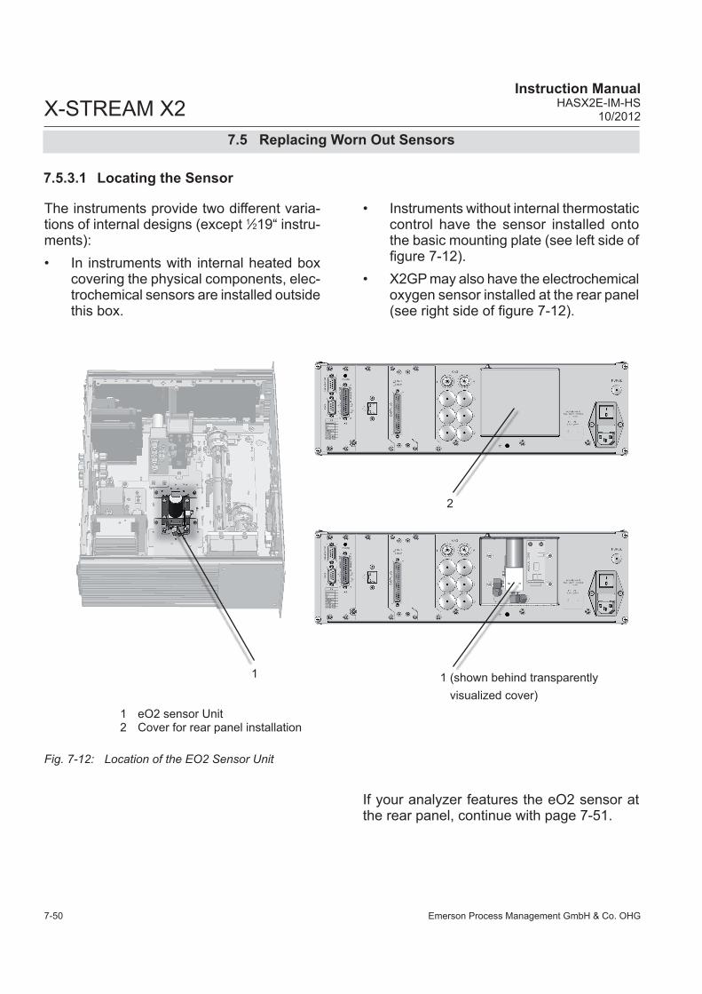
Emerson Process Management GmbH & Co. OHG7-50
X-STREAM X2Instruction Manual
HASX2E-IM-HS10/2012
7.5.3.1 Locating the Sensor
The instruments provide two different varia-tions of internal designs (except 1⁄219“ instru-ments):• In instruments with internal heated box
covering the physical components, elec-trochemical sensors are installed outside this box.
Fig. 7-12: Location of the EO2 Sensor Unit
• Instruments without internal thermostatic control have the sensor installed onto the basic mounting plate (see left side of figure 7-12).
• X2GP may also have the electrochemical oxygen sensor installed at the rear panel (see right side of figure 7-12).
1 eO2 sensor Unit2 Cover for rear panel installation
If your analyzer features the eO2 sensor at the rear panel, continue with page 7-51.
1 1 (shown behind transparently visualized cover)
2
7.5 Replacing Worn Out Sensors

Emerson Process Management GmbH & Co. OHG 7-51
X-STREAM X2Instruction ManualHASX2E-IM-HS10/2012
7M
aint
enan
ce &
Pro
cedu
res
7.5.3.2 Disassembling the Sensor UnitThe sensor unit consists of a holder, an elec-tronics board and the sensor itself, all together installed on a base plate (Fig. 7-13).After loosening the nut (5), push the holder (3) with sensor (1) until the nut is above the hole (see details), then lift the holder from the base plate (4). The sensor is still fixed in the holder by means of a clip (8).Now loosen the screws (7), fixing the sensor block (6) to the holder, push the holder down-wards until the screws heads slip through the holes.
Pull off the signal connector from the electro-nics board (2) and take off the sensor.Take a new sensor, remove its plug, insert the sensor into the block and connect the signal connector to P2 on the electronics board (Fig. 7-14).
3 7
Sensors
newweared
Now re-assemble the sensor unit in reverse order, but do not yet install it into the analyzer as it requires a signal adjustment.
1 Sensor2 Electronics Board3 Holder4 Base Plate
5 Nuts6 Sensor block7 Screws8 Clip
Fig. 7-13: Sensor Unit Design
1
3
5
7
2
6
8
4
(details rotated
90°)3
7.5 Replacing Worn Out Sensors

Emerson Process Management GmbH & Co. OHG7-52
X-STREAM X2Instruction Manual
HASX2E-IM-HS10/2012
7.5.3.3 Adjusting the Output Signal
Fig. 7-14: Sensor At Rear Panel
Fig. 7-15: OXS Board, Top View
Procedure:• power on the open instrument.• Supply ambient air (approx. 21 % O2) • Connect a digital voltmeter (DVM) to Tp 1 (signal) and Tp 2 (GND) on the elec- tronics board OXS (fig. 7-14).• Adjust the measured signal to 3360 mV DC (± 5 mV) utilizing the potentiometer R4 on OXS board.
Having replaced the worn sensor, the board´s output signal requires some adjustment.
Note!Once the output signal has been adjusted for a specific sensor, further changing the potentiometer settings will cause incorrect measuring results!
Strip P3 for sensor connection
Potentiometer R4 Tp 1Tp 2
Consider all applicable safety instructions, especially those at the beginning of this section 7.5
Replacing the sensor if rear panel installed
1. Loosen the screw nut at the cover's upper side.
2. Open the cover to get ac-cess to the sensor.
3. Take out the sensor by pulling it upwards.
4. Properly insert the new sensor into the block.
Sensor Electronics boardCoverScrew nut
7.5 Replacing Worn Out Sensors

Emerson Process Management GmbH & Co. OHG 7-53
X-STREAM X2Instruction ManualHASX2E-IM-HS10/2012
7M
aint
enan
ce &
Pro
cedu
res
• Disconnect the analyzer from power• Re-install the sensor unit into the analyzer• Close the housing. Take care to use all
screws, especially if the instrument is to be used in hazardous areas!
or close the rear panel cover and secure it
with the screw nut.
7.5.3.4 Finalizing the Sensor Replacement
In a next step for proper measuring results, perform a zero and a span calibration at least for the channel with the replaced sensor.
To ensure proper disposal, send back the old sensor to the EMERSON Process Manage-ment factory (or to your local sales office) or to an industrial waste management contractor for waste disposal.
EXPLOSION HAZARDSpecial conditions and instructions for start-up after maintenance apply to instruments to be operated in hazardous areas! Not observing these conditions and instructions may cause explosions!See the associated manuals, provided with instruments for use in hazardous areas, for more information.
7.5 Replacing Worn Out Sensors

Emerson Process Management GmbH & Co. OHG7-54
X-STREAM X2Instruction Manual
HASX2E-IM-HS10/2012
7.5 Replacing Worn Out Sensors
7.5.4 Replacing the Trace Oxygen Sensor
Replacing the trace oxygen sensor requires considering special instructions, shipped to-gether with every single sensor.Two versions of this sensor are available, differing in the background gas they can be used for:P/N 42718102: For sample gases containing acid gases, hydrocarbons or hydrogenP/N 42718103: For sample gases without acid gases, hydrocarbons and hydrogenIf replacing this sensor is necessary (con-sumable), contact Emerson for information on how to order a substitute. A new sensor will be provided together with detailled installation and handling instructions.
Consider all information given by the replacement instructions to avoid damaging the sensor, and to achieve best possible life time!

Emerson Process Management GmbH & Co. OHG 7-55
X-STREAM X2Instruction ManualHASX2E-IM-HS10/2012
7M
aint
enan
ce &
Pro
cedu
res
7.5.5 Replacing the Trace Moisture Sensor
• Locate the sensor unit within your ana-lyzer.
• Open the fittings, connecting the unit to the piping.
• Only loosen the small nuts (do not remove them), fixing the sensor unit to the analy-zer plate and carefully take the unit out of the analyzer.
• Take off the signal plug at the sensor's end (it is fixed by a screw!).
• Place a wrench (size: 27 mm) at the hexa-gon and screw out the sensor by turning it counterclockwise (ccw).
Do not use the cylindric sen-sor body to losen the sensor!Place a second wrench with size 30 mm from the top to counterhold the block.
• Take the new sensor and carefully place the HDPE protected end of the sensor into the sensor block.
• Place the one wrench at the hexagon, the other at the block to counterhold and fix the sensor by turning it clockwise (cw).
To ensure proper measure-ments, apply a torque of min. 30.5 Nm (269 in.lb).Do not use the cylindric sensor body to install the sensor!
• Install the connector to the sensor and fix it with the screw.
• Place the unit into the analyzer and fix it with the small nuts.
• Re-install the piping fittings.• Make sure that all the plugs associated
with the sensor are properly connected the same way as before.
30 mm
Connectors: 1 sensor signal plug 2 power to sensor 3 signal to analyzerFor details see appendix!
1
2
3
Consider all applicable safety instructions, especially those at the beginning of this section 7.5
Sensor block
Fig. 7-16: Trace Moisture Sensor Assembly Separated
7.5 Replacing Worn Out Sensors

Emerson Process Management GmbH & Co. OHG7-56
X-STREAM X2Instruction Manual
HASX2E-IM-HS10/2012
Seal the open analyzer´s gas fit-tings utilizing PVC caps to avoid pollution of inner gas path.
• Moisten the lint-free cloth with a mixture of 3 parts of water and 1 part of the general purpose detergent.
7.6 Cleaning the Instrument´s Outside
7.6 Cleaning the Instrument´s Outside
Use a liquid general purpose detergent and a lint-free cloth for cleaning the analyzer´s outside.
Procedure• Disconnect the instrument from power!
• If disconnecting from gas lines is re-quired, take care of the following:
EXPLOSIVE, FLAMMABLE AND HARMFUL GASES HAZARD Before opening gas paths they must be purged with ambient air or neutral gas (N2) to avoid hazards caused by toxic, flammable, explosive or harmful to health sample gas components!
HAZARD FROM UNHEALTHY SUBSTANCES
Take care to follow the safety instructions and instructions for use given by the manufacturer of the chosen general purpose detergent!
Do NOT drench the cloth, just moisten it to prevent liquid en-tering the housing!
• Clean the analyzer housing outside with the moistened cloth.
• If need be dry the housing after cleaning.

Emerson Process Management GmbH & Co. OHG 7-57
X-STREAM X2Instruction ManualHASX2E-IM-HS10/2012
7M
aint
enan
ce &
Pro
cedu
res
7.7 Save / Restore Configuration Data Sets
7.7 Save / Restore Configuration Data Sets
After some time of operating the instrument, one can assume all the parameters (calibration gases setup, measuring ranges, inputs and outputs, etc) are setup to meet the application´s and operator´s needs. To save these settings for means of restoring them in case of failures, data loss or even overwriting) use the options of the SAVE-LOAD menus.X-STREAM analyzers support saving analy-zer data by providing 3 different sets of data:FactData
This is the factory analyzer configuration setup, stored in a FRAM section. The user may only restore this write-protected data into RAM, but not save changed parameters as FactData.
CfgData This current analyzer configuration is stored in a separate FRAM section and used during analyzer operation.Each time the instrument is powered, a CfgData checksum is calculated. If it appears to be wrong, the UserData infor-mation is restored into RAM, overwriting CfgData. This ensures the instrument remains operable.
UserData UserData allows the operator to backup and restore his individual analyzer con-figuration and settings into/from FRAM. Each analyzer is shipped with CfgData configured during factory startup and copied to UserData and FactData.
So, as CfgData is overwritten by UserData in case of a checksum failure, it is recommended to store the CfgData once the instrument is setup to the operator‘s needs, to ensure, the analyzer setup is not lost.
In addition to backup the CfgData in internal FRAM memory, the SAVE-LOAD menu allows to save/restore such data to/from an external device (e.g. PC), connected to the service interface (SvcPort).Additional software is required to backup/restore data to/from an external device. If using a PC, an open source terminal soft-ware for MS-Windows™, that may be used for this purpose, is e.g.
UTF-8 TeraTerm Pro with TTSSH2,downloadable at
http://sourceforge.jp/projects/ttssh2/files.
Note!Please notice that Emerson Process Manage-ment does not provide support for any such software!

Emerson Process Management GmbH & Co. OHG7-58
X-STREAM X2Instruction Manual
HASX2E-IM-HS10/2012
Fig. 7-17: Relationship of Supported Data Sets and Where to Find Further Information
UserData configuration
saved to FRAM
Backup on user request(CfgData --> SvcPort,
7.6.4.2, page 7-57)
On user request restore and overwrite current configurati-
on in RAM (SvcPort --> CfgData, 7.6.4.3, page 7-59 )
Automatically overwrites in case of faulty checksum, or on user request (UserData --> CfgData,
7.6.2, page 7-54)
Overwrites after factory analy-zer startup, or on user request
(CfgData --> UserData, 7.6.1, page 7-53)
CfgDataconfiguration used during operation
FactDataFactory setup configuration
Overwrites on user request (FactData --> CfgData,
7.6.3, page 7-55)
Overwrites after factory analyzer startup
SvcPortBackup/Restore
to/from external device
Note!Before using the SvcPort read the instructions in 7.6.4.1, page 7-56.
7.7 Save / Restore Configuration Data Sets

Emerson Process Management GmbH & Co. OHG 7-59
X-STREAM X2Instruction ManualHASX2E-IM-HS10/2012
7M
aint
enan
ce &
Pro
cedu
res
7.7.1 Save CfgData to UserData
2nd menu page
FactData > CfgData..CfgData > UserData..UserData > CfgData..
Save-LoadCfgData > SvcPort!SvcPort > CfgData..Verify!
1st menu page
CfgData>UserData Are you sure?No!Yes!
(i)
-COMMAND EXECUTED-
Setup..Save-Load..
Copying data - PLEASE WAIT -
Procedure X:E000
Starting at the measurement screen press the DOWN key to open the MAIN MENU, enter the SETUP and next the SAVE-LOAD.. menu.
Now select the "CfgData>UserData.." line and press the ENTER key.
Press the DOWN key to open the second menu page.
A screen appears to confirm the operation: Select Yes! and after pressing the ENTER key a new screen comes up showing the current status.
The instrument now stores the currently used (and changed by operator) analyzer setup into a special memory area. This data is then called UserData and used for backup only, while the data used for operation still is CfgData.
Any further changes affecting the instrument's setup update the CfgData only, as long as not manually saved to the UserData set.
When the procedure has finished, the COM-MAND EXECUTED screen shows up.
If system is setup accordingly, access level 3 code must be entered to gain access to this menu.
7.7 Save / Restore Configuration Data Sets

Emerson Process Management GmbH & Co. OHG7-60
X-STREAM X2Instruction Manual
HASX2E-IM-HS10/2012
7.7.2 Restore UserData to CfgData
7.7. Save / Restore Configuration Data Sets
2nd menu page
FactData > CfgData..CfgData > UserData..UserData > CfgData..
Save-LoadCfgData > SvcPort!SvcPort > CfgData..Verify!
1st menu page
Setup..Save-Load..
If system is setup accordingly, access level 3 code must be entered to gain access to this menu.
Starting at the measurement screen press the DOWN key to open the MAIN MENU, enter the SETUP and next the SAVE-LOAD.. menu.
Now select the "UserData>CfgData.." line and press the ENTER key.
Press the DOWN key to open the second menu page.
UserData>CfgData Are you sure?No!Yes!
A screen appears to confirm the operation: Select Yes! and after pressing the ENTER key a new screen comes up showing the current status.
(i)
-COMMAND EXECUTED-
The instrument now replaces the currently used (and changed by operator) analyzer se-tup by the UserData set. All settings changed since the UserData was saved, will be over-written!When the procedure has finished, the COM-MAND EXECUTED screen shows up for 2 seconds, followed by...
FactData > CfgData..CfgData > UserData..UserData > CfgData..
... the previous menu page. After a few se-conds the analyzer automatically starts to reboot.

Emerson Process Management GmbH & Co. OHG 7-61
X-STREAM X2Instruction ManualHASX2E-IM-HS10/2012
7M
aint
enan
ce &
Pro
cedu
res
7.7.3 Copy FactData to CfgData
7.7. Save / Restore Configuration Data Sets
2nd menu page
FactData > CfgData..CfgData > UserData..UserData > CfgData..
Save-LoadCfgData > SvcPort!SvcPort > CfgData..Verify!
1st menu page
If system is setup accordingly, access level 3 code must be entered to gain access to this menu.
Now select the "FactData>CfgData.." line and press the ENTER key.
Press the DOWN key to open the second menu page.
FactData>CfgData Are you sure?No!Yes!
A screen appears to confirm the operation: Select Yes! and after pressing the ENTER key a new screen comes up showing the current status.
The instrument now replaces the currently used (and changed by operator) analyzer se-tup by the FactData set. All settings changed by the operator will be overwritten and the instrument setup to the factory settings.When the procedure has finished, the COM-MAND EXECUTED screen shows up for 2 seconds, followed by...
(i)
-COMMAND EXECUTED-
FactData > CfgData..CfgData > UserData..UserData > CfgData..
... the previous menu page. After a few se-conds the analyzer automatically starts to reboot.
Setup..Save-Load..
Starting at the measurement screen press the DOWN key to open the MAIN MENU, enter the SETUP and next the SAVE-LOAD.. menu.

Emerson Process Management GmbH & Co. OHG7-62
X-STREAM X2Instruction Manual
HASX2E-IM-HS10/2012
7.7.4 Save / Restore CfgData to External Device7.7.4.1 Preparation
7.7. Save / Restore Configuration Data Sets
Before starting any of these procedures an external device (e.g. computer) has to be connected to the analyzer via the service interface, which is of type RS232 (Fig. 7-17).
This service interface is NOT optically isolated from the ana-lyzer electronics! Take care to not destroy the electronics by electrostatic discharge or high voltages!
Make sure both devices (computer and ana-lyzer) provide the same type of interface. If need be, use a converter.Furthermore a terminal software is required to setup a communication. An open source terminal software for MS-Windows™, that may be used for this purpose, is UTF-8 TeraTerm Pro with TTSSH2, downloadable at http://sourceforge.jp/projects/ttssh2/files.
The fixed (not operator editable) settings for the interface are
Baudrate 19200 Startbit 1Parity EvenStopbit 1MODB mode1) 32 BitID number 1
1) MODB mode may be changed via related Modbus register
Pin9876
Pin54321
Pin no. RS 232
1 not used2 RXD3 TXD4 not used5 Common6 not used7 not used8 not used9 not used
Fig. 7-18: Service Port Connector - Serial RS 232 Interface

Emerson Process Management GmbH & Co. OHG 7-63
X-STREAM X2Instruction ManualHASX2E-IM-HS10/2012
7M
aint
enan
ce &
Pro
cedu
res
7.7.4.2 Save CfgData to SvcPort
Open the terminal software on your external device.
7.7. Save / Restore Configuration Data Sets
If system is setup accordingly, access level 3 code must be entered to gain access to this menu.
Save-LoadCfgData > SvcPort!SvcPort > CfgData..Verify!
Now select the "CfgData>SvcPort!" line and press the ENTER key.
When the procedure has finished, the COM-MAND EXECUTED screen shows up.
(i)
-COMMAND EXECUTED-
Copying data - PLEASE WAIT -
Procedure <-->
The instrument now copies the currently used (and possibly changed by operator) analyzer setup on an external device for future use.
Starting at the measurement screen press the DOWN key to open the MAIN MENU, enter the SETUP.. and next the SAVE-LOAD.. menu.
Setup..Save-Load..

Emerson Process Management GmbH & Co. OHG7-64
X-STREAM X2Instruction Manual
HASX2E-IM-HS10/2012
Save-LoadCfgData > SvcPort!SvcPort > CfgData..Verify!
7.7. Save / Restore Configuration Data Sets
The SAVE-LOAD.. menu also offers an option to verify that the saved data on the external device has not been corrupted during trans-mission:
With the external device still connected select the "Verify!" line and press the ENTER key.The analyzer now loads the data from the ex-ternal device and compares it to the CfgData. Finally a status screen shows up, followed by a COMMAND EXECUTED screen or an error message, if the data does not match.
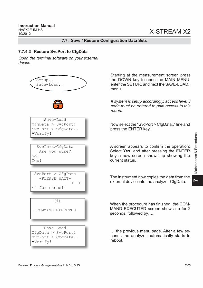
Emerson Process Management GmbH & Co. OHG 7-65
X-STREAM X2Instruction ManualHASX2E-IM-HS10/2012
7M
aint
enan
ce &
Pro
cedu
res
7.7.4.3 Restore SvcPort to CfgData
7.7. Save / Restore Configuration Data Sets
Open the terminal software on your external device.
SvcPort>CfgData Are you sure?No!Yes!
A screen appears to confirm the operation: Select Yes! and after pressing the ENTER key a new screen shows up showing the current status.
Save-LoadCfgData > SvcPort!SvcPort > CfgData..Verify!
Now select the "SvcPort > CfgData.." line and press the ENTER key.
SvcPort > CfgData -PLEASE WAIT- <-->8 for cancel!
The instrument now copies the data from the external device into the analyzer CfgData.
Starting at the measurement screen press the DOWN key to open the MAIN MENU, enter the SETUP.. and next the SAVE-LOAD.. menu.
Setup..Save-Load..
(i)
-COMMAND EXECUTED-When the procedure has finished, the COM-MAND EXECUTED screen shows up for 2 seconds, followed by….
If system is setup accordingly, access level 3 code must be entered to gain access to this menu.
Save-LoadCfgData > SvcPort!SvcPort > CfgData..Verify!
… the previous menu page. After a few se-conds the analyzer automatically starts to reboot.

Emerson Process Management GmbH & Co. OHG7-66
X-STREAM X2Instruction Manual
HASX2E-IM-HS10/2012

Emerson Process Management GmbH & Co. OHG 8-1
X-STREAM X2Instruction ManualHASX2E-IM-HS10/2012
8Tr
oubl
esho
otin
g
Chapter 8 Troubleshooting
8.1 AbstractThis chapter covers troubleshooting the ana-lyzer: Section 8.2 describes messages possibly ap-pearing in the measuring screen‘s status line (4th line), gives hints on the potential causes and on how to solve the problem(s). Two tables differentiate between analyzer related messages and channel related mes-sages.
As the analyzer software is not capable to detect all problems and faults, section 8.3 describes such faults, their consequences, gives hints on potential causes and on how to solve the problem(s).Section 8.4 gives detailled instructions on how to replace or adjust components, addressed to personnel familiar with the aspects of wor-king on such components.
8.2 Problems Indicated by Status Messages
Analyzer Related Messages page 8-3
Channel Related Messages page 8-6
8.3 Problems NOT Indicated by Status Messages page 8-11
8.4 Extended Troubleshooting on Components page 8-17

Emerson Process Management GmbH & Co. OHG8-2
X-STREAM X2Instruction Manual
HASX2E-IM-HS10/2012
8.2 Solving Problems Indicated by Status Messages
8.2 Solving Problems Indicated By Status Messages
In the following all possible status messages are listed in an alphabetical order together with hints on the possible causes and tips on how to solve the problems.
The list also shows a level indicator: In general one can assign four different levels to causes generating status messages. Depending on the level assigned the instrument activates different relay status signals, according the NAMUR NE 107 specifications.
Failures: Requires immediate actions. The analyzer is not any longer working properly and the output signal is invalid due to mal-function.
Off-spec: The analyzer is working outside its specification (e.g. measuring range), or internal diagnoses indicate deviations due to internal problems. To achieve proper outputs, corrective action is required.
Check request (or maintenance requests): The instrument is still working properly, within its specifications and the output signal is valid, but maintenance is required in for-seeable fu-ture because a function will soon be restricted or a wear reserve is nearly exhausted.
Function check: The analyzer is still working properly but currently is in a status where the output signal is temporarily invalid (e.g. frozen) due to the ongoing work on the instru-ment (e.g. during calibration).
If solving a reported problem requires working inside an open instrument, take care of the safety instructions given at the beginning of this manual!
As mentioned status messages are displayed inthe measuring screen‘s 4 th line. Multiple status messages active at a time show up sequentially in the status line. To see all sta-tus messages at a glance enter the STATUS menu:
Supported status levels:
Status..
1 Failures..0 Check requests..1 Function checks..0 Off spec..
The first page shows 4 lines each beginning with a number (indicating how many mes-sages of the related kind are active). Enter a line with a number different than "0" to see the related messages.

Emerson Process Management GmbH & Co. OHG 8-3
X-STREAM X2Instruction ManualHASX2E-IM-HS10/2012
8Tr
oubl
esho
otin
g
8.2.1 Analyzer related messages
8.2.1 Analyzer Related Messages
Message Status levelExplanation
Description Actions
FlowAlm Check request
Explanation:The internal flow control detected a flow problem
The detected flow is too low or missing due to a leak, not limited to the instrument‘s internal gas path
Check the external and inter-nal gas path for leakage and plugging
If applicable check internal pump function
LocalAccess Function check
Explanation:This status message is activated when a parameter is changed using the front panel keys
Someone has changed a parameter by using the front panel keys
Press the HOME key: The status message is reset when returning to the measurement screenAcknowledge the message via menu CONTROL.. - ACKNOWLEDGEMENTS.. Note! This resets ALL status mes-sages!
NotSampleGas Function check
Explanation:The gas currently flowing is not the expected sample gas
Other than sample valve is opened within installed valve block
Switch on sample valve
Installed pump is switched off Switch on the pump
Instrument is currently in cali-bration mode Wait for calibration to end
After calibration the sample gas valve has opened, but the post-purge time has not yet elapsed
Wait for purge time to elapse. If appropriate reduce purge time
Pressure Out of spec
Explanation:The internal pressure control detected a pressure problem
The detected pressure is too low or missing due to a leak inside or outside the instru-ment
Check the external and inter-nal gas path for leakage and plugging
If applicable check internal pump function

Emerson Process Management GmbH & Co. OHG8-4
X-STREAM X2Instruction Manual
HASX2E-IM-HS10/2012
Message Status levelExplanation
Description Actions
NVRAM fail Check request
Explanation:NVRAM test failed
Installed NVRAM and/or electronics board defective Replace
ROMmemory Failure
Explanation:Wrong code checksum
Installed FLASH memory defective Replace board
Simulation Function check
Explanation:This message does not appear during operation modes!
The instrument is set into a debugging mode by service personnel
Switch analyzer off and on again to exit the debugging mode
Switch off the related simu-lation parameters (in service level or by Modbus command)
Warm-up Function check
Explanation:This message may require temperature monitoring enabled within the service level
The warm-up time has not yet elapsed after last analyzer restart
Wait for warm-up time to elapse
Temperature of analyzer components or physical ther-mostatted compartment is not within the configured range
Wait for instrument to heat up
check internal heater for pro-per function
SensTimeout Failure
Explanation:No internal communi-cation to XSP board
Check internal wiring
Check COM parameters via SVC port
SensCmdFail Failure
Explanation:Sending a command to XSP board failed
Bandwidth, currently available for data exchange with XSP board, too small
Acknowledge the message. If recurring, call for service.
8.2.1 Analyzer related messages

Emerson Process Management GmbH & Co. OHG 8-5
X-STREAM X2Instruction ManualHASX2E-IM-HS10/2012
8Tr
oubl
esho
otin
g
Message Status levelExplanation
Description Actions
Calibration Function check
Explanation:Calibration active
Currently a calibration proce-dure is ongoing
Wait for calibration to finish
Cancel calibration
SvcPort > Cf Function check
Explanation:SVC port in use
Instrument is currently confi-gured via service interface Wait for data transfer to finish
SVC port is in pass through mode
Switch back to normal com-munication mode
Unlinear Off-spec
Explanation:This message does not appear during operation modes!
Instrument has been set to "unlinear mode" by service personnel (see "simulation")
Switch off diagnostic mode (Modbus command)
8.2.1 Analyzer related messages

Emerson Process Management GmbH & Co. OHG8-6
X-STREAM X2Instruction Manual
HASX2E-IM-HS10/2012
8.2.2 Channel Related Messages (Preceded By Channel Tag, E.g. CO2.1)
Message Status levelExplanation
Description Actions
ADC-Error Failure
Explanation:A/D conversion overflow
The A/D converter of the related channel is not working properly
Switch analyzer OFF and ON again
Call for service
RangeOverflo Off-spec
Explanation:Gas concentration is out of range
Gas concentration is out of measurement range and the-refore linearization curve does not apply
Adjust gas concentration to be within range
Simulation Function check
Explanation:This message does not appear during operation modes!
The instrument is set into a debugging mode by service personnel
Switch analyzer off and on again to exit the debugging mode
Switch off the related simu-lation parameters (in service level menu)
Temperature Out of spec
Explanation: Temperature out of specified range
Warm-up not yet finishedWait until warm-up has fini-shed (10 - 50 min, depending on system)
Temperature controler defec-tive Call service center
Chopper Failure
Explanation:Chopper is not working properly
Either speed control or chop-per itself is defective Replace defective component
Detector Failure
Explanation:Preamp is not working properly
Either output signal too small or distorted, or preamp is defective
Check output signal or replace component
8.2.2 Channel Related Messages

Emerson Process Management GmbH & Co. OHG 8-7
X-STREAM X2Instruction ManualHASX2E-IM-HS10/2012
8Tr
oubl
esho
otin
g
Message Status levelExplanation
Description Actions
Source Failure
Explanation:IR found defective
Normally this message is initiated by a missing power supply.
CAUTION!Hot components!
Check source (cold housing means defective).
Replace source
SCalTolChk Check request
Explanation:Enabled tolerance check detected while spanning (measured value differing more than 10 % from setpoint)
Wrong setpoint value Check span gas setpoint
Wrong span gas applied Check span gas
IR/UV channel: Photometric components polluted
Check and if need be clean photometric components
Instrument not yet calibrated (first calibration after installa-tion)
Disable tolerance check before restarting the calibration
ZCalTolChk Check request
Explanation:Enabled tolerance check detected while zeroing (measured value differing more than 10 % from setpoint)
Wrong setpoint value Check zero gas setpoint
Wrong zero gas applied Check zero gas
IR/UV channel: Photometric components polluted
Check and if need be clean photometric components
Instrument not yet calibrated (first calibration after installa-tion)
Disable tolerance check before restarting the calibration
ZCalRefused Check request
Explanation:This message does not appear during normal operation modes!
Wrong DSP (sensor) configu-ration Call for service
8.2.2 Channel Related Messages

Emerson Process Management GmbH & Co. OHG8-8
X-STREAM X2Instruction Manual
HASX2E-IM-HS10/2012
Message Status levelExplanation
Description Actions
SCalRefused Check request
Explanation:This message does not appear during normal operation modes!
Wrong DSP (sensor) configu-ration Call for service
FlowLimAlm Check request
Explanation:Flow too low
Flow sensor detected flow to be below set limit
Increase flow
Set new limit
TempRange Off-spec
Explanation:Only at instruments with thermostate control
Temperature during operation out of range Check heater elements
TempSensor Off-spec
Explanation:Temperatur sensor defective
Instruments µP detected tem-perature sensor to be defec-tive
Check temperature sensor
Alarm Level1 - -
Explanation:Concentration alarm level 1 is activated (exceeded)
Alarm level 1 was exceededAdjust the gas concentration to be within the set limits
Alarm Level2 - -
Explanation: Concentration alarm level 2 is activated (exceeded)
Alarm level 2 was exceededAdjust the gas concentration to be within the set limits
8.2.2 Channel Related Messages

Emerson Process Management GmbH & Co. OHG 8-9
X-STREAM X2Instruction ManualHASX2E-IM-HS10/2012
8Tr
oubl
esho
otin
g
Message Status levelExplanation
Description Actions
Spanning Function check
Explanation: Ongoing span calibrationNote! In the status menu this message shows up in the "Calibration" line without channel tag!
Span calibration ongoing for the channel identified by the tag
Wait until calibration has fini-shed
Cancel calibration
Zeroing Function check
Explanation:Ongoing zero calibrationNote! In the status menu this message shows up in the "Calibration" line without channel tag!
Zero calibration ongoing for the channel identified by the tag
Wait until calibration has fini-shed
Cancel calibration
8.2.2 Channel Related Messages

Emerson Process Management GmbH & Co. OHG8-10
X-STREAM X2Instruction Manual
HASX2E-IM-HS10/2012
8.2.2 Channel Related Messages

Emerson Process Management GmbH & Co. OHG 8-11
X-STREAM X2Instruction ManualHASX2E-IM-HS10/2012
8Tr
oubl
esho
otin
g
8.3 Solving Problems Not Indicated By Status Messages
The following table lists possible faults not detectable by the instrument‘s software, gives hints on the potential causes and tips on how to solve the problems.If solving a problem requires working inside the instrument take care of the safety instruc-tions given at the beginning of this manual!
Note on X-STREAM Fieldhousings!To see the current status even when the front door is open, the front panel may be swivelled to the side (XLF; XXF) or downwards (X2FD). To do so loosen the four nuts fixing the front panel to the door and swivel the front panel using the remaining srews as hinges.
8.3 Solving Problems Not Indicated by Status Messages

Emerson Process Management GmbH & Co. OHG8-12
X-STREAM X2Instruction Manual
HASX2E-IM-HS10/2012
8.3 Solving Problems Not Indicated by Status Messages
Situation Description Actions
Display dark Power supply missing
Check power connection
Check power supplyCheck instrument‘s power fusesCheck power supply unit: green LED (OK)
Front panel connection faulty Check front panel connectionsInstrument does not work nor respond on inputs CPU hang up Disconnect power to reset
CPU
No analog output signal
External failure Check external circuitry for failures
Internal connection failure
Check signal connection at P22 of board XPSAXPSA: If red LED "No PWM" glows - check connection to P19XPSA: LED "No PWM" dark - check power connection to XPSA (2-pole cable br/wht)
Analog outputs 2 - 4 affected check installation of module XSIA on XPSA board
Digital outputs not working properly
External failure Check external circuitry for failures
Configuration failure Check digital outputs menu settings
Outputs 1 - 4 affected
XPSA: If red LED "TIMEOUT" glows - check connection to P33 XPSA: LED "TIMEOUT" dark - check power connection to XPSA (2-pole cable br/wht)

Emerson Process Management GmbH & Co. OHG 8-13
X-STREAM X2Instruction ManualHASX2E-IM-HS10/2012
8Tr
oubl
esho
otin
g
8.3 Solving Problems Not Indicated by Status Messages
Situation Description Actions
Digital outputs not working properly (cont.)
Outputs on extension board(s) (XDIO) affected
XDIO: If LED "TIMEOUT" glows - check jumpers on XDIO. XDIO #1: jumper on ADR2XDIO #2: jumpers on ADR2 & ADR0XDIO: If LED "TIMEOUT" glows - check connection to P33XDIO: If LED "NO SPI" glows - check internal SPI communi-cation cable (10 pole cable)
Digital inputs not working properly
External failure Check external circuitry for failures
Configuration failure Check digital inputs menu settings
Outputs on extension board(s) (XDIO) affected
XDIO: If LED "TIMEOUT" glows - check jumpers on XDIO. XDIO #1: jumper on ADR2XDIO #2: jumpers on ADR2 & ADR0XDIO: If LED "TIMEOUT" glows - check connection to P33XDIO: If LED "NO SPI" glows - check internal SPI communi-cation cable (10 pole cable)
Internal valves not working properly Connection failure
Check electrical connection of valvesXPSA: If red LED "TIMEOUT" glows - check connection to P33 XPSA: LED "TIMEOUT" dark - check power connection to XPSA (2-pole cable br/wht)
External valves not working properly
Valves connected to digital outputs
See "Digital outputs not wor-king properly"
Valves not connected to digital outputs
Check external valve control-ler

Emerson Process Management GmbH & Co. OHG8-14
X-STREAM X2Instruction Manual
HASX2E-IM-HS10/2012
8.3 Solving Problems Not Indicated by Status Messages
Situation Description Actions
Serial communication not working properly
External failure Check external circuitry for failures
Connection failure
XPSA: If red LED "TIMEOUT" glows - check connection to P33Check installation of interface module (SIF xxx)
Fluctuating or invalid readout
Leak in gas path Perform a leak test
Ambient air contains high concentration of measured gas component
Check absorber (at chopper/measuring cell) and replace if need be.Replace photometer with sealed version (option)Purge instrument with neutral gas
Fluctuating gas pressure
Check gas path before and behind cell and sensorRemove restriction behind gas outlet
Reduce gas flow or pump rateSensor or detector not con-nected Check detectors connections
Electrochemical Oxygen sen-sor worn-out
Check sensor and replace if need be
IR channel: Source not connected or de-fective
Check connections: X3 (1/2) / source channel 1X3 (4/5) / source channel 2If source housing is cold:Exchange both source in case of dual channel analyzer / replace source if need be (see service manual)
Analog preamplifier of af-fected channel defective
Check measuring point ( 8-4-2-1-6, page 8-19)

Emerson Process Management GmbH & Co. OHG 8-15
X-STREAM X2Instruction ManualHASX2E-IM-HS10/2012
8Tr
oubl
esho
otin
g
8.3 Solving Problems Not Indicated by Status Messages
Situation Description Actions
Fluctuating or invalid readout (continued)
Gas path(s) polluted
Check analysis cells and win-dows for pollution
Clean polluted parts (see ser-vice manual)
Check gas paths for pollution and clean gas paths if need be
Wrong pressure value used for compensation
Set ambient pressure to pro-per value ( 6.2.3.3, page 6-28) Sensor failure ( status message "PressSensor“, page 8-4)
Condensation inside gas path
Check temperature of gas path(s)Remove all sources of con-densationKeep all temperatures at least 10 °C above sample gas tem-perature
Readout damping time too long
Wrong signal damping settings Check signal damping ( 6.2.3.3.1, page 6-29)
Pump rate too low
Distance between sampling point and analyzer too longReplace pump by external model with higher pump rate (operate in bypass mode,
fig. 4-2, page 4-4)
Gas path(s) pollutedCheck gas path and sample handling system for pollutionClean gas path

Emerson Process Management GmbH & Co. OHG8-16
X-STREAM X2Instruction Manual
HASX2E-IM-HS10/2012
Situation Description Actions
No gas flow
Sample gas pump (option) switched off
Switch on sample gas pump ( 6.2.2, page 6-5)
Membrane of sample gas pump defective
Replace sample pump mem-brane
Sample gas pump defective Replace sample gas pump
Solenoid valves (option) not opened / defective
External valves:Check connection between valves and digital outputsCheck valve seat and replace if need beReplace solenoid valvesFor valve control via serial interface or digital inputs: Any valve activated?
Gas path(s) pollutedCheck gas path and sample handling system for pollutionClean gas path
8.3 Solving Problems Not Indicated by Status Messages

Emerson Process Management GmbH & Co. OHG 8-17
X-STREAM X2Instruction ManualHASX2E-IM-HS10/2012
8Tr
oubl
esho
otin
g
8.4 Troubleshooting On ComponentsThis section give information on how to check and replace internal components.
Some work described on the next pages need to be carried out by qualified personnel only, and may require special tools, to ensure the instrument or component is not damaged or disadjusted!
8.4 Troubleshooting on Components
8.4.1 Opening X-STREAM Analyzers page 8-19 8.4.2 Measuring Points page 8-21 8.4.3 Sample Pump: Replacement of Diaphragm page 8-22 8.4.4 Paramagnetic Oxygen Cell: Adjustment of Physical Zero page 8-33 8.4.5 Thermal Conductivity Cell: Adjustment of Output Signal page 8-36
ELECTRICAL SHOCK HAZARD Working at opened and powered instruments means working near live parts and is subject to instructed and trained personnel only!Take care to observe all applicable safety instructions!

Emerson Process Management GmbH & Co. OHG8-18
X-STREAM X2Instruction Manual
HASX2E-IM-HS10/2012
ELECTROSTATIC DISCHARGE HAZARD Working at internal components of electronical and electrical instruments may cause electrostatic discharge (ESD), destroying components! Working at open instruments is recommended at special workplaces only! If no such workplace is available, at minimum perform the following procedures to not destroy electronic components:Discharge the electric charge from your body. Do this by touching a device that is grounded electrically (e.g. instruments with earth connectors, heating installations). This should be done periodically when working at open instruments (especially after leaving the service site, because e.g. walking on low conducting floors might cause additional ESD).
HAZARD FROM EXPLOSIVE, FLAMMABLE AND HARMFUL GASESBefore opening gas paths they must be purged with ambient air or neutral gas (N2) to avoid hazards caused by toxic, flammable, explosive or harmful to health sample gas components!
HIGH TEMPERATURESWhile working at internal components hot surfaces may be accessible, even after the instrument has been disconnected from power!
8.4 Troubleshooting on Components

Emerson Process Management GmbH & Co. OHG 8-19
X-STREAM X2Instruction ManualHASX2E-IM-HS10/2012
8Tr
oubl
esho
otin
g
8.4 Troubleshooting on Components
Fig. 8-1: X-STREAM X2GP
8.4.1 Opening X-STREAM Analyzers
8.4.1.1 How To Open X-STREAM X2GP
8.4.1.2 How To Open X-STREAM X2GK
Remove the top cover after loosening the 12 screws. 12 screws on top
of the instrument
Fig. 8-2: X-STREAM X2GK
If your instrument is equipped with a handle• loosen the 6 screws at the front panel, • to only get access to the cover screws,
push frame and handle about 2 cm / 1" towards the rear.
Note!To completely remove frame and handle, you need to disconnect all gas and electrical connections and push frame and handle over the rear panel.
• push the cover towards the rear and re-move it.
• remove the 4 screws for the cover,(2 screws on each side of the instrument

Emerson Process Management GmbH & Co. OHG8-20
X-STREAM X2Instruction Manual
HASX2E-IM-HS10/2012
8.4 Troubleshooting on Components
Fig. 8-3: X-STREAM X2 Field housings and X2FD - How to Open
Sash fasteners
Screws at the flange
8.4.1.4 How To Open X-STREAM X2FDTo open a X-STREAM X2FD loosen the 20 screws located at the instrument´s flange. Then carefully flip down the front door to not damage the instrument, hinges or equipment installed below the analyzer.
8.4.1.3 How To Open X-STREAM Field-housings
EXPLOSION HAZARDX-STREAM X2FD as well as special variations of X-STREAM XLF and XXF Fieldhousings are intended to be installed in hazardous areas. Maintaining such instruments is permitted only considering special conditions, givenin the associated separate manuals.Do not open nor maintain instruments in hazardous areas without having read and understood all related instruction manuals!
Depending on the individual analyzer con-figuration, either open the upper or lower front door to the left, utilizing the two sash fasteners.
GASKETS AT LOW TEMPERATURESConsider that enclosure gaskets may be frozen if the instrument is installed outdoors. Carefully open the enclosure at temperatures below -10 °C to not damage the gaskets. Damaged gaskets void the ingress protection, possibly causing property damage, personal injury or death.

Emerson Process Management GmbH & Co. OHG 8-21
X-STREAM X2Instruction ManualHASX2E-IM-HS10/2012
8Tr
oubl
esho
otin
g
Fig. 8-4: XSP - Allocation of signal connectors
8.4 Troubleshooting on Components
8.4.2 Signal Connectors On XSP Board

Emerson Process Management GmbH & Co. OHG8-22
X-STREAM X2Instruction Manual
HASX2E-IM-HS10/2012
8.4.3 Sample Pump: Replacement Of Diaphragm
8.4 Troubleshooting on Components
This instruction explains the procedure to replace the diaphragms of sample gas pumps (PN 42716569) used in the X-STREAM series gas analyzers.
To do so you need to dismantle the pump from your analyzer.

Emerson Process Management GmbH & Co. OHG 8-23
X-STREAM X2Instruction ManualHASX2E-IM-HS10/2012
8Tr
oubl
esho
otin
g
8.4 Troubleshooting on Components
Step 1:
If applicable:Remove the screws S1 on both sides of the pump. Take off the cover.
Required parts for the spare parts kit for the pump (PN 0375946).
S1

Emerson Process Management GmbH & Co. OHG8-24
X-STREAM X2Instruction Manual
HASX2E-IM-HS10/2012
8.4 Troubleshooting on Components
Step 2:
Remove the screws S2 and screw S3.
Step 3:
Take out the pump assy.
S2
S3

Emerson Process Management GmbH & Co. OHG 8-25
X-STREAM X2Instruction ManualHASX2E-IM-HS10/2012
8Tr
oubl
esho
otin
g
8.4 Troubleshooting on Components
Step 5:
Remove the white block.
Step 4:
Mark the pump assy. before di-sassembly.

Emerson Process Management GmbH & Co. OHG8-26
X-STREAM X2Instruction Manual
HASX2E-IM-HS10/2012
8.4 Troubleshooting on Components
Step 6:
Remove the teflon gasket.
Step 7:
Remove the remaining two pump parts.Clean the white plate for the gas in- and outlet.

Emerson Process Management GmbH & Co. OHG 8-27
X-STREAM X2Instruction ManualHASX2E-IM-HS10/2012
8Tr
oubl
esho
otin
g
8.4 Troubleshooting on Components
Step 8:
Disassemble the lower block and the clamp. Loosen the screw S4 and the nut N1.
Clamp
S4
N1

Emerson Process Management GmbH & Co. OHG8-28
X-STREAM X2Instruction Manual
HASX2E-IM-HS10/2012
8.4 Troubleshooting on Components
Step 9:
Remove the two washers on the diaphragm.
Step 10:
Replace the old with the new dia-phragm and assemble the was-hers and the clamp in reverse order (step 9 and 8).

Emerson Process Management GmbH & Co. OHG 8-29
X-STREAM X2Instruction ManualHASX2E-IM-HS10/2012
8Tr
oubl
esho
otin
g
8.4 Troubleshooting on Components
Step 11:
Remove the locking springs on both sides of the white block and take out the old diaphragms on both sides.

Emerson Process Management GmbH & Co. OHG8-30
X-STREAM X2Instruction Manual
HASX2E-IM-HS10/2012
8.4 Troubleshooting on Components
Step 13:
Assemble the pump assy. Take care of your marker ( step 4)
1. Put the two upper plates under the clamp ( steps 6 & 7 for reference).
2. Put the white block and the new teflon gasket between the lower block and the in-outlet pla-te.
Step 12:
Clean the white block.
Afterwards put in the new dia-phragms and fix them with the new locking springs.
1
2

Emerson Process Management GmbH & Co. OHG 8-31
X-STREAM X2Instruction ManualHASX2E-IM-HS10/2012
8Tr
oubl
esho
otin
g
8.4 Troubleshooting on Components
Step 14:
Assemble the pump assy in re-verse order.
Put it in the pump housing and fix it with the screws S2.Fix the clamp with screw S3 and the black buffer.
S2
S3

Emerson Process Management GmbH & Co. OHG8-32
X-STREAM X2Instruction Manual
HASX2E-IM-HS10/2012
8.4 Troubleshooting on Components
Step 15:
If applicable: Install the cover and fix it with screws S1 at both sides.
Finally re-install the pump into your analy-zer, to complete the replace-ment of pump diaphragm.
S1

Emerson Process Management GmbH & Co. OHG 8-33
X-STREAM X2Instruction ManualHASX2E-IM-HS10/2012
8Tr
oubl
esho
otin
g
8.4 Troubleshooting on Components
8.4.4 Paramagnetic Oxygen Cell: Adjustment Of Physical Zero
Step 1:
The adjoining figure shows a heated paramagnetic oxygen cell.
Step 2:
Open the cell cover by loosening the screw S1 at the top.
To adjust the physical zero you need to measure some voltages on the XSP board:Depending on which channel the cell is as-signed to, the measuring signal (+) can be measured at pin 3 of the related connector. GND (-) is available at a separate pin (see figure).The measured voltage should be 0 V ± 50 mV.
The cell contains strong ma-gnets! Use only non-magnetic tools to adjust the zero point!
S1 Note!Depending on your specific instrument alter-natively an unheated cell may be installed.In this case skip step 2 and continue with step 3.
+6 V -6 V
Signal connectorsSignal pins
GND

Emerson Process Management GmbH & Co. OHG8-34
X-STREAM X2Instruction Manual
HASX2E-IM-HS10/2012
8.4 Troubleshooting on Components
Step 5:
Tighten the screw S2 with care, close the cover and check the zero point again.
Step 4:
Carefully loosen the screw S2.Now you can adjust the physical zero point with screw S3. Turn the screw carefully.
Step 3:
Apply N2 to the analyzer.
The cell´s electronic is light sen-sitive: When exposed to light while adjusting the zero point utilizing screw S3, a zero point shift may arise after the cover is closed. Tip: Shade the cell with a cloth when adjusting screw S3.
A
S3S2
You might have to re-adjust the zero point several times until it remains at the expected value.
Note!If the cell itself does not provide a cover, close the instrument while checking the cell!

Emerson Process Management GmbH & Co. OHG 8-35
X-STREAM X2Instruction ManualHASX2E-IM-HS10/2012
8Tr
oubl
esho
otin
g
8.4 Troubleshooting on Components
Step 6:
Fix the closed cell´s cover with screw S1.
This completes the zero point adjustment procedure.
S1

Emerson Process Management GmbH & Co. OHG8-36
X-STREAM X2Instruction Manual
HASX2E-IM-HS10/2012
8.4 Troubleshooting on Components
8.4.5 Thermal Conductivity Cell: Adjustment Of Output Signal
To adjust the zero signal of this measuring cell you need to have access to both sides of the related electronics board WAP 100.
A digital voltmeter (DVM) is required to measure and adjust several voltages!

Emerson Process Management GmbH & Co. OHG 8-37
X-STREAM X2Instruction ManualHASX2E-IM-HS10/2012
8Tr
oubl
esho
otin
g
8.4 Troubleshooting on Components
Step 1:
Check the solder bridges, lo-cated at the solder side of the board, for proper configuration:
LB10 openLB4 2-5 closedLB21 1-4 closedLB20 open
Step 2:
Switch on the analyzer. The onboard LED will light up red and green.
LED
When the warmup time has elapsed, the LED flashes green.
LED
LB21
LB4
LB20
LB10
LED

Emerson Process Management GmbH & Co. OHG8-38
X-STREAM X2Instruction Manual
HASX2E-IM-HS10/2012
8.4 Troubleshooting on Components
R60
Test connector P4
P4.15
P4.16 +
_
Step 3:
Locate test connector P4 to measure the bridge voltage:
P4.16 Bridge voltage (+)P4.15 Bridge voltage (-); GNDCAUTION! Do not short-circuit pins!
Alternatively the GND signal (-) is accessible on the main board BKS, too: Locate X11 ( fig. 8-3, page 8-16) .The bridge voltage depends on range and sample gas and should be between 3V and 5V.Only if the WAP 100 board has been replaced, it is necessary to adjust the voltage with potentio-meter R60.

Emerson Process Management GmbH & Co. OHG 8-39
X-STREAM X2Instruction ManualHASX2E-IM-HS10/2012
8Tr
oubl
esho
otin
g
8.4 Troubleshooting on Components
P11/ P17
Step 4:
To adjust the physical zero point:Apply zero gas to the analyzer.Connect the DVM to the follo-wing pins:P4.5 Raw signal (+)P4.15 Bridge voltage (-); GND CAUTION! Do not short-circuit pins!
To adjust the physical zero point, it is necessary to install a resistor between P11/ P17 at position 1, 2, 3 or 4 (the following figure shows it at position 4). The position and value depends on the individual cell parameters. Proper configuration is a result of "try and error"!Change resistor and/or position until the voltage is 0 V ± 500 mV.
Finally solder in the resistor between P11/ P17.
P11
P17
P4.15
P4.5 Raw
P4

Emerson Process Management GmbH & Co. OHG8-40
X-STREAM X2Instruction Manual
HASX2E-IM-HS10/2012
8.4 Troubleshooting on Components
Step 5:
To adjust the physical span:Apply span gas to the analyzer.Do not disconnect the DVM:P4.5 Raw signal (+)P4.15 Bridge voltage (-); GND CAUTION! Do not short-circuit pins!
Adjust the voltage to 10V utilizing R119.If 10V is not within the adjustable range, it is necessary to change the signal amplification with sol-der bridge LB3:
Step 6:Now once more check the zero point:Apply zero gas to the analyzer.Do not disconnect the DVM:
The voltage should be 0 V ± 500 mV.If it does not, repeat from step 3!
P4.15
P4.5 Raw
For an amplification closefactor of 20 1-5 150 3-5 300 4-5 500 2-3-4-5
LB3
R119
P4

Emerson Process Management GmbH & Co. OHG 8-41
X-STREAM X2Instruction ManualHASX2E-IM-HS10/2012
8Tr
oubl
esho
otin
g
8.4 Troubleshooting on Components
Step 7:
To finetune the physical zero point:Close solder bridge LB10.Apply zero gas to the analyzer.Do not disconnect the DVM:P4.5 Raw signal (+)P4.15 Bridge voltage (-); GNDCAUTION! Do not short-circuit pins!
Now you can finetune the zero point to a minimum value, using R103.
Check the zero point with zero gas again and perform a zero calibration.
Check the full scale signal (10V at P4.5) with span gas and per-form a span calibration.
This step completes the adjustment of output procedure.
LB10
R103
P4
P4.15
P4.5 Raw

Emerson Process Management GmbH & Co. OHG8-42
X-STREAM X2Instruction Manual
HASX2E-IM-HS10/2012

Emerson Process Management GmbH & Co. OHG 9-1
X-STREAM X2Instruction ManualHASX2E-IM-HS10/2012
9M
odbu
s C
omm
ands
Chapter 9 Modbus Functions
This chapter lists all Modbus functions and registers supported by X-STREAM gas analyzers. Refer to the www.Modbus-IDA.org website for detailled documentation about program-ming the interface. At date of creation of this instruc-tion manual the following documents were used:• MODBUS Protocol Specification:
Modbus_Application_Protocol_V1_1a.pdf
• MODBUS Serial Line Implementation Guide: Modbus_over_serial_line_V1.pdf.
9.1 Abstract
For a list of supported functions 9.2, page 9-2
supported parameters and registers, ordered by parameter tag name 9.3, page 9-2 ordered by register number 9.4, page 9-22
Before using Modbus TCP/IP take care to configure the communication properly:
6.2.3.6, page 6-45.For Modbus TCP/IP the analyzer is factory configured to support DHCP servers: The mo-ment, the powered instrument is connected
9.1.1 Modbus TCP/IP
Download the configuration utility software for the installed XPort AR from: http://www.lantronix.com/support/downloads.html
to a DHCP server via ethernet, it will receive a valid IP address and become visible in the network.If a DHCP server is not available, special software is downloadable to configure the ethernet port.

Emerson Process Management GmbH & Co. OHG9-2
X-STREAM X2Instruction Manual
HASX2E-IM-HS10/2012
9.2 Supported Functions
Modbus Function Function Code
Note 1)
decimal (hex)ReadCoils 01 (0x01) for registers of 2000ReadDiscreteInputs 02 (0x02) for registers of 1000ReadHoldingRegisters 03 (0x03) for registers of 3000, 8000, 9000ReadInputRegisters 04 (0x04) for registers of 4000, 8000, 9000WriteSingleCoil 05 (0x05) for registers of 2000WriteSingleRegister 06 (0x06) for registers of 3000Diagnostic 08 (0x08) sub function "00 = Return Query Data" onlyWriteMultipleCoils 15 (0x0F) for registers of 2000WriteMultipleRegisters 16 (0x10) for registers of 3000, 8000, 9000
EncapsulatedInterfaceTransport 43 (0x28)sub function "0x60" and "0x81" only(to be used for configuration file transfer)
9.2 Modbus - Supported Functions
1) Registers ranges 8000 and 9000 are Daniel long word or floating point registers. To calculate the related Modicon registers use the following table:
Daniel Modicon Data type
8001 - 8499 equals 5001 - 5999 long word9001 - 9999 equals 6001 - 7999 floating point
or the following pages for comparisons of all Daniel and Modicon registers.
9.3 List Of Parameters And Registers - Sorted By Tag Name
Note!The client access column in the following list provides information about the read only (RO) or read/write (R/W) access of each parameter.All parameters with read/write access and tag names beginning with "Service." require entering the service level access code into the register 3008 for parameter "Service.RemoteSecurity" to enable write access.

Emerson Process Management GmbH & Co. OHG 9-3
X-STREAM X2Instruction ManualHASX2E-IM-HS10/2012
9M
odbu
s C
omm
ands
9.3 List of Parameters and Registers - Sorted by Tag Name
Tag NameAddress Data
TypeClient
Access DescriptionModicon Daniel
Control.AcknowledgeStates 2038 2038 Boolean R/W 1=Acknowledge device‘s states, 0=no effect
Control.AnalogOut.ZoomState1 3257 3257 Word R/W ZoomStatus AOut1 (0=Normal, 1=Zoo-med)
Control.AnalogOut.ZoomState2 3258 3258 Word R/W ZoomStatus AOut2 (0=Normal, 1=Zoo-med)
Control.AnalogOut.ZoomState3 3259 3259 Word R/W ZoomStatus AOut3 (0=Normal, 1=Zoo-med)
Control.AnalogOut.ZoomState4 3260 3260 Word R/W ZoomStatus AOut4 (0=Normal, 1=Zoo-med)
Control.ApplyGas.PumpState 2033 2033 Boolean R/W 0=Off, 1=On
Control.ApplyGas.SampleValve 2021 2021 Boolean R/W 0=close all valves, 1=open sample valve
Control.ApplyGas.SpanValve1 2029 2029 Boolean R/W 0=open sample valve, 1=open span valve comp1
Control.ApplyGas.SpanValve2 2030 2030 Boolean R/W 0=open sample valve, 1=open span valve comp2
Control.ApplyGas.SpanValve3 2031 2031 Boolean R/W 0=open sample valve, 1=open span valve comp3
Control.ApplyGas.SpanValve4 2032 2032 Boolean R/W 0=open sample valve, 1=open span valve comp4
Control.ApplyGas.ZeroValve1 2025 2025 Boolean R/W 0=open sample valve, 1=open zero valve comp1
Control.ApplyGas.ZeroValve2 2026 2026 Boolean R/W 0=open sample valve, 1=open zero valve comp2
Control.ApplyGas.ZeroValve3 2027 2027 Boolean R/W 0=open sample valve, 1=open zero valve comp3
Control.ApplyGas.ZeroValve4 2028 2028 Boolean R/W 0=open sample valve, 1=open zero valve comp4
Control.Calibration.Calibration_Cancel 2012 2012 Boolean R/W Cancel any calibration (1=cancel)Control.Calibration.Span_1 2006 2006 Boolean R/W Span calibration comp1 (1=start)Control.Calibration.Span_2 2007 2007 Boolean R/W Span calibration comp2 (1=start)Control.Calibration.Span_3 2008 2008 Boolean R/W Span calibration comp3 (1=start)Control.Calibration.Span_4 2009 2009 Boolean R/W Span calibration comp4 (1=start)Control.Calibration.Span_All 2010 2010 Boolean R/W Span calibration all (1=start)Control.Calibration.Zero_1 2001 2001 Boolean R/W Zero calibration comp1 (1=start)Control.Calibration.Zero_2 2002 2002 Boolean R/W Zero calibration comp2 (1=start)Control.Calibration.Zero_3 2003 2003 Boolean R/W Zero calibration comp3 (1=start)Control.Calibration.Zero_4 2004 2004 Boolean R/W Zero calibration comp4 (1=start)Control.Calibration.Zero_All 2005 2005 Boolean R/W Zero calibration all (1=start)Control.Calibration.ZeroSpan_All 2011 2011 Boolean R/W Zero + span calibration all (1=start)

Emerson Process Management GmbH & Co. OHG9-4
X-STREAM X2Instruction Manual
HASX2E-IM-HS10/2012
9.3 List of Parameters and Registers - Sorted by Tag Name
Tag NameAddress Data
TypeClient
Access DescriptionModicon Daniel
Control.RemoteExclusive 2039 2039 Boolean R/W Device access mode (0=Remote&LOI, 1=RemoteOnly)
Control.ResetDevice 2037 2037 Boolean R/W reset the device: 0=none, 1=reset
Info.ChannelId1 3201… 3210
3201… 3210 String RO channel identification text of comp1
Info.ChannelId2 3211… 3220
3211… 3220 String RO channel identification text of comp2
Info.ChannelId3 3221… 3230
3221… 3230 String RO channel identification text of comp3
Info.ChannelId4 3231… 3240
3231… 3240 String RO channel identification text of comp4
Info.EndOfRange1 6069… 6070 9035 Float RO end of range of component1
Info.EndOfRange2 6071… 6072 9036 Float RO end of range of component2
Info.EndOfRange3 6073… 6074 9037 Float RO end of range of component3
Info.EndOfRange4 6075… 6076 9038 Float RO end of range of component4
Info.InstalledOptions.DIO_Installed 3030 3030 Word RO dig. IO installed: 0=None, 1=Card1, 2 = Card1+2
Info.InstalledOptions.FlowAlarmInstalled 3023 3023 Word RO digital flow alarm installed
Info.InstalledOptions.FlowSensorAssigned1 3273 3273 Word RO flow sensor assigned to comp1 (0=None, etc.)
Info.InstalledOptions.FlowSensorAssigned2 3274 3274 Word RO flow sensor assigned to comp2 (0=None, etc.)
Info.InstalledOptions.FlowSensorAssigned3 3275 3275 Word RO flow sensor assigned to comp3 (0=None, etc.)
Info.InstalledOptions.FlowSensorAssigned4 3276 3276 Word RO flow sensor assigned to comp4 (0=None, etc.)
Info.InstalledOptions.PressureSensorIn-stalled 3027 3027 Word RO pressure (0=manual,1=intSens,2=cyclR
emote,3=comp2)
Info.InstalledOptions.PumpInstalled 3043 3043 Word RO pump is installed and controlled by device
Info.InstalledOptions.SIntInstalled 3025 3025 Word RO serial interface hardware installed
Info.InstalledOptions.TempSensorAssigned1 3277 3277 Word RO temp sensor assigned to comp1 (0=None, etc.)
Info.InstalledOptions.TempSensorAssigned2 3278 3278 Word RO temp sensor assigned to comp2 (0=None, etc.)
Info.InstalledOptions.TempSensorAssigned3 3279 3279 Word RO temp sensor assigned to comp3 (0=None, etc.)
Info.InstalledOptions.TempSensorAssigned4 3280 3280 Word RO temp sensor assigned to comp4 (0=None, etc.)

Emerson Process Management GmbH & Co. OHG 9-5
X-STREAM X2Instruction ManualHASX2E-IM-HS10/2012
9M
odbu
s C
omm
ands
9.3 List of Parameters and Registers - Sorted by Tag Name
Tag NameAddress Data
TypeClient
Access DescriptionModicon Daniel
Info.InstalledOptions.ValvesInstalled 3031 3031 Word RO kind of valve unit installed (0=No,1=int.,2=ext.,3=int.&ext.)
Info.InterfaceID 4033 4033 Word RO Interface which is communicated to (1 = Process, 2 = Service)
Info.LowestEndRange1 6077… 6078 9039 Float RO min. range of comp1 that keeps specs
Info.LowestEndRange2 6079… 6080 9040 Float RO min. range of comp2 that keeps specs
Info.LowestEndRange3 6081… 6082 9041 Float RO min. range of comp3 that keeps specs
Info.LowestEndRange4 6083… 6084 9042 Float RO min. range of comp4 that keeps specs
Info.ManufacturingInfo 3281… 3296
3281… 3296 String RO Infos stored for manufacturing purpo-
ses
Info.ProgramVersion 3241… 3256
3241… 3256 String RO software release version
Info.SensorBuild 4030 4030 Word RO Build number of sensor firmwareInfo.SensorVersion 4029 4029 Word RO Version number of sensor firmware
Info.SerialNumber 3196… 3200
3196… 3200 String RO serial number of the device
Info.StartOfRange1 6061… 6062 9031 Float RO start of range of component1
Info.StartOfRange2 6063… 6064 9032 Float RO start of range of component2
Info.StartOfRange3 6065… 6066 9033 Float RO start of range of component3
Info.StartOfRange4 6067… 6068 9034 Float RO start of range of component4
Service.AccessMode 4010 4010 Word RO 0=Normal, 3=Service
Service.AnalogOut.AOutAdjustEnd1 3309 3309 Short R/W gain value for fine adjustment of analog output1
Service.AnalogOut.AOutAdjustEnd2 3310 3310 Short R/W gain value for fine adjustment of analog output2
Service.AnalogOut.AOutAdjustEnd3 3311 3311 Short R/W gain value for fine adjustment of analog output3
Service.AnalogOut.AOutAdjustEnd4 3312 3312 Short R/W gain value for fine adjustment of analog output4
Service.AnalogOut.AOutAdjustStart1 3305 3305 Short R/W offset value for fine adjustment of ana-log output1
Service.AnalogOut.AOutAdjustStart2 3306 3306 Short R/W offset value for fine adjustment of ana-log output2
Service.AnalogOut.AOutAdjustStart3 3307 3307 Short R/W offset value for fine adjustment of ana-log output3

Emerson Process Management GmbH & Co. OHG9-6
X-STREAM X2Instruction Manual
HASX2E-IM-HS10/2012
9.3 List of Parameters and Registers - Sorted by Tag Name
Tag NameAddress Data
TypeClient
Access DescriptionModicon Daniel
Service.AnalogOut.AOutAdjustStart4 3308 3308 Short R/W offset value for fine adjustment of ana-log output4
Service.Communication.SvcModbusFt32 3028 3028 Word R/W Svc: 32bit regs format (0=Daniel, 1=Modicon, 2=Modicon swap)
Service.General.ChannelId1 3201… 3210
3201… 3210 String R/W channel identification text of comp1
Service.General.ChannelId2 3211… 3220
3211… 3220 String R/W channel identification text of comp2
Service.General.ChannelId3 3221… 3230
3221… 3230 String R/W channel identification text of comp3
Service.General.ChannelId4 3231… 3240
3231… 3240 String R/W channel identification text of comp4
Service.General.EmersonAccCode 3186… 3189
3186… 3189 String R/W code for getting LOI access to Emerson
areas
Service.General.EmersonAccMode 3190 3190 Word RO mode for getting LOI access to Emer-son areas
Service.General.NumberChannels 3001 3001 Word R/W number of built-in component channels
Service.General.SerialNumber 3196… 3200
3196… 3200 String R/W serial number of the device
Service.General.WarmupTime 3002 3002 Word R/W time in secs that is used for warmup phase
Service.InstalledOptions.AOutNumber 3024 3024 Word R/W number of installed analog outputs
Service.InstalledOptions.DIO_Installed 3030 3030 Word R/W dig. IO installed: 0=None, 1=Card1, 2=Card1+2
Service.InstalledOptions.FlowAlarmInstalled 3023 3023 Word R/W digital flow alarm installedService.InstalledOptions.FlowSensorAssi-gned1 3273 3273 Word R/W flow sensor assigned to comp1
(0=None, etc.)Service.InstalledOptions.FlowSensorAssi-gned2 3274 3274 Word R/W flow sensor assigned to comp2
(0=None, etc.)Service.InstalledOptions.FlowSensorAssi-gned3 3275 3275 Word R/W flow sensor assigned to comp3
(0=None, etc.)Service.InstalledOptions.FlowSensorAssi-gned4 3276 3276 Word R/W flow sensor assigned to comp4
(0=None, etc.)Service.InstalledOptions.PressureSensorIn-stalled 3027 3027 Word R/W pressure (0=manual,1=intSens,2=cycl
Remote)
Service.InstalledOptions.PumpInstalled 3043 3043 Word R/W pump is installed and controlled by device
Service.InstalledOptions.SIntInstalled 3025 3025 Word R/W serial interface hardware installedService.InstalledOptions.TempSensorAssi-gned1 3277 3277 Word R/W temp sensor assigned to comp1
(0=None, etc.)Service.InstalledOptions.TempSensorAssi-gned2 3278 3278 Word R/W temp sensor assigned to comp2
(0=None, etc.)

Emerson Process Management GmbH & Co. OHG 9-7
X-STREAM X2Instruction ManualHASX2E-IM-HS10/2012
9M
odbu
s C
omm
ands
9.3 List of Parameters and Registers - Sorted by Tag Name
Tag NameAddress Data
TypeClient
Access DescriptionModicon Daniel
Service.InstalledOptions.TempSensorAssi-gned3 3279 3279 Word R/W temp sensor assigned to comp3
(0=None, etc.)Service.InstalledOptions.TempSensorAssi-gned4 3280 3280 Word R/W temp sensor assigned to comp4
(0=None, etc.)
Service.InstalledOptions.ValvesInstalled 3031 3031 Word R/W kind of valve unit installed (0=No,1=int.,2=ext.,3=int.&ext.)
Service.Linearizer.Unlinear 3007 3007 Word R/W activates unlinear concentration mea-surement (0 = no, 1 = yes)
Service.LOI.HideOptionLines 3161 3161 Word R/W hides menu lines if depending on installed options: 0=Off 1=On
Service.LOI.KeyDebounceCount 3164 3164 Word R/W number of key scans for validatingService.Measurement.DifferenceMeasure-ment 3015 3015 Word R/W bitfield to enable difference mode
(b0=Ch1, b1=Ch2 etc.)Service.Measurement.DSPresetCount 3301 3301 Word R/W counter of DSP resets
Service.Measurement.EndOfRange1 6069… 6070 9035 Float R/W end of range of component1
Service.Measurement.EndOfRange2 6071… 6072 9036 Float R/W end of range of component2
Service.Measurement.EndOfRange3 6073… 6074 9037 Float R/W end of range of component3
Service.Measurement.EndOfRange4 6075… 6076 9038 Float R/W end of range of component4
Service.Measurement.LowestEndRange1 6077… 6078 9039 Float R/W min. range of comp1 that keeps specs
Service.Measurement.LowestEndRange2 6079… 6080 9040 Float R/W min. range of comp2 that keeps specs
Service.Measurement.LowestEndRange3 6081… 6082 9041 Float R/W min. range of comp3 that keeps specs
Service.Measurement.LowestEndRange4 6083… 6084 9042 Float R/W min. range of comp4 that keeps specs
Service.Measurement.MaxConcePercent1 3011 3011 Word R/W max. allowed values in % of range for cal gases and conc limits
Service.Measurement.MaxConcePercent2 3012 3012 Word R/W max. allowed values in % of range for cal gases and conc limits
Service.Measurement.MaxConcePercent3 3013 3013 Word R/W max. allowed values in % of range for cal gases and conc limits
Service.Measurement.MaxConcePercent4 3014 3014 Word R/W max. allowed values in % of range for cal gases and conc limits
Service.Measurement.PV1 6001… 6002 9001 Float R/W Concentration of component1 (in ppm)
Service.Measurement.PV2 6003… 6004 9002 Float R/W Concentration of component2 (in ppm)

Emerson Process Management GmbH & Co. OHG9-8
X-STREAM X2Instruction Manual
HASX2E-IM-HS10/2012
9.3 List of Parameters and Registers - Sorted by Tag Name
Tag NameAddress Data
TypeClient
Access DescriptionModicon Daniel
Service.Measurement.PV3 6005… 6006 9003 Float R/W Concentration of component3 (in ppm)
Service.Measurement.PV4 6007… 6008 9004 Float R/W Concentration of component4 (in ppm)
Service.Measurement.Simulation 3191 3191 Word R/W bitfield for enabling simulation of single components
Service.Measurement.StartOfRange1 6061… 6062 9031 Float RO start of range of component1
Service.Measurement.StartOfRange2 6063… 6064 9032 Float RO start of range of component2
Service.Measurement.StartOfRange3 6065… 6066 9033 Float RO start of range of component3
Service.Measurement.StartOfRange4 6067… 6068 9034 Float RO start of range of component4
Service.Measurement.StartRawMeas1 3192 3192 Word R/W start raw measurement of component1Service.Measurement.StartRawMeas2 3193 3193 Word R/W start raw measurement of component2Service.Measurement.StartRawMeas3 3194 3194 Word R/W start raw measurement of component3Service.Measurement.StartRawMeas4 3195 3195 Word R/W start raw measurement of component4Service.RemoteSecurity 3008 3008 Word R/W Input Code to enable service accesss
Service.Status.NAMUR.FailureMask 5021… 5022 8011 DWord R/W Bitmask that disables failure sources
Service.Status.NAMUR.FctCheckMask 5027… 5028 8014 DWord R/W Bitmask that disables NAMUR Fct-
Check sources
Service.Status.NAMUR.MaintMask 5023… 5024 8012 DWord R/W Bitmask that disables NAMUR mainte-
nance request sources
Service.Status.NAMUR.OffSpecMask 5025… 5026 8013 DWord R/W Bitmask that disables NAMUR OffSpec
sources
Service.TempControl.TempCheckEnable1 3109 3109 Word R/W check of comp1 for correct tempera-ture: 0=Off 1=Temp1 2=Temp2
Service.TempControl.TempCheckEnable2 3110 3110 Word R/W check of comp2 for correct tempera-ture: 0=Off 1=Temp1 2=Temp2
Service.TempControl.TempCheckEnable3 3111 3111 Word R/W check of comp3 for correct tempera-ture: 0=Off 1=Temp1 2=Temp2
Service.TempControl.TempCheckEnable4 3112 3112 Word R/W check of comp4 for correct tempera-ture: 0=Off 1=Temp1 2=Temp2
Service.TempControl.TempHighLimit1 3117 3117 Word R/W high limit in °C for temperature check of comp1
Service.TempControl.TempHighLimit2 3118 3118 Word R/W high limit in °C for temperature check of comp2
Service.TempControl.TempHighLimit3 3119 3119 Word R/W high limit in °C for temperature check of comp3

Emerson Process Management GmbH & Co. OHG 9-9
X-STREAM X2Instruction ManualHASX2E-IM-HS10/2012
9M
odbu
s C
omm
ands
9.3 List of Parameters and Registers - Sorted by Tag Name
Tag NameAddress Data
TypeClient
Access DescriptionModicon Daniel
Service.TempControl.TempHighLimit4 3120 3120 Word R/W high limit in °C for temperature check of comp4
Service.TempControl.TempLowLimit1 3113 3113 Word R/W low limit in °C for temperature check of comp1
Service.TempControl.TempLowLimit2 3114 3114 Word R/W low limit in °C for temperature check of comp2
Service.TempControl.TempLowLimit3 3115 3115 Word R/W low limit in °C for temperature check of comp3
Service.TempControl.TempLowLimit4 3116 3116 Word R/W low limit in °C for temperature check of comp4
Setup.Alarms.FlowAlarmTyp1 3297 3297 Word R/W alarm type flow limit comp1: 0=offFS 1=lowFS
Setup.Alarms.FlowAlarmTyp2 3298 3298 Word R/W alarm type flow limit comp2: 0=offFS 1=lowFS
Setup.Alarms.FlowAlarmTyp3 3299 3299 Word R/W alarm type flow limit comp3: 0=offFS 1=lowFS
Setup.Alarms.FlowAlarmTyp4 3300 3300 Word R/W alarm type flow limit comp4: 0=offFS 1=lowFS
Setup.Alarms.FlowLimLevel1 6201… 6202 9101 Float R/W flow alarm level (l/min) for comp1
Setup.Alarms.FlowLimLevel2 6203… 6204 9102 Float R/W flow alarm level (l/min) for comp3
Setup.Alarms.FlowLimLevel3 6205… 6206 9103 Float R/W flow alarm level (l/min) for comp3
Setup.Alarms.FlowLimLevel4 6207… 6208 9104 Float R/W flow alarm level (l/min) for comp4
Setup.Alarms.Limit1AlarmTyp1 3101 3101 Word R/W alarm type limit1 comp1: 0=off 1=lo 2=hi 3=offFS 4=loFS 5=hiFS
Setup.Alarms.Limit1AlarmTyp2 3102 3102 Word R/W alarm type limit1 comp2: 0=off 1=lo 2=hi 3=offFS 4=loFS 5=hiFS
Setup.Alarms.Limit1AlarmTyp3 3103 3103 Word R/W alarm type limit1 comp3: 0=off 1=lo 2=hi 3=offFS 4=loFS 5=hiFS
Setup.Alarms.Limit1AlarmTyp4 3104 3104 Word R/W alarm type limit1 comp4: 0=off 1=lo 2=hi 3=offFS 4=loFS 5=hiFS
Setup.Alarms.Limit1Level1 6161… 6162 9081 Float R/W comp1 alarm level (ppm) for limit1
Setup.Alarms.Limit1Level2 6163… 6164 9082 Float R/W comp2 alarm level (ppm) for limit1
Setup.Alarms.Limit1Level3 6165… 6166 9083 Float R/W comp3 alarm level (ppm) for limit1
Setup.Alarms.Limit1Level4 6167… 6168 9084 Float R/W comp4 alarm level (ppm) for limit1

Emerson Process Management GmbH & Co. OHG9-10
X-STREAM X2Instruction Manual
HASX2E-IM-HS10/2012
9.3 List of Parameters and Registers - Sorted by Tag Name
Tag NameAddress Data
TypeClient
Access DescriptionModicon Daniel
Setup.Alarms.Limit2AlarmTyp1 3105 3105 Word R/W alarm type limit2 comp1: 0=off 1=lo 2=hi 3=offFS 4=loFS 5=hiFS
Setup.Alarms.Limit2AlarmTyp2 3106 3106 Word R/W alarm type limit2 comp2: 0=off 1=lo 2=hi 3=offFS 4=loFS 5=hiFS
Setup.Alarms.Limit2AlarmTyp3 3107 3107 Word R/W alarm type limit2 comp3: 0=off 1=lo 2=hi 3=offFS 4=loFS 5=hiFS
Setup.Alarms.Limit2AlarmTyp4 3108 3108 Word R/W alarm type limit2 comp4: 0=off 1=lo 2=hi 3=offFS 4=loFS 5=hiFS
Setup.Alarms.Limit2Level1 6169… 6170 9085 Float R/W comp1 alarm level (ppm) for limit2
Setup.Alarms.Limit2Level2 6171… 6172 9086 Float R/W comp2 alarm level (ppm) for limit2
Setup.Alarms.Limit2Level3 6173… 6174 9087 Float R/W comp3 alarm level (ppm) for limit2
Setup.Alarms.Limit2Level4 6175… 6176 9088 Float R/W comp4 alarm level (ppm) for limit2
Setup.Alarms.LimitHysteresis1 6177… 6178 9089 Float R/W alarm hysteresis for limits of comp1 in
percent of range
Setup.Alarms.LimitHysteresis2 6179… 6180 9090 Float R/W alarm hysteresis for limits of comp2 in
percent of range
Setup.Alarms.LimitHysteresis3 6181… 6182 9091 Float R/W alarm hysteresis for limits of comp3 in
percent of range
Setup.Alarms.LimitHysteresis4 6183… 6184 9092 Float R/W alarm hysteresis for limits of comp4 in
percent of rangeSetup.Calibration.Auto.AutoZeroSpanTim-eInterval 3098 3098 Word R/W time interval in hours for automatic
zero&span calibrations
Setup.Calibration.Auto.AutoZeroStartHours 3096 3096 Word R/W hour part for next start of automatic zero calibration
Setup.Calibration.Auto.AutoZeroStartMinutes 3097 3097 Word R/W minute part for next start of automatic zero calibration
Setup.Calibration.Auto.AutoZeroTimeInterval 3095 3095 Word R/W time interval in hours for automatic zero calibrations
Setup.Calibration.Auto.AutoZSpanStartHours 3099 3099 Word R/W hour part for next start of automatic zero&span calibrations
Setup.Calibration.Auto.AutoZSpanStartMi-nutes 3100 3100 Word R/W minute part for next start of automatic
zero&span calibrations
Setup.Calibration.FlushingPeriod 3041 3041 Word R/W purge delay time (in secs) for gas supply
Setup.Calibration.HoldStatus 3042 3042 Word R/W hold analog outputs and alarms during non sample gas flowing
Setup.Calibration.RestoreCalibSpan1 2017 2017 Boolean R/W restore span calibration parameters from user memory for comp1

Emerson Process Management GmbH & Co. OHG 9-11
X-STREAM X2Instruction ManualHASX2E-IM-HS10/2012
9M
odbu
s C
omm
ands
9.3 List of Parameters and Registers - Sorted by Tag Name
Tag NameAddress Data
TypeClient
Access DescriptionModicon Daniel
Setup.Calibration.RestoreCalibSpan2 2018 2018 Boolean R/W restore span calibration parameters from user memory for comp2
Setup.Calibration.RestoreCalibSpan3 2019 2019 Boolean R/W restore span calibration parameters from user memory for comp3
Setup.Calibration.RestoreCalibSpan4 2020 2020 Boolean R/W restore span calibration parameters from user memory for comp4
Setup.Calibration.RestoreCalibZero1 2013 2013 Boolean R/W restore zero calibration parameters from user memory for comp1
Setup.Calibration.RestoreCalibZero2 2014 2014 Boolean R/W restore zero calibration parameters from user memory for comp2
Setup.Calibration.RestoreCalibZero3 2015 2015 Boolean R/W restore zero calibration parameters from user memory for comp3
Setup.Calibration.RestoreCalibZero4 2016 2016 Boolean R/W restore zero calibration parameters from user memory for comp4
Setup.Calibration.SpanGasValue1 6121… 6122 9061 Float R/W value for comp1 (in ppm) which a span
calibration adjusts to
Setup.Calibration.SpanGasValue2 6123… 6124 9062 Float R/W value for comp2 (in ppm) which a span
calibration adjusts to
Setup.Calibration.SpanGasValue3 6125… 6126 9063 Float R/W value for comp3 (in ppm) which a span
calibration adjusts to
Setup.Calibration.SpanGasValue4 6127… 6128 9064 Float R/W value for comp4 (in ppm) which a span
calibration adjusts to
Setup.Calibration.ToleranceCheck 3021 3021 Word R/W check deviation tolerance (0=Off,1=On/AutoClear,2=On)
Setup.Calibration.Valves.SpanValveAssign1 3036 3036 Word R/W assigns span gas of comp1 to valves Setup.Calibration.Valves.SpanValveAssign2 3037 3037 Word R/W assigns span gas of comp2 to valves Setup.Calibration.Valves.SpanValveAssign3 3038 3038 Word R/W assigns span gas of comp3 to valves Setup.Calibration.Valves.SpanValveAssign4 3039 3039 Word R/W assigns span gas of comp4 to valves Setup.Calibration.Valves.ZeroValveAssign1 3032 3032 Word R/W assigns zero gas of comp1 to valves Setup.Calibration.Valves.ZeroValveAssign2 3033 3033 Word R/W assigns zero gas of comp2 to valves Setup.Calibration.Valves.ZeroValveAssign3 3034 3034 Word R/W assigns zero gas of comp3 to valves Setup.Calibration.Valves.ZeroValveAssign4 3035 3035 Word R/W assigns zero gas of comp4 to valves
Setup.Calibration.ZeroGasValue1 6101… 6102 9051 Float R/W value for comp1 (in ppm) which a zero
calibration adjusts to
Setup.Calibration.ZeroGasValue2 6103… 6104 9052 Float R/W value for comp2 (in ppm) which a zero
calibration adjusts to
Setup.Calibration.ZeroGasValue3 6105… 6106 9053 Float R/W value for comp3 (in ppm) which a zero
calibration adjusts to
Setup.Calibration.ZeroGasValue4 6107… 6108 9054 Float R/W value for comp4 (in ppm) which a zero
calibration adjusts to
Setup.Communication.SIntModbusFt32 3026 3026 Word R/W 32bit regs format (0=Daniel, 1=Modi-con, 2=Modicon swap)

Emerson Process Management GmbH & Co. OHG9-12
X-STREAM X2Instruction Manual
HASX2E-IM-HS10/2012
9.3 List of Parameters and Registers - Sorted by Tag Name
Tag NameAddress Data
TypeClient
Access DescriptionModicon Daniel
Setup.Display.Component.DecimalPoint1 3128 3128 Word R/W decimal points displayed for compo-nent1
Setup.Display.Component.DecimalPoint2 3138 3138 Word R/W decimal points displayed for compo-nent2
Setup.Display.Component.DecimalPoint3 3148 3148 Word R/W decimal points displayed for compo-nent3
Setup.Display.Component.DecimalPoint4 3158 3158 Word R/W decimal points displayed for compo-nent4
Setup.Display.Component.PrimVariableNa-me1
3121… 3124
3121… 3124 String R/W displayed tag for component1
Setup.Display.Component.PrimVariableNa-me2
3131… 3134
3131… 3134 String R/W displayed tag for component2
Setup.Display.Component.PrimVariableNa-me3
3141… 3144
3141… 3144 String R/W displayed tag for component3
Setup.Display.Component.PrimVariableNa-me4
3151… 3154
3151… 3154 String R/W displayed tag for component4
Setup.Display.Component.PrimVariableUnit1 3125… 3127
3125… 3127 String R/W unit displayed for comp1
Setup.Display.Component.PrimVariableUnit2 3135… 3137
3135… 3137 String R/W unit displayed for comp2
Setup.Display.Component.PrimVariableUnit3 3145… 3147
3145… 3147 String R/W unit displayed for comp3
Setup.Display.Component.PrimVariableUnit4 3155… 3157
3155… 3157 String R/W unit displayed for comp4
Setup.Display.Component.PVAunitFactor1 6149… 6150 9075 Float R/W factor to convert ppm into displayed
PrimVariableUnit1
Setup.Display.Component.PVAunitFactor2 6151… 6152 9076 Float R/W factor to convert ppm into displayed
PrimVariableUnit2
Setup.Display.Component.PVAunitFactor3 6153… 6154 9077 Float R/W factor to convert ppm into displayed
PrimVariableUnit3
Setup.Display.Component.PVAunitFactor4 6155… 6156 9078 Float R/W factor to convert ppm into displayed
PrimVariableUnit4
Setup.Display.Component.PVAunitOffset1 6141… 6142 9071 Float R/W offset to convert ppm into displayed
PrimVariableUnit1
Setup.Display.Component.PVAunitOffset2 6143… 6144 9072 Float R/W offset to convert ppm into displayed
PrimVariableUnit2
Setup.Display.Component.PVAunitOffset3 6145… 6146 9073 Float R/W offset to convert ppm into displayed
PrimVariableUnit3
Setup.Display.Component.PVAunitOffset4 6147… 6148 9074 Float R/W offset to convert ppm into displayed
PrimVariableUnit4
Setup.Display.Lang3Name 3165 3165 String R/W LOI‘s 3rd language (according ISO 639-1)

Emerson Process Management GmbH & Co. OHG 9-13
X-STREAM X2Instruction ManualHASX2E-IM-HS10/2012
9M
odbu
s C
omm
ands
9.3 List of Parameters and Registers - Sorted by Tag Name
Tag NameAddress Data
TypeClient
Access DescriptionModicon Daniel
Setup.Display.Language 3162 3162 Word R/W LOI‘s language (0=EN, 1=DE, 2=3rd language)
Setup.Display.LOIAutoHome 3163 3163 Word R/W Auto ‚Home‘ for LOI (0=Never, 1=1mi-nute, 2=10minutes)
Setup.Display.MeasureLines.MeasLine1 3166 3166 Word R/W signal assigned to line1 of 1st mea-surement display(0..n)
Setup.Display.MeasureLines.MeasLine2 3167 3167 Word R/W signal assigned to line2 of 1st mea-surement display(0..n)
Setup.Display.MeasureLines.MeasLine3 3168 3168 Word R/W signal assigned to line3 of 1st mea-surement display(0..n)
Setup.Display.MeasureLines.MeasLine4 3169 3169 Word R/W signal assigned to line4 of 1st mea-surement display(0..n)
Setup.Display.MeasureLines.MeasLine5 3313 3313 Word R/W signal assigned to line1 of 2nd mea-surement display(0..n)
Setup.Display.MeasureLines.MeasLine6 3314 3314 Word R/W signal assigned to line2 of 2nd mea-surement display(0..n)
Setup.Display.MeasureLines.MeasLine7 3315 3315 Word R/W signal assigned to line3 of 2nd mea-surement display(0..n)
Setup.Display.MeasureLines.MeasLine8 3316 3316 Word R/W signal assigned to line4 of 2nd mea-surement display(0..n)
Setup.Display.MenuAccesss.AutoCodeMode 3170 3170 Word R/W defines how codes autom. locked (0=never,1=home,2=1minute)
Setup.Display.MenuAccesss.BasicAccess-Code
3171… 3174
3171… 3174 String R/W user code for getting access to basic
areas
Setup.Display.MenuAccesss.BasicAccMode 3175 3175 Word R/W mode for access to basic areas (0=allowed,1=code, 2=prohibited)
Setup.Display.MenuAccesss.ExpertAccess-Code
3176… 3179
3176… 3179 String R/W user code for getting access to expert
areas
Setup.Display.MenuAccesss.ExpertAccMode 3180 3180 Word R/W mode for access to expert areas (0=allowed,1=code,2=prohibited)
Setup.Display.MenuAccesss.SpecialAcces-sCode
3181… 3184
3181… 3184 String R/W user code for getting access to special
areasSetup.Display.MenuAccesss.SpecialAccMo-de 3185 3185 Word R/W mode for access special areas (0=allow
ed,1=code,2=prohibited) Setup.Display.SecVars.FlowDecimalPoint 3150 3150 Word R/W decimal point position for flow displaysSetup.Display.SecVars.FlowUnit 3149 3149 Word R/W unit to display flows (0=??, 1=??)
Setup.Display.SecVars.PresDecimalPoint 3140 3140 Word R/W decimal point position for pressure displays
Setup.Display.SecVars.PressUnit 3139 3139 Word R/W unit to display pressures (0=Pa,1=hPa,2=mbar,3=Bar,4=psig)
Setup.Display.SecVars.TempDecimalPoint 3130 3130 Word R/W decimal point position for temperature displays

Emerson Process Management GmbH & Co. OHG9-14
X-STREAM X2Instruction Manual
HASX2E-IM-HS10/2012
9.3 List of Parameters and Registers - Sorted by Tag Name
Tag NameAddress Data
TypeClient
Access DescriptionModicon Daniel
Setup.Display.SecVars.TempUnit 3129 3129 Word R/W unit to display temperatures (0=°C, 1=°F)
Setup.In/Outputs.AnalogOut.AOutEndRan-ge1
6093… 6094 9047 Float R/W level (ppm) where analoge output sca-
ling ends for comp1Setup.In/Outputs.AnalogOut.AOutEndRan-ge2
6095… 6096 9048 Float R/W level (ppm) where analoge output sca-
ling ends for comp2Setup.In/Outputs.AnalogOut.AOutEndRan-ge3
6097… 6098 9049 Float R/W level (ppm) where analoge output sca-
ling ends for comp3Setup.In/Outputs.AnalogOut.AOutEndRan-ge4
6099… 6100 9050 Float R/W level (ppm) where analoge output sca-
ling ends for comp4Setup.In/Outputs.AnalogOut.AOutSignalAs-sign1 3017 3017 Word R/W asgn AOut1(0=std,1=AdjStart,2=AdjEn
d, 3=Rng-C2)
Setup.In/Outputs.AnalogOut.AOutSignalAs-sign2 3018 3018 Word R/W
asgn AOut2 (0=std,1=AdjStart,2=AdjEnd, 3=Rng-C2)
Setup.In/Outputs.AnalogOut.AOutSignalAs-sign3 3019 3019 Word R/W
asgn AOut3 (0=std,1=AdjStart,2=AdjEnd, 3=Rng-C2)
Setup.In/Outputs.AnalogOut.AOutSignalAs-sign4 3020 3020 Word R/W
asgn AOut4 (0=std,1=AdjStart,2=AdjEnd, 3=Rng-C2)
Setup.In/Outputs.AnalogOut.AOutStar-tRange1
6085… 6086 9043 Float R/W level (ppm) where analoge output sca-
ling starts for comp1Setup.In/Outputs.AnalogOut.AOutStar-tRange2
6087… 6088 9044 Float R/W level (ppm) where analoge output sca-
ling starts for comp2Setup.In/Outputs.AnalogOut.AOutStar-tRange3
6089… 6090 9045 Float R/W level (ppm) where analoge output sca-
ling starts for comp3Setup.In/Outputs.AnalogOut.AOutStar-tRange4
6091… 6092 9046 Float R/W level (ppm) where analoge output sca-
ling starts for comp4
Setup.In/Outputs.AnalogOut.AOutType 3016 3016 Word R/W AOut behavior (0=0_20,1=4_20,2=0_20L,3=4_20L,4=0_20H,5=4_20H)
Setup.In/Outputs.AnalogOut.Zoom1 3261 3261 Word R/W Zoom AOut1 (in %)Setup.In/Outputs.AnalogOut.Zoom2 3262 3262 Word R/W Zoom AOut2 (in %)Setup.In/Outputs.AnalogOut.Zoom3 3263 3263 Word R/W Zoom AOut3 (in %)Setup.In/Outputs.AnalogOut.Zoom4 3264 3264 Word R/W Zoom AOut4 (in %)
Setup.In/Outputs.AnalogOut.ZoomControl1 3265 3265 Word R/W ZoomControl of AOut1 (0=Manual, 1=DigInput, 2=Auto)
Setup.In/Outputs.AnalogOut.ZoomControl2 3266 3266 Word R/W ZoomControl of AOut2 (0=Manual, 1=DigInput, 2=Auto)
Setup.In/Outputs.AnalogOut.ZoomControl3 3267 3267 Word R/W ZoomControl of AOut3 (0=Manual, 1=DigInput, 2=Auto)
Setup.In/Outputs.AnalogOut.ZoomControl4 3268 3268 Word R/W ZoomControl of AOut4 (0=Manual, 1=DigInput, 2=Auto)

Emerson Process Management GmbH & Co. OHG 9-15
X-STREAM X2Instruction ManualHASX2E-IM-HS10/2012
9M
odbu
s C
omm
ands
9.3 List of Parameters and Registers - Sorted by Tag Name
Tag NameAddress Data
TypeClient
Access DescriptionModicon Daniel
Setup.In/Outputs.AnalogOut.ZoomPosit1 3269 3269 Word R/W ZoomPosition AOut1 (0=LowScale, 1=HighScale)
Setup.In/Outputs.AnalogOut.ZoomPosit2 3270 3270 Word R/W ZoomPosition AOut2 (0=LowScale, 1=HighScale)
Setup.In/Outputs.AnalogOut.ZoomPosit3 3271 3271 Word R/W ZoomPosition AOut3 (0=LowScale, 1=HighScale)
Setup.In/Outputs.AnalogOut.ZoomPosit4 3272 3272 Word R/W ZoomPosition AOut4 (0=LowScale, 1=HighScale)
Setup.In/Outputs.AnalogOut.ZoomState1 3257 3257 Word R/W ZoomStatus AOut1 (0=Normal, 1=Zoo-med)
Setup.In/Outputs.AnalogOut.ZoomState2 3258 3258 Word R/W ZoomStatus AOut2 (0=Normal, 1=Zoo-med)
Setup.In/Outputs.AnalogOut.ZoomState3 3259 3259 Word R/W ZoomStatus AOut3 (0=Normal, 1=Zoo-med)
Setup.In/Outputs.AnalogOut.ZoomState4 3260 3260 Word R/W ZoomStatus AOut4 (0=Normal, 1=Zoo-med)
Setup.In/Outputs.DigitalInOut.DIO1In.Input1 3081 3081 Word R/W signal assigned to Input1 of DIO-board#1
Setup.In/Outputs.DigitalInOut.DIO1In.Input2 3082 3082 Word R/W signal assigned to Input2 of DIO-board#1
Setup.In/Outputs.DigitalInOut.DIO1In.Input3 3083 3083 Word R/W signal assigned to Input3 of DIO-board#1
Setup.In/Outputs.DigitalInOut.DIO1In.Input4 3084 3084 Word R/W signal assigned to Input4 of DIO-board#1
Setup.In/Outputs.DigitalInOut.DIO1In.Input5 3085 3085 Word R/W signal assigned to Input5 of DIO-board#1
Setup.In/Outputs.DigitalInOut.DIO1In.Input6 3086 3086 Word R/W signal assigned to Input6 of DIO-board#1
Setup.In/Outputs.DigitalInOut.DIO1In.Input7 3087 3087 Word R/W signal assigned to Input7 of DIO-board#1
Setup.In/Outputs.DigitalInOut.DIO1Out.Out1 3061 3061 Word R/W signal assigned to Output1 of DIO-board#1
Setup.In/Outputs.DigitalInOut.DIO1Out.Out2 3062 3062 Word R/W signal assigned to Output2 of DIO-board#1
Setup.In/Outputs.DigitalInOut.DIO1Out.Out3 3063 3063 Word R/W signal assigned to Output3 of DIO-board#1
Setup.In/Outputs.DigitalInOut.DIO1Out.Out4 3064 3064 Word R/W signal assigned to Output4 of DIO-board#1
Setup.In/Outputs.DigitalInOut.DIO1Out.Out5 3065 3065 Word R/W signal assigned to Output5 of DIO-board#1
Setup.In/Outputs.DigitalInOut.DIO1Out.Out6 3066 3066 Word R/W signal assigned to Output6 of DIO-board#1

Emerson Process Management GmbH & Co. OHG9-16
X-STREAM X2Instruction Manual
HASX2E-IM-HS10/2012
9.3 List of Parameters and Registers - Sorted by Tag Name
Tag NameAddress Data
TypeClient
Access DescriptionModicon Daniel
Setup.In/Outputs.DigitalInOut.DIO1Out.Out7 3067 3067 Word R/W signal assigned to Output7 of DIO-board#1
Setup.In/Outputs.DigitalInOut.DIO1Out.Out8 3068 3068 Word R/W signal assigned to Output8 of DIO-board#1
Setup.In/Outputs.DigitalInOut.DIO1Out.Out9 3069 3069 Word R/W signal assigned to Output9 of DIO-board#1
Setup.In/Outputs.DigitalInOut.DIO2In.Input1 3088 3088 Word R/W signal assigned to Input1 of DIO-board#2
Setup.In/Outputs.DigitalInOut.DIO2In.Input2 3089 3089 Word R/W signal assigned to Input2 of DIO-board#2
Setup.In/Outputs.DigitalInOut.DIO2In.Input3 3090 3090 Word R/W signal assigned to Input3 of DIO-board#2
Setup.In/Outputs.DigitalInOut.DIO2In.Input4 3091 3091 Word R/W signal assigned to Input4 of DIO-board#2
Setup.In/Outputs.DigitalInOut.DIO2In.Input5 3092 3092 Word R/W signal assigned to Input5 of DIO-board#2
Setup.In/Outputs.DigitalInOut.DIO2In.Input6 3093 3093 Word R/W signal assigned to Input6 of DIO-board#2
Setup.In/Outputs.DigitalInOut.DIO2In.Input7 3094 3094 Word R/W signal assigned to Input7 of DIO-board#2
Setup.In/Outputs.DigitalInOut.DIO2Out.Out1 3071 3071 Word R/W signal assigned to Output1 of DIO-board#2
Setup.In/Outputs.DigitalInOut.DIO2Out.Out2 3072 3072 Word R/W signal assigned to Output2 of DIO-board#2
Setup.In/Outputs.DigitalInOut.DIO2Out.Out3 3073 3073 Word R/W signal assigned to Output3 of DIO-board#2
Setup.In/Outputs.DigitalInOut.DIO2Out.Out4 3074 3074 Word R/W signal assigned to Output4 of DIO-board#2
Setup.In/Outputs.DigitalInOut.DIO2Out.Out5 3075 3075 Word R/W signal assigned to Output5 of DIO-board#2
Setup.In/Outputs.DigitalInOut.DIO2Out.Out6 3076 3076 Word R/W signal assigned to Output6 of DIO-board#2
Setup.In/Outputs.DigitalInOut.DIO2Out.Out7 3077 3077 Word R/W signal assigned to Output7 of DIO-board#2
Setup.In/Outputs.DigitalInOut.DIO2Out.Out8 3078 3078 Word R/W signal assigned to Output8 of DIO-board#2
Setup.In/Outputs.DigitalInOut.DIO2Out.Out9 3079 3079 Word R/W signal assigned to Output9 of DIO-board#2
Setup.In/Outputs.DigitalInOut.PSAOut.Relais1 3047 3047 Word R/W signal assigned to relais1 of PSA-board
Setup.In/Outputs.DigitalInOut.PSAOut.Relais2 3048 3048 Word R/W signal assigned to relais2 of PSA-board

Emerson Process Management GmbH & Co. OHG 9-17
X-STREAM X2Instruction ManualHASX2E-IM-HS10/2012
9M
odbu
s C
omm
ands
9.3 List of Parameters and Registers - Sorted by Tag Name
Tag NameAddress Data
TypeClient
Access DescriptionModicon Daniel
Setup.In/Outputs.DigitalInOut.PSAOut.Relais3 3049 3049 Word R/W signal assigned to relais3 of PSA-board
Setup.In/Outputs.DigitalInOut.PSAOut.Relais4 3050 3050 Word R/W signal assigned to relais4 of PSA-board
Setup.In/Outputs.DigitalInOut.PSASHS.Pump1 3059 3059 Word R/W signal assigned to pump1 of PSA-
boardSetup.In/Outputs.DigitalInOut.PSASHS.Pump2 3060 3060 Word R/W signal assigned to pump2 of PSA-
boardSetup.In/Outputs.DigitalInOut.PSASHS.Valve1 3051 3051 Word R/W signal assigned to valve1 of PSA-board
Setup.In/Outputs.DigitalInOut.PSASHS.Valve2 3052 3052 Word R/W signal assigned to valve2 of PSA-board
Setup.In/Outputs.DigitalInOut.PSASHS.Valve3 3053 3053 Word R/W signal assigned to valve3 of PSA-board
Setup.In/Outputs.DigitalInOut.PSASHS.Valve4 3054 3054 Word R/W signal assigned to valve4 of PSA-board
Setup.In/Outputs.DigitalInOut.PSASHS.Valve5 3055 3055 Word R/W signal assigned to valve5 of PSA-board
Setup.In/Outputs.DigitalInOut.PSASHS.Valve6 3056 3056 Word R/W signal assigned to valve6 of PSA-board
Setup.In/Outputs.DigitalInOut.PSASHS.Valve7 3057 3057 Word R/W signal assigned to valve7 of PSA-board
Setup.In/Outputs.DigitalInOut.PSASHS.Valve8 3058 3058 Word R/W signal assigned to valve8 of PSA-board
Setup.Measurement.AirPressure 6017… 6018 9009 Float R/W pressure (in hPa), if no pressure sensor
installed then input
Setup.Measurement.ResponseTime1 3003 3003 Word R/W signal damping (in secs) for gas chan-ge of comp1
Setup.Measurement.ResponseTime2 3004 3004 Word R/W signal damping (in secs) for gas chan-ge of comp2
Setup.Measurement.ResponseTime3 3005 3005 Word R/W signal damping (in secs) for gas chan-ge of comp3
Setup.Measurement.ResponseTime4 3006 3006 Word R/W signal damping (in secs) for gas chan-ge of comp4
Setup.SaveLoadUpdate.ConfigSaveLoad 3159 3159 Word R/W load/save memory: 0=load user, 1=load factory, 2=save user
Status.Calibration.AutoZeroStartHours 3096 3096 Word RO hour part for next start of automatic zero calibration
Status.Calibration.AutoZeroStartMinutes 3097 3097 Word RO minute part for next start of automatic zero calibration
Status.Calibration.AutoZSpanStartHours 3099 3099 Word RO hour part for next start of automatic zero&span calibrations

Emerson Process Management GmbH & Co. OHG9-18
X-STREAM X2Instruction Manual
HASX2E-IM-HS10/2012
9.3 List of Parameters and Registers - Sorted by Tag Name
Tag NameAddress Data
TypeClient
Access DescriptionModicon Daniel
Status.Calibration.AutoZSpanStartMinutes 3100 3100 Word RO minute part for next start of automatic zero&span calibrations
Status.Calibration.CalibrationCount 4005 4005 Word RO second decrementer for calibration and/or purging procedures
Status.Calibration.CalibrationState 4004 4004 Word RO 0=None 1=valve 2=purge 3=Zstart 4=Sstart 5=Zwait 6=Swait 7=cance
Status.Calibration.CalValveState 4003 4003 Word RO current state of the valves: bit0=sample, b1=V4, b2=V1, b3=V2
Status.Calibration.FactZeroOffset1 6129… 6130 9065 Float RO zero correction value comp1 deter-
mined in factory
Status.Calibration.FactZeroOffset2 6131… 6132 9066 Float RO zero correction value comp2 deter-
mined in factory
Status.Calibration.FactZeroOffset3 6133… 6134 9067 Float RO zero correction value comp 3 deter-
mined in factory
Status.Calibration.FactZeroOffset4 6135… 6136 9068 Float RO zero correction value comp2 deter-
mined in factory
Status.Calibration.PumpControl 3044 3044 Word RO internal pump is controlled by 0=Pump-State, 1=dig.input
Status.Calibration.PumpState 2033 2033 Boolean RO state of built-in pump
Status.Calibration.ZeroOffset1 6109… 6110 9055 Float RO offset for comp1 determined by zero
calibration
Status.Calibration.ZeroOffset2 6111… 6112 9056 Float RO offset for comp2 determined by zero
calibration
Status.Calibration.ZeroOffset3 6113… 6114 9057 Float RO offset for comp3 determined by zero
calibration
Status.Calibration.ZeroOffset4 6115… 6116 9058 Float RO offset for comp4 determined by zero
calibration
Status.ChannelState.ChannelState1 5011… 5012 8006 DWord RO component1‘s state bitfield (b0:......)
Status.ChannelState.ChannelState2 5013… 5014 8007 DWord RO component2‘s state bitfield (b0:......)
Status.ChannelState.ChannelState3 5015… 5016 8008 DWord RO component3‘s state bitfield (b0:......)
Status.ChannelState.ChannelState4 5017… 5018 8009 DWord RO component4‘s state bitfield (b0:......)
Status.DeviceState 5009… 5010 8005 DWord RO device‘s state bit-field
Status.DIO.InputState1 4008 4008 Word RO Input state of a Digital Input Card #1Status.DIO.InputState2 4009 4009 Word RO Input state of a Digital Input Card #2Status.DIO.OutputState1 4006 4006 Word RO Output state of a XDIO Card #1Status.DIO.OutputState2 4007 4007 Word RO Output state of a XDIO Card #2Status.DIO.PSAOutputState 4002 4002 Word RO DOut state of a PSA Card

Emerson Process Management GmbH & Co. OHG 9-19
X-STREAM X2Instruction ManualHASX2E-IM-HS10/2012
9M
odbu
s C
omm
ands
9.3 List of Parameters and Registers - Sorted by Tag Name
Tag NameAddress Data
TypeClient
Access DescriptionModicon Daniel
Status.DIO.PSASHSState 4031 4031 Word RO state of a PSA Card‘s SHS
Status.Flow1 6193… 6194 9097 Float RO flow component1 in l/min
Status.Flow2 6195… 6196 9098 Float RO flow component2 in l/min
Status.Flow3 6197… 6198 9099 Float RO flow component3 in l/min
Status.Flow4 6199… 6200 9100 Float RO flow component4 in l/min
Status.Meas.FlowSensor1 6021… 6022 9011 Float RO calculated flow of sensor1 in l/min
Status.Meas.FlowSensor2 6023… 6024 9012 Float RO calculated flow of sensor2 in l/min
Status.Meas.FlowSensor3 6025… 6026 9013 Float RO calculated flow of sensor3 in l/min
Status.Meas.FlowSensor4 6027… 6028 9014 Float RO calculated flow of sensor4 in l/min
Status.Meas.RawMeasConcentration1 6009… 6010 9005 Float RO raw ADC of measure-side component1
Status.Meas.RawMeasConcentration2 6011… 6012 9006 Float RO raw ADC of measure-side component2
Status.Meas.RawMeasConcentration3 6013… 6014 9007 Float RO raw ADC of measure-side component3
Status.Meas.RawMeasConcentration4 6015… 6016 9008 Float RO raw ADC of measure-side component4
Status.Meas.RawQuotConce1 6053… 6054 9027 Float RO raw ADC quotient of component1
Status.Meas.RawQuotConce2 6055… 6056 9028 Float RO raw ADC quotient of component2
Status.Meas.RawQuotConce3 6057… 6058 9029 Float RO raw ADC quotient of component3
Status.Meas.RawQuotConce4 6059… 6060 9030 Float RO raw ADC quotient of component4
Status.Meas.RawRefConce1 6045… 6046 9023 Float RO raw ADC of reference side component1
Status.Meas.RawRefConce2 6047… 6048 9024 Float RO raw ADC of reference side component2
Status.Meas.RawRefConce3 6049… 6050 9025 Float RO raw ADC of reference side component3
Status.Meas.RawRefConce4 6051… 6052 9026 Float RO raw ADC of reference side component4
Status.Meas.SourceCurrent1 6037… 6038 9019 Float RO source current of component 1 in mA

Emerson Process Management GmbH & Co. OHG9-20
X-STREAM X2Instruction Manual
HASX2E-IM-HS10/2012
Tag NameAddress Data
TypeClient
Access DescriptionModicon Daniel
Status.Meas.SourceCurrent2 6039… 6040 9020 Float RO source current of component 2 in mA
Status.Meas.SourceCurrent3 6041… 6042 9021 Float RO source current of component 3 in mA
Status.Meas.SourceCurrent4 6043… 6044 9022 Float RO source current of component 4 in mA
Status.Meas.TempSensor1 6029… 6030 9015 Float RO calculated temperature 1 in °C
Status.Meas.TempSensor2 6031… 6032 9016 Float RO calculated temperature 2 in °C
Status.Meas.TempSensor3 6033… 6034 9017 Float RO calculated temperature 3 in °C
Status.Meas.TempSensor4 6035… 6036 9018 Float RO calculated temperature 4 in °C
Status.NamurState 4001 4001 Word RO device‘s NAMUR state bit-field (b0:F, b1:M, b2:O, b3:C)
Status.NamurStates.NamurFailure 5001… 5002 8001 DWord RO Namur Failure bitfield
Status.NamurStates.NamurFctCheck 5007… 5008 8004 DWord RO Namur Function Check bitfield
Status.NamurStates.NamurMaint 5003… 5004 8002 DWord RO Namur Maintenance Request bitfield
Status.NamurStates.NamurOffSpec 5005… 5006 8003 DWord RO Namur Off Specification bitfield
Status.Pressure 6017… 6018 9009 Float RO Air Pressure
Status.PV1 6001… 6002 9001 Float RO Concentration of component1 (in ppm)
Status.PV1_Dis 6209… 6210 9105 Float RO Concentration of comp1 (in unit of
display)
Status.PV2 6003… 6004 9002 Float RO Concentration of component2 (in ppm)
Status.PV2_Dis 6211… 6212 9106 Float RO Concentration of comp2 (in unit of
display)
Status.PV3 6005… 6006 9003 Float RO Concentration of component3 (in ppm)
Status.PV3_Dis 6213… 6214 9107 Float RO Concentration of comp3 (in unit of
display)
Status.PV4 6007… 6008 9004 Float RO Concentration of component4 (in ppm)
Status.PV4_Dis 6215… 6216 9108 Float RO Concentration of comp4 (in unit of
display)
9.3 List of Parameters and Registers - Sorted by Tag Name

Emerson Process Management GmbH & Co. OHG 9-21
X-STREAM X2Instruction ManualHASX2E-IM-HS10/2012
9M
odbu
s C
omm
ands
Tag NameAddress Data
TypeClient
Access DescriptionModicon Daniel
Status.Temperature1 6185… 6186 9093 Float RO calculated temperature 1 in °C
Status.Temperature2 6187… 6188 9094 Float RO calculated temperature 2 in °C
Status.Temperature3 6189… 6190 9095 Float RO calculated temperature 3 in °C
Status.Temperature4 6191… 6192 9096 Float RO calculated temperature 4 in °C
Status.ZoomState1 3257 3257 Word RO ZoomStatus AOut1 (0=Normal, 1=Zoo-med)
Status.ZoomState2 3258 3258 Word RO ZoomStatus AOut2 (0=Normal, 1=Zoo-med)
Status.ZoomState3 3259 3259 Word RO ZoomStatus AOut3 (0=Normal, 1=Zoo-med)
Status.ZoomState4 3260 3260 Word RO ZoomStatus AOut4 (0=Normal, 1=Zoo-med)
9.3 List of Parameters and Registers - Sorted by Tag Name

Emerson Process Management GmbH & Co. OHG9-22
X-STREAM X2Instruction Manual
HASX2E-IM-HS10/2012
9.4 List Of Parameters And Registers - Sorted By Daniel Registers
9.4 List of Parameters and Registers - Sorted by Registers
Address Tag Name Data Type
Client Access Description
Daniel Modicon2001 2001 Control.Calibration.Zero_1 Boolean R/W Zero calibration comp1 (1=start)2002 2002 Control.Calibration.Zero_2 Boolean R/W Zero calibration comp2 (1=start)2003 2003 Control.Calibration.Zero_3 Boolean R/W Zero calibration comp3 (1=start)2004 2004 Control.Calibration.Zero_4 Boolean R/W Zero calibration comp4 (1=start)2005 2005 Control.Calibration.Zero_All Boolean R/W Zero calibration all (1=start)2006 2006 Control.Calibration.Span_1 Boolean R/W Span calibration comp1 (1=start)2007 2007 Control.Calibration.Span_2 Boolean R/W Span calibration comp2 (1=start)2008 2008 Control.Calibration.Span_3 Boolean R/W Span calibration comp3 (1=start)2009 2009 Control.Calibration.Span_4 Boolean R/W Span calibration comp4 (1=start)2010 2010 Control.Calibration.Span_All Boolean R/W Span calibration all (1=start)2011 2011 Control.Calibration.ZeroSpan_All Boolean R/W Zero + span calibration all (1=start)
2012 2012 Control.Calibration.Calibration_Cancel Boolean R/W Cancel any calibration (1=cancel)
2013 2013 Setup.Calibration.RestoreCalibZe-ro1 Boolean R/W restore zero calibration parameters from user
memory for comp1
2014 2014 Setup.Calibration.RestoreCalibZe-ro2 Boolean R/W restore zero calibration parameters from user
memory for comp2
2015 2015 Setup.Calibration.RestoreCalibZe-ro3 Boolean R/W restore zero calibration parameters from user
memory for comp3
2016 2016 Setup.Calibration.RestoreCalibZe-ro4 Boolean R/W restore zero calibration parameters from user
memory for comp4
2017 2017 Setup.Calibration.RestoreCalib-Span1 Boolean R/W restore span calibration parameters from user
memory for comp1
2018 2018 Setup.Calibration.RestoreCalib-Span2 Boolean R/W restore span calibration parameters from user
memory for comp2
2019 2019 Setup.Calibration.RestoreCalib-Span3 Boolean R/W restore span calibration parameters from user
memory for comp3
2020 2020 Setup.Calibration.RestoreCalib-Span4 Boolean R/W restore span calibration parameters from user
memory for comp42021 2021 Control.ApplyGas.SampleValve Boolean R/W 0=close all valves, 1=open sample valve 2025 2025 Control.ApplyGas.ZeroValve1 Boolean R/W 0=open sample valve, 1=open zero valve comp1 2026 2026 Control.ApplyGas.ZeroValve2 Boolean R/W 0=open sample valve, 1=open zero valve comp2 2027 2027 Control.ApplyGas.ZeroValve3 Boolean R/W 0=open sample valve, 1=open zero valve comp32028 2028 Control.ApplyGas.ZeroValve4 Boolean R/W 0=open sample valve, 1=open zero valve comp42029 2029 Control.ApplyGas.SpanValve1 Boolean R/W 0=open sample valve, 1=open span valve comp1 2030 2030 Control.ApplyGas.SpanValve2 Boolean R/W 0=open sample valve, 1=open span valve comp22031 2031 Control.ApplyGas.SpanValve3 Boolean R/W 0=open sample valve, 1=open span valve comp32032 2032 Control.ApplyGas.SpanValve4 Boolean R/W 0=open sample valve, 1=open span valve comp4

Emerson Process Management GmbH & Co. OHG 9-23
X-STREAM X2Instruction ManualHASX2E-IM-HS10/2012
9M
odbu
s C
omm
ands
9.4 List of Parameters and Registers - Sorted by Registers
Address Tag Name Data Type
Client Access Description
Daniel Modicon2033 2033 Control.ApplyGas.PumpState Boolean R/W 0=Off, 1=On2033 2033 Status.Calibration.PumpState Boolean RO state of built-in pump2037 2037 Control.ResetDevice Boolean R/W reset the device: 0=none, 1=reset2038 2038 Control.AcknowledgeStates Boolean R/W 1=Acknowledge device‘s states, 0=no effect
2039 2039 Control.RemoteExclusive Boolean R/W Device access mode (0=Remote&LOI, 1=Remo-teOnly)
3001 3001 Service.General.NumberChannels Word R/W number of built-in component channels3002 3002 Service.General.WarmupTime Word R/W time in secs that is used for warmup phase
3003 3003 Setup.Measurement.Response-Time1 Word R/W signal damping (in secs) for gas change of comp1
3004 3004 Setup.Measurement.Response-Time2 Word R/W signal damping (in secs) for gas change of comp2
3005 3005 Setup.Measurement.Response-Time3 Word R/W signal damping (in secs) for gas change of comp3
3006 3006 Setup.Measurement.Response-Time4 Word R/W signal damping (in secs) for gas change of comp4
3007 3007 Service.Linearizer.Unlinear Word R/W activates unlinear concentration measurement (0 = no, 1 = yes)
3008 3008 Service.RemoteSecurity Word R/W Input Code to enable service accesss
3011 3011 Service.Measurement.MaxConce-Percent1 Word R/W max. allowed values in % of range for cal gases
and conc limits
3012 3012 Service.Measurement.MaxConce-Percent2 Word R/W max. allowed values in % of range for cal gases
and conc limits
3013 3013 Service.Measurement.MaxConce-Percent3 Word R/W max. allowed values in % of range for cal gases
and conc limits
3014 3014 Service.Measurement.MaxConce-Percent4 Word R/W max. allowed values in % of range for cal gases
and conc limits
3015 3015 Service.Measurement.Difference-Measurement Word R/W bitfield to enable difference mode (b0=Ch1,
b1=Ch2 etc.)
3016 3016 Setup.In/Outputs.AnalogOut.AOutType Word R/W AOut behavior (0=0_20,1=4_20,2=0_20L,3=4_20
L,4=0_20H,5=4_20H)
3017 3017 Setup.In/Outputs.AnalogOut.AOut-SignalAssign1 Word R/W asgn AOut1(0=std,1=AdjStart,2=AdjEnd, 3=Rng-
C2)
3018 3018 Setup.In/Outputs.AnalogOut.AOut-SignalAssign2 Word R/W asgn AOut2 (0=std,1=AdjStart,2=AdjEnd, 3=Rng-
C2)
3019 3019 Setup.In/Outputs.AnalogOut.AOut-SignalAssign3 Word R/W asgn AOut3 (0=std,1=AdjStart,2=AdjEnd, 3=Rng-
C2)
3020 3020 Setup.In/Outputs.AnalogOut.AOut-SignalAssign4 Word R/W asgn AOut4 (0=std,1=AdjStart,2=AdjEnd, 3=Rng-
C2)
3021 3021 Setup.Calibration.ToleranceCheck Word R/W check deviation tolerance (0=Off,1=On/AutoClear,2=On)

Emerson Process Management GmbH & Co. OHG9-24
X-STREAM X2Instruction Manual
HASX2E-IM-HS10/2012
9.4 List of Parameters and Registers - Sorted by Registers
Address Tag Name Data Type
Client Access Description
Daniel Modicon
3023 3023 Info.InstalledOptions.FlowAlarmIn-stalled Word RO digital flow alarm installed
3023 3023 Service.InstalledOptions.FlowAlar-mInstalled Word R/W digital flow alarm installed
3024 3024 Service.InstalledOptions.AOutNumber Word R/W number of installed analog outputs
3025 3025 Info.InstalledOptions.SIntInstalled Word RO serial interface hardware installed
3025 3025 Service.InstalledOptions.SIntIn-stalled Word R/W serial interface hardware installed
3026 3026 Setup.Communication.SIntModbus-Ft32 Word R/W 32bit regs format (0=Daniel, 1=Modicon, 2=Modi-
con swap)
3027 3027 Info.InstalledOptions.PressureSen-sorInstalled Word RO pressure (0=manual,1=intSens,2=cyclRemote,3=
comp2)
3027 3027 Service.InstalledOptions.Pressure-SensorInstalled Word R/W pressure (0=manual,1=intSens,2=cyclRemote)
3028 3028 Service.Communication.SvcMod-busFt32 Word R/W Svc: 32bit regs format (0=Daniel, 1=Modicon,
2=Modicon swap)3030 3030 Info.InstalledOptions.DIO_Installed Word RO dig. IO installed: 0=None, 1=Card1, 2=Card1+2
3030 3030 Service.InstalledOptions.DIO_In-stalled Word R/W dig. IO installed: 0=None, 1=Card1, 2=Card1+2
3031 3031 Info.InstalledOptions.ValvesIn-stalled Word RO kind of valve unit installed (0=No,1=int.,2=ext.,3=
int.&ext.)
3031 3031 Service.InstalledOptions.ValvesIn-stalled Word R/W kind of valve unit installed (0=No,1=int.,2=ext.,3=
int.&ext.)
3032 3032 Setup.Calibration.Valves.ZeroVal-veAssign1 Word R/W assigns zero gas of comp1 to valves
3033 3033 Setup.Calibration.Valves.ZeroVal-veAssign2 Word R/W assigns zero gas of comp2 to valves
3034 3034 Setup.Calibration.Valves.ZeroVal-veAssign3 Word R/W assigns zero gas of comp3 to valves
3035 3035 Setup.Calibration.Valves.ZeroVal-veAssign4 Word R/W assigns zero gas of comp4 to valves
3036 3036 Setup.Calibration.Valves.SpanVal-veAssign1 Word R/W assigns span gas of comp1 to valves
3037 3037 Setup.Calibration.Valves.SpanVal-veAssign2 Word R/W assigns span gas of comp2 to valves
3038 3038 Setup.Calibration.Valves.SpanVal-veAssign3 Word R/W assigns span gas of comp3 to valves
3039 3039 Setup.Calibration.Valves.SpanVal-veAssign4 Word R/W assigns span gas of comp4 to valves
3041 3041 Setup.Calibration.FlushingPeriod Word R/W purge delay time (in secs) for gas supply

Emerson Process Management GmbH & Co. OHG 9-25
X-STREAM X2Instruction ManualHASX2E-IM-HS10/2012
9M
odbu
s C
omm
ands
9.4 List of Parameters and Registers - Sorted by Registers
Address Tag Name Data Type
Client Access Description
Daniel Modicon
3042 3042 Setup.Calibration.HoldStatus Word R/W hold analog outputs and alarms during non sam-ple gas flowing
3043 3043 Info.InstalledOptions.PumpInstalled Word RO pump is installed and controlled by device
3043 3043 Service.InstalledOptions.PumpIn-stalled Word R/W pump is installed and controlled by device
3044 3044 Status.Calibration.PumpControl Word RO internal pump is controlled by 0=PumpState, 1=dig.input
3047 3047 Setup.In/Outputs.DigitalInOut.PSAOut.Relais1 Word R/W signal assigned to relais1 of PSA-board
3048 3048 Setup.In/Outputs.DigitalInOut.PSAOut.Relais2 Word R/W signal assigned to relais2 of PSA-board
3049 3049 Setup.In/Outputs.DigitalInOut.PSAOut.Relais3 Word R/W signal assigned to relais3 of PSA-board
3050 3050 Setup.In/Outputs.DigitalInOut.PSAOut.Relais4 Word R/W signal assigned to relais4 of PSA-board
3051 3051 Setup.In/Outputs.DigitalInOut.PSASHS.Valve1 Word R/W signal assigned to valve1 of PSA-board
3052 3052 Setup.In/Outputs.DigitalInOut.PSASHS.Valve2 Word R/W signal assigned to valve2 of PSA-board
3053 3053 Setup.In/Outputs.DigitalInOut.PSASHS.Valve3 Word R/W signal assigned to valve3 of PSA-board
3054 3054 Setup.In/Outputs.DigitalInOut.PSASHS.Valve4 Word R/W signal assigned to valve4 of PSA-board
3055 3055 Setup.In/Outputs.DigitalInOut.PSASHS.Valve5 Word R/W signal assigned to valve5 of PSA-board
3056 3056 Setup.In/Outputs.DigitalInOut.PSASHS.Valve6 Word R/W signal assigned to valve6 of PSA-board
3057 3057 Setup.In/Outputs.DigitalInOut.PSASHS.Valve7 Word R/W signal assigned to valve7 of PSA-board
3058 3058 Setup.In/Outputs.DigitalInOut.PSASHS.Valve8 Word R/W signal assigned to valve8 of PSA-board
3059 3059 Setup.In/Outputs.DigitalInOut.PSASHS.Pump1 Word R/W signal assigned to pump1 of PSA-board
3060 3060 Setup.In/Outputs.DigitalInOut.PSASHS.Pump2 Word R/W signal assigned to pump2 of PSA-board
3061 3061 Setup.In/Outputs.DigitalInOut.DIO1Out.Out1 Word R/W signal assigned to Output1 of DIO-board#1
3062 3062 Setup.In/Outputs.DigitalInOut.DIO1Out.Out2 Word R/W signal assigned to Output2 of DIO-board#1
3063 3063 Setup.In/Outputs.DigitalInOut.DIO1Out.Out3 Word R/W signal assigned to Output3 of DIO-board#1

Emerson Process Management GmbH & Co. OHG9-26
X-STREAM X2Instruction Manual
HASX2E-IM-HS10/2012
9.4 List of Parameters and Registers - Sorted by Registers
Address Tag Name Data Type
Client Access Description
Daniel Modicon
3064 3064 Setup.In/Outputs.DigitalInOut.DIO1Out.Out4 Word R/W signal assigned to Output4 of DIO-board#1
3065 3065 Setup.In/Outputs.DigitalInOut.DIO1Out.Out5 Word R/W signal assigned to Output5 of DIO-board#1
3066 3066 Setup.In/Outputs.DigitalInOut.DIO1Out.Out6 Word R/W signal assigned to Output6 of DIO-board#1
3067 3067 Setup.In/Outputs.DigitalInOut.DIO1Out.Out7 Word R/W signal assigned to Output7 of DIO-board#1
3068 3068 Setup.In/Outputs.DigitalInOut.DIO1Out.Out8 Word R/W signal assigned to Output8 of DIO-board#1
3069 3069 Setup.In/Outputs.DigitalInOut.DIO1Out.Out9 Word R/W signal assigned to Output9 of DIO-board#1
3071 3071 Setup.In/Outputs.DigitalInOut.DIO2Out.Out1 Word R/W signal assigned to Output1 of DIO-board#2
3072 3072 Setup.In/Outputs.DigitalInOut.DIO2Out.Out2 Word R/W signal assigned to Output2 of DIO-board#2
3073 3073 Setup.In/Outputs.DigitalInOut.DIO2Out.Out3 Word R/W signal assigned to Output3 of DIO-board#2
3074 3074 Setup.In/Outputs.DigitalInOut.DIO2Out.Out4 Word R/W signal assigned to Output4 of DIO-board#2
3075 3075 Setup.In/Outputs.DigitalInOut.DIO2Out.Out5 Word R/W signal assigned to Output5 of DIO-board#2
3076 3076 Setup.In/Outputs.DigitalInOut.DIO2Out.Out6 Word R/W signal assigned to Output6 of DIO-board#2
3077 3077 Setup.In/Outputs.DigitalInOut.DIO2Out.Out7 Word R/W signal assigned to Output7 of DIO-board#2
3078 3078 Setup.In/Outputs.DigitalInOut.DIO2Out.Out8 Word R/W signal assigned to Output8 of DIO-board#2
3079 3079 Setup.In/Outputs.DigitalInOut.DIO2Out.Out9 Word R/W signal assigned to Output9 of DIO-board#2
3081 3081 Setup.In/Outputs.DigitalInOut.DIO1In.Input1 Word R/W signal assigned to Input1 of DIO-board#1
3082 3082 Setup.In/Outputs.DigitalInOut.DIO1In.Input2 Word R/W signal assigned to Input2 of DIO-board#1
3083 3083 Setup.In/Outputs.DigitalInOut.DIO1In.Input3 Word R/W signal assigned to Input3 of DIO-board#1
3084 3084 Setup.In/Outputs.DigitalInOut.DIO1In.Input4 Word R/W signal assigned to Input4 of DIO-board#1
3085 3085 Setup.In/Outputs.DigitalInOut.DIO1In.Input5 Word R/W signal assigned to Input5 of DIO-board#1
3086 3086 Setup.In/Outputs.DigitalInOut.DIO1In.Input6 Word R/W signal assigned to Input6 of DIO-board#1

Emerson Process Management GmbH & Co. OHG 9-27
X-STREAM X2Instruction ManualHASX2E-IM-HS10/2012
9M
odbu
s C
omm
ands
9.4 List of Parameters and Registers - Sorted by Registers
Address Tag Name Data Type
Client Access Description
Daniel Modicon
3087 3087 Setup.In/Outputs.DigitalInOut.DIO1In.Input7 Word R/W signal assigned to Input7 of DIO-board#1
3088 3088 Setup.In/Outputs.DigitalInOut.DIO2In.Input1 Word R/W signal assigned to Input1 of DIO-board#2
3089 3089 Setup.In/Outputs.DigitalInOut.DIO2In.Input2 Word R/W signal assigned to Input2 of DIO-board#2
3090 3090 Setup.In/Outputs.DigitalInOut.DIO2In.Input3 Word R/W signal assigned to Input3 of DIO-board#2
3091 3091 Setup.In/Outputs.DigitalInOut.DIO2In.Input4 Word R/W signal assigned to Input4 of DIO-board#2
3092 3092 Setup.In/Outputs.DigitalInOut.DIO2In.Input5 Word R/W signal assigned to Input5 of DIO-board#2
3093 3093 Setup.In/Outputs.DigitalInOut.DIO2In.Input6 Word R/W signal assigned to Input6 of DIO-board#2
3094 3094 Setup.In/Outputs.DigitalInOut.DIO2In.Input7 Word R/W signal assigned to Input7 of DIO-board#2
3095 3095 Setup.Calibration.Auto.AutoZero-TimeInterval Word R/W time interval in hours for automatic zero calibra-
tions
3096 3096 Setup.Calibration.Auto.AutoZero-StartHours Word R/W hour part for next start of automatic zero calibra-
tion
3096 3096 Status.Calibration.AutoZeroStart-Hours Word RO hour part for next start of automatic zero calibra-
tion
3097 3097 Setup.Calibration.Auto.AutoZero-StartMinutes Word R/W minute part for next start of automatic zero calibra-
tion
3097 3097 Status.Calibration.AutoZeroStart-Minutes Word RO minute part for next start of automatic zero calibra-
tion
3098 3098 Setup.Calibration.Auto.AutoZero-SpanTimeInterval Word R/W time interval in hours for automatic zero&span
calibrations
3099 3099 Setup.Calibration.Auto.AutoZSpan-StartHours Word R/W hour part for next start of automatic zero&span
calibrations
3099 3099 Status.Calibration.AutoZSpanStart-Hours Word RO hour part for next start of automatic zero&span
calibrations
3100 3100 Setup.Calibration.Auto.AutoZSpan-StartMinutes Word R/W minute part for next start of automatic zero&span
calibrations
3100 3100 Status.Calibration.AutoZSpanStart-Minutes Word RO minute part for next start of automatic zero&span
calibrations
3101 3101 Setup.Alarms.Limit1AlarmTyp1 Word R/W alarm type limit1 comp1: 0=off 1=lo 2=hi 3=offFS 4=loFS 5=hiFS
3102 3102 Setup.Alarms.Limit1AlarmTyp2 Word R/W alarm type limit1 comp2: 0=off 1=lo 2=hi 3=offFS 4=loFS 5=hiFS
3103 3103 Setup.Alarms.Limit1AlarmTyp3 Word R/W alarm type limit1 comp3: 0=off 1=lo 2=hi 3=offFS 4=loFS 5=hiFS

Emerson Process Management GmbH & Co. OHG9-28
X-STREAM X2Instruction Manual
HASX2E-IM-HS10/2012
9.4 List of Parameters and Registers - Sorted by Registers
Address Tag Name Data Type
Client Access Description
Daniel Modicon
3104 3104 Setup.Alarms.Limit1AlarmTyp4 Word R/W alarm type limit1 comp4: 0=off 1=lo 2=hi 3=offFS 4=loFS 5=hiFS
3105 3105 Setup.Alarms.Limit2AlarmTyp1 Word R/W alarm type limit2 comp1: 0=off 1=lo 2=hi 3=offFS 4=loFS 5=hiFS
3106 3106 Setup.Alarms.Limit2AlarmTyp2 Word R/W alarm type limit2 comp2: 0=off 1=lo 2=hi 3=offFS 4=loFS 5=hiFS
3107 3107 Setup.Alarms.Limit2AlarmTyp3 Word R/W alarm type limit2 comp3: 0=off 1=lo 2=hi 3=offFS 4=loFS 5=hiFS
3108 3108 Setup.Alarms.Limit2AlarmTyp4 Word R/W alarm type limit2 comp4: 0=off 1=lo 2=hi 3=offFS 4=loFS 5=hiFS
3109 3109 Service.TempControl.TempCheckE-nable1 Word R/W check of comp1 for correct temperature: 0=Off
1=Temp1 2=Temp2
3110 3110 Service.TempControl.TempCheckE-nable2 Word R/W check of comp2 for correct temperature: 0=Off
1=Temp1 2=Temp2
3111 3111 Service.TempControl.TempCheckE-nable3 Word R/W check of comp3 for correct temperature: 0=Off
1=Temp1 2=Temp2
3112 3112 Service.TempControl.TempCheckE-nable4 Word R/W check of comp4 for correct temperature: 0=Off
1=Temp1 2=Temp2
3113 3113 Service.TempControl.TempLowLi-mit1 Word R/W low limit in °C for temperature check of comp1
3114 3114 Service.TempControl.TempLowLi-mit2 Word R/W low limit in °C for temperature check of comp2
3115 3115 Service.TempControl.TempLowLi-mit3 Word R/W low limit in °C for temperature check of comp3
3116 3116 Service.TempControl.TempLowLi-mit4 Word R/W low limit in °C for temperature check of comp4
3117 3117 Service.TempControl.TempHighLi-mit1 Word R/W high limit in °C for temperature check of comp1
3118 3118 Service.TempControl.TempHighLi-mit2 Word R/W high limit in °C for temperature check of comp2
3119 3119 Service.TempControl.TempHighLi-mit3 Word R/W high limit in °C for temperature check of comp3
3120 3120 Service.TempControl.TempHighLi-mit4 Word R/W high limit in °C for temperature check of comp4
3121… 3124
3121… 3124
Setup.Display.Component.PrimVa-riableName1 String R/W displayed tag for component1
3125… 3127
3125… 3127
Setup.Display.Component.PrimVa-riableUnit1 String R/W unit displayed for comp1
3128 3128 Setup.Display.Component.Decimal-Point1 Word R/W decimal points displayed for component1
3129 3129 Setup.Display.SecVars.TempUnit Word R/W unit to display temperatures (0=°C, 1=°F)

Emerson Process Management GmbH & Co. OHG 9-29
X-STREAM X2Instruction ManualHASX2E-IM-HS10/2012
9M
odbu
s C
omm
ands
9.4 List of Parameters and Registers - Sorted by Registers
Address Tag Name Data Type
Client Access Description
Daniel Modicon
3130 3130 Setup.Display.SecVars.TempDeci-malPoint Word R/W decimal point position for temperature displays
3131… 3134
3131… 3134
Setup.Display.Component.PrimVa-riableName2 String R/W displayed tag for component2
3135… 3137
3135… 3137
Setup.Display.Component.PrimVa-riableUnit2 String R/W unit displayed for comp2
3138 3138 Setup.Display.Component.Decimal-Point2 Word R/W decimal points displayed for component2
3139 3139 Setup.Display.SecVars.PressUnit Word R/W unit to display pressures (0=Pa,1=hPa,2=mbar,3=Bar,4=psig)
3140 3140 Setup.Display.SecVars.PresDeci-malPoint Word R/W decimal point position for pressure displays
3141… 3144
3141… 3144
Setup.Display.Component.PrimVa-riableName3 String R/W displayed tag for component3
3145… 3147
3145… 3147
Setup.Display.Component.PrimVa-riableUnit3 String R/W unit displayed for comp3
3148 3148 Setup.Display.Component.Decimal-Point3 Word R/W decimal points displayed for component3
3149 3149 Setup.Display.SecVars.FlowUnit Word R/W unit to display flows (0=??, 1=??)
3150 3150 Setup.Display.SecVars.FlowDeci-malPoint Word R/W decimal point position for flow displays
3151… 3154
3151… 3154
Setup.Display.Component.PrimVa-riableName4 String R/W displayed tag for component4
3155… 3157
3155… 3157
Setup.Display.Component.PrimVa-riableUnit4 String R/W unit displayed for comp4
3158 3158 Setup.Display.Component.Decimal-Point4 Word R/W decimal points displayed for component4
3159 3159 Setup.SaveLoadUpdate.ConfigSa-veLoad Word R/W load/save memory: 0=load user, 1=load factory,
2=save user
3161 3161 Service.LOI.HideOptionLines Word R/W hides menu lines if depending on installed options: 0=Off 1=On
3162 3162 Setup.Display.Language Word R/W LOI‘s language (0=EN, 1=DE, 2=3rd language)
3163 3163 Setup.Display.LOIAutoHome Word R/W Auto ‚Home‘ for LOI (0=Never, 1=1minute, 2=10minutes)
3164 3164 Service.LOI.KeyDebounceCount Word R/W number of key scans for validating3165 3165 Setup.Display.Lang3Name String R/W LOI‘s 3rd language (according ISO 639-1)
3166 3166 Setup.Display.MeasureLines.MeasLine1 Word R/W signal assigned to line1 of 1st measurement
display(0..n)
3167 3167 Setup.Display.MeasureLines.MeasLine2 Word R/W signal assigned to line2 of 1st measurement
display(0..n)
3168 3168 Setup.Display.MeasureLines.MeasLine3 Word R/W signal assigned to line3 of 1st measurement
display(0..n)

Emerson Process Management GmbH & Co. OHG9-30
X-STREAM X2Instruction Manual
HASX2E-IM-HS10/2012
9.4 List of Parameters and Registers - Sorted by Registers
Address Tag Name Data Type
Client Access Description
Daniel Modicon
3169 3169 Setup.Display.MeasureLines.MeasLine4 Word R/W signal assigned to line4 of 1st measurement
display(0..n)
3170 3170 Setup.Display.MenuAccesss.Auto-CodeMode Word R/W defines how codes autom. locked
(0=never,1=home,2=1minute)3171… 3174
3171… 3174
Setup.Display.MenuAccesss.Basi-cAccessCode String R/W user code for getting access to basic areas
3175 3175 Setup.Display.MenuAccesss.Basi-cAccMode Word R/W mode for access to basic areas
(0=allowed,1=code, 2=prohibited) 3176… 3179
3176… 3179
Setup.Display.MenuAccesss.Exper-tAccessCode String R/W user code for getting access to expert areas
3180 3180 Setup.Display.MenuAccesss.Exper-tAccMode Word R/W mode for access to expert areas (0=allowed,1=co
de,2=prohibited) 3181… 3184
3181… 3184
Setup.Display.MenuAccesss.Spe-cialAccessCode String R/W user code for getting access to special areas
3185 3185 Setup.Display.MenuAccesss.Spe-cialAccMode Word R/W mode for access special areas (0=allowed,1=code
,2=prohibited) 3186… 3189
3186… 3189 Service.General.EmersonAccCode String R/W code for getting LOI access to Emerson areas
3190 3190 Service.General.EmersonAccMode Word RO mode for getting LOI access to Emerson areas
3191 3191 Service.Measurement.Simulation Word R/W bitfield for enabling simulation of single compon-ents
3192 3192 Service.Measurement.StartRaw-Meas1 Word R/W start raw measurement of component1
3193 3193 Service.Measurement.StartRaw-Meas2 Word R/W start raw measurement of component2
3194 3194 Service.Measurement.StartRaw-Meas3 Word R/W start raw measurement of component3
3195 3195 Service.Measurement.StartRaw-Meas4 Word R/W start raw measurement of component4
3196… 3200
3196… 3200 Info.SerialNumber String RO serial number of the device
3196… 3200
3196… 3200 Service.General.SerialNumber String R/W serial number of the device
3201… 3210
3201… 3210 Info.ChannelId1 String RO channel identification text of comp1
3201… 3210
3201… 3210 Service.General.ChannelId1 String R/W channel identification text of comp1
3211… 3220
3211… 3220 Info.ChannelId2 String RO channel identification text of comp2
3211… 3220
3211… 3220 Service.General.ChannelId2 String R/W channel identification text of comp2

Emerson Process Management GmbH & Co. OHG 9-31
X-STREAM X2Instruction ManualHASX2E-IM-HS10/2012
9M
odbu
s C
omm
ands
9.4 List of Parameters and Registers - Sorted by Registers
Address Tag Name Data Type
Client Access Description
Daniel Modicon3221… 3230
3221… 3230 Info.ChannelId3 String RO channel identification text of comp3
3221… 3230
3221… 3230 Service.General.ChannelId3 String R/W channel identification text of comp3
3231… 3240
3231… 3240 Info.ChannelId4 String RO channel identification text of comp4
3231… 3240
3231… 3240 Service.General.ChannelId4 String R/W channel identification text of comp4
3241… 3256
3241… 3256 Info.ProgramVersion String RO software release version
3257 3257 Control.AnalogOut.ZoomState1 Word R/W ZoomStatus AOut1 (0=Normal, 1=Zoomed)
3257 3257 Setup.In/Outputs.AnalogOut.Zoom-State1 Word R/W ZoomStatus AOut1 (0=Normal, 1=Zoomed)
3257 3257 Status.ZoomState1 Word RO ZoomStatus AOut1 (0=Normal, 1=Zoomed)3258 3258 Control.AnalogOut.ZoomState2 Word R/W ZoomStatus AOut2 (0=Normal, 1=Zoomed)
3258 3258 Setup.In/Outputs.AnalogOut.Zoom-State2 Word R/W ZoomStatus AOut2 (0=Normal, 1=Zoomed)
3258 3258 Status.ZoomState2 Word RO ZoomStatus AOut2 (0=Normal, 1=Zoomed)3259 3259 Control.AnalogOut.ZoomState3 Word R/W ZoomStatus AOut3 (0=Normal, 1=Zoomed)
3259 3259 Setup.In/Outputs.AnalogOut.Zoom-State3 Word R/W ZoomStatus AOut3 (0=Normal, 1=Zoomed)
3259 3259 Status.ZoomState3 Word RO ZoomStatus AOut3 (0=Normal, 1=Zoomed)3260 3260 Control.AnalogOut.ZoomState4 Word R/W ZoomStatus AOut4 (0=Normal, 1=Zoomed)
3260 3260 Setup.In/Outputs.AnalogOut.Zoom-State4 Word R/W ZoomStatus AOut4 (0=Normal, 1=Zoomed)
3260 3260 Status.ZoomState4 Word RO ZoomStatus AOut4 (0=Normal, 1=Zoomed)
3261 3261 Setup.In/Outputs.AnalogOut.Zoom1 Word R/W Zoom AOut1 (in %)
3262 3262 Setup.In/Outputs.AnalogOut.Zoom2 Word R/W Zoom AOut2 (in %)
3263 3263 Setup.In/Outputs.AnalogOut.Zoom3 Word R/W Zoom AOut3 (in %)
3264 3264 Setup.In/Outputs.AnalogOut.Zoom4 Word R/W Zoom AOut4 (in %)
3265 3265 Setup.In/Outputs.AnalogOut.Zoom-Control1 Word R/W ZoomControl of AOut1 (0=Manual, 1=DigInput,
2=Auto)
3266 3266 Setup.In/Outputs.AnalogOut.Zoom-Control2 Word R/W ZoomControl of AOut2 (0=Manual, 1=DigInput,
2=Auto)
3267 3267 Setup.In/Outputs.AnalogOut.Zoom-Control3 Word R/W ZoomControl of AOut3 (0=Manual, 1=DigInput,
2=Auto)

Emerson Process Management GmbH & Co. OHG9-32
X-STREAM X2Instruction Manual
HASX2E-IM-HS10/2012
Address Tag Name Data Type
Client Access Description
Daniel Modicon
3268 3268 Setup.In/Outputs.AnalogOut.Zoom-Control4 Word R/W ZoomControl of AOut4 (0=Manual, 1=DigInput,
2=Auto)
3269 3269 Setup.In/Outputs.AnalogOut.Zoom-Posit1 Word R/W ZoomPosition AOut1 (0=LowScale, 1=HighScale)
3270 3270 Setup.In/Outputs.AnalogOut.Zoom-Posit2 Word R/W ZoomPosition AOut2 (0=LowScale, 1=HighScale)
3271 3271 Setup.In/Outputs.AnalogOut.Zoom-Posit3 Word R/W ZoomPosition AOut3 (0=LowScale, 1=HighScale)
3272 3272 Setup.In/Outputs.AnalogOut.Zoom-Posit4 Word R/W ZoomPosition AOut4 (0=LowScale, 1=HighScale)
3273 3273 Info.InstalledOptions.FlowSenso-rAssigned1 Word RO flow sensor assigned to comp1 (0=None, etc.)
3273 3273 Service.InstalledOptions.FlowSen-sorAssigned1 Word R/W flow sensor assigned to comp1 (0=None, etc.)
3274 3274 Info.InstalledOptions.FlowSenso-rAssigned2 Word RO flow sensor assigned to comp2 (0=None, etc.)
3274 3274 Service.InstalledOptions.FlowSen-sorAssigned2 Word R/W flow sensor assigned to comp2 (0=None, etc.)
3275 3275 Info.InstalledOptions.FlowSenso-rAssigned3 Word RO flow sensor assigned to comp3 (0=None, etc.)
3275 3275 Service.InstalledOptions.FlowSen-sorAssigned3 Word R/W flow sensor assigned to comp3 (0=None, etc.)
3276 3276 Info.InstalledOptions.FlowSenso-rAssigned4 Word RO flow sensor assigned to comp4 (0=None, etc.)
3276 3276 Service.InstalledOptions.FlowSen-sorAssigned4 Word R/W flow sensor assigned to comp4 (0=None, etc.)
3277 3277 Info.InstalledOptions.TempSenso-rAssigned1 Word RO temp sensor assigned to comp1 (0=None, etc.)
3277 3277 Service.InstalledOptions.TempSen-sorAssigned1 Word R/W temp sensor assigned to comp1 (0=None, etc.)
3278 3278 Info.InstalledOptions.TempSenso-rAssigned2 Word RO temp sensor assigned to comp2 (0=None, etc.)
3278 3278 Service.InstalledOptions.TempSen-sorAssigned2 Word R/W temp sensor assigned to comp2 (0=None, etc.)
3279 3279 Info.InstalledOptions.TempSenso-rAssigned3 Word RO temp sensor assigned to comp3 (0=None, etc.)
3279 3279 Service.InstalledOptions.TempSen-sorAssigned3 Word R/W temp sensor assigned to comp3 (0=None, etc.)
3280 3280 Info.InstalledOptions.TempSenso-rAssigned4 Word RO temp sensor assigned to comp4 (0=None, etc.)
3280 3280 Service.InstalledOptions.TempSen-sorAssigned4 Word R/W temp sensor assigned to comp4 (0=None, etc.)
9.4 List of Parameters and Registers - Sorted by Registers

Emerson Process Management GmbH & Co. OHG 9-33
X-STREAM X2Instruction ManualHASX2E-IM-HS10/2012
9M
odbu
s C
omm
ands
Address Tag Name Data Type
Client Access Description
Daniel Modicon3281… 3296
3281… 3296 Info.ManufacturingInfo String RO Infos stored for manufacturing purposes
3297 3297 Setup.Alarms.FlowAlarmTyp1 Word R/W alarm type flow limit comp1: 0=offFS 1=lowFS3298 3298 Setup.Alarms.FlowAlarmTyp2 Word R/W alarm type flow limit comp2: 0=offFS 1=lowFS3299 3299 Setup.Alarms.FlowAlarmTyp3 Word R/W alarm type flow limit comp3: 0=offFS 1=lowFS3300 3300 Setup.Alarms.FlowAlarmTyp4 Word R/W alarm type flow limit comp4: 0=offFS 1=lowFS
3301 3301 Service.Measurement.DSPreset-Count Word R/W counter of DSP resets
3305 3305 Service.AnalogOut.AOutAdjust-Start1 Short R/W offset value for fine adjustment of analog output1
3306 3306 Service.AnalogOut.AOutAdjust-Start2 Short R/W offset value for fine adjustment of analog output2
3307 3307 Service.AnalogOut.AOutAdjust-Start3 Short R/W offset value for fine adjustment of analog output3
3308 3308 Service.AnalogOut.AOutAdjust-Start4 Short R/W offset value for fine adjustment of analog output4
3309 3309 Service.AnalogOut.AOutAdju-stEnd1 Short R/W gain value for fine adjustment of analog output1
3310 3310 Service.AnalogOut.AOutAdju-stEnd2 Short R/W gain value for fine adjustment of analog output2
3311 3311 Service.AnalogOut.AOutAdju-stEnd3 Short R/W gain value for fine adjustment of analog output3
3312 3312 Service.AnalogOut.AOutAdju-stEnd4 Short R/W gain value for fine adjustment of analog output4
3313 3313 Setup.Display.MeasureLines.MeasLine5 Word R/W signal assigned to line1 of 2nd measurement
display(0..n)
3314 3314 Setup.Display.MeasureLines.MeasLine6 Word R/W signal assigned to line2 of 2nd measurement
display(0..n)
3315 3315 Setup.Display.MeasureLines.MeasLine7 Word R/W signal assigned to line3 of 2nd measurement
display(0..n)
3316 3316 Setup.Display.MeasureLines.MeasLine8 Word R/W signal assigned to line4 of 2nd measurement
display(0..n)
4001 4001 Status.NamurState Word RO device‘s NAMUR state bit-field (b0:F, b1:M, b2:O, b3:C)
4002 4002 Status.DIO.PSAOutputState Word RO DOut state of a PSA Card
4003 4003 Status.Calibration.CalValveState Word RO current state of the valves: bit0=sample, b1=V4, b2=V1, b3=V2
4004 4004 Status.Calibration.CalibrationState Word RO 0=None 1=valve 2=purge 3=Zstart 4=Sstart 5=Zwait 6=Swait 7=cance
4005 4005 Status.Calibration.CalibrationCount Word RO second decrementer for calibration and/or purging procedures
9.4 List of Parameters and Registers - Sorted by Registers

Emerson Process Management GmbH & Co. OHG9-34
X-STREAM X2Instruction Manual
HASX2E-IM-HS10/2012
Address Tag Name Data Type
Client Access Description
Daniel Modicon4006 4006 Status.DIO.OutputState1 Word RO Output state of a XDIO Card #14007 4007 Status.DIO.OutputState2 Word RO Output state of a XDIO Card #24008 4008 Status.DIO.InputState1 Word RO Input state of a Digital Input Card #14009 4009 Status.DIO.InputState2 Word RO Input state of a Digital Input Card #24010 4010 Service.AccessMode Word RO 0=Normal, 3=Service4029 4029 Info.SensorVersion Word RO Version number of sensor firmware4030 4030 Info.SensorBuild Word RO Build number of sensor firmware4031 4031 Status.DIO.PSASHSState Word RO state of a PSA Card‘s SHS
4033 4033 Info.InterfaceID Word RO Interface which is communicated to (1 = Process, 2 = Service)
8001 5001… 5002 Status.NamurStates.NamurFailure DWord RO Namur Failure bitfield
8002 5003… 5004 Status.NamurStates.NamurMaint DWord RO Namur Maintenance Request bitfield
8003 5005… 5006 Status.NamurStates.NamurOffSpec DWord RO Namur Off Specification bitfield
8004 5007… 5008
Status.NamurStates.NamurFct-Check DWord RO Namur Function Check bitfield
8005 5009… 5010 Status.DeviceState DWord RO device‘s state bit-field
8006 5011… 5012
Status.ChannelState.Channel-State1 DWord RO component1‘s state bitfield (b0:......)
8007 5013… 5014
Status.ChannelState.Channel-State2 DWord RO component2‘s state bitfield (b0:......)
8008 5015… 5016
Status.ChannelState.Channel-State3 DWord RO component3‘s state bitfield (b0:......)
8009 5017… 5018
Status.ChannelState.Channel-State4 DWord RO component4‘s state bitfield (b0:......)
8011 5021… 5022
Service.Status.NAMUR.Failure-Mask DWord R/W Bitmask that disables failure sources
8012 5023… 5024 Service.Status.NAMUR.MaintMask DWord R/W Bitmask that disables NAMUR maintenance
request sources
8013 5025… 5026
Service.Status.NAMUR.OffSpec-Mask DWord R/W Bitmask that disables NAMUR OffSpec sources
8014 5027… 5028
Service.Status.NAMUR.FctCheck-Mask DWord R/W Bitmask that disables NAMUR FctCheck sources
9001 6001… 6002 Service.Measurement.PV1 Float R/W Concentration of component1 (in ppm)
9001 6001… 6002 Status.PV1 Float RO Concentration of component1 (in ppm)
9.4 List of Parameters and Registers - Sorted by Registers

Emerson Process Management GmbH & Co. OHG 9-35
X-STREAM X2Instruction ManualHASX2E-IM-HS10/2012
9M
odbu
s C
omm
ands
Address Tag Name Data Type
Client Access Description
Daniel Modicon
9002 6003… 6004 Service.Measurement.PV2 Float R/W Concentration of component2 (in ppm)
9002 6003… 6004 Status.PV2 Float RO Concentration of component2 (in ppm)
9003 6005… 6006 Service.Measurement.PV3 Float R/W Concentration of component3 (in ppm)
9003 6005… 6006 Status.PV3 Float RO Concentration of component3 (in ppm)
9004 6007… 6008 Service.Measurement.PV4 Float R/W Concentration of component4 (in ppm)
9004 6007… 6008 Status.PV4 Float RO Concentration of component4 (in ppm)
9005 6009… 6010
Status.Meas.RawMeasConcentra-tion1 Float RO raw ADC of measure-side component1
9006 6011… 6012
Status.Meas.RawMeasConcentra-tion2 Float RO raw ADC of measure-side component2
9007 6013… 6014
Status.Meas.RawMeasConcentra-tion3 Float RO raw ADC of measure-side component3
9008 6015… 6016
Status.Meas.RawMeasConcentra-tion4 Float RO raw ADC of measure-side component4
9009 6017… 6018 Setup.Measurement.AirPressure Float R/W pressure (in hPa), if no pressure sensor installed
then input
9009 6017… 6018 Status.Pressure Float RO Air Pressure
9011 6021… 6022 Status.Meas.FlowSensor1 Float RO calculated flow of sensor1 in l/min
9012 6023… 6024 Status.Meas.FlowSensor2 Float RO calculated flow of sensor2 in l/min
9013 6025… 6026 Status.Meas.FlowSensor3 Float RO calculated flow of sensor3 in l/min
9014 6027… 6028 Status.Meas.FlowSensor4 Float RO calculated flow of sensor4 in l/min
9015 6029… 6030 Status.Meas.TempSensor1 Float RO calculated temperature 1 in °C
9016 6031… 6032 Status.Meas.TempSensor2 Float RO calculated temperature 2 in °C
9017 6033… 6034 Status.Meas.TempSensor3 Float RO calculated temperature 3 in °C
9018 6035… 6036 Status.Meas.TempSensor4 Float RO calculated temperature 4 in °C
9019 6037… 6038 Status.Meas.SourceCurrent1 Float RO source current of component 1 in mA
9.4 List of Parameters and Registers - Sorted by Registers

Emerson Process Management GmbH & Co. OHG9-36
X-STREAM X2Instruction Manual
HASX2E-IM-HS10/2012
Address Tag Name Data Type
Client Access Description
Daniel Modicon
9020 6039… 6040 Status.Meas.SourceCurrent2 Float RO source current of component 2 in mA
9021 6041… 6042 Status.Meas.SourceCurrent3 Float RO source current of component 3 in mA
9022 6043… 6044 Status.Meas.SourceCurrent4 Float RO source current of component 4 in mA
9023 6045… 6046 Status.Meas.RawRefConce1 Float RO raw ADC of reference side component1
9024 6047… 6048 Status.Meas.RawRefConce2 Float RO raw ADC of reference side component2
9025 6049… 6050 Status.Meas.RawRefConce3 Float RO raw ADC of reference side component3
9026 6051… 6052 Status.Meas.RawRefConce4 Float RO raw ADC of reference side component4
9027 6053… 6054 Status.Meas.RawQuotConce1 Float RO raw ADC quotient of component1
9028 6055… 6056 Status.Meas.RawQuotConce2 Float RO raw ADC quotient of component2
9029 6057… 6058 Status.Meas.RawQuotConce3 Float RO raw ADC quotient of component3
9030 6059… 6060 Status.Meas.RawQuotConce4 Float RO raw ADC quotient of component4
9031 6061… 6062 Info.StartOfRange1 Float RO start of range of component1
9031 6061… 6062
Service.Measurement.StartO-fRange1 Float RO start of range of component1
9032 6063… 6064 Info.StartOfRange2 Float RO start of range of component2
9032 6063… 6064
Service.Measurement.StartO-fRange2 Float RO start of range of component2
9033 6065… 6066 Info.StartOfRange3 Float RO start of range of component3
9033 6065… 6066
Service.Measurement.StartO-fRange3 Float RO start of range of component3
9034 6067… 6068 Info.StartOfRange4 Float RO start of range of component4
9034 6067… 6068
Service.Measurement.StartO-fRange4 Float RO start of range of component4
9035 6069… 6070 Info.EndOfRange1 Float RO end of range of component1
9035 6069… 6070
Service.Measurement.En-dOfRange1 Float R/W end of range of component1
9.4 List of Parameters and Registers - Sorted by Registers

Emerson Process Management GmbH & Co. OHG 9-37
X-STREAM X2Instruction ManualHASX2E-IM-HS10/2012
9M
odbu
s C
omm
ands
Address Tag Name Data Type
Client Access Description
Daniel Modicon
9036 6071… 6072 Info.EndOfRange2 Float RO end of range of component2
9036 6071… 6072
Service.Measurement.En-dOfRange2 Float R/W end of range of component2
9037 6073… 6074 Info.EndOfRange3 Float RO end of range of component3
9037 6073… 6074
Service.Measurement.En-dOfRange3 Float R/W end of range of component3
9038 6075… 6076 Info.EndOfRange4 Float RO end of range of component4
9038 6075… 6076
Service.Measurement.En-dOfRange4 Float R/W end of range of component4
9039 6077… 6078 Info.LowestEndRange1 Float RO min. range of comp1 that keeps specs
9039 6077… 6078
Service.Measurement.LowestEn-dRange1 Float R/W min. range of comp1 that keeps specs
9040 6079… 6080 Info.LowestEndRange2 Float RO min. range of comp2 that keeps specs
9040 6079… 6080
Service.Measurement.LowestEn-dRange2 Float R/W min. range of comp2 that keeps specs
9041 6081… 6082 Info.LowestEndRange3 Float RO min. range of comp3 that keeps specs
9041 6081… 6082
Service.Measurement.LowestEn-dRange3 Float R/W min. range of comp3 that keeps specs
9042 6083… 6084 Info.LowestEndRange4 Float RO min. range of comp4 that keeps specs
9042 6083… 6084
Service.Measurement.LowestEn-dRange4 Float R/W min. range of comp4 that keeps specs
9043 6085… 6086
Setup.In/Outputs.AnalogOut.AOut-StartRange1 Float R/W level (ppm) where analoge output scaling starts
for comp1
9044 6087… 6088
Setup.In/Outputs.AnalogOut.AOut-StartRange2 Float R/W level (ppm) where analoge output scaling starts
for comp2
9045 6089… 6090
Setup.In/Outputs.AnalogOut.AOut-StartRange3 Float R/W level (ppm) where analoge output scaling starts
for comp3
9046 6091… 6092
Setup.In/Outputs.AnalogOut.AOut-StartRange4 Float R/W level (ppm) where analoge output scaling starts
for comp4
9047 6093… 6094
Setup.In/Outputs.AnalogOut.AOu-tEndRange1 Float R/W level (ppm) where analoge output scaling ends for
comp1
9048 6095… 6096
Setup.In/Outputs.AnalogOut.AOu-tEndRange2 Float R/W level (ppm) where analoge output scaling ends for
comp2
9049 6097… 6098
Setup.In/Outputs.AnalogOut.AOu-tEndRange3 Float R/W level (ppm) where analoge output scaling ends for
comp3
9.4 List of Parameters and Registers - Sorted by Registers

Emerson Process Management GmbH & Co. OHG9-38
X-STREAM X2Instruction Manual
HASX2E-IM-HS10/2012
Address Tag Name Data Type
Client Access Description
Daniel Modicon
9050 6099… 6100
Setup.In/Outputs.AnalogOut.AOu-tEndRange4 Float R/W level (ppm) where analoge output scaling ends for
comp4
9051 6101… 6102 Setup.Calibration.ZeroGasValue1 Float R/W value for comp1 (in ppm) which a zero calibration
adjusts to
9052 6103… 6104 Setup.Calibration.ZeroGasValue2 Float R/W value for comp2 (in ppm) which a zero calibration
adjusts to
9053 6105… 6106 Setup.Calibration.ZeroGasValue3 Float R/W value for comp3 (in ppm) which a zero calibration
adjusts to
9054 6107… 6108 Setup.Calibration.ZeroGasValue4 Float R/W value for comp4 (in ppm) which a zero calibration
adjusts to
9055 6109… 6110 Status.Calibration.ZeroOffset1 Float RO offset for comp1 determined by zero calibration
9056 6111… 6112 Status.Calibration.ZeroOffset2 Float RO offset for comp2 determined by zero calibration
9057 6113… 6114 Status.Calibration.ZeroOffset3 Float RO offset for comp3 determined by zero calibration
9058 6115… 6116 Status.Calibration.ZeroOffset4 Float RO offset for comp4 determined by zero calibration
9061 6121… 6122 Setup.Calibration.SpanGasValue1 Float R/W value for comp1 (in ppm) which a span calibration
adjusts to
9062 6123… 6124 Setup.Calibration.SpanGasValue2 Float R/W value for comp2 (in ppm) which a span calibration
adjusts to
9063 6125… 6126 Setup.Calibration.SpanGasValue3 Float R/W value for comp3 (in ppm) which a span calibration
adjusts to
9064 6127… 6128 Setup.Calibration.SpanGasValue4 Float R/W value for comp4 (in ppm) which a span calibration
adjusts to
9065 6129… 6130 Status.Calibration.FactZeroOffset1 Float RO zero correction value comp1 determined in factory
9066 6131… 6132 Status.Calibration.FactZeroOffset2 Float RO zero correction value comp2 determined in factory
9067 6133… 6134 Status.Calibration.FactZeroOffset3 Float RO zero correction value comp 3 determined in
factory
9068 6135… 6136 Status.Calibration.FactZeroOffset4 Float RO zero correction value comp2 determined in factory
9071 6141… 6142
Setup.Display.Component.PVAuni-tOffset1 Float R/W offset to convert ppm into displayed PrimVaria-
bleUnit1
9072 6143… 6144
Setup.Display.Component.PVAuni-tOffset2 Float R/W offset to convert ppm into displayed PrimVaria-
bleUnit2
9073 6145… 6146
Setup.Display.Component.PVAuni-tOffset3 Float R/W offset to convert ppm into displayed PrimVaria-
bleUnit3
9074 6147… 6148
Setup.Display.Component.PVAuni-tOffset4 Float R/W offset to convert ppm into displayed PrimVaria-
bleUnit4
9.4 List of Parameters and Registers - Sorted by Registers

Emerson Process Management GmbH & Co. OHG 9-39
X-STREAM X2Instruction ManualHASX2E-IM-HS10/2012
9M
odbu
s C
omm
ands
Address Tag Name Data Type
Client Access Description
Daniel Modicon
9075 6149… 6150
Setup.Display.Component.PVAu-nitFactor1 Float R/W factor to convert ppm into displayed PrimVaria-
bleUnit1
9076 6151… 6152
Setup.Display.Component.PVAu-nitFactor2 Float R/W factor to convert ppm into displayed PrimVaria-
bleUnit2
9077 6153… 6154
Setup.Display.Component.PVAu-nitFactor3 Float R/W factor to convert ppm into displayed PrimVaria-
bleUnit3
9078 6155… 6156
Setup.Display.Component.PVAu-nitFactor4 Float R/W factor to convert ppm into displayed PrimVaria-
bleUnit4
9081 6161… 6162 Setup.Alarms.Limit1Level1 Float R/W comp1 alarm level (ppm) for limit1
9082 6163… 6164 Setup.Alarms.Limit1Level2 Float R/W comp2 alarm level (ppm) for limit1
9083 6165… 6166 Setup.Alarms.Limit1Level3 Float R/W comp3 alarm level (ppm) for limit1
9084 6167… 6168 Setup.Alarms.Limit1Level4 Float R/W comp4 alarm level (ppm) for limit1
9085 6169… 6170 Setup.Alarms.Limit2Level1 Float R/W comp1 alarm level (ppm) for limit2
9086 6171… 6172 Setup.Alarms.Limit2Level2 Float R/W comp2 alarm level (ppm) for limit2
9087 6173… 6174 Setup.Alarms.Limit2Level3 Float R/W comp3 alarm level (ppm) for limit2
9088 6175… 6176 Setup.Alarms.Limit2Level4 Float R/W comp4 alarm level (ppm) for limit2
9089 6177… 6178 Setup.Alarms.LimitHysteresis1 Float R/W alarm hysteresis for limits of comp1 in percent of
range
9090 6179… 6180 Setup.Alarms.LimitHysteresis2 Float R/W alarm hysteresis for limits of comp2 in percent of
range
9091 6181… 6182 Setup.Alarms.LimitHysteresis3 Float R/W alarm hysteresis for limits of comp3 in percent of
range
9092 6183… 6184 Setup.Alarms.LimitHysteresis4 Float R/W alarm hysteresis for limits of comp4 in percent of
range
9093 6185… 6186 Status.Temperature1 Float RO calculated temperature 1 in °C
9094 6187… 6188 Status.Temperature2 Float RO calculated temperature 2 in °C
9095 6189… 6190 Status.Temperature3 Float RO calculated temperature 3 in °C
9096 6191… 6192 Status.Temperature4 Float RO calculated temperature 4 in °C
9097 6193… 6194 Status.Flow1 Float RO flow component1 in l/min
9.4 List of Parameters and Registers - Sorted by Registers

Emerson Process Management GmbH & Co. OHG9-40
X-STREAM X2Instruction Manual
HASX2E-IM-HS10/2012
Address Tag Name Data Type
Client Access Description
Daniel Modicon
9098 6195… 6196 Status.Flow2 Float RO flow component2 in l/min
9099 6197… 6198 Status.Flow3 Float RO flow component3 in l/min
9100 6199… 6200 Status.Flow4 Float RO flow component4 in l/min
9101 6201… 6202 Setup.Alarms.FlowLimLevel1 Float R/W flow alarm level (l/min) for comp1
9102 6203… 6204 Setup.Alarms.FlowLimLevel2 Float R/W flow alarm level (l/min) for comp3
9103 6205… 6206 Setup.Alarms.FlowLimLevel3 Float R/W flow alarm level (l/min) for comp3
9104 6207… 6208 Setup.Alarms.FlowLimLevel4 Float R/W flow alarm level (l/min) for comp4
9105 6209… 6210 Status.PV1_Dis Float RO Concentration of comp1 (in unit of display)
9106 6211… 6212 Status.PV2_Dis Float RO Concentration of comp2 (in unit of display)
9107 6213… 6214 Status.PV3_Dis Float RO Concentration of comp3 (in unit of display)
9108 6215… 6216 Status.PV4_Dis Float RO Concentration of comp4 (in unit of display)
9.4 List of Parameters and Registers - Sorted by Registers

Emerson Process Management GmbH & Co. OHG 10-1
X-STREAM X2Instruction ManualHASX2E-IM-HS10/2012
10S
ervi
ce In
form
atio
n
Chapter 10 Service Information
If factory repair of defective equipment is required, proceed as follows:1. Secure a return authorization from a
Rosemount Analytical Sales Office or Representative before returning the equipment. Equipment must be returned with complete identification in accordance with Rosemount instructions or it will not be accepted.
2. In no event will Rosemount be respon-sible for equipment without proper autho-rization and identification.
3. Carefully pack defective unit in a sturdy box with sufficient shock absorbing mate-rial to ensure no additional damage will occur during shipping.
The completed and signed Declaration of Decontamination ( A.6, page A-33) must be included with the instrument (we recommend to attach it to the packaging outside)!
4. In a cover letter, describe completely:a. The symptoms that determined the equip-
ment is faulty.b. The environment in which the equipment
was operating (housing, weather, vibra-tion, dust, etc.).
c. Site from which equipment was re-moved.
d. Whether warranty service or non-warran-ty service is requested.
e. Complete shipping instructions for the return of the equipment.
5. Enclose a cover letter and purchase order and ship the defective equipment according to instructions provided in a Rosemount Return Authorization, pre-paid, to:In Europe:
Emerson Process Management GmbH & Co. OHGService DepartmentDeutschland+49 6055 884-470/-472
In US:Emerson Process ManagementRosemount Analytical Inc.Customer Service Center1-800-433-6076 1-440-914-1261
In Asia Pacific:Emerson Process Management Asia Pacific Pte LimitedSingapore+65-6-777-8211
If warranty service is expected, the defective unit will be carefully inspected and tested at the factory. If failure was due to conditions listed in the standard Rosemount warranty, the defective unit will be repaired or replaced at Rosemount’s option, and an operating unit will be returned to the customer in accordance with shipping instructions furnished in the cover letter.For equipment no longer under warranty, the equipment will be repaired at the factory and returned as directed by the purchase order and shipping instructions.
10.1 Return Of Material

Emerson Process Management GmbH & Co. OHG10-2
X-STREAM X2Instruction Manual
HASX2E-IM-HS10/2012
10.2 Customer ServiceFor order administration, replacement parts, applicaton assistance, on-site or factory repair, service or maintenance contract information, contact:In Europe:
Emerson Process Management GmbH & Co. OHGService DepartmentGermanyT +49 6055 884-470/-472
In US:Emerson Process ManagementRosemount Analytical Inc.Customer Service CenterT 1-800-433-6076 T 1-440-914-1261
In Asia Pacific:Emerson Process Management Asia Pacific Pte Limited1 Pandan CrescentSingapore 128461T +65-6-777-8211
10.3 TrainingA comprehensive Factory Training Program of operator and service classes is available. For a copy of the training schedule contact:In Europe:
Emerson Process Management GmbH & Co. OHGService DepartmentGermanyT +49 6055 884-470/-472
In US:Emerson Process ManagementRosemount Analytical Inc.Customer Service CenterT 1-800-433-6076 T 1-440-914-1261
In Asia Pacific:Emerson Process Management Asia Pacific Pte Limited1 Pandan CrescentSingapore 128461T +65-6-777-8211
10 Service Information

Emerson Process Management GmbH & Co. OHG 11-1
X-STREAM X2Instruction ManualHASX2E-IM-HS10/2012
11D
ism
ount
ing
& D
ispo
sal
Chapter 11 Dismounting and Disposal
11.1 Dismounting and Diposal of the Analyzer
HAZARDS FROM DISMOUNTINGDismounting instruments installed in hazardous area requires special documents to be issued and instructions to be followed! Do not dismount such instruments without written permit!Failure to follow may result in explosion!Gas lines may contain unhealthy or toxic gases, depending on the application, the instrument has been used for! Take care to purge such gas lines prior to disconnection, to remove all unhealthy or toxic components.
HEAVY INSTRUMENTX-STREAM fieldhousings, intended for outside and wall mounted use, weigh between 26 kg (57 lb) and 63 kg (139 lb), depending on version and options installed.Two people and/or lifting equipment is required to lift and carry these units.
HAZARD BY VOLTAGEDismounting is permitted to qualified and instructed personnel only, with indepth knowledge of resulting risks, technical and legislative requirements. Failure to follow may result in personal injury or death.Disconnect from power instruments with screw terminals before starting to work, e. g. by switching off the disconnect switch in the installation.

Emerson Process Management GmbH & Co. OHG11-2
X-STREAM X2Instruction Manual
HASX2E-IM-HS10/2012
11 Dismounting & Disposal
When the instrument has reached the end of its useful life, do not throw it in a trash can!This instrument has been made of materials to be recycled by waste disposal contractors specialised in this field. Let the instrument and the packing material duly disposed of in environmentally sound manner. Ensure the equipment is free of dangerous and harmful substances (decontaminated).Take care of all local regulations for waste treatment.
Advice concerning the disposal of chemicalsThis instrument may contain electrochemical sensors, e. g. for measuring O2. For these sensors applies:
• Don‘t dispose of together with household carbage.• At the end of useful life, the instrument and the sensors must be disposed of in compliance
with the wast regulations, see instructions below.
When the instrument has reached the end of its useful life,• purge all gas lines with inert gas • ensure all gas lines are pressureless• disconnect all gas lines • switch off power and signal lines• disconnect and remove all electrical connections• for wall mounted instruments, support the instrument before loosening the fixing screws.• properly fill out the Declaration of Decontamination ( A-35 )
• hand over the dismounted instrument together with the Declaration of Decontamination to a waste disposal contractor. This contractor then has to disassemble the instrument, recycle and dispose of in compliance with all applicable waste treatment regulations.
Advice concerning the disposal of chemicalsThis instrument may contain electrochemical sensors, e. g. for measuring O2. For these sensors the same applies as to the battery:
• Don‘t dispose of together with household carbage.
• At the end of their or the instruments useful life, the sensors must be disposed of in compliance with the wast regulations, see instructions below.

Emerson Process Management GmbH & Co. OHG A-1
X-STREAM X2Instruction ManualHASX2E-IM-HS10/2012
AA
ppen
dix
Appendix
This chapter contains an excerpt from the Modbus publication "Modbus_over_serial_line“ A.1, page A-2
EC declaration of conformity A.2, page A-12
CSA Certificate of Compliance A.3, page A-14
Block diagram A.4, page A-21
Water Vapor: Conversion of Dewpoint, Vol.-% and g/Nm³ A.5, page A-31
Declaration of Deontamination A.6, page A-33
Assignment of Terminals and Sockets A.7, page A-35

Emerson Process Management GmbH & Co. OHGA-2
X-STREAM X2Instruction Manual
HASX2E-IM-HS10/2012
A.1 Modbus Specification
A.1 Modbus Specification

Emerson Process Management GmbH & Co. OHG A-3
X-STREAM X2Instruction ManualHASX2E-IM-HS10/2012
AA
ppen
dix
A.1 Modbus Specification

Emerson Process Management GmbH & Co. OHGA-4
X-STREAM X2Instruction Manual
HASX2E-IM-HS10/2012
A.1 Modbus Specification

Emerson Process Management GmbH & Co. OHG A-5
X-STREAM X2Instruction ManualHASX2E-IM-HS10/2012
AA
ppen
dix
A.1 Modbus Specification

Emerson Process Management GmbH & Co. OHGA-6
X-STREAM X2Instruction Manual
HASX2E-IM-HS10/2012
A.1 Modbus Specification

Emerson Process Management GmbH & Co. OHG A-7
X-STREAM X2Instruction ManualHASX2E-IM-HS10/2012
AA
ppen
dix
A.1 Modbus Specification

Emerson Process Management GmbH & Co. OHGA-8
X-STREAM X2Instruction Manual
HASX2E-IM-HS10/2012
A.1 Modbus Specification

Emerson Process Management GmbH & Co. OHG A-9
X-STREAM X2Instruction ManualHASX2E-IM-HS10/2012
AA
ppen
dix
A.1 Modbus Specification

Emerson Process Management GmbH & Co. OHGA-10
X-STREAM X2Instruction Manual
HASX2E-IM-HS10/2012
A.1 Modbus Specification

Emerson Process Management GmbH & Co. OHG A-11
X-STREAM X2Instruction ManualHASX2E-IM-HS10/2012
AA
ppen
dix
A.1 Modbus Specification

Emerson Process Management GmbH & Co. OHGA-12
X-STREAM X2Instruction Manual
HASX2E-IM-HS10/2012
A.2 EC Declaration of Conformity
A.2 EC Declaration of Conformity
2004/108/EC

Emerson Process Management GmbH & Co. OHG A-13
X-STREAM X2Instruction ManualHASX2E-IM-HS10/2012
AA
ppen
dix
A.2 EC Declaration of Conformity

Emerson Process Management GmbH & Co. OHGA-14
X-STREAM X2Instruction Manual
HASX2E-IM-HS10/2012
A.3 CSA Certificate of Compliance
Certificate of ComplianceCertificate: 1714037 (LR 105173) Master Contract: 185562
Project: 2507282 Date Issued: March 14, 2012
DQD 507 Rev. 2009-09-01 Page: 1
Issued to: Emerson Process Management
GmbH & Co. OHGIndustriestrasse 1Hasselroth, 63594GermanyAttention: Uwe Schmidt
The products listed below are eligible to bear the CSAMark shown with adjacent indicators 'C' and 'US' for
Canada and US or with adjacent indicator 'US' forUS only or without either indicator for Canada only.
Nicholas Cameron
Issued by: Nicholas Cameron
PRODUCTSCLASS 2258 02 - PROCESS CONTROL EQUIPMENT - For Hazardous LocationsCLASS 2258 82 - PROCESS CONTROL EQUIPMENT - For Hazardous Locations -
Certified to US StandardsCLASS 8721 05 - LABORATORY EQUIPMENT - ElectricalCLASS 8721 85 - ELECTRICAL EQUIPMENT FOR LABORATORY USE - Certified to US
Standards
CLASS 8721 05 - LABORATORY ELECTRICAL EQUIPMENT
CLASS 8721 85 - ELECTRICAL EQUIPMENT FOR LABORATORY USE (Certified to U.S. Standards)
Gas analyzer, Model: X-STREAM, rated 100-240Vac, 50/60 Hz, 3 - 1.5A, Class I, Pollution Degree II.• X-STREAM (XLF) or X-STREAM Enhanced Field Housing Gas Analyzer (XEF): Wall mounting with
field wiring terminals, for outdoor use type 4 & IP66 and display;• X-STREAM (X2GP) or X-STREAM Enhanced (XEGP) General Purpose Gas Analyzer: Table Top or
Rack Mount with appliance inlet for indoor use and display (optional with field wiring terminals for indooruse);
• X-STREAM Gas Analyzer Core (XCA) Table Top or Rack Mount with appliance inlet for indoor use andno display (optional with field wiring terminals for indoor use);
A.3 CSA Certificate of Compliance
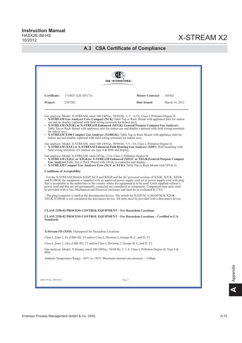
Emerson Process Management GmbH & Co. OHG A-15
X-STREAM X2Instruction ManualHASX2E-IM-HS10/2012
AA
ppen
dix
Certificate: 1714037 (LR 105173) Master Contract: 185562
Project: 2507282 Date Issued: March 14, 2012
DQD 507 Rev. 2009-09-01 Page: 2
Gas analyzer, Model: X-STREAM, rated 100-240Vac, 50/60 Hz, 1, 3 – 0,7A, Class I, Pollution Degree II.• X-STREAM Gas Analyzer Core Compact (XCK) Table Top or Rack Mount with appliance inlet for indoor
use and no display (optional with field wiring terminals for indoor use);• X-STREAM (X2GK) or X-STREAM Enhanced (XEGK) General Purpose Compact Gas Analyzer:
Table Top or Rack Mount with appliance inlet for indoor use and display (optional with field wiring terminalsfor indoor use);
• X-STREAM X100 Compact Gas Analyzer (X100GK): Table Top or Rack Mount with appliance inlet forindoor use and display (optional with field wiring terminals for indoor use);
Gas analyzer, Model: X-STREAM, rated 100-240Vac, 50/60 Hz, 5.5 - 3A, Class I, Pollution Degree II.• X-STREAM (XXF) or X-STREAM Enhanced Field Housing Gas Analyzer (XDF): Wall mounting with
field wiring terminals, for outdoor use type 4 & IP66 and display;
Gas analyzer, Model: X-STREAM, rated 24Vdc, 2.5A, Class I, Pollution Degree II.• X-STREAM (X2GC or X2GK)or X-STREAM Enhanced (XEGC or XEGK)General Purpose Compact
Gas Analyzer Table Top or Rack Mount with 24Vdc in connector and display;• X-STREAM Compact Gas Analyzer Core (XCC or XCK): Table Top or Rack Mount with 24Vdc in
Conditions of Acceptability
- For the X-STREAM Models X2GP, XCA and XEGP and the AC powered versions of X2GK, X2CK, XEGKand X100GK the equipment is supplied with an approved power supply cord set or power supply cord with plugthat is acceptable to the authorities in the country where the equipment is to be used. Units supplied without apower cord and that are not permanently connected are considered as component. Component-type units mustbe provided with a Fire, Mechanical and Electrical enclosure and must be re-evaluated by CSA.
- The plug/connector is used as the disconnected device. The switch for X2GP/XCA/XEGP/XCK/X2GK/XEGK/X100GK is not considered the disconnect device. All units must be provided with a disconnect device.
CLASS 2258-02 PROCESS CONTROL EQUIPMENT – For Hazardous Locations
CLASS 2258-82 PROCESS CONTROL EQUIPMENT – For Hazardous Locations – Certified to U.S.Standards.
X-Stream FD (XFD): Flameproof for Hazardous Locations
Class I, Zone 1, Ex d IIB+H2, T3 and/or Class I, Division 2, Groups B, C, and D, T3
Class I, Zone 1, AEx d IIB+H2, T3 and/or Class I, Division 2, Groups B, C, and D, T3
Gas analyzer, Model: X-Stream, rated 100-240Vac, 50/60 Hz, 2–1 A. Class I, Pollution Degree II; Type 4 &IP66
Ambient Temperature Range: -30°C to +50°C Maximum internal case pressure = 110kpa
A.3 CSA Certificate of Compliance

Emerson Process Management GmbH & Co. OHGA-16
X-STREAM X2Instruction Manual
HASX2E-IM-HS10/2012
Certificate: 1714037 (LR 105173) Master Contract: 185562
Project: 2507282 Date Issued: March 14, 2012
DQD 507 Rev. 2009-09-01 Page: 3
XFD-abcdefghijklmnop
a = Language: A, B, C, D or E
b = Ambient Conditions: 1, 2, 3, 4, 5 or 6
c = Instrument: 1, 2, 3, 4, 5, 6 or 7
d = Bench 1: any combination of 2 or 3 alpha-numeric characters
e = Bench 1 – Special Linearization or Calibration: 0, 1, 2, 3, 4 or 5
f = Bench 2: any combination of 2 or 3 alpha-numeric characters
g = Bench 2 – Special Linearization or Calibration: 0, 1, 2, 3, 4 or 5
h = Enclosure: 1, 2, 3, 4, 5 or 6
i = Hazardous Area Options and Special Approvals: B or D
B = CSA Certification
D = CSA Certification with a Breathing Device for Venting (Same Device as option “p”)
j = Input/Output Options: 1, 2, 5 or 6
k = Communication Interface: A, B, C or D
l = Sample Handling: 0, 1, 3, 5 or 7
m = Gas Path Sensors: 0, 1, 2, 3, 4 or 5
n = Gas Path Tubing: A, B, C, D or E
o = Gas Path Fittings: 3, 4, 5 or 6
p = Flame Arrestors: 2, 3, 4, 5, 6, 7 or 8
X-Stream FD (X2FD): Flameproof for Hazardous Locations
Class I, Zone 1, Ex d IIB+H2, T3 and/or Class I, Division 2, Groups B, C, and D, T3
Class I, Zone 1, AEx d IIB+H2, T3 and/or Class I, Division 2, Groups B, C, and D, T3
Gas analyzer , Model: X-Stream, rated 100-240Vac, 50/60 Hz, 3 - 1.5A, Class I, Pollution Degree II; AmbientTemperature Range: -30°C to +50°C
A.3 CSA Certificate of Compliance

Emerson Process Management GmbH & Co. OHG A-17
X-STREAM X2Instruction ManualHASX2E-IM-HS10/2012
AA
ppen
dix
Certificate: 1714037 (LR 105173) Master Contract: 185562
Project: 2507282 Date Issued: March 14, 2012
DQD 507 Rev. 2009-09-01 Page: 4
X-Stream FD (X2FD) has same electronics as the X-STREAM General Purpose Gas Analyzer (X2GP) withnew Hazardous Locations Enclosure.
X2FD-abcdefghijklmnopqrstuv
a = Language: A, B, C, D, E or F
b = Ambient Conditions: 1, 2, 3, 4, 5 or 6
c = Instrument: 01, 02, 03, 04, 05, 06, 07, 08, 09, 10, 11, 12, 13, 14 or 15
d = Bench 1: any combination of 2 or 3 alpha-numeric characters
e = Bench 1 – Special Linearization or Calibration: 0, 1, 2, 3, 4, 5, A, B, C or D
f = Bench 2: any combination of 2 or 3 alpha-numeric characters
g = Bench 2 – Special Linearization or Calibration: 0, 1, 2, 3, 4, 5, A, B, C or D
h = Bench 3: any combination of 2 or 3 alpha-numeric characters
i = Bench 3 – Special Linearization or Calibration: 0, 1, 2, 3, 4, 5, A, B, C or D
j = Bench 4: any combination of 2 or 3 alpha-numeric characters
k = Bench 4 – Special Linearization or Calibration: 0, 1, 2, 3, 4, 5, A, B, C or D
l = Enclosure: 1, 2, 3, 4, 5 or 6
m = Hazardous Area Options and Special Approvals: B or D
B = CSA Certification
D = CSA Certification with a Breathing Device for Venting (Same Device as option “v”)
n = Analog Outputs: 1, 2, 3 or 4
o = Digital Inputs/Relay Outputs: 0, 1 or 2
p = Communication Interface: 0, A, B, C or D
q = Spare: 0
r = Sample Handling: 0, 1, 2, 3, 4, 5 or 6
s = Gas Path Sensors: 0, 1, 2, 3, 4, 5, 6, 7 or 8
t = Gas Path Tubing: A, B, C, D, E, F, G, H or I
A.3 CSA Certificate of Compliance

Emerson Process Management GmbH & Co. OHGA-18
X-STREAM X2Instruction Manual
HASX2E-IM-HS10/2012
Certificate: 1714037 (LR 105173) Master Contract: 185562
Project: 2507282 Date Issued: March 14, 2012
DQD 507 Rev. 2009-09-01 Page: 5
u = Gas Path Fittings: E, F, G, H, I, J, K or L
v = Flame Arrestors: 2, 3, 4, 5, 6, 7 or 8
X-STREAM FD (XEFD): Flameproof for Hazardous Locations
Class I, Zone 1, Ex d IIB+H2, T3 and/or Class I, Division 2, Groups B, C, and D, T3
Class I, Zone 1, AEx d IIB+H2, T3 and/or Class I, Division 2, Groups B, C, and D, T3
Gas analyzer , Model: X-STREAM, rated 100-240Vac, 50/60 Hz, 3 - 1.5A, Class I, Pollution Degree II;Ambient Temperature Range: -30°C to +50°C
X-STREAM FD Enhanced (XEFD) has same electronics as the X-STREAM Enhanced General Purpose GasAnalyzer (XEF) with same Hazardous Locations Enclosure as X-STREAM X2FD.
XEFD-abcdefghijklmnopqrstuv
a = Language: A, B, C, D, E, F or G
b = Ambient Conditions: 1 or 4
c = Instrument: 01, 02, 03, 04, 05, 06, 07, 08, 09, 10, 11, 12, 13, 14 or 15
d = Bench 1: any combination of 2 or 3 alpha-numeric characters
e = Bench 1 – Special Linearization or Calibration: 0, 1, 2, 3, 4, 5, A, B, C or D
f = Bench 2: any combination of 2 or 3 alpha-numeric characters
g = Bench 2 – Special Linearization or Calibration: 0, 1, 2, 3, 4, 5, A, B, C or D
h = Bench 3: any combination of 2 or 3 alpha-numeric characters
i = Bench 3 – Special Linearization or Calibration: 0, 1, 2, 3, 4, 5, A, B, C or D
j = Bench 4: any combination of 2 or 3 alpha-numeric characters
k = Bench 4 – Special Linearization or Calibration: 0, 1, 2, 3, 4, 5, A, B, C or D
l = Enclosure: 1, 2, 3 or 4
m = Hazardous Area Options and Special Approvals: B or D
B = CSA Certification
A.3 CSA Certificate of Compliance

Emerson Process Management GmbH & Co. OHG A-19
X-STREAM X2Instruction ManualHASX2E-IM-HS10/2012
AA
ppen
dix
Certificate: 1714037 (LR 105173) Master Contract: 185562
Project: 2507282 Date Issued: March 14, 2012
DQD 507 Rev. 2009-09-01 Page: 6
D = CSA Certification with a Breathing Device for Venting (Same Device as option “v”)
n = Analog Outputs: 1, 2, 3 or 4
o = Digital Inputs/Relay Outputs/Analog Inputs: 0, 1, 2, 5 or A
p = Communication Interface: 0, A or B
q = Advanced Software capabilities: 0, 1, 2 or 3
r = Sample Handling: 0, 1, 2, 3, 4, 5 or 6
s = Gas Path Sensors: 0, 1, 3, 5, 7 or 9
t = Gas Path Tubing: E, F, G, H, I, J, K or L
u = Gas Path Fittings: E, F, G, H, I, J, K or L
v = Flame Arrestors: 2, 3, 4, 5, 6, 7 or 8
X-STREAM FN (XLFN, XXFN, XEFN, XDFN): Non-Incendive for Hazardous Locations
Class 1 Zone 2 Ex nAC IIC T4
Class 1 Zone 2 AEx nAC IIC T4
Class I Div 2 Groups ABCD
-20 °C to +50 °C IP66 Enclosure Type 4X
• X-STREAM (XLFN) or X-STREAM Enhanced (XEFN)Field Housing Gas Analyzer:
Gas analyzer, Model: X-STREAM, rated 100-240Vac, 50/60 Hz, 3 - 1.5A, Class I, Pollution Degree II• X-STREAM (XXFN) or X-STREAM Enhanced Dual (XDFN) Field Housing Gas Analyzer:
Gas analyzer, Model: X-STREAM, rated 100-240Vac, 50/60 Hz, 5.5 - 3A, Class I, Pollution Degree II
APPLICABLE REQUIREMENTS
CAN/CSA-C22.2 No. 61010-1-04 - Safety Requirements for Electrical Equipment for Measurement, Control,and Laboratory Use, Part 1: General Requirements
UL Std No. 61010-1, 2nd Edition - Safety Requirements for Electrical Equipment for Measurement, Control,and Laboratory Use, Part 1: General Requirements
A.3 CSA Certificate of Compliance

Emerson Process Management GmbH & Co. OHGA-20
X-STREAM X2Instruction Manual
HASX2E-IM-HS10/2012
Certificate: 1714037 (LR 105173) Master Contract: 185562
Project: 2507282 Date Issued: March 14, 2012
DQD 507 Rev. 2009-09-01 Page: 7
CAN/CSA-E60079-0:02 (R2006) - Electric Apparatus for Explosive Gas Atmospheres, Part 0: GeneralRequirements
CAN/CSA-E60079-1:02 (R2006) - Electric Apparatus for Explosive Gas Atmospheres, Part 1: Construction andVerification Test of Flameproof Enclosures of Electrical Apparatus “d”
CAN/CSA-E60079-15:02 (R2006) - Electric Apparatus for Explosive Gas Atmospheres, Part 15: Type ofprotection "n"
CSA C22.2 No 213-M1987 - Non-Incendive Electrical Equipment for Use in Class I,Division 2 HazardousLocations
CAN/CSA-C22.2 No. 94-M91 (R2006) - Special Purpose Enclosures
CAN/CSA C22.2 No. 60529:05 - Degrees of protection provided by enclosure (IP Code)
ANSI/ISA-12.00.01-2002 (IEC 60079-0 Mod) - Electric Apparatus for Use in Class I, Zones 0, 1 & 2Hazardous (Classified) Locations: General Requirements
ANSI/ISA-12.22.01-2002 (IEC 60079-1 Mod) - Electric Apparatus for Use in Class I, Zones 1 Hazardous(Classified) Locations Type of Protection – Flameproof “d”
UL 60079-15:2009 - Electric Apparatus for Explosive Gas Atmospheres, Part 15: Construction, Test andMarking of Type of Protection ’n’ Electrical Apparatus
IEC 60529 Edition 2.1-2001-02 - Degrees of protection provided by enclosure (IP Code)
UL 50 11th Edition - Enclosures for Electrical Equipment
ANSI/ISA 12.12.01-2011 - Non-Incendive Electrical Equipment for Use in Class I and II, Division 2 and ClassIII, Divisions 1 and 2 Hazardous (Classified) Locations
A.3 CSA Certificate of Compliance

Emerson Process Management GmbH & Co. OHG A-21
X-STREAM X2Instruction ManualHASX2E-IM-HS10/2012
AA
ppen
dix
A.4 Block diagram
A.4 Block Diagram
Sta
nd
ard
++
+
++
+
+
+ +
++ +
Ap
plic
ab
le s
he
ets
X-S
TR
EA
M V
ers
ion
X2
GC
X2
GK
with
D
C P
ow
er
Su
pp
ly
or
X2
GK
with
AC
Po
we
r S
up
ply
X2
GP
XL
FX
2F
DX
LF
N
XX
FX
XF
N
Ho
usin
g
19
”
19
”
19
”
Fie
ld h
ou
sin
g,
sin
gle
co
mp
.F
lam
ep
roo
f fie
ld h
ou
sin
g,
No
n-in
ce
nd
ive
fie
ld h
ou
sin
g,
sin
gle
co
mp
art
me
nt
Fie
ld h
ou
sin
g,
du
al co
mp
.N
on
-in
cen
div
e f
ield
ho
usi
ng
,d
ua
l co
mp
art
me
nt
½
½
++
+
++
+S
he
et
11
Sh
ee
t 11
Sh
ee
t 11
Sh
ee
t 11
Sh
ee
t 11
Sh
ee
t 11
Sh
ee
t 2
Sh
ee
t 2
Sh
ee
t 4
Sh
ee
t 4
Sh
ee
t 6
Sh
ee
t 7
Sh
ee
t 9
Sh
ee
t 9
Sh
ee
t 9
Sh
ee
t 9
Sh
ee
t 9
Sh
ee
t 9
Sh
ee
t 3
Sh
ee
t 3
Sh
ee
t 3
Sh
ee
t 5
Sh
ee
t 8
Sh
ee
t 8
Sh
ee
t 1
3
Op
tion
Op
tio
n
+
1
Weitergabe sowie Vervielfältigung dieserUnterlage, Verwertung und Mitteilung ihresInhaltes sind nur mit unserer Zustimmunggestattet. Alle Rechte vorbehalten.
Copying of this document, and giving it toothers and the use or communication of thecontents thereof, are only allowed with ouragreement. All rights are reserved.
E
Mic
roIn
de
xÄ
nd
eru
ng
, re
visi
on
Da
tum
Na
me
Be
arb
.
Ge
pr.
20
__
_D
atu
mN
am
e
Be
sch
reib
un
g,
de
scrip
tio
nZ
eic
hn
un
g-N
r.:
Dra
win
g-N
o.:
Ind
ex
Ide
nt-
Nr.
:
Bla
ttS
he
et
vo
no
f
Au
ftra
gs-N
r.:
+=
DCBA
EDCBA
12
34
56
78
910
1112
13
14
15
16
12
34
56
78
910
1112
13
14
15
16
4.3
00
-51
58
/407
02.1
0.
Walth
er
Sch
mid
tX
-ST
RE
AM
X2
Blo
ck d
iagra
m03.1
0.
BN
eu
e G
eh
äu
seva
ria
nte
n h
inzu
1
2.0
8.0
9M
Ba
CT
N8
46
: T
race
Mo
istu
re h
inzu
11
.11
.10
MB
a
DT
N9
34
: A
ktu
alis
iert
20
.01
.11
MB
a
13
F
EM
Ba
11.1
1.1
1T
N1
27
3: A
ktu
alis
iert
F1
9.0
1.1
2T
N1
34
5, T
N1
34
6, T
N1
34
7: A
ktu
alis
iert

Emerson Process Management GmbH & Co. OHGA-22
X-STREAM X2Instruction Manual
HASX2E-IM-HS10/2012
A.4 Block Diagram
X2G
C
T 3
.15 A
/ 2
50V
24V
GN
D
FE
XL
R S
teck
er
EM
V F
ilte
r,
XLR
Plu
g in
EM
I F
ilter, fuse
hold
er
5x20 m
m
Sic
he
run
gsh
alte
r 5
x20
mm
Pow
er
Input
DC
10-3
0 V
wid
e r
ange
max.
2.5
A
3/A
524V
DC
Input
Zeic
hnung
/Dra
win
g4.3
00-7
273/4
3
2-a
drig
e L
eitu
ng
/ c
ab
le w
ith 2
lin
es
Sym
bole
rklä
rung:
De
scrip
tion
of
use
d ic
on
s:
Le
itun
gsfa
rbe
/ c
ab
le c
olo
ur
bl
Ste
ckve
rbin
dung
/ pl
ug c
onne
ctio
n
/2.4
Ver
wei
s au
f Sei
te 2
, Spa
lte 4
/ re
fere
nce
to s
h 2,
row
4
4.x
xx-x
xxx
Zei
chnu
ngs-
/Sac
hnum
mer
/ D
raw
ing-
/Par
tnum
ber
2
2
Weitergabe sowie Vervielfältigung dieserUnterlage, Verwertung und Mitteilung ihresInhaltes sind nur mit unserer Zustimmunggestattet. Alle Rechte vorbehalten.
Copying of this document, and giving it toothers and the use or communication of thecontents thereof, are only allowed with ouragreement. All rights are reserved.
E
Mic
roIn
dex
Änderu
ng, re
visi
on
Datu
mN
am
e
Bearb
.
Gepr.
20___
Datu
mN
am
e
Besc
hre
ibung, desc
riptio
nZ
eic
hnung-N
r.: D
raw
ing-N
o.:
Index
Ident-
Nr.:
Bla
ttS
heet
von
of
Auftra
gs-
Nr.:
+=
DCBA
EDCBA
12
34
56
78
910
1112
13
14
15
16
12
34
56
78
910
1112
13
14
15
16
4.3
00-5
158/4
07
02.1
0.
Walth
er
Sch
mid
tX
-ST
RE
AM
X2
Blo
ck d
iag
ram
03.1
0.
BN
eue G
ehäuse
variante
n h
inzu
12.0
8.0
9M
Ba
CT
N846: T
race
Mois
ture
hin
zu
11.1
1.1
0M
Ba
DT
N934: A
ktualis
iert
20.0
1.1
1M
Ba
13
F
EM
Ba
11.1
1.1
1T
N1273: A
ktualis
iert
F19.0
1.1
2T
N1345, T
N1346, T
N1347: A
ktualis
iert

Emerson Process Management GmbH & Co. OHG A-23
X-STREAM X2Instruction ManualHASX2E-IM-HS10/2012
AA
ppen
dix
A.4 Block Diagram
LC
DO
ptio
nV
FD
P4
X2
GC
, X
2G
K
XS
P 0
1
XS
P 0
1/P
3
sie
he
Bla
tt 9
, 1
0se
e s
heet 9, 10
UF
PS
W 0
1Ta
sta
tur
Keybo
ard
Str
om
laufp
lan
/
sch
em
atic
s:
4.3
50-0
500
Str
om
lau
fpla
n /
sch
em
atic
s:
4.3
00-4
970
XF
P 0
1
Au
f F
ron
tpla
tte
At
fro
nt
pa
ne
l
P9
P8
Dire
kt g
eko
pp
elt
Dire
ctly
cou
ple
d
5
.25.25
.1 .1
XS
TA
01
Str
om
laufp
lan
/
sche
ma
tics:
4.3
50-0
460
Direkt gekoppeltDirectly coupled
XS
P 0
1/P
32
.9.9
.1 .1
P1
P7
XD
IO 0
1S
trom
lau
fpla
n /
sch
em
atic
s:
4.3
00-4
680
P1 1
0
P2
Su
b-D
P4 .25.25
.1 .1
XS
TD
01
Str
om
laufp
lan /
schem
atics
:4.3
50-0
480
Direkt gekoppeltDirectly coupled
P1
Ext
ern
Ext
ern
al
FlachbandkabelFlat ribbon cable
Ext
ern
e S
chra
ub
kle
mm
en
ad
ap
ter
exte
rna
l scre
wte
rmin
ala
dapte
rO
ptio
n
*2
X1
X2
X4.1
(QS
PI)
3
4.300-7273
2/C114/B13
+P
ow
er
Option*1
2
P2
4.3
00-8
05
7-V
2
Hin
weis
1:
Es is
t m
axim
al ein
e z
usä
tzlic
he O
ptio
n m
öglic
h(X
DIO
01
+ X
ST
D 0
1)
Note
1: A
t m
axi
mum
one
add
itio
nal option s
ele
cta
ble
(XD
IO 0
1 +
XS
TD
01
)
4.3
00
-912
4
11/B
...
11/E
11
P3
P2
XP
SA
01 / 0
2S
trom
laufp
lan
/ s
chem
atics
:4.3
00-4
660 / 4
.350-0
920
P33
Analogausgang 1Analog Output 1
XSIA 01Analogausgang 2
Analog Output 2Stromlaufplan /
schematics:4.350-0380
P1
P2
P13
P16
XSIA 01Analogausgang 3
Analog Output 3Stromlaufplan /
schematics:4.350-0380
P1
P2
P25
P26
XSIA 01Analogausgang 4
Analog Output 4Stromlaufplan /
schematics:4.350-0380
P1
P2
P3
1
P3
2
Direkt gekoppeltDirectly coupled
P22 2
6
P1
Sub-D
P18
4 x “NAMUR”-Relais4 x “NAMUR-Relays
Serielle KommunikationSerial Communication
Option
Sub-D
P17
Inte
rnIn
tern
al
Service SchnittstelleService Port
Su
b-D
P27P
8
P9
P10
P3
Sie
he
au
ch B
latt
9s
ee a
lso s
heet 9
XSIA 01Analogausgang 4
Analog Output 4Stromlaufplan /
schematics:4.350-0380
P1
P2
P3
1
P3
2
64
+PowerSignals
Exte
rne
r S
chra
ub
kle
mm
en
ad
ap
ter
exte
rna
l scre
wte
rmin
ala
dapte
rO
ption
*2
*Hin
we
is 2
: N
ich
t im
X2
GK
*Note
2: N
ot in
X2G
K
10
4.3
00-9
133
3
10
3
13
3
Weitergabe sowie Vervielfältigung dieserUnterlage, Verwertung und Mitteilung ihresInhaltes sind nur mit unserer Zustimmunggestattet. Alle Rechte vorbehalten.
Copying of this document, and giving it toothers and the use or communication of thecontents thereof, are only allowed with ouragreement. All rights are reserved.
E
Mic
roIn
dex
Änderu
ng, re
visi
on
Datu
mN
am
e
Bearb
.
Gepr.
20___
Datu
mN
am
e
Besc
hre
ibung, desc
riptio
nZ
eic
hnung-N
r.: D
raw
ing-N
o.:
Index
Ident-
Nr.:
Bla
ttS
heet
von
of
Auftra
gs-N
r.:
+=
DCBA
EDCBA
12
34
56
78
91
011
12
13
14
15
16
12
34
56
78
91
011
12
13
14
15
16
4.3
00-5
158/4
07
02.1
0.
Walth
er
Sch
mid
tX
-ST
RE
AM
X2
Blo
ck d
iag
ram
03.1
0.
BN
eue G
ehäuse
variante
n h
inzu
12.0
8.0
9M
Ba
CT
N846: T
race
Mois
ture
hin
zu
11.1
1.1
0M
Ba
DT
N934: A
ktualis
iert
20.0
1.1
1M
Ba
13
F
EM
Ba
11.1
1.1
1T
N1273: A
ktualis
iert
F19.0
1.1
2T
N1345, T
N1346, T
N1347: A
ktu
alis
iert

Emerson Process Management GmbH & Co. OHGA-24
X-STREAM X2Instruction Manual
HASX2E-IM-HS10/2012
A.4 Block Diagram
4.3
00-9
125
Gn/gegn/ye
Erd
ungsb
olz
en a
uf der
Monta
gepla
tte
Gro
undin
g p
in o
n m
ountin
g p
anel
T 4
A/2
50V
L N
PE
FK
ID2-5
0-4
/1G
erä
teste
cke
r-K
om
bie
lem
ent
2-S
tufe
n Inle
t F
ilter,
Netz
schalter
2-p
olig
, 2 S
icheru
ngsh
alte
r 5x2
0 m
mP
ow
er
entr
y m
odule
2-s
tage inle
t F
ilter,
2-p
ole
line s
witch,
2 fuse
hold
er
5x20 m
m
Po
we
r In
pu
tA
C 1
00
- 2
40
V W
ide
ran
ge
50
/ 6
0 H
z
Gerä
test
eck
dose
C14 g
em
äss
IE
C/E
N 6
0320-1
Applia
nce-I
nle
tC
14 a
cc. To IE
C/E
N 6
0320-1
Erd
ungsb
olz
en a
uf der
Heiz
ungsa
bdecku
ng
Gro
undin
g p
in o
n h
eate
r cover
Gn/g
egn/y
e
T 4
A/2
50V
X2
GP
4.300-81004.3
00-8
101
4.3
00-8
101
4.3
00-8
109
Netz
teil
100V
-240V
~P
ow
er
Supply
AC
100V
-240V
~w
ide r
ange 4.300-8113
4.300-810824V
-24V
DC
XH
M 0
1S
trom
laufp
lan/s
chem
atic
4.3
50-0
680/3
P6
2
P9
2
P4
2
P8
2
P2
2
P7
P1
Tem
pera
turs
enso
rTe
mpera
ture
sensor
4.3
00-6
452
2
22
4.300-8104
Verbindung wenn keine XHM 01 eingebaut istConnection if no XHM 01 is used
Heiz
ung 1
Heate
r 1
ETC02286
Heiz
ung 2
Heate
r 2
ETC02286
Übert
em
pera
turs
chalte
rO
vert
em
pera
turs
witch
ETC02286
Optionale Heizung optional Heater
*1
*Hin
weis
1: N
icht im
X2G
K*N
ote
1: N
ot in
X2G
K
2-a
drige L
eitu
ng / c
able
with 2
lines
Sym
bole
rklä
rung:
Desc
riptio
n o
f use
d ic
ons:
Leitungsf
arb
e / c
able
colo
ur
bl
Ste
ckve
rbin
dung
/ pl
ug c
onne
ctio
n
/2.4
Ver
wei
s au
f Sei
te 2
, Spa
lte 4
/ re
fere
nce
to s
h 2,
row
4
4.x
xx-x
xxx
Zei
chnu
ngs-
/Sac
hnum
mer
/ D
raw
ing-
/Par
tnum
ber
2
Netz
teil
100V
-240V
~P
ow
er
Supply
AC
100V
-240V
~w
ide r
ange
24V
-24V
DC
3/A
55/A
52
4.3
00-9
125
Netz
teil
100V
-240V
~P
ow
er
Supply
AC
100V
-240V
~w
ide r
ange
24V
-24V
DC
Netz
teil
100V
-240V
~P
ow
er
Supply
AC
100V
-240V
~w
ide r
ange *
2 *
3 *
424V
-24V
DC
Netz
teil
100V
-240V
~P
ow
er
Supply
AC
100V
-240V
~w
ide r
ange
24V
-24V
DC
2
4.3
00-9
125
5/A
6
4.300-8126
Optio
nale
s zw
eite
s N
etz
teil
Optio
nal s
eco
nd P
ow
er
Supply
*Hin
weis
2: E
s si
nd b
is z
u z
wei N
etz
teile
im
Analy
sato
r m
öglic
h*N
ote
2: T
here
are
up to tw
o p
ow
er
supplie
s poss
ible
inth
e a
naly
ser
2
Hin
weis
: B
ei e
inem
Netz
teil
Note
: F
or
one p
ow
er
supply
*Hin
weis
3: N
icht im
XE
GK
*Note
3: N
ot in
X2G
K
*Hin
weis
4: N
icht fü
r th
erm
ost
atis
iert
eA
naly
sato
ren
*Note
4: N
ot fo
r heate
d a
naly
sers
2
4.3
00-9
125
5/A
5
4
Weitergabe sowie Vervielfältigung dieserUnterlage, Verwertung und Mitteilung ihresInhaltes sind nur mit unserer Zustimmunggestattet. Alle Rechte vorbehalten.
Copying of this document, and giving it toothers and the use or communication of thecontents thereof, are only allowed with ouragreement. All rights are reserved.
E
Mic
roIn
dex
Änderu
ng, re
visi
on
Datu
mN
am
e
Bearb
.
Gepr.
20___
Datu
mN
am
e
Besc
hre
ibung, desc
riptio
nZ
eic
hnung-N
r.: D
raw
ing-N
o.:
Index
Ident-
Nr.:
Bla
ttS
heet
von
of
Auftra
gs-
Nr.:
+=
DCBA
EDCBA
12
34
56
78
910
1112
13
14
15
16
12
34
56
78
910
1112
13
14
15
16
4.3
00
-51
58
/407
02
.10
.W
alth
er
Sch
mid
tX
-ST
RE
AM
X2
Blo
ck d
iag
ram
03
.10
.B
Neue G
ehäuse
variante
n h
inzu
12.0
8.0
9M
Ba
CT
N846: T
race M
ois
ture
hin
zu
11.1
1.1
0M
Ba
DT
N934: A
ktu
alis
iert
20.0
1.1
1M
Ba
13
F
EM
Ba
11.1
1.1
1T
N1273: A
ktu
alis
iert
F19.0
1.1
2T
N1345, T
N1346, T
N1347: A
ktualis
iert

Emerson Process Management GmbH & Co. OHG A-25
X-STREAM X2Instruction ManualHASX2E-IM-HS10/2012
AA
ppen
dix
A.4 Block Diagram
X2G
P
LC
DO
ptio
nV
FD
P4
XS
P 0
1
XS
P 0
1/P
3
UF
PS
W 0
1Ta
sta
tur
Keyboard
Str
om
laufp
lan /
s chem
atic
s:
4.3
50-0
500
Str
om
laufp
lan /
s chem
atics:
4.3
00-4
970
XF
P 0
1
Au
f F
ron
tpla
tte
At
fro
nt
pa
ne
l
P9
P8
64
Dire
kt
ge
kop
pe
ltD
irectly
couple
d
5
.25.25
.1 .1
XS
TA
01
Str
om
laufp
lan /
schem
atics:
4.3
50-0
460
Direkt gekoppeltDirectly coupled
XS
P 0
1/P
32
.9.9
.1 .1
P1
P7
XD
IO 0
1S
trom
laufp
lan /
schem
atics
:4.3
00-4
680
P1 1
0
P2
Sub-D
P4 .25.25
.1 .1
XS
TD
01
Str
om
laufp
lan /
sch
em
atic
s:
4.3
50-0
480
Direkt gekoppeltDirectly coupled
P1
Ext
ern
Ext
ern
al
FlachbandkabelFlat ribbon cable
Ext
ern
er
Sch
rau
bkle
mm
en
ad
ap
ter
exte
rnal scr
ew
term
inala
dapte
rO
ption
Ext
ern
e S
ch
rau
bkle
mm
en
ad
ap
ter
exte
rnal sc
rew
term
inala
dapte
rO
ptio
n
X1
X2
X4.1
(QS
PI)
2
4.300-9125
4/B13
+P
ow
er
Option*1
2
P2
4.3
00-9
124
11/E
11
P3
XD
IO 0
1S
trom
laufp
lan /
schem
atic
s:4.3
00-4
680
P2
Sub-D
P4 .25.25
.1 .1
XS
TD
01
Str
om
laufp
lan /
schem
atics
:4.3
50-0
480
Direkt gekoppeltDirectly coupled
P1
X4.2
Option*1
P2
Hin
weis
1: E
s sin
d m
axi
mal zw
ei z
usätz
liche O
ptio
nen m
öglic
h(X
DIO
01 +
XS
TD
01)
Note
1: A
t m
axim
um
tw
o a
dditio
nal optio
ns a
re s
ele
ctable
(XD
IO 0
1 +
XS
TD
01)
10
4.3
00-9
133
3
10
3
13
4.3
00-8
057-V
2
24.3
00-8
057-V
2
11/B
...
sie
he
Bla
tt 9
, 1
0see s
heet 9, 10
P2
XP
SA
01 / 0
2S
trom
laufp
lan / s
chem
atics:
4.3
00-4
660 / 4
.350-0
920
P33
Analogausgang 1Analog Output 1
XSIA 01Analogausgang 2
Analog Output 2Stromlaufplan /
schematics:4.350-0380
P1
P2
P13
P16
XSIA 01Analogausgang 3
Analog Output 3Stromlaufplan /
schematics:4.350-0380
P1
P2
P25
P26
XSIA 01Analogausgang 4
Analog Output 4Stromlaufplan /
schematics:4.350-0380
P1
P2
P31
P32
Direkt gekoppeltDirectly coupled
P22 2
6
P1
Sub-D
P18
4 x “NAMUR”-Relais4 x “NAMUR-Relays
Serielle KommunikationSerial Communication
Option
Sub-D
P17
Inte
rnIn
tern
al
Service SchnittstelleService Port
Sub-D
P27P
8
P9
P10
P11
P3
Sie
he
au
ch B
latt
9se
e a
lso s
heet 9
XSIA 01Analogausgang 4
Analog Output 4Stromlaufplan /
schematics:4.350-0380
P1
P2
P31
P32
+PowerSignals
5
Weitergabe sowie Vervielfältigung dieserUnterlage, Verwertung und Mitteilung ihresInhaltes sind nur mit unserer Zustimmunggestattet. Alle Rechte vorbehalten.
Copying of this document, and giving it toothers and the use or communication of thecontents thereof, are only allowed with ouragreement. All rights are reserved.
E
Mic
roIn
dex
Änderu
ng, re
visi
on
Datu
mN
am
e
Bearb
.
Gepr.
20___
Datu
mN
am
e
Besc
hre
ibung, desc
riptio
nZ
eic
hnung-N
r.: D
raw
ing-N
o.:
Index
Ident-
Nr.:
Bla
ttS
heet
von
of
Auftra
gs-N
r.:
+=
DCBA
EDCBA
12
34
56
78
910
1112
13
14
15
16
12
34
56
78
910
1112
13
14
15
16
4.3
00-5
158/4
07
02.1
0.
Walth
er
Sch
mid
tX
-ST
RE
AM
X2
Blo
ck d
iagra
m03.1
0.
BN
eue G
ehäuse
variante
n h
inzu
12.0
8.0
9M
Ba
CT
N846: T
race M
ois
ture
hin
zu
11.1
1.1
0M
Ba
DT
N934: A
ktu
alis
iert
20.0
1.1
1M
Ba
13
F
EM
Ba
11.1
1.1
1T
N1273: A
ktualis
iert
F19.0
1.1
2T
N1345, T
N1346, T
N1347: A
ktu
alis
iert

Emerson Process Management GmbH & Co. OHGA-26
X-STREAM X2Instruction Manual
HASX2E-IM-HS10/2012
A.4 Block Diagram
Erd
un
gsb
olz
en
au
f d
er
Mo
nta
ge
pla
tte
Gro
un
din
g p
in o
n m
ou
ntin
g p
an
el
Erd
un
gsb
olz
en
au
f d
er
He
izu
ng
sa
bd
eck
un
gG
rou
nd
ing
pin
on
he
ate
r co
ve
r
Gn
/ge
gn
/ye
4.3
00-8
101
4.3
00-8
101
Sin
gle
co
mp
art
me
nt
field
ho
usi
ng
s
L N
PE
Netz
ein
gangsm
odul m
it S
chra
ubkl
em
men,
2-p
olig
e S
icheru
ng 5
x20 m
mP
ow
er
en
try
mo
du
le w
ith s
cre
w t
erm
ina
ls,
2 f
use
ho
lde
r 5
x20
mm
Ze
ich
nu
ng
/dra
win
g4
.27
1-6
58
0
Mo
de
l X
2F,
X2
FN
, X
2F
DP
ow
er
Input
AC
100 -
240 V
wid
e r
ange
50 / 6
0 H
zE
MV
Filt
er
2-s
tufig
es
Filt
er
verg
osse
nE
MI
Filt
er
2-s
tag
e F
ilte
rp
ott
ed
Str
om
lau
fpla
n/s
ch
em
atic
4.2
71
/65
81
Gn
/ge
gn
/ye
4.3
00-8
102
T 4
A /
25
0V
T 4
A /
25
0V
T 6
.3 A
/ 2
50
VL N
PE
Netz
ein
gangsm
odul m
it S
chra
ubkl
em
men,
2-p
olig
e S
icheru
ng 5
x20 m
mP
ow
er
en
try m
od
ule
with
scr
ew
te
rmin
als
,2
fu
seh
old
er
5x2
0 m
mZ
eic
hn
un
g/d
raw
ing
4.2
71
-73
40
Mo
de
ls X
LF,
XL
FN
Pow
er
Input
AC
100 -
240 V
wid
e r
ange
50 / 6
0 H
z
T 6
.3 A
/ 2
50
V
EM
V F
ilter
6E
T1
1-s
tufig
es F
ilter
EM
I F
ilte
r 6
ET
11
-sta
ge
Filt
er
4.3
00-8
102
Gn
/ge
gn
/ye
4.300-8099
4.300-8108
XH
M 0
1S
tro
mla
ufp
lan
/sch
em
atic
4.3
50
-06
80
/3
P6
2
P9
2
P4
2
P8
2
P2
2
P7
Optionale Heizungoptional Heater
P1
Tem
pera
turs
ensor
Tem
pe
ratu
rese
nso
r4.3
00-6
452
2
4.300-8104
3
Verbindung wenn keine XHM 01 eingebaut istConnection if no XHM 01 is used
2
4.3
00-8
118
3
Heiz
ung 1
He
ate
r 1
ETC02286
Heiz
ung 2
He
ate
r 2
ETC02286
Übert
em
pera
turs
chalte
rO
vert
em
pe
ratu
rsw
itch
ETC02286
2-a
drige L
eitu
ng / c
able
with 2
lines
Sym
bo
lerk
läru
ng
:D
escriptio
n o
f use
d ico
ns:
Leitungsfa
rbe / c
able
colo
ur
bl
Ste
ckve
rbin
dung
/ pl
ug c
onne
ctio
n
/2.4
Ver
wei
s au
f Sei
te 2
, Spa
lte 4
/ re
fere
nce
to s
h 2,
row
4
4.x
xx-x
xxx
Zei
chnu
ngs-
/Sac
hnum
mer
/ D
raw
ing-
/Par
tnum
ber
2
Netz
teil
100V
-240V
~P
ow
er
Su
pp
lyA
C 1
00
V-2
40
V ~
wid
e r
an
ge
24V
-2
4V
DC
Netz
teil
100V
-240V
~P
ow
er
Su
pp
lyA
C 1
00
V-2
40
V ~
wid
e r
an
ge
*1
24V
-2
4V
DC
Netz
teil
100V
-240V
~P
ow
er
Su
pp
lyA
C 1
00
V-2
40
V ~
wid
e r
an
ge
24V
-2
4V
DC
2
4.3
00-9
125
5/A
6
Verbindung wenn Seite 13 aktiv istConnection if Page 13 is active
13/B8
4.300-8126
Op
tion
ale
s zw
eite
s N
etz
teil
Op
tion
al s
eco
nd
Po
we
r S
up
ply
*Hin
weis
1: E
s si
nd b
is z
u z
wei N
etz
teile
im
Analy
sato
r m
öglic
h*N
ote
1: T
he
re a
re u
p t
o t
wo
po
we
r su
pp
lies
po
ssib
le in
the
an
aly
ser
Hin
we
is:
Be
i e
ine
m N
etz
teil
No
te:
Fo
r o
ne
po
we
r su
pp
ly
2
4.3
00-9
125
8/A
5
2
4.3
00-9
125
X1
0
6
Weitergabe sowie Vervielfältigung dieserUnterlage, Verwertung und Mitteilung ihresInhaltes sind nur mit unserer Zustimmunggestattet. Alle Rechte vorbehalten.
Copying of this document, and giving it toothers and the use or communication of thecontents thereof, are only allowed with ouragreement. All rights are reserved.
E
Mic
roIn
dex
Änderu
ng, re
visi
on
Datu
mN
am
e
Bearb
.
Gepr.
20___
Datu
mN
am
e
Besc
hre
ibung, desc
ription
Zeic
hnung-N
r.: D
raw
ing-N
o.:
Index
Ident-
Nr.:
Bla
ttS
heet
von
of
Auftra
gs-N
r.:
+=
DCBA
EDCBA
12
34
56
78
91
011
12
13
14
15
16
12
34
56
78
91
011
12
13
14
15
16
4.3
00
-51
58
/407
02
.10
.W
alth
er
Sch
mid
tX
-ST
RE
AM
X2
Blo
ck d
iagra
m0
3.1
0.
BN
eu
e G
eh
äu
seva
ria
nte
n h
inzu
1
2.0
8.0
9M
Ba
CT
N8
46
: T
race
Mo
istu
re h
inzu
11
.11
.10
MB
a
DT
N9
34
: A
ktu
alis
iert
20
.01
.11
MB
a
13
F
EM
Ba
11.1
1.1
1T
N1
27
3: A
ktu
alis
iert
F1
9.0
1.1
2T
N1
34
5, T
N1
34
6, T
N1
34
7: A
ktu
alis
iert

Emerson Process Management GmbH & Co. OHG A-27
X-STREAM X2Instruction ManualHASX2E-IM-HS10/2012
AA
ppen
dix
A.4 Block Diagram
T 6
.3 A
/ 2
50
VL N
PE
Netz
ein
gangsm
odul m
it S
chra
ubkle
mm
en,
2-p
olig
e S
icheru
ng 5
x20 m
mP
ow
er
en
try m
od
ule
with
scr
ew
te
rmin
als
,2
fu
se
ho
lde
r 5
x20
mm
Ze
ich
nu
ng
/dra
win
g4
.27
1-7
34
0
Pow
er
Input
AC
100 -
240 V
wid
e r
ange
50 / 6
0 H
z
T 6
.3 A
/ 2
50
V
EM
V F
ilter
6E
T1
1-s
tufig
es
Filt
er
EM
I F
ilte
r 6
ET
11
-sta
ge
Filt
er
XD
F, X
DF
N
Gn
/ge
gn
/ye
Erd
un
gsb
olz
en
au
f d
er
Mo
nta
ge
pla
tte
Gro
un
din
g p
in o
n m
ou
ntin
g p
an
el
4.3
00-8
118
XH
M 0
1S
tro
mla
ufp
lan
/sch
em
atic
4.3
50
-06
80
/3
P6
2
P9
2
4.300-8108 P4
P8
P2
Gn
/ge
gn
/ye
P7
4.3
00-8
102
4.3
00-8
101
4.3
00-8
100
Optionale Heizungoptional Heater
P1
Tem
pera
turs
enso
rTe
mp
era
ture
sen
so
r4.3
00-6
452
Erd
un
gsb
olz
en
au
f d
er
Trä
ge
rpla
tte
Gro
un
din
g p
in o
n m
ou
ntin
g p
late
2 22
2
6
4.300-8113
32
4.300-8104
Verbindung wenn keine XHM 01 eingebaut istConnection if no XHM 01 is used
Heiz
ung 1
He
ate
r 1
ETC02286
Heiz
ung 2
He
ate
r 2
ETC02286
Übert
em
pera
turs
chalte
rO
ve
rte
mp
era
turs
witch
ETC02286
2-a
drige L
eitu
ng / c
able
with 2
lines
Sym
bo
lerk
läru
ng
:D
escr
iptio
n o
f use
d ico
ns:
Leitungsfa
rbe / c
able
colo
ur
bl
Ste
ckve
rbin
dung
/ pl
ug c
onne
ctio
n
/2.4
Ver
wei
s au
f Sei
te 2
, Spa
lte 4
/ re
fere
nce
to s
h 2,
row
4
4.x
xx-x
xxx
Zei
chnu
ngs-
/Sac
hnum
mer
/ D
raw
ing-
/Par
tnum
ber
2
Netz
teil
100V
-240V
~P
ow
er
Su
pp
lyA
C 1
00
V-2
40
V ~
wid
e r
an
ge
24V
-2
4V
DC
2
4.3
00-9
125
8/A
6
Netz
teil
100V
-240V
~P
ow
er
Su
pp
lyA
C 1
00
V-2
40
V ~
wid
e r
an
ge
24V
-2
4V
DC
Netz
teil
100V
-240V
~P
ow
er
Su
pp
lyA
C 1
00
V-2
40
V ~
wid
e r
an
ge
*1
24V
-2
4V
DC
Netz
teil
100V
-240V
~P
ow
er
Su
pp
lyA
C 1
00
V-2
40
V ~
wid
e r
an
ge
24V
-2
4V
DC
2
4.3
00-9
125
5/A
6
4.300-8126
Op
tion
ale
s zw
eite
s N
etz
teil
Op
tion
al s
eco
nd
Po
we
r S
up
ply
*Hin
weis
1: E
s si
nd b
is z
u z
wei N
etz
teile
im
Analy
sato
r m
öglic
h*N
ote
1: T
he
re a
re u
p t
o t
wo
po
we
r su
pp
lies
po
ssib
le in
the
an
aly
ser
Hin
we
is:
Be
i e
ine
m N
etz
teil
No
te:
Fo
r o
ne
po
we
r su
pp
ly
2
4.3
00-9
125
8/A
5
2
4.3
00-9
125
X1
0
7
Weitergabe sowie Vervielfältigung dieserUnterlage, Verwertung und Mitteilung ihresInhaltes sind nur mit unserer Zustimmunggestattet. Alle Rechte vorbehalten.
Copying of this document, and giving it toothers and the use or communication of thecontents thereof, are only allowed with ouragreement. All rights are reserved.
E
Mic
roIn
dex
Änderu
ng, re
visi
on
Datu
mN
am
e
Bearb
.
Gepr.
20___
Datu
mN
am
e
Besc
hre
ibung, desc
ription
Zeic
hnung-N
r.: D
raw
ing-N
o.:
Index
Ident-
Nr.:
Bla
ttS
heet
von
of
Auftra
gs-N
r.:
+=
DCBA
EDCBA
12
34
56
78
91
011
12
13
14
15
16
12
34
56
78
91
011
12
13
14
15
16
4.3
00
-51
58
/407
02
.10
.W
alth
er
Sch
mid
tX
-ST
RE
AM
X2
Blo
ck d
iagra
m0
3.1
0.
BN
eu
e G
eh
äu
seva
ria
nte
n h
inzu
1
2.0
8.0
9M
Ba
CT
N8
46
: T
race
Mo
istu
re h
inzu
11
.11
.10
MB
a
DT
N9
34
: A
ktu
alis
iert
20
.01
.11
MB
a
13
F
EM
Ba
11.1
1.1
1T
N1
27
3: A
ktu
alis
iert
F1
9.0
1.1
2T
N1
34
5, T
N1
34
6, T
N1
34
7: A
ktu
alis
iert

Emerson Process Management GmbH & Co. OHGA-28
X-STREAM X2Instruction Manual
HASX2E-IM-HS10/2012
A.4 Block Diagram
Inte
rnIn
tern
al
Fie
ldhousi
ngs
(all)
XS
P 0
1
Direkt
geko
pp
elt
Direct
ly c
ouple
d
.25.25
.1 .1
XS
TA
01
Str
om
laufp
lan /
sch
em
atic
s:
4.3
50-0
460
XS
P 0
1/P
32
.9.9
.1 .1
P1
P7
XD
IO 0
1S
trom
laufp
lan /
sch
em
atics
:4.3
00-4
680
10
P2
Sub-D
P4 .25.25
.1 .1
XS
TD
01
Str
om
laufp
lan /
schem
atic
s:4.3
50-0
480
P1
FlachbandkabelFlat ribbon cable
X1
X2
X4
.1
XIN
01/P
8
2
+P
ow
er
Option*1
Inte
rner
Sch
raubkl
em
menadapte
rin
tern
al s
crew
term
inal a
dapte
r
FlachbandkabelFlat ribbon cable
4.300-9129
FlachbandkabelFlat ribbon cable
4.300-9130
4.300-9128
9
4.3
00-9
127
Y-K
abel
Y-C
able
4.300-9125
XS
P 0
1/P
3X
IN 0
1/X
1
6/B13, 7/B13
11/E
11
(QS
PI)
LC
DO
ption
VF
DP
4
UF
PS
W 0
1Ta
sta
tur
Keyboard
Str
om
laufp
lan /
sch
em
atics
:4.3
50-0
500
Str
om
laufp
lan /
sch
em
atic
s:4.3
00-4
970
XF
P 0
1
Auf F
ron
tpla
tte
At fr
ont
pan
el
P9
P8 5
P1
P3
10
4.3
00-9
133
3
10
3
13
4.3
00-9
124
24.3
00-8
057-V
2
24.3
00-8
057-V
2
XD
IO 0
1S
trom
laufp
lan /
sch
em
atics
:4.3
00-4
680
P2
Sub-D
P4 .25.25
.1 .1
XS
TD
01
Str
om
laufp
lan /
sch
em
atic
s:4.3
50-0
480
P1
X4
.2
Option*1
P2
FlachbandkabelFlat ribbon cable
10/B
411
/B...
sie
he B
latt 9
, 10
see s
heet 9, 10
P2
XP
SA
01
/ 0
2S
trom
laufp
lan / s
chem
atics
:4.3
00-4
660 / 4
.350-0
920
P33
Analogausgang 1Analog Output 1
XSIA 01Analogausgang 2
Analog Output 2Stromlaufplan /
schematics:4.350-0380
P1
P2
P13
P16
XSIA 01Analogausgang 3
Analog Output 3Stromlaufplan /
schematics:4.350-0380
P1
P2
P25
P26
XSIA 01Analogausgang 4
Analog Output 4Stromlaufplan /
schematics:4.350-0380
P1
P2
P31
P32
Direkt gekoppeltDirectly coupled
P22 2
6
P1
Sub-D
P18
4 x “NAMUR”-Relais4 x “NAMUR-Relays
Serielle KommunikationSerial Communication
Option
Sub-D
P17
Inte
rnIn
tern
al
P19
Service SchnittstelleService Port
Sub-D
P27P
8
P9
P10
P11
P3
Sie
he a
uch
Bla
tt 9
see a
lso s
heet 9
XSIA 01Analogausgang 4
Analog Output 4Stromlaufplan /
schematics:4.350-0380
P1
P2
P31
P32
64
+PowerSignals
Inte
rne S
chra
ubkle
mm
enad
apte
rin
tern
al s
crew
term
inal a
dapte
rs*)
Optio
n
Hin
weis
1: E
s si
nd m
axi
mal z
wei z
usä
tzlic
he O
ptio
nen m
öglic
h(X
DIO
01 +
XS
TD
01)
Note
1: A
t m
axi
mum
tw
o a
dditi
onal o
ptio
ns
are
sele
ctable
(XD
IO 0
1 +
XS
TD
01)
13/B
11,D
12
4.3
00-8
130
2
8
Weitergabe sowie Vervielfältigung dieserUnterlage, Verwertung und Mitteilung ihresInhaltes sind nur mit unserer Zustimmunggestattet. Alle Rechte vorbehalten.
Copying of this document, and giving it toothers and the use or communication of thecontents thereof, are only allowed with ouragreement. All rights are reserved.
E
Mic
roIn
de
xÄ
nd
eru
ng
, re
vis
ion
Da
tum
Na
me
Be
arb
.
Ge
pr.
20
__
_D
atu
mN
am
e
Be
sch
reib
un
g,
de
scrip
tion
Ze
ich
nu
ng
-Nr.
: D
raw
ing
-No
.:In
de
x
Ide
nt-
Nr.
:
Bla
ttS
he
et
von
of
Au
ftra
gs-
Nr.
:
+=
DCBA
EDCBA
12
34
56
78
91
011
12
13
14
15
16
12
34
56
78
91
011
12
13
14
15
16
4.3
00-5
158/4
07
02.1
0.
Walth
er
Sch
mid
tX
-ST
RE
AM
X2
Blo
ck d
iagra
m03.1
0.
BN
eue G
ehäuse
variante
n h
inzu
12.0
8.0
9M
Ba
CT
N846: T
race
Mois
ture
hin
zu
11.1
1.1
0M
Ba
DT
N934: A
ktu
alis
iert
20.0
1.1
1M
Ba
13
F
EM
Ba
11.1
1.1
1T
N1273: A
ktualis
iert
F19.0
1.1
2T
N1345, T
N1346, T
N1347: A
ktualis
iert

Emerson Process Management GmbH & Co. OHG A-29
X-STREAM X2Instruction ManualHASX2E-IM-HS10/2012
AA
ppen
dix
A.4 Block Diagram
Dru
ck
Ch
1
P3
1P
30
Pre
ssureC
h2
Te
mp
era
tur
Ch
1
P1
8P
17
P1
6P
11
Tem
pera
ture
Ch
4C
h3
Ch
2
Du
rch
fluss
Ch
1
P6
P7
P4
P5
Flo
w
Ch
4C
h3
Ch
2
AC
-De
tekt
ore
n
Ch
1
P2
4P
25
P2
3P
21
AC
-dete
ctors
Ch
4C
h3
Ch
2C
h5
Str
ah
ler
Ch
1
P1
5P
14
P1
3P
12
Sourc
e
Ch
4C
h3
Ch
2
DC
-Dete
kto
ren
Ch
1
P2
0P
19
P2
8P
26
Chopper
DC
-dete
cto
rs
M2
M1
Ch4
Ch
2
P2
7
phys
ikalis
che B
augru
ppen (
mess
prinzi
pabhängig
)
therm
ost
atis
iert
(O
ption, nic
ht fü
r X
2G
C)
ph
ysic
al co
mp
on
en
ts (
de
pen
din
g o
n m
ea
sure
me
nt
sys
tem
)
Th
erm
ost
ate
co
ntr
ol (
op
tion
, n
ot
for
X2
GC
)
sie
he
Bla
tt 3
, 5
, 8
see s
heet 3, 5, 8
P3
2
XS
P 0
1,
XP
SA
01
an
d p
hys
ica
l co
mp
on
en
ts
XS
P 0
1S
trom
laufp
lan / s
chem
atic
s:4.3
50-0
520
Ch
3D
urc
h-
fluss
-sc
ha
lter
Flo
w-S
witch
8
XP
SA
01 / 0
2S
trom
laufp
lan / s
chem
atic
s:4.3
00-4
660 / 4
.350-0
920
Ve
ntil
-b
lock
1V
alv
e-
unit
1
Ve
ntil
-b
lock
2V
alv
e-
unit
2
Me
ssg
as-
pu
mp
e 1
Pum
p 1
Pum
p 2
P2
9P
21
P2
8
sie
he
au
ch B
latt
3,
5,
8s
ee a
lso s
heet 3
, 5, 8
P2
4
8
88
Mess
gas-
pum
pe
2
P1
0
+Power
Signals
Serial
P3
3
SS
I 01
Str
om
laufp
lan /
sch
em
atics
:4.3
00-4
520
SV
2
10
4.300-9164
Fe
uch
teM
ois
ture
HT
S 0
1S
trom
laufp
lan /
sch
em
atics
:4.3
00-4
400
JP2
9
Weitergabe sowie Vervielfältigung dieserUnterlage, Verwertung und Mitteilung ihresInhaltes sind nur mit unserer Zustimmunggestattet. Alle Rechte vorbehalten.
Copying of this document, and giving it toothers and the use or communication of thecontents thereof, are only allowed with ouragreement. All rights are reserved.
E
Mic
roIn
de
xÄ
nd
eru
ng
, re
vis
ion
Da
tum
Na
me
Be
arb
.
Ge
pr.
20
__
_D
atu
mN
am
e
Be
sch
reib
un
g,
de
scrip
tion
Ze
ich
nu
ng
-Nr.
: D
raw
ing
-No
.:In
de
x
Ide
nt-
Nr.
:
Bla
ttS
he
et
von
of
Au
ftra
gs-
Nr.
:
+=
DCBA
EDCBA
12
34
56
78
910
1112
13
14
15
16
12
34
56
78
910
1112
13
14
15
16
4.3
00
-51
58
/40
7
02.1
0.
Walther
Sch
mid
tX
-ST
RE
AM
X2
Blo
ck d
iagra
m03.1
0.
BN
eue G
ehäuse
variante
n h
inzu
12.0
8.0
9M
Ba
CT
N846: T
race
Mois
ture
hin
zu
11.1
1.1
0M
Ba
DT
N934: A
ktualis
iert
20.0
1.1
1M
Ba
13
F
EM
Ba
11.1
1.1
1T
N1273: A
ktualis
iert
F19.0
1.1
2T
N1345, T
N1346, T
N1347: A
ktu
alis
iert

Emerson Process Management GmbH & Co. OHGA-30
X-STREAM X2Instruction Manual
HASX2E-IM-HS10/2012
Dru
ck
Ch1
P31
P30
Pre
ssureC
h2
Tem
pera
tur
Ch1
P18
P17
P16
P11
Tem
pera
ture
Ch
4C
h3
Ch2
Du
rchfluss
Ch1
P6
P7
P4
P5
Flo
w
Ch
4C
h3
Ch2
AC
-Dete
kto
ren
Ch1
P24
P25
P23
P2
1
AC
-dete
cto
rs
Ch4
Ch
3C
h2
Ch
5
Str
ahle
r
Ch1
P15
P1
4P
13
P12
Sourc
e
Ch4
Ch3
Ch2
DC
-Dete
kto
ren
Ch
1
P20
P19
P26
Chopper
DC
-dete
ctors
M2
M1
Ch4
Ch2
P2
7
ph
ysik
alis
ch
e B
au
gru
pp
en
(m
ess
prin
zip
ab
hä
ng
ig)
the
rmo
sta
tisie
rt (
Op
tio
n)
ph
ysic
al c
om
pon
ents
(d
epen
din
g o
n m
easu
rem
ent
syste
m)
The
rmosta
te c
ontr
ol (o
ption)
sie
he B
latt 3
, 5, 8
see s
heet 3, 5, 8
P3
2
XS
P 0
1, X
PS
A 0
1 a
nd p
hys
ical c
om
ponents
in d
ual c
om
part
ment fie
ldhousi
ng
XFTB 02.1P16
Str
om
laufp
lan / s
chem
atics
: 4.3
50-0
900
XF
TB
02
XF
TB
02
.1P
7
XFTB 02.1P17XFTB 02.2P16XFTB 02.2P17
XFTB 02.1P18XFTB 02.2P18
XFTB 02.1P14XFTB 02.2P15XFTB 02.1P14XFTB 02.2P15
XFTB 02.1P8XFTB 02.2P8
XFTB 02.1P9XFTB 02.1P10XFTB 02.2P9XFTB 02.2P10
XFTB 02.1P12XFTB 02.1P13XFTB 02.2P12XFTB 02.2P13
XFTB 02.1P11XFTB 02.2P11
34
XF
TB
02
.2P
7*H
inw
eis
1*N
ote
1
XS
P 0
1S
trom
laufp
lan / s
chem
atics
:4.3
50-0
520
34
2
+P
ow
er
4.300-9125
8/C10
XFTB 02....P2XFTB 02....P3XFTB 02....P4
XF
TB
02
....
P1
2
11/E1111/B...
2
11/E1111/B...
2
11/E1111/B...
*Hin
we
is 1
: Je
nach
Anzahl u
nd
Kon
figura
tion d
er
ph
ysi
kalis
che
n
Ba
ug
rup
pen w
erd
en 1
oder
2 S
tk. X
FT
B 0
2 e
inge
setz
t.H
ierd
urc
h k
ann d
ie Z
uo
rdn
ung d
er
AC
- o
der
DC
-Dete
ktore
n z
u d
en
Ste
ckplä
tzen d
er
XF
TB
02 v
ariie
ren.
*Note
1: U
p to tw
o p
cb’s
XF
TB
02 m
ay
be in
stalle
d d
ependin
gon the n
um
ber
and c
onfigura
tion o
f phys
ical c
om
ponents
.T
he m
appin
g o
f A
C-
or
DC
-Dete
ctors
fro
m the c
onnecto
rs o
n the X
FT
B 0
2 m
ay
vary
.
XFTB 02.1P5
XFTB 02.1P20
XFTB 02.1P21
XF
TB
02.1
P19 8
XFTB 02.1P23
XFTB 02.1P24
XF
TB
02.1
P22
9
89
8
Ventil-
blo
ck
1V
alv
e-
unit
1
Ve
ntil-
blo
ck 2
Valv
e-
unit 2
Mess
gas-
pum
pe 1
Pum
p 1
Pum
p 2
P29
P21
P28
P24
8
88
Mess
gas-
pum
pe 2
Durc
h-
flu
ss-
sch
alte
rF
low
-Sw
itch
P10
XP
SA
01
/ 0
2S
trom
laufp
lan / s
chem
atics
:4.3
00-4
660 / 4
.350-0
920
siehe
auch B
latt 3
, 5, 8
see a
lso s
heet 3
, 5, 8
+Power
Signals
Serial
10
Weitergabe sowie Vervielfältigung dieserUnterlage, Verwertung und Mitteilung ihresInhaltes sind nur mit unserer Zustimmunggestattet. Alle Rechte vorbehalten.
Copying of this document, and giving it toothers and the use or communication of thecontents thereof, are only allowed with ouragreement. All rights are reserved.
E
Mic
roIn
de
xÄ
nd
eru
ng
, re
vis
ion
Da
tum
Na
me
Be
arb
.
Ge
pr.
20
__
_D
atu
mN
am
e
Be
sch
reib
un
g,
de
scrip
tion
Ze
ich
nu
ng
-Nr.
: D
raw
ing
-No
.:In
de
x
Ide
nt-
Nr.
:
Bla
ttS
he
et
von
of
Au
ftra
gs-
Nr.
:
+=
DCBA
EDCBA
12
34
56
78
91
011
12
13
14
15
16
12
34
56
78
91
011
12
13
14
15
16
4.3
00-5
158/4
07
02.1
0.
Walth
er
Sch
mid
tX
-ST
RE
AM
X2
Blo
ck d
iagra
m03.1
0.
BN
eue G
ehäuse
variante
n h
inzu
12.0
8.0
9M
Ba
CT
N846: T
race
Mois
ture
hin
zu
11.1
1.1
0M
Ba
DT
N934: A
ktualis
iert
20.0
1.1
1M
Ba
13
F
EM
Ba
11.1
1.1
1T
N1273: A
ktualis
iert
F19.0
1.1
2T
N1345, T
N1346, T
N1347: A
ktualis
iert
A.4 Block Diagram

Emerson Process Management GmbH & Co. OHG A-31
X-STREAM X2Instruction ManualHASX2E-IM-HS10/2012
AA
ppen
dix
Ph
ysic
al c
om
po
ne
nts
Sp
ure
nsa
ue
rsto
ffm
ess
ung
Tra
ce O
xygen
4
P1
XO
X 0
1S
trom
laufp
lan /
sch
em
atic
s:4.3
50-0
440
XT
EC
02
Str
om
laufp
lan/s
chem
atic
4.3
50-1
280/3
4.300-8057P22
P4
2J2
2P
25,
P26
Tem
pe
ratu
rse
nso
rTem
pera
ture
senso
r
2
Peltie
r K
ühle
rP
elti
er
Coole
r
Üb
ert
em
pe
ratu
rsch
alte
rO
vert
em
pera
turs
witc
h
2P
23,
P24
Üb
ert
em
pe
ratu
rsch
alte
rO
vert
em
pera
turs
witc
h
P3
2-a
drige
Le
itun
g /
ca
ble
with
2 li
ne
s
Sym
bole
rklä
rung:
De
scrip
tion
of
use
d ic
on
s:
Le
itu
ng
sfa
rbe
/ c
ab
le c
olo
ur
bl
Ste
ckve
rbin
dung
/ pl
ug c
onne
ctio
n
/2.4
Ver
wei
s au
f Sei
te 2
, Spa
lte 4
/ re
fere
nce
to s
h 2,
row
4
4.x
xx-x
xxx
Zei
chnu
ngs-
/Sac
hnum
mer
/ D
raw
ing-
/Par
tnum
ber
2
PO
T 0
1E
lekt
roch
em
isch
er
Sen
sor
Ele
ctro
chem
ical s
enso
rS
trom
laufp
lan /
schem
atics
:4.3
50-0
600
4
4.300-9150
WA
P 1
00
Wärm
ele
itfä
hig
keits
sen
sor
Therm
al c
onductiv
ity s
enso
rS
trom
laufp
lan /
sch
em
atic
s:4.3
00-2
000
4
JP
1P
15
2
P2
3/C105/C108/C1010/D4
4.300-8057
Wä
rme
leitf
äh
igke
itss
en
so
rT
herm
al c
onduct
ivity
senso
r
4
JP1
2
ST
3
3/C105/C108/C1010/D4
4.300-8057
Angesc
hlo
ssen a
ls D
C-D
ete
ktor
siehe S
eite 9
oder
10
Connecte
d a
s a
DC
dete
ctor
see p
age 9
or
10
Sen
sore
n
mit
4 .
.. 2
0 m
A
Sch
leife
nst
rom
vers
org
un
gS
enso
rs w
ith 4
... 2
0 m
A lo
oppow
er
2
X1
2
3/C105/C108/C1010/D4
4.3
00-8
057
XH
A 0
1S
trom
laufp
lan /
sch
em
atic
s:4.3
50-0
980
SP
I 0
1S
trom
laufp
lan /
sch
em
atics
:4.3
50-0
200
TC
D 0
1S
trom
laufp
lan /
sch
em
atic
s:4.3
50-0
000
Angesc
hlo
ssen a
ls D
C-D
ete
ktor
sie
he S
eite
9 o
der
10
Connect
ed a
s a D
C d
ete
ctor
see p
age 9
or
10
Angesc
hlo
ssen a
ls D
C-D
ete
ktor
siehe S
eite
9 o
der
10
Connect
ed a
s a D
C d
ete
ctor
see p
age 9
or
10
Angesc
hlo
ssen a
ls D
C-D
ete
ktor
sie
he S
eite
9 o
der
10
Connect
ed a
s a D
C d
ete
ctor
see p
age 9
or
10
therm
ost
atisi
ert
(O
ption, nic
ht fü
r X
EG
C)
The
rmo
sta
te c
on
tro
l (o
ption
, n
ot
for
XE
GC
)
UV
SS
III
UV
Se
nso
rU
V s
enso
rS
trom
laufp
lan /
schem
atic
s:4.3
00-2
280
VV
S 0
3IR
Se
nso
rIR
senso
rS
trom
laufp
lan /
schem
atic
s:
4.3
00-4
300
4A
ngesc
hlo
ssen a
ls A
C-D
ete
ktor
siehe S
eite
9 o
der
10
Connecte
d a
s a
n A
C d
ete
ctor
see p
age 9
or
10
4A
ngesc
hlo
ssen a
ls A
C-D
ete
ktor
sie
he S
eite
9 o
der
10
Connect
ed a
s an A
C d
ete
ctor
see p
age 9
or
10
OX
S 0
1E
lekt
roche
mis
cher
Se
nso
rE
lect
roch
em
ical S
ensor
Str
om
laufp
lan /
schem
atic
s:4.3
00-0
800
4
P1
Angesc
hlo
sse
n a
ls D
C-D
ete
kto
rsie
he S
eite 9
oder
10
Connect
ed a
s a
DC
dete
ctor
see p
age 9
or
10
3/C105/C108/C1010/D4
Angesch
losse
n a
ls D
C-D
ete
ktor
sie
he S
eite 9
oder
10
Connect
ed a
s a D
C d
ete
cto
rsee p
age 9
or
10
PO
2
Pa
ram
ag
n.
O-S
en
sor
2
Para
magnetic
O s
enso
r2
43
2
Angesc
hlo
ssen a
ls D
C-D
ete
ktor
siehe S
eite
9 o
der
10
Connect
ed a
s a D
C d
ete
ctor
see p
age 9
or
10
Angesc
hlo
ssen a
ls T
em
pera
turs
enso
rsi
ehe S
eite
9 o
der
10
Connect
ed a
s te
mpera
ture
senso
rse
e p
age 9
or
10
Optio
nal a
ngesc
hlo
ssen a
n P
9si
ehe S
eite
3, 5 o
der
8optio
n, co
nnect
ed to P
9se
e p
age 3
, 5 o
r 8
BeheizerHeater
Temp.-Sensor
Temp.-Sensor
11
Weitergabe sowie Vervielfältigung dieserUnterlage, Verwertung und Mitteilung ihresInhaltes sind nur mit unserer Zustimmunggestattet. Alle Rechte vorbehalten.
Copying of this document, and giving it toothers and the use or communication of thecontents thereof, are only allowed with ouragreement. All rights are reserved.
E
Mic
roIn
de
xÄ
nd
eru
ng
, re
vis
ion
Da
tum
Na
me
Be
arb
.
Ge
pr.
20
__
_D
atu
mN
am
e
Be
sch
reib
un
g,
de
scrip
tion
Ze
ich
nu
ng
-Nr.
: D
raw
ing
-No
.:In
de
x
Ide
nt-
Nr.
:
Bla
ttS
he
et
von
of
Au
ftra
gs-
Nr.
:
+=
DCBA
EDCBA
12
34
56
78
910
1112
13
14
15
16
12
34
56
78
910
1112
13
14
15
16
4.3
00
-51
58
/40
7
02.1
0.
Walther
Sch
mid
tX
-ST
RE
AM
X2
Blo
ck d
iagra
m03.1
0.
BN
eue G
ehäuse
variante
n h
inzu
12.0
8.0
9M
Ba
CT
N846: T
race M
ois
ture
hin
zu
11.1
1.1
0M
Ba
DT
N934: A
ktualis
iert
20.0
1.1
1M
Ba
13
F
EM
Ba
11.1
1.1
1T
N1273: A
ktualis
iert
F19.0
1.1
2T
N1345, T
N1346, T
N1347: A
ktu
alis
iert
A.4 Block Diagram

Emerson Process Management GmbH & Co. OHGA-32
X-STREAM X2Instruction Manual
HASX2E-IM-HS10/2012
Inte
ntio
na
lly le
ft b
lan
k
12
Weitergabe sowie Vervielfältigung dieserUnterlage, Verwertung und Mitteilung ihresInhaltes sind nur mit unserer Zustimmunggestattet. Alle Rechte vorbehalten.
Copying of this document, and giving it toothers and the use or communication of thecontents thereof, are only allowed with ouragreement. All rights are reserved.
E
Mic
roIn
de
xÄ
nd
eru
ng
, re
vis
ion
Da
tum
Na
me
Be
arb
.
Ge
pr.
20
__
_D
atu
mN
am
e
Be
sch
reib
un
g,
de
scrip
tion
Ze
ich
nu
ng
-Nr.
: D
raw
ing
-No
.:In
de
x
Ide
nt-
Nr.
:
Bla
ttS
he
et
von
of
Au
ftra
gs-
Nr.
:
+=
DCBA
EDCBA
12
34
56
78
91
011
12
13
14
15
16
12
34
56
78
91
011
12
13
14
15
16
4.3
00-5
158/4
07
02.1
0.
Walth
er
Sch
mid
tX
-ST
RE
AM
X2
Blo
ck d
iagra
m03.1
0.
BN
eue G
ehäuse
variante
n h
inzu
12.0
8.0
9M
Ba
CT
N846: T
race
Mois
ture
hin
zu
11.1
1.1
0M
Ba
DT
N934: A
ktualis
iert
20.0
1.1
1M
Ba
13
F
EM
Ba
11.1
1.1
1T
N1273: A
ktualis
iert
F19.0
1.1
2T
N1345, T
N1346, T
N1347: A
ktualis
iert
A.4 Block Diagram

Emerson Process Management GmbH & Co. OHG A-33
X-STREAM X2Instruction ManualHASX2E-IM-HS10/2012
AA
ppen
dix
XH
M 0
2S
trom
laufp
lan/s
chem
atic
4.3
50-0
680/3
P6
2
P4
P8
P7
2
P2
Tem
pera
turs
en
sor
Tem
pera
ture
sensor
4.3
00-9
171
2
Heiz
tasc
he
Heate
rjacke
t655228
Übert
em
pe
ratu
rsch
alte
rO
vert
em
pera
turs
witch
ETC02580
X11
2-a
drige L
eitu
ng / c
able
with 2
lines
Sym
bo
lerk
läru
ng
:D
escriptio
n o
f use
d ic
ons:
Leitungsfa
rbe / c
able
co
lour
bl
Ste
ckve
rbin
dung
/ pl
ug c
onne
ctio
n
/2.4
Ver
wei
s au
f Sei
te 2
, Spa
lte 4
/ re
fere
nce
to s
h 2,
row
4
4.x
xx-x
xxx
Zei
chnu
ngs-
/Sac
hnum
mer
/ D
raw
ing-
/Par
tnum
ber
2
4.300-8108
6/B8
4.300-8126
4.3
00-9
169
2
Netz
teil
100V
-240V
~P
ow
er
Supply
AC
100V
-240V
~w
ide r
ange *
22
4V
-24V
DC
*Hin
weis
2: E
s si
nd n
ur
insg
esa
mt zw
ei N
etz
teile
im
Analy
sato
r m
öglic
h*N
ote
2: T
here
are
only
tw
o p
ow
er
supplie
s in
the a
naly
ser
poss
ible
„Vapor
Reco
very
“
4.3
00-8
129
2
4.3
00-8
130
1
4.3
00-8
130
1
8/E
14
8/E
14
Nur
für
X2F
DO
nly
for
X2F
D
13
Weitergabe sowie Vervielfältigung dieserUnterlage, Verwertung und Mitteilung ihresInhaltes sind nur mit unserer Zustimmunggestattet. Alle Rechte vorbehalten.
Copying of this document, and giving it toothers and the use or communication of thecontents thereof, are only allowed with ouragreement. All rights are reserved.
E
Mic
roIn
de
xÄ
nd
eru
ng
, re
visi
on
Da
tum
Na
me
Be
arb
.
Ge
pr.
20
__
_D
atu
mN
am
e
Be
sch
reib
un
g,
de
scrip
tion
Ze
ich
nu
ng
-Nr.
: D
raw
ing
-No
.:In
de
x
Ide
nt-
Nr.
:
Bla
ttS
he
et
von
of
Au
ftra
gs-
Nr.
:
+=
DCBA
EDCBA
12
34
56
78
91
011
12
13
14
15
16
12
34
56
78
91
011
12
13
14
15
16
4.3
00-5
158/4
07
02.1
0.
Walth
er
Sch
mid
tX
-ST
RE
AM
X2
Blo
ck d
iagra
m03.1
0.
BN
eue G
ehäuse
variante
n h
inzu
12.0
8.0
9M
Ba
CT
N846: T
race
Mois
ture
hin
zu
11.1
1.1
0M
Ba
DT
N934: A
ktualis
iert
20.0
1.1
1M
Ba
13
F
EM
Ba
11.1
1.1
1T
N1273: A
ktualis
iert
F19.0
1.1
2T
N1345, T
N1346, T
N1347: A
ktualis
iert
A.4 Block Diagram

Emerson Process Management GmbH & Co. OHGA-34
X-STREAM X2Instruction Manual
HASX2E-IM-HS10/2012
A.5 Water Vapor: Relationship of Dewpoint, Vol.-% and g/Nm³
A.5 Calculation of Water Vapor
Note!Standard conditions: 273 K (0 °C) and 1013 hPa.Water concentration calculated at dry standard conditions.
Dewpoint Content of Water
Water Concentration
° C ° F Vol. -% g/Nm³0 32,0 0,60 4,881 33,8 0,65 5,242 36,8 0,68 5,643 37,4 0,75 6,064 39,2 0,80 6,505 41,0 0,86 6,986 42,8 0,92 7,497 44,6 0,99 8,038 46,4 1,06 8,609 48,2 1,13 9,21
10 50,0 1,21 9,8611 51,8 1,29 10,5512 53,6 1,38 11,2913 55,4 1,48 12,0714 57,2 1,58 12,8815 59,0 1,68 14,5316 60,8 1,79 14,6917 62,6 1,90 16,0818 64,4 2,04 16,7219 66,2 2,16 17,7220 68,0 2,30 19,0121 69,8 2,45 20,2522 71,6 2,61 21,5523 73,4 2,77 22,9524 75,2 2,95 24,4125 77,0 3,12 25,9726 78,8 3,32 27,6227 80,6 3,52 29,3728 82,4 3,73 32,2829 84,2 3,96 33,1530 86,0 4,18 35,2031 87,6 4,43 37,3732 89,6 4,69 39,6733 91,4 4,97 42,0934 93,2 5,25 44,6435 95,0 5,55 47,35
Dewpoint Content of Water
Water Concentration
° C ° F Vol. -% g/Nm³36 96,8 5,86 50,2237 98,6 6,20 53,2338 100,4 6,55 56,8739 102,2 6,90 59,7640 104,0 7,18 62,6742 107,6 8,10 70,9544 111,2 8,99 79,5045 113,0 9,45 84,0246 114,8 9,96 89,2048 118,4 11,07 99,8050 122,0 12,04 110,8152 125,6 13,43 124,6154 129,2 14,80 139,5555 131,0 15,55 147,9756 132,8 16,29 156,2658 136,4 17,91 175,1560 140,0 19,65 196,4562 143,6 21,55 220,6064 147,2 23,59 247,9066 150,8 25,80 279,2068 154,4 28,18 315,1070 158,0 30,75 356,7072 161,6 33,50 404,5074 165,2 36,47 461,0576 168,8 39,66 527,6078 172,4 43,06 607,5080 176,0 46,72 704,2082 179,6 50,65 824,0084 183,2 54,84 975,4086 186,8 59,33 1171,5088 190,4 64,09 1433,3090 194,0 69,18 1805,00

Emerson Process Management GmbH & Co. OHG A-35
X-STREAM X2Instruction ManualHASX2E-IM-HS10/2012
AA
ppen
dix
Instrument detailsAnalyzer model
Serial no.
Process detailsTemperature
Pressure
Declaration and Sender DataWe hereby declare that the retumed parts have been carefully cleaned. To the best of our knowledge they are free from any residues in dangerous quantities.Company Contact Person / Function
Address
Phone
Location, Date Signature
A.6 Declaration of Decontamination
A.6 Declaration of Decontamination
Because of legal regulations and for the safety of Emerson Process Management employees and operating equipment, we need this "Declaration of Decontamination", signed by an authorized person, prior to processing your order. Ensure to include it with the shipping documents, or (re-commended) attach it to the outside of the packaging.
Please check where applicable, include safety data sheet and, if necessary, special handling instructions!
The medium was used for
Medium and concentration CAS No. toxic harmful corrosive flamma-
ble other1) harmless
Process
Process cleaning
Cleaning of returned parts
1) e.g. explosive, radioactive, environmentally hazardous, of biological risk, etc.
Describe:
__________________________________________________________________

Emerson Process Management GmbH & Co. OHGA-36
X-STREAM X2Instruction Manual
HASX2E-IM-HS10/2012

Emerson Process Management GmbH & Co. OHG A-37
AA
ppen
dix
X-STREAM X2Instruction ManualHASX2E-IM-EX10/2012
A.7 Assignment of Terminals and Sockets
A.7.1 Tabletop & Rack Mount Analyzers
A.7 Assignment Of Terminals And Sockets
DC 24 V Input (X2GK)
Socket X1 - Analog outputs, relay outputs 1...4(Assignment of screw terminals adaptor: see XSTA on next page)
Socket X4 - Digital I/O(Assignment of screw terminals adaptor: see XSTD on next page)
Pin 1
Pin 8
Connector X2 - IOIOI - Serial Modbus interface(Assignment of screw terminals adaptor: see XSTA on next page)
Service Port Socket - Serial RS 232 interface
Pin9876
Pin54321
Ethernet connector for Modbus
Note!Configuration of relay contacts as per standard factory setting (NAMUR status signals)
Signal Pin
Ana
log
outp
uts
Channel 1, (+) 4 (0) - 20 mA 1Channel 2, (+) 4 (0) - 20 mA 2Channel 3, (+) 4 (0) - 20 mA 3Channel 4, (+) 4 (0) - 20 mA 4unused 5unused 6unused 7
Rel
ay c
onta
cts
(Sta
tus
sign
als)
Output1 (Failure) NC 8Output1 (Failure) NO 9Output1 (Failure) COM 10Output3 (Off spec) NC 11Output3 (Off spec) NO 12Output3 (Off spec) COM 13
Pin Signal14 Channel 1, GND
Ana
log
outp
uts
15 Channel 2, GND16 Channel 3, GND17 Channel 4, GND18 unused19 unused20 Output2 (Maintenance request) NC
Rel
ay c
onta
cts
(Sta
tus
sign
als)21 Output2 (Maintenance request) NO
22 Output2 (Maintenance request) COM23 Output4 (Function check) NC24 Output4 (Function check) NO25 Output4 (Function check) COM
Signal PinInput 1 1Input 2 2Input 3 3Input 4 4GND for all digital inputs 5unused 6unused 7Output 5 NC 8Output 5 NO 9Output 5 COM 10Output 6, NC 11Output 6, NO 12Output 6, COM 13Output 7, NC 14Output 7, NO 15Output 7, COM 16Output 8, NC 17Output 8, NO 18Output 8, COM 19
Dig
ital
outp
uts
Dig
ital
inpu
ts
Pin Signal20 Input 521 Input 622 Input 723 Output 9, NC24 Output 9, NO25 Output 9, COM26 Output 10, NC27 Output 10, NO28 Output 10, COM29 Output 11, NC30 Output 11, NO31 Output 11, COM32 Output 12, NC33 Output 12, NO34 Output 12, COM35 Output 13, NC36 Output 13, NO37 Output 13, COM
Dig
ital
outp
uts
Dig
ital
inpu
ts
Note!The configuration illustrated here is that of the first socket, labelled X4.1. Inputs 8-14 and outputs 14-22, are on the second socket (X4.2), if installed.
Pin6789
Pin12345
1: ME 2: + 24 V3: 0 V (⊥)
2 3 1
Pin no. MOD 485/2 wire
MOD 485/4 wire RS 232
1 Common Common Common2 not used not used RXD3 not used not used TXD4 not used RXD1(+) not used
5 D1(+) TXD1(+) Common6 not used not used not used
7 not used not used not used
8 not used RXD0(-) not used
9 D0(-) TXD0(-) not used
Pin no. RS 232
1 Common2 RXD3 TXD4 not used
5 Common6 not used
7 not used
8 not used
9 not used
Pin no. Signal
1 TX+2 TX-3 RX+6 RX-
other not used

X-STREAM X2
Emerson Process Management GmbH & Co. OHGA-38
Instruction ManualHASX2E-IM-EX
10/2012
A.7 Assignment of Terminals and Socket
A.7.2 Field Housings
PinSignal
P3.1
Input 1P
3.2Input 2
P3.3
Input 3P
3.4Input 4
P3.5
Input 5P
3.6Input 6
P3.7
Input 7P
3.8G
ND
for Inputs 1-7P
3.9not used
P3.10
Output 5, N
CP
3.11O
utput 5, NO
P3.12
Output 5, C
OM
P4.1
Output 6, N
CP
4.2O
utput 6, NO
P4.3
Output 6, C
OM
P4.4
Output 7, N
CP
4.5O
utput 7, NO
P4.6
Output 7, C
OM
P4.7
Output 8, N
CP
4.8O
utput 8, NO
P4.9
Output 8, C
OM
P4.10
Output 9, N
CP
4.11O
utput 9, NO
P4.12
Output 9, C
OM
P2.1
Output 10, N
CP
2.2O
utput 10, NO
P2.3
Output 10, C
OM
P2.4
Output 11, N
CP
2.5O
utput 11, NO
P2.6
Output 11, C
OM
P2.6
Output 12, N
CP
2.8O
utput 12, NO
P2.9
Output 12, C
OM
P2.10
Output 13, N
CP
2.11O
utput 13, NO
P2.12
Output 13, C
OM
Digital InputsDigital Outputs
PinSignal
P3.1
Input 8P
3.2Input 9
P3.3
Input 10P
3.4Input 11
P3.5
Input 12P
3.6Input 13
P3.7
Input 14P
3.8G
ND
for Inputs 8-14P
3.9not used
P3.10
Output 14, N
CP
3.11O
utput 14, NO
P3.12
Output 14, C
OM
P4.1
Output 15, N
CP
4.2O
utput 15, NO
P4.3
Output 15, C
OM
P4.4
Output 16, N
CP
4.5O
utput 16, NO
P4.6
Output 16, C
OM
P4.7
Output 17, N
CP
4.8O
utput 17, NO
P4.9
Output 17, C
OM
P4.10
Output 18, N
CP
4.11O
utput 18, NO
P4.12
Output 18, C
OM
P2.1
Output 19, N
CP
2.2O
utput 19, NO
P2.3
Output 19, C
OM
P2.4
Output 20, N
CP
2.5O
utput 20, NO
P2.6
Output 20, C
OM
P2.6
Output 21, N
CP
2.8O
utput 21, NO
P2.9
Output 21, C
OM
P2.10
Output 22, N
CP
2.11O
utput 22, NO
P2.12
Output 22, C
OM
Digital InputsDigital Outputs
XSTA: Standard strip with standard and optional signals XSTD: First optional strip with optional 7 Dig Inputs and 9 Dig Outputs
XSTD: Second optional strip with another set of optional 7 Dig Inputs and 9 Dig Outputs
Power terminals
Flameproof (cast) housingFieldhousing
Note!Line and neutral terminals with built-in fuse holders
L
PE
N
Power cord entry
L= LineN= NeutralPE= Protective Earth
Service Port Connector - Serial RS 232 interface
Pin9876
Pin54321
Ethernet connector for Modbus
Pin 1 Pin 8
Pin no. Signal
1 TX+2 TX-3 RX+6 RX-
other not used
PinSignal
P2.1
Channel 1, (+) 4 (0) - 20 m
AP
2.2C
hannel 1, GN
DP
2.3C
hannel 2, (+) 4 (0) - 20 mA
P2.4
Channel 2, G
ND
P2.5
Channel 3, (+) 4 (0) - 20 m
AP
2.6C
hannel 3, GN
DP
2.7C
hannel 4, (+) 4 (0) - 20 mA
P2.8
Channel 4, G
ND
P2.9
not usedP
2.10not used
P2.11
not usedP
2.12not used
P3.1
not usedP
3.2not used
P3.3
Output 1 (Failure), N
CP
3.4O
utput 1 (Failure), NO
P3.5
Output 1 (Failure), C
OM
P3.6
Output 2 (M
aintenance Request), N
CP
3.7O
utput 2 (Maintenance R
equest), NO
P3.8
Output 2 (M
aintenance Request), C
OM
P3.9
Output 3 (O
ut of Spec), N
CP
3.10O
utput 3 (Out of S
pec), NO
P3.11
Output 3 (O
ut of Spec), C
OM
P3.12
Output 4 (Function check), N
CP
4.1O
utput 4 (Function check), NO
P4.2
Output 4 (Function check), C
OM
P4.3
not usedP
4.4P
4.5P
4.6P
4.7P
4.8P
4.9P
4.10P
4.11P
4.12
Relay Outputs**) Analog OutputsSerial Interface*)
*) See table below **) Configuration of relay output termi-nals as per standard factory setting (NAMUR status signals)
Signal Terminals Strips
Assignment of serial interface terminals
Terminal MOD 485/2 wire
MOD 485/4 wire RS 232
P4.4 SER1 Common Common CommonP4.5 SER2 not used not used RXDP4.6 SER3 not used not used TXDP4.7 SER4 not used RXD1(+) not usedP4.8 SER5 D1(+) TXD1(+) CommonP4.9 SER6 not used not used not used
P4.10 7 not used not used not usedP4.11 8 not used RXD0(-) not usedP4.12 9 D0(-) TXD0(-) not used
Pin no. RS 232
1 Common2 RXD3 TXD4 not used
5 Common6 not used
7 not used
8 not used
9 not used

Emerson Process Management GmbH & Co. OHG I-1
X-STREAM X2Instruction ManualHASX2E-IM-HS10/2012
IDX
Inde
x
Index
AAcknowledgements Menu See also Software:
MenusAlarms See also Software: Menus: Alarm Setup
Menu; See also Software: Menus: Alarm Status Menu
Concentration Alarms 5-28SpanRange 5-29
Ambient Temperature 3-9, 3-22Analyzer
Settings 5-13Assignment of Terminals and Sockets A-1ATEX 1-1, 1-2Authorized Personnel S-6
BBackup see Software: Menus: Save-Load MenuBackup Data See also Save-LoadBlock Diagram A-1
CCalibration
Advanced Calibration 7-21Span All Calibration 7-25Zero All Calibration 7-22Zero & Span All Calibration 7-28
AutoCal in 6-27Automatic Calibration 7-37Calibration Gases 5-17Calibration Menu 6-22Calibration Procedures 7-5Calibration Setup 5-17Calibration Status See also Software: Menus:
Calibration Status MenuCancelling an Ongoing Calibration 7-41Manual Calibration 7-18Preparing Calibrations 7-6Purge Time 5-18Purge Time 7-16Remote Calibration 7-32
Modbus Activated Calibration 7-35Resetting a Calibration 7-40Valve Assignment 7-10Valve Assignment 5-18Verifying a Calibration 7-40Zero Calibration 3-22
CfgData See also Configuration Data Sets
Check Request See TroubleshootingChemicals
Disposal 11-2Cleaning the Instrument 7-56 See MaintenanceConcentration Limits see also AlarmsConfiguration Data Sets 7-60, 7-61, 7-62, 7-63,
7-64, 7-65Restore 7-57Save 7-57
Conversion Table See Water Vapor: Conversion of Dewpoint, Vol.-% and g/Nm³
CSA Certificate of Compliance A-1Customer Service 10-2
DDaniel Registers See ModbusDeclaration of Decontamination A-35Digital Inputs 6-39, 7-33, A-38 See also Calibra-
tion: Remote CalibrationDigital Outputs 6-37, 7-11, A-38Dimensions 2-15, 2-16, 4-24Display 5-3
Configuring the Display 5-16
EEC Declaration of Conformity A-1Electrochemical Sensor See Oxygen: Electroche-
mical SensorElectronics Boards
XSP Board 8-21Ethernet 1-25, 2-18, 4-25Explosion 7-53External Device See Configuration Data Sets
FFactData 7-61 See also Configuration Data SetsFailures S-11, 4-20, 4-28, 7-14, A-38 See
also Software: Menus: Status Menu; See Soft-ware: Menus: Status Menu; See also Trouble-shooting; See Troubleshooting; See Trouble-shooting
Fieldhousing 1-12Flow Monitor Switch 1-5Flow Sensor 1-5, 4-6Front Panel 1-3, 1-30, 5-2
LED 7-8Function Check see Software: Menus: Status Menu;

Emerson Process Management GmbH & Co. OHGI-2
X-STREAM X2Instruction Manual
HASX2E-IM-HS10/2012
Index
See TroubleshootingFuses 2-18
GGas Connections 4-5Gases 3-19
Gas Conditioning 4-3Gas Pressure 3-20, 3-21, 3-22
Sample Gas 3-10, 3-13, 7-6Gas Flow Diagram 1-8Gas Inlets 4-25Gas Lines 1-4
Configuration of 1-4Heated Area, Optional 1-7Optional Components for 1-5
Gas Outlets 1-24, 4-25
HHazardous Areas 1-2
IInfallible Containment 1-4Installation 1-1, 1-28, 4-1
Electrical Connections 4-7Notes On Wiring 4-34
High-Current Loads 4-37Inductive Loads 4-37Multiple Loads 4-38
Shielded Cables 4-26, 4-34X-STREAM X2FD 4-8X-STREAM X2GK 4-9X-STREAM X2GP 4-15X-STREAM X2XF 4-23
Installed Options See OptionsInterfaces See Options
Analog Outputs 1-9Optional Interfaces 1-10Service Interface 1-21Status Relays 1-9
Interval Time See Calibration: Automatic Calibration
KKeys 5-4
LLeak Test 7-4LEDs 5-3
Literature, Additional S-6
MMain Menu See also Software: MenusMaintenance 4-20, 4-28, 7-1, A-38 See Calibrati-
on; See Leak Test; See Oxygen: Paramagnetic Cell; See Pump; See Thermal Conductivity Cell
Maintenance Requests See also Software: Menus: Status Menu; See Software: Menus: Status Menu; See also Troubleshooting; See Trouble-shooting
Measurement Display 5-11, 6-4, 6-34, 6-60Measurement Range 6-62Measuring Principles
Infrared 3-1Oxygen
Electrochemical 3-8Paramagnetic 3-5, 3-6, 3-7Trace 3-11
Specifications 3-19Thermal Conductivity 1-4, 3-13, 3-20Trace Moisture 3-15Ultraviolet 3-1
Menus See also SoftwareMessages
Analyzer Related 8-1Channel Related 8-1
Modbus See Options - Interfaces; See also Soft-ware: Menus: Communications Settings; See Calibration: Remote Calibration
Functions 9-1Modbus Publication „Modbus_over_serial_
line“ A-1Modbus TCP/IP 9-1Supported Functions 9-1Supported Parameters and Registers 9-1
Modbus Specification See Modbus: Modbus Publi-cation „Modbus_over_serial_line“
Modicon Registers See Modbus
NNAMUR 4-11, 4-18
NE 43 5-21NE 44 1-3, 1-9NE 107 1-3Status 4-11, 4-18

Emerson Process Management GmbH & Co. OHG I-3
X-STREAM X2Instruction ManualHASX2E-IM-HS10/2012
IDX
Inde
x
Index
OOff-Spec See also Software: Menus: Status Menu;
See also TroubleshootingOpening the Analyzers 7-44
X-STREAM X2FD 7-45, 8-20X-STREAM X2GK 7-44X-STREAM X2GP 7-44X-STREAM X2XF 7-45, 8-20
Optional InterfacesDigital Inputs 1-11Digital Outputs 1-11Modbus Interface, Ethernet 1-10Modbus Interface, Serial 1-10
OptionsInstalled Options 6-61, 6-63Interfaces 1-9, 1-10, 1-11
COM-Interf 5-14, 6-63, 7-11Modbus 4-19, 4-29, 6-45, 7-5, A-37, A-38
Pump 5-14, 6-42, 6-61, 7-11, 7-33Pump Control See Pump Control
Out of Spec A-38Oxygen
Electrochemical SensorAdjusting the Output Signal 7-52Replacement 7-43, 7-47
Paramagnetic CellAdjustment of Physical Zero 8-33
PPowering Up 5-11Pressure 6-28Pressure Sensor 1-6Procedures 7-1Pump 6-5
Replacement of Diaphragm 8-22Pump Control 6-61Purge Gas see Case Purge; See Reference, OpenPurge Time See CalibrationPurging
Open Reference Option 4-4
RReference, Open 4-4Replacing Worn Out Sensors 7-43Return of Material 10-1
SSafety Instructions S-5
Intended Use Statement S-5Residual Risk S-5
Sample Gas Pump 1-5Sample Handling System see Software: Menus:
IntSHS MenuSave-Load 5-34, 6-8, 6-14 See Software: Menus:
Save-Load Menu; See Configuration Data SetsCfgData 5-34FactData 5-34SvcPort 5-34UserData 5-34
Save / Restore CfgData to External Device 7-62Scaling See also Setup: Analog OutputsScope of Supply 4-1Sensors
ReplacementElectrochemical Oxygen Sensor 7-47Trace Moisture 7-55Trace Oxygen Sensor 7-54
Service Information 10-1ServicePort See Configuration Data SetsSettings see Software: SettingsSetup
Analog Outputs 5-20Accuracy 5-27Failsafe 5-30Scaling 5-24Signal 5-23SignalRange 5-20Zooming 5-25
Signal See also Setup: Analog OutputsSignalRange See also Setup: Analog Outputs:
SignalRangeSockets See Assignment of Terminals and SocketsSoftware 5-7
Access Levels 5-9Language 5-12Menus 6-1
Acknowledgements Menu 6-12Advanced Calibration Menu 6-10Alarm Setup Menu 6-46Alarm Status Menu 6-60Analog Outputs Menu 6-31AutoCal in Menu 6-27Calibration Gases Menu 6-24

Emerson Process Management GmbH & Co. OHGI-4
X-STREAM X2Instruction Manual
HASX2E-IM-HS10/2012
Index
Calibration Setup Menu 6-22Calibration Status Menu 6-55Calibration Status Menu 6-9Communications Settings 6-45Control Menu 6-5Digital Inputs Menu 6-39Digital Outputs Menu 6-37Display Setup 6-15Function Checks 6-53Info Menu 6-61In/Outputs Setup 6-30Installed Options Menu 6-43Interval Time Menu 6-26IntSHS Menu 6-41Main Menu 6-4Measurement Display 6-4Measurement Menu 6-28Menu Access Setup 6-18Off-Specs Menu 6-54RESET Calibration Menu 6-8Save-Load Menu 6-48Setup Menu 6-14Signal Range Menu 6-33Span Calibration Menu 6-7Status Menu 6-50Valve Assignment Menu 6-25Zero Calibration Menu 6-6Zoom Menu 6-13Zoom Output Menu 6-36
Menu System 6-3Navigating and Editing 5-7Settings
Backing Up the Settings 5-34Calibration Setup 5-17Installed Options 5-14
Special Messages 5-10Software Menus See also Save-LoadSpan Calibration Menu See also Software: MenusSpanRange See also Alarms: Concentration AlarmsStartup 3-6, 5-1Status See also Software: Menus: Status MenuStatus LED 5-3SvcPort See Configuration Data SetsSymbols S-3–S-4
TTechnical Data 2-1
Common 2-2Model Specific
External Power Supply Units 2-8X-STREAM X2FD 2-19X-STREAM X2GK 2-5X-STREAM X2GP 2-12X-STREAM X2XF 2-15
Technical Description 1-1Temperature Sensors 1-6Terminals 4-25, A-37, A-38 See Assignment of
Terminals and SocketsAssignment of Terminals A-37, A-38
Terms S-2Thermal Conductivity Cell
Adjustment of Output Signal 8-36Training 10-2Troubleshooting 8-1 See also Messages
Extended Troubleshooting on Components 8-1Problems NOT Indicated by Status Messa-
ges 8-1
UUnattended Automatic Calibration See Calibrati-
on: Automatic CalibrationUserData 6-8, 7-40, 7-59 See also Configuration
Data Sets
VValve Assignment 6-25 See CalibrationValve Block 1-5, 7-13
WWater Vapor: Conversion of Dewpoint, Vol.-% and
g/Nm³ A-1
XX-STREAM
Variations 1-12X2FD 1-13, 1-27X2GK 1-12, 1-14X2GP 1-12, 1-17X2XF 1-13, 1-20
XLF 4-23XXF 4-23
XLFN 1-26XLFS 1-26XLFZ 1-26

Emerson Process Management GmbH & Co. OHG I-5
X-STREAM X2Instruction ManualHASX2E-IM-HS10/2012
IDX
Inde
x
Index
XXFN 1-26XXFS 1-26XXFZ 1-26
X-STREAM XCA 1-18X-STREAM XCC 1-15
ZZero Calibration Menu See also Software: MenusZoom 6-5, 6-13, 6-34 See also Setup: Analog
OutputsZoom Menu See also Zoom

Emerson Process Management GmbH & Co. OHGI-6
X-STREAM X2Instruction Manual
HASX2E-IM-HS10/2012
Index


© 2012 Emerson Process Management GmbH & Co. OHG
AMERICAS
Emerson Process Management Rosemount Analytical 10241 West Little York, Suite 200Houston, TX 77040 USA T 866 422 3683T +1 713 396 8880T +1 713 396 8759 F +1 713 466 [email protected]
ASIA-PACIFIC
Emerson Process ManagementAsia Pacific Private Limited1 Pandan CrescentSingapore 128461Republic of SingaporeT +65 6 777 8211F +65 6 777 [email protected]
MIDDLE EAST AND AFRICA
Emerson Process ManagementEmerson FZEP.O Box 17033Jebel Ali Free ZoneDubai, United Arab EmiratesT +971 4 811 8100F +971 4 886 [email protected]
The Emerson logo is a trademark and service mark of Emerson Electric Co. Rosemount Analytical is a mark of one of the Emerson Process Management family of companies. All other marks are the property of their respective owners.
The contents of this publication are presented for information purposes only, and while effort has been made to ensure their accuracy, they are not to be construed as warranties or guarantees, express or implied, regarding the products or services described herein or their use or applicability. All sales are governed by our terms and conditions, which are available on request. We reserve the right to modify or improve the designs or specifications of our products at any time without notice.
EUROPE
Emerson Process Management GmbH & Co. OHG Rosemount Analytical Process Gas Analyzer Center of ExcellenceIndustriestrasse 163594 Hasselroth, GermanyT +49 6055 884 0F +49 6055 884 209www.RosemountAnalytical.com