VID-JB - Emerson
17
Part Number: MAN-0126 Rev 0 VID-JB March 14, 2011 VID-JB SURVEILLANCE VIDEO CAMERA USER MANUAL (Available in Aluminum & Stainless Steel)
-
Upload
khangminh22 -
Category
Documents
-
view
1 -
download
0
Transcript of VID-JB - Emerson

Part Number: MAN-0126 Rev 0 VID-JB March 14, 2011
VID-JB SURVEILLANCE VIDEO CAMERA
USER MANUAL
(Available in Aluminum & Stainless Steel)

MAN-0126 Rev 0 VID-JB March 14, 2011 1
IMPORTANT INFORMATION This manual is for informational purposes only. Although every effort has been made to ensure the correctness of the information, technical inaccuracies may occur and periodic changes may be made without notice. Net Safety Monitoring Inc., assumes no responsibility for any error contained within this manual. This manual is a guide for using the VID-JB Surveillance Video Camera and the data and procedures contained within this document have been verified and are believed to be adequate for the intended use of the device. If the device or procedures are used for purposes other than as described in the manual without receiving prior confirmation of validity or suitability, Net Safety Monitoring Inc. does not guarantee the results and assumes no obligation or liability. No part of this manual may be copied, disseminated or distributed without the express consent of Net Safety Monitoring Inc. Net Safety Monitoring Inc. products are carefully designed and manufactured from high quality components and can be expected to provide many years of trouble free service. Each product is thoroughly tested, inspected and calibrated prior to shipment. Failures can occur which are beyond the control of the manufacturer. Failures can be minimized by adhering to the operating and maintenance instructions herein. Where the absolute greatest of reliability is required, redundancy should be designed into the system. WARRANTY Net Safety Monitoring Inc warrants this device against defective parts and workmanship for a period of for 36 months from date of purchase. No other warranties or liability, expressed or implied, will be honoured by Net Safety Monitoring Inc. Contact Net Safety Monitoring Inc. or an authorized representative for details. We welcome your input at Net Safety Monitoring Inc. If you have any comments please contact us at the telephone number or address below or visit our web-site and complete our on-line customer survey: Web-site: www.net-safety.com CONTACT INFORMATION Net Safety Monitoring Inc Direct: (403) 219-0688 Corporate Headquarters Facsimile: (403) 219-0694 2721 Hopewell Place NE E-mail: [email protected] Calgary, AB. Web-site: www.net-safety.com Canada T1Y 7J7

MAN-0126 Rev 0 VID-JB March 14, 2011 2
Table of Contents SECTION 1: INTRODUCTION ................................................................................................................................................................................... 4
1.1 Description ........................................................................................................................................................................................................... 4
1.1.1 Available models .......................................................................................................................................................................................... 4
1.2 Unpack ................................................................................................................................................................................................................. 5
1.3 Mounting .............................................................................................................................................................................................................. 5
1.4 Field Installation .................................................................................................................................................................................................. 5
1.4.1 Installation Considerations ............................................................................................................................................................................ 5
1.5 Wiring .................................................................................................................................................................................................................. 5
1.6 Seal ....................................................................................................................................................................................................................... 6
1.7 VID-JB General Application ............................................................................................................................................................................... 6
1.8 VID-JB Dimensional Drawing ............................................................................................................................................................................. 6
Figure 1: Dimensional Drawing ............................................................................................................................................................................ 6
1.9 Mounting and Positioning VID-JB ...................................................................................................................................................................... 7
Figure 2: Mounting and Installation. ..................................................................................................................................................................... 7
SECTION 2: Operation .................................................................................................................................................................................................. 8
2.1 VID-JB Terminal Board....................................................................................................................................................................................... 8
Figure 3: VID-JB Terminal Board ......................................................................................................................................................................... 8
2.2 VID-JB Typical wiring diagram .......................................................................................................................................................................... 9
SECTION 4: Maintenance .......................................................................................................................................................................................... 10
4.1 Troubleshooting ..................................................................................................................................................................................................... 10
4.2 Storage ................................................................................................................................................................................................................... 10
4.3 Spare Parts / Accessories ....................................................................................................................................................................................... 10

MAN-0126 Rev 0 VID-JB March 14, 2011 3
HOW TO RETURN EQUIPMENT ............................................................................................................................................................................. 11
Appendix A: ELECTROSTATIC SENSITIVE DEVICE (ESD) ................................................................................................................................ 12
Appendix B: RESISTANCE (OHMS) ......................................................................................................................................................................... 13
Appendix B: Resistance Table (cont’d) ....................................................................................................................................................................... 14
Appendix C: Technical Specifications of Video Camera ............................................................................................................................................ 15

MAN-0126 Rev 0 VID-JB March 14, 2011 4
SECTION 1: INTRODUCTION
1.1 Description Net Safety’s upgrade in surveillance camera is the VID-JB which comprises a colour video camera module mounted inside an explosion proof junction box with attached adjustable swivel. It is light in weight, easy to install and robust enough for harsh and hazardous industrial environments. It provides monitoring over a wide area, with a field of view is 100 degrees. This fact makes the VID-JB well suited for use in many industrial, manufacturing and commercial applications. Equipped with the VID-JB, operators and users are able to make quick and critical decisions in the event of a fire or explosion. With the VID-JB real time viewing and wide field of view, operators have sufficient information on the location and severity of events. In the event of industrial accidents, personnel on site or in close proximity to danger areas could be guided into safe areas by reliable information provided. The surveillance video camera can also be a part of the preventative systems in industry, as pending dangers can be viewed and corrective actions taken before a catastrophe occurs. In an age where the safety of personnel and the protection of property and equipment are increasing concerns, the use of the VID-JB surveillance video camera in a CCTV system provides reliable viewing. With its high resolution and wide field of view, effective monitoring of unauthorized entry into restricted areas is assured. The VID-JB employs digital signal processor (DSP) technology and delivers a composite video output for use with most monitoring systems/video monitors. Output video is delivered by a shielded twisted pair cable which has a male RCA connector attached. Video formats available are the NTSC (National Television Systems Committee) and PAL (Phase Alternating Line) systems; operators and users are able to choose between the NTSC formatted video and the PAL formatted video camera. Models are available in Aluminum (AL) and Stainless Steel (SS).
1.1.1 Available models Aluminum (AL) models: VID-JB (NTSC formatted camera) / VID-JB-P (PAL formatted camera) Stainless Steel (SS) models: VID-JB-SS (NTSC formatted camera) / VID-JB-P-SS (PAL formatted camera)
MAN-0126 Rev 0 VID-JB March 14, 2011 5
1.2 Unpack Remove all packaging components from the box. Carefully remove the product by holding the junction box enclosure. Check components against the enclosed packing list and inspect all components for obvious damage such as broken or loose parts. Use the Net Safety lens cleaner to clean the camera window before installation and operation.
1.3 Mounting The junction box enclosure has three ¾ inch NPT conduit entries. Connection of conduit and cable glands to conduit entries should be done so by use of appropriate tools. A 6mm Hex Key is required for installing or removing conduit entry plugs. The junction box has mounting holes for installing directly on a wall, flat surface or to a pole as desired.
1.4 Field Installation WARNING: Wiring codes and regulations may vary. Compliance with regulations is the responsibility of the installer. Wiring must comply with applicable regulations relating to the installation of electrical equipment in a hazardous area. If in doubt, consult a qualified official before wiring the system.
1.4.1 Installation Considerations
Point the VID-JB to ensure an unobstructed view of the area to be monitored. If required employ sufficient units to ensure the coverage area is fully monitored. The unit should be accessible for cleaning of the window. If possible, tilt the unit downward a few degrees to reduce dirt and dust accumulation. Securely mount the unit so as to reduce vibration as much as possible. When located outside, ensure unit visibility is not reduced by heavy fog, rain and/or ice accumulation on face of enclosure. Ensure unit is mounted in areas where surrounding temperatures are within the specified operating temperature range. See Appendix B.
1.5 Wiring
WARNING Wiring must comply with all applicable regulations relating to the installation of electrical equipment in a hazardous area and is the responsibility of the installer. Proper shielding and grounding procedures, for the specific area must be followed. Consult local electrical codes and /or qualified personnel before wiring. WARNING Do not open the VID-JB enclosure in a classified area (Do not open when an explosive atmosphere may be present). The area should be de-classified prior to opening.

MAN-0126 Rev 0 VID-JB March 14, 2011 6
1.6 Seal
Warning To fully avoid any environmental exposure (water ingress), the use of seals is recommended, especially for installations that use high-pressure or steam cleaning devices in proximity to VID-JB.
It is recommended that explosion-proof drains and conduit breathers be used. Changes in temperature and barometric pressure can cause 'breathing' which allows moist air to enter conduit. Joints are seldom enough to prevent 'breathing'.Consult qualified personnel on sealing requirements relating to equipment, application and local regulations.
1.7 VID-JB General Application The VID-JB surveillance camera can be used in almost all applications requiring monitoring and surveillance. Real time video feed is provided along a shielded 22 gauge (AWG) twisted pair cable with a male RCA connector. Consult qualified personnel when mixing different types of cables and for video transmission over extended distances. 1.8 VID-JB Dimensional Drawing Figure 1: Dimensional Drawing Measurements are in [Millimeters] and Inches
MAN-0126 Rev 0 VID-JB March 14, 2011 7
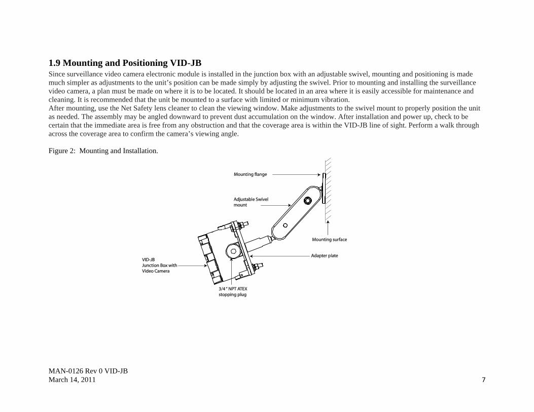
1.9 Mounting and Positioning VID-JB Since surveillance video camera electronic module is installed in the junction box with an adjustable swivel, mounting and positioning is made much simpler as adjustments to the unit’s position can be made simply by adjusting the swivel. Prior to mounting and installing the surveillance video camera, a plan must be made on where it is to be located. It should be located in an area where it is easily accessible for maintenance and cleaning. It is recommended that the unit be mounted to a surface with limited or minimum vibration. After mounting, use the Net Safety lens cleaner to clean the viewing window. Make adjustments to the swivel mount to properly position the unit as needed. The assembly may be angled downward to prevent dust accumulation on the window. After installation and power up, check to be certain that the immediate area is free from any obstruction and that the coverage area is within the VID-JB line of sight. Perform a walk through across the coverage area to confirm the camera’s viewing angle. Figure 2: Mounting and Installation.

MAN-0126 Rev 0 VID-JB March 14, 2011 8
SECTION 2: Operation
2.1 VID-JB Terminal Board The surveillance video camera and one end of the shielded twisted pair video cable is factory fitted to the terminal board. The free end of the video cable (male RCA) should be connected to the video monitor cabling system by the user. User interface is made to Terminal blocks J2 (power connections) Figure 3: VID-JB Terminal Board Table 1: Junction Box Terminals
Power Terminal (J2) wiring Terminal J2 Designation/Function
1 Not used 2 Not used 3 Not used 4 GND (Com-) 5 Not Used 6 +V (Vdc +)
MAN-0126 Rev 0 VID-JB March 14, 2011 9
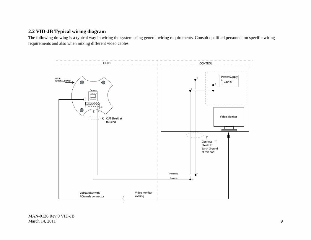
2.2 VID-JB Typical wiring diagram The following drawing is a typical way in wiring the system using general wiring requirements. Consult qualified personnel on specific wiring requirements and also when mixing different video cables.

MAN-0126 Rev 0 VID-JB March 14, 2011 10
SECTION 4: Maintenance Maintenance of this product is made simple, since only the clean of the camera viewing window and scheduled coverage area walkthrough may be performed by the user. It is recommended that cleaning be done with Net Safety cleaning products. When performing walk- through, ensure that the camera is positioned as intended and that there are no obstruction in its line of sight. Perform a walk across the area from end to end and ensure that the desired areas are properly covered and adjust the camera position as needed.
4.1 Troubleshooting If a problem should develop, carefully check for correct wiring and refer to individual product manuals. If it is determined that the problem is caused by an electronic defect, the device should be returned to the factory for repair. If returning equipment, see ‘How to Return Equipment’. Repairs to Net Safety products should not be performed in the field. Repairs to faulty or damaged equipment should only be performed at the factory; otherwise warranty on the product will be voided.
4.2 Storage The VID-JB should be stored in locations free from dust and moisture. The storage temperature should be well within the limits of specified operating temperature. See Appendix C.
4.3 Spare Parts / Accessories Table 5: Available Spare Parts
Description Net Safety Part Number
Junction Box Electronics w/t camera (PAL) EMOD-0023
Junction Box Electronics w/t camera (NTSC) EMOD-0024
Adjustable swivel mounting kit (aluminum) KIT-0701
Adjustable swivel mounting kit (Stainless Steel) KIT-0700

MAN-0126 Rev 0 VID-JB March 14, 2011 11
HOW TO RETURN EQUIPMENT A Material Return Authorization number is required in order to return equipment. Please contact Net Safety Monitoring at (403) 219-0688 before returning equipment or consult our Service Department to possibly avoid returning equipment.
If you are required to return equipment, include the following information: 1. A Material Return Authorization number provided over the phone to you by Net Safety. 2. A detailed description of the problem. The more specific you are regarding the problem, the quicker our Service department can determine and resolve the problem. 3. A company name, contact name and telephone number. 4. A Purchase Order, from your company, authorizing repairs or request for quote. 5. Ship all equipment, prepaid to: Net Safety Monitoring Inc 2721 Hopewell Place NE Calgary, Alberta, Canada T1Y 7J7 6. Mark all packages: RETURN for REPAIR Waybills, for shipments from outside Canada, must state: Equipment being returned for repair All charges to be billed to the sender Also, please ensure a duplicate copy of the packing slip is enclosed inside the box indicating item 1-4 along with the courier and account number for returning the goods. All Equipment must be Shipped prepaid. Collect shipments will not be accepted. Pack items to protect them from damage and use anti-static bags or Aluminum- backed cardboard as protection from electrostatic discharge.

MAN-0126 Rev 0 VID-JB March 14, 2011 12
Appendix A: ELECTROSTATIC SENSITIVE DEVICE (ESD) Electrostatic discharge (ESD) is the transfer, between bodies, of an electrostatic charge caused by direct contact or induced by an electrostatic field. The most common cause of ESD is physical contact. Touching an object can cause a discharge of electrostatic energy—ESD! If the charge is sufficient and occurs near electronic components, it can damage or destroy those components. In some cases, damage is instantaneous and an immediate malfunction occurs. However, symptoms are not always immediate —performance may be marginal or seemingly normal for an indefinite period of time, followed by a sudden failure. To eliminate potential ESD damage, review the following guidelines: • Handle boards by metal shields—taking care not to touch electronic components. • Wear grounded wrist or foot straps, or ESD shoes or heel grounders to dissipate unwanted static energy. • Prior to handling boards, dispel any charge in your body or equipment. • Ensure components are transported and stored in static safe packaging. • When returning boards, carefully package in the original carton and static protective wrapping. • Ensure ALL personnel are educated and trained in ESD Control Procedures. In general, exercise accepted and proven precautions normally observed when handling electrostatic sensitive devices. A warning label is placed on the packaging, identifying product using electrostatic sensitive semiconductor devices.

MAN-0126 Rev 0 VID-JB March 14, 2011 13
Appendix B: RESISTANCE (OHMS)
Distance (Feet)
AWG #20 AWG #18 AWG #16 AWG #14 AWG #12 AWG #10 AWG #8
100 1.02 0.64 0.40 0.25 0.16 0.10 0.06
200 2.03 1.28 0.80 0.51 0.32 0.20 0.13
300 3.05 1.92 1.20 0.76 0.48 0.30 0.19
400 4.06 2.55 1.61 1.01 0.64 0.40 0.25
500 5.08 3.20 2.01 1.26 0.79 0.50 0.31
600 6.09 3.83 2.41 1.52 0.95 0.60 0.38
700 7.11 4.47 2.81 1.77 1.11 0.70 0.44
800 8.12 5.11 3.21 2.02 1.27 0.80 0.50
900 9.14 5.75 3.61 2.27 1.43 0.90 0.57
1000 10.20 6.39 4.02 2.53 1.59 1.09 0.63
1250 12.70 7.99 5.03 3.16 1.99 1.25 0.79
1500 15.20 9.58 6.02 3.79 2.38 1.50 0.94
1750 17.80 11.20 7.03 4.42 2.78 1.75 1.10
2000 20.30 12.80 8.03 5.05 3.18 2.00 1.26
2250 22.80 14.40 9.03 5.68 3.57 2.25 1.41
2500 25.40 16.00 10.00 6.31 3.97 2.50 1.57
3000 30.50 19.20 12.00 7.58 4.76 3.00 1.88
3500 35.50 22.40 14.10 8.84 5.56 3.50 2.21
4000 40.60 25.50 16.10 10.00 6.35 4.00 2.51
4500 45.70 28.70 18.10 11.40 7.15 4.50 2.82
5000 50.10 32.00 20.10 12.60 7.94 5.00 3.14

MAN-0126 Rev 0 VID-JB March 14, 2011 14
Distance (Feet)
AWG #20
AWG #18
AWG #16
AWG #14
AWG #12
AWG #10
AWG #8
5500 55.80 35.10 22.10 13.91 8.73 5.50 3.46
6000 61.00 38.30 24.10 15.20 9.53 6.00 3.77
6500 66.00 41.50 26.10 16.40 10.30 6.50 4.08
7000 71.10 44.70 28.10 17.70 11.10 7.00 4.40
7500 76.10 47.90 30.10 19.00 12.00 7.49 4.71
8000 81.20 51.10 23.10 20.20 12.70 7.99 5.03
9000 91.40 57.50 36.10 22.70 14.30 8.99 5.65
10000 102.00 63.90 40.20 25.30 15.90 9.99 6.28 Note: Resistance is one way. This figure should be doubled when determining closed loop.
Appendix B: Resistance Table (cont’d)

MAN-0126 Rev 0 VID-JB March 14, 2011 15
Appendix C: Technical Specifications of Video Camera
Specification Video Camera Image Pick-up Device 1/3” Super HAD II CCD High Resolution
Pixel number NTSC=270K / PAL=320K(normal resolution), NTSC = 380K / PAL= 440K(High resolution) Effective Picture Elements NTSC:768*494, PAL: 752*582(H*V)
Horizontal Resolution 540 TV lines Minimum Illumination [email protected]
S/N Ratio More than 48 dB Auto Electronic shutter NTSC:1/60s ~ 1/100,000s, PAL:1/50s ~ 1/110,000s Gamma Characteristic 0.45
Gain control Automatically White Balance Automatically(2500K ~ 9500K)
Synchronous System Negative sync. Internal Video Output 1Vp-p composite video
Operating temperature -20°C to +70°C Field of View 100 degrees
Specification Junction Box Electronics Electrical rating Operating Voltage: 12 to 32 VDC
Power consumption At 24VDC: Nominal 62mA/1.48W Max 69mA/1.66W
Specification Junction Box Metallurgy Aluminum (AL) or 316 SS
Weight Aluminum: 0.8 Kg / 2.0 lbs (316 SS 1.6 Kg / 3.5lbs)NEMA/IP IP6Iyjr NEMA 4X /IP67ry
Approvals
Enclosure Only:
US: XP/I/1/BCD/-55°C < +85°C; Type 4X, IP67 I/1/ AEx d IIB+H2 -55°C < Ta < +85°C ; Type 4X, IP67 Can:: XP/I/1/BCD/ -55°C < +85°C; Type 4X, IP67 I/1/ Ex d IIB+H2 -55°C < Ta < +85°C ; Type 4X, IP67
ATEX (Certificate FM09ATEX0027U) II 2 G Ex d IIB+H2 -55°C < Ta < +85°C ; IP67

MAN-0126 Rev 0 VID-JB March 14, 2011 16
Net Safety Monitoring Inc. 2721 Hopewell Place NE, Calgary, AB Canada T1Y 7J7 1‐866‐FIREGAS (347‐3427) | ph. (403) 219‐0688 | fx. (403) 219‐0694 http://www.net‐safety.com | Email: nsmsales@net‐safety.com
PRODUCT SERVICES CONTACT INFORMATION Telephone [ 8am ‐ 5pm MDT ]: (403) 769‐6074 | (403) 717‐8219 Fax: (403) 219‐0694 Email: productservices@net‐safety.com http://www.net‐safety.com/service/product_services.html


![Emersonian : [Emerson College yearbook]](https://static.fdokumen.com/doc/165x107/6321be5e117b4414ec0b98a5/emersonian-emerson-college-yearbook.jpg)