
wp 9, rev 1_ai 3.4 - cns sg18 report.pdf - ICAO
493
APANPIRG/25 - WP/9 Agenda Item: 3.4 Revision 1 INTERNATIONAL CIVIL AVIATION ORGANIZATION TWENTY FIFTH MEETING OF THE ASIA/PACIFIC AIR NAVIGATION PLANNING AND IMPLEMENTATION REGIONAL GROUP (APANPIRG/25) Kuala Lumpur, Malaysia, 8 – 11 September 2014 Agenda Item 3: Performance Framework for Regional air navigation planning and implementation 3.4 CNS REPORT ON THE EIGHTEENTH MEETING OF CNS SUB-GROUP (Presented by Chairman of CNS SG) SUMMARY This paper presents the report of the Eighteenth Meeting of the CNS Sub-group (CNS SG/18) held in Beijing from 21 to 25 July 2014. The meeting is invited to review the report and adopt the draft Decisions and Conclusions formulated by the Sub-group. This paper relates to – Strategic Objectives: A: Safety – Enhance global civil aviation safety B: Air Navigation Capacity and Efficiency—Increase the capacity and improve the efficiency of the global aviation system E: Environmental Protection — minimize the adverse environment effects of civil aviation activities. 1. INTRODUCTION 1.1 The Eighteenth Meeting of the CNS Sub-group was held from 21 to 25 July 2014. The meeting was attended by 78 participants from 23 States/Administrations, IATA, and SITA. A summary report of the meeting prepared for the consideration by APANPIRG/25 is provided in the Attachment to this paper. Full report of the Sub-group was posted on the ICAO APAC Office website and can be access on the following webpage: http://www.icao.int/APAC/Meetings/Pages/2014-CNSSG18.aspx
-
Upload
khangminh22 -
Category
Documents
-
view
1 -
download
0
Transcript of wp 9, rev 1_ai 3.4 - cns sg18 report.pdf - ICAO

APANPIRG/25 - WP/9 Agenda Item: 3.4
Revision 1
INTERNATIONAL CIVIL AVIATION ORGANIZATION TWENTY FIFTH MEETING OF THE ASIA/PACIFIC AIR NAVIGATION PLANNING AND IMPLEMENTATION REGIONAL GROUP (APANPIRG/25) Kuala Lumpur, Malaysia, 8 – 11 September 2014
Agenda Item 3: Performance Framework for Regional air navigation planning and
implementation
3.4 CNS
REPORT ON THE EIGHTEENTH MEETING OF
CNS SUB-GROUP
(Presented by Chairman of CNS SG)
SUMMARY
This paper presents the report of the Eighteenth Meeting of the CNS Sub-group (CNS SG/18) held in Beijing from 21 to 25 July 2014. The meeting is invited to review the report and adopt the draft Decisions and Conclusions formulated by the Sub-group. This paper relates to – Strategic Objectives: A: Safety – Enhance global civil aviation safety
B: Air Navigation Capacity and Efficiency—Increase the capacity and improve the efficiency of the global aviation system
E: Environmental Protection — minimize the adverse environment
effects of civil aviation activities.
1. INTRODUCTION 1.1 The Eighteenth Meeting of the CNS Sub-group was held from 21 to 25 July 2014. The meeting was attended by 78 participants from 23 States/Administrations, IATA, and SITA. A summary report of the meeting prepared for the consideration by APANPIRG/25 is provided in the Attachment to this paper. Full report of the Sub-group was posted on the ICAO APAC Office website and can be access on the following webpage: http://www.icao.int/APAC/Meetings/Pages/2014-CNSSG18.aspx

APANPIRG/25 - WP/9 Agenda Item: 3.4
-2-
2. DISCUSSION 2.1 The meeting considered 36 Working Papers and 29 Information Papers covering its 11 Agenda Items.
2.2 Based on the outcome of discussions on various agenda items, the meeting developed 17 Draft Conclusions, 3 Draft Decisions for consideration by APANPIRG/25 meeting. In addition, the Sub-group made 3 Decisions relating to its work programme. List of these outcome are as follows:
Draft Conclusion 18/1 Response to AN- Conf/12 Recommendations Draft Conclusion 18/2 Regional Priorities and Targets Draft Decision 18/3 AIDC Implementation Task Force Draft Conclusion 18/4 AMHS Naming Registration Procedure and Form Draft Conclusion 18/5 PfA to FASID CNS Tables Draft Conclusion 18/6 Change of AMHS/SITA Interconnection Architecture Draft Conclusion 18/7 CRV Cost Benefit Analysis Draft Conclusion 18/8 Harmonization for AIDC Implementation Draft Decision 18/9 Terms of Reference of the APAC aeronautical Common
Regional VPN Task Force (CRV TF) Draft Conclusion 18/10 CRV Concept of Operations (CONOP) Draft Conclusion 18/11 CRV Pioneer Parties Draft Conclusion 18/12 Adoption of PAN Regional ICD for AIDC Draft Decision 18/13 Dissolving Inter-regional AIDC Task Force Decision 18/14 Supports Formation of PBN ICG Draft Conclusion 18/15 Navigation Strategy for the Asia/Pacific Region Draft Conclusion 18/16 Revised ADS-B Implementation Guidance Document
(AIGD) Draft Conclusion 18/17 Flight Plan Item 10 – ADS-B Indicators Draft Conclusion 18/18 Regulations for Compliance of ADS-B Transmissions Decision 18/19 Adoption of the Terms of Reference of SRWG Draft Conclusion 18/20 ANRFs and Responsibility Matrix Draft Conclusion 18/21 Seamless ATM Implementation Guidance

APANPIRG/25 - WP/9 Agenda Item: 3.4
-3-
Draft Conclusion 18/22 Web-based reporting process Decision 18/23 Development of the CNS part of future eANP in the CNS
fields and associated Proposals for Amendments (PfAs)
2.3 In the Attachment to this paper, a shorter summary report provides the outcome of the CNS SG/18 meeting including all Draft Conclusions and Draft Decisions for consideration by APANPIRG/25 meeting.
2.4 Appendices used from the CNS SG/18 report in the Summary Report carry the same Appendix numbers as those in the meeting report of CNS SG/18 for easy reference. 3. ACTION BY THE MEETING 3.1 The meeting is invited to:
i) review the summary report on the outcome of the CNS SG/18 meeting; and ii) consider adoption of the draft Conclusions and the draft Decisions developed
by the CNS Sub-group.
— — — — — — —

Outcomes of CNS SG/18 1
APANPIRG/25 – WP/9 Attachment
Agenda Item 1: Adoption of agenda
1.1 The tentative agenda items presented in WP/01 was adopted by the meeting without change.
Agenda Item 2: Review:
2.1) Relevant action items of the 50th DGCA Conference 2.2) Follow up to AN Conf/12 recommnedations
Relevant Action Items of the 50th DGCA Conference 2.1 The Conference developed in total 15 Action Items and requested States and Administrations to act upon the agreed Action Items. Some of the action items relevant to the work programme of CNS SG were 50/1, 50/4, 50/5, 50/6 and 50/13. 2.2 The meeting encouraged States/Administrations to take actions regarding the relevant action items of the 50th DGCA Conference. States/Administrations were also encouraged to provide CNS related input to the 51st DGCA Conference. Follow-up to AN Conf/12 Recommendations 2.3 The Twelfth Air Navigation Conference (AN-Conf/12) held in Montréal from 19 to 30 November 2012 made fifty-six recommendations under its six agenda items covering a variety of air navigation subjects. On 28 January 2013, APANPIRG/24 formulated Conclusion 24/4 requesting States and International Organizations, on the basis of analysis to take follow-up action as appropriate on the applicable recommendations of AN-Conf/12 and made Decision 24/5 asking the subgroups of APANPIRG to study the recommendations of the AN-Conf/12, initiate appropriate follow-up actions and submit a report on the outcomes of these actions to APANPIRG/25. 2.4 The meeting noted that in this connection, follow-up State Letter issued by the ICAO Regional Office dated 2 August 2013 invited States/Administrations and international organizations to initiate action as appropriate on the applicable AN-Conf/12 Recommendations and submit the action planned by 31 January 2014. Australia, Hong Kong China, Japan, New Zealand, Singapore, Thailand and USA submitted their action plans which were compiled in the Attachment to WP/03. Philippines and Malaysia confirmed that they would follow up with the recommendations of AN Conf/12. 2.5 ADS-B SITF/13 meeting held in April 2014 proposed to take action on 16 of the 56 recommendations and formulated a draft Conclusion that its response to these 16 recommendations be adopted as guidance for consideration by States. Similarly, ACSICG/1 meeting held in May 2014 identified Recommendations 1/6, 3/2, 3/3, 3/4 and 3/5 as relevant to the work of ACSICG and recommendations 3/9 and 6/13 are indirectly linked to ACSICG activity. 2.6 The responses from States, ADS-B SITF/13 and ACSICG/1 meetings were consolidated into a single recommended action by an ad hoc working group during the meeting (this ad hoc group was led by Hong Kong China, with members from Australia, Japan, Singapore and USA). The meeting further reviewed the consolidated response and formulated following Draft Conclusion: Draft Conclusion 18/1 - Response to AN-Conf/12 Recommendations
That, the regional response to the Recommendations of AN-Conf/12, as proposed in Appendix A to the report be adopted as guidance for consideration by States.

2 Outcomes of CNS SG/18 System Wide Information Managment (SWIM ) CONOP and Implementation
Requirement 2.7 The meeting noted information on the status of SWIM Concept of Operation Draft Version 0.9 presented by USA. The meeting noted the information contained in the paper and several issues which need to be addressed likely through a technical manual that would be developed. In response to a query, it was clarified that an IP-based network infrastructure would be required to support SWIM. 2.8 Japan informed the meeting that the ATM Requirements and Performance Panel (ATMRPP) working group meeting was held in Tokyo from 7 to 11 July 2014. The draft SWIM CONOP is expected to be finalized by ATMRPP in end October 2014. The Secretarait informed the meeting that some States and Administrations in the Region had started conducting SWIM research and trials and a mini-SWIM demonstration has been planned for a presentation at APANPIRG/25 meeting in September 2014. 2.9 The meeting noted that contents contained in this paper had been preseented to the ACP WG recently and ACP’s concerns would be conveyed directly by ACP to ATMRPP. 2.10 While recognizing SWIM has been included in ASBU Block 1 with start of implementation from year 2018, the meeting encouraged States/Administrations in the region to consider issues identified in the paper during their implementation of SWIM. Agend Item 3: Review -Outcome of Sub-group Chairpersons Meeting and relevant meetings
Priorities and Targets (WP/05) - Separate WP is also prepared under agenda item 3.0 based on outcome of CNS SG/18 including Draft Conclusion 18/2. 3.1 The meeting recalled that APANPIRG/24 adopted Conclusion 24/2 regarding establishment of regional priorities and targets. 3.2 Following Conclusion 24/2, teleconferences with Chairpersons of the APANPIRG Sub Groups and the ICAO Secretariat were held three times on 13 September, 30 October and 13 December 2013. Co-Chairs of the dissolved Seamless ATM Planning Group were also invited to attend the teleconferences. One face-to-face meeting was held in Hong Kong, China on 16 – 17 January 2014. 3.3 In accordance with Assembly/37 Resolution and regional needs, the Chairpersons agreed to include implementation of PBN in Terminal airspace in the APAC priorities. The Chairpersons also agreed at teleconferences in 2013 that the following implementation items would be included in the APAC regional priorities.
• B0-APTA - Performance Based Navigation (PBN) - Terminal • B0-NOPS - Air Traffic Flow Management /A-CDM • B0-DATM - Aeronautical Information Management • B0-FICE - ATS Inter-facility Data Communication (AIDC) • B0-FRTO - Flexible Use of Airspace • B0-ASUR - Surveillance • B0-TBO - Data link (ADS-C and CPDLC)

Outcomes of CNS SG/18 3 3.4 The Chairpersons considered further development of regional priorities and targets at its meeting in January 2014. The Chairpersons noted that the Asia/Pacific Seamless ATM Plan, adopted by APANPIRG/24, contained 42 seamless ATM elements, with each element assigned its own priorities. After reviewing the 42 seamless ATM elements in the Plan, the Chairpersons identified ten elements as priorities for regional implementation. Targets 3.5 The 42 ATM elements in the Seamless ATM Plan are expected to be implemented by 12 November 2015 (Phase 1) and by 08 November 2018 (Phase 2), or as soon as possible thereafter. Since the ten priority elements have been selected from the 42 ATM seamless elements, it was considered that seven out of the ten priority elements should coincide with the Phase 1 implementation, i.e. 12 November 2015. The Chairperson noted that such targets are not requirements but goals for Phase 1 implementation. Indicators 3.6 The Chairpersons developed indicators for the ten priority elements and considered that such indicators which measure progress of implementation of the priority elements should be meaningful and collectable from States. In order to align with indicators of other Regions, slight necessary changes were made to the indicators developed by the Chairpersons at the January 2014 meeting. 3.7 While noting priorities and targets, the meeting identified that some indicators were not synchronized fully with their targets. The meeting was informed that such non-synchronization came about from the need to align indicators with those of other ICAO regions for comparison purpose, while keeping specific regional targets adopted by APANPIRG/24 as part of the Asia/Pacific Seamless ATM Plan. It was understood that some revisions of the targets, perhaps on a regular basis, may be agreed in the future. As such, the targets and associated completion dates were left untouched while the meeting’s comments such as non-synchronisation of indicators and targets, etc. were recorded in a new column titled “Review by CNS SG/18” as shown in Appendix C to this Report. 3.8 The framework of implementation was also discussed for the CNS-related targets and is recorded in the new column “Framework of implementation”. Concerning the AIDC target, the meeting opined that the proposed AIDC Task Force could also support the implementation of AIDC target through its task (c), while focusing on its tasks (a) and (b) on a short term action plan to solve the safety problems raised by RASMAG/19 meeting. Concerning B0-ASUR and B0-TBO, the meeting opined that the implementation bodies already exist, but their TORs should be reviewed against the targets and changed as necessary to make sure they could support effective implementation. Concerning B0-APTA, the proposed PBNICG reporting directly to APANPIRG would provide necessary framework to achieve this target. 3.9 As a result of discussion, CNS SG/18 recommended the regional priorities and targets to APANPIRG for adoption and subsequent submission to ICAO Headquarters with following Draft Conclusion:
Draft Conclusion 18/2 - Regional Priorities and Targets
That, Regional Priorities and Targets contained in Appendix C to the Report be adopted and submitted to ICAO Headquarters.

4 Outcomes of CNS SG/18
Outcome of FIT-AISA/3 and RASMAG/19 Meetings 3.10 The meeting noted the outcome of the 3rd Meeting of the Future Air Navigation Systems Interoperability Team-Asia (FIT-Asia/3) and the Nineteenth Meeting of the Regional Airspace Safety Monitoring Advisory Group (RASMAG/19) held in Pattaya, Thailand from 26-30 May 2014.
3.11 The meeting noted the datalink performance status reports from India, China and Singapore and the draft PfA to SUPPs regarding CPDLC (14/07), ADS-B, ADS-C, ACAS II and SSR Mode S transponders (14/09).
3.12 The meeting focused its discussion on the following three items that required actions by CNS SG.
a) Regarding the recommended guidance material for implementation of data link systems provided by Australia in FIT-Asia/3/IP04, after lengthy discussion on title of the recommended guidance material, its relation with GOLD, difference between ADS-C and CPDLC etc., the meeting concluded that contents of this guidance material would be more relevant for consideration by ATM SG.
b) The meeting discussed the ATS direct speech circuit and COM/SUR problems between China and Pakistan as identified by RASMAG, namely the interface between Urumqi and Lahore (Pakistan) FIRs. China requested ICAO to work with Pakistan to resolve this problem, as it was concerned about the safety risks at the PURPA crossing point. A side meeting between China and Pakistan was held during the CNS SG/18 meeting during which the reported issues were reviewed and proposed solutions were discussed. As first step, both sides agree to designate focal point for this issue. ICAO Regional Office was requested to organize a COM Coordination meeting as soon as possible. As one of the priorities, both China and Pakistan agreed to improve existing means of ATS direct speech circuit for transferring air traffic.
c) Regarding proposed establishment of AIDC Task Force to facilitate AIDC implementation so as to reduce Large Height Deviation errors during air traffic transfer between States in the SEA and BOB areas, the meeting discussed several issues and explored several alternate ways of addressing the identified problem in a timely and effective manner. Considering AIDC implementation being identified as one of the regional priorities, its inclusion in the ASBU B0 modules and noting APANPIRG Conclusions 24/17, 24/27 on AIDC Implementation, the meeting endorsed following Draft Decision:
Draft Decision 18/3- AIDC Implementation Task Force
That, AIDC Implementation Task Force be established with Terms of Reference provided in Appendix D to this Report.
3.13 The concept of GO-team as proposed by IATA as one available means to facilitate AIDC implementations was included in the draft TOR of the Task Force. It was also informed that corresponding working team in the States/Administrations would be required to achieve the desired result through effective coordination.
3.14 The meeting was informed that a SIP AIDC Seminar was scheduled for 28-31 October 2014 where some concerned issues may be addressed

Outcomes of CNS SG/18 5
Agenda Item 4: Aeronautical Fixed Service (AFS) First Meeting of ACSICG
4.1 The meeting reviewed the outcome of the First Meeting of the Aeronautical Communication Services Implementation Co-ordination Group of APANPIRG (ACSICG/1), hosted by Republic of Korea in May 2014. 4.2 The meeting reviewed the work programme structure provided by the ACSICG, considering the proposed regional priorities from Chairpersons. It was discussed that this is an initial work programme structure and would be refined through webconference(s). The meeting was of the opinion that the task “Develop SWIM CONOPS refinement for APAC (FIXM. WXXM, AIXM, NOTAM) - models/infrastructure” was redundant in respect of the technical work conducted by ICAO panel on SWIM. It was clarified that the task objective was to refine when needed the global requirements once available. The risk of starting regional technical definitions too early would lead to wasted time and misaligned requirements, therefore the note “Note: none of the tasks 3 to 6 under the SIAF project should start until technical guidance be available from ICAO panels” was included in the table. Close coordination with ICAO HQ had been initiated to align global and regional roadmaps, with insufficient feedback so far. 4.3 Based on deliberations and recommendations by ACSICG/1 meeting, the meeting endorsed the following Draft Conclusions:
Draft Conclusion 18/4 - AMHS Naming Registration Procedure and Form That, States/Administrations be urged to follow the AMHS Naming Registration procedure as follows:
a) AMC Network Inventory Form and the Major Change Form - Pro forma for modification of AMHS MD Identifier and/or Addressing Scheme, provided in the Appendix E1 and Appendix E2 be used;
b) Asia/Pacific AMHS Naming Registration Form no longer be used; and
c) For NSAP addresses in AMC Information Form, insert a value of “91” for byte 5 of an NSAP address following instruction given in the Third Edition of the ASIA/PAC ATN Network Service Access point (NSAP) Addressing Plan.
Draft Conclusion 18/5- PfA to FASID CNS Tables
That, Table CNS 1A, Table CNS 1B and Table CNS 1C of Regional ANP (Doc 9673 Vol. II) be amended in accordance with the established procedure based on information provided in Appendices F, G and H to this report.
Draft Conclusion 18/6 - Change of AMHS/SITA Interconnection Architecture That, States/Administrations concerned in APAC Region consider coordination with
SITA for upgrading those existing interconnection between ANSPs and SITA using AMHS/SITA Interconnection Architecture Document provided in Appendix I.
Draft Conclusion 18/7 - CRV Cost Benefit Analysis
That, 1st iteration of CRV Cost Benefit analysis provided in Appendix J be adopted and distributed to States/Administrations for their reference.

6 Outcomes of CNS SG/18
Draft Conclusion 18/8 - Harmonization for AIDC Implementation That, States/Administrations in APAC Region be urged to share their implementation
plan and experiences with concerned States for an expeditious AIDC implementation in a harmonized and time bound manner.
CRV Terms of Reference and project progress (WP/31) 4.4 Based on the Decision of APANPIRG/24, the CRV project started in December 2013 to study the Common Regional Virtual Private Network in APAC Region. Since then, the project has been working in accordance with a work programme, with all planned activities on track against CRVTF Project_rev08 Gantt chart provided in Appendix K. 4.5 The CNS meeting noted the deliveries of the Task Force and sustained pace of meetings, and commended the results of the Task Force reached within 7 months. 4.6 Regarding the TOR of the CRV Task Force recommended by the ACSICG/1, the meeting endorsed the following Draft Decision:
Draft Decision 18/9 - Terms of Reference of the APAC Aeronautical Common Regional VPN Task Force (CRV TF) That, the Terms of Reference of the APAC Aeronautical Common Regional VPN Task Force (CRV TF) placed at Appendix L be adopted.
Asia and Pacific Common Regional Virtual Private Network (CRV) Benefits 4.7 The USA on behalf of Australia, Fiji, India, Japan, New Zealand, Singapore, Thailand and USA explained that CRV benefits were to be expected on costs and functionalities. States/Administrations were urged to join the CRV TF “pioneer group” to review and adopt requirements and cost for CRV, which in turn would ensure specific requirements would be met and cost issues addressed. CRV was considered as the only option that allows States with only one connection to others to expand their network for diversity without cost increase. It was also recalled for States that had decided not to join at this time that their response to the ICAO survey was critical for the option to join after contract award. Asia/Pacific Common Regional Virtual Private Network (CRV) Concept of Operations 4.8 The paper introduced the current version of the Concept of Operations (CONOPS) for a Virtual Private Network (VPN) using an existing commercial network to provide service for Air Traffic Service Message Handling System (AMHS) and other IP-based services. The CRV CONOPS was developed with contribution from member of the CRV Task Force and would be further refined with the outcome of Request For Information (RFI). It was also recalled that the presentation placed at Attachment X on the OOG concept of operations detailed further the provisions on OOG laid down in the CRV CONOP. This could constitute a good basis for the OOG policies and implementation plan for stage 2. 4.9 As a result of discussion, the meeting endorsed the following Draft Conclusion recommended by ACSICG/1:

Outcomes of CNS SG/18 7
Draft Conclusion 18/10 - CRV Concept of Operations (CONOP)
That, a) the initial Concept of Operation (CONOP) for the APAC CRV provided in
Appendix M be adopted as version 1; and
b) States/Administrations be urged to consider the initial Concept of Operations for the APAC CRV.
Draft Management Service Agreement for Stage 1 of the CRV Project 4.10 During CRV TF/1 in December 2013, discussions were held to use the ICAO Technical Cooperation Bureau (TCB) services for selecting the single regional Communication Service Provider. ICAO TCB then advised to use a Sealed Tender process. ICAO TCB Services would be contracted through a Management Service Agreement (MSA). A draft MSA, placed at Appendix N, was prepared by ICAO TCB in coordination with the ICAO APAC Regional Office and discussed with States. The updated table of comments resulting from review by ICAO TCB is appended to Appendix N. 4.11 APAC States/Administrations were invited through the letter T 8/2.11 & T 8/10.21:AP093/14 (CNS) dated 24 June 2014 to review the table of comments on the MSA and ICAO TCB’s answers before 18 July 2014. Since the MSA is a template agreement approved by the ICAO Legal Bureau and used in the past by ICAO TCB and ICAO Member States in a number of other cooperation projects, only necessary changes should be considered to expedite the process. The consolidated version of the MSA would then be submitted to the ICAO Legal Bureau, and the result of consultation be submitted to APANPIRG/25. The signing of MSA has to take place before 15 December 2014. 4.12 The total cost of engaging ICAO TCB for stage 1 of the CRV project is estimated at USD 109,300. This fund will have to be transferred to the ICAO TCB bank account in advance and before 31st of January 2015. The services by ICAO TCB (review of the user requirements, selection of the provider, etc. as specified in the MSA) are expected to start from the second quarter of 2015. It was clarified that the MSA concerns only the stage 1 of CRV project. The stage 2 is covered by a DOA, a draft of which was already produced but will need to be further reviewed. Thus, by signing the MSA before 15 December 2014 after the endorsement by APANPIRG/25, the States/Administrations expressed interest only to the procurement phase, and not to the implementation of the network. 4.13 The meeting discussed the issue concerning the capped budget or amount. Some States were desirous to have a capped amount mechanism in the MSA in order to plan their budget accordingly. Nevertheless ICAO TCB advised that ICAO could not operate with “capped” amounts, as this was contrary to ICAO Financial Regulations and Rules and could potentially put ICAO in a financially liable situation, which is not acceptable to ICAO Financial Department or ICAO auditors. However the MSA proposed a standard mechanism whereby ICAO could not incur expenditures beyond the approved budget without express consent from the State (or States in this case), which somehow gave the guarantee to Pioneer States/Administrations that the budget could not be exceeded without their consent. 4.14 Miscellaneous costs were included in all ICAO TCB project budgets, and may comprise of (but not limited to) UN common costs, security costs, insurance, communication costs, courier, bank charges, and third party transaction costs (i.e. UNDP).

8 Outcomes of CNS SG/18
Proposal for the Provision of a same Project Budget for each State/Administration Participating in Stage 1 of the CRV Project 4.15 USA introduced the working paper on behalf of Australia, Fiji, India, New Zealand, Singapore, Thailand and USA. Since ICAO TCB was unable to provide a “capped amount” for States/Administrations, it was proposed that each participating State/Administration secured a budget of USD 20,000 for the TCB services under the MSA. Any additional TCB works approved by the CRV Task Force are deemed to be agreeable by the participating States/Administrations so long as the revised project cost, after inclusion of the additional works, is still within the approved budget of USD 20,000 per participating State/Administration. This would minimize the risk of project delay due to additional budget approval processes of participating States/Administrations. 4.16 For the 11 States having expressed interest to be Pioneer State, the corresponding “capped amount” would add up to USD 220,000. This would not mean that ICAO TCB would claim this amount as the actual amount payable to ICAO TCB is based on the actual works it has contracted and delivered. 4.17 Consequently the meeting recognized that the draft MSA could not include a “capped amount” mechanism. 4.18 Noting that the estimated project cost to each Pioneer State would be determined by the actual number of Pioneer States, to be confirmed on 14 November 2014, and that the MSA indicates the total estimated project cost to be divided on an equal basis, the meeting recommended that States intending to be CRV Pioneer States plan a same project budget of USD20, 000 with the view of funding on an equal basis the cost of TCB services in Stage 1 of the CRV project, including contingencies. The Secretariat was requested to notify States/Administrations concerned through a letter. 4.19 Appreciating through IP/11 that DSNA France expressed interest to CRV stage 1, the meeting endorsed the following Draft Conclusion: Draft Conclusion 18/11 – CRV Pioneer Parties That,
a) Considering the number of States/Administrations (Australia, Fiji, France,
Hong Kong China, India, Japan, Malaysia, New Zealand, Singapore, Thailand, and USA) that expressed interest to be Pioneer Parties and sign the MSA;
b) Considering the favorable Cost Benefit for CRV operations as a major enabler
for achieving GANP 4th edition roadmap; i) The Management Service Agreement (MSA) provided in Appendix N be
adopted; ii) States/Administrations in APAC Region which have not expressed interest be
urged to become Pioneer Parties before 14 November 2014 or join for Stage 2; iii) States/Administrations sign the MSA before 15 December 2014 and transfer
the necessary funds to ICAO TCB for its services before 31 January 2015.

Outcomes of CNS SG/18 9
Request for Information (RFI) for the Asia Pacific 4.20 The meeting noted that the CRV TF developed a RFI to collect data from network service providers to define clear user requirements in the Sealed Tender process, get a better awareness of typical pricing schemes/prices, and insight into evaluation criteria. The RFI did not commit any State/Administration to further procure any service from any vendor. The RFI would not be used for selecting/eliminating vendors. Likewise non response to this RFI would not preclude any service providers from participating in the Sealed Tender. The tendering process will be conducted through the Sealed Tender process in accordance with the ICAO procurement.
4.21 The milestones of the RFI process are as follow:
15 August 2014 Public RFI issuance for all telecommunication Service Providers
17 October 2014 Deadline to receive questions 03 November 2014 Deadline to receive RFI responses from service providers
wishing to present at the 09December CRV TF session 28 November 2014 Deadline to receive RFI responses from service providers
not wishing to present at the 9 December CRV TF session 28 November 2014 Deadline for sending out the presentation for the 9
December session to the CRV TF 9 December 2014 Presentation of responses to CRV TF (duration of slot will
be fairly allocated), questions and answers 4.22 This RFI material will be finalized before 30 July 14 by CRV participants and published on ICAO website before 15 August 14. States/Administrations are invited to publish a link on their website to relay the information. The text of the news to be posted on the ICAO website was reviewed by the meeting. 4.23 The meeting also urged States/Administrations which have not yet responded to ICAO State Letter ref. T 8/2.10, T8/10.21:AP170/13 (CNS) dated 18 December 2013, to provide response according to the APAC Survey or at least complete Attachment A with their communication site location and contact details and invited States/Administrations to publish a link to the ICAO RFI webpage on their own website to relay the information. Pan Regional ICD for AIDC 4.24 The meeting noted the following activities of the inter-regional AIDC Task Force (IRAIDTF):
− IRAIDTF/1 meeting was held in ICAO Paris Office from 16-18 January 2013; − IRAIDTF WebEx meeting held on 27 February 2013; − IRAIDTF WebEx meeting held on 10 April 2013; − IRAIDTF/2 meeting was held in ICAO Bangkok Office from 22-26 July 2013; − IRAIDTF/3 meeting s held in ICAO Headquarters from 24-28 March 2014; − IRAIDTF Teleconference held on 11 June 2014; − IRAIDTF Teleconference held on 9 July 2014; and − IRAIDTF Teleconference held on 6 August 2014.

10 Outcomes of CNS SG/18 4.25 The meeting reviewed and endorsed the latest draft of the Pan Regional APAC/NAT AIDC ICD (Version 0.91). Later Version 0.92 was issued as outcome of Teleconference on 6 August 2014 which is provided in Appendix O. The ICD was initially developed based on the APAC AIDC ICD Version 3.0 and NAT AIDC ICD Version 1.3.0. It was anticipated that the ICD would likely be adopted by IMG in NAT Region in November then get NAT SPG agreement through correspondence by the end of 2014. For the APAC Region, similar to the process for adoption of GOLD, the PAN Regional ICD for AIDC may also be adopted as interim version by APANPIRG/25 in September 2014 subject to adoption by NAT SPG in the end of 2014. In view of the foregoing, the meeting endorsed the following Draft Conclusion: Draft Conclusion 18/12 – Adoption of PAN Regional ICD for AIDC
That, upon release by IRAIDC Task Force by September 2014, the PAN Regional ICD for AIDC provided in Appendix O, be adopted as Version 1.0 serving as regional guidance for AIDC implementation in the APAC and NAT Regions.
4.26 Considering the tasks given by NAT SPG through Conclusion 48/28 and APANPIRG through Conclusion 23/20 being completed once the PAN regional ICD for AIDC is adopted by both the regions, the meeting agreed that IRAIDC Task Force be dissolved after adoption of the Version 1 of PAN Inter-regional ICD for AIDC by NAT SPG. Accordingly the meeting endorsed following draft Decision: Draft Decision 18/13- Dissolving Inter-regional AIDC Task Force
That, once Version 1 of PAN Inter-regional ICD for AIDC is adopted by both APAN and NAT Regions, the Inter-regional AIDC Task Force established through NAT SPG Conclusion 48/28 and APANPIRG Conclusion 23/20 be dissolved.
4.27 While congratulating the Inter-regional Task Force for its achievements, the meeting recorded its appreciation to the continuous support and active contributions from experts nominated by USA (as Chair), Australia, India, New Zealand, Singapore and Thailand in the APAC Region. COM Coordination Meeting 4.28 A COM Coordination Meeting attended by China, Cambodia, Myanmar, Nepal and Thailand was held in Chendu, China from 18 to 19 February 2014. The meeting was hosted by the Air Traffic Management Bureau (ATMB), China. 4.29 The COM coordination meeting reviewed the implementation and operational status of the required Aeronautical Fixed Services and developed coordinated Action Plans for improving the performance of some of the concerned circuits to satisfy the established operational requirements. The meeting urged States concerned to take follow-up actions to implement the seven action items agreed by the COM coordination meeting. AMHS and AFTN Implementation Tool on Website 4.30 The meeting noted the AMHS/AFTN implementation tool with three items available on the following page: http://www.icao.int/APAC/Pages/apac-projects.aspx 4.31 States were urged to update the contact point information and switch information to the AFTN routing directory with user name and password provided during the meeting. Administrations were also reminded to provide contact information on ATN/AMHS to the ICAO Regional Office for updates.

Outcomes of CNS SG/18 11
Agenda Item 5: Aeronautical Mobile Service (AMS) RCP/RSP Implementation Framework 5.1 Under this agenda item, a number of working papers on RCP/RSP related Framework were presented and discussed at the meeting Introduction on Performance Based Communication and Surveillance 5.2 New Zealand presented the guidance material on performance based communication and surveillance (PBCS) that is currently under development by the ICAO Operational Data link Panel. The current Doc 9869 Manual of RCP is being revised and renamed as the PBCS Manual with completion scheduled in October 2014. The guidance material presented by New Zealand was extracted from Chapter two of an interim draft revision v1.3.x to Doc 9869. The OPLINKP drafting team considers that this material is mature and may be used by CNS SG/18 for discussion of the RCP/RSP implementation framework in Asia/Pac Region. 5.3 Through IP/10, the Secretariat informed of the proposed structure i.e. Table of Contents for Performance-based Communication and Surveillance Manual (Doc 9869) and the frame work of the proposed amendment to Annexes 6, Part I, Annex 11 and PANS-ATM. An OPLINKP PBCS drafting group is working on improving the contents of the PBCS Manual and proposed amendments to Annexes and PANS. The OPLINKP is planning to submit mature proposals to FLTOPSP in due course (preferably prior to the next FLTOPSP meeting in October 2014) for its consideration and comments. The mature proposals will include amendments to Annexes 6, 11, PANS-ATM, and Doc 9869 (PBCS Manual). 5.4 The meeting noted that OPLINK Panel had a plan to review the final proposals on PBCS at its next meeting scheduled for 6-17 October 2014. The proposals for amendments to Annexes and PANS will then, if consensus is reached, be refined for presentation to the ANC in early 2015, proposing applicability date of November 2016.
Proposed RCP/RSP Implementation Framework 5.5 The Secretariat proposed an initial implementation framework of RCP/RSP across APAC Region in response to APANPIRG Decision 24/33 - APAC RCP/RSP Implementation Framework. The PBCS concept applies RCP and RSP specifications in any one or more of the following ways:
• Air traffic services (ATS) provision and prescription (in accordance with ICAO
Annex 11, PANS, Doc 7030 and/or Aeronautical Information Publication (or equivalent publication)) of a RCP specification for a communication capability and/or a RSP specification for a surveillance capability, either of which is required for the ATS in a particular airspace;
• Operator authorization (under Air Operator Certificate, special authorization or
equivalent, in accordance with ICAO Annex 6) of a communication and/or surveillance capability including aircraft equipage where RCP and/or RSP specifications have been prescribed for the communications and/or surveillance capabilities supporting the ATS provision;
Proposed scope of work 5.6 Based on the above, the bodies potentially concerned by the RCP/RSP work programme under APANPIRG were also proposed in the paper. 5.7 The meeting discussed about the RCP/RSP implementation issues. It was considered intensive work needs to be addressed under PBCS framework. It may also require contributory body

12 Outcomes of CNS SG/18 to be established in the future to deal with the implementation, planning and related issues. There was also a proposal to review the scope of monitoring agencies such as CRA under RASMAG to see if they can be redefined to include PBCS. 5.8 Considering that PBCS manual would be made available in 2015 and related SARPs and PANS-ATM would be updated to include PBCS in end of 2016, ICAO was requested to organize more workshops/seminars to facilitate understanding on the subject and the requirements for implementation in the future.
PBCS in NZZO – Current FANS1/A Performance and Issues 5.9 New Zealand presented an update on current FANS1/A performance observed in NZZO between January and June 2014 and provided information on the analysis of two current issues relating to the performance of Iridium and HF data link. It also illustrated post implementation monitoring from an ANSP perspective. Little change has been observed in FANS1/A performance in the first six months of 2014. PBCS IN NZZO – Post Implementation Monitoring 5.10 New Zealand presented to the meeting two FANS1/A performance issues identified in NZZO (i.e. Auckland Oceanic FIR) in 2013. These provided good examples of why New Zealand supports performance based communications and surveillance. The first issue involved the introduction of a new aircraft fleet where measured performance was well below RSP180 requirements. The second issue involved a significant deterioration in observed performance for all aircraft using the Pacific I4 GES. 5.11 New Zealand observed a number of instances where system changes have resulted in significant performance deterioration therefore confirmed the need for post implementation monitoring and the need for effective CRA and problem reporting structures as part of an Asia/Pac RCP/RSP framework Technical Issues Affecting VDL2 and the ATN Baseline 1 Data Link in Europe 5.12 New Zealand presented recommendations about the need for implementation of a robust reporting and resolution process extracted from the EASA report on data link implementation in Europe. The EASA report on data link implementation in Europe is available at http://ec.europa.eu/transport/modes/air/single_european_sky/doc/implementing_rules/2014-04-23-easa-datalink-report.pdf 5.13 The EASA report has identified several major technical issues that render the current ATN/VDL2 technology unsustainable in support of the European Commission’s Data Link Services Implementing Rule. These issues are not covered in the WP/20. However, the EASA report does identify the need for the implementation of a robust reporting and resolution process which is seen as pertinent to the discussion of an Asia/Pacific Performance Based Communication and Surveillance RCP/RSP framework. Problem reporting and resolution process was considered as an important part of any PBCS RCP/RSP framework.

Outcomes of CNS SG/18 13
SATVOICE Communication 5.14 India informed the meeting that India adopted SATVOICE communication and has implemented it at Oceanic Control Center at Mumbai and planned to implement SATVOICE at Chennai and Kolkata. The guidance for use of SATVOICE in India was currently through standard operating procedures. India encouraged States in Asia/Pac region to use SATVOICE as an LRCS option in addition to routine and emergency use. 5.15 States were also encouraged to consider including SATVOICE capability into their ATM automation system when such systems are replaced or upgraded in accordance with directive of APANPIRG. 5.16 The meeting was informed of Australia SATVOICE Position that the use of SATVOICE has been restricted to non-routine and emergency purposes only and it won’t be used for routine ATS service until new Australian ATM system becoming operational. New Zealand indicated that it also has similar position for using SATVOICE communication. 5.17 IATA restated its position for using SATVOICE Communication as backup system only for emergency use. The meeting identified need for the training using SATCOM including upgrading and refresh training.
SATVOICE Communication in the Auckland (NZZO) Oceanic FIR
5.18 New Zealand informed the meeting that at the Informal South Pacific ATS Coordinating Group (ISPACG) in March 2014, the status of both the SVGM and SATVOICE operations were discussed. 5.19 The Airways paper presented to the ISPACG describes the operational issues that have been encountered using the Iridium, MTSAT and Inmarsat services. The Iridium ATS Safety Voice Service requires the ATS user to call an Iridium access number and then enter a discreet User ID and PIN followed by the call priority and the ICAO 8-digit octal aircraft identifier. While MTSAT is used for CPDLC and ADS-C, access is not provided (by the CSP) for SATVOICE. Airways experienced difficulty calling some Inmarsat-equipped aircraft as a result of the introduction of the Inmarsat I3 GES, when Inmarsat took back control of the I3 GES operations from the previous GES operators. ANSPs and aircraft operators now require a contract with either SITA or ARINC. 5.20 Japan expressed that it will study the status of MTSAT for SATVOICE. Agenda Item 6: Navigation PBN Implementation Progress and ICAO Supports
6.1 The meeting noted that with rapid increase in aviation demand and needs for higher fuel efficiency; there is an urgent call for use of new navigation technologies and operation procedures to meet such requirements. In response to this call for actions, ICAO had endorsed the use of Performance-Based Navigation (PBN) and Global Navigation Satellite System (GNSS) as the new navigation elements of CNS systems. 6.2 The implementation of PBN has been considered to be one of the highest air navigation priorities. ICAO Assembly Resolution A37-11 re-emphasizes the PBN global targets, especially regarding State PBN Implementation Plan and deployment of approach with vertical guidance. At the 44th Conference of Directors-General of Civil Aviation in October 2007, IATA expressed that implementation of PBN provides significant safety, efficiency and environmental benefits to operators and service providers. In September 2009, APANPIRG adopted the first version of the Asia/Pacific Regional PBN Implementation Plan through its Conclusion 20/41.

14 Outcomes of CNS SG/18 6.3 The number of published PBN SID/STAR procedures within the APAC Region continues to increase. For approach operations, currently 51% of all instrument runways within APAC have published PBN approach procedures. Beyond establishing relevant ICAO standards and guidance material, to assist Member States with on-going PBN planning and implementation, ICAO in cooperation with industry partners such as IATA had organized several PBN implementation focus activities. These activities include PBN symposia, workshops, Go-Team visits, training courses and learning packages. ICAO has also established implementation support offices for PBN implementation in the form of the APAC Regional Sub-Office (RSO) and a Flight Procedure Programmes Office at Beijing. 6.4 To serve as the primary forum to support implementation of PBN in this region, ICAO will be proposing to APANPIRG about the formation of a PBN Implementation Coordination Group (PBN ICG). This PBN ICG will continue the good work of the now defunct PBN Task Force. The meeting reviewed the draft Terms of Reference of the proposed PBN ICG and supported the latter’s establishment, with endorsement of the following Decision: Decision 18/14 – Support Formation of PBN ICG
That, the CNS SG supports the establishment of the PBN ICG and its draft Terms of Reference as in Appendix P.
Implementation of GBAS in India 6.5 The meeting noted that India will be installing and certifying a CAT 1 Ground-based Augmentation System (GBAS) at Chennai Airport by end 2014, thus providing precision approaches to all 4 ends of the two runways at Chennai Airport. In so doing, the new GBAS overcomes existing site constraints there which now prevent installation of ILS for one of the runways. Hand-in-hand with this, development of new GBAS procedures is also in progress. Current Status and Working Plan of Ionospheric Studies Task Force 6.6 The meeting noted Japan’s presentation of the status and working plans of the Ionospheric Studies Task Force (ISTF) whose goals is to study any need for development of regional ionospheric threat models for GBAS and SBAS, to develop them if the need is identified, and to investigate the effects of space weather on CNS systems in the APAC Region. 6.7 To help ISTF achieve its goals, 6 tasks were identified as follows: -
a) Identification of data source, GNSS data collection, sharing, distribution and archiving. Identification of data sharing format;
b) Identification of analysis methodology and GNSS ionospheric data analysis;
c) GNSS total electron content (TEC) gradient data generation;
d) GNSS ionospheric scintillation data generation;
e) Assessment of need for Regional GBAS and SBAS ionospheric models and
development of these models if it is needed; and
f) Analysis, based on data shared within ISTF and public information, of the effects of space weather and the concept of operations for the provision of space weather information in support of international air navigation

Outcomes of CNS SG/18 15 6.8 The meeting noted that above Tasks (a) and (b) have been partly finished, with Tasks (c) and (d) to be launched soon. Task (e) has not been launched, and will only be initiated with outputs from Tasks (c) and (d). Task (f) has been launched and is in progress in parallel with Tasks (a) to (e).
6.9 The meeting noted that to facilitate Task (a), a data server had been installed at the Electronic Navigation Research Institute, Japan, to host the collected and analyzed data. Data from Thailand, Hong Kong China, as well as from the APEC GNSS Implementation Team (GIT) test bed had been transferred to this data server for analysis. Taking the opportunity of the CNS SG meeting, India and Philippines provided their data, which would now allow the data analysis to fully start. 6.10 Due to delay in data collection and in identifying the analysis methodology, the meeting noted that the progress of the ISTF activities was behind schedule. Potential risk in the ISTF’s working plan is a lack of information on the ionospheric threat model definition used in different SBAS systems, which is usually confidential. As such, this would make it difficult to assess the need of regional model for SBAS. To mitigate this risk, information on the ionospheric threat definitions for different SBAS systems should be collected from publically available publications. Navigation Strategy for the Asia/Pacific Region 6.11 New Zealand, working together with IATA, carried out a review of the Navigation Strategy for the Asia/Pacific Region outside the meeting and submitted update proposals for the meeting’s review. Slight updates were proposed and after some discussion, the meeting agreed to adopt the updated Navigation Strategy for the Asia/Pacific Region as proposed by New Zealand and IATA and formulated following Draft Conclusion:
Draft Conclusion 18/15 - Navigation Strategy for the Asia/Pacific Region That, the revised navigation strategy provided in Appendix Q to the report be adopted for the Asia/Pacific Region.
Agenda Item 7: Surveillance Outcome of ADS-B SITF/13 Meeting 7.1 The meeting reviewed the report of the Thirteenth Meeting of Automatic Dependent Surveillance – Broadcast (ADS-B) Study and Implementation Task Force (ADS-B SITF/13). An ADS-B Seminar and the ADS-B SITF/13 meeting, hosted by the CAD Hong Kong China was held from 22 to 25 April 2014. The deliberations during the Seminar were taken into consideration at the 13th meeting of the Task Force. The report of the meeting and other relevant documents are provided on the following ICAO APAC webpage: http://www.icao.int/APAC/Meetings/Pages/2014-ADSB-SITF13.aspx 7.2 The outcome of the Ninth meeting of the SEA/BOB ADS-B Working Group (SEA/BOB ADS-B WG/9) held at ICAO RSO in November 2013 was consolidated in the report of the ADS-B SITF/13 meeting. The report of the Working Group is available at: http://www.icao.int/APAC/Meetings/Pages/2013-SEABOB-ADSB-WG9.aspx 7.3 The SEA/BOB ADS-B WG/9 meeting noted that Mode S radars are being deployed by a number of States in the Region, however function of Mode S radar with DAPS for ATM automation system has not been fully utilized.

16 Outcomes of CNS SG/18 7.4 The meeting noted that the Terms of Reference of the ADS-B SITF was reviewed by the Task Force and was considered still appropriate for the time being. However, the Task Force meeting identified the need to reflect correct name of APANPIRG Sub-groups in the note of ToR as shown in Appendix C to the ADS-B SITF/13 meeting report. 7.5 The meeting noted that a survey was conducted by ADS-B SITF on the readiness of ADS-B ground stations that had been upgraded to be capable of receiving ADS-B D0260B compliant ADS-B data. The result of the survey is provided in Appendix R to this report. ADS-B implementation Status 7.6 The meeting noted the implementation status and developments in Australia, Bangladesh, Canada, China, French Polynesia, India, Japan, Malaysia, Maldives, Republic of Korean, Singapore, Viet Nam and USA. The detailed information is provided in the report of ADS-B SITF/13 meeting. 7.7 The meeting reviewed the regional ADS-B implementation status appended in an Appendix to the ADS-B SITF/13 report. The information further updated during the meeting is provided in Appendix S to this Report. Proposed Amendment to AIGD 7.8 The meeting noted that Australia, Hong Kong China and Singapore had proposed amendment to the ADS-B Implementation and Guidance Document (AIGD) to incorporate guidance for monitoring and analysis of the performance of ADS-B avionics. The meeting reviewed the revised AIGD appended to the ADS-B SITF/13 report. The proposed amendment also included guidance materials on synergy between ADS-B and GNSS, revised ATC phraseology and clarification on the flight planning requirements etc. In view of the foregoing, the meeting endorsed the following Draft Conclusion: Draft Conclusion 18/16 - Revised ADS-B Implementation and Guidance
Document. That, the revised ADS-B Implementation and Guidance Document (AIGD) provided in Appendix T (including T2) to this report be adopted.
7.9 It was foreseeable that increasing number of States worldwide would start to formulate plans to implement ADS-B in order to meet their operational needs and implement relevant Aviation System Block Upgrades (ASBUs). Therefore, it was recommended that the AIGD should be promulgated to States in other Regions as guidance materials for experience and knowledge sharing on ADS-B implementation in order to reap early operational benefits and save efforts. The Secretariat informed the meeting that the AIGD had already been forwarded to other ICAO Regional Office for their reference and agreed to seek assistance from ICAO Headquarters to make the AIGD available to States in other Regions to achieve better synergy in ADS-B implementation. 7.10 The meeting noted the information on the ADS-B performance monitoring in Singapore and Indian FIRs.
The Use of Flight Plan Data to Support ATM and the Effect of Variable Application of Flight Planning Requirements
7.11 The meeting noted that Amendment 1 to the 15th Edition of ICAO Doc 4444 (PANS/ATM), effective from November 2012, introduced new, more detailed flight planning requirements, improving the description aircraft capabilities in Items 10 and 18 of the ICAO FPL. Descriptors for surveillance equipment capabilities were provided for in Item 10b of the FPL. Descriptors for ADS-B capability were provided in both the “SSR Mode S” and “ADS-B” ranges of descriptors. The purpose of the ADS-B descriptors was to allow ATC to plan operations with an
Outcomes of CNS SG/18 17 expectation that the aircraft will or will not be transmitting ADS-B as indicated in the FPL, before the aircraft was detected. 7.12 Examination of Flight Plan data indicated that serviceable ADS-B capability was not consistently indicated, perhaps due to a lack of clarity and understanding of the ICAO FPL requirements.
− B1 and B2 included the term “dedicated”, which could suggest an ADS-B
transmitter which was separate from the Mode S transponder. Depending on interpretation, B1 or B2 could be planned, depending on interpretation, to indicate ADS-B capability, regardless of the transmitter hardware (being either the Mode S transponder or a discrete unit), or only where the ADS-B transmitter was separate from the Mode S transponder;
− There was no value in ATC knowing whether or not the ADS-B capability was in
a discrete unit or not. ATC was only interested in whether the aircraft as a whole was transmitting useable ADS-B data;
− The majority of ADS-B equipped flight plans received by Australia indicated
both the SSR Mode S capability, and the associated ADS-B capability, e.g. EB1, LB1, LB2. Some ADS-B equipped flights we observed to be planning “E” or “L”, but without “B1” or B2”;
− There were significant issues faced by other regions that required DO260B for
operational purposes. Currently there were no means in the flight plan to distinguish between DO260 and DO260B. It was likely that Europe/USA would require a designator to indicate DO260B compliance. For example:
o B1/B2 : DO260 (or DO260A) o B3/B4 : DO260B
− European organizations had discussed additions to Item 18 SUR/ to achieve this
as an interim measure until the ICAO FPL could be revised again. European organizations had also identified potential redundancy between L (and E) and the B1/B2 designators.
− An understanding of each aircraft’s ADS-B capability was important for the Air
Traffic Controllers’ traffic management and planning. :
− The variability of flight planning understanding among operators, pilots and ANSPs undermined the reliability of information presented to the air traffic controller. There were no known current or anticipated operational uses for the declaration of 1090 MHz Extended Squitter capability in the flight plan beyond declaration of ADS-B capability.
− It was recommended that ICAO Doc 4444 (PANS/ATM) Appendix 2 (A2-7) and
Appendix 3 (A3-13) be amended. 7.13 The meeting endorsed proposed changes to be included in the regional interpretation into the AIGD, and agreed to the following Draft Conclusion formulated by the ADS-B SITF:
Draft Conclusion 18/17 – Flight Plan Item 10 ADS-B Indicators That, ICAO be invited to consider to amend relevant contents in Doc 4444 PANS/ATM Appendix 2 (A2-7) and Appendix 3 (A3-13) as shown below:

18 Outcomes of CNS SG/18
o E Transponder — Mode S, including aircraft identification, pressure-altitude and extended squitter (ADS-B out) capability
o L Transponder — Mode S, including aircraft identification, pressure-altitude, extended squitter (ADS-B out) and enhanced surveillance capability
o B1 ADS-B with dedicated 1 090 MHz ADS-B “out” capability using 1
090MHz extended squitter.
o B2 ADS-B with dedicated 1 090 MHz ADS-B “out” and “in” capability using 1 090MHz extended squitter.
− In this recommended amendment, there was duplication of indication of ADS-B
carriage for aircraft where the Mode S transponder was the transmission device. − This recommendation would be unlikely to require significant changes to ATM
systems; the descriptors were unchanged but their interpretation was clarified. Some adaptation changes could be required where ANSPs were currently using the descriptors as triggers for system processing such as controller HMI indications.
− Changes to flight planning systems would be required in cases where the text
associated with each descriptor was provided for pilot reference and to individual States’ AIP where ICAO DOC 4444 flight planning requirements were repeated.
ADS-B Operational approval requirement
7.14 The meeting recalled that a number of Asia Pacific States required State of Registry operational approvals for the introduction of ADS-B airspace in December 2013, possibly to conform with the APANPIRG Conclusion/template. 7.15 At ADS-B SITF/13 meeting, Australia recommended that States and ANSPs should reconsider any current requirements for “operational approval” for aircraft operators, and remove any such reference to a requirement for an “operational approval” or “operational specification” from State regulations and AIP. New Zealand and USA supported the proposal to remove the requirement for operational approvals, and Canada advised that they also did not require operational approval. However, other States stated that they would have difficulty in supporting ADS-B operations without an operational approval process. The meeting discussed the varying regulatory and legislative circumstances that may exist among Asia/Pacific States, and the evolutionary nature of each State’s development of ADS-B regulations. 7.16 In view of the foregoing and in order to provide flexibility to those States until more experience was gained, the following Draft Conclusion developed by the Task Force was endorsed by the meeting:
Draft Conclusion 18/18 - Regulations for Compliance of ADS-B Transmissions That, States be urged to implement regulations to give effect to Regional Supplementary Procedure Serial APAC-S12/10 – MID/Asia 5-3 to ensure that all aircraft transmitting ADS-B are compliant with the standards; States in the Asia and Pacific Regions may choose to require or not require an Operations Specification or Operations Approval for ADS-B OUT.

Outcomes of CNS SG/18 19
ADS-B Operational Approval for Operations Outside of U.S. Domestic Airspace 7.17 The meeting noted that USA provided information on how the FAA issued State of Registry operational approval for U.S.-registered aircraft to comply with ADS-B mandates of other States and discussing the burden to the aircraft operator and approving regulator of requiring “State of Registry” operational approval. Very recent updates on the FAA Flight Standards Service (AC 90-114, Change 1) indicates that no operational approval is required for aircraft with avionics compliant with AC 20-165A to operate in U.S. airspace defined in Title 14 of the Code of Federal Regulation (14 CFR) § 91.225 (part of the U.S. ADS-B Final Rule). Space based ADS-B Surveillance Service (Canada) 7.18 An overview of NAV CANADA’s plans for introduction of space-based ADS-B surveillance services was provided to the ADS-B SITF meeting. The meeting appreciated the opportunities offered to States/Administrations in the APAC Region to receive additional information through a workshop on space-based ADS-B supported by NAV CANADA. The meeting further noted that one day workshop on space-based ADS-B would be arranged in conjunction with ADS-B SEA/BOB WG meeting in Singapore on 11 November 2014. Business Jet Aircraft Fitment Issues 7.19 The meeting noted the ADS-B fitment rate issue for Business jet aircraft. It was advised that a number of States/Administrations had received a letter from IBAC asking for suspension or withdrawal of the ADS-B mandates in the specified routes segments of the concerned State/Administrations’ airspace. The meeting noted outcome of discussions on this matter recorded in the Report of the ADS-B SITF/13 meeting.
Separation Minima, Airspace Capacity and ADS-B Mandates 7.20 The meeting noted the combined 4th Meeting of the South Asia/Indian Ocean ATM Coordination Group and 21st Meeting of the South East Asia ATS Coordination Groups (SAIOCG/4 & SEACG/2 held in February 2014 had agreed to a draft Conclusion on ADS-B Airspace Mandates. The meeting noted the Draft Conclusion was supported and endorsed by the ADS-B SITF. The meeting reviewed draft PfA without any further comments.
7.21 IATA urged States to consider and address the issues impeding the region from implementing the separation standards that would improve airspace capacity and efficiency by providing ATC with the tools to deliver optimal services.
ADS-B Data Sharing Between India and Myanmar 7.22 The meeting was provided with an update by India of the status of ADS-B data sharing between India and Myanmar, which had been agreed in principle between the States. Initial discussions initiated at ADS-B SITF/11 in April 2012 were further progressed at the ADS-B focus group meeting facilitated by CANSO in July 2012. 7.23 ADS-B SITF/12 (April 2013) had agreed to Draft Conclusion 12/2, adopting milestones for data sharing between India and Myanmar, who had earlier agreed in principle to share data from the Agartala, Port Blair, Sittwe and Coco Island sites.

20 Outcomes of CNS SG/18 7.24 The Port Blair and Agartala ADS-B ground station receivers were installed and regulatory approval was expected by end of May 2014. The installation at Sittwe had also been completed, but Coco Island’s was delayed till end of 2014 due to bad weather and logistics issues. The proposed data sharing agreement, based on the ICAO Asia/Pacific ADS-B Data Sharing Agreement Template, had been submitted to the Ministry of Civil Aviation, which was actively coordinating for inter-ministerial clearances which were expected by end of June 2014. The date for signing the data sharing agreement may be realistically expected in 2nd half of 2014 after approval from the Ministry of Civil Aviation. Sub-regional ADS-B Implementation Plan Updates 7.25 The meeting noted that Singapore had started receiving ADS-B data from the Indonesian islands of Matak and Natuna while Indonesia had also started receiving ADS-B data from Singapore. Singapore also received ADS-B data from Vietnamese island of Con Son. As for the communications, VHF radios from Con Son is operational; while the VHF radios from Matak and Natuna were installed and expected to be operational within 2014. While IATA lauded such ADS-B data sharing among Indonesia, Vietnam and Singapore which enables ADS-B surveillance coverage in the western and north-west parts of the South China Sea area, IATA would also like to have similar ADS-B surveillance coverage of other parts of South China Sea such as its north-eastern part. 7.26 The Philippines and Singapore also agreed in-principle on ADS-B data sharing. The Philippines is securing a site in Quezon Palawan for the installation of ADS-B ground station and VHF radios. It was noted that two additional ADS-B ground stations will be installed 2015, one of them will be in Manila. The ADS-B station at Quezon Palawan being discussed between Singapore and the Philippines will not be integrated into the new ATM system. It was further informed that the interim ATS system to be made available at Manila by end of 2014 will be capable to process ADS-B data. In this connection, IATA urged the Philippines to ensure the new ADS-B stations to be installed in the Palawan area provided surveillance coverage of the routes in the South China Sea that not currently covered. 7.27 Singapore informed the meeting that from 24 July 2014, 30 NM separations has been applied to the ATS routes between Singapore and Viet Nam based on the capability of ADS-B surveillance and from the same day, AIDC between Singapore and Ho Chi Minh ATCC became operational. The meeting congratulated two States for the successful implementation. 7.28 The meeting noted the readiness checklist contained in Appendix L to the ADS-B SITF/13 meeting report. Air Transport Aircraft ADS-B OUT Forward Fit 7.29 The meeting discussed the following draft Conclusion proposed by Australia on ADS-B OUT forward fit for air transport aircraft. The significant benefits were highlighted for new aircraft to be equipped with ADS-B avionics compliant with Version 2 ES and the proposal does not bring significant costs to the airline community. ADS-B OUT Forward Fit
That, States/Administrations in APAC Region mandate that air transport aircraft with a maximum take-off weight of more than 5,700 kg and an individual certificate of airworthiness first issued on or after 8 January 2018 (two years after the European forward fitment mandate is effective) be equipped with ADS-B avionics compliant with Version 2 ES (equivalent to RTCA DO260B).

Outcomes of CNS SG/18 21 7.30 The meeting recalled that ADS-B SITF/13 meeting decided not to endorse a similar draft Conclusion proposed by the Working Group regarding the regional ADS-B OUT forward fit mandate commencing from December 2017 as there were cost concerns for those aircraft which would only fly within non-ADS-B airspace as well as costly implementation for GA aircraft with such a mandate. Japan expressed that she needed more time to consult with stakeholders and also new emerging space based ADS-B technology should also be considered. Pakistan indicated that there was a need to consult with airworthiness experts in this regard. As a result of discussion, the meeting refers Australia’s proposal of ADS-B OUT forward fit mandate to the ADS-B SITF for further consideration. 7.31 The meeting encouraged States/Administration, when planning their transition to ADS-B, to consider cost effectiveness of publishing forward fit and retrofit mandates as well as early promulgation of such mandates and transition plan for forward fit and retrofit of ADS-B avionics for aircraft in their airspace. Member states of ADS-B Study and Implementation Task Force were also urged to consult with their domestic stakeholders regarding the proposed forward fit mandate and actively participate in discussion prior to ADS-B SITF/14 meeting in April 2015. ADS-B Avionics Problem Reporting Database (APRD) 7.32 Hong Kong China reported the latest progress in development of the ADS-B Avionics Problem Reporting Database, and called for support from CNS SG on continuous development of the database through collaboration with concerned States and ICAO RSO. 7.33 It was recalled that during past ADS-B SITF and SEA/BOB ADS-B WG meetings, Australia, Hong Kong China and Singapore had presented working papers highlighting work undertaken to monitor and analyse avionics performance of ADS-B equipped aircraft. A proposal to establish a centralized database at the ICAO Regional Sub-office (RSO) was initially discussed for sharing the monitoring results to enhance aviation safety for the Region. The proposal has gained support and endorsement from the ADS-B SITF/13 meeting. Since then, Hong Kong China, Australia and Singapore have been working with the RSO to develop detailed requirements and specification for the database together with access and security procedures for provision and sharing of data. 7.34 The basic requirement and procedure flow chart of the database was reviewed by the meeting. The meeting expressed support for continuous development and operation of the database by the ICAO RSO to facilitate ADS-B implementation in the Region. Hong Kong China was requested to designate a contact point for closely working together with RSO to improve database performance including detailed specification, secured access and information updating procedure.
7.35 ICAO Secretariat is looking for resources to support database once it has been developed. Agenda Item 8: Aeronautical electromagnetic spectrum utilization 8.1 The meeting noted that the 2st APT APG WRC-15 and 3rd meeting of APT APG WRC-15 were respectively held in Bangkok in July 2013 and Brisbane in June 2014. Outcome of Regional Preparatory Group for WRC-2015 8.2 A Regional Preparatory Group Meeting for ITU World Radiocommunication Conference – 2015 (WRC – 2015) was held in Pattaya, Thailand on 11 and 12 March 2014. The meeting was organized in conjunction with the Thirtieth Meeting of the Aeronautical Communication Panel, Working Group – F (ACP WG-F/30). States and Administrations were urged to update the information of focal points designated by the Administrations.

22 Outcomes of CNS SG/18
Outcomes of Second and Third APT-APG Meetings
8.3 The second meeting of the Asia-Pacific Conference Preparatory Group for WRC-15 (APT APG2015-2) was held in Thailand from 1 to 5 July 2013. The purpose of ICAO participation was to introduce the ICAO Position on all WRC-15 agenda items relevant to civil aviation and seeking support from administrations and ensure to the maximum extent possible that the common Asia-Pacific preliminary views are in line with ICAO Position. 8.4 The ICAO flight Global tracking initiative was presented by ICAO in the plenary session of ATP APG2015-3. A good support was received, but without direct input from any State to the APG-3 meeting, the drafting could not take place at this meeting. The matter would be progressed through the Plenipotentiary Conference and its preparatory meetings and in APG-4 and -5 meetings. APT views on WRC-15 agenda items were reasonably in line with ICAO position, although Agenda Item 1.1 (additional allocations to IMT) has slowly progressed and remains a threat on civil aviation frequency bands (1300 – 1400 MHz (PSR), 1518 – 1559 and 1626.5 – 1660.5 MHz (AMS(R)S – both Inmarsat and Iridium Satcom, 2700 – 2900 MHz (S-band ARNS - PSR), 2900- 3400 MHz (S-band ARNS – PSR), 3400 – 4200 MHz (VSAT), 5350- 5470 MHz (airborne weather radar). 8.5 In this regard, surveys were requested by ICAO Secretariat during RPG meeting in April 14 as per Recommendation, and the meeting opined that States/Administrations not having replied yet to the surveys on the actual use of 1300 – 1400 MHz and 2700 – 2900 MHz (S-band ARNS - PSR), 2900- 3400 should do so, in the first place those States using primary surveillance, which would feed a paper by States at APG/4 or /5 if necessary. Outcome of the First Meeting of Spectrum Review Working Group (SRWG/1) 8.6 The First Meeting of the Spectrum Review Working Group (SRWG/1) of APANPIRG was held in Bangkok, Thailand. The meeting was attended by 8 participants from Australia, India, Singapore, and Thailand. Hong Kong China, New Zealand and Japan nominated experts but expressed regrets for being unable to have them participated in the meeting due to the current situation in Bangkok. Mr. Paul Dowsett, Airservices Australia was elected chairman of the Working Group. 8.7 The meeting reviewed the terms of reference draftd by the SRWG/1 meeting and adopted the Terms of Reference of SRWG through Decision 18/19. 8.8 The 3 stages approach initially developed at the RPG meeting to identify VHF Voice future needs and current limitations, identify solutions and then implement in a coordinated manner was refined. 8.9 The meeting discussed and commended the good practice for ANSPs to equip with mixed 25 KHz/8.33KHz radios, as they were now available at a reasonable price, and would be able to cater for any outcome of the SRWG’s study.

Outcomes of CNS SG/18 23
Use of a Refined Frequency Assignment Method in the APAC Region 8.10 The revised frequency assignment planning material in the Handbook on Radio Frequency Spectrum Requirements for Civil Aviation, Volume II (Doc 9718) provides for increased efficiency and flexibility in frequency assignment planning since it allows for more precisely calculating minimum separation distances between dis-similar services (stations) operating on the same frequency. In addition, non-uniform values for the designated operational coverage can be used, thus tailoring this coverage more precisely to the actual operational needs. The table provided in Appendix B contains the minimum separation distances that can be applied in these cases. More information can be found in the Handbook Volume II, § 2.7 and § 2.8. 8.11 Considering the amendment of Annex 10, Volume V Aeronautical Radio Frequency Utilization, Chapter 4 on Utilization of frequencies above 30 MHz, paragraph 4.1 Utilization of the Frequency band 117.975 – 137 MHz published in 2013 and Doc 9718 and the need for improved efficiency in managing the assignments in the VHF band stemming from increasing operational demand, the SRWG would benefit from studying the new operational needs following the “radio horizon method” as per Annex 10, Volume V, paragraph 4.1.4.1. With respect to the method for implementing frequency assignment planning criteria as contained in Doc 9718, the following applies:
1) The uniform designated operational coverage (DOC) as per Table 2-5 recognizing that other values for the DOC may be required to meet specific operational requirements
2) The separation distances (co-frequency) as per Table 2-9 are applied where appropriate
3) The regional allotment plan for the APAC Region, as contained in the Doc 9718 is applied except in cases where no suitable frequency can be assigned to satisfy a requirement.
4) There would also be great benefits to adopt Frequency Finder and the global database as the sole reliable and secured tool for managing the frequency spectrum worldwide such as improved interregional coordination of frequencies and a more efficient frequency spectrum management.
8.12 However Frequency Finder should be made reliable and secured to become the frequency management tool, with appropriate ICAO resources; however this may take some time. Meanwhile, Frequency Finder can be used for the SRWG work and guidance developed above may constitute a valuable input to actions and simulation work to be conducted by SRWG. 8.13 In view of the above, the meeting confirmed the relevance of the extensive guidance developed by ICAO HQ in WP/13 and the use of Frequency Finder tool for the simulation work of SRWG and recommended this approach to the APANPIRG as suitable for the simulation work by SRWG TF. It also recommended that ICAO HQ should secure the maintenance of the Frequency Finder tool as it would be used in the APAC region for simulation work, and probably for the purpose of radio frequency assignment management in the future. 8.14 Viet Nam informed the meeting that it would prefer to maintain 25 kHz spacing for VHF bands and had no need to introduce 8.33 kHz from its own perspective.

24 Outcomes of CNS SG/18 8.15 Pakistan expressed concerns on frequencies interference experienced between neighboring countries on co-channel assignment. States/Administrations were encouraged to use necessary planning tool to control the transmitting power for appropriate coverage of the functions. States/Administrations were also reminded of the ITU Interference Reporting Form available in the existing Basic ANP Part IV. The updated version of the form as provided in Appendix W should be used for coordination on remedial action when encountering interference. 8.16 The meeting was also reminded that 8.33 kHz may not be possible for offset used at extended Remote Control Air/ground Communications (RCAG) stations. 8.17 There was a proposal for Administrations to consider replacement with 8.33 kHz capable transmission equipment when current ground VHF radio equipment is approaching its end of life cycle. However, cost of equipage of avionics should also be considered. Agenda Item 9: Review and updates 9.1) Air Navigation Reporting Forms and Seamless ATM Reporting Form, Regional Performance Dashboard 9.2) Review development of eANP and GANP 9.3) Review TOR of CNS SG and other countributory bodies ANRF, Seamless Reporting and Monitoring of Regional Progress (WP/26)
- Separate Working Paper is prepared under agenda item 3.0 including Draft Conclusion 18/20, 18/21 and 18/22
9.1 The meeting reviewed the draft ANRF, amended the responsibility matrix (with consideration of 2 scenarios, namely whether the PBNICG would be created or otherwise) and recommended their adoption to APANPIRG/25 through the following Draft Conclusion: Draft Conclusion 18/20 - ANRFs and Responsibility Matrix
That, the ANRF on B0-ASUR, B0-FICE, B0-TBO, B0-APTA, B0-CCO, B0-CDO, B0-SNET, B0-ACAS, B0-ASEP and B0-SURF together with the matrix of responsibilities as provided in Appendix X be adopted.
9.2 The meeting also reviewed the Seamless ATM Implementation Guidance v4.3 and recommended its adoption to APANPIRG/25 through the following Draft Conclusion: Draft Conclusion 18/21 - Seamless ATM Implementation Guidance
That, the Seamless ATM Implementation Guidance Version 4.3, provided in Appendix Y be adopted by APAC States/Administrations and maintained by the ICAO Regional Office.
9.3 The meeting noted the information showcasing the web-based on-line Reporting process about State’s Seamless ATM implementation progress by the State’s nominated point of contact. The meeting recommended to APANPIRG/25 the adoption of the following Draft Conclusion: Draft Conclusion 18/22 - Web-based reporting process
That, States/Administrations start reporting through the ICAO online process on their Seamless ATM implementation progress at least once a year, starting from October 2014 onwards.
Outcomes of CNS SG/18 25 9.4 Lastly the meeting noted that the targets and metrics as per WP/05 draft conclusion would be recommended to ICAO/HQ for inclusion and used in the public ICAO APAC Regional Performance Dashboard until further update if such draft conclusion was endorsed. New Regional Air Navigation Plan (ANP) Template and Procedure for Amendment 9.5 The meeting noted the information related to the review by the ANC and the approval by the Council of the new regional ANP template (Volumes I, II and III), its procedure for amendment and the action plan for its electronic availability and maintenance online. Moreover it noted the work for developing a new APAC Regional Air Navigation Plan document that should obtain agreement by mid-2015, and endorsed the proposal to develop a new APAC ANP/eANP (CNS Part) based on the Council-approved ANP Template as part of the work programme of the APANPIRG CNS Sub-group. The APAC ANP/eANP (CNS Part) would be expected to be presented to APANPIRG/26 in 2015 for endorsement. Ad Hoc Working Group on eANP CNS Related Parts of eANP
9.6 As an initial input to task 1, a gap analysis prepared by the Secretariat is provided at Appendix Z. Concerning Volume III specifically, the meeting noted the inclusion of a table in Part I of Volume III with a defined set of implementation indicator(s), based on the SMART criteria (specific, measurable, achievable, relevant and time bound), for each of the 18 ASBU Block 0 modules as well as other information as deemed necessary, for use in all regions. Details related to the monitoring of the ASBU modules, including the design of supporting enablers (tables/databases), would be left to the regions/PIRGs. 9.7 The meeting discussed about the transition from the current regional ANP to the new eANP and endorsed the need to establish a small working group (working via teleconferences and reporting to the CNS SG) through the following Decision:
Decision 18/23 - Development of the CNS part of future eANP in the CNS fields and associated proposals for amendments (PfAs)
That, a small working group under the CNS Sub-group be formed to:
a) conduct a gap analysis between current RANP provisions and future eANP
expected provisions, b) based on the outcome of (a), populate the template eANP in the CNS fields; and c) develop proposals for amendments (PfAs) as deemed necessary for submission to
the CNS SG/19 for consideration. Review Terms of Reference (TOR of CNS SG) 9.8. The meeting reviewed the Terms of Reference of the CNS SG and did not identify a need to change this time. The meeting also noted the existing terms of reference of other contributory bodies reporting to APANPIRG through CNS SG. The meeting noted that these TORs may be required to be updated based on ASBU-based performance implementation approach. States and Administration were urged to review the terms of reference of such groups reporting to APANPIRG through the CNS SG to see if any changes are required for discussion at next SG meeting. Agenda Item 10: Review status of CNS deficiencies (APANPIRG Deficiency List) 10.1 The meeting reviewed and updated the status of the deficiencies in the CNS fields as shown in Appendix AA (to be reviewed under agenda item 4 - WP/11). Deficiencies in the CNS fields were highlighted as follows:

26 Outcomes of CNS SG/18
The current situation of air-ground communications in Yangon FIR (Report updated in March 2013) 10.2 Based on reports from operators, about 70% flights had normal air ground communication over Yangon FIR. 10.3 The meeting was informed that the DCA Myanmar has been making efforts to eliminate deficiencies over Yangon FIR, in close coordination with IATA and ICAO Regional Office. For ADS-C/CPDLC service, the interface between ATM system and SITA was updated from X.25 communication protocol to IP protocol on 14 March 2013. Airlines logged in the FANS data link including both VHF data link and SATCOM were SIA, CPA, UAE, QTR, MAS, THY, DLH, THA, FIN etc. 10.4 DCA. Myanmar is still working with IATA towards achieving a position whereby current In Flight Broadcast Procedure (IFBP) requirements can be removed. IATA confirmed at the meeting that the IFBP currently is still in place. Navigation Aids Performance deficiencies in Philippines (First reported in September 2009) 10.5 The meeting was informed that the new CNS/ATM project was expected to be operational in year 2016. The existing Thales ATM system would be upgraded by end of 2014 to support ADS-C and CPDLC functions to be operational in early 2015. The DVOR/DME at Manila Airport is being replaced with a new one. The CAAP was urged to inform ICAO Regional Office to completely remove the deficiency from the list once the new Manila Airport DVOR/DME has been put into operation.
Poor ground/ground communication between Afghanistan and Pakistan (First reported in 2011)
10.6 Issues related to unreliability of AFS communication between Afghanistan and Pakistan was brought to the notice of APANPIRG/21. Lack of reliable communication infrastructure between Afghanistan and Pakistan, poor performance of Aeronautical Fix Service including data communication between Kabul and Karachi and ATS voice communication between Lahore and Kabul had become issues of concerns. Karachi – Kabul AFTN circuit was out of service from 31 August 2011 resulting from unserviceable VSAT system. AFS requirements as specified in the regional air navigation plan are not met. Administrations were urged to work out a remedial solution and improve AFS service. 10.7 A COM coordination meeting Afghanistan and Pakistan was held in Karachi in June 2012. The meeting developed a remedial action plan. A follow-up COM coordination meeting is scheduled to be held from 9-10 December 2014. India’s assistance in hosting this COM coordination meeting is expected. 10.8 For AFTN traffic, temporary arrangement has been made via a VPN connection. For ATS Direct Speech circuits, arrangements have been made using IDD hot lines. However, some operational issues still exist. The COM coordination meeting in June 2012 developed a remedial plan as follows, with action items to be implemented:
− Action Item 2: Mid-term by end of March 2013, harmonize VSAT terminal equipment and select common network service provider to recover the VSAT Links; (still not recovered) and
− Action Item 3: Long-term by end of June 2014, establish 2 MB dedicated landline
connection with multiplexers between Afghanistan and Pakistan to support both

Outcomes of CNS SG/18 27 data and voice communication between COM centres and ACCs. – Not implemented and status needs to be updated.
10.9 It was reported by Pakistan that efforts had been made to recover VSAT circuit by replacing aging parts. Further efforts are expected from concerned States.
Ground to ground data communication between Myanmar and China 10.10 The AFTN circuit between Beijing and Yangon had been out of service since 14 July 2008 due to the CU board of the VSAT system being out of order. The AFTN traffic between China and Myanmar is exchanged via alternate routing via Bangkok. No other alternate routing available for Myanmar in case of the Yangon/Bangkok circuit becoming out of order. There was no immediate plan in place to get the failed CU board repaired to restore the circuit. 10.11 The circuit is specified in the regional Air Navigation Plan - FASID Table CNS 1A. In addition to the normal AFTN traffic between Myanmar and Z AFS Routing Area, the circuit also plays a critical role as the alternate routing for Bangkok-Yangon circuit. 10.12 The prolonged outage status has to be resolved as it was considered important to avoid situation of single point of failure. 10.13 A COM coordination meeting in February 2014 developed two action items to rectify the deficiency as soon as possible with target date no later than October 2014. In end of February an E1 (2 Mbytes) circuit has been ordered from Myanmar side for connection through China Unicom. The terminal equipment (Huawei) for fiber cable was purchased in June 2014 in accordance with the Action Agreed No. 2 at the COM Coordination meeting. ATS direct speech circuit and COM/SUR facilities between Pakistan and China
10.14 Air Traffic Transfer incidents reported between Lahore and Urumqi Area Control Centers (ACCs) in 2010 was brought to the notice of Pakistan and China. These mistakes were initially found attributable to the unsatisfactory performance of ATS Direct Speech Circuit provided between the ACCs of the two States. A special coordination meeting between China and Pakistan was held in Karachi in 2011 with LOA renewed. The ATS direct communication operating via IDD was observed to be not stable. In recent RASMAG/19 meeting held in Pattaya in May 2014, it was identified as one of concerned issues based on report in 2013 that require further improvements and necessary remedial action. It was stated that China had proposed enhancements to communications and ATS surveillance near the border, but had encountered difficulties in establishing the facilities, which might best be sited in Pakistan. China requested ICAO to work with Administrations concerned to resolve the problem, as they were concerned about the safety risks at the PURPA crossing point. 10.15 A side meeting was held between China and Pakistan during CNS SG/18 meeting in July 2014. Focal points will be designated for investigation and resolution. A Special Coordination Meeting was considered necessary between Pakistan and China to address this high risk situation. Accordingly, both the States were requested to further investigate the current operating status and take urgent action to improve communication and surveillance capability between Lahore/Karachi and Urumqi ACCs.

28 Outcomes of CNS SG/18
Agenda Item 11: Any other business Note of appreciation 11.1 The meeting expressed its appreciation to ICAO RSO for hosting the meeting and its good logistics arrangement. 11.2 The meeting also expressed gratitude to States/Administrations which supported ICAO regional CNS activities through hosting of the following meetings:
− The FAA for hosting 12th meeting of ATNICG WG in Reston in August 2013;
− The Office of Civil Aviation of MOLIT for hosting the ISTF/3 meeting in Seoul in October 2013;
− The Airports Authority of India (AAI) for hosting ISTF/4 meeting in early
February 2014;
− ATMB, China for hosting the COM coordination meeting in Chengdu in February 2014;
− CAD Hong Kong China for hosting the ADS-B SITF in Hong Kong in April
2014;
− The Office of Civil Aviation of MOLIT and KAC for hosting 2nd meeting of CRV Task Force and 1st meeting of ACSICG in Seoul in May 2014.
Integration of Human Factors (HF) in Research, Acquisitions, Operations and Maintenance of CNS/ATM Systems
11.3 India through Working Paper WP/28 and USA through IP/5 highlighted the need for integration of Human factor engineering in Research, Acquisition, Operations and Maintenance of CNS/ATM Systems. 11.4 As result of discussion, the meeting agreed to add additional agenda item on Human Factor for next year meeting agenda. Chair also proposed consideration of possible inclusion of Human Factors and other related issues such as training into the TOR of the CNS SG when these TORs are reviewed next year.
_ _ _ _ _ _ _ _ _ _ _ _ _

CNS SG/18 Appendix A to the Report
FOLLOW UP TO AN-CONF/12 RECOMMENDATIONS
A - 1
RECOMMENDATIONS ADOPTED BY AN-CONF/12 FOLLOW-UP
PARTIES RESPONSE FROM CNS SG/18
Recommendation 1/1 – The draft Fourth Edition of the Global Air Navigation Plan (Doc 9750, GANP) That States: a) agree in-principle, with the replacement of the introduction by the high level policy principles as shown in the appendix and
inclusion of other proposed improvements made at this Conference, into the updated draft Fourth Edition of the GANP; b) should have the opportunity to provide any final comments on the updated draft GANP to ICAO before it is considered by
the ICAO Assembly in 2013; That ICAO: c) include the key air navigation policy principles presented in the appendix under “Global Air Navigation Plan” into the Fourth
Edition of the Global Air Navigation Plan (Doc 9750, GANP); d) develop financial policies which support efficient acquisition and implementation of global air navigation services
infrastructure and aircraft equipage; e) taking a total systems and performance-based approach, create a Standards and Recommended Practices development
plan for the aviation system block upgrades including the establishment of agreed global priorities between the different blocks and modules;
f) define a stable and efficient process for endorsement by the 38th Session of the ICAO Assembly, for updating the GANP
that ensures stability in module timelines for any future updates; and g) ensure that the nature and status of the planning information in the various documents pertaining to the GANP are
consistent and complete and allow due account to be taken of the inputs from ATM research, development and deployment programmes.
ICAO HQs Completed by ICAO HQs
Fourth Edition of the Global Air Navigation Plan (Doc 9750, GANP) was issued in Feb 2013.
ssomsri
Typewritten Text
ssomsri
Typewritten Text

CNS SG/18 Appendix A to the Report
A - 2
RECOMMENDATIONS ADOPTED BY AN-CONF/12 FOLLOW-UP
PARTIES RESPONSE FROM CNS SG/18
Recommendation 1/2 – Implementation That ICAO: a) through its regional offices, provide guidance and practical assistance to States and regions and subregions when they
decide to implement individual blocks or modules of the aviation system block upgrades; b) establish a group and improved mechanism for interregional cooperation to ensure harmonization of air traffic
management; and c) assist States and regions in training and capacity-building towards implementation of the relevant modules of the aviation
system block upgrades.
APANPIRG APANPIRG has already, and will continue, to provide guidance and practical assistance to States in our APAC region regarding planning and implementation of ASBU modules. APANPIRG and its contributory bodies have established various Task Forces/Working Groups and organized relevant seminars/workshops in assisting States on setting priorities and targets on implementing ASBU modules in the Asia Pacific Region.
Recommendation 1/3 – Guidance on business cases That ICAO complete the development of guidance material on business case analysis, adopting such appropriate guidance material that may be already available or under development.
ICAO/RO ICAO Regional Office has formulated Air Navigation Report Form (ANRF) on prioritized ASBU modules for reference by States. APANPIRG to endorse these forms and keep track of the implementation progress.
Recommendation 1/4 – Architecture That ICAO: a) develop, for inclusion in the first update of the GANP after the 38th Session of the ICAO Assembly, a global ATM logical
architecture representation in support of the GANP and planning work by States and regions; and b) develop a breakdown of the logical architecture of the ground system to the level needed to best address the global
interoperability issues.
ICAO HQs
Recommendation 1/5 – Time reference accuracy That ICAO define the accuracy requirements for the future use of a time reference and to prepare the necessary amendments to Standards and Recommended Practices.
ICAO HQs

CNS SG/18 Appendix A to the Report
A - 3
RECOMMENDATIONS ADOPTED BY AN-CONF/12 FOLLOW-UP
PARTIES RESPONSE FROM CNS SG/18
Recommendation 1/6 – Data communications issues That ICAO: a) organize a multidisciplinary review of air traffic control communication requirements and issues; and b) review the operation, management and modernization of a regional digital network technical cooperation project and other
similar regional experiences with the aim that this efficient practice can be adapted for use in other ICAO regions; That States: c) explore multi-modal solutions when appropriate to overcome transition issues; and d) anticipate and accelerate the migration of air traffic management communication systems towards more efficient
technologies to timely service the aviation system block upgrade modules.
ICAO HQs and States CNS SG: a) ATNICG completed this task and concluded that the current infrastructure based on International Private Line (IPL)
arrangement between ANSPs is time consuming, increasingly obsolete and infrastructure is limited to support growth in traffic
b) CRV TF has conducted a benchmark on operation, management, and modernization of other ICAO regional network such as Pan-European Network Service (PENS), MEVA in Caribbean region to develop an Asia/Pacific Common Regional Virtual Private Network (CRV)
c) APANPIRG is being studying the opportunity and feasibility to deploy a Common Regional network through the CRV Task Force established in June 2013. Benchmarking was done regarding other regional initiatives such as PENS, MEVA and REDDIG. It is anticipated in APAC Region that to support B0-FICE, enable B1-SWIM and the sharing of surveillance and support the transition to VoIP communications, a modern and cost effective network needs to be implemented. The Cost Benefit Analysis developed Q1 2014 by the CRV Task Force shows solutions like IP MPLS-based networks would prove to be an efficient technology. Its feasibility in APAC will be confirmed through a Request For Information towards Industry. In 2016 APANPIRG plans to establish a regional group called OOG (CRV Operations Oversight Group) to coordinate and monitor the transition from legacy communication networks to the CRV network. The safety issues that may be linked to the transition will be studied in the preliminary safety case of CRV project. If confirmed by APANPIRG the CRV network operations should start late 2016/early 2017. (from ACSICG/1)
States:
c) States to provide support to CRV TF to perform market survey, develop Operational Concept, Users requirements and Document of Agreement to support a procurement of CRV
d) As of July2014, 11 (Ten) States/Administrations have intended to join the CRV. The CRV is expected to provide performant services based on dynamic network backbone, large bandwidth, and a common equipment standard to support the ASBU modules like B0-FICE, enable B1-SWIM and the sharing of surveillance and support the transition to VoIP communications
Recommendation: APANPIRG/25 to give a GO to stage 1(procurement) based on the CRV concept of operations, the Cost Benefit analysis, the MSA and CRV planning. APANPIRG/26 or APANPIRG//27 to accelerate the migration to CRV by giving a GO to stage 2 (implementation) based on the Sealed Tender outcome and matured concept of operations for OOG.

CNS SG/18 Appendix A to the Report
A - 4
RECOMMENDATIONS ADOPTED BY AN-CONF/12 FOLLOW-UP
PARTIES RESPONSE FROM CNS SG/18
Recommendation 1/7 – Automatic dependent surveillance — broadcast That States: a) recognize the effective use of automatic dependent surveillance — broadcast (ADS-B) and associated communication
technologies in bridging surveillance gaps and its role in supporting future trajectory-based air traffic management operating concepts, noting that the full potential of ADS-B has yet to be fully realized; and
b) recognize that cooperation between States is key towards improving flight efficiency and enhancing safety involving the use
of automatic dependent surveillance — broadcast technology; That ICAO: c) urge States to share automatic dependent surveillance — broadcast (ADS-B) data to enhance safety, increase efficiency
and achieve seamless surveillance and to work closely together to harmonize their ADS-B plans to optimize benefits.
ICAO HQs and States ICAO RO: APANPIRG has already proposed early implementation of ADS-B OUT technology, and will continue to do so. APANPIRG has encouraged ADS-B data sharing among States. Conclusions have been adopted under APANPIRG to urge States to share their ADS-B data and DCPC facilities. ADS-B data sharing is already operational in the region and further deployments are being planned. Besides, APANPIRG has also encouraged harmonized ADS-B implementation among States. Templates for harmonized ADS-B implementation, promulgation of harmonized ADS-B avionics equipage requirements, and guidelines for airworthiness and operational approval, have been developed and published. The dates of ADS-B mandates in many sub-regions were also aligned to take effect from 12 December 2013. APANPIRG has developed and published guidance materials on ADS-B data sharing and harmonized ADS-B implementation, and will continue to promote it at each APANPIRG and its contributory bodies' meetings. (from ADS-B SITF/13) States: The Seamless ATM Plan Phase 1 for ADS-B data sharing with neighbouring ATC units within high density FIRs has progressed well for the Asia Pacific region, with ADS-B data sharing among states already implemented and further sharing being planned for other areas. In Phase 2, sharing of ADS-B data will be expanded to all neighbouring ATC units. States will put in place programmes to advocate ADS-B data sharing. States had adhered to ICAO recommendations to share its ADS-B data and working closely to harmonize their ADS-B plans. In the future, CRV would enable a secured and performant sharing of surveillance data across APAC Region.
Recommendation 1/8 – Rationalization of radio systems That ICAO and other stakeholders to explore strategies for the decommissioning of some navigation aids and ground stations, and the rationalization of the on-board communications, navigation and surveillance systems while maintaining safety and coordinating the need for sufficient system redundancy.
APANPIRG APANPIRG/24 has endorsed the Navigation Strategy for the APAC Region which requires States/Administrations to:
(i) Convert from terrestrial-based instrument flight procedures to PBN operations in accordance with the Asia/Pacific Seamless ATM Plan ; (ii) Develop PBN implementation roadmap to rationalize terrestrial navigation aids, retaining a minimum network of terrestrial aids necessary to maintain safety of aircraft operations. Efforts will be made to decommission some of the terrestrial navigation aids and ground stations, rationalise the on-board CNS systems, and retain essential terrestrial navigation aids in order to mitigate the potential loss of GNSS service for maintaining safety.
Recommendation 1/9 – Space-based automatic dependent surveillance — broadcast That ICAO: a) support the inclusion in the Global Air Navigation Plan, development and adoption of space-based automatic dependent
surveillance — broadcast surveillance as a surveillance enabler; b) develop Standards and Recommended Practices and guidance material to support space-based automatic dependent
surveillance — broadcast as appropriate; and
ICAO HQs CNS SG: APANPIRG noted the development of space-based ADS-B. APANPIRG suggests that the highest cost benefit for this technology will be in the NAT region. The technology may also be cost effective in oceanic regions where installation of ground surveillance equipment/systems are technically infeasible. In this case, the cost benefit from reduced separation standards competes against FANS ADS-C and with ADS-B IN technology. It is noted that the cost to ANSPs and the applicable lateral separations are not yet clear and that the technology is, as yet, unproven. However, APANPIRG sees enormous potential for space-based ADS-B across the oceans of the region. The strategy being adopted by the region is to keep an eye on its development until there is clarity about technical success and about the cost of the services before committing to this technology. (from ADS-B SITF/13)

CNS SG/18 Appendix A to the Report
A - 5
RECOMMENDATIONS ADOPTED BY AN-CONF/12 FOLLOW-UP
PARTIES RESPONSE FROM CNS SG/18
c) facilitate needed interactions among stakeholders, if necessary, to support this technology.
Asia/Pacific Seamless ATM Planning meeting has identified space-based ADS-B as one of the key technology the holds great promise and is being considered for acceptance in the pursuit of seamless ATM beyond ASBU Block 0 implementations, and with global interoperability. There is potential for development of space-based ADS-B to cover the airspace over the oceanic regions of Asia Pacific region. ICAO should facilitate, especially on proving the technical and economic viability to States for their buy-in.
Recommendation 1/10 – Automatic dependent surveillance — self-organizing wireless data networks That ICAO consider the use of self-organizing wireless data networks based on VDL Mode-4 technology taking into account: a) possible technical advantages; b) whether it satisfies any unmet operational need; and c) its impact of forward and retro-fit on the global air transport fleet.
ICAO HQs CNS SG supports ICAO’s consideration.
Recommendation 1/11 – Automation roadmap That ICAO: a) develop a global roadmap for the evolution of ground air traffic management automation systems in line with aviation
system block upgrade implementation; and b) develop performance-based system requirements for air traffic management automation systems so that:
1) where necessary these systems are interoperable across States and regions; and 2) the function and operation of these systems will result in consistent and predictable air traffic management system
performance across States and regions.
ICAO HQs CNS SG: Some of the newly deployed air traffic management automation systems being adopted by States includes ICAO adopted surveillance technologies such as ADS-B / MLAT and Mode S DAPS (Mode S Enhanced Surveillance). Depending on whether there will be operational benefits to States and the region, a time line of expected ADS-B / MLAT / Mode S DAPS capabilities in respective States air traffic management automation systems is recommended to be promulgated as in line with the "Preferred ATM Service Levels" PASL Phase II in Asia/Pacific Seamless ATM Plan. The PBCS framework will allocate performance-based requirements to the ATM systems as part of the global performance budget. States should deign and/or procure ATM systems based on their expected performance.
Recommendation 1/12 – Development of the aeronautical frequency spectrum resource That States and stakeholders: a) recognize that a prerequisite for the deployment of systems and technologies is the availability of adequate and appropriate
radio spectrum to support aeronautical safety services; b) work together to deliver efficient aeronautical frequency management and “best practices” to demonstrate the effectiveness
and relevance of the industry in spectrum management;
ICAO HQs and States CNS SG: With the deployment of ADS-B consideration should be given to the decommissioning of radars to reduce frequency spectrum utilization. The sharing of DCPC facilities to support ADS-B operations could also lead to decommissioning of certain HF stations and thus releasing the associated HF frequencies. High ADS-B fitment rates may lead to the removal of primary radars in some states. The Regional Surveillance Strategy has encouraged States to reduce dependence on primary radars for area surveillance. (from ADS-B SITF/13) The Spectrum Review Working Group propose improvements to the existing regional VHF frequency assignment process based

CNS SG/18 Appendix A to the Report
A - 6
RECOMMENDATIONS ADOPTED BY AN-CONF/12 FOLLOW-UP
PARTIES RESPONSE FROM CNS SG/18
c) support ICAO activities relating to the aviation spectrum strategy and policy through relevant expert group meetings and regional planning groups; and
d) support Assembly Resolution A36-25 and the requirement for sufficient State representation of aviation interests at World
Radiocommunication Conferences (WRCs) and relevant International Telecommunication Union WRC preparatory meetings;
That ICAO: e) develop and implement a comprehensive aviation frequency spectrum strategy to be referenced to the Global Air
Navigation Plan (GANP), which includes the following objectives:
1) timely availability and appropriate protection of adequate spectrum to create a sustainable environment for growth and technology development to support safety and operational effectiveness for current and future operational systems and allow for the transition between present and next generation technologies;
2) demonstrate efficient use of the spectrum allocated through efficient frequency management and use of best practises;
and 3) clearly state in the strategy the need for aeronautical systems to operate in spectrum allocated to an appropriate
aeronautical safety service; f) establish timelines and methodologies to complement the GANP planning objectives with a frequency spectrum strategy; g) continue to allocate adequate resources with a far-sighted approach to its work programmes regarding aviation spectrum
challenges; h) consider a methodology to enable ATM stakeholders to effectively share ICAO material on aviation frequency spectrum as
a common guidance for securing the aviation position at World Radiocommunication Conferences; and i) consider structuring the Handbook on Radio Frequency Spectrum Requirements for Civil Aviation including Statement of
Approved ICAO Policies (Doc 9718) by using a web-based platform as appropriate, to further support States in their implementation of the spectrum strategy.
on the new tool, Handbook on Radio Frequency Spectrum Requirements for Civil Aviation including Statement of Approved ICAO Policies (Doc 9718) provisions and enhanced coordination, aiming at avoiding introduction of 8.33 kHz spacing in the APAC Region in the near future. The direction to avoid introducing 8.33 kHz spacing in APAC Region as long as practicable with improvements in regional VHF frequency assignment based on new tool (e.g. the ICAO Global Database) and enhanced coordination, while closely monitoring the regional needs through Spectrum Review Working Group is supported. (from SRWG/1) States: a-d) In General, the States actively support the overview of aeronautical frequency spectrum resource, as well as the relevant ICAO and ITU activities, including the WRC-2015. For many states, the frequency resources are centrally regulated by governmental bodies which the spectrum is shared not only aeronautical but also use in other domains.

CNS SG/18 Appendix A to the Report
A - 7
RECOMMENDATIONS ADOPTED BY AN-CONF/12 FOLLOW-UP
PARTIES RESPONSE FROM CNS SG/18
Recommendation 1/13 – Potential use of fixed satellite service spectrum allocations to support the safe operation of remotely piloted aircraft systems That ICAO support studies in the International Telecommunication Union Radio Communication Sector (ITU-R) to determine what ITU regulatory actions are required to enable use of frequency bands allocated to the fixed satellite service for remotely piloted aircraft system command and control (C2) links to ensure consistency with ICAO technical and regulatory requirements for a safety service.
ICAO HQs CNS SG supports ICAO’s position and actions.
Recommendation 1/14 – Long-term very small aperture terminal spectrum availability and protection That: a) ICAO and Member States not support additional international mobile telecommunications spectrum allocations in the fixed
satellite service C-band spectrum at the expense of the current or future aeronautical very small aperture terminal networks; and
b) ICAO and Member States pursue this matter in the International Telecommunication Union Radio Communication Sector
(ITU-R) and during the World Radiocommunication Conference (WRC-15), with a coordinated proposal to promote a solution where the international mobile telecommunications spectrum allocation does not compromise the availability of the aeronautical very small aperture terminal networks.
ICAO HQs and States States: Majority of states have declared their support to this recommendation for a long-term VSAT spectrum availability and protection, as well as ICAO ‘s action in ITU-R and WRC-2015 on the topic. In addition, CNS SG supports ICAO’s actions.
Recommendation 1/15 – Performance monitoring and measurement of air navigation systems That ICAO: a) establish a set of common air navigation service performance metrics supported by guidance material, building on existing
ICAO documentation (e.g. Manual on Global Performance of the Air Navigation System (Doc 9883) and the Manual on Air Navigation Services Economics (Doc 9161));
b) promote the development and use of “leading safety indicators” to complement existing “lagging safety indicators” as an
integral and key component to drive improvement in performance and in the achieved management of risk; and c) encourage the early and close involvement of the regulator and oversight bodies in the development, proving of concepts
and implementation of the aviation system block upgrades and regional programmes.
ICAO HQs CNS SG supports ICAO’s actions.

CNS SG/18 Appendix A to the Report
A - 8
RECOMMENDATIONS ADOPTED BY AN-CONF/12 FOLLOW-UP
PARTIES RESPONSE FROM CNS SG/18
Recommendation 1/16 – Access and equity considerations That States: a) ensure, as part of the aviation system block upgrade implementation, the principles of access and equity are included in all
airspace modernization and redesign efforts; and b) detail how they will monitor the service providers to ensure that they are providing fair, equitable, and efficient access to all
aviation services including general aviation.
States ICAO RO: CNS SG to develop a tracking mechanism for all systems and services identified in ASBU Blocks 0 and 1 for up to date report. Access and equity is included in many States’ airspace management. States to provide update in annual CNS SG meeting. Recommendation: APANPIRG to task CNS SG to maintain the progress tracking of ASBU Blocks 0 and 1 of the States in the region.
Recommendation 2/1 – ICAO aviation system block upgrades relating to airport capacity That the Conference: a) endorse the aviation system block upgrade modules relating to airport capacity included in Block 1 and recommend that
ICAO use them as the basis of its standards work programme on the subject; b) agree in principle to the aviation system block upgrade modules relating to airport capacity included in Blocks 2 and 3 as
the strategic direction for this subject; c) recommend that the ICAO Council supports the implementation of the APEX in Safety Programme and asks the Secretary
General to continue ICAO participation in safety reviews and sharing of relevant safety information, as provided for in the Memorandum of Cooperation between ACI and ICAO;
That ICAO: d) include, following further development and editorial review, the aviation system block upgrade modules relating to airport
capacity in the draft Fourth Edition of the Global Air Navigation Plan (Doc 9750, GANP); e) States and service providers ensure that airport capacity, including relevant airport planning and operational issues, are
addressed and accounted for when planning for air traffic management capacity and system performance; f) work with the Airports Council International (ACI) and other interested parties on guidance material to promote the globally-
harmonized implementation of airport collaborative decision-making, including best practices and global technical standards; and
That States: g) according to their operational needs, implement the aviation system block upgrade modules relating to airport capacity
included in Block 0.
ICAO HQs and States CNS SG: airport capacity is part of the Regional Seamless ATM items. States: g) Many states have already started their planning on implementing ASBU Block 0 for increasing airport capacity. With the endorsement of regional priorities and targets in CNS SG and APANPIRG, we foresee that more aligned targets could be achieved in APAC states by November 2015. (For ICAO items, they belong to ICAO HQ Not applicable to ICAO Regional Office. Tracking of ASBU Block 0 has been included in Recommendation 1/16)

CNS SG/18 Appendix A to the Report
A - 9
RECOMMENDATIONS ADOPTED BY AN-CONF/12 FOLLOW-UP
PARTIES RESPONSE FROM CNS SG/18
Recommendation 2/2 – Development of ICAO provisions for remotely operated air traffic services That ICAO provide: a) updates on additional guidelines for surveillance and air and ground communications systems; b) requirements for the use of sensors and display technologies to replace visual observation to air traffic in the provision of air
traffic services; and c) requirements for air traffic services (ATS) personnel and flight crew training, ATS personnel licensing and related
procedures for remotely operated air traffic services.
ICAO HQs ICAO RO: Due to the high Mode-S and ADS-B fitment and usage in the APAC region, trials of remotely operated ATS may be practical within the region earlier than other regions. APAC states should be encouraged to support these activities. (from ADS-B SITF/13) Furthermore, CNS SG supports ICAO’s actions.
Recommendation 2/3 – Security of air navigation systems That ICAO: a) seek the support of States and stakeholders to complete its work in developing a robust, secure aeronautical
telecommunication network; and b) establish, as a matter of urgency, an appropriate mechanism including States and industry to evaluate the extent of the
cyber security issues and develop a global air traffic management architecture taking care of cyber security issues.
ICAO HQs CNS SG supports ICAO’s actions. Security requirements will be included in the procurement of services from a common service provider of common regional VPN network;. CRV Network Security will be monitored by the OOG. Security guidelines from ICAO EUR region will be reviewed and adopted by ACSICG as part of its work programme.
Recommendation 2/4 – Optimized management of wake turbulence That ICAO: a) accelerate the implementation of new ICAO wake turbulence categorization systems and to pursue development of
dynamic wake turbulence separation provisions with supporting implementation guidance; b) support the continuation of the cooperative work on-going addressing the static pair wise separation, with a view to having
revised global provisions in place in advance of Block 1 timescales; and c) develop the wake vortex flight safety system (WVSS) concept description along with a proposed system architecture with
the possibility for WVSS to be included in the aviation system block upgrade Modules B1-70, B2-70, B1-85 and B2-85.
PBN/TF
(disbanded)
ICAO HQs
APAC States to submit PBN implementation plan. ICAO HQs to develop WVSS concept for Block 1 and Block 2 modules. APANPIRG to KIV of the regional development.

CNS SG/18 Appendix A to the Report
A - 10
RECOMMENDATIONS ADOPTED BY AN-CONF/12 FOLLOW-UP
PARTIES RESPONSE FROM CNS SG/18
Recommendation 2/5 – Performance-based navigation for terminal and approach operations implementation That States and stakeholders: a) urgently implement, where appropriate, performance-based navigation for terminal and approach operations in accordance
with Assembly Resolution A37-11; b) urgently adopt efficient operations approval procedures and support the mutual recognition of other States’ operational
approvals; c) share their best practices including required navigation performance authorization required implementation initiatives as
well as relevant flight operational safety assessment documentation with other States; d) determine operational requirements in support of their airspace concept in accordance with the processes described in the
Performance-based Navigation (PBN) Manual in order to select the appropriate PBN specification; e) including regulators, airport authorities, air navigation service providers, commercial operators, General Aviation and the
military, work together at all levels and in close coordination to ensure successful performance-based navigation implementation;
f) international organizations and industry continue to provide resources to support ICAO with the development of provisions,
guidance and training material in support of performance-based navigation implementation; and g) States, when considering performance-based navigation routes arriving at and departing from airports, should ensure that
air navigation service providers and aircraft operators involve airport operators from the outset so that they may consult fully with local communities in order to avoid adverse noise impact on those communities.
CNS/SG PBN/TF
(disbanded)
PBN Terminal is a regional priority 1 in APAC. States developed PBN Implementation Roadmap and submitted to the ICAO/RO. a) States and IOs urgently implement, where appropriate, PBN for terminal and approach operations in accordance with Assembly Resolution A37-11; b) States and IOs urgently adopt efficient operations approval procedures and support the mutual recognition of other States’ operational approvals; c) States and IOs share their best practices
d) States and IOs determine operational requirements in support of their airspace concept in accordance with the processes described in the PBN Manual e) States and IOs work together at all levels and in close coordination to ensure successful PBN implementation; f) IOs provide resources to support ICAO with the development of provisions, guidance and training material in support of PBN implementation g) States, when considering PBN routes arriving at and departing from airports, should ensure that air navigation service providers and aircraft operators involve airport operators from the outset so that they may consult fully with local communities in order to avoid adverse noise impact on those communities. Establishment of APVs is part of the Seamless ATM Plan. A PBN ICG is proposed to be established by APANPIRG/25 to assist States in their implementation
Recommendation 2/6 – Development of ICAO provisions for performance-based navigation for en route terminal and approach operations That ICAO study and make appropriate additions where required to the ICAO provisions, including: a) required navigation performance authorization-required departure navigation specification; b) the application of performance-based navigation standard terminal arrival routes for en route independent simultaneous
approaches; c) assessment of the need for ICAO provisions on the use of ground-based augmentation system to append standard
instrument arrival and standard instrument departure procedures to approach and landing trajectory; d) development of separation minima to support all performance-based navigation specifications and which will also allow for
CNS/SG PBN/TF
(disbanded)
States put in place PBN Implementation Roadmap and submitted to the ICAO/RO. Establishment of APVs is part of the Seamless ATM Plan. A PBN ICG is proposed to be established by APANPIRG/25 to assist States in their implementation
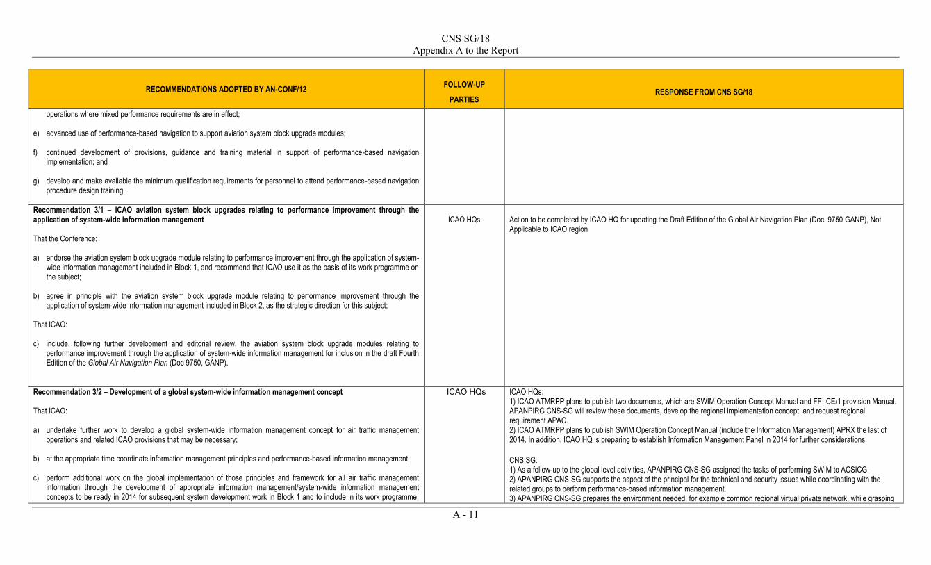
CNS SG/18 Appendix A to the Report
A - 11
RECOMMENDATIONS ADOPTED BY AN-CONF/12 FOLLOW-UP
PARTIES RESPONSE FROM CNS SG/18
operations where mixed performance requirements are in effect; e) advanced use of performance-based navigation to support aviation system block upgrade modules; f) continued development of provisions, guidance and training material in support of performance-based navigation
implementation; and g) develop and make available the minimum qualification requirements for personnel to attend performance-based navigation
procedure design training.
Recommendation 3/1 – ICAO aviation system block upgrades relating to performance improvement through the application of system-wide information management That the Conference: a) endorse the aviation system block upgrade module relating to performance improvement through the application of system-
wide information management included in Block 1, and recommend that ICAO use it as the basis of its work programme on the subject;
b) agree in principle with the aviation system block upgrade module relating to performance improvement through the
application of system-wide information management included in Block 2, as the strategic direction for this subject; That ICAO: c) include, following further development and editorial review, the aviation system block upgrade modules relating to
performance improvement through the application of system-wide information management for inclusion in the draft Fourth Edition of the Global Air Navigation Plan (Doc 9750, GANP).
ICAO HQs
Action to be completed by ICAO HQ for updating the Draft Edition of the Global Air Navigation Plan (Doc. 9750 GANP), Not Applicable to ICAO region
Recommendation 3/2 – Development of a global system-wide information management concept That ICAO: a) undertake further work to develop a global system-wide information management concept for air traffic management
operations and related ICAO provisions that may be necessary; b) at the appropriate time coordinate information management principles and performance-based information management; c) perform additional work on the global implementation of those principles and framework for all air traffic management
information through the development of appropriate information management/system-wide information management concepts to be ready in 2014 for subsequent system development work in Block 1 and to include in its work programme,
ICAO HQs ICAO HQs: 1) ICAO ATMRPP plans to publish two documents, which are SWIM Operation Concept Manual and FF-ICE/1 provision Manual. APANPIRG CNS-SG will review these documents, develop the regional implementation concept, and request regional requirement APAC. 2) ICAO ATMRPP plans to publish SWIM Operation Concept Manual (include the Information Management) APRX the last of 2014. In addition, ICAO HQ is preparing to establish Information Management Panel in 2014 for further considerations.
CNS SG: 1) As a follow-up to the global level activities, APANPIRG CNS-SG assigned the tasks of performing SWIM to ACSICG. 2) APANPIRG CNS-SG supports the aspect of the principal for the technical and security issues while coordinating with the related groups to perform performance-based information management. 3) APANPIRG CNS-SG prepares the environment needed, for example common regional virtual private network, while grasping

CNS SG/18 Appendix A to the Report
A - 12
RECOMMENDATIONS ADOPTED BY AN-CONF/12 FOLLOW-UP
PARTIES RESPONSE FROM CNS SG/18
specific activities tailored at coordinating system-wide information management deployment at a local, regional and global level;
d) update the information management/system-wide information management (IM/SWIM) working arrangements; That States and stakeholders: e) work together to demonstrate how system-wide information management capabilities and functions will meet the needs of
the future air traffic management system.
the local characteristic. Furthermore, the integrated nature of SWIM may need to identify dependencies with ATM and MET SGs. 4) From ACSICG/1: APANPIRG has reviewed the SWIM CONOPS. APANPIRG through ATNICG has studied and A cost-benefit analysis for CRV was developed. A cost-benefit analysis for IMS/SWIM at regional level is planned to be developed. (Conclusion C 23/21). Action proposed: expedite the cost-benefit analysis for IMS/SWIM Action proposed: APANPIRG to initiate a Task “Develop SWIM APAC implementation framework”. While this task can initially report to APANPIRG through ACSICG and CNS/SG, the integrated nature of SWIM may need to integrate ATM and MET SG States through CNS SG and ACSICG to: 1) Evaluate SWIM service to support ATM evolution. 2) Coordinate among States and IOs to demonstrate how SWIM capabilities and functions could meet the needs of the future ATM. 3) Participate as an active member of the Task Force set up under APANPIRG Decision 24/32 to collaborate with States and IOs to study the development of a common Regional Virtual Private Network (VPN) for aeronautical information exchange, which provides a backbone infrastructure for future implementation of SWIM, and demonstrates how SWIM capabilities and functions can support the future ATM. 4) Participate actively in the development of ICAO Meteorological Information Exchange Model (IWXXM) by ICAO and World Meteorological Organization (WMO). 5) Address by the National Airspace and Air Navigation Plan, and the Aeronautical Information Service to Aeronautical Information Management (AIS-AIM) Plan. 6) Establish the System Wide Information Management (SWIM) Program to implement a set of Information Technology (IT) principles in the NAS and provide users with relevant and commonly understandable information. 7) Develop the ICAO SWIM Operational Procedure adhering to the SWIM Concept Document developed by the ICAO ATMRPP. 8) Conduct a mini-global demonstration beginning in later 2014 which includes demonstration of SWIM service to international community.
Recommendation 3/3 – Development of ICAO provisions relating to system-wide information management That: a) under the leadership of ICAO, develop detailed technical specifications for system-wide information management in close
collaboration with the aviation community; b) detailed technical specifications for system-wide information management should be open and rely on generic international
standards to the extent possible; and c) ICAO undertake work to identify the security standards and bandwidth requirements for system-wide information
management.
APANPIRG ICAO RO: a) APANPIRG CNS-SG is recognizing that the definition of aviation community depends on regional characteristic, therefore APANPIRG CNS-SG conduct the leadership in order to achieve the agreement in whole member States, such as the CRV project. b) APANPIRG CNS-SG assigned the tasks for performing SWIM to ACSICG that have the responsibility for the implementation of current aeronautical communications (AFTN/AMHS). ACSICG develops the detailed technical specification for SWIM under the opened discussion and using SWIM technical specification (Concept Document and/or Technical manual) developed by ATMRPP. The Regional SWIM Technical Guideline and implementation plan is subjected for APANPIRG adoption through CNS-SG. c) The bandwidth is already considered through the CRV project as the issue should be improved. Concerning to the security issue, APANPIRG CNS-SG assigned it as one of the tasks for ACSICG. From ACSICG/1: The Task “Generate User Requirements” of CRV project is expected to address security standards and bandwidth requirements for all data conveyed, including SWIM data. Yet this will be early requirements as not all the provisions

CNS SG/18 Appendix A to the Report
A - 13
RECOMMENDATIONS ADOPTED BY AN-CONF/12 FOLLOW-UP
PARTIES RESPONSE FROM CNS SG/18
and guidance about SWIM will be available in 2014-2015. Action proposed: APANPIRG to include identification of security standards and bandwidth requirements for SWIM in the Statement of Work of the Task “Develop SWIM APAC implementation framework”.
Recommendation 3/4 – State and industry and industry support of system-wide information management a) industry support the transition towards system-wide information management by providing appropriate systems supporting
automation and the exchange of all relevant air traffic management data in a globally standardized manner; and b) States and all relevant stakeholders contribute to further development and harmonization of performance-based information
management.
ACSICG CNS SG: a) ACSICG utilizes the System Oriented Architecture (SOA) to ensure the globally standardized environment to corroborate with any stakeholders in SWIM including industries by developing the regional SWIM concept. From ACSICG/1: Action proposed: APANPIRG to include performance-based information management for SWIM in the Statement of Work of the Task “Develop SWIM APAC implementation framework”. STATES: b) - support the transition to SWIM and is working in ICAO and other for to develop SWIM. - support of SWIM under the ICAO ASBU Block 1 initiatives, and will contribute to further development and harmonization of performance- based information management. - procured a new Aeronautical Information Management System supporting exchange of air traffic management data based on AIXM 4.5 standards. The system is planned to be put into operational use towards end 2014. - developed a roadmap for AIS- AIM transition harmonized with the ICAO roadmap on AIS- AIM transition to provide foundation for future implementation of SWIM. - participated actively in the development of IWXXM by ICAO and World Meteorological Organization. - To prepare for the transition to SWIM, the local MET authority is arranging trial offline exchange of OPMET data in XML code form with other MET authorities. - participated actively in the Expert Team on Meteorological Services to ATM and Meteorological Information Exchange (ET- M&M) of WMO. - host the website on behalf of the Commission for Aeronautical Meteorology (CAeM) of WMO showcasing demonstration projects to facilitate further development and harmonization of performance- based information management. - support toward standardizing the air traffic management data by the research and development with industries. - will be conducted for the performance- based information management. - Addressed by the National Airspace and Air Navigation Plan, and the Aeronautical Information Service to Aeronautical Information Management (AIS-AIM) Plan. - support the transition towards SWIM. - will participate in appropriate forums and contribute to further development and harmonization of performance- based information management. - working with ICAO and other international organizations to support international transition to SWIM.
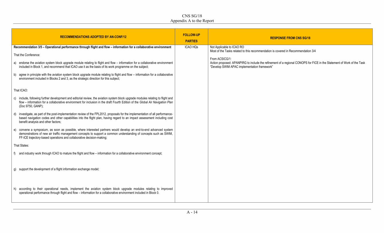
CNS SG/18 Appendix A to the Report
A - 14
RECOMMENDATIONS ADOPTED BY AN-CONF/12 FOLLOW-UP
PARTIES RESPONSE FROM CNS SG/18
Recommendation 3/5 – Operational performance through flight and flow – information for a collaborative environment That the Conference: a) endorse the aviation system block upgrade module relating to flight and flow – information for a collaborative environment
included in Block 1, and recommend that ICAO use it as the basis of its work programme on the subject; b) agree in principle with the aviation system block upgrade module relating to flight and flow – information for a collaborative
environment included in Blocks 2 and 3, as the strategic direction for this subject; That ICAO: c) include, following further development and editorial review, the aviation system block upgrade modules relating to flight and
flow – information for a collaborative environment for inclusion in the draft Fourth Edition of the Global Air Navigation Plan (Doc 9750, GANP);
d) investigate, as part of the post-implementation review of the FPL2012, proposals for the implementation of all performance-
based navigation codes and other capabilities into the flight plan, having regard to an impact assessment including cost benefit analysis and other factors;
e) convene a symposium, as soon as possible, where interested partners would develop an end-to-end advanced system
demonstrations of new air traffic management concepts to support a common understanding of concepts such as SWIM, FF-ICE trajectory-based operations and collaborative decision-making;
That States: f) and industry work through ICAO to mature the flight and flow – information for a collaborative environment concept; g) support the development of a flight information exchange model; h) according to their operational needs, implement the aviation system block upgrade modules relating to improved
operational performance through flight and flow – information for a collaborative environment included in Block 0.
ICAO HQs Not Applicable to ICAO RO Most of the Tasks related to this recommendation is covered in Recommendation 3/4 From ACSICG/1: Action proposed: APANPIRG to include the refinement of a regional CONOPS for FICE in the Statement of Work of the Task “Develop SWIM APAC implementation framework”

CNS SG/18 Appendix A to the Report
A - 15
RECOMMENDATIONS ADOPTED BY AN-CONF/12 FOLLOW-UP
PARTIES RESPONSE FROM CNS SG/18
Recommendation 3/6 – ICAO aviation system block upgrades relating to service improvement through aeronautical information management as well as digital air traffic management information That the Conference: a) endorse the aviation system block upgrade module relating to service improvement through the integration of digital air
traffic management information included in Block 1 and recommend that ICAO use it as the basis of its work programme on the subject;
That ICAO: b) include, following further development and editorial review, the aviation system block upgrade modules relating to service
improvement through digital aeronautical information management as well as integration of digital air traffic management information in the draft in the draft Fourth Edition of the Global Air Navigation Plan (Doc 9750, GANP);
That States: c) according to their operational needs, implement the aviation system block upgrade module relating to service improvement
through digital aeronautical information management included in Block 0.
ICAO HQs Not Applicable to ICAO RO Most of the Tasks related to this recommendation is covered in Recommendations 3/3 and 3/4
Recommendation 3/7 – ICAO provisions relating to service improvement through aeronautical information management as well as digital air traffic management information That ICAO: a) expedite the development of relevant Standards facilitating the transition of aeronautical information service to aeronautical
information management and the implementation of system-wide information management taking into account the work accomplished in State programmes; and
b) as a matter of urgency, to translate and make available the necessary Standards and guidance material to facilitate the
global transition from aeronautical information service to aeronautical information management.
ICAO HQs Not Applicable to ICAO RO

CNS SG/18 Appendix A to the Report
A - 16
RECOMMENDATIONS ADOPTED BY AN-CONF/12 FOLLOW-UP
PARTIES RESPONSE FROM CNS SG/18
Recommendation 3/8 – State actions relating to service improvement through aeronautical information management as well as digital air traffic management information That States: a) accelerate transition from aeronautical information service to aeronautical information management by implementing a fully
automated digital aeronautical data chain; b) implement necessary processes to ensure the quality of aeronautical data and information from the origin to the end users; c) engage in intraregional and interregional cooperation for an expeditious transition from aeronautical information service
(AIS) to aeronautical information management (AIM) in a harmonized manner and to using digital data exchange and consider regional or subregional AIS databases as an enabler for the transition from AIS to AIM; and
d) review their NOTAM publication procedures, provide appropriate guidance to NOTAM originators and ensure adequate
oversight of the NOTAM publication process is conducted.
ATM/SG Seamless ATM Planning Group
(disbanded)
Relevant actions haves been included in the APAC Seamless ATM Plan.
Recommendation 3/9 – Review of NOTAM system and development of options for replacement That ICAO initiate a review of the current NOTAM system, building further on the digital NOTAM activities, including the development of options for a replacement system that would enable web-based applications and compliant with the system-wide information management principles that are being developed for the air traffic management system.
ICAO HQs Not Applicable to ICAO RO This task is under IMP. From ACSICG/1: This recommendation has an indirect impact. NOTAM may be conveyed upon SWIM in the future. NOTAM have to be considered by the Task “Develop SWIM APAC implementation framework”.
Recommendation 4/1 – Efficient management of airspace and improved flow performance through collaborative decision-making That the Conference: a) endorse the aviation system block upgrade modules relating to network operations included in Block 1 and recommend that
ICAO use them as the basis of its work programme on the subject; b) agree in principle with the aviation system block upgrade modules relating to network operations included in Blocks 2 and 3
as the strategic direction for this subject; That ICAO:
AN-CONF
ICAO HQ
CNS SG: With our previous effort in putting CDM as one of the regional priorities and targets, which is endorsed in the WP/05, we have put CDM as an essential element for ATFM which to be achieved by November 2015. CDM in some environments may be improved by separate organisations having a common view of the traffic. ADS-B data sharing between organisations may support better CDM. (From ADS-B SITF/13)

CNS SG/18 Appendix A to the Report
A - 17
RECOMMENDATIONS ADOPTED BY AN-CONF/12 FOLLOW-UP
PARTIES RESPONSE FROM CNS SG/18
c) include, following further development and editorial review, the aviation system block upgrade modules relating to network operations in the draft Fourth Edition of the Global Air Navigation Plan (Doc 9750, GANP);
d) include in its work programme the future standardization of all elements to support the collaborative decision-making
process underlying the air traffic control (ATC)-air traffic flow management (ATFM) integration as well as of the technical exchanges between ATFM and ATC;
e) develop and incorporate into the ICAO Manual on Collaborative Air Traffic Flow Management (Doc 9971) implementation
guidance on Airport-CDM and provisions on air traffic flow management data exchange format including trajectory information;
f) develop and execute global communications, roll-out and training plan for the ICAO Manual on Collaborative Air Traffic
Flow Management (Doc 9971); and g) develop further provisions and guidance on flexible use of airspace principles for future use and in preparation for future 4D
trajectory-based airspace management. That States: h) accelerate the implementation of collaborative decision-making processes in the provision of services at the regional level,
being guided by the principles set forth in the Manual on Collaborative Air Traffic Flow Management (Doc 9971) and the Manual on Flight and Flow – Information for a Collaborative Environment (Doc 9965);
i) according to their operational needs, implement the aviation system block upgrade modules relating to network operations included in Block 0.
States
Recommendation 4/2 – ICAO aviation system block upgrades relating to ground surveillance using automatic dependent surveillance – broadcast/multilateration, air traffic situational awareness, interval management and airborne separation. That the Conference: a) endorse the aviation system block upgrade modules relating to interval management included in Block 1 and recommend
that ICAO use them as the basis of its work programme on the subject; b) agree in principle to the aviation system block upgrade modules relating to airborne separation included in Block 2 as the
strategic direction for this subject;
AN-CONF
CNS SG: From ADS-B SITF/13: APANPIRG supports and prioritizes deployment of ASBU B0-ASUR (Initial Capability for Ground Surveillance) using ADS-B OUT technology. Initially, this serves the needs of ground surveillance but will place the region in a good position for ADS-B IN applications listed in Block 0, 1 and 2. APANPIRG may consider to enhance safety & efficiency in the region by supporting further deployment of ADS-B IN capabilities available in Block 0, including :- -B0-ASEP Air Traffic Situational Awareness (ATSA) -B0-OPFL Improved Access to Optimum Flight Levels Through Climb/Descent Procedures Using ADS-B (ITP) The Seamless ATM Plan recognises that B0-ASUR is a priority 1 element
States:

CNS SG/18 Appendix A to the Report
A - 18
RECOMMENDATIONS ADOPTED BY AN-CONF/12 FOLLOW-UP
PARTIES RESPONSE FROM CNS SG/18
That ICAO: c) include, following further development and editorial review, the aviation system block upgrade modules relating to airborne
separation in the Appendices to the draft Fourth Edition of the Global Air Navigation Plan (Doc 9750, GANP); d) agree in principle to review the concepts and terminology of the “airborne separation” concepts involving controllers
assigning tasks to flight crews, with controllers able to apply different, risk-based separation minima for properly equipped ADS-B IN aircraft;
e) in the development of provisions, acknowledge the relationship between airborne separation and airborne collision
avoidance system; f) modify aviation system block upgrade (ASBU) Module B2-85 to reflect d) and e), modify ASBU Module B2-101 to reflect f);
and g) agree in principle to review the concepts and terminology supporting B2-85 “airborne separation” and amend the module
accordingly. That States: h) according to their operational needs, to implement the aviation system block upgrade modules relating to ground
surveillance, improved air traffic situational awareness and improved access to optimum flight levels included in Block 0.
ICAO HQ
STATES
Most states has adopted ADS-B and MLAT on airport surface to enhance safety and efficiency of airport operations. States were also requested to consider the cost effectiveness of using forward fit mandates (requiring new airframes to be equipped) when planning the transition to ADS-B.
Recommendation 4/3 – ICAO aviation system block upgrades relating to airborne collision avoidance systems and ground-based safety nets That the Conference: a) endorse the aviation system block upgrade module relating to ground-based safety nets included in Block 1 and
recommend that ICAO use it as the basis of its work programme on the subject; b) agree in principle to the aviation system block upgrade module relating to airborne collision avoidance systems included in
Block 2, as the basis of the strategic direction for this subject;
APANPIRG CNS SG: From ADS-B SITF/13: Depending on whether there will be operational benefits for States and the region, APANPIRG could further improve safety in the region by encouraging States in the region to implement: - B0-SNET Increased Effectiveness of Ground Based Safety Nets. States in the region could agree, based on ALARP principles, to replace / upgrade their ATC systems to include Short-term conflict alert (STCA) using data from available surveillance sensors such as Radar, WAM and ADS-B - Area proximity warning (APW) - Minimum safe altitude warning (MSAW) - Route adherence monitoring (RAM) - Cleared level adherence monitoring (CLAM)

CNS SG/18 Appendix A to the Report
A - 19
RECOMMENDATIONS ADOPTED BY AN-CONF/12 FOLLOW-UP
PARTIES RESPONSE FROM CNS SG/18
That ICAO: c) include, following further development and editorial review, the aviation system block upgrade modules relating to airborne
collision avoidance systems and ground-based safety nets in the Appendices to the draft Fourth Edition of the Global Air Navigation Plan (Doc 9750, GANP);
d) adopt a coordinated approach towards reviewing and developing as necessary Standards and Recommended Practices,
Procedures for Air Navigation Services and guidance material for ground-based and airborne safety nets, taking into account careful evaluation and validations of the effects on safety and performance of downlinking airborne collision avoidance system (ACAS) Resolution Advisories (RAs) to controllers;
e) when considering Standards and Recommended Practices for airborne collision avoidance system (ACAS) downlink, to
emphasize the significant amount of training material already existing and the importance of increased pilot and air traffic controller training on the responsibilities and requirements to reacting correctly to ACAS RA events and then communicating;
f) develop an ICAO Manual for Ground-based Safety Nets, which includes provision for tools for validation and certification of
these; g) incorporate the new generation of airborne collision avoidance system (ACAS X) into its work programme; h) encourage the Federal Aviation Administration to work with other States with the capacity and capability to do so, in the
development of new generation of airborne collision avoidance system (ACAS X); That States:
i) according to their operational needs, to implement the aviation system block upgrade modules relating to airborne collision avoidance systems and ground based safety nets included in Block 0.
- Selected level mismatch (using Mode C, Mode S and ADS-B data). The Asia/Pacific Seamless ATM Plan has set target date for implementation of the ground-based safety nets by PASL Phase II (expected implementation by November 2018). This could be done at the same time as upgrading the ATC system to support ADS-B. This recommendation supports ACAS-X which uses ADS-B to improve ACAS performance. An ADS-B fitment mandate across the APAC region would improve the effectiveness of these ACAS-X capabilities. The Seamless ATM recognises B0-SNET as a priority 2 element and also B0-ACAS as a priority 2 element, noting the requirement for forward fit from 01 January 2014 and retrofit by 01 January 2017 of aircraft ACAS installations with an upgraded collision avoidance logic known as TCAS V7.1
Recommendation 4/4 – Positioning and tracking over oceanic and remote areas, and flight data triggered transmission That ICAO: a) continue the evaluation of the necessary changes in the field of transmission of flight data, bearing in mind the cost
associated with any of these changes as well as the need to improve search and rescue operations; and b) develop suitable proposals for the amendment of ICAO documents, as necessary.
CNS/SG ADS-B-SITF
N.A

CNS SG/18 Appendix A to the Report
A - 20
RECOMMENDATIONS ADOPTED BY AN-CONF/12 FOLLOW-UP
PARTIES RESPONSE FROM CNS SG/18
Recommendation 4/5 – Civil/military coordination / cooperation and sharing of airspace That States: a) planning and implementation regional groups, and ICAO to analyse the benefits that could be achieved through improved
civil/military cooperation and sharing of the airspace serving international traffic flows and express the results of this analysis in terms of:
1) capacity increases and reduction in routine delays as measured by traffic volumes on major traffic flows; 2) document fuel savings and emission reductions through the use of the fuel savings estimation tools; and 3) other additional benefits;
b) based on the analysis made by States, planning and implementation regional groups, and ICAO, urge States to develop
plans to implement improvements for the cooperative use of airspace related to the top areas of opportunity and establish concrete targets using tools already available for this purpose;
c) in relation to international traffic flows, for each ICAO region urge the planning and implementation regional groups and
their associated States to identify the top areas of opportunity that could benefit the most from improvements in civil/military cooperation and sharing of the airspace and develop concrete targets for improvement;
That ICAO: d) develop a set of criteria or metrics to enable objective measurement of progress in civil/military cooperation; and e) continue to develop guidance material for States on the flexible use of their airspace, airspace design, interoperability and
integration of humanitarian assistance flights in crisis response scenarios in their airspaces to facilitate integrated use of the airspace.
STATES
ICAO HQs
CNS SG: From ADS-B SITF/13: APAC could consider encouraging the sharing of ADS-B data between civilian and military authorities, including those from neighbouring States, to support a common view of the airspace. Engagement of the military in ADS-B could lead to improved co-ordination and increased airspace sharing. Use of ADS-B data provided by the civilian authority could fill surveillance gaps in the military system (at least as far as civilian traffic is concerned). Guidance materials on advice to military authorities regarding ADS-B data sharing has been developed and published. States: Reported states have established measures to promulgate civil/military coordination on optimising the sharing use of airspace.
Recommendation 4/6 – ICAO aviation system block upgrades relating to integration of remotely piloted aircraft into non-segregated airspace That the Conference: a) endorse the aviation system block upgrade module relating to remotely piloted aircraft included in Block 1 and recommend
that ICAO use it as the basis of its work programme on the subject;
AN-CONF
CNS SG: From ADS-B SITF/13: According to ICAO Annex 2 – Rules of the Air, “remotely piloted aircraft” is defined as “an unmanned aircraft which is piloted from a remote pilot station”. A key to the support of remotely piloted aircraft in civilian airspace is surveillance. It could be appropriate to insist that all new registered remotely piloted aircraft operating in civilian airspace are required to have appropriate ADS-B OUT or MODE-S capability.

CNS SG/18 Appendix A to the Report
A - 21
RECOMMENDATIONS ADOPTED BY AN-CONF/12 FOLLOW-UP
PARTIES RESPONSE FROM CNS SG/18
b) agree in principle to the aviation system block upgrade modules relating to remotely piloted aircraft included in Blocks 2 and 3 as the strategic direction for this subject;
That ICAO: c) as a matter of urgency, develop the necessary regulatory framework in its entirety to support the integration of remotely
piloted aircraft into non-segregated airspace and at aerodromes including and clearly showing the scope of such regulation; d) investigate the need for and scope of oversight of datalinks related to command, control and air traffic control
communications for remotely piloted aircraft systems; e) include, following further development and editorial review, the aviation system block upgrade modules relating to the
integration of remotely piloted aircraft into non segregated airspace in the Appendices to the draft Fourth Edition of the Global Air Navigation Plan (Doc 9750, GANP);
That States: f) be cognizant of the recent amendments to Annexes 2 — Rules of the Air and 7 — Aircraft Nationality and Registration
Marks related to remotely piloted aircraft systems and to support the continuation of this work at ICAO; g) work closely with ICAO and each other to ensure harmonization of provisions if they have an urgent need to accommodate
remotely piloted aircraft system operations.
ICAO HQs
STATES
The APANPIRG publication of such a rule could avoid the costs of an expensive retrofit in the future. The time is right for ADS-Bf SITF to deliberate such a strategic move. States: Many of the reported states have been actively participating into ICAO Unmanned Aerial Systems Study Group and supporting the ICAO ‘s work for a harmonised scheme for RPAS operations.
Recommendation 4/7 – ICAO aviation system block upgrades relating to meteorological information
That the Conference:
a) endorse the aviation system block upgrade module relating to meteorological information included in Block 1, including the addition of the provision of information on space weather, and recommend that ICAO uses it as the basis of its work programme on the subject;
b) agree in principle the aviation system block upgrade module relating to meteorological information included in Block 3 as the strategic direction for this subject;
That ICAO: c) include, following further development and editorial review, the aviation system block upgrade modules relating to
meteorological information in the draft Fourth edition of the Global Air Navigation Plan (Doc 9750, GANP);
MET/SG N/A for CNS SG. The recommendation should be under MET SG to consider.

CNS SG/18 Appendix A to the Report
A - 22
RECOMMENDATIONS ADOPTED BY AN-CONF/12 FOLLOW-UP
PARTIES RESPONSE FROM CNS SG/18
d) undertake the development of the air traffic management meteorological information integration plan and an associated roadmap by a cross-disciplinary group of experts;
e) work on defining the meteorological information exchange model as an enabler for system-wide information management; f) invite the next Meteorology Divisional Meeting, held in coordination with the World Meteorological Organization, to develop
initial provisions in Annex 3 — Meteorological Service for International Air Navigation relating to the aviation system block upgrade modules concerning meteorological information and f) above, and to develop a long-term strategy to support their further development and full implementation;
That States: g) according to their operational needs, to implement the aviation system block upgrade module relating to meteorological
information included in Block 0, including the addition of the provision of OPMET information; h) work together in the implementation of the aviation system block upgrades relating to meteorological information and to
increase investment in education and training.
Recommendation 4/8 – Crisis coordination arrangements and contingency plans That ICAO: a) consider how crisis coordination arrangements for potentially disruptive events, similar to that used for volcanic eruptions,
could be established on a regional basis; and b) and regional offices continue to support the development, promulgation, maintenance of contingency plans, including the
holding of practical exercises, in preparedness for potentially disruptive events, including those events that may adversely impact aviation safety.
ICAO HQs N/A for CNS SG. The recommendation should be under ATM SG to consider.
Recommendation 5/1 – Improved operations through enhanced airspace organization and routing Considering that performance-based navigation (PBN) is one of ICAO’s highest air navigation priorities and the potential benefits achievable through creation of additional capacity with PBN: That States: a) implement performance-based navigation in the en-route environment;
CNS/SG PBN/TF
(disbanded)
a) States implement PBN in the en-route environment. PBN ICG is planned to be established by APANPIRG/25 to support and keep promoting en route PBN. b) States fully assess the operational, safety, performance and cost implications of a harmonization of transition altitude and, if the benefits are proven to be appropriate, undertake further action on a national and (sub) regional basis a first step towards a globally harmonized transition altitude; c) States and PIRGs take advantage of improved models for inter-regional coordination and collaboration to achieve seamless

CNS SG/18 Appendix A to the Report
A - 23
RECOMMENDATIONS ADOPTED BY AN-CONF/12 FOLLOW-UP
PARTIES RESPONSE FROM CNS SG/18
b) fully assess the operational, safety, performance and cost implications of a harmonization of transition altitude and, if the benefits are proven to be appropriate, undertake further action on a national and (sub) regional basis a first step towards a globally harmonized transition altitude;
c) take advantage of improved models for inter-regional coordination and collaboration to achieve seamless air traffic
management and more optimum routes through the airspace; d) through the planning and implementation regional groups improve their methods of coordination to increase implementation
of en-route performance-based navigation in order to achieve more optimum routes through the airspace; That ICAO: e) encourage the planning and implementation regional groups to support the early deployment of performance-based
navigation in accordance with Assembly Resolution 37-11; f) support, through development of a framework that capitalizes, builds on, and promotes demonstration activities which
confirm the benefits of performance-based navigation as an enabler of more efficient operations in the en-route phase of flight; and
g) that avionics incorporate fixed radius transition functionality to support closer spacing of performance-based navigation
routes and improve airspace capacity.
air traffic management and more optimum routes through the airspace; d) States and PIRGs improve their methods of coordination to increase implementation of en-route performance-based navigation in order to achieve more optimum routes through the airspace; e) and f) Note. g) Note e/ and f/ The Asia/Pacific Seamless ATM Plan contains extensive expectations to implement PBN based and performance-based airspace within the Asia/Pacific (incorporating the Asia/Pacific Regional PBN Plan). The Asia/Pacific Regional Sub-Office is actively studying proposals to implement improved ATS structures using PBN as a key enabler.
Recommendation 5/2 – ICAO aviation system block upgrades relating to trajectory based operations That the Conference: a) endorse the aviation system block upgrade module relating to trajectory-based operations included in Block 1 and ICAO
use it as the basis of its work programme on the subject; b) agree in principle with the aviation system block upgrade module relating to 4D trajectory-based operations included in
Block 3 as the strategic direction for this subject; That ICAO: c) include, following further development and editorial review, the aviation system block upgrade module relating to 4D
trajectory-based operations in the draft Fourth Edition of the Global Air Navigation Plan (Doc 9750, GANP); That States:
CNS SG: support development of SARPs and guidance material related to TBO States: Implement, according to their operational needs, the ASBU module relating to TBO included in Block 0.
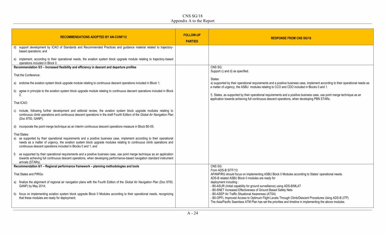
CNS SG/18 Appendix A to the Report
A - 24
RECOMMENDATIONS ADOPTED BY AN-CONF/12 FOLLOW-UP
PARTIES RESPONSE FROM CNS SG/18
d) support development by ICAO of Standards and Recommended Practices and guidance material related to trajectory-based operations; and
e) implement, according to their operational needs, the aviation system block upgrade module relating to trajectory-based
operations included in Block 0.
Recommendation 5/3 – Increased flexibility and efficiency in descent and departure profiles That the Conference: a) endorse the aviation system block upgrade module relating to continuous descent operations included in Block 1; b) agree in principle to the aviation system block upgrade module relating to continuous descent operations included in Block
2; That ICAO: c) include, following further development and editorial review, the aviation system block upgrade modules relating to
continuous climb operations and continuous descent operations in the draft Fourth Edition of the Global Air Navigation Plan (Doc 9750, GANP);
d) incorporate the point merge technique as an interim continuous descent operations measure in Block B0-05; That States: e) as supported by their operational requirements and a positive business case, implement according to their operational
needs as a matter of urgency, the aviation system block upgrade modules relating to continuous climb operations and continuous descent operations included in Blocks 0 and 1; and
f) as supported by their operational requirements and a positive business case, use point merge technique as an application
towards achieving full continuous descent operations, when developing performance-based navigation standard instrument arrivals (STARs).
CNS SG: Support c) and d) as specified. States: e) supported by their operational requirements and a positive business case, implement according to their operational needs as a matter of urgency, the ASBU modules relating to CCO and CDO included in Blocks 0 and 1. f) States, as supported by their operational requirements and a positive business case, use point merge technique as an application towards achieving full continuous descent operations, when developing PBN STARs.
Recommendation 6/1 – Regional performance framework – planning methodologies and tools That States and PIRGs: a) finalize the alignment of regional air navigation plans with the Fourth Edition of the Global Air Navigation Plan (Doc 9750,
GANP) by May 2014; b) focus on implementing aviation system block upgrade Block 0 Modules according to their operational needs, recognizing
that these modules are ready for deployment;
CNS SG: From ADS-B SITF/13: APANPIRG should focus on implementing ASBU Block 0 Modules according to States' operational needs. ADS-B related ASBU Block 0 modules are ready for deployment including : - B0-ASUR (Initial capability for ground surveillance) using ADS-B/MLAT - B0-SNET Increased Effectiveness of Ground Based Safety Nets - B0-ASEP Air Traffic Situational Awareness (ATSA) - B0-OPFL Improved Access to Optimum Flight Levels Through Climb/Descent Procedures Using ADS-B (ITP) The Asia/Pacific Seamless ATM Plan has set the priorities and timeline in implementing the above modules.

CNS SG/18 Appendix A to the Report
A - 25
RECOMMENDATIONS ADOPTED BY AN-CONF/12 FOLLOW-UP
PARTIES RESPONSE FROM CNS SG/18
c) use the electronic regional air navigation plans as the primary tool to assist in the implementation of the agreed regional planning framework for air navigation services and facilities;
d) involve regulatory and industry personnel during all stages of planning and implementation of aviation system block
upgrade modules; e) develop action plans to address the identified impediments to air traffic management modernization as part of aviation
system block upgrade planning and implementation activities; That ICAO: f) considers how the continuous monitoring approach to safety oversight maps to the evaluation of Member States’ safety
oversight capabilities concerning aviation system block upgrades g) review the current amendment process to the Regional Air Navigation Plans (ANPs) and recommend improvements to
increase efficiencies related to the approval and maintenance of the data in the regional ANPs; h) develop guidance material, on the basis of best practices employed worldwide, for the regional/local deployment of new
ATM technologies, required procedures, operational approvals and continue to support States in the implementation of the aviation system block upgrades;
i) identify the issues, funding, training and resource requirements necessary to support a safety framework that would lay the
foundation for successful implementation the aviation system block upgrades; j) develop, together with industry and stakeholders, an engagement strategy to address the economic and institutional
impediments to implementation of the aviation system block upgrades; k) develop a mechanism for sharing of best practices for the aviation system block upgrade implementation; and l) define a methodology to ensure interregional and global harmonization of air navigation services through ANRF reporting in
an effective and timely manner, and consider the employment of interregional and multi-regional fora.
States: a): States through APANPIRG and its sub groups to finalize the alignment of regional air navigation plans with the Fourth Edition of the Global Air Navigation Plan (Doc 9750, GANP) by May 2014; b): States through APANPIRG and its sub groups to focus on implementing ASBU Block 0 Modules according to their operational needs. c) States through APANPIRG and its sub groups to use the electronic regional air navigation plans as the primary tool to assist in the implementation of the agreed regional planning framework for air navigation services and facilities; d) States through APANPIRG and its sub groups to involve regulatory and industry personnel during all stages of planning and implementation of ASBU modules; e) States through APANPIRG and its sub groups to develop action plans to address the identified impediments to air traffic management modernization as part of aviation system block upgrade planning and implementation activities;

CNS SG/18 Appendix A to the Report
A - 26
RECOMMENDATIONS ADOPTED BY AN-CONF/12 FOLLOW-UP
PARTIES RESPONSE FROM CNS SG/18
Recommendation 6/2 – Guidelines on service priority That: a) ICAO develop an appropriate set of operational and economic incentive principles to allow early benefits of new
technologies and procedures, as described in the aviation system block upgrade modules, to support operational improvements, while maximizing safety, capacity and overall system efficiency; and
b) States and international organizations contribute to this work.
Not Applicable to ICAO RO. The intention of this recommendation is covered by specific recommendations and projects (CRV, STARS, SWIM, etc.).The priority of each specific task/project has been identified.
Yet, from ADS-B SITF/13: APANPIRG could obtain some quick wins by promulgating a view that aircraft equipped with ADS-B have service priority over those that don’t (i.e. better equipped, better served). This will increase the business case for equipage. The above has already been reflected in the ADS-B mandate published by States (e.g. non-ADS-B equipped aircraft is required to fly outside the ADS-B airspace)
Recommendation 6/3 – Assessment of economic, financial and social implications of air traffic management modernization and aviation system block upgrades deployment That ICAO: a) undertake work toward developing a network-wide operational improvement level assessment for global use, which should
include the development of standard values and processes for economic evaluations; b) take the relevant conclusions from the AN-Conf/12, regarding economic, financial and social aspects of the aviation system
block upgrades, to the Sixth Air Transport Conference with the aim of developing solutions which would support a safe and sustainable air navigation system;
That States: c) conduct their economic, financial and social analyses in a closely coordinated manner with relevant ATM stakeholders in
view of their diverse position of involvement in the implementation of aeronautical systems.
ICAO HQs CNS SG supports ICAO’s actions.

CNS SG/18 Appendix A to the Report
A - 27
RECOMMENDATIONS ADOPTED BY AN-CONF/12 FOLLOW-UP
PARTIES RESPONSE FROM CNS SG/18
Recommendation 6/4 – Human performance That ICAO: a) integrate human performance as an essential element for the implementation of ASBU modules for considerations in the
planning and design phase of new systems and technologies, as well as at the implementation phase, as part of a safety management approach. This includes a strategy for change management and the clarification of the roles, responsibilities and accountabilities of the aviation professionals involved;
b) develop guidance principles, guidance material and provisions, including SARPs as necessary, on ATM personnel training
and licensing including instructors and assessors, and on the use of synthetic training devices, with a view to promoting harmonization, and consider leading this effort with the support of States and industry;
c) develop guidance material on using field experience and scientific knowledge in human performance approaches through
the identification of human-centred operational and regulatory processes to address both current safety priorities and the challenges of future systems and technologies;
d) assess the impact of new technologies on competencies of existing aviation personnel, and prioritize and develop
competency-based provisions for training and licensing to attain global harmonization;
e) establish provisions for fatigue risk management for safety within air traffic services operations; f) develop guidance material on different categories of synthetic training devices and their respective usage; That States: g) provide human performance data, information and examples of operational and regulatory developments to ICAO for the
benefit of the global aviation community; h) support all ICAO activities in the human performance field through the contribution of human performance expertise and
resources; i) adopt airspace procedures, aircraft systems, and space-based/ground-based systems that take into account human
capabilities and limitations and that identify when human intervention is required to maintain optimum safety and efficiency; and
j) investigate methods to encourage adequate numbers of high quality aviation professionals of the future and ensure training
programmes are in line with the skills and knowledge necessary to undertake their roles within a changing industry.
APANPIRG CNS SG: Through APANPIRG and its sub groups a) – f) Address in general terms the various processes for the integration of human factors analysis in training, system development operational performance and safety. States generally concur and will consider recommended implementation. States: g) States will supply human factors data. Some data already available on line concerning flight deck operations and fatigue. h) States will support. Some examples given. i) States advise that they currently take into account human factors and limitations is systems and operational developments. Some examples of guidance material were given. j) States concur with the need to recruit and maintain highly trained and proficient aviation professionals. Several alternative approaches were identified to recruit new personnel. A common theme is to promote the aviation profession to upcoming generations during formative years.

CNS SG/18 Appendix A to the Report
A - 28
RECOMMENDATIONS ADOPTED BY AN-CONF/12 FOLLOW-UP
PARTIES RESPONSE FROM CNS SG/18
Recommendation 6/5 – ICAO work programme to support global navigation satellite system evolution That ICAO undertake a work programme to address: a) interoperability of existing and future global navigation satellite system constellations and augmentation systems, with
particular regard to the technical and operational issues associated with the use of multiple constellations; b) identification of operational benefits to enable air navigation service providers and aircraft operators to quantify these
benefits for their specific operational environment; and c) continued development of Standards and Recommended Practices and guidance material for existing and future global
navigation satellite system elements and encouraging the development of industry standards for avionics.
ICAO HQs CNS SG supports ICAO’s actions. States: a)-c) These recommendations require ICAO actions only. Contributions to these actions can be done at a global level of ICAO. States are contributing to the groups/panels at a global level of ICAO. States that operate SBAS systems in this region (India, Japan, and USA) participate in the SBAS Interoperability Working Group to ensure the interoperability between SBAS systems.
Recommendation 6/6 – Use of multiple constellations That States, when defining their air navigation strategic plans and introducing new operations: a) take advantage of the improved robustness and availability made possible by the existence of multiple global navigation
satellite system constellations and associated augmentation systems; b) publish information specifying the global navigation satellite system elements that are approved for use in their airspace; c) adopt a performance-based approach with regard to the use of global navigation satellite system (GNSS), and avoid
prohibiting the use of GNSS elements that are compliant with applicable ICAO Standards and Recommended Practices; d) carefully consider and assess if mandates for equipage or use of any particular global navigation satellite system core
constellation or augmentation system are necessary or appropriate; That aircraft operators: e) consider equipage with GNSS receivers able to process more than one constellation in order to gain the benefits
associated with the support of more demanding operations.
States
AIRCRAFT OPERATORS
Summaries from States: a) ADS-B Study and Implementation Task Force (ADS-B SITF) of APANPIRG finds that ADS-B robustness would be improved if multiple constellations could be used. Some of States/Administrations in APAC region note/consider the use of multi constellation GNSS. The United States will continue to provide GPS and its augmentations free of direct charges to all users for the foreseeable future. b) ADS-B SITF could develop guidance materials for use of multiple constellations to support ADS-B in APAC region, when aviation standard multi constellation GNSS equipment/systems become available, c) Some of States/Administrations in APAC region adopt performance based approach with multi constellation GNSS based on availability of Standards and Recommended Practices and related guidance materials. One of the States is looking at the new Medium Earth Orbit Search and Rescue (MEOSAR) as well as SATCOM voice which make use of multiple constellations. d) ADS-B SITF is in an opinion that APANPIRG could request states to ensure that future ADS-B and GNSS mandates do not rely on a single constellation. States/Administrations in APAC region will carefully consider and assess if mandates for equipage or use of any particular global navigation satellite system core constellation or augmentation system are necessary or appropriate. From ADS-B SITF/13: ADS-B robustness would be improved if multiple constellations could be used. APANPIRG could consider to request states to ensure that future ADS-B and GNSS mandates do not rely on a single constellation. When aviation standard multi constellation GNSS equipment/systems become available, ADS-B SITF could then develop guidance materials for use of multiple constellations to support ADS-B in APAC region

CNS SG/18 Appendix A to the Report
A - 29
RECOMMENDATIONS ADOPTED BY AN-CONF/12 FOLLOW-UP
PARTIES RESPONSE FROM CNS SG/18
Recommendation 6/7 – Assistance to States in mitigating global navigation satellite system vulnerabilities That ICAO: a) continue technical evaluation of known threats to the global navigation satellite system, including space weather issues,
and make the information available to States; b) compile and publish more detailed guidance for States to use in the assessment of global navigation satellite system
vulnerabilities; c) develop a formal mechanism with the International Telecommunication Union and other appropriate UN bodies to address
specific cases of harmful interference to the global navigation satellite system reported by States to ICAO; and d) assess the need for, and feasibility of, an alternative position, navigation and timing system.
ICAO HQs CNS SG supports ICAO’s actions.
Recommendation 6/8 – Planning for mitigation of global navigation satellite system vulnerabilities That States: a) assess the likelihood and effects of global navigation satellite system vulnerabilities in their airspace and apply, as
necessary, recognized and available mitigation methods; b) provide effective spectrum management and protection of global navigation satellite system (GNSS) frequencies to reduce
the likelihood of unintentional interference or degradation of GNSS performance; c) report to ICAO cases of harmful interference to global navigation satellite system that may have an impact on international
civil aviation operations; d) develop and enforce a strong regulatory framework governing the use of global navigation satellite system repeaters,
pseudolites, spoofers and jammers; e) allow for realization of the full advantages of on-board mitigation techniques, particularly inertial navigation systems; and f) where it is determined that terrestrial aids are needed as part of a mitigation strategy, give priority to retention of distance
measuring equipment (DME) in support of inertial navigation system (INS)/DME or DME/DME area navigation, and of instrument landing system at selected runways.
States
States: a) States/Administrations in APAC region consider and support assessment of the likelihood and effects of global navigation satellite system vulnerabilities in their airspace. One of the States has developed a dedicated team to study GNSS interference impacts to its airspace System as well as current and potential mitigations. Another State assesses the GNSS vulnerabilities In the equatorial region. The Ionospheric Studies Task Force (ISTF) the CNS subgroup of APANPIRG studies the impacts of ionospheric scintillation on GNSS. b) Some of the States/Administrations of APAC region study on the GNSS interference from technical and regulatory aspects including the interference monitoring system and arrangements to ensure effective spectrum management. c) States/Administrations of APAC region will report to ICAO cases of harmful interference to global navigation satellite system that may have an impact on international civil aviation operations based on the process that will be developed by ICAO. One of the States has worked with, and will continue to collaborate with, International air navigation service provider partners on reporting to ICAO incidents of GNSS interference. d) Some States/Administrations of APAC region have authorities managing the frequency spectrum and regulating framework governing the use of global navigation satellite system repeaters, pseudolites, spoofers and jammers. e) On-board mitigation techniques to mitigate risks in the potential loss of GNSS service including inertial navigation systems and aircraft-based augmentation system (ABAS) are allowed in some of States/Administrations in APAC region. Equipage of inertial systems is encouraged in one of the States in APAC region. On-board aircraft systems, as well as external systems are explored by one of the States to address identified issues.

CNS SG/18 Appendix A to the Report
A - 30
RECOMMENDATIONS ADOPTED BY AN-CONF/12 FOLLOW-UP
PARTIES RESPONSE FROM CNS SG/18
f) DME and ILS are retained as backup to GNSS in Some of States/Administrations in APAC region. However, DME-DME is not considered a viable solution in some States due topographic constraints, and VOR and ILS will be retained. ADF and NDB could also be alternate means of navigation. Alternative Position, Navigation, and Timing (PNT) systems are studied by States/Administrations in APAC region.
Recommendation 6/9 – Ionosphere and space weather information for future global navigation satellite system implementation That ICAO: a) coordinate regional and global activities on ionosphere characterization for global navigation satellite system
implementation; b) continue its effort to address the global navigation satellite system (GNSS) vulnerability to space weather to assist States in
GNSS implementation taking into account of long-term GNSS evolution as well as projected space weather phenomena; c) study the optimum use of space weather information that is globally applicable from low to high magnetic latitude regions
for enhanced global navigation satellite system performance at a global context; That States: d) consider a collaborative approach to resolve ionospheric issues including ionospheric characterization for cost-effective,
harmonized and regionally suitable global navigation satellite system implementation.
States: a) - c) The Ionospheric Studies Task Force (ISTF) that has been established under the CNS subgroup of APANPIRG since 2011 to resolve ionospheric and space weather issues by characterizing the ionosphere for regionally suitable global navigation satellite system. This will form a part of globally applicable utilization of space weather information. ISTF is assessing the need of regional ionospheric models for SBAS and GBAS, and if the need is identified, will develop them. ISTF also studies the use of Space Weather information in the regional context in response to a decision by APANPIRG/23 to review the impact of Space Weather on CNS. d) States are contributing the Ionospheric Studies Task Force as well as other groups at a global level of ICAO (such as International Airways Volcano Watch Operations Group that is developing the Space Weather Concept of Operations, and Navigation Systems Panel).
Recommendation 6/10 – Rationalization of terrestrial navigation aids That, in planning for the implementation of performance-based navigation, States should: a) assess the opportunity for realizing economic benefits by reducing the number of navigation aids through the
implementation of performance-based navigation; b) ensure that an adequate terrestrial navigation and air traffic management infrastructure remains available to mitigate the
potential loss of global navigation satellite system service in their airspace; and c) align performance-based navigation implementation plans with navigation aid replacement cycles, where feasible, to
maximize cost savings by avoiding unnecessary infrastructure investment.
APANPIRG APANPIRG/24 has endorsed the Navigation Strategy for the APAC Region which requires States/Administrations to:
(i) Convert from terrestrial-based instrument flight procedures to PBN operations in accordance with the Asia/Pacific Seamless ATM Plan ; (ii) Develop PBN implementation roadmap to rationalize terrestrial navigation aids, retaining a minimum network of terrestrial aids necessary to maintain safety of aircraft operations. Efforts will be made to decommission some of the terrestrial navigation aids and ground stations, rationalise the on-board CNS systems, and retain essential terrestrial navigation aids in order to mitigate the potential loss of GNSS service for maintaining safety.
From ADS-B SITF/13: APANPIRG could consider to:
a) publish a list of the approvals available to operators in different States. Eg: GNSS NPA approvals without requiring a conventional alternate. This could encourage other states to increase the usability of GNSS systems
b) APANPIRG could promote the synergy between ADS-B and GNSS equipage. ADS-B requires a high performance GNSS system. The business case of ADS-B and GNSS combined is better than for either alone. ADS-B SITF could consider developing guidance materials on this subject.

CNS SG/18 Appendix A to the Report
A - 31
RECOMMENDATIONS ADOPTED BY AN-CONF/12 FOLLOW-UP
PARTIES RESPONSE FROM CNS SG/18
Recommendation 6/11 – Regional performance framework – alignment of air navigation plans and regional supplementary procedures That ICAO initiate a formal amendment process in accordance with normal procedures to align the areas of applicability of the air navigation plans and the regional supplementary procedures, observing the following principles: 1) there will be no change to the current accreditation of the ICAO regional offices to Contracting States; 2) there will be no change to the obligation of individual States to provide services in accordance with ICAO Annex 11 — Air
Traffic Services, 2.1; 3) there will be no change to the governance responsibilities of the ICAO Council, including approval of amendments to air
navigation plans and regional supplementary procedures; 4) there will be no change to the current requirements for services and facilities and or to the current supplementary
procedures for a given airspace as listed in current air navigation plans and regional supplementary procedures; 5) there will be no change to the principle that a planning and implementation regional group is composed of the Contracting
States providing air navigation service in the air navigation region and that other Contracting States can participate in the activities with observer status;
6) there will be no change to ICAO’s assistance to planning and implementation regional groups from the regional offices; 7) the responsibilities of the performance framework management for an air navigation region will now be integrated and will
rest with the planning and implementation regional group established for the region; and 8) to the extent possible, the main traffic flows will be accommodated within homogeneous airspaces in order to minimize
changes between different air navigation systems and different operational procedures during flight.
ICAO HQs CNS SG supports ICAO’s actions.
Recommendation 6/12 – Prioritization and categorization of block upgrade modules That States and PIRGs: a) continue to take a coordinated approach among air traffic management stakeholders to encourage effective investment into
airborne equipment and ground facilities; b) take a considerate approach when mandating avionics equipage in its own jurisdiction of air navigation service provision,
taking into account of burdens on operators including foreign registry and the need for consequential regional/global harmonization;
ICAO RO through APANPIRG and its sub groups a) States concur that a collaborative approach is necessary in prioritizing and implementing ASBU modules. All are working with stakeholders in developing integrated approaches for matching implementation of new technologies and procedures throughout all components of the system. b) States acknowledged the importance of a considerate approach and many gave examples of successful cooperative implementation of new procedures/standards coupled with equipage requirements.

CNS SG/18 Appendix A to the Report
A - 32
RECOMMENDATIONS ADOPTED BY AN-CONF/12 FOLLOW-UP
PARTIES RESPONSE FROM CNS SG/18
That ICAO: c) continue to work on guidance material for the categorization of block upgrade modules for implementation priority and
provide guidance as necessary to planning and implementation regional groups and States; d) modify the block upgrade module naming and numbering system using, as a basis, the intuitive samples agreed by the
Conference; and e) identify modules in Block 1 considered to be essential for implementation at a global level in terms of the minimum path to
global interoperability and safety with due regard to regional diversity for further consideration by States.
c-e) Noted
Recommendation 6/13 – Development of Standards and Recommended Practices, procedures and guidance material That ICAO: a) improve its project management and coordination of contributing ICAO panels, study groups and other expert groups,
including task forces and other specialized teams tasked with the development of ICAO provisions and related work, through:
1) consistent application of the Directives for Panels of the Air Navigation Commission (Doc 7984); 2) receiving regular reports from the expert groups against agreed terms of reference and work programmes; 3) mandating strong coordination between all expert groups developing ICAO provisions to ensure efficient management
of issues and avoidance of duplication; 4) application of the principles of accountability, geographical representation, focus, efficiency, consistency, transparency
and integrated planning to the operation of all the expert groups; 5) developing documented procedures for other expert groups, including task forces and other specialized teams as well;
and 6) better use of today’s communication media and internet to facilitate virtual meetings, thereby increasing participation
and reducing costs to States and ICAO; b) continue to coordinate with the other recognized standards-making organizations (Assembly Resolution A37-15 refers) in
order to make the best use of the capabilities of these other recognized standards-making organizations and to make reference to their material, where appropriate;
ICAO HQs ICAO HQ: a) Recommendation that ICAO to expedite its panel restructuring to insure timely response to current issues. a-6) One committee noted that it had begun practice of virtual meetings to increase level of coordination From ACSICG/1: APANPIRG has already structured its CRV project based on tasks and progresses its work mainly through use of portal and web conferences. Action proposed: APANPIRG to use virtual meetings as the main vector of progress for its tasks:
APANPIRG has developed an ANRF for B0-FICE in which regional implementation and challenges are captured. Action proposed APANPIRG to include the development of B1-SWIM ANRF in the Statement of Work of the Task “Develop SWIM APAC implementation framework.

CNS SG/18 Appendix A to the Report
A - 33
RECOMMENDATIONS ADOPTED BY AN-CONF/12 FOLLOW-UP
PARTIES RESPONSE FROM CNS SG/18
c) initiate studies to improve the verification and validation process required within ICAO before material developed by
recognized standards-making organizations can be referenced in ICAO documentation; and d) consider a methodology by which ICAO can capture the regional implementation and challenges, and to reflect them in a
standardized process to effectively support the aviation system block upgrade deployment.
Recommendation 6/14 – Guidelines for conducting aeronautical studies to assess permissible penetration of obstacle limitation surfaces That ICAO develop comprehensive guidelines for States in the uniform application in conducting aeronautical studies to assess the permissible penetration of obstacle limitation surfaces (OLS).
ICAO HQs
_ _ _ _ _ _ _ _ _ _ _ _ _

CNS SG/18 Appendix D to the Report
D - 1
ASIA/PACIFIC
ATS INTER-FACILITY DATA-LINK COORDINATION (AIDC)
TASK FORCE (APA/TF)
TERMS OF REFERENCE APA/TF Objective and Scope The Asia/Pacific ATS Inter-Facility Data-Link Coordination Task Force (APA/TF) shall be responsible for overseeing the expedition of AIDC implementation in accordance with the Asia/Pacific Seamless ATM Plan within the Asian Region, with a particular focus on the Bay of Bengal (BOB) and South China Sea (SCS) areas. Tasks The APA/TF shall support the implementation of AIDC within the Asia/Pacific Region by:
a) identifying problems and barriers for implementation of AIDC, with a particular focus on the BOB and SCS areas and establish an action plan committing the stakeholders to agreed and realistic* milestones. The action plan should prioritize the actions according to the potential safety impacts of the considered issues and use the most efficient mechanisms including Small Working Groups (SWGs), aviation industry teams and/or Go-teams (subject to funding) where required, to directly assist Asia/Pacific administrations within the BOB and SCS areas;
b) solving the problems according to the action plan; and
c) taking any appropriate action to meet the AIDC regional targets (phase 1 for 2015 and prepare phase 2018) as far as practicable, including the development of Asia/Pacific AIDC implementation guidance material* to complement ICAO Standards and Recommended Practices and the deliverables of the ICAO Inter-Regional AIDC Task Force (IRAIDC TF).
* This means that the milestones will take into account the delays induced by funding and implementation of ATM systems upgrades and associated procedures if needed. ** Such guidance material should take into account the density and complexity of air traffic (including the prevalence of ATC coordination errors), the requirements for User Preferred Routing (UPR) and Dynamic Airborne Re-route Planning (DARP), the Flight Information Region Boundary (FIRB) proximity to departure and arrival aerodromes or other FIRBs and ancillary AIDC functions (including automated transfer of Controller-Pilot Data-link Communications (CPDLC) data authority).
Frequency The APA/TF shall meet approximately twice a year and will use webconferences. Schedule The TF should complete its work in accordance with the planning. An indication could be 1 to 2 years for tasks a) and b) and 2 to 3 years for task c). Reporting The TF should report to APANPIRG through CNS SG.
ssomsri
Typewritten Text
ssomsri
Typewritten Text

CNS SG/18 Appendix D to the Report
D - 2
Composition of APA/TF The APA/TF will consist of ATM and CNS representatives from Asia/Pacific States (ANS Providers), IATA, CANSO, IFALPA and IFATCA. Experts on AIDC from outside the Asia/Pacific may attend if their technical input would be beneficial to the APA/TF. Trans-regional States to the Asia/Pacific concerned by the action plan or having an interest in AIDC may also be invited.
_ _ _ _ _ _ _ _ _ _ _ _ _

CNS SG/18 Appendix E1 to the Report
E1 - 1
AMC Network Inventory
Part 1 : Person & Contact & COM Centre
1. Country: ……………………………………………………………………………………………… 2. Location: …………………………………………................................................................................ 3. COM Operator: ……………………………………………………………………………………………… 4. First name: ……………………………………………………………………………………………… 5. Sure name: ……………………………………………………………………………………………… 6. Local title: ……………………………………………………………………………………………… 7. Phone: ……………………………………………………………………………………………… 8. Fax: ………………………………………………………............................................................ 9. E-mail: ……………………………………………………………………………………………… 10. Telex: ……………………………………………………………………………………………… 11. AFTN: ……………………………………………………………………………………………… 12. OPMET: ……………………………………………………………………………………………… 13. SITA: ……………………………………………………………………………………………… 14. COM Postal Address: ……………………………………………………………………………………... ……………………………………………………………………………………………… 15. Remark: ………………………………………………………………………………………………
ssomsri
Typewritten Text
ssomsri
Typewritten Text

CNS SG/18 Appendix E1 to the Report
E1 - 2
Part 2 : AFTN Capabilities
Please select one of the following options below:
1. Ax – VCG Mapping Capability o Automatic o Manual
2. Ax – VCG Mapping Actual Used o Automatic o Manual
3. Ad – Ax Mapping Capability o Automatic o Manual
4. Ad – Ax Mapping Actual Used o Automatic o Manual
5. Long Message Processing o Yes o No

CNS SG/18 Appendix E1 to the Report
E1 - 3
Part 3 : AMHS Capabilities
ATS Message Server 1. MTA Name: ……………………………………………………………………………………… 2. Maximum Content Length: ……………………………………………………………………….. 3. Extended Encoded Information type in Support of:
Please select on the following options o IA5 o FTBP o General Text Body Part (ISO646) o General Text Body Part (ISO8859-1)
4. Message Lifetime (Minutes) Urgent: ……………………………………………………………………………… Non Urgent: ……………………………………………………………………………… Normal: ……………………………………………………………………………… Report: ………………………………………………………………………………
AFTN/AMHS Gateway Currently Authorized Message Length : ………………………………………….. Maximum Number of Address : ……………………………………………………… Converted General – Text Body Part
Please select on of the following options o ISO646 o ISO8859-1
5. Protocol Capabilities Protocol ……………………………………………………………………………… P – SEL ……………………………………………………………………………… S – SEL ……………………………………………………………………………… T – SEL ……………………………………………………………………………… Network Address (NSAP or IP) :
………………………………………………………………….………… 6. Operational Status:
o Operate o Non-operate

CNS SG/18 Appendix E1 to the Report
E1 - 4
Part 4 : Connections
Existing Connections (Only International Connections)
1. Remote COM : ……………………………………………………………………………………… 2. Protocol :
o AMHS/TPO-X.25 o AFTN X.25 o AMHS o AMHS/TCP-IP o CIDIN PVC o CIDIN SVC o CONV. AFTN o WMO
3. Network Address : …………………………………………………………………………………….. 4. Link type : ……………………………………………………………………………………… 5. Capacity : ……………………………………………………………………………………… 6. Supplier : ……………………………………………………………………………………… 7. Circuit Type:
o L-Landline o M-Multiplexer o N-Network o R-Radio o S-Satellite
8. Active / Not Active 9. Remark : ………………………………………………………………………………………
*1 sheet for 1 connection

CNS SG/18 Appendix E1 to the Report
E1 - 5
Part 4 : Connections
Planned Connections (Only International Connections)
1. Remote COM : ……………………………………………………………………………………… 2. Protocol :
o AMHS/TPO-X.25 o AFTN X.25 o AMHS o AMHS/TCP-IP o CIDIN PVC o CIDIN SVC o CONV. AFTN o WMO
3. Network Address : …………………………………………………………………………………….. 4. Link type : ……………………………………………………………………………………… 5. Capacity : ……………………………………………………………………………………… 6. Supplier : ……………………………………………………………………………………… 7. Circuit Type:
o L-Landline o M-Multiplexer o N-Network o R-Radio o S-Satellite
8. Active / Not Active 9. Remark : ………………………………………………………………………………………
*1 sheet for 1 connection
_ _ _ _ _ _ _ _ _ _ _ _ _

CNS SG/18 Appendix E2 to the Report
E2 - 1
Major Change Form
(Appendix E2) – Pro forma for modification of AMHS MD Identifier and/or Addressing Scheme
Part 1: Modification of PRMD-name Registration
State: ……………………………………..
Nationality letters: ……….………………
PRMD-name registered before modification: ............................................
Please consider the following options in case of modification:
Option A: the PRMD-name to be the following reserved identifier.
Option B: the PRMD-name to be modified as proposed below, after validation by the Secretariat.
Option C: the PRMD-name to remain unchanged (only the addressing scheme is modified, see Part 2).
Please specify your choice (A, B or C):
If choice is B, please specify the proposed PRMD-name identifier:
P =
Proposed applicability date for the modification (an AIRAC date): ………………………………………..
Name of organization managing the AMHS MD (if applicable): …………………………………………..
The contact point: …………………………………………………………………………………………...
Postal/electronic mail address and telephone/fax number: ………………………………………………….
Additional comments:
ssomsri
Typewritten Text
ssomsri
Typewritten Text

CNS SG/18 Appendix E2 to the Report
E2 - 2
Pro forma for modification of AMHS MD Identifier and/or Addressing Scheme (major change)
Part 2: Modification of declaration of addressing scheme
State: ………………………………..……
Nationality letters: ……….………………
PRMD-name registered before modification: ............................................
Addressing scheme declared before modification: ....................................
Please select one of the following options in case of modification:
Choice A: AMHS user addresses to be allocated by application of the (recommended) CAAS addressing scheme in the AMHS MD operated in the above State.
Choice B: AMHS user addresses to be allocated by application of the (default) XF addressing scheme in the AMHS MD operated in the above State.
Choice C: the addressing scheme to remain unchanged (only the PRMD-name is modified, see Part 1).
Please specify your choice (A, B or C):
If choice is A (CAAS), please fill in the following table for all location indicators found in Doc 7910 under the above nationality letters.
Organization-name for the group of locations location indicators
(table to be expanded as appropriate)

CNS SG/18 Appendix E2 to the Report
E2 - 3
Pro forma for modification of AMHS MD Identifier and/or Addressing Scheme (major change)
Proposed applicability date for the modification (an AIRAC date): ………………………………………
Name of organization managing the AMHS MD (if applicable): …………………………………………
The contact point: …………………………………………………………………………………………
Postal/electronic mail address and telephone/fax number: ………………………………………………
_ _ _ _ _ _ _ _ _ _ _ _

CNS SG/18 Appendix F to the Report
F - 1
TABLE CNS 1A - AFTN PLAN
Explanation of the Table Column 1 The AFS station or facility of individual State, listed alphabetically. Each circuit
appears twice in the Table. 2 Category of circuit M - Main trunk circuit connecting Main AFTN Communication Centres. T - Tributary circuit connecting Main AFTN Communication Centre and AFTN
stations to relay or retransmit AFTN traffic. S - AFTN circuit which is used to transmit and receive AFTN traffic to and
from a Main or Tributary AFTN communication centre directly connected to it and does not relay AFTN traffic except for the purpose of serving national station(s).
3 and 7 Type of circuit provided: LTT landline teletypewriter LTT/a landline teletypewriter, analogue (eg. cable, microwave) LTT/d landline teletypewriter, digital (eg. cable, microwave) LDD/a landline data circuit, analogue (eg. cable, microwave) LDD/d landline data circuit, digital (eg. cable, microwave) SAT/n/a/d satellite link, the number indicates the number of hubs in the circuit:
Also use/a for analogue or/d for digital appropriate to the tail circuit. 4 and 8 Circuit signalling speed, current or planned. 5 and 9 Circuit protocols, current or planned. COP-B Character oriented data link control procedure – System Category - B X. 25 X.25 protocol 6 and 10 Data transfer code (syntax), current or planned. ITA-2 International Telegraph Alphabet No. 2 (Baudot code) IA-5 International Alphabet No. 5 (7 - unit code) 11 Target date of implementation
12 Remarks Note 1: Circuit is required for alternate routing and for national routing for international traffic. Note 2: Requirements exist for speech and data (S + DX) communication.
ssomsri
Typewritten Text
ssomsri
Typewritten Text

CNS SG/18Appendix F to the Report
State/Station Signalling Signalling Remarks
Type Speed Protocol Code Type Speed Protocol Code
1 2 3 4 5 6 7 8 9 10 11 12
AFGHANISTAN
KABUL-S/OAKB Karachi/OPKC S SAT/d 2400 bps None IA-5 Note 2 Tehran/OIII S LDD/d 2400 bps None IA-5
AMERICAN SAMOA
PAGO PAGO - S/NSTU
United States/KSLC S LDD/d 2400 bps X.25 IA-5
AUSTRALIA
BRISBANE - M/YBBB
Christchurch/NZCH M LDD/d 2400 bps X.25 IA-5 Note 2
Honiara/AGGG S LDD/d 9600 bps X.25 IA-5 Internet Gateway
Jakarta/WIII S SAT/d 2400 bps X.25 IA-5 Note 1,2
Nadi/NFFN M LDD/d 4800 bps X.25 IA-5 LDD/d 64 kbps IP IA-5 2014 Note 2
Nauru/ANAU S LDD/d 9600 bps X.25 IA-5 Internet Gateway
Port Moresby/AYPM S SAT/d 9600 bps X.25 IA-5 Note 2
Port Vila/NVVV S LDD/d 9600 bps X.25 IA-5 Internet Gateway
Dili/WPDL S LDD/d 9600 bps X.25 IA-5 Internet Gateway
Santiago/SCSC M Ldd/d 2400 bps X.25 IA-5 Singapore/WSSS M LDD/d 64 Kbps X.25 IA-5
United States/KSLC M SAT/d 2400 bps X.25 IA-5
Johannesburg M SAT/d 64 Kbps X.25 IA-5
BANGLADESH
DHAKA - S/VGZR
Bangkok/VTBB S SAT/d 300 baud None IA-5
Kolkata/VECC S LDD/d 64 Kbps X.25 IA-5
BHUTAN
PARO - S/VQPR
Mumbai/VABB S SAT/a 300 baud None ITA-2 Dial up
BRUNEI DARUSSALAM BRUNEI - S/WBSB Singapore/WSSS S LDD/d 64 kbps X.25 IA-5 Kuala Lumpur/WMKK S LTT 75 baud None ITA-2 LDD/d 9600 bps X.25 IA-5 Note 1,2
CAMBODIA PHNOM PENH - S/VDPP Bangkok/VTBB S SAT/d 300 baud None IA-5 Note 2
Target date of
implemen-
tation
CURRENT PLANNED
Cat.
F - 2

CNS SG/18Appendix F to the Report
State/Station Signalling Signalling Remarks
Type Speed Protocol Code Type Speed Protocol Code
1 2 3 4 5 6 7 8 9 10 11 12
Target date of
implemen-
tation
CURRENT PLANNED
Cat.
CHINA BEIJING - M/ZBBB
Bangkok/VTBB M SAT/d 2400 bps None IA-5
Guangzhou/ZGGG M LDD/d 64 Kbps X.25 IA-5 Karachi/OPKC M LDD/d 2400 bps None IA-5 Kathmandu/VNKT S SAT/d 300 baud None IA-5 Russian Fedration/UHHH M SAT/d 2400 bps None IA-5 LDD/d 64 kbps X.25 IA-5 (Khabarovsk) Pyongyang/ZKKK S SAT/d 9600 bps None IA-5 LDD/D 64 kbps X.25 or IP IA-5 Seoul/RKSS S SAT/d 9600 bps X.25 IA-5
Fukuoka/RJJJ M LDD/d 64 kbps X.25 IA-5 Ulaan Baatar/ZMUB S LDD/d 64 kbps None IA-5 Note 2 Yangon/VYYY S SAT/d 300 baud None IA-5 LDD/d 64 kbps none IA-5
GUANGZHOU-M/ZGGG Beijing/ZBBB M LDD/d 64 kbps X.25 IA-5 Hanoi/VVNB S SAT/d 2400 bps None IA-5 Hong Kong/VHHH M LDD/d 2400 bps None IA-5 Note 1 Macau/VMMC S LDD/d 2400 bps None IA-5 Sanya/ZJSY S LDD/d 2400 bps None IA-5
SANYA-S/ZJSY Guangzhou/ZGGG S LDD/d 2400 bps None IA-5 Hong Kong/VHHH S LDD/d 2400 bps None IA-5
TAIBEI - S/RCTP Hong Kong/VHHH S LDD/d 4800 bps X.25 IA-5 Manila/RPLL S LDD/d 300 bps None ITA-2 Note 1, 2 Fukuoka/RJJJ S LDD/d 64 kbps X.25 IA-5
HONG KONG, CHINA HONG KONG-M/VHHH Bangkok/VTBB M LDD/d 64 kbps X.25 IA-5 ATN/AMHS link Guangzhou/ZGGG M LDD/d 2400 bps None IA-5 Note 1 Ho-Chi-Minh/VVTS S LDD/d 2400 bps None IA-5 Macau/VMMC S LDD/d 64 kbps None IA-5 ATN/AMHS Link Manila/RPLL S LDD/d 9600 bps None IA-5 Haikou/ZJHK S LDD/d 2400 bps None IA-5 Note 1 Taibei/RCTP S LDD/d 4800 bps X.25 IA-5 Fukuoka/RJJJ M LDD/d 9600 bps X.25 IA-5
MACAU, CHINA MACAU - S/VMMC
Hong Kong/VHHH S LDD/d 64 kbps None IA-5
Guangzhou/ZGGG S LDD/d 2400 bps None IA-5
F - 3

CNS SG/18Appendix F to the Report
State/Station Signalling Signalling Remarks
Type Speed Protocol Code Type Speed Protocol Code
1 2 3 4 5 6 7 8 9 10 11 12
Target date of
implemen-
tation
CURRENT PLANNED
Cat.
COOK ISLANDS RAROTONGA-S/NCRG Christchurch/NZCH S LDD/d 2400 bps X.25 IA-5
DPR KOREA PYONGYANG-S/ZKKK Beijing/ZBBB S SAT/d 9600 bps None IA-5 LDD/d 64 kbps X.25 or IP IA-5
FIJI NADI - M/NFFN Brisbane/YBBB M LDD/d 4800 bps X.25 IA-5 LDD/d 64 kbps IP IA-5 2014 upgrade to AMHS in 2014 (64K) Funafuti/NGFU S SAT/d Internet VPN IA-5 2015 upgrade to AMHS UA in 2015 Noumea/NWWW S LDD/d 2400 bps V.24 IA-5 SAT/d 64Kbps IP IA-5 2015 upgrade to AMHS/ATN in 2015
Tarawa/NGTT S LDD/d 2400 bps None IA-5 SAT/d Internet VPN IA-5 2015 upgrade to AMHS UA in 2015
United States/KSLC M LDD/d 9600 bps X.25 IA-5 AMHS/ATN used in 2012
Wallis Is./NLWW S LDD/a 2400 bps None IA-5 Current routing via Noumea
FRENCH POLYNESIA (FRANCE) PAPEETE/NTAA Christchurch/NZCH S LDD/d 2400 bps X.24 IA-5
INDIA MUMBAI - M/VABB Bangkok/VTBB M LDD/d 64 Kbps X.25 IA-5 Kolkata/VECC S LDD/d 64 Kbps X.25 IA-5 Colombo/VCCC M LDD/d 64 Kbps X.25 IA-5 Karachi/OPKC M SAT/d 2400 bps None IA-5 Note 2 Kathmandu/VNKT S SAT/a 50 baud None ITA-2 Traffuc via AMHS since 2 June 2014 Muscat Seeb/OOMS M SAT/a 300 baud None ITA-2 Note 2 Nairobi/HKNC M SAT/a 50 baud None ITA-2 Paro/VQPR S SAT/a 300 baud None ITA-2 Dial up
KOLKATA - S/VECC Dhaka/VGZR S LDD/d 64 Kbps None IA-5 Mumbai/VABB S LDD/d 64 Kbps X.25 IA-5
DELHI - S/VIDD Tashkent/UTTT S SAT/a 50 baud None ITA-2
CHENNAI - S/VOMM Kuala Lumpur/WMKK S LDD/d 9600 bps X.25 IA-5 Note 1, 2
INDONESIA JAKARTA - S/WIII Brisbane/YBBB S SAT/d 2400 bps X.25 IA-5 Note1,2 Singapore/WSSS S SAT/d 64 kbps X.25 IA-5 Note 2
F - 4

CNS SG/18Appendix F to the Report
State/Station Signalling Signalling Remarks
Type Speed Protocol Code Type Speed Protocol Code
1 2 3 4 5 6 7 8 9 10 11 12
Target date of
implemen-
tation
CURRENT PLANNED
Cat.
JAPAN FUKUOKA - M/RJJJ Beijing/ZBBB M LDD/d 64 kbps X.25 IA-5 Hong Kong/VHHH M LDD/d 9600 bps X.25 IA-5
Russian Federation/UUUU M LTT 64 kbps X.25 IA-5 Seoul/RKSS S LDD/d 9600 bps X.25 IA-5 Singapore/WSSS M LDD/d 9600 bps X.25 IA-5 United States/KSLC M Traffic exchange via AMHS Taibei/RCTP S LDD/d 64 kbps X.25 IA-5
KIRIBATI TARAWA - S/NGTT Nadi/NFFN S LDD/d 2400 bps None IA-5 SAT/d Internet VPN IA-5 2015
LAO PDR VIENTIANE - S/VLVT Bangkok/VTBB S SAT/d 300 baud None IA-5 Note 2 Hanoi/VVNB S SAT/d 2400 bps None IA-5
MALAYSIA KUALA LUMPUR-S/WMKK Bangkok/VTBB S SAT/d 2400 bps None IA-5 Note 1, 2
Brunei/WBSB S LTT 75 baud None ITA-2 LDD/d 9600 bps X.25 IA-5 Note 1, 2 Chennai/VOMM S LDD/d 9600 bps X.25 IA-5 Note 1, 2 Singapore/WSSS S SAT/d 64 kbps X.25 IA-5 Note 1, 2
MALDIVES MALE - S/VRMM Colombo/VCCC S LTT 50 baud None ITA-2 SAT/d 9600 bps X.25 IA-5 Note 2
MARSHALL ISLAND MAJURO - S/PKMJ United States/KSLC S SAT/d 1200 bps X.25 IA-5 Service to be transferred to internet
F - 5

CNS SG/18Appendix F to the Report
State/Station Signalling Signalling Remarks
Type Speed Protocol Code Type Speed Protocol Code
1 2 3 4 5 6 7 8 9 10 11 12
Target date of
implemen-
tation
CURRENT PLANNED
Cat.
MICRONESIA
FEDERATED STATE OF CHUUK - S/PTKK United States/KSLC S SAT/a 1200 bps X.25 IA-5 Service to be transferred to Internet KOSRAE - S/PTSA United States/KSLC S SAT/a 1200 bps X.25 IA-5 Service to be transferred to Internet
PONAPEI - S/PTPN United States/KSLC S SAT/a 1200 bps X.25 IA-5 Service to be transferred to Internet
YAP - S/PTYA United States/KSLC S SAT/a 1200 bps X.25 IA-5 Service to be transferred to Internet
MONGOLIA ULAANBAATAR-S/ZMUB Beijing/ZBBB S LDD/d 64 kbps None IA-5 Russian Federation/UIII S LTT 50 baud None ITA-2 LDD/d 9600 bps X.25 IA-5 (Irkutsk)
MYANMAR YANGON - S/VYYY Bangkok/VTBB S SAT/d 300 baud None IA-5 Note 2 Beijing/ZBBB S SAT/d 300 baud None IA-5 LDD/d 64 kbps none IA-5 Note 1,2
NAURU NAURU - S/ANAU Brisbane/YBBB S LDD/d 9600 bps X.25 IA-5 Internet Gateway
NEPAL KATHMANDU - S/VNKT
Beijing/ZBBB S SAT/d 300 baud None IA-5 Mumbai/VABB S SAT/a 50 baud None ITA-2 Traffuc via AMHS since 2 June 2014
NEW CALEDONIA (FRANCE) NOUMEA - S/NWWW Nadi/NFFN S LDD/d 2400 bps V.24 IA-5 SAT/d 64Kbps IP IA-5 2015 Note 2
F - 6

CNS SG/18Appendix F to the Report
State/Station Signalling Signalling Remarks
Type Speed Protocol Code Type Speed Protocol Code
1 2 3 4 5 6 7 8 9 10 11 12
Target date of
implemen-
tation
CURRENT PLANNED
Cat.
NEW ZEALAND CHRISTCHURCH-T/NZCH Faleolo/NSFA S LDD/d 2400 bps X.25 IA-5 Brisbane/YBBB M LDD/d 2400 bps X.25 IA-5 Note 2 Niue/NIUE S Currently by FAX Papeete/NTAA S SAT/d 2400 bps X.25 IA-5 Rarotonga/NCRG S LDD/d 2400 bps X.25 IA-5 Tongatapu/NFTF S LDD/d 2400 bps X.25 IA-5 USA/KSLC M LDD/d 9600 bps X.25 IA-5
NIUE IS NIUE - S/NIUE Christchurch/NZCH S Currently by FAX
PAKISTAN KARACHI - M/OPKC Beijing/ZBBB M LDD/d 2400 bps None IA-5
Mumbai/VABB M SAT/d 2400 bps None IA-5 Note 2 Kabul/OAKB S SAT/d 2400 bps None IA-5 Note 2 Kuwait/OKBK M LDD/d 2400 bps None IA-5
PALAU KOROR - S/PTRO United States/KSLC S SAT/d 1200 bps X.25 IA-5 Service to be transferred to Internet
PAPUA NEW GUINEA PORT MORESBY-S/AYPM Brisbane/YBBB S SAT/d 9600 bps X.25 IA-5 Note 2
PHILIPPINES MANILA - S/RPLL Hong Kong/VHHH S LDD/d 9600 bps None IA-5 Singapore/WSSS S LDD/d 64 kbps X.25 ITA-2 Taibei/RCTP S LDD/d 300 baud None ITA-2
REPUBLIC OF KOREA SEOUL - S/RKSS Beijing/ZBBB s SAT/d 9600 bps X.25 IA-5 Fukuoka/RJJJ S LDD/d 9600 bps X.25 IA-5 Note 2
SAMOA FALEOLO - S/NSFA Chistchurch/NZCH S LDD/d 2400 bps X.25 IA-5
F - 7

CNS SG/18Appendix F to the Report
State/Station Signalling Signalling Remarks
Type Speed Protocol Code Type Speed Protocol Code
1 2 3 4 5 6 7 8 9 10 11 12
Target date of
implemen-
tation
CURRENT PLANNED
Cat.
SINGAPORE SINGAPORE-M/WSSS Bahrain/OBBI M LTT 64 Kbps X.25 IA-5 Bangkok/VTBB M LDD/d 64 kbps X.25 IA-5 Note 2 Brisbane/YBBB M LDD/d 64 kbps X.25 IA-5 Brunei/WBSB S LDD/d 64kbps X.25 IA-5 Colombo/VCCC M LDD/d 64 kbps X.25 IA-5 Ho-Chi-Minh/VVTS S SAT/d 300 baud X.25 IA-5 SAT/d 9600 bauds X.25 IA-5 Jakarta/WIII S SAT/d 64 kbps X.25 IA-5 Note 2 Kuala Lumpur/WMKK S SAT/d 64 Kbps X.25 IA-5 Note 1,2 Mumbai/VABB M LDD/d 64kbps X.25 IA-5 London/EGGG M LDD/d 128 kbps X.25 IA-5 Manila/RPLL S LDD/d 64 kbpx X 25 ITA-2 Fukuoka/RJJJ M LDD/d 64 kbps X.25 IA-5
SOLOMON IS. HONIARA - S/AGGG Brisbane/YBBB S LDD/d 9600 bps X.25 IA-5 Internet Gateway
SRI LANKA COLOMBO - M/VCCC Mumbai/VABB M LDD/d 64 kbps X.25 IA-5
Male/VRMM S LTT 50 baud None ITA-2 SAT/d 9600 bps X.25 IA-5 Note2
Singapore/WSSS M LDD/d 9600 bps X.25 IA-5
THAILAND BANGKOK - M/VTBB Beijing/ZBBB M SAT/d 2400 bps None IA-5 Mumbai/VABB M LDD/d 64 kbps X.25 IA-5 Dhaka/VGHS S SAT/d 300 baud None IA-5 Ho-Chi-Minh/VVTS S SAT/d 2400 bps None IA-5 Hong Kong/VHHH M LDD/d 64 Kbps X.25 IA-5 ATN link carrying AFTN Traffic Kuala Lumpur/WMKK S SAT/d 2400 bps None IA-5 Note 1, 2 Phnom Penh/VDPP S SAT/d 32 kbps None IA-5 Note 2 Rome/LIII M LDD/d 64 kbps X.25 IA-5 Singapore/WSSS M LDD/d 64 kbps X.25 IA-5 Note 2 Vientiane/VLVT S SAT/d 300 baud None IA-5 Yangon/VYYY S SAT/d 300 baud None IA-5 Note 2
TIMOR LESTE DILI/WPDL Brisbane/YABB S LDD/d 9600 bps X.25 IA-5 Internet Gateway
TONGA
TONGATAPU - S/NFTF S
Cristchurch/NZCH LDD/d 2400 bps X.25 IA-5
TUVALU FUNAFUTI - S/NGFU Nadi/NFFN S LDD/d 2400 bps None IA-5 12/05 Dial-up
F - 8

CNS SG/18Appendix F to the Report
State/Station Signalling Signalling Remarks
Type Speed Protocol Code Type Speed Protocol Code
1 2 3 4 5 6 7 8 9 10 11 12
Target date of
implemen-
tation
CURRENT PLANNED
Cat.
UNITED STATES USA-M/KSLC Brisbane/YBBB M SAT/d 2400 bps X.25 IA-5 Christchurch S LDD/d 9600 bps X.25 IA-5 Chuuk/PTKK S SAT/d 1200 bps X.25 IA-5 Service to be transferred to internet
Koror/PTRO S SAT/d 1200 bps X.25 IA-5 Service to be transferred to internet
Kosrae/PTSA S SAT/d 1200 bps X.25 IA-5 Service to be transferred to internet
Majuro/PKMJ S SAT/d 1200 bps X.25 IA-5 Service to be transferred to internet Nadi/NFFN M SAT/d 2400 bps X.25 IA-5 Pago Pago/NSTU S SAT/d 2400 bps X.25 IA-5 Ponapei/PTPN S SAT/a 1200 bps X.25 IA-5 Service to be transferred to internet Fukuoka/RJJJ M via AMHS Traffic exchanged via AMHS Yap/PTYA S SAT/d 1200 bps X.25 IA-5 Service to be transferred to internet
VANUATU PORT VILA - S/NVVV Brisbane/YBBB S LDD/d 9600 bps X.25 IA-5 Internet gateway
VIET NAM HANOI-S/VVNB Vientiane/VLVT S SAT/d 2400 bps None IA-5 Ho-Chi-Minh/VVTS S SAT/d 9600 bps None IA-5 Guangzhou/ZGGG S SAT/d 2400 bps None IA-5
HO-CHI-MINH - S/VVTS Bangkok/VTBB S SAT/d 2400 bps None IA-5 Hanoi/VVNB SAT/d 9600 bps None IA-5 Hong Kong/VHHH S SAT/d 2400 bps None IA-5 Singapore/WSSS S SAT/a 300 baud None IA-5
WALLIS IS. (FRANCE) WALLIS - S/NLWW
Nadi/NFFN S LDD/A 2400 bps None IA-5 Current routing via Noumea.
Circuit will be implemented when traffic justifies.
F - 9
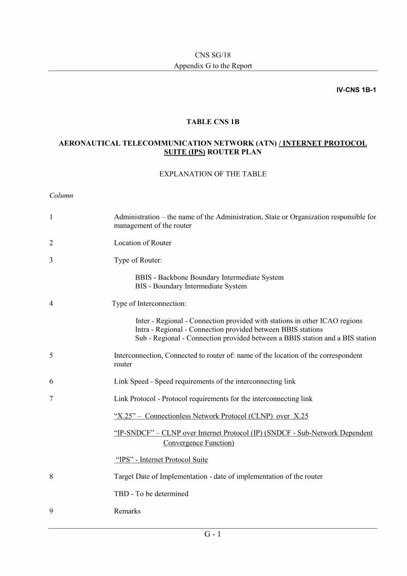
CNS SG/18 Appendix G to the Report
G - 1
IV-CNS 1B-1
TABLE CNS 1B
AERONAUTICAL TELECOMMUNICATION NETWORK (ATN) / INTERNET PROTOCOL SUITE (IPS) ROUTER PLAN
EXPLANATION OF THE TABLE
Column 1 Administration – the name of the Administration, State or Organization responsible for
management of the router 2 Location of Router 3 Type of Router: BBIS - Backbone Boundary Intermediate System BIS - Boundary Intermediate System 4 Type of Interconnection:
Inter - Regional - Connection provided with stations in other ICAO regions
Intra - Regional - Connection provided between BBIS stations Sub - Regional - Connection provided between a BBIS station and a BIS station 5 Interconnection, Connected to router of: name of the location of the correspondent
router 6 Link Speed - Speed requirements of the interconnecting link 7 Link Protocol - Protocol requirements for the interconnecting link
“X.25” – Connectionless Network Protocol (CLNP) over X.25
“IP-SNDCF” – CLNP over Internet Protocol (IP) (SNDCF - Sub-Network Dependent Convergence Function)
“IPS” - Internet Protocol Suite
8 Target Date of Implementation - date of implementation of the router
TBD - To be determined 9 Remarks
ssomsri
Typewritten Text
ssomsri
Typewritten Text

CNS IV-CNS 1B-2
G - 2
Administration Location of Router
Type of Router
Type of Interconnection
Interconnection, Connected to router
of:
Link Speed Link Protocol
Target date of Implementatio
n Remarks
1 2 3 4 5 6 7 8 9
Afghanistan Kabul BIS Sub-Regional Pakistan 64000bps IPS 2015 Intra-domain
BIS Inter-Regional Iran 9600 bps IPS 2015
American Samoa Pago Pago United States 2013 Intra-domain
Australia Brisbane BBIS Intra-Regional Fiji 64000 bps CLNP/IP-SNDCF
2014
BIS Sub-Regional Indonesia 64000 bps X.25/IP SNDCF
2015
BBIS Intra-Regional Japan 64000 bps IP/SNDCF TBD Not implemented
Nauru IPS 2013 Intra-domain
BIS Sub-Regional New Zealand 64000 bps IPS 2013 Implemented
Papua New Guinea 64000 bps IPS 2013 Intra-domain/Implemented
BBIS Intra-Regional Singapore 64000 bps CLNP/IP-SNDCF
2014
BBIS Inter-Regional South Africa 64000 bps TBD TBD Not implemented
Solomon Islands IPS 2012 Intra-domain
Timor Leste IPS 2013 Intra-domain
Vanuatu IPS 2010 Intra-domain
BBIS Inter-Regional United States 64000 bps IPS/SNDCF 2015
Bangladesh Dhaka BIS Sub-Regional India 64000 bps IPS TBD
BIS Sub-Regional Thailand 9600 bps X.25 2013
Bhutan Paro BIS Sub-Regional India 9600 bps IPS TBD

CNS IV-CNS 1B-3
G - 3
Administration Location of Router
Type of Router
Type of Interconnection
Interconnection, Connected to router
of:
Link Speed Link Protocol
Target date of Implementatio
n Remarks
1 2 3 4 5 6 7 8 9
Brunei Darussalam Brunei BIS Sub-Regional Malaysia 64000 bps X.25 2013
BIS Sub-Regional Singapore 9600 bps X.25 2013 Circuit implemented
Cambodia Phnom Penh BIS Sub-Regional Thailand 9600 bps X.25 2013
China Beijing BIS Sub-Regional DPR Korea 9600 bps X.25 2013 Router Implemented
BBIS Intra-Regional Hong Kong, China 64000 bps X.25 2012 Router Implemented
BBIS Intra-Regional India 64000 bps IPS 2013
BBIS Intra-Regional Japan 64000 bps IPS/SNDCF TBD
BBIS Inter-Regional Kuwait 64000 bps X.25 2013 Router Implemented
BIS Sub-Regional Macau, China 64000 bps X.25 2012 Implemented
BIS Sub-Regional Mongolia 9600 bps X.25 2013 Router Implemented
BIS Sub-Regional Myanmar 9600 bps IPS 2015 Router Implemented
BIS Sub-Regional Nepal 9600 bps X.25 2013 Router Implemented
BIS Sub-Regional Pakistan 64000 bps X.25 2013 Router Implemented
BIS Sub-Regional Republic of Korea 64000 bps X.25 2011 Implemented
BBIS Inter-Regional Russian Federation 64000 bps X.25 2012 Router Implemented
BBIS Intra-Regional Thailand 64000 bps X.25 2014 Router Implemented
BIS Sub-Regional Vietnam 9600 bps X.25 2013
Taibei BIS Sub-Regional Hong Kong, China 64000 bps X.25 2012
BIS Sub-Regional Japan 64000 bps IPS/SNDCF TBD
Hong Kong, China Hong Kong BBIS Intra-Regional China 64000 bps X.25 2012
BIS Sub-Regional Macau, China 64000 bps X.25 2009 Implemented
BBIS Intra-Regional Japan 64000 bps IPS/SNDCE TBD

IV-CNS 1B-4 ASIA/PAC FASID
G - 4
Administration Location of Router
Type of Router
Type of Interconnection
Interconnection, Connected to router
of:
Link Speed Link Protocol
Target date of Implementatio
n Remarks
1 2 3 4 5 6 7 8 9
BIS Sub-Regional Philippines 64000 bps X.25/IPS 2015
BBIS Sub-Regional Taibei 64000 bps X.25 2012
BBIS Intra-Regional Thailand 64000 bps X.25 2003 Router Implemented
BIS Sub-Regional Viet Nam 64000 bps X.25 2013
Macau, China Macau BIS Sub-Regional China 64000 bps X.25 2012 Implemented
BIS Sub-Regional Hong Kong, China 64000 bps X.25 2009 Implemented
Cook Islands Rarotonga New Zealand 9600 bps IPS 2013 Intra-domain
DPR Korea Pyongyang BIS Sub-Regional China 9600 bps X.25 2013
Fiji Nadi BBIS Intra-Regional Australia 64000 bps CLNP/IP-SNDCF
2014
Kiribati 64000 bps IPS 2014 Intra-domain
BIS Sub-Regional New Caledonia 2013 Intra-domain
Tuvalu IPS 2011 Intra-domain
BBIS Inter-Regional United States 9600 bps X.25 2011 Circuit implemented
Wallis Islands 2013 Intra-domain
French Polynesia Papeete New Zealand 9600 bps IPS 2013 Intra-domain
India Mumbai BIS Sub-Regional Bangladesh 64000 bps IPS TBD
BIS Sub-Regional Bhutan 9600 bps IPS TBD
BBIS Intra-Regional China 64000 bps IPS 2013
BIS Inter-Regional Kenya 9600 bps TBD TBD
BIS Sub-Regional Nepal 64000 bps IPS 2014
BIS Inter-Regional Oman 9600 bps IPS 2012 Interoperability trials in Q2/2012

CNS IV-CNS 1B-5
G - 5
Administration Location of Router
Type of Router
Type of Interconnection
Interconnection, Connected to router
of:
Link Speed Link Protocol
Target date of Implementatio
n Remarks
1 2 3 4 5 6 7 8 9
BIS Sub-Regional Pakistan 64000 bps IPS 2013 Interoperability test completed in 2010. Trial operations in progress.
BBIS Intra-Regional Singapore 64000 bps X.25 2011 Circuit Implemented
BIS Sub-Regional Sri Lanka 9600 bps IPS TBD
BBIS Intra-Regional Thailand 64000 bps X. 25 2013 Trials Commence from Q2/2012
Indonesia Jakarta BIS Sub-Regional Australia 64000bps IPS 2015
BIS Sub-Regional Singapore 64000 bps IPS 2013 Circuit implemented
Japan Tokyo BBIS Intra-Regional Australia 64000 bps X.25/IP-SNDCF
TBD Not implemented
BBIS Intra-Regional China 64000 bps X.25/IP-SNDCF
TBD Implement gradually from 2016 on-wards
BBIS Intra-Regional Hong Kong, China 64000 bps X.25/IP-SNDCF
TBD Implement gradually from 2016 on-wards
BBIS Inter-Regional Europe 64000 bps X.25/IP-SNDCF
TBD Implement gradually from 2016 on-wards
BIS Sub-Regional Republic of Korea 64000 bps X .25/IP-SNDCF
TBD
BBIS Inter-Regional Russia Federation 64000 bps X.25/IP-SNDCF
TBD Implement gradually from 2016 on-wards
BBIS Intra-Regional Singapore 64000 bps X.25/IP-SNDCF
TBD Implement gradually from 2016 on-wards
BIS Sub-Regional Taibei 64000 bps X.25/IP-SNDCF
TBD Implement gradually from 2016 on-wards

IV-CNS 1B-6 ASIA/PAC FASID
G - 6
Administration Location of Router
Type of Router
Type of Interconnection
Interconnection, Connected to router
of:
Link Speed Link Protocol
Target date of Implementatio
n Remarks
1 2 3 4 5 6 7 8 9
BBIS Inter-Regional United States 64000 bps X.25/IP-SNDCF
2015 Circuit implemented
Kiribati Tarawa BIS Sub-Regional Fiji 64000 bps IPS 2014 Intra-domain
Lao PDR Vientiane BIS Sub-Regional Thailand 64000 bps IPS 2013 VSAT
BIS Sub-Regional Viet Nam 9600 bps X.25 2013
Malaysia Kuala Lumpur BIS Sub-Regional Brunei 64000 bps X.25 2013
BIS Sub-Regional Singapore 64000 bps IPS 2007 Circuit implemented
BIS Sub-Regional Thailand 64000 bps IPS 2013 VSAT
Maldives Male BIS Sub-Regional Sri Lanka 64000 bps X.25 2013
Marshall Islands Majuro United States 2006 Intra-domain
Micronesia Federated State of
Chuuk United States 2006 Intra-domain
Kosrae United States 2006 Intra-domain
Ponapei United States 2006 Intra-domain
Yap United States 2006 Intra-domain
Mongolia Ulaanbaatar BIS Sub-Regional China 9600 bps X.25 2013
Myanmar Yangon BIS Sub-Regional China 9600 bps IPS 2015
BIS Sub-Regional Thailand 9600 bps IPS 2015
Nauru Nauru Australia 2013 Intra-domain
Nepal Kathmandu BIS Sub-Regional China 9600bps X.25 2013
BIS Sub-Regional India 64000 bps IPS 2014
New Caledonia Noumea Fiji 2013 Intra-domain

CNS IV-CNS 1B-7
G - 7
Administration Location of Router
Type of Router
Type of Interconnection
Interconnection, Connected to router
of:
Link Speed Link Protocol
Target date of Implementatio
n Remarks
1 2 3 4 5 6 7 8 9
New Zealand Christchurch BIS Sub-Regional Australia 64000 bps IPS 2013
Cook Is. 24000 bps IPS 2013 Intra-domain
French Polynesia 9600 bps IPS 2013 Intra-domain
Samoa 2400 bps IPS 2013 Intra-domain
Tonga 85000 bps IPS 2013 Intra-domain
BIS Inter-Regional USA 64000 bps IPS 2015
Pakistan Karachi BIS Sub-Regional Afghanistan 64000 bps IPS 2013
BIS Sub-Regional China 64000 bps X.25 2013
BIS Sub-Regional India 64000 bps IPS 2013 Interoperability test completed in 2010. Trial operations in progress.
BIS Inter-Regional Oman 64000 bps - 2013
BIS Inter-Regional Iran 64000 bps - 2013
BIS Inter-Regional Kuwait 64000 bps - 2013
Palau Koror United States 2006 Intra-domain
Papua New Guinea Port Moresby Australia 64000 bps IPS 2013 Intra-domain
Philippines Manila BIS Sub-Regional Hong Kong, China 64000 bps X.25/IPS 2015 Circuit Implemented
BIS Sub-Regional Singapore 64000 bps X.25 2015
Republic of Korea Seoul BIS Sub-Regional China 64000 bps X.25 2011 Implemented
BIS Sub-Regional Japan 64000 bps X.25 TBD
Samoa Faleolo New Zealand 2400 bps IPS 2013 Intra-domain

IV-CNS 1B-8 ASIA/PAC FASID
G - 8
Administration Location of Router
Type of Router
Type of Interconnection
Interconnection, Connected to router of:
Link Speed
Link Protocol
Target date of Implementation Remarks
1 2 3 4 5 6 7 8 9
Singapore Singapore BBIS Intra-Regional Australia 64000 bps CLNP/IP-SNDCF
2014
BBIS Inter-Regional Bahrain 64000 bps IPS 2014
BIS Sub-Regional Brunei 64000 bps IPS 2015
BBIS Intra-Regional India 64000 bps X.25 2011 Implemented
BIS Sub-Regional Indonesia 64000 bps IPS 2014
BBIS Intra-Regional Japan 64000 bps IPS/SNDCF 2016
BIS Sub-Regional Malaysia 64000 bps IPS 2014
BIS Sub-Regional Philippines 64000 bps IPS 2015
BIS Sub-Regional Sri Lanka 64000 bps IPS 2014
BBIS Intra-Regional Thailand 64000 bps X.25 2014
BBIS Inter-Regional United Kingdom 64000 bps IPS 2012 Implemented
BIS Sub-Regional Viet Nam 9600 bps X.25 2015
Solomon Islands Honiara Australia IPS 2012 Intra-Domain
Sri Lanka Colombo BIS Sub-Regional India 9600 bps IPS TBD
BIS Sub-Regional Maldives 64000 bps
X.25 2013
BIS Sub-Regional Singapore 64000 bps X.25 2013
Thailand Bangkok BIS Sub-Regional Bangladesh 32000 bps IPS 2014 VSAT
BIS Sub-Regional Cambodia 32000bps IPS 2013 VSAT
BBIS Intra-Regional Beijing, China 64000 bps X.25 2014

CNS IV-CNS 1B-9
G - 9
BBIS Intra-Regional Hong Kong, China 64000 bps X.25 2013
Administration Location of Router
Type of Router
Type of Interconnection
Interconnection, Connected to router of:
Link Speed
Link Protocol
Target date of Implementation Remarks
1 2 3 4 5 6 7 8 9
BBIS Intra-Regional India 64000 bps X.25 2014
BBIS Inter-Regional Italy 64000 bps X.25 2014
BIS Sub-Regional Lao PDR. 32000 bps IPS 2014 VSAT
BIS Sub-Regional Malaysia 32000 bps IPS 2014 VSAT
BIS Sub-Regional Myanmar 32000 bps 9600 bps IPS 2015 VSAT
BBIS Intra-Regional Singapore 64000 bps X.25 2014
BIS Sub-Regional Viet Nam 32000 bps 9600 bps IPS 2015 VSAT
Timor Leste Dili Australia IPS 2013 Intra-domain
Tonga Tongatapu New Zealand 9600 bps IPS 2013 Intra-domain
Tuvalu Funafuti Fiji IPS 2011 Intra-domain
United States Salt Lake City BBIS Inter-Regional Australia 64000 bps IPS/SNDCF 2015
American Samoa 2013 Intra-domain
BBIS Inter-Regional Fiji 9600 bps X.25 2011 Circuit implemented
BBIS Inter-Regional Japan 64000 bps IPS/SNDCF 2015 Circuit implemented
Marshall Islands 2006 Intra-domain
Micronesia, Federated State of
2006 Intra-domain
BIS Inter-Regional New Zealand 64000 bps IPS 2015 Circuit Implemented
Palau 2006 Intra-domain
Vanuatu Port Vila Australia IPS 2010 Intra-domain

IV-CNS 1B-10 ASIA/PAC FASID
G - 10
Administration Location of Router
Type of Router
Type of Interconnection
Interconnection, Connected to router of:
Link Speed
Link Protocol
Target date of Implementation Remarks
1 2 3 4 5 6 7 8 9
Viet Nam Ho Chin Minh/Hanoi
BIS Sub-Regional China 9600 bps X.25 2013
BIS Sub-Regional Hong Kong, China 64000 bps
X.25 2013
BIS Sub-Regional Lao PDR. 9600 bps X.25 2013
BIS Sub-Regional Singapore 9600 bps X.25 2013
BIS Sub-Regional Thailand 9600 bps X.25 2015
Wallis Islands Wallis Fiji 2013 Intra-domain
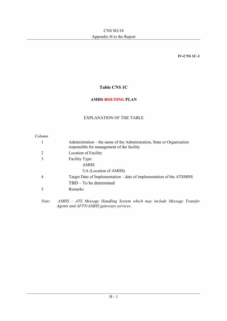
CNS SG/18 Appendix H to the Report
H - 1
IV-CNS 1C-1
Table CNS 1C
AMHS ROUTING PLAN
EXPLANATION OF THE TABLE
Column
1 Administration – the name of the Administration, State or Organization responsible for management of the facility
2 Location of Facility 3 Facility Type:
AMHS UA (Location of AMHS)
4 Target Date of Implementation – date of implementation of the ATSMHS TBD – To be determined
5 Remarks
Note: AMHS – ATS Message Handling System which may include Message Transfer Agents and AFTN/AMHS gateways services.
ssomsri
Typewritten Text
ssomsri
Typewritten Text

CNS IV-CNS 1C-2
H - 2
Administration Location of Facility Facility Type Target Date of Implementation
Remarks
Afghanistan Kabul AMHS 2014
American Samoa Pago Pago UA (Salt Lake City) 2013
Australia Brisbane AMHS 2006 Implemented
Bangladesh Dhaka AMHS 2013
Bhutan Paro UA (Mumbai) 2013
Brunei Darussalam Brunei AMHS 2013
Cambodia Phnom Penh AMHS 2013
China Beijing AMHS 2011 Implemented
Taibei AMHS 2010
Hong Kong, China Hong Kong AMHS 2009 Implemented
Macau, China Macau AMHS 2009 Implemented
Cook Island Rarotonga UA (Christchurch) 2013 Implemented
DPR Korea Pyongyang AMHS 2013
Fiji Nadi AMHS 2010 Implemented
French Polynesia Papeete AMHS 2013
India Mumbai AMHS 2011 Implemented
Indonesia Jakarta AMHS 2009 Implemented
Ujung Pandang AMHS 2010
NOTAM Office DGCA
AMHS 2012
Japan Fukuoka AMHS 2006 Implemented
Kiribati Tarawa UA (Nadi) 2011
Lao PDR Vientiane AMHS 2013

CNS IV-CNS 1C-3
H - 3
Administration Location of Facility Facility Type Target Date of Implementation
Remarks
Malaysia Kuala Lumpur AMHS 2013
Maldives Male AMHS 2013
Marshall Island Majuro UA (Salt Lake City) 2006 UA Implemented
Micronesia Federated State of
Chuuk UA (Salt Lake City) 2006 UA Implemented
Kosrai UA (Salt Lake City) 2006 UA Implemented
Ponapei UA (Salt Lake City) 2006 UA Implemented
Yap UA (Salt Lake City) 2006 UA Implemented
Mongolia Ulaanbaatar AMHS 2013
Myanmar Yangon AMHS 2013
Nauru Nauru UA (Brisbane) 2013
Nepal Kathmandu AMHS 2013
New Caledonia Noumea AMHS 2013
New Zealand Christchurch AMHS 2013
Niue Is. Niue UA (Christchurch) 2013
Pakistan Karachi AMHS 2009 Implemented. 50 UA implemented in Pakistan
and all International traffic through AFTN/AMHS
Gateway.
Palau Koror UA (Salt Lake City) 2006 UA Implemented
Papua New Guinea Port Moresby UA (Brisbane) 2013
Philippines Manila AMHS 2015
Republic of Korea Seoul AMHS 2010 Implemented
Samoa Faleolo UA (Christchurch) 2013
Singapore Singapore AMHS 2007 Implemented

IV-CNS 1C-4 ASIA/PAC FASID
H - 4
Administration Location of Facility Facility Type Target Date of Implementation
Remarks
Solomon Is. Honiara UA (Brisbane) 2012
Sri Lanka Colombo AMHS 2013
Thailand Bangkok AMHS 2011
Timor Leste Dili UA (Brisbane) 2013
Tonga Tongatapu UA (Christchurch) 2013
Tuvalu Funafuti UA (Nadi) 2011
United States Salt Lake City AMHS 2005 Implemented
Vanuatu Port Vila UA (Brisbane) 2010 Implemented
Viet Nam Ho Chi Minh AMHS 2013
Wallis Is. Wallis AMHS 2013
_ _ _ _ _ _ _ _ _ _ _ _

SITA Type X Gateway in a mixed AFTN/AMHS environment ICAO APAC Region
AMHS / SITA Type X Interconnection Architecture Version 0.7 I - 1 22/05/2014
CNS SG/18 Appendix I to the Report
AMHS / SITA Type X Interconnection Architecture
SITA Type X Gateway in a mixed AFTN/AMHS environment
Document Reference: APAC AMHS Documentation, AMHS / SITA Type X Interconnection Architecture
Author: AFSG Operations Group and APAC ACSICG
Revision Number: Version 0.9
Date: 22/05/2014
Filename: AMHS - SITA Type X Interconnection Architecture v_0_9.docx
ssomsri
Typewritten Text
ssomsri
Typewritten Text

SITA Type X Gateway in a mixed AFTN/AMHS environment ICAO APAC Region
AMHS / SITA Type X Interconnection Architecture Version 0.7 I - 2 22/05/2014
Document Control Log
Edition Date Comments section/pages affected
0.9 22/05/2014 Document creation and update from AFSG SITA- AMHS Interconnection architecture document
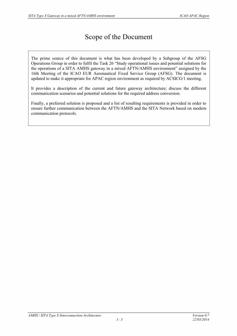
SITA Type X Gateway in a mixed AFTN/AMHS environment ICAO APAC Region
AMHS / SITA Type X Interconnection Architecture Version 0.7 I - 3 22/05/2014
Scope of the Document
The prime source of this document is what has been developed by a Subgroup of the AFSG Operations Group in order to fulfil the Task 26 “Study operational issues and potential solutions for the operations of a SITA AMHS gateway in a mixed AFTN/AMHS environment” assigned by the 16th Meeting of the ICAO EUR Aeronautical Fixed Service Group (AFSG). The document is updated to make it appropriate for APAC region environment as required by ACSICG/1 meeting.
It provides a description of the current and future gateway architecture; discuss the different communication scenarios and potential solutions for the required address conversion.
Finally, a preferred solution is proposed and a list of resulting requirements is provided in order to ensure further communication between the AFTN/AMHS and the SITA Network based on modern communication protocols.

SITA Type X Gateway in a mixed AFTN/AMHS environment ICAO APAC Region
AMHS / SITA Type X Interconnection Architecture Version 0.7 I - 4 22/05/2014
Table of contents
1 INTRODUCTION ......................................................................................................................................... 7
1.1 PURPOSE OF THE DOCUMENT ....................................................................................................................... 7
2 TODAY’S COMMUNICATION ARCHITECTURE BETWEEN AFTN AND SITA ........................... 8
2.1 OVERVIEW ................................................................................................................................................... 8 2.2 ASIA PACIFIC AFTN/SITA TYPE B GATEWAY CONNECTIONS..................................................................... 8 2.3 FUNCTION OF THE AFTN/SITA TYPE B GATEWAY ..................................................................................... 9 2.4 MESSAGE CONVERSION IN THE AFTN/SITA TYPE B GATEWAY ............................................................... 10
2.4.1 Outgoing conversion methods from AFTN/SITA Type B Gateway to AFTN ........................................ 10 2.4.2 Incoming conversion methods from AFTN ........................................................................................... 11
2.5 COMMUNICATION SCENARIOS .................................................................................................................... 12 2.5.1 Introduction .......................................................................................................................................... 12 2.5.2 Scenario from SITA to AFTN ................................................................................................................ 12 2.5.3 Scenario from AFTN to SITA ................................................................................................................ 14 2.5.4 Remarks regarding the message flow in the communication scenarios ............................................... 15
3 DESCRIPTION OF FUTURE TYPE X RELATED ARCHITECTURE .............................................. 16
3.1 EVOLUTION OF THE SITA MESSAGING ENVIRONMENT ............................................................................... 16 3.2 AMHS/SITA TYPE X GATEWAY ............................................................................................................... 17 3.3 MESSAGE AND ADDRESS CONVERSION IN THE AMHS/SITA TYPE X GATEWAY ....................................... 18 3.4 COMMUNICATION SCENARIOS IN A MIXED AFTN/AMHS ENVIRONMENT ................................................. 19
3.4.1 Introduction .......................................................................................................................................... 19 3.4.2 Scenario from SITA Type X to AMHS ................................................................................................... 20 3.4.3 Scenario from SITA to AFTN via AMHS .............................................................................................. 21 3.4.4 Scenario from AMHS to SITA ............................................................................................................... 23 3.4.5 Scenario from AFTN via AMHS to SITA .............................................................................................. 24
3.5 TRANSITIONAL ASPECTS FROM SITA TYPE B TO SITA TYPE X ................................................................. 26
4 REPRESENTATION OF SITA TYPE X USERS BY THEIR AFTN ADDRESSES ........................... 27
4.1 INTRODUCTION .......................................................................................................................................... 27 4.2 DISCUSSION OF THE OPTIONS ..................................................................................................................... 27
4.2.1 Option 1: Table based identification of SITA Type X users in AFTN ................................................... 27 4.2.2 Option 2: Use of a unique first letter in the AFTN address for SITA Type X users .............................. 29
4.3 RECOMMENDED SOLUTION ........................................................................................................................ 31 4.3.1 First conclusions .................................................................................................................................. 31 4.3.2 Principle of the recommended solution ................................................................................................ 31
5 COMMUNICATION REQUIREMENTS FOR THE AMHS/SITA TYPE X GATEWAY ................. 33
5.1 TECHNICAL REQUIREMENTS....................................................................................................................... 33 5.2 OPERATIONAL REQUIREMENTS .................................................................................................................. 33 5.3 SPECIFIC OPERATIONAL REQUIREMENTS .................................................................................................... 33
6 REQUIREMENTS CONCERNING UNDERLYING IP INFRASTRUCTURE .................................. 35
7 MIGRATION SCENARIO ........................................................................................................................ 36
8 ROAD MAP ................................................................................................................................................. 37

SITA Type X Gateway in a mixed AFTN/AMHS environment ICAO APAC Region
AMHS / SITA Type X Interconnection Architecture Version 0.7 I - 5 22/05/2014
References ICAO Documentation
[1] ICAO Annex 10 – Aeronautical Telecommunications, Volume II and Volume III
[2] ICAO Doc 9880-AN/466: Manual on Detailed Technical Specifications for the Aeronautical Telecommunication Network (ATN) using ISO/OSI Standards and Protocols, Part II – Ground-Ground Applications - Air Traffic Services Message Handling Services (ATSMHS), First Edition – 2010
[3] ICAO Doc 9880-AN/466: Manual on Detailed Technical Specifications for the Aeronautical Telecommunication Network (ATN) using ISO/OSI Standards and Protocols, Part III – Upper Layer Communications Service (ULCS) and Internet Communications Service (ICS), , First Edition – 2010
[4] ICAO Doc 9880-AN/466: Manual on Detailed Technical Specifications for the Aeronautical Telecommunication Network (ATN) using ISO/OSI Standards and Protocols, Part IV – Directory Services, Security and Systems Management, First Edition – 2010
[5] ICAO Doc 9896-AN/469: Manual on the Aeronautical Telecommunication Network (ATN) using Internet Protocol Suite (IPS) Standards and Protocols, First Edition – 2010
[6] ICAO Doc 7910, Location Indicators
[7] ICAO Doc 8585, Designators for Aircraft Operating Agencies, Aeronautical Authorities and Services
[8] EUR Doc 020 – EUR AMHS Manual, including Appendices A - G
[9] EUR Doc 021 – ATS Messaging Management Manual
[10] EUR Doc 027 – IP Infrastructure Test Guidelines for EUR AMHS
[11] Air Transport & Travel Industry, “TypeX Messaging Specification”, (System Communications & Reference Volume7), v2.0 First Publication - Sept 2009

SITA Type X Gateway in a mixed AFTN/AMHS environment ICAO APAC Region
AMHS / SITA Type X Interconnection Architecture Version 0.7 I - 6 22/05/2014
Table of Figures FIGURE 1: TYPICAL INTERCONNECTION OF AFTN AND SITA NETWORK BY AN AFTN/SITA TYPE B GATEWAY .... 9 FIGURE 2: MESSAGE FLOW FROM A SITA TYPE B TO AN AFTN TERMINAL ........................................................... 13 FIGURE 3: MESSAGE FLOW FROM AN AFTN TO A SITA TYPE B TERMINAL ............................................................ 14 FIGURE 4: PLANNED INTERCONNECTIONS BETWEEN AFTN, AMHS AND SITA TYPE X NETWORK ....................... 18 FIGURE 5: MESSAGE FLOW FROM A SITA TYPE X TERMINAL TO AN AMHS UA .................................................... 20 FIGURE 6: EXAMPLE FOR A MESSAGE FLOW FROM SITA TYPE X TO AFTN VIA AMHS ........................................ 22 FIGURE 7: EXAMPLE FOR A MESSAGE FLOW FROM SITA TYPE X TO AMHS .......................................................... 23 FIGURE 8: EXAMPLE FOR A MESSAGE FLOW FROM AFTN TO SITA TYPE X VIA AMHS ........................................ 25
Index of Tables TABLE 1: AVERAGE TRAFFIC FIGURES EXCHANGED BETWEEN AFTN AND SITA NETWORK ..................................... 8 TABLE 2: ADDRESS CONVERSION PRINCIPLE AFTN INTO SITA TYPE B ................................................................. 15 TABLE 3: ADDRESS CONVERSION PRINCIPLE AMHS INTO SITA TYPE X ................................................................ 24 TABLE 4: AFTN ADDRESS STRUCTURE OF A SITA TYPE X USER IN OPTION 2 ........................................................ 29 TABLE 5: SITA TYPE X AND AFTN ADDRESSES OF SITA TYPE X USERS IN OPTION 2 ........................................... 30

SITA Type X Gateway in a mixed AFTN/AMHS environment ICAO APAC Region
AMHS / SITA Type X Interconnection Architecture Version 0.7 I - 7 22/05/2014
1 Introduction
1.1 Purpose of the document
1.1.1 The purpose of the document is to study operational issues and potential solutions for the operations of a SITA AMHS gateway in a mixed AFTN/AMHS environment.
1.1.2 This document will inform about the current and future gateway architecture, discuss the different communication scenarios and potential solutions for the required address conversion.
1.1.3 The target of the document is to provide a baseline for selection and help for the decision about the future solution in order to ensure further communication between the AFTN/AMHS and the SITA Network based on modern communication protocols. The SITA AMHS addressing version 0.8 of this document was based on CAAS addressing scheme. This is changed to AMHS XF addressing scheme following ICAO EURNAT AFSG recommendation. Examples in this document use XF addressing scheme for SITA users AMHS addresses.

SITA Type X Gateway in a mixed AFTN/AMHS environment ICAO APAC Region
AMHS / SITA Type X Interconnection Architecture Version 0.7 I - 8 22/05/2014
2 Today’s Communication architecture between AFTN and SITA
2.1 Overview
2.1.1 SITA has been operating AFTN/SITA Type B Gateways for over 40 years. The gateways are today connected via low and medium speed connections to AFTN COM Centres in several States.
2.1.2 These inter-connections allow SITA customers to communicate with the AFS Network (AFTN/CIDIN) using the message type of their network. The AFTN/SITA Type B Gateway provides the necessary message conversion to enable seamless data exchange between both networks.
2.1.3 Currently SITA operates 32 AFTN/SITA Type B Gateway connections. 7 gateway connections are provided in Asia Pacific.
2.1.4 Approximately forty thousand messages are exchanged between SITA and the AFS network on a daily basis.
Received by SITA from
AFTN
Transmitted by SITA to
AFTN Total
Worldwide 21,542 14,155 35,697
ASIA/PAC Region 5,183 6,678 11,861
One typical AFTN/SITA Type B Gateway connection in EUR 1,246 540 1,786
Table 1: Average traffic figures exchanged between AFTN and SITA network
2.1.5 Globally approximately 1400 SITA addresses including their allocated AFTN addresses are configured in the AFTN/SITA Type B Gateways. These pair entries are used for the address translation SITA to AFTN and vice versa in the gateways for the messages sent to and/or received from the AFTN.
2.1.6 An AFTN address table in the AFTN/SITA Type B Gateways was implemented which should provide an AFTN originator validation for messages issued by SITA customers.
2.2 Asia Pacific AFTN/SITA Type B Gateway connections
2.2.1 The AFTN/SITA Type B Gateway connections in the APAC Region are provided with COM Centres in:
Australia
French Polynesia

SITA Type X Gateway in a mixed AFTN/AMHS environment ICAO APAC Region
AMHS / SITA Type X Interconnection Architecture Version 0.7 I - 9 22/05/2014
Malaysia
New Caledonia
Singapore
Taiwan
Thailand
2.2.2 The AFTN/SITA Type B Gateways and their respective connections (X.25, low speed) are end of life.
2.3 Function of the AFTN/SITA Type B Gateway
2.3.1 A typical interconnection of AFTN and SITA Network by an AFTN/SITA Type B Gateway is shown in Figure 1.
Figure 1: Typical interconnection of AFTN and SITA Network by an AFTN/SITA Type B
Gateway
2.3.2 Within the SITA Type B Network the SITA users transmit and receive messages in IATA Type B format.
2.3.3 Within the AFTN the AFS users transmit and receive messages in AFTN format.
2.3.4 The AFTN/SITA Type B Gateways allow SITA users to communicate to the AFTN and convert the messages into the correct format for the respective network.
2.3.5 The function of the AFTN/SITA Type B Gateway is the conversion of addresses and message header from AFTN to SITA Type B and vice versa.
AFTN
SITA Type B Network
AFTN/ SITA
Type B Gateway

SITA Type X Gateway in a mixed AFTN/AMHS environment ICAO APAC Region
AMHS / SITA Type X Interconnection Architecture Version 0.7 I - 10 22/05/2014
2.4 Message conversion in the AFTN/SITA Type B Gateway
2.4.1 Outgoing conversion methods from AFTN/SITA Type B Gateway to AFTN
2.4.1.1 Enveloped method
2.4.1.1.1 A SITA customer creates a message which is intended to be sent to an AFS user in AFTN format. This message is sent to the AFTN/SITA Type B Gateway directly by means of a SITA Type B message-envelope. The embedded AFTN message is formally the “text” of the SITA Type B message.
2.4.1.1.2 The AFTN/SITA Type B Gateway strips the SITA Type B envelope before the embedded AFTN message is transmitted from the SITA side to AFTN.
2.4.1.1.3 The embedded AFTN message is routed to the “most appropriate” AFTN/SITA Type B Gateway connection. This means that the routing is done according the “Routing on Origin” principle to the “nearest” COM Centre related to the AFTN originator address of the embedded AFTN message.
2.4.1.1.4 The following example should illustrate the “envelope method”:
Message generated by an SITA customer:
QU HDQYFXS .KULKKAF 220834 }
SITA Type B header with HDQYFXS as AFTN/SITA Type B Gateway address
FF WSSSSIAX 220834 WMKKAFRK text =
Embedded AFTN Message
Message sent to AFTN:
FF WSSSSIAX 220834 WMKKAFRK text
AFTN Message
Example 1: “Conversion” of a message from SITA network to AFTN
Note.– The appropriate AFTN start and ending signals are not shown in the examples.
2.4.1.1.5 In case of Example 1 the “most appropriate” AFTN/SITA Type B Gateway is the gateway in Kuala Lumpur; the AFTN originator address belongs to WMKK – Sepang Area, ICAO Nationality Letter: WM, Malaysia.
2.4.1.1.6 The relation between the AFTN originator address of the embedded AFTN message and the origin in the SITA Type B header is not checked. This is under the responsibility of the SITA customer itself.
2.4.1.1.7 However, the gateway checks the syntax of AFTN addresses and compares on SITA Type B site the addresses with specific lists in terms of address and access validity (which should means that the address is allowed as an originator indicator).
2.4.1.2 Message conversion method
2.4.1.2.1 A SITA customer creates a message which is intended to be sent to an AFS user in AFTN format. In the SITA network this message is routed to an AFTN/SITA Type B

SITA Type X Gateway in a mixed AFTN/AMHS environment ICAO APAC Region
AMHS / SITA Type X Interconnection Architecture Version 0.7 I - 11 22/05/2014
Gateway because the SITA Type B address is known as an AFS user outside the SITA Type B network.
2.4.1.2.2 In this case a mapping table is used in the AFTN/SITA Type B Gateway to get the related AFTN Destination addresses. As Originator address the AFTN address of the respective gateway is used. The AFTN/SITA Type B Gateway creates the AFTN message header and attaches the SITA Type B message as message text.
2.4.1.2.3 A typical message looks like:
Message generated by an SITA customer:
QN HDQOWTG .JAOXTXS 123456 FREE TEXT
SITA Type B header with HDQOWTG as Destination address routed to the AFTN/SITA Type B Gateway plus message text (FREE TEXT)
Message sent to AFTN:
GG VTBSTHAW 123456 WSSSSITX } AFTN Message header QN HDQOWTG .JAOXTXS 123456 FREE TEXT
attached SITA Message
Example 2: Message conversion from SITA to AFTN
Note.– The appropriate AFTN start and ending signals are not shown in the examples.
2.4.2 Incoming conversion methods from AFTN
2.4.2.1 Envelope method
2.4.2.1.1 A message received from AFTN will be embedded into a SITA Type B envelope by the AFTN/SITA Type B Gateway.
2.4.2.1.2 The SITA address line is deduced from the ICAO priority and the AFTN Destination Address(es) found in the incoming AFTN message.
2.4.2.1.3 The SITA origin line is composed of:
the SITA Service Address of the AFTN/SITA Type B Gateway connection from where the message has been received,
the date/time group corresponding to the reception time of the AFTN message, and
the information “AFTN” to indicate origin of the message.
Message received from AFTN:
GG YSSYQFAB 100525 LOOOYFYX text
AFTN Message

SITA Type X Gateway in a mixed AFTN/AMHS environment ICAO APAC Region
AMHS / SITA Type X Interconnection Architecture Version 0.7 I - 12 22/05/2014
Note.– The appropriate AFTN start and ending signals are not shown in the examples.
Message sent to an airline (SITA customer):
QN SYDXJQF .SINXYYF 100530AFTN
generated SITA Type B header GG YSSYQFAB 100525 LOOOYFYX text =
Embedded AFTN Message
Example 3: “Conversion” of a message from AFTN to SITA network
2.4.2.1.4 AFTN Destination Addresses which cannot be converted are intercepted as unknown AFTN addresses. The related AFTN COM Centre is informed by an AFTN SVC “ADS UNKNOWN” in order to make corrections or purge.
2.4.2.2 Message conversion method
2.4.2.2.1 In direction from AFTN to SITA this message does not apply in the AFTN/SITA Type B Gateway.
2.5 Communication scenarios
2.5.1 Introduction
2.5.1.1 The following communication scenarios describe the typical message flows in the current AFTN – SITA Type B environment.
2.5.1.2 The descriptions should help to identify future potential communication requirements.
2.5.1.3 In the scenarios following communication partners are involved:
SITA Type B user: The Operations manager of Eva Air in Taipei. His SITA Type B address is TPEOOBR.
AFTN (AFS) user: The Operator in Tower Singapore. Its AFTN Address is WSSSZTZX.
2.5.1.4 A fictive message exchange between both communication partners is the base of the following scenarios:
2.5.2 Scenario from SITA to AFTN
2.5.2.1 Message flow
2.5.2.1.1 The SITA Type B user wishes to send a message from his SITA Terminal to the Tower in Singapore in order to inform about an event which is not related to IFPS. Figure 2 shows the expected message flow.

SITA Type X Gateway in a mixed AFTN/AMHS environment ICAO APAC Region
AMHS / SITA Type X Interconnection Architecture Version 0.7 I - 13 22/05/2014
Figure 2: Message flow from a SITA Type B to an AFTN Terminal
2.5.2.2 Generation of the message
2.5.2.2.1 The following message is generated by the Operations manager of Eva Air in Taipei:
QU HDQYFXS .TPEOOBR 220944 }
SITA Type B header GG WSSSZTZX 220944 RCTPEVAO PLEASE CONFIRM THE FOLLOWING TEXT text =
Embedded AFTN
Message
Example 4: Embedded AFTN message
2.5.2.2.2 The message is routed within the SITA Type B network to the AFTN/SITA Type B Gateway.
2.5.2.3 Conversion of the message in the AFTN/SITA Type B Gateway
2.5.2.3.1 The AFTN/SITA Type B Gateway removes the SITA envelope, identifies the appropriate Gateway connection following the principle “Routing by Originator” and finally sends the following AFTN message to the COM Centre Taipei:
GG WSSSZTZX 220944 RCTPEVAO PLEASE CONFIRM THE FOLLOWING TEXT text
AFTN Message
Example 5: Converted AFTN message
Note.– The appropriate AFTN start and ending signals are not shown in the examples.
2.5.2.4 Switching of the AFTN message by COM Centres RCTP and WSSS
2.5.2.4.1 The COM Centre Taipei receives the above message and delivers it via the AFS (COM Centre Singapore) finally to the AFTN Terminal of the Tower of Singapore WSSSZTZX.
AFTN SITA Type B
Network
AFTN/ SITA
Type B Gateway
AFTN
WSSSZTZX
Type B
TPEOOBR RCTP
(AFTN) WSSS
(AFTN)

SITA Type X Gateway in a mixed AFTN/AMHS environment ICAO APAC Region
AMHS / SITA Type X Interconnection Architecture Version 0.7 I - 14 22/05/2014
2.5.3 Scenario from AFTN to SITA
2.5.3.1 Message flow
2.5.3.1.1 Due to the content of the AFTN message received the Operator in the Singapore Tower will send back to the origin the requested confirmation. Figure 3 shows the expected message flow.
Figure 3: Message flow from an AFTN to a SITA Type B terminal
2.5.3.2 Generation of the message
2.5.3.2.1 The Operator in the Singapore Tower generates the following AFTN message:
ZCZC ... GG RCTPEVAO 220954 WSSSZTZX CONFIRM RECEPTION OF YR 220944 RCTPEVAO BRGDS WSSSZTZX NNNN
AFTN Message
Example 6: Generated reply AFTN message
2.5.3.3 Switching of the AFTN message by the COM Centre WSSS and RCTP
2.5.3.3.1 The COM Centre of Singapore receives the above message from the AFTN Terminal of the Tower of Singapore WSSSZTZX and send via the AFS to COM Centre Taipei.
2.5.3.3.2 Due to the fact that the COM Centre Taipei knows the AFTN address RCTPEVAO as a SITA Type B user the above message is routed to the AFTN/SITA Type B Gateway interconnected with Taipei.
2.5.3.3.3 Within the AFTN Routing Table of COM Centre Taipei about 15 different AFTN Addresses for SITA Type B users are configured currently and routed to the AFTN/SITA Type B Gateway.
2.5.3.4 Conversion of the message in the AFTN/SITA Type B Gateway
2.5.3.4.1 The AFTN/SITA Type B Gateway derives the necessary attributes for the SITA envelope from the AFTN message and generates the respective SITA Type B message.
2.5.3.4.2 2.5.3.4.2 The SITA Type B network will deliver the message to the addressed SITA Type B user.
AFTN SITA Type B
Network
AFTN/ SITA
Type B Gateway
AFTN
WSSSZTZX
Type B
TPEOOBR RCTP
(AFTN) WSSS
(AFTN)

SITA Type X Gateway in a mixed AFTN/AMHS environment ICAO APAC Region
AMHS / SITA Type X Interconnection Architecture Version 0.7 I - 15 22/05/2014
2.5.3.4.3 The addressed SITA Type B user receives the following SITA Type B message:
QN TPEOOBR .SINXYYF 220956/AFTN }
SITA Type B header
FF RCTPEVAO 220954 WSSSZTZX CONFIRM RECEPTION OF YR 220944 RCTPEVAO BRGDS WSSSZTZX =
embedded AFTN Message
Example 7: Embedded AFTN message (Reply)
2.5.3.5 Address conversion principle in the AFTN/SITA Type B Gateway
2.5.3.5.1 In the AFTN/SITA Type B Gateway the following address conversion principle within message conversion from AFTN to SITA Type B is used:
AFTN Address (8 letter) into SITA Type B address (7 letter)
Location indicator (4 letter) → IATA Location code (3 letter)
Three letter designator (3 letter) → IATA Airline code (2 letter)
Filler letter "X" or letter representing a department or division within the organization addressed (1 letter)
→ Department code (2 letter)
Table 2: Address conversion principle AFTN into SITA Type B
2.5.4 Remarks regarding the message flow in the communication scenarios
2.5.4.1 For the message flow from AFTN to SITA the AFTN COM Centres with interconnection to a SITA Type B Gateway have configured in their AFTN Routing Tables only the AFTN addresses of those SITA Type B users which are served locally.
2.5.4.2 AFTN addresses for SITA Type B users served by other COM Centres are not known and therefore not configured. Today, there is no specific indication in an AFTN address identifying a SITA Type B user in the AFTN.
2.5.4.3 For handling of exceptional cases, some COM Centres agreed special procedures bilaterally with adjacent COM Centres to ensure a coordinated routing of AFTN addresses for “other local” SITA Type B users.

SITA Type X Gateway in a mixed AFTN/AMHS environment ICAO APAC Region
AMHS / SITA Type X Interconnection Architecture Version 0.7 I - 16 22/05/2014
3 Description of future Type X related architecture
3.1 Evolution of the SITA messaging environment
3.1.1 The evolution of the SITA messaging environment is based on the IATA Type X Messaging Specification [11] which is a messaging standard based on XML and Web service technologies ratified by IATA in September 2009.
3.1.2 IATA Type X standard supports message delivery between SITA Type X users.
3.1.3 The communication between SITA Type X users and users outside of the Type X environment is ensured via dedicated Type X Gateways. In case of AMHS the dedicated gateway is called in the following “AMHS/SITA Type X Gateway”.
3.1.4 All addresses in the Type X Messaging environment (Destination and Originator addresses) are of TXM_Address type composed of three elements according [11], 4.5:
One TypeX_address,
Zero or one SubAddress,
Zero or one FreeFormName.
3.1.5 The TypeX_address is the logical address of a specific user. The SubAddress is specified for nodes that are not addressable directly by a Type X address (the SubAddress carries the actual originator or receiver address in its own messaging environment). The FreeFormName associates an optional name. ([11], 4.5)
3.1.6 In the context of AMHS only the TypeX_address is relevant which consists of:
one City field to identify a city code (or location code),
one Department field to identify a department code,
one Airline field to identify an airline or more generally an organisation code,
Auxiliary field (to identify an organisation using a shared airline code). This field is not used for AMHS communication.
3.1.7 The relevant fields of the Type X address itself consists of:
City Code: on 3 or 4 alphabetic characters (IATA or ICAO code)
Department Code: on 1 to 3 alphanumeric characters
Airline Code on 2 or 3 alphanumeric characters (IATA or ICAO code)

SITA Type X Gateway in a mixed AFTN/AMHS environment ICAO APAC Region
AMHS / SITA Type X Interconnection Architecture Version 0.7 I - 17 22/05/2014
3.1.8 Type X City, Department and Airline codes correspond to the current Type B address city, department and airline codes, keeping the possibility to increase each field by 1 character. ([11], 14.1)
3.1.9 A Type X Address (TypeX_address) is defined in XML as:
<TYPEX_Address>
<Airline>airlinecode</Airline> <City>citycode</City> <Department>departmentcode</Department>
</TYPEX_Address>
3.1.10 From the above Type X Address (TypeX_address) other address elements are derived to ensure an optimal routing of the messages in the Type X environment (e.g. the Type X gateway address used in the transport header for identifying the target Type X node). The full address of the end user is composed of the Type X gateway address completed by the end user address in its own messaging environment. (see [11], 14.1)
3.1.11 The routing of the message is performed according to the Type X gateway address up to the gateway. (see 4.3 and 4.4 of [11])
3.1.12 In the context of communication to and from AMHS the Type X addresses represents always AFTN Addresses both as Destination and as Originator. Therefore in a message sent to AMHS the originator address consists of the Type X address representing the AFTN address of the SITA user which could be the same as used today in the SITA Type B environment.
3.1.13 To ensure the correct routing within the SITA Type X network all Type X addresses with 4 letters in the address attribute “City” (ICAO code) are listed in tables in which for the full qualified AFTN address the corresponding target Type X node (Type X gateway address) is assigned. Such a target Type X node (Type X gateway address) can be either the AMHS/SITA Type X Gateway (if AFS users are addressed) or the Type X node serving the SITA user.
3.1.14 More comprehensive details could be found in [11].
3.2 AMHS/SITA Type X Gateway
3.2.1 The AMHS/SITA Type X Gateway is the “bridge” between AMHS and the SITA messaging environment Type X. The typical interconnection between the existing and future networks is shown in Figure 4.
3.2.2 The AMHS/SITA Type X Gateway can be connected to an AMHS COM Centre which also provides during the transition AFTN/AMHS Gateway services for AFTN/CIDIN users. In such a configuration the AMHS/SITA Type X Gateway is not only connected to the AMHS it is connected to an AFTN/AMHS Gateway as well.
3.2.3 SITA plans to establish two AMHS/SITA Type X Gateways with one connection to Europe and one to Asia (see Figure 4).

SITA Type X Gateway in a mixed AFTN/AMHS environment ICAO APAC Region
AMHS / SITA Type X Interconnection Architecture Version 0.7 I - 18 22/05/2014
Figure 4: Planned interconnections between AFTN, AMHS and SITA Type X Network
3.3 Message and address conversion in the AMHS/SITA Type X Gateway
3.3.1 The move to the new communication environment at SITA side (Type X) requires interconnection to AMHS in the near future to enable continued support of data exchange between ATS Organizations using AMHS and SITA customers using Type X communication.
3.3.2 The guiding principle should be to provide address transparency to both kind of users (AMHS and SITA Type X).
3.3.3 An AMHS user within the AMHS network should be able to address a SITA Type X user using its AMHS address (SITA Type X users are being seen as AMHS user with PRMD=SITA).
3.3.4 A SITA Type X user within the SITA Type X network should be able to address an AMHS user using the corresponding Type X address (AMHS users are being seen in the SITA Type X environment as SITA Type X users in principle with an ICAO code in the Type X address element “City”. All Type X address elements are derived from the AFTN address within the O/R address – either common-name or organisational-unit-name-1 depending on the addressing scheme).
3.3.5 The AMHS originator address of a SITA Type X user will be created in the AMHS/SITA Type X Gateway. The generic resulting O/R address representing the SITA Management Domain (PRMD=SITA) will look like in accordance with the addressing scheme declared by SITA:
SITA
ICAO/ ANSP
AMHS/SITA Type X Gateway
AFTN/AMHS Gateway
COM Centre with AFTN/AMHS Gateway
AFTN
AMHS
AFTN
AMHS
AFTN
AMHS
AFTN
AMHS

SITA Type X Gateway in a mixed AFTN/AMHS environment ICAO APAC Region
AMHS / SITA Type X Interconnection Architecture Version 0.7 I - 19 22/05/2014
XF: /C=XX/A=ICAO/P= SITA/O= AFTN/OU=<AFTNADDR>
Where <AFTNADDR> – AFTN address representing the SITA Type X user.
3.3.6 The AMHS/SITA Type X Gateway supports the conversion of message delivery reports which could be mapped to equivalent AMHS delivery reports and vice versa facilitating end to end delivery assurance and tracking in an interconnected environment.
3.4 Communication scenarios in a mixed AFTN/AMHS environment
3.4.1 Introduction
3.4.1.1 The following communication scenarios describe typical expected message flows between a SITA Type X Gateway and two different AFS environments:
a pure AMHS communication environnent,
a mixed AFTN/AMHS communication environment.
3.4.1.2 Resulting potential requirements for future communication will be summarised in Chapter 5.
3.4.1.3 In the scenarios following communication partners are involved:
SITA Type X user: The Station manager of Eva Air in Taipei. His SITA Type X address in XML format (TypeX_address – Type X Address) is: <Airline>EVA</Airline> <City>RCTP</City> <Department>O</Department> which is equivalent to the AFTN address RCTPEVAO representing the SITA user in the AFTN environment.
Direct AMHS User: The Operator of Tower in Singapore His AMHS O/R address is /C=XX/A=ICAO/P=SINGAPORE /O=WSJC/OU1=WSSS/CN=WSSSZTZX. His AFTN Address is WSSSZTZX.
AFTN (AFS) user: The Operator of Tower in Sepang. His AFTN Address is WMKKZTZX. His indirect AMHS user address (O/R address) is: /C=XX/A=ICAO/P=MALAYSIA /O=WMFC/OU1=WMKK/CN=WMKKZTZX.
3.4.1.4 A fictive message exchange between both of them is the base of the following scenarios:

SITA Type X Gateway in a mixed AFTN/AMHS environment ICAO APAC Region
AMHS / SITA Type X Interconnection Architecture Version 0.7 I - 20 22/05/2014
3.4.2 Scenario from SITA Type X to AMHS
3.4.2.1 Message flow
3.4.2.1.1 The SITA Type X user wishes to send a message from its SITA Type X Terminal to the Direct AMHS User in order to inform about a special event which requires an active answer.
3.4.2.1.2 Figure 5 shows the Message flow from a SITA Type X terminal to an AMHS User Agent (UA) via the involved network elements. The switching nodes within the AMHS are the MTAs (Message transfer agents) while at SITA side Type X nodes are used.
Figure 5: Message flow from a SITA Type X terminal to an AMHS UA
3.4.2.2 Generation of the message
3.4.2.2.1 The following message is generated by the Station manager of Eva Air in Taipei airport (SITA Type X user).
<Airline>EVA</Airline> <City>RCTP</City> <Department>O</Department>
SITA Type X Originator address
<Airline>ZTZ</Airline> <City>WSSS</City> <Department>X</Department>
SITA Type X Destination Address
PLEASE CONFIRM THE FOLLOWING TEXT text =
} Message text
Example 8: Type X message
Note.– In this example only a part of the Type X message schema is shown. For the full Type X message schema see [11].
3.4.2.2.2 The SITA Type X Destination Address (TypeX_address) defines the targeted receiver.
3.4.2.2.3 In this example the SITA Type X message is routed within the SITA Type X network to the AMHS/SITA Type X Gateway using the Type X address attributes based on the ICAO codes.
AMHS SITA Type X Network AMHS/
SITA Type X
Gateway
<Airline>EVA</Airline> <City>RCTP</City>
<Department>O</Department>>
X UA
XX/ICAO/SINGAPORE/WSSS/WSSSZTZX
RCTP (MTA)
WSSS (MTA)

SITA Type X Gateway in a mixed AFTN/AMHS environment ICAO APAC Region
AMHS / SITA Type X Interconnection Architecture Version 0.7 I - 21 22/05/2014
3.4.2.3 Conversion of the message in the AMHS/SITA Type X Gateway
3.4.2.3.1 The AMHS/SITA Type X Gateway converts the Type X message and its attributes into an AMHS (X.400) message.
3.4.2.3.2 The following main AMHS attributes / X.400 message elements form the AMHS Message:
/C=XX/A=ICAO/P=SINGAPORE/O=WSJC/OU1=WSSS/CN=WSSSZTZX /C=XX/A=ICAO/P=SITA/O=AFTN/OU =RCTPEVAO GG 220944 PLEASE CONFIRM THE FOLLOWING TEXT text
- X.400 Recipient address - X.400 Originator address - Message Prio - Filing time
} Message text
Example 9: Main attributes of an AMHS message
Note.– RCTPEVAO represents the AFTN address of the SITA Type X user.
3.4.2.3.3 The converted message (AMHS) is sent from the AMHS/SITA Type X Gateway MTA to the MTA of the adjacent COM Centre; in this scenario MTA-RCTP-1.
Note.– The AMHS/SITA Type X Gateway needs to include an MTA in order to be able to communicate with AMHS COM Centres.
3.4.2.4 Switching of the AMHS message by the MTA of the involved COM Centres RCTP and WSSS
Note.– In AMHS a COM Centre will be represented technically by its MTA.
3.4.2.4.1 The MTA-RCTP-1will receive the above message and forward the message to MTA-WSSS-1 (PRMD=SINGAPORE) which will deliver the message to the User Agent (UA) of the Singapore Tower – /C=XX/A=ICAO/P=SINGAPORE/O=WSJC/OU1=WSSS/CN=WSSSZTZX.
3.4.3 Scenario from SITA to AFTN via AMHS
3.4.3.1 Message flow
3.4.3.1.1 Assume that the above SITA Type X user (Station manager of Eva Air in Taipei Taoyuan airport) has addressed the Tower of Sepang equipped with an AFTN Terminal (WMKKZTZX) instead of the Direct AMHS User “Singapore Tower”. Figure 6 shows the expected message flow.

SITA Type X Gateway in a mixed AFTN/AMHS environment ICAO APAC Region
AMHS / SITA Type X Interconnection Architecture Version 0.7 I - 22 22/05/2014
Figure 6: Example for a Message flow from SITA Type X to AFTN via AMHS
3.4.3.1.2 In this case, the message flow is the same till MTA-WMKK-1 as described in the previous flow, but the MTA-WMKK-1 will route the message to the MTCU of the AFTN/AMHS Gateway of COM Centre WMKK.
3.4.3.2 Conversion of the message in the AFTN/AMHS Gateway
3.4.3.2.1 The AFTN/AMHS Gateway of COM Centre WMKK converts the message to an AFTN message using the described AMHS message attributes:
/C=XX/A=ICAO/P=MALAYSIA/O=WMFC/OU1=WMKK/CN=WMKKZTZX. /C=XX/A=ICAO/P=SITA/O=AFTN/OU=RCTPEVAO GG 220944 PLEASE CONFIRM THE FOLLOWING TEXT text
- X.400 Recipient address - X.400 Originator address - Message Prio - Filing time
} Message text
Example 10: Main attributes of the AMHS message to “Ibiza Tower”
3.4.3.2.2 The following AFTN message is generated by the AFTN/AMHS Gateway of COM Centre WMKK:
ZCZC GG WMKKZTZX 220944 RCTPEVAO PLEASE CONFIRM THE FOLLOWING TEXT text NNNN
AFTN Message
Example 11: Converted AFTN message to “Sepang Tower”
3.4.3.2.3 The AFTN part of the COM Centre WMKK receiving the above message from the AFTN/AMHS Gateway forwards it to the AFTN Terminal of the Tower of Sepang WMKKZTZX.
AMHS SITA Type X Network AMHS/
SITA Type X
Gateway
AFTN
WMKKZTZX
AFTN AFTN/ AMHS Gate-way
WMKK (AFTN)
RCTP (MTA)
WMKK (MTA)
WMKK (AFTN)
<Airline>EVA</Airline> <City>RCTP</City>
<Department>O</Department>
X

SITA Type X Gateway in a mixed AFTN/AMHS environment ICAO APAC Region
AMHS / SITA Type X Interconnection Architecture Version 0.7 I - 23 22/05/2014
3.4.4 Scenario from AMHS to SITA
3.4.4.1 Message flow
3.4.4.1.1 Due to the content of the AMHS message received the Operator in the Singapore Tower sends back to the originator the requested confirmation. Figure 7 shows the expected message flow.
Figure 7: Example for a Message flow from SITA Type X to AMHS
3.4.4.2 Generation of the message from a UA
3.4.4.2.1 The Operator in the Singapore Tower creates an AMHS message with following AMHS/X.400 attributes at his User Agent (UA):
/C=XX/A=ICAO/P=SITA/O=AFTN/OU=RCTPEVAO /C=XX/A=ICAO/P=SINGAPORE/O=WSJC/OU1=WSSS/CN=WSSSZTZX GG 220954 CONFIRM RECEPTION OF YR 220944 RCTPEVAO BRGDS WSSSZTZX
- X.400 Recipient address - X.400 Originator address - Message Prio - Filing time
} Message text
Example 12: Main attributes of the AMHS message from UA
3.4.4.2.2 The User Agent (UA) submits the AMHS message to MTA-WSSS-1.
3.4.4.3 Switching of the AMHS message by the COM Centre MTAs (WSSS, RCTP)
3.4.4.3.1 The MTA-WSSS-1 routes PRMD=SITA to MTA-RCTP-1while MTA-RCTP-1 routes PRMD=SITA to the MTA of the AMHS/SITA Type X Gateway.
3.4.4.3.2 In the X.400 Routing Tables of all MTAs a routing entry for PRMD=SITA is provided. This is also valid for each other PRMD name.
3.4.4.4 Conversion of the message in the AMHS/SITA Type X Gateway
3.4.4.4.1 The AMHS/SITA Type X Gateway derives all necessary information for the SITA Type X message from the AMHS message attributes.
3.4.4.4.2 The addressed SITA Type X user receives the following SITA Type X message:
AMHS SITA Type X Network AMHS/
SITA Type X
Gateway UA
XX/ICAO/SINGAPORE/WSSS/WSSSZTZX
RCTP (MTA)
WSSS (MTA)
<Airline>EVA</Airline> <City>RCTP</City>
<Department>O</Department>
X

SITA Type X Gateway in a mixed AFTN/AMHS environment ICAO APAC Region
AMHS / SITA Type X Interconnection Architecture Version 0.7 I - 24 22/05/2014
<Airline>ZTZ</Airline> <City>WSSS</City> <Department>X</Department>
SITA Type X Originator address
<Airline>EVA</Airline> <City>RCTP</City> <Department>O</Department>
SITA Type X Recipient address
CONFIRM RECEPTION OF YR 220944 RCTPEVAO BRGDS WSSSZTZX =
} Message text
Example 13: Converted Type X message
3.4.4.5 Address conversion principle in the AMHS/SITA Type X Gateway
3.4.4.5.1 In the AMHS/SITA Type X Gateway following mapping for the address conversion from AMHS to SITA Type X is used:
AFTN address
(example: LEMAZTZX)
SITA Type X address (8 letter)
Location indicator (4 letters) → <City>WSSS</City>
Three letter designator (3 letters) → <Airline>ZTZ</Airline>
Filler letter "X" or letter representing a department or division within the organization addressed (1 letter)
→ <Department>X</Department>
Table 3: Address conversion principle AMHS into SITA Type X
3.4.4.5.2 In the AMHS/SITA Type X Gateway the validity and access rights of the converted addresses are checked table based.
3.4.5 Scenario from AFTN via AMHS to SITA
3.4.5.1 Message flow
3.4.5.1.1 Different to the above scenario the Tower of Sepang (Indirect AMHS User) replies to the message provided in 3.4.3 from its AFTN Terminal (WKMMZTZX). Figure 8 shows the expected message flow.

SITA Type X Gateway in a mixed AFTN/AMHS environment ICAO APAC Region
AMHS / SITA Type X Interconnection Architecture Version 0.7 I - 25 22/05/2014
Figure 8: Example for a Message flow from AFTN to SITA Type X via AMHS
3.4.5.2 Generation of the message from an AFTN terminal
3.4.5.2.1 The Tower Operator of Ibiza (Indirect AMHS User) creates from its AFTN Terminal following responding AFTN message:
ZCZC ... GG RCTPEVAO 220954 WMKKTZX CONFIRM RECEPTION OF YR 220944 RCTPEVAO BRGDS WMKKZTZX NNNN
AFTN Message
Example 14: Generated AFTN message from “Ibiza Tower”
3.4.5.3 Switching of the AFTN message by the COM Centre serving WMKKZTZX
3.4.5.3.1 The AFTN part of the COM Centre in Sepang receiving the above message from the AFTN Terminal of the Tower of Sepang WMKKZTZX forwards the message to the AFTN/AMHS Gateway.
3.4.5.3.2 Attention: The above AFTN message with Destination Address RCTPEVAO is only routed to the AFTN/AMHS Gateway in Sepang if a full qualified entry for RCTPEVAO in the AFTN Routing Table exists pointing to the AFTN/AMHS Gateway. In all other cases the message will be routed in accordance with the routing of the Nationality Letters RC to the COM Centre of Taiwan in Taipei.
3.4.5.4 Message conversion in the AFTN/AMHS Gateway
3.4.5.4.1 The AFTN/AMHS Gateway converts the AFTN message into an AMHS message with following AMHS message attributes:
/C=XX/A=ICAO/P=SITA/O=AFTN/OU=RCTPEVAO /C=XX/A=ICAO/P=MALAYSIA/O=WMFC/OU1=WMKK/CN=WMKKZTZX GG 220954 CONFIRM RECEPTION OF YR 220944 RCTPEVAO BRGDS WMKKZTZX
- X.400 Recipient address - X.400 Originator address - Message Prio - Filing time
} Message text
Example 15: Main attributes of the AMHS message from “Sepang Tower”
AMHS SITA Type X Network AMHS/
SITA Type X
Gateway
AFTN
WMKKZTZX
AFTN AFTN/ AMHS Gate-way WMKK
(AFTN) RCTP (MTA)
WMKK (MTA)
<Airline>EVA</Airline> <City> RCTP</City>
<Department>O</Department>
X

SITA Type X Gateway in a mixed AFTN/AMHS environment ICAO APAC Region
AMHS / SITA Type X Interconnection Architecture Version 0.7 I - 26 22/05/2014
3.4.5.4.2 Attention: The address conversion of the AFTN Address “RCTPEVAO” into an O/R address of PRMD=SITA is only possible if the AFTN/AMHS Gateway is able to identify this address as an address representing a SITA Type X user. Otherwise this address would be converted into a “national” (Taiwan) O/R address and routed accordingly. In that case the message would never reach the AMHS/SITA Type X Gateway and so never reach the intended SITA Type X user.
3.4.5.5 Switching of the AMHS message by the involved COM Centre MTAs
3.4.5.5.1 In the positive case that the AFTN/AMHS Gateway has converted the AFTN message correctly in an AMHS message the MTA-WMKK-1 routes PRMD=SITA to MTA-RCTP-1 while MTA-RCTP-1 routes PRMD=SITA to the MTA of the AMHS/SITA Type X Gateway.
3.4.5.6 Conversion of the message in the AMHS/SITA Type X Gateway
3.4.5.6.1 The message is converted as described in 3.4.4.4 and finally delivered to the addressed SITA Type X user.
3.5 Transitional aspects from SITA Type B to SITA Type X
3.5.1 With the evolution of the SITA messaging environment by creating the SITA Type X network Type B/Type X and Type B/AFTN Gateways exists on SITA side in order to ensure the reachability of former Type B users migrated to Type X capabilities.
3.5.2 There are two migration scenarios in the SITA messaging environment:
migration of the end users from Type B to Type X capabilities; and
migration from AFTN Type B to AMHS Type X gateways.
3.5.3 The Type B/AFTN Gateway will be used during migration scenarios from SITA AFTN connections to AMHS on SITA side. Migration of SITA Type B users to Type X is seen as a longer process and will start after migration of SITA AFTN connections to AMHS in which case Type X/AMHS gateway will be used to support this transition.
3.5.4 From the view point of the AFS (either AFTN or AMHS) the Type B/Type X Gateway ensures that a SITA user remains reachable independent if an AFTN/SITA Type B Gateway or an AMHS/SITA Type X Gateway is used for communication.
3.5.5 This configuration matter is under the responsibility of SITA and will be ensured in line with the progress of the different migration scenarios.
SITA Type X Gateway in a mixed AFTN/AMHS environment ICAO APAC Region
AMHS / SITA Type X Interconnection Architecture Version 0.7 I - 27 22/05/2014
4 Representation of SITA Type X users by their AFTN addresses
4.1 Introduction
4.1.1 In a mixed AFTN/AMHS environment it is essential – as described in 3.4.5.3.2 (AFTN Routing) and 3.4.5.4.2 (Address Conversion) – that all AFTN addresses representing SITA Type X users could be identified as such.
4.1.2 In the following Section the options will be discussed how an AFTN Address could be identified to represent a SITA Type X user. Two principle options are seen:
Table based identification of SITA Type X users
Use of a unique first letter in the AFTN address for SITA Type X users
4.2 Discussion of the options
4.2.1 Option 1: Table based identification of SITA Type X users in AFTN
4.2.1.1 Principle
4.2.1.1.1 All SITA Type X users are listed with their AFTN addresses and O/R addresses (PRMD=SITA) in a special table.
4.2.1.1.2 This table will be used in:
AFTN COM Centres to configure the exceptional AFTN Routing for all AFTN addresses representing SITA Type X users, and in
AFTN/AMHS gateways to configure the respective User address look-up table.
4.2.1.2 Exceptional routing of AFTN addresses representing SITA Type X users
4.2.1.2.1 In the AFS all messages with AFTN addresses representing SITA Type X users have to be routed towards the nearest AMHS island with a SITA Type X – AMHS connection (either in Europe or in Asia).
4.2.1.2.2 In order to fulfil this AFTN Routing requirement, certain AFTN COM Centres need additional entries in their AFTN Routing table for SITA Type X users. These entries are required in the AFTN COM Centre to ensure that the messages addressed to SITA are forwarded to an AFTN/AMHS Gateway.
4.2.1.2.3 The exceptional AFTN Routing must be configured in the following categories of AFTN COM Centres:
a) AFTN COM Centres of States with AFTN addresses of SITA users;
b) COM Centres with AFTN/AMHS Gateways;

SITA Type X Gateway in a mixed AFTN/AMHS environment ICAO APAC Region
AMHS / SITA Type X Interconnection Architecture Version 0.7 I - 28 22/05/2014
c) AFTN COM Centres which are in the routing path between an AFTN COM Centre corresponding to case a) above, and the nearest COM Centre corresponding to case b) above.
4.2.1.2.4 In an environment with few AFTN/AMHS Gateways, it could be needed to configure the exceptional routing in all AFTN Centres. Conversely, category c) is not required, if all COM Centres of category a) above either include an AFTN/AMHS Gateway or are adjacent to a COM Centre with an AFTN/AMHS Gateway.
4.2.1.3 Address conversion of AFTN addresses representing SITA users
4.2.1.3.1 In the table based option the table mentioned in 4.2.1 provides the mapping of AFTN addresses of SITA users to the O/R address with PRMD=SITA.
4.2.1.3.2 In the AFTN/AMHS Gateways the table based address conversion is done by means of the User address look-up table.
4.2.1.3.3 The mapping of AFTN addresses of SITA users to the PRMD=SITA can only ensure that those messages are routed correctly to the AMHS/SITA Type X Gateway within the AMHS network.
4.2.1.3.4 As an example, if not contained in the User address look-up table, the AFTN address WSSSZTZX would be converted in the AFTN/AMHS gateway according to standard conversion rule for Singapore AFTN addresses to :
/C=XX/A=ICAO/P=SINGAPORE/O=WSJC/OU1=WSSS/CN=WSSSZTZX
4.2.1.3.5 However WSSSZTZX is actually an AFTN address associated with a SITA Type X user so that it shall be routed to the AMHS/SITA Type X Gateway. Therefore, considering the above SITA – AMHS addressing scheme, WSSSZTZX must be converted to /C=XX/A=ICAO/P=SITA/O=AFTN/OU= WSSSZTZX by use of the respective User address look-up table entry.
4.2.1.3.6 The same User address look-up table entries must be configured in all AFTN/AMHS gateways worldwide.
4.2.1.4 Pro’s
No change of AFTN addresses representing SITA Type X users is required; all current SITA users can maintain their AFTN addresses.
The principle of the address conversion option is described in the AMHS documentation (Doc 9880) and implemented in the AFTN/AMHS Gateways.
This option is aligned with a fully transitioned AMHS solution.
No update of any ICAO documentation (i.e. Doc 9880, Doc 7910) is required.
This option is a solution which could be introduced quickly and without any risk.

SITA Type X Gateway in a mixed AFTN/AMHS environment ICAO APAC Region
AMHS / SITA Type X Interconnection Architecture Version 0.7 I - 29 22/05/2014
In a later stage, the big amount of information used in the User address look-up tables could be provided automatically via the European Directory Service (EDS), if available.
4.2.1.5 Con’s
The option will require the maintenance of a large User address look-up table in each AMHS COM Centre operating an AFTN/AMHS Gateway.
Those AMHS COM Centres have to configure in their AFTN Routing tables the exceptional routing for all AFTN addresses present in the User address look-up table in direction to their MTCU.
Other AFTN COM Centres may also have to configure an exceptional routing but in direction to a COM Centre nearby or related to an AFTN/AMHS Gateway to ensure that SITA Type X user related AFTN addresses are finally routed to a Gateway correctly.
The EDS is not yet available.
4.2.2 Option 2: Use of a unique first letter in the AFTN address for SITA Type X users
4.2.2.1 Principle
4.2.2.1.1 The AFTN Address representing a SITA Type X will start with a unique first letter, e.g. “X” which means de facto the allocation of an AFS Routing Area “X”.
4.2.2.1.2 The AFTN addresses with a unique first letter have the following structure:
AFTN Address (8 letter) derived from
SITA Type X address (7 letter)
“X” first letter of Location indicator
2nd-4th letter of Location indicator ← IATA Airport code (3 letter)
Three letter designator (3 letter) ← ICAO Airline code (3 letter)
Filler letter "X" or letter representing a department or division within the organization addressed (1 letter)
← Department code (1 letter)
Table 4: AFTN address structure of a SITA Type X user in option 2
4.2.2.1.3 The AFTN Address representing a SITA Type X could be assigned easily in the AMHS/SITA Type X Gateway as follows:

SITA Type X Gateway in a mixed AFTN/AMHS environment ICAO APAC Region
AMHS / SITA Type X Interconnection Architecture Version 0.7 I - 30 22/05/2014
SITA Type X user SITA Type X address Assigned AFTN address
Operations manager of Lufthansar in Frankfurt
<Airline>DLH</Airline> <City>FRA</City> <Department>O</Department>
XFRADLHO
Station manager of Air France in Paris Charles de Gaulle airport
<Airline>AFR</Airline> <City>CDG</City> <Department>T</Department>
XCDGAFRT
Table 5: SITA Type X and AFTN addresses of SITA Type X users in option 2
4.2.2.2 Routing of AFTN addresses representing SITA Type X users
4.2.2.2.1 All AFTN addresses representing SITA Type X users can be routed towards the nearest AMHS island with a SITA AMHS connection by the routing indicator “X”.
4.2.2.2.2 In order to fulfil this AFTN routing requirement in all AFTN COM Centres only one additional entry (X for routing to the next AFTN/AMHS Gateway) is required.
4.2.2.3 Address conversion of AFTN addresses representing SITA Type X users
4.2.2.3.1 In the AFTN/AMHS Gateway the address conversion would be done as for other AFTN addresses.
4.2.2.3.2 Only one additional entry needs to be inserted into the MD Look-up table and in the CAAS table. No entries are required in the User address look-up table.
4.2.2.3.3 All SITA Type X users communicating with the AFTN are identified by the AFTN address starting with “X”. The address conversion is done with one general rule in the AFTN/AMHS Gateway. All AFTN addresses belonging to the AFS Routing Area “X” are converted to /C=XX/A=ICAO/P=SITA/O=AFTN/OU=<AFTNADDR> with the AFTN address in OU.
AFTN address O/R address
XFRADLHO /C=XX/A=ICAO/P=SITA/O=AFTN/OU=XFRADLHO
Example 16: Conversion of XFRADLHO into O/R address
4.2.2.4 Pro’s
The AFTN/AMHS address conversion could be employed for either XF or CAAS addressing as it is done for all other AFTN addresses.
Each user from outside the AFTN and reachable via a dedicated Gateway is uniquely (one-to-one) identified within the AFTN.
The routing tables in all AFTN COM Centres worldwide require only one additional entry (to route ‘X’...).

SITA Type X Gateway in a mixed AFTN/AMHS environment ICAO APAC Region
AMHS / SITA Type X Interconnection Architecture Version 0.7 I - 31 22/05/2014
Traditional AFTN routing could be employed, no exceptional routing entries required.
4.2.2.5 Con’s
A general change of all AFTN addresses for SITA users (currently used and locally known AFTN addresses become invalid).
This option needs to be discussed in ICAO level. It has to be taken into account that this option has already been rejected by ICAO once in AFTN context.
An update of Doc 7910 is required to introduce the new AFS Routing Area (the SITA “locations” are listed yet – IATA code) and to introduce the resulting new AFTN address structure.
The institutional changes could take too much time with unknown result and might not meet the time constrains for the replacement of X.25, low speed lines and other equipment.
4.3 Recommended solution
4.3.1 First conclusions
4.3.1.1 The option to use of a unique first letter in the AFTN address for SITA Type X users (allocation of a Routing area) seems to be too complicated to meet the time constrains mentioned above.
4.3.1.2 Especially the administrative problems in ICAO level are not calculable.
4.3.1.3 Therefore the Group discussed another approach based in principle on option 1 in order to limit the drawbacks to all COM Centres worldwide.
4.3.2 Principle of the recommended solution
4.3.2.1 The table based approach (use of User address look-up table) is the preferred option but with a number of slight modifications to the plan initially presented by SITA.
4.3.2.2 At first, the current topology of the interconnections between AFTN and SITA should remain in the first phase of the migration to AMHS. That means: the migration from the AFTN/SITA Type B Gateways to the AMHS/SITA Type X Gateways should be done step by step, starting with the most needed replacement of an existing AFTN/SITA Type B Gateway connection by an AMHS/SITA Type X one.
4.3.2.3 The advantage of such an approach is that in this stage only one COM Centre is involved and an urgent need could be satisfied. Only minor drawbacks to others could occur.
4.3.2.4 Due to the fact that most of the EUR COM Centres today serving a SITA Type B Gateway have proven AMHS capabilities such a replacement could be continued.
4.3.2.5 One precondition is that the AFTN/SITA Type B Gateways and the AMHS/SITA Type X Gateways can operate in parallel for a longer time during that the possible target topology could be defined.

SITA Type X Gateway in a mixed AFTN/AMHS environment ICAO APAC Region
AMHS / SITA Type X Interconnection Architecture Version 0.7 I - 32 22/05/2014
4.3.2.6 This leads to second: The former planned two AMHS – SITA Type X connections have to be expanded to a larger number so that all ICAO Regions are served sufficiently and independently. It has to be clarified how many Regional interconnections AMHS – SITA Type X will be required.
4.3.2.7 Multiple inter-Regional connections would allow limiting the exceptional routing to Regional level. In consequence not all SITA Type X user AFTN addresses have to be configured everywhere (not in all AFTN COM Centres worldwide).
4.3.2.8 The target topology should be discussed on Regional level. So the potential AFTN routing issues remain under Regional responsibility. On Regional level it could be decided how many connections would be sufficient.
4.3.2.9 In parallel to the stepwise replacement of the AFTN/SITA Type B Gateways the target architecture could be discussed between the Regions not affecting the deployment of the AMHS/SITA Type X rollout. This global coordination should be seen as an optimisation process.
4.3.2.10 Last but not least: SITA had initially chosen to use a CAAS addressing scheme. In this sense the request for allocation of a PRMD named SITA under the ADMD of ICAO was done at ICAO HQ level. Now, if the table based approach is used for identifying of SITA Type X users in AFTN the selection of the addressing scheme CAAS or XF has no relevance.
4.3.2.11 If the corresponding O/R address for a SITA Type X user is in accordance with XF or CAAS doesn’t really matter in the User address look-up table. Within the AMHS the routing will be performed by the PRMD=SITA only. No other attribute has routing relevance.
4.3.2.12 In the User address look-up table more attributes has to be maintained correctly if the CAAS addressing scheme is used in the future. The XF addressing scheme needs the minimum required attributes only:
XF: /C=XX/A=ICAO/P=SITA/O=AFTN/OU1=<AFTNADDR>
Where <AFTNADDR> – AFTN address representing the SITA Type X user
4.3.2.13 Third, therefore it is recommended that the XF schema shall be used for the O/R addresses of the SITA Type X users. The User address look-up table entries can be created easier compared to CAAS.
4.3.2.14 Once address mapping information became available through Directory services such as the European Directory Service (EDS), a Directory-based solution would ease distribution of address mapping information.

SITA Type X Gateway in a mixed AFTN/AMHS environment ICAO APAC Region
AMHS / SITA Type X Interconnection Architecture Version 0.7 I - 33 22/05/2014
5 Communication requirements for the AMHS/SITA Type X Gateway
5.1 Technical requirements
5.1.1 Requirement 1: The AMHS/SITA Type X Gateway shall be interconnected to AMHS COM Centres by use of the X.400 Message Transfer Protocol (P1) over IPv4 or IPv6.
5.1.2 Requirement 2: Based on the requirements for long-term logging at the AFTN/AMHS Gateway, the AMHS/SITA Type X Gateway shall perform traffic logging as per ICAO Doc 9880, Part II, section 4.3.1.
5.1.3 Requirement 3: Before the AMHS/SITA Type X Gateway will be interconnected to an AMHS COM Centre in the EUR Region the gateway system shall pass an AMHS Conformance Tests based on the EUR AMHS Manual, Appendix D provisions.
5.1.4 Requirement 4: Any further operational testing shall base on the AMHS Interoperability and AMHS Pre-operational Tests laid down in the EUR AMHS Manual, Appendices E and F.
5.2 Operational requirements
5.2.1 Requirement 5: Minimum two AMHS/SITA Type X Gateway operators (main and backup) shall participate in AMC (ATS Messaging Managements Centre) Operations. They will be registered in AMC as External COM Operators.
5.2.2 Requirement 6: SITA has to ensure that qualified Operators are nominated as External COM Operator participating and acting actively in order to ensure an up-to-date data base in the AMC and resulting in the AMHS/SITA Type X Gateways.
5.2.3 Requirement 7: The address conversion in the AMHS/SITA Type X Gateway shall based on the actual AMHS Address Managements Tables provided by the AMC on regular basis (AIRAC cycle). Later on the Address Management data should be downloaded from EDS (European Directory Service) if operationally.
5.3 Specific operational requirements
5.3.1 Requirement 8: The AMHS/SITA Type X Gateways shall ensure that only those SITA Type X users communicate with the AMHS which are registered, trained and published as an indirect AMHS user.
5.3.2 Requirement 9: The AMHS/SITA Type X Gateways shall ensure that each generated AMHS messages contains as originator address only those SITA Type X users addresses listed in the User address look-up table. All messages with SITA Type X users addresses being not listed in the User address look-up table shall be suppressed and never reach the AMHS.
5.3.3 Requirement 10: The responsible AMHS/SITA Type X Gateway operator shall maintain the User address look-up table in the AMC with all SITA Type X users allowed to communicate with AMHS containing their SITA Type X address as AFTN address and the corresponding O/R address with PRMD=SITA.

SITA Type X Gateway in a mixed AFTN/AMHS environment ICAO APAC Region
AMHS / SITA Type X Interconnection Architecture Version 0.7 I - 34 22/05/2014
5.3.4 Requirement 11: The responsible AMHS/SITA Type X Gateway operator shall maintain the User Capabilities of the SITA Type X users communicating with AMHS via the AMHS/SITA Type X Gateways in the AMC (AMHS User Capabilities Table).
5.3.5 Requirement 12: The responsible AMHS/SITA Type X Gateway operator shall ensure that the tables in the AMHS/SITA Type X Gateways are consistent to the tables maintained in AMC at any time of operations.
5.3.6 Requirement 13: For this purpose, the AMHS/SITA Type X Gateways shall support the “versioning” of the operational tables as provided by AMC and later on by EDS.

SITA Type X Gateway in a mixed AFTN/AMHS environment ICAO APAC Region
AMHS / SITA Type X Interconnection Architecture Version 0.7 I - 35 22/05/2014
6 Requirements concerning Underlying IP Infrastructure
6.1 Requirement 14: The IPv4 connection between an AMHS/SITA Type X Gateway and an AMHS COM Centre shall be redundant. That means that such an IP connection will not be interrupted by single hardware faults. Any SPOFs (single point of failure) have to be avoided.
6.2 Requirement 15: The final acceptance tests of the IP infrastructure between an AMHS/SITA Type X Gateway and an AMHS COM Centres have to be performed in line with the principles laid down in EUR Doc 027 – IP Infrastructure Test Guidelines for EUR AMHS.
6.3 Requirement 16: Especially the recovery time after single outages of one component of a redundant connection (router, firewall or others) shall be measured and should be in a range of 10 seconds.
6.4 Requirement 17: The dimensioning of the connection (bandwidth) has to be done on the real traffic figures. Potential growing of the traffic as well as additional bandwidth for recover scenarios has to be taken into account.

SITA Type X Gateway in a mixed AFTN/AMHS environment ICAO APAC Region
AMHS / SITA Type X Interconnection Architecture Version 0.7 I - 36 22/05/2014
7 Migration scenario
7.1 Precondition for the start of the migration is completion of AMHS/SITA Type X Gateway specification and the successful implementation documented by the Acceptance Tests and the AMHS Conformance Tests.
7.2 The migration should be started by defined pilot connections in close cooperation with the foreseen first COM Centre(s) in the EUR Region.
7.3 It is recommended to agree on a schedule of the required steps as there are:
Completion and test of the IP infrastructure;
Planning of the AMHS Interoperability Test;
Coordination of the Operational procedures between the AMHS COM Centres and SITA AMHS/Type X Gateway;
Planning of the Pre-operational Tests;
Date of operation.
7.4 In parallel the SITA Gateway operators shall setup the required tables in the AMC as there are:
User address look-up table, and
AMHS user Capabilities Table.
7.5 From the very beginning the complete tables shall be maintained by the SITA AMHS/Type X Gateway operators (not tailored or shortened tables) in order to ensure the setup of the required AFTN/AMHS Gateway tables, the X.400 and AFTN routing tables in the COM Centres worldwide.
7.6 If the pilot implementation is finished successfully the next connections should be replaced.
7.7 In line with the discussions with the other ICAO Regions and their results the replacement of AFTN – SITA Type B Gateway connections by AMHS – SITA AMHS/Type X Gateway connections should be performed.
7.8 The AMC Operator will assist and monitor the progress in cooperation with the assigned SITA AMHS/Type X Gateway Operator.
7.9 The AFSG Operations Group will accompany the migration and offers support.

SITA Type X Gateway in a mixed AFTN/AMHS environment ICAO APAC Region
AMHS / SITA Type X Interconnection Architecture Version 0.7 I - 37 22/05/2014
8 Road map
8.1 The replacement of the current connections AFTN – SITA Type B by AMHS – SITA Type X ones has become very urgent in the last months due to the announced decommissioning of low speed links by the telecom providers in several European States by end of 2014.
8.2 A further driving factor is the need to be prepared for XML based information exchange such as digital NOTAMs (AIXM), Flight plans (FIXM) and meteorological messages (WXXM).
8.3 The following road map coordinated with SITA should be envisaged in order to meet the above mentioned communication requirements:
Adoption of the AMHS/SITA Type X concept by AFSG/17
2013, April
Completion of AMHS/SITA Type X Gateway Specification
2013
Definition of the pilot replacements of AFTN – SITA Type B by AMHS – SITA Type X connections in EUR
2013
Definition of the target topology
2013
Discussion of the AMHS/SITA Type X concept with other ICAO Regions
2013
Factory Acceptance testing including AMHS Conformance Tests
2013
First AMHS Interoperability Test in the EUR Region
2014
Completion of the Operational procedures (Cooperation of the AMHS COM Centres and SITA Type X Gateways)
2014

SITA Type X Gateway in a mixed AFTN/AMHS environment ICAO APAC Region
AMHS / SITA Type X Interconnection Architecture Version 0.7 I - 38 22/05/2014
Initial data entry in AMC (User address look-up table)
2014
Definition of the replacements of AFTN – SITA Type B by AMHS – SITA Type X connections in other ICAO Regions
2014
First Pre-operational Tests in the EUR Region
2014
Date of operation in the EUR Region
2014/2015
Continued replacement of AFTN – SITA Type B by AMHS – SITA Type X connections in EUR and other ICAO Regions
2015
_ _ _ _ _ _ _ _ _ _ _ _

CNS SG/18 Appendix J to the Report
INTERNATIONAL CIVIL AVIATION ORGANIZATION
Common Regional Virtual Private Network (CRV) Of Asia/Pacific
Air Navigation Planning and implementation Regional Group
(APANPIRG)
Cost Benefit Analysis (First iteration)
INTERNATIONAL CIVIL AVIATION ORGANIZATION
ASIA-PACIFIC OFFICE
ssomsri
Typewritten Text
ssomsri
Typewritten Text

CNS SG/18 Appendix J to the Report
J - 1
Document Change Record
Version Number Date Reason for Change Sections Affected
1 29 April 2014 Creation of draft CBA for CRV TF/2 and ACSICG/1 meetings

CNS SG/18 Appendix J to the Report
J - 2
CONTENTS
1. Introduction ........................................................................................................................ 3
1.1. Current Status ............................................................................................................ 3
1.2. Brief introduction to CRV .......................................................................................... 4
2. Scenario Analysis ............................................................................................................... 4
2.1. Scenario 1 – Do Nothing ............................................................................................ 4
2.1.1. Benefit Analysis .................................................................................................. 5
2.1.2. Cost Analysis ....................................................................................................... 7
2.2. Scenario 2 – Move to CRV ........................................................................................ 11
2.2.1. Benefit Analysis ................................................................................................. 11
2.2.2. Cost Analysis ..................................................................................................... 14
3. Summary ........................................................................................................................... 18

CNS SG/18 Appendix J to the Report
J - 3
1. Introduction
The First Meeting of the CRV (Common Regional Virtual Private Network) Task Force elaborated a work plan for carrying out the study mandated by the Asia/Pacific Air Navigation Planning and Implementation Regional Group (APANPIRG) under Decision 24/32 Common Regional Virtual Private Network (VPN) Task Force.
It was recognized that such a service could be considered as a multinational service, as per ICAO Document ASIA/PAC BASIC ANP Doc9673, and that such approach would require a cost benefit analysis to make sure that the project was cost efficient and beneficial for both developing and advanced States. The task was initiated to collect data from various member states as per Appendix 1 template in order to better define the recurring costs and problems associated with the current configurations. Every State or Administration of the Asia/Pacific Region was invited to reply to this Survey to ICAO Asia and Pacific Office (ICAO APAC Survey).
Fifteen organizations including one ANSP and fourteen States, have positively contributed through the ICAO APAC Survey, as per Appendix 2. This Cost Benefit Analysis (CBA) document analyzes the reports based on the Survey of these States and evaluates options that will help APANPIRG and the member states to take a decision for joining the CRV network and plan their budget accordingly.
1.1. Current Status
Currently, Aeronautical Fixed Telecommunication Network (AFTN) and AMHS services
in the Asia/Pacific Region are operated over point-to-point international private lines
(IPL). This network configuration exhibits a number of limitations, including (but not
limited to):
Half circuit arrangement between States is increasingly difficult to order and time
consuming;
Circuit upgrades between states is also impacted due to variable pricing and
bandwidth availability of the half circuit at each State;
Dynamic routing is not supported due to limited bandwidth and no central
administration of the network;
Incompatible network protocol do not support Extended Service as specified in
‘Manual on Detailed Technical Specifications for the Aeronautical
CNS SG/18 Appendix J to the Report
J - 4
Telecommunication Network (ATN) using ISO/OSI Standards and Protocols (ICAO
Doc9880)’;
New features enhancement as recommended by ICAO 12th Air Navigation
Conference such as System Wide Information Management (SWIM) is not supported;
Network security measures cannot be implemented which leads many States to
implement their own security measures and policy adding to overall costs; and
Different budget cycles and priorities between States make the synchronization of
upgrades difficult and in turn limit the seamless distribution of Aeronautical Fixed
Service (AFS) data.
1.2. Brief introduction to CRV
In an attempt to resolve these issues, the CRV Task Force was formally established in
accordance with APANPIRG Decision (24/32), (Bangkok, Thailand, 24-26 June 2013).
It was decided that a dedicated, common network operated by a Communication service provider is a viable approach to be studied to replace the current configuration. Common networks have successfully been deployed in other ICAO regions (e.g. PENS in the EUR Region and MEVA in the CAR Region). Therefore, the Meeting adopted the following decision:
Decision 24/32 - Common Regional Virtual Private Network (VPN) Task Force
That, a Task Force with Subject Matter Experts (SME) be established to study the virtual private network and develop a detailed proposal by 2016. The Task Force reports the outcome of its study to APANPIRG through ACSICG and CNS SG.
2. Scenario Analysis
The CBA document has studied two scenarios: introducing and not introducing a common aeronautical regional network in the Asia/Pacific region. Cost and benefit analysis was performed for the two scenarios.
2.1. Scenario 1 – Do Nothing
This chapter considers the case of not introducing the CRV.

CNS SG/18 Appendix J to the Report
J - 5
2.1.1. Benefit Analysis
2.1.1.1. Summarized cost of current link infrastructure from ICAO APAC Survey
From ICAO APAC Survey and analyses on the data provides following
Type of circuits in use: There are three types of circuits currently used by states, ‘Voice only’, ‘Data only’ and ‘Multiplexed Data + Voice’. Summarizing all usage types, the total number of circuits are 181. Distribution of usage is ‘Data only’: 43%, ‘Voice only’: 43% and ‘Multiplexed Data+ Voice’: 14%. Usage of Multiplexed ‘Voice’ and ‘Data’ remains quite low at 14%, indicating that separate circuits are provided for data and voice in most cases. Bandwidth in use: Currently circuits with 64 Kbps bandwidth accounts for the highest number of circuits in use and amount to 39% of all the circuits in use in Asia/Pacific region. 9.6kbps accounts for 12%. Furthermore the slowest bandwidth used is 2.4kbps and highest bandwidth is 2Mbps. There are 8 lines of 2Mbps. Ratio of Landline to Satellite circuits: Regarding the use of connection between various states, the ratio of Land Line is 85%, and the ratio of Satellite is quite low at 15%. In accordance with the result from ICAO APAC Survey, the cost of the communication infrastructure that is currently connected is summarized in the table below:
Figure 1: Result of ICAO APAC Survey
For all Communications
For voice only For data only For multiplexed
data + voice
Total monthly cost of communications for all States (in US$)
415,647 185,009 162,498 68,140
Total yearly cost of communications for all States (in US$)
4,987,764 2,220,110 1,949,976 817,678
Average yearly cost by State (in US$)
332,518 148,007 129,998 54,512
Average kbps cost (in US$)
98.7
Caveats: Number of States/Administrations in the Survey is 15 organizations (States/ANSPs). All currencies have been converted into US$ based on the March 14 rate

CNS SG/18 Appendix J to the Report
J - 6
Costs are a minimal estimate since costs as per use are not included
It may be noted that the 15 organizations (States/ANSPs) that were reported by ICAO APAC Survey are spending a total US$ 5 million per year for international aeronautical ground-to-ground communications (voice and data).
2.1.1.2. Negative impact from doing nothing (can be considered as cost)
Negative impact of non-introduction of the CRV by states based on available data is as follows:
2.1.1.2.1. Inability to support GANP technology roadmap
SWIM is an integral part of the Global Air Navigation Plan (GANP) and relates to a number of Aviation System Block Upgrades (ASBUs) modules. It will offer SWIM technical services based as much as possible on mainstream information technologies (IT) technologies. It will preferably be based on commercial off-the-shelf (COTS) products and services. Typically dedicated, secured IP networks will be applied to the underlying basic ground/ground connectivity. Also a dedicated IP network is an explicit requirement of the technology roadmap to enable SWIM and Voice over IP for inter‐centre voice ATM communications. In Asia/Pacific region, IP network that connects between each States is not currently implemented. The CRV if not implemented will be a major stumbling block in realizing the future plan of ICAO.
2.1.1.2.2. Difficult to expand / manage ground-ground communications (lack of scalability and manageability)
The management - and specifically the upgrade - of the present IPL which are based on half circuit agreements between states is becoming increasingly difficult. Setting up and maintaining the circuits require regular coordination between telecommunication service providers and are difficult to manage. The actual implementation of the circuit requires a long lead time as each State has a different contract procedure and is required to pay for its own half circuit thus making it increasingly difficult to order the circuits in several States. Also, there is no common point for management of faults thus requiring each state to individually research into the cause of a circuit failure and thus it takes a lot of time to isolate the fault. Furthermore, whenever an upgrade of circuit is required due to increased bandwidth requirements, the service provider is not able to upgrade and mostly a new

CNS SG/18 Appendix J to the Report
J - 7
circuit is required to be established to cater for higher bandwidth.
2.1.1.2.3. No common interface – different interfaces due to different technologies used such as X.25, VSAT, etc.
The existing regional network has been built up with large number of IPLs between individual States. These circuits use various underlying protocols and physical interfaces such as X.25, X25/IP conversion, or voice/data MUX, making it increasingly difficult to manage for the technical teams. In addition, many interfaces, which were designed to support point-to-point or application-to-application exchanges, have limited flexibility to accommodate new users, additional systems, new content or changed formats use.
2.1.1.2.4. Obsolescence
According to the ICAO APAC Survey, the maintenance of low-speed IPL by the telecommunication service provider is becoming increasingly difficult. The legacy technologies like X.25 or PES/TES VSAT etc. are almost obsolete, requiring lot of effort and increasing costs to maintain and sustain the network. The service providers are therefore reluctant to maintain the legacy technologies. X.25 technology has been taken over by IP based/ MPLS networks which are more efficient and provide higher bandwidths at lower costs. Also, the Voice/Data Multiplexer has become difficult to maintain as the industry has moved to Voice over Internet Protocol (VoIP) standard. In some cases, spare parts can no longer be obtained from industry.
2.1.2. Cost Analysis
2.1.2.1. Current predictable cost
Currently, the contract method of IPLs is based on half circuit arrangement: the cost is shared by two States for establishing one circuit. In view of difficulty in analyzing each line approach of total cost and average connecting cost in the Asia/Pacific region has been adopted accordance with the purpose.
The analysis of the data based on annual cost per circuit for each bandwidth connection reveals that 64Kbps accounts for 39% of the total circuits and the protocol mainly used is X.25 protocol, and the average cost per circuit is US$ 30,673.
The reason of usage of 64Kbps being so widespread is the use of underlying X.25 protocol which supports 64Kbps as a maximum bandwidth. The cost worked out is per circuit, so total cost for each State depends on the number of connections.

CNS SG/18 Appendix J to the Report
J - 8
In the future, the need for internet protocol suite (IPS) would increase, requiring faster line speeds. As per the plans AMHS will be used to exchange weather information (WXXM) defined by the XML format, and thus the lines for AMHS will be expected to use IPS for accommodating increased flow of data through XML format.
Figure 3: The Number of lines per bandwidth
Furthermore, it may be seen that bandwidth requirements/ new circuits will increase in the short-term to cater for the exchange for AIDC messages with adjacent States.
9,105 22,355
6,400
30,437 12,000
10,121
30,673 5,310
20,578
7,740 8,016
13,080
149,812
3,000
293,340
162,647
23,879
51,523
0
50,000
100,000
150,000
200,000
250,000
300,000
350,000
Auun
ual C
ost (
US$
)
BandWidth (Kbps)
Figure 2: Annual Cost per Line of each Bandwidth
8 6 6
21
1 4
70
2 7
3 3 1 6
1 1 1 2 8
0
10
20
30
40
50
60
70
80
Num
ber o
f eac
h B
andw
idth
BandWidth (Kbps)

CNS SG/18 Appendix J to the Report
J - 9
Also as per ICAO APAC Survey, MUX for Voice and Data cannot be maintained by telecommunication service providers in near future, so it is imperative to look for alternative method or install individual circuits for different services.
In the medium to long term perspective, strong growth of demand is expected toward 2032. The demand for aircraft movement of the Intra-Asia/Pacific is shown in the figure 5 below. To cater to these demands, States will need to achieve the ASBUs in GANP (e.g. SWIM). Therefore, the wider bandwidths supported by a secure IP/ MPLS network will be required by existing and new international aeronautical communication services.
Figure 5: Intra-Asia/Pacific Aircraft Movement Forecast
Forecasts of Transpacific and Intra-Asia/Pacific Traffic to the Year 2032
Data voice Data+VoiceLines 78 77 26Yearly Cost (USD) 1,949,976 2,220,110 817,678
0
500,000
1,000,000
1,500,000
2,000,000
2,500,000
Year
ly C
ost (
USD
)
Figure 4: Annual Cost of Type

CNS SG/18 Appendix J to the Report
J - 10
(REPORT OF THE ASIA/PACIFIC AREA TRAFFIC FORECASTING GROUP (APA TFG) SIXTEENTH MEETING
MONTREAL, 19 – 21 SEPTEMBER 2012)
Consequently, it may be seen that the present method of constructing the network by IPLs to meet the existing requirements as listed above, the cost to maintain the circuits will continue to upwards from yearly US$ 5 million presently being used by 15 States in ICAO APAC Survey.

CNS SG/18 Appendix J to the Report
J - 11
2.2. Scenario 2 – Move to CRV
This chapter considers the case of introducing the CRV network in the Asia/Pacific region.
2.2.1. Benefit Analysis
2.2.1.1. Support Global Air Navigation Plan (GANP) roadmap
‘ICAO’s Global Air Navigation Plan (GANP) (ICAO Doc 9750)’ has introduced the Aviation System Block Upgrade (ASBUs) framework and roadmaps in 2013. As a follow-up to APANPIRG/24 Conclusion 24/2, regarding the establishment of Regional Priorities and Targets, and referring to the ICAO APAC Seamless ATM plan v1.0, the initial regional priorities endorsed by APANPIRG/25 in September 2014 should be:
• ATFM/A-CDM (B0-NOPS);
• AIM (B0-DATM);
• AIDC (B0-FICE);
• FUA (B0-FRTO);
• Surveillance (B0-ASUR); and
• Data-link ADS-C and CPDLC (B0-TBO).
To enable specifically AIDC (B0--FICE) in the initial regional priorities, implementation of a common network internationally is essentially required. According to the ICAO APAC Survey, currently, there are many problems, such as described in 1.1 Current Status to the introduction of IPLs. For catering to the future services, the communication infrastructure is required in an environment that can take advantage of IT technology.
A dedicated, common regional virtual private network operated by a communication service provider will be of utmost importance in the Asia/Pacific region, in order to promote the implementation of the GANP roadmap and is under consideration to replace the current configuration. Common networks had successfully been deployed in some other ICAO regions (e.g. PENS in the EUR Region and MEVA in the CAR Region).
2.2.1.2. CRV technology is the enabler for future services:
The CRV network shall be established by using the IP based virtual private network (IP-VPN) service, which will be a closed private IP network via the access line.
Specific service level agreement (SLA) will be put in place between States and a common service provider to guarantee the speed of the circuit, the quality of service (QoS) and other performance and quality parameters.

CNS SG/18 Appendix J to the Report
J - 12
The usage fee shall be determined based on bandwidth usage or other similar criteria as agreed upon or quoted by a common service provider and is expected to be lower than the one of existing IPL.
As compared to IPL services, such as wide-area Ethernet or conventional Frame Relay, the IP-VPN is advantageous in terms of low running cost, and easy to construct with a flexible network configuration. In addition, priority control and bandwidth control is also feasible, thereby allowing high speed and large capacity of data flow enabling voice communication as well using VoIP.
Therefore, the CRV is sufficient to meet the technical requirements of demands on future concepts, as applications may be developed using IT technology according to the future concepts.
2.2.1.2.1. SWIM
The SWIM is mainly contained in the ASBUs B1-SWIM and B2-SWIM. In addition, the modules relating to service improvement through digital aeronautical information management and integration (B0-DATM & B1-DATM) as well as modules for improving operational performance through FF-ICE (B1-FICE, B2-FICE, and B3-FICE) are important early components of overall SWIM.
Figure 6: Roadmap of Global Air Navigation Plan

CNS SG/18 Appendix J to the Report
J - 13
As an IP network based on IP-VPN, the CRV network will be the future communication infrastructure to support the SWIM.
2.2.1.2.2. ASBUs – B0-FICE
The ICAO, B0-FICE in ASBUs is required to be implemented during the period Block0 (2013 ~ 2018).
Figure 7: Summary of Module B0-FICE in ASBUs
B0-FICE Item Increased Interoperability Efficiency and Capacity through Ground
– Ground Integration Summary Supports the coordination of ground – ground data communication
between ATSU based on ATS Inter-facility Data Communication (AIDC) defined by ICAO Document 9694.
Comment Increased Interoperability, Efficiency and Capacity though Ground – Ground Integration Improves coordination between air traffic service units (ATSUs) by using ATS inter-facility data communication (AIDC) defined by ICAO’s Manual of Air Traffic Services Data Link Applications (Doc9694). The transfer of communication in a data link environment improves the efficiency of this process, particularly for oceanic ATSUs.
It is set as the target in the short term. Therefore, the reduction in lead time to introduce the procedures will greatly contribute to the achievement. The whole process to implement AIDC with adjacent FIR can be expedited by implementing the CRV instead of establishing IPL which will be expensive and difficult to manage.
2.2.1.3. Manageability
The CRV will provide a seamless and homogeneous service in view of better management and service level agreements that will be in place between individual states and the communication service provider. Service provider will be in a better position to manage, report and restore the circuits in case of failure. In addition, dynamic increase in bandwidth of the circuits and network will be possible as per the requirement on short notice. The network will be using the underlying IP protocol and thus COTS products/applications will be easily available. The system of monitoring and the maintenance by service provider will be built in 365 days 24 hours. Fault detection will be easy and fault status and reporting can be determined by point of contact quickly and fault section and report generated end-to-end. Monitoring of communication equipment and the circuits shall be possible remotely (e.g. Ping Monitoring, CPU utilization, Memory usage/rate, Traffic (in/out)). In

CNS SG/18 Appendix J to the Report
J - 14
addition, the country that connects to the CRV will be able to ensure the monitoring environment using the WEB.
2.2.2. Cost Analysis
2.2.2.1. Initial One-off deployment costs
To assess the one-off deployment costs, a survey was carried out on several IP-VPN service providers (KDDI, NTT communications). The results of the survey is as follows.
(1) The one-off deployment does not depend on the bandwidth.
(2) If 21 locations in the 15 States of ICAO APAC Survey introduce IP-VPN, the estimated amounts would be:
A) Large difference occurs in the estimated amount by the situation of the communications infrastructure in each State.
B) From US$ 600 ~ to: US$ 50,000.
Based on the information above, following a conservative approach, the initial one-off deployment costs of introducing the CRV would be assumed to be as follows:
(1) The one-off deployment costs should be assumed that it will be introduced as the most expensive case to communication facility of 21 locations.
21(locations) x 50,000(US$) = US$ 1,050,000
(2) The costs necessary to TCB for CRV introduction is estimated at: US$ 180,000
(3) Adapting the current equipment owned by States to interface with the CRV network is assessed as not needed, because the common service provide will deploy and maintain all necessary equipment.
(4) The costs for States representatives to participate in the CRV task force are estimated as follows:
15(States) x 5,000(US$) x 10(times) = US$ 750,000
(5) It is required 100 days until operation after application for IP-VPN. In addition, Project management, Design, Safety, Installation and Tests cost for the creation of the network for 15 States (21 locations) for States would be assumed to be US $ 700 per day.

CNS SG/18 Appendix J to the Report
J - 15
21(locations) x 100(Days) x 700(US $) = US$ 1,470,000
As a result, the initial one-off deployment cost conservative estimative for 15 States (21 locations) amounts to US$ 3,450,000.
2.2.2.2. Total cost of ownership over 10 years
To compare the cost of the two scenarios on a fair basis, the cost of moving to the CRV has to be estimated over the CRV lifecycle, 10 years (initial 5 years contract plus 5 years extension), including the initial one-off deployment costs to implement the CRV network.
According to Proposed Asia/Pacific Internet Protocol (IP) Virtual Private Network (VPN) (APANPIRG/24 - WP/20, using an IP-VPN could result in 30% cost saving and significant additional bandwidth when compared to point-to-point circuits.
The initial one-off deployment costs could be recovered in one or two years, even if it is assumed that the introduction of IP-VPN would only encompass all connected points that were reported in the ICAO APAC Survey (conservative approach).
Figure 8: Total cost of ownership over 10 years for 15 States, for the 2 scenarios
Figure 9: Compared total cost of ownership over 10 years for 15 States, for the 2 scenarios
2017 2018 2019 2020 2021 2022 2023 2024 2025 2026
Scenario 1 Do Nothing
One-off costs (15 States) 0 0 0 0 0 0 0 0 0 0
Yearly service costs (extrapolated), (15 States)
5.00 5.00 5.00 5.00 5.00 5.00 5.00 5.00 5.00 5.00
Cumulative total 5.00 10.00 15.00 20.00 25.00 30.00 35.00 40.00 45.00 50.00
Scenario 2 Move to CRV
One-off costs (15 States) 3.45 0 0 0 0 0 0 0 0 0
Yearly service costs (extrapolated), (15 States)
3.50 3.50 3.50 3.50 3.50 3.50 3.50 3.50 3.50 3.50
Cumulative total 6.79 10.29 13.79 17.29 20.79 24.29 27.79 31.29 34.79 38.29

CNS SG/18 Appendix J to the Report
J - 16
In reality it is foreseeable that the number of connections will have to be increased in both scenarios as more States opt in.
If the number of connecting points is increased, the IPL network in Scenario 1will need to be further meshed and the service costs will increase accordingly. In the Scenario 2, the IP-VPN network is not sensitive to the increase in the number of connecting points, which will augment the distance between the 2 scenarios, in favour of Scenario 2.
For example, for an IP network of 1Mbytes with 5 connecting points, the cost comparison between IPL and IP-VPN would be estimated by the following modeling approach:
Current IPL line is composed of domestic access lines and international IPL line. The costs of the global IPL line is assumed to be 100, in addition, total costs of access lines to the end of both on the global IPL is assumed to be 100. In this case, it becomes 200 to carry out 1 line.
Regarding the IP-VPN access, since the cost of IP-VPN becomes at least 30% reduction compared with the cost of international IPL line, the cost of the global IP-VPN is assumed to be 70. Since there is no difference in the cost of the access line to the global IP-VPN, it is assumed to be 100.
It should be noted that, if there is no requirement to increase the bandwidth and access lines, it is not necessary to implement one more line even if the number of connecting States has increased.
Figure 10: The Cost Comparison between IPL and IP-VPN connectivity
0
10
20
30
40
50
60
2017 2018 2019 2020 2021 2022 2023 2024 2025 2026
Cum
ulat
ive
tota
l (M
illio
n U
S$)
Scenario 2 Move to CRV
Scenario 1 Do Nothing

CNS SG/18 Appendix J to the Report
J - 17
Figure 11: The Costs increase of IPL and IP-VPN with an increasing number of Parties
This shows that the distance between the 2 scenarios as regards the total cost of ownership has been estimated in a conservative way. Costs increase induced by greater connectivity is exponential in Scenario 1 and linear in Scenario 2. Any new need of connectivity would favour even more the scenario 2.
0
50,000
100,000
150,000
200,000
250,000
1 6 11 16 21 26 31 36 41 46
Access to IPL
International Portion (IPL)
Number of Parties
0
5,000
10,000
15,000
20,000
25,000
1 6 11 16 21 26 31 36 41 46
plan B International Portion (IP-VPN)
Number of Parties
IP-VPN IPL
Access Access Access Access
100 x 10
100 x 10 100 x 5 100 x 70% x 5
5
International Portion
Access
IP-VPN

CNS SG/18 Appendix J to the Report
J - 18
3. Summary
Currently, the Aeronautical Fixed Telecommunication Network (AFTN) and Air Traffic Service Message Handling System (AMHS) provide ground to ground message switching functions based on point-to-point IPLs in the Asia/Pacific Region. The protocol in use is mainly X.25 protocol, which is almost obsolete and becoming difficult to maintain. In the Scenario 1, Do Nothing, the acquisition of new IPL circuits by half circuit arrangement between States will become increasingly difficult and require lot of time to establish. Its sustainability may even be threatened by equipment and technology obsolescence.
The Scenario 2 presents strong advantages. Since the AMHS in BBIS is equipped with a dual-stack ATN router, it corresponds to the IP network. Therefore, the IP network is a strong candidate while considering setting up of a new network to facilitate intra region communication. In addition, to achieve the GANP ROADMAP, when considering the introduction of the SWIM, the IP network is essential as a common communication platform that can be connected by various stakeholders. The implementation of the common IP network in the Asia/Pacific region will solve issues of obsolescent technology and enable the introduction of new applications.
The overall architecture of the CRV will provide use of optimum bandwidth and number of circuits for connecting between Asia/Pacific states thus providing sufficient cost benefits and will be a cost effective solution. In the future, the aircraft movement in Asia/Pacific region is forecasted to grow exponentially. Considering the above issues, the introduction of the CRV network is essential, in particular, to build up a system that can correspond to the introduction of new technology for performing collaborative decision-making.
Figure 12: Summarized Cost Benefit Analysis for CRV
Scenario 1 – Do Nothing
(based on ICAO survey) Scenario 2 – Move to CRV
Quantitative benefit

CNS SG/18 Appendix J to the Report
J - 19
Cost
Scenario of reference Costs increase induced by greater connectivity is exponential
Expected reduction of the total cost of ownership by 23% over 10 years for 15 States (same number as for Scenario of reference) Initial one-off deployment efforts paid back in one to two years Costs increase induced by greater connectivity is linear
Performance
Lower performance due to low speed/obsolescent technology and unsuitable design
Better performance based on performance and safety monitoring, and ad hoc design including high speed technology (1~2 Mbps connectivity)
Diversity
Fallback solutions by Operator when available
Solutions available on the market (logical fallback on IP-VPN and physical diversity etc) but shall be required through user requirements and monitored
Reactivity (Delays)
Longer period to implement a new line with poor control of delays (a couple of months) Poor synchronisation in change management between APAC States
Reduced time to coordinate and implement any upgrade following pre-established and homogeneous contractual requirements (a couple of weeks)
Qualitative benefit
Safety Lay down by Point to point, secured by physical
Ensured through network design
International commitment
Not possible to meet ICAO GANP objectives
Possible to meet ICAO GANP objectives
Contingency
Manage with coordinating each half-circuit by both Service Providers
Manage a whole network by Service Provider
Upgradeability
Need for new line and facility to upgrade Bandwidth
Easy to upgrade Bandwidth without installing additional facility

CNS SG/18 Appendix J to the Report
J - 20
• Addendum
As planned in the CRV planning, CRV Task 27 “Data Collection All states” and Task 28 “Update CBA for ACSICG/2 from RFI” may bring new elements. Particularly the Task 27 Data Collection All states may be used to update the Scenario 1 actual costs to a larger set of States (currently 15 States participated). In this case the Scenario 2 should also be updated to encompass the same number of Parties.
Besides, Task 28 “Update CBA for ACSICG/2 from RFI” could be used to ascertain the assumption made in Paragraph 2.2.2.2 on the cost reduction according to APANPIRG/24 - WP/20 Proposed Asia/Pacific Internet Protocol (IP) Virtual Private Network (VPN).
Nevertheless it is not expected that such updates would change dramatically the assessment that the Scenario 2 Move to CRV is definitively more cost efficient and operationally needed by the APAC Region, considering the expected traffic growth in the coming years.

CNS SG/18 Appendix J to the Report
J - 21
Appendix 1
ICAO Cost Benefit Analysis Survey template
Location
1. Please specify the physical postal address of your Communication Center and its
phone number
Costs
2. Please specify the monthly recurring costs and bandwidth for all circuits used for
international telecommunication, for both data and voice
Please specify for each one:
For data communications: which data are conveyed (AFTN, etc) and
destination of the data
For voice communications: destination of the communications
Currency of the costs
Telecommunications Application(s)
conveyed
Destination Current
bandwidth
Monthly cost Currency
Data
Voice
Obsolescence
3. Please specify if you experience issues with the maintenance of the international
telecommunication circuits and their associated equipment
Reliability
4. Please specify the frequency of disruptions you experience in the last 2 years, and
origin (last mile infrastructure, backbone, other?)
5. Please specify if you need telecommunication backup or diversity
6. Please specify if you have only one circuit for international telecommunication
7. Please specify if you need to have voice telephone service. If you do, please advise if
you have any issue in maintenance support.
Required and actual performance
8. Please specify if you have required performance or service levels in your contract
9. Please specify if your provider reports about actual performance, or if you monitor
the performance

CNS SG/18 Appendix J to the Report
J - 22
10. Please specify if you need an increase in bandwidth but are unable to do so due to
cost increase technical limitation of infrastructure, or contractual limitation of the
service contract

CNS SG/18 Appendix J to the Report
J - 23
Appendix 2
The Result of ICAO Cost Benefit Analysis Survey
1. State or Air Navigation Service Provider
Australia, Airservices Australia Fiji (Airports Fiji Limited) Hong Kong China Japan India Macau Malaysia Mongolia Myanmar, Department of Civil Aviation New Zealand Republic of Korea Philippines Singapore Thailand United States (Salt Lake City, Oakland)
2. Usage Type
data voice data + voice
3. Telecommunication Specification
Data Voice Data + Voice (on a shared 64k link) voice C-BAND Half-Link (VSAT) Data (on a shared 256k link) IPL Half-Link (E1) IPL Half-Link (x.21) (on a shared 64k link) IPL Half-Link (x.21) Land Line (E1) As per use IPL Whole-Link (x.21) Shared 86k link ETPI SAT Whole-Link (x.21) SITA Land Line (4 wires) VSAT Land Line (E1) VSAT downlink PHILCOM VSAT Uplink Shared 86k link
Voice V-SAT

CNS SG/18 Appendix J to the Report
J - 24
4. Application(s) conveyed
ADS/CPDLC 1 ATS-Lease Line 1 AFTN 50 Compressed voice 4 AFTN & voice 5 DDN/Data (IP) 1 AFTN (VSAT) 2 DDN/Data+voice (IP) 2 AFTN / ATN Bis Router 1 Direct speech circuit 18 AFTN +voice (Optic) 2 DSC (1 line) 2 AFTN- Satellite 5 DSC (3 lines) 1 AFTN, AMHS 3 Hotlines 1 AFTN, AMHS, Voice 1 IASC AFTN, Radar, Voice 1 IDD (Programmed ISD phone) 2 AFTN/AIDC 1 IMBS 11 AFTN-Lease Line 4 Intl calls 1 AFTN-Satellite 1 PABX 1 AIDC 2 PDC/DATIS 1 AIDC/AMHS 1 Radar, voice 1 AMHS 4 Telephone 1 AMHS- Satellite 3 Voice 7 AMHS/AIDC 1 VoIP 2 ATN 1 X25 Data (AFTN) 1 ATN Bis Router 1 X25 Data (ATN) 4 ATS- Satellite 5 TOTAL 160

CNS SG/18 Appendix J to the Report
J - 25
5. Current bandwidth (Kbps) and number
2.4Kbps 8 86Kbps 2 768Kbps 1 4.8Kbps 6 128Kbps 7 1,540Kbps 1 8.0Kbps 6 137.5Kbps 3 1,544Kbps 2 9.6Kbps 21 142.5Kbps 3 2,048Kbps 8 19.2Kbps 1 232.5Kbps 1 32Kbps 4 256Kbps 6 64Kbps 70 512Kbps 1 TOTAL 151
6. Type of Transmission Path (LL/VSAT/Satellite) and number
Land Line 141
Satellite 15
VSAT 10
TOTAL 166
7. Costa (US$)
For all communications
For voice only
For data only
For multiplexed data + voice
Total monthly cost of communications for all States (in USD)
415,647 185,009 162,498 68,140
Total yearly cost of communications for all States (in USD)
4,987,764 2,220,110 1,949,976 817,678
Average yearly cost by State (in USD) 332,518 148,007 129,998 54,512 Average kbps cost (in USD) 98.7 Caveats: Number of States/Administrations in the survey 15 All currencies have been converted into USD based on the March 14 rate Costs are a minimal estimate since costs as per use are not included

CNS SG/18 Appendix J to the Report
J - 26
8. Contact
Australia, Airservices Australia
Communication Centre National Operation Centre Level 3 , Alan Wood Building 25 Constitution Ave, Canberra, ACT, 2600 02 6268 4150
Fiji (Airports Fiji Limited)
Nadi Air Traffic Management Center, Airports Fiji Limited, Private Mail Bag, Nadi Airport. Main Phone No. 679-6725 777 ext. 4195, 679 - No. 679-6724 600
Hong Kong China
Room 203, 2/F., Air Traffic Control Complex, 1 Control Tower Road, Hong Kong International Airport, Lantau, Hong Kong. +852 2910 6222 (Duty Supervisor)
Japan
(1) Air Traffic Management Center (ATMC) 1302-17 Nata Higashi-ku Fukuoka-city Fukuoka-Pref. 811-0204 Japan (2) Systems Development, Evaluation and Contingency Management Center (SDECC) 2-2 Kuko Ikeda-city Osaka-pref. 563-0034 Japan
India
Executive Director (CNS-OM) Airports Authority of India Rajiv Gandhi Bhawan, New Delhi -110003 91-11-24652075 / 91-11-24654142 (Fax)
Macau
ADA- Administraiton of Airports Macau International Airport, PAC on Talpa Macao, China Tel number: (+853) 2886 1111

CNS SG/18 Appendix J to the Report
J - 27
Malaysia
Kuala Lumpur FIR Kuala Lumpur Air Traffic Control Centre (KL ATCC) Air Traffic Control Centre Block B, ATCC Complex, Sultan Abdul Aziz Shah Airport 47200 Subang Selangor Darul Ehsan Tel : +603 78473573 Fax : +603 78473572 Kota Kinabalu FIR Kota Kinabalu Air Traffic Control Centre Bangunan ATCC, 88618 Kota Kinabalu Sabah Tel : +6088 224911 Fax : +6088 219198 Kuching Sub-Centre Kuching Air Traffic Control Centre Kuching International Airport, 93728 Kuching Sarawak Tel : +6082 455572 Fax : +6082 453199
Mongolia
UB-17120, Communication Navigation Surveillance section, Civil Aviation Authority of Mongolia, Khan-Uul district, 10th khoroo, Buyant-Ukhaa, Ulaanbaatar, Mongolia Phone:+976 11 281603 Fax: +976 1170049785 Email: [email protected]
Myanmar, Department of Civil Aviation
ATC Tower Building, Yangon Int’l Airport Airport Road, (11021), Mingaladon Tsp: Yangon, Myanmar. 95-1-533045

CNS SG/18 Appendix J to the Report
J - 28
New Zealand
• Main Site: 20 Sir William Pickering Drive, Russley, Christchurch, New Zealand • Contingency site: Cyrill Kay Road, Auckland Airport, Auckland, New Zealand
Republic of Korea
AFTN Center Address : 62, Haneul-Gil Gangseo-Gu Seoul, 157-711, Korea Phone : 82226602931 ACC Address : P.O.B No 29, 272, Gonghangno jung-gu Inchon 400-340, Korea Phone : 82328800335
Philippines Civil Aviation of the Philippines, Old Mia Road, Pasay City, Philippines, 1300, +63-2-8799255
Singapore Singapore Air Traffic Control Centre, LORADS II Building, 60, Biggin Hill Road, Singapore Postal Code 509950, Telephone No: 6214 8050 / 6214 8065 / Fax: 6545 9370
Thailand Aeronautical Radio Of Thailand LTD. 102 Ngamduplee Tungmahamek sathorn Bangkok Thailand 10120 Tel 0-2287-3531-41
United States (Salt Lake City)
Salt Lake City Network Enterprise Management Center 2150 W. 700 N. Salt Lake City UT 84116 Main Phone Number; 801-320-2172 Oakland Air Route Traffic Control Center 5125 Central Avenue Fremont, CA 94536-6531 Main Phone Number; 510-745-3000
United States (Oakland)
Oakland Air Route Traffic Control Center 5125 Central Avenue Fremont, CA 94536-6531 Main Phone Number; 510-745-3000
9. Obsolescence
Australia, Airservices Australia
IPL circuits are not a preferred delivery method all though Australian Services Providers can still deliver the services. Current IndoSAT service to Indonesia is ageing and requires replacement.
Fiji (Airports Fiji Limited)
IPLC is phasing out as some service providers are not supporting this technology. Voice /data multiplexer has become difficulty to support as spare parts are obsolete.

CNS SG/18 Appendix J to the Report
J - 29
Hong Kong China Obsolescence of telecom equipment and modem at Philippines side resulting in unstable IASC/AFTN performance affecting effective ATC coordination and inducing prolonged service outage.
Japan We have to spend the cost and period when we need to change the type of circuit, by the system upgrade, the end of legacy circuit service.
India
a) Difficulty in Availability of half circuits. b) Phasing out of certain type of medias like satellite to submarine cable
(e.g. in case of Nairobi) c) Obsolescence of low speed circuits. d) Maintenance of circuits is with Communication service provider .
Macau International telecommunication circuits are stable
Malaysia
Most of direct speech circuits between Kuala Lumpur ATCC and its neighboring ATCC (as listed in Para 2 above) are analogue circuits. The service providers at both ends are facing obsolescence issues with the network equipment used to provision these circuits. All international circuits are on half circuit arrangement whereby each ANSP will subscribe the required circuit from their preferred telecommunication service provider.
Mongolia
Currently we have no issues on our international telecommunication circuits for: Beijing (cisco 3825) with VSAT and optic Irkutsk (SDM 9880) with VSAT and optic
Myanmar, Department of Civil Aviation
The maintenance of Circuit and associated equipment for Yangon-Bangkok V-SAT link which conveyed AFTN and three DSC lines to Bangkok are done by AEROTHAI.' The land line (E1) connection to Beijing is new and under installation which is substituted to old Yangon-Beijing V-SAT link.

CNS SG/18 Appendix J to the Report
J - 30
New Zealand
• We have experienced sever outages with the connection to Rarotonga, one that took 6months to resolve due to the hardware used on the last mile being obsolete and the replacement was unable to be configured. We ended up sending one of our technicians to assist in the resolution.
• Tonga used to suffer multiple outages so we installed our own satellite dish and equipment.
The circuit to Tonga is on an Airways owned Satellite link, leasing Bandwidth from a satellite Service provider. Airways is planning an expansion of satellite services in the Pacific in the next Financial Year, including Rarotonga and Samoa
Republic of Korea Nil
Philippines Yes
Singapore
It is getting more difficult to lease slow speed international telecom. Circuits (64kbps and below) from Telecom Service Providers in Singapore. Some Telcos have notified that they are only able to provide services for 2Mbps (E1) and above. This is a potential problem as there is no immediate need for higher bandwidth to support existing applications. Therefore bilateral counterparts may not be willing to match the higher bandwidth due to higher cost involved.
Thailand
AEROTHAI provide the ATS-satellite communication services to our neighbors. We have annual maintenance procedure in place and we will inform our users (neighbors) about the maintenance. As for the ATS lease lines service, the service provider are maintaining the circuits. However, we have not received any coordination from them with regards to maintenances. The contract that we have did not require the service provider to inform us before, however, we would like to have coordination with service provider with regards to maintenance in order to plan our alternative services accordingly.
United States (Salt Lake City)
The Voice/Data Multiplexer has become difficult to maintain as the industry has moved to Voice over Internet Protocol (VoIP) standard. The spare part can no longer be obtained from industry.

CNS SG/18 Appendix J to the Report
J - 31
United States (Oakland)
The Voice/Data Multiplexer has become difficult to maintain as the industry has moved to Voice over Internet Protocol (VoIP) standard. The spare part can no longer be obtained from industry.
10. Reliability
(1) Frequency of disruptions you experience in the last 2 years
Australia, Airservices Australia
Fiji 13 New Zealand 12 Papua New Guinea 6 South Africa 34 Singapore 8 United States of America 9 Indonesia 14 Most faults relate to Carrier backbone.
Fiji (Airports Fiji Limited)
In the last 2 years, the circuit has been performing statisfactory. There were outages relate to the international circuits due to link problems. Traffic to adjacent Communication Centres was diverted via alternate paths when encountering link problems and no delay to traffic was recorded.
Hong Kong China
In the last 2 years, covering the period from January 2012 to December 2013, the performance of the international links was satisfactory. There were 6 interruptions for over 60 minutes on the international circuits due to link problems and AAG/SMW3 network cable problems. Traffic to adjacent Communication Centres was diverted via alternate paths when encountering link problems and no delay to traffic was recorded.
Japan
The disruptions against 38 leased circuits have been occurred 7 times in the last 2 years under the responsibility of our contracting provider, because of transmission equipment failure, urgent maintenance work, fiber damage, and network terminal unit(NTU) failure.

CNS SG/18 Appendix J to the Report
J - 32
India
Macau 4 times in the last 2 years, due to service enhancement works or maintenance activities by Telecommunication Service Provider
Malaysia
The service disruptions occurred almost every month on certain circuits and it took a very long to restore. Among the circuits that used to have long outages are: • Kota Kinabalu – Manila • Kota Kinabalu – Ujung Pandang (VSAT) • Kuala Lumpur – Chennai The problem could originate from either side and mostly due to the last mile cable cut or equipment obsolescence issues
Mongolia No issues except solar interference, during the solar interference the AFTN is switched to optic.
S.No. Circuit Name Circuit Type Average % Serviceability for 2012
Average % Serviceability for 2013
1. Mumbai – Bangkok AFTN 100 84.14
2. Mumbai – Colombo AFTN 100 99.33
3. Mumbai – Karachi AFTN/DSC 99.95 97.05
4. Mumbai – Muscat DSC 99.85 100
5. Mumbai –Nairobi AFTN 100 80.99
6. Mumbai – Kathmandu AFTN 100 49.41
7. Mumbai – Singapore AFTN 100 99.87
8. Mumbai – Beijing AFTN NOT YET IN OPERATION
9. Mumbai - Paro AFTN 100 88.18
10. Kolkata - Dhaka AFTN/DSC 100 98.27
11. Kolkata - Yangon DSC 100 87.58
12. Chennai - Kualalumpur AFTN/DSC 99 99.15
13. Delhi - Karachi DSC 99.25 98.19
14. Delhi - Lahore DSC 41.76 98.45
15. Amritsar –Lahore DSC 96.49 ----
16. Delhi – Karachi IDD HOTLINE ---- ----
17. Delhi - Lahore IDD HOTLINE ---- ----
18. Varanasi – Kathmandu IDD HOTLINE 98.49 91.92
19. Amritsar –Lahore IDD HOTLINE 95.54 ----
20. Kolkata - Kathmandu IDD HOTLINE ---- 95.78
21. Kolkata – Dhaka IDD HOTLINE ---- ----
22. Guwahati - Dhaka IDD HOTLINE 96.45 100
23. Agartala - Dhaka IDD HOTLINE 84.23 96.54
24. Chennai - Colombo IDD HOTLINE 99.67 99.27
25. Chennai - Median IDD HOTLINE 99.30 100
26. Chennai - Yangon IDD HOTLINE 87.66 98.98
27. Trivandrum - Colombo IDD HOTLINE 100 100
28. Mumbai – Karachi IDD HOTLINE 100 94.88
29. Ahmedabad - Karachi IDD HOTLINE 97.67 ----

CNS SG/18 Appendix J to the Report
J - 33
Myanmar, Department of Civil Aviation
Nil
New Zealand
• Tonga suffers every year due to Solar events but this is manageable and the local technician is excellent. • We continue to have several outages a year with Rarotonga that appear to be a combination of backbone and last mile issues.
Republic of Korea Nil
Philippines
6 outages/month (average in the last two years) on Hong Kong AFTN 5 outages/month (average in the last two years) on Singaore Hotline and AFTN 2 outages/month (average in the last two years) on Oakland, Ujung Pandang, Kota Kinabalu, Ho Chi Minh, Taipei, 1 outage/month (average in the last two years) on Naha, Fukuoka, Hong Kong
Singapore
Disruptions of services vary from one country to another, ranging from no or very little disruption to almost every day experiencing circuit issues. Faults are also varied: last mile infrastructure like modems, servers; international link outages etc
Thailand
United States (Salt Lake City)
The circuits have not had any issues yet. The equipment is maintained using in-house maintenance personnel and spare part. It is noted that by the end of 2014, the industry will not offer additional bandwidth nor new dedicated circuit. This will impact support for future requirement
No. of failure
1-jan-2013 to 1-jan-2014
Rome Lease Line 20 cable fail
Singapore Lease Line 4 cable fail
Mumbai Lease Line 22 cable fail
Hongkong Lease Line 4 cable fail
No. of failure
1-jan-2012 to 1-jan-2014
Dhaka Satellite 9 maintenance ,electrical and equipment fail
Yangon Satellite 5 maintenance and equipment fail
Hochiminh Satellite 5 maintenance and equipment fail
Satellite 4 maintenance and equipment fail
submarine communications cable fail
and maintenance submarine communications cable
Vientiane Satellite 6 maintenance ,electrical and equipment fail
Phnom
Penh
Satellite
4 maintenance ,electrical and equipment fail
Kuala
lumpur Lease Line 17
Site Link Type Cause
Site Link Type Cause

CNS SG/18 Appendix J to the Report
J - 34
United States (Oakland)
The circuits have not had any issues yet. The equipment is maintained using in-house maintenance personnel and spare part. It is noted that by the end of 2014, the industry will not offer additional bandwidth nor new dedicated circuit. This will impact support for future requirement
(2) Need for telecommunication backup or diversity
Australia, Airservices Australia
Airservices operates two enroute centres, one in Brisbane and one in Melbourne. Each centre backs up the other, so connections need to be made to both.
Fiji (Airports Fiji Limited)
Yes. We have only one center without any redundant international link for communication diversity.
Hong Kong China
There are normally main and standby circuits for local tails due space diversity of local main/backup communication centres. Resilience arrangements are solicited from teleco for international connections to oversea counterparts, e.g. ring, satellite and submarine, two backbone circuits, etc. for network protection in the form of Service Level Agreement with CAD.
Japan
We have to establish 2 access lines to CRV in Japan. The one will be used at ATMC for operational purpose, the other will be done at SDECC(Systems Development Evaluation and Contingency Management Center) in Osaka there are backup features when ATMC is suffered or lost the feature by the disaster .
India Yes definitely backup is required as it will ensure enhanced service levels
Macau Yes we need

CNS SG/18 Appendix J to the Report
J - 35
Malaysia
There is a backup service over VSAT available for Kuala Lumpur – Bangkok only. The diversity or backup is required since a single circuit especially in digital platform are normally carrying both data and voice traffic. Line failure will affect total failure of communication between both ANSPs, hence affecting the efficiency of traffic coordination and safety.
Mongolia We have Optic and VSAT for both Beijing and Irkutsk.
Myanmar, Department of Civil Aviation
telecommunication link to India for ADSB data sharing, AFTN, AIDC and DSC
New Zealand
• Within New Zealand yes. We currently have a connection point at our Main operations centre in Christchurch and another connection at our operations centre in Auckland. These two are linked via our own network and form part of a ring network with other states.
Republic of Korea Nil
Philippines Yes
Singapore
Yes, both. Our backup is usually additional/redundant link which we can fall back on if the main circuit goes down. As for diversity, we can either send/receive AFTN/AMHS messages from more than one routing based on the routing tables if the main route has problem.
Thailand
We wish to have backup / diversity for all ATS links to reduce the single point of failure. The redundancy line should follow common rule that all paths / equipments of the line should be duplicated and separate, e.g. fiber used for each line should be different, lines coming in our facility should be separated, equipments should be duplicated and separate, termination points should be separated, etc.
United States (Salt Lake City)
Yes.
United States (Oakland)
Yes.
No. of failure
1-jan-2013 to 1-jan-2014
RomeLease Line20cable fail
SingaporeLease Line4cable fail
MumbaiLease Line22cable fail
HongkongLease Line4cable fail
No. of failure
1-jan-2012 to 1-jan-2014
DhakaSatellite9maintenance ,electrical and equipment fail
YangonSatellite5maintenance and equipment fail
HochiminhSatellite5maintenance and equipment fail
Satellite4maintenance and equipment fail
submarine communications cable fail
and maintenance submarine communications cable
VientianeSatellite6maintenance ,electrical and equipment fail
Phnom
Penh
Satellite
4maintenance ,electrical and equipment fail
Kuala
lumpurLease Line17
SiteLink TypeCause
SiteLink TypeCause

CNS SG/18 Appendix J to the Report
J - 36
(3) Have only one circuit for international telecommunication?
Australia, Airservices Australia
Airservices has 9 stand alone international circuits which carrier Voice and Data
Fiji (Airports Fiji Limited)
AFL has 4 dedicated international IPLC circuit that carry voice & data traffic.
Hong Kong China
There is only one backbone circuit subscribed for each international data connection, more than one circuits are arranged for IASC telephone connection with each counterpart.
Japan None
India No
Macau have more than 1 circuit for international telecommunication with connections to Zhuhai and Hong Kong
Malaysia There are multiple circuits available between Malaysian FIRs and neighboring FIRs.
Mongolia We have 2 international telecommunication circuits such as Irkutsk (Russia), and Beijing (China)
Myanmar, Department of Civil Aviation
Nil
New Zealand • We have 6 circuits
Republic of Korea Nil
Philippines - No for Oakland, Ujung, Kota, Ho Chi Minh, Taiei,Hong Kong - Yes for Naha, Fukuoka, Singapore
Singapore Not Applicable.
Thailand Not Applicable. No. of failure
1-jan-2013 to 1-jan-2014
RomeLease Line20cable fail
SingaporeLease Line4cable fail
MumbaiLease Line22cable fail
HongkongLease Line4cable fail
No. of failure
1-jan-2012 to 1-jan-2014
DhakaSatellite9maintenance ,electrical and equipment fail
YangonSatellite5maintenance and equipment fail
HochiminhSatellite5maintenance and equipment fail
Satellite4maintenance and equipment fail
submarine communications cable fail
and maintenance submarine communications cable
VientianeSatellite6maintenance ,electrical and equipment fail
Phnom
Penh
Satellite
4maintenance ,electrical and equipment fail
Kuala
lumpurLease Line17
SiteLink TypeCause
SiteLink TypeCause

CNS SG/18 Appendix J to the Report
J - 37
United States (Salt Lake City)
No. FAA has 6 dedicated circuits to Asia/Pacific region in addition to multiple connections to Pacific region using public internet or internal telecommunication network.
United States (Oakland)
No. FAA has 6 dedicated circuits to Asia/Pacific region in addition to multiple connections to Pacific region using public internet or internal telecommunication network
11. Voice telephone service
Australia, Airservices Australia
Airservices has voice intercoms to international ANSP’s as indicated in Question 2. We already mix voice and data together on many of our lines and we see this as necessary for the success of the CRV. Without voice on the CRV the cost/benefit is much poorer as we would then need to establish a separate solution for the voice."
Fiji (Airports Fiji Limited)
We have voice intercom to adjacent FIR centters (Brisbaneia, Auckland, Oakland) and ANSP (New Caledonia) using the voice/data mux and telephone circuit to Vanuatu, Kiribati & Tuvalu)
Hong Kong China CAD has IASC telephone connections to Guangzhou, Haikou, Macao, Taipei and Manila, respectively. IDD phones are the backup systems for IASC phones.
Japan We expect the CRV to use voice over Internet Protocol (VoIP).Instead of installing the voice router maintenance, we have to install the monitoring equipment of voice router.
India Yes voice circuits are already in use. Issues similar to data circuits.
Macau Yes, needed. However, service will be interrupted when maintenance work is performed by Telecom SP. Coordination with end users has to be carried out to minimize impact
Malaysia
Voice telephone service (or also known as International Direct Dialing – IDD) is essential as alternative communication to direct speech circuit. There is no issue with regards to the availability and maintenance support for voice telephone service in Malaysia

CNS SG/18 Appendix J to the Report
J - 38
Mongolia Both of our AFTN terminals have voice telephone services. No issue in maintenance support.
Myanmar, Department of Civil Aviation
Nil
New Zealand • We have voice services off our Voice Communication System (VCS) to Tonga, USA, Australia and Fiji. • We utilize PABX phone lines to Tahiti, Rarotonga and Samoa
Republic of Korea Nil
Philippines Yes, also expericning maintenance support on voice telephone service
Singapore Yes we do need to coordinate with adjacent FIRs and ATC centre. Currently we don’t have any issue with maintenance support
Thailand
We do need to have voice telephone service. Furthermore, for those voice telephone services, we truly need to have the maintenance procedure in place due to its importance.
United States (Salt Lake City)
Yes. FAA has many voice services to Asia/Pacific region. The FAA is in the process to replace the voice service that is based on voice/data multiplexer to VoIP.
United States (Oakland)
Yes. FAA has many voice services to Asia/Pacific region. The FAA is in the process to replace the voice service that is based on voice/data multiplexer to VoIP.
12. Required and actual performance
(1) Required performance or service levels in your contract
Australia, Airservices Australia
All services have services level associated with them for response and restoration of faults
Fiji (Airports Fiji Limited)
We are still discussing with our service provider for an SLA. Our performance availability requirement is 99.99%.
No. of failure
1-jan-2013 to 1-jan-2014
RomeLease Line20cable fail
SingaporeLease Line4cable fail
MumbaiLease Line22cable fail
HongkongLease Line4cable fail
No. of failure
1-jan-2012 to 1-jan-2014
DhakaSatellite9maintenance ,electrical and equipment fail
YangonSatellite5maintenance and equipment fail
HochiminhSatellite5maintenance and equipment fail
Satellite4maintenance and equipment fail
submarine communications cable fail
and maintenance submarine communications cable
VientianeSatellite6maintenance ,electrical and equipment fail
Phnom
Penh
Satellite
4maintenance ,electrical and equipment fail
Kuala
lumpurLease Line17
SiteLink TypeCause
SiteLink TypeCause

CNS SG/18 Appendix J to the Report
J - 39
Hong Kong China
Resilience arrangements are solicited from teleco for international connections to oversea counterparts, e.g. ring, satellite and submarine, two backbone circuits, etc. for network protection in the form of Service Level Agreement. The availability performance pledge required is at least 99.99%. Direct links with minimal and predictable data transmission delay for safety critical information.
Japan Our systems require connecting to the closed network for the security, for example, except the connection to the public internet circuit.
India At present no SLAs exist in our contract for international circuits.
Macau On circuit breakdown reported to the TSP, promptly investigate the cause, repair and restore the service at the shortest practicable time
Malaysia
The service provider in Malaysia is unable to offer service level guarantee to international private leased circuits (IPLC) on half circuit arrangement. It is on best effort basis and very much depends on the good coordination telecommunication service providers at both ends.
Mongolia No
Myanmar, Department of Civil Aviation
Nil
New Zealand • I am not aware of any
Republic of Korea Nil
Philippines It is not specified in our contracts but we require the service providers to maintain no less than 97% serviceability and reliability in accordance with ICAO standard/requirements
Singapore Yes we do. Currently the service performance for half-circuits for bilateral agreement is up to 99% or better, from Singapore-end to the international front end.

CNS SG/18 Appendix J to the Report
J - 40
Thailand
United States (Salt Lake City)
FAA operational requirement for a circuit/connection is 99.5%. Overall performance availability requirement is 99.9%. The 99.9% of service availability requirement is defined by using the voice service as a backup for AIDC and AFTN/AMHS backup is supported by dual AMHS as well as alternative routing.
United States (Oakland)
FAA operational requirement for a circuit/connection is 99.5%. Overall performance availability requirement is 99.9%. The 99.9% of service availability requirement is defined by using the voice service as a backup for AIDC and AFTN/AMHS backup is supported by dual AMHS as well as alternative routing.
(2) Does your provider report about actual performance, or if you monitor the
performance
Australia, Airservices Australia
Performance is monitored by Airservices.
Fiji (Airports Fiji Limited)
We can only monitor the performance of the link through the operational status of the circuit. We rely on the service providers advice on the link outages and causes.
No. of failure
1-jan-2013 to 1-jan-2014
RomeLease Line20cable fail
SingaporeLease Line4cable fail
MumbaiLease Line22cable fail
HongkongLease Line4cable fail
No. of failure
1-jan-2012 to 1-jan-2014
DhakaSatellite9maintenance ,electrical and equipment fail
YangonSatellite5maintenance and equipment fail
HochiminhSatellite5maintenance and equipment fail
Satellite4maintenance and equipment fail
submarine communications cable fail
and maintenance submarine communications cable
VientianeSatellite6maintenance ,electrical and equipment fail
Phnom
Penh
Satellite
4maintenance ,electrical and equipment fail
Kuala
lumpurLease Line17
SiteLink TypeCause
SiteLink TypeCause
Site Required Performance (%)
Rome (Lease Line) 99.9000
Hong Kong (Lease Line) 99.9000
Singapore (Lease Line) 99.9000
Mumbai (Lease Line) 99.9000
Kuala Lumpur (Lease Line) 99.9000
Kuala Lumpur (Satellite) 99.9700
Dhaka (Satellite) 99.9700
Yangon (Satellite) 99.9700
Ho Chi Minh (Satellite) 99.9700
Vientiane (Satellite) 99.9700
Phnom Penh (Satellite) 99.9700
Kun Ming (Satellite) 99.9700

CNS SG/18 Appendix J to the Report
J - 41
Hong Kong China
CAD monitors the real-time performance of international circuits on application availability perspective on daily basis. Any anomaly will be checked with teleco and counterparts for confirmation of root cause as well as liaison for timely implementation of mitigation measures in order to resume services.
Japan Our provider reports immediately when the line disconnection occurred, and in monthly, they report the rate of operation, the detail of line disconnected and the network undersea cable to us.
India Performance is monitored in house on Daily/Monthly basis. But no regular reports are received from the service provider.
Macau Circuits are stable. Performance report provided on abnormal fault
Malaysia The monitoring of performance is achieved by having monthly report based on the docket issued for each occurrence of service disruption.
Mongolia We report about the actual performance
Myanmar, Department of Civil Aviation
SITA reports actual performance and the others are done by self monitoring.
New Zealand
• At present we only monitor the Tonga link as that is the only IP one. This is still being developed. • Telecom New Zealand will provide us with information regarding outages, resolution and why the outage occurred.
Republic of Korea Nil
Philippines Monthly outages are submitted to the provider whilst monitoring circuit availability
Singapore
Yes, service providers submit monthly reports about actual performance of the circuits contracted as well as any major faults with frequent updates on the status. Separately, we also monitor the circuit performance at the AFTN/AMHS Comcentre.

CNS SG/18 Appendix J to the Report
J - 42
Thailand
United States (Salt Lake City)
The FAA has a capability to monitor the network performance. However, most of its international circuits are shared 50% with other ANSPs that prevent it from a complete end-to-end monitoring. This caused delay in identifying the failure and correction in a timely manner
United States (Oakland)
The FAA has a capability to monitor the network performance. However, most of its international circuits are shared 50% with other ANSPs that prevent it from a complete end-to-end monitoring. This caused delay in identifying the failure and correction in a timely manner
(3) Need for an increase in bandwidth?
Australia, Airservices Australia
No , at this stage this is not an issue but in the future the CRV should be flexible in the ability to increase bandwidth when required for applications such as System Wide Information Management (SWIM)
Fiji (Airports Fiji Limited)
No, we do not need any increase in bandwidth on the existing operational requirements but more bandwidth will be required in future to support the ASBU initiatives.
Hong Kong China Increase in bandwidth to at least 64kbps for connection of ATN/AMHS services with Backbone Boundary Intermediate System (BBIS) and Boundary Intermediate System (BIS) is planned.
Japan None
No. of failure
1-jan-2013 to 1-jan-2014
RomeLease Line20cable fail
SingaporeLease Line4cable fail
MumbaiLease Line22cable fail
HongkongLease Line4cable fail
No. of failure
1-jan-2012 to 1-jan-2014
DhakaSatellite9maintenance ,electrical and equipment fail
YangonSatellite5maintenance and equipment fail
HochiminhSatellite5maintenance and equipment fail
Satellite4maintenance and equipment fail
submarine communications cable fail
and maintenance submarine communications cable
VientianeSatellite6maintenance ,electrical and equipment fail
Phnom
Penh
Satellite
4maintenance ,electrical and equipment fail
Kuala
lumpurLease Line17
SiteLink TypeCause
SiteLink TypeCause
Site Actual Performance(%)
Rome (Lease Line) 91.7136
Hong Kong (Lease Line) 99.9231
Singapore (Lease Line) 99.9486
Mumbai (Lease Line) 93.0222
Kuala Lumpur (Lease Line) 93.3753
Kuala Lumpur (Satellite) 99.4813
Dhaka (Satellite) 99.9471
Yangon (Satellite) 99.9589
Ho Chi Minh (Satellite) 97.8154
Vientiane (Satellite) 99.9374
Phnom Penh (Satellite) 99.8763
Kun Ming (Satellite) 99.9952
SiteRequired Performance (%)
Rome (Lease Line)99.9000
Hong Kong (Lease Line)99.9000
Singapore (Lease Line)99.9000
Mumbai (Lease Line)99.9000
Kuala Lumpur (Lease Line)99.9000
Kuala Lumpur (Satellite)99.9700
Dhaka (Satellite)99.9700
Yangon (Satellite)99.9700
Ho Chi Minh (Satellite)99.9700
Vientiane (Satellite)99.9700
Phnom Penh (Satellite)99.9700
Kun Ming (Satellite)99.9700
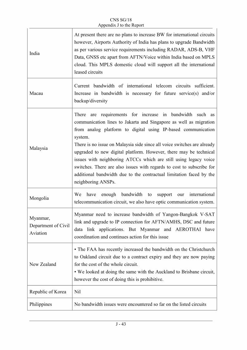
CNS SG/18 Appendix J to the Report
J - 43
India
At present there are no plans to increase BW for international circuits however, Airports Authority of India has plans to upgrade Bandwidth as per various service requirements including RADAR, ADS-B, VHF Data, GNSS etc apart from AFTN/Voice within India based on MPLS cloud. This MPLS domestic cloud will support all the international leased circuits
Macau Current bandwidth of international telecom circuits sufficient. Increase in bandwidth is necessary for future service(s) and/or backup/diversity
Malaysia
There are requirements for increase in bandwidth such as communication lines to Jakarta and Singapore as well as migration from analog platform to digital using IP-based communication system. There is no issue on Malaysia side since all voice switches are already upgraded to new digital platform. However, there may be technical issues with neighboring ATCCs which are still using legacy voice switches. There are also issues with regards to cost to subscribe for additional bandwidth due to the contractual limitation faced by the neighboring ANSPs.
Mongolia We have enough bandwidth to support our international telecommunication circuit, we also have optic communication system.
Myanmar, Department of Civil Aviation
Myanmar need to increase bandwidth of Yangon-Bangkok V-SAT link and upgrade to IP connection for AFTN/AMHS, DSC and future data link applications. But Myanmar and AEROTHAI have coordination and continues action for this issue
New Zealand
• The FAA has recently increased the bandwidth on the Christchurch to Oakland circuit due to a contract expiry and they are now paying for the cost of the whole circuit. • We looked at doing the same with the Auckland to Brisbane circuit, however the cost of doing this is prohibitive.
Republic of Korea Nil
Philippines No bandwidth issues were encountered so far on the listed circuits

CNS SG/18 Appendix J to the Report
J - 44
Singapore
Currently, there is no urgent or immediate need for increase in bandwidth. The difficulty we faced usually is due to cost factor. Since most of the circuits are bilateral, both States must agree to the cost increase (if any) to be incurred at their own end before proceeding with the procurement.
Thailand
As for our satellite services, we have enough spare bandwidth to accommodate an increase (temporally) in bandwidth usage without additional cost. However, for the lease lines, we do have restriction for connection with certain sites due to hardware limitation, e.g. no available port or timeslot. Furthermore, requesting for more bandwidth requires additional charges, which will take a long time for us to get approved.
United States (Salt Lake City)
Yes. The FAA is in need to increase the bandwidth to support Traffic Flow Management data, weather data, etc. but unable to carry out due to high cost incurred to other ANSPs. In addition, it is time consuming to upgrade the service as the selected vendors have to establish business process to each other and the process to obtain formal bi-lateral agreement. It’s usually taken 3-5 years to upgrade telecommunication service between ANSPs.
United States (Oakland)
Yes. The FAA is in need to increase the bandwidth to support Traffic Flow Management data, weather data, etc. but unable to carry out due to high cost incurred to other ANSPs. In addition, it is time consuming to upgrade the service as the selected vendors have to establish business process to each other and the process to obtain formal bi-lateral agreement. It’s usually taken 3-5 years to upgrade telecommunication service between ANSPs
No. of failure
1-jan-2013 to 1-jan-2014
RomeLease Line20cable fail
SingaporeLease Line4cable fail
MumbaiLease Line22cable fail
HongkongLease Line4cable fail
No. of failure
1-jan-2012 to 1-jan-2014
DhakaSatellite9maintenance ,electrical and equipment fail
YangonSatellite5maintenance and equipment fail
HochiminhSatellite5maintenance and equipment fail
Satellite4maintenance and equipment fail
submarine communications cable fail
and maintenance submarine communications cable
VientianeSatellite6maintenance ,electrical and equipment fail
Phnom
Penh
Satellite
4maintenance ,electrical and equipment fail
Kuala
lumpurLease Line17
SiteLink TypeCause
SiteLink TypeCause
SiteActual Performance(%)
Rome (Lease Line)91.7136
Hong Kong (Lease Line)99.9231
Singapore (Lease Line)99.9486
Mumbai (Lease Line)93.0222
Kuala Lumpur (Lease Line)93.3753
Kuala Lumpur (Satellite)99.4813
Dhaka (Satellite)99.9471
Yangon (Satellite)99.9589
Ho Chi Minh (Satellite)97.8154
Vientiane (Satellite)99.9374
Phnom Penh (Satellite)99.8763
Kun Ming (Satellite)99.9952
SiteRequired Performance (%)
Rome (Lease Line)99.9000
Hong Kong (Lease Line)99.9000
Singapore (Lease Line)99.9000
Mumbai (Lease Line)99.9000
Kuala Lumpur (Lease Line)99.9000
Kuala Lumpur (Satellite)99.9700
Dhaka (Satellite)99.9700
Yangon (Satellite)99.9700
Ho Chi Minh (Satellite)99.9700
Vientiane (Satellite)99.9700
Phnom Penh (Satellite)99.9700
Kun Ming (Satellite)99.9700

ID CRV Task
Task Name Start Finish Predecessors Duration
1 1 ACSICG/1 Mon 5/12/14 Fri 5/16/14 5 days?2 2 CNS SG/18 Mon 7/21/14 Fri 7/25/14 5 days?3 3 APANPIRG/25 Mon 9/8/14 Fri 9/12/14 5 days?4 4 ACSICG/2 Mon 5/11/15 Fri 5/15/15 5 days?5 5 CNS SG/19 Mon 7/13/15 Fri 7/17/15 5 days?6 6 APANPIRG/26 Mon 9/14/15 Fri 9/18/15 5 days?7 7 ACSICG/3 Mon 5/9/16 Fri 5/13/16 5 days?8 8 CNS SG/20 Mon 7/11/16 Fri 7/15/16 5 days?9 9 APANPIRG/27 Mon 9/12/16 Fri 9/16/16 5 days?
10 10 CONOP Tue 12/3/13 Tue 10/7/14 220.36 day...11 11 Draft CONOP Tue 12/3/13 Mon 12/23/13 14.8 days?12 12 Update CONOP from ACSICG/1 Mon 5/19/14 Tue 6/17/14 1 21.27 days?
13 13 Update CONOP from CNS/18 Mon 7/28/14 Thu 8/7/14 2 8.73 days?
14 14 Refine CONOP after APANPIRG Mon 9/15/14 Tue 10/7/14 3 16.36 days?
15 15 MSA/DoA Tue 12/3/13 Fri 12/22/17 1059 days?16 16 Draft DoA Tue 12/3/13 Fri 12/13/13 8.5 days?17 17 Funding Cost Assessment Fri 12/13/13 Fri 4/4/14 16 80 days?18 18 Update MSA/DoA from ACSICG/1 Mon 5/19/14 Thu 7/10/14 1 39 days?
19 19 Update MSA/DoA from CNS/18 Mon 7/28/14 Tue 8/19/14 2 17 days?
20 20 Finalize MSA for Signature (if needed) Mon 9/15/14 Fri 10/24/14 3 30 days?
21 Deadline to decide to be a Pioneer Party
Fri 11/14/14 Fri 11/14/14 1 day?
22 21 Sign MSA (Stage 1) Mon 9/8/14 Mon 12/15/14 3SS 71 days23 22 Finalize DOA (Stage 2) for Signature Mon 10/27/14 Thu 6/30/16 20,34,64FF 439 days?
24 23 Sign DoA (Stage 2) Mon 9/19/16 Fri 12/22/17 23,9,64 330 days?25 24 CBA Tue 12/3/13 Thu 6/4/15 393 days?26 25 Data Collection (Including State Letter) Tue 12/3/13 Fri 2/14/14 54 days?
27 26 Draft CBA for ACSICG/1 Mon 2/17/14 Fri 4/25/14 26 50 days?
28 27 Data Collection All Parties Mon 4/28/14 Wed 12/31/14 27 178 days?
29 28 Update CBA for ACSICG/2 from RFI Mon 3/23/15 Thu 6/4/15 35 54 days?30 29 RFI Mon 3/17/14 Fri 3/20/15 265 days?31 30 Draft RFI Mon 3/17/14 Fri 7/11/14 11 85 days?
USA (Leader),Australia,India,ICAO Secretariat,Japan
Fiji,Australia,USA (Leader),Japan,Thailand,India,China,Hong Kong China,New Zealand,Singapore,ICAO Secretariat
Singapore,Australia,Fiji,Japan,Thailand,India,China,Hong Kong China,New Zealand,USA (Leader),ICAO Secretariat
Singapore,Australia,Fiji,Japan,Thailand,India,China,Hong Kong China,New Zealand,USA (Leader),ICAO Secretariat
USA,Japan,Hong Kong China,Singapore (Leader)
ICAO Secretariat,ICAO TCB
USA,Japan,Hong Kong China,Singapore (Leader)
Singapore (Leader),US,Japan,Hong Kong China
Singapore (Leader),US,Japan,Hong Kong China
November 14, 2014
Hong Kong China,US,Japan,Singapore (Leader)
ICAO Secretariat (Leader),USA,Thailand,Japan,Fiji
Japan (Leader),Australia,India,ICAO Secretariat
ICAO Secretariat (Leader),USA,Thailand,Japan,Fiji
USA (Leader),Australia,Singapore,Thailand,ICAO RO
D J F M A M J J A S O N D J F M A M J J A S O N D J F M A M J J A S O N D J F M A M J J A S O N DHalf 1, 2014 Half 2, 2014 Half 1, 2015 Half 2, 2015 Half 1, 2016 Half 2, 2016 Half 1, 2017 Half 2, 2017 H
Task
Split
Milestone
Summary
Project Summary
External Tasks
External Milestone
Inactive Milestone
Inactive Summary
Manual Task
Duration-only
Manual Summary Rollup
Manual Summary
Start-only
Finish-only
External Tasks
External Milestone
Progress
Deadline
Wed 7/9/14
Page 1
Project: CRVTFProject_rev08_2007
ssomsri
Typewritten Text
CNS SG/18 Appendix K to the Report
ssomsri
Typewritten Text
ssomsri
Typewritten Text
ssomsri
Typewritten Text
ssomsri
Typewritten Text
ssomsri
Typewritten Text
ssomsri
Typewritten Text
ssomsri
Typewritten Text
ssomsri
Typewritten Text
K - 1
ssomsri
Typewritten Text
ssomsri
Typewritten Text

ID CRV Task
Task Name Start Finish Predecessors Duration
32 31 Release of RFI Mon 7/14/14 Fri 8/15/14 31 25 days
33 32 Waiting Response Mon 8/18/14 Fri 11/28/14 32 75 days34 33 RFI Close Fri 11/28/14 Fri 11/28/14 33 0 days35 34 Review and Process RFI Mon 12/1/14 Fri 3/20/15 34,1,27 80 days?
36 35 RFP Tue 4/1/14 Thu 7/9/15 333 days?37 36 Gather State Information Mon 3/23/15 Fri 5/22/15 14,35 45 days?
38 37 Generate Requirements Tue 4/1/14 Fri 4/17/15 274 days39 37-a Make User Requirement Template Tue 4/1/14 Mon 4/28/14 1 mon
40 37-b Make Safety Preliminary analysis Tue 4/29/14 Mon 3/30/15 39 12 mons
41 37-c Make user Requirements Thu 7/24/14 Fri 4/17/15 9.56 mons
42 38 Determine Selection Process Mon 4/20/15 Mon 5/4/15 22,41 11 days?43 39 Determine Awarding Process Tue 5/5/15 Thu 6/4/15 42 23 days?44 40 Update APANPIRG/26 on Sealed
TenderFri 6/5/15 Thu 7/9/15 43 25 days?
45 41 TCB Process Fri 4/4/14 Fri 11/11/16 680.5 days?46 42 Funding Preparation Fri 4/4/14 Fri 12/26/14 17 190 days47 43 Funds are ready Fri 12/26/14 Fri 12/26/14 46 0 days48 44 TCB Requirement Reviews and
PackagingMon 4/20/15 Fri 6/12/15 22,38,47 40 days
49 44-a (a) Review the technical specifications Mon 4/20/15 Fri 5/8/15 41 3 wks
50 44-b (b) Develop the evaluation criteria Mon 5/11/15 Fri 5/22/15 49 2 wks
51 44-c (c) Prepare tender documents Mon 4/20/15 Fri 6/12/15 2 mons
52 45 TCB Publication of Sealed Tender Mon 4/20/15 Fri 6/19/15 45 days53 45-d (d) Identify suitable suppliers Mon 4/20/15 Fri 5/15/15 49SS 1 mon
54 45-e (e) Advertise Sealed Tender (ST) Mon 6/15/15 Fri 6/19/15 53,51 1 wk
55 46 Consultation & ST Response Mon 6/22/15 Fri 1/8/16 54 145 days?56 Wait for proposals from Tenderers Mon 6/22/15 Fri 9/11/15 54 60 days
57 Proposals from Tenderers Mon 9/14/15 Mon 9/14/15 56 1 day?
58 46-f (f) Coordinate site surveys Mon 6/22/15 Fri 9/11/15 3 mons
59 46-g (g) Handle tender clarifications Mon 9/14/15 Fri 12/4/15 58 3 mons
60 46-h (h) Face to Face meeting with RT Mon 1/4/16 Fri 1/8/16 59FS+1 mon 1 wk
61 53 Establish Common Provisions (including CRV design and SLA)
Mon 9/14/15 Fri 3/25/16 59SS 7 mons
62 47 Selection Mon 4/4/16 Mon 6/27/16 60FS+3 mo 61 days?63 47-i (i) Carry out a preevaluation and evaluation mee Mon 4/4/16 Fri 6/24/16 3 mons
64 48-l (l) Notify selection to supplier Mon 6/27/16 Mon 6/27/16 63 1 day?
65 49 Contract preparation Tue 6/28/16 Mon 9/19/16 64 60 days66 49-k (k) Prepare Individual Service Contract template Tue 6/28/16 Mon 9/19/16 3 mons
67 49-j (j) Participate as a technical advisor to the CRV Ta Mon 6/8/15 Fri 11/11/16 375 days
68 50 Implementation Plan Tue 4/5/16 Mon 9/19/16 120 days?69 51 Draft Implementation Plan Tue 6/28/16 Mon 9/19/16 62 3 mons?70 52 OOG Setting Up and Staffing Tue 4/5/16 Mon 9/19/16 69FF 6 mons?71 Start Individual Service Contracts Tue 9/20/16 Tue 9/20/16 66 1 day?
USA (Leader),Australia,Singapore,Thailand,ICAO RO
Suppliers
November 28, 2014
USA (Leader),Australia,Singapore,Thailand,ICAO RO
Thailand (Leader),Fiji Japan Malaysia Philippines Singapore,USA,ICAO Secretariat
ICAO Secretariat
ICAO Secretariat (Leader),Australia,Hong Kong China,India Singapore,Thailand
Thailand (Leader),Fiji Japan Malaysia Philippines Singapore,USA,ICAO Secretariat,Australia
ICAO Secretariat,ICAO TCB
Pioneer States
CRV TF
Pioneer Parties
December 26, 2014
ICAO TCB
ICAO TCB,Pioneer Parties,ICAO Secretariat
ICAO TCB,Pioneer Parties,ICAO Secretariat
ICAO TCB
June 19, 2015
September 14, 2015
ICAO TCB
ICAO TCB
ICAO TCB,Pioneer Parties,ICAO Secretariat
ICAO TCB,Pioneer Parties,ICAO Secretariat,Tenderers
ICAO TCB,Pioneer Parties,ICAO Secretariat
June 27, 2016
ICAO TCB,Pioneer Parties,ICAO Secretariat
ICAO TCB
Pioneer Parties,Ordinary Parties
September 20, 2016
D J F M A M J J A S O N D J F M A M J J A S O N D J F M A M J J A S O N D J F M A M J J A S O N DHalf 1, 2014 Half 2, 2014 Half 1, 2015 Half 2, 2015 Half 1, 2016 Half 2, 2016 Half 1, 2017 Half 2, 2017 H
Task
Split
Milestone
Summary
Project Summary
External Tasks
External Milestone
Inactive Milestone
Inactive Summary
Manual Task
Duration-only
Manual Summary Rollup
Manual Summary
Start-only
Finish-only
External Tasks
External Milestone
Progress
Deadline
Wed 7/9/14
Page 2
Project: CRVTFProject_rev08_2007
ssomsri
Typewritten Text
CNS SG/19 Appendix K to the Report
ssomsri
Typewritten Text
ssomsri
Typewritten Text
ssomsri
Typewritten Text
ssomsri
Typewritten Text
K - 2
ssomsri
Typewritten Text
ssomsri
Typewritten Text
ssomsri
Typewritten Text

CNS SG/18
Appendix L to the Report
L - 1
Common Regional Virtual Private Network (VPN) of
Asia/Pacific Air Navigation Planning and Implementation Regional Group (APANPIRG) (APANPIRG CRV TF)
TERMS OF REFERENCE 1. Background
The establishment of APANPIRG CRV TF was proposed by a number of States at the Eighth meeting of Aeronautical Communication Network Implementation Co-ordination Group (ATNICG) and the Twenty Fourth meeting of APANPIRG, as a dedicated task force to study regional virtual private network (VPN) and develop a detailed proposal by January 2016. The APANPIRG CRV TF was formally established in accordance to APANPIRG Decision (24/32) (Bangkok, Thailand, 24-26 June 2013). 2. Terms of Reference
In order to address the common VPN issues, the following activities are to be developed by the APANPIRG CRV TF:
a) Develop and propose to the APANPIRG a multinational agreement proposing the
organizational policies and procedures for managing the regional network including inter-regional coordination;
b) Study and propose to the APANPIRG the concept of operation for common VPN for
APAC Region including cost-benefit consideration;
c) Develop the RFI to be distributed to interested service providers and analyze questions/information received from RFI;
d) Develop the Request For Proposal (RFP) for common VPN for APAC Region and
evaluate/select the best proposal; and
e) Develop the procedures for commissioning common VPN for APAC Region.
2. Work Programme
See attachment.
3. Working Methods a) APANPIRG CRV TF Work Programme should present their activities in terms of
objectives, responsibilities, deliverables and timelines;
b) APANPIRG CRV TF will avoid duplication of work within the regional working group and maintain close coordination among the existing entities to optimize the use of available resources and experience;
ssomsri
Typewritten Text
ssomsri
Typewritten Text
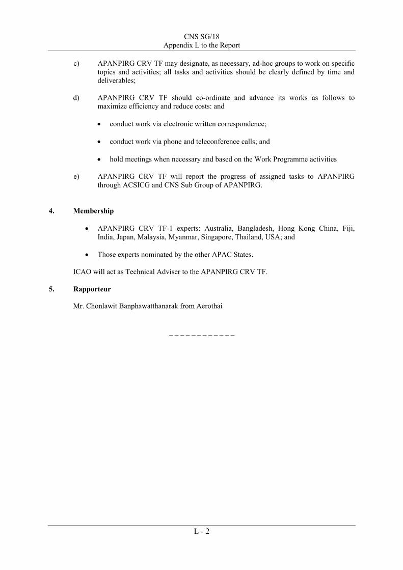
CNS SG/18
Appendix L to the Report
L - 2
c) APANPIRG CRV TF may designate, as necessary, ad-hoc groups to work on specific topics and activities; all tasks and activities should be clearly defined by time and deliverables;
d) APANPIRG CRV TF should co-ordinate and advance its works as follows to
maximize efficiency and reduce costs: and conduct work via electronic written correspondence;
conduct work via phone and teleconference calls; and
hold meetings when necessary and based on the Work Programme activities
e) APANPIRG CRV TF will report the progress of assigned tasks to APANPIRG
through ACSICG and CNS Sub Group of APANPIRG. 4. Membership
APANPIRG CRV TF-1 experts: Australia, Bangladesh, Hong Kong China, Fiji, India, Japan, Malaysia, Myanmar, Singapore, Thailand, USA; and
Those experts nominated by the other APAC States. ICAO will act as Technical Adviser to the APANPIRG CRV TF.
5. Rapporteur
Mr. Chonlawit Banphawatthanarak from Aerothai
_ _ _ _ _ _ _ _ _ _ _ _

M - 1
INTERNATIONAL CIVIL AVIATION ORGANIZATION
Common Regional Virtual Private Network (CRV) Of Asia/Pacific Air Navigation Planning and Implementation
Regional Group (APANPIRG)
Concept of Operations
INTERNATIONAL CIVIL AVIATION ORGANIZATION ASIA-PACIFIC OFFICE
CNS SG/18 Appendix M to the Report
ssomsri
Typewritten Text
ssomsri
Typewritten Text

M - 2
Document Change Record
Version Number
Date
Reason for Change
Sections Affected
0.1 March 1, 2014
Initial Draft All
0.2 March 28, 2014
Addition of Section 4 4
0.3 April 02, 2014
Inclusion of comments from ICAO
Result of review by CRV Participants on 02 April14 Meeting
All
0.4 April 30, 2014
Modifications resulting from review in 0.3 above All
0.5 June 3, 2014
Modifications resulting from ACSICG/TF meeting All
0.6 June 19, 2014
Modifications resulting from participants’ comments
All

M - 3
Table of Contents 1 INTRODUCTION ...................................................................................................... 1
1.1 Purpose ................................................................................................................. 1 1.2 Background / Current Capability ......................................................................... 1 1.3 Geographic Applicability ..................................................................................... 2 1.4 Intended Audience................................................................................................ 2 1.5 Intended Benefits................................................................................................ 32
2 OPERATIONAL CONCEPT ..................................................................................... 4 2.1 Objective .............................................................................................................. 4 2.2 Scope .................................................................................................................... 4 2.3 Services Carried by the CRV Network ................................................................ 5 2.4 Use Cases ............................................................................................................. 5
2.4.1 Use Case 1 - ANSPs Interconnect AMHS .................................................... 5
2.4.2 Use Case 2 - ANSPs Implement ATC Voice Co-ordination Circuits .......... 6 2.4.3 Use Case 3 - ANSPs Share Automatic Dependent Surveillance-Broadcast (ADS-B) Data Along Their Border............................................................................. 7 2.4.4 Use Case 4: ANSP ‘A’ is Experiencing Poor AMHS Service with ANSP ‘B’ 7 2.4.5 Use Case 5 - ANSP ‘A’ is Experiencing Poor Voice Communications With ANSP ‘B’ .................................................................................................................... 8 2.4.6 Use Case 6 - ANSP ‘B’ Has Two Access Points and One Fails................... 9 2.4.7 Use Case X:the CRV network wants to connect to another Region (to be developed ata later stage) ........................................................................................ 910
Question to the vendors (RFI)? .................................. Error! Bookmark not defined.10 Action F.Lecat: to inform CRV about the PENS Service Provider now/in the future.................................................................................... Error! Bookmark not defined.10
2.5 Measures of Effectiveness ............................... Error! Bookmark not defined.10 2.6 Stakeholders ................................................................................................... 1011
2.6.1 Introduction .............................................. Error! Bookmark not defined.11
2.6.2 Roles and Responsibilities ....................... Error! Bookmark not defined.11 2.6.3 Transition of responsibilities between stage 1 and stage 2 (CRV and OOG coordination) ......................................................... Error! Bookmark not defined..13
2.7 Capability Description.................................................................................... 1114
2.7.1 Accessibility ............................................................................................ 1114 2.7.2 Physical Connectivity Between Member and CRV Service Provider .... 1114 2.7.3 Access Bandwidth and Quality of Services (QoS) ................................. 1114 2.7.4 Network Security .................................................................................... 1215 2.7.5 Capacity for Growth and Expansion ....................................................... 1215
2.7.6 Network Monitoring ............................................................................... 1216 2.7.7 Reporting................................................................................................. 1316
2.7.8 Service Notifications ............................................................................... 1316 2.7.9 Network Design and IP Addressing ........................................................ 1316
2.8 Support Environment ..................................................................................... 1417 3 REGULATORY REQUIREMENTS.................................................................... 1518
3.1 ICAO Standards and Regulations .................................................................. 1518 3.2 ANSP Specific Requirements ........................................................................ 1518

M - 4
4 NETWORK GROWTH AND TRANSITION ..................................................... 1619
4.1 Initial Phase of Operation ............................................................................... 1619 4.2 Additional Participants in CRV ..................................................................... 1619 4.3 Effect of CRV on Boundary Intermediate Systems (BIS) and Backbone Boundary Intermediate Systems (BBIS) ................................................................... 1619 4.4 CRV Network Expansion ............................................................................... 1619
4.4.1 Expansion of Membership ...................................................................... 1619 4.4.2 Expansion of Connectivity ...................................................................... 1720 4.4.3 Expansion of Use and Applicability ....................................................... 1720
REFERENCES ............................................................................................................. 1821 ABBREVIATIONS ...................................................................................................... 1922

M - 1
1 INTRODUCTION
1.1 Purpose The purpose of this document is to provide a Concept of Operations (ConOps) for a Common Regional Virtual Private Network (CRV) to serve the Asia/Pacific Region. This would be an Internet Protocol (IP) based VPN using a private commercial network to provide service for the exchange of Air Traffic Service Message Handling System (AMHS) data and potentially other types of data. The Air Navigation Service Providers (ANSPs) of the Asia/Pacific Region see a clear need for an upgrade to the current telecommunications network, and the CRV is the recommended solution as determined by the Aeronautical Communication Services Implementation Coordination Group (ACSICG) of Asia/Pacific Air Navigation Planning and Implementation Regional Group (APANPIRG) of the International Civil Aviation Organization (ICAO). 1.2 Background / Current Capability Currently, aeronautical ground-ground communications in the ICAO Asia/Pacific Region, and in particular Aeronautical Fixed Telecommunication Network (AFTN) and AMHS services, operate over point-to-point international leased circuits. As pointed out by the ICAO survey on ground-ground communications performed early 2014, this network configuration exhibits a number of limitations, including (but not limited to):
cost limitations: high costs per connection; a marked obsolescence threat due to ageing technologies and protocols
(IPL, X25 etc); a need for telecommunication backup or diversity, although the current
reliability is assessed as rather satisfactory; problems experienced with change management;
o Need for separate requisition process for each new connection, generally a time-consuming and cumbersome process;
o Limited flexibility for increase in bandwidth; o Limited flexibility for expansion to other end-points; o Need to deal with half circuit vs. full circuit arrangements, depending upon
policies of ANSPs involved; A design that is not adapted to the current and new needs;

M - 2
o Potential duplication of network services as bandwidth for other types of data are generally obtained separately;
o the inability to switch to new protocols like VoIP or SWIM with an efficient network design; and
Heterogeneous practices as to performance requirements and monitoring. A CRV Task Force (TF) was formally established in accordance with APANPIRG Decision (24/32), (Bangkok, Thailand, 24-26 June 2013). There it was determined that a dedicated, common network operated by a service provider is a viable approach to be considered to replace the current configuration. Common networks have successfully been deployed in other ICAO regions (e.g. PENS in the EUR Region and MEVA in the CAR Region). Therefore, the Meeting adopted the following decision:
Decision 24/32 - Common Regional Virtual Private Network (VPN) Task Force
That, a Task Force with Subject Matter Experts (SME) be established to study the virtual private network and develop a detailed proposal by 2016. The Task Force reports the outcome of its study to APANPIRG through ACSICG and CNS SG. 1.3 Geographic Applicability The initial intended geographic coverage of the CRV consists of the accredited States and Territories to ICAO Asia Pacific Regional Office. 1.4 Intended Audience This ConOps presents a vision for establishing an IP VPN to provide efficient, cost-effective network services for AMHS and other IP-based services. The intended audience of this ConOps is the membership of ACSICG and all stakeholders who are interested in the acquisition and implementation of the CRV, including all interested parties of each ANSP in the ICAO Asia/Pacific Region. The document will also be presented to APANPIRG to be used during the approval process for the CRV. It can be used as a source of information for the development of the Request for Information (RFI) and Sealed Tender (ST) to be written and provided to potential vendors as part of the tender process.

M - 3
1.5 Intended Benefits The Asia/Pacific VPN is anticipated to provide a broad range of benefits to the CRV Members, including (but not limited to):
Cost efficiencies as compared to multiple point-to-point connections; Reduced procurement time and effort, as each ANSP will require only the
initial connection to the CRV; Potential to carry new services (i.e., ATFM, SWIM, etc.); Transition from the current bandwidth limitations to an harmonized and
homogeneous level of network performance and services delivered by the CRV Service Provider, including ease of growth, connectivity and modification;
Potential for additional connectivity beyond the initial AFTN-like routing network, including both regional and inter-regional connectivity;
Greater ease of handling of network service issues.

M - 4
2 OPERATIONAL CONCEPT
2.1 Objective The objective of the CRV is to offer a safe, secure, robust and cost effective telecommunications transport service to all Members, and to offer the possibility to all Candidates to contract to that service. It will facilitate voice and data communications between Members by allowing all participants on the network to establish communications with each other. Telecommunication costs will be minimized as countries will only need a small number of connections to a far reaching network, rather than individual connections to each neighboring state. Each user of the network will take responsibility for their own IT security. However, the network will support this security by being a closed private network, without access to the public Internet. Each Member can (and should) establish IT security protections so that they comply with their organization’s security policies. At their discretion, some Members may also establish bi-lateral VPN overlays over the CRV to provide an additional layer of protection. Finally, the network should support the telecommunication standards which the Region intends to use. Accordingly, it should carry both IP version 4 and 6.
2.2 Scope The scope of the CRV is to provide a cross-border telecommunications network for Members in the ICAO Asia/Pacific Region. This network will allow each Member to easily communicate with any other Members in the Region. To facilitate the creation and on-going operation of this network, this document also includes the creation of the business rules and management for the network. The network will be used to support the delivery of ATM services. It must be fit for purpose so that each ANSP can provide the highest levels of safety. Finally, it is possible that over time the network will grow to include other users such as the military, airport, ATM industry and airlines. If this does occur then it is anticipated

M - 5
that this document will be revised to accommodate the increased scope of the additional stakeholders. If widely adopted, the CRV is a strong candidate to provide the network which underpins the future System Wide Information Management (SWIM).
2.3 Services Carried by the CRV Network Ground-ground voice ATM communications, referred to as voice
communications Air-ground Data Link communications (in case we have one day ATN routers in
common), referred to as Data Link communications Ground-ground ATS surveillance data, referred to as surveillance data Ground-ground AIDC data, referred to as AIDC data Ground-ground AIM data, referred to as AIM data Ground-ground ATFM data, referred to as ATFM data Ground-ground SWIM data, referred to as ATFM data Miscellaneous data: other data not pertaining to the categories above, or carried
for TEST purpose only Any other category as agreed later
2.4 Use Cases The Use Cases contained in this section illustrate how the proposed capability will operate and how users will interact. 2.4.1 Use Case 1 - ANSPs Interconnect AMHS
Summary of Situation
ANSP ‘A’ and ANSP ‘B’ wish to have a direct connection between their AMHS. Both ANSPs decide that the AMHS application shall be built upon the Aeronautical Telecommunication Network (ATN). The ATN will in turn use the CRV.
User Response
Each ANSP already has a connection to the CRV. Each ANSP: 1. Notifies the OOG Coordinator of their intention to establish the
new facility. 2. Determines if their existing access speed is sufficient. If it is not
the ANSP will arrange with the CRV Service Provider to increase their bandwidth.
3. Negotiates bi-laterally with the other ANSP to determine what IT security arrangements are required. In this User Case they decide to implement an IPSec VPN.

M - 6
4. Negotiates bi-laterally with the other ANSP to determine what testing, acceptance and commissioning procedures are required.
Operational Needs
UC1.1 The CRV must meet the reliability and availability needs of AMHS. UC1.2 The CRV must provide IP version 4 transport for the ATN. UC1.3 The CRV must provide IP version 6 transport for the ATN. UC1.4 The CRV must allow the ANSPs to implement IPSec VPN tunnels. UC1.5 The CRV must allow for bandwidth changes.
2.4.2 Use Case 2 - ANSPs Implement ATC Voice Co-ordination Circuits
Summary of Situation
ANSPs ‘A’ and ‘B’ wish to build upon the success of their AMHS implementation and have identified four voice circuits which should be moved to the CRV.
User Response
Each ANSP already has a connection to the CRV. Each ANSP: 1. Notifies the OOG Coordinator of their intention to establish the
new facility. 2. Determines if their existing access speed is sufficient. If it is not
the ANSP will arrange with the Service Provider to increase their bandwidth.
3. Negotiates bi-laterally with the other ANSP to determine what IT security arrangements are required. In this User Case they decide to not implement an IPSec VPN as they see that their existing firewalls provide a compliant level protection.
4. Negotiates bi-laterally with the other ANSP to determine what testing, acceptance and commissioning procedures are required.
5. Each ANSP will tag the Voice over Internet Protocol (VoIP) and Session Initiation Protocol (SIP) data with appropriate priority markings to allow the CRV Service Provider to identify the voice traffic.
Operational Needs
UC2.1 The CRV must meet the reliability and availability needs of ATC voice. UC2.2 The CRV must provide IP version 4 transport for the VoIP. UC2.3 The CRV must provide IP version 6 transport for the VoIP.

M - 7
UC2.4 The CRV will use the high priority tags in the packet headers to ensure that VoIP traffic is given high priority and minimal delay. The CRV must give an appropriate level of priority to SIP. UC2.5 The CRV must deliver voice so that it is clearly understood with minimal delay.
2.4.3 Use Case 3 - ANSPs Share Automatic Dependent Surveillance-Broadcast
(ADS-B) Data Along Their Border Summary of Situation
ANSP ‘B’ and ANSP ‘C’ decide that sharing ADS-B data from ground stations along their border will improve safety. They decide to use the CRV to transport the data.
User Response
Each ANSP already has a connection to the CRV. Each ANSP: 1. Notifies the OOG Coordinator of their intention to establish the
new facility. 2. Determines if their existing access speed is sufficient. If it is not
the ANSP will arrange with the Service Provider to increase their bandwidth.
3. Negotiates bi-laterally with the other ANSP to determine what IT security arrangements are required. In this User Case they decide to implement an IPSec VPN.
4. Negotiates bi-laterally with the other ANSP to determine what testing, acceptance and commissioning procedures are required.
5. Each ANSP will tag the ADS-B data with a medium priority marking to allow the CRV Service Provider to give it an appropriate transport.
Operational Needs
UC3.1 The CRV must meet the reliability and availability needs of informational ADS-B. UC3.2 The CRV must provide IP version 4 transport for the ADS-B. UC3.3 The CRV must provide low drop rates and latency for ADS-B.
2.4.4 Use Case 4: ANSP ‘A’ is Experiencing Poor AMHS Service with ANSP ‘B’
Summary of Situation
ANSP ‘A’ notices that AMHS service is not reliable with ANSP ‘B’.

M - 8
User Response ANSP ‘A’ and ANSP ‘B’ both start to diagnose the problem by:
1. Checking their systems. 2. Notifying the CRV Service Provider. 3. Hopefully at this point the problem is discovered and resolved. 4. If no fault is found then the OOG Coordinator is notified. Each
ANSP verifies stability of their AMHS system, including the ability (or lack thereof) to communicate with other ANSPs. Local network elements will be verified, and end-to-end stepwise validation will take place. This will provide enough information to determine the location of the fault.
5. The fault is rectified. Operational Needs
UC4.1 The CRV Service Provider and the CRV Members must have a clear fault resolution process.
2.4.5 Use Case 5 - ANSP ‘A’ is Experiencing Poor Voice Communications With ANSP ‘B’ Summary of Situation
ANSP ‘A’ notices that when their voice calls go to ANSP ‘B’ that the call quality is poor.
User Response
ANSP ‘A’ starts to diagnose the problem by: 1. Checking their systems. 2. Notifying both the CRV Service Provider and ANSP ‘B’ of the
problem. 3. Hopefully at this point the problem is discovered and resolved. 4. If no fault is found then the OOG Coordinator is notified. Each
ANSP takes a packet capture of the voice call at the interface boundary. The packet captures are compared and examined for problems. This will provide enough information to determine the location of the fault.
5. The fault is rectified. Operational Needs
UC5.1 The CRV Service Provider and the CRV Members must have a clear fault resolution process.

M - 9
2.4.6 Use Case 6 - ANSP ‘B’ Has Two Access Points and One Fails
Summary of Situation
ANSP ‘B’ has two CRV access points, one in city Alpha and one in city Beta. City Alpha’s connection fails.
User Response
ANSP ‘B’ responds by: 1. Notifying the CRV Service Provider of the problem. The CRV
Service provider commences rectification action. 2. AMHS is unaffected, as ANSP ‘B’ is using ATN and the ATN has
automatically detected the fault and redirected traffic to use the city Beta path.
3. Current voice calls fail, but ATC have been provided with two methods to make their calls, one which is via city Alpha and one by city Beta. ATC select the city Beta path and quickly re-establish communications.
4. The ADS-B sharing completely fails as it does not have a rerouting capability.
5. The CRV Service Provider fixes the fault and service delivery returns to normal.
6. The ANSP notifies the OOG Coordinator so that the performance of the CRV Service Provider is tracked.
Operational Needs
UC6.1 If an ANSP requires high availability then they must design into their applications a mechanism which can use dual CRV access points. UC6.2 (optional) ANSPs wanting the network to automatically reroute in response to networking failures can implement bi-lateral measures.
2.4.7 Use Case X - The CRV Network Wants to Connect to Another Region (to be supplied at a later stage)

M - 10
2.5 Safety Case
CRV will carry operational data, the failure of which may have impacts on the safety of operations. As safety risks must remain controlled, a Safety risk management process including hazard identification, safety risk assessment and the implementation of appropriate remediation measures has to be implemented. The safety risk management component systematically identifies hazards that exist within the context of the delivery of CRV services. Hazards may be the result of systems that are deficient in their design, technical function, human interface or interactions with other processes and systems. They may also result from a failure of existing processes or systems to adapt to changes in the service providers’ operating environments. Careful analysis of these factors during the planning, design and implementation phases can identify potential hazards before CRV becomes operational. A list of Operational Hazards is attached to this CONOPS. The likelihood of their consequences occurring and severity will be assessed during the users’ requirement process. For the risks that cannot be eliminated by design, the mitigation strategy to reduce the risks when it is not acceptable will be part of the user requirements, OOG procedures and/or CSP's procedures. During the operational life cycle of the CRV network, reports or incident investigations will be analyzed by OOG to identify new safety hazards and/or monitor the frequency of occurrence. The escalation process will identify when any event is likely to have a safety impact handle it with appropriate care and urgency.
2.6 Stakeholders
The initial primary stakeholders of the CRV will be the set of ANSPs that form the group of founding members of the CRV. These will be the members which agree to the initial contract with the CRV Service Provider. As other ANSPs subsequently elect to join the CRV, they will be added to the primary stakeholders group. Other potential stakeholders may include military, airport, and airline representatives should it become practical for them to join the network. Secondary stakeholders may include service providers and manufacturers, as well as military, airport, and airline representatives who may not join the network but could be associated users, via a gateway, for example.

M - 11
2.7 Capability Description
The CRV is required to provide a telecommunications network between Members. While there are some common requirements, each Member will have different needs and it is expected that a variety of connections will be established.
2.7.1 Accessibility The CRV Service Provider shall offer access to the CRV network to every Member. The location of the interface point shall be at the Member’s premises.
2.7.2 Physical Connectivity Between Member and CRV Service Provider The choice of physical connector type to be used between the Member and the CRV Service Provider is a matter for those two organizations to decide. Commonly this may be 100/1000 BaseT Ethernet; however, other technologies are possible. Each Member will determine the number and location of connections to the CRV Service Provider. Those Members who chose to have more than one connection will gain the benefits of network diversity and higher availability. However, this diversity and higher availability may be dictated at some connection points by the performance and safety requirements, depending of the role played by the Member regarding a particular application (example: hosting an application hub, or an interregional connection).
2.7.3 Access Bandwidth and Quality of Services (QoS) Each CRV Member shall determine what amount of bandwidth they require for each Quality of Service (QoS) sub queue. For example, a Member may decide that they need 128kbps of high priority voice bandwidth, plus 512kbps of low priority traffic.
Figure 1: Traffic priority
PE (Provider Edge Router)

M - 12
In addition, each CRV Member will determine the total access bandwidth that they need to purchase.
2.7.4 Network Security The CRV is to be a private network, only available and dedicated to CRV Members. It is not to be connected to the public Internet and should not share the infrastructure with the public Internet. It is anticipated that Members will work bi-laterally to agree on their security arrangements so that they comply with their organizations’ security policies and minimal requirements, if any, as set by the OOG Coordinator. Any change to these initial arrangements should be coordinated with the OOG Coordinator. Some members may choose to use only a firewall, while others may require a firewall and an encrypted VPN. The firewall is provided by the CRV Member and remains under its responsibility. In Appendix A is provided a table of operational threats for each type of data.
CRV Member ‘A’ network
CRV Service Providers network
CRV Members ‘A’ firewall CRV Member
‘B’ networkCRV Member ‘B’
firewall
Encrypted VPN
Figure 2: Example of an encrypted Virtual Private Network (VPN)
To facilitate these overlays the network will accommodate packets of at least 1550 bytes in length, without requiring packet fragmentation.
2.7.5 Capacity for Growth and Expansion It is expected that the network will require greater speeds over time as more Members join and additional applications are added. If a Member requires a speed or class of service upgrade, this should ideally be a simple process whereby the Member contacts the OOG Coordinator to arrange for an upgrade.
2.7.6 Network Monitoring The CRV Service Provider shall provide their networking equipment into the Members’ premises. The CRV Service Provider shall manage and monitor the private network to promptly identify faults and performance degradations. On detecting an issue the CRV Service Provider will notify the CRV Member(s) and OOG coordinator and a fault rectification process will commence under the coordination by the OOG coordinator.

M - 13
2.7.7 Reporting The CRV Service Provider shall provide a monthly performance report to the OOG Coordinator. The report shall include the availability of each access link, any areas of congestion and a summary of notable events (e.g. additions or removal of accesses, discussion on any failures, physical configuration, etc.). The Coordinator will make this report available to the all Members.
2.7.8 Service Notifications The CRV Service Provider shall provide at least 10 days advance notice to a Member and OOG coordinator of any planned maintenance which will result in a loss or degradation of service.
2.7.9 Network Design and IP Addressing The CRV Service Provider shall provide the network design. It is anticipated that the typical Member interface will adopt the interface design shown below.
CRV Member’s Premises
Interface point
CRV Member’s network CRV Service
Providers network
CRV Members’s firewall CRV Service Provider’s
equipment
IP version 4 and version 6 address space will be proposed by the CRV Service Provider and agreed with the CRV Coordinator during the procurement process. It is anticipated that Members will need to use Network Address Translation (NAT) due to the various IP addressing schemes used by the Members. The OOG Coordinator will manage the Regional IP address plan after the contract is awarded.

M - 14
2.8 Support Environment Day to day support will be provided by the CRV Service Provider. This includes issues such as billing, reporting, fault detection and fault finding. Members hold the responsibility for ensuring that their access links are appropriately sized and configured. When establishing new inter-Member links these will need to be documented and implemented bi-laterally between the two Members, in coordination with the OOG Coordinator. For testing purposes, each Member can choose to either use an operational access or to establish a dedicated test access point.

M - 15
3 REGULATORY REQUIREMENTS
3.1 ICAO Standards and Regulations The CRV service shall support all functional and performance requirements for Aeronautical Fixed Service (AFS) as specified in ICAO Annex 10-Aeronautical Telecommunication, Volume III-Communication Systems, Part I-Digital Data Communication Systems and Part II-Voice Communication Systems. The following are the sections that are applied to the CRV service:
1. Part I-Digital Data Communication Systems (AFTN/AMHS/AIDC)
a. Chapter 3-Aeronautical Telecommunication Network (ATN)
b. Chapter 8-Aeronautical Telecommunication Fixed Network (AFTN)
2. Part II-Voice Communication Systems.
a. Aeronautical Speech Circuits (VoIP and legacy interface conversion to IP)
The CRV shall also support the functional and performance characteristics as specified in the following ICAO Documents:
1. 9896 ATN Manual for The ATN Using Internet Protocol Suite (IPS)
2. 9880 Manual on Detailed Technical Specifications for the Aeronautical Telecommunication Network (ATN) using ISO/OSI Standards and Protocols
The CRV service planning, procurement and implementation shall be compliant against the ICAO Supplementary Provisions Doc 7030 and Regional Air Navigation Plan Doc 9673. The safety case supporting the performance and safety requirements shall be conducted following ICAO Doc 9859 (Safety Management Manual).
3.2 ANSP Specific Requirements Any specific requirement that is not specified in the document indicated in Section 3.1 above shall be applied strictly between the CRV service provider and respective ANSP through bi-lateral contract document.

M - 16
4 NETWORK GROWTH AND TRANSITION
4.1 Initial Phase of Operation The initial operation of the CRV service is expected to include all Pioneer Parties as well as all Members which have elected to sign a contract with the Service Provider. Initially, it is likely that the CRV service shall be used to provide a platform for IP services that are either existing (currently using the point-to-point circuits which the CRV is intended to replace), or planned for the very near term (those services which would very likely have been hosted on point-to-point connections absent the benefit of the CRV). In general, the initial function of the CRV will be for the exchange of AMHS data between Members. However, as described below, it is envisioned that additional services and applications could be added to the CRV in the future.
4.2 Additional Participants in CRV New States /Administrations of the ICAO Asia/Pacific Region may opt in to become Members of the CRV, as such need and intent arises. This process shall be conducted via the OOG Coordinator.
4.3 Effect of CRV on Boundary Intermediate Systems (BIS) and Backbone Boundary Intermediate Systems (BBIS)
The current view of the Asia/Pacific ATN is of a network that is supported by a series of BIS and BBIS routers. These roles of these routers are as described in ICAO Document 9705. Currently, it is anticipated that there will be no change to this view of the Asia/Pacific ATN in the initial phase of operation of the CRV.
4.4 CRV Network Expansion Network expansion of the CRV can be thought of in several ways, as described in the following sections.
4.4.1 Expansion of Membership As described above, there may be new Members added as members of the CRV. This may be for purposes of AMHS connectivity or for other potential purposes as discussed below.

M - 17
4.4.2 Expansion of Connectivity While the initial connectivity within the CRV is expected to mirror current AFTN routing as per ICAO routing charts, the CRV may present opportunity for additional connectivity between members. While a point-to-point architecture (as used today) requires additional physical connections to be procured to add new connectivity between Members, the use of a common network (such as the CRV) provides the potential for any-to-any connectivity among its configured members. This may offer the opportunity for future expansion of connectivity between Members, thereby providing increased efficiency of routing and route diversion within the Region.
4.4.3 Expansion of Use and Applicability While the initial use of the CRV is intended to be for AMHS, consideration should be given in the future to utilizing the network non-AMHS applications, as listed in paragraph 2.3. For Members, the carriage of such applications may induce new classes of service or requirements. Such change as an increase in bandwidth would be obtainable in a much simpler manner than for point-to-point connectivity. For example, applications such as System Wide Information Management (SWIM), once deployed to the Region, may be able to use the CRV, thereby eliminating the need for acquisition of new network resources.

M - 18
REFERENCES To be supplied.

M - 19
ABBREVIATIONS ABBREVIATION DESCRIPTION ACSICG Aeronautical Communication Services Implementation
Coordination Group ADS-B Automatic Dependent Surveillance-Broadcast AFS Aeronautical Fixed Service AFTN Aeronautical Fixed Telecommunication Network AMHS Air Traffic Service Message Handling System ANSP Air Navigation Service Provider APANPIRG Asia/Pacific Air Navigation Planning and Implementation
Regional Group Asia/Pac Asia/Pacific ATC Air Traffic Control ATM Air Traffic Management ATN Aeronautical Telecommunication Network BBIS Backbone Boundary Intermediate System BIS Boundary Intermediate System CAR Caribbean Region ConOps Concept of Operations CRV Common Regional Virtual Private Network EUR European Region ICAO International Civil Aviation Organization IP Internet Protocol IPS Internet Protocol Suite NAT Network Address Translation OH Operational Hazard OOG Operation Oversight Group QoS Quality of Service RFI Request for Information RFP Request for Proposal SIP Session Initiation Protocol SME Subject Matter Expert ST Sealed Tender SWIM System Wide Information Management TF Task Force UC Use Case VoIP Voice Over Internet Protocol VPN Virtual Private Network
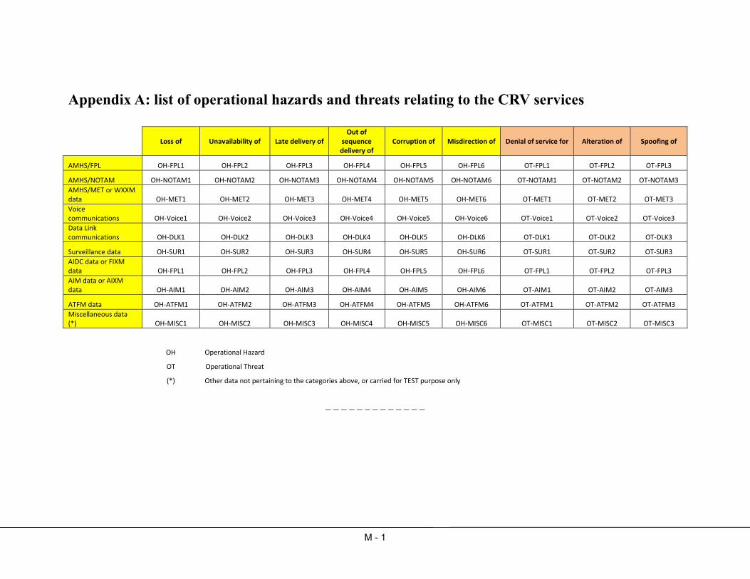
M - 1
Appendix A: list of operational hazards and threats relating to the CRV services
Loss of Unavailability of Late delivery of Out of
sequence delivery of
Corruption of Misdirection of Denial of service for Alteration of Spoofing of
AMHS/FPL OH-FPL1 OH-FPL2 OH-FPL3 OH-FPL4 OH-FPL5 OH-FPL6 OT-FPL1 OT-FPL2 OT-FPL3
AMHS/NOTAM OH-NOTAM1 OH-NOTAM2 OH-NOTAM3 OH-NOTAM4 OH-NOTAM5 OH-NOTAM6 OT-NOTAM1 OT-NOTAM2 OT-NOTAM3
AMHS/MET or WXXM data OH-MET1 OH-MET2 OH-MET3 OH-MET4 OH-MET5 OH-MET6 OT-MET1 OT-MET2 OT-MET3
Voice communications OH-Voice1 OH-Voice2 OH-Voice3 OH-Voice4 OH-Voice5 OH-Voice6 OT-Voice1 OT-Voice2 OT-Voice3
Data Link communications OH-DLK1 OH-DLK2 OH-DLK3 OH-DLK4 OH-DLK5 OH-DLK6 OT-DLK1 OT-DLK2 OT-DLK3
Surveillance data OH-SUR1 OH-SUR2 OH-SUR3 OH-SUR4 OH-SUR5 OH-SUR6 OT-SUR1 OT-SUR2 OT-SUR3
AIDC data or FIXM data OH-FPL1 OH-FPL2 OH-FPL3 OH-FPL4 OH-FPL5 OH-FPL6 OT-FPL1 OT-FPL2 OT-FPL3
AIM data or AIXM data OH-AIM1 OH-AIM2 OH-AIM3 OH-AIM4 OH-AIM5 OH-AIM6 OT-AIM1 OT-AIM2 OT-AIM3
ATFM data OH-ATFM1 OH-ATFM2 OH-ATFM3 OH-ATFM4 OH-ATFM5 OH-ATFM6 OT-ATFM1 OT-ATFM2 OT-ATFM3
Miscellaneous data (*) OH-MISC1 OH-MISC2 OH-MISC3 OH-MISC4 OH-MISC5 OH-MISC6 OT-MISC1 OT-MISC2 OT-MISC3
OH Operational Hazard
OT Operational Threat
(*) Other data not pertaining to the categories above, or carried for TEST purpose only
_ _ _ _ _ _ _ _ _ _ _ _ _

CNS SG/18 Appendix N to the Report
N - 1
MANAGEMENT SERVICE AGREEMENT
BETWEEN THE INTERNATIONAL CIVIL AVIATION ORGANIZATION
AND THE CIVIL AVIATION AUTHORITIES AND/OR RELATED ANSPs OF THE PARTICIPATING
STATES The CIVIL AVIATION AUTHORITIES AND/OR RELATED ANSPs, hereinafter referred to as the “Participating States”, represented by their respective authorities and The International Civil Aviation Organization, hereinafter referred to as "ICAO", represented by the Secretary General; Hereinafter referred to as the “Parties”; AGREE ON THE FOLLOWING: 1. GENERAL PROVISIONS 1.1 The Parties agree to enter into an agreement regarding management and other support services to be provided by or through ICAO, as specified in this Management Service Agreement (hereinafter referred to as "this Agreement"). 1.2 A detailed description of the Project(s) in relation to which specific Services are going to be provided will be set out in and designated as Annex(es) to this Agreement. 1.3 Services to be provided by or through ICAO under this Agreement in response to requests submitted by the Participating States shall be furnished under the direction of the Director, Technical Co-operation Bureau of ICAO on behalf of the Participating States. Nevertheless, the Participating States shall retain overall responsibility for the implementation of the Project(s). 1.4 The services shall be approved by ICAO and shall be specified in the Annex(es) to this Agreement (hereinafter referred to as “the Services”). Such Services shall be provided in accordance with ICAO’s policies, practices, procedures and rules and subject to all necessary funds having been made available to ICAO. 1.5 The specific responsibilities of the Parties with regard to the contribution for the implementation of Project(s) shall be outlined as inputs in the Annex(es) to this Agreement.
ssomsri
Typewritten Text
ssomsri
Typewritten Text

CNS SG/18 Appendix N to the Report
N - 2
1.6 ICAO and the Participating States shall maintain close consultations respecting all aspects of the provision of the Services contemplated under this Agreement. 1.7 Any change to the duration of the Agreement and/or the scope of the Project(s) shall require negotiations between the Parties. 1.8 ICAO shall, on behalf of the Participating States, contract for inputs required for the provision of the Services specified in the Annex(es) to this Agreement. The recruitment of personnel and the signature of contracts shall be subject to prior approval by the Participating States. 1.9 In the performance of the duties the personnel or contractors shall collaborate closely with officials of the Participating States and shall help to execute the Project(s) in conformity with such general guidelines as the Participating States may establish in consultation with ICAO. The latter shall furnish to the above-mentioned personnel or contractors whatever guidance ICAO deems necessary for the successful implementation of the Services. 1.10 Unless agreed otherwise by the Participating States and ICAO in the Annex(es) to this Agreement, the Participating States shall be solely responsible, using funds other than those specified in the Annex(es), for the recruiting of local personnel and payment of their salaries and benefits, as well as for the administrative support (local secretarial and personal services, offices, locally produced equipment and supplies, transportation within the country, and communications) required for the execution of the Project(s) and the provision of the Services and related support. 1.11 The funds and activities under this Agreement shall be administered according to applicable ICAO regulations, rules, directives, procedures and practices. 1.12 The obligations assumed by the parties under this Agreement shall continue to exist after termination of this Agreement to the extent necessary to permit the orderly finalization of activities, the withdrawal of personnel, the distribution of funds and assets, the liquidation of accounts existing between the parties, and the settlement of contractual obligations. Additional funds, if necessary, to cover the above-mentioned expenditures shall be provided by the Participating States. 2. FINANCING PROVISIONS 2.1. The estimated total cost of the Services will be indicated in the Annex(es) to this Agreement. For management of the Services, ICAO shall be paid Administrative Charges as indicated in the Annex(es). The total cost (Services and Administrative Charges) of the Project(s) may not exceed the amount reflected in the Annex(es) without the prior agreement of the Participating States. 2.2. Upon signature of the Annex(es), the Participating States shall deposit the amounts detailed in the Annex(es) to cover the estimated cost of the Services and Administrative Charges. 2.3. All cash receipts to, and payments made by, ICAO under this Agreement shall be recorded in a separate account, opened, inter alia, in order to place on record the receipt and administration of payments. All payments made to ICAO shall be made in U.S. dollars and deposited in ICAO’s bank account as follows:
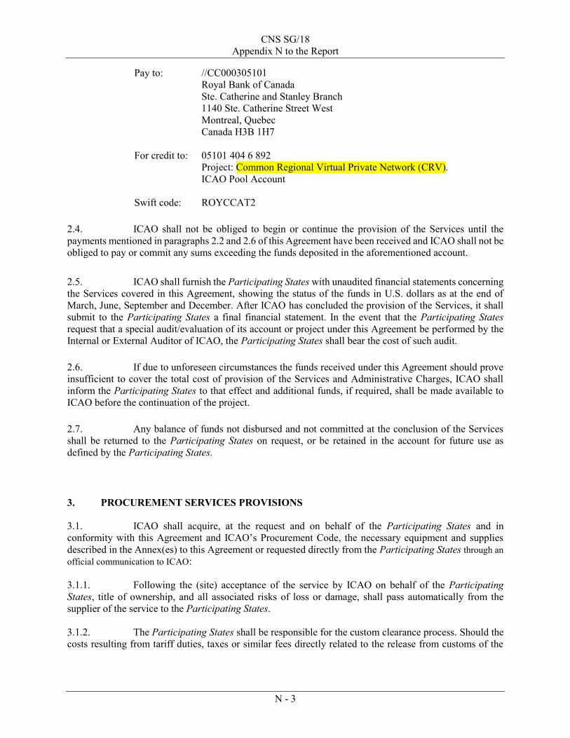
CNS SG/18 Appendix N to the Report
N - 3
Pay to: //CC000305101 Royal Bank of Canada Ste. Catherine and Stanley Branch 1140 Ste. Catherine Street West Montreal, Quebec Canada H3B 1H7 For credit to: 05101 404 6 892
Project: Common Regional Virtual Private Network (CRV). ICAO Pool Account Swift code: ROYCCAT2 2.4. ICAO shall not be obliged to begin or continue the provision of the Services until the payments mentioned in paragraphs 2.2 and 2.6 of this Agreement have been received and ICAO shall not be obliged to pay or commit any sums exceeding the funds deposited in the aforementioned account. 2.5. ICAO shall furnish the Participating States with unaudited financial statements concerning the Services covered in this Agreement, showing the status of the funds in U.S. dollars as at the end of March, June, September and December. After ICAO has concluded the provision of the Services, it shall submit to the Participating States a final financial statement. In the event that the Participating States request that a special audit/evaluation of its account or project under this Agreement be performed by the Internal or External Auditor of ICAO, the Participating States shall bear the cost of such audit. 2.6. If due to unforeseen circumstances the funds received under this Agreement should prove insufficient to cover the total cost of provision of the Services and Administrative Charges, ICAO shall inform the Participating States to that effect and additional funds, if required, shall be made available to ICAO before the continuation of the project. 2.7. Any balance of funds not disbursed and not committed at the conclusion of the Services shall be returned to the Participating States on request, or be retained in the account for future use as defined by the Participating States.
3. PROCUREMENT SERVICES PROVISIONS 3.1. ICAO shall acquire, at the request and on behalf of the Participating States and in conformity with this Agreement and ICAO’s Procurement Code, the necessary equipment and supplies described in the Annex(es) to this Agreement or requested directly from the Participating States through an official communication to ICAO: 3.1.1. Following the (site) acceptance of the service by ICAO on behalf of the Participating States, title of ownership, and all associated risks of loss or damage, shall pass automatically from the supplier of the service to the Participating States.
3.1.2. The Participating States shall be responsible for the custom clearance process. Should the costs resulting from tariff duties, taxes or similar fees directly related to the release from customs of the

CNS SG/18 Appendix N to the Report
N - 4
equipment and supplies not be subject to exemption by the Government, theParticipating States shall be responsible for defraying such costs using funds not proceeding from those specified in the Annexes.
3.1.3. The Administrative Charge fees will be phased according to the degree of advancement of the procurement process (20% at the issuance of the tender, additional 30% when the evaluation process has been completed and the balance upon signature of the purchase order/contract). Should an on-going Purchase Requisition approved by the Participating Statesbe cancelled before the purchase is effected, ICAO shall be entitled to recover its costs based on the amount of work that has been completed in the implementation of the said Purchase Requisition. ICAO will invoice the corresponding amount to the Participating States.
3.1.4. An amendment to a Purchase Order/Contract shall not decrease the Administrative Charges associated with the issuance of the original Purchase Order/Contract.
4. DISPUTES RESOLUTION (SETTLEMENT OF DISPUTES) 4.1 Any dispute, controversy or claim arising out of or relating to this Agreement, or the breach, termination or invalidity thereof, shall be settled, in the first instance, by direct negotiations between the parties. If unsuccessful, such dispute, controversy or claim shall be settled by arbitration in accordance with the United Nations Commission on International Trade Law (UNCITRAL) Arbitration Rules, as in force at the time of arbitration. The place of arbitration shall be Montreal, Province of Quebec, Canada, conducted in the English language. Arbitration shall be conducted by one arbitrator. The arbitral award shall contain a statement of reasons on which it is based and shall be accepted by the Parties as the final adjudication of the dispute. 5. ICAO PRIVILEGES AND IMMUNITIES 5.1 Nothing in or relating to this Agreement shall be deemed a waiver, express or implied, of any immunity from suit or legal process or any privilege, exemption or other immunity enjoyed or which may be enjoyed by ICAO, its officers, staff, assets and funds either pursuant to the Convention on the Privileges and Immunities of the Specialized Agencies, 1947 or other applicable conventions, agreements, laws or decrees. 6. CORRESPONDENCE 6.1 All correspondence relating to the implementation of this Agreement other than this signed Agreement or the amendments thereto, shall be addressed to: ICAO: Regional Director Asia and Pacific Office P.O. Box 11, Samyaek Ladprao Bangkok 10901 Thailand

CNS SG/18 Appendix N to the Report
N - 5
6.2 The Participating States shall keep ICAO duly informed of all measures which it adopts for the fulfilment of this Agreement or which may affect this Agreement. 7. ENTRY INTO FORCE, AMENDMENTS AND TERMINATION 7.1 This Agreement shall come into force on the date on which it has been signed by both parties. It shall continue to be in force until terminated under paragraphs 1.12, 7.2 and 7.3 below. Upon coming into force, it shall supersede existing Agreements concluded between the parties on the same subject matter. 7.2 This Agreement may be amended at any time by written agreement between the parties. 7.3 This Agreement may be terminated at any time, by either Party, giving to the other a written notification. This Agreement shall terminate sixty (60) calendar days after receipt of the notification.
Agreed on behalf of the International Civil Aviation Organization:
Signed by:
________________________________
Name:
________________________________
Title:
________________________________
Date:
________________________________
Agreed on behalf of the Participating States:
Signed by:
Australia ________________________________
Name:
________________________________
Title:
________________________________
Date:
________________________________

CNS SG/18 Appendix N to the Report
N - 6
Signed by:
China ________________________________
Name:
________________________________
Title:
________________________________
Date:
________________________________
Signed by:
Fiji ________________________________
Name:
________________________________
Title:
________________________________
Date:
________________________________
Signed by:
France ________________________________
Name:
________________________________
Title:
________________________________
Date:
________________________________
Signed by:
Hong Kong China ________________________________
Name:
________________________________
Title:
________________________________
Date:
________________________________

CNS SG/18 Appendix N to the Report
N - 7
Signed by:
India ________________________________
Name:
________________________________
Title:
________________________________
Date:
________________________________
Signed by:
Japan ________________________________
Name:
________________________________
Title:
________________________________
Date:
________________________________
Signed by:
Malaysia ________________________________
Name:
________________________________
Title:
________________________________
Date:
________________________________
Signed by:
New Zealand ________________________________
Name:
________________________________
Title:
________________________________
Date:
________________________________

CNS SG/18 Appendix N to the Report
N - 8
Signed by:
Singapore ________________________________
Name:
________________________________
Title:
________________________________
Date:
________________________________
Signed by:
Thailand ________________________________
Name:
________________________________
Title:
________________________________
Date:
________________________________
Signed by:
United States of America (USA) ________________________________
Name:
________________________________
Title:
________________________________
Date:
________________________________
− END −

CNS SG/18 Appendix N to the Report
N - 9
INTERNATIONAL CIVIL AVIATION ORGANIZATION
ANNEX 1 TO THE MANAGEMENT SERVICE AGREEMENT BETWEEN THE INTERNATIONAL CIVIL AVIATION ORGANIZATION AND
THE CIVIL AVIATION AUTHORITIES AND/OR RELATED ANSPs AS LISTED IN APPENDIIX A Project Title: Common Regional Virtual Private Network (CRV) multinational service
with a common service provider Project No.: RAS/14/801 Initial duration: 01 June 2015. – 31 November 2016 Sector and Sub-Sector: Transport and Civil Aviation Country Implementing Agency: Civil Aviation Authorities and/or related ANSPs Executing Agency: International Civil Aviation Organization (ICAO) Location: Asia Pacific Estimated Start Date: June 2015, with informal coordination needed upfront Estimated Project Cost: US$ 109,300 Brief Description: ICAO will assist the Civil Aviation Authorities and/or related ANSPs in the procurement management (i.e. Stage 1) of the APAC CRV Project and in the selection of a common service provider. The ICAO assistance covers the specific work scope outlined in this project document.
Signed on behalf of: Signature
Name/Title
Date
International Civil Aviation Organization
Raymond Benjamin Secretary General
Civil Aviation Authorities/ANSPs
Pioneer State/Administration
This is a CONFIDENTIAL DOCUMENT intended only for the exclusive use by the recipient Government, and the International Civil Aviation Organization. No part of this document may be disseminated, distributed, reproduced, or used in any other way by any individual, company, organization or any other entity without the prior written approval by the recipient Government and the International Civil Aviation Organization.

CNS SG/18 Appendix N to the Report
N - 10
Background:
1. The Civil Aviation Authorities and/or related ANSPs as listed in Appendix A, hereinafter collectively referred to as the “Parties” and individually as the “Party”, have determined that the Common Regional Virtual Private Network (CRV) multinational service with a common service provider can more effectively:
• provide network services to the Parties; • support a common Internet Protocol (IP) network; • establish services based on Voice over IP (VoIP); and • enhance network diversity and timely service implementation and delivery.
2. All Parties jointly agree to appoint ICAO Technical Cooperation Bureau or TCB to assist in the
procurement management (i.e. Stage 1) of the CRV project and in the selection of the common Service Provider. Upon selection of the common service provider after a Sealed Tender (ST) process through TCB, a Party shall subscribe to the Services by signing an individual Service Contract with the Service Provider for the procurement, installation, training, testing, commissioning and operation of the CRV network and the associated services.
3. The subsequent implementation and operation stage shall be managed by the CAAs/ANSPs
themselves through the establishment of an Operational Oversight Group (OOG) of the CRV network.
Services to be provided:
1. Through this Annex to the above-mentioned Management Service Agreement, the following services will be provided by ICAO:
Tender Preparation Stage
o Review the technical specifications provided by the CRV Task Force with the aim to have SMART (Simple, Measurable, Assignable, Realistic and Time-related) and consolidated requirements;
o Develop the evaluation criteria for CRV Task Force consideration and finalization; o Prepare tender documents including integrating the technical specifications, and any
other information required in the tender documents.
TCB Publication of Sealed Tender o Investigate market and propose and identify suitable suppliers to register with ICAO,
including those having participated in the Request For Information (RFI), which is handled by the ICAO APAC Regional Office;
o Advertise Sealed Tender (ST) on ICAO’s tendering website and notify the appropriate suppliers.
Consultation & RFP Response o Coordinate any site survey needed by RT, as appropriate; o Handle all the tender clarifications including consultation with the CRV Task Force,
organization of tender clarification meetings (by telephone, webconference, etc), and fair dissemination of information to all RT;
o Optionally, to set up a Face to Face meeting with RT to exhaust questions before submission of responses.

CNS SG/18 Appendix N to the Report
N - 11
Selection o Receive tender responses at ICAO’s tendering website, carry out a pre-evaluation, and
provide support to the CRV Tender Evaluation Committee meetings, including a final physical evaluation meeting;
o Award the tender.
General On-going Assistance o Participate as a technical advisor to the CRV Task Force ; o Any other related services.
Budget: The detailed budget is as attached at Appendix B.
1. Funds will be equally shared among the Civil Aviation Authorities and/or related ANSPs as listed in Appendix A, and provided by them in advance of commencement of the project.
2. The total estimated amount is of US$ 109,300 as per Appendix B. This amount is the total estimated amount including administrative and technical support.
Risk Assessment Initial Major Risk Factor 1.1 Delay in the signing of this project document and remittance of funds.
Risk Level: Medium Mitigation: ICAO will work through the Chairman of the CRV Task Force with the Civil
Aviation Authorities and/or related ANSPs to facilitate the signing of the project document and the remittance of required funds.
Other Risk Factors 1.2 Delay in the signing the DOCUMENT OF AGREEMENT (DOA) on the joint
administration of a Common Regional Virtual Private Network (CRV) for aeronautical telecommunications services (stage 2).
Risk Level: Low Mitigation: ICAO through APANPIRG will engage with the CAAs/States to expedite the acceptance of the concept of operations of a multinational service with a common service provider.
Project Plan (CRV planning): The CRV Project planning as per May 2014 is attached at Appendix D.

CNS SG/18 Appendix N to the Report
N - 12
Appendix A
PARTIES TO THIS MSA (FOR STAGE 1) The Civil Aviation Authorities, related Organizations of the Governments such as Air Navigation Service Providers, Organizations representing States and/or act on behalf of States) as listed below, agree to be parties of the aforementioned MSA. All parties commit to complying with the Management Service Agreement and have appointed the Chairman of the CRV Task Force to sign the MSA and associated Annex 1 of the Project Document on their behalf.
Australia Fiji France Hong Kong China India Japan Malaysia New Zealand Singapore Thailand United States of America (USA)
NOTE: This list will be finalized on 14 November 2014 at the latest.

CNS SG/18 Appendix N to the Report
N - 13
Appendix B
PROJECT BUDGET COVERING MSA CONTRIBUTION(IN UNITED STATES DOLLARS)
COUNTRY: REGIONAL PROJECTPROJECT NO: RAS14801PROJECT TITLE: ASSISTANCE WITH THE PROCUREMENT OF A CRV (COMMON REGIONAL VPN)WORK ORDER: RAS14801-01
w/m $ w/m $PROJECT PERSONNEL
INTERNATIONAL PROFESSIONAL POSTSB554A CONSULTANTS FOR TSS 2.0 81 800 2.0 81 800
SUB-TOTAL (INTERNATIONAL PROFESSIONAL POSTS) 2.0 81 800 2.0 81 800
TOTAL (PROJECT PERSONNEL) 81 800 81 800
MISCELLANEOUS B807L REPORTING COSTS 5 000 5 000B807M MISCELLANEOUS EXPENSES 4 300 4 300B754A OVERHEAD CHARGES 18 200 18 200
TOTAL (MISCELLANEOUS) 27 500 27 500
PROJECT TOTAL 109 300 109 300
TOTAL 2015

CNS SG/18 Appendix N to the Report
N - 14
Appendix C
International Civil Aviation Organization Technical Cooperation Bureau – Job Description
POSITION INFORMATION
Generic Title: Communications expert Position Number (ID):
Specific Title: Aeronautical communications procurement expert Skill Code: (By FRU)
Project Number: Post Number/Job Code:
Duty Station: Home and Bangkok Classification Level: (By FRU)
Duration: 58 days at Home and 9 in Bangkok (3 missions to Bangkok of 3 w/d each)
Starting Date: June 2015
ORGANISATIONAL SETTING
The Technical Cooperation Bureau (TCB) of ICAO is responsible for planning, development, implementation, and evaluation of the ICAO Technical Co-operation Programme. TCB provides assistance in identifying priority development needs of the civil aviation sector and provides technical cooperation to the receiving States. The Field Operations Section (FOS) implements projects and programmes in accordance with the policies and practices of TCB. The objective of the CRV project (Common Regional Virtual Private Network) is to build the Asia Pacific aeronautical network that will carry aeronautical data and voice communications between the States of this region from end of 2016 onwards, and that will also be connected to other regional networks as needed and practicable. The project consists in procuring a service of transportation (and not equipment) through a virtual network provided by a Telecommunication Service Provider. The CRV project constitutes a follow-up to the decision 24/32 made by APANPIRG in June 2013 that a Task Force with Subject Matter Experts be established to study the virtual private network and develop a detailed proposal by 2016. It is conducted by the CRV Project management team composed of the CRV Task Force chairman in coordination and the ICAO APAC CNS Officer. The ICAO TCB is in charge of facilitating the procurement process.
IMPACT OF OUTCOME OF THE POSITION
Selection of a single Communication Service Provider (CSP) for the CRV network in APAC region.
MAJOR DUTIES AND RESPONSIBILITIES
Under the supervision of the Director, Technical Cooperation Bureau, the consultant will: 1. Main Tasks:
1. Review all documentation developed for this project in order to understand the Concept of Operations developed for CRV
2. Review the user requirements (general, technical and process) provided by the CRV Task Force with the aim to have consolidated requirements;
3. Develop the evaluation criteria for CRV Task Force consideration and finalization; 4. Assist TCB, if required, to handle the tender technical clarifications including consultation with the CRV Task Force, 5. If needed, participate in a Face to Face meeting with Registered Tenderers to exhaust questions before submission of
responses;

CNS SG/18 Appendix N to the Report
N - 15
6. Carry out a pre-evaluation, and provide support to the CRV Tender Evaluation Committee meetings, including a final physical evaluation meeting;
7. Participate as a technical advisor to the CRV Task Force for tender preparation and evaluation. 8. Perform any other task related to the points mentioned above, as required.
Specifically, On-Site work at ICAO Regional Office facilities in Bangkok, Thailand, will consist in the following tasks:
Provide technical support for the review of CRV user requirements with APAC States as appropriate; Provide technical and Secretariat support to the Face to Face meeting with Registered Tenderers and some
APAC States to clarify the project technical requirements before submission of responses; and Provide technical support to the final CRV Tender Evaluation Committee meeting.
2. Deliverables include:
a) A consolidated List of CRV validated user requirements (general, technical and process); b) Draft evaluation criteria for CRV Task Force consideration; c) Provide technical support for clarifications requested by the Registered Tenderers, d) A pre-evaluation of the proposals from Tenderers; e) A final evaluation of the proposals from Tenderers including recommendation of the winner; and f) A summary report of the procurement process.
3. Reporting duties:
a) Prepare and submit Periodic Progress and Final Reports to CRV Project Management Team and TCB, in accordance to the approved project Work Plan Report. Participate in periodic teleconferences CRV Project Management Team and TCB, as appropriate.
4. Coordination duties:
a) Coordinate with ICAO TCB and CRV Project management team, the preparation of the Work Plan, and submission of the Work Plan report within 5 working days of start of assignment. b) Act as focal point liaising with CRV Project management team, TCB, and other stakeholders as appropriate. c) Perform any other project management/coordination duties as required.
QUALIFICATIONS AND EXPERIENCE
Educational background
University degree in Telecommunications Engineering or Equivalent acceptable academic and technical qualifications
Professional experience and knowledge
Minimum 10 years of professional experience with aeronautical telecommunications Minimum 5 years of professional experience in the preparation of specifications, negotiations and acquisition of aeronautical telecommunications services Minimum 5 years of professional experience in the Planning, installation, operation and maintenance of aeronautical telecommunications facilities Experience in safety cases related to Air Traffic Services In-depth experience with review of tender documentation and recommendation for selection of suppliers In-depth Knowledge of related ICAO SARPS regarding Aeronautical Fixed Services, fault/configuration/safety/security management of communications networks, typical designs for IP networks, Voice over IP
Language Skills

CNS SG/18 Appendix N to the Report
N - 16
1. Expert must to be fluent in English (both written and verbal).
Competencies
1. Judgment/decision–making: Proven ability to take ownership of all responsibilities and to honour commitments, to exercise mature and fair judgment, to recognize key issues and analyse relevant information, to make feasible recommendations and to make sound decisions. 2. Communication: Ability to write clearly and concisely and to present articulate verbal reports. 3. Teamwork: Ability to work with colleagues to achieve the project goals and maintain harmonious working relationships in a multinational environment. 4. Client Orientation: Ability to establish and maintain partnerships with external collaborators, to work and advocate effectively in a consensus-based system and to successfully manage and resolve conflict. 5. Commitment to continuous learning: Willingness to keep abreast of new developments in professional field. 6. Technological awareness: Ability to use contemporary office automation equipment, software, databases.
SALARY
TBD by FPS/FRU

CNS SG/18
Appendix N to the Report
Document Para Author Comments received from States as per meeting 28 May 14 ICAO TCB's answer
MSA
All sections
containing
"Annex" CRV TF delete the “(es)” from “Annex(es)” or “(s)” from “Project(s)”,
No need to delete the “(es)” from “Annex(es)” or “(s)” from “Project(s)”, since this is template agreement and we can’t predict at
this point if there will not be another project or annex.
MSA 1.4 CRV TF The said services are considered approved if they are laid out in the Annex as the annex will be reviewed by ICAO TCB. should not delete “shall be approved by ICAO”; as previously mentioned, this is standard text and not a necessary change.
MSA 1.4 CRV TF We suggest to add: “Unless otherwise agreed by the Parties, […]”
Comment LF5: we should not include “unless otherwise agreed by the Parties” as it is not possible to implement projects outside
the scope of ICAO policies, practices, etc.
MSA 1.4 CRV TF Add "and subsequent variations " fine with the suggested addition
MSA 1.7 CRV TF Add "and the changes to the Agreement shall be made in accordance with 7.2" fine with the suggested addition
MSA 1.8 CRV TF What is the meaning of “contract for inputs required for the provision of the Services”? Is that expert inputs?
“inputs" is the generic term ICAO uses to indicate any number of services such as contracting experts, facilitating fellowships,
procurement services, etc.”
MSA 1.8 CRV TF
The CRV meeting dated 28 May 14 considers that this approval may require a long time. This sentence may be deleted by
ICAO TCB
agree to delete: “The recruitment of personnel and the signature of contracts shall be subject to prior approval by the
Participating States”, as this would not be practical.
MSA 1.12 CRV TF
The total cost (Services and Administrative Charges) of the Project(s) including these additional funds shall not exceed the capped amount reflected in the Annex(es) without the prior agreement of the Participating States.
should not include the proposed text as ICAO does not operate with “capped” amounts, this is contrary to ICAO Financial
Regulations and Rules and could potentially put ICAO in a financially liable situation, which is not acceptable to FIN or our auditors.
MSA 2.1 & 2.2 CRV TF Replace "estimated" by "capped" as previously mentioned, we can’t make reference to a “capped” amount.
MSA 2.4 CRV TF Add "and shall not be obliged to pay or commit any sums"
the proposed change does not really affect the general purpose of the clause, so in keeping with the line that no unnecessary
changes should be made, we should keep the original language already approved by LEB.
MSA 2.6 CRV TF Replace "requesting" by "Participating" States fine with the suggested addition
MSA 2.6 CRV TF Add "and not exceeding the capped amount of the total cost (Services and Administrative Charges)" again, must remove reference to “capped” amount
MSA 2.7 CRV TF Is that necessary that Parties’ bank accounts be indicated in this MSA then? we agree that including bank details of multiple States is not advisable.
MSA 3.1 to 3.1.4 CRV TF
Replace "equipment and supplies" by "services" and "requested directly from the Participating States through an official
communication to ICAO" by "otherwise agreed by the Parties". we can’t accept these changes as they are standard clauses in all our MSAs and CAPS agreements.
MSA 3.1.1 and 3.1.2 CRV TF Delete those subparagraphs as they do not apply to CRV
MSA 6.1 CRV TF Add "For the Participant States: to the signatories of this MSA" fine with the suggested addition
Annex 1 Appendix B ICAO RO What do the miscellaneous costs cover?
As you may be aware, this is a standard budget line included in all of our project budgets, which may comprise of (but not limited
to) UN common costs, security costs, insurance, communication costs, courier, bank charges, and third party transaction costs (i.e.
UNDP).
Annex 1 ICAO RO Capped amount
As mentioned in our comments to MSA, we can’t adhere to a “capped” amount principle. However, as also stated in the MSA, ICAO
may not incur expenditures beyond the approved budget without express consent from the State (or States in this case). This is
standard in all our technical cooperation projects.
N - 17

Pan Regional (NAT
and APAC) Interface
Control Document for
ATS Interfacility Data
Communications
(PAN AIDC ICD)
This edition has been issued by the Inter-Regional AIDC Task Force for the Asia/Pacific Air Navigation Planning and Implementation Regional Group (APANPIRG) and the North Atlantic Systems Planning Group (NAT SPG).
Coordination Draft Version 0.92 — August, 2014
International Civil Aviation Organization
ssomsri
Typewritten Text
CNS SG/18 Appendix O to the Report
ssomsri
Typewritten Text
ssomsri
Typewritten Text
ssomsri
Typewritten Text
ssomsri
Typewritten Text

Version 0.92 – August 2014 ii PAN ICD
This document is available by accessing any of the following ICAO regional websites.
Asia and Pacific (APAC) Office http://www.icao.int/apac
European and North Atlantic (EUR/NAT) Office http://www.paris.icao.int
For more information, contact the ICAO regional office.

PAN ICD iii Version 0.92 – August 2014
Pan Regional (NAT
and APAC) Interface
Control Document for
ATS Interfacility Data
Communications
(PAN AIDC ICD)
This edition has been issued by the Inter-Regional AIDC Task Force for the Asia/Pacific Air Navigation Planning and Implementation Regional Group (APANPIRG) and the North Atlantic Systems Planning Group (NAT SPG).
Coordination Draft Version 0.92 —August, 2014
International Civil Aviation Organization

Version 0.92 – August 2014 iv PAN ICD
Amendments to the PAN ICD
The following table will be used to track updates to the PAN ICD by the Ad Hoc Working Group. This document contains procedures material from the Asia/Pacific Regional ICD for AIDC and the North Atlantic Common Coordination ICD.
Amendment Source Subject(s) Date
0.1 Not used
0.2 Pre-PAN ICD Annotated outline incorporated into document structure May 2010
0.3 PAN ICD The draft document at this stage is focused on populating the outline with relevant material. Document style, formatting, and presentation of material are still to be considered.
Oct 2010
0.4 PAN ICD Comments inserted from v0.3 comment forms
Changes inserted from NAT CC ICD new v1.2.9 to reflect editorial changes and corrections
Changes inserted from NAT CC ICD new v1.3.0 to reflect changes specified in Amendment 1, effective 15 Nov 2012, to the ICAO Doc 4444 Procedures for Air Navigation Services-Air Traffic Management, Fifteenth Edition
Nov 2011
0.5 PAN ICD (IRAIDTF/1) updated Version 0.4 of the PAN Regional ICD for AIDC to include comments from Iceland, Australia, the APAC AIDC Seminar, and the Secretariat.
Jan 2013
0.6 PAN ICD (IRAIDTF Web/1) added AIDC+LRM response examples, AIDC message table, proposed field 15 wording, sample AIDC message containing field 15, Field 14-Estimate Data added and moved to Chapter 4.
Feb 2013
0.7 PAN ICD (IRAIDTF Web/2) Chapter 8 will be deleted and included in a new appendix; added LRM examples, new AIDC message table, new Field 15 wording.
Apr 2013
0.8 PAN ICD IRAIDTF/2 updated Version 0.7 of the Pan Regional ICD for AIDC and removed Chapter 8, Chapter 9 relocated as Attachment A and Chapter 6 relocated as Attachment B to the ICD.
July 2013
0.85 PAN ICD IRAIDTF/3 updated Version 0.83 in Chapters 3, 4, 5 and 6. Renumbering Appendices A,B and C
March 2014

PAN ICD v Version 0.92 – August 2014
0.86 PAN ICD Subsequent to Web/3 held on 11 June 2014, IRAIDTF updated Version 0.85 in Chapters 2, 4 and 6. Additional Implementation Guidance Material appended as Appendix C
June 2014
0.91 PAN ICD Subsequent to Web/4 held on 9 July 2014, IRAIDTF updated Version 0.86 in Chapters 2, 3, 4 and 6.
July 2014
0.92 PAN ICD Subsequent to Web/5 held on 6 August 2014, IRAIDTF updated Version 0.91 in Chapters 2, 3, 4 and 6 mainly related to Restriction Formats and Field 15.
August 2014

Version 0.92 – August 2014 vi PAN ICD
AMENDMENTS
The issue of amendments is announced by the ICAO Regional Offices concerned, which holders of this publication should consult. The space below is provided to keep a record of such amendments.
RECORD OF AMENDMENTS AND CORRIGENDA
AMENDMENTS CORRIGENDA
No. Date applicable
Date entered
Entered by No. Date applicable
Date entered
Entered by

Version 0.90 – July 2014 vii PAN ICD
Table of Contents
Page
FOREWORD. ............................................................................................................................................. x
1. Historical background ............................................................................................................ x
2. Scope and Purpose ................................................................................................................. x
3. Status .................................................................................................................................... xi
4. Implementation .................................................................................................................... xi
5. References ............................................................................................................................ xi
6. Changes to the document ..................................................................................................... xi
Chapter 1 Abbreviations and AIDC Messages ................................................................................... 1-1
1.1 Abbreviations ........................................................................................................................ 1-1 1.2 AIDC Messages .................................................................................................................... 1-5
Chapter 2 Purpose, Policy and Units of Measurement ....................................................................... 2-1
2.1 Purpose ................................................................................................................................. 2-1 2.2 Policy .................................................................................................................................... 2-1 2.3 Units of measurement and data convention .......................................................................... 2-2 2.4 Restriction Formats ............................................................................................................... 2-4
Chapter 3 Communications and Support Mechanisms ....................................................................... 3-1
3.1 Introduction .......................................................................................................................... 3-1 3.2 Message Headers, Timers and ATSU Indicators .................................................................. 3-1 3.3 Engineering considerations ................................................................................................... 3-4 3.4 Test considerations ............................................................................................................... 3-6 3.5 Scheduled Maintenance and Failures ................................................................................... 3-7
Chapter 4 AIDC Messages ................................................................................................................. 4-1
4.1 Introduction .......................................................................................................................... 4-1 4.2 Message Field Requirements ................................................................................................ 4-1 4.3 AIDC message groups ........................................................................................................ 4-10 4.4 Notification messages ......................................................................................................... 4-11 4.5 Coordination messages ....................................................................................................... 4-13 4.6 Transfer of control messages .............................................................................................. 4-24 4.7 General information messages ............................................................................................ 4-25 4.8 Application management messages .................................................................................... 4-26 4.9 Surveillance Data Transfer Service Messages ............................................................. 4-354-34
Chapter 5 Error Codes ........................................................................................................................ 5-1
5.1 Introduction .......................................................................................................................... 5-1
Chapter 6 Implementation Guidance Material.................................................................................... 6-1
6.1 Introduction .......................................................................................................................... 6-1 6.2 Preliminaries ......................................................................................................................... 6-1 6.3 AIDC message sequences and AIDC flight states .............................................................. 6-11 6.4 Message Sequencing ........................................................................................................... 6-25

PAN ICD
Version 0.92 – August 2014 viii PAN ICD
6.5 Other AIDC messages ........................................................................................................ 6-29 6.6 Examples ............................................................................................................................ 6-39
Tables
Table 4-1. Contents of Field 14 ........................................................................................................... 4-1
Table 4-2. Contents of Field 15 ........................................................................................................... 4-6
Table 4-3. AIDC Messages ................................................................................................................ 4-10
Table 4-4. CPDLC Connection Status ............................................................................................... 4-33
Table 4-5. Frequency Identifier ......................................................................................................... 4-34
Table 4-6. PAN AIDC Messages and their Field Composition ......................................................... 4-35
Table 5-1. Error Codes ......................................................................................................................... 5-1
Table 6-1. Required Operational Response ......................................................................................... 6-3
Table 6-2. AIDC Flight States ........................................................................................................... 6-11
Table 6-3. Flight State Transition table ............................................................................................. 6-23
Table 6-4. AIDC Message Sequence of commonly used AIDC messages ........................................ 6-25
Table 6-5. Valid Messages by ATSU and flight states ...................................................................... 6-27
Table 6-6. FCN Transmission ............................................................................................................ 6-32
List of Figures
Figure 6-1 Flight State Transition Diagram ....................................................................................... 6-27
Figure 6-2. Routine Data Link Transfer Using FAN and FCN Messaging......................................... 6-33
Figure 6-3 CPDLC Transfer Using FAN and FCN Messaging – Initial Connection Request Failed 6-34
Figure 6-4 CPDLC Transfer Using FAN and FCN Messaging – Unable to Establish CPDLC Connection... 6-35
Figure 6-5 CPDLC Transfer Using FAN and FCN Messaging – Initial NDA not Delivered ........... 6-36

PAN ICD
PAN ICD ix Version 0.92 – August 2014
Appendices
Appendix A Templates for Bilateral Letter of Agreement on AIDC
Appendix B Regionally Specific Messages
Appendix C Additional Implementation Guidance Material

PAN ICD x Version 0.91 – July 2014
FOREWORD.
1. Historical background
1.1 The Pan Regional Interface Control Document (PAN ICD) for ATS Interfacility Data Communications (AIDC) is the result of the progressive evolution of the Asia/Pacific Regional ICD for AIDC, issued by the ICAO Asia/Pacific Regional Office on behalf of the Asia Pacific Air Navigation Planning and Implementation Regional Group (APANPIRG), and the North Atlantic Common Coordination ICD, published by the ICAO European and North Atlantic Office, on behalf of the North Atlantic Systems Planning Group (NAT SPG).
1.2 Each of the two founding documents provided guidance on a regional basis. However, in recognition of the need to provide globally harmonized guidance for AIDC, the PAN ICD First Edition, merging the APAC and NAT guidance material, was adopted by the APAC and NAT Regions in 201X.
1.3 The PAN ICD addresses the ground-ground data link provision from a technical and operational point of view taking into account lessons learned, global implications and guidance on recent initiatives.
2. Scope and Purpose
2.1 The PAN-ICD provides guidance and information concerning ground-ground data link operations and is intended to facilitate the uniform application of Standards and Recommended Practices contained in Annex 2 — Rules of the Air, Annex 10 — Aeronautical Telecommunications and Annex 11 — Air Traffic Services, the provisions in the Procedures for Air Navigation Services — Air Traffic Management (PANS-ATM, Doc 4444) and, when necessary, the Regional Supplementary Procedures (Doc 7030).
2.2 This guidance material specifies the facilities and messages to be used for the exchange of notification, coordination, transfer of control, and related data between automated Air Traffic Service (ATS) systems. The material is intended to improve safety and maximize operational benefits by promoting standardized ground-ground data link operations throughout the world.
2.3 The following personnel and organizations should be familiar with relevant aspects of its contents: regulators, airspace planners, air navigation service providers (ANSPs), training organizations, regional/State monitoring agencies, automation specialists at centers and equipment suppliers.
2.4 The guidance will support the following activities:
a) Safety regulatory oversight of air navigation services;
b) The development of letters of agreements between ANSPs;
c) The development of operational procedures;
d) The implementation activities; and,
e) Operational monitoring, analysis, and exchange of operational data among regions and States.
2.5 The messages defined in this document are used during the various stages of the flight. Though outside the scope of the AIDC application, the Emergency-, Flight Planning- and Supplementary Message Categories as defined in PANS-ATM Appendix 3 will continue to be used to perform functions not provided by the AIDC application.
2.6 In particular, the Flight Planning function is required and will be required in the future to support operations. The ICAO messages FPL (Filed Flight Plan), CHG (Modification), DLA (Delay),

PAN ICD
PAN ICD xi Version 0.92 – August 2014
DEP (Departure), ARR (Arrival), CNL (Cancel) and RQP (Request Flight Plan) will be used to support this function.
2.7 There is a great need for a communications and data interchange infrastructure to significantly reduce the need for verbal coordination between ATSUs. AIDC standards, as defined in the PAN ICD, provide a harmonised means for data interchange between ATS units during the notification, coordination, confirmation and transfer of control phases of operations.
2.8 The message sets and procedures described in the PAN ICD have been designed for use with the ATS Message Handling System (AMHS) and/or Aeronautical Fixed Telecommunications Network (AFTN). They can also be exchanged over dedicated private communication lines. In the interest of global standardisation, ICAO methods and messages as defined in PANS-ATM Appendix 3 Air Traffic Services Messages, were used wherever possible. Where ICAO methods and messages do not meet requirements, new messages were identified using existing ICAO field definitions to the extent possible. Specifically, the PAN ICD defines the following:
a) Basic communications and support required to coordinate implementation of AIDC;
b) Common boundary agreements between all the ATSUs concerned;
c) Implementation guidance material;
3. Status
3.1 This guidance is approved and maintained by the respective participating PIRGs and has a status of an ICAO regional guidance material. It contains material that may eventually become Standards and Recommended Practices (SARPs) or PANS provisions when it has reached the maturity and stability necessary for adoption or approval. It also comprises material prepared as an amplification of the basic principles in the corresponding SARPs, and designed particularly to assist the user in the application of the SARPs and PANS.
4. Implementation
4.1 With a view of facilitating implementation of the provisions herein by States, this guidance material has been prepared using language that permits direct use by all users.
5. References
5.1 The following references are cited in this document:
a) Annex 2 — Rules of the Air,
b) Annex 10 — Aeronautical Telecommunications,
c) Annex 11 — Air Traffic Services,
d) PANS - Air Traffic Management (Doc 4444),
e) PANS - Regional Supplementary Procedures (Doc 7030),
f) PANS – ICAO Abbreviations and Codes (Doc 8400).
6. Changes to the document
6.1 This document is maintained as a regional document in coordination with all ICAO planning and implementation regional groups (PIRGs) providing ground-ground data link services within their

PAN ICD
Version 0.92 – August 2014 xii PAN ICD
region. Each participating PIRG establishes a mechanism for submitting and administering change proposals.
6.2 Change proposals (CPs) can be submitted by any stakeholder participating in ground-ground data link operations. The stakeholder should submit a Change Proposal to their ICAO regional office. The ICAO regional office will coordinate the change proposal within its own region, other regions, and ICAO HQ, to determine the acceptability of the change proposal. Once the ICAO regional office has completed coordination and the participating PIRGs accept the change proposal, the document is updated.

PAN ICD
PAN ICD xiii Version 0.92 – August 2014
Amendments to the PAN ICD
Amendment Source(s) Subject(s) Approved applicable
1st Edition ([date])
Asia/Pacific Air Navigation Planning and Implementation Regional Group (APANPIRG/ – [year])
North Atlantic Systems Planning Group (NAT SPG/ – [year])
Pan Regional ICD (PAN ICD) Applicable within participating Regions on [date].


PAN ICD
PAN ICD 1-1 Version 0.92 – August 2014
Chapter 1 Abbreviations and AIDC Messages 1.1 Abbreviations
1.1.1 When the following abbreviations are used in the present document they have the following meanings. Where the abbreviation has “(ICAO)” annotated, the term has already been decoded in ICAO DOC 8400 (PANS-ICAO Abbreviations and Codes, Eighth Edition-2010). AIDC message abbreviations marked with “*” may have different formats from ICAO ATS Messages.
Abbreviations
ACARS Aircraft Communication Addressing and Reporting System (ICAO)
ACI Area of Common Interest
ADF Application Data Field (FAN Message)
ADF ADS-C Data Field (ADS Message)
ADS-B Automatic Dependent Surveillance - Broadcast (ICAO)
ADS-C Automatic Dependent Surveillance – Contract (ICAO)
AFD Standard Message Identifier (SMI) for ATS Facility Notification (ARINC622)
AFN ATS Facilities Notification
AFTN Aeronautical Fixed Telecommunication Network (ICAO)
AIDC ATS Interfacility Data Communications (ICAO)
AMHS ATS Message Handling System
ANSPs Air Navigation Service Providers
APAC Asia and Pacific Office
APANPIRG Asia/Pacific Air Navigation Planning and Implementation Regional Group
ARINC Aeronautical Radio Inc.
ARR Arrival (ICAO)
ATC Air Traffic Control (ICAO)
ATM Air Traffic Management (ICAO)
ATMOC Air Traffic Management Operations Centre

PAN ICD
Version 0.92 – August 2014 1-2 PAN ICD
ATS Air Traffic Services (ICAO)
ATSC Air Traffic Service Center (ICAO)
ATSU Air Traffic Service Unit
ATSU-1 Transferring/Upstream ATSU
ATSU-2 Receiving/Downstream ATSU
CFL Cleared Flight Level
CHG Modification Message (ICAO)
CNL Cancel (ICAO)
COP Change Over Point (ICAO)
CPD CPDLC Connection Status identifier
CPDLC Controller Pilot Data Link Communications (ICAO)
CPs Change proposals
CRC Cyclic Redundancy Check (ICAO)
CSF Communication Status Field
DCT Direct (ICAO)
DEP Departure (ICAO)
DEST Destination (ICAO)
DIA Coordination Dialogue
DLA Delay (ICAO)
DOF Date of Flight
EOBT Estimated Off Block Time (ICAO)
FANS Future Air Navigation System
FI Flight Identifier
FIR Flight Information Region (ICAO)

PAN ICD
PAN ICD 1-3 Version 0.92 – August 2014
FM3 Standard Message Identifier (SMI) for the Center (#3) Flight Management Computer (ARINC622)
FMC Flight Management Computer (ICAO)
FMD Flight Management Computer (Selected)
FMH Facilities Notification Message Header
FML Flight Management Computer (Left)
FMR Flight Management Computer (Right)
FN_CAD AFN Contact Advisory
FPL Filed Flight Plan (ICAO)
FPO Facilities Notification Current Position
FREQ Frequency (ICAO)
GOLD Global Operational Data Link Document
HDG Heading (ICAO)
HQ Head Quarter
IA-5 International Alphabet
ICAO International Civil Aviation Organization
ICD Interface Control Document
IMI Imbedded Message Identifier
IRAIDTF Inter-Regional AIDC Task Force
LOA Letter of Agreement
MOU Memorandum of Understanding
MTI Message Type Identifier
NAT CC ICD North Atlantic Common Coordination ICD.
NAT SPG North Atlantic Systems Planning Group
NDA Next Data Authority

PAN ICD
Version 0.92 – August 2014 1-4 PAN ICD
OAC Oceanic Area Control Centre (ICAO)
OCA Oceanic Control Area (ICAO)
OCS Oceanic Control System
ODF Optional Data Field
OTD Off track deviation
PAN ICD Pan Regional Interface Control Document
PANS Procedures for Air Navigation Services (ICAO)
PANS-ATM Procedures for Air Navigation Services – Air Traffic Management
PIRGs Planning and Implementation Regional Groups
PRL Present Level
RFL Requested Flight Level
RMK Remark (ICAO)
RNP Required Navigational Performance (ICAO)
RQP Request Flight Plan (ICAO)
SARPs Standards and Recommended Practices (ICAO)
SMI Standard Message Identifier
SOH Start of Header
SPD Speed
STX Start of Text
T Truncation indicator
TDF Track Data Field
UTC Coordinated Universal Time (ICAO)
VSP Variable System Parameter
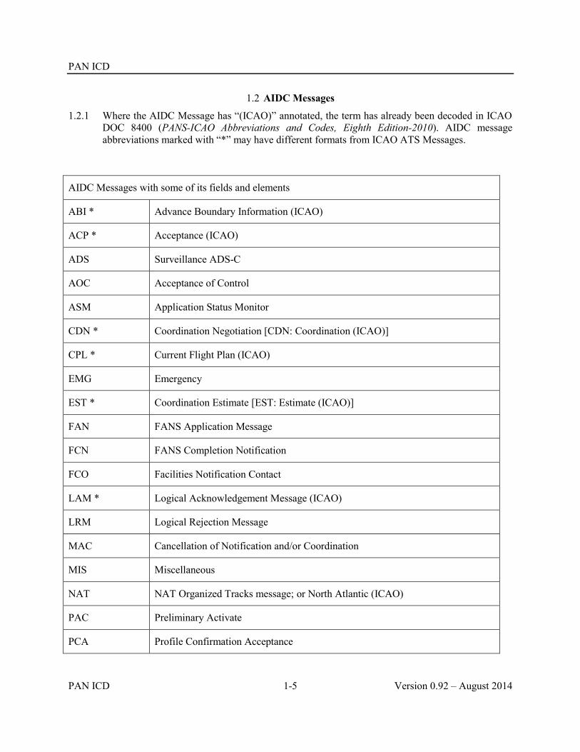
PAN ICD
PAN ICD 1-5 Version 0.92 – August 2014
1.2 AIDC Messages
1.2.1 Where the AIDC Message has “(ICAO)” annotated, the term has already been decoded in ICAO DOC 8400 (PANS-ICAO Abbreviations and Codes, Eighth Edition-2010). AIDC message abbreviations marked with “*” may have different formats from ICAO ATS Messages.
AIDC Messages with some of its fields and elements
ABI * Advance Boundary Information (ICAO)
ACP * Acceptance (ICAO)
ADS Surveillance ADS-C
AOC Acceptance of Control
ASM Application Status Monitor
CDN * Coordination Negotiation [CDN: Coordination (ICAO)]
CPL * Current Flight Plan (ICAO)
EMG Emergency
EST * Coordination Estimate [EST: Estimate (ICAO)]
FAN FANS Application Message
FCN FANS Completion Notification
FCO Facilities Notification Contact
LAM * Logical Acknowledgement Message (ICAO)
LRM Logical Rejection Message
MAC Cancellation of Notification and/or Coordination
MIS Miscellaneous
NAT NAT Organized Tracks message; or North Atlantic (ICAO)
PAC Preliminary Activate
PCA Profile Confirmation Acceptance

PAN ICD
Version 0.92 – August 2014 1-6 PAN ICD
PCM Profile Confirmation Message
REJ Rejection
TDM Track Definition Message
TOC Transfer of Control
TRU Track Update

PAN ICD
PAN ICD 2-1 Version 0.92 – August 2014
Chapter 2 Purpose, Policy and Units of Measurement
2.1 Purpose
2.1.1 The AIDC application supports information exchanges between ATC application processes within automated ATS systems located at different ATSUs, as defined in PANS-ATM, Appendix 6. This application supports the Notification, Coordination, Transfer of Control, and Transfer of Data link Communication functions between these ATSUs
2.1.2 The PAN ICD specifies the facilities and messages to be used for the exchange of notification, coordination, confirmation, transfer of control, and transfer of Data link communication related data between automated ATS systems. The messages defined in this document are used during the active phase of flight.
2.2 Policy
2.2.1 The application of AIDC to replace or supplement traditional voice coordination between ATS Units should be based on a step-by-step data distribution scheme comprising three (3) operational phases: NOTIFICATION, COORDINATION, TRANSFER OF CONTROL. In support of these operational phases, application management messages are required to support application level dialogues between automated ATS systems.
2.2.2 The Advance Boundary Information (ABI) message should be used for notification, subject to bilateral agreement. The ABI can also be used to update the cleared profile of an aircraft, particularly when using abbreviated coordination and not utilising the CPL message.
2.2.3 For the coordination phase, the Current Flight Plan (CPL) message should be used to coordinate the initial cleared profile in conjunction with the Coordination (CDN) message to negotiate changes. Coordination dialogues must be terminated using an Acceptance (ACP) or a Rejection (REJ) message. If abbreviated coordination is in use, the EST or PAC message should be used for coordination.
2.2.4 Towards the end of the coordination phase, the Profile Confirmation Message (PCM) should be used to confirm that the coordinated information is correct prior to the aircraft crossing the control area boundary. The ATSU receiving the PCM transmits a Profile Confirmation Acceptance (PCA) message to confirm that information in the PCM is in compliance with the previously coordinated information.
2.2.5 The Transfer of Control (TOC) and Acceptance of Control (AOC) messages should be used for the automatic transfer of control function.
2.2.6 In addition to the above, additional AIDC messages are provided, supporting the transfer of FANS-1/A logon information and confirmation of CPDLC connection status from one ATSU to another.
2.2.7 The capability to revert to verbal coordination, manual transfer of control and manual data link transfers (i.e. Address forwarding) should be retained.
2.2.8 Flight plans and flight plan related messages should continue to be filed in accordance with existing procedures.

PAN ICD
Version 0.92 – August 2014 2-2 PAN ICD
2.3 Units of measurement and data convention
2.3.1 AIDC messages described in the PAN ICD may support different units of measurement to those described below. If this occurs, bilateral agreements should determine the units to be transmitted, as well as their format and any associated limitations (e.g. minimum/maximum value, resolution etc).
2.3.2 Time and Date.
2.3.2.1 All time information should be expressed in UTC as four digits (HHMM) rounded to the nearest whole minute, with midnight expressed as 0000. Subject to bilateral agreement, time may be expressed as 6 digits (HHMMSS). When date information is used, it should be expressed in YYMMDD format
2.3.3 Geographic Position Information.
2.3.3.1 Geographic position information should be specified in accordance with PANS-ATM, Appendix 3.
2.3.4 Level Information.
2.3.4.1 All level information should be specified as flight level(s) or altitude(s) expressed in hundreds of feet. With the exception of block levels and cruise climb, level information – including supplementary crossing data and crossing conditions – should be specified in accordance with PANS-ATM, Appendix 3.
2.3.5 Block Level Information
2.3.5.1 Where a block level is to be included in an AIDC message, it should be expressed as the lower level followed by the upper level.
Example
Format Explanation
F320F340 The aircraft is operating in a block of levels between F320 and F340 (inclusive)
Block level information may be included in Field 14 of any AIDC message, or in the Track Data field of a TRU message.
2.3.6 Cruise Climb Information
2.3.6.1 Where a cruise climb is to be included in an AIDC message, it should be expressed as the upper level followed by lower level, then the single letter C.
Example
Format Explanation
F340F320C The aircraft is cruise climbing from F320 to F340
Cruise climb information may be included in Field 14 of any AIDC message, or in the Track Data field of a TRU message.

PAN ICD
PAN ICD 2-3 Version 0.92 – August 2014
2.3.7 Speed Information
2.3.7.1 All speed information should be expressed as true airspeed in knots or as a true Mach number. With the exception of Mach Number in Field 14, speed information should be specified in accordance with PANS-ATM, Appendix 3.
2.3.8 Mach Number Information
2.3.8.1 Where Mach Number information is to be included in Field 14 in an AIDC message it should be expressed as:
A single character describing whether an aircraft will be maintaining the notified Mach Number or less (L), the notified Mach Number or greater (G), or exactly the notified Mach Number (E); and
Four characters defining the specified Mach Number, expressed as the letter M followed by 3 figures specifying the Mach number to the nearest hundredth of unit Mach.
Examples
Format Explanation
GM085 The aircraft is maintaining M0.85 or greater
EM076 The aircraft is maintaining M0.76
LM083 The aircraft is maintaining M0.83 or less
Mach Number information may be included in Field 14 of any AIDC message
2.3.9 Offset and Weather Deviation Information
2.3.9.1 Where Offset or weather deviation information is to be included in an AIDC message it should be expressed as:
A single character describing whether the information is associated with an offset (O) or a weather deviation (W); and,
One to three characters indicating the lateral distance off route associated with this clearance (leading zeros should not be used); and,
A direction, indicating left (L), right (R) or either side of route (E).
Examples
Format Explanation
O30R The aircraft is offsetting 30NM to the right of route
W25E The aircraft is conducting a weather deviation up to 25NM either side of route
W100L The aircraft is conducting a weather deviation up to 100NM to the left of route

PAN ICD
Version 0.92 – August 2014 2-4 PAN ICD
2.3.9.2 Offset and weather deviation information may be included in Field 14 of any AIDC message, or in the Track Data field of a TRU message.
2.3.9.3 When transmitting an AIDC message containing Offset information, the direction “E” (either side of route) should not be used.
2.3.9.4 Valid "off track" distance values are integers between 1 and 250, with no leading zeros. The distance off route is measured in nautical miles (NM).
Note: Refer to Chapter 4 for more information concerning the use of Fields 14 and 15
2.3.10 Functional Addresses.
2.3.10.1 A functional address, which refers to a function within an ATS unit (e.g. an ATC watch supervisor), may be substituted in the MIS and EMG messages for the aircraft identification found in Field 7. Where such an address is used, it is preceded by an oblique stroke “/” to differentiate it from aircraft identification.
2.4 Restriction Formats
2.4.1 Principles.
2.4.1.1 “Restriction” is the term used to describe a clearance that requires an aircraft to comply with an instruction either at, prior to, or after a specific time or position. This instruction may involve a speed, level or speed/level change, or a required time to cross a position.
2.4.1.2 The use of restrictions is optional. This section describes the conventions and formats used to permit the inclusion of a restriction in Field 15 of an AIDC Message transmitted from one ATSU to another.
2.4.1.3 The use of restrictions should be prescribed by bilateral agreement. ATS Units may agree to use all types of restrictions described below, or only a sub-set of them.
2.4.1.4 Restrictions may only be included in Field 15 of AIDC messages.
2.4.1.5 The Field 15 formats described in this section DO NOT support:
the inclusion of a restriction containing a block level or a cruise climb;
the inclusion of a crossing condition as defined for Field 14 (e.g. F350F330A). Where Field 15 contains a restriction containing a change of level, climb or descent to that level is implied;
a restriction involving only a speed change, where that speed change is to be completed at or before a time or position.
2.4.1.6 The Field 15 formats described in this section DO support the coordination of:
Level changes, speed changes or speed/level changes that are commencing at or after a time or position;
Level changes or speed/level changes that are to be completed at or before a time or position;
Requirements to cross a position AT, AT OR BEFORE, or AT OR AFTER a specified time.

PAN ICD
PAN ICD 2-5 Version 0.92 – August 2014
2.4.1.7 The restriction information provided by ATSU 1 to ATSU 2 should be limited to the flight profile at and beyond the ACI boundary associated with ATSU 2. Restrictions prior to the ACI boundary should not be included in AIDC messages transmitted to ATSU 2.
2.4.1.8 The cleared level, supplementary crossing data and crossing conditions in field 14 should be based on the conditions at the point of coordination in Field 14a.
2.4.1.9 If a position that is not in Field 15 of the original flight plan is used in a restriction associated with a speed/level change, this position must be included in Field 15 of the AIDC message. In addition, an appropriate amended clearance must be issued to the aircraft so that this position is included in the FMS route.
2.4.2 Terminology.
2.4.2.1 For the purpose of this section of the document, the following terminology applies.
Terminology Refers to…
level change Refers to a clearance solely relating to the cleared level of the aircraft
speed change Refers to a clearance solely relating to the cleared speed of the aircraft
speed/level change Refers to a clearance relating to the cleared speed and level of the aircraft
speed and/or level change Refers to a clearance relating to either a speed change, a level change, or a speed/level change (as described above)
level or speed/level change Refers to a clearance relating to either a level change, or a speed/level change (as described above). It specifically excludes clearances relating solely to a speed change
2.4.3 Level and/or Speed Restrictions associated with a position.

PAN ICD
Version 0.92 – August 2014 2-6 PAN ICD
2.4.3.1 Route, speed and level information contained in Field 14 and Field 15 represent the current cleared (or proposed) profile of the aircraft. The following section describes the required format of a restriction involving a speed and/or level change associated with a position in an AIDC message.
Where a clearance issued to an aircraft requires a speed and/or level change to be commenced after passing a position, then the format of [position] followed by an oblique stroke “/” and the new speed and/or level will be used;
Where a clearance issued to an aircraft requires a level or speed/level change to be completed prior to passing a position then the format of the new level or speed/level followed by an oblique stroke “/” and the [position] will be used;
Where a clearance issued to an aircraft requires a level and/or speed/level change to be commenced after passing a position and to be completed prior to passing the subsequent position then a combination of the two formats described above shall be used.
Intent/Format
i. After passing the specified position, the aircraft is cleared to maintain the specified speed and/or level:
a. [position]/[level] b. [position]/[speed] c. [position]/[speed][level]
Examples
a. MICKY/F350 b. 10N150W/M084 c. 2030N05045W/M084F350
ii. The aircraft is cleared to maintain the specified level or speed/level and to be maintaining the level or speed/level before the specified position:
a. [level]/[position] b. [speed][level]/[position]
Examples
a. F350/2030S15030E b. M084F350/36S163E
iii. After passing the first specified position, the aircraft is cleared to maintain the specified level or
speed/level and to be maintaining the level or speed/level before the second specified position:
a. [position1]/[level]/[position2] b. [position1]/[speed][level]/[position2]
Examples
a. MICKY/F370/30S160E b. 1020N14040W/M084F350/DAFFY

PAN ICD
PAN ICD 2-7 Version 0.92 – August 2014
2.4.3.2 The intent is that the elements in Field 15 remain in chronological order. If the clearance issued to an aircraft requires a level or speed/level change to be commenced after passing one position and to be completed prior to passing a subsequent position (that is not the next position), then the format shown in the example below shall be used:
Intent/Format
After passing the first specified position, the aircraft is cleared to maintain the specified level or speed/level and to be maintaining the level or speed/level before a subsequent position that is not the next position:
a. [position1]/[level] [position2] [position3] [level]/[position4] b. [position1]/[speed][level] [position2] [position3] [speed][level]/[position4]
Examples
a. MICKY/F390 MINNY 05S080E F390/PLUTO b. 1020N14040W/M084F350 DAISY DONLD M084F350/DAFFY
Note. Other valid Field 15 information (e.g. an ATS route designator, or DCT) may be included between the two restrictions:
MICKY/M084F350 A123 DONLD M084F350/DAFFY
2.4.4 Time Restrictions relating to crossing a position
2.4.4.1 A clearance may require an aircraft to cross a position at a specified time. There are three variations to such a clearance, requiring an aircraft to cross the position either AT the specified time, AT OR BEFORE the specified time, or AT OR LATER than the specified time. The following section describes the required format of a clearance involving a time restriction for a position in an AIDC message.
The position with which the restriction is associated; followed by An oblique stroke “/”; and The appropriate 4 digit time; and A single letter suffix qualifying the type of restriction as described below.
Restriction type Suffix
AT A
AT OR BEFORE B
AT OR LATER L
Intent/Format
i. The aircraft has been instructed to cross the specified position at (exactly) the specified time:
[position]/[time]A
Example

PAN ICD
Version 0.92 – August 2014 2-8 PAN ICD
DAFFY/1230A
ii. The aircraft has been instructed to cross the specified position at or before the specified time:
[position]/[time]B
Example
2540N16300E/0005B
iii. The aircraft has been instructed to cross the specified position at or later than the specified time:
[position]/[time]L
Example
10N140W/1845L
2.4.4.2 A time restriction may also be combined with a speed and/or level change restriction. Where a position has a combination of restrictions associated with it, the time restriction always follows immediately after the associated position.
Intent/Format
i. The aircraft has been instructed to cross the specified position at the specified time or later, and after crossing the specified position, the aircraft is cleared to maintain the specified speed and/or level:
a. [position]/[time]L/[speed] b. [position]/[time]L/[level] c. [position]/[time]L/[speed][level]
Examples
a. MICKY/1640L/M084 b. 05N030W/0200L/F350 c. 3030S16300E/1045L/M084F350
Note. Time restriction types “A” or “B” can be used instead of “L” as appropriate
DAFFY/2330A/F390
ii The aircraft has been cleared to maintain the specified level or speed/level and is required to be maintaining the level or speed/level at or before crossing the specified position, and to cross the specified position at the specified time:
a. [level]/[position]/[time]A b. [speed][level]/[position]/[time]A
Examples
a. F350/2030S16300E/0428A b. M084F350/MICKY/0450A
Note. Time restriction types “L” or “B” can be used instead of “A” as appropriate F390/05N030W/2200B

PAN ICD
PAN ICD 2-9 Version 0.92 – August 2014
iii. After crossing [position1] the aircraft is cleared to maintain the specified level or speed/level and is required to be maintaining the level or speed/level at or before [position2]. In addition the aircraft has been instructed to cross [position2] at or before the specified time
a. [position1]/[level]/[position2]/[time]B b. [position1]/[speed][level]/[position2]/[time]B
Examples
a. DAFFY/F350/10N150W/1645B b. 0830N14500W/M084F350/10N150W/1645B
Note. Time restriction types “A” or “L” can be used instead of “B” as appropriate
MICKY/F390/2000S16000E/2245A
iv. The aircraft has been instructed to cross [position1] at the specified time, and after crossing [position1] the aircraft is cleared to maintain the specified level or speed/level and is required to be maintaining the level or speed/level at or before [position2]. In addition the aircraft has been instructed to cross [position2] at or after the specified time
a. [position1]/[time1]A/[level]/[position2]/[time2]L b. [position1]/[time1]A/[speed][level]/[position2]/[time]L
Examples
a. MICKY/1550A/F350/10N150W/1645L b. 06N145W/0200A/M084F350/10N150W/0300L
2.4.5 Level and/or Speed Restrictions associated with a time
2.4.5.1 A clearance may require an aircraft to change speed and/or level at or after a specified time, or for a level or speed/level change to be completed at or before a specified time. The following section describes the required format of a restriction involving a speed and/or level change associated with a time in an AIDC message.
Where a clearance issued to an aircraft requires a speed and/or level change to be commenced at or after a specific time, then the format of [time] followed by an oblique stroke “/” and the new speed and/or level will be used;
Where a clearance issued to an aircraft requires a level or speed/level change to be completed prior to a specific time then the format of the new level or speed/level followed by an oblique stroke “/” and the [time] will be used;
Where a clearance issued to an aircraft requires a level or speed/level change to be commenced after a specific time and to be completed prior to a later time then a combination of the two formats described above shall be used.
Intent/Format

PAN ICD
Version 0.92 – August 2014 2-10 PAN ICD
i After the specified time, the aircraft is cleared to maintain the specified speed and/or level:
a. [time]/[speed] b. [time]/[level] c. [time]/[speed][level]
Examples
a. 1545/M084 b. 2030/M084F350 c. 0230/F350
ii The aircraft is cleared to maintain the specified level or speed/level and to be maintaining the
level or speed/level at or before the specified time:
a. [level]/[time] b. [speed][level]/[time]
Examples
a. F350/2250 b. M084F350/1245
iii After the first specified time, the aircraft is cleared to maintain the specified level or speed/level
and to be maintaining the level or speed/level before the second specified time:
a. [time1]/[level]/[time2] b. [time1]/[speed][level]/[time2]
Examples
a. 1230/F350/1330 b. 1800/M084F370/1900
2.4.5.2 A time restriction associated with a level or speed/level change may be used in conjunction with a restriction associated with a position
Intent/Format
i After the specified time, the aircraft is cleared to maintain the specified level or speed/level and to be maintaining the level or speed/level before the specified position:
a. [time1]/[level]/[position] b. [time1]/[speed][level]/[position]
Examples
a. 1130/F370/SCUBY b. 0200/M080F350/05N030W
ii After passing the specified position, the aircraft is cleared to maintain the specified level or speed/level and to be maintaining the level or speed/level before the specified time:
a. [position]/[level]/[time] b. [position]/[speed][level]/[time]

PAN ICD
PAN ICD 2-11 Version 0.92 – August 2014
Examples
a. GOOFY/F350/1230 b. 2000S16300E/M084F350/2245
2.4.5.3 The intent is that the contents in Field 15 remain in chronological order. If the clearance issued to an aircraft requires a level or speed/level change to be commenced at or after a specified time (or after passing a position) and to be completed prior to a time that is after the next position, then the format shown in the example below shall be used:
Intent/Format
After the first specified time (or position), the aircraft is cleared to maintain the specified level or speed/level and to be maintaining the level or speed/level before the subsequently specified time (or position) (and there is one or more positions between the commencement and completion times of the clearance):
a. [time1]/[level] [position1] [position2] [level]/[time2] b. [time]/[speed][level] [position1] [position2] [speed][level]/[position3] c. [position1]/[level] [position2] [position3] [level]/[time] d. [position1]/[speed][level] [position2] [position3] [speed][level]/[position4]
Examples
a. 0830/F350 DAISY DAFFY F350/1030 b. 1000/M084F350 MICKY 05S175E M084F350/PLUTO c. DAFFY/F390 DAISY MICKY F390/1030 d. 4030S16300E/M084F350 DAISY 39S170E M084F350/3730S16500E
Additional permutations are also possible using the previously described rules for formatting restrictions.
Note. Other valid Field 15 information (e.g. an ATS route designator or DCT) may be included between the two restrictions:
1200/M084F350 GOOFY A123 DONLD DCT M084F350/1400
2.4.5.4 A combination of all the previously described restriction formats is permitted.
2.4.5.5 The following table provides a variety of examples of different restrictions that may be included in Field 15.
Field 15 The aircraft has been instructed…
10N150W/M084 After crossing 10N150W maintain M0.84
0130/FL310 At or after 0130 climb/descend to FL310

PAN ICD
Version 0.92 – August 2014 2-12 PAN ICD
F350/2030S15030E Be maintaining FL350 at or before 2030S15030E
FL390/2245 Be maintaining FL390 at or before 2245
1020N14040W/M084F350/DAFFY After crossing 1020N14040W climb/descend to FL350 and to maintain M0.84
Be maintaining FL350 and M0.84 prior to DAFFY
MICKY/M084F350 A123 DONLD M084F350/DAFFY
After crossing MICKY climb/descend to FL350 and to maintain M0.84
Be maintaining FL350 and M0.84 prior to DAFFY, where DAFFY is not the position after MICKY
2540N16300E/0005B Cross 2540N16300E at or before 0005
05N030W/0200L/F350
Cross 05N030W at 0200 or later After crossing 05N030W, climb/descent to
FL350
DAFFY/2200L/M085F370/DAISY/2300A Cross DAFFY at 2200 or later
After crossing DAFFY climb/descend to FL370 and to maintain M0.85
Be maintaining FL370 and M0.85 prior to DAISY
Cross DAISY at 2300
34S160E/1500B/F390 DCT 3200S16200E/1545A F390/1615 3025S16415E/1700L
Cross 34S160E at or before 1500
After crossing 34S160E climb/descend to FL390
Cross 3200S16200E at 1545
Be maintaining FL390 before 1615
Cross 3025S16415E at or after 1700
2.4.5.6 Under normal circumstances, restrictions in Field 15 would consist of:
A [position] or [time] that a change of speed and/or level is to commence; or
A [position] or [time] that a change of level or speed/level is to commence, as well as a [position] or [time] that a change of level or speed/level is to be completed by
However, when used in conjunction with a crossing condition in Field 14, it is also allowable for Field 15 to contain a restriction consisting only of a [position] or [time] that a change of speed and/or level is to be completed by.

PAN ICD
PAN ICD 2-13 Version 0.92 – August 2014
Field 14 Field 15 The aircraft has been instructed to…
PLUTO/1330F350F330A …F350/SCUBY … Climb to FL350 (and the aircraft will enter the ACI, or cross the FIR boundary, at or above FL330)
Be maintaining FL350 at or before SCUBY
1020N14030W/0400F370F350A … F370/0600 … Climb to FL370 (and the aircraft will enter the ACI, or cross the FIR boundary, at or above FL350)
Be maintaining FL370 at or before 0600


PAN ICD
PAN ICD 3-1 Version 0.92 – August 2014
Chapter 3 Communications and Support Mechanisms 3.1 Introduction
3.1.1 Coordination communication requirements are divided between the need for voice communications as well as data communications between ATS Units. It is anticipated that the continuing implementation of automated data communications between ATSUs will result in a reduction in the utilization of voice communications, with a corresponding increase in data communications.
3.1.2 AIDC messages can be exchanged over either AMHS and/or AFTN. The exchange of AIDC messages can also be supported by dedicated private communication lines.
3.2 Message Headers, Timers and ATSU Indicators
3.2.1 Message Headers.
3.2.1.1 The AFTN IA-5 Message Header, including the use of the Optional Data Field (ODF), will be utilised for the exchange of all AIDC messages. The AFTN message header (referred to as the AIDC message header within this document) is defined in ICAO Annex 10, Vol. II. When AMHS or a dedicated line is used, the ODF in AFTN IA-5 Message Header is still required to be included as the first line of the message text. Standard IA-5 Message Header including ODF should be employed at AMHS/AFTN gateway.
3.2.2 AFTN Priority
3.2.2.1 The AFTN priority indicator FF should normally be used for all AIDC messages, except for EMG, which should be assigned a priority indicator SS.
3.2.3 Optional Data Field (ODF)
3.2.3.1 The ODF provides a flexible means to transmit and respond to AIDC messages, without being affected by the communication processes along the network path.
3.2.3.2 ODF 1 has already been allocated for additional addressing uses, and is described in ICAO Annex 10, Vol II. ODF 2 and 3 have been defined for computer applications to convey message identification and message reference information and are adopted in this ICD.
3.2.3.3 The use of ODF is required to ensure the successful exchange of AIDC messages. When AMHS or AFTN/AMHS gateways are used for AIDC message exchanges, the ODFs specified in this ICD must be supported.
3.2.3.4 The proposed encoding has no impact on AFTN switching centers as they ignore this part of the origin line.
3.2.4 Addressing.
3.2.4.1 The Origin and Destination addresses of the AFTN header convey the direction and logical identity of the application processes exchanging AIDC data information. The application process must be aware of the AFTN addresses that are used for this function.
3.2.4.2 The first four characters in the address specify the location as per the ICAO Location Indicators (Doc 7910), while the next three characters specify an office/agency or a processor at the given location as per Doc 8585. The eighth character of the address indicates the end system application and is determined by the ATSU.

PAN ICD
Version 0.92 – August 2014 3-2 PAN ICD
3.2.5 Message Identification Number.
3.2.5.1 The message identification number is a six digit number and is encoded in the AIDC message header in ODF 2.
3.2.5.2 Each AIDC message will be assigned a message identification number. A check for duplicate message identification numbers received from each ATSU should be made.
3.2.5.3 Message identifier numbers should be sequential. Receipt of an out of sequence message should result in a warning being issued.
3.2.6 Reference Information.
3.2.6.1 The message reference number provides a means of linking an AIDC response to a previously transmitted or received AIDC message.
3.2.6.2 The message reference number consists of two parts:
The ICAO location indicator of the immediately preceding message in the dialogue. This is required because the AIDC message being referenced could have originated from a number of sources (i.e. different ATS Units); and
The message identification number of the first message in the dialogue.
Examples are found in paragraph 3.2.11. Refer to paragraphs 6.2.4.3.5 – 6.2.4.3.7.
3.2.6.3 The message reference number is encoded in the AIDC message header in ODF 3
3.2.7 Time Stamp.
3.2.7.1 The time stamp is expressed as 12 digits in year, month, day, hours, minutes, and seconds (YYMMDDHHMMSS) and represents the time that the AIDC message was released from the ATS system. Because the resolution of the time stamp is in seconds, it will support the computation of transmission delays.
3.2.7.2 The time stamp is encoded in the AIDC message header in ODF 4.
3.2.8 Cyclic Redundancy Check (CRC).
3.2.8.1 The CRC is a four digit hexadecimal number that is used to ensure end-to-end message integrity. The CRC method employed is the CRC-CCITT (XModem). The CRC is computed over the message text, from the beginning left parenthesis to the closing right parenthesis, inclusive. Non printable characters such as line feeds and carriage returns must be excluded from the CRC calculation.
3.2.8.2 The CRC is encoded in the AIDC message header in ODF 5.
3.2.8.3 A number of different methods of calculating the CCITT CRC are available. It is important to ensure that the XModem method is used. A number of ATS Units have encountered AIDC interoperability problems by using a different CRC. To assist in AIDC system testing, a number of AIDC messages as well as their associated CRC are included in the Table below.
AIDC message CRC
(ABI-ANZ124/A1405-YMML-SASRO/0332F350-NZAA-8/IS-9/B77W/H-10/SDE1E2E3GHIJ3J4J5M1RWXY/LB1D1-15/N0479F350 CORRS DCT
1025

PAN ICD
PAN ICD 3-3 Version 0.92 – August 2014
RIKUS DCT GEMAC N759 MIKEL/N0476F370 N759 SASRO DCT LUNBI DCT-18/PBN/B1C1D1L1O1S2T1 REG/ZKOKQ EET/YBBB0034 NZZO0142 SEL/EFGQ CODE/C81E22 OPR/ANZ RALT/NZCH YSSY RMK/TCAS EQUIPPED)
(EST-QFA143/A1425-YSSY-ESKEL/0050F360-NZAA) B60B
(CDN-QFA149/A1403-YSSY-NZAA-14/ESKEL/0909F360) 6586
(TOC-VOZ188/A1024-YBBN-NZAA) 5500
3.2.9 Accountability Timer.
3.2.9.1 The accountability timer determines the maximum period of time for the responding application to confirm receipt of a given message. The default value for this timer nominally should be three minutes. If there is no valid response from the responding application, the initiating processor should retransmit the message and reset the timer, or initiate local recovery procedures. When local procedures allow retransmission, a maximum value, such as three, must be determined before local recovery procedures are initiated. The accountability timer should be cancelled by the receipt of any message with the appropriate message/data reference identifier, which will typically be a LAM or LRM. Retransmissions use the same message identification number as the original message.
3.2.10 Interpretation of the AIDC header
3.2.10.1 The contents of the following AIDC message header are listed separately in the Table below
140010 NZZOZQZF 2.000922-3.YBBB019042-4.131214000932-5.284E-
Optional Data Field Use Example
1 AFTN address NZZOZQZF
2 Message identification number 000922
3 Message reference number YBBB019042
4 Time stamp 131214000932
5 CRC 284E
Note. The hyphen following the CRC (ODF 5) is required to separate the AIDC message header from the AIDC message text.

PAN ICD
Version 0.92 – August 2014 3-4 PAN ICD
3.2.11 The following examples show two AIDC Messages encoded in accordance with the previous procedures.
The first AIDC message is EST message (message identification number 019042) transmitted by Brisbane Centre (YBBBZQZF) to Auckland Oceanic (NZZOZQZF) at time 131214000930:
FF NZZOZQZF 140009 YBBBZQZF 2.019042-4.131214000930-5.B60B- (EST-QFA143/A1425-YSSY-ESKEL/0050F360-NZAA)
The next AIDC message shows the ACP response from NZZO in reply to the EST message from the previous example.
Auckland Oceanic (NZZOZQZF) accepts the proposed coordination received from Brisbane Centre (YBBBZQZF) by sending an ACP message with message identification number 000922 from NZZOZQZF to YBBBZQZF at 131214000932. The message refers to the message transmitted earlier by YBBBZQZF, with message reference number YBBB019042 This message reference number is a combination of the location indicator (YBBB) and the message identification (019042) of the original message.
FF YBBBZQZF 140010 NZZOZQZF 2.000922-3.YBBB019042-4.131214000932-5.284E- (ACP-QFA143/A1425-YSSY-NZAA)
3.3 Engineering considerations
3.3.1 AIDC messages have traditionally been exchanged via the AFTN. However, the use of AMHS through AMHS/AFTN gateways may also be implemented.
3.3.2 Performance Criteria.
3.3.2.1 In order to effectively use the AIDC application for the interchange of ATC coordination data, ATSUs should monitor the performance of the communication links to ensure the required performance is achieved. This monitoring should measure the latency of the AIDC message traffic between ATS systems in terms of the time measured between message transmission at the originating ATS system and receipt of the message at the receiving ATS system.
3.3.2.2 The performance of the communications links should be such that 95% of all messages should be received within 12 seconds of transmission and 99.9% of all messages should be received within 30 seconds of transmission. In bilateral agreements, ATSUs, may agree on different performance requirements.
3.3.2.3 The communication signal speed between ATS systems using AFTN/AMHS should be greater than 2400 bps.
3.3.3 Measuring AIDC performance
3.3.3.1 Monitoring AIDC performance ensures that AFTN or AMHS delays are detected, as well as identifying AIDC interoperability issues with adjacent ATS Units. As described below, there are a number of different methods that may be used to measure AIDC performance.
3.3.3.2 One way performance for a transmitted AIDC message

PAN ICD
PAN ICD 3-5 Version 0.92 – August 2014
Calculate the difference between the time stamp in the message header of the transmitted message and the time stamp in the message header of the Application response (LAM/LRM):
Example:
ATSU Message Time stamp Transit time
ATSU 1 270646 YBBBZQZF 2.013490-4.140627064655-5.C997-
(EST-QFA147/A1551-YSSY-ESKEL/0727F390-NZAA)
140627064655
ATSU 2 270647 NZZOZQZF 2.024216-3.YBBB013490-4.140627064658-5.CF71-
(LAM)
140627064658 3 sec
3.3.3.3 One way performance for a received AIDC message
Calculate the difference between the time stamp in the message header of the received message and the time stamp in the measure header of the Application response (LAM/LRM):
Example:
ATSU Message Time stamp Transit time
ATSU 2 160503 NZZOZQZF 2.000751-4.140627064655-5.FCE9-
(EST-QFA146/A0277-NZAA-OLREL/0540F390-YSSY)
140627064655
ATSU 1 160502 YBBBZQZF 2.158853-3.NZZO000751-4. 140627064659-5.CF71-
(LAM)
140627064659 4 sec
Note. Instead of using the time stamp in the message header of the Application response, an alternative method is to use the network time stamp for the receipt of the EST message sent by ATSU 2.
3.3.3.4 Round trip performance for an AIDC message dialogue
Round trip performance can be calculated by:
Adding the one way performance for the individual messages in the dialogue; or
Comparing a combination of time stamps in message headers and network time stamps for the first and last messages in the AIDC dialogue.
An alternative method, that uses information derived solely from the AIDC message is outlined below.
Calculate the difference between the time stamp in the message header of the first AIDC message in the dialogue and the time stamp in the measure header of the Application
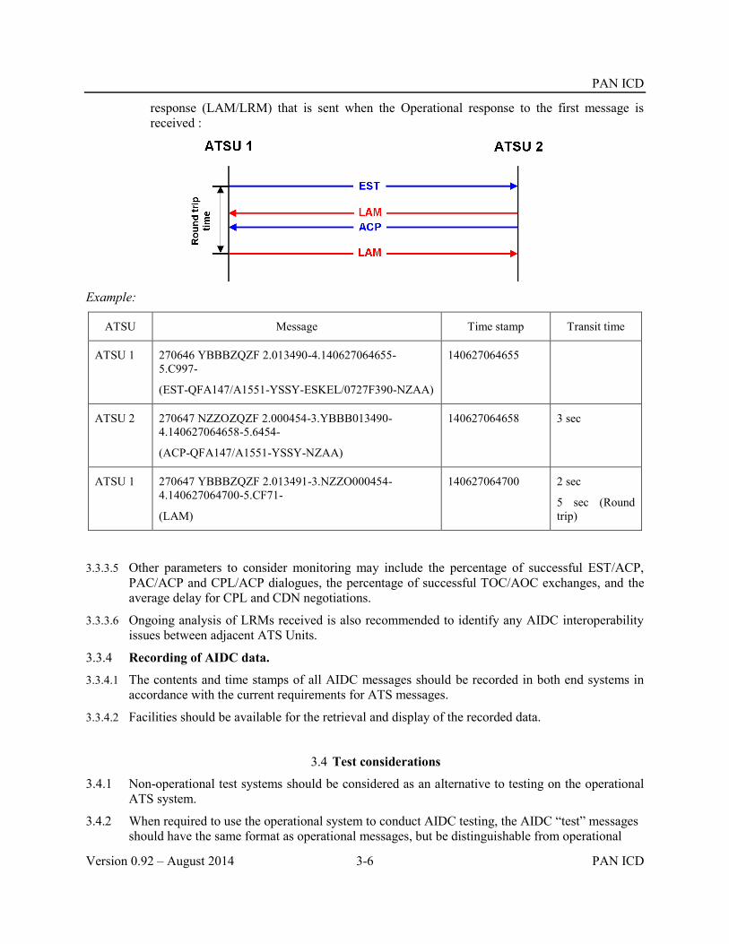
PAN ICD
Version 0.92 – August 2014 3-6 PAN ICD
response (LAM/LRM) that is sent when the Operational response to the first message is received :
Example:
ATSU Message Time stamp Transit time
ATSU 1 270646 YBBBZQZF 2.013490-4.140627064655-5.C997-
(EST-QFA147/A1551-YSSY-ESKEL/0727F390-NZAA)
140627064655
ATSU 2 270647 NZZOZQZF 2.000454-3.YBBB013490-4.140627064658-5.6454-
(ACP-QFA147/A1551-YSSY-NZAA)
140627064658 3 sec
ATSU 1 270647 YBBBZQZF 2.013491-3.NZZO000454-4.140627064700-5.CF71-
(LAM)
140627064700 2 sec
5 sec (Round trip)
3.3.3.5 Other parameters to consider monitoring may include the percentage of successful EST/ACP, PAC/ACP and CPL/ACP dialogues, the percentage of successful TOC/AOC exchanges, and the average delay for CPL and CDN negotiations.
3.3.3.6 Ongoing analysis of LRMs received is also recommended to identify any AIDC interoperability issues between adjacent ATS Units.
3.3.4 Recording of AIDC data.
3.3.4.1 The contents and time stamps of all AIDC messages should be recorded in both end systems in accordance with the current requirements for ATS messages.
3.3.4.2 Facilities should be available for the retrieval and display of the recorded data.
3.4 Test considerations
3.4.1 Non-operational test systems should be considered as an alternative to testing on the operational ATS system.
3.4.2 When required to use the operational system to conduct AIDC testing, the AIDC “test” messages should have the same format as operational messages, but be distinguishable from operational

PAN ICD
PAN ICD 3-7 Version 0.92 – August 2014
traffic by the use of non-operational call signs. These callsigns should be specified in bilateral agreements.
3.5 Scheduled Maintenance and Failures
3.5.1 ANSPs should be aware that maintenance on AIDC and AFTN systems may have an operational effect on other ANSPs. Such an effect may for example include loss of the AIDC function due to flooding of messages or out of sequence messages following an AIDC server reboot. Any maintenance affecting the AIDC and AFTN systems shuld therefore be prior coordinated with the ANSP counterparts and backup procedures decided.
3.5.2 Failure of the AIDC and/or AFTN systems should be immediately notified to the ANSP counterparts and backup or recovery procedures implemented.


PAN ICD
PAN ICD 4-1 Version 0.92 – August 2014
Chapter 4 AIDC Messages 4.1 Introduction
4.1.1 This chapter describes the permitted fields and formats of AIDC messages. AIDC message fields conform to ICAO definitions contained in PANS-ATM Appendix 3 except as described below for Fields 14 and 15, as well as a “Text” field that is used in some AIDC messages.
4.1.2 ATS data in AIDC messages is enclosed between parentheses. Only one ATS message is permitted to be included in each transmission.
4.1.3 Unless specified otherwise by the ATSU, the optional elements in the AIDC message fields described in this chapter and shown in Table 4-3Table 4-3should be made available in the system by the manufacturer and be user configurable.
4.2 Message Field Requirements
Fields in AIDC messages do not always require the full contents of the defined ICAO message field. This section specifies the usage of specific elements from message fields defined in the PANS-ATM as well as additional information that may be included in Fields 14 and 15.
4.2.1 Field 3 requirements.
4.2.1.1 All AIDC messages should use Field 3a (Message type) only.
4.2.1.2 Fields 3b (Message number) and 3c (Message reference data) are not used, since in AIDC messages the reference numbers contained in these fields are included in the Optional Data Field (ODF), option 2 and 3. See Chapter 3Chapter 3, para Error! Reference source not found..
4.2.2 Field 7 requirements.
4.2.2.1 Where Field 7 is required in an AIDC message, Field 7a (Aircraft Identification) must be included. Fields 7b (SSR Mode) and 7c (SSR Code) are optional but should be included if the information is available and applicable.
4.2.3 Field 13 requirements.
4.2.3.1 Where Field 13 is required in an AIDC message only Field 13a (Departure aerodrome), is required. Field 13b (Departure time) is not to be transmitted. The use of ZZZZ in Field 13 is supported.
4.2.4 Field 14 requirements
The following section describes the allowed contents of Field 14 (Estimate data), as well as providing examples of how Field 14 data can be incorporated in an AIDC message.
4.2.4.1 Field 14 may contain a number of mandatory and optional items. The following Table 4-1Table 4-1 provides an overview on the type of information that may be included in Field 14.
Table 4-1. Contents of Field 14
Data Example Mandatory/Optional Comment
Position
(14a)
46N150W
1545S16545E
M Normally a waypoint or system calculated position on or near the FIR or ACI boundary as agreed to

PAN ICD
Version 0.92 – August 2014 4-2 PAN ICD
GOOFY by bilateral agreement.
Field 14a is followed by an oblique stroke “/”
Estimated time
(14b)
2200 M The estimate for the position in 14a
Level
(14c)
A090
F330
F330F370
M The coordinated level of the aircraft
While 14c is mandatory, the support for the block level format is optional
Supplementary crossing data
(14d)
A120
F350
Included when applicable
Use in conjunction with 14e to indicate that an aircraft may be on climb or descent at, or within tolerances of, the FIR boundary
Crossing condition
(14e)
A
B
C
Included when applicable
(A) The aircraft may be on climb from the level specified in 14d
(B) The aircraft may be on descent from the level specified in 14d
(C) The aircraft is cruise climbing from the level specified in 14d.
The support for the cruise climb format is optional
Mach Number GM084
EM076
LM083
O Used when a Mach number speed restriction has been assigned to the aircraft by ATC.
Offset and weather deviation
W25R
W100E
O30L
O When an offset or weather deviation is in effect, the position in 14a should be a position on the flight planned route, rather than the offset route
Note1. Each item of optional information in Field 14 is separated from the previous item by an oblique stroke “/”;
Note2. The order that the item is included in Field 14 is the order in which it is listed in Table 4-1Table 4-1. For example, if an AIDC message were to include an assigned Mach Number as well as a weather deviation, the mach number information would precede the weather deviation information in Field 14.
4.2.4.2 Supplementary Crossing Data and Crossing Conditions in Field 14

PAN ICD
PAN ICD 4-3 Version 0.92 – August 2014
4.2.4.2.1 Field 14 may contain information that an aircraft is on climb, descent or cruise climb to the specified level. This is achieved by including supplementary crossing data and crossing conditions in Field 14.
4.2.4.2.2 The inclusion of cruise climb information in AIDC messages should only be made following bilateral agreement.
Example:
Field 14 Explanation
DUMBO/2130F310F290A The aircraft is estimating DUMBO at 2130, assigned F310 and is climbing from (or “above”) F290.
30N160W/0215F310F330B The aircraft is estimating 30N160W at 0215, assigned F310 and is descending from (or “below”) F330.
ADSAM/1547F360F340C The aircraft is estimating ADSAM at 1547 and is cruise climbing from F340 to F360.
4.2.4.3 Block level information in Field 14
4.2.4.3.1 Field 14 may contain information that an aircraft is operating in a block level clearance. It is permissible to include supplementary crossing data and a crossing condition with a block level, but if this occurs the supplementary information may only be a single level (i.e. it cannot be a block level).
Example:
Field 14 Explanation
MINNY/2125F320F340 The aircraft is estimating MINNY at 2125, and is operating in a block of levels between F320 and F340 (inclusive).
46N150W/0244F310F350F290A The aircraft is estimating 46N150W at 0244, and has been assigned a block of levels between F310 and F350 (inclusive) and is climbing to the cleared block and will be at or above F290 at 46N150W.
4.2.4.3.2 The AIDC format does not support a cruise climb into a block clearance.
4.2.4.3.3 The inclusion of block level information in AIDC messages should only be made following bilateral agreement.
4.2.4.4 Mach Number information in Field 14
4.2.4.4.1 Field 14 may contain information that an aircraft has been assigned a speed restriction (Mach Number). When included in an AIDC message, any Mach Number information should always follow directly after the level information and be separated from the level information by an oblique stroke “/”.

PAN ICD
Version 0.92 – August 2014 4-4 PAN ICD
Example:
Field 14 Explanation
BUGGS/0349F350/GM085 The aircraft is estimating BUGGS at 0349 at F350 and has been instructed to maintain M0.85 or greater
4305N17510W/0215F310/EM076 The aircraft is estimating 4305N17510W at 0215 at F310 and has been instructed to maintain M0.76
4.2.4.4.2 The absence of speed information in Field 14 of an AIDC message provides advice that any previously notified speed has been cancelled.
Example:
Field 14 Explanation
SPEDY/1237F310F330B/LM083
Subsequently followed by:
SPEDY/1238F310
The aircraft is estimating SPEDY at 1237, assigned F310 and will cross SPEDY at or below F330, maintaining M0.83 or less.
The aircraft is now estimating SPEDY at 1238, is maintaining F310 (i.e. no longer on descent at SPEDY), and the mach number restriction has been cancelled.
4.2.4.4.3 The inclusion of Mach Number information in AIDC messages should only be made following bilateral agreement.
4.2.4.5 Offset and Weather Deviation Information in Field 14
4.2.4.5.1 Field 14 may contain information that an aircraft is subject to either a weather deviation or offset clearance. When included in an AIDC message, any offset and weather deviation information should always be the last information in Field 14, and should be separated from preceding information by an oblique stroke “/”.
4.2.4.5.2 It is important that the difference between an offset and a weather deviation is correctly understood. This difference is depicted in the diagram below.

PAN ICD
PAN ICD 4-5 Version 0.92 – August 2014
4.2.4.5.3 An offset is a flight trajectory that is parallel to the original route, offset by a specified distance and direction. Once an aircraft is established on the offset, separation may be applied solely based on the offset path.
4.2.4.5.4 A weather deviation permits an aircraft to operate anywhere between the original route and the specified distance and direction from the original route. Separation must therefore be applied to the entire airspace in which the aircraft has been cleared to operate in.
4.2.4.5.5 The following examples show various combinations of weather deviations and offsets, combined with other optional information allowed in Field 14.
Example:
Field 14 Explanation
2830S16300E/0140F330/W20L The aircraft is estimating 2830S16300E at 0140, maintaining F330, and has been cleared to deviate up to 20NM to the left of route.
GOOFY/2330F310/GM084/O30R The aircraft is estimating GOOFY at 2330, maintaining F310, instructed to maintain M0.84 or greater, and has been cleared to offset 30NM to the right of route.
41N040W/0215F310F330/W25E The aircraft is estimating 41N040W at 0215, is operating in a block of levels between F310 and F330 (inclusive), and has been cleared to deviate up to 25NM either side of route.
DAFFY/0215F310F350F370B/W100L The aircraft is estimating DAFFY at 0215, and has been assigned a block of levels between F310 and F350 (inclusive), will cross DAFFY at or below F370, and has been cleared to deviate up to 100NM to the left of route.
4.2.4.5.6 The absence of offset or weather deviation in Field 14 of an AIDC message provides advice that any previously notified off-track information has been cancelled.
Example:
Field 14 Explanation
34N040W/1519F330/W15R
Subsequently followed by:
34N040W/1520F330
The aircraft is deviating up to 15NM right of track.
The aircraft is back on track (and one minute later than previously coordinated).

PAN ICD
Version 0.92 – August 2014 4-6 PAN ICD
4.2.4.5.7 When an aircraft is offsetting or deviating, the coordination point included in Field 14a should be a position based on the flight planned route rather than the offset route. The estimate included in Field 14b shall be the estimate for the “abeam” position for the position included in Field 14a.
4.2.4.5.8 The inclusion of offsets and weather deviation information in AIDC messages should only be made following bilateral agreement. Depending on their operational requirements, some ATS Units may choose to only implement the weather deviation format. If applicable, this should also be specified in bilateral agreements.
4.2.5 Field 15 requirements
4.2.5.1 The following section describes the allowed contents of Field 15 (Route), as well as providing examples of how Field 15 data can be incorporated in an AIDC message.
4.2.5.2 A number of different AIDC messages (e.g. ABI, PAC, CPL, CDN and PCM) may contain Field 15 (Route) information. Depending on the AIDC message being used, this route information may be either the current cleared route of the aircraft, or a proposed amendment to it.
4.2.5.3 While Field 15 may be optional in an AIDC message (refer Table 4-2Table 4-2), if it is included, all Field 15 sub-fields (15a, b and c) must also be included.
Table 4-2. Contents of Field 15
Data Example Mandatory/Optional
Comment
Speed
(15a)
M084
N0488
M (Included in a flight plan as the initial requested speed for a flight).
In AIDC messaging:
if a speed has been specified in Field 14c, then the speed in Field 15a should be the same value; otherwise,
it should represent the expected speed of the aircraft at the coordination point included in Field 14a.
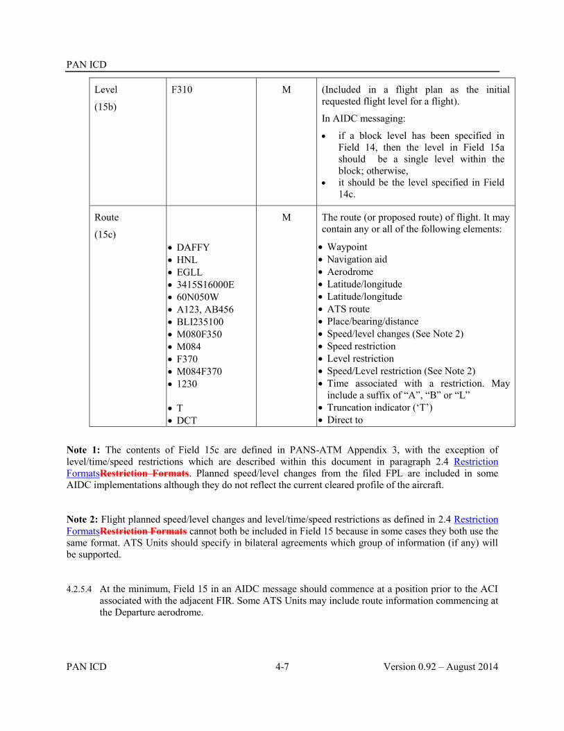
PAN ICD
PAN ICD 4-7 Version 0.92 – August 2014
Level
(15b)
F310
M (Included in a flight plan as the initial requested flight level for a flight).
In AIDC messaging:
if a block level has been specified in Field 14, then the level in Field 15a should be a single level within the block; otherwise,
it should be the level specified in Field 14c.
Route
(15c)
DAFFY HNL EGLL 3415S16000E 60N050W A123, AB456 BLI235100 M080F350 M084 F370 M084F370 1230
T DCT
M The route (or proposed route) of flight. It may contain any or all of the following elements:
Waypoint Navigation aid Aerodrome Latitude/longitude Latitude/longitude ATS route Place/bearing/distance Speed/level changes (See Note 2) Speed restriction Level restriction Speed/Level restriction (See Note 2) Time associated with a restriction. May
include a suffix of “A”, “B” or “L” Truncation indicator (‘T’) Direct to
Note 1: The contents of Field 15c are defined in PANS-ATM Appendix 3, with the exception of level/time/speed restrictions which are described within this document in paragraph 2.4 Restriction FormatsRestriction Formats. Planned speed/level changes from the filed FPL are included in some AIDC implementations although they do not reflect the current cleared profile of the aircraft.
Note 2: Flight planned speed/level changes and level/time/speed restrictions as defined in 2.4 Restriction FormatsRestriction Formats cannot both be included in Field 15 because in some cases they both use the same format. ATS Units should specify in bilateral agreements which group of information (if any) will be supported.
4.2.5.4 At the minimum, Field 15 in an AIDC message should commence at a position prior to the ACI associated with the adjacent FIR. Some ATS Units may include route information commencing at the Departure aerodrome.

PAN ICD
Version 0.92 – August 2014 4-8 PAN ICD
4.2.5.5 Field 15 information transmitted by ATSU1 to ATSU2 should commence at (or before) MICKY. This permits ATSU2 to calculate the profile of the aircraft commencing at the ACI boundary.
4.2.5.6 ATS Route
4.2.5.6.1 An ATS route may only be preceded and followed by a waypoint that is defined to be on that ATS route.
4.2.5.7 Latitude/Longitudes
4.2.5.7.1 Latitude and longitude in Field 15 must either be both in whole degrees, or both in degrees and minutes.
4.2.5.8 Flight Planned Speed/Level Changes
4.2.5.8.1 Some ATSUs may include flight planned speed/level changes in Field 15c although they do not reflect the current cleared profile of the aircraft. An ATSU receiving Field 15c data containing planned FPL level speed changes should accept the information. However, the receiving ATS Unit may choose not to use it the planned FPL level speed changes to update their flight plan, and may choose not to forward it in any subsequent AIDC messages.
4.2.5.9 Time/Speed/Level Restrictions
4.2.5.9.1 While the information in Field 14 defines the conditions for crossing the ACI or FIR boundary, ATSU 1 may include in Field 15 time/speed/level restrictions that have been issued in a clearance to an aircraft. These clearances may include a requirement for an aircraft to cross a position at a specific time or to change level and/or speed at or by a specific time or position.
4.2.5.10 Truncation Indicator
4.2.5.10.1 While it is desirable for Field 15 to describe the entire route to destination, on occasions this may not be possible. If it is not possible to define the route to destination, it is necessary to truncate (delete the remainder of the route) and insert a truncation indicator (‘T’).
4.2.5.10.2 Bilateral agreements should define the use and meaning of the truncation indicator. For example the truncation indicator may represent:
the point at which the route in Field 15 rejoins the original flight planned route, or
the end of the oceanic cleared route.
4.2.5.10.3 The truncation indicator should only follow a significant point in Field 15 and should not follow an ATS Route, or “DCT”.
Note. A significant point also refers to a significant point followed or preceded by:
A Speed/level change; or
A speed and/or level and/or time restriction

PAN ICD
PAN ICD 4-9 Version 0.92 – August 2014
Examples of Field 15c
SY L521 AA Navaid, ATS Route
Note that both “SY” and “AA” are defined on airway L521
SY L521 GEROS 32S160E 3425S16300E LUNBI AA Navaid, ATS Route, waypoint, lat/long (dd), lat/long (ddmm)
SY GEROS GEROS045100 ESKEL L521 AA Place/bearing/distance
SY L521 GEROS/M085F370 L521 AA DCT BB Speed/level change, DCT
SY L521 LUNBI T
SY L521 GEROS 32S160E 3425S16300E T
SY L521 LUNBI/M085F370 T
Truncation indicator
SY L521 GEROS/F370 L521 F370/LUNBI AA
SY GEROS/2245L 32S160E ESKEL/M085F390 AA
SY L521 M084F350/GEROS/1230A ESKEL/M083 L521 AA
Restrictions
4.2.6 Field 16 Requirements
4.2.6.1 Where Field 16 is required in an AIDC message, only Field 16a (Destination aerodrome), is required. Field 16b (Total estimated elapsed time) and Field 16c (Alternate aerodrome(s)) are not to be transmitted. The use of ZZZZ in Field 16 is supported.
4.2.7 Field 18 Requirements
4.2.7.1 Field 18 should contain other information from the current flight plan and is used to update the flight plan at the receiving ATSU.
4.2.7.2 When transmitting Field 18 in an AIDC message all Field 18 indicators should be included, even if the change only affects data in an individual Field 18 indicator. However, ATS Units may agree by bilateral agreement to omit specific indicators (e.g. EET/) if required. If omitting indicators, ATS Units should have due regard to the potential effect to downstream ATS Units.
4.2.7.3 The contents of Field 18 in AIDC messages should be specified in bilateral agreements between ATS Units.
Note: Some legacy implementations allowed provision for the modification of individual sub fields by communicating only that specific subfield. This is not recommended practice.
4.2.7.4 In some AIDC messages, Field 18 may contain only a RMK/ indicator which is used to convey free text data information. This applies to the MAC, EMG, LRM and MIS messages.
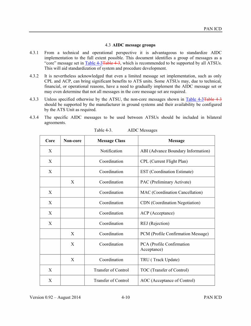
PAN ICD
Version 0.92 – August 2014 4-10 PAN ICD
4.3 AIDC message groups
4.3.1 From a technical and operational perspective it is advantageous to standardize AIDC implementation to the full extent possible. This document identifies a group of messages as a “core” message set in Table 4-3Table 4-3, which is recommended to be supported by all ATSUs. This will aid standardization of system and procedure development.
4.3.2 It is nevertheless acknowledged that even a limited message set implementation, such as only CPL and ACP, can bring significant benefits to ATS units. Some ATSUs may, due to technical, financial, or operational reasons, have a need to gradually implement the AIDC message set or may even determine that not all messages in the core message set are required.
4.3.3 Unless specified otherwise by the ATSU, the non-core messages shown in Table 4-3Table 4-3 should be supported by the manufacturer in ground systems and their availability be configured by the ATS Unit as required.
4.3.4 The specific AIDC messages to be used between ATSUs should be included in bilateral agreements.
Table 4-3. AIDC Messages
Core Non-core Message Class Message
X Notification ABI (Advance Boundary Information)
X Coordination CPL (Current Flight Plan)
X Coordination EST (Coordination Estimate)
X Coordination PAC (Preliminary Activate)
X Coordination MAC (Coordination Cancellation)
X Coordination CDN (Coordination Negotiation)
X Coordination ACP (Acceptance)
X Coordination REJ (Rejection)
X Coordination PCM (Profile Confirmation Message)
X Coordination PCA (Profile Confirmation Acceptance)
X Coordination TRU ( Track Update)
X Transfer of Control TOC (Transfer of Control)
X Transfer of Control AOC (Acceptance of Control)

PAN ICD
PAN ICD 4-11 Version 0.92 – August 2014
Core Non-core Message Class Message
X General Information EMG (Emergency)
X General Information MIS (Miscellaneous)
X Application Management LAM (Logical Acknowledgement Message)
X Application Management LRM (Logical Rejection Message)
X Application Management ASM (Application Status Monitor)
X Application Management FAN ( FANS Application Message)
X Application Management FCN (FANS Completion Notification)
X Surveillance Data Transfer
ADS (Surveillance ADS-C)
4.4 Notification messages
4.4.1 ABI (Advance Boundary Information).
4.4.1.1 Purpose.
4.4.1.2 An ABI message is transmitted to provide information on a flight to the receiving ATSU. The purpose of the ABI is to synchronize the flight plan information held between two ATS Units.
4.4.1.3 The transmission of the initial ABI will normally be triggered at an agreed time or position prior to the common boundary or ACI, or possibly by a change in flight state. Before coordination occurs, amendments to information contained in a previously transmitted ABI should be notified by the transmission of another ABI.
4.4.1.4 Message format.
ATS Field Description
3 Message type
7 Aircraft identification
13 Departure aerodrome
14 Estimate data
16 Destination aerodrome
22 Amendment field
Field 22 should contain as a minimum the following fields:

PAN ICD
Version 0.92 – August 2014 4-12 PAN ICD
9 Number, type of aircraft and wake turbulence category
15 Route
Field 22 may optionally include any or all of the following fields:
8 Flight rules and type of flight
10 Equipment
18 Other information
Example
An ABI message containing the minimum contents of Field 22, with full route details to destination.
(ABI-IBE6175-LEMD-41N040W/0700F330-KMIA
-9/B744/H
-15/M084F350 41N030W 41N040W 41N050W 40N060W 38N065W DANER A699 NUCAR DCT HEATT
An ABI message containing a supplementary crossing condition and Mach Number in Field 14, a truncated Field 15 containing a level restriction, and an agreed subset of Field 18:
(ABI-ICE615-BIKF-62N030W/0700F350F310A/GM080-KJFK
-8/IS
-9/B752/M
-10/SDIJ5RXW/SD1
-15/M080F350 62N030W 60N040W/M080F370 57N050W DCT OYSTR DCT STEAM T
-18/PBN/A1L1)
An ABI containing a weather deviation in Field 14, a speed/level change in Field 15, and the entire Field 18 from the original FPL:
(ABI-ANZ716/A1565-YSSY-ESKEL/0743F370/W20R-NZAA
-8/IS
-9/A320/M
-10/SDE1E3FGHIM2RW/LB1
-15/N0448F370 EVONN L521 ESKEL/N0448F390 L521 LUNBI DCT
-18/PBN/A1C1D1O1S2T1 REG/ZKOJI EET/YBBB0009 NZZO0121 SEL/HLAM CODE/C8178C OPR/ANZ RALT/YSNF RMK/TCAS EQUIPPED)

PAN ICD
PAN ICD 4-13 Version 0.92 – August 2014
4.5 Coordination messages
4.5.1 CPL (Current Flight Plan)
4.5.1.1 Purpose.
4.5.1.1.1 A CPL message is used to initiate coordination for a flight.
4.5.1.1.2 The transmission of the CPL message will normally be triggered at an agreed time or position prior to the common boundary or ACI, or possibly by a change in flight state.
4.5.1.1.3 The ATSU receiving the CPL message should either agree to the proposed coordination by responding with an ACP message, otherwise negotiate the proposed coordination by responding with a CDN message.
4.5.1.1.4 A coordination dialogue initiated by a CPL message may only be closed by an ACP message.
4.5.1.2 Message format.
ATS Field Description
3 Message type
7 Aircraft identification
8 Flight rules and type of flight
9 Number, type of aircraft and wake turbulence category
10 Equipment
13 Departure aerodrome
14 Estimate data
15 Route
16 Destination aerodrome
18 Other information
Example
A CPL message containing a block level with a supplementary crossing condition in Field 14, and an agreed subset of Field 18:
(CPL-UAL815-IS
-B773/H-SDIJ5RXW/SD1
-LFPG-54N030W/1417F350F370F330A
-M080F350 54N020W 54N030W 54N040W 52N050W DCT CRONO DCT DOTTY
-KIAD
-PBN/A1L1 REG/N456UA SEL/KLBF)
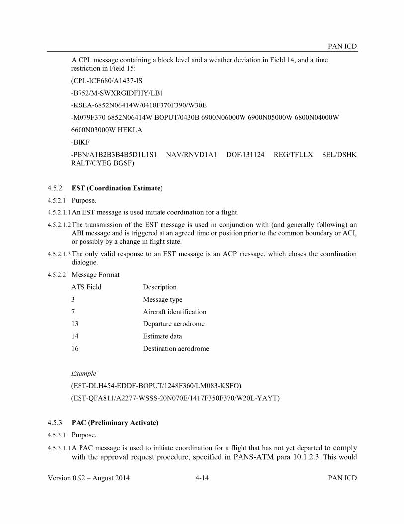
PAN ICD
Version 0.92 – August 2014 4-14 PAN ICD
A CPL message containing a block level and a weather deviation in Field 14, and a time restriction in Field 15:
(CPL-ICE680/A1437-IS
-B752/M-SWXRGIDFHY/LB1
-KSEA-6852N06414W/0418F370F390/W30E
-M079F370 6852N06414W BOPUT/0430B 6900N06000W 6900N05000W 6800N04000W
6600N03000W HEKLA
-BIKF
-PBN/A1B2B3B4B5D1L1S1 NAV/RNVD1A1 DOF/131124 REG/TFLLX SEL/DSHK RALT/CYEG BGSF)
4.5.2 EST (Coordination Estimate)
4.5.2.1 Purpose.
4.5.2.1.1 An EST message is used initiate coordination for a flight.
4.5.2.1.2 The transmission of the EST message is used in conjunction with (and generally following) an ABI message and is triggered at an agreed time or position prior to the common boundary or ACI, or possibly by a change in flight state.
4.5.2.1.3 The only valid response to an EST message is an ACP message, which closes the coordination dialogue.
4.5.2.2 Message Format
ATS Field Description
3 Message type
7 Aircraft identification
13 Departure aerodrome
14 Estimate data
16 Destination aerodrome
Example
(EST-DLH454-EDDF-BOPUT/1248F360/LM083-KSFO)
(EST-QFA811/A2277-WSSS-20N070E/1417F350F370/W20L-YAYT)
4.5.3 PAC (Preliminary Activate)
4.5.3.1 Purpose.
4.5.3.1.1 A PAC message is used to initiate coordination for a flight that has not yet departed to comply with the approval request procedure, specified in PANS-ATM para 10.1.2.3. This would

PAN ICD
PAN ICD 4-15 Version 0.92 – August 2014
normally occur if the departure point is close to the FIR or ACI boundary and preflight coordination is required.
4.5.3.1.2 Because the departure point is close to the boundary, the transmission of a PAC message would normally be triggered by a change in flight state.
4.5.3.1.3 Where a PAC contains enough optional fields to capture any flight plan updates that may have occurred it is not normally preceded by an ABI message. However, this is considered a local implementation issue and should be determined by bi-lateral agreement.
4.5.3.1.4 A coordination dialogue initiated by a PAC message may only be closed by an ACP message.
4.5.3.2 Message Format
ATS Field Description
3 Message type
7 Aircraft identification
13 Departure aerodrome
14 Estimate data
16 Destination aerodrome
22 Amendment field
Field 22 may optionally include any or all of the following fields
8 Flight rules and type of flight
9 Number, type of aircraft and wake turbulence category
10 Equipment
15 Route
18 Other information
Example
An example of an abbreviated PAC message:
(PAC-ANZ763-YSNF-TEKEP/0250F360F001A-YSSY)
An example of a PAC message containing all message fields:
(PAC-ATN460/A4440-FJDG-LATEP/1822F310F001A-WSAP -8/IN -9/B752/M -10/ SDIRXW/S -15/N0473F370 DCT NKW R348 LATEP/M080F350 R348 KADAP/N0489F290 P627 DABAP/N0467F370 N628 PKU R469 TAROS/M080F370 DCT PIMOK W401 KK DCT PU DCT -18/PBN/A1B2C2D2O2 NAV/RNVD1E2A1 DOF/131212 REG/N753CX EET/YMMM0027 SEL/GSQR OPR/ATN ORGN/KLITATNX RMK/TCAS EQUIPPED)

PAN ICD
Version 0.92 – August 2014 4-16 PAN ICD
4.5.4 MAC (Cancellation of Notification and/or Coordination)
4.5.4.1 Purpose.
4.5.4.1.1 A MAC message is transmitted to advise an ATSU that any notification and/or coordination previously received for a flight is no longer relevant to that ATSU.
4.5.4.1.2 A MAC message should only be transmitted to an ATSU that has previously received notification and/or coordination for a flight. While a MAC message might be transmitted after a flight has been cancelled, the MAC message should not to be considered as equivalent to a CNL message as its purpose is not to cancel the flight plan.
4.5.4.2 Message Format
ATS Field Description
3 Message type
7 Aircraft identification
13 Departure aerodrome
16 Destination aerodrome
22 Amendment field
Field 22 may optionally include any or all of the following fields:
14 Estimate Data
18 Other information (limited to RMK/)
Field 14 containing the estimate data previously transmitted may be included in the MAC message. It may be used if required, to correctly identify the flight concerned by the MAC, when appropriate. If a MAC message is transmitted as a result of a diversion to a new destination (i.e. such that the receiving ATSU is no longer affected by the flight), Field 16 – Destination aerodrome – should contain the destination contained in the original Notification and/or coordination messages.
Example
(MAC-BCA789-EGKK-KLAX)
(MAC-THA989-VTBD-YMML-18/RMK/DIVERTED TO YPDN)
(MAC-FJI910/A1452-YSSY-NFFN-14/UBLIN/2330F370)
4.5.5 CDN (Coordination Negotiation)
4.5.5.1 Purpose.
4.5.5.1.1 A CDN message is used to propose amendments to previously agreed coordination conditions or coordination proposed in a CPL message or a CDN message.

PAN ICD
PAN ICD 4-17 Version 0.92 – August 2014
4.5.5.1.2 An initial coordination dialogue following a CPL message is always terminated by an ACP message; otherwise an ATSU receiving a CDN message can indicate that the proposed revision is not acceptable (by replying with an REJ message) or propose an amendment to the proposed coordination by replying with a CDN message.
4.5.5.1.3 If sent in response to another AIDC message, The CDN message is linked to the original AIDC message using message identifier and reference identifier information described in Chapter 3, Abbreviations and AIDC MessagesAbbreviations and AIDC Messages.
4.5.5.2 Message Format.
ATS Field Description
3 Message type
7 Aircraft identification
13 Departure aerodrome
16 Destination aerodrome
22 Amendment field
Normally, Field 22 may contain any or all of the following fields:
14 Estimate data
15 Route
18 Other Information
Subject to bilateral agreement, the following fields may also be included in Field 22.
10 Equipment
Text Amended Destination
4.5.5.3 Amended Destination is a free text field that may be used in the CDN message to propose the coordination of a new destination aerodrome. The field consists of an identifier (“DEST”) followed by a “/” character, followed by the name or location of the destination. When used, the Amended destination field is the last field within Field 22.
Example
CDN messages proposing amendments to Field 14. This would normally be the most common field that is amended:
(CDN-NWA36-KBOS-EDDF
-14/54N030W/0446F370)
(CDN-ANZ135/A2462-NZAA-YBBN

PAN ICD
Version 0.92 – August 2014 4-18 PAN ICD
-14/RIGMI/0220F360F380/W20L)
A CDN message proposing amendments to Field 10 (in this case RVSM capability has been removed) (subject to bilateral agreement):
(CDN-QFA43/A4422-YSSY-NZAA
-10/SDE2E3GHIRYZ/LB1)
A CDN message proposing amendments to Fields 14 and 15:
(CDN-BAW32N-KMIA-EGGL
-14/37N040W/0201F360
-15/M085F360 32N050W 37N040W 42N030W 45N020W OMOKO GUNSO GAPLI UL620 GIBSO)
A CDN message proposing amendments to field 18:
(CDN-BAW242-MMMX-EGLL
-18/PBN/A1 DOF/120412 REG/GBNLI EET/KZHU0054 LPPO0546 CZQX0606 EGGX0643 49N020W0732 BEDRA0757 GUNSO0813 EGTT0833 SEL/BPCE ORGN/EGLLBAWH RALT/CYQX EIDW RMK/TCAS)
CDN messages proposing an amended destination (subject to bilateral agreement):
(CDN-KAL823-RJAA-NZCH
-15/LTO G591 AA-DEST/NZAA)
(CDN-MAPLE1-PKMJ-ZZZZ
-14/MARTI/2200F310-15/MARTI 02N168E
-DEST/0150N16745E)
4.5.5.4 The last two examples demonstrate a CDN message proposing a new route to an amended destination. The first of these examples shows a change in route and destination, with no change in Field 14 (i.e. the proposed re-route occurs after the boundary position). The second example shows a change of route with a corresponding change to Field 14. The “DEST/” included in this example refers to the proposed destination, rather than the original “ZZZZ” destination that may have been included in the flight plan. Refer to Chapter 6, Implementation Guidance MaterialImplementation Guidance Material, for the methodology in proposing a diversion to a new destination.
4.5.6 ACP (Acceptance)

PAN ICD
PAN ICD 4-19 Version 0.92 – August 2014
4.5.6.1 Purpose.
4.5.6.1.1 An ACP message is used to confirm that the coordination proposed in a received CPL, CDN, EST or PAC message is acceptable and to close the coordination dialogue. The agreed coordination conditions are updated in accordance with the proposed coordination.
4.5.6.1.2 An ACP message is linked to the original AIDC message using message identifier and reference identifier information described in Chapter 3, Abbreviations and AIDC MessagesAbbreviations and AIDC Messages and Chapter 6, Implementation Guidance MaterialImplementation Guidance Material.
4.5.6.2 Message Format.
ATS Field Description
3 Message type
7 Aircraft identification
13 Departure aerodrome
16 Destination aerodrome
Example
(ACP-ACA860-NZAA-KSFO)
(ACP-UAL816/A3312-YSSY-KLAX)
4.5.7 REJ (Rejection)
4.5.7.1 Purpose.
4.5.7.1.1 An REJ message is used to reject the coordination proposed in a received CDN message and to close the coordination dialogue. The previously agreed coordination conditions remain unchanged.
4.5.7.1.2 An REJ message may not be used to close an initial coordination dialogue
4.5.7.1.3 An REJ message is linked to the original CDN message using message identifier and reference identifier information described in Chapter 3, Abbreviations and AIDC MessagesAbbreviations and AIDC Messages and Chapter 6, Implementation Guidance MaterialImplementation Guidance Material.
4.5.7.2 Message Format.
ATS Field Description
3 Message type
7 Aircraft Identification
13 Departure Aerodrome
16 Destination Aerodrome
Example

PAN ICD
Version 0.92 – August 2014 4-20 PAN ICD
(REJ-AAL780-KJFK-EGLL)
(REJ-BAW32N/A2262-KMIA-EGGL)
4.5.8 PCM (Profile Confirmation Message) 4.5.8.1 Purpose.
4.5.8.1.1 The PCM is used as a final conformance check between the transferring ATSU and the receiving ATSU to enable detection of coordination errors and to ensure that the receiving ATSU has the most up to date information on the aircraft.
4.5.8.1.2 At the minimum, the PCM is used to confirm boundary estimate information, but may also be used to confirm other flight plan information as well.
4.5.8.1.3 The transmission of the PCM should be automatically triggered at an agreed time or position approaching the common boundary or ACI.
4.5.8.1.4 The only valid response to a PCM is a PCA message.
4.5.8.2 Message Format.
ATS Field Description
3 Message type
7 Aircraft identification
13 Departure aerodrome
14 Estimate data
16 Destination aerodrome
The PCM may optionally include any or all of the following fields:
8 Flight rules and type of flight
9 Number, type of aircraft and wake turbulence category
10 Equipment
15 Route
18 Other information.
Example
A PCM containing mandatory Field 14 information only:
(PCM-QFA43/A2233-YSSY-ESKEL/1417F350-NZAA)
A PCM containing mandatory Field 14 information as well as Field 10:
(PCM-UAL815/A2211-YSSY-2801S16300E/2255F310-KLAX
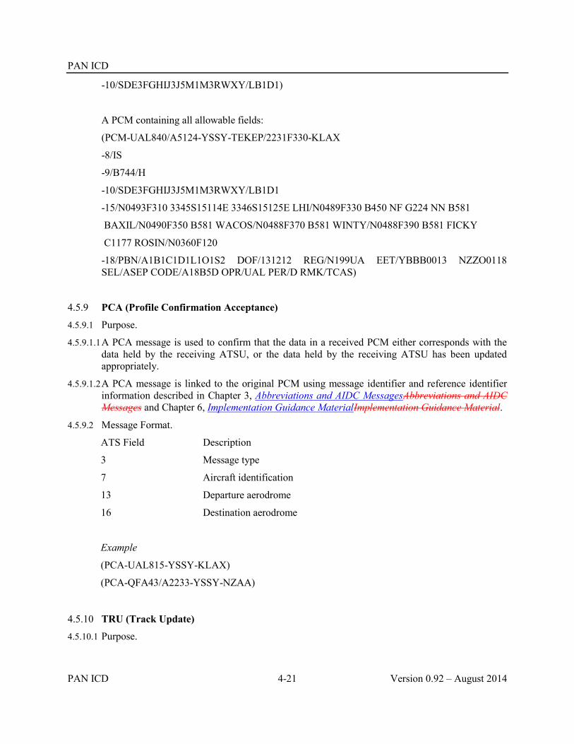
PAN ICD
PAN ICD 4-21 Version 0.92 – August 2014
-10/SDE3FGHIJ3J5M1M3RWXY/LB1D1)
A PCM containing all allowable fields:
(PCM-UAL840/A5124-YSSY-TEKEP/2231F330-KLAX
-8/IS
-9/B744/H
-10/SDE3FGHIJ3J5M1M3RWXY/LB1D1
-15/N0493F310 3345S15114E 3346S15125E LHI/N0489F330 B450 NF G224 NN B581
BAXIL/N0490F350 B581 WACOS/N0488F370 B581 WINTY/N0488F390 B581 FICKY
C1177 ROSIN/N0360F120
-18/PBN/A1B1C1D1L1O1S2 DOF/131212 REG/N199UA EET/YBBB0013 NZZO0118 SEL/ASEP CODE/A18B5D OPR/UAL PER/D RMK/TCAS)
4.5.9 PCA (Profile Confirmation Acceptance)
4.5.9.1 Purpose.
4.5.9.1.1 A PCA message is used to confirm that the data in a received PCM either corresponds with the data held by the receiving ATSU, or the data held by the receiving ATSU has been updated appropriately.
4.5.9.1.2 A PCA message is linked to the original PCM using message identifier and reference identifier information described in Chapter 3, Abbreviations and AIDC MessagesAbbreviations and AIDC Messages and Chapter 6, Implementation Guidance MaterialImplementation Guidance Material.
4.5.9.2 Message Format.
ATS Field Description
3 Message type
7 Aircraft identification
13 Departure aerodrome
16 Destination aerodrome
Example
(PCA-UAL815-YSSY-KLAX)
(PCA-QFA43/A2233-YSSY-NZAA)
4.5.10 TRU (Track Update)
4.5.10.1 Purpose.

PAN ICD
Version 0.92 – August 2014 4-22 PAN ICD
4.5.10.1.1 A TRU message is used to coordinate amendments to previously agreed coordination conditions, or other flight-related information, where prior coordination of the change(s) is not required.
4.5.10.1.2 Unlike the CDN message, there is no operational response to the TRU message, and so use of this message must be in strict accordance with bilateral agreements.
4.5.10.2 Message Format.
ATS Field Description
3 Message type
7 Aircraft Identification
13 Departure Aerodrome
16 Destination Aerodrome
Text Track Data
4.5.10.2.1 Track data is a free text field used in the TRU message to permit the transfer of updated information from one ATSU to another. This field contains a number of elements which are described below. Each element consists of an “identifier” and a value which are separated by a “/” character.
4.5.10.2.2 All of the elements within the Track data field are optional, and multiple elements may be included, separated by a single <space> character. Track data will contain at least one element. When multiple elements are to be transmitted in a single TRU message, the order of the elements within the Track data field is the order in which they are listed below. Unused elements are not included in the Track data field.
4.5.10.2.2.1 Requested Flight Level (RFL)
This element is preceded by the identifier ‘RFL’ and contains the aircraft’s most recent requested level. Block levels and cruise climbs are supported as defined in Chapter 2, Purpose, Policy and Units of MeasurementPurpose, Policy and Units of Measurement.
Example
RFL/F390
RFL/A090
RFL/F310F330
RFL/F330F310C
4.5.10.2.2.2 Present Level (PRL)
This element is preceded by the identifier ‘PRL’ and contains the aircraft’s last reported level.
Example
PRL/F390
PRL/A090
4.5.10.2.2.3 Heading (HDG)

PAN ICD
PAN ICD 4-23 Version 0.92 – August 2014
This element is preceded by the identifier ‘HDG’ and contains the magnetic heading that has been assigned to the aircraft, expressed as a three digit number between 001 and 360 (inclusive).
Example
HDG/080
4.5.10.2.2.4 Cleared Flight Level (CFL)
This element is preceded by the identifier ‘CFL’ and contains the amended level that the aircraft has been assigned. Block levels and cruise climbs in accordance with Chapter 2, Purpose, Policy and Units of MeasurementPurpose, Policy and Units of Measurement are also supported.
Example
CFL/F330
CFL/F310F330
CFL/F310F330F210A
CFL/F330F310C
4.5.10.2.2.5 Speed (SPD)
This element is preceded by the identifier ‘SPD’ and contains details of the speed (Mach Number or Indicated airspeed) that the aircraf t has been assigned.
Mach numbers are expressed as “M” followed by 3 figures giving the true Mach Number or to the nearest .01 Mach.
Indicated airspeeds are expressed as “I” followed by 4 figures giving the Indicated Airspeed in knots.
To cancel an assigned speed that had been previously coordinated, the SPD identifier is followed by a “/” character, followed by a zero (0).
Example
SPD/M084
SPD/I0250
SPD/0
4.5.10.2.2.6 Direct to (DCT)
This element is preceded by the identifier “DCT” and contains the position that the aircraft has been cleared directly to.
Example
DCT/MICKY
DCT/30S160E
4.5.10.2.2.7 Off track deviation (OTD)
This element is preceded by the identifier ‘OTD’ and contains the details of any off track clearance that has been issued to the aircraft. The format of the off track deviation is as

PAN ICD
Version 0.92 – August 2014 4-24 PAN ICD
described in Chapter 2, Purpose, Policy and Units of MeasurementPurpose, Policy and Units of Measurement, para 2.3.9.12.3.9.1; i.e.
a single character providing advice as to whether the clearance is an offset (O) or a weather deviation (W); and
an off track distance associated with this clearance: a direction, indicating left (L) or right (R) or, in the case of weather deviation, either side
of track (E); and when including Offset information in and AIDC message, the direction “E” (either side
of track) should not be used To cancel a previously coordinated off track deviation, the OTD identifier is followed by an oblique stroke “/”, followed by a zero (0).
Example
OTD/W20R
OTD/O30L
OTD/0
Examples
TRU message notifying that an aircraft is requesting an amended level (which is not currently available):
(TRU-ICE456-BIKF-EGPF-RFL/F370)
TRU messages notifying of a weather deviation, subsequently followed by the cancellation of the weather deviation:
(TRU-UAL73-NTAA-KLAX-OTD/W20R)
(TRU-UAL73-NTAA-KLAX-OTD/0)
TRU messages notifying that an aircraft is initially on a heading of 115, assigned F270, and at reduced speed (250 knots), subsequently followed by notification that the aircraft has been re-cleared direct to GEROS, assigned F370, and the speed restriction has been removed:
(TRU-QFA43/A2244-YSSY-NZAA-HDG/115 CFL/F270 SPD/I0250)
(TRU-QFA43/A2244-YSSY-NZAA-CFL/370 SPD/0 DCT/GEROS)
4.6 Transfer of control messages
4.6.1 TOC (Transfer of Control)
4.6.1.1 Purpose.
4.6.1.1.1 The TOC message is sent to propose executive control of a flight to the receiving ATSU.
4.6.1.2 Message Format
ATS Field Description

PAN ICD
PAN ICD 4-25 Version 0.92 – August 2014
3 Message type
7 Aircraft identification
13 Departure aerodrome
16 Destination aerodrome
Example
(TOC-TAP451-LPPT-KJFK)
(TOC-QFA135/A2217-YMML-NZCH)
4.6.2 AOC (Acceptance of Control)
4.6.2.1 Purpose.
4.6.2.1.1 The AOC message is transmitted in response to a received TOC message to indicate acceptance of executive control of a flight.
4.6.2.2 Message Format.
ATS Field Description
3 Message type
7 Aircraft identification
13 Departure aerodrome
16 Destination aerodrome
Example
(AOC-TAP451-LPPT-KJFK)
(AOC-QFA135/A2217-YMML-NZCH)
4.7 General information messages
4.7.1 EMG (Emergency)
4.7.1.1 Purpose.
4.7.1.1.1 The EMG message is used when it is considered that the contents require immediate attention by the receiving ATSU.
4.7.1.1.2 When the EMG does not refer to a specific flight, a functional address may be used (where this functionality is supported) to present the information to the appropriate ATS position. Where such an address is used it is preceded by an oblique stroke “/” to differentiate it from aircraft identification.
4.7.1.1.3 The following are examples of circumstances which could justify the use of an EMG message.
a) Reports of emergency calls or emergency locator transmission reports;

PAN ICD
Version 0.92 – August 2014 4-26 PAN ICD
b) Messages concerning hijack or bomb warnings;
c) Messages concerning serious illness or disturbance among passengers;
d) Sudden alteration in flight profile due to technical or navigational failure;
e) Communications failure.
4.7.1.2 Message format.
ATS Field Description
3 Message type
7 Aircraft identification (or functional address)
18 Other information (limited to RMK/)
Example
(EMG-UAL123-RMK/Free Text)
(EMG-/ASUP-RMK/Free Text)
4.7.2 MIS (Miscellaneous)
4.7.2.1 Purpose.
4.7.2.1.1 The MIS message is used to transmit operational information which cannot be formatted to comply with any other message type and for plain language statements.
4.7.2.1.2 When the MIS does not refer to a specific flight, a functional address may be used (where this functionality is supported) to present the information to the appropriate ATS position. Where such an address is used it is preceded by an oblique stroke “/” to differentiate it from an aircraft’s identification.
4.7.2.2 Message format.
ATS Field Description
3 Message type
7 Aircraft identification (or functional address)
18 Other information (limited to RMK/)
Examples
(MIS-NWA456-RMK/Free Text)
(MIS-/ASUP-RMK/Free Text)
4.8 Application management messages
4.8.1 LAM (Logical Acknowledgement Message)
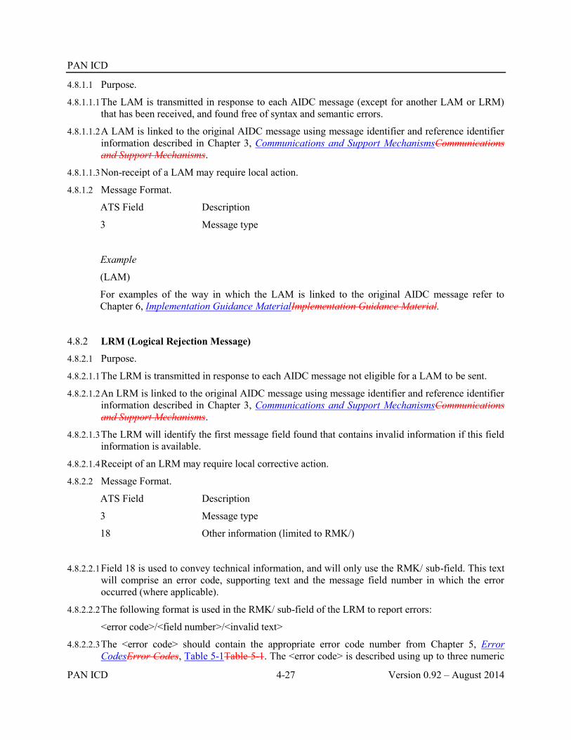
PAN ICD
PAN ICD 4-27 Version 0.92 – August 2014
4.8.1.1 Purpose.
4.8.1.1.1 The LAM is transmitted in response to each AIDC message (except for another LAM or LRM) that has been received, and found free of syntax and semantic errors.
4.8.1.1.2 A LAM is linked to the original AIDC message using message identifier and reference identifier information described in Chapter 3, Communications and Support MechanismsCommunications and Support Mechanisms.
4.8.1.1.3 Non-receipt of a LAM may require local action.
4.8.1.2 Message Format.
ATS Field Description
3 Message type
Example
(LAM)
For examples of the way in which the LAM is linked to the original AIDC message refer to Chapter 6, Implementation Guidance MaterialImplementation Guidance Material.
4.8.2 LRM (Logical Rejection Message)
4.8.2.1 Purpose.
4.8.2.1.1 The LRM is transmitted in response to each AIDC message not eligible for a LAM to be sent.
4.8.2.1.2 An LRM is linked to the original AIDC message using message identifier and reference identifier information described in Chapter 3, Communications and Support MechanismsCommunications and Support Mechanisms.
4.8.2.1.3 The LRM will identify the first message field found that contains invalid information if this field information is available.
4.8.2.1.4 Receipt of an LRM may require local corrective action.
4.8.2.2 Message Format.
ATS Field Description
3 Message type
18 Other information (limited to RMK/)
4.8.2.2.1 Field 18 is used to convey technical information, and will only use the RMK/ sub-field. This text will comprise an error code, supporting text and the message field number in which the error occurred (where applicable).
4.8.2.2.2 The following format is used in the RMK/ sub-field of the LRM to report errors:
<error code>/<field number>/<invalid text>
4.8.2.2.3 The <error code> should contain the appropriate error code number from Chapter 5, Error CodesError Codes, Table 5-1Table 5-1. The <error code> is described using up to three numeric
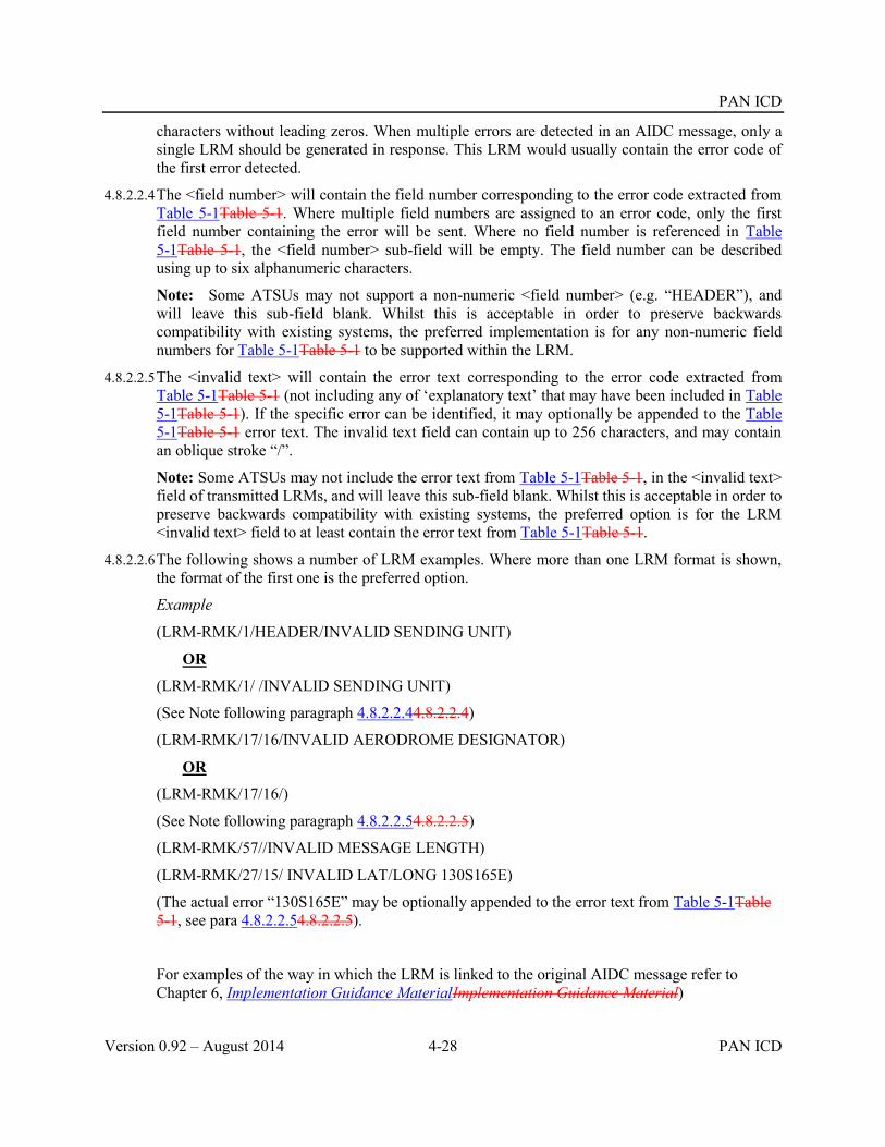
PAN ICD
Version 0.92 – August 2014 4-28 PAN ICD
characters without leading zeros. When multiple errors are detected in an AIDC message, only a single LRM should be generated in response. This LRM would usually contain the error code of the first error detected.
4.8.2.2.4 The <field number> will contain the field number corresponding to the error code extracted from Table 5-1Table 5-1. Where multiple field numbers are assigned to an error code, only the first field number containing the error will be sent. Where no field number is referenced in Table 5-1Table 5-1, the <field number> sub-field will be empty. The field number can be described using up to six alphanumeric characters.
Note: Some ATSUs may not support a non-numeric <field number> (e.g. “HEADER”), and will leave this sub-field blank. Whilst this is acceptable in order to preserve backwards compatibility with existing systems, the preferred implementation is for any non-numeric field numbers for Table 5-1Table 5-1 to be supported within the LRM.
4.8.2.2.5 The <invalid text> will contain the error text corresponding to the error code extracted from Table 5-1Table 5-1 (not including any of ‘explanatory text’ that may have been included in Table 5-1Table 5-1). If the specific error can be identified, it may optionally be appended to the Table 5-1Table 5-1 error text. The invalid text field can contain up to 256 characters, and may contain an oblique stroke “/”.
Note: Some ATSUs may not include the error text from Table 5-1Table 5-1, in the <invalid text> field of transmitted LRMs, and will leave this sub-field blank. Whilst this is acceptable in order to preserve backwards compatibility with existing systems, the preferred option is for the LRM <invalid text> field to at least contain the error text from Table 5-1Table 5-1.
4.8.2.2.6 The following shows a number of LRM examples. Where more than one LRM format is shown, the format of the first one is the preferred option.
Example
(LRM-RMK/1/HEADER/INVALID SENDING UNIT)
OR
(LRM-RMK/1/ /INVALID SENDING UNIT)
(See Note following paragraph 4.8.2.2.44.8.2.2.4)
(LRM-RMK/17/16/INVALID AERODROME DESIGNATOR)
OR
(LRM-RMK/17/16/)
(See Note following paragraph 4.8.2.2.54.8.2.2.5)
(LRM-RMK/57//INVALID MESSAGE LENGTH)
(LRM-RMK/27/15/ INVALID LAT/LONG 130S165E)
(The actual error “130S165E” may be optionally appended to the error text from Table 5-1Table 5-1, see para 4.8.2.2.54.8.2.2.5).
For examples of the way in which the LRM is linked to the original AIDC message refer to Chapter 6, Implementation Guidance MaterialImplementation Guidance Material)

PAN ICD
PAN ICD 4-29 Version 0.92 – August 2014
4.8.3 ASM (Application Status Monitor)
4.8.3.1 Purpose.
4.8.3.1.1 The ASM message is transmitted to an adjacent ATSU to confirm that end-to-end messaging is available with that ATSU.
4.8.3.1.2 The transmission of an ASM message normally occurs when no AIDC messages (including Application messages) have been received from the adjacent ATSU within a specified time as defined in bilateral agreement.
4.8.3.2 Message Format.
ATS Field Description
3 Message type
Example
(ASM)
4.8.4 FAN (FANS Application Message)
4.8.4.1 Purpose.
4.8.4.1.1 The FAN is transmitted by one ATSU (generally the transferring ATSU) to another ATSU (generally the receiving ATSU) to provide the required information necessary to establish CPDLC and/or ADS-C connections with FANS-1/A equipped aircraft. Use of the FAN message significantly reduces the number of data link messages normally required to achieve a data link transfer using the Address Forwarding process, as well as improving the reliability and performance associated with data link transfers.
4.8.4.2 Message Format.
ATS Field Description
3 Message type
7 Aircraft identification
13 Departure aerodrome
16 Destination aerodrome
Text Application data
4.8.4.2.1 Application data is a free text field used in the FAN message to permit the transfer of FANS-1/A logon information from one ATSU to another. This field contains a number of elements which are described below. Each element consists of an “identifier” and a value which are separated by a “/” character. The abbreviation used for the identifier corresponds to the associated ICAO abbreviation (where one exists), otherwise the three character MTI (Message Type Identifier) contained in the logon is used (refer to ARINC 622 for a listing of various MTIs)
4.8.4.2.2 The order of the elements within the FAN message is the order that they are listed below, with consecutive elements being separated by a single <space> character. Although some elements

PAN ICD
Version 0.92 – August 2014 4-30 PAN ICD
within the Application data field may be “optional”, they should be included if the corresponding data is available (i.e. if the ATSU transmitting the FAN message has this information available, either from a logon or a FAN message). This is for the benefit of downstream ATSUs that may use the information within these optional elements. If the data is not available for an optional element, that element is not to be included in the FAN message.
4.8.4.2.3 Additional information concerning the elements described below is contained in Chapter 6, Implementation Guidance MaterialImplementation Guidance Material.
4.8.4.2.4 Standard message identifier (SMI)
4.8.4.2.4.1 This mandatory element is preceded by the identifier ‘SMI’, and contains information relating to the address to which uplink messages are routed to in the avionics. The value of the SMI sent in the FAN message is the downlink SMI as it was received in either the most recently received logon or FAN message.
4.8.4.2.4.2 Allowable values for the SMI are listed in ARINC 620. Examples of SMIs include “FML”, “FMR”, “FMD”, FM3” and “AFD”.
Example
SMI/FMD
4.8.4.2.5 Aircraft identification
4.8.4.2.5.1 This mandatory element is preceded by the identifier ‘FMH’ and contains the aircraft identification as it was received in either the most recently received logon or FAN message.
Example
FMH/MAS123
4.8.4.2.6 Aircraft registration
4.8.4.2.6.1 This mandatory element is preceded by the identifier ‘REG’ and contains the registration details of the aircraft – including the hyphen if applicable – as it was received in either the most recently received logon or FAN message. While a hyphen is not permitted in the registration in other AIDC messages, it is necessary in the FAN message in order to allow data link messages to be correctly addressed to the aircraft. Any “padding” in the registration contained in the AFN logon (e.g. preceding periods “.”) must not be included in the FAN message.
Example
Registration format in logon Registration format in FAN message
.N12345 REG/N12345
.9V-ABC REG/9V-ABC
Note the periods preceding the registration letters are not included in the FAN message

PAN ICD
PAN ICD 4-31 Version 0.92 – August 2014
4.8.4.2.7 Aircraft Address (ICAO 24 bit code)
4.8.4.2.7.1 This optional element is preceded by the identifier ‘CODE’ and contains the six character hexadecimal translation of the 24 bit aircraft address as it was received in either the most recently received logon or FAN message.
Example
CODE/ABC123
4.8.4.2.8 Aircraft position information
4.8.4.2.8.1 This optional element is preceded by the identifier ‘FPO’ and contains the position of the aircraft as determined by the ATSU at the time of transmission of the FAN message (if this information is available). The position of the aircraft is expressed as a latitude/longitude in either dd[NS]ddd[EW] or ddmm[NS]dddmm[EW] format. The position that may have been provided by the aircraft in a previous logon should not be included in the FAN message, because it is most likely no longer accurate
Example
FPO/23S150E
FPO/0823N11025E
4.8.4.2.9 ATS Application and Version Number
4.8.4.2.9.1 There will usually be multiple elements associated with the ATS Application and Version number (i.e. CPDLC and ADS-C). Occurrences of this element are preceded by the identifier ‘FCO’ which describes the ATS data link application(s) available in the avionics, as they were received in a logon or a previously received FAN message. The FAN message must include at least one ATS data link application – a separate identifier is used for each available application. These elements may be transmitted in any order, separated by a single <space>.
4.8.4.2.9.2 The value associated with the FCO identifier consists of three letters to describe the application name immediately followed by (i.e. with no intervening spaces) two figures characters to represent the associated version number. Possible values for the three letters are “ATC” (for CPDLC) or “ADS” (for ADS-C), and the possible range of version numbers is 01 to 99.
Example
FCO/ATC01 FCO/ADS01
FCO/ADS01
4.8.4.2.10 The second example above illustrates a FAN message with the ADS-C application only. This may be either because the aircraft is not CPDLC equipped, or because the FAN is being used with an adjacent ATSU to enable monitoring using ADS-C by that ATSU when the aircraft is only entering the Area of Common Interest (ACI).

PAN ICD
Version 0.92 – August 2014 4-32 PAN ICD
Example
(FAN-ACA870-CYUL-LFPG
-SMI/AFD FMH/ACA870 REG/C-GOJA FPO/53N035W FCO/ATC01 FCO/ADS01)
(FAN-UAL951-EBBR-KIAD
-SMI/FML FMH/UAL951 REG/N123UA CODE/A254B3 FCO/ADS01)
(FAN-ANZ123/A2213-NZAA-KLAX
-SMI/FML FMH/ANZ123 REG/ZK-NJP FCO/ADS01)
(FAN-SIA221-WSSS-YSSY
-SMI/FMD FMH/SIA221 REG/9M-MRP CODE/A254B3 FPO/1214S11223E FCO/ATC01 FCO/ADS01)
4.8.4.2.11 ATSUs should ensure that at least two of the ACID, REG, or CODE elements are used to ensure that the logon information contained in the FAN message is associated with the correct flight plan.
Note 1. If the FAN message is being transmitted to permit the next ATS unit to establish a CPDLC connection, it should not be sent until after an appropriate CPDLC Next Data Authority message (NDA) has been transmitted to the aircraft, either by allowing a reasonable time for delivery of the NDA message or waiting until a successful MAS (MAS/S) message has been received in response to the transmission of the NDA message.
Note 2. Where an aircraft enters an adjacent ATSU’s ACI but does not actually enter the ATSU’s airspace and a FAN message is sent to the adjacent ATSU to enable monitoring using ADS-C then the FCO identifier for the CPDLC application should not be included.
4.8.5 FCN (Fans Completion Notification)
4.8.5.1 Purpose.
4.8.5.1.1 The FCN message is transmitted by the either the transferring or receiving ATSU to provide information concerning the CPDLC Connection status of the aircraft.
4.8.5.1.2 The FCN message is transmitted by the transferring ATSU when their CPDLC Connection with the aircraft is terminated, providing notification to the receiving ATSU that they are now the CPDLC “Current Data Authority”. The FCN message may also be transmitted by the receiving ATSU to provide notification of their establishment of (or failure to establish) a CPDLC Connection.
4.8.5.1.3 An FCN message transmitted by the receiving ATSU may also (optionally) include contact/monitor frequency information to be issued to the aircraft by the transferring ATSU.
4.8.5.2 Message Format.

PAN ICD
PAN ICD 4-33 Version 0.92 – August 2014
ATS Field Description
3 Message type
7 Aircraft identification
13 Departure aerodrome
16 Destination aerodrome
Text Communication Status
4.8.5.2.1 Communication Status is a free text field used in the FCN message to permit the transfer of CPDLC connection status and (optionally) frequency information from one ATSU to another. This field may contain a number of elements which are described below. Each element consists of an “identifier” and a value which are separated by a “/” character. Separate elements are separated by a single < space> character.
4.8.5.2.2 CPDLC Connection Status identifier (CPD)
4.8.5.2.2.1 This mandatory element is preceded by the identifier “CPD” and contains a single integer value which is used to provide information concerning an aircraft’s CPDLC Connection status. The value to be included in the CPDLC Connection Status field is determined from the following table.
Table 4-4. CPDLC Connection Status
CPDLC Connection Status
Meaning FCN sent by transferring ATSU
FCN sent by receiving ATSU
0 The CPDLC Connection with the aircraft has been terminated
0 No CPDLC Connection could be established with the aircraft before a time parameter prior to the FIR boundary
1 The CPDLC Connection Request failed due to the receiving ATSU not being the nominated CPDLC Next Data Authority
2 A CPDLC Connection has been established with the aircraft
Example
CPD/0

PAN ICD
Version 0.92 – August 2014 4-34 PAN ICD
4.8.5.2.3 Frequency identifier (FREQ)
4.8.5.2.3.1 This optional element is preceded by the identifier ‘FREQ’ and may be included in an FCN message transmitted by the receiving ATSU to advise of any changes to a previously notified (or a default) frequency. The FREQ/ identifier provides advice to the transferring ATSU of the voice frequency information to be transmitted to the aircraft in the CPDLC Contact/Monitor instruction. If no frequency information is available or required, this element should not be included in the FCN message.
4.8.5.2.3.2 When included in the FCN message, the frequency variable does not contain units, spaces or leading zeroes. It may be up to 7 characters in length, containing integers or a decimal point selected from the frequency range below.
Table 4-5. Frequency Identifier
Range Units
HF 2850 to 28000 kHz
VHF 117.975 to 137.000 MHz
UHF 225.000 to 399.975 MHz
Example
FREQ/117.975
Example of FCN message
FCN messages transmitted by the receiving ATSU:
The CPDLC Connection request for SIA221 was unsuccessful
(FCN-SIA221-YSSY-WSSS-CPD/0)
The CPDLC Connection request for QFA44 was unsucessful because the receiving ATSU was not the nominated next data authority
(FCN-QFA44/A1145-NZAA-YSSY-CPD/1)
The CPDLC Connection request for ANZ15 was successful. The Contact/Monitor voice frequency is 13261
(FCN-ANZ15/A4466-KLAX-NZAA-CPD/2 FREQ/13261)
FCN message transmitted by the transferring ATSU:

PAN ICD
PAN ICD 4-35 Version 0.92 – August 2014
The CPDLC Connection with ICE615 has been terminated
(FCN-ICE615-BIKF-KJFK-CPD/0)
4.9 Surveillance Data Transfer Service Messages
4.9.1 ADS (Surveillance ADS-C)
4.9.1.1 Purpose.
4.9.1.1.1 The ADS message is used to transfer information contained in an ADS-C report from one ATSU to another.
4.9.1.2 Message Format.
ATS Field Description
3 Message type 7 Aircraft identification 13 Departure aerodrome 16 Destination aerodrome Text ADS-C Data
4.9.1.2.1 ADS-C data is a free text field used in the ADS message to permit the transfer of information contained in an ADS-C report from one ATSU to another. The data field consists of an identifier ’ADS’ followed by an oblique stroke “/”, followed by a text string containing specific text extracted from the encoded ACARS ADS-C report received from the aircraft.
4.9.1.2.2 Any hyphen in the registration of the aircraft in the ACARS ADS-C report is included in the ADS message. Unlike the FAN message, any “padding” in the registration contained in the ACARS ADS-C report (e.g. preceding periods “.”) MUST be included in the ADS message.
4.9.1.2.3 The ADS-C data field may also be used to indicate that no further ADS messages will be sent to the receiving ATSU for the flight. To indicate this state the ADS identifier is followed by an oblique stroke “/”, followed by a “0” (zero). The trigger for this would be by bilateral agreement (e.g. when an ADS-C report has been received that places the aircraft outside the ACI and the ADS-C Predicted Route group indicates that the aircraft will not re-enter the ACI).
4.9.1.2.4 The specific text to be included in the AIDC ADS message is described in Chapter 6, Implementation Guidance MaterialImplementation Guidance Material.
Example
(ADS-ANZ90/A2233-RJAA-NZAA
-ADS/.ZK-OKC030007FF946B6F6DC8FC044B9D0DFC013B80DA88FC0A64F9E4438B4AC8FC000E34D0EDC00010140F3E86)
(ADS-ANZ90/A2233-RJAA-NZAA
-ADS/0)


PAN ICD
PAN ICD 4-35 Version 0.92 – August 2014
Table 4-6. PAN AIDC Messages and their Field Composition
Message 3
a b c
7
a b c
8
a b
9
a b c
10
a b
13
a b
14
a b c d e
15
a b c
16
a b c 18 19 20 21
22
8
a b
9
a b c
10
a b
14
a b c d e
15
a b c 18 Text
ABI M - - MOO M - MMMOO M - - OO MMM OO MMM O
CPL M - - MOO MM MMM MM M - MMMOO MMM M - - M
EST M - - MOO M - MMMOO M - -
PAC M - - MOO M - MMMOO M - - OO OOO OO OOO O
MAC M - - MOO M - M - - OOOOO O
CDN M - - MOO M - M - - OO OOOOO OOO O O
ACP M - - MOO M - M - -
REJ M - - MOO M - M - -
PCM M - - MOO M - MMMOO M - - OO OOO OO OOO O
PCA M - - MOO M - M -
TRU M - - MOO M - M - - M

PAN ICD
Version 0.92 – August 2014 4-36 PAN ICD
Message 3
a b c
7
a b c
8
a b
9
a b c
10
a b
13
a b
14
a b c d e
15
a b c
16
a b c 18 19 20 21
22
8
a b
9
a b c
10
a b
14
a b c d e
15
a b c 18 Text
TOC M - - MOO M - M - -
AOC M - - MOO M - M - -
EMG M - - MOO M
MIS M - - MOO M
LAM M - -
LRM M - - M
ASM M - -
FAN M - - MOO M - M - - M
FCN M - - MOO M - M - - M
ADS M - - MOO M - M - - M

PAN ICD
PAN ICD 5-1 Version 0.92 – August 2014
Chapter 5 Error Codes 5.1 Introduction
5.1.1 A set of error codes has been developed for those messages contained in the AIDC message set. A list of the codes, associated field number and error text is contained in the table below. This information is for the inclusion in any Logical Rejection Message transmitted in response to the reception of an AIDC message containing an err
5.1.2 It is recommended that when specific error code is available, receiving ATSU should use the specific error code instead of general error codes, such as Error Code 57.
Table 5-1. Error Codes
Error Code Field Number Error Text
1 HEADER INVALID SENDING UNIT (e.g., AFTN Address)
2 HEADER INVALID RECEIVING UNIT (e.g., AFTN Address)
3 HEADER INVALID TIME STAMP
4 HEADER INVALID MESSAGE ID
5 HEADER INVALID REFERENCE ID
6 7 INVALID ACID
7 7 DUPLICATE ACID
8 7 UNKNOWN FUNCTIONAL ADDRESS
9 7 INVALID SSR MODE
10 7 INVALID SSR CODE
11 8 INVALID FLIGHT RULES
12 8 INVALID FLIGHT TYPE
13 9 INVALID AIRCRAFT MODEL
14 9 INVALID WAKE TURBULENCE CATEGORY
15 10 INVALID EQUIPMENT DESIGNATOR
16 10 INVALID SSR EQUIPMENT DESIGNATOR
17 13, 16 INVALID AERODROME DESIGNATOR
18 13 INVALID DEPARTURE AERODROME
19 16 INVALID DESTINATION AERODROME
20 RESERVED
21 RESERVED
22 13, 16 TIME DESIGNATOR PRESENT WHEN NOT

PAN ICD
Version 0.92 – August 2014 5-2 PAN ICD
EXPECTED
23 14 INVALID TIME DESIGNATOR
24 14 MISSING TIME DESIGNATOR
25 14 INVALID BOUNDARY POINT DESIGNATOR
26 14, 15 INVALID ENROUTE POINT
27 14, 15 INVALID LAT/LONG DESIGNATOR
28 14, 15 INVALID NAVAID FIX
29 14, 15 INVALID LEVEL DESIGNATOR
30 14, 15 MISSING LEVEL DESIGNATOR
31 14 INVALID SUPPLEMENTARY CROSSING DATA
32 14 INVALID SUPPLEMENTARY CROSSING LEVEL
33 14 MISSING SUPPLEMENTARY CROSSING LEVEL
34 14 INVALID CROSSING CONDITION
35 14 MISSING CROSSING CONDITION
36 15 INVALID SPEED/LEVEL DESIGNATOR
37 15 MISSING SPEED/LEVEL DESIGNATOR
38 15 INVALID SPEED DESIGNATOR
39 15 MISSING SPEED DESIGNATOR
40 15 INVALID ROUTE ELEMENT DESIGNATOR
41 15 INVALID ATS ROUTE/SIGNIFICANT POINT DESIGNATOR
42 15 INVALID ATS ROUTE DESIGNATOR
43 15 INVALID SIGNIFICANT POINT DESIGNATOR
44 15 FLIGHT RULES INDICATOR DOES NOT FOLLOW SIGNIFICANT POINT
45 15 ADDITIONAL DATA FOLLOWS TRUNCATION INDICATOR
46 15 INCORRECT CRUISE CLIMB FORMAT
47 15 CONFLICTING DIRECTION
48 18 INVALID OTHER INFORMATION ELEMENT
49 RESERVED
50 22 INVALID AMENDMENT FIELD DATA
51 MISSING FIELD nn (See Note 2)

PAN ICD
PAN ICD 5-3 Version 0.92 – August 2014
52 MORE THAN ONE FIELD MISSING
53 MESSAGE LOGICALLY TOO LONG
54 SYNTAX ERROR IN FIELD nn (See Note 2)
55 INVALID MESSAGE LENGTH
56 TDM/NAT ERROR
57 INVALID MESSAGE
58 MISSING PARENTHESIS
59 MESSAGE NOT APPLICABLE TO zzzz OAC
60 3 INVALID MESSAGE MNEMONIC (i.e., 3 LETTER IDENTIFIER)
61 HEADER INVALID CRC
62 UNDEFINED ERROR
63 RESERVED
64 RESERVED
65 RESERVED
66 14 INVALID BLOCK LEVEL
67 14 INVALID OFF-TRACK CLEARANCE TYPE
68 14 INVALID OFF-TRACK DIRECTION
69 14 INVALID OFF-TRACK DISTANCE
70 14 INVALID MACH NUMBER QUALIFIER
71 14 INVALID MACH NUMBER
72 ADF (See Note 3) INVALID IDENTIFIER
73 ADF (See Note 3) INVALID SMI
74 ADF (See Note 3) INVALID ACID IN FMH/ IDENTIFIER
75 ADF (See Note 3) INVALID REGISTRATION IN REG/ IDENTIFIER
76 ADF (See Note 3) INVALID AIRCRAFT ADDRESS IN CODE/ IDENTIFIER
77 ADF (See Note 3) INVALID LOCATION IN FPO/ IDENTIFIER
78 ADF (See Note 3) INVALID DATA LINK APPLICATION IN FCO/ IDENTIFIER
79 ADF (See Note 3) INVALID OR UNSUPPORTED CPDLC VERSION NUMBER
80 ADF (See Note 3) INVALID OR UNSUPPORTED ADS-C VERSION NUMBER

PAN ICD
Version 0.92 – August 2014 5-4 PAN ICD
81 ADF (See Note 3) INVALID IDENTIFIER IN FAN MESSAGE
82 CSF (See Note 4) INVALID CPDLC CONNECTION STATUS
83 CSF (See Note 4) INVALID FREQUENCY IN FREQ/ IDENTIFIER
84 ADF (See Note 5) INVALID IDENTIFIER IN ADS MESSAGE
85 ADF (See Note 5) INVALID DATA IN ADS MESSAGE
Note. This error message refers to the encoded ADS-C data (e.g. if it contains non-hexadecimal characters), rather than whether the contents of the decoded ADS-C report itself are valid.
86 TDF (See Note 6) INVALID IDENTIFIER IN TRU MESSAGE
87 TDF (See Note 6) INVALID HEADING IN HDG/ IDENTIFIER
88 TDF (See Note 6) INVALID POSITION IN DCT/ IDENTIFIER
89 TDF (See Note 6) INVALID OFF TRACK DEVIATION IN OTD/ IDENTIFIER
90 TDF (See Note 6) INVALID FLIGHT LEVEL IN CFL/ IDENTIFIER
91 TDF (See Note 6) INVALID SPEED IN SPD/ IDENTIFIER
92 TDF (See Note 6) INVALID FLIGHT LEVEL IN RFL/ IDENTIFIER
93 TDF (See Note 6) INVALID FLIGHT LEVEL IN PRL/ IDENTIFIER
94-256 RESERVED FOR FUTURE USE
Note 1. It is not intended that any amplifying text contained in parenthesis (i.e. “(e.g., AFTN Address)”) within the error text column be transmitted in any LRM.
Note 2. The intention is that in error codes 51, 54, 59 and 65 that lower case text (e.g. “nn”, or “xxxxxx”) is replaced by the applicable value when this information is available.
Note 3. In the FAN message, the “ADF” field number refers to the Application data field
Note 4. In the FCN message, the “CSF” field number refers to the Communication Status field
Note 5. In the ADS message, the “ADF” field number refers to the ADS-C data field
Note 6. In the TRU message, the “TDF” field number refers to the Track data field

PAN ICD
PAN ICD 6-1 Version 0.92 – August 2014
Chapter 6 Implementation Guidance Material 6.1 Introduction
6.1.1 The AIDC Message set described in Chapter 4, AIDC MessagesAIDC Messages, supports six ATS-related functions:
a) Notification;
b) Coordination;
c) Transfer of Control;
d) General Information;
e) Application Management; and
f) Surveillance Data Transfer.
6.1.2 This chapter contains information of an explanatory nature, including how the AIDC message set is intended to be used, as well as guidance in dealing with specific issues, The aim is to provide information and guidance that will assist software engineers responsible for developing ATM systems, as well as ATSUs that implement AIDC messaging.
6.2 Preliminaries
6.2.1 Assumptions
6.2.1.1 Within this guidance material, the following assumptions have been made:
The material described below generally applies only to AIDC message exchanges between two automated ATM systems;
It must be possible to revert to manual intervention of the Notification, Coordination, and Transfer of Control processes at any time;
The coordination confirmation process should be automatic and independent of other processes;
Exceptional conditions, such as loss of communications between two ATSUs are not addressed in this document and are subject to local procedures.
6.2.2 Message header
6.2.2.1 Every AIDC message transmitted should contain an AFTN header, as specified in Chapter 3, Abbreviations and AIDC MessagesAbbreviations and AIDC Messages. This header should contain the optional data fields described in Chapter 3.
6.2.2.2 The message identification numbers contained in Optional Data Field 2 (ODF2) should begin at 0, proceed sequentially to 999,999, then reset to 0. It is acknowledged that following a system restart, the message identification number may reset to 0.

PAN ICD
Version 0.92 – August 2014 6-2 PAN ICD
6.2.2.3 For each AIDC connection, the ATSU should maintain a separate 0 to 999,999 message identification number sequence.
6.2.3 Linking AIDC messages to flight plans
6.2.3.1 When using an AIDC message to update the flight plan held by the ATS Unit, the air traffic system must ensure that the correct flight plan is updated. This requires matching a number of items from the AIDC message and the flight plan:
Field 7 (Aircraft identification);
Field 13 (Departure aerodrome)
Field 16 (Destination aerodrome)
6.2.3.2 In some environments where multiple-leg flight plans with the same Field 7, 13 and 16 may exist, an additional uniqueness check using the EOBT and DOF should be considered.
6.2.3.3 On receipt of an AIDC message, if no corresponding flight plan exists, an ATSU should automatically create a flight plan if the AIDC message contains sufficient information. If a flight plan cannot be created the ATSU should request a FPL by transmitting an RQP message.
6.2.4 Responses to AIDC messages
6.2.4.1 There are two types of possible responses to AIDC messages:
Application response (LAM, LRM); and
Operational response (ACP, REJ, CDN, PCA, AOC)
6.2.4.2 Application response
6.2.4.2.1 With the exception of a LAM or LRM, every AIDC message received by an ATSU should be responded to with a LAM or LRM as appropriate. This response is referred to as an “Application Response”, and is generated automatically by the automation system. Each Application response has a message identification number (ODF 2), as well as a message reference number (ODF 3), which references the original AIDC message.
6.2.4.2.2 An ATSU receiving an AIDC message should transmit a LAM response when the received message is determined to be syntactically and semantically correct and the message is eligible for further processing or presentation. It is necessary to distinguish between “syntactic” and “semantic” error on one hand and logical errors (e.g. a misspelt position name, or not having a flight plan, etc.) on the other hand. Such logical errors should not prevent a LAM from being transmitted.
6.2.4.2.3 If a LAM response is not eligible to be sent because of errors in the AIDC message, an LRM response should be transmitted.
6.2.4.2.4 While no LAM should be generated for a syntactically correct LRM, an ATSU may choose to respond to a syntactically incorrect LRM with an LRM.
6.2.4.2.5 The time out value Talarm associated with an application response should typically be less than 180 seconds, measured from the transmission time of the original message and may be specified by bilateral agreement. Talarm corresponds to the nominal value associated with the accountability timer described in Chapter 3, Communications and Support Mechanisms, para 3.2.9.

PAN ICD
PAN ICD 6-3 Version 0.92 – August 2014
6.2.4.2.6 Failure to receive an expected application response within Tr seconds (≤ Talarm ) can optionally result in a re-transmission (up to a maximum number Nr) of the original message, using the same information contained in ODF 2 and ODF 3 (if applicable) of the original AIDC message. If so, Tr should be reset upon re-transmission of the message.
6.2.4.2.7 Failure to receive an application response within Talarm seconds from the transmission of the original AIDC message should result in a warning message being displayed to the controller. Receipt of an LRM should also result in a warning message or alert being displayed to the controller. The level of alerting should be appropriate to the importance of the associated message.
6.2.4.2.8 The transmission of an application response should be triggered after the semantic and syntactic checks have been performed on the incoming message. This is because the purpose of an application response is to indicate that a received AIDC message has both been received and is semantically and syntactically correct.
6.2.4.2.9 Receipt of an LRM should cause the ATSU to take a corrective action before re-transmitting the rejected message with a new message identification number. This corrective action may be automatic or manual.
6.2.4.3 Operational response
6.2.4.3.1 A number of AIDC messages require an operational response in addition to the application response. Table 6-1 shows the required operational responses for these messages. AIDC messages that are not included in Table 6-1 have no operational response.
Table 6-1. Required Operational Response
Received Message Required Operational Response
CPL ACP or CDN*
EST ACP
PAC ACP
CDN ACP, CDN, or REJ
PCM PCA
TOC AOC
Note *An REJ is not a valid response to a CDN message within an Initial Coordination Dialogue (refer 6.3.6.3)
6.2.4.3.2 Top refers to the timeout value associated with non-receipt of an operational response to an AIDC message.
6.2.4.3.3 The value of Top may vary depending on the operational environment, and whether manual processing is required to generate the operational response. Because some operational responses should be automated (e.g. PCA message), whilst some would normally be sent manually (e.g.

PAN ICD
Version 0.92 – August 2014 6-4 PAN ICD
response to a CDN message), ground systems should have the ability to set different Top values for different operational responses. As a general rule, the maximum value of Top should be 600 seconds when a manual action is required to trigger the operational response.
6.2.4.3.4 Failure to receive an operational response within timeout period Top should result in a warning message being displayed to the controller.
6.2.4.3.5 Each operational response has a message identification number (ODF 2), as well as a message reference number (ODF 3). The message reference number consists of the ICAO location indicator of the immediately preceding message in the dialogue and the message identification number of the first message in the dialogue.
Note: This method reflects all currently known implementations of CDN-CDN dialogues in operational use in the NAT and Asia-PAC at the time this document was drafted.
6.2.4.3.6 For example, an ATSU may initiate an initial coordination dialogue by transmitting a CPL message to an adjacent ATSU. A sequence of CDN messages may then occur, terminated by an ACP message. The message reference numbers in the CDN and ACP messages would all reference the message identification number of the original CPL message. While the message identification number of the first message in the dialogue is retained as the reference number, the location indicator of the originator of the previous message in the dialogue shall always be used as the prefix. A number of examples are contained in Table below.
6.2.4.3.7 The message reference numbers of operational messages in a coordination dialogue always reference the message identification number of the first message in the dialogue. After completion of the initial coordination dialogue one ATSU may initiate a coordination negotiate dialogue by transmitting a CDN message. A sequence of CDN messages may then occur terminated by an ACP or REJ message. The message reference numbers of all operational messages in this new coordination negotiate dialogue would reference the message identification number of the first CDN message in the new dialogue. While the message identification number of the first message in the dialogue is retained as the reference number, the location indicator of the previous message shall always be used as a prefix. The message reference numbers used in a LAM or LRM message always refer to the immediately preceding message that is being referenced.
Examples
Message ATS Unit
sending message
ATS Unit
receiving message
MIN MRN
Example 1: Exchange between NTTT and NZZO with ABI-CPL-ACP sequence
FF NZZOZQZF 061755 NTTTZQZF 2.000069-4.140806175555-5.C4FD- (ABI-THT101/A2605 -NTAA-2149S15700W/1856F380 -NZAA-8/IS-9/A343/H-10/SDE1E2E3FGHIJ3J5J6M1M2ZRWXY/LB1D1-15/N0465F380 TAF 1739S14945W 21S155W 2149S15700W 23S160W 26S165W/M080F400 30S170W 33S175W/N0466F400 DCT OLBEX EXOPI6B-18/PBN/A1B1D1L1
NTTT NZZO 000069

PAN ICD
PAN ICD 6-5 Version 0.92 – August 2014
Message ATS Unit
sending message
ATS Unit
receiving message
MIN MRN
NAV/RNVD1A1 DAT/SV DOF/140806 REG/FOJTN EET/NZZO0114 SEL/MSAD CODE/3A266D PER/C RALT/NCRG NZAA TALT/NCRG) FF NTTTZQZF 061756 NZZOZQZF 2.000672-3.NTTT000069-4.140806175559-5.CF71- (LAM)
NZZO NTTT 000672 NTTT000069
FF NZZOZQZF 061821 NTTTZQZF 2.000070-4.140806182159-5.79A9- (CPL-THT101/A2605-IS -A343/H-SDE1E2E3FGHIJ3J5J6M1M2ZRWXY/LB1D1 -NTAA-2149S15700W/1859F380 -N0465F380 21S155W 2149S15700W 23S160W 26S165W/M080F400 30S170W 33S175W/N0466F400 DCT OLBEX EXOPI6B -NZAA -PBN/A1B1D1L1 NAV/RNVD1A1 DAT/SV DOF/140806 REG/FOJTN EET/NZZO0114 SEL/MSAD CODE/3A266D PER/C RALT/NCRG NZAA TALT/NCRG)
NTTT NZZO 000070
FF NTTTZQZF 061822 NZZOZQZF 2.000673-3.NTTT000070-4.140806182203-5.CF71- (LAM)
NZZO NTTT 000673 NTTT000070
FF NTTTZQZF 061822 NZZOZQZF 2.000674-3.NTTT000070-4.140806182203-5.DFE4- (ACP-THT101/A2605-NTAA-NZAA)
NZZO NTTT 000674 NTTT000070
FF NZZOZQZF 061822 NTTTZQZF 2.000071-3.NZZO000674-4.140806182204-5.CF71- (LAM)
NTTT NZZO 000071 NZZO000674
Example 2: Exchange between YBBB and NZZO with EST-ACP-CDN-ACP sequence
FF NZZOZQZFM 061455 YBBBZQZF 2.105712-4.140806145517-5.B76C- (EST-JST171/A1315-YMML-OMKIN/1535F330-NZCH)
YBBB NZZO 105712
FF YBBBZQZF 061455 NZZOZQZF 2.000356-3.YBBB105712-4.140806145518-5.CF71- (LAM)
NZZO YBBB 000356 YBBB105712
FF YBBBZQZF 061455 NZZOZQZF 2.000357-3.YBBB105712-4.140806145518-5.C0A9- (ACP-JST171/A1315-YMML-NZCH)
NZZO YBBB 000357 YBBB105712
FF NZZOZQZF 061455 YBBBZQZF 2.105713-3.NZZO000357-4.140806145524- YBBB NZZO 105713 NZZO

PAN ICD
Version 0.92 – August 2014 6-6 PAN ICD
Message ATS Unit
sending message
ATS Unit
receiving message
MIN MRN
5.CF71- (LAM)
000357
FF NZZOZQZF 061507 YBBBZQZF 2.105734-4.140806150731-5.BD5D- (CDN-JST171/A1315-YMML-NZCH-14/OMKIN/1532F330-15/N0434F330 CORRS Y260 ECKHO/N0437F330 L508 OMKIN L508 CH DCT)
YBBB NZZO 105734
FF YBBBZQZF 061508 NZZOZQZF 2.000360-3.YBBB105734-4.140806150733-5.CF71- (LAM)
NZZO YBBB 000360 YBBB105734
FF YBBBZQZF 061508 NZZOZQZF 2.000361-3.YBBB105734-4.140806150743-5.C0A9- (ACP-JST171/A1315-YMML-NZCH)
NZZO YBBB 000361 YBBB105734
FF NZZOZQZF^M 061507 YBBBZQZF 2.105736-3.NZZO000361-4.140806150744-5.CF71- (LAM)
YBBB NZZO 105736 NZZO000361
Example 3: Exchange between KZCE and NZZO with CPL-CDN-ACP sequence
FF KZCEZQZX 101131 NZZOZQZF 2.000709-4.140710113054-5.0E3A- (CPL-HAL466-IS -B763/H-SDE3FGHIJ7M3RWXYZ/LB1D1 -NSTU-ELLMS/1205F350F370 -M080F350 BUDRA G457 EBEBE DASNE 18N162W CHOKO OPACA4 -PHNL -PBN/A1B2C1D1L1 NAV/RNVD1E2A1 REG/N580HA EET/KZAK0119 EBEBE0219 DASNE0318 18N162W0415 PHZH0417 SEL/FPDH CODE/A77698 OPR/HAWAIIAN AIRLINES PER/D RALT/PHKO)
NZZO KZCE 000709
FF NZZOZQZF 101131 KZCEZQZX 2.000941-3.NZZO000709-4.140710113105-5.CF71- (LAM)
KZCE NZZO 000941 NZZO000709
FF NZZOZQZF 101133 KZCEZQZX 2.000952-3.NZZO000709-4.140710113230-5.7F4A- (CDN-HAL466-NSTU -PHNL -14/ELLMS/1206F360F370 -15/M080F360 BUDRA G457 EBEBE DCT DASNE DCT 18N162W DCT CHOKO OPACA4)
KZCE NZZO 000952 NZZO000709
FF KZCEZQZX 101131 NZZOZQZF 2.000710-3.KZCE000952-4.140710113105- NZZO KZCE 000710 KZCE

PAN ICD
PAN ICD 6-7 Version 0.92 – August 2014
Message ATS Unit
sending message
ATS Unit
receiving message
MIN MRN
5.CF71- (LAM)
000952
FF KZCEZQZX 101133 NZZOZQZF 2.000712-3.KZCE000709-4.140710113252-5.2315- (ACP-HAL466-NSTU-PHNL)
NZZO KZCE 000712 KZCE000709
FF NZZOZQZX 101133 KZCEZQZX 2.000954-3.NZZO000712-4.140710113305-5.CF71- (LAM)
KZCE NZZO 000954 NZZO000712
Example 4: Exchange between KZCE and RJJJ with CPL-CDN-CDN-ACP sequence.
FF KZCEZQZX 271302 RJJJZOZA 2.195920-4.130927130200-5.C4B0- (CPL-JAL786-IS-B763/H-SDFLOVE1E2E3GHIJ3J4J5J6M1M2RW/SD1-RJAA-3536N165E/1335F330F350-0464F350 36N160E 3536N165E 35N170E 31N180E/M080F370 26N170W DCT CANON BOOKE8 -PHNL-PBN/A1L1B1C1D1 DOF/130927 REG/JA604J EET/KZAK0233 SEL/GMAL RALT/RJAA PMDY PHLI PHNL)
RJJJ KZCE 195920
FF RJJJZOZA 271302 KZCEZQZX 2.000819-3.RJJJ195920-4.130927130228-5.CF71- (LAM)
KZCE RJJJ 000819 RJJJ 195920
FF RJJJZOZA 271303 KZCEZQZX 2.000820-3.RJJJ195920-4.130927130302-5.4FA1- (CDN-JAL786-RJAA-PHNL-14/3536N16500E/1335F330-15/N0464F330 36N160E 3536N16500E 35N170E 31N180E 26N170W DCT CANON BOOKE8)
KZCE RJJJ 000820 RJJJ 195920
FF KZCEZQZX 271303 RJJJZOZA 2.195921-3.KZCE000820-4.130927130310-5.CF71- (LAM)
RJJJ KZCE 195921 KZCE000820
FF KZCEZQZX 271303 RJJJZOZA 2.195922-3.KZCE195920-4.130927130321-5.BAEE- (CDN-JAL786-RJAA-PHNL-14/3536N16500E/1335F350)
RJJJ KZCE 195922 KZCE195920
FF RJJJZOZA 271302 KZCEZQZX 2.000819-3.RJJJ195920-4.130927130328-5.CF71- (LAM)
KZCE RJJJ 000821 RJJJ 195922
FF RJJJZOZA 271304 KZCEZQZX 2.000822-3.RJJJ195920-4.130927130350-5.6A3E- (ACP-JAL786-RJAA-PHNL)
KZCE RJJJ 000822 RJJJ 195920
FF KZCEZQZX 271304 RJJJZOZA 2.195923-3.KZCE000822-4.130927130359-5.CF71- (LAM)
RJJJ KZCE 195923 KZCE000822
Example 5: YBBB exchange with NFFF for FJI910 with EST-ACP sequence and YBBB exchange with NZZO for QFA149 with CDN-CDN-ACP sequence.

PAN ICD
Version 0.92 – August 2014 6-8 PAN ICD
Message ATS Unit
sending message
ATS Unit
receiving message
MIN MRN
FF NFFFZQZF 170857 YBBBZQZF 2.023120-4.131217085702-5.017F- (EST-FJI910/A1442-YSSY-UBLIN/0937F370-NFFN)
YBBB NFFF 023120
FF YBBBZQZF 170857 NFFFZQZF 2.012363-3.YBBB023120-4.131217085703-5.CF71- (LAM)
NFFF YBBB 012363 YBBB023120
FF NZZOZQZF 170857 YBBBZQZF 2.045770-4.131217085703-5.1E39- (CDN-QFA149/A1330-YSSY-NZAA-14/ESKEL/0937F350-NZAA)
YBBB NZZO 045770
FF YBBBZQZF 170857 NFFFZQZF 2. 012364-3.YBBB023120-4.131217085709-5.686C- (ACP- FJI910/A1442-YSSY-NFFN)
NFFF YBBB 012364 YBBB023120
FF YBBBZQZF 170857 NZZOZQZF 2.035674-3.YBBB045770-4.131217085711-5.CF71- (LAM)
NZZO YBBB 035674 YBBB045770
FF NFFFZQZF 170857 YBBBZQZF 2. 023121-3.NFFF012364-4.131217085712-5.CF71- (LAM)
YBBB NFFF 023121 NFFF012364
FF YBBBZQZF 170857 NZZOZQZF 2. 035675-3.YBBB045770-4.131217085720-5.CD3A- (CDN-QFA149/A1330-YSSY-NZAA-14/ESKEL/0937F360-NZAA)
NZZO YBBB 035675 YBBB045770
FF NZZOZQZF 170857 YBBBZQZF 2. 045771-3.NZZO035675-4.131217085721-5.CF71- (LAM)
YBBB NZZO 045771 NZZO035675
FF NZZOZQZF 170858 YBBBZQZF 2. 045772-3.NZZO045770-4.131217085740-5.12A6- (ACP-QFA149/A1330-YSSY-NZAA)
YBBB NZZO 045772 NZZO045770
FF YBBBZQZF 170858 NZZOZQZF 2.035676-3. YBBB045772-4.131217085742-5.CF71- (LAM)
NZZO YBBB 035676 YBBB045772
6.2.5 The Area of Common Interest.
6.2.5.1 The Area of Common Interest (ACI) refers to a volume of airspace within which the operation of an aircraft may have an impact on an adjacent ATS Unit. The ACI is located outside the area of responsibility of an ATSU.
6.2.5.2 The size of the ACI is agreed to by the two adjacent ATSUs, and may vary in different operating environments. In a procedural environment the size of the ACI would generally be equivalent to
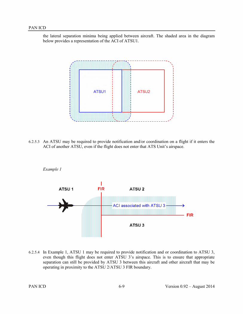
PAN ICD
PAN ICD 6-9 Version 0.92 – August 2014
the lateral separation minima being applied between aircraft. The shaded area in the diagram below provides a representation of the ACI of ATSU1.
6.2.5.3 An ATSU may be required to provide notification and/or coordination on a flight if it enters the ACI of another ATSU, even if the flight does not enter that ATS Unit’s airspace.
Example 1
6.2.5.4 In Example 1, ATSU 1 may be required to provide notification and or coordination to ATSU 3, even though this flight does not enter ATSU 3’s airspace. This is to ensure that appropriate separation can still be provided by ATSU 3 between this aircraft and other aircraft that may be operating in proximity to the ATSU 2/ATSU 3 FIR boundary.

PAN ICD
Version 0.92 – August 2014 6-10 PAN ICD
Example 2
6.2.5.5 In Example 2, ATSU 1 may be required to provide notification and/or coordination to ATSU 2, even though this flight does not even cross the FIR boundary. This is to ensure that appropriate separation can still be provided by ATSU 2 between this aircraft and other aircraft that may be operating in proximity to the ATSU 1/ATSU 2 FIR boundary.
Example 3
6.2.5.6 In Example 3, the nominal route of the flight does not enter the airspace or the ACI associated with ATSU 2. However, ATSU 1 may be required to provide notification and/or coordination to ATSU 2 because the weather deviation clearance issued to the aircraft does infringe the ACI associated with ATSU 2. This is to ensure that appropriate separation can still be provided by ATSU 2 between this aircraft and other aircraft that may be operating in proximity to the ATSU 1/ATSU 2 FIR boundary.

PAN ICD
PAN ICD 6-11 Version 0.92 – August 2014
6.3 AIDC message sequences and AIDC flight states
6.3.1 For each ATSU, a flight progresses through a number of different AIDC “flight states”. These flight states are listed in Table 6-2. For a number of reasons, a flight may not necessarily progress through every one of these flight states and not necessarily in the order shown.
Table 6-2. AIDC Flight States
Flight State
Pre-Notified
Notified
Negotiating
Coordinating
Coordinated
Re-Negotiating
Confirming
Transferring
Transferred
Backward Re-Negotiating
6.3.2 Different AIDC messages are associated with each flight state, and an AIDC message (or the response to it) is generally the trigger to transition from one flight state to another. Refer to Table 6-3Table 6-3 and Error! Not a valid bookmark self-reference. for more information.
6.3.3 Bilateral agreements should specify the AIDC messages that will be exchanged between ATSUs, as well as the timing of these messages, and the use of any optional information (e.g. block levels, off track deviations, etc) that may be included in AIDC messages.
6.3.4 The following guidance material makes use of a flight thread involving an aircraft that is initially within airspace controlled by ATSU 1, and will eventually enter the FIR or ACI of ATSU 2.
6.3.5 Flight states associated with Notification
6.3.5.1 The aircraft is several hours flight time from the FIR or ACI boundary of ATSU 2. While ATSU 2 should previously have received a Filed Flight Plan (FPL) for the aircraft, and possibly

PAN ICD
Version 0.92 – August 2014 6-12 PAN ICD
amendments to it (CHG), no AIDC messages have yet been transmitted from ATSU 1 to ATSU 2.
6.3.5.2 The flight is in the “Pre-Notified” flight state.
6.3.5.3 At a system parameter time or position prior to the FIR or ACI boundary, ATSU 1 transmits a Notification message (ABI) to ATSU 2 for the flight. The ABI provides current flight plan information (including Estimate data) to ATSU 2. On receipt of the ABI, ATSU 2 updates their flight plan details with the information contained in the ABI.
6.3.5.4 If no FPL is held for the flight, automation in ATSU 2 should automatically create a flight plan from information contained in the ABI (if sufficient information is available). If a flight plan cannot be created the ATSU should request a FPL by transmitting an RQP message,
6.3.5.5 The timing of the initial Notification message depends on the operational environment. Sufficient time should be allowed for manual processing of the ABI (if automation was unsuccessful) or requesting a FPL (if required).
6.3.5.6 On receipt of a successful application response (LAM) the flight is in the Notified flight state.
6.3.5.7 Prior to coordination occurring, any revision to flight plan information should result in ATSU 1 transmitting an updated Notification message to ATSU 2. These revisions would normally involve Estimate data, but could include amendments to the aircraft’s route, equipment, or other information in the flight plan.

PAN ICD
PAN ICD 6-13 Version 0.92 – August 2014
6.3.5.8 To reduce the number of superfluous Notification messages being transmitted, revised estimates should not result in the transmission of a new Notification message unless the estimate has changed by more than a value specified in bilateral agreements.
6.3.5.9 Re-Route Notification.
6.3.5.9.1 If an aircraft has been re-routed, the revised route will be notified to affected ATSUs as Notification messages are transmitted from one ATSU to another.
6.3.5.10 Complete route to Destination.
6.3.5.10.1 An aircraft’s route information is described in Field 15 (Route) of the FPL. As re-routes occur, ATSU 1 must update Field 15 accordingly, and transmit this information in a Notification message to ATSU 2. To ensure the integrity of the route information being transmitted in AIDC messages, ATSU 1’s flight plan should contain details of the complete route to destination. If it is not possible to hold route details to destination (e.g. due to unknown or duplicate waypoints or a route discontinuity), the route field should be terminated after the last known significant point with the ICAO truncation indicator, which is the letter “T”.
6.3.5.11 Re-route to new destination.
6.3.5.11.1 Notification messages contain current route information. As a consequence, when an aircraft has been re-routed to a new destination, the notification message will contain the new route in Field 15 as well as the new destination in Field 16.
6.3.5.11.2 When ATSU 2 receives the Notification message, it will not be possible to match the ABI to a flight plan since the destination airport in the ABI will be different from the one in the filed FPL. When this occurs, ATSU 2 should automatically create a flight plan from information contained in the ABI (if sufficient information is available). If a flight plan cannot be created the ATSU should request a FPL by transmitting an RQP message..
6.3.5.12 Notification and the ACI.
6.3.5.12.1 ATSU 1may be required to transmit a Notification message to ATSU 2 for an aircraft if it enters the ACI of ATSU 2, but does not enter ATSU 2’s airspace.
6.3.5.13 Notification Cancellation
6.3.5.13.1 If ATSU 1 has already transmitted a notification message to ATSU 2, and a revision (e.g. change in route) occurs such that the aircraft will no longer enter ATSU 2’s airspace or its ACI, ATSU 1 transmits a MAC message to ATSU 2.
6.3.5.13.2 Receipt of a MAC message by ATSU 2 means that any Notification information previously received for the flight is no longer relevant. The original FPL information (including any CHG modifications) should continue to be held, in accordance with local procedures.

PAN ICD
Version 0.92 – August 2014 6-14 PAN ICD
6.3.5.13.3 On receipt of a MAC message the flight is returned to the Pre-Notified flight state.
6.3.6 Flight states associated with Coordination
6.3.6.1 Coordination is required when a flight will enter the airspace or ACI of an adjacent ATS Unit.In AIDC, coordination is referred to as a “dialogue”, involving the proposed coordination and the response(s) to it. Coordination involves a proposal for a flight to enter an adjacent ATS Unit’s airspace or ACI under specified conditions (i.e. position, time and level, although other parameters are available).
6.3.6.2 There are two types of AIDC coordination dialogues available:
Initial coordination dialogue, using a CPL message; or
Abbreviated initial coordination dialogue, using an EST or PAC message;
6.3.6.3 Initial coordination dialogue
6.3.6.3.1 At a system parameter time or position prior to the FIR or ACI boundary, ATSU 1 transmits a CPL message to ATSU 2, opening an initial coordination dialogue. In some circumstances it may be necessary for the CPL message to be initiated manually by the controller.
6.3.6.3.2 The flight is now in the Negotiating flight state.
6.3.6.3.3 ATSU 2 can either:
Accept the proposed coordination conditions by responding with an ACP message to ATSU 1, or
Propose modifications to the proposed coordination conditions by responding with a CDN message. The initial coordination dialogue remains open. A series of negotiations between the two ATSUs may then be conducted using additional CDN messages until mutually agreed coordination conditions are achieved. The acceptance of the coordination conditions is indicated by the transmission of an ACP message.
6.3.6.3.4 Once an ACP response has been transmitted, the initial coordination dialogue is closed, and the flight is in the Coordinated flight state.
6.3.6.3.5 ATSU 2 should update its flight plan with the finally agreed coordination (which may involve updates from both the CPL and the final CDN message). If no FPL is held for the flight, automation in ATSU 2 should allow the creation of a flight plan from information contained in the CPL (if sufficient information is available).

PAN ICD
PAN ICD 6-15 Version 0.92 – August 2014
Note1. An initial coordination dialogue cannot be closed with an REJ response.
Note2. While the AIDC specifications technically support multiple CDN-CDN exchanges within a single negotiation, a procedural limit on the number of such exchanges (e.g. maximum of 2) should be described in bilateral agreements and the coordination in such cases completed manually.
6.3.6.4 Re-route to new destination.
6.3.6.4.1 CPL messages contain current route information. As a consequence, when an aircraft has been re-routed to a new destination, the CPL will contain the new route in Field 15 as well as the new destination in Field 16.
6.3.6.4.2 When ATSU 2 receives the CPL, it will not be possible to match it to a flight plan since the destination airport will be different from the one in the filed FPL. When this occurs, ATSU 2 should automatically create a flight plan from information contained in the CPL. If a flight plan cannot be created the ATSU should request a FPL by transmitting an RQP message.
6.3.6.5 Abbreviated Initial Coordination Dialogue.
6.3.6.5.1 An Abbreviated Initial Coordination dialogue may be used in place of an initial coordination dialogue when it is expected that a flight’s coordination data will be mutually acceptable to both ATS Units, accurate route information is available at the receiving ATS Unit (i.e. from an ABI message), and both ATSUs have agreed to the use of abbreviated initial coordination dialogues in bilateral agreements.
6.3.6.5.2 An Abbreviated Initial Coordination Dialogue consists of:
ATSU 1 transmitting an EST message to ATSU 2 at a system parameter time or position prior to the FIR or ACI boundary; or
ATSU 1 transmitting a PAC message to ATSU 2 prior to the flight departing. This normally only occurs when the departure aerodrome is close to the FIR or ACI boundary. Depending on the departure aerodrome, the PAC might be sent when the aircraft receives its airways clearance, or when the aircraft taxies. Any estimate sent in a PAC message should include a reasonable allowance for taxi time etc.
Note: Where a PAC contains enough optional fields to capture any flight plan updates that may have occurred it is not normally preceded by an ABI message. However, this is considered a local implementation issue and should be detailed in bilateral agreements.

PAN ICD
Version 0.92 – August 2014 6-16 PAN ICD
6.3.6.5.3 After transmission of the EST or PAC message, the flight is in the Coordinating flight state.
6.3.6.5.4 In response ATSU 2 transmits an ACP message, which confirms that the message has been processed, and the proposed coordination conditions contained within the EST or PAC message have been accepted.
6.3.6.5.5 Once an ACP response has been transmitted the abbreviated initial coordination dialogue is closed, and the flight is now in the Coordinated flight state.
6.3.6.5.6 Negotiations via CDN messages are not permitted within the abbreviated initial coordination dialogue. Even If ATSU 2 cannot accept the proposed coordination conditions, an ACP response should still be sent, and an amendment subsequently proposed.
6.3.6.6 Coordination Cancellation.
6.3.6.6.1 If ATSU 1 has already completed coordination with ATSU 2, and a revision (e.g. change in route) occurs such that the aircraft will no longer enter ATSU 2’s airspace or its ACI, ATSU 1 transmits a MAC message to ATSU 2.
6.3.6.6.2 Receipt of a MAC by ATSU 2 means that any coordination data previously received for that flight is no longer relevant. Filed flight plan information (and any modification) should continue to be held in accordance with local ATSU procedures.
6.3.6.6.3 On receipt of a MAC message the flight reverts to the Pre-Notified flight state.
6.3.6.7 Coordination and the ACI.
6.3.6.7.1 ATSU 1may be required to initiate a coordination dialogue with ATSU 2 for an aircraft if it enters the ACI of ATSU 2, but does not enter ATSU 2’s airspace.
6.3.6.8 Coordinating revisions to flight details
6.3.6.8.1 After coordination has been completed, revisions to previously agreed coordination must be negotiated between the affected ATS Units.

PAN ICD
PAN ICD 6-17 Version 0.92 – August 2014
6.3.6.8.2 ATSU 1 might propose a revision, if an aircraft requests a change to its profile (e.g. level, route or off track deviation), or it is necessary to amend an estimate or a change to the aircraft’s equipment or other information.
6.3.6.8.3 ATSU 2 might propose a revision if the originally agreed coordination conditions are no longer suitable (e.g. a change of level or route is required prior to the FIR or ACI boundary).
6.3.6.9 Re-Negotiation Dialogue.
6.3.6.9.1 The re-negotiation dialogue may be used to propose an amendment to previously agreed coordination conditions. Either ATSU 1 or ATSU 2 may initiate a re-negotiation dialogue by transmitting a CDN message containing the proposed changes to the other ATSU.
6.3.6.9.2 On transmission of a CDN message, the flight is in the Re-negotiating flight state.
6.3.6.9.3 The ATSU receiving the CDN message can either:
Accept the proposed coordination by responding with an ACP message to the ATSU that transmitted the CDN message; or
Reject the proposed coordination by responding with an REJ message to the ATSU that transmitted the CDN message; or
Propose an amendment to the proposed coordination by responding with a CDN message to the ATSU that transmitted the original CDN message. The re-negotiation dialogue remains open. A series of negotiations between the two ATSUs may then be conducted using additional CDN messages until either an ACP message is transmitted indicating agreement with the most recent proposed coordination, or an REJ message is transmitted indicating the proposed coordination is rejected, and the previously agreed coordination is retained.
6.3.6.9.4 On transmission (or receipt) of an ACP or REJ response the re-negotiation dialogue is closed, and the flight is in the Coordinated flight state.
6.3.6.9.5 While the AIDC specifications technically support multiple CDN-CDN exchanges within a single negotiation, a procedural limit on the number of such exchanges (e.g. maximum of 2) should be described in bilateral agreements and the coordination in such cases completed manually.

PAN ICD
Version 0.92 – August 2014 6-18 PAN ICD
6.3.6.9.6 For a given flight, only one re-negotiation dialogue may be open between any pair of ATSUs. It is possible, however, for more than one re-negotiation dialogue to be open for a flight between different pairs of ATSUs (e.g. between ATSU 1/ATSU 2, and ATSU 1/ATSU 3).
6.3.6.9.7 In the rare case where two ATSUs simultaneously transmit a CDN message to each other, the ATSU controlling the flight should transmit a REJ to the other ATSU, to close the re-negotiation dialogue initiated by the non-controlling ATSU.
6.3.6.9.8 CDN messages are proposals; neither ATSU should make changes to the previously agreed coordination conditions until an ACP response has been transmitted and an application response received.
6.3.6.10 Use of a CDN message to propose an amended destination
6.3.6.10.1 The procedures described below are to ensure interoperability when using a CDN to propose a diversion to an alternative destination by ATSUs that support this functionality.
6.3.6.10.2 To permit the CDN to be associated with a flight plan, the mandatory Field 16 should contain the original (i.e., the “current”) destination aerodrome. The Amended Destination text field should contain the amended destination.
6.3.6.10.3 The format of the Amended destination field should be one of the options described below:
ICAO four-letter location indicator; or
Name of the destination aerodrome, for aerodromes listed in Aeronautical Information Publications; or
Latitude/longitude in the format dd[NS]ddd{EW] or ddmm[NS]dddmm[EW]; or
Bearing and distance from a significant point using the following format:
o The identification of the significant point followed by
o The bearing from the significant point in the form of 3 figures giving degrees magnetic followed by
o The distance from the significant point in the form of 3 figures expressing nautical miles.
6.3.6.10.4 The mandatory Field 16 contained in the operational response (ACP, REJ, CDN) to a CDN that proposes an amended destination should contain the original (i.e. the “current”) destination aerodrome.
6.3.6.10.5 Due to the complexities involved with maintaining multiple profiles for “current destination” and “amended destination” ATSUs should consider prohibiting (via bilateral agreement) an operational response of CDN in any coordination renegotiation dialogues that contain an amended destination.
6.3.6.10.6 The following diagram shows a proposed reroute to a new destination (CCCC), via a new route, MICKY DONLD DEWEY CC.
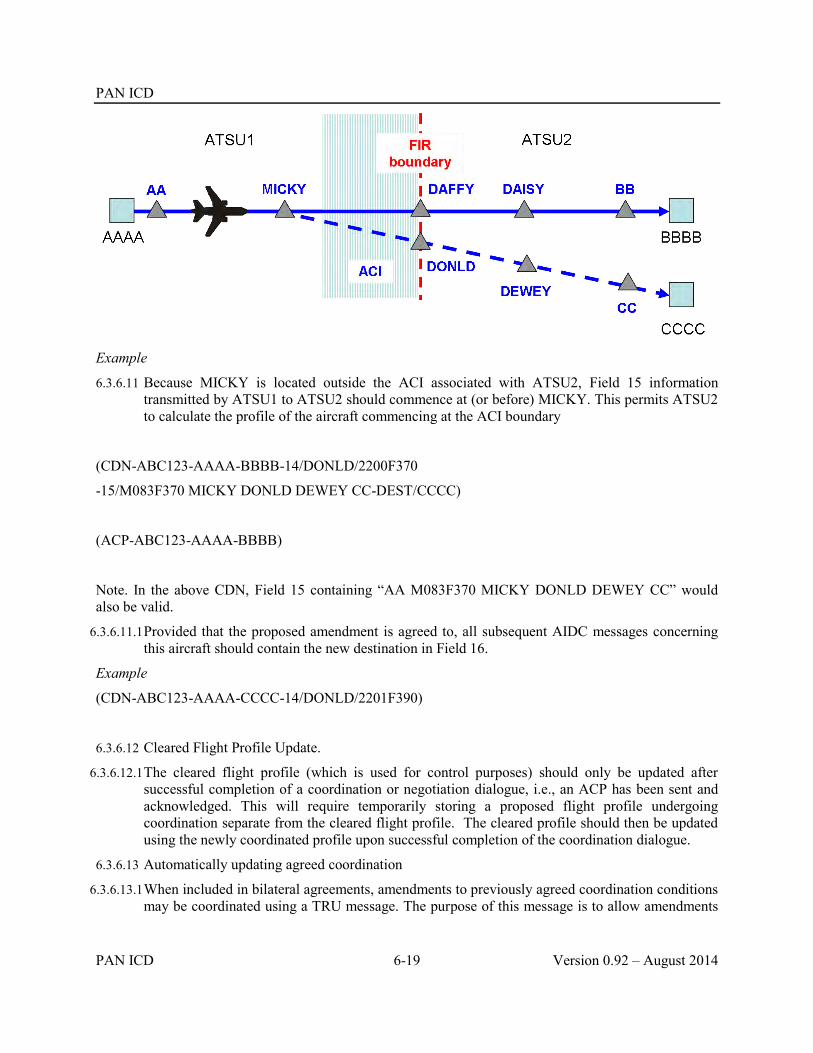
PAN ICD
PAN ICD 6-19 Version 0.92 – August 2014
Example
6.3.6.11 Because MICKY is located outside the ACI associated with ATSU2, Field 15 information transmitted by ATSU1 to ATSU2 should commence at (or before) MICKY. This permits ATSU2 to calculate the profile of the aircraft commencing at the ACI boundary
(CDN-ABC123-AAAA-BBBB-14/DONLD/2200F370
-15/M083F370 MICKY DONLD DEWEY CC-DEST/CCCC)
(ACP-ABC123-AAAA-BBBB)
Note. In the above CDN, Field 15 containing “AA M083F370 MICKY DONLD DEWEY CC” would also be valid.
6.3.6.11.1 Provided that the proposed amendment is agreed to, all subsequent AIDC messages concerning this aircraft should contain the new destination in Field 16.
Example
(CDN-ABC123-AAAA-CCCC-14/DONLD/2201F390)
6.3.6.12 Cleared Flight Profile Update.
6.3.6.12.1 The cleared flight profile (which is used for control purposes) should only be updated after successful completion of a coordination or negotiation dialogue, i.e., an ACP has been sent and acknowledged. This will require temporarily storing a proposed flight profile undergoing coordination separate from the cleared flight profile. The cleared profile should then be updated using the newly coordinated profile upon successful completion of the coordination dialogue.
6.3.6.13 Automatically updating agreed coordination
6.3.6.13.1 When included in bilateral agreements, amendments to previously agreed coordination conditions may be coordinated using a TRU message. The purpose of this message is to allow amendments

PAN ICD
Version 0.92 – August 2014 6-20 PAN ICD
to certain elements of an aircraft’s clearance, as well as other information, to be coordinated to an adjacent ATSU.
6.3.6.13.2 Unlike the CDN, there is no operational response to a TRU message – this message may only be used when there is agreement to what types of amendments can be made to an aircraft’s clearance by the controlling ATSU after initial coordination has occurred.
6.3.6.13.3 The TRU message makes use of the Track data text field to allow ATSU 1 to provide updated clearance and other information to ATSU 2. The Track data field may be used to update assigned heading, assigned level, off track clearance, assigned speed, or ‘direct to’ information, as well as to notify the last reported or requested level of the aircraft.
6.3.6.13.4 Whilst a number of the elements that may be coordinated by TRU message may be more suited to an environment associated with an ATS Surveillance system (e.g. Heading, Direct to, etc.), other elements may be applicable in any ATS environment (e.g. Cleared Flight Level, Off track deviation, Speed, etc).
6.3.6.13.5 When using the DCT/[position] element in the TRU message, [position] would normally be located on the flight planned route of the aircraft. Local procedures should specify the actions to be taken in the event that [position] is not on the flight planned route.
6.3.6.13.6 For the purpose of the TRU message, the format of [position] is one of the following:
From 2 to 5 characters being coded designator assigned to an en-route point or aerodrome; or
ddmm[NS]dddmm[EW]; or
dd[NS]ddd[EW]; or
2 or 3 characters being the coded identification of a navigation aid followed by 3 decimal figures giving the bearing from the point in degrees magnetic followed by 3 decimal figures giving the distance from the point in nautical mile.
6.3.6.13.7 The amended coordination can be considered as being completed upon receipt of a successful application message response (LAM).
6.3.6.13.8 The transmission of a TRU message does not change the flight state.
6.3.6.14 Confirmation of coordination
6.3.6.14.1 Most automated air traffic control systems include functionality for the controller to indicate that coordination, or revisions to it, has been completed manually. Such functionality introduces the possibility of human error, resulting in a coordination error.

PAN ICD
PAN ICD 6-21 Version 0.92 – August 2014
6.3.6.14.2 The PCM is intended to detect and allow recovery from such coordination errors. The use of the PCM is optional and should be implemented when it is determined that the use of this message can improve the safety and reliability of ATC coordination.
6.3.6.14.3 While Field 14 (Estimate data) of the PCM is mandatory, there are also a number of optional fields. When implementing the PCM, ATSUs should determine what information is required to be cross-checked, and ensure that this information is included in the PCM.
6.3.6.14.4 At a system parameter time or position prior to the FIR or ACI boundary, but prior to the transfer of control occurring, ATSU 1 automatically transmits a PCM to ATSU 2. If a coordination or re-negotiation dialogue is open, the transmission of the PCM should be delayed until the dialogue is closed. To maximize its effectiveness, the PCM should be transmitted as close as reasonable (e.g. 1 to 2 minutes) prior to the transfer of control occurring.
6.3.6.14.5 After transmitting the PCM, the flight is in the Confirming flight state.
6.3.6.14.6 On receipt of the PCM, ATSU 2 should automatically compare the contents of the PCM with the flight plan held by ATSU 2
6.3.6.14.7 If no discrepancy exists, ATSU 2 should automatically transmit a PCA message in response to ATSU 1 to close the confirmation dialogue.
6.3.6.14.8 If a discrepancy is detected, or no coordination has previously been received, ATSU 2 should:
i) Update the ATS flight plan with the information in the PCM; and ii) Alert the controller about the data discrepancy (which indicates a coordination error has
occurred). Consideration should be given to suppressing this alert if it involves a minor discrepancy such as a 1-2 minute estimate revision;
iii) Transmit a PCA message in response to ATSU 1 to close the confirmation dialogue.
Note. If the PCM cannot be matched with a flight plan, ATSU 2 must create one from information received in the PCM. If it is not possible to create a flight plan, the controller must be alerted immediately as this is a critical situation.
6.3.6.14.9 ATSU 1 should generate a warning if a PCA response is not received within a defined time period.
6.3.6.14.10 On receipt of the PCA, the flight is in the Coordinated flight state.
6.3.6.14.11 The diagram above depicts the flight state transitions associated with a PCM/PCA exchange following routine coordination. However, in the event of an error having occurred that has resulted in coordination not being completed, other transitions may be possible.

PAN ICD
Version 0.92 – August 2014 6-22 PAN ICD
6.3.6.14.12 While the transitions shown above are valid, this should not be interpreted as an acceptable alternative means to complete coordination.
6.3.6.14.13 The confirmation of coordination messages are intended as a final coordination safety net. They should be used in conjunction with, rather than instead of, other safeguards to ensure that coordination is accurately and reliably completed.
6.3.7 Flight states associated with Transfer of Control
6.3.7.1 As the aircraft approaches the FIR boundary, ATSU 1 transmits a TOC message to ATSU 2 to propose the transfer of control of the flight. If a coordination, re-negotiation or confirmation dialogue is open, the transmission of the TOC should be delayed until the dialogue is closed.
6.3.7.2 The timing of the TOC message depends on the operational environment. In a non-ATS surveillance environment, typical values are 2 – 5 minutes, but much less in an ATS surveillance environment.
6.3.7.3 The flight is now in the Transferring flight state.
6.3.7.4 On receipt of the TOC, ATSU 2 responds with an AOC message to accept the transfer of control of the flight.
6.3.7.5 Once a successful application response (LAM) for the AOC has been received, ATSU 2 becomes the controlling ATSU, and the transfer of control dialogue is closed.
6.3.7.6 The flight is now in the Transferred flight state.
6.3.7.7 Transfer of Control and the ACI.

PAN ICD
PAN ICD 6-23 Version 0.92 – August 2014
6.3.7.7.1 If a flight enters ATSU 2’s ACI but does not enter ATSU 2’s airspace, under normal circumstances, no Transfer of Control to ATSU 2 will occur.
6.3.7.8 Amendments after the ACI or FIR boundary
6.3.7.8.1 No changes to the flight profile may be made while the aircraft is in ATSU 2’s ACI without mutual agreement by ATSU 1 and ATSU 2.
6.3.7.8.2 No changes to the flight profile may be made while the aircraft is in ATSU 2’s FIR (but still within ATSU 1’s ACI without mutual agreement by ATSU 1 and ATSU 2.
6.3.7.9 A Re-Negotiating dialogue may be used to coordinate profile amendments after entering the ACI of an adjacent ATSU, or after the transfer of control has been completed. The re-negotiating dialogue is initiated by the transmission of a CDN message, as described below.
6.3.7.10 After the transmission of a CDN message, the flight is in a Backward Re-Negotiating State.
6.3.7.11 After the transmission of an ACP or REJ response, the re-negotiation dialogue is closed and the flight is in the Transferred state.
6.3.8 Flight state transitions
6.3.8.1 The following table shows the various permissible flight state transitions, as well as the AIDC message that triggers the flight state transition.
Table 6-3. Flight State Transition table
Flight State Transition Message Trigger
Description
Before After
Pre-Notified Notified ABI An ABI triggers the Notified state.

PAN ICD
Version 0.92 – August 2014 6-24 PAN ICD
Flight State Transition Message Trigger
Description
Before After
Pre-Notified Negotiating CPL A CPL triggers the Negotiating state.
Pre-Notified Coordinating PAC A PAC is used to initiate an abbreviated coordination dialogue for an aircraft that has not yet departed without being preceded by an ABI if the PAC contains all optional fields necessary to update the flight plan of the adjacent ATSU
Pre-Notified Confirming PCM A PCM triggers the Confirming state. This state transition only occurs if an error has occurred and neither notification nor coordination has taken place.
Notified Notified ABI Following any changes made to a flight, a subsequent ABI is transmitted to update the information held by an adjacent ATSU.
Notified Pre-Notified MAC A flight that was expected to cross the FIR or ACI boundary of an adjacent ATSU will no longer do so.
Notified Confirming PCM A PCM triggers the Confirming state. This state transition only occurs if an error has occurred and coordination has not taken place.
Notified
Negotiating
CPL A CPL is used to initiate a coordination dialogue for an aircraft that will enter the airspace or ACI of an adjacent ATSU.
Notified Coordinating EST An EST is used to initiate an abbreviated coordination dialogue for an aircraft that will enter the airspace or ACI of an adjacent ATSU.
Notified Coordinating PAC A PAC is used to initiate an abbreviated coordination dialogue for an aircraft that has not yet departed that will enter the airspace or ACI of an adjacent ATSU.
Negotiating Negotiating CDN If an adjacent ATSU cannot accept the coordination proposed in a CPL message, the coordination can be negotiated using CDN messages.

PAN ICD
PAN ICD 6-25 Version 0.92 – August 2014
Flight State Transition Message Trigger
Description
Before After
Negotiating Coordinated ACP The coordination dialogue is closed when one ATSU accepts the proposed coordination by responding with an ACP.
Coordinating Coordinated ACP The abbreviated coordination dialogue is closed when the adjacent ATSU transmits an ACP response
Coordinated Re-Negotiating CDN A coordination negotiation dialogue can be initiated at any time after the initial coordination and before the initiation of the transfer of control procedure.
Re-Negotiating Re-Negotiating CDN A CDN may be used as a counter-proposal to a previously received CDN.
Re-Negotiating Coordinated ACP
An ACP closes a re-negotiation dialogue with new mutually agreed coordination conditions.
REJ An REJ closes a re-negotiation dialogue with the coordination conditions remaining as previously agreed
Coordinated Coordinated TRU A TRU may be sent by the controlling ATSU after the initial coordination dialogue has been completed to update previously agreed coordination conditions.
Coordinated Confirming PCM A PCM may be transmitted to confirm that coordination has been completed and is up to date
Confirming Coordinated PCA A PCA message closes the confirmation dialogue, and confirms that the adjacent ATSU has updated coordination information.
Coordinated Pre-Notified MAC A flight that was expected to enter an adjacent ATSU’s airspace or ACI will no longer do so.
Coordinated Transferring TOC The TOC message proposes a transfer of control to an adjacent ATSU.
Transferring Transferred AOC An adjacent ATSU has accepted control of a flight in response to a TOC message

PAN ICD
Version 0.92 – August 2014 6-26 PAN ICD
Flight State Transition Message Trigger
Description
Before After
Transferred Backward-
Re-Negotiating
CDN A Re-negotiation dialogue can be opened at any time after the transfer of control has occurred while the aircraft is still within the ACI of the previous ATSU.
Backward-
Re-Negotiating
Backward-
Re-Negotiating
CDN A CDN counter-proposal to a previous CDN.
Backward-
Re-Negotiating
Transferred
ACP
An ACP closes the re-negotiation dialogue with new mutually agreed coordination conditions.
REJ An REJ closes the re-negotiation dialogue with the coordination conditions remaining as previously agreed
6.3.8.2 A complete flight state transition diagram is shown in Error! Not a valid bookmark self-reference.. This diagram depicts graphically how the flight transitions from one state to the next. It can be seen that the AIDC messages act as triggers for the transition from one flight state to another.

PAN ICD
PAN ICD 6-27 Version 0.92 – August 2014
Figure 6-1 Flight State Transition Diagram


PAN ICD
PAN ICD 6-25 Version 0.92 – August 2014
6.4 Message Sequencing
6.4.1 The Table 6-4Table 6-4 below shows sequences of commonly used AIDC messages including the next possible AIDC message. Application responses (LAM and LRM) have not been included. The receipt of an LRM may affect the sequence as shown in the Table 6-4Table 6-4. In the event that the transaction cannot be completed by AIDC then verbal communication should be used to complete the coordination.
Table 6-4. AIDC Message Sequence of commonly used AIDC messages
AIDC message initiated by
ATSU1
Next possible AIDC message
initiated by ATSU2
Next possible AIDC message by ATSU1
Next possible AIDC message by
ATSU2
Remarks
ATSU1 ATSU2
ATSU2 ATSU1
ATSU1 ATSU2 ATSU2 ATSU1
Notification and Negotiation Sequences
ABI
- ABI -
- MAC -
- CPL CDN
ACP
- EST ACP
PAC ACP
PCM PCA
Coordination Sequences
CPL ACP
TRU -
TOC AOC
CDN
CDN
ACP
REJ
PCM PCA

PAN ICD
Version 0.92 – August 2014 6-26 PAN ICD
MAC -
CDN
ACP -
CDN CDN
ACP
EST or PAC ACP TRU -
TOC AOC
CDN
CDN
ACP
REJ
PCM PCA
MAC -
CDN
[After initial Coordination has been successful)
CDN
CDN
CDN
ACP or REJ
ACP -
REJ -
ACP or REJ
TRU -
TOC AOC
CDN
CDN
ACP
REJ
PCM PCA
MAC -
TRU - TRU -

PAN ICD
PAN ICD 6-27 Version 0.92 – August 2014
[After initial Coordination has been successful)
TOC AOC
CDN
CDN
ACP
REJ
PCM PCA
MAC -
PCM PCA
TRU -
TOC AOC
CDN
CDN
ACP
REJ
PCM PCA
MAC -
Transfer of Control Sequence
TOC AOC CDN CDN
ACP
REJ
AOC - CDN
6.4.2 Table 6-5Table 6-5 lists the AIDC messages which are valid for each flight state. The ATSU which can transmit the message is also identified.
Table 6-5. Valid Messages by ATSU and flight states
Flight State Message Sent by
Pre-Notified ABI ATSU 1
Pre-Notified PAC ATSU 1

PAN ICD
Version 0.92 – August 2014 6-28 PAN ICD
Flight State Message Sent by
Pre-Notified CPL ATSU 1
Pre-Notified PCM ATSU 1
Notified ABI ATSU 1
Notified MAC ATSU 1
Notified CPL ATSU 1
Notified EST ATSU 1
Notified PAC ATSU 1
Notified PCM ATSU 1
Negotiating CDN Either ATSU
Negotiating ACP Either ATSU
Coordinating ACP ATSU 2
Coordinated CDN Either ATSU
Coordinated TRU ATSU 1
Coordinated PCM ATSU 1
Coordinated TOC ATSU 1
Coordinated MAC ATSU 1
Confirming PCA ATSU 2
Re-Negotiating CDN Either ATSU
Re-Negotiating ACP Either ATSU
Re-Negotiating REJ Either ATSU
Transferring AOC ATSU 2
Transferred CDN Either ATSU
Backward-
Re-Negotiating
CDN Either ATSU

PAN ICD
PAN ICD 6-29 Version 0.92 – August 2014
Flight State Message Sent by
Backward-
Re-Negotiating
ACP Either ATSU
Backward-
Re-Negotiating
REJ Either ATSU
6.5 Other AIDC messages
6.5.1 The previous sections have discussed the use of Notification, Coordination Confirmation and Transfer of Control messages. There are three additional AIDC message groups:
General Information messages;
Application management messages; and
Surveillance Data Transfer messages.
6.5.2 All AIDC messages within these three message groups require only an application response; no operational response is defined. No change to flight state occurs as a result of transmitting or receiving these AIDC messages.
6.5.3 General information messages.
6.5.3.1 EMG and MIS Messages.
6.5.3.2 These messages support the exchange of text information between ATSUs. A communicator (usually a person, but a computer or application process is also permitted) in one ATSU can send a free text message to a functional address at another ATSU. Typical functional addresses could be an area supervisor or an ATC sector. The EMG should have an AFTN emergency priority (SS).
6.5.4 Application Management messages.
6.5.4.1 Application management messages refer to Application responses (LAM and LRM) status monitoring (ASM), and FANS data link connection transfer (FAN and FCN) capabilities.
6.5.4.2 Because of their important role in the AIDC process, the LAM and LRM were described separately, earlier in this document (refer to para 4.84.8).
6.5.4.3 Application Status Monitor (ASM)
6.5.4.3.1 The ASM message is used to confirm that the communication link between two ATS Units is on line, as well as confirming that the AIDC application of another ATS Unit is on-line. This message is sent by one ATSU to another if, after a mutually agreed time, no AIDC messages (including Application response messages - LAM or LRM) have been received from the other

PAN ICD
Version 0.92 – August 2014 6-30 PAN ICD
ATSU. An ATSU receiving an ASM message should respond with an appropriate application response.
6.5.4.3.2 Non receipt of a response to an ASM may indicate either a communication link failure or an ATC system failure. If an ATSU that has sent an ASM message does not receive an application response within a specified time, a warning message should be displayed at an appropriate position so that local contingency procedures can be executed.
6.5.4.3.3 The ASM message would normally be sent automatically, but may be sent manually for testing purposes.
6.5.4.4 FANS Application Message (FAN)
6.5.4.4.1 The FAN message may be used to transfer a data link-equipped aircraft’s logon information from one ATSU to another. Implementation of this message is a replacement for the five step “Address Forwarding” process (initiated by the “Contact Request” (or FN_CAD)) that was developed for FANS-1/A. The FAN message contains all the information that is required for an ATSU to establish ADS-C and/or CPDLC connections with the aircraft.
6.5.4.4.2 In the event that only an ADS-C connection will be required, the ATSU transmitting the FAN message should only include ADS-C information in the Application field. If a FAN message is transmitted containing ADS-C information only, there should be no expectation of subsequently receiving an FCN. If a FAN message is received containing ADS-C application information only, there should be no attempt to establish a CPDLC connection.
6.5.4.4.3 Normally, one FAN message would be sent for each data link transfer per flight. However, when an FCN is received with a communication status field value of (1) indicating that ATSU 2 is not the Next Data Authority ATSU 1 should send another NDA message to the aircraft and another FAN message to ATSU 2 to indicate that the NDA has been sent (refer to Figure 6-5Figure 6-5). While the second FAN may not be required for address forwarding purposes it does provide ATSU 2 with a positive indication that another NDA has been sent to the aircraft.
6.5.4.4.4 ATSUs implementing the FAN message should consider retaining existing Address Forwarding functionality to be used as a contingency for data link transfers in the event of failure of the ground-ground link.
6.5.4.4.5 Similarly to Address Forwarding, the FAN message should be sent by ATSU 1 at a time parameter prior to the boundary or ACI with ATSU 2. This parameter should be in accordance

PAN ICD
PAN ICD 6-31 Version 0.92 – August 2014
with guidance outlined in the ICAO Global Operational Data Link Document (GOLD). Functionality for the transmission of a FAN message manually by ATC should also be available.
6.5.4.4.6 Information concerning the identity of the aircraft (i.e. aircraft identification, aircraft address and registration) contained in the Application data field must not be extracted from the flight plan – it must be information that was contained in either the most recently received logon or FAN message.
Note. This requirement only applies to the aircraft identification within the Application data field of the FAN message. The aircraft identification (i.e. Field 7a) at the beginning of the FAN message is the identification of the aircraft from the ATS flight plan.
6.5.4.4.7 When extracting the aircraft identification from the logon, the information required is the aircraft identification within the CRC protected portion of the logon – not the flight identifier (FI) that is contained in Line 4 of the ACARS logon message. In the example below, the aircraft identification is QFA924 rather than the QF0924 contained in Line 4 of the ACARS message.
QU BNECAYA
.QXSXMXS 010019
AFD
FI QF0924/AN VH-EBA
DT QXT POR1 010019 J59A
- AFN/FMHQFA924, .VH-EBA,,001902/FPOS33373E150484,0/FCOADS, 01/FCOATC,01292B
6.5.4.4.8 Under certain circumstances (e.g. FMC failure) it is possible for the SMI of an aircraft to change in flight, which will require a new logon from the aircraft to permit data link services to continue. To ensure that the next ATSU has up to date information, the SMI transmitted in any FAN message should be the SMI from the most recently received logon or FAN message.
6.5.4.4.9 A hyphen within the registration that was contained in either the logon or any previously received FAN message must also be included in the REG element of any transmitted FAN message. Without this hyphen, data link messages transmitted by the ATSU will not be delivered to the aircraft.
6.5.4.4.10 Any “padding” in the registration contained in the AFN logon (e.g. preceding periods “.”) must not be included in the FAN message. In the sample ACARS message above, the registration to be included in the FAN message would be “VH-EBA”, not “.VH-EBA”.
6.5.4.4.11 Some ATSUs may utilise the aircraft position which is an optional field that may be contained in the logon. If the aircraft position information element is to be included in any transmitted FAN message, the calculated position of the aircraft at the time of FAN transmission should be used. The aircraft position from the original logon should not be used for this purpose because this information will be out of date when the FAN message is transmitted.
6.5.4.5 FANS Completion Notification (FCN)
6.5.4.5.1 The FCN message, where used, provides advice to ATSU 1 concerning the CPDLC connection status of ATSU 2. The transmission of an FCN message is triggered by an event such as the termination of a CPDLC Connection by ATSU 1, or the establishment of (or failure to establish)

PAN ICD
Version 0.92 – August 2014 6-32 PAN ICD
an inactive CPDLC Connection by ATSU 2. FCN messages should only be transmitted when a CPDLC transfer is being effected – i.e. not for transfers involving aircraft that are only ADS-C equipped, or where a FAN message has been transmitted solely to permit an adjacent ATS Unit to establish ADS contracts with an aircraft.
6.5.4.6 Multiple FCN messages.
6.5.4.6.1 The general philosophy for use of the FCN is that only a single FCN message is transmitted by each ATSU for each flight. Under normal conditions, changes in CPDLC status after transmission of an FCN should not result in the transmission of another FCN (an exception to this is when a Connection request fails due to ATSU 2 not being the nominated next data authority – see Table 6-6Table 6-6 below).
Table 6-6. FCN Transmission
ATSU transmitting FCN When an FCN should be sent
ATSU 1 On receipt of a Disconnect Request terminating the CPDLC Connection (CPD=0)
ATSU 2 On receipt of a Connection Confirm, establishing a CPDLC Connection (CPD=2)
ATSU 2 On receipt of CPDLC downlink DM64 [ICAO facility designation] (CPD=1),
Note. This provides advice to ATSU 1 to uplink an appropriate Next Data Authority message to the aircraft.
And subsequently:
On establishment of a CPDLC Connection (CPD=2)
ATSU 2 At a time parameter prior to the FIR boundary, if no CPDLC Connection could be established (CPD=0)
6.5.4.6.2 Procedures following a change to CPDLC Connectivity, e.g., loss of the inactive CPDLC connection, following the transmission of an FCN message should be described in local procedures (e.g. voice coordination), rather than by transmission of another FCN message.
6.5.4.6.3 Non-receipt of an FCN (CPD = 0) by ATSU 2 should prompt ATSU 2 to ensure that they are the CPDLC current data authority for the aircraft.
6.5.4.6.4 Procedures for the notification of changes to the voice communication frequency after the transmission of an FCN message should be described in local procedures rather than via the transmission of another FCN message.
6.5.4.7 Sample flight threads involving FAN and FCN messages
6.5.4.7.1 The following diagrams show typical flight threads involving the FAN and FCN messages. Relevant uplink and downlink messages between the aircraft and the ATSU are also shown.

PAN ICD
PAN ICD 6-33 Version 0.92 – August 2014
Figure 6-2. Routine Data Link Transfer Using FAN and FCN Messaging
6.5.4.7.2 Figure 6-2Figure 6-2 shows a routine CPDLC transfer from one ATSU to the next. The first step in the transfer process is the uplink of a CPDLC Next Data Authority message to the aircraft advising the avionics of the next centre that will be communicating with the aircraft via CPDLC. A FAN message is then sent to the next ATSU to provide them with the aircraft’s logon information. ATSU 2 then successfully establishes a CPDLC connection with the aircraft and transmits a ‘successful’ FCN (CPD = 2) to ATSU 1. On termination of the CPDLC connection, ATSU 1 transmits an FCN (CPD = 0) to ATSU 2 indicating that it has become the CPDLC current data authority.

PAN ICD
Version 0.92 – August 2014 6-34 PAN ICD
Figure 6-3 CPDLC Transfer Using FAN and FCN Messaging – Initial Connection Request Failed
6.5.4.7.3 Figure 6-3Figure 6-3 shows a CPDLC transfer where there is no response by the avionics to the initial Connection Request uplinked by ATSU 2. A subsequent Connection Request is uplinked to the aircraft which is successful. Because the CPDLC connection is finally established before the ‘time out’ VSP prior to the FIR boundary, a successful FCN (CPD=2) is transmitted to ATSU 1. On termination of the CPDLC connection, ATSU 1 transmits an FCN (CPD=0) to ATSU 2.
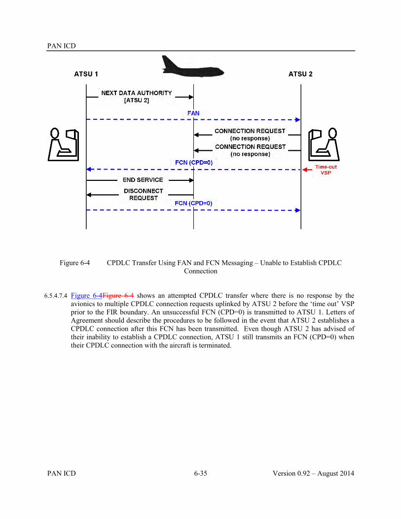
PAN ICD
PAN ICD 6-35 Version 0.92 – August 2014
Figure 6-4 CPDLC Transfer Using FAN and FCN Messaging – Unable to Establish CPDLC Connection
6.5.4.7.4 Figure 6-4Figure 6-4 shows an attempted CPDLC transfer where there is no response by the avionics to multiple CPDLC connection requests uplinked by ATSU 2 before the ‘time out’ VSP prior to the FIR boundary. An unsuccessful FCN (CPD=0) is transmitted to ATSU 1. Letters of Agreement should describe the procedures to be followed in the event that ATSU 2 establishes a CPDLC connection after this FCN has been transmitted. Even though ATSU 2 has advised of their inability to establish a CPDLC connection, ATSU 1 still transmits an FCN (CPD=0) when their CPDLC connection with the aircraft is terminated.

PAN ICD
Version 0.92 – August 2014 6-36 PAN ICD
Figure 6-5 CPDLC Transfer Using FAN and FCN Messaging – Initial NDA not Delivered
6.5.4.7.5 Figure 6-5Figure 6-5 shows a CPDLC transfer in which the original Next Data Authority message uplinked by ATSU 1 is not delivered to the aircraft. An FCN (CPD=1) is transmitted by ATSU 2 advising of the failure of their CPDLC Connection request. Another Next Data Authority message is uplinked to the aircraft. ATSU 1 may send another FAN message after which ATSU 2 successfully establishes a CPDLC connection. Because this occurs before the time out VSP prior to the FIR boundary, a successful FCN (CPD=2) is transmitted back to ATSU 1. On termination of the CPDLC connection, ATSU 1 transmits an FCN (CPD=0) to ATSU 2.
6.5.5 Surveillance data transfer messages.
6.5.5.1 The ADS message is used to transfer data contained within an ADS-C report including optional ADS-C groups to an adjacent ATSU.
6.5.5.2 The ADS message contains a text field – the ADS-C data field – which contains information from the ADS-C report in its original hexadecimal format. The ADS-C data field consists of the text that immediately follows the “ADS” IMI (but excluding the 4 character CRC) within the application data portion of the ADS-C report.

PAN ICD
PAN ICD 6-37 Version 0.92 – August 2014
6.5.5.3 The following example shows an encoded ACARS ADS-C report – as it would be received by an ATSU – as well as an example of what information from this report would be transferred into the corresponding ADS-C data field. The ATSU receiving the AIDC ADS message simply decodes the ADS-C data field and extracts the data that is required by the ATSU.
ACARS ADS-C
report
QU BNECAYA
.QXSXMXS 011505
PAR
FI NZ0090/AN ZK-OKC
DT QXT POR1 011505 F59A
- ADS.ZK-OKC030007FF946B6F6DC8FC044B9D0DFC013B80DA88FCOA64F9E4438B4AC8FC000E34D0EDC00010140F3E8660F3
ADS-C data field
ADS/.ZK-OKC030007FF946B6F6DC8FC044B9D0DFC013B80DA88FC0A64F9E4438B4AC8FC000E34D0EDC00010140F3E86
Note. Because it is part of the 7 character registration field the leading “.” in front of the registration in the ACARS message (“.ZK-OKC”) must be retained. The 4 character CRC (“60F3”) at the end of the ACARS ADS-C report is not included in the ADS-C data field.
6.5.5.4 The types of ADS-C reports (i.e. periodic or event) transmitted in the AIDC ADS message should be in accordance with bilateral agreements. When implementing the AIDC ADS message, ATSUs should consider the effect of relaying numerous ADS-C periodic reports via ground-ground links (e.g. AFTN) when a high periodic reporting rate is in effect.
6.5.5.5 The AIDC ADS message is used to transfer ADS-C information only. Other messaging protocols exist for the transfer of ADS-B and other types of surveillance information.
6.5.5.6 While the AIDC ADS message may be used to transfer ADS-C information, this data may also be transferred using the ACARS ground-ground network by re-addressing the received ADS-C message to the other ATSU. States should agree on the method to be used on a bilateral basis.
Example: Brisbane ATSU (BNECAYA) receives an ADS-C downlink via the ACARS network from its Data link Service Provider SITA (QXSXMXS)
QU BNECAYA
QXSXMXS 011505
PAR
FI NZ0090/AN ZK-OKC
DT QXT POR1 011505 F59A
- ADS.ZK-OKC0300FF946B6F6DC8FC044B9D0DFC013B80DA88FC0A64F9E4438B4AC8FC000E34D0EDC00010140F3EE8660F3
Brisbane re-addresses the downlink and forwards to Auckland via the ACARS ground-ground network:

PAN ICD
Version 0.92 – August 2014 6-38 PAN ICD
QU AKLCBYA
.BNECAYA 011505
PAR
FI NZ0090/AN ZK-OKC
DT QXT POR1 011505 F59A
- ADS.ZK-OKC0300FF946B6F6DC8FC044B9D0DFC013B80DA88FC0A64F9E4438B4AC8FC000E34D0EDC00010140F3EE8660F3

PAN ICD
PAN ICD 6-39 Version 0.92 – August 2014
6.6 Examples
6.6.1 The following section contains a number of examples illustrating how the AIDC message set may be used operationally. These examples are illustrative only – they do not necessarily reflect the AIDC messages that might actually be used in the circumstances, nor the actual airspace coordination requirements.
6.6.2 The specific AIDC messages to be used and the timing of the transmission of these messages is defined in bilateral agreements between the relevant ATS Units.
6.6.3 In the following examples, unless otherwise stated, the AIDC messages are transmitted at a specified time or position prior to the FIR or ACI boundary. Depending on the AIDC message received, Operational responses might be transmitted either automatically or manually.
6.6.4 Each of the following examples consists of:
A text description;
A flight thread that graphically illustrates the sequence of messages. For ease of reference, these flight threads are colour coded, with message dialogues displayed in the same colour. AIDC messages not related to Notification, Coordination or Transfer of Control, are shown as a dashed line;
A table containing the associated AIDC messages.
For simplification, the examples do not include Application Management (LAM/LRM) messages.
6.6.4.1 Example 1 – Coordination using abbreviated initial coordination dialogue
6.6.4.1.1 ATSU 1transmits a notification message (ABI) to ATSU 2. The ABI contains Estimate data of RUNOD at 1209, operating in a block clearance between FL350 and FL370. By agreement, ATSU 1 includes flight planned speed/level changes in Field 15 of AIDC messages. Subsequently the estimate for RUNOD changes to 1213, but ATSU 1 has an agreement with ATSU 2 not to sent revised Notification messages for revisions of less than 5 minutes.
6.6.4.1.2 ATSU 1 transmits an abbreviated coordination message (EST) to ATSU 2. The proposed coordination contains Estimate data of RUNOD at 1213 operating in a block clearance between FL350 and FL370. ATSU 2 accepts the proposed coordination conditions by responding with an ACP.
6.6.4.1.3 ATSU 1 proposes a transfer of control responsibility by transmitting a TOC to ATSU 2. ATSU 2 accepts control responsibility by responding with an AOC.

PAN ICD
Version 0.92 – August 2014 6-40 PAN ICD
ATSU 1 (ABI-ANZ804/A1207-YBBN-RUNOD/1209F350F370-NZCH-8/IS-9/A320/M-10/SDE1E3FGHIM2RW/LB1-15/N0448F370 2719S15313E SCOTT Y76 SIFRA/M078F390 L503 CH DCT-18/PBN/A1C1D1O1S2T1 REG/ZKOJK EET/NZZO0132 SEL/HJRS CODE/C81845 OPR/ANZ RALT/NZAA YBCG YSSY RMK/TCAS EQUIPPED)
ATSU 1 (EST-ANZ804/A1207-YBBN-RUNOD/1213F350F370-NZCH)
ATSU 2 (ACP-ANZ804/A1207-YBBN-NZCH)
ATSU 1 (TOC-ANZ804/A1207-YBBN-NZCH)
ATSU 2 (AOC-ANZ804/A1207-YBBN-NZCH)
6.6.4.2 Example 2 – Coordination using initial coordination dialogue
6.6.4.2.1 ATSU 1 transmits a notification message (ABI) to ATSU 2. The ABI contains Estimate data of 6852N06414W at 1503 climbing from F350 to F370, and with a weather deviation clearance up to 20NM to the right of route.
6.6.4.2.2 ATSU 1 transmits a coordination message (CPL) to ATSU 2. The proposed coordination contains Estimate data of 6852N06414W at 1505 climbing from F350 to F370, and with a weather deviation clearance up to 20NM to the right of route. ATSU 2 accepts the proposed coordination without modification by responding with an ACP.
6.6.4.2.3 ATSU 1 proposes a transfer of control responsibility by transmitting a TOC to ATSU 2. ATSU 2 accepts control responsibility by responding with an AOC

PAN ICD
PAN ICD 6-41 Version 0.92 – August 2014
ATSU 1 (ABI-ICE680-KSEA-6852N06414W/1503F370F350A/W20R-BIKF-8/IS-9/B752/M-10/SWXRGIDFHY/LB1-15/M079F370 6852N06414W BOPUT 6900N06000W 6900N05000W 6800N04000W 6600N03000W HEKLA-18/PBN/A1B2B3B4B5D1L1S1 NAV/RNVD1A1 DOF/131124 REG/TFLLX EET/CZVR0019 CZEG0049 BGGL0450 BIRD0621 SEL/DSHK OPR/ICE RALT/CYEG BGSF RMK/ADSB)
ATSU 1 (CPL-ICE680-IS-B752/M-SWXRGIDFHY/LB1-KSEA-6852N06414W/1505F370F350A/W20R-M079F370 6852N06414W BOPUT 6900N06000W 6900N05000W 6800N04000W 6600N03000W HEKLA-BIKF-PBN/A1B2B3B4B5D1L1S1 NAV/RNVD1A1 DOF/131124 REG/TFLLX EET/CZVR0019 CZEG0049 BGGL0450 BIRD0621 SEL/DSHK OPR/ICE RALT/CYEG BGSF RMK/ADSB)
ATSU 2 (ACP-ICE680-KSEA-BIKF)
ATSU 1 (TOC-ICE680-KSEA-BIKF)
ATSU 2 (AOC-ICE680-KSEA-BIKF)
6.6.4.3 Example 3 – Negotiation of proposed coordination, and CPDLC transfer
6.6.4.3.1 ATSU 1 transmits a notification message (ABI) to ATSU 2. The ABI contains Estimate data of 3010S16300E at 2325 at F370.
6.6.4.3.2 ATSU 1 transmits a coordination message (CPL) to ATSU 2. The proposed coordination contains Estimate data of 3010S16300E at 2324 at F370
6.6.4.3.3 ATSU 2 responds by transmitting a negotiation message (CDN) to ATSU 1 proposing (or requesting) an amendment to the proposed coordination to F390. ATSU 2 accepts the revised coordination by responding with ACP. The agreed coordination is now 3010S16300E at 2324 at F390.
6.6.4.3.4 ATSU 1 transmits a FAN message to ATSU 2 providing the logon information that ATSU 2 requires to establish a CPDLC connection as well as ADS contracts.
6.6.4.3.5 When an inactive CPDLC connection is established, ATSU 2 transmits an FCN to ATSU 1, including the appropriate HF frequency for the aircraft to monitor.

PAN ICD
Version 0.92 – August 2014 6-42 PAN ICD
6.6.4.3.6 ATSU 1 proposes a transfer of control responsibility by transmitting a TOC to ATSU 2. ATSU 2 accepts control responsibility by responding with an AOC.
6.6.4.3.7 ATSU 1 terminates the CPDLC connection and transmits an FCN to ATSU 2 notifying them that the CPDLC connection has been terminated.
ATSU 1 (ABI-ANZ764-YSSY-3010S16300E/2325F370-YSNF-8/IS-9/A320/M-10/SDE1E3FGHIJ3J5M2RW/LB1D1-15/M078F370 SY B450 LHI 3010S16300E NF DCT-18/PBN/A1C1D1O1S2T1 REG/ZKOJK EET/NZZO0131 SEL/HJRS CODE/C81845 OPR/ANZ RMK/TCAS EQUIPPED)
ATSU 1 (CPL-ANZ764-IS-A320/M-SDE1E3FGHIJ3J5M2RW/LB1D1-YSSY-3010S16300E/2324F370-M078F370 SY B450 LHI 3010S16300E NF DCT-YSNF-PBN/A1C1D1O1S2T1 REG/ZKOJK EET/NZZO0131 SEL/HJRS CODE/C81845 OPR/ANZ RMK/TCAS EQUIPPED)
ATSU 2 (CDN-ANZ764-YSSY-YSNF-14/3010S16300E/2324F390)
ATSU 1 (ACP-ANZ764-YSSY-YSNF)
ATSU 1 (FAN-ANZ764-YSSY-YSNF-SMI/AFD FMH/ANZ764 REG/ZK-OJK FPO/3108S16013E FCO/ATC01 FCO/ADS01)
ATSU 2 (FCN-ANZ764-YSSY-YSNF-CPD/2 FREQ/13261)
ATSU 1 (TOC-ANZ764-YSSY-YSNF)
ATSU 2 (AOC-ANZ764-YSSY-YSNF)
ATSU 1 (FCN-ANZ764-YSSY-YSNF-CPD/0)

PAN ICD
PAN ICD 6-43 Version 0.92 – August 2014
6.6.4.4 Example 4 – Multiple notifications, automatic coordination updates and coordination confirmation
6.6.4.4.1 ATSU 1 transmits a notification message (ABI) to ATSU 2. The ABI contains Estimate data of 65N040W at 0405 at F350. The route in the ABI (and subsequent AIDC messages) is truncated (“T”) due to a duplicated waypoint in the flight planned route.
6.6.4.4.2 Following the issuing of a cruise climb and weather deviation clearance, ATSU 1 transmits an additional notification message (ABI) to ATSU 2. The ABI now contains Estimate data of 65N040W at 0406 cruise climbing from F350 to F370, and with a weather deviation clearance up to 30NM either side of route.
6.6.4.4.3 ATSU 1 transmits a coordination message (CPL) to ATSU 2. The proposed coordination contains Estimate data of 65N040W at 0407 at F370F350C, and with a weather deviation clearance up to 30NM either side of route. ATSU 2 accepts the proposed coordination without modification by responding with an ACP.
6.6.4.4.4 ATSU 1 transmits a TRU message to ATSU 2, providing a coordination update that the aircraft is now cleared in a weather deviation up to 40NM either side of route.
6.6.4.4.5 ATSU 1 transmits a PCM to ATSU 2 to confirm that the coordination held by ATSU 2 is correct. ATSU 2 confirms that their coordination is up to date by responding with a PCA.
6.6.4.4.6 ATSU 1 proposes a transfer of control responsibility by transmitting a TOC to ATSU 2. ATSU 2 accepts control responsibility by responding with an AOC
ATSU 1 (ABI-MSR995/A3057-HECA-65N040W/0405F350-CYYZ-8/IS-9/B77W/H-10/SDE1E2E3FGHIJ2J3J4J5M1RWXYZ/LB1D1-15/M084F350 65N040W 63N050W 60N060W LAKES T-18/PBN/A1B1C1D1 NAV/RNVD1E2A1 RNP5 DAT/SVH DOF/131124 REG/SUGDM EET/LCCC0029 LTAA0051 LTBB0115 SEL/FSDP OPR/EGYPTAIR RALT/EGPK CYYR RMK/TCAS)
ATSU 1 (ABI-MSR995/A3057-HECA-65N040W/0406F370F350C/W30E-CYYZ-8/IS-9/B77W/H-10/SDE1E2E3FGHIJ2J3J4J5M1RWXYZ/LB1D1-15/M084F350 65N040W

PAN ICD
Version 0.92 – August 2014 6-44 PAN ICD
63N050W 60N060W LAKES T-18/PBN/A1B1C1D1 NAV/RNVD1E2A1 RNP5 DAT/SVH DOF/131124 REG/SUGDM EET/LCCC0029 LTAA0051 LTBB0115 SEL/FSDP OPR/EGYPTAIR RALT/EGPK CYYR RMK/TCAS)
ATSU 1 (CPL-MSR995/A3057-IS-B77W/H-SDE1E2E3FGHIJ2J3J4J5M1RWXYZ/LB1D1-HECA-65N040W/0407F370F350C/W30E-M084F370 65N040W 63N050W 60N060W LAKES T-CYYZ-PBN/A1B1C1D1 NAV/RNVD1E2A1 RNP5 DAT/SVH DOF/131124 REG/SUGDM EET/LCCC0029 LTAA0051 LTBB0115 SEL/FSDP OPR/EGYPTAIR RALT/EGPK CYYR RMK/TCAS)
ATSU 2 (ACP-MSR995/A3057-HECA-CYYZ)
ATSU 1 (TRU-MSR995/A3057-HECA-CYYZ-OTD/W40E)
ATSU 1 (PCM-MSR995/A3057-HECA-65N040W/0407F370F350C/W40E-CYYZ-8/IS-9/B77W/H-10/SDE1E2E3FGHIJ2J3J4J5M1RWXYZ/LB1D1-15/M084F370 65N040W 63N050W 60N060W LAKES T-18/PBN/A1B1C1D1 NAV/RNVD1E2A1 RNP5 DAT/SVH DOF/131124 REG/SUGDM EET/LCCC0029 LTAA0051 LTBB0115 SEL/FSDP OPR/EGYPTAIR RALT/EGPK CYYR RMK/TCAS)
ATSU 2 (PCA-MSR995/A3057-HECA-CYYZ)
ATSU 1 (TOC-MSR995/A3057-HECA-CYYZ)
ATSU 2 (AOC-MSR995/A3057-HECA-CYYZ)
6.6.4.5 Example 5 – Coordination re-negotiation and automatic coordination updates
6.6.4.5.1 ATSU 1 transmits a notification message (ABI) to ATSU 2. The ABI contains Estimate data of ESKEL at 0245 at F350.
6.6.4.5.2 ATSU 1 transmits an abbreviated coordination message (EST) to ATSU 2.The proposed coordination contains Estimate data of ESKEL at 0245 at F350. ATSU 2 accepts the proposed coordination conditions by responding with an ACP.
6.6.4.5.3 After coordination has been completed, but prior to the transfer of control ATSU 2 proposes (or requests) an amendment to the proposed coordination to F390 by transmitting a negotiation message (CDN) to ATSU 1 The proposed amendment is not acceptable to ATSU 1, and the proposal is rejected by the transmitting of an REJ response to ATSU 2.
6.6.4.5.4 ATSU 1 transmits a TRU message to ATSU 2, providing a coordination update that the aircraft has been cleared to deviate up to 20NM left of route. The TRU also provides advice that the aircraft is requesting F370. The requested level was not proposed by a negotiation message (CDN), because the requested level was not available in ATSU 1’s airspace.
6.6.4.5.5 ATSU 1 proposes a transfer of control responsibility by transmitting a TOC to ATSU 2. ATSU 2 accepts control responsibility by responding with an AOC.

PAN ICD
PAN ICD 6-45 Version 0.92 – August 2014
ATSU 1 (ABI-QFA143/A1540-YSSY-ESKEL/0245F350-NZAA-8/IS-9/B738/M-10/SDE2E3FGHIRWYZ/LB1-15/N0448F350 EVONN L521 AA DCT-18/PBN/A1S1T1 NAV/GPSRNAV DOF/140117 REG/ZKZQC EET/YBBB0008 NZZO0121 SEL/ESAP CODE/C81CF8 PER/C)
ATSU 1 (EST-QFA143/A1540-YSSY-ESKEL/0245F350-NZAA)
ATSU 2 (ACP-QFA143/A1540-YSSY-NZAA)
ATSU 2 (CDN-QFA143/A1540-YSSY-NZAA-14/ESKEL/0245F390)
ATSU 1 (REJ-QFA143/A1540-YSSY-NZAA)
ATSU 1 (TRU-QFA143/A1540-YSSY-NZAA-RFL/F370 OTD/W20L)
ATSU 1 (TOC-QFA143/A1540-YSSY-NZAA)
ATSU 2 (AOC-QFA143/A1540-YSSY-NZAA)
6.6.4.6 Example 6 – Coordination re-negotiation, automatic coordination updates and coordination confirmation
6.6.4.6.1 ATSU 1 transmits a notification message (ABI) to ATSU 2. The ABI contains Estimate data of 65N040W at 1145, operating in a block clearance F350 to F370. The route in the ABI (and subsequent AIDC messages) is truncated (“T”) due to a duplicated waypoint in the flight planned route.
6.6.4.6.2 ATSU 1 transmits a coordination message (CPL) to ATSU 2. The proposed coordination contains Estimate data of 65N040W at 1146, operating in a block clearance F350 to F370. ATSU 2 accepts the proposed coordination without modification by responding with an ACP.
6.6.4.6.3 After coordination has been completed, but prior to the transfer of control, ATSU 1 proposes an amendment to the proposed coordination to block clearance F370 to F390 (climbing from

PAN ICD
Version 0.92 – August 2014 6-46 PAN ICD
FL360), as well as a weather deviation of up to 40NM either side of route by transmitting a negotiation message (CDN) to ATSU 2 The proposed amendment is acceptable to ATSU 2, and the proposal is accepted by the transmitting of an ACP response to ATSU 1.
6.6.4.6.4 ATSU 1 transmits a TRU message to ATSU 2, providing a coordination update that the aircraft’s cleared level is FL390 (i.e. the block clearance is cancelled), the aircraft is maintaining FL390 and is back on route.
6.6.4.6.5 ATSU 1 transmits a PCM to ATSU 2 to confirm that the coordination held by ATSU 2 is correct. At the time of transmitting the PCM, the estimate has changed by one minute (1147 at 65N040W), which is included in the PCM. On receipt of the PCM, ATSU 2 updates their flight plan, and confirms that their coordination is up to date by responding with a PCA.
6.6.4.6.6 ATSU 1 proposes a transfer of control responsibility by transmitting a TOC to ATSU 2. ATSU 2 accepts control responsibility by responding with an AOC
ATSU 1 (ABI-UAE231/A3105-OMBD-65N040W/1145F350F370-KIAD-8/IS-9/B77W/H-10/SDE2E3GHIJ3J5M1RWXYZ/LB2D1-15/M083F360 65N040W 63N050W 59N060W LOMTA T-18/PBN/A1B1C1D1L1O1S2T1 NAV/RNVD1E2A1 DOF/131124 REG/A6EGH EET/OMAE0008 SEL/ACDF RALT/EIDW CYQX RMK/NRP HAR TCAS ADSB)
ATSU 1 (CPL-UAE231/A3105-IS-B77W/H-SDE2E3GHIJ3J5M1RWXYZ/LB2D1-OMDB-65N040W/1146F350F370-M083F360 65N040W 63N050W 59N060W LOMTA T-KIAD-PBN/A1B1C1D1L1O1S2T1 NAV/RNVD1E2A1 DOF/131124 REG/A6EGH EET/OMAE0008 SEL/ACDF RALT/EIDW CYQX RMK/NRP HAR TCAS ADSB)
ATSU 2 (ACP-UAE231/A3105-OMDB-KIAD)
ATSU 1 (CDN-UAE231/A3105-OMDB-KIAD-14/65N040W/1146F370F390F360A/W40E)

PAN ICD
PAN ICD 6-47 Version 0.92 – August 2014
ATSU 2 (ACP-UAE231/A3105-OMDB-KIAD)
ATSU 1 (TRU-UAE231/A3105-OMDB-KIAD-PRL/F390 CFL/F390 OTD/0)
ATSU 1 (PCM-UAE231/A3105-OMBD-65N040W/1147F390-KIAD-8/IS-9/B77W/H-10/SDE2E3GHIJ3J5M1RWXYZ/LB2D1-15/M083F390 65N040W 63N050W 59N060W LOMTA T-18/PBN/A1B1C1D1L1O1S2T1 NAV/RNVD1E2A1 DOF/131124 REG/A6EGH EET/OMAE0008 SEL/ACDF RALT/EIDW CYQX RMK/NRP HAR TCAS ADSB)
ATSU 2 (PCA-UAE231/A3105-OMDB-KIAD)
ATSU 1 (TOC-UAE231/A3105-OMDB-KIAD)
ATSU 2 (AOC-UAE231/A3105-OMDB-KIAD)
6.6.4.7 Example 7 – Coordination from nearby aerodrome using abbreviated initial coordination dialogue, coordination re-negotiation and coordination confirmation
6.6.4.7.1 Several minutes before departure time (e.g. at taxi time), ATSU 1 transmits an abbreviated coordination message (PAC) to ATSU 2. The proposed coordination contains Estimate data of EGATU at 1213 at FL290. ATSU 2 accepts the proposed coordination conditions by responding with an ACP. The coordination prior to departure is required due to the proximity of the departure aerodrome to the FIR or ACI boundary.
6.6.4.7.2 On departure, the aircraft’s actual estimate differs from that previously coordinated by more than the value specified in bilateral agreements. ATSU 1 proposes an amendment to the estimate to 1219 by transmitting a negotiation message (CDN) to ATSU 2 The proposed amendment is acceptable to ATSU 2, and the proposal is accepted by the transmitting of an ACP response to ATSU 1
6.6.4.7.3 ATSU 1 transmits a PCM to ATSU 2 to confirm that the coordination held by ATSU 2 is correct. ATSU 2 confirms that their coordination is up to date by responding with a PCA.
6.6.4.7.4 ATSU 1 proposes a transfer of control responsibility by transmitting a TOC to ATSU 2. ATSU 2 accepts control responsibility by responding with an AOC.
6.6.4.7.5 After the transfer of control has occurred, but while the aircraft is still within the ACI associated with ATSU 1, the aircraft requests FL330. ATSU 2 proposes an amendment to the coordination held by ATSU 1 to F330 (climbing from FL290) by transmitting a negotiation message (CDN) to ATSU 1. The Estimate data in the CDN reflects the time that the aircraft actually crossed EGATO (1220). The proposed amendment is acceptable to ATSU 1, and the proposal is accepted by the transmitting of an ACP response to ATSU 2

PAN ICD
Version 0.92 – August 2014 6-48 PAN ICD
ATSU 1 (PAC-GIA726/A1351-WADD-EGATU/1213F290-YPPH-8/IS-9/B738/M-10/SDE2E3FGHIJ2ZRWY/LB1-15/N0464F290 MURAI2B DCT LIPRA/M078F330 G578 EGATU/N0466F330 L514 MUNNI/N0463F320 L514 REVOP Q67 JULIM DCT-18/PBN/A1D1 NAV/AUSEP DOF/140117 REG/PKGFU EET/YBBB0039 YMMM0104 SEL/AKMQ OPR/GARUDA PER/C RMK/TCAS EQUIPPED)
ATSU 2 (ACP-GIA726/A1351-WADD-YPPH)
ATSU 1 (CDN-GIA726/A1351-WADD-YPPH-14/EGATU/1219F290)
ATSU 2 (ACP-GIA726/A1351-WADD-YPPH)
ATSU 1 (PCM-GIA726/A1351-WADD-EGATU/1219F290-YPPH-8/IS-9/B738/M-10/SDE2E3FGHIJ2ZRWY/LB1-15/N0464F310 MURAI2B DCT LIPRA/M078F330 G578 EGATU/N0466F330 L514 MUNNI/N0463F320 L514 REVOP Q67 JULIM DCT-18/PBN/A1D1 NAV/AUSEP DOF/140117 REG/PKGFU EET/YBBB0039 YMMM0104 SEL/AKMQ OPR/GARUDA PER/C RMK/TCAS EQUIPPED)
ATSU 2 (PCA-GIA726/A1351-WADD-YPPH)
ATSU 1 (TOC-GIA726/A1351-WADD-YPPH)
ATSU 2 (AOC-GIA726/A1351-WADD-YPPH)
ATSU 2 (CDN-GIA726/A1351-WADD-YPPH-14/EGATU/1220F330F290A)
ATSU 1 (ACP-GIA726/A1351-WADD-YPPH)
6.6.4.8 Example 8 – Multiple notification, coordination cancellation, and use of the ASM

PAN ICD
PAN ICD 6-49 Version 0.92 – August 2014
6.6.4.8.1 ATSU 1 transmits a notification message (ABI) to ATSU 2. The ABI contains Estimate data of 29S163E at 1105 at FL290
6.6.4.8.2 Prior to coordination, a modification to the cleared flight level is made resulting in the transmission of another notification message to ATSU 2. The ABI contains Estimate data of 29S163E at 1107 at FL310.
6.6.4.8.3 ATSU 1 has not received any AIDC or application management messages from ATSU 3 for a system parameter, and so an ASM is transmitted to ATSU 3.
6.6.4.8.4 ATSU 1 transmits an abbreviated coordination message (EST) to ATSU 2. The proposed coordination contains Estimate data of 29S163E at 1108 at FL310. ATSU 2 accepts the proposed coordination conditions by responding with an ACP.
6.6.4.8.5 Due to weather the aircraft requests and is issued an amended route clearance that will now no longer affect ATSU 2. To cancel any notification and/or coordination, ATSU 1 transmits a MAC message to ATSU 2.
ATSU 1 (ABI-QFA11-YSSY-29S163E/1105F290-NFFN-8/IS-9/B744/H-10/SADE2E3FGHIJ2J4J5M1RWYZ/LB1D1-15/M081F290 DCT NOBAR B450 ABARB 29S163E 26S170E NILAX VIPOB MI-18/PBN/A1B1C1D1L1O1S2 NAV/GPSRNAV RNVD1A1 DOF/140117 REG/VHOQF EET/YBBB0009 NFFF0123 SEL/DLHS CODE/7C4925)
ATSU 1 (ABI-QFA11-YSSY-29S163E/1107F310-NFFN-8/IS-9/B744/H-10/SADE2E3FGHIJ2J4J5M1RWYZ/LB1D1-15/M081F350 DCT NOBAR B450 ABARB 29S163E 26S170E NILAX VIPOB MI-18/PBN/A1B1C1D1L1O1S2 NAV/GPSRNAV RNVD1A1 DOF/140117 REG/VHOQF EET/YBBB0009 NFFF0123 SEL/DLHS CODE/7C4925)
ATSU 1 (ASM)
ATSU 1 (EST-QFA11-YSSY-29S163E/1108F310-NFFN)
ATSU 2 (ACP-QFA11-YSSY-NFFN)
ATSU 1 (MAC-QFA11-YSSY-NFFN)

PAN ICD
Version 0.92 – August 2014 6-50 PAN ICD
6.6.4.9 Example 9 – CPDLC connection failure, multiple coordination re-negotiation, coordination confirmation
6.6.4.9.1 ATSU 1 transmits a notification message (ABI) to ATSU 2. The ABI contains Estimate data of OMKIN at 1209 at FL350, assigned M081 or greater.
6.6.4.9.2 ATSU 1 transmits an abbreviated coordination message (EST) to ATSU 2. The proposed coordination contains Estimate data of OMKIN at 1211 at FL350, assigned M081 or greater. ATSU 2 accepts the proposed coordination conditions by responding with an ACP.
6.6.4.9.3 ATSU 1 transmits a FAN message to ATSU 2 providing the logon information that ATSU 2 requires to establish a CPDLC connection as well as ADS contracts.
6.6.4.9.4 ATSU 2 is unable to establish an inactive CPDLC connection because they are not the nominated CPDLC “next data authority” and transmits an FCN message to ATSU 2 notifying them of this. Note. The non-receipt of an NDA message by the avionics could be because either the NDA message was not sent, or it was not delivered successfully to the aircraft.
6.6.4.9.5 ATSU 1 transmits an appropriate CPDLC Next data Authority message to the aircraft. ATSU 1 then transmits another FAN message to ATSU 2 providing the logon information that ATSU 2 requires to establish a CPDLC connection as well as ADS contracts. While this FAN message is technically not required, it provides information to ATSU 2 that an NDA message has been sent to the aircraft.
6.6.4.9.6 When an inactive CPDLC connection is established, ATSU 2 transmits an FCN to ATSU 1
6.6.4.9.7 After coordination has been completed, but prior to the transfer of control, ATSU 1 proposes an amendment to the proposed coordination to F370 (cancelling the speed restriction) by transmitting a negotiation message (CDN) to ATSU 2. The CDN also contains a revised estimate of 1213 at OMKIN. The proposed amendment is not acceptable to ATSU 2, but an alternative level (FL360, without speed restriction) is available. ATSU 2 therefore proposes an amendment to the original CDN by responding with a negotiation message (CDN) to ATSU 1. The proposed amendment is acceptable to ATSU 1, and the proposal is accepted by the transmitting of an ACP response to ATSU 2.
6.6.4.9.8 ATSU 1 transmits a PCM to ATSU 2 to confirm that the coordination held by ATSU 2 is correct. ATSU 2 confirms that their coordination is up to date by responding with a PCA.
6.6.4.9.9 ATSU 1 proposes a transfer of control responsibility by transmitting a TOC to ATSU 2. ATSU 2 accepts control responsibility by responding with an AOC.
6.6.4.9.10 ATSU 1 terminates the CPDLC connection and transmits an FCN to ATSU 2 notifying them that the CPDLC connection has been terminated.
6.6.4.9.11 ATS Units implementing CDN messaging should be aware that multiple complex negotiation dialogues may be more easily solved using voice communication.
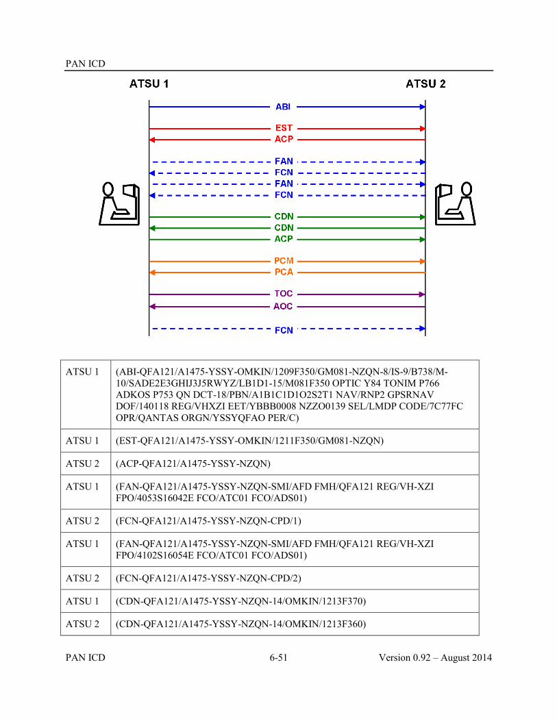
PAN ICD
PAN ICD 6-51 Version 0.92 – August 2014
ATSU 1 (ABI-QFA121/A1475-YSSY-OMKIN/1209F350/GM081-NZQN-8/IS-9/B738/M-10/SADE2E3GHIJ3J5RWYZ/LB1D1-15/M081F350 OPTIC Y84 TONIM P766 ADKOS P753 QN DCT-18/PBN/A1B1C1D1O2S2T1 NAV/RNP2 GPSRNAV DOF/140118 REG/VHXZI EET/YBBB0008 NZZO0139 SEL/LMDP CODE/7C77FC OPR/QANTAS ORGN/YSSYQFAO PER/C)
ATSU 1 (EST-QFA121/A1475-YSSY-OMKIN/1211F350/GM081-NZQN)
ATSU 2 (ACP-QFA121/A1475-YSSY-NZQN)
ATSU 1 (FAN-QFA121/A1475-YSSY-NZQN-SMI/AFD FMH/QFA121 REG/VH-XZI FPO/4053S16042E FCO/ATC01 FCO/ADS01)
ATSU 2 (FCN-QFA121/A1475-YSSY-NZQN-CPD/1)
ATSU 1 (FAN-QFA121/A1475-YSSY-NZQN-SMI/AFD FMH/QFA121 REG/VH-XZI FPO/4102S16054E FCO/ATC01 FCO/ADS01)
ATSU 2 (FCN-QFA121/A1475-YSSY-NZQN-CPD/2)
ATSU 1 (CDN-QFA121/A1475-YSSY-NZQN-14/OMKIN/1213F370)
ATSU 2 (CDN-QFA121/A1475-YSSY-NZQN-14/OMKIN/1213F360)

PAN ICD
Version 0.92 – August 2014 6-52 PAN ICD
ATSU 1 (ACP-QFA121/A1475-YSSY-NZQN)
ATSU 1 (PCM-QFA121/A1475-YSSY-OMKIN/1213F360-NZQN-8/IS-9/B738/M-10/SADE2E3GHIJ3J5RWYZ/LB1D1-15/N0442F360 OPTIC Y84 TONIM P766 ADKOS P753 QN DCT-18/PBN/A1B1C1D1O2S2T1 NAV/RNP2 GPSRNAV DOF/140118 REG/VHXZI EET/YBBB0008 NZZO0139 SEL/LMDP CODE/7C77FC OPR/QANTAS ORGN/YSSYQFAO PER/C))
ATSU 2 (PCA-QFA121/A1475-YSSY-NZQN)
ATSU 1 (TOC-QFA121/A1475-YSSY-NZQN)
ATSU 2 (AOC-QFA121/A1475-YSSY-NZQN)
ATSU 1 (FCN-QFA121/A1475-YSSY-NZQN-CPD/0)
6.6.4.10 Example 10 – Coordination re-negotiation of a revised destination, CPDLC transfer, infringing an adjacent ACI and use of the ADS message
6.6.4.10.1 ATSU 1 transmits a notification message (ABI) to ATSU 2. The ABI contains Estimate data of RUNOD at 0006 at F370.
6.6.4.10.2 ATSU 1 transmits an abbreviated coordination message (EST) to ATSU 2. The proposed coordination contains Estimate data of RUNOD at 0007 at FL370. ATSU 2 accepts the proposed coordination conditions by responding with an ACP.
6.6.4.10.3 After the coordination has been completed, but prior to the transfer of control, the aircraft requests a diversion to a new destination aerodrome (NZAA), which also involves an amended route and estimate data. ATSU 1 proposes an amendment to the proposed coordination by transmitting a negotiation message (CDN) to ATSU 2. The CDN contains new Estimate data of VEPAS at 2357 at FL370. ATSU 2 accepts the revised coordination by responding with ACP (which contains the original destination – NZCH). All subsequent AIDC messages for this aircraft contain “NZAA” as the destination aerodrome.
6.6.4.10.4 ATSU 1 transmits a FAN message to ATSU 2 providing the logon information that ATSU 2 requires to establish a CPDLC connection as well as ADS contracts.
6.6.4.10.5 When an inactive CPDLC connection is established, ATSU 2 transmits an FCN to ATSU 1.
6.6.4.10.6 The amended route now infringes the ACI associated with ATSU 3. ATSU 1 transmits a notification message (ABI) to ATSU 3. The ABI contains Estimate data of VEPAS at 2357 at F370. ATSU 3 previously would have had no flight plan for the aircraft but creates a flight plan from information in the ABI.
6.6.4.10.7 ATSU 1 transmits a coordination message (CPL) to ATSU 3. The proposed coordination contains Estimate data of VEPAS at 2358, at F370. ATSU 3 accepts the proposed coordination without modification by responding with an ACP. Note that the estimates coordinated to ATSU 2 and ATSU 3 differ by 1 minute. There is no requirement for ATSU 1 to re-coordinate the 1 minute revision to ATSU 2, because the discrepancy is less than that prescribed in bilateral agreements.
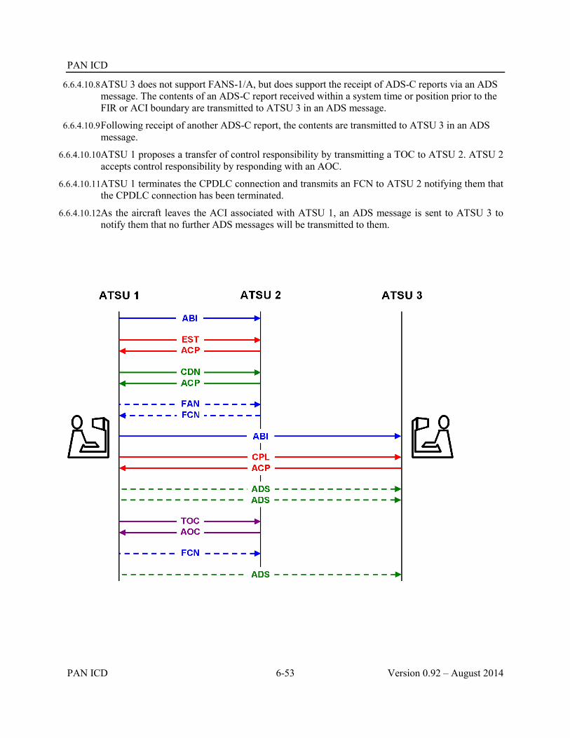
PAN ICD
PAN ICD 6-53 Version 0.92 – August 2014
6.6.4.10.8 ATSU 3 does not support FANS-1/A, but does support the receipt of ADS-C reports via an ADS message. The contents of an ADS-C report received within a system time or position prior to the FIR or ACI boundary are transmitted to ATSU 3 in an ADS message.
6.6.4.10.9 Following receipt of another ADS-C report, the contents are transmitted to ATSU 3 in an ADS message.
6.6.4.10.10ATSU 1 proposes a transfer of control responsibility by transmitting a TOC to ATSU 2. ATSU 2 accepts control responsibility by responding with an AOC.
6.6.4.10.11ATSU 1 terminates the CPDLC connection and transmits an FCN to ATSU 2 notifying them that the CPDLC connection has been terminated.
6.6.4.10.12As the aircraft leaves the ACI associated with ATSU 1, an ADS message is sent to ATSU 3 to notify them that no further ADS messages will be transmitted to them.

PAN ICD
Version 0.92 – August 2014 6-54 PAN ICD
ATSU 1 (ABI-ANZ136-YBBN-RUNOD/0006F370-NZCH-8/IS-9/A320/M-10/SDE1E3FGHIJ3J5M2RW/LB1D1-15/M078F350 DCT SCOTT Y76 SIFRA L503 CH DCT-18/PBN/A1C1D1O1S2T1 REG/ZKOJD EET/NZZO0137 NZZC0239 SEL/HSDG CODE/C816BF OPR/ANZ RMK/TCAS EQUIPPED)
ATSU 1 (EST-ANZ136-YBBN-RUNOD/0007F370-NZCH)
ATSU 2 (ACP-ANZ136-YBBN-NZCH)
ATSU 1 (CDN-ANZ136-YBBN-NZCH-14/VEPAS/2357F370-15/M078F350SCOTT Y32 SIFRA 3314S15941E VEPAS PAPTI AA-DEST/NZAA)
ATSU 2 (ACP-ANZ136-YBBN-NZCH)
ATSU 1 (FAN-ANZ136-YBBN-NZAA-SMI/AFD FMH/ANZ136 REG/ZK-OJD FPO/3320S16004E FCO/ATC01 FCO/ADS01)
ATSU 2 (FCN-ANZ136-YBBN-NZAA-CPD/2)
ATSU 1 (ABI-ANZ136-YBBN-VEPAS/2357F370-NZAA-8/IS-9/A320/M-10/SDE1E3FGHIJ3J5M2RW/LB1D1-15/M078F370 SCOTT Y32 SIFRA 3314S15941E VEPAS PAPTI AA-18/PBN/A1C1D1O1S2T1 REG/ZKOJD EET/NZZO0137 NZZC0239 SEL/HSDG CODE/C816BF OPR/ANZ RMK/TCAS EQUIPPED)
ATSU 1 (CPL-ANZ136-IS-A320/M-SDE1E3FGHIJ3J5M2RW/LB1D1-YBBN-VEPAS/2358F370-M078F370 SCOTT Y32 SIFRA 3314S15941E VEPAS PAPTI AA-NZAA-PBN/A1C1D1O1S2T1 REG/ZKOJD EET/NZZO0137 NZZC0239 SEL/HSDG CODE/C816BF OPR/ANZ RMK/TCAS EQUIPPED)
ATSU 3 (ACP-ANZ136-YBBN-NZAA)
ATSU 1 (ADS-ANZ136-YBBN-NZAA-ADS/.ZK-OJD030207E8D77390B64908A3949D0DE787539F4A090884C8E5B81BB54A0908800E2EB8F77FFC1008025E8E)
ATSU 1 (ADS-ANZ136-YBBN-NZAA-ADS/.ZK-OJD030207E8D77390B64908A3949D0DE787539F4A090884C8E5B81BB54A0908800E2EB8F77FFC1008025E8E)
ATSU 1 (TOC-ANZ136-YBBN-NZAA)
ATSU 2 (AOC-ANZ136-YBBN-NZAA)
ATSU 1 (FCN-ANZ136-YBBN-NZAA-CPD/0)
ATSU 1 (ADS-ANZ136-YBBN-NZAA-ADS/0)
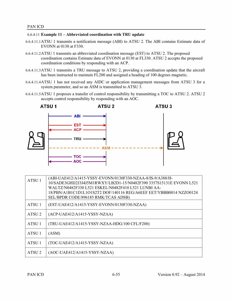
PAN ICD
PAN ICD 6-55 Version 0.92 – August 2014
6.6.4.11 Example 11 – Abbreviated coordination with TRU update
6.6.4.11.1 ATSU 1 transmits a notification message (ABI) to ATSU 2. The ABI contains Estimate data of EVONN at 0130 at F330.
6.6.4.11.2 ATSU 1 transmits an abbreviated coordination message (EST) to ATSU 2. The proposed coordination contains Estimate data of EVONN at 0130 at FL330. ATSU 2 accepts the proposed coordination conditions by responding with an ACP.
6.6.4.11.3 ATSU 1 transmits a TRU message to ATSU 2, providing a coordination update that the aircraft has been instructed to maintain FL200 and assigned a heading of 100 degrees magnetic.
6.6.4.11.4 ATSU 1 has not received any AIDC or application management messages from ATSU 3 for a system parameter, and so an ASM is transmitted to ATSU 3.
6.6.4.11.5 ATSU 1 proposes a transfer of control responsibility by transmitting a TOC to ATSU 2. ATSU 2 accepts control responsibility by responding with an AOC.
ATSU 1 (ABI-UAE412/A1415-YSSY-EVONN/0130F330-NZAA-8/IS-9/A388/H-10/SADE3GHIJ2J3J4J5M1RWXY/LB2D1-15/N0482F390 3357S15131E EVONN L521 WALTZ/N0482F330 L521 ESKEL/N0482F410 L521 LUNBI AA-18/PBN/A1B1C1D1L1O1S2T2 DOF/140116 REG/A6EEF EET/YBBB0014 NZZO0124 SEL/BPDR CODE/896185 RMK/TCAS ADSB)
ATSU 1 (EST-UAE412/A1415-YSSY-EVONN/0130F330-NZAA)
ATSU 2 (ACP-UAE412/A1415-YSSY-NZAA)
ATSU 1 (TRU-UAE412/A1415-YSSY-NZAA-HDG/100 CFL/F200)
ATSU 1 (ASM)
ATSU 1 (TOC-UAE412/A1415-YSSY-NZAA)
ATSU 2 (AOC-UAE412/A1415-YSSY-NZAA)

PAN ICD
Version 0.92 – August 2014 6-56 PAN ICD
6.6.4.12 Example 12 – ACI coordination and use of ADS message
6.6.4.12.1 The route of the aircraft is such that it will enter the airspace of ATSU 2, as well as the ACI associated with ATSU 3.
6.6.4.12.2 ATSU 1 transmits a notification message (ABI) to ATSU 2. The ABI contains Estimate data of 2925S16300E at 0529 descending from F320 to F300. In addition, the aircraft has been cleared to descend to FL290 after passing 26S170E, and to be maintaining FL290 by NILAX. This level restriction is included in Field 15 of the ABI.
6.6.4.12.3 ATSU 1 also transmits a notification message (ABI) to ATSU 3. The ABI contains Estimate data of 2925S16300E at 0529 descending from F320 to F300. This ABI also contains the level restriction described in the previous paragraph.
6.6.4.12.4 ATSU 1 transmits a coordination message (CPL) to ATSU 2. The proposed coordination contains Estimate data of 2925S16300E at 0529 descending from F320 to F300, as well as the level restriction to descend to FL290. ATSU 2 accepts the proposed coordination without modification by responding with an ACP.
6.6.4.12.5 ATSU 1 transmits a coordination message (CPL) to ATSU 3. The proposed coordination contains Estimate data of 2925S16300E at 0529 descending from F320 to F300, as well as the level restriction to descend to FL290. ATSU 3 accepts the proposed coordination without modification by responding with an ACP.
6.6.4.12.6 ATSU 1 transmits a FAN message to ATSU 2 providing the logon information that ATSU 2 requires to establish a CPDLC connection as well as ADS contracts.
6.6.4.12.7 When an inactive CPDLC connection is established, ATSU 2 transmits a FCN to ATSU 1, including the appropriate HF frequency for the aircraft to monitor.
6.6.4.12.8 ATSU 3 does not support FANS-1/A, but does support the receipt of ADS-C reports via an ADS message. The contents of an ADS-C report received within a system time or position prior to the FIR or ACI boundary are transmitted to ATSU 3 in an ADS message.
6.6.4.12.9 ATSU 1 proposes a transfer of control responsibility by transmitting a TOC to ATSU 2. ATSU 2 accepts control responsibility by responding with an AOC.
6.6.4.12.10Following receipt of another ADS-C report, the contents are transmitted to ATSU 3 in an ADS message.
6.6.4.12.11ATSU 1 terminates the CPDLC connection and transmits an FCN to ATSU 2 notifying them that the CPDLC connection has been terminated.
6.6.4.12.12As the aircraft leaves the ACI associated with ATSU 1, an ADS message is sent to ATSU 3 to notify them that no further ADS messages will be transmitted to them.

PAN ICD
PAN ICD 6-57 Version 0.92 – August 2014
ATSU 1 (ABI-FJI930/A4425-YSSY-2925S16300E/0529F300F320B-NFFN-8/IS-9/A332/H-10/SDFGHIJ5LRWXY/LB1D1-15/M081F300 DCT NOBAR B450 ABARB DCT EKIDA DCT 2925S16300E 26S170E/F290/NILAXDCT VIPOB DCT MI DCT-18/PBN/A1L1S2 REG/DQFJV EET/YBBB0009 NFFF0125 SEL/LQJR CODE/C8801A RMK/TCAS EQUIPPED)
ATSU 1 (ABI-FJI930/A4425-YSSY-2925S16300E/0529F300F320B-NFFN-8/IS-9/A332/H-10/SDFGHIJ5LRWXY/LB1D1-15/M081F300 DCT NOBAR B450 ABARB DCT EKIDA DCT 2925S16300E 26S170E/F290/NILAX DCT VIPOB DCT MI DCT-18/PBN/A1L1S2 REG/DQFJV EET/YBBB0009 NFFF0125 SEL/LQJR CODE/C8801A RMK/TCAS EQUIPPED)
ATSU 1 (CPL-FJI930/A4425-IS-A332/H-SDFGHIJ5LRWXY/LB1D1-YSSY-2925S16300E/0529F300F320B-15/M081F300 DCT NOBAR B450 ABARB DCT EKIDA DCT 2925S16300E 26S170E/F290/NILAX DCT VIPOB DCT MI DCT-NFFN-PBN/A1L1S2 REG/DQFJV EET/YBBB0009 NFFF0125 SEL/LQJR CODE/C8801A RMK/TCAS EQUIPPED)
ATSU 2 (ACP-FJI930/A4425-YSSY-NFFN)
ATSU 1 (CPL-FJI930/A4425-IS-A332/H-SDFGHIJ5LRWXY/LB1D1-YSSY-2925S16300E/0529F300F320B-15/M081F300 DCT NOBAR B450 ABARB DCT EKIDA DCT 2925S16300E 26S170E/F290/NILAX DCT VIPOB DCT MI DCT-NFFN-PBN/A1L1S2 REG/DQFJV EET/YBBB0009 NFFF0125 SEL/LQJR CODE/C8801A RMK/TCAS EQUIPPED)

PAN ICD
Version 0.92 – August 2014 6-58 PAN ICD
ATSU 3 (ACP-FJI930/A4425-YSSY-NFFN)
ATSU 1 (FAN-FJI930/A4425-YSSY-NFFN-SMI/AFD FMH/FJI930 REG/DQ-FJV FPO/3038S16014E FCO/ATC01 FCO/ADS01)
ATSU 2 (FCN-FJI930/A4425-YSSY-NFFN-CPD/2 FREQ/5565)
ATSU 1 (ADS-FJI930/A4425-YSSY-NFFN-ADS/.DQ-FJV07E9762B84080753363D9D0DEB15CB9F4A0753075BEC6A33BECE4753000E1631100000103EA91E76)
ATSU 1 (TOC-FJI930/A4425-YSSY-NFFN)
ATSU 2 (AOC-FJI930/A4425-YSSY-NFFN)
ATSU 1 (ADS-FJI930/A4425-YSSY-NFFN-ADS/.DQ-FJV07E9762B84080753363D9D0DEB15CB9F4A0753075BEC6A33BECE4753000E1631100000103EA91E76)
ATSU 1 (FCN-FJI930/A4425-YSSY-NFFN-CPD/0)
ATSU 1 (ADS-FJI930/A4425-YSSY-NFFN-ADS/0)
6.6.4.13 Example 13 – Profile confirmation as a safety net
6.6.4.13.1 Due to an error, notification and coordination to ATSU 2 has not occurred, and the controllers in ATSU 1 and ATSU 2 are unaware of this failure.
6.6.4.13.2 ATSU 1 transmits a PCM to ATSU 2 to confirm that the coordination held by ATSU 2 is correct. ATSU 2 updates their flight plan (if one exists, otherwise a flight plan is created from information in the PCM), and confirms that their coordination is up to date by responding with a PCA. Because coordination had not previously been received, the controller in ATSU 2 is alerted, to prompt them to confirm the coordination with ATSU 1 by other means (e.g. voice).
6.6.4.13.3 ATSU 1 proposes a transfer of control responsibility by transmitting a TOC to ATSU 2. ATSU 2 accepts control responsibility by responding with an AOC

PAN ICD
PAN ICD 6-59 Version 0.92 – August 2014
ATSU 1 (PCM-UAE230/A3152-KSEA-7306N07157W/0602F310-OMDB-8/IS-9/B77W/H-10/SWXRGIDE2E3FHJ3J5M1YZ/LB2D1-15/M083F310 7306N07157W 7330N07000W 7500N06000W 7800N04000W 7800N02000W EXITA P190 INSEP P65 VANOS A74 PELOR G476 UREPI B958 BD BD3T FV R11 GUSLI M54 ADILA N82 ADANO N77 MAGRI UR654 SAV UP574 SYZ G666 ORSAR B416 DESDI-18/PBN/A1B1C1D1L1O1S2T1 NAV/RNVD1A1E2 DOF/131125 REG/A6ECH EET/KZSE0010 CZVR0019 CZEG0049 ENOB0618 ENOR0712 ULMM0730 ULLL0754 ULWW0833 UUWV0855 URRV1010 UGGG1103 UDDD1117 OIIX1136 OMAE1324 SEL/GLBJ RALT/CYXE BIKF RMK/ADSB TCAS)
ATSU 2 (PCA-UAE230/A3152-KSEA-OMDB)
ATSU 1 (TOC-UAE230/A3152-KSEA-OMDB)
ATSU 2 (AOC-UAE230/A3152-KSEA-OMDB)
6.6.4.14 Example 14 – Coordination with a restriction in field 15
6.6.4.14.1 ATSU 1 transmits a notification message (ABI) to ATSU 2. The ABI contains Estimate data of 63N030W at 1732 at F340.
6.6.4.14.2 ATSU 1 transmits a coordination message (CPL) to ATSU 2. The proposed coordination contains Estimate data of 63N030W at 1733 at F340
6.6.4.14.3 ATSU 2 responds by transmitting a negotiation message (CDN) to ATSU 1 proposing (or requesting) an amendment to the proposed coordination to F350 with a restriction that the aircraft must cross 62N040W at F350. ATSU 2 accepts the revised coordination by responding with ACP. The restriction is formatted as “F350/62N040W” in Field 15.
6.6.4.14.4 ATSU 1 transmits a FAN message to ATSU 2 providing the logon information that ATSU 2 requires to establish a CPDLC connection as well as ADS contracts.
6.6.4.14.5 When an inactive CPDLC connection is established, ATSU 2 transmits an FCN to ATSU 1, including the appropriate VHF frequency for the aircraft to monitor.
6.6.4.14.6 ATSU 1 proposes a transfer of control responsibility by transmitting a TOC to ATSU 2. ATSU 2 accepts control responsibility by responding with an AOC.
6.6.4.14.7 ATSU 1 terminates the CPDLC connection and transmits an FCN to ATSU 2 notifying them that the CPDLC connection has been terminated.

PAN ICD
Version 0.92 – August 2014 6-60 PAN ICD
ATSU 1 (ABI-ICE631/A3577-BIKF-63N030W/1732F340-KBOS-8/IS-9/B752/M-10/SDFHIRWXYG/LB1-15/M078F340 63N030W 62N040W 60N050W PORGY HO T-18/PBN/A1L1B2B3B4B5D1S1 DOF/131124 REG/TFFIO EET/FLOSI0021 64N030W0032 CZQX0058 62N040W0115 BGGL0117 60N050W0158 CZQX0203 CZQX0242 CZUL0331 CZQM0400 KZBW0414 SEL/EQFL OPR/ICE RALT/BIKF CYYR)
ATSU 1 (CPL-ICE631/A3577-IS-B752/M-SDFHIRWXYG/LB1-BIKF-63N030W/1733F340-M078F340 63N030W 62N040W 60N050W PORGY HO T-KBOS-PBN/A1L1B2B3B4B5D1S1 DOF/131124 REG/TFFIO EET/FLOSI0021 64N030W0032 CZQX0058 62N040W0115 BGGL0117 60N050W0158 CZQX0203 CZQX0242 CZUL0331 CZQM0400 KZBW0414 SEL/EQFL OPR/ICE RALT/BIKF CYYR)
ATSU 2 (CDN-ICE631/A3577-BIKF-KBOS-15/M078F340 63N030W F350/62N040W 60N050W PORGY HO T)
ATSU 1 (ACP-ICE631/A3577-BIKF-KBOS)
ATSU 1 (FAN-ICE631/A3577-BIKF-KBOS-SMI/AFD FMH/ICE631 REG/TF-FIO FPO/6331N02537W FCO/ATC01 FCO/ADS01)
ATSU 2 (FCN-ICE631/A3577-BIKF-KBOS-CPD/2 FREQ/127.900)
ATSU 1 (TOC-ICE631/A3577-BIKF-KBOS)
ATSU 2 (AOC-ICE631/A3577-BIKF-KBOS)
ATSU 1 (FCN-ICE631/A3577-BIKF-KBOS-CPD/0)

A-1 PAN ICD
PAN ICD A-1 Version 0.92 – August 2014
Appendix A Templates for Bilateral Letter of Agreement on AIDC
At an organizational level, the implementation of AIDC to enable data transfers between automated ATS systems is accomplished under the authority and strict operational terms of a bilateral letter of agreement or memorandum of understanding on AIDC arrangements that must be established between the two ATSUs involved. Depending on the particular circumstances, the legally less sophisticated Memorandum of Understanding (MOU) format could be used for the initial implementation of AIDC until the more formalized Letter of Agreement (LOA) is put in place. The choice of legal instrument will be a decision made by the two ATSUs as they prepare the formal agreement to enable AIDC data transfer between States.
In order to provide guidance in the structure and content of bilateral arrangements, templates have been included in this appendix to assist States in preparing suitable memorandums of understandings/letters of agreement on AIDC arrangements. The templates are based upon documentation developed by Airways New Zealand in implementation evolving AIDC arrangements between Auckland Oceanic and all neighbouring States over a period of approximately 10 years commencing from the mid 1990’s. Three templates are included:
Template 1 provides a generic example of a basic Letter of Agreement
Template 2 is an example of an actual Letter of Agreement between Auckland Oceanic (New Zealand) and Brisbane ATS Centre (Australia); and
Template 3 is an example of an actual Memorandum of Understanding between Auckland Oceanic (New Zealand) and Nadi ATM Operations Centre (Fiji).
The templates are intended as guidance material only. It is important to note that although changes in the AIDC arrangements applicable to Auckland Oceanic will occur over time, Templates 2 and 3 will NOT be routinely updated. Accordingly, as the circumstances for each bilateral implementation will differ, appropriate adjustments should be made to the content of the templates to ensure that the resulting MOU or LOA is fit for the purpose intended.

A-2 PAN ICD
Version 0.92 – August 2014 A-2 PAN ICD
Template 1
Generic Letter of Agreement
AIDC Procedures
1. The format of AIDC messages (List messages used e.g. ABI, PAC, CDN, CPL, ACP, REJ, MAC, LAM and LRM) are as defined by the Pan Regional (NAT and APAC) AIDC Interface Control Document (ICD) as amended from time to time, unless described otherwise in this LOA.
2. List messages not supported (e.g. “EST, TOC, AOC messages are not supported”).
3. Acceptance of CPL or CDN message is approval of the flight’s profile and requires no further voice communication (i.e. Non-Standard Altitudes, Block Altitudes, and Deviations).
4. (Describe other procedures applicable to the use of AIDC for this LOA. Some examples are listed below)
a. Example only. If there is any doubt with regard to the final coordination data, voice coordination should be used for confirmation.
b. Example only. Receipt of a MAC message must not be interpreted as meaning that the flight plan has been cancelled. Voice coordination must be conducted by the transferring controller to confirm the status of the flight.
c. Example only. Each facility should advise the other facility of any known equipment outage that affects AIDC. In the event of AIDC outage, voice communication procedures will apply.
d. Example only. Truncation. Where route amendment outside the FIR is unavoidable.
i. Terminate the route details at the farthest possible flight plan significant point of the flight and enter “T” immediately following this.
ii. Without amending the originally received details, every effort is to be made to truncate the route at a minimum of one significant point beyond the adjacent FIR to provide an entry track in that FIR.
AIDC Messages
(For each message used describe when it will be sent by each ATSU under the parameter column and use the Notes column to describe other applicable information for the message use by each ATSU. The data below provides an example of the type of information that could be incorporated.)
Messages Parameter Notes
ABI ATSU1: Sends ABI approx. 80 minutes prior to boundary (73 min prior to the 50 nm expanded sector boundary).
ATSU2: Sends ABI approx. 87 minutes prior to boundary (80 min prior to the 50 nm expanded sector
ATSU1 : ATSU2
Updated ABI’s will be sent automatically if there is any change to profile. ABI is sent automatically and is transparent to the controller. ABI automatically updates the receiving unit’s flight data record.

PAN ICD A-3
PAN ICD A-3 Version 0.92 – August 2014
boundary).
(Note: An updated ABI will not be sent once a CPL has been sent.)
CPL ATSU1 : ATSU2
Send CPL messages approx 37 minutes prior to the boundary (30 minutes prior to the 50 nm expanded sector boundary).
ATSU1 : ATSU2
CPL messages should be sent by the transferring controller in sufficient time to allow the completion of coordination at least 30 minutes prior to the boundary or 30 minutes prior to the aircraft passing within 50nmof the FIR boundary for information transfers.
CDN ATSU1 : ATSU2
CDN messages are sent by either the transferring or receiving facility to propose a change once the coordination process has been completed, i.e., CPL sent and ACP received. CDN’s must contain all applicable profile restrictions (e.g. weather deviations, speed assignment, block altitude). If the use of a CDN does not support this requirement, then verbal coordination is required.
ATSU1 : ATSU2
The APS will display a flashing “DIA” until receipt of ACP. If ACPJ not received within ten (10) minutes, controller is alerted with a message to the queue.
CDN messages are not normally used for coordination of reroutes; however, with the receiving facilities approval a CDN may be used to coordinate a reroute on a critical status aircraft such as in an emergency.
PAC ATSU1 : ATSU2
PAC messages will normally be sent when the time criteria from the departure point to the boundary is less than that stipulated in the CPL.
ATSU1 : ATSU2
Will respond to a PAC message with an ACP. PAC messages should be verbally verified with receiving facility.
ACP ATSU1 : ATSU2
ATSU1 : ATSU2
The APS will display a flashing “DIA” until receipt of ACP. If ACP not received within ten (10) minutes, controller is alerted with a message to the queue.
TOC ATSU1 : ATSU2
Not supported. Implicit hand in/off.
ATSU1 : ATSU2
AOC ATSU1 : ATSU2
Not supported. Implicit hand in/off.

A-4 PAN ICD
Version 0.92 – August 2014 A-4 PAN ICD
MAC ATSU1 : ATSU2
MAC messages are sent when a change to the route makes the other facility no longer the “next” responsible unit.
ATSU1 : ATSU2
Receipt of a MAC message must not be interpreted as meaning that the flight plan has been cancelled. Voice coordination must be conducted by the transferring controller to confirm the status of the flight.
REJ ATSU1 : ATSU2
REJ messages are sent in reply to a CDN message when the request change is unacceptable
ATSU1 : ATSU2
REJ messages are sent only as a response to a CDN message.

PAN ICD A-5
PAN ICD A-5 Version 0.92 – August 2014
Template 2
Example: Auckland Oceanic – Brisbane ATS Centre
Letter of Agreement
Coordination – General
Transfer of The Transfer of Control Point (TCP) should be either on receipt of an Acceptance Control Point of Control (AOC) to a Transfer of Control (TOC) or the common FIR boundary,
whichever occurs first. The TCP should also be the point of acceptance of primary
guard.
All ATS units should coordinate an estimate for the FIR boundary at least thirty (30) minutes prior to the boundary. Such coordination constitutes an offer of transfer of responsibility.
After the estimate for the FIR boundary has been sent, units should coordinate any revised estimate that varies by 3 minutes or more.
_________________________________________________________________
Communication Use of communications systems coordination between adjacent units should be in the Systems following order of priority:
a. ATS Interfacility Data Communication (AIDC)
b. AIDC messages and procedures are specified in the following sections;
c. ATS direct speech circuits;
d. International telephone system;
e. Any other means of communication available.
AIDC Messages AIDC message format will be in accordance with the Asia/Pacific/North Atlantic Regional Interface Control Document (ICD), as amended from time to time, unless described otherwise in the LOA.
Successful coordination via AIDC occurs on receipt of an ACP message in response to an EST message.
Each centre should advise the other of any known equipment outage that affects AIDC.
AIDC Message The following table details the AIDC parameters and message to be used.

A-6 PAN ICD
Version 0.92 – August 2014 A-6 PAN ICD
Parameters
Message Parameter Notes
ABI EUROCAT: 5-60 minutes prior to COP (Note: An updated ABI will not be sent once an EST has been sent)
OCS: 40 minutes prior 50nm expanded boundary
ABI is sent automatically and is transparent to controller. ABI automatically updates flight plan.
EST EUROCAT: 40 minutes prior to COP
OCS: 40 minutes prior 50mn expanded boundary
Any changes to EST level or estimate conditions as detailed in LOA to be notified by voice after initial coordination completed. See notes below on voice procedures. EST is required to track generation in EUROCAT.
ACP EUROCAT: Sends automatic ACP on receipt of EST
OCE: Sends automatic ACP on receipt of EST
EUROCAT: If ACP not received within 4 minutes the sending controller is alerted. Sending controller will initiate voice coordination if ACP is not received within 4 minutes of sending EST.
Receiving controller will initiate voice coordination if proposed EST conditions are not acceptable.
OCS: If ACP is not received within 5 minutes the sending controller is alerted. Sending controller will not initiate voice coordination if ACP is not received within 5 minutes of sending EST. Receiving controller will initiate voice coordination if proposed EST conditions are not acceptable.
TOC EUROCAT: Sent automatically 5 minutes prior to boundary
OCS: Sent automatically 2 minutes prior to boundary
AOC EUROCAT: Sent automatically on controller acceptance of a TOC
OCS: Sent automatically on receipt of a TOC
Continued to next page

PAN ICD A-7
PAN ICD A-7 Version 0.92 – August 2014
AIDC Message (continued)
Coordination - General
Parameters
Message Parameter Notes
CDN EUROCAT: Manually by the controller when required
Responses to the CDN should be ACP or REJ only – there will be no CDN negotiations.
CDN messages will be sent by Brisbane only to revise coordination on eastbound flights.
CDN messages may be used to coordinate changes to estimate or assigned altitude only.
Only on CDN dialogue may be open per aircraft at any time.
Not to be used if the aircraft will not be maintaining the assigned altitude 10 minutes prior to the TCP.
MAC As per ICD
LRM As per ICD. Controller alerted on receipt
LAM As per ICD. Controller alerted on non-receipt
Amendment to Route amendment – routes/waypoints may be added/deleted as long as they do not Flight Data change the original intent or integrity of the flight plan information.
Record
Truncation – where route amendment outside the FIR unavoidable:
a. Terminate the route details at the farthest possible ‘flight planned’ point of the flight outside the FIR and enter “T” immediately following this.
b. If insufficient ‘flight planned’ point exist outside the FIR for truncation, insert the first ‘defined’ point in the adjoining FIR and enter “T” immediately following this.
c. The minimum acceptable truncation point must be at least the first point in the adjoining FIR.
d. Every effort is to be made to truncate the route at a minimum of one point beyond the adjacent international FIR to provide an entry track in to that FIR.
Continued on next page

A-8 PAN ICD
Version 0.92 – August 2014 A-8 PAN ICD
Coordination – General, Continued
Address Brisbane ATSC and Auckland OAC should send automatic Next Data Authority
Forwarding (NDA) and Address Forwarding (CAD) for data link aircraft as per the following
And Next Data table:
Authority
Brisbane ATSC Auto NDA sent 22 minutes prior to the FIR boundary
Auto CAD sent 20 minutes prior to the FIR boundary
Auckland OAC Auto NDA sent 40 minutes prior to the FIR boundary
Auto CAD sent 35 minutes prior to the FIR boundary
________________________________________________________________________
Voice Voice coordination is not required when AIDC messaging has been successful to Coordination offer and accepts transfer of control.
However, the receiving controller will initiate voice coordination if the proposed AIDC EST conditions are not acceptable.
If AIDC messaging is not to be sent following voice coordination, it should be stated as part of the voice coordination by use of the phrase “AIDC messaging will not be sent”. A read back is required.
Voice Coordination is required for aircraft operating under any of the following conditions:
block level clearance;
weather deviations;
offset track; or
Mach Number technique.
Read backs should comprise all elements of the voice coordination passed by the transferring controller. Read back by the receiving unit confirms acceptance of the offer of transfer of control subject to any other conditions negotiated.
_________________________________________________________________
Hemstitch A hemstitch flight is any flight that will remain within the New Zealand FIR for Flights less time than the NDA VSP (40 minutes) prior to the flight entering the
Brisbane FIR.
Auckland AOC should voice coordinate any hemstitch flight.
Continued on next page

PAN ICD A-9
PAN ICD A-9 Version 0.92 – August 2014
Coordination – General, Continued
________________________________________________________________________
Near Boundary ATS units should relay significant details of any flight which is, or intends Operations operating within fifty nautical miles (50NM0 of the common FIR boundary.
________________________________________________________________________
HF Frequencies Brisbane ATC and Auckland ATC should update each other as to the current voice backup frequency for use by ATC data link equipped aircraft.

A-10 PAN ICD
Version 0.92 – August 2014 A-10 PAN ICD
Template 3
Example: Auckland Oceanic – Nadi ATM Operations Centre
Memorandum of Understanding
Between
Airways New Zealand Limited
And
Nadi ATM Operations Centre
Subject Air Traffic Services Inter-facility Data Communications (AIDC) Coordination Procedures
_______________________________________________________________________
Validity Period This Memorandum of Understanding should be effective from 0506300300 UTC and may be cancelled by either party with written notice.
_______________________________________________________________________
Signatories The following signatories have ratified this Agreement:
Authority Signature Date
(Name of Officer)
Oceanic Business Unit Manager Airways New Zealand
(Name of Officer)
Manager, Operations Strategic Air
Services Limited
Fiji
(Name of Officer)
Chairman, ATM Projects Committee, Airports Fiji Limited
Fiji
Continued on next page
Memorandum of Understanding, Continued

PAN ICD A-11
PAN ICD A-11 Version 0.92 – August 2014
Purpose To establish procedures to permit AIDC messages for coordination purposes to be transmitted by Auckland Oceanic and received by Nadi Air Traffic Management Operations Centre (ATMOC).
_________________________________________________________________
Scope This MOU between Auckland and Nadi is supplementary to the procedures contained in the Airways Corporation of New Zealand Limited and Airport Fiji Limited LOA, dated 25 November 2004. Revision to this MOU should be made only with the concurrence of all parties.
_________________________________________________________________
Procedures The format of AIDC messages (ABI, EST, PAC, CDN, CPL, ACP, REJ, TOC, AOC, MAC, LAM and LRM) is defined by the Asia/Pacific/North Atlantic Regional AIDC Interface Control Document (ICD) version 2.0. The optional formats for the coordination of block levels, weather deviations and Mach Number Technique have not been implemented.
Each facility should advise the other facility of any known equipment outage that will affect AIDC. In the even of AIDC outage, voice coordination procedures will apply.
The following table details the messaging parameters and additional information for each message.
Message Parameter Notes
ABI
Non Hem-stitching flights
Auckland: Sends ABI 48 minutes prior to boundary
(Note: An updated ABI will no be sent once an EST has been sent)
Updated ABIs will be sent automatically if there is any change to profile. ABI is sent automatically and is transparent to the controller. ABI automatically updates the receiving units flight data record
EST
(general)
Non Hem-stitching flights
Auckland: Sends EST 38 minutes prior to boundary
EST is sent automatically and automatically coordinates the receiving unit’s flight data record. Any change to the EST (level or estimate) conditions as detailed in LOA are to be notified by voice after the initial coordination completed. See section below on voice procedures
ABI & EST
Hem-stitch flights
Auckland: Sends ABI & EST messages for flights that re-enter the Nadi FIR as soon as the aircraft enters NZZO FIR
In these cases the ABI and EST are sent automatically
PAC Auckland: Voice coordination will take place in those situations when a PAC is sent
Continued on next page

A-12 PAN ICD
Version 0.92 – August 2014 A-12 PAN ICD
Memorandum of Understanding, Continued
Message Parameter Notes
ACP Auckland: Sent automatically on receipt of EST
Nadi: Sent automatically on receipt of EST or PAC
Auckland: The APS will display a flashing “DIA” until receipt of ACP. If ACP not received within ten (10) minutes, controller is alerted with a message to the queue
TOC Auckland: Sent automatically 2 minutes prior to boundary
This proposes a hand-off to the receiving unit
AOC Auckland: Sent automatically on receipt of TOC
Nadi: Sent by the controller on acceptance of TOC
This completes the hand-off proposal
MAC Auckland: Sent manually when a change to the route makes Nadi no longer the “next” responsible unit
Receipt of a MAC message should not be interpreted as meaning that the flight plan has been cancelled. Voice coordination should be conducted by the receiving controller to confirm the status of the flight
Procedures, Block levels, offsets, and weather deviations, or Mach Number Techniques are Continued not included in the current version of AIDC messaging. Voice coordination should
be conducted for aircraft operating under these circumstances.
If there is any doubt with regard to the final coordination conditions, voice coordination should be used for confirmation.
Truncation – Where route amendment outside the FIR is unavoidable:
Terminate the route details at the farthest possible ‘flight planned’ point of the flight and enter “T” immediately following this.
Without amending the originally received details, every effort is to be made to truncate the route a minimum of one point beyond the adjacent FIR to provide an entry track in to that FIR
For any reason where changes to this MOU are advisable the requesting unit should propose the pertinent revision. The revision should be emailed of faxed to the

PAN ICD A-13
PAN ICD A-13 Version 0.92 – August 2014
appropriate Manager for action. The Manager or the designated deputies should agree by email or telephone, followed by a confirming fax message signed by all parties. Formal exchange of signed copies of the amended MOW should take place as soon as practicable thereafter.
Hemstitch A Hemstitch flight is any flight that vacates FIR 1 and transits FIR 2 before re-
Flights entering FIR 1.
When a hemstitching flight vacates FIR 1 and then re-enter FIR 2 30 minutes or less later, the re-entry coordination is considered to have been completed when coordination for the initial entry is completed and further coordination is only required if the aircraft requests:
A weather deviation, or
A level change, or
Any change to the EST time is received or
If there is any doubt that the receiving FIR has the correct boundary information
AIDC messages (ABI and EST) will still be sent by Auckland, but only when the aircraft flight state becomes active control. For hem stitching flights this will usually be when the aircraft enters the NZZO FIR, therefore these messages will normally be sent at less that 30 minutes prior to the TCP.
Voice The following is provided as a summary of occasions when voice coordination is
Coordination required:
In the event of an AIDC outage;
Aircraft operating under any of the following conditions:
o Block level clearance;
o Unfulfilled time constraints;
o Weather deviations;
o Offset track; or
o Mach Number technique
Any change to the EST (level or time) conditions;
On receipt of a warning that an ACP has not been received;
On receipt of a MAC message;
If there is any doubt with regard to the final coordination conditions;
Continued on next page
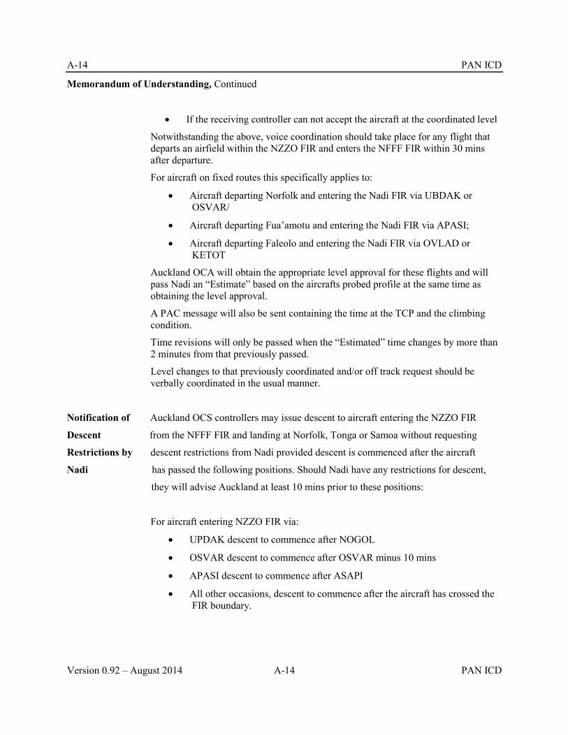
A-14 PAN ICD
Version 0.92 – August 2014 A-14 PAN ICD
Memorandum of Understanding, Continued
If the receiving controller can not accept the aircraft at the coordinated level
Notwithstanding the above, voice coordination should take place for any flight that departs an airfield within the NZZO FIR and enters the NFFF FIR within 30 mins after departure.
For aircraft on fixed routes this specifically applies to:
Aircraft departing Norfolk and entering the Nadi FIR via UBDAK or OSVAR/
Aircraft departing Fua’amotu and entering the Nadi FIR via APASI;
Aircraft departing Faleolo and entering the Nadi FIR via OVLAD or KETOT
Auckland OCA will obtain the appropriate level approval for these flights and will pass Nadi an “Estimate” based on the aircrafts probed profile at the same time as obtaining the level approval.
A PAC message will also be sent containing the time at the TCP and the climbing condition.
Time revisions will only be passed when the “Estimated” time changes by more than 2 minutes from that previously passed.
Level changes to that previously coordinated and/or off track request should be verbally coordinated in the usual manner.
Notification of Auckland OCS controllers may issue descent to aircraft entering the NZZO FIR
Descent from the NFFF FIR and landing at Norfolk, Tonga or Samoa without requesting
Restrictions by descent restrictions from Nadi provided descent is commenced after the aircraft
Nadi has passed the following positions. Should Nadi have any restrictions for descent,
they will advise Auckland at least 10 mins prior to these positions:
For aircraft entering NZZO FIR via:
UPDAK descent to commence after NOGOL
OSVAR descent to commence after OSVAR minus 10 mins
APASI descent to commence after ASAPI
All other occasions, descent to commence after the aircraft has crossed the FIR boundary.

PAN ICD B-1
PAN ICD B-1 Version 0.92 – August 2014
Appendix B Regionally Specific Messages
B.1 TDM (TRACK DEFINITION MESSAGE)
B.1.1 Purpose.
B.1.1.1 Used to distribute Pacific track information to affected ATSUs and Aeronautical Operational Control (AOCs) for flight planning.. The message contains track definition and activity time periods.
B.1.2 Message Format.
B.1.2.1 Track Name. The track name consists of two fields. The first field is always ‘TRK’. The second field is the track identifier. The track identifier consists of 1 to 4 alphanumeric characters.
B.1.2.2 General Information. General information contains:
a. Date and time the track was generated and message number tor that particular track in YYMMDDHHMMNN format where NN represents the message number. The initial TDM date/time message number group will look like: 941006134501. Message numbers 02 to 99 indicate TDM amendments or revisions. Note that an additional preceding zero may be required to provide the correct number of digits. b. Track status. Blank field for initial message or “AMDT” for amendment.
B.1.2.3 Activity Time Interval. This field consists of two date/time pairs, separated by a blank character, in the following format: YYMMDDHHMM YYMMDDHHMM.
The first date/time pair represents the track activation, while the second is the track termination date/time.
Example: 9410070300 9410071500.
This example represents an activation date/time of October 7, 1994, at 0300 UTC and a termination date/time of October 7, 1994 at 1500 UTC.
B.1.2.4 Track Waypoint. This field contains the set of waypoints defining the track from the ingress fix to the egress fix. Waypoints are represented as latitude/longitude or named en route points. Waypoints are separated from each other by a blank space. Note that an additional preceding zero may be required to provide the correct number of digits For example:
60N150W 60N160W, or NORMU NUMMI, or FINGS 5405N13430W, etc.
B.1.2.5 Optional Fields
a. Level: This optional field will not be used in the Pacific operations since levels are published in separate documents, e.g. Pacific SUPPS (Doc 7030) . A rack level list may be specified for the east and westbound directions of flight and a track level list would contain the complete list of levels available on the track for the specified direction of flight. The levels would apply to all waypoints in the track waypoint list. b. Connecting routes (RTS): The RTS field is an optional field not normally used by automated ATS systems. When used, it is located after the waypoint list (before the remarks
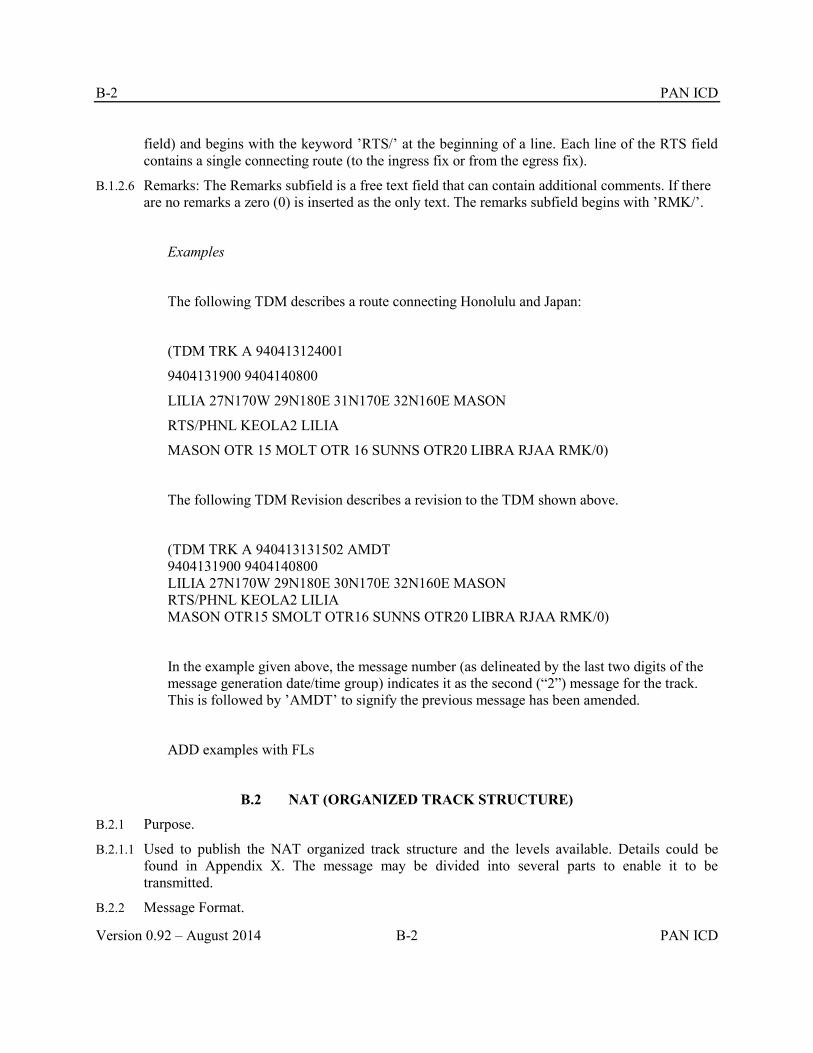
B-2 PAN ICD
Version 0.92 – August 2014 B-2 PAN ICD
field) and begins with the keyword ’RTS/’ at the beginning of a line. Each line of the RTS field contains a single connecting route (to the ingress fix or from the egress fix).
B.1.2.6 Remarks: The Remarks subfield is a free text field that can contain additional comments. If there are no remarks a zero (0) is inserted as the only text. The remarks subfield begins with ’RMK/’.
Examples
The following TDM describes a route connecting Honolulu and Japan:
(TDM TRK A 940413124001
9404131900 9404140800
LILIA 27N170W 29N180E 31N170E 32N160E MASON
RTS/PHNL KEOLA2 LILIA
MASON OTR 15 MOLT OTR 16 SUNNS OTR20 LIBRA RJAA RMK/0)
The following TDM Revision describes a revision to the TDM shown above.
(TDM TRK A 940413131502 AMDT 9404131900 9404140800 LILIA 27N170W 29N180E 30N170E 32N160E MASON RTS/PHNL KEOLA2 LILIA MASON OTR15 SMOLT OTR16 SUNNS OTR20 LIBRA RJAA RMK/0)
In the example given above, the message number (as delineated by the last two digits of the message generation date/time group) indicates it as the second (“2”) message for the track. This is followed by ’AMDT’ to signify the previous message has been amended.
ADD examples with FLs
B.2 NAT (ORGANIZED TRACK STRUCTURE)
B.2.1 Purpose.
B.2.1.1 Used to publish the NAT organized track structure and the levels available. Details could be found in Appendix X. The message may be divided into several parts to enable it to be transmitted.
B.2.2 Message Format.

PAN ICD B-3
PAN ICD B-3 Version 0.92 – August 2014
ATS Field Description
3 Message type
Text Structured text
B.2.3 Structured Text Format.
B.2.3.1 It is required to adhere strictly to the syntax described hereafter in order to facilitate automated processing of NAT messages.
B.2.3.2 In the examples below, text between angle brackets should be understood to represent characters by their ASCII name. E.g. <sp> stands for ‘space character’, <cr> for ‘carriage return>, <lf> for ‘line feed’, and any combination <crlf> is the same as <cr><lf>. No control character should be inserted in the message text unless specified as in the examples below. This restriction of course applies to <cr> and <lf> as well as any other control character.
B.2.3.3 It should be noted that NAT Track messages should otherwise follow current AFTN syntax requirements as expressed in ICAO Annex 10, , e.g. that the alignment function with the message text, header and trailer is composed of a single <cr> followed by a single <lf>. However modern systems should also be able to process the older alignment function composed of a double <cr> followed by a single <lf> as if it were a single <cr> followed by a single <lf> for backward compatibility reasons and to facilitate transition.
B.2.3.4 Characters in bold underlined in Message Text (syntax) column are to be replaced or dealt with as explained in the Description column.
B.2.3.5 The structured text is first composed of a NAT message header, as follows:
Id Message Text (syntax) Description (semantics)
1 (NAT-a/b<sp> a designates the part number in the b parts of the NAT
TRACKS<sp> message (a and b are one decimal digit)
2 FLS<sp>nnn/mmm nnn and mmm designating the minimum and maximum
<sp>INCLUSIVE concerned flight levels in hundreds of feet (three decimal digits)
3 <crlf>
4 month<sp>d1/h1m1Z Validity time with:
<sp>TO<sp> month: for the month of validity full month name in letters
month<sp>d2/h2m2Z d1/h1m1: beginning time of validity
d2/h2m2: ending time of validity(day/hour minute,

B-4 PAN ICD
Version 0.92 – August 2014 B-4 PAN ICD
2 digits each, no space, leading zero required if number
is less than 10)
5 <crlf>
6 PART<sp>a a and b textual numbers (ONE, TWO, THREE, FOUR) or one decimal <sp>OF<SP> digit. Both numbers should represent the same digits as referred to in item Id 1 above.
b<sp> PARTS- Terminal character S may be omitted if b is ONE.
7 <crlf><crlf>
B.2.3.6 Following the NAT message header is a repeat of the following structure for each North Atlantic Track part of the message. If the resulting NAT message text is longer than 1800 characters, it must be separated into as many parts as necessary. Separation must happen between individual North Atlantic Track descriptions, not within an individual description.
Id Message Text (syntax) Description (semantics)
8 L letter designating the name of the NAT track.
One of:
ABCDEFGHIJKLM for Westbound tracks. The most northerly Track of the day is designated as NAT Track Alpha, the adjacent Track to the south as NAT Track Bravo, etc.
NPQRSTUVWXYZ for Eastbound tracks The most southerly Track of the day is designated as NAT Track Zulu, the adjacent Track to the north as NAT Track Yankee, etc.
Tracks must be defined in sequence starting at any letter in the appropriate set, each following track using the immediately following letter in that set, e.g. UVWXYZ or ABCDE etc.
The first track in the message should be the most northerly one and each subsequent track should be the next one towards the south.

PAN ICD B-5
PAN ICD B-5 Version 0.92 – August 2014
9 <sp>
10 list of points Each point, separated by a space, is either significant points (named points from the published ICAO list of fixes) or a LAT/LONG given in degrees or degrees and minutes. At present only whole degrees are used.
Acceptable LAT/LONG syntaxes are:
xx/yy
xxmm/yy
xx/yymm
xxmm/yymm
Where xx is the north latitude, yy the west longitude, and mm the minutes part of the latitude or longitude.
11 <crlf>
12 EAST LVLS<sp>List list the allowed flight levels for eastbound flights. This list can of allowed levels contain NIL if there is no allowed level or a list of numbers (3
decimal digits) for each allowed level separated by a space.
13 <crlf>
14 West LVLS<sp>List list the allowed flight levels for westbound flight. This list can
of allowed levels contain NIL if there is no allowed level or a list of numbers (3
decimal digits) for each allowed level separated by a space.
15 <crlf>
16 EUR<sp>RTS<sp> (optional field)
WEST<sp>XXX <sp> Note that the indentation does not indicate the presence of

B-6 PAN ICD
Version 0.92 – August 2014 B-6 PAN ICD
VIA<sp>RP space characters, it is a presentation mechanism to highlight
two variant syntaxes for this field.
OR
EUR<sp>RTS<sp> Description of European links to the tracks, this
WEST<sp> NIL description will be given separately for Eastbound and/or
Westbound flights.
XXX designating the Irish/UK route structure linked to the
NAT track.
RP designating the point recommended to be over flown by
westbound flights for joining the NAT track.
The text “VIA<sp>RP” is optional.
Or
There is no European link.
17 <crlf>
18 NAR<sp>list (optional)
OR Description of North American links to the tracks list
NAR<sp>NIL list of North American airways recommended to be
overflown by flights for joining or leaving the NAT track
Or
There are no recommended North American airways
19 -
20 <crlf><crlf>

PAN ICD B-7
PAN ICD B-7 Version 0.92 – August 2014
B.2.3.7 And to terminate the NAT message is composed of a trailer
Id Message Text (syntax) Description (semantics)
21 <crlf>
22 REMARKS<crlf>text This field is optional and can only be present in the last part
<crlf> of a multipart NAT message, or in the unique part in case of a
mono-part NAT message.
The remark text must contain the Track Message Identifier
(TMI).
It is recommended to consistently place the TMI in the first remark.
The syntax for the TMI is as follows:
Any text may precede the keywords that identify the TMI.
The TMI is recognised as the first occurrence of the string (without the quotes) “TMI<sp>IS<sp>xxx” is the TMI and “a” the optional track message revision letter.
To facilitate automated processing, this string should be followed by a space character before any subsequent remark text is inserted in the track message.
The TMI should be the Julian calendar day in the year – i.e. starting at one (001) on the first of January or each year, 002 for second of January etc.
23 END<sp>OF<sp>PART a and b textual numbers (ONE, TWO, THREE, FOUR) or one
<sp>a<sp>OF<sp>b decimal digit.
<sp>PARTS) Both numbers must be the same as in field 6 above.
Terminal character S may be omitted if b is ONE.
B.2.3.8 Example of westbound message set.
(NAT-1/3 TRACKS FLS 310/390 INCLUSIVE JULY 01/1130Z TO JULY 01/1800Z PART ON OF THREE PARTS- A 57/10 59/20 61/30 62/40 62/50 61/60 RODBO EAST LVLS NIL WEST LVLS 320 340 360 380

B-8 PAN ICD
Version 0.92 – August 2014 B-8 PAN ICD
EUR RTS WEST NIL NAR N498C N4996C N484C- B 56/10 58/20 60/30 61/40 60/50 59/60 LAKES EAST LVLS NIL WEST LVLS 310 330 350 370 390 EUR RTS WEST 2 NAR N434C N428C N424E N416C C 55/10 57/20 59/30 60/40 59/50 PRAWN YDP EAST LVLS NIL WEST LVLS 310 32 330 340 350 360 370 380 390 EUR RTS WEST NIL NAR N322B N326B N328C N336H N346A N348C N352C N356C N362B- D MASIT 56/20 58/30 59/40 58/50 PORGY HO EAST LVL NIL WEST LVLS 310 320 330 340 350 360 370 380 390 EUR RTS WEST DEVOL NAR N284B N292C N294C N298H N302C N304E N306C N308E N312A- E 54/15 55/20 57/30 57/40 56/50 SCROD VALIE EAST LVLS NIL WEST LVLS 310 320 330 340 350 360 370 380 390 EUR RTS WEST BURAK NAR N240C N248C N250E N252E N254A N256A N258A N260A- END OF PART ONE OF THREE PARTS (NAT-2/3 TRACKS FLS 310.390 INCLUSIVE JULY 01/1130Z TO JULY 01/1800Z PART TWO OF THREE PARTS F 53/15 54/20 56/30 56/40 55/50 OYSTR STEAM EAST LVLS NIL WEST LVLS 310 320 330 340 350 360 370 380 390 EUR RTS WEST GUNSO NAR NIL- END OF PART TWO OF THREE PARTS) (NAT-3/3 TRACKS FLS 310/390 INCLUSIVE JULY 01/1130Z TO JULY 01/1800Z PART THREE OF THREE PARTS-

PAN ICD B-9
PAN ICD B-9 Version 0.92 – August 2014
H BANAL 43/20 44/30 44/40 43/50 JEBBY CARAC EAST LVLS NIL WEST LVLS 310 350 370 EUR RTS WEST DIRMA NAR N36E N44B-
REMARKS
1. TMI IS 182 AND OPERATORS ARE REMINDED TO INCLUDE THE TMI NUMBER AS PART OF THE OCEANIC CLEARANCE READ BACK.
2. OPERATORS ATTENTION IS DRAWN TO CZUL NOTAM A2152/01
3. OPERATORS ATTENTION IS DRAWN TO UK NOTAMS A1098/01 AND G0120/01
4. MNPS AIRSPACE EXTENDS FROM FL285 TO FL420. OPERATORS ARE REMINDED THAT SPECIFIC MNPS APPROVAL IS REQUIRED TO FLY IN THIS AIRSPACE. IN ADDITION, RVSM APPROVAL IS REQUIRED TO FLY BETWEEN FL310 AND FL390 INCLUSIVE.
5. EIGHTY PERCENT OR GROSS NAVIGATION ERRORS RESULT FROM POOR COCKPIT PROCEDURES. ALWAYS CARRY OUT PROPER WAY POINT CHECKS.-
END OF PART THREE OR THREE PARTS)
B.2.3.9 Example of eastbound message set.
(NAT-1/1 TRACKS FLS 310/390 INCLUSIVE JULY 01/0100Z TO JULY 01/0800Z PART ONE OF ONE PART- V YAY 53/50 54/40 55/30 56/20 56/10 MAC EAST LVLS 310 320 330 340 350 360 370 380 390 WEST LVLS NIL NAR N125A N129B- W DOTTY 52/50 53/40 54/30 55/20 55/10 TADEX EAST LVLS 310 320 330 340 350 360 370 380 390 WEST LVLS NIL EUR RTS WEST NIL NAR N109E N113B- X CYMON 51/50 52/40 53/30 54/20 54/15 BABAN EAST LVLS 310 320 330 340 350 360 370 380 390 WEST LVLS NIL EUR RTS WEST NIL NAR N93B N97B-

B-10 PAN ICD
Version 0.92 – August 2014 B-10 PAN ICD
Y YQX 50/50 51/40 52/30 53/20 53/15 BURAK EAST LVLS 310 320 330 340 350 360 370 380 390 WEST LVLS NIL EUR RTS WEST NIL NAR 77B N83B- Z VIXUN 49/50 50/40 51/30 52/20 52/15 DOLIP EAST LVLS 310 320 330 340 350 360 370 380 390 WEST LVLS NIL EUR RTS WEST NIL NAR 61B N67B-
REMARKS:
1. TMI IS 182 AND OPERATORS ARE REMINDED TO INCLUDE THE TMI NUMBER AS PART OF THE OCEANIC CLEARANCE READ BACK.
2. CLEARANCE DELIVERY FREQUENCY ASSIGNMENTS FOR AIRCRAFT OPERATING FROM MOATT OT BOBTU INCLUSIVE: MOATT – SCROD 128.7 OYSTR – DOTTY 135.45 CYMON – YQX 135.05 VIXUN – COLOR 128.45 BANCS AND SOUTH 119.42
3. PLEASE REFER TO INTERNATIONAL NOTAMS CZUL A2152/01
4. MNPS AIRSPACE EXTENDS FROM FL285 TO FL420. OPERATORS ARE REMINDED THAT SPECIFIC MNPS APPROVAL IS REQUIRED TO FLY IN THIS AIRSPACE. IN ADDITION, RVSM APPROVAL IS REQUIRED TO FLY WITHIN THE NAT REGIONS BETWEEN FL310 AND FL390 INCLUSIVE.
5. 80 PERCENT OF GROSS NAVIGATIONAL ERRORS RESULT FROM POOR COCKPIT PROCEDURES. ALWAYS CARRY OUT PROPER WAYPOINT CHECKS.
6. REPORT NEXT WAYPOINT DEVIATIONS OF 3 MINUTES OR MORE TO ATC.
7. EASTBOUND UK FLIGHT PLANNING RESTRICTIONS IN FORCE. SEE NOTAMS A1098/01.
END OF PART ONE OF ONE PART)
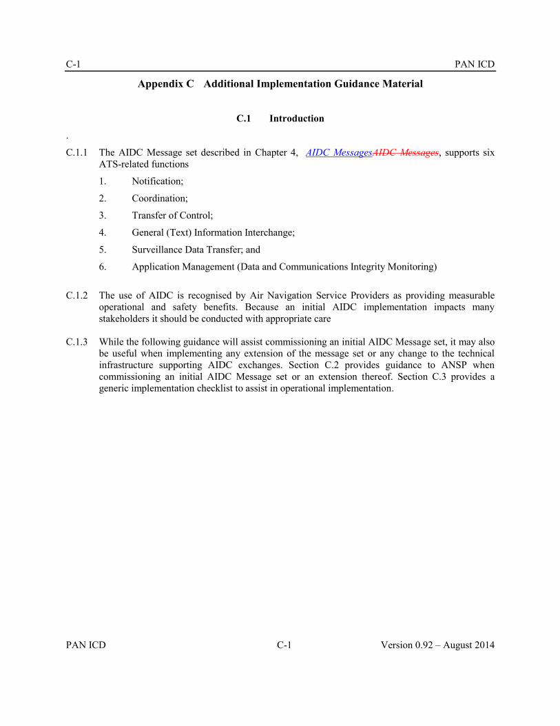
C-1 PAN ICD
PAN ICD C-1 Version 0.92 – August 2014
Appendix C Additional Implementation Guidance Material
C.1 Introduction
.
C.1.1 The AIDC Message set described in Chapter 4, AIDC MessagesAIDC Messages, supports six ATS-related functions
1. Notification;
2. Coordination;
3. Transfer of Control;
4. General (Text) Information Interchange;
5. Surveillance Data Transfer; and
6. Application Management (Data and Communications Integrity Monitoring)
C.1.2 The use of AIDC is recognised by Air Navigation Service Providers as providing measurable
operational and safety benefits. Because an initial AIDC implementation impacts many stakeholders it should be conducted with appropriate care
C.1.3 While the following guidance will assist commissioning an initial AIDC Message set, it may also be useful when implementing any extension of the message set or any change to the technical infrastructure supporting AIDC exchanges. Section C.2 provides guidance to ANSP when commissioning an initial AIDC Message set or an extension thereof. Section C.3 provides a generic implementation checklist to assist in operational implementation.
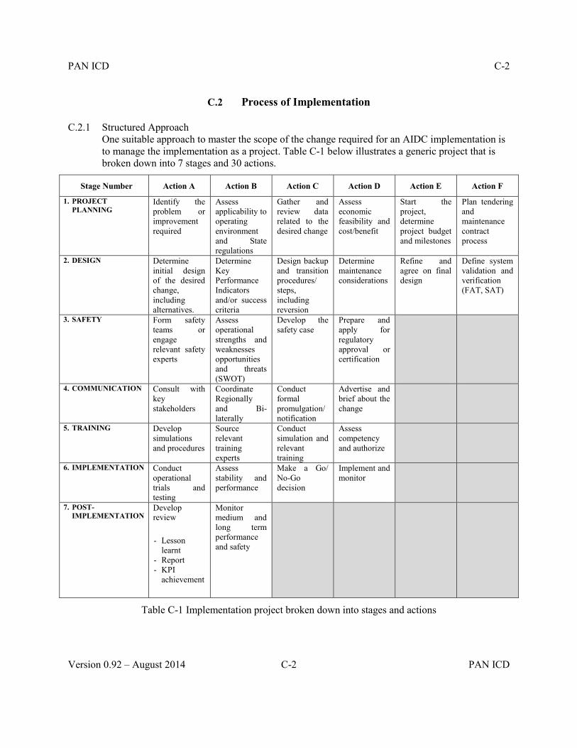
PAN ICD C-2
Version 0.92 – August 2014 C-2 PAN ICD
C.2 Process of Implementation
C.2.1 Structured Approach One suitable approach to master the scope of the change required for an AIDC implementation is to manage the implementation as a project. Table C-1 below illustrates a generic project that is broken down into 7 stages and 30 actions.
Stage Number Action A Action B Action C Action D Action E Action F
1. PROJECT PLANNING
Identify the problem or improvement required
Assess applicability to operating environment and State regulations
Gather and review data related to the desired change
Assess economic feasibility and cost/benefit
Start the project, determine project budget and milestones
Plan tendering and maintenance contract process
2. DESIGN Determine initial design of the desired change, including alternatives.
Determine Key Performance Indicators and/or success criteria
Design backup and transition procedures/ steps, including reversion
Determine maintenance considerations
Refine and agree on final design
Define system validation and verification (FAT, SAT)
3. SAFETY Form safety teams or engage relevant safety experts
Assess operational strengths and weaknesses opportunities and threats (SWOT)
Develop the safety case
Prepare and apply for regulatory approval or certification
4. COMMUNICATION Consult with key stakeholders
Coordinate Regionally and Bi-laterally
Conduct formal promulgation/ notification
Advertise and brief about the change
5. TRAINING Develop simulations and procedures
Source relevant training experts
Conduct simulation and relevant training
Assess competency and authorize
6. IMPLEMENTATION Conduct operational trials and testing
Assess stability and performance
Make a Go/ No-Go decision
Implement and monitor
7. POST-IMPLEMENTATION
Develop review
- Lesson learnt
- Report - KPI
achievement
Monitor medium and long term performance and safety
Table C-1 Implementation project broken down into stages and actions
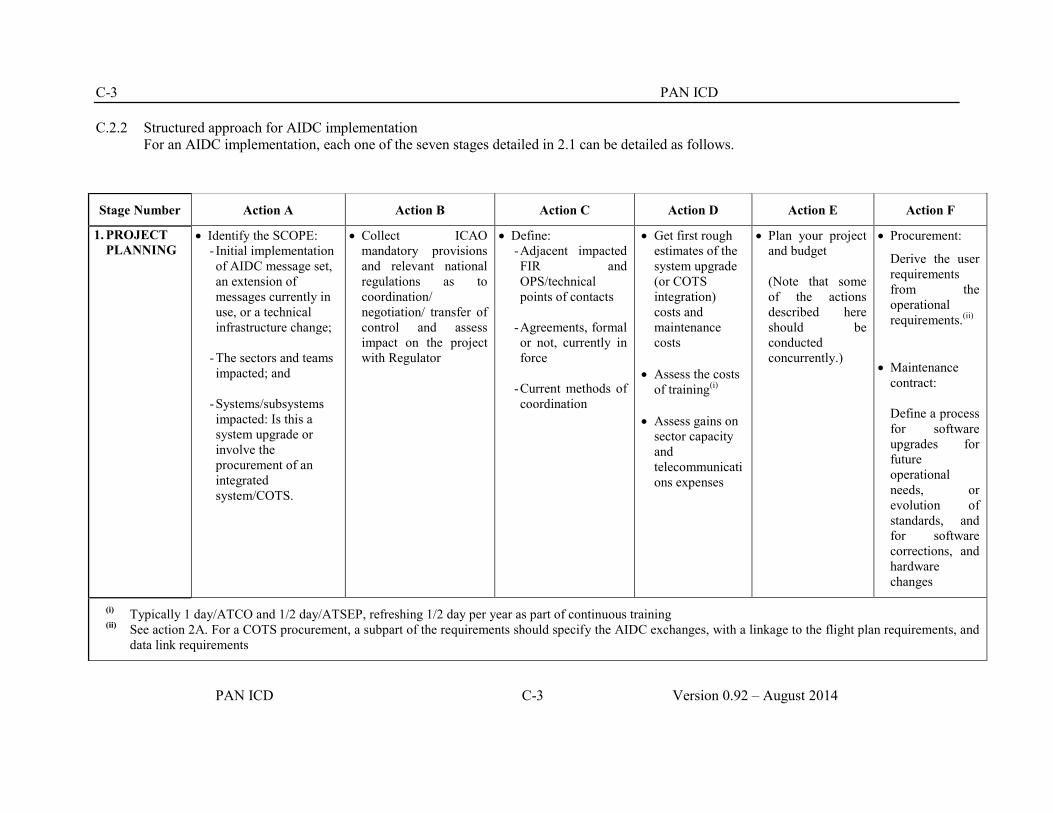
C-3 PAN ICD
PAN ICD C-3 Version 0.92 – August 2014
C.2.2 Structured approach for AIDC implementation For an AIDC implementation, each one of the seven stages detailed in 2.1 can be detailed as follows.
Stage Number Action A Action B Action C Action D Action E Action F
1. PROJECT PLANNING
Identify the SCOPE: - Initial implementation of AIDC message set, an extension of messages currently in use, or a technical infrastructure change;
- The sectors and teams impacted; and
- Systems/subsystems impacted: Is this a system upgrade or involve the procurement of an integrated system/COTS.
Collect ICAO mandatory provisions and relevant national regulations as to coordination/ negotiation/ transfer of control and assess impact on the project with Regulator
Define: - Adjacent impacted FIR and OPS/technical points of contacts
- Agreements, formal or not, currently in force
- Current methods of coordination
Get first rough estimates of the system upgrade (or COTS integration) costs and maintenance costs
Assess the costs
of training(i) Assess gains on
sector capacity and telecommunications expenses
Plan your project and budget (Note that some of the actions described here should be conducted concurrently.)
Procurement:
Derive the user requirements from the operational requirements.(ii)
Maintenance contract: Define a process for software upgrades for future operational needs, or evolution of standards, and for software corrections, and hardware changes
(i) Typically 1 day/ATCO and 1/2 day/ATSEP, refreshing 1/2 day per year as part of continuous training (ii) See action 2A. For a COTS procurement, a subpart of the requirements should specify the AIDC exchanges, with a linkage to the flight plan requirements, and
data link requirements

PAN ICD C-4
Version 0.92 – August 2014 C-4 PAN ICD
2. DESIGN Determine - Operational
requirements (including HMI),
- In the case of a COTS, take the actual design as an input
- The AIDC message set that will be supported for each adjacent FIR
- The linkage between AIDC exchanges and flight plan states and on data link function (transfer of communications).(iii)
Determine Key Performance indicators: - Efficiency: gains of
capacity on sectors equipped with AIDC, or measured reduction of voice communications,
- Safety: e.g. measured reduction of LHD due to erroneous coordinations
- other
The operator may develop a transition plan with a phased introduction of operational changes (e.g. : boundary by boundary).
Test and commissioning stages should be coordinated with the peer ANSP.
Plan - preventive
scheduled maintenance procedures (internal and bilateral)
- corrective maintenance procedures in case of failure
Detailed system/ components requirements and procedures for normal and degraded cases (revert to voice communications)
in case of COTS: validation of the system/components requirements, and of the needed changes
drafting of working methods
Define FAT tests based on the refined requirements
Define SAT tests with peer FIRs (all neighboring ATSUs if possible) and plan to conduct them with test platforms embarking the same software as the one intended for operational use.
(iii) A good approach consists of capturing operational requirements through use cases for the implementation of planned AIDC phases using PAN ICD guidance as
a starting point: Consider - how is it working now? How will it work with AIDC? - does future automation bring new opportunities? (e.g.: frequent position update in case of areas of common interest coming from the other ATSU’s system, etc) This should associate the neighboring ATSUs, at least for final review. The use cases may state the actions by the operators and by the system. When system actions are expected to be automatic, conditions for its triggering, including timing, should be specified. In coordination with the safety case, this initial phase may determine what could go wrong, and design the need for alerts or alarms notification and acknowledgment. Note also a new responsibility to handle queued AIDC messages which should be assigned to an operator. Associated HMI should be designed/reviewed as well. In the initial design, the operator may also review the provisions for performance/safety monitoring: end-to-end transit times measurement, number of messages transmitted/rejected/discarded and associated errors, alerts/alarms raised and acknowledged.

C-5 PAN ICD
PAN ICD C-5 Version 0.92 – August 2014
3. SAFETY Integrate a skilled safety engineer in the procurement/design team
Network performance, handling of congestion
Human performance: addressing of messages (AFTN), handling of queued AIDC messages by FDO, ATCO
Ground systems:
addressing of messages, processing time
Study and mitigate hazards including: - HMI design - Loss of AIDC
messages - Out of sequence
messages - Too early or too
late delivery of AIDC messages
- Corruption of AIDC messages
- Misdirection of AIDC messages
- Flooding by AIDC messages
Safety case, evidence that regulatory requirements are met
4. COMMUNICATION
Common writing and cross checking of LOAs
Test phase with AIDC test platforms (SAT and live trials)
Cut-over date Post transition
operations (typically: date at which voice coordination will cease for nominal cases)
5. TRAINING Scenarios developed for design can be used to build the simulations.
AIDC should be introduced in the simulator, identical to the OPS.
Source relevant experts. Benchmarking from other ANSP may be useful.
Train ATCOs, and other affected staff
Training may be associated with the global transition to a new system, or be a delivered as a dedicated session.
Conduct the evaluation of normal and degraded situations

PAN ICD C-4
Version 0.92 – August 2014 C-6 PAN ICD
6. IMPLEMENTATION
Conduct technical trials between test platforms and then operational trials, including reverting to voice
Assess the stability and performance of your AIDC communications, against voice communications
Based on results of training, tests, trials, and LOA cross-check, make a coordinated GO/NO GO decision with neighbouring FIRs (refer to Chapter 3 checklist)
Implement and monitor
7. POST -IMPLEMENTATION
Build a project Report with Lessons learnt and KPI achievement.
Keep monitoring the handling of message queues, and messages discarded and take relevant actions

C-7 PAN ICD
PAN ICD C-7 Version 0.92 – August 2014
C.3 Checklist
C.3.1 The following template is provided to give guidance as to specific agreements needed when implementing an AIDC implementation with an adjacent ATSU.
Stakeholders: (ATSU1) …………. and (ATSU2)…………. Date:…………….
No Item Yes/No Remarks 1 System Readiness 1.1 Liaison established with adjacent ATSU 1.2 AIDC Addressing Information agreed 1.3 AIDC version agreed 1.4 AIDC message format agreed 2 LoA 2.1 COPs agreed 2.2 AIDC Messages agreed 2.3 Procedures agreed 2.4 Time parameters agreed 2.5 Contingency Fall back measures agreed 3 Quality & Safety Management System 3.1 Hazard/risk identification completed 3.2 Safety Assessment completed 3.3 Transition plan completed 4 Training 4.1 ATCO training/briefing completed 4.2 Other staff training/briefing completed 5 Transition Activities 5.1 Limited time parallel operations agreed From………. To…………. 6 Implementation 6.1 Operational cut-over agreed Date/Time………………….. 7 Post Implementation 7.1 Post-implementation monitoring and
performance parameters agreed
Signatures
Name: Name:

PAN ICD C-4
Version 0.92 – August 2014 C-2 PAN ICD
© ICAO PAN AIDC ICD Coordination Draft Version 0.92 — August 2014

CNS SG/18
Appendix P to the Report
P - 1
Draft Terms of Reference (TOR) APAC PBN Implementation Coordination Group (PBNICG) 1) Serve as the primary APAC Regional forum to support PBN implementation with a goal to
enhance safety and efficiency of aircraft trajectories and operations. The forum also takes into account activities related to the implementation of relevant ASBU elements, with initial focus on B0-CDO, B0-FRTO, B0-CCO, and B0-APTA. The following are the main topics to be addressed:
o Monitor PBN implementation of APAC States/Administrations and make recommendations as necessary in areas where ICAO APAC RSO can provide assistance.
o Through ICAO APAC RSO, provide assistance and guidance to States to update their PBN implementation plans. Identify challenges within State PBN Implementation Plans and PBN implementation activities and assist States in addressing these challenges in a harmonized manner.
o Taking a multi-disciplinary approach, promote more efficient flight operations and
trajectories and, as necessary, addressing related topics including air traffic services (ATS) route network, airspace organization, flexible use of airspace, navigation specification harmonization, and performance and sharing of GNSS/surveillance/communication infrastructures and facilities.
o Analyse regional indicators associated with Seamless plan items, make
recommendations for updating the Seamless Plan, and keep the relevant ANRFs updated.
o Analyse and report operational benefits of PBN implementations and provide regular
PBN implementation updates to ICAO APAC for inclusion in the regional performance dashboard.
2) Identify issues/action items which are related to the implementation of PBN and related ASBU elements, and where appropriate, communicate with relevant ICAO panels or working/study groups.
3) Coordinate and consult with COSCAPs, FPPs, international organizations, industry partners and
volunteering administrations which provide support to PBN implementation. 4) Review regional priorities/targets and relevant regional plans as related to PBN implementation and provide recommendations to APANPIRG. Composition The PBNICG will compose of multi-disciplinary experts nominated by ICAO member States/Administrations in the Asia and Pacific Regions and International Organizations. Secretariat support for the PBN ICG will be provided by the ICAO APAC RSO with assistance from APAC RO.
ssomsri
Typewritten Text
ssomsri
Typewritten Text

CNS SG/18
Appendix P to the Report
P - 2
Reporting The PBNICG will report to the APANPIRG and will also provide briefing to the ATM and CNS Sub-group as necessary Note: The PBNICG, while undertaking the tasks, should take into account of the work being undertaken by relevant ICAO Panels and other study/working groups. APAC PBN Task Force TOR – Now Defunct a) Continue the refinement and ongoing review of the Asia Pacific Regional PBN implementation
plan and monitor and report on its application in the region.
b) Carry out specific studies, develop guidance material and facilities training to assist States with RNAV/RNP implementation in the en-route, terminal, and approach flight phases, taking into account the performance based navigation (PBN) concept, according to the ICAO Strategic Objectives and Global Plan Initiatives (GPI) on this matter (GPI 5, 7, 10, 11, 12, 20, 21)
c) Assist States in the preparation and review of their PBN implementation documentation and provide feedback to ensure regional harmonization and for possible inclusion in ICAO-developed model documentation.
d) Develop and review material needed to meet the ICAO initiative on the introduction of APV approaches including Baro-VNAV and RNP-AR as part of the PBN initiative.
e) Monitor the progress of State PBN implementation, identify constraints to implementation and capture information on the effectiveness (tangible benefits) of State PBN applications.
f) Continue the review of the PBN Manual and its practical application in the implementation of PBN in the region.
g) Develop, in coordination with RASMAG, the necessary airspace safety and monitoring requirements for the introduction and continued application of PBN based procedures.
h) Review activities of PBN Task Force from other regions including their action plans for PBN implementation to ensure harmonization and avoid duplication of work.
i) Address other regional PBN implementation issues, including the development of staff resources and skills, as needed by safety management. Coordinate and consult with ICAO RSO, COSCAP, industry partners and volunteering administrations who are providing support to State PBN implementation.
_ _ _ _ _ _ _ _ _ _ _ _

CNS SG/18 Appendix Q to the Report
Q - 1
REVISED NAVIGATION STRATEGY FOR THE ASIA/PACIFIC REGION Considering: a) the material contained in the Performance Based Navigation Manual (Doc 9613) for enroute,
approach, landing and departures operations; b) operators are approved to conduct PBN operations;
c) GNSS is the primary navigation system for RNP;
d) APV operations may be conducted with either BARO-VNAV or augmented GNSS;
e) Augmented GNSS is available to support Category I, and will be able to support Category II and III operations by 2016;
f) ILS is capable of meeting the majority of requirements for precision approach and landing in the Asia-Pacific Region;
g) MLS CAT III is operational;
h) the need to maintain aircraft and ground interoperability both within the Region and between the Asia/Pacific Region and other ICAO regions and to provide flexibility for future aircraft equipage;
i) single-frequency GNSS may be susceptible to radio frequency interference and ionospheric disturbances:
Strategy
i) Convert from terrestrial-based instrument flight procedures to PBN operations in accordance with the Asia/Pacific Seamless ATM Plan;
ii) retain ILS as an ICAO standard system for as long as it is operationally acceptable and economically beneficial;
iii) implement GNSS with augmentation as required for APV and precision approach or RNP operations where it is operationally and economically beneficial;
iv) implement the use of APV operation in accordance with the Asia/Pacific Seamless ATM Plan;
v) rationalize terrestrial navigation aids, retaining a minimum network of terrestrial aids necessary to maintain safety of aircraft operations;
vi) protect all the Aeronautical Radio Navigation Service (ARNS) frequencies;
vii) ensure civil-military interoperability; and
viii) continue monitoring the development of alternative position, navigation and timing
_ _ _ _ _ _ _ _ _ _ _ _ _ _
ssomsri
Typewritten Text

CNS SG/18 Appendix R to the Report
R - 1
ADS-B SITF TASK 7/36 – States to advise when their ground stations can be upgraded to receive ADS-B D0260B compliant ADS-B data
State or Administration
No. of ADS-B Ground Stations Installed
D0260B Compliant?
Yes (all) Yes (some) No If some or No, planned date of full D0260B
capability
Australia 33 Sydney WAM (SYDWAM) site yet to be upgraded
Bangladesh Nil
Hong Kong, China 9
Macao, China Nil
India 21
Indonesia 31 To be discussed
Japan Nil
Malaysia
Maldives 4 Not yet determined.
Myanmar
ssomsri
Typewritten Text

CNS SG/18 Appendix R to the Report
R - 2
ADS-B SITF TASK 7/36 – States to advise when their ground stations can be upgraded to receive ADS-B D0260B compliant ADS-B data
State or Administration
No. of ADS-B Ground Stations Installed
D0260B Compliant?
Yes (all) Yes (some) No If some or No, planned date of full D0260B
capability
Nepal Nil
New Zealand 22 December 2014
Philippines Nil
Pakistan 1 Test basis. Will discuss outcomes from ADS-B SITF Meeting.
Republic of Korea 2 2017
Singapore 1
Thailand 1
USA 634
Viet Nam 3

CNS SG/18 Appendix S to the Report
S - 1
ADS-B IMPLEMENTATION STATUS IN THE APAC REGION
State/ Administration
ADS-B Ground Infrastructure and ATC System readiness or Implementation plan
Date of issue/effectiveness date of equipage mandate
Mandated Airspace
and/or ATS-routes
Intended separation criteria to be applied
Remarks
AFGHANISTAN ADS-B & Multi
Lateration system installed.
subject to safety assessment
AUSTRALIA A total of 31 ADS-B stations and 28 WAM stations are currently used. ATC system readiness since 2004. ADS-B data sharing with Indonesia operational since 2/2011. ASMGCS using multilateration is operational in Brisbane, Sydney & Melbourne. It is being installed in Perth. Additional 15 ADS-B stations from 2014-2016. OneSKY replacing current ATM system is estimated for full operational around 2020.
2009/effective date of mandating in UAP 12/12/2013. A forward fit ADS-B mandate also applies from 2/2014 for all IFR aircraft at all flight levels. An ADS-B for all IFR aircraft applies from 2/2017.
at/above FL290 UAP from 12/2013 for domestic & foreign aircraft. Mandates for additional flight level are considered for 2015 & 2017. WAM is operating in Tasmania since 2010 delivery 5 Nm separation service. WAM is also operating in Sydney for 3 Nm separation service in TMA and for precision runway monitoring function.
5 NM 3 NM SYDWAN
ssomsri
Typewritten Text
ssomsri
Typewritten Text

CNS SG/18 Appendix S to the Report
S - 2
State/ Administration
ADS-B Ground Infrastructure and ATC System readiness or Implementation plan
Date of issue/effectiveness date of equipage mandate
Mandated Airspace
and/or ATS-routes
Intended separation criteria to be applied
Remarks
BANGLADESH Bangladesh has
a plan to commission four ADS-B ground stations to be installed at Dhaka, Cox’s Bazar, Saidpur and Barisal Airports by 2016. ADS-B data will be integrated with new ATS system at Dhaka.
CAMBODIA 3 ADS-B ground stations have been installed in Cambodia since 2011 and able to provide full surveillance coverage for Phnom Penh FIR.
CHINA 5 UAT ADS-B sites are used for flight training of CAFUC. 8 ADS-B stations installed by end of 2012. 200 ADS-B stations nationwide will deployed as 1st phase. 1 ADS-B station operational in Sanya FIR since 2008. Sanya ATC system ready since July 2009 to support L642
NOTAM issued on ADS-B trial operation
ADS-B signal alone won’t be used for ATC separation

CNS SG/18 Appendix S to the Report
S - 3
State/ Administration
ADS-B Ground Infrastructure and ATC System readiness or Implementation plan
Date of issue/effectiveness date of equipage mandate
Mandated Airspace
and/or ATS-routes
Intended separation criteria to be applied
Remarks
and M771. Chengdu-Jiuzhai project finished in 2008 with 2 ADS-B stations and additional site is planned to enhance the surveillance coverage. Chengdu - Lhasa route surveillance project completed with 5 ADS-B stations using 1090ES since 2010. Trials planned from May 2011. 1 ADS-B site installed in Sanya FIR since 2008. 3 additional ground stations planned, Trial planned for Jun, 2011.
HONG KONG CHINA
A larger-scale A-SMGCS covering the whole Hong Kong International Airport put into operational use in April 2009.
AIP supplement issued on 29 Oct.2013/12 Dec. 2013 as effective date.
L642/M771 ATS routes.
To be determined.
ADS-B signals being fed to ATC controllers under an operational trial programme. ATS automation system to be ready in 2015

CNS SG/18 Appendix S to the Report
S - 4
State/ Administration
ADS-B Ground Infrastructure and ATC System readiness or Implementation plan
Date of issue/effectiveness date of equipage mandate
Mandated Airspace
and/or ATS-routes
Intended separation criteria to be applied
Remarks
Data collection/ analysis on aircraft ADS-B equipage in Hong Kong airspace conducted on quarterly basis since 2004. ADS-B trial using a dedicated ADS-B system completed in 2007. ADS-B out operations over PBN routes L642 and M771 at or above FL 290 within HK FIR are planned in December 2013 and within HK FIR at or above FL 290 in December 2014. ADS-B ground station infrastructure completed in 2013. ADS-B trial using ADS-B signal provided by Mainland China to cover southern part of Hong Kong FIR commenced in 2010.
ADS-B planned to be put into operational use 6 months after new ATM System in operation
MACAO, CHINA
Mode S MSSR coverage available for monitoring purposes.

CNS SG/18 Appendix S to the Report
S - 5
State/ Administration
ADS-B Ground Infrastructure and ATC System readiness or Implementation plan
Date of issue/effectiveness date of equipage mandate
Mandated Airspace
and/or ATS-routes
Intended separation criteria to be applied
Remarks
DEMOCRATIC PEOPLE’S REPUBLIC OF KOREA
ADS-B has been used as back-up surveillance of SSR since 2008.
FIJI ISLANDS ADS- B /multilateration ground stations installed. Situations awareness service will be provided in 2013.
FRANCE (French Polynesia)
Project launched to install 9 ADS-B stations. 2 stations to be installed in 2014; 3 in 2015 and 4 will be installed in 2016.
5 NM for airspace under coverage.
INDIA ASMGCS (SMR + Multilat) is operational at Delhi, Mumbai, Chennai, Kolkata, Bangalore and Hyderabad Airports. ASMGCS is also being installed at 05 more international airports. ADS-B Ground Stations installed at 14 locations in phase one across continental and Oceanic airspace at Port Blair. 07 more ADS-B
AIP supplement issued on 17th April 2014 with effective date of implementation from 29th May 2014.
ADS-B in India to provide redundancy for radar and filling the surveillance gaps. Currently study the integrity of ADS-B data and evaluating in both Non-radar and radar environment for ATC purposes.

CNS SG/18 Appendix S to the Report
S - 6
State/ Administration
ADS-B Ground Infrastructure and ATC System readiness or Implementation plan
Date of issue/effectiveness date of equipage mandate
Mandated Airspace
and/or ATS-routes
Intended separation criteria to be applied
Remarks
Ground stations in phase two in 2014. ATS systems at 12 ACCs are capable of processing ADS-B data and provide the information on Display. Wide area Multilateration pilot project is being planned in Kolkata TMA to augment the surveillance coverage.
INDONESIA 30 Ground Station successfully installed. Since 2009, ATC Automation in MATSC has capabilities to support ADS-B application. ADS-B Task Force team established to develop planning and action concerning ADS-B Implementation within Indonesia FIR ADS-B data sharing with Australia and Singapore.
ADS-B Task Force Team is considering a mandate in 2016

CNS SG/18 Appendix S to the Report
S - 7
State/ Administration
ADS-B Ground Infrastructure and ATC System readiness or Implementation plan
Date of issue/effectiveness date of equipage mandate
Mandated Airspace
and/or ATS-routes
Intended separation criteria to be applied
Remarks
JAPAN Multilateration
Systems for surface monitoring have been implemented at seven airports and are being implemented at another one airport. PRM (WAM) is planned to be implemented at Narita Airport. (Operation will start in 2014). Basic design of en-route WAM system completed in FY2013. Plans to start manufacture in FY2014 and estimated operational in FY2018. Plan to evaluate accuracy of ADS-B information and has intension to introduce ADS-B to the oceanic direction.
MALAYSIA Malaysia planned to start mandate ADS-B requirement in KL FIR in 2018 and full implementation of ADS-B service at
Plan to issue mandate with target effective date end of 2018.

CNS SG/18 Appendix S to the Report
S - 8
State/ Administration
ADS-B Ground Infrastructure and ATC System readiness or Implementation plan
Date of issue/effectiveness date of equipage mandate
Mandated Airspace
and/or ATS-routes
Intended separation criteria to be applied
Remarks
specific routes/exclusive airspace by end of 2020. Plan to install two ADS-B stations at Pulau Langkawi and Genting Highland by 2016. Data sharing with neighbouring by mid. 2017.
MALDIVES 4 ADS-B stations installed in Nov. 2012 (2 at Male’ Ibrahim Nasir Intl Airport, 1 at Kulhudhuffushi Island in the North and 1 at Fuah Mulah Island in the South to cover 95% of the FIR at/above FL290. Maldives’ ADS-B is integrated with the ATM system (in November 2013), and under observation prior to commencing trials. Maldives has plan to share ADS-B data with its adjacent FIRs.
Seaplane in Maldives equipped with ADS-B for AOC purpose. These seaplanes have ADS-B IN functions as well.

CNS SG/18 Appendix S to the Report
S - 9
State/ Administration
ADS-B Ground Infrastructure and ATC System readiness or Implementation plan
Date of issue/effectiveness date of equipage mandate
Mandated Airspace
and/or ATS-routes
Intended separation criteria to be applied
Remarks
MONGOLIA Five ADS-B
ground stations for combination with SSR will be implemented first quarter of 2013. Full coverage for surveillance gaps will be implemented by 2015-2016.
MYANMAR
ADS-B ground stations to be installed at Sittwe, Co Co Island by end of 2014 as 1st phase Yango , Lashio and Myeik -2015 as 2nd phase; Kengteng, Myitkyina in 2016. Completion of integration to Euro Cat. C. in 2014. Agreed to share ADS-B data with India, agreement on sharing being negotiated.
Supplement radar and fill the gaps to improve safety and efficiency. ADS-C/CPDLC integrated in Yangon ACC since 2010.
NEPAL ADS-B feasibility study conducted in 2007.

CNS SG/18 Appendix S to the Report
S - 10
State/ Administration
ADS-B Ground Infrastructure and ATC System readiness or Implementation plan
Date of issue/effectiveness date of equipage mandate
Mandated Airspace
and/or ATS-routes
Intended separation criteria to be applied
Remarks
NEW CALEDONIA
Three ADS-B ground stations commissioned in 2010 to cover international traffic at La tontouta airport serving Tontouta ACC & APP. It is used for Situation awareness and SAR.
NEW ZEALAND
MLAT being used in Queenstown area (WAM) and Auckland (airport surface movements). ADS-B data available from all MLAT & SSR sites. New Zealand Navigation and Airspace and Air Navigation Plan “New Southern SKY” issued May 2014
5 NM Surveillance Separation
PAKISTAN Feasibility study for using ADS-B is in hand. One station was installed at ACC Karachi and evaluation is in progress.
PAPUA NEW GUINEA
Legislation mandating ADS-B and guidelines for aircraft equipage and operational approval to be issued by
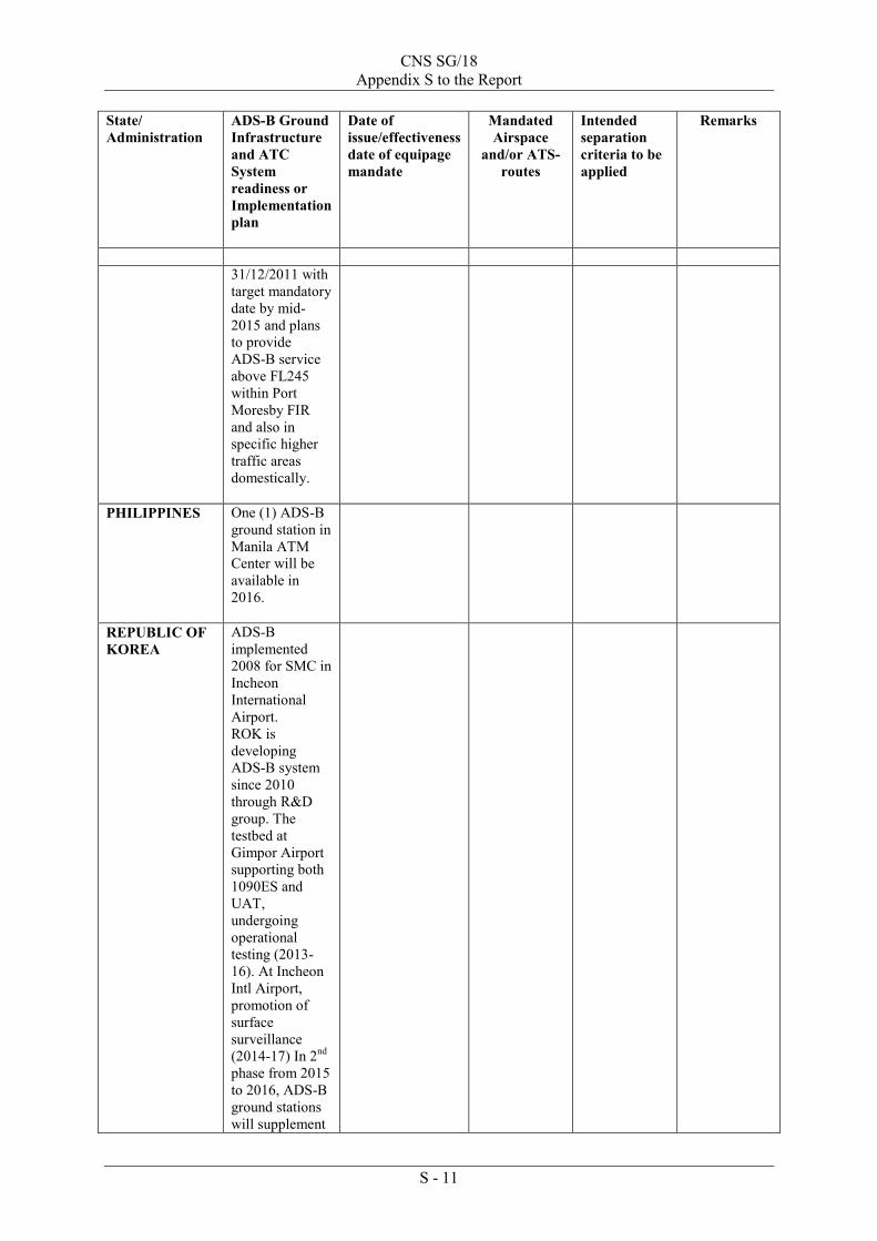
CNS SG/18 Appendix S to the Report
S - 11
State/ Administration
ADS-B Ground Infrastructure and ATC System readiness or Implementation plan
Date of issue/effectiveness date of equipage mandate
Mandated Airspace
and/or ATS-routes
Intended separation criteria to be applied
Remarks
31/12/2011 with target mandatory date by mid-2015 and plans to provide ADS-B service above FL245 within Port Moresby FIR and also in specific higher traffic areas domestically.
PHILIPPINES One (1) ADS-B ground station in Manila ATM Center will be available in 2016.
REPUBLIC OF KOREA
ADS-B implemented 2008 for SMC in Incheon International Airport. ROK is developing ADS-B system since 2010 through R&D group. The testbed at Gimpor Airport supporting both 1090ES and UAT, undergoing operational testing (2013-16). At Incheon Intl Airport, promotion of surface surveillance (2014-17) In 2nd phase from 2015 to 2016, ADS-B ground stations will supplement

CNS SG/18 Appendix S to the Report
S - 12
State/ Administration
ADS-B Ground Infrastructure and ATC System readiness or Implementation plan
Date of issue/effectiveness date of equipage mandate
Mandated Airspace
and/or ATS-routes
Intended separation criteria to be applied
Remarks
to the radar in the terminal area and fill up the gap between radar coverage. The last phase from 2017 to 2020, ADS-B will be deployed for entire Incheon FIR.
SINGAPORE The airport MLAT system was installed in 2007 and “far-range” ADS-B sensor was installed in 2009.
ATC system has been processing ADS-B data since 2013.
AIC was issued on 28 December 2010/effective from 12 December 2013. AIP supplement published in Nov 2013 to remind operators of ADS-B exclusive airspace implementation.
L642 and M771. At and above FL290. Also affect the following ATS routes N891, M753, L644 & N892
40nm on ATS routes L642, L644, M753, M771, N891 and N892 30nm planned for 26th June 2014 on ATS routes L642, M753, M771 and N892; 20nm panned for end 2015
Safety case was completed end of November. 2013.
SRI LANKA ADS-B Trials planned for 2012 and implementation in 2013. The ADS-B station was planned at Pidurutalagala.
THAILAND Multilateration implemented in 2006 at Suvarnbhumi Int’l. Airport. An ADS-B Ground Station has been installed in Bangkok as test unit. ADS-B is planned to be part of future

CNS SG/18 Appendix S to the Report
S - 13
State/ Administration
ADS-B Ground Infrastructure and ATC System readiness or Implementation plan
Date of issue/effectiveness date of equipage mandate
Mandated Airspace
and/or ATS-routes
Intended separation criteria to be applied
Remarks
surveillance infrastructure. New ATM System to be in operational in 2015 will be capable of processing ADS-B data.
TONGA
Trial planned for 2017
UNITED STATES
As of 31 March 2014, 634 radio sites had been installed; these sites cover the “baseline” set of Service Volumes planned by the FAA in 2007. Since 2007, FAA has planned and funded activities to activate additional Service Volumes that will constitute an additional 29 radio sites. Approximately 100 of the 230 U.S. air traffic control facilities are using ADS-B for ATC separation; all facilities are planned to be using ADS-B by 2019.
The U.S. ADS-B Out rule (14 CFR 91.225 and 14 CFR 91.227) was issued in May 2010 and specifies that the ADS-B Out mandate is effective on 1 January 2020.
Class A, B, and C airspace, plus Class E airspace above 10,000 ft MSL. See 14 CFR 91.225 for details.
The U.S. is using both terminal and en route (5nm) separation criteria, depending on the specific airspace and available surveillance information. Terminal separation includes the following separation criteria: - 3nm - 2.5nm - independent parallel approach operations down to 4300 ft centreline separation - dependent parallel approach operations down to 2500 ft centreline

CNS SG/18 Appendix S to the Report
S - 14
State/ Administration
ADS-B Ground Infrastructure and ATC System readiness or Implementation plan
Date of issue/effectiveness date of equipage mandate
Mandated Airspace
and/or ATS-routes
Intended separation criteria to be applied
Remarks
separation (currently 1.5 nm diagonal distance).
VIET NAM Two phases ADS-B implementation plan adopted. Phase 1 implemented in March 2013. Phase 2 for whole lower and upper airspace of Ha Noi and Ho Chi Minh FIR to be completed by 2016.
AIC issued on 20 June 2013/ADS-B mandating effective from 12 December 2013 in Ho Chi Minh FIR.
M771, L642, L625, N892, M765, M768, N500 and L628 At/above FL290.
Operators required to have operational approval from State of aircraft registry.
_ _ _ _ _ _ _ _ _ _ _ _ _ _

CNS SG/18
Appendix T to the Report
ADS-B IMPLEMENTATION AND
OPERATIONS GUIDANCE DOCUMENT
Edition 67.0 -– SeptemberJune 20143
INTERNATIONAL CIVIL AVIATION ORGANIZATION
ASIA AND PACIFIC OFFICE

ADS-B Implementation and Operations Guidance Document
Edition 6.0 June 2013 T - 2
Intentionally left blank

ADS-B Implementation and Operations Guidance Document
Edition 6.0 June 2013 T - 3
TABLE OF CONTENTS
1. INTRODUCTION ............................................................................................................ 6
1.1 Arrangement of the AIGD .................................................................................................. 6
1.2 Document History and Management .................................................................................. 6
1.3 Copies ................................................................................................................................. 6
1.4 Changes to the AIGD .......................................................................................................... 7
1.5 Editing conventions ............................................................................................................ 7
1.6 AIGD Request for Change Form ........................................................................................ 7
1.7 Amendment Record ............................................................................................................ 9
2. ACRONYM LIST & GLOSSARY OF TERMS............................................................ 10
2.1 Acronym List .................................................................................................................... 10
2.2 Glossary of Terms ........................................................................................................... 112
3. REFERENCE DOCUMENTS…………………………………………………………12
4. ADS-B DATA .................................................................................................................. 13
5. ADS-B IMPLEMENTATION ....................................................................................... 14
5.1 Introduction ....................................................................................................................... 14
5.1.1 Planning ................................................................................................................... 14
5.1.2 Implementation team to ensure international coordination ..................................... 14
5.1.3 System compatibility ............................................................................................... 14
5.1.4 Integration ................................................................................................................ 15
5.1.6 Coverage Predictions ............................................................................................... 16
5.2 Implementation checklist .................................................................................................. 16
5.2.1 Introduction .............................................................................................................. 16
5.2.2 Activity Sequence .................................................................................................... 16
5.2.3 Concept Phase .......................................................................................................... 16
5.2.4 Design Phase ............................................................................................................ 17
5.2.5 Implementation Phase .............................................................................................. 18
6. HARMONIZATION FRAMEWORK FOR
ADS-B IMPLEMENTATION ....................................................................................... 19
6.1 Background ................................................................................................................ 19
6.2 Template of Harmonization Framework for ADS-B Implementation .............................. 20
7. SYSTEM INTEGRITY AND MONITORING ............................................................ 23
7.1 Introduction ....................................................................................................................... 23
7.2 Personnel Licensing and Training .................................................................................... 23
7.3 System Performance Criteria for an ATC separation service ........................................... 23
7.4 ATC system validation ..................................................................................................... 24

ADS-B Implementation and Operations Guidance Document
Edition 6.0 June 2013 T - 4
7.4.1 Safety Assessment Guidelines ............................................................................. 24
7.4.2 System safety assessment .................................................................................... 24
7.4.3 Integration test ..................................................................................................... 24
7.4.4 ATS Operation Manuals ...................................................................................... 25
7.4.5 ATS System Integrity .......................................................................................... 25
7.5 System Monitoring ........................................................................................................... 25
7.5.1 Problem Reporting System (PRS) ....................................................................... 25
7.5.2 The monitoring process ....................................................................................... 26
7.5.3 Distribution of confidential information ............................................................. 26
7.5.4 ADS-B problem reports ....................................................................................... 25
7.5.5 ADS-B periodic status report............................................................................... 27
7.5.6 Processing of Reports .......................................................................................... 27
7.6 APANPIRG ....................................................................................................................... 27
7.7 Local Data Recording and Analysis ................................................................................. 28
7.7.1 Data recording ..................................................................................................... 28
7.7.2 Local data collection ............................................................................................ 28
7.7.3 Avionics problem identification and correction .................................................. 28
7.8 ADS-B Problem Report .................................................................................................... 29
7.8.1 Report Form ......................................................................................................... 29
7.8.2 Description of Fields ........................................................................................... 30
7.9 ADS-B Performance Report Form .................................................................................... 31
8. RELIABILITY & AVAILABILITY CONSIDERATIONS ....................................... 32
8.1 Reliability ......................................................................................................................... 32
8.2 Availability ....................................................................................................................... 32
8.3 Recommendations for high reliability/availability ADS-B systems ................................. 33
A: System design ......................................................................................................... 33
B: Logistics strategy ................................................................................................... 33
C: Configuration Management .................................................................................... 35
D: Training & Competency plans ................................................................................ 36
E: Data collection & Review ....................................................................................... 36
9. ADS-B REGULATIONS AND PROCEDURES .......................................................... 37
9.1 Introduction ....................................................................................................................... 37
9.2 ADS-B Regulations .......................................................................................................... 37
9.3 Factors to be considered when using ADS-B ................................................................... 38
9.3.1 Use of ADS-B Level data..................................................................................... 38
9.3.2 Position Reporting Performance .......................................................................... 38
9.3.3 GNSS Integrity Prediction Service ...................................................................... 38
9.3.4 Sharing of ADS-B Data........................................................................................ 39
9.3.5 Synergy between GNSS and ADS-B .................................................................. 40

ADS-B Implementation and Operations Guidance Document
Edition 6.0 June 2013 T - 5
9.4 Reporting Rates .............................................................................................................. 410
9.4.1 General .............................................................................................................. 401
9.5 Separation ....................................................................................................................... 401
9.5.1 General ............................................................................................................... 401
9.5.2 Identification Methods ....................................................................................... 401
9.5.3 ADS-B Separation ................................................................................................ 41
9.5.4 Vertical tolerance standard .................................................................................. 41
9.6 Air Traffic Control Clearance Monitoring ..................................................................... 421
9.6.1 General ............................................................................................................... 421
9.6.2 Deviation from ATC clearances ........................................................................ 421
9.7 Alerting service ............................................................................................................... 421
9.8 Position Reporting ............................................................................................................ 42
9.8.1 Pilot position reporting requirements in ADS-B coverage .................................. 42
9.8.2 Meteorological reporting requirement in ADS-B airspace .................................. 42
9.9 Phraseology ....................................................................................................................... 42
9.9.1 Phraseology standard ........................................................................................... 42
9.9.2 Operations of Mode S Transponder and ADS-B ................................................. 43
9.10 Flight Planning ................................................................................................................ 454
9.10.1 ADS-B Flight Planning Requirement – Flight Identity ..................................... 454
9.10.2 ADS-B Flight Planning Requirements ................................................................. 45
9.10.3 Setting Flight Identification in Cockpits ............................................................ 465
9.11 Procedures to Handle Non-compliant ADS-B Aircraft or Mis-leading ADS-B Transmissions
476
9.12 Emergency Procedures ................................................................................................ 5048
10. Security Issues Associated with ADS-B .................................................................... 5149
10.1 Introduction ................................................................................................................... 5149
10.2 Considerations .............................................................................................................. 5149
Appendix 1 – An Example of Commissioning Checklist ......................................................... 50
Appendix 2 – Guidance Materials on Monitoring and Analysis of ADS-B Avionics Performance

ADS-B Implementation and Operations Guidance Document
Edition 6.0 June 2013 T - 6
1. INTRODUCTION
The Eleventh ICAO Air Navigation Conference held in 2003 recommended that States recognize ADS-
B as an enabler of the global ATM concept bringing substantial safety and capacity benefits; support the
cost-effective early implementation of it; and ensuring it is harmonized, compatible and interoperable
with operational procedures, data linking and ATM applications.
The Twelve ICAO Air Navigation Conference held in 2012 endorsed the Aviation System Block
Upgrades (ASBU) to provide a framework for global harmonization and interoperability of seamless
ATM systems. Among the Block Upgrades, the Block 0 module “Initial Capability for Ground
Surveillance” recommends States to implement ADS-B which provides an economical alternative to
acquire surveillance capabilities especially for areas where it is technically infeasible or commercially
unviable to install radars.
This ADS-B Implementation and Operations Guidance Document (AIGD) provides guidance material
for the planning, implementation and operational application of ADS-B technology in the Asia and
Pacific Regions.
The procedures and requirements for ADS-B operations are detailed in the relevant States’ AIP. The
AIGD is intended to provide key information on ADS-B performance, integration, principles,
procedures and collaboration mechanisms.
The content is based upon the work to date of the APANPIRG ADS-B Study and Implementation Task
Force (SITF) and various ANC Panels developing provisions for the operational use of ADS-B.
Amendment to the guidance material will be required as new/revised SARPs and PANS are published.
1.1 ARRANGEMENT OF THE AIGD
The AIGD consists of the following Parts:
Section 1 Introduction
Section 2 Acronyms and Glossary of Terms
Section 3 Reference Documents
Section 4 ADS-B Data
Section 5 ADS-B Implementation
Section 6 Template of Harmonization Framework for ADS-B
Implementation
Section 7 System Integrity and Monitoring
Section 8 Reliability and Availability Considerations
Section 9 ADS-B Regulations and Procedures
Section 10 Security Issues Associated with ADS-B
1.2 DOCUMENT HISTORY AND MANAGEMENT
This document is managed by the APANPIRG. It was introduced as draft to the first Working Group
meeting of the ADS-B SITF in Singapore in October 2004, at which it was agreed to develop the draft to
an approved working document that provides implementation guidance for States. The first edition was
presented to APANPIRG for adoption in August 2005. It is intended to supplement SARPs, PANS and
relevant provisions contained in ICAO documentation and it will be regularly updated to reflect
evolving provisions.
1.3 COPIES

ADS-B Implementation and Operations Guidance Document
Edition 6.0 June 2013 T - 7
Paper copies of this AIGD are not distributed. Controlled and endorsed copies can be found at the
following web site:
www.bangkok.icao.int/edocs/index.htmlhttp://www.icao.int/APAC/Pages/edocs.aspx
Copy may be freely downloaded from the web site, or by emailing APANPIRG through the ICAO Asia
and Pacific Regional Office who will send a copy by return email.
1.4 CHANGES TO THE AIGD
Whenever a user identifies a need for a change to this document, a Request for Change (RFC) Form
(see Section 1.6 below) should be completed and submitted to the ICAO Asia and Pacific Regional
Office. The Regional Office will collate RFCs for consideration by the ADS-B Study and
Implementation Task Force.
When an amendment has been agreed by a meeting of the ADS-B Study and Implementation Task
Force then a new version of the AIGD will be prepared, with the changes marked by an “|” in the
margin, and an endnote indicating the relevant RFC, so a reader can see the origin of the change. If the
change is in a table cell, the outside edges of the table will be highlighted; e.g.:
Final approval for publication of an amendment to the AIGD will be the responsibility of APANPIRG.
1.5 EDITING CONVENTIONS
(Intentionally blank)
1.6 AIGD REQUEST FOR CHANGE FORM
RFC Nr:
Please use this form when requesting a change to any part of this AIGD. This form may be photocopied
as required, emailed, faxed or e-mailed to ICAO Asia and Pacific Regional Office
+66 (2) 537-8199 or [email protected]@icao.int
1. SUBJECT:
2. REASON FOR CHANGE:
3. DESCRIPTION OF PROPOSAL: [expand / attach additional pages if necessary]

ADS-B Implementation and Operations Guidance Document
Edition 6.0 June 2013 T - 8
4. REFERENCE(S):
5. PERSON INITIATING: DATE:
ORGANISATION:
TEL/FA/X/E-MAIL:
6. CONSULTATION RESPONSE DUE BY DATE:
Organization Name Agree/Disagree Date
7. ACTION REQUIRE :
8. AIGD EDITOR DATE REC’D :
9. FEEDBACK PASSED DATE :

ADS-B Implementation and Operations Guidance Document
Edition 6.0 June 2013 T - 9
1.7 AMENDMENT RECORD
Amendment
Number
Date Amended by Comments
0.1 24 December 2004 W. Blythe
H. Anderson
Modified draft following contributions from
ADS-B SITF Working Group members.
Incorporated to TF/3 Working Paper #3.
0.2 (1.0) 24 March 2005 H. Anderson Final draft prepared at ADS-B SITF WG/3
0.3 (1.1) 03 June 2005 Nick King Amendments following SASP WG/WHL
meeting of May 2005
0.4 15 July 2005 CNS/MET SG/9 Editorial changes made
1.0 26 August 2005 APANPIRG/16 Adopted as the first Edition
2.0 25 August 2006 Proposed by
ADS-B SITF/5
and adopted by
APANPIRG/17
Adopted as the second Edition
3.0 7 September 2007
Proposed by
ADS-B SITF/6
and adopted by
APANPIRG/18
Adopted as the second amendment (3rd
edition)
4.0 5 September 2011 Proposed by
ADS-B SITF/10
and adopted by
APANPIRG/22
Adopted amendment on consequential
change to the Flight Plan and additional
material on the reliability and availability
for ADS-B ground system
5.0 14 September 2012 Proposed by
ADS-B SITF/11
and adopted by
APANPIRG/23
Included sample template on harmonization
framework
6.0 June 2013 Proposed by ADS-
B SITF/12 and
adopted by
APANPIRG/24
Revamped to include the latest ADS-B
developments and references to guidance
materials on ADS-B implementation
7.0 September 2014 Proposed by ADS-
B SITF/13 and
adopted by
APANPIRG/25
(i) Included guidance materials on
monitoring and analysis of ADS-B
equipped aircraft
(ii) Included guidance materials on synergy
between GNSS and ADS-B
(iii) Revised ATC Phraseology
(i)(iv) Included clarification on Flight
Planning

ADS-B Implementation and Operations Guidance Document
Edition 6.0 June 2013 T - 10
2. ACRONYM LIST & GLOSSARY OF TERMS
2.1 ACRONYM LIST
ACID Aircraft Identification
ADS-C Automatic Dependent Surveillance - Contract
ADS-B Automatic Dependent Surveillance - Broadcast
AIGD ADS-B Implementation and Operations Guidance Document
AIP Aeronautical Information Publication
AIT ADS-B Implementation Team
AMSL Above Mean Sea Level
APANPIRG Asia/Pacific Air Navigation Planning and Implementation Regional Group
ARINC Aeronautical Radio Incorporate
ATC Air Traffic Control (or Air Traffic Controller)
ATM Air Traffic Management
ATS Air Traffic Services
ATSP ATS Provider
ATSU ATS unit
CNS Communications, Navigation, Surveillance
CRC Cyclic Redundancy Check
CDTI Cockpit Display Traffic Information
DAIW Danger Area Infringement Warning
FIR Flight Information Region
FLTID Flight Identification
FMS Flight Management System
FOM Figure of Merit used in ASTERIX messaging
GPS Global Positioning System (USA)
HPL Horizontal Protection Level
ICAO International Civil Aviation Organization
MSAW Minimum Safe Altitude Warning
MTBF Mean Time Between Failures
MTCA Medium Term Conflict Alert
MTTR Mean Time To Restore
NAC Navigation Accuracy Category
NIC Navigation Integrity Category
PRS Problem Reporting System
RAI Restricted Area Intrusion
RAM Route Adherence Monitoring
RAIM Receiver Autonomous Integrity Monitoring
RFC Request for Change
RNP Required Navigation Performance
SIL Surveillance Integrity Level
SITF Study and Implementation Task Force
STCA Short Term Conflict Alert

ADS-B Implementation and Operations Guidance Document
Edition 6.0 June 2013 T - 11
2.2 GLOSSARY OF TERMS
ADS-B In
An ADS-B system feature that enables the display of
real time ADS-B tracks on a situation display in the
aircraft cockpit.
ADS-B Out
An ADS-B system feature that enables the frequent
broadcast of accurate aircraft position and vector
data together with other information.
Asterix 21
Eurocontrol standard format for data message
exchange
FOM (Figure of Merit) A numeric value that is used to determine the
accuracy and integrity of associated position data.
HPL (Horizontal Position Limit)
The containment radius within which the true
position of the aircraft will be found for 95% of the
time (See DO229c).
NAC (Navigational Accuracy Category) Subfield used to announce the 95% accuracy limits
for the horizontal position data being broadcast.
NIC (Navigational Integrity Category) Subfield used to specify the containment radius
integrity associated with horizontal position data.
NUCp ( Navigation Uncertainty Category) A numeric value that announces the integrity of the
associated horizontal position data being broadcast.
SIL (Surveillance Integrity Level) Subfield used to specify the probability of the true
position lying outside the containment radius defined
by NIC without being alerted.

ADS-B Implementation and Operations Guidance Document
Edition 6.0 June 2013 T - 12
3. REFERENCE DOCUMENTS
Id Name of the document Reference Date Origin Domain
1 Annex 2: Rules of the Air Tenth Edition
Including
Amendment 43
dated 16/7/12
July 2005 ICAO
2 Annex 4: Aeronautical Chart Eleventh Edition
including
Amendment 56
dated 12/7/10
July 2009 ICAO
3 Annex 10: Aeronautical
Telecommunications, Vol. IV –
Surveillance Radar and Collision
Avoidance Systems
Fourth Edition
Including
Amendment 87
dated 12/7/10
July 2007 ICAO
4 Annex 11: Air Traffic Services Thirteenth Edition
including
Amendment 48
dated 16/7/12
July 2001 ICAO
5 Annex 15: Aeronautical
Information Services
Thirteen Edition July 2010 ICAO
6 PAN-ATM (Doc 4444/ATM501) Fifteen Edition
including
Amendment 4
applicable on
15/11/12
2007 ICAO
7 Manual on Airspace Planning
Methodology for the Determination
of Separation Minima (Doc
9689/AN953)
First Edition
including
Amendment 1
dated 30/8/02
1998 ICAO
8 Doc 9859 Safety Management
Manual (SMM)
Third Edition 2012 ICAO
9 ICAO Circular 326 AN/188
“Assessment of ADS-B and
Multilateration Surveillance to
Support Air Traffic Services and
Guidelines for Implementation”.
First Edition 2012 ICAO
10 Regional Supplementary
Procedures (Doc 7030)
Fifth Edition
including
Amendment 5
dated 22/7/11
2008 ICAO
ADS-B Implementation and Operations Guidance Document
Edition 6.0 June 2013 T - 13
4. ADS-B DATA
APANPIRG has decided to use 1090MHz Extended Squitter data link for ADS-B data exchange in the
Asia and Pacific Regions. In the longer term an additional link type may be required.
To ensure interoperability of ADS-B ground stations in the Asia Pacific (ASIA/PAC) Regions, during
the 16th APANPIRG Meeting held in August 2005, the ASTERIX Category 21 version 0.23 (V0.23)
which had incorporated DO260 standard was adopted as the baselined ADS-B data format for
deployment of ADS-B ground stations and sharing of ADS-B data in the ASIA/PAC Regions. At this
time, DO260A and DO260B standards were not defined.
This baselined version provides adequate information so that useful ATC operational services, including
aircraft separation, can be provided. V0.23 can be used with DO260, DO260A and DO260B ADS-B
avionics/ground stations to provide basic ATC operational services. However, V0.23 cannot fully
support the more advanced capabilities offered by DO260A and DO260B.
States intending to implement ADS-B surveillance and share ADS-B data with others might consider to
adopt a more updated version of ASTERIX in order to make use of the advanced capabilities offered by
DO260A and DO260B compliant avionics.
A guidance material on generation, processing and sharing of ASTERIX Cat. 21 ADS-B messages is
provided on the ICAO APAC website
“http://www.icao.int/APAC/Pages/edocs.aspxhttp://www.bangkok.icao.int/edocs/index.html” for
reference by States.
In this guidance material, the ADS-B data contained inside ASTERIX Cat 21 are classified as Group 1
(mandatory), Group 2 (Desirable) and Group 3 (Optional). It is required to transmit all data that are
operationally desirable (Group 2), when such data are received from the aircraft, in addition to the data
that are mandatory (Group 1) in ASTERIX messages. Whether Group 3 optional data will need to be
transmitted or not should be configurable on item-by-item basis within the ADS-B ground station
depending on specific operational needs.
It is considered necessary that all data that are mandatory in ASTERIX messages (i.e. Group 1 data
items) and operationally desirable (i.e. Group 2 data items) when such data are received from aircraft,
should be included in data sharing. In the event that the data have to be filtered, the list of optional data
items (i.e. Group 3 data items) needs to be shared will be subject to mutual agreement between the two
data sharing parties concerned.
ADS-B Implementation and Operations Guidance Document
Edition 6.0 June 2013 T - 14
5. ADS-B IMPLEMENTATION
5.1 INTRODUCTION
5.1.1 Planning
There are a range of activities needed to progress ADS-B implementation from initial concept
level to operational use. This section addresses the issues of collaborative decision making,
system compatibility and integration, while the second section of this chapter provides a
checklist to assist States with the management of ADS-B implementation activities.
5.1.2 Implementation team to ensure international coordination
5.1.2.1 Any decision to implement ADS-B by a State should include consultation with the
wider ATM community. Moreover, where ADS-B procedures or requirements will
affect traffic transiting between states, the implementation should also be coordinated
between States and Regions, in order to achieve maximum benefits for airspace users
and service providers.
5.1.2.2 An effective means of coordinating the various demands of the affected organizations is
to establish an implementation team. Team composition may vary by State or Region,
but the core group responsible for ADS-B implementation planning should include
members with multidiscipline operational expertise from affected aviation disciplines,
with access to other specialists where required.
5.1.2.3 Ideally, such a team should comprise representatives from the ATS providers, regulators
and airspace users, as well as other stakeholders likely to be influenced by the
introduction of ADS-B, such as manufacturers and military authorities. All identified
stakeholders should participate as early as possible in this process so that their
requirements can be identified prior to the making of schedules or contracts.
5.1.2.4 The role of the implementation team is to consult widely with stakeholders, identify
operational needs, resolve conflicting demands and make recommendations to the
various stakeholders managing the implementation. To this end, the implementation
team should have appropriate access to the decision-makers.
5.1.3 System compatibility
5.1.3.1 ADS-B has potential use in almost all environments and operations and is likely to
become a mainstay of the future ATM system. In addition to traditional radar-like
services, it is likely that ADS-B will also be used for niche application where radar
surveillance is not available or possible. The isolated use of ADS-B has the potential to
foster a variety of standards and practices that, once expanded to a wider environment,
may prove to be incompatible with neighbouring areas.
5.1.3.2 Given the international nature of aviation, special efforts should be taken to ensure
harmonization though compliance with ICAO Standards and Recommended Practices
(SARPs). The choice of systems to support ADS-B should consider not only the
required performance of individual components, but also their compatibility with other
CNS systems.

ADS-B Implementation and Operations Guidance Document
Edition 6.0 June 2013 T - 15
5.1.3.3 The future concept of ATM encompasses the advantages of interoperable and seamless
transition across flight information region (FIR) boundaries and, where necessary, ADS-
B implementation teams should conduct simulations, trials and cost/benefit analysis to
support these objectives.
5.1.4 Integration
5.1.4.1 ADS-B implementation plans should include the development of both business and
safety cases. The adoption of any new CNS system has major implications for service
providers, regulators and airspace users and special planning should be considered for
the integration of ADS-B into the existing and foreseen CNS/ATM system. The
following briefly discusses each element.
5.1.4.2 Communication system
5.1.4.2.1 The communication system is an essential element within CNS. An air
traffic controller can now monitor an aircraft position in real time using
ADS-B where previously only voice position reports were available.
However, a communication system that will support the new services
that result from the improved surveillance may be necessary.
Consequently, there is an impact of the ongoing ADS-B related work on
the communication infrastructure developments.
5.1.4.3 Navigation system infrastructure
5.1.4.3.1 ADS-B is dependent upon the data obtained from a navigation system
(typically GNSS), in order to enable its functions and performance.
Therefore, the navigation infrastructure should fulfill the corresponding
requirements of the ADS-B application, in terms of:
a) Data items; and
b) Performance (e.g. accuracy, integrity, availability etc.).
5.1.4.3.2 This has an obvious impact on the navigation system development,
which evolves in parallel with the development of the surveillance
system.
5.1.4.4 Other surveillance infrastructure
5.1.4.4.1 ADS-B may be used to supplement existing surveillance systems or as
the principal source of surveillance data. Ideally, surveillance systems
will incorporate data from ADS-B and other sources to provide a
coherent picture that improves both the amount and utility of
surveillance data to the user. The choice of the optimal mix of data
sources will be defined on the basis of operational demands, available
technology, safety and cost-benefit considerations.
5.1.4.4.2 A guidance material on issues to be considered in ATC multi-sensor fusion
processing including integration of ADS-B data is provided on the ICAO
website
http://www.bangkok.icao.int/edocs/index.htmlhttp://www.icao.int/APAC/P
ages/edocs.aspx for reference by States.

ADS-B Implementation and Operations Guidance Document
Edition 6.0 June 2013 T - 16
5.1.4.4.3 A guidance material on processing and displaying of ADS-B data at air
traffic controller positions is provided on the ICAO website
http://www.bangkok.icao.int/edocs/index.html
“http://www.icao.int/APAC/Pages/edocs.aspx” for reference by States.
5.1.5 Coverage Predictions
5.1.5.1 Reliable and robust analysis and planning of ADS-B coverage to support seamless
ATM initiative requires accurate and reliable coverage modelling. States should ensure
that surveillance engineering/technical teams are provided with modelling tools to
provide accurate and reliable coverage predictions for ATM planning and analysis.
5.2 IMPLEMENTATION CHECKLIST
5.2.1 Introduction
The purpose of this implementation checklist is to document the range of activities that needs to be
completed to bring an ADS-B application from an initial concept to operational use. This checklist may
form the basis of the terms of reference for an ADS-B implementation team, although some activities
may be specific to individual stakeholders. An example of the checklist used by AirServices Australia
is given at Appendix 1.
5.2.2 Activity Sequence
The activities are listed in an approximate sequential order. However, each activity does not have to be
completed prior to starting the next activity. In many cases, a parallel and iterative process should be
used to feed data and experience from one activity to another. It should be noted that not all activities
will be required for all applications.
5.2.3 Concept Phase
a) construct operational concept:
1) purpose;
2) operational environment;
3) ATM functions; and
4) infrastructure;
b) identify benefits:
1) safety enhancements;
2) efficiency;
3) capacity;
4) environmental;
5) cost reductions;
6) access; and
7) other metrics (e.g. predictability, flexibility, usefulness);
c) identify constraints:

ADS-B Implementation and Operations Guidance Document
Edition 6.0 June 2013 T - 17
1) pair-wise equipage;
2) compatibility with non-equipped aircraft;
3) need for exclusive airspace;
4) required ground infrastructure;
5) RF spectrum;
6) integration with existing technology; and
7) technology availability;
d) prepare business case:
1) cost benefit analysis; and
2) demand and justification.
5.2.4 Design Phase
a) identify operational requirements:
1) security; and
2) systems interoperability;
b) identify human factors issues:
1) human-machine interfaces;
2) training development and validation;
3) workload demands;
4) role of automation vs. role of human;
5) crew coordination/pilot decision-making interactions; and
6) ATM collaborative decision-making;
c) identify technical requirements:
1) standards development;
2) data required;
3) functional processing;
4) functional performance; and
5) required certification levels;
d) equipment development, test, and evaluation:
1) prototype systems built to existing or draft standards/specifications;
2) developmental bench and flight tests; and
3) acceptance test parameters; and
4) select and procure technology;
e) develop procedures:
1) pilot and controller actions and responsibilities;
2) phraseologies;
3) separation/spacing criteria and requirements;
4) controller’s responsibility to maintain a monitoring function, if appropriate;
5) contingency procedures;
6) emergency procedures; and
7) develop AIP and Information documentation

ADS-B Implementation and Operations Guidance Document
Edition 6.0 June 2013 T - 18
f) prepare design phase safety case:
1) safety rationale;
2) safety budget and allocation; and
3) functional hazard assessment.
5.2.5 Implementation phase
a) prepare implementation phase safety case;
b) conduct operational test and evaluation:
1) flight deck and ATC validation simulations; and
2) flight tests and operational trials;
c) obtain systems certification:
1) aircraft equipment; and
2) ground systems;
d) obtain regulatory approvals:
1) flight operations; and
2) air traffic certification of use;
e) implementation transition:
1) Promulgate procedures and deliver training
2) continue data collection and analysis;
3) resolve any unforeseen issues; and
4) continue feedback into standards development processes;
f) performance monitoring to ensure that the agreed performance is maintained.
5.2.5.1 Once the implementation project is complete, ongoing maintenance and upgrading of
both ADS-B operations and infrastructure should continue to be monitored, through
the appropriate forums.

ADS-B Implementation and Operations Guidance Document
Edition 6.0 June 2013 T - 19
6. HARMONIZATION FRAMEWORK FOR ADS-B IMPLEMENTATION
6.1 BACKGROUND
6.1.1 It is obvious that full benefits of ADS-B will only be achieved by its harmonized
implementation and seamless operations. During the 6th meeting of ADS-B SEA/WG in
February 2011, Hong Kong, China initiated to strengthen collaboration among
concerned States/Administrations for harmonized ADS-B implementation and seamless
operations along two ATS routes L642 and M771 with major traffic flow (MTF). An
ad-hoc workgroup comprising concerned CAAs/ANSPs from Hong Kong, China,
Mainland China, Vietnam and Singapore was subsequently formed to elaborate and
agree on a framework regarding implementation timelines, avionics standards, optimal
flight levels, and ATC and engineering handling procedures. As a coherent effort, ADS-
B implementation along ATS routes L642 and M771 has been harmonized while Hong
Kong, China and Singapore have published respective Aeronautical Information
Circulars and Airworthiness Notices on ADS-B mandates for these two routes with
effect on 12 December 2013.
6.1.2 It is considered that the above implementation framework for ATS routes L642/M771
would serve as a useful template for extension to other high density routes to harmonize
ADS-B implementation. Paragraph 6.2 shows the detailed framework.

ADS-B Implementation and Operations Guidance Document
Edition 6.0 June 2013 T - 20
6.2 TEMPLATE OF HARMONIZATION FRAMEWORK FOR ADS-B IMPLEMENTATION
Harmonization Framework for ADS-B Implementation along ATS Routes L642 and M771
No. What to harmonize What was agreed Issue / what needs to be further
discussed
1 Mandate Effective Singapore (SG), Hong Kong (HK), China (Sanya) :
12 Dec 2013
Vietnam (VN) : to be confirmed
2 ATC Operating Procedures No need to harmonize Refer to SEACG for consideration of the
impact of expanding ADS-B surveillance
on ATC Operating Procedures including
Large Scale Weather procedures.
3 Mandate Publish Date No need to harmonize To publish equipment requirements as
early as possible.
4 Date of Operational Approval
No need to harmonize

ADS-B Implementation and Operations Guidance Document
Edition 6.0 June 2013 T - 21
5 Flight Level SG, HK, CN :
- At or Above FL290 (ADS-B airspace)
- Below FL290 (Non-ADS-B airspace)
VN to be confirmed
6 Avionics Standard (CASA/AMC2024) SG - CASA or AMC2024 or FAA AC No. 20-165
HK - CASA or AMC2024 or FAA AC No. 20-165
VN - CASA or AMC2024 or FAA AC No. 20-165
CN - CASA or AMC2024 or FAA AC No. 20-165
ADS-B Task Force agreed that DO260B
will be accepted as well.
SG, HK, and CN agreed their ADS-B GS
will accept DO260, DO260A and
DO260B by 1 July 2014 (Note 1)
7 Flight Planning Before 15 Nov 2012, as per AIDG
On or after 15 Nov 2012, as per new flight plan
format
8 Aircraft Approval
8a) Procedures if Aircraft Not Approved or
Aircraft without a Serviceable ADS-B
Transmitting Equipment before Flight
SG, HK, CN : FL280 and Below
VN to be confirmed

ADS-B Implementation and Operations Guidance Document
Edition 6.0 June 2013 T - 22
8b) Aircraft Approved but Transmitting Bad
Data (Blacklisted Aircraft)
For known aircraft, treat as non ADS-B aircraft.
Share blacklisted aircraft among
concerned States/Administration
9 Contingency Plan
9a) Systemic Failure such as Ground System
/ GPS Failure
Revert back to current procedure.
9b) Avionics Failure or Approved Aircraft
Transmitting Bad Data in Flight
Provide other form of separation, subject to bilateral
agreement.
From radar/ADS-B environment to ADS-B only
environment, ATC coordination may be able to
provide early notification of ADS-B failure.
Address the procedure for aircraft
transiting from radar to ADS-B airspace
and from ADS-B to ADS-B airspace.
10 Commonly Agreed Route Spacing SEACG Need for commonly agreed minimal in-
trail spacing throughout.
Note 1: Also included two ADS-B GS supplied by Indonesia at Matak and Natuna
_ _ _ _ _ _ _ _ _ _ _ _ _ _

ADS-B Implementation and Operations Guidance Document
Edition 6.0 June 2013 T - 23
7. SYSTEM INTEGRITY AND MONITORING
7.1 INTRODUCTION
The Communications, Navigation, Surveillance and Air Traffic Management (CNS/ATM) environment
is an integrated system including physical systems (hardware, software, and communication networks),
human elements (pilots, controllers and engineers), and the operational procedures for its applications.
ADS-B is a surveillance system that may be integrated with other surveillance technologies or may also
operate as an independent source for surveillance monitoring within the CNS/ATM system.
Because of the integrated nature of such system and the degree of interaction among its components,
comprehensive system monitoring is recommended. The procedures described in this section aim to
ensure system integrity by validation, identification, reporting and tracking of possible problems
revealed during system monitoring with appropriate follow-up actions.
These procedures do not replace the ATS incident reporting procedures and requirements, as specified
in PANS-ATM (Doc 4444), Appendix 4; ICAO’s Air Traffic Services Planning Manual (Doc 9426),
Chapter 3; or applicable State regulations, affecting the reporting responsibilities of parties directly
involved in a potential ATS incident.
7.2 PERSONNEL LICENSING AND TRAINING
Prior to operating any element of the ADS-B system, operational and technical personnel shall
undertake appropriate training as determined by the States, including compliance with the Convention
on International Civil Aviation where applicable.
Notwithstanding the above requirement and for the purposes of undertaking limited trials of the
ADS-B system, special arrangements may be agreed between the operator and an Air Traffic Services
Unit (ATSU).
7.3 SYSTEM PERFORMANCE CRITERIA FOR AN ATC SEPARATION SERVICE
A number of States have started to introduce ADS-B for the provision of Air Traffic Services, including
‘radar-like’ separation. The ICAO Separation and Airspace Safety Panel (SASP) has completed
assessment on the suitability of ADS-B for various applications including provision of aircraft
separation based on comparison of technical characteristics between ADS-B and monopulse secondary
surveillance radar. It is concluded that that ADS-B surveillance is better or at least no worse than the
referenced radar, and can be used to provide separation minima as described in PANS-ATM (Doc 4444)
whether ADS-B is used as a sole means of ATC surveillance or used together with radar, subject to
certain conditions to be met. The assessment result is detailed in the ICAO Circular 326 AN/188
“Assessment of ADS-B and Multilateration Surveillance to Support Air Traffic Services and Guidelines
for Implementation”.
States intending to introduce ADS-B separation minima shall comply with provisions of PANS-ATM,
Regional Supplementary Procedures (Doc 7030) and Annex 11 paragraph 3.4.1. States should adopt the
guidelines contained in this document unless conformance with
PANS-ATM specifications requires change.

ADS-B Implementation and Operations Guidance Document
Edition 6.0 June 2013 T - 24
7.4 ATC SYSTEM VALIDATION
7.4.1 Safety Assessment Guidelines
To meet system integrity requirements, States should conduct a validation process that confirms
the integrity of their equipment and procedures. Such processes shall include:
a) A system safety assessment for new implementations is the basis for definitions of
system performance requirements. Where existing systems are being modified to utilize
additional services, the assessment demonstrates that the ATS Provider’s system will
meet safety objectives;
b) Integration test results confirming interoperability for operational use of airborne and
ground systems; and
c) Confirmation that the ATS Operation Manuals are compatible with those of adjacent
providers where the system is used across a common boundary.
7.4.2 System safety assessment
The objective of the system safety assessment is to ensure the State that introduction and
operation of ADS-B is safe. This can be achieved through application of the provisions of
Annex 11 paragraph 2.27 and PANS-ATM Chapter 2. The safety assessment should be
conducted for initial implementation as well as any future enhancements and should include:
a) Identifying failure conditions;
b) Assigning levels of criticality;
c) Determining risks/ probabilities for occurrence;
d) Identifying mitigating measures and fallback arrangements;
e) Categorising the degree of acceptability of risks; and
f) Operational hazard ID process.
Following the safety assessment, States should institute measures to offset any identified failure
conditions that are not already categorized as acceptable. This should be done to reduce the
probability of their occurrence to a level as low as reasonably practicable. This could be
accomplished through system automation or manual procedures.
Guidance material on building a safety case for delivery of an ADS-B separation service is
provided on the ICAO APAC website
“http://www.bangkok.icao.int/edocs/index.htmhttp://www.icao.int/APAC/Pages/edocs.aspxl”
for reference by States.
7.4.3 Integration test
States should conduct trials with suitably equipped aircraft to ensure they meet the operational
and technical requirements to provide an ATS. Alternatively, they may be satisfied by test
results and analysis conducted by another State or organization deemed competent to provide
such service. Where this process is followed, the tests conducted by another State or

ADS-B Implementation and Operations Guidance Document
Edition 6.0 June 2013 T - 25
organization should be comparable (i.e. using similar equipment under similar conditions).
Refer also to the Manual on Airspace Planning Methodology for the Determination of
Separation Minima (Doc9689).
7.4.4 ATS Operation Manuals
States should coordinate with adjacent States to confirm that their ATS Operation Manuals
contain standard operating procedures to ensure harmonization of procedures that impact across
common boundaries.
7.4.5 ATS System Integrity
With automated ATM systems, data changes, software upgrades, and system failures can affect
adjacent units. States shall ensure that:
a) A conservative approach is taken to manage any changes to the system;
b) Aircrew, aircraft operating companies and adjacent ATSU(s) are notified of any planned
system changes in advance, where that system is used across a common boundary;
c) ATSUs have verification procedures in place to ensure that following any system
changes, displayed data is both correct and accurate;
d) In cases of system failures or where upgrades (or downgrades) or other changes may
impact surrounding ATS units, ATSUs should have a procedure in place for timely
notification to adjacent units. Such notification procedures will normally be detailed in
Letters of Agreement between adjacent units; and
e) ADS-B surveillance data is provided with equal to or better level of protection and
security than existing surveillance radar data.
7.5 SYSTEM MONITORING
During the initial period of implementation of ADS-B technology, routine collection of data is necessary
in order to ensure that the system continues to meet or exceed its performance, safety and
interoperability requirements, and that operational service delivery and procedures are working as
intended. The monitoring program is a two-fold process. Firstly, summarised statistical data should be
produced periodically showing the performance of the system. This is accomplished through ADS-B
Periodic Status Reports. Secondly, as problems or abnormalities arise, they should be identified,
tracked, analyzed and corrected and information disseminated as required, utilizing the ADS-B Problem
Report.
Guidance materials on monitoring and analysis of ADS-B Avionics Performance are given at Appendix
2.
7.5.1 Problem Reporting System (PRS)
The Problem Reporting System is tasked with the collection, storage and regular dissemination
of data based on reports received from ADS-B SITF members. The PRS tracks problem reports
and publish information from those reports to ADS-B SITF members. Problem resolution is the
responsibility of the appropriate ADS-B SITF members.
The PRS Administrator shall:

ADS-B Implementation and Operations Guidance Document
Edition 6.0 June 2013 T - 26
a) prepare consolidated problem report summaries for each ADS-B SITF meeting;
b) collect and consolidate ADS-B Problem Reports; and
c) maintain a functional website (with controlled access) to manage the problem reporting
function.
7.5.2 The monitoring process
When problems or abnormalities are discovered, the initial analysis should be performed by the
organization(s) identifying the problem. In addition, a copy of the problem report should be
entered in to the PRS which will assign a tracking number. As some problems or abnormalities
may involve more than one organization, the originator should be responsible for follow-up
action to rectify the problem and forward the information to the PRS. It is essential that all
information relating to the problem is documented and recorded and resolved in a timely
manner.
The following groups should be involved in the monitoring process and problem tracking to
ensure a comprehensive review and analysis of the collected data:
a) ATS Providers;
b) Organizations responsible for ATS system maintenance (where different from the ATS
provider);
c) Relevant State regulatory authorities;
d) Communication Service Providers being used;
e) Aircraft operators; and
f) Aircraft and avionics manufacturers.
7.5.3 Distribution of confidential information
It is important that information that may have an operational impact on other parties be
distributed by the authorised investigator to all authorised groups that are likely to be affected,
as soon as possible. In this way, each party is made aware of problems already encountered by
others, and may be able to contribute further information to aid in the solution of these
problems. The default position is that all states agree to provide the data which will be de-
identified for reporting and record keeping purposes.
7.5.4 ADS-B problem reports
Problem reports may originate from many sources, but most will fall within two categories;
reports based on observation of one or more specific events, or reports generated from the
routine analysis of data. The user would document the problem, resolve it with the appropriate
party and forward a copy of the report to the PRS for tracking and distribution. While one
occurrence may appear to be an isolated case, the receipt of numerous similar reports by the
PRS could indicate that an area needs more detailed analysis.

ADS-B Implementation and Operations Guidance Document
Edition 6.0 June 2013 T - 27
To effectively resolve problems and track progress, the problem reports should be sent to the
nominated point of contact at the appropriate organization and the PRS. The resolution of the
identified problems may require:
a) Re-training of system operators, or revision of training procedures to ensure compliance
with existing procedures;
b) Change to operating procedures;
c) Change to system requirements, including performance and interoperability; or
d) Change to system design.
7.5.5 ADS-B periodic status report
The ATS Providers should complete the ADS-B Periodic Status Report annually and deliver the
report to the regional meeting of the ADS-B SITF. The Periodic Status Report should give an
indication of system performance and identify any trend in system deficiencies, the resultant
operational implications, and the proposed resolution, if applicable.
Communications Service Providers, if used, are also expected to submit Periodic Status Reports
on the performance of the networks carrying ADS-B data at the annual regional meeting of the
ADS-B SITF. These reports could also contain the details of planned or current upgrades to the
network.
7.5.6 Processing of Reports
Each group in the monitoring process should nominate a single point of contact for receipt of
problem reports and coordination with the other parties. This list will be distributed by the PRS
Administrator to all parties to the monitoring process.
Each State should establish mechanisms within its ATS Provider and regulatory authority to:
a) Assess problem reports and refer them to the appropriate technical or operational
expertise for investigation and resolution;
b) Coordinate with aircraft operators;
c) Develop interim operational procedures to mitigate the effects of problems until such
time as the problem is resolved;
d) Monitor the progress of problem resolution;
e) Prepare a report on problems encountered and their operational implications and
forward these to the PRS;
f) Prepare the ADS-B periodic status report at pre-determined times and forward these to
the Secretary of the annual meeting of the ADS-B SITF; and
g) Coordinate with any Communication Service Providers used.
7.6 APANPIRG

ADS-B Implementation and Operations Guidance Document
Edition 6.0 June 2013 T - 28
APANPIRG, with the assistance of its contributory bodies, shall oversee the monitoring process to
ensure the ADS-B system continues to meet its performance and safety requirements, and that
operational procedures are working as intended. The APANPIRG’S objectives are to:
a) review Periodic Status Reports and any significant Problem Reports;
b) highlight successful problem resolutions to ADS-B SITF members;
c) monitor the progress of outstanding problem resolutions;
d) prepare summaries of problems encountered and their operational implications; and
e) assess system performance based on information in the PRS and Periodic Status
Reports.
7.7 LOCAL DATA RECORDING AND ANALYSIS
7.7.1 Data recording
It is recommended that ATS Providers and Communication Service Providers retain the records
defined below for at least 30 days to allow for accident/incident investigation processes. These
records should be made available on request to the relevant State safety authority. Where data
is sought from an adjacent State, the usual State to State channels should be used.
These recordings shall be in a form that permits a replay of the situation and identification of
the messages that were received by the ATS system.
7.7.2 Local data collection
ATS providers and communications service providers should identify and record ADS-B system
component failures that have the potential to negatively impact the safety of controlled flights or
compromise service continuity.
7.7.3 Avionics problem identification and correction
ATS providers need to develop systems to :
a) detect ADS-B avionics anomalies and faults
b) advise the regulators and where appropriate the aircraft operators on the detected ADS-B
avionics anomalies and faults
c) devise mechanisms and procedures to address identified faults
Regulators need to develop and maintain systems to ensure that appropriate corrective actions
are taken to address identified faults.

ADS-B Implementation and Operations Guidance Document
Edition 6.0 June 2013 T - 29
7.8 ADS-B PROBLEM REPORT
7.8.1 Report Form
PRS #
Date UTC Time UTC
Registration
Aircraft ID
Flight ID ICAO 24 Bit Code
Aircraft Type
Flight Sector/
Location
ATS Unit
Description / additional information
Originator Originator Reference
number
Organization

ADS-B Implementation and Operations Guidance Document
Edition 6.0 June 2013 T - 30
7.8.2 Description of Fields
Field Meaning
Number A unique identification number assigned by the PRS
Administrator to this problem report. Organizations writing problem reports
are encouraged to maintain their own internal list of these problems for
tracking purposes. Once the problems have been reported to the PRS and
incorporated in the database, a number will be assigned by the PRS and used
for tracking by the ADS-B SITF.
Date UTC UTC date when the event occurred.
Time UTC UTC time (or range of times) at which the event occurred.
Registration Registration number (tail number) of the aircraft involved.
Aircraft ID (ACID) Coded equivalent of voice call sign as entered in FPL Field 7.
ICAO 24 Bit Code Unique aircraft address expressed in Hexadecimal form (e.g. 7432DB)
Flight ID (FLTID) The identification transmitted by ADS-B for display on a controller situation
display or a CDTI.
Flight
Sector/Location
The departure airport and destination airport for the sector being flown by
the aircraft involved in the event. These should be the ICAO identifiers of
those airports. Or if more descriptive, the location of the aircraft during the
event.
Originator Point of contact at the originating organization for this report (usually the
author).
Aircraft Type The aircraft model involved.
Organization The name of the organization (airline, ATS provider or communications
service provider) that created the report.
ATS Unit ICAO identifier of the ATC Center or Tower controlling the aircraft at the
time of the event.
Description This should provide as complete a description of the situation leading up to
the problem as is possible. Where the organization reporting the problem is
not able to provide all the information (e.g. the controller may not know
everything that happens on the aircraft), it would be helpful if they would
coordinate with the other parties to obtain the necessary information.
The description should include:
A complete description of the problem that is being reported
The route contained in the FMS and flight plan
Any flight deck indications
Any indications provided to the controller when the problem
occurred
Any additional information that the originator of the problem report
considers might be helpful but is not included on the list above
If necessary to contain all the information, additional pages may be added. if
the originator considers it might be helpful, diagrams and other additional
information (such as printouts of message logs) may be appended to the
report.

ADS-B Implementation and Operations Guidance Document
Edition 6.0 June 2013 T - 31
7.9 ADS-B PERFORMANCE REPORT FORM
Originating Organization
Date of submission Originator
Report Period
TECHNICAL ISSUES
OPERATIONAL ISSUES
GENERAL COMMENTS

ADS-B Implementation and Operations Guidance Document
Edition 6.0 June 2013 T - 32
8. RELIABILITY & AVAILABILITY CONSIDERATIONS
Reliability and Availability of ADS-B systems should normally be equivalent or better than the
reliability and availability of radar systems.
Guidance material on Reliability and Availability standards for ADS-B systems and supporting voice
communications systems are included in the document “Baseline ADS-B Service Performance
Parameters” which is available on the ICAO APAC website at:
http://www.icao.int/APAC/Documents/edocs/cns/ADSB_ServicePer.pdfhttp://www.bangkok.icao.int/ed
ocs/cns/adsb_serviceper.pdf
The “Baseline ADS-B Performance Parameters” document contains three Tiers of service performance
parameters with different reliability and availability standards for each Tier. The appropriate Tier should
be selected for the type of ADS-B service intended:
(a) Tier 1 standards are for a high performance traffic separation service;
(b) Tier 2 standards are for a traffic situational awareness service with procedural separation; and
(c) Tier 3 standards are for a traffic advisory service (flight information service)
To achieve high operational availability of ADS-B systems to support aircraft separation services, it is
necessary to operate with duplicated/redundant systems. If one system fails, the service continues using
an unduplicated system. This is acceptable for a short period, whilst the faulty system is being repaired,
because the probability of a second failure during the short time window of repairing is low.
However, it is necessary to ensure that the repair does not take too long. A long repair time increases the
risk of an unexpected failure (loss of service continuity); which in turn, introduces potential loss of
service (low availability) and loss of aircraft operational efficiency and/or safety impacts.
8.1 Reliability
8.1.1 Reliability is a measure of how often a system fails and is usually measured as Mean
Time Between Failure (MTBF) expressed in hours. Continuity is a measure equivalent
to reliability, but expressed as the probability of system failure over a defined period. In
the context of this document, failure means inability to deliver ADS-B data to the ATC
centre. Ie: Failure of the ADS-B system rather than an equipment or component failure.
8.1.2 Poor system MTBF has a safety impact because typically it causes unexpected
transition from one operating mode to another. For example, aircraft within surveillance
coverage that are safely separated by a surveillance standard distance (say, 5 NM) are
unexpectedly no longer separated by a procedural standard distance (say 15 mins), due
to an unplanned surveillance outage.
8.1.3 In general, reliability is determined by design (see para 8.3 B below)
8.2 Availability
8.2.1 Availability is a measure of how often the system is available for operational use. It is
usually expressed as a percentage of the time that the system is available.
8.2.2 Poor availability usually results in loss of economic benefit because efficiencies are not

ADS-B Implementation and Operations Guidance Document
Edition 6.0 June 2013 T - 33
available when the ATC system is operating in a degraded mode (eg using procedural
control instead of say 5 NM separation).
8.2.3 Planned outages are often included as outages because the efficiencies provided to the
Industry are lost, no matter what the cause of the outage. However, some organisations
do not include planned outages because it is assumed that planned outages only occur
when the facility is not required.
8.2.4 Availability is calculated as
Availability (Ao) = MTBF/(MTBF+MDT)
where MTBF= Mean Time Between SYSTEM Failure
MDT = Mean Down Time for the SYSTEM
The MDT includes Mean Time To Repair (MTTR), Turn Around Time (TAT) for
spares, and Mean Logistic Delay Time (MLDT)
NB: This relates to the failure of the system to provide a service, rather than the time
between individual equipment failures. Some organisations use Mean Time Between
Outage (MTBO) rather than MTBF.
8.2.5 Availability is directly a function of how quickly the SYSTEM can be repaired. Ie:
directly a function of MDT. Thus availability is highly dependent on the ability & speed
of the support organisation to get the system back on-line.
8.3 Recommendations for high reliability/availability ADS-B systems
A : System design can keep system failure rate low with long MTBF. Typical techniques are :
to duplicate each element and minimise single points of failure. Automatic changeover or
parallel operation of both channels keeps system failure rates low. Ie: the system keeps
operating despite individual failures. Examples are :
o Separate communication channels between ADS-B ground station and ATC centre
preferably using different technologies or service providers eg one terrestrial and one
satellite
Consideration of Human factors in design can reduce the number of system failures due to
human error. E.g. inadvertent switch off, incorrect software load, incorrect maintenance
operation.
Take great care with earthing, cable runs and lightning protection to minimise the risks of
system damage
Take great care to protect against water ingress to cables and systems
Establish a system baseline that documents the achieved performance of the site that can be
later be used as a reference. This can shorten troubleshooting in future.
System design can also improve the MDT by quickly identifying problems and alerting
maintenance staff. Eg Built in equipment test (BITE) can significantly contribute to
lowering MDT.

ADS-B Implementation and Operations Guidance Document
Edition 6.0 June 2013 T - 34
B: Logistics strategy aims to keep MDT very low. Low MDT depends on logistic support
providing short repair times. To achieve short repair times, ANSPs usually provide a range
of logistics, including the following, to ensure that the outage is less than a few days :
ensure the procured system is designed to allow for quick replacement of faulty modules to
restore operations
provide remote monitoring to allow maintainers to identify the faulty modules for transport
to site
provide support tools to allow technicians to repair faulty modules or to configure/setup
replacement modules
provide technicians training to identify & repair the faulty modules
provide local maintenance depots to reduce the time it takes to access to the site
provide documentation and procedures to “standardise” the process
use an in-country spares pool to ensure that replacement modules are available within
reasonable times
use a maintenance contract to repair faulty modules within a specified turnaround time.
I.e.: to replenish the spares pool quickly.
Whilst technical training and remote monitoring are usually considered by ANSPs, sometimes
there is less focus on spares support.
Difficulties can be experienced if States :
a) Fail to establish a spares pool – because procurement of spares at the time of failure can
bring extensive delays due to :
b) obtaining funds
c) obtaining approval to purchase overseas
d) obtaining approval to purchase from a “sole source”
e) difficulties and delays in obtaining a quotation
f) delays in delivery because the purchase was unexpected by the supplier
g) Fail to establish a module repair contract resulting in :
- long repair times
- unplanned expenditure
- inability for a supplier to repair modules because the supplier did not have adequate
certainty of funding of the work
Spares pool
ANSPs can establish, preferably as part of their acquisition purchase, adequate spares buffer
stock to support the required repair times. The prime objective is to reduce the time period that
the system operates un-duplicated. It allows decoupling of the restoration time from the module
repair time.
Module repair contract
ANSPs can also enter into a maintenance repair contract, preferably as part of their acquisition
purchase, to require the supplier to repair or replace and deliver failed modules within a
specified time – preferably with contractual incentives/penalties for compliance. Such support
contracts are best negotiated as part of the acquisition contract when competition between
vendors is at play to keep costs down. Sometimes it is appropriate to demand that the support
contractor also keep a certain level of buffer stock of spares “in country”.
It is strongly recommended that maintenance support is purchased under the same contract as

ADS-B Implementation and Operations Guidance Document
Edition 6.0 June 2013 T - 35
the acquisition contract.
The advantages of a module repair contract are :
- The price can be determined whilst in the competitive phase of acquisition
– hence avoids excessive costs
- The contract can include the supplier bearing all shipping costs
- Can be funded by a define amount per year, which support the budget
processes. If the costs are fixed, the supplier is encouraged to develop a
reliable system minimising module repairs.
- It avoids delays and funding issues at the time of the module failure
Other typical strategies are:
Establish availability and reliability objectives that are agreed organization wide. In
particular agree System response times (SRT) for faults and system failure to ensure that
MDT is achieved. An agreed SRT can help organizations to decide on the required logistics
strategy including number, location and skills of staff to support the system.
Establish baseline preventative maintenance regimes including procedures and performance
inspections in conjunction with manufacturer recommendations for all subsystems
Use remote control & monitoring systems to identify faulty modules before travel to site.
This can avoid multiple trips to site and reduce the repair time
Have handbooks, procedures, tools available at the site or a nearby depot so that travel time
does not adversely affect down time
Have adequate spares and test equipment ready at a maintenance depot near the site or at the
site itself. Vendors can be required to perform analysis of the number of spares required to
achieve low probability of spare “stock out”
Have appropriate plans to cope with system and component obsolescence. It is possible to
contractually require suppliers to regularly report on the ability to support the system and
supply components.
Have ongoing training programs and competency testing to ensure that staff are able to
perform the required role
The detailed set of operational and technical arrangements in place and actions required to
maintain a system through the lifecycle are often documented in a Integrated Logistics Support
Plan.
C: Configuration Management aims to ensure that the configuration of the ground stations is
maintained with integrity. Erroneous configuration can cause unnecessary outages. Normally
configuration management is achieved by :
Having clear organizational & individual responsibilities and accountabilities for system
configuration.
Having clear procedures in place which define who has authority to change configuration
and records of the changes made including, inter alia

ADS-B Implementation and Operations Guidance Document
Edition 6.0 June 2013 T - 36
o The nature of the change including the reason
o Impact of the change & safety assessment
o An appropriate transition or cutover plan
o Who approved the change
o When the change was authorized and when the change was implemented
Having appropriate test and analysis capabilities to confirm that new configurations are
acceptable before operational deployment.
Having appropriate methods to deploy the approved configuration (Logistics of
configuration distribution). Suggested methods;
o Approved configuration published on intranet web pages
o Approved configuration distributed on approved media
D: Training & Competency plans aim to ensure that staff has the skills to safety repairs
Normally this is achieved by:
Conduct of appropriate Training Needs Analysis (TNA) to identify the gap between trainee
skill/knowledge and the required skill/knowledge.
Development and delivery of appropriate training to maintainers
Competency based testing of trainees
Ongoing refresher training to ensure that skills are maintained even when fault rates are low
E: Data collection & Review :
Regular and scheduled review should be undertaken to determine whether reliability/availability
objectives are being met. These reviews need to consider :
Reports of actual achieved availability & reliability
Data regarding system failures including “down time” needs to be captured and analysed so
the ANSP actually knows what is being (or not being) achieved.
Any failure trends that need to be assessed. This requires data capture of the root cause of
failures
Any environmental impacts on system performance, such coverage obstructions such as
trees, planned building developments, corrosion, RFI etc. Changes in infrastructure may
also be relevant including air conditioning (temperature/humidity etc) and power system
changes.
System problem reports especially those that relate to software deficiencies (design)
System and component obsolescence
Staff skills and need for refresher training

ADS-B Implementation and Operations Guidance Document
Edition 6.0 June 2013 T - 37
9. ADS-B REGULATIONS AND PROCEDURES
9.1 INTRODUCTION
ADS-B involves the transmission of specific data messages from aircraft and vehicle systems. These
data messages are broadcast at approximately 0.5 second intervals and received at compatible ground
stations that relay these messages to ATSU(s) for presentation on ATS situation displays. The
following procedures relate to the use of ADS-B data in ATS ground surveillance applications.
The implementation of the ADS-B system will support the provision of high performance surveillance,
enhancing flight safety, facilitating the reduction of separation minima and supporting user demands
such as user-preferred trajectories.
9.2 ADS-B REGULATIONS
As agreed at APANPRIG 22/8, States intending to implement ADS-B based surveillance services may
designate portions of airspace within their area of responsibility by:
(a) mandating the carriage and use of ADS-B equipment; or
(b) providing priority for access to such airspace for aircraft with operative ADS-B equipment over
those aircraft not operating ADS-B equipment.
In publishing ADS-B mandate/regulations, States should consider to :
define the ADS-B standards applicable to the State. For interoperability and harmonization,
such regulations need to define both the standards applicable for the aircraft ADS-B position
source and the ADS-B transmitter.
define the airspace affected by the regulations and the category of aircraft that the regulation
applies to.
define the timing of the regulations allowing sufficient time for operators to equip. Experience
in Asia Pacific Regions is that major international carriers are having high equippage rates of
ADS-B avionics. However the equippage rates of ADS-B avionics for some regional fleets,
business jets and general aviation are currently low and more time will be required to achieve
high equippage rates.
establish the technical and operational standards for the ground stations and air traffic
management procedures used for ADS-B separation services, including the associated voice
communications services.
States may refer to the APANPIRG Conclusion 22/36 on the template for ADS-B mandate/regulations
on provision of ADS-B based ground surveillance. Some States listed below have published their ADS-
B mandate/regulations on their web sites that could be used for reference.
(a) Civil Aviation Safety Authority (CASA) of Australia
Civil Aviation Order 20.18 Amendment Order (No. 1) 2009, Civil Aviation Order 82.1 Amendment
Order (No. 1) 2009, Civil Aviation Order 82.3 Amendment Order (No. 2) 2009, Civil Aviation Order
82.5 Amendment Order (No. 2) 2009 and Miscellaneous Instrument CASA 41/09 – Direction – use of
ADS-B in foreign aircraft engaged in private operations in Australian territory
“http://www.comlaw.gov.au/Details/F2012C00103/Download”

ADS-B Implementation and Operations Guidance Document
Edition 6.0 June 2013 T - 38
(b) Civil Aviation Department (CAD) of Hong Kong, China
Aeronautical Information Publication Supplement Circular (AIC) No. 0913/113 dated 249 MayOctober
20131
“http://www.hkatc.gov.hk/HK_AIP/aic/AIC09-11.pdfhttp://www.hkatc.gov.hk/HK_AIP/supp/A13-
13.pdf”
(c) Civil Aviation Authority of Singapore (CAAS)
Aeronautical Information Publication Supplment Circular (AIC) No. 14254/130 dated 628
DecemberNovember 20103
“http://www.caas.gov.sg/caasWeb2010/export/sites/caas/en/Regulations/Aeronautical_Information/AIC
/AIC_PDFs/AIC_14_2010.pdfhttp://www.caas.gov.sg/caasWeb2010/export/sites/caas/en/Regulations/A
eronautical_Information/AIP_Supplements/download/AIPSUP254-13.pdf”
(d) Federal Aviation Administration (FAA)
ADS–B Out Performance Requirements To Support Air Traffic Control (ATC) Service, Final Rule
“http://www.gpo.gov/fdsys/pkg/FR-2010-05-28/pdf/2010-12645.pdf”
9.3 FACTORS TO BE CONSIDERED WHEN USING ADS-B
9.3.1 Use of ADS-B Level data
The accuracy and integrity of pressure altitude derived level information provided by ADS-B
are equivalent to Mode C level data provided through an SSR sensor and subject to the same
operational procedures as those used in an SSR environment. Where the ATM system converts
ADS-B level data to display barometric equivalent level data, the displayed data should not be
used to determine vertical separation until the data is verified by comparison with a pilot
reported barometric level.
9.3.2 Position Reporting Performance
The ADS-B data from the aircraft will include a NUC/NIC/SIL categorization of the accuracy
and integrity of the horizontal position data. This figure is determined from
NIC/ NAC/ SIL values for DO260A/B compliant avionics and NUC values for DO260/ED102
compliant avionics.
In general, for 5NM separation, if the HPL value used to generate ADS-B quality indicators
(NUC or NIC) is greater than 2 nautical miles the data is unlikely to be of comparable quality to
that provided by a single monopulse SSR. ADS-B data should not be used for separation unless
a suitable means of determining data integrity is used.
The key minimum performance requirements for an ADS-B system to enable the use of a 3 NM
or 5 NM separation minimum in the provision of air traffic control is provided in the ICAO
Circular 326 (especially Appendix C).
ADS-B reports with low integrity may be presented on situation displays, provided the
controller is alerted (e.g. by a change in symbology and/or visual alert) to the change and the
implications for the provision of separation. An ANS Provider may elect not to display
ADS-B tracks that fail to meet a given position reporting performance criterion.
9.3.3 GNSS Integrity Prediction Service
Early implementations of ADS-B are expected to use GNSS for position determination. As
such, availability of GNSS data has a direct influence on the provision of a surveillance service.

ADS-B Implementation and Operations Guidance Document
Edition 6.0 June 2013 T - 39
ATS Providers may elect to use a GNSS integrity prediction service to assist in determining the
future availability of useable ADS-B data. The integrity prediction service alerts users to
potential future loss or degradation of the ADS-B service in defined areas. When these alerts
are displayed, the system is indicating to its users that at some time in the future the ADS-B
positional data may be inadequate to support the application of ADS-B separation. It is
recommended that the prediction service is made available to each ATSU that is employing
ADS-B to provide a separation service, to ensure that air traffic controllers are alerted in
advance of any predicted degradation of the GNSS service and the associated reduction in their
ability to provide ADS-B separation to flights that are within the affected area. This is similar
to having advance warning of a planned radar outage for maintenance.
ADS-B should not be used to provide separation between aircraft that will be affected by an
expected period of inadequate position reporting integrity.
If an unpredicted loss of integrity occurs (including a RAIM warning report from aircrew) then;
(a) ADS-B separation should not be applied by ATC to the particular aircraft reporting
until the integrity has been assured; and
(b) The controller should check with other aircraft in the vicinity of the aircraft reporting
the RAIM warning, to determine if they have also been affected and establish
alternative forms of separation if necessary.
9.3.4 Sharing of ADS-B Data
ADS-B Data-sharing for ATC Operations
Member States should consider the benefits of sharing ADS-B data received from aircraft
operating in the proximity of their international airspace boundaries with adjacent States that
have compatible technology in an effort to maximize the service benefits and promote
operational safety.
Data sharing may involve the use of the data to provide separation services if all the
requirements for delivery of separation services are satisfied, In some cases, States may choose
to use a lower standard that supports surveillance safety nets and situational awareness whilst
operations are conducted using procedural separation standards.
Any agreement on the sharing of surveillance data should be incorporated in Letters of
Agreement between the States concerned. Such agreements may also include the sharing of
VHF communication facilities.
A template for ADS-B data-sharing agreement is provided on the ICAO APAC website
“http://www.bangkok.icao.int/edocs/index.htmlhttp://www.icao.int/APAC/Pages/edocs.aspx”
for reference by States.
ADS-B Data-sharing for Safety Monitoring
With endorsement of the methodology by both the ICAO Separation and Airspace Safety Panel
(SASP) and the Regional Monitoring Agencies Coordination Group (RMACG), ADS-B data
can be used for calculating the altimetry system error (ASE) which is a measure of the height-
keeping performance of an aircraft. It is an ICAO requirement that aircraft operating in RVSM
airspace must undergo periodic monitoring on height-keeping performance. The existing

ADS-B Implementation and Operations Guidance Document
Edition 6.0 June 2013 T - 40
methods to estimate aircraft ASE include use of a portable device, the Enhanced GPS
Monitoring Unit, and ground-based systems called Height Monitoring Unit/Aircraft Geometric
Height Measurement Element. The use of ADS-B data for height-keeping performance
monitoring, on top of providing enhanced and alternative means of surveillance, will provide a
cost-effective option for aircraft operators. States are encouraged to share ADS-B data to
support the height-keeping performance monitoring of airframe.
Civil/Military ADS-B Data-sharing
Civil/military data sharing arrangements, including aircraft surveillance, were a key part of
civil/military cooperation in terms of tactical operational responses and increasing trust between
civil and military units.
Aircraft operating ADS-B technology transmit their position, altitude and identity to all
listeners, conveying information from co-operative aircraft that have chosen to equip and
publicly broadcast ADS-B messages. Thus there should be no defence or national security
issues with the use and sharing of such data.
Some military transponders may support ADS-B using encrypted DF19 messages, but these data
are normally not decoded or used at all by civil systems. In most cases today, tactical military
aircraft are not ADS-B equipped or could choose to disable transmissions. In future, increasing
numbers of military aircraft will be ADS-B capable, with the ability to disable these
transmissions. ADS-B data sharing should not influence the decision by military authorities to
equip or not equip with ADS-B. Moreover, it is possible for States to install ADS-B filters that
prevent data from sensitive flights being shared. These filters can be based on a number of
criteria and typically use geographical parameters to only provide ADS-B data to an external
party if aircraft are near the boundary.
A guidance material on advice to military authorities regarding ADS-B data sharing is provided
on the ICAO APAC website “http://www.icao.int/APAC/Pages/edocs.aspx” for reference by
States.
9.3.5 Synergy of ADS-B and GNSS
States intending to implement GNSS/PBN or ADS-B should consider the efficiency of
implementing the other technology at the same time due to the inherent efficiencies in doing so.
GNSS systems provide navigation solutions to IFR aircraft for the conduct of enroute, terminal
and non-precision approaches. The use of GNSS/PBN can provide higher performance and
higher safety. Transition to GNSS can avoid significant ground infrastructure costs.
ADS-B systems provide surveillance based upon GNSS position source. ADS-B provides high
performance and high update surveillance for both air-air and ATC surveillance. Transition to
ADS-B can avoid the costs associated with ground based radar infrastructure. ADS-B system
installations rely on acceptable GNSS equipment being installed in the aircraft to provide the
position source and integrity.
If the fleet is equipped with ADS-B, they will already have most of the requirements to use
GNSS for navigation satisfied. Similarly, if aircraft have suitable GNSS on board, they will
have a position source to support ADS-B. It is noted however, that some care is needed to
ensure that the requirements of GNSS/PBN and surveillance are both satisfied.
There is significantly less cost for these systems to be installed in an aircraft at the same time. A
single installation of GNSS & ADS-B will involve :

ADS-B Implementation and Operations Guidance Document
Edition 6.0 June 2013 T - 41
- a single design activity instead of two - a single downtime instead of two
- installation of the connection between GPS and ADS-B transponder
- a single test, certification and aircraft flight test
For the affected aviation community (ANSP, regulator and operator), the lessons learnt and
issues faced in both GNSS and ADS-B have significant commonality. This can lead to
efficiencies in Industry education and training.
9.4 Reporting Rates
9.4.1 General
The ADS-B system shall maintain a reporting rate that ensures at least an equivalent degree of
accuracy, integrity and availability as for a radar system that is used to provide a similar ATC
service. The standard reporting rate is approximately 0.5 second from the aircraft, but the rate
of update provided to the ATM system (for the situation display) may be less frequent (e.g. 5
seconds), provided the equivalency with radar is preserved.
9.5 SEPARATION
9.5.1 General
ADS-B data may be used in combination with data obtained by other means of surveillance
(such as radar, flight plan track, ADS-C) for the application of separation provided appropriate
minima as determined by the State are applied. It should be noted that the quality of
communications will have a bearing on the determination of appropriate minima.
All safety net features (MSAW, STCA, MTCA, RAM and DAIW/ RAI etc) should possess the
same responsiveness as equivalent radar safety net features.
9.5.2 Identification Methods
Some of the methods approved by ICAO for establishing identification with radar, may be
employed with ADS-B (see PANS-ATM chapter 8). One or more of the following
identification procedures are suggested:
a) direct recognition of the aircraft identification in an ADS-B label on a
situation display;
b) transfer of ADS-B identification;
c) observation of compliance with an instruction to TRANSMIT ADS-B IDENT.
Note: In automated systems, the “IDENT” feature may be presented in different ways,
e.g. as a flashing of all or part of the position indication and associated label.
9.5.3 ADS-B Separation
ADS-B Separation minima has been incorporated by ICAO in PANS-ATM (Doc 4444), and in
Regional Supplementary Procedures (Doc 7030).

ADS-B Implementation and Operations Guidance Document
Edition 6.0 June 2013 T - 42
In a mixed surveillance environment, States should use the larger separation standard applicable
between aircraft in the conflict pair being considered.
9.5.4 Vertical separation
9.5.4.1 Introduction
The ADS-B level data presented on the controllers situation display shall normally be
derived from barometric pressure altitude. In the event that barometric altitude is
absent, geometric altitude shall not be displayed on displays used for provision of air
traffic services. Geometric altitude may be used in ATM systems for other purposes.
9.5.4.2 Vertical tolerance standard
The vertical tolerances for ADS-B level information should be consistent with those
applied to Mode C level information.
9.5.4.3 Verification of ADS-B level information
The verification procedures for ADS-B level information shall be the same as those
employed for the verification of Mode C level data in a radar environment.
9.6 AIR TRAFFIC CONTROL CLEARANCE MONITORING
9.6.1 General
ADS-B track data can be used to monitor flight path conformance with air traffic control
clearances.
9.6.2 Deviations from ATC clearances
The ATC requirements relating to monitoring of ADS-B traffic on the situation display should
be similar to those contained in PANS-ATM Ch.8.
9.7 ALERTING SERVICE
For ADS-B equipped aircraft, the provision of an alerting service should be based on the same criteria
as applied within a radar environment.
9.8 POSITION REPORTING
9.8.1 Pilot position reporting requirements in ADS-B coverage
States should establish voice and/or CPDLC position reporting procedures consistent with those
applicable with radar for aircraft that have been identified by ATC.
9.8.2 Meteorological reporting requirements in ADS-B airspace
ATSUs may promulgate in the AIP meteorological reporting requirements that apply within the
nominated FIR. The meteorological reporting data required and the transmission methods to be
used by aircrew shall be specified in AIP.

ADS-B Implementation and Operations Guidance Document
Edition 6.0 June 2013 T - 43
9.9 PHRASEOLOGY
9.9.1 Phraseology Standard
States should note the requirement for ADS-B specific phraseology equivalent to radar specific
phraseology as well as the opportunity to use generic phraseology applicable to multiple
systems.States should use common phraseology for both ADS-B and radar where possible, and
should note the requirement for ADS-B specific phraseology in some instances. States shall
refer to PANS ATM Chapter 12 for ADS-B phraseology:
States shall refer to PANS ATM Chapter 12 for ADS-B phraseology:
ADS-B EQUIPMENT DEGRADATION
ADS-B OUT OF SERVICE (appropriate information as necessary).
TO REQUEST THE CAPABILITY OF THE ADS-B EQUIPMENT
a) ADVISE ADS-B CAPABILITY;
*b) ADS-B TRANSMITTER (data link);
*c) ADS-B RECEIVER (data link);
*d) NEGATIVE ADS-B.
* Denotes pilot transmission.
Note: For (b) and (c) – the options are not available for aircraft that are not equipped.
TO REQUEST RESELECTION OF AIRCRAFT IDENTIFICATION
REENTER [ADS-B or MODE S] AIRCRAFT FLIGHT IDENTIFICATION.
Note: For some aircraft, this option is not available in-flight
TERMINATION OF RADAR AND/OR ADS-B SERVICE
IDENTIFICATION LOST [reasons] (instructions).
TO REQUEST THE OPERATION OF THE MODE S OR ADS-B IDENT FEATURE
SQUAWKTRANSMIT ADS-B IDENT.
Note: For some standalone ADS-B equipage affecting General Aviation, the option of
“TRANSMIT ADS-B IDENT” may be available
TO REQUEST AIRCRAFT SWITCHING TO OTHER TRANSPONDER OR TERMINATION
OF ADS-B TRANSMITTER OPERATION
a) SWITCH TO OTHER TRANSPONDER
b) STOP ADS-B TRANSMISSION. SQUAWK (code) ONLY.
Note:
a) In many cases the ADS-B transmitter cannot be operated independently of the SSR
transponder and switching off the ADS-B transmission would also switch off the SSR
transponder operation
b) “STOP ADS-B TRANSMISSION” applies only to aircraft that have the facility to
switch off the ADS-B transmission, while maintaining SSR operation.
TO REQUEST TERMINATION OF SSR TRANSPONDER AND/OR ADS-B
TRANSMITTER OPERATION

ADS-B Implementation and Operations Guidance Document
Edition 6.0 June 2013 T - 44
a) STOP SQUAWK. [TRANSMIT ADS-B ONLY];
b) STOP ADS-B TRANSMISSION [SQUAWK (code) ONLY].
Note: In some cases the ADS-B transmitter cannot be operated independently of the SSR
transponder and the loss of SSR and ACAS surveillance derived from the operation of the SSR
transponder should be considered.
9.9.2 Operations of Mode S Transponder and ADS-B
It should be noted that independent operations of Mode S transponder and ADS-B may will not be
possible in all many aircraft (e.g. where ADS-B is solely provided by 1090 MHz extended squitter
emitted from the transponder). Additionally, some desirable but optional features of ADS-B transmitters
may not be fitted in some aircraft. Controller training on this issue, as it relates to the following
examples of radio telephony and/or CPDLC phraseology is recommended.
9.9.2.1 STOP ADSB TRANSMISSION or STOP SQUAWK
Issue: In most commercial aircraft, a common “transponder control head” is used for SSR transponder,
ACAS and ADS-B functionality. In this case, a pilot who complies with the instruction to stop operation
of one system will also need to stop operation of the other systems – resulting in a loss of surveillance
not intended or expected by the controller.
ATC need to be aware that an instruction to “Stop ADS-B Transmission” may require the pilot to switch
off their transponder that will then stop all other functions associated with the transponder operations
(such as ACARs etc). Pilots need to be aware of their aircraft’s equipment limitations, the
consequences of complying with this ATC instruction, and be aware of their company policy in regard
to this. As with any ATC instruction issued, the pilot should advise ATC if they are unable to comply.
Recommendation: It is recommended that the concatenated phrases STOP ADSB TRANSMISSION,
SQUAWK (code) ONLY or STOP SQUAWK, TRANSMIT ADSB ONLY are used. It is recommended
that controller training highlights the possible consequences of issuing these instructions and that pilot
training highlights the consequences of complying with this instruction. It is also recommended that
aircraft operators have a clearly stated policy on procedures for this situation. Should a pilot respond
with UNABLE then the controller should consider alternative solutions to the problem that do not
remove the safety defences of the other surveillance technologies. This might include manual changes to
flight data, coordination with other controllers and/or change of assigned codes or callsigns.
9.9.2.2 STOP ADSB ALTITUDE TRANSMISSION [WRONG INDICATION or reason] and
TRANSMIT ADSB ALTITUDE
Issue: Some Most aircraft may will not have separate control of ADSB altitude transmission. In such
cases compliance with the instruction may require the pilot to stop transmission of all ADSB data and/or
Mode C altitude – resulting in a loss of surveillance not intended or expected by the controller.
Recommendation: It is recommended that, should the pilot respond with UNABLE, the controller
should consider alternative solutions to the problem that do not remove the safety defences of other
surveillance data. This might include a procedure that continues the display of incorrect level
information but uses pilot reported levels with manual changes to flight data and coordination with other
controllers.

ADS-B Implementation and Operations Guidance Document
Edition 6.0 June 2013 T - 45
9.9.2.3 TRANSMIT ADS-B IDENT
Issue: Some aircraft may not be capable or the ADSB SPI IDENT control may be shared with the SSR
SPI IDENT function.
Recommendation: It is recommended that controllers are made aware that some pilots are unable to
comply with this instruction. An alternative means of identification that does not rely on the ADSB SPI
IDENT function should be used.
9.10 FLIGHT PLANNING
9.10.1 ADS-B Flight Planning Requirement – Flight Identity
The aircraft identification (ACID) must be accurately recorded in section 7 of the ICAO Flight
Plan form as per the following instructions:
Aircraft Identification, not exceeding 7 characters is to be entered both in item 7 of the flight
plan and replicated exactly when set in the aircraft (for transmission as Flight ID) as follows:
Either,
a) The ICAO three-letter designator for the aircraft operating agency followed by the
flight identification (e.g. KLM511, BAW213, JTR25), when:
in radiotelephony the callsign used consists of the ICAO telephony designator for the
operating agency followed by the flight identification (e.g. KLM 511, SPEEDBIRD
213, HERBIE 25).
Or,
b) The registration marking of the aircraft (e.g. EIAKO, 4XBCD, OOTEK), when:
1) in radiotelephony the callsign used consists of the registration marking alone
(e.g. EIAKO), or preceded by the ICAO telephony designator for the operating
agency (e.g. SVENAIR EIAKO),
2) the aircraft is not equipped with radio.
Note 1: No zeros, hyphens, dashes or spaces are to be added when the Aircraft
Identification consists of less than 7 characters.
Note 2: Appendix 2 to PANS-ATM refers. ICAO designators and telephony designators
for aircraft operating agencies are contained in ICAO Doc 8585.
9.10.2 ADS-B Flight Planning Requirements
9.10.2.1 ICAO Flight Plan Item 10 – Surveillance Equipment and Capabilities
An appropriate ADS-B designator shall be entered in item 10 of the flight plan to indicate that the
flight is capable of transmitting ADS-B messages.
For information, these includeThese are defined in ICAO DOC 4444 as follows:
B1 ADS-B with dedicated 1090 MHz ADS-B “out” capability

ADS-B Implementation and Operations Guidance Document
Edition 6.0 June 2013 T - 46
B2 ADS-B with dedicated 1090 MHz ADS-B “out” and “in” capability
U1 ADS-B “out” capability using UAT
U2 ADS-B “out” and “in” capability using UAT
V1 ADS-B “out” capability using VDL Mode 4
V2 ADS-B “out” and “in” capability using VDL Mode 4
During the ADS-B SITF/13 meeting held in April 2014, clarification of the B1 and B2 descriptors
was recommended as follows. This will be progressed for change to ICAO DOC 4444, but may
take some time for formal adoption:
B1 ADS-B “out” capability using 1090 MHz extended squitter
B2 ADS-B “out” and “in” capability using 1090 MHz extended squitter
States should consider use of the revised descriptors in AIP.
9.10.2.2 ICAO Flight Plan Item 18 – Other Information
Where required by the appropriate authority the ICAO Aircraft Address (24 Bit Code) may be
recorded in Item 18 of the ICAO flight plan, in hexadecimal format as per the following example:
CODE/7C432B
States should note that use of hexadecimal code may be prone to human error and is
less flexible in regard to airframe changes for a notified flight.
9.10.2.3 Transponder Capabilities
When an aircraft is equipped with a mode S transponder, that transmits ADS-B messages,
according to ICAO Doc 4444, an appropriate Mode S designator should also be entered in item 10;
i.e.: either
o E Transponder — Mode S, including aircraft identification, pressure-altitude and extended
squitter (ADS-B) capability, or
o L Transponder — Mode S, including aircraft identification, pressure-altitude, extended squitter
(ADS-B) and enhanced surveillance capability.
During the ADS-B SITF/13 meeting held in April 2014, clarification of the E and L descriptors was
recommended as follows. This will be progressed for change to ICAO DOC 4444, but may take
some time for formal adoption:
o E Transponder — Mode S, including aircraft identification, pressure-altitude and ADS-B
capability, or
o L Transponder — Mode S, including aircraft identification, pressure-altitude, ADS-B and
enhanced surveillance capability.
States should consider use of the revised descriptors in AIP.
9.10.3 Setting Aircraft Flight Identification (Flight ID) in Cockpits
(a) Flight ID Principles
The aircraft identification (sometimes called the flight identification or FLTID) is the equivalent
of the aircraft callsign and is used in both ADS-B and Mode S SSR technology. Up to seven
characters long, it is usually set in airline aircraft by the flight crew via a cockpit interface. It

ADS-B Implementation and Operations Guidance Document
Edition 6.0 June 2013 T - 47
enables air traffic controllers to identify and aircraft on a display and to correlate a radar or
ADS-B track with the flight plan date. Aircraft identification is critical, so it must be entered
carefully. Punching in the wrong characters can lead to ATC confusing once aircraft with
another.
It is important that the identification exactly matches the aircraft identification (ACSID) entered
in the flight notification.
Intuitive correlation between an aircraft’s identification and radio callsign enhances situational
awareness and communication. Airline aircraft typically use a three letter ICAO airline code
used in flight plans, NOT the two letter IATA codes.
(b) Setting Flight ID
The callsign dictates the applicable option below for setting ADS-B or Mode S Flight ID:
(i) the flight number using the ICAO three-letter designator for the aircraft operator if a
flight number callsign is being used (e.g. QFA1 for Qantas 1, THA54 for Thai 54).
(ii) the nationality and registration mark (without hyphen) of the aircraft if the callsign is
the full version of the registration (e.g .VHABC for international operations).
(iii) The registration mark alone of the aircraft if the callsign is the abbreviated version of
the registration (eg ABC for domestic operations).
(iv) The designator corresponding to a particular callsign approved by the ANSP or
regulator (e.g. SPTR13 for firespotter 3).
(v) The designator corresponding to a particular callsign in accordance with the operations
manual of the relevant recreational aircraft administrative organization (e.g. G123 for
Gyroplance 123).
9.11 PROCEDURES TO HANDLE NON-COMPLANT ADS-B AIRCAFT OR MIS-LEADING
ADS-B TRANSMISSIONS
ADS-B technology is increasingly being adopted by States in the Asia/Pacific Region. Asia/Pacific
Region adopted 1090 extended squitter technology. Reliance on ADS-B transmissions can be expected
to increase over the coming years.
Currently a number of aircraft are transmitting ADS-B data which is misleading or non-compliant with
the ICAO standards specified in Annex 10. Examples include:
a) aircraft broadcasting incorrect message formats;
b) aircraft broadcasting inertial positional data and occasionally indicating in the messages that the data
has high integrity when it does not;
c) using GPS sources that do not generate correct integrity data, whilst indicating in the messages that
the data has high integrity;
d) transmitting ADS-B data with changing (and incorrect) flight identity; and
e) transmitting ADS-B data with incorrect flight identity continuously.

ADS-B Implementation and Operations Guidance Document
Edition 6.0 June 2013 T - 48
If the benefits of ADS-B are to flow to the aviation industry, misleading and non-compliant ADS-B
transmissions need to be curtailed to the extent possible.
The transmission of a value of zero for the NUCp or the NIC or the SIL by an aircraft indicates a
navigational uncertainty related to the position of the aircraft or a navigation integrity issue that is too
significant to be used by air traffic controllers.
As such, the following procedure, stipulated in the Regional Supplementary Procedures Doc 7030, shall
be applicable in the concerned FIRs on commencement of ADS-B based surveillance services notified
by AIP or NOTAM:
If an aircraft operates within an FIR where ADS-B-based ATS surveillance service is provided, and
a) carries 1090 extended squitter ADS-B transmitting equipment which does not comply with one of the
following:
1) EASA AMC 20-24; or
2) the equipment configuration standards in Appendix XI of Civil Aviation Order 20.18 of the
Civil Aviation Safety Authority of Australia; or
3) installation in accordance with the FAA AC No. 20-165 – Airworthiness Approval of ADS; or
b) the aircraft ADS-B transmitting equipment becomes unserviceable resulting in the aircraft
transmitting misleading information;
then:
a) except when specifically authorized by the appropriate ATS authority, the aircraft shall not fly unless
the equipment is:
1) deactivated; or
2) transmits only a value of zero for the NUCp or NIC or SIL
States may elect to implement a scheme to blacklist those non-compliant aircraft or aircraft consistently
transmitting mis-leading ADS-B information, so as to refrain the aircraft from being displayed to ATC.
A sample template is given below for reference by States to publish the procedures to handle non-
compliant ADS-B aircraft or misleading ADS-B transmissions in their ADS-B mandate/regulations:
After <insert earliest date that ADS-B may be used for any relevant operational purpose> if an aircraft
carries ADS-B transmitting equipment which does no comply with :
(a) EASA AMC 20-24; or
(b) the equivalent configuration standards in Appendix XI of Civil Aviation Order 20.18 of the
Civil Aviation Safety Authority of Australia; or
(c) Installation in accordance with the FAA AC No. 20-165 – Airworthiness Approval of ADS;
or the aircraft ADS-B transmitting equipment becomes unserviceable resulting in the aircraft
transmitting misleading information;
the aircraft must not fly unless equipment is:
(a) deactivated; or
(b) set to transmit only a value of zero for the NUCp or NIC or SIL.

ADS-B Implementation and Operations Guidance Document
Edition 6.0 June 2013 T - 49
Note:
1. It is considered equivalent to deactivation if NUCp or NIC or SIL is set to continually transmit
only a value of zero.
2. Regulators should take appropriate action to ensure that such regulations are complied with.
3. ATC systems should discard ADS-B data when NUC or NIC or SIL =0.

ADS-B Implementation and Operations Guidance Document
Edition 6.0 June 2013 T - 50
9.12 EMERGENCY PROCEDURES
ATC surveillance systems should provide for the display of safety-related alerts and warnings, including
conflict alert, minimum safe altitude warning, conflict prediction and unintentionally duplicated SSR
codes and aircraft identifications.
The ADS-B avionics may transmit emergency status messages to any ADS-B ground station within
coverage. The controller receiving these messages should determine the nature of the emergency,
acknowledge receipt if appropriate, and initiate any assistance required. An aircraft equipped with
ADS-B might operate the emergency and/or urgency mode as follows:
a) emergency;
b) no communications;
c) unlawful interference;
d) minimum fuel; and/or
e) medical.
Selection of an emergency transponder code (e.g. 7600) automatically generates an emergency
indication in the ADS-B message. However, some ADS-B transponders may only generate a generic
emergency indication. That means, the specific type of emergency, e.g., communication failure, is not
always conveyed to the controller in an ADS-B environment. The controller may only receive a generic
emergency indication irrespective of the emergency codes being selected by the pilot.
Due to limitations of some ADS-B transponders, procedures should be developed for ATC to confirm
the types of emergency with pilots based on operational needs of States.
Executive control responsibility
The responsibility for control of the flight rests with the ATSU within whose airspace the aircraft is
operating. However, if the pilot takes action contrary to a clearance that has already been coordinated
with another sector or ATSU and further coordination is not possible in the time available, the
responsibility for this action would rest with the pilot in command, and performed under the pilot’s
emergency authority.
Emergency procedures
The various circumstances surrounding each emergency situation preclude the establishment of exact
detailed procedures to be followed. The procedures outlined in PANS-ATM Chapter 15 provide a
general guide to air traffic services personnel and where necessary, should be adapted for the use of
ADS-B.

ADS-B Implementation and Operations Guidance Document
Edition 6.0 June 2013 T - 51
10. SECURITY ISSUES ASSOCIATED WITH ADS-B
10.1 INTRODUCTION
ADS-B technologies are currently “open systems” and the openness is an essential component of
successful use of ADS-B. It was also noted that ADS-B transmission from commercial aircraft is a “fact
of life” today. Many commercial aircraft are already equipped with ADS-B and have been transmitting
data for some time.
It was noted that there has been considerable alarmist publicity regarding ADS-B security. To a large
extent, this publicity has not considered the nature and complexity of ATC. Careful assessment of
security policies in use today for ADS-B and other technologies can provide a more balanced view.
10.2 CONSIDERATIONS
A list of ADS-B vulnerabilities categorised into threats to Confidentiality, Integrity and Availability has
been reviewed and documented into the guidance material on security issues associated with ADS-B
provided on the ICAO APAC website
“http://www.bangkok.icao.int/edocs/index.htmlhttp://www.icao.int/APAC/Pages/edocs.aspx” under
“Restricted Site” for reference by States. States could contact ICAO Regional Office to get access to
the guidance material. The following recommendations are made to States :
(a) While ADS-B is recognized as a key enabling technology for aviation with potential safety
benefits, it is recommended that States made aware of possible ADS-B security specific issues;
(b) It is recommended that States note that much of the discussion of ADS-B issues in the Press has
not considered the complete picture regarding the ATC use of surveillance data;
(c) For current ADS-B technology implementation, security risk assessment studies should be made
in coordination with appropriate national organisations and ANSPs to address appropriate
mitigation applicable in each operational environment, in accordance with ATM interoperability
requirements; and
(d) Future development of ADS-B technology, as planned in the SESAR master plan for example,
should address security issues. Studies should be made to identify potential encryption and
authentication techniques, taking into consideration the operational need of air to ground and air
to air surveillance applications. Distribution of encryption keys to a large number of ADS-B
receivers is likely to be problematic and solutions in the near and medium term are not
considered likely to be deployed worldwide. Internet based encryption strategies are not
deployable when ground stations are pass receivers.
_ _ _ _ _ _ _ _ _ _ _ _ _ _ _

CNS SG/18
Appendix T2 to the Report
T2 - 1
Guidance Materials on Monitoring and Analysis
of ADS-B Avionics Performance
1. Introduction
1.1 The APANPIRG has endorsed the following Conclusion during its 24th
Meeting to
encourage States/Administration to exchange their ADS-B performance monitoring
results and experience gained from the process :
Conclusion 24/45 - Exchange ADS-B Performance Monitoring Result
“That, States be encouraged to exchange findings/result of their ADS-B performance
monitoring including experience gained in conducting the required performance
monitoring.”
1.2 Since the ADS-B mandate for some airspace in the Region became effective in December
2013, monitoring and analysis on avionics performance of ADS-B equipped aircraft has
become an increasingly important task for concerned States. The APANPIRG has also
requested and the ICAO has agreed to support establishing a centralized database to be
hosted by the ICAO Regional Sub-office (RSO) for sharing the monitoring results in
order to enhance safety for the Region. The specification for the database and relevant
access procedures are being developed by the ADS-B Study and Implementation Task
Force, and will be shared with States in due course.
1.3 This document serves to provide guidance materials on monitoring and analysis of
avionics performance of ADS-B equipped aircraft, which is based on the experience
gained by States.
2. Problem Reporting and Feedback
2.1 For ADS-B avionics problems, it is critical that an appropriate reporting and feedback
mechanism be established. It is highly desirable that those discovering the problems
should report them to the appropriate parties to take action, such as study and analyse the
problems, identify the root causes, and rectify them. Those action parties include :-
(a) Air Navigation Service Providers (ANSPs) – upon detection of any unacceptable
ADS-B reports from an aircraft, report the observed problem to the performance
monitoring agent(s), if any, and the Aircraft Operators for investigation. In addition,
ANSPs should take all actions to avoid using the ADS-B reports from the aircraft
until the problem is rectified (e.g. black listing the aircraft), if usage of such reports
could compromise safety.
(b) Regulators – to initiate any appropriate regulatory action or enforcement.
(c) Aircraft Operators – to allow avionics specialists to examine the causes and as
customers of the avionics manufacturers ensure that corrective action will take place.

CNS SG/18
Appendix T2 to the Report
T2 - 2
(d) Avionics Manufacturers and Aircraft Manufacturers – to provide technical evidence
and knowledge about the problem and problem rectification
2.2 Incentives should be received by those parties acting on the problems including :-
(a) Regulations that require deficiencies to be rectified
(b) Regulatory enforcement
(c) Consequences if conduct of operations with problematic equipment (e.g. no access to
the airspace requiring healthy equipment)
2.3 When an ADS-B avionics problem is reported, it should come along with adequate
details about the problem nature to the action parties. In addition, the problem should be
properly categorised, so that appropriate parties could diagnose and rectify them
systematically.
3. Problem Categorisation
3.1 Regarding ADS-B avionics, their problems are quite diversified in the Region but can be
categorized to ensure they will be examined and tackled systematically.
3.2 Based on the experience gained from States, the common ADS-B avionics problems in
the Region are summarized under different categories in Attachment A. It is noted that
only a relatively minor portion of the aircraft population exhibits these problems. It must
be emphasized that aircraft transmitting incorrect positional data with NUC = 0 or NIC =
0 should not be considered a safety problem. The data transmitted have no integrity and
shall not be used by ATC. This situation exists for many aircraft when their GNSS
receivers are not connected to the transponders.
4. Managing the Problem
4.1 There are two major approaches to manage the problems :-
(a) Regulatory approach
Regulations which require non-approved avionics to disable ADS-B transmission (or
transmit “no integrity”), and the concerned operators to file flight plans to indicate no
ADS-B equipage. APANPIRG has endorsed this approach which is reflected in the
Regional Supplementary Procedures (Doc 7030).
(b) Blacklist approach
Filtering out (“black listing”) any airframes that do not comply with the regulations or
transmitting bad data, and advising the regulator of the non-compliance. This
approach is temporary which allows the ANSP to protect the system whilst regulatory
action is underway.

CNS SG/18
Appendix T2 to the Report
T2 - 3
5. Systematic Monitoring and Analysis of the Problem
5.1 For States who have radar coverage, a systematic and efficient means to monitor and
analyse the problem could be considered on top of relying on ATC to report the problem /
sample checking. This can be achieved by developing a system to automatically compare
radar and flight plan information with ADS-B reported position, and examine the ADS-B
quality indicators 1 and Flight Identification (FLTID) contained in the ADS-B reports.
5.2 The system will intake all recorded information on ADS-B, radar targets and ATS flight
plans in an offline manner. For each ADS-B flight, the system will compare it with its
corresponding radar and flight plan information, and analyse if the following pre-defined
criteria are met :-
(a) Deviation between ADS-B reported position and independent referenced radar
position is greater than 1NM for more than 5% of total number ADS-B updates; or
(b) NUC of each ADS-B reported position is smaller than 4 for more than 5% of total
number of ADS-B updates; or
(c) FLTID entered via cockpit interface and downlinked in ADS-B data (i.e. I021/170 in
Asterix CAT 21) does not match with aircraft callsign in the ATS Flight Plan for
more than 5% of total number of ADS-B updates.
5.3 For (a) above, deviation between ADS-B and radar tracks is set to 1NM in accordance
with ICAO Circular 326 defining position integrity (NUC) shall be at least 4 (0.5NM <
HPL < 1NM) for 3NM aircraft separation use, on assumption that radar targets are close
to actual aircraft position. A threshold of 5% is initially set to exclude aircraft only
exhibiting occasional problems during their flight journey. The above criteria should be
made configurable to allow fine-turning in future.
5.4 The system will generate a list of aircraft meeting the above pre-defined criteria showing
full details of each occurrence such as date/time of occurrence, Mode S address, screen
capture of radar and ADS-B history tracks, graphs of NUC value changes and deviation
between radar and ADS-B tracks along the flight journey. A sample screen shot of the
system is given at Attachment B for reference.
* * * * * * * *
1 Navigational Uncertainty Category (NUC) for Version 0 avionics (DO260) and
Navigational Integrity Category (NIC) and Source Integrity Level (SIL) for Version 1 and Version 2
avionics (DO260A and DO260B)

Appendix 2
T2 - 4
Attachment A – List of known ADS-B avionics problems
Ref. Problem Cause Safety Implications to ATC
(Yes / No)
Recommendations
1. Track Jumping problem
with Rockwell Collins
TPR901
(See Figure1)
Software issue with TPR901
transponder initially only
affecting Boeing aircraft.
Does not occur in all aircraft
with this transponder.
Subsequent investigation by
Rockwell Collins has found
that the particular
transponder, common to all
of the aircraft where the
position jumps had been
observed, had an issue when
crossing ±180 degrees
longitude.
On some crossings (10%
probability), errors are
introduced into the position
longitude before encoding.
These errors are not self-
correcting and can only be
removed by a power reset of
the transponder. The
problem, once triggered can
last days, since many
transponders are not
routinely powered down.
Yes.
Will present as a few wild/large
positional jumps. Nearly all reports
are tagged as low quality (NUC=0)
and are discarded, however, some
occasional non zero reports get
through.
Problem is very “obvious”. Could
result in incorrect longitudinal
position of Flight Data Record
track. Can trigger RAM alerts.
Rockwell Collins has successfully
introduced a Service Bulletin that
solves the problem in Boeing aircraft.
The problem is known to exist on
Airbus aircraft. Rockwell has advised
that a solution will not be available in
the near future because of their
commitment to DO260B
development.
Rockwell Collins may not have a fix
for some time. Workaround solutions
are being examined by Airbus,
Operators and Airservices Australia.
The only workaround identified at
this time is to power down the
transponders before flight to states
using ADS-B – after crossing
longitude 180. It can be noted that in
Airbus aircraft it is not possible to
safely power down the transponder in
flight.
Airbus have prepared a procedure to
support power down before flight.
Airservices Australia have negotiated
with 2 airlines to enact this procedure
prior to flights to Australia.

Appendix 2
T2 - 5
Ref. Problem Cause Safety Implications to ATC
(Yes / No)
Recommendations
An additional partial workaround is :
to ensure that procedures exist for
ATC to ask the pilot to changeover
transponders if the problem is
observed. Since there is a 10%
chance of the problem occurring on
each crossing of ±180 degrees
longitude, the chance that both
transponders being affected is 1%.
There is no complete workaround
available for flights that operate
across 180 degrees longitude directly
to destination without replacing the
transponder. Airbus advise that a new
TPR901 transponder compliant with
DO260B will be available in 2014.
This new transponder will not exhibit
the problem.
2. Rockwell Collins TDR94
Old version.
The pattern of erroneous
positional data is very
distinctive of the
problem.
(See Figure 2)
Old software typically before
version -108. The design was
completed before the ADS-B
standards were established
and the message definitions
are different to the current
DO260.
Rockwell has recommended
that ADS-B be disabled on
these models.
Yes.
Will present as a few wild
positional jumps. Nearly all reports
are tagged as low quality (NUC=0)
and are discarded, however, some
occasional non zero reports get
through. Also causes incorrect
altitude reports.
Problem is very “obvious”.
Problem well known. Particularly
affects Gulfstream aircraft which
unfortunately leave the factory with
ADS-B enabled from this
transponder model.
Rockwell has issued a service
bulletin recommending that ADS-B
be disabled for aircraft with this
transponder software. See Service
Information Letter 1-05 July 19,
2005. It is easy to disable the
transmission.

Appendix 2
T2 - 6
Ref. Problem Cause Safety Implications to ATC
(Yes / No)
Recommendations
If a new case is discovered, an entry
needs to be made to the black list
until rectification has been effected.
3. Litton GPS with proper
RAIM processing
Litton GNSSU (GPS) Mark
1 design problem. (Does not
apply to Litton Mark II).
GPS does not output correct
messages to transponder.
No.
Perceived GPS integrity changes
seemingly randomly. With the GPS
satellite constellation working
properly, the position data is good.
However the reported integrity is
inconsistent and hence the data is
sometimes/often discarded by the
ATC system. The effected is
perceived extremely poor
“coverage”. The data is not
properly “protected” against
erroneous satellite ranging signals –
although this cannot be “seen” by
ATC unless there is a rare satellite
problem.
This GPS is installed in some older,
typically Airbus, fleets.
Data appears “Correct” but integrity
value can vary. Performance under
“bad” satellite conditions is a
problem.
Correction involves replacing the
GNSSU (GPS) which is expensive.
If a new case is discovered, an entry
needs to be made to the black list
until rectification has been effected.
4. SIL programming error
for DO260A avionics
Installers of ADS-B avionics
using the newer DO260A
standard mis program “SIL”.
a) This problem appears for
DO260A transponders, with
SIL incorrectly set to 0 or 1
(instead of 2 or 3)
b) As the aircraft enters
No.
First report of detection appears
good (and is good), all subsequent
reports not displayed because the
data quality is perceived as “bad”
by the ATC system. Operational
effect is effectively no ADS-B data.
Hence no risk.
Would NOT be included in a “black
list”.
Aircraft with “Dynon avionics”
exhibit this behavior. They do not
have a certified GPS and hence
always set SIL = 0. This is actually
correct but hence they do not get
treated as ADS-B equipped.

Appendix 2
T2 - 7
Ref. Problem Cause Safety Implications to ATC
(Yes / No)
Recommendations
coverage, the ADS-B ground
station correctly assumes
DO260 until it receives the
version number.
c) The transmitted NIC
(DO260A) is interpreted as a
good NUC (DO260) value,
because no SIL message has
yet been received. The data
is presented to ATC.
5. Garmin “N” Flight ID
problem
(See Figure 3)
Installers of Garmin
transponder incorrectly set
“Callsign”/Flight ID. This is
caused by poor human
factors and design that
assumes that GA aircraft are
US registered.
Yes.
Flight ID appears as “N”. Inhibits
proper coupling.
Can be corrected by installer
manipulation of front panel. Does not
warrant “black list” activity.
6. Flight ID corruption issue
1 – trailing “U”
Flight ID’s received :
GT615, T615U ,NEB033,
NEB033U, QF7550,
QF7550U, QF7583,
QF7583U, QF7585,
QF7585, QF7585U,
QF7594, QFA7521,
QFA7531, QFA7531,
QFA7531U, QFA7532,
QFA7532U, QFA7532W,
QFA7550, QFA7552,
TPR901 software problem
interfacing with Flight ID
source. Results in constantly
changing Flight ID with
some reports having an extra
“U” character.
Yes.
Flight ID changes during flight
inhibits proper coupling or causes
decoupling.
Affects mainly B747 aircraft. Boeing
SB is available for Rockwell
transponders and B744 aircraft.
Rockwell Collins have SB 503 which
upgrades faulty -003 transponder to -
005 standard.
If a new case is discovered, an entry
needs to be made to the black list
until rectification has been effected.

Appendix 2
T2 - 8
Ref. Problem Cause Safety Implications to ATC
(Yes / No)
Recommendations
QFA7581
7. Flight ID corruption issue
2
ACSS software problem
results in constantly
changing Flight ID.
Applies to ACSS XS950
transponder Pn 7517800-
110006 and Honeywell FMC
(pn 4052508 952). ACSS fix
was available in Sept 2007.
Yes.
Flight ID changes during flight
inhibits proper coupling or causes
decoupling.
Software upgrade available.
If a new case is discovered, an entry
needs to be made to the black list
until rectification has been effected.
8. No Flight ID transmitted Various causes No.
Flight ID not available. Inhibits
proper coupling.
Aircraft could “fail to couple with
Flight Data Record”. Not strictly
misleading – but could cause
controller distraction.
9. ACSS Transponder
10005/6 without Mod A
reports NUC based on
HFOM.
Yes.
Appears good in all respects until
there is a satellite constellation
problem (not normally detectable
by ground systems).
Not approved and hence not
compliant with CASA regulations.
If known could be added to black list.
Configuration is not permitted by
regulation.
10. Occasional small position
jump backwards
(See Figure 4)
For some older Airbus
aircraft, an occasional report
may exhibit a small “jump
back” of less than 0.1 nm
Root cause not known
No.
Not detectable in ATC due to
extrapolation, use of latest data and
screen ranges used.
ATC ground system processing can
eliminate these.
11. Older ACSS transponders
report integrity too
Design error reports integrity
one value worse than reality No.
Can be treated in the same manner as
a loss of transponder capability.

Appendix 2
T2 - 9
Ref. Problem Cause Safety Implications to ATC
(Yes / No)
Recommendations
conservatively In poor GPS geometry cases the
ATC system could discard the data
when the data is in fact useable.
Will be perceived as loss of ADS-B
data.
12. Intermittent wiring GPS
transponder
ADS-B transmissions switch
intermittently between INS
position and GPS position.
Yes.
Normally the integrity data goes to
zero when INS is broadcast, but
sometimes during transition
between INS and GPS, an INS
position or two can be broadcast
with “good” NUC value.
Disturbing small positional jump.
If a new case is discovered, an entry
needs to be made to the black list
until rectification has been effected.
13. Wrong 24 bit code Installation error No.
No direct ATC impact unless a rare
duplicate is detected.
This is not a direct ADS-B problem,
but relates to a Mode S transponder
issue that can put TCAS at risk.
Cannot be fixed by black list entry.
Needs to be passed to regulator for
resolution.
14. Toggling between high
and low NUC
(See Figure 5)
Faulty GPS receiver/ADS-B
transponder No.
ATC will see tracks appear and
disappear discretely. No safety
implications to ATC.
While it is normal for NUC value to
switch between a high and low figure
based on the geometry of GPS
satellites available, it is of the view
that more should be done to examine
this phenomenon. It is observed that
such switching between high and low
NUC occurs on certain airframe and

Appendix 2
T2 - 10
Ref. Problem Cause Safety Implications to ATC
(Yes / No)
Recommendations
not on others. The issue was raised to
the airlines so as to get a better
understanding. On one occasion, the
airline replied that a module on their
GPS receiver was faulty. On another
occasion, the airline replied that one
of the ADS-B transponder was
faulty. Good NUC was transmitted
when the working transponder was in
use and poor NUC was transmitted
when the faulty ADS-B transponder
was in use.
15. Consistent Low NUC
(See Figure 6)
GNSS receivers are not
connected to the ADS-B
transponders.
No.
Data shall be filtered out by the
system and not detectable in ATC
Not considered a safety problem but
a common phenomenon in the
Region – the concerned aircraft will
be treated equivalent to “aircraft not
equipped with ADS-B”.
While it is normal for aircraft to
transmit low NUC, it is of the view
that “consistent low NUC’ could be
due to the avionics problem (e.g.
GNSS receiver is not connected to
the ADS-B transponder).
It is recognised that operators may
not be aware that their aircraft are
transmitting unexpected low NUC
/ NIC values, due to equipment
malfunction. Hence, it is desirable
for States to inform the operators
when unexpected low NUC

Appendix 2
T2 - 11
Ref. Problem Cause Safety Implications to ATC
(Yes / No)
Recommendations
values are transmitted, where
practicable.
Concerned airline operators are
required to take early remedial
actions. Otherwise, their aircraft will
be treated as if non-ADS-B equipped
which will be requested to fly outside
the ADS-B airspace after the ADS-B
mandate becomes effective.
16. ADS-B position report
with good integrity (i.e.
NUC >= “4”) but ADS-B
position data are actually
bad as compared with
radar (met criteria 5.2(a))
Faulty ADS-B avionics Yes.
As the ground system could not
"automatically" discard ADS-B
data with good integrity (i.e. NUC
value >=4), there could be safety
implications to ATC.
The problem should be immediately
reported to the concerned
CAA/operators for problem
diagnosis including digging out the
root causes, avionics/GPS types etc.,
and ensure problem rectification
before the ADS-B data could be used
by ATC.
Consider to “blacklist” the aircraft
before the problem is rectified.
17. FLTID transmitted by
ADS-B aircraft does not
match with callsign in
flight plan
(see Figures 7a – 7d)
Human errors Yes.
Could lead to screen clutter - two
target labels with different IDs (one
for radar and another for ADS-B)
being displayed, causing potential
confusion and safety implications
to ATC.
Issue regulations/letters to concerned
operators urging them to set FLTID
exactly match with callsign in flight
plan.

Appendix 2
T2 - 12
Figure 1 - Track Jumping problem with TPR901 Figure 3 - Garmin “N” Flight ID problem
Figure 2 - Rockwell Collins TDR94 Old version. The pattern of
erroneous positional data is very distinctive of the problem
Figure 4 - Occasional small position jump backwards

Appendix 2
T2 - 13
Figure 5 - NUC value toggling Figure 6 – Consistent low NUC
NUC always 0

Appendix 2
T2 - 14
Figure 7a - Additional zero inserted Figure 7b - ICAO Airline Designator Code dropped
Figure 7c - Wrong numerical codes entered Figure 7d - IATA Airline Designator Code used
ADS-B
Radar
ADS-B
Radar
Radar
ADS-B ADS-B
Radar
NUC always 0

Appendix 2
T2 - 15
Attachment B - Sample screen shot of a system to monitor and analyse performance of ADS-B avionics

CNS SG/18
Appendix W to the Report
W - 1
APPENDIX 10 (REV.WRC-07)
Report of harmful interference
(See Article 15, Section VI)
Particulars concerning the station causing the interference:
a Name, call sign or other means of identification .........................................
b Frequency measured .........................................
Date: .........................................
Time (UTC): .........................................
c Class of emission1 .........................................
d Bandwidth (indicate whether measured or estimated) .........................................
e Measured field strength or power flux-density2 .........................................
Date: .........................................
Time (UTC): .........................................
f Observed polarization .........................................
g Class of station and nature of service .........................................
h Location/position/area/bearing (QTE3) (WRC-07) .........................................
i Location of the facility which made the above
measurements .........................................
Particulars concerning the transmitting station interfered with:
j Name, call sign or other means of identification .........................................
k Frequency assigned .........................................
_______________
1 The class of emission shall contain the basic characteristics listed in Appendix 1. If any characteristic cannot be
determined, indicate the unknown symbol with a dash. However, if a station is not able to identify unambiguously
whether the modulation is frequency or phase modulation, indicate frequency modulation (F).
2 When measurements are not available, signal strengths according to the QSA scale should be provided.
3 See the most recent version of Recommendation ITU-R M.1172. (WRC-07)

CNS SG/18
Appendix W to the Report
W - 2
l Frequency measured .........................................
Date: .........................................
Time (UTC): .........................................
m Class of emission4 .........................................
n Bandwidth (indicate whether measured or estimated, or
indicate the necessary bandwidth notified to the
Radiocommunication Bureau) .........................................
o Location/position/area .........................................
p Location of the facility which made the above
measurements .........................................
Particulars furnished by the receiving station experiencing the interference:
q Name of station .........................................
r Location/position/area .........................................
s Dates and times (UTC) of occurrence of harmful
interference .........................................
t Bearings (QTE5) or other particulars (WRC-07) .........................................
u Nature of interference .........................................
v Field strength or power flux-density of the wanted
emission at the receiving station experiencing the
interference6 .........................................
Date: .........................................
Time (UTC): .........................................
w Polarization of the receiving antenna or observed
polarization .........................................
x Action requested .........................................
NOTE – For convenience and brevity, telegraphic reports shall be in the format above, using the letters in the order
listed in lieu of the explanatory titles, but only those letters for which information is provided should be used. However,
sufficient information shall be provided to the administration receiving the report, so that an appropriate investigation
can be conducted.
_______________
4 See footnote 1.
5 See footnote 3.
6 See footnote 2.

CNS SG/18
Appendix Z to the Report
eANP provisions Current RANP provisions Early analysis by APAC RO Secretariat Recommendation of Ad Hoc working Group to CNS SG/19
VOLUME I Basic Air Navigation PlanPart I — General planning aspects (GEN) Not in the scope of CNS SG
Table GEN I-1 — List of Flight Information Regions (FIR)/Upper Information
Regions Not in the scope of CNS SG
(UIR) in the Region [New] Not in the scope of CNS SGPart II — Aerodromes / Aerodrome Operations (AOP) Not in the scope of CNS SG
Table AOP I-1 — International aerodromes required in the Region Not in the scope of CNS SG
Part III - Communication Navigation and Surveillance (CNS) Requires to be reviewed with current text provisions
Part IV — Air traffic management (ATM) Not in the scope of CNS SG
Table ATM I-1 — Flight Information Regions (FIR)/Upper Flight Information
Regions Not in the scope of CNS SG
(UIR) of the Region [New] Not in the scope of CNS SG
Chart ATM I-1 — Flight Information Regions (FIR) of the Region Not in the scope of CNS SG
Chart ATM I-2 — Upper Flight Information Regions (UIR) of the Region Not in the scope of CNS SG
Part V — Meteorology (MET) Not in the scope of CNS SG
Table MET I-1 — State Volcano Observatories [former MET 3C] Not in the scope of CNS SG
Part VI — Search and rescue services (SAR) Not in the scope of CNS SG
Table SAR I-1 — Search and Rescue Regions (SRR) of the Region [New] Not in the scope of CNS SG
Chart SAR I-1 — Search and Rescue Regions Not in the scope of CNS SG
VOLUME II FASID
Part I — General planning aspects (GEN) Not in the scope of CNS SG
Table GEN II-1 — Homogeneous areas and major traffic flows identified in the
Region Not in the scope of CNS SG
Part II — Aerodromes / Aerodrome Operations (AOP) Not in the scope of CNS SG
Table AOP II-1 - Requirements and capacity assessment in international
aerodromes in the Region Not in the scope of CNS SG
Part III — Communications, Navigation and Surveillance (CNS)
Textual provisions Current textual provisions Note eANP textual provisions
Table CNS II-1 — AFTN Plan [former 1A] CNS 1A AFTN PLAN GAP - format changed
Table CNS II-2 — Required ATN Infrastructure Routing Plan [former 1B] CNS 1B ATN ROUTER PLAN SLIGHT GAP - format slightly changed
Table CNS II-3 — ATS Direct Speech Circuits Plan [former 1C] CNS 1D ATS DIRECT SPEECH CIRCUITS PLAN NO GAP
Table CNS II-4 — HF Network designators applicable for the Region [former
page 2-25 to 2-28]
GAP: required by eANP mandatory requirements and relevant information
appended to existing Table CNS 2
CNS 1C AMHS routing plan
GAP: Not required by eANP template provisions - May be a specific regional
requirement or not
CNS 1E AIDC IMPLEMENTATION PLAN
GAP: Not required by eANP template provisions - May be kept (or not) as a
specific regional requirement
Part III- SPECIFIC REGIONAL REQUIREMENTS
Textual provisions Current textual provisions
eANP provisions should be complemented by specific regional provisions as
necessary
Table CNS 2A - VHF Aeronautical Mobile Service and AMSS
CNS 2 AERONAUTICAL MOBILE SERVICE AND AERONAUTICAL
MOBILE SATELLITE SERVICE NO GAP
Table CNS 3 radio navigation aids and GNSS in support of the PBN
implementation CNS 3 RADIO NAVIGATION AIDS NO GAP
CNS 4A SURVEILLANCE SYSTEMS
GAP: Not required by eANP template provisions - May be kept (or not) as a
specific regional requirement
CNS 4B ATS AUTOMATION SYSTEMS
GAP: Not required by eANP template provisions - May be kept (or not) as a
specific regional requirement
Associated charts of PartIV of the FASID
Att A - LANDLINE TELETYPEWRITER CIRCUIT PERFORMANCE
CHART
GAP: Not required by eANP template provisions - May be kept (or not) as a
specific regional requirement
Att B - AFTN CIRCUIT LOADING STATISTICS
GAP: Not required by eANP template provisions - May be kept (or not) as a
specific regional requirement
Att C - HARMFUL INTERFERENCE REPORT FORM
GAP: Not required by eANP template provisions - May be kept (or not) as a
specific regional requirement
Chart CNS 1A - AFTN /DATA circuit for APAC REGION
GAP: Not required by eANP template provisions - May be kept (or not) as a
specific regional requirement
Chart CNS 1D - ATS Direct Cicuits plan
GAP: Not required by eANP template provisions - May be kept (or not) as a
specific regional requirement
Chart CNS 2 - HF En-route Netork
GAP: Not required by eANP template provisions - May be kept (or not) as a
specific regional requirement
Chart CNS 3A - En-route Navigatoin Aids
GAP: Not required by eANP template provisions - May be kept (or not) as a
specific regional requirement
Chart CNS 3B - Aids to final approach and landing
GAP: Not required by eANP template provisions - May be kept (or not) as a
specific regional requirement
Regular publications
Frequency list 1 List of facilities in the band 190 - 526.5 kHz
GAP: Not required by eANP template provisions - May be kept (or not) as a
specific regional requirement
Frequency list 2 List of facilities in the band 108 - 117.975 MHz
and 960 - 1215 MHz
GAP: Not required by eANP template provisions - May be kept (or not) as a
specific regional requirement
Frequency list 3 List of facilities in the band 117.975 - 137.000
MHz
GAP: Not required by eANP template provisions - May be kept (or not) as a
specific regional requirement
List of SSR II codes
GAP: Not required by eANP template provisions - May be kept (or not) as a
specific regional requirement
ASIA/PAC Catalogue of Flight Inspection Units
GAP: Not required by eANP template provisions - May be kept (or not) as a
specific regional requirement
Online tools
AFTN routing chart
GAP: Not required by eANP template provisions - May be kept (or not) as a
specific regional requirement
ATN routing chart
GAP: Not required by eANP template provisions - May be kept (or not) as a
specific regional requirement
ATN doc tree
GAP: Not required by eANP template provisions - May be kept (or not) as a
specific regional requirement
Part IV — Air Traffic Management (ATM) Not in the scope of CNS SG
Only if required by the Region under “Specific Regional Requirements”: Not in the scope of CNS SG
Table ATM II-X — ATS Routes agreed through regional air navigation
agreement but not Not in the scope of CNS SG
implemented Not in the scope of CNS SG
Chart ATM II-X — ATS Routes agreed through regional air navigation
agreement but not Not in the scope of CNS SG
implemented Not in the scope of CNS SG
Table ATM II-X — SSR Code Allocation Plan of the Region Not in the scope of CNS SG
Part V — Meteorology (MET) Not in the scope of CNS SG
Table MET II-1 — Meteorological watch offices [former 1B] Not in the scope of CNS SG
Table MET II-2 — Aerodrome meteorological offices [former 1A] Not in the scope of CNS SG
Table MET II-3 — VHF VOLMET broadcast [former Table ATS 2] Not in the scope of CNS SG
Only if required by the Region under “Specific Regional Requirements”: Not in the scope of CNS SG
Table MET II-X — Offshore structures [former 1C] Not in the scope of CNS SG
Part VI — Search and Rescue Services (SAR) Not in the scope of CNS SG
Table SAR II-1 — Rescue Coordination Centres (RCCs) and Rescue Sub-centres
(RSCs) in Not in the scope of CNS SG
the Region Not in the scope of CNS SG
Part VII — Aeronautical Information Management (AIM) Not in the scope of CNS SG
Table AIM II-1 - Responsibility for the provision of AIS/AIM Facilities and
Services in the Not in the scope of CNS SG
Region Not in the scope of CNS SG
Table AIM II-2 - Production responsibility for sheets of the World Aeronautical
Chart — Not in the scope of CNS SG
ICAO 1: 1 000 000 or Aeronautical Chart — ICAO 1: 500 000 Not in the scope of CNS SG
VOLUME III
PART 0 — Introduction
Textual provisions eANP provisions should be developed/complemented as necessary
PART I — General Planning Aspects (GEN)
Textual provisions eANP provisions should be developed/complemented as necessary
Table GEN III-1 – Implementation Indicator(s) for each ASBU Block 0 Module
Appendix A – Sample Template for Air Navigation Report Form (ANRF)
Appendix B – Main Planning Table Template
PART II — Air Navigation System Implementation
Textual provisions eANP provisions should be developed/complemented as necessary
Main Planning Table
eANP Main Planning Table should be developed/complemented as necessary
(draft developed)
ANRF ANRF should be attached (draft developed)
Supplementary Tables templates, as needed
eANP tables templates for collecting data should be placed here (should not
be redundant with Seamless data collected)
Supplementary Tables populated, as needed eANP tables populated withj collecting data should be placed here
Online tools
Seamless ATM online reporting process URL and guidance should be provided
Regional Performance Dashboard URL and guidance should be provided
Regional Picture (project) URL and guidance should be provided
Z - 1