
Wide-Area-Real-Time-GIC-Measurements-using-Phasor ...
15
Wide Area Real Time GIC Monitoring using Phasor Measurement Units (PMUs) Dr. Krish Narendra Chief Technology Officer, ERLPhase Power Technologies Ltd, Winnipeg, Canada [email protected] www.erlphase.com Dr. Nuwan Perera Protection System Architect, ERLPhase Power Technologies Ltd, Winnipeg, Canada [email protected] www.erlphase.com Introduction Geo Magnetic Disturbance (GMD) activity, which causes Geomagnetic Induced Current (GIC), has been seriously studied in many geographical areas across the globe. Specifically, North America probably has greater impacts from GIC, according to calculations and judging by past events [1]. Figure 1: Solar storm activity [1] To monitor and mitigate GMD effects, the North American Electric Reliability Corporation (NERC), the commission-certified electric reliability organization,
-
Upload
khangminh22 -
Category
Documents
-
view
3 -
download
0
Transcript of Wide-Area-Real-Time-GIC-Measurements-using-Phasor ...
Wide Area Real Time GIC Monitoring using Phasor Measurement Units (PMUs)
Dr. Krish Narendra
Chief Technology Officer, ERLPhase Power Technologies Ltd, Winnipeg, Canada [email protected]
www.erlphase.com
Dr. Nuwan Perera Protection System Architect, ERLPhase Power Technologies Ltd, Winnipeg, Canada
[email protected] www.erlphase.com
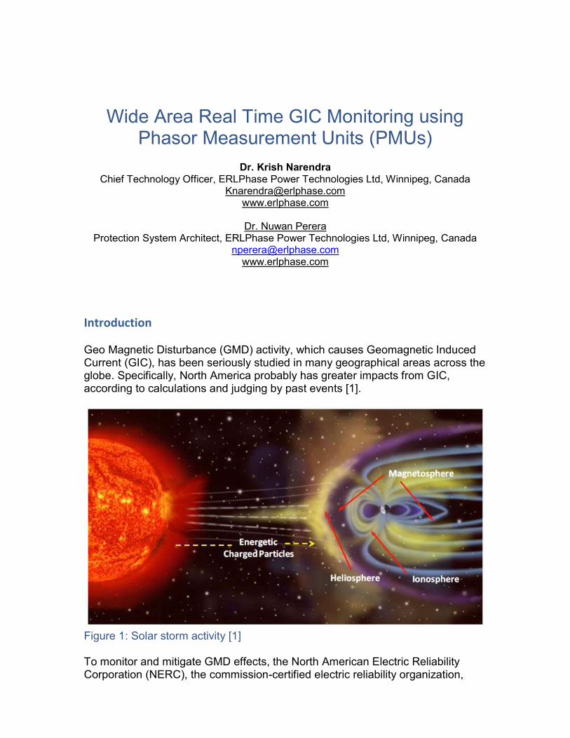
Introduction Geo Magnetic Disturbance (GMD) activity, which causes Geomagnetic Induced Current (GIC), has been seriously studied in many geographical areas across the globe. Specifically, North America probably has greater impacts from GIC, according to calculations and judging by past events [1].
Figure 1: Solar storm activity [1] To monitor and mitigate GMD effects, the North American Electric Reliability Corporation (NERC), the commission-certified electric reliability organization,
submitted a reliability standard in response to FERC Order No. 779 [2]. This reliability standard is designed to mitigate the effects of geomagnetic disturbances (GMD) on the bulk power system by requiring responsible entities to implement operating plans, procedures and processes. On March 10, 1989, a strong wind left the sun, heading for Earth. On March 12, the first voltage fluctuations were being seen on the Hydro Québec transmission grid [3]. The system control center was doing what it could to maintain stability. However, on March 13 at 2:44 a.m., the Earth's magnetic field was fluctuating violently. The grid's protection system was triggered, and a blackout occurred in less than a minute! The province was submerged in darkness for more than nine hours. Later, Hydro Québec reviewed the protection and control procedures to adapt to GIC impacts.
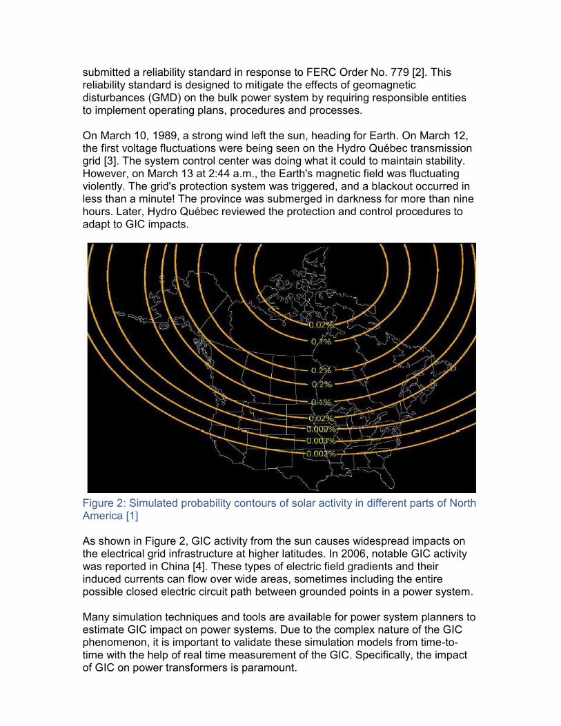
Figure 2: Simulated probability contours of solar activity in different parts of North America [1] As shown in Figure 2, GIC activity from the sun causes widespread impacts on the electrical grid infrastructure at higher latitudes. In 2006, notable GIC activity was reported in China [4]. These types of electric field gradients and their induced currents can flow over wide areas, sometimes including the entire possible closed electric circuit path between grounded points in a power system. Many simulation techniques and tools are available for power system planners to estimate GIC impact on power systems. Due to the complex nature of the GIC phenomenon, it is important to validate these simulation models from time-to-time with the help of real time measurement of the GIC. Specifically, the impact of GIC on power transformers is paramount.
This paper describes a wide area, real time (as defined by the PMU data sample rate) monitoring technique using synchrophasors or Phasor Measurement Units (PMUs) to support the easy implementation of the directive [2]. The mitigation of GIC and the protection of the power system are outside the scope of this paper.
Power System Components Affected by GIC Power Transformers (neutral grounded) When GIC flows through the ground into a closed circuit path, the most affected power system component is the grounded station power transformers (due to the very nature of the non-linear magnetic circuit, as well as its design, construction, type and saturation characteristics). GIC impact on transformers is discussed in more detail later in this paper. Generators Generators are not directly affected by GIC, but due to the transformers’ saturation effect, harmonics (odd and even) will be generated from the transformers, and nearby generators connected through the GSUs (generator step-up transformers) are affected by the negative sequence current overheating. Harmonic currents also affect the rotor of the generator [5]. Even though the GIC’s frequency of oscillation is between 0.001 to 0.1 Hz, one must also consider interaction from the mechanical natural modes of the turbine and generator rotor systems. Current Transformers (CTs) and Potential Transformers (PTs) A CT’s time-to-saturate is, by design, higher than that of a power transformer since it has more “iron” available to deal with the DC offsets during fault conditions. Therefore, solar storms with lesser GIC may not impact power transformers more than CTs. On the other hand, during fault, when a CT is driven to near saturation, moderate GIC current is enough to drive the CTs to saturate quicker and hence the secondary current is not reproduced faithfully. Protection will be impacted, but most modern microprocessor-based relays effectively deal with the CT saturation. Another important parameter to watch is the burden on the secondary, which also plays an important role in CT saturation. Wound PTs usually respond to GIC like power transformers do, and their time-to-saturate depends on the PT’s design and construction. However, at the transmission level, voltage measurement is generally done through CCVTs (Capacitive Coupled Voltage Transformers), therefore relatively unaffected by the GIC flow. Side effects from harmonics and overheating due to nearby transformers is a concern.
Shunt Capacitors Capacitors themselves are not impacted directly by the GIC quasi DC current, but distorted voltages due to nearby transformer saturation can adversely affect capacitor bank protection. For example, an incident in the Hydro Québec system resulted in over voltage relays operating due to distorted voltage [3]. Series Capacitors In fact, series capacitors block GIC and are considered GMD reduction devices. Series capacitors have several advantages, but their interaction with distributed resources on the grid can cause sub harmonics and require attention. Also, installing new series capacitors (even with less capacity) into existing networks is not economically justified solely on the basis of blocking GIC. Shunt Reactors Shunt reactors with iron cores and grounded neutrals saturate like power transformers unless utilities use specially designed shunt reactors to withstand DC. Air-core shunt reactors are not directly affected by GIC, although harmonics may cause extra heating from nearby transformer current distortion. Static Var Compensators (SVCs) GIC caused many misoperations of the SVCs during the 1989 Hydro-Quebec blackout [3]. The Hydro Québec study also showed SVC resonance at 120 Hz, which further caused operation of the SVCs protection. Depending on SVC design, if the reference control signal uses true RMS voltage values, performance can be affected during GIC. The impact will be severe if the nearby transformer is highly saturated and is consuming more reactive power. HVDC Systems The continuous adjustment of firing angle control on both the rectifier and invertor will take care of GIC effect. Therefore at moderate GIC levels, little or no effect is felt (terminal voltage at both ends may vary by a small percentage). Convertor transformers are affected by GIC. Overloading of filter banks due to harmonics is a concern, and commutation failures may happen in line-commutated convertors. Communication Systems PLC (Power Line Carriers), Ethernet switches, telecommunication systems and, to an extent, the fiber-optic networks are all impacted directly or indirectly by GIC.
Impact on Power Transformers Power transformers are the most affected component in a power system [6,7,8,9,10,11,12]. Power transformers with grounded neutrals are impacted by GIC as follows: 1. Half cycle saturation due to GIC offset
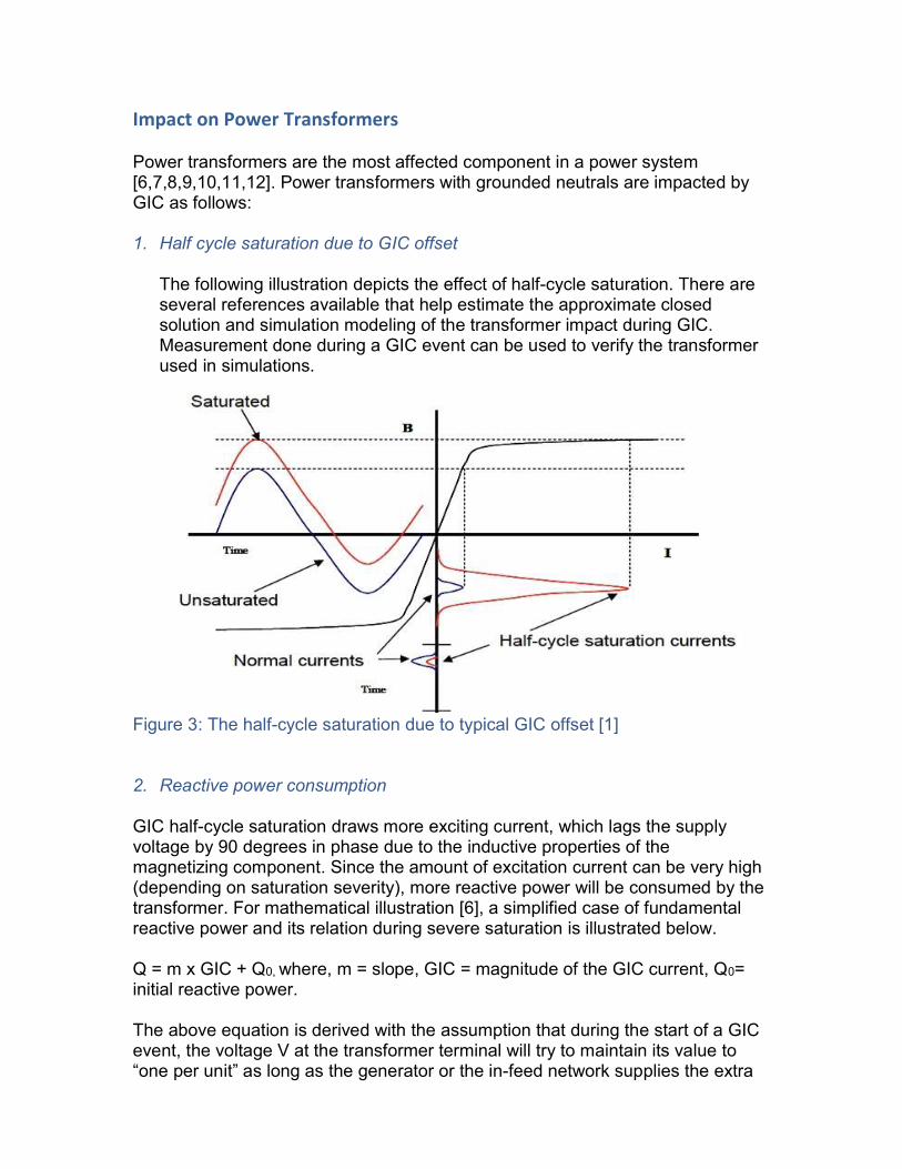
The following illustration depicts the effect of half-cycle saturation. There are several references available that help estimate the approximate closed solution and simulation modeling of the transformer impact during GIC. Measurement done during a GIC event can be used to verify the transformer used in simulations.
Figure 3: The half-cycle saturation due to typical GIC offset [1] 2. Reactive power consumption GIC half-cycle saturation draws more exciting current, which lags the supply voltage by 90 degrees in phase due to the inductive properties of the magnetizing component. Since the amount of excitation current can be very high (depending on saturation severity), more reactive power will be consumed by the transformer. For mathematical illustration [6], a simplified case of fundamental reactive power and its relation during severe saturation is illustrated below. Q = m x GIC + Q0, where, m = slope, GIC = magnitude of the GIC current, Q0= initial reactive power. The above equation is derived with the assumption that during the start of a GIC event, the voltage V at the transformer terminal will try to maintain its value to “one per unit” as long as the generator or the in-feed network supplies the extra
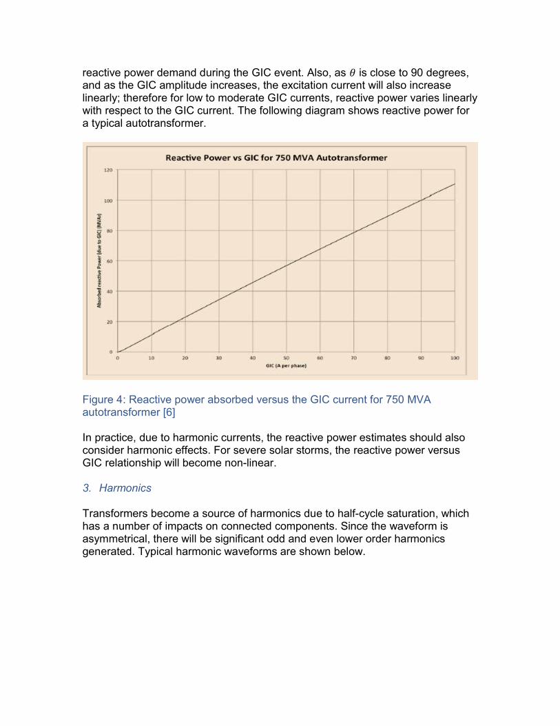
reactive power demand during the GIC event. Also, as ߠ is close to 90 degrees, and as the GIC amplitude increases, the excitation current will also increase linearly; therefore for low to moderate GIC currents, reactive power varies linearly with respect to the GIC current. The following diagram shows reactive power for a typical autotransformer.
Figure 4: Reactive power absorbed versus the GIC current for 750 MVA autotransformer [6] In practice, due to harmonic currents, the reactive power estimates should also consider harmonic effects. For severe solar storms, the reactive power versus GIC relationship will become non-linear. 3. Harmonics Transformers become a source of harmonics due to half-cycle saturation, which has a number of impacts on connected components. Since the waveform is asymmetrical, there will be significant odd and even lower order harmonics generated. Typical harmonic waveforms are shown below.
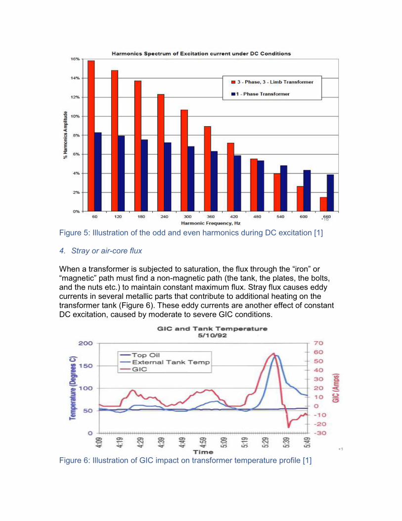
Figure 5: Illustration of the odd and even harmonics during DC excitation [1] 4. Stray or air-core flux When a transformer is subjected to saturation, the flux through the “iron” or “magnetic” path must find a non-magnetic path (the tank, the plates, the bolts, and the nuts etc.) to maintain constant maximum flux. Stray flux causes eddy currents in several metallic parts that contribute to additional heating on the transformer tank (Figure 6). These eddy currents are another effect of constant DC excitation, caused by moderate to severe GIC conditions.
Figure 6: Illustration of GIC impact on transformer temperature profile [1]
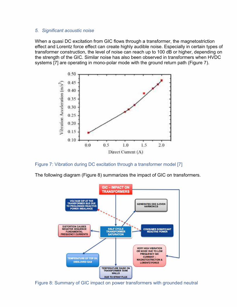
5. Significant acoustic noise When a quasi DC excitation from GIC flows through a transformer, the magnetostriction effect and Lorentz force effect can create highly audible noise. Especially in certain types of transformer construction, the level of noise can reach up to 100 dB or higher, depending on the strength of the GIC. Similar noise has also been observed in transformers when HVDC systems [7] are operating in mono-polar mode with the ground return path (Figure 7). Figure 7: Vibration during DC excitation through a transformer model [7] The following diagram (Figure 8) summarizes the impact of GIC on transformers.
Figure 8: Summary of GIC impact on power transformers with grounded neutral
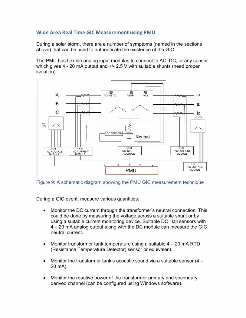
Wide Area Real Time GIC Measurement using PMU During a solar storm, there are a number of symptoms (named in the sections above) that can be used to authenticate the existence of the GIC. The PMU has flexible analog input modules to connect to AC, DC, or any sensor which gives 4 - 20 mA output and +/- 2.5 V with suitable shunts (need proper isolation).
Figure 9: A schematic diagram showing the PMU GIC measurement technique During a GIC event, measure various quantities:
Monitor the DC current through the transformer’s neutral connection. This could be done by measuring the voltage across a suitable shunt or by using a suitable current monitoring device. Suitable DC Hall sensors with 4 – 20 mA analog output along with the DC module can measure the GIC neutral current.
Monitor transformer tank temperature using a suitable 4 – 20 mA RTD (Resistance Temperature Detector) sensor or equivalent.
Monitor the transformer tank’s acoustic sound via a suitable sensor (4 –
20 mA).
Monitor the reactive power of the transformer primary and secondary derived channel (can be configured using Windows software).
Monitor the THD on transformer input currents and voltages. The PMU can measure this using AC voltage and current modules. The PMU can also measure individual harmonics. Care should be taken to supervise the fundamental voltage or current quantities in setting THD. Loading (fundamental frequency quantities) severely impairs THD ratios, and we recommend a supervised THD that can be configured through user defined logics.
Measure transformer tap positions using digital input status.
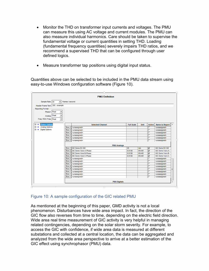
Quantities above can be selected to be included in the PMU data stream using easy-to-use Windows configuration software (Figure 10).
Figure 10: A sample configuration of the GIC related PMU As mentioned at the beginning of this paper, GMD activity is not a local phenomenon. Disturbances have wide area impact. In fact, the direction of the GIC flow also reverses from time to time, depending on the electric field direction. Wide area real time measurement of GIC activity is very helpful in managing related contingencies, depending on the solar storm severity. For example, to access the GIC with confidence, if wide area data is measured at different substations and collected at a central location, the data can be aggregated and analyzed from the wide area perspective to arrive at a better estimation of the GIC effect using synchrophasor (PMU) data.

The following diagram (Figure 11) shows several PMUs in different locations streaming data to the central PDC (Phasor Data Concentrator) to determine GIC impact.
Figure 11: Wide area GIC measurements using PMUs There are 12 quantities per PMU (user can also configure more, if needed), which can be measured and / or calculated. User has to select the PMU data sample rate. It is recommended to select low PMU data sample rate (30 frames/sec or 30 Hz for a 60 Hz system or less) to capture the above quantities. Usually, the relay-based PMUs cannot measure DC quantities or low-level analog sensor signals, but the proposed PMU can send up to 36 phasors and up to 12 analog quantities (to accommodate the DC and low level analog sensor values needed to monitor GIC). Measure the following analog quantities through the PMU analog data stream:
1. DC Neutral Current (hall sensor) through DC module 2. Reactive power of the transformer corresponding to the HV and the LV
windings (readily available in the proposed PMU as a calculated channel) 3. Transformer tank temperature (4 – 20 mA output sensor) through DC
module 4. Top oil temperature ( 4- 20 mA output sensor) through DC module 5. Gas sensor (4- 20 mA) through DC module 6. Acoustic sensor ( 4 – 20 mA) through DC module
7. THD – logic through digital input (logic configured through output contact into one of the digital inputs)
8. Tap position (digital Input)
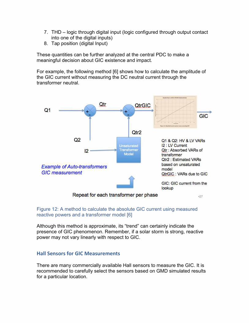
These quantities can be further analyzed at the central PDC to make a meaningful decision about GIC existence and impact. For example, the following method [6] shows how to calculate the amplitude of the GIC current without measuring the DC neutral current through the transformer neutral.
Figure 12: A method to calculate the absolute GIC current using measured reactive powers and a transformer model [6] Although this method is approximate, its “trend” can certainly indicate the presence of GIC phenomenon. Remember, if a solar storm is strong, reactive power may not vary linearly with respect to GIC.
Hall Sensors for GIC Measurements There are many commercially available Hall sensors to measure the GIC. It is recommended to carefully select the sensors based on GMD simulated results for a particular location.
Conclusions
• Measurement techniques proposed in this paper are very useful to monitor wide area GIC events and compare the performance of the power system using simulation models. These real time measurements provide extra confidence and visibility to handle system contingencies during a wide area GIC event.
• During a solar storm, wide area based measurement of GIC can use PMU data to help monitor and handle contingencies in real time.
• Mere detection of DC current in a transformer’s neutral is not necessarily an indication of the GIC.
• GIC phenomenon can be detected readily with PMUs by measuring the transformer VARs, harmonic flows, temperature measurements, acoustic sensor measurements and other values during half-cycle saturation.
• GIC affects overall power system protection and its sensitivity. Different principles should be used, with review, to mitigate the detrimental effects.
References [1] “NERC GMDTF Interim Report: Effects of Geomagnetic Disturbances on the Bulk Power System–February 2012”. [2] “Reliability Standards for Geomagnetic Disturbances”, Order No. 779, 78 FR 30,747 (May 23, 2013), 143 FERC, 61,147, 144 FERC 61,113 (2013). [3] http://www.hydroquebec.com/learning/notions-de-base/tempete-mars-1989.html. [4] Mingde Cui, Chunming Liu, Lianguang Liu, and Xinyuan Zhang, “Preliminary Study of the Influence Caused by Solar Storm on Sichuan Power Grid”, “International Conference on Power System Technology”, pp 1-6. [5] W.B. Gish, W.E. Feero, G.D. Rockefeller, “Rotor heating effects from geomagnetic induced currents”, IEEE Transactions on Power Delivery, Vol. 9, No. 2, April 1994, pp 712-719. [6] Berge, Jonathan E., "Impact of Geomagnetically Induced Currents on Power Transformers" (2011). Electronic Thesis and Dissertation Repository. Paper 132, University of Western Ontario, Canada. [7] Jinliang He, Zhanqing, Bo Zhang, “Vibration and Audible Noise Charateristics of AC Transformer Caused by HVDC System Under Monopole Operation”, IEEE Transactions on Power Delivery, Vol 27, No.4, Oct 2012, pp 1835-1842. [8] Marti, L., Rezaei-Zare, A., Narang, A., “Simulation of Transformer Hotspot Heating due to Geomagnetically Induced Currents”, IEEE Transactions on Power Delivery, Vol.28, No.1, pp 320-327, Jan 2013. [9] R. A. Walling, and A.H. Khan, “Characteristics of transformer exciting-current during Geomagnetic Disturbances”, IEEE Transactions on Power Delivery, Vol. 6, No. 4, Oct 1991, pp 1707-1714. [10] Ashley Karl Zeimer, “Effect of DC current on Power Transformers”, Dissertation Report Submitted for Course ENG4111 & 4112 Research Project, Bachelor of Electrical/ Electronic Engineering, University of Southern Queensland, October 2000. [11] Luis Marti, Jonathan Berge, Rajiv K. Varma, “Determination of Geomagnetically Induced Current Flow in a Transformer From Reactive Power Absorption”, IEEE Transaction on Power Delivery, Vol. 28, No. 3, July 2013. [12] N. Mohan, J.G. Kappenman, and V. D. Albertson, “Harmonics and Switching Transients in the Presence of Geomagnetically-Induced Currents”, IEEE Transactions on Power Apparatus and Systems, Vol PAS-100, No. 2, Feb 1981, pp 585-593.
Biography Krish Narendra, Ph.D Chief Technology Officer and Board Member ERL - Power Automation & Smart Grid Dr. Narendra has over 25 years of experience in power system protection, monitoring, control and analysis. He is responsible for innovative design, implementation, quality and commercialization of protective relays and disturbance monitoring recorders using advanced digital signal processing technologies on embedded systems, and in Windows development environments. Dr. Narendra has been a valued IEEE member for over 15 years. He is actively participating in the IEEE PRSC working groups, and is a member of the PRTT of NASPI. He is a member of the CIGRE C4-B5 working group and NERC SMS committee. He has published over 35 papers in various IEEE/IEC journals and conferences, and is an innovator of several patents. His areas of interests include power systems disturbance analysis, protection, micro grid protection, sub-harmonics in power systems, SSR (sub synchronous resonance), ferroresonance, HVDC controls, neural networks, artificial intelligence, fuzzy logic, phasor technology (PMUs), and the application of IEC 61850 protocols for protection and control. Nuwan Perera, PhD, PEng Protection System Architect ERLPhase Technologies Ltd Nuwan Perera received the B.Sc. (Eng.) degree from University of Moratuwa, Sri Lanka, in 2003 and the M.Sc. and Ph.D. degrees from University of Manitoba in 2007 and 2012 respectively.
He works at ERLPhase Power Technologies, Winnipeg , Canada and responsible for designing protection & control solutions, leading power system studies, providing the technical specifications for development projects and providing the technical support for the application & sales team. His is a senior IEEE Member involved with IEEE PSRC Working Groups.
His research interests are in power system protection, distributed generation and smart grids. He is a registered Professional Engineer in the Province of Manitoba, Canada.